Power Generation from Solid Fuels
704
-
Upload
khangminh22 -
Category
Documents
-
view
0 -
download
0
Transcript of Power Generation from Solid Fuels


Power Systems
For further volumes:http://www.springer.com/series/4622


Hartmut Spliethoff
Power Generationfrom Solid Fuels
123
Dr. Hartmut SpliethoffTU MunchenInstitut fur Energiewirtschaftund AnwendungstechnikArcisstrasse 2180333 [email protected]
ISSN 1612-1287ISBN 978-3-642-02855-7 e-ISBN 978-3-642-02856-4DOI 10.1007/978-3-642-02856-4Springer Heidelberg Dordrecht London New York
Library of Congress Control Number: 2009942919
c© Springer-Verlag Berlin Heidelberg 2010This work is subject to copyright. All rights are reserved, whether the whole or part of the material isconcerned, specifically the rights of translation, reprinting, reuse of illustrations, recitation, broadcasting,reproduction on microfilm or in any other way, and storage in data banks. Duplication of this publicationor parts thereof is permitted only under the provisions of the German Copyright Law of September 9,1965, in its current version, and permission for use must always be obtained from Springer. Violationsare liable to prosecution under the German Copyright Law.The use of general descriptive names, registered names, trademarks, etc. in this publication does notimply, even in the absence of a specific statement, that such names are exempt from the relevant protectivelaws and regulations and therefore free for general use.
Cover design: deblik, Berlin
Printed on acid-free paper
Springer is part of Springer Science+Business Media (www.springer.com)
Preface
Today, fossil fuels dominate worldwide primary energy consumption. In 2000, about40% of total primary energy was used for electricity generation, and of this, coal wasthe fuel for 40%, making it the most important primary energy carrier for powerproduction. Forecasts of future energy consumption predict a further increase ofworldwide coal utilisation in the coming 20 years. In comparison to natural gas andoil, coal has the advantage of being the most abundant fossil energy carrier.
Fossil fuels are the major source of CO2 emissions and cause global warmingwith all its negative impacts. It is generally accepted today that huge efforts haveto be undertaken to limit the emissions of CO2 and to reduce the impact of globalwarming. Mitigation scenarios indicate that this can only be achieved if all optionsfor CO2 reduction are followed. The principle possibilities for reducing CO2 emis-sions are more efficient energy utilisation, the substitution of fossil fuels by renew-able energies or nuclear energy and carbon capture.
It is the intention of the author to explain the technical possibilities for reducingCO2 emissions from solid fuels. The strategies which will be treated in this book aremore efficient power and heat generation technologies, processes for the utilisationof renewable solid fuels, such as biomass and waste, and technologies for carboncapture and storage.
The book introduces the different technologies to produce heat and power fromsolid fossil (hard coal, brown coal) and renewable (biomass, waste) fuels, suchas combustion and gasification, steam power plants and combined cycles. Thetechnologies are discussed with regard to their efficiency, emissions, operationalbehaviour, residues and costs. Besides proven state of the art processes, the focuswill be on the potential of new technologies currently under development or demon-stration.
Chapter 1 gives an overview of current worldwide primary energy consumptionand its future development. The impact of CO2 emissions on global warming issummarised and the strategies for CO2 reduction are identified.
Chapter 2 deals with the origin and classification of solid fuels. Reserves of solidfossil fuels are indicated and the energy potential of biomass and waste is estimated.The fuel properties are characterised with regard to thermal conversion processes.
Chapter 3 provides the thermodynamic fundamentals of the thermal cycles whichare required to convert the chemically bound energy of the fuels into power.
v

vi Preface
The focus of Chapter 4 is the technology of the steam power plant, which isthe dominant process for power plants. The fundamentals of steam generation areintroduced and the design principles of a conventional state-of-the-art steam powerplant are explained. In comparison to this reference plant, the different possibilitiesfor efficiency increase and the impact of advanced steam conditions on the steamgenerator is discussed. A summary of the design data of the most advanced operatedpower plants in the world is included in the outlook for the further development ofsteam power plants.
Chapter 5 deals with combustion, which is the dominant technology of fuel con-version. Starting from the principles of solid fuel combustion and the fundamentalsof pollutant formation, the different combustion technologies of fixed bed, fluidisedbed and pulverised fuel combustion are compared. Emission reduction technologies,either primary measures within the combustion process or secondary flue gas clean-ing, are examined. Operational problems such as slagging, fouling and corrosion,which have to be related to ash properties and process conditions and which are ofgreat importance for solid fuel combustion, are discussed. The production of mineralresidues is inevitable in solid fuel combustion; the options to use the residues aredescribed.
Although the technologies for biomass and waste conversion follow the sameprinciples as for coal, substantial differences arise due to the differing fuel qualityand the smaller capacity of such power plants. Therefore, biomass and wastes aretreated separately in Chapter 6. Besides biomass combustion, biomass gasification,waste combustion and co-combustion technologies are the focus of this chapter. Itexplains how ash-related problems in biomass and waste conversion are even morepronounced than for coal and will effect the operation of biomass/waste plants andlimit the electrical efficiency. Co-utilisation of biomass in coal-fired power stationsis a further process option, and the impact on emissions and operational problems isdiscussed.
Gas turbine-based combined cycles for natural gas offer the highest efficienciesin power generation, of up to about 60%. The focus of Chapter 7 is to show the stateof development of combined cycle processes for solid fuels. After describing thetechnology of natural gas-based combined cycles, the processes, the potentials andthe development stages of the integrated gasification combined cycle (IGCC), thecombined cycle with pressurised fluidised bed combustion (PFBC), the combinedcycle with pressurised pulverised coal combustion (PPCC) and the externally firedcombined cycle (EFCC) will be explored.
Along with the efficiency increases and the use of renewable energy sources, CO2
capture and storage methods offer a possible means of CO2 reduction in fossil fuel-fired power plants. Chapter 8 gives an overview of the options for CO2 separation,transport and storage for power plants.
This book developed over the years of my activities at the University of Stuttgart,the Technical University of Delft and now the Technical University of Munich.Results from various research projects are included in the book. The basis of thisbook was my habilitation “Combustion of solid fuels”, which was published in2000 in German. Since that time, a lot of new developments have emerged, while

Preface vii
other areas within the field have progressed only slightly. This is reflected in thebook.
I would like to thank all those who provided materials, contributions and com-ments to the different chapters of this book: Dr. Oliver Gohlke, Dr. Michael Muller,Dr. Arnim Wauschkuhn, Mr. Sven Kjaer, Mr. Helmuth Bruggemann, Mr. Kendel,co-workers from my chair Energy Systems at the Technical University of Munichand my colleagues from my former employers the Technical University of Delft andthe University of Stuttgart. Furthermore, I would like to thank Herbert Rausch fortranslations and Patrick Lavery for proofreading. Special thanks go to Mrs. BrigitteDemmel for requesting copyrights and Mrs. Korinna Riechert for drawing figures.
MunchenAugust 2009


Contents
1 Motivation . . . . . . . . . . . . . . . . . . . . . . . . . . . . . . . . . . . . . . . . . . . . . . . . . . . . . 11.1 Primary Energy Consumption and CO2 Emissions . . . . . . . . . . . . . . . . 1
1.1.1 Development of Primary Energy Consumptionin the Past 40 Years . . . . . . . . . . . . . . . . . . . . . . . . . . . . . . . . . . . 1
1.1.2 Developments Until 2030 . . . . . . . . . . . . . . . . . . . . . . . . . . . . . . 11.2 Greenhouse Effect and Impacts on the Climate . . . . . . . . . . . . . . . . . . . 5
1.2.1 Greenhouse Effect . . . . . . . . . . . . . . . . . . . . . . . . . . . . . . . . . . . . 61.2.2 Impacts . . . . . . . . . . . . . . . . . . . . . . . . . . . . . . . . . . . . . . . . . . . . . . 81.2.3 Scenarios of the World Climate . . . . . . . . . . . . . . . . . . . . . . . . . . 8
1.3 Strategies of CO2 Reduction . . . . . . . . . . . . . . . . . . . . . . . . . . . . . . . . . . . 101.3.1 Substitution . . . . . . . . . . . . . . . . . . . . . . . . . . . . . . . . . . . . . . . . . . 101.3.2 Carbon Capture and Storage (CCS) . . . . . . . . . . . . . . . . . . . . . . 111.3.3 Energy Saving . . . . . . . . . . . . . . . . . . . . . . . . . . . . . . . . . . . . . . . . 121.3.4 Mitigation Scenarios . . . . . . . . . . . . . . . . . . . . . . . . . . . . . . . . . . . 12
References . . . . . . . . . . . . . . . . . . . . . . . . . . . . . . . . . . . . . . . . . . . . . . . . . . . . . . 13
2 Solid Fuels . . . . . . . . . . . . . . . . . . . . . . . . . . . . . . . . . . . . . . . . . . . . . . . . . . . . . 152.1 Fossil Fuels . . . . . . . . . . . . . . . . . . . . . . . . . . . . . . . . . . . . . . . . . . . . . . . . . 15
2.1.1 Origin and Classification of Coal Types . . . . . . . . . . . . . . . . . . . 152.1.2 Composition and Properties of Solid Fuels . . . . . . . . . . . . . . . . 162.1.3 Reserves of Solid Fuels . . . . . . . . . . . . . . . . . . . . . . . . . . . . . . . . 25
2.2 Renewable Solid Fuels . . . . . . . . . . . . . . . . . . . . . . . . . . . . . . . . . . . . . . . 292.2.1 Potential and Current Utilisation . . . . . . . . . . . . . . . . . . . . . . . . . 292.2.2 Considerations of the CO2 Neutrality of Regenerative Fuels . . 402.2.3 Fuel Characteristics of Biomass . . . . . . . . . . . . . . . . . . . . . . . . . 42
References . . . . . . . . . . . . . . . . . . . . . . . . . . . . . . . . . . . . . . . . . . . . . . . . . . . . . . 54
3 Thermodynamics Fundamentals . . . . . . . . . . . . . . . . . . . . . . . . . . . . . . . . . . 573.1 Cycles . . . . . . . . . . . . . . . . . . . . . . . . . . . . . . . . . . . . . . . . . . . . . . . . . . . . . 57
3.1.1 Carnot Cycle . . . . . . . . . . . . . . . . . . . . . . . . . . . . . . . . . . . . . . . . . 573.1.2 Joule–Thomson Process . . . . . . . . . . . . . . . . . . . . . . . . . . . . . . . . 583.1.3 Clausius–Rankine Cycle . . . . . . . . . . . . . . . . . . . . . . . . . . . . . . . 61
ix

x Contents
3.2 Steam Power Cycle: Energy and Exergy Considerations . . . . . . . . . . . . 643.2.1 Steam Generator Energy and Exergy Efficiencies . . . . . . . . . . . 673.2.2 Energy and Exergy Cycle Efficiencies . . . . . . . . . . . . . . . . . . . . 693.2.3 Energy and Exergy Efficiency of the Total Cycle . . . . . . . . . . . 70
References . . . . . . . . . . . . . . . . . . . . . . . . . . . . . . . . . . . . . . . . . . . . . . . . . . . . . . 71
4 Steam Power Stations for Electricity and Heat Generation . . . . . . . . . . 734.1 Pulverised Hard Coal Fired Steam Power Plants . . . . . . . . . . . . . . . . . . 73
4.1.1 Energy Conversion and System Components . . . . . . . . . . . . . . 734.1.2 Design of a Condensation Power Plant . . . . . . . . . . . . . . . . . . . 754.1.3 Development History of Power Plants – Correlation
Between Unit Size, Availability and Efficiency . . . . . . . . . . . . 774.1.4 Reference Power Plant . . . . . . . . . . . . . . . . . . . . . . . . . . . . . . . . . 81
4.2 Steam Generators . . . . . . . . . . . . . . . . . . . . . . . . . . . . . . . . . . . . . . . . . . . . 814.2.1 Flow and Heat Transfer Inside a Tube . . . . . . . . . . . . . . . . . . . . 834.2.2 Evaporator Configurations . . . . . . . . . . . . . . . . . . . . . . . . . . . . . . 874.2.3 Steam Generator Construction Types . . . . . . . . . . . . . . . . . . . . . 934.2.4 Operating Regimes and Control Modes . . . . . . . . . . . . . . . . . . . 95
4.3 Design of a Condensation Power Plant . . . . . . . . . . . . . . . . . . . . . . . . . . 1044.3.1 Requirements and Boundary Conditions . . . . . . . . . . . . . . . . . . 1044.3.2 Thermodynamic Design of the Power Plant Cycle . . . . . . . . . . 1104.3.3 Heat Balance of the Boiler and Boiler Efficiency . . . . . . . . . . . 1144.3.4 Design of the Furnace . . . . . . . . . . . . . . . . . . . . . . . . . . . . . . . . . 1154.3.5 Design of the Steam Generator and of the Heating
Surfaces . . . . . . . . . . . . . . . . . . . . . . . . . . . . . . . . . . . . . . . . . . . . 1214.3.6 Design of the Flue Gas Cleaning Units and the
Auxiliaries . . . . . . . . . . . . . . . . . . . . . . . . . . . . . . . . . . . . . . . . . . 1414.4 Possibilities for Efficiency Increases in the Development of a Steam
Power Plant . . . . . . . . . . . . . . . . . . . . . . . . . . . . . . . . . . . . . . . . . . . . . . . . 1414.4.1 Increases in Thermal Efficiencies . . . . . . . . . . . . . . . . . . . . . . . . 1424.4.2 Reduction of Losses . . . . . . . . . . . . . . . . . . . . . . . . . . . . . . . . . . . 1614.4.3 Reduction of the Auxiliary Power Requirements . . . . . . . . . . . 1724.4.4 Losses in Part-Load Operation . . . . . . . . . . . . . . . . . . . . . . . . . . 1754.4.5 Losses During Start-Up and Shutdown . . . . . . . . . . . . . . . . . . . 1784.4.6 Efficiency of Power Plants During Operation . . . . . . . . . . . . . . 1794.4.7 Fuel Drying for Brown Coal . . . . . . . . . . . . . . . . . . . . . . . . . . . . 179
4.5 Effects on Steam Generator Construction . . . . . . . . . . . . . . . . . . . . . . . . 1844.5.1 Membrane Wall . . . . . . . . . . . . . . . . . . . . . . . . . . . . . . . . . . . . . . . 1864.5.2 Heating Surfaces of the Final Superheater . . . . . . . . . . . . . . . . . 1944.5.3 High-Pressure Outlet Header . . . . . . . . . . . . . . . . . . . . . . . . . . . . 2014.5.4 Furnaces Fuelled by Dried Brown Coal . . . . . . . . . . . . . . . . . . . 204
4.6 Developments – State of the Art and Future . . . . . . . . . . . . . . . . . . . . . . 2064.6.1 Hard Coal . . . . . . . . . . . . . . . . . . . . . . . . . . . . . . . . . . . . . . . . . . . 2064.6.2 Brown Coal . . . . . . . . . . . . . . . . . . . . . . . . . . . . . . . . . . . . . . . . . . 214
References . . . . . . . . . . . . . . . . . . . . . . . . . . . . . . . . . . . . . . . . . . . . . . . . . . . . . . 214

Contents xi
5 Combustion Systems for Solid Fossil Fuels . . . . . . . . . . . . . . . . . . . . . . . . . 2215.1 Combustion Fundamentals . . . . . . . . . . . . . . . . . . . . . . . . . . . . . . . . . . . . 223
5.1.1 Drying . . . . . . . . . . . . . . . . . . . . . . . . . . . . . . . . . . . . . . . . . . . . . . 2245.1.2 Pyrolysis . . . . . . . . . . . . . . . . . . . . . . . . . . . . . . . . . . . . . . . . . . . . 2255.1.3 Ignition . . . . . . . . . . . . . . . . . . . . . . . . . . . . . . . . . . . . . . . . . . . . . 2275.1.4 Combustion of Volatile Matter . . . . . . . . . . . . . . . . . . . . . . . . . . 2305.1.5 Combustion of the Residual Char . . . . . . . . . . . . . . . . . . . . . . . . 230
5.2 Pollutant Formation Fundamentals . . . . . . . . . . . . . . . . . . . . . . . . . . . . . 2345.2.1 Nitrogen Oxides . . . . . . . . . . . . . . . . . . . . . . . . . . . . . . . . . . . . . . 2345.2.2 Sulphur Oxides . . . . . . . . . . . . . . . . . . . . . . . . . . . . . . . . . . . . . . . 2415.2.3 Ash formation . . . . . . . . . . . . . . . . . . . . . . . . . . . . . . . . . . . . . . . . 2425.2.4 Products of Incomplete Combustion . . . . . . . . . . . . . . . . . . . . . . 245
5.3 Pulverised Fuel Firing . . . . . . . . . . . . . . . . . . . . . . . . . . . . . . . . . . . . . . . . 2465.3.1 Pulverised Fuel Firing Systems . . . . . . . . . . . . . . . . . . . . . . . . . . 2465.3.2 Fuel Preparation . . . . . . . . . . . . . . . . . . . . . . . . . . . . . . . . . . . . . . 2495.3.3 Burners . . . . . . . . . . . . . . . . . . . . . . . . . . . . . . . . . . . . . . . . . . . . . . 2525.3.4 Dry-Bottom Firing . . . . . . . . . . . . . . . . . . . . . . . . . . . . . . . . . . . . 2545.3.5 Slag-Tap Firing . . . . . . . . . . . . . . . . . . . . . . . . . . . . . . . . . . . . . . . 257
5.4 Fluidised Bed Firing Systems . . . . . . . . . . . . . . . . . . . . . . . . . . . . . . . . . . 2635.4.1 Bubbling Fluidised Bed Furnaces . . . . . . . . . . . . . . . . . . . . . . . . 2645.4.2 Circulating Fluidised Bed Furnaces . . . . . . . . . . . . . . . . . . . . . . 266
5.5 Stoker/Grate Firing Systems . . . . . . . . . . . . . . . . . . . . . . . . . . . . . . . . . . . 2715.5.1 Travelling Grate Stoker Firing . . . . . . . . . . . . . . . . . . . . . . . . . . . 2715.5.2 Self-Raking Type Moving-Grate Stokers . . . . . . . . . . . . . . . . . . 2735.5.3 Vibrating-Grate Stokers . . . . . . . . . . . . . . . . . . . . . . . . . . . . . . . . 275
5.6 Legislation and Emission Limits . . . . . . . . . . . . . . . . . . . . . . . . . . . . . . . 2755.7 Methods for NOx Reduction . . . . . . . . . . . . . . . . . . . . . . . . . . . . . . . . . . . 277
5.7.1 Combustion Engineering Measures . . . . . . . . . . . . . . . . . . . . . . 2795.7.2 NOx Reduction Methods, SNCR and SCR
(Secondary Measures) . . . . . . . . . . . . . . . . . . . . . . . . . . . . . . . . . 3025.7.3 Dissemination and Costs . . . . . . . . . . . . . . . . . . . . . . . . . . . . . . . 306
5.8 SO2-Reduction Methods . . . . . . . . . . . . . . . . . . . . . . . . . . . . . . . . . . . . . . 3075.8.1 Methods to Reduce the Sulphur Content of the Fuel . . . . . . . . 3085.8.2 Methods of Fuel Gas Desulphurisation . . . . . . . . . . . . . . . . . . . 3085.8.3 Dissemination and Costs . . . . . . . . . . . . . . . . . . . . . . . . . . . . . . . 315
5.9 Particulate Control Methods . . . . . . . . . . . . . . . . . . . . . . . . . . . . . . . . . . . 3155.9.1 Mechanical Separators (Inertia Separators) . . . . . . . . . . . . . . . . 3165.9.2 Electrostatic Precipitators . . . . . . . . . . . . . . . . . . . . . . . . . . . . . . 3175.9.3 Fabric Filters . . . . . . . . . . . . . . . . . . . . . . . . . . . . . . . . . . . . . . . . . 3195.9.4 Applications and Costs . . . . . . . . . . . . . . . . . . . . . . . . . . . . . . . . . 321
5.10 Effect of Slag, Ash and Flue Gas on Furnace Wallsand Convective Heat Transfer Surfaces (Operational Problems) . . . . . 3225.10.1 Slagging . . . . . . . . . . . . . . . . . . . . . . . . . . . . . . . . . . . . . . . . . . . . . 3245.10.2 Fouling . . . . . . . . . . . . . . . . . . . . . . . . . . . . . . . . . . . . . . . . . . . . . . 3345.10.3 Erosion . . . . . . . . . . . . . . . . . . . . . . . . . . . . . . . . . . . . . . . . . . . . . . 335

xii Contents
5.10.4 High-Temperature Corrosion . . . . . . . . . . . . . . . . . . . . . . . . . . . . 3365.11 Residual Matter . . . . . . . . . . . . . . . . . . . . . . . . . . . . . . . . . . . . . . . . . . . . . 340
5.11.1 Forming and Quantities . . . . . . . . . . . . . . . . . . . . . . . . . . . . . . . . 3405.11.2 Commercial Exploitation . . . . . . . . . . . . . . . . . . . . . . . . . . . . . . . 344
References . . . . . . . . . . . . . . . . . . . . . . . . . . . . . . . . . . . . . . . . . . . . . . . . . . . . . . 351
6 Power Generation from Biomass and Waste . . . . . . . . . . . . . . . . . . . . . . . . 3616.1 Power Production Pathways . . . . . . . . . . . . . . . . . . . . . . . . . . . . . . . . . . . 361
6.1.1 Techniques Involving Combustion . . . . . . . . . . . . . . . . . . . . . . . 3616.1.2 Techniques Involving Gasification . . . . . . . . . . . . . . . . . . . . . . . 363
6.2 Biomass Combustion Systems . . . . . . . . . . . . . . . . . . . . . . . . . . . . . . . . . 3646.2.1 Capacities and Types . . . . . . . . . . . . . . . . . . . . . . . . . . . . . . . . . . 3646.2.2 Impact of Load and Forms of Delivery of the Fuel Types . . . . 3656.2.3 Furnace Types . . . . . . . . . . . . . . . . . . . . . . . . . . . . . . . . . . . . . . . . 3666.2.4 Flue Gas Cleaning and Ash Disposal . . . . . . . . . . . . . . . . . . . . . 3736.2.5 Operational Problems . . . . . . . . . . . . . . . . . . . . . . . . . . . . . . . . . . 377
6.3 Biomass Gasification . . . . . . . . . . . . . . . . . . . . . . . . . . . . . . . . . . . . . . . . . 3796.3.1 Reactor Design Types . . . . . . . . . . . . . . . . . . . . . . . . . . . . . . . . . . 3806.3.2 Gas Utilisation and Quality Requirements . . . . . . . . . . . . . . . . . 3896.3.3 Gas Cleaning . . . . . . . . . . . . . . . . . . . . . . . . . . . . . . . . . . . . . . . . . 3916.3.4 Power Production Processes . . . . . . . . . . . . . . . . . . . . . . . . . . . . 398
6.4 Thermal Utilisation of Waste (Energy from Waste) . . . . . . . . . . . . . . . . 4016.4.1 Historical Development of Energy from Waste
Systems (EfW) . . . . . . . . . . . . . . . . . . . . . . . . . . . . . . . . . . . . . . . 4056.4.2 Grate-Based Combustion Systems . . . . . . . . . . . . . . . . . . . . . . . 4086.4.3 Pyrolysis and Gasification Systems . . . . . . . . . . . . . . . . . . . . . . 4186.4.4 Refuse-Derived Fuel (RDF) . . . . . . . . . . . . . . . . . . . . . . . . . . . . . 4216.4.5 Sewage Sludge . . . . . . . . . . . . . . . . . . . . . . . . . . . . . . . . . . . . . . . 4236.4.6 Steam Boilers . . . . . . . . . . . . . . . . . . . . . . . . . . . . . . . . . . . . . . . . 4246.4.7 Efficiency Increases in EfW Plants . . . . . . . . . . . . . . . . . . . . . . . 4256.4.8 Dioxins . . . . . . . . . . . . . . . . . . . . . . . . . . . . . . . . . . . . . . . . . . . . . 4346.4.9 Flue Gas Cleaning . . . . . . . . . . . . . . . . . . . . . . . . . . . . . . . . . . . . 435
6.5 Co-combustion in Coal-Fired Power Plants . . . . . . . . . . . . . . . . . . . . . . 4386.5.1 Co-combustion Design Concepts . . . . . . . . . . . . . . . . . . . . . . . . 4406.5.2 Biomass Preparation and Feeding . . . . . . . . . . . . . . . . . . . . . . . . 4426.5.3 Co-combustion in Pulverised Fuel Firing . . . . . . . . . . . . . . . . . . 4466.5.4 Co-combustion in Fluidised Bed Furnaces . . . . . . . . . . . . . . . . 458
References . . . . . . . . . . . . . . . . . . . . . . . . . . . . . . . . . . . . . . . . . . . . . . . . . . . . . . 461
7 Coal-Fuelled Combined Cycle Power Plants . . . . . . . . . . . . . . . . . . . . . . . 4697.1 Natural Gas Fuelled Combined Cycle Processes . . . . . . . . . . . . . . . . . . 4697.2 Overview of Combined Processes with Coal Combustion . . . . . . . . . . 474
7.2.1 Introduction . . . . . . . . . . . . . . . . . . . . . . . . . . . . . . . . . . . . . . . . . . 4747.2.2 Hot Gas Purity Requirements . . . . . . . . . . . . . . . . . . . . . . . . . . . 477
Contents xiii
7.2.3 Overview of the Hot Gas Cleaning System for CoalCombustion Combined Cycles . . . . . . . . . . . . . . . . . . . . . . . . . . 480
7.2.4 Effect of Pressure on Combustion . . . . . . . . . . . . . . . . . . . . . . . . 4817.3 Pressurised Fluidised Bed Combustion (PFBC) . . . . . . . . . . . . . . . . . . . 483
7.3.1 Overview . . . . . . . . . . . . . . . . . . . . . . . . . . . . . . . . . . . . . . . . . . . . 4837.3.2 Hot Gas Cleaning After the Pressurised Fluidised Bed . . . . . . 4907.3.3 Pressurised Bubbling Fluidised Bed Combustion
(PBFBC) . . . . . . . . . . . . . . . . . . . . . . . . . . . . . . . . . . . . . . . . . . . . 4987.3.4 Pressurised Circulating Fluidised Bed Combustion
(PCFBC) . . . . . . . . . . . . . . . . . . . . . . . . . . . . . . . . . . . . . . . . . . . . 5077.3.5 Second-Generation Fluidised Bed Firing Systems
(Hybrid Process) . . . . . . . . . . . . . . . . . . . . . . . . . . . . . . . . . . . . . 5147.3.6 Summary . . . . . . . . . . . . . . . . . . . . . . . . . . . . . . . . . . . . . . . . . . . . 517
7.4 Pressurised Pulverised Coal Combustion (PPCC) . . . . . . . . . . . . . . . . . 5187.4.1 Overview . . . . . . . . . . . . . . . . . . . . . . . . . . . . . . . . . . . . . . . . . . . . 5187.4.2 Molten Slag Removal . . . . . . . . . . . . . . . . . . . . . . . . . . . . . . . . . . 5207.4.3 Alkali Release and Capture . . . . . . . . . . . . . . . . . . . . . . . . . . . . . 5237.4.4 State of Development . . . . . . . . . . . . . . . . . . . . . . . . . . . . . . . . . . 5387.4.5 Summary and Conclusions . . . . . . . . . . . . . . . . . . . . . . . . . . . . . 545
7.5 Externally Fired Gas Turbine Processes . . . . . . . . . . . . . . . . . . . . . . . . . 5467.5.1 Structure, Configurations, Efficiency . . . . . . . . . . . . . . . . . . . . . 5467.5.2 High-Temperature Heat Exchanger . . . . . . . . . . . . . . . . . . . . . . 5517.5.3 State of Development . . . . . . . . . . . . . . . . . . . . . . . . . . . . . . . . . . 5617.5.4 Conclusions . . . . . . . . . . . . . . . . . . . . . . . . . . . . . . . . . . . . . . . . . . 568
7.6 Integrated Gasification Combined Cycle (IGCC) . . . . . . . . . . . . . . . . . . 5697.6.1 History of Coal Gasification . . . . . . . . . . . . . . . . . . . . . . . . . . . . 5697.6.2 Applications of Gasification Technology . . . . . . . . . . . . . . . . . . 5707.6.3 Gasification Systems and Chemical Reactions . . . . . . . . . . . . . 5767.6.4 Classification of Coal Gasifiers . . . . . . . . . . . . . . . . . . . . . . . . . . 5857.6.5 Gas Treatment . . . . . . . . . . . . . . . . . . . . . . . . . . . . . . . . . . . . . . . . 5937.6.6 Components and Integration . . . . . . . . . . . . . . . . . . . . . . . . . . . . 6087.6.7 State of the Art and Perspectives . . . . . . . . . . . . . . . . . . . . . . . . . 612
References . . . . . . . . . . . . . . . . . . . . . . . . . . . . . . . . . . . . . . . . . . . . . . . . . . . . . . 619
8 Carbon Capture and Storage (CCS) . . . . . . . . . . . . . . . . . . . . . . . . . . . . . . . 6298.1 Potential for Carbon Capture and Storage . . . . . . . . . . . . . . . . . . . . . . . . 6298.2 Properties and Transport of CO2 . . . . . . . . . . . . . . . . . . . . . . . . . . . . . . . 6308.3 CO2 Storage . . . . . . . . . . . . . . . . . . . . . . . . . . . . . . . . . . . . . . . . . . . . . . . . 632
8.3.1 Industrial Use . . . . . . . . . . . . . . . . . . . . . . . . . . . . . . . . . . . . . . . . 6328.3.2 Geological Storage . . . . . . . . . . . . . . . . . . . . . . . . . . . . . . . . . . . . 633
8.4 Overview of Capture Technologies . . . . . . . . . . . . . . . . . . . . . . . . . . . . . 6378.4.1 Technology Overview . . . . . . . . . . . . . . . . . . . . . . . . . . . . . . . . . 6378.4.2 Separation Technologies . . . . . . . . . . . . . . . . . . . . . . . . . . . . . . . 639

xiv Contents
8.5 Post-combustion Technologies . . . . . . . . . . . . . . . . . . . . . . . . . . . . . . . . . 6428.5.1 Chemical Absorption . . . . . . . . . . . . . . . . . . . . . . . . . . . . . . . . . . 6428.5.2 Solid Sorbents . . . . . . . . . . . . . . . . . . . . . . . . . . . . . . . . . . . . . . . . 646
8.6 Oxy-fuel Combustion . . . . . . . . . . . . . . . . . . . . . . . . . . . . . . . . . . . . . . . . 6478.6.1 Oxy-fuel Steam Generator Concepts . . . . . . . . . . . . . . . . . . . . . 6498.6.2 Impact of Oxy-fuel Combustion . . . . . . . . . . . . . . . . . . . . . . . . . 6518.6.3 Oxy-fuel Configurations . . . . . . . . . . . . . . . . . . . . . . . . . . . . . . . 6568.6.4 Chemical-Looping Combustion . . . . . . . . . . . . . . . . . . . . . . . . . 659
8.7 Integrated Gasification Combined Cycles with Carbon Captureand Storage . . . . . . . . . . . . . . . . . . . . . . . . . . . . . . . . . . . . . . . . . . . . . . . . 661
8.8 Comparison of CCS Technologies . . . . . . . . . . . . . . . . . . . . . . . . . . . . . . 663References . . . . . . . . . . . . . . . . . . . . . . . . . . . . . . . . . . . . . . . . . . . . . . . . . . . . . . 665
Index . . . . . . . . . . . . . . . . . . . . . . . . . . . . . . . . . . . . . . . . . . . . . . . . . . . . . . . . . . . . . 669
List of Figures
1.1 Global primary energy consumption 1965–2005 by country groupings(BP 2008) . . . . . . . . . . . . . . . . . . . . . . . . . . . . . . . . . . . . . . . . . . . . . . . . . . . . 2
1.2 Primary energy consumption in 2005 by regions and countries (BP2008) . . . . . . . . . . . . . . . . . . . . . . . . . . . . . . . . . . . . . . . . . . . . . . . . . . . . . . . 2
1.3 Primary energy consumption in 2005 by primary energy sources (BP2008) . . . . . . . . . . . . . . . . . . . . . . . . . . . . . . . . . . . . . . . . . . . . . . . . . . . . . . . 3
1.4 Primary energy demand 1980–2030 of countries and regions withrespect to primary energy sources (IEA 2002, 2006b; BP 2008) . . . . . . . 3
1.5 Electric power production 1980–2030 of countries and regions withrespect to primary energy sources (IEA 2002, 2006b) . . . . . . . . . . . . . . . 4
1.6 Installed power generation capacity 2000–2030 (IEA 2002) . . . . . . . . . . 41.7 CO2 emissions 1970–2030 (IEA 2002, 2006b) . . . . . . . . . . . . . . . . . . . . . 51.8 Change in radiative forcing in the period 1750–2005 (IPCC 2007b) . . . 81.9 Scenarios of the global CO2 emissions (a), CO2 concentration (b),
temperature rise (c) and sea level (d) (IPCC 2001b) . . . . . . . . . . . . . . . . . 91.10 Strategies to reduce the CO2 emissions to the atmosphere from the
energy sector . . . . . . . . . . . . . . . . . . . . . . . . . . . . . . . . . . . . . . . . . . . . . . . . . 111.11 CO2 emissions of fossil fuels in respect to their calorific value . . . . . . . . 111.12 Primary energy use for the baseline scenario (a) and for the mitigation
scenario (b) and CO2 emissions of the baseline scenario (c) and themitigation scenario (d) (van Vuuren 2006) . . . . . . . . . . . . . . . . . . . . . . . . . 12
2.1 Comparison of different coal classification systems (Skorupska 1993) . 162.2 Coal composition . . . . . . . . . . . . . . . . . . . . . . . . . . . . . . . . . . . . . . . . . . . . . 192.3 Characteristic ash fusion temperatures according to DIN and ASME . . . 222.4 Volatile matter of macerals as a function of the coal type (Ruhrkohle
1987) . . . . . . . . . . . . . . . . . . . . . . . . . . . . . . . . . . . . . . . . . . . . . . . . . . . . . . . 242.5 Correlation of the volatile matter content to the reflectance Rm of
vitrinite (Ruhrkohle 1987) . . . . . . . . . . . . . . . . . . . . . . . . . . . . . . . . . . . . . . 252.6 Reflectance analysis for coals with a similar volatile matter content
(Ruhrkohle 1987) . . . . . . . . . . . . . . . . . . . . . . . . . . . . . . . . . . . . . . . . . . . . . 262.7 Distribution of coal reserves and resources (data from BMWi 2008) . . . 272.8 Coal consumption in the power generation sector and other sectors
(data from IEA 2007) . . . . . . . . . . . . . . . . . . . . . . . . . . . . . . . . . . . . . . . . . . 28
xv

xvi List of Figures
2.9 Price trend of hard coal in comparison to oil and natural gas (datafrom BMWi 2008) . . . . . . . . . . . . . . . . . . . . . . . . . . . . . . . . . . . . . . . . . . . . 28
2.10 Amount, utilisation and disposal of MSW in Germany in 2005 (datafrom BMU 2007a) . . . . . . . . . . . . . . . . . . . . . . . . . . . . . . . . . . . . . . . . . . . . 36
2.11 Effect of treatment on the volume reduction of sewage sludge(Gerhardt et al. 1996) . . . . . . . . . . . . . . . . . . . . . . . . . . . . . . . . . . . . . . . . . . 39
2.12 Breakdown of the CO2 emissions in Miscanthus processing (Kicherer1996) . . . . . . . . . . . . . . . . . . . . . . . . . . . . . . . . . . . . . . . . . . . . . . . . . . . . . . . 41
2.13 CO2 emissions from the combustion of Miscanthus and hard coal . . . . . 412.14 Harvest ratios of various biomass types (Hartmann and Strehler 1995) . 422.15 Calorific value as a function of the moisture content . . . . . . . . . . . . . . . . 442.16 Volatile matter, residual char and ash contents of various biomasses
and coals . . . . . . . . . . . . . . . . . . . . . . . . . . . . . . . . . . . . . . . . . . . . . . . . . . . . 442.17 Ranges of nitrogen, sulphur and chlorine contents in biomass
compared to hard coal . . . . . . . . . . . . . . . . . . . . . . . . . . . . . . . . . . . . . . . . . 472.18 Ash fusion temperatures of various biomass types . . . . . . . . . . . . . . . . . . 472.19 Lower heating value of waste in different countries (Source: Martin) . . . 512.20 Calorific values of municipal sewage sludge (Gerhardt 1998) . . . . . . . . . 533.1 Carnot cycle T − s and p − V diagrams . . . . . . . . . . . . . . . . . . . . . . . . . . 583.2 Schematic diagram of an open gas turbine process . . . . . . . . . . . . . . . . . . 593.3 p − V and T − s diagrams for the ideal Joule – Thomson process . . . . 593.4 T − s diagram of the real Joule – Thomson process . . . . . . . . . . . . . . . . . 613.5 Schematic diagram of a simple steam-electric power plant . . . . . . . . . . . 623.6 Ideal Clausius–Rankine cycle T − s and h − s diagrams . . . . . . . . . . . . 623.7 Isobaric state changes in the evaporator (Baehr and Kabelac 2006) . . . . 683.8 Exergy losses of a simple steam cycle (Baehr and Kabelac 2006) . . . . . . 704.1 Components of a steam power plant . . . . . . . . . . . . . . . . . . . . . . . . . . . . . . 744.2 Energy transformation or conversion, circulation of energy-carrying
media and efficiency in a condensation power plant . . . . . . . . . . . . . . . . . 744.3 Schematic diagram of a hard coal fired thermal power station . . . . . . . . . 754.4 Maximum unit capacity . . . . . . . . . . . . . . . . . . . . . . . . . . . . . . . . . . . . . . . . 784.5 Evolution of live steam conditions of German plants . . . . . . . . . . . . . . . . 784.6 Evolution of the efficiency level of German plants . . . . . . . . . . . . . . . . . . 794.7 Schematic graphic of a shell boiler . . . . . . . . . . . . . . . . . . . . . . . . . . . . . . . 824.8 Evaporation process in vertical evaporation tubes . . . . . . . . . . . . . . . . . . . 834.9 Schematic diagram of the evaporation processes in a vertical tube
(Adrian et al. 1986) . . . . . . . . . . . . . . . . . . . . . . . . . . . . . . . . . . . . . . . . . . . . 844.10 Tube wall temperatures at different heat flux densities (Stultz and
Kitto 1992) . . . . . . . . . . . . . . . . . . . . . . . . . . . . . . . . . . . . . . . . . . . . . . . . . . . 854.11 Flow patterns and wall temperatures in plain and internally finned
vertical evaporator tubes (Kefer et al. 1990) . . . . . . . . . . . . . . . . . . . . . . . 864.12 Flow patterns and wall temperatures in a single-sided heated,
horizontal or inclined evaporator tube (Kefer et al. 1990) . . . . . . . . . . . . 864.13 Evaporator configurations . . . . . . . . . . . . . . . . . . . . . . . . . . . . . . . . . . . . . . 88

List of Figures xvii
4.14 Schematic diagram of a natural-circulation steam generator (Stultzand Kitto 1992) . . . . . . . . . . . . . . . . . . . . . . . . . . . . . . . . . . . . . . . . . . . . . . . 88
4.15 Density differences in a natural-circulation steam generator (Stultzand Kitto 1992) . . . . . . . . . . . . . . . . . . . . . . . . . . . . . . . . . . . . . . . . . . . . . . . 89
4.16 Benson boiler (Dolezal 1990) . . . . . . . . . . . . . . . . . . . . . . . . . . . . . . . . . . . 914.17 Sulzer boiler (Dolezal 1990) . . . . . . . . . . . . . . . . . . . . . . . . . . . . . . . . . . . . 914.18 Evaporators with wound-pattern furnace walls and with vertical
tubing for once-through steam generators (Wittchow 1995) . . . . . . . . . . 924.19 Comparison of single- and two-pass boilers (Strauß 2006) . . . . . . . . . . . 944.20 Turbine with nozzle set and control wheel (Traupel 2001) . . . . . . . . . . . . 984.21 Influence of the control mode on the pressure pattern at the turbine
intake (not to scale) (Baehr 1985) . . . . . . . . . . . . . . . . . . . . . . . . . . . . . . . . 1004.22 Temperatures in the high-pressure section of the turbine with different
control modes (Wittchow 1982) . . . . . . . . . . . . . . . . . . . . . . . . . . . . . . . . . 1014.23 Startup system of a power plant unit (Wittchow 1982) . . . . . . . . . . . . . . . 1034.24 Allowable temperature gradients and warm-up times of thick-walled
construction parts of drum and once-through boilers (Wittchow 1982) . 1044.25 Decrease of specific costs for the plant entity and for the
plant components with increasing unit capacity (STEAG 1988;Kotschenreuther and Klebes 1996) . . . . . . . . . . . . . . . . . . . . . . . . . . . . . . 108
4.26 Breakdown of investment costs of a large pulverised coalfired power plant . . . . . . . . . . . . . . . . . . . . . . . . . . . . . . . . . . . . . . . . . . . . . . 109
4.27 Economically feasible additional investments per percentage of heatrate increase as a function of fuel price and operation time . . . . . . . . . . . 109
4.28 Cycle of a conventional steam power plant with hard coal firing(reference power plant) (Spliethoff and Abroll 1985) . . . . . . . . . . . . . . . . 111
4.29 Guideline values for the design of steam power plants (Baehr 1985) . . . 1124.30 Specific heat rate of the turbine generator (Baehr 1985) . . . . . . . . . . . . . . 1134.31 Heat balance of a steam generator . . . . . . . . . . . . . . . . . . . . . . . . . . . . . . . . 1144.32 Burnout limits and furnace exit temperatures in hard coal fired
tangential combustion systems (Strauß 2006) . . . . . . . . . . . . . . . . . . . . . . 1164.33 Reference values for steam generators . . . . . . . . . . . . . . . . . . . . . . . . . . . . 1164.34 Allowable heat release rates in furnaces (Adrian et al. 1986; Strauß
2006; Baehr 1985) . . . . . . . . . . . . . . . . . . . . . . . . . . . . . . . . . . . . . . . . . . . . 1174.35 Calculated heat flux distribution across the height of the furnace
(Effenberger 2000) . . . . . . . . . . . . . . . . . . . . . . . . . . . . . . . . . . . . . . . . . . . . 1214.36 Heating surface configuration of a single-pass boiler (“tower boiler”) . . 1224.37 Heating surface configuration of a two-pass boiler . . . . . . . . . . . . . . . . . . 1234.38 Flue gas, temperature of the working medium and heat flux density
of the reference power plant . . . . . . . . . . . . . . . . . . . . . . . . . . . . . . . . . . . . . 1244.39 h − p diagram for LP and HP boilers (Dolezal 1990) . . . . . . . . . . . . . . . 1254.40 Construction of a low-pressure and of a high-pressure drum boiler
(Dolezal 1990) . . . . . . . . . . . . . . . . . . . . . . . . . . . . . . . . . . . . . . . . . . . . . . . . 1254.41 Inside wall temperatures of a heated plain tube (Franke et al. 1993) . . . . 1274.42 Schematic drawing of the helical winding (Dolezal 1990) . . . . . . . . . . . . 128
xviii List of Figures
4.43 Wall tubing of a single-pass boiler with helical winding in the furnacesection (Source: Alstom Power) . . . . . . . . . . . . . . . . . . . . . . . . . . . . . . . . . 129
4.44 Wall tubing of a single-pass boiler with vertical tubes in the furnacesection (Source: Alstom Power) . . . . . . . . . . . . . . . . . . . . . . . . . . . . . . . . . 130
4.45 Throughput characteristic of a tube with 25% extra heating (Wittchow1995) . . . . . . . . . . . . . . . . . . . . . . . . . . . . . . . . . . . . . . . . . . . . . . . . . . . . . . . 131
4.46 Characteristic curves of the evaporator (Baehr 1985) . . . . . . . . . . . . . . . . 1324.47 Heating surface divisions in US constructions (Stultz and Kitto 1992) . . 1344.48 Crossing of multistage superheaters . . . . . . . . . . . . . . . . . . . . . . . . . . . . . . 1354.49 Characteristics of radiation and convection heating surfaces . . . . . . . . . . 1364.50 Dependence of the HP spray water flow on the unit output and on the
fouling state of the furnace (Wittchow 1982) . . . . . . . . . . . . . . . . . . . . . . . 1374.51 Pressure influence on the exhaust steam conditions (Baehr 2006) . . . . . . 1434.52 Influence of live steam pressure and temperature on heat rate . . . . . . . . . 1444.53 Changes of state in the process with reheating (Baehr and Kabelac
2006) . . . . . . . . . . . . . . . . . . . . . . . . . . . . . . . . . . . . . . . . . . . . . . . . . . . . . . . 1444.54 Equidistant efficiency curves with the deviation from the optimum
net efficiency as a function of the reheater pressures with doublereheating (Kjaer 1990) . . . . . . . . . . . . . . . . . . . . . . . . . . . . . . . . . . . . . . . . . 146
4.55 Influence on the efficiency of reheater spraying (Baehr 1985) . . . . . . . . . 1474.56 Feed water temperature as a function of the reheat pressure (Rukes
et al. 1994) . . . . . . . . . . . . . . . . . . . . . . . . . . . . . . . . . . . . . . . . . . . . . . . . . . . 1484.57 Heat flow diagram of a thermal power plant with advanced steam
conditions and nine-stage feed water heating (data from Tremmel andHartmann 2004) . . . . . . . . . . . . . . . . . . . . . . . . . . . . . . . . . . . . . . . . . . . . . . 149
4.58 Effect of the live steam pressure and the feed water temperature onthe heat rate (Klebes 2007) . . . . . . . . . . . . . . . . . . . . . . . . . . . . . . . . . . . . . 150
4.59 Influence of the number of stages on the net efficiency, at constantoutlet temperature (Eichholtz et al. 1994) . . . . . . . . . . . . . . . . . . . . . . . . . 150
4.60 Impact of a heat dissipation temperature reduction of 1 K . . . . . . . . . . . . 1524.61 Cooling systems in power plant technology (Baehr 1985) . . . . . . . . . . . . 1534.62 Achievable condenser pressures in different cooling systems
(Baehr 1985) . . . . . . . . . . . . . . . . . . . . . . . . . . . . . . . . . . . . . . . . . . . . . . . . . 1554.63 Impact of the condenser pressure on the net efficiency (Adrian et al.
1986; Kjaer 1993) . . . . . . . . . . . . . . . . . . . . . . . . . . . . . . . . . . . . . . . . . . . . . 1564.64 Yearly trend of cold water temperatures (Johanntgen 1998) . . . . . . . . . . 1564.65 Influence of ambient conditions on efficiency (Eichholtz et al. 1994) . . . 1574.66 Wet tower cooling circuit with design data for a 720 MW hard coal
fuelled power station (Baehr 1985) . . . . . . . . . . . . . . . . . . . . . . . . . . . . . . . 1584.67 Temperature relations in circuit cooling systems by wet cooling tower . 1594.68 Thermodynamic comparison between parallel- and series-connected
partial condensers, both with the same condenser surface (STEAG1988) . . . . . . . . . . . . . . . . . . . . . . . . . . . . . . . . . . . . . . . . . . . . . . . . . . . . . . . 160
4.69 Development of the internal efficiencies of steam turbines (Billotetand Johanntgen 1995) . . . . . . . . . . . . . . . . . . . . . . . . . . . . . . . . . . . . . . . . . 162

List of Figures xix
4.70 Boiler loss as a function of the boiler exit temperature and air ratio,for hard coal firing (Riedle et al. 1990) . . . . . . . . . . . . . . . . . . . . . . . . . . . . 163
4.71 SO3 dew point of flue gases (Bauer and Lankes 1997) . . . . . . . . . . . . . . . 1644.72 SO3 fouling temperature as a function of sulphur content and
CaO + MgO content (Muller-Odenwald et al. 1995) . . . . . . . . . . . . . . . . 1664.73 Configuration of the catalyst for high-dust and reheating after FGD . . . 1674.74 Configuration of the catalyst for low dust . . . . . . . . . . . . . . . . . . . . . . . . . 1694.75 Configuration for extended flue gas heat utilisation (Billotet and
Johanntgen 1995) . . . . . . . . . . . . . . . . . . . . . . . . . . . . . . . . . . . . . . . . . . . . . 1704.76 Specific heat rate of the turbine generator as a function of the output,
with different control modes (without feed pump capacity)(Baehr 1985) . . . . . . . . . . . . . . . . . . . . . . . . . . . . . . . . . . . . . . . . . . . . . . . . . 175
4.77 Load dependence of the boiler feed pump power in sliding- andconstant-pressure operation (Baehr 1985) . . . . . . . . . . . . . . . . . . . . . . . . . 176
4.78 Net heat rate changes with different control modes(Adrian et al. 1986) . . . . . . . . . . . . . . . . . . . . . . . . . . . . . . . . . . . . . . . . . . . . 177
4.79 Efficiencies of the reference power plant during part-load operation . . . 1774.80 Start-up losses of a 700 MW power plant unit as a function of outage
periods (Adrian et al. 1986) . . . . . . . . . . . . . . . . . . . . . . . . . . . . . . . . . . . . . 1784.81 Design and operation efficiencies (data from Theis 2005) . . . . . . . . . . . . 1794.82 Fluidised bed configurations with convection and contact drying
(Klutz and Holzenkamp 1996) . . . . . . . . . . . . . . . . . . . . . . . . . . . . . . . . . . . 1824.83 Schematic diagram of WTA-drying – fluid bed drying with internal
waste heat exploitation (Klutz et al. 1996) . . . . . . . . . . . . . . . . . . . . . . . . . 1834.84 Efficiency improvement by pre-drying (Schwendig et al. 2006) . . . . . . . 1844.85 Furnace wall construction of a refractory-lined and fully
welded boiler . . . . . . . . . . . . . . . . . . . . . . . . . . . . . . . . . . . . . . . . . . . . . . . . . 1854.86 Development of steam conditions and steam generator materials
(Source: Alstom Power) . . . . . . . . . . . . . . . . . . . . . . . . . . . . . . . . . . . . . . . . 1864.87 Heat-up in the evaporator as a function of the pressure: h − p diagram
(Riemenschneider 1995) . . . . . . . . . . . . . . . . . . . . . . . . . . . . . . . . . . . . . . . 1884.88 Creep Strength for membrane wall materials (Source: Alstom Power) . . 1894.89 Allowable evaporator outlet temperature for various materials as a
function of the pressure before turbine (Source: Alstom Power) . . . . . . . 1904.90 Impact of furnace exit temperature on the evaporator outlet
temperature for different steam conditions . . . . . . . . . . . . . . . . . . . . . . . . . 1914.91 Heat transfer from HP steam to cold reheat steam . . . . . . . . . . . . . . . . . . 1924.92 Maximum steam parameters for membrane wall material type
13 CrMo 4 4 (hard coal LCV = 26.1 MJ/kg, feedwater inlet temp.290◦C, reheater temp. = HP temp. +20 K) (Source: Alstom Power) . . . 194
4.93 Maximum steam parameters for membrane wall steel 7CrMMoVTiB10 10 (Lorey and Scheffknecht 2000) . . . . . . . . . . . . . . . . . . . . . . . . . . . . . 195
4.94 Design of a conventional and of a high-temperature steam generator:h − p diagram (Source: Alstom Power) . . . . . . . . . . . . . . . . . . . . . . . . . . . 195
xx List of Figures
4.95 100,000 h mean values of creep rupture for superheater and reheatermaterials (Source: Alstom Power) . . . . . . . . . . . . . . . . . . . . . . . . . . . . . . . . 196
4.96 Limits for high-temperature tube materials (Source: Alstom Power) . . . 1974.97 Weight loss of austenitic materials due to high-temperature corrosion,
and physical state of corrosive sulphates as a function of temperature . . 1984.98 Gas-side corrosion rate as a function of flue gas and wall temperatures
(Heiermann et al. 1993) . . . . . . . . . . . . . . . . . . . . . . . . . . . . . . . . . . . . . . . . 1994.99 Influence of the chromium content on high-temperature corrosion
(Heiermann et al. 1993) . . . . . . . . . . . . . . . . . . . . . . . . . . . . . . . . . . . . . . . . 1994.100 Scaling thicknesses for different chromium contents of a material and
different live steam temperatures (Heiermann et al. 1993) . . . . . . . . . . . . 2004.101 Increase of tube wall temperatures for different chromium contents of
the material and different live steam temperatures (Heiermann et al.1993) . . . . . . . . . . . . . . . . . . . . . . . . . . . . . . . . . . . . . . . . . . . . . . . . . . . . . . . 201
4.102 100,000 h creep rupture strength for pipe and header materials(Source: Alstom Power) . . . . . . . . . . . . . . . . . . . . . . . . . . . . . . . . . . . . . . . . 202
4.103 Wall thickness of header materials for different steam conditions(Source: Alstom Power) . . . . . . . . . . . . . . . . . . . . . . . . . . . . . . . . . . . . . . . . 203
4.104 Influence of the brown coal drying degree on steam generatordimensions (Riemenschneider 1995) . . . . . . . . . . . . . . . . . . . . . . . . . . . . . 204
4.105 Heat absorption in the membrane wall in raw brown coal and driedbrown coal firing systems (1,000 MWel, 275 bar, 580◦C, 600◦C(Pollack and Heitmuller 1996) . . . . . . . . . . . . . . . . . . . . . . . . . . . . . . . . . . . 205
4.106 Average efficiency of hard coal fired power stations in differentregions (Meier 2004) . . . . . . . . . . . . . . . . . . . . . . . . . . . . . . . . . . . . . . . . . . 207
4.107 Efficiency development in hard coal fired power stations(Rukes 2002) . . . . . . . . . . . . . . . . . . . . . . . . . . . . . . . . . . . . . . . . . . . . . . . . . 208
4.108 Net efficiency of seawater-cooled supercritical power plants (Kjaerand Drinhaus 2008) . . . . . . . . . . . . . . . . . . . . . . . . . . . . . . . . . . . . . . . . . . . . 213
5.1 Distinctive features of firing systems (Gorner 1991) . . . . . . . . . . . . . . . . . 2235.2 Schematic drawing of the combustion process in pulverised
fuel firing . . . . . . . . . . . . . . . . . . . . . . . . . . . . . . . . . . . . . . . . . . . . . . . . . . . . 2245.3 Impact of temperature and residence time on weight loss during
pyrolysis (Kobayashi et al. 1977) . . . . . . . . . . . . . . . . . . . . . . . . . . . . . . . . 2265.4 Distribution of products of pyrolysis of a brown and of a hard coal
(Smoot and Smith 1985) . . . . . . . . . . . . . . . . . . . . . . . . . . . . . . . . . . . . . . . 2275.5 Ignition mechanism as a function of the heating rate and the particle
size for a high-volatile bituminous coal (hvb) (Stahlherm et al. 1974) . . 2285.6 Ignition temperature as a function of the volatile matter
(Zelkowski 2004) . . . . . . . . . . . . . . . . . . . . . . . . . . . . . . . . . . . . . . . . . . . . . 2295.7 Ignition rate as a function of the primary air fraction (Dolezal 1990) . . . 2305.8 Combustion process of a char particle . . . . . . . . . . . . . . . . . . . . . . . . . . . . 2315.9 Arrhenius diagram of char combustion . . . . . . . . . . . . . . . . . . . . . . . . . . . . 2325.10 Oxygen concentration profile around a char particle . . . . . . . . . . . . . . . . . 232

List of Figures xxi
5.11 Burn times for pulverised coal as a function of particle size(t = 1,300◦C, λ = 1.2) (hvb: high-volatile, mvb: medium-volatile)(Gumz 1962) . . . . . . . . . . . . . . . . . . . . . . . . . . . . . . . . . . . . . . . . . . . . . . . . . 233
5.12 NOx formation mechanisms . . . . . . . . . . . . . . . . . . . . . . . . . . . . . . . . . . . . 2355.13 NOx emissions in coal combustion (Zelkowski 2004) . . . . . . . . . . . . . . . 2355.14 Distribution of the fuel nitrogen during pyrolysis . . . . . . . . . . . . . . . . . . . 2375.15 Homogeneous formation and reduction mechanisms . . . . . . . . . . . . . . . . 2395.16 Formation of fly ash in pulverised coal combustion (Beer 1988) . . . . . . . 2435.17 Particle size distribution of fly ashes relating to different combustion
systems (Source: Alstom Power) . . . . . . . . . . . . . . . . . . . . . . . . . . . . . . . . . 2445.18 Injection systems (Source: Alstom Power) . . . . . . . . . . . . . . . . . . . . . . . . . 2475.19 Applications of pulverised hard-coal firing systems as a function of
volatile matter and ash contents (Source: Alstom Power) . . . . . . . . . . . . . 2485.20 Applications of pulverised brown coal firing systems as a function of
moisture and ash contents of the fuel as mined (Source: Alstom Power) 2485.21 Requirements for milling (Source: Alstom Power) . . . . . . . . . . . . . . . . . . 2505.22 Schematic drawing of a ball mill (Source: Alstom Power) . . . . . . . . . . . . 2515.23 Schematic drawing of a bowl mill (Source: Alstom Power) . . . . . . . . . . . 2525.24 Schematic drawing of a beater-wheel mill with a primary beater
stage (throughput raw lignite ca. 170 t/h, ventilation 535, 000 m3/h,diameter of Wheel 4,300 mm) (Source: Alstom Power) . . . . . . . . . . . . . . 253
5.25 Flow fields of a jet burner (above) and a swirl burner (below) . . . . . . . . . 2545.26 Burner configurations of dry-bottom firing systems (Soud and
Fukasawa 1996) . . . . . . . . . . . . . . . . . . . . . . . . . . . . . . . . . . . . . . . . . . . . . . 2555.27 Jet burners for a tangential hard coal firing (Source: Alstom Power) . . . 2565.28 Divided slag-tap furnace . . . . . . . . . . . . . . . . . . . . . . . . . . . . . . . . . . . . . . . 2585.29 Studding and refractory lining of the slag-tap furnace walls
(Dolezal 1990) . . . . . . . . . . . . . . . . . . . . . . . . . . . . . . . . . . . . . . . . . . . . . . . . 2595.30 Steam generator losses of slag-tap and dry-bottom firing systems
(Dolezal 1990) . . . . . . . . . . . . . . . . . . . . . . . . . . . . . . . . . . . . . . . . . . . . . . . . 2605.31 Cyclone construction types (Dolezal 1961) . . . . . . . . . . . . . . . . . . . . . . . . 2615.32 Steam generator with cyclone furnace (Dolezal 1961) . . . . . . . . . . . . . . . 2625.33 Installed capacities of bubbling and circulating fluidised bed furnaces;
data from Koornneef and Junginger (2007) . . . . . . . . . . . . . . . . . . . . . . . . 2645.34 Schematic of a bubbling fluidised bed firing system . . . . . . . . . . . . . . . . . 2655.35 Circulating fluidised bed systems . . . . . . . . . . . . . . . . . . . . . . . . . . . . . . . . 2675.36 Particle separation configurations . . . . . . . . . . . . . . . . . . . . . . . . . . . . . . . . 2695.37 Particle burnout behaviour (Michel 1992) . . . . . . . . . . . . . . . . . . . . . . . . . 2695.38 Combustion procedure for a travelling grate (Adrian et al. 1986) . . . . . . 2725.39 Bed height of hard coal on travelling grates (Adrian et al. 1986) . . . . . . 2735.40 Travelling grate stoker firing with a spreader stoker
(Source: Alstom Power) . . . . . . . . . . . . . . . . . . . . . . . . . . . . . . . . . . . . . . . . 2745.41 Pusher-type grate firing for biomass/sludge (Source: Alstom Power) . . . 2755.42 Methods of NOx reduction . . . . . . . . . . . . . . . . . . . . . . . . . . . . . . . . . . . . . . 2795.43 The techniques of air and fuel staging . . . . . . . . . . . . . . . . . . . . . . . . . . . . 280

xxii List of Figures
5.44 Reactions of nitrogen formation and reduction in fuel stagingwith pulverised fuel as the primary fuel and gas as the reburn fuel(Spliethoff 1992) . . . . . . . . . . . . . . . . . . . . . . . . . . . . . . . . . . . . . . . . . . . . . . 281
5.45 Electrically heated tube reactor (20 kWFuel) . . . . . . . . . . . . . . . . . . . . . . . . 2825.46 Dry-bottom pulverised-fuel-fired furnace (0.5 MW) . . . . . . . . . . . . . . . . . 2835.47 NOx emissions and nitrogen components in the primary zone
(Chen et al. 1982b) . . . . . . . . . . . . . . . . . . . . . . . . . . . . . . . . . . . . . . . . . . . . 2845.48 Effect of residence time on a high volatile hard coal . . . . . . . . . . . . . . . . . 2845.49 Temperature influence on NOx formation from a high volatile
hard coal . . . . . . . . . . . . . . . . . . . . . . . . . . . . . . . . . . . . . . . . . . . . . . . . . . . . . 2855.50 Concentrations along the combustion course at different temperatures
and air ratios . . . . . . . . . . . . . . . . . . . . . . . . . . . . . . . . . . . . . . . . . . . . . . . . . 2855.51 Influence of the coal type in air staging . . . . . . . . . . . . . . . . . . . . . . . . . . . 2865.52 NOx emissions with different gaseous reduction fuels (Greul 1997) . . . 2875.53 NOx emissions of gaseous, liquid, and solid reburn fuels
(0.5 MW furnace) . . . . . . . . . . . . . . . . . . . . . . . . . . . . . . . . . . . . . . . . . . . . . 2875.54 Comparison of NOx emissions in air staging and fuel staging . . . . . . . . . 2885.55 Addition of NH3 in air and fuel staging . . . . . . . . . . . . . . . . . . . . . . . . . . . 2895.56 Effect of NH3 addition on NOx emissions with air staging . . . . . . . . . . . 2895.57 Technological development of the swirl burner (Source: Hitachi
Power Europe; Tigges et al. 1996; Leisse and Lasthaus 2008) . . . . . . . . 2915.58 Decrease of NOx emissions with swirl burners (Tigges et al. 1996;
Leisse et al. 1993) . . . . . . . . . . . . . . . . . . . . . . . . . . . . . . . . . . . . . . . . . . . . . 2925.59 Schematic presentation of air staging (Effenberger 2000) . . . . . . . . . . . . 2935.60 Effect of burner stoichiometry on NOx emissions when air staging
with tangential firing (VGB 2007; Bruggemann 2008) . . . . . . . . . . . . . . . 2945.61 Brown-coal fuelled steam generator with low-NOx firing (Source:
Alstom Power) . . . . . . . . . . . . . . . . . . . . . . . . . . . . . . . . . . . . . . . . . . . . . . . . 2945.62 Development of brown-coal burners (Source: Hitachi Power Europe;
Tigges et al. 1996) . . . . . . . . . . . . . . . . . . . . . . . . . . . . . . . . . . . . . . . . . . . . . 2965.63 Effect of burner air staging and flue gas recirculation on NOx
emissions (Spliethoff 1992) . . . . . . . . . . . . . . . . . . . . . . . . . . . . . . . . . . . . . 2975.64 Slag tap furnace Fenne 3 . . . . . . . . . . . . . . . . . . . . . . . . . . . . . . . . . . . . . . . 2995.65 NOx emissions with different reburn fuels . . . . . . . . . . . . . . . . . . . . . . . . . 3005.66 NO and N2O emissions as a function of the temperature in a fluidised
bed furnace (Konig 1996) . . . . . . . . . . . . . . . . . . . . . . . . . . . . . . . . . . . . . . 3015.67 NO reduction as a function of temperature and oxygen content
(Wolfrum 1985) . . . . . . . . . . . . . . . . . . . . . . . . . . . . . . . . . . . . . . . . . . . . . . . 3035.68 Correlation between NH3 slip, catalyst volume and NOx reduction
degree (Becker 1986) . . . . . . . . . . . . . . . . . . . . . . . . . . . . . . . . . . . . . . . . . . 3055.69 Locations of additive injections for flue-gas desulphurisation . . . . . . . . . 3095.70 Effect of temperature on the desulphurisation process for a range of
additives (Wickert 1963) . . . . . . . . . . . . . . . . . . . . . . . . . . . . . . . . . . . . . . . 3105.71 SO2 emissions as a function of the Ca/S ratio in pulverised brown
coal combustion (Hein and Schiffers 1979) . . . . . . . . . . . . . . . . . . . . . . . . 311

List of Figures xxiii
5.72 Decomposition of additives with heat . . . . . . . . . . . . . . . . . . . . . . . . . . . . . 3115.73 Desulphurisation rate as a function of the Ca/S ratio for a circulating
fluidised bed (Takeshita 1994) . . . . . . . . . . . . . . . . . . . . . . . . . . . . . . . . . . . 3125.74 A wet flue gas desulphurisation plant with gypsum production . . . . . . . . 3135.75 Reaction mechanisms of flue gas desulphurisation by limestone . . . . . . . 3145.76 Schematic of a cyclone separator . . . . . . . . . . . . . . . . . . . . . . . . . . . . . . . . 3165.77 Principles of electrostatic precipitation (Soud 1995) . . . . . . . . . . . . . . . . . 3175.78 Electrical dust resistance for different coals (Wu 2000) . . . . . . . . . . . . . . 3195.79 Schematic drawing of a bag filter (Soud 1995) . . . . . . . . . . . . . . . . . . . . . 3205.80 Fouling and slagging in single-pass and in two-pass boilers
(Couch 1994) . . . . . . . . . . . . . . . . . . . . . . . . . . . . . . . . . . . . . . . . . . . . . . . . . 3235.81 Viscosities of different coal types as a function of the temperature
(Stultz and Kitto 1992) . . . . . . . . . . . . . . . . . . . . . . . . . . . . . . . . . . . . . . . . . 3275.82 Melting temperature of ash as a function of basic ash components
(Stultz and Kitto 1992) . . . . . . . . . . . . . . . . . . . . . . . . . . . . . . . . . . . . . . . . . 3305.83 Fusion behaviour of deposits and flue gas temperatures in the
combustion of different brown coal types in a 325 MWel pulverisedfuel-fired furnace (Heinzel et al. 1997) . . . . . . . . . . . . . . . . . . . . . . . . . . . . 332
5.84 Principle of slag cleaning by water cannons (Simon et al. 2006) . . . . . . . 3345.85 Effect of the chlorine content on the corrosion rate in the furnace for
hard coals (Simon et al. 1997) . . . . . . . . . . . . . . . . . . . . . . . . . . . . . . . . . . . 3385.86 Dependence of the corrosion rate on the tube wall temperature (Stultz
and Kitto 1992) . . . . . . . . . . . . . . . . . . . . . . . . . . . . . . . . . . . . . . . . . . . . . . . 3385.87 Composition of layers on tubes and mechanisms of chlorine-induced
high-temperature corrosion (Schumacher 1996) . . . . . . . . . . . . . . . . . . . . 3405.88 Load of combustion and flue gas cleaning residues in the EU-15 from
1993 to 2005, data from (Ecoba 2006) . . . . . . . . . . . . . . . . . . . . . . . . . . . . 3415.89 Rates of residual matter utilisation and disposal in the EU 15 in 2005
(Ecoba 2006) . . . . . . . . . . . . . . . . . . . . . . . . . . . . . . . . . . . . . . . . . . . . . . . . . 3506.1 Pathways for the production of power from biomass . . . . . . . . . . . . . . . . 3626.2 Combustion systems as functions of plant size and biomass
shape (PF pulverised fuel, S shaft furnace, UF underfeed firing,PG pusher-type grate, FB fluidised bed furnace, C cigar burner) . . . . . . . 365
6.3 A shaft furnace with lateral burnout (Kaltschmitt 2001) . . . . . . . . . . . . . . 3676.4 Underfeed firing (Kaltschmitt et al. 2009) . . . . . . . . . . . . . . . . . . . . . . . . . 3686.5 A forward pusher-grate furnace (Kaltschmitt et al. 2009) . . . . . . . . . . . . 3696.6 A cigar burner . . . . . . . . . . . . . . . . . . . . . . . . . . . . . . . . . . . . . . . . . . . . . . . . 3706.7 Staged BFB combustion (biomass) in comparison to unstaged BFB
combustion (coal) . . . . . . . . . . . . . . . . . . . . . . . . . . . . . . . . . . . . . . . . . . . . . 3716.8 A pulverised fuel muffle furnace (Kaltschmitt et al. 2009) . . . . . . . . . . . . 3736.9 NOx emissions from biomass-fired stokers (Biollaz and Nussbaumer
1996) . . . . . . . . . . . . . . . . . . . . . . . . . . . . . . . . . . . . . . . . . . . . . . . . . . . . . . . 3756.10 Dependence of corrosion rate on material temperature (measured at a
straw combustion plant by corrosion probe) (Clausen and Sorensen1997) . . . . . . . . . . . . . . . . . . . . . . . . . . . . . . . . . . . . . . . . . . . . . . . . . . . . . . . 377
xxiv List of Figures
6.11 Mechanisms of melt-induced and coating-induced agglomeration . . . . . 3796.12 Fuel capacity ranges for gasifier designs . . . . . . . . . . . . . . . . . . . . . . . . . . 3816.13 Co-current gasifier (downdraft gasification, left) and counter-current
gasifier (updraft gasification) . . . . . . . . . . . . . . . . . . . . . . . . . . . . . . . . . . . . 3836.14 Operating principles of fluidised bed gasifiers . . . . . . . . . . . . . . . . . . . . . . 3846.15 Process flow diagram of the Varnamo plant (Kaltschmitt et al. 2009) . . 3866.16 Schematic of the SilvaGas (Batelle) gasifier . . . . . . . . . . . . . . . . . . . . . . . 3876.17 Schematic of the Gussing plant (from Higman and van der Burgt
2008, c© 2008, with permission of Elsevier) . . . . . . . . . . . . . . . . . . . . . . . 3886.18 Process flow diagram of the Choren process (from Higman and van
der Burgt 2008, c© 2008, with permission of Elsevier) . . . . . . . . . . . . . . . 3886.19 Options for gas utilisation . . . . . . . . . . . . . . . . . . . . . . . . . . . . . . . . . . . . . . 3896.20 Tar classification and chemical structure of selected tars. GC = gas
chromatograph . . . . . . . . . . . . . . . . . . . . . . . . . . . . . . . . . . . . . . . . . . . . . . . . 3926.21 Saturation concentrations of some tar components in nitrogen
(Spliethoff et al. 1998) . . . . . . . . . . . . . . . . . . . . . . . . . . . . . . . . . . . . . . . . . 3936.22 Contribution of each gas component to the chemical energy of
the product gas (beach wood, 800◦C, λ = 0.25) (Morsch 2000;Spliethoff et al. 1998) . . . . . . . . . . . . . . . . . . . . . . . . . . . . . . . . . . . . . . . . . . 394
6.23 Influence on the tar content of the tested operating parameterscompared to the standard test case for a bench-scale fluidised bed(Morsch 2000; Spliethoff et al. 1998) . . . . . . . . . . . . . . . . . . . . . . . . . . . . . 394
6.24 Power production processes (Knoef and Ahrenfeldt 2005) . . . . . . . . . . . 3996.25 Net electrical efficiency and production costs for biomass CFB
processes (Knoef and Ahrenfeldt 2005) . . . . . . . . . . . . . . . . . . . . . . . . . . . 4006.26 Capital and electricity production costs as a function of the capacity
for biomass CFB processes (Knoef and Ahrenfeldt 2005) . . . . . . . . . . . . 4016.27 Classical EfW system suitable for MSW, RDF and the co-combustion
of sewage sludge (Source: Martin) . . . . . . . . . . . . . . . . . . . . . . . . . . . . . . . 4046.28 Schematic drawing of a grate-based combustion system for MSW . . . . . 4086.29 Heating value, moisture and ash content triangle
(Bilitewski et al. 2000) . . . . . . . . . . . . . . . . . . . . . . . . . . . . . . . . . . . . . . . . . 4116.30 Thermal power and throughput diagram. . . . . . . . . . . . . . . . . . . . . . . . . . . 4116.31 Different grate types . . . . . . . . . . . . . . . . . . . . . . . . . . . . . . . . . . . . . . . . . . . 4136.32 Furnace and grate arrangements for EfW systems . . . . . . . . . . . . . . . . . . 4156.33 Corrosion diagram . . . . . . . . . . . . . . . . . . . . . . . . . . . . . . . . . . . . . . . . . . . . 4176.34 Siemens SBA gasification of MSW (pyrolysis in rotary kiln followed
by slag-tap combustion) . . . . . . . . . . . . . . . . . . . . . . . . . . . . . . . . . . . . . . . . 4196.35 Thermoselect gasification of MSW (gasification with pure
oxygen and integrated melting of the ash as well as post combustionin a boiler) . . . . . . . . . . . . . . . . . . . . . . . . . . . . . . . . . . . . . . . . . . . . . . . . . . . 420
6.36 A suspension combustion system for RDF in the USA . . . . . . . . . . . . . . 4226.37 Bubbling fluidised bed for sewage sludge combustion (Treiber and
Schroth 1992) . . . . . . . . . . . . . . . . . . . . . . . . . . . . . . . . . . . . . . . . . . . . . . . . 4246.38 Boiler arrangements for waste combustion (Source: Martin) . . . . . . . . . . 425

List of Figures xxv
6.39 Influence of the excess air rate on efficiency (Gohlke and Spliethoff2007) . . . . . . . . . . . . . . . . . . . . . . . . . . . . . . . . . . . . . . . . . . . . . . . . . . . . . . . 429
6.40 Influence of boiler exit temperature on net electrical efficiency(Gohlke and Spliethoff 2007) . . . . . . . . . . . . . . . . . . . . . . . . . . . . . . . . . . . 429
6.41 Influence of condensation pressure on net electrical efficiency(Gohlke and Spliethoff 2007) . . . . . . . . . . . . . . . . . . . . . . . . . . . . . . . . . . . 430
6.42 Medium temperature of heat addition of the reference plant and of aplant with reheating (Gohlke and Spliethoff 2007) . . . . . . . . . . . . . . . . . . 430
6.43 Water-steam schematic diagram of a 130 bar/440◦C system withintermediate reheating (Gohlke and Spliethoff 2007) . . . . . . . . . . . . . . . . 431
6.44 Gross electric efficiency–heat recovery rate diagram (Gohlke andMurer 2009) . . . . . . . . . . . . . . . . . . . . . . . . . . . . . . . . . . . . . . . . . . . . . . . . . . 433
6.45 Configurations for flue gas cleaning . . . . . . . . . . . . . . . . . . . . . . . . . . . . . . 4386.46 Co-combustion arrangement options . . . . . . . . . . . . . . . . . . . . . . . . . . . . . 4406.47 Indirect co-combustion configurations . . . . . . . . . . . . . . . . . . . . . . . . . . . . 4416.48 Fuel supply arrangements for PF and FB co-firing . . . . . . . . . . . . . . . . . . 4436.49 Milling energy required for cutting and hammer mills of different
sieve insert diameters (Siegle 2000; Spliethoff 2000) . . . . . . . . . . . . . . . . 4446.50 Medium particle size as a function of sieve diameter (Siegle 2000;
Spliethoff 2000) . . . . . . . . . . . . . . . . . . . . . . . . . . . . . . . . . . . . . . . . . . . . . . 4456.51 Possible impacts of co-combustion (Spliethoff 2000) . . . . . . . . . . . . . . . . 4466.52 Increase in the volumetric as-received fuel mass flow in biomass
co-combustion (bulk density of coal = 870 kg/m3, brown coal740 kg/m3, chopped material (30% moisture content) = 250 kg/m3,straw bales (15% moisture content) = 150 kg/m3) . . . . . . . . . . . . . . . . . . 447
6.53 Change of moist flue gas volume in biomass co-combustion . . . . . . . . . . 4476.54 Influence of co-combustion of sewage sludge on the fuel mass flow
(Gerhardt et al. 1997) . . . . . . . . . . . . . . . . . . . . . . . . . . . . . . . . . . . . . . . . . . 4486.55 Influence of sewage sludge co-combustion on the moist flue gas flow
(Gerhardt 1997) . . . . . . . . . . . . . . . . . . . . . . . . . . . . . . . . . . . . . . . . . . . . . . . 4486.56 Course of the combustion process of a mixed biomass/coal firing . . . . . 4506.57 Corrosion rates of straw co-combustion in a 130 MWel pulverised
fuel firing system (Spliethoff and Hein 1995; Bemtgen et al. 1995) . . . . 4516.58 NOx emissions with air staging for different biomass types, biomass
fraction: 25% (Kicherer 1996; Spliethoff and Hein 1996) . . . . . . . . . . . . 4536.59 SO2 emissions as a function of the biomass ratio for different blends.
(Kicherer 1996; Spliethoff and Hein 1996) . . . . . . . . . . . . . . . . . . . . . . . . 4546.60 Concentration of trace metals in dry fuels and ashes (Gerhardt et al.
1996; BMU 1996; Fahlke 1994) . . . . . . . . . . . . . . . . . . . . . . . . . . . . . . . . . 4566.61 Corrosion rate during co-combustion as a function of the steam
temperature when using a 50% straw fraction in a circulating fluidisedbed furnace (Binderup Hansen et al. 1997) . . . . . . . . . . . . . . . . . . . . . . . . 460
7.1 Combined cycle process in a T –S diagram with a gas turbine process(1-2-3-4) and a single pressure (A-B-C-D) or dual-pressure steamprocess (A-B-C-C′-D′-E-F) . . . . . . . . . . . . . . . . . . . . . . . . . . . . . . . . . . . . . 470

xxvi List of Figures
7.2 Diagram of the combined cycle process . . . . . . . . . . . . . . . . . . . . . . . . . . . 4707.3 State-of-the-art gas turbine (Source: Siemens) . . . . . . . . . . . . . . . . . . . . . 4717.4 Impact of pressure and the gas turbine inlet temperature (ISO) on the
efficiency and output of a gas turbine and a combined cycle process(Kloster 1999) . . . . . . . . . . . . . . . . . . . . . . . . . . . . . . . . . . . . . . . . . . . . . . . . 472
7.5 Temperature course in a waste heat boiler (Riedle et al. 1990) . . . . . . . . 4737.6 Coal-based combined cycle processes (Bohm 1994) . . . . . . . . . . . . . . . . 4757.7 Efficiency of combined cycle processes depending on the gas turbine
inlet temperature . . . . . . . . . . . . . . . . . . . . . . . . . . . . . . . . . . . . . . . . . . . . . . 4767.8 Effect of pressure on combustion (Gockel 1994) . . . . . . . . . . . . . . . . . . . . 4827.9 Cooling of PFBC furnaces (Emsperger and Bruckner 1986)
and amendments . . . . . . . . . . . . . . . . . . . . . . . . . . . . . . . . . . . . . . . . . . . . . . 4847.10 Configurations of PFBC furnaces (Thambimuthu 1993) . . . . . . . . . . . . . 4857.11 Comparison of bubbling (stationary) and circulating fluidised beds
with and without pressure (JBDT 1992) . . . . . . . . . . . . . . . . . . . . . . . . . . . 4877.12 Commercial pressurised FBC furnaces (data from Wu 2006;
Schemenau 1993) . . . . . . . . . . . . . . . . . . . . . . . . . . . . . . . . . . . . . . . . . . . . . 4887.13 Effect of pressure on heat transfer in a pressurised fluidised bed
(Bunthoff and Meier 1987) . . . . . . . . . . . . . . . . . . . . . . . . . . . . . . . . . . . . . 4897.14 Cyclone collection efficiency as a function of particle diameter
(Thambimuthu 1993) . . . . . . . . . . . . . . . . . . . . . . . . . . . . . . . . . . . . . . . . . . 4917.15 Schematic drawing of a packed-bed filter (Thambimuthu 1993) . . . . . . . 4937.16 Schematic drawing of a candle filter (Thambimuthu 1993) . . . . . . . . . . . 4947.17 Schematic drawing of a tube filter by Asahi Glass, Japan
(Thambimuthu 1993) . . . . . . . . . . . . . . . . . . . . . . . . . . . . . . . . . . . . . . . . . . 4967.18 Candle filter of a 150 MWel power plant with circulating PFBC
furnace (Bauer et al. 1994; Rehwinkel et al. 1992) . . . . . . . . . . . . . . . . . . 4977.19 Diagram of the PBFBC power plant in Cottbus (Walter et al. 1997) . . . . 5007.20 15 MWth test plant with bubbling PFB combustion (Rehwinkel et al.
1993) . . . . . . . . . . . . . . . . . . . . . . . . . . . . . . . . . . . . . . . . . . . . . . . . . . . . . . . 5097.21 15 MWth test plant with circulating PFB combustion (Rehwinkel
et al. 1993) . . . . . . . . . . . . . . . . . . . . . . . . . . . . . . . . . . . . . . . . . . . . . . . . . . . 5107.22 Freeboard temperature as a function of load (Rehwinkel et al. 1993) . . . 5117.23 CO emissions as determined by the freeboard temperature (Rehwinkel
et al. 1993) . . . . . . . . . . . . . . . . . . . . . . . . . . . . . . . . . . . . . . . . . . . . . . . . . . . 5117.24 NOx emissions as a function of excess air, bubbling PFBC
(Rehwinkel et al. 1993) . . . . . . . . . . . . . . . . . . . . . . . . . . . . . . . . . . . . . . . . 5127.25 NOx emissions as determined by the primary air fraction, circulating
PFBC (Rehwinkel et al. 1993) . . . . . . . . . . . . . . . . . . . . . . . . . . . . . . . . . . . 5127.26 N2O emissions as determined by the freeboard temperature
(Rehwinkel et al. 1993) . . . . . . . . . . . . . . . . . . . . . . . . . . . . . . . . . . . . . . . . 5137.27 Projected 150 MW pressurised CFBC furnace (Bauer et al. 1994) . . . . . 5147.28 Schematic of a second-generation PFBC . . . . . . . . . . . . . . . . . . . . . . . . . . 5157.29 Foster Wheeler’s second-generation PFBC concept (Nagel 2002) . . . . . 516
List of Figures xxvii
7.30 Schematic of a pressurised fluidised bed with staged combustion(Nagel 2002) . . . . . . . . . . . . . . . . . . . . . . . . . . . . . . . . . . . . . . . . . . . . . . . . . 517
7.31 Schematic diagram of a pressurised pulverised coal firing system(Forster et al. 2001) . . . . . . . . . . . . . . . . . . . . . . . . . . . . . . . . . . . . . . . . . . . . 518
7.32 PPCC concepts (Thambimuthu 1993) . . . . . . . . . . . . . . . . . . . . . . . . . . . . . 5197.33 Cyclone removal rate in PPCC as a function of particle size (Weber
et al. 1993) . . . . . . . . . . . . . . . . . . . . . . . . . . . . . . . . . . . . . . . . . . . . . . . . . . . 5217.34 Vapour pressures of the chlorides, hydroxides and sulphates of
sodium and potassium (Scandrett and Clift 1984) . . . . . . . . . . . . . . . . . . . 5247.35 States of aggregation of sodium (Na) and potassium (K) compounds
under pressurised fluidised bed conditions (Mojtahedi and Backman1989) . . . . . . . . . . . . . . . . . . . . . . . . . . . . . . . . . . . . . . . . . . . . . . . . . . . . . . . 526
7.36 Effect of pressure on alkalis in the gas phase, data from Mojtahediand Backman (1989) . . . . . . . . . . . . . . . . . . . . . . . . . . . . . . . . . . . . . . . . . . . 526
7.37 Effect of chlorine content on concentrations of gaseous alkalis, datafrom Mojtahedi and Backman (1989) . . . . . . . . . . . . . . . . . . . . . . . . . . . . . 527
7.38 Equilibrium of alkali capture reactions (Scandrett and Clift 1984) . . . . . 5297.39 Evaporation of sodium and potassium for different coal types
and concentrations in the gas phase as a function of the particletemperature (Aho et al. 1995) . . . . . . . . . . . . . . . . . . . . . . . . . . . . . . . . . . . 533
7.40 Gas-phase sodium and potassium concentrations for combustion ofdifferent coal types (Reichelt 2001) . . . . . . . . . . . . . . . . . . . . . . . . . . . . . . 534
7.41 Results of thermodynamic calculations for the estimation of hotcorrosion risks (from Escobar et al. 2008, c© 2008, with permissionof Elsevier) . . . . . . . . . . . . . . . . . . . . . . . . . . . . . . . . . . . . . . . . . . . . . . . . . . 538
7.42 Schematic drawing of the 1 MW PPCC facility (Forster et al. 2005) . . . 5397.43 1 MW PPC combustion chamber and hot gas cleaning (Forster et al.
2005) . . . . . . . . . . . . . . . . . . . . . . . . . . . . . . . . . . . . . . . . . . . . . . . . . . . . . . . 5407.44 Westinghouse’s PPCC facility (Pillsbury et al. 1989) . . . . . . . . . . . . . . . . 5437.45 Solar Turbines’ PPCC facility (Cowell et al. 1992b) . . . . . . . . . . . . . . . . . 5447.46 An open EFFCC process using air (atmospheric slag-tap furnace)
(Spliethoff and Baum 2002) . . . . . . . . . . . . . . . . . . . . . . . . . . . . . . . . . . . . . 5477.47 An open EFCC process using flue gas (pressurised slag-tap furnace)
(Spliethoff and Baum 2002) . . . . . . . . . . . . . . . . . . . . . . . . . . . . . . . . . . . . . 5477.48 A closed EFCC process (atmospheric slag-tap furnace) (Spliethoff
and Baum 2002) . . . . . . . . . . . . . . . . . . . . . . . . . . . . . . . . . . . . . . . . . . . . . . 5487.49 An EFCC process with additional natural gas firing (Spliethoff and
Baum 2002) . . . . . . . . . . . . . . . . . . . . . . . . . . . . . . . . . . . . . . . . . . . . . . . . . . 5497.50 Cycle diagram with design data of a 350 MWel EFCC process
(Spliethoff and Baum 2002; Baum 2001) . . . . . . . . . . . . . . . . . . . . . . . . . . 5497.51 Efficiency and the gas turbine/steam turbine output ratio as a function
of the real gas turbine inlet temperature (Spliethoff and Baum 2002;Baum 2001) . . . . . . . . . . . . . . . . . . . . . . . . . . . . . . . . . . . . . . . . . . . . . . . . . . 550
7.52 Influence of furnace cooling on the efficiency and the gasturbine/steam turbine output ratio (Baum 2001) . . . . . . . . . . . . . . . . . . . . 551
xxviii List of Figures
7.53 Strength of metallic and ceramic materials(Kainer and Willmann 1987) . . . . . . . . . . . . . . . . . . . . . . . . . . . . . . . . . . . . 553
7.54 Heat exchanger systems (Kainer 1988) . . . . . . . . . . . . . . . . . . . . . . . . . . . 5567.55 A typical regenerator – a hot blast stove with an external furnace for
blast furnace operation (Kainer 1988) . . . . . . . . . . . . . . . . . . . . . . . . . . . . 5577.56 Schematic drawing of a heat pipe (from Bliem 1985, c© 1985, with
permission from Noyes Publications) . . . . . . . . . . . . . . . . . . . . . . . . . . . . . 5587.57 Unit of a module-type heat exchanger (from Bliem 1985, c© 1985,
with permission from Noyes Publications) . . . . . . . . . . . . . . . . . . . . . . . . 5597.58 Working principle of a ceramic recuperator (Kainer and Willmann
1987) . . . . . . . . . . . . . . . . . . . . . . . . . . . . . . . . . . . . . . . . . . . . . . . . . . . . . . . 5607.59 Tube-in-tube recuperators (b from Bliem 1985), c© 1985, with
permission of Noyes Publications) . . . . . . . . . . . . . . . . . . . . . . . . . . . . . . . 5607.60 Recuperator by Hague International (LaHaye 1989, 1986) . . . . . . . . . . . 5617.61 Cycle diagram of the EFCC plant, which has a metal heat exchanger,
in Gelsenkirchen (Bammert 1986) . . . . . . . . . . . . . . . . . . . . . . . . . . . . . . . 5627.62 Schematic diagram of the EFCC plant in Ravensburg,
Baden-Wurttemberg (Keller and Gaehler 1961) . . . . . . . . . . . . . . . . . . . . 5637.63 Schematic diagram of a 7.4 MWth EFCC test plant (Vandervort 1991,
Vandervort and Orozco 1992) . . . . . . . . . . . . . . . . . . . . . . . . . . . . . . . . . . . 5667.64 An EFCC process with a furnace, heat exchanger and multi-fuel
combustion chamber (Neumann et al. 1996) . . . . . . . . . . . . . . . . . . . . . . . 5677.65 Ceramic heat exchanger module (Benson 2000) . . . . . . . . . . . . . . . . . . . . 5687.66 Production possibilities with gasification . . . . . . . . . . . . . . . . . . . . . . . . . . 5717.67 An IGCC process without CO2 capture (Maurstad 2005) . . . . . . . . . . . . 5727.68 IGCC process with CO2 capture (Maurstad 2005) . . . . . . . . . . . . . . . . . . 5737.69 A simplified IGCC process for efficiency calculations . . . . . . . . . . . . . . . 5747.70 Principle of autothermal (above) and allothermal gasification (below) . . 5777.71 Variation of syngas compositions with pressure at a temperature
of 1,000◦C (from Higman and van der Burgt 2008, c© 2008, withpermission from Elsevier) . . . . . . . . . . . . . . . . . . . . . . . . . . . . . . . . . . . . . . 584
7.72 Variation of syngas compositions due to temperature at a pressureof 30 bar (from Higman and van der Burgt 2008, c© 2008, withpermission from Elsevier) . . . . . . . . . . . . . . . . . . . . . . . . . . . . . . . . . . . . . . 584
7.73 Cold gas efficiencies (from Higman and van der Burgt 2008, c© 2008,with permission from Elsevier) . . . . . . . . . . . . . . . . . . . . . . . . . . . . . . . . . . 585
7.74 Major types of gasifiers . . . . . . . . . . . . . . . . . . . . . . . . . . . . . . . . . . . . . . . . 5877.75 The Shell Coal Gasification Process (from Higman and van der Burgt
2008, c© 2008, with permission from Elsevier) . . . . . . . . . . . . . . . . . . . . . 5937.76 Siemens gasifier with cooling screen (Source: Siemens Fuel
Gasification) . . . . . . . . . . . . . . . . . . . . . . . . . . . . . . . . . . . . . . . . . . . . . . . . . 5947.77 Process flow diagram for different gasification processes (Maurstad
2005) and additions (a: EF + gas quench, b: EF+ water quench,c: EF + radiant cooling, d: fluidised bed) . . . . . . . . . . . . . . . . . . . . . . . . . 597
List of Figures xxix
7.78 Process flow diagrams of gas cleaning (a) without shift conversion,(b) sour shift conversion, (c) clean shift conversion (Maurstad 2005) . . 599
7.79 Loading capacity of physical and chemical solvents (from Higmanand van der Burgt 2008, c© 2008, with permission from Elsevier) . . . . . 600
7.80 Schematic diagram of a hot gas cleaning process . . . . . . . . . . . . . . . . . . . 6037.81 Sorption-enhanced reforming . . . . . . . . . . . . . . . . . . . . . . . . . . . . . . . . . . . 6067.82 A burner for syngas applications (Huth et al. 1998) . . . . . . . . . . . . . . . . . 6097.83 Integrated IGCC power Plants – level of integration (from Higman
and van der Burgt 2008, c© 2008, with permission from Elsevier) . . . . . 6117.84 Process availability of existing IGCC plants (Folke 2006) . . . . . . . . . . . . 6157.85 Cost of IGCC plants in comparison to conventional steam power
plants (Lako 2004) . . . . . . . . . . . . . . . . . . . . . . . . . . . . . . . . . . . . . . . . . . . . 6167.86 Process flow diagram of IGCC 98 (Pruschek 2002) . . . . . . . . . . . . . . . . . 6167.87 Potential future development of IGCC power plants (Pruschek 1998) . . 6178.1 Phase diagram of CO2 (Ritter et al. 2007) . . . . . . . . . . . . . . . . . . . . . . . . . 6308.2 CO2 density as a function of temperature and pressure (IPCC 2005) . . . 6318.3 Specific compression energy as a function of pressure and CO2 purity
(Gottlicher 1999) . . . . . . . . . . . . . . . . . . . . . . . . . . . . . . . . . . . . . . . . . . . . . . 6328.4 Options for geological storage . . . . . . . . . . . . . . . . . . . . . . . . . . . . . . . . . . . 6338.5 Classification of CO2 sequestration technologies . . . . . . . . . . . . . . . . . . . 6388.6 CO2 emissions from power plants with CO2 capture and storage
(IPCC 2005) . . . . . . . . . . . . . . . . . . . . . . . . . . . . . . . . . . . . . . . . . . . . . . . . . 6398.7 Schematic diagram of separation processes (IPCC 2005) . . . . . . . . . . . . 6408.8 Reversible separation energy (Gottlicher 1999) . . . . . . . . . . . . . . . . . . . . . 6418.9 Exergetic efficiency of CO2 separation processes (Gottlicher 1999).
Bars indicate range of efficiency . . . . . . . . . . . . . . . . . . . . . . . . . . . . . . . . . 6428.10 CO2 recovery by chemical absorption (IPCC 2005) . . . . . . . . . . . . . . . . . 6438.11 Energy demand for chemical absorption of CO2 from flue gases
(Gottlicher 1999) . . . . . . . . . . . . . . . . . . . . . . . . . . . . . . . . . . . . . . . . . . . . . . 6458.12 CO2 recovery with a CaCO3 sorbent . . . . . . . . . . . . . . . . . . . . . . . . . . . . . 6478.13 Energy requirement for cryogenic air separation (Gottlicher 1999) . . . . 6488.14 Adiabatic flame temperatures as a function of stoichiometry for
different flue gas recirculation ratios, calculated by Factsage (Baleet al. 2002) . . . . . . . . . . . . . . . . . . . . . . . . . . . . . . . . . . . . . . . . . . . . . . . . . . . 650
8.15 Controlled fuel/oxygen staging in the furnace. λ is the ratio of thesupplied comburent to the stoichiometric comburent requirement . . . . . 652
8.16 Temperature-heat diagram for different recirculation ratios (wet fluegas recirculation, recirculation temperature 300 ◦C, bituminous coal) . . 654
8.17 Flue gas volume as a function of the recirculation ratio for abituminous coal (1,000 MWFuel) . . . . . . . . . . . . . . . . . . . . . . . . . . . . . . . . . 654
8.18 Relation between pollution conversion rate and concentration (Katheret al. 2007a) . . . . . . . . . . . . . . . . . . . . . . . . . . . . . . . . . . . . . . . . . . . . . . . . . . 655
8.19 An oxy-fuel process diagram (air leakage 1%, oxygen purity 99.5%,excess air 15%) (Kather et al. 2007a) . . . . . . . . . . . . . . . . . . . . . . . . . . . . . 657

xxx List of Figures
8.20 Flue gas recirculation concepts for oxy-fuel combustion (Kather et al.2007a) and amendments . . . . . . . . . . . . . . . . . . . . . . . . . . . . . . . . . . . . . . . . 659
8.21 Chemical looping process diagram . . . . . . . . . . . . . . . . . . . . . . . . . . . . . . . 6608.22 Schematic diagram of IGCC with CO2 capture (Pruschek 2002) . . . . . . 6628.23 Energy losses due to CO2 capture from IGCC syngas (Gottlicher 1999) 6628.24 Effect of the CO2 capture ratio on the efficiency loss and the specific
energy requirement (Gottlicher 1999) . . . . . . . . . . . . . . . . . . . . . . . . . . . . . 6638.25 Comparison of costs and efficiencies of CCS technologies . . . . . . . . . . . 6648.26 Future improvement in efficiency of various technologies with CO2
separation using lignite (Ewers and Renzenbrink 2005) . . . . . . . . . . . . . . 664

List of Tables
1.1 Present concentrations of greenhouse gases and their contribution tothe natural and anthropogenic greenhouse effect (data from IPCC(2007b) and Beising (2006)) . . . . . . . . . . . . . . . . . . . . . . . . . . . . . . . . . . . . 6
2.1 Composition of hard and brown coals (Effenberger 2000) and AlstomPower . . . . . . . . . . . . . . . . . . . . . . . . . . . . . . . . . . . . . . . . . . . . . . . . . . . . . . 17
2.2 Coal minerals (Adrian et al. 1986) . . . . . . . . . . . . . . . . . . . . . . . . . . . . . . . 212.3 Main components of coal ash (Adrian et al. 1986) . . . . . . . . . . . . . . . . . . 212.4 Macerals of brown and hard coals (Zelkowski 2004) . . . . . . . . . . . . . . . . 242.5 World coal production and exports (in million tonnes) (IEA 2006) . . . . . 272.6 Biomass potential and utilisation in Germany (Schneider 2007) . . . . . . 342.7 Biomass potential, current utilisation and share of PEC in different
regions of the world (Schneider 2007; Van Loo 2008; Kaltschmittet al. 2009) . . . . . . . . . . . . . . . . . . . . . . . . . . . . . . . . . . . . . . . . . . . . . . . . . . 34
2.8 Amount of wastes in Germany (Becker et al. 2007) . . . . . . . . . . . . . . . . . 362.9 Components of biomass (% by wt) (Kicherer 1996) . . . . . . . . . . . . . . . . 432.10 Fuel composition of biomass types (Kaltschmitt 2001; Lewandowski
1996; Hartmann and Strehler 1995; Clausen and Schmidt 1996;Obernberger 1997; Spliethoff et al. 1996) . . . . . . . . . . . . . . . . . . . . . . . . . 46
2.11 Ash composition (%) of a wood (spruce) and a straw compared withone hard and one brown coal type . . . . . . . . . . . . . . . . . . . . . . . . . . . . . . . 48
2.12 Densities (at a moisture content of 15%) of various biomasses(kg/m3) (Kicherer 1996; Hartmann and Strehler 1995) . . . . . . . . . . . . . . 48
2.13 Energy densities of various biomasses . . . . . . . . . . . . . . . . . . . . . . . . . . . . 492.14 Composition of residual MSW (example) (Hoffmann 2008) . . . . . . . . . 502.15 Variations of fuel characteristics and the composition of residual
MSW in Germany (Effenberger 2000) . . . . . . . . . . . . . . . . . . . . . . . . . . . 502.16 Composition of various RDFs, showing the influence of the input
material (Fehrenbach et al. 2006) . . . . . . . . . . . . . . . . . . . . . . . . . . . . . . . . 522.17 Fuel composition of sewage sludge (Gerhardt et al. 1997; Gerhardt
1998) . . . . . . . . . . . . . . . . . . . . . . . . . . . . . . . . . . . . . . . . . . . . . . . . . . . . . . . 544.1 Data for the reference power plant (Spliethoff and Abroll 1985) . . . . . . 804.2 Boiler losses for the reference power plant and for a new plant . . . . . . . 164
xxxi

xxxii List of Tables
4.3 Auxiliary power requirement breakdown for the reference and a newpower plant . . . . . . . . . . . . . . . . . . . . . . . . . . . . . . . . . . . . . . . . . . . . . . . . . . 173
4.4 Pressure losses of the reference power plant and of an advancedthermal power plant . . . . . . . . . . . . . . . . . . . . . . . . . . . . . . . . . . . . . . . . . . . 173
4.5 Chemical composition of boiler steels (Source: Alstom Power andadditions) . . . . . . . . . . . . . . . . . . . . . . . . . . . . . . . . . . . . . . . . . . . . . . . . . . . 187
4.6 Materials required for steam generator advancements . . . . . . . . . . . . . . . 2074.7 Data concerning various advanced steam power plants (Billotet and
Johanntgen 1995; Breuer et al. 1995; Eichholtz et al. 1994; Lambertzand Gasteiger 2003; Meier 2004; VGB 2004; Spliethoff and Abroll1985; Tippkotter and Scheffknecht 2004; Kohn 1993; Kjaer 1993;Vattenfall 2007) . . . . . . . . . . . . . . . . . . . . . . . . . . . . . . . . . . . . . . . . . . . . . . 209
5.1 Comparison of grate, fluidised bed and pulverised fuel firing systems . 2225.2 Output ranges of firing systems . . . . . . . . . . . . . . . . . . . . . . . . . . . . . . . . . 2225.3 Partial processes of coal combustion in firing systems . . . . . . . . . . . . . . 2255.4 Dust content of firing systems . . . . . . . . . . . . . . . . . . . . . . . . . . . . . . . . . . 2445.5 Comparison between circulating fluidised bed firing (CFBF) and
pulverised fuel firing systems (PFF) . . . . . . . . . . . . . . . . . . . . . . . . . . . . . 2715.6 Emission limits of the EU Large Combustion Plant Directive
(Nalbandian 2007 . . . . . . . . . . . . . . . . . . . . . . . . . . . . . . . . . . . . . . . . . . . . . 2775.7 Emission standards for solid fuels in Germany (17.BimSchV 2003;
13.BImSchV 2004) . . . . . . . . . . . . . . . . . . . . . . . . . . . . . . . . . . . . . . . . . . . . 2785.8 Capital and production costs of NOx reduction measures (data from
Wu 2002; Soud and Fukasawa 1996) . . . . . . . . . . . . . . . . . . . . . . . . . . . . . 3075.9 Collection efficiency as a function of particle size (Soud 1995) . . . . . . . 3215.10 Melting points of compounds in furnaces (Hein 1984) . . . . . . . . . . . . . . 3285.11 Eutectic mixtures with low melting points (Zelkowski 2004; Hein
1984) . . . . . . . . . . . . . . . . . . . . . . . . . . . . . . . . . . . . . . . . . . . . . . . . . . . . . . . 3295.12 Slagging and fouling indices (Stultz and Kitto 1992; Zelkowski 2004;
Juniper 1995; Bals 1997) . . . . . . . . . . . . . . . . . . . . . . . . . . . . . . . . . . . . . . 3305.13 Chemical composition of ashes [% by wt.] (Peters and vom Berg
1992) . . . . . . . . . . . . . . . . . . . . . . . . . . . . . . . . . . . . . . . . . . . . . . . . . . . . . . . 3425.14 Chemical parameters of FGD and natural gypsum [% by wt.] (Peters
and vom Berg 1992) . . . . . . . . . . . . . . . . . . . . . . . . . . . . . . . . . . . . . . . . . . 3435.15 Composition of lime-spray drying products [% by wt.] (Peters and
vom Berg 1992) . . . . . . . . . . . . . . . . . . . . . . . . . . . . . . . . . . . . . . . . . . . . . . 3445.16 Heavy metal concentrations of power plant residues in comparison
with maxima of the German Sewage Sludge Ordinance [mg/kg](Peters and vom Berg 1992) . . . . . . . . . . . . . . . . . . . . . . . . . . . . . . . . . . . . 348
5.17 Eluate values of power plant products compared to the ordinance ondrinking water and water for food processing companies [mg/l] (DIN38414, EULAT 1:10) (Peters and vom Berg 1992) . . . . . . . . . . . . . . . . . 349
5.18 Production and utilisation of by-products from coal-fired powerplants in Germany in 2006 (VGB 2008) . . . . . . . . . . . . . . . . . . . . . . . . . . 350
List of Tables xxxiii
6.1 Typical flue gas emissions of woodchip combustion plants (Spliethoff2000) . . . . . . . . . . . . . . . . . . . . . . . . . . . . . . . . . . . . . . . . . . . . . . . . . . . . . . . 373
6.2 Heating value and product gas composition for air- and steam-blowngasification (Kaltschmitt 2001; FNR 2006; Knoef 2005) . . . . . . . . . . . . 381
6.3 Tar and particle concentrations for different gasification systems(Kaltschmitt 2001) . . . . . . . . . . . . . . . . . . . . . . . . . . . . . . . . . . . . . . . . . . . . 382
6.4 Medium-to-large-scale fluidised bed biomass gasification plants(Spliethoff 2001; Knoef 2005) . . . . . . . . . . . . . . . . . . . . . . . . . . . . . . . . . . 385
6.5 Gas quality requirements for gas engines and gas turbines (FNR2006; Spliethoff 2001; Kaltschmitt 2009) . . . . . . . . . . . . . . . . . . . . . . . . . 390
6.6 Removal efficiencies of different tar cleaning devices (Kaltschmitt2001) . . . . . . . . . . . . . . . . . . . . . . . . . . . . . . . . . . . . . . . . . . . . . . . . . . . . . . . 397
6.7 Thermal treatment of waste in Germany in 2006(Statistisches Bundesamt 2008) . . . . . . . . . . . . . . . . . . . . . . . . . . . . . . . . . 402
6.8 Historical development of total waste treatment capacity in classicalEfW plants in Germany (UBA 2005b) . . . . . . . . . . . . . . . . . . . . . . . . . . . . 406
6.9 Installed capacity (in 2008) of the processes for the pyrolysis orgasification of waste realised in Japan in the 2000s (Themelis 2007) . . 418
6.10 Overview of measures to increase efficiencies of electricity generation(R1 criterion of European Draft Waste Framework Directive is 0.6and 0.65 after 2009) (Gohlke and Spliethoff 2007). D = Germany,I = Italy, NL = Netherlands, E = Spain . . . . . . . . . . . . . . . . . . . . . . . . . . 427
7.1 Possible development of combined cycle processes (Bohn 2005) . . . . . . 4747.2 Comparison of power plant processes . . . . . . . . . . . . . . . . . . . . . . . . . . . . 4767.3 Permissible guideline concentrations for dusts and trace elements
in the hot gas for gas turbine V94.3 (now SGT5-4000F) (data fromJansson 1996; Mitchell 1997) . . . . . . . . . . . . . . . . . . . . . . . . . . . . . . . . . . . 479
7.4 Required flue gas purity for pressurised pulverised coal combustion . . . 4807.5 Summary of temperature windows for use of particulate matter
collection technologies . . . . . . . . . . . . . . . . . . . . . . . . . . . . . . . . . . . . . . . . 4817.6 Summary data for PBFBC plants currently in service (data from Wu
2006 and additions) . . . . . . . . . . . . . . . . . . . . . . . . . . . . . . . . . . . . . . . . . . . 4997.7 Emissions from PBFBC plants in operation (Wu 2006) . . . . . . . . . . . . . 5037.8 Classification of alkalis in coal . . . . . . . . . . . . . . . . . . . . . . . . . . . . . . . . . . 5237.9 Saturation-phase pressures and concentrations of alkali compounds at
1,173 K (Scandrett and Clift 1984) . . . . . . . . . . . . . . . . . . . . . . . . . . . . . . . 5257.10 Composition by weight of additives for alkali capture (Punjak et al.
1989) . . . . . . . . . . . . . . . . . . . . . . . . . . . . . . . . . . . . . . . . . . . . . . . . . . . . . . . 5287.11 PPCC Development Programme (Forster et al. 2005) . . . . . . . . . . . . . . . 5397.12 PPCC cycle calculations (Schuknecht 2003) . . . . . . . . . . . . . . . . . . . . . . 5417.13 Suitability of ceramic materials as construction materials for
high-temperature heat exchangers (Baum 2001; Kuhnle et al. 1997;Fichtner 1992) . . . . . . . . . . . . . . . . . . . . . . . . . . . . . . . . . . . . . . . . . . . . . . . 554
7.14 Data for ceramic materials compared to other recuperator materials(Kainer 1988) . . . . . . . . . . . . . . . . . . . . . . . . . . . . . . . . . . . . . . . . . . . . . . . . 555

xxxiv List of Tables
7.15 Gasification reactions (Higman and van der Burgt 2008),(Juntgen and van Heek 1981) . . . . . . . . . . . . . . . . . . . . . . . . . . . . . . . . . . . 579
7.16 Characteristics of different gasification processes . . . . . . . . . . . . . . . . . . 5867.17 Gas quality of dry and wet feeding (Radtke et al. 2005), (Uhde 2008) . 5917.18 Data for IGCC power plants in operation (Hannemann et al. 2003;
Lako 2004; Tampa Electric 2002; Tampa Electric 2004; Holt 2003;Coca 2003) . . . . . . . . . . . . . . . . . . . . . . . . . . . . . . . . . . . . . . . . . . . . . . . . . . 614
8.1 Energy requirements for liquefaction and freezing (Gottlicher 1999) . . 6318.2 Technical potential of geological storage options (IPCC 2005) . . . . . . . 6348.3 Composition of the flue gases of firing systems with air and with
oxygen (fuel: hard coal, λ = 1.15; gas properties from Kretzschmaret al. 2005) . . . . . . . . . . . . . . . . . . . . . . . . . . . . . . . . . . . . . . . . . . . . . . . . . . 653
8.4 Comparison of CCS technologies . . . . . . . . . . . . . . . . . . . . . . . . . . . . . . . 663

List of Symbols
Symbol Unit Meaninga % part loadA m2 cross section, surfaceb J/kg specific anergyb m widthU flh/a utilisation factor (full-load operating
hours per year)c kJ/(kg K) specific heat capacitycp kJ/(kg K) specific heat capacity at constant
pressureC kJ/(kg · K) specific heat capacityC f e/GJ fuel costs
C0 = 5, 77 × 10−8 W/(m2 K4) coefficient of radiation of the black
bodyCoC 1/a cost of capitald m diametere J/kg specific exergieh m heighth J/kg specific enthalpyH J enthalpyHR kJ/kWh heat rateHHV kJ/kg higher heating valueI e investment costsKo – Konakow numberk kg/s reaction velocityLHV kJ/kg lower heating valuem kg massm¯
kg/s mass flown – numberP W powerP m perimeterp bar pressure
xxxv

xxxvi List of Symbols
Q J heatQ¯
W heat fluxq J/kg specific heatq¯
W/m2 specific heat fluxR J/(mol K) general gas constantR1 – efficiency criteria for wasteS J/K entropys J/(kg K) specific entropys m lengthT K thermodynamic temperaturet s timet ◦C temperaturetP m tube pitchu,v,w m/s velocity componentsV m3 volumeW J workw J/kg mass-related workx – steam mass fractionβ Grad helix angleε – emissivityζ – exergetic efficiencyη – efficiencyκ – lossκ – adiabatic coefficientλ – air ratio, stoichiometryv – stoichiometric coefficientΦ kg/(m2 s) mass flow density
Indices
1,2, j states12 state change 1–20 base case, without
lossesaux auxiliarya ambientA airAd adiabaticb boundaryB boilerChem. chemicaldiff diffusionel electrical

List of Symbols xxxvii
F fuelF furnaceFE furnace exitFG flue gasFL flameFW feed waterFW furnace wallGen GeneratorGT gas turbinei inneri isentropicl lowerLS live steamm mechanicalm meanne netp particleP pipeRC radiation convectionS steamS slagST steam turbinetot totalth thermal cycleT turbineu upperU unburntW wallW water
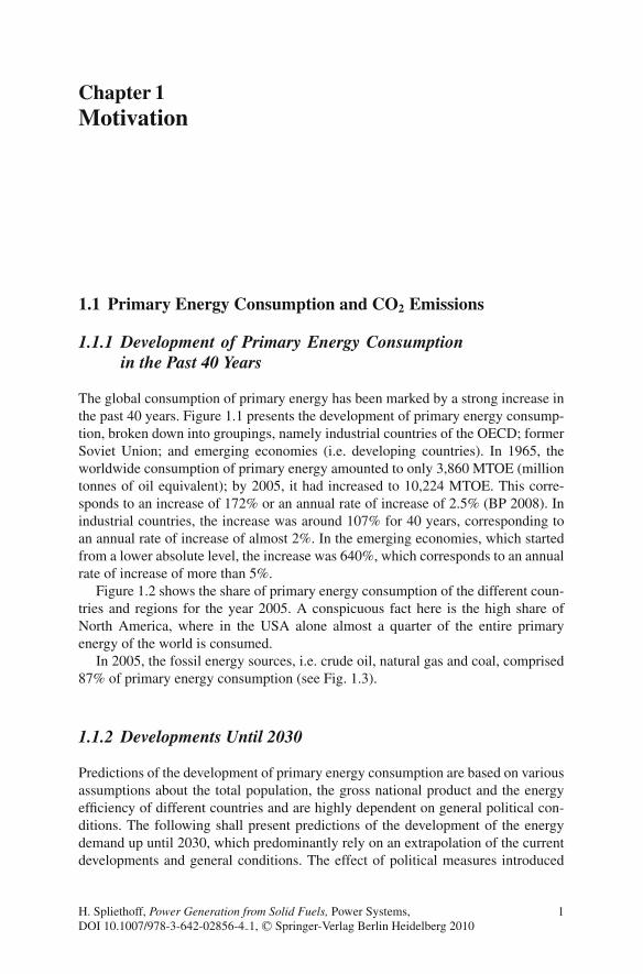
Chapter 1Motivation
1.1 Primary Energy Consumption and CO2 Emissions
1.1.1 Development of Primary Energy Consumptionin the Past 40 Years
The global consumption of primary energy has been marked by a strong increase inthe past 40 years. Figure 1.1 presents the development of primary energy consump-tion, broken down into groupings, namely industrial countries of the OECD; formerSoviet Union; and emerging economies (i.e. developing countries). In 1965, theworldwide consumption of primary energy amounted to only 3,860 MTOE (milliontonnes of oil equivalent); by 2005, it had increased to 10,224 MTOE. This corre-sponds to an increase of 172% or an annual rate of increase of 2.5% (BP 2008). Inindustrial countries, the increase was around 107% for 40 years, corresponding toan annual rate of increase of almost 2%. In the emerging economies, which startedfrom a lower absolute level, the increase was 640%, which corresponds to an annualrate of increase of more than 5%.
Figure 1.2 shows the share of primary energy consumption of the different coun-tries and regions for the year 2005. A conspicuous fact here is the high share ofNorth America, where in the USA alone almost a quarter of the entire primaryenergy of the world is consumed.
In 2005, the fossil energy sources, i.e. crude oil, natural gas and coal, comprised87% of primary energy consumption (see Fig. 1.3).
1.1.2 Developments Until 2030
Predictions of the development of primary energy consumption are based on variousassumptions about the total population, the gross national product and the energyefficiency of different countries and are highly dependent on general political con-ditions. The following shall present predictions of the development of the energydemand up until 2030, which predominantly rely on an extrapolation of the currentdevelopments and general conditions. The effect of political measures introduced
H. Spliethoff, Power Generation from Solid Fuels, Power Systems,DOI 10.1007/978-3-642-02856-4 1, C© Springer-Verlag Berlin Heidelberg 2010
1
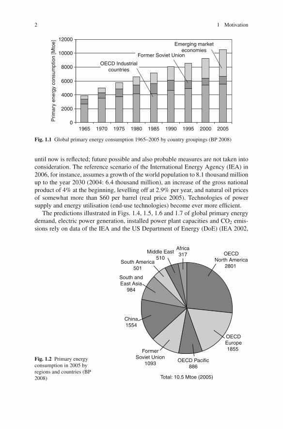
2 1 Motivation
0
2000
4000
6000
8000
10000
12000
1965
Prim
ary
ener
gy c
onsu
mpt
ion
[Mto
e] Emerging marketeconomies
Former Soviet Union
OECD Industrialcountries
1970 1975 1980 1985 1990 1995 2000 2005
Fig. 1.1 Global primary energy consumption 1965–2005 by country groupings (BP 2008)
until now is reflected; future possible and also probable measures are not taken intoconsideration. The reference scenario of the International Energy Agency (IEA) in2006, for instance, assumes a growth of the world population to 8.1 thousand millionup to the year 2030 (2004: 6.4 thousand million), an increase of the gross nationalproduct of 4% at the beginning, levelling off at 2.9% per year, and natural oil pricesof somewhat more than $60 per barrel (real price 2005). Technologies of powersupply and energy utilisation (end-use technologies) become ever more efficient.
The predictions illustrated in Figs. 1.4, 1.5, 1.6 and 1.7 of global primary energydemand, electric power generation, installed power plant capacities and CO2 emis-sions rely on data of the IEA and the US Department of Energy (DoE) (IEA 2002,
Fig. 1.2 Primary energyconsumption in 2005 byregions and countries (BP2008) Total: 10.5 Mtoe (2005)
OECDNorth America
2801
OECDEurope1855
OECD Pacific886
FormerSoviet Union
1093
South andEast Asia
984
South America501
Middle East510
Africa317
China1554
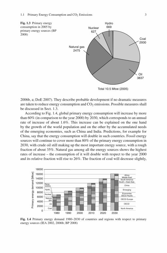
1.1 Primary Energy Consumption and CO2 Emissions 3
Fig. 1.3 Primary energyconsumption in 2005 byprimary energy sources (BP2008)
Total 10.5 Mtoe (2005)
Coal2930
Oil3837
Natural gas2475
Nuclear627
Hydro669
2006b, a; DoE 2007). They describe probable development if no dramatic measuresare taken to reduce energy consumption and CO2 emissions. Possible measures shallbe discussed in Sect. 1.3.
According to Fig. 1.4, global primary energy consumption will increase by morethan 60% (in comparison to the year 2000) by 2030, which corresponds to an annualrate of increase of about 1.6%. This increase can be explained on the one handby the growth of the world population and on the other by the accumulated needsof the emerging economies, such as China and India. Predictions, for example forChina, say that the energy consumption will double in such countries. Fossil energysources will continue to cover more than 80% of the primary energy consumption in2030, with crude oil still making up the most important energy source, with a roughfraction of about 35%. Natural gas among all the energy sources shows the highestrates of increase – the consumption of it will double with respect to the year 2000and its relative fraction will rise to 26%. The fraction of coal will decrease slightly,
OECD
North America
OECD Europe
China
South AmericaSouth + East Asia
AfricaMiddle East
Emerging
EconomiesOECD Pacific
Coal
Oil
Naturalgas
Rene-wables
1980 1990 2000 2010 2020 20300
2000
4000
6000
8000
10000
12000
14000
16000
18000
Hydro
Nuclear
Prim
ary
ener
gy d
eman
d [M
toe]
Fig. 1.4 Primary energy demand 1980–2030 of countries and regions with respect to primaryenergy sources (IEA 2002, 2006b; BP 2008)
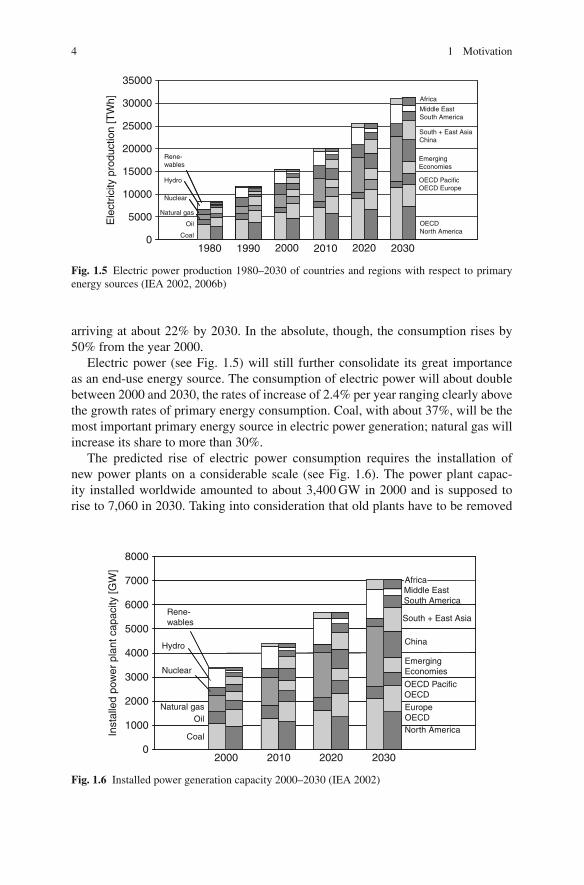
4 1 Motivation
1980 1990 2000 2010 2020 20300
5000
10000
15000
20000
25000
30000
35000
OECDNorth America
OECD PacificOECD Europe
South + East AsiaChina
Middle EastSouth America
Africa
EmergingEconomies
Ele
ctric
ity p
rodu
ctio
n [T
Wh]
Coal
Oil
Rene-wables
Natural gas
Nuclear
Hydro
Fig. 1.5 Electric power production 1980–2030 of countries and regions with respect to primaryenergy sources (IEA 2002, 2006b)
arriving at about 22% by 2030. In the absolute, though, the consumption rises by50% from the year 2000.
Electric power (see Fig. 1.5) will still further consolidate its great importanceas an end-use energy source. The consumption of electric power will about doublebetween 2000 and 2030, the rates of increase of 2.4% per year ranging clearly abovethe growth rates of primary energy consumption. Coal, with about 37%, will be themost important primary energy source in electric power generation; natural gas willincrease its share to more than 30%.
The predicted rise of electric power consumption requires the installation ofnew power plants on a considerable scale (see Fig. 1.6). The power plant capac-ity installed worldwide amounted to about 3,400 GW in 2000 and is supposed torise to 7,060 in 2030. Taking into consideration that old plants have to be removed
2000 2010 2020 20300
1000
2000
3000
4000
5000
6000
7000
8000
Inst
alle
d po
wer
pla
nt c
apac
ity [G
W]
North America
EuropeOECD
OECD PacificOECD
China
South + East Asia
Middle EastSouth America
Africa
EmergingEconomies
Coal
Natural gasOil
Rene-wables
Nuclear
Hydro
Fig. 1.6 Installed power generation capacity 2000–2030 (IEA 2002)

1.2 Greenhouse Effect and Impacts on the Climate 5
Asia
China
OECD Europe
North America
0
5000
10000
15000
20000
25000
30000
35000
40000
45000
CO
2 em
issi
on [M
t]
coal
gas
oil
1970 1980 1990 2000 2010 2020 2030
AfricaMiddle East
South America
South + East
EmergingEconomiesOECD Pacific
Fig. 1.7 CO2 emissions 1970–2030 (IEA 2002, 2006b)
from service and replaced, it follows that, by 2030, electricity-generating plantswith a total capacity of 4,800 GW will have to be erected throughout the world.This corresponds to 9,600 power plants with an electrical power output of 500 MW.One has to assume in this respect that new power plants will be built predominantlyfor primary energy sources such as natural gas (about 2,000 GW) and coal (about1,500 GW). In China alone, thermal power plants, for example, with a total powerof 720 GW shall have to be installed by 2020; per year, between 30 and 40 newcoal-fired power plants with a capacity of 600 MW are currently being built. Whilein the emerging economies and developing countries, new power plants cover theadded demand, new power plants in Europe are planned mainly as substitutes forexisting old plants. By the year 2020, about 200 GW of power station capacity shallbe newly installed in Europe.
The CO2 emissions illustrated in Fig. 1.7 suggest a likely rise to about 38 thou-sand million tonnes of carbon dioxide per year until 2030. Referring to the year2000, this corresponds to a rise of about 68%.
1.2 Greenhouse Effect and Impacts on the Climate
The climate of the Earth is vital for the living conditions of the entire living world.The discussion about possible future climatic changes has reached all strata of oursociety and has in many fields an influence on political and economic action, both ona national and on the international scale. The standard of knowledge of internationalclimate research is compiled in the assessment reports of the IntergovernmentalPanel on Climate Change (IPCC) (www.ipcc.ch).

6 1 Motivation
1.2.1 Greenhouse Effect
Some gases contained in the atmosphere have a filtering effect: they let the majorityof short-wavelength solar radiation pass through, while partly absorbing infra-redradiation emitted from the Earth, leading to a heating-up of the lower layers of theatmosphere. These gases, accounting for this so-called greenhouse effect, are hencetermed greenhouse gases. They bring about a natural net warming of about 33◦C.Without the present composition of the Earth’s atmosphere, a temperature of −18◦Cwould predominate on Earth. The atmosphere and the oceans balance the heat bud-get and provide for heat exchange between day and night, summer and winter, polarand equatorial zones. Without an Earth-like atmosphere, temperature differences of250◦C between day and night occur, for example on the Moon’s surface, to draw acomparison (Borsch 1992).
A distinction is made between the natural greenhouse gases and those producedby man, the so-called anthropogenic greenhouse gases. Some of the greenhousegases are both of natural and anthropogenic origin. Table 1.1 shows the contributionof the various greenhouse gas types to the natural and anthropogenic greenhouseeffect. The most significant greenhouse gas is carbon dioxide (CO2). It is producedthrough energy consumption in the combustion of carbonaceous fossil fuels suchas coal, natural gas and crude oil. In the process, dead organic substance becomesoxidised to carbon dioxide, which is given off to the atmosphere. The quantitiesdischarged this way to the atmosphere amount to about 26 thousand million tonnesof carbon dioxide1 per year (2005). Added to this, there are further, inexactly quan-tifiable, amounts of emitted carbon dioxide from forest clearing and through soildegradation. The contribution of these emissions is estimated at about 3–7 thousandmillion tonnes of carbon dioxide per year.
Table 1.1 Present concentrations of greenhouse gases and their contribution to the natural andanthropogenic greenhouse effect (data from IPCC (2007b) and Beising (2006))
Chloro-Carbon Methane fluorocarbons Nitrous Ozone Water
Greenhouse gas dioxide CO2 CH4 CFCs oxide N2O O3 vapour
Concentration: 280 ppm 0.7 ppm 0 270 ppb –2.6%pre-industrial time(about 1800)
Today (2005) 379 ppm 1.8 ppm 0.5 ppb 319 ppb 25 ppb 2.6%Increase rate (2005) +1.9 ppm/a +2 ppb/a 0.8 ppb/aEmissions (2005) 26 Gt/a 400 Mt/a 0.4 Mt/a 15 Mt/a 0.5 Gt/aContribution to natural
greenhouse effect =temperature rise
26% 2% – 4% 8% 60%
Contribution toanthropogenicgreenhouse effect
61% 15% 11% 4% 9% –
1 One tonne of carbon corresponds to 3.67 tonnes of carbon dioxide.
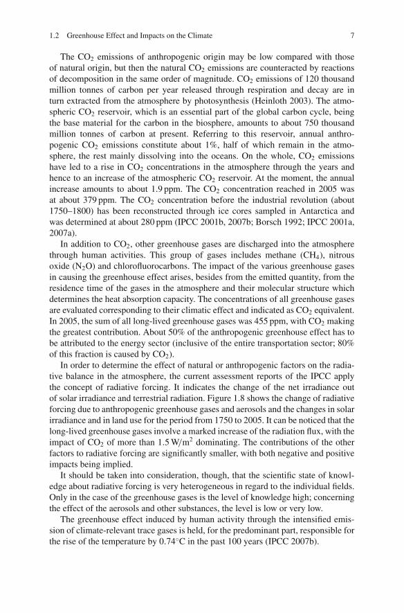
1.2 Greenhouse Effect and Impacts on the Climate 7
The CO2 emissions of anthropogenic origin may be low compared with thoseof natural origin, but then the natural CO2 emissions are counteracted by reactionsof decomposition in the same order of magnitude. CO2 emissions of 120 thousandmillion tonnes of carbon per year released through respiration and decay are inturn extracted from the atmosphere by photosynthesis (Heinloth 2003). The atmo-spheric CO2 reservoir, which is an essential part of the global carbon cycle, beingthe base material for the carbon in the biosphere, amounts to about 750 thousandmillion tonnes of carbon at present. Referring to this reservoir, annual anthro-pogenic CO2 emissions constitute about 1%, half of which remain in the atmo-sphere, the rest mainly dissolving into the oceans. On the whole, CO2 emissionshave led to a rise in CO2 concentrations in the atmosphere through the years andhence to an increase of the atmospheric CO2 reservoir. At the moment, the annualincrease amounts to about 1.9 ppm. The CO2 concentration reached in 2005 wasat about 379 ppm. The CO2 concentration before the industrial revolution (about1750–1800) has been reconstructed through ice cores sampled in Antarctica andwas determined at about 280 ppm (IPCC 2001b, 2007b; Borsch 1992; IPCC 2001a,2007a).
In addition to CO2, other greenhouse gases are discharged into the atmospherethrough human activities. This group of gases includes methane (CH4), nitrousoxide (N2O) and chlorofluorocarbons. The impact of the various greenhouse gasesin causing the greenhouse effect arises, besides from the emitted quantity, from theresidence time of the gases in the atmosphere and their molecular structure whichdetermines the heat absorption capacity. The concentrations of all greenhouse gasesare evaluated corresponding to their climatic effect and indicated as CO2 equivalent.In 2005, the sum of all long-lived greenhouse gases was 455 ppm, with CO2 makingthe greatest contribution. About 50% of the anthropogenic greenhouse effect has tobe attributed to the energy sector (inclusive of the entire transportation sector; 80%of this fraction is caused by CO2).
In order to determine the effect of natural or anthropogenic factors on the radia-tive balance in the atmosphere, the current assessment reports of the IPCC applythe concept of radiative forcing. It indicates the change of the net irradiance outof solar irradiance and terrestrial radiation. Figure 1.8 shows the change of radiativeforcing due to anthropogenic greenhouse gases and aerosols and the changes in solarirradiance and in land use for the period from 1750 to 2005. It can be noticed that thelong-lived greenhouse gases involve a marked increase of the radiation flux, with theimpact of CO2 of more than 1.5 W/m2 dominating. The contributions of the otherfactors to radiative forcing are significantly smaller, with both negative and positiveimpacts being implied.
It should be taken into consideration, though, that the scientific state of knowl-edge about radiative forcing is very heterogeneous in regard to the individual fields.Only in the case of the greenhouse gases is the level of knowledge high; concerningthe effect of the aerosols and other substances, the level is low or very low.
The greenhouse effect induced by human activity through the intensified emis-sion of climate-relevant trace gases is held, for the predominant part, responsible forthe rise of the temperature by 0.74◦C in the past 100 years (IPCC 2007b).

8 1 Motivation
CO2
N2O
Halocarbons
TroposphericStratospheric
(-0,05)
Land use Black carbonon snow
(0,01)
Long-livedgreenhouse gases
Ozone
Stratosphericwater vapour
Direct effectTotal Aerosol
Cloud albedoeffect
Linear contrails
Solar irradiance
Total nethuman activities
Surface albedo
CH4
Hu
man
act
ivit
ies
Nat
ura
lp
roce
ss
Radiative forcing of climate between 1750 and 2005
−2 −1 0 1 2Radiative forcing (watts per square metre)
Radiative Forcing Terms
Fig. 1.8 Change in radiative forcing in the period 1750–2005 (IPCC 2007b)
1.2.2 Impacts
A small temperature increase of even few degrees can lead to a far-reaching changeof the global climate. A warming process will shift the climatic zones. The subtrop-ical dry zones, for example, will expand poleward into the currently fertile regionsin southern Europe, the USA, China, South America and Australia. On top of this,climatic variations and climate extremes like storms, hurricanes, storm tides, periodsof drought and heavy rains will become more frequent and stronger. The sea levelwill rise because of melting ice masses on land and through the expansion of water,thus threatening coastal regions. In what way and to what extent plants and animalsare capable of adapting to the climate change depend on the rate at which the climatealters (Heinloth 2003).
1.2.3 Scenarios of the World Climate
The IPCC’s assessment reports provide a comprehensive presentation of the currentstandard of knowledge in climate modelling (IPCC 2001b, a, 2007b, a). The taskof climate modelling is to determine the climate system’s reactions to natural or

1.2 Greenhouse Effect and Impacts on the Climate 9
B1 A1T B2 IS92a A1B A2 A1FI
Several modelsall SRES
Models ensemble
envelope
IS92a B2 B1 A2 A1T A1B A1FI
Model averageall SRESenvelope
Several modelsall SRESenvelope
All SRES envelopeincluding land -ice
uncertainly B2 B1 A2 A1FI A1T A1B
2000 2020 2040 2060 2080 21005
10
15
20
25
30(a) CO2 emissions
Year
B1 B2 A1T IS92a A1B A2 A1FI
2000 2020 2040 2060 2080 2100300
500
700
900
1100
1300(b) CO2 concentrations
Year
Several modelsall SRES
Models ensembleall SRESenvelope
IS92a B2 B1 A2 A1T A1B A1FI
2000 2020 2040 2060 2080 21000
1
2
3
4
5
6
Tem
pera
ture
cha
nge
(°C
)
(c) Temperature change
Year
Model averageall SRESenvelope
Several modelsall SRESenvelope
All SRES envelopeincluding land -ice
uncertainly B2 B1 A2 A1FI A1T A1B
2000 2020 2040 2060 2080 21000.0
0.2
0.4
0.6
0.8
1.0(d) Sea level rise
Year
Sea
leve
l ris
e (m
etre
s)
CO
2 em
issi
ons
(GT
C/y
r)
CO
2 co
ncen
trat
ion
(ppm
)envelope
Fig. 1.9 Scenarios of the global CO2 emissions (a), CO2 concentration (b), temperature rise (c)and sea level (d) (IPCC 2001b)
anthropogenic changes, such as the increase of the CO2 concentration, and thus theresilience of the system. A summary of the calculations is presented in Fig. 1.9.
Scenarios of the global energy consumption and the associated emissions up tothe year 2100 (Special Report on Emission Scenarios (IPCC 2001c) (SRES 2001))are intended to cover a wide range of possible developments, and they form the basisfor the calculation of the world’s climate in the long term. Figure 1.9a shows the CO2
emissions for different scenarios which are used for numerical climate simulations.Complex climate models are based on the conservation of mass, impulse and energyin a three-dimensional grid encompassing the globe and have to take into accountatmosphere, oceans, continental surfaces, the cryosphere, the biosphere and theirinteractions as individual components. The further development of the partly verysimple models is in progress.
The different scenarios of the CO2 emissions assume a rise of the CO2 concen-tration in the atmosphere to values between 540 and 970 ppm up to the year 2100(see Fig. 1.9b) (IPCC 2001c; SRES 2001). According to the assessment report of2007, temperature increases of the global mean surface temperature between 2.5and 4.1◦C by the end of this century in comparison to the mean value between1961 and 1990 were determined for selected scenarios (see Fig. 1.9c). The sourceof uncertainty on the one hand lies in uncertainties of the climate model calculations

10 1 Motivation
and, on the other, in the wide range of emission scenarios investigated. Accordingto Fig. 1.9d, the average sea level will rise by 21–51 cm; in higher latitudes, though,up to 1 m; in the North Sea, it will rise by 50 cm (IPCC 2007b).
Even if the CO2 concentrations were frozen at today’s level (which is tantamountto an almost complete reduction of the CO2 emissions worldwide), both the temper-ature and the sea level would continue to rise. This can be put down to the interactionbetween troposphere and ocean. While the troposphere responds to changes of con-centrations and the associated radiative forcing on a timescale of less than 1 month,the timescales in the case of near-surface sea water range between years to decades,and even centuries in the case of the deep ocean and ice caps. So, even with freezingtoday’s CO2 concentrations, the temperature would still rise by about 0.5–0.6◦C onthe whole, with the biggest part of the increase happening within the next 100 years.
These relationships underline the need for a quick and drastic reduction of CO2
emissions, precisely because our climate reacts with great inertia to the increase ofgreenhouse gases. It also becomes clear, though, that global warming can only belimited, not negated, even by intensive abatement efforts. In the so-called stabilisa-tion scenarios, CO2 emission is reduced to achieve a stable equilibrium concentra-tion in the atmosphere.
1.3 Strategies of CO2 Reduction
For reduction of CO2 emissions from the energy sector there are principally threedifferent strategies, as shown in Fig. 1.10:
– Energy saving– Substitution (C-lean/free for C-rich energy sources)– CO2 capture and storage (Carbon capture and storage, CCS)
1.3.1 Substitution
The primary energy sources produce CO2 emissions to various extents. Fossil fuels,for instance, depending on the fuel composition, more or less involve high CO2
emissions. Figure 1.11 shows the specific CO2 emissions of fossil fuels with respectto their calorific values. Fuels like natural gas, with a lower carbon fraction, producein consequence lower and fuels like bituminous coal or lignite, higher specific CO2
emissions.By substituting natural gas as the lower carbon fuel for lignite, bituminous coal
or crude oil as the higher carbon fuels, it is possible to correspondingly reduce theemissions of carbon dioxide. What stands in the way of using natural gas, however,are the smaller reserves of this energy source.
Renewable energy sources or nuclear energy involve only small CO2 emissionsin the power generation process. So if fossil energy sources are replaced by them,CO2 emissions are almost completely avoided.

1.3 Strategies of CO2 Reduction 11
1.3.2 Carbon Capture and Storage (CCS)
Pollutants from combustion processes of fossil energy sources, such as sulphurdioxide, nitrogen oxides and particulates, are to a great extent removed nowadays.For separating (and thereby removing) these pollutants, which are even beforeremoval in low concentrations, an amount of energy is needed such that the effi-ciency of the plant is diminished by 1–2%. Carbon dioxide, in contrast to thesepollutants, is the main product of combustion and arises in great amounts. Its cap-ture is possible from the technical point of view. Various concepts in this respectare being pursued at present, and projects are in progress for constructing coal-firedpower plants with CO2 capture. Carbon dioxide capture and transport to a storagelocation involve a marked diminution of the efficiency by 8–10%.
The different possibilities of CO2 capture and storage from coal-fuelled powergeneration processes are discussed in Chap. 8.
Fig. 1.10 Strategies to reduce the CO2 emissions to the atmosphere from the energy sector
Fig. 1.11 CO2 emissions offossil fuels in respect to theircalorific value
Brown coal Bituminouscoal
Fuel oil (light) Natural gas
Sp
ecif
ic C
O2
Em
issi
on
[kg
/kW
h]
0
0.5
0.4
0.3
0.2
0.1
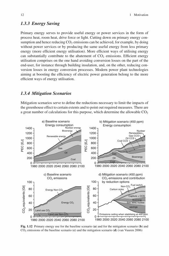
12 1 Motivation
1.3.3 Energy Saving
Primary energy serves to provide useful energy or power services in the form ofprocess heat, room heat, drive force or light. Cutting down on primary energy con-sumption and hence reducing CO2 emissions can be achieved, for example, by doingwithout power services or by producing the same useful energy from less primaryenergy (more efficient energy utilisation). More efficient ways of utilising energycan substantially contribute to the abatement of CO2 emissions. Efficient energyutilisation comprises on the one hand avoiding conversion losses on the part of theend-user, for instance through building insulation, and, on the other, reducing con-version losses in energy conversion processes. Modern power plant technologiesaiming at boosting the efficiency of electric power generation belong to the moreefficient ways of energy utilisation.
1.3.4 Mitigation Scenarios
Mitigation scenarios serve to define the reductions necessary to limit the impacts ofthe greenhouse effect to certain extents and to point out required measures. There area great number of calculations for this purpose, which determine the allowable CO2
20001980 2000 2020 2040 2060 2080 21000
200
400
600
800
1000
1200
1400 Nuclear energy
Renewable energy
Gas
Bioenergy
Oil
Coal
a) Baseline scenario Energy consumption
PE
C [E
J]
1980 2020 2040 2060 2080 21000
200
400
600
800
1000
1200
1400
PE
C [E
J]
Nuclear
b) Mitigation scenario (450 ppm) Energy consumption
Gas CCSRenewables
Oil CCSCoal CCS
BioenergyGas
Oil
Coal
1980 2000 2020 2040 2060 2080 21000
20
40
60
80
100
CO
2 eq
uiva
lent
s [G
t]
CO
2 eq
uiva
lent
s [G
t]
c) Baseline scenario CO2 emissions
Land use CO2
Land use Non-CO2
Energy Non-CO2
Energy CO2
1980 2000 2020 2040 2060 2080 21000
20
40
60
80
100Fuel switch
d) Mitigation scenario (450 ppm) CO2-emissions and contribution by reduction options
Non-CO2
Capture + CCS
BioenergySun, wind, nuclear
savings
Emissions ceiling when stabilising at 450 ppm
Carbon sinks
Fig. 1.12 Primary energy use for the baseline scenario (a) and for the mitigation scenario (b) andCO2 emissions of the baseline scenario (c) and the mitigation scenario (d) (van Vuuren 2006)

References 13
emissions or, according to the different scenarios shown in Fig. 1.9, the necessaryreduction to maintain a stable, defined CO2 concentration in the atmosphere (IPCC2001b, 2007b). The following shall present the example of a calculation, without,however, stating a plan for translation into practice (van Vuuren 2006).
The starting point of the calculation is the target to limit global warming to a riseof 2◦C. With a stabilised CO2 concentration in the Earth’s atmosphere at 450 ppmCO2 equivalents or less, it can be assumed with a probability greater than 50% thatthis aim will be achieved. The results of the calculations are compiled in Fig. 1.12. Inorder to achieve a stable CO2 concentration at 450 ppm, the CO2 emissions world-wide have to be reduced by 40% up to the year 2050 and by 70% up to 2100 incomparison to 1990 values.
The primary energy consumption is plotted in Fig. 1.12a for the baseline scenarioand in Fig. 1.12b for the mitigation scenario. Figure 1.12d shows a CO2 emissionreduction scenario and the contribution of the different measures taken to achievethose reductions in comparison to the baseline scenario (Fig. 1.12c). Withoutentering a discussion of the individual measures, it becomes clear that, for achievingthat aim, all possible options have to be taken into consideration. Increasing theenergy efficiency ought to always be the first action.
References
Beising, R. (2006). Klimawandel und Energiewirtschaft – Eine Literaturrecherche, Stand Oktober2006. Essen, VGB PowerTech.
Borsch, P. (1992). Was wird aus unserem Klima? Fakten, Analysen & Perspektiven. Munchen[u.a.], Bonn Aktuell.
BP (2008). Statistical review of world energy 2008, from www.bp.com.DoE (2007). International Energy Outlook, Energy Information Administration, Department of
Energy, from www.eia.doe.gov/oiaf/ieo/index.html.Heinloth, K. (2003). Energie und Umwelt – Klimavertragliche Nutzung von Energie. Stuttgart,
Teubner.IEA (2002). World energy outlook 2002. Paris, IEA.IEA (2006a). Energy Technology Perspectives, Scenarios and Strategies to 2050. Paris,
OECD/IEA.IEA (2006b). World energy outlook 2006. Paris, IEA.IPCC (2001a). Climate change 2001: mitigation. (Third Assessment report WG3). Cambridge,
Cambridge University Press.IPCC (2001b). Climate change 2001: the scientific basis. (Third Assessment report WG1).
Cambridge, Cambridge University Press.IPCC (2001c). Special report on emission scenarios (SRES). Cambridge, Cambridge Univer-
sity Press.IPCC (2007a). Climate change 2007 – mitigation of climate change, working group III contribu-
tion to the fourth assessment report of the IPCC intergovernmental panel on climate change.Cambridge, Cambridge University Press.
IPCC (2007b). Climate change 2007 – the physical science basis, working group I Contributionto the fourth assessment report of the IPCC intergovernmental panel on climate change. Cam-bridge, Cambridge University Press.
van Vuuren, D., Berk, M., Farla, J. and de Vos, R. (2006). From climate objectives to emissionsreduction. Netherlands Environmental Assessment Agency, Publication 500114003/2006, fromwww.mnp.nl/en.
Chapter 2Solid Fuels
2.1 Fossil Fuels
2.1.1 Origin and Classification of Coal Types
Coal, oil and natural gas are called fossil fuels because they are the remains of plantand animal life preserved in sedimentary rocks. It is generally believed that coal wasformed from plant matter and oil formed from marine organisms (Drbal 1996).
Brown and hard coal developed through a process of partial decomposition underair-deficient conditions of plant matter that had accumulated on land and in swampsduring previous geological periods. By continued deposition of sediments and plantdebris, the older sediments gradually sank to greater depths and, with growingpressure and a resulting dewatering process, became compacted. Under anaerobicconditions, the organic substance underwent, by pressure and heat, a metamorphicprocess called coalification. Peat formation and the formation of soft brown coal arethe first steps of the coalification process. With greater depths, higher pressures andrising temperatures, coalification proceeds (thermal metamorphosis), hard browncoal develops from soft brown coal and, eventually, hard coal is formed.
The coalification process involves an increase in the fraction of solid carbonand a decrease in the volatile matter content of the material. In the early stagesof decomposition, the formation of H2O, CO2 and N2 predominates; in advancedstages, CH4 is mainly formed. The increasing pressure pushes the water contentdown further and further. The moisture content decreases from about 70% (in peat)to about 15% (in anthracite). Volatiles diminish from a fraction of 75 to 10%. As aconsequence of the release of CH4 and CO2, the C content increases from about 50to more than 90%.
Coal types are commonly differentiated from one another according to their con-tent of volatile components (for definitions, see Sect. 2.1.2) on a dry and ash-freematter basis and according to the characteristics of the coke. The USA, Great Britainand Germany each use their own classification systems, which are all based on thevolatile content (see Fig. 2.1) (Skorupska 1993).
An international classification system is in place that assigns a three digit num-ber to each bituminous coal. For an assessment of the combustion characteristics,
H. Spliethoff, Power Generation from Solid Fuels, Power Systems,DOI 10.1007/978-3-642-02856-4 2, C© Springer-Verlag Berlin Heidelberg 2010
15
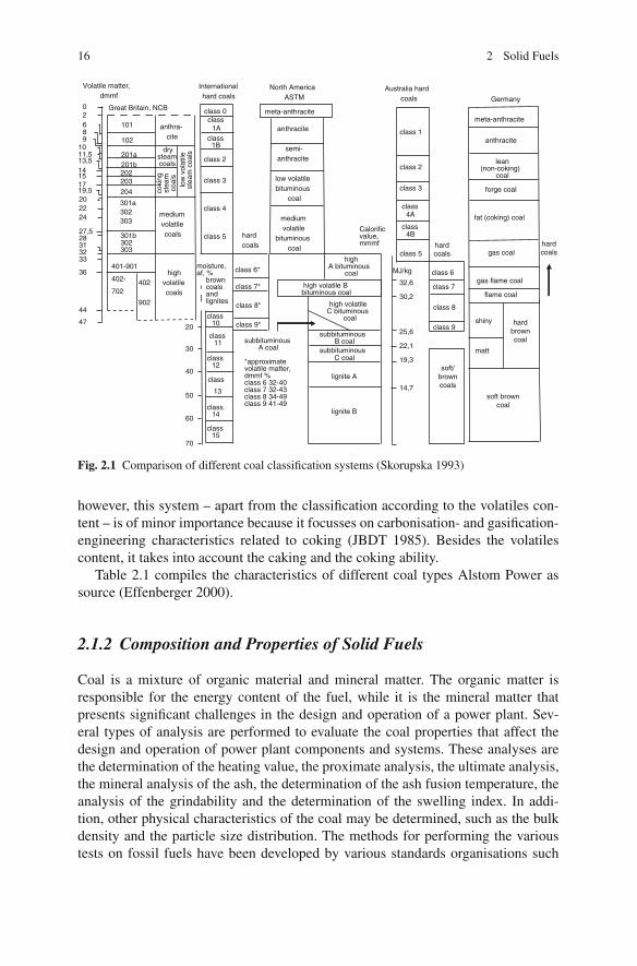
16 2 Solid Fuels
Volatile matter,dmmf
02689
1011,513,514151719,5202224
27,528313233
36
44
47
203
204
101
201a201b
301b302303
401-901
402-
702
301a302303
202
anthra-cite
drysteamcoals
coki
ngst
eam
coal
slo
wvo
latil
est
eam
coal
s
mediumvolatilecoals
highvolatilecoals
402
902
class 0class
1Aclass
1B
class 2
class 3
class 4
class 5 hardcoals
meta-anthracite
anthracite
semi-anthracite
low volatilebituminous
coal
mediumvolatile
bituminouscoal
class 6*
class 7*
class 8*
class 9*class
10
class12
class14
class15
class11
20
30
40
50
60
70
moisture,af, %
browncoalsandlignites
subbituminousA coal
*approximatevolatile matter,dmmf %class 6 32-40class 7 32-43class 8 34-49class 9 41-49
highA bituminous
coal
high volatile B bituminous coal
high volatileC bituminous
coal
subbituminousB coal
lignite A
lignite B
32,6
30,2
25,6
22,1
19,3
14,7
class 1
class 2
class 3
class 5
class4A
Calorificvalue,mmmf
MJ/kg class 6
class 9
class 7
soft/browncoals
meta-anthracite
anthracite
lean(non-coking)
coal
forge coal
fat (coking) coal
gas coal
gas flame coal
flame coal
shiny
matt
hardbrowncoal
soft browncoal
Great Britain, NCB
Internationalhard coals
North AmericaASTM
Australia hardcoals Germany
hardcoals
hardcoals
102
subbituminousC coal
class4B
class 8
class
13
Fig. 2.1 Comparison of different coal classification systems (Skorupska 1993)
however, this system – apart from the classification according to the volatiles con-tent – is of minor importance because it focusses on carbonisation- and gasification-engineering characteristics related to coking (JBDT 1985). Besides the volatilescontent, it takes into account the caking and the coking ability.
Table 2.1 compiles the characteristics of different coal types Alstom Power assource (Effenberger 2000).
2.1.2 Composition and Properties of Solid Fuels
Coal is a mixture of organic material and mineral matter. The organic matter isresponsible for the energy content of the fuel, while it is the mineral matter thatpresents significant challenges in the design and operation of a power plant. Sev-eral types of analysis are performed to evaluate the coal properties that affect thedesign and operation of power plant components and systems. These analyses arethe determination of the heating value, the proximate analysis, the ultimate analysis,the mineral analysis of the ash, the determination of the ash fusion temperature, theanalysis of the grindability and the determination of the swelling index. In addi-tion, other physical characteristics of the coal may be determined, such as the bulkdensity and the particle size distribution. The methods for performing the varioustests on fossil fuels have been developed by various standards organisations such

2.1 Fossil Fuels 17
Tabl
e2.
1C
ompo
sitio
nof
hard
and
brow
nco
als
(Eff
enbe
rger
2000
)an
dA
lsto
mPo
wer
Coa
ltyp
eD
ryas
h-fr
eem
atte
rba
sis
Raw
coal
Ori
gin
Site
ofde
posi
tV
olat
iles
(%)
C (%)
H (%)
O (%)
N (%)
S (%)
Hig
her
heat
ing
valu
eH
HV
(MJ/
kg)
Ash
(%)
Wat
er(%
)L
ower
heat
ing
valu
e:L
HV
(MJ/
kg)
Peat
IRL
Der
rygr
eena
gh69
.658
.05.
634
.91.
20.
323
.86
1.5
55.0
7.7–
7.9
GR
Phili
ppi
68.5
57.5
5.4
33.5
2.8
0.8
23.0
20–2
240
–45
7.3–
7.9
Soft
brow
nco
alD
Rhi
nela
nd55
.068
.35.
027
.50.
50.
526
.38
5–20
50–6
26.
3–9.
6D
Hel
mst
edt
59.4
72.6
5.8
16.7
0.4
4.4
29.7
512
–22
42–4
69.
2–10
.5D
Schw
ando
rf55
.063
.65.
026
.11.
34.
025
.33
6–20
50–5
86.
3–7.
5D
Lau
sitz
55.0
67.5
5.2
25.5
1.0
0.8
25.3
72–
555
–60
8.2–
8.5
DL
eipz
ig63
.071
.66.
119
.50.
72.
128
.35
5–7
50–5
59.
0–11
DH
alle
-Bitt
erfe
ld57
.572
.05.
518
.30.
83.
429
.81
5–7
52–5
69.
6–10
.0G
RPt
olem
ais
57.0
65.3
5.3
26.5
1.6
0.5
25.2
56–
2252
–60
3.6–
6.7
GR
Meg
alop
olis
62.0
60.5
6.2
30.6
1.3
1.4
24.4
513
–17
60–6
42.
8–4.
0A
US
Yal
lour
n51
.567
.54.
826
.70.
70.
325
.54
1–2
63–7
25.
0–7.
5PL
,DPa
tnow
,Lus
atia
58.4
73.6
5.1
19.7
0.5
1.1
28.5
66–
1552
–58
8.0–
8.8
HG
yong
yos/
Vis
onta
63.0
63.8
4.8
26.8
1.1
3.5
24.8
315
–30
46–5
45.
0–6.
7T
RE
lbis
tan
67.0
61.4
5.1
29.6
0.8
5.1
23.6
98–
2448
–62
3.3–
6.2
Har
dbr
own
coal
DPe
isse
nber
g52
.074
.05.
514
.51.
44.
629
.23
12–2
08–
1219
.7–2
3.0
AFo
hnsd
orf
47.0
72.5
5.4
16.3
1.2
4.6
30.3
58–
168–
1420
.0–2
2.6
AK
oflac
h56
.067
.75.
725
.01.
20.
327
.21
6–10
30–3
513
.0–1
4.7
SLO
Trb
ovlje
53.0
72.5
5.6
17.2
1.2
3.5
28.4
730
–35
20–2
410
.0–1
1.7
HR
Ras
a50
.475
.25.
46.
91.
111
.534
.12
6–20
2–4
27.6
–30.
1C
ZM
ost(
Bru
x)48
.077
.55.
814
.61.
01.
232
.32
5–15
15–2
518
.8–2
2.2
CZ
Falk
nov
54.5
73.5
6.0
17.9
1.1
1.5
30.9
4–14
25–3
515
.1–1
8.4
HTa
taba
nya
52.0
73.0
5.8
17.7
0.9
2.6
31.4
6–12
12–1
423
.0–2
4.3
TR
Tun
cbile
k44
.576
.45.
813
.82.
51.
532
.19
14.2
214
–24
15.0
–18.
1
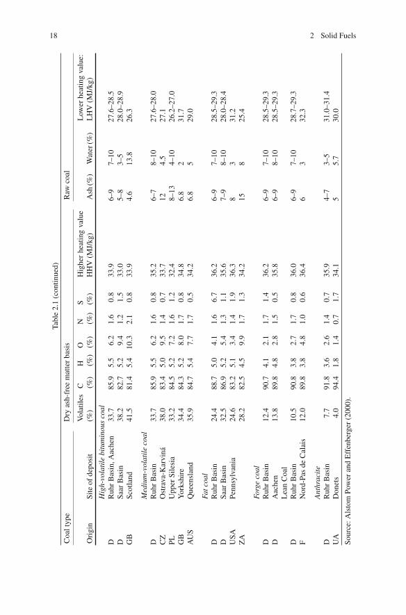
18 2 Solid Fuels
Tabl
e2.
1(c
ontin
ued)
Coa
ltyp
eD
ryas
h-fr
eem
atte
rba
sis
Raw
coal
Ori
gin
Site
ofde
posi
tV
olat
iles
(%)
C (%)
H (%)
O (%)
N (%)
S (%)
Hig
her
heat
ing
valu
eH
HV
(MJ/
kg)
Ash
(%)
Wat
er(%
)L
ower
heat
ing
valu
e:L
HV
(MJ/
kg)
Hig
h-vo
lati
lebi
tum
inou
sco
alD
Ruh
rB
asin
,Aac
hen
33.7
85.9
5.5
6.2
1.6
0.8
33.9
6–9
7–10
27.6
–28.
5D
Saar
Bas
in38
.282
.75.
29.
41.
21.
533
.05–
83–
528
.0–2
8.9
GB
Scot
land
41.5
81.4
5.4
10.3
2.1
0.8
33.9
4.6
13.8
26.3
Med
ium
-vol
atil
eco
alD
Ruh
rB
asin
33.7
85.9
5.5
6.2
1.6
0.8
35.2
6–7
8–10
27.6
–28.
0C
ZO
stra
va-K
arvi
na38
.083
.45.
09.
51.
40.
733
.712
4.5
27.1
PLU
pper
Sile
sia
33.2
84.5
5.2
7.2
1.6
1.2
32.4
8–13
4–10
26.2
–27.
0G
BY
orks
hire
34.4
84.3
5.2
8.0
1.7
0.8
34.8
6.8
231
.7A
US
Que
ensl
and
35.9
84.7
5.4
7.7
1.7
0.5
34.2
6.8
529
.0
Fatc
oal
DR
uhr
Bas
in24
.488
.75.
04.
11.
66.
736
.26–
97–
1028
.5–2
9.3
DSa
arB
asin
32.5
86.9
5.2
5.4
1.3
1.1
35.6
7–9
8–10
28.0
–28.
4U
SAPe
nnsy
lvan
ia24
.683
.25.
13.
41.
41.
936
.38
331
.2Z
A28
.282
.54.
59.
91.
71.
334
.215
825
.4
Forg
eco
alD
Ruh
rB
asin
12.4
90.7
4.1
2.1
1.7
1.4
36.2
6–9
7–10
28.5
–29.
3D
Aac
hen
13.8
89.8
4.8
2.8
1.5
0.5
35.8
6–9
8–10
28.5
–29.
3L
ean
Coa
lD
Ruh
rB
asin
10.5
90.8
3.8
2.7
1.7
0.8
36.0
6–9
7–10
28.7
–29.
3F
Nor
d-Pa
sde
Cal
ais
12.0
89.8
3.8
4.8
1.0
0.6
36.4
63
32.3
Ant
hrac
ite
DR
uhr
Bas
in7.
791
.83.
62.
61.
40.
735
.94–
73–
531
.0–3
1.4
UA
Don
ets
4.0
94.4
1.8
1.4
0.7
1.7
34.1
55.
730
.0
Sour
ce:A
lsto
mPo
wer
and
Eff
enbe
rger
(200
0).

2.1 Fossil Fuels 19
Fig. 2.2 Coal composition
as the American Society for Testing Materials (ASTM), the Deutsches Institut furNormung (DIN), the British Standards Institution, Australian Standards (AS) andthe International Standards Organisation (ISO).
Figure 2.2 shows the general composition of a coal. The raw coal, besides thecombustible organic substance, contains inert material, which is made up of mineralmatter and water. Since the determination of the mineral content requires rathersophisticated methods, the common practice is to use the ash content instead (JBDT1976; Gumz 1962; Adrian et al. 1986; Ruhrkohle 1987).
The proximate analysis includes the determination of the total moisture, the air-dried moisture, the volatile matter, the fixed carbon and the ash. It involves heat-ing the sample to various temperatures for different periods of time and noting theweight loss in the sample.
A proximate analysis reports moisture in only two categories: total and air-dried.Air-dried moisture is also referred to as inherent moisture. The total moisture con-tent is composed of free or surface moisture and inherent moisture. While freemoisture adheres to the outside surface of the fuel, inherent moisture is bound inthe capillaries inside the grain. Drying at room temperature makes the free mois-ture evaporate; the air-dried sample remains. Further heating to 105 ◦C makes theremaining, inherent moisture evaporate, and the dry, “moisture-free” coal remains.Chemically bound water, in the form of hydrates of the mineral matter, such as clayminerals, remains in the coal. These hydrates are not taken into consideration in theconventional moisture content determination at 105 ◦C (Ruhrkohle 1987).
Heating the dry, moisture-free sample to 900 ◦C in an inert atmosphere releasesthe volatile components. In this process, a multitude of vapours and gases escape.The remaining matter is called char. From the weight loss in this process, the volatilematter content is calculated. It should be taken into consideration when assessingthis value that, because of the dissociation and release of carbonates, the volatilematter content may appear higher than it actually is. The combustible fraction of thechar is described as fixed carbon (fixed C); the incombustible fraction is termed ash.
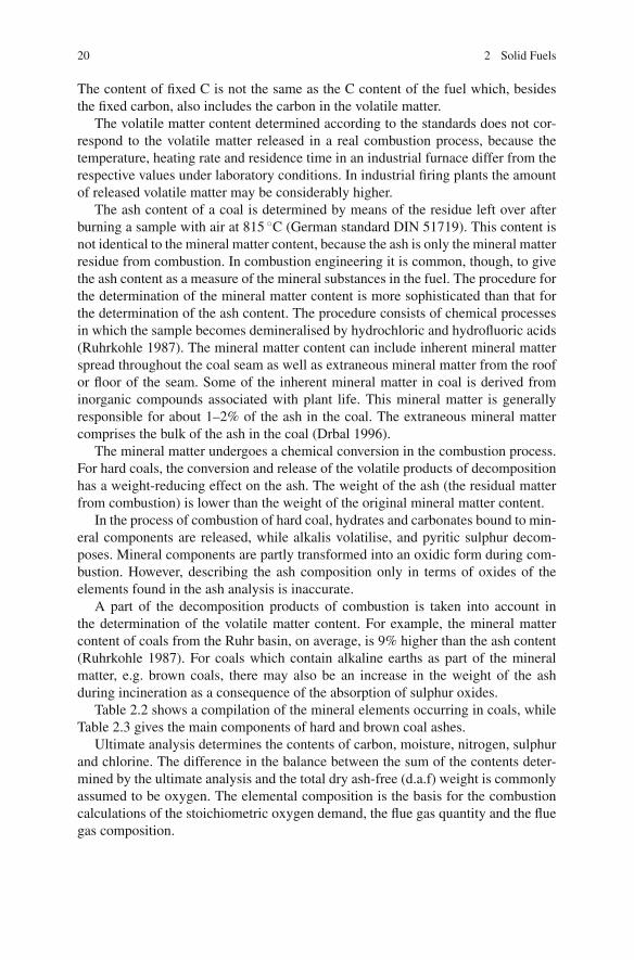
20 2 Solid Fuels
The content of fixed C is not the same as the C content of the fuel which, besidesthe fixed carbon, also includes the carbon in the volatile matter.
The volatile matter content determined according to the standards does not cor-respond to the volatile matter released in a real combustion process, because thetemperature, heating rate and residence time in an industrial furnace differ from therespective values under laboratory conditions. In industrial firing plants the amountof released volatile matter may be considerably higher.
The ash content of a coal is determined by means of the residue left over afterburning a sample with air at 815 ◦C (German standard DIN 51719). This content isnot identical to the mineral matter content, because the ash is only the mineral matterresidue from combustion. In combustion engineering it is common, though, to givethe ash content as a measure of the mineral substances in the fuel. The procedure forthe determination of the mineral matter content is more sophisticated than that forthe determination of the ash content. The procedure consists of chemical processesin which the sample becomes demineralised by hydrochloric and hydrofluoric acids(Ruhrkohle 1987). The mineral matter content can include inherent mineral matterspread throughout the coal seam as well as extraneous mineral matter from the roofor floor of the seam. Some of the inherent mineral matter in coal is derived frominorganic compounds associated with plant life. This mineral matter is generallyresponsible for about 1–2% of the ash in the coal. The extraneous mineral mattercomprises the bulk of the ash in the coal (Drbal 1996).
The mineral matter undergoes a chemical conversion in the combustion process.For hard coals, the conversion and release of the volatile products of decompositionhas a weight-reducing effect on the ash. The weight of the ash (the residual matterfrom combustion) is lower than the weight of the original mineral matter content.
In the process of combustion of hard coal, hydrates and carbonates bound to min-eral components are released, while alkalis volatilise, and pyritic sulphur decom-poses. Mineral components are partly transformed into an oxidic form during com-bustion. However, describing the ash composition only in terms of oxides of theelements found in the ash analysis is inaccurate.
A part of the decomposition products of combustion is taken into account inthe determination of the volatile matter content. For example, the mineral mattercontent of coals from the Ruhr basin, on average, is 9% higher than the ash content(Ruhrkohle 1987). For coals which contain alkaline earths as part of the mineralmatter, e.g. brown coals, there may also be an increase in the weight of the ashduring incineration as a consequence of the absorption of sulphur oxides.
Table 2.2 shows a compilation of the mineral elements occurring in coals, whileTable 2.3 gives the main components of hard and brown coal ashes.
Ultimate analysis determines the contents of carbon, moisture, nitrogen, sulphurand chlorine. The difference in the balance between the sum of the contents deter-mined by the ultimate analysis and the total dry ash-free (d.a.f) weight is commonlyassumed to be oxygen. The elemental composition is the basis for the combustioncalculations of the stoichiometric oxygen demand, the flue gas quantity and the fluegas composition.
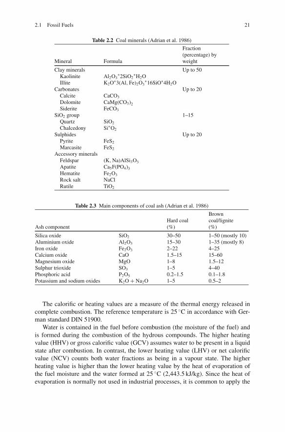
2.1 Fossil Fuels 21
Table 2.2 Coal minerals (Adrian et al. 1986)
Fraction(percentage) by
Mineral Formula weight
Clay minerals Up to 50Kaolinite Al2O3
∗2SiO2∗H2O
Illite K2O∗3(Al, Fe)2O3∗16SiO∗4H2O
Carbonates Up to 20Calcite CaCO3
Dolomite CaMg(CO3)2Siderite FeCO3
SiO2 group 1–15Quartz SiO2
Chalcedony Si∗O2
Sulphides Up to 20Pyrite FeS2
Marcasite FeS2
Accessory mineralsFeldspar (K, Na)AlSi3O3Apatite Ca5F(PO4)3Hematite Fe2O3
Rock salt NaClRutile TiO2
Table 2.3 Main components of coal ash (Adrian et al. 1986)
BrownHard coal coal/lignite
Ash component (%) (%)
Silica oxide SiO2 30–50 1–50 (mostly 10)Aluminium oxide Al2O3 15–30 1–35 (mostly 8)Iron oxide Fe2O3 2–22 4–25Calcium oxide CaO 1.5–15 15–60Magnesium oxide MgO 1–8 1.5–12Sulphur trioxide SO3 1–5 4–40Phosphoric acid P2O5 0.2–1.5 0.1–1.8Potassium and sodium oxides K2O + Na2O 1–5 0.5–2
The calorific or heating values are a measure of the thermal energy released incomplete combustion. The reference temperature is 25 ◦C in accordance with Ger-man standard DIN 51900.
Water is contained in the fuel before combustion (the moisture of the fuel) andis formed during the combustion of the hydrous compounds. The higher heatingvalue (HHV) or gross calorific value (GCV) assumes water to be present in a liquidstate after combustion. In contrast, the lower heating value (LHV) or net calorificvalue (NCV) counts both water fractions as being in a vapour state. The higherheating value is higher than the lower heating value by the heat of evaporation ofthe fuel moisture and the water formed at 25 ◦C (2,443.5 kJ/kg). Since the heat ofevaporation is normally not used in industrial processes, it is common to apply the
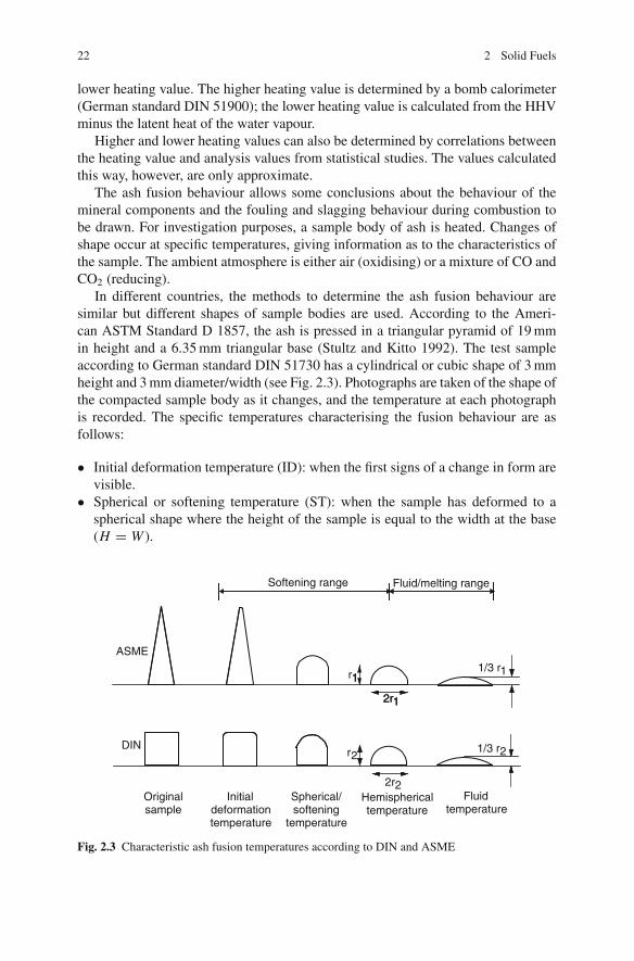
22 2 Solid Fuels
lower heating value. The higher heating value is determined by a bomb calorimeter(German standard DIN 51900); the lower heating value is calculated from the HHVminus the latent heat of the water vapour.
Higher and lower heating values can also be determined by correlations betweenthe heating value and analysis values from statistical studies. The values calculatedthis way, however, are only approximate.
The ash fusion behaviour allows some conclusions about the behaviour of themineral components and the fouling and slagging behaviour during combustion tobe drawn. For investigation purposes, a sample body of ash is heated. Changes ofshape occur at specific temperatures, giving information as to the characteristics ofthe sample. The ambient atmosphere is either air (oxidising) or a mixture of CO andCO2 (reducing).
In different countries, the methods to determine the ash fusion behaviour aresimilar but different shapes of sample bodies are used. According to the Ameri-can ASTM Standard D 1857, the ash is pressed in a triangular pyramid of 19 mmin height and a 6.35 mm triangular base (Stultz and Kitto 1992). The test sampleaccording to German standard DIN 51730 has a cylindrical or cubic shape of 3 mmheight and 3 mm diameter/width (see Fig. 2.3). Photographs are taken of the shape ofthe compacted sample body as it changes, and the temperature at each photographis recorded. The specific temperatures characterising the fusion behaviour are asfollows:
• Initial deformation temperature (ID): when the first signs of a change in form arevisible.
• Spherical or softening temperature (ST): when the sample has deformed to aspherical shape where the height of the sample is equal to the width at the base(H = W ).
r11/3 r1
1/3 r2
2r1
r2
2r2
ASME
DIN
Softening range Fluid/melting range
Originalsample
Initialdeformationtemperature
Spherical/softening
temperature
Hemisphericaltemperature
Fluidtemperature
1
2r1
Fig. 2.3 Characteristic ash fusion temperatures according to DIN and ASME

2.1 Fossil Fuels 23
• Hemispherical temperature (HT): when the sample body has changed to a hemi-spherical shape. Its height equals one half the width of the base (H = 1/2 W ).
• Fluid temperature (FT): when the sample body has melted down to a flat layerwith a maximum height of about one third of its height at the hemisphericaltemperature.
The temperature range between the initial deformation and hemispherical tem-perature is defined as the softening range, the range between hemispherical and fluidtemperature as the fluid temperature range. When the difference between the hemi-spherical temperature and ash fluid temperature is small, then the slag is referred toas “short”; a large difference occurs when the slag is “long”.
The results of the above-described investigations are transferable to an industrialscale only to a limited extent, because the laboratory conditions do not correspondto the conditions in industrial firing systems, either in the way the samples are pre-pared, or in the procedure of the method.
2.1.2.1 Petrographic Analysis
Petrographic analysis classifies the coal according to its structural constituents – themacerals (Chiche 1970, 1973). This information is used to gain an insight into theprocess of the coal formation, so as to relate the decayed organic matter to the coal.
Maceral is the term for the smallest structural constituent recognisable by anoptical microscope. The macerals can be distinguished from one another by theirreflectance. In the analysis of maceral groups of hard coal, three maceral types –vitrinite, exinite and inertinite – are distinguished. Vitrinite comes from wood mat-ter, while exinite mainly consists of products of digested sludge. The third maceralgroup, inertinite, which requires further analysis before being confirmed as origi-nating from the vegetable matter, is relatively unreactive (Ruhrkohle 1987; Adrianet al. 1986). With brown coal, the maceral groups distinguished are huminite, lipti-nite and inertinite, where huminite and liptinite, as far as their origin is concerned,correspond to the hard coal maceral groups of vitrinite and exinite, but with a lowerdegree of decomposition (Zelkowski 2004). Table 2.4 gives a general compilationof the maceral groups and macerals of hard and brown coals.
The various maceral groups are distinguished by their contents of volatile matterand their reflectance. In the case of hard coal, exinite has the highest volatile mattercontent and the lowest level of reflectance, while inertinite has the lowest content ofvolatile components and the highest reflectance of the maceral groups. With highercoalification degrees, the volatile matter contents of all maceral groups decreasewhile converging towards each other (see Fig. 2.4) (Ruhrkohle 1987).
Hard coals of the northern and the southern hemispheres differ markedly as totheir maceral composition. Coals of the northern hemisphere show a dominance ofvitrinite, the content being about 60–80%, with the contents of both exinite andinertinite varying, with a maximum of 30% each. Coals of the southern hemispherehave a significantly higher inertinite content of more than 50%. There is a directcorrelation between the volatile matter in a coal and the reflectance of vitrinite

24 2 Solid Fuels
Table 2.4 Macerals of brown and hard coals (Zelkowski 2004)
Brown coal Hard coal
Maceral group Maceral Maceral group Maceral
Huminite Textinite, ulminite attrinite,densinite gelinite,corpohuminite
Vitrinite Telinite, collinitevitrodetrinite
Liptinite Sporinite, cutinite,resinite, suberinite,alginate, liptodetrinitechlorophyllinite
Exinite Sporinite, cutiniteresinite, alginiteliptodetrinite
Inertinite Fusinite, semifusinite,macrinite, sclerotiniteinertodetrinite
Inertinite Micrinite, macrinitesemifusinite,fusiniteinertodetrinite
(see Fig. 2.5). This correlation is used to determine the distribution of the contents ofvolatile matter. Results serve to infer whether the fuel in question is a pure coal or ablended type. For example, despite having the same volatile matter content, the coaltypes in Fig. 2.6 exhibit clear differences in the distribution of macerals (Ruhrkohle1987).
Fig. 2.4 Volatile matter ofmacerals as a function of thecoal type (Ruhrkohle 1987)
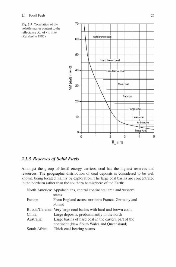
2.1 Fossil Fuels 25
Fig. 2.5 Correlation of thevolatile matter content to thereflectance Rm of vitrinite(Ruhrkohle 1987)
2.1.3 Reserves of Solid Fuels
Amongst the group of fossil energy carriers, coal has the highest reserves andresources. The geographic distribution of coal deposits is considered to be wellknown, being located mainly by exploration. The large coal basins are concentratedin the northern rather than the southern hemisphere of the Earth:
North America: Appalachians, central continental area and westernstates
Europe: From England across northern France, Germany andPoland
Russia/Ukraine: Very large coal basins with hard and brown coalsChina: Large deposits, predominantly in the northAustralia: Large basins of hard coal in the eastern part of the
continent (New South Wales and Queensland)South Africa: Thick coal-bearing seams
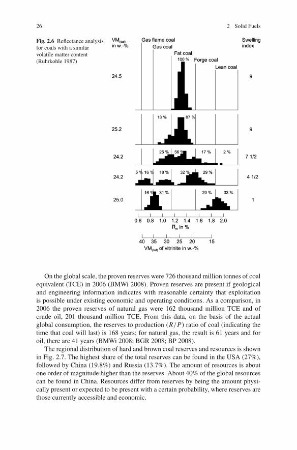
26 2 Solid Fuels
Fig. 2.6 Reflectance analysisfor coals with a similarvolatile matter content(Ruhrkohle 1987)
On the global scale, the proven reserves were 726 thousand million tonnes of coalequivalent (TCE) in 2006 (BMWi 2008). Proven reserves are present if geologicaland engineering information indicates with reasonable certainty that exploitationis possible under existing economic and operating conditions. As a comparison, in2006 the proven reserves of natural gas were 162 thousand million TCE and ofcrude oil, 201 thousand million TCE. From this data, on the basis of the actualglobal consumption, the reserves to production (R/P) ratio of coal (indicating thetime that coal will last) is 168 years; for natural gas, the result is 61 years and foroil, there are 41 years (BMWi 2008; BGR 2008; BP 2008).
The regional distribution of hard and brown coal reserves and resources is shownin Fig. 2.7. The highest share of the total reserves can be found in the USA (27%),followed by China (19.8%) and Russia (13.7%). The amount of resources is aboutone order of magnitude higher than the reserves. About 40% of the global resourcescan be found in China. Resources differ from reserves by being the amount physi-cally present or expected to be present with a certain probability, where reserves arethose currently accessible and economic.

2.1 Fossil Fuels 27
North America203 (1136)
Europe41 (520)
CIS138 (3204)
Asia235 (4182)
Australia50 (253)
Africa42 (59)
South America17 (42)
Total reserves 726 TCE (Total resources 9,397 TCE)
TCE: Thousand million tonnes of coal equivalent
Fig. 2.7 Distribution of coal reserves and resources (data from BMWi 2008)
The production of hard and brown coal in the world as a whole reached 6.2thousand million tonnes of coal in 2006, corresponding to 4.3 thousand milliontonnes of coal equivalent (TCE) (BP 2008). Of this, hard coal comprised 93% andbrown coal 7% (BGR 2008).
The relative fractions of the solid fossil fuels in primary energy consumption willremain relatively constant in the near future, as explained in Sect. 1.1. At the sametime, absolute coal production and consumption will increase. This is illustrated inTable 2.5, which shows coal production for selected years in the past and predictionsfor the future until 2030, divided into OECD and other countries. One may notice thesteep rise in Asian countries, which account for 80% of the rise in coal productionup to 2015.
Table 2.5 World coal production and exports (in million tonnes) (IEA 2006)
Production 1980 2004 2015 2030
OECD North America 687 1,080 1,248 1,376OECD Europe 1,163 834 855 905OECD Pacific 183 399 450 453Eastern Europe 842 736 809 707Africa 93 193 211 248China 626 1,881 3,006 3,867India 114 441 636 1,020Asia, other countries 64 202 295 419Latin America 18 34 44 63Total 3,822 5,558 7,328 8,858Export 172 619 819 975

28 2 Solid Fuels
Fig. 2.8 Coal consumption inthe power generation sectorand other sectors (data fromIEA 2007)
TEOther OECDEU 27Japan
US
Other DC
India
China
4000
3500
3000
2500
2000
1500
1000
500
0
Mto
e
Power generation other
2005 2030 20302005
Coal is predominantly used for power production. Figure 2.8 shows coal con-sumption in the power generation sector and in other sectors (mainly from cokeutilisation in the steel industry). Figure 2.8 clearly shows that China and Indiaaccount for 78% of the growth of coal use in the power generation and 90% ofthe growth in other sectors (IEA 2007).
In this context, coal is for the most part used in the proximity of the coal miningsite. It is estimated that 60% of the coal used in power production is sourced withina radius of 50 km of the plant. Compared to other fossil fuels, the trade in hard coalis less developed. In 2004, about 11% of the total production was exported. Thehard coal trade, however, is expected to grow strongly because the consumptionin countries with small deposits of their own, such as Japan and other South andEast Asian countries, will rise while subsidised coal mining in Europe will furtherdecrease. In Asian regions in particular a strong trade will develop.
The price trend for imported steam coal in Germany is plotted in Fig. 2.9 andcompared to the costs of natural gas and crude oil, using the basis of 1 TCE. It isobvious that the increase in coal prices is smaller in comparison to oil and natu-ral gas. Prices of all fossil fuels will rise further in the future, but due to its highflexibility of supply, it is assumed that a bottleneck will not occur for coal.
Fig. 2.9 Price trend of hardcoal in comparison to oil andnatural gas (data from BMWi2008) 1990 1995 2000 2005 2010
coal
0
50
100
150
200
250
300
350
Crude oil
Natural gas
Eu
ro /
TC
E (
Ger
man
bo
rder
)
2.2 Renewable Solid Fuels 29
2.2 Renewable Solid Fuels
Definition of biomass: The term biomass describes material of organic origin, beit living or dead. Biomass therefore includes plant and animal life, their respectivewaste or residual material and in the broader sense all conversion products such aspaper or cellulose, organic residuals from the food industry and organic waste fromhouseholds, trade and industry. The distinction between biomass and fossil fuelsbegins with peat, which is not defined as biomass (Kaltschmitt 2001; Kleemann andMeliß 1993; CMA 1995).
The line between biomass and waste is drawn differently from country to coun-try. In some countries the term biomass is used for any plant-derived organic matteravailable on a renewable basis, thus including dedicated energy crops and trees, agri-cultural food and feed crops, agricultural crop waste and residues, wood wastes andresidues, aquatic plants, animal wastes, municipal wastes and other waste materials.In other countries the term biomass is defined more strictly and takes biomass tomean only fuels arising from agricultural and forestry sources, using a separate cat-egory, waste fuels, for the waste products of human, urban and industrial processes.In the context of this book the latter definition will be used.
2.2.1 Potential and Current Utilisation
The stock of biomass on the land mass of Earth is currently estimated on an energybasis at 1,000,000 million TCE. Biomass as a whole grows at a rate of about 100,000million TCE per year, i.e. about 10% of the biomass stock on Earth (Kleemann andMeliß 1993). With a fraction of 90%, forests are the biggest biomass source (CMA1995).
Looking at the figures, the energy contained within the biomass that grows eachyear is 6–7 times as much as the total world primary energy consumption. How-ever, about 50% of the biomass, such as roots and leaves, is not exploitable forenergy recovery. About 2% of the world biomass production is used as food andforage, 2% is used in combustion and 1% is industrially processed to make woodproducts and paper and fibre materials. The fraction used as fuel, more than 1,700million TCE per year, covers about 10% of the world primary energy consumption(IEA 2006).
In developing countries, biomass use mostly takes the form of wood combus-tion. Sustainable forestry strategies are generally not practiced. Worldwide, onlyabout 10% of woodland area is used for forestry; wood that grows in natureremains unused to a large extent. Even in industrial countries where forests arecultivated, wood is predominately used by the wood-processing industry. The useof wood for energy recovery, i.e. as fuel, has minor importance in these coun-tries. Considering the world as a whole, only a fraction of wood is used as fuel(CMA 1995).
30 2 Solid Fuels
Biomass data distinguishes between three different potentials:
• the total or theoretical potential, which describes the total accumulated biomassquantity,
• the technical potential, which is the quantity that could actually be used, and• the economic potential, which indicates the yield that can today, or within several
years, economically compete with other fuels (i.e. fossil fuels).
The technical potential is smaller than the total, and the economical lower thanthe technically usable potential (Kaltschmitt et al. 2006).
Estimating the biomass potential for energy consumption, a distinction has to bedrawn between residual or waste biomass on the one hand and biomass from sitesused exclusively for energy purposes on the other. Residual biomass that can beused for energy purposes is produced
• in farming, in the form of cereal straw, residuals from foliage plants and animalwaste,
• in forestry, in large quantities in the form of residual wood, and• in waste management, in the form of household organic residual matter and
industrial waste (see Sect 2.2.1.2).
The potential of energy crops is given by the available arable land which couldbe used for the plantation of cereals, reed and grass plants, or fast-growing trees.
2.2.1.1 Biomass from Farming and Forestry
By-Products of Farming
Residuals and by-products from farming can be used as fuels for power production.Straw is obtained as a by-product in the production of cereals. In sugar productionfrom sugar cane, bagasse is a by-product which is widely used as a fuel, as arepressing residues arising in the production of vegetable oils, if they do not have ause as food supplement in the feeding of livestock.
In Germany, in terms of farming residuals as fuels, straw is essentially the onlyone. The straw yield can be estimated from the data on the area under cultivationand the straw obtained from the respective cereal type. The amount is about 46million tonnes/year (Schneider et al. 2007). Of the gross yield of straw, however,only a fraction can be exploited for energy purposes – the fraction that remains afterfarming uses has been exhausted. These uses include the ploughing of the straw intothe soil to improve the soil structure and/or for the formation of humus and using itas litter or forage for livestock (Kaltschmitt et al. 2006). Based on the assumptionthat only about a fifth of the straw is usable as an energy carrier, the result is anenergy potential of about 130 PJ/year or 4.4 million TCE/year, corresponding to afraction of the primary energy consumption of 0.9%.
2.2 Renewable Solid Fuels 31
By compiling worldwide data on the fractions of herbaceous residual matter andby-products which can be used as fuels, and taking into account the relevant restric-tions, it can be estimated that there is a global technical potential of about 17,000PJ/year (580 million TCE). The biggest energy potentials in this context are found inAsia. In Europe, straws from cereals, rape and maize arise in farming. Cereals, witha cultivated area of about 33 million ha, are the most significant of these. Assuminga 20% utilisation of the straw produced, the technical potential of straw amounts toabout 485 PJ/year in the EU 15 and to 721 PJ/year for the EU 30 (EU 27, Norway,Switzerland, Turkey) (Schneider et al. 2007). Including other herbaceous biomassfractions such as grass, the potential amounts to 1,000 PJ/year in the EU 15 and1,500 PJ/year in the EU 30.
Residual Wood
In Germany, completely naturally grown forests hardly exist nowadays, apart froma few exceptions such as the Bavarian Forest National Park. Instead, forests arecultivated to obtain wood for industrial use. Besides trunk wood as the main product,the processes of thinning out and trunk wood harvesting produce residual materialwhich today remains in the forest, to a large extent unused. This material consistsof trunk wood sections and thick branches which are not suitable for industrial pur-poses but can be used as fuel. The additional biomass in the forest, such as witheredbranches and twigs, bark and leaves cannot be utilised as fuel in an industriallyreasonable way and should remain in the forest to conserve the humus and nutri-ent cycle.
For the regional distribution of the yield, the points of reference are the woodlandareas. In Germany, the well-wooded southern federal states are characterised byhigher and the sparsely wooded northern states by lower potentials (Kaltschmittet al. 2006).
In trunk wood processing, residual matter is produced in particular in sawmillsand in the processing of the timber. These residues, however, are for the most partutilised as feedstocks for the paper industry and in chipboard manufacturing or asa fuel in the wood-processing industry. Wood biomass is also sourced from wastewood, i.e. wood no longer used for its original purpose (Kaltschmitt 2001; Fruhwald1990; Wegener and Fruhwald 1994).
The technical potential of residual wood in Germany amounts to about 424PJ/year of forestry residues (waste timber, bark, etc.), 57 PJ/year from the wood-processing industry and 78 PJ/year of waste wood. The total potential is 570 PJ/year,corresponding to a fraction of the primary energy consumption of 4%.
The worldwide potential can be calculated on the basis of existing wooded areasand the average of the different wood yields. The result of such a calculation isa potential of approximately 42,000 PJ/year or 1,400 million TCE. Broken down,this amount is composed half by the wood yield theoretically exploitable as a fuel,13 and 17% by the production residuals from timber cutting and further industrialprocessing, respectively, 7% by the waste wood produced each year and 8% byother kinds of wood residues. The biggest potential for the exploitation of wood

32 2 Solid Fuels
as an energy source is found in North America due to the currently unused largeyield of wood. In the countries of the European Union, the potential yield of woodybiomass, including waste wood, amounts to some 3,200 PJ/year in the EU 15 and toalmost 5,000 PJ/year in the EU 30.
Energy Crops
For areas of arable land no longer needed for food production, one potential useunder discussion is the plantation of energy crops. The biomass types in questionare the following (Kaltschmitt et al. 2006; Kaltschmitt 2001; Lewandowski 1996):
• Conventional cereals (barley, rye, triticale, maize). Cereals, besides producinggrain for food and forage, can also be grown for use in power production. Inthis process, the above-ground parts of the cereal plant (the straw and the grain)are used as a solid fuel. The advantage of the plantation of cereals to produce asolid energy carrier is the known, mature technology for cultivation and harvest.Depending on the local conditions, the resulting average annual yields of dry mat-ter (straw and grain) for cereal crops such as triticale, winter wheat, winter barleyand rye range between 9 and 13 tonnes of dry matter/ha. Arguments against thecombustion of these crops for power production, which could also serve as food,are the ethical and moral concerns which arise from the context of the continued,widespread hunger around the world.
• Fast-growing reed and grass plants. Fast-growing reed and grass plants are C4
plants, which in the process of photosynthesis, consuming carbon dioxide fromthe atmosphere, build up a compound with four carbon atoms as a first buildingblock. The group of these plants includes maize, millet and sugar cane. In con-trast, most of the plants on Earth, and almost all European plants, are C3 plants(Borsch 1992). Due to their more efficient photosynthetic mechanism, C4 grassesconsume less water per kilogram of produced dry matter while also providing ahigher yield per acre (Lewandowski 1996). The plant, dry after the growth period,can be used as a solid fuel.
The advantage of C4 plants is their high yield of biomass; the drawback is thescant experience of large-scale cultivation and harvesting. Among the plants suitablefor cultivation for energy purposes in Germany, those most suitable are thosecharacterised not only by high yields but also by relatively low requirements forsoil, climate and care.
Due to its high yields, Miscanthus sinensis in particular has become known asa potential energy carrier. Miscanthus, also called the Chinese reed, is a C4 plantnative to East Asia, which belongs to the Poaceae family. In contrast to annualgrass plants such as cereals or maize, Miscanthus is a perennial plant which hassubterranean perennial organs (rhizomes) from which new shoots develop in spring(Lewandowski 1996). Miscanthus is grown for a period of about 10 years, producingfull yields from the third year or so. The anticipated high yields, of up to 40–50tonnes of dry matter/ha, have in practice, in Europe, not met expectations. Instead,yearly maximum yields of 20–25 tonnes dry matter/ha from the third year seem to be

2.2 Renewable Solid Fuels 33
realistic from fields in central Europe (Hartmann and Strehler 1995). Depending onlocal and climatic conditions, the yield may also be a lot lower (Kaltschmitt 1993).In central Europe, frost in winter may damage the rhizomes and hence diminishthe yield.
Other C4 plants are the reed and the giant reed, types of millet also belongingto the Poaceae family. Compared to Miscanthus, however, they are expected to pro-duce lower yields under central European conditions. The millet types which can becultivated in Germany are C4 plants of tropical origin too. In conditions of heavyprecipitation and mild climate, the achievable dry matter yields range between 15and 22 tonnes/ha yearly.
• Fast-growing trees (willow, poplar). Biomass can also be produced through fast-growing tree types, such as willow or poplar, which are grown as short rotationcrops. After a breeding phase, the above-ground biomass is mechanically har-vested after 4–20 years. In the form of woodchips, it can be used as a solid fuel.The tree stumps sprout again. The biomass can be harvested again after 2–12years, respectively, depending on the site, climate and the tree type. In Germany,the respective yearly yields are 12–15 tonnes of dry matter/ha (Kaltschmitt 1993;Hartmann and Strehler 1995).
The fundamental parameter for the technical potential of energy crops is the areaavailable for cultivation. Worldwide, this area is estimated to be between 350 and950 million ha. In industrial nations, the area of the existing arable land which canbe assumed to be available for the cultivation of energy crop averages around 7%.In developing countries, the area theoretically available and suitable for energy cropgrowing is on average considerably higher. Supposing that a mix of plants suited tothe given location was cultivated on these areas, a technical energy potential can becalculated. The calculated potentials vary between 37 and 82 EJ/year. The highestpotential in this respect is in Africa. The potential in Europe is limited. The countriesof the European Union offer a potential in the range of 1.8–3.8 EJ/year. In Germany,in the medium term, a maximum area of 2 million ha will probably be useable forenergy crop cultivation, so a potential of about 365 PJ/year has to be assumed.
Summary of Potentials and Current Utilisation
Table 2.6 compiles the above-discussed potentials for Germany and shows the extentof current use. At present, almost all residual wood from forestry and industry, aswell as all waste wood, is exploited. Other sorts of wood and straw remain unused,so there is a potential to increase the share of biomass in primary energy consump-tion from the current 2% or so up to about 8%. Other authors state a potential use ofsolid biomass of between 2 and 15% of the primary energy consumption.
The dominant renewable energy source in Europe is biomass, with a share of4.5% of the primary energy consumption in 2005 and 68% of total renewables.Biomass provides 30% of the PEC in Latvia and nearly 20% in Finland. Most ofthis is wood. Sweden is not far behind with 17.5% (Eurostat 2007). The specificdifferences between the countries result from differing boundary conditions, such

34 2 Solid Fuels
Table 2.6 Biomass potential and utilisation in Germany (Schneider 2007)
Potential Utilisation Potential/PEC Utilisation/PEC
in PJ/yr Share in %
Residual forest wood 169 147–165 3.0 1.0–1.1Small wood 123Additional forestry
wood132
Wood industryresiduals
57 51 0.4 0.4
Waste wood 78 62 0.5 0.4Other woody biomass 10 1 0.1 0Straw 130 3 0.9 0Grass, other 48–77 0 0.4–0.6 0Energy crops 365 0 2.6 0Total 1,112–1,141 261–279 7.8–8.0 1.8–2.0
PEC: Primary energy consumption
as the fraction of forest area, the fraction of agriculturally productive land, the cli-matic conditions or national policies. Furthermore, in countries which, compared toGermany, have a higher use of biomass, the potentials are higher than the currentutilisation.
Worldwide, though, the share of biomass in primary energy consumption is sig-nificantly higher than in Europe. Table 2.7 shows the worldwide potentials of wood
Table 2.7 Biomass potential, current utilisation and share of PEC in different regions of the world(Schneider 2007; Van Loo 2008; Kaltschmitt et al. 2009)
North Latin Middle FormerAmerica America Asia Africa Europe East SU Total
Potential [EJ/a]Wood 12.8 5.9 7.7 5.4 4.0 0.4 5.4 41.6Herbaceous
biomass2.2 1.7 9.9 0.9 1.6 0.2 0.7 17.2
Dung 0.8 1.8 2.7 1.2 0.7 0.1 0.3 7.6Biogas (0.3) (0.6) (0.9) (0.4) (0.3) (0.0) (0.1) (2.6)Energy crops 4.1 12.1 1.1 13.9 2.6 0.0 3.6 37.4Total 19.9 21.5 21.4 21.4 8.9 0.7 10.0 103.8
Current utilisation [EJ/a]Trad.
biomass1.2 22.5 9.7 33.4
Modernbiomass
4.1 2.4 3.6 2.3 3.4 0.7 16.8
Total 4.1 3.6 26.1 12 3.4 0 0.7 50.2
PEC [EJ/a] 120.4 21.8 154.8 25 78.9 19.5 46.5 473Utilisation/
PEC [%]3 17 17 48 4 0 2 10.6
Potential/PEC [%]
17 98 14 86 11 1 22 22

2.2 Renewable Solid Fuels 35
and herbaceous residual matter and energy crops differentiated by region and relatedto the primary energy consumption. Globally, a technical potential of biomass ofabout 100 EJ/year can be surmised, which corresponds to a share of 22% of the totalprimary energy consumption in 2006. The current utilisation of biomass, as a per-centage of the primary energy consumption, is 10.6%. This high share comes aboutfrom traditional biomass use in fast-developing and developing countries, for exam-ple as firewood. Table 2.7 distinguishes between modern and traditional biomassutilisation. Modern refers to modern technologies, such as biomass combustionfor combined heat and power production. The share of modern biomass in PECis around 3.5% worldwide (Van Loo and Koppejan 2008; Schneider et al. 2007).
2.2.1.2 Wastes
Waste is an unwanted or undesired material or substance. The European Union,under the Waste Framework Directive (EU 2008), more precisely defines waste asan object the holder discards, intends to discard or is required to discard.
The waste management ambition in Germany and Europe is to avoid the pro-duction of waste, for instance by using low-waste production processes. If wasteis produced it should be used as a material (recycling) or thermally to convert theenergy content of the waste to useful thermal or electrical energy (recovery). Thedisposal of wastes is the option used as the last resort. Disposal includes on the oneside dumping (to landfill) but also thermal conversion processes, where disposal isthe primary objective.
This means that the thermal treatment of waste can be classified either as dis-posal or as recovery. The distinction between recovery (or utilisation) and disposalis based on the energy efficiency of the process. This is laid down in the EuropeanWaste Framework Directive (EU 2008), where an energy efficiency criterion, R1,is defined. The utilisation of waste in plants having an efficiency above a certainvalue is considered recovery, and below this value it is considered disposal. The R1criterion is defined in a footnote to Annex II of the Waste Framework Directive (EU2008) and is discussed in Sect. 6.4.
Political specifications and laws have affected a change in the total wastes pro-duced and their division. The total waste volume in Germany is going down, andat the same time the proportion of recovered matter is increasing. Usable materialssuch as paper, glass, metal and plastics are collected separately or get separatedfrom other municipal wastes once collected. Only particular waste types have acalorific value.
Of the total waste volume in Germany of 331 million tonnes in 2005 (Beckeret al. 2007), only a minor part was of organic origin. Given that a definite dis-tinction between organic wastes and wastes of fossil origin is not possible in mostcases, Table 2.8 presents an overview of the entire waste volume in Germany. Itdistinguishes between waste volumes from manufacturing industries and the wastescollected by public waste disposal services (Bilitewski et al. 2000).
A major fraction of waste arises in the building and mining industries, mainlyas building rubble (180 million tonnes per year) and overburden from mining (52

36 2 Solid Fuels
Table 2.8 Amount of wastes in Germany (Becker et al. 2007)
2002 2003 2004 2005
Waste volume 1,000 t
Total 381,262 366,412 339,368 331,876Building rubble and
demolition waste (incl.roadway rubble)
240,812 223,389 187,478 184,919
Mining spoil(non-hazardous waste)
45,461 46,689 50,452 52,308
Wastes from productionprocesses and industry
42,218 46,712 53,005 48,094
Municipal wastes 52,772 49,622 48,434 46,555
All values in thousands of tonnes
million tonnes per year). However, these wastes have little or no exploitable energy(Becker et al. 2007). The 48 million tonnes (approximately) of waste per year inthe producing industries is distributed over a multitude of material groups, each ofwhich can be partly utilised for energy purposes. Examples are residual matter frompaper production, wood treatment, petroleum finishing and coal beneficiation andplastic and textile waste.
Municipal solid waste (MSW) had a share of 14% of the total waste volume,corresponding to 46 million tonnes, in 2005. Figure 2.10 shows the amount, theutilisation and disposal of MSW in Germany. MSW predominantly refers to house-hold waste (domestic waste), and sometimes also to commercial wastes collectedby a municipality. Due to the increasing proportion of separated fractions, such aspaper, plastics, glass in Germany, the amount of mixed household waste decreased
Fig. 2.10 Amount, utilisationand disposal of MSW inGermany in 2005 (data fromBMU 2007a)
Municipal Solid Waste46.5 Mil. Mg
Household wasteseparate collection
Mixed householde waste ,Househ . waste likecommercial waste ,
bulky waste21.2 Mil. Mg
Recycling25.0 Mil. Mg
Bio waste 3.8Garden residues 3.9Glas 3.6Paper 7.9Plastics 4.6
Landfill4.0
Mil. Mg
Treat -ment4.2
Mil. Mg
Wasteincineration12.8 Mil. Mg
commercial
Glass

2.2 Renewable Solid Fuels 37
continuously in the last years to about 14 million tonnes per year in 2005 (Beckeret al. 2007). Mixed household waste is also termed residual waste (or householdrefuse). The average calorific value of residual waste ranges between 6 and 10 MJ/kg(Thome-Kozmiensky 1994). With its heterogeneous composition and its diversetypes of hazardous matter, these waste types are disposed of in specially designedwaste incineration plants, mostly stoker-fired furnaces. In 2007, 18 million tonneswas thermally treated in 72 waste incineration plants (BMU 2007b). In accord withnational law (TA Siedlungsabfall, German Technical Specifications for the Disposalof Municipal Waste) dumping of wastes with an organic fraction of greater than 5%has been forbidden in Germany since 2005.
2.2.1.3 Refuse-Derived Fuels
In Germany and in other European countries, municipal, industrial and residualwastes are partially pretreated and then prepared into fuels (refuse-derived fuel(RDF) or secondary recovered fuel (SRF)). The aim of the preparation is to improvethe quality of the waste stream in a way that the substitute fuel produced can beburned in plants without operational problems and without pollution loading. Theuse as a fuel in an RDF power plant or as a supplementary fuel in coal-fired powerplants or cement kilns in this respect imposes various requirements on the fuel. Theproduction of RDF as a rule uses the following waste streams as feedstocks:
– Mixed household waste (residual waste)– Bulky waste– Household waste like commercial waste– Homogeneous, mostly industrial, waste streams such as plastics, paper, wood and
textiles
The purpose of the treatment is to produce a homogeneous, highly calorific,chemically and biologically stable and low-pollution fuel. There are a great num-ber of methods available which treat the feed material in a mechanical, thermal orbiological way. Typical process steps of the preparation are
– drying by thermal or biological methods,– mechanical separation of partial streams by selection and classification (using an
air classifier or rotary drum screens),– separation of iron and non-ferrous metals,– separation or reduction of impurities, for example chlorine, and– size reduction and homogenisation.
The processing usually consists of the sieving out of the fraction of fines,crushing, metal separation and drying and usually increases the heating value. Theseparated metals are sold. It is also possible to obtain reduced chlorine contentsby carefully selecting specific waste streams, especially in the case of commercial

38 2 Solid Fuels
waste. There are various RDF utilisation schemes around the world. In most coun-tries the RDF is processed on the site of the energy from waste (EfW) plant.
In Germany, many decentralised plants with a combination of mechanical andbiological treatment of waste have been built in recent years. The purpose is toproduce a fuel which can be utilised in EfW plants elsewhere. Two process variantsare distinguished:
– Conventional mechanical – biological treatment (MBT) first separates metals andhighly calorific components from the feed waste. The highly calorific compo-nents are used as a substitute fuel/RDF for co-firing in coal-fired power plantsor as the only fuel in RDF power plants. The remaining fraction goes to landfillafter biological treatment (aerobic digestion).
– The aim of mechanical – biological stabilisation (MBS) is to dump no or onlysmall amounts of mineral wastes and to use most of the feed waste for the produc-tion of substitute fuels (stabilate). The feed waste is first dried in the biologicalprocess by the reaction heat that is produced. The dried wastes are then sortedinto recyclable fractions (substitute fuels, ferrous and non-ferrous metals, etc.).The substitute fuel/RDF is then used for co-combustion in coal-fired power plantsor RDF power stations.
The energy balance of a mechanical – biological process is very much dependenton the process configuration. A typical ratio of the energy output of the RDF fuel tothe energy input of the feed waste is about 60–70% for MBT and 80–90% for MBS.
Both variants can only be used when there are sufficient capacities in indus-trial fuel-burning plants capable of handling substitute fuels (produced from highlycalorific fractions of the wastes) or stabilates.
Mechanical – biological waste treatment – as opposed to thermal waste treat-ment – is not an independent disposal process but divides the waste into vari-ous groups and prepares these for disposal or recycling. MBT processes thereforerequire integration into other waste management processes for the further disposalof the waste fractions produced.
The total capacity of the mechanical – biological waste treatment plants inGermany currently ranges around 5–6 million tonnes per year. After completionof all the plants planned in 2006, 66 mechanical – biological waste treatment plantswith a capacity of about 7.1 million tonnes/year will be available (UBA 2008).
2.2.1.4 Sewage Sludge
Sewage sludge shall be discussed here as an example of a homogeneous waste typeobtained in great quantities. Sewage sludge is the residual matter from treatmentprocesses of household and industrial wastewaters. The quantity of it depends on thenumber of households in the treatment plant catchment, the industrial wastewaterload and the efficiency of the sewage treatment plants (Bilitewski et al. 2000). Adistinction is made between raw sludge and digested sludge.
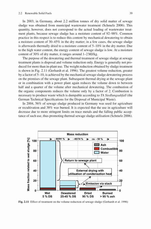
2.2 Renewable Solid Fuels 39
In 2003, in Germany, about 2.2 million tonnes of dry solid matter of sewagesludge was obtained from municipal wastewater treatment (Schmelz 2006). Thisquantity, however, does not correspond to the actual loading of wastewater treat-ment plants, because sewage sludge has a moisture content of 92–98%. Commonpractice in this respect is to reduce this content by mechanical dewatering to obtaina moisture content of 30–45% in the dry matter; in a few cases, the sewage sludgeis afterwards thermally dried to a moisture content of 5–10% in the dry matter. Dueto the high water content, the energy content of sewage sludge is low. At a moisturecontent of 30% of dry matter, it ranges around 1–2 MJ/kg.
The purpose of the dewatering and thermal treatment of sewage sludge at sewagetreatment plants is disposal and volume reduction only. Energy is generally not pro-duced for more than in-plant use. The weight reduction obtained by sludge treatmentis shown in Fig. 2.11 (Gerhardt et al. 1996). The greatest volume reduction, greaterby a factor of 5–10, is achieved by the mechanical sewage sludge dewatering processon the premises of the sewage plant. Subsequent thermal drying at the sewage plantor in combination with a power plant again reduces the volume down to betweenhalf and a quarter of the volume after mechanical dewatering. The combustion ofthe organic components reduces the volume only by a factor of 2. Combustion isnecessary to produce waste which is dumpable according to TA Siedlungsabfall (theGerman Technical Specifications for the Disposal of Municipal Waste).
In 2004, 56% of sewage sludge produced in Germany was used for agricultureor recultivation and 38% was burned. It is expected that the use in agriculture willdecrease due to more stringent limits on trace metals and the falling public accep-tance of such use, thus promoting thermal sewage sludge utilisation (Schmelz 2006).
Fig. 2.11 Effect of treatment on the volume reduction of sewage sludge (Gerhardt et al. 1996)

40 2 Solid Fuels
2.2.2 Considerations of the CO2 Neutrality of Regenerative Fuels
Carbon dioxide is produced from the combustion of biomass as well as from fossilfuels. However, an equivalent quantity of CO2 is taken up from the atmosphere bythe plant during its growth. Thus in agricultural systems, which follow regulatedcultivation methods, the growth period has an effect of balancing out the CO2 emis-sions from the utilisation of biomass as a fuel. When biomass is overexploited, suchas in the case of the slash-and-burn of tropical forests, the growth period followingutilisation does not adequately compensate for the CO2 produced during combus-tion. The bound carbon is released, and so slash-and-burn has to be seen as the sameas fossil fuel utilisation (Schmidt 1992).
When residual matter such as straw or forest wood residue is used for energypurposes, most of the emitted CO2 is extracted from the atmosphere again duringthe growth period of the cycle. However, because there is no strict interdependencebetween the production of the biomass and its use as a fuel, the CO2 capture of thegrowth period cannot be set against the CO2 release during its utilisation for energy;no reduction of CO2 emissions follows from it at first. If, on the other hand, thisbiomass is not utilised for energy, the carbon is released to the atmosphere again inthe form of CO2 or as methane (which is much worse) during natural decomposition.The same is true for the organic fractions of household refuse or sewage sludge(Kaltschmitt et al. 2006).
2.2.2.1 Comparison of Miscanthus and Hard Coal on a GreenhouseGas Emissions Basis
A comparative study was made between the use of coal and the use of cultivatedMiscanthus as a fuel (Kicherer 1996). Miscanthus was grown on permanent fallowland and, once harvested, co-combusted in an existing pulverised hard coal firedpower plant. As a basis, it was assumed that the biomass was transported 50 km onaverage and that it substituted coal directly.
When comparing the CO2 emissions, the CO2 generated during the productionprocesses were taken into account, for example the operation and maintenance ofmachines and buildings. Additionally, the CO2 emissions involved in the productionof goods such as fertilisers were considered. However, the CO2 emissions from theconstruction of machines and buildings were ignored. CO2 emissions were also pro-duced during the transport and preparation of Miscanthus, and this was accountedfor. Furthermore, the estimated additional N2O emissions from the soil as a resultof the cultivating of Miscanthus were included and converted into CO2 equivalentemissions using N2O’s greenhouse-CO2 equivalency factor. Figure 2.12 shows thepercentage contributions to the total greenhouse gas emissions of the various stepsin Miscanthus processing. It is conspicuous that nitrogen fertilisation contributesalmost 50% of the greenhouse gas emissions. On one hand, this has to be put downto the energy which has to be expended for the production of the fertiliser and,on the other, to the N2O emissions released by the nitrogen fertiliser when spread.The contribution of the transport of the biomass over distances of 50 km, in con-
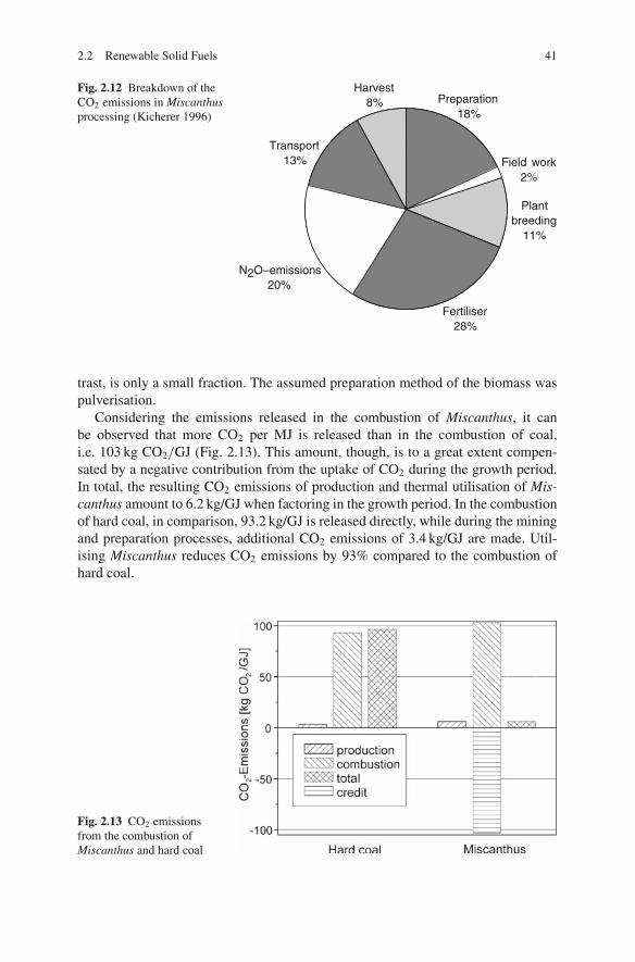
2.2 Renewable Solid Fuels 41
Fig. 2.12 Breakdown of theCO2 emissions in Miscanthusprocessing (Kicherer 1996)
Preparation18%
Field work2%
Plantbreeding
11%
Fertiliser28%
N2O–emissions20%
Transport13%
Harvest8%
trast, is only a small fraction. The assumed preparation method of the biomass waspulverisation.
Considering the emissions released in the combustion of Miscanthus, it canbe observed that more CO2 per MJ is released than in the combustion of coal,i.e. 103 kg CO2/GJ (Fig. 2.13). This amount, though, is to a great extent compen-sated by a negative contribution from the uptake of CO2 during the growth period.In total, the resulting CO2 emissions of production and thermal utilisation of Mis-canthus amount to 6.2 kg/GJ when factoring in the growth period. In the combustionof hard coal, in comparison, 93.2 kg/GJ is released directly, while during the miningand preparation processes, additional CO2 emissions of 3.4 kg/GJ are made. Util-ising Miscanthus reduces CO2 emissions by 93% compared to the combustion ofhard coal.
Fig. 2.13 CO2 emissionsfrom the combustion ofMiscanthus and hard coal

42 2 Solid Fuels
2.2.2.2 Harvest Ratios
The result of the evaluation of the regenerative energy utilisation of a fuel is itsenergy balance. It is given as an output/input ratio by means of so-called harvestratios, where the useful energy of an energy medium is set in proportion to theexpenditure of energy necessary for its production (Hartmann and Strehler 1995;Born 1992). If the harvest ratio is above 1, this means that, using the technology, andfor the fuel considered, energy is released and CO2 abated. Harvest ratios below 1often occur but such crops are not realistic candidates for energy production becausein those cases more energy is expended during growth and preparation than is gainedthrough utilisation.
Biogenous solid fuels yield harvest ratios between 10 and 20 or so. In the studymentioned above, a harvest ratio of 14 was calculated for Miscanthus (cultivationand utilisation). According to others (Hartmann and Strehler 1995), the harvest ratiofor Miscanthus is over 19 (see Fig. 2.14). Liquid energy media such as rapeseed oilor ethanol from sugar beet or sweet sorghum have lower harvest ratios.
Energy crop
Ethanol from sweet sorghum
Ethanol from sugar beet
Short rotation coppice (SRC)
Miscanthus
Semi-refined rapeseed oil
Residual straw
Wood chips from forestry
Photovoltaics
Solar thermal power generation
Hydropower
Wind energy utilisation
Energy Balance, Output/Input [MJ/MJ]
123
5.7
1.3
5
8.5
19.7
14.2
20.4
19
13.5
3.7
37
0 10 20 30 40
Fig. 2.14 Harvest ratios of various biomass types (Hartmann and Strehler 1995)
2.2.3 Fuel Characteristics of Biomass
2.2.3.1 Biomass from Farming and Forestry
Molecular Structure
Biomass essentially consists of macromolecular organic polymers – lignin, cellu-lose and hemicellulose. Cellulose is by far the most common organic substance. Itis a polysaccharide consisting solely of glucose chains which are held together by
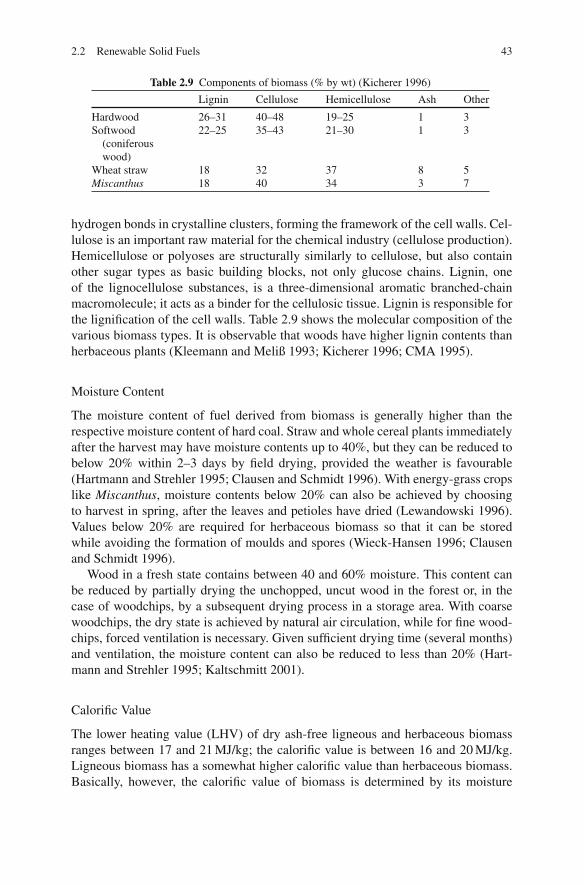
2.2 Renewable Solid Fuels 43
Table 2.9 Components of biomass (% by wt) (Kicherer 1996)
Lignin Cellulose Hemicellulose Ash Other
Hardwood 26–31 40–48 19–25 1 3Softwood
(coniferouswood)
22–25 35–43 21–30 1 3
Wheat straw 18 32 37 8 5Miscanthus 18 40 34 3 7
hydrogen bonds in crystalline clusters, forming the framework of the cell walls. Cel-lulose is an important raw material for the chemical industry (cellulose production).Hemicellulose or polyoses are structurally similarly to cellulose, but also containother sugar types as basic building blocks, not only glucose chains. Lignin, oneof the lignocellulose substances, is a three-dimensional aromatic branched-chainmacromolecule; it acts as a binder for the cellulosic tissue. Lignin is responsible forthe lignification of the cell walls. Table 2.9 shows the molecular composition of thevarious biomass types. It is observable that woods have higher lignin contents thanherbaceous plants (Kleemann and Meliß 1993; Kicherer 1996; CMA 1995).
Moisture Content
The moisture content of fuel derived from biomass is generally higher than therespective moisture content of hard coal. Straw and whole cereal plants immediatelyafter the harvest may have moisture contents up to 40%, but they can be reduced tobelow 20% within 2–3 days by field drying, provided the weather is favourable(Hartmann and Strehler 1995; Clausen and Schmidt 1996). With energy-grass cropslike Miscanthus, moisture contents below 20% can also be achieved by choosingto harvest in spring, after the leaves and petioles have dried (Lewandowski 1996).Values below 20% are required for herbaceous biomass so that it can be storedwhile avoiding the formation of moulds and spores (Wieck-Hansen 1996; Clausenand Schmidt 1996).
Wood in a fresh state contains between 40 and 60% moisture. This content canbe reduced by partially drying the unchopped, uncut wood in the forest or, in thecase of woodchips, by a subsequent drying process in a storage area. With coarsewoodchips, the dry state is achieved by natural air circulation, while for fine wood-chips, forced ventilation is necessary. Given sufficient drying time (several months)and ventilation, the moisture content can also be reduced to less than 20% (Hart-mann and Strehler 1995; Kaltschmitt 2001).
Calorific Value
The lower heating value (LHV) of dry ash-free ligneous and herbaceous biomassranges between 17 and 21 MJ/kg; the calorific value is between 16 and 20 MJ/kg.Ligneous biomass has a somewhat higher calorific value than herbaceous biomass.Basically, however, the calorific value of biomass is determined by its moisture

44 2 Solid Fuels
Fig. 2.15 Calorific value as a function of the moisture content
content; starting out from the dry matter, it diminishes with an increasing mois-ture content (see Fig. 2.15). Up to 60% moisture, the calorific value of wood maybe between 6 and 18 MJ/kg. Air-dried wood with 15–20% moisture has a calorificvalue between 14 and 15.2 MJ/kg.
Volatile Matter, Residual Char, Ash
Figure 2.16 compares the contents of volatile matter, fixed carbon and ash of straw,wood, hard coal and brown coal. Biomass has a markedly higher volatile matter con-tent than hard coal. As the fuel is heated in the furnace, the volatile matter is released
Fig. 2.16 Volatile matter,residual char and ash contentsof various biomassesand coals
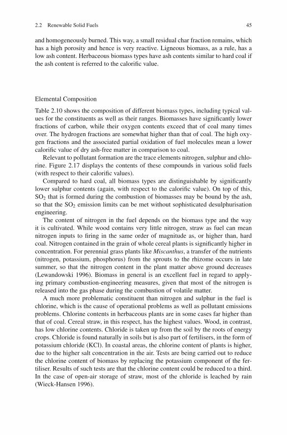
2.2 Renewable Solid Fuels 45
and homogeneously burned. This way, a small residual char fraction remains, whichhas a high porosity and hence is very reactive. Ligneous biomass, as a rule, has alow ash content. Herbaceous biomass types have ash contents similar to hard coal ifthe ash content is referred to the calorific value.
Elemental Composition
Table 2.10 shows the composition of different biomass types, including typical val-ues for the constituents as well as their ranges. Biomasses have significantly lowerfractions of carbon, while their oxygen contents exceed that of coal many timesover. The hydrogen fractions are somewhat higher than that of coal. The high oxy-gen fractions and the associated partial oxidation of fuel molecules mean a lowercalorific value of dry ash-free matter in comparison to coal.
Relevant to pollutant formation are the trace elements nitrogen, sulphur and chlo-rine. Figure 2.17 displays the contents of these compounds in various solid fuels(with respect to their calorific values).
Compared to hard coal, all biomass types are distinguishable by significantlylower sulphur contents (again, with respect to the calorific value). On top of this,SO2 that is formed during the combustion of biomasses may be bound by the ash,so that the SO2 emission limits can be met without sophisticated desulphurisationengineering.
The content of nitrogen in the fuel depends on the biomass type and the wayit is cultivated. While wood contains very little nitrogen, straw as fuel can meannitrogen inputs to firing in the same order of magnitude as, or higher than, hardcoal. Nitrogen contained in the grain of whole cereal plants is significantly higher inconcentration. For perennial grass plants like Miscanthus, a transfer of the nutrients(nitrogen, potassium, phosphorus) from the sprouts to the rhizome occurs in latesummer, so that the nitrogen content in the plant matter above ground decreases(Lewandowski 1996). Biomass in general is an excellent fuel in regard to apply-ing primary combustion-engineering measures, given that most of the nitrogen isreleased into the gas phase during the combustion of volatile matter.
A much more problematic constituent than nitrogen and sulphur in the fuel ischlorine, which is the cause of operational problems as well as pollutant emissionsproblems. Chlorine contents in herbaceous plants are in some cases far higher thanthat of coal. Cereal straw, in this respect, has the highest values. Wood, in contrast,has low chlorine contents. Chloride is taken up from the soil by the roots of energycrops. Chloride is found naturally in soils but is also part of fertilisers, in the form ofpotassium chloride (KCl). In coastal areas, the chlorine content of plants is higher,due to the higher salt concentration in the air. Tests are being carried out to reducethe chlorine content of biomass by replacing the potassium component of the fer-tiliser. Results of such tests are that the chlorine content could be reduced to a third.In the case of open-air storage of straw, most of the chloride is leached by rain(Wieck-Hansen 1996).

46 2 Solid Fuels
Tabl
e2.
10Fu
elco
mpo
sitio
nof
biom
ass
type
s(K
alts
chm
itt20
01;L
ewan
dow
ski1
996;
Har
tman
nan
dSt
rehl
er19
95;C
laus
enan
dSc
hmid
t199
6;O
bern
berg
er19
97;S
plie
thof
fet
al.1
996)
Har
dco
alB
row
nco
alSt
raw
Woo
dM
isca
nthu
sW
hole
cere
alpl
ants
(com
pari
son)
(com
pari
son)
Typi
cal
Typi
cal
Typi
cal
Typi
cal
valu
eR
ange
valu
eR
ange
valu
eR
ange
valu
eR
ange
Got
telb
orn
Fort
una
Moi
stur
eco
nten
t[%
]15
10–2
045
20–6
020
10–3
015
10–2
07
55
LH
V,r
aw[M
J/kg
]14
.812
.5–1
6.4
9.6
5.7–
15.5
14.0
11.2
–16.
614
.912
.5–1
6.6
27.9
8.7
LH
V,d
ryas
h-fr
ee[M
J/kg
]18
.717
.5–1
9.0
19.5
18.5
–20.
018
.518
–19
18.7
17.5
–19
30.2
22.2
Ash
%dr
y4.
53–
70.
50.
3–4
2.5
1.5–
5.0
4.0
3–7
89
Vol
atile
mat
ter
%dr
y78
75–8
180
70–8
580
78–8
478
.075
–81
35.1
53
C47
.046
–48
5049
–52
4847
–50
47.0
46–4
874
.362
.8H
6.0
5.4–
6.4
5.8
5.2–
6.1
6.0
5.2–
6.5
6.0
5.3–
6.8
54
N0.
50.
3–1.
50.
20.
1–0.
70.
30.
1–0.
41.
40.
4–1.
71.
50.
5S
0.15
0.10
–0.2
0.05
<0.
10.
10.
02–0
.13
0.1
0.07
–0.1
11
0.5
Cl
0.4
0.1–
1.1
0.02
<0.
10.
30.
1–0.
40.
30.
25–0
.50.
2O
(dif
fere
nce)
41.5
43.4
42.8
41.2
9.5
23.2
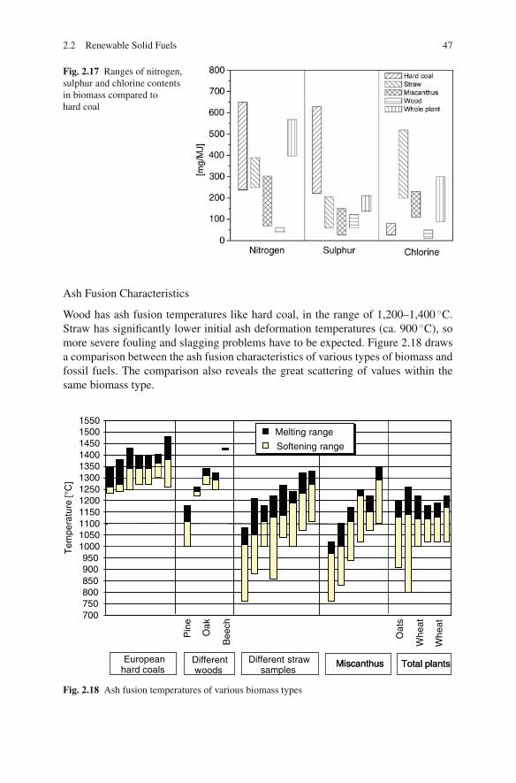
2.2 Renewable Solid Fuels 47
Fig. 2.17 Ranges of nitrogen,sulphur and chlorine contentsin biomass compared tohard coal
Ash Fusion Characteristics
Wood has ash fusion temperatures like hard coal, in the range of 1,200–1,400 ◦C.Straw has significantly lower initial ash deformation temperatures (ca. 900 ◦C), somore severe fouling and slagging problems have to be expected. Figure 2.18 drawsa comparison between the ash fusion characteristics of various types of biomass andfossil fuels. The comparison also reveals the great scattering of values within thesame biomass type.
700750800850900950
100010501100115012001250130013501400145015001550
Pin
e
Oak
Bee
ch
Oat
s
Whe
at
Whe
at
Tem
pera
ture
[°C
]
Melting range
Softening range
Melting range
Softening range
Europeanhard coals
Differentwoods
Different strawsamples
Total plantsMiscanthusEuropeanhard coals
Total plantsMiscanthus
Fig. 2.18 Ash fusion temperatures of various biomass types

48 2 Solid Fuels
Table 2.11 Ash composition (%) of a wood (spruce) and a straw compared with one hard and onebrown coal type
Straw Spruce Hard coal Brown coal
SiO2 65.43 29.61 43.46 11.07Al2O3 0.59 2.59 27.83 8.05Fe2O3 1.17 6.73 9.93 5.03CaO 9.47 37.06 5.21 31.19MgO 1.76 5.38 2.75 4.02K2O 18.07 9.52 3.54 0.10Na2O 0.20 1.97 1.18 0.10SO3 0.98 3.21 4.42 40.24TiO2 0.10 0.31 1.08 0.20ZnO 0.00 0.21 0.10 0.00P2O5 2.25 3.42 0.49 0.00
The low fusion temperatures of herbaceous biomass can be put down to the com-position of the inorganic ash components. Comparing the components, it can be seenthat Si, Al and Fe dominate in the ash of hard coal, while Si, K and Ca dominatein biomass ash. For ash of herbaceous biomass in particular, the melting point islowered by its high potassium content, which, with respect to the calorific value,is about 4–20 times as much as the content in hard coal. Table 2.11 shows the ashcompositions for a wood type (spruce) and a straw type compared to one hard andone brown coal.
Densities of Biomass Types
The density of a fuel type has an influence on the transport method and the associ-ated costs, the necessary storage space and the required fuel preparation and feeding.For biomass, this density is significantly lower than for fossil fuels and depends notonly on the fuel type (straw, wood, cereals, C4 grass plants), but also on what formthe fuel is in (i.e. bales, chaff, chips, pellets, powder, shavings).
Table 2.12 shows the density of various types of biomass, including variationsfor different forms of particular biomasses.
Table 2.12 Densities (at a moisture content of 15%) of various biomasses (kg/m3) (Kicherer 1996;Hartmann and Strehler 1995)
Biomass Density Bulk density
Herbaceousbiomass:
Large-size cubic bales Round bales Chaff Pellets
Straw 150 120 70 520Miscanthus 130 120Whole cereal plants 220 190 130 560
Grain Grain 700
Wood Cordwood Chips Pellets300–500 200–300 650

2.2 Renewable Solid Fuels 49
Table 2.13 Energy densities of various biomasses
FuelDensityρ [kg/m3]
Lower heating value (LHV)[MJ/kg]
Energy density[GJ/m3]
Straw, large-sizecubic bales
150 14.4 2.2
Straw, chaff 70 14.4 1.0Straw, pellets 520 14.4 7.5Whole plant,
large-sizecubic bales
220 14.4 3.2
Miscanthus,large-sizecubic bales
130 14.4 1.9
Wood chips 250 15.3 3.8Hard coal 870 28 24.4Brown coal 740 10 7.4
The form of preparation that has become generally accepted for ligneous biomassis that of woodchips; for herbaceous biomass, according to experience in Denmark,big bale systems seem to be most suitable for straw. Further compaction in the fieldor in the forest is not beneficial for transport, but means additional costs and energyexpenditures.
Due to the low densities of biomasses and their low calorific value, the resultingenergy densities lie about one order of magnitude below the density of hard coal andsignificantly below the density of brown coal (see Table 2.13).
2.2.3.2 Waste
The fuel properties of residual wastes differ a lot from region to region dependingon the relative fractions of the material groups (such as plastics, paper, cardboard,wood and organics) in the waste. Table 2.14 shows the distribution of the materialgroups for one type of residual waste in Germany. Based on the moisture contentsand the calorific values of each group, it is possible to determine the average valuesof a residual waste as a whole. In the given case the result is a mean moisture contentof 33% by weight and a mean calorific value of about 8.5 MJ/kg (Hoffmann et al.2008). The upper and lower limits of the fuel properties of residual waste are givenin Table 2.15 (Reimann and Hammerli 1995).
In the past few decades, the lower heating values (LHVs) of municipal wasteshave risen substantially in industrial countries. This is partly due to an increasedconsumption of paper and plastic materials. The widespread introduction of theseparate collection of organic waste, with its relatively low heating value, has alsocontributed. Whereas in the 1980s, the average LHV was in the range of around6 MJ/kg, the value increased in Germany to 8.7 MJ/kg in 1992. Today, for the designof a municipal waste incinerator, a design heating value of 9.5–10 MJ/kg is chosen(Bilitewski et al. 2000). Figure 2.19 shows the variations of the lower heating valuesfor different countries.

50 2 Solid Fuels
Table 2.14 Composition of residual MSW (example) (Hoffmann 2008)
Fraction
Fractionof waste[wt%]
Moisture[wt%]
LHV[kJ/kg]
Organics 35.0 65.0 7,000Paper, cardboard 8.0 25.0 11,000Wood 3.0 31.0 15,000Fine fraction
(< 10 mm)19.0 23.0 3,500
Combinedmaterials
6.0 12.0 12,000
Other 5.0 5.0 6,000Textiles 4.0 28.0 14,000Plastics 10.5 6.0 22,500Fe metal 2.0 0 0NF metal 0.5 0 0Glass 3.0 0 0Minerals 3.0 0 0Pollutants 1.0 0 5,000Average 33.0 8,438
Table 2.15 Variations of fuel characteristics and the composition of residual MSW in Germany(Effenberger 2000)
Ultimate analysis (%)Fusion behaviour(fly ash) (◦C)
Heavy metals (g/kgraw)
H = 4–5S = 0.2–0.7O = 17–30N = 0.3–0.45Cl = 0.5–1.5
⎫⎪⎪⎪⎬
⎪⎪⎪⎭
water free
Deformation temp. 1,100 Pb = 0.6–2Fluid temp. 1,260 Cu = 0.12–0.78
Fe = 10–100Zn = 0.44–2.3Sn = 0.05–0.32Cr = 0.02–0.88
Ash ∼= 25 Bulk density in kg/m3 Cd = 0.003–0.012Moisture ∼= 30 Ba = 0.084–1.225Combustable = 45 Bulk 90–120
Collection vehicle 350–550LHV=8,300 –10,500 kJ/kg Receiving bunker 200–300
2.2.3.3 Refuse-Derived Fuel (RDF)
Table 2.16 shows the composition of various refuse-derived fuels produced fromdifferent input materials (and different mechanical – biological treatment methodsfor MSW). As described in Sect. 2.2.1.3, the preparation methods serve to producea homogeneous, highly calorific fuel with reduced levels of pollutants which can beburned in an RDF power plant or co-fired in a coal-fired power plant. It is notice-able that the calorific values are significantly higher (up to 25 MJ/kg) than the basicwaste. Utilisation problems can be posed in particular by the contents of chlorineand heavy metals.

2.2 Renewable Solid Fuels 51
Fig. 2.19 Lower heatingvalue of waste in differentcountries (Source: Martin)
2.2.3.4 Sewage Sludge
Moisture and Ash Content, Calorific Value
In municipal sewage treatment plants, raw sludge or, more commonly, digestedsludge is produced. For raw sludge, a moisture content of about 96% is typical.The dry solid matter, on average, consists of 65% organic and combustible com-ponents and 35% ash. Digested sludges have a higher ash content because part ofthe organic matter of the sewage sludge is converted either into CH4 (in anaerobicconditions) or CO2 (in aerobic conditions) in the digestion process. In addition, themoisture content may be diminished during the longer period of storage. The drysolid matter of digested sewage sludge is composed half of organic matter and halfof ash (Gerhardt 1998; Spliethoff et al. 1996).
The calorific value of sewage sludge is determined by the moisture and theash contents. Figure 2.20 explains these correlations. For purely organic matter, acalorific value of about 21 MJ/kg can be taken as a basis. The variation in calorificvalue of sewage sludge from different sewage treatment plants, and from the sameplant at different times, ranges around ±1 MJ/kg (Gerhardt et al. 1997). For sewagesludge with an ash content of 35%, the calorific value of the dry solids is about14 MJ/kg, while digested sewage sludge with 50% ash has a dry solids calorificvalue of about 10.5 MJ/kg.
Due to the high moisture content, sewage sludge produced in a sewage treat-ment plant has no or a negative calorific value because heat has to be used tovaporise the water. The common and energy-saving method is mechanical dewa-tering at the sewage treatment plant. The resulting dewatering degree depends onthe sewage sludge, the dewatering method and the addition of conditioning agents.Incompletely digested sewage sludge cannot be stored for a long time after dewa-tering because of the development of odours and build-up of flammable gases.As Figure 2.20 shows, the calorific value of an undigested sewage sludge (type C)with a dry solid matter content of around 20% lies between 0.5 and 1.2 MJ/kg.
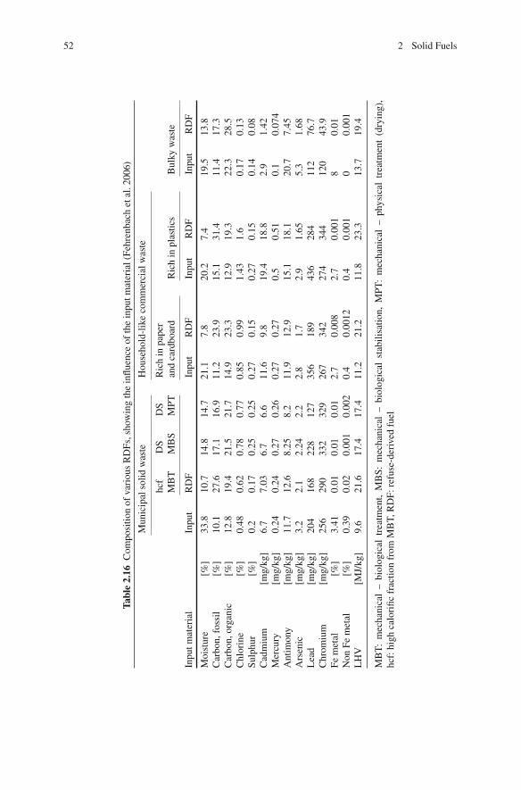
52 2 Solid Fuels
Tabl
e2.
16C
ompo
sitio
nof
vari
ous
RD
Fs,s
how
ing
the
influ
ence
ofth
ein
putm
ater
ial(
Fehr
enba
chet
al.2
006)
Mun
icip
also
lidw
aste
Hou
seho
ld-l
ike
com
mer
cial
was
te
hcf
MB
TD
SM
BS
DS
MPT
Ric
hin
pape
ran
dca
rdbo
ard
Ric
hin
plas
tics
Bul
kyw
aste
Inpu
tmat
eria
lIn
put
RD
FIn
put
RD
FIn
put
RD
FIn
put
RD
F
Moi
stur
e[%
]33
.810
.714
.814
.721
.17.
820
.27.
419
.513
.8C
arbo
n,fo
ssil
[%]
10.1
27.6
17.1
16.9
11.2
23.9
15.1
31.4
11.4
17.3
Car
bon,
orga
nic
[%]
12.8
19.4
21.5
21.7
14.9
23.3
12.9
19.3
22.3
28.5
Chl
orin
e[%
]0.
480.
620.
780.
770.
850.
991.
431.
60.
170.
13Su
lphu
r[%
]0.
20.
170.
250.
250.
270.
150.
270.
150.
140.
08C
adm
ium
[mg/
kg]
6.7
7.03
6.7
6.6
11.6
9.8
19.4
18.8
2.9
1.42
Mer
cury
[mg/
kg]
0.24
0.24
0.27
0.26
0.27
0.27
0.5
0.51
0.1
0.07
4A
ntim
ony
[mg/
kg]
11.7
12.6
8.25
8.2
11.9
12.9
15.1
18.1
20.7
7.45
Ars
enic
[mg/
kg]
3.2
2.1
2.24
2.2
2.8
1.7
2.9
1.65
5.3
1.68
Lea
d[m
g/kg
]20
416
822
812
735
618
943
628
411
276
.7C
hrom
ium
[mg/
kg]
256
290
332
329
267
342
274
344
120
43.9
Fem
etal
[%]
3.41
0.01
0.01
0.01
2.7
0.00
82.
70.
001
80.
01N
onFe
met
al[%
]0.
390.
020.
001
0.00
20.
40.
0012
0.4
0.00
10
0.00
1L
HV
[MJ/
kg]
9.6
21.6
17.4
17.4
11.2
21.2
11.8
23.3
13.7
19.4
MB
T:
mec
hani
cal
–bi
olog
ical
trea
tmen
t,M
BS:
mec
hani
cal
–bi
olog
ical
stab
ilisa
tion,
MPT
:m
echa
nica
l–
phys
ical
trea
tmen
t(d
ryin
g),
hcf:
high
calo
rific
frac
tion
from
MB
T,R
DF:
refu
se-d
eriv
edfu
el

2.2 Renewable Solid Fuels 53
Fig. 2.20 Calorific values ofmunicipal sewage sludge(Gerhardt 1998)
Digested sludge is more effectively dewatered by mechanical means than byother means. Figure 2.20 shows the range of values of a badly dewatered (D) and awell-dewatered type of sewage sludge (B). Digested sludge, at a moisture content of60%, has a net calorific value of 2–3 MJ/kg. By thermal drying, the calorific valuecan be markedly increased, but this requires energy to vaporise the water. It canbe noticed that the calorific value of the thermally dried digested sludge (range A)generally lies below 11 MJ/kg.
Composition
Table 2.17 shows the analytical data for the dry state of different sewage sludgetypes in comparison to hard and brown coal. Sewage sludge has a higher ash contentbecause of the input of sand and other inert material. The volatile matter correspondsmainly to the organic substances in the sludge. A conspicuous result of the ultimateanalysis is the low carbon content and the high oxygen content. The nitrogen contentof sewage sludge is significantly higher than that of coal.
The mineral fraction of sewage sludge consists of about 40% acidic oxides, suchas silicon oxide (SiO2) and aluminium oxide (Al2O3), and 40% basic oxides suchas CaO, Fe2O3, K2O, MgO and Na2O. The remaining 20% is composed of phos-phates, sulphates and carbonates. In contrast, the fraction of the acidic oxides in hardcoal almost reaches double this value (ca. 80%) whereas the fraction of the basic

54 2 Solid Fuels
Table 2.17 Fuel composition of sewage sludge (Gerhardt et al. 1997; Gerhardt 1998)
Dewatered sewage sludge
Typical value Range Hard coal Brown coal
Moisture content [%] 55 (dewatered)5 (thermally dried)
7 55
Lower heating value(LHV) raw [MJ/kg]
3.6 (dewatered)10.2 (thermally dried
27.9 8.7
Lower heating value(LHV) dry [MJ/kg]
10.9 8.8–14.4 30.2 22.2
Ash % dry 46.9 39–53 8.3Volatile matter % dry 51 28–55 34.7 50Fixed C dry 2.5 1–24 57 38C 25.5 20–40 72.5 63H 5 2–5 5 4N 3.3 2–5 1.3 0.5S 1.1 0.6–7 0.9 0.5Cl 0.1 0.02–0.6 0.2 0.1
oxides is around 20%. The nature of the ash composition of sewage sludge means alower ash softening point in comparison to hard coal ash. The initial ash deformationtemperature lies, depending on the sewage sludge type, around 1,100–1,200◦C.
References
Adrian, F., Quittek, C. and Wittchow, E. (1986). Fossil beheizte Dampfkraftwerke. HandbuchreiheEnergie, Band 6, Herausgeber T. Bohn. Technischer Verlag Resch, Verlag TUV Rheinland.
Becker, B., Knichel, H., Thomas, J. and Hauschild, W. (2007). Nachhaltige Abfallwirtschaft inDeutschland, Ausgabe 2007. Statistisches Bundesamt.
BGR (2008). Reserven, Ressourcen und Verfugbarkeit von Energierohstoffen 2006, Jahresbericht2006, Bundesanstalt fur Geowissenschaften und Rohstoffe.
Bilitewski, B., Hardtle, G. W. and Marek, K. A. (2000). Abfallwirtschaft: Handbuch fur Praxis undLehre. Berlin [u.a.], Springer.
BMU (2007a). Aufkommen, Beseitigung und Verwertung von Abfallen im Jahr 2005.BMU (2007b). Bericht zur Siedlungsabfallentsorgung 2006, Stand 1.9.2006, from www.bmu.de.BMWi (2008). Zahlen und Fakten: Energiedaten, BMWi.Born, P. (1992). CO2-neutrale Energietrager aus Biomasse? BWK 44(6): 271–274.Borsch, P. (1992). Was wird aus unserem Klima?: Fakten, Analysen & Perspektiven. Munchen
[u.a.], Bonn Aktuell.BP (2008). Statistical review of world energy 2008, from www.bp.com.Chiche, P. (1970). Grundlagenforschung uber Chemie und Physik von Kohle und Koks III.
Forschungshefte Kohle. Luxemburg, Europaische Gemeinschaft fur Kohle und Stahl.Chiche, P. (1973). Grundlagenforschung uber Chemie und Physik von Kohle und Koks IV.
Forschungshefte Kohle. Luxemburg, Europaische Gemeinschaft fur Kohle und Stahl.Clausen, J. C. and Schmidt, E.R. (1996). Specifications for solid biofuels in Denmark. Tagung
“Biomasse als Festbrennstoff–Anforderungen, Einflussmoglichkeiten, Normung” Schriften-reihe “Nachwachsende Rohstoffe”, Band 6, Landwirtschaftsverlag, Munster.
CMA (1995). Nachwachsende Energie aus Land- und Forstwirtschaft. Broschure.Drbal, L. F. (1996). Power plant engineering. New York [u.a.], Chapman & Hall.Effenberger, H. (2000). Dampferzeugung. Berlin, Heidelberg, Springer.

References 55
EU (2008). EU Commission: Directive 2008/98/EC of the European Parliament and of the Councilof 19 November 2008 on waste and repealing certain directives (Waste Framework Directive).
Eurostat (2007). Measuring progress towards a more sustainable Europe, 2007 monitoring reportof the EU sustainable development strategy. E. Communities.
Fehrenbach, H., Giegrich, J. and Mohler, S. (2006). Behandlungsalternativen fur klimarelevanteStoffstrome. Heidelberg, ifeu.
Fruhwald, A. (1990). Holzbe- und -verarbeitung. VDI-Berichte Nr. 794, 1990, pp. 9–21Gerhardt, T. (1998). Thermische Behandlung von kommunalen Klarschlammen in Kohlen-
staubfeuerungen. Essen, VGB-Kraftwerkstechnik, Verl. Techn.-Wiss. Schriften.Gerhardt, T., Spliethoff, H. and Hein, K. R. G. (1996). Thermische Nutzung von Klarschlammen
in Kraftwerksfeuerungen. Untersuchungen an einer Staubfeuerung im Pilotmaßstab.Entsorgungspraxis (3).
Gerhardt, T., Spliethoff, H. and Hein, K.R.G. (1997). Bedarf von thermischen Behandlungsver-fahren fur kommunale Klarschlamme. Entsorgungspraxis (3): 40–47.
Gumz, W. (1962). Kurzes Handbuch der Brennstoff- und Feuerungstechnik. Berlin, Gottingen,Heidelberg, Springer.
Hartmann, H. and Strehler, A. (1995). Die Stellung der Biomasse im Vergleich zu anderen erneuer-baren Energietragern aus okologischer, okonomischer und technischer Sicht, SchriftenreiheNachwachsende Rohstoffe, Band 3.
Hoffmann, G., Wunsch, C. and Biletewski, B. (2008). Ersatzbrennstoffe aus Siedlungsabfall –Eine Energiebilanz. 4. Fachtagung “Verfahren und Werkstoffe fur die Energietechnik”:Biomasse & Abfall – Regionale Brennstoffe richtig nutzen, Sulzbach-Rosenberg, Dorner.
IEA (2006). World energy outlook 2006. Paris, IEA.IEA (2007). World energy outlook 2007. Paris, IEA.JBDT (1976). Jahrbuch der Dampferzeugertechnik, 3. Ausgabe, Vulkan, Essen.JBDT (1985). Jahrbuch der Dampferzeugertechnik, 5. Ausgabe, Vulkan, Essen.Kaltschmitt, M. (1993). Energietragerproduktion auf pflanzlicher Basis. Landtechnik 48(8/9):
400–406.Kaltschmitt, M. (2001). Energie aus Biomasse: Grundlagen, Techniken und Verfahren. Berlin
[u.a.], Springer.Kaltschmitt, M., Hartmann, H. and Hofbauer, H. (2009). Energie aus Biomasse: Grundlagen,
Techniken und Verfahren. Dordrecht, Heidelberg, London, New York, Springer.Kaltschmitt, M., Streicher, W. and Wiese, A. (2006). Erneuerbare Energien, Systemtechnik,
Wirtschaftlichkeit, Umweltaspekte. Berlin, Heidelberg, Springer.Kicherer, A. (1996). Biomasseverbrennung in Staubfeuerungen – technische Moglichkeiten und
Schadstoffemissionen. Dusseldorf, VDI.Kleemann, M. and Meliß, M. (1993). Regenerative Energiequellen. Berlin [u.a.], Springer.Lewandowski, I. (1996). Einflußmoglichkeiten der Pflanzenproduktion auf die Brennstoffeigen-
schaften am Beispiel von Grasern. Tagung Biomasse als Festbrennstoff – Anforderungen,Einflussmoglichkeiten, Normung, Schriftenreihe Nachwachsende Rohstoffe, Band 6,Landwirtschaftsverlag, Munster.
Obernberger, I. (1997). Nutzung fester Biomasse in Verbrennungsanlagen unter besondererBerucksichtigung des Verhaltens aschebildender Elemente. Graz, dbv.
Reimann, D. O. and Hammerli, H. (1995). Verbrennungstechnik fur Abfalle in Theorie und Praxis.Bamberg, Reimann.
Ruhrkohle (1987). Ruhrkohlenhandbuch. Essen, Gluckauf.Schmelz, K.-G. (2006). Klarschlammmengen und Entsorgungskosten im Vergleich zum
europaischen Ausland. Perspektiven der Klarschlammverwertung, Bonn.Schmidt, A. (1992). Bioenergie – Ein Vergleich der biologischen mit den technischen
Moglichkeiten der Nutzung von Solarenergie. BWK 44(5): 227–231.Schneider, S., Deimling, S. and Kaltschmitt, M. (2007). Leitfaden Bioenergie : Planung, Betrieb
und Wirtschaftlichkeit von Bioenergieanlagen. Biogene Brennstoffe als nachwachsendeEnergietrager. Gulzow b. Gustrow, Fachagentur Nachwachsende Rohstoffe.

56 2 Solid Fuels
Skorupska, N. M. (1993). Coal specifications – impact on power station performance. London,IEA Coal Research.
Spliethoff, H., Siegle, V. and Hein, K.R.G. (1996). Erforderliche Eigenschaften holz- undhalmgutartiger Biobrennstoffe bei der Zufeuerung in existierenden Kohlekraftwerken.Tagung: Biomasse als Festbrennstoff - Anforderungen, Einflussmoglichkeiten, Normung.Landwirtschaftsverlag, Munster, Schriftenreihe “Nachwachsende Rohstoffe”, Band 6.
Stultz, S. C. and Kitto, J. B. (1992). Steam, its generation and use. Barberton, OH, The Babcock& Wilcox Company.
Thome-Kozmiensky, K. J. (1994). Thermische Abfallbehandlung. Berlin, EF fur Energie- undUmwelttechnik.
UBA. (2008). Retrieved 17.8.2008, from http://www.umweltbundesamt.de/abfallwirtschaft/entsorgung/index.htm.
Van Loo, S. and Koppejan, J. (2008). The handbook of biomass combustion and co-firing. London,Earthscan.
Wegener, G. and Fruhwald, A. (1994). Das CO2-Minderungspotential durch Holznutzung, Holzals Energietrager. Energiewirtschaftliche Tagesfragen 44(7): 421–425.
Wieck-Hansen, K. (1996). Parameters influencing Straw Quality. Tagung “Biomasse alsFestbrennstoff–Anforderungen, Einflussmoglichkeiten, Normung”. Schriftenreihe “Nachwach-sende Rohstoffe”, Band 6, Landwirtschaftsverlag, Munster.
Zelkowski, J. (2004). Kohlecharakterisierung und Kohleverbrennung. Essen, VGB PowerTech.
Chapter 3Thermodynamics Fundamentals
3.1 Cycles
3.1.1 Carnot Cycle
Named after the French scientist Nicolas Carnot, the ideal Carnot cycle converts amaximum fraction of heat input into work. In this process, work is delivered with-out heat exchange and without losses, and heat is added and taken out without anychange in temperature. As a reference process, the Carnot cycle illustrates funda-mental knowledge about the thermodynamics of energy conversion (Hahne 2004;Meyer and Schiffner 1989; Strauß 2006). The Carnot cycle combines two processsteps with isentropic changes of state and two process steps with isothermal changesof state to form a closed reversible cycle. These steps are shown in Fig. 3.1:
1–2: isentropic compression with work input w12,2–3: isothermal expansion at a constant upper process temperature Tu with heat
input q23 = qin,3–4: isentropic expansion with work output w34,4–1: isothermal compression at a constant lower process temperature Tl with
heat output q41 = qout.
The energy added to the cycle in the form of heat is only partially converted intouseful work; the other portion is released to the environment. The lines of state ofthe four process steps of the Carnot cycle form a rectangle in the T−s diagram. Thearea beneath the isotherm Tu gives the heat input:
qin = Tu (s3 − s2) (3.1)
and the area beneath the isotherm Tl gives the heat output:
|qout| = Tl (s4 − s1) = Tl (s3 − s2) (3.2)
H. Spliethoff, Power Generation from Solid Fuels, Power Systems,DOI 10.1007/978-3-642-02856-4 3, C© Springer-Verlag Berlin Heidelberg 2010
57

58 3 Thermodynamics Fundamentals
Fig. 3.1 Carnot cycle T − s and p − V diagrams
The useful work of the Carnot cycle is described as follows:
|w| = qin − |qout| (3.3)
which, in the T − s diagram, corresponds to the rectangular area enclosed by thelines of state.
The thermal efficiency (the ratio of useful work to input heat) is calculated forthe Carnot cycle as follows:
ηth = |w|qin
= qin − |qout|qin
= 1 − |qout|qin
(3.4)
Consequently, for the Carnot cycle, this becomes
ηth = Tu (s3 − s2) − Tl (s3 − s2)
Tu (s3 − s2)= Tu − Tl
Tu= 1 − Tl
Tu(3.5)
hence the thermal efficiency of the reversible Carnot cycle, also called the Carnotfactor, only depends on the constant temperatures of heat input and output. TheCarnot factor is greater the higher the temperature Tu of the heat input and the lowerthe temperature Tl of the heat output.
The Carnot factor is always less than 1 because the heat release temperaturealways lies above the ambient temperature of about 280–300 K. There is no cyclewhich has a better efficiency for a given temperature gradient Tmax−Tmin. To achievehigh efficiencies, one tries to bring real processes closer to the Carnot cycle.
3.1.2 Joule–Thomson Process
The Joule–Thomson process is the idealised reference process for gas turbines. Asimple, open gas turbine process, shown in Fig. 3.2, consists of a compressor, a com-bustion chamber and a gas turbine. The air sucked in from the environment at p1 andT1 becomes compressed by the compressor to pressure p2. The compressed air in thecombustion chamber oxidises the fuel, turning it into a hot flue gas with temperature

3.1 Cycles 59
Fig. 3.2 Schematic diagramof an open gas turbineprocess
T3, which afterwards does work in the turbine, expands and is cooled down to thegas turbine exit temperature. The waste gas is released to the environment.
For the ideal Joule–Thomson process, the assumption is that both the compres-sion and the expansion processes are isentropic, i.e. reversible. The Joule–Thomsonprocess therefore consists of two isentropes and two isobars. If the discharge of thecooled-down but still hot gases to the environment is conceived as an isobaric heatdissipation, the course of the process can be represented as a cycle. The correspond-ing p − V and T − s diagrams are shown in Fig. 3.3.
For the heat input and output quantities, assuming an ideal gas1 with a constantcP , the following holds true:
qin = h3 − h2 = cp (T3 − T2) (3.6)
and
|qout| = h4 − h1 = cp (T4 − T1) (3.7)
Fig. 3.3 p − V and T − s diagrams for the ideal Joule – Thomson process
1 For real gases cp is a function of the temperature. In this case the medium specific heat capacitycp between the corresponding temperatures has to be used for the calculations.

60 3 Thermodynamics Fundamentals
It holds true that for the work w12 to be done by the compressor:
w12 = h2 − h1 (3.8)
and that for the work w34 produced by the turbine:
w34 = h4 − h3 (3.9)
and that for the gain in work w:
|w| = |w34| − w12 (3.10)
Hence, the efficiency of the Joule–Thomson process is
ηth = |w|qin
= 1 − |qout|qin
= 1 − cp (T4 − T1)
cp (T3 − T2)= 1 − T4 − T1
T3 − T2(3.11)
From the equations of state for the isentropes of the process
T2
T1=
(p2
p1
) κ−1κ
(3.12)
and
T3
T4=
(p3
p4
) κ−1κ
(3.13)
the relation
T2
T1= T3
T4(3.14)
is given by p2 = p3 and p4 = p1.Thus, by putting Eq. (3.14) into Eq. (3.11) and by transforming it, one gets the
following expression for the thermal efficiency of the ideal Joule–Thomson process:
ηth = 1 − T1
T2= 1 −
(p1
p2
) κ−1κ
(3.15)
Thus the efficiency of the ideal Joule–Thomson process is only dependent on thepressure ratio. An increase of the pressure ratio, though, also results in an increaseof the temperature T2. Given that the heat in the combustion chamber:
qin = |w|η
(3.16)
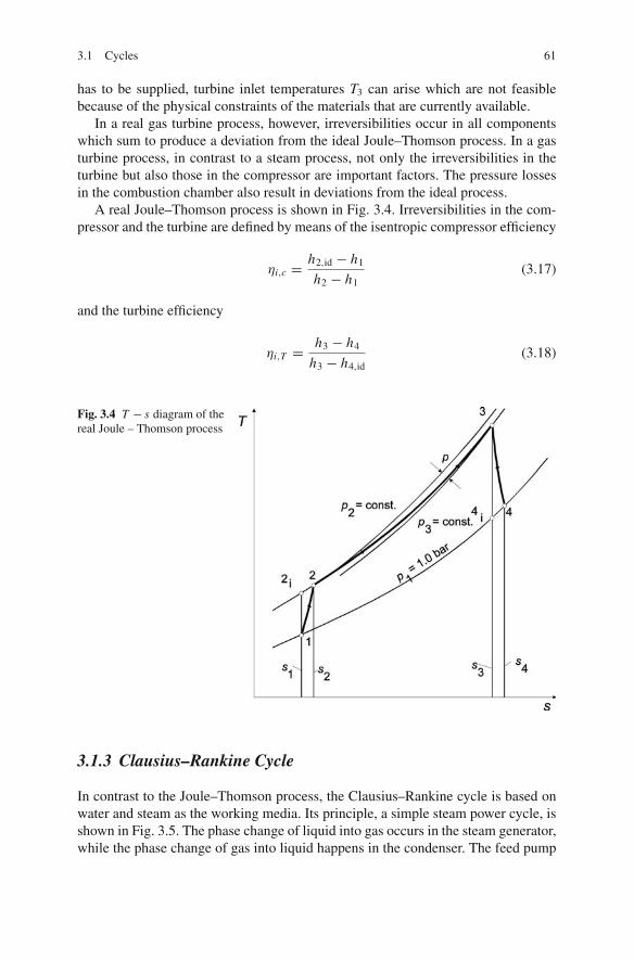
3.1 Cycles 61
has to be supplied, turbine inlet temperatures T3 can arise which are not feasiblebecause of the physical constraints of the materials that are currently available.
In a real gas turbine process, however, irreversibilities occur in all componentswhich sum to produce a deviation from the ideal Joule–Thomson process. In a gasturbine process, in contrast to a steam process, not only the irreversibilities in theturbine but also those in the compressor are important factors. The pressure lossesin the combustion chamber also result in deviations from the ideal process.
A real Joule–Thomson process is shown in Fig. 3.4. Irreversibilities in the com-pressor and the turbine are defined by means of the isentropic compressor efficiency
ηi,c = h2,id − h1
h2 − h1(3.17)
and the turbine efficiency
ηi,T = h3 − h4
h3 − h4,id(3.18)
Fig. 3.4 T − s diagram of thereal Joule – Thomson process
3.1.3 Clausius–Rankine Cycle
In contrast to the Joule–Thomson process, the Clausius–Rankine cycle is based onwater and steam as the working media. Its principle, a simple steam power cycle, isshown in Fig. 3.5. The phase change of liquid into gas occurs in the steam generator,while the phase change of gas into liquid happens in the condenser. The feed pump

62 3 Thermodynamics Fundamentals
Fig. 3.5 Schematic diagramof a simple steam-electricpower plant
transports the water into the steam generator, where it gets preheated, evaporatedand superheated. In the turbine, the steam is expanded at constant entropy, impartingmechanical work in the process. In the condenser, heat is extracted and the wastesteam condensed. The condensate in turn is fed to the feed pump.
Figure 3.6 shows the reversible Clausius–Rankine cycle in h − s and T − s dia-grams. This cycle serves as a thermodynamic reference process for steam generationprocesses. The steps are as follows:
1–2: isentropic compression in the feed pump by work input w12
2–3: isobaric heat supply q23 = qin in the steam generator (preheating, evapo-ration, superheating)
3–4: isentropic expansion in the turbine with work output w34
4–1: isobaric heat dissipation q41 = qout in the condenser (Hahne 2004).
In the turbine, the steam imparts mechanical work, whereas for raising the pres-sure of the feed water, work has to be supplied. Hence the gain in work in the cycleprocess is
|w| = |w34| − w12 = (h3 − h4) − (h2 − h1) (3.19)
3
s s
criticalpoint
4
1
2
h3
41
2
T
critical point
Fig. 3.6 Ideal Clausius–Rankine cycle T − s and h − s diagrams

3.1 Cycles 63
The thermal efficiency of the Clausius–Rankine cycle is then
ηth = |w|qin
= h3 − h4 − (h2 − h1)
h3 − h2(3.20)
For comparison with the Carnot cycle, the thermodynamic mean temperature ofthe heat supply
Tm,in = qin
s3 − s2= h3 − h2
s3 − s2(3.21)
and that of the heat extraction
Tm,out = |qout|s4 − s1
= h4 − h1
s4 − s1(3.22)
are defined so that, for the reversible Rankine cycle, the Carnot factor can also becalculated:
ηth = Tm,in − Tm,out
Tm,in= 1 − Tout
Tin(3.23)
The thermal efficiency of the Clausius–Rankine cycle thus becomes greater thehigher the mean thermodynamic temperature of the heat supply and the lower themean thermodynamic temperature of the heat extraction. Another consequence isthat, at a given maximal heat supply temperature and a minimal heat dissipationtemperature, the result of the idealised isothermal heat exchange processes of theCarnot cycle is in each case the highest efficiency. In the Clausius–Rankine cycle,feed water preheating, evaporation and superheating inevitably result in a loweraverage temperature of the heat input, so the efficiency of the Rankine cycle islower than the Carnot factor. Therefore, measures to raise the thermal efficiencyof the steam power cycle can be assessed with reasonable adequacy by means of theaverage thermodynamic heat input temperature.
Like in every technical plant, there are losses in steam-electric power plantprocesses, making a reversible course of the Clausius–Rankine cycle impossible.Irreversibilities develop in the form of pressure losses in the cycle–by friction, tur-bulence and mixture losses in the turbo-machinery and in other components–andalso in the form of heat transfer losses in processes with finite temperature differ-ences (all heat exchangers). The irreversibilities result in an increase in entropy. Thisentropy increase in the turbine is included in the isentropic efficiency:
ηi,T = h3 − h4
h3 − h4,id(3.24)

64 3 Thermodynamics Fundamentals
3.2 Steam Power Cycle: Energy and Exergy Considerations
The energy efficiency, η, is the ratio of the power delivered or produced by a processto the power which is supplied to it (Adrian et al. 1986). In condensation powerplants, fuel power is used exclusively for electrical power production. The electricalcapacity of a power plant is described by both the gross installed capacity and alsothe net output capacity. The gross installed capacity Pgr is the capacity measuredat the generator, whereas the net output capacity Pne is the power output deliveredto the network. The difference between the gross and net output capacities is givenby the so-called electrical auxiliary power Paux, el which is needed to supply allelectrical auxiliary devices, e.g. for coal milling, for driving the feed pump (onlywhen there is an electrical feed pump), the combustion air and flue gas fans and tocover the loss of the station service transformer:
Pne = Pgr − Paux,el (3.25)
The total or net efficiency of a power plant producing only electrical power isthe quotient of the electrical power output and the supplied fuel power, the latterof which is the product of the fuel flow m F and the lower heating value, LHV, ofthe fuel:
ηne = Pne
mF · LHV(3.26)
The efficiency of a power plant is made up of various single efficiencies which,multiplied with each other, add up to the total efficiency:
ηne = ηB · ηth · ηm · ηGen · ηaux · ηP (3.27)
where ηB is the steam generator efficiency and ηth is the thermal efficiency. Effi-ciency ηm reflects the mechanical losses of the turbine; the generator efficiency,ηGen, covers electrical and mechanical losses of the generator.
The auxiliary power efficiency ηaux takes into account the electrical and themechanical power demand (if not included in ηth already), while efficiency ηR rep-resents the heat losses of the live steam and reheater pipes which connect the steamgenerator and the turbine.
For the boiler or steam generator the efficiency becomes:
ηB =∑
mS, j · Δhj
mF · LHV(3.28)
where ms, j are the individual mass flows of the working medium (water/steam)supplied with heat from combustion in the steam generator. Δhj are the increases ofenthalpy attained in each mass flow. For the simple steam cycle shown in Fig. 3.5,this becomes
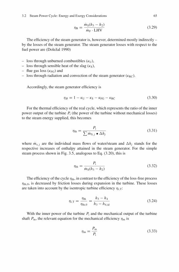
3.2 Steam Power Cycle: Energy and Exergy Considerations 65
ηB = mS(h3 − h2)
mF · LHV(3.29)
The efficiency of the steam generator is, however, determined mostly indirectly –by the losses of the steam generator. The steam generator losses with respect to thefuel power are (Dolezal 1990)
– loss through unburned combustibles (κU),– loss through sensible heat of the slag (κS),– flue gas loss (κFG) and– loss through radiation and convection of the steam generator (κRC).
Accordingly, the steam generator efficiency is
ηB = 1 − κU − κS − κFG − κRC (3.30)
For the thermal efficiency of the real cycle, which represents the ratio of the innerpower output of the turbine Pi (the power of the turbine without mechanical losses)to the steam energy supplied, this becomes
ηth = Pi∑
mS, j • Δhj(3.31)
where ms, j are the individual mass flows of water/steam and Δhj stands for therespective increases of enthalpy attained in the steam generator. For the simplesteam process shown in Fig. 3.5, analogous to Eq. (3.20), this is
ηth = Pi
mS(h3 − h2)(3.32)
The efficiency of the cycle ηth, in contrast to the efficiency of the loss-free processηth,0, is decreased by friction losses during expansion in the turbine. These lossesare taken into account by the isentropic turbine efficiency ηi,T:
ηi,T = ηth
ηth,0= h3 − h4
h3 − h4,id(3.24)
With the inner power of the turbine Pi and the mechanical output of the turbineshaft Pm, the relevant equation for the mechanical efficiency ηm is
ηm = Pm
Pi(3.33)

66 3 Thermodynamics Fundamentals
for the generator efficiency
ηGen = PGen
Pm(3.34)
and for the auxiliary power efficiency
ηaux = Pne
PGen(3.35)
If the feed pump is driven electrically, and also if driven by a steam turbine, thedriving power of the feed pump is commonly added to the auxiliary power. In thecase of a turbine-driven feed water pump, the power of the feed pump turbine istaken into account in calculating the thermal efficiency of the real cycle and addedto the power output of the main turbine in Eq. (3.31).
Often, the turbine or turbine generator efficiency ηT is used, which represents theratio of the gross electrical output and, if necessary, the mechanical power output(in the case of feed pumps with a steam turbine drive) to the steam energy input:
ηT = P∗Gen
∑ms, j · Δhj
= ηth · ηm · ηGen (3.36)
with
P∗Gen = PGen + Paux,m (3.37)
If the feed pump is driven by a steam turbine, the power output of the turbine gener-ator P∗
Gen increases, surpassing the gross output PGen by the amount of the mechan-ical output of the turbine drive Paux, m. Where the feed pump is driven electrically,the power output P∗
Gen equals the generator output PGen. The turbine generatorefficiency, in contrast to the thermal efficiency of the cycle, also takes into accountthe losses occurring in the turbine and the generator.
Therefore the auxiliary power efficiency becomes
ηaux = Pne
P∗Gen
= P∗Gen − Paux,el − Paux,m
P∗Gen
(3.38)
Besides an energy efficiency, it is also possible to develop an expression for thetotal and single exergy efficiencies:
ζne = ζB · ζth · ζGen · ζaux · ζm · ζP (3.39)
Given that the fuel energy and exergy differ only very slightly, the total energyand exergy efficiencies are almost equal. Significant differences, however, arise forthe single efficiencies, in particular in the process of energy conversion in the steam

3.2 Steam Power Cycle: Energy and Exergy Considerations 67
generator and in the energy conversion process of the real cycle. The mechanicalefficiency and the generator efficiency have the same values if the friction heat isnot utilised (Herbrik 1993).
3.2.1 Steam Generator Energy and Exergy Efficiencies
Analogous to the energy efficiency ηB of the steam generator, and in accordancewith Eq. (3.29), the exergy efficiency ζB of the boiler can be defined as
ζB = mS(e3 − e2)
mF · eF(3.40)
where mS is the steam mass flow, mF is the fuel mass flow and eF stands for thefuel’s, e2 for the water’s and e3 for the superheated steam’s exergy.
From Eq. (3.29), it follows by transformation that
mS
mF= ηB
LHV
h3 − h2(3.41)
For the input of exergy, the ambient temperature Ta is incorporated:
e3 − e2 = h3 − h2 − Ta(s3 − s2) (3.42)
If Eqs. (3.41) and (3.42) are inserted into Eq. (3.40), then the following expres-sion is derived:
ζB = LHV
eFηB
(
1 − Tas3 − s2
h3 − h2
)
(3.43)
or
ζB = LHV
eFηB
e3 − e2
h3 − h2(3.44)
for the boiler exergy efficiency.The boiler exergy efficiency indicates which part of the supplied fuel exergy eF
is maintained as exergy of the steam. This efficiency, in contrast to ηB, assesses theenergy conversion in the steam generator.
The exergy efficiency thus essentially depends on two factors. The first factor, ηB
LHV/ eF, represents the losses through flue gas and radiation. The second factor canbe calculated from the feed water inlet and exiting live steam state quantities. Thisfactor implicitly includes the considerable exergy losses through the irreversibilitiesof combustion and heat transfer.
The changes of state of the water are shown in Fig. 3.7. The water entering attemperature T2 first gets preheated, vaporised and superheated. The area below
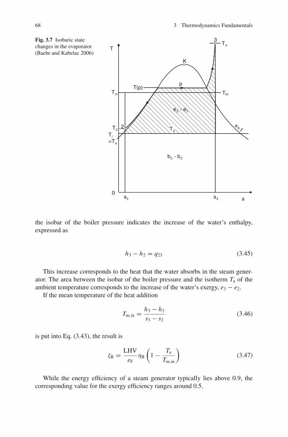
68 3 Thermodynamics Fundamentals
Fig. 3.7 Isobaric statechanges in the evaporator(Baehr and Kabelac 2006)
K
p
3
2
Tl
=Ta
T2
Tm Tm
T3
T(p)
Ta
0s2 s3 s
T
e3 - e2
b3 - b2
x=1
the isobar of the boiler pressure indicates the increase of the water’s enthalpy,expressed as
h3 − h2 = q23 (3.45)
This increase corresponds to the heat that the water absorbs in the steam gener-ator. The area between the isobar of the boiler pressure and the isotherm Ta of theambient temperature corresponds to the increase of the water’s exergy, e3 − e2.
If the mean temperature of the heat addition
Tm,in = h3 − h2
s3 − s2(3.46)
is put into Eq. (3.43), the result is
ζB = LHV
eFηB
(
1 − Ta
Tm,in
)
(3.47)
While the energy efficiency of a steam generator typically lies above 0.9, thecorresponding value for the exergy efficiency ranges around 0.5.

3.2 Steam Power Cycle: Energy and Exergy Considerations 69
This low value is caused by
– exergy losses via flue gas and irradiation – about 6%,– the exergy loss of combustion – about 15% and– the exergy loss of the heat transfer – about 30%.
Losses through the sensible heat of the flue gas and through irradiation aretaken into account in both the energy and exergy efficiency. Losses through theirreversibilities of combustion and heat transfer are only included in the exergyefficiency. Irreversible combustion and heat transfer convert about half of the fuelexergy input into anergy, while exergy cannot be made use of in the following energyconversion steps, having to be discharged as waste heat.
3.2.2 Energy and Exergy Cycle Efficiencies
Analogous to the energy efficiency of the Clausius–Rankine Cycle:
ηth = Pi
mS(h3 − h2)= w
h3 − h2(3.48)
it is possible to define an exergy efficiency:
ζth = Pi
mS(e3 − e2)= w
e3 − e2(3.49)
This efficiency specifies what part of the exergy taken up in the steam generatoris converted into useful work. If the cycle is reversible, the thermal efficiency ζth
becomes 1; divergences from this ideal value represent thermodynamic losses. Tobreak these down, the useful work is calculated as
w = h3 − h4 − (h2 − h1) = e3 − e4 − (e2 − e1) − Ta[(s3 − s4) − (s2 − s1)]= e3 − e2 − (e4 − e1) − eL34 − eL12
(3.50)
So the useful work obtained is the exergy taken up in the steam generator (e3−e2)minus the exergy losses – the exergy delivered in the condenser (e4 − e1) and theexergy losses caused by irreversibilities in the feed pump (eL12) and in the turbine(eL34).
Hence, for the exergy cycle efficiency, the expression becomes
ζth = 1 − e4 − e1
e3 − e2− eL12 + eL34
e3 − e2(3.51)
The losses of exergy are pictured in Fig. 3.8. The exergy loss of the feed pump,eL12, is small in contrast to the exergy loss of the steam turbine, eL34. The exergyloss of the steam turbine depends on the isentropic efficiency of the turbine.

70 3 Thermodynamics Fundamentals
Fig. 3.8 Exergy losses of asimple steam cycle (Baehrand Kabelac 2006)
ciritical point
p
3
4
p
21
Ta
0s1s2 s3 s4 s
T
eL34eL12
b3–b2
e4–e1 p1, T1
Given that in the condenser, the exergy e4 − e1 is transferred to and then dis-charged to the environment with the cooling water, it has to be regarded as an exergyloss. A reduction of the exergy losses can be achieved by bringing the condensationtemperature as close as possible to the ambient temperature by using a large heattransfer surface and a large cooling water mass flow.
In the condenser, the heat q41 (which can be represented by the rectangular areabelow isobar 4 – 1 in the T − s diagram) is given off to the cooling water flow. It canbe expressed as
q41 = b3 − b2 + eL = b3 − b2 + (e4 − e1) + eL12 + eL34 (3.52)
Besides the exergy losses of the cycle, which arise through irreversibilities andconvert exergy into anergy, the heat q41 also comprises the anergy b3 − b2 taken upin the steam generator with the heat q23. From the condenser, therefore, the entireanergy load is discharged to the environment.
Typical exergy efficiencies of the cycle, which are around 0.9, are significantlyabove the typical energy efficiencies of about 0.45.
3.2.3 Energy and Exergy Efficiency of the Total Cycle
There is no influence on the overall efficiency by this differentiated – i.e. energeticor exergetic – approach. There are, however, clear differences when consideringthe steam generator efficiency and the thermal efficiency of the cycle. The exergyefficiency defines the place where the thermodynamic losses originate and hencebetter indicates the potential for efficiency increases (Baehr and Kabelac 2006).
References 71
The greatest exergy losses and thus the greatest potential for improving theefficiency are found in the steam generator section of the process. The losses inthe turbine are significantly smaller.
References
Adrian, F., Quittek, C. and Wittchow, E. (1986). Fossil beheizte Dampfkraftwerke. HandbuchreiheEnergie, Band 6, Herausgeber T. Bohn. Technischer Verlag Resch, Verlag TUV Rheinland.
Baehr, H. D. and Kabelac, S. (2006). Thermodynamik: Grundlagen und technische Anwendungen.Berlin, Heidelberg, Springer.
Dolezal, R. (1990). Dampferzeugung: Verbrennung, Feuerung, Dampferzeuger. Berlin,Heidelberg, New York, Springer.
Hahne, E. (2004). Technische Thermodynamik: Einfuhrung und Anwendung. Munchen [u.a.],Oldenbourg.
Herbrik, R. (1993). Energie- und Warmetechnik. Stuttgart, Teubner.Meyer, G. and Schiffner, E. (1989). Technische Thermodynamik. Leipzig, Fachbuch.Strauß, K. (2006). Kraftwerkstechnik: zur Nutzung fossiler, nuklearer und regenerativer
Energiequellen. Berlin [u.a.], Springer.
Chapter 4Steam Power Stations for Electricityand Heat Generation
4.1 Pulverised Hard Coal Fired Steam Power Plants
4.1.1 Energy Conversion and System Components
Power plants produce electricity, process heat or district heating, according to theirtask (Stultz and Kitto 1992). Electric power is the only product of a condensationpower plant and the main product of a power plant with extraction – condensationturbines, where extraction steam is a by-product. Power plants for process heat gen-eration or combined heat and power (CHP) stations generate electrical power, steamand district heat as their main products. Simultaneous heat and/or steam utilisation,along with power generation, is an effective method to diminish waste heat losses atthe cold end of the turbine.
Figure 4.1 shows the main components of a modern coal-fired power plant. Theycan be divided into the following plant sections:
• Fuel supply and preparation• Steam generator with furnace• Turbine and generator• Heat rejection unit, condenser, cooling tower• Units for emissions reduction and disposal
The generation of electrical power in a steam power plant involves the multipleconversion of the primary energy contained within the fuel (Schroder 1968). In com-bustion, the fuel is oxidised by the oxygen of the combustion air, thus generating hotflue gas. In this process, the fuel’s latent chemical energy is released. The hot fluegas transfers its thermal energy by radiation and convection to the working media(water/steam) via the boiler heat exchanger surfaces.
In the turbine, the thermal energy of the steam is converted into mechanicalenergy which, in turn, is transformed into electrical energy in the generator. Theseconversions involve certain losses of the fuel energy input, as seen in Fig. 4.2. Themajor loss, of 50% of the fuel heat input, occurs during the energy conversion inthe turbine. This loss can be explained by the cycle efficiency. The waste heat isdissipated to the environment through the condenser. Further significant losses occur
H. Spliethoff, Power Generation from Solid Fuels, Power Systems,DOI 10.1007/978-3-642-02856-4 4, C© Springer-Verlag Berlin Heidelberg 2010
73
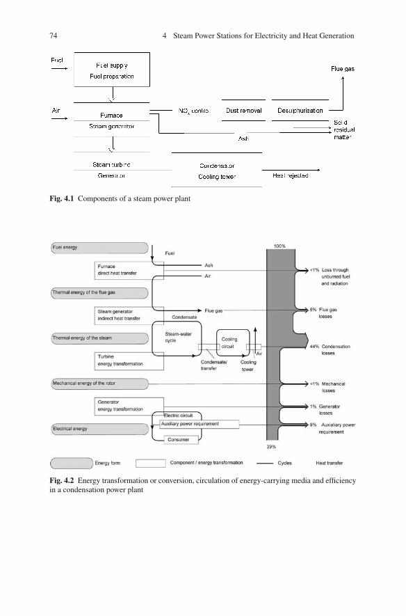
74 4 Steam Power Stations for Electricity and Heat Generation
Fig. 4.1 Components of a steam power plant
Fig. 4.2 Energy transformation or conversion, circulation of energy-carrying media and efficiencyin a condensation power plant
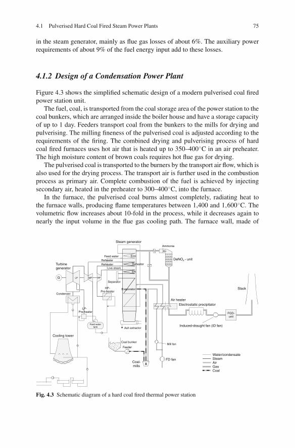
4.1 Pulverised Hard Coal Fired Steam Power Plants 75
in the steam generator, mainly as flue gas losses of about 6%. The auxiliary powerrequirements of about 9% of the fuel energy input add to these losses.
4.1.2 Design of a Condensation Power Plant
Figure 4.3 shows the simplified schematic design of a modern pulverised coal firedpower station unit.
The fuel, coal, is transported from the coal storage area of the power station to thecoal bunkers, which are arranged inside the boiler house and have a storage capacityof up to 1 day. Feeders transport coal from the bunkers to the mills for drying andpulverising. The milling fineness of the pulverised coal is adjusted according to therequirements of the firing. The combined drying and pulverising process of hardcoal fired furnaces uses hot air that is heated up to 350–400◦C in an air preheater.The high moisture content of brown coals requires hot flue gas for drying.
The pulverised coal is transported to the burners by the transport air flow, which isalso used for the drying process. The transport air is further used in the combustionprocess as primary air. Complete combustion of the fuel is achieved by injectingsecondary air, heated in the preheater to 300–400◦C, into the furnace.
In the furnace, the pulverised coal burns almost completely, radiating heat tothe furnace walls, producing flame temperatures between 1,400 and 1,600◦C. Thevolumetric flow increases about 10-fold in the process, while it decreases again tonearly the input volume in the flue gas cooling path. The furnace wall, made of
Eco
Reheater
SH
Evaporator
Feed water
Live steam
ReheaterReheater
HPMPLPG
Condenser
LP-Pre-heater
HP-Pre-heater
Feed watertank
Separator
Coal bunker
Feeder
Ash extractor
Ammonia
Mill fan
FD fanxCoal-
mills
Air heaterElectrostatic precipitator
Induced-draught fan (ID fan)
DeNOX - unit
Steam generator
Turbinegenerator
Cooling tower
Stack
Water/condensateSteamAirGasCoal
FGD-unit
Fig. 4.3 Schematic diagram of a hard coal fired thermal power station

76 4 Steam Power Stations for Electricity and Heat Generation
tightly welded membranes, forms the evaporative heating surface, which vaporisesthe feed water. After the flue gases are cooled to about 1,200–1,300◦C at the endof the furnace, they are further cooled down by the convective heating surfaces ofthe superheater (SH), the reheater (RH) and the feed water preheater, also calledthe economiser. Then nitrogen is removed from the flue gas in a DeNOx unit ata temperature range of 300–400◦C. In the air heaters the flue gases transfer theirresidual heat to the combustion air, during which they are cooled to the exit flue gastemperature of the steam generator.
For further cleaning, the flue gas is conducted through an electrostatic precipita-tor (ESP) to remove dust and, through a flue gas desulphurisation unit, to meet theallowed sulphur dioxide emission standards. The gases are discharged to the envi-ronment via a stack or natural-draught cooling tower. One or more induced-draughtfans transport the flue gas from the furnace to the outlet. In the course of retrofittingmeasures in various power plants, further series-connected induced-draught fanshave been added to the existing equipment to transport the flue gas through thedesulphurisation and DeNOx units. In new power stations, equipped with flue gasdesulphurisation and DeNOx units from the outset, one or more induced-draughtfans are connected in parallel to overcome the pressure loss of all installations andcomponents in the flue gas train.
In the steam generator, the energy released in combustion is transferred to thesteam – water cycle, and the enthalpy of the steam is converted into mechanicalwork by the turbine. The turbine exhaust steam is turned to water in the condenser.
The steam – water cycle is a substantial parameter in the overall design of thepower plant. The thermodynamic data of the water – steam cycle is the basis forthe steam generator and turbine configurations and determine the power plant’s effi-ciency.
Condensate pumps transport the condensate to the feed water tanks via low-pressure preheaters (LP preheaters), which are heated by steam from the lowerpressure-staged turbine extraction. In the feed water tanks, the condensate is furtherpreheated and degassed by steam from the mid-section turbine extraction in a direct-contact heater. The high-pressure feed water pump sets the operating pressure in thewater – steam section of the boiler and transports the feed water to the boiler inletvia the high-pressure preheaters, which are heated by steam from the upper pressureturbine extraction stages. The feed water is preheated to the entry temperature of theboiler in 6–9 stages. In the preheater, the extraction steam is cooled, condensed andpossibly supercooled and drained back into the condensate or feed water flow beforethe preheater. The higher the feed water temperature of the respective preheatingstage is, the higher the boiling temperatures have to be, and hence the extractionpressure of the associated extraction steam flow. The last preheating stage beforethe boiler is fed with steam taken from the cold reheater in a conventional design orfrom the HP turbine extraction in an advanced design.
In the boiler, the preheated feed water is further heated in the economiser, the lastconvective heating surface in the flue gas path, and then conducted to the evaporatorheat exchanger surface. The superheater heats the steam coming from the evaporatorup to exit temperature of the superheater, i.e. to the level of the so-called live steam
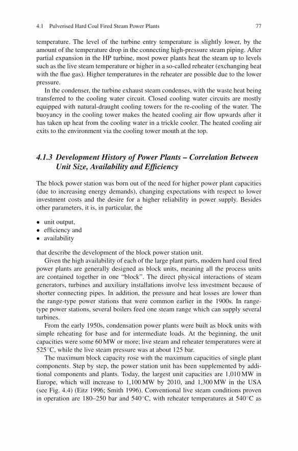
4.1 Pulverised Hard Coal Fired Steam Power Plants 77
temperature. The level of the turbine entry temperature is slightly lower, by theamount of the temperature drop in the connecting high-pressure steam piping. Afterpartial expansion in the HP turbine, most power plants heat the steam up to levelssuch as the live steam temperature or higher in a so-called reheater (exchanging heatwith the flue gas). Higher temperatures in the reheater are possible due to the lowerpressure.
In the condenser, the turbine exhaust steam condenses, with the waste heat beingtransferred to the cooling water circuit. Closed cooling water circuits are mostlyequipped with natural-draught cooling towers for the re-cooling of the water. Thebuoyancy in the cooling tower makes the heated cooling air flow upwards after ithas taken up heat from the cooling water in a trickle cooler. The heated cooling airexits to the environment via the cooling tower mouth at the top.
4.1.3 Development History of Power Plants – Correlation BetweenUnit Size, Availability and Efficiency
The block power station was born out of the need for higher power plant capacities(due to increasing energy demands), changing expectations with respect to lowerinvestment costs and the desire for a higher reliability in power supply. Besidesother parameters, it is, in particular, the
• unit output,• efficiency and• availability
that describe the development of the block power station unit.Given the high availability of each of the large plant parts, modern hard coal fired
power plants are generally designed as block units, meaning all the process unitsare contained together in one “block”. The direct physical interactions of steamgenerators, turbines and auxiliary installations involve less investment because ofshorter connecting pipes. In addition, the pressure and heat losses are lower thanthe range-type power stations that were common earlier in the 1900s. In range-type power stations, several boilers feed one steam range which can supply severalturbines.
From the early 1950s, condensation power plants were built as block units withsimple reheating for base and for intermediate loads. At the beginning, the unitcapacities were some 60 MW or more; live steam and reheater temperatures were at525◦C, while the live steam pressure was at about 125 bar.
The maximum block capacity rose with the maximum capacities of single plantcomponents. Step by step, the power station unit has been supplemented by addi-tional components and plants. Today, the largest unit capacities are 1,010 MW inEurope, which will increase to 1,100 MW by 2010, and 1,300 MW in the USA(see Fig. 4.4) (Eitz 1996; Smith 1996). Conventional live steam conditions provenin operation are 180–250 bar and 540◦C, with reheater temperatures at 540◦C as

78 4 Steam Power Stations for Electricity and Heat Generation
Fig. 4.4 Maximum unitcapacity
well. All over the world, one can see a trend towards higher live steam conditions.Figure 4.5 shows the development of live steam conditions in Germany.
With the unit capacities and the live steam conditions increasing, the efficiencylevels rose as well (see Fig. 4.6). The power station costs decreased, depending on
Fig. 4.5 Evolution of live steam conditions of German plants

4.1 Pulverised Hard Coal Fired Steam Power Plants 79
Fig. 4.6 Evolution of theefficiency level of Germanplants
the capacity, making efficiency-enhancing measures become more cost-effective.Higher efficiencies of large units can also be explained physically: specific surfaceheat losses of boilers and losses of rotating machinery due to leakiness diminishwith higher capacities.
Availability of technology becomes important with increasing capacities, theneed for more pollution control equipment and the desire for technical develop-ments towards higher efficiency levels. High availability is desirable for reliableelectricity production and is a necessary comparative criterion of technical develop-ments. Further development of steam power plants should therefore be based on thecomparable availability of proven power plant concepts.
Besides being economically significant, availability also has an environmentalimpact. The lowest CO2 emission level is achieved by a generation system whenthe power plants with the highest efficiency are of comparably high availability.Lower availability rates, in consequence, deteriorate the gain in efficiency. Untilthe second half of the 1960s, the development of the power plant unit efficiencywas sustained by development of the plant’s thermal efficiency. There are numerousscientific studies on this subject (Knizia 1966). In the 1970s, the efficiency wasfurther enhanced along with increasing unit sizes from 150 via 300 to more than600 MW. At the same time, the availability rate was increased and thus the effect ofthe efficiency enhancement improved.
While the flue gas particulate collector was a fixed component in the plant designfrom the very beginning, the plants were augmented by flue gas desulphurisationunits only from the mid-1970s and by nitrogen oxide control devices from the mid-1980s on. The availabilities of these components were at first low but then increasedas they developed. For example, in Germany gas cleaning devices for SO2 and NOx

80 4 Steam Power Stations for Electricity and Heat Generation
Table 4.1 Data for the reference power plant (Spliethoff and Abroll 1985)
Power plant unitGross rated power 740 MWNet rated power 690 MWEfficiency 39%Mechanical capacity of the feed pump 21 MWAuxiliary power requirement 50 MWMode of service Intermediate load range (170 starts p.a.)
Steam generatorCapacity 2250 t/h (625 kg/s)Construction Once-through boilerLive steam condition 209 bar, 535◦CSteam condition after reheater 39.6 bar, 535◦CEntry temperature of feed water 250◦C
FiringAir ratio 1.3Flue gas temperature 130◦CCoal mills 4 × 74 t/hForced-draught fan (FD fan) 1 × 100%Induced-draught fan (ID fan) 1 × 100%Range of control 40–100%Steam generator efficiency 94%
Boiler feed pump 1 × 100% duty turbine-driven pump1 × 50% duty motor-driven pump
Steam turbine generatorConstructionOperational mode
Condensation turbine with single reheatingmodified sliding-pressure operation withthrottling of the intake valves (5%)
Turbine pressure sections/number ofextractions
4 (1 × HP, 1 × MP, 2 × LP)/6
Live steam condition 190 bar/530◦CExhaust steam pressure 0.0549 bar
Back-cooling systemCooling tower construction Natural-draught wet-type cooling towerHeat rejection 894 MWAir temperature 10◦C, max. 35◦CCold water temperature 16.6◦C, max. 29◦C
Flue gas cleaning unitParticulate collector Electrostatic precipitator (ESP)Nitrogen oxide control device High-dust catalyst before air preheaterDesulphurisation unit Wet desulphurisation with limestoneFlue gas off-take Stack, reheat after FGD unit
became required by law in 1988 with the inception of ordinances of the GermanBundesimmissionsschutzgesetz (BImSchG), or Federal Pollution Control Act. Anypower plant with emission levels exceeding the prescribed standards concerningdust, SO2 and NOx may be operated only at limited duty or not at all.

4.2 Steam Generators 81
Different national standards in some countries have in consequence differingnitrogen oxide control methods. Higher limits make it possible to develop and applyless complex emission control techniques as well as the more advanced technolo-gies. In such situations, more lenient emission standards may mean higher energyconversion efficiencies and lower losses as compared to power stations with stricteremission standards.
The environmental stipulations that have an impact on the efficiency of inlandpower plants also limit the use of cooling water and once-through cooling cycles.Comparisons of efficiency and availability across national borders should take thesedifferences into account.
4.1.4 Reference Power Plant
Operating experiences and technological developments are introduced into the plan-ning of new power plants and thus form the basis of the respective technical stateof the art. Developments build upon this state of the art. For this reason, a referencepower plant, the data for which is compiled in Table 4.1, shall be the basis for furtherdiscussion in this chapter. This power plant corresponds to the state of the art fromthe 1980s in Germany. The reference power plant will be used in the followingsections to explain fundamentals and design by way of comparison with the furtherdevelopment of steam power plants.
4.2 Steam Generators
In a steam generator fired with fossil fuels, the chemically bound energy in the fuelis released through combustion and transferred to the generator’s steam – waterheating surface system. The high-pressure water is evaporated and superheated. Thecapacity range of steam generators lies between 0.4 t/h for process steam genera-tors, up to 4,500 t/h for large power plant boilers for electricity production (Stultzand Kitto 1992). The steam parameters are determined by the requirements of theprocess. Large steam generators for electricity production are operated at steamtemperatures of 540◦C and steam pressures of 180–240 bar (STEAG 1988). Newplants are designed for live steam pressures up to 300 bar and live steam and reheattemperatures up to 600◦C/620◦C.
The fossil fuels used are coal, oil or gas. In electricity production, steam gener-ation from nuclear energy plays an important part too. Other energy sources usedtoday for steam production are fuels of biogenetic origin and residual matter fromindustrial processes, e.g. peat, wood, wood residues, biogases, straw, waste liquorsand gases from chemical processes as well as blast furnace gas from pig iron pro-duction.
The schematic design of a simple steam generator, a shell boiler, is shown inFig. 4.7 (Dolezal 1990). Tubes that conduct flue gas, immersed in a boiling water

82 4 Steam Power Stations for Electricity and Heat Generation
Fig. 4.7 Schematic graphicof a shell boiler
bath, transfer heat for steam generation. In order to maintain a continuous process,steam extraction from the steam space and water supply to the water bath are syn-chronised according to the water level. Shell boilers are suited to low steam pres-sures only and so are utilised for low capacities up to 54 t/h of steam output andsteam pressures up to 35 bar (Sobbe 2004).
In steam generators of higher capacity, the heat exchange surfaces consist ofcomplex parallel tube systems. A great number of small water and steam flows,conducted through tubes with a small inner diameter, take up heat along the heatedstretches of the tubes. Both technically and economically, this is the most effectivemethod to generate steam at high pressures. This method is also utilised to preheat,evaporate and superheat the working medium, water, up to saturation temperature.Accordingly, a steam generator consists of various heat exchange surfaces, such asthe feed water heater or economiser, evaporator, superheater and reheater, whichoperate with different heat flux densities depending on the firing and the hot fluegases. The increases in the volumetric flows are provided for by branching of theheated single tubes, introducing more flow capacity. The relative heat absorptionsof the economiser, evaporator and superheater are dependent on the pressure, as theevaporation enthalpies decrease with higher pressures. The heat absorptions of theeconomiser and the superheater increase with higher pressures.
The various steam generator systems differ in the configuration of the evaporator,while there is no difference in the superheater and economiser units. A distinction ismade between circulation and once-through systems. The course of evaporation inthe tubes is shown in Fig. 4.8 for partial (circulation) and for complete evaporation(once through) (Stultz and Kitto 1992). In circulation steam generators, water isheated to boiling temperature in the heated vertical evaporator tubes, forming steambubbles. In the drum mounted above the heated tubes, the rising water – steammixture is divided, with the steam flow being fed to the superheater and the waterflowing back through downcomer pipes to re-enter the heated evaporator tubes. Inthis case, the process is a mere partial evaporation in the evaporator tube. Completeevaporation is achieved only after several recirculations. Circulation systems have afixed liquid – vapour phase transition point in the drum.
In contrast, in once-through steam generators, the water in the evaporator tube isin one stage preheated, evaporated and partially superheated. Because steam leaves

4.2 Steam Generators 83
Fig. 4.8 Evaporation processin vertical evaporation tubes
the evaporator, this system does not need a water – steam division drum. In once-through systems, the liquid – vapour phase transition point is not fixed.
The required heat for steam generation is transferred to the heat exchange sur-faces by radiation and convection. The heat exchange conditions in the evaporator –water-wetted tube walls and high mass flow densities – make it possible to achievehigh heat transfer rates in the evaporator. The furnace walls, which have the high-est heat flux density in a steam generator, due to the flame radiation, are thereforemostly designed as evaporative heating surfaces.
4.2.1 Flow and Heat Transfer Inside a Tube
Parameters of great importance for the design of steam generators are the heat trans-fer and the flow in the evaporation area. Figure 4.9 presents the processes duringevaporation in a long, vertical-flow tube with homogeneous heating (Adrian et al.1986). The water first enters the tube as an under-cooled liquid, cooling the tube byconvective heat transfer. In this area, where there is only water flow, the heat transferbetween the tube wall and the medium is good and only depends on the velocity.
The first steam bubbles form when the water touching the inside wall reachesthe boiling point, thus developing a bubble flow. This is termed sub-cooled boil-ing, because the liquid in the centre of the tube flow has not yet reached boilingtemperature. The temperature continues to rise until the entire medium reaches the

84 4 Steam Power Stations for Electricity and Heat Generation
Fig. 4.9 Schematic diagram of the evaporation processes in a vertical tube (Adrian et al. 1986)
boiling temperature. The steam bubbles forming in the boiling process merge, theflow changes from a bubble flow to a plug flow and subsequently to an annular flow,where the wall is eventually wetted by just a water film. This water film becomes sothin that evaporation in it is suppressed. The heat in this state is transferred by con-vection and thermal conduction through the water film, and vaporisation takes placeat the interface between the water and the steam. Boiling and bubble movementresult in a high heat transfer coefficient, the highest in a steam generator.
When the water film becomes sparse, wetting the wall only incompletely, theheat transfer diminishes and the wall temperature rises considerably. A boiling cri-sis occurs, also called dryout, with the tube wall drying more and more. The heattransfer becomes small, because the wall is wetted only in parts and steam coolinghas not yet become effective due to partial evaporation. The location of the boilingcrisis and the level the wall temperature rises to depend on numerous factors, suchas the heat flux density, the mass flow density, the tube design and the steam quality.
Figure 4.10 shows the influence of the heat flux density on the wall temperature(Stultz and Kitto 1992).
In the region immediately following the dryout region, some water droplets arestill present, although at this stage the steam is already slightly superheated. Withthe remaining water droplets evaporating, the steam quality and its velocity rise, sothat cooling improves and the wall temperature falls slightly. After evaporation iscomplete, the flow becomes a steam flow with convective heat transfer. Both thetemperature of the steam flow and the temperature of the tube increase thereafter.
For the design of steam generators, boiling crises are of great importance,because they can lead to excess temperatures in the tube walls, which have tobe taken into account in the design stage. There is a distinction between a “first-
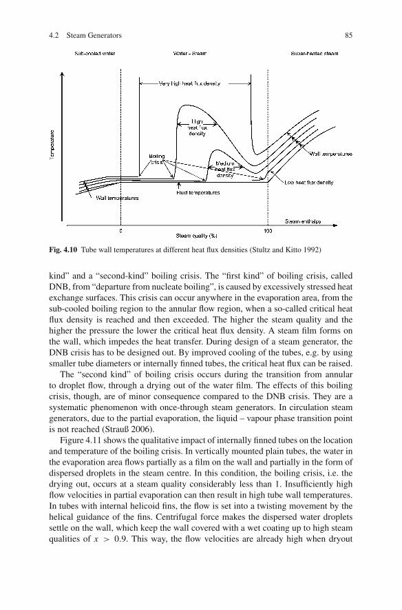
4.2 Steam Generators 85
Fig. 4.10 Tube wall temperatures at different heat flux densities (Stultz and Kitto 1992)
kind” and a “second-kind” boiling crisis. The “first kind” of boiling crisis, calledDNB, from “departure from nucleate boiling”, is caused by excessively stressed heatexchange surfaces. This crisis can occur anywhere in the evaporation area, from thesub-cooled boiling region to the annular flow region, when a so-called critical heatflux density is reached and then exceeded. The higher the steam quality and thehigher the pressure the lower the critical heat flux density. A steam film forms onthe wall, which impedes the heat transfer. During design of a steam generator, theDNB crisis has to be designed out. By improved cooling of the tubes, e.g. by usingsmaller tube diameters or internally finned tubes, the critical heat flux can be raised.
The “second kind” of boiling crisis occurs during the transition from annularto droplet flow, through a drying out of the water film. The effects of this boilingcrisis, though, are of minor consequence compared to the DNB crisis. They are asystematic phenomenon with once-through steam generators. In circulation steamgenerators, due to the partial evaporation, the liquid – vapour phase transition pointis not reached (Strauß 2006).
Figure 4.11 shows the qualitative impact of internally finned tubes on the locationand temperature of the boiling crisis. In vertically mounted plain tubes, the water inthe evaporation area flows partially as a film on the wall and partially in the form ofdispersed droplets in the steam centre. In this condition, the boiling crisis, i.e. thedrying out, occurs at a steam quality considerably less than 1. Insufficiently highflow velocities in partial evaporation can then result in high tube wall temperatures.In tubes with internal helicoid fins, the flow is set into a twisting movement by thehelical guidance of the fins. Centrifugal force makes the dispersed water dropletssettle on the wall, which keep the wall covered with a wet coating up to high steamqualities of x > 0.9. This way, the flow velocities are already high when dryout
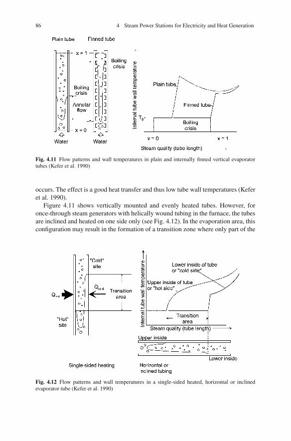
86 4 Steam Power Stations for Electricity and Heat Generation
Fig. 4.11 Flow patterns and wall temperatures in plain and internally finned vertical evaporatortubes (Kefer et al. 1990)
occurs. The effect is a good heat transfer and thus low tube wall temperatures (Keferet al. 1990).
Figure 4.11 shows vertically mounted and evenly heated tubes. However, foronce-through steam generators with helically wound tubing in the furnace, the tubesare inclined and heated on one side only (see Fig. 4.12). In the evaporation area, thisconfiguration may result in the formation of a transition zone where only part of the
Fig. 4.12 Flow patterns and wall temperatures in a single-sided heated, horizontal or inclinedevaporator tube (Kefer et al. 1990)

4.2 Steam Generators 87
inner perimeter of the evaporator tube is wetted. With the heating only on one side,the water film dries on the heated side faster than on the cold side.
If the tube is inclined or mounted horizontally, gravity causes a segregation ofwater and steam. The water flows – mainly as a film or in droplets – in the lowerpart of the tube cross-section, while the more light-weight steam flows in the upperpart. This way, the wetting is maintained at differing lengths in the upper and lowerparts of the cross-section, possibly resulting in differing inner wall temperaturesbetween the upper and lower sides. In the extreme case, the upper inside of the tubeis dry before evaporation begins, while the wet coating on the lower inside onlydries when there is total vaporisation.
Due to the variable wetting, transient thermal stress may occur, causing damageto the tube. A comparison of the temperature conditions in a horizontal tube with asegregated water/steam flow to a vertical tube without segregated flow revealed thatthe temperature maxima of the horizontal tube was lower. This can be explained bythe thermal conduction between the cold lower and hot upper parts of the tube andthe eddies that form during vaporisation (Kefer et al. 1990).
4.2.2 Evaporator Configurations
As already described in Sect. 4.2.1, steam generator systems are divided into circu-lation and once-through systems. The various state-of-the-art designs are shown inFig. 4.13.
4.2.2.1 Natural Circulation
Natural-circulation steam generators typically consist of economisers and an evap-orator with risers that form the heated furnace wall, a drum for the separation ofwater from steam and unheated down pipes and superheaters (see Fig. 4.14).
Water with a temperature just below the boiling point flows down through thedowncomer pipes. In the vertically mounted evaporator risers with upward flow, awater – steam mixture forms through heating and is again divided into water andsteam in the drum.
In a natural-circulation steam generator, a circulating flow forms because of thedensity difference between the falling water in the unheated downcomer and thewater – steam mixture in the heated riser (see Fig. 4.15). Besides accelerating therising water, the density and pressure differences also compensate for the flow resis-tance in the evaporator and in the drum.
With the heating increasing, the flow speeds up in stable circulation until amaximum is reached. With a further increase in the heating, the pressure loss inthe evaporator tubes also increases, while the change of the density difference, thedriving force, is only insignificant, meaning that the flow slows down (an unstablearea). In designing natural-circulation boilers, the fact that a rise in the thermal loadalways leads to higher circulation velocities (in stable circulation) must be taken into
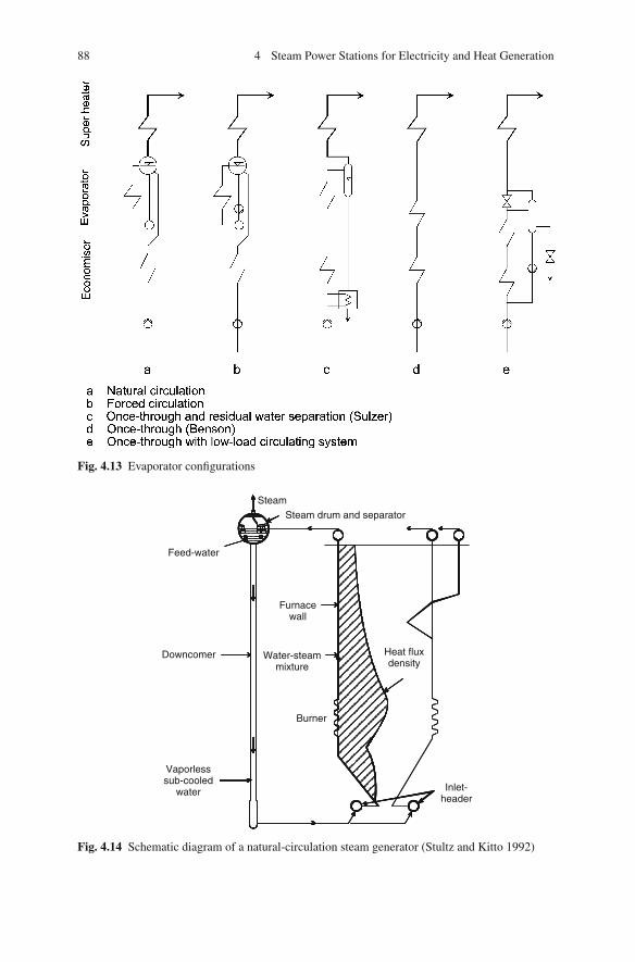
88 4 Steam Power Stations for Electricity and Heat Generation
Fig. 4.13 Evaporator configurations
Downcomer
Vaporlesssub-cooled
water
Burner
Inlet-header
Water-steammixture
Furnacewall
Feed-water
SteamSteam drum and separator
Heat fluxdensity
Fig. 4.14 Schematic diagram of a natural-circulation steam generator (Stultz and Kitto 1992)

4.2 Steam Generators 89
Fig. 4.15 Density differences in a natural-circulation steam generator (Stultz and Kitto 1992)
account. In this case, the flow necessary for cooling is determined by the heating(Stultz and Kitto 1992).
Natural-circulation steam generators work effectively where the density differ-ences between water and water – steam mixture are high. Natural circulation islimited by the circulation ratio, which decreases with a higher design pressure and ahigher steam quality, meaning cooling is no longer ensured at pressures above 185bar in the drum – corresponding to 170–180 bar before the turbine. The absoluteupper limit for a drum boiler is the critical pressure, because at this point and above,a two-phase water – steam mixture no longer exists.
The advantages of natural circulation are its simple construction and the lowpower demand of the feeding pump. In addition, the requirements for the feed waterquality are lower than in once-through systems because impurities accumulate in thedrum, meaning they can be blown down. Disadvantages are due to the necessarilythick wall of the drum, which may restrict the allowable rate of load change, and therestriction on the system pressure (Dolezal 1990). Thick-walled high-pressure partsare more sophisticated with regard to manufacturing and quality approval.
4.2.2.2 Forced Circulation
In forced-circulation systems, the buoyancy of the steam, as the only driver of thewater or the water – steam mixture circulation, is supported by a circulating pump,preferably installed at the bottommost point of the downcomer, where there is thehighest water pressure. Forced circulation is limited to a range of about 200 bar toensure sufficient water – steam separation in the drum (Adrian et al. 1986).
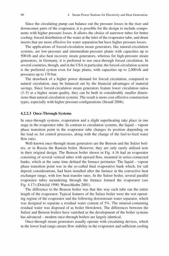
90 4 Steam Power Stations for Electricity and Heat Generation
Since the circulating pump can balance out the pressure losses in the riser anddowncomer parts of the evaporator, it is possible for the design to include compo-nents with higher pressure losses. It allows the choice of narrower tubes for bettercooling; forced distribution of the water at the inlet of the evaporator tube; and druminserts that are more effective for water separation but have higher pressure losses.
The applications of forced-circulation steam generators, like natural-circulationsystems, are low-pressure and intermediate-pressure plants with capacities up to500 t/h and also heat recovery steam generators, whereas for high-pressure steamgenerators, in Germany, it is preferred to use once-through forced circulation. Inseveral countries, though, and in the USA in particular, the forced-circulation systemis the preferred system even for large plants, with capacities up to 2,000 t/h andpressures up to 170 bar.
The drawback of a higher power demand for forced circulation, compared tonatural circulation, may be balanced out by the financial advantages of materialsavings. Since forced-circulation steam generators feature lower circulation ratios(3–5) at a higher steam quality, they can be built in considerably smaller dimen-sions than natural-circulation systems. The result is more cost-effective constructiontypes, especially with higher pressure configurations (Strauß 2006).
4.2.2.3 Once-Through Systems
In once-through systems, evaporation and a slight superheating take place in onestage in the evaporator tube. In contrast to circulation systems, the liquid – vapourphase transition point in the evaporator tube changes its position depending onthe load or, for control processes, along with the change of the fuel-to-feed waterflow ratio.
Well-known once-through steam generators are the Benson and the Sulzer boil-ers, or in Russia the Ramsin boiler. However, they are only rarely utilised nowin their original design. The Benson boiler shown in Fig. 4.16 had an evaporatorconsisting of several vertical tubes with upward flow, mounted in series-connectedbanks, which at the same time defined the furnace perimeter. The liquid – vapourphase transition point was in the so-called final evaporative bank which, for saltdeposit considerations, had been installed after the furnace in the convective heatexchanger range, with low heat transfer rates. In the Sulzer boiler, several parallelevaporator tubes meandering through the furnace formed the evaporator (seeFig. 4.17) (Dolezal 1990; Wauschkuhn 2001).
The difference to the Benson boiler was that this way each tube ran the entirelength of the evaporator. Typical features of the Sulzer boiler were the wet operat-ing regime of the evaporator and the following downstream water separator, whichwas designed to separate a residual water content of 5%. The mineral-containingresidual water was disposed of as boiler blowdown. The differences between theSulzer and Benson boilers have vanished as the development of the boiler systemshas advanced – modern once-through boilers are largely identical.
Once-through steam generators usually operate with circulating devices, whichin the lower load range ensure flow stability in the evaporator and sufficient cooling
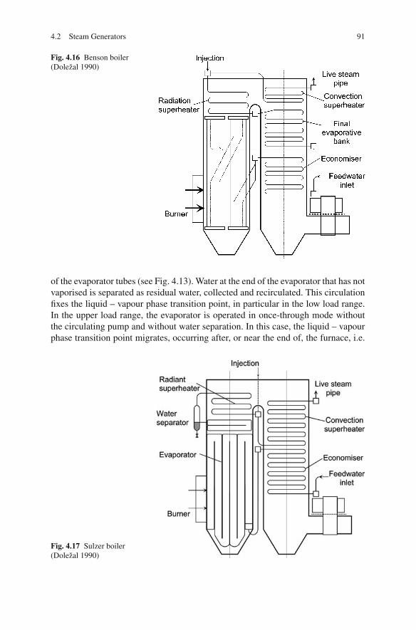
4.2 Steam Generators 91
Fig. 4.16 Benson boiler(Dolezal 1990)
of the evaporator tubes (see Fig. 4.13). Water at the end of the evaporator that has notvaporised is separated as residual water, collected and recirculated. This circulationfixes the liquid – vapour phase transition point, in particular in the low load range.In the upper load range, the evaporator is operated in once-through mode withoutthe circulating pump and without water separation. In this case, the liquid – vapourphase transition point migrates, occurring after, or near the end of, the furnace, i.e.
Fig. 4.17 Sulzer boiler(Dolezal 1990)

92 4 Steam Power Stations for Electricity and Heat Generation
in areas of low heat flux density. This is usually in the area where convective heattransfer has started (Adrian et al. 1986; Baehr 1985).
Evaporators of once-through steam generators today are made of tightly weldedmembrane tube walls. The mass flow density in the evaporator tubes has to be setsuch that excessive tube wall temperatures are avoided even with low heat trans-fer coefficients of the inside tube walls. Helically mounted evaporator tubes are ameasure to ensure that the mass flow densities required for cooling are also suitablefor large radiant heat fluxes in the furnace. Heating differences due to high heatfluxes in the wall centre and relatively low fluxes in the furnace corners, as well asunbalanced combustion, are compensated by each of the tubes running through allthe walls. Another possible measure is internally finned evaporator tubes.
Membrane tube walls in a helically wound pattern, however, are not able to carry,without additional support, the weight of the furnace, the structural bracings, theinsulation and the water contained within it, as well as the possible fouling andslagging deposits. Nor can they sustain tubular offsets, caused by changes in thefurnace pressure. The load is borne by vertical sling straps, which are welded on.Tubular offsets of the membrane walls caused by (furnace) pressure forces work-ing vertically against the tube walls are limited by structural sling straps mountedhorizontally around the perimeter at different heights. In the upper section of thefurnace, it is possible to change to vertical tubing under lower heat flux densities(see Fig. 4.18) (Franke et al. 1993, 1995; Wittchow 1995).
In Germany, all large-scale steam generators since 1960 have been designed asonce-through systems. Disadvantages of such systems are the more complex con-struction of the furnace walls, due to the wound pattern of the tubes; the higherauxiliary energy demand for the feed water pressure increase; and the higher controlrequirements. Despite lesser material requirements, the more complicated manufac-turing and assembly result in higher costs compared to drum boilers with verticaltubing. The fact, however, that once-through systems have no thick-walled compo-nents, such as the drum in circulation systems, offers advantages such as the abilityto operate with a sliding pressure, faster start-up and a greater flexibility to makefast load changes. This is important, especially for large coal-fired power stations
Fig. 4.18 Evaporators withwound-pattern furnace wallsand with vertical tubing foronce-through steamgenerators (Wittchow 1995)
Furnace with verticalinternally finned tubes
Furnace with wound-patternwalls and girders
4.2 Steam Generators 93
which are used for medium load operation, where some stations are started up andshut down daily. In contrast to circulation systems, once-through systems can alsobe applied in advanced steam generators with higher steam parameters, becauseit is the only system suited to supercritical pressures. Higher steam temperatures,though, can also be used in circulation systems (Stultz and Kitto 1992; Dolezal1990; Strauß 2006; Wittchow 1982).
A further development of once-through steam generator technology is the use ofinternally finned tubes. The more intensive cooling of these tubes allows lower massflow densities in the evaporator, thus making it possible to use vertical evaporatortubes. In contrast to the state-of-the-art wound-pattern walls, this new constructioninvolves both lower costs and a number of additional operational advantages, whichwill be discussed in Sect. 4.3.5.3 in the context of evaporator design. For futurepower stations with advanced steam parameters, the forced once-through circulationconcept has many advantages (Wittchow 1995; Lehmann et al. 1996).
4.2.3 Steam Generator Construction Types
The introduction of membrane walls that were fully joined by welding changed thedesign, manufacture and assembly of steam generators.
Until the 1960s, the evaporator tubes were individually mounted in the refractorylining of the furnace wall, without fins connecting adjoining tubes. The evapora-tor tubes only had the function of heat absorption. Fireside sealing-off against theboiler house was ensured by the wall construction of firebricks, insulation and metalcasing.
Membrane walls fulfil both functions. The wall construction consists only ofgas-tight evaporator tube banks and the insulation behind them. Fireproof lining isunnecessary. In addition to the lengthwise expansion of the tubes, the membranewalls also expand in the traverse direction, so that the expansion forces have to becountered by adequate reinforcement.
The membrane wall being welded from bottom to top limits the free design ofthe steam generator. Whereas previously, the evaporator could be adapted to the heatabsorption (for instance by the final evaporative bank), today the furnace dimensionspre-set the size of the evaporator.
4.2.3.1 Single-Pass Boilers and Two-Pass Boilers
Steam generator designs (or construction types) are divided into two groups: single-pass and two-pass boilers. In single-pass or tower boilers, the convective heatingsurfaces (the superheater, reheater and economiser) are mounted above the furnace,so that the flue gases only have to be redirected after the last water vapour/steamheating surfaces. This helps to minimise erosion, in particular with high-ash coaltypes. Only after being cooled down to 400◦C are the flue gases conducted to theair preheater through an uncooled blank pass.
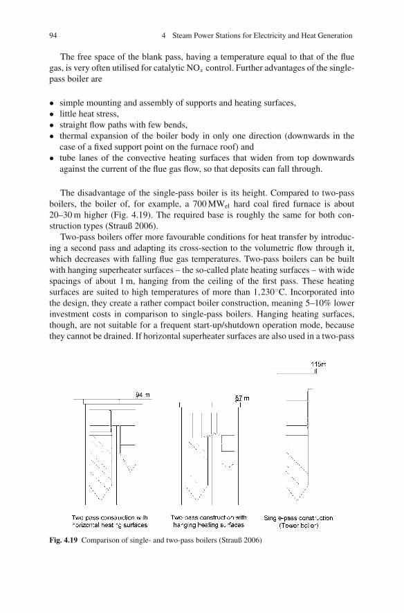
94 4 Steam Power Stations for Electricity and Heat Generation
The free space of the blank pass, having a temperature equal to that of the fluegas, is very often utilised for catalytic NOx control. Further advantages of the single-pass boiler are
• simple mounting and assembly of supports and heating surfaces,• little heat stress,• straight flow paths with few bends,• thermal expansion of the boiler body in only one direction (downwards in the
case of a fixed support point on the furnace roof) and• tube lanes of the convective heating surfaces that widen from top downwards
against the current of the flue gas flow, so that deposits can fall through.
The disadvantage of the single-pass boiler is its height. Compared to two-passboilers, the boiler of, for example, a 700 MWel hard coal fired furnace is about20–30 m higher (Fig. 4.19). The required base is roughly the same for both con-struction types (Strauß 2006).
Two-pass boilers offer more favourable conditions for heat transfer by introduc-ing a second pass and adapting its cross-section to the volumetric flow through it,which decreases with falling flue gas temperatures. Two-pass boilers can be builtwith hanging superheater surfaces – the so-called plate heating surfaces – with widespacings of about 1 m, hanging from the ceiling of the first pass. These heatingsurfaces are suited to high temperatures of more than 1,230◦C. Incorporated intothe design, they create a rather compact boiler construction, meaning 5–10% lowerinvestment costs in comparison to single-pass boilers. Hanging heating surfaces,though, are not suitable for a frequent start-up/shutdown operation mode, becausethey cannot be drained. If horizontal superheater surfaces are also used in a two-pass
Fig. 4.19 Comparison of single- and two-pass boilers (Strauß 2006)
4.2 Steam Generators 95
boiler, the investment costs are roughly the same. Two-pass boilers can be erectedfaster, because both passes can be assembled at the same time.
The choice of the boiler construction type depends on factors such as the ashcontent, the ash composition and the service mode of the steam generator. In Europe,single-pass boilers are preferred, because coal-fired furnaces are used for intermedi-ate load ranges. Outside Europe, two-pass boilers with hanging superheater surfacesare usually constructed (Strauß 2006; Adrian et al. 1986).
4.2.4 Operating Regimes and Control Modes
4.2.4.1 Operating Regimes
Power stations can be categorised according to the duty they operate under: peak,intermediate and base loads.
A peak load power station is operated for only a small number of hours perday and only a fraction of the days in the year. Its annual output corresponds toabout 2,000 annual full-load hours (equivalent hours of full-load operation per year),where there are 8,760 h in each year. (The actual amount will be greater because ofstart-up, shut down and partial-load operation). Such a station should reach its ratedpower within a short time (i.e. start-up time), and it should be possible to shut itdown very quickly. The energy losses during start-up and shutdown should be small.Power stations such as pumped storage power stations or gas turbine power plantsare used for peak load.
The base load power station, in contrast, is designed for inexpensive fuels, highefficiency levels and a small number of start-up and shutdowns. The output per yearcorresponds to about 6,000–8,000 annual full-load hours. It features a relativelysmall load control range between about 70 and 100% of its rated power, where theload change capability is not a very important criterion because the plant is mostlyoperated at its rated power. With few outages per year, start-up and shutdown timesare of minor importance.
The yearly output of mid-range power stations lies between 2,000 and 6,000annual full-load hours. Such a plant should be capable of dealing with peak loadoperation, with daily start-ups and shutdowns, as well as base load operation, withlong operating periods and part-load conditions. It features a wide control range ofabout 30 or 40–100% of its rated power, and a good dynamic transient response andan efficiency as high as possible are sought.
Based on the operating regime of the power plant, the number of start-ups hasto be specified in the design phase. Start-ups are classified into cold, warm and hotstart-ups:
– Hot start-up: after an outage of maximum 8 h. Such an outage typically occursovernight. For a hard coal fired power station operated in the mid-range such asthe reference power plant, about 3,000–4,500 hot start-ups are scheduled for thelifetime of 40 years.
96 4 Steam Power Stations for Electricity and Heat Generation
– Warm start-up: after an outage of 8–72 h. The outage is typically over the week-end. For a medium-range power plant the number of warm start-ups is about1,000 over the station lifetime.
– Cold start-up: after an outage of more than 72 h. This start-up is quite rare; thetotal number for the medium-range power plant is about 200 (Zehtner 2009).
4.2.4.2 Primary, Secondary and Tertiary Control
The generation of power within a network such as the UCTE (Union for the Co-ordination of Transmission of Electricity) network in central Europe needs to becontrolled and monitored for a secure and high-quality supply of electricity. Thegoal of the control is to maintain a balance between generation and consumption(demand) of electricity. The key control variable is the frequency of the net, whichshould be kept stable at 50 Hz, or 60 Hz in the USA or parts of Japan. In case of adrop in the frequency, caused by a higher consumption in comparison to the gen-eration, power plants have to increase their load in order to stabilise the frequency.The rules of load-frequency control and requirements of power station performanceare given in the Transmission Code for the West European UCTE net (UCTE 2004).The guidelines distinguish between primary, secondary and tertiary control.
Primary Control
The objective of primary control is to rapidly re-establish the balance between gen-eration and consumption within the synchronous area by using turbine speed orturbine governors. By the joint action of all interconnected units, primary controlstabilises the system frequency at a stationary value after a disturbance in a time-frame of seconds, but without restoring the reference values of system frequencyand power exchanges. Outside periods of correction, the set-point frequency orscheduled frequency value is 50 Hz. Primary control is activated if the frequencydeviation exceeds ±20 mHz.
All power stations have to be capable of delivering a maximum primary controlreserve of 2% of the rated power within 30 s. The maximum reserve has to be acti-vated at a frequency deviation of 200 mHz and has to be maintained over a periodof 15 min. At lower frequency deviations, the required increase is correspondinglysmaller, though the load change speed of 1% load per 15 s remains the same.
Primary control is supported by the self-regulation of consumption and genera-tion in the network. The self-regulation is assumed to be 1%/Hz, meaning a loaddecrease of 0.2% occurs in case of a frequency drop of 200 mHz.
Secondary Control
Secondary control restores primary control reserves and maintains a balance betweengeneration and consumption of electricity within each control area in a timeframeof seconds to, typically, 15 min. Accordingly, load variations of differing magni-tudes must be corrected in the control area within this timeframe. Secondary control

4.2 Steam Generators 97
is based on secondary control reserves which are under automatic control by theoperator of the network area. Secondary control is accomplished by increasing thefuel input of a power plant and thus puts requirements on the dynamic behaviourof power plants. The recommendations of the Deutsche Verbundgesellschaft (theassociation of German transmission system operators), located in Heidelberg, in1991 fixed a required load change rate of coal-fired power plants of between 4 and8%/min, referring to the rated load, within a load range of 40–100% (Verbundge-sellschaft 1991). With the expanded European interconnected network system, thesestrict limits are no longer valid. It is now the responsibility of the operator of thenetwork area to cater for a sufficient secondary control reserve (Verbundgesellschaft1996; VDN 2007).
Tertiary Control
Tertiary control reserve is required to restore the secondary control reserves. Tertiarycontrol reserve is usually activated manually after activation of secondary controland frees secondary reserve. Tertiary control is achieved by re-scheduling powergeneration of operating plants or start-up of additional plants. Tertiary control thuscorresponds to the operation planning of all power plants within a network area.
4.2.4.3 Constant-Pressure and Sliding-Pressure Operation
The output of a condensation power station is set by means of the live steam massflow mLS (Dolezal 1990). The mechanical power, Pm, of the turbine shaft dependson the live steam pressure pLS, the cross-section of the opening A, or the liftingof the turbine intake valves, and the live steam temperature, TLS, according to thefollowing relation:
Pm ≈ mLS ≈ ApLS√TLS
(4.1)
The live steam temperature should remain constant throughout the whole loadcontrol range, so that a high efficiency rate is also achieved during part load andto avoid stress on the turbine caused by temperature changes. The turbine outputand the live steam mass flow to the turbine are set during steady-state conditions,either when the live steam pressure is at a constant cross-section of the turbine intakevalves (sliding or variable pressure) or when the intake cross-section is at a constantsteam pressure (constant or fixed pressure).
Constant-Pressure Operation
The control in constant-pressure operation is subdivided into throttle control andgoverning control. In constant-pressure governing control, the first turbine stage isdesigned as a control wheel and is preceded by sets of nozzle valves (see Fig. 4.20).As the load increases, the nozzle valves are sequentially opened.

98 4 Steam Power Stations for Electricity and Heat Generation
Fig. 4.20 Turbine withnozzle set and control wheel(Traupel 2001)
Under any load condition, only one of the valves is partially open, so loss throughthrottling only occurs there. The other valves are already fully opened or still closed.Because only a partial flow is subject to throttling losses, the part-load efficiency ofthe turbine is high. In such a case, the first stage of the turbine, the control stage, ischarged by a high pressure pB only for part of the circumference, where this pressureis slightly lower than the live steam pressure (i.e. constant pressure). The controlstage cuts the pressure back to the wheel chamber pressure pW and homogenisesthe steam distribution over the blading of the circumference of the following turbinestage (Traupel 1982).
In constant-pressure operation with throttle control, the total live steam mass flowis controlled by throttling the steam pressure through all the live steam valves at thesame time. The turbine does not need a control stage, since the first turbine stageis charged uniformly and with lower pressure than the nozzle set governed stage.The pressure losses in throttling have a disadvantageous effect on the heat rate inpart-load operation. In full-load operation, the heat rate may be somewhat betterthan in constant-pressure operation with the nozzle set governing, because there isno efficiency-decreasing impact of the control stage.
In the balanced steady-state conditions of a power station unit, the steam pro-duced and the steam consumed by the turbine are equal. Fuel flow and steam gen-eration correspond. The steam production is controlled by the fuel mass flow, thechanges of which, however, have a delayed effect due to the thermal inertia of thesteam generator. In constant-pressure operation, the steam energy stored in the boileris used to control rapid load changes. By further opening the intake cross-section ofthe turbine control valve, additional steam is extracted from the steam generator andused to bridge the interval until the conditions are balanced out by the fuel supply.
Sliding-Pressure Control
In sliding-pressure operation, the turbine output and the steam flow are adjustedby the pressure at the outlet of the boiler. In natural sliding-pressure operation, thelive steam valves of the turbine are completely opened, and the cross-section of theturbine intake is constant throughout the whole load range.

4.2 Steam Generators 99
An output change using this control type can only be carried out by changing thefuel flow, a consequence of which is a long delay control characteristic of a changein the steam generator. Given that, in sliding-pressure operation, the pressure riseswith increasing output, it is necessary that an increased steam flow is produced bythe boiler before the output of the turbine increases.
In industrial practice, in order to diminish the disadvantages of the delayed con-trol characteristic of natural sliding-pressure operation, modified sliding-pressurecontrol is used. The live steam valves in this operation are opened about 95% dur-ing steady-state conditions, so that in the case of a power demand similar to that ofconstant-pressure operation, the valves open and thus increase the steam flow to theturbine. By this slight throttling of the turbine intake valves, a limited loss is chosenin favour of better control dynamics (Baehr 1985).
Advantages of sliding-pressure control are a load-independent temperature dis-tribution in the turbine, a lower pressure stress on the steam generator and a lowerpower demand of the boiler feed water pump in part-load operation. Disadvan-tages are the changes of the boiling temperature in the evaporator, due to the pres-sure changes. The advantage of the decreasing power requirement for boiler feedpumping is stronger when the live steam pressure becomes higher. The generaloutcome in applying natural sliding pressure is a heat rate (including that of theboiler feed pumping power) which is slightly better than with nozzle-governedconstant-pressure operation; with modified sliding pressure the heat rate is higher(Adrian et al. 1986; Baehr 1985). See also Sect. 4.4.4.
4.2.4.4 Impacts on the Turbine by Sliding-Pressureor Constant-Pressure Operation
The comparison of the different control modes in Fig. 4.21 shows that, in constant-pressure operation with the nozzle set controlling, the pressure pB after the turbineinlet valves and before the blading remains almost constant over the load range. Insliding-pressure control, in contrast, and also in constant-pressure operation withthrottle control, the pressure shows a linear rise with the output.
Both in sliding-pressure and in constant-pressure operation with throttle control,the stage pressures change to the same degree depending on the output, so that thestage temperatures are constant. In constant pressure operating with the nozzle setcontrolling, the pressure drop over the control stage pB − pW becomes steeper witha decreasing output, so that the stage temperatures of the stages drop as well (Strauß2006).
The influence of the control mode on the temperature in the high-pressure sec-tion is shown in Fig. 4.22. Load changes in constant-pressure operation cause con-siderable changes in temperature in the area of the first stage of the high-pressureturbine. Thermal stress arising in the process therefore limits the load change rate,in particular in the case of high-capacity turbines. In sliding-pressure operation, thetemperature conditions in the turbine remain almost constant, so load changes arepossible even with large turbines, even abruptly. This means that in sliding-pressureoperation, the steam generator determines the dynamic performance of the power
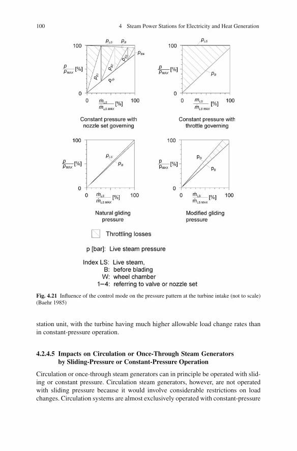
100 4 Steam Power Stations for Electricity and Heat Generation
Fig. 4.21 Influence of the control mode on the pressure pattern at the turbine intake (not to scale)(Baehr 1985)
station unit, with the turbine having much higher allowable load change rates thanin constant-pressure operation.
4.2.4.5 Impacts on Circulation or Once-Through Steam Generatorsby Sliding-Pressure or Constant-Pressure Operation
Circulation or once-through steam generators can in principle be operated with slid-ing or constant pressure. Circulation steam generators, however, are not operatedwith sliding pressure because it would involve considerable restrictions on loadchanges. Circulation systems are almost exclusively operated with constant-pressure
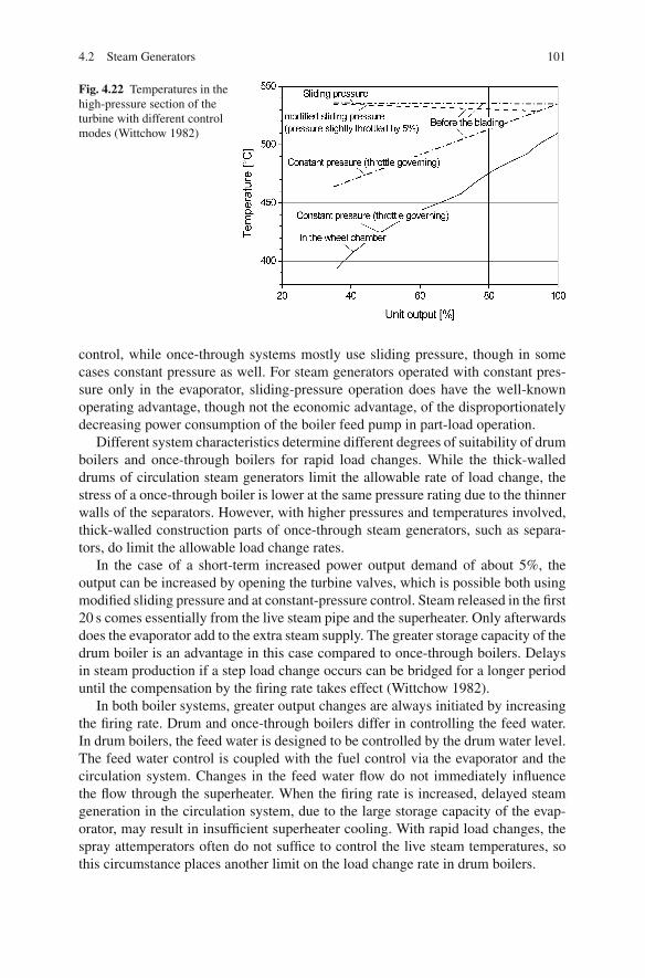
4.2 Steam Generators 101
Fig. 4.22 Temperatures in thehigh-pressure section of theturbine with different controlmodes (Wittchow 1982)
control, while once-through systems mostly use sliding pressure, though in somecases constant pressure as well. For steam generators operated with constant pres-sure only in the evaporator, sliding-pressure operation does have the well-knownoperating advantage, though not the economic advantage, of the disproportionatelydecreasing power consumption of the boiler feed pump in part-load operation.
Different system characteristics determine different degrees of suitability of drumboilers and once-through boilers for rapid load changes. While the thick-walleddrums of circulation steam generators limit the allowable rate of load change, thestress of a once-through boiler is lower at the same pressure rating due to the thinnerwalls of the separators. However, with higher pressures and temperatures involved,thick-walled construction parts of once-through steam generators, such as separa-tors, do limit the allowable load change rates.
In the case of a short-term increased power output demand of about 5%, theoutput can be increased by opening the turbine valves, which is possible both usingmodified sliding pressure and at constant-pressure control. Steam released in the first20 s comes essentially from the live steam pipe and the superheater. Only afterwardsdoes the evaporator add to the extra steam supply. The greater storage capacity of thedrum boiler is an advantage in this case compared to once-through boilers. Delaysin steam production if a step load change occurs can be bridged for a longer perioduntil the compensation by the firing rate takes effect (Wittchow 1982).
In both boiler systems, greater output changes are always initiated by increasingthe firing rate. Drum and once-through boilers differ in controlling the feed water.In drum boilers, the feed water is designed to be controlled by the drum water level.The feed water control is coupled with the fuel control via the evaporator and thecirculation system. Changes in the feed water flow do not immediately influencethe flow through the superheater. When the firing rate is increased, delayed steamgeneration in the circulation system, due to the large storage capacity of the evap-orator, may result in insufficient superheater cooling. With rapid load changes, thespray attemperators often do not suffice to control the live steam temperatures, sothis circumstance places another limit on the load change rate in drum boilers.
102 4 Steam Power Stations for Electricity and Heat Generation
The once-through boiler, compared to the drum boiler, has less steam storagecapacity. In addition, in sliding-pressure operation, a large load change involvesthe boiler being more highly pressurised. For the once-through boiler, the enthalpyafter the evaporator is used as the controlling variable for the feed water control. Bymeans of a short increase in the feed water flow, the pressurising can be acceleratedand the cooling of the superheater ensured. The limits of the once-through boilerthus result from delays in steam production in consequence to fuel flow changes.
So it can be said that different control modes and operation of once-throughsteam generators determine both the dynamic behaviour of the unit and theload-dependent heat rate. Once-through boilers are capable of coping with loadchange rates of 5–8% per minute, which is higher than the rates of 2–3% per minutethat drum boilers can deal with (Wittchow 1982). The influence of the differentcontrol modes on the heat rate is described in Sect. 4.4.4.
4.2.4.6 Start-Up
The operation of a power station unit in the lower intermediate load range and peakload range also involves frequent start-ups and shutdowns. Start-up losses shouldbe kept at a minimum in order not to impair the economic efficiency of powergeneration.
These losses are smaller with shorter start-up times, and the earlier the electricalunit output reaches the minimum output that allows the shutting of steam bypassesto the turbine.
After ignition, fuel flow and electric power consumption rise very quickly, butthey cannot be used for power generation until the turbine generator is connectedto the electrical grid. After connection to the grid, the start-up losses decrease asturbine bypasses are closed.
Once-through and circulation steam generators today are usually started up withwater – steam separation behind a filled evaporator, which ensures that only steamis fed to the superheater. In all steam-generating systems, sufficient cooling of allheating surfaces must be guaranteed in the start-up process. Additional restrictionsmay arise due to thick-walled parts (Adrian et al. 1986; Wittchow 1982).
During start-up, a natural-circulation steam generator can only slowly increaseits firing rate, because sufficient cooling of the heated risers becomes effective onlywhen the circulating flow starts, that is, after evaporation has set in. It is also becausesteam must be available for the cooling of the superheater. In once-through or cir-culation systems, the evaporator and each tube already have a defined flow beforeignition of the burners, both in the initial water phase and in the following water –steam phase. Due to the small storage capacity of water/steam in the system, steamgeneration can quickly be increased.
The reliable cooling of all superheater surfaces is a prerequisite for a rapidincrease in the firing rate. It is ensured by an adequate turbine bypass system (seeFig. 4.23) (Adrian et al. 1986). Separated bypass systems for the high-pressuresection (HPS), and the intermediate- and the low-pressure sections (IPS, LPS) ofthe turbine allow independent charging of the turbine parts while maintaining the

4.2 Steam Generators 103
Fig. 4.23 Startup system of apower plant unit (Wittchow1982)
cooling of the reheater. The pressure systems of the boiler and the turbine parts aredecoupled. This makes it possible to operate them in independent regimes, such asduring the start-up and the shutdown processes, and in accidents. In short-term fail-ures of the turbine generator, caused by network disturbances for instance, it is pos-sible to keep the boiler operating at any output rate, so that after the fault is cleared,the turbine generator can be charged again within a very short time. During start-up,the bypass heats those plant components which are unheated to wall temperature, sothey can be charged with steam in duty operation and interconnected rapidly.
In Germany, the above-described bypass system is utilised in all power plants inorder to make use of the favourable start-up behaviour of the once-through boilerswhich are used there almost exclusively.
This system has advantages for other boiler systems as well. The usual long start-up times for units with drum boilers in other countries can be put down to the start-upsystems used, which often lack turbine bypasses with sufficiently large dimensions.
A further criterion for assessment of the start-up process for each plant is theallowable temperature gradient across the thick-walled construction parts.Figure 4.24 shows the corresponding values for the drum of a 660 MW boiler andfor the separators of a 720 MW once-through boiler. Correlated with the pressure-dependent boiling temperature, it is possible to calculate the warm-up times forthese parts. Owing to the thermal flexibility of its construction, the once-throughboiler, compared to drum boilers, has advantages when starting up from a cold stateand after weekend shutdowns. In contrast, there are no remarkable differences forwarm or hot start-ups, provided that the pressure in the drum boiler has not droppedtoo low before start-up (Wittchow 1982).

104 4 Steam Power Stations for Electricity and Heat Generation
Fig. 4.24 Allowable temperature gradients and warm-up times of thick-walled construction partsof drum and once-through boilers (Wittchow 1982)
4.3 Design of a Condensation Power Plant
This chapter presents the design procedure for a condensation steam power plantfiring pulverised hard coal, with particular focus on the thermal and fluid design ofthe steam generator. The general design fundamentals shall be explained using theexample of a pulverised coal fired mid-range load power plant with conventionalsteam conditions. The parameters of this power plant, designated in the followingas the reference power plant, are given in Table 4.1.
4.3.1 Requirements and Boundary Conditions
The design of a condensation power plant and, in particular, the steam generator, issubject to a range of requirements with respect to the
• Plant capacity• Fuel• Operating regime• Boundary conditions and official directives• Efficiency• Availability• Investment and operating costs• Serviceability• Service life, maintenance and repair (STEAG 1988; Baehr 1985)

4.3 Design of a Condensation Power Plant 105
Because the requirements are partly contradictory, the design in each case is acompromise between the different requirements. The task of a plant design is theoptimisation for the given case. From the beginning, the plant capacity, fuel, operat-ing regime and location are usually fixed design parameters (Stultz and Kitto 1992;Adrian et al. 1986; Baehr 1985).
4.3.1.1 Fuel
The planned fuel is a key factor for the design of the plant. Compared to a gas-firedpower plant, a coal-fired power plant is much more complex and requires additional,sophisticated components such as installations for the unloading, transport, storageand mixing of solid fuels, as well as machinery for fuel preparation, equipment forthe cleaning of heating surfaces, devices for ash transportation and disposal andadditional flue gas cleaning units. The design of the furnace, the steam generatorand other components is dependent on the fuel. For this reason, designing a powerplant includes the specification of a design fuel and the range of fuels fired.
4.3.1.2 Operating Regime
The plant design has to take into account the planned operating regime – base load,mid-range load or peak load (see Sect. 4.2.4). The number of expected start-upsper year, classified into cold, warm or hot starts, and the necessary load controlranges and daily load changes between the minimum and the rated power have to bedetermined prior to the design.
Both the fuel costs and the utilisation factor (the number of maximum-equivalenthours per year the plant is operated) of the plant determine the economic optimumof the investment costs. For a base load power plant, the higher investment costsof the desired higher efficiency rates are more economic than for a mid-range loadplant. If a plant is almost only full-load operated, thick-walled components and theresulting limits to the load change rate can be tolerated. It is sufficient to designsuch a plant for operating regimes with small load changes and a small number ofstart-ups.
The design of mid-range load plants, however, involves more compromise andtherefore requires a more considered design with regard to the behaviour duringload changes, start-ups and shutdowns, the minimum power and the efficiency overthe load range. Modern hard coal fired plants can usually be operated in a load rangefrom about 35 to 100% of the rated power. Loads below 35% are in general onlypossible with oil or gas as backup firing.
4.3.1.3 General Conditions and Official Directives
The conditions specific to the location have to be exactly determined prior todesigning a power plant. An important part of these conditions, which have to beincorporated into the power plant design, is the legislative directives. The legislator
106 4 Steam Power Stations for Electricity and Heat Generation
stipulates allowable emission levels which have to be complied with by installingflue gas cleaning and noise insulation. Water withdrawal for process cooling andthe discharge of wastewater have to be planned and carried out in compliancewith the ordinances referring to water rights. In Germany, to give an example,the thermal stress that it would impart upon rivers may no longer allow the oper-ation of once-through cooling in the summer. This restriction can be avoided byback-cooling processes, which are mostly used for inland locations. The height ofnatural-draught towers can also be limited by directives. Locations near the seasideallow once-through cooling with seawater. Aspects of the design that impact uponwaterways, railways and highways have, as a rule, to comply with directives of localauthorities as well.
Further location-specific factors are climatic conditions such as the temperatureand humidity of the air and the air pressure. The surrounding infrastructure, residen-tial areas and use of the environment, the geographical and geological conditionsand, in particular, the available surface area have an important influence on the typeof construction.
4.3.1.4 Efficiency
High overall efficiencies of conventional steam power plants can be achieved by thefollowing features:
• High temperatures and pressures of the generated live steam before it enters theturbine
• High temperatures of the single or multiple reheat cycle in intermediate pressurestages
• Regenerative air heating and fuel drying• Regenerative feed water heating• Low exhaust steam pressures of the turbine before condensation• Low losses of all plant components• A low electric auxiliary power demand
The different methods to raise the efficiency will be dealt with in Sect. 4.4. Thesemethods, however, inevitably result in higher construction and maintenance costs.The strength of the metallic material exposed to high temperatures deteriorates withtime. Plant components with higher efficiency rates require parts with thicker wallsto withstand higher temperatures and pressures. When fast temperature changesoccur, stronger thermal stresses evolve in these parts, leading to levels that canexceed the allowable design strength and consequently to a shorter service life of thecomponents. Therefore, advanced power plants necessarily involve longer start-uptimes and thus greater start-up losses and lower load change rates.

4.3 Design of a Condensation Power Plant 107
4.3.1.5 Availability
A high availability of technology implies a high-quality standard of plant com-ponents, standby components and care in operating, control and maintenance. Forfinancial reasons and because of an achievable high level of availability, large singlecomponents such as boilers, forced-draught fans (FD fans), induced-draught fans(ID fans), turbines, cooling towers, generators and transformers are designed asmono-devices (i.e. one unit operating at full load instead of two or more at par-tial load).
As regards plant equipment designs, for example of FGD units and catalytic NOx
control units, there is a tendency towards single-line design. In the case of other plantcomponents, standby options have to be discussed on the basis of their individualavailability and the extra costs. In the case of an interconnected network system, theconsiderations about unit availability can include the existing reserve capacity of thenetwork.
4.3.1.6 Costs
Costs are classified as variable costs, which depend on the operating period of theplant, and fixed costs. Variable costs are basically the fuel costs and the operatingand maintenance costs. Fixed costs are the capital and personnel costs. The costs forthe personnel depend on the serviceability of the plant.
The costs of power production are largely influenced by the plant unit size.Both the specific investment costs per unit of the capacity and the maintenance andthe personnel costs decrease when the size of the unit is greater. Large hard coalfired power plants have the cost of capital as their greatest part of the fixed costs.Figure 4.25 shows how the unit investment costs of the entire plant and of its maincomponents decrease as the capacity increases. The cost decrease lessens with highunit capacities, so a rise of the capacity will yield less financial advantages (STEAG1988; Kotschenreuther and Klebes 1996).
Figure 4.26 shows the breakdown of investment costs for a large hard coalfired power plant. In Germany, the specific investment costs of large power stationunits amounted to about 1,000 Euro/kWel around 2005. For power plants plannedand built in Asia, the costs are about 30–40% lower due to lower manufacturingcosts and less demanding directives/regulations. Competition in the past induceda decrease of the specific investment costs; however, recently the huge worldwidemetal demand has caused an increase in investment costs by 50% (2008).
The economic optimum for a specific power plant configuration is determinedby balancing the cost reductions achieved through higher efficiencies against theadditional costs of the efficiency increase.
The correlation between the economically feasible investment ΔI and an advan-tage of consumption ΔHR/HR0 results from the following formula:
ΔI
ΔHR/HR0= HR0 · Pel · U · CF · 10−5
CoC(4.2)

108 4 Steam Power Stations for Electricity and Heat Generation
with
ΔI
ΔHR/HR0= economically feasible additional investments referring to the
heat rate improvement [Euro/%]HR0 = basic heat rate (net) [kJ/kWh]U = utilisation factor (full-load operating hours per year) [flh/a]Pel = electric net power output at full load [MW]CF = fuel costs [e/GJ]CoC = cost of capital/debt service factor as a function of financing and opera-
tion period (STEAG 1988) [1/a]
The level of economically feasible investment costs per percent of heat rateimprovement and installed electrical kW net power are shown in Fig. 4.27 for thereference 750 MW hard coal fired power plant. The reference power plant, equipped
Fig. 4.25 Decrease of specific costs for the plant entity and for the plant components with increas-ing unit capacity (STEAG 1988; Kotschenreuther and Klebes 1996)
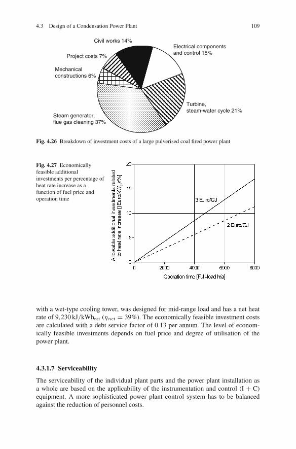
4.3 Design of a Condensation Power Plant 109
Electrical componentsand control 15%
Turbine,steam-water cycle 21%
Steam generator,flue gas cleaning 37%
Mechanicalconstructions 6%
Project costs 7%
Civil works 14%
Fig. 4.26 Breakdown of investment costs of a large pulverised coal fired power plant
Fig. 4.27 Economicallyfeasible additionalinvestments per percentage ofheat rate increase as afunction of fuel price andoperation time
with a wet-type cooling tower, was designed for mid-range load and has a net heatrate of 9,230 kJ/kWhnet (ηnet = 39%). The economically feasible investment costsare calculated with a debt service factor of 0.13 per annum. The level of econom-ically feasible investments depends on fuel price and degree of utilisation of thepower plant.
4.3.1.7 Serviceability
The serviceability of the individual plant parts and the power plant installation asa whole are based on the applicability of the instrumentation and control (I + C)equipment. A more sophisticated power plant control system has to be balancedagainst the reduction of personnel costs.
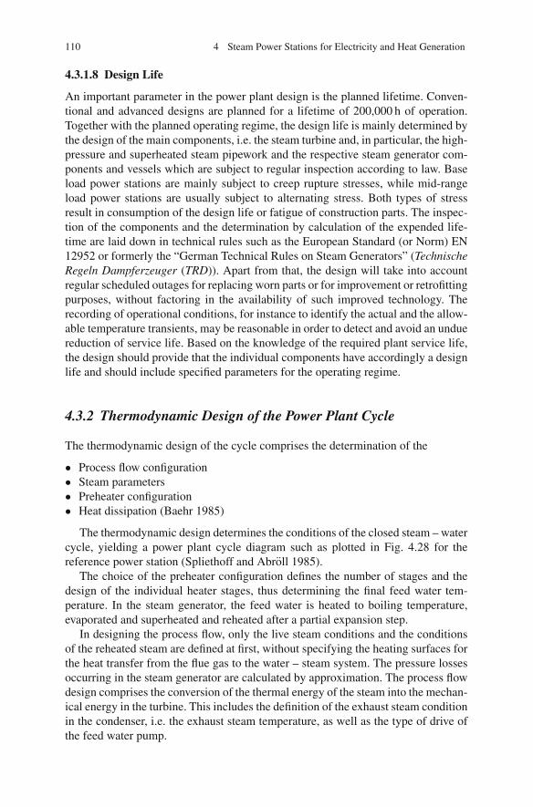
110 4 Steam Power Stations for Electricity and Heat Generation
4.3.1.8 Design Life
An important parameter in the power plant design is the planned lifetime. Conven-tional and advanced designs are planned for a lifetime of 200,000 h of operation.Together with the planned operating regime, the design life is mainly determined bythe design of the main components, i.e. the steam turbine and, in particular, the high-pressure and superheated steam pipework and the respective steam generator com-ponents and vessels which are subject to regular inspection according to law. Baseload power stations are mainly subject to creep rupture stresses, while mid-rangeload power stations are usually subject to alternating stress. Both types of stressresult in consumption of the design life or fatigue of construction parts. The inspec-tion of the components and the determination by calculation of the expended life-time are laid down in technical rules such as the European Standard (or Norm) EN12952 or formerly the “German Technical Rules on Steam Generators” (TechnischeRegeln Dampferzeuger (TRD)). Apart from that, the design will take into accountregular scheduled outages for replacing worn parts or for improvement or retrofittingpurposes, without factoring in the availability of such improved technology. Therecording of operational conditions, for instance to identify the actual and the allow-able temperature transients, may be reasonable in order to detect and avoid an unduereduction of service life. Based on the knowledge of the required plant service life,the design should provide that the individual components have accordingly a designlife and should include specified parameters for the operating regime.
4.3.2 Thermodynamic Design of the Power Plant Cycle
The thermodynamic design of the cycle comprises the determination of the
• Process flow configuration• Steam parameters• Preheater configuration• Heat dissipation (Baehr 1985)
The thermodynamic design determines the conditions of the closed steam – watercycle, yielding a power plant cycle diagram such as plotted in Fig. 4.28 for thereference power station (Spliethoff and Abroll 1985).
The choice of the preheater configuration defines the number of stages and thedesign of the individual heater stages, thus determining the final feed water tem-perature. In the steam generator, the feed water is heated to boiling temperature,evaporated and superheated and reheated after a partial expansion step.
In designing the process flow, only the live steam conditions and the conditionsof the reheated steam are defined at first, without specifying the heating surfaces forthe heat transfer from the flue gas to the water – steam system. The pressure lossesoccurring in the steam generator are calculated by approximation. The process flowdesign comprises the conversion of the thermal energy of the steam into the mechan-ical energy in the turbine. This includes the definition of the exhaust steam conditionin the condenser, i.e. the exhaust steam temperature, as well as the type of drive ofthe feed water pump.
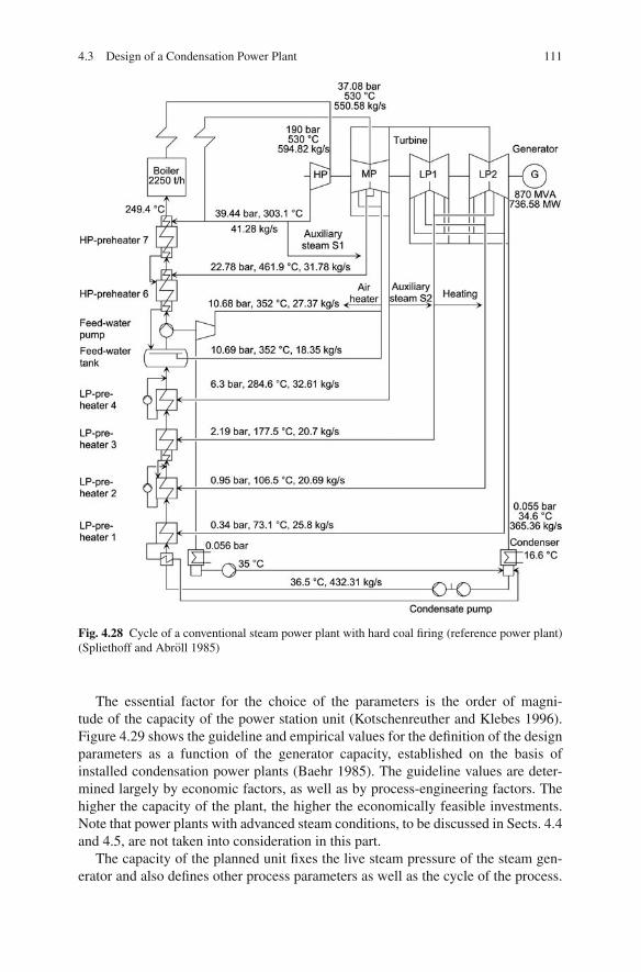
4.3 Design of a Condensation Power Plant 111
Fig. 4.28 Cycle of a conventional steam power plant with hard coal firing (reference power plant)(Spliethoff and Abroll 1985)
The essential factor for the choice of the parameters is the order of magni-tude of the capacity of the power station unit (Kotschenreuther and Klebes 1996).Figure 4.29 shows the guideline and empirical values for the definition of the designparameters as a function of the generator capacity, established on the basis ofinstalled condensation power plants (Baehr 1985). The guideline values are deter-mined largely by economic factors, as well as by process-engineering factors. Thehigher the capacity of the plant, the higher the economically feasible investments.Note that power plants with advanced steam conditions, to be discussed in Sects. 4.4and 4.5, are not taken into consideration in this part.
The capacity of the planned unit fixes the live steam pressure of the steam gen-erator and also defines other process parameters as well as the cycle of the process.

112 4 Steam Power Stations for Electricity and Heat Generation
Fig. 4.29 Guideline values for the design of steam power plants (Baehr 1985)
Higher pressure stages also justify more complex technology. Reheating is providedfor pressures of more than 125 bar. The recommended live steam temperatures arealso defined by the pressure stage.
Figure 4.29 presents several recommended pressure stages for a given genera-tor capacity. The choice of higher pressure stages is reasonable for high fuel costsand full-load plants, the low-pressure stages for mid-range or peak load and lowfuel costs.
The exhaust steam temperature of the turbine is determined by the temperature ofthe cooling medium, which takes the waste heat, and the temperature gradient of thewaste heat transfer defined in the design. The location also determines the choiceof the cooling medium, e.g. seawater or ambient air, and their respective seasonalaverage temperature.
Lower exhaust steam temperatures bring about higher efficiency contributions tothe production of electric power by the “cold end”. On the other hand, the invest-ments rise with decreasing temperature differences between the condensate and thecooling medium. The justifiable expenditures have to be estimated by means of acost-effectiveness optimisation.
The “thermal cornerstones” – the live steam conditions, the reheater steam con-ditions, the regenerative feed water preheating by turbine extraction and the coldend of the turbine – determine the thermal efficiency and the heat rate of the con-densation turbine.
Figure 4.30 shows the turbine heat rate for the configurations shown in Fig. 4.29.Today, cycle simulation software is commonly utilised for designing and optimisingthe thermodynamic cycle. Section 4.4 discusses measures to increase the thermalefficiency in the heat flow design of a power plant.
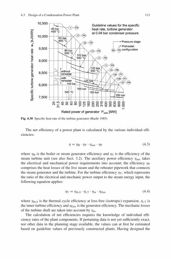
4.3 Design of a Condensation Power Plant 113
Fig. 4.30 Specific heat rate of the turbine generator (Baehr 1985)
The net efficiency of a power plant is calculated by the various individual effi-ciencies:
η = ηB · ηT · ηaux · ηP (4.3)
where ηB is the boiler or steam generator efficiency and ηT is the efficiency of thesteam turbine unit (see also Sect. 3.2). The auxiliary power efficiency ηaux takesthe electrical and mechanical power requirements into account; the efficiency ηP
comprises the heat losses of the live steam and the reheater pipework that connectsthe steam generator and the turbine. For the turbine efficiency ηT, which representsthe ratio of the electrical and mechanic power output to the steam energy input, thefollowing equation applies:
ηT = ηth,0 · ηi,T · ηm · ηGen (4.4)
where ηth,0 is the thermal cycle efficiency at loss-free (isotropic) expansion, ηi,T isthe inner turbine efficiency and ηGen is the generator efficiency. The mechanic lossesof the turbine shaft are taken into account by ηm.
The calculation of net efficiencies requires the knowledge of individual effi-ciency rates of the plant components. If pertaining data is not yet sufficiently exact,nor other data in the planning stage available, the values can at first be estimatedbased on guideline values of previously constructed plants. Having designed the

114 4 Steam Power Stations for Electricity and Heat Generation
components, these estimations have to be corrected later and the calculations haveto be repeated.
4.3.3 Heat Balance of the Boiler and Boiler Efficiency
In the boiler or steam generator, the chemically bound energy of the fuel is convertedinto thermal energy of the flue gas and then transferred to the steam – water cycle.For a steam generator with a single reheating heat exchange stage, the heat balancecan be calculated according to Fig. 4.31:
QF + QA = mLS (hLS − hFW) + mRS (hRS2 − hRS1) + QLOSS (4.5)
The boiler efficiency can be calculated directly when the steam conditions andflows and the heat addition into the furnace are known:
ηB = mLS (hLS − hFW) + mRS (hLS2 − hLS1)
mF · LHV + mAcPA (tA − to)(4.6)
For the indirect calculation of the boiler efficiency, only the losses of the boilerhave to be known. Initially, they will be based on experience values. With the lossthrough unburned matter (KU), the loss through sensible heat of the slag (KS), theflue gas loss (KFG) and the loss through radiation and convection of the externalsurfaces of the boiler (KRC), the boiler efficiency can be calculated:
Fig. 4.31 Heat balance of asteam generator
( )b−1
RS1h
RS2h,
LSh
Flue gas
Air preheater
Feed water
Reheat steam
Live steam
Fuel
ECO
RH
SH
QF
,mFW hFW
mRS
,mLS
QF
QA
QIN
η
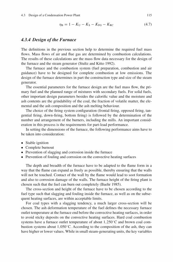
4.3 Design of a Condensation Power Plant 115
ηB = 1 − KU − KS − KFG − KRC (4.7)
4.3.4 Design of the Furnace
The definitions in the previous section help to determine the required fuel massflows. Mass flows of air and flue gas are determined by combustion calculations.The results of these calculations are the mass flow data necessary for the design ofthe furnace and the steam generator (Stultz and Kitto 1992).
The furnace and the combustion system (fuel preparation, combustion and airguidance) have to be designed for complete combustion at low emissions. Thedesign of the furnace determines in part the construction type and size of the steamgenerator.
The essential parameters for the furnace design are the fuel mass flow, the pri-mary fuel and the planned range of mixtures with secondary fuels. For solid fuels,other important design parameters besides the calorific value and the moisture andash contents are the grindability of the coal, the fraction of volatile matter, the ele-mental and the ash composition and the ash melting behaviour.
The choice of the firing system configuration (frontal firing, opposed firing, tan-gential firing, down-firing, bottom firing) is followed by the determination of thenumber and arrangement of the burners, including the mills. An important consid-eration in this process is the requirements for part-load performance.
In setting the dimensions of the furnace, the following performance aims have tobe taken into consideration:
• Stable ignition• Complete burnout• Prevention of slagging and corrosion inside the furnace• Prevention of fouling and corrosion on the convective heating surfaces
The depth and breadth of the furnace have to be adapted to the flame form in away that the flame can expand as freely as possible, thereby ensuring that the wallswill not be touched. Contact of the wall by the flame would lead to soot formationand also to corrosion damage of the walls. The furnace height of the firing plant ischosen such that the fuel can burn out completely (Baehr 1985).
The cross-section and height of the furnace have to be chosen according to thefuel type such that slagging and fouling inside the furnace, as well as on the subse-quent heating surfaces, are within acceptable limits.
For coal types with a slagging tendency, a much larger cross-section will bechosen. The ash deformation temperature of the fuel defines the necessary furnaceoutlet temperature at the furnace end before the convective heating surfaces, in orderto avoid sticky deposits on the convective heating surfaces. Hard coal combustionsystems have a furnace outlet temperature of about 1,250◦C and brown coal com-bustion systems about 1,050◦C. According to the composition of the ash, they canhave higher or lower values. While in small steam-generating units, the key variables
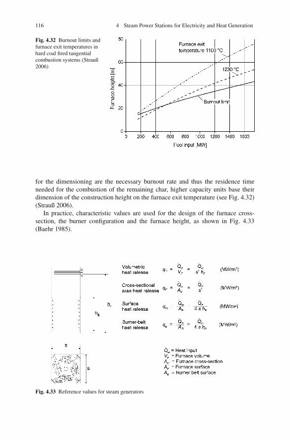
116 4 Steam Power Stations for Electricity and Heat Generation
Fig. 4.32 Burnout limits andfurnace exit temperatures inhard coal fired tangentialcombustion systems (Strauß2006)
for the dimensioning are the necessary burnout rate and thus the residence timeneeded for the combustion of the remaining char, higher capacity units base theirdimension of the construction height on the furnace exit temperature (see Fig. 4.32)(Strauß 2006).
In practice, characteristic values are used for the design of the furnace cross-section, the burner configuration and the furnace height, as shown in Fig. 4.33(Baehr 1985).
Fig. 4.33 Reference values for steam generators

4.3 Design of a Condensation Power Plant 117
4.3.4.1 Volumetric Heat Release Rate
The furnace volumetric heat release is a measure of the residence time in the furnaceand thus makes it possible to evaluate the burnout. It is defined by the given cross-section and the furnace outlet temperature.
4.3.4.2 Cross-Sectional Area Heat Release Rate
The cross-sectional area heat release rate is one of the key variables in the design ofthe furnace and is a measure of the flue gas velocity. It depends on the fuel and onthe steam generator capacity (see Fig. 4.34) and sets the cross-section of the furnacefor the design.
Fig. 4.34 Allowable heat release rates in furnaces (Adrian et al. 1986; Strauß 2006; Baehr 1985)
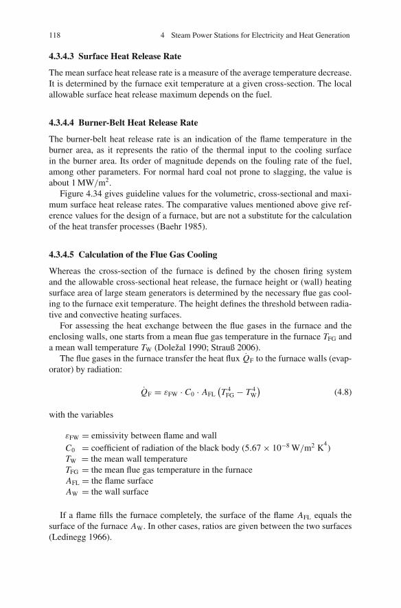
118 4 Steam Power Stations for Electricity and Heat Generation
4.3.4.3 Surface Heat Release Rate
The mean surface heat release rate is a measure of the average temperature decrease.It is determined by the furnace exit temperature at a given cross-section. The localallowable surface heat release maximum depends on the fuel.
4.3.4.4 Burner-Belt Heat Release Rate
The burner-belt heat release rate is an indication of the flame temperature in theburner area, as it represents the ratio of the thermal input to the cooling surfacein the burner area. Its order of magnitude depends on the fouling rate of the fuel,among other parameters. For normal hard coal not prone to slagging, the value isabout 1 MW/m2.
Figure 4.34 gives guideline values for the volumetric, cross-sectional and maxi-mum surface heat release rates. The comparative values mentioned above give ref-erence values for the design of a furnace, but are not a substitute for the calculationof the heat transfer processes (Baehr 1985).
4.3.4.5 Calculation of the Flue Gas Cooling
Whereas the cross-section of the furnace is defined by the chosen firing systemand the allowable cross-sectional heat release, the furnace height or (wall) heatingsurface area of large steam generators is determined by the necessary flue gas cool-ing to the furnace exit temperature. The height defines the threshold between radia-tive and convective heating surfaces.
For assessing the heat exchange between the flue gases in the furnace and theenclosing walls, one starts from a mean flue gas temperature in the furnace TFG anda mean wall temperature TW (Dolezal 1990; Strauß 2006).
The flue gases in the furnace transfer the heat flux QF to the furnace walls (evap-orator) by radiation:
QF = εFW · C0 · AFL(T 4
FG − T 4W
)(4.8)
with the variables
εFW = emissivity between flame and wallC0 = coefficient of radiation of the black body (5.67 × 10⁻⁸ W/m2 K
4)
TW = the mean wall temperatureTFG = the mean flue gas temperature in the furnaceAFL = the flame surfaceAW = the wall surface
If a flame fills the furnace completely, the surface of the flame AFL equals thesurface of the furnace AW. In other cases, ratios are given between the two surfaces(Ledinegg 1966).

4.3 Design of a Condensation Power Plant 119
The emissivity between the flame and the wall depends on the emissivities of thesurface wall and the flame and can be calculated:
εFW =(
1
εF+ 1
εW− 1
)−1
(4.9)
The surface emissivity of an oxidised steel surface is between 0.6 and 0.8. Fur-nace ash deposits affect the heat transfer. The emissivity of deposits depends on thechemical composition, structure and porosity of the layer. The apparent emissivity,which describes the combined deposit and substrate emissivity, lies between 0.5 and0.8 for most deposits (Stultz and Kitto 1992).
The flame emissivity can be calculated by
εF = ε∞(1 − exp(−ks)) (4.10)
where ε∞ is the emissivity for a very thick flame. The parameter s is the thickness ofthe flame or beam length and k depends on the character of the flame. The parameterk varies between 0.75 for luminous flames and 0.5 for blue flames.
Typical values for the emissivity ε∞ are as follows:
Hard coal, brown coal 0.55–0.8Oil 0.6–0.85Natural gas 0.4–0.6
The resulting emissivity is, for a hard coal fired furnace, in the range of 0.4–0.7,mainly depending on fouling and slagging.
The mean furnace temperature of the dry bottom furnaces is calculated as thegeometric mean of the adiabatic combustion temperature Tad and the furnace outlettemperature TFE:
TFG =√
Tad · TFE (4.11)
The heat flux in the furnace QF is transferred from the flue gas mass flow mFG,having a specific heat cpF6 , which cools from the adiabatic flame temperature Tad
down to furnace exit temperature TFE:
QF = mFG · cpF6 (Tad − TFE) (4.12)
The resulting heat balance is
εFW · C0 · AW(T 2
ad · T 2FE − T 4
W
) = mFG · cpF6 (Tad − TFE) (4.13)
and can be expressed as

120 4 Steam Power Stations for Electricity and Heat Generation
(TFE
Tad
)2
+ K o · TFE
Tad=
(T 4
W
Tad
)2
+ K o (4.14)
where
K o = mFG · cpF6
εFW · C0 · AW · T 3ad
(4.15)
Ko is an undimensional similarity coefficient, called the Konakow number.The relation above serves to calculate the exit temperature of a given furnace or,
in case of a given outlet temperature, the surface necessary for the cooling of theflue gases. In the calculation of modern steam generators with water-cooled tubesand vaporisation temperatures below 400◦C, TW
4 can be neglected. Fouling andslagging of furnace walls make the temperatures rise considerably.
The calculation of furnace wall heating surfaces and the preselected form (design)and dimensions of the cross-section together define the furnace height. By means ofadditional internal heating surfaces, such as a division wall that divides the furnacevertically, it is possible to reduce the furnace height (Dolezal 1990).
The prediction of the radiant heat transferred to the walls of the furnace is one ofthe most important steps in designing a steam generator and has to be more exactthan the calculation method described above, which only allows a rough estimationof the furnace exit temperature. The objective of such a calculation is to determinethe local heat fluxes towards the furnace walls and to determine the distribution ofthe temperature and heat flux densities inside the furnace and at the furnace end(Baehr 1985).
In most cases, simpler, partially empirical models are employed. The results ofa one-dimensional plug flow model based upon a mean cross-sectional temperatureare shown in Fig. 4.35. The maximum heat flow density in the upper burner arearanges around 0.27 MW/m2 during standard operation.
Firing conditions deviating from standard operation, such as those during fuelchanges, when changing burner combinations, while there are unbalanced fuel andair distributions, during load change, or furnace wall fouling, can lead to locallyhigher heat flow densities. In the design and calculations of firing and heat transferconditions, these cases are usually taken into account using empirical values (Stultzand Kitto 1992).
The calculation of the combustion course, in particular for new firing and burnerconcepts, employs three-dimensional numerical models which consider flow, reac-tion and heat transfer and determine the distribution of heat flow densities at thefurnace walls. This way it is possible to determine and describe the impacts ofdeviations from standard firing conditions.

4.3 Design of a Condensation Power Plant 121
4.3.5 Design of the Steam Generator and of the Heating Surfaces
In designing the steam generator, it is necessary to dimension the heating surfacessuch that the temperatures and mass flows defined in the cycle design can be metwhile taking the allowable material temperatures into consideration. Designing thethermal configuration and the steam generator is an iterative procedure. Given thatat the beginning not all data is available and that guideline values have to be reliedon, the design has to be repeated until the required mass flows and temperaturesare met over the entire load range. This iteration is first carried out for the steamgenerator and then for the total cycle.
After designing the thermal configuration and the steam generator, it is possibleto design the pressure parts and to begin to develop details. In Europe the “Pres-surised Equipment Directive PED 97/23/EG” defines the boundary conditions forpressurised equipment. The design and construction regulations for steam genera-tors are specified in the European Standard (or Norm) EN 12952, which replaced thedesign rules “Technische Regeln fur Dampfkessel (TRD)” or “Technical Rules forBoilers” in Germany. Alternative to the European regulations, the “ASME Boilerand Pressure Vessel Code” by the American Society of Mechanical Engineers(ASME) can be used (even in Europe).
The steam generator heating surfaces are the membrane furnace walls and theflue gas pass, as well as the tube banks across the flue gas cross-section.
The usual construction for furnace and flue gas pass walls are tube-fin bar-tubewall constructions which are connected and welded together to make gas-tight
Fig. 4.35 Calculated heatflux distribution across theheight of the furnace(Effenberger 2000)
furnace
hopp
er
1.0
0.8
0.6
0.4
0.2
0
furnace
hopp
er
Rel
ativ
e fu
rnac
e he
ight
Heat flux [kW/m²]
0 50 100 150 200 250 300

122 4 Steam Power Stations for Electricity and Heat Generation
membrane walls. These walls are only exposed to thermal radiation on one side;the other side is insulated against the outside in order to avoid heat loss.
The components in the flue gas path that follow after the furnace are the con-vective heating surfaces of the superheater, the reheater and the economiser. Theyconsist of a great number of parallel tubes which are mounted crossways to the flow.Heat is mostly transferred by convection.
Evaporator and superheater surfaces are exposed to much higher temperatureson the side facing the fire and the flue gas than on the water/steam-cooled side.Heat transfer conditions on the inside and the outside surfaces of the heated tubescharacterise the tube wall temperatures. At high inner pressures and defined flowvelocities, they range only a little above the steam temperatures and are thus muchlower than the furnace and the flue gas temperatures.
The allowable tube wall temperatures can be above the temperature of the work-ing medium by a maximum of 50 K for radiant heating surfaces and of 20 K forconvective heating surfaces. The temperatures must not exceed the tube wall tem-perature limits, which are dependent on the materials and the design pressure.Unheated tube, header and vessel walls will take, approximately, the temperaturesof the steam flows.
Figure 4.36 shows a schematic drawing of the heating surface configuration ofa single-pass or tower boiler, with the same furnace and flue gas duct cross-sectionover the height of the tower – a widespread construction type in Europe and Japan.
Fig. 4.36 Heating surfaceconfiguration of a single-passboiler (“tower boiler”)

4.3 Design of a Condensation Power Plant 123
Fig. 4.37 Heating surfaceconfiguration of a two-passboiler
Figure 4.37 shows the configuration of a steam generator in two-pass construction –the common type in the US and other countries.
For economic reasons, the steam generator should be designed such that thetotal heating surface area is a minimum. This minimum is met by a configurationthat leads the hot flue gases in a counter-current flow to the working medium (i.e.water/steam) – a design that is only partly feasible.
The furnace walls are the heating surfaces with the highest temperatures (occur-ring on the flue gas side) and highest heat flux densities. The water/steam has toguarantee sufficient cooling in order keep the tube-furnace wall temperatures belowthe allowable material temperatures. However, this requirement cannot be met bythe low heat transfer of steam. So in practice these heating surfaces are used tovaporise the medium, because this process with its two-phase mixture provides agood heat transfer.
The construction of the area of the convective heating surfaces uses a counterflowconfiguration. An exception to this is made only for some superheaters, in order toensure constant temperatures of the live steam as a function of the load. Figure 4.38charts the flue gas temperatures and the material temperatures along the flue gas pathof the reference power plant. It can be observed that the heat flux density declinesalong the flue gas path. The heat transfer coefficient, too, shows a decrease towardsthe end of the steam generator, with the exception of the economiser stage.

124 4 Steam Power Stations for Electricity and Heat Generation
Fig. 4.38 Flue gas,temperature of the workingmedium and heat flux densityof the reference power plant
0 20 40 60 80 1000
200
400
600
800
1000
1200
1400
EvaporatorSH1
SH2
SH4
RH2
SH3
RH1 Eco
Tem
pera
ture
[°C
]
Transferred heat [%]
0 20 40 60 80 1000
50
100
150
200
250
.
Evaporator SH1
SH2
SH4
RH2
SH3
RH1
Eco
Hea
t flu
x de
nsity
q [k
W/m
2 ]
Transferred heat [%]
4.3.5.1 Impact of the Live Steam Pressure
The steam conditions defined in the thermal design pre-set the conceptual designof the evaporator (natural circulation, forced circulation or once through) and theheat levels necessary for preheating, vaporisation, superheating and reheating. Thefurnace exit temperature defines the heat to be transferred in the furnace and by thedownstream convective heating surfaces.
The next step is to integrate the live steam pressure defined by the steam condi-tions into the design of the heating surfaces. Figure 4.39 shows h − p diagrams for alow-pressure and for a high-pressure boiler. At low pressures, the heat of evaporationpredominates, whereas at higher pressures, the vaporisation enthalpy decreases andthe heat demand for superheating increases (Dolezal 1990).
In designing steam generation systems with a fixed liquid – vapour phase tran-sition point, it is possible for over-determination to occur. This is because thevaporisation heat decreases with higher design pressures, while the flue gas coolingrequirements and the evaporator capacity are fixed. As Fig. 4.40 shows, the entirefurnace is required to act as an evaporative heating surface at low pressures, as thefeed water is preheated and steam superheated only on convective heating surfaces.Given the lower vaporisation enthalpy at high pressures, the flue gases are not suf-
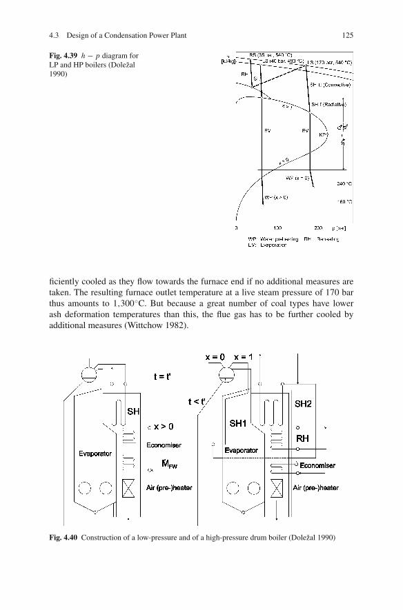
4.3 Design of a Condensation Power Plant 125
Fig. 4.39 h − p diagram forLP and HP boilers (Dolezal1990)
ficiently cooled as they flow towards the furnace end if no additional measures aretaken. The resulting furnace outlet temperature at a live steam pressure of 170 barthus amounts to 1,300◦C. But because a great number of coal types have lowerash deformation temperatures than this, the flue gas has to be further cooled byadditional measures (Wittchow 1982).
Fig. 4.40 Construction of a low-pressure and of a high-pressure drum boiler (Dolezal 1990)

126 4 Steam Power Stations for Electricity and Heat Generation
One of the options, pictured in Fig. 4.40, is to mount additional heating surfacesfor superheating in the furnace. Such additional surfaces, however, are undesirablein practice as their incorporation into the evaporator wall is difficult due to the dif-fering steam temperatures.
Another possibility is flue gas recirculation, which shifts the heat absorption fur-ther into the convective area. The disadvantage here is the higher auxiliary powerdemand. Plants in the USA utilise hanging plate heating surfaces as the first super-heater surface in the flue gas flow. These can be located anywhere where flue gastemperatures are up to 1,400◦C. They are also relatively insensitive to slag depositsbecause of their construction. When considering the furnace dimensions, it is usefulto know that such heating surfaces are very compact.
The correlation of flue gas cooling and evaporator design only holds for steamgenerators with a fixed liquid – vapour phase transition point for natural or forcedcirculation. Limits resulting from the water and steam do not exist in dimensioningthe furnace of once-through steam generators. For once-through steam generatorswith variable start and end points of vaporisation, the furnace and flue gas ductwalls form a single heating surface where the last stage of preheating, the vapori-sation and the first superheating stage take place. The transition from vaporisationto superheating migrates within the evaporator tubes, occurring mostly in the upperfurnace section. With an increasing pressure, the liquid – vapour phase transitionpoint shifts further down, and the furnace wall is used for superheating to a greaterextent. Because the heat flux density in the upper evaporator and furnace walls isalready below the mean heat flux density of furnace walls, levels that exceed theallowable tube wall temperatures are not expected in the range of the boiling crisisof the “second kind” (see Sect. 4.2.1).
4.3.5.2 Design of the Evaporator
In the furnace, the radiant heat transferred to the evaporator wall determines, via theheat flux distribution, the mass flow density necessary for cooling the evaporatortubes. At the furnace wall, at about the height of the burners, the highest heat fluxdensities occur. They decrease towards furnace end, falling further afterwards, inthe area of the convective heating surfaces (see Fig. 4.38). Increasingly, the heat istransferred by convection, which also occurs in the flue gas duct walls.
For the design of a steam generator, it is necessary to know beforehand the max-imum tube wall temperature, which is a function of the gas-side heat flux density(about 300–350 kW for hard coal firing systems), and the mass flow density of thesteam – water mix. This is in order to avoid the allowable material temperaturesbeing exceeded where the boiling crisis occurs. In once-through steam generators,the water/steam mass flow used for cooling decreases with the load, whereas theheat flux densities in the burner area decrease only to a minor extent, so it is thepartial-load condition that determines the design. In general, the mass flow densityof an evaporator with plain tubes lies between 700 and 800 kg/m2 s at a minimumoutput of 30–40% (Franke et al. 1993). The mass flow density at the rated powerlies between 2,000 and 2,500 kg/m2 s.
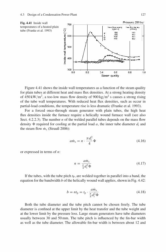
4.3 Design of a Condensation Power Plant 127
Fig. 4.41 Inside walltemperatures of a heated plaintube (Franke et al. 1993)
Figure 4.41 shows the inside wall temperatures as a function of the steam qualityfor plain tubes at different heat and mass flux densities. At a strong heating densityof 450 kW/m2, a too-low mass flow density of 900 kg/m2 s causes a strong risingof the tube wall temperatures. With reduced heat flux densities, such as occur inpartial-load conditions, the temperature rise is less dramatic (Franke et al. 1993).
For a forced once-through steam generator with plain tubes, the high heatflux densities inside the furnace require a helically wound furnace wall (see alsoSect. 4.2.2.3). The number n of the welded parallel tubes depends on the mass flowdensity Φ required for cooling at the partial load a, the inner tube diameter di andthe steam flow ms (Strauß 2006):
ams = n · πd2i
4Φ (4.16)
or expressed in terms of n:
n = amsπ4 d2
i Φ(4.17)
If the tubes, with the tube pitch tP, are welded together in parallel into a band, theequation for the bandwidth b of the helically wound wall applies, shown in Fig. 4.42:
b = ntp = tp · amsπ4 d2
i Φ(4.18)
Both the tube diameter and the tube pitch cannot be chosen freely. The tubediameter is confined at the upper limit by the heat transfer and the tube weight andat the lower limit by the pressure loss. Large steam generators have tube diametersusually between 30 and 50 mm. The tube pitch is influenced by the fin-bar widthas well as the tube diameter. The allowable fin-bar width is between about 12 and

128 4 Steam Power Stations for Electricity and Heat Generation
Fig. 4.42 Schematic drawingof the helical winding(Dolezal 1990)
15 mm. The upper limit of the fin-bar width is given by the hazard of scaling of thefin bar, the lower one is given by constructive and economic points of view.
The bandwidth b is smaller than the furnace perimeter PF, so the band has to bewound helically around the furnace to completely line the furnace wall. The helixangle β can be calculated as
β = arcsin (b/PF) (4.19)
The helix angle increases with the boiler size.In the upper area of the steam generator, before the convective area begins, the
helical winding transforms into vertical tubing. Because vertical tubing is moreeconomical than helical winding, it should be designed to begin at the lowest pos-sible furnace height. The helical winding and vertical tubing are joined by clevises(see Fig. 4.43). In the vertical tubing, the mass flow density of the working fluid,then in a vapour state, is diminished by increasing the number of tubes by a factorof 3–4. If the transition to vertical tubing is carried out at a furnace height which istoo low, it is possible that, with high gas-side heat flux densities and low mass flowdensities of the cooling fluid, excessive tube wall temperatures arise in the verticaltubes. In contrast, when the helical winding is too high, non-uniform heating canhave stronger effects due to the longer tubes of the helix, thus also causing the tubewall temperatures to exceed the allowable limit (Kefer et al. 1990).
Commonly, the helical tube winding finishes with the furnace, while the verti-cal tubing begins in the convective section. Where heat flux densities decrease, forinstance when flue gas temperatures fall to between 750 and 800◦C, the numberof tubes is diminished. It becomes possible to double the tube pitch, because thefin-bar temperatures are below the scaling temperature of the material. The largertube pitch of the membrane walls facilitates the insertion of the superheaters andreheaters, which have narrowing tube pitches. The tube pitch in the upper section ofthe vertical pass – commonly 100–120 mm – defines the tube pitch in all wall areas.Figure 4.43 shows the tube pitches of the reference power plant.

4.3 Design of a Condensation Power Plant 129
Fig. 4.43 Wall tubing of asingle-pass boiler with helicalwinding in the furnacesection (Source:Alstom Power)
4.3.5.3 Evaporators with Vertical Internally Rifled Tubes
The helical winding of tubes, as opposed to vertical tubes, requires a more complexconstruction, because the tubes are not self-supporting. Vertical mounting of theevaporator tubing in the furnace, using plain tubes, would require a great numberof parallel tubes at adequately low mass flow densities which, even then, would notensure sufficient cooling (Franke et al. 1993; Wittchow 1995).
Internally rifled evaporator tubes allow lower densities of the water/steam massflow at the same heat flux density, owing to the more intensive heat transfer from theinner tube wall to the working fluid, so that the evaporator tubes can also be mountedvertically in the furnace (see Fig. 4.44). The helically wound tubing of the referencepower plant (740 MWel, 1,900 MW thermal input of fuel), with about 400 tubessized 38×5.6 mm, is designed for a mass flow density at full load of 2,100 kg/m2 s.The angle of the helix is 16◦. A steam generator of the same size, to draw a com-parison, needs about 1,500 internally finned, vertically mounted evaporator tubes,sized 34×6 mm. The mass flow density in full load operation is only 1,000 kg/m2 s.For a sufficient cooling at the heat flow densities at full load, mass flow densities of250–350 kg/m2 s are satisfactory (Franke et al. 1993).
The low mass flow densities of internally rifled tubes allow sufficient coolingat low minimum capacities, without causing high pressure losses due to high massflow densities at full load. In comparison to inclined tubes, vertical mounting avoidssegregation processes. The minimum load of the steam generator can be loweredfrom 35–40 to 20%. A lower minimum load could decrease the number of start-ups
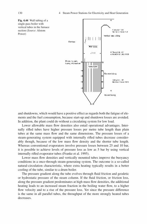
130 4 Steam Power Stations for Electricity and Heat Generation
Fig. 4.44 Wall tubing of asingle-pass boiler withvertical tubes in the furnacesection (Source: AlstomPower)
and shutdowns, which would have a positive effect as regards both the fatigue of ele-ments and the fuel consumption, because start-up and shutdown losses are avoided.In addition, the plant could do without a circulating system for low load.
Lower allowable mass flow densities also entail operational advantages. Inter-nally rifled tubes have higher pressure losses per metre tube length than plaintubes at the same mass flow and the same dimensions. The pressure losses of asteam-generating system equipped with internally rifled tubes decrease consider-ably though, because of the low mass flow density and the shorter tube length.Whereas conventional evaporators involve pressure losses between 25 and 10 bar,it is possible to achieve levels of pressure loss as low as 5 bar by using verticalinternally rifled evaporator tubes (Franke et al. 1995).
Lower mass flow densities and vertically mounted tubes improve the buoyancyconditions in a once-through steam-generating system. The outcome is a so-callednatural-circulation characteristic, where extra heating typically results in a bettercooling of the tube, similar to a drum boiler.
The pressure gradient along the tube evolves through fluid friction and geodeticor hydrostatic pressure of the steam column. If the fluid friction, or friction loss,along the pressure gradient predominates at high mass flow densities, the additionalheating leads to an increased steam fraction in the boiling water flow, to a higherflow velocity and to a rise of the pressure loss. Yet since the pressure differenceis the same in all parallel tubes, the throughput of the more strongly heated tubesdecreases.

4.3 Design of a Condensation Power Plant 131
Fig. 4.45 Throughputcharacteristic of a tube with25% extra heating (Wittchow1995)
If the geodetic pressure loss predominates, the additional heating leads to highermass flow densities. Due to the increased steam formation, the geodetic pressure lossof a tube with constant mass flow diminishes, because the steam column becomeslighter. The decrease of the geodetic pressure drop is higher than the rise of thefriction loss. The pressure loss being given, however, the mass flow through theadditionally heated tube rises (natural-circulation characteristic, see Fig. 4.45). Theimpact of the extra heating on the steam temperatures at the evaporator outlet isminimised by the self-regulating effect. This can be an advantage for the applicationof higher steam conditions, since the difference between the fluid temperature in theevaporator and the allowable material temperature may be smaller (Franke et al.1993, 1995; Wittchow 1995). On the other hand, the counterbalance of the heatingby the helically wound tubes does not apply.
Though one might expect a higher price for the tubes, financial benefits of thesteam generator of up to 10% have been found, because the evaporator can bedesigned as a self-supporting construction (Wittchow 1995). Also, manufacturingand mounting are simpler than for helically wound tubing, which may be an advan-tage if the manufacturing is to be done in newly industrialised countries. Investi-gations in large-scale industrial plants with a test configuration of several verticalinternally finned tubes mounted in parallel with helically wound tubes confirm theadvantages of this concept (Franke et al. 1995; Kral et al. 1993).
In circulation steam generator construction, the more economical vertical tubesare used. The maximum heat flow density of about 0.4 MW/m2 common in coal-fired furnaces requires mass flow densities in the evaporator of around 600 kg/m2 s,which have to be controlled by the natural circulation. Since the circulation ratiodecreases with rising pressure in natural circulation, limits of approximately 185bar arise for the maximum pressure in the evaporator, which corresponds to a livesteam pressure before the turbine of about 175 bar. In a forced-circulation system,the circulation mass flow of 1,000–2,000 kg/m2 s is controlled by the circulatingpump (Strauß 2006).

132 4 Steam Power Stations for Electricity and Heat Generation
4.3.5.4 Evaporator Stability
Different operating modes of and uneven fuel flows to the burners of a burner groupcause asymmetric firing conditions and non-uniform heat fluxes to the furnace walls.Given their great lengths and temperature rises, evaporator tubes of forced once-through steam generators react to heating differences with differing temperatures inthe tube wall and at the evaporator outlet. The helical winding still ensures a goodheating balance because each of the parallel tubes runs along all four walls of thefurnace (Franke et al. 1993).
The design of a steam generator has to ensure an even flow through all the paralleltubes of the evaporator as well. Impacts of additional heating on the flow conditionsin the evaporator tubes depend on the characteristic response of the evaporator. Ifthe extra heating of a tube causes the flow through it to diminish (once-through char-acteristic), the possible consequence is that the temperatures exceed the allowablelimit for the material. For the previously described natural-circulation characteristic,a temperature rise through extra heating is counterbalanced by the self-regulatingrise of the boiling water vapour flow in the tube in question. This characteristicdepends on the mass flow density and the fluid friction of the fluid involved. Lowmass flow densities (below 1,000 kg/m2 s) favour the operator-preferred natural-circulation characteristic response (see Fig. 4.45) (Wittchow 1995).
One option for checking whether a stable and even flow in the evaporator hasbeen achieved is to consult the characteristic curves of the evaporator (Baehr 1985).Figure 4.46 shows the correlation between pressure loss and steam mass flow withthe heating as a parameter. While the characteristics of tubes filled with a water flow
Fig. 4.46 Characteristiccurves of the evaporator(Baehr 1985)

4.3 Design of a Condensation Power Plant 133
correspond to a second-order parabola, tubes which are filled by a flowing two-phasemixture, i.e. boiling water and steam, give a third-order curve.
An unstable flow occurs if the curve has a saddle-like behaviour, the consequenceof which can be that three different mass flows evolve for the same pressure gradient.If a mass flow has a lower rate than needed for cooling the tubes, the effect can bedamage to the tubes. The stability of steam generators and measures to raise thestability are dealt with in detail in Dolezal (1990).
4.3.5.5 Design of the Convective Heating Surfaces
The units in the flue gas path following the furnace are the convective heating sur-faces of the superheater, the reheater and the economiser. While the superheaterand the reheater heat the steam up to the required turbine inlet temperatures, theeconomiser cools the flue gases down prior to the air heater and preheats the feedingwater to a level close to the boiling point.
The convective heating surfaces consist of a great number of parallel tubes in across-flow arrangement to the flue gas flow. In contrast to the heat transfer to theevaporator surfaces by radiation, transfer by convection applies heat to the wholetube circumference, which is why the heating surface banks are smaller for thesame temperature difference (Strauß 2006). The heating surface dimensions beingdecided previously, the heat transfer depends on the flue gas velocity and the drivingtemperature difference. The tubes should be mounted in the flue gas duct as close toeach other as possible in order to achieve a high heat transfer level. The distance ofthe tube, however, is limited by the increasing pressure loss on the flue gas side andby possible fouling due to fly ash deposits (Stultz and Kitto 1992).
Superheater and Reheater
Heating surfaces used for superheaters and reheaters can be hanging or horizontaltube bundles. In Germany, where the single-pass construction is commonly built,only horizontal, drainable heating surfaces are used. In boilers in two-pass con-struction, hanging heating surfaces are often used in the cross-pass for super- orreheating. The distance between the tubes, the so-called tube pitch, depends on theflue gas temperature and the flue gas dust concentration (ash content of the coal).With the decreasing temperature, the tube pitch narrows in the direction of the fluegas flow. With low ash contents of the coal, it is possible to use smaller tube pitchesand hence to build a more compact steam generator.
Two-pass boilers of the US type often have a hanging plate-type superheaterwhich can be used in areas of high temperatures of around 1,400◦C. With theseheating surfaces, the predominant method of heat transfer is radiation. The tubes,wound closely to each other in a plane, form a plate, with large distances, of morethan 1 m, between the plates. Such plate superheaters are insensitive to ash deposits.Figure 4.47 shows the tube pitches as a function of the flue gas temperature forUS-type steam generators. In the case of single-pass or tower boilers, the upward-diminishing transverse pitch enables the dropping through of ash deposits that havecome off.

134 4 Steam Power Stations for Electricity and Heat Generation
114 mm114 mm229 mm305 mm610 mm1372 mm
Hangingradiant
superheater(SH1)
(plate-typeor platen SH)
Hanging superheater(SH2)
Hangingreheater
Horizontal convectiveheating surfaces(reheater, SH1)
Flue gas
Furnace
Tem
p.
Convective pass
Average gas temperature
Flue gas path
Fig. 4.47 Heating surface divisions in US constructions (Stultz and Kitto 1992)
The superheater and the reheater are designed for high steam temperatures, whichonly allow low temperature differences between the different tubes of a heatingsurface. Material temperatures in excess of the allowable limits may arise via anuneven flow through the tubes or by an imbalanced heating of some of the tubes.Asymmetric fireside temperatures have more of an effect when the temperature riseof a heating surface is higher.
Design and construction therefore have to guarantee an even flow and to coun-teract the impacts of an imbalanced heating. Temperature discrepancies betweenindividual tubes are balanced out by dividing the superheater system into severalstages, combining and mixing all single-tube steam flows in one stage and thenre-establishing the division in the following stage into single-tube steam flows. Dis-advantages of multistage superheaters are the higher costs and higher pressure lossesdue to headers and manifolds. Large steam generators usually have superheatersdivided up into several piping runs connected in parallel. By crossing the piping

4.3 Design of a Condensation Power Plant 135
Fig. 4.48 Crossing ofmultistage superheaters
runs between the superheater stages, it is possible to counteract uneven heating (seeFig. 4.48).
With this construction the steam flows in the runs change their position in theflue gas pass from one outside to the other or, in the case of four piping runs, fromoutside to inside and vice versa (Strauß 2006; Baehr 1985).
For the control and limitation of live steam and reheater steam temperatures,attemperation is commonly applied. High-pressure feed water (HP feed water) isinjected before or after the last superheater or reheater stage in attemperators.
Maintaining Constant Live Steam Temperatures
Falling high pressures and reheater steam temperatures in partial-load conditionsdiminish the mean temperature of the heat addition and hence the thermal efficiency.The live steam and reheater steam temperature should therefore be constant through-out the whole load range.
The design and location of the heating surfaces determine the temperaturecharacteristics as a function of the load for each superheater and reheater. Heatingsurfaces in areas of high temperatures, above about 1,200◦C, take up heat predom-inantly by radiation, and heating surfaces in areas of low temperatures, mainly byconvection (Strauß 2006). With the output diminishing, the radiant heating surfacesin the furnace take up relatively more heat (radiation characteristic) whereas theheat share of the convective heating surfaces decreases (convection characteristic).Care should be taken that, for superheating and reheating convection surfaces, bothconvection and radiation characteristics are incorporated into the design, in order to

136 4 Steam Power Stations for Electricity and Heat Generation
Fig. 4.49 Characteristics ofradiation and convectionheating surfaces
achieve a constant steam temperature throughout the output range (see Fig. 4.49)(Stultz and Kitto 1992; Dolezal 1990; Adrian et al. 1986).
A heat flux shift between the evaporator and the convective heating surfaces hasdifferent impacts on the superheater and the live steam temperatures, which alsodepend on the evaporator system (Wittchow 1982).
During part-load operation of once-through steam generators with a variable liq-uid – vapour phase transition point, the vaporisation area migrates to the begin-ning of the evaporator, with the heat absorption in the furnace increasing and thesuperheating area in the membrane wall becoming larger. The lower heat uptake inthe convective heating surfaces has therefore only a minor effect on the live steamtemperature. In once-through boilers, the live steam temperature is kept constantup to about 35% of the load capacity by the setting of the ratio of the fuel flowto the feed water flow. The ratio of attemperator water to feed water flow remainsunchanged at about 5% throughout the whole output range. It is not necessary totake measurements on the flue gas side.
The injection of the spray water in the high-pressure section of the steam gener-ator causes a reduction of the efficiency only if the temperature of the spray waterdiffers from the entrance temperature of the feed water. Generally though, waterfor injection is extracted after the high-pressure preheaters, so no efficiency loss isinvolved.
In circulation steam generators with a fixed liquid – vapour phase transitionpoint, a higher heat absorption in the vaporisation area results in a greater steamflow which, with the consequently smaller convective heat flux, becomes less super-heated. Therefore, below outputs of about 50–60%, the live steam temperature ofsuch generators decreases.
In steam generators of the US-type circulation configuration, hanging platesuperheaters are used, with a radiation characteristic at high temperatures, for super-heating and reheating at the furnace end. By means of measures on the flue gasside, such as shifting the firing to the upper burner levels, or by additional plant
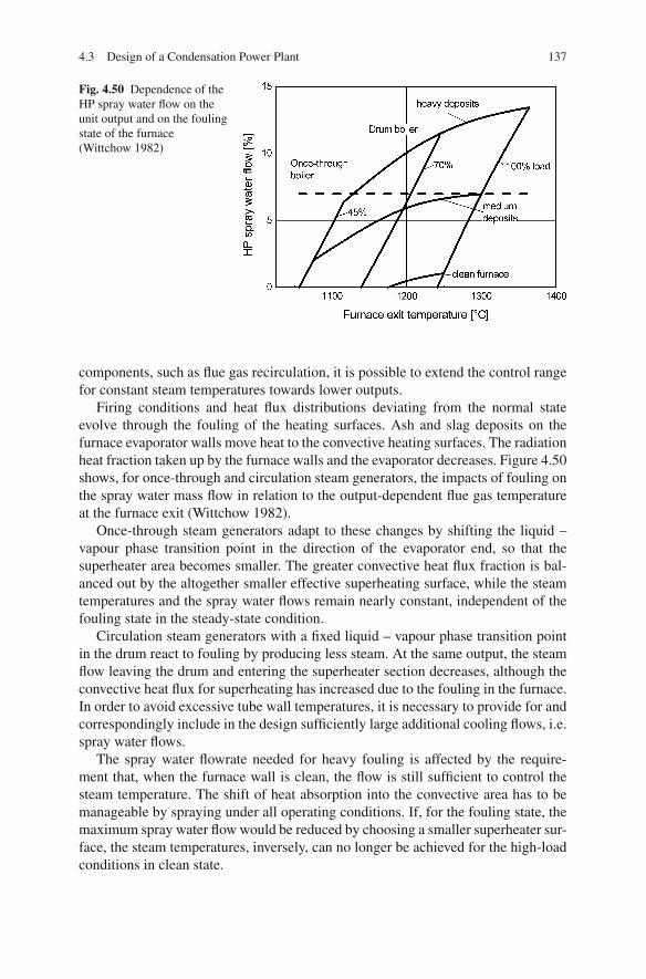
4.3 Design of a Condensation Power Plant 137
Fig. 4.50 Dependence of theHP spray water flow on theunit output and on the foulingstate of the furnace(Wittchow 1982)
components, such as flue gas recirculation, it is possible to extend the control rangefor constant steam temperatures towards lower outputs.
Firing conditions and heat flux distributions deviating from the normal stateevolve through the fouling of the heating surfaces. Ash and slag deposits on thefurnace evaporator walls move heat to the convective heating surfaces. The radiationheat fraction taken up by the furnace walls and the evaporator decreases. Figure 4.50shows, for once-through and circulation steam generators, the impacts of fouling onthe spray water mass flow in relation to the output-dependent flue gas temperatureat the furnace exit (Wittchow 1982).
Once-through steam generators adapt to these changes by shifting the liquid –vapour phase transition point in the direction of the evaporator end, so that thesuperheater area becomes smaller. The greater convective heat flux fraction is bal-anced out by the altogether smaller effective superheating surface, while the steamtemperatures and the spray water flows remain nearly constant, independent of thefouling state in the steady-state condition.
Circulation steam generators with a fixed liquid – vapour phase transition pointin the drum react to fouling by producing less steam. At the same output, the steamflow leaving the drum and entering the superheater section decreases, although theconvective heat flux for superheating has increased due to the fouling in the furnace.In order to avoid excessive tube wall temperatures, it is necessary to provide for andcorrespondingly include in the design sufficiently large additional cooling flows, i.e.spray water flows.
The spray water flowrate needed for heavy fouling is affected by the require-ment that, when the furnace wall is clean, the flow is still sufficient to control thesteam temperature. The shift of heat absorption into the convective area has to bemanageable by spraying under all operating conditions. If, for the fouling state, themaximum spray water flow would be reduced by choosing a smaller superheater sur-face, the steam temperatures, inversely, can no longer be achieved for the high-loadconditions in clean state.

138 4 Steam Power Stations for Electricity and Heat Generation
Figure 4.50 shows the impacts of fouling on the total spray water flow for a plantin service. The change of the spray water flow by fouling with a factor of 2 or moreis considerably stronger than the output-dependent change of the spray water flow.
Maintaining Constant Reheater Temperatures
As in the case of superheating in high-pressure zones, heating surfaces with convec-tion and radiation characteristics should be utilised in order to keep constant reheatersteam temperatures. Reheating does not involve the balancing influence on the livesteam temperature by migrating vaporisation and superheating zones in the furnacewall of a once-through steam generator.
The operating regime of a steam generator – fixed or sliding pressure – can havean influence, however, on the necessary temperature rise. In fixed-pressure opera-tion, the reheater must be supplied with relatively more heat because the reheaterinlet steam temperature drops as the output decreases. But in sliding-pressure oper-ation, the reheater inlet temperature is nearly independent of the output.
A relatively simple method to control and limit the reheater outlet temperatureis to spray feed water between two subsequent reheat surfaces at a pressure similarto the exit steam pressure of the high-pressure turbine. In this case, the reheateris designed to be larger for full load and its steam exit temperature is limited tothe allowable temperature by spray water admixing. When output diminishes, thenecessary spray water flow decreases as well.
Reheater spraying for temperature control, however, has the consequence of aloss in efficiency, because the high-pressure zone of the steam generator is bypassed,and only steam at the reheater pressure is produced and exploited. The heating ofthe spray water by mixing at a low reheater pressure results in a lower temperatureof heat addition.
Other methods of temperature control avoid the disadvantageous effect of reheaterspraying on the steam generator efficiency, for instance by transferring heat betweenthe live steam and the reheater steam system or by shifting the heat flux through fluegas recirculation or tilting burner, to set constant reheater steam outlet temperatures.In order to control the heat transfer between the high-pressure superheater and thereheat surfaces, the reheat surfaces are designed to be either larger or smaller thanwithout this control. Designed larger, they transfer heat to the live steam systemin the upper output range. Designed smaller, they take heat from the high-pressuresuperheaters in lower output range. The heat is exchanged either in heat exchang-ers outside the flue gas duct or in live steam and reheat tubes mounted coaxiallyand heated by flue gas from the outside (the “Triflux system”). Excess heat of thereheater can also be used to preheat the feed water. This kind of temperature controlonly involves pressure losses (Adrian et al. 1986).
In Germany, the measure usually adopted is reheater temperature control byspraying, with sufficient excess air in part-load operation. Usually, the reheaterspray water flow of a forced once-through steam generator at full load operatedwith sliding pressure comprises 1% of the feed water flow.
4.3 Design of a Condensation Power Plant 139
Economiser
The economiser (sometimes shortened to “eco”), or feed water preheater, is a steamgenerator’s penultimate fireside heating surface and at the same time its first heatingsurface on the steam side. The entrance temperature of the feed water is 250◦C forthe reference power plant, while the flue gases are cooled from about 450 to about350◦C. In once-through steam generators, the last part of preheating before boilingstarts occurs in the evaporator, avoiding premature vaporisation in the economiser.In circulation steam generators, the preheated feed water, for the same reason, is fedinto the evaporator drum before the boiling stage.
As a consequence of the small temperature difference between the two workingmedia, the economiser needs a very large heat exchange surface. The raw materialutilised for the economiser is usually unalloyed steel. Plain tubes are used as a rule.External fins improve the fireside heat transfer if they are kept free from ash deposits(Stultz and Kitto 1992).
The risk of corrosion from flue gases cooling below their dew point must beavoided. Cold feed water must therefore not be fed to the economiser. The regener-ative feed water preheating, which heats the feed water up to the above-mentionedtemperature of 200–300◦C before it enters the economiser and which lets the fluegas cool down to temperatures of, at most, above that level, determines the firesideoutlet temperature, depending on the terminal temperature difference (TTD) of theeconomiser.
If nitrogen oxide control is necessary, further requirements for the flue gas tem-perature between the economiser and the air preheater may arise (Reuter and Honig1988). In so-called high-dust configurations, the catalyst is mounted between theeconomiser and the air preheater. A catalytic flue gas DeNOx reactor needs a reac-tion temperature of about 350◦C, which is provided in this location.
4.3.5.6 Air Preheater
The air preheater transfers flue gas heat from the lower flue gas temperature regionto the combustion air. This low-temperature heat transfer diminishes the necessaryfuel energy on one hand and, on the other, influences the ignition and the combustioncourse of the firing by higher temperatures of the combustion air.
The use of regenerative feed water preheating to raise the cycle efficiencyrequires combustion air preheating, as the medium, water, cannot be used to makeuse of the flue gas waste heat, because of the higher temperatures. Air preheatingraises the combustion temperature (in the furnace) and, owing to the higher tem-perature drop between flue gas and steam, makes it possible to use smaller heatingsurfaces.
In the air preheater of the reference power plant, the flue gas cools down fromthe temperature after the economiser of 350◦C to a temperature of 130◦C, whichlies above the acid dew point of the flue gas. In the counterflow, the combustionair of about 45◦C, after being preheated by a steam air heater, is heated up to thecombustion temperature of 310◦C. Low outlet flue gas temperatures minimise the
140 4 Steam Power Stations for Electricity and Heat Generation
flue gas energy losses of the steam generator. The acid dew point of the flue gas setsthe low-temperature limit, as temperatures below this point would result in corrosionand fouling. Measures to increase the efficiency by limiting the flue gas energylosses make use of existing design reserves, but may apply restrictions on the coalfeedstock (see also Sect. 4.4.2.2).
Since the combustion air flow is about 10% smaller than the flue gas flow, acombustion air temperature correspondingly below the flue gas temperature devel-ops. The terminal temperature difference (TTD) of the heat exchanger should notlie below 20 K, in order to limit the construction size (Strauß 2006).
The combustion air temperature (the air preheat temperature) depends on therequirements of the furnace. For coal-fired furnaces, the temperature ranges from350 to 400◦C, where higher temperatures are chosen for slag-tap furnaces and lowerones for dry-bottom furnaces. For fluidised bed furnaces, with their low combustiontemperatures determined by the system, the level usually reaches up to 250◦C. Forstoker-fired furnaces, the design air preheat temperatures may only go up to 150◦Cin order to prevent caking on the stoker. In all combustion systems, low calorificcoal types are generally combusted with hotter combustion air and correspond-ingly higher preheat temperatures than high calorific coals. Stable combustion isanother reason why it is necessary to preheat the combustion air when using lowcalorific coals.
For financial reasons, regenerative heat exchangers are utilised almost exclu-sively for combustion air preheating in steam generators. At first, the flue gas heatis transferred to a heat accumulator, which transfers it, with a delay, to the air to bepreheated. The heat accumulator consists of plate packages where air and flue gasflow alternatively through.
The construction is such that either the heat accumulator is the rotating compo-nent and the two inlet and outlet hoods are the stator (Ljungstroem construction)or the two hoods are the rotating component and the heat accumulator is the stator(Rothemuehle construction). Despite gaskets between the movable and the fixedparts, it is not possible to completely avoid leakage from the airside under pressure.The leakage flow of combustion air typical for regenerative heat exchangers liesin the order of magnitude of 5% and causes an increase of the flue gas mass flow(Stultz and Kitto 1992).
If a regenerative heat exchanger is charged with cold combustion air, the platetemperatures at the air inlet fall below the dew point temperature. For this reason,the cold side is fitted with corrosion-resistant material, e.g. enamelled plates, andwith cleaning equipment to remove deposits. Deposits left in place increase bothairside and fireside pressure losses. The temperature drop below the dew point canbe prevented if the regenerative air preheater is preceded by a steam air heater,which raises the temperature of the supplied air above the dew point temperatureof the flue gas. Such a steam air heater is also used in part-load operation becauseduring such operation the medium plate temperature can also be below the dew-point temperature.
The air preheater of pulverised hard coal furnaces is designed dual flow – for pri-mary air and secondary air. This way, the different air temperature requirements of

4.4 Possibilities for Efficiency Increases in the Development of a Steam Power Plant 141
the furnace and for combined drying and pulverising can be met. The secondary airtemperature corresponds to the necessary combustion air temperature. The primaryair temperature is determined by the necessary heat for coal drying. The primaryair system is operated above atmospheric pressure in order to balance out the flowresistance of the primary air ducts, the mill and the fuel powder transport fromthe mill.
4.3.6 Design of the Flue Gas Cleaning Units and the Auxiliaries
4.3.6.1 Design of the Flue Gas Cleaning Units
The allowable emission standards require installations for dust removal, nitrogencontrol and desulphurisation. The boundary conditions are the pre-determined fluegas mass flow and the necessary removal efficiencies, which are determined by thedust content, the sulphur dioxide and nitrogen oxide concentrations in the raw gasand the respective emission standards. The techniques of emission reduction aredealt with in Chap. 5 in the context of firing technology.
4.3.6.2 Design of the Auxiliaries
The forced-draught fan supplies the burners with the air mass flow required forcombustion (determined during the design). The necessary overpressure of the sec-ondary air is determined by the resistance of the air inlet, the air preheater, the airducts and the burners. Booster fans produce the rise in pressure of the primary airnecessary to surmount the additional resistance in the mills, classifiers, pulverisedcoal supply pipes and the burners. The pressure losses of the secondary air rangearound 70 mbar; those of the primary air are about 160 mbar.
The power demand of the induced-draught (ID) fans for transporting the fluegases depends on the flue gas mass flow and on the pressure drop along the fluegas path. The furnace is operated with some mbar of underpressure. The pressuredrop along the flue gas path before the ID fan, which transports the total flue gas,amounts to 40–50 mbar at the rated power of the plant, depending on the firesideflow resistance.
4.4 Possibilities for Efficiency Increases in the Developmentof a Steam Power Plant
One solution for the reduction of CO2 emissions from power plants fired with fossilfuels is to increase their efficiency. All fossil fuels have a content of carbon, eitherhigher or lower. Coal, among them, is a fuel with a comparatively high carboncontent and at the same time the fuel with the highest percentage use worldwidein power production.

142 4 Steam Power Stations for Electricity and Heat Generation
Research and development is currently being conducted, aimed at reducing CO2
emissions by increasing the efficiencies of all the units in a power plant discussed inthis book. The possibilities in this respect are distinguished for stationary operationas follows:
• Increases in the thermal efficiency of the cycle• Measures to minimise the losses• Measures to reduce the auxiliary power requirements
The stated efficiency rates usually refer to the rated power. However, the effi-ciency of the plant in part-load operation and the losses at start-up and shutdownshould be taken into account as well.
4.4.1 Increases in Thermal Efficiencies
Improvements of thermal cycles aim at attaining a high mean temperature of theheat addition and a low mean temperature of the heat extraction.
High mean temperatures of the heat addition and therefore high thermal efficien-cies are achieved by
• increasing the live steam conditions (temperature and pressure),• single or double reheating,• regenerative feed water preheating,• reducing reheater spraying and lowering mean temperatures of the heat dissipa-
tion and• low exhaust steam temperatures in the condenser.
The conversion processes associated with losses are presented in Fig. 4.2.
4.4.1.1 Increasing the Live Steam and Reheater Steam Conditions, Singleor Double Reheating and Reheater Spraying
High mean temperatures of the heat addition contribute to a high thermal efficiency.They can be achieved by a high pressure in the high-pressure steam generator (HPsteam generator), by a high live steam temperature, by regenerative feed water pre-heating and by reheating to high reheater temperatures.
A higher live steam pressure entails correspondingly high boiling water tem-peratures, which raise the heat input temperatures to a higher mean level, with theoutlet temperature remaining the same, thus increasing the thermal efficiency. Lowerlive steam pressures and hence lower boiling water temperatures decrease the meantemperature of heat addition and the efficiency. However, higher pressures requiremore power for the feed water pump. Further pressure increases give diminishinglygreater thermal efficiencies, which are eventually cancelled out, and then exceededby, the efficiency losses due to the increased feed water pump power requirements.
The pressure level at which the pressure impact on the efficiency becomesinverted lies considerably higher, though, than the live steam pressure levels common

4.4 Possibilities for Efficiency Increases in the Development of a Steam Power Plant 143
Fig. 4.51 Pressure influenceon the exhaust steamconditions (Baehr 2006)
today, which are limited by the strength of the available construction materials(Adrian et al. 1986).
With increasing pressure, the live steam conditions shift towards smaller entropies.Correspondingly, the exhaust steam conditions also shift to lower steam and higherwater contents (see Fig. 4.51). However, for technical reasons, the so-called exhaustmoisture (1 − x4) must not exceed values of about 0.1. With an excessively highexhaust moisture, droplet impact occurs in the last stages of the turbine, whichleads to erosion of the final-stage blades. The prescribed exhaust moisture limitsthe choice of the live steam pressure for a simple steam-generating plant withoutreheating or makes it necessary to install reheating (Baehr and Kabelac 2006). Sincethe reheated steam after expansion has a higher entropy with a higher steam quality,damage of turbine blades through droplet impact is less likely.
Higher live steam and reheater outlet steam temperatures also result in highermean temperatures of the heat input, and thus in a higher thermal efficiency.Figure 4.52 shows the influence of pressure and temperature on the efficiency ofthe cycle, given as the relative heat rate gain. For the temperature range of up to600◦C, a rule of thumb is an increase of the net efficiency of 0.02% (absolute)per degree of temperature increase (with the live steam temperature equalling thereheater temperature). In the range from 600 to 700◦C, the increase is about 0.016%per degree of temperature increase. The influence of the temperature increase of thelive steam is in this process somewhat higher than that of the reheater temperature.In the pressure range up to 250 bar, a rise of the live steam pressure results in anefficiency improvement of 0.01%/bar; higher pressures of up to 300 bar result inan improvement of about 0.008 bar. With yet higher live steam pressures, the gainin net efficiency diminishes again (Klebes 2007; Adrian et al. 1986; Billotet andJohanntgen 1995; Kotschenreuther et al. 1993).
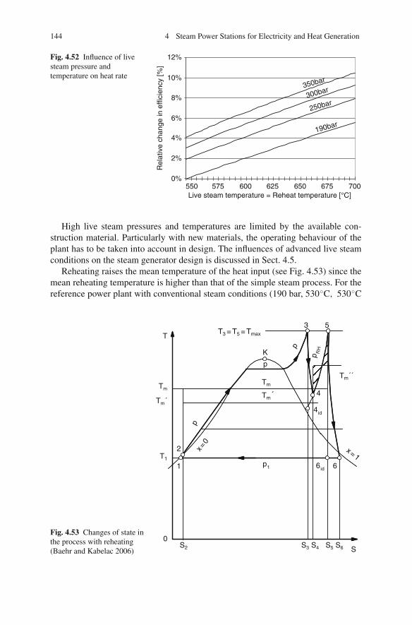
144 4 Steam Power Stations for Electricity and Heat Generation
Fig. 4.52 Influence of livesteam pressure andtemperature on heat rate
0%
2%
4%
6%
8%
10%
12%
550 575 600 625 650 675 700Live steam temperature = Reheat temperature [°C]
Rel
ativ
e ch
ange
in e
ffici
ency
[%]
190bar
350bar
250bar300bar
High live steam pressures and temperatures are limited by the available con-struction material. Particularly with new materials, the operating behaviour of theplant has to be taken into account in design. The influences of advanced live steamconditions on the steam generator design is discussed in Sect. 4.5.
Reheating raises the mean temperature of the heat input (see Fig. 4.53) since themean reheating temperature is higher than that of the simple steam process. For thereference power plant with conventional steam conditions (190 bar, 530◦C, 530◦C
Fig. 4.53 Changes of state inthe process with reheating(Baehr and Kabelac 2006)
3 5T
Tm
Tm´
T1
2
1
0
p
p1
S2 S3 S4 S5 S6 S
6id 6
Tm
4id
4
Tm´´
p RH
Tm´
x = 0
x = 1
p
K
p
T3 = T5 = Tmax

4.4 Possibilities for Efficiency Increases in the Development of a Steam Power Plant 145
(turbine inlet)) the mean heat input temperature in the high-pressure part of thesteam generator lies at tm′ = 364◦C, while the medium temperature of heat additionin the reheater is tm′′ = 430◦C, resulting in an overall mean temperature of heataddition tm = 376◦C. For a power plant with advanced steam conditions (285 bar,600◦C, 620◦C) the medium temperature of heat addition lies at tm = 415◦C, whilein the high-pressure part of the steam generator the mean temperature is tm′ = 400◦Cand in the reheater tm′′ = 470◦C.
In designing a power plant, optimum pressure ranges arise both in single and indouble reheating. The optimum pressure depends on the live steam pressure. As arule of thumb, the ratio between live steam and reheater pressure in modern powerplants is between 5 and 6. The optimum can be explained with Fig. 4.53. Reheatingresults in a maximum increase of efficiency, if the cold reheat temperature T4, whichis a function of the reheat pressure, is at the level of the medium temperature of heataddition tm′ in the high-pressure part of the steam generator. In this case, reheatingincreases the medium temperature of heat addition of the steam generator. If the coldreheat temperature is lower, at least part of the heat addition in the reheater resultsin lower efficiencies. Additionally, a reheat pressure that is too low can result insuperheated steam at the turbine exit and thereby increase the medium temperatureof heat dissipation.
Figure 4.54 shows the optimum of a double reheating regime in the form ofequidistant efficiency curves. Deviations from the optimum pressures entail a dete-rioration of the efficiency. The optimum depends on the chosen live steam pressure(Rukes et al. 1994).
Assuming conventional steam conditions – such as those of the reference powerplant for instance – introducing double reheating raises the net efficiency rate by upto 2%. Higher live steam pressures increase, while higher live steam temperaturesdecrease the gain in efficiency (Adrian et al. 1986). For a power plant with steamconditions of 280 bar, 585◦C (live steam), 600◦C (reheat steam), double reheatingraises the net efficiency by 0.7% (Kotschenreuther et al. 1993). A drawback is theincreased pressure loss. Double reheating can have a disadvantageous effect on theoperating regime. In an investigation into the use of a double reheating processfor a base-load power plant, an allowable load change rate between 2 and 4%per minute was reported. In comparison, load change rates of 4–8% per minuteare required in Germany for a mid-range load power plant. Double reheating, asopposed to single reheating, makes additional investments necessary for the steamgenerator, the tubes and the turbine of between 2.5% (Kjaer 1993) and 3% (STEAG1988) of the total investment costs. In Germany, double reheating was installed11 times in total between 1950 and 1983 (VGB 1995). Because of the highercosts and the disadvantages for mid-range load operation, this technology was notemployed after that time and is not taken into consideration in current projects inGermany.
Double reheating allows low condenser pressures, because the exhaust steammoisture is reduced, avoiding droplet erosion of the last-stage blades (Kjaer 1993).With the low condenser pressures associated with seawater cooling, double reheat-ing allows the use of higher live steam pressures and lower condenser pressures.
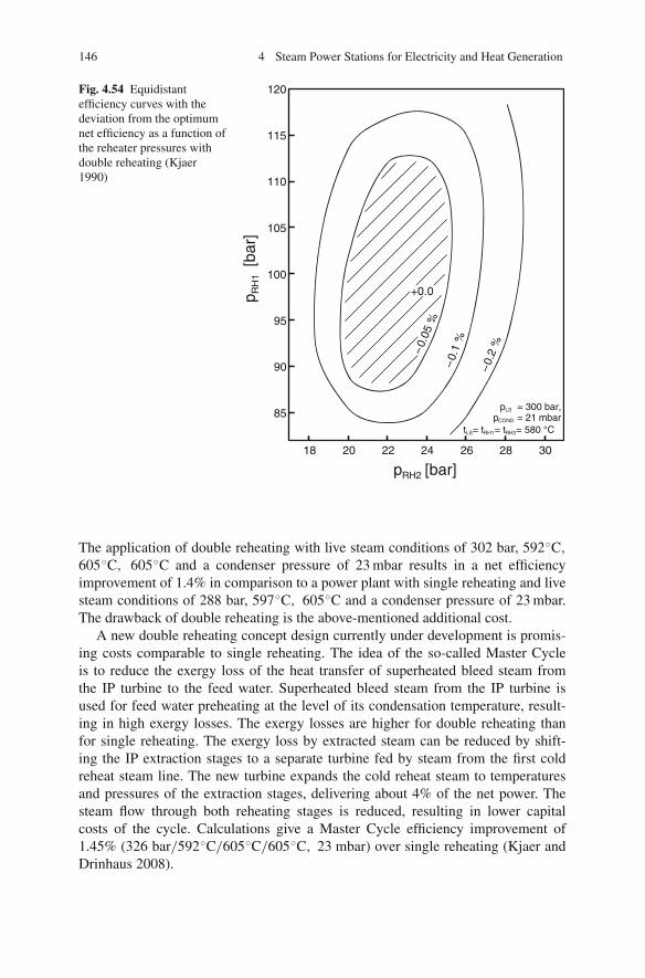
146 4 Steam Power Stations for Electricity and Heat Generation
Fig. 4.54 Equidistantefficiency curves with thedeviation from the optimumnet efficiency as a function ofthe reheater pressures withdouble reheating (Kjaer1990)
pRH2 [bar]18 20 22 24 26 28 30
85
90
95
100
105
110
115
120
pLS = 300 bar,pCOND = 21 mbar
tLS= tRH1= tRH2= 580 °C
p RH
1[b
ar]
+0.0
– 0.0
5 %
– 0.
1 %
– 0.2
%
The application of double reheating with live steam conditions of 302 bar, 592◦C,
605◦C, 605◦C and a condenser pressure of 23 mbar results in a net efficiencyimprovement of 1.4% in comparison to a power plant with single reheating and livesteam conditions of 288 bar, 597◦C, 605◦C and a condenser pressure of 23 mbar.The drawback of double reheating is the above-mentioned additional cost.
A new double reheating concept design currently under development is promis-ing costs comparable to single reheating. The idea of the so-called Master Cycleis to reduce the exergy loss of the heat transfer of superheated bleed steam fromthe IP turbine to the feed water. Superheated bleed steam from the IP turbine isused for feed water preheating at the level of its condensation temperature, result-ing in high exergy losses. The exergy losses are higher for double reheating thanfor single reheating. The exergy loss by extracted steam can be reduced by shift-ing the IP extraction stages to a separate turbine fed by steam from the first coldreheat steam line. The new turbine expands the cold reheat steam to temperaturesand pressures of the extraction stages, delivering about 4% of the net power. Thesteam flow through both reheating stages is reduced, resulting in lower capitalcosts of the cycle. Calculations give a Master Cycle efficiency improvement of1.45% (326 bar/592◦C/605◦C/605◦C, 23 mbar) over single reheating (Kjaer andDrinhaus 2008).

4.4 Possibilities for Efficiency Increases in the Development of a Steam Power Plant 147
Fig. 4.55 Influence on theefficiency of reheaterspraying (Baehr 1985)
As reported in Sect. 4.3.5.5, controlling the reheater temperature by a sprayattemperator diminishes the efficiency, because the high-pressure range of the steamgenerator is bypassed by doing so, and steam is produced at a low pressure and tem-perature. Figure 4.55 shows the influence on the efficiency of the reheater attemper-ator mass flow (Baehr 1985). In the case of the reference power plant, the sprayingmass flow at full load is about 0.9% of the feed water mass flow. New power plantdesigns limit the temperature-controlling spraying mass flow to 0.2% of the feedwater mass flow (Breuer et al. 1995).
The measures described above have an effect only on the thermal and on theturbine efficiency, but not on the energetic steam generator efficiency. They areincluded in the exergetic steam generator efficiency rate, though (see Sect. 3.2).
4.4.1.2 Influence of Feed Water Preheating
Based on the condensate temperature, regenerative preheating of the feed waterraises the feed water temperature, via several stages, up to the temperature at whichit enters the steam generator. During this process, steam is extracted that has alreadybeen through the turbine. The extraction steam flows reduce the exhaust steam flowand thus the loss of exhaust steam heat.
With the live steam pressure and the superheater outlet temperature staying con-stant, preheating the feed water raises the mean temperature of the heat input.
The water flowrate and the extraction pressure define the preheating of a regen-erative feed water heater:
• The steam pressure of the turbine extraction and the flow of the water to be heated(i.e., in LP heaters the condensate flow and in HP heaters the feed water flow)define the single-extraction steam flows.
• The extraction steam transfers its heat inclusive of the condensation heat. Thewater, before leaving the heater, heats up almost to the boiling temperature of theextraction steam pressure.

148 4 Steam Power Stations for Electricity and Heat Generation
Nowadays, six to nine feed water heaters with feed water outlet temperaturesbetween 250 and 300◦C are commonly used for large thermal power plants. Higherfeed water outlet temperatures are chosen as live steam pressures increase. Theheater configuration of the reference power plant without raised live steam con-ditions is shown in Fig. 4.28. Four LP heaters and two HP heaters preheat the feedwater up to 250◦C, with the feed water tank and pumps necessary parts of the pro-cess.
The last, upper-most HP heater is usually heated by extracted steam from the coldreheat line behind the HP turbine. The reheat pressure, derived from optimisationcalculations for the entire cycle, thus defines the feed water outlet temperature (seeFig. 4.56) (Rukes et al. 1994).
The feed water heating temperature can be further raised by inserting an addi-tional preheater, heated by extraction steam from the high-pressure section of theturbine. Such additional extraction from the HP turbine section uncouples thereheater pressure and feed water outlet temperature. Figure 4.57 shows a heat flowdiagram, with stages, where the feed water is preheated to 300◦C.
A feed water heating temperature increase from 250 to 290◦C, by additionalextraction of steam from the HP turbine section, results in an efficiency increase of0.7% (Billotet and Johanntgen 1995); the result of an increase from 270 to 300◦C isan absolute improvement of 0.75% (Kotschenreuther et al. 1993). Figure 4.58 showsthe impact of an increase in the feed water temperature – a relative decrease of theheat rate, which is dependent on the pressure level (Klebes 2007).
The rise of the feed water outlet temperature comes up against limiting factorswith regard to the steam generator design. It is imperative to prevent boiling in theeconomiser in order to avoid flow instabilities and to ensure a steady charge of theevaporator tubes. For this reason, the economiser must be designed to be smallerfor higher outlet temperatures of the regenerative feed water heating. Increasingfeed water temperatures entering the steam generator make the transferable flue
40 60 80 100 120 140 160250
270
290
310
330
350
Fee
dwat
er te
mpe
ratu
re [°
C]
Reheat pressure [bar]
Fig. 4.56 Feed water temperature as a function of the reheat pressure (Rukes et al. 1994)

4.4 Possibilities for Efficiency Increases in the Development of a Steam Power Plant 149
Boiler
4.3 bar600°C285 bar
620°C52 bar
HP IP LP1 LP2
300°CDesuper heater
HD-Pre-heater 8
HD-Pre-heater 7
HD-Pre-heater 6
Feed-waterpump
LP-pre-heater 4
LP-pre-heater 3
LP-pre-heater 2
LP-pre-heater 1
193°C357 bar
45 mbarCondensator
187°C
800 MW
G
273 MW
Feed-watertank
Condensatepump
Fig. 4.57 Heat flow diagram of a thermal power plant with advanced steam conditions and nine-stage feed water heating (data from Tremmel and Hartmann 2004)
gas heat in the economiser decrease, which can then be used only to preheat thecombustion air.
In designing a power plant, after the feed water heating outlet temperature isdefined, further optimisation is only possible within the feed water heating chain.The design should, in this process, provide for the smallest possible temperaturedifference between the heating medium, i.e. the extracted steam, and the feed waterto be heated. By increasing the number of heaters while keeping the same outlettemperature, smaller temperature rises for the individual stages result. This helps toachieve a better adaptation of the temperatures of the heat-absorbing to the heat-dissipating heat transfer medium – water flow and extraction steam flows – and thusto minimise the exergy losses. The improvement in efficiency of each additionalstage, as shown in Fig. 4.59, is positive but decreasing, so that a point is reachedwhere installation of yet another stage cannot be justified economically (Eichholtzet al. 1994).
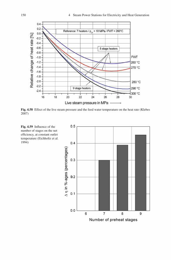
150 4 Steam Power Stations for Electricity and Heat Generation
Fig. 4.58 Effect of the live steam pressure and the feed water temperature on the heat rate (Klebes2007)
Fig. 4.59 Influence of thenumber of stages on the netefficiency, at constant outlettemperature (Eichholtz et al.1994)

4.4 Possibilities for Efficiency Increases in the Development of a Steam Power Plant 151
The temperature differences between the heat-dissipating and the heat-absorbingflows in a preheating stage are characterised by the so-called terminal temperaturedifference (TTD), which is defined as the smallest temperature difference betweenthe two mediums. At the transition to small TTDs, larger heating surfaces and henceheavy and expensive plant components are required. A compact construction is theresult when counterflow heat exchangers are used.
Preheaters are usually designed as shell-and-tube heat exchangers. The extractedsteam and the feed water are segregated from each other by a heat exchanger sur-face, which consists of tube bundles. The sensible heat of the steam can be utilisedin so-called desuperheaters. The sensible heat of the condensate can be utilised incondensate coolers, which can be mounted either by integration into the preheatersor separately. The desuperheater, with respect to the feed water, is mounted after thepreheater(s). This way, the feed water can be heated to a higher temperature than ispossible with the condensing preheater. The condensate cooler, with respect to thefeed water, is mounted before the preheater.
The most reasonable solution in terms of thermodynamics is to mix, withoutcooling, the condensate in the preheater with the feed water. This method is not usedfor HP preheaters because the high feed water pressure requires a complex systemof pumps, pipes and fittings. Thermodynamically, it is therefore a compromise tosubcool the condensates and to let them flow into the next lowest preheat stage. Inconfigurations with multistage LP preheaters, it is usually economical to pump thecondensates of one or several preheat stages back into the condensate flow.
In a direct-contact heater, the heat of the extracted steam is transferred to thefeed water by mixing and condensation of steam in water. Given its low terminaltemperature difference, the direct-contact heater has thermodynamic advantages.However, because the container is under the pressure of extraction, the entirecondensate flow has to be pumped to reach the corresponding pressure level.Because of the necessary pumps, direct-contact heaters are only used in the feedwater tank for deaeration.
The common values for the terminal temperature differences of regenerativeheaters of modern hard coal power plants are (STEAG 1988) as follows:
• Desuperheater 25 K• Condensation equipment 2 K• Condensate cooler 7 K
4.4.1.3 Lower Heat Dissipation Temperatures – Optimisationof the “Cold End”
The portion of the supplied heat which cannot be converted into mechanical workremains as condensation heat in the turbine exhaust steam and is discharged to theenvironment. In condensation power plants, the exhaust steam temperature of theturbine is about 30◦C. At this temperature it is not possible to extract further heatdue to the lack of heat sinks.

152 4 Steam Power Stations for Electricity and Heat Generation
Fig. 4.60 Impact of a heatdissipation temperaturereduction of 1 K
Besides the mean heat input temperature into the steam generator, the mean heatdissipation temperature is another factor which determines the thermal efficiency ofthe cycle. This temperature has to be chosen to be as low as possible in order tomaximise the total efficiency. Low exhaust-steam temperatures and pressures in thecondenser can be set by low temperatures of the cooling medium. The steam can befurther expanded to the low exhaust steam pressure by the final LP blading. Moreheat is converted into mechanical work and thus the waste heat cut down by thisheat fraction.
The heat dissipation temperature has an impact on the efficiency, which increasesin strength when the heat input temperature is lower. This correlation is shown inFig. 4.60 for the Carnot cycle, with a mean heat dissipation temperature of 30◦C,corresponding to the condensation temperature. These fundamental correlations alsohold true for other thermal power processes. Therefore it is evident that in a puresteam process, in comparison to a combined-cycle (gas and steam turbine) pro-cess, a higher efficiency increase can be achieved by improvements at the cold end(Johanntgen 1998). For the reference power plant, with a mean heat input temper-ature of 376◦C, a decrease in the condensation temperature of 1 K diminishes theheat rate by 0.29% in the ideal case.
In a given turbine unit, the steam outlet velocity rises with an increase in thespecific volume, i.e. when the condenser pressure decreases. Compared to the isen-tropic expansion, changes in the condenser pressure cause less change in the heatrate. With the condenser pressure decreasing, the losses increase through the kineticenergy of the exhaust steam, due to the rising outlet velocity. If sonic velocityis reached at very low condenser pressures, a further decrease of the condenserpressure does not improve the efficiency (Adrian et al. 1986). The losses in theexhaust steam are taken into account by the internal efficiency of the turbine.
The optimisation of the cold end must therefore involve not only the designof the cooling circuit but also the choice of the low-pressure turbine. In order tomake use of the efficiency advantage of low condenser pressures, it is necessary toenlarge the exhaust steam cross-section of the LP turbine. As well as developing and
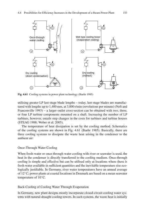
4.4 Possibilities for Efficiency Increases in the Development of a Steam Power Plant 153
G
a b
G
Wet type cooling tower(evaporation cooling)
c
G
M
Dry cooling(direct condensation)
d
G
Dry cooling(indirect)
Fig. 4.61 Cooling systems in power plant technology (Baehr 1985)
utilising greater LP last-stage blade lengths – today, last-stage blades are manufac-tured with lengths up to 1,400 mm, at 3,000 r/min (revolutions per minute) (Neft andFranconville 1993) – a larger outlet cross-section can be obtained with two, three,or four LP turbine components mounted on a shaft. Increasing the number of LPturbines, however, entails step changes in the costs for turbines and turbine houses(STEAG 1988; Weber et al. 2005).
The temperature of heat dissipation is set by the cooling method. Schematicsof the cooling systems are shown in Fig. 4.61 (Baehr 1985). Basically, there arethree cooling systems to dissipate the waste heat arising in the condenser to theambient air:
Once-Through Water Cooling
When fresh-water or once-through water cooling with river or seawater is used, theheat in the condenser is directly transferred to the cooling medium. Once-throughcooling is simple and effective but can be utilised only at locations where there isfresh water available in sufficient quantities and the inevitable temperature rise eco-logically justifiable. In Germany, river water temperatures have an annual averageof 12◦C; power plants at coastal locations in Denmark are based on a mean seawatertemperature of 10◦C.
Back-Cooling of Cooling Water Through Evaporation
In Germany, new plant designs mostly incorporate closed-circuit cooling water sys-tems with natural-draught cooling towers. In such systems, the waste heat is initially
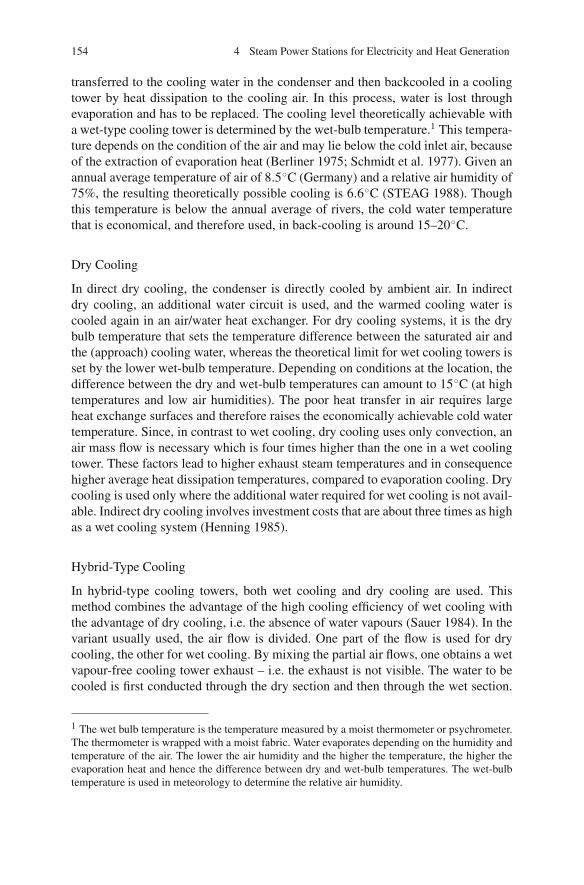
154 4 Steam Power Stations for Electricity and Heat Generation
transferred to the cooling water in the condenser and then backcooled in a coolingtower by heat dissipation to the cooling air. In this process, water is lost throughevaporation and has to be replaced. The cooling level theoretically achievable witha wet-type cooling tower is determined by the wet-bulb temperature.1 This tempera-ture depends on the condition of the air and may lie below the cold inlet air, becauseof the extraction of evaporation heat (Berliner 1975; Schmidt et al. 1977). Given anannual average temperature of air of 8.5◦C (Germany) and a relative air humidity of75%, the resulting theoretically possible cooling is 6.6◦C (STEAG 1988). Thoughthis temperature is below the annual average of rivers, the cold water temperaturethat is economical, and therefore used, in back-cooling is around 15–20◦C.
Dry Cooling
In direct dry cooling, the condenser is directly cooled by ambient air. In indirectdry cooling, an additional water circuit is used, and the warmed cooling water iscooled again in an air/water heat exchanger. For dry cooling systems, it is the drybulb temperature that sets the temperature difference between the saturated air andthe (approach) cooling water, whereas the theoretical limit for wet cooling towers isset by the lower wet-bulb temperature. Depending on conditions at the location, thedifference between the dry and wet-bulb temperatures can amount to 15◦C (at hightemperatures and low air humidities). The poor heat transfer in air requires largeheat exchange surfaces and therefore raises the economically achievable cold watertemperature. Since, in contrast to wet cooling, dry cooling uses only convection, anair mass flow is necessary which is four times higher than the one in a wet coolingtower. These factors lead to higher exhaust steam temperatures and in consequencehigher average heat dissipation temperatures, compared to evaporation cooling. Drycooling is used only where the additional water required for wet cooling is not avail-able. Indirect dry cooling involves investment costs that are about three times as highas a wet cooling system (Henning 1985).
Hybrid-Type Cooling
In hybrid-type cooling towers, both wet cooling and dry cooling are used. Thismethod combines the advantage of the high cooling efficiency of wet cooling withthe advantage of dry cooling, i.e. the absence of water vapours (Sauer 1984). In thevariant usually used, the air flow is divided. One part of the flow is used for drycooling, the other for wet cooling. By mixing the partial air flows, one obtains a wetvapour-free cooling tower exhaust – i.e. the exhaust is not visible. The water to becooled is first conducted through the dry section and then through the wet section.
1 The wet bulb temperature is the temperature measured by a moist thermometer or psychrometer.The thermometer is wrapped with a moist fabric. Water evaporates depending on the humidity andtemperature of the air. The lower the air humidity and the higher the temperature, the higher theevaporation heat and hence the difference between dry and wet-bulb temperatures. The wet-bulbtemperature is used in meteorology to determine the relative air humidity.

4.4 Possibilities for Efficiency Increases in the Development of a Steam Power Plant 155
Optimum values inGermany and Denmark
- Once-through cooling
- Seawater (10°C) 20–25 mbar
- River water(12°C) 30–35 mbar
- Evaporation 35–40 mbar
0.140.120.10.080.060.050.040.030.02 0.2
Condenser pressure [bar]
Evaporativecooling
0.035
Dry coolingindirect0.07 0.15
Dry coolingdirect
Once-throughcooling
0.02 0.06
0.1
0.12
0.15
0.2
Fig. 4.62 Achievable condenser pressures in different cooling systems (Baehr 1985)
Wet cooling is usually exclusively used during summer operation, with the mixeduse occurring in winter. The investment costs of this technique amount to three timesas much the costs for a wet cooling tower, and its cooling characteristics resemblethat of the wet-type cooling tower (Henning 1985).
Figure 4.62 shows the exhaust steam pressures achievable by the different cool-ing methods. It becomes evident that the chosen cooling technique has a substan-tial influence on the condensation temperatures and exhaust steam pressures. Theranges given in Fig. 4.62 are functions of the location-dependent air and watertemperatures. Systems using once-through cooling thus offer favourable, systemswith dry cooling unfavourable conditions for attaining a high thermal efficiency.Evaporative cooling, in general, involves higher condensation temperatures thanonce-through cooling, though clearly lower temperatures than dry cooling sys-tems (Baehr 1985). In Denmark, condenser pressures between 20 and 25 mbar areachieved in advanced steam cycles with seawater cooling at an annual average ofabout 10◦C. Reports on power plants with wet cooling towers mention condenserpressures between 35 and 40 mbar (Meier 2004; Lambertz and Gasteiger 2003;Tremmel et al. 2006; Mandel and Schettler 2007; Billotet and Johanntgen 1995;Eichholtz et al. 1994). The reference values for river water cooling in Germanyrange around 30 mbar.
The impacts of the condenser pressure on the net efficiency is shown in Fig. 4.63for a power plant with conventional and with advanced steam conditions (Adrianet al. 1986; Kjaer 1993). Evaporative cooling, compared to seawater cooling, hasa disadvantage in efficiency of about 1–1.5%, yet an advantage of greater than 1%compared to dry cooling.
The seasonal fluctuations of water and/or air temperatures have a direct effecton the exhaust steam quality in the condenser and hence on the thermal efficiencytoo. Figure 4.64 shows the yearly trend of cold water temperatures for the cases ofseawater cooling and evaporation cooling (Johanntgen 1998).

156 4 Steam Power Stations for Electricity and Heat Generation
Fig. 4.63 Impact of the condenser pressure on the net efficiency (Adrian et al. 1986; Kjaer 1993)
Fig. 4.64 Yearly trend of cold water temperatures (Johanntgen 1998)
Lower exhaust steam pressures in winter have less of an effect on the efficiency,however, than the rise of the condenser pressure in summer, because the outlet lossof the turbine increases with descending pressure. Exhaust steam qualities which arelower than those designed for can also be limited by the allowable exhaust moisture.Wet cooling towers might also confer restrictions on the cold water temperature, forexample that they should not fall below 12◦C, to prevent icing (Adrian et al. 1986).A temperature rise of 22◦C to a level 30◦C above the design temperature of 8◦C of a

4.4 Possibilities for Efficiency Increases in the Development of a Steam Power Plant 157
Fig. 4.65 Influence ofambient conditions onefficiency (Eichholtz et al.1994)
natural-draught cooling tower deteriorates the efficiency of a modern power plant by1.8%. Ambient temperatures of −10◦C yield an improvement of only about 0.2%(see Fig. 4.65) (Eichholtz et al. 1994). The impact depends on the turbine design(Weber et al. 2005). The conditions on site and the legislation concerning waterrights and urban planning and building laws set criteria which narrow the choiceof thermodynamically reasonable cooling techniques at the cold end of the powerplant. In Germany, natural-draught cooling towers for waste heat dissipation andback-cooling of the heat carrier, i.e. cooling water, have become standard. Withall cooling systems, the difference between the condensation temperature and thecooling medium temperature for the heat dissipation has to be kept as small aspossible.
Back-Cooling by Natural-Draught Cooling Tower
Figure 4.66 presents the schematic diagram and the design data of a closed-circuitsystem with a natural-draught cooling tower for a 720 MW hard coal power plant(Baehr 1985).
In the condenser, the cooling water gets heated from an inlet temperature tW1 =20◦C up to 34.5◦C. For back-cooling, the water is transported to the cooling towerwhere, over about 10–15 m height, it is sprayed through nozzles that are locatedaround the cooling tower cross-section.
The cooling water falls and disperses, via distribution plates, onto the fill packing,which it flows through, then dropping down into the cooling tower basin. In coun-terflow to the rising cooling air, the water cools to a temperature of tW1 = 20◦C bothby convection and by evaporation, whereupon it is returned to the condenser. In theexample shown in Fig. 4.66, 30% of the cooling efficiency is achieved by convectivecooling with air and 70% by evaporation.
Ambient air at a temperature of tA1 = 8.5◦C and with a relative humidity of76.3% flows into the cooling tower, where its temperature rises to tA2 = 27.1◦C. Bywarming and buoyancy of the air, a convective flow forms in the cooling tower – this

158 4 Steam Power Stations for Electricity and Heat Generation
Power plant cooling tower circuit
Condenser temperatures
Condenser
G~
Mist eliminators
Fillpacking
Tower shell
Cooling tower temperatures
CCTSVWLAdAMUB
= Condenser= Cooling tower= Steam= Vapour= Water = Losses= Air= dry air= Make-up water= Blow down water
tC = 36°C
tW1= 20°C
tW2 = 34.5°C
~720 MW
mW2 = 15555 kg/s.
mMW = m
V + mB
. . .mB ~ 0.01 mW1
. .mW = m W2 – mV
. . .
DCT = 96.5 m
ρA1 = 76.3 %
xA1 = 5.2 g/kgmdA = 14847 kg/s.
HCT = 128 m
WCT = 5 m/sxCT = 23 g/kg
mA = 15194 kg/s; vA = 13098 m3/s. .
tW1 = 20°C
tA1 = 8.5°C
tW2 = 34.5°C
tA2 = 27.1°C
mV = 0.024 mW1
. .
Boiler
Spraynozzles
dTS = 54 m
Fig. 4.66 Wet tower cooling circuit with design data for a 720 MW hard coal fuelled power station(Baehr 1985)
defines a natural-draught cooling tower. With increasing humidity, the flowrateslows. Since the cooling power depends on the air mass flow, the air flowrate canbe forced much higher by ventilators (a ventilator cooling tower), the driving powerdemand of which increases the auxiliary power requirement of the plant.
The wet-bulb temperature of the ambient air tWB, which in the example is 6.6◦C,is the physical limit for the mean condensation temperature tC and hence for theefficiency improvement at the cold end. For plants with wet cooling towers, thedifference between the wet-bulb temperature of the ambient air and the economictemperature, or the mean condensation temperature (here 36◦C) results from (seeFig. 4.67) (Odenthal and Spangenmacher 1959)
• The cooling range (tW2 − tW1): This is the temperature rise of the cooling waterin the condenser from tW1 to tW2, which is determined by the cooling water massflow with a given heat dissipation. In the cooling tower, the cooling water iscooled back to its temperature tW2 before entry to the condenser. In the givenexample, the difference is tW2 − tW1 = 14.5◦C.
• The terminal temperature difference (TTD) of the condenser: In the example, thedifference is tC − tW2 = 1.5◦C.
• The approach tW1 − tWB of the cooling tower: This is the temperature differencebetween the temperature of the backcooled water and the theoretically possiblecold water temperature, which equals the wet-bulb temperature. In the example,the difference is tW1 − tWB = 13.4◦C.

4.4 Possibilities for Efficiency Increases in the Development of a Steam Power Plant 159
Fig. 4.67 Temperaturerelations in circuit coolingsystems by wet cooling tower
Diminishing the cooling range, the approach or the TTD of the condenser by 1 Kresults, for each of these parameters, in an equal lowering rate of the condensationtemperature (STEAG 1988).
A smaller cooling range is achieved by a greater cooling-water mass flow. Thelower water outlet temperature after the condenser then decreases the condensationtemperatures correspondingly, with the same TTD maintained.
A greater cooling-water mass flow requires, for the heat and mass transfer, agreater surface for the cooling water to flow down, which is achieved by appropriateinserts, increasing the surface area. In the case of natural-draught cooling towers,enlarging the transfer surfaces as a rule involves the enlargement in height anddiameter of the body as well. In the case of ventilator cooling towers, the powerdemand of the ventilators increases. In the condenser, narrowing the cooling rangecauses a reduction of the mean logarithmic temperature difference so that, at thesame TTD, larger condenser surfaces are needed. The cooling range values commonin Germany are between 16 and 10 K, the latter holding true for plants currently inplanning.
Small approaches in the cooling tower can be achieved with larger transfer sur-faces. In the extreme case of the ideal cooling tower – which only exists theoreti-cally – the water is cooled down to the wet-bulb temperature, and the approach isthen tW1 − tWB = 0. Such an ideal cooling tower has to function by counterflow andhas an infinitely large transfer surface (Klenke 1966). Commonly, approaches arebetween 8 and 12 K.
Smaller terminal temperature differences (TTDs) in the condenser are achievedwith larger condenser surfaces. Commonly, condenser TTDs are about 1–2 K.
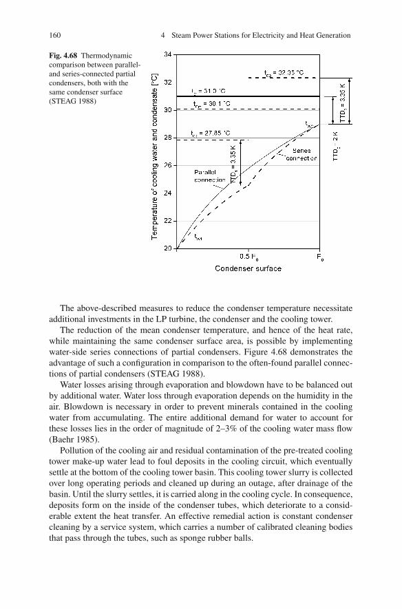
160 4 Steam Power Stations for Electricity and Heat Generation
Fig. 4.68 Thermodynamiccomparison between parallel-and series-connected partialcondensers, both with thesame condenser surface(STEAG 1988)
The above-described measures to reduce the condenser temperature necessitateadditional investments in the LP turbine, the condenser and the cooling tower.
The reduction of the mean condenser temperature, and hence of the heat rate,while maintaining the same condenser surface area, is possible by implementingwater-side series connections of partial condensers. Figure 4.68 demonstrates theadvantage of such a configuration in comparison to the often-found parallel connec-tions of partial condensers (STEAG 1988).
Water losses arising through evaporation and blowdown have to be balanced outby additional water. Water loss through evaporation depends on the humidity in theair. Blowdown is necessary in order to prevent minerals contained in the coolingwater from accumulating. The entire additional demand for water to account forthese losses lies in the order of magnitude of 2–3% of the cooling water mass flow(Baehr 1985).
Pollution of the cooling air and residual contamination of the pre-treated coolingtower make-up water lead to foul deposits in the cooling circuit, which eventuallysettle at the bottom of the cooling tower basin. This cooling tower slurry is collectedover long operating periods and cleaned up during an outage, after drainage of thebasin. Until the slurry settles, it is carried along in the cooling cycle. In consequence,deposits form on the inside of the condenser tubes, which deteriorate to a consid-erable extent the heat transfer. An effective remedial action is constant condensercleaning by a service system, which carries a number of calibrated cleaning bodiesthat pass through the tubes, such as sponge rubber balls.

4.4 Possibilities for Efficiency Increases in the Development of a Steam Power Plant 161
The economic efficiency of the condenser temperature depends on the degreeof the utilisation of the power plant and the fuel price on one hand and on thenecessary additional investment for an efficiency increase on the other (see alsoSect. 4.3.1). The condenser pressure for a mid-range plant, with an operation factorof 4,000 full-load h/annum and a unit size of 500 MWel, in the 1980s ranged between0.04 and 0.05 bar (STEAG 1988). Recent power station plans provide for valuesbetween 45 and 30 mbar (Meier 2004; Lambertz and Gasteiger 2003; Tremmel et al.2006; Mandel and Schettler 2007; Billotet and Johanntgen 1995; Eichholtz et al.1994).
4.4.2 Reduction of Losses
4.4.2.1 Internal Turbine Efficiency and Losses
In the expansion process in the turbine, the steam is accelerated, and its kineticenergy converted into mechanical work by impulse transfer onto the rotating blades.The measure for the quality of the conversion into mechanical work is the internalturbine efficiency ηi,T, which indicates the difference between real and loss-freeisentropic expansions. For the real thermal cycle efficiency ηth, the followingapplies:
ηth = ηth,0 · ηi,T (3.31)
where ηth,0 represents the thermal cycle efficiency at loss-free expansion.About two thirds of the total losses occur over the blade stages. The HP first
stages (of the turbine), in particular, and the LP last stages (of the turbine) are theareas of the turbine incurring the highest losses. The losses arise through fluid fric-tion in the channels, friction of the rotating blades in the surrounding steam, steamleakages from rotating and fixed parts and through steam moisture in the last stages(Strauß 2006).
The greatest single loss, in the order of magnitude of about one tenth to one thirdof the total loss, is the outlet loss. It comes about because of the kinetic energy of theexhaust steam. Further losses occur in the inlet valves and in the cross-over pipes(Adrian et al. 1986).
An exhaust steam diffuser partly recovers kinetic energy from the exhaust steamexiting at high velocity from the last blading. The kinetic energy is converted intopressure energy in the diffuser, which is located between the last turbine bladesand before the condenser, and partially compensates for the pressure losses arisingon the way to the condenser. With a constant condenser pressure, an exhaust steamdiffuser brings about a lower pressure after the last turbine stage and in consequencemore power is produced in the turbine than would be the case without the diffuser(Schroder 1968).
Besides by an exhaust steam diffuser, it is possible to influence the outlet loss bythe exhaust steam velocity, which, at a given steam mass flow and a given condenser

162 4 Steam Power Stations for Electricity and Heat Generation
Fig. 4.69 Development of theinternal efficiencies of steamturbines (Billotet andJohanntgen 1995)
pressure, can only be varied by means of the cross-sectional area of the turbineoutlet. Because of the limited blade length of the last LP stage, the outlet surfacecan only be enlarged by the number of the LP turbines. The last stages and theexhaust steam cross-section are designed in combination with the heat extraction(see Sect. 4.4.1.3).
Turbine improvements have contributed substantially to the increases in effi-ciency of modern power plants. Three-dimensional calculations (i.e. computer mod-elling) of flow processes reveal the potential for reducing the flow losses, andmodern manufacturing technologies make it possible to build complex blade geome-tries (Nowi and Haller 1997; Oeynhausen et al. 1996). The modernisation of theturbine of existing power plants is an effective means to increase the efficiency.Figure 4.69 shows the internal turbine efficiencies for existing and planned powerplants (Billotet and Johanntgen 1995).
4.4.2.2 Steam Generator Losses
In the steam generator, or boiler, the chemically bound energy of the fuel is con-verted into thermal energy of the flue gas and then transferred to the steam – watercycle. The efficiency of the energy conversion is designated as the steam generatoror boiler efficiency ηB, and the arising losses are called the boiler losses. Referringto the calorific value of the fuel, the steam generator efficiency of modern hard coalfired furnaces amounts to 94%, while brown coal fuelled furnaces have an efficiencyof around 90%.
The losses consist of the following:
• Loss through unburned matter (κU)• Loss through sensible heat of the slag (κS)• Flue gas loss (κFG)• Loss through radiation and convection of the external surfaces of the boiler (κRC)
4.4 Possibilities for Efficiency Increases in the Development of a Steam Power Plant 163
Losses through unburned matter are well below 1%. Of these losses, a differen-tiation is made between unburned gas, unburned matter in the slag and unburnedmatter in the fly ash. Where a carbon content of less than 5% is required for the useof the fly ash as a by-product, the respective maximum loss of unburned matter inthe fly ash will be, for instance, 0.5% for a coal type with an ash content of 10%.Typical losses through unburned matter range around 0.3% (Riedle et al. 1990).
Heat losses due to radiative, conductive and convective transfer to the environ-ment by the steam generator are below 1% and diminish further as the power ratingof the steam generator increases. The losses of brown coal fuelled furnaces are sig-nificantly higher than hard coal fuelled furnaces because, at the same output, thesteam generator has a considerably larger external surface area. Hard coal fuelledfurnaces typically have heat losses around 0.3% (Billotet and Johanntgen 1995).
Ash is predominantly removed in the electrostatic precipitator (ESP) as fly ash,though part of it stays in the furnace as slag and is typically removed while in a hotstate. The sensible heat of the slag, when unused, results in a portion of the boilerlosses. In dry-bottom furnaces, the amount of the so-called hopper ash is about 10%of the total ash mass flow, and the respective loss is below 0.4% of the calorificenergy input in hard coal fuelled furnaces. In slag-tap furnaces, the loss by sensibleheat is higher, because either all or a large portion of the ash (depending on thedegree of retention and the fraction of the re-injected ash) runs off as liquid slagwith a high temperature.
The principal loss of the steam generator occurs because the flue gas cannot becooled down to ambient temperature. After the exhaust steam heat loss, this is themost major loss in a power plant.
Efforts to increase the steam generator efficiency concentrate on reducing the fluegas heat loss. This loss depends both on the flue gas outlet temperature of the steamgenerator (after the air heater) and on the flue gas mass flow. Figure 4.70 shows the
Fig. 4.70 Boiler loss as a function of the boiler exit temperature and air ratio, for hard coal firing(Riedle et al. 1990)

164 4 Steam Power Stations for Electricity and Heat Generation
Table 4.2 Boiler losses for the reference power plant and for a new plant
Reference power plant New plant
Air ratio 1.3 1.15Flue gas temperature 130◦C 110◦CFlue gas losses 5.3% 3.8%Boiler radiation 0.25% 0.3%Loss through unburned matter
Fly ash 0.2% < 0.3%Hopper ash 0.1% < 0.2%
Sensible heatFly ash 0.02% 0.03%Hopper ash 0.04% 0.04%
Total boiler loss 5.9% 4.6%
flue gas loss for hard coal firing as a function of the excess air coefficient and theboiler exit temperature (Riedle et al. 1990). Table 4.2 compares the boiler losses ofthe reference power plant and a planned power plant.
The flue gas outlet temperature of the boiler has a limit that depends on thecondensation of sulphuric acid. Both in the air heater and in the downstream ESP,the temperatures should not fall below this minimal flue gas temperature, which liesabove the dew point of sulphuric acid, in order to prevent corrosion and fouling(Muller-Odenwald et al. 1995).
The dew point of sulphuric acid changes with the flue gas contents of sulphurtrioxide (SO3) and water vapour (see Fig. 4.71) (Bauer and Lankes 1997). Part of thesulphur dioxide formed in the combustion is converted to SO3 in the flue gas path.
Fig. 4.71 SO3 dew point offlue gases (Bauer and Lankes1997)

4.4 Possibilities for Efficiency Increases in the Development of a Steam Power Plant 165
The SO3 content correlates to the SO2 partial pressure in the flue gas and also tothe sulphur content of the fuel. The conversion rate and the SO3 content depend, fur-thermore, on the excess air and the combustion temperature. A high level of excessair supports the conversion of SO2 to SO3, while a high combustion temperature hasthe opposite effect (Baehr 1985). Typical conversion rates are around 2%. A catalystfor NOx reduction inserted between the economiser and the air heater may act toform additional SO3 (Maier et al. 1992). Flue gas temperatures after the air heater,depending on the sulphur content of the hard coal, today commonly range between120 and 140◦C. Because of the resulting higher dew point of sulphuric acid, higherwater vapour contents in brown coal firing limit the flue gas temperature between140 and 170◦C, depending on the sulphur content.
For the above-mentioned flue gas temperatures, local temperatures at the cold endof the air heater are below the acid dew point temperature. The lowest plate tempera-ture at the cold end is roughly the arithmetic mean of the flue gas outlet temperatureand the air inlet temperature. For the reference power plant, with a 130◦C flue gasoutlet temperature and a 45◦C air inlet temperature, the lowest plate temperature,of slightly less than 90◦C, lies well below the acid dew point. In consequence, SO3
condenses to sulphuric acid in the flue gas, which is taken up by the dust particles.Measurements in plants in service show that this way, 80–90% of the SO3 can beremoved from the flue gas, so the acid dew point for the subsequent equipmentdecreases. SO3 condenses into sulphuric acid until it reaches a degree where theacid dew point correlates with the local plate temperature. The temperature at theboiler exit thus determines the SO3 emissions after the air heater. The decrease ofthe heating surface temperature and the accompanying H2SO4 condensation in theair heater is limited to the point when a condensate film forms on the plates. Thiscauses fouling which cannot be cleaned by soot-blowing. In addition, the corrosiveattack becomes more severe with increasing acid condensation.
Minimum achievable flue gas outlet temperatures, achievable through the use ofa regenerative air heater, strongly depend on the coal. In some power plants, fluegases are cooled down to 110–115◦C, while in other plants, even temperatures of125◦C cause fouling at the cold end. An important part in this process is playedby the contents of CaO and MgO in the ash, which have an effect against fouling.A fouling temperature as a function of the ash composition can be defined, belowwhich the local temperature should not fall (see Fig. 4.72).
In consequence, a steam generator designed for low flue gas temperatures restrictsthe range of coal types.
The flue gas mass flow, as a further parameter influencing the flue gas loss, isaugmented by the excess air and also by leaks in the air and flue gas train of thesteam generator. This increases the flue gas mass flow to an amount greater thanthe theoretical air demanded by the stoichiometry of the combustion. For balance-draught furnaces, which are commonly in operation today, design calculations takeinto account an air leak mass flow between the burners and the economiser of about1.5% of the total combustion air flow (Adrian et al. 1986). Additional leaks occurin the regenerative air heater, which raise the flue gas mass flow by about 5% of theair flow (see Sect. 4.3.5.6).

166 4 Steam Power Stations for Electricity and Heat Generation
Fig. 4.72 SO3 foulingtemperature as a function ofsulphur content andCaO + MgO content(Muller-Odenwald et al.1995)
As an alternative to the less expensive regenerative air heaters, it may also bepossible to use recuperators to preheat the air. The impermeability (i.e. the smallerleakage losses) of these could reduce the flue gas loss and the auxiliary demand ofthe forced-draught fan.
Furnaces are operated at excess air to achieve the required complete combustion.Lower air ratios do reduce the flue gas loss; however, an excessively low excess airrate causes losses through unburned gases and unburned carbon in the fly ash. Sothere is an optimum with a minimum boiler loss at a definite air ratio. Lower excessair rates are possible if complete combustion can be guaranteed by other measures,such as increasing the milling fineness (Baehr 1985).
Slag-tap firing systems, with their higher combustion temperatures, allow thesetting of lower excess air levels than dry-bottom furnaces. In the past, this level wasbetween 1.2 and 1.35 in dry-bottom furnaces and between 1.1 and 1.2 in slag-tapfurnaces. In new and planned power plants, the air ratios for brown coal fuelled fur-naces are 1.15, while for hard coal fired dry-bottom furnaces, 1.15 (volatile mattercontent greater than 25%) or 1.18 (volatile matter content smaller than 25%), andfor slag-tap furnaces, the value is 1.1 (Riemenschneider 1995). Besides its effect onflue gas loss, the excess air raises the auxiliary demand of forced-draught (FD) andinduced-draught (ID) fans.
Flue gas losses, together with the relationships described above, depend on thefiring system. Complete combustion at high temperatures in slag-tap furnaces allowsthe setting of low air ratios such that the conversion into SO3 is reduced and hencelower flue gas temperatures can be set. This advantage in the efficiency of slag-tapfurnaces, however, is depleted through the loss of the sensible heat of the slag forash contents of more than 20%.
Compared to a hard coal with a moisture of 10% or so, the flue gas mass flowof a brown coal fuelled furnace, with 50–60% moisture, is larger by more than 20to over 30%. This fact, in addition to the higher allowable flue gas temperature,explains the high flue gas losses in pulverised brown coal firing, which can be twiceas high as those in hard coal firing. The excess air is occasionally made use of to

4.4 Possibilities for Efficiency Increases in the Development of a Steam Power Plant 167
set a mass flow necessary for the heat transfer of the convective heating surfaces. Inpart-load operation, often a higher excess air is chosen, in order to shift the heat fluxdistribution in favour of the convective heating surfaces.
4.4.2.3 Loss Through Reheating
National laws impose legal restraints on temperatures at which flue gas may bedischarged into the environment. Examples include the USA, Japan and severalEuropean countries, including Germany.
Wet scrubbing processes for flue gas desulphurisation cool the flue gases downbelow the exhaust gas temperature of the steam generator. After flowing throughthe steam generator, the air preheater and the ESP, the flue gas is conducted to thescrubber. Cleaned of remaining dust and desulphurised, the flue gas – now termedclean gas – leaves the FGD unit via a droplet separator. The flue gases during wetscrubbing cool from the flue gas temperature after the air preheater down to the oper-ating temperature of the FGD, and at this temperature they are saturated with water.
Up to 2004, according to the German Ordinance on Large Combustion Plants(13.BImSchV in German), the clean gas had to be dissipated into the open airvia a stack at a temperature higher than 72◦C. The intention of this high temper-ature was to raise the plume of the flue gas after it had left the stack to ensureits spread and wide distribution. If the operating temperature of the FGD waslower than the required 72◦C, the flue gas had to be reheated (Adrian et al. 1986;13.BImSchV 2004).
In existing power stations in Germany, in many cases the operating temperatureof the FGD is lower than 72◦C, and so a regenerative heat exchanger (RHX) is usedfor reheating. In such heat exchangers, the flue gas heat of the un-desulphurised andcooled flue gases (raw gas) is transferred to the cleaned flue gases (clean gas) (seeFig. 4.73). In this process, the raw gas is cooled from about 110 to 130◦C down to70–75◦C, while the clean gas in turn is heated from 45 to 50◦C up to about 80–90◦C.
NH3
DeNOx
AH
Fly ash
RGHFGD
Stack
ESPSG
SG: Steam generatorDeNOx: Nitrogen oxide reduction plantAH: Air heaterESP: Electrostatic precipitatorRGH: Regenerative gas heaterFGD: Flue gas desulphurisation (unit)
Gypsum:
Fig. 4.73 Configuration of the catalyst for high-dust and reheating after FGD

168 4 Steam Power Stations for Electricity and Heat Generation
To vaporise the remaining droplets after the FGD unit, it is possible to raise theflue gas temperature by about 5◦C by means of an ash-free fuel. An alternative is toreturn part of the flue gas flow from the back to the front of the rotary gas heater,in order to ensure the prevention of possible build-ups of deposits on the heatingsurfaces of the rotary gas heater. Adding energy also adds loss: even when reheatingdoes not require additional heat, there is still a higher need for electricity for in-plantuse due to the pressure losses of the heat exchangers.
If the flue gas was fed into the cooling tower, the requirement of a flue gas tem-perature of 72◦C was not applicable. The stack in this case was not needed at allor could be reduced to a stack for starting up. This method was applied for the firsttime in the Volklingen model power plant (Ernst et al. 1986). Today, it is used inall newly built plants with evaporative cooling. The spread of the great volumetricflow of the cooling tower ensures a comparatively better distribution than whenthe flue gas is discharged via a stack. Feeding the flue gas into the cooling toweroffered an advantage in efficiency of 0.1–0.15%, taking into account the lower in-plant electricity demand in comparison to reheating (Billotet and Johanntgen 1995).Where additional energy was needed for reheating, the efficiency increase of feedingthe flue gas into the cooling tower was greater than compared to discharge via astack.
In Germany, the Ordinance on Large Combustion Plants was modified in 2004 toincorporate European law. The requirement of a flue gas chimney inlet temperatureof 72◦C is no longer included (13.BImSchV 2004). Instead, it has to be proventhat the additional contribution of the plant to the local pollutant load will be belowcertain limits. New power plants currently under construction with once-throughcooling estimate a flue gas temperature at the chimney inlet of about 50◦C, which isbasically the temperature of the FGD. Because of the condensation of saturated fluegas droplets, the chimney has to be designed for wet operation.
The same problems as in the past for reheating after desulphurisation mayalso occur in NOx control. Since the DeNOx process needs a catalyst tempera-ture between 300 and 350◦C, the DeNOx reactor is usually arranged in a high-dust configuration, after the economiser and before the air heater (see Fig. 4.73).In exceptional cases, where a high-dust configuration is not possible, the DeNOx
reactor is arranged in a low-dust configuration, with the unit placed after the dustcontrol and desulphurisation units (see Fig. 4.74). This set-up may be chosen whenthere are space limitations or when the flue gas composition is such that a shortlifetime of the catalysts is expected. In slag-tap firing, with ash recirculation fromthe ESP to slag-tap furnace, the accumulation of arsenic compounds would, in thecase of a high-dust configuration, eventually poison the catalysts associated with thecorresponding reactivity loss, so the low-dust configuration is often applied in thisfiring system.
As previously described, the flue gas temperatures after the flue gas desulphuri-sation unit are at around 50◦C, so it is necessary to reheat the flue gas up to thetemperature of about 320◦C required for the catalytic flue gas DeNOx process. Thereheating process then usually combines a regenerative preheater and direct reheat-ing by means of natural gas or indirectly by hot steam. A small direct reheating
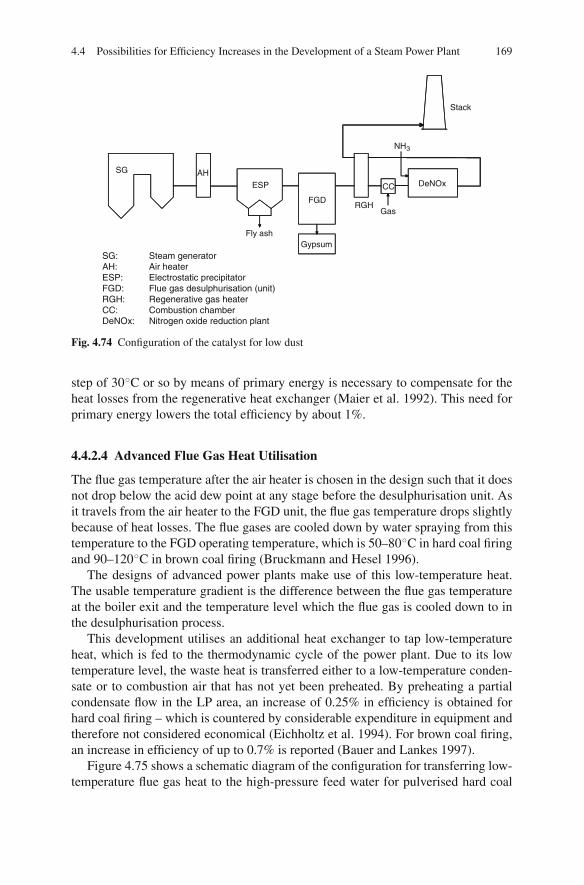
4.4 Possibilities for Efficiency Increases in the Development of a Steam Power Plant 169
NH3
DeNOxAH
Fly ash
RGHFGD
Gypsum
Stack
CC
Gas
SG
ESP
SG: Steam generatorAH: Air heaterESP: Electrostatic precipitatorFGD: Flue gas desulphurisation (unit)RGH: Regenerative gas heaterCC: Combustion chamberDeNOx: Nitrogen oxide reduction plant
Fig. 4.74 Configuration of the catalyst for low dust
step of 30◦C or so by means of primary energy is necessary to compensate for theheat losses from the regenerative heat exchanger (Maier et al. 1992). This need forprimary energy lowers the total efficiency by about 1%.
4.4.2.4 Advanced Flue Gas Heat Utilisation
The flue gas temperature after the air heater is chosen in the design such that it doesnot drop below the acid dew point at any stage before the desulphurisation unit. Asit travels from the air heater to the FGD unit, the flue gas temperature drops slightlybecause of heat losses. The flue gases are cooled down by water spraying from thistemperature to the FGD operating temperature, which is 50–80◦C in hard coal firingand 90–120◦C in brown coal firing (Bruckmann and Hesel 1996).
The designs of advanced power plants make use of this low-temperature heat.The usable temperature gradient is the difference between the flue gas temperatureat the boiler exit and the temperature level which the flue gas is cooled down to inthe desulphurisation process.
This development utilises an additional heat exchanger to tap low-temperatureheat, which is fed to the thermodynamic cycle of the power plant. Due to its lowtemperature level, the waste heat is transferred either to a low-temperature conden-sate or to combustion air that has not yet been preheated. By preheating a partialcondensate flow in the LP area, an increase of 0.25% in efficiency is obtained forhard coal firing – which is countered by considerable expenditure in equipment andtherefore not considered economical (Eichholtz et al. 1994). For brown coal firing,an increase in efficiency of up to 0.7% is reported (Bauer and Lankes 1997).
Figure 4.75 shows a schematic diagram of the configuration for transferring low-temperature flue gas heat to the high-pressure feed water for pulverised hard coal
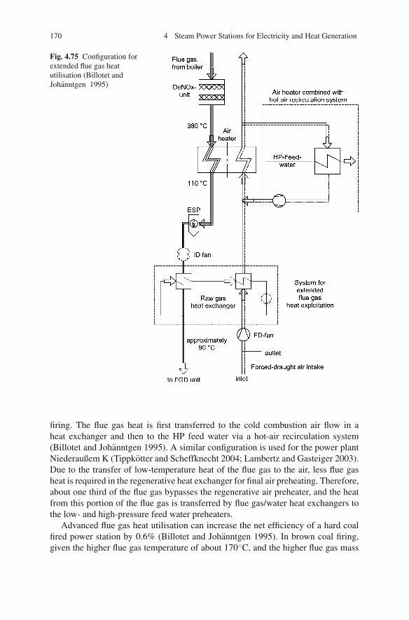
170 4 Steam Power Stations for Electricity and Heat Generation
Fig. 4.75 Configuration forextended flue gas heatutilisation (Billotet andJohanntgen 1995)
firing. The flue gas heat is first transferred to the cold combustion air flow in aheat exchanger and then to the HP feed water via a hot-air recirculation system(Billotet and Johanntgen 1995). A similar configuration is used for the power plantNiederaußem K (Tippkotter and Scheffknecht 2004; Lambertz and Gasteiger 2003).Due to the transfer of low-temperature heat of the flue gas to the air, less flue gasheat is required in the regenerative heat exchanger for final air preheating. Therefore,about one third of the flue gas bypasses the regenerative air preheater, and the heatfrom this portion of the flue gas is transferred by flue gas/water heat exchangers tothe low- and high-pressure feed water preheaters.
Advanced flue gas heat utilisation can increase the net efficiency of a hard coalfired power station by 0.6% (Billotet and Johanntgen 1995). In brown coal firing,given the higher flue gas temperature of about 170◦C, and the higher flue gas mass
4.4 Possibilities for Efficiency Increases in the Development of a Steam Power Plant 171
flow, increases of up to 1.6% can be achieved (Bauer and Lankes 1997; Bruckmannand Hesel 1996).
In order to prevent the flue gas temperature falling below the dew point whentravelling between the air heater outlet and the FGD unit, the low-temperatureheat exchanger should be mounted immediately before the FGD unit. The heatexchanger, located where temperatures range close to the sulphuric acid dew point,has to be made of corrosion-resistant material and be equipped with cleaning mecha-nisms. Such systems have already been developed for flue gas reheating after desul-phurisation and so are available today. Shell-and-tube heat exchangers with tubesmade of synthetic materials such as perfluoroalkoxy (PFA), polytetrafluoroethylene(PTFE) or polyvinylidene fluoride (PVDF) are suitable to use. The heat exchangercasing itself is made of steel coated with a synthetic material (Suhr 1992).
4.4.2.5 Other Types of Losses
Pipework Losses
The hot HP steam produced in the steam generator is fed to the HP section, andthe hot reheater steam is fed to the intermediate-pressure section (IPS) of theturbine – both via pipes with lengths of 100–150 m. Even for the highest capacities,it is common to use two live steam pipes for each run. The energetic heat losses ofthese pipes, which connect the steam generator to turbine, have an efficiency ηpipe,which is around 0.997 (Kohn 1993).
Besides heat losses, pressure losses also cause a temperature decrease and thuslead to exergy losses of the steam between the steam generator and the turbine inlet.The temperature decrease caused by throttling does not have an effect on the pipeloss ηpipe, but on the thermal cycle efficiency. The temperature of the live steamdecreases between 5 and 2◦C in total; the pressure loss ranges between 10 and 5bar. The latter values hold for new plants and for power plants in the planning stage.
Generator Loss
In the generator, the mechanical energy is converted into electrical energy. The effi-ciencies of large generators, in the range of 700–900 MVA, with a water-cooledstator and a hydrogen-cooled rotor, are around 98.7%. For this configuration, thereare only small possible efficiency increases. An efficiency increase to about 99.4%is expected to be possible with a superconducting rotor winding. In addition to theefficiency increase, a smaller space requirement is expected as well (Riedle et al.1990).
Losses of the Main Transformer
Main transformers transform the electrical voltage of the power output supplied tothe electrical network – from 21 to 220 or 380 kV or higher, in order to keep the net-work losses low. They are usually designed as three-phase transformers. The trans-
172 4 Steam Power Stations for Electricity and Heat Generation
former efficiency, as the ratio of the supplied energy to the energy absorbed, lies,with large main transformers, at rated power, in the range of 99.6–99.7% (Adrianet al. 1986).
4.4.3 Reduction of the Auxiliary Power Requirements
The auxiliary power requirement of a power plant is the sum total of the electricaland the mechanical power demand for driving ancillary and auxiliary systems. Theelectrical auxiliary power requirement Paux,el is comprised of the input power of allmachines driven by electric motors, such as fans (FD and ID fans and primary airfan), pumps (the feed water pump if it has an electrical drive, and the condensate,cooling-water and scrubbing slurry pumps), mills, and other power for electricaldevices and equipment such as the transducer and the electrostatic precipitator (ESP)for dust removal. Mechanical power is employed if the feed water pump is drivenby steam turbine instead of electrically:
Paux = Paux,el + Paux,m (4.20)
The auxiliary power demand efficiency can be calculated using the auxiliarypower demand and the power of the turbine (including the power of a turbine-drivenfeed water pump):
ηaux = Paux
P∗Gen
= Paux
PGen + Paux,m(4.21)
About 6–10% of the gross electrical power of a power plant is needed for theauxiliary power of the plant, meaning an auxiliary power demand efficiency of90–94%.
The electrical auxiliary power demand is made of “useful” power plus losses. Theuseful or net power is roughly between 90 and 99%, while the losses correspondto between 10 and 1% of the power demand. Process-engineering improvementsreduce both the useful power demand and the losses; improvements of the auxiliariesonly diminish the losses. In the example of air staging for the reduction of NOx
formation, the useful power demand and losses of auxiliaries are cut down, thusthe auxiliary power requirements diminished. The aim of optimisation measures fordrives and machines is to reduce the losses.
The auxiliary power demand of different main and auxiliary devices are describedin Table 4.3. For the reference power plant and for a new plant, the auxiliary powervalues reported are given in the table.
The feed water pump has the highest power demand. With the live steam pres-sures common today for large hard coal power plants, the power of the boiler feedpump is between 2.5 and 3.5% of the rated generator capacity. The power demanddepends on the pressure rise and the feed water mass flow. Approximately, by

4.4 Possibilities for Efficiency Increases in the Development of a Steam Power Plant 173
Table 4.3 Auxiliary power requirement breakdown for the reference and a new power plant
Live steam pressureReference powerplant 190 bar New plant 250 bar
FD fan 0.8% 0.5%ID fan 1.2% 0.8%Mills and mill fan 0.4% 0.4%Coal handling, ash removal, dust
removal0.3% 0.3%
Boiler feed pump 2.7% (260 bar) 2.9% (310 bar)Condensate pump 0.3% 0.2%Cooling water pump 0.7% 0.6%FGD unit 2.0% 0.8%Other equipment 1.0% 0.7%
Total 9.4% 7.2%
neglecting the impact of the efficiency on the feed water mass flow, theresult is:
pfeed
P∗Gen
[%] = pfeedpump
100(4.22)
The pressure after the feed water pump is higher than the live steam pressure byan amount equal to the sum of the pressure losses of the HP feed-heating train, thesteam generator and the main steam pipe. Table 4.4 compares the pressure losses ofthe reference power plant to those of an advanced thermal power plant, both powerplants being once-through steam generator types. It can be observed that pressurelosses are lower for the advanced plant in all areas. An exception is the superheater,the pressure losses of which increase due to the higher live steam temperatures.The pressure losses in the HP area have a large impact on the power demand ofthe feed water pump, but have no impact on the steam generator efficiency andthe thermal efficiency of the cycle, if one assumes the same live steam conditionsbefore the turbine. Pressure losses in the reheater area only have an impact on thethermal efficiency, via the temperature decrease associated with throttling. Reducingthe power of the boiler feed pump is a means to contribute to the efficiency increase.
Table 4.4 Pressure losses of the reference power plant and of an advanced thermal power plant
750 MW PP unit Reference PP (bar)Advancedthermal PP
Pressure after feed pump 265 320Pressure before turbine 190 270Δp HP heater 8 6Δp economiser 3 2Δp evaporator 25 10Δp superheater 20 25Δp live steam pipe 19 8
Δp Total 75 50
174 4 Steam Power Stations for Electricity and Heat Generation
The feed pump input power also depends on the design of the steam generator. Inonce-through systems, the water-side losses in the steam generator are higher thanin natural-circulation systems. The feed pump for the feed water flow control is avariable-speed type. The feed water capacity is disproportionately reduced becauseof these losses, in particular during part-load operation with sliding-pressure control.
Feed pump configurations for hard coal power plants today are usually either
• a variable-speed turbine-powered 100% duty pump and an electrically driven50% duty pump or
• two 50% duty pumps with variable-speed electrical drives.
Driving the main duty pump by means of a condensation branch turbine – with itsown condenser fed from one of the lower tapping points – is the common techniquein large power plant units. The order of magnitude of its capacity is not limited.The turbine can be coupled directly to the pump and has little loss if the operatingregime does not deviate too much from the design conditions.
The following are typical options for the electrical drive of a variable-speed feedpump:
• A three-phase current induction motor (cage induction motor with unregulatedconstant motor speed). The number of revolutions is adjusted by a loss-inducingvariable-speed hydraulic coupling.
• A synchronous motor supplied by an electronic power converter. The number ofrevolutions is regulated through adjustment of the supplied power.
• A wound-rotor induction motor (variable-speed three-phase current inductionmotor). The slip to synchronous speed is adjusted by a modifiable resistor inthe rotor circle. The slip energy can be recovered and fed back into the network.
Turbine drives are adequate for configurations with a single feed pump. Theyhave a lower auxiliary power requirement in the upper load section of base-loadpower plants compared to electrical feed pump drives.
Power plants in mid-range duty operation are very often equipped with electrical-as well as turbine-driven pumps. They have a comparably low auxiliary powerrequirement in part-load operation of less than 50% of full load. High-range plantunits, above 500 MW or so, must then be equipped with two 50% duty auxiliaries,because the current power maxima are not sufficient for a single auxiliary. A min-imum total heat rate is achieved if, in operation with a load above 50–60% of theplant output, a turbine-driven pump is used and, at output rates below 50%, a motor-driven pump.
Other large-size pumps in a thermal power plant are the circulating pumps of theboiler, the condensate pumps and the cooling water pumps. For a 700 MW unit, thecapacity of the circulating pump of a once-through steam generator is about 1 MW.The two 50% condensate pumps together need about 2 MW. The input power of thecooling water pumps, depending on the cooling technique, ranges around severalMW. The FD and ID fans are next largest in size after the feed pump.
The FD and ID fans are driven almost exclusively by constant-speed three-phasecurrent induction motors. The control features are the adjustable inlet guide vanes orthe variable pitch blades of the fans. Inlet vane control is also called variable-pitch
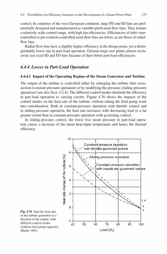
4.4 Possibilities for Efficiency Increases in the Development of a Steam Power Plant 175
control. In countries of the west European continent, large FD and ID fans are pref-erentially designed and manufactured as variable-pitch axial-flow fans. They featurea relatively wide control range, with high fan efficiencies. Efficiencies of inlet-vane-controlled or pre-rotation-controlled axial-flow fans are lower, as are those of radial-flow fans.
Radial-flow fans have a slightly higher efficiency at the design point, yet a distin-guishably lower one in part-load operation. German large-size plants almost exclu-sively use axial ID and FD fans because of their better part-load efficiencies.
4.4.4 Losses in Part-Load Operation
4.4.4.1 Impact of the Operating Regime of the Steam Generator and Turbine
The output of the turbine is controlled either by enlarging the turbine inlet cross-section (constant-pressure operation) or by modifying the pressure (sliding-pressureoperation) (see also Sect. 4.2.4). The different control modes diminish the efficiencyin part-load operation to varying extents. Figure 4.76 shows the impacts of thecontrol modes on the heat rate of the turbine, without taking the feed pump workinto consideration. Both in constant-pressure operation with throttle control andin sliding-pressure operation, the heat rate increases with decreasing load to a fargreater extent than in constant-pressure operation with governing control.
In sliding-pressure control, the lower live steam pressure in part-load opera-tion causes a decrease of the mean heat-input temperature and hence the thermalefficiency.
Fig. 4.76 Specific heat rateof the turbine generator as afunction of the output, withdifferent control modes(without feed pump capacity)(Baehr 1985)

176 4 Steam Power Stations for Electricity and Heat Generation
Fig. 4.77 Load dependenceof the boiler feed pumppower in sliding- andconstant-pressure operation(Baehr 1985)
In constant-pressure operation with throttle control, the mean temperature of heataddition changes only a little through the range of the load. The efficiency deteri-orates because of the throttling of the steam flow, and the temperature decreaseassociated with throttling has an additional negative effect.
In constant-pressure operation with governing control, the deterioration of theefficiency is less severe than for throttling control, because only one valve is everopened partly, while the others are either closed or opened totally. Hence, the throttleloss affects only a part of the flow (Traupel 2001).
The power used by the boiler feed pump decreases both in constant-pressureand in sliding-pressure operation as a consequence of the part-load regime (seeFig. 4.77). It decreases more strongly in sliding-pressure operation because thepump pressure diminishes with the feed water flow for partial loads.
In taking the auxiliary power demand of the feed pump into account additionallyto the heat rate of the turbine, one gets a comparison as shown in Fig. 4.78. Theefficiency disadvantage of sliding-pressure operation turns into a small advantagecompared to constant-pressure operation with governing control. Modified slidingpressure involves a higher heat rate than natural sliding pressure, which is due to theslight throttling of the valves.
At rated load, both constant-pressure operation with throttling control – i.e. thesteam flow not being throttled – and sliding-pressure operation have an efficiencyadvantage, because the turbine control wheel necessary for constant-pressure oper-ation with the nozzle-set governing has a lower HP turbine stage efficiency.
4.4.4.2 Example for the Reference Power Plant
In part-load operation, the efficiency of the reference power plant diminishes becausethe efficiencies of the plant components change. Besides showing the total efficiencyηtot, Fig. 4.79 shows the course of the thermal efficiency ηth, the steam generator
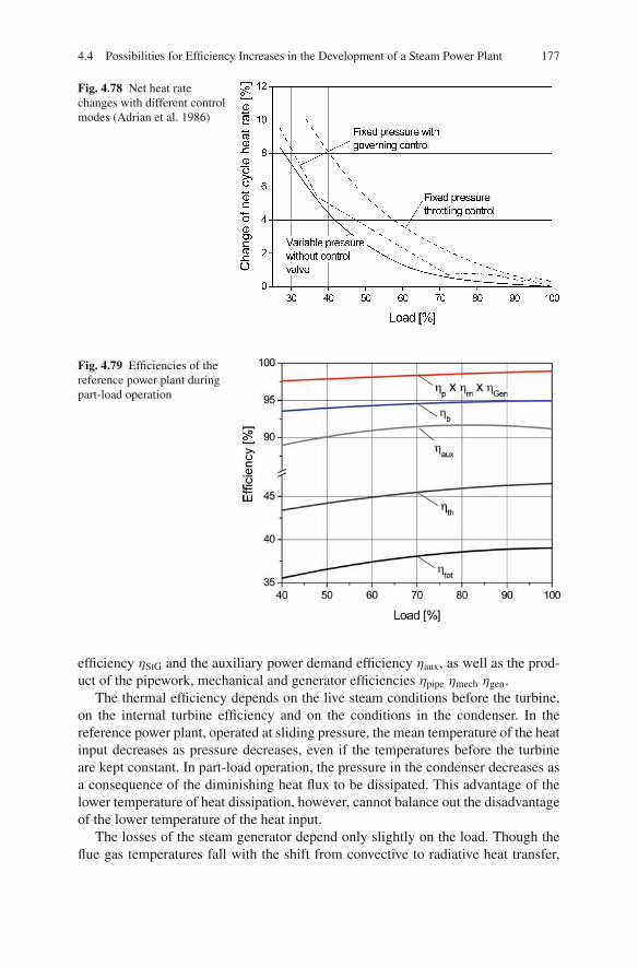
4.4 Possibilities for Efficiency Increases in the Development of a Steam Power Plant 177
Fig. 4.78 Net heat ratechanges with different controlmodes (Adrian et al. 1986)
Fig. 4.79 Efficiencies of thereference power plant duringpart-load operation
efficiency ηStG and the auxiliary power demand efficiency ηaux, as well as the prod-uct of the pipework, mechanical and generator efficiencies ηpipe ηmech ηgen.
The thermal efficiency depends on the live steam conditions before the turbine,on the internal turbine efficiency and on the conditions in the condenser. In thereference power plant, operated at sliding pressure, the mean temperature of the heatinput decreases as pressure decreases, even if the temperatures before the turbineare kept constant. In part-load operation, the pressure in the condenser decreases asa consequence of the diminishing heat flux to be dissipated. This advantage of thelower temperature of heat dissipation, however, cannot balance out the disadvantageof the lower temperature of the heat input.
The losses of the steam generator depend only slightly on the load. Though theflue gas temperatures fall with the shift from convective to radiative heat transfer,

178 4 Steam Power Stations for Electricity and Heat Generation
Fig. 4.80 Start-up losses of a700 MW power plant unit asa function of outage periods(Adrian et al. 1986)
the advantage is nullified by the higher air ratio for the reheater temperature control.Since the power requirement of the auxiliary drives, except for the regulated ones,does not decrease with the load, the auxiliary power requirement with respect to theturbine output increases.
For the reference power plant under consideration in Fig. 4.79, the total efficiencydrops from 38.8% at full load to 35.5–40% load.
4.4.5 Losses During Start-Up and Shutdown
Energy supplied to the power plant during start-up heats the steam generator or islost as waste heat via the stack and condenser. Thermal energy stored in the boileris lost during shutdown, unless it acts as the standby service until the next (warm)start-up.
The start-up losses continue at their full extent until the power plant is in parallelconnection with the electricity network and then diminish accordingly as the livesteam and the reheat steam flows are taken up by the turbine, and the steam flowbypasses of the high-pressure, intermediate-pressure and low-pressure turbines areclosed (see Sect. 4.2.4.4).
The guideline start-up time for an outage of 48 h of a hard coal fuelled unit isabout 4–5 h, for an outage of 8 h, about 2 h, and for an outage of 30 min, about 1 h(STEAG 1988).
The losses occurring during start-up and shutdown depend on
• the capacity of the power plant unit,• the construction type of the steam generator and• the period of the preceding outage (Adrian et al. 1986).
The start-up losses decrease with increasing unit capacity. The longer the periodof an outage, the higher the losses of the following start-up. Figure 4.80 describesstart-up losses of an existing 700 MW power plant unit. The start-up losses of powerplants designed today are well below these levels. For a design 400 MW unit, for

4.4 Possibilities for Efficiency Increases in the Development of a Steam Power Plant 179
Fig. 4.81 Design and operation efficiencies (data from Theis 2005)
instance, losses of 400 GJ after an 8 h outage are reported. So the specific start-uploss of 2 GJ/MW (see Fig. 4.80) is reduced to about 1 GJ/MW (Kotschenreutheret al. 1993).
4.4.6 Efficiency of Power Plants During Operation
When discussing efficiencies, it has to be pointed out that normally only the bestefficiencies at full load are mentioned. In Fig. 4.81, efficiencies which are achievedduring operation are compared, for German power plants, to the respective bestdesign efficiencies for different ages and thermal capacities. The efficiency duringoperation of power plants is about 2–3% (in absolute terms) lower than the designefficiency. With increasing age of the power plant and decreasing thermal capacity,the difference is higher. The lower efficiency during operation is due to the lowerpart-load efficiency and the losses during start-up and shutdown, as discussed inSects. 4.4.4 and 4.4.5.
4.4.7 Fuel Drying for Brown Coal
Moist fuels, compared to dry fuels, involve some efficiency disadvantages for apower plant. The high moisture content of brown coals of 50–60% by weightincreases the flue gas mass flow and the allowable boiler exit temperature. The steam

180 4 Steam Power Stations for Electricity and Heat Generation
generator efficiency diminishes as there are higher flue gas losses. The efficiency isabout 90%, whereas hard coal fuelled furnaces have rates of 94–95%.
Brown coal needs a pre-drying stage for combustion-engineering reasons. Themoisture of German brown coal is almost entirely inherently bound in capillaries,so thermal drying is needed to evaporate the moisture. In a conventional brown coalpower plant, moist raw brown coal is milled and dried in a beater-wheel mill. Thedrying process utilises a 1,000◦C hot, recirculated flue gas partial flow to providethe heat. The simultaneous milling accelerates the evaporation heat exchange withthe hot flue gas. The dried and milled brown coal powder is injected into the firingtogether with the milling vapours. The milling – drying, which is state-of-the-arttechnology for brown coal firing, causes efficiency loss due to the high temperatureof the drying medium and, compared to hard coal firing, 1–2% lower thermal cycleefficiencies. This can be explained exergetically by the decline of the temperaturelevel from about 1,000◦C to about 150◦C and the associated exergy losses. Exter-nal hot gas drying with the same flue gas and water-vapour temperatures would beunfavourable in exergetic terms as well.
The exergetically unfavourable drying, with its low cycle efficiency, and the influ-ence of the fuel moisture on the flue gas loss have the result that the net efficiencyof a brown coal power plant, at comparable steam conditions, may be up to 3%lower than the net efficiency of a hard coal power plant, depending on moistureand sulphur contents. The high temperatures of the partial flue gas flow are notnecessary for drying the brown coal and achieving the required moisture content.However, they offer the advantage of a compact construction size and high dryingcapacities.
The disadvantage of the low cycle efficiency of brown coal (as opposed to hardcoal) can be compensated or even overcompensated by fuel drying using low-exergydrying media. Higher cycle efficiencies can be achieved if media with low temper-ature and exergy are utilised for the drying. Brown coal drying needs only tempera-tures of somewhat above 100◦C, so low-temperature flue gases or extraction steamare possible drying means.
External drying with separate discharges of water vapours and flue gases candiminish the flue gas losses. Separate discharges allow the use of lower temperaturesfor both the water vapour and the flue gas, due to the low acid dew point.
A further efficiency increase is possible if the evaporation heat of the watervapour can be recovered in the power-generating process. This way, the grosscalorific value can be tapped for exploitation. This kind of efficiency increase isonly worthwhile for fuels with an adequate difference between the higher and lowerheating values or with a high fuel moisture content.
In terms of drying technology, there is a distinction between convection and con-tact dryers.
Convection dryers transfer the energy of hot gases, necessary for vaporising themoisture, to the substance to be dried in a direct mass and heat transfer. In thisprocess, the gas cools and takes up the evaporated moisture. In contact driers, theenergy necessary for vaporisation is captured via heating surfaces (Kallmeyer andWick 1997; Bocker et al. 1992; Klutz and Holzenkamp 1996).
4.4 Possibilities for Efficiency Increases in the Development of a Steam Power Plant 181
4.4.7.1 Warm-Gas Drying
Flue gases, extracted after the economiser at 350◦C and cleaned of coarse particles,cool down to temperatures above the dew point (140–170◦C) during convectivedrying of moist brown coal in a beater-wheel mill. This temperature, 350◦C beinglow in comparison to the conventional drying temperature of 1,000◦C, makes itnecessary to use the entire flue gas flow for the drying. Following the removal ofthe coal particles, the flue gases are conducted into the FGD unit. Instead of aflue gas air heater, a steam air heater is used to preheat the combustion air. Thisconcept of warm-gas drying improves the total efficiency by about 2% compared tohot-gas drying or combined drying and pulverising (Zimmer). The acid dew pointshould not fall below, in order to prevent corrosion. The drawback there is that thecondensation heat of the vaporised water from the flue gas/water vapour mixturecannot be gained isothermally but only to the dew point temperature, and henceis less attractive in terms of thermodynamics. Given that the efficiency potential isthus limited, this method is currently less attractive for integration in the power plantcycle (Kallmeyer and Wick 1997).
4.4.7.2 Drying by Extraction Steam
For the drying of brown coal, the condensation heat of the extraction steam fromthe turbine can be used. The available techniques are using tubular or fluidised beddryers (Bocker et al. 1992).
In technical terms, tubular dryers are deemed to be contact dryers. These dryersdominate in the field of the production of dried brown coal. With capacities of up to50 t/h of raw brown coal, they are used for drying from 60 to 12% moisture. A shell-and-tube heat exchanger is mounted in a slightly inclined rotary cylinder. Extractionsteam condenses on the outside of the tubes, transferring the condensation heat fordrying to the coal, which flows through the tubes. Air flowing through the tubes withthe coal takes up the evaporated fuel moisture. As for warm gas drying, the exploita-tion of the condensation heat of the evaporated water in the air/water mixture is notattractive from the thermodynamic point of view (Bocker et al. 1992).
Fluidised bed dryers are particularly suited to being incorporated into the powerplant cycle. They are a drying technology preferentially used for very moist gran-ules; they stand out due to their very good heat transfer.
A portion of the water vapour from the turbine is recirculated in order to createa pure steam atmosphere in the fluidised bed. This way, the water vapours of thesteam-fluidised bed can be condensed almost isothermally, and their evaporationheat can be recovered (Bocker et al. 1992). Fluidised bed dryers can be designed asboth convection and contact dryers. In convection drying by fluidised bed, the heatof the extraction steam is transferred to the fluidising medium in an external heatexchanger. Contact dryers transfer the condensation heat of the extraction steam viathe in-bed heat-transfer surface placed inside the fluidised bed (see Fig. 4.82). Con-tact drying offers advantages over convection drying, particularly when high mois-ture evaporation capacities are required (Klutz and Holzenkamp 1996). It is reported

182 4 Steam Power Stations for Electricity and Heat Generation
Fig. 4.82 Fluidised bed configurations with convection and contact drying (Klutz and Holzenkamp1996)
that throughput rates in the order of magnitude of up to 350 t/h of raw brown coal(180 t/h dried brown coal) are possible (Klutz et al. 1996). A steam-fluidised bedwith a throughput of 45 t/h of raw coal is in service in Australia (Schmalfeld andTwigger 1996).
The efficiency increase (without water vapour exploitation, which is explained inthe following passage) with this kind of technique is in the order of magnitude of2–3%, depending on the pressure where the extraction steam is taken.
4.4.7.3 Exploitation of the Condensation Heat of the Water Vapours
An additional efficiency increase is possible if the condensation heat of the vapoursfrom the fluidised bed dryer can be utilised. The energetic exploitation, however,requires a drying of the brown coal in a pure steam atmosphere, so that the watervapours can be condensed without an interfering influence from air or flue gas.Using this method, an additional increase of 2–3% can be achieved.
A schematic diagram of the WTA process (Wirbelschichttrocknung mitAbwarmenutzung: fluidised bed drying with internal waste heat exploitation) isshown in Fig. 4.83 (Klutz et al. 1996). At a temperature of about 100–120◦C, the bedis fluidised with water vapour from the drying process. To obtain a residual moistureof the brown coal of 12%, it is necessary to have a fluidised bed temperature around110◦C. After a dust removal stage, the water vapours formed during drying arecompressed in a vapour compressor to about 4 bar and then condensed in an in-bedheat-transfer surface to dry the fluidised brown coal bed. In the fluidised bed heatexchanger, the superheat and the condensation heat of the vapours are transferred toprovide the evaporation heat of the brown coal moisture. After condensation the heatof the condensate is used to preheat the coal. Another portion of the water vapoursis recirculated as a fluidising medium.
For the demonstration of the WTA process, a pilot-scale plant for drying 53 t ofraw brown coal per hour was in service from 1993 to 1999. The plant was designedfor a grain size of raw brown coal of up to 6 mm. In a further demonstration step, the
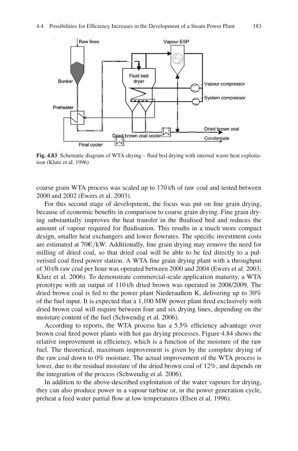
4.4 Possibilities for Efficiency Increases in the Development of a Steam Power Plant 183
Fig. 4.83 Schematic diagram of WTA-drying – fluid bed drying with internal waste heat exploita-tion (Klutz et al. 1996)
coarse grain WTA process was scaled up to 170 t/h of raw coal and tested between2000 and 2002 (Ewers et al. 2003).
For this second stage of development, the focus was put on fine grain drying,because of economic benefits in comparison to coarse grain drying. Fine grain dry-ing substantially improves the heat transfer in the fluidised bed and reduces theamount of vapour required for fluidisation. This results in a much more compactdesign, smaller heat exchangers and lower flowrates. The specific investment costsare estimated at 70e/kW. Additionally, fine grain drying may remove the need formilling of dried coal, so that dried coal will be able to be fed directly to a pul-verised coal fired power station. A WTA fine grain drying plant with a throughputof 30 t/h raw coal per hour was operated between 2000 and 2004 (Ewers et al. 2003;Klutz et al. 2006). To demonstrate commercial-scale application maturity, a WTAprototype with an output of 110 t/h dried brown was operated in 2008/2009. Thedried brown coal is fed to the power plant Niederaußem K, delivering up to 30%of the fuel input. It is expected that a 1,100 MW power plant fired exclusively withdried brown coal will require between four and six drying lines, depending on themoisture content of the fuel (Schwendig et al. 2006).
According to reports, the WTA process has a 5.5% efficiency advantage overbrown coal fired power plants with hot gas drying processes. Figure 4.84 shows therelative improvement in efficiency, which is a function of the moisture of the rawfuel. The theoretical, maximum improvement is given by the complete drying ofthe raw coal down to 0% moisture. The actual improvement of the WTA process islower, due to the residual moisture of the dried brown coal of 12%, and depends onthe integration of the process (Schwendig et al. 2006).
In addition to the above-described exploitation of the water vapours for drying,they can also produce power in a vapour turbine or, in the power generation cycle,preheat a feed water partial flow at low temperatures (Elsen et al. 1996).

184 4 Steam Power Stations for Electricity and Heat Generation
Fig. 4.84 Efficiencyimprovement by pre-drying(Schwendig et al. 2006)
4.5 Effects on Steam Generator Construction
Looking at their history, it is evident that the transition to live steam conditionsabove 540◦C and 260 bar and reheater temperatures above 540◦C was made morethan 50 years ago. As early as 1951, in Germany, a plant with a superheater tem-perature of 600◦C was put into service for the first time. Even though at that timethere was little experience of using most high-temperature materials, a great numberof plants with supercritical steam conditions were built in the 1950s. The peak ofthe development was reached with the construction of the Eddystone power plantin the USA in 1954, with an output of 325 MWel and live steam conditions of650◦C/650◦C/345 bar.
However, the steam generators used in those power plants had several featureswhich at that time were favourable for the application of high steam conditions.
• Compared to modern steam generators with steam-generating capacities up to2,500 t/h, the steam outputs then ranged around 200 t/h.
• The firing systems, as a rule, were slag-tap furnaces, with furnace walls made ofsingle, vertically arranged tubes with a refractory-lined wall behind them. Today,fully welded, gas-tight membrane walls are constructed with external heat insu-lation and helically wound wall tubes (Fig. 4.85). As well as the multi-pass typeconstruction, the single-pass type has become generally accepted, often beingbuilt in central Europe. The ash is removed from the firing in a dry state.
• Live steam conditions of 600◦C/600◦C/350 bar, mostly applied in the chemicalindustry, usually operated at base load for steam and electricity supply. Depend-ing on the fuel prices in a given country, coal-fired furnaces are also built todayfor mid-range load duty.
The increasing steam outputs and higher steam conditions imply that, for largesteam generator components such as HP outlet headers – even when parallel tube
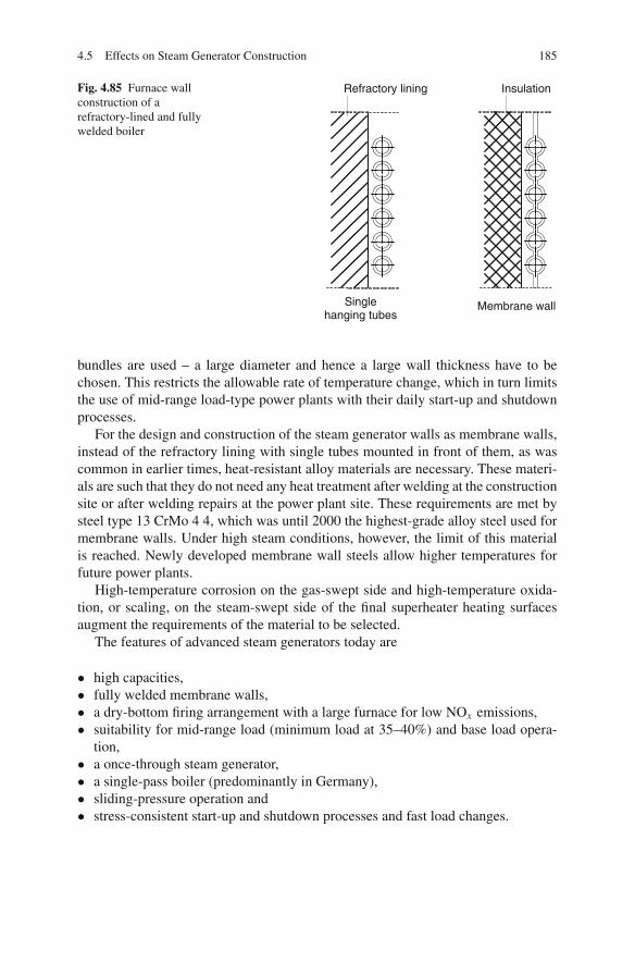
4.5 Effects on Steam Generator Construction 185
Fig. 4.85 Furnace wallconstruction of arefractory-lined and fullywelded boiler
Refractory lining Insulation
Singlehanging tubes
Membrane wall
bundles are used – a large diameter and hence a large wall thickness have to bechosen. This restricts the allowable rate of temperature change, which in turn limitsthe use of mid-range load-type power plants with their daily start-up and shutdownprocesses.
For the design and construction of the steam generator walls as membrane walls,instead of the refractory lining with single tubes mounted in front of them, as wascommon in earlier times, heat-resistant alloy materials are necessary. These materi-als are such that they do not need any heat treatment after welding at the constructionsite or after welding repairs at the power plant site. These requirements are met bysteel type 13 CrMo 4 4, which was until 2000 the highest-grade alloy steel used formembrane walls. Under high steam conditions, however, the limit of this materialis reached. Newly developed membrane wall steels allow higher temperatures forfuture power plants.
High-temperature corrosion on the gas-swept side and high-temperature oxida-tion, or scaling, on the steam-swept side of the final superheater heating surfacesaugment the requirements of the material to be selected.
The features of advanced steam generators today are
• high capacities,• fully welded membrane walls,• a dry-bottom firing arrangement with a large furnace for low NOx emissions,• suitability for mid-range load (minimum load at 35–40%) and base load opera-
tion,• a once-through steam generator,• a single-pass boiler (predominantly in Germany),• sliding-pressure operation and• stress-consistent start-up and shutdown processes and fast load changes.

186 4 Steam Power Stations for Electricity and Heat Generation
With increasing live steam conditions in large-scale steam generators, the designsof the membrane wall and final superheater heating surfaces and the HP out-let header approach maximum stress limits of the material (Stamatelopoulos andWeissinger 2005; Scheffknecht et al. 2002; Chen and Scheffknecht 2003a; Katherand Scheffknecht 1997). Figure 4.86 illustrates how material developments of steelsdetermine and limit the application of higher steam conditions. This will be dis-cussed in the following sections in regard to the membrane wall, superheater andthick-walled components. The development and qualification of new materials forfuture power plants with steam conditions up to 350 bar and 750◦C is ongoing invarious research projects in Europe, Japan and the USA (Blum et al. 2007; Blumand Vanstone 2005; Chen and Scheffknecht 2003b; Chen et al. 2005; Husemann2003; Kjaer et al. 2002; Viswanathan et al. 2005a, b).
Table 4.5 shows the chemical composition of conventional and new steam gen-erator steels (Scheffknecht et al. 1996; Chen and Scheffknecht 2003b).
Tubes
270 580 600
350 700 720
SH outlet header
270 580 600
350 700 720
bar °C °C
Membrane wall
270 580 600
350 700 720
2010
1998
1995
260 550 570
290 600 620
X 20 CrMoV 12 1
E 9 11, P 92, P 122
P 91
260 550 570
290 600 620
X 2CrMoV0 12 1
7 CrMo VTiB 10 10 HCM 2S
13 CrMo 4 4
260 550 570
290 600 620
Austenite
HCM 12 (?),Nickel alloy
Nickel alloy Nickel alloy
9 - 12 %Cr-steels
Austenite
Fig. 4.86 Development of steam conditions and steam generator materials (Source: Alstom Power)
4.5.1 Membrane Wall
Higher live steam pressures, live steam and reheater temperatures and higher inlettemperatures of the feed water result in higher compressive and thermal stresses onthe evaporative system. These stresses can be reduced by process-engineering mea-sures. The above parameters all cause – to varying extents – an increase of the steamoutlet temperature of the evaporator. A higher compressive stress is a result only ofthe higher live steam pressure. While the effect of higher inlet temperatures of thefeed water on the evaporator outlet temperature (the same temperature rise) is some-

4.5 Effects on Steam Generator Construction 187
Tabl
e4.
5C
hem
ical
com
posi
tion
ofbo
iler
stee
ls(S
ourc
e:A
lsto
mPo
wer
and
addi
tions
)St
eel
CSi
Mn
PM
ax.
SM
ax.
Cr
Ni
Co
Mo
Al
Cu
VW
Ti
Nb
Oth
er
15M
o3
(1.5
415)
0.12
–0.2
00.
10–0
.35
0.40
–0.8
00.
035
0.03
5–
–0.
25–0
.35
––
––
––
–13
CrM
o4
4(1
.733
5)0.
10–0
.18
0.10
–0.3
50.
40–0
.70
0.03
50.
035
0.70
–1.1
0–
0.45
–0.6
5–
––
––
––
10C
rMo
910
(1.7
380)
0.08
–0.1
5M
ax.0
.50
0.40
–0.7
00.
035
0.03
52.
00–2
.50
–0.
90–1
.20
––
––
––
–
15N
iCuM
oNb
5(1
.636
8)0.
10–0
.17
0.25
–0.5
00.
80–1
.20
0.03
00.
025
Max
.0.3
01.
00–1
.30
0.25
–0.5
0M
ax.0
.050
0.5–
0.8
––
–0.
015
0.04
5N
:Max
.0.0
20
X20
CrM
oV12
1(1
.492
2)0.
17–0
.23
Max
.0.5
0M
ax.1
.00
0.03
00.
030
10.0
–12.
50.
30–0
.80
0.8–
1.2
––
0.25
–0.3
5–
––
–
X10
CrM
oVN
b9
1(T
/P91
)(1
.490
3)0.
08–0
.12
0.20
–0.5
00.
30–0
.60
0.02
00.
010
8.0–
9.5
Max
.0.4
00.
85–1
.05
Max
.0.0
40–
0.18
–0.2
5–
–0.
06–0
.10
N:0
.030
–0.0
70
7C
rMoV
TiB
1010
(T24
)(1
.737
8)0.
05–0
.10
0.15
–0.4
50.
30–0
.70
0.02
00.
010
2.20
–2.6
0–
0.90
–1.1
0M
ax.0
.020
–0.
20–0
.30
–0.
05–0
.10
–N
:Max
.0.0
1B
:Max
.0.0
007
HC
M25
(T23
)0.
04–0
.10
Max
.0.5
00.
30–0
.60
0.03
00.
010
1.90
–2.6
0–
Max
.0.3
0M
ax.0
.030
–0.
20–0
.30
1.45
–1.7
5–
0.02
–0.0
8N
:Max
.0.0
3B
:Max
.0.0
006
HC
M12
Max
.0.1
4M
ax.0
.50
0.30
–0.7
00.
030
0.03
011
.0–1
3.0
–0.
80–1
.20
––
0.20
–0.3
00.
8–1.
2–
Max
.0.2
0–
HC
M12
A(P
122)
Max
.0.1
5M
ax.0
.40
Max
.0.7
00.
030
0.02
010
.0–1
2.0
Max
.0.7
00.
20–0
.60
Max
.0.0
40M
ax.2
.50.
15–0
.30
1.5–
2.5
–0.
02–0
.10
N:0
.02–
0.10
X10
CrW
MoV
Nb
92
NF
616/
P92
(1.9
01)
Max
.0.1
5M
ax.0
.50
Max
.1.0
00.
020
0.01
08.
0–13
.0–
Max
.1.0
––
0.10
–0.3
01.
5–2.
5–
Max
.0.1
0N
:0.0
2–0.
10B
:Max
.0.0
1
E91
1(1
.490
5)0.
10–0
.18
0.5
0.5
0.01
00.
005
10.0
–12.
00.
1–1.
01.
0M
ax.0
.010
–0.
21.
0–
Max
.0.0
6N
:Max
.0.0
7N
F12
0.08
0.05
0.5
––
11.0
0.5
0.15
––
0.2
2.6
–0.
07N
:0.5
,B:0
.004
Co:
2.4–
2.8
X3
CrN
iMoN
1713
(1.4
910)
Max
.0.0
4M
ax.0
.75
Max
.2.0
00.
035
0.01
516
.0–1
8.0
12.0
–14.
02.
0–2.
8–
––
––
–N
:0.1
0–0.
18
X8
CrN
iMoN
b16
16(1
.498
1)0.
04–0
.10.
3–0.
6M
ax.1
.50.
035
0.01
515
.5–1
7.5
15.5
–17.
51.
6–2.
0–
––
–10
xC1.
2–
TP
347H
FG0.
04–0
.10
Max
.0.7
5M
ax.2
.00
0.04
00.
030
17.0
–20.
09.
0–13
.0–
––
––
–8x
C–
NF
709
0.04
–0.1
0M
ax.0
.75
Max
.1.5
00.
030
0.01
019
.0–2
2.0
23.0
–27.
01.
0–2.
0–
––
–0.
02–0
.20
0.10
–0.4
0N
:0.1
0–0.
20B
:Max
.0.0
07H
R3C
0.04
–0.0
Max
.0.7
5M
ax.2
.00
0.03
00.
030
24.0
–26.
017
.0–2
3.0
––
––
––
0.20
–0.6
0N
:0.1
5–0.
35Su
per
304
H0.
04–0
.10
1.0
Max
.2.0
00.
040
0.03
018
.0–2
0.0
8.0–
11.0
––
0.3–
0.6
N,C
uA
lloy
617
0.05
–0.1
Max
.0.2
Max
.0.2
0.01
00.
010
20.0
–23.
0R
est
10.0
–13.
08.
0–10
.00.
70–1
.40
Max
.0.5
00.
2–0.
5–
Fe<
2.00

188 4 Steam Power Stations for Electricity and Heat Generation
what obvious, the impact of the higher live steam and reheater conditions can beexplained by the higher live steam enthalpy hLS. At the same boiler power output QB
QB = mLS (hLS − hFW) (4.23)
the steam mass flow decreases correspondingly. Given that the heat transferred inthe furnace remains constant at a fixed furnace outlet temperature, the outlet tem-perature from the evaporator rises.
A higher steam pressure, in addition, causes a higher boiling temperature in theevaporator and, with the decrease of the enthalpy of evaporation, higher outlet tem-peratures of the evaporator, provided there is the same heat input in each case. Thisis clarified in Fig. 4.87. A simultaneous temperature increase of 10 K at both theHP and the reheater outlet makes the steam temperature in the wall rise by about7 K, and a pressure increase of 10 bar raises the steam temperature by about 3 K.Because of the greater effect on efficiency, higher live steam temperatures shouldbe preferred to higher live steam pressures if the limit of the membrane walls isreached.
The allowable outlet temperature of the evaporator can be limited by the avail-able materials. Figure 4.88 shows the creep rupture strength for conventional andadvanced membrane wall materials. Besides the necessary strength, membrane wallmaterials have to meet the requirement of being weldable without post-weld heattreatment. In order to avoid hydrogen-induced stress corrosion in the areas of themembrane wall subject to heat loads, post-weld heat treatment is necessary whenthe hardness of about 350–400 HV 10 is exceeded (Kather and Scheffknecht 1997).
Fig. 4.87 Heat-up in theevaporator as a function ofthe pressure: h − p diagram(Riemenschneider 1995)
0 100 200Pressure [bar]
300
100
200
300
400
500
600
700
800t
[°C
]
Ent
halp
y h
[kJ/
kg]
0
1000
2000
3000
4000
100 K 125 K
QVD = const ..
Δ t = 50 K
100
200
300
400
500
600
700
800t
[°C
]
0
..
Δ

4.5 Effects on Steam Generator Construction 189
Fig. 4.88 Creep Strength formembrane wall materials(Source: Alstom Power)
Post-weld heat treatment is feasible in the workshop, though not during installation,assembly or repair works at the power plant site. For this reason, only materialswhich do not require post-weld heat treatment are suitable for membrane walls.
This requirement is met by steel-type 13 CrMo 4 4, which was the preferredmaterial until 2000 for steam power plants. With high steam conditions, however,the limit of this material is reached. At the usual temperature additions, an outsidetube diameter (OD) of 38 mm and a wall thickness of 6.3 mm, an evaporator out-let temperature of about 435◦C is allowable for the membrane wall steel-type 13CrMo 44 (see Fig. 4.89). By choosing a greater wall thickness, and with mechanicalrelief from the secondary load of the membrane wall, the allowable temperature canbe increased up to a maximum of 460–470◦C (Riemenschneider 1995; Scheffknechtet al. 1996). With the material 10 CrMo 9 10 (T22), the steam parameters cannot beincreased considerably.
A substantial improvement of the creep strength, with limited hardness levelsin as-welded conditions, can be reached by the newly developed, ferritic, 2–2.5%chromium steels. The typical examples of this group of steels are the material HCM2S (T23) and 7 CrMoVTiB 10 10 (T24). By the use of these steels, the steamtemperature limit at the water wall can be increased by approximately 50 K incomparison to the conventional 13 CrMo 4 4 steel. Substantial testing of this steelhas been carried out in different research programmes and the steels will be usedas the membrane wall material for power plants currently under construction. For afurnace outlet temperature of 1,250◦C, steam conditions of 300 bar/640◦C can berealised (Chen and Scheffknecht 2003b; Stamatelopoulos and Weissinger 2005).
For very high live steam conditions such as 375 bar and 700◦C, with maximummetal temperatures of above 600◦C, the 2–2.5% chromium steels are no longer ade-quate because of their limited creep strength and the lower corrosion and oxidationresistance. In order to meet the strength and corrosion requirements of very high

190 4 Steam Power Stations for Electricity and Heat Generation
Fig. 4.89 Allowableevaporator outlet temperaturefor various materials as afunction of the pressurebefore turbine (Source:Alstom Power)
live steam conditions, higher-alloy steels are needed. Austenitic steels cannot beused because of their large thermal expansion coefficients, which inhibit the use ofa welded joint between austenitic and ferritic water-wall sections. Candidate mate-rials are 9–12% martensitic chromium steels. The most promising candidate wasthe HCM 12 steel, which has a higher creep strength and corrosion and oxidationresistance, and the hardness in the in-welded condition is the lowest amongst the9–12% chromium steels (Chen 2003). Unfortunately a major reduction of long-termcreep rupture strength at temperatures above 550◦C is expected for many 10–12%chromium steels, including HCM 12, due to changes in the microstructure. Newroutes for the development of iron-based materials for furnace walls have to befound, otherwise the only alternative would be nickel-based superalloys for thehottest part of the furnace wall (Blum et al. 2007). Nickel-based alloys, whichdo not require post-weld treatment, are potential materials for the water wall. Awell-known alloy is the material Alloy 617, which has the advantage of high rup-ture strength, high corrosion and oxidation resistance and heat expansion coeffi-cients similar to martensitic steels. However, the Ni-based alloys are much moreexpensive; in comparison to HCM 12, Ni-based alloy tubes are roughly 10 times asexpensive (Blum et al. 2007).
Significant efforts are ongoing for the development of heat-resistant steels andtheir qualification for use, so that higher steam temperatures may be used in mem-brane wall tubes of evaporators. As an alternative, process-engineering methodswhich avoid or limit higher evaporator outlet temperatures for high steam conditionshave been investigated, such as
• increasing the furnace outlet temperature by using a smaller-sized furnace,• heat shifting by flue gas recirculation,• adding additional heating surfaces in the furnace,• extracting heat from the membrane wall and transferring it to the reheat cycle,• decreasing the size of the economiser,

4.5 Effects on Steam Generator Construction 191
• decreasing the feed water temperature,• minimising the spray attemperator water mass flow into the HP system, in order
to raise the cooling water – steam mass flow through the steam generator wall,and
• reducing the pressure losses in the evaporator and the superheater.
A substantial influence on the evaporator outlet temperature is exerted by thefurnace outlet temperature. As a rule, this temperature is set to range around 50◦Cbelow the ash deformation temperature of the coal. Relatively low furnace outlettemperatures are chosen to allow the firing of a broad range of coal types. Thisprevents slagging on the first convection heating surfaces, even for coals with a lowdeformation point. The furnace outlet temperature, at the same time, establishes theheat absorption of the evaporator in the furnace, and hence the evaporative capacity.Reduced dimensions of the furnace, with the consequence of a higher furnace outlettemperature, decrease the evaporator outlet temperature. An increase of the furnaceoutlet temperature from 1,250 to 1,300◦C, for instance, leads to a decrease of theevaporator outlet temperature by about 16◦C. So, under advanced steam conditions,efforts are made to set the furnace outlet temperature as high as possible. This,however, may result in a restriction of the usable coal types in the firing. Figure 4.90shows the impact of the furnace outlet temperature on the wall exit temperature fordifferent steam conditions.
At the same furnace outlet temperature, flue gas recirculation shifts the heatabsorption from the furnace to the convective heat exchanger surfaces by the useof a higher flue gas mass flow. The evaporator outlet temperature drops as a resultof this process. When designing for flue gas recirculation, the flue gas duct cross-
400
450
500
550
600
1050 1100 1150 1200 1250 1300
Ash deformation temperature [°C]
Wall exit temperature [°C]
A617
P92
7 CrMoVTiB 10 10
13 C rMo 4 4
Fig. 4.90 Impact of furnace exit temperature on the evaporator outlet temperature for differentsteam conditions

192 4 Steam Power Stations for Electricity and Heat Generation
section has to be enlarged in order to not exceed the allowable flue gas velocity inthe convective heating surface section.
The plant efficiency is diminished by the power consumption of the flue gasrecirculation process. Hot flue gas recirculation and cold flue gas recirculation areprocess options that have to be weighed up. In the cold variant, the flue gas is drawnoff after the ESP and recirculated. The disadvantage is the larger air heater surfacearea. In hot flue gas recirculation, the flue gas is extracted before the air heater andre-injected in the burner area. The higher volumetric flow, due to the higher flue gastemperature, requires a greater power demand. In addition, the dust load of the gasmay cause problems. A 10% cold flue gas recirculation lowers the outlet temperatureof the steam by 20◦C (Heiermann et al. 1993). Design concepts for advanced powerplants do not include flue gas recirculation. An increase of the excess air does shiftheat to the convective section, but it increases the flue gas losses because of thehigher mass flow, and thus should not be incorporated.
Arranging additional heating surfaces in the furnace to remove load from theevaporator is a difficult construction task. Wall heating surfaces mounted in front ofthe furnace wall result in different ductile behaviour in different parts of the walls.In principle, only heating surfaces exposed to temperatures lower than the meantemperature in the evaporator should be chosen for additional heating surfaces, dueto the material restrictions. Only the first, and colder, reheater section could hencebe utilised as a wall heating surface. Since, however, those heat exchanger sectionsare missing in the convective section of the furnace, the other heating surfaces aremade larger.
Plate heating surfaces, which are already able to be used at relatively high tem-peratures of about 1,400◦C at the furnace outlet, also reduce the furnace height andare thus suited for removing load from the evaporator. With a wide pitch and thetubes of one plate element mounted tightly next to each other, these heating surfacesare unlikely to experience slag build-up. These types of heating surface, however,can only be taken into consideration for two-pass boilers.
Figure 4.91 shows a concept for transferring heat from the evaporator to the coldreheat steam. Steam is taken from the pipes at the end of the helical winding out of
Fig. 4.91 Heat transfer fromHP steam to cold reheatsteam
ColdReheat

4.5 Effects on Steam Generator Construction 193
the walls, cooled by cold reheat steam and then re-injected into vertically arrangedevaporator pipes.
An economiser designed for a smaller temperature rise or, in the extreme case, isnot included at all restricts the effect of the higher feed water inlet temperature onthe evaporator. Higher flue gas losses can then only be prevented by increasing thedimension of the reheater or the air heating. Greater dimensions of the air heater,due to the higher air preheating temperature at the same furnace outlet tempera-ture, result in an increase of the heat absorption in the evaporator, and thus have tobe avoided. For power plants with advanced steam conditions, a larger reheater istaken into consideration for this reason. A drawback, though, may arise in this casebecause of a deterioration of the convective characteristics of the reheater, so eitherthe injected mass flow would have to be increased or the reheater temperature woulddrop at part-load operation, if remedial action is not taken by other measures (seeSect. 4.3.5.6).
The reduction of the pressure losses in the evaporator and the superheater resultsin lower compressive stresses on the evaporator at the same live steam pressurebefore the turbine. If the maximum load of the membrane material is reached,smaller pressure losses allow higher live steam pressures and therefore a higherefficiency. According to Table 4.4, the predominating pressure loss in advancedsteam generators occurs in the superheater. The potential for reduction of super-heater pressure losses is only small. Superheater tubes with a larger diameter aremore complicated and expensive if the material needed is austenite (Heiermann et al.1993).
The size of the steam generator also has consequences for the membrane walldesign. In small steam generators, a minimum residence time in the furnace isrequired to ensure primary NOx control. Burnout entails a relatively low furnaceoutlet temperature, and hence the problem of an increased steam temperature atthe wall outlet. In large steam generators, the dead load can cause the main forcesto be in the longitudinal direction of the tube instead of the direction of the tubecircumference, because of the inside pressure of the tube. To reduce the total load,the dead load has to be supported by additional weight-bearing components, in ordernot to be forced to restrict the pressure.
These construction and process-engineering measures only have to be consid-ered if the limits of the available membrane wall materials have been reached.Figure 4.92, for the example of material type 13 CrMo 4 4 and hard coal firedfurnaces, shows how the live steam conditions depend on the furnace outlet tem-perature as the essential design parameter. For coals that allow high furnace outlettemperatures of 1,250–1,300◦C, the resulting maximum live steam conditions areup to 300 bar and 600◦C. If lower furnace outlet temperatures are required, it isreasonable to decrease the pressure and keep the live steam temperature.
Figure 4.93 shows the limits of the new membrane wall steel 7 CrMoVTiB10 10 (Lorey and Scheffknecht 2000), which is considered in the design of all newplants. With live steam conditions of the currently planned power stations of upto 300 bar, 600◦C and 620◦C, the limits of the new membrane wall material are

194 4 Steam Power Stations for Electricity and Heat Generation
Fig. 4.92 Maximum steam parameters for membrane wall material type 13 CrMo 4 4 (hard coalLCV = 26.1 MJ/kg, feedwater inlet temp. 290◦C, reheater temp. = HP temp. +20 K) (Source:Alstom Power)
only reached at low furnace exit temperatures of 1,150◦C. With the new material,process-engineering measures are not required.
In Fig. 4.94, the evaporator outlet temperatures for power plants built in Ger-many, or being planned, are shown in a h − p diagram. In all existing power plants,it was possible to use the well-known material 13 CrMo 4 4 for the membrane walls(see Table 4.7), as the evaporator outlet temperature could be limited to 460◦C. Onthe other hand, it is obvious that power plants which are currently planned requirethe new 2–2.5% chromium steels, because the evaporator outlet temperature rangesaround 480◦C. The new 2–2.5% chromium steels can be used for temperatures upto approximately 500◦C. For the 700◦C power plant with evaporator outlet temper-atures of 550◦C, new nickel-based alloys are required.
4.5.2 Heating Surfaces of the Final Superheater
The final superheating surfaces are the convective heating surfaces, which are sub-ject to both the highest steam and the highest flue gas temperatures. X 20 CrMoV12 1, the martensitic steel type commonly used for conventional steam conditions,has proven very worthwhile for steam temperatures up to about 550◦C. The corre-sponding tube wall temperatures are in the range of 600◦C. With ever higher temper-atures, the creep rupture strength of the material diminishes and cannot be balancedout by thicker tube walls, because this would make the temperature differences

4.5 Effects on Steam Generator Construction 195
Fig. 4.93 Maximum steam parameters for membrane wall steel 7CrMMoVTiB 10 10 (Lorey andScheffknecht 2000)
BMCR
Ent
halp
y
4,000
3,600
3,200
2,800
2,400
2,000
1,600
1,200
800
400
kJ/kg
300 bar 400
4,000
3,600
2,800
2,400
2,000
kJ/kg
Pressure0 50 100 150 200 250
100 °C
150 °C
100 °C
150 °C
200 °C
250 °C
300 °C
350 °C
300 °C
375 °C
400 °C
450 °C
500 °C
°C
°C
550 °C
600 °C
650 °C
700 °C
°C
°C
°C
°C
750 °C
Wall outlet
510 °C
460 °C
1 Niederaußem K 275 bar, 580/600 °C 2 Schwarze Pumpe 268 bar, 547/565 °C3 Westfalen D 290 bar, 600/620 °C4 300 bar, 633/651 °C 5 AD 700 358 bar, 702/720 °C
1 2 3 4 5
Fig. 4.94 Design of a conventional and of a high-temperature steam generator: h − p diagram(Source: Alstom Power)
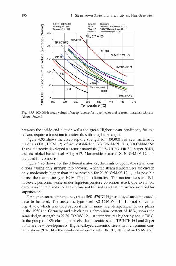
196 4 Steam Power Stations for Electricity and Heat Generation
Fig. 4.95 100,000 h mean values of creep rupture for superheater and reheater materials (Source:Alstom Power)
between the inside and outside walls too great. Higher steam conditions, for thisreason, require a transition to materials with a higher strength.
Figure 4.95 shows the creep rupture strength for 100,000 h of new martensiticmaterials (T91, HCM 12), of well-established (X3 CrNiMoN 1713, X8 CrNiMoNb1616) and newly developed austenitic materials (TP 347H FG, HR 3C, Super 304H)and the nickel-based steel Alloy 617. Martensitic material X 20 CrMoV 12 1 isincluded for comparison.
Figure 4.96 shows, for the different materials, the limits of applicable steam con-ditions, taking only strength into account. When the steam temperatures are chosenonly moderately higher than those possible for X 20 CrMoV 12 1, it is possibleto use the martensite-type HCM 12 as an alternative. The martensitic steel T91,however, performs worse under high-temperature corrosion attack due to its lowchromium content and should therefore not be used as a heating surface material forsuperheaters.
For higher steam temperatures, above 560–570◦C, higher-alloyed austenitic steelshave to be used. The austenitic-type steel X8 CrMoNb 16 16 (not shown inFig. 4.96), which was used successfully in many high-temperature power plantsin the 1950s in Germany and which has a chromium content of 16%, shows thesame design strength as X 20 CrMoV 12 1 at temperatures higher by about 70◦C.In the group of 18% chromium steels, the austenitic steels TP 347H FG and Super304H are new developments. Higher-alloyed austenitic steels with chromium con-tents above 20%, like the newly developed steels HR 3C, NF 709 and SAVE 25,
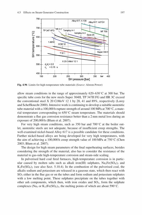
4.5 Effects on Steam Generator Construction 197
Fig. 4.96 Limits for high-temperature tube materials (Source: Alstom Power)
allow steam conditions in the range of approximately 620–630◦C at 300 bar. Thespecific tube costs for the new steels Super 304H, TP 347H FG and HR 3C exceedthe conventional steel X 20 CrMoV 12 1 by 28, 41 and 89%, respectively (Loreyand Scheffknecht 2000). Intensive work is continuing to develop a suitable austenitictube material with a 100,000 h rupture strength of around 100 MPa at 700◦C, a mate-rial temperature corresponding to 650◦C steam temperature. The materials shoulddemonstrate a flue gas corrosion resistance better than a 2 mm metal loss during anexposure of 200,000 h (Blum et al. 2007).
For very high steam conditions, such as 350 bar and 700◦C at the boiler out-let, austenitic steels are not adequate, because of insufficient creep strengths. Thewell-examined nickel-based Alloy 617 is a possible candidate for these conditions.Further nickel-based alloys are being developed for very high temperatures, withthe aim of achieving a 100,000 h creep strength value of 100 MPa at 750◦C (Chen2003; Blum et al. 2007).
The design for high steam parameters of the final superheating surfaces, besidesconsidering the strength of the material, also has to consider the resistance of thematerial to gas-side high-temperature corrosion and steam-side scaling.
In pulverised hard coal fired furnaces, high-temperature corrosion is in partic-ular caused by molten salts such as alkali iron(III) sulphates, Na3Fe(SO4)3 andK3Fe(SO4)3 (see also Sect. 5.10.4). In the combustion of the pulverised coal, thealkalis sodium and potassium are released in a gaseous state, which then react withSO3 either in the flue gas or on the tubes and form sodium and potassium sulphateswith a low melting point. These sulphates precipitate on the tubes together withother ash components, which then, with iron oxides and SO3, form the sulphatecomplexes (Na3 or K3)Fe(SO4)3, the melting points of which are about 590◦C.

198 4 Steam Power Stations for Electricity and Heat Generation
Figure 4.97 shows the corrosion rate for an austenitic material as a function oftemperature (Plumpley and Roczniak 1988; Apblett 1973). The diagram also showsthe concentrations of the sulphate complexes and their changes of physical state. Atabout 580◦C, the corrosion rate begins to rise markedly until it reaches the max-imum value at about 660◦C. In this range the sodium and potassium complexesare present in molten form. In the range above 700◦C, these become unstable andevaporate. The material wear rate starts to decrease as a consequence. The corro-sion rates of ferritic and martensitic materials are considerably higher at the sametemperatures than the rates of the austenitic materials shown in Fig. 4.97.
The location and the level of the maximum corrosion rate depend on the com-position of the coal. Prime determining factors of the coal’s corrosiveness are thecontent of volatile alkalis and the SO3 content of the flue gas. Larger corrosion ratesfor chlorine-containing coal types are put down to the fact that a higher chlorinecontent is favourable for the formation of volatile alkalis. CaO and MgO in the coalash reduce corrosion. CaO or MgO addition to the fuel at a controlled rate can beused to reduce high-temperature corrosion.
Besides the surface temperature of the tube, the flue gas temperature is anotherimportant factor affecting the corrosion rate. In the range of the surface temper-atures that are associated with high steam conditions and which still lie below themaximum corrosion rate, higher flue gas temperatures lead to higher corrosion rates,because the conditions are favourable for the complexes to melt (see Fig. 4.98).
The corrosion rate depends a lot on the tube material used. From Fig. 4.99 itcan be inferred that the resistance of the material against high-temperature corro-sion is primarily influenced by the chromium content. The higher the chromiumcontent, the higher the resistance against high-temperature corrosion. With theirelevated chromium content, austenites are more corrosion-resistant than ferritesand martensites and should in this respect be given preference for use in the high-temperature area.
Fig. 4.97 Weight loss ofaustenitic materials due tohigh-temperature corrosion,and physical state ofcorrosive sulphates as afunction of temperature
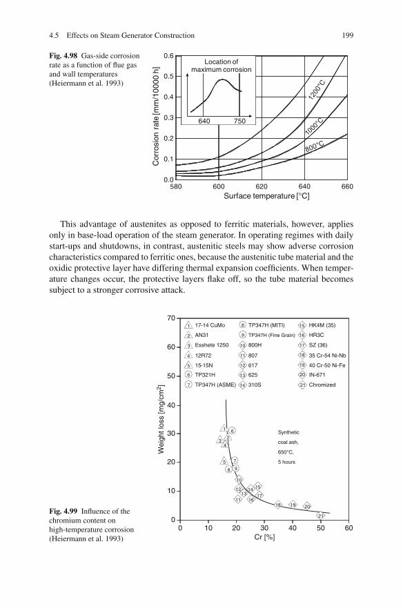
4.5 Effects on Steam Generator Construction 199
Fig. 4.98 Gas-side corrosionrate as a function of flue gasand wall temperatures(Heiermann et al. 1993)
580 600 620 640 6600.0
0.1
0.2
0.3
0.4
0.5
0.6
Surface temperature [°C]
Cor
rosi
on r
ate
[mm
/100
00 h
]
640
Location ofmaximum corrosion
750
This advantage of austenites as opposed to ferritic materials, however, appliesonly in base-load operation of the steam generator. In operating regimes with dailystart-ups and shutdowns, in contrast, austenitic steels may show adverse corrosioncharacteristics compared to ferritic ones, because the austenitic tube material and theoxidic protective layer have differing thermal expansion coefficients. When temper-ature changes occur, the protective layers flake off, so the tube material becomessubject to a stronger corrosive attack.
Fig. 4.99 Influence of thechromium content onhigh-temperature corrosion(Heiermann et al. 1993)
0 10 20 30 40 50 600
10
17-14 CuMo
AN31
Esshete 1250
12R72
15-15N
TP321H
TP347H (ASME) 310S Chromized
625 IN-671
617 40 Cr-50 Ni-Fe
807 35 Cr-54 Ni-Nb
800H SZ (36)
TP347H (MITI)
TP347H (Fine Grain)
HK4M (35)
HR3C
20
30
40
50
60
70
Cr [%]
Synthetic
coal ash,
650°C,
5 hours
Wei
ght l
oss
[mg/
cm2 ]
11
11
13
13
15
15
14
14
12
12
8
8
1
1
6
6
2
2
3
3
4
4
5
5
7
7
9
9
10
10
16
16
17
17
18
18
19
19
20
20
21
21

200 4 Steam Power Stations for Electricity and Heat Generation
Fig. 4.100 Scalingthicknesses for differentchromium contents of amaterial and different livesteam temperatures(Heiermann et al. 1993)
Further measures to control high-temperature corrosion are
• the use of composite tubes or coated tubes,• the replacement of tubes that are particularly at risk after a defined operating
period and• the application of metal or ceramic half-pipe sections to protect tubes especially
at risk, such as the row of tubes of a heating surface bank which are exposed tothe flow first. The surface temperature of these protective half-pipes in this caseis clearly above that which causes the maximum permissible corrosion rate. Thepotential to use them, however, remains restricted to relatively few areas in thesteam generator, because they considerably impair the heat transfer.
The last reheater stage, with its high steam temperature (usually higher than thereheater temperature due to the lower reheat pressure) and low heat transfer coeffi-cient, is the heating surface most at risk of high-temperature corrosion. It shouldtherefore be arranged downstream of the final superheater on the flue gas side,which makes keeping constant reheater temperatures at part-load operation moredifficult.
Another problem arising in high-temperature operations is high-temperature oxi-dation, or scaling, of the tubes on the steam side. As a consequence of the highersteam temperatures, the scaling rate on the inside of the heated tubes rises, deterio-rating the heat transfer and raising the tube wall temperature. The higher tempera-ture diminishes the creep rupture strength of the materials and increases the firesidecorrosion rate.
The scaling constants of the various materials help to determine scale thicknessvalues as functions of time (Fig. 4.100). These values, in turn, are used to estimatethe increases of the tube wall temperatures (Fig. 4.101). Higher chromium contentsdiminish the effects of high-temperature oxidation.
At the power plant Niederaußem K, with steam conditions of 580◦C/600◦C(SH/RH), unstable layers of magnetite oxide inside the tubes resulted in tube fail-ures. The austenitic steel X3 CrNiMoN 17 13 (1.4910) was replaced partly by
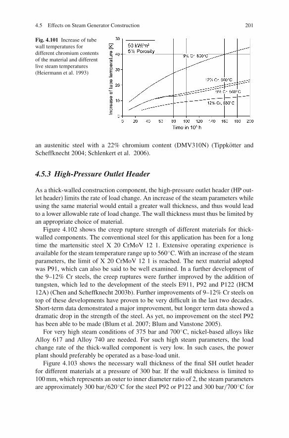
4.5 Effects on Steam Generator Construction 201
Fig. 4.101 Increase of tubewall temperatures fordifferent chromium contentsof the material and differentlive steam temperatures(Heiermann et al. 1993)
an austenitic steel with a 22% chromium content (DMV310N) (Tippkotter andScheffknecht 2004; Schlenkert et al. 2006).
4.5.3 High-Pressure Outlet Header
As a thick-walled construction component, the high-pressure outlet header (HP out-let header) limits the rate of load change. An increase of the steam parameters whileusing the same material would entail a greater wall thickness, and thus would leadto a lower allowable rate of load change. The wall thickness must thus be limited byan appropriate choice of material.
Figure 4.102 shows the creep rupture strength of different materials for thick-walled components. The conventional steel for this application has been for a longtime the martensitic steel X 20 CrMoV 12 1. Extensive operating experience isavailable for the steam temperature range up to 560◦C. With an increase of the steamparameters, the limit of X 20 CrMoV 12 1 is reached. The next material adoptedwas P91, which can also be said to be well examined. In a further development ofthe 9–12% Cr steels, the creep ruptures were further improved by the addition oftungsten, which led to the development of the steels E911, P92 and P122 (HCM12A) (Chen and Scheffknecht 2003b). Further improvements of 9–12% Cr steels ontop of these developments have proven to be very difficult in the last two decades.Short-term data demonstrated a major improvement, but longer term data showed adramatic drop in the strength of the steel. As yet, no improvement on the steel P92has been able to be made (Blum et al. 2007; Blum and Vanstone 2005).
For very high steam conditions of 375 bar and 700◦C, nickel-based alloys likeAlloy 617 and Alloy 740 are needed. For such high steam parameters, the loadchange rate of the thick-walled component is very low. In such cases, the powerplant should preferably be operated as a base-load unit.
Figure 4.103 shows the necessary wall thickness of the final SH outlet headerfor different materials at a pressure of 300 bar. If the wall thickness is limited to100 mm, which represents an outer to inner diameter ratio of 2, the steam parametersare approximately 300 bar/620◦C for the steel P92 or P122 and 300 bar/700◦C for

202 4 Steam Power Stations for Electricity and Heat Generation
Fig. 4.102 100,000 h creep rupture strength for pipe and header materials (Source: Alstom Power)
Alloy 617 (based on current VdTUV values). An upgrading to the Ni-based Alloy617 can reduce the wall thickness by about 30% (Chen and Scheffknecht 2003b;Hahn and Bendick 2006). The layout of the plant may, to a limited extent, allow asmaller wall thickness, in addition to the selection of materials. By increasing thenumber of parallel steam runs, it is possible to reduce the diameter of the header andthus the wall thickness.
High-pressure outlet headers can become limiting components in power plantswith advanced steam conditions, because technical regulations result in a greaterratio of the outside to the inside diameter compared to the ratio for live steam pipes.For the live steam pipes, the same materials are considered as for the HP outlet head-ers. Due to the smaller wall thickness/diameter ratio, the design limit, as opposed tothe outlet headers, is not reached.
4.5.3.1 Impacts on the Turbine
In contrast to the steam generator and the tubes, the problems in the constructionof steam turbines for extreme steam conditions arise almost exclusively from thetemperature (Adrian et al. 1986). The critical components are those swept by hotsteam – that is, the cast valve chests and the HP and IP (intermediate-pressure)cylinders, the forged HP and IP rotors and the blading of the first HP and IP stages.The high-temperature power plants in the 1950s and 1960s used austenitic steels for

4.5 Effects on Steam Generator Construction 203
Fig. 4.103 Wall thickness of header materials for different steam conditions (Source:Alstom Power)
the critical turbine components such as the valve chest and rotor forgings; however,experience with these steels was unsatisfactory. The high coefficients of thermalexpansion and low thermal conductivities, as well as the low yield strengths, meanthat thermal cycles cause high thermal gradients and stresses in thick section compo-nents. As a consequence, the use of austenitic steels for advanced steam conditionsis now avoided. The increase of steam conditions in the turbine section was onlypossible with the introduction of the use of martensitic 9–11% chromium steels.The 10% chromium steel X14 CrMoVNbN10 2 as a standard for rotor materialstoday allows steam conditions between 585 and 610◦C. Within different phases ofthe European COST programme, work is ongoing to develop martensitic steels fortemperatures up to 630 and 650◦C, by the increase of the chromium content to 11%and the addition of Co and B to increase the oxidation resistance and the creeprupture strength. The temperature at which the 100,000 h rupture creep strength isaround 100 MPa is a reasonable indicator of the maximum application temperatureas a steam turbine material. To support the development of steam turbines for tem-peratures greater than 700◦C, development of nickel-based alloys for use in criticalturbine components is currently in progress in European programmes such as AD700. The timeframe to develop a new, completely reliable, mature turbine steel isabout 12 years (Blum and Vanstone 2005; Blum et al. 2007; Tremmel et al. 2006;Oakey et al. 2003; Wichtmann et al. 2005).
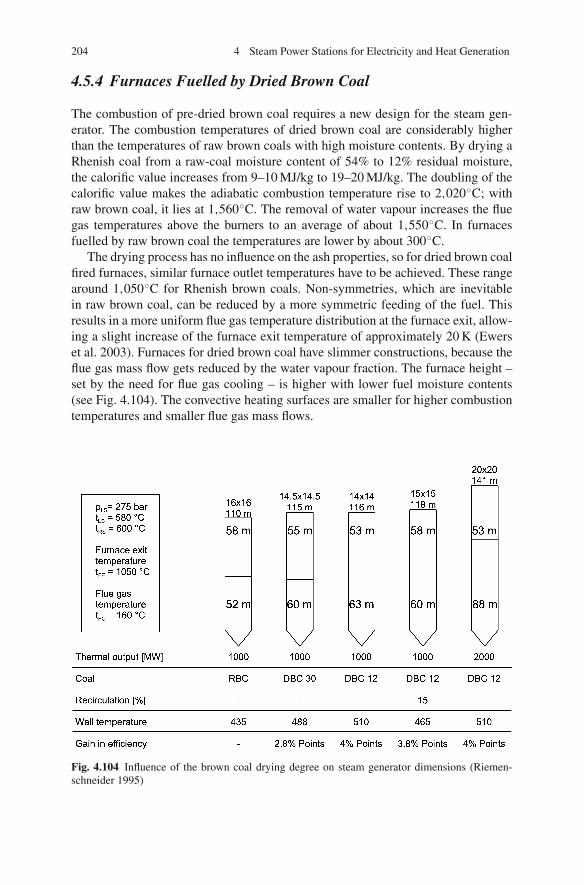
204 4 Steam Power Stations for Electricity and Heat Generation
4.5.4 Furnaces Fuelled by Dried Brown Coal
The combustion of pre-dried brown coal requires a new design for the steam gen-erator. The combustion temperatures of dried brown coal are considerably higherthan the temperatures of raw brown coals with high moisture contents. By drying aRhenish coal from a raw-coal moisture content of 54% to 12% residual moisture,the calorific value increases from 9–10 MJ/kg to 19–20 MJ/kg. The doubling of thecalorific value makes the adiabatic combustion temperature rise to 2,020◦C; withraw brown coal, it lies at 1,560◦C. The removal of water vapour increases the fluegas temperatures above the burners to an average of about 1,550◦C. In furnacesfuelled by raw brown coal the temperatures are lower by about 300◦C.
The drying process has no influence on the ash properties, so for dried brown coalfired furnaces, similar furnace outlet temperatures have to be achieved. These rangearound 1,050◦C for Rhenish brown coals. Non-symmetries, which are inevitablein raw brown coal, can be reduced by a more symmetric feeding of the fuel. Thisresults in a more uniform flue gas temperature distribution at the furnace exit, allow-ing a slight increase of the furnace exit temperature of approximately 20 K (Ewerset al. 2003). Furnaces for dried brown coal have slimmer constructions, because theflue gas mass flow gets reduced by the water vapour fraction. The furnace height –set by the need for flue gas cooling – is higher with lower fuel moisture contents(see Fig. 4.104). The convective heating surfaces are smaller for higher combustiontemperatures and smaller flue gas mass flows.
Fig. 4.104 Influence of the brown coal drying degree on steam generator dimensions (Riemen-schneider 1995)
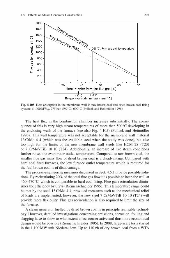
4.5 Effects on Steam Generator Construction 205
Fig. 4.105 Heat absorption in the membrane wall in raw brown coal and dried brown coal firingsystems (1,000 MWel, 275 bar, 580◦C, 600◦C (Pollack and Heitmuller 1996)
The heat flux in the combustion chamber increases substantially. The conse-quence of this is very high steam temperatures of more than 500◦C developing inthe enclosing walls of the furnace (see also Fig. 4.105) (Pollack and Heitmuller1996). This wall temperature was not acceptable for the membrane wall material13 CrMo 4 4 (which was the available steel when the study was done), but alsotoo high for the limits of the new membrane wall steels like HCM 2S (T23)or 7 CrMoVTiB 10 10 (T24). Additionally, an increase of live steam conditionsfurther raises the evaporator outlet temperature. Compared to raw brown coal, thesmaller flue gas mass flow of dried brown coal is a disadvantage. Compared withhard coal fired furnaces, the low furnace outlet temperature which is required forthe fuel brown coal is of disadvantage.
The process-engineering measures discussed in Sect. 4.5.1 provide possible solu-tions. By recirculating 20% of the total flue gas flow it is possible to keep the wall at460–470◦C, which is comparable to hard coal firing. Flue gas recirculation dimin-ishes the efficiency by 0.2% (Riemenschneider 1995). This temperature range couldbe met by the steel 13 CrMo 4 4, provided measures such as the mechanical reliefof loads are implemented; however, the new steel 7 CrMoVTiB 10 10 (T24) willprovide more flexibility. Flue gas recirculation is also required to limit the size ofthe furnace.
A steam generator fuelled by dried brown coal is in principle realisable technol-ogy. However, detailed investigations concerning emissions, corrosion, fouling andslagging have to show to what extent a less conservative and thus more economicaldesign would be possible (Riemenschneider 1995). In 2008, large-scale tests startedin the 1,100 MW unit Niederaußem. Up to 110 t/h of dry brown coal from a WTA
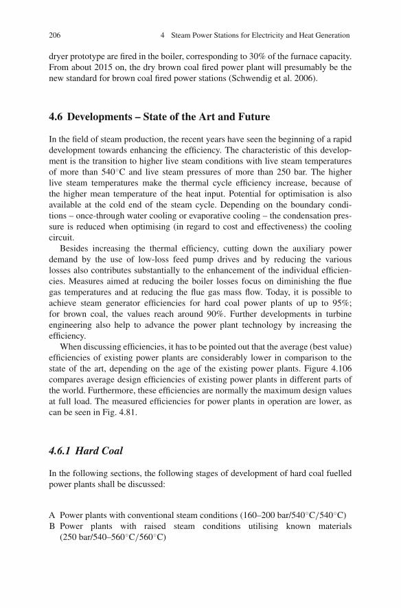
206 4 Steam Power Stations for Electricity and Heat Generation
dryer prototype are fired in the boiler, corresponding to 30% of the furnace capacity.From about 2015 on, the dry brown coal fired power plant will presumably be thenew standard for brown coal fired power stations (Schwendig et al. 2006).
4.6 Developments – State of the Art and Future
In the field of steam production, the recent years have seen the beginning of a rapiddevelopment towards enhancing the efficiency. The characteristic of this develop-ment is the transition to higher live steam conditions with live steam temperaturesof more than 540◦C and live steam pressures of more than 250 bar. The higherlive steam temperatures make the thermal cycle efficiency increase, because ofthe higher mean temperature of the heat input. Potential for optimisation is alsoavailable at the cold end of the steam cycle. Depending on the boundary condi-tions – once-through water cooling or evaporative cooling – the condensation pres-sure is reduced when optimising (in regard to cost and effectiveness) the coolingcircuit.
Besides increasing the thermal efficiency, cutting down the auxiliary powerdemand by the use of low-loss feed pump drives and by reducing the variouslosses also contributes substantially to the enhancement of the individual efficien-cies. Measures aimed at reducing the boiler losses focus on diminishing the fluegas temperatures and at reducing the flue gas mass flow. Today, it is possible toachieve steam generator efficiencies for hard coal power plants of up to 95%;for brown coal, the values reach around 90%. Further developments in turbineengineering also help to advance the power plant technology by increasing theefficiency.
When discussing efficiencies, it has to be pointed out that the average (best value)efficiencies of existing power plants are considerably lower in comparison to thestate of the art, depending on the age of the existing power plants. Figure 4.106compares average design efficiencies of existing power plants in different parts ofthe world. Furthermore, these efficiencies are normally the maximum design valuesat full load. The measured efficiencies for power plants in operation are lower, ascan be seen in Fig. 4.81.
4.6.1 Hard Coal
In the following sections, the following stages of development of hard coal fuelledpower plants shall be discussed:
A Power plants with conventional steam conditions (160–200 bar/540◦C/540◦C)B Power plants with raised steam conditions utilising known materials
(250 bar/540–560◦C/560◦C)

4.6 Developments – State of the Art and Future 207
Fig. 4.106 Average efficiency of hard coal fired power stations in different regions (Meier 2004)
C Power plants with high steam conditions employing austenitic materials for thefinal-stage superheater and available new steel types for thick-walled parts (270–290 bar/580◦C/600◦C)
D Power plants with the highest steam conditions employing austenitic materialsfor superheaters, and new ferritic steel types for thick-walled parts and the evap-orator (300–330 bar/600–630◦C/600–630◦C)
E Power plants with steam conditions up to 350 bar/700–750◦C, with futurematerials
Figure 4.107 gives a breakdown of the efficiencies of the individual developmentstages for hard coal power plants. In the long term, an increase of the efficiencyto more than 50% can be expected, which will require the development of suitablematerials. Table 4.6 describes the materials used and to be used for boilers.
Table 4.6 Materials required for steam generator advancements
SteamThick-walled parameters Commissioning
Evaporator Superheater components [bar/◦C/◦C/◦C] year
A 13 CrMo 4 4 X20 X20 180/540/540 39 1985B 13 CrMo 4 4 X20∗ X20∗ 250/540/560 43 1993C 13 CrMo 4 4∗ Austenite P91∗ 270/580/600 45 2000D HCM 2S∗
7 CrMo. . .
Austenite∗ Ferrite (P92, NF616, NF 12) oraustenite∗
300/600/620 47 2010
E HCM 12 Nickel alloy Nickel alloy 350/700/700 50 2020∗ Material stress limit reached.
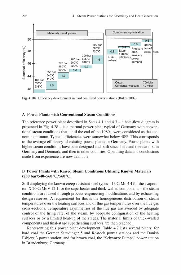
208 4 Steam Power Stations for Electricity and Heat Generation
Output: 700 MWCondenser vacuum: 40 mbar
50
48
46
44
42
Materials development
167 bar538°C538°C
250 bar540°C540°C
270 bar580°C600°C
285 bar600°C620°C
300 bar625°C640°C
300 bar700°C720°C
1.5
1.3
0.60.7
1.6
Component optimisation
Dualreheat
Steamturbineefficiency
Pressuredrop,auxiliarypowerdemand
Utilisa-tion ofwaste heat
Output: 700 MWCondenser vacuum: 40 mbar
0.40.6
0.6
0.8
Ele
ctric
al e
ffici
ency
[%]
Fig. 4.107 Efficiency development in hard coal fired power stations (Rukes 2002)
A Power Plants with Conventional Steam Conditions
The reference power plant described in Sects 4.1 and 4.3 – a heat-flow diagram ispresented in Fig. 4.28 – is a thermal power plant typical of Germany with conven-tional steam conditions that, until the end of the 1980s, were considered as the eco-nomic optimum. Typical efficiencies were somewhat below 40%. This correspondsto the average efficiency of existing power plants in Germany. Power plants withhigher steam conditions have been designed and built since, here and there at first inGermany and Denmark, and then in other countries. Operating data and conclusionsmade from experience are now available.
B Power Plants with Raised Steam Conditions Utilising Known Materials(250 bar/540–560◦C/560◦C)
Still employing the known creep-resistant steel types – 13 CrMo 4 4 for the evapora-tor, X 20 CrMoV 12 1 for the superheater and thick-walled components – the steamconditions are raised through process-engineering modifications and by exhaustingdesign reserves. A requirement for this is the homogeneous distribution of steamtemperatures over the heating surfaces and of flue gas temperatures over the flue gascross-sections. Temperature asymmetries of the flue gas are avoided by adequatecontrol of the firing rate; of the steam, by adequate configuration of the heatingsurfaces or by a limited heat-up of the stages. The material limits of thick-walledcomponents and final-stage superheating surfaces are then reached.
Representing this power plant development, Table 4.7 lists several plants: forhard coal the German Staudinger 5 and Rostock power stations and the DanishEsbjerg 3 power station, and for brown coal, the “Schwarze Pumpe” power stationin Brandenburg, Germany.
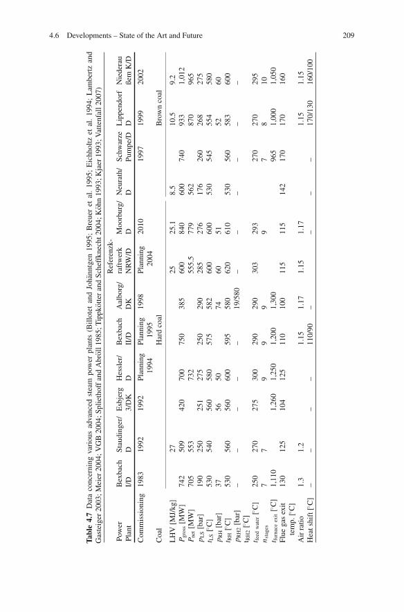
4.6 Developments – State of the Art and Future 209
Tabl
e4.
7D
ata
conc
erni
ngva
riou
sad
vanc
edst
eam
pow
erpl
ants
(Bill
otet
and
Joha
nntg
en19
95;
Bre
uer
etal
.19
95;
Eic
hhol
tzet
al.
1994
;L
ambe
rtz
and
Gas
teig
er20
03;M
eier
2004
;VG
B20
04;S
plie
thof
fan
dA
brol
l198
5;T
ippk
otte
ran
dSc
heff
knec
ht20
04;K
ohn
1993
;Kja
er19
93;V
atte
nfal
l200
7)
Ref
eren
zk-
Pow
erB
exba
chSt
audi
nger
/E
sbje
rgH
essl
er/
Bex
bach
Aal
borg
/ra
ftw
erk
Moo
rbur
g/N
eura
th/
Schw
arze
Lip
pend
orf
Nie
dera
uPl
ant
I/D
D3/
DK
DII
/DD
KN
RW
/DD
DPu
mpe
/DD
ßem
K/D
Com
mis
sion
ing
1983
1992
1992
Plan
ning
1994
Plan
ning
1995
1998
Plan
ning
2004
2010
1997
1999
2002
Coa
lH
ard
coal
Bro
wn
coal
LH
V[M
J/kg
]27
2525
.18.
510
.59.
2P g
ross
[MW
]74
250
942
070
075
038
560
084
060
074
093
31,
012
P net
[MW
]70
555
373
255
5.5
779
562
870
965
p LS
[bar
]19
025
025
127
525
029
028
527
617
626
026
827
5t L
S[◦ C
]53
054
056
058
057
558
260
060
053
054
555
458
0p R
H[b
ar]
3756
5074
6051
5260
t RH
[◦ C]
530
560
560
600
595
580
620
610
530
560
583
600
p RH
2[b
ar]
––
––
–19
/580
––
––
––
t RH
2[◦ C
]t fe
edw
ater
[◦ C]
250
270
275
300
290
290
303
293
270
270
295
n sta
ges
77
99
99
78
10t fu
rnac
eex
it[◦ C
]1,
110
1,26
01,
250
1,20
01,
300
965
1,00
01,
050
Flue
gas
exit
tem
p.[◦ C
]13
012
510
412
511
010
011
511
514
217
017
016
0
Air
ratio
1.3
1.2
1.15
1.17
1.15
1.17
1.15
1.15
Hea
tshi
ft[◦ C
]–
––
–11
0/90
––
––
170/
130
160/
100
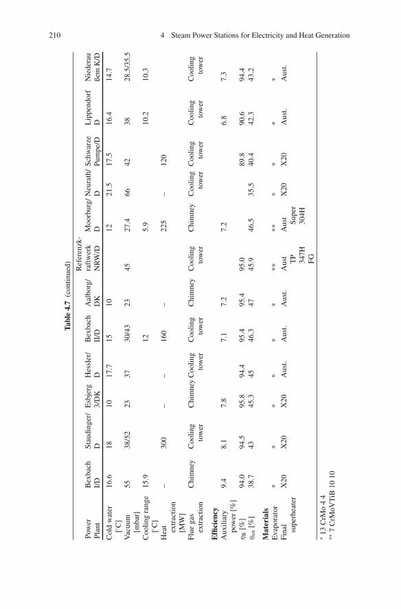
210 4 Steam Power Stations for Electricity and Heat Generation
Tabl
e4.
7(c
ontin
ued) Ref
eren
zk-
Pow
erB
exba
chSt
audi
nger
/E
sbje
rgH
essl
er/
Bex
bach
Aal
borg
/ra
ftw
erk
Moo
rbur
g/N
eura
th/
Schw
arze
Lip
pend
orf
Nie
dera
uPl
ant
I/D
D3/
DK
DII
/DD
KN
RW
/DD
DPu
mpe
/DD
ßem
K/D
Col
dw
ater
[◦ C]
16.6
1810
17.7
1510
1221
.517
.516
.414
.7
Vac
uum
[mba
r]55
38/5
223
3730
/43
2345
27.4
6642
3828
.5/3
5.5
Coo
ling
rang
e[◦ C
]15
.912
5.9
10.2
10.3
Hea
tex
trac
tion
[MW
]
–30
0–
–16
0–
225
–12
0
Flue
gas
extr
actio
nC
him
ney
Coo
ling
tow
erC
him
ney
Coo
ling
tow
erC
oolin
gto
wer
Chi
mne
yC
oolin
gto
wer
Chi
mne
yC
oolin
gto
wer
Coo
ling
tow
erC
oolin
gto
wer
Coo
ling
tow
er
Effi
cien
cyA
uxili
ary
pow
er[%
]9.
48.
17.
87.
17.
27.
26.
87.
3
ηB
[%]
94.0
94.5
95.8
94.4
95.4
95.4
95.0
89.8
90.6
94.4
ηto
t[%
]38
.743
45.3
4546
.347
45.9
46.5
35.5
40.4
42.3
43.2
Mat
eria
lsE
vapo
rato
r*
**
**
***
***
**
*Fi
nal
supe
rhea
ter
X20
X20
X20
Aus
t.A
ust.
Aus
t.A
ust
TP
347H
FG
Aus
tSu
per
304H
X20
X20
Aus
t.A
ust.
∗13
CrM
o4
4∗∗
7C
rMoV
TiB
1010

4.6 Developments – State of the Art and Future 211
The plant currently (2009) featuring the highest efficiency amongst the hard coalfuelled thermal power plants of the public power supply in Germany is the 553 MWRostock power plant unit with 43.2%, which went into operation in 1994. The effi-ciency is achieved by high live steam conditions (262 bar/545◦C/560◦C), by feedwater preheating up to 270◦C and by seawater cooling. The 553 MW power plantStaudinger 5, which went into operation in 1992, is similar in design and steam con-ditions and achieves an efficiency of 42.7%, with an optimised evaporative coolingsystem. The losses of the boiler and the turbine were diminished and the auxiliarypower demand reduced by utilising low-loss drives for the main feed pump andcondensate pumps, as well as more effective fans. Still employing conventionalmaterials, the design limitations were set by the final-stage superheater material,X20; higher temperatures would have required the use of austenitic materials (Rukeset al. 1994; E.ON 2006).
The Danish plant of Vestkraft has roughly comparable thermodynamic condi-tions and reaches a noticeably deeper vacuum due to the once-through cooling withcold seawater. Cooling with seawater helps to achieve a vacuum of 22 mbar at anannual average of 10◦C, whereas inland in Germany, it is only possible to achievecold water temperatures of 15–18◦C by evaporative cooling, which correspond toa vacuum of 36–42 mbar. By seawater cooling and the rather lower steam genera-tor flue gas temperature of 104◦C, which, however, requires low-sulphur coal, it ispossible to achieve an efficiency which is better by 2%.
C Power Plants with High Steam Conditions Employing Austenitic Materialsfor the Final-Stage Superheater and Available New Steel Types forThick-Walled Parts (270–290 bar/580◦C/600◦C)
For power plants designed before 2000, net efficiencies of 45–46% could be achieved(Billotet and Johanntgen 1995; Kotschenreuther et al. 1993; Eichholtz et al. 1994;Kjaer 1993). The respective live steam conditions of 270–290 bar and 580◦C and thereheat temperature of 600◦C allowed the use of the approved 13 CrMo 4 4 materialfor the evaporator wall, whereas the superheating surfaces required austenitic mate-rials. Only the development of the ferritic steel P91 for thick-walled componentsmade it possible to employ advanced steam conditions. Helically wound tubing forthe evaporators in the furnace section was used.
In the planning of the 700 MW Hessler power plant, an efficiency was calculatedthat ranged around 45% (Eichholtz et al. 1994).
The Danish Aalborg power plant achieves an efficiency of 47%, applying doublereheating, cooling with seawater and low boiler-outlet temperatures. This plant stillholds the world record for efficiency of a coal-fired steam power plant today (2009).
D Power Plants with the Highest Steam Conditions Employing AusteniticMaterials for Superheaters, and New Ferritic Steel Types for Thick-WalledParts and the Evaporator (300–330 bar/600–630◦C/600–630◦C)
Power plants employing austenitic materials for superheaters, and new martensiticsteel types for thick-walled parts and the evaporator, are predicted to raise efficien-
212 4 Steam Power Stations for Electricity and Heat Generation
cies up to 48%. This is made possible by raising the steam conditions up to 300–330bar and 630◦C/630◦C and advancing the process and the single components (Kjaer1994). The transition to higher steam conditions requires higher-duty steel typesboth for the evaporator wall and for thick-walled components. For the evaporator,new steels like HCM 2S and 7 CrMoVTiB 10 10 are now available. For thick-walledcomponents, steel P91 becomes unsuitable, and the newly developed steel P92 hasto be used. The live steam conditions mentioned mean that the stress maximumoccurs on the evaporator walls, the final-stage superheater and the thick-walledcomponents. Turbine shafts and cylinders, as well, need to be built with austeniticmaterials. From power plants used in the chemical industry, data based on experi-ence with turbines at live steam conditions of more than 300 bar and temperaturesup to 625◦C is available.
A number of power plants are today (2009) under construction in Germany(Datteln, Karlsruhe, Moorburg and Westfalen). The current maximum achievablesteam conditions with presently available steels are considered to be 300 bar and600◦C/620◦C. The design of these power plants will be similar to the design ofthe reference power plant North Rhine-Westphalia (RPP NRW), which is given inTable 4.7. The RPP NRW achieves an efficiency of 45.9% with live steam condi-tions of 285 bar and 600◦C and reheat steam temperatures of 620◦C. The designstudy showed that by increasing the feed water preheating up to 320◦C, decreasingthe condenser pressure to 35 mbar and increasing the flue gas heat utilisation, it ispossible to raise the efficiency to 47.3%. The power plant in Moorburg has a designefficiency of 46.5% (Meier 2004; VGB 2004; Michel 2006; Klebes 2007; Schmitz2007; Willeke 2007; Mandel and Schettler 2007; Then et al. 2007; Vattenfall2007).
E Power Plants with Steam Conditions up to 350 bar/700–750◦C, with FutureMaterials
Initiatives have commenced to further increase the live steam temperatures up to700–750◦C and the live steam pressure up to 350 bar (Blum et al. 2007; Bauer et al.2003). For a power plant with a single reheat cycle cooled by a wet cooling tower,net efficiencies are in the range of 50–51%, and 53–54% if it is based on a doublereheat cycle cooled by seawater (Hoestgaard-Jensen et al. 2003). The 700◦C tech-nology is expected to be mature after 2010 and long-term targets are net efficienciesabove 55%, based on maximum steam temperatures in the range of 800◦C (Kjaeret al. 2002). In Germany, E.ON has announced it will build a 550 MW power plantwith 365 bar/705◦C/720◦C and an efficiency of about 50%, which is expected to beoperational in 2014 (Bauer et al. 2008).
In order to run such a high-temperature process, new materials and constructionprocedures have to be developed and approved for the steam generator, turbine andpiping. The testing of the critical components for the 700◦C technology was thereason for launching the European Research Project AD 700 in 1998. Major tar-gets were the development of austenitic steels and nickel-based superalloys for thehottest parts of boilers, steam lines and turbines, and the development of boiler and

4.6 Developments – State of the Art and Future 213
Fig. 4.108 Net efficiency of seawater-cooled supercritical power plants (Kjaer and Drinhaus 2008)
turbine designs. The materials under consideration for the evaporator are the HCM12 steel or various nickel-based alloys. For the convective heating surfaces and forthick-walled components, nickel-based alloys are the only choice (Blum et al. 2007;Bauer et al. 2003; Chen et al. 2005). When applying the new materials, problemsto do with wall thickness, high-temperature corrosion and steam oxidation have tobe taken into account. Besides the mechanical properties and the workability, thecosts have to be borne in mind when choosing the material, considering the highquantities needed of it in a thermal power plant.
Figure 4.108 shows the net efficiency of a number of seawater-cooled super-critical power plants versus the maximum steam temperature and the ideal Carnotefficiency. It is obvious that higher process temperatures drive the Carnot and the netefficiency upwards. Over the past 20 years, materials development has resulted in anincrease of live steam and reheat temperatures by 60 K to about 600◦C, correspond-ing to a heat rate improvement of 3%. However, further steel-based improvementsare not expected for the next 10–15 years as no new candidates replacing P92 arein sight, and presently only nickel-based alloys seem to allow steam conditions of700◦C.
Figure 4.108 divides the gap between the Carnot and the net efficiency into twogaps of almost equal size, one reflecting the lack of thermodynamic completeness ofthe super critical water/steam cycles (the Carnotisation gap) and the other internallosses (the internal losses gap). The dividing curve has been calculated by setting allequipment efficiencies at 100% and parasitic losses at zero and calculating the netefficiency of the supercritical power plants. Both gaps are about 10% for a steamtemperature of 600◦C. Whereas higher steam temperatures raise the Carnot effi-ciency, optimisation of the thermodynamic cycle with a higher live steam pressure,

214 4 Steam Power Stations for Electricity and Heat Generation
a higher feed water preheating temperature and double reheating, etc. can reduce theCarnotisation gap. It is expected that the optimisation of the Carnotisation gap wouldprovide limited potential for efficiency increase. Efficiency improvements of com-ponents and reductions of the auxiliary power demand are already quite advancedand only minor improvements are likely to be made (Kjaer and Drinhaus 2008).
4.6.2 Brown Coal
A considerable increase of efficiency could be achieved as well for brown coal. Afterthe 600 MW units built after 1972 in the Rhenish mining area, with efficienciesaround 35.5% (Heitmuller et al. 1996), it was possible to achieve an efficiency of40% for the Schwarze Pumpe power plant (2 × 800 MW), at live steam conditionscomparable with the power plant Staudinger 5 (Lauterbach et al. 1993). The Lip-pendorf power plant (2 × 930 MW), in service since 1997, reaches an efficiencyof 42.3%, with again higher steam conditions (Breuer et al. 1995). The operatingconditions of the Niederaußem power plant, put into operation in 2002 in the Rhen-ish mining area, can be compared to those of the plant design of the Hessler plantand achieves an efficiency of 43.2% (Heitmuller et al. 1996; Bocker and Hlubek1995; Lambertz and Gasteiger 2003). Brown coal fired power stations with similarsteam conditions are planned (Kehr et al. 2005). Comparing the power plants in theRhenish mining area with those in East Germany, it has to be considered that theEast-German brown coal types, having a higher fouling tendency, limit the furnace-outlet temperature to values between 950 and 1,000◦C, whereas the Rhenish browncoal allows furnace-outlet temperatures of around 1,050◦C, and thus favours theapplication of higher steam conditions (see Table 4.7).
A pre-drying stage for the moist brown coal is a point of discussion as well.Such a stage would increase the efficiency by 2%, so that brown- and hard coalpower plants would in the end feature more or less the same overall efficiency. If thedrying method additionally exploited the condensation heat of the water vapours,the efficiency could be increased by about 4–6% to eventually reach 47–49% (280bar/580◦C, 600◦C) (Ewers et al. 2003).
References
13.BImSchV. (2004). 13. Verordnung zur Durchfuhrung des Bundesimmissionsschutzgesetzes(Verordnung uber Großfeuerungsanlagen, 13. BImSchV) vom 23.7.2004, BGBl. I Nr. 37,p. 1717, from http://www.gesetze-im-internet.de/bimschv 13 2004/index.html.
Adrian, F., Quittek, C. and Wittchow, E. (1986). Fossil beheizte Dampfkraftwerke. HandbuchreiheEnergie, Band 6, Herausgeber T. Bohn. Technischer Verlag Resch, Verlag TUV Rheinland
Apblett, W. R. (1973). Corrosion in coal combustion systems. Corrosion and erosion of coal con-version systems materials.
Baehr, H. D. and Kabelac, S. (2006). Thermodynamik: Grundlagen und technische Anwendungen.Berlin, Heidelberg, Springer.
References 215
Baehr, R. (1985). Konzeption und Aufbau von Dampfkraftwerken, Handbuchreihe Energie, Band5, Herausgeber T. Bohn. Technischer Verlag Resch, Verlag TUV Rheinland.
Bauer, F., Stamatelopoulos, G., Vortmeyer, N. and Bugge, J. (2003). Driving coal-fired powerplants to over 50% efficiency. VGB PowerTech 83(12): 97–100.
Bauer, F., Tschaffon, H. and Hourfar, D. (2008). Role of 700◦C technology for the carbon-lowpower supply. VGB PowerTech 88(4): 30–34.
Bauer, G. and Lankes, F. (1997). Erhohung des Blockwirkungsgrades durch verbesserteAbgaswarmenutzung. VGB Kraftwerkstechnik 77(5): 376–381.
Berliner, P. (1975). Kuhlturme. Grundlagen der Berechnung und Konstruktion. Berlin, Heidelberg,New York, Springer.
Billotet, T. and Johanntgen, U. (1995). Kraftwerk Bexbach II – Fortschrittliche Stromerzeugungaus Steinkohle. VGB Kraftwerkstechnik 75(1): 21–25.
Blum, R. and Vanstone, R. W. (2005). Materials Development for Boilers and Steam TurbinesOperating at 700◦C. Proceedings of the 1st International Conference on Super-High StrengthSteels, 2–4 November 2005, Rome, Italy, Associazione Italiana di Metallurgia.
Blum, R., Kjaer, S. and Bugge, J. (2007). Development of a PF Fired High Efficiency PowerPlant (AD700). Proceedings of the Riso International Energy Conference “Energy Solutionsfor Sustainable Development”, Denmark, 2007 Riso-R-1608 (EN).
Bocker, D. and Hlubek, W. (1995). Umwelt- und Klimaschutzprogramm fur die rheinischeBraunkohle. ET 45(3): 119–127.
Bocker, D., Klocker, K. J. and Klutz, H.-J. (1992). Verfahren zur Trocknung und Mahlung vonBraunkohle. BWK 44(7/8): 315–322.
Breuer, H., Kehr, M. and Gerstmeyer, R. (1995). Darstellung und Entwicklung der neuenBraunkohlekraftwerke der VEAG. Beispiel des Gemeinschaftskraftwerkes Lippendorf. VGBKraftwerkstechnik 75(2): 93–100.
Bruckmann, W. and Hesel, U. (1996). Exergiesteigerung durch Schaltungsanderung derWarmeauskopplung bei Kohlekraftwerken. VDI-Tagung. “Entwicklungslinien der Energie-und Kraftwerkstechnik”. Siegen.
Chen, Q. and Scheffknecht, G. (2003a). Neue Dampferzeuger- und Rohrleitungswerkstoffe undihre Anwendungsgrenzen. VGB Konferenz “Kraftwerke im Wettbewerb – Technik, Betriebund Umwelt 2003”. Koln.
Chen, Q. and Scheffknecht, G. (2003b). New boiler and piping materials. VGB PowerTech83(11): 91–98.
Chen, Q., Stamatelopoulos, G., Helmrich, A., Kjaer, S. and Stolzenberger, C. (2005). Investigationson oxidation and corrosion characteristics of the advanced boiler materials at steam tempera-tures up to 720◦C, Proceedings of the 1st International Conference on Super-High StrengthSteels, 2–4 November 2005, Rome, Italy, Associazione Italiana di Metallurgia.
Dolezal, R. (1990). Dampferzeugung: Verbrennung, Feuerung, Dampferzeuger. Berlin,Heidelberg, New York, Springer.
E.ON (2006). www.kraftwerk-rostock.de.Effenberger, H. (2000). Dampferzeugung. Berlin, Heidelberg, Springer.Eichholtz, A., Hourfar, D. and Kubler, D. (1994). Der 700-MW-Steinkohleblock der VEBA
Kraftwerke Ruhr AG in Gelsenkirchen-Heßler. VGB Kraftwerkstechnik 74(1): 25–29.Eitz, A. W. (1996). Kraftwerkstechnik in Deutschland – gestern, heute und morgen. Fachvortrag
anlaßlich der 75-jahrigen Jubilaumsfeier der Firma EVT.Elsen, R., Blumenthal, U., Wick, W. and Ewers, J. (1996). Wirkungsgradverbesserung neuer
Braunkohlekraftwerke durch vorgeschaltete Trocknung. VDI-Berichte 1280, pp. 149–164.Ernst, G., Leidinger, B., Natusch, K., Petzel, H. and Scholl, G. (1986). Kuhlturm und Rauch-
gasentschwefelungsanlage des Modellkraftwerkes Volklingen. VDI-Fortschrittberichte, Reihe15, Nr. 45.
Ewers, J., Klutz, H.-J., Renzenbrink, W. and Scheffknecht, G. (2003). The development of pre-drying and BoA-Plus technology. VGB PowerTech 83(11): 60–65.
Franke, J., Cossmann, R. and Huschauer, H. (1995). Benson-Dampferzeuger mit senkrechtberohrter Brennkammer: Praxisnaher Großversuch belegt Auslegungssicherheit. VGBKraftwerkstechnik 75(4): 353–359.

216 4 Steam Power Stations for Electricity and Heat Generation
Franke, J., Kohler, W. and Wittchow, E. (1993). Verdampferkonzepte fur Benson-Dampferzeuger:Heutiger Stand und neue Entwicklungen. VGB Kraftwerkstechnik 73(4): 352–361.
Hahn, B. and Bendick, W. (2006). Stand der Werkstoffentwicklungen fur neue Kraftwerke,Moglichkeiten fur deren Nutzung fur die Ertuchtigung von Altanlagen. VGB PowerTech86(6): 46–55.
Heiermann, G., Husemann, R.-U., Hougard, P., Kather, A. and Knizia, M. (1993). Dampferzeugerfur fortgeschrittene Dampfzustande. VGB Kraftwerkstechnik 73(8): 678–689.
Heitmuller, R. J., Kallmeyer, D., Kuckelhaus, K. and Wick, W. (1996). Neue Braunkohleblockemit hohem Wirkungsgrad bei RWE Energie AG. Dusseldorf VDI-Berichte 1280, pp. 77–90.
Henning, H. (1985). Stand und Entwicklung im Kuhlturmbau. Technische Mitteilungen 78(10):511–524.
Hoestgaard-Jensen, P., Bauer, F. and Kjaer, S. (2003). Emax: VGB initiative for clean coal tech-nologies. VGB PowerTech 83(5): 92–95.
Husemann, R.-U. (2003). Development status of boiler and piping materials for increased steamconditions. VGB PowerTech 83(9): 124–128.
Johanntgen, U. (1998). Kuhlwasserseitige Bypass-Schaltung an Kondensationsanlagen. VGBKraftwerkstechnik 78(3): 57–64.
Kallmeyer, D. and Wick, W. (1997). Entwicklungsschritte zum trockenbraunkohlebefeuertenKraftwerk. VGB Kraftwerkstechnik 77(4): 300–303.
Kather, A. and Scheffknecht, G. (1997). Neue Werkstoffe und Dampferzeugerbau. BWK49(11/12): 62–67.
Kefer, E., Kohler, W. and Wittchow, E. (1990). Warmeubergang und Druckverlust inDampferzeugerrohren: Forschung und Anwendung. VGB Kraftwerkstechnik 70(10): 827–832.
Kehr, M., Elsen, R. and Ewers, J. (2005). Aktuelle Neubauprodukte und Weiterentwicklungen inder Kohlekraftwerkstechnik. VGB PowerTech 80(4): 30–35.
Kjaer, S. (1990). Kohlestaubgeforderte Kraftwerksblocke mit fortgeschrittenem Wasser/Dampfprozess. VGB Kraftwerkstechnik 70(3): 201–208.
Kjaer, S. (1993). Die zukunftigen 400 MW-ELSAM-Blocke in Aalborg und Skaeraek. VGBKraftwerkstechnik 73(11): 933–940.
Kjaer, S. (1994). Advanced steam cycles. IFRF-Conference “Advanced Power Generation”,TOTEM 10. Veldhoven, NL.
Kjaer, S. and Drinhaus, F. (2008). Presentation of a modified double reheat cycle. 40. Kraftwerk-stechnisches Kolloquium, 14–15 Oktober 2008, Vortrag V 5.5, Dresden.
Kjaer, S., Klauke, F., Vanstone, R. W., Zeijseink, A., Weissinger, G., Kristensen, P., Meier, J.,Blum, R. and Wieghardt, K. (2002). The advanced supercritical 700◦C pulverised coal-firedpower plant. VGB PowerTech 82(7): 46–49.
Klebes, J. (2007). High-efficiency coal-fired power plants based on proven technology. VGB Pow-erTech 87(3): 80–84.
Klenke, W. (1966). Die Kuhlturmkennlinie als Mittel fur die Beurteilung von Kuhlturmen. BWK18(3): 97–105.
Klutz, H. J. and Holzenkamp, M. (1996). Verfahren und Anlagen zur Braunkohletrocknung.Dusseldorf, VDI-Berichte Nr. 1280, pp. 91–105.
Klutz, H.-J., Klocker, K. J. and Lambertz, J. (1996). Das WTA-Verfahren als Vortrocknungsstufefur moderne Kraftwerkskonzepte auf Basis Braunkohle. VGB Kraftwerkstechnik 76(3):224–229.
Klutz, H.-J., Moder, C. and Block, D. (2006). WTA-Feintrocknung, Baustein fur dieBraunkohlekraftwerke der Zukunft. VGB PowerTech 86(11): 57–61.
Knizia, K. (1966). Die Thermodynamik des Dampfkraftprozesses. Berlin, Springer.Kohn, G. (1993). Staudinger 5 – Auslegung und Erfahrungen aus Inbetriebnahme und erster
Betriebszeit. VGB Kraftwerkstechnik 73(11): 927–932.Kotschenreuther, H. and Klebes, J. (1996). Die Marktentwicklung bestimmt die zukunftigen
Kraftwerkskonzeptionen in Europa. Dusseldorf, VDI-Berichte Nr. 1280, pp. 39–52.Kotschenreuther, H., Hauser, U. and Weirich, P. H. (1993). Zukunftige wirtschaftliche Kohlever-
stromung. VGB Kraftwerkstechnik 1: 22–28.

References 217
Kral, R., Schroder, S. and Zipfel, T. (1993). Versuche mit einem senkrecht berohrten Benson-Verdampfer in einem 160-t/h Dampferzeuger. VGB Kraftwerkstechnik 73(9): 793–797.
Lambertz, J. and Gasteiger, G. (2003). BoA Niederaußem: Konzeption und Betriebserfahrungen.VGB PowerTech 83(5): 82–87.
Lauterbach, K., Mandel, H., Haase, H. and Kotschenreuther, H. (1993). Konzepte fur800-MW-Turbinen der VEAG im Kraftwerk Boxberg und im Gemeinschaftskraftwerkder VEAG/ESPAG am Standort Schwarze Pumpe. VGB Kraftwerkstechnik 73(6):500–508.
Ledinegg, M. (1966). Dampferzeugung, Dampfkessel, Feuerungen. Wien, New York, Springer.Lehmann, L., Klein, M. and Wittchow, E. (1996). Der Block 4 im Kraftwerk Heyden: Referenzan-
lage fur moderne 1000 MW-Steinkohlekraftwerke. VGB Kraftwerkstechnik 76(2): 85–94.Lorey, H. and Scheffknecht, G. (2000). Zwangdurchlauf-Dampferzeuger mit hohen Dampfparam-
etern, Entwicklungsstand und Entwicklungstendenzen. BWK 52(1/2): 42–48.Maier, H., Bilger, H. and Mayer, G. (1992). Betriebserfahrungen mit der SCR-
Stickoxidminderungstechnik. VGB Kraftwerkstechnik 72(9): 796–800.Mandel, H. and Schettler, H. (2007). Die Neubaublocke von Vattenfall Europe mit ihren technis-
chen Herausforderungen. VGB-Konferenz, “Kraftwerke im Wettbewerb”. Hamburg.Meier, H. J. (2004). Reference Power Plant North Rhine-Westfalia (RPP NRW). VGB PowerTech
84(5): 76–89.Michel, M. (2006). Kraftwerksneubau der E.ON Energie AG in Deutschland. VGB PowerTech
86(4): 46–51.Muller-Odenwald, H., Demuth, J. and Farwick, H. (1995). Der Luftvorwarmer – eine Komponente
zur Emissionsminderung (CO2 + SO3). VGB Kraftwerkstechnik 75(11): 972–979.Neft, H. G. and Franconville, G. (1993). Neue Dampfturbinenkonzepte fur hohere Eintrittsparam-
eter und langere Endschaufeln. VGB Kraftwerkstechnik 73(5): 409–415.Nowi, A. and Haller, B. R. (1997). Wirkungsgradentwicklung bei Dampfturbinen. VGB Kraftwerk-
stechnik 77(7): 551–555.Oakey, J. E., Pinder, L. W., Vanstone, R., Henderson, M. and Osgerby, S. (2003). Review of
status of advanced materials for power generation. Report Nr. COAL R224, DTI/Pub URN02/159, 2003.
Odenthal, A. and Spangenmacher, K. (1959). Der Kuhlturm im Dampfkraftprozeß. BWK 11(12):556–652.
Oeynhausen, H., Drosdziok, A. and Deckers, M. (1996). Dampfturbinen fur die neue Kraftwerks-generation. VGB Kraftwerkstechnik 76(12): 974–979.
Plumpley, A. L. and Roczniak, W. R. (1988). Coal ash corrosion field testing of advanced boilertube materials. Proceedings of the 2nd EPRI International Conference on “Improved Coal FiredPower Plants” Palo Alto, CA.
Pollack, M. and Heitmuller, R. J. (1996). Trockenbraunkohle-gefeuerte Dampferzeuger. VDI-Berichte 1280, pp. 133–148.
Reuter, F. D. and Honig, J. (1988). Beeinflussung der Kesselauslegung durch Einbau einer SCR-Anlage. VGB Kraftwerkstechnik 68(2): 118–124.
Riedle, K., Rukes, B. and Wittchow, E. (1990). Die Erhohung des Kraftwerkswirkungsgrades inder Vergangenheit und in der Zukunft. VGB Konferenz “Kraftwerkstechnik 2000”. Essen, VGBTB 120.
Riemenschneider, G. (1995). Entwicklungspotentiale bei stein- und braunkohlegefeuertenDampferzeugern. BWK 47(7/8): 296–302.
Rukes, B. (2002). Perspectives of fossil power technology. VGB PowerTech 82(10):71–76.
Rukes, B., Vollmer, W. and Wittchow, E. (1994). Abgestimmte Auslegung von Dampfturbine undDampferzeuger. VGB Kraftwerkstechnik 74(5): 405–411.
Sauer, E. (1984). Abwarmetechnik, Kuhlsysteme, Umweltprobleme, Abwarmenutzung. Koln, Ver-lag TUV Rheinland.
Scheffknecht, G., Chen, Q. and Kather, A. (1996). Dampferzeuger mit fortschrittlichen Dampfpa-rametern. VDI-Berichte Nr. 1280, pp. 335–353.

218 4 Steam Power Stations for Electricity and Heat Generation
Scheffknecht, G., Stamatelopoulos, G. and Lorey, H. (2002). Moderne Kohlekraftwerke. BWK54(6): 46–50.
Schelenkert, J. U., Rusenberg, D., Bruch, U. and Niepel, A. (2006). Erfahrungen beim Betriebdes Dampferzeugers Block K im Kraftwerk Neideraußem der RWE Power. VGB-FachtagungDampferzeuger, Industrie- und Heizkraftwerke, 4–6 September 2006, Wurzburg.
Schmalfeld, J. and Twigger, C. (1996). Erfahrungen mit dem Betrieb der Dampfwirbelschicht-Trocknungsanlage Loy Yang, Australien. Dusseldorf, VDI-Berichte Nr. 1280, pp. 107–117.
Schmidt, E., Stephan, K. and Mayinger, F. (1977). Technische Thermodynamik. Band 2,Mehrstoffsysteme und chemische Reaktionen. Berlin, Heidelberg, New York, Springer.
Schmitz, E. (2007). Energiepolitische Perspektiven fur Europa und Deutschland sowie die Rolleder Steinkohle im Energiemix. VGB-Konferenz “Kraftwerke im Wettbewerb”. Hamburg.
Schroder, K. (1968). Große Dampfkraftwerke, Band 3a: Die Kraftwerksausrustung. Berlin, Hei-delberg, New York, Springer.
Schwendig, F., Klutz, H. J. and Ewers, J. (2006). Das Trockenbraunkohle befeuerte Kraftwerk.VGB PowerTech 86(12): 51–57.
Smith, J. W. (1996). Babcock & Wilcox Company Supercritical (Once Through) Boiler Technol-ogy. Barberton, OH, Firmenschrift Babcock & Wilcox BR-1614.
Sobbe, W. (2004). Shell boilers with a steam output of up to 54 t/h. VGB PowerTech 84(1–2):77–79.
Spliethoff, H. and Abroll, G. (1985). Das 750 MW-Steinkohlekraftwerk Bexbach. VGB Kraftwerk-stechnik 65: 346–362.
Stamatelopoulos, G.-N. and Weissinger, G. (2005). Die nachste Generation vonSteinkohlekraftwerken. VGB-Konferenz “Kraftwerke im Wettbewerb 2005, Ordnungspolitik,Markt und Umweltschutz”, Potsdam.
STEAG (1988). Strom aus Steinkohle: Stand der Kraftwerkstechnik. Berlin, Heidelberg, NewYork, London, Paris, Tokyo, Springer.
Strauß, K. (2006). Kraftwerkstechnik: Zur Nutzung fossiler, nuklearer und regenerativerEnergiequellen. Berlin [u.a.], Springer.
Stultz, S. C. and Kitto, J. B. (1992). Steam, Its Generation and Use. Barberton, OH, The Babcock& Wilcox Company.
Suhr, L. (1992). Warmeauskopplung aus Kraftwerksabgasen mit korrosionsfestenWarmetauschern zur Kondensat- und Luftvorwarmung. VGB Kraftwerkstechnik 72(8):687–690.
Theis, K. A. (2005). Kurzbericht uber die Tatigkeit der VGB PowerTech in 2004/2005. VGBPowerTech 85(9): 37–69.
Then, O., Wullenweber, H.-J. and Kleinhorster, B. (2007). Neue Kohlekraftwerke bei RWEPower – Technologien und Herausforderungen. VBG-Konferenz “Kraftwerke im Wettbewerb”,Hamburg, 25–26. April 2007.
Tippkotter, T. and Scheffknecht, G. (2004). Betriebserfahrungen mit dem neuen BOA-Block undAusblick. VGB PowerTech 84(4): 48–55.
Traupel, W. (1982). Thermische Turbomaschinen, Band 2, Geanderte Betriebsbedingungen,Regelung, Mechanische Probleme, Temperaturprobleme, 3. Auflage. Berlin, Heidelberg, NewYork, Springer.
Traupel, W. (2001). Thermische Turbomaschinen, Bd. II, Stromungsmaschinen. Berlin, Springer.Tremmel, A. and Hartmann, D. (2004). Efficient steam turbine technology for fossil fuel power
plants in economy and ecologically driven markets. VGB PowerTech 84(11): 38–43.Tremmel, A., Mander, H., Klauke, U. and Brandt, C. (2006). Modernste Turbinentechnologie mit
hochsten Dampftemperaturen fur das Kraftwerk Boxberg R. VGB PowerTech 86(12): 71–75.UCTE (2004). UCTE operation handbook, P1 load-frequency control and performance, from
http:/www.ucte.org.Vattenfall (2007). Antrag auf Genehmigung nach dem Bundes-Immissionsschutzgesetz fur die
Errichtung und den Betrieb des Kraftwerkes Moorburg Stadt Hamburg.VDN (2007). TransmissionCode 2007, Netz und Ubertragungsregeln der deutschen Netzbetreiber,
from http://www.vdn-berlin.de.

References 219
Verbundgesellschaft, D. (1991). Das versorgungsgerechte Verhalten der thermischen Kraftwerke.Heidelberg, DVG.
Verbundgesellschaft, D. (1996). Anforderungen an die Primarregelung im UCPTE-Verbundbetrieb.Heidelberg, DVG.
VGB (1995). Kraftwerke 1970 bis 1995 – Wege und Meilensteine. Ein Uberblick anlaßlich des75jahrigen Bestehens der VGB. Essen.
VGB (2004). Konzeptstudie Referenzkraftwerk Nordrhein-Westfalen.Viswanathan, R., Henry, J. F., Tanzosh, J., Stanko, G., Shingledecker, J., Vitalis, B. and Purgert,
R. (2005a). U.S. program on materials technology for ultra-supercritical coal power plants.Journal of Materials Engineering and Performance. 14(3): 281–291.
Viswanathan, R., Purgert, R. and Rao, U. (2005b). Materials technology for advanced coal powerplants. Proceedings of the 1st International Conference on Super-High Strength Steels. A. I. d.Metallurgia. Rome, Italy.
Wauschkuhn, A. (2001). Wirtschaftlichkeitssteigerung thermischer Kraftwerke unterBerucksichtigung der Prozessdynamik. University of Stuttgart. Doktorarbeit, Shaker,Aachen.
Weber, F., Alzinger, R. and Maschke, U. (2005). Optimierungspotential fur Kraftwerke zurStromerzeugung – Maßnahmen am kalten Ende. VGB PowerTech 85(9): 85–87.
Wichtmann, A., Deckers, M. and Ulm, W. (2005). Ultra-supercritical steam turbine turbosets – bestefficiency solution for conventional steam power plants. VGB PowerTech 85(11): 44–49.
Willeke, A. (2007). Das Steinkohlekraftwerk Datteln 4 – Start der E.O.N.-Konvoi-Projekte inder 1.100-MW-Klasse. VGB-Konferenz “Kraftwerke im Wettbewerb”, Hamburg, pp. 25–26April 2007.
Wittchow, E. (1982). Trommelkessel oder Durchlaufkessel: Einfluß des Verdampfersystems aufdie Auslegung und das Betriebsverhalten der Anlage. VGB Kraftwerkstechnik 62(5): 346–356.
Wittchow, E. (1995). Weiterentwicklung des Benson Dampferzeugers. Dusseldorf, VDI-BerichteNr. 1182, pp. 121–136.
Zehtner, W. (2009). Betriebsoptimierung von Steinkohlekraftwerken durch Simulation. Munchen,TUM. Disserationsschrift.
Zimmer, C. and Leithner, R. (1995). Wirkungsgradverbesserungen eines konventionellenKraftwerkes durch Braunkohleaustrocknung mit Abgas. BWK (47), Nr. 3, pp. 78–81.

Chapter 5Combustion Systems for Solid Fossil Fuels
Coal firing systems are comprised of the sub-systems of fuel supply and preparation,fuel and combustion air transport and distribution, the furnace for releasing the heatfrom the fuel and flue gas cleaning.
The systems used for combusting solid fossil fuels are as follows:
• Grate firing• Fluidised bed firing• Pulverised fuel firing (Stultz and Kitto 1992; Strauß 2006; STEAG 1988; Dolezal
1990; Gunther 1974; Gumz 1962; Gorner 1991)
Table 5.1 compares the advantages and disadvantages of different combustionsystems. Figure 5.1 gives the characteristic gas and solid fuel flow velocities, pres-sure losses and heat transfer coefficients of each of the combustion systems.
In a grate firing system, the solid fuel lies in a bulk bed on a moving grate.The fuel burns with the combustion air which is blown through the grate bars andthrough the bulk. At low flow velocities, single coarse coal particles with sizes upto 30 mm (approximately the size of a nut) remain in the coal layer on the grate.Notable quantities of solids are not entrained. Because of the limited capacity ofthis furnace type, coal-fired grates are only used for industrial and thermal powerplants of small capacity. Grate firing is the preferred system for ballast-containingfuels such as waste, or for solid industrial wastes, or biomass, because no or minorfuel preparation is required.
In fluidised bed firing, the solid fuel is fluidised and burns while in a gas – solidsuspension. The fluidising medium also provides the oxygen for the oxidation of thefuel. With the lower flow velocities of the bubbling fluidised bed (BFB), only thefine-grained ash from the fluidised bed is entrained in the gas after burnout and abra-sion of the coal. Coarse-grained ash accumulates in the fluidised bed, from whereit is removed. With the higher flow velocities of combustion air and combustiongases of the circulating fluidised bed (CFB), the entire solid flow in the furnace isentrained and circulated. The circulating fluidised bed occupies the entire furnacevolume. In both systems, the solids stay in the furnace appreciably longer than thegas flow.
H. Spliethoff, Power Generation from Solid Fuels, Power Systems,DOI 10.1007/978-3-642-02856-4 5, C© Springer-Verlag Berlin Heidelberg 2010
221

222 5 Combustion Systems for Solid Fossil Fuels
Table 5.1 Comparison of grate, fluidised bed and pulverised fuel firing systems
Bubbling fluidised bed (BFB)and circulating fluidised bed Pulverised fuel firing
Grate firing systems (CFB) firing systems systems
Advantages Advantages Advantages
– Relatively minor fuelpreparation requirement
– Relatively minor fuelpreparation requirement
– High process availability– Large capacities
– Clear design – Flue gas cleaning consists onlyof particulate collection
– High power density– High process availability – Good burnout– simple operation – Utilisable ash– Low auxiliary power
demand Disadvantages of BFB and CFB Disadvantages
– Low NOx emissions (e.g.bituminous coals< 400mg/m3)
– High limestone demand forsulphur capture
– Ash not utilisable withoutfurther preparation
– Relatively major fuelpreparation requirement
– Flue gas cleaning neededfor particulates, SO2 andNOx
– Partial desulphurisationby limestone addition
Disadvantages Advantages of CFB against BFB
– High combustion lossesof 2–4% unburnt carbon
– High flue gastemperatures due tolimited air preheating
– Unsuitable forfine-grained fuels
– Better burnout– Lower limestone demand for
sulphur capture– Lower emission values– No in-bed heating surfaces at
risk of erosion– Better power control
In pulverised fuel firing systems, the coal particles are carried along with the airand combustion gas flow. Because particles are entrained in the gas flow, this firingtype is also known as entrained-flow combustion. Pulverised fuel and combustionair are injected into the firing via the burner and mixed in the furnace. With a fineraw coal milling degree and high combustion gas flow velocities, particle and gasresidence times are almost equal. The combustion of the pulverised coal/air mixturebeing a rapid process distributed over the entire furnace makes it possible to achievehigher capacities than grate or fluidised bed firing systems.
The choice of the firing system depends on the properties of the fuel and on thesteam generating capacity (Strauß 2006). Combustion systems for solid fuels areoffered on the market with the capacities shown in Table 5.2:
Table 5.2 Output ranges of firing systems
Firing system Output range [MWth]
Pulverised fuel firing 40 up to 2,500Bubbling fluidised bed firing up to 80Circulating fluidised bed firing 40 up to 750Grate firing 2.5 up to 175

5.1 Combustion Fundamentals 223
Fig. 5.1 Distinctive featuresof firing systems (Gorner1991)
Fixedbed
Fluidised bedbubbling circulating
Pulverisedfuel
Heat transfer coefficient
Pressure loss
Gas velocity[m/s]
uf ut
Particle velocity
Gas velocity
SlipIncreasingparticleload
Bed expansion
Vel
ocity
[m/s
]Ig
α [k
W/(
m²K
)]P
ress
ure
loss
lg Δ
p [bar]
5.1 Combustion Fundamentals
The purpose of the combustion process is to release by oxidation the energy whichis chemically bound in the fuel and to convert it into sensible heat.
The heterogeneous combustion process of solid fuels is more complex than thehomogeneous combustion of gaseous fuels. Solid fuels such as coal are composedof different fractions of organic matter and minerals. As the fuel heats up in thefurnace, the pyrolysis of the organic matter starts. In this process, volatile interme-diate products such as hydrocarbons, carbon oxides, hydrogen, sulphur and nitrogencompounds and residual char (as a solid intermediate product) are generated. Igni-tion begins the combustion process. Prerequisite for ignition, besides a sufficientlyhigh temperature, is the forming of a burnable mixture. Under these conditions,the volatile matter and the residual char combust together with the oxygen of thecombustion air. Figure 5.2 schematically presents the combustion process of coal inpulverised fuel firing.
The combustion of solid fuels evolves in the partial processes of (Dolezal 1990;van Heek and Muhlen 1985)
• drying,• pyrolysis,• ignition,

224 5 Combustion Systems for Solid Fossil Fuels
Volatile mattercombustion
Residualchar
Pyrolysis
Fly ash0.1–10 μm
1000
1500
1000
500
Residence time [ms]
50 % Burnout 90 % 99 %
Burnout zoneNear burner zone
Minerals
Air preheating
Coal dustH2O
10–100 μm
Temperature[°C]
1 10 100
Fig. 5.2 Schematic drawing of the combustion process in pulverised fuel firing
• combustion of volatile matter and• combustion of the residual char.
The first two partial processes are a thermal decomposition as a consequenceof the heating up of the fuel. The quantity of heat necessary to heat the fuel up toignition temperature is transferred mostly by convection. In pulverised fuel firing,for example, hot flue gas is admixed in the near-burner zone, while in a fluidised bed,the heat is transferred by particles of solid matter. In grate firing systems, heating upis carried out by means of refractory-lined hot walls transferring the heat to the fuelby radiation.
In the last two partial processes – combustion of volatile matter and combus-tion of residual char – the organic matter is converted chemically. Conversion isdivided into homogeneous and heterogeneous reactions. The partial processes donot necessarily run one after the other but, depending on the firing type, may over-lap. Table 5.3 provides an estimate of the necessary time for each of the partialprocesses. It is evident from the table that the total combustion time of all firingsystems is determined by the combustion of the residual char.
In the following, the partial processes of solid fuel combustion are discussed inmore detail.
5.1.1 Drying
Water can adhere both to the particle surface and to the pores inside the coal particle.As the fuel heats up in the furnace, water begins to vaporise (at temperatures above100◦C). At temperatures up to 300◦C, the vaporised pore water becomes desorbedor released. Besides water vapour, other gases such as methane, carbon dioxide and

5.1 Combustion Fundamentals 225
Table 5.3 Partial processes of coal combustion in firing systems
Firing systemParticlediameter [mm]
Heatingrate [K/s]
Drying andpyrolysisperiod [s]
Time of volatilemattercombustion [s]
Time of residualchar combustion[s]
Fixed bed firing 100 100–102 ca. 100 Determined byrelease andmixing withcombustionair
>1,000
Fluidised bedfiring
5–10 103–104 10–50 100–500
Pulverised fuelfiring
0.05–0.1 104–106 <0.1 1–2
nitrogen, which have formed during the coalification process, outgas as well (vanHeek 1988).
Depending on the combustion system, the firing is capable of drying fuels withdifferent moisture contents. Whereas grate or fluidised bed firing systems can be fedwith moisture-containing fuels without further treatment, for pulverised fuel firingthe fuel is predried in mills in order to ensure a fast combustion process within theavailable residence time.
5.1.2 Pyrolysis
The decomposition of the organic coal substance and the formation of gaseous prod-ucts during the heating of the coal are termed devolatilisation or pyrolysis (van Heekand Muhlen 1985; Zelkowski 2004; Rudiger 1997; Klose 1992).
Devolatilisation of volatile matter by cracking of compounds of organic coalstructures starts at temperatures above 300◦C. In a temperature range up to about600◦C, tars (liquids at lower temperatures) and gaseous products are formed. Thegases consist of carbon dioxide (CO2), methane (CH4) and other, lighter hydrocar-bons such as C2H6, C2H4 and C2H2. Tars are complex hydrocarbon compounds, intheir organic structure similar to the base fuel, which evaporate from the coal sub-stance at temperatures between about 500 and 600◦C (Solomon and Colket 1979).
The particle form remains almost unchanged up to temperatures of about 400◦C.Above this temperature, the coal particle begins to soften. The tars and gases formedinside the coal can swell the particle at temperatures reaching slightly above 550◦C.The particle solidifies into the so-called semi-char which has a cavity structure witha distinct pore system and an enlarged surface area (van Heek and Muhlen 1985).
Further heating, above about 600◦C, converts the semi-char into char, releas-ing mainly carbon monoxide and hydrogen in the process (Anthony and Howard1976). With rising temperatures, light gas components such as hydrogen and carbonmonoxide, as well as soot, form from the tar compounds.
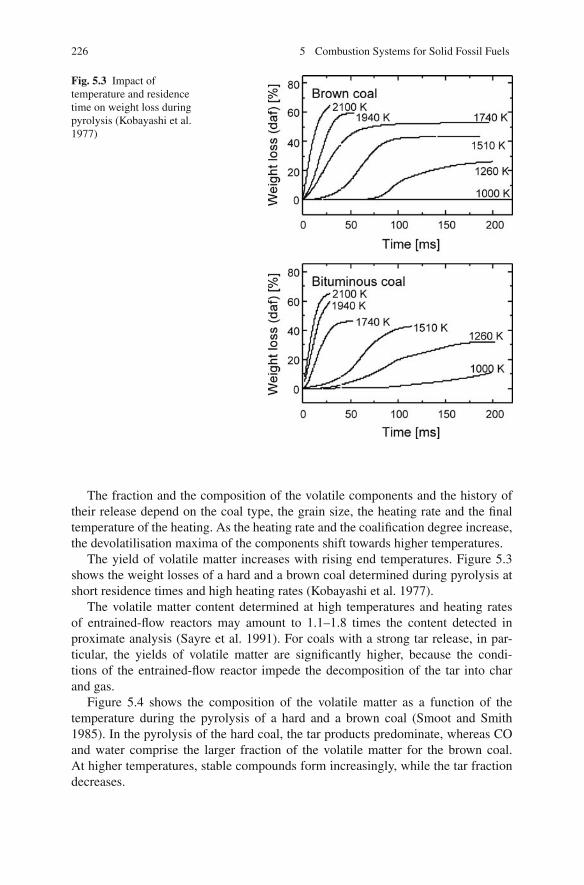
226 5 Combustion Systems for Solid Fossil Fuels
Fig. 5.3 Impact oftemperature and residencetime on weight loss duringpyrolysis (Kobayashi et al.1977)
The fraction and the composition of the volatile components and the history oftheir release depend on the coal type, the grain size, the heating rate and the finaltemperature of the heating. As the heating rate and the coalification degree increase,the devolatilisation maxima of the components shift towards higher temperatures.
The yield of volatile matter increases with rising end temperatures. Figure 5.3shows the weight losses of a hard and a brown coal determined during pyrolysis atshort residence times and high heating rates (Kobayashi et al. 1977).
The volatile matter content determined at high temperatures and heating ratesof entrained-flow reactors may amount to 1.1–1.8 times the content detected inproximate analysis (Sayre et al. 1991). For coals with a strong tar release, in par-ticular, the yields of volatile matter are significantly higher, because the condi-tions of the entrained-flow reactor impede the decomposition of the tar into charand gas.
Figure 5.4 shows the composition of the volatile matter as a function of thetemperature during the pyrolysis of a hard and a brown coal (Smoot and Smith1985). In the pyrolysis of the hard coal, the tar products predominate, whereas COand water comprise the larger fraction of the volatile matter for the brown coal.At higher temperatures, stable compounds form increasingly, while the tar fractiondecreases.

5.1 Combustion Fundamentals 227
Fig. 5.4 Distribution ofproducts of pyrolysis of abrown and of a hard coal(Smoot and Smith 1985)
5.1.3 Ignition
Ignition begins the process of combustion. The ignition temperature is defined asthe temperature above which combustion evolves independently. At temperaturesbelow the ignition temperature, the heat released during fuel oxidation is dissipatedto the environment, so the temperature does not rise notably. Only at or above theignition temperature does the reaction velocity reach a rate where the amount ofheat released exceeds the amount dissipated to the surroundings. Thus the reactionis accelerated, so a stable combustion can be maintained (Dolezal 1990).
In the combustion of solid fuels, both the volatile components and the residualchar have to be ignited. The volatile components ignite as soon as they form acombustible mixture with the combustion air and the ignition temperature of themixture is either reached or exceeded. The residual char particle, in order to ignite,has to reach or surpass its ignition temperature and receive sufficient oxygen at itssurface (Zelkowski 2004). The ignition temperatures of the combustible mixture of

228 5 Combustion Systems for Solid Fossil Fuels
Fig. 5.5 Ignition mechanism as a function of the heating rate and the particle size for a high-volatile bituminous coal (hvb) (Stahlherm et al. 1974)
volatile matter and combustion air range between 500 and 700◦C, while the ignitiontemperatures of the residual char particle lie above 800◦C.
In coal combustion, the history and sequence of ignition processes above alldepend on the heating rate and the particle size. The impact of these two parameterson the ignition mechanisms in the combustion of a high-volatile bituminous coal,determined at a laboratory-scale plant, is demonstrated in Fig. 5.5 (van Heek andMuhlen 1985; Stahlherm et al. 1974; Stahlherm 1973).
During slow heating and with coarse particles, the volatile components are firstreleased, then ignite in the near-particle zone and then burn out. Devolatilisation andvolatile matter combustion result in a gas atmosphere that envelops large particles,thus impeding the diffusion of oxygen to the particle, which can ignite only after thevolatile matter has burned up (ignition mechanism I).
Coarse particles and high heating rates favour the simultaneous ignition ofvolatile matter and residual char (ignition mechanism II). Pyrolysis reactions shifttowards higher temperatures, with the ignition temperature of the particle changingto a lesser extent. This way, the ignition of the particle is possible even before allthe gases are burned completely.
With very small particles, ignition happens directly at the particle surface. Giventhe great surface-to-volume ratio, these particles are rapidly heated up, so the igni-tion temperature of the particle is reached even before an ignitable mixture hasformed around the particle (ignition mechanism III) (Stahlherm et al. 1974).
Besides the high-volatile bituminous coal analysed in Fig. 5.5, a low-volatileanthracite coal was investigated as well. At the same conditions, ignition took placeat the particle surface (Stahlherm et al. 1974).
For coarse-grained coal in grate firing, the volatile matter ignites first, whereasmedium-sized coal particles and higher heating rates in fluidised bed firing promote

5.1 Combustion Fundamentals 229
the simultaneous ignition of volatile matter and particle. High heating rates andsmall particle sizes in pulverised fuel firing make low-volatile bituminous (lvb)coals ignite at the particle, whereas high-volatile bituminous (hvb) coals show asimultaneous ignition of both volatile matter and particle.
The ignition temperature, in solid fuel combustion, depends not only on thefuel characteristics, such as the volatile matter, moisture and ash contents, and onthe physical structure, such as the particle size and the inner surface of the coal,but also on the combustion conditions of the firing system (heating rate, dust andgas concentrations, etc.). Depending on the fraction of volatile components, theignition temperature is high for lean fuels and char and low for higher volatilefuels. The temperature decreases with increasing fineness of the fuel (STEAG 1988;Dolezal 1990). Figure 5.6 gives reference values as a function of the volatile mattercontent and oxygen concentration for the design of pulverised coal firing systems(Zelkowski 2004).
The ignition velocity – which is understood as the velocity of flame propagationin the mixture – has a clear dependence on the volatile components, the ash contentand the primary air mixture in the case of a hard coal flame, as in Fig. 5.7. Theignition velocity always reaches a maximum depending on the primary air fraction.At low air ratios, the oxygen in the primary air is not sufficient to combust thevolatile matter in the near-burner zone. With a stronger primary air flow, the primaryair which is not needed for the combustion of the volatile matter serves to decreasethe flame temperature. In both cases, the ignition velocity decreases. A higher ashcontent also has a delaying effect on ignition. The ignition velocity is a crucialparameter for the burner design for two reasons. On the one hand, the burner throatvelocity has to be notably higher than the ignition velocity in order to surely preventthe flame from flashing back. On the other hand, to have a stable flame front, ithas to be ensured that zones form where the flow velocity is equal to the ignitionvelocity (Dolezal 1990).
In pulverised fuel firing, the coal as well as the carrier gas flow (consisting ofprimary air and vapours) has to be preheated – starting from classifier temperature(i.e. the temperature in the mill) – to values equal to or higher than the ignition
Fig. 5.6 Ignition temperatureas a function of the volatilematter (Zelkowski 2004)
0 10 20 30 40 50 60 70 80400
500
600
700
800
900
1000
1100
Volatile matter [daf%]
Igniti
on tem
pera
ture
[°C
]
10,5% O10,5% O10,5% O10,5% O2
21% O2

230 5 Combustion Systems for Solid Fossil Fuels
Fig. 5.7 Ignition rate as afunction of the primary airfraction (Dolezal 1990)
temperature. For this reason, only the amount of primary air that is necessary for thecombustion of the volatile matter should be fed.
5.1.4 Combustion of Volatile Matter
The homogeneous combustion of the volatile components is characterised by a veryhigh reaction velocity, so that the burning time is essentially determined by theirrelease and mixing with air.
The highest concentrations of volatile components develop on the particle sur-face, the concentration diminishing with increasing distance from the particle. Thevolatile matter combustion stabilises into a diffusion flame in areas where there isa stoichiometric concentration of volatile matter and oxygen. The diameter of aflame enveloping a particle is about three to five times the diameter of a particle(Zelkowski 2004). In pulverised coal combustion, the volatile matter combustionprocesses of the individual particles combine so they can be considered a coherentgas flame.
5.1.5 Combustion of the Residual Char
The volatile matter having been released from the particle, it remains a porousstructure consisting almost only of carbon and ash. The carbon, at a sufficientlyhigh particle surface temperature, is oxidised by oxygen, carbon monoxide, carbondioxide and water vapour.
At the same temperature, the reaction velocity of the heterogeneous combustionof solid residual char with oxygen is orders of magnitude lower than the homoge-
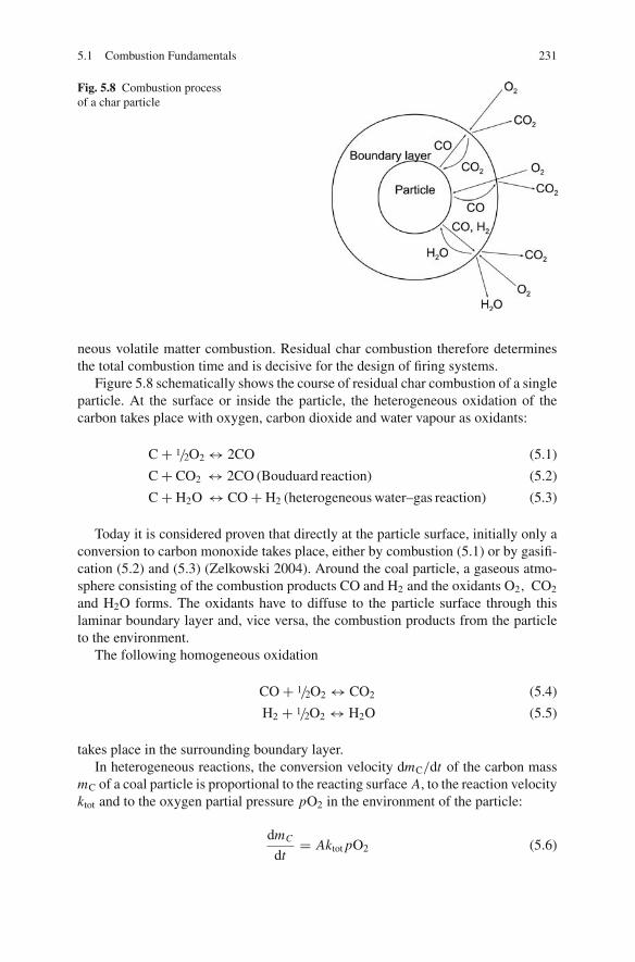
5.1 Combustion Fundamentals 231
Fig. 5.8 Combustion processof a char particle
neous volatile matter combustion. Residual char combustion therefore determinesthe total combustion time and is decisive for the design of firing systems.
Figure 5.8 schematically shows the course of residual char combustion of a singleparticle. At the surface or inside the particle, the heterogeneous oxidation of thecarbon takes place with oxygen, carbon dioxide and water vapour as oxidants:
C + 1/2O2 ↔ 2CO (5.1)
C + CO2 ↔ 2CO (Bouduard reaction) (5.2)
C + H2O ↔ CO + H2 (heterogeneous water–gas reaction) (5.3)
Today it is considered proven that directly at the particle surface, initially only aconversion to carbon monoxide takes place, either by combustion (5.1) or by gasifi-cation (5.2) and (5.3) (Zelkowski 2004). Around the coal particle, a gaseous atmo-sphere consisting of the combustion products CO and H2 and the oxidants O2, CO2
and H2O forms. The oxidants have to diffuse to the particle surface through thislaminar boundary layer and, vice versa, the combustion products from the particleto the environment.
The following homogeneous oxidation
CO + 1/2O2 ↔ CO2 (5.4)
H2 + 1/2O2 ↔ H2O (5.5)
takes place in the surrounding boundary layer.In heterogeneous reactions, the conversion velocity dmC/dt of the carbon mass
mC of a coal particle is proportional to the reacting surface A, to the reaction velocityktot and to the oxygen partial pressure pO2 in the environment of the particle:
dmC
dt= Aktot pO2 (5.6)
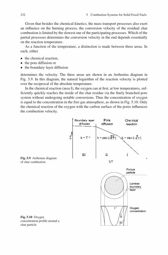
232 5 Combustion Systems for Solid Fossil Fuels
Given that besides the chemical kinetics, the mass transport processes also exertan influence on the burning process, the conversion velocity of the residual charcombustion is limited by the slowest one of the participating processes. Which of thepartial processes determines the conversion velocity in the end depends essentiallyon the reaction temperature.
As a function of the temperature, a distinction is made between three areas. Ineach, either
• the chemical reaction,• the pore diffusion or• the boundary layer diffusion
determines the velocity. The three areas are shown in an Arrhenius diagram inFig. 5.9. In this diagram, the natural logarithm of the reaction velocity is plottedover the reciprocal of the absolute temperature.
In the chemical reaction (area I), the oxygen can at first, at low temperatures, suf-ficiently quickly reaches the inside of the char residue via the finely branched poresystem without undergoing notable conversions. Thus the concentration of oxygenis equal to the concentration in the free gas atmosphere, as shown in Fig. 5.10. Onlythe chemical reaction of the oxygen with the carbon surface of the pores influencesthe combustion velocity.
Fig. 5.9 Arrhenius diagramof char combustion
Fig. 5.10 Oxygenconcentration profile around achar particle

5.1 Combustion Fundamentals 233
In pore diffusion (area II), the velocity of the chemical reaction increases withrising temperatures. In the inside of the char residue, the oxygen molecules getdepleted so that a concentration drop from the fringe to the centre of the particledevelops. The burning velocity in this area depends on how fast oxygen can besupplied by pore diffusion.
In boundary film diffusion (area III), at still higher temperatures, oxygen is nolonger able to penetrate into the pores. The gradient of the oxygen partial pressureshows that the combustion process takes place only on the outer surface of the par-ticle. The particle is enveloped by a laminar boundary layer and the conversionvelocity is determined by the diffusion of the oxygen through this layer.
The total velocity is the result of the single reaction velocity constants:
ktot = 11
kdiff,b+ 1
kdiff,p+ 1
kchem
(5.7)
The temperature zones shift depending on the particle size and the coal type.Whereas pore and boundary layer diffusion determine the reaction velocity at tem-peratures above a level of 1,450◦C or so for coal particles of 20 μm, this holds trueeven at 1,150◦C in the case of larger particles of 200 μm.
During the combustion process, the relative ash fraction in the coal particleincreases. An ash layer enveloping the remaining combustible matter develops, sothe oxygen has to penetrate this ash cover. Given that as the burning process pro-ceeds, the ash cover grows thicker, the combustion velocity gradually decreases.The more retarded the combustion is, the more ash and the less pores the fuel
Fig. 5.11 Burn times forpulverised coal as a functionof particle size(t = 1,300◦C, λ = 1.2)(hvb: high-volatile, mvb:medium-volatile) (Gumz1962)

234 5 Combustion Systems for Solid Fossil Fuels
contains (Zelkowski 2004). The pyrolysis process preceding the char combustionhas a positive effect on the burnout. Depending on the volatile matter content, amore-or-less marked cavity structure is formed in the char during pyrolysis. Thisstructure considerably enlarges the surface available for the chemical reaction inthe raw coal particle (Rudiger 1997; Spliethoff 1995). Coals with a higher volatilematter content burn faster because the respective residual char gets a much largersurface area through pyrolysis than the residual char of a low-volatile bituminous(lvb) coal. Figure 5.11 shows the combustion time of different coals at a temperatureof 1,300◦C (Gumz 1962).
5.2 Pollutant Formation Fundamentals
5.2.1 Nitrogen Oxides
Different mechanisms during the combustion of fossil fuels cause the formation ofNO and NO2, which, combined, are termed NOx (nitrogen oxides). Nitrogen oxideemissions from power plants are composed of about 95% NO and 5% NO2 but arecalculated simply as NO2. This is because nitrogen monoxide (NO) formed insidethe flame is converted into NO2 in the flue gas path after the furnace as temperaturesfall below 600◦C, as well as in the atmosphere (Jacobs and Hein 1988).
Because emission regulations prescribe measurement of the sum of NO and NO2,the term NOx emissions will always be used when discussing emissions in this text.In the context of combustion engineering measurements, the nitrogen oxides at thefurnace exit will also be termed NOx emissions, regardless of whether they are fur-ther reduced by secondary measures. However, if nitrogen oxide concentrations at aspecific location within the combustion process are considered, the designation willbe NO concentrations or NOx concentrations, if NO and NO2 are measured.
In the combustion of fossil fuels without organically bound nitrogen, emissionsof nitrogen oxides, formed at high combustion temperatures from nitrogen of thecombustion air, can in most cases be limited to allowable values by combustionengineering measures. If nitrogenous fuels and low combustion temperatures areused, nitrogen emissions are mainly formed out of the fuel nitrogen, if present.During combustion, the fuel nitrogen is converted partly or totally into nitrogenoxide.
In pulverised coal combustion, nitrogen oxides can be formed by three differentmechanisms (de Soete 1981; Leuckel 1985; Warnatz 1985; Wolfrum 1985):
• Thermal NO formation• Prompt NO formation and• NO formation out of the fuel nitrogen
Figure 5.12, in a simplified way, describes the pathways of reaction and Fig. 5.13,for the different formation mechanisms, shows the NOx emissions at the furnace exitas a function of the furnace temperature (Pohl and Sarofim 1976; Zelkowski 2004).
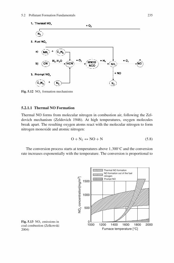
5.2 Pollutant Formation Fundamentals 235
Fig. 5.12 NOx formation mechanisms
5.2.1.1 Thermal NO Formation
Thermal NO forms from molecular nitrogen in combustion air, following the Zel-dovich mechanism (Zeldovich 1946). At high temperatures, oxygen moleculesbreak apart. The resulting oxygen atoms react with the molecular nitrogen to formnitrogen monoxide and atomic nitrogen:
O + N2 ↔ NO + N (5.8)
The conversion process starts at temperatures above 1,300◦C and the conversionrate increases exponentially with the temperature. The conversion is proportional to
Fig. 5.13 NOx emissions incoal combustion (Zelkowski2004) Furnace temperature [°C]
1500
1000
500
0
Thermal NO formation NO formation out of the fuelnitrogen Prompt NO
1000 1200 1400 1600 1800 2000
NO
x co
ncen
trat
ion[
mg/
m3 ]
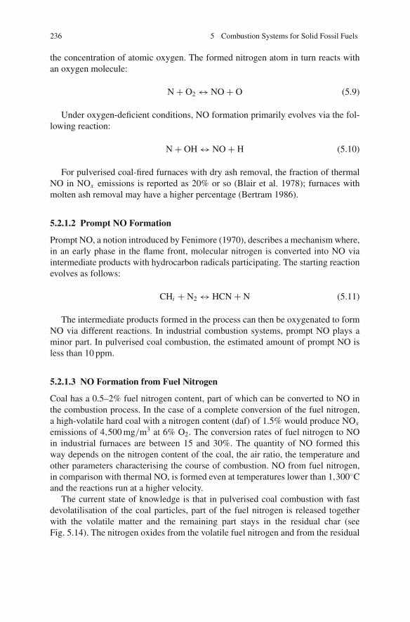
236 5 Combustion Systems for Solid Fossil Fuels
the concentration of atomic oxygen. The formed nitrogen atom in turn reacts withan oxygen molecule:
N + O2 ↔ NO + O (5.9)
Under oxygen-deficient conditions, NO formation primarily evolves via the fol-lowing reaction:
N + OH ↔ NO + H (5.10)
For pulverised coal-fired furnaces with dry ash removal, the fraction of thermalNO in NOx emissions is reported as 20% or so (Blair et al. 1978); furnaces withmolten ash removal may have a higher percentage (Bertram 1986).
5.2.1.2 Prompt NO Formation
Prompt NO, a notion introduced by Fenimore (1970), describes a mechanism where,in an early phase in the flame front, molecular nitrogen is converted into NO viaintermediate products with hydrocarbon radicals participating. The starting reactionevolves as follows:
CHi + N2 ↔ HCN + N (5.11)
The intermediate products formed in the process can then be oxygenated to formNO via different reactions. In industrial combustion systems, prompt NO plays aminor part. In pulverised coal combustion, the estimated amount of prompt NO isless than 10 ppm.
5.2.1.3 NO Formation from Fuel Nitrogen
Coal has a 0.5–2% fuel nitrogen content, part of which can be converted to NO inthe combustion process. In the case of a complete conversion of the fuel nitrogen,a high-volatile hard coal with a nitrogen content (daf) of 1.5% would produce NOx
emissions of 4,500 mg/m3 at 6% O2. The conversion rates of fuel nitrogen to NOin industrial furnaces are between 15 and 30%. The quantity of NO formed thisway depends on the nitrogen content of the coal, the air ratio, the temperature andother parameters characterising the course of combustion. NO from fuel nitrogen,in comparison with thermal NO, is formed even at temperatures lower than 1,300◦Cand the reactions run at a higher velocity.
The current state of knowledge is that in pulverised coal combustion with fastdevolatilisation of the coal particles, part of the fuel nitrogen is released togetherwith the volatile matter and the remaining part stays in the residual char (seeFig. 5.14). The nitrogen oxides from the volatile fuel nitrogen and from the residual
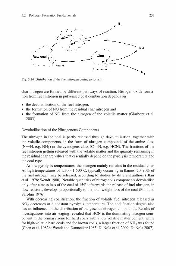
5.2 Pollutant Formation Fundamentals 237
Fig. 5.14 Distribution of the fuel nitrogen during pyrolysis
char nitrogen are formed by different pathways of reaction. Nitrogen oxide forma-tion from fuel nitrogen in pulverised coal combustion depends on
• the devolatilisation of the fuel nitrogen,• the formation of NO from the residual char nitrogen and• the formation of NO from the nitrogen of the volatile matter (Glarborg et al.
2003).
Devolatilisation of the Nitrogenous Components
The nitrogen in the coal is partly released through devolatilisation, together withthe volatile components, in the form of nitrogen compounds of the amine class(N H, e.g. NH3) or the cyanogens class (C N, e.g. HCN). The fractions of thefuel nitrogen getting released with the volatile matter and the quantity remaining inthe residual char are values that essentially depend on the pyrolysis temperature andthe coal type.
At low pyrolysis temperatures, the nitrogen mainly remains in the residual char.At high temperatures of 1,300–1,500◦C, typically occurring in flames, 70–90% ofthe fuel nitrogen may be released, according to studies by different authors (Blairet al. 1978; Wendt 1980). Notable quantities of nitrogenous components devolatiliseonly after a mass loss of the coal of 15%; afterwards the release of fuel nitrogen, inflow reactors, develops proportionally to the total weight loss of the coal (Pohl andSarofim 1976).
With decreasing coalification, the fraction of volatile fuel nitrogen released asNOx decreases at a constant pyrolysis temperature. The coalification degree alsohas an influence on the distribution of the gaseous nitrogen compounds. Results ofinvestigations into air staging revealed that HCN is the dominating nitrogen com-ponent in the primary zone for hard coals with a low volatile matter content, whilefor high-volatile hard coals and for brown coals, a larger fraction of NH3 was found(Chen et al. 1982b; Wendt and Dannecker 1985; Di Nola et al. 2009; Di Nola 2007).

238 5 Combustion Systems for Solid Fossil Fuels
NO Formation from Residual Char Nitrogen
The conversion rates of residual char nitrogen to NO are low – the percentage is at10–25% (Pohl and Sarofim 1976; Song et al. 1982). This fact is put down to theindirect reduction of NO on the coal particle surface. In contrast to the formation ofnitrogen oxide from volatile nitrogen, heterogeneous nitrogen oxide formation canbe influenced only to a limited extent (Pohl et al. 1982; Schulz 1985). Influence onthe conversion rates is exerted by the flame temperature, the air ratio and the char-acteristics of the char. With higher temperatures, the formation of NO from residualchar nitrogen decreases (Pohl and Sarofim 1976; Song et al. 1982). Conversion ratesof residual char nitrogen to NO of less than 10% were measured in combustion inreducing conditions (Pohl and Sarofim 1976).
NO Formation from Volatile Fuel Nitrogen
In pulverised coal combustion, the conversion of volatile fuel nitrogen to NO mayreach considerably higher rates than the conversion of residual char nitrogen. Therate strongly depends on the combustion conditions and can be reduced effectivelyby primary measures such as air staging. Essential parameters pertaining to the con-version into NO are the air ratio, the concentration of nitrogen in the gas phase andthe temperature (Fenimore 1976, 1978). The fuel nitrogen released by devolatili-sation can be oxidised to NO or decomposed to molecular nitrogen by reductionmechanisms. Combustion engineering measures can particularly help to reduce NOformation from volatile fuel nitrogen, to the extent that, according to the opinion ofseveral authors, the NO formation from residual char establishes a limiting value tothe total NOx emissions which cannot be further reduced by air staging measures(Mechenbier 1989; Wendt 1980; Spliethoff and Hein 1997).
In industrial firing systems, the conversion of total fuel nitrogen to NO is about30%; by means of primary measures like air staging it is possible to achieve conver-sions as low as 5%.
5.2.1.4 NO-Reducing Mechanisms
During the process of the combustion, it is possible to reduce nitrogen oxides thatform. A difference is made between
• heterogeneous reduction and• homogeneous reduction.
Heterogeneous reduction is the reduction of residual char which has not yetundergone reaction. The very low level of NO formed from residual char has to beput down to the reduction of NO on the surface of the coal particle. Heterogeneousreduction plays an important part when there are high loads of pulverised coal with a
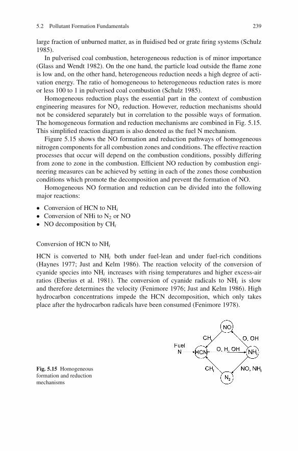
5.2 Pollutant Formation Fundamentals 239
large fraction of unburned matter, as in fluidised bed or grate firing systems (Schulz1985).
In pulverised coal combustion, heterogeneous reduction is of minor importance(Glass and Wendt 1982). On the one hand, the particle load outside the flame zoneis low and, on the other hand, heterogeneous reduction needs a high degree of acti-vation energy. The ratio of homogeneous to heterogeneous reduction rates is moreor less 100 to 1 in pulverised coal combustion (Schulz 1985).
Homogeneous reduction plays the essential part in the context of combustionengineering measures for NOx reduction. However, reduction mechanisms shouldnot be considered separately but in correlation to the possible ways of formation.The homogeneous formation and reduction mechanisms are combined in Fig. 5.15.This simplified reaction diagram is also denoted as the fuel N mechanism.
Figure 5.15 shows the NO formation and reduction pathways of homogeneousnitrogen components for all combustion zones and conditions. The effective reactionprocesses that occur will depend on the combustion conditions, possibly differingfrom zone to zone in the combustion. Efficient NO reduction by combustion engi-neering measures can be achieved by setting in each of the zones those combustionconditions which promote the decomposition and prevent the formation of NO.
Homogeneous NO formation and reduction can be divided into the followingmajor reactions:
• Conversion of HCN to NHi
• Conversion of NHi to N2 or NO• NO decomposition by CHi
Conversion of HCN to NHi
HCN is converted to NHi both under fuel-lean and under fuel-rich conditions(Haynes 1977; Just and Kelm 1986). The reaction velocity of the conversion ofcyanide species into NHi increases with rising temperatures and higher excess-airratios (Eberius et al. 1981). The conversion of cyanide radicals to NHi is slowand therefore determines the velocity (Fenimore 1976; Just and Kelm 1986). Highhydrocarbon concentrations impede the HCN decomposition, which only takesplace after the hydrocarbon radicals have been consumed (Fenimore 1978).
Fig. 5.15 Homogeneousformation and reductionmechanisms

240 5 Combustion Systems for Solid Fossil Fuels
Conversion of NHi to N2 or NO
The NHi compounds originating from the decomposition of HCN either react withNO to form N2
NHi + NO → N2 + products (5.12)
or are oxygenated to NO under excess-air conditions that arise at the latest whenburnout air is added following an air-deficient zone:
NHi + O2 → NO + products (5.13)
Besides the decomposition of the NHi species via NO, self-decomposition of theNHi compounds is possible as well. Thus the conversion of the ammonia speciesinto NO or N2 primarily depends on the fuel – air ratios. In air-deficient zones, theammonia radicals that are present are mostly decomposed, leaving N2; in excess-airzones, at the common firing system temperatures of more than 1,000◦C, they areoxidised to form NO.
Within a small range of temperatures, between 900 and 1,000◦C, and while alsoin excess-oxygen conditions, nitrogen oxides are decomposed via ammonia radicals(Wolfrum 1985). These conditions exist in such cases as that of ammonia additionin a 900–1,000◦C hot flue gas flow with excess air or when there is burnout airaddition at the end of a reduction zone containing ammonia radicals in air- or fuel-staged operation. The location of the temperature window depends on the flue gasconcentrations of O2, CO, H2 and H2O. The reaction times are some hundredthsof seconds (Hemberger et al. 1987).
NO Reduction by CHi
Besides the decomposition of NO via NHi species, it is also possible for NO tobe decomposed via hydrocarbon radicals to form HCN (Wendt 1980; Chen et al.1982a; McCarthy et al. 1987; Myerson 1974):
NO + CHi → HCN + products (5.14)
The decomposition reactions via hydrocarbon radicals are 10–100 times fasterthan the conversion from HCN into NHi (Just and Kelm 1986). The decompositionby hydrocarbon radicals is also termed the NO recycle mechanism, because already-formed NO re-enters the fuel N mechanism.
When taking technical measures to reduce NOx emissions, NO reduction mecha-nisms through ammonia or hydrocarbon radicals are those that diminish NOx emis-sions most significantly. While in air-staged combustion, NO is reduced mainly
5.2 Pollutant Formation Fundamentals 241
through NO decomposition by NHi compounds, fuel staging additionally makesuse of NO decomposition through hydrocarbon radicals.
For an effective reduction by means of fuel staging, the objective to be attainedis the complete decomposition of the nitrogen oxides through hydrocarbon radicals.As the decomposition reactions via CHi radicals run very quickly, the decomposi-tion rate of nitrogen oxides is determined by how fast and complete the admixtureof the hydrocarbon-containing reduction fuel is. The reaction conditions should befavourable for the slow conversion of HCN to NHi , with high temperatures and lowhydrocarbon concentrations, in order to completely decompose HCN to N2.
5.2.2 Sulphur Oxides
Coal is a fuel which contains sulphur, the major fraction of which is converted intosulphur dioxide during combustion. The sulphur content of coal may be up to 8%,but usually the fraction is below 2%. Accordingly, as an example, if there is a fuelsulphur to SO2 conversion rate of 90%, with a hard coal having a sulphur content of1%, the resulting SO2 emission level is 1.6–1.7 g/m3.
The sulphur can exist in different forms in the coal, for instance, as follows:
• organic sulphur which is bound in the organic coal structure;• sulphides, which originate from the mineral impurities such as pyrite (iron sul-
phide (Fe2S)) or marcasite;• sulphates, which are found in particular in younger hard coals and brown coals
(CaSO4, Na2SO4);• elemental sulphur (Gumz 1962; Morrison 1986).
Pyrite and organic sulphur dominate in coals. Sulphate sulphur, like gypsum oriron sulphate, usually has a fraction of the total sulphur less than 0.1%; the fractionof elemental sulphur is smaller than 0.2% (Morrison 1986).
The relative distribution of pyrite and organic sulphur depends on the coalifi-cation degree. While most of the sulphur is bound organically in younger fuels,like brown coal, the fraction of organic sulphur in the total sulphur content of hardcoals ranges between 40 and 80% (Morrison 1986). The organic sulphur is lessstable than the inorganic type. It is released as H2S as early as in the devolatilisationphase, together with the volatile components (Zelkowski 2004). Both the pyrite andthe organic sulphur participate in the combustion and are oxygenated to sulphurdioxide, SO2. Another oxidation, forming sulphur trioxide (SO3), does occur, butthe fraction is small due to the short residence time in industrial firing systems (Heinand Schiffers 1979).
If the coal ash contains alkalis or alkaline earths, sulphur dioxides can be cap-tured in the ash. However, this type of capture needs low temperatures, such asarise in brown coal combustion due to the high-moisture load (STEAG 1988). Inpulverised hard coal combustion, the conversion of the fuel sulphur into SO2 reaches
242 5 Combustion Systems for Solid Fossil Fuels
a relatively high rate of between 85 and 90% – and is more or less independent fromthe combustion conditions (Morrison 1986).
5.2.3 Ash formation
Solid fuels contain inorganic mineral matter and inorganic elements, which can bebound organically in the coal or present in the form of simple salts. At high temper-atures in the combustion process, these constituents undergo chemical and physicaltransformations to form ash.
Mineral matter in coal commonly includes alumino-silicate clays, silicates, car-bonates and disulphides as major components. According to its association with thecoal particle, it can be classified into two groups, namely included minerals andexcluded minerals. Included minerals refer to those locked inside the coal matrixand generally have smaller sizes. Excluded minerals are those liberated from thecoal completely during crushing, grinding and milling processes and are relativelylarge.
As part of the coal preparation process, a portion of the excluded minerals canbe separated from the mined coal. Smaller or larger fractions, however, remain dis-persed in the coal. If as-mined coal is used directly in power plant furnaces, asin the case of brown coal, the mineral components remain in the coal completely.In the case of hard coal, the preparation process separates the coal into high-gradecoal, with some 10% of mineral components, low-grade or high-ash coal, with about30–40% of mineral components, and overburden, with a small percentage of resid-ual coal. Hard coal power stations commonly use high-grade coal.
Organically bound inorganic elements such as Na, K, Ca and Mg, which aredistributed within the coal macerals, are commonly found in lower rank coals. Inthe lowest rank coals, these elements can comprise up to 60% of the total inorganiccontent. However, they only represent a very small proportion in high-rank coals(Wu 2005). In high-rank coals, sodium and potassium are either in the form of water-soluble chlorides or alumino-silicates (Heinzel 2004).
Figure 5.16 shows a diagram of the mechanisms of ash formation (Beer 1988). Inthe combustion of pulverised coal, the first partial process is fragmentation, whereseveral particles originate from one single coal particle. Through the burnout of thecombustible matter surrounding the mineral components, finely distributed ash com-ponents reach the particle surface. With the carbon burnout increasing, the moltenash components sticking to the coal structure merge into ever-larger particles on theshrinking coal particle. In pulverised coal combustion, ash particles with a size of1–20 μm develop this way.
Part of the ash may vaporise at high temperatures. The extent of vaporisation isaffected by the char particle temperature. For example, about 1% of the ash of a hardcoal vaporises at temperatures of 1,400–1,600◦C in the pulverised coal flame. Thevaporised ash particles condense in the process of cooling and form very fine dustparticles in the range of 0.02–0.2 μm (also known as aerosols) by nucleation, which
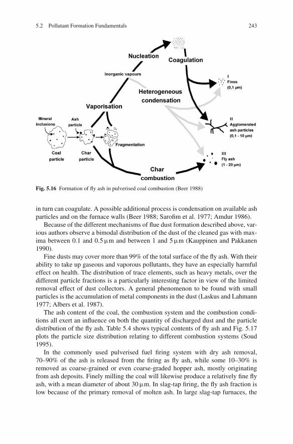
5.2 Pollutant Formation Fundamentals 243
Fig. 5.16 Formation of fly ash in pulverised coal combustion (Beer 1988)
in turn can coagulate. A possible additional process is condensation on available ashparticles and on the furnace walls (Beer 1988; Sarofim et al. 1977; Amdur 1986).
Because of the different mechanisms of flue dust formation described above, var-ious authors observe a bimodal distribution of the dust of the cleaned gas with max-ima between 0.1 and 0.5 μm and between 1 and 5 μm (Kauppinen and Pakkanen1990).
Fine dusts may cover more than 99% of the total surface of the fly ash. With theirability to take up gaseous and vaporous pollutants, they have an especially harmfuleffect on health. The distribution of trace elements, such as heavy metals, over thedifferent particle fractions is a particularly interesting factor in view of the limitedremoval effect of dust collectors. A general phenomenon to be found with smallparticles is the accumulation of metal components in the dust (Laskus and Lahmann1977; Albers et al. 1987).
The ash content of the coal, the combustion system and the combustion condi-tions all exert an influence on both the quantity of discharged dust and the particledistribution of the fly ash. Table 5.4 shows typical contents of fly ash and Fig. 5.17plots the particle size distribution relating to different combustion systems (Soud1995).
In the commonly used pulverised fuel firing system with dry ash removal,70–90% of the ash is released from the firing as fly ash, while some 10–30% isremoved as coarse-grained or even coarse-graded hopper ash, mostly originatingfrom ash deposits. Finely milling the coal will likewise produce a relatively fine flyash, with a mean diameter of about 30 μm. In slag-tap firing, the fly ash fraction islow because of the primary removal of molten ash. In large slag-tap furnaces, the

244 5 Combustion Systems for Solid Fossil Fuels
Table 5.4 Dust content of firing systems
Firing systemDust content after firing[g/m3]
Pulverised fuel firing 5–30Grate firing with spreader stoker 2–5Grate firing 1–3Cyclone firing 0.5–1.5
fly ash amounts to about 50%, while it ranges around 10–30% in cyclone slag-tapfurnaces. Given the rotating pattern of the gas flow, only the coarse particles gatheron the cyclone wall, while the small ones are carried out of the cyclone with thegas. The fly ash of a cyclone firing system, considering its particle size distribution,therefore features a considerably finer dust than the ash of a dry-bottom firing sys-tem. In grate firing systems, the fly ash fraction is only about 40% due to the coarsefuel, the rest is extracted as bottom ash. The fly ash is significantly coarser thanthe average ash in pulverised fuel firing. Grate firing systems with a spreader stokerfeature a higher flue dust fraction.
In circulating fluidised bed firing, the total ash flow is carried out from the fur-nace, so needs a dust collecting unit.
Fig. 5.17 Particle sizedistribution of fly ashesrelating to differentcombustion systems (Source:Alstom Power)

5.2 Pollutant Formation Fundamentals 245
The data on the amount of dust and the properties of the ash are of great impor-tance for the design of the secondary ash removal system (Stultz and Kitto 1992;Klingspor and Vernon 1988; Soud 1995).
5.2.4 Products of Incomplete Combustion
The purpose of the combustion process is the complete conversion of the fuel totransform the bound fuel energy into the sensible heat of the flue gas. Incompleteconversion causes loss and produces emissions of
• carbon monoxide,• hydrocarbons and• soot (Baumbach 1990).
In general, the emissions from incomplete combustion in large-scale firing sys-tems stay below the prescribed limiting values. Higher emission levels arise in smallplants, in particular, where the combustion process is transient. The combustiontechniques under consideration in this text – pulverised fuel, fluidised bed and gratefiring – during stationary operation feature high fuel conversion rates and completecombustion.
The completeness of the combustion is influenced by the combustion control, thetemperature and the residence time. The design of a combustion plant has to be suchthat the fuel, depending on the temperature, remains in the furnace sufficiently long:the higher the temperature, the faster the oxidation reactions of the fuel.
CO in common firing systems always forms as an intermediate product ofthe combustion, which in the course of the combustion process is almost com-pletely converted to CO2. Typical CO emissions in pulverised fuel firing are below50 mg/Nm3. CO is also used as a reference value for emissions of hydrocarbons.Soot rarely develops in the combustion of solid fuels in firing systems operatedat excess air. It is virtually undetected as a solid matter combustion residue inthe ash.
The emissions from incomplete combustion also have to be considered in thecontext of other kinds of emissions. For instance, with lower air ratios of the com-bustion process, NOx emissions decrease and CO emission increases.
When measures for nitrogen oxide reduction are taken, it can be observed that theburnout partly deteriorates and CO emission rises. This rise can be counteracted bya longer residence time in the burnout zone or by a finer milling. Newly developedconcepts of nitrogen oxide abatement, which will be considered in Sect. 5.7, showthat a reduction of NOx emissions is not necessarily associated with a deteriora-tion of the burnout. By setting high temperatures, for instance, both the combustioncourse and nitrogen oxide reduction can be accelerated.
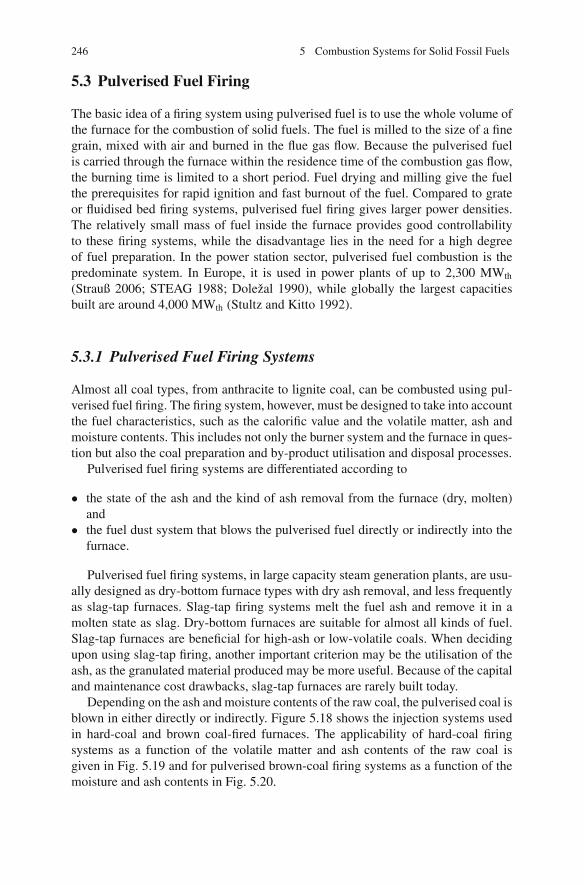
246 5 Combustion Systems for Solid Fossil Fuels
5.3 Pulverised Fuel Firing
The basic idea of a firing system using pulverised fuel is to use the whole volume ofthe furnace for the combustion of solid fuels. The fuel is milled to the size of a finegrain, mixed with air and burned in the flue gas flow. Because the pulverised fuelis carried through the furnace within the residence time of the combustion gas flow,the burning time is limited to a short period. Fuel drying and milling give the fuelthe prerequisites for rapid ignition and fast burnout of the fuel. Compared to grateor fluidised bed firing systems, pulverised fuel firing gives larger power densities.The relatively small mass of fuel inside the furnace provides good controllabilityto these firing systems, while the disadvantage lies in the need for a high degreeof fuel preparation. In the power station sector, pulverised fuel combustion is thepredominate system. In Europe, it is used in power plants of up to 2,300 MWth
(Strauß 2006; STEAG 1988; Dolezal 1990), while globally the largest capacitiesbuilt are around 4,000 MWth (Stultz and Kitto 1992).
5.3.1 Pulverised Fuel Firing Systems
Almost all coal types, from anthracite to lignite coal, can be combusted using pul-verised fuel firing. The firing system, however, must be designed to take into accountthe fuel characteristics, such as the calorific value and the volatile matter, ash andmoisture contents. This includes not only the burner system and the furnace in ques-tion but also the coal preparation and by-product utilisation and disposal processes.
Pulverised fuel firing systems are differentiated according to
• the state of the ash and the kind of ash removal from the furnace (dry, molten)and
• the fuel dust system that blows the pulverised fuel directly or indirectly into thefurnace.
Pulverised fuel firing systems, in large capacity steam generation plants, are usu-ally designed as dry-bottom furnace types with dry ash removal, and less frequentlyas slag-tap furnaces. Slag-tap firing systems melt the fuel ash and remove it in amolten state as slag. Dry-bottom furnaces are suitable for almost all kinds of fuel.Slag-tap furnaces are beneficial for high-ash or low-volatile coals. When decidingupon using slag-tap firing, another important criterion may be the utilisation of theash, as the granulated material produced may be more useful. Because of the capitaland maintenance cost drawbacks, slag-tap furnaces are rarely built today.
Depending on the ash and moisture contents of the raw coal, the pulverised coal isblown in either directly or indirectly. Figure 5.18 shows the injection systems usedin hard-coal and brown coal-fired furnaces. The applicability of hard-coal firingsystems as a function of the volatile matter and ash contents of the raw coal isgiven in Fig. 5.19 and for pulverised brown-coal firing systems as a function of themoisture and ash contents in Fig. 5.20.

5.3 Pulverised Fuel Firing 247
injection
1
2
5
4
3
1
2 3
4
5
6a
78
1
23
4 5
6b7
9
10
10
11
1213
1
23
4
56b
10
1213
78
6a
10
10
11
13 12
914
1
2 3
4
5
e) Semi direct injection (brown coal)
c) Indirect injection with intermediatestorage (hard coal, brown coal)
a) Direct (hard coal, brown coal)
b) Direct injection with vapourseparation (brown coal)
d) Indirect injection with intermediateseparation (hard coal, brown coal)
1 Raw coal2 Flue gas (brown coal)3 Hot air (hard coal)4 Mill5 Pulverised coal burner6a Vapour separator6b Cyclone7 Vapour8 Vapour burner9 Fan10 Cellular wheel 11 Storage bin12 Delivery nozzle13 Hot air fan14 Bag filter
8
Fig. 5.18 Injection systems (Source: Alstom Power)
The technique of direct pulverised fuel injection (Fig. 5.18a) is such that the driedand pulverised coal is blown into the firing by primary (or transport) air and themilling vapours. In design, the general preference is for hard-coal and brown-coalfiring systems to have direct pulverised fuel injection, since this system is relativelysimple and cost-efficient. It needs a smaller number of components, less expenditurefor monitoring and measurement and less auxiliary power.
An excessively high-fuel moisture content is likely to impair a stable ignition.For this reason, the system of direct injection for high-moisture brown coals is only

248 5 Combustion Systems for Solid Fossil Fuels
5040
30
20
1086
43
Vol
atile
mat
ter
(daf
) %
0 10 20 30 40 50 % 60Ash content, raw
Direct firingIndirect firingIndirect firing, top firing
b) Slag-tap firing
IndirectDirectSlag -tap firing can also be chosen forother reasons than combustionengineering, e.g. ash discharge
5040
30
20
1086
43
Vol
atile
mat
ter
(daf
) %
0 10 20 30 40 50 % 60Ash content, raw
a) Dry-bottom firing
Fig. 5.19 Applications of pulverised hard-coal firing systems as a function of volatile matter andash contents (Source: Alstom Power)
suitable for calorific values somewhat higher than 5.5 MJ/kg, or, depending on theash content, for moisture contents below 50–65% (Lehmann 1990). In order to raisethe ignition stability of fuels of higher moisture contents, the dust concentration isincreased by segregating the milling vapours from the fuel flow that is channelled
Fig. 5.20 Applications ofpulverised brown coal firingsystems as a function ofmoisture and ash contents ofthe fuel as mined (Source:Alstom Power)
no fossil fuelresources4
2
13
Ash content [%]
60
50
40
30
20
10
00 10 20 30 40 50 60 70 80
1 Direct injection, no vapour separation
2 Indirect injection with vapour separation
3 Direct injection with vapour removal
4 Indirect injection
no fossil fuel resources
2
M =
Moi
stur
eLH
V =
Low
er h
eatin
g va
lue
2440
MLH
Vϕ
=

5.3 Pulverised Fuel Firing 249
to the main burners. The vapours, to burn their residual dust content, are fed intothe furnace above the main combustion zone. Figure 5.18b shows this kind of directinjection with vapour separation.
If, in the case of higher moisture contents, injecting the vapours would be dis-advantageous, the vapours are cleaned of dust separately by ESP or bag filter(Fig. 5.18e). The resulting super-fine dust, accounting for as much as 30% of thetotal fuel heat, is blown in by air, which raises the flame stability of the main burn-ers. This system of semi-direct firing is used for fuels with calorific values below5.5 MJ/kg and moisture contents of more than 70% (Lehmann 1990).
In the combustion of high-ash hard or brown coals, intermediate storage – the so-called bin-and-feeder system (Fig. 5.18c) – or intermediate separation (Fig. 5.18d)is used to achieve a high dust saturation and a high primary mixture temperature.In both systems, the pulverised coal, after milling, is separated from the millingvapours and, after the intermediate steps, transported pneumatically to the furnace.The difference is that in intermediate separation, the separated pulverised coal isdirectly transported to the burners by a particular transport gas flow, whereas thebin-and-feeder system stores the separated coal powder, charges the carrier air withit via a pulverised coal feeder and feeds it to the firing independently to the rawcoal feeding system. When pulverised coal firing was first used, the bin-and-feedersystem was used for all coal types in order to be able to continue the operationof the combustion plant if the mills were not operating. A bin-and-feeder system,however, has a higher capital cost compared to an intermediate removal system(STEAG 1988). Bin-and-feeder and intermediate removal systems are used bothwith low-volatile, high-ash hard coals and with high-volatile, high-ash lignite coals.
5.3.2 Fuel Preparation
Pulverised fuel combustion requires a preparation step in order to completely burnthe fuel in the furnace within a short residence time (typically between 2 and 5 s).Combustible coal powder is dry and fine-grained and is the product of the prepara-tion of more-or-less moist, coarse-grained run-of-mine coal. The preparation of thefuel for combustion consists of the steps of crushing, milling, drying and classifi-cation. The necessary milling fineness depends on the types of fuel and the firingsystem. Figure 5.21 shows the requirements for the milling of the fuel as a functionof the volatile matter content for dry-bottom and slag-tap firing systems.
5.3.2.1 Drying
The process steps of milling and drying are combined in a simultaneous drying –grinding process to reduce the amount of time required to complete the drying.
During drying, the moisture in the coal is vaporised and removed by the carrierair or carrier gas flow. The drying heat is supplied together with the carrier gas flow.The control variable is the classifier temperature and the manipulated variables arethe hot and cold gas flows. In direct injection systems, the classifier temperature sets

250 5 Combustion Systems for Solid Fossil Fuels
Fig. 5.21 Requirements for milling (Source: Alstom Power)
the temperature of the primary air mixture. The drying medium is either hot air orflue gas.
Hard coal is generally dried by hot air to a residual moisture content of 1%.Brown coal types with moisture contents up to 60% and above require great quan-tities of heat for drying. The heat needed for brown coal is around 16% of the fuelheat, while hard coal needs only around 3%. For this reason, the only drying mediumconsidered for brown coal is hot flue gas, which is extracted from the furnace at hightemperatures of around 1,000◦C. The residual moisture of brown coal after dryingranges between 12 and 18% (Dolezal 1990).
5.3.2.2 Milling
The grinding of coal is performed via one of the following different methods(Zelkowski, 2004):
Gravity Mills (Ball mills)
In an armoured drum rotating slowly around its horizontal axis, the coal is groundby crunching and grating in a milling bed of steel balls. These mills are used forthe production of an especially fine powder and for grinding hard types of coal(Fig. 5.22).

5.3 Pulverised Fuel Firing 251
Fig. 5.22 Schematic drawing of a ball mill (Source: Alstom Power)
Applied-Force Mills (Bowl Mills, Roller Mills)
In applied-force mills, coal is comminuted and ground by pressure. On a motor-driven grinding table with a vertical axis of rotation, the coal lies in a bed whichis passed over by two or three grinding rollers at the circumference. The grindingrollers, hinged and rotatable on swing hammers, are unpowered but are pressedagainst the bed by spring elasticity or a hydraulic system. The run-of-mine coal isfed to the table centrally from above. Figure 5.23 shows the schematic diagram of aroller mill. Applied-force mills are often used for hard coals.
Beater Mills
In beater mills, the incoming coal is caught by rapidly circulating beaters whichare fixed at the perimeter of a rotor and comminuted by the impact of the beateragainst the armoured mill housing. A differentiation is made between beater millsand beater-wheel mills. Beater mills have a rotor equipped with rigid beater armson which movable beater tips are mounted. Beater-wheel mills are equipped withthe so-called impact plates mounted on a circulating wheel. Beater-wheel mills, likebeater mills, have a ventilating effect – they transport the pulverised coal and carriergas to the burners. Beater-wheel mills are used for the grinding of brown coal. Theyare usually prefaced by a beater mill for primary crushing (Fig. 5.24). Beater millsas well as gravity and applied-force mills are used in hard coal firing plants.
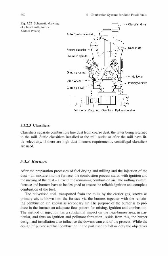
252 5 Combustion Systems for Solid Fossil Fuels
Fig. 5.23 Schematic drawingof a bowl mill (Source:Alstom Power)
5.3.2.3 Classifiers
Classifiers separate combustible fine dust from coarse dust, the latter being returnedto the mill. Static classifiers installed at the mill outlet or after the mill have lit-tle selectivity. If there are high dust fineness requirements, centrifugal classifiersare used.
5.3.3 Burners
After the preparation processes of fuel drying and milling and the injection of thedust – air mixture into the furnace, the combustion process starts, with ignition andthe mixing of the dust – air with the remaining combustion air. The milling system,furnace and burners have to be designed to ensure the reliable ignition and completecombustion of the fuel.
The pulverised coal, transported from the mills by the carrier gas, known asprimary air, is blown into the furnace via the burners together with the remain-ing combustion air, known as secondary air. The purpose of the burner is to pro-duce in the furnace an adequate flow pattern for mixing, ignition and combustion.The method of injection has a substantial impact on the near-burner area, in par-ticular, and thus on ignition and pollutant formation. Aside from this, the burnerdesign and installation also influence the downstream end of the process. While thedesign of pulverised fuel combustion in the past used to follow only the objectives

5.3 Pulverised Fuel Firing 253
Fig. 5.24 Schematic drawing of a beater-wheel mill with a primary beater stage (throughputraw lignite ca. 170 t/h, ventilation 535, 000 m3/h, diameter of Wheel 4,300 mm) (Source: AlstomPower)
of stable combustion and complete burnout of the fuel, today additional require-ments such as low emission levels or usability of the combustion residues haveto be met.
For a stable ignition, the coal powder – air mixture has to be heated up to theignition temperature within a very short time. The supply of heat by radiation isonly a relevant mechanism at very high temperatures, for instance, in slag-tap firing.A substantial fraction of the ignition energy has to be provided by recirculation ofhot flue gases. The basic aim is to first raise to ignition temperature the primarymixture alone and then to admix the secondary air only after ignition. The ignitioncan be positively influenced by finer milling, a high air preheating temperature anda high-dust saturation in the primary air mixture.
Figure 5.25 shows the flow fields of a jet burner and a vortex burner. A jet burnerusually injects secondary air via two inlets and primary air through a jet in betweenthese, the primary jet loaded with pulverised coal. With hard coal, the primaryjet is injected at about 18–22 m/s, and with brown coal, at about 10–14 m/s. Thesecondary air is injected at a considerably higher velocity, i.e. 40–80 m/s, thus itdefines the flow field. The secondary jet sucks hot flue gas from the furnace andmixes it with the primary air jet. The distance between the pulverised coal jet andthe secondary air jets has to be such that the coal particles ignite before mixing withthe secondary air. The heating to ignition temperature is affected by the recirculated

254 5 Combustion Systems for Solid Fossil Fuels
Fig. 5.25 Flow fields of a jetburner (above) and a swirlburner (below)
hot flue gas. Ignition for a jet burner occurs at a distance of 0.8–1.5 m from theburner (Strauß 2006; Lehmann 1996; Adrian et al. 1986).
Swirl burners inject the primary and secondary air jets into the furnace via con-centrically arranged annular nozzles. The secondary air is fed by the outer annularnozzles at high velocities (30–50 m/s); the primary air is injected through the centrenozzle at a velocity of about 18–25 m/s. An adjustable cascade which passes airaxially is a possible additional device to give the secondary air an added swirl. Theswirling of the secondary air, the cone-shaped widening of the burner tip and theinterior barrier baffle plate create an inner recirculation zone which returns hot fluegases from the area of complete combustion to the flame core. Ignition takes place inthe shear zone of the opposed flows of primary and secondary air immediately nextto the burner. Because of the intensive mixing of primary and secondary air, theseburners historically featured a secure and excellent flame stability, but also a highlevel of nitrogen oxide emissions. By dividing the secondary air flows and delayingthe mixing, it was possible to significantly reduce the NOx emissions.
The impact of the burner design on NOx emissions will be explained inSect. 5.7.1.2 in the context of emissions of nitrogen oxides.
5.3.4 Dry-Bottom Firing
Dry-bottom firing, suitable for both hard and brown coal, is a widely used powerplant technology. In this firing system, the ash is designed to leave the furnace in asolid state. The broad temperature range of the flame core lies between 1,000 and1,600◦C, depending on the coal and the burner type.
The flame temperature considered sufficient is that which ensures a stable igni-tion and a sufficiently fast and complete process of combustion. In the flame centreduring dry-bottom firing, it is possible for ash particles to melt. Therefore, it hasto be ensured that the ash particles in this state do not coagulate, agglomerate and

5.3 Pulverised Fuel Firing 255
cause slagging on the furnace walls. Otherwise, in an extreme case, the dry-bottomfiring could turn into slag-tap firing. The ash is removed from the furnace in a drystate, either as slag or as fly ash. The coarse particles of the slag, which developthrough the sticking and sintering of ash in the furnace, fall into the furnace hopper,while the fly ash is carried out with the flue gas and is removed in the electrostaticprecipitator. The fraction of slag amounts to 10–15% of the total ash.
Dry-bottom firing is suitable for a broad range of coal types:
• Those with ash in fuel up to 50% (dry)• High- and medium-volatile coals with volatile matter contents higher than 20%
(daf) (Dolezal 1990)
The burner configurations used in dry-bottom firing systems are tangential firing,frontal firing and opposed firing (see Fig. 5.26). The residence time for hard coal,in the entire space of the furnace, lies at about 4–5 s; in the space from above theupmost burners to the furnace top, it ranges around 2 s (Adrian et al. 1986). Thelower the volatile matter content and the less reactive the fuel, the higher the furnacetemperature and/or the longer the residence time have to be in order to achievecomplete burnout.
In tangential firing systems for hard coals, the jet burners are mounted in thefurnace corners and oriented towards a fire circle to achieve the longest possibleflame. Figure 5.27 shows the burner arrangement of a 900 MWel power plant. Thefurnace is equipped with six burner levels, the four corner burners of each levelbeing supplied with pulverised coal by one mill. In the case of the 900 MWel plant,two burners are arranged in one compartment, as shown in Fig. 5.27. Every burnerunit consists of two pulverised coal nozzles and one lower, central and upper air
(a) (b) (c) (d) (e)
(a) Tangential firing (hard coal)(b) Tangential firing (brown coal)(c) Wall firing(d) Opposed firing(e) Down firing
Fig. 5.26 Burner configurations of dry-bottom firing systems (Soud and Fukasawa 1996)

256 5 Combustion Systems for Solid Fossil Fuels
Fig. 5.27 Jet burners for a tangential hard coal firing (Source: Alstom Power)
nozzle each. The central air nozzle has one integrated oil burner. The separation offuel and air nozzles and the parallel channelling of the fuel and air flows result, incomparison to vortex burners, in a delayed mixing of fuel and combustion air andin consequence to less formation of nitrogen oxides.
Brown coal-fired furnaces are predominantly designed as tangential firing sys-tems with jet burners. The burners in this case are positioned in vertical stacks inthe side walls. In contrast to hard coal firing, each stack of burners is supplied by aseparate mill. One reason for this is the combined drying – crushing, using hot fluegases, which requires a mechanical draught mill for the transport of the primary airmixture. With the limited pressure increase of the beater-wheel mills, the supply ofone burner level by a single mill is not possible, because the pressure loss of thepipelines, which are of differing lengths, would have to be balanced out by flowrestrictors which would cause too high a pressure loss. The connection to a verticalburner row, however, results in asymmetries in the firing.
The high-moisture content and the flue gas recirculation via the drying – crushingunit are two factors why the dimensions of the furnace are larger for brown coal thanthat of a hard-coal firing system. For the drying – crushing process, the flue gasesare extracted at 1,000◦C and fed to the mill. The ground fuel, in the most frequentlyapplied direct injection method, is fed to the furnace via the burners along with themilling vapours.

5.3 Pulverised Fuel Firing 257
The milling degree of brown coal is relatively coarse. If a mill without a classifieris used, the residues on the 1 mm sieve may amount to a fraction of 12%. In con-sequence, the fraction of unburned matter in the residues increases proportionallyto the milling degree. Therefore, the design in various plants includes a secondarycombustion grate below the furnace hopper in order to diminish the losses throughresidual material (Lehmann 1996).
Hard coal-fired furnaces with a wall or opposed firing configuration work, asa rule, with swirl burners. Swirl burners, as opposed to jet burners, can also beoperated as individual burners, so they allow a greater freedom with respect to theconfiguration of the furnace. The modifications to swirl burners with regard to NOx
reduction are described in Sect. 5.7.1.2.The down firing type shown in Fig. 5.26e is often used for the combustion of
low-volatile coal types. The injection against the main direction of the flow createsa longer residence time of the fuel. To achieve higher temperatures, it is possibleto apply refractory lining in part of the furnace (Stultz and Kitto 1992). Furthermeasures, such as intermediate removal, as described in Sect. 5.3.1, are taken whenthe fuel is a low-volatile coal.
5.3.5 Slag-Tap Firing
Achieving the highest possible degree of ash retention in the firing was the objectiveof the development, and the reason for the spread, of slag-tap firing technology inthe 1960s. The temperatures in the furnace have to range between 100 and 200◦Cabove the ash fluid temperature to be able to remove the ash in a molten state. Inlarge-volume slag-tap boilers, the combustion of the coal dust takes place in theflow, as in dry-bottom firing, whereas in cyclone slag-tap boilers, the coal particlesburn on a slag layer on the wall of a cyclone (Dolezal 1990, 1961).
In contrast to firing types with dry ash removal, in slag-tap firing the heat releaseand the heat transfer by radiation are separate. The slag-tap chamber has the functionof burning the fuel and retaining the ash at a sufficiently high temperature. Any kindof heat dissipation is unwanted in the chamber. Only after the chamber are the fluegases cooled down by radiating and convecting heat (Adrian et al. 1986).
5.3.5.1 Large-Volume Slag-Tap Boilers
In large-volume slag-tap boilers the pulverised fuel burns in the slag-tap furnace,which is designed to achieve melting and complete burnout at high temperatures.The residence time in the slag-tap furnace is typically 1 s or shorter. The volumetricheat release rate of the slag-tap furnace ranges between 0.5 and roughly 1 MW/m3
(Dolezal 1990).Among the construction types which have been developed for slag-tap boilers,
the U-furnace has become the most widely accepted. The cross section of sucha large-volume slag-tap boiler is shown in Fig. 5.28. The high temperatures of1,400–1,600◦C in the slag-tap furnace make the ash melt, which partly precipitates

258 5 Combustion Systems for Solid Fossil Fuels
Fig. 5.28 Divided slag-tap furnace
on the walls. The cooling effect of the evaporator tubes solidifies the molten slagclosest to the wall side along the walls and bottom of the furnace. The molten slagruns down this insulating layer, is collected at the bottom and routed to a water bathwhere it granulates.
The combustion process is accelerated by the use of finely pulverised coal, swirlburners and strong air preheating – together they can achieve the high tempera-tures desired in the slag-tap furnace. By applying ceramic refractory material to theevaporator tubes, held by studs welded onto the tubes, the heat extraction from theslag-tap furnace is diminished, including when a slag layer is absent (for example,during start-up). The refractory material at the same time forms the base for theinsulating slag layer. The purpose of the refractory material and the insulating slaglayer is to protect the furnace tube walls against corrosion. Figure 5.29 schematicallyshows the refractory lining. The slag screen forms the boundary of the slag-tap fur-nace. The function of this screen is to abate heat emission from the slag-tap furnaceand to separate molten and softened ash particles from the flue gas.
In slag-tap firing, the molten state removal of ash must be ensured even in part-load operation. At minimum load, there may be the risk of the slag solidifying onthe bottom or in the slag discharge mouth. The ash would then accumulate on thefurnace bottom and melt out only with a load increase. A slag-tap firing system,in thermal terms, should therefore be designed such that, even at minimum load,sufficient temperatures are achieved to guarantee a satisfactory ash flow. This has
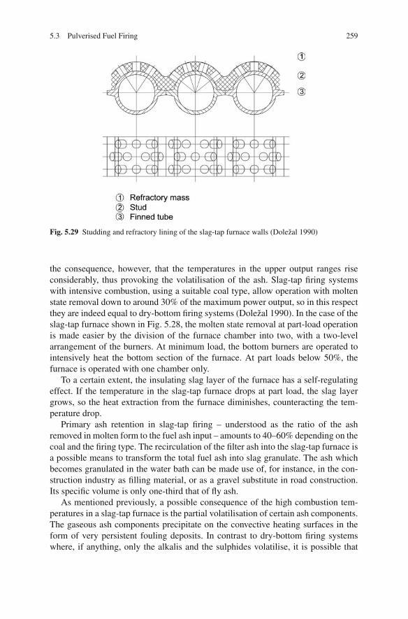
5.3 Pulverised Fuel Firing 259
Fig. 5.29 Studding and refractory lining of the slag-tap furnace walls (Dolezal 1990)
the consequence, however, that the temperatures in the upper output ranges riseconsiderably, thus provoking the volatilisation of the ash. Slag-tap firing systemswith intensive combustion, using a suitable coal type, allow operation with moltenstate removal down to around 30% of the maximum power output, so in this respectthey are indeed equal to dry-bottom firing systems (Dolezal 1990). In the case of theslag-tap furnace shown in Fig. 5.28, the molten state removal at part-load operationis made easier by the division of the furnace chamber into two, with a two-levelarrangement of the burners. At minimum load, the bottom burners are operated tointensively heat the bottom section of the furnace. At part loads below 50%, thefurnace is operated with one chamber only.
To a certain extent, the insulating slag layer of the furnace has a self-regulatingeffect. If the temperature in the slag-tap furnace drops at part load, the slag layergrows, so the heat extraction from the furnace diminishes, counteracting the tem-perature drop.
Primary ash retention in slag-tap firing – understood as the ratio of the ashremoved in molten form to the fuel ash input – amounts to 40–60% depending on thecoal and the firing type. The recirculation of the filter ash into the slag-tap furnace isa possible means to transform the total fuel ash into slag granulate. The ash whichbecomes granulated in the water bath can be made use of, for instance, in the con-struction industry as filling material, or as a gravel substitute in road construction.Its specific volume is only one-third that of fly ash.
As mentioned previously, a possible consequence of the high combustion tem-peratures in a slag-tap furnace is the partial volatilisation of certain ash components.The gaseous ash components precipitate on the convective heating surfaces in theform of very persistent fouling deposits. In contrast to dry-bottom firing systemswhere, if anything, only the alkalis and the sulphides volatilise, it is possible that

260 5 Combustion Systems for Solid Fossil Fuels
the very high temperatures of more than 1,800◦C in slag-tap firing systems causethe volatilisation of silicon as well (Dolezal 1961).
One advantage of a slag-tap boiler in comparison to a dry-bottom boiler is ahigher steam generator efficiency. Due to the high temperatures, it is possible tooperate this firing at a lower air ratio (1.05–1.15) than dry-bottom firing. In addition,the low SO3 content and the associated low acid dewpoint in the flue gas allow lowerboiler exit temperatures in slag-tap firing systems. A drawback is that heat is lostthrough the removal of the hot molten slag, the magnitude of which depends on theash content of the coal. For low volatile coal types, the burnout is significantly betterthan in dry-bottom firing. The resulting losses are one parameter for considerationin comparison with a dry-bottom firing system (Fig. 5.30).
Today, one application of slag-tap firing considered particularly apt is for thecombustion of low-volatile coals, because the slag-tap furnace in this case ensurescomplete combustion in a more efficient manner than the dry-bottom furnace. Inthe past, however, the combustion of medium- and high-volatile hard coals in slag-tap furnaces was also successful. For coals with a very high ash content, a lowerefficiency compared to dry-bottom firing arises through the heat loss of the slag.With respect to ash fluid temperatures, a broad range of fuels can be burned in slag-tap firing. Coal types have been used, for instance, with a fluid temperature higherthan 1,600◦C. However, the necessary temperatures for acceptable operation, in thiscase above 1,800◦C, may provoke ash volatilisation and heat exchanger fouling.
The essential disadvantages of slag-tap firing in comparison to dry-bottom firingsystems are the higher capital costs and the maintenance necessary for the restora-tion of the slag-tap furnace refractory lining and the wall and slag screen heatingsurfaces. Slag-tap firing systems involve about 10% higher capital costs than dry-bottom systems. Another disadvantage is the higher nitrogen oxide emissions ofthe slag-tap furnace, but it is possible for slag-tap firing to achieve a reduction ofNOx emissions to between 800 and 1,000 mg/m3 and should be possible to furtherreduce these emissions by means of the methods described in Sect. 5.7. Slag-tapfiring systems are justified when the given coal type requires appropriately high
Fig. 5.30 Steam generatorlosses of slag-tap anddry-bottom firing systems(Dolezal 1990)

5.3 Pulverised Fuel Firing 261
temperatures for the complete combustion or where the ash can only be utilised ordisposed of in granulate form (Kather 1995).
The first slag-tap firing system was put into service in 1934 in Czechoslovakia(Dolezal 1954). In Germany, the development of this technology continued afterWW II. Large-scale slag-tap boilers were scarcely used in other countries. Theadvantages of slag-tap firing technology which resulted from the development inGermany in turn resulted in 75% of the use of the technology being in Germany by1970. Due to the disadvantages mentioned above, however, slag-tap firing systemswere rarely built in the time that followed.
5.3.5.2 Cyclone Furnaces
Cyclone furnaces differ from the previously described large-volume slag-tap fur-naces by a higher volumetric heat release rate, which results from the use of muchcoarser coal particles and a higher primary ash retention. The combustion processtakes place in a (usually horizontally installed) cyclone which typically measures1.8–3 m in diameter. The volumetric heat release lies between 4 and 8 MW/m3. Thecyclone, as with the large-scale slag-tap furnace, is lined with a ceramic materialto reduce heat absorption. Due to the small cyclone volume, only about 10% of thetotal heat is transferred to the cyclone heating surface of the steam – water cycle(Stultz and Kitto 1992).
Fig. 5.31 Cyclone construction types (Dolezal 1961)
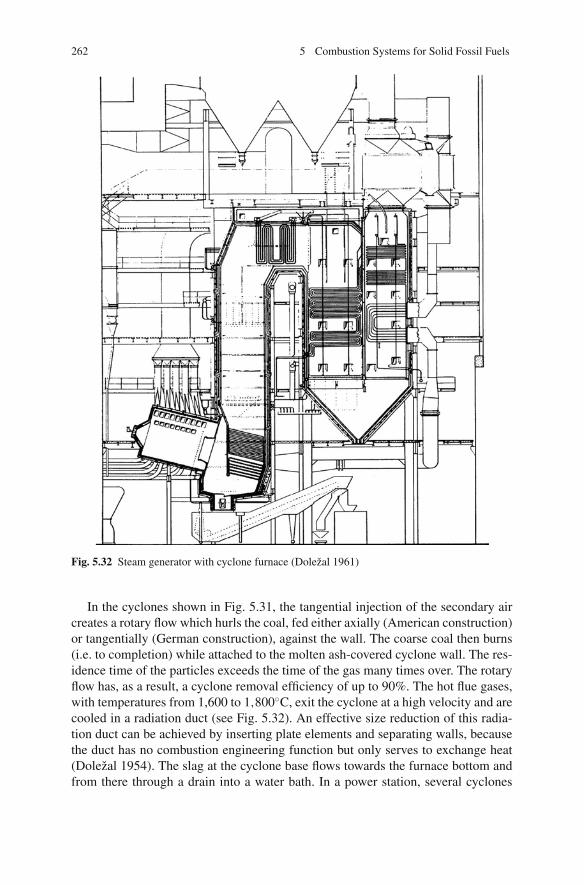
262 5 Combustion Systems for Solid Fossil Fuels
Fig. 5.32 Steam generator with cyclone furnace (Dolezal 1961)
In the cyclones shown in Fig. 5.31, the tangential injection of the secondary aircreates a rotary flow which hurls the coal, fed either axially (American construction)or tangentially (German construction), against the wall. The coarse coal then burns(i.e. to completion) while attached to the molten ash-covered cyclone wall. The res-idence time of the particles exceeds the time of the gas many times over. The rotaryflow has, as a result, a cyclone removal efficiency of up to 90%. The hot flue gases,with temperatures from 1,600 to 1,800◦C, exit the cyclone at a high velocity and arecooled in a radiation duct (see Fig. 5.32). An effective size reduction of this radia-tion duct can be achieved by inserting plate elements and separating walls, becausethe duct has no combustion engineering function but only serves to exchange heat(Dolezal 1954). The slag at the cyclone base flows towards the furnace bottom andfrom there through a drain into a water bath. In a power station, several cyclones

5.4 Fluidised Bed Firing Systems 263
are usually installed next to and above each other to achieve greater outputs. In oneparticular 1,100 MWel plant, for instance, there are 23 cyclones (Stultz and Kitto1992).
Sufficient coal preparation is achieved by a crusher which mills the coal to a sizesmaller than 4 mm, with a mean particle diameter of 0.5 mm. The lesser millingwork requirement of cyclone firing systems, however, is counterbalanced by thehigher power demand of the air fans. A fan pressure of 0.5–1 bar is needed due tothe high pressure loss in the cyclone. The cyclone furnace requires a lower auxiliarypower, in comparison to dry-bottom furnaces, only when the feedstock is a high-ashcoal type (Stultz and Kitto 1992).
5.4 Fluidised Bed Firing Systems
Fluidised bed firing (BFB) technology was industrially applied for the first timein the 1920s by Winkler for the gasification of coal. The development of bubblingfluidised bed combustion began in the 1960s, resulting in the first commercial appli-cations at the beginning of the 1970s, with capacities of up to 20 MWth. The capacityof bubbling systems have increased since then – today, the biggest are the Shawnee(USA) plant, with an electrical output of 160 MWel, which went into service in 1988,and the 350 MWel Takehara plant in Japan, which started up in 1995. However,these BFB demonstrations do not seem to have led to any follow-up installations.This is probably because circulating fluidised bed combustion (CFBC) has come todominate the larger scale applications.
At the end of the 1970s, circulating fluidised bed techniques were developed asan alternative to bubbling systems and have superseded them more and more since.With technological advances, the achievable unit size has increased steadily overthe past decades. Today, CFBC units in operation range in size from a few MWth to300 MWel. In 1995, a circulating fluidised bed furnace with an output of 259 MWel
was put into service in Gardanne, Provence-Cote d’Azur (France) and in 2001 theJEA plant of 2 × 300 MWel went into service in Jacksonville/FL/USA. A 460 MWel
boiler, which was built in Lagisza (Poland), is currently the world’s largest CFBCunit (Goidich et al. 2006). A capacity increase of up to around 800 MWel isconsidered feasible within the medium-term future (Hotta and Venalainen 2006).Figure 5.33 shows the development of the thermal capacity of bubbling and circulat-ing fluidised bed furnaces installed worldwide (Wu 2006; Koornneef and Junginger2007).
The way a fluidised bed works is shown in Fig. 5.1. A fluidised bed consistsof a packed bed of fuel particles above a grid through which air can be passedupwards to the bed. According to the velocity of the air, the bed is said to haveone of three distinct stages of fluidisation – fixed bed, bubbling fluidised bed orcirculating fluidised bed.
At low gas velocities, the gas simply flows through the packed bed without dis-turbing the particles significantly. The bed acts as a porous media and is called afixed bed. As the gas velocity increases, the gas particle drag forces compensate for

264 5 Combustion Systems for Solid Fossil Fuels
Fig. 5.33 Installed capacitiesof bubbling and circulatingfluidised bed furnaces; datafrom Koornneef andJunginger (2007)
the bed weight and the point of minimum fluidisation is reached. The inter-particledistances increase, the bed expands and the particles appear to be suspended in thegas. When the gas velocity exceeds the minimum fluidisation velocity, the excessgas passes through the bed as bubbles and the remainder leaks through the bedmaterial. The bed is then called a bubbling fluidised bed and the furnace abovethe bed is defined as the freeboard. Bubbling fluidised beds are normally operatedat gas velocities several times higher than the minimum fluidisation velocity. Thepassage of the bubbles result in an intensive mixing of the bed particles, althoughthe particles remain in close contact and are not carried upwards to a significantdegree. The height of the fluidised bed, and hence the distance between each of thesingle particles – the void fraction – is proportional to the throughput of air. Thenecessary air pressure is higher than in grate firing systems and remains constant influidised bed firing even at increasing velocities of the air. Only when the velocitiesexceed the particle free-fall velocity are the bed particles entrained in the gas streamand lifted out of the bed. The gas velocity at this point is known as the particleterminal velocity. The fluidisation and the terminal velocities limit the air velocityrange of a furnace using a bubbling fluidised bed. The range for circulating fluidisedbeds lies above the terminal velocity, in the transition range to pneumatic transport(Wu 2003; Dolezal 1990).
The temperatures of fluidised beds are limited to between 800 and 900◦C, on theone hand, in order to ensure the prevention of the sticking of ash particles and, onthe other hand, to achieve an optimum SO2 capture.
5.4.1 Bubbling Fluidised Bed Furnaces
The bubbling fluidised bed features a defined bed surface and a high solid matterdensity. The gas velocities range between 1 and 2 m/s. The fluidised bed, consistingof 96% inert material and limestone, has a height of 1–1.5 m. Fine particles arecarried out of the bed and removed in a downstream dust collector. Recirculating
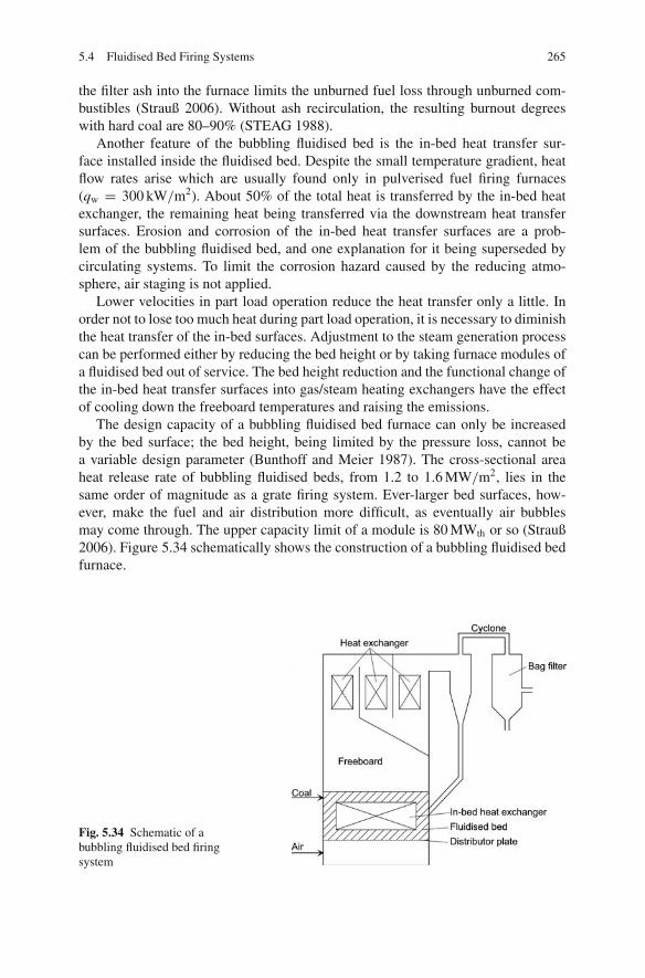
5.4 Fluidised Bed Firing Systems 265
the filter ash into the furnace limits the unburned fuel loss through unburned com-bustibles (Strauß 2006). Without ash recirculation, the resulting burnout degreeswith hard coal are 80–90% (STEAG 1988).
Another feature of the bubbling fluidised bed is the in-bed heat transfer sur-face installed inside the fluidised bed. Despite the small temperature gradient, heatflow rates arise which are usually found only in pulverised fuel firing furnaces(qw = 300 kW/m2). About 50% of the total heat is transferred by the in-bed heatexchanger, the remaining heat being transferred via the downstream heat transfersurfaces. Erosion and corrosion of the in-bed heat transfer surfaces are a prob-lem of the bubbling fluidised bed, and one explanation for it being superseded bycirculating systems. To limit the corrosion hazard caused by the reducing atmo-sphere, air staging is not applied.
Lower velocities in part load operation reduce the heat transfer only a little. Inorder not to lose too much heat during part load operation, it is necessary to diminishthe heat transfer of the in-bed surfaces. Adjustment to the steam generation processcan be performed either by reducing the bed height or by taking furnace modules ofa fluidised bed out of service. The bed height reduction and the functional change ofthe in-bed heat transfer surfaces into gas/steam heating exchangers have the effectof cooling down the freeboard temperatures and raising the emissions.
The design capacity of a bubbling fluidised bed furnace can only be increasedby the bed surface; the bed height, being limited by the pressure loss, cannot bea variable design parameter (Bunthoff and Meier 1987). The cross-sectional areaheat release rate of bubbling fluidised beds, from 1.2 to 1.6 MW/m2, lies in thesame order of magnitude as a grate firing system. Ever-larger bed surfaces, how-ever, make the fuel and air distribution more difficult, as eventually air bubblesmay come through. The upper capacity limit of a module is 80 MWth or so (Strauß2006). Figure 5.34 schematically shows the construction of a bubbling fluidised bedfurnace.
Fig. 5.34 Schematic of abubbling fluidised bed firingsystem
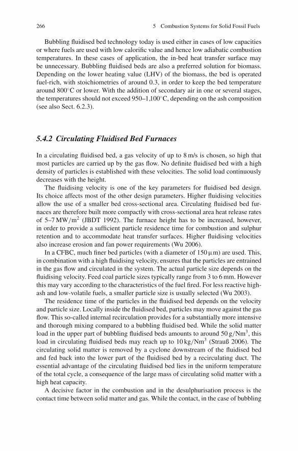
266 5 Combustion Systems for Solid Fossil Fuels
Bubbling fluidised bed technology today is used either in cases of low capacitiesor where fuels are used with low calorific value and hence low adiabatic combustiontemperatures. In these cases of application, the in-bed heat transfer surface maybe unnecessary. Bubbling fluidised beds are also a preferred solution for biomass.Depending on the lower heating value (LHV) of the biomass, the bed is operatedfuel-rich, with stoichiometries of around 0.3, in order to keep the bed temperaturearound 800◦C or lower. With the addition of secondary air in one or several stages,the temperatures should not exceed 950–1,100◦C, depending on the ash composition(see also Sect. 6.2.3).
5.4.2 Circulating Fluidised Bed Furnaces
In a circulating fluidised bed, a gas velocity of up to 8 m/s is chosen, so high thatmost particles are carried up by the gas flow. No definite fluidised bed with a highdensity of particles is established with these velocities. The solid load continuouslydecreases with the height.
The fluidising velocity is one of the key parameters for fluidised bed design.Its choice affects most of the other design parameters. Higher fluidising velocitiesallow the use of a smaller bed cross-sectional area. Circulating fluidised bed fur-naces are therefore built more compactly with cross-sectional area heat release ratesof 5–7 MW/m2 (JBDT 1992). The furnace height has to be increased, however,in order to provide a sufficient particle residence time for combustion and sulphurretention and to accommodate heat transfer surfaces. Higher fluidising velocitiesalso increase erosion and fan power requirements (Wu 2006).
In a CFBC, much finer bed particles (with a diameter of 150 μm) are used. This,in combination with a high fluidising velocity, ensures that the particles are entrainedin the gas flow and circulated in the system. The actual particle size depends on thefluidising velocity. Feed coal particle sizes typically range from 3 to 6 mm. Howeverthis may vary according to the characteristics of the fuel fired. For less reactive high-ash and low-volatile fuels, a smaller particle size is usually selected (Wu 2003).
The residence time of the particles in the fluidised bed depends on the velocityand particle size. Locally inside the fluidised bed, particles may move against the gasflow. This so-called internal recirculation provides for a substantially more intensiveand thorough mixing compared to a bubbling fluidised bed. While the solid matterload in the upper part of bubbling fluidised beds amounts to around 50 g/Nm3, thisload in circulating fluidised beds may reach up to 10 kg/Nm3 (Strauß 2006). Thecirculating solid matter is removed by a cyclone downstream of the fluidised bedand fed back into the lower part of the fluidised bed by a recirculating duct. Theessential advantage of the circulating fluidised bed lies in the uniform temperatureof the total cycle, a consequence of the large mass of circulating solid matter with ahigh heat capacity.
A decisive factor in the combustion and in the desulphurisation process is thecontact time between solid matter and gas. While the contact, in the case of bubbling
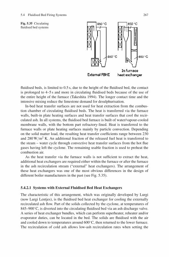
5.4 Fluidised Bed Firing Systems 267
Fig. 5.35 Circulatingfluidised bed systems
fluidised beds, is limited to 0.5 s, due to the height of the fluidised bed, the contactis prolonged to 4–5 s and more in circulating fluidised beds because of the use ofthe entire height of the furnace (Takeshita 1994). The longer contact time and theintensive mixing reduce the limestone demand for desulphurisation.
In-bed heat transfer surfaces are not used for heat extraction from the combus-tion chamber of circulating fluidised beds. The heat is transferred via the furnacewalls, built-in plate heating surfaces and heat transfer surfaces that cool the recir-culated ash. In all systems, the fluidised bed furnace is built of water/vapour-cooledmembrane walls, with the bottom part refractory-lined. Heat is transferred to thefurnace walls or plate heating surfaces mainly by particle convection. Dependingon the solid matter load, the resulting heat transfer coefficients range between 230and 280 W/m2 K. An additional fraction of the released fuel heat is transferred tothe steam – water cycle through convective heat transfer surfaces from the hot fluegases having left the cyclone. The remaining usable fraction is used to preheat thecombustion air.
As the heat transfer via the furnace walls is not sufficient to extract the heat,additional heat exchangers are required either within the furnace or after the furnacein the ash recirculation stream (“external” heat exchangers). The arrangement ofthese heat exchangers was one of the most obvious differences in the design ofdifferent boiler manufacturers in the past (see Fig. 5.35).
5.4.2.1 Systems with External Fluidised Bed Heat Exchangers
The characteristic of this arrangement, which was originally developed by Lurgi(now Lurgi Lentjes), is the fluidised bed heat exchanger for cooling the externallyrecirculated ash flow. Part of the solids collected by the cyclone, at temperatures of845–900◦C, is diverted into the circulating fluidised bed via an ash discharge valve.A series of heat exchanger bundles, which can perform superheater, reheater and/orevaporator duties, can be located in the bed. The solids are fluidised with the airand cooled down to temperatures around 600◦C, then returned to the lower furnace.The recirculation of cold ash allows low-ash recirculation rates when setting the

268 5 Combustion Systems for Solid Fossil Fuels
fluidised bed combustion temperature of 850◦C. The fluidised bed velocity rangesbetween 6 and 8 m/s.
A fluidised bed heat exchanger (FBHE) has a relatively high rate of heat transferfrom the hot solids to the tube bundles. With a low fluidising velocity, typically lessthan 0.3 m/s, and fine particle sizes (about 200 μm), the potential for erosion of thetubes is eliminated. As the heat exchanger is fluidised with air and not exposed tocorrosive elements in the flue gas stream, the potential for corrosion is also min-imised. Additionally, with the ash flow control valve, one can control the heat trans-fer to the immersed bundles. This in turn controls the furnace temperature (Takeshita1994; Wu 2006).
5.4.2.2 Systems with Plate Heat Exchangers
This circulating fluidised bed firing technique, originally developed by the AhlstromCompany, Finland (now Foster Wheeler), with gas velocities from 6 to 8 m/s, isin the category of classical circulating fluidised bed types. The circulated ash isremoved outside the furnace in a refractory-lined cyclone and fed again, uncooled,to the fluidised bed. The temperature of the solid matter – flue gas mixture at the exitof the furnace ranges between 800 and 900◦C, thus corresponding to the combustiontemperature. The heat is transferred inside the furnace via the furnace wall and viaadditional platen heating surfaces in the upper section of the furnace and outside thefurnace in downstream convective heat transfer surfaces. In order to maintain thefluidised bed temperatures, high-ash recirculation rates are required. As the boilersize increases, the furnace surface to volume ratio decreases and it then may not bepossible to perform all the required heat exchange in the furnace and back passage.Hence an external fluidised bed heat exchanger has to be used for boilers in the300 MWel range or higher.
5.4.2.3 Solid Separation Systems
The most commonly applied separation systems are cyclones consisting of a steelshell lined with heat- and erosion-resistant refractory material. However, these thickmulti-layer linings often require high maintenance efforts. This has led to the devel-opment of water- or steam-cooled cyclones, which are lined with a thin layer ofrefractory material held in place by a dense pattern of metal studs.
In order to achieve a more compact design of the CFBC, Foster Wheeler hasdeveloped a compact separator integrated with the furnace. The design is still basedon centrifugal separation but has flat walls, thus simplifying fabrication and con-struction. Gas with entrained solids enters the separator through a tall and narrowopening and exits from the top. A swirling imparted to the gas flow causes solidseparation.
Another possibility for achieving a more compact design is to recirculate the ashinside the furnace (Maryamchik and Wietzke 2005). Impingement separators in theform of a U-beam mounted in the upper furnace section return the ash within the
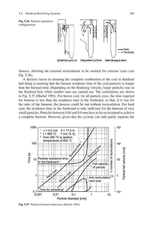
5.4 Fluidised Bed Firing Systems 269
Fig. 5.36 Particle separationconfigurations
furnace, allowing the external recirculation to be omitted for extreme cases (seeFig. 5.36).
A decisive factor in ensuring the complete combustion of the coal in fluidisedbed firing is ensuring that the furnace residence time of the coal particles is longerthan the burnout time. Depending on the fluidising velocity, larger particles stay inthe fluidised bed, while smaller ones are carried out. The correlations are shownin Fig. 5.37 (Michel 1992). For brown coal, for all particle sizes, the time requiredfor burnout is less than the residence time in the freeboard, so that, if it was forthe sake of the burnout, the process could be run without recirculation. For hardcoal, the residence time in the freeboard is only sufficient for the burnout of verysmall particles. Particles between 0.04 and 0.8 mm have to be recirculated to achievea complete burnout. However, given that the cyclone can only partly separate the
Fig. 5.37 Particle burnout behaviour (Michel 1992)
270 5 Combustion Systems for Solid Fossil Fuels
particles to be recirculated, the result for hard coal is a loss due to unburned com-bustibles in the fly ash.
The fly ashes of hard coal-fired circulating fluidised bed furnaces in generalhave high carbon contents, typically of 30%. Measures to increase the removalefficiency of the recirculating cyclones, in particular for small particles, can reduceloss through unburned combustibles.
Start-up times of circulating fluidised bed systems are determined by the refrac-tory lining of the recirculating cyclone and the ash flow ductwork. Because theheating-up may only proceed at a maximum temperature change of 50–80◦C perhour, long times for the start-up from a cold state (cold start; outage > 72 h) withauxiliary fuels are needed which, accordingly, cause start-up losses. Hot starts (out-age < 8 h) or load changes are assisted by the great heat storage of the fluid bedand the refractory lining, and the start-up times from a hot state or from rates ofload change are comparable to pulverised fuel firing systems (VGB 1997). Forwarm starts (outage 8–72 h) the start-up time ranges in between and depends onthe outage time.
The load is controlled by modifying the fuel feed rate and the air flow to thesteam generator. By means of supplementary ash from the bed ash storage, thecirculating ash flow can be changed and the heat extraction adjusted according tothe firing rate in order to set the desired fluidised bed temperature. This proceduremanipulates the impact of the solid matter load on the heat transfer coefficient. Incirculating fluidised bed systems with external fluid-bed heat exchangers and a highcirculating ash flow, the fluidised bed temperature is controlled by modifying theash recirculation temperature (Stultz and Kitto 1992).
The circulating has almost superseded the bubbling fluidised bed because of itsnumerous advantages in the mid-load and upper load range of fluidised bed fur-naces. The main advantage of the fluidised bed firing system, as opposed to othercombustion technologies, lies in the fact that it is able to meet emission controlstandards without additional desulphurisation and DeNOx plants.
Due to the high-ash load in circulating fluidised bed furnaces, the heat transfersurfaces are subject to increased erosion. However, satisfactory solutions for thisproblem have been achieved by taking measures such as installing the tubes parallelto the direction of flow and coating areas threatened by erosion with ceramic mate-rial. Another problematic issue is the utilisation of the combustion residues. Theresidual material, consisting of inert material, fuel ash, additive(s) and products ofthe desulphurisation process, is not suitable for immediate utilisation. Table 5.5draws a comparison between circulating fluidised beds and pulverised fuel firingsystems (VGB 1997).
5.4.2.4 Future Developments
Considerable efforts are continuing to further improve the performance of CFBCboilers and to scale up the technology to 600–800 MWel. As the unit size increases,the furnace depth remains constant while the furnace width increases and cyclonesare added as required. A limit is reached when the unit size approaches 300 MWel
or when four cyclones are required. For larger electrical capacities, a deeper furnace

5.5 Stoker/Grate Firing Systems 271
Table 5.5 Comparison between circulating fluidised bed firing (CFBF) and pulverised fuel firingsystems (PFF)
CFBF PFF
Capacity range 600 MWel 1,000 MWel
Fuel range Wide LimitedFuel flexibility Great ModerateSpace required Little ModerateEfficiency High High (higher than CFBF)Availability >90% >90%Investment costs 90% (of PFF) 100% (of which ca. 10% DeNOx ,
15% FGD unit)Operating costs High limestone consumption Low limestone consumption
(Ca/S = 1.5–2.7) (Ca/S = 1.05)ash disposal ash utilisationlandfill, mining (0–50 e per ton) as building material, revenue up to 10 e
per ton utilisation of gypsum, revenueup to 5 e per ton
is used and cyclones are arranged in parallel at both sides of the furnace. Dependingon the manufacturer, the furnace either still has one fluidising grid or is split to forma dual grid (Wu 2006; Stamatelopoulos and Weissinger 2005a, b; Goidich et al.2006).
5.5 Stoker/Grate Firing Systems
The stoker-fired furnace is considered the oldest combustion system for solid fuels.At the beginning of the 20th century, mechanical stoker firing was the only avail-able combustion technology for coal. Having limited capacities, it was increasinglysuperseded in the 1920s and 1930s by pulverised fuel firing (Stultz and Kitto 1992).Stoker-fired furnaces are used in the capacity range from 0.3 up to 150 MWth inindustrial and thermal power plants (JBDT 1985). In this range, they compete withfluidised bed furnaces, which is why these furnace types have become a seldom-applied technology for fossil fuels. In waste incineration, in contrast, stoker firing isalmost the only technology and it is suited for biomass as well.
The type of stoker firing is chosen depending on the properties of the fuel feed-stock. For coals, the system commonly used is the travelling grate stoker; for high-ash fuels like biomass and waste, firing systems with a mixing function, such aspusher-type grate firing systems, are used.
5.5.1 Travelling Grate Stoker Firing
Characteristic of the travelling grate stoker firing is the travelling of a glowing fuelbed on the upper track of a circulating grate belt. The coal glides from the coalbunker onto the grate and forms a bulk layer which is then heated by radiation fromthe furnace and thereby dried, then devolatilised and ignited, radiating heat back

272 5 Combustion Systems for Solid Fossil Fuels
Fig. 5.38 Combustion procedure for a travelling grate (Adrian et al. 1986)
into the furnace. After combustion of the solid coke residue, the ash dammed up byswinging cut-off gates at the end of the grate falls into the ash hopper (see Fig. 5.38).The coal bulk layer resting and burning on the travelling grate is not poked (Strauß2006; Dolezal 1990; Lehmann 1996; Adrian et al. 1986).
The travelling grate is composed of a great number of parallel grate bars mountedin rows one behind the other and linked by joints. The major part of the combustionair, the primary air, is blown into the layer from below, cooling the grate at the sametime. Combustion air preheating is therefore limited to about 150◦C.
Stoker-fired furnaces are suitable for the combustion of lump fuels – fines inthe fuel are not desirable because they may fall through the grate clearances, thusincreasing the unburned fuel loss. Strongly caking coal is little suited to combustionon travelling grates – it forms big, very slowly burning coke cakes which hamperthe homogeneous distribution of combustion air throughout the fuel bed. Lightlycaking coal, in contrast, is desirable because the forming of small lumps that clingtogether prevents the discharge of fines without obstructing the air flow through thebed (Adrian et al. 1986).
The fuel bed height is adjusted according to the combustion characteristics ofthe feedstock. It depends on the volatile matter content and the grain characteristicsof the fuel. Figure 5.39 provides reference values for the bed height to be chosen(Adrian et al. 1986). For finer fuel grains and a higher volatile matter content, thebulk height is reduced in order to ensure the passage of air.
A good burnout is achieved by sufficient residence times for the solid fuel onthe grate and for the gases in the furnace. For optimum conditions it is necessarythat the bed height, the grate forward movement and the course of burnout areco-ordinated. The velocities of the grate forward movement vary from 1.5 to 15 m/h.Too slow a grate movement along with too high a bed results in excessively high

5.5 Stoker/Grate Firing Systems 273
Fig. 5.39 Bed height of hardcoal on travelling grates(Adrian et al. 1986)
concentrations of unburned gases above the devolatilisation zone. The lower limitof the grate velocity is a consequence of the danger of a flashback into the feedhopper. Too fast a movement and too low a bed height, in turn, may break off theignition.
The load of a travelling grate stoker is controlled mainly by adjusting the grateforward movement, as the bed height as a manipulated variable is too slow inresponding (Strauß 2006).
The ratio of the fuel heat release to grate surface area is termed the grate load.The maximum grate load is limited by the combustion and slagging behaviour ofthe coal. When there is too high a grate load, the consequence may be slagging onthe grate and hence operational malfunctions. Typical grate loads lie between 1 and2 MW/m2.
The maximum output of a travelling grate stoker-fired furnace is determined bythe grate surface area. These areas have a size of up to 100 m2, yielding heat outputsup to 125 MWth (JBDT 1985).
For fuels with fines, feeding is better executed by spreader stokers which throwthe fuel onto the grate mechanically (see Fig. 5.40), rather than by hoppers. Thisway, finer fuel particles already start to burn while in the air. The grate load maythus be greater by 50% compared to hopper feeding (Strauß 2006). The fuel in thiscase ignites via the base fire on the grate. As part of the fuel is carried out of thefurnace, it is reasonable to recirculate the fly dust in order to limit the loss throughunburnt carbon. This firing system represents a transition to a pulverised fuel firingsystem. Achievable thermal outputs reach a maximum of 175 MWth.
5.5.2 Self-Raking Type Moving-Grate Stokers
For high-ash, low-calorific fuels, travelling grates are not an adequate technology,because the movement of the grate only serves for fuel feeding and for the transportof fuel and ash. Difficulties arise igniting such fuels and during burnout. Such types

274 5 Combustion Systems for Solid Fossil Fuels
1 Steam generator 2 Louvre type travelling grate3 Chute 4 Shut off gate5 Feeder 6 Spreader7 Carrying air 8 Secondary air9 Coke fines feed back 10 Ash hopper
11 Screw conveyor 12 Submerged scrapper conveyor
Fig. 5.40 Travelling grate stoker firing with a spreader stoker (Source: Alstom Power)
of fuel have to be constantly broken up by poking/raking in order to ensure theaccess of air and to subject all of the fuel to the radiant heat.
A difference is made between pusher-type grates where the rams move the fuel inthe direction of the proceeding combustion and reciprocating grates where the ramsmove the fuel against the direction of combustion. The applications of different gratevariants are more thoroughly discussed in Sect. 6.4.2.
Figure 5.41 shows a schematic drawing of a pusher-type grate firing system.Every second row of grate bars is fixed, while the bar rows mounted in-betweenmake a pushing movement, forced by a hydraulic cylinder. The coal is transportedby this pushing, burning in a layer roughly 500 mm thick. The reciprocal row move-ments of the grate poke the coal and thus break the coal cakes. The grate load hereis about 1 MW/m2 of grate surface area. The necessary power of the grate driveis higher than the power used by a travelling grate. This construction type is suit-able for moist brown coals, caking hard coals, wood and waste. With respect to thegrains, this construction type is less delicate than the travelling grate.
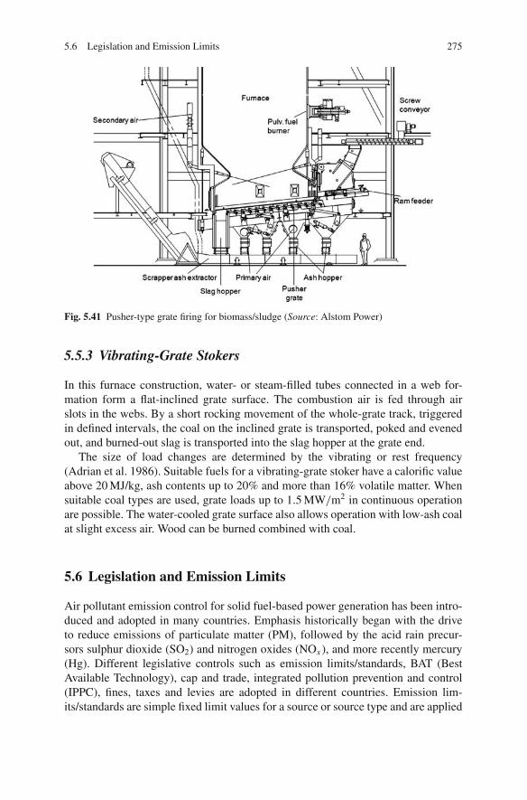
5.6 Legislation and Emission Limits 275
Fig. 5.41 Pusher-type grate firing for biomass/sludge (Source: Alstom Power)
5.5.3 Vibrating-Grate Stokers
In this furnace construction, water- or steam-filled tubes connected in a web for-mation form a flat-inclined grate surface. The combustion air is fed through airslots in the webs. By a short rocking movement of the whole-grate track, triggeredin defined intervals, the coal on the inclined grate is transported, poked and evenedout, and burned-out slag is transported into the slag hopper at the grate end.
The size of load changes are determined by the vibrating or rest frequency(Adrian et al. 1986). Suitable fuels for a vibrating-grate stoker have a calorific valueabove 20 MJ/kg, ash contents up to 20% and more than 16% volatile matter. Whensuitable coal types are used, grate loads up to 1.5 MW/m2 in continuous operationare possible. The water-cooled grate surface also allows operation with low-ash coalat slight excess air. Wood can be burned combined with coal.
5.6 Legislation and Emission Limits
Air pollutant emission control for solid fuel-based power generation has been intro-duced and adopted in many countries. Emphasis historically began with the driveto reduce emissions of particulate matter (PM), followed by the acid rain precur-sors sulphur dioxide (SO2) and nitrogen oxides (NOx ), and more recently mercury(Hg). Different legislative controls such as emission limits/standards, BAT (BestAvailable Technology), cap and trade, integrated pollution prevention and control(IPPC), fines, taxes and levies are adopted in different countries. Emission lim-its/standards are simple fixed limit values for a source or source type and are applied

276 5 Combustion Systems for Solid Fossil Fuels
in most countries, for example, across Europe. Including BAT within internationalor national legislation requires the application of the newest technology. Integratedpollution prevention and control (IPPC) moves away from fixed standards for differ-ent emissions to a broader, integrated and preventive approach and includes variousemissions, but also wider issues such as energy efficiency and the minimisation ofwaste. Cap and trade systems allow trading of total emissions of a single pollutant(Nalbandian 2004; Sloss 2003).
The main EU policies which are relevant for power stations are the IntegratedPollution Prevention and Control Directive (IPCC), the National Emissions CeilingDirective (NECD) and the Large Combustion Plants Directive (LCPD).
The EU IPCC directive of 1996 required the introduction of an integrated envi-ronmental licensing system which applies to combustion installations greater than50 MWth and had to be implemented by the member states by 1999. The IPCCdirective includes a large number of air pollutants such as SO2, NOx , CO, VOC,metals, particulate matter, chlorine, fluorine, dioxins and furans and specifies thatbest available techniques should be installed.
The National Emissions Ceiling Directive (2001/81/EC) set limits for each mem-ber state for the SO2, NOx , VOC and ammonia for the year 2010 (Sloss 2003).
The LCPD establishes emission limits for sulphur dioxide (SO2), nitrogen oxides(NOx ) as well as emissions of fine and coarse particulate matter (PM), for all exist-ing and new plants with a thermal capacity more than 50 MW. New combustionplants must meet emission limit values (ELVs) as given in Table 5.6 (Nalbandian2007). The LCPD does not include waste fuels which are covered by the WasteIncineration Directive, but does include biomass fuels such as agricultural andforestry residues, waste from the paper and pulp industry and wood wastes, exceptthose containing halogenated organic compounds or heavy metals as a result oftreatment.
The EU directives were implemented by national legislation in member coun-tries, with the compliance mechanism left largely optional. Therefore specific legis-lation varies from country to country.
In Germany emissions from large combustion plants with thermal outputs inexcess of 50 MWth are regulated by the Ordinance on Large Combustion Plants(13.BImSchV 2004). The emission standards are given in Table 5.7. For plantswith thermal capacities between 1 and 50 MWth emission limits are given in theTechnische Anleitung Luft (TALuft 2002).
Waste incineration plants must comply with the stricter limits of the Ordinanceon Incinerators for Waste and Similar Combustible Materials (17.BimSchV 2003),which is in line with the European Waste Incineration Directive. When waste fuelsare co-fired in coal-fired power plants up to a fraction of 25% (based on heatinput), the emission limits are calculated based on the emission limits of the twoordinances. This calculation, which is known as the mixing rule, takes account ofthe calorific values, flue gas volumes and other data. In some cases, the limits forwaste fuels include pollutants not included in the Ordinance on Large CombustionPlants.

5.7 Methods for NOx Reduction 277
Table 5.6 Emission limits of the EU Large Combustion Plant Directive (Nalbandian 2007)
Revised 2001 LCPD emission limit values (ELVs) for new plants
ELVs (mg/m3)
Pollutant Fuel type 50–100 MWth 100–300 MWth > 300 MWth
SO2 Biomass 200 200 200General case 850 200 200Liquid 850 400–200 (linear
decrease)200
Gaseous 35 – in general5 – liquefied gas400 – low calorific gases from coke oven300 – low calorific gases from blast furnace
NOx Solid – biomass 400 300 200Solid – general case 400 200 200Liquid 400 200 200Gaseous– Natural gas 150 150 100– Other gas 200 200 200Gas turbines– Natural gas 50 50 50– Other gases 120 120 120– Liquid fuels 120 120 120
Particulate Solid 50 30 30matter Liquid 50 30 30
Gaseous 5 – as a rule10 – blast furnace gas30 – steel industry gases that can be used elsewhere
5.7 Methods for NOx Reduction
Measures to reduce nitrogen oxide can be divided into two categories: combustionengineering methods and methods applied downstream of the furnace. For this cate-gorisation, the furnace is defined as the space where the fuel is burned. The differentmethods of NOx reduction can be classified as follows (Spliethoff 2000; Spliethoffand Hein 2002; Wu 2002):
Combustion Engineering Measures
• Measures applied at the burner◦ flue gas recirculation◦ air staging◦ fuel staging
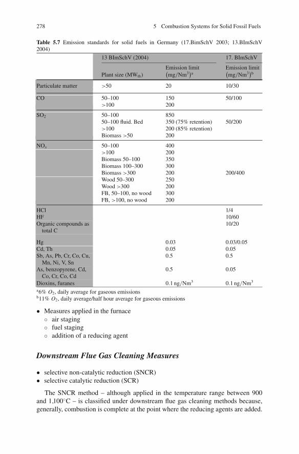
278 5 Combustion Systems for Solid Fossil Fuels
Table 5.7 Emission standards for solid fuels in Germany (17.BimSchV 2003; 13.BImSchV2004)
13 BImSchV (2004) 17. BImSchV
Emission limit Emission limitPlant size (MWth)
(mg/Nm3
)a
(mg/Nm3
)b
Particulate matter >50 20 10/30
CO 50–100 150 50/100>100 200
SO2 50–100 85050–100 fluid. Bed 350 (75% retention) 50/200>100 200 (85% retention)Biomass >50 200
NOx 50–100 400>100 200Biomass 50–100 350Biomass 100–300 300Biomass >300 200 200/400Wood 50–300 250Wood >300 200FB, 50–100, no wood 300FB, >100, no wood 200
HCl 1/4HF 10/60Organic compounds as
total C10/20
Hg 0.03 0.03/0.05Cd, Th 0.05 0.05Sb, As, Pb, Cr, Co, Cu,
Mn, Ni, V, Sn0.5 0.5
As, benzopyrene, Cd,Co, Cr, Co, Cd
0.5 0.05
Dioxins, furanes 0.1 ng/Nm3 0.1 ng/Nm3
a6% O2, daily average for gaseous emissionsb11% O2, daily average/half hour average for gaseous emissions
• Measures applied in the furnace◦ air staging◦ fuel staging◦ addition of a reducing agent
Downstream Flue Gas Cleaning Measures
• selective non-catalytic reduction (SNCR)• selective catalytic reduction (SCR)
The SNCR method – although applied in the temperature range between 900and 1,100◦C – is classified under downstream flue gas cleaning methods because,generally, combustion is complete at the point where the reducing agents are added.
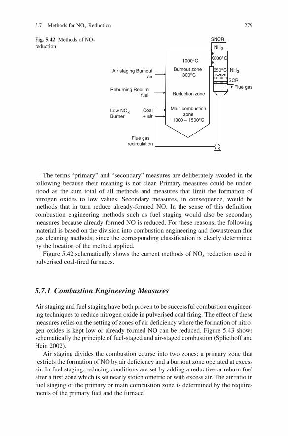
5.7 Methods for NOx Reduction 279
Fig. 5.42 Methods of NOx
reductionSNCR
NH3
800°C
350°C
SCRFlue gas
1000°C
Burnout zone1300°C
Reduction zone
Main combustionzone
1300 – 1500°C
fuel
Coal+ air
Flue gasrecirculation
Air staging Burnoutair
Reburning Reburn
Low NOxBurner
NH3
The terms “primary” and “secondary” measures are deliberately avoided in thefollowing because their meaning is not clear. Primary measures could be under-stood as the sum total of all methods and measures that limit the formation ofnitrogen oxides to low values. Secondary measures, in consequence, would bemethods that in turn reduce already-formed NO. In the sense of this definition,combustion engineering methods such as fuel staging would also be secondarymeasures because already-formed NO is reduced. For these reasons, the followingmaterial is based on the division into combustion engineering and downstream fluegas cleaning methods, since the corresponding classification is clearly determinedby the location of the method applied.
Figure 5.42 schematically shows the current methods of NOx reduction used inpulverised coal-fired furnaces.
5.7.1 Combustion Engineering Measures
Air staging and fuel staging have both proven to be successful combustion engineer-ing techniques to reduce nitrogen oxide in pulverised coal firing. The effect of thesemeasures relies on the setting of zones of air deficiency where the formation of nitro-gen oxides is kept low or already-formed NO can be reduced. Figure 5.43 showsschematically the principle of fuel-staged and air-staged combustion (Spliethoff andHein 2002).
Air staging divides the combustion course into two zones: a primary zone thatrestricts the formation of NO by air deficiency and a burnout zone operated at excessair. In fuel staging, reducing conditions are set by adding a reductive or reburn fuelafter a first zone which is set nearly stoichiometric or with excess air. The air ratio infuel staging of the primary or main combustion zone is determined by the require-ments of the primary fuel and the furnace.
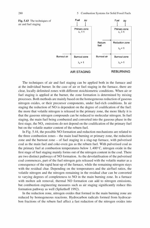
280 5 Combustion Systems for Solid Fossil Fuels
Fig. 5.43 The techniques ofair and fuel staging
The techniques of air and fuel staging can be applied both in the furnace andat the individual burner. In the case of air or fuel staging in the furnace, there areclear, locally delimited zones with different stoichiometric conditions. When air orfuel staging is applied at the burner, the zone formation is determined by mixingprocesses. Both methods are mainly based on the homogeneous reduction of gaseousnitrogen oxides, or their precursor components, under fuel-rich conditions. In airstaging the reduction of NO is dependent on the degree of coalification of the fuel:the more that volatile nitrogen is released in the primary zone, the more likely it isthat the gaseous nitrogen compounds can be reduced to molecular nitrogen. In fuelstaging, the main fuel being combusted and converted into the gaseous phase in thefirst stage, the NOx emissions do not depend on the coalification of the primary fuelbut on the volatile matter content of the reburn fuel.
In Fig. 5.44, the possible NO formation and reduction mechanisms are related tothe three combustion zones – the main load burning or primary zone, the reductionzone and the burnout zone – of fuel staging in a slag-tap furnace, with pulverisedcoal as the main fuel and coke-oven gas as the reburn fuel. With pulverised coal asthe primary fuel at combustion temperatures below 1,400◦C, nitrogen oxide in thefirst stage of fuel staging mainly forms out of the nitrogen content in the coal. Thereare two distinct pathways of NO formation. As the devolatilisation of the pulverisedcoal commences, part of the fuel nitrogen gets released with the volatile matter as aconsequence of the rapid heat-up of the furnace, while the remaining nitrogen stayswith the residual char. Depending on the temperatures and the air/fuel ratios, thevolatile nitrogen and the nitrogen remaining in the residual char can be convertedto varying degrees of completeness to NO in the main burning zone. In a furnacewith molten ash removal, thermal NO formation can add to nitrogen emissions,but combustion engineering measures such as air staging significantly reduce thisformation pathway as well (Spliethoff 1992).
In the reduction zone, nitrogen oxides that formed in the main burning zone arereduced by homogeneous reactions. Hydrocarbon radicals formed from hydrocar-bon fractions of the reburn fuel affect a fast reduction of the nitrogen oxides into
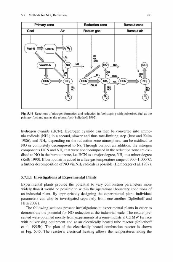
5.7 Methods for NOx Reduction 281
Fig. 5.44 Reactions of nitrogen formation and reduction in fuel staging with pulverised fuel as theprimary fuel and gas as the reburn fuel (Spliethoff 1992)
hydrogen cyanide (HCN). Hydrogen cyanide can then be converted into ammo-nia radicals (NHi ) in a second, slower and thus rate-limiting step (Just and Kelm1986), and NHi , depending on the reduction zone atmosphere, can be oxidised toNO or completely decomposed to N2. Through burnout air addition, the nitrogencomponents HCN and NHi that were not decomposed in the reduction zone are oxi-dised to NO in the burnout zone, i.e. HCN to a major degree, NHi to a minor degree(Kolb 1990). If burnout air is added in a flue gas temperature range of 900–1,000◦C,a further decomposition of NO via NHi radicals is possible (Hemberger et al. 1987).
5.7.1.1 Investigations at Experimental Plants
Experimental plants provide the potential to vary combustion parameters morewidely than it would be possible to within the operational boundary conditions ofan industrial plant. By appropriately designing the experimental plant, individualparameters can also be investigated separately from one another (Spliethoff andHein 2002).
The following sections present investigations at experimental plants in order todemonstrate the potential for NO reduction at the industrial scale. The results pre-sented were obtained mostly from experiments at a semi-industrial 0.5 MW furnacewith pulverising equipment and at an electrically heated tube reactor (Spliethoffet al. 1995b). The plan of the electrically heated combustion reactor is shownin Fig. 5.45. The reactor’s electrical heating allows the temperatures along the

282 5 Combustion Systems for Solid Fossil Fuels
Fig. 5.45 Electrically heated tube reactor (20 kWFuel)
combustion course to be set to facilitate separate investigations of the impacts ofindividual parameters on the combustion course and pollutant formation. For themethods of air-staged and fuel-staged combustion of hard and brown coals, system-atic parameter studies were carried out as functions of temperature, stoichiometryand residence times (Greul et al. 1996b; Spliethoff et al. 1996). At the semi-industrial 0.5 MW plant shown in Fig. 5.46, the temperature – residence time courseof the combustion was set within boundary conditions similar to an industrial plant(Maier 1998). Investigations concentrated on mixing phenomena.
Air Staging
In a separate investigation using two different coal types, the NOx emissions andthe NO, HCN and NH3 concentrations, as well as the nitrogen remaining in theresidual char, were measured in the primary zone (Fig. 5.47) (Chen et al. 1982b).At a specific air ratio, termed the optimum air ratio, a minimum NOx emission levelappears. At a higher air ratio, NO is only insufficiently decomposed in the primaryzone. Below the optimum air ratio, NO in the primary zone is almost completely

5.7 Methods for NOx Reduction 283
Fig. 5.46 Dry-bottom pulverised-fuel-fired furnace (0.5 MW)
decomposed, but part of the nitrogen stays in the residual char or forms NH3 andHCN as intermediate components which, when burnout air is added, can again beoxidised to NO. The nitrogen in the residual char cannot be reduced by way ofhomogeneous gas phase reactions.
In the following sections, the influence of the air ratio, residence time and temper-ature on NOx emissions in the primary zone shall be discussed using the example ofthe investigations at the electrically heated combustion reactor described previously(Spliethoff 2000; Spliethoff and Hein 2002).
The lower the air ratio of the primary zone, the lower will be the NOx emissionlevel. This correlation persists until the minimum NOx emission rate develops at adefinite air ratio (the optimum air ratio) (Fig. 5.48). Higher and lower air ratios thanthis cause higher NOx emissions. At a residence time in the primary zone of 3–4 sand an air ratio of about 0.8, the NOx emissions drop to the lowest level. At shorterprimary zone residence times, the optimum was not attained within the investigatedrange of air ratios.
Longer residence times in the primary zone significantly reduce the NOx emis-sions (Fig. 5.48). However, a prolongation beyond 4 s results in only slightly lowerNOx emissions, so the residence time between 3 and 4 s is considered sufficient.

284 5 Combustion Systems for Solid Fossil Fuels
Fig. 5.47 NOx emissions andnitrogen components in theprimary zone (Chen et al.1982b)
In scaling up the residence time influence on NOx emissions from this experi-mental plant to an industrial plant scale, one has to take into account that reducingconditions develop only after the complete reaction of the fuel. The experimentalset-up chosen here – the injection of the fuel in the direction of the main flow –results in a shorter effective residence time in the primary zone. In industrial plants,
Fig. 5.48 Effect of residencetime on a high volatile hardcoal

5.7 Methods for NOx Reduction 285
Fig. 5.49 Temperatureinfluence on NOx formationfrom a high volatile hard coal
the fuel fed via the burners is mostly injected horizontally into the furnace, and sothe flue gases are only gradually led upwards by the main flow. Therefore, the sameNO reduction effects are to be expected even at shorter residence times.
The extent of the influence of temperature on NO reduction depends on theflue gas atmosphere. In excess-air conditions, higher temperatures produce higherNOx emissions, whereas under a deficiency of air, NO reduction is accelerated. Thepositive temperature effect is shown in Fig. 5.49 for a high-volatile hard coal. Thispositive impact of the temperature is also valid for brown coal.
The effect of the temperature in air staging can be explained using the exampleof NO concentrations measured along the combustion course (see Fig. 5.50). Inall configurations of the air ratio and temperature, the measurements showed thatNO concentrations increased considerably in the immediate burner vicinity. Theydecreased again in fuel-rich conditions. Higher temperatures lead first to higherNO concentrations in the near-burner area. In air-deficient conditions, though, NOdecomposition speeds up so that, at the low air ratio of 0.75, lower NOx emissionsresult at a high rather than a low temperature (Spliethoff and Hein 1997).
Fig. 5.50 Concentrationsalong the combustion courseat different temperatures andair ratios

286 5 Combustion Systems for Solid Fossil Fuels
Given that the effect of air staging is based on homogeneous decompositionreactions, high-volatile fuels are better suited to NOx emission reductions via thismethod than low-volatile ones. Figure 5.51 plots the NOx emissions achievable atdefined residence times and temperatures for fuels with different volatile mattercontents. While it suggests that it is possible to stay below the German emissionstandards when using brown coal at different temperatures and air ratios and withsufficient residence times, these standards cannot be complied with using low-volatile fuels. For hard coals with a volatile matter content of 35–40% daf, it ispossible to achieve a value of about 250 mg/Nm3.
Fuel Staging
The optimum residence time in fuel staging ranges from around 1–1.5 s; a furtherrise of the residence time results in only slightly lower NOx emissions. Analogouslyto air staging, higher temperatures bring about a decrease in NOx emissions in fuelstaging.
Figure 5.52 shows a comparison of the effect of different gaseous reductiveagents at a residence time in the reduction zone of 1.5 s (Greul 1997). Amongthese, methane and the synthetic pyrolysis gas mixtures 1 (8% H2, 25% CO, 61%hydrocarbons) and 2 (28% H2, 17% CO, 59% hydrocarbons) show more or lessthe same NOx emission levels. With a pyrolysis gas produced from coal, NOx
emissions around 200 mg NOx/Nm3 are achieved even in less fuel-rich conditionsin the reduction zone. This pyrolysis gas was produced in the entrained flow ata temperature of about 1,000◦C and, besides the gaseous components (51% H2,18% CO, 27% hydrocarbons), also contains tar vapours such as benzene, toluene,naphthalene and nitrogenous components. The positive effect is put down to thenitrogen components in the tar released after a delay in the reduction zone (Greulet al. 1996b). Without these tar components, a clearly weaker NOx reduction is theresult. Pyrolysis gases produced from other fuels such as straw and sewage sludgealso show this characteristic (Rudiger 1997).
Fig. 5.51 Influence of thecoal type in air staging
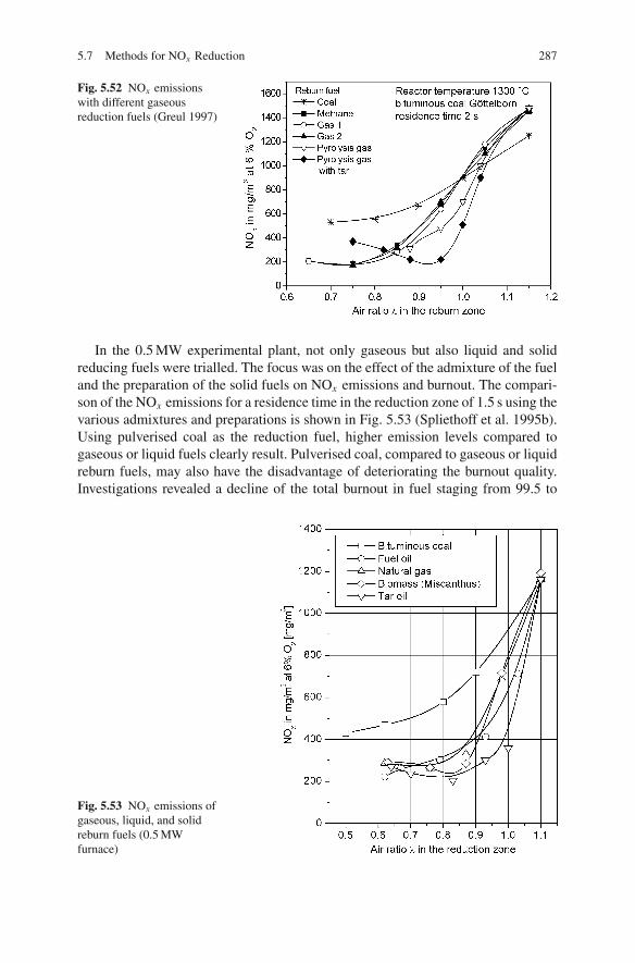
5.7 Methods for NOx Reduction 287
Fig. 5.52 NOx emissionswith different gaseousreduction fuels (Greul 1997)
In the 0.5 MW experimental plant, not only gaseous but also liquid and solidreducing fuels were trialled. The focus was on the effect of the admixture of the fueland the preparation of the solid fuels on NOx emissions and burnout. The compari-son of the NOx emissions for a residence time in the reduction zone of 1.5 s using thevarious admixtures and preparations is shown in Fig. 5.53 (Spliethoff et al. 1995b).Using pulverised coal as the reduction fuel, higher emission levels compared togaseous or liquid fuels clearly result. Pulverised coal, compared to gaseous or liquidreburn fuels, may also have the disadvantage of deteriorating the burnout quality.Investigations revealed a decline of the total burnout in fuel staging from 99.5 to
Fig. 5.53 NOx emissions ofgaseous, liquid, and solidreburn fuels (0.5 MWfurnace)

288 5 Combustion Systems for Solid Fossil Fuels
around 97%, despite the use of a high-volatile coal and fine milling with 2% residueson the 90 μm screen. By applying gaseous or liquid reburn fuels, a burnout rate withmore than 99%, which is nearly complete for experimental plants, was achieved atall parameter settings. The higher reductive effect of tar oil compared with fueloil or natural gas is put down to the nitrogen compounds in tar oil which, with adelayed release, favour the decomposition of NO (Greul 1997). Comparing to theresults from tests using the electrically heated tube reactor, the lower temperaturesof the semi-industrial furnace cause roughly a 100 mg higher NOx emission level.The emissions achieved with the biogenetic reburn fuels, i.e. straw and Miscanthus,lie in the order of magnitude that could be reached with gaseous (natural gas) orliquid fuels (fuel oil). They are lower, though, than in the case of pulverised coal asa reburn fuel.
Comparison of Air Staging to Fuel Staging
For both techniques, the same total residence time, given by the size of the firingsystem, must be used in order to be able to compare the effects. In the case ofthe NOx emissions shown in Fig. 5.54, the residence time in the primary zone was3 s with air staging; with fuel staging, the residence time in the primary zone wasset at 2 and 1 s in the reduction zone. The residence time in the burnout zone was1.5 s with both staging techniques (Spliethoff et al. 1995b).
For brown coal, it is possible with air staging to achieve lower emissions of wellbelow 200 mg/Nm3, a level not attainable with fuel staging even with brown coalas the primary fuel and natural gas as the reburn fuel. NOx emissions in fuel stagingare lower, however, with medium- and low-volatile coals. Hence it is the case in thisscenario that the lower the content of volatile matter, the more favourable the resultof the fuel staging in terms of NOx emissions. Gaseous, liquid or high-volatile solidfuels such as biomass used as reductive agents in fuel staging feature the highestNOx reduction degrees and have only a small effect on the combustion and thefly ash.
Fig. 5.54 Comparison ofNOx emissions in air stagingand fuel staging
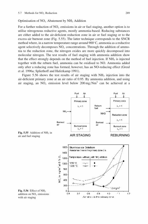
5.7 Methods for NOx Reduction 289
Optimisation of NOx Abatement by NH3 Addition
For a further reduction of NOx emissions in air or fuel staging, another option is toutilise nitrogenous reductive agents, mostly ammonia-based. Reducing substancesare either added to the air-deficient reduction zone in air or fuel staging or to theexcess-air burnout zone (Fig. 5.55). The latter technique corresponds to the SNCRmethod where, in a narrow temperature range around 900◦C, ammonia as a reductiveagent selectively decomposes NOx concentrations. Through the addition of ammo-nia to the reduction zone, the nitrogen oxides are more quickly decomposed intomolecular nitrogen. The test results of fuel staging with ammonia addition showthat the effect strongly depends on the method of fuel injection. If NH3 is injectedtogether with the reburn fuel, ammonia can be oxidised to NO. Ammonia addedonly after a reducing zone has formed, however, has an NO-reducing effect (Greulet al. 1996a; Spliethoff and Haferkamp 1991).
Figure 5.56 shows the test results of air staging with NH3 injection into theair-deficient primary zone at an air ratio of 0.95. By ammonia addition, and usingair staging, an NOx emission level below 200 mg/Nm3 can be achieved at a
Fig. 5.55 Addition of NH3 inair and fuel staging
Fig. 5.56 Effect of NH3
addition on NOx emissionswith air staging

290 5 Combustion Systems for Solid Fossil Fuels
stoichiometric NH3/NOx molecular ratio. The reduction here can be put down tothe accelerated decomposition of NO under reducing conditions. Due to the hightemperatures of 1,300◦C in the burnout zone, a selective catalytic reduction is notpossible.
5.7.1.2 NOx Abatement in Pulverised Coal Combustion – State of the Art
Air Staging in Hard Coal-Fuelled Wall Firing Systems
The development of NOx abatement by air staging at the burner and inside the fur-nace shall be described by the burner development of the Babcock Borsig PowerCompany (today Hitachi Power Europe) (Tigges et al. 1996). Similar designs oflow NOx swirl burners have been developed by other manufacturers, which aredescribed in Wu (2002). The vortex burners used at the beginning of the 1970swere designed to achieve a complete and stable combustion by intensive mixing ofcombustion air and pulverised coal. The burner in Fig. 5.57a shows a coaxial core-air injection, a swirled coaxial secondary air injection and a concentric pulverisedcoal injection. The intensive mixing is achieved by swirling the secondary air andby dust separators. Given that all of the combustion air is already involved in thecombustion process in the near-burner area, high NOx emissions are an inevitableside-effect.
The first low-NOx burners (first generation) injected the secondary air after adelay in order to decrease the NOx emissions (Fig. 5.57b). The delayed admix-ing on the one hand diminished NO formation due to the lower oxygen availablein the primary zone. On the other hand, however, it slowed down the combustionprocess so that the flame extended, the flame temperatures fell and, in many cases,the unburnt combustible material content increased and the flame became unstable.The burner configuration shown in Fig. 5.57b features a division of the secondaryair into two partial flows. The inner swirled secondary air, as well as the unswirledtertiary air, slowly mixes after a delay into the primary combustion zone. This airstaging at the burner was often combined with air staging in the furnace. Comparedto swirl burners, it was possible with these first low-NOx burners and air staging inthe furnace to diminish the NOx emissions by about 50%.
Depending on the coal, air ratio and plant type, NOx emissions could be keptbetween 450 and 600 mg/Nm3. The deterioration of the burnout had to be madeup for by a finer milling degree, which was achieved by using dynamic classifierswithin the mills. The corrosion of the furnace walls in these cases depended on theair ratio of the furnace air staging. It could be limited, for example, by a lateral aircurtain.
The fluid dynamics of later, second-generation low-NOx burners (those usedtoday) are optimised by intensively mixing the pulverised coal with part of the com-bustion air and completely mixing in, after a delay, the combustion air necessary fortotal burnout. The high mixedness of the coal powder is achieved by the combinationof swirl vanes and by toothed rings at the burner outlet so that single streaks wereformed which mixed intensively with the air. This thorough mixing ensures a stable

5.7 Methods for NOx Reduction 291
Fig. 5.57 Technological development of the swirl burner (Source: Hitachi Power Europe; Tiggeset al. 1996; Leisse and Lasthaus 2008)
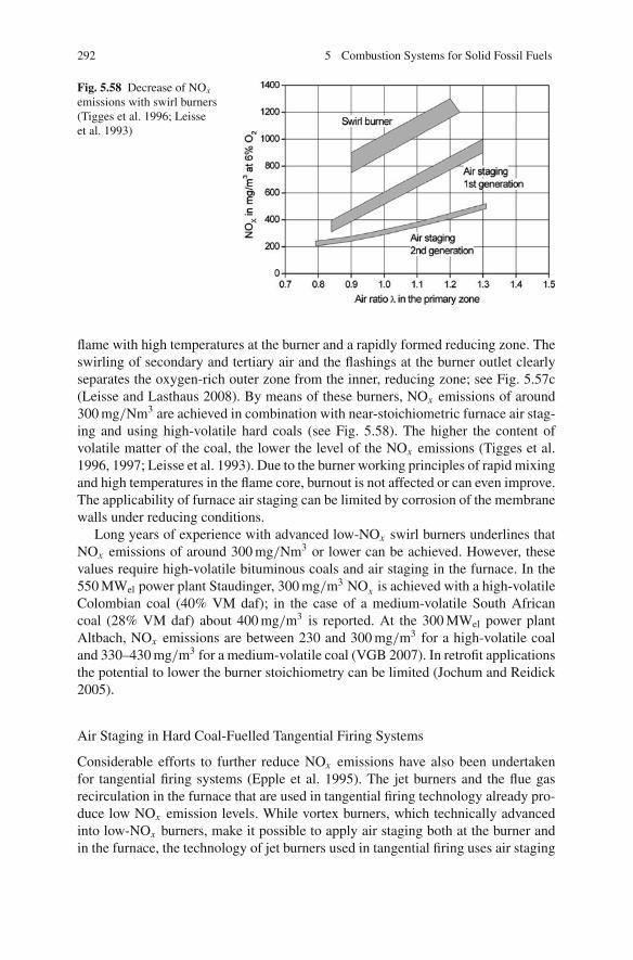
292 5 Combustion Systems for Solid Fossil Fuels
Fig. 5.58 Decrease of NOx
emissions with swirl burners(Tigges et al. 1996; Leisseet al. 1993)
flame with high temperatures at the burner and a rapidly formed reducing zone. Theswirling of secondary and tertiary air and the flashings at the burner outlet clearlyseparates the oxygen-rich outer zone from the inner, reducing zone; see Fig. 5.57c(Leisse and Lasthaus 2008). By means of these burners, NOx emissions of around300 mg/Nm3 are achieved in combination with near-stoichiometric furnace air stag-ing and using high-volatile hard coals (see Fig. 5.58). The higher the content ofvolatile matter of the coal, the lower the level of the NOx emissions (Tigges et al.1996, 1997; Leisse et al. 1993). Due to the burner working principles of rapid mixingand high temperatures in the flame core, burnout is not affected or can even improve.The applicability of furnace air staging can be limited by corrosion of the membranewalls under reducing conditions.
Long years of experience with advanced low-NOx swirl burners underlines thatNOx emissions of around 300 mg/Nm3 or lower can be achieved. However, thesevalues require high-volatile bituminous coals and air staging in the furnace. In the550 MWel power plant Staudinger, 300 mg/m3 NOx is achieved with a high-volatileColombian coal (40% VM daf); in the case of a medium-volatile South Africancoal (28% VM daf) about 400 mg/m3 is reported. At the 300 MWel power plantAltbach, NOx emissions are between 230 and 300 mg/m3 for a high-volatile coaland 330–430 mg/m3 for a medium-volatile coal (VGB 2007). In retrofit applicationsthe potential to lower the burner stoichiometry can be limited (Jochum and Reidick2005).
Air Staging in Hard Coal-Fuelled Tangential Firing Systems
Considerable efforts to further reduce NOx emissions have also been undertakenfor tangential firing systems (Epple et al. 1995). The jet burners and the flue gasrecirculation in the furnace that are used in tangential firing technology already pro-duce low NOx emission levels. While vortex burners, which technically advancedinto low-NOx burners, make it possible to apply air staging both at the burner andin the furnace, the technology of jet burners used in tangential firing uses air staging

5.7 Methods for NOx Reduction 293
Fig. 5.59 Schematicpresentation of air staging(Effenberger 2000)
Burnout air
Tangentially fired system
Coal + AirDeflected Air
only in the furnace. Because elongated flames are one of the combustion advantagesof using jet burners, these burners are not suited to burner air staging. For the pur-pose of prevention of the corrosion of the furnace walls, the air is not only stagedover the furnace height (axially) but also on the horizontal plane, at an angle to theburner axis (radially). It is achieved by deviating a portion of the combustion airflow towards the walls. The principle of overlapping axial and radial air staging isshown in Fig. 5.59.
An example is as follows: by retrofitting a 770 MWel tangential firing systemaccording to the axial and radial air staging principle, NOx emissions were dimin-ished from about 850 mg/Nm3 to values between 250 and 300 mg/Nm3 throughoutthe entire load range. The unburnt combustible material increased slightly, but with a3% loss at ignition within the whole load range, stayed significantly below the valuerequired for utilisation in the concrete industry. Measured O2 and CO concentrationsnear the wall suggest that corrosion of the furnace walls, for the present case of ahigh-volatile hard coal with a high chlorine content up to 0.4%, can be avoided bythe applied measures (Bruggemann et al. 1997).
The principle of axial and radial air staging has been applied at the 2x 900 MWel
hard coal-fired power station WaiGaoQiao/China. Figure 5.60 shows the measuredNOx emissions as a function of the burner stoichiometry. The Chinese hard coal hasa volatile content of 37% (daf) (VGB 2007; Bruggemann 2008).
Air Staging with Brown Coal
After a development and testing phase of several years, combustion engineeringmeasures were retrofitted to pulverised brown-coal furnaces in Germany as the onlytechnology used to comply with the NOx emission standards (Hein and Kallmeyer1989; Kallmeyer and Konig 1987). In new 800–900 MWel brown-coal furnaces,combustion engineering measures are also the only ones taken. Figure 5.61 shows

294 5 Combustion Systems for Solid Fossil Fuels
Fig. 5.60 Effect of burnerstoichiometry on NOx
emissions when air stagingwith tangential firing (VGB2007; Bruggemann 2008)
Fig. 5.61 Brown-coal fuelledsteam generator withlow-NOx firing (Source:Alstom Power)
5.7 Methods for NOx Reduction 295
the furnace of an 800 MW brown coal-fired steam generator equipped with this tech-nology. In this plant, the following measures for NO abatement are applied:
• Reduction of the total excess-air ratio• Air staging with multi-staged burnout air addition• Main burning zone volume reduction by fuel compression• Flue gas recirculation• Fuel splitting (fuel-rich/fuel-lean burners, vapour burner)
These NO-reducing measures make use of the high reactivity and the high-volatile matter content of brown coal. In contrast to hard-coal furnaces, the foulingbehaviour in brown-coal furnaces requires much lower furnace outlet temperaturesthat, according to the fuel, should range between 950 and 1,100◦C. This results inlarge combustion chambers with long residence times, a favourable feature for NOreduction. The residence time in the reducing primary zone is of key importance forNO abatement. To increase the residence time, the fuel is compressed by chargingonly the lower burner levels. The air ratio of the primary zone, between 0.9 and1.0, effects the decomposition of the nitrogen oxides into nitrogenous intermediateproducts or molecular nitrogen.
The burnout air has to be added in stages and the total excess-air rate reducedin order to prevent reformation of nitrogen oxides. Experience has shown thatcompliance with the NOx limit requires a residence time of about 4 s above the mainburners (Kather 1995). If in the retrofit case these residence times are not possible itis necessary to apply additional techniques such as flue gas recirculation or millingvapour burners. Flue gas recirculation improves the mixing in the air-deficient zoneand thus accelerates the NO decomposition reactions. The techniques of vapourseparation and subsequent injection of the vapours above the main combustion zonecorrespond to the principle of fuel staging because the vapours contain about 30%of the fed pulverised brown coal.
Operational experience of air staging has shown that corrosion is not a problemfor power plants fired with Rhenish brown coal. However, eastern German browncoals with a raw coal sulphur content of more than 1.5% have caused severe water –wall corrosion due to high flue gas concentrations of H2S. In order to avoid theproblem, measures were taken to guarantee concentric firing over the cross sectionof the tangentially fired boiler and to avoid flame impingements normal for browncoal firing, which come about from the non-symmetric firing arrangement, one millbeing out of service (VGB 2007; Kahlert et al. 2008).
These NO-reducing measures exploit the well-known burner concepts of browncoal furnaces. The burners have a simple construction, designed as jet burners. Onetypical example is presented in Fig. 5.62a. The combustion air enters the furnacevia the inlets separately from the coal and mixes after a certain delay such that theseburners by themselves stage the air addition. The further developed design shownin Fig. 5.62b aims at preventing streaks of coal dust while mixing intensively withpart of the combustion air so that a rapid ignition at the burner is achieved.
Currently, research is in progress into a brown-coal burner design followingthe construction of hard-coal burners (Fig. 5.62c). The air swirlers in this design,
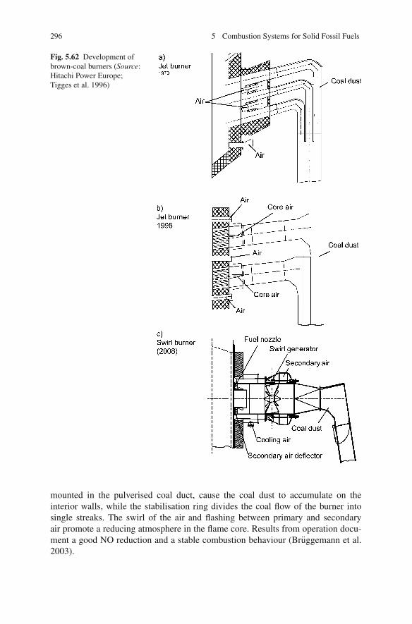
296 5 Combustion Systems for Solid Fossil Fuels
Fig. 5.62 Development ofbrown-coal burners (Source:Hitachi Power Europe;Tigges et al. 1996)
mounted in the pulverised coal duct, cause the coal dust to accumulate on theinterior walls, while the stabilisation ring divides the coal flow of the burner intosingle streaks. The swirl of the air and flashing between primary and secondaryair promote a reducing atmosphere in the flame core. Results from operation docu-ment a good NO reduction and a stable combustion behaviour (Bruggemann et al.2003).
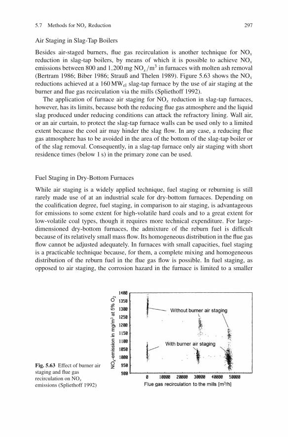
5.7 Methods for NOx Reduction 297
Air Staging in Slag-Tap Boilers
Besides air-staged burners, flue gas recirculation is another technique for NOx
reduction in slag-tap boilers, by means of which it is possible to achieve NOx
emissions between 800 and 1,200 mg NOx/m3 in furnaces with molten ash removal(Bertram 1986; Biber 1986; Strauß and Thelen 1989). Figure 5.63 shows the NOx
reductions achieved at a 160 MWel slag-tap furnace by the use of air staging at theburner and flue gas recirculation via the mills (Spliethoff 1992).
The application of furnace air staging for NOx reduction in slag-tap furnaces,however, has its limits, because both the reducing flue gas atmosphere and the liquidslag produced under reducing conditions can attack the refractory lining. Wall air,or an air curtain, to protect the slag-tap furnace walls can be used only to a limitedextent because the cool air may hinder the slag flow. In any case, a reducing fluegas atmosphere has to be avoided in the area of the bottom of the slag-tap boiler orof the slag removal. Consequently, in a slag-tap furnace only air staging with shortresidence times (below 1 s) in the primary zone can be used.
Fuel Staging in Dry-Bottom Furnaces
While air staging is a widely applied technique, fuel staging or reburning is stillrarely made use of at an industrial scale for dry-bottom furnaces. Depending onthe coalification degree, fuel staging, in comparison to air staging, is advantageousfor emissions to some extent for high-volatile hard coals and to a great extent forlow-volatile coal types, though it requires more technical expenditure. For large-dimensioned dry-bottom furnaces, the admixture of the reburn fuel is difficultbecause of its relatively small mass flow. Its homogeneous distribution in the flue gasflow cannot be adjusted adequately. In furnaces with small capacities, fuel stagingis a practicable technique because, for them, a complete mixing and homogeneousdistribution of the reburn fuel in the flue gas flow is possible. In fuel staging, asopposed to air staging, the corrosion hazard in the furnace is limited to a smaller
Fig. 5.63 Effect of burner airstaging and flue gasrecirculation on NOx
emissions (Spliethoff 1992)

298 5 Combustion Systems for Solid Fossil Fuels
wall area due to the reducing flue gas atmosphere, so the need for an air curtain orwall air is limited.
The in-furnace fuel staging technique was applied in an oil-fuelled furnace forthe first time in 1982 by Mitsubishi, whose term for it was the MACT method. Byadding oil as the reduction fuel above the main combustion zone, it was possible toreduce NOx emissions by 50% (Murakami 1985; Takahashi et al. 1982). The appli-cation of the MACT method in pulverised coal-fuelled furnaces, with pulverisedcoal as the reburn fuel, turned out to be costly. The further developed version, calledthe “Advanced MACT Method”, did without the addition of reduction fuel. Instead,air-deficient conditions were set in the main combustion zone (Araoka et al. 1987).In the case of pulverised coal-fuelled dry-bottom furnaces, the differences betweenair and fuel staging become indistinct. In dry-bottom furnaces with several burnerplanes, the difference between air and fuel staging can hardly be determined, as thefiring has alternating zones of excess air and a deficiency of air. By applying a firingregime which consisted of fuel staging at the burner and air staging in the furnacein a hard-coal-fuelled furnace in Germany, it was possible to achieve NOx emissionlevels around 400 mg/m3 (Benesh et al. 2001).
Investigations into classical fuel staging (or reburning) in the furnace, with areduction zone well separated from the main combustion zone, were carried out indemonstration projects funded by the European Union. The plants involved in theproject were a 600 MWel power plant unit in Scotland with natural gas as the reburnfuel and a 320 MWel power plant unit in Italy with pulverised coal as the reburn fuel(Macphail et al. 1997; Bertacchi et al. 1997).
The NOx emissions could be reduced to ca. 350 mg/Nm3 by fuel staging withnatural gas, with a slight rise of the unburned combustible material (Ghribelli et al.1999). Air staging tests at this plant, using the same air ratios in the reductionzone, produced both higher NOx emissions and higher C-contents in the fly ash.The results of the demonstration tests with pulverised coal as reburn fuel were NOx
emission levels between 300 and 370 mg/Nm3 at a relatively short residence timein the reduction zone of 0.5 s, associated with a rise of the unburned combustibleC-content in the fly ash from 6 to 8%. Air staging in the furnace brought aboutroughly the same level of NOx emissions at this plant, but significantly higher ratesof unburned combustible matter resulted (Bertacchi et al. 1997; Wu 2002).
In the USA, fuel staging was tested using natural gas in several power plants.At a 158 MWel wall-fired furnace and at a 71 MWel tangentially fired furnace, forinstance, the NOx emissions determined ranged around 330 mg/Nm3 at 6% O2,corresponding to a reduction of 60–70% (Folsom et al. 1995).
Fuel Staging in Slag-Tap Furnaces
In contrast to dry-bottom furnaces, where the original principle of fuel staging, i.e.with a clear separation of the main combustion zone from the reburn fuel addi-tion, is followed only in some industrial plants, the situation is different for slag-tapfurnaces.
In the USA a total capacity of more than 26,000 MWel of cyclone furnaces areoperated. Reburning has been judged as an adequate NOx reduction technique for

5.7 Methods for NOx Reduction 299
most of these cyclone furnaces. When reburning is used, the cyclone burners oper-ate within their normal non-corrosive, oxidising conditions, thereby minimisingany adverse effects on combustor and boiler performance. Fuel staging has beendemonstrated or is operated at several, mostly, smaller plants with natural gas andpulverised coal (DoE 1999). The NOx emission concentrations achievable with nat-ural gas as the reduction fuel range between 350 and 450 mg/Nm3 at 6% O2, withreduction rates of about 55–70% from the high baseline emissions of cyclone fur-naces. The necessary fraction of natural gas is between 15 and 20% of the fuel heatinput (Folsom et al. 1995; Booth et al. 1991; Farzan et al. 1995). Using pulverisedcoal, NOx emission concentrations between 420 and 480 mg/Nm3 could be reached(Newell et al. 1995).
The economic viability of reburn technology for cyclone NOx control has beenchallenged by the application of SCR and air staging technologies. The majority ofcyclones are large, base-loaded units, and utilities have chosen to apply overfire airand SCR technologies to meet the more stringent NOx emission levels (Farzan et al.2004).
In Germany, fuel staging was investigated with coke-oven gas and tar oil asreduction fuels at a 160 MWel slag-tap furnace. Figure 5.64 shows a sectional viewof the firing plant. Under test conditions using coke-oven gas, NOx emissions couldbe reduced to 350 mg/Nm3 at an air ratio of λ = 0.9 in the reduction zone (ref-erenced to 5% O2) and after optimisation towards the minimum values of below300 mg/Nm3 (see Fig. 5.65) (Spliethoff 1992, 1991). Whereas with coke-oven gas,the same NOx emissions were detected in the industrial plant and in comparativeinvestigations at an experimental plant, the fuel staging test with tar oil at the160 MWel slag-tap furnace revealed higher NOx emissions, of 500 mg NOx/m3,than tests at a 0.5 MW test furnace where 200 mg/Nm3 were detected. The lowerreducing effect of tar oil has to be put down to the insufficient admixture of the liquidfuel under test conditions at the industrial plant (Spliethoff et al. 1995a; Spliethoff1995).
Fig. 5.64 Slag tap furnaceFenne 3

300 5 Combustion Systems for Solid Fossil Fuels
Fig. 5.65 NOx emissionswith different reburn fuels
5.7.1.3 NOx and N2O Reduction in Fluidised Bed Combustion – Stateof the Art
Under the conditions of the low combustion temperatures of around 850◦C in flu-idised bed furnaces, thermal NO does not form. Therefore the nitrogen in the fuelis the main source for nitrogen oxide emissions. The conversion into NO lies below10%. Contrasting with pulverised fuel combustion, this low conversion percentagehas to be put down to the heterogeneous reduction of nitrogen oxides on the pul-verised coal.
The most effective measure to limit NOx emissions in fluidised bed combustionis to decrease excess air. By the utilisation of air staging it is possible with almostall fuel types to meet the limit of 200 mg NOx/m3 at 6% O2. In this process, thecombustion air is injected through the distributor plate as primary air and on severallevels above the fluidised bed as secondary air. However, the method of air stagingis restricted to circulating and stationary fluidised bed furnaces without in-bed heattransfer surfaces, the tubes of which would be corroded in the reducing flue gasatmosphere (Stultz and Kitto 1992).
In stationary fluidised bed combustion, the NOx emissions change with the tem-perature; in circulating fluidised bed combustion, the temperature influence is slight.
For several years, N2O emissions from fluidised bed furnaces have been the sub-ject of critical observation as well. N2O belongs to the group of greenhouse gasesand is a contributor to the decline of the stratospheric ozone layer (Jacobs and Hein1988). While the N2O emissions in the combustion of fossil fuels in other firingsystems have a level below 10 vpm, the values measured in fluidised bed furnacesreach a maximum of up to 250 ppm (Bonn and Baumann 1991; Bonn et al. 1993).
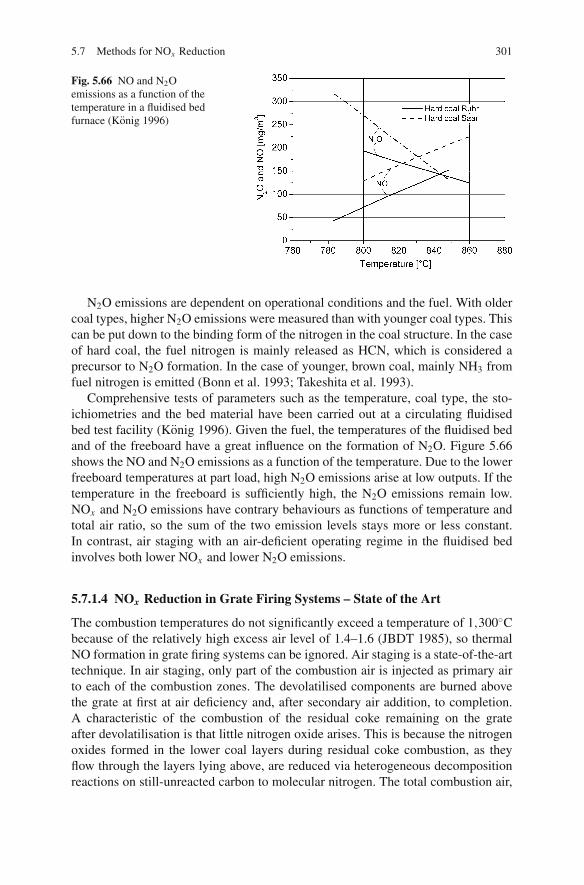
5.7 Methods for NOx Reduction 301
Fig. 5.66 NO and N2Oemissions as a function of thetemperature in a fluidised bedfurnace (Konig 1996)
N2O emissions are dependent on operational conditions and the fuel. With oldercoal types, higher N2O emissions were measured than with younger coal types. Thiscan be put down to the binding form of the nitrogen in the coal structure. In the caseof hard coal, the fuel nitrogen is mainly released as HCN, which is considered aprecursor to N2O formation. In the case of younger, brown coal, mainly NH3 fromfuel nitrogen is emitted (Bonn et al. 1993; Takeshita et al. 1993).
Comprehensive tests of parameters such as the temperature, coal type, the sto-ichiometries and the bed material have been carried out at a circulating fluidisedbed test facility (Konig 1996). Given the fuel, the temperatures of the fluidised bedand of the freeboard have a great influence on the formation of N2O. Figure 5.66shows the NO and N2O emissions as a function of the temperature. Due to the lowerfreeboard temperatures at part load, high N2O emissions arise at low outputs. If thetemperature in the freeboard is sufficiently high, the N2O emissions remain low.NOx and N2O emissions have contrary behaviours as functions of temperature andtotal air ratio, so the sum of the two emission levels stays more or less constant.In contrast, air staging with an air-deficient operating regime in the fluidised bedinvolves both lower NOx and lower N2O emissions.
5.7.1.4 NOx Reduction in Grate Firing Systems – State of the Art
The combustion temperatures do not significantly exceed a temperature of 1,300◦Cbecause of the relatively high excess air level of 1.4–1.6 (JBDT 1985), so thermalNO formation in grate firing systems can be ignored. Air staging is a state-of-the-arttechnique. In air staging, only part of the combustion air is injected as primary airto each of the combustion zones. The devolatilised components are burned abovethe grate at first at air deficiency and, after secondary air addition, to completion.A characteristic of the combustion of the residual coke remaining on the grateafter devolatilisation is that little nitrogen oxide arises. This is because the nitrogenoxides formed in the lower coal layers during residual coke combustion, as theyflow through the layers lying above, are reduced via heterogeneous decompositionreactions on still-unreacted carbon to molecular nitrogen. The total combustion air,
302 5 Combustion Systems for Solid Fossil Fuels
depending on the volatile matter content of the coal, is divided into roughly 70–80%primary air and about 20–30% secondary air.
In the combustion of hard coals, by applying combustion engineering measuressuch as air staging and flue gas recirculation, it is possible to achieve NOx emissionsbelow 450 mg/m3 (Schroth 1985).
5.7.2 NOx Reduction Methods, SNCR and SCR(Secondary Measures)
Downstream DeNOx processes following the firing can be classified either as oxida-tion or as reduction processes. In oxidation processes (which shall not be discussedin detail in this context) NO is oxidised to form NO2 and then separated by a scrub-bing liquid (STEAG 1988).
The downstream DeNOx processes most frequently applied are reduction tech-niques, i.e. the methods of
• selective non-catalytic reduction (SNCR) and• selective catalytic reduction (SCR) (Baumbach 1990; Wu 2002)
In both processes, nitrogen oxides are reduced to molecular nitrogen and watervapour by ammonia. Both methods work selectively, i.e. only a reaction with thenitrogen oxides occurs. In contrast, hydrocarbons as reducing agents in fuel stagingdo not react selectively because they also consume oxygen.
5.7.2.1 Selective Non-catalytic Reduction (SNCR)
The method of selective non-catalytic reduction uses either ammonia or urea asthe reducing agent. The flue gas temperature necessary for optimal reduction liesbetween 900 and 1,050◦C, depending on the flue gas composition and the reducingagent employed. Figure 5.67 shows the influence of the O2 content on the tem-perature range under laboratory conditions. By adding further substances such ashydrogen, the range can be expanded to temperatures below 900◦C (Wolfrum 1985).
In the optimal temperature range, the reaction triggered by NH3 addition is
4 NO + 4 NH3 + O2 → 4 N2 + 6 H2O (5.15)
or, by urea addition,
2 NO + (NH2)2CO + 1/2 O2 → 2 N2 + 2 H2O + CO2 (5.16)
If the temperature is too low, the ammonia slip (the unreacted ammonia in the fluegas) increases; if the temperature is too high, NH3 burns, forming additional nitro-gen oxides. Excess ammonia can react with SO3, forming ammonium salts whichcan lead to fouling in the following heat transfer surfaces and the air preheater.Using urea may carry the risk of developing emissions of N2O.

5.7 Methods for NOx Reduction 303
Fig. 5.67 NO reduction as afunction of temperature andoxygen content (Wolfrum1985)
Prerequisite for an effective reduction, besides maintaining the temperature win-dow, is a good mixing of the employed reducing agent with the flue gas. The mixingmomentum may be given either through the burnout air or by a recirculated flue gasflow. A greater number of single nozzles improve the thoroughness of the mixingand the distribution. In this process, the most homogeneous possible temperatureand concentration distribution in the flue gas flow should be established before injec-tion. Due to the inevitably inhomogeneous distributions of temperatures and flue gasconcentrations across their flue gas profiles, it is difficult to attain in industrial plantsthe reduction degrees achievable in laboratory plants.
An NH3 dosing rate set higher than an amount corresponding to the NH3/NO sto-ichiometry at the injection location causes NH3 slip, which increases with a higherNH3/NO stoichiometry. NOx reduction and NH3 slip have to be weighed up.
Even though it is possible to achieve removal efficiencies of 70% under favourablebasic conditions, values between 30 and 50% are rather typical at stoichiometriesup to a maximum of 2 – so as to limit both the consumption of ammonia and theNH3 slip (Stultz and Kitto 1992; Zellinger and Tauschitz 1989; Staudt et al. 1995;Himes et al. 1995; Hofmann et al. 1989; Gebel et al. 1989).
The SNCR technique is therefore only suitable for combustion plants whererelatively low DeNOx degrees are required. It is mainly applied in furnaces withrelatively low thermal outputs and corresponding small furnace cross sections,because an even flue gas flow and comparatively good admixing can be workedwith more easily.
5.7.2.2 Selective Catalytic Reduction (SCR)
Selective catalytic reduction processes, similar to SNCR processes, utilise ammoniafor reducing NOx ; however, the reduction process runs at significantly lower tem-peratures, using catalysts which reduce the activation energy. In the flue gas flow,the nitrogen oxides NO and NO2 and the reducing agent, ammonia, are selectivelyreduced to nitrogen and water via the following reactions:
304 5 Combustion Systems for Solid Fossil Fuels
4 NO + 4 NH3 + O2 → 4 N2 + 6 H2O (5.17)
or
2 NO2 + 4 NH3 + O2 → 3 N2 + 6 H2O (5.18)
The catalyst mediums are made of porous, ceramic basic materials, which pro-vide a large surface area for adsorption. The material usually used is a SO2-resistingtitanium oxide or silicon oxide. Active metal compounds such as tungstic oxidewith small additions of vanadium pentoxide or, alternatively, molybdenum, copperor iron oxide (MoO, CuO, FeO) are either mixed with or applied on the basic mass(STEAG 1988). The catalysts are made in the form of pellets, honeycomb catalystsor coated plates (VGB 1996).
Depending on the catalyst used, the reduction can for the most part develop evenat temperatures around 100◦C (Hannes et al. 1987). For coal-fired steam generators,though, the temperatures for catalytic NOx reduction have to lie between 320 and400◦C. The upper temperature limit is imposed by the risk of surface sintering,which blocks the access to the pores and the interior surface. The lower temperaturelimit is determined by the temperature at which, with SO3 and NH3, ammonium sul-phate and ammonium hydrogen sulphate form, which may provoke fouling and cor-rosion in the catalyst and the following heat exchanger surfaces (the air preheater).The tendency of the catalyst to oxidise some of the SO2 into SO3 increases theformation of sulphates and in addition raises the acid dew point (Frank et al. 2006).
One of the essential prerequisites for effective reduction, besides a homoge-neously distributed NO concentration in the flue gas, is an even distribution of fluegas flow, fly ash and the reducing agent over the reactor cross section. For this rea-son, flow straighteners are arranged in front of the catalysts in the flue gas canal.Ammonia is added through a great number of nozzles with adjustable single flowsto achieve a uniform distribution. Unequal distributions are problematic becausethey can provoke sub- and over-stoichiometric zones which increase the NOx emis-sions or NH3 slip. Dust deposits may clog some of the catalyst sections so that theflow velocity increases in other sections. The consequences of this are higher NOx
emissions and an increased ammonia slip. The higher flow velocity also involvesthe risk of erosion.
The SCR process uses almost the entire amount of ammonia for the reduction ofNO, so high removal degrees are achieved even at a stoichiometric ratio below 1.The NH3 consumption in the SCR process is therefore significantly lower than inthe SNCR process, but yields higher removal degrees.
The design of the catalysts of an SCR process is usually based on an expectedremoval efficiency after about 2–3 years. In particular, it takes into account thediminishing activity of the catalyst. In various high-dust installations with the cat-alyst arranged in the flue gas flow before the dust removal unit, losses of activityof the catalyst of about 10–20% within a period of 20,000 h have been determined(Maier 1992; Farwick and Rummenhohl 1993). The aging of the catalysts is putdown to various flue gas components, such as heavy metals, alkalis and SO2 – in

5.7 Methods for NOx Reduction 305
Fig. 5.68 Correlationbetween NH3 slip, catalystvolume and NOx reductiondegree (Becker 1986)
technical terms, a poisoning of the catalyst. If the activity falls short of the designedlevel, it is necessary to replace some catalyst volume to limit the NOx emissions andthe ammonia slip.
In the design process, the necessary catalyst volume is calculated from therequired removal efficiency and the level of slip to be maintained (Fig. 5.68). Wherehigher input concentrations require greater removal efficiencies, it is necessary toprovide for a greater catalyst volume, while keeping the ammonia slip at the samelevel (Becker 1986, 1987).
Due to the inevitable occurrence of inhomogeneous distributions of the reducingagent or flue gas concentrations, the resulting removal efficiency of the SCR pro-cess reaches a maximum around 90%. These inhomogeneous distributions result inthe forming of zones of ammonia excess or deficiency. In excess zones, ammoniareduces the nitrogen oxides totally. If the NOx concentration reaches zero in someplaces, the inevitable consequence is a remainder of NH3. This surplus of ammonia(NH3 slip) can only be diminished to a limited extent, even by additional catalystvolume.
The inhomogeneous distributions are, with lower emission control standards, allthe more problematic because they make the excess zones, where NOx forms, moreprobable. Low NOx emission control standards, using SCR technology, thus lead tobarely controllable problems. Lower NOx emissions are limited not by the catalystactivity but because of the mixing problems (Frank et al. 2006).
Investigations show that about 70% of the excess ammonia is taken up by thefly ash, possibly resulting in odour nuisances in cases of high ammonia slip. Ingeneral, the slip is limited to values of less than 2 ppm so as not to risk the usabilityof the ash. The catalysts are usually placed after the economiser and before theair heater in what is called a high-dust configuration, i.e. in the dust-laden flue gasflow (see Sect. 4.4.2.3). The thermodynamic design has to ensure that the flue gastemperatures in the catalyst area do not rise higher than 400◦C and do not fall below320◦C. The flue gas temperature after the economiser, by installing a fireside or

306 5 Combustion Systems for Solid Fossil Fuels
waterside economiser bypass, has to be limited to temperatures above 320◦C toprevent catalyst fouling (Reuter and Honig 1988).
Besides this high-dust configuration, in Germany a low-dust configuration withthe placement of the catalyst after the dust collection and flue gas desulphurisationunits is used in some plants as well. This arrangement is chosen in cases where,for reasons of space, a high-dust configuration is not possible, or where the flue gascompositions give reason to expect a short lifetime of the catalysts. If a high-dustconfiguration was applied, for instance, in slag-tap furnaces with fly ash recircula-tion, an enrichment with arsenic compounds would have the consequence of poi-soning the catalyst, entailing a corresponding loss of activity. For this reason, thelow-dust configuration is often applied in these furnace types.
The charging of the catalyst with desulphurised and fly-ash-free flue gas prolongsthe lifetime of the catalyst in comparison to the high-dust configuration. Lower dustconcentrations allow the use of catalysts with smaller pore diameters and largeractive surfaces, so more compact designs are possible. The lower SO2 concentrationof the flue gas makes it possible to use a catalyst with higher activity.
The flue gas temperatures after the FGD unit are only around 50◦C at first, so itis necessary to reheat the flue gases to a temperature of about 320◦C for catalyticNOx removal. The reheating process mostly consists of a combination of regener-ative heating and heating by natural gas or steam. This direct reheating is neededto compensate for the heat losses (about 30◦C) of the gas heater and the DeNOx
unit. These heat losses ultimately diminish the efficiency of the boiler and the totalefficiency (Maier et al. 1992).
5.7.3 Dissemination and Costs
Combustion engineering measures to reduce NOx formation are state of the art inmodern pulverised coal power stations. Low NOx burners are currently in operationin more than 800 pulverised coal-fired units of a total capacity of above 295 GWel
as a stand-alone measure or combined with over-fire air (OFA) (Nalbandian 2004).SCR technology has been used commercially in Japan since 1980 and in Ger-
many since 1986 on power stations burning mainly low-sulphur coal and in somecases medium-sulphur coal. The technology has been (since the mid-1990s) andcontinues to be retrofitted in many existing coal-fired power plants in the USA.SCRs are currently in operation or under construction in more than 315 pul-verised coal-fired units of a total capacity of above 130 GWel (Nalbandian 2004). InGermany, power stations with a capacity of 35 GWel are equipped with SCR (Franket al. 2006).
The first commercial SNCR application in a coal-fired power plant was in 1980.SNCR systems are currently in operation or under construction in around 50 units ofa total capacity of approximately 10 GWel. As it is difficult to achieve good mixingin large boilers, almost all the commercial applications to date have been limited totypically less than 200 MWel (Nalbandian 2004).

5.8 SO2-Reduction Methods 307
Table 5.8 Capital and production costs of NOx reduction measures (data from Wu 2002; Soud andFukasawa 1996)
Production costsPrimary measures NOx reduction [%] Capital costs [ea/kWe] [ecent/kWhe]
Low NOx burner 30–50 10–15 0.035–0.045Furnace air staging 50 5–20 0.03–0.05Low NOx burner and
furnace air staging60 15–30 0.03–0.06
Coal reburning 50 15–45c 0.05–0.15Gas reburning 50 10–15b 0.11–0.2d
Flue gas cleaningSNCR 50 5–30 0.05–0.13SCR 70–90 50–80 0.15–0.25a1e = $1 (2002), bno pipeline included, cupper value includes pulveriser; ddepending ondifference between gas and coal price.
The capital costs of a high-dust SCR unit after a pulverised hard coal-fired boilerrange between 50 and 80 e/kW of electrical power. In relation to the total capitalcosts of a large pulverised coal-fired power plant, the result is a cost fraction of about5–8%. The additional power production costs range around 0.2–0.3 e cents/kWh attotal prime costs of about 4–6 cents/kWh. The costs for a low-dust configuration areabout twice as high as a high-dust configuration.
The costs for SNCR, from 5 to 30 e/kW, are significantly lower than the expen-ditures for SCR. The large spread is a result of the expenditure necessary for theadjustment of local temperature and concentration conditions at differing capaci-ties and the associated control. High DeNOx degrees, in particular, result in greaterexpenditures (Himes et al. 1995).
Table 5.8 draws a comparison between reduction potential and necessary capitalcosts of different NOx reduction measures.
5.8 SO2-Reduction Methods
Desulphurisation methods may be categorised into
– methods to reduce the sulphur content of the fuel and– methods to desulphurise the flue gas.
The flue gas desulphurisation methods distinguish between
– additive injection in the furnace or in the flue gas ducts (dry) and– downstream desulphurisation processes (semi-dry, wet).

308 5 Combustion Systems for Solid Fossil Fuels
5.8.1 Methods to Reduce the Sulphur Content of the Fuel
The reduction methods involving the ash and sulphur contents in the coal usuallyemploy physical separation processes which make use either of the density differ-ence between the combustible and the mineral substances or of differing surfacequalities. The methods used in coal preparation are wet processes. In Germany,about 95% of mined coal is treated in preparation processes. The costs of thesephysical preparation processes range between 1.5 and 2.5 e/tonne of fuel. Dur-ing this preparation, however, only part of the pyritic sulphur is removed (Vernonand Jones 1993). The effectiveness of the separation process depends on the coalproperties but is never sufficient to comply with emission control standards. It is,for instance, possible with some coal types to diminish the sulphur content from 1.3to 1% (Chugtai and Michelfelder 1983).
A more complete removal of sulphur, including the organic fuel sulphur, is pos-sible by chemical and biological processes, but they are relatively expensive and donot yet meet the state of the art (Vernon and Jones 1993).
5.8.2 Methods of Fuel Gas Desulphurisation
Sulphur oxides in flue gases can be captured by different alkali and alkaline earthcompounds and, principally, by all kinds of metal oxides as well, hence there beingnumerous variants of SO2 reduction in flue gases (STEAG 1988).
Desulphurisation methods today mainly employ processes based on limestone(CaCO3) or lime (quicklime (CaO) or hydrated lime (Ca(OH)2)). The processeswork in dry, semi-dry or wet conditions. In dry conditions, the desulphurisationmedium and the products of desulphurisation are solids, in wet conditions both areliquid. In a semi-dry process, the medium is added in a liquid state and the productsare solids. In contrast to alkali compounds, which are more active in SO2 capture,lime has the advantages of being more cost-effective, available in great quantities innature, and of forming a by-product (gypsum) which is reusable.
The application of alkali compounds or metal compounds is a potentially viableoption for small plants where the capital costs would be relatively small comparedto the operating expenses.
Figure 5.69 shows the different possible applications for additives in desulphuri-sation processes (Vernon 1990). For dry injection, possible devices are the burnersor special injection nozzles above the furnace, upstream of the economiser or theESP. In downstream FGD units, the capturing agent is added in a suspension withwater.
5.8.2.1 Additive Injection in the Furnace
With respect to process equipment, the injection into the flue gas flow of powderycalcium-based additives is a relatively simple variant of an SO2 reduction process.Only installations for the preparation, storage, dosage and transport of the additive

5.8 SO2-Reduction Methods 309
Fig. 5.69 Locations ofadditive injections forflue-gas desulphurisation
are needed. The dry additive is injected into the furnace or into the flue gas ducts,then the products of desulphurisation and the unreacted additive have to be removedin the dust collector together with the fly ash. The injected additive increases theload on the dust collector plant. Another drawback may be the limited usabilityof the resulting mixture of fly ash, calcium sulphate and limestone. In the case ofdry additive injection into the flue gas flow, Ca/S ratios which are higher than thestoichiometric additive ratio are necessary.
Calcium-based additives are the source from which calcium oxide, CaO (quick-lime), forms in a first step (calcination) under heat. If Ca(OH)2 (calcium hydrateor hydrated lime) or CaCO3 (limestone) are used as additives, the dehydration ordecarbonisation process evolves according to the following reactions:
Ca(OH)2 → CaO + H2O (5.19)
CaCO3 → CaO + CO2 (5.20)
The reactive CaO then reacts with the sulphur oxides, forming sulphates. Cal-cium oxide, though, also bonds with other flue gas components:
CaO + SO2 + 1/2O2 → CaSO4 (5.21)
CaO + SO3 → CaSO4 (5.22)
CaO + 2 HCl → CaCl2 + H2O (5.23)
CaO + 2 HF → CaF2 + H2O (5.24)
The reactions of lime are temperature dependent. The optimum temperaturerange of a dry reduction process via lime is at gas temperatures of around 850◦C.At lower temperatures, the calcination reaction does not run satisfactorily. At toohigh a temperature (above 1,100◦C), the lime sinters and so becomes inactive. Inaddition, calcium sulphate that has formed may decompose. Figure 5.70 depicts thedependence of the desulphurisation process on the flue gas temperature for a rangeof powdery additives (Wickert 1963).
Further parameters having an influence on the desulphurisation degree are theparticle size and the type of additive. Since the reaction occurs on the surface, afiner grinding of limestone improves the desulphurisation extent. Sulphate alreadyformed on the limestone surface may block further reaction. Hydrated lime

310 5 Combustion Systems for Solid Fossil Fuels
Fig. 5.70 Effect oftemperature on thedesulphurisation process for arange of additives (Wickert1963)
(Ca(OH)2), which triggers the calcination reaction even at lower temperatures, ismore reactive than calcium carbonate (limestone (CaCO3)) (Vernon 1990). Becausethe equilibrium of the capture reaction cannot be achieved in industrial combustionsystems, it is necessary to take the residence time into account as an additionalparameter (Hein and Schiffers 1979).
High temperatures and a low loading of ground lime in the flue gas put a limit toSO2 reduction in the furnace of boilers fired by pulverised hard coal. From the pro-cess engineering point of view, the injection of the additive in combination with thecoal or via the different combustion air flows is possible. In tests injecting Ca(OH)2
into the external recirculation zone at a Ca/S ratio of 2, it was possible to achievedesulphurisation degrees between 50 and 60%. Higher rates of sulphur removal wereonly possible with very high amounts of additive. The injection via nozzles abovethe furnace yielded better results, but this technique, due to the mixing problem,appears suitable only for small steam generators (Chugtai and Michelfelder 1983).
The significantly lower combustion temperatures of pulverised brown coalfiring – the maximum temperatures range between 1,100 and 1,150◦C – providemuch more favourable conditions for in situ desulphurisation. Additionally, browncoal ash already contains a certain fraction of alkaline earths, so desulphurisationpartially occurs even without an additive. Figure 5.71 shows the measured desul-phurisation rates in brown coal furnaces as a function of the Ca/S ratio (Hein andSchiffers 1979). The cause for the higher capture of Ca(OH)2 or CaCO3 is its spon-taneous decomposition upon being fed to the furnace, which yields a large reactivesurface of the CaO (Fig. 5.72).
In contrast to pulverised fuel firing, desulphurisation in fluidised bed furnacescan be carried out in the optimum temperature range of desulphurisation. A highconcentration of ground lime, a good mixing of the additive in the fluidised bedand, in particular, a long contact time between flue gas and additive have a positiveeffect on the desulphurisation process. In bubbling fluidised bed furnaces, removalefficiency rates of more than 80% have been achieved at Ca/S molecular ratios of2–4. In circulating fluidised bed furnaces, higher values of about 90% were achievedat Ca/S ratios of 1.5–2. Apart from limestone, dolomite (CaCO3 × MgCO3) is also
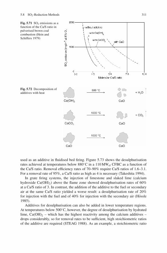
5.8 SO2-Reduction Methods 311
Fig. 5.71 SO2 emissions as afunction of the Ca/S ratio inpulverised brown coalcombustion (Hein andSchiffers 1979)
Fig. 5.72 Decomposition ofadditives with heat
used as an additive in fluidised bed firing. Figure 5.73 shows the desulphurisationrates achieved at temperatures below 880◦C in a 110 MWel CFBC as a function ofthe Ca/S ratio. Removal efficiency rates of 70–90% require Ca/S ratios of 1.6–3.1.For a removal rate of 95%, a Ca/S ratio as high as 4 is necessary (Takeshita 1994).
In grate firing systems, the injection of limestone and slaked lime (calciumhydroxide Ca(OH)2) above the flame zone showed desulphurisation rates of 60%at a Ca/S ratio of 3. In contrast, the addition of the additive to the fuel or secondaryair at the same Ca/S ratio yielded a worse result: a desulphurisation rate of 20%for injection with the fuel and of 40% for injection with the secondary air (Hossle1985).
Additives for desulphurisation can also be added in lower temperature regions.At temperatures below 500◦C, however, the degree of desulphurisation by hydratedlime, Ca(OH)2 – which has the highest reactivity among the calcium additives –drops considerably, so for removal rates to be sufficient, high stoichiometric ratiosof the additive are required (STEAG 1988). As an example, a stoichiometric ratio

312 5 Combustion Systems for Solid Fossil Fuels
Fig. 5.73 Desulphurisationrate as a function of the Ca/Sratio for a circulatingfluidised bed (Takeshita1994)
of 8 is necessary in order to achieve removal rates of 50% at 150◦C. So to effi-ciently use Ca(OH)2 in the temperature range after the air heater or before the ESP(130–180◦C), it is necessary to humidify and/or cool down the flue gas to near dewpoint. This way, removal rates of 60–80% can be achieved. With this humidificationand cooling down of the flue gas, this method becomes a wet process. Besides cal-cium, which has found widespread use as an additive for flue gas desulphurisation,sodium-based additives are also suitable (Vernon 1990; Nolan 1994).
5.8.2.2 Downstream Desulphurisation (Semi-dry, Wet)
Semi-dry SO2 removal processes, as well as wet processes, are techniques whichachieve a better utilisation of the reacting agents than dry processes. This, above all,is owing to the kinetics, which proceed faster in the liquid. While in wet processes,sulphur dioxide is removed by absorption in the aqueous phase only, semi-dry pro-cesses are followed by an additional dry SO2 capture which works in the same wayas in dry processes (STEAG 1988).
Wet Flue Gas Desulphurisation
Wet desulphurisation processes applied at an industrial scale predominantly uselime or limestone. The different processes are usually distinguished by the differ-ent scrubber types, the absorbents and the final products. These processes featurehigh removal rates of between 95 and 99% at an almost stoichiometric quantity ofabsorbents (Takeshita 1994).
The process, in very simplified terms, has the following reactions following theapplication of lime (Rosenberg and Oxley 1993):
Ca(OH)2 + SO2 + H2O → CaSO3 · 1/2 H2O + 3/2 H2O (5.25)
and with limestone:
CaCO3 + SO2 + 1/2 H2O → CaSO3 · 1/2 H2O + CO2 (5.26)

5.8 SO2-Reduction Methods 313
and, subsequently, using both additives:
CaSO3 · 1/2 H2O + 1/2 O2 + 3/2 H2O → CaSO4 · 2 H2O (5.27)
CaSO3, as a product formed through desulphurisation, is usually oxidised to formCaSO4 in order to create a usable product. This can be done either separately indifferent reactors, as described by the equations above, or, most commonly, in onereactor, the absorber.
Most desulphurisation plants in Germany and the USA use lime (CaO, Ca(OH)2)or limestone (CaCO3). Today, limestone, being a more cost-effective material, ispredominant (STEAG 1988).
Figure 5.74 shows a process schematic using limestone as the additive andwhich produces gypsum as a final product. Figure 5.75 describes the reactions ina limestone-based process. After the sulphur-containing flue gases have passed thedust removal stage, they are cooled and conducted through the absorption tower.The absorption tower consists of a reaction space, a suspension sump or a washingliquid tank and a demister. The limestone suspension for SO2 removal is fed tothe suspension sump and mixed with the washing liquid. Pumps then transfer thewashing liquid through a pipe to the spraying levels which are arranged in the upperpart of the absorber vessel. In the counterflow of falling droplets of washing liquidand rising flue gas flow, sulphur dioxide reacts with limestone and the intermediateproducts are formed. SO2 is absorbed in the washing liquid and converted into cal-cium dihydrate by way of complex reactions. Besides SO2, SO3, Cl and F are alsoremoved. In the sump of the absorption tower, the limestone dissolves, forming gyp-sum crystallites. The oxygen necessary for oxygenation comes partly from the fluegases; additionally, air is injected into the suspension. Washing liquid is extracted
Washingcircuit
Gypsum
Waste water
Process water
Air
120–130 °C
Flue gas
Gaspreheater
80–90 °C 45–50 °CHydrocyclone Gypsum
dewatering
Washer
Lime slurry
Fig. 5.74 A wet flue gas desulphurisation plant with gypsum production

314 5 Combustion Systems for Solid Fossil Fuels
Fig. 5.75 Reaction mechanisms of flue gas desulphurisation by limestone
from the absorber sump, concentrated in a thickener and subsequent hydrocyclonesand then dewatered by a vacuum band filter or centrifuges.
Semi-dry Spray Dryer Process
The spray dryer process, as a semi-dry desulphurisation method, usually uses a limeslurry, which is made of quicklime (CaO) and water (Kolar 1995). The lime suspen-sion is sprayed and distributed in the reactor which the flue gases to be cleaned areconducted through. This way, the gas components – SO2, mainly, and HCl and HF –are provided with, in one passage, a large surface for chemisorption. The captureprocess of sulphur dioxide runs according to the following elemental formula:
Ca(OH)2 + SO2 → CaSO3 + H2O (5.28)
The reactor residence time of the gas necessary for absorption and drying maybe more than 10 s in this process, which requires correspondingly large vesseldimensions. The temperatures of the flue gases entering the absorption tower rangebetween 130 and 300◦C and are cooled by the evaporation of the lime slurry. Caremust be taken so that the temperature does not fall below the dew point. The drydesulphurisation products are removed in an ESP or a bag filter. Despite the longresidence times of the lime slurry and the flue gas in the absorption tower, thereacting agents are not converted completely. Unreacted Ca(OH)2 mixes with otherresidual and desulphurisation products. Compared to wet processes, an excess ofthe added Ca is necessary. At a removal efficiency of 80%, the Ca/S ratio is about2 (Adrian et al. 1986). In contrast to wet desulphurisation techniques, spray dryerprocesses do not produce waste water. A drawback is the lesser usability of theproduct (Vernon and Jones 1993).
5.9 Particulate Control Methods 315
The application of spray dry scrubbers is generally limited to flue gases fromplants of up to 200 MWel capacity. Larger plants require the use of several modulesto deal with the total flue gas flow. This is why in general the technology is used insmall- to medium-sized coal-fired power plants. Spray dry scrubbers in commercialuse have achieved removal efficiencies in excess of 90% (Nalbandian 2004).
5.8.3 Dissemination and Costs
The application of FGD technology for SO2 control in pulverised coal power plantsbegan in the early 1970s in Japan and the USA. Western Europe followed in the1980s. FGD has now become more widespread and is also installed in central andeastern Europe and in Asia. Today, there are over 780 FGD systems installed world-wide, with a total capacity of over 260 GWel. Wet desulphurisation processes aredominant, with a market share of 88%. The semi-dry processes have a share ofabout 8%. The rest comprises dry processes and other methods (Nalbandian 2004).
The dry additive processes, though requiring only low capital costs, achieve onlymoderate desulphurisation efficiency rates of up to 60% and are therefore scarcelyapplied. Wet scrubbers, compared to spray dryers, have about 30% higher capitalcosts but feature the advantages of a low additive demand and a usable product.
In the USA, the capital cost of wet FGD systems in the early 1990s reachedapproximately $200/kW. By the late 1990s, capital costs were reduced to $125/kW,which corresponds to the current capital costs quoted in the USA. The cost reduc-tions can be explained by design improvements in using high-velocity absorberswith increased sorbent utilisation. High tower velocities result in a smaller towercross-sectional area, and hence provide material cost savings. The wet absorbertypically represents 40–50% of the cost of an installed FGD system.
The capital costs for a wet desulphurisation plant range between 80 and120e/kWel (2005). The additional costs from flue gas desulphurisation are about0.4–0.6e cents/kWh at power generation costs of 3–6 cents (Nalbandian 2006).
5.9 Particulate Control Methods
Combustion of solids that contain mineral matter produces ash in the form of par-ticulates in the flue gas. The formation of ash has been discussed in Sect. 5.2.3.for the different firing systems. Particulate concentrations are usually regulated bylaw for environmental and health reasons; to meet the required emission limits, thefollowing devices are used for their removal from flue gases:
– Mechanical separators– Electrostatic precipitators– Fabric filters

316 5 Combustion Systems for Solid Fossil Fuels
The required collection efficiency is determined by the particulate emissions ofthe firing system and the required emission limit.
5.9.1 Mechanical Separators (Inertia Separators)
Inertia separators are thus called because they remove particulates by making useof the inertia of the particles. Gas and particulates are separated by deflecting thedust-laden gas flow.
Cyclone separators use the centrifugal force of the dust particles. A cyclone con-sists of a cylindrical vessel with a tangential gas inlet and a gas outlet which ismounted in a central position as part of the vessel cover (Fig. 5.76). A downwardvortex forms in the cyclone and particles are collected near the wall and fall to thebottom.
Mechanical separators are in widespread use in industrial plants and are mostfrequently employed where emission limits are less strict. Their features are a simpleconstruction, a small size, robustness and low operating and construction costs.
The removal rate of simple cyclones is limited to about 90%. As the removalefficiency is dependent on the centrifugal force, the removal rate can be increasedeither by raising the speed or by reducing the cyclone diameter. Speed increasesare ruled out because of the resulting increase in pressure loss. In multicycloneinstallations, a reduction in diameter is achieved by dividing the gas flow into severalsmall cyclones connected in parallel. Most of the time, though, an increase of theremoval efficiency, for instance, by two-stage cyclones or by multicyclones also
Fig. 5.76 Schematic of acyclone separator

5.9 Particulate Control Methods 317
involves an increase in the loss of pressure. In general, with decreasing particle size,the removal efficiency decreases (Vernon 1990).
5.9.2 Electrostatic Precipitators
In coal-fuelled power plants, particulates are most frequently removed by electro-static precipitators (ESPs), which reliably meet the strict emission limits of today.ESPs feature high removal rates and low pressure losses and are suitable for largeflue gas flows. Their removal rate may be more than 99.8% (Zhu 2003; Soud 1995;Vernon 1990).
In electrostatic filtration the dust particles are electrically charged by and thenremoved in an electric field (Loffler 1988). The functioning of an ESP is shown inFig. 5.77. The charging of the dust particles is performed mostly by corona dis-charge. The electric field is created by applying a high DC voltage of 30–80 kVbetween the discharge electrodes and the earthed collecting electrodes. The gasis ionised in the vicinity of the discharge electrodes and split into positive gasions, which remain in the vicinity of the discharge electrode wire, and electrons.The electrons migrate to the collecting electrodes, and on their way are collectedby particulates. These dust particles, as charge carriers in this electric field, thenmigrate towards the collecting electrodes, where they accumulate. Through mechan-ical rappers the dust is removed, collecting in the bottom hopper, from where it getsdischarged.
Fig. 5.77 Principles of electrostatic precipitation (Soud 1995)

318 5 Combustion Systems for Solid Fossil Fuels
In the dust collector, the gas to be cleaned is conducted through channels, theedges of which are collecting electrode plates. The width of the channels is usuallybetween 200 and 600 mm (Loffler 1988); in large hard coal-fuelled boilers the widthis 300 mm. Discharge electrode wires are suspended parallel to the direction of flowin the centre of each channel, at distances of 300 mm apart. The number of collectionchannels amount to the width of the ESP; the height of the electrode plates determinethe effective ESP height and the length of the channels the effective length.
Because the removal efficiency of the ESP increases with higher voltage, thevoltage is set high. This is done by a voltage regulator. The voltage regulator, cyclingthrough each field, checks the sparkover limit for each and resets the voltage some-what below the sparkover voltage, at which the electrical field breaks down.
The electrical resistance of the ash particles has a great impact on the removalefficiency of the electrostatic precipitator. It has been shown that the specific dustresistance range favourable for the removal process extends from 104 to 1011 Ω
(Loffler 1988). Particles with low resistance and high conductivity, such as carbon,give off their charge before impinging and contacting the collecting electrode. Theydo not adhere to the collecting electrode but instead migrate with the gas flow some-what further downstream until they get recharged and travel once more towards thecollecting electrode. With too high a resistance, the dust charge carriers are removedonly very slowly and an electric field forms over the dust layer covering the collect-ing electrode. This counteracts the field between the discharge electrode and thecollecting electrode, reducing its removal efficiency. The electric field developingover the dust layer may grow so large that gas discharges may occur in the pores ofthe dust layer and cause an electrical breakdown, which results in a re-entrainmentof the particles in the flue gas (Baumbach 1990).
The resistance of the dust depends on the dust composition, the gas compo-sition and the temperature. The electrical resistance of a particle is a product ofthe resistance of the surrounding gas atmosphere and the surface resistance of theparticle. The gas composition has an influence on the resistance of the gas atmo-sphere around the particle, and the dust composition and potentially condensedcomponents on it have an impact on the resistance on the particle surface (Klingsporand Vernon 1988). Higher water vapour contents and concentrations of SO3 result ina lower resistance and hence in better removal efficiencies. Coals with lower sulphurcontents thus have inherent difficulties in the removal process (see Fig. 5.78). Thisis put down to the lower sulphuric acid contents on the surface of the dust particle(Klingspor and Vernon 1988). To increase the removal efficiency of problematicdusts, sulphur trioxide, SO3, is added to the flue gas in some facilities.
The electrical resistance of the fly ash depends on the composition. Alkalis in theash bring about a better conductivity; alkaline earths, a worse one. Condensed sul-phur components and humidity also increase the conductivity, as described above.Also influential are the contents of silicon, aluminium and iron. The sizing of theESP is strongly influenced by the resistance of the dust. A high resistance, as foundwith low-sulphur coals, requires bigger and hence more expensive ESPs (Zhu 2003;Wu 2000; Soud 1995; Stultz and Kitto 1992; Klingspor and Vernon 1988).
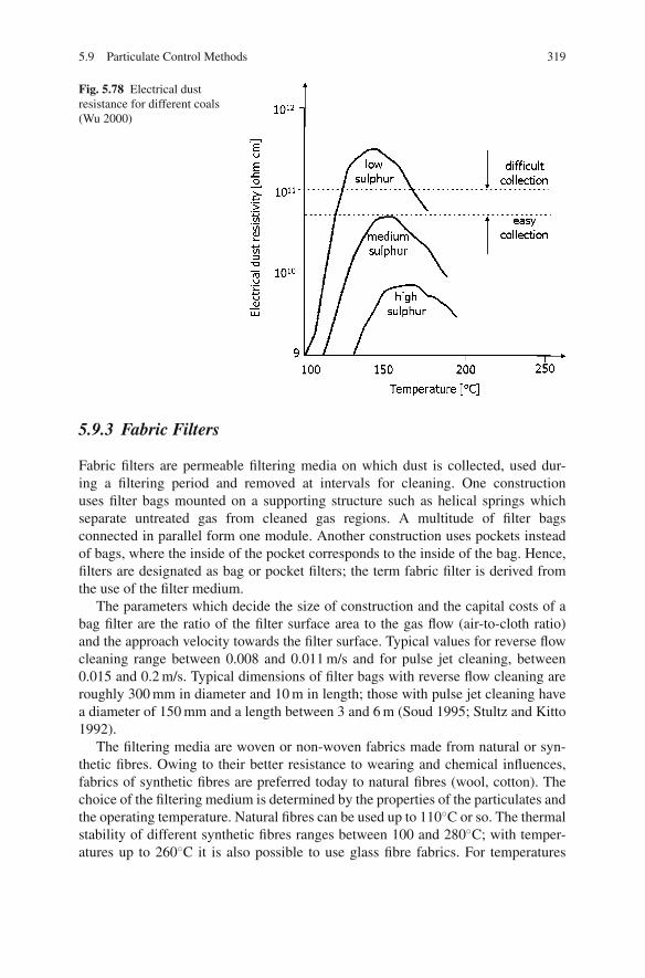
5.9 Particulate Control Methods 319
Fig. 5.78 Electrical dustresistance for different coals(Wu 2000)
5.9.3 Fabric Filters
Fabric filters are permeable filtering media on which dust is collected, used dur-ing a filtering period and removed at intervals for cleaning. One constructionuses filter bags mounted on a supporting structure such as helical springs whichseparate untreated gas from cleaned gas regions. A multitude of filter bagsconnected in parallel form one module. Another construction uses pockets insteadof bags, where the inside of the pocket corresponds to the inside of the bag. Hence,filters are designated as bag or pocket filters; the term fabric filter is derived fromthe use of the filter medium.
The parameters which decide the size of construction and the capital costs of abag filter are the ratio of the filter surface area to the gas flow (air-to-cloth ratio)and the approach velocity towards the filter surface. Typical values for reverse flowcleaning range between 0.008 and 0.011 m/s and for pulse jet cleaning, between0.015 and 0.2 m/s. Typical dimensions of filter bags with reverse flow cleaning areroughly 300 mm in diameter and 10 m in length; those with pulse jet cleaning havea diameter of 150 mm and a length between 3 and 6 m (Soud 1995; Stultz and Kitto1992).
The filtering media are woven or non-woven fabrics made from natural or syn-thetic fibres. Owing to their better resistance to wearing and chemical influences,fabrics of synthetic fibres are preferred today to natural fibres (wool, cotton). Thechoice of the filtering medium is determined by the properties of the particulates andthe operating temperature. Natural fibres can be used up to 110◦C or so. The thermalstability of different synthetic fibres ranges between 100 and 280◦C; with temper-atures up to 260◦C it is also possible to use glass fibre fabrics. For temperatures
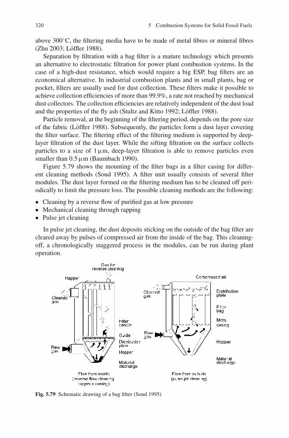
320 5 Combustion Systems for Solid Fossil Fuels
above 300◦C, the filtering media have to be made of metal fibres or mineral fibres(Zhu 2003; Loffler 1988).
Separation by filtration with a bag filter is a mature technology which presentsan alternative to electrostatic filtration for power plant combustion systems. In thecase of a high-dust resistance, which would require a big ESP, bag filters are aneconomical alternative. In industrial combustion plants and in small plants, bag orpocket, filters are usually used for dust collection. These filters make it possible toachieve collection efficiencies of more than 99.9%, a rate not reached by mechanicaldust collectors. The collection efficiencies are relatively independent of the dust loadand the properties of the fly ash (Stultz and Kitto 1992; Loffler 1988).
Particle removal, at the beginning of the filtering period, depends on the pore sizeof the fabric (Loffler 1988). Subsequently, the particles form a dust layer coveringthe filter surface. The filtering effect of the filtering medium is supported by deep-layer filtration of the dust layer. While the sifting filtration on the surface collectsparticles to a size of 1 μm, deep-layer filtration is able to remove particles evensmaller than 0.5 μm (Baumbach 1990).
Figure 5.79 shows the mounting of the filter bags in a filter casing for differ-ent cleaning methods (Soud 1995). A filter unit usually consists of several filtermodules. The dust layer formed on the filtering medium has to be cleaned off peri-odically to limit the pressure loss. The possible cleaning methods are the following:
• Cleaning by a reverse flow of purified gas at low pressure• Mechanical cleaning through rapping• Pulse jet cleaning
In pulse jet cleaning, the dust deposits sticking on the outside of the bag filter arecleared away by pulses of compressed air from the inside of the bag. This cleaning-off, a chronologically staggered process in the modules, can be run during plantoperation.
Fig. 5.79 Schematic drawing of a bag filter (Soud 1995)

5.9 Particulate Control Methods 321
In cleaning by a reverse flow of purified gas, the dust layer is taken off by revers-ing the gas flow and transported to the filter bottom. In rapper cleaning, a purginggas flow from the cleaned to the untreated gas also assists the transport of the filtercake which has been cleaned off by rapping. In these two methods, often appliedin the USA, cleaning-off during the filtering process is not possible, so that the in-and outflow have to be diverted by means of valves. The filter therefore consists ofseveral filter casings or modules, one casing is taken out of service for cleaning at atime (Soud 1995).
The cleaning of filters is performed in power plants in a temperature range typi-cally between 120 and 180◦C. The limit of the lower temperatures in this range is setby the acid dew point, under which dust particles would not stick together. The limitof the upper temperatures is set by the allowable temperatures of the filter medium.
5.9.4 Applications and Costs
The application of the different removal methods depends on the required collectionefficiency, the capital costs and the operational costs (pressure loss, maintenance).Table 5.9 presents the collection efficiency as a function of the particle size, compar-ing the different methods. Mechanical collectors are not efficient at removing smallparticles, so they are not suitable where strict emission control standards apply.
The pressure losses of electrostatic precipitators (ESPs) are the lowest, whereasthe losses of filtration separators and cyclone dust collectors are considerably higher.The different pressure losses influence the power demand of the flue gas fans. Theoperating costs of a bag filter are higher due to the higher pressure loss and thelimited lifetime of the filter bags.
The notable attractions of mechanical dust collectors are both the low capitalcosts and the low operating costs. They are used where the emission control stan-dards can be complied with without any additional particulate treatment, for exam-ple, in small furnaces, which are often only regulated for coarse fly ash particles.The emission control standards laid down for industrial and power plant furnacescan only be complied with by ESPs and fabric filters. The respective costs dependmainly on the size of the plant, the required emission limits and the properties of thedust. Generally, ESPs are more economical for large power plant furnaces and bagfilters for industrial plants. The costs are equal at 250 MWth, with lower emissioncontrol standards and a high-dust resistance favouring the bag filter (Soud 1995;Takeshita 1995; Vernon and Jones 1993). In the power range of large pulverisedcoal-fired power plants, electrostatic precipitators are employed almost exclusively(Stultz and Kitto 1992).
Table 5.9 Collection efficiency as a function of particle size (Soud 1995)
Dust collection
Separation system < 1 μm 1–3 μm 3–10 μm > 10 μm
ESP 96.5 98.25 99.1 99.5Bag filter 99 99.75 > 99.95 > 99.95Multicyclone 11 54 85 95

322 5 Combustion Systems for Solid Fossil Fuels
For large pulverised coal-fired power plants, reports cite capital costs for dustcollection of about 30–50e/kWel (1990), i.e. a fraction of 3–4% of the total capitalcosts. The additional cost of power generation amounts to about 0.25e cents/kWhat a total cost of 3–6e cents/kWh (Takeshita 1995).
5.10 Effect of Slag, Ash and Flue Gas on FurnaceWalls and Convective Heat Transfer Surfaces(Operational Problems)
Ash components in solid fuels affect coal-fired furnaces in numerous ways. Becauseit is incombustible matter content, ash reduces the calorific value. Ash particles inthe hot flue gas flow participate in the transfer of radiant heat. On the one hand, ashis employed as a heat carrier; on the other hand, heat is lost through the dischargeof ash and slag. In the following sections, the interactions of ash, slag and flue gasin the context of their impact on heating surfaces and the respective heat transferwill be discussed. The ash fraction and the ash properties of solid fuels are decisiveparameters for the design of the furnace and are a requirement for estimating ashdeposits, erosion and corrosion. The predicted impacts of the ash on the operation ofsolid fuel-fired furnaces have to be taken into account during the design of the plant.Within this chapter the focus is on ash-related problems in coal-fired furnaces, butthe principles are also valid for biomass and waste combustion, which are discussedin Sect. 6.
Deposits may form both in the furnace and on the convective heat transfer sur-faces. Slagging refers to molten deposits, while fouling refers to dry solid (i.e. notmolten) deposits. Another differentiation which shall be used in the following refersto the location of the deposits. In the area of the furnace and the platen heatingsurfaces where heat is mainly transferred by radiation, the term used is slagging, andin the area of the convective heat transfer surfaces, the term is fouling. Figure 5.80depicts the areas of possible slagging and fouling deposits for a single-pass and atwo-pass boiler (Couch 1994).
Slagging and fouling are often associated with erosion and corrosion. For exam-ple, deposits in many instances cause corrosion damage to or narrowing of the fluegas ducts. Locally narrowed areas raise the flue gas velocity in those areas and thusincrease the eroding action. Erosion may impede the formation of protective metal-lic oxide layers, so that tube walls are attacked by corrosion (Skorupska 1993).Erosive action, though, may also wear away deposits or impede their growth.
Operational disturbances, damage of plant components and resulting failures canbe a direct consequence of slagging and fouling:
Impediment of the Heat Transfer
Deposits insulate the heating surfaces, deteriorating the heat transfer from the fluegas to the steam – water cycle. Slagging in the area of the furnace reduces the heat

5.10 Effect of Slag, Ash and Flue Gas on Furnace Walls 323
(b) Two pass boiler
Convective heat exch. (SH + RH)
Furnace
Burner
Ash
to airpreheater
8
6
45
3
12
9
7
8
7
6
4
3
21
9
5
8
6
45
3
12
7
(a) Single pass boilerEconomiser
Convectiveheat exch.(SH + RH)
Burner
Furnace
to airpreheater
FoulingSlagging
Ash
8
7
6
4
3
21
9
5
Places of Ash Deposition1 ash discharge (clogging) 2 ash hopper (mech.damage) 3 burner slagging4 slag on wall 5 division wall (existent) 6 plate-type superh. (bridging)7 conv. heat exch. (deposits) 8 economiser (deposits) 9 air (pre)heater (fouling)
Fig. 5.80 Fouling and slagging in single-pass and in two-pass boilers (Couch 1994)
absorption of the evaporator and shifts heat to the convective heat transfer surfaces.This displacement of heat has to be counteracted by the design of the firing system;as a last remedy the thermal output has to be reduced. A higher heat absorption of theconvective heat transfer surfaces has to be balanced out by spray attemperation tolimit the maximum steam temperatures. Reheater attemperation in this context hasthe consequence of lower efficiencies. If, in the case of severe slagging in the fur-nace, the furnace outlet temperature is exceeded, the power output has to be reducedin order to avoid molten deposits on the convective heat transfer surfaces. Foulingin the convective section may increase the flue gas heat loss.
Narrowing of the Flue Gas Path
In an extreme case, deposits and bridging of solid material make the flue gas pathin the convective heat transfer section so narrow that the boiler eventually has to beshut down to remove the deposits manually. The sections of the system affected arethe platen heating surfaces at the furnace outlet and the first heat exchanger tubebundles.
Blocking of the Ash Discharge
Deposits that form in the furnace may detach and clog the discharge of the bottomash via the hopper of the furnace. If necessary the boiler has to be shut down.

324 5 Combustion Systems for Solid Fossil Fuels
Damage to the Steam Generator
The pressure part of the steam generator system may be damaged by large fallingslag lumps.
Material Wear through Erosion or Corrosion
Metal heat exchanger materials may be worn through corrosion and erosion. In thecase of excessive material wear, it becomes necessary to replace heating surfaces.
5.10.1 Slagging
5.10.1.1 The Process of Slagging
Deposit formation on heat exchangers is determined by three main steps:
– Release and conversion of ash-forming elements– Transport to the tubes and deposition– Deposit reactions (Heinzel 2004)
The process of ash formation is described in Sect. 5.2.3. Excluded and includedmineral matter, organically bound elements and solid or dissolved salts all undergotransformations to form ash. Ash formation includes the processes of coalescence,fragmentation, fusion, vaporisation and condensation, which can occur sequentiallyor simultaneously. The results are particles of different sizes and chemistry.
Excluded and included minerals form the major part of the ash; their particle dis-tribution is determined by the coalescence and fragmentation processes. At the hightemperatures of pulverised coal combustion, ash particles melt either completely orpartially. The physical state of the ash particles at a given place in the furnace isthen determined by the cooling process. This process is decisive in the formation ofdeposits in the furnace.
During combustion, reactive alkalis, either in the form of simple salts or organi-cally bound, are released to form vapour. When cooling down, the alkalis nucleateto form very fine particles or condense on ash particles.
Depending on the size, the particles are transported via different mechanismsto the heat exchange tubes. Larger particles collide with the tubes by impaction,while small particles are transported by turbulent diffusion or thermophoresis (seeSect. 7.2.2).
On clean tubes, deposits form only very slowly at first. If molten ash particlesget onto a clean tube, they are cooled very quickly down to temperatures belowthe deformation point. They flake off and are caught again by the flue gas flow.Gradually, though, a basic layer of very fine particles, which tend to be transportedselectively towards walls and tubes, forms. This basic layer may react chemically,

5.10 Effect of Slag, Ash and Flue Gas on Furnace Walls 325
either with ash particles with low melting points that come afterwards or withthe condensate of vaporised ash components, to form a sticking layer (Zelkowski2004). The insulating effect of the basic layer makes its surface temperature rise, sothat particles impinging on the tube cool to lesser and lesser extents, and even-tually hardly at all. With the layer growing in thickness, the exterior tempera-ture rises, and the layer reaches a plastic state on its outside. In consequence,all particles that come into contact with the wall stick to it and the layer thick-ness continues to grow. If the temperatures on the outside reach the ash fluidtemperature, a state of equilibrium develops, where the ash starts to flow downthe layer, draining off. The slag layer and its effect on the heat transfer reacha stable state. The dripping slag, however, may cause problems in furnace areasbelow.
If the ash fluid temperature at the outside slag layer is not reached, for instance, inthe cases of high-ash melting temperatures or low furnace temperatures, the depositscontinue to grow. Due to the weaker solidification of the first (inner) layers, it isalso possible for deposits to fall from the tubes if the total mass becomes largeenough. The deposit formation in these temperature ranges is uncontrolled. It can bepossible, however, to remove the deposits by using blowers, thus avoiding problemsdue to solidification and total mass. Changing the load of a plant may intensify theproblems if deposits build up at part load and solidify at full load.
Slagging is not only influenced by coal and ash properties but also depends to agreat extent on the combustion conditions and the furnace design.
The process of slagging is based on the following conditions (Skorupska 1993;Juniper 1995):
• Ash particles can only form deposits if they can reach the wall. Their trajectorieshave to be seen in the context of furnace design and the aerodynamics of theburners
• The linkage forces between the walls and particle(s) have to be great enough forthe particles to adhere to and not bounce off the wall. For large particles with ahigh velocity, the necessary linkage forces are greater than for small particles.The linkage forces are a function not only of the softening and melting processbut also of the partial vaporisation of mineral components
• If particles have deposited on the wall, the wall – particle linkage forces have tobe strong enough so that the particles do not fall off because of their dead weight.The linkage forces between the single particles and between the particles andthe wall increase with time due to the diffusion of gaseous compounds into thedeposits and through chemical reactions (Raask 1973)
Slagging in the furnace poses a problem only in dry-bottom furnaces. In slag-tapfurnaces, the behaviour described above is intentionally made use of for primaryash removal. Suitable feedstocks for slag-tap furnaces are those coal types with lowmelting points, which would cause slagging in dry-bottom furnaces. Inversely, thefuels suited to dry-bottom furnaces are coals with high melting points, because thelow furnace temperatures keep the ash in a solid state, which in turn is not desirablein slag-tap furnaces. Slagging should be limited in slag-tap firing systems, though,
326 5 Combustion Systems for Solid Fossil Fuels
to the furnace. In the downstream radiation region, slagging is as undesirable as indry-bottom furnaces.
In stoker-fired furnaces, slagging may occur on the grate, in the furnace and onthe first superheater. While a slight sintering of the burning coal layer is desired toimpede the release of fines, slag deposits or cakings hamper the penetration of airthrough the coal layer, hence have to be avoided. Due to the lower ash load, thereis less danger of slag deposits on the furnace walls and superheater surfaces thanin pulverised fuel-fired furnaces. Slag problems in stoker firing systems are to beexpected, particularly if alkali-rich biomass is used as a fuel.
Fluidised bed furnaces, with their low combustion temperatures, are normally notaffected by slagging. However, bed sintering can occur, particularly with alkali-richbiomass as a fuel feedstock. This is discussed in Sect. 6.2.5.
5.10.1.2 Evaluation of the Slagging Behaviour
Ash Fusion Behaviour
Laboratory analysis of ash fusion behaviour yields data for the design of a fur-nace (namely the furnace outlet temperature) and the first guideline values for theevaluation of the slagging behaviour of the ash. Ash produced in the laboratory attemperatures of about 800◦C is used to make a cylindrical, cube-shaped or pyrami-dal sample body. The changing shapes of the sample body during a slow heating-upare recorded photographically. In accordance with convention, a distinction is madebetween initial ash deformation, spherical or softening, hemispherical and fluidtemperatures. The temperature at which the first changes of shape are discernibleis designated as initial ash deformation temperature. The temperature at which thesample body changes from a solid into a plastic state, losing its shape, is termedhemispherical (see also Fig. 2.3). Types of coal ash with high fusion temperatureshave less of a tendency towards slagging, since they cool below the ash deformationtemperature inside the furnace and so do not stick to the walls. Low fusion temper-atures make it likely that slagging occurs. The ash fusion behaviour, however, canonly give a limited amount of information about the slagging behaviour (Albrechtand Pollmann 1980), because the ash sample used in the laboratory can only par-tially represent the composition and structure of deposits in the boiler. However,this method is not suitable for detecting sintering, because the sample body keepsits shape. With sintering, melting only occurs locally on the particle surface.
Investigations into Ash Viscosity
Physical parameters of interest can be determined by viscosity measurements ofthe molten ash (slag), though these tests are confined to homogeneous ashes. Thismethod was originally applied to evaluate coal types for their suitability for slag-tap furnaces (Stultz and Kitto 1992; Albrecht and Pollmann 1980). Usually, theviscosity is determined by measuring the torque of a platinum plate rotating inthe slag. In a defined flue gas atmosphere, the slag temperature is decreased step

5.10 Effect of Slag, Ash and Flue Gas on Furnace Walls 327
by step and thus the viscosity determined depending on the temperature. As theslag cools down, a linear decrease of the logarithm of the viscosity correlatedto the temperature can be observed initially. Below a certain temperature, it canbe seen that, due to the partial crystallisation of high melting temperature com-ponents, the viscosity increases more strongly. The viscosity here usually rangesaround 250 poise. The temperature at which a viscosity of 250 poise developsis designated as the temperature of critical viscosity, Tcr or T250. The end of theplastic phase is reached with the solidification temperature, at a viscosity of about10,000 poise.
The limiting temperature for a coal for use in slag-tap furnaces is 1,425◦C for acritical viscosity of 250 poise. This temperature should not be exceeded, since coalswith higher temperatures at T250 either require excessively high temperatures in theslag-tap furnace or impair the slag flow. Conversely, it is possible to apply a limitto dry-bottom furnaces and classify coals as slagging if the ash viscosity of 250poise is reached at lower temperatures (Albrecht and Pollmann 1980). Coals withlow temperatures at T250 generally have low deformation temperatures as well.
Figure 5.81 shows the viscosity behaviour for two different coal types and var-ious flue gas atmospheres (Stultz and Kitto 1992). Both the temperature at whichthe plastic behaviour sets in and the temperature range of the plastic behaviourgive information about the slagging behaviour. A coal type with a slight slaggingtendency features high temperatures Tcr and a narrow temperature range of plas-tic behaviour. Coals with a tendency towards slagging (slagging coals) have lowtemperatures TCr and large temperature ranges of plastic behaviour. The impact ofthe reducing atmosphere should also be taken into account in the case of the coalshown in Fig. 5.81, which has a high Fe content that produces a widening of thetemperature range of plastic behaviour. This may be important when consideringNOx -reducing measures in the furnace.
Since methods for the determination of the slag viscosity are costly, the viscosityis usually estimated by calculation, using the chemically analysed ash composition.One approach to establish the viscosity from the ash analysis is the determination
Fig. 5.81 Viscosities ofdifferent coal types as afunction of the temperature(Stultz and Kitto 1992)

328 5 Combustion Systems for Solid Fossil Fuels
of the basic and the acid ash components in proportion to the total ash or the ratioof basic to acidic components.
Impact of the Ash Composition
In an ash analysis of a coal, its ash components are investigated to determine theirelemental composition, usually indicated as oxides of the elements. The ash is pro-duced in the laboratory by slowly heating a coal sample to 815◦C with an air supply.Coal ash contains silicon, aluminium, iron, calcium, small amounts of magnesium,titanium, sodium, potassium, phosphorus and sulphur. Ashes of hard coals typicallyhave higher contents of silicon, aluminium and iron; ashes of younger coals havehigher contents of calcium, magnesium and in some cases of sodium. Although theash components are given as oxides, they are actually found in various compounds,i.e. as silicates, oxides and sulphates. Even if there is no clear correlation betweenthe ash composition and the slagging intensity of the different compounds of theash elements and their conversion processes, it is well known that certain chemicalelements in the ash intensify the slagging process. Such elements include sodium,potassium, calcium and iron.
Under the effects of the temperature and flue gas, the ash-forming componentscan be converted into other compounds which have a lower melting temperature,or, alternatively, different ash compounds can form a eutectic mixture which hasa lower melting temperature than the single compounds. Table 5.10 presents acompilation of melting points of compounds and Table 5.11 of melting points ofmixtures.
Iron may be found in different compounds such as pyrite (FeS2), siderite (Fe2CO3),haematite (Fe2O3), magnetite (Fe3O4) and ankerite [(Ca,Fe,Mg)CO3]. Under oxidis-ing conditions, pyrite is converted into Fe2O3 and SO2. Under reducing conditionsthough, pyrrhotite (FeS), weakly oxidised compounds (FeO) and metallic iron are
Table 5.10 Melting points of compounds in furnaces (Hein 1984)
CompoundMeltingpoint (◦C) Compound
Meltingpoint (◦C)
Sulphates OxidesCaSO4 1,447 MgO 2,800Na2SO4 884 CaO 2,570K2SO4 1,076 Al2O3 2,020Na2K3Fe2(SO4)6 552 SiO2 1,723
Fe2O3 1,566FeO 1,369
Sulphides SilicatesNa2S 1,175 Na2O· 2SiO2 874K2S 840 Na2O · SiO2 1,089FeS 1,195 CaO· SiO2 1,544FeS2 1,171 CaO· Al2O3 · 2SiO2 1,553
K2O· Al2O3 · 6SiO2 1,150Na2O· Al2O3 · 6SiO2 1,118

5.10 Effect of Slag, Ash and Flue Gas on Furnace Walls 329
Table 5.11 Eutectic mixtures with low melting points (Zelkowski 2004; Hein 1984)
System Melting point (◦C) System Melting point (◦C)
Pure oxides SilicatesAl2O3–SiO2 1,590 SiO2–Al2O3–CaO 1,165–1,260CaO–Fe2O3 1,205 SiO2–Al2O3–Fe2O3 1,073CaO-FeO 1,133 SiO2–Al2O3–K2O 750CaO–SiO2 1,436 SiO2–CaO–Na2O 725Na2O–SiO2 827 SiO2–CaO–K2O 710
CaO–FeO–SiO2 1,093CaO–FeO–SiO2–MgO <1,047
Sulphurous compoundsNa2SO4–NaCl 625Na2SO4–CaSO4 918Na2SO4–CaSO4–K2SO4 845–933Na2S–FeS 640
formed. The compounds formed in reducing flue gas atmospheres lower the ashmelting point, whereas haematite, Fe2O3, which forms at excess oxygen, raises theash melting temperature (Stultz and Kitto 1992). Mixtures of different compoundssuch as FeS and FeO further decrease the melting point.
A similar effect to iron is also found with calcium. The melting temperaturedepends on the state of oxidation – calcium oxide has very high, calcium sulphidevery low melting temperatures. Mixtures of CaSO4 and CaS, as a eutectic, have amelting temperature of 850◦C. Slagging caused by calcium predominately occurs inthe combustion of brown coal.
Severe slagging, as an example, occurs in the combustion of coals which haverather large fractions of sodium sulphate (Na2SO4) and/or sodium chloride (NaCl).Difficulties in the combustion arise because of the low melting temperatures ofthe eutectic mixture of NaSO4–NaCl, with a minimum of 625◦C. Ash componentsmolten on the coal surface may also hamper the supply of oxygen.
Without taking into consideration the various effects of certain ash compounds,the calculation of the melting temperature is often based on a determination of theratio of basic to acidic ash components. The basic components include iron, alkalineearths and alkalis and among the acidic ones are silicon, aluminium and titanium.Both acidic and basic ashes have high melting temperatures. If basic and acidicashes get mixed, low melting temperatures are the consequence (Fig. 5.82). Theminimum melting temperatures are found in the range of 40–45% basic components(and hence 55–60% acidic), which corresponds to a base/acid ratio of 0.7–0.8. Coalswith a base/acid ratio between 0.5 and 1.2 are categorised as slagging coals.
Slagging Indices
In accordance with the correlations described above, the slagging behaviour is pre-dicted using a range of evolving indices, a selection of which are described inTable 5.12. Slagging indices are mostly based on the ash viscosity behaviour, whichis either determined by experiment or calculated from the ash composition.
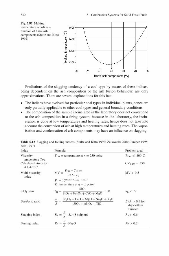
330 5 Combustion Systems for Solid Fossil Fuels
Fig. 5.82 Meltingtemperature of ash as afunction of basic ashcomponents (Stultz and Kitto1992)
Predictions of the slagging tendency of a coal type by means of these indices,being dependent on the ash composition or the ash fusion behaviour, are onlyapproximations. There are several explanations for this fact:
• The indices have evolved for particular coal types in individual plants, hence areonly partially applicable to other coal types and general boundary conditions
• The composition of the sample incinerated in the laboratory does not correspondto the ash composition in a firing system, because in the laboratory, the incin-eration is done at low temperatures and heating rates, hence does not take intoaccount the conversion of ash at high temperatures and heating rates. The vapor-isation and condensation of ash components may have an influence on slagging
Table 5.12 Slagging and fouling indices (Stultz and Kitto 1992; Zelkowski 2004; Juniper 1995;Bals 1997)
Index Formula Problem area
Viscositytemperature T250
T250 = temperature at η = 250 poise T250 <1,400◦C
Calculated viscosityat 1,426◦C
CV1,426 < 350
Multi-viscosityindex
MV = T250 − T10,000
97.5 · FsMV > 0.5
Fs = 10(0.00186·T2,000−1.933)
Tx temperature at η = x poise
SiO2 ratio SR = SiO2
SiO2 + Fe2O3 + CaO + MgO· 100 SR < 72
Base/acid ratioB
A= Fe2O3 + CaO + MgO + Na2O + K2O
SiO2 + Al2O3 + TiO2B/A > 0.5 for
dry-bottomfurnace
Slagging index RS = B
A· Swf (S sulphur) RS > 0.6
Fouling index RF = B
A· Na2O RF > 0.2

5.10 Effect of Slag, Ash and Flue Gas on Furnace Walls 331
• Even with the same total ash composition, there may be different compoundspresent in the ash and inhomogeneous distributions of the ash components
• The indices determine the tendency of ash towards deposit formation but can-not predict the method of removal nor destruction of the deposits (Kautz andZelkowski 1985)
Although the indices cannot offer a safe prediction of the slagging behaviour,they are usually the only available information and, because they are associatedwith experiences at industrial plants for similar coal types and with investigations atsemi-industrial experimental plants, provide a valuable guideline for the design ofcombustion systems.
Further Development
The prediction of deposits is currently following two distinct principal lines ofdevelopment. For one line, the aim is to predict the slagging and fouling tenden-cies by means of improved or advanced experimental methods, while the other linepursues the analysis of deposits of real combustion processes.
• Fusability and sintering testsGiven the slight predictive power of conventional ash analyses and characteris-tics, there are intensive efforts ongoing to develop new or improved sintering andfusion analyses for prediction. Usually the samples used in these investigationsare not laboratory-produced ashes but real ash samples from experimental fur-naces or industrial plants, so that the complex reactions running in combustionprocesses are taken into account. The assigning of temperatures to significantchanges of shape, as practiced in the conventional ash fusion analysis, full ofuncertainties, is dropped in favour of a continuous determination of the shrink-age or shape change. The height of the sample body is measured as a functionof the temperature. Figure 5.83 as an example shows such a result for variousslagging and fouling studies of different brown coals at a 325 MWth pulverisedbrown-coal combustion plant. The measured changes of height of deposits takenfrom the furnace, using different coal types, are compared with the measured fluegas temperatures (Heinzel et al. 1997; Heinzel 2004).
Different methods utilise different sample shapes or in addition subject thesample to pressure. Alternatively or additionally, other properties may be used todetermine the clinkering as well. For instance, the electrical or thermal conduc-tivity is a measure for the sintering behaviour of the sample.
Another method, known as simultaneous thermal analysis (STA), is based onthe simultaneous measurement of the weight and temperature during the slowcontinuous heating of a sample compared to an inert sample. By means of weightchanges, it is possible to determine evaporation processes, and, by temperaturechanges compared to the inert sample, melting processes can be measured. Basedon the data on the conversion and melting energies, it is possible to determine themolten fraction in the sample.
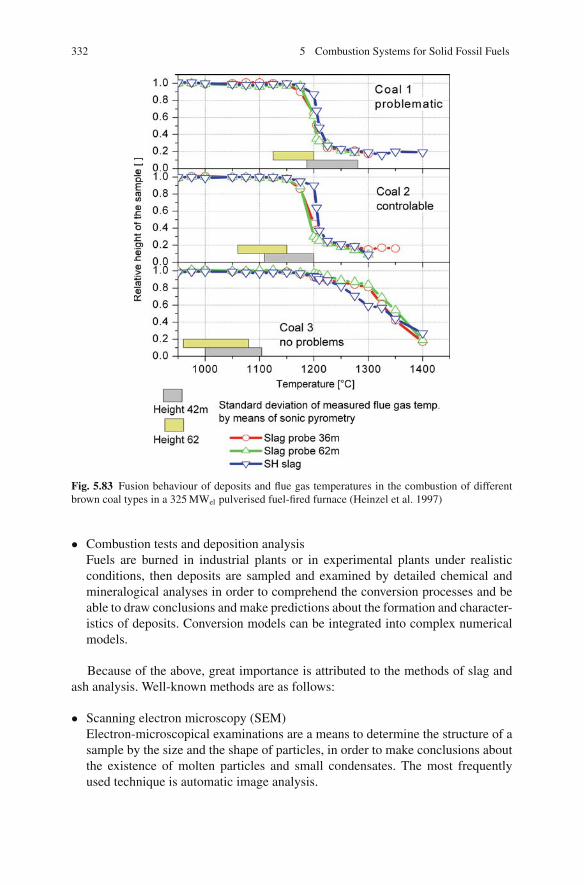
332 5 Combustion Systems for Solid Fossil Fuels
Fig. 5.83 Fusion behaviour of deposits and flue gas temperatures in the combustion of differentbrown coal types in a 325 MWel pulverised fuel-fired furnace (Heinzel et al. 1997)
• Combustion tests and deposition analysisFuels are burned in industrial plants or in experimental plants under realisticconditions, then deposits are sampled and examined by detailed chemical andmineralogical analyses in order to comprehend the conversion processes and beable to draw conclusions and make predictions about the formation and character-istics of deposits. Conversion models can be integrated into complex numericalmodels.
Because of the above, great importance is attributed to the methods of slag andash analysis. Well-known methods are as follows:
• Scanning electron microscopy (SEM)Electron-microscopical examinations are a means to determine the structure of asample by the size and the shape of particles, in order to make conclusions aboutthe existence of molten particles and small condensates. The most frequentlyused technique is automatic image analysis.
5.10 Effect of Slag, Ash and Flue Gas on Furnace Walls 333
• X-ray diffraction (XRD)The technique of X-ray diffraction serves to qualitatively verify mineral frac-tions in a sample. X-rays are diffracted at different degrees through the crystallattices of mineral compounds. The diffraction angles are characteristic for thelattice distances. By measuring the intensity of the diffracted light as a functionof the diffraction angle, it is possible to determine the crystalline structures andto assign the mineral types.
• Scanning electron microscopy with electron-dispersive X-ray analysis(SEM-EDX)In addition to the sample structure determined by the scanning electron micro-scope, X-ray analysis makes it possible to determine the elemental compositionat the surface of the sample at selected locations. EDX is based on the excite-ment of single atoms by electron rays and the emission of X-radiation which ischaracteristic for the element.
• Computer-controlled scanning electron microscopy (CCSEM)An image received by a scanning electron microscope is numerically evaluated,contours are determined and particle sizes are measured. Afterwards, all particlesand structures are analysed by EDX, determining their composition. The evalu-ation assigns size, composition and mass to the particles. This method can beused for mineral inclusions in the raw coal, but also for ashes and deposits fromfurnaces.
5.10.1.3 Impacts, Countermeasures and Remedial Actions
A general characteristic of coals with a slagging tendency is a low-ash deforma-tion temperature. Design-wise, they require low furnace outlet temperatures andtherefore low volumetric heat release rates. Another essential criterion in a designconceived to prevent slagging is to choose a low burner-belt heat release rate inorder to decrease the temperatures in the burner zone.
Operational measures such as increasing the air ratio to decrease the tempera-ture only have a limited range of application. The injection of additives to diminishthe linkage forces between the deposits can be successful for iron-containing coals(Raask 1973).
By means of a homogeneous distribution of coal powder and air, sufficient burnerdistance to neighbouring and opposite walls and a restriction of the coarse particlefraction, it is possible to reduce the solid matter fraction that, in a molten or plasticstate, may hit the wall. For coarse particles, it is in particular the residual carbon andthe pyrite fraction that cause trouble. By secondary combustion of coarse particleson the walls, localised reducing zones are created which, according to the above-described correlations, are favourable for slagging.
Depending on the hardness and the degree of sticking of the slag deposits,removal by blowing is possible, using steam, water jet or air jet blowers. For clean-ing in the region of the evaporator, water jet blowers are usually used, which aremore effective against slag deposits than steam or air jet blowers. Figure 5.84 showsthe cleaning mechanisms of a water jet and the arrangement of water cannons at
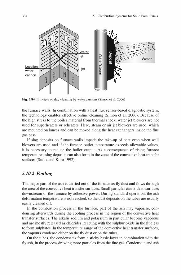
334 5 Combustion Systems for Solid Fossil Fuels
Locationwatercannon
Waterjet
Water/steam
Water
jet
Water/steam
Deposit
Water
Fig. 5.84 Principle of slag cleaning by water cannons (Simon et al. 2006)
the furnace walls. In combination with a heat flux sensor-based diagnostic system,the technology enables effective online cleaning (Simon et al. 2006). Because ofthe high stress to the boiler material from thermal shock, water jet blowers are notused for superheaters or reheaters. Here, steam or air jet blowers are used, whichare mounted on lances and can be moved along the heat exchangers inside the fluegas pass.
If slag deposits on furnace walls impede the take-up of heat even when wallblowers are used and if the furnace outlet temperature exceeds allowable values,it is necessary to reduce the boiler output. As a consequence of rising furnacetemperatures, slag deposits can also form in the zone of the convective heat transfersurfaces (Stultz and Kitto 1992).
5.10.2 Fouling
The major part of the ash is carried out of the furnace as fly dust and flows throughthe area of the convective heat transfer surfaces. Small particles can stick to surfacesdownstream of the furnace by adhesive power. During standard operation, the ashdeformation temperature is not reached, so the dust deposits on the tubes are usuallyeasily cleaned off.
In the combustion process in the furnace, part of the ash may vaporise, con-densing afterwards during the cooling process in the region of the convective heattransfer surfaces. The alkalis sodium and potassium in particular become vaporousand are mostly released as chlorides, reacting with the sulphur oxide in the flue gasto form sulphates. In the temperature range of the convective heat transfer surfaces,the vapours condense either on the fly dust or on the tubes.
On the tubes, the condensates form a sticky basic layer in combination with thefly ash, in the process drawing more particles from the flue gas. Condensate and ash

5.10 Effect of Slag, Ash and Flue Gas on Furnace Walls 335
particles react with each other and the deposits sinter or melt totally. Sintering isthe process of particles sticking together below the fusion temperature as a resultof the localised stickiness of a particle surface. With time, the deposits solidify andeventually become rather difficult to clean off.
One method to determine the sintering behaviour involves taking fly ash from thefurnace and pressing it into a cylindrical sample body. Then, in a laboratory furnace,the samples are subjected to various temperatures, up to about 1,000◦C, for severalhours. After cooling down, increasing pressure is exerted on the sample, determin-ing the degree of compressive stress at which the sample breaks. This degree is ameasure of the sintered state of the sample. For coals, the fouling behaviour can becorrelated to the sodium content. The water-soluble sodium in particular, which issupposed to vaporise during combustion, has an impact on sintering. The influenceof the potassium content, in contrast, is small. Potassium is mostly bound in themineral phase in the coal and not vaporised during combustion (Stultz and Kitto1992).
Low and homogeneous furnace temperatures reduce fouling in the convec-tive section because fewer ash components vaporise. Fouling prevention measuresare identical to a large extent to slagging reduction measures such as a low volu-metric heat release, the use of flue gas recirculation, a high excess air ratio and ahomogeneous distribution of the pulverised coal.
Furthermore, the design of the convective heat transfer surfaces has to be adaptedto the coal type. For coals that have a slagging tendency, larger spacings are chosen.A careful arrangement of the tubes also helps to limit fouling. Since ash depositscannot be avoided during operation, they have to be removed by regular soot blow-ing. The cleaning interval in this respect has to be set such that sintering of thedeposits is prevented (Stultz and Kitto 1992; Hein 1984; Reidick and Schumacher1985).
Due to the higher combustion temperatures in slag-tap furnaces, 5% of the ashmay vaporise and condense on downstream heat transfer surfaces, contributing tofouling in these places (Kautz and Zelkowski 1985). At very high temperatures, thesilicon of the ash may vaporise as well, forming stubborn deposits (Dolezal 1990).
5.10.3 Erosion
In pulverised coal furnaces, the largest fraction of the ash, as fly ash, is carried outof the firing with the flue gas flow and through the tube banks of the convective heattransfer surfaces. Ash particles impinging on and rubbing along the tubes lead tomaterial wear through erosion. Factors having a substantial effect on the degree oferosion are the ash content of the coal, the flow velocity and the properties of the flydust. Fly dust is more abrasive than coal because the soft organic components of thecoal are absent. Quartz fractions in the ash have a very abrasive effect. The shape ofthe ash particles, too, has an influence on erosion. If fly dust particles are smoothedby melting at high temperatures, their erosive effect diminishes.

336 5 Combustion Systems for Solid Fossil Fuels
Erosion occurs in areas of flow reversion. This is the reason why single-passboilers are used for Rhenish brown coals, the fly ash of which contains high quartzfractions. Bridging of ash deposits in the area of the convective heat transfer surfacesmay make the flow velocity rise locally, causing erosion (Couch 1994).
5.10.4 High-Temperature Corrosion
High-temperature corrosion is the term for chemical and physical–chemical wastageof the flue-gas-exposed tubes in solid fuel-fired steam generators. Tube wastageleads to tube ruptures and tube blower damage. According to an EPRI study, 50%of all breakdowns in fossil fuel-fired US power plants and a large majority of alltube damage can be put down to corrosion (Neumann and Kautz 1995). Firesidecorrosion of steam generators accounts for a large part of the maintenance costsin waste incineration plants. The reasons for corrosion and potential to reduce it areknown from comprehensive experience. Even so, it is not possible to control damagecaused in solid fuels combustion to any degree of certainty (Born 2005).
High-temperature corrosion often occurs in the context of slagging and fouling,caused by the gaseous atmosphere or by interactions of slag and ash deposits. Con-ducive to corrosion are the contents of alkalis, chlorine and sulphur in the coal.Corrosion can occur both in the furnace section and in the section of the convectiveheat transfer surfaces. Corrosion occurring in low temperature regions shall not bea subject of the present discussion.
The following mechanisms of high-temperature corrosion are distinguishableand shall be discussed in more detail below:
– Gaseous corrosion by hydrogen chloride– Chlorine-induced corrosion– Molten salt corrosion
The chlorine to sulphur ratio in the fuel is the decisive parameter determining thedominating corrosion mechanism, and hence the corrosion rate. For low sulphur tochlorine ratios in the fuel, chlorine is mainly present as alkali chlorides, which maycondense on heat exchangers to form deposits. The deposits can react with sulphurdioxide to release chlorine in the vicinity of the tube, inducing severe corrosion (i.e.chlorine-induced corrosion). In the case of high sulphur to chlorine ratios, alkalichloride is sulphated in the flue gas to form HCl and alkali sulphates. The gaseouscorrosive attack by HCl is of much lower intensity than the attack by chlorine-induced corrosion.
5.10.4.1 Furnace Corrosion Through Hydrogen Chloride
Under oxidising conditions, metal tubes develop a protective oxide film of Fe3O4
(magnetite) and Fe2O3 (haematite). Under reducing conditions, the oxidic protec-tive layer and the tube material are attacked by hydrogen chloride (HCl) and FeCl2

5.10 Effect of Slag, Ash and Flue Gas on Furnace Walls 337
forms. The corrosion rate in the furnace may even intensify if, through the reac-tion of SO2 or SO3 with deposited chlorine compounds, chlorine is released andalso attacks the tube wall (chlorine-induced corrosion). In contrast, HCl reacts onlyslightly, if at all, with the protective layer on the tube wall in the presence of oxygen.Therefore, a sufficient oxygen-rich atmosphere can help to prevent corrosion (Neu-mann and Kautz 1995; Schirmer and Thomen 1984). In unfavourable conditions,wear rates of up to 600 nm/h have been observed, while the normal oxidation ratesforming the protective film amount to 8 nm/h (Skorupska 1993).
In spite of a sufficiently high oxygen content in the flue gas, ferrous chlorideformation may occur on near-white metal tubes at the initial start-up of a boiler. Forthis reason, metal wastage is higher during start-up than during standard operation.Besides the protection provided by an oxygen-rich atmosphere, chlorine-inducedcorrosion of the tube material still occurs, though only transitorily. This forming offerrous chloride can be explained by the strong oxygen consumption of the protec-tive oxide film.
When white metal tubes are repeatedly subject to strong soot blowing or erosion,the process is called erosion – corrosion (Neumann and Kautz 1995).
Evaporator wall corrosion is often correlated with unfavourable combustion con-ditions and deposits on the walls. Optimised combustion control parameters are ameans to avoid reducing zones near the wall. A homogeneous distribution of the pul-verised coal and air to the burners diminishes the forming of fuel-rich streaks, anda finer grinding accelerates the combustion and limits the extension of low-oxygenzones. Reducing zones may also form at the tube walls due to carbon-containingdeposits which by reaction consume the oxygen, raising the tube wall temperaturein the process. When air staging is applied in the furnace to reduce NOx , care has tobe taken (by ensuring an adequate air injection or by applying an air curtain) suchthat no reducing flue gas atmosphere exists in near-wall zones.
Corrosion in the furnace is largely dependent on the chlorine content of thefuel. Whereas in brown coal-fired furnaces, due to the low chlorine content, cor-rosion problems are extremely rare, problems have to be expected in furnaces firedwith hard coals with a chlorine content above 0.15% (Kautz and Zelkowski 1985).Figure 5.85 shows the expected relative wear rates in the furnace as a function ofthe chlorine content for hard coals (Simon et al. 1997). Corrosion of the evaporatorwalls occurs to a higher degree in waste incineration plants (Neumann and Kautz1995).
5.10.4.2 Corrosion of the Convective Heat Transfer Surfaces by Molten Salts
While under conventional steam conditions up to 540◦C, high-temperature cor-rosion is negligible, this type of corrosion becomes appreciable at higher steamtemperatures. The corrosion rate then mainly depends on the tube wall temperatureand the gas temperature. Figure 5.86 shows the dependence of the corrosion rateon the tube wall temperature. Corrosion begins at temperatures somewhat above600◦C, reaching a maximum at about 700◦C (Stultz and Kitto 1992).

338 5 Combustion Systems for Solid Fossil Fuels
Fig. 5.85 Effect of thechlorine content on thecorrosion rate in the furnacefor hard coals (Simon et al.1997)
Fig. 5.86 Dependence of thecorrosion rate on the tubewall temperature (Stultz andKitto 1992)
High-temperature corrosion of the convection heating surfaces is due to complexalkali iron(III) sulphates and alkali aluminium(III) sulphates, which form in thedeposits of the fly ash. These alkali sulphates and SO2, which reacts in the depositsto become SO3, diffuse through the fly ash and react with the iron or aluminiumoxides of the fly ash:
3K2SO4 + Fe2O3 + 3 SO3 → 2K3Fe(SO4)3 (5.29)
or
K2SO4 + Al2O3 + 3SO3 → 2 Al(SO4)2 (5.30)
Alkali iron/aluminium sulphates are molten in the temperature range of550–700◦C or so. In this state, they even attack high-alloy steels by corrosion. Alltypes of hard coals contain enough alkalis and sulphur for the development of high-
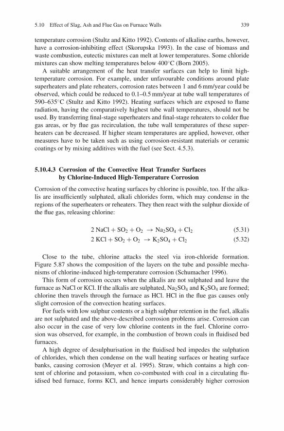
5.10 Effect of Slag, Ash and Flue Gas on Furnace Walls 339
temperature corrosion (Stultz and Kitto 1992). Contents of alkaline earths, however,have a corrosion-inhibiting effect (Skorupska 1993). In the case of biomass andwaste combustion, eutectic mixtures can melt at lower temperatures. Some chloridemixtures can show melting temperatures below 400◦C (Born 2005).
A suitable arrangement of the heat transfer surfaces can help to limit high-temperature corrosion. For example, under unfavourable conditions around platesuperheaters and plate reheaters, corrosion rates between 1 and 6 mm/year could beobserved, which could be reduced to 0.1–0.5 mm/year at tube wall temperatures of590–635◦C (Stultz and Kitto 1992). Heating surfaces which are exposed to flameradiation, having the comparatively highest tube wall temperatures, should not beused. By transferring final-stage superheaters and final-stage reheaters to colder fluegas areas, or by flue gas recirculation, the tube wall temperatures of these super-heaters can be decreased. If higher steam temperatures are applied, however, othermeasures have to be taken such as using corrosion-resistant materials or ceramiccoatings or by mixing additives with the fuel (see Sect. 4.5.3).
5.10.4.3 Corrosion of the Convective Heat Transfer Surfacesby Chlorine-Induced High-Temperature Corrosion
Corrosion of the convective heating surfaces by chlorine is possible, too. If the alka-lis are insufficiently sulphated, alkali chlorides form, which may condense in theregions of the superheaters or reheaters. They then react with the sulphur dioxide ofthe flue gas, releasing chlorine:
2 NaCl + SO2 + O2 → Na2SO4 + Cl2 (5.31)
2 KCl + SO2 + O2 → K2SO4 + Cl2 (5.32)
Close to the tube, chlorine attacks the steel via iron-chloride formation.Figure 5.87 shows the composition of the layers on the tube and possible mecha-nisms of chlorine-induced high-temperature corrosion (Schumacher 1996).
This form of corrosion occurs when the alkalis are not sulphated and leave thefurnace as NaCl or KCl. If the alkalis are sulphated, Na2SO4 and K2SO4 are formed;chlorine then travels through the furnace as HCl. HCl in the flue gas causes onlyslight corrosion of the convection heating surfaces.
For fuels with low sulphur contents or a high sulphur retention in the fuel, alkalisare not sulphated and the above-described corrosion problems arise. Corrosion canalso occur in the case of very low chlorine contents in the fuel. Chlorine corro-sion was observed, for example, in the combustion of brown coals in fluidised bedfurnaces.
A high degree of desulphurisation in the fluidised bed impedes the sulphationof chlorides, which then condense on the wall heating surfaces or heating surfacebanks, causing corrosion (Meyer et al. 1995). Straw, which contains a high con-tent of chlorine and potassium, when co-combusted with coal in a circulating flu-idised bed furnace, forms KCl, and hence imparts considerably higher corrosion
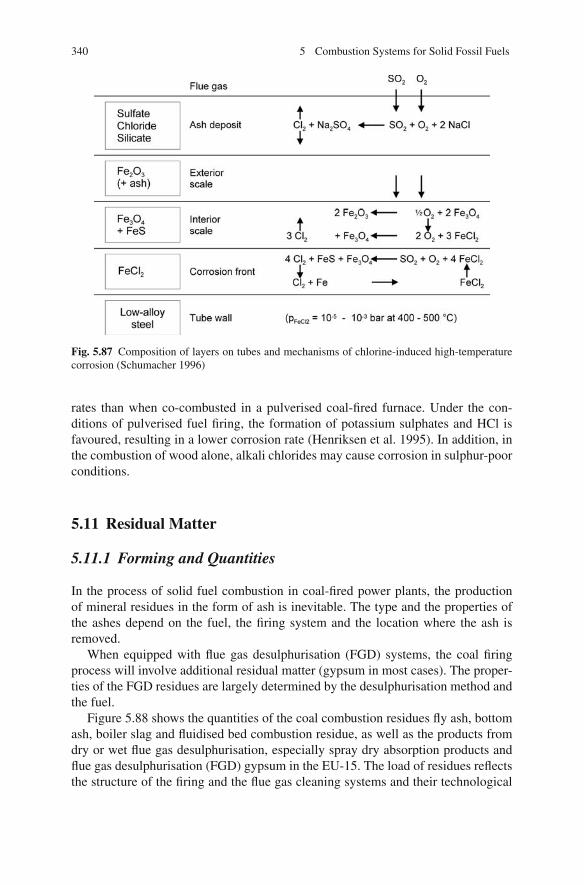
340 5 Combustion Systems for Solid Fossil Fuels
Fig. 5.87 Composition of layers on tubes and mechanisms of chlorine-induced high-temperaturecorrosion (Schumacher 1996)
rates than when co-combusted in a pulverised coal-fired furnace. Under the con-ditions of pulverised fuel firing, the formation of potassium sulphates and HCl isfavoured, resulting in a lower corrosion rate (Henriksen et al. 1995). In addition, inthe combustion of wood alone, alkali chlorides may cause corrosion in sulphur-poorconditions.
5.11 Residual Matter
5.11.1 Forming and Quantities
In the process of solid fuel combustion in coal-fired power plants, the productionof mineral residues in the form of ash is inevitable. The type and the properties ofthe ashes depend on the fuel, the firing system and the location where the ash isremoved.
When equipped with flue gas desulphurisation (FGD) systems, the coal firingprocess will involve additional residual matter (gypsum in most cases). The proper-ties of the FGD residues are largely determined by the desulphurisation method andthe fuel.
Figure 5.88 shows the quantities of the coal combustion residues fly ash, bottomash, boiler slag and fluidised bed combustion residue, as well as the products fromdry or wet flue gas desulphurisation, especially spray dry absorption products andflue gas desulphurisation (FGD) gypsum in the EU-15. The load of residues reflectsthe structure of the firing and the flue gas cleaning systems and their technological
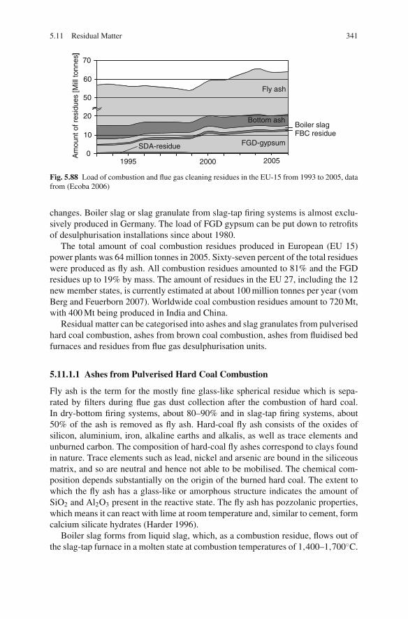
5.11 Residual Matter 341
Boiler slagFBC residue
0
10
20
50
60
70
SDA-residue FGD-gypsum
Bottom ash
Fly ash
Am
ount
of r
esid
ues
[Mill
tonn
es]
2000 20051995
SDA-residue FGD-gypsum
Bottom ash
Fly ash
]
Fig. 5.88 Load of combustion and flue gas cleaning residues in the EU-15 from 1993 to 2005, datafrom (Ecoba 2006)
changes. Boiler slag or slag granulate from slag-tap firing systems is almost exclu-sively produced in Germany. The load of FGD gypsum can be put down to retrofitsof desulphurisation installations since about 1980.
The total amount of coal combustion residues produced in European (EU 15)power plants was 64 million tonnes in 2005. Sixty-seven percent of the total residueswere produced as fly ash. All combustion residues amounted to 81% and the FGDresidues up to 19% by mass. The amount of residues in the EU 27, including the 12new member states, is currently estimated at about 100 million tonnes per year (vomBerg and Feuerborn 2007). Worldwide coal combustion residues amount to 720 Mt,with 400 Mt being produced in India and China.
Residual matter can be categorised into ashes and slag granulates from pulverisedhard coal combustion, ashes from brown coal combustion, ashes from fluidised bedfurnaces and residues from flue gas desulphurisation units.
5.11.1.1 Ashes from Pulverised Hard Coal Combustion
Fly ash is the term for the mostly fine glass-like spherical residue which is sepa-rated by filters during flue gas dust collection after the combustion of hard coal.In dry-bottom firing systems, about 80–90% and in slag-tap firing systems, about50% of the ash is removed as fly ash. Hard-coal fly ash consists of the oxides ofsilicon, aluminium, iron, alkaline earths and alkalis, as well as trace elements andunburned carbon. The composition of hard-coal fly ashes correspond to clays foundin nature. Trace elements such as lead, nickel and arsenic are bound in the siliceousmatrix, and so are neutral and hence not able to be mobilised. The chemical com-position depends substantially on the origin of the burned hard coal. The extent towhich the fly ash has a glass-like or amorphous structure indicates the amount ofSiO2 and Al2O3 present in the reactive state. The fly ash has pozzolanic properties,which means it can react with lime at room temperature and, similar to cement, formcalcium silicate hydrates (Harder 1996).
Boiler slag forms from liquid slag, which, as a combustion residue, flows out ofthe slag-tap furnace in a molten state at combustion temperatures of 1,400–1,700◦C.
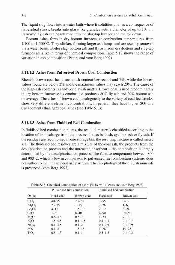
342 5 Combustion Systems for Solid Fossil Fuels
The liquid slag flows into a water bath where it solidifies and, as a consequence ofits residual stress, breaks into glass-like granules with a diameter of up to 10 mm.Removed fly ash can be returned into the slag-tap furnace and melted down.
Bottom ashes form in dry-bottom furnaces at combustion temperatures from1,100 to 1,300◦C. They clinker, forming larger ash lumps and are usually removedvia a water basin. Boiler slag, bottom ash and fly ash from dry-bottom and slag-tapfurnaces are alike in terms of chemical composition. Table 5.13 shows the range ofvariation in ash composition (Peters and vom Berg 1992).
5.11.1.2 Ashes from Pulverised Brown Coal Combustion
Rhenish brown coal has a mean ash content between 4 and 7%, while the lowestvalues found are below 2% and the maximum values may reach 20%. The cause ofthe high-ash contents is sandy or clayish matter. Brown coal is used predominantlyin dry-bottom furnaces; its combustion produces 80% fly ash and 20% bottom ashon average. The ashes of brown coal, analogously to the variety of coal feedstocks,show very different element concentrations. In general, they have higher SO3 andCaO contents than hard coal ashes (see Table 5.13).
5.11.1.3 Ashes from Fluidised Bed Combustion
In fluidised bed combustion plants, the residual matter is classified according to thelocation of its discharge from the process, i.e. as bed ash, cyclone ash or fly ash. Ifthe residues are recombined in one storage bin, the resulting mixture is called mixedash. The fluidised bed residues are a mixture of the coal ash, the products from thedesulphurisation process and the unreacted absorbent – the composition is largelydetermined by the desulphurisation process. The furnace temperature between 800and 900◦C, which is low in comparison to pulverised fuel combustion systems, doesnot suffice to melt the mineral ash particles. The morphology of the clayish mineralsis preserved (vom Berg 1993).
Table 5.13 Chemical composition of ashes [% by wt.] (Peters and vom Berg 1992)
Pulverised fuel combustion Fluidised bed combustion
Oxide Hard coal Brown coal Hard coal Brown coal
SiO2 40–55 20–70 7–55 3–17Al2O3 23–35 1–15 2–26 1–6Fe2O3 4–17 1.5–70 2–12 8–24CaO 1–8 8–40 4–50 30–50MgO 0.8–4.8 0.5–7 1–2.1 7–13K2O 1.5–5.5 0.1–1.5 0.4–4.3 0.1–0.7Na2O 0.1–3.5 0.1–2 0.1–0.9 0.1–0.9SO3 0.1–2 1.5–15 1–28 10–25TiO2 0.5–1.3 0.1–1 0.5–1.5 0.1–0.2
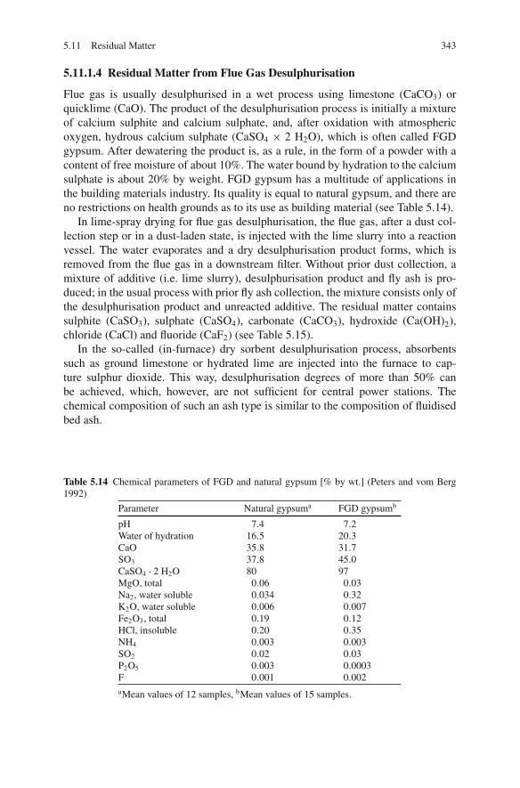
5.11 Residual Matter 343
5.11.1.4 Residual Matter from Flue Gas Desulphurisation
Flue gas is usually desulphurised in a wet process using limestone (CaCO3) orquicklime (CaO). The product of the desulphurisation process is initially a mixtureof calcium sulphite and calcium sulphate, and, after oxidation with atmosphericoxygen, hydrous calcium sulphate (CaSO4 × 2 H2O), which is often called FGDgypsum. After dewatering the product is, as a rule, in the form of a powder with acontent of free moisture of about 10%. The water bound by hydration to the calciumsulphate is about 20% by weight. FGD gypsum has a multitude of applications inthe building materials industry. Its quality is equal to natural gypsum, and there areno restrictions on health grounds as to its use as building material (see Table 5.14).
In lime-spray drying for flue gas desulphurisation, the flue gas, after a dust col-lection step or in a dust-laden state, is injected with the lime slurry into a reactionvessel. The water evaporates and a dry desulphurisation product forms, which isremoved from the flue gas in a downstream filter. Without prior dust collection, amixture of additive (i.e. lime slurry), desulphurisation product and fly ash is pro-duced; in the usual process with prior fly ash collection, the mixture consists only ofthe desulphurisation product and unreacted additive. The residual matter containssulphite (CaSO3), sulphate (CaSO4), carbonate (CaCO3), hydroxide (Ca(OH)2),chloride (CaCl) and fluoride (CaF2) (see Table 5.15).
In the so-called (in-furnace) dry sorbent desulphurisation process, absorbentssuch as ground limestone or hydrated lime are injected into the furnace to cap-ture sulphur dioxide. This way, desulphurisation degrees of more than 50% canbe achieved, which, however, are not sufficient for central power stations. Thechemical composition of such an ash type is similar to the composition of fluidisedbed ash.
Table 5.14 Chemical parameters of FGD and natural gypsum [% by wt.] (Peters and vom Berg1992)
Parameter Natural gypsuma FGD gypsumb
pH 7.4 7.2Water of hydration 16.5 20.3CaO 35.8 31.7SO3 37.8 45.0CaSO4 · 2 H2O 80 97MgO, total 0.06 0.03Na2, water soluble 0.034 0.32K2O, water soluble 0.006 0.007Fe2O3, total 0.19 0.12HCl, insoluble 0.20 0.35NH4 0.003 0.003SO2 0.02 0.03P2O5 0.003 0.0003F 0.001 0.002aMean values of 12 samples, bMean values of 15 samples.

344 5 Combustion Systems for Solid Fossil Fuels
Table 5.15 Composition of lime-spray drying products [% by wt.] (Peters and vom Berg 1992)
ComponentWithout priordust collection
With dustcollection
CaSO3 9–47 17–685CaSO4 1.7–17 3.5–29CaCO3 4.5–13.7 5–13Ca(OH)2 1–15 0.5–15CaCl 0.8–6.3 0.8–9.5CaF2 < 0.4 < 0.4Fly ash 20–85 < 8
5.11.2 Commercial Exploitation
The following presents the potential for commercial exploitation of the residualmaterial described in Sect. 5.11.1.
5.11.2.1 Ash from Combustion of Pulverised Hard Coal
Concrete and Concrete Products
The majority of the fly ash from hard coal-fired power stations in Europe is sup-plied to the concrete industry. As an example, about 75% of the fly ash fromhard coal firing in Germany is used for concrete production. Fly ashes can beused in concrete or products of concrete as a direct additive or as an aggre-gate produced from fly ash, provided they meet specified quality standards. Theutilisation of fly ash as a concrete additive is regulated by the European Stan-dard EN 450 “Fly Ash for Concrete”. The standard refers to siliceous fly ashfrom hard coal combustion only. Calcareous fly ash, commonly obtained from thecombustion of lignite, cannot be utilised as a concrete additive according to EN450 (vom Berg and Feuerborn 2005).
The first requirement of fly ashes used as concrete additives is that they be harm-less, homogeneous and effective as desired. The guideline outlines limits for theloss of unburnt material (< 5% for category A), SO3 (< 3%), Cl− (< 0.1%), thecontent of free lime (CaO) (<2.5%), the content of alkalis (<5%), MgO (<4%),P2O5 (<100 mg/kg), the grain fraction (<0.045 mm) (>60%) and for the mechani-cal behaviour (solidification, volume constancy, compressive strength of the mortarand cement, carbonation behaviour, frost resistance). The revised EN 450 allows theco-combustion of secondary fuels such as wood and sewage sludge up to a certainmass fraction (Wiens 2005) (see also Sect. 6.5.3).
Processed granulate material and coarse ashes also have a use as a sand additivein concrete and in concrete products.
Cement
In cement production, fly ash can be added as a component of the basic materialor to the milling process. The requirements are specified in the European Standard
5.11 Residual Matter 345
EN 197: “Fly ash for cement”. As a general rule the requirements for the fly ashquality are lower than for the use in concrete production. The guideline distinguishesbetween fly ash from lignite and hard coal power plants. For siliceous fly ash fromhard coal, depending on the cement class, the allowable fly ash fraction is between6 and 35%. The guideline outlines similar limits for the loss of unburnt materialand the content of free lime as in EN 450 for concrete; however, limits on chlorineand sulphate, for example, are less stringent, as they are based on the concentrationsin the cement and not the ash. Utilisation of the fly ash in cement production isgenerally less attractive, because revenues are lower than for utilisation in concreteproduction.
Road Construction and Earth and Landscaping Work
In the construction of roads and in earth and landscaping works, it is possible to usefly ashes that have a content of unburnt material of up to 15%. The most importantfield of application, in terms of quantity of use, for fly ash in road construction isthe construction of base courses (i.e. the underlying layers of the road construction).Owing to their cement-like behaviour, hard-coal fly ashes help to cut down on thenecessary quantity of binder. Fly ash can also be used as a filler in the constructionof the road pavement (i.e. the surface layer of the road).
In earth and landscaping works, too, fly ash can be used as an additive to improvethe granulometric composition of natural soil. In general, fly ashes meet all require-ments with respect to soil statics and mechanics for stability. Considerable quantitiesof fly ash can be made use of, especially when there is an imbalance of the cut andfill in the construction of new roads. For embankments (i.e. earthworks), the useof fly ash may remove the need for any other hydraulic binder. When appropriateconstruction methods are used, fly ash has the same high quality of natural soilmaterials. The increasing frequency of the construction of vision and noise barriersoffers a use for very large quantities of fly ash. The same is true for the backfillingof buildings, bridges and retaining walls.
Granulate matter from ash removal devices can be utilised with or without binderin all courses of the road construction. Granulates are impact-crushed before use ifnecessary. Granulates and coarse ashes are relatively equal in physical and chemi-cal properties and can be used without restriction in earth and landscaping works.They also meet all requirements with respect to soil mechanics and are chemicallyinert.
Mining, Pneumatic Stowing and Backfilling of Cavities
In the production of mining mortar for applications in underground mining, fly ashis used as a filler or binder. If used as a filler, the mortar is produced by mixingfly ash with a binder and adding a coarse granulate. Alternatively, when acting asthe binder, another material is used as the filler. Mining mortar can be used for theconstruction of gate side packs and for the sealing of rock. Fly ash or mixes of flyash and FGD gypsum are used for backfilling cavities in underground mining.

346 5 Combustion Systems for Solid Fossil Fuels
Clay Bricks, Sandy Limestone Bricks and Aerated Concrete
Fly ash can be used in the manufacturing of clay bricks, sandy limestone bricks andaerated concrete. In brick fabrication, fly ash can be used to make clays leaner. Gran-ulate material and coarse ashes are suitable for the production of sandy limestonebricks.
Mortar, Screed and Plaster
For mortar, screed and plaster production, fly ash can be used as an additive. Therequirements for fly ash depend on the type of binder used. Granulates are suitablefor use as additives without the need for any treatment. Coarse ash can, as a rule, beused for masonry mortar as well.
Other Purposes
Because of its low permeability to water, fly ash can be used with other sealingproducts in the construction of landfill sites. Boiler slag and bottom ash, becauseof their relatively high permeability and resistance to water, are suitable for use asfilter layers and in bedding for drainage systems. Boiler slag material is used in theproduction of blasting media. It is also used as grit for road traction in winter.
5.11.2.2 Ash from Combustion of Pulverised Brown Coal
For brown coal ash, there is currently no potential for reuse in the conventionalconstruction and building materials sector(s) or in underground mining. Due tothe varying composition of German brown coal ash, no test marks exist as yet inGermany. However, brown coal ash, in the same way as hard coal ash, can serveas an additive to natural soils to improve the soil structure. Because of its mineralcomponents, this ash can be used in agriculture and forestry, horticulture, earth andlandscaping works as a plant nutrient and as a soil conditioning agent. The majorityof brown coal ash is used for recultivation of landscapes in opencast brown coalmining.
5.11.2.3 Ash from Fluidised Bed Combustion
The fluidised bed combustion plants currently in service are operated mainly bycommunal utility companies. The plants are at a distance from each other and thelocal yield of residual matter is comparatively low. An additional fact is that theresidues from different fluidised bed combustion plants, due to differing processtechnologies and fuel qualities, may have very dissimilar properties. These boundaryconditions, unfavourable for any application, as well as the complex composition ofthe fluidised bed residues, make it more difficult to convert them to usable materi-als. Despite this, it is reported that much fluidised bed ash is reused. The predom-inant part is utilised in underground hard coal mining for pneumatic and hydraulic

5.11 Residual Matter 347
stowing and as a component for mining mortar. Repurchase by the coal supplier ofthe ash is usually a component of the contract between the supplier and the utilitycompany.
5.11.2.4 Residual Matter from Flue Gas Desulphurisation
FGD gypsum from coal-fired power plants can be used as a fully adequate substi-tute for natural gypsum. Comparative investigations into natural gypsum and FGDgypsum have verified that FGD gypsum can be used for the fabrication of buildingmaterials without increased health risks. It is used in the gypsum and cement indus-tries for the manufacturing of wallboards, gypsum blocks, projection plasters andfloor screeds and for the production of cement.
Due to the varying properties of brown coal, FGD gypsum from brown coal-firedpower plants in the past did not meet the requirements of the gypsum and cementindustries for properties and purity. This gypsum was used instead to stabilise thebackfilling material in opencast brown coal mining. The high demand for FGD gyp-sum has led to further development of the technology for multistage preparation ofthe gypsum, so that, today, gypsum from brown coal-fired power plants can also beused in the production of gypsum products and in cement production.
Today, all FGD gypsum from hard coal-fired and part of the FGD gypsum frombrown coal-fired power plants is used as a raw material in the gypsum industry. Thetotal amount used in 2004 was more than 7 million tonnes. As a comparison, theproduction of natural gypsum in Europe is about 25 million tonnes.
The reuse of desulphurisation products from lime-spray drying is more difficultand more complex technologically than those from wet flue gas desulphurisationprocesses. There is no potential for these products to replace a natural or industrialmaterial. They have no outstanding technical properties to make them particularlyuseful in a technical application. So the development of a new product or an upgrad-ing process is necessary in order to reuse these materials. Another disadvantage isthe small quantity and varying quality produced by a plant. Additionally, the residualmaterial contains corrosive chlorine. Despite these problems, in Germany 76% ofthe residual matter is utilised. Possible applications are as a raw material for miningmortar, as an additive for sandy limestone brick and aerated concrete and as a rawmaterial for other processes, such as sulphuric acid production or anhydrite produc-tion. Another option is addition in a wet FGD process for the further oxidation ofsulphite (Kolar 1995).
5.11.2.5 Heavy Metals and Leaching Behaviour of Residual Matter
In certain applications, in soils, for instance, it is necessary to know the concen-trations of various elements in order to evaluate the general environmental impactof the reuse of residual matter. These elements are divided into potentially harmfulsubstances and beneficial elements, with the boundaries being fluid depending onthe concentrations.

348 5 Combustion Systems for Solid Fossil Fuels
Tabl
e5.
16H
eavy
met
alco
ncen
trat
ions
ofpo
wer
plan
tre
sidu
esin
com
pari
son
with
max
ima
ofth
eG
erm
anSe
wag
eSl
udge
Ord
inan
ce[m
g/kg
](P
eter
san
dvo
mB
erg
1992
) Fly
ash
Flui
dise
dbe
das
hB
oile
ras
hb
Hea
vym
etal
Har
dco
ala
Bro
wn
coal
Har
dco
alB
row
nco
alH
ard
coal
FGD
gyps
umN
atur
algy
psum
Sew
age
slud
geor
d.St
anda
rdva
lue
for
soil
Lea
d20
020
150
1030
54
900
100
Cad
miu
m2
0.6
1.5
0.5
0.4
0.05
0.2
10/5
1.5/
1C
hrom
ium
120
4013
020
253
790
010
0C
oppe
r16
015
130
1530
35
800
60N
icke
l17
035
120
1560
24
200
50M
ercu
ry0.
10.
50.
50.
7<
0.1
0.5
0.03
81
Zin
c30
045
300
100
6015
132,
500/
2,00
020
0/15
0a D
ry-b
otto
mfu
rnac
e;bG
ranu
late
mat
ter
and
coar
seas
h.
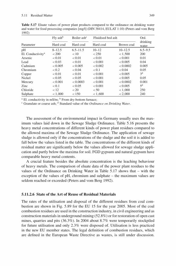
5.11 Residual Matter 349
Table 5.17 Eluate values of power plant products compared to the ordinance on drinking waterand water for food processing companies [mg/l] (DIN 38414, EULAT 1:10) (Peters and vom Berg1992)
Fly ashb Boiler ashc Fluidised bed ash Ord.drinkingwaterParameter Hard coal Hard coal Hard coal Brown coal
pH 8–12.5 6.5–11.5 10–12 10–12.5 6.5–9.5El. Conductivitya <200 <10 <250 <1,500 200Arsenic <0.01 <0.01 <0.01 <0.001 0.01Lead <0.03 <0.01 <0.001 <0.005 0.04Cadmium <0.005 <0.005 <0.002 <0.0002 0.005Chromium <0.2 <0.04 <0.1 <0.04 0.05Copper <0.01 <0.01 <0.001 <0.005 3d
Nickel <0.05 <0.05 <0.001 <0.005 0.05Mercury <0.001 <0.0003 <0.001 <0.0002 0.001Zinc <0.1 <0.05 <0.001 <0.005 5d
Chloride <12 <20 <50 <1,000 250Sulphate <1,000 <150 <1,600 <2,000 240a El. conductivity in mS/m; b From dry-bottom furnace;c Granulate or coarse ash; d Standard value of the Ordinance on Drinking Water.
The assessment of the environmental impact in Germany usually uses the max-imum values laid down in the Sewage Sludge Ordinance. Table 5.16 presents theheavy metal concentrations of different kinds of power plant residues compared tothe allowed maxima of the Sewage Sludge Ordinance. The application of sewagesludge is allowed only if the concentrations of the sludge and the soil it is added tofall below the values listed in the table. The concentrations of the different kinds ofresidual matter are significantly below the values allowed for sewage sludge appli-cation and partly below the maxima for soil. FGD gypsum and natural gypsum havecomparable heavy metal contents.
A crucial feature besides the absolute concentration is the leaching behaviourof heavy metals. The comparison of eluate data of the power plant residues to thevalues of the Ordinance on Drinking Water in Table 5.17 shows that – with theexception of the values of pH, chromium and sulphate – the maximum values areseldom reached or exceeded (Peters and vom Berg 1992).
5.11.2.6 State of the Art of Reuse of Residual Materials
The rates of the utilisation and disposal of the different residues from coal com-bustion are shown in Fig. 5.89 for the EU 15 for the year 2005. Most of the coalcombustion residues are used in the construction industry, in civil engineering and asconstruction materials in underground mining (52.8%) or for restoration of open castmines, quarries and pits (36.3%). In 2004 about 8.7% were temporarily stockpiledfor future utilisation and only 2.3% were disposed of. Utilisation is less practicedin the new EU member states. The legal definition of combustion residues, whichare defined in the European Waste Directive as wastes, is still under discussion.
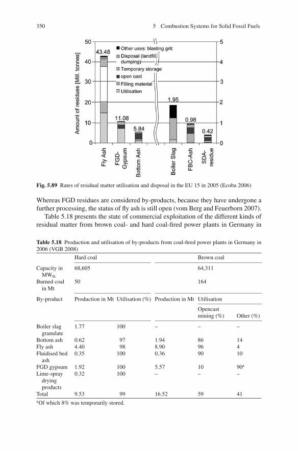
350 5 Combustion Systems for Solid Fossil Fuels
Fig. 5.89 Rates of residual matter utilisation and disposal in the EU 15 in 2005 (Ecoba 2006)
Whereas FGD residues are considered by-products, because they have undergone afurther processing, the status of fly ash is still open (vom Berg and Feuerborn 2007).
Table 5.18 presents the state of commercial exploitation of the different kinds ofresidual matter from brown coal- and hard coal-fired power plants in Germany in
Table 5.18 Production and utilisation of by-products from coal-fired power plants in Germany in2006 (VGB 2008)
Hard coal Brown coal
Capacity inMWth
68,605 64,311
Burned coalin Mt
50 164
By-product Production in Mt Utilisation (%) Production in Mt Utilisation
Opencastmining (%) Other (%)
Boiler slaggranulate
1.77 100 – – –
Bottom ash 0.62 97 1.94 86 14Fly ash 4.40 98 8.90 96 4Fluidised bed
ash0.35 100 0.36 90 10
FGD gypsum 1.92 100 5.57 10 90a
Lime-spraydryingproducts
0.32 100 – – –
Total 9.53 99 16.52 59 41aOf which 8% was temporarily stored.

References 351
2004 (VGB 2008). The main fields of application for hard coal fly ash are concreteand cement production, mining and road construction. Boiler slag and bottom ashare on the whole utilised in earth and road works, in products of sandy limestone,in concrete and concrete. Brown coal ash is almost entirely used for backfillingmined-out opencast mines and for recultivation of mine landscapes.
Although utilisation of fly ash has been practised in both North America andEurope since the 1950s, the rates of utilisation are still at a modest level in manycountries. Whereas the utilisation of fly ash in Europe (EU 15) is nearly 100%, therate of utilisation in the USA is only 35%. In China the rate of utilisation remainedlow in the 1980s but then grew rapidly during the 1990s. It reached 66% of an ashproduction rate of 150 Mt in 2002. The production of fly ash in China is predictedto increase to 350 Mt in 2010 and 600 Mt in 2020 (Smith 2005).
References
BImSchV (2004). 13. Verordnung zur Durchfuhrung des Bundesimmissionsschutzgesetzes(Verordnung uber Großfeuerungsanlagen, 13. BImSchV) vom 23.7.2004, BGBl. I Nr. 37,P.1717, from http://www.gesetze-im-internet.de/bimschv 13 2004/index.html.
BImSchV (2003). 17. Verordnung zur Durchfuhrung des Bundesimmissionsschutzgesetzes(Verordnung uber die Verbrennung und die Mitverbrennung von Abfallen. Bekanntmachungvom 14. August 2003 (BGBl. I P. 1633).
Adrian, F., Quittek, C. and Wittchow, E. (1986). Fossil beheizte Dampfkraftwerke. HandbuchreiheEnergie, Band 6, Herausgeber T. Bohn. Technischer Verlag Resch, Verlag TUV Rheinland
Albers, U., Holzapfel, T. and Wollner, G. (1987). Forschungsbericht Umweltschutztechnik Schad-stoffanalytik. Bestimmung der Spurenelement-Verbindungen in Reingasstauben aus steinkohle-und mullbefeuerten Kraftwerken. BMFT, VQ 223–1.
Albrecht, W. and Pollmann, S. (1980). Neuere Beitrage zum Verschlackungsmechanismus in trock-enentaschten Steinkohlefeuerungen. VGB Kraftwerkstechnik 60(2): 90–97.
Amdur, M. O. (1986). Coal combustion aerosols and SO2 – an interdisciplinary analysis. Environ-mental Science & Technology 20(2): 138–145.
Anthony, D. B. and Howard, J. B. (1976). Coal devolatilization and hydrogasification. AIChE-Journal 22(4): 625–656.
Araoka, M., Iwanaga, A. and Sakai, M. (1987). Application of Mitsubishi “Advanced MACT” infurnace removal process. 1987 Joint Symposium on Stationary Combustion NOx Control. NewOrleans.
Bals, M. (1997). Untersuchungen zum Verschmutzungsverhalten zukunftig anstehender Kohlendes Rheinischen Reviers. VGB-Fachtagung Feuerungen. Essen.
Baumbach, G. (1990). Luftreinhaltung. Berlin/Heidelberg, Springer.Becker, J. (1986). Moglichkeiten der Stickoxidminderung durch SCR-Anlagen. BWK
(Sonderdruck Fachreport Rauchgasreinigung): 19–26.Becker, J. (1987). Aktiva und Passiva. Betriebserfahrungen zur NOx-Minderung der NOx-
Emission. Energie Spektrum (6).Beer, J. M. (1988). Stationary combustion – the environmental Leitmotiv. Proceedings of the 22nd
Symposium (International) on Combustion, pp. 1–16. Pittsburgh, The Combustion Institute.Benesh, W. A., Howe, G., Lumkemann (2001). 12 Jahre Betriebserfahrung mit der Brennstoffstu-
fung im Kraftwerk Herne. VDI-Berichte 1629, pp. 25–30. Dusseldorf, VDI.Bertacchi, S., Fioresi, S. and Pasini, S. (1997). Vado Ligure coal-over-coal reburn project. Pro-
ceedings of the 4th International Conference on Technologies and Combustion for a CleanEnvironment. Lisbon.

352 5 Combustion Systems for Solid Fossil Fuels
Bertram, J. (1986). Ubersicht uber Erfahrungen und Stand feuerungstechnischerNOx-Minderungsmaßnahmen bei Steinkohlenstaubfeuerungen mit flussigem Ascheabzug.VGB Kraftwerkstechnik 66(12): 1150–1159.
Biber, K. H. (1986). Erfolgreiche Primarmaßnahmen zur NOx-Reduzierung an einer Steinkohlen-Schmelzfeuerung. VGB Kraftwerkstechnik 66(9): 835–843.
Blair, D. W., Wendt, J. O. L. and Bartok, W. (1978). Evolution of nitrogen and other species duringcontrolled pyrolysis of coal. Proceedings of the 17th Symposium (International) on Combus-tion. Pittsburgh, The Combustion Institute.
Bonn, B. and Baumann, H. (1991). Kenntnisstand der N2O-Bildung in verschiedenenFeuerungsanlagen, VDI-Berichte 922, pp. 625–634.
Bonn, B., Baumann, H. and Pelz, G. (1993). Bildung und Abbau von N2O in Wirbelschichtfeuerun-gen. VGB Forschung in der Kraftwerkstechnik. Essen, VGB-TB 231.
Booth, R. C. and Borio, R. W. e. a. (1991). Reburn technology for NOx control on a cyclone-firedboiler. 1991 Joint Symposium on Stationary Combustion NOx Control. Washington D.C.
Born, M. (2005). Cause and risk evaluation for high-temperature chlorine corrosion. VGBPowerTech 4(5): 107–111.
Bruggemann, H. (2008). Erfahrungen mit modernen Steinkohlefeuerungen. VGB PowerTech88(11): 36–42.
Bruggemann, H., Scheffknecht, G., Marx, F. J. and Koch, G. (1997). Erste Betriebserfahrungennach dem Umbau des Kraftwerkes Bexbach I. VGB-Fachtagung Feuerungen. Essen.
Bruggemann, H., Stamatelopoulos, G., Krohmer, B. and Kessel, W. (2003). Die Entwicklung einesRundbrennerkonzeptes – Simulation, Auslegung, Betriebserfahrung. VDI-Berichte 1750, VDI.
Bunthoff, D. and Meier, H. J. (1987). Umweltfreundliches Kraftwerk mit Druckwirbelschicht-feuerung, Planungskriterien fur die Dampferzeuger. VGB Kraftwerkstechnik 67(8): 751–757.
Chen, S. L., Clark, W. C., Heap, M. P. and Pershing, D. W. (1982a). NOx-reduction by reburningwith gas and coal – bench scale studies. Joint Symposium on Stationary Combustion NOxControl. Palo Alto, CA.
Chen, S. L., Heap, M. P., and Pershing, D. W. (1982b). Influence of coal composition on the fateof volatile and char nitrogen during combustion. Proceedings of the 19th Symposium (Interna-tional) on Combustion. Pittsburgh, The Combustion Institute.
Chugtai, M. Y. and Michelfelder, S. (1983). Schadstoffeinbindung durch Additiveinblasung um dieFlamme. BWK 35(3): 75–83.
Couch, G. (1994). Understanding slagging and fouling during PF combustion. London, IEA CoalResearch. JEA CR72.
de Soete, G. (1981). Physikalisch-chemische Mechanismen bei der Stickoxidbildung in indus-triellen Flammen. Gas Warme International 39: 29–35.
Di Nola, G., de Jong, W., and Spliethoff, H. (2009). The fate of main gaseous and nitrogen speciesduring fast heating rate devolatilization of coal and secondary fuels using a heated wire meshreactor. Fuel Processing Technology 90(3): 388–395.
Di Nola, G. (2007). Biomass fuel characterization for NO emissions in co-firing applications, TUDelft. Ph.D.
DoE (1999). Reburning technologies for the control of nitrogen oxides emissions from coal-firedboilers. Topical Report Number 14.
Dolezal, R. (1954). Schmelzfeuerungen Theorie, Bau und Betrieb. Berlin, VEB Verlag Technik.Dolezal, R. (1961). Großkesselfeuerungen, Theorie, Bau und Regelung. Berlin, Gottingen, Heidel-
berg, Springer.Dolezal, R. (1990). Dampferzeugung: Verbrennung, Feuerung, Dampferzeuger. Berlin, Heidel-
berg, New York, Springer.Eberius, H., Just, T. Kelm, S. and Schug, K. P. (1981). Messungen von NOx, HCN, NH3
und N2 im Abgas vorgemischter, CH3-NH2-dotierter Propanflammen. VDI Bericht Nr. 423,pp. 49–54.
Ecoba. (2006). EN10 Residues from combustion of coal for energy production, fromhttp://themes.eea.europa.eu/Sectors and activities/energy/indicators/EN10,2007.04.
References 353
Effenberger, H. (2000). Dampferzeugung. Berlin, Heidelberg, Springer.Epple, B., Bruggemann, H., and Kather, A. (1995). NOx-arme Steinkohletangentialfeuerung. EVT
Register 54: 37–49.Farwick, H. and Rummenhohl, V. (1993). SCR-Katalysatoren. VGB Kraftwerkstechnik 73(5):
437–441.Farzan, H., Latham, C. E., Maringo, G. J., Hallstrom, J. E., Beard, C. T., Weed, G. E. and Prataps, J.
(1995). Gas reburn retrofit on an industrial cyclone boiler. 1995 Joint Symposium on StationaryCombustion NOx Control. Kansas City.
Farzan, H., Kokkinos, A., Maringo, J. and Yagiela, T. (2004). B& W’S experience on the appli-cation of reburn technology on cyclone boilers. Conference on Reburning for NOx ControlReburning on Trial.
Fenimore, C. P. (1970). Formation of nitric oxide in premixed hydrocarbon flames. Proceedings ofthe 13th Symposium (International) on Combustion. Pittsburgh, The Combustion Institute.
Fenimore, C. P. (1976). Reactions of fuel-nitrogen in rich flame gases. Combustion and Flame 26:249–256.
Fenimore, C. P. (1978). Studies of fuel nitrogen species in rich flame gases. Proceedings of the17th Symposium (International) on Combustion, pp. 661–671. Pittsburgh, The CombustionInstitute.
Folsom, B., Sommer, T., Ritz, H., Pratapas, J., Bautista, P. and Facchiano, T. (1995). Three gasreburning field evaluations. Final Results and Long Term Performance. 1995 Joint Symposiumon Stationary Combustion NOx Control. Kansas City.
Frank, M. J., Gutberlet, H. and Brandenstein, J. (2006). Betrieb von Rauchgas-Entstickungsanlagenmit DENOX-Katalysatoren. VGB PowerTech 86(4): 72–77.
Gebel, K., Madlsperger, G., Hein, K. and Bokenbrink, D. (1989). Entwicklung einesKombinations-DENOX-Verfahrens unter Verwendung feuerungstechnischer Minderungsmaß-nahmen und Harnstoff-SNCR-Technik. VGB Kraftwerkstechnik 69(12): 1200–1208.
Ghribelli, L., Pasini, S., Benedetto, D., De Santis, R. and Manini, G. (1999). Results from theapplication of a gas reburning technology on a 600 MW coal fired boiler. EPRI-DOE-EPAMega Symposium, Atlanta 16–20 August 1999.
Glarborg, P., Jensen, A. D. and Johnsson, J. E. (2003). Fuel nitrogen conversion in solid fuel firedsystems. Progress in Energy and Combustion Science 29(2): 89–113.
Glass, J. W. and Wendt, J. O. L. (1982). Mechanisms governing the destruction of nitrogen speciesduring the fuel rich combustion of pulverized coal. Proceedings of the 19th Symposium (Inter-national) on Combustion. Pittsburgh, The Combustion Institute.
Goidich, S. J., Fan, Z., Sippu, D. and Bose, A. C. (2006). Integration of ultra-supercritical OTUand CFB boiler technologies. Proceedings of the 19th International Fluidized Bed CombustionConference, May 21–24. Vienna, Austria.
Gorner, K. (1991). Technische Verbrennungssysteme. Grundlagen, Modellbildung, Simulation.Berlin, Heidelberg, New York, Springer.
Greul, U. (1997). Experimentelle Untersuchung feuerungstechnischer NOx-Minderungsverfahrenbei der Kohlenstaubverbrennung. Dissertation Universtat Stuttgart.
Greul, U., Rudiger, H., Spliethoff, H. and Hein, K.R.G. (1996a). NOx controlled combustion in abench scale test facility. Proceedings of the 21st International Conference on Coal Utilization& Fuel Systems. Clearwater, FL.
Greul, U., Spliethoff, H., Magel, H. C., Schnell, U., Rudiger, H., Hein, K. R. G., Li, C. Z., andNelson, P. F. (1996b). Impact of temperature and fuel-n-content on fuel-staged combustionwith coal pyrolysis gas. Proceedings of the 26th Symposium (International) on Combustion.Pittsburgh, The Combustion Institute.
Gumz, W. (1962). Kurzes Handbuch der Brennstoff- und Feuerungstechnik. Berlin, Gottingen,Heidelberg, Springer.
Gunther, R. (1974). Verbrennung und Feuerungen. Berlin, Heidelberg, Springer.Hannes, K., Schmahl, K.-H. and Weiler, H. (1987). Moglichkeiten zur NOx-Minderung fur große
Feuerungsanlagen. BWK, Fachreport NOx-Minderung in Rauchgasen, Oktober.

354 5 Combustion Systems for Solid Fossil Fuels
Harder, J. (1996). Moderne Entaschungstechnik und Ascheverwertung bei Steinkohlekraftwerkenmit Trockenfeuerung. VGB Kraftwerkstechnik 76(9): 791–798.
Haynes, B. S. (1977). The oxidation of hydrogen cyanide in fuel-rich flames. Combustion andFlame 28: 113–121.
Hein, K. and Schiffers, A. (1979). Verbesserung der naturlichen Schwefeleinbindung bei der Ver-feuerung Rheinischer Braunkohlen. Dusseldorf, VDI-Berichte Nr. 346, pp. 77–80.
Hein, K.R.G. (1984). Rauchgasseitige Probleme bei der Verfeuerung niederkalorischerKohlen. VGB-Konferenz Verschlackungen, Verschmutzungen und Korrosionen in Warme-kraftwerken. Essen.
Hein, K.R.G. and Kallmeyer, D. (1989). Stand der NOx-Minderung bei braunkohlebefeuertenGroßkesselanlagen. VGB Kraftwerkstechnik 69(6): 591–596.
Heinzel, T. (2004). Ascheseitige Probleme bei der Mitverbrennung von Biomasse in Kohlen-staubfeuerungen. Dissertation Uni Stuttgart. Aachen, Shaker.
Heinzel, T., Maier, J., Spliethoff, H., Hein, K. R. G. and Cleve, W. (1997). Slagging tests on thesuitability of alternative coals in a 325 MWel PFC boiler. Engineering Foundation Conference“The Impact of Mineral Impurities in Solid Fuel Combustion”. Kona, Hawaii.
Hemberger, H., Neckel, H. and Wolfrum, J. (1987). Lasermeßtechnik und mathematische Simu-lation von Sekundarmaßnahmen zur NOx-Minderung in Kraftwerken. 3. TECFLAM Seminar,Karlsruhe.
Henriksen, N., Larsen, O. H., Blum, R. and Inselmann, S. (1995). High-temperature corrosionwhen co-firing coal and straw in pulverized coal boilers and circulating fluidized bed boilers.VGB-Konferenz “Korrosion und Korrosionsschutz in der Kraftwerkstechnik”, Essen.
Himes, R., Hubbard, D. and Stallings, J. (1995). Summary of SNCR applications to two coal-fired wet bottom boilers. 1995 Joint Symposium on Stationary Combustion NOx Control.Kansas City.
Hofmann, J. E., von Bergmann, J., Bokenbrink, D. and Hein, K. (1989). NOx control in a browncoal-fired utility boiler. 1989 Joint Symposium on Stationary Combustion NOx Control. SanFrancisco.
Hossle, H. (1985). Entschwefelung mit Trockenadditiven in Rostfeuerungen. Energie 37(7):32–36.
Hotta, A. and Venalainen, I. (2006). Design and scale-up philosophy of once-through CFB boilerswith supercritical parameters. VGB PowerTech 86(4): 66–71.
Jacobs, J. and Hein, K. R. G. (1988). Bedeutung des N2O innerhalb der Stickoxidemissionen.VGB-Kraftwerkstechnik 68(8): 841–843.
JBDT (1985). Jahrbuch der Dampferzeugertechnik, 5. Ausgabe, Essen Vulkan.JBDT (1992). Jahrbuch der Dampferzeugertechnik, 7. Ausgabe, Essen Vulkan.Jochum, B., and Reidick, A. (2005). Umrustung der Feuerung des 680 MW Dampferzeugers Wei-
her III der SaarEnergie auf Babcock-DS-Brennertechnologie. VGB PowerTech 85(3): 50–54.Juniper, L. (1995). Applicability of ash slagging indices-revisited. Combustion News, published by
Australian Combustion Technology Centre, February.Just, T. and Kelm, S. (1986). Mechanismen der NOx-Entstehung und Minderung bei technischer
Verbrennung. Industriefeuerung 38: 96–102.Kahlert, J., Wutzler, F. and Lange, P. (2008). Erfahrungen mit Korrosionsprozessen an den Damp-
ferzeugern des Kraftwerkes Lippendorf. VGB PowerTech 88(6): 37–42.Kallmeyer, D. and Konig, J. (1987). Einfuhrung von NOx-Minderungstechniken in mit rheinischer
Braunkohle gefeuerten Kraftwerken. BWK 39(5): 249–253.Kather, A. (1995). Verfahrenstechnische und konstruktive Auslegung moderner Braunkohle-
Dampferzeuger. VGB Kraftwerkstechnik 75(9): 763–770.Kauppinen, E. I. and Pakkanen, T. A. (1990). Coal combustion aerosols. A field study. Environ-
mental Science Technology 24: 1811–1818.Kautz, K. and Zelkowski, J. (1985). Verschlackungs-, Verschmutzungs- und Korrosionsprobleme
bei der Verfeuerung von Steinkohle weltweiter Herkunft. VGB-Konferenz “Verschlackungen,Verschmutzungen und Korrosionen in Warmekraftwerken”. Essen.
References 355
Klingspor, J. S. and Vernon J. L. (1988). Particulate control for coal combustion. London, IEACoal Research. JEA CR/05
Klose, E. (1992). Pyrolyse – Wissenschaftsgebiet und technische Anwendung. Energieanwendung+ Energietechnik 41(12): 488–496.
Kobayashi, H., Howard, J. B. and Sarofim, A. F. (1977). Coal devolatilization at high temperatures.Proceedings of the 16th Symposium (International) on Combustion. Pittsburgh, The Combus-tion Institute.
Kolar, J. (1995). Verwertungsmoglichkeiten fur Reststoffe der Spruhabsorptionsverfahren. VGBKraftwerkstechnik 75(2): 167–173.
Kolb, T. (1990). Experimentelle und theoretische Untersuchungen zur Minderung der NOx-Emission technischer Feuerungen durch gestufte Verbrennungsfuhrung. Dissertation Univer-sitat Karlsruhe.
Konig, J. (1996). N2O-Bildung bei der Verbrennung von rheinischer Braunkohle in Wirbelschicht-feuerungen. Dusseldorf, VDI-Fortschrittberichte Reihe 15, Nr. 147.
Koornneef, J. and Junginger, M. (2007). Development of fluidized bed combustion – An overviewof trends, performance and cost. Progress in Energy and Combustion Science 33(1): 19–55.
Laskus, L. and Lahmann, E. (1977). Korngroßenverteilung von Stauben im Rauchgas vonKraftwerksstauben und in atmospharischer Luft. Staub-Reinhaltung der Luft 37(4): 136–140.
Lehmann, H. (1990). Handbuch der Dampferzeugerpraxis. Munchen, Resch.Lehmann, H. (1996). Repetitorium Dampferzeuger. Herrsching, Energie & Management.Leisse, A., Grawe, H. and Streffing, M. (1993). Neuentwicklung NOx-armer Feuerungssysteme,
VDI-Berichte 1029, pp. 165–181.Leisse, A. and Lasthaus, D. (2008). New experience gained from operating DS (Swirl Stage) burn-
ers. VGB PowerTech 88(11): 43–49.Leuckel, W. (1985). Schadstoffbildung bei industriellen Verbrennungsanlagen und primare Min-
derungsmaßnahmen. 1. TECFLAM Seminar, Heidelberg, pp. 35–50.Loffler, F. (1988). Staubabscheiden. Stuttgart, Thieme Verlag.Macphail, J., Rhine, J. M. and Hughes, M. (1997). The demonstration of gas reburning technology
on a 600 MW boiler at Longannet, Scotland. Proceedings of the 4th International Conferenceon Technologies and Combustion for a Clean Environment. Lisbon.
Maier, H. (1998). Experimentelle Untersuchungen der Kohlenstaubverbrennung unterBerucksichtigung der Brennstoffaufbereitung. Dissertation Universitat Stuttgart, Shaker,Aachen.
Maier, H., Bilger, H. and Mayer, G. (1992). Betriebserfahrungen mit der SCR-Stickoxidminde-rungstechnik. VGB Kraftwerkstechnik 72(9): 796–800.
Maryamchik, M. and Wietzke, D. L. (2005). B&W IR-CFB operating experience and new devel-opment. Proceedings of the 18th International Fluidized Bed Combustion Conference, May22–25. Toronto, Ontario, Canada.
McCarthy, J. M., Chen, S. L., Seeker, W. R. and Pershing, D. W. (1987). Pilot scale studies on theapplication of reburning for NOx control. 1987 Joint Symposium on Stationary CombustionNOx Control. New Orleans.
Mechenbier, R. (1989). Experimentelle Untersuchung der Stickoxid-Reduktion durch Brennstoff-stufung mit Methan bei der Kohlenstaubverbrennung. Dissertation Universitat Bochum.
Meyer, B., Willmes, O. and Roper, B. (1995). Mechanismen der chlorinduzierten Korrosion vonWirbelschicht-Heizflachen. VGB Kraftwerkstechnik 75(12): 1043–1048.
Michel, W. (1992). Wirbelschichttechnik in der Energiewirtschaft. Leipzig, Deutscher Verlag furGrundstoffindustrie.
Morrison, F. (1986). Understanding Pulverized Coal Combustion. London, IEA Coal Research.Murakami, N. (1985). Application of MACT in-furnace NOx removal process coupled with low-
NOx SGR burner. 1985 Joint Symposium on Stationary Combustion NOx Control. Boston.Myerson, A. L. (1974). The reduction of nitric oxide in simulated combustion, effluents by
hydrocarbon-oxide mixtures. Proceedings of the 15th Symposium (International) on Combus-tion, pp. 1085–1092. Pittsburgh, The Combustion Institute.

356 5 Combustion Systems for Solid Fossil Fuels
Nalbandian, H. (2004). Air pollution control technologies and their interactions. London, IEAClean Coal Centre, CCC/92.
Nalbandian, H. (2006). Economics of retrofit air pollution control technologies. London, IEAClean Coal Centre, CCC/111.
Nalbandian, H. (2007). European legislation (Revised LCPD and EU ETS) and coal. London, IEAClean Coal Centre. CCC/121.
Neumann, J. and Kautz, H. R. (1995). Auswertung der internationalen Literatur zur Hochtem-peraturkorrosion in Kohle- und Mullkraftwerken. VGB-Konferenz Korrosion und Korrosionss-chutz in der Kraftwerkstechnik. Essen.
Newell, R., Campbell, J., Wamsley, J., Gebhart, S., Yagiela, A. S., Maringo, G. J., Farzan, H. andHaggard, R. W. (1995). Coal reburning application on a cyclone boiler. 1993 Joint Symposiumon Stationary Combustion NOx Control. Miami Beach.
Nolan, P. S. (1994). Flue-gas desulfurization in thermal power plants. Thermal Engineering 41(6):434–438.
Peters, F. and vom Berg, W. (1992). Entstehung und Eigenschaften von Kraftwerksreststoffen.VGB Kraftwerkstechnik 72(4): 371–376.
Pohl, J. H. and Sarofim, A. F. (1976). Devolatilization and oxidation of coal nitrogen. Proceedingsof the 16th Symposium (International) on Combustion, pp. 491–591. Pittsburgh, The Combus-tion Institute.
Pohl, J. H., Chen, S. L., Heap, M. P. and Pershing, D. W. (1982). Correlation of NOx-emissionswith basic physical and chemical characteristics of coal. Joint Symposium on Stationary NOxControl. Palo Alto, CA.
Raask, E. (1973). Verschlackungen in steinkohlegefeuerten Kesseln – Verschlackungsmechanis-mus und Verhutungsmaßnahmen. VGB Kraftwerkstechnik 53(4): 248–254.
Reidick, H. and Schumacher, D. (1985). Verschmutzungsverhalten bei der Verfeuerung vonBraunkohlen. VGB-Konferenz “Verschlackungen, Verschmutzungen und Korrosionen inWarmekraftwerken”. Essen.
Reuter, F. D. and Honig, J. (1988). Beeinflussung der Kesselauslegung durch Einbau einer SCR-Anlage. VGB Kraftwerkstechnik 68(2): 118–124.
Rosenberg, H. S. and Oxley, J. H. (1993). Stand der Rauchgasentschwefelung in den Elek-trizitatswerken der USA. VGB Kraftwerkstechnik 72(3): 237–246.
Rudiger, H. (1997). Pyrolyse von festen biogenen und fossilen Brennstoffen zur Erzeu-gung eines Zusatzbrennstoffes fur Feuerungsanlagen, Universitat Stuttgart, Shaker, Aachen.Dissertation.
Sarofim, A. F., Howard, J. B. and Padia, A. S. (1977). The physical transformation of mineralmatter in pulverized coal under simulated combustion conditions. Combustion Science andTechnology 16: 187–204.
Sayre, A. N., Knill, K. J. and Smart, J. P. (1991). Coal characterization requirements for modellingpulverized coal flames. IFRF Doc F/88/y/13. Ijmuiden, NL.
Schirmer, U. and Thomen, H. J. (1984). Korrosionen und Verschmutzungen in Mullver-brennungsanlagen – Ursachen, Wirkungen, Gegenmaßnahmen. Internationale VGB-Konferenz“Verschlackungen, Verschmutzungen und Korrosionen in Warmekraftwerken”, 29.2.–2.3-1984, Essen.
Schroth, G. (1985). Rost-renaissance? Energie 37(7): 27–30.Schulz, W. (1985). Experimentelle Untersuchung der Bildung von Stickoxiden bei der Kohlestaub-
verbrennung. Dissertation Universitat Bochum.Schumacher, F. (1996). Korrosion in Abfallverbrennungsanlagen. Teil 1 Rauchgasseitige Korro-
sion. BWK 48(11/12): 74–80.Simon, E., Schonrok, M. and Henjes, F. (1997). Kohlekriterien in gestaffelten Bandbreiten und
deren Einflusse auf den Dampferzeugerbetrieb. VGB Kraftwerkstechnik 77(8): 643–649.Simon, S., Frach, M., Jochum, B. and Lang, A. (2006). Leistungssteigerung von
Dampferzeugern beim Einsatz unterschiedlicher Kohlequalitaten durch neue intelligente On-load-Reinigungstechnologie. VGB PowerTech 86(5): 40–45.

References 357
Skorupska, N. M. (1993). Coal specifications – impact on power station performance. London,IEA Coal Research.
Sloss, L. (2003). Trends in emission standards, CCC/77. London, IEA Clean Coal Centre.Smith, I. M. (2005). Cement and concrete - benefits and barriers in coal ash utilisation. IEA
CCC/94. London, IEA Coal Research.Smoot, L. D. and Smith, P. J. (1985). Coal combustion and gasification. New York, Plenum Press.Solomon, P. R. and Colket, M. B. (1979). Coal devolatilization. Proceedings of the 17th Interna-
tional Symposium on Combustion, pp. 131–143. Pittsburg, The Combustion Institute.Song, Y. H., Pohl, J. H., Beer, J. M. and Sarofim, A. F. (1982). Nitric oxide formation during
pulverized coal combustion. Combustion Science and Technology 28: 31–39.Soud, H. N. (1995). Developments in particulate control for coal combustion. London, IEA Coal
Research. JEA CR/78Soud, H. N. and Fukasawa, K. (1996). Developments in NOx abatement and control. London, IEA
Coal Research. JEA CR/89Spliethoff, H. (1991). Large scale trials and development of fuel staging in a slag tap furnace. 1991
Joint Symposium on Stationary Combustion NOx Control. Washington, D.C.Spliethoff, H. (1992). Großtechnische Untersuchung der Stickstoffoxidminderung mit dem
Schwerpunkt Brennstoffstufung an einer Schmelzkammerfeuerung. VDI-FortschrittberichteReihe 6. Nr. 276. Dusseldorf, VDI.
Spliethoff, H. (1995). NOx-Minderung mit Reduktionsbrennstoffen aus der Steinkohle, VGB TW207, Essen.
Spliethoff, H. (2000). Verbrennung fester Brennstoffe zur Strom- und Warmeerzeugung: Verfahrenund Stand der Technik – Wirkungsgrad, Betrieb, Emissionen und Reststoffe. VDI Fortschritt-Berichte, Reihe 6 Energietechnik, Nr. 443. Dusseldorf, VDI.
Spliethoff, H. and Haferkamp, A. (1991). Einsatz von Ammoniak bei der Brennstoffstufung aneiner Schmelzkammerfeuerung - Projekt Brennstofftrennstufung. VGB Konferenz Kraftwerkund Umwelt. Essen.
Spliethoff, H. and Hein, K. R. G. (1997). Effect of fuel quality on low-NOx combustion. Pro-ceedings of the 4th International Conference on Technologies and Combustion for a CleanEnvironment. Lisbon.
Spliethoff, H. and Hein, K.R.G (2002). Combustion engineering measures to reduce NOx in pul-verised coal furnaces. VGB PowerTech 82(4): 88–99.
Spliethoff, H., Gerhardt, T., Greul, U. and Hein, K. R. G. (1995a). Use of tar oil as reburning fuel –tests in a semi-industrial and large scale furnace. TOTEM 11 “Liquid Fuels, Heavy Oils, Wastesand Slurries”. Biarritz, IFRF.
Spliethoff, H., Greul, U., Maier, H. and Hein, K. R. G. (1995b). Low-NOx combustion for pul-verized coal – a comparison of air staging and reburning. Proceedings of the 2nd InternationalConference Combustion and Emission Control. London.
Spliethoff, H., Greul, U., Rudiger, H. and Hein, K. R. G. (1996). Basic effects on NOx emissionsin air staging and reburning at a bench-scale facility. Fuel 75(5): 560–564.
Stahlherm, D. (1973). Pyrolyse und Verbrennung einzelner Kohlekorner bei hohen Aufheizraten.Dissertation RWTH Aachen.
Stahlherm, D., Juntgen, H. and Peters, W. (1974). Zundmechanismus und Abbrand vonKohlekornern. Erdol und Kohle -Erdgas – Petrochemie 27(2): 64–70.
Stamatelopoulos, G.-N. and Weissinger, G. (2005a). Die nachste Generation vonSteinkohlekraftwerken. VGB-Konferenz “Kraftwerke im Wettbewerb 2005, Ordnungspolitik,Markt und Umweltschutz”, Potsdam.
Stamatelopoulos, G.-N. and Weissinger, G. (2005b). Die nachste Generation vonSteinkohlekraftwerken. VGB PowerTech 85(10): 49–53.
Staudt, J. E., Casill, R. P. and Tsai, T. S. A. (1995). Commercial Application of UREA SNCRfor NOx RACT Compliance on a 112 MWe Pulverized Coal Boiler. 1995 Joint Symposium onStationary Combustion NOx Control. Kansas City.

358 5 Combustion Systems for Solid Fossil Fuels
STEAG (1988). Strom aus Steinkohle: Stand der Kraftwerkstechnik. Berlin, Heidelberg,New York, London, Paris, Tokyo, Springer.
Strauß, K. (2006). Kraftwerkstechnik: zur Nutzung fossiler, nuklearer und regenerativerEnergiequellen. Berlin [u.a.], Springer.
Strauß, K. and Thelen, F. (1989). Brennstoffaufbereitung als Beitrag zur NOx-Minderung. VGBKraftwerkstechnik 69(2): 207–211.
Stultz, S. C. and Kitto, J. B. (1992). Steam, its generation and use. Barberton, OH, The Babcock& Wilcox Company.
Takahashi, Y., Sakai, M. Kunimto, T., Ohme, S., Haneda, H. and Kawamura, T. (1982). Develop-ment of “MACT” in Furnace NOx removal process for steam generators. 1982 Joint Sympo-sium on Stationary Combustion NOx Control.
Takeshita, M. (1994). Environmental performance of coal-fired FBC. London, IEA Coal Research.JEA CR/75.
Takeshita, M. (1995). Air pollution control costs for coal fired power stations. London, IEA CoalResearch. ieaper/17.
Takeshita, M., Sloss, L.L. and Smith, I.M. (1993). N2O emissions from coal use, IEAPER/06.London, IEA Coal Research.
TALuft (2002). 1. Allg. Verwaltungsvorschrift zum Bundesimmissionsschutzgesetz (TechnischeAnleitung zur Reinhaltung der Luft) vom 27.2.1986, Gem. Ministerialblatt vom 30. Juli 2002(GMBl. 2002, Heft 25–29, pp. 511–605).
Tigges, K. D., Leisse, A., Lasthaus, D. and Streffing, M. (1996). Entwicklung von schadstoffarmenStaubfeuerungssystemen. VGB Kraftwerkstechnik 76(5): 388–393.
Tigges, K. D., Leisse, A. and Petzel, H.-K. (1997). Betriebserfahrungen mit dem Omega-Verfahrenzur Primarentstickung im Heizkraftwerk Volklingen. VGB Kraftwerkstechnik 77(5): 401–406.
van Heek, K. H. (1988). Die Pyrolyse als Schlusselprozeß der Kohleumwandlung. Gluckauf124(4–5): 259–265.
van Heek, K. H. and Muhlen, H. J. (1985). Heterogene Reaktionen bei der Verbrennung von Kohle.BWK 37(1–2): 20–27.
Vernon, J. L. (1990). Pollution control for industrial coal-fired boilers. London, IEA Coal Research.ieacr/25.
Vernon, J. L. and Jones, T. (1993). Sulphur and coal. London, IEA Coal Research. ieacr/57.VGB (1996). VGB-Handbuch “NOx-Bildung und NOx-Minderung bei Dampferzeugern fur fossile
Brennstoffe”. Essen.VGB (1997). VGB technical scientific report thermal power plants 212e: The future of fluidized
bed combustion. Essen, VGB.VGB (2007). VGB-Erfahrungsbericht: Primarmaßnahmen zur NOx-Minderung an Staubfeuerun-
gen fur Stein- und Braunkohle. VGB-TW 216. Essen, VGB PowerTech.VGB. (2008). Aufkommen und Verwertung von Nebenprodukten aus kohlebefeuerten
Kraftwerken in Deutschland im Jahr 2006. Retrieved 1.11.2008, from http://www.vgb.org/NAV.html.
vom Berg, W. (1993). Verwertung von Ruckstanden aus Wirbelschichtfeuerungsanlagen. VDI-Berichte 1081: 265–283.
vom Berg, W. and Feuerborn, H.-J. (2005). Coal combustion products in Europe. VGB PowerTech85(12): 50–54.
vom Berg, W. and Feuerborn, H.-J. (2007). Coal ashes and FGD gypsum – byproduct or waste.VGB PowerTech 87(12): 56–61.
Warnatz, J. (1985). Elementarreaktionen in Verbrennungsprozessen. BWK 37(1–2): 11–19.Wendt, J. O. L. (1980). Fundamental coal combustion mechanics and pollution formation in
furnaces. Progress Energy Combustion Science 6: 201–222.Wendt, J. O. L. and Dannecker, K. M. (1985). Mechanics governing the destruction of nitrogen
species during staged coal combustion. Joint Symposium on Stationary Combustion NOxControl. Boston.
References 359
Wickert, K. (1963). Versuche zur Entschwefelung vor und hinter dem Brenner zur Verringerungdes SO2-Auswurfs. Mitteilungen der VGB 83: 74–82.
Wiens, U. (2005). Neues aus den Regelwerken zur Verwendung von Flugasche in Beton. VGBPowerTech 85(10): 73–79.
Wolfrum, J. (1985). Chemische Elementarprozesse bei der Bildung und Beseitigung von Schad-stoffen in Verbrennungsvorgangen. 1. TECFLAM Seminar, Heidelberg, pp. 7–21.
Wu, Z. (2000). Prevention of particulate emissions, CCC/40. London, IEA Clean Coal Centre.Wu, Z. (2002). NOx control for pulverised coal fired power stations. IEA CCC/69. London, IEA
Coal Research.Wu, Z. (2003). Understanding fluidised bed combustion. London, IEA Clean Coal Centre.
ieaccc/76.Wu, Z. (2005). Fundamentals of pulverised coal combustion, IEA CCC/95. London, IEA Clean
Coal Centre.Wu, Z. (2006). Developments in fluidised bed combustion technology. London, IEA Clean Coal
Centre. ieaccc/110.Zeldovich, J. (1946). The oxidation of nitrogen in combustion and explosions. Acta Physiochimica
URSS 21(4): 577–628.Zelkowski, J. (2004). Kohlecharakterisierung und Kohleverbrennung. Essen, VGB PowerTech.Zellinger, G. and Tauschitz, J. (1989). Betriebserfahrungen mit der nichtkatalytischen Stick-
oxidreduktion in den Dampfkraftwerken der Osterreichischen Draukraftwerke AG. VGBKraftwerkstechnik 69(12): 1194–1200.
Zhu, Q. (2003). Developments in particulate control, CCC/73. London, IEA Clean Coal Centre.
Chapter 6Power Generation from Biomass and Waste
The thermal use of biomass or waste is a cheaper and more technically completeoption for reducing CO2 emissions compared to other renewable energy sources.Possible biogenous fuels include forestry and agriculture residues such as wood andstraw, and also specially cultivated reproducible raw materials such as Miscanthussinensis, whole cereal plants, poplars or willows.
For the conversion of biomass into electric power and heat, a great number ofprocesses are available. They can be classified according to the following:
• Fuel type: biomasses (such as wood or straw), organic residues, municipal solidwaste, sewage sludge or refuse-derived fuel
• Fuel conversion: combustion or gasification (atmospheric or pressurised)• Power production: combustion engine, gas turbine, steam turbine, Stirling motor
or fuel cell• Output capacity• Products: electricity or heat or both combined• Exploitation of biomass alone or combined with fossil fuels
6.1 Power Production Pathways
The pathways for heat or electric power production from solid biomass and wastecan be subdivided into systems with combustion and systems with gasification.A systematic arrangement of the individual steps in each pathway is presentedschematically in Fig. 6.1.
6.1.1 Techniques Involving Combustion
In combustion, the chemical energy of the fuel is converted into sensible heat whichthe flue gases carry, which is then transferred to a working medium in a heatexchanger. The working medium expands in a turbine or other such device to createmechanical energy for power production.
H. Spliethoff, Power Generation from Solid Fuels, Power Systems,DOI 10.1007/978-3-642-02856-4 6, C© Springer-Verlag Berlin Heidelberg 2010
361

362 6 Power Generation from Biomass and Waste
Fig. 6.1 Pathways for theproduction of power frombiomass Steam
Steam
Flue gas
Flue gas
Fuel gas
Fuel gas
Fuel gas
Conversion
Biomass
ORC turbine
Power production
Steam turbinemotor
Stirling engine
Externally firedgas turbine
Gas turbine/ Combined cycle
Gas engine
Fuel cell
Gasification
Combustion
Steam Turbines and Steam Engines: Production of power by steam turbine isthe widest spread electrical power generation process in thermal power plants. Theefficiency of the power generation is determined by the live steam conditions in frontof the turbine and the exhaust steam conditions. For economic reasons, lower plantoutputs mean lower achievable efficiencies. In the range of several megawatts, it ispossible to achieve around a 20% plant efficiency and in the range of several tens ofmegawatts, about 30%. In comparison to this, the maximum efficiencies reach about45% in the capacity range of several 100 MW. Steam turbines are on the market forcapacities starting from 1 MW; for capacities less than 1 MW, steam engines areused. In the low capacity range, the high costs of the steam power process, whichuses turbines, are a disadvantage.
Organic Rankine Cycle (ORC) Processes: The ORC process is based on theRankine process, just as the conventional steam process is. Instead of water, how-ever, the working fluid is of organic origin and has low boiling and condensationtemperatures. Accordingly, the ORC process is suited to heat exploitation at a lowertemperature. Due to the low temperature of the working fluid, the resulting efficien-cies for biomass applications from a thermodynamic point of view must be lowerthan in a steam process, because the maximum steam temperature of the organicmedium is in the range of 250◦C. Electrical efficiencies for ORC plants in operationare in the range of up to 15%; however, it has to be considered that nearly all areoperated as CHP plants (ADMONT 2001; Obernberger 2003). For the purposes ofcomparison, this would correspond to an electrical efficiency of about 20–24% for apure power cycle. Improvements in the ORC power production process are currently

6.1 Power Production Pathways 363
being introduced by employing two parallel flows of the organic medium to improvethe heat transfer (i.e. the split process) (Turboden 2009).
Externally Fired Combined Cycle (EFCC) Processes: This closed gas turbineprocess works with a high-temperature heat exchanger which can be operated usingthe exhaust gas from the firing. Here, the energy is transmitted to pre-compressedair which is then expanded in a turbine. Metallic materials may be used for theconstruction of smaller capacity gas turbines because of the lower turbine entrytemperatures. Therefore, the EFCC process is ideally suited to new and existingbiomass-fired furnaces for decentralised electric power and heat generation. Theproblems arising in gas cleaning in biomass gasification are avoided. In general, anefficiency in the order of magnitude of 25% seems to be achievable (Kaltschmittet al. 2009).
Stirling Engines: The Stirling engine is a type of expansion engine. In contrastto combustion engines, the piston is moved not through the expansion of exhaustgases from internal combustion but through the expansion of a constant, closedgas volume, caused by heat transfer from an external heat source. This way, thegeneration of power is separate from the heat source, which means such enginescan be fuelled by heat from biomass combustion plants. In the case of biomass-firedfurnaces, there is a conflict concerning the design. On the one hand, the aim is toheat the smallest possible gas volume to high temperatures, on the other hand, fora high-efficiency and a low-heat flux, the heat exchanger should be designed at thelargest possible scale. For natural gas-fired plants with capacities of between 10 and40 kW, it is possible to achieve efficiencies of 20–25% by utilising the hot waste airas combustion air. Since this variant cannot be used in biomass-fuelled installationsbecause of slagging, the efficiencies for biomass-fired engines range between 10and 15%.
6.1.2 Techniques Involving Gasification
In gasification, the fuel is converted at air-deficient conditions into combustible gasby an addition of air or another gasification agent (such as water vapour). Thecombustible gases that are produced can be fed to a machine driven by internalcombustion. Particular consideration is given to the gas engine and the gas turbine,each of which involve different efficiencies, costs and gas quality requirements.
Gas Engines: In gas engine applications, the product gas is mixed with air, con-ducted to the engine and burned in its cylinder according to either the spark igni-tion or the diesel principle. The mechanical work of the engine is converted intoelectrical energy by means of a coupled generator. Engines in conjunction withatmospheric fixed bed or fluidised bed gasifiers are suitable for capacities fromabout 50 kWel to 10 MWel. With gasification and subsequent motor-driven use ofthe combustible gas, it is possible even at small capacities to achieve high electri-cal efficiencies above those of combustion-based processes. For capacities around500 kWel, net efficiencies between 24 and 31% are indicated (Vogel 2007).
364 6 Power Generation from Biomass and Waste
Gas Turbines: For outputs of 5 MWel and over, it is reasonable to use gas turbines.Suitable gasifiers in this range are atmospheric or pressurised fluidised beds. Gasturbines have the potential of increasing the efficiency up to about 45% by installinga downstream heat recovery boiler with a steam turbine (output 20 MWel).
Besides that, it is possible to conceive using gas turbines in innovative tech-nologies presently still in development, such as fuel cells. In fuel cells (FCs), thechemically bound energy of the fuel is directly converted into electrical energy, withhigher efficiencies than conventional technologies can achieve. Coupling of singleFC technologies with downstream gas and steam turbine processes presents itselfas a means for better fuel exploitation. FC technology, however, is still in differentstages of development, depending on the FC type.
6.2 Biomass Combustion Systems
Biomass combustion systems can be classified by the same principle as used forcoals (see Sect. 5.1) – that is, into fixed bed, fluidised bed and pulverised fuel sys-tems. A lot of technologies have been derived from coal combustion systems; inthe smaller capacity range, especially, a large variety exists (Nussbaumer 2003; VanLoo and Koppejan 2008; Eltrop et al. 2007; Kaltschmitt et al. 2009). In the courseof this chapter only the most widespread systems are presented.
6.2.1 Capacities and Types
One essential criterion for the choice of the combustion system is the size of theplant that shall be built. In this respect, the classification distinguishes between smallfurnaces of up to a 15 kW thermal capacity, medium-scale plants of up to 1 MW andlarge-scale plants (Kaltschmitt 2001):
• Small furnaces are used in the household sector for hot water and room heating,with capacities of up to 15 kWth. They will not be considered further in this text.
• Plants up to a thermal output of 1 MWth are used in commerce and trade. Thefiring systems widely employed are shaft and underfeed firing furnaces. Investi-gations into the emission behaviour of plants in service in industry and trade showthat, during changes of operating mode (i.e. start-up, shutdown, load change),higher emissions of dust, carbon monoxide and hydrocarbons are producedthrough incomplete combustion. These emissions are often caused not only byintermittent fuel feeding practices at start-up and shutdown but also from opera-tion at part load, when the output is controlled by connecting and disconnectingthe fuel supply and the fuel/air ratio is not set optimally. Newly developed under-feed firing systems for woodchips show that combustion and operation at lowemission levels are possible even in this output range of up to 1 MWth.
• Plants with capacities higher than 1 MWth which are used for the production ofheat, process steam and electricity are usually operated as combined heat and

6.2 Biomass Combustion Systems 365
power production plants (CHP plants). The upper capacity limit of plants firedexclusively with biomass is seen today as 50–100 MWth, because transport andthe logistics of the fuel supply become too complex and costly at higher capaci-ties. In this capacity range, the predominant firing types are stoker-fired furnaces,which are suited to fuels that are moist, problematic and/or in lumps, and requirelittle in terms of fuel preparation. Fluidised bed furnaces are attractive becauseof their lower emissions but have more complex constructions and are thereforeeconomical only for output capacities above 10 MWth. Furnaces designed forpulverised fuel are suitable for firing biomass, in particular if the fuel is availablein a small-particle form. Pulverised fuel-fired furnaces are the dominating com-bustion technology for coal in large plants because of their high power density,good controllability and complete combustion. For fuels with fine and coarsefractions, it may also be practical to combine pulverised fuel and stoker firing.In Denmark, the so-called cigar burner proved to be a reliable technology for thecombustion of straw bales.
• Co-combustion: Besides using biomass as the only feedstock, it is also possibleto fire it combined with other, preferably solid, fuels. The respective firing andflue gas cleaning systems must be tested for their suitability in this case.
6.2.2 Impact of Load and Forms of Delivery of the Fuel Types
Besides considering the power plant capacity, the choice of the firing system hasto take into account the shape (shavings, chaff, pellets, bales, etc.) in which thebiomass is available. Figure 6.2 presents the field of application of firing systems asa function of the plant size and the biomass shape.
• Pieces of firewood (logs) can be used in shaft or pusher-type grate furnaces,depending on the thermal input.
Fig. 6.2 Combustion systemsas functions of plant size andbiomass shape (PF pulverisedfuel, S shaft furnace,UF underfeed firing,PG pusher-type grate,FB fluidised bed furnace,C cigar burner)

366 6 Power Generation from Biomass and Waste
• Woodchips can be used in almost all firing systems (i.e. shaft, underfeed, stoker-fired and fluidised bed furnaces).
• Preparation into the form of woodchips is the standard technology for woodybiomass types.
• Shavings of wood can be burned in underfeed firing up to a determined fraction.In pusher-type grate, pulverised fuel and fluidised bed firing systems, there areno such restrictions.
• Powdery biomass can be used only in pulverised fuel firing.• Straw bales can be directly burned in cigar burners, which are used at capacities
over 3 MW.• Chaff from herbaceous biomass can be used in underfeed, in pusher-type and, to
limited extent, in fluidised bed firing systems.• Pellets are well suited for use in firing systems, with advantages similar to
chopped material.
For herbaceous biomass types, there are essentially two competing methods ofdelivery. In the first, the biomass is mown in the field and pressed into bales. Balesare either fed as a whole to the cigar burner or are undone and cut into chaff beforebeing fed to the combustion plant. The second delivery method involves the herba-ceous biomass being pelletised in the field, thus increasing the density for transport.For underfeed, grate and fluidised bed firing systems, the fuel is delivered ready inthe form most suitable for combustion.
In Denmark, the delivery method that has become generally accepted for thethermal utilisation of straw is the pressing into large-size Hesston bales, which canbe performed at a relatively low cost using state-of-the-art technology (Kaltschmitt2001; Nikolaisen 1992).
In biomass combustion, a high fuel storage capacity is required because of itslow energy density. Storing on-site at the combustion facility over a long period isonly possible for smaller facilities, so for plants of the megawatt order of magnitudeor greater, biomass is usually stored on the producer’s premises and delivered dailyto the combustion facility. Often, these plants have an on-site fuel storage capacityof just 2–3 days fuel consumption.
6.2.3 Furnace Types
6.2.3.1 Shaft Furnaces
In the lower capacity range, from 20 kW up to about 250 kW, shaft furnaces are usedfor the combustion of both lump wood residues and woodchips. The fuel types thatcan be used in these plants usually do not require additional preparation (Eltrop et al.2007; Spliethoff and Hein 1995a). Figure 6.3 shows an example of a shaft furnacewith lateral burnout for thermal capacities between 50 and 150 kW.
The furnace design is based on the principle of bottom, or lateral burnout, whichmeans that the flame extends from the side or the bottom into the combustion cham-

6.2 Biomass Combustion Systems 367
Fig. 6.3 A shaft furnace with lateral burnout (Kaltschmitt 2001)
ber. The air, supplied by natural draught or by fan, is divided into primary andsecondary air in modern installations. The primary air is injected below and at theside of the grate, while the secondary air is directed into the combustion chamber.As a rule, these furnaces are fed manually and operated intermittently. The degreeof automation and potential for control are smaller than for plants with continuousfeeding. After the frequency and quantity of feeding, further control is generallylimited to combustion air throttling. Modern firewood boilers with two-stage controlallow adjustment of the firing to produce low emissions. The output in this case iscontrolled by the primary air flow; the secondary air, controlled by the exhaust gascomposition, ensures the complete burnout.
The lack of the need for fuel preparation, the simple firing technology and therelatively low cost of purchase are the reasons for the widespread use of this firingtype in the given capacity range.
6.2.3.2 Underfeed Firing
Underfeed firing systems, which are available on the market in a broad capacityrange – from 20 kWth to 6 MWth – are suitable for the firing of chips, pellets, shav-ings and, to a certain extent, for pulverised wood residues as well – those with amoisture content between 5 and 40%. The maximum size of the fuel is limited by

368 6 Power Generation from Biomass and Waste
Cyclone
Heat exchanger
Ash extraction
Primary air fan
Secondary air fan
Post combustionchamber
Fixed bed
Feeding
Fig. 6.4 Underfeed firing (Kaltschmitt et al. 2009)
the fuel feeding system. The fuel should be low in ash, finely grained and of ahomogeneous structure.
The firing systems (Fig. 6.4) are automatically fed by screw conveyors directlyfrom a silo. In a great number of the furnaces, the fuel is transported from belowinto a trough inside the combustion chamber, a so-called retort, then dried anddevolatilised.
The pyrolysis gases and primary air enter the glowing bed layer from below,ignite and burn to completion following the addition of burnout air. Underfed firesare as a rule self-igniting and in principle controllable to an acceptable degree by co-coordinated fuel and air supply. Continuously working screw feeders and the smallamounts of embers and fuel in the furnace result in operation with little emission ofpollutants.
This combustion technology is widely employed for the thermal utilisation ofresidues from wood processing, because it
• works almost fully automatically,• is built using simple technology and fewer components in comparison to other
firing types such as pulverised fuel or stoker firing systems and• is economically attractive, even if the storage, feeding and potential need for
fuel preparation equipment is taken into account (Van Loo and Koppejan 2008;Spliethoff 2000).
6.2.3.3 Stokers
For capacities of around 1 MWth and higher, stoker-type furnaces are the dominanttechnology for the combustion of biomass. Figure 6.5 shows a forward pusher-grate furnace, which is the dominant system used for woody biomass. Other grate

6.2 Biomass Combustion Systems 369
Fig. 6.5 A forwardpusher-grate furnace(Kaltschmitt et al. 2009)
firing technologies, such as travelling or reverse reciprocating grates, can also beused; they are described in Sect. 5.5. Problematic fuels, for example, moist woodresidues or high-ash bark residues can also be fired in these systems. In stoker fir-ing, it is also possible to burn straw as the only fuel – as the practice in Denmarkdemonstrates.
The grate is either fed from the fuel storage via a hopper, by screw conveyor orhydraulic conveyor. The feedstock moves from the feeding point to the grate end atthe grate speed. The fuel dries, pyrolyses and burns completely as it is pushed downthe grate.
Primary air enters from below the grate and through the grate bars, and secondaryair is injected above the grate and ahead of the partly firebrick-lined secondary com-bustion zones. In stokers, low fuel qualities can be combusted effectively becausethe residence times of the fuel and the combustion air flow can be adjusted to awide range of fuel properties. Compared to underfeed-type furnaces, moving-gratestokers are harder to control and less suitable for fast load changes due to the greaterfuel loads inside the furnace.
With their complicated plant mechanics, stokers are economical only from capac-ities of around 1 MWth and above. For the combustion of wood and wood residues,these furnaces are partly operated in connection with a direct firing system for pul-verised residues.
Stokers are also suited to the combustion of herbaceous biomasses such as straw,Miscanthus or grass. However, the ash fusion temperatures, lower than for wood,may result in fuel caking, which impedes the passage of air and thus combustion.In these cases, temperatures below the ash softening point can be set by lower bulkheights and grate heat release rates. Grate raking is not a reliable remedial action ifit risks causing incomplete burnout (Biollaz and Nussbaumer 1996).
6.2.3.4 “Cigar Burner” for Herbaceous Biomass Bales
The so-called cigar burner of the Volund Company is in principle a grate firingsystem, as can be seen in Fig. 6.6. The bales, however, are not deposited on thegrate in exactly the delivered form but first ignited at the front before being graduallypushed into the combustion chamber.

370 6 Power Generation from Biomass and Waste
Fig. 6.6 A cigar burner
Unburned straw layers that break off fall into pieces onto the grate and burn tocompletion while moving along it. The ash gets discharged as a result of the forwardmovement of the grate. Water cooling and flashback dampers inside the bale chargerprevent a burning back of the bales.
The advantages of this technology are the relatively minor preparation neededfor the fuel, the continuous fuel supply and the relatively simple construction of theplant. The disadvantages are the narrow range of fuels and the restriction to one baletype. Burning straw layers falling onto the grate at intervals may cause increased COemissions.
The bale shape and the minimum feed rate determine the minimum stable capac-ity of this firing type. Because of the complex automatic control technology of thestorage and feeding installations, this firing type is justifiable from an economicalpoint of view only for capacities of about 2–3 MWth and above. A modified versionof this type for smaller outputs involves a preparation step where the large bales arecut into several slices to be put onto the grate.
In Denmark, several plants of this type are in service, predominantly for strawbales, at capacities from 3 to more than 20 MWth. The boilers can be used bothfor heat and for electricity production (Van Loo and Koppejan 2008; Nikolaisen1992).
6.2.3.5 Fluidised Bed Combustion (FBC)
In fluidised bed combustion, the prepared fuel is burned at 800–900◦C in a fluidisedbed consisting of 95–98% inert material and only 2–5% combustible material. Theprocess-related intensive mixing and combustion, the excellent heat transfer in thefluidised bed and the decoupling of the particle residence time and the flue gasvelocity allow a wide range of fuels to be used. In particular, a wide range of mois-ture contents, compositions and fuel preparations can be exploited. Fluidised bedfurnaces are particularly suited to the combustion of several, even very different, fueltypes. In addition, fluidised bed combustion has advantages over grate combustionwhen sludge fuels are used.

6.2 Biomass Combustion Systems 371
Given the low combustion temperature, problems such as slagging and foulingare less severe in FBC furnaces. There is a risk of fluid bed sintering, but only whenfiring very high alkali fuels, such as straw. This risk may rule out the application offluidised bed technology for such fuels if they are to be used in monofuel combus-tion. The characteristics of bubbling and circulating fluidised bed combustion aredescribed in detail in Sect. 5.4.
Today, the design of modern, stationary fluidised bed firing systems for biomassclearly deviate from the design of a classic stationary fluidised bed for firing coal.When firing biomass, there is no need for an in-bed heat transfer surface becausethe bed is operated with a high deficiency of air and so only part of the fuel heatis released in the bed. By setting the air ratio in the fluidised bed, it is possible toreliably control bed temperatures between 650 and 800◦C. The air ratio depends onthe heating value of the fuel and the temperature required to assure the preventionof sintering of the bed. For wood chips the air ratio is typically in the range of0.35–0.45 and the temperature is below 800◦C (Bolhar-Nordenkampf et al. 2006).The temperature at which sintering of the bed can occur depends mainly on the ashcomposition of the fuel. When biomasses with high alkali contents are used, suchas straw, sintering temperatures significantly below 800◦C develop. The addition ofthe remaining air is performed in several stages in the freeboard of the furnace. Inthis process, for the sake of cleanliness, temperatures of about 1,050◦C for cleanwood should not be exceeded when air is added so that fouling in the freeboardis prevented. The temperatures can be controlled by adding the secondary air inseveral stages and by heat dissipation. The air-staged mode of operation leads to lowemissions of NOx . The principle of air-staged fluidised bed combustion is shownschematically in Fig. 6.7 and compared to the design of a stationary fluidised bedfor coal.
Flue gas
Air
Freeboard
Fuel
BFB, unstagedwith FB heat exchanger
BFB, stagedwithout FB heat exchanger
λ = 1.2
Air
Air
AirFuel
Air
λ = 1.2
λ = 0.3
Fig. 6.7 Staged BFB combustion (biomass) in comparison to unstaged BFB combustion (coal)
372 6 Power Generation from Biomass and Waste
The fuel preparation for a bubbling FBC furnace is a similar process to that usedin a stoker-fired furnace. In both plants, wood cut into pieces smaller than 90 mmcan be used. A circulating FBC furnace requires pieces smaller than 30–50 mm.Since fluidised bed combustion involves high capital costs, it can be operated eco-nomically only in larger units (bubbling FB greater than 10 MWth, circulating FBgreater than 30 MWth). At Stadtwerke, Leipzig, a CFB with a capacity of 55 MWfuel input (clean wood) went into operation in 2005. The plant features an electricalefficiency of 37%, which is achieved with high steam conditions of 535◦C, 130bar and reheating (to 535◦C) (Beckert and Schaarrschuch 2007). Such advancedconditions are the exception for a plant of this size.
Fluidised bed combustion, as a novel technology, competes with the predom-inant biomass combustion technology, i.e. the stoker. For monofuel combustionof wood, FBC is a proven technology, but not yet for herbaceous biomass. In theScandinavian countries and increasingly in other countries, too, wood residues andsludge from paper and pulp production are mostly fired in fluidised bed furnacesthat are an integrated part of the production process. Due to the economical outputcapacity, especially of circulating fluidised bed furnaces, biomass is used along withother fuels such as peat, coal and waste in such plants (Gockner and Rechberger2008; Bolhar-Nordenkampf et al. 2006; McCann and Simons 1997; Seemann et al.2008).
6.2.3.6 Pulverised Fuel Combustion (PFC)
The pulverised fuel furnace is a practical solution for biomass, in particular whenthe available fuel is already very fine. This is often the case in wood-processingenterprises, which usually employ high-speed machines, resulting in fine residues.For fuels with a certain fraction of coarser materials, a PFC furnace with a burnoutgrate may be reasonable. PF-fired furnaces stand out because of their high powerdensities, high furnace efficiencies and good controllability. They are offered on themarket at capacities ranging between 500 kWth and 50 MWth.
Pulverised fuel furnaces for biomass combustion are usually designed as directfiring systems, i.e. by cyclone or through a muffle.
Figure 6.8 shows the principle of direct firing through a muffle for the combustionof pulverised wood. The fuel is injected tangentially into the combustion chambertogether with the primary air. A whirling flow, similar to a vortex flow, develops.Larger particles are blown into and deposit in the rear of the combustion chamber,burning out after they have landed. Fine particles burn out while still airborne. Sec-ondary air is injected at a constriction in the muffle. This constriction at the endof the muffle causes a rise in the velocity and thus a good mixing of the flue gaseswith the secondary air. Modern and bigger cyclone suspension furnaces are operatedwith continuous control – the fuel feeding is adjusted to the firing rate required ata given time and the combustion air supply is adjusted exactly to the fuel charge.These firing systems help to keep the emissions of unburned flue gas components

6.2 Biomass Combustion Systems 373
Fig. 6.8 A pulverised fuel muffle furnace (Kaltschmitt et al. 2009)
to a low level. The exact matching of fuel and combustion air makes it possible toapply effective primary measures of NOx reduction.
6.2.4 Flue Gas Cleaning and Ash Disposal
The application of emission reduction techniques depends on the plant size, the fuelto be used and the emission limits to be complied with. Table 6.1 shows typical emis-sion concentrations for the untreated gas (before flue gas cleaning) and after dust
Table 6.1 Typical flue gas emissions of woodchip combustion plants (Spliethoff 2000)
Emissions (mg/Nm3) Typical value Range
Emission limit,Germany (TA Luft)a
(mg/Nm3)
SO2 170 50–350 –NOx as NO2 250 100–400 250Particle (raw gas) 500 200–800 20–100b
Particle, multicyclone 300 200–400Particle, flue gas condensation 40 20–50a 1–50 MWthb Depending on capacity

374 6 Power Generation from Biomass and Waste
collectors in wood chip combustion plants. These values, in practice, can stronglydeviate beyond the given ranges in the table. They are compared to the emissionlimits of the TA Luft (the German Clean Air Code) for wood-firing appliances. Itis obvious that, for larger biomass combustion plants, the design has to include fluegas particulate collectors. In biomass-fired plants, aside from dust collection, furtherflue gas cleaning units are not commonly installed.
6.2.4.1 Particulate Control
Dust collection for herbaceous fuels is more demanding than for woody biomass.Due to the greater lump sizes and the higher density of the fuel, the ash produced inwood combustion is coarser. With herbaceous biomass, the higher alkali, chlorineand sulphur contents trigger the development of salts (KCl, K2SO4), which formultrafine fly ash particles that can be separated effectively only by a particulate filtersuch as an electrostatic precipitator (ESP) or a fabric filter.
Multicyclones used in wood combustion efficiently only remove particles largerthans 10 μm with tolerable pressure losses, which, in chip and bark combustion,results in residual flue gas dust contents of 120 to around 400 mg/Nm3. The emis-sion limits, dependent on the plant size, cannot be met in most instances, whichmeans another dust collecting unit has to be installed downstream. For woodybiomass, common practice is to use cyclones for coarse separation and ESPs orfabric filters for fine separation. This way it is possible to reduce dust contents tobetween 10 and 50 mg/Nm3. ESPs are the preferred technology. For small plants thehigher pressure loss of fabric filters exclude their application; for plants larger than10 MW, ESPs are more economical (Kaltschmitt et al. 2009; Hasler and Nussbaumer1996; Johnsen and Svendsen 1997; Obernberger 1997; Biollaz and Nussbaumer1996).
ESPs can be problematic if used when firing herbaceous biomass, because thedust of dry straw ash has a higher resistance than coal ash. However, if ESPs areemployed at lower flue gas temperatures, the fly ash will absorb water and the resis-tivity will decline. If temperatures become too low, the ash becomes sticky and willcause fouling problems. The result is a narrow temperature window around 115◦Cfor the use of an ESP (Johnsen and Svendsen 1997). The separators well suitedto these applications seem to be fabric filters, which, besides their high collectionefficiency, have the advantage of a higher degree of capture of chlorine and sulphurin the fly ash, which is favoured by the intensive contact between flue gas and ashon the surface of the filter bags (Obernberger 1996).
For all the fuels mentioned, wet cleaning processes, in which the flue gas is con-ducted through a scrubber where spray water is injected, are also used. During thisprocess, the dust particles are bound and discharged with the water. In addition,acidic pollutant gases, such as SO2 and HCl, can be removed by wet cleaning. How-ever, the wastewater creates an additional disposal problem (Nikolaisen 1992).
When moist fuels are used, flue gas condensation plants for heat recovery candouble as particle collectors, if needed in combination with wet dust removal.
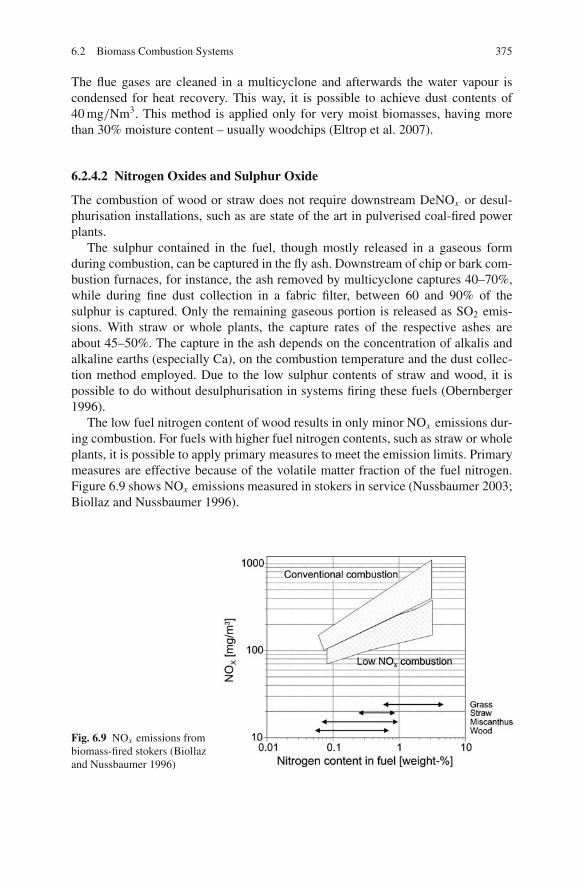
6.2 Biomass Combustion Systems 375
The flue gases are cleaned in a multicyclone and afterwards the water vapour iscondensed for heat recovery. This way, it is possible to achieve dust contents of40 mg/Nm3. This method is applied only for very moist biomasses, having morethan 30% moisture content – usually woodchips (Eltrop et al. 2007).
6.2.4.2 Nitrogen Oxides and Sulphur Oxide
The combustion of wood or straw does not require downstream DeNOx or desul-phurisation installations, such as are state of the art in pulverised coal-fired powerplants.
The sulphur contained in the fuel, though mostly released in a gaseous formduring combustion, can be captured in the fly ash. Downstream of chip or bark com-bustion furnaces, for instance, the ash removed by multicyclone captures 40–70%,while during fine dust collection in a fabric filter, between 60 and 90% of thesulphur is captured. Only the remaining gaseous portion is released as SO2 emis-sions. With straw or whole plants, the capture rates of the respective ashes areabout 45–50%. The capture in the ash depends on the concentration of alkalis andalkaline earths (especially Ca), on the combustion temperature and the dust collec-tion method employed. Due to the low sulphur contents of straw and wood, it ispossible to do without desulphurisation in systems firing these fuels (Obernberger1996).
The low fuel nitrogen content of wood results in only minor NOx emissions dur-ing combustion. For fuels with higher fuel nitrogen contents, such as straw or wholeplants, it is possible to apply primary measures to meet the emission limits. Primarymeasures are effective because of the volatile matter fraction of the fuel nitrogen.Figure 6.9 shows NOx emissions measured in stokers in service (Nussbaumer 2003;Biollaz and Nussbaumer 1996).
Fig. 6.9 NOx emissions frombiomass-fired stokers (Biollazand Nussbaumer 1996)
376 6 Power Generation from Biomass and Waste
6.2.4.3 Chlorine
Chlorine can be captured in fly ash as well. At woodchip and bark combustion facil-ities, capture rates between 40 and 80% have been measured, with the rates for strawand whole plants ranging around 80–85% when applying a downstream fabric filter.Even with an 85% capture of chlorine, the German limit of 30 mg/m3 for straw- andwhole-plant firing systems is exceeded when there are fuel Cl concentrations over0.15% by weight in the dry matter.
Higher chlorine concentrations in consequence require secondary measures suchas a scrubber or ultrafine dust collector combined with dry sorption (Biollaz andNussbaumer 1996). If fabric filters or ESPs are used, the flue gas is mixed with analkaline solid sorbent such as calcium hydroxide (Ca(OH2)2) before entering thefilter. In wet dust collection processes, the removal of acidic pollutant gases withoutadditives is possible but is more effective when alkaline additives are used (Haslerand Nussbaumer 1996).
High chlorine contents may trigger dioxin formation. High combustion tempera-tures and a fast cooling down of the flue gas to the low-temperature area are a meansto ensure low dioxin emissions. Measurements taken at various biomass-fired plantsin service for different fuels (woodchips, bark, straw, whole plants) show that theapplied firing technologies – underfeed, grate and cigar burner – in normal operationcomply with the emission standards laid down in the 17th BImSchV (Ordinance onIncinerators for Waste and Similar Combustible Materials) (Obernberger 1996).
6.2.4.4 Ash Utilisation
The residual matter from the combustion of natural wood can be used as a fertiliserin agriculture and forestry. While the dioxin and furan contents of these ashes areecologically harmless, their heavy metal content must be assessed. The enrichmentof heavy metals in the fine particulates of wood ash prohibits the utilisation inforests. Certain highly volatile heavy metals such as cadmium, lead and zinc concen-trate in the finest ash fraction in the ESP or the fabric filter. Waste disposal strategiesaim at enriching the heavy metals in the ultrafine filter ash (which is disposed of afterremoval) and utilising only the coarse ash from the cyclone together with the grateash (Kaltschmitt et al. 2009; Obernberger and Biedermann 1996).
In Austria, the fertilisation of forests, fields and grassland with cyclone and grateash from wood combustion is a widespread practice, controlled by the authori-ties. Filter ash and sludge from flue gas condensation are always sent to landfill(Kaltschmitt et al. 2009). In Denmark, woodchip ash is often used to fertilise theforest area from which the wood was harvested. The ash from straw-fired ther-mal power plants is mainly used as a fertiliser in agriculture (Nikolaisen 1992).In Germany, the utilisation of biomass ash as a fertiliser and soil conditioner inagriculture and forestry falls under the regulation for fertilisers. Furnace ash frommonofuel combustion of untreated biomass can be used for the production of fer-tilisers and soil conditioners, whereas cyclone or ultrafine fly ashes cannot be usedas a matter of principle. When using herbaceous biomass ash as a fertiliser or when
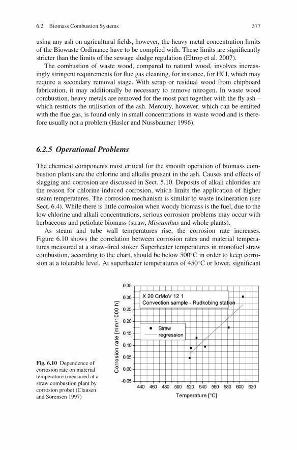
6.2 Biomass Combustion Systems 377
using any ash on agricultural fields, however, the heavy metal concentration limitsof the Biowaste Ordinance have to be complied with. These limits are significantlystricter than the limits of the sewage sludge regulation (Eltrop et al. 2007).
The combustion of waste wood, compared to natural wood, involves increas-ingly stringent requirements for flue gas cleaning, for instance, for HCl, which mayrequire a secondary removal stage. With scrap or residual wood from chipboardfabrication, it may additionally be necessary to remove nitrogen. In waste woodcombustion, heavy metals are removed for the most part together with the fly ash –which restricts the utilisation of the ash. Mercury, however, which can be emittedwith the flue gas, is found only in small concentrations in waste wood and is there-fore usually not a problem (Hasler and Nussbaumer 1996).
6.2.5 Operational Problems
The chemical components most critical for the smooth operation of biomass com-bustion plants are the chlorine and alkalis present in the ash. Causes and effects ofslagging and corrosion are discussed in Sect. 5.10. Deposits of alkali chlorides arethe reason for chlorine-induced corrosion, which limits the application of highersteam temperatures. The corrosion mechanism is similar to waste incineration (seeSect. 6.4). While there is little corrosion when woody biomass is the fuel, due to thelow chlorine and alkali concentrations, serious corrosion problems may occur withherbaceous and petiolate biomass (straw, Miscanthus and whole plants).
As steam and tube wall temperatures rise, the corrosion rate increases.Figure 6.10 shows the correlation between corrosion rates and material tempera-tures measured at a straw-fired stoker. Superheater temperatures in monofuel strawcombustion, according to the chart, should be below 500◦C in order to keep corro-sion at a tolerable level. At superheater temperatures of 450◦C or lower, significant
Fig. 6.10 Dependence ofcorrosion rate on materialtemperature (measured at astraw combustion plant bycorrosion probe) (Clausenand Sorensen 1997)

378 6 Power Generation from Biomass and Waste
corrosion does not occur in straw-fired stokers or cigar burner furnaces. If steamconditions above these temperatures are required, either a limited lifetime of thesuperheater has to be accepted or other fuels such as natural gas, wood or coal haveto be used for superheating. A plant firing straw for the production of 470◦C steamand firing wood for superheating to 540◦C went into service in 1997 (Clausen andSorensen 1997; Johnsen and Svendsen 1997). Severe corrosion can be avoided ifaustenitic steel (TP 347 FG, see Sect. 4.5) is used for the high-temperature sectionof the superheater. Inspections of corrosion at the Maribo Sakskobing plant (livesteam temperature 540◦C) indicated an expected lifetime of more than 25 years(Berg and Jensen 2008).
The important factors influencing the ash fusion behaviour are the concentrationsof the alkaline earths Ca and Mg and the alkalis Na and K. Alkaline earths raise thefusion temperatures, while alkalis lower it. Chlorides, too, may cause the meltingpoint to rise. Herbaceous biomass is the most likely to cause slagging on the grate,in the furnace and on the first superheater due to the high potassium content andthe low ash softening temperature (Clausen and Sorensen 1997). The maximumfurnace temperature should not be higher than 800–900◦C (Obernberger 1996).Homogeneous fuel distribution, staged air injection to control the heat release,water-cooled grates, water- or steam-cooled walls and flue gas recirculation aremeans to limit the furnace temperatures and avoid slagging. In new straw-firedunits precautions against slagging have been taken. A platen pendant superheatersection is located above the furnace, operating as a slag condenser. The wet slagis designed to drip off the platen sections, and, because the spacing is so large, theslag deposits should not grow together to a massive slag formation (Berg and Jensen2008).
In addition, fouling of the other heating surfaces is probable. Due to its smallerfly ash particles, herbaceous biomass poses a greater risk of fouling of the heatingsurfaces than woody biomass. Herbaceous biomass as a feedstock is finer and has alower density and a higher alkali content than wood, which results in the smaller flyash. In straw-fired plants in Denmark, the straw in some years had especially highchlorine and alkali contents, which caused various problems. Severe deposits werefound throughout the entire furnace of both a grate and a cigar burner system, onradiant superheaters and air preheaters, in induced draught fans, ESPs and stacks.The problems could not be solved even by using soot blowers, so after 1–2 weeksof combustion operation with straw the plants had to be shut down and the heatingsurfaces cleaned (Obernberger 1996). However, satisfying boiler operating periods,inter-dispersed by manual cleaning intervals, are expected if pendant superheaterswith large transverse pitches are employed.
In bubbling fluidised bed combustion, defluidisation of the bed resulting fromthe agglomeration of bed grains can be a major problem (Khan 2007; Khan et al.2009). During biomass combustion in a fluidised bed, part of the ash and alkalis arereleased. Ash particles remaining in the bed can glue bed material grains together.This melt phase roughly matches the chemical composition of the ash. Another, evenmore severe type of agglomeration is the so-called coating-induced agglomeration(Visser et al. 2003). Sodium and potassium, released during combustion, form a very

6.3 Biomass Gasification 379
Coating Sintering
Bedparticle
Ash
Sintering
Bedparticle
Gaseousalkalies
Fig. 6.11 Mechanisms of melt-induced and coating-induced agglomeration
thin and sticky coating of the bed grains. This type of agglomeration is believedto be the dominant process in commercial-scale installations. The mechanisms ofmelt-induced and coating-induced agglomeration are shown in Fig. 6.11.
High alkali fuels such as straw are known to provoke severe sintering of thebed, to an extent that the fluidisation can no longer be maintained, and operationmust be halted. Fluidised bed technology is therefore limited in the fuels that it canfire alone – for instance, it is not suitable for the combustion of straw by itself.Investigations into straw combustion at a laboratory-scale furnace revealed that at atemperature of 800◦C, defluidisation sets in after only 20 min. Tests with additives toprevent sintering were not very successful. The addition of coal was found to havea positive effect, though, suggesting a combined combustion of coal and straw influidised beds would be feasible (Lin et al. 1997; Bapat et al. 1997). In certain casesthe use of quartz-free bed materials has also been successful in reducing sintering(Almark and Hiltunen 2005).
6.3 Biomass Gasification
The fundamentals of gasification are described in detail in Sect. 7.6 in the contextof coal-based IGCC applications. Within this chapter, the focus is to discuss thespecial features of biomass gasification, though the principles of reactor design andgas cleaning are very much the same. The major differences in comparison to coalgasification are as follows:
– Due to the lower energy density and more limited availability of the feedstock,plant capacities only in the range of several megawatts up to 50–100 MW areconsidered. These sizes are much smaller than for coal gasification. The sizeof the plant is the dominating parameter for the power production costs anddetermines the choice of the gasification technology (the reactor design andthe gasification medium). The preferred reactor technologies are fixed bed and

380 6 Power Generation from Biomass and Waste
fluidised bed gasification, which, due to their lower gasification temperatures,give higher tar concentrations in comparison to the higher temperatures ofentrained-flow gasification, the standard technology for coal gasification. Forthese capacities, gasifiers are usually air-blown.
– Biomass as a feedstock differs from coal. Biomass has a more inhomogeneouscomposition and particle size distribution, and generally fuel pre-treatment isrequired to produce a homogeneous feedstock suitable for the gasifier type. Ham-mer mills can only be used for relatively dry materials; to homogenise the sizeof wet materials, chippers equipped with blades can be used. Feeding must suitthe higher bulk densities and the higher moisture contents that biomasses usuallyhave, and therefore the feeding may require pre-drying. The higher volatile con-tents (in comparison to coal) are beneficial, requiring less residence time in thereactor for the conversion of the carbon, though the generally higher particle sizemay counteract this advantage. Alkali concentrations in the ash are higher thanfor coal.
6.3.1 Reactor Design Types
A large variety of gasification reactor designs are available for small and largescales. The designs can be classified in different ways (Kaltschmitt et al. 2009;Hofbauer 2007; Knoef and Ahrenfeldt 2005; Kaltschmitt and Bridgwater 1997;Spliethoff 2001; Kaltschmitt 2001; Higman and van der Burgt 2008; de Jong 2005),the most common being the following:
According to the gasification medium:
– Air-blown gasifiers– Oxygen-blown gasifiers– Steam gasifiers
According to the heat supply for the gasification:
– Autothermal or direct gasifiers: Heat is supplied by partial oxidation ofthe biomass, which results in a lower heating value of the product gas.
– Allothermal or indirect gasifiers: Heat is supplied from an external heatsource, or for two-stage gasifiers, from the combustion zone to the gasifi-cation zone.
According to the pressure in the gasifier:
– Atmospheric– Pressurised
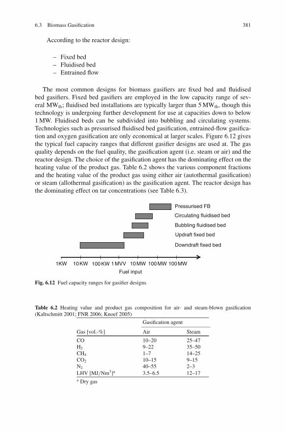
6.3 Biomass Gasification 381
According to the reactor design:
– Fixed bed– Fluidised bed– Entrained flow
The most common designs for biomass gasifiers are fixed bed and fluidisedbed gasifiers. Fixed bed gasifiers are employed in the low capacity range of sev-eral MWth; fluidised bed installations are typically larger than 5 MWth, though thistechnology is undergoing further development for use at capacities down to below1 MW. Fluidised beds can be subdivided into bubbling and circulating systems.Technologies such as pressurised fluidised bed gasification, entrained-flow gasifica-tion and oxygen gasification are only economical at larger scales. Figure 6.12 givesthe typical fuel capacity ranges that different gasifier designs are used at. The gasquality depends on the fuel quality, the gasification agent (i.e. steam or air) and thereactor design. The choice of the gasification agent has the dominating effect on theheating value of the product gas. Table 6.2 shows the various component fractionsand the heating value of the product gas using either air (autothermal gasification)or steam (allothermal gasification) as the gasification agent. The reactor design hasthe dominating effect on tar concentrations (see Table 6.3).
Pressurised FB
Circulating fluidised bed
Bubbling fluidised bed
Updraft fixed bed
Downdraft fixed bed
Fuel input
1KW 10 KW 1 MVV100 KW 100 MW10 MW 100 MW
Fig. 6.12 Fuel capacity ranges for gasifier designs
Table 6.2 Heating value and product gas composition for air- and steam-blown gasification(Kaltschmitt 2001; FNR 2006; Knoef 2005)
Gasification agent
Gas [vol.-%] Air Steam
CO 10–20 25–47H2 9–22 35–50CH4 1–7 14–25CO2 10–15 9–15N2 40–55 2–3LHV [MJ/Nm3]a 3.5–6.5 12–17a Dry gas
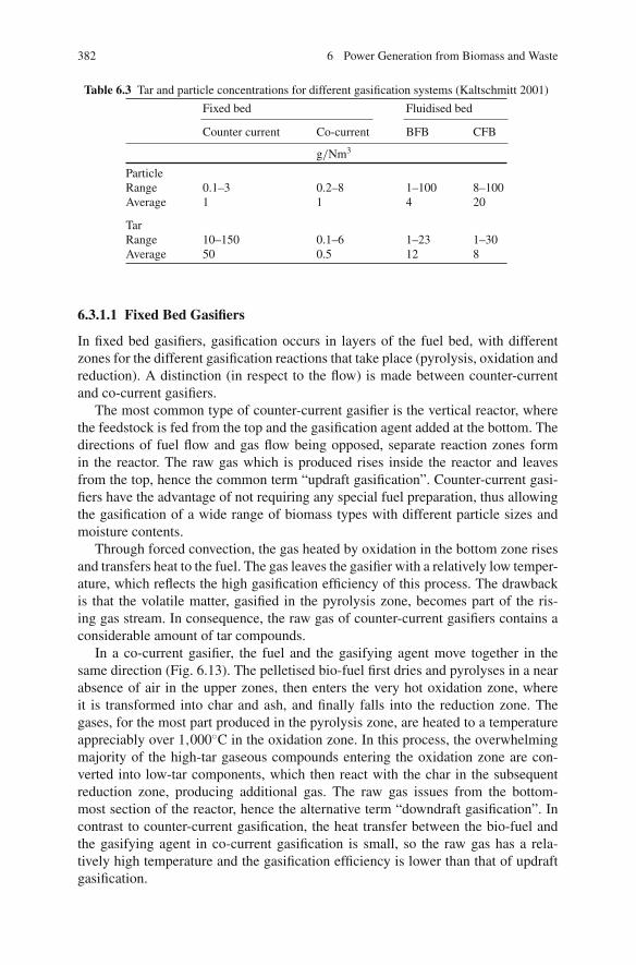
382 6 Power Generation from Biomass and Waste
Table 6.3 Tar and particle concentrations for different gasification systems (Kaltschmitt 2001)
Fixed bed Fluidised bed
Counter current Co-current BFB CFB
g/Nm3
ParticleRange 0.1–3 0.2–8 1–100 8–100Average 1 1 4 20
TarRange 10–150 0.1–6 1–23 1–30Average 50 0.5 12 8
6.3.1.1 Fixed Bed Gasifiers
In fixed bed gasifiers, gasification occurs in layers of the fuel bed, with differentzones for the different gasification reactions that take place (pyrolysis, oxidation andreduction). A distinction (in respect to the flow) is made between counter-currentand co-current gasifiers.
The most common type of counter-current gasifier is the vertical reactor, wherethe feedstock is fed from the top and the gasification agent added at the bottom. Thedirections of fuel flow and gas flow being opposed, separate reaction zones formin the reactor. The raw gas which is produced rises inside the reactor and leavesfrom the top, hence the common term “updraft gasification”. Counter-current gasi-fiers have the advantage of not requiring any special fuel preparation, thus allowingthe gasification of a wide range of biomass types with different particle sizes andmoisture contents.
Through forced convection, the gas heated by oxidation in the bottom zone risesand transfers heat to the fuel. The gas leaves the gasifier with a relatively low temper-ature, which reflects the high gasification efficiency of this process. The drawbackis that the volatile matter, gasified in the pyrolysis zone, becomes part of the ris-ing gas stream. In consequence, the raw gas of counter-current gasifiers contains aconsiderable amount of tar compounds.
In a co-current gasifier, the fuel and the gasifying agent move together in thesame direction (Fig. 6.13). The pelletised bio-fuel first dries and pyrolyses in a nearabsence of air in the upper zones, then enters the very hot oxidation zone, whereit is transformed into char and ash, and finally falls into the reduction zone. Thegases, for the most part produced in the pyrolysis zone, are heated to a temperatureappreciably over 1,000◦C in the oxidation zone. In this process, the overwhelmingmajority of the high-tar gaseous compounds entering the oxidation zone are con-verted into low-tar components, which then react with the char in the subsequentreduction zone, producing additional gas. The raw gas issues from the bottom-most section of the reactor, hence the alternative term “downdraft gasification”. Incontrast to counter-current gasification, the heat transfer between the bio-fuel andthe gasifying agent in co-current gasification is small, so the raw gas has a rela-tively high temperature and the gasification efficiency is lower than that of updraftgasification.

6.3 Biomass Gasification 383
Gas Air
AirAir
Gas
Grate
Ash
Heart
Fuel
Drying zone Drying zone
Pyrolysis zonePyrolysis zone
Oxidation zone
Oxidation zone
Reduction zone
Reduction zone
Fuel
Temperaturelevel
200 °C
400 °C
600 °C
950 °C
1300 °C
Fig. 6.13 Co-current gasifier (downdraft gasification, left) and counter-current gasifier (updraftgasification)
There is also a higher tendency for slag to form in co-current gasifiers than incounter-current gasifiers because of the high temperatures in the oxidation zone.A uniform temperature distribution within the individual reactor zones and a highpermeability of the char to the gas are decisive factors for the gas quality. Co-currentgasifiers therefore require a greater degree of fuel preparation to adjust the fuelparticle size and the moisture content. The major advantage of co-current gasifiersis that the raw gas produced contains far less tar products than the gas from counter-current gasifiers.
Fixed bed gasifiers are generally atmospheric, air-blown (autothermal) and fuelledby wood, the latter of which results in a typical product gas heating value ofbetween 4 and 6 MJ/m3. The gas can be used for heating purposes or in gas engines.Co-current bed gasifiers are superior to counter-current installations because of theirlower tar concentrations, which are in the range of several 100 mg/m3. Quite alarge number of fixed bed gasifiers have been tested, demonstrated or operated.However, most installations have had operational problems with fuel feeding, thegasifier itself, gas cleaning and prime movers. Current development concentrates onsolving problems to do with automation, fuel feeding, the operation of the gasifier,gas cleaning and treatment of by-products. The tar concentrations are still a majorconcern.
A number of installations have been operated successfully in India for severalyears. These systems can be characterised by a near total absence of automation andby the use of wet gas cleaning with a sand bed filter for final tar removal. Europeanstandards, however, require fully automated installations and a gas cleaning systemwith disposable by-products.
Fluidised Bed Gasification
Fluidised bed gasification makes use of the advantageous mixing, reaction kinetics,gas – solid contact and heat transfer, as well as the ability to inject additives, of

384 6 Power Generation from Biomass and Waste
Fig. 6.14 Operating principles of fluidised bed gasifiers
fluidised beds. The bed material usually used is silica sand or, for high ash fuels, theash of the fuel. The gasification temperature is typically around 800◦C. The longresidence time of the solid fuel and the intensive mixing are the reasons why veryhigh gasification rates are achieved. The basic design types are bubbling (BFB) andcirculating (CFB) fluidised beds, which can be seen in Fig. 6.14.
In a bubbling fluidised bed, the oxidant velocity is significantly lower than theterminal velocity of the bed material. The freeboard (the free space in the furnaceabove the bed) therefore has a gas flow which contains only small ash particles.In a circulating fluidised bed, in contrast, the oxidant approach velocity lies in theorder of magnitude of the terminal velocity, and as a consequence the bed material iscarried into the freeboard, thus forming a gas/solids flow through the entire reactor.By way of a cyclone, the transported bed material is separated from the gas streamand recirculated into the reactor. CFBs have significantly higher specific outputs.In addition, the gas/solids flow makes the mixing efficiency higher than in BFBs,which results in a better fuel conversion and lower tar contents. Drawbacks are thestricter fuel form requirements (the fuel needs to be in the form of grains) and thesignificantly higher pressure loss (meaning a higher process power consumption).What is more, controlling the bed material and the recirculation flow is more com-plex and the construction must be much taller than for a BFB. For lower outputs, abubbling fluidised bed is therefore the better solution. With respect to the tar content,bubbling fluidised beds perform much worse (by about one order of magnitude) thanco-current fixed bed gasifiers. Circulating fluidised beds are somewhat better, but donot reach the low concentrations of co-current fixed bed gasifiers.
In nearly all medium-to-large-scale electricity-producing biomass gasificationdemonstration plants to date, circulating fluidised beds (CFB) have been the preferred

6.3 Biomass Gasification 385
technology. The main reasons are that CFBs can handle a high throughput, are easyto scale up and accept a wide range of fuels. However, tar conversion or tar scrub-bing is required for all cold gas applications, that is, where the gas is fed to a boileror an engine at ambient temperatures (Knoef and Ahrenfeldt 2005). Table 6.4 givessome examples of fluidised bed gasifiers in operation, but does not intend to providea complete list. All CFB gasifiers are air-blown and produce a product gas with anLHV of 4–6 MJ/Nm3 (with wood as the fuel).
Pressurised gasification technology was successfully demonstrated from 1993to 2000 in the world’s first complete BIGCC (Biomass Integrated Gasification
Table 6.4 Medium-to-large-scale fluidised bed biomass gasification plants (Spliethoff 2001;Knoef 2005)
Gasifier FuelsUse of productgas
Start of operation/shutdown
Ruedersdorf,Germany
100 MW ACFB,Lurgi
wood, RDF,lignite,waste
Cement kiln 1996
Pietarsaari, Finland 35 MW ACFB,FW
Bark, Wood,waste
Lime kiln 1983
Norrsundet, Sweden 27 MW ACFB,FW
Bark, woodwaste
Lime kiln 1985
Rodao Mill,Portugal
17 MW ACFB,FW
Bark, woodwaste
Lime kiln 1986
Zeltweg, Austria 10 MW ACFB,AEE
Wood PC co-firing 1997–2000
Lahti, Finland 40–70 MWACFB, FW
PC/NG boiler 1997
Geertruidenberg,Netherlands
80 MW ACFB,Lurgi
Wood waste PC co-firing 2000
Ruien, Belgium 86 MW ACFB PC co-firing 2002Greve-in-Chianti,
Italy2 × 15 MW
ACFB, TPSRDF Steam cycle
7 MWe
1993
Burlington, USA BattelleColumbusintercon-nectedCFBs
Initially steamcycle powerplant
1997/shut down
Hawaii, USA IGT RenugasPressurisedBFB
Gas cleanuptesting
1995–1997
Varnamo, Sweden(Bioflow)
18 MW PCFB,FW
IGCC 1993/1999
Tampere, FinlandBiocycle
7 MWe PBFBCarbona
IGCC Unknown
Aire Valley, UnitedKingdom(ARBRE)
8 MWe ACFB,TPS
Willow,poplar
IGCC 2001
Gussing, Austria 8 MW FICFB Woodchips Gas engine 2001
ACFB: atmospheric circulating FB, PBFB: pressurised bubbling FB, PCFB: pressurised circu-lating FB, FICFB: fast internal circulating FB, FW: Foster Wheeler, AEE: Austrian Energy &Environment, TPS: Termiska Processor AB
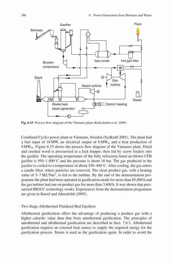
386 6 Power Generation from Biomass and Waste
Biomass
Hot gas filter
Flare
Boostercompressor
Stack
Waste heatsteam generator
Gas cooler
Gas turbine
District heating
Gasifier
Diesel
Steam turbine
~
~
~
~
Fig. 6.15 Process flow diagram of the Varnamo plant (Kaltschmitt et al. 2009)
Combined Cycle) power plant in Varnamo, Sweden (Sydkraft 2001). The plant hada fuel input of 18 MW, an electrical output of 6 MWel and a heat production of9 MWth. Figure 6.15 shows the process flow diagram of the Varnamo plant. Driedand crushed wood is pressurised in a lock hopper, then fed by screw feeders intothe gasifier. The operating temperature of the fully refractory-lined air-blown CFBgasifier is 950–1,000◦C and the pressure is about 18 bar. The gas produced in thegasifier is cooled to a temperature of about 350–400◦C. After cooling, the gas entersa candle filter, where particles are removed. The clean product gas, with a heatingvalue of 5–7 MJ/Nm3, is fed to the turbine. By the end of the demonstration pro-gramme the plant had been operated in gasification mode for more than 85,000 h andthe gas turbine had run on product gas for more than 3,600 h. It was shown that pres-surised BIGCC technology works. Experiences from the demonstration programmeare given in Knoef and Ahrenfeldt (2005).
Two-Stage Allothermal Fluidised Bed Gasifiers
Allothermal gasification offers the advantage of producing a product gas with ahigher calorific value than that from autothermal gasification. The principles ofautothermal and allothermal gasification are described in Sect. 7.6.3. Allothermalgasification requires an external heat source to supply the required energy for thegasification process. Steam is used as the gasification agent. In order to avoid the
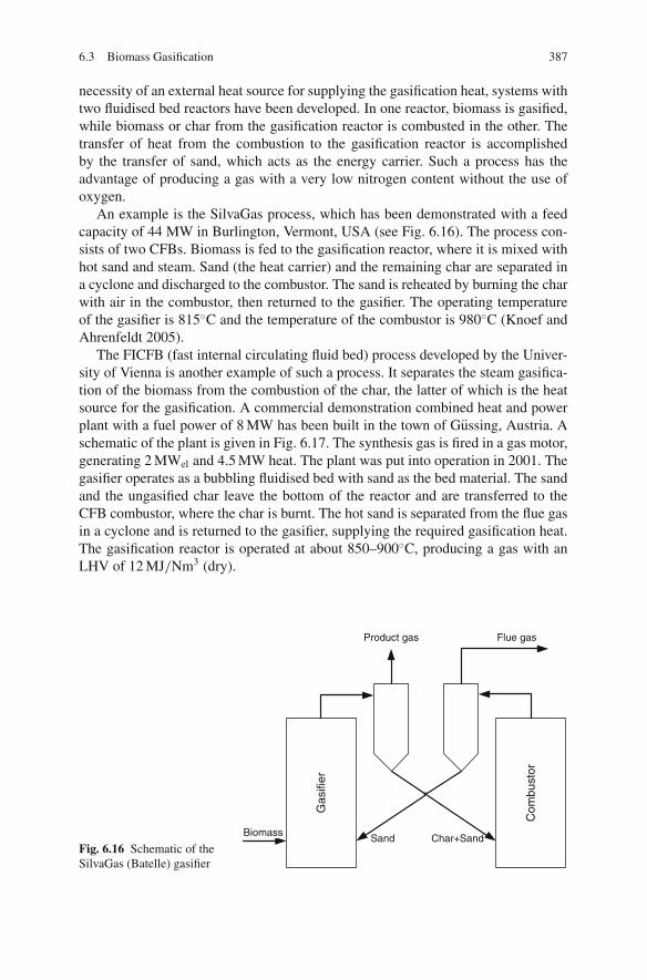
6.3 Biomass Gasification 387
necessity of an external heat source for supplying the gasification heat, systems withtwo fluidised bed reactors have been developed. In one reactor, biomass is gasified,while biomass or char from the gasification reactor is combusted in the other. Thetransfer of heat from the combustion to the gasification reactor is accomplishedby the transfer of sand, which acts as the energy carrier. Such a process has theadvantage of producing a gas with a very low nitrogen content without the use ofoxygen.
An example is the SilvaGas process, which has been demonstrated with a feedcapacity of 44 MW in Burlington, Vermont, USA (see Fig. 6.16). The process con-sists of two CFBs. Biomass is fed to the gasification reactor, where it is mixed withhot sand and steam. Sand (the heat carrier) and the remaining char are separated ina cyclone and discharged to the combustor. The sand is reheated by burning the charwith air in the combustor, then returned to the gasifier. The operating temperatureof the gasifier is 815◦C and the temperature of the combustor is 980◦C (Knoef andAhrenfeldt 2005).
The FICFB (fast internal circulating fluid bed) process developed by the Univer-sity of Vienna is another example of such a process. It separates the steam gasifica-tion of the biomass from the combustion of the char, the latter of which is the heatsource for the gasification. A commercial demonstration combined heat and powerplant with a fuel power of 8 MW has been built in the town of Gussing, Austria. Aschematic of the plant is given in Fig. 6.17. The synthesis gas is fired in a gas motor,generating 2 MWel and 4.5 MW heat. The plant was put into operation in 2001. Thegasifier operates as a bubbling fluidised bed with sand as the bed material. The sandand the ungasified char leave the bottom of the reactor and are transferred to theCFB combustor, where the char is burnt. The hot sand is separated from the flue gasin a cyclone and is returned to the gasifier, supplying the required gasification heat.The gasification reactor is operated at about 850–900◦C, producing a gas with anLHV of 12 MJ/Nm3 (dry).
Fig. 6.16 Schematic of theSilvaGas (Batelle) gasifier
Gas
ifier
Com
bust
or
Biomass
Product gas
Sand Char+Sand
Flue gas

388 6 Power Generation from Biomass and Waste
Productgas cooler
Productgas filter
Productgas scrubber
Catalyst
G
Gasengine
air
Flue gas cooler
Stack
Districtheatingboiler
Fly ash
Flue gascollerAir
Bed ash
Steam
Biomass
Gasifier
Cyclone
Combustor
G
Fig. 6.17 Schematic of the Gussing plant (from Higman and van der Burgt 2008, c© 2008, withpermission of Elsevier)
Entrained-Flow Gasification
Entrained-flow gasification (described in more detail in Sect. 7.6) is the most com-mon process for coal gasification. Despite the trend of using fluidised beds forbiomass gasification, there are some cases of biomass gasification using entrained-flow technology.
One example is the Choren process, which is a combination of a low-temperaturepyrolysis process with a two-stage entrained-flow gasifier, as shown in Fig. 6.18.
Low temperaturegasifier Carbo-V gasifier
Oxygen
Biomass Pyrolysis gasRawgas
Steam
BFW
Deduster
Syngas
Mill
Char
Vitrifiedslag
Residualchar/ash
Wastewater
Oxygen
Gasscrubber
Fig. 6.18 Process flow diagram of the Choren process (from Higman and van der Burgt 2008, c©2008, with permission of Elsevier)
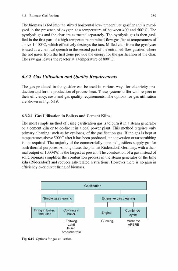
6.3 Biomass Gasification 389
The biomass is fed into the stirred horizontal low-temperature gasifier and is pyrol-ysed in the presence of oxygen at a temperature of between 400 and 500◦C. Thepyrolysis gas and the char are extracted separately. The pyrolysis gas is then gasi-fied in the first part of a high-temperature entrained-flow gasifier at temperatures ofabove 1,400◦C, which effectively destroys the tars. Milled char from the pyrolyseris used as a chemical quench in the second part of the entrained-flow gasifier, wherethe hot gases from the first zone provide the energy for the gasification of the char.The raw gas leaves the reactor at a temperature of 800◦C.
6.3.2 Gas Utilisation and Quality Requirements
The gas produced in the gasifier can be used in various ways for electricity pro-duction and for the production of process heat. These systems differ with respect totheir efficiency, costs and gas quality requirements. The options for gas utilisationare shown in Fig. 6.19.
6.3.2.1 Gas Utilisation in Boilers and Cement Kilns
The most simple method of using gasification gas is to burn it in a steam generatoror a cement kiln or to co-fire it in a coal power plant. This method requires onlyprimary cleaning, such as by cyclones, of the gasification gas. If the gas is kept attemperatures above 500◦C after it has been produced, tar conversion or tar scrubbingis not required. The majority of the commercially operated gasifiers supply gas forsuch thermal purposes. Among these, the plant at Rudersdorf, Germany, with a ther-mal output of 100 MW, is the largest at present. The combustion of a gas instead ofsolid biomass simplifies the combustion process in the steam generator or the limekiln (Rudersdorf) and reduces ash-related restrictions. However there is no gain inefficiency over direct firing of biomass.
Gasification
Simple gas cleaning
Firing in boiler,lime kilns
Co-firing inboiler Engine
Combinedcycle
ZeltwegLahtiRuien
Amercentrale
Güssing VärnamoARBRE
Extensive gas cleaning
Fig. 6.19 Options for gas utilisation

390 6 Power Generation from Biomass and Waste
Utilisation in Gas Engines and Gas Turbines
Gas utilisation in a turbine, motor or fuel cell for power production offers a higherefficiency than combustion in a steam generator.
The gas quality requirements for these applications are very high. In order toavoid fouling and deposits in the engine, the gas should be tar and dust free to ahigh degree. Typical concentration requirements for gas engines and gas turbinesare listed in Table 6.5. Turbo-charged engines require an even higher gas qual-ity for operation. It should be noted that the values given in published literaturevary. Gasifiers available on the market today far exceed the indicated values whenoperated without gas cleaning. The removal of both tar and particles is therefore aprerequisite. The required concentrations are the result of a compromise betweenincreased gas cleaning expenditure and a higher engine or turbine maintenancedemand.
Engines are suitable for capacities between 50 kWel and 10 MWel and are usedin connection with atmospheric fixed bed or fluidised bed gasifiers. With engines,the maximum electricity production efficiency is around 30%, although by includingwaste heat utilisation, the overall efficiency can be higher. Smaller plants yield lowerefficiencies of up to about 25%. These efficiencies are somewhat above those thatcan be achieved by steam turbines in this capacity range.
From a capacity of about 5 MWel, gas turbines are the better technology. Thegasifiers suitable for use in connection with such turbines are atmospheric or pres-surised fluidised bed reactors. With gas turbines, it is possible to increase the effi-ciency up to 45% by installing a tailing waste-heat boiler with a further steam tur-bine (capacities > 25 MWel).
Only a few integrated gasification processes using gas turbines have been demon-strated, so experience with such plants is limited. In Vaernamo, Sweden, a pres-surised fluidised bed furnace with an electrical output of 6 MWel was in servicefrom 1993 to 2000 (see Fig. 6.15). An atmospheric bubbling fluidised bed using theTPS (Termiska Processor AB) system, with an electric output of 8 MWel, was putinto service in 2000 (ARBRE Project, Great Britain). Both systems are now out ofservice due to economic reasons.
Table 6.5 Gas quality requirements for gas engines and gas turbines (FNR 2006; Spliethoff 2001;Kaltschmitt 2009)
Gas engine Gas turbine
LHV [MJ/Nm3] > 2 > 5Tar [mg/Nm3] < 100 < 5Particle [mg/Nm3] < 50 < 30Particle size [μm] < 3 < 5Ammonia [mg/Nm3] < 30–55H2S [mg/Nm3] < 1,150 < 1Alkalis [mg/Nm3] < 50 < 3Halogens [mg/Nm3] < 100 < 2

6.3 Biomass Gasification 391
6.3.3 Gas Cleaning
Gas cleaning for biomass gasification remains an area of uncertainty, in need ofdevelopment. Gas cleaning depends on the cycle arrangement and the gas qualityrequirements of the gas engine or gas turbine.
Atmospheric gasification systems require the removal of both particulates andtars. In atmospheric systems in which the product gas is fed to an engine or a com-pressor, cooling of the product gas down to about 50◦C is required. In such cases, themost simple method for cleaning is to perform the separation of particles and tars inone step at the temperature that the gas is used at. Separation uses physical methodswhich require the cooling of the gas prior to cleaning, such as wet scrubbing or wetelectrostatic precipitation.
The separate collection of tars and particles is a strategy applied in dry, high-temperature gas cleaning systems, using hot gas particle filtration and a thermal orcatalytic cracker for tar reduction. Separate removal processes can also be advanta-geous when the tar separation unit, for example, a scrubber with an organic solventat low temperatures, requires a low product gas particle content. Disposal restric-tions, for instance, the forbidding of a mix of tars, particles and water to be dis-charged, may also necessitate separate removal processes.
Pressurised systems with gas utilisation in a turbine do not require a tar separationstep if the gas flow can be kept above the dew point of the tars. In this case thechemical energy of the tars can be exploited in the turbine. Solids are removed inhot gas filters at temperatures of 400–500◦C; typically, ceramic or metal candlefilters with back-pulsing are employed. The temperature of the filtration step has tobe below 500◦C so that alkalis can be removed by condensation on the particles.Temperatures below 400◦C have to be avoided to prevent tar condensation. Lowertemperatures reduce the efficiency of the cycle because of losses of sensible heat andchemical energy in the tars (FNR 2006; Knoef and Ahrenfeldt 2005; Kaltschmitt2001; Spliethoff 2001).
6.3.3.1 Tar Formation in Gasification
Tars are organic compounds (hydrocarbons), which condense at room temperature.The tar species formed in gasification are aromatic, heterocyclic aromatic or poly-aromatic hydrocarbons. The species that are commonly found in fractions above 5%are toluene, naphthalene and, when process temperatures are below 800◦C, phenol.A great number of compounds occur only as trace elements, but taken as a groupthey can also constitute a considerable fraction of the tar quantity.
While the literature does not provide a uniform definition of the term “tarspecies”, efforts have been undertaken in European projects to standardise tar clas-sification and tar measurements. Based on the so-called tar guideline (or “tar proto-col”), a CEN (Comite Europeen de Normalisation) standard (CEN Technical Spec-ification) has been developed (Neeft et al. 2002; Good et al. 2005; Coda et al. 2004;DIN 2006). The intention is to make tar measurements in gases produced frombiomass comparable.

392 6 Power Generation from Biomass and Waste
Fig. 6.20 Tar classification and chemical structure of selected tars. GC = gas chromatograph
The “tar guideline” defines tars as the group of all organic compounds excludinggaseous hydrocarbons (C1–C6) and benzene. Benzene is not included because itdoes not condense at room temperatures at the concentrations typical of biomassgasification. The classification system in the “tar guideline” reports five differentclasses of individual tar compounds, as shown in Fig. 6.20 along with chemicalstructures of some typical tar components.
Class 1 consists of heavy poly-aromatic hydrocarbons (PAH) which cannot bedetected with a gas chromatograph (GC) and is determined by subtracting the GC-detectable tar fraction from the total gravimetric tar. Class 2 tars are aromatic com-pounds with hetero atoms (pyridine, phenol) while class 3 tars are light compoundswith one aromatic ring (xylene, styrene, toluene). The last two categories, classes4 and 5, consist of light polycyclic aromatic hydrocarbons (PAH) with two or threearomatic rings (naphthalene, fluorene, anthracene) and heavy PAH with four to fivearomatic rings (pyrene) (Neeft et al. 2002).
Whether a component condenses when the temperature falls below the boilingpoint depends on the steam pressure and on the concentration. Figure 6.21 showsthe saturation concentration of some typical tar components and benzene in nitro-gen. Benzene at 25◦C, for instance, reveals a saturation concentration of more than300 g/m3. Since this value is higher than the typical concentrations in product gasesby orders of magnitude, the condensation of benzene is not to be expected and ben-zene is not considered a tar. On the other hand, components such as fluorene havesaturation concentrations of only a few milligrams per cubic metre at 25◦C, so analmost complete condensation has to be taken into account.
The measurement of the dew point gives the highest temperature at whichthe first tar molecules can condense, information which is required to prevent a
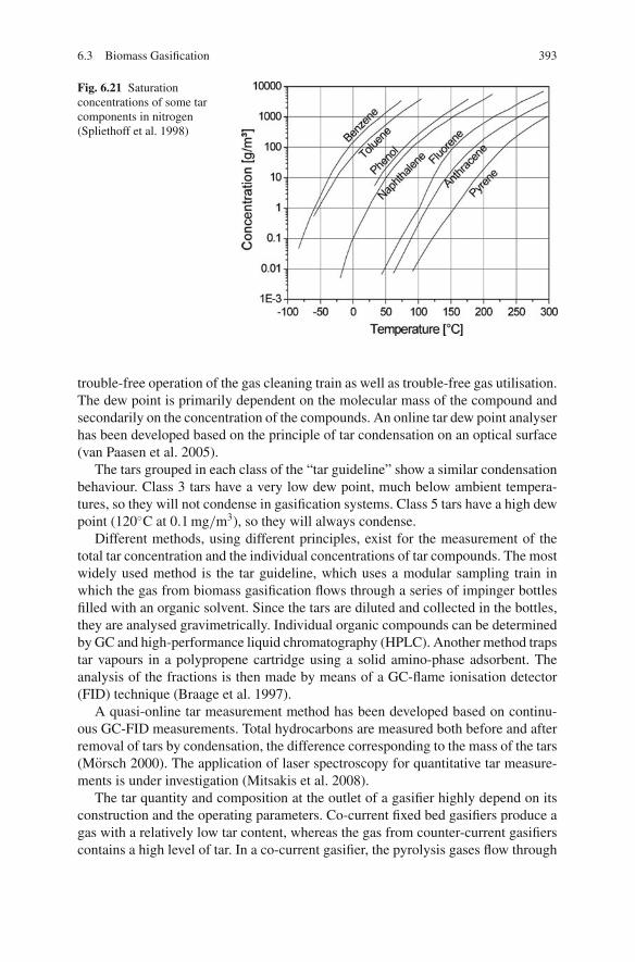
6.3 Biomass Gasification 393
Fig. 6.21 Saturationconcentrations of some tarcomponents in nitrogen(Spliethoff et al. 1998)
trouble-free operation of the gas cleaning train as well as trouble-free gas utilisation.The dew point is primarily dependent on the molecular mass of the compound andsecondarily on the concentration of the compounds. An online tar dew point analyserhas been developed based on the principle of tar condensation on an optical surface(van Paasen et al. 2005).
The tars grouped in each class of the “tar guideline” show a similar condensationbehaviour. Class 3 tars have a very low dew point, much below ambient tempera-tures, so they will not condense in gasification systems. Class 5 tars have a high dewpoint (120◦C at 0.1 mg/m3), so they will always condense.
Different methods, using different principles, exist for the measurement of thetotal tar concentration and the individual concentrations of tar compounds. The mostwidely used method is the tar guideline, which uses a modular sampling train inwhich the gas from biomass gasification flows through a series of impinger bottlesfilled with an organic solvent. Since the tars are diluted and collected in the bottles,they are analysed gravimetrically. Individual organic compounds can be determinedby GC and high-performance liquid chromatography (HPLC). Another method trapstar vapours in a polypropene cartridge using a solid amino-phase adsorbent. Theanalysis of the fractions is then made by means of a GC-flame ionisation detector(FID) technique (Braage et al. 1997).
A quasi-online tar measurement method has been developed based on continu-ous GC-FID measurements. Total hydrocarbons are measured both before and afterremoval of tars by condensation, the difference corresponding to the mass of the tars(Morsch 2000). The application of laser spectroscopy for quantitative tar measure-ments is under investigation (Mitsakis et al. 2008).
The tar quantity and composition at the outlet of a gasifier highly depend on itsconstruction and the operating parameters. Co-current fixed bed gasifiers produce agas with a relatively low tar content, whereas the gas from counter-current gasifierscontains a high level of tar. In a co-current gasifier, the pyrolysis gases flow through

394 6 Power Generation from Biomass and Waste
Fig. 6.22 Contribution ofeach gas component to thechemical energy of theproduct gas (beach wood,800◦C, λ = 0.25) (Morsch2000; Spliethoff et al. 1998)
CO 28%CH4 23%
C2 + 12%H2 30%
Benzene 2.1%Other tars 5%
Toluene 0.4%
the hot reaction zone, which results in the tar species getting cracked. The tar contentof the product gas from fluidised bed gasification lies between these two values.
Investigations carried out in a bench-scale fluidised bed gasifier have revealed theimpact of process conditions on tar formation. The reference case is the standard testwith beech wood as the fuel, sand as the bed material, a gasification temperature of800◦C and an air ratio of λ = 0.25. The tar concentration in this case was 8.2 g/m3.Figure 6.22 shows the contribution of each of the gas components to the total heatingvalue of the product gas of 5.2 MJ/m3.
Figure 6.23 gives the tar content of the product gas under variations of the operat-ing and fuel parameters. The graphic shows for each case the tar concentrations after
0
4
8
12
16
20
Fin
e m
illin
g
Gas
vel
ocity
0.9
m/s
Sta
ndar
d
10%
moi
stur
e
Sew
ages
ludg
e
CF
B
900
°C
λ=
0.3
5
Woo
d, 9
20 °
C, λ
= 0
.35
Sew
ages
ludg
e, 9
00 °
C,
λ=
0.4
5
Dol
omite
Opt
imum
, Dol
omite
, 920
°C
, λ=
0.3
5
Fig. 6.23 Influence on the tar content of the tested operating parameters compared to the standardtest case for a bench-scale fluidised bed (Morsch 2000; Spliethoff et al. 1998)
6.3 Biomass Gasification 395
a modification of a parameter in comparison to the reference case. With increasingprocess temperatures and air ratios, the tar content drops. At higher temperatures,there is also a shift in the tar composition towards lighter components. It should benoted that an electrically heated facility such as this bench-scale fluidised bed gasi-fier enables the air ratio and the temperature to be varied independently, whereas ina real autothermal gasifier, the air ratio and the gasification temperature are coupled.High temperatures in the bed can be limited by bed agglomeration.
The most effective measure to reduce tar concentrations established in the testswas the use of a catalytic material – in particular, dolomite. When employing thismaterial, tar concentrations suitable for the direct utilisation of the gas are reachedat temperatures above 900◦C. The lowest tar concentrations using a dolomite bed, ofjust 250 mg/m3, were produced at 920◦C and an air ratio of λ = 0.35. The resultingcalorific value was 5.2 MJ/m3 at a cold gas efficiency of 85%. The main problem inusing this technique is the low abrasion resistance of burned dolomite, meaning thecatalyst gets entrained in the gas flow along with some of the bed material. To makeup for this loss, it is necessary to constantly add a certain amount of bed material.
6.3.3.2 Secondary Tar Reduction
Tar cleaning is required if the product gas has to be cooled prior to use (for example,when used in gas engines) or if it has to be compressed (as in a combined cycleprocess with an atmospheric gasifier). The amount of tars present in the productgas, as described previously, depends on the gasification temperature, the reactordesign and the biomass type. In most cases primary measures for tar reduction arenot sufficient to meet the requirements for gas utilisation, so secondary measures fortar removal have to be implemented. These measures can take the form of a physicalseparation or a chemical conversion of the tars.
– In most cases physical methods are used for tar reduction. The two most commonmethods are scrubbing and electrostatic precipitation. Both methods remove thetars in a condensed form, which requires the gas to be cooled prior to the clean-ing step. If the separated tars are not recycled to the gasification reactor, theirchemical energy is lost from the process, reducing the cycle efficiency. Physicalseparation of tars and particles can be performed in a single step in one device atlow temperatures.
– Chemical conversion of tars into lighter gas components can be achieved by ther-mal or catalytic tar cracking. After such processes, the chemical energy of thetars can be used to increase the heating value of the product gas.
Scrubbers
Wet scrubbing is the most common method for tar removal. If water is used as thescrubbing medium, the tar separation efficiency is limited and multistage cleaning

396 6 Power Generation from Biomass and Waste
may be required. In order to be able to separate tars in a wet scrubber, the tarshave to be condensed so that the aerosols and droplets collide with the water andincrease their particle size. For this reason the product gas has to be cooled andsaturated with water before the cleaning step. Because tars are hydrophobic andhave a low solubility in water, tars which remain in the vapour phase cannot beremoved.
Using a wet water scrubber to remove tar from the product gas requires a gastemperature of 30–60◦C. Different washer types are in operation, for example,tower, rotating tower and Venturi washers. To achieve a higher tar removal effi-ciency, washers tend to be multistage, meaning a higher pressure drop. Clean gasconcentrations of 20–40 mg/m3 can be achieved.
By using lipophilic liquids, which can act as solvents and so are used as a scrub-bing medium, gas phase tars can also be removed. At the Gussing plant in Austria,a wet scrubber is used with oil (RME) as the scrubbing liquid. Used oil, saturatedwith tars and condensate, is vaporised and recycled to the gasifier. Another scrub-bing technology (OLGA) has been developed and patented by ECN. The removalof tars is accomplished by scrubbing the tar-loaded product gas with a speciallydeveloped liquid oil in an absorption column. Tar removal efficiencies of 99% of theheterocyclic tars and almost all the heavy and light tars have been measured. Thedew point of tars is as low as −17◦C. The current design of the OLGA technologyrequires a dust-free gas.
Fixed Bed Filters
Fixed bed filters employing sand, saw dust or other materials as the filter mediumare usually used in smaller units due to their simple design. Sand filters have a highremoval efficiency of up to 95%, but use of them is problematic because of the needto dispose of the contaminated bed sand.
Wet Electrostatic Precipitators
A wet ESP, which is operated at temperatures of about 60◦C, is a more attractivesolution than a wet scrubber due to a higher removal efficiency, a lower pressuredrop and a lower quantity of waste water being produced. The gas is cooled andsaturated with water prior to the cleaning, then the liquid droplets and particlesare separated by electrostatic precipitation. The removal of the condensed tars isimproved by the use of a small water stream to flush them away. The ESP has theadvantage of high particle and tar removal rates. The water – tar – dust mixture canbe fed back into the gasifier.
Catalytic Tar Reduction
Higher tar reduction rates than those of physical gas cleaning can be achieved withcatalytic hot gas cleaning at temperatures between 800 and 900◦C. In this process,
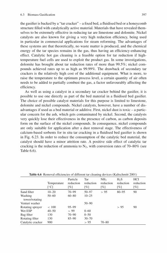
6.3 Biomass Gasification 397
the gasifier is backed by a “tar cracker” – a fixed bed, a fluidised bed or a honeycombstructure filled with catalytically active material. Materials that have revealed them-selves to be extremely effective in reducing tar are limestone and dolomite. Nickelcatalysts are also known for giving a very high reduction efficiency, being usedin particular in commercial applications for steam reforming. The advantages ofthese systems are that theoretically, no waste matter is produced, and the chemicalenergy of the tar species remains in the gas, thus having an efficiency-enhancingeffect. Catalytic hot gas cleaning is a feasible option for tar reduction if high-temperature fuel cells are used to exploit the product gas. In some investigations,dolomite has brought about tar reduction rates of more than 99.5%; nickel com-pounds achieved rates up to as high as 99.99%. The drawback of secondary tarcrackers is the relatively high cost of the additional equipment. What is more, toraise the temperature to the optimum process level, a certain quantity of air oftenneeds to be added to partially combust the gas, a factor unfavourably affecting theefficiency.
As well as using a catalyst in a secondary tar cracker behind the gasifier, it ispossible to use one directly as part of the bed material in a fluidised bed gasifier.The choice of possible catalyst materials for this purpose is limited to limestone,dolomite and nickel compounds. Nickel catalysts, however, have a number of dis-advantages if used as a bed material or additive. First, nickel dust is toxic – a partic-ular concern for the ash, which gets contaminated by nickel. Second, the catalystsvery quickly lose their effectiveness in the presence of carbon, as carbon depositsform on the surface of the nickel compounds. In consequence, nickel compoundsare only suitable for application after a dust removal stage. The effectiveness ofcalcium-based sorbents for in situ tar cracking in a fluidised bed gasifier is shownin Fig. 6.23. In order to reduce the consumption of the catalytic bed material, thecatalyst should have a minor attrition rate. A positive side effect of catalytic tarcracking is the reduction of ammonia to N2, with conversion rates of 70–80% (seeTable 6.6).
Table 6.6 Removal efficiencies of different tar cleaning devices (Kaltschmitt 2001)
Particle Tar NH3 H2S HCITemperature reduction reduction reduction reduction reduction[◦C] [%] [%] [%] [%] [%]
Sand filter 10–20 70–99 50–97 > 95 80–95 90Washing
tower/rotating50–60 60–80 10–25
Venturi washer 50–90Rotating sprayer < 100 95–99 > 95 90Wet ESP 40–50 > 99 0–60Bag filter 130 70–90 0–50Rotating filter 130 85–90 30–70Catalytic cracker 900 > 95 70–80
398 6 Power Generation from Biomass and Waste
Thermal Tar Reduction
Thermal tar reduction (cracking) offers an effective method for removal of tars andis typically performed at temperatures of about 1,200◦C. The application of thermaltar crackers to fluidised bed gasifiers therefore would require a temperature increasefrom 800 to 1,200◦C, which would have to be accomplished by partial oxidation.As partial oxidation would reduce the heating value of the product gas and wouldreduce the cycle efficiency, it is not used in biomass gasification.
Table 6.6 gives an overview of particle and tar removal efficiencies for differentdevices.
6.3.3.3 Particle Cleaning
The principles of particle cleaning are discussed in detail in Sect. 5.8 in the con-text of dust removal from combustion systems and in Sect. 7.4 in the context ofpressurised fluidised bed combustion.
Low-temperature gas cleaning devices such as wet scrubbers or wet electrostaticprecipitators have been described in Sect. 6.3.3.2. The systems operate at tempera-tures of about 50◦C and are capable of removing both particles and tars. The particleremoval efficiency is generally higher than that for tars.
Barrier filters are the common choice for dry particulate removal. Barrier filterswith a rigid, porous, metal or ceramic candle can be operated at temperatures up to500◦C. However due to the higher costs and lower reliability, barrier filters such asbag house filters, which can be operated at temperatures of up to 350◦C, are usuallypreferred. Depending on the dew point of the tars, condensation of tars in the filtercan occur, blocking the filter. At the Gussing plant the fabric filter is operated at atemperature of about 160–180◦C. Since some tar condensation on the filter does notinhibit the operation of the process as a whole, the filter is coated with a materialthat is cleaned from the filter together with the particulates when it is back-flushed.The cleaned material and particulates are fed back to the combustion section of thegasifier.
6.3.4 Power Production Processes
The focus of the following comparison of potential processes is power productionat the medium to large scale. Within this range, circulating fluidised beds are con-sidered the most promising technology, and therefore only these will be consideredin this comparison, though the concepts can be transferred to other gasification sys-tems. The processes under consideration are shown in Fig. 6.24.
A. Pressurised gasification with a combined gas– steam cycle: The concept of pres-surised fluidised bed gasification has been put into practice at the VarnamoBiomass Integrated Gasification Combined Cycle (BIGCC). Pressurisation

6.3 Biomass Gasification 399
Pressurisedgasification
Heatexchanger
Hot gasfilter
Gasturbine
Steamcycle
rawgas
400°C
Autothermalgasification
Allothermalgasification Filter
Tarscrubber
Clean gas400°C
fluegas
rawgas
Heatexchanger
QuenchwetESP
Gasturbine
Steamcycle
Clean gas
50°C
fluegas
Gasengine
Steamcycle
fluegas
Autothermalgasification
rawgas
Heatexchanger
QuenchwetESP
rawgas
180°C Gasengine
Steamcycle
fluegas
Heatexchanger
A
B
C
D
Clean gas50°C
Clean gas
50°C
Fig. 6.24 Power production processes (Knoef and Ahrenfeldt 2005)
allows the use of the product gas in the gas turbine after gas cleaning with-out further compression. Therefore tar removal is not required and the heat-ing value of the tars can be used in the gas turbine. The gas conditioning andcleaning consists of a heat exchanger to cool down the product gas to about400◦C and then dust removal in a hot gas filter. The cleaned gas is combusted inthe gas turbine, which also supplies the gasification reactor with pressurisedair. The waste heat of the gas turbine is transferred to a waste heat steamgenerator.
B. Autothermal atmospheric gasification with a combined gas– steam cycle: Theproduct gas from the autothermal atmospheric gasifier is cooled in a heatexchanger down to a temperature of about 400◦C. Additional cooling is achievedby quenching until a suitable temperature is reached for dust and tars to beremoved in a wet electrostatic precipitator. The removal of tars is required forthe compression of the product gas to the pressure of the gas turbine.
C . Autothermal atmospheric gasification with a gas engine and waste heat utilisa-tion: The gasification and gas cleaning is the same as in case B, but instead ofa gas turbine, a gas engine is used for power production. The flue gas from thegas engine has to be treated catalytically to achieve the CO emission limits. Thewaste heat is used in a steam cycle.
D. Allothermal gasification with a gas engine: This concept is based on the designof the Gussing plant. The allothermal fluidised bed gasifier produces a gas witha low nitrogen content, which is cooled, de-dusted in a bag house filter andcleaned from tars using a solvent scrubber.

400 6 Power Generation from Biomass and Waste
Fig. 6.25 Net electricalefficiency and productioncosts for biomass CFBprocesses (Knoef andAhrenfeldt 2005)
The results of thermodynamic and economic assessments of the above processconcepts are given in Fig. 6.25. The different gasification concepts are comparedto a combustion-based conventional steam cycle (case E). The assessment has beencarried out for an electrical output of 20 MWel; details can be found in Knoef andAhrenfeldt (2005). Pressurised fluidised bed gasification yields the highest effi-ciency of 44%, whereas the other cases achieve efficiencies of about 35%. Thelower efficiency of atmospheric gasification with a gas turbine is due to the powerdemand for the compression stage. All gasification processes achieve much higherefficiencies than the 28% of the reference steam cycle.
The importance of the scale is demonstrated in Fig. 6.26, which shows that thepressurised process has lower power production costs only above a certain scale(6 MWel), because of the higher capital costs of the pressurised system.
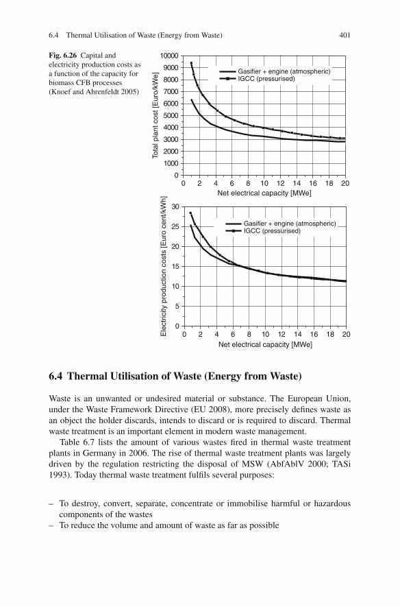
6.4 Thermal Utilisation of Waste (Energy from Waste) 401
Fig. 6.26 Capital andelectricity production costs asa function of the capacity forbiomass CFB processes(Knoef and Ahrenfeldt 2005)
0 2 4 6 8 10 12 14 16 18 200
5
10
15
20
25
30
Ele
ctric
ity p
rodu
ctio
n co
sts
[Eur
o ce
nt/k
Wh]
Gasifier + engine (atmospheric)IGCC (pressurised)
Net electrical capacity [MWe]
0 2 4 6 8 10 12 14 16 18 200
1000
2000
3000
4000
5000
6000
7000
8000
9000
10000
Tota
l pla
nt c
ost [
Eur
o/kW
e]
Net electrical capacity [MWe]
Gasifier + engine (atmospheric)IGCC (pressurised)
6.4 Thermal Utilisation of Waste (Energy from Waste)
Waste is an unwanted or undesired material or substance. The European Union,under the Waste Framework Directive (EU 2008), more precisely defines waste asan object the holder discards, intends to discard or is required to discard. Thermalwaste treatment is an important element in modern waste management.
Table 6.7 lists the amount of various wastes fired in thermal waste treatmentplants in Germany in 2006. The rise of thermal waste treatment plants was largelydriven by the regulation restricting the disposal of MSW (AbfAblV 2000; TASi1993). Today thermal waste treatment fulfils several purposes:
– To destroy, convert, separate, concentrate or immobilise harmful or hazardouscomponents of the wastes
– To reduce the volume and amount of waste as far as possible

402 6 Power Generation from Biomass and Waste
Table 6.7 Thermal treatment of waste in Germany in 2006 (Statistisches Bundesamt 2008)
Amount treated in 2006(millions of tonnes)
Municipal solid waste (MSW) 18,142Sewage sludge 1,669Hazardous waste 1,056Waste used as a fuel in
power/CHP plants and others(wood residues, RDF, paper)
12,330
– To transform the remaining residues into usable substances or to put them into adisposable form
– To use the thermal energy released in the process to the greatest extent possible
Until 2008, the distinction between thermal treatment being “disposal” or “recov-ery” was made in Germany using the heating value of the waste, according to theGerman waste law “Kreislaufwirtschaftsgestetz” (KrWG 1994). The incinerationof waste with heating values above 11 MJ/kg was considered “recovery”, whereasbelow this value, the process was considered “disposal”. The distinction followeda similar pattern in Italy, where the utilisation of so-called CDR (combustiblesfrom waste, “Combustibile derivato dai rifiuti”), with heating values of more than14 MJ/kg, was considered recovery. This kind of division seems to be rather arbi-trary or politically motivated and is not consistent from the engineering point ofview. The efficiency of an energy from waste (EfW) system depends on numerousfactors, such as the process technology, the energy consumption of pre-treatmentand transportation and generally speaking whether heat or electricity is used in theprocess. The heating value in itself only plays a minor role.
The European Waste Framework Directive (EU 2008) of 2008 introduced a newmethodology for distinguishing between “disposal” and “recovery” with respect tothermal treatment:
– “Recovery” means “any operation the principal result of which is waste, serv-ing a useful purpose by replacing other materials which would otherwise havebeen used to fulfil a particular function, or waste being prepared to fulfil thatfunction, in the plant or in the wider economy.” In plainer English, recoveryis a process in which waste replaces another material or where it is preparedso that it can replace another material. The recovery criterion (R1-recovery)based on energy efficiency, described in Annex II of the directive, is explainedbelow.
– “Disposal” means any operation which is not recovery, even where the operationhas as a secondary consequence the reclamation of substances or energy. Thedisposal criterion (D10-treatment) is described in Annex I of the directive.
In practice, the distinction between “disposal” and “recovery” is made dependingon the energy efficiency of the process. Plants gaining approval after 2008 need to
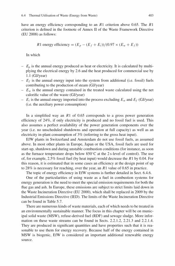
6.4 Thermal Utilisation of Waste (Energy from Waste) 403
have an energy efficiency corresponding to an R1 criterion above 0.65. The R1criterion is defined in the footnote of Annex II of the Waste Framework Directive(EU 2008) as follows:
R1 energy efficiency = (E p − (E f + Ei ))/(0.97 × (Ew + E f ))
In which
– Ep is the annual energy produced as heat or electricity. It is calculated by multi-plying the electrical energy by 2.6 and the heat produced for commercial use by1.1 (GJ/year)
– Ef is the annual energy input into the system from additional (i.e. fossil) fuelscontributing to the production of steam (GJ/year)
– Ew is the annual energy contained in the treated waste calculated using the netcalorific value of the waste (GJ/year)
– Ei is the annual energy imported into the process excluding Ew and Ef (GJ/year)(i.e. the auxiliary power consumption)
In a simplified way an R1 of 0.65 corresponds to a gross power generationefficiency of 24%, if only electricity is produced and no fossil fuel is used. Thisalso assumes a perfect availability of the power generation components over theyear (i.e. no unscheduled shutdowns and operation at full capacity) as well as anelectricity in-plant consumption of 3% (referring to the gross heat input).
EfW plants in Switzerland and Amsterdam do not use fossil fuels, as assumedabove. In most other plants in Europe, Japan or the USA, fossil fuels are used forstart-up, shutdown and during unstable combustion conditions (for instance, as soonas the furnace temperature drops below 850◦C at the 2 s-level of control). The useof, for example, 2.5% fossil fuel (by heat input) would decrease the R1 by 0.04. Forthis reason, it is estimated that in some cases an efficiency at the design point of upto 28% is necessary for reaching, over the year, an R1 value of 0.65 in practice.
The topic of energy efficiency in EfW systems is further detailed in Sect. 6.4.6.One of the particularities of using waste as a fuel in combustion systems for
energy generation is the need to meet the special emission requirements for both theflue gas and ash. In Europe, these emissions are subject to strict limits laid down inthe Waste Incineration Directive (EU 2000), which shall be replaced in 2009 by theIndustrial Emissions Directive (IED). The limits of the Waste Incineration Directivecan be found in Table 5.7.
There are numerous kinds of waste materials, each of which needs to be treated inan environmentally sustainable manner. The focus in this chapter will be on munic-ipal solid waste (MSW), refuse-derived fuel (RDF) and sewage sludge. More infor-mation on these waste streams can be found in Sects. 2.2.1.2, 2.21.3 and 2.2.1.4.They are produced in significant quantities and have properties such that it is rea-sonable to use them for energy recovery. Because half of the energy contained inMSW is biogenic, EfW is considered an important additional renewable energysource.

404 6 Power Generation from Biomass and Waste
Fig. 6.27 Classical EfW system suitable for MSW, RDF and the co-combustion of sewage sludge(Source: Martin)
Municipal Solid Waste (MSW): In Germany, the thermal treatment of MSWand the resulting energy generation in classical EfW plants uses the most waste,with about 18 million tonnes being treated in 70 plants. An example of a typicalplant employing classical technology is shown in Fig. 6.27. The key componentsare a waste bunker, a waste feeding process, a grate-based combustion system, aboiler, a turbine and a flue gas cleaning process. Typical boiler steam conditions are380–420◦C and 40 bar. The flue gas cleaning system is based on the injection oflime and activated carbon to remove pollutants and a downstream baghouse filterfor removing the fly ash and the products of reaction from the pollutant removal.NOx is reduced by ammonia injection in the furnace.
This type of EfW system is typically used for untreated municipal solid waste(also called residual waste), which can be quite heterogeneous in composition. Inaddition, residues from mechanical – biological waste treatment plants, as well asindustrial wastes, are also fed to classical EfW plants. On top of that, co-combustionof between 5 and 15% sewage sludge (by mass input) is quite common.
Refuse-Derived Fuel (RDF): RDF (also called solid recovered fuel (SRF) or sub-stitute fuel) is produced from municipal solid waste by mechanical – biologicaltreatment, in most cases including commercial waste as a feedstock. RDF usuallyhas a higher heating value and a narrower particle range than untreated MSW, whichmakes it possible to use it in fluidised bed combustion systems, unlike untreatedMSW. Another option is co-combustion in coal power plants or in cement plants.For RDF processed from MSW it is most common to use grate-based combustionsystems.
Sewage Sludge: Sewage sludge is a type of waste which arises in a relativelyhomogeneous form, largely because of its high water content. Typical sewage
6.4 Thermal Utilisation of Waste (Energy from Waste) 405
sludge, even after digestion and mechanical drying, has a water content of between60 and 80%. It can be co-combusted in this state in waste incineration plants andbrown coal-fired power stations or used as the only fuel in fluidised bed systems. Forco-combustion in hard coal-fired power stations, thermal drying is usually necessary.In 2004, more than one-third of the 2.2 million tonnes of dry sewage sludge matterproduced was combusted in Germany: 0.4 million tonnes in 21 monofuel combus-tion plants and 0.3 million tonnes in 25 coal power stations, with 0.05 million tonnesbeing co-combusted in EfW plants (Quicker et al. 2005; Schmelz 2006; Hermann2004).
The following subchapters cover
– the historical development of EfW systems (with a focus on MSW, being themost used waste source for energy generation),
– grate-based combustion systems (most common for MSW and also used for RDFand the co-combustion of sewage sludge),
– pyrolysis and gasification systems (used for MSW and RDF),– RDF systems (combustion systems being designed specifically for RDF using
suspension or fluidised bed combustion),– sewage sludge systems (mono-combustion),– boilers for MSW, RDF and sewage sludge as a group and– flue gas treatment for MSW, RDF and sewage sludge as a group.
The co-combustion of RDF and sewage sludge in coal power plants is describedin Sect. 6.5.
6.4.1 Historical Development of Energy from Waste Systems (EfW)
The incineration of MSW began around the end of the 19th and the beginning of20th centuries, when the first plants were constructed in England, the USA andGermany. The main purpose of these plants was to promote public health, as thepractice of distributing waste on fields had been instrumental in the spread of choleraepidemics. The technology was very simple: brick-lined cell ovens with a fixedmetal grate over an ash pit below, with one opening in the top or side of the oven forloading and another opening in the side for removing the solid residues, clinker orash. Since that time, the technology has made huge advances in terms of emissioncontrol and energy efficiency (Gohlke and Spliethoff 2007).
An efficient energy from waste industry developed in Europe in the 1960/1970sand in the USA in the 1980/1990s. Typical EfW plants constructed in the USAduring this period used steam parameters of 60 bar/443◦C and, generally speaking,were more energy efficient than the European 40 bar boilers or the Japanese 20bar boilers of this time. Waste incineration or energy from waste plants is oftendescribed in the USA as waste-to-energy plants (WTE), which can be considered asessentially the same.
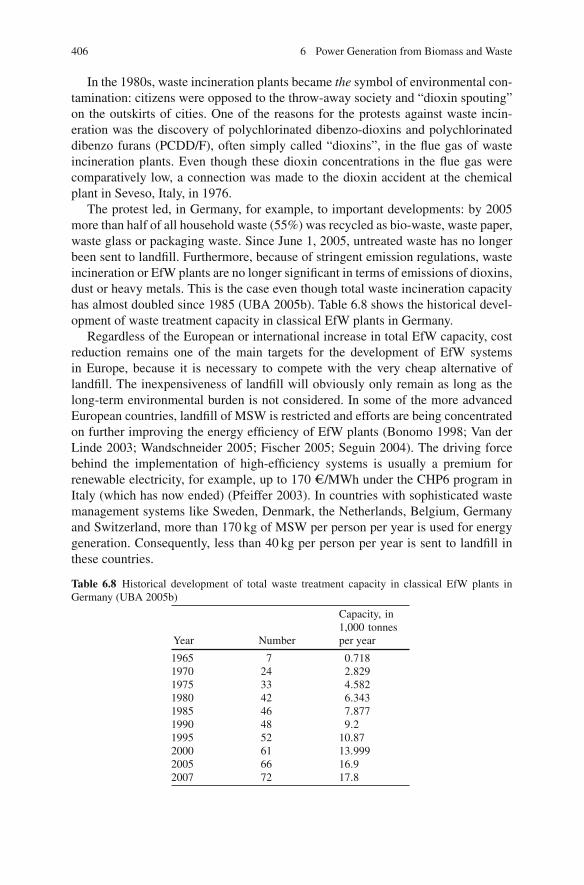
406 6 Power Generation from Biomass and Waste
In the 1980s, waste incineration plants became the symbol of environmental con-tamination: citizens were opposed to the throw-away society and “dioxin spouting”on the outskirts of cities. One of the reasons for the protests against waste incin-eration was the discovery of polychlorinated dibenzo-dioxins and polychlorinateddibenzo furans (PCDD/F), often simply called “dioxins”, in the flue gas of wasteincineration plants. Even though these dioxin concentrations in the flue gas werecomparatively low, a connection was made to the dioxin accident at the chemicalplant in Seveso, Italy, in 1976.
The protest led, in Germany, for example, to important developments: by 2005more than half of all household waste (55%) was recycled as bio-waste, waste paper,waste glass or packaging waste. Since June 1, 2005, untreated waste has no longerbeen sent to landfill. Furthermore, because of stringent emission regulations, wasteincineration or EfW plants are no longer significant in terms of emissions of dioxins,dust or heavy metals. This is the case even though total waste incineration capacityhas almost doubled since 1985 (UBA 2005b). Table 6.8 shows the historical devel-opment of waste treatment capacity in classical EfW plants in Germany.
Regardless of the European or international increase in total EfW capacity, costreduction remains one of the main targets for the development of EfW systemsin Europe, because it is necessary to compete with the very cheap alternative oflandfill. The inexpensiveness of landfill will obviously only remain as long as thelong-term environmental burden is not considered. In some of the more advancedEuropean countries, landfill of MSW is restricted and efforts are being concentratedon further improving the energy efficiency of EfW plants (Bonomo 1998; Van derLinde 2003; Wandschneider 2005; Fischer 2005; Seguin 2004). The driving forcebehind the implementation of high-efficiency systems is usually a premium forrenewable electricity, for example, up to 170 e/MWh under the CHP6 program inItaly (which has now ended) (Pfeiffer 2003). In countries with sophisticated wastemanagement systems like Sweden, Denmark, the Netherlands, Belgium, Germanyand Switzerland, more than 170 kg of MSW per person per year is used for energygeneration. Consequently, less than 40 kg per person per year is sent to landfill inthese countries.
Table 6.8 Historical development of total waste treatment capacity in classical EfW plants inGermany (UBA 2005b)
Year Number
Capacity, in1,000 tonnesper year
1965 7 0.7181970 24 2.8291975 33 4.5821980 42 6.3431985 46 7.8771990 48 9.21995 52 10.872000 61 13.9992005 66 16.92007 72 17.8
6.4 Thermal Utilisation of Waste (Energy from Waste) 407
The development in the USA was different: in 1994, the US Supreme Courtrejected the practice of waste flow control (US Supreme Court 1994). Waste flowcontrols are legal provisions that allow state and local governments to designate theplaces where municipal solid waste is treated or disposed. This rejection then led toan abrupt halting of the development of energy from waste schemes. Instead, wastewas transported by truck to mega-landfills which had been developed at low costin more remote areas. This resulted in the very negative environmental impacts oflandfilling: land consumption, transportation by truck over long distances, methaneemissions, leaching of pollutants to soil and to groundwater. The development ofmore sustainable waste management systems was no longer possible. However,after landfill taxes and premiums for renewable electricity were introduced and fuelprices for transport by truck increased, there has been an increasing trend towardsthe development of improved EfW processes since the middle of the first decade ofthe 2000s.
Waste incineration is very widespread in Japan, as landfill has traditionally notbeen an option due to the lack of space. In the 20th century most waste was incin-erated in numerous small plants. In the year 2000, there were still more than 10,000plants with a capacity of less than 2 t/h, while there were more than 2000 plants witha capacity of more than 2 t/h (Konda 2000). The UNEP (United Nations Environ-ment Programme) published a study in 1995 which showed that 4 kg of the global10 kg TEQ (toxic equivalent units, a measure of all toxic dioxins, furans and PCBs interms of the most toxic form of dioxin, 2,3,7,8-TCDD) of dioxin emissions per yearcame from Japan. This resulted in a major policy change and a new dioxin regulationwas put into effect in 2003. The dioxin emissions for existing plants larger than 4 t/hwere limited to 1 ng TEQ/Nm3 and for new plants to 0.1 ng TEQ/Nm3. Up untilthe end of 2002, a dioxin emission of 80 ng TEQ/Nm3 was still acceptable. As aconsequence, most small incineration plants had to shut down, because retrofittingdioxin reduction technologies was not economically feasible. The formation anddestruction of dioxins is discussed in Sect. 6.4.8.
These new regulations and the general policy from 1995 to 2005 in Japan weredrivers for the development and installation of new gasification and ash melting pro-cesses. Today, there are more than 90 gasification and over 90 ash melting processesin operation or under construction in Japan. The main purpose of these processesis to improve ash quality (by reducing the extent of leaching of the contaminantsfrom the ash) and to reduce the total dioxin output per tonne of waste. This devel-opment peaked in 2000, when a total capacity of 3 million tonnes per year of plantswere ordered. Half of this capacity was realised through gasification plants and theother half through stoker-based systems combined with ash melting (Vehlow 2006).However, both these processes are considered to be somewhat inadequate in terms ofenergy/cost efficiency and availability (Martin et al. 2005). The same experience washad in Europe in the 1990s with gasification systems, which have now all been shutdown. For this reason, a policy change was announced in Japan in 2005. The newpolicy states that gasification or ash melting would no longer be required if plantswere situated in remote areas or if it could be proved that the plants had at least 15years of landfill capacity for ash or other ash recycling options. As a consequence,
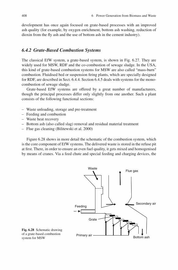
408 6 Power Generation from Biomass and Waste
development has once again focused on grate-based processes with an improvedash quality (for example, by oxygen enrichment, bottom ash washing, reduction ofdioxin from the fly ash and the use of bottom ash in the cement industry).
6.4.2 Grate-Based Combustion Systems
The classical EfW system, a grate-based system, is shown in Fig. 6.27. They arewidely used for MSW, RDF and the co-combustion of sewage sludge. In the USA,this kind of grate-based combustion systems for MSW are also called “mass-burn”combustion. Fluidised bed or suspension firing plants, which are specially designedfor RDF, are described in Sect. 6.4.4. Section 6.4.5 deals with systems for the mono-combustion of sewage sludge.
Grate-based EfW systems are offered by a great number of manufacturers,though the principal processes differ only slightly from one another. Such a plantconsists of the following functional sections:
– Waste unloading, storage and pre-treatment– Feeding and combustion– Waste heat recovery– Bottom ash (also called slag) removal and residual material treatment– Flue gas cleaning (Bilitewski et al. 2000)
Figure 6.28 shows in more detail the schematic of the combustion system, whichis the core component of EfW systems. The delivered waste is stored in the refuse pitat first. There, in order to ensure an even fuel quality, it gets mixed and homogenisedby means of cranes. Via a feed chute and special feeding and charging devices, the
Fig. 6.28 Schematic drawingof a grate-based combustionsystem for MSW Bottom ash
Waste
Feeding
Grate
Flue gas
Secondary air
Primary air

6.4 Thermal Utilisation of Waste (Energy from Waste) 409
waste is loaded onto the stoker. The grate transports the fuel through the variouszones of the combustion process while providing a good mixing. On the whole,the waste remains on the grate for about an hour until all processes are completelyfinished. The remaining ash is discharged into a basin filled with water, called theash discharger. Subsequently, the cooled bottom ash can be subjected to varioustreatments, such as the separation of metals, crushing and sieving, to make it moresuitable for use as a filler material.
The hot flue gases are cooled in a steam boiler, creating steam, which is normallyused for electricity production. Additionally, it can be used to deliver heat for districtheating. In EfW plants, the design of the steam generator has to be given specialattention, because the flue gases from the combustion of waste are very aggressive,reducing the heat transfer through fouling and slagging and potentially corrodingthe heat transfer surfaces. For this reason, the allowable steam conditions in EfWplants are markedly lower than the conditions in large steam power plants – a factcontributing to the lower power generation efficiency of a waste treatment plant.The design, the restrictions on it and the possible means to increase the efficiencyare discussed in Sect. 6.4.7.
The cooled flue gases are treated in a flue gas cleaning section, where the remain-ing fly ash, including components such as heavy metals and organic toxic compo-nents, e.g. dioxins, is removed. Additionally, gaseous pollutants such as hydrochlo-ric acid, hydrofluoric acid, sulphur dioxide and nitrogen oxides are removed. A largevariety of technologies and systems are available for this purpose and are discussedin Sect. 6.4.9.
For the combustion of untreated municipal solid wastes, the grate furnace isthe most widespread technology employed in the large EfW markets of Europe,the USA and Southeast Asia. The essential advantage of the grate furnace is itscapacity to process lump-sized waste and accommodate fluctuating fuel properties(Bilitewski et al. 2000; Scholz et al. 2001; Dolezal 1990; UBA 2005a; Effenberger2000; VDI 2006, 2007; EIPPCB 2005). In a grate furnace, the combustion processcan be divided into different phases, though these overlap to a large degree:
– Drying and devolatilisation: In the upper area of the grate, the waste is heated,dried and devolatilised by heat radiation from the refractory-lined walls or ceil-ings or by thermal convection of hot flue gases. The devolatilisation process usu-ally takes place in a reducing atmosphere.
– Gasification and combustion: In these processes, two kinds of reactions runconcurrently – heterogeneous fuel reactions and homogeneous reactions of thereleased volatile components in the combustion zone above the grate.
– Burnout zone: In the final area of the grate, complete burnout should be achieved.The burnout of bottom ash in modern waste incinerators is characterised by a lossof unburnt carbon of less than 2%.
– Secondary combustion: For the complete burnout of CO and fly ash particles,there is always a secondary combustion zone. Here, air or recirculated flue gas isadded to complete the combustion.

410 6 Power Generation from Biomass and Waste
The primary air injected below the grate provides the combustion air for the com-bustion reactions on the grate; the remaining combustion air is added as secondaryair above the grate for the post-combustion of the unburnt components. In orderto be able to adapt the primary air injection to the requirements of the individualcombustion zones, the primary air ducts are divided into compartments. Large gratefurnaces can have compartments not only in terms of length but also in terms ofwidth. The amount of air per compartment can be controlled. With the aim of a com-plete burnout at low NOx emissions in mind, the combustion of the bulk is mostlyset at near-stoichiometric to air-deficient conditions. To give an example, at a totalair ratio of about 1.6, 60% of the air is, as primary air, divided up and distributedto the drying zone (10%), to the combustion zone (40%) and to the burnout zone(10%). The rest of the total air is secondary air. The grate bars are protected andcooled by the primary air and the ash layer. The combustion air can be preheatedfor low waste LHVs. For high LHVs, e.g. above 12 MJ/kg, no preheating is appliedand for LHVs of 6 MJ/kg, the preheating temperature can be up to 150◦C. Forwardpushing grate systems may need water cooling in case of high LHVs.
At the end of the grate, the bottom ash falls into an ash discharger, which is effec-tively a water basin, and is cooled down for further treatment. The amount of bottomash is approximately 25% by weight or 10% of the volume of the original waste.A small portion of the fine ash may fall through the grate. These riddlings (alsocalled grate siftings) are collected and transported pneumatically or via mechanicalconveyers to the ash discharger.
The maximum combustion temperatures along the grate should be set so that themineral components on the grate become sintered while avoiding the formation oflarge agglomerates, the latter because they would hamper the passage of air and thusthe combustion process. Such an incidence is counteracted regardless, however, bythe stoking effect of the grate firing system. Generally speaking, waste bed tempera-tures between 800 and 1,250◦C are desired. The waste bed temperature can be mon-itored by infrared cameras in the furnace roof. A few plants have been constructedwith oxygen enrichment of the primary air in order to achieve an improvement in theash quality through the resulting higher waste bed temperatures (Martin et al. 2005).This enriching of primary air with oxygen also improves the general effectivenessof the combustion. Other positive impacts are the decreases of the flue gas flowrateand the emissions and the increase in thermal efficiency brought about by less fluegas loss. However, the consumption of electricity required for oxygen productioncancels out the increase in the thermal efficiency.
6.4.2.1 Design of the Grate Firing System
The decisive parameter for the design of grate furnaces is the heating value. Forresidual waste, the heating value determination includes the ash and water contents.Theoretically, according to Fig. 6.29, MSW can be burned without back-up firingif the low heating value lies above 3,500 kJ/kg. However, the state-of-the-art com-bustion conditions required by today’s environmental regulations for emissions and

6.4 Thermal Utilisation of Waste (Energy from Waste) 411
Fig. 6.29 Heating value,moisture and ash contenttriangle (Bilitewski et al.2000)
Ash
Lower heating value (M
J/kg)
Moisture
Combustable matter
0%
20%
40%
60%
80%
100%
14.0
1.0
2.04.0
6.08.0
10.0
12.0
16.0
18.0
20.0
0% 20% 40% 60% 80% 100%
0%
Stablecombustion
Moisture
0%
20%
40%
60%
80%
100%
1.0
2.04.0
6.08.0
10.0
12.0
16.0
18.0
20.0
1.0
2.04.0
6.08.0
10.0
12.0
16.0
18.0
20.0
0% 20% 40% 60% 80% 100%
0%
14.0
ash quality make it necessary to have a heating value of above 6 MJ/kg (withoutany additional fossil fuel). For the combustion of untreated MSW in Germany, anaverage LHV of 9–10 MJ/kg, with fluctuations between 8 and 12 MJ/kg, is taken asa basis.
Grate incineration is very flexible in regard to the heating value and the wastecharacteristics. Figure 6.30 provides an example of a waste incineration diagram,indicating the relationship between waste throughput, LHV and thermal output.Waste incinerators are designed for large variations of the average LHV, normallybetween 6 and 12 MJ/kg. Wastes with low LHVs require air preheating. Because ofvariations in the waste composition, spare steam generator capacity is required forpeaks in the heat input.
Fig. 6.30 Thermal power andthroughput diagram
Fuel input[MW]
83(110%)
75(100%)
35(47%)
Reserve capacity 12 MJ/kgLHV 9 MJ/kg
Design point
7 MJ/kg
6 MJ/kg
Air preheatingrequired
18 30 Waste throughput [t/h]
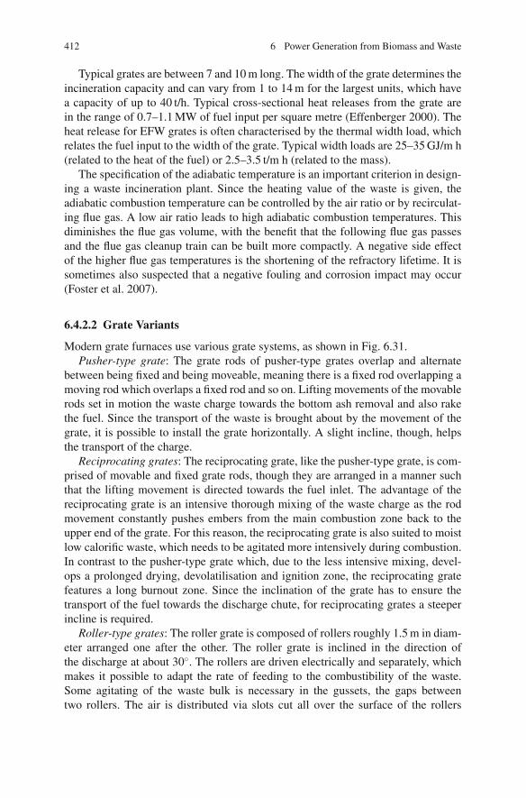
412 6 Power Generation from Biomass and Waste
Typical grates are between 7 and 10 m long. The width of the grate determines theincineration capacity and can vary from 1 to 14 m for the largest units, which havea capacity of up to 40 t/h. Typical cross-sectional heat releases from the grate arein the range of 0.7–1.1 MW of fuel input per square metre (Effenberger 2000). Theheat release for EFW grates is often characterised by the thermal width load, whichrelates the fuel input to the width of the grate. Typical width loads are 25–35 GJ/m h(related to the heat of the fuel) or 2.5–3.5 t/m h (related to the mass).
The specification of the adiabatic temperature is an important criterion in design-ing a waste incineration plant. Since the heating value of the waste is given, theadiabatic combustion temperature can be controlled by the air ratio or by recirculat-ing flue gas. A low air ratio leads to high adiabatic combustion temperatures. Thisdiminishes the flue gas volume, with the benefit that the following flue gas passesand the flue gas cleanup train can be built more compactly. A negative side effectof the higher flue gas temperatures is the shortening of the refractory lifetime. It issometimes also suspected that a negative fouling and corrosion impact may occur(Foster et al. 2007).
6.4.2.2 Grate Variants
Modern grate furnaces use various grate systems, as shown in Fig. 6.31.Pusher-type grate: The grate rods of pusher-type grates overlap and alternate
between being fixed and being moveable, meaning there is a fixed rod overlapping amoving rod which overlaps a fixed rod and so on. Lifting movements of the movablerods set in motion the waste charge towards the bottom ash removal and also rakethe fuel. Since the transport of the waste is brought about by the movement of thegrate, it is possible to install the grate horizontally. A slight incline, though, helpsthe transport of the charge.
Reciprocating grates: The reciprocating grate, like the pusher-type grate, is com-prised of movable and fixed grate rods, though they are arranged in a manner suchthat the lifting movement is directed towards the fuel inlet. The advantage of thereciprocating grate is an intensive thorough mixing of the waste charge as the rodmovement constantly pushes embers from the main combustion zone back to theupper end of the grate. For this reason, the reciprocating grate is also suited to moistlow calorific waste, which needs to be agitated more intensively during combustion.In contrast to the pusher-type grate which, due to the less intensive mixing, devel-ops a prolonged drying, devolatilisation and ignition zone, the reciprocating gratefeatures a long burnout zone. Since the inclination of the grate has to ensure thetransport of the fuel towards the discharge chute, for reciprocating grates a steeperincline is required.
Roller-type grates: The roller grate is composed of rollers roughly 1.5 m in diam-eter arranged one after the other. The roller grate is inclined in the direction ofthe discharge at about 30◦. The rollers are driven electrically and separately, whichmakes it possible to adapt the rate of feeding to the combustibility of the waste.Some agitating of the waste bulk is necessary in the gussets, the gaps betweentwo rollers. The air is distributed via slots cut all over the surface of the rollers

6.4 Thermal Utilisation of Waste (Energy from Waste) 413
Fig. 6.31 Different gratetypes
and through the gussets. One advantage of the roller grate is the slight amount ofwear and tear, a consequence of the grate surfaces only being exposed to the highfurnace temperatures briefly during the turning movement and being cooled by theprimary air the rest of the time. The disadvantages are the great accumulation of“riddlings” and the fact that there is only slight grate agitation, meaning a lesserability to intensify the combustion process.
In normal grate furnaces, the lifetime of the grate material is limited, especiallythe material in the incineration zone. Higher heating values further reduce the life-time, even if specific advanced alloys are used for the grates. In consequence, water-
414 6 Power Generation from Biomass and Waste
cooled grates have been developed. By water cooling, the temperatures can be keptsignificantly lower and the air distribution can be made more flexibly. However,water cooling is costly and has a negative impact on the efficiency, because at thelow temperature of the cooling water the heat cannot be used in the thermal process.Approximately up to 5% of the thermal capacity is lost and is therefore not availablefor steam and electricity production. This corresponds to a decrease in the electricalefficiency of about 1%. With air-cooled grates, the grate design also has an impacton the grate temperatures. The reciprocating grate, owing to the intensive mixing ofthe grate bed and reliable covering of the grate with waste and ash, is able to manageeven higher heating values without water cooling. The use of water-cooled grates,on the whole, is rare. Excessively high grate rod temperatures can be expected whenthe grate is not covered with fuel. This is avoided by appropriate operation.
6.4.2.3 Furnace and Boiler
The waste heat of the hot flue gases is recovered in a steam generator. EfW steamgenerators differ significantly from coal-fuelled steam generators, for example,by having comparatively large combustion chambers which ensure the necessaryburnout and allow the substantial cooling of the flue gases. Different sections of thesteam generator are distinguished:
– The first flue gas pass is the combustion chamber (or furnace) above the grate,including the primary and secondary combustion zones as well as the remain-ing first radiation pass. The combustion chamber size is limited by water/steam-cooled membrane wall heating surfaces, which are refractory-lined or protectedby SiC tiles in the lower part. This serves to protect the metal heating surfacesfrom corrosion, but it also aids in reducing the heat transfer so that the stipulatedflue gas temperature of 850◦C can be met. In this refractory-protected area, oneor several fossil fuel-fired burners are installed in the side walls. These burnersare used for start-up and shutdown of the plant in order to maintain the minimumtemperature conditions at all times. The membrane wall of the upper part of thefurnace, from 8 to 12 m above the grate, is generally unprotected or equipped withoverlay-welded nickel-based alloys (cladding). In the first part of the 2000s, afew plants with combustion chambers where the membrane walls are completelycladded down to the grate have been constructed.
– Subsequently, in the second flue gas pass, there are metal, not refractory-lined,membrane-wall heating surfaces. In many EfW plants, up to three empty fluegas passes (including the combustion chamber) are built in to cool the flue gasesdown to low temperatures by radiant heat transfer.
– Convective heating surfaces for superheating and, in the cooler area, for feed-water heating (the economiser) are arranged, preferably in the area of flue gastemperatures below 650◦C.
The design of the combustion chamber above the grate (the incineration chamber)has to be suited to the grate and depends on the chosen flue gas routing above it.

6.4 Thermal Utilisation of Waste (Energy from Waste) 415
In the combustion of waste, due to the high volatile matter content, only a smallpart of the combustion process takes place on the grate, the larger part occurringin the area above. Therefore, it is necessary to have a sufficient residence time athigh temperatures in that upper zone. The furnace geometry has to be chosen suchthat a high and even flue gas velocity above the grate will develop. The combustionchamber walls and the ceiling in the part above the grate are refractory-lined in orderto limit the heat transfer and to protect the walls from corrosion. The refractorylining of the combustion chamber ceiling favours the heating of the fuel by radiantheat from the hot walls.
The design of the grate and combustion chamber differs according to the sup-pliers and their specific experiences. In general, three basic designs can be dis-tinguished. The nomenclature comes from the flow direction of the flue gases inrelation to the waste flow: co-current, counter-current and medium current, as shownin Fig. 6.32.
Co-current or parallel flow furnace: In a co-current combustion arrangement,primary combustion air and waste are guided together in a co-current flow throughthe combustion chamber. Accordingly, the flue gas outlet is located at the end ofthe grate. Only a comparatively low amount of energy is exchanged between thecombustion gases and the waste on the grate. The advantage of co-current designsis that the hot flue gas passes above the ash bed and improves the burnout of theash, which is why it is most commonly used for roller grate systems. To facilitateignition for wastes with very low heating values, the primary air must be preheated.
Counter-current furnace: In this case, the primary combustion air and the wasteare guided in opposing directions in a counter-current flow arrangement through thecombustion chamber and the flue gas outlet is located at the front end of the grate.The hot flue gases facilitate drying and ignition of the waste. Special attention mustbe paid to avoid the slip of unburned gas streams.
Medium current furnace: The medium current design is a compromise systemsuitable for a wide range of fuel properties. In this case, the flue gas outlet is locatedin the middle of the grate. Mixture-promoting chamber contours and/or secondaryair injections can be used to promote a thorough mixing of the various flue gas
Fig. 6.32 Furnace and grate arrangements for EfW systems
416 6 Power Generation from Biomass and Waste
streams. Nearly all modern EfW plants in Europe, the USA and Japan built in the2000s have been designed using characteristics lying in between medium-currentand counter-current furnace designs.
The primary combustion zone is followed by the secondary combustion zone,where the secondary air (or overfire air) is added for the combustion of the unburnedgaseous components. The following secondary combustion conditions are favourablefor a complete burnout of the flue gases:
– Availability of sufficient oxygen. An oxygen concentration of approximately 6%was considered as a minimum in the German regulation “17. Bundesimmission-sschutzverordnung (17. BImSchV – the 17th Amendment to the Federal GermanEmissions Control Act)” of 1993. In later revisions of the 17. BImSchV (17.Bim-SchV 2009) this requirement was removed in order to be consistent with the EUWaste Incineration Directive (EU 2000).
– Sufficient residence time at a high temperature. According to the European WasteIncineration Directive (EU 2000), a minimum residence time of 2 s with tempera-tures above 850◦C is required to ensure the destruction of dioxins (see Sect. 6.4.8)
– Complete mixing of secondary air and homogeneity of flue gas flow. This condi-tion is included in the combustion engineering principle 3T, meaning that time,temperature and turbulence are required for good quality combustion.
In some cases, the primary and secondary combustion chambers are separated bya constriction. Adding the remaining secondary air prior to but near the constrictionprovides an intensive mixing of the flue gases, which is followed by a homogeneousflow profile on the other side of the constriction.
6.4.2.4 Ash Deposition
Even though the dust load in the flue gases of grate-based EfW plants is muchlower than in fluidised bed systems, special care must be taken to avoid dust-relatedslagging, fouling and corrosion. Reduced underfire air flows and flue gas veloci-ties in the furnace generally favour less carryover of fly ash to the boiler. MSWashes contain various components such as relatively inert aluminosilicates, lime-related compounds (in the form of oxide carbonates or sulphates) and salts. Themajority of the salts are alkali and earth alkali chlorides, but significant amountsof heavy metal chlorides also occur. Alkali chlorides, and especially the lead andzinc chlorides, form eutectic mixtures with low melting temperatures. Therefore,the above-mentioned flue gas temperatures of 850◦C in the first flue gas path shouldnot be markedly exceeded, because at flue gas temperatures of 1,000◦C or so, stickyparticles may lead to severe fouling and slagging in this section. Because it is nearlyimpossible to completely avoid the formation of deposits in the flue gas path, ade-quate measures have to be taken to control the growth of deposits and to avoidunscheduled shutdowns of the power plant for the manual cleaning of deposits.Several techniques have been developed to reduce the formation of deposits duringoperation. Cleaning can be accomplished with water cannons or shower cleaning,soot blowers using steam or air, mechanical rappers or explosives.

6.4 Thermal Utilisation of Waste (Energy from Waste) 417
6.4.2.5 Corrosion
High-temperature corrosion is the biggest operational problem in the thermal treat-ment of waste, and it limits the efficiency of the conversion into electrical power.Corrosion is worst when there is, at the same time, high chlorine and low sulphurcontents in the MSW and a high content of heavy metal chlorides in the fly ash.The membrane wall heating surfaces and the superheater surfaces can be severelycorroded. The corrosion mechanisms are discussed in Sect. 5.10.4.
In the area of the membrane wall, corrosion is caused by molten salts. In order todiminish the effects of corrosion in the furnace above the refractory-protected area,coatings made of nickel– chromium alloys are applied by deposition welding (alsocalled cladding) to protect the steel of the membrane wall tubes. This cladding maycover the entire upper furnace (first pass) and the first part of the second pass and isconsidered state of the art for the most common 40–60 bar boilers used in Europe,Japan and the USA. It can be applied either in the workshop during the constructionof the plant or retrofitted if corrosion problems occur. Consequently, membrane wallcorrosion no longer presents a frequent problem in EfW plants in service today.
On the other hand, however, high-temperature corrosion of superheater tubesis still an unsolved problem and limits the allowable live steam temperatures tovalues of 400–450◦C. In this corrosion mechanism, sulphation of alkali chlorides inboiler tube deposits sets a chlorine cycle going which involves very strong wear andtear. In the design of EfW plants, this is the reason the allowable working mediumtemperatures are chosen as a function of additional parameters such as the flue gastemperature or the flue gas velocity, i.e. in order to avoid superheater corrosion.This design practice is represented in Fig. 6.33 by the so-called Flingern corrosiondiagram.
The investigation of corrosion processes and the development of corrective mea-sures are the subject of extensive research (Born 2007; Born 2005; VDI 2006, 2007).Corrective measures for reducing superheater corrosion take two forms: develop-ments of new materials and combustion engineering measures. Making use of the
Fig. 6.33 Corrosion diagram
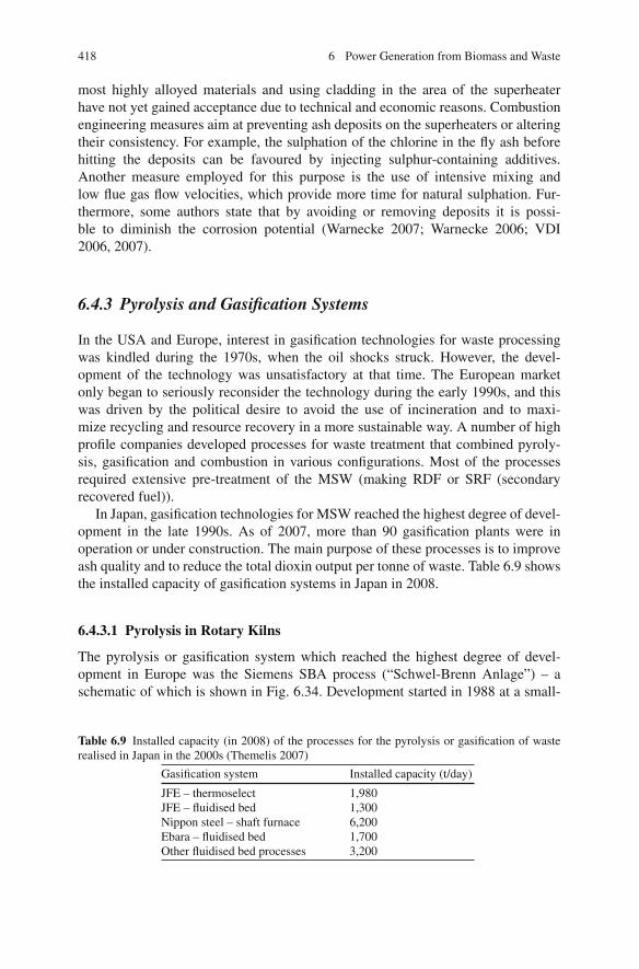
418 6 Power Generation from Biomass and Waste
most highly alloyed materials and using cladding in the area of the superheaterhave not yet gained acceptance due to technical and economic reasons. Combustionengineering measures aim at preventing ash deposits on the superheaters or alteringtheir consistency. For example, the sulphation of the chlorine in the fly ash beforehitting the deposits can be favoured by injecting sulphur-containing additives.Another measure employed for this purpose is the use of intensive mixing andlow flue gas flow velocities, which provide more time for natural sulphation. Fur-thermore, some authors state that by avoiding or removing deposits it is possi-ble to diminish the corrosion potential (Warnecke 2007; Warnecke 2006; VDI2006, 2007).
6.4.3 Pyrolysis and Gasification Systems
In the USA and Europe, interest in gasification technologies for waste processingwas kindled during the 1970s, when the oil shocks struck. However, the devel-opment of the technology was unsatisfactory at that time. The European marketonly began to seriously reconsider the technology during the early 1990s, and thiswas driven by the political desire to avoid the use of incineration and to maxi-mize recycling and resource recovery in a more sustainable way. A number of highprofile companies developed processes for waste treatment that combined pyroly-sis, gasification and combustion in various configurations. Most of the processesrequired extensive pre-treatment of the MSW (making RDF or SRF (secondaryrecovered fuel)).
In Japan, gasification technologies for MSW reached the highest degree of devel-opment in the late 1990s. As of 2007, more than 90 gasification plants were inoperation or under construction. The main purpose of these processes is to improveash quality and to reduce the total dioxin output per tonne of waste. Table 6.9 showsthe installed capacity of gasification systems in Japan in 2008.
6.4.3.1 Pyrolysis in Rotary Kilns
The pyrolysis or gasification system which reached the highest degree of devel-opment in Europe was the Siemens SBA process (“Schwel-Brenn Anlage”) – aschematic of which is shown in Fig. 6.34. Development started in 1988 at a small-
Table 6.9 Installed capacity (in 2008) of the processes for the pyrolysis or gasification of wasterealised in Japan in the 2000s (Themelis 2007)
Gasification system Installed capacity (t/day)
JFE – thermoselect 1,980JFE – fluidised bed 1,300Nippon steel – shaft furnace 6,200Ebara – fluidised bed 1,700Other fluidised bed processes 3,200
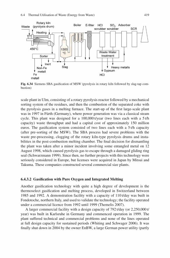
6.4 Thermal Utilisation of Waste (Energy from Waste) 419
Fig. 6.34 Siemens SBA gasification of MSW (pyrolysis in rotary kiln followed by slag-tap com-bustion)
scale plant in Ulm, consisting of a rotary pyrolysis reactor followed by a mechanicalsorting system of the residues, and then the combustion of the separated coke withthe pyrolysis gases in a melting furnace. The start-up of the first large-scale plantwas in 1997 in Furth (Germany), where power generation was via a classical steamcycle. This plant was designed for a 100,000 t/year (two lines each with a 5 t/hcapacity) waste throughput and had a capital cost of approximately 150 millioneuros. The gasification system consisted of two lines each with a 5 t/h capacity(after pre-sorting of the MSW). The SBA process had severe problems with thewaste pre-processing, clogging of the rotary kiln-type pyrolysis drums and insta-bilities in the post-combustion melting chamber. The final decision for dismantlingthe plant was taken after a minor incident involving some entangled metal on 12August 1998, which caused pyrolysis gas to escape through a damaged gliding ringseal (Schwarzmann 1999). Since then, no further projects with this technology wereseriously considered in Europe, but licenses were acquired in Japan by Mitsui andTakuma. These companies constructed several commercial size plants.
6.4.3.2 Gasification with Pure Oxygen and Integrated Melting
Another gasification technology with quite a high degree of development is thethermoselect gasification and melting process, developed in Switzerland between1985 and 1992. A demonstration facility with a capacity of 110 t/day was built inFondotoche, northern Italy, and used to validate the technology; the facility operatedunder a commercial licence from 1992 until 1999 (Themelis 2007).
A larger commercial facility with a design capacity of 792 t/day (or 2,250,000 t/year) was built in Karlsruhe in Germany and commenced operation in 1999. Theplant suffered technical and commercial problems and none of the lines operatedat full design capacity for sustained periods (Whiting and Schwager 2006). It wasfinally shut down in 2004 by the owner EnBW, a large German power utility (partly

420 6 Power Generation from Biomass and Waste
Fig. 6.35 Thermoselect gasification of MSW (gasification with pure oxygen and integrated meltingof the ash as well as post combustion in a boiler)
owned by EDF – Electricite de France). Since then it has been “mothballed” pendingthe outcome of litigation between the supplier Thermoselect S.A. and the ownerEnBW. The third European thermoselect plant, which was constructed in Ansbach,never went in operation. The schematic of the thermoselect process is shown inFig. 6.35.
In Japan, similar plants have been built by JFE (Japan Steel Engineering), licens-ing the thermoselect technology. The first plant was completed in 1999 at a steelmill in Chiba with the synthesis gas produced being used in the mill. A further sixJFE plants using the thermoselect technology had begun operation by 2006.
6.4.3.3 Fluidised Bed Gasification
In Europe and the USA, no highly developed fluidised bed gasification systems havebeen realised. In contrast, by the beginning of the 2000s in Japan, 13 companieswere engaged in the development of fluidised bed gasification systems for MSW.The most utilised system in Japan is the Twin Internally Circulating Fluidised BedGasifier (TIFG), developed by the Ebara Corporation (Fujimura et al. 2001). It gasi-fies the wastes first and uses the heat content of the gases to raise the temperature inthe following slag combustion furnace stage.
For all the gasification technologies that have been developed to a significantextent and have some market impact, the pyrolysis and gasification steps are onlya pre-treatment. These steps are directly followed by combustion of the gasesand, in the case of pyrolysis, of the pyrolysis char as well. The only exceptionis the fixed bed gasification technology “Sekundarrohstoff-Verwertungszentrum
6.4 Thermal Utilisation of Waste (Energy from Waste) 421
Schwarze Pumpe” (SVZ) that was developed in Schwarze Pumpe/Spremberg(Brandenburg/Germany), based on German Democratic Republic (GDR – i.e. theformer East Germany) coal gasification technology and used at the end of 1990s andbeginning of the 2000s for MSW. Insolvency in 2004 meant the final withdrawal ofthis technology from the waste business in 2007 (Mielke 2007). The example ofSVZ-Schwarze Pumpe seems to show that it makes little sense to use MSW, withits difficult properties, as a raw material for complex biomass to liquid (BtL) ormethanol production processes, as long as coal is available.
The main driving forces for the development of gasification processes have beena desire to improve ash qualities and reduce dioxin outputs. However, the more com-plex gasification processes result in lower efficiencies, lower process availabilitiesand higher costs. Although in principle, gasification offers a better efficiency, thereal plant efficiencies are even lower than conventional EfW plants. Gasificationwith oxygen and integrated melting has produced electrical efficiencies well below10%, for example. Because of this, gasification technologies are no longer devel-oped and demonstrated in Europe, while in Japan, the focus of development hasbeen readjusted to grate-based processes producing improved ash qualities (e.g. byusing oxygen enrichment, bottom ash washing, reduction of dioxin from the fly ashand the use of bottom ash in the cement industry).
6.4.4 Refuse-Derived Fuel (RDF)
The basic idea of the combustion of refuse-derived fuel by itself is that the EfW plantcan be designed especially for the quality of this more homogeneous fuel. In doingso, there are design and operational advantages, and in addition it becomes possibleto decentralise the plants. RDF contains chlorine, as MSW does, which means thatthe steam parameters are restricted in a similar way to about 60 bar and 450◦C. Inthis respect, then, there is no advantage over waste incineration plants. However, theconstruction and the design of the flue gas cleaning facilities is often simpler thanfor EfW plants using unprocessed MSW (as a rule reduced to an SNCR processfollowed by calcium hydrate and activated carbon addition upstream of a fabricfilter), because there are fewer pollutants. Designing the flue gas cleaning processfor a narrower fuel range, though, can give rise to problems if the composition of theRDF fluctuates, especially if the chlorine and sulphur contents change (Neukirchen2008).
The majority of RDF plants use grate furnaces. The technology is rather similarto conventional EfW plants, which have been thoroughly discussed in Sect. 6.4.2.Attention has to be paid to the higher LHV, for example, by using water-cooledgrates. Fluidised beds are a reasonable technology for RDF combustion, owing tothe more homogeneous fuel quality, but they are less common than grate combustion.
Four fluidised bed combustion plants were built in France between 1995 and1997 in Mulhouse, Giens, Guerville and Monthyon (ActuEnvironment 2005). Afterthat, no other fluidised bed projects were constructed in France. A similar sce-nario occurred in Japan, where 44 fluidised bed plants for MSW or RDF were

422 6 Power Generation from Biomass and Waste
operating in 1999, with a further 11 being installed between 1999 and 2003. After2003, there is no report of any other fluidised bed combustion plants for MSW orRDF being constructed, but various types of fluidised bed gasification processeswere developed (see Sect. 6.4.3). The reasons for the low acceptance seems to bethe higher pre-processing requirement in comparison to grate combustion and somenegative experiences with increased dioxin formation rates in the past. The latter,however, can be solved by an appropriate design of the flue gas train, as discussedin Sect. 6.4.8.
In Germany, some circulating fluidised bed (CFB) plants were built in the 2000sto treat the increasing amounts of coarse fractions from mechanical– biologicaltreatment (MBT) plants. One relatively well-documented example is the CFB plantin Premnitz, operated by the large German utility EON-Energy from waste. It wasdesigned for steam parameters of 97 bar and 500◦C, with superheating realised inan external bed heat exchanger. Superheating steam in the external fluidised bedheat exchanger of the recirculation loop in principle provides the opportunity tosuperheat steam to higher temperatures than superheaters situated directly in the fluegas path, because of a less corrosive environment. However, erosion and corrosionproblems still seem to occur, resulting in a reduction of the steam temperature andpressure to 75 bar and 450◦C. The CO and dioxin formation rates are much lowerthan in the Japanese and French examples of fluidised bed combustion and are wellbelow the emission limits (Borghart 2008).
In most cases, RDF plants in the USA do the pre-processing of the waste on-siteand utilise suspension combustion, as shown in Fig. 6.36 (Themelis 2007). RDF is
Fig. 6.36 A suspensioncombustion system for RDFin the USA
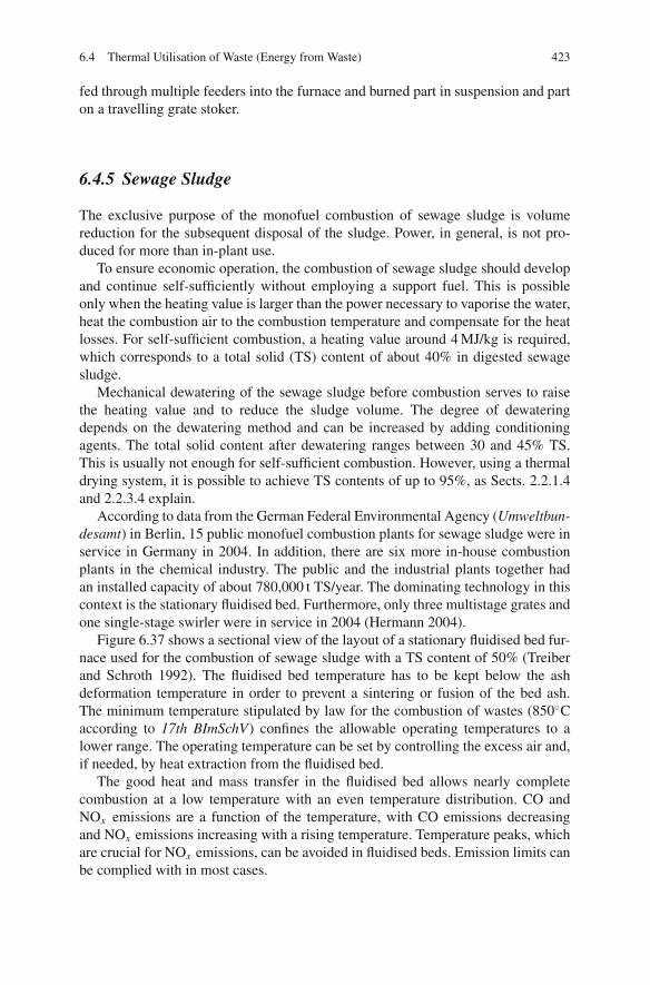
6.4 Thermal Utilisation of Waste (Energy from Waste) 423
fed through multiple feeders into the furnace and burned part in suspension and parton a travelling grate stoker.
6.4.5 Sewage Sludge
The exclusive purpose of the monofuel combustion of sewage sludge is volumereduction for the subsequent disposal of the sludge. Power, in general, is not pro-duced for more than in-plant use.
To ensure economic operation, the combustion of sewage sludge should developand continue self-sufficiently without employing a support fuel. This is possibleonly when the heating value is larger than the power necessary to vaporise the water,heat the combustion air to the combustion temperature and compensate for the heatlosses. For self-sufficient combustion, a heating value around 4 MJ/kg is required,which corresponds to a total solid (TS) content of about 40% in digested sewagesludge.
Mechanical dewatering of the sewage sludge before combustion serves to raisethe heating value and to reduce the sludge volume. The degree of dewateringdepends on the dewatering method and can be increased by adding conditioningagents. The total solid content after dewatering ranges between 30 and 45% TS.This is usually not enough for self-sufficient combustion. However, using a thermaldrying system, it is possible to achieve TS contents of up to 95%, as Sects. 2.2.1.4and 2.2.3.4 explain.
According to data from the German Federal Environmental Agency (Umweltbun-desamt) in Berlin, 15 public monofuel combustion plants for sewage sludge were inservice in Germany in 2004. In addition, there are six more in-house combustionplants in the chemical industry. The public and the industrial plants together hadan installed capacity of about 780,000 t TS/year. The dominating technology in thiscontext is the stationary fluidised bed. Furthermore, only three multistage grates andone single-stage swirler were in service in 2004 (Hermann 2004).
Figure 6.37 shows a sectional view of the layout of a stationary fluidised bed fur-nace used for the combustion of sewage sludge with a TS content of 50% (Treiberand Schroth 1992). The fluidised bed temperature has to be kept below the ashdeformation temperature in order to prevent a sintering or fusion of the bed ash.The minimum temperature stipulated by law for the combustion of wastes (850◦Caccording to 17th BImSchV) confines the allowable operating temperatures to alower range. The operating temperature can be set by controlling the excess air and,if needed, by heat extraction from the fluidised bed.
The good heat and mass transfer in the fluidised bed allows nearly completecombustion at a low temperature with an even temperature distribution. CO andNOx emissions are a function of the temperature, with CO emissions decreasingand NOx emissions increasing with a rising temperature. Temperature peaks, whichare crucial for NOx emissions, can be avoided in fluidised beds. Emission limits canbe complied with in most cases.

424 6 Power Generation from Biomass and Waste
Fig. 6.37 Bubbling fluidisedbed for sewage sludgecombustion (Treiber andSchroth 1992)
Another advantage of fluidised bed combustion is the possibility of capturingSO2 in the fluidised bed. Owing to the alkaline earth matter contained in the sewagesludge, part of the sulphur dioxide is bound without any additive being supplied. Fora higher degree of capture, calcium-based additives such as limestone are usuallyused. The capture capacity shows a maximum at temperatures around 900◦C, a factwhich can be used if an operational mode is sought to optimise the capture of SO2.However, the option of running waste incineration processes without any secondarydesulphurisation measures cannot be inferred from this capture, because low SO2
emission limits cannot be met with these operating parameters alone.
6.4.6 Steam Boilers
The heat released in the combustion of waste is used in a boiler (steam genera-tor) to produce steam which in turn works in a steam turbine to produce electricalpower. The flue gases, initially at about 1,000–1,200◦C, are cooled in the boiler totemperatures typically in the range of 140–300◦C. This temperature range is usu-ally required for the subsequent flue gas cleaning process. Boilers for waste need adesign suited to the often particular and rather difficult composition of the flue gas,with its corrosion and fouling effects.
The envelopment of the furnace, the following empty passes and the passes whereevaporator and superheater tube bundles are located are generally designed as water-cooled membrane walls. The first pass generally needs to be empty, as hot gases aretoo corrosive and particulate matter is too sticky for convective heat exchangers.
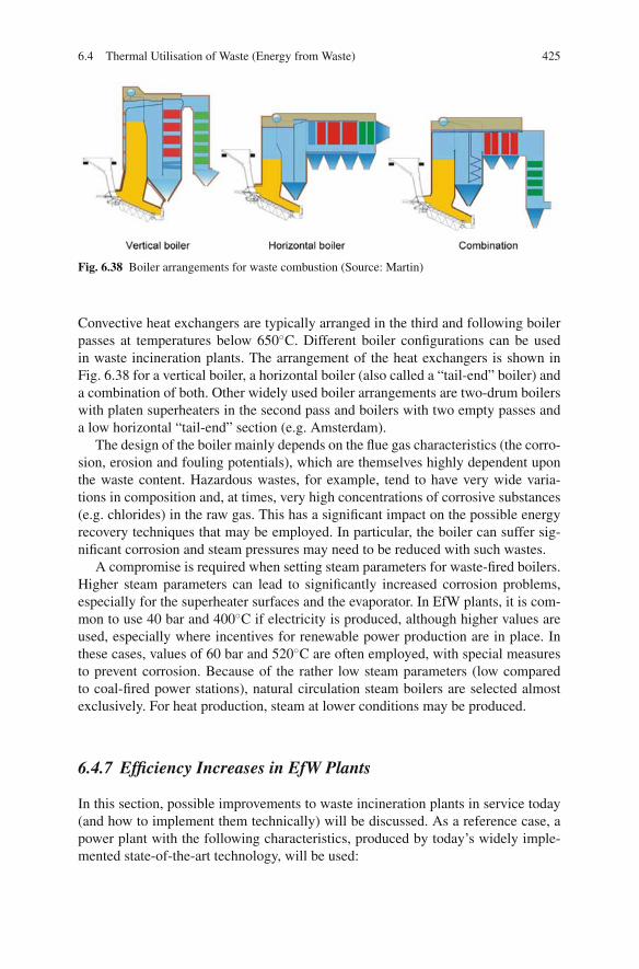
6.4 Thermal Utilisation of Waste (Energy from Waste) 425
Fig. 6.38 Boiler arrangements for waste combustion (Source: Martin)
Convective heat exchangers are typically arranged in the third and following boilerpasses at temperatures below 650◦C. Different boiler configurations can be usedin waste incineration plants. The arrangement of the heat exchangers is shown inFig. 6.38 for a vertical boiler, a horizontal boiler (also called a “tail-end” boiler) anda combination of both. Other widely used boiler arrangements are two-drum boilerswith platen superheaters in the second pass and boilers with two empty passes anda low horizontal “tail-end” section (e.g. Amsterdam).
The design of the boiler mainly depends on the flue gas characteristics (the corro-sion, erosion and fouling potentials), which are themselves highly dependent uponthe waste content. Hazardous wastes, for example, tend to have very wide varia-tions in composition and, at times, very high concentrations of corrosive substances(e.g. chlorides) in the raw gas. This has a significant impact on the possible energyrecovery techniques that may be employed. In particular, the boiler can suffer sig-nificant corrosion and steam pressures may need to be reduced with such wastes.
A compromise is required when setting steam parameters for waste-fired boilers.Higher steam parameters can lead to significantly increased corrosion problems,especially for the superheater surfaces and the evaporator. In EfW plants, it is com-mon to use 40 bar and 400◦C if electricity is produced, although higher values areused, especially where incentives for renewable power production are in place. Inthese cases, values of 60 bar and 520◦C are often employed, with special measuresto prevent corrosion. Because of the rather low steam parameters (low comparedto coal-fired power stations), natural circulation steam boilers are selected almostexclusively. For heat production, steam at lower conditions may be produced.
6.4.7 Efficiency Increases in EfW Plants
In this section, possible improvements to waste incineration plants in service today(and how to implement them technically) will be discussed. As a reference case, apower plant with the following characteristics, produced by today’s widely imple-mented state-of-the-art technology, will be used:

426 6 Power Generation from Biomass and Waste
– Steam parameters of 40 bar/380◦C– A boiler outlet flue gas temperature of 209◦C– An excess air ratio of 1.75 (flue gas O2 content of 8.4%, dry)– Condenser pressure of 150 mbar– An in-plant power consumption of 2.1 MW (0.1 MWh/t of waste)
The power plant, with its live steam conditions of 40 bar and 380◦C, has a netelectrical power production efficiency of 20.6%. In comparison, the average effi-ciency of plants in service in Europe lies at about 13%.
Within the framework of a study, the potential of technically feasible solutions toimprove the efficiency has been investigated using this reference power plant. Theresults are compiled in Table 6.10 (Gohlke and Spliethoff 2007; Spliethoff et al.2008).
Excess air ratio: Since the development of EfW plants in the 1960s, the excessair rates have remained relatively high, between 1.8 and 2.2. This was necessary inorder to compensate for fluctuating combustion conditions and to avoid the addedwear from refractory and membrane wall corrosion. Today, some EfW plants havereduced the excess air ratio in conjunction with special precautions.
Mixed municipal waste is relatively homogenous and therefore well suited todecreasing the excess air ratio. Should pre-processed waste fractions or commercialwaste be used, it is preferable to use higher excess air ratios (leading to lower effi-ciencies). The decrease of the air ratio from 1.75 for the reference case to 1.4 resultsin a net increase of the efficiency of 0.6% (Fig. 6.39).
Boiler exit temperature: Typically, the flue gas is cooled down in the economisersto approximately 200◦C at the outlet of the boiler (209◦C in the example of thereference case). The remaining energy is lost by quenching the flue gas with water totypical scrubber temperatures of 150◦C or less. Alternatively, cooling can be realisedby additional heat exchangers used for condensate preheating (in this case whereno direct use of heat is considered). As temperatures fall below the dew points,advanced materials are needed for these heat exchangers. The reduction of the fluegas temperature to 135.5◦C leads to an efficiency increase of 0.7–21.3% (Fig. 6.40).
Condensation pressure: The condenser temperature has a strong influence on theplant efficiency. The reference plant employs air condensers with a condensationtemperature of 54◦C, corresponding to a pressure of 150 mbar. The efficiency can beincreased by 2.8 percentage points to 23.4% if a water-cooled condenser with a tem-perature of 23◦C and 30 mbar pressure is used. However, this option for increasingthe efficiency is limited in the “real world” because cooling water is rarely available(Fig. 6.41).
Steam pressure and temperature: An increase in the pressure and temperature ofthe steam results in an increase in the efficiency of the thermal cycle. The gain in effi-ciency by increasing the live steam pressure, the live steam temperature and reheat-ing can be evaluated from a temperature/entropy (T − s) diagram (see Fig. 6.42).Basically, the efficiency of the thermal cycle is η = 1 − (Tout/Tin), where Tin
and Tout are the average medium temperatures of heat addition and heat extraction.Steam parameters can be increased in convective superheaters up to around 73 bar
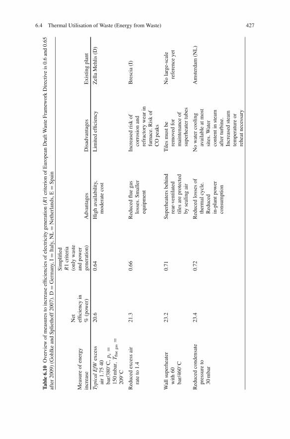
6.4 Thermal Utilisation of Waste (Energy from Waste) 427
Tabl
e6.
10O
verv
iew
ofm
easu
res
toin
crea
seef
ficie
ncie
sof
elec
tric
ityge
nera
tion
(R1
crite
rion
ofE
urop
ean
Dra
ftW
aste
Fram
ewor
kD
irec
tive
is0.
6an
d0.
65af
ter
2009
)(G
ohlk
ean
dSp
lieth
off
2007
).D
=G
erm
any,
I=
Ital
y,N
L=
Net
herl
ands
,E=
Spai
n
Sim
plifi
edR
1cr
iteri
aN
et(o
nly
was
teM
easu
reof
ener
gyef
ficie
ncy
inan
dpo
wer
incr
ease
%(p
ower
)ge
nera
tion)
Adv
anta
ges
Dis
adva
ntag
esE
xist
ing
plan
t
Typi
calE
fWex
cess
air
1.75
40ba
r/38
0◦ C,
p c=
150
mba
r,T fl
uega
s=
209◦ C
20.6
0.64
Hig
hav
aila
bilit
y,m
oder
ate
cost
Lim
ited
effic
ienc
yZ
ella
Meh
lis(D
)
Red
uced
exce
ssai
rra
teto
1.4
21.3
0.66
Red
uced
flue
gas
loss
es.S
mal
ler
equi
pmen
t
Incr
ease
dri
skof
corr
osio
nan
dre
frac
tory
wea
rin
furn
ace.
Ris
kof
CO
peak
s
Bre
scia
(I)
Wal
lsup
erhe
ater
with
60ba
r/46
0◦ C
23.2
0.71
Supe
rhea
ters
behi
ndre
ar-v
entil
ated
tiles
are
prot
ecte
dby
seal
ing
air
Tile
sm
ustb
ere
mov
edfo
rm
aint
enan
ceof
supe
rhea
ter
tube
s
No
larg
e-sc
ale
refe
renc
eye
t
Red
uced
cond
ensa
tepr
essu
reto
30m
bar
23.4
0.72
Red
uced
loss
esof
ther
mal
cycl
e.R
educ
edin
-pla
ntpo
wer
cons
umpt
ion
No
wat
erco
olin
gav
aila
ble
atm
ost
site
s.W
ater
cont
enti
nst
eam
afte
rtu
rbin
e.In
crea
sed
stea
mte
mpe
ratu
reor
rehe
atne
cess
ary
Am
ster
dam
(NL
)
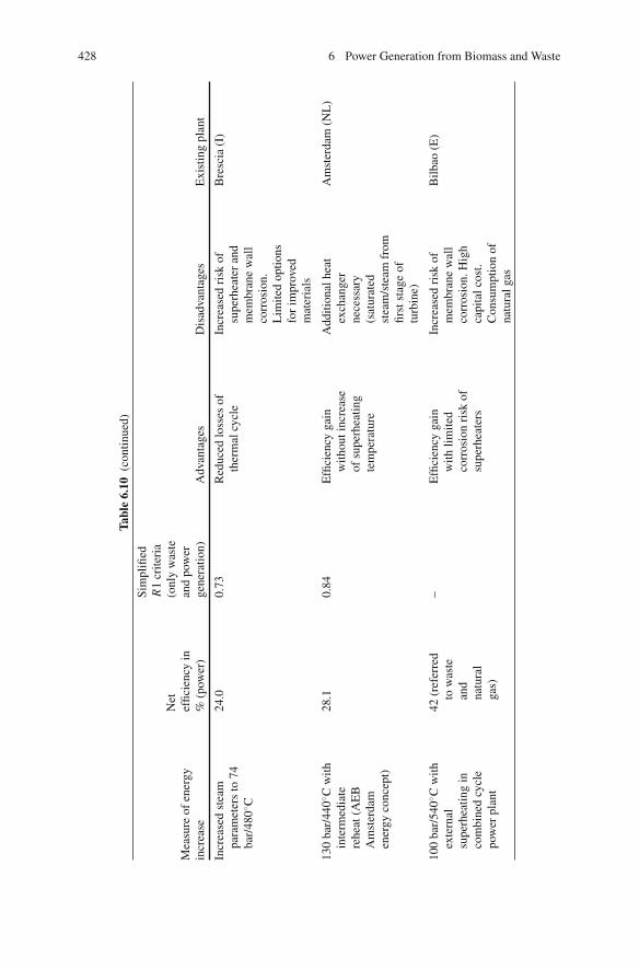
428 6 Power Generation from Biomass and Waste
Tabl
e6.
10(c
ontin
ued)
Sim
plifi
edR
1cr
iteri
aN
et(o
nly
was
teM
easu
reof
ener
gyef
ficie
ncy
inan
dpo
wer
incr
ease
%(p
ower
)ge
nera
tion)
Adv
anta
ges
Dis
adva
ntag
esE
xist
ing
plan
t
Incr
ease
dst
eam
para
met
ers
to74
bar/
480◦ C
24.0
0.73
Red
uced
loss
esof
ther
mal
cycl
eIn
crea
sed
risk
ofsu
perh
eate
ran
dm
embr
ane
wal
lco
rros
ion.
Lim
ited
optio
nsfo
rim
prov
edm
ater
ials
Bre
scia
(I)
130
bar/
440◦ C
with
inte
rmed
iate
rehe
at(A
EB
Am
ster
dam
ener
gyco
ncep
t)
28.1
0.84
Effi
cien
cyga
inw
ithou
tinc
reas
eof
supe
rhea
ting
tem
pera
ture
Add
ition
alhe
atex
chan
ger
nece
ssar
y(s
atur
ated
stea
m/s
team
from
first
stag
eof
turb
ine)
Am
ster
dam
(NL
)
100
bar/
540◦ C
with
exte
rnal
supe
rhea
ting
inco
mbi
ned
cycl
epo
wer
plan
t
42(r
efer
red
tow
aste
and
natu
ral
gas)
–E
ffici
ency
gain
with
limite
dco
rros
ion
risk
ofsu
perh
eate
rs
Incr
ease
dri
skof
mem
bran
ew
all
corr
osio
n.H
igh
capi
talc
ost.
Con
sum
ptio
nof
natu
ralg
as
Bilb
ao(E
)

6.4 Thermal Utilisation of Waste (Energy from Waste) 429
Fig. 6.39 Influence of theexcess air rate on efficiency(Gohlke and Spliethoff 2007)
Fig. 6.40 Influence of boilerexit temperature on netelectrical efficiency (Gohlkeand Spliethoff 2007)
and 480◦C with a classical boiler design, resulting in an efficiency increase of 3.4percentage points to 24%. However, this increase is associated with a significantlyhigher risk of corrosion in comparison to a typical process which uses 40 bar and380◦C.
Another innovative approach to increase steam parameters is to use wall super-heaters, where the most critical superheating tubes are placed behind rear-ventilatedfurnace tiles. In this way, the superheating temperature can be increased withoutadditional corrosion problems. The critical tubes are protected by the sealing air ofthe rear-ventilated tiles. It is possible to obtain an efficiency increase of 2.6 per-centage points to 23.2% with wall superheaters and steam parameters of 460◦C and60 bar.

430 6 Power Generation from Biomass and Waste
Fig. 6.41 Influence ofcondensation pressure on netelectrical efficiency (Gohlkeand Spliethoff 2007)
1
2
34
5
6
7
8
6is
8is
0.15
0.03
0 2 4 6 80
50
100
150
200
250
300
350
400
450
500
T [
°C]
s [kJkg–1K–1]
pRH
40 bar
70 bar90 bar
130 bar
0.80.60.40.2
Tm Amsterdam
Tm Zella MehlisTm RH
Fig. 6.42 Medium temperature of heat addition of the reference plant and of a plant with reheating(Gohlke and Spliethoff 2007)
Intermediate reheating: To achieve a further increase in efficiency, it is nec-essary to use intermediate steam reheating. This process has been developed byAfval Energie Bedrijf (AEB) Amsterdam (“the City of Amsterdam Waste and EnergyCompany”) and is now used in the new Amsterdam plant, which began operationin spring 2007 (Van Berlo 2006). The system is run with a steam pressure of 130bar, a superheating temperature of 440◦C and reheating of the steam, using saturateddrum steam, to 320◦C after the first stage of the turbine (see Fig. 6.43). Compared tothe reference EfW plant mentioned above, the configuration provides an efficiencyincrease of 7.5 percentage points to 28.1%. In Amsterdam, an even higher efficiency
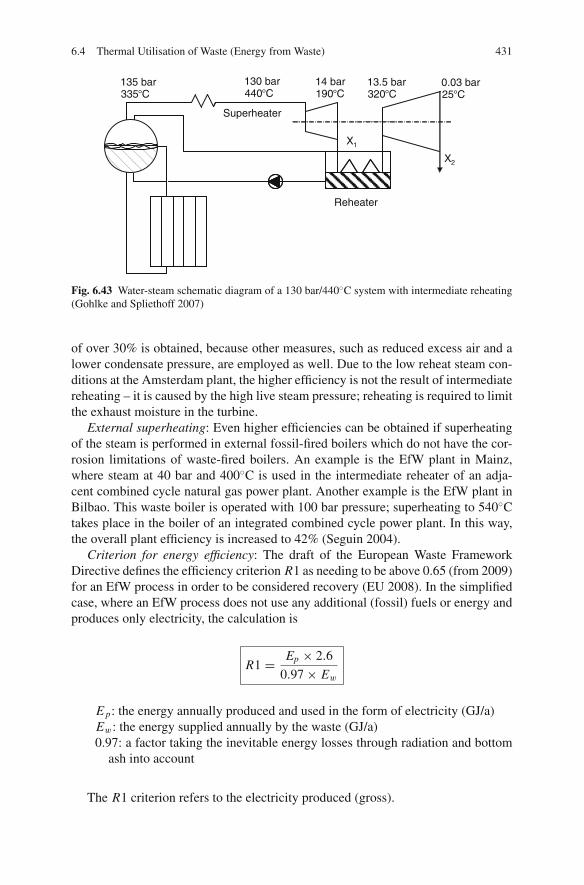
6.4 Thermal Utilisation of Waste (Energy from Waste) 431
135 bar335°C
130 bar440°C
14 bar190°C
13.5 bar320°C
0.03 bar25°C
Reheater
X1
X2
Superheater
Fig. 6.43 Water-steam schematic diagram of a 130 bar/440◦C system with intermediate reheating(Gohlke and Spliethoff 2007)
of over 30% is obtained, because other measures, such as reduced excess air and alower condensate pressure, are employed as well. Due to the low reheat steam con-ditions at the Amsterdam plant, the higher efficiency is not the result of intermediatereheating – it is caused by the high live steam pressure; reheating is required to limitthe exhaust moisture in the turbine.
External superheating: Even higher efficiencies can be obtained if superheatingof the steam is performed in external fossil-fired boilers which do not have the cor-rosion limitations of waste-fired boilers. An example is the EfW plant in Mainz,where steam at 40 bar and 400◦C is used in the intermediate reheater of an adja-cent combined cycle natural gas power plant. Another example is the EfW plant inBilbao. This waste boiler is operated with 100 bar pressure; superheating to 540◦Ctakes place in the boiler of an integrated combined cycle power plant. In this way,the overall plant efficiency is increased to 42% (Seguin 2004).
Criterion for energy efficiency: The draft of the European Waste FrameworkDirective defines the efficiency criterion R1 as needing to be above 0.65 (from 2009)for an EfW process in order to be considered recovery (EU 2008). In the simplifiedcase, where an EfW process does not use any additional (fossil) fuels or energy andproduces only electricity, the calculation is
R1 = Ep × 2.6
0.97 × Ew
E p: the energy annually produced and used in the form of electricity (GJ/a)Ew: the energy supplied annually by the waste (GJ/a)0.97: a factor taking the inevitable energy losses through radiation and bottom
ash into account
The R1 criterion refers to the electricity produced (gross).
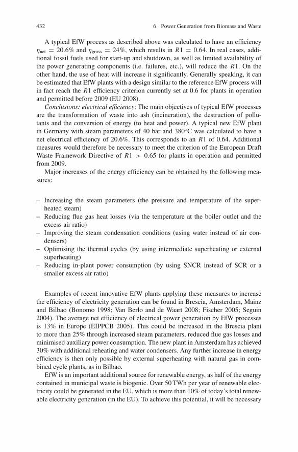
432 6 Power Generation from Biomass and Waste
A typical EfW process as described above was calculated to have an efficiencyηnet = 20.6% and ηgross = 24%, which results in R1 = 0.64. In real cases, addi-tional fossil fuels used for start-up and shutdown, as well as limited availability ofthe power generating components (i.e. failures, etc.), will reduce the R1. On theother hand, the use of heat will increase it significantly. Generally speaking, it canbe estimated that EfW plants with a design similar to the reference EfW process willin fact reach the R1 efficiency criterion currently set at 0.6 for plants in operationand permitted before 2009 (EU 2008).
Conclusions: electrical efficiency: The main objectives of typical EfW processesare the transformation of waste into ash (incineration), the destruction of pollu-tants and the conversion of energy (to heat and power). A typical new EfW plantin Germany with steam parameters of 40 bar and 380◦C was calculated to have anet electrical efficiency of 20.6%. This corresponds to an R1 of 0.64. Additionalmeasures would therefore be necessary to meet the criterion of the European DraftWaste Framework Directive of R1 > 0.65 for plants in operation and permittedfrom 2009.
Major increases of the energy efficiency can be obtained by the following mea-sures:
– Increasing the steam parameters (the pressure and temperature of the super-heated steam)
– Reducing flue gas heat losses (via the temperature at the boiler outlet and theexcess air ratio)
– Improving the steam condensation conditions (using water instead of air con-densers)
– Optimising the thermal cycles (by using intermediate superheating or externalsuperheating)
– Reducing in-plant power consumption (by using SNCR instead of SCR or asmaller excess air ratio)
Examples of recent innovative EfW plants applying these measures to increasethe efficiency of electricity generation can be found in Brescia, Amsterdam, Mainzand Bilbao (Bonomo 1998; Van Berlo and de Waart 2008; Fischer 2005; Seguin2004). The average net efficiency of electrical power generation by EfW processesis 13% in Europe (EIPPCB 2005). This could be increased in the Brescia plantto more than 25% through increased steam parameters, reduced flue gas losses andminimised auxiliary power consumption. The new plant in Amsterdam has achieved30% with additional reheating and water condensers. Any further increase in energyefficiency is then only possible by external superheating with natural gas in com-bined cycle plants, as in Bilbao.
EfW is an important additional source for renewable energy, as half of the energycontained in municipal waste is biogenic. Over 50 TWh per year of renewable elec-tricity could be generated in the EU, which is more than 10% of today’s total renew-able electricity generation (in the EU). To achieve this potential, it will be necessary
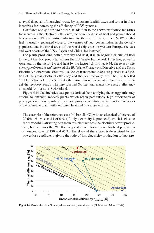
6.4 Thermal Utilisation of Waste (Energy from Waste) 433
to avoid disposal of municipal waste by imposing landfill taxes and to put in placeincentives for increasing the efficiency of EfW systems.
Combined use of heat and power: In addition to the above-mentioned measuresfor increasing the electrical efficiency, the combined use of heat and power shouldbe considered. This is particularly true for the use of energy from MSW, as thisfuel is usually generated close to the centres of heat consumption in the denselypopulated and industrial areas of the world (big cities in western Europe, the eastand west coasts of the USA, Japan and China, for instance).
For plants producing both electricity and heat, it is an ongoing discussion howto weight the two products. Within the EU Waste Framework Directive, power isweighted by the factor 2.6 and heat by the factor 1.1. In Fig. 6.44, the energy effi-ciency performance indicators of the EU Waste Framework Directive and the SwissElectricity Generation Directive (EU 2008; Bundesamt 2008) are plotted as a func-tion of the gross electrical efficiency and the heat recovery rate. The line labelled“EU Directive R1 = 0.65” marks the minimum requirement a plant must fulfil toget the recovery status. The line labelled Switzerland marks the energy efficiencythreshold for plants in Switzerland.
Figure 6.44 also includes data points derived from applying the energy efficiencycriteria to different modern plants which reach particularly high efficiencies ofpower generation or combined heat and power generation, as well as two instancesof the reference plant with combined heat and power generation.
– The example of the reference case (40 bar, 380◦C) with an electrical efficiency of20.6% achieves an R1 of 0.64 (if only electricity is produced) which is close tothe threshold. Extracting heat from this plant reduces the electrical power produc-tion, but increases the R1 efficiency criterion. This is shown for heat productionat temperatures of 130 and 95◦C. The slope of these lines is determined by thepower loss coefficient, giving the ratio of lost electricity production to heat pro-
Fig. 6.44 Gross electric efficiency–heat recovery rate diagram (Gohlke and Murer 2009)
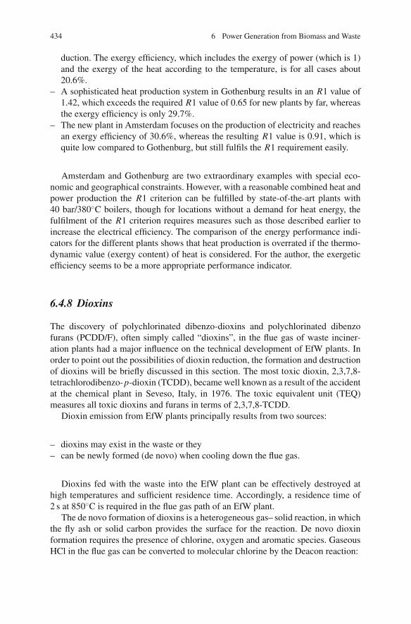
434 6 Power Generation from Biomass and Waste
duction. The exergy efficiency, which includes the exergy of power (which is 1)and the exergy of the heat according to the temperature, is for all cases about20.6%.
– A sophisticated heat production system in Gothenburg results in an R1 value of1.42, which exceeds the required R1 value of 0.65 for new plants by far, whereasthe exergy efficiency is only 29.7%.
– The new plant in Amsterdam focuses on the production of electricity and reachesan exergy efficiency of 30.6%, whereas the resulting R1 value is 0.91, which isquite low compared to Gothenburg, but still fulfils the R1 requirement easily.
Amsterdam and Gothenburg are two extraordinary examples with special eco-nomic and geographical constraints. However, with a reasonable combined heat andpower production the R1 criterion can be fulfilled by state-of-the-art plants with40 bar/380◦C boilers, though for locations without a demand for heat energy, thefulfilment of the R1 criterion requires measures such as those described earlier toincrease the electrical efficiency. The comparison of the energy performance indi-cators for the different plants shows that heat production is overrated if the thermo-dynamic value (exergy content) of heat is considered. For the author, the exergeticefficiency seems to be a more appropriate performance indicator.
6.4.8 Dioxins
The discovery of polychlorinated dibenzo-dioxins and polychlorinated dibenzofurans (PCDD/F), often simply called “dioxins”, in the flue gas of waste inciner-ation plants had a major influence on the technical development of EfW plants. Inorder to point out the possibilities of dioxin reduction, the formation and destructionof dioxins will be briefly discussed in this section. The most toxic dioxin, 2,3,7,8-tetrachlorodibenzo-p-dioxin (TCDD), became well known as a result of the accidentat the chemical plant in Seveso, Italy, in 1976. The toxic equivalent unit (TEQ)measures all toxic dioxins and furans in terms of 2,3,7,8-TCDD.
Dioxin emission from EfW plants principally results from two sources:
– dioxins may exist in the waste or they– can be newly formed (de novo) when cooling down the flue gas.
Dioxins fed with the waste into the EfW plant can be effectively destroyed athigh temperatures and sufficient residence time. Accordingly, a residence time of2 s at 850◦C is required in the flue gas path of an EfW plant.
The de novo formation of dioxins is a heterogeneous gas– solid reaction, in whichthe fly ash or solid carbon provides the surface for the reaction. De novo dioxinformation requires the presence of chlorine, oxygen and aromatic species. GaseousHCl in the flue gas can be converted to molecular chlorine by the Deacon reaction:

6.4 Thermal Utilisation of Waste (Energy from Waste) 435
4 HCl + O2 → 2 H2O + 2 Cl2 (6.1)
Molecular chlorine reacts with aromatic species and soot in the flue gas to formPCDDs and PCDFs, the amount and particular species depending on the temperatureand the boiler design. Copper in the fuel or the ashes may act as catalyst for forma-tion. It has been shown that the de novo reaction takes place in a temperature windowof 180–450◦C, with a maximum formation at about 300◦C, and is dependent on theresidence time of the gas and in particular the fly ash in that temperature range.
Effective primary measures to reduce the de novo formation of dioxins are asfollows:
– A complete burnout, which reduces the potential of dioxide formation by destroy-ing the aromatic compounds and soot. The residence of 2 s at 850◦C, which servesto destroy existing dioxins also promotes a complete burnout.
– A low residence time of the flue gas and fly ash in the temperature range of180–450◦C. This can be achieved by rapid cooling or quenching of the flue gases.Particle filters should be installed at lower temperatures, preferably below 180◦C.
Dioxin emissions can be effectively reduced by primary measures to destroyexisting dioxins in the fuel and to prevent de novo formation by appropriate boilerdesign and flue gas handling. Dioxin emissions are influenced by the burnoutbehaviour and depend on the temperature course of the flue gas train. High dioxinemissions from EfW plants in the past were mainly caused by de novo formationin particle filters installed at excessively high temperatures in combination with anincomplete burnout. Additionally, dioxins can be reduced by secondary flue gascleaning. Secondary measures can be catalytic dioxin reduction or adsorption onchar coal, which then has to be treated thermally. As a result of emission controlrequirements, incineration in developed countries is now a very minor contributorto dioxin emissions (Baumbach 1990; Nussbaumer 2004).
6.4.9 Flue Gas Cleaning
To comply with the stipulated emission limits of the European Waste IncinerationDirective, a great number of methods for each individual pollutant are available. Inthe flue gas cleaning process, the following pollutants have to be removed from theflue gas:
• Fly ash (removed by ESP or bag filter)• Sour gases like HCl, HF and SO2 (removed by wet scrubbing, spray dry absorp-
tion, etc.)• Heavy metals like Hg, Pb, Zn (removed by activated carbon filter or filsorption)• Organic substances like PCDD/F (removed by activated carbon filter or filsorp-
tion)• Nitrogen oxides (removed by SNCR or SCR)

436 6 Power Generation from Biomass and Waste
Since the different methods of flue gas treatment have largely been discussed inChap. 5, they shall be examined in the following only in regard to their use in wasteincineration plants (Nethe 2008; Vehlow 2006).
Dust separation: Both fabric filters (also called baghouse filters) and electrostaticprecipitators (ESPs) are suitable for removing particulate pollutants. To combinedust separation with wet absorption of acid gases (HCl, SO2), ESPs are usuallyemployed. They are cheaper and associated with a lower pressure loss than bag-house filters. The removal of dust and pollutants is lower with ESPs, but sufficientif associated with wet scrubbers for the additional removal of pollutants. In com-bination with spray dryer processes, the fabric filter is advantageous, because thesorptive effect on the filter linings can be exploited. The operating temperatures ofbaghouse filters are usually between 140 and 200◦C. ESPs are also used at temper-atures up to 280◦C, upstream of the last economiser (last in relation to the flue gasstream; first in relation to the condensate water stream) in combination with SCRcatalysts.
Separation of acid gases: For the separation of acid flue gas components such asHCl, HF, SO2 and SO3, wet and dry processes rival each other. Wet processes usescrubbing slurries, putting them into close contact with the flue gas to be cleaned.The separation process usually runs in two steps: in the first step, HF, HCl andHg compounds are scrubbed with water and in the second step, SO2 and SO3 areseparated by the addition of a lime slurry or sodium hydroxide. Wet scrubbingmethods, with their good mass transfer between the gas and the liquid, are veryeffective and work under nearly stoichiometric conditions, so the consumption ofabsorbents is low. A drawback is the wastewater that is produced, which is of a typerequiring wastewater treatment or concentration by evaporation. Wet processes arepreferred in countries where it is authorised to discharge effluent to the river, suchas in Switzerland and Austria or to the sea like in the Netherlands.
Dry or spray drying processes, in contrast, do not produce wastewater. In dryabsorption or in an entrained-flow absorber, solid absorbents like calcium hydrateor sodium carbonate are fed to the reactor to separate the acid components, whereasin spray drying, an aqueous lime slurry is finely atomised and completely evapo-rated. The good mass transfer between the gas and the liquid in spray draying isagain advantageous. The salt particles formed as a consequence of evaporation ofthe water and chemisorption are removed from the gas flow in a filtering separa-tor. In this case, fabric filters offer the advantage of further removal via the solidlayer of matter on the filter. Spray drying processes typically run at temperatures of150–170◦C.
A further reduction of organic pollutants or heavy metals can be effected byadding surface-active adsorbents such as activated carbon or activated charcoal.Dry or spray drying flue gas cleaning systems are preferred in countries where itis difficult to get authorisation for effluent discharge to rivers or seas. This is thecase in most western and southern European countries as well as in the USA andJapan. In Germany, dry or spray drying processes are favoured because of the optionof disposing the fly ash and flue gas cleaning residues in abandoned salt mines at

6.4 Thermal Utilisation of Waste (Energy from Waste) 437
relatively low cost. In France and Japan, these residues are solidified with cementor concrete, which is costly, and there is contention over the long-term stability ofsuch procedures.
Toxic heavy metals (e.g. Hg, Cd, Pb, Zn) and organic substances (e.g. PCDD/F):The technologies used for these pollutants are entrained-flow and fixed bed adsor-bers. The methods to separate heavy metals and organic matter are based on theadsorption of the pollutants by carbonaceous surfactants such as activated carbon orlignite coke and not on absorption as in the removal of acid gases. Entrained-flowprocesses are designed for the separation of heavy metals and dioxins by adsorptiononto reactants which are injected to the flue gas stream. In a fixed bed adsorber, theseparation process occurs as the flue gas flows through a packed bed of carbona-ceous adsorbents. Single-chamber systems with fillings of activated carbon/lignitecoke and multi-chamber systems with various adsorbents are used.
Both entrained-flow and fixed bed adsorbers can be used as safety or “police”filters at the end of the flue gas cleaning train. Remaining heavy metals or dioxins areremoved by adsorption onto carbonaceous material and remaining acid componentscan be absorbed by the addition of calcium hydroxide.
NOx reduction: Nitrogen oxides can be reduced by primary measures, by selec-tive non-catalytic reduction (SNCR) or by selective catalytic reduction (SCR). SCRtechnology not only gives the highest reduction rates but also involves the highestcost. In the low-dust SCR configurations which are most common in Europe andJapan, the catalyst is arranged after the scrubber to prevent deactivation. This con-figuration has the disadvantage of the need to reheat the flue gases to the operatingtemperature of the catalyst (above 240◦C). In the USA it is common to use SNCR(and not SCR) in EfW plants.
Flue gas cleaning configurations: All modern waste incineration plants areequipped with an efficient flue gas cleaning system which guarantees a reliablecompliance with emission limits. Figure 6.45 shows possible process variants. Con-figurations with wet gas cleaning (configuration a) are clearly more complex thandry processes. In German plants with wet gas cleaning, concentration of the blow-down solutions by evaporation is required, which can be performed by an externalevaporator or by installing a spray dryer and a fabric filter into the hot flue gas stream(configuration b). In contrast, the dry variant in combination with NOx control bySNCR is clearly less complex (configuration c). By means of the spray dryer, boththe acid gases and mercury and dioxins can be separated by adding activated car-bon. In the following fabric filter, the products from flue gas cleaning are removedtogether with the fly ash. In some plants, the fly ash is removed separately before-hand.
The dry process has the disadvantage that it has to be operated with a highersorbent stoichiometry and so produces considerably higher amounts of residues,which, because of their solubility in water, are more difficult to dispose of (Vehlow2006). Police filters were used in Germany and Austria in the 1990s but are notcommon in newer plants because of the general advancement of flue gas cleaningtechnologies.

438 6 Power Generation from Biomass and Waste
HCIWS
SO2WS
SCR
HCIWS
SO2WS
SCR
H2O CaCO3 ActivatedCarbon (AC)
250°C
Boiler
65°C
H2O CaCO3 AC
110°C 250°C
Boiler
250°C
Ca (OH)2Ca CO3
150°C 140°C 65°C 110°C 250°C
900°C 150°C 140°C
NH3
SNCR SDA
SDA
WS Wet scrubberF FilterPF Police filterSDA Spray dry absorber
PF
PF
F
F
a) Wet cleaning
b) Wet cleaning + waste water evaporation
c) Dry cleaning
ESP
ESP
Stack
Stack
Stack
SCR Selective catalytic reductionSNCR Selective non-catalytic reduction
SCRPF
Fig. 6.45 Configurations for flue gas cleaning
6.5 Co-combustion in Coal-Fired Power Plants
The combined thermal utilisation of biomass and fossil fuels provides a cost-efficient option for the short-term exploitation of the biomass that is currentlyavailable. Given that biomass is a solid fuel, it is reasonable from the technicalpoint of view to use it in combustion or gasification plants in combination withother solid fuels. Existing coal firing power plants, with outputs up to a maximumof 2,500 MWth, are almost all combustion plants and, because of their firing andflue gas cleaning installations, are ideally suited to the co-combustion of biomass(Spliethoff 2000; Spliethoff et al. 2001).
The share of the biomass in the total thermal output of a co-fired power plant islimited by the biomass flow that can be used without inhibiting the operation of theplant and also by the quantity of biomass that can be supplied to a given plant site.This second constraint sets a limit of around 50–100 MW of bio-fuel energy input.Higher capacities strongly increase goods traffic, which becomes problematic whenattempting to gain the approval of authorities. A fraction of 10–30% of biomass inthe total thermal output from a pulverised hard coal plant should not be exceeded, sothat adaptation measures in the plant can be kept to a minimum. In brown coal-firedand fluidised bed furnaces, it is possible to use greater fractions. The exact valueshave to be determined for each plant individually.
Power generation by co-firing biomass in existing coal-fired power plants has anumber of advantages over generation in small plants fired with biomass only:

6.5 Co-combustion in Coal-Fired Power Plants 439
• The large total existing power plant capacity – even with a relatively smallbiomass fraction of the total fuel input – allows biomass utilisation at a largescale without a delay for construction of biomass-specific plants. This holds truedespite the fact that not all large power plants are generally suitable for the co-combustion of biomass.
• The power generation efficiencies of large power plants are high compared to theefficiencies of small plants fired with biomass only.
• In case of seasonal non-availability or of shortfalls in bio-fuel supply due toweather conditions, the generation of power can still be guaranteed based oncoal (i.e. a high security of supply combined with high fuel flexibility).
• The additional capital costs needed to co-fire biomass in existing coal-fired powerplants are relatively low compared to new dedicated biomass combustion sys-tems. While the capital costs for the new construction of a local biomass com-bustion plant amount to between 2,500 and 3,000 e/kWel of installed capacity,retrofitting an existing power plant for co-combustion requires capital costs ofabout 300 e/kWel of biomass input. In the main, these additional costs are allot-ted to fuel preparation (VGB 2008).
Besides biomasses such as wood and straw, other biomasses that are producedin adequate and homogeneous quantities can, in general, also be used in co-combustion, for example, sewage sludge. Co-combustion is also suitable for biomasstypes that are rather problematic from the combustion engineering point of view. InGermany, if the co-fired fuels derived from waste are within the legally definedrange of between 0 and 25% of the thermal capacity, the plant can still be licensedand operated according to the German Ordinance on Large Combustion Plants (13thBImSchV). Only part of the statutory regulations for waste incinerators (re 17thBImSchV) apply to co-combustion (see also Sect. 5.6).
Co-firing technologies are presently being routinely commercially practiced inthe USA, Finland, Denmark, Germany, Belgium, the Netherlands, Austria, Spain,Australia, Britain and a number of other countries. An inventory of the applica-tion of co-firing worldwide in 2004 indicated that more than 150 coal-fired powerplants had experience with co-firing of biomass or waste, at least on a trial basis. Alarge range of biomass materials including herbaceous and woody materials, wastesand energy crops are co-fired today (Van Loo and Koppejan 2008; Baxter 2005;Fernando 2005; Fernando 2007).
The focus of co-combustion activities varies from country to country and dependson the availability of biomass types, but mainly on legal issues and nationalincentives. Many countries have initiated incentives to encourage the use of biomassfor electricity production. Some examples are as follows:
• According to a political agreement in Denmark from 1993, power stations inDenmark have to use 1.4 million tonnes of biomass, of which at least 1.0 milliontonnes must be straw, every year beyond 2000 (Berg and Jensen 2008).
• In 2002, the Dutch government agreed a coal covenant with the six major utilitiesin which they were obliged to reduce CO2 emissions from coal by 5.8 Mt/yearin the period 2008–2012. More than half of this target, namely 3.2 Mt, is to be
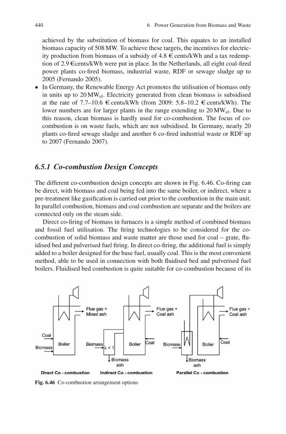
440 6 Power Generation from Biomass and Waste
achieved by the substitution of biomass for coal. This equates to an installedbiomass capacity of 508 MW. To achieve these targets, the incentives for electric-ity production from biomass of a subsidy of 4.8 e cents/kWh and a tax redemp-tion of 2.9ecents/kWh were put in place. In the Netherlands, all eight coal-firedpower plants co-fired biomass, industrial waste, RDF or sewage sludge up to2005 (Fernando 2005).
• In Germany, the Renewable Energy Act promotes the utilisation of biomass onlyin units up to 20 MWel. Electricity generated from clean biomass is subsidisedat the rate of 7.7–10.6 e cents/kWh (from 2009: 5.8–10.2 e cents/kWh). Thelower numbers are for larger plants in the range extending to 20 MWel. Due tothis reason, clean biomass is hardly used for co-combustion. The focus of co-combustion is on waste fuels, which are not subsidised. In Germany, nearly 20plants co-fired sewage sludge and another 6 co-fired industrial waste or RDF upto 2007 (Fernando 2007).
6.5.1 Co-combustion Design Concepts
The different co-combustion design concepts are shown in Fig. 6.46. Co-firing canbe direct, with biomass and coal being fed into the same boiler, or indirect, where apre-treatment like gasification is carried out prior to the combustion in the main unit.In parallel combustion, biomass and coal combustion are separate and the boilers areconnected only on the steam side.
Direct co-firing of biomass in furnaces is a simple method of combined biomassand fossil fuel utilisation. The firing technologies to be considered for the co-combustion of solid biomass and waste matter are those used for coal – grate, flu-idised bed and pulverised fuel firing. In direct co-firing, the additional fuel is simplyadded to a boiler designed for the base fuel, usually coal. This is the most convenientmethod, able to be used in connection with both fluidised bed and pulverised fuelboilers. Fluidised bed combustion is quite suitable for co-combustion because of its
Fig. 6.46 Co-combustion arrangement options

6.5 Co-combustion in Coal-Fired Power Plants 441
fuel flexibility, whereas the pulverised coal combustor requires a well-defined fuelsize distribution. Experience shows that only minor quantities of additional fuels(a few per cent of the fuel power) can be prepared together with the coal in theexisting coal mills of a PC plant. If larger quantities are to be used, special mills andburners are desirable. There are no such limitations in FBC. In fluidised beds, largerquantities and larger fuel particle sizes can be used (Leckner 2007; Spliethoff 2000).
Because there are only a small number of grate firing systems used for coal, thistechnology shall not be considered further in the context of co-combustion. Gratesare used for mono-combustion of biomass and predominantly for waste incineration,since their capacities are adequate for the quantities of waste produced at manylocations and the technology is suitable for a wide range of fuel types.
Direct co-combustion of biomass in coal-fired plants, however, can have negativeeffects on operation and the quality of the residual matter. It can impair the plantperformance through fouling, slagging, or corrosion, or reduce the potential for useof the fly ash. An additional pre-treatment step for the biomass such as pyrolysis,gasification or washing can solve these problems (see Fig. 6.47).
In contrast to direct co-combustion, it is possible to separately remove and utilisethe ashes of coal and biomass by topping with a pyrolysis or gasification step.Combustible, low-calorific-value gas is injected and burned in the main combustor,whereas most of the ashes remain in the gasifier, from where they are removed,
Fig. 6.47 Indirectco-combustion configurations

442 6 Power Generation from Biomass and Waste
separately to the ash removal from the main boiler. However, gaseous componentssuch as volatile alkali compounds or trace elements from the additional fuel willenter the main combustor if no adequate gas cleaning is provided for. Such systemshave been built in the Netherlands, Finland and Austria. Used as a reburn fuel, thepyrolysis gases are able to reduce the nitrogen oxides formed in the combustion ofthe pulverised fuel. Fouling or erosive effects caused by biomass ashes are avoidedor reduced, and the commercial value of the fly ash from the coal is not impaired(Leckner 2007; Fernando 2002).
In parallel co-combustion, biomass is fired in an entirely separate combustionsystem which is connected to the main boiler only on the steam side. Steam pro-duced in the biomass combustor can be either fed directly to the joint turbine or tothe coal boiler to be superheated. In this way, the additional furnace can provide heatto the steam cycle at a suitable steam temperature. Another advantage of connect-ing only on the steam side is that any harmful substance released in the additionalboiler will not affect the main combustor, and both ashes and flue gases can betreated separately. This promotes the utilisation of both the coal and the biomassash. An example of such a plant is the 600 MWel multi-fuel power plant at Avedore,Denmark. Straw of a thermal input of 100 MW is burnt in a grate combustor, withthe steam produced having the same steam conditions as the main boiler – 300 barand 580◦C. The multi-fuel concept enables efficiencies of 48% for the main unit and45% for the straw unit (Noppenau 2003; Fernando 2002).
Direct co-firing is straightforward but can lead to several technical problems.Indirect and parallel co-firing incurs greater costs and is in particular suitable forbiomass containing troublesome or harmful components or when the quality of theash is of importance. It is necessary to weigh up the costs and the other pros andcons of the available technologies. Indirect and parallel co-firing is less commonthan direct co-firing.
6.5.2 Biomass Preparation and Feeding
The required preparation for bio-fuel for direct co-combustion in existing powerplants depends on the type of biomass and on the firing technology. For wood,woodchips can be regarded as the state of the art. Experience in Denmark suggeststhat providing herbaceous biomass in the form of bales is suitable.
Different methods for supplying the fuel to the furnace can be distinguished.Preparation for and feeding of PC boilers usually require more steps, for example,milling or even separate burners for the additional fuels. The methods are shown inFig. 6.48.
The simplest option is to blend the bio-fuel with the coal, introducing the mix-ture through the existing fuel-handling system and through the existing pulverisedcoal burners. The main restriction is the different milling behaviours of coal andbiomass. Most coal mill designs base the pulverisation of the coal on its brittle-ness. This milling principle can be used in the case of sewage sludge, but it is not
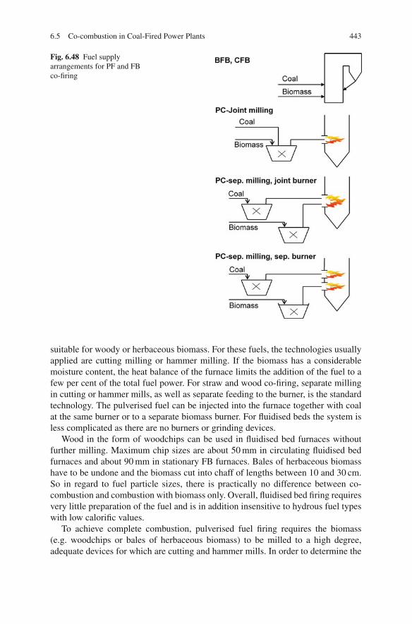
6.5 Co-combustion in Coal-Fired Power Plants 443
Fig. 6.48 Fuel supplyarrangements for PF and FBco-firing
suitable for woody or herbaceous biomass. For these fuels, the technologies usuallyapplied are cutting milling or hammer milling. If the biomass has a considerablemoisture content, the heat balance of the furnace limits the addition of the fuel to afew per cent of the total fuel power. For straw and wood co-firing, separate millingin cutting or hammer mills, as well as separate feeding to the burner, is the standardtechnology. The pulverised fuel can be injected into the furnace together with coalat the same burner or to a separate biomass burner. For fluidised beds the system isless complicated as there are no burners or grinding devices.
Wood in the form of woodchips can be used in fluidised bed furnaces withoutfurther milling. Maximum chip sizes are about 50 mm in circulating fluidised bedfurnaces and about 90 mm in stationary FB furnaces. Bales of herbaceous biomasshave to be undone and the biomass cut into chaff of lengths between 10 and 30 cm.So in regard to fuel particle sizes, there is practically no difference between co-combustion and combustion with biomass only. Overall, fluidised bed firing requiresvery little preparation of the fuel and is in addition insensitive to hydrous fuel typeswith low calorific values.
To achieve complete combustion, pulverised fuel firing requires the biomass(e.g. woodchips or bales of herbaceous biomass) to be milled to a high degree,adequate devices for which are cutting and hammer mills. In order to determine the
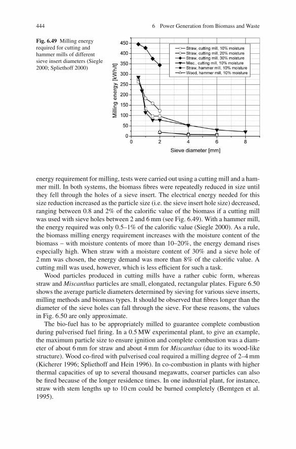
444 6 Power Generation from Biomass and Waste
Fig. 6.49 Milling energyrequired for cutting andhammer mills of differentsieve insert diameters (Siegle2000; Spliethoff 2000)
energy requirement for milling, tests were carried out using a cutting mill and a ham-mer mill. In both systems, the biomass fibres were repeatedly reduced in size untilthey fell through the holes of a sieve insert. The electrical energy needed for thissize reduction increased as the particle size (i.e. the sieve insert hole size) decreased,ranging between 0.8 and 2% of the calorific value of the biomass if a cutting millwas used with sieve holes between 2 and 6 mm (see Fig. 6.49). With a hammer mill,the energy required was only 0.5–1% of the calorific value (Siegle 2000). As a rule,the biomass milling energy requirement increases with the moisture content of thebiomass – with moisture contents of more than 10–20%, the energy demand risesespecially high. When straw with a moisture content of 30% and a sieve hole of2 mm was chosen, the energy demand was more than 8% of the calorific value. Acutting mill was used, however, which is less efficient for such a task.
Wood particles produced in cutting mills have a rather cubic form, whereasstraw and Miscanthus particles are small, elongated, rectangular plates. Figure 6.50shows the average particle diameters determined by sieving for various sieve inserts,milling methods and biomass types. It should be observed that fibres longer than thediameter of the sieve holes can fall through the sieve. For these reasons, the valuesin Fig. 6.50 are only approximate.
The bio-fuel has to be appropriately milled to guarantee complete combustionduring pulverised fuel firing. In a 0.5 MW experimental plant, to give an example,the maximum particle size to ensure ignition and complete combustion was a diam-eter of about 6 mm for straw and about 4 mm for Miscanthus (due to its wood-likestructure). Wood co-fired with pulverised coal required a milling degree of 2–4 mm(Kicherer 1996; Spliethoff and Hein 1996). In co-combustion in plants with higherthermal capacities of up to several thousand megawatts, coarser particles can alsobe fired because of the longer residence times. In one industrial plant, for instance,straw with stem lengths up to 10 cm could be burned completely (Bemtgen et al.1995).

6.5 Co-combustion in Coal-Fired Power Plants 445
Fig. 6.50 Medium particlesize as a function of sievediameter (Siegle 2000;Spliethoff 2000)
1 2 3 4 5 6
300
500
700
900
1100
1300
1500 Straw, cutting mill 10 % moisture Miscanthus, cutting mill 10 % moisture Willow, hammer mill 10 % moisture Straw, hammer mill 10 % moisture
Med
ium
gra
in s
ize
[µm
]
Sieve diameter [mm]
Preparation and feeding of mechanically dewatered or (additionally) thermallydried sewage sludge can usually be achieved using the existing installations for coalhandling and preparation. For this purpose the sewage sludge is added before themilling process, so that it is completely dried, milled and injected into the firingtogether with the coal. If, however, only mechanically dewatered sewage sludge isfed to the mill (i.e. not thermally dried sludge) along with the coal, the amountof sewage sludge for co-firing is limited by the mill’s capacity to evaporate themoisture. The process of milling and drying the fuels together ensures that coal andsewage sludge are well mixed.
Another possible requirement might be to dry the biomass. While it is usually notnecessary to dry wood and straw for the actual combustion, there may be an energyefficiency advantage in doing so, in particular when previously unused waste heatcan be utilised. Sewage sludge, in contrast, does as a rule require at least partialdrying. Mechanical dewatering by centrifuge or compartment-type filter press canraise the dry matter fraction of the sewage sludge from about 3–5% to between20 and 45%. This process, though, is already carried out at the sewage treatmentworks. Combustion or thermal drying can effect a further decrease of the water con-tent. While mechanical sludge dewatering is in all cases used at sewage treatmentplants for volume reduction, the application of thermal drying is debatable. Theissue, however, is not whether adequate process technology makes thermal dryingsuperfluous, but where the drying should be carried out (external to or inside thecombustion plant), how the dewatered sewage sludge should be integrated into thethermal process, what the costs are for the individual solutions and what the out-comes are of the respective energy balances.
For an external drying process, using a low-energy drying medium can optimisethe heat utilisation. Sewage sludge drying at a power plant offers the opportunityof employing either low-temperature steam, flue gas or combustion air. The lessfavourable option is drying at the sewage sludge works either by using a dryer firedwith gas collected from the treatment works (mainly methane) and/or natural gas ordirectly in a firing system.
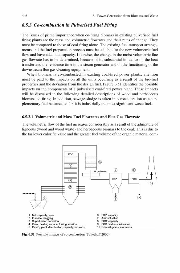
446 6 Power Generation from Biomass and Waste
6.5.3 Co-combustion in Pulverised Fuel Firing
The issues of prime importance when co-firing biomass in existing pulverised fuelfiring plants are the mass and volumetric flowrates and their rates of change. Theymust be compared to those of coal firing alone. The existing fuel transport arrange-ments and the fuel preparation process must be suitable for the new volumetric fuelflow and have adequate capacity. Likewise, the change in the moist volumetric fluegas flowrate has to be determined, because of its substantial influence on the heattransfer and the residence time in the steam generator and on the functioning of thedownstream flue gas cleaning equipment.
When biomass is co-combusted in existing coal-fired power plants, attentionmust be paid to the impacts on all the units occurring as a result of the bio-fuelproperties and the deviation from the design fuel. Figure 6.51 identifies the possibleimpacts on the components of a pulverised coal-fired power plant. These impactswill be discussed in the following detailed descriptions of wood and herbaceousbiomass co-firing. In addition, sewage sludge is taken into consideration as a sup-plementary fuel because, so far, it is industrially the most significant waste fuel.
6.5.3.1 Volumetric and Mass Fuel Flowrates and Flue Gas Flowrate
The volumetric flow of the fuel increases considerably as a result of the admixture ofligneous (wood and wood waste) and herbaceous biomass to the coal. This is due tothe far lower calorific value and the greater fuel volume of the organic material com-
Fig. 6.51 Possible impacts of co-combustion (Spliethoff 2000)
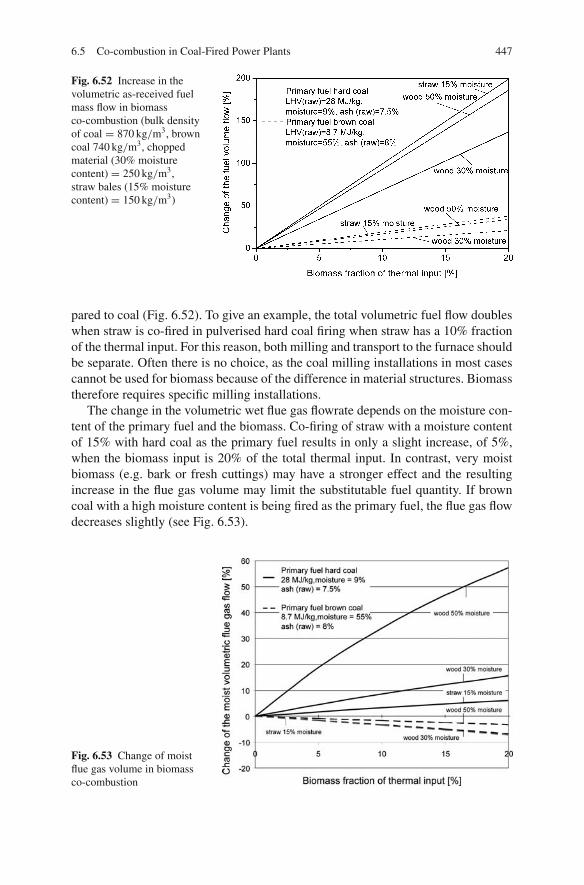
6.5 Co-combustion in Coal-Fired Power Plants 447
Fig. 6.52 Increase in thevolumetric as-received fuelmass flow in biomassco-combustion (bulk densityof coal = 870 kg/m3, browncoal 740 kg/m3, choppedmaterial (30% moisturecontent) = 250 kg/m3,straw bales (15% moisturecontent) = 150 kg/m3)
pared to coal (Fig. 6.52). To give an example, the total volumetric fuel flow doubleswhen straw is co-fired in pulverised hard coal firing when straw has a 10% fractionof the thermal input. For this reason, both milling and transport to the furnace shouldbe separate. Often there is no choice, as the coal milling installations in most casescannot be used for biomass because of the difference in material structures. Biomasstherefore requires specific milling installations.
The change in the volumetric wet flue gas flowrate depends on the moisture con-tent of the primary fuel and the biomass. Co-firing of straw with a moisture contentof 15% with hard coal as the primary fuel results in only a slight increase, of 5%,when the biomass input is 20% of the total thermal input. In contrast, very moistbiomass (e.g. bark or fresh cuttings) may have a stronger effect and the resultingincrease in the flue gas volume may limit the substitutable fuel quantity. If browncoal with a high moisture content is being fired as the primary fuel, the flue gas flowdecreases slightly (see Fig. 6.53).
Fig. 6.53 Change of moistflue gas volume in biomassco-combustion

448 6 Power Generation from Biomass and Waste
0 5 10 15 20 25 300
50
100
150
200
250
300
0
50
100
150
200
250
300
Sewage sludge:LCV(dry) = 10.9 MJ/kgHard coal Göttelborn:LCV(dry) = 30.2 MJ/kg7% Moisture
mechanically
dewatered
thermallydried
Isolines of constant drysubstancequantity
55% Moisture
5% Moisture
75%
Moi
stur
e
Water free
Incr
ease
of
fuel
mas
s fl
ow
[%
]
Sewagde sludge fraction of the thermal input [%]
Fig. 6.54 Influence of co-combustion of sewage sludge on the fuel mass flow (Gerhardt et al. 1997)
The influence of the moisture content of sewage sludge in co-combustion withhard coal is described in Fig. 6.54 for the fuel mass flow and in Fig. 6.55 for thevolumetric flue gas flow (Gerhardt et al. 1996, 1998). Both diagrams are presentedas a function of the sewage sludge fraction of the fuel heat input. When readingthese charts it must be remembered that the same fraction of sewage sludge with ahigher moisture content would need more dry substance to be fired with it for theevaporation of its moisture.
For this reason, the diagrams in Figs. 6.54 and 6.55 also feature isolines of equaldryness and constant population equivalents (the population equivalent gives the
15
Sewage sludge fraction of the thermal input [%]
0 5 10 20 25 300
10
20
30
40
0
10
20
30
40mechanically
dewateredSewage sludge:LHV (dry) = 10.9 MJ/kg
Hard coal Göttelborn:LHV (dry) = 30.2 MJ/kg
thermally dried
Isolinies of constant dry
substance quantity
5% Moisture
moisture free
75%
Moi
stur
e
55% Moisture
Incr
ease
of
mo
ist
flu
e g
as f
low
[%
]
Fig. 6.55 Influence of sewage sludge co-combustion on the moist flue gas flow (Gerhardt 1997)
6.5 Co-combustion in Coal-Fired Power Plants 449
average amount of sewage sludge to be disposed of per inhabitant). While the fuelmass flow amounts to 18% for a thermally dried sewage sludge with 95% drynessby weight, contributing a 10% fraction to the thermal capacity, the fuel mass flowrises to about 70% for mechanically dewatered sludge at 45% dryness by weightif the same thermal fraction is to be contributed. In this latter case (mechanicallydewatered sewage sludge), a higher dry substance mass flow is fed to the firing,which means that a greater sewage sludge quantity, given in population equivalents,is disposed of. If the same population equivalent is taken as a basis both for themechanically dewatered and for the thermally dried sewage sludge, the result isa 50% larger fuel mass flow for the mechanically dewatered sludge, as seen inFig. 6.54. The thermal input fraction is around 7% compared to 10% for thermallydried sewage sludge.
There is a strong case for the mechanical handling equipment, the mills and thefuel feeding via the burners to be modified if the sewage sludge will bring exces-sively high moisture into the installed equipment of the power plant. The same istrue, more or less, for the flue gas system. The higher flow velocity leads to changedheat transfer rates and also impairs the separating performance of the flue gas clean-ing train.
If the primary and additional fuels have nearly the same moisture contents, onlyminor modifications are necessary. In practice, therefore, either mechanically dewa-tered sewage sludge is combined with raw brown coal (moisture about 50%) orthermally dried sewage sludge is combined with hard coal (moisture about 7%). Ifthere is only a small fraction of mechanically dewatered sewage sludge, however, itis also possible to use it in hard coal firing.
6.5.3.2 Combustion Process
Due to the high volatile matter content of biomass in comparison to coal, muchcoarser biomass particles can be used in pulverised fuel firing. Herbaceous biomasstypes are more reactive than wood in this respect and therefore require less finemilling.
The significantly coarser milling degree of the biomass particles has an impact onthe combustion process. Figure 6.56 shows the course of combustion for three fuelcombinations: pure coal, 20% milled straw/80% coal and 25% sewage sludge/75%coal. The gradients of the mean oxygen concentration and the temperatures (notshown) of the combustion courses illustrate how the ignition of the coarse strawparticles is delayed. After ignition, though, oxygen is consumed faster and the com-bustion proceeds more rapidly to completion in comparison to firing coal only. Forthermally dried sewage sludge with a similar particle size distribution to coal, com-bustion proceeds faster.
6.5.3.3 Slagging, Fouling, Erosion
The process of deposit formation is described in detail in Sect. 5.10. There aretwo principal mechanisms through which co-combustion can affect slagging and

450 6 Power Generation from Biomass and Waste
Fig. 6.56 Course of thecombustion process of amixed biomass/coal firing
fouling. The first mechanism is dependent on the melting of the bulk ash and ismainly related to the formation of molten deposits (Tortosa Masia 2006). Whenbiomass is co-fired with coal in low to medium ratios, the behaviour of the resultingash will be dominated by the coal ash. However, the presence of significant levelsof alkali and alkaline earth compounds in the mixed ash can change the behaviourof the coal ash, reducing ash fusion temperatures by 100–200◦C and promotingformation of molten deposits. This effect is more pronounced for coal ashes withhigh fusion temperatures. In these cases co-firing at even modest ratios can havea major impact on the ash fusion behaviour. The effect is less dramatic with coalashes originally having lower fusion temperatures and already having significantslag formation propensities. The effects of lower ash fusion temperatures differbetween dry-bottom and slag-tap furnaces. While low fusion temperatures may berather welcome in slag-tap furnaces, in dry-bottom firing they can lead to slaggingin the combustion chamber, especially around the burner, thus impairing the firingprocess.
When co-firing woody or herbaceous biomass fuels (which have moderate ashcontents), the volatilisation and condensation of alkali metals is the major mech-anism for the initiation and growth of fouling deposits. Alkalis vaporise at flametemperatures, undergo chemical transformations and settle on surfaces that havesuitable temperatures for condensation. The sticky layer of condensed alkalis actsas a glue for other solid ash constituents, thus initiating deposit formation. Mosttypes of biomass or wastes are high-fouling fuels, and in almost all cases co-firingwith coal increases the likelihood of fouling in comparison to coal alone. On theother hand, deposit formation is lower than in pure biomass combustion (Fernando2007; Leckner 2007).
Although fouling and slagging problems on convective heating surfaces areincreased by the addition of low-melting biomass ash, investigations at a 0.5 MWplant showed that the fouling rate in straw co-combustion is only slightly higherthan in the combustion of a low fouling tendency coal. Dust layers were easilyremoved as well. If the biomass fraction is not very high, the coal ash characteristics

6.5 Co-combustion in Coal-Fired Power Plants 451
dominate. However, when the fraction is larger, incompletely burned straw particlesform deposits, resulting in slagging because of the low fusion temperatures of strawash (Heinzel 2004).
The large-scale experience in Europe suggests that slagging and fouling areunlikely to be a problem for co-firing ratios less than 10%. At one plant using a 20%co-combustion ratio of straw, the boiler performance was still satisfactory, althoughthere was need for additional soot blowing, and some slagging occurred (Fernando2005).
With sewage sludge, lower fusion temperatures and a higher ash content than thestandard fuel may be the causes of slagging inside the furnace. The ash deformationtemperatures of investigated sewage sludges have been found to be between 1,200and 1,300◦C, 100◦C lower than the temperature of hard coal ash (Gerhardt 1998).In slag-tap firing, lower fusion temperatures may be favourable, but they can causeslagging in a dry-bottom furnace. The high ash content may cause erosion of theconvective heating surfaces, a risk that also occurs with poultry litter, which containsa high ash content as well. However, the impacts of the much higher ash fraction ofsewage sludge should still be controllable by soot blowing.
6.5.3.4 Corrosion
Herbaceous biomasses such as straw or cereals have significantly higher chlorinecontents than coal and most other bio-fuels, which may increase high-temperaturecorrosion of the heat exchange surfaces. The high-duty surfaces of the superheater,where there are high steam and flue gas temperatures, are most likely to be affected.In a Danish 130 MWel pulverised coal furnace, corrosion tests were carried out fortwo superheater materials. Using a 10% thermal input fraction of straw, the corro-sion rates were moderate and only slightly higher than in coal mono-combustion(Fig. 6.57) (Bemtgen et al. 1995; Spliethoff and Hein 1995b). The results were con-
Fig. 6.57 Corrosion rates ofstraw co-combustion in a130 MWel pulverised fuelfiring system (Spliethoff andHein 1995; Bemtgen et al.1995)
452 6 Power Generation from Biomass and Waste
firmed in a 2-year investigation into co-firing with straw in a 150 MWel coal-firedboiler. Up to steam temperatures of 580◦C, the corrosion risks seemed tolerable.The introduction of a 20% straw fraction increased the corrosion rates by a factor of1.5–3 at steam temperatures up to 540◦C. Nevertheless, the corrosion rates are thesame as those of low to medium corrosive coals (Wieck-Hansen et al. 2000). Duringthese tests the fly ash and deposits that were formed mainly consisted of potassiumaluminosilicates and potassium sulphate. Most of the chlorine left the boiler as lesscorrosive HCl, and there was little KCl in the deposits (Andersen et al. 2000). Thisexample demonstrates the beneficial effect of the minerals and the sulphur in thecoal on the transformation of the potassium in the straw (Leckner 2007).
Waste fuels containing high levels of alkalis or chlorine, such as refuse-derivedfuel (RDF) and poultry manure, can increase corrosion rates by factors comparableto straw. RDF, if it has a high plastic content, can contain chlorine levels five to sixtimes higher than average coals. Any efforts to increase the efficiency of the unitby increasing steam parameters will promote high-temperature corrosion. Sewagesludge has chlorine levels similar to coal and hence is less likely to cause hightemperature corrosion.
In pulverised coal co-combustion, the extent of corrosion by high alkali and chlo-rine fuels is reduced by the presence of sulphur dioxide in the flue gas, an effectnot occurring in monofuel combustion. SO2 reacts with alkali and alkaline earthchlorides to form less corrosive sulphates. These sulphate compounds, however, areonly stable under oxidising conditions, hence corrosion may still occur in overfireair systems (Fernando 2007).
6.5.3.5 Emissions
One result of co-firing ligneous and herbaceous biomass is a reduction of the majorpollutants in the uncleaned flue gas – sulphur dioxide (SO2) and nitrogen oxides(NOx ). CO emissions do not rise if the biomass has an adequately high millingdegree. Supporting evidence came from investigations within the framework of anEU project, which produced more detailed information about emissions from differ-ent plant types co-firing herbaceous and woody bio-fuels (Bemtgen et al. 1995).
NOx emissions: The high volatile matter content is the reason why biomass isespecially suitable for the application of NOx reduction measures like air and fuelstaging (Spliethoff and Hein 1998). Although the fuel nitrogen in straw in relationto the calorific value is in the same order of magnitude as the content in coal, theresult of the higher release of pyrolysis products and volatile nitrogen compoundsfrom straw is less NOx formation. Figure 6.58 shows the NOx emissions measuredat an experimental plant co-combusting different biomass types with hard coal, thebiomass comprising 25% of the thermal input. The results reveal roughly the sameemissions of NOx , regardless of the fuel nitrogen content. The suitability of biomassto nitrogen-reducing combustion engineering measures is indicated by the decreas-ing NOx emissions at diminishing primary air ratios. Co-combustion of biomass inpulverised coal firing therefore does not depend on the biomass nitrogen content.Even higher concentrations in sewage sludge or poultry litter can be controlled, to

6.5 Co-combustion in Coal-Fired Power Plants 453
Fig. 6.58 NOx emissionswith air staging for differentbiomass types, biomassfraction: 25% (Kicherer1996; Spliethoff and Hein1996)
a certain extent, by combustion engineering measures. Biomass fuels promote theformation of ammonia instead of HCN in the primary combustion zone (DiNola2007; Di Nola et al. 2009). Detailed investigations into the emission behaviour ofbiomass-coal blends in different combustion processes are described in Kicherer(1996). Due to its high volatile content, biomass is also suitable for reburning toreduce NOx emissions. As shown in Fig. 5.53, pulverised Miscanthus as a reburnfuel is nearly as effective as natural gas. A pyrolysis gas from biomass can even bebetter as a reburn fuel than natural gas (Rudiger 1997).
Despite the much higher fuel nitrogen content of sewage sludge, the NOx concen-trations after the fuel-burning system are not correspondingly higher, as they are lim-ited by a lower conversion rate. However, within the typical range of use, up to 25%of the thermal input, an increase in emissions when incorporating sewage sludgeco-firing must be expected if there are no additional methods to reduce NOx . Byapplying the investigated in-furnace reduction methods of air and fuel staging, NOx
emissions from sewage sludge co-combustion were comparable to the combustionof coal only. Still, the high fuel nitrogen content should be taken into considerationwhen designing and constructing the furnace and considering the distribution of airin the combustion chamber.
SO2 emissions: In pulverised coal combustion, the sulphur contained in the fuelis almost completely oxidised into sulphur dioxide (SO2), so that SO2 emissions canbe directly correlated with the sulphur input. Figure 6.59 plots SO2 emissions as afunction of the fraction of biomass or sewage sludge, respectively, in investigationscarried out at a 0.5 MW furnace. Increasing the share of biomass (i.e. wood, straw orMiscanthus) caused a decrease in SO2 emissions. This reduction can be attributed tothe low sulphur input. However, it is observed that sulphur is additionally capturedin the biomass ash. Starting from about 90% in pure coal combustion, the conversionrate drops linearly to reach a value of 50% in pure biomass combustion. The coarsemilling of the biomass and its moisture content delay combustion, thus favouring,because of the lower temperatures, the capture of SO2 in the biomass ash (Spliethoffand Hein 1998).
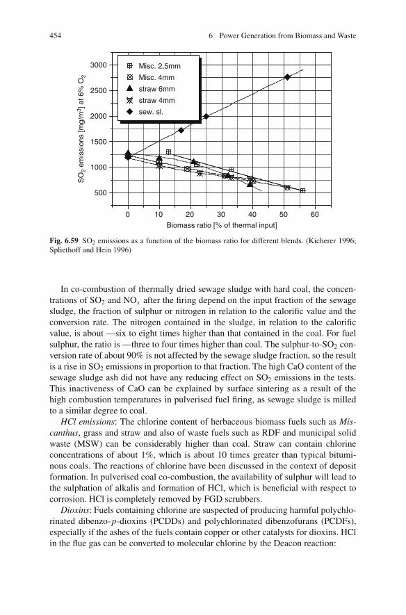
454 6 Power Generation from Biomass and Waste
0 10 20 30 40 50 60
500
1000
1500
2000
2500
3000
SO
2 em
issi
ons
[mg/
m3 ]
at 6
% O
2
Biomass ratio [% of thermal input]
Misc. 2,5mm
Misc. 4mm
straw 6mm
straw 4mm
sew. sl.
Fig. 6.59 SO2 emissions as a function of the biomass ratio for different blends. (Kicherer 1996;Spliethoff and Hein 1996)
In co-combustion of thermally dried sewage sludge with hard coal, the concen-trations of SO2 and NOx after the firing depend on the input fraction of the sewagesludge, the fraction of sulphur or nitrogen in relation to the calorific value and theconversion rate. The nitrogen contained in the sludge, in relation to the calorificvalue, is about —six to eight times higher than that contained in the coal. For fuelsulphur, the ratio is —three to four times higher than coal. The sulphur-to-SO2 con-version rate of about 90% is not affected by the sewage sludge fraction, so the resultis a rise in SO2 emissions in proportion to that fraction. The high CaO content of thesewage sludge ash did not have any reducing effect on SO2 emissions in the tests.This inactiveness of CaO can be explained by surface sintering as a result of thehigh combustion temperatures in pulverised fuel firing, as sewage sludge is milledto a similar degree to coal.
HCl emissions: The chlorine content of herbaceous biomass fuels such as Mis-canthus, grass and straw and also of waste fuels such as RDF and municipal solidwaste (MSW) can be considerably higher than coal. Straw can contain chlorineconcentrations of about 1%, which is about 10 times greater than typical bitumi-nous coals. The reactions of chlorine have been discussed in the context of depositformation. In pulverised coal co-combustion, the availability of sulphur will lead tothe sulphation of alkalis and formation of HCl, which is beneficial with respect tocorrosion. HCl is completely removed by FGD scrubbers.
Dioxins: Fuels containing chlorine are suspected of producing harmful polychlo-rinated dibenzo-p-dioxins (PCDDs) and polychlorinated dibenzofurans (PCDFs),especially if the ashes of the fuels contain copper or other catalysts for dioxins. HClin the flue gas can be converted to molecular chlorine by the Deacon reaction:

6.5 Co-combustion in Coal-Fired Power Plants 455
4HCl + O2 → 2H2O + 2Cl2 (6.2)
Molecular chlorine reacts with aromatic species in the fuel to form PCDDsand PCDFs, depending on the temperature and the boiler design. When chlorine-containing biomass and waste fuels are co-fired with coal, the formation of PCDDsand PCDFs is inhibited. The possible mechanisms for PCDD/F inhibition includethe depletion of molecular chlorine concentrations by the reaction with SO2:
Cl2 + SO2 + H2O → 2HCl + SO3 (6.3)
Results from laboratory and large-scale investigations show that in co-combustion,due to the SO2 in the flue gas, the emissions of PCDD/F are as low as for coal-firedplants (Fernando 2007; Leckner 2007).
6.5.3.6 Effects on Residual Matter
The effects of biomass co-combustion in coal-fired power plants on residual mattershould be split into two: the consequences of a greater ash load and the effect on thecommercial exploitability of the ash.
Ash load: The low ash content of wood and straw bio-fuels reduces the workloadof the dust removal equipment. All in all, less ash will be produced in comparisonto coal firing alone when co-firing ligneous and herbaceous or petiolate bio-fuels.In contrast, the typically high ash contents of sewage sludge dry matter can leadto higher workloads for the electrostatic precipitator when larger sludge fractionsare used.
Commercial exploitability of fly ash: The composition of the fly and bottom ashesin coal firing determines their possible uses. For the utilisation of fly ash in thecement and concrete industries, the critical parameters are the concentrations ofalkalis, SO3, Cl, CaO and unburned carbon.
Since fly ash utilisation was one of the major obstacles for the broad applicationof co-combustion in hard coal-fired power plants, a review of EN 450 was initi-ated in 1999 and, since 2005, a new European Standard “fly ash for concrete” hasreplaced the earlier one. Fly ash from co-combustion of specific secondary fuelssuch as woodchips, straw, olive shells, cultivated biomass, municipal sewage sludgeand paper sludge can now be used for concrete if the percentage of secondary fueldoes not exceed 20% by mass of the total fuel, the derived amount of ash from theco-combustion material is not greater than 10% of the total ash and the requirementsof the fly ash quality can be met (Wiens 2005). The maximum allowed contents oftotal alkalis, Cl and residual carbon for fly ash to be used in concrete production are5% by wt., 0.1% by wt. and 5% by wt., respectively (see Sect. 5.11).
The commercial operation of straw co-firing at the 350 MWel pulverised coal-fired Studstrup Unit 4 in Denmark began by burning straw with a maximum shareof only about 10% on an energy basis. The fly ash is presently used for cementproduction (Zheng et al. 2007).

456 6 Power Generation from Biomass and Waste
In the Netherlands, a programme was carried out to determine whether the flyash produced from co-firing met the quality requirements for its utilisation as a fillermaterial or as a cement replacement and for the production of concrete. Tests wereundertaken at several power plants using up to 10% by mass of the secondary fuel.The fuels used included several types of pellets, sewage sludge, pet cokes, woodchips, poultry manure, MBM (meat-and-bone meal) and liquid hydrocarbons. Theresulting fly ashes demonstrated that even high biomass co-firing percentages canproduce fly ashes that meet European standards (Fernando 2007).
The ash from brown coal firing is commonly used as a filler material in opencastmines, and the regulations extend to this use, with the most critical parameter beingthe leachability of the ash components.
Waste fuels such as sewage sludge or RDF may contain higher concentrationsof heavy metals. The evaluation of the ash properties, therefore, and in contrastto coal ash, above all has to take into account these heavy metals, which display anaccumulation behaviour in the biosphere. Heavy metal concentrations in waste fuelsare highly dependent on the origin of the fuel. As far as municipal sewage sludgesare concerned, surveys certify that despite the given variations only a few sewagesludges have higher pollutant concentrations than is permitted for use in farming.
Apart from substances such as mercury, selenium and arsenic, which escape inelemental or compound form in appreciable fractions in the flue gas flow becauseof their low boiling points, most of the trace elements from sewage sludges arefound in the solid residues from the furnace or the flue gas cleaning processes.Figure 6.60 shows a direct comparison between heavy metal ash concentrationsof sewage sludge ash and of typical hard coal ash (Gerhardt et al. 1996; BMU1996; Fahlke 1994). According to this comparison, the trace element concentra-tions, taking into account the different ash contents, approximate each other. Theco-combustion of sewage sludge and hard coal therefore does not result in a seriouschange of pollutant concentrations in the ash.
For heavy metals that are partly carried out in the flue gas flow from the plant, itis necessary to check the removal efficiency in the cleaning sections downstream of
Fig. 6.60 Concentration of trace metals in dry fuels and ashes (Gerhardt et al. 1996; BMU 1996;Fahlke 1994)

6.5 Co-combustion in Coal-Fired Power Plants 457
the furnace. In the wet flue gas desulphurisation units common in power plants, onlysome of these heavy metals are removed, so the remaining part is emitted as part ofthe exhaust gas flow (Tauber et al. 1996). For mercury, for instance, a removal effi-ciency of about 50% is given (Fahlke 1994); the rest gets emitted. This circumstancecan make it necessary to improve the common flue gas desulphurisation systems inpower plants, for instance, by the addition of specially adapted precipitants or by thedownstream installation of an additional filtering stage (e.g. an activated charcoalfilter).
6.5.3.7 NOx Control Equipment
When considering the impacts of co-firing on NOx control, two scenarios have tobe considered: plants with high-dust removal configurations and those with low-dust configurations. There is a smaller impact on low-dust configurations, becauseNOx cleaning is preceding by the gas cleaning steps of ESP and FGD, which meanlow-dust configurations are better suited to co-firing than high-dust ones.
Common practice in hard coal-fired dry-bottom furnaces is to install NOx con-trol in high-dust configurations. This puts the catalyst at risk, especially if strawis used, when employing biomass co-combustion. Various mechanisms may workto deactivate the catalyst. One of these is based on reactions of the catalyst withpotassium and sodium. Accordingly, catalyst manufacturers set limits on the alkalifraction (K2O + Na2O < 4% by weight of ash). Depending on the coal type used,this amount may be reached even with small straw fractions. Another mechanism istriggered by alkalis and alkaline earths blocking up pores of the active catalyst cells.Arsenic and phosphorus, too, can poison the catalyst. Catalyst deactivation can belimited by installing the catalyst after the flue gas desulphurisation unit – that is, byemploying a low-dust configuration. In brown coal firing, where sulphur is removedby combustion engineering techniques, this problem does not occur.
Testing of SCR catalyst elements in the slip stream of a power plant resultedin high deactivations when co-firing with 20% straw. After 3,000 h of operationthe catalyst activity was reduced by 35% with a high-dust configuration, whereaswith a low-dust configuration employing dry flue gas desulphurisation, the loss wasbetween 10 and 15%. Due to the set-up of the facility, the test conditions are con-sidered to be the worst-case scenario. More than 7,500 h can be expected before theactivity is reduced to 50% (in the high-dust configuration), which is still considereda high level of activity (Wieck-Hansen et al. 2000). Results of 2 years of 7% co-firing of straw at Studstrup Unit 4 showed that there was no decrease in the removalefficiency of the high-dust SCR (Fernando 2005).
The high ash content of sewage sludge can cause fouling and erosion in high-dustconfigurations. Because of the high nitrogen content of sewage sludge, the NOx
concentrations after the furnace may rise to a level such that they have to be reducedby NOx control.
In co-combustion processes with sewage sludge and meat-and-bone meal as sec-ondary fuels in hard coal-fired power plants, an increased deactivation of the SCR-DeNOx catalysts for flue gas denitrification was observed. Investigations revealed

458 6 Power Generation from Biomass and Waste
a correlation between the phosphorus content in the fuel and the degree of catalystdeactivation. In combustion, the phosphorus is released from the fuel, leading toincreased concentrations of both particulate and gaseous phosphorus compounds.Gaseous phosphates in particular penetrate the catalyst surface, effecting severedeactivation. Particulate phosphorus, too, contributes to the deactivation by obstruct-ing the catalyst pores and reacting with sulphuric acid. A calcium addition can abatethe deactivation by phosphorus (Beck 2007).
6.5.3.8 Flue Gas Desulphurisation (FGD) Equipment
The low sulphur content of biomass reduces the load on the flue gas desulphurisationplant. However, the increase in other flue gas components as a result of the use of thebiomass may impair the function of FGD or necessitate additional FGD capacity.These potential consequences set a limit on the biomass fraction, particularly inregard to the chlorine input into the FGD.
Besides sulphur, the FGD unit also removes a number of other flue gas com-ponents. The volatile ash components leaving with the flue gas, such as mercury,arsenic, lead and other heavy metals, are partly removed together with the FGDresidual matter, the quality of which has to be checked if it is to be commerciallyused. However, the concentrations of these substances in the biomasses that havebeen investigated can be neglected in comparison to coal. This is not the case whenmunicipal sewage sludge is co-fired – in this case, the quality of the residues cansometimes be negatively affected.
Sulphur in sewage sludge exceeds the usual sulphur content of coal considerably.The FGD unit must have sufficient capacity to deal with this additional load. With a25% thermal input fraction of sludge, the SO2 to be dealt with rises to 1.6 times thequantity from coal alone.
6.5.4 Co-combustion in Fluidised Bed Furnaces
Fluidised bed furnaces are suited to a wide range of fuels, including biomasses suchas wood or straw and wastes. Biomass can be co-fired both in bubbling and in cir-culating fluidised bed furnaces. Co-combustion in a fluidised bed is uncomplicatedand in most cases limited only by the heat balance of the bed. When co-firing withherbaceous biomass or waste fuels, steam conditions can be limited by the need toavoid deposition and corrosion (Leckner 2007).
Given its higher volatile content, biomass tends to have post-combustion reac-tions in the freeboard volume of the furnace, in particular in bubbling fluidised bedfurnaces. In these furnaces, lightweight particles such as straw can easily be carriedaway from the fluidised bed, which raises the temperature in the freeboard if theypost-combust. The well-mixedness of a circulating fluidised bed creates an evendistribution of furnace temperatures. Nevertheless, an upward temperature shift canalso be observed.
As fluidised bed firing is especially suited to high-ash and high-moisture fueltypes, it seems a good technology for mechanically dewatered sewage sludge. While

6.5 Co-combustion in Coal-Fired Power Plants 459
the higher moisture content of the sludge increases the volumetric flue gas flowwhen co-firing with hard coal, there is little effect when co-firing with brown coal.
The impact of biomass co-combustion on gaseous emissions was investigated atexperimental and industrial plants of various thermal capacities within the frame-work of a research project funded by the European Union (Bemtgen et al. 1995).Except for HCl emissions in straw co-combustion, the results showed that biomassaddition has a positive effect. In all plants, the observed result was a reduction inSO2 emissions with an increasing biomass fraction of the thermal input. This effectcan be put down on the one hand to the low sulphur contents of the biomasses andon the other hand to the fact that SO2 is captured in the biomass ash.
The correlations between NOx emissions and co-combustion were diverse. Witha low biomass fraction, the emissions of NOx changed very little in some of theplants. In other plants, the emissions were reduced, in particular by co-firing wood(the reduction increasing with the wood fractions).
While in co-combustion of woody bio-fuels, additional operational problemsare not expected, herbaceous fuels may cause severe corrosion, slagging and foul-ing, with the potassium chloride contained in such bio-fuels playing a major part(Binderup Hansen et al. 1997).
6.5.4.1 Co-combustion of Coal and Straw in an 88 MWth CFBC
Coal and straw have been co-fired for over 10 years at the CHP plant in Grenaa,Denmark. The 88 MWth circulating fluidised bed furnace is designed to fire upto 60% straw and up to 100% coal on an energy basis. During initial operation,co-firing of straw and a coal type with a high sulphur content of 3% (each witha 50% thermal input fraction) resulted in severe slagging in the furnace, in thecyclone and in the superheater area, so that the operational parameters could not bemaintained even shortly after start-up. In consequence, coals with a sulphur contentbelow 1% were later used exclusively, and deposit formation occurred only to aminor extent. The only remaining problem was in the superheater area, where thenarrowly designed spacing (tube pitch) of 37 mm was favourable for the build-up ofdeposits. The measures used to prevent deposits in this area are to employ hangingsuperheaters with a spacing of 50 mm (tube pitch) (thus avoiding bridging) and tolower the flue gas temperature at the superheater. At flue gas temperatures belowthe melting point of potassium chloride (770◦C), solid deposits do not pose anyproblem. In comparison to combustion of coal only, the fouling rate from usinga straw fraction of 50% quintupled, though the deposits could be removed easily(Binderup Hansen et al. 1997; Clausen and Sorensen 1997). Special attention is paidto the bed inventory in order to limit the enrichment of potassium in the bed and toprevent bed agglomeration. Instead of sand with a high silica content, ash from astoker-fired furnace with a high alumina concentration is used (Wieck-Hansen andSander 2003).
Severe corrosion was observed at the final convective superheater, which had tobe replaced after only 1 year of operation. Corrosion studies were carried out inthe fluidised bed furnace by testing several different materials. Using a different
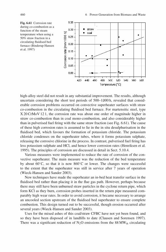
460 6 Power Generation from Biomass and Waste
Fig. 6.61 Corrosion rateduring co-combustion as afunction of the steamtemperature when using a50% straw fraction in acirculating fluidised bedfurnace (Binderup Hansenet al. 1997)
high-alloy steel did not result in any substantial improvement. The results, althoughuncertain considering the short test periods of 500–1,000 h, revealed that consid-erable corrosion problems occurred on convective superheater surfaces with strawco-combustion in the circulating fluidised bed furnace. For martensitic steel, typeX 20 CrMoV 12 1, the corrosion rate was about one order of magnitude higher instraw co-combustion than in coal mono-combustion, and also considerably higherthan in pulverised fuel firing with the same straw fraction (see Fig. 6.61). The causeof these high corrosion rates is assumed to lie in the in situ desulphurisation in thefluidised bed, which favours the formation of potassium chloride. The potassiumchloride condenses on the superheater tubes, where it forms potassium sulphate,releasing the corrosive chlorine in the process. In contrast, pulverised fuel firing hasless potassium sulphate and HCl, and hence lower corrosion rates (Henriksen et al.1995). The principles of corrosion are discussed in detail in Sect. 5.10.4.
Various measures were implemented to reduce the rate of corrosion of the con-vective superheater. The main measure was the reduction of the bed temperatureby about 60◦C, so that it is now 860◦C or lower. The changes were successfulto the extent that the superheater was still in service after 7 years of operation(Wieck-Hansen and Sander 2003).
New techniques have made the superheater an in-bed heat transfer surface in thefluidised bed rather than placing it in the flue gas path. However, perhaps becausethere may still have been unburned straw particles in the cyclone return pipe, whichform KCl as they burn, corrosion probes inserted in the return pipe measured com-parably high wear rates. In order to avoid corrosion, it became necessary to arrangean uncooled section upstream of the fluidised bed superheater to ensure completecombustion. This design turned out to be successful, though erosion occurred afterseveral years (Wieck-Hansen and Sander 2003).
Uses for the mixed ashes of this coal/straw CFBC have not yet been found, andso they have been disposed of in landfills to date (Clausen and Sorensen 1997).There was a significant reduction of N2O emissions from the 88 MWth circulating

References 461
fluidised bed furnace in comparison to coal firing alone, a fact explained by thehigher temperatures in the upper part of the furnace and in the cyclones. The chlorineinput into the process using straw at a thermal input fraction of 60% was 20 timeshigher than in the combustion of coal only. The inputted chlorine was found almostentirely in the flue gas.
6.5.4.2 Co-combustion of Sewage Sludge in a CFBC
Tests in a 230 MWth brown coal-fired circulating fluidised bed for sewage sludgeco-combustion have shown that emissions of SO2, NOx , CO and dust are withinthe normal operational range. The mechanically dewatered sewage sludge has amoisture content of 70%. This experience has demonstrated that the performanceof circulating fluidised bed furnaces does not deteriorate through sewage sludge co-combustion. Depending on the calorific value of the sludge input, there is only a dropin the thermal output and thus in the steam production. The percentage regulationlimits imposed by the 17th BImSchV (17th Amendment to the Federal German Pol-lution Control Act) were not reached. For continuous operation, an additional fluegas cleaning stage, consisting of an entrained-flow absorber using lignite-derivedcoke, was installed downstream of the ESP in order to ensure compliance with themercury limits (Bierbaum et al. 1996). The plant has been in continuous operationsince 1995 and co-fires approximately 200,000 t of sewage sludge a year (Roper andKipshagen 2003).
Given that sewage sludge has an ash content of about 15% (raw), the ash loadincreases considerably. The pollutants in the sludge are captured inertly in the ash,except for mercury, which is transported in the flue gas. The ash is, as before, utilisedfor regeneration of opencast brown coal mines. It meets the requirements for land-fill grade 1 of the German Technical Instructions on Municipal Solid Waste (TASiedlungabfall).
References
17.BImSchV (2009). 17. Verordnung zur Durchfuhrung des Bundesimmissionsschutzgesetzes(Verordnung uber die Verbrennung und die Mitverbrennung von Abfallen. Bekanntmachungvom 14. August 2003 (BGBl. I S. 1633), geandert durch Artikel 2 der Verordnung vom 27.January 2009 (BGBl. I P. 129). §5 Absatz 5 mit Jahresmittelwert 100 mg/Nm3.
AbfAblV (2000). Verordnung uber die umweltgerechte Ablagerung von Siedlungsabfallen unduber biologische Abfallbehandlungsanlagen [in Deutschland]. Bundesgesetzblatt Part 1 No. 10,pp. 305–324 (Abfallablagerungsverordnung AbfAblV nachfolgend der TASi-TA Siedlungsab-fall).
ActuEnvironment (2005). L’incinerateur de Gien plombe le bilan annuel des incinerateurs de toutle territoire. Actu Environment 1.6.2005, from http://www.actu-environnement.com/ae/news/1153.php4.
ADMONT. (2001). Biomass fired CHP Plant Based on a ORC cycle- Project. ORCSITA-Admont. Final publishable report, 1.6.1998–31.12.2000, from http://www.bios-bioenergy.at/uploads/media/Report-ORCAdmont-Thermie-2001-03-26.pdf.

462 6 Power Generation from Biomass and Waste
Almark, M. and Hiltunen, M. (2005). Alternative bed materials for high alkali fuels. Proceedingsof the 18th International Fluidized Bed Combustion Conference, May 22–25, 2005, Toronto,Canada.
Andersen, K. H., Frandsen, F. J., Hansen, P. F. B., Wieck-Hansen, K., Rasmussen, I., Overgaard,P. and Dam-Johansen, K. (2000). Deposit formation in a 150 MWe utility PF-boiler duringco-combustion of coal and straw. Energy Fuels 14(4): 765–780.
Bapat, D. W., Kulkarni, S. V. and Bhandarkar, V. P. (1997). Design and operating experience onfluidized bed boiler during burning biomass fuels with high Alkali Ash. Proceedings of the 14thInternational Conference on Fluidized Bed Combustion, Vancouver, Canada.
Baumbach, G. (1990). Luftreinhaltung. Berlin/Heidelberg, Springer-Verlag.Baxter, L. (2005). Biomass-coal co-combustion: opportunity for affordable renewable energy. Fuel
84(10): 1295–1302.Beck, J. (2007). The behaviour of phosphorus compounds and their effect on DeNOx-catalysts in
coal fired power plants, Universitat Stuttgart. Dissertation.Beckert, F. and Schaarrschuch, H. (2007). Das erste Biomassekraftwerk der Stadtwerke Leipzig
mit zirkulierender Wirbelschichtfeuerung und Zwischenuberhitzung. VGB Powertech 87(4):50–54.
Bemtgen, J. M., Hein, K. R. G. and Minchener, A. (1995). Combined combustion of biomass/sewage sludge and coals volume II: Final Reports, APAS Clean Coal Technology Programme,ISBN -3-928123-16-5.
Berg, M. E. and Jensen, J. P. (2008). Biomass and secondary fuels in Denmark, history and per-spective. VGB PowerTech 88(1/2): 62–64.
Bierbaum, K., Lambertz, J. and Thomas, G. (1996). Klarschlamm-Mitverbrennung in einem Indus-triekraftwerk. Bamberg, VDI-Seminar Klarschlammentsorgung II.
Bilitewski, B., Hardtle, G. W. and Marek, K. A. (2000). Abfallwirtschaft : Handbuch fur Praxisund Lehre. Berlin [u.a.], Springer.
Binderup Hansen, P. F., Lin, W. and Dam-Johansen, K. (1997). Chemical reaction conditions ina Danish 80 MWth CFB-boiler co-firing straw and coal. Proceedings of the 14th InternationalConference on Fluidized Bed Combustion, Vancouver, Canada, ASME.
Biollaz, S. and Nussbaumer, T. (1996). Einsatz von Rostfeuerungen fur Holz- und Halmguter.4. Holzenergiesymposium “Feuerungstechnik, Ascheverwertung und Warme-Kraft-Kopplung”Zurich.
BMU (1996). Bericht gemaß Artikel 17 der EG-Richtlinie 86/278/EWG uber die Klars-chlammverwertung in der Bundesrepublik Deutschland, Berichtszeitraum 1991–1994. N. u.R. Bundesministerium fur Umwelt, Referat WAII 5(L).
Bolhar-Nordenkampf, M., Gartnar, F., Tschanun, I. and Kaiser, S. (2006). Combustion of biomassin bubbling fluidised beds – operation experience. Proceedings of the 19th International Flu-idized Bed Combustion Conference, May 21–24. Vienna, Austria.
Bonomo, A. (1998). Combining energy efficiency, renewable energy, environmental protection,cost efficiency. First operational results from the Brescia WtE plant. ISWA 4th InternationalManagement Conference. Amsterdam, 24.11.1998.
Borghart, R. (2008). Einsatz von EBS in industriellen Kraftwerken – Erfahrungen und Weit-erentwicklungen. 13. Fachtagung thermische Abfallbehandlung [11. Bis 12. Marz 2008 inMunchen]. Kassel University Press, 2008. ISBN 3899583841.
Born, M. (2005). Dampferzeugerkorrosion : [Teil 1: Stand der Kenntnisse, Teil 2: Vortrage zum 2.Diskussionsforum “Rauchgasseitige Dampferzeugerkorrosion”, Freiberg, 27. und 28. Oktober2005]. Freiberg, SAXONIA Standortentwicklungs- u. -verwaltungsges.
Born, M. (2007). Dampferzeugerkorrosion 2007. Freiberg, Saxonia Standortentwicklungs- undVerwaltungsges.
Braage, C., Yu, Q., Chen, G. and Sjostrom, K. (1997). Use of amino phase adsorbent for biomasstar sampling and separation. Fuel 76: 137–142.
Clausen, C. and Sorensen, M. (1997). Anlagen- und Betriebserfahrungen mit strohgefeuertenKesseln in Heizkraftwerken. VGB Kraftwerkstechnik 77(10): 802–806.
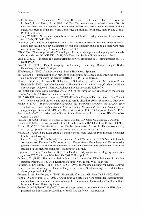
References 463
Coda, B., Zielke, U., Suomalainen, M., Knoef, H., Good, J., Liliedahl, T., Unger, C., Ventress,L., Neeft, J., v.d. Hoek, H. and Kiel, J. (2004). Tar measurement standard: a joint effort forthe standardisation of a method for measurement of tars and particulates in biomass producergases. Proceedings of the 2nd World Conference on Biomass for Energy, Industry and ClimateProtection, Rome, Italy.
de Jong, W. (2005). Nitrogen compounds in pressurised fluidised bed gasification of biomass andfossil fuels, TU Delft. Ph.D.
Di Nola, G., de Jong, W. and Spliethoff, H. (2009). The fate of main gaseous and nitrogen speciesduring fast heating rate devolatilization of coal and secondary fuels using a heated wire meshreactor. Fuel Processing Technology 90(3): 388–395.
DIN (2006). Biomass gasification-Tar and particles in product gases – Sampling and analysis.German Version DIN CEN/TS 15439, DIN Deutsches Institut fur Normung e.V. Berlin.
DiNola, G. (2007). Biomass fuel characterization for NO emissions in Co-firing applications, TUDelft. Ph.D.
Dolezal, R. (1990). Dampferzeugung: Verbrennung, Feuerung, Dampferzeuger. Berlin,Heidelberg, New York, Springer.
Effenberger, H. (2000). Dampferzeugung. Berlin, Heidelberg, Springer.EIPPCB (2005). Integrated pollution prevention and control. Reference document on the best avail-
able techniques for waste incineration (BREF) E. I. P. P. a. C. Bureau.Eltrop, L., Raab, K., Hartmann, H., Schneider, S., Schroder, G., Kaltschmitt, M., Jahraus, B. and
Heinrich, P. (2007). Leitfaden Bioenergie: Planung, Betrieb und Wirtschaftlichkeit von Bioen-ergieanlagen. Gulzow b. Gustrow, Fachagentur Nachwachsende Rohstoffe.
EU (2000). EU commission: Directive 2000/76/EC of the European Parliament and of the Councilof 4 December 2000 on the incineration of waste.
EU (2008). EU Commission: Directive 2008/98/EC of the European Parliament and of the Councilof 19 November 2008 on waste and repealing certain directives (Waste Framework Directive).
Fahlke, J. (1994). Spurenelementbilanzierungen bei Steinkohlefeuerungen am Beispiel einerTrocken- und einer Schmelzkammerfeuerung unter Berucksichtigung der Rauchgasreini-gungsanlagen. Dusseldorf, VDI, VDI Fortschrittsberichte Reihe 15, Umwelttechnik Nr. 120.
Fernando, R. (2002). Experience of indirect cofiring of biomass and coal. London, IEA Clean CoalCentre, CCC/64.
Fernando, R. (2005). Fuels for biomass cofiring. London, IEA Clean Coal Centre, CCC/102.Fernando, R. (2007). Cofiring of coal with waste fuels. London, IEA Clean Coal Centre, CCC/126.Fischer, B. (2005). Energieeffizienz des Mullheizkraftwerkes Mainz. In Thome-Kozmiensky,
K. J. (ed.), Optimierung der Abfallverbrennung 2. pp. 565–578 Berlin, TK.FNR (2006). Analyse und Evaluierung der thermo-chemischen Vergasung von Biomasse. Munster,
Landwirtschaftsverlag.Foster, N. A., Drager, R., Daublebsky von Eichhain, C. and Warnecke, R. (2007). Warmetechnische
Auslegung von Kesseln fur Verbrennung von Reststoffen – Grundlagen und Korrosionsdia-gramm. Seminar des VDI-Wissensforums “Belage und Korrosion, Verfahrenstechnik und Kon-struktion in Großfeuerungsanlagen”, Frankfurt/Main, VDI.
Fujimura, H., Oshita, T. and Naruse, K. (2001). Fluidised bed gasification and slagging combustionsystems. IT3 Conference May 14–18th 2001, Philadelphia, PA.
Gerhardt, T. (1998). Thermische Behandlung von kommunalen Klarschlammen in Kohlen-staubfeuerungen. Essen, VGB-Kraftwerkstechnik, Verl. Techn.-Wiss. Schriften.
Gerhardt, T., Spliethoff, H. and Hein, K. R. G. (1996). Thermische Nutzung von Klarschlammenin Kraftwerksfeuerungen. Untersuchungen an einer Staubfeuerung im Pilotmaßstab.Entsorgungspraxis 3:50–58.
Gockner, L. and Rechberger, N. (2008). Biomassekraftwerke. VGB PowerTech 88(1/2): 5661.Gohlke, O. and Murer, M. J. (2009). Anwendung von aktuellen Kennzahlen der Energieeffizienz
auf moderne europaische Beispielanlagen. 14. Fachtagung Thermische Abfallbehandlung.Munchen, Kassel University Press.
Gohlke, O. and Spliethoff, H. (2007). Innovative approaches to increase efficiency in EfW plants –potential and limitations. Proceedings of the ISWA conference. Amsterdam.

464 6 Power Generation from Biomass and Waste
Good, J., Ventress, L., Knoef, L., Zielke, U., Lyck Hansen, P., van de Kamp, W., de Wild, B., Coda,B., van Paasen, S., Kiel, J., Sjostrom, K., Unger, C., Neeft, J., Suomalainen, M. and Simell, P.(2005). Sampling and analysis of tar and particles in biomass producer gases, Technical Report,http://www.tarweb.net/
Hasler, P. and Nussbaumer, T. (1996). Brennstoffeigenschaften und Anforderungen an Feuerung-stechnik und Abgasreinigung fur die Nutzung von Industrie- und Altholz. Tagung“Biomasse als Festbrennstoff – Anforderungen, Einflussmoglichkeiten, Normung”, Schriften-reihe Nachwachsende Rohstoffe, Band 6, Landwirtschaftsverlag, Munster.
Heinzel, T. (2004). Ascheseitige Probleme bei der Mitverbrennung von Biomasse in Kohlen-staubfeuerungen. Dissertation Uni Stuttgart. Aachen, Shaker.
Henriksen, N., Larsen, O. H., Blum, R. and Inselmann, S. (1995). High-temperature corrosionwhen co-firing coal and straw in pulverized coal boilers and circulating fluidized bed boilers.Essen, VGB-Konferenz “Korrosion und Korrosionsschutz in der Kraftwerkstechnik”.
Hermann, T. (2004). Daten zur Anlagentechnik und zu den Standorten der thermischenKlarschlammentsorgung in der Bundesrepublik Deutschland. Berlin, Umweltbundesamt.
Higman, C. and van der Burgt, M. (2008). Gasification. Amsterdam [u.a.], Elsevier/GPP, GulfProfessional Publishing.
Hofbauer, H. (2007). Conversion technologies: gasification overview. Proceedings of the 17thEuropean Biomass Conference & Exhibition. Berlin, Germany.
Johnsen, J. B. and Svendsen, J. J. (1997). Straw-fired Benson boiler of 120 t/h steam production.Essen, VGB, VGB-Konferenz Feuerungen 1997.
Kaltschmitt, M. (2001). Energie aus Biomasse: Grundlagen, Techniken und Verfahren. Berlin[u.a.], Springer.
Kaltschmitt, M. and Bridgewater, A. V. (1997). Biomass Gasification and Pyrolysis: State of theArt and Future Prospects. Newbury, CPL Press.
Kaltschmitt, M., Hartmann, H. and Hofbauer, H. (2009). Energie aus Biomasse: Grundlagen, Tech-niken und Verfahren. Dordrecht, Heidelberg, London, New York, Springer.
Khan, A. A. (2007). Combustion and co-combustion of biomass in a bubbling fluidized bed boiler,TU Delft. Ph.D.
Khan, A. A., de Jong, W., Jansens, P. J. and Spliethoff, H. (2009). Biomass combustion in fluidizedbed boilers: potential problems and remedies. Fuel Processing Technology 90(1): 21–50.
Kicherer, A. (1996). Biomasseverbrennung in Staubfeuerungen – Technische Moglichkeiten undSchadstoffemissionen. Dusseldorf, VDI.
Knoef, H. and Ahrenfeldt, J. (2005). Handbook biomass gasification. Enschede, BTG BiomassTechnology Group.
Konda, C. (2000). Measures against dioxins in waste management. In: German/Japanese Consul-tations on Environmental Policies 2000, Part I, Workshop on dioxin policies, 18–19 September,Berlin.
KrWG (1994). Gesetz zur Forderung der Kreislaufwirtschaft und Sicherung der umweltver-traglichen Beseitigung von Abfallen (Kreislaufwirtschafts- und Abfallgesetz – KrW-/AbfG(German Waste Law).
Leckner, B. (2007). Co-combustion – a summary of technology. Thermal Science 11(4): 5–40.Lin, W., Krulsholm, G., Dam-Johansen, K., Musahi, E. and Bank, L. (1997). Agglomeration phe-
nomena in fluidized bed combustion of straw. Proceedings of the 14th International Conferenceon Fluidized Bed Combustion. Vancouver, Canada.
Martin, J., Gohlke, O., Tabaries, F., Praud, A., Yanagisawa, Y. and Takuma, M. (2005). Defininginert. Waste Management World Sept./Okt(70–73).
McCann, D. and Simons, H. A. (1997). Design review of biomass bubbling fluidized bed boilers.Proceedings of the 14th International Conference on Fluidized Bed Combustion. Vancouver,Canada, ASME.
Mielke, T. (2007). Sustec halt an Spreewald fest. Lausitzer Rundschau vom 7.11.2007, fromhttp://www.lr-online.de/regionen/Weisswasser;art13826,1832164.

References 465
Mitsakis, P., Karellas, S. and Spliethoff, H. (2008). Application of laser spectroscopy for thequantitative analysis of biomass gasification tars. Proceedings of the 16th European BiomassConference & Exhibition. p. 652–658. Valencia, Spain.
Morsch, O. (2000). Entwicklung einer online Methode zur Bestimmung des Teergehalts im Gasaus der Vergasung von Biomasse. Dusseldorf, VDI.
Neeft, J. P. A., van Paasen, S. V. B., Knoef, H. A. M., Buffinga, G. J., Zielke, U., Sjostrom, K.,Brage, C., Hasler, P., Simell, P. A., Suomalainen, M., Dorrington, M. A. and Thomas, L. (2002).Tar guideline – A standard method for measurement of tars and particles in biomass producergases. Proceedings of the 12th European Conference and Technology Exhibition on Biomassfor Energy, Industry and Climate Protection. pp. 469–572 Amsterdam, ETA Florence and WIP-Munich.
Nethe, L.-P. (2008). Abfallverbrennung – Emissionsminderung durch Sekundarmaßnahmen.4. Fachtagung “Verfahren und Werkstoffe fur die Energietechnik”: Biomasse & Abfall –Regionale Brennstoffe richtig nutzen, Sulzbach-Rosenberg, Dorner.
Neukirchen, B. (2008). Erfahrungen in Monoanlagen. 13. Fachtagung Thermische Abfallbehand-lung, Munchen, Kassel University Press.
Nikolaisen, L. (1992). Stroh als Energietrager. Technik-Umwelt-Okonomie. Arhus, Center furBiomasse-Technologie.
Noppenau, H. (2003). Concept and first operating experience with Avedore 2. VGB PowerTech83(5): 88–91.
Nussbaumer, T. (2003). Combustion and co-combustion of biomass: fundamentals, technologies,and primary measures for emission reduction. Energy & Fuels 17(6): 1510–1521.
Nussbaumer, T. (2004). Dioxin- und PAK-Emissionen der privaten Abfallverbrennung, Liter-aturstudie und Situationsanalyse. http://www.bafu.admin.ch/publikationen/publikation/00265/index.html?lang=de
Obernberger, I. (1996). Erforderliche Brennstoffeigenschaften holz- und halmgutartiger Biomassefur den Einsatz in Großanlagen (1 bis 20 MW thermische Leistung), Tagung “Biomasse alsFestbrennstoff – Anforderungen, Einflussmoglichkeiten, Normung”, Schriftenreihe Nachwach-sende Rohstoffe, Band 6, Landwirtschaftsverlag, Munster.
Obernberger, I. (1997). Nutzung fester Biomasse in Verbrennungsanlagen unter besondererBerucksichtigung des Verhaltens aschebildender Elemente. Graz, dbv.
Obernberger, I. (2003). Biomasse-KWK auf Basis des ORC-Prozesses, from http://www.bios-bioenergy.at/uploads/media/Presentation-Obernberger-ORC-LienzAdmont-2003-11-26.pdf
Obernberger, I. and Biedermann, F. (1996). Anlagenkonzept zur fraktionierten Ascheabschei-dung bei Holzfeuerungen. 4. Holzenergiesymposium Feuerungstechnik, Ascheverwertung undWarme-Kraft-Kopplung, Zurich.
Pfeiffer, A. E. (2003). Governmental support to waste-to-energy. ISWA beacon conference,Malmo.
Quicker, P., Mocker, M. and Faulstich, M. (2005). Energie aus Klarschlamm. 1. Fachtagung “Ver-fahren und Werkstoffe fur die Energietechnik”: Energie aus Biomasse und Abfall, Sulzbach-Rosenberg, Forster.
Roper, B. and Kipshagen, F. J. (2003). Operational experience with sewage sludge and waste woodco-combustion in the Berrenrath power plant. VGB Power Tech 83(6): 60–64.
Rudiger, H. (1997). Pyrolyse von festen biogenen und fossilen Brennstoffen zur Erzeugung einesZusatzbrennstoffes fur Feuerungsanlagen, Universitat Stuttgart, Shaker, Aachen. Dissertation.
Schmelz, K.-G. (2006). Klarschlammmengen und Entsorgungskosten im Vergleich zumeuropaischen Ausland. Bonn, Perspektiven der Klarschlammverwertung.
Scholz, R., Beckmann, M. and Schulenburg, F. (2001). Abfallbehandlung in thermischen Ver-fahren: Verbrennung, Vergasung, Pyrolyse, Verfahrens- und Anlagenkonzepte. Stuttgart [u.a.],Teubner.
Schwarzmann, O. (1999). Schwelbrennanlage Furth (SBA Furth): Plant concept, commission-ing, cancellation of the contracts. VDI – Seminar Waste Disposal at a Turning Point, Reuse/Co-Incineration/Secondary fuel. Munich: Paper No. 11.

466 6 Power Generation from Biomass and Waste
Seemann, B., Steer, T. and Hein, D. (2008). Consistent further development of the BFB-technology – application of the BioCOM for problematic residues of the wood and fibre-board industry. Proceedings of the 9th International Conference on circulating Fluidized Beds,Hamburg.
Seguin, P. (2004). Zabalgarbi Bilbao plant: integration of a waste to energy unit into a combinedcycle with a high energy efficiency. Karlsruhe, GVC-DECHEMA Jahrestagung.
Siegle, V. (2000). Biogene Brennstoffe in Aufbereitung und Verbrennung. Dissertation UniversitatStuttgart. Aachen, Shaker.
Spliethoff, H. (2000). Verbrennung fester Brennstoffe zur Strom- und Warmeerzeugung: Verfahrenund Stand der Technik – Wirkungsgrad, Betrieb, Emissionen und Reststoffe. VDI Fortschritt-Berichte, Reihe 6 Energietechnik, Nr. 443. Dusseldorf, VDI.
Spliethoff, H. (2001). Status of biomass gasification for power production. IFRF – CombustionJournal: 1–25.
Spliethoff, H. and Hein, K. R. G. (1998). Effect of co-combustion of biomass on emissions inpulverized fuel furnaces. Fuel Processing Technology 54(1–3): 189–205.
Spliethoff, H. and Hein, K. R. G. (1995a). Nutzung und Chancen von Ligno-Cellulose-Pflanzenals Energiequelle. Landinfo 3: 21–27.
Spliethoff, H. and Hein, K. R. G. (1995b). Eignung von Kohlenstaubfeuerungen zur Mitverbren-nung von Biomasse und Klarschlamm. Dusseldorf, VDI-Berichte 1193, 1995, pp. 125–133.
Spliethoff, H. and Hein, K. R. G. (1996). Effect of co-combustion of biomass on emissions inpulverized fuel furnaces. Snowbird, UT Biomass Usage for Utility and Industrial Power.
Spliethoff, H., Gohlke, O. and Seitz, A. (2008). Effiziente Nutzung von Energie aus Abfall 40.Kraftwerkstechnisches Kolloquium, Dresden.
Spliethoff, H., Moersch, O. and Hein, K. R. G. (1998). Gasqualitaten von Biomassevergasern –Stand und Perspektiven. Gulzower Fachgesprach “Energetische Nutzung von Biomasse mitBrennstoffzellenverfahren”, 9–10. Dezember 1998, Gulzow.
Spliethoff, H., Unterberger, S. and Hein, K. R. G. (2001). Status of co-combustion of coal andbiomass in Europe. Proceedings of the 6th International Conference on Technologies and Com-bustion for a Clean Environment, Porto.
Statistisches Bundesamt (2008). Fachserie 19 Reihe 1: Abfallentsorgung 2006. Wiesbaden.Sydkraft (2001). Varnamo Demonstration Plant. Trelleborg.TASi (1993). TA Siedlungsabfall: Technische Anleitung zur Verwertung, Behandlung und son-
stigen Entsorgung von Siedlungsabfallen (Dritte Allgemeine Verwaltungsvorschrift zumAbfallgesetz) vom 14. Mai 1993 (BAnz. Nr. 99a vom 29.05.1993).
Tauber, C., Klemm, J. and Schonrok, M. (1996). Mitverbrennung kommunaler Klarschlammein Steinkohlekraftwerken – Erfahrungen der Preussen Elektra aus einem Langzeitversuch.Bamberg, VDI-Seminar Klarschlammentsorgung II.
Themelis, N. (2007). Thermal treatment review. Waste Management World 8(4): 37–44.Tortosa Masia, A. and Spliethoff, H. (2006). Experimental study on deposition behaviour during
co-firing of coal with biomass fuels. Snowbird, UT Impacts of fuel quality on power production.Treiber, H. and Schroth, H. (1992). Die Klarschlamm-Wirbelschichtverbrennungsanlage II im
Hauptklarwerk Stuttgart-Muhlhausen. BWK/TU/UT-Spezial 10: M38–M46.Turboden (2009). HRS Einheiten mit hohem elektrischem Wirkungsgrad. Retrieved 2009, from
http://www.turboden.eu/de/public/downloads/Turboden HRS brochure deutsch.pdf.UBA (2005a). Integrierte Vermeidung und Verminderung der Umweltverschmutzung (IVU)
BVT-Merkblatt uber beste verfugbare Techniken der Abfallverbrennung Juli 2005, fromhttp://www.bvt.umweltbundesamt.de.
UBA (2005b). Waste incineration a potential danger: bidding farewell to dioxin spouting,Report by Germany’s Ministry of the Environment, from http://www.seas.columbia.edu/earth/wtert/sofos/Waste Incineration A Potential Danger.pdf
US Supreme Court (1994). Petition declaring flow control unconstitutional: C & A Carbone, Inc.ET AL., Petitioners v. Town of Clarkstown, New York, Certiorari to the appellate division,Supreme Court of New York, Second Judicial Department No. 92-1402, Argued December 7,1993, Decided May 16, 1994.

References 467
Van Berlo, M. (2006). Waste is innovation: Amsterdam’s high efficiency waste fired power plant.ISWA World Congress 2006, Copenhagen.
Van Berlo, M. and de Waart, H. (2008). Unleashing the power in waste. Proceedings of the 16thAnnual North American Waste to Energy Conference. Philadelphia.
Van der Linde, K. D. (2003). 4th-generation waste incineration. ECOTECH Conference.Amsterdam.
Van Loo, S. and Koppejan, J. (2008). The handbook of biomass combustion and co-firing. London,Earthscan.
van Paasen, S., Boerrigter, H., Kuipers, J., Struijk, F. and Stokes, A. (2005). On-line tar dewpointmeasurements. Proceedings of the 14th European Biomass Conference, Paris, France.
VDI (2006). Seminar des VDI-Wissensforums “Belage und Korrosion in Großfeuerungsanlagen”,Wurzburg.
VDI (2007). Seminar des VDI-Wissensforums “Belage und Korrosion, Verfahrenstechnik undKonstruktion in Großfeuerungsanlagen”, Frankfurt/Main, VDI.
Vehlow, J. (2006). Internationale Entwicklungen der Thermischen Abfallbehandlung. 11. Fachta-gung Thermische Abfallbehandlung, Munchen, 14. bis 15. Marz, Kassel University Press.
VGB (2008). Advantages and Limitations Biomass Co-combustion in Fossil Fired Power Plants.From http://www.vgb.org/en/news biomass co combustion march2008.html
Visser, H. J. M., van Lith, S. C. and Kiel, J. H. A. (2003). Biomass ash – bed material interac-tions leading to agglomeration in FBC. Proceedings of the 17th International Fluidized BedCombustion Conference, Jacksonville, FL.
Vogel, A. (2007). Dezentrale Strom- und Warmeerzeugung aus biogenen Festbrennstoffen: einetechnische und okonomische Bewertung der Vergasung im Vergleich zur Verbrennung. Leipzig,Inst. fur Energetik und Umwelt.
Wandschneider, J. (2005). Development of technology and basic engineering for two high-efficiency incineration lines at the HR-AVI Amsterdam, from http://www.wg-ing.de/en/dok/hr-avi.pdf (July 15, 2006).
Warnecke, R. (2006). Stand der Forschungs- und Praxisergebbnisse fur die HT-Chlor-Korrosion. Seminar des VDI-Wissensforums “Belage und Korrosion in Großfeuerungsanla-gen”, Wurzburg.
Warnecke, R. (2007). Belage und Korrosion, Verfahrenstechnik und Konstruktion in Chlor-belasteten thermischen Anlagen. Seminar des VDI-Wissensforums “Belage und Korrosion,Verfahrenstechnik und Konstruktion in Großfeuerungsanlagen”, Frankfurt/Main, VDI.
Whiting, K., Schwager, J. (2006). Why are novel technologies such as gasification for MSW pro-cessing struggling to make an impact in Europe? Proceedings of the 4th i-CIPEC Conference,September 26–29, 2006, Kyoto, Juniper Consultancy Services Ltd., Sheppards Mill, SouthStreet, Uley (GB).
Wieck-Hansen, K., Overgaard, P. and Larsen, O. H. (2000). Cofiring coal and straw in a 150 MWepower boiler experiences. Biomass and Bioenergy 19(6): 395–409.
Wieck-Hansen, K. and Sander, B. (2003). 10 years experience with co-firing straw and coal as mainfuels with different types of biomasses in a CFB boiler in Grena, Denmark. VGB PowerTech83(10): 64–67.
Wiens, U. (2005). Neues aus den Regelwerken zur Verwendung von Flugasche in Beton. VGBPowerTech 85(10): 73–79.
Zheng, Y., Jensen, P. A., Jensen, A. D., Sander, B. and Junker, H. (2007). Ash transformationduring co-firing coal and straw. Fuel 86(7–8): 1008–1020.

Chapter 7Coal-Fuelled Combined Cycle Power Plants
Combined cycle power plant, when used as a generic term, refers to a plant whichconverts heat into mechanical energy in a combined gas and steam turbine process.Combined cycle processes with coal gasification or coal combustion turn solid fuelsinto a fuel gas or a hot pressurised gas which is then used in the gas and steam tur-bine processes. Coal-fuelled combined cycle plants will be discussed in detail in thefollowing sections. A start will be made by describing the basic technical featuresand the characteristic data of combined cycle power plants fuelled by natural gas forthe purposes of comparison to coal.
7.1 Natural Gas Fuelled Combined Cycle Processes
The combined cycle process offers a number of advantages over the simpler steam –water only process. These are
• highly efficient generation of electrical power,• a straightforward process,• low investment costs and• a smaller environmental impact.
The only requirement is a fuel gas which is suitable for gas turbines, for examplenatural gas.
The high efficiency results from combining the high-temperature gas turbine pro-cess with the low-temperature steam process. The fuel is fed to the process only viathe gas turbine combustion chamber. While it is being combusted with compressedair, hot flue gas is produced under pressure in the combustion chamber. The gasturbine then converts the energy from the pressurised hot flue gas into mechanicalenergy. This causes the gas to expand, having lost most of its pressure, at low tem-perature at the turbine outlet. The residual heat from the flue gas has a temperatureof 500–600◦C and is transferred to the downstream steam process.
In a natural gas fired combined cycle, about two thirds of the electrical poweris produced in the gas turbine and one third in the steam turbine. The gas turbine
H. Spliethoff, Power Generation from Solid Fuels, Power Systems,DOI 10.1007/978-3-642-02856-4 7, C© Springer-Verlag Berlin Heidelberg 2010
469
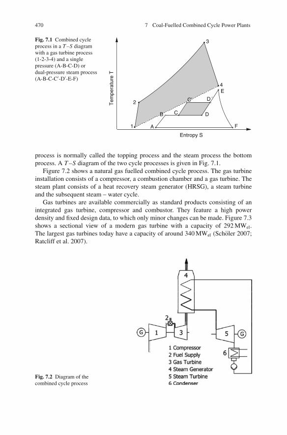
470 7 Coal-Fuelled Combined Cycle Power Plants
Fig. 7.1 Combined cycleprocess in a T –S diagramwith a gas turbine process(1-2-3-4) and a singlepressure (A-B-C-D) ordual-pressure steam process(A-B-C-C′-D′-E-F)
Entropy S
Tem
pera
ture
T
3
4
2
1 A
B C D
E
C` D´
F
process is normally called the topping process and the steam process the bottomprocess. A T –S diagram of the two cycle processes is given in Fig. 7.1.
Figure 7.2 shows a natural gas fuelled combined cycle process. The gas turbineinstallation consists of a compressor, a combustion chamber and a gas turbine. Thesteam plant consists of a heat recovery steam generator (HRSG), a steam turbineand the subsequent steam – water cycle.
Gas turbines are available commercially as standard products consisting of anintegrated gas turbine, compressor and combustor. They feature a high powerdensity and fixed design data, to which only minor changes can be made. Figure 7.3shows a sectional view of a modern gas turbine with a capacity of 292 MWel.The largest gas turbines today have a capacity of around 340 MWel (Scholer 2007;Ratcliff et al. 2007).
Fig. 7.2 Diagram of thecombined cycle process

7.1 Natural Gas Fuelled Combined Cycle Processes 471
Fig. 7.3 State-of-the-art gasturbine (Source: Siemens)
Natural gas has an adiabatic combustion temperature of about 2,200◦C. For thisreason, the furnace of the gas turbine is operated at a high excess air level in orderto reduce the flue gas temperature to the permissible inlet temperature of the gasturbine itself. The flue gases in the newest gas turbines enter the turbine at a tem-perature of around 1,400–1,500◦C. The turbine blades closest to the entry point, inparticular, are therefore subjected to high thermal and mechanical stresses, as wellas chemical stress from oxidation and corrosion.
Since the metallic turbine materials currently in use can only be exposed to sur-face temperatures of up to around 950◦C, the first stages of a gas turbine are cooledby air from the compressor. Over the last decades cooling has evolved from con-vection over impingement to film cooling. The blades are made from a compositematerial; the base material provides the mechanical properties, and one or moresurface-protective coatings ensure corrosion and oxidation resistance. Thermal bar-rier coatings can also offer thermal insulation and allow higher gas turbine inlettemperatures (Bohn 2007).
There is no standard definition of the turbine inlet temperature (TIT). The termcan, in fact, refer to different temperatures. The three definitions of relevance are asfollows:
(1) The temperature at the outlet from the combustor (i.e. at the inlet to the firstturbine stator).
(2) The temperature at the outlet from the first turbine stator (i.e. at the inlet to thefirst rotor). At this point, the temperature is typically 40–70◦C lower than indefinition 1 due to the cooling air or steam for the first stator. This definition ofthe TIT is used by General Electric.

472 7 Coal-Fuelled Combined Cycle Power Plants
(3) The calculated temperature (not physical) that would result from mixing allthe cooling air with the combustor exhaust gas. This temperature is typically70–110◦C lower than definition 2. Siemens uses this definition, which is alsoknown as the “ISO TIT”.
It should be added that all three definitions would be identical for a gas turbinewithout cooling (Maurstad 2005). In this book, definition 1 (TIT) and definition 3(ISO TIT) will be used.
Given a TIT of roughly 1,400◦C at the outlet from the combustor, the ISO tem-perature calculated for a modern gas turbine is around 1,200◦C. The highest ISOgas turbine inlet temperature is around 1,320◦C in current practice.
Figure 7.4 shows how the efficiency is influenced by the design parameters (e.g.the ISO turbine inlet temperature and pressure ratio of the gas turbine), both for thegas turbine itself and for the turbine in the gas/steam combination of a combinedcycle power plant.
When the gas turbine is operated by itself, the turbine’s pressure influences theefficiency, while the inlet temperature influences the output. With a constant gas tur-bine inlet temperature, the efficiency rises as the pressure increases. This is becausethe flue gas outlet temperature behind the turbine and hence the losses decrease.If the pressure rises above the optimum level, the energy required for compressionincreases more quickly than the additional gain in the gas turbine’s power output.
The gas turbine inlet temperature has only a minor impact when the gas turbineis being operated alone. This is because the higher temperature of the heat input ispartly compensated for by the higher temperature of heat dissipation. In combinedcycle operation, the inlet temperature of the gas turbine has a discernible effect onefficiency. The gain in efficiency obtained by the higher temperature of the heatinput is conserved. This is because the waste heat of the high flue gas temperaturesis used in the heat recovery process.
The optimum pressure of a gas turbine for the combined cycle process is lowerthan for a gas turbine operated by itself, because the steam process only achievesa high efficiency at flue gas temperatures above 600–650◦C, which generates
340 360 380 400 420 440 460 480 500 520 540
32
33
34
35
36
37
38
39
40
41
42
43
44
1300°C 1400°C1350°C1250°CISO TIT = 1200°C
πV = 10
πV = 14
πV = 18
πV = 22
πV = 26
πV = 30
Eff
icie
ncy
[%
]
Specific power [kJ/kg]400 450 500 550 600 650 700 750 800 850 900
56
57
58
59
60
61
62
63
64
65
66
1300 °C
ISO TIT = 1200 °C
1400 °C
10
14
182226πV, opt = 30
πV, opt = 16
πV, opt = 21
πV, opt = 26
Eff
icie
ncy
[%
]
Specific power [kJ/kg]
Fig. 7.4 Impact of pressure and the gas turbine inlet temperature (ISO) on the efficiency and outputof a gas turbine and a combined cycle process (Kloster 1999)
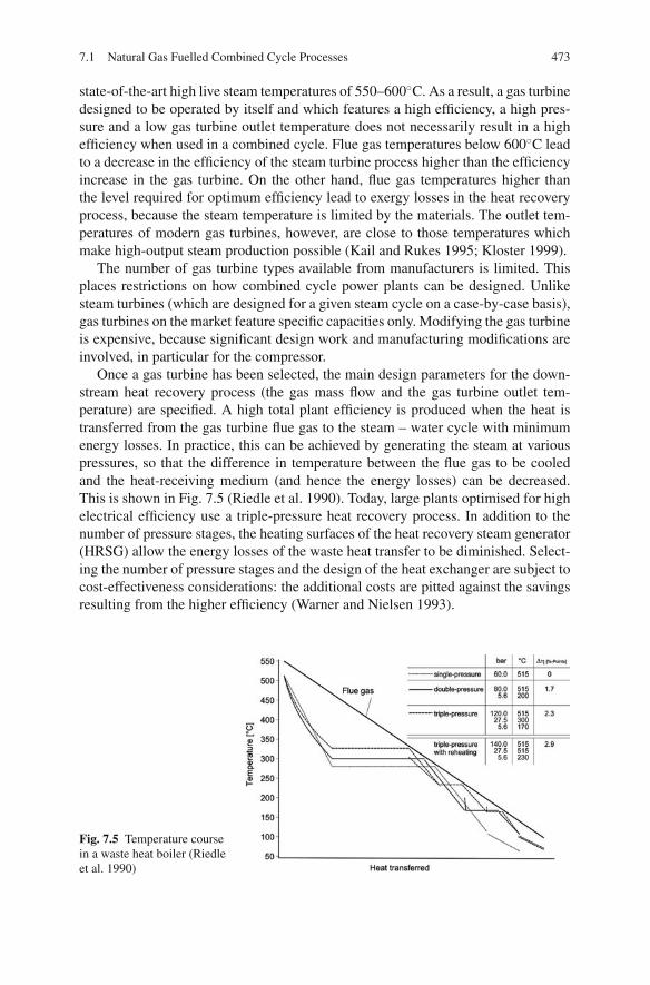
7.1 Natural Gas Fuelled Combined Cycle Processes 473
state-of-the-art high live steam temperatures of 550–600◦C. As a result, a gas turbinedesigned to be operated by itself and which features a high efficiency, a high pres-sure and a low gas turbine outlet temperature does not necessarily result in a highefficiency when used in a combined cycle. Flue gas temperatures below 600◦C leadto a decrease in the efficiency of the steam turbine process higher than the efficiencyincrease in the gas turbine. On the other hand, flue gas temperatures higher thanthe level required for optimum efficiency lead to exergy losses in the heat recoveryprocess, because the steam temperature is limited by the materials. The outlet tem-peratures of modern gas turbines, however, are close to those temperatures whichmake high-output steam production possible (Kail and Rukes 1995; Kloster 1999).
The number of gas turbine types available from manufacturers is limited. Thisplaces restrictions on how combined cycle power plants can be designed. Unlikesteam turbines (which are designed for a given steam cycle on a case-by-case basis),gas turbines on the market feature specific capacities only. Modifying the gas turbineis expensive, because significant design work and manufacturing modifications areinvolved, in particular for the compressor.
Once a gas turbine has been selected, the main design parameters for the down-stream heat recovery process (the gas mass flow and the gas turbine outlet tem-perature) are specified. A high total plant efficiency is produced when the heat istransferred from the gas turbine flue gas to the steam – water cycle with minimumenergy losses. In practice, this can be achieved by generating the steam at variouspressures, so that the difference in temperature between the flue gas to be cooledand the heat-receiving medium (and hence the energy losses) can be decreased.This is shown in Fig. 7.5 (Riedle et al. 1990). Today, large plants optimised for highelectrical efficiency use a triple-pressure heat recovery process. In addition to thenumber of pressure stages, the heating surfaces of the heat recovery steam generator(HRSG) allow the energy losses of the waste heat transfer to be diminished. Select-ing the number of pressure stages and the design of the heat exchanger are subject tocost-effectiveness considerations: the additional costs are pitted against the savingsresulting from the higher efficiency (Warner and Nielsen 1993).
Fig. 7.5 Temperature coursein a waste heat boiler (Riedleet al. 1990)

474 7 Coal-Fuelled Combined Cycle Power Plants
Table 7.1 Possible development of combined cycle processes (Bohn 2005)
Parameter Reference Phase 1 Phase 2 Phase 3
Efficiency 57.4% 61.7% 63.3% 65.0%Combustion exit
temperature1,500◦C 1,500◦C 1,520◦C 1,520◦C
Cooling GT 21.46% 11.7% 12.4% 9.9%ISO turbine inlet
temperature1,172◦C 1,432◦C 1,439◦C 1,473◦C
Max. substrate temp. (GT) 850◦C 900◦C 950◦C 990◦CMax. material temp. (ST) 560◦C 580◦C 595◦C 650◦CRequired cooling steam – 2.2% 1.0% 0.3%
State-of-the-art gas turbine technology, designed for gas turbine only plants,achieves efficiencies of up to 38%. In a combined cycle plant with an optimisedheat recovery process, efficiencies rise to 58% (Jopp 2005). A new gas turbine iscurrently being tested with an efficiency of around 40% as a stand-alone gas turbineand above 60% as part of a combined cycle plant (Scholer 2007). Gas turbine tech-nology has undergone continuous, high-level development in recent years. A furtherrise in the ISO gas turbine inlet temperature, and hence in the gas turbine efficiency,is expected in the future. A higher ISO TIT results in higher gas turbine outlet tem-peratures and promotes the use of advanced live steam conditions. Table 7.1 showspotential developments in the coming years (Bohn 2005; Bohn 2007).
The high efficiencies of the combined cycles shown above are only possible witha clean fuel such as natural gas. Otherwise, the purity requirements of the gas turbinefor the working medium (pressurised hot flue gas) cannot be met.
7.2 Overview of Combined Processes with Coal Combustion
7.2.1 Introduction
For coal-based combined cycle processes, the solid fuels must first be convertedinto a fuel or a hot gas suitable for gas turbines. Impurities in the fuel preventit from being used directly in today’s gas turbines. Compared to the natural gasfired combined cycle process, more steps are required (COORETEC 2003; JBDT1992; Rukes 1993; Wittchow and Muller 1993; Jahraus and Dieckmann 1989; Bohm1994). The processes shown in Fig. 7.6 have been investigated, tested and partiallyimplemented on an industrial scale in order to put a coal-based combined cycle intopractice. They are
• integrated gasification combined cycle (IGCC),• combined cycle with pressurised fluidised bed combustion (PFBC),• combined cycle with pressurised pulverised coal combustion (PPCC) and• externally fired combined cycle (EFCC).

7.2 Overview of Combined Processes with Coal Combustion 475
Fig. 7.6 Coal-based combined cycle processes (Bohm 1994)
In the integrated gasification combined cycle, the process starts by transformingthe solid fuel into a fuel gas at high temperatures in a gasifier. The gas then has tobe purified. Following this, the fuel gas is burned in the gas turbine. The fuel gasproduced is cooled by water/steam for the flue gas cleaning step. This results in alow ratio (about 1.3:1) of the gas to the steam turbine power outputs, and hence to alower efficiency compared to the natural gas fired combined cycle.
In the combustion-based combined cycles of pressurised fluidised bed combus-tion (PFBC) and pressurised pulverised coal combustion (PPCC), the fuel is com-pletely combusted under pressure. Before entering the gas turbine, the hot flue gashas to be cleaned so that it meets the required gas purity standard. Whereas in
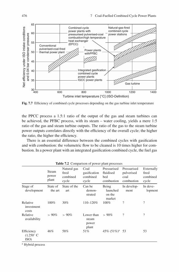
476 7 Coal-Fuelled Combined Cycle Power Plants
Power plantswithPFBC
Conventionalpulverised-coal-firedthermal power plant
Natural-gas-fired
power stations
power plantsIGCC power plants
Gas turbine
(EFCC)
65
60
55
50
45
40
35
30400 600 800 1000 1200 1400
Turbine inlet temperature [°C] (ISO-Definition)
Net
effi
cien
cy u
nder
ISO
inta
ke c
ondi
tions
and
0.04
bar
con
dens
er p
ress
ure
combined cycle
Integrated gasificationcombined cycle
Combined cyclepower plants withpressurised pulverised-coalcombustion/high temperatureheat exchanger
Fig. 7.7 Efficiency of combined cycle processes depending on the gas turbine inlet temperature
the PPCC process a 1.5:1 ratio of the output of the gas and steam turbines canbe achieved, the PFBC process, with its steam – water cooling, yields a mere 1:5ratio of the gas and steam turbine outputs. The ratio of the gas to the steam turbinepower outputs correlates directly with the efficiency of the overall cycle; the higherthe ratio, the higher the efficiency.
There is an essential difference between the combined cycles with gasificationand with combustion: the volumetric flow to be cleaned is 10 times higher for com-bustion. In a power plant with an integrated gasification combined cycle, the fuel gas
Table 7.2 Comparison of power plant processes
Steampowerplant
Natural gasfiredcombinedcycle
Coalgasificationcombinedcycle
Pressurisedfluidisedbedcombustion
Pressurisedpulverisedcoalcombustion
Externallyfiredcombinedcycle
Stage ofdevelopment
State ofthe art
State of theart
Can bedemon-strated
Beinglaunchedon themarket
In develop-ment
In deve-lopment
Relativeinvestmentcosts
100% 30% 110–120% 100% ? ?
Relativeavailability
> 90% > 90% Lower thansteampowerplant
> 90% ? ?
Efficiency(1,250◦ CISO)
46% 58% 51% 45% (51%)a 53 53
a Hybrid process

7.2 Overview of Combined Processes with Coal Combustion 477
flow can be cleaned at a lower temperature than that of gasification. By contrast, inthe combustion-based combined cycles with pressurised fluidised bed combustionand pressurised pulverised coal combustion, the flue gas has to be cleaned at tem-peratures above the gas turbine inlet temperature. Otherwise, there would be a highloss in efficiency.
In the externally fired combined cycle (EFCC) process, a high-temperature heatexchanger is used to avoid the problems of hot gas cleaning. The energy yieldedby combustion is transferred to a clean working medium in a heat exchanger. Thisworking medium, which is suitable for use in a gas turbine, charges the turbine.
These different methods are at differing stages of development. While both PFBCand IGCC are already being used in industry, the EFCC and PPCC processes havenot been implemented at industrial scale.
In Fig. 7.7, the efficiencies of coal and natural gas based combined cycles arecompared with each other and with the conventional steam power plant at a specificturbine inlet temperature. Table 7.2 shows a comparative evaluation.
7.2.2 Hot Gas Purity Requirements
The purity of the working medium for the gas turbine required by gas turbine man-ufacturers is a parameter which determines how the conversion process is designedand which purification steps are selected. When evaluating impurities in the fuel gasor hot flue gas, a distinction must be made between components that lead to
• high-temperature corrosion, erosion and deposits in the gas turbine,• corrosion at the cold end of the heat recovery steam generator or• undesirable emissions.
The damage to the flue gas charged gas turbine caused by corrosion, erosion anddeposits shall be discussed below, because monitoring these problems is decisive inensuring the success of coal-fired combined cycles.
Deposits on the turbine blades lead to a decline in the turbine efficiency. They canbe removed by scrubbing the gas turbine. Such a process uses water jets installed inthe combustion chamber. Desalted water is sprayed into the chamber under pressureand reaches the turbine via the air flow. This water washes away the water-solublecompounds and penetrates the pores and crevices of water-insoluble compounds.When the gas turbine heats up, the water in the pores and crevices evaporates. Theresulting steam pressure causes the deposits to spall (JBDT 1992).
Erosion and corrosion wear the turbine down and lead to a reduction in theturbine’s lifetime and efficiency. Solid as well as liquid particles reach the turbineblades in a number of ways (Thambimuthu 1993):
– Inertial impaction:Large particles do not follow the gas flow due to their inertia. The particles whichhit the blades cause erosion but can also add to deposits. Impinging particles can

478 7 Coal-Fuelled Combined Cycle Power Plants
also carry deposits away again under certain conditions. Particles smaller than5 μm or so follow the gas flow and therefore do not cause erosion.
– Turbulent and Brown’s diffusions:Inertia is not the only factor which can cause particles to deviate from theircourse. Turbulent and Brown’s diffusions can have a similar effect. In the case ofturbulent diffusion, the particles are caught by the eddies of the turbulent bound-ary layer flow. In Brown’s diffusion, the kinetic energy of the gas molecules istransferred to small particles. Both turbulent and Brown’s diffusion phenomenacatch even the smallest particles, which are deposited over the whole inner sur-face of the gas turbine.
– Thermophoresis:Thermophoresis refers to transportation by thermal diffusion as a result of ther-mal gradients between the gas and the surfaces. While thermophoresis can beignored in the case of low gas turbine inlet temperatures, it can play a significantrole where blade cooling (required for higher tube inlet temperatures) is involved.
Of particular importance with regard to contamination and corrosion are sodiumand potassium. These gaseous alkalis are released during combustion, and evensmall traces of them can shorten the lifetime of the gas turbines. Gaseous alkaliscondense in the turbine while it is cooling down. They then form molten alkali sul-phates (in compounds using SO2 from the flue gas, for example) which are depositedon the turbine blades or on ash particles. Alkalis cause the ash fusion temperaturesto fall, and this in turn causes some or all of the ash particles to melt, either beforeor after they reach the blade. In the latter case, they form deposits on the blades.Melting or sintering of the ash causes deposits to form on the blades that are difficultto remove (Thambimuthu 1993).
The molten alkali compounds attack the gas turbine blades severely. By meansof high-temperature corrosion, they destroy the oxidic protective layers of the partsthey come in contact with. This causes an intense corrosive attack on the unpro-tected base material, resulting in a drastic shortening of the lifetime of the blades.The rate of corrosion depends on the chemical composition of the deposits; thegreater the alkali content, the faster the rate of corrosion. The available informationon the corrosive impact of alkalis is based on experience of the combustion of oildistillation residues and heavy fuel oil in gas turbines. Literature on this issue oftenuses the limit of 0.024 mg/kg fuel, set by General Electric, for the combustion of oildistillation residues, though it varies depending on the fuel used. Even if it seemsimpossible to apply this data directly to the conditions of coal-fuelled firing, they doform a basis for specifying the alkali requirements to be met by the hot gas.
Certain metals such as vanadium, lead and zinc can cause the same destruction ofprotective layers as do alkalis. Chlorine, fluorine and their acids can wear away theprotective layers by forming gaseous chloride and fluorides (JBDT 1992). Alkalineearth metals can lead to hard deposits on the turbine blades (Hannes et al. 1989).
The limiting values for turbines depend on the gas turbine inlet temperature.Lower permissible limits are reported for higher temperatures. Much less stringentrequirements are expected after PFB firing due to the gas turbine inlet temperatures,which are lower in comparison to pressurised pulverised coal firing.

7.2 Overview of Combined Processes with Coal Combustion 479
Table 7.3 Permissible guideline concentrations for dusts and trace elements in the hot gas for gasturbine V94.3 (now SGT5-4000F) (data from Jansson 1996; Mitchell 1997)
Dust Total [mg/kg] 1
Dust distribution > 10 μm % by wt 02–10 μm % by wt 7.50–2 μm % by wt 92.5
Trace elements Ca [mg/kg] 0.4V + Pb [mg/kg] 0.01Na + K [mg/kg] 0.01
Table 7.3 gives the permissible flue gas concentrations in front of the turbine forthe Siemens V94.3 (now SGT5-4000F) gas turbine at a gas turbine inlet temperatureof 1,120◦C (ISO) which are required after combustion of natural or coal gas. Thetable shows the limits for the total particulate matter content, the maximum size ofparticles and the concentrations of heavy metals – lead (Pb) and vanadium (V) – thealkaline earth metal calcium (Ca) and the alkali metals sodium (Na) and potassium(K) in the flue gas (Jansson 1996). For combined cycles with pressurised coal firing,limits comparable to natural gas fuelled gas turbines are used as a basis.
The fact that pollutants can also be sucked in together with the combustion airmust be taken into consideration as well. At coastal locations, for instance, themarine salt contained in the fresh air can make a major contribution to the alkaliload in the process.
Although gas turbines have been operated with hot gas generated by PFB com-bustion for several years now, no detailed data on erosion, deposits and corrosion,or relevant limits for prevention of such damage, is available. The values achievedwith the hot gas filters currently used for PFB furnaces, i.e. 250–650 mg/Nm3,reveal much higher concentrations of particulates in the flue gas than the valuesgiven in Table 7.3. All particles are smaller than 10 μm and the mean diameter is2–3 μm (Jansson 1995b). The concept developed by ABB (now Alstom) is basedon a modified robust gas turbine, designed to minimise erosion.
The technical data currently available is provided by experimental plants withgas turbine cascades. In order to limit the erosion caused by hot gases in fluidisedbed combustion (FBC) furnaces, limits are suggested for concentrations of particleslarger than 4 μm as such (Stringer 1989):
> 20 μm: 1 mg/kg10–20 μm: 1 mg/kg4–10 μm: 10 mg/kg
Particles smaller than 4 μm are likely to appear but they will not cause erosion,contamination or corrosion. At lower gas turbine inlet temperatures in PFB furnaces,concentrations of particulates up to 100 mg/Nm3 are considered tolerable as long asall particles are smaller than 5 μm (Emsperger and Bruckner 1986).
The alkali emissions from PFB furnaces can be one or more orders of magni-tude higher than the 0.024 mg/kg fuel indicated as a limit for turbine corrosion forcombustion of oil distillation residues. Although the installed PFB furnaces are notequipped with an alkali remover, the reported corrosion is mild.

480 7 Coal-Fuelled Combined Cycle Power Plants
Table 7.4 Required flue gas purity for pressurised pulverised coal combustion
Dust content [mg/Nm3] 3Maximum particle diameter [μm] <3Gaseous alkalis [mg/Nm3] 0.01
The values in Table 7.4 for the required purity of the flue gas at the turbine inlettemperature for the pressurised pulverised coal firing concept are somewhat higherthan the values given in Table 7.3 (Hannes 1986; Forster et al. 2005).
7.2.3 Overview of the Hot Gas Cleaning System for CoalCombustion Combined Cycles
In a combined cycle with coal gasification, cold gas cleaning of the fuel gas isthe standard procedure. By contrast, hot flue gas cleaning, an efficiency-improvingoption, is essential for combustion-based combined cycles. FBC systems can oper-ate with no more than dust removal, whereas pressurised pulverised coal firing alsorequires alkali removal. The removal of pollutant gases (sulphur dioxide or nitrogenoxide, for example) which the gas turbine can tolerate can take place either beforeor after the gas turbine. While sulphur dioxide removal can take the form of anin situ process in fluidised bed firing, pressurised pulverised coal firing requiresdesulphurisation after the heat has been recovered in the steam generator.
The choice of the dust removal technique depends on the fusion behaviour ofthe fuel ash. Below the ash deformation temperature, fly ash is separated in solidform; at temperatures above ash fluid temperatures, it is separated as liquid slag.In the temperature range of roughly between 900 and 1,300◦C, hot gas cleaning ofash is possible in theory. However, difficulties will arise when cleaning the filtercomponents, because the particles stick to the equipment.
Table 7.5 offers an overview of the possible dust removal techniques (Weber andPavone 1990; Weber et al. 1993; Pruschek et al. 1990). They can be classified asfollows:
• Mass force separators• Wet scrubbers• Filter separators• Electrostatic precipitators (ESPs)
The class of filters used for separation by mass force comprises all separators thatuse only mass forces to clean the gas, i.e. gravity, inertia or centrifugal force. Thenames of the various separators are therefore derived from the effective force in thecase in question. The majority of mass force separators are straightforward in designand pose few engineering problems. Compared to other dust-collecting devices, theyare cost-effective and easy to service and operate. However, they are not suitable forthe removal of soft or sticky particles. They are well suited to the removal of liquidslag at temperatures above 1,500◦C, though material-related problems may arise.
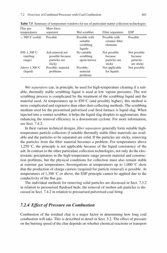
7.2 Overview of Combined Processes with Coal Combustion 481
Table 7.5 Summary of temperature windows for use of particulate matter collection technologies
Flue gas Mass forcetemperatures separator Wet scrubber Filter separators ESP
< 900◦C (solid) Possible Possible withsuitablescrubbingliquids
Possible withceramic filterelements
Possible
850–1,300◦C(meltingrange)
Ash removal notpossible becauseparticles aresticky
No suitablescrubbingagent known
Not possiblebecauseparticles aresticky
Not possiblebecauseparticlesare sticky
Above 1,300◦C(liquid)
Possible; materialproblems
Possible;materialproblems
Not applicablefor liquids
Not possible
Wet separators can, in principle, be used for high-temperature cleaning if a suit-able, thermally stable scrubbing liquid is used at low vapour pressures. The wetscrubbing process is complicated by the treatment of the scrubbing liquid and thematerial used. At temperatures up to 850◦C (and possibly higher), this method ismore complicated and expensive than other dust-collecting methods. The scrubbingmedium used for the pressurised pulverised coal fired furnace is liquid slag. Wheninjected into a venturi scrubber, it helps the liquid slag droplets to agglomerate, thusenhancing the removal efficiency in a downstream cyclone. For more information,see Sect. 7.4.2.
In their various technical designs, filter separators generally form suitable high-temperature particle collectors if suitable thermally stable filter materials are avail-able and the particles to be separated are solid. If the particles are sticky, removingthe particles from the filter material becomes a problem. For temperatures above1,250 ◦C, the principle is not applicable because of the liquid consistency of theash. In contrast to the other particulate collection technologies, not only do the elec-trostatic precipitators in the high-temperature range present material and construc-tion problems, but the physical conditions for collection must also remain stableat extreme gas temperatures. Investigations at temperatures up to 1,000 ◦C showthat the production of charge carriers (required for particle removal) is possible. Attemperatures of 1,300 ◦C or above, the ESP principle cannot be applied due to theconductivity of the flue gas.
The individual methods for removing solid particles are discussed in Sect. 7.3.2in relation to pressurised fluidised beds; the removal of molten ash particles is dis-cussed in Sect. 7.4.2 in relation to pressurised pulverised coal firing.
7.2.4 Effect of Pressure on Combustion
Combustion of the residual char is a major factor in determining how long coalcombustion will take. This is described in detail in Sect. 5.2. The effect of pressureon the burning speed of the char depends on whether chemical reactions or transport
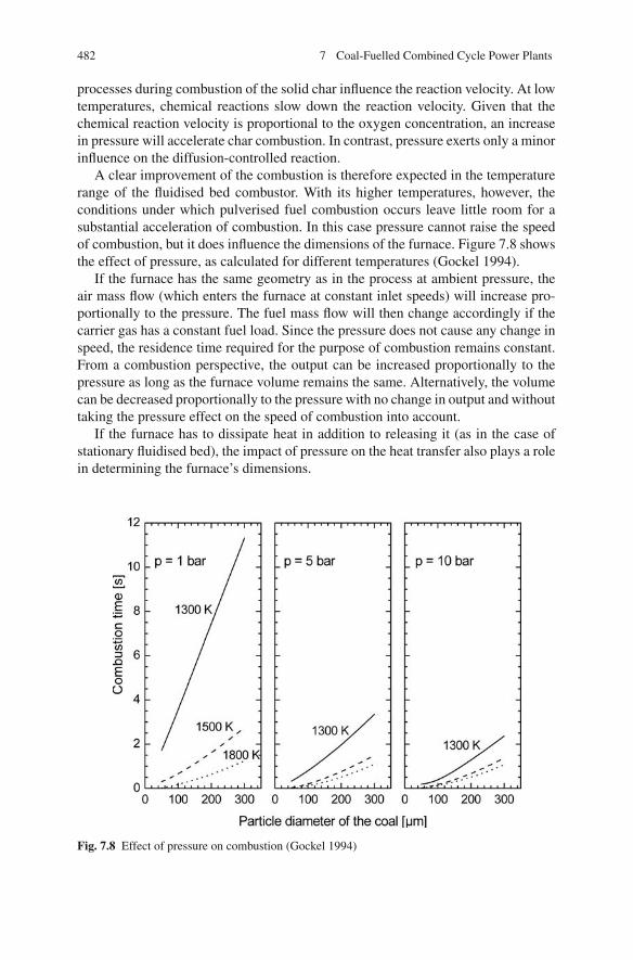
482 7 Coal-Fuelled Combined Cycle Power Plants
processes during combustion of the solid char influence the reaction velocity. At lowtemperatures, chemical reactions slow down the reaction velocity. Given that thechemical reaction velocity is proportional to the oxygen concentration, an increasein pressure will accelerate char combustion. In contrast, pressure exerts only a minorinfluence on the diffusion-controlled reaction.
A clear improvement of the combustion is therefore expected in the temperaturerange of the fluidised bed combustor. With its higher temperatures, however, theconditions under which pulverised fuel combustion occurs leave little room for asubstantial acceleration of combustion. In this case pressure cannot raise the speedof combustion, but it does influence the dimensions of the furnace. Figure 7.8 showsthe effect of pressure, as calculated for different temperatures (Gockel 1994).
If the furnace has the same geometry as in the process at ambient pressure, theair mass flow (which enters the furnace at constant inlet speeds) will increase pro-portionally to the pressure. The fuel mass flow will then change accordingly if thecarrier gas has a constant fuel load. Since the pressure does not cause any change inspeed, the residence time required for the purpose of combustion remains constant.From a combustion perspective, the output can be increased proportionally to thepressure as long as the furnace volume remains the same. Alternatively, the volumecan be decreased proportionally to the pressure with no change in output and withouttaking the pressure effect on the speed of combustion into account.
If the furnace has to dissipate heat in addition to releasing it (as in the case ofstationary fluidised bed), the impact of pressure on the heat transfer also plays a rolein determining the furnace’s dimensions.
Fig. 7.8 Effect of pressure on combustion (Gockel 1994)

7.3 Pressurised Fluidised Bed Combustion (PFBC) 483
7.3 Pressurised Fluidised Bed Combustion (PFBC)
7.3.1 Overview
The pressurised fluidised bed is one method of using coal as a fuel in a combinedcycle process. The solid fuel is burned in a bubbling or circulating fluidised com-bustion bed at temperatures between 850 and 950◦C and pressures of up to 16 bar.Following cleaning, the hot flue gas is brought to the gas turbine.
The optimum temperature in the fluidised bed is determined by the requirementthat it must remain below the ash deformation temperature at all times, in order toprevent agglomerations from forming in the fluidised bed and in order to achieveoptimal desulphurisation. Therefore it is necessary to cool the fluidised bed, asthe adiabatic combustion temperature of coal is above 2,000 ◦C. Various methodscan be used for the purpose of cooling: operation at a high excess air level, aircooling or vapour – water cooling (Emsperger and Bruckner 1986). In natural gasfired combined cycles, by comparison, the gas turbine inlet temperature (which ismuch higher than the fluidised bed though) is set by operating at 100% excessair. Figure 7.9 shows the different cooling process variants, which are describedbelow:
– Adiabatic pressurised fluidised bed:An adiabatic fluidised bed with no in-bed heating surface needs an excess air levelof 300% (an air ratio of 4) in order to limit the fluidised bed temperatures. Thisresults in a furnace with large dimensions and particulate removal downstream.The ratio of the gas turbine output to the steam turbine output is about 2:1. Theadiabatic fluidised bed has been studied conceptually, but as yet a plant has beenneither planned nor constructed.
– Pressurised fluidised bed with an air-cooled heating surface:In this configuration, compressed air is heated to about 700◦C in the in-bed heatexchanger and mixed with the cleaned flue gas before the gas turbine. Due tothe lower air temperature, the gas turbine inlet temperature drops below the tem-perature of the fluidised bed, resulting in a lower efficiency. The ratio of the gasturbine output to the steam turbine output is about 2:1. This variant presents somemajor drawbacks, such as the poorer heat transfer of air as a cooling medium(compared to steam and water) and the higher material temperatures.
– Pressurised fluidised bed with steam – water cooling:Steam – water cooling is the method used in today’s PFBC furnaces due tothe more compact, and hence more cost-effective, design of these furnaces.Therefore, only this variant shall be discussed in more detail. A disadvantageis the fact that the gas turbine makes no more than a minor contribution (one fifthto one quarter) to the total power output. The efficiency depends on the steamconditions used. In the case of a high-quality steam process, the efficiency ishigher than that of the adiabatic fluidised bed; in the case of low-quality steamconditions, the efficiency is lower.

484 7 Coal-Fuelled Combined Cycle Power Plants
Fig. 7.9 Cooling of PFBC furnaces (Emsperger and Bruckner 1986) and amendments
– Pressurised fluidised bed with steam – water cooling and turbocharger:In this configuration, the flue gases are cooled down by convective heat exchangesurfaces to about 400–500◦C before particulates are collected. This avoids theproblem of hot flue gas cleaning at temperatures of around 850◦C. At these lowgas turbine inlet temperatures, however, the gas turbine only provides the powernecessary to drive the compressor. The advantage of this configuration is lim-ited to its compact design. Its efficiency depends solely on the steam process(Emsperger and Bruckner 1986; Dibelius and Pitt 1989). Such a plant, with athermal capacity of 40 MW and a maximum pressure of 4 bar, was used between1984 and 1989 in the thermal power station operated by the Aachen University of
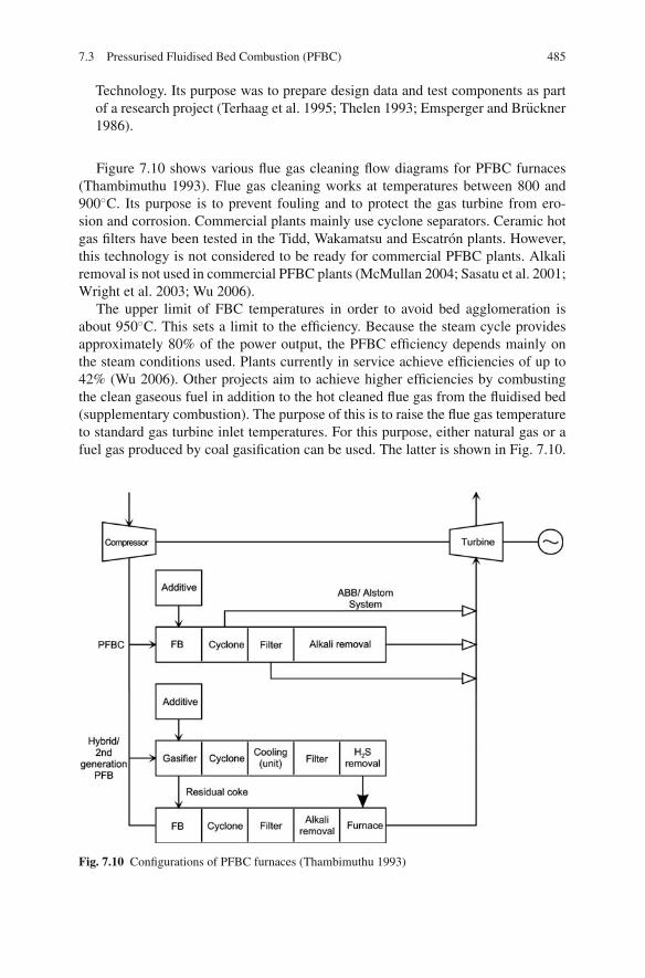
7.3 Pressurised Fluidised Bed Combustion (PFBC) 485
Technology. Its purpose was to prepare design data and test components as partof a research project (Terhaag et al. 1995; Thelen 1993; Emsperger and Bruckner1986).
Figure 7.10 shows various flue gas cleaning flow diagrams for PFBC furnaces(Thambimuthu 1993). Flue gas cleaning works at temperatures between 800 and900◦C. Its purpose is to prevent fouling and to protect the gas turbine from ero-sion and corrosion. Commercial plants mainly use cyclone separators. Ceramic hotgas filters have been tested in the Tidd, Wakamatsu and Escatron plants. However,this technology is not considered to be ready for commercial PFBC plants. Alkaliremoval is not used in commercial PFBC plants (McMullan 2004; Sasatu et al. 2001;Wright et al. 2003; Wu 2006).
The upper limit of FBC temperatures in order to avoid bed agglomeration isabout 950◦C. This sets a limit to the efficiency. Because the steam cycle providesapproximately 80% of the power output, the PFBC efficiency depends mainly onthe steam conditions used. Plants currently in service achieve efficiencies of up to42% (Wu 2006). Other projects aim to achieve higher efficiencies by combustingthe clean gaseous fuel in addition to the hot cleaned flue gas from the fluidised bed(supplementary combustion). The purpose of this is to raise the flue gas temperatureto standard gas turbine inlet temperatures. For this purpose, either natural gas or afuel gas produced by coal gasification can be used. The latter is shown in Fig. 7.10.
Fig. 7.10 Configurations of PFBC furnaces (Thambimuthu 1993)

486 7 Coal-Fuelled Combined Cycle Power Plants
For a hybrid or second-generation PFBC process of this nature, efficiencies of up to52% are reported (when advanced gas turbine inlet temperatures and an advancedsteam-production process are used). However, the higher gas turbine inlet tempera-tures generated by supplementary combustion place higher requirements on the gascleaning stage after the PFB furnace. This in turn requires advanced filter systemsand an alkali removal stage (Robertson et al. 2005).
A PFBC furnace is designed in such a way that the steam generator is installedinside a pressure vessel, because the compressive forces generated by the fur-nace pressure cannot be absorbed by the furnace’s heat-absorbing enclosing walls.Because of the steam generator size and geometry, the vessels considered are cylin-drical or spherical in shape.
The pressurised design facilitates a much more compact furnace compared toatmospheric plants. The advantage of operating under pressure lies in the fact thatthe oxygen partial pressure of the combustion air increases as the operating pressureincreases. As a result, the fuel throughput can be considerably higher for a givensteam generator size.
The cross-sectional heat release rate qf/abed specifies the specific thermal outputin relation to the bed surface. It is therefore a factor in determining the size of thefluidised bed combustor. Assuming equal fluidising velocities, the cross-sectionalarea heat release rate increases in proportion to the pressure (Bunthoff and Meier1987).
In Fig. 7.11, the bubbling (stationary) and the circulating FBC types are com-pared with each other, with and without pressure. The parameters used for compar-ison are the superficial velocity and the cross-sectional heat release rate.
Atmospheric bubbling firing has fluidising velocities between 1 and 2.5 m/s.The speed cannot be further increased as it could cause erosion of the in-bed heatexchange surfaces. Due to this erosion hazard and the higher level of emissionsof CO and NOx in bubbling FBC furnaces, circulating FBC has become the usualtechnology for plants operated at atmospheric pressure. Here, the fluidising speedcan be raised to 8 m/s, because there are no heat transfer surfaces inside the fluidisedbed. As a result, the cross-sectional heat release rate in atmospheric combustionplants rises from 1.5 MW/m2 in stationary operation to 5–7 MW/m2 in circulatingoperation.
Pressurisation allows the plant capacity to be increased considerably. In orderto prevent erosion of the heating surfaces, the fluidising speed is limited to 1 m/sfor bubbling pressurised fluidised beds. Despite this, the cross-sectional area heatrelease rate is between 10 and 17 MW/m2 because of the increase in pressure. If thiscombustion technology is changed to a circulating type of pressurised fluidised bed,cross-sectional heat release rates of up to 50 MW/m2 can be achieved. One outcomeof this is a relatively slim pressure vessel design. The bubbling and the circulatingFBC furnaces thus differ in geometry or, more precisely, in the proportion of thebed cross-section to the boiler height. Circulating FBC furnaces have a slimmerbody and also promise lower emission levels. However, a circulating type features amore complicated plant design (JBDT 1992).

7.3 Pressurised Fluidised Bed Combustion (PFBC) 487
Fig. 7.11 Comparison of bubbling (stationary) and circulating fluidised beds with and withoutpressure (JBDT 1992)
Although pressurised circulating FBC furnaces offer a range of advantages, onlystationary combustion types are used commercially. Pressurised circulating FBCfurnaces have been developed in Germany and Finland (Renz 1994). A pilot pres-surised circulating fluidised bed furnace has been tested by Foster Wheeler as onecomponent in a second-generation PFBC (Wheeldon et al. 2001). Figure 7.12 showsthe commercial plants which have been built to date and their electrical capacities.Most of the pressurised FBC furnaces which have been planned and built are inJapan (McMullan 2004; Schemenau and van den Bergh 1993; Wu 2006).
In designing a fluidised bed, complete combustion must be ensured either througha sufficient residence time in the furnace or by ash recirculation. The particles emit-ted from the bed of a stationary FBC are completely combusted by means of highercombustion reaction velocities at a higher pressure. The size of the emitted particlesdepends on the fluidising speed and the density of the particles. Under the condi-tions offered by a bubbling fluidised bed with a fluidising speed of about 0.9 m/s,the emitted particles are smaller than 250 μm. Since these particles are completelycombusted in the freeboard volume of the furnace, they do not have to be recircu-lated under pressurised fluidised bed con ditions. As a result of the higher fluidisingvelocities of circulating combustion, coarser particles are also emitted. This means

488 7 Coal-Fuelled Combined Cycle Power Plants
Fig. 7.12 Commercial pressurised FBC furnaces (data from Wu 2006; Schemenau 1993)
that the particle residence time in the freeboard stays below the necessary burnouttime, and hence complete burnout is only achieved after several recirculations.
In order to reduce sulphur dioxide emissions, limestone is added to the combus-tion. It binds the developing sulphur dioxide and forms calcium sulphate. Atmo-spheric fluidised beds require ash recirculation in order to make better use of thelimestone and to improve the sulphur capture. Recirculation is not needed in pres-surised FBCs because of the better reaction kinetics of desulphurisation under pres-sure (Bunthoff et al. 1990).
In bubbling atmospheric FBCs, the bed height, generally around 1 m, is limitedby the bed’s pressure loss. An excessive loss should not be chosen for economicreasons. In comparison, the high thermal load and the large heat extraction surface ofthe bubbling PFBC furnace require higher beds of between 3 and 6 m. It is possibleto use these high beds because the relative pressure loss, in relation to the processpressure, is low (Bunthoff and Meier 1987).
Pressure has a positive effect on the heat transfer. The heat transfer coefficientsdepend on the grains of the bed material, the fluidising velocity and the tube walltemperatures. The relationship between the pressure and the heat transfer coefficientis shown in Fig. 7.13. This figure shows that, compared to atmospheric operation, anincrease in pressure to 16 bar (through the increase in gas density and the dynamicviscosity) improves the heat transfer of a bubbling fluidised bed by about 80%.Consequently, smaller heat transfer surfaces can be built for the same thermal output(Bunthoff and Meier 1987).
Oscillations of the grains of the fuel influence the heat absorbed by the in-bedheat transfer surfaces of the bubbling fluidised bed. An in-bed heat transfer surfacewhich is large enough for one fuel type may be too large or too small for another fueland may affect both the steam generation and the gas turbine inlet temperature. The
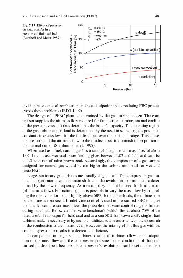
7.3 Pressurised Fluidised Bed Combustion (PFBC) 489
Fig. 7.13 Effect of pressureon heat transfer in apressurised fluidised bed(Bunthoff and Meier 1987)
division between coal combustion and heat dissipation in a circulating FBC processavoids these problems (JBDT 1992).
The design of a PFBC plant is determined by the gas turbine chosen. The com-pressor supplies the air mass flow required for fluidisation, combustion and coolingof the pressure vessel. It thus determines the boiler’s capacity. The operating regimeof the gas turbine at part load is determined by the need to set as large as possible aconstant air excess level for the fluidised bed over the part-load range. This causesthe pressure and the air mass flow to the fluidised bed to diminish in proportion tothe thermal output (Stuhlmuller et al. 1995).
When used as a fuel, natural gas has a ratio of flue gas to air mass flow of about1.02. In contrast, wet coal paste feeding gives between 1.07 and 1.11 and can riseto 1.3 with run-of-mine brown coal. Accordingly, the compressor of a gas turbinedesigned for natural gas would be too big or the turbine too small for wet coalpaste FBC.
Large, stationary gas turbines are usually single shaft. The compressor, gas tur-bine and generator have a common shaft, and the revolutions per minute are deter-mined by the power frequency. As a result, they cannot be used for load control(of the mass flow). For natural gas, it is possible to vary the mass flow by control-ling the inlet vane for loads slightly above 50%; for smaller loads, the turbine inlettemperature is decreased. If inlet vane control is used in pressurised FBC to adjustthe smaller compressor mass flow, the possible inlet vane control range is limitedduring part load. Below an inlet vane benchmark (which lies at about 70% of therated useful heat output for hard coal and at about 80% for brown coal), single-shaftturbines make it necessary to bypass the fluidised bed in order to keep the excess airin the combustion at a constant level. However, the mixing of hot flue gas with thecold compressor air results in a decreased efficiency.
In comparison to single-shaft turbines, dual-shaft turbines allow better adapta-tion of the mass flow and the compressor pressure to the conditions of the pres-surised fluidised bed, because the compressor’s revolutions can be set independent

490 7 Coal-Fuelled Combined Cycle Power Plants
of the grid’s frequency. With two exceptions, all existing plants with bubbling PFBCimplement dual-shaft turbines of the same design. However, modern stationary gasturbines from all manufacturers, without exception, are currently single-shaft tur-bines (Stuhlmuller and Schauenburg 2001).
Combined cycle processes with pressurised fluidised bed combustion also differfrom the natural gas fuelled combined cycle due to the much higher pressure lossesin the fluidised bed boiler, filtering system and pipework – about 1 bar in total asopposed to 0.3 bar with natural gas. The pressure losses diminish the turbine’s out-put. Since the impact on the efficiency is limited, the loss in efficiency is regardedas not too serious, and the fact that adapting the compressor blading is highly com-plicated further discourages addressing this drawback.
The gas turbine inlet has a low temperature of around 850◦C. This is significantlylower than the temperatures of gas turbines in use today. With these lower tempera-tures, blade cooling can be simplified or dispensed with, meaning less cooling air isrequired.
7.3.2 Hot Gas Cleaning After the Pressurised Fluidised Bed
Hot gas cleaning after fluidised bed combustion concentrates on particulate matterremoval (fly ash), although in some plants alkali removal may be taken into con-sideration as well (see Sect. 7.4.3). Sulphur is captured in the fluidised bed, whilenitrogen oxide formation can be limited by the conditions of the combustion.
FB combustion has a temperature of up to 900◦C, which is well below the ashdeformation temperature. As a result, the separation process has to remove solidparticulate matter from the hot gas flow. Various technologies for hot gas fly ashremoval in PFBC furnaces are discussed below. They are
• cyclone separators,• electrostatic precipitators (ESPs) and• particulate collectors such as candles, tubulars, bags or cross-flow filters and
packed-bed filters.
7.3.2.1 Cyclone Separators
Cyclone separators use the principle of separation by centrifugation. The flue gas,laden with fly ash, enters the cyclone tangentially, creating a downward rotatingflow, changing direction as it reaches the bottom of the cyclone. It then leaves thecyclone at the top, free from fly ash (see also Fig. 5.76). The ash particles are pushedoutwards by centrifugal force, hit the walls and fall by gravity to the bottom of thecyclone, where they are removed.
Cyclone separators are simple in design and feature high throughputs and removalrates. The removal rate depends on several factors. The higher the inlet speed, parti-cle size and density and the smaller the cyclone diameters, the greater the centrifugal
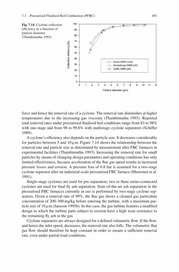
7.3 Pressurised Fluidised Bed Combustion (PFBC) 491
Fig. 7.14 Cyclone collectionefficiency as a function ofparticle diameter(Thambimuthu 1993)
force and hence the removal rate of a cyclone. The removal rate diminishes at highertemperatures due to the increasing gas viscosity (Thambimuthu 1993). Reportedtotal removal rates under pressurised fluidised bed conditions range from 83 to 98%with one-stage and from 98 to 99.6% with multistage cyclone separators (Schiffer1989).
A cyclone’s efficiency also depends on the particle size. It decreases considerablyfor particles between 5 and 10 μm. Figure 7.14 shows the relationship between theremoval rate and particle size as determined by measurement after FBC furnaces inexperimental facilities (Thambimuthu 1993). Increasing the removal rate for smallparticles by means of changing design parameters and operating conditions has onlylimited effectiveness, because acceleration of the flue gas speed results in increasedpressure losses and erosion. A pressure loss of 0.8 bar is assumed for a two-stagecyclone separator after an industrial-scale pressurised FBC furnace (Mustonen et al.1991).
Single-stage cyclones are used for pre-separation; two or three series-connectedcyclones are used for final fly ash separation. State-of-the-art ash separation in thepressurised FBC furnaces currently in use is performed by two-stage cyclone sep-arators. Given a removal rate of 99%, the flue gas shows a cleaned gas particulateconcentration of 200–500 mg/kg before entering the turbine, with a maximum par-ticle size of 10 μm (Jansson 1995b). In this case, the gas turbine features a modifieddesign in which the turbine parts subject to erosion have a high wear resistance tothe remaining fly ash in the gas.
Cyclone separators are always designed for a defined volumetric flow. If the flow,and hence the inlet speed, decreases, the removal rate also falls. The volumetric fluegas flow should therefore be kept constant in order to ensure a sufficient removalrate, even under partial-load conditions.

492 7 Coal-Fuelled Combined Cycle Power Plants
7.3.2.2 Electrostatic Precipitators
An electrostatic precipitator (ESP), used to remove particulate matter, is a well-established piece of technology in coal-fuelled power plants. The principles of ESPshave been discussed in Sect. 5.9.2 in the context of pulverised coal combustion. Forpulverised coal combustion, the ESP is located at the cold end of the flue gas pathin the temperature range of about 150◦C. In the temperature and pressure range ofpressurised fluidised bed combustion, the removal behaviour of ESPs has only beeninvestigated in laboratories. These investigations revealed a remarkably high ESPenergy demand, which has to be attributed to the lower electrical resistance of flyash at higher gas temperatures.
Although negative results, which would exclude the principle of the use of anESP under pressurised FBC conditions, have not been reported, there is no infor-mation available about R&D projects which continue the work in this field (Weberet al. 1993; Takahashi et al. 1995; Renz 1993).
7.3.2.3 Filtration Separators
Filtering separators use filter media such as granular bulk materials, sintered ceramicmaterial, tissue, felt, non-woven material or shaped pieces of fibre. Particulatesdeposit on the surface of these and are cleaned off periodically. For fly ash collectionin pressurised fluidised beds, packed filter beds made from temperature-resistantgranular material, ceramic filter media in the form of bags, and rigid elements in theform of plates or cylinders are the types of equipment investigated today (Wu 2006;Jansson et al. 1996; Sasatu et al. 2001; Toriyama et al. 1999; Newby et al. 2001;Newby et al. 1999; Weitzel and McDonald 1999; Wheeldon et al. 2001; Wrightet al. 2003).
– Packed-bed or granular bed filtersIn a packed-bed filter, the gas containing the particulates flows through a bulkbed made of granular material, where it deposits the particles. Figure 7.15 showssuch a packed-bed filter. The untreated gas containing the particulates from com-bustion flows into the bed through a concentric duct from above. It is deflectedinside the bulk bed and extracted in the form of cleaned gas at the top. As the par-ticulate deposits accumulate in the bulk bed, the bed’s flow resistance increases.The polluted bulk material is continuously discharged at the bottom while freshbulk material is supplied from above.
Today, packed-bed filters are used to collect particulate matter contained in hotwaste gases from industrial furnaces containing abrasive, chemically aggressiveand/or sticky dusts. Investigations into the sorption of gaseous pollutants showthat packed-bed filters can also be used to remove pollutant gases such as HCl,SO2 and alkalis (Schiffer 1989).
Packed-bed filters are efficient at removing particulates from hot gases andsatisfy the purity requirements of gas turbines. During investigations underFBC conditions, removal rates of 97–99% and a particulate concentration of

7.3 Pressurised Fluidised Bed Combustion (PFBC) 493
Fig. 7.15 Schematic drawingof a packed-bed filter(Thambimuthu 1993)
4–6 mg/m3 in the cleaned gas were achieved, with pressure losses of 50–80 mbar.The flow velocities range from 0.1 to 0.3 m/s (Renz 1993). Compared to cycloneseparators, it is clear that less pressure is lost when packed-bed filters are used.Even if a cyclone is installed upstream, the total pressure loss reported is about200 mbar. This is also lower than the rate of the two-stage cyclone (Mustonenet al. 1991).
A packed-bed filter installation needs considerably more equipment, however.This includes vessels for cleaning and for the polluted bulk material, the appro-priate lock-hopper system for pressurised operation and a regeneration systemfor the polluted bulk material (Mustonen et al. 1991).
– Candle filtersCandle filters are named after their shape, which resembles a hose with a closedend. Figure 7.16 shows the installation of a candle filter in a pressure vessel, whileFig. 7.18 shows the design for a 150 MWel PFBC plant. The untreated flue gascontaining the particulates enters the lower part of the vessel, flows through thefilter candles and is extracted in the upper part of the vessel. The filter candles areheld in place both vertically and horizontally by a perforated plate. The untreatedgas and cleaned gas zones are separated from each other by the candles and plate.The filter medium is porous and only allows very small fly ash particles to passthrough. The maximum size depends on the pore diameter of the filter material. Afilter cake forms on the outside of the filter candle and plays a major part in fly ashcollection and also increases the pressure loss. The filter cake can be removed by

494 7 Coal-Fuelled Combined Cycle Power Plants
Fig. 7.16 Schematic drawingof a candle filter(Thambimuthu 1993)
means of compressed air pulses from the side of the cleaned gas. The particulatesare extracted from the bottom of the vessel.
The candle tubes, closed at their bottom end, are made of a coarsely porous sin-tered ceramic material. Typical filter elements have an outer diameter of 60 mm,a wall thickness of 10–20 mm and a length of 1–1.5 m. If the material is siliconcarbide, the pore diameter ranges between 30 and 100 μm. The filter efficiencycan be improved by applying a finely porous surface layer of ceramic fibres to theside of the ceramic material facing the untreated flue gas. These fibres are firmlyjoined by sintering with the main body. When a two-component system such asthis is used, the pore sizes can be as small as 3 μm (Thambimuthu 1993).
The filter shown in Fig. 7.16 was installed after a cyclone separator for long-term tests at an experimental plant. Given an initial particle concentration of1,000–4,000 mg/kg in the untreated gas, with an average particle diameter of3–7 μm, removal rates of 99% were reached. This meant that particulate concen-trations below 10 mg/kg were achieved in the cleaned gas. The approach speedat the filter candles ranged between 0.03 and 0.07 m/s (Thambimuthu 1993). Atan approach speed of 0.07 m/s, the pressure loss was 230 mbar. The basic disad-vantage of the configuration shown in Fig. 7.16 is that filter suspension and thecleaning system cannot be scaled up for larger filter units (Renz 1993).
The only practical method for cleaning the filter candles while ensuring aconstant flue gas mass flow to the gas turbine is pulse jet cleaning. A method
7.3 Pressurised Fluidised Bed Combustion (PFBC) 495
involving constant switching of single filter modules would not be compatiblewith the operating regime of the gas turbine. What is more, there are no suffi-ciently reliable hot gas valves available for this purpose (Stuhlmuller et al. 1995).
Even though ceramic candle filters are highly developed, their suitability foruse in industry has not yet been proven. At temperatures above 775◦C, it grad-ually becomes more difficult to remove the filter cake as ash properties beginto change and as the operating pressure loss increases (Jansson and Svensson1997). In different PFBC demonstration projects, ceramic filters have been testedusing a partial flow of hot flue gas. At the Tidd plant, ceramic candle filters wereinstalled after one of the primary cyclones. The main problems encountered in thetest included ash bridging between candles, difficulties in cleaning the candlesand difficulties in draining the filter vessel. The bridging reduced the effectivefiltration area and, more seriously, led to mechanical failure of the elementsunder tensile stress. At the Escatron plant, ceramic candle filters were testedat 750–820◦C. The filters were also subjected to ash bridging and mechanicalfailure (Wu 2006; Wright et al. 2003).
– Bag filtersIn contrast to the self-supporting candle filters, bag filters need a support cageto maintain the form of a hose because of their fabric filter. Ceramic or metallicmaterials are the fabrics considered for the application of bag filters in the tem-perature range of FBC furnaces. A survey of filter materials which have alreadybeen investigated can be found in Thambimuthu (1993).
– Tube filtersTube filters work according to the same principle as candle filters. The untreatedgas, however, approaches from inside the tubes. The design of a tube filter isshown in Fig. 7.17. The gas flow containing the particulates enters the vessel andceramic tubes from above and exits as clean gas. The particulates are removed asthe flue gas radially passes through filter tube walls. The particulate matter col-lects inside the tube, is removed by compressed air, pushed downwards, collectedat the vessel bottom and discharged. The tubes have large internal diameters of140 mm in order to prevent clogging of the filter media. The tube is up to 6 m inlength, which gives the advantage of a compact design (Thambimuthu 1993).
This configuration was used in a circulating PFBC test furnace of 10 MWth andin a stationary PFBC test furnace of 15 MWth. An outlet particulate load of around3 mg/Nm3 was achieved in the cleaned gas. At the 71 MWel stationary PFBC fur-nace in Wakamatsu, Japan, the tube filter technique was tested during demonstrativeoperation (Sasatu et al. 2001). Following a coarse separation stage in cyclones, thewhole flue gas flow was cleaned in two tube filters. Each tube filter was 3.2 m indiameter and 16 m in height. Under trouble-free operation conditions, the designparameters of about 2 mg/Nm3 for the particulate matter content and 100 mbar forthe pressure loss were achieved. Tests were carried out in two phases, with a total of11,500 h of operation. The longest surviving filter had a lifetime of approximately8,000 h (Wu 2006). On the whole, however, a series of problems such as filter failureand ash clogging occurred.
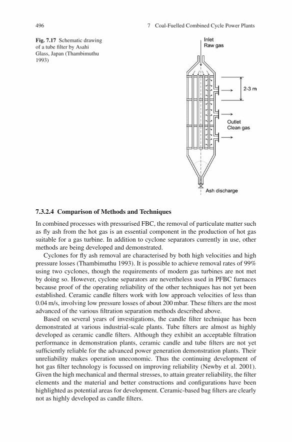
496 7 Coal-Fuelled Combined Cycle Power Plants
Fig. 7.17 Schematic drawingof a tube filter by AsahiGlass, Japan (Thambimuthu1993)
7.3.2.4 Comparison of Methods and Techniques
In combined processes with pressurised FBC, the removal of particulate matter suchas fly ash from the hot gas is an essential component in the production of hot gassuitable for a gas turbine. In addition to cyclone separators currently in use, othermethods are being developed and demonstrated.
Cyclones for fly ash removal are characterised by both high velocities and highpressure losses (Thambimuthu 1993). It is possible to achieve removal rates of 99%using two cyclones, though the requirements of modern gas turbines are not metby doing so. However, cyclone separators are nevertheless used in PFBC furnacesbecause proof of the operating reliability of the other techniques has not yet beenestablished. Ceramic candle filters work with low approach velocities of less than0.04 m/s, involving low pressure losses of about 200 mbar. These filters are the mostadvanced of the various filtration separation methods described above.
Based on several years of investigations, the candle filter technique has beendemonstrated at various industrial-scale plants. Tube filters are almost as highlydeveloped as ceramic candle filters. Although they exhibit an acceptable filtrationperformance in demonstration plants, ceramic candle and tube filters are not yetsufficiently reliable for the advanced power generation demonstration plants. Theirunreliability makes operation uneconomic. Thus the continuing development ofhot gas filter technology is focussed on improving reliability (Newby et al. 2001).Given the high mechanical and thermal stresses, to attain greater reliability, the filterelements and the material and better constructions and configurations have beenhighlighted as potential areas for development. Ceramic-based bag filters are clearlynot as highly developed as candle filters.

7.3 Pressurised Fluidised Bed Combustion (PFBC) 497
Fig. 7.18 Candle filter of a 150 MWel power plant with circulating PFBC furnace (Bauer et al.1994; Rehwinkel et al. 1992)
Figure 7.18 shows the design of a ceramic candle filter for a planned 150 MWel
power plant with a circulating PFBC furnace (Bauer et al. 1994; Rehwinkel et al.1992). The flue gas containing the particulates is fed into the filter vessel and candlesfrom above. An impact plate acts as a flow deflector, ensuring a steady flow of solidflue gas across the entire cross-section of the filter.
In the filter unit shown, 1,800 ceramic filter candles are arranged upright onsupporting headers on three levels. This vertical mounting has several advan-tages compared to the suspended mounting. First, the weight load on the ceramicmaterial takes the form of compressive stress and not tensile strain, which is thepreferable design for ceramics. Furthermore, the filter candles, with an increasingdegree of pollution, are pressed more firmly into their sealed fit. The concentra-tion of outlet particulates in the cleaned gas is less than 5 mg/Nm3 (Bauer et al.1994).
Packed-bed filters work at higher velocities (0.2 m/s) and have lower pressurelosses of less than 200 mbar. In addition, they allow the removal of other substanceswhich are likely to damage the gas turbine. Although packed-bed filters are not yetas highly developed as candle filters, they are expected to be just as suitable as themin general.

498 7 Coal-Fuelled Combined Cycle Power Plants
7.3.3 Pressurised Bubbling Fluidised Bed Combustion (PBFBC)
7.3.3.1 State of Development
The technology used in bubbling pressurised fluidised bed combustion is highlyadvanced. A total of eight PBFBC plants have been built around the world, givinga cumulative installed capacity of 1,125 MWel to date (McMullan 2004; Wrightet al. 2003; Wu 2006). Some of the plants initially functioned as demonstrationunits; today, however, the majority are operated on a commercial basis. The com-pany known as ABB Carbon, now part of Alstom Power, has supplied most of theinstallations; two units have been built in Japan with Japanese PFBC technology.Overall, the uptake of PBFBC technology has been progressing slowly. Table 7.6summarises the details of existing PBFBC plants.
Four demonstration plants were built around 1990. They were based on ABBCarbon’s P200 module and had a thermal output of about 200 MWth. Two of themare operated by Stockholm Energi in Vartan, Stockholm, Sweden, and one byENDESA in Escatron, Zaragoza, Spain. The Tidd plant near Brilliant, Ohio, oper-ated by American Electric Power, was taken out of service in 1995 after operating asa demonstration plant for several years. The Tidd and Escatron plants were designedfor an electrical output of 70 and 76 MWel, respectively, whereas the Vartan plant(two P200 modules) is operated as a CHP power station with an electrical outputof 135 MWel and a thermal heat extraction rate of 225 MW. In Escatron, hot gasfiltration using a partial flue gas flow was investigated (Jansson 1995a; Jansson et al.1996; Jansson 1995b; Martinez Crespo 1995).
In 1993, another plant entered service in Kyushu, Japan. This plant is alsoequipped with a filtration separator for the whole flue gas flow (Goto 1995; Sasatuet al. 2001). In 1999, a pressurised fluidised bed based on the P200 module andfuelled by brown coal entered service in Cottbus, Brandenburg, Germany (Walteret al. 1997). Based on the experience with the P200 module, an FBC furnace wasdesigned and manufactured for a plant in Karita, Japan. This furnace featured athermal capacity of 800 MWth. The plant began demonstration operation in 1999and entered commercial operation in 2001. It features advanced supercritical steamconditions (24.1 MPa/566◦C/593◦C) and a net thermal efficiency rate of nearly 42%(HHV), corresponding to about 44% (LHV) (Koike et al. 2003; Asai et al. 2004).This represents state-of-the-art PFBC technology (Jansson and Anderson 1999).
Other PBFBC plants have been built by Japanese companies in Japan: the85 MWel Tomatouatsuma Unit No. 3 built by Mitsubishi Heavy Industries (MHI),which uses a ceramic filter, and the 250 MWel Osaki Plant by Hitachi (Shimuzu andItoh 2001; Hokari et al. 2001).
The apparent lack of market penetration in Europe and North America is believedto be a result of PBFBC’s perceived higher costs and complexity compared to com-peting systems, coupled with an increasing focus on natural gas fired combinedcycle gas turbine plants. As Japan does not have access to substantial gas reservesand is a net importer of LNG, the future market potential is seen as being mainlyin Japan. Due to rationalisation of Alstom resources, PBFBC is no longer actively

7.3 Pressurised Fluidised Bed Combustion (PFBC) 499
Tabl
e7.
6Su
mm
ary
data
for
PBFB
Cpl
ants
curr
ently
inse
rvic
e(d
ata
from
Wu
2006
and
addi
tions
)
Proj
ect/t
ypic
alfe
atur
eV
arta
nE
scat
ron
Tid
dW
akam
atsu
Cot
tbus
Tom
atou
atsu
ma
Osa
kiK
arita
Star
t-up
date
1989
1991
1991
1994
1998
1999
1999
1999
Type
AB
B2x
P200
CH
PA
BB
P200
Con
d.A
BB
P200
Con
d.A
BB
P200
Con
d.A
BB
P200
CH
PM
HI
Hita
chi
AB
BP8
00C
ond.
P el,
net
135.
0M
W79
.5M
W70
.5M
W71
.0M
W74
MW
85M
W25
0M
W36
0M
WP t
h22
4.0
MW
––
–12
0M
WG
astu
rbin
e2x
GT
35P
GT
35P
GT
35P
GT
35P
GT
35P
MW
-151
PG
EF7
EA
GT
140P
Boi
ler
pres
sure
12ba
r12
bar
12ba
r12
bar
12ba
r10
bar
12ba
rB
edte
mp.
860◦ C
860◦ C
860◦ C
860◦ C
840◦ C
870◦ C
865◦ C
870◦ C
Gas
clea
n-up
Cyc
lone
s2
stag
esC
yclo
nes
2st
ages
Cyc
lone
s2
stag
esC
yclo
nes+
cera
mic
filte
rC
yclo
nes
2st
ages
Cyc
lone
s+
cera
mic
filte
rC
yclo
nes
2st
ages
Cyc
lone
s2
stag
esC
oal
Har
dco
al,
Pola
ndB
row
nco
alH
ard
coal
,Ohi
oH
ard
coal
Bro
wn
coal
,dr
ied
Har
dco
alH
ard
coal
Sulp
hura
0.1–
1.5%
2.9–
9.0%
3.4–
4%0.
3–1.
2%<
0.8%
0.3–
1.2%
Ash
a8–
21%
23–4
7%12
–20%
2–18
%5–
6%2–
18%
Moi
stur
ea6–
15%
14–2
0%5–
15%
8–26
%18
–20%
8–30
%C
oalf
eedi
ngPa
ste
Dry
Past
ePa
ste
Dry
Dry
Past
ePa
ste
Sorb
entf
eedi
ngPa
ste
with
coal
Dry
Dry
Past
ew
ithco
alD
ryPa
ste
with
coal
Past
ew
ithco
alSo
rben
tD
olom
iteL
imes
tone
Dol
omite
Lim
esto
neL
imes
tone
Lim
esto
neL
imes
tone
Liv
est
eam
pres
sure
137
bar
94ba
r90
bar
103
bar
142
bar
166
bar
167
bar
241
bar
Liv
est
eam
tem
p.53
0◦ C51
3◦ C49
6◦ C59
3◦ C/
593◦ C
537◦ C
/53
7◦ C56
6◦ C/
538◦ C
571◦ C
/59
6◦ C57
0◦ C/
595◦ C
Bed
heig
ht3.
5m
3.5
m3.
5m
3.5
m4
m3.
5m
Net
effic
ienc
y,%
36(H
HV
)35
(HH
V)
38(H
HV
)41
(HH
V)
42(H
HV
)44
(LH
V)
aA
s-m
ined
coal

500 7 Coal-Fuelled Combined Cycle Power Plants
marketed, although support is still provided for existing installations. It seems thatthe PBFBC technology will only flourish if its use is promoted by the Japaneselicensees and their local competitors or if it is utilised in some form of a hybridcycle (McMullan 2004).
7.3.3.2 Industrial-Scale Configurations
The design of ABB Carbon’s P200 module will be described in more detail below,as it is the most widely used PFBC technology and information about its designand operation has been published. Figure 7.19 shows the plant in Cottbus, which isbased on pre-dried brown coal (Walter et al. 1997; Jansson and Anderson 1999). Itcan be divided into three sections – a gas turbine cycle, a steam – water cycle and afluidised bed.
The combustion air is taken in from the ambient air, pre-compressed in a low-pressure compressor (LP compressor), intercooled and then further compressed toreach the required working pressure for combustion. Intercooling is chosen so thatlow inlet temperatures of around 300◦C can be set in order to cool the pressurevessel. Afterwards, the air is injected into the furnace via the distributor plate.
The flue gas produced by combustion is cleaned in a two-stage cyclone separator.It is then directed, in the form of hot gas, to the high-pressure gas turbine via acoaxial duct, inside which the hot gas flows, while the compressed air flows onthe outside. In the high-pressure gas turbine, the hot flue gas is pre-expanded, thenfurther expanded in the low-pressure gas turbine, in order to drive the low-pressurecompressor.
Fig. 7.19 Diagram of the PBFBC power plant in Cottbus (Walter et al. 1997)

7.3 Pressurised Fluidised Bed Combustion (PFBC) 501
The low-pressure cycle, featuring an LP gas turbine and a pre-compressor, isdriven at variable speed; the high-pressure cycle, featuring a HP turbine, a HPcompressor and a generator, is driven at constant speed. Power output is gener-ated exclusively by the HP gas turbine, which drives the generator via gears. Afterpassing through the two cyclone separators, the particulate matter typically comesto between 200 and 500 mg/kg (Jansson 1995b), with a maximum particle size ofabout 10 μm. The gas turbine used has been modified and adapted in order to suitthe cleaned hot gas from the PFB – to limit the impact of erosion, corrosion andfouling and to achieve a longer lifetime.
A standard gas turbine was modified for low flow velocities by increasing thenumber of stages (in order to reduce the deflections) and by reinforcing the bladeprofiles of the parts at risk. This made it more suitable for operation after the flu-idised bed combustion furnace. With its pressure conditions and mass flow, the gasturbine chosen determines the design of the pressurised FBC furnace. Since it is tooexpensive to develop a gas turbine especially for pressurised FBC furnaces, recourseis made to suitably modified existing gas turbines. The compressor mass flow thensets the key values for the design of such a furnace.
The waste heat from the gas turbine can only be used for feed water heating atrelatively low gas turbine outlet temperatures in the steam – water cycle. This heataccounts for 10% of the steam produced. The far greater portion of heat in the steamproduced in fluidised bed combustion – about 90% – is transferred directly to in-bedheating surfaces and furnace walls and used for vaporisation and superheating. Thegas turbine accounts for only a small share of the total power output. This is becausethe steam – water cooling of the fluidised bed (by means of in-bed heating surfaces,in order to maintain the FBC temperatures) has to stay below 850◦C and becausethis heat is not used in the gas turbine. The output ratio of the gas turbine to thesteam turbine is about 1–5.
The pressure vessel in the P200 module in the installed plants is 20 m high andhas a diameter of 13 m. In these plants, the cyclones are located to the side of thefluidised bed component. In the Wakamatsu and Cottbus plants, the cyclones arelocated above the fluidised bed which, with a diameter of 11 m and a height of 32 m,makes the body of the pressure vessel higher and more slender.
The vessel interior is cooled by the combustion air coming from the compressorbefore it is used for fluidisation and combustion in the fluidised bed. Because of thelow temperature, low-alloy steel types can be used for the pressure vessel.
In order to be used in FBC, the coal has to be ground to a grain size of lessthan 5 mm. Any further preparation depends on the calorific value and the sulphurcontent of the coal. In the case of the Vartan power station, coal and limestone aremixed with water and pumped into the firing facility by means of a slurry pump.The water content in this coal – water suspension amounts to about 25%. From aprocess-engineering perspective, wet feeding is less complicated than dry feedingusing pneumatic conveying and a lock-hopper system. Coals with higher calorificvalues, ash contents below 25% and lower sulphur contents require less additivesfor desulphurisation. If such coals are used, losses in efficiency due to the necessaryevaporation heat and the increased volumetric flue gas flow are compensated for by

502 7 Coal-Fuelled Combined Cycle Power Plants
the lower auxiliary power requirement of wet feeding. Wet feeding works withoutcoal drying and pressurisation of the lock-hopper system.
Dry feeding is used for coals with a low calorific value and a high sulphur con-tent, as in the Escatron plant, because if wet feeding were used the high fuel andadditive mass flows in this plant would lead to a reduced efficiency. In the Tiddplant, the fuel is fed in wet, while the additive for desulphurisation is dry.
A high fluidised bed of 4 m and a relatively low flow speed result in a sufficientresidence time of about 4 s for the gas in the fluidised bed; the residence time in thefreeboard above the bed is also around 4 s. The relatively long residence times, aswell as the pressure conditions, favour burnout, resulting in a low carbon level ofabout 1% in the fluidised bed. This is the same as the level of unburned matter in theextracted ash. It is not necessary to recirculate the ash in order to raise the burnoutin PFBC (Schemenau 1993).
7.3.3.3 Control
At partial load, the operating pressure is reduced to the level of the fluidisation speedand the inlet velocities to that of the cyclones, and the excess air has to be keptconstant. The operating pressure and volumetric air flow are set by the variable-speed LP compressor in the cross-compound gas turbine, and the HP compressorunit is driven at a constant speed. The speed of the LP compressor is controlled byadjustable inlet guide vanes in the LP turbine (Keppel 1995). The power output ofthe gas turbine diminishes with a diminishing pressure.
Partial loads in the steam generator and steam turbine are set by means of thefluidised bed height. For this, the heating surfaces are only partly submerged into thefluidised bed, because heat generated by the gas is not transferred as effectively asthat generated by the fluidised solid matter in the bed. As a result, heat absorption bythe in-bed heating surfaces diminishes and steam production decreases. The flue gascooling by the free-lying, in-bed heating surfaces (i.e. those portions of the heatingsurfaces that are not emerged in the bed) causes the gas turbine inlet temperaturesto drop, resulting in a decreased efficiency.
So that the ash balance within the system is maintained during partial-load opera-tion, the pressure vessel contains a buffer bed ash storage unit. As the load decreases,this unit removes bed ash from the fluidised bed and, in return, provides stored ash torefill the fluidised bed according to the (pre-determined) rated loads of ash. A pneu-matic transport system stores the ash and discharges it. In the Cottbus plant, fuel oilis supplied to the firing unit at partial load in order to keep the freeboard temperatureor the gas turbine inlet temperature constant across the entire load range. This alsohelps to reduce nitrogen oxide loads by means of ammonia injection before thecyclones (SNCR) (Jansson and Anderson 1999).
Experience at the Karita plant has shown that the minimum stable capacity is40% of the nominal power output, and the load change rates are about 3%/minbetween a 40 and 90% load and 2%/min between a 90 and 100% load. A cold startfrom ignition to full load takes 11 h, a warm start takes 4 h and a hot start takes 3 h.When the plant is starting up, the compressor is first of all run by the generator,

7.3 Pressurised Fluidised Bed Combustion (PFBC) 503
which is operated as a motor, whereupon the fluidised bed is heated up by naturalgas or fuel oil (Asai et al. 2004).
7.3.3.4 Emissions
Table 7.7 shows the emissions for selected PBFBC demonstration plants. Thanksto the low combustion temperature of the fluidised bed, NOx emissions are gen-erally lower than 200 ppm, but vary widely from plant to plant. As these plantsuse similar bed temperatures of around 860–870◦C, this variation is probably due tothe differences in the fuel-N content, fuel-volatile content and other parameters. TheVartan plant burns a bituminous coal with 1.3 wt% nitrogen and 27% volatile matterand has relatively high emissions of 165–191 ppm. At the Osaki plant, however, theuncontrolled NOx emissions are as low as 14.4 ppm (Wu 2006). As the power outputdecreases, the NOx emissions increase, because the heterogeneous reduction of thenitrogen oxides by the fluidised bed ash diminishes due to the lower bed height.
Compliance with emission limits requires further measures. In addition to inject-ing ammonia in order to control nitrogen oxide (selective non-catalytic reduction),manufacturers suggest a “freeboard” firing stage in order to increase the temperatureand stage the fuel. Both methods have been applied in the Cottbus plant (Walteret al. 1997; Almhem 1996). In the case of high uncontrolled emissions, selectivecatalytic reduction (SCR) is the most effective, but also the most expensive, NOx
reduction technology. For example, the Karita plant has achieved NOx emissions of35–42 ppm by using SCR.
The plants can achieve desulphurisation of more than 90% by adding limestoneor dolomite, depending on the Ca/S molar ratio. A sulphur retention of 90% is typ-ically achieved at Ca/S molar ratios of 1.8–2.0. As shown in Table 7.7, the SO2
emissions for these plants vary widely from 5 to 350 ppm. The Vartan plant hasparticularly low SO2 emissions due to the low-sulphur (0.1–0.6%) coal burned anda high sulphur retention (96–98%). The Escatron plant burns a high-sulphur (3–9%)coal but with a moderate sulphur retention (90–95%). This results in relatively high
Table 7.7 Emissions from PBFBC plants in operation (Wu 2006)
Plant Vartan Tidd Escatron Osaki Karita
NOx without control,ppm
165–191 86–102 120–170 14.4
NOx with control,ppm
20–33(SNCR)
35–42 (SCR)
Sulphur retention, % 96–98 93 90–95 97.7Ca/S molar ratio 3.3 2.0–2.2 1.7–2.0Ca/S ratio at 90%
sulphur retention2.0 1.8–1.9 1.8
SO2 emissions, ppm 5–9 350 7.1 7–36Particulates, mg/m3 < 30 18 76 ≤ 3.5 (2-stage
cyclones +bag filters)
5–15 (2-stagecyclones +ESP)

504 7 Coal-Fuelled Combined Cycle Power Plants
SO2 emissions. The Vartan plant meets the German standard emission limits of400 mg SO2/Nm3 at 6% O2, whereas both Tidd and Escatron exceed these standardlimits by far. This is due to the high sulphur content of the coal used in these plants(Jansson et al. 1996).
Particulate emissions for the PBFBC plants in operation are also relatively low,between 3.5 and 76 mg/m3. The levels depend on the initial gas cleaning before thegas turbine (cyclones or ceramic filters) as well as final cleaning (ESP or bag filters)prior to discharge from the stack. For example, the Osaki plant employs two-stagecyclones for initial cleaning and bag filters for final cleaning. This plant has achievedparticulate emissions as low as 3.5 mg/m3 (Wu 2006).
7.3.3.5 Residual Material
In order to operate a power plant, it is essential to use, rather than dispose of, anyresidual material produced. In a PFBC furnace, residual material is produced in thecyclone filters (20–50%), the bag filter after the turbine (2%) and as a result ofash removal from the bed material (45–75%). According to manufacturers’ data,the residual material mainly contains calcium sulphate (Ca2SO4), additive (CaCO3)and small quantities of quicklime (CaO), sulphites (CaSO3) and sulphides (CaS),in addition to coal ash. After the addition of water, the residual material is self-capturing, and eluted trace elements are scarce. Using the ash presents the sameopportunities and problems as ash from atmospheric FBC furnaces (see Sect. 5.11).Examples of options for PFBC ash include using it as filling material in undergroundconstructions or for road substructures (Rogbeck 1996).
7.3.3.6 Operating Expertise
The operational expertise gained at the different experimental plants is compiled andsummarised in Stringer (1989). The major problems are erosion and corrosion ofin-bed heating surfaces and gas turbines. Extensive investigations at the test plantsrevealed the need to improve the design of the in-bed heating surfaces, to chooselower flow velocities and to limit the grain size in order to minimise erosion of thesurfaces. The corrosion phenomena of the in-bed heating surfaces can be comparedto those in atmospheric FBC furnaces. Corrosion can be limited by the choice ofmaterial and by preventing air-deficient zones. An efficient particle removal tech-nique is essential in preventing erosion of the turbine. The use of two-stage cycloneseparators should help to meet these requirements, even though there is little leewaywhen there are disturbances. At FB temperatures below 850◦C, problems are notexpected to arise from corrosion of the gas turbine, though they are likely to occurat higher temperatures.
An overview of the operational expertise gained through use of the demonstrationplants is summarised in Wright et al. (2003) and Wu (2006). A series of operationalproblems arose in all plants, as is quite common when new technologies are intro-duced for the first time. However, most of the problems were not associated with
7.3 Pressurised Fluidised Bed Combustion (PFBC) 505
pressurised fluidised bed combustion. The specific problems of PBFBC furnacesreported are discussed below.
Erosion of In-Bed and Membrane Wall Heating Surfaces
The furnace walls feature a water-cooled membrane design and are lined withvarious refractories in order to prevent the bed materials from causing erosion.Heat transfer surfaces may be located within the furnace in the form of evapo-rator tubes, superheaters and reheaters. The evaporator tubes are typically madeof low-grade steel with a 1 mm thick flame-sprayed coating (Metco-2 with a sin-tered bond coating). The high-temperature superheater or reheater tubes are madeof high-chromium steel or austenitic stainless steel. They are left uncoated becausethe intrinsically formed protective oxide layer on the surfaces has a high resistanceto wastage (Wu 2006).
In the early plants (Vartan, Tidd and Escatron), the furnace membrane wallswere left uncoated and subsequently experienced various degrees of wastage. InVartan, those parts of the membrane wall which were exposed (e.g. tubular offsetsfor inspection openings) showed erosion damage caused by the return flow of thebed material along the wall (Schemenau and Anderson 1992). However, the mem-brane walls performed satisfactorily following the application of suitable refractorycoatings (Wright et al. 2003).
The material performance of the evaporator tubes depended on the steam condi-tions and the corrosive environment. At the Vartan plant, one of the two units expe-rienced a failure of the Metco-2 coating on the evaporator tubes. The tube bundlewas replaced with a new one, incorporating modifications to the bed flow pattern inorder to minimise erosion, and alternative coatings were tested. The Escatron plantalso experienced flaking of the coatings in some local areas. However, the Metco-2coating performed well at the Tidd plant. There was only minor tube erosion, appar-ently resulting from local flow disturbances near the bottom of the tube bundle. Thismight be attributed to the lower steam pressure at Tidd, and thus a lower tube surfacetemperature than at the Vartan and Escatron plants (Wright et al. 2003).
Overall, the uncoated superheater tubes performed satisfactorily. The Vartanand Tidd plants experienced some wastage in locations exposed to increased par-ticle flow. This can be treated by taking suitable measures such as heat exchangerredesign or coating (Bauer and Marocco 1995). Only minor erosion damage wasdetected in the Escatron plant. The significantly stronger erosion in the Vartan plantcan be attributed to the different ash behaviour within it (Jansson 1995a).
Sintering
Sintering inside the fluidised bed and in the cyclones causes severe problems.In higher temperature zones in the fluidised bed, bed material sinters and formsagglomerates. These are no longer fluidised and stick to heating surfaces and walls.This interferes with the heat transfer of the fluidised bed and impairs steam produc-tion. In extreme cases, fluidisation of the bed cannot be maintained. Improvements

506 7 Coal-Fuelled Combined Cycle Power Plants
to the fuel injection in order to set a homogeneous temperature distribution coun-teract the sintering processes. Furthermore, uncooled tubes should be avoided in thefluidised bed because these “hot spots” can cause sintered deposits. Such depositswill then accumulate in precisely these “hot spots”. Sintering phenomena alsooccur in the cyclones: deposits form inside the cyclone, then break off during loadchanges, clogging the ash discharge from the cyclones (Martinez Crespo 1995).
In Escatron, both plant components – the fluidised bed and the cyclone – areaffected by sintering. As a remedial action, the fluidised bed is operated at a lowertemperature and power output. Low fluidised bed temperatures prevent clogging dueto sintered pieces in the cyclones. At the plants in Tidd and Vartan, problems alsoarose with limestone, but not with dolomite. No sintering phenomena were detectedat the Wakamatsu plant (Kaser 1996).
Sintering depends on the composition of the coal ash. The alkalis in the fuellower the deformation point of the ash particles, which stick together and sinter.The additives used for desulphurisation have a similar effect. Limestone intensifiessintering more than dolomite. However, the reason behind this has not yet beenclarified. One possible reason is that lower deformation and sintering temperaturesdevelop when the mixture features limestone with other ash components, such asalkali compounds, than with dolomite (Kaser 1996). Another cause may be the dif-ferent comminution behaviour during calcination. It is assumed that the pressure,with limestone, suppresses calcination so that larger and heavier particles form.These fail to mix properly in the fluidised bed and are therefore more likely to sinter(Weitzel et al. 1996). The SO2 concentration of the flue gas also appears to havean effect. At high SO2 emissions and a low desulphurisation degree, the problemswhich have arisen have been more severe.
The findings collected at the industrial-scale plants in service make it possibleto correlate the problems encountered with the alkali contents of the fuel, the SO2
content of the flue gas and the additive used. As a result, the suitability of fuels canbe assessed in advance (Kaser 1996).
Gas Turbine Erosion
At several plants, erosive wear of the turbine blades was detected (despite the useof erosion/corrosion-resistant coatings) as well as of the inlet guide vanes. Thisoccurred mainly as a result of plugging of the cyclone ash discharge legs. This,in turn, caused an excessive loading of dust and more damaging coarse particulatesto be transferred to the turbine. However, when the cyclone ash system performedwithout problems, the erosive wear was generally limited. At the Escatron plant,there was lower erosion because of the relatively soft ash which formed from theblack lignite used (Wright et al. 2003). Even though the erosion damage does notcause a premature shutdown, it shortens the service life of the machines and raisesthe maintenance costs. Filtering separators are absolutely essential in order to pre-vent lifetime-curtailing erosion and fouling of the gas turbines. On the basis ofinvestigations at the Tidd plant, featuring trouble-free operation of the cyclones,a blade lifetime of more than 20,000 h can be expected (Bauer and Marocco 1995).
7.3 Pressurised Fluidised Bed Combustion (PFBC) 507
The lifetimes of turbine blades and in-bed heating surfaces are estimated at 20,000–30,000 h (Renz 1994; Schemenau and van den Bergh 1993).
7.3.3.7 Comparison of Bubbling Pressurised Fluidised Beds to ConventionalPulverised Coal Firing
Pressurisation of the FBC furnace results in a very compact structure, and henceto reduced expenditure on material. A comparison of material requirements fora 330 MWel power plant with a pressurised FBC furnace to those with a pul-verised fuel fired furnace gives a weight difference of more than 40%. Whereas theequipment requirements for coal feeding and ash removal, mechanical equipmentand auxiliary systems in both power plant types are more or less equal, the massof material for the boiler installation alone is cut by more than 60% for PFBC.Although the weight comparison is not the only tool for comparing the expectedcosts, it explains the reason behind the development of PFBC furnaces (Rehwinkel1989).
Based on published data on the Cottbus PFBC plant, the specific costs for a100 MWel plant in condensing operation were about e2,050/kWel in 1999. This iscomparable to the cost of other power plant technologies for coal. In the lower out-put range, the PFBC furnace has an efficiency of about 42% and is thus more advan-tageous than conventional steam cycles, whose efficiency typically falls below 40%.Cost comparisons for higher outputs show that the capital costs for 350 MW and800 MWel PFBC power plants are equal to, or lower than, pulverised coal fuelledpower plants with conventional steam conditions (Weitzel et al. 1996; Wauschkuhn1994).
7.3.4 Pressurised Circulating Fluidised Bed Combustion (PCFBC)
Thanks to its advantages, circulating fluidised bed combustion (CFBC) has becomeaccepted as the preferred option to stationary fluidised bed combustion for atmo-spheric operation (see Sect. 5.4.2). These advantages also hold true in operationunder pressure. In spite of this, pressurised circulating fluidised bed combustion(PCFBC) has not yet reached a similar stage of development. No large-scale plantshave been built to date, even though extensive investigations have been carried outand complete plans for industrial power plants with capacities of up to 150 MWel
have been prepared (Bauer et al. 1994; DOE 2003a). As a result, no operating exper-tise has been gained in this area.
One essential characteristic of a CFBC furnace is the decoupling of heat releaseand dissipation (see Fig. 7.11). All the heat is released via the entire furnace. Thereare no heating surfaces inside the furnace beyond the cooled furnace walls. The heatis dissipated via the furnace walls and an ash fluid bed heat exchanger. The lattercools the ash that was removed in the cyclone.
The necessary temperatures in the fluidised bed are adjusted by recirculating thecooled ash. Depending on the ash recirculation flow, the temperature of the cooled
508 7 Coal-Fuelled Combined Cycle Power Plants
ash lies between 400 and 600◦C. The output of the circulating PFBC is controlledby the fuel flow; the ash recirculation flow controls the temperature in the fluidisedbed and the flue gas temperature. Increasing the output also causes an increase inthe ash recirculation flowrate.
In bubbling PFBC furnaces, by contrast, heat release and heat dissipation takeplace in the fluidised bed. Although this makes for compact plant structures, itcouples combustion, pollutant formation and heat transfer. Separating the combus-tion and heat transfer functions from the steam – water cycle in circulating FBcombustion offers several advantages (Rehwinkel et al. 1993):
• Without having to take the in-bed heating surfaces into account, the flow velocitycan be increased to about 5 m/s in order to generate a high cross-sectional heatrelease rate and a compact construction body. By contrast, the speed of a sta-tionary FBC is limited to 1 m/s in order to prevent erosion on the in-bed heatingsurfaces.
• In the ash fluid bed heat exchanger, the fluidisation speed can be chosen indepen-dently of the combustion air quantity. Given the small grain size of the circulationash, low velocities of 0.3 m/s are sufficient for fluidisation. As a result, erosionproblems do not arise.
• The flue gas temperature at the outlet of the CPFB furnace can be kept constantover the whole load. This is because the output is controlled by the fuel massflow and the temperature by the ash recirculation flow. In the freeboard, it is pos-sible to set flue gas temperatures of 900–1,000◦C, even at low loads and low ashrecirculation flows, without impairing the desulphurisation process. As a result,the hot gas temperature always lies at 850◦C or above. In stationary fluidisedbed combustion, the temperature of the fluidised bed is set by changing the bedheight. Because of the low fluidisation speed and the lower mass flow, it is notpossible to balance the temperature between the bed and freeboard. The in-bedheating surfaces projecting from the bed at part load cause a further decrease inthe freeboard temperature of the stationary PFB. At half load, the temperatureranges around 550◦C, compared to 850◦C at full load. At an inlet temperature of550◦C, the useful output of the gas turbine falls to zero.
• Any influence of the fuel’s grain size on the heat transfer in circulating PFBCcan be counteracted by modifying the ash recirculation flow. Depending on thereaction kinetic conditions, the plant can be operated with fine or coarse grains.By contrast, a change in grain size influences the heat transfer in stationary FBC.It is impossible to counteract this effect. This results in changes to the steamproduction from the in-bed heating surfaces and to the flue gas temperature.
• Air staging is one possible method of reducing NOx emissions. Using thismethod, only part of the combustion air is injected into the fluidised bed viathe distributor plate. The remaining combustion air is injected further up in thefurnace at a later point in time. In stationary PFBC furnaces, in-bed heating sur-faces would be damaged not only by erosion but also by increased corrosion inair-deficient zones.

7.3 Pressurised Fluidised Bed Combustion (PFBC) 509
7.3.4.1 Bubbling and Circulating Pressurised Fluidised Bed Combustion:Comparison in a Pilot-Scale Plant
A 15 MWel pilot-scale power plant, the original design of which included hot gasfilters based on ceramic filter candles, was run in stationary operation from 1989 to1991. Afterwards, it was rebuilt for circulating operation. The tests in circulatingoperation were performed up until 1992 (Rehwinkel et al. 1993).
The bubbling PFB boiler is shown in Fig. 7.20. The plant comprised wet feedingfor coal and limestone and a multistage compressor for supplying the system withcombustion air. The PFB firing, the ash removal system and the hot gas filters werelocated in the pressure vessel. Designed as a bubbling PFB, its equipment includedin-bed heating surfaces with a 4 m high bed and a freeboard above it, also 4 m inheight. Operated as bubbling FB combustion, the height of the bed had to be loweredat part load in order to reduce the heat transfer to the in-bed heating surfaces. Theexcess ash was buffered in a bed ash buffer storage facility.
In 1991, the plant was retrofitted for a circulating process (see Fig. 7.21). Thepressure vessel then contained the circulating PFB firing with a cyclone downstream
Fig. 7.20 15 MWth test plant with bubbling PFB combustion (Rehwinkel et al. 1993)

510 7 Coal-Fuelled Combined Cycle Power Plants
Fig. 7.21 15 MWth test plant with circulating PFB combustion (Rehwinkel et al. 1993)
for ash recirculation and a fluid bed heat exchanger to cool the recirculated ash. Thebed ash buffer storage facility, which was required for stationary PFB combustion,was removed. The peripheral systems for coal feeding, ash removal, steam cycle andhot gas filtration were left more or less unchanged. The circulating PFB combustionworked with a stationary fluidised bed in the lower part of the combustion reactor tofacilitate the admixture of the coal – water suspension. The primary air entered viathe distributor plate. Secondary air was injected above the fluidised bed.
The following cyclone removed the ash. In the ash fluid bed heat exchanger, thesensible heat was transferred to the steam – water cycle and directed towards the firstpass at 400–600◦C. The ash recirculation rate, i.e. the ratio of the ash recirculationflow to the mass flow of fuel and additive fed to the firing, was about 10–20. Lowerash recirculation rates caused the temperature in the freeboard to rise to levels abovethat of the bed temperatures. By contrast, an increase in the ash recirculation ratecaused the excess temperature in the freeboard to fall.
Figure 7.22 shows the freeboard temperatures, measured in tests, as determinedby the load. While in bubbling PFB combustion, the in-bed heating surfaces pro-jecting from the fluidised bed at part load caused the freeboard temperatures to fall.These temperatures remained constant in circulating PFB combustion. At full load,the freeboard temperatures in circulating PFB combustion were about 50◦C higherthan those in the stationary process.
The CO emissions more or less depended on the temperature. The bubbling FBChad low CO emission levels at full load. However, it exhibited a strong increaseat part load due to the corresponding decrease in freeboard temperatures. The
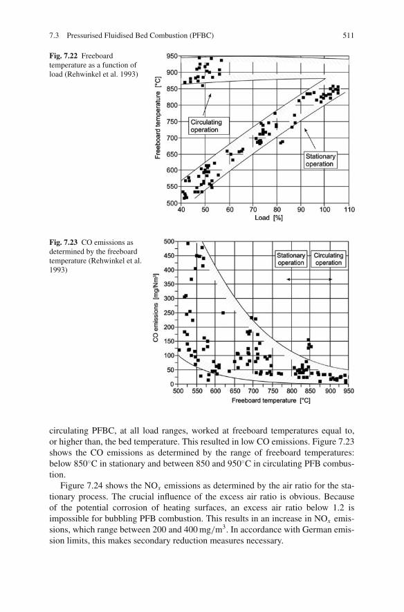
7.3 Pressurised Fluidised Bed Combustion (PFBC) 511
Fig. 7.22 Freeboardtemperature as a function ofload (Rehwinkel et al. 1993)
Fig. 7.23 CO emissions asdetermined by the freeboardtemperature (Rehwinkel et al.1993)
circulating PFBC, at all load ranges, worked at freeboard temperatures equal to,or higher than, the bed temperature. This resulted in low CO emissions. Figure 7.23shows the CO emissions as determined by the range of freeboard temperatures:below 850◦C in stationary and between 850 and 950◦C in circulating PFB combus-tion.
Figure 7.24 shows the NOx emissions as determined by the air ratio for the sta-tionary process. The crucial influence of the excess air ratio is obvious. Becauseof the potential corrosion of heating surfaces, an excess air ratio below 1.2 isimpossible for bubbling PFB combustion. This results in an increase in NOx emis-sions, which range between 200 and 400 mg/m3. In accordance with German emis-sion limits, this makes secondary reduction measures necessary.

512 7 Coal-Fuelled Combined Cycle Power Plants
Fig. 7.24 NOx emissions as afunction of excess air,bubbling PFBC (Rehwinkelet al. 1993)
Fig. 7.25 NOx emissions asdetermined by the primary airfraction, circulating PFBC(Rehwinkel et al. 1993)
By applying the air staging technique in circulating PFBC – impossible in bub-bling PFBC because of the risk of corrosion to in-bed heating surfaces – it is possibleto limit NOx emissions without further NOx measures. Figure 7.25 plots the NOx
emissions in circulating PFB combustion as determined by the primary air fraction.The operating range lies below a 60% primary air fraction. This produces NOx
emissions between 100 and 200 mg/m3.At combustion temperatures below 900◦C, typical for bubbling PFB firing,
another type of nitrogen oxide develops – N2O (nitrous oxide, or laughing gas).Tests at a stationary PFBC furnace showed that N2O emissions are influencedalmost exclusively by the temperature. Below 900◦C, they rise dramatically as the

7.3 Pressurised Fluidised Bed Combustion (PFBC) 513
Fig. 7.26 N2O emissions asdetermined by the freeboardtemperature (Rehwinkel et al.1993)
temperature decreases. At freeboard temperatures of 850–950◦C in circulating PFBcombustion, N2O emissions can be disregarded. Figure 7.26 shows the N2O emis-sions of the bubbling and circulating PFB combustion as determined by the temper-ature for both cases.
The test results obtained at the pilot-scale plant show how much more advanta-geous circulating PFB combustion is than bubbling (Rehwinkel et al. 1993). Theseadvantages include
• lower emissions,• higher part-load efficiency and• a wider range of fuels.
Studies and plans for circulating PFBC furnaces have been undertaken based onexpertise gained with the test plants.
Four companies – VEAG, LLB, Steinmueller and Siemens (Bauer et al. 1994) –planned a power plant with pressurised circulating fluidised bed combustion and acapacity of 150 MWel. Raw brown coal was used as the fuel. The planned efficiencyof the plant was 45%, with a gas turbine output fraction of 46 MW and a steamturbine power output of 112 MW. The gas turbine inlet temperature was 880◦C, thepressure 16 bar. The steam parameters were 190 bar/580◦C/585◦C (see Fig. 7.27).By awarding the contract for the thermal power plant to Cottbus, the bubbling FBCfurnace was chosen over the PCFBC concept.
It was planned to build a 137 MWel PCFBC plant in Lakeland, FL, USA, underthe US DOE Clean Coal Technology Demonstration Program. The plant would haveused Foster Wheeler’s pressurised circulating fluidised bed (PCFB) technology andSiemens Westinghouse’s hot gas filtration system. The projected net efficiency was36% (HHV basis). However, this project was cancelled because technical and eco-nomic issues could not be resolved. A subsequent plan to convert the installation
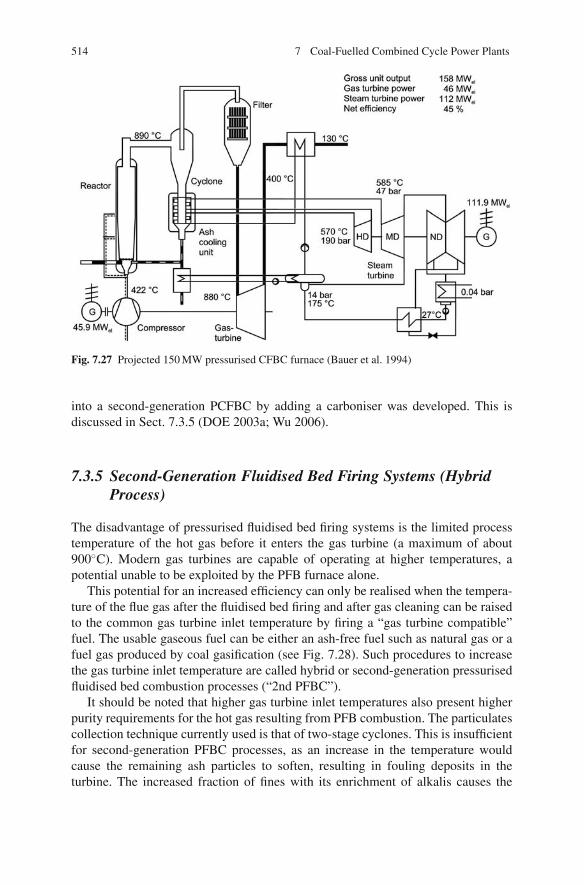
514 7 Coal-Fuelled Combined Cycle Power Plants
Fig. 7.27 Projected 150 MW pressurised CFBC furnace (Bauer et al. 1994)
into a second-generation PCFBC by adding a carboniser was developed. This isdiscussed in Sect. 7.3.5 (DOE 2003a; Wu 2006).
7.3.5 Second-Generation Fluidised Bed Firing Systems (HybridProcess)
The disadvantage of pressurised fluidised bed firing systems is the limited processtemperature of the hot gas before it enters the gas turbine (a maximum of about900◦C). Modern gas turbines are capable of operating at higher temperatures, apotential unable to be exploited by the PFB furnace alone.
This potential for an increased efficiency can only be realised when the tempera-ture of the flue gas after the fluidised bed firing and after gas cleaning can be raisedto the common gas turbine inlet temperature by firing a “gas turbine compatible”fuel. The usable gaseous fuel can be either an ash-free fuel such as natural gas or afuel gas produced by coal gasification (see Fig. 7.28). Such procedures to increasethe gas turbine inlet temperature are called hybrid or second-generation pressurisedfluidised bed combustion processes (“2nd PFBC”).
It should be noted that higher gas turbine inlet temperatures also present higherpurity requirements for the hot gas resulting from PFB combustion. The particulatescollection technique currently used is that of two-stage cyclones. This is insufficientfor second-generation PFBC processes, as an increase in the temperature wouldcause the remaining ash particles to soften, resulting in fouling deposits in theturbine. The increased fraction of fines with its enrichment of alkalis causes the

7.3 Pressurised Fluidised Bed Combustion (PFBC) 515
Fig. 7.28 Schematic of asecond-generation PFBC
deformation temperature to fall to about 1,000–1,050◦C, which is much lower thanthe deformation temperature of the original coal ash of between 1,150 and 1,250◦C.As a result, a hybrid scheme requires a more effective particulate collection system,as well as a hot gas cleaning stage which extracts gaseous alkalis by means of get-ters. Otherwise, the purity requirements for the gas turbine cannot be met (Jansson1996).
In the PFBC furnaces currently in use, the output of the gas turbine is one fifthof the overall output. This low figure is due to the cooling of the furnace by steamand water. As a result, an increase in the gas turbine inlet temperature does notcause a corresponding increase in efficiency. A higher efficiency is achieved if theentire fuel is fed to the gas turbine and steam is produced only in the heat recoveryboiler. In this case, either the fluidised bed needs to be cooled by a higher excessof air or the heating surfaces have to be air-cooled. The additional gaseous fuelsreact with the excess oxygen of the hot gas in a special gas turbine combustionchamber. This causes the hot gas temperature to increase to the permissible gasturbine inlet temperature. In this configuration, the output of the gas turbine is about50–60% of the total output (Rehwinkel et al. 1993). However, cooling the fluidisedbed by means of excess air or air-cooled heat exchangers is not state of the art.Those second-generation PFBC systems featuring steam cooling of the fluidisedbed combustor which are currently under consideration have a lower share from thegas turbine of the total output. Therefore, the potential for efficiency increases issmaller than for the competing coal-based combined cycles (IGCC, PPCC, EFCC).
Figure 7.29 shows second-generation pressurised fluidised bed combustion asproposed and developed by Foster Wheeler. Coal is fed into an air-blown pres-surised bubbling fluidised bed partial gasifier, called a carboniser. The air is sup-plied in sub-stoichiometric quantities, and the carboniser operates at 900–950◦C and19 bar to produce a low calorific, coal-derived syngas and a char-sorbent residue.After passing through a cyclone and a ceramic barrier filter to remove particulatesand alkali vapours, the hot syngas is burned in a specially designed gas turbine
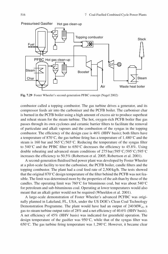
516 7 Coal-Fuelled Combined Cycle Power Plants
Pressurised Gasifier
Hot gas clean-up
Topping combustorStack
Fuel
Hot gas clean-up
Booster
GT G
Air
Steam
Waste heat boiler
Char
Steam
PFBC
Fig. 7.29 Foster Wheeler’s second-generation PFBC concept (Nagel 2002)
combustor called a topping combustor. The gas turbine drives a generator, and itscompressor feeds air into the carboniser and the PCFB boiler. The carboniser charis burned in the PCFB boiler using a high amount of excess air to produce superheatand reheat steam for the steam turbine. The hot, oxygen-rich PCFB boiler flue gaspasses through its own cyclones and ceramic barrier filters to facilitate the removalof particulate and alkali vapours and the combustion of the syngas in the toppingcombustor. The efficiency of the design case is 46% (HHV basis); both filters havea temperature of 870◦C, the gas turbine firing has a temperature of 1,480◦C and thesteam is 160 bar and 565◦C/565◦C. Reducing the temperature of the syngas filterto 540◦C and the PFBC filter to 650◦C decreases the efficiency to 45.8%. Usingdouble reheating and advanced steam conditions of 275 bar/595◦C/595◦C/595◦Cincreases the efficiency to 50.5% (Robertson et al. 2005; Robertson et al. 2001).
A second-generation fluidised bed power plant was developed by Foster Wheelerat a pilot-scale facility to test the carboniser, the PCFB boiler, candle filters and thetopping combustor. The plant had a coal feed rate of 2,500 kg/h. The tests showedthat the original 870◦C design temperature of the filter behind the PCFB was not fea-sible. The limit was determined more by the properties of the ash than by those of thecandles. The operating limit was 760◦C for bituminous coal, but was about 540◦Cfor petroleum and sub-bituminous coal. Operating at lower temperatures would alsomeant that an alkali getter would not be required (Wheeldon et al. 2001).
A large-scale demonstration of Foster Wheeler’s advanced PCFBC was origi-nally planned in Lakeland, FL, USA, under the US DOE’s Clean Coal TechnologyDemonstration Programme. The plant would have had an output of 240 MWel, agas-to-steam turbine output ratio of 28% and a net efficiency of 40.6% (HHV basis).A net efficiency of 45% (HHV basis) was indicated for greenfield operation. Thedesign temperature of the gasifier was 950◦C, while that of the syngas filter was650◦C. The gas turbine firing temperature was 1,290◦C. However, it became clear

7.3 Pressurised Fluidised Bed Combustion (PFBC) 517
GTPreheaterAsh
Fuel
Hot gas clean-upTopping combustor
Stack
Booster
G
Steam
Waste heat boiler
Steam
Air
PFBC
Fig. 7.30 Schematic of a pressurised fluidised bed with staged combustion (Nagel 2002)
that no suitable gas turbine was available. As a result, a decision was taken towardslate 2003 to terminate this project (DOE 2003b).
Another possible method of implementing a hybrid scheme is air-deficient oper-ation of the fluidised bed firing followed by flue gas cleaning at the fluidised bedtemperature. The addition of air causes the conversion of the unburned gas compo-nents and an increase in temperature (Moersch et al. 1999; Nagel et al. 1998).
Figure 7.30 shows a pressurised fluidised bed with staged combustion. Com-bustion takes place at sub-stoichiometric conditions with air ratios of 0.6–0.8 andtemperatures of 800–900◦C. Before the particulates are removed by the cycloneand ceramic candle filters, the temperature is lowered to below 700◦C. The LCVgas (low calorific value gas with an LHV much less than 10 MJ/m3) produced inthe first stage is then combusted in a separate combustion chamber to increase thetemperature to 1,200◦C prior to expansion in the gas turbine. The major advantageof this process over the configuration shown in Fig. 7.29 is the considerably lowercapital cost, since only one reactor is required (Nagel 2002). The process has beeninvestigated in greater detail at a pilot scale (Chalupnik et al. 2001).
7.3.6 Summary
There is little market potential for PBFBC. While the technology has been demon-strated in several parts of the world, hot gas clean-up remains a key issue. PBFBCalso appears to offer less scope for efficiency increases and environmental perfor-mance improvements than does IGCC. In addition, it is more complex than super-critical PCC and CFBC, which can offer comparable efficiencies. All these factorsmay have resulted in the current market difficulties. Alstom, the original developerof PBFBC, is no longer actively marketing the technology, although it does maintainsupport for existing installations. PBFBC is thus “stalled” at present, and its futuredevelopment and deployment have become uncertain. If this technology is to be

518 7 Coal-Fuelled Combined Cycle Power Plants
taken forward, it is more likely to be in the form of advanced PBFBC/PCFBC,which offers greater scope for efficiency increases (Wu 2006).
7.4 Pressurised Pulverised Coal Combustion (PPCC)
7.4.1 Overview
The aim of pressurised pulverised coal combustion (PPCC) is to produce a hot gasat a high temperature and pressure by the direct combustion of pulverised coal andthen to convert its energy into electrical energy in a gas turbine. A downstreamheat recovery steam generator (HRSG) and steam turbine extract more electricalenergy from the hot gas. The principle of PPC combustion is shown in Fig. 7.31.In the furnace, pulverised coal is burned, producing temperatures of 1,400–1,600◦C(which is above the ash fluid point) and a pressure of around 18 bar. Upstream ofthe gas turbine, it is necessary to remove the molten slag and the gaseous alkalicompounds from the hot gas. The heat recovery process, after the hot gas has beencleaned, corresponds to a combined cycle process which is fuelled by natural gas orcrude oil. Additionally, though, a DeNOx and a desulphurisation stage for the fluegases is necessary at the cold end in order to comply with allowed emission limits.
Pressurised pulverised coal combustion, compared to other advanced methods ofpower generation by coal, has the potential for the highest efficiency. The PPCC pro-cess reaches efficiencies of 53% at ISO gas turbine entry temperatures of 1,200◦C(see Sect. 7.1 for a definition of the ISO temperature in relation to gas turbines).Further development of gas turbines towards higher turbine entry temperatures areexpected to increase the PPCC process efficiency up to 55% (Schuknecht 2003). In
Fig. 7.31 Schematic diagram of a pressurised pulverised coal firing system (Forster et al. 2001)

7.4 Pressurised Pulverised Coal Combustion (PPCC) 519
contrast to technologies that are already demonstrated at an industrial scale (thermalpower plants with advanced steam conditions, pressurised fluidised bed combustionand coal gasification), PPCC has not yet reached the demonstration stage. Investi-gations to date have focussed on slag and alkali removal after the furnace process.Research aiming at implementing the concept of “directly pulverised coal fuelledgas turbines” has been carried out at pilot-scale plants in the USA (Parsons andByam 1989) and in Germany (Hannes 1996; Hannes 2002; Forster et al. 2005;Forster et al. 2001). Development was discontinued in the USA after approximately1990, while development in Germany ended in 2005.
All PPCC designs feature in common combustion occurring above the ash fluidtemperature, which means part of the ash can be removed early, in its molten statein the furnace. Because the hot flue gas is supposed to serve directly as the workingmedium of the gas turbine, cleaning of slag particles from the gas is necessary tomeet “turbine-compatible” particulates concentration limits. For the conditions ofPPCC, a maximum particulate content of 3 mg/Nm3, a maximum particle diameterof 3 μm and a maximum alkali content of 0.01 mg/Nm3 STP are desired (Forsteret al. 2005).
The designs differ in the gas turbine entry temperature (see Fig. 7.32). Theresearch carried out in the USA focussed on gas turbine entry temperatures of about1,000◦C (Parsons and Byam 1989). The reduction of nitrogen oxide emissions wasachieved by running the combustion in two stages. Cleaning of the flue gas was
Fig. 7.32 PPCC concepts (Thambimuthu 1993)

520 7 Coal-Fuelled Combined Cycle Power Plants
carried out either in or immediately after the furnace at high temperatures, or ina range somewhat above the gas turbine entry temperatures, after cooling the fluegas by air or water vapour. The concept favoured in Germany featured a one-stagecombustion process and flue gas cleaning at temperatures of 1,400–1,500◦C withmolten ash removal. The flue gas was conducted to the gas turbine without furthercooling (Hannes 1996).
For all PPCC designs, particulates removal at high temperatures and the impactsof gaseous substances forming in the process of combustion at high temperaturesare problematic factors. Essentially, these gaseous substances are the alkalis in theflue gas. The alkalis condense in the gas turbine and, in the relevant temperaturerange, lead to deposition on the turbine blades and to corrosion.
In both the US and the German PPCC designs, hot gas cleaning is at least partlycarried out at high temperatures above the ash fluid point. While the German conceptuses only high-temperature cleaning, the US concept, with temperatures of about1,000◦C, has the option of cleaning the hot gas both above the ash fluid and belowthe ash deformation temperature.
Hot gas cleaning, besides slag components, has to remove gaseous gas turbineincompatible components as well. In the following, only the techniques of moltenash removal will be discussed, as the dry ash removal techniques have already beencovered in the context of pressurised fluidised bed combustion.
7.4.2 Molten Slag Removal
Given the high temperatures, molten slag removal is the only option considered forPPCC with high gas turbine entry temperatures. Therefore the gas cleaning temper-ature must be above the ash fluid temperature, which depends on the coal-specificcomposition of the ash. The fluid temperatures of hard coal ashes range between1,350 and 1,500◦C. Since thin fluid ash with a low viscosity can be removed moreeasily, the operating temperature of the gas cleaning should be about 100◦C abovethe fluid temperature. Compared to separation techniques for solid ash particles, theremoval of molten ash has only had limited development. Investigations have beencarried out at pilot-scale plants in Germany and the USA within the frameworkof developments of PPCC furnaces (Thambimuthu 1993; Weber and Pavone 1990;Weber et al. 1993; Hannes 1996; Hubner et al. 1988; Forster et al. 2001; Hannes2002; Forster et al. 2005).
Filtration separators using ceramic filter candles have a high efficiency in thetemperature range of that after a fluidised bed combustion zone. For the highergas temperatures and the conditions of PPCC, suitable filter materials are not yetavailable. Ceramic filters which have as a base aluminium silicate, aluminium oxideand silicon carbide are attacked and destroyed by molten slag (Hubner et al. 1988).Furthermore, it is unclear whether the removal mechanism of ceramic filter candles,based on surface filtration, can also be applied to liquid matter or molten ash. On theone hand, the risk is that molten ash may penetrate through the pores; on the other,

7.4 Pressurised Pulverised Coal Combustion (PPCC) 521
molten ash may hinder the gas penetration when small pore cross-sections are used.The filtering effect that the layer of dust deposition has in the lower temperatures ofFBC processes does not occur for PPCC (Weber et al. 1993).
Separation by ESP in the temperature range of PPCC is not possible becausethe conductivity at such temperatures means a corona cannot form on the sprayelectrodes (Forster et al. 2001).
Investigations into molten ash removal focus almost exclusively on mass forceseparators. Among these, inertia and centrifugation separators are the most suitabletechnologies, since they are much more efficient than gravitation separators. Massforce separators only play a minor role nowadays in conventional dust collectiontechnology, removing solid particles from flue gases under moderate temperatureand pressure conditions. Their use has declined because they do not collect smallparticles and so yield only modest removal rates. The case can be different whenmolten particles have to be removed. They are more likely to merge before or dur-ing the removal process into larger, heavier drops and also stick to the wall of thecollector, so that the secondary flows interfering with the gas cleaning process areof minor importance (Weber et al. 1993).
Different variants of slag removal were investigated by the project partners ofthe combined project “Pressurised Pulverised Coal Combustion”. For the most part,results were obtained from tests at atmospheric plants and later verified in part inpressurised operation (Weber et al. 1993).
By means of a centrifugation separator (a two-stage cyclone) it was possibleto achieve outlet particulate loadings of the cleaned gas as low as 20 mg/Nm3.Figure 7.33 shows the fraction collection efficiencies of the cyclone separator mea-sured under atmospheric conditions. According to the diagram, the particle sizesare very small. In contrast to solid ash particle removal, molten ash removal is muchmore efficient despite the higher temperatures and the higher gas viscosity. Thiscan be put down to the collision and agglomeration of small droplets, as mentionedabove, and the drops deforming and sticking when they impinge upon the wall.
Fig. 7.33 Cyclone removalrate in PPCC as a function ofparticle size (Weber et al.1993)
522 7 Coal-Fuelled Combined Cycle Power Plants
Unlike solid particles, they lose impingement energy through deformation. Also,dispersion of the removed particles is impossible because of the liquid consistency.
From the point of view of material engineering, fewer problems are expectedfrom the use of cyclones because they can be refractory-lined. However, industrial-scale plants with pressurised pulverised coal firing would need a great number ofcyclones of a small diameter to achieve high removal efficiency rates – which meansthe configuration and homogeneous flue gas charging of the cyclones could pose aproblem (Weber and Pavone 1990).
Another concept investigated involves a venturi scrubber connected to a cycloneseparator. In the venturi scrubber, molten slag is added vertically to the speedingflue gas flow (of a velocity of about 100 m/s) in order to agglomerate the moltenash particles. Therefore a coarser particle spectrum is fed into the cyclone, whichresults in a higher removal efficiency. Tests carried out discontinuously with slagunder atmospheric conditions at temperatures up to 1,600◦C showed a reduction inthe amount of particulates after the cyclone to 7 mg/Nm3, as opposed to 32 mg/Nm3
without a venturi scrubber. The addition of molten slag is assumed to also favour ahigher alkali capture in the slag (Hoberg and Gudenau 1998). Problems in apply-ing this concept may arise with liquid ash recirculation, necessary for a continuousprocess, and the materials’ ability to resist corrosion by molten ash.
Although packed-bed or granular bed filters for solid dust particle removal areclassified as filtration separators, the removal of liquid matter by such means mustbe classed as separation by inertia and mass force. Divided into many sub-streams,the untreated gas flows through the packed bed. Each sub-stream is deflected by bulkmaterial, and droplets, due to their inertia, impinge upon it. The packed bed offerssufficiently many flow paths for the slag to drain out. Outlet particulates loadings ofthe cleaned gas between 50 and 200 mg/Nm3, depending on the filter velocity, arereported for atmospheric tests (Hannes 1996).
The developments at the PPCC test facility at Dorsten in its last years focussedon molten slag removal in a packed-bed filter (Forster et al. 2005; Hannes 2002;Forster et al. 2001). As a result of the long years’ tests, it was concluded that inertiaseparators, such as the packed-bed filter, are not capable of achieving concentra-tions lower than about 350 mg/Nm3 or removing particles with a diameter smallerthan 3 μm. The removal rates of the pressurised 1 MW facility were considerablyhigher than the previously reported atmospheric small-scale test results. Tests withhigher velocities, increased bed heights and smaller bed material did not improvethe removal efficiency.
This is explained by the electrical behaviour of the flue gas, which can be con-sidered to be a cold plasma at the existing process temperatures, meaning that theflue gas behaves neutrally macroscopically, but a separation due to electrical chargesoccurs. This fact can be verified by the conductivity of the flue gas, as well as by thecharges of the particles. The positive charges of the small particles cause an elec-trostatic repulsion, so that small particles can no longer agglomerate and thereforecannot be separated.
This knowledge provided the basis for developing a novel concept for fine par-ticulates separation by exploiting the electrical properties. By disassociating the

7.4 Pressurised Pulverised Coal Combustion (PPCC) 523
charges from the particles, the resulting non-charged particles can agglomerate andbe separated by adhesion on the bed material. Employing a suitable electrical fieldcan enhance the separation of charged particles. Disassociating the charges requiresconductive ceramic materials such as those containing ZrO2. Investigations werecarried out to design a local electrical gradient by combining suitable ceramic mate-rials and employing SiC (silicon carbide) electrodes behind the packed bed. As aresult of this development, particulates concentrations below 1 mg/Nm3 with allparticles smaller than 1 μm were claimed to be achieved, which would fulfil therequirements of advanced gas turbines (Forster et al. 2005).
7.4.3 Alkali Release and Capture
7.4.3.1 Fundamentals
Alkali Release
Coal ashes contain the alkalis sodium (Na) and potassium (K) in very differingconcentrations depending on the coal type. Hard coal shows typical concentrationsin the order of magnitude of 0.5–6, with a maximum of 15% by weight of the coalash. Alkalis are organically bound in the coal matrix or exist in the mineral phaseeither as simple salts or as complex aluminosilicates. The type of bond has a majorimpact on the behaviour of alkalis during the combustion process.
Alkalis are released from combustion as gaseous components mainly in the formof NaCl and KCl or else retained firmly bound in the coal ash. Alkalis releasedduring combustion are termed “active alkalis” (see Table 7.8). Active alkalis consistprimarily of simple, inorganic salts and organically bound alkalis. Those alkalisbound in clay minerals as aluminosilicates stay almost inert during combustion.While for hard coals, alkalis are more frequently bound in the mineral components,younger coals, such as brown coal, have a higher alkali fraction in the organic com-ponents (Singer 1991).
The main parameter of the combustion process influencing the degree of gaseousalkali release is the temperature. The alkali release of a fuel is often correlated withthe chlorine content of the coal. This correlation is valid for coal types which con-tain alkalis in the form of simple salts, such as German hard coals. Although notgenerally applicable to fuels with organically bound alkalis, it has been observedfor German brown coals as well (Oleschko and Muller 2007).
Another possible method to determine the active alkali content is by solutionin water or weak acids. Depending on the type of solvent used, this method either
Table 7.8 Classification of alkalis in coalActive Inactive
• Simple inorganic salts Clay and schist minerals:◦ NaCl, Na2SO4, Na2CO3 Complex aluminium silicates◦ KCl, K2SO4, K2CO3 Na2Al2Si6O16
• Organically bonded alkalis K2Al2Si6O16
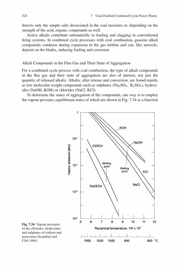
524 7 Coal-Fuelled Combined Cycle Power Plants
detects only the simple salts dissociated in the coal moisture or, depending on thestrength of the acid, organic compounds as well.
Active alkalis contribute substantially to fouling and slagging in conventionalfiring systems. In combined cycle processes with coal combustion, gaseous alkalicompounds condense during expansion in the gas turbine and can, like aerosols,deposit on the blades, inducing fouling and corrosion.
Alkali Compounds in the Flue Gas and Their State of Aggregation
For a combined cycle process with coal combustion, the type of alkali compoundsin the flue gas and their state of aggregation are also of interest, not just thequantity of released alkalis. Alkalis, after release and conversion, are found mainlyas low molecular weight compounds such as sulphates (Na2SO4, K2SO4), hydrox-ides (NaOH, KOH) or chlorides (NaCl, KCl).
To determine the states of aggregation of the compounds, one way is to employthe vapour pressure, equilibrium states of which are shown in Fig. 7.34 as a function
Fig. 7.34 Vapour pressuresof the chlorides, hydroxidesand sulphates of sodium andpotassium (Scandrett andClift 1984)
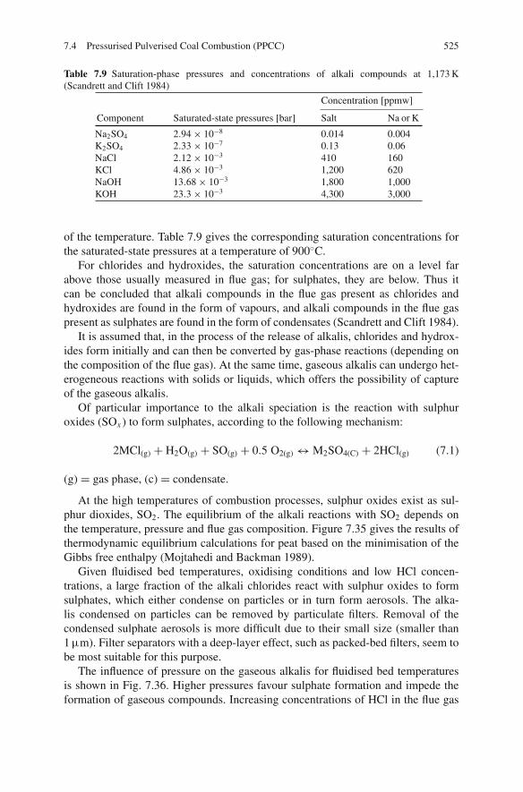
7.4 Pressurised Pulverised Coal Combustion (PPCC) 525
Table 7.9 Saturation-phase pressures and concentrations of alkali compounds at 1,173 K(Scandrett and Clift 1984)
Concentration [ppmw]
Component Saturated-state pressures [bar] Salt Na or K
Na2SO4 2.94 × 10⁻⁸ 0.014 0.004K2SO4 2.33 × 10⁻⁷ 0.13 0.06NaCl 2.12 × 10⁻³ 410 160KCl 4.86 × 10⁻³ 1,200 620NaOH 13.68 × 10⁻³ 1,800 1,000KOH 23.3 × 10⁻³ 4,300 3,000
of the temperature. Table 7.9 gives the corresponding saturation concentrations forthe saturated-state pressures at a temperature of 900◦C.
For chlorides and hydroxides, the saturation concentrations are on a level farabove those usually measured in flue gas; for sulphates, they are below. Thus itcan be concluded that alkali compounds in the flue gas present as chlorides andhydroxides are found in the form of vapours, and alkali compounds in the flue gaspresent as sulphates are found in the form of condensates (Scandrett and Clift 1984).
It is assumed that, in the process of the release of alkalis, chlorides and hydrox-ides form initially and can then be converted by gas-phase reactions (depending onthe composition of the flue gas). At the same time, gaseous alkalis can undergo het-erogeneous reactions with solids or liquids, which offers the possibility of captureof the gaseous alkalis.
Of particular importance to the alkali speciation is the reaction with sulphuroxides (SOx ) to form sulphates, according to the following mechanism:
2MCl(g) + H2O(g) + SO(g) + 0.5 O2(g) ↔ M2SO4(C) + 2HCl(g) (7.1)
(g) = gas phase, (c) = condensate.
At the high temperatures of combustion processes, sulphur oxides exist as sul-phur dioxides, SO2. The equilibrium of the alkali reactions with SO2 depends onthe temperature, pressure and flue gas composition. Figure 7.35 gives the results ofthermodynamic equilibrium calculations for peat based on the minimisation of theGibbs free enthalpy (Mojtahedi and Backman 1989).
Given fluidised bed temperatures, oxidising conditions and low HCl concen-trations, a large fraction of the alkali chlorides react with sulphur oxides to formsulphates, which either condense on particles or in turn form aerosols. The alka-lis condensed on particles can be removed by particulate filters. Removal of thecondensed sulphate aerosols is more difficult due to their small size (smaller than1 μm). Filter separators with a deep-layer effect, such as packed-bed filters, seem tobe most suitable for this purpose.
The influence of pressure on the gaseous alkalis for fluidised bed temperaturesis shown in Fig. 7.36. Higher pressures favour sulphate formation and impede theformation of gaseous compounds. Increasing concentrations of HCl in the flue gas

526 7 Coal-Fuelled Combined Cycle Power Plants
Fig. 7.35 States ofaggregation of sodium (Na)and potassium (K)compounds under pressurisedfluidised bed conditions(Mojtahedi and Backman1989)
Fig. 7.36 Effect of pressureon alkalis in the gas phase,data from Mojtahedi andBackman (1989)
shift the equilibrium of the reaction towards the gaseous compounds and impede theformation of sulphates (see Fig. 7.37). The alkali content of the fuel itself only playsa minor role in determining the concentration of gaseous compounds (Mojtahedi andBackman 1989).

7.4 Pressurised Pulverised Coal Combustion (PPCC) 527
Fig. 7.37 Effect of chlorinecontent on concentrations ofgaseous alkalis, data fromMojtahedi and Backman(1989)
At the higher temperatures of pressurised pulverised coal firing, gaseous chlo-rides and hydroxides predominate. Elemental gaseous alkalis occur only in tracequantities across the entire temperature range (Hannes 1986).
In conditions without SO2, for example in gasification, no sulphates but onlygaseous alkali compounds form, such as chlorides and hydroxides. Two or threeorders of magnitude higher levels of gaseous alkali compounds are thus reportedfor pressurised fluidised bed gasification in contrast to pressurised fluidised bedcombustion.
Alkali Removal
Alkalis can be separated by chemical reaction or removed by physical adsorptionon solid or liquid sorbents (known as getters). In the case of chemical sorption,the getters become exhausted, while in the case of physical adsorption, they can beregenerated. In the temperature range of fluidised bed combustion, the basic pro-cedure is physical adsorption, possibly followed by chemical capture. Because ofits negative temperature gradient, adsorption is not suitable for higher temperatures,which means chemical capture has to be applied.
Suitable alkali getter materials are quartz (SiO2), aluminosilicates (Al2O3 ·SiO2),clay (Al2O3) and naturally occurring substances such as bauxite, kaolinite, emathliteor diatomaceous earth, essentially composed of aluminium oxide and silicon oxide(Thambimuthu 1993; Punjak et al. 1989). Table 7.10 shows their composition byweight.
Thermodynamic equilibrium calculations of systems with different getter mate-rials can be used to evaluate their potential for the chemical capture of alkalis. Eventhough these evaluations are valid only for the state of equilibrium, they are effectiveto some extent in predicting the practicability of various getter materials.
In principle, a differentiation has to be made between the type of bonding processof the sulphates and the chlorides. In the temperature range of fluidised beds, the

528 7 Coal-Fuelled Combined Cycle Power Plants
Table 7.10 Composition by weight of additives for alkali capture (Punjak et al. 1989)
DiatomaceousComponent Bauxite earth Kaolinite Emathlite
SiO2 0.11 0.92 0.521 0.734Al2O3 0.842 0.05 0.449 0.139Fe2O3 0.048 0.008 0.034TiO2 – 0.022 0.004CaO – – 0.05MgO – – 0.026K2O – – 0.012Na2O – – 0.001
alkali compounds are bound mainly as sulphates, but also as chlorides; at the hightemperatures of pressurised pulverised coal firing, binding as chlorides dominates:
(a) Reactions of the alkali sulphates (Scandrett and Clift 1984):The chemical bonding of the alkali sulphates can occur according to the fol-lowing reaction mechanisms:
(1) Silica sand:
Na2SO4(c) + SiO2(s) ↔ Na2O · SiO2(c) + SO2(g) + 0.5O2(g) (7.2)
K2SO4(c) + SiO2(s) ↔ K2O · SiO2(C) + SO2(g) + 0.5O2(g) (7.3)
(2) Aluminium silicate:
Na2SO4(c) + Al2O3 · SiO2(s) + 5SiO2(s) ↔ 2NaAlSi3O8(s) + SO2(g) + 0.5O2(g)
(7.4)
K2SO4(c) + Al2O3 · SiO2(s) + 5SiO2(s) ↔ 2KAlSi3O8(s) + SO2(g) + 0.5O2(g)
(7.5)
(g) = gas phase, (c) = condensate, (s) = solid matter.All bonding reactions of alkali sulphates are strongly endothermic reactionsand so require a certain temperature to proceed. Reactions with silica sandneed a temperature of above 1,300 K to achieve bonding of the sulphates. Fora chemical capture process following fluidised bed combustion, reactions withsilica sand therefore do not seem suitable at these temperatures. Aluminiumsilicates react and bond with alkalis at temperatures above 1,000 K.
(b) Reactions of the alkali chlorides (Scandrett and Clift 1984):
(1) Silica sand:
2NaCl(g) + SiO2(s) + H2O(g) ↔ Na2O · SiO2(c) + 2HCl(g) (7.6)
2KCl(g) + SiO2(s) + H2O(g) ↔ K2O · SiO2(c) + 2HCl(g) (7.7)
2NaCl(g) + 2SiO2(s) + H2O(g) ↔ Na2O · 2SiO2(c) + 2HCl(g) (7.8)

7.4 Pressurised Pulverised Coal Combustion (PPCC) 529
(2) Aluminium silicates:
2NaCl(g) + Al2O3 · SiO2(s) + 5SiO2(s) + H2O(g) ↔ 2NaAlSi3O8(s) + 2HCl(7.9)
2KCl(g) + Al2O3 · SiO2(s) + 5SiO2(s) + H2O(g) ↔ 2KAlSi3O8(s) + 2HCl(7.10)
(3) Alumina:
2NaCl(g) + Al2O3(s) + H2O(g) ↔ 2NaAlO2(s) + 2HCl(g) (7.11)
(g) = gas phase, (c) = condensate, (s) = solid matter.
All bonding reactions of alkali chlorides are strongly exothermic reactions, so thecapture rates of all of the getters decrease with rising temperatures. Silica sand get-ters yield very low capture rates. With pure alumina as a getter, substantial conver-sion takes place only at temperatures below 800 K (530◦C). The use of aluminiumsilicates, however, makes it possible to achieve a capture rate of 99% at 1,000 K(730◦C) and above 95% at 1,200 K (930◦C). From this it is evident that aluminiumsilicates are the only practical material for getters for gaseous alkalis (see Fig. 7.38).For the calculations with pressures of 1 and 10 bar, it was assumed that HCl devel-ops exclusively by reaction and that the water vapour content was 3% by volume.Higher water vapour contents favour, while higher HCl concentrations in the fluegas impede the chemical conversion (Scandrett and Clift 1984).
Thermodynamic calculations substantiate that capturing is also possible at ahigh-temperature range of around 1,400 ◦C. At such temperatures, the aluminiumsilicates mentioned before have an optimal capture rate at an Al2O3-to-SiO2 ratio of1:8. The alkalis are captured in the liquid phase (Willenborg et al. 2006).
Fig. 7.38 Equilibrium ofalkali capture reactions(Scandrett and Clift 1984)

530 7 Coal-Fuelled Combined Cycle Power Plants
Measurements of Gaseous Alkali Compounds
When comparing concentrations of gaseous alkalis, attention must be paid to themeasurement method as well as to the measurement location. The ability of each ofthe measurement methods to detect condensed aerosol particles as well as gaseouscomponents, or only gaseous components, must be known. If the measurementmethod detects the sum of all the gaseous, liquid and fine particles portion of thesolid alkalis, the filter system has the task of separating the liquid and solid alkalisto exclusively feed the sampling setup with gaseous alkalis. While the filtration ofcondensed and particle-bound sulphates is possible, it is more difficult to removeaerosols, and hence errors of measurement can occur. In the worst case, when thefiltration is insufficient, the solid alkali compounds present in small particles arealso measured.
Measurements of the gaseous alkalis under fluidised bed conditions are usuallycarried out behind filters, so that most of the sulphates have already been sepa-rated and only gaseous compounds are detected. At higher temperatures, gaseouschlorides and hydroxides predominate instead of liquid sulphates. Measurementsobtained at combustion plants are influenced by the alkali release and gas-phase andheterogeneous capture reactions with bed, fly and liquid ash.
Concentrations are given either per unit mass in mg alkalis/kg flue gas or perunit volume in ppmv.1,2 Wet-chemical measurement methods detect the ions in thesolvent, while on-line measurement methods detect alkali atoms or alkali ions inthe gas (Bonn 1996). Results of on-line alkali concentration measurements usingsimultaneous surface ionisation (SI) and excimer laser-induced fragmentation flu-orescence (ELIF) have been compared for a PFBC (Monkhouse et al. 2003). Bothmethods measure in real time but are complementary in that ELIF can discriminatetowards gas-phase alkali species, whereas SI detects alkali both in the gas phase andon aerosol particles (Monkhouse 2002).
Mass concentrations can be given either as pure alkali metals or as compounds.For a comparison and the conversion of concentrations per unit mass and per unitvolume, it is necessary to know the compound used as a basis as well as the flue gascomposition. Usually, however, the relevant data cannot be found in the literature.
By way of example: for alkali chlorides at an air ratio of 1.3, the following con-version holds true:
1 ppmv Na = 1 ppmv NaCl = 1/2Na2SO4 ppmv
∼ 0.75 mg Na/kg(0.75 ppmw) ∼ 1.9 mg NaCl/kg ∼ 4.6 mg Na2SO4/kg (7.12)
1ppmv K = 1 ppmv KCl = 1/2K2SO4 ppmv
∼ 1.27 mg K/kg(= 1.27 ppmw) ∼ 2.42 mg KCl/kg ∼ 5.65 mg K2SO4/kg(7.13)
1 ppmv = volume parts per million2 ppmw = mass parts per million

7.4 Pressurised Pulverised Coal Combustion (PPCC) 531
7.4.3.2 Alkali Emissions from Combustion
Most published research into alkali emissions from pressurised fluidised bed com-bustion has been carried out at a temperature range of about 800–900◦C. Only alimited number of measurements have been reported for the conditions of high-temperature pressurised pulverised coal combustion.
Measurements taken after a filter unit under fluidised bed conditions reveal agreat scattering of values, from several μg/kg up to some mg/kg. These differencescan be put down to the different fuels and test parameters, in particular the tempera-ture. The measurement technology for gaseous alkalis also contributes significantlyto this degree of scattering.
To give an example: for peat, a young fuel type, reports give flue gas sodium con-centrations between 0.2 and 1.5 mg/kg and potassium concentrations between 0.07and 0.4 mg/kg. These concentrations increase with rising temperatures and decreasewith pressure. They are also dependent on the additive for sulphur retention, withdolomite showing lower concentrations than limestone. These concentrations meanconversion rates of the fuel alkalis of 1–4% for sodium and 0.2–0.5% for potassium.In the case of a hard coal, the flue gas sodium concentrations ranged from 0.01 to0.06 mg/kg and the potassium concentrations from 0.02 to 0.07 mg/kg – even thoughthe sodium and potassium contents of this hard coal were equal to or higher thanthose of peat. Thus the resulting conversion rates are 0.01–0.05% for the sodium inthe fuel and 0.01–0.02% for the fuel potassium (Hippinen et al. 1991).
The consideration of the thermodynamics of the reactions of alkali chlorides andhydroxides in forming sulphates in Sect. 7.4.3.1 (Eq. 7.1) suggests that removal inthe temperature conditions of pressurised fluidised bed firing should be complete.Tests, however, did not substantiate this. The assumed cause was the presence ofHCl, which impedes the formation of sulphates but favours the formation of gaseouschlorides which cannot be removed in the filter (Thambimuthu 1993).
Measurements by optical laser, which only detects gaseous alkali chlorides andhydroxides, show big differences for different coal types. Measured after a cyclonefilter for a brown coal type, the concentrations of sodium in the gas phase amountedto 4–5 ppmv and for potassium to 3.5–4 ppmv, whereas for hard coals, the con-centrations of sodium and potassium were 30–70 and 10–30 ppbv, respectively.This variability corresponds to the range of dispersion of other measurements. Theaddition of kaolin reduced the flue gas concentrations by a factor of 2–3 due tocapture by the increased amount of aluminosilicate. The use of the hard coal ash asthe bed material for lignite combustion resulted in a decrease in concentrations byone order of magnitude. For both coals, potassium was more effectively capturedthan sodium (Gottwald et al. 2001).
Research into the in situ capture of alkalis in fluidised bed combustion has beencarried out at various experimental plants. At one pressurised fluidised bed testplant, combustion tests using a brown coal determined the influence of differentbed materials on the alkali concentrations after a two-stage cyclone. With alu-mina, which consists of 99% aluminium oxide, a reduction ratio of nearly 90%was achieved. The capturing mechanism is based on reactions of alumina with

532 7 Coal-Fuelled Combined Cycle Power Plants
the silicon compounds in the coal, converting vaporous alkali chlorides and alkalisulphates into high melting point alkali aluminium silicates. Using silica sand, thecapture rate was lower. However, the test results show that, even with alumina as anadditive, the limit of 0.024 mg/kg was usually exceeded by one order of magnitude(Radhakrishnan et al. 1986). Further investigations with additions of bauxite andkaolinite at another PFBC plant revealed that both materials are suitable for thecapture of alkalis. Although tests with a high-alkali young brown coal and withan older brown coal with sodium added to it achieved capture rates of up to 90%,the concentrations of gaseous sodium compounds were in the order of just below1 mg/kg – thus significantly higher than the previously mentioned limit (Mann andLudlow 1997).
At the pressurised fluidised bed demonstration plant in Wakamatsu, alkali con-centrations of approximately 0.03 mg/kg were detected in the flue gas after aceramic filter unit, using different hard coals at fluidised bed temperatures of 800◦C(Daijou et al. 1997).
Aho (Aho et al. 1995) carried out systematic tests at an electrically heatedentrained-flow reactor at particle temperatures between 1,000 and 2,400◦C. Thegaseous release of sodium was higher than that of potassium for two hard coalsand one lignite. In these tests, the conversion of the sodium was several percent attemperatures somewhat above 1,000◦C and between 25 and 50% at higher temper-atures (see Fig. 7.39). This data shows that the alkali concentrations, even at lowtemperatures of around 1,000◦C, are at least two orders of magnitude higher thanthose allowed for gas turbines.
The alkali release was studied during comprehensive investigations by Reicheltat a pressurised entrained-flow reactor (Reichelt 2001). As in the investigationsby Aho, the reactor was operated differentially according to the entrained-flowprinciple. This means that the fuel mass flow is very small in comparison to thevolumetric gas flow. The volumetric gas flow, with an oxygen concentration of 6%,is preheated to reactor temperature; the slight loading of the fuel, of 6 g/m3, causesminor changes in the concentration in the reactor (i.e. a differential mode of opera-tion). Because of the small fuel load and the corresponding low ash concentration,it is assumed that, in contrast to industrial plants, capturing of alkalis in the solidphase is suppressed to a great extent. For two hard and two brown coals, the gaseouschlorides and hydroxides were detected by means of optical lasers. The resultsreveal rising alkali emissions with increasing temperatures and falling emissionswith increasing pressure. The alkali concentrations presented for a hard coal, at areactor temperature of 1,400◦C, and atmospheric pressure, correlate with a sodiumrelease of about 50% and potassium release of only 20%.
Investigations by other authors indicate a release of sodium of about 50% andof potassium of about 20% for a hard coal at 1,600◦C, whereas at temperatures of1,800–1,900◦C, the studies identified an almost complete release (Wen et al. 1992).
Reichelt (Reichelt 2001) also investigated an atmospherically operated combus-tion reactor. This reactor was operated integrally, at an air ratio of 1.2, as it is cus-tomary for industrial firing systems operating atmospherically. In contrast to thedifferential tests presented above, reactions of alkali capture in the ash and slag

7.4 Pressurised Pulverised Coal Combustion (PPCC) 533
Fig. 7.39 Evaporation of sodium and potassium for different coal types and concentrations in thegas phase as a function of the particle temperature (Aho et al. 1995)
could be observed. This means that a clear decrease of alkali concentrations occursas the residence time in the reactor increases. Figure 7.40 shows the measuredconcentrations for different hard and brown coals. The maximum rate of releasein the tests for the Ensdorf hard coal, at 1,400◦C and a short residence time, wasabout 10% for sodium and about 5% for potassium. With longer residence times,a high capture in the ash was observed, entailing a reduction of the gaseous alkaliconcentrations of more than one order of magnitude. The capturing effect in the ashwas significantly weaker with brown coal due to the lack of aluminium silicates. By
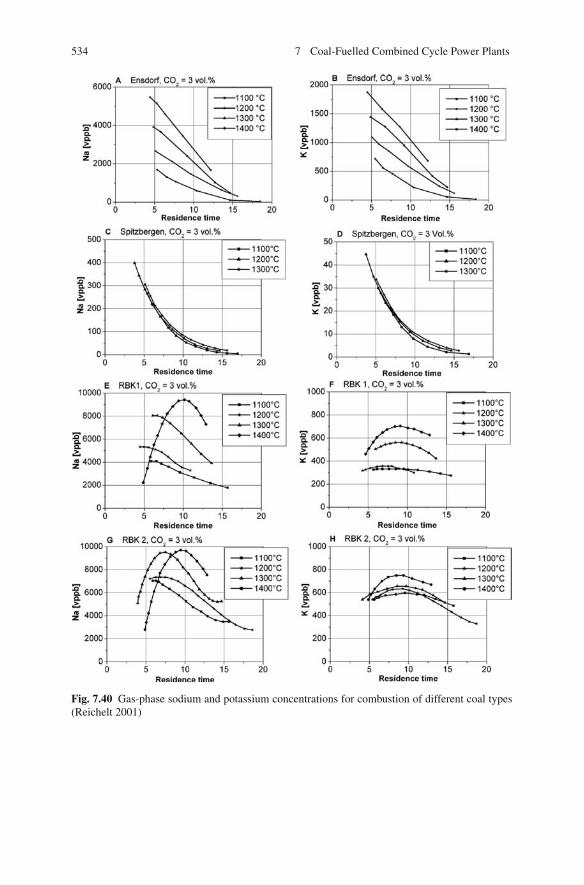
534 7 Coal-Fuelled Combined Cycle Power Plants
Fig. 7.40 Gas-phase sodium and potassium concentrations for combustion of different coal types(Reichelt 2001)
7.4 Pressurised Pulverised Coal Combustion (PPCC) 535
injecting additives such as alumina and silica in the combustion of the Ensdorf coal,reductions up to one order of magnitude were achieved (Schurmann et al. 2001).
7.4.3.3 Secondary Alkali Removal
For pressurised pulverised coal firing, the removal of alkali compounds is a prereq-uisite to preventing damage of the gas turbines. The low temperatures of pressurisedfluidised bed combustion involve lower concentrations of volatile alkali compounds,and what is more, the turbine is less sensitive to alkali loading because of the lowgas turbine entry temperature. The PFBC plants currently in service operate withoutalkali removal. For hybrid pressurised fluidised bed processes, however, the highergas turbine entry temperatures entail similar requirements to pressurised pulverisedcoal firing.
The abatement of alkali concentrations hazardous to the turbine can be achievedby a combination of methods, proposed as follows:
• Leaching of the coal to reduce the contents of alkali chlorides.• In situ absorption in the furnace by injection of additives and selection of process
parameters to raise the rate of capture.• Absorption in a filter downstream of the combustion. A packed-bed filter, for
instance, besides having the function of particle separation can in addition beused for alkali removal (see Sect. 7.3.2).
The most preferable method of alkali removal is to pass the combustion gasesthrough a fixed bed of non-volatile inorganic solid sorbents. Potential sorbentsshould show a high temperature stability, fast sorption kinetics and a high loadingcapacity. Kaolin, bauxite and emathlite have been identified as suitable sorbentsfor gas-phase alkalis. The capturing mechanism can be based upon the principle ofphysical absorption and/or upon a chemical reaction.
In the temperature range of fluidised bed firing systems, the most effectiveremoval process is physical absorption of condensed alkali components followedby chemical bonding. In contrast, given the high temperatures, the chemical reac-tions are most effective in pressurised pulverised coal firing. A chemical reactionconsumes the getters, while exclusively physical absorption allows their regenera-tion. As physical absorption is a reversible reaction and alkalis could be released bypressure and/or temperature changes, chemical reactions are the preferred option.
Studies into the suitability of potential getter materials have for the most part usedsynthetic gases at temperatures in the range of fluidised beds (Punjak et al. 1989;Uberoi 1990; Turn et al. 1998). Only recently have results for higher temperaturesbecome available (Oleschko and Muller 2007; Willenborg et al. 2006; Escobar andMuller 2007; Escobar et al. 2008).
In another investigation, using a portion of the flue gas flow from a PFBC plant,different sorbents in a granular bed filter were tested for alkali removal. The pur-pose of these tests was to develop an alkali measurement technology employingabsorption of the alkalis in a bulk bed, with subsequent analysis of the absorbedalkalis. Measurements at bulk bed temperatures of 800–850◦C and a pressure of 9
536 7 Coal-Fuelled Combined Cycle Power Plants
bar showed an 88% removal of the gaseous sodium using activated bauxite and an86% removal with diatomaceous earth (Thambimuthu 1993; Lee and Carls 1990;Lee and Swift 1991).
At a laboratory-scale PFB furnace with particulate and alkali removal, data wasobtained in practical tests with a packed-bed filter (Zakkay et al. 1989). During thetests, the plant was operated at a temperature of between 809 and 871◦C and a pres-sure of between 7 and 9.3 bar. The particle- and alkali-laden flue gas from the PFBfurnace flowed into a granular bed filter after an initial cleaning step in a cyclone.The filter medium was of alumina granulates. The measurements showed an averagedust removal degree of 97.8–99% and an alkali removal degree of 90–96%. Thealkali emissions at the outlet of the granular bed filter ranged between 0.0019 and0.041 mg/kg for sodium and between 0.001 and 0.031 mg/kg for potassium, whichmeant most of the measurements were below the limit of 0.024 mg/kg given by gasturbine manufacturers.
Documentation of industrial-scale experience with alkali capture by such a filterarrangement is not available.
Studies into alkali capture at temperatures above 1,300◦C are being carriedout at a 1 MWth experimental plant within the framework of the joint pressurisedpulverised coal combustion project. The subject of the investigations is the captureof gaseous alkalis by the molten coal slag either in the furnace or in the downstreampacked-bed filter for molten ash removal. Given that the getter materials silicon andaluminium oxide are the main components of coal ash, it seems reasonable to makeuse of this getter potential. The main influencing parameters in alkali removal byslag are the temperature and, to a great extent, the residence time (Hannes 1996).
In tests at the 1 MW PPCC furnace, considerable reductions of the alkali con-centrations were achieved, supporting the theory of the molten ash removal process.Starting out from an initial 18 mg/m3, the alkali concentrations were reduced toabout 8 mg/m3 by using inertia separators and reduced further to less than 6 mg/m3
by fine particulates removal. The downstream alkali removal by non-optimised alu-minosilicate sorbents affected another clear reduction to less than 2 mg/m3. Becausevaporous alkalis are present in an ionised state at high temperatures, the alkali cap-ture by means of slag or getters can be improved by the implementation of electricalfields. This has been proven in laboratory-scale investigations at high temperaturesof 1,300◦C (Hubner et al. 2003). By also using electrical fields, the alkali concen-trations in the 1 MW PPCC furnace could be reduced to 0.2 mg/Nm3 (Forster et al.2005; Muller et al. 2008).
Accompanying fundamental investigations at lab scale were carried out to deter-mine the alkali retention potential of the coal ash present in the combustion cham-ber and the liquid slag separator. For this reason, alkali partial pressures over coalash slags with and without additives were determined by Knudsen effusion massspectrometry (KEMS). Although alkali vapour reductions of one order of mag-nitude could be achieved by the addition of SiO2 or TiO, the vapour pressuresare still about 2 orders of magnitude higher than those required by gas turbinemanufacturers. Therefore, a separate alkali removal unit is necessary to achievealkali concentrations in the hot flue gas compatible with these specifications. In

7.4 Pressurised Pulverised Coal Combustion (PPCC) 537
further investigations, model sorbents were exposed to sodium-containing gases.Aluminium silicates having an Al2O3/SiO2 ratio of about 1:8 showed the high-est sorption capabilities (Willenborg et al. 2006). In laboratory-scale flow channelexperiments at 1,400◦C, kaolin and silica-enriched bauxite have shown the bestpotential for sufficiently removing the alkalis. The alkalis are bound in a glass meltstate formed during alkali sorption. The total NaCl concentration can be reducedto less than 30 ppbv using kaoline or silica-enriched bauxite. The sorption reactionof potassium is favoured over that of sodium. However, with sufficient water, bothreactions take place to equal extents (Escobar and Muller 2007).
Thermodynamic calculations based on the experimental results were used for afirst estimation of the risk of hot corrosion to the turbine blading of a PPCC (Escobaret al. 2008; Muller 2008). By expanding and cooling the flue gas in the gas turbine,alkali components can condense and cause corrosion. For corrosion to occur, twoconditions are necessary:
– The components have to condense, which means that the blade temperatures mustbe below the dew point or condensation temperature.
– The dew point has to be higher than the melting temperature, because corrosionis caused by liquids.
Hot gas corrosion (type I) is caused by the formation of liquid Na2SO4 above itsmelting point (884◦C). Another type of hot gas corrosion (type II) is caused by theformation of a eutectic melt of NiSO4 and Na2SO4 above 671◦C. NiSO4 is formedby the reaction of the oxide scale of Ni based alloys with SO3 according to theSO3 partial pressure in the hot flue gas. Therefore, the coexistence of Na2SO4 andNiSO4 or the formation of liquid Na2SO4 is taken as the criterion for the risk of hotgas corrosion.
The thermodynamic stability of the sulphates and other species in the gas tur-bine was calculated using a three-staged reactor model consisting of a combustionchamber, hot gas cleaning and a gas turbine. The thermodynamic equilibrium wascalculated for all stages. In the hot gas cleaning stage, the alkali content of the gaswas set to 2 ppbv at 16 bar according to the experimentally obtained values of about24 ppbv at 1 bar. The ultimate thermodynamic stability of the sulphates dependedon the equilibrium calculation of the gas turbine stage.
The results of the thermodynamic calculations are shown in Fig. 7.41. Na2SO4 isthe first alkali species that condenses – coal contains high amounts of sulphur andNa2SO4 is the least volatile sodium species in the flue gas. The condensation temper-atures of Na2SO4 range from 650◦C at 1 bar to 720◦C at 16 bar. These temperaturesare below the melting temperature. Furthermore, there should be no condensation ofNa2SO4 on the gas turbine blades at all, because the calculated dew point is lowerthan the temperature of each blade. Therefore, no hot gas corrosion (type I) shouldtake place. The dew point temperature of K3Na(SO4)2, the thermodynamically moststable potassium sulphate, is 20 K lower again, so the corrosion risk is even lower.
The shadowed area marks the region in which both Na2SO4 and NiSO4 are stableabove the eutectic temperature of 671◦C, where hot gas corrosion type II may occur.
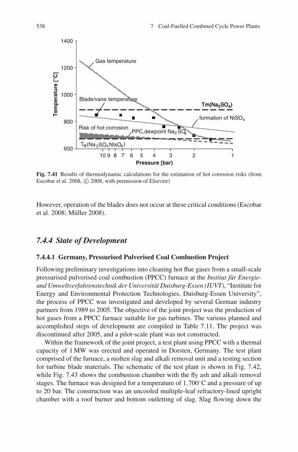
538 7 Coal-Fuelled Combined Cycle Power Plants
1400
1200
1000
800
60010 9
2
2 4
4 4
8 7 6 5 4 3 2 1Pressure [bar)
Tem
per
atu
re [
°C]
Tm(Na2SO4) Tm(Na2SO4)
Te(Na SO NIsO )
Risk of hot corrosionPPC,dewpoint Na SO
formation of NiSO4
Gas temperature
Blade/vane temperature
Fig. 7.41 Results of thermodynamic calculations for the estimation of hot corrosion risks (fromEscobar et al. 2008, c© 2008, with permission of Elsevier)
However, operation of the blades does not occur at these critical conditions (Escobaret al. 2008; Muller 2008).
7.4.4 State of Development
7.4.4.1 Germany, Pressurised Pulverised Coal Combustion Project
Following preliminary investigations into cleaning hot flue gases from a small-scalepressurised pulverised coal combustion (PPCC) furnace at the Institut fur Energie-und Umweltverfahrenstechnik der Universitat Duisburg-Essen (IUVT), “Institute forEnergy and Environmental Protection Technologies, Duisburg-Essen University”,the process of PPCC was investigated and developed by several German industrypartners from 1989 to 2005. The objective of the joint project was the production ofhot gases from a PPCC furnace suitable for gas turbines. The various planned andaccomplished steps of development are compiled in Table 7.11. The project wasdiscontinued after 2005, and a pilot-scale plant was not constructed.
Within the framework of the joint project, a test plant using PPCC with a thermalcapacity of 1 MW was erected and operated in Dorsten, Germany. The test plantcomprised of the furnace, a molten slag and alkali removal unit and a testing sectionfor turbine blade materials. The schematic of the test plant is shown in Fig. 7.42,while Fig. 7.43 shows the combustion chamber with the fly ash and alkali removalstages. The furnace was designed for a temperature of 1,700◦C and a pressure of upto 20 bar. The construction was an uncooled multiple-leaf refractory-lined uprightchamber with a roof burner and bottom outletting of slag. Slag flowing down the
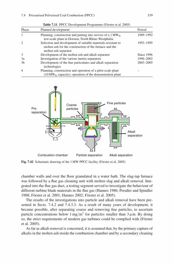
7.4 Pressurised Pulverised Coal Combustion (PPCC) 539
Table 7.11 PPCC Development Programme (Forster et al. 2005)
Phase Planned development Period
1 Planning, construction and putting into service of a 1 MWth
test-scale plant in Dorsten, North Rhine-Westphalia1989–1992
2 Selection and development of suitable materials resistant tomolten ash for the construction of the furnace and themolten ash separator
1993–1995
3 Development of the molten ash and alkali separator Since 19963a Investigation of the various inertia separators 1996–20023b Development of the fine particulates and alkali separation
technologies2003–2005
4 Planning, construction and operation of a pilot-scale plant(10 MWth capacity); operation of the demonstration plant
–
Coarseparticles
Fine particles
Alkaliseparation
Combustion chamber Particle separation Alkali separation
Preseparation
Fig. 7.42 Schematic drawing of the 1 MW PPCC facility (Forster et al. 2005)
chamber walls and over the floor granulated in a water bath. The slag-tap furnacewas followed by a flue gas cleaning unit with molten slag and alkali removal. Inte-grated into the flue gas duct, a testing segment served to investigate the behaviour ofdifferent turbine blade materials in the flue gas (Hannes 1986; Preußer and Spindler1988; Forster et al. 2001; Hannes 2002; Forster et al. 2005).
The results of the investigations into particle and alkali removal have been pre-sented in Sects. 7.4.2 and 7.4.3.3. As a result of many years of development, itbecame possible, after separating coarse and removing fine particles, to ascertainparticle concentrations below 1 mg/m3 for particles smaller than 3 μm. By doingso, the strict requirements of modern gas turbines could be complied with (Forsteret al. 2005).
As far as alkali removal is concerned, it is assumed that, by the primary capture ofalkalis in the molten ash inside the combustion chamber and by a secondary cleaning

540 7 Coal-Fuelled Combined Cycle Power Plants
Fig. 7.43 1 MW PPC combustion chamber and hot gas cleaning (Forster et al. 2005)
step, it will be possible to comply with the required limit values of 0.01 mg/m3
(Forster et al. 2005).Considerable work within the PPCC project was also directed towards testing
and developing materials suitable for the high-temperature zones of the combustionchamber, the molten ash separator and the alkali removal unit. Such materials shouldhave a high temperature stability, resistance and density to withstand the moltenslag. Suitable materials are isostatically pressed or fusion-cast ceramics. They aretemperature and corrosion resistant and have a high density and low porosity, whichprevent the slag from penetrating the refractory lining (Weber et al. 1993). A draw-back, however, is the high chromium content, which evaporates at the tempera-tures used, forming, in particular, compounds with alkalis, which is likely to meandeposits in the gas turbine. Potential solutions to the problem are coatings to reducethe evaporation of the chromium or the use of hafnium oxide based ceramics, whichare free from chromium (Forster et al. 2001; Muller 2008).
7.4.4.2 Efficiency Potential and Design of PPCC Furnaces
The joint PPCC project was the framework for the planning of industrial-scaleplants with capacities of 150 and 300 MWel (as of 1992). The configuration ofthe 150 MWel PPCC furnace was a two-line concept, each line with a combustionchamber and a gas turbine. The type of gas turbine taken as a basis was an existinggas turbine, V64.3 by Siemens, with a capacity of 53 MWel at an ISO gas turbineentry temperature of 1,150◦C. Each combustion chamber was designed for a thermaloutput of 159 MW. The combustion chamber had an inner diameter of 3 m and alength of 6 m. The waste heat recovery process was shared by the two lines and wasexecuted as a dual-pressure (steam) cycle, with moderate steam conditions of 70 bar
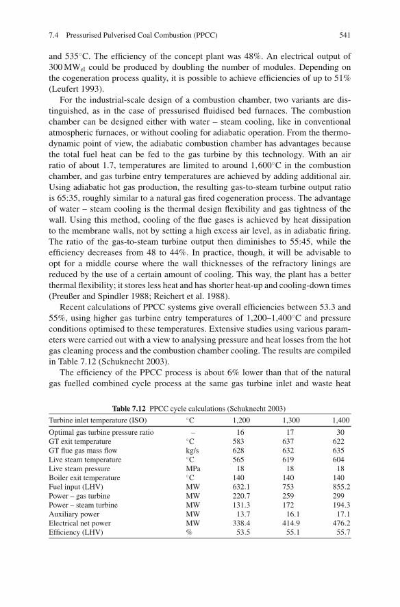
7.4 Pressurised Pulverised Coal Combustion (PPCC) 541
and 535◦C. The efficiency of the concept plant was 48%. An electrical output of300 MWel could be produced by doubling the number of modules. Depending onthe cogeneration process quality, it is possible to achieve efficiencies of up to 51%(Leufert 1993).
For the industrial-scale design of a combustion chamber, two variants are dis-tinguished, as in the case of pressurised fluidised bed furnaces. The combustionchamber can be designed either with water – steam cooling, like in conventionalatmospheric furnaces, or without cooling for adiabatic operation. From the thermo-dynamic point of view, the adiabatic combustion chamber has advantages becausethe total fuel heat can be fed to the gas turbine by this technology. With an airratio of about 1.7, temperatures are limited to around 1,600◦C in the combustionchamber, and gas turbine entry temperatures are achieved by adding additional air.Using adiabatic hot gas production, the resulting gas-to-steam turbine output ratiois 65:35, roughly similar to a natural gas fired cogeneration process. The advantageof water – steam cooling is the thermal design flexibility and gas tightness of thewall. Using this method, cooling of the flue gases is achieved by heat dissipationto the membrane walls, not by setting a high excess air level, as in adiabatic firing.The ratio of the gas-to-steam turbine output then diminishes to 55:45, while theefficiency decreases from 48 to 44%. In practice, though, it will be advisable toopt for a middle course where the wall thicknesses of the refractory linings arereduced by the use of a certain amount of cooling. This way, the plant has a betterthermal flexibility; it stores less heat and has shorter heat-up and cooling-down times(Preußer and Spindler 1988; Reichert et al. 1988).
Recent calculations of PPCC systems give overall efficiencies between 53.3 and55%, using higher gas turbine entry temperatures of 1,200–1,400◦C and pressureconditions optimised to these temperatures. Extensive studies using various param-eters were carried out with a view to analysing pressure and heat losses from the hotgas cleaning process and the combustion chamber cooling. The results are compiledin Table 7.12 (Schuknecht 2003).
The efficiency of the PPCC process is about 6% lower than that of the naturalgas fuelled combined cycle process at the same gas turbine inlet and waste heat
Table 7.12 PPCC cycle calculations (Schuknecht 2003)
Turbine inlet temperature (ISO) ◦C 1,200 1,300 1,400
Optimal gas turbine pressure ratio – 16 17 30GT exit temperature ◦C 583 637 622GT flue gas mass flow kg/s 628 632 635Live steam temperature ◦C 565 619 604Live steam pressure MPa 18 18 18Boiler exit temperature ◦C 140 140 140Fuel input (LHV) MW 632.1 753 855.2Power – gas turbine MW 220.7 259 299Power – steam turbine MW 131.3 172 194.3Auxiliary power MW 13.7 16.1 17.1Electrical net power MW 338.4 414.9 476.2Efficiency (LHV) % 53.5 55.1 55.7

542 7 Coal-Fuelled Combined Cycle Power Plants
steam generator conditions. The efficiency loss in comparison to a natural gas firedcombined cycle is due to several reasons:
• In the combined process with PPCC, the auxiliary power demand, of about 4% ofthe gross electric power generation, is about double that of the natural gas fuelledprocess, due to the power needed for coal preparation, flue gas desulphurisationand DeNOx . This causes an efficiency decrease of 2% in comparison to a gas-fired combined cycle.
• If the heat loss of the combustion chamber and the hot gas cleaning unit is 0.5%,accordingly the efficiency decrease is then about 0.5%.
• The pressure loss in the combustion chamber and the gas cleaning unit decreasesthe efficiency by approximately an additional 0.5%.
• Water/steam cooling of the combustion chamber further decreases the efficiency.The larger the heat flow dissipated to the steam turbine using combustion cham-ber cooling, the higher the efficiency loss.
• Another reason for the efficiency difference is the higher flue gas exit tempera-ture needed when using coal as the fuel (Preußer and Spindler 1988; Schuknecht2003).
7.4.4.3 USA
In the USA, the Westinghouse, Solar Turbines and Allison Gas Turbines companiesdeveloped processes with coal-fuelled gas turbines supported by the Department ofEnergy (DoE). While Solar and Allison wanted to provide plants with a capacityof 20 MWel for industry, Westinghouse focussed on the power plant sector, withcapacities of 200 MWel.
The principal configurations of these variants were shown previously, in Fig. 7.32.The gas turbine entry temperature of all of the process variants was only around1,000◦C, which limits the efficiency. The reasons for developing these processeswas cost reduction (in comparison to conventional power plants) and the ability toconstruct small-capacity units using coal as fuel (Parsons and Byam 1989).
The processes were investigated at pilot scale up until 1993; publications onnewer investigations do not seem to be in the public domain. It seems reasonable toassume that, due to operational problems (especially with hot gas cleaning), PPCCdevelopment has been discontinued in the USA. Publications in the USA to do withnew coal-firing concepts do not involve PPCC, which supports this assumption.
7.4.4.4 Westinghouse
The Westinghouse Company carried out investigations at a furnace with a capacityof 3.5 MWth. The schematic diagram of the furnace is shown in Fig. 7.44. The pro-cess concept is based on two-stage combustion, molten slag removal and low gasturbine entry temperatures of 1,000◦C, controlled by a high excess air level in thesecond combustion stage.
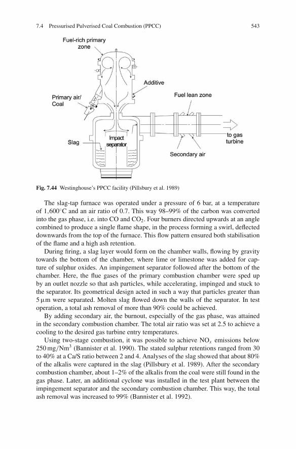
7.4 Pressurised Pulverised Coal Combustion (PPCC) 543
Fig. 7.44 Westinghouse’s PPCC facility (Pillsbury et al. 1989)
The slag-tap furnace was operated under a pressure of 6 bar, at a temperatureof 1,600◦C and an air ratio of 0.7. This way 98–99% of the carbon was convertedinto the gas phase, i.e. into CO and CO2. Four burners directed upwards at an anglecombined to produce a single flame shape, in the process forming a swirl, deflecteddownwards from the top of the furnace. This flow pattern ensured both stabilisationof the flame and a high ash retention.
During firing, a slag layer would form on the chamber walls, flowing by gravitytowards the bottom of the chamber, where lime or limestone was added for cap-ture of sulphur oxides. An impingement separator followed after the bottom of thechamber. Here, the flue gases of the primary combustion chamber were sped upby an outlet nozzle so that ash particles, while accelerating, impinged and stuck tothe separator. Its geometrical design acted in such a way that particles greater than5 μm were separated. Molten slag flowed down the walls of the separator. In testoperation, a total ash removal of more than 90% could be achieved.
By adding secondary air, the burnout, especially of the gas phase, was attainedin the secondary combustion chamber. The total air ratio was set at 2.5 to achieve acooling to the desired gas turbine entry temperatures.
Using two-stage combustion, it was possible to achieve NOx emissions below250 mg/Nm3 (Bannister et al. 1990). The stated sulphur retentions ranged from 30to 40% at a Ca/S ratio between 2 and 4. Analyses of the slag showed that about 80%of the alkalis were captured in the slag (Pillsbury et al. 1989). After the secondarycombustion chamber, about 1–2% of the alkalis from the coal were still found in thegas phase. Later, an additional cyclone was installed in the test plant between theimpingement separator and the secondary combustion chamber. This way, the totalash removal was increased to 99% (Bannister et al. 1992).
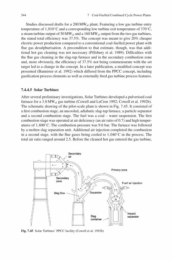
544 7 Coal-Fuelled Combined Cycle Power Plants
Studies discussed drafts for a 200 MWel plant. Featuring a low gas turbine entrytemperature of 1,010◦C and a corresponding low turbine exit temperature of 370◦C,a steam turbine output of 50 MWel and a 160 MWel output from the two gas turbines,the stated total efficiency was 37.5%. The concept was meant to give 20% cheaperelectric power production compared to a conventional coal-fuelled power plant withflue gas desulphurisation. A precondition to that estimate, though, was that addi-tional hot gas cleaning was not necessary (Pillsbury et al. 1989). Difficulties withthe flue gas cleaning in the slag-tap furnace and in the secondary combustion zoneand, more obviously, the efficiency of 37.5% not being commensurate with the settarget led to a change in the concept. In a later publication, a modified concept waspresented (Bannister et al. 1992) which differed from the PPCC concept, includinggasification process elements as well as externally fired gas turbine process features.
7.4.4.5 Solar Turbines
After several preliminary investigations, Solar Turbines developed a pulverised coalfurnace for a 3.8 MWel gas turbine (Cowell and LeCren 1992; Cowell et al. 1992b).The schematic drawing of the pilot-scale plant is shown in Fig. 7.45. It consisted ofa first combustion stage, an uncooled, adiabatic slag-tap furnace, a particle separatorand a second combustion stage. The fuel was a coal – water suspension. The firstcombustion stage was operated at air deficiency (an air ratio of 0.7) and high temper-atures of 1,600◦C. The combustion pressure was 9.6 bar. The furnace was followedby a molten slag separation unit. Additional air injection completed the combustionin a second stage, with the flue gases being cooled to 1,040◦C in the process. Thetotal air ratio ranged around 2.5. Before the cleaned hot gas entered the gas turbine,
Fig. 7.45 Solar Turbines’ PPCC facility (Cowell et al. 1992b)
7.4 Pressurised Pulverised Coal Combustion (PPCC) 545
the plant had another dust removal unit, using ceramic filters, at the secondary com-bustion temperature (Cowell et al. 1992a).
The separation unit installed between the combustion chamber and secondaryair injection consisted of seven staggered rows of ceramic rods with a diameter of3.2 cm, arranged with a clearance of 1.9 cm. The flue gas duct cross-section waswidened to reduce the flow velocity, thus preventing the ash removed by the rodsfrom being re-entrained (Cowell et al. 1992b).
During the investigations at the test plant, an ash removal of 61% in the combus-tion chamber and of 98% after the ceramic rods between the primary and secondaryzones could be achieved. The particle content was thus about 40 mg/kg flue gas. Thestaged combustion made it possible to achieve low NOx emissions of 150 mg/Nm3
at 6% O2 (calculated as NO2) along with equally low CO emissions of 30 mg/Nm3
at 6% O2. There are no results available from the operation of the pilot-scale plant,including for the ceramic filters and the gas turbine.
7.4.4.6 Allison
The concept of Allison differed from the concepts of Westinghouse and Solar bynot including slag removal. Only dry fly ash was separated, at temperatures around1,000◦C. The coal – water suspension was burned in a dry bottom furnace at tem-peratures of 1,200◦C, at air deficiency. The flue gases were cooled to below 1,000◦Cby a water quench; the fly ash was removed in a cyclone. After a second combustionstage, with injection of the remaining combustion air, and another cyclone stage forfly ash removal, the hot gases were fed to the gas turbine (Parsons and Byam 1989).
Allison carried out tests with a 3.5 MWel gas turbine firing coal at part load so thatan entry temperature of 816◦C was achieved. After each 4 h test, the gas turbine wasunmounted and the blading inspected. A mass balance revealed that about 0.2% ofthe fuel ash had been deposited in the turbine. An analysis of the deposits indicatedan enrichment of alkalis and sulphur. The deposits could be easily removed from theblades by washing, but with longer operation, it would be expected that adhesive,stable deposits of ash would form. In addition, corrosion would occur. As a result,alkali separation (from the flue gas) would have to be introduced into the process forany practical applications. The authors wanted to achieve this by a further loweringof the quench stage temperature.
7.4.5 Summary and Conclusions
PPCC offers the potential for a high efficiency in comparison to the competing coal-based combined cycle processes. To exploit this potential, high-temperature particleand alkali removal at temperatures of 1,400–1,600◦C is a prerequisite. Althoughsubstantial progress in both fields has been achieved, the PPCC development inGermany and, it seems, in the USA, has been discontinued.

546 7 Coal-Fuelled Combined Cycle Power Plants
7.5 Externally Fired Gas Turbine Processes
Combined cycles with integrated coal gasification or pressurised pulverised coalfiring use a gas cleaning stage to produce a clean fuel (i.e. a hot gas) for the gasturbine. The externally fired gas turbine process, in contrast, uses a heat exchangerto heat a gas already clean enough to meet the gas turbine related requirements. Thisindirectly fuelled or externally fired combined cycle (EFCC) presents an alternativeto the combined cycle processes that integrate coal gasification or operate usingpressurised firing (Baum 2001; Spliethoff 2000; Spliethoff and Baum 2002a, b;Benson 2000).
7.5.1 Structure, Configurations, Efficiency
In an indirectly fired combined cycle, the heat from the fuel is released by com-bustion in a firing system. A heat exchanger follows the furnace, the hot fluegases giving heat to a clean, pressurised turbine working fluid. Hot gas cleaningis not needed for the indirectly fired process, as the flue gases and turbine fluid aresegregated by the heat-exchanging walls. Therefore, any necessary flue gas cleaningto meet emission limits can be performed at low temperatures, as in conventionalcoal-fired power plants.
There are various configurations possible for indirectly fired gas turbine com-bined cycles. Open gas turbine processes use air or cleaned flue gas as the turbineworking fluid, while closed gas turbine processes work with gases such as heliumor carbon dioxide. These gases have better thermodynamic properties than air or hotflue gas but can only be used in closed gas turbine processes.
Figure 7.46 shows a schematic diagram of an open process using air as the work-ing fluid for the gas turbine. After compression, the air is heated to the gas turbineinlet temperature in the high-temperature heat exchanger. Part of the gas turbineexhaust air is fed to the firing as combustion air. The heat of the remaining exhaustair is used in a heat recovery process together with the remaining hot flue gas heatwhich was not transferred in the high-temperature heat exchanger.
The configuration of an open EFCC process using flue gas as the working fluidfor the gas turbine shown in Fig. 7.47 employs pressurised slag-tap firing. The hotpressurised flue gas transfers heat in a high-temperature heat exchanger and in aheat recovery process. It is cleaned at a low temperature before being reheated inthe high-temperature heat exchanger, then enters the gas turbine. In contrast to theopen variant using air, this process has the advantage of not subjecting the heatexchanger to compressive stresses except through its own pressure drop and that ofthe gas cleaning process. Equipment costs, however, are significantly higher thanusing air as the working fluid for the gas turbine.
Figure 7.48 shows a schematic diagram of a closed EFCC process. The workingfluid of the gas turbine is conducted in a closed circuit, while the firing and the fluegas path remain unmodified. The basic advantage is the potential to use gases withbetter thermodynamic properties for the heat transfer. The high compressor inlettemperature, however, has a negative effect on the overall efficiency.

7.5 Externally Fired Gas Turbine Processes 547
Fig. 7.46 An open EFFCCprocess using air(atmospheric slag-tapfurnace) (Spliethoff andBaum 2002)
Fig. 7.47 An open EFCCprocess using flue gas(pressurised slag-tap furnace)(Spliethoff and Baum 2002)
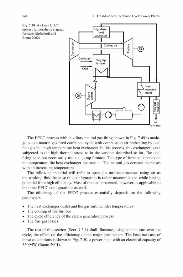
548 7 Coal-Fuelled Combined Cycle Power Plants
Fig. 7.48 A closed EFCCprocess (atmospheric slag-tapfurnace) (Spliethoff andBaum 2002)
The EFCC process with auxiliary natural gas firing shown in Fig. 7.49 is analo-gous to a natural gas fired combined cycle with combustion air preheating by coalflue gas in a high-temperature heat exchanger. In this process, this exchanger is notsubjected to the high thermal stress as in the variants described so far. The coalfiring need not necessarily use a slag-tap furnace. The type of furnace depends onthe temperature the heat exchanger operates at. The natural gas demand decreaseswith an increasing temperature.
The following material will refer to open gas turbine processes using air asthe working fluid because this configuration is rather uncomplicated while havingpotential for a high efficiency. Most of the data presented, however, is applicable tothe other EFCC configurations as well.
The efficiency of the EFCC process essentially depends on the followingparameters:
• The heat exchanger outlet and the gas turbine inlet temperatures• The cooling of the furnace• The cycle efficiency of the steam generation process• The flue gas losses
The rest of this section (Sect. 7.5.1) shall illustrate, using calculations over thecycle, the effect on the efficiency of the major parameters. The baseline case ofthese calculations is shown in Fig. 7.50, a power plant with an electrical capacity of350 MW (Baum 2001).
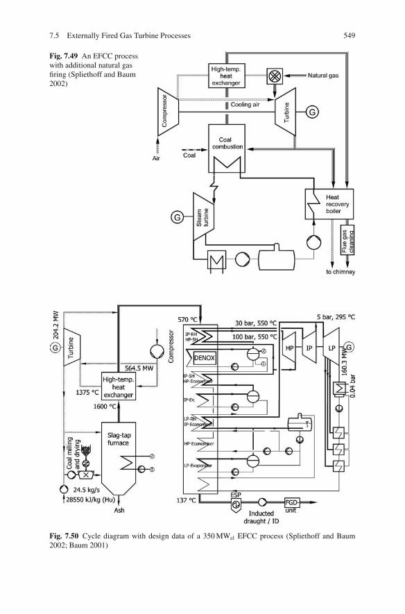
7.5 Externally Fired Gas Turbine Processes 549
Fig. 7.49 An EFCC processwith additional natural gasfiring (Spliethoff and Baum2002)
Fig. 7.50 Cycle diagram with design data of a 350 MWel EFCC process (Spliethoff and Baum2002; Baum 2001)

550 7 Coal-Fuelled Combined Cycle Power Plants
The input of heat from the fuel (coal) to the slag-tap furnace is 700 MW in themodel case. The furnace uses steam – water cooling, and about 7% of the total fuelheat input is directly transferred to the steam – water cycle. Further cooling to theflue gas outlet temperature of 1,600◦C is achieved by operating at an air ratio of 2.1.In the high-temperature heat exchanger which follows, the flue gas transfers its heatto the compressed air, heating it to 1,375◦C.
In order to cool the gas turbine, part of the compressor air is conducted directlyto it. The result is an ISO gas turbine inlet temperature of 1,184◦C for this baselinecase. That part of the gas turbine exhaust which is not used as secondary air iseither used for the drying-milling process of the coal, and for its transport, or ismixed with the flue gas from the combustion of the coal and used for waste heatsteam generation.
Taking into account the auxiliary power demand for coal preparation, pumpsand the induced-draught, and other losses, totalling about 6% of the gross electricaloutput, the gross efficiency of 52% is reduced to a net efficiency of 49% for thebaseline case. It should be mentioned that, given the conservative assumptions aboutthe machine efficiency, the terminal temperature difference in the waste heat boilerand so forth, the process discussed here is not efficiency optimised. The efficiencypotential of the EFCC process is comparable to the IGCC process. With higher ISOturbine inlet temperatures of 1,250◦C and an improved steam cycle it should bepossible to achieve a net efficiency of about 52%, comparable to the IGCC 98 case(see Sect. 7.6) (Edelmann and Stuhlmuller 1997).
The influence of the heat exchanger outlet temperature (which is to say the realgas turbine inlet temperature) on the efficiency of an EFCC process is shown inFig. 7.51. The heat exchanger outlet temperature and the thermodynamic efficiencyincrease with higher mean heat input temperatures. The gas turbine share of thetotal process output increases as well. At a constant mass flow, higher gas turbineinlet temperatures make larger heat transfer surfaces necessary. As the high processtemperatures make it impossible to use metal, it is only possible to use ceramic
Fig. 7.51 Efficiency and thegas turbine/steam turbineoutput ratio as a function ofthe real gas turbine inlettemperature (Spliethoff andBaum 2002; Baum 2001)

7.5 Externally Fired Gas Turbine Processes 551
Fig. 7.52 Influence offurnace cooling on theefficiency and the gasturbine/steam turbine outputratio (Baum 2001)
materials for these surfaces. The ceramic heat exchanger is the only component inthe indirectly fired combined cycle which is not yet state of the art. It is discussedin detail in Sect. 7.5.2.
The cooling technique for the furnace has a substantial influence on the EFCCprocess, in a similar way as in pressurised pulverised coal firing (see Fig. 7.52). Theefficiency is highest if the heat of the furnace and heat exchanger is transferred tothe working fluid of the gas turbine and the steam-generating process is heated onlyby the waste heat from the gas turbine.
This can be achieved by an adiabatic furnace without cooling or by an air-cooledfurnace. Water/steam cooling, as a third option, is simpler to construct. It was there-fore chosen as the basis for calculations.
The cycle efficiency of the steam process is another important parameter influ-encing the total efficiency of the EFCC process. Since the steam process contributes40 – 50% of the total output, depending on the type of furnace cooling and the gasturbine inlet temperature, an improvement of the steam process by 1% means anincrease of the total efficiency of 0.4 – 0.5%.
7.5.2 High-Temperature Heat Exchanger
The concept of an indirectly fired gas turbine is an alternative to combined cycleprocesses with integrated coal gasification or pressurised firing which have enjoyedthe majority of research efforts. A critical aspect of the indirect firing concept if it isto be put into practice is the high-temperature heat exchanger where the heat of theflue gas is transferred to the working fluid of the gas turbine.
7.5.2.1 Requirements
The requirements in process-engineering terms for such a heat exchanger are thefollowing:

552 7 Coal-Fuelled Combined Cycle Power Plants
– Process temperatures of up to a maximum of 1,600◦CModern gas turbines work at ISO gas turbine inlet temperatures of up to 1,300◦C,which correspond to real gas turbine inlet temperatures of up to 1,500◦C. Toachieve these temperatures on the side of the cleaned gas of the high-temperatureheat exchanger, it is necessary to be able to set flue gas temperatures of up to1,600◦C on the side of the untreated gas.
– Compressive stress of the heat exchangerIn the case of the open EFCC process using air, the heat-transferring walls aresubjected to stress by the pressure difference between the turbine working fluidand the flue gas. This difference is the result of the compression ratio of the gasturbine, which is around 16–18 for gas turbines designed for natural gas with gasturbine inlet temperatures of 1,200–1,300◦C. It must be observed in this respectthat ceramic material should not be subject to tensile stress.
– Tightness of the heat exchangerThe heat exchanger should be leak-tight because losses by leakage leads to lowerefficiencies. Problems in this respect are to be expected at tube/tube or tube/tube-sheet joints.
– Pulverised coal firing durabilityAs the heat exchanger is charged with fly ash laden flue gas, it is susceptible tothe hazards of corrosion and fouling.
The heat exchanger material must be resistant to flue gas and slag at high tem-peratures. Fouling of the heat exchanger has to be either prevented by appropriateupstream removal or minimised by deposit removal during operation. The decisivefactors are the temperatures at which the heat exchanger is operated and the state ofthe arising ash or slag. In the temperature range above 1,400◦C, i.e. higher than theash fluid temperature, slag is removed in a molten state. At temperatures below theash deformation point, the ability of soot-blowing to remove fouling deposits shouldbe tested. At temperatures above the ash deformation point and below the ash fluidpoint, it may be necessary to heat up and melt the deposits.
Last but not least, there has to be safety during all operating states – start-up andshutdown and continuous operation, and cases of outages. None of these cases mustlead to damage of the heat exchanger.
7.5.2.2 Selection of the Material
The material properties of the heat exchanger decide the upper limit of the pro-cess temperatures and hence the efficiency of the EFCC process. Figure 7.53 high-lights the temperature-dependent stability of selected ceramic and metal materials.It is clear from the figure that, for the operation of the EFCC process in the high-temperature range, only ceramic materials can be considered (Kainer and Willmann1987).

7.5 Externally Fired Gas Turbine Processes 553
Fig. 7.53 Strength of metallic and ceramic materials (Kainer and Willmann 1987)
Steels
Low-alloy steel types (represented typically by 15 Mo 3, 13 CrMo 4 4, 10 CrMo 9 10)can be used at temperatures of up to about 500◦C. Higher-alloy ferritic steels –such as the type used for the final superheater stage in steam power plants,X 20 CrMoV 12 1 – or martensitic steels can be used up to temperatures of around600◦C. Austenitic steels can be used up to 750◦C.
Nickel-Based Alloys
Nickel-based alloys, where nickel is the main element of the alloy, have a highertemperature resistance and strength than austenitic steels. The temperature limit isabout 850◦C. Due to the composition, these materials are relatively expensive andrather difficult to handle.
ODS Superalloys
ODS (oxide dispersion strengthened) alloys are powder metallurgical (PM) manu-factured superalloys based on nickel or iron. They feature a high temperature resis-tance along with comparably good strength properties. Typical are Inconel MA 754(Ni base) and PM 2000 (Fe base). They show highly promising properties such ashigh temperature and corrosion resistances up to temperatures of 1,150◦C (Aquaroand Pieve 2007; Hurley et al. 2003).
Ceramic Materials
Ceramic materials, with respect to temperature resistance paired with strength, arelargely superior to metallic materials. Of disadvantage are the limited thermal shock
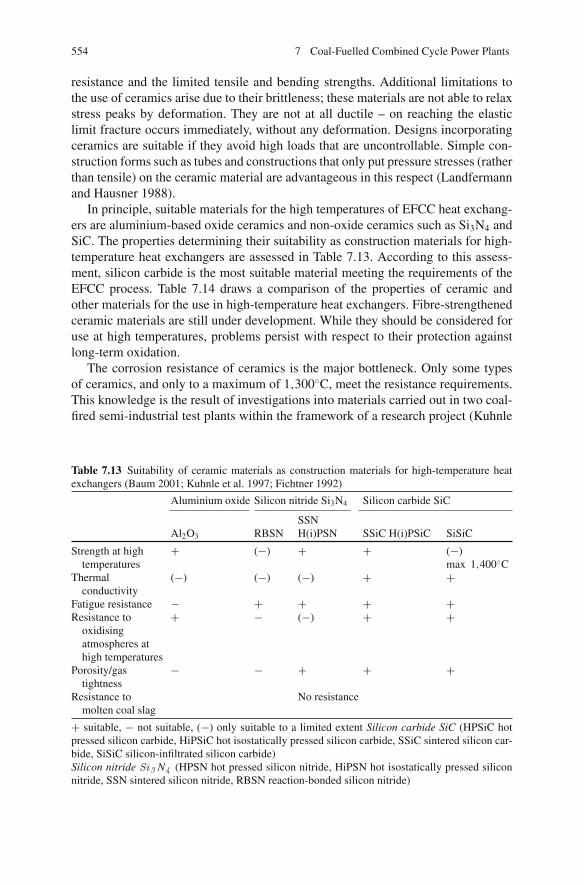
554 7 Coal-Fuelled Combined Cycle Power Plants
resistance and the limited tensile and bending strengths. Additional limitations tothe use of ceramics arise due to their brittleness; these materials are not able to relaxstress peaks by deformation. They are not at all ductile – on reaching the elasticlimit fracture occurs immediately, without any deformation. Designs incorporatingceramics are suitable if they avoid high loads that are uncontrollable. Simple con-struction forms such as tubes and constructions that only put pressure stresses (ratherthan tensile) on the ceramic material are advantageous in this respect (Landfermannand Hausner 1988).
In principle, suitable materials for the high temperatures of EFCC heat exchang-ers are aluminium-based oxide ceramics and non-oxide ceramics such as Si3N4 andSiC. The properties determining their suitability as construction materials for high-temperature heat exchangers are assessed in Table 7.13. According to this assess-ment, silicon carbide is the most suitable material meeting the requirements of theEFCC process. Table 7.14 draws a comparison of the properties of ceramic andother materials for the use in high-temperature heat exchangers. Fibre-strengthenedceramic materials are still under development. While they should be considered foruse at high temperatures, problems persist with respect to their protection againstlong-term oxidation.
The corrosion resistance of ceramics is the major bottleneck. Only some typesof ceramics, and only to a maximum of 1,300◦C, meet the resistance requirements.This knowledge is the result of investigations into materials carried out in two coal-fired semi-industrial test plants within the framework of a research project (Kuhnle
Table 7.13 Suitability of ceramic materials as construction materials for high-temperature heatexchangers (Baum 2001; Kuhnle et al. 1997; Fichtner 1992)
Aluminium oxide Silicon nitride Si3N4 Silicon carbide SiC
SSNAl2O3 RBSN H(i)PSN SSiC H(i)PSiC SiSiC
Strength at hightemperatures
+ (−) + + (−)max 1,400◦C
Thermalconductivity
(−) (−) (−) + +
Fatigue resistance − + + + +Resistance to
oxidisingatmospheres athigh temperatures
+ − (−) + +
Porosity/gastightness
− − + + +
Resistance tomolten coal slag
No resistance
+ suitable, − not suitable, (−) only suitable to a limited extent Silicon carbide SiC (HPSiC hotpressed silicon carbide, HiPSiC hot isostatically pressed silicon carbide, SSiC sintered silicon car-bide, SiSiC silicon-infiltrated silicon carbide)Silicon nitride Si3 N4 (HPSN hot pressed silicon nitride, HiPSN hot isostatically pressed siliconnitride, SSN sintered silicon nitride, RBSN reaction-bonded silicon nitride)
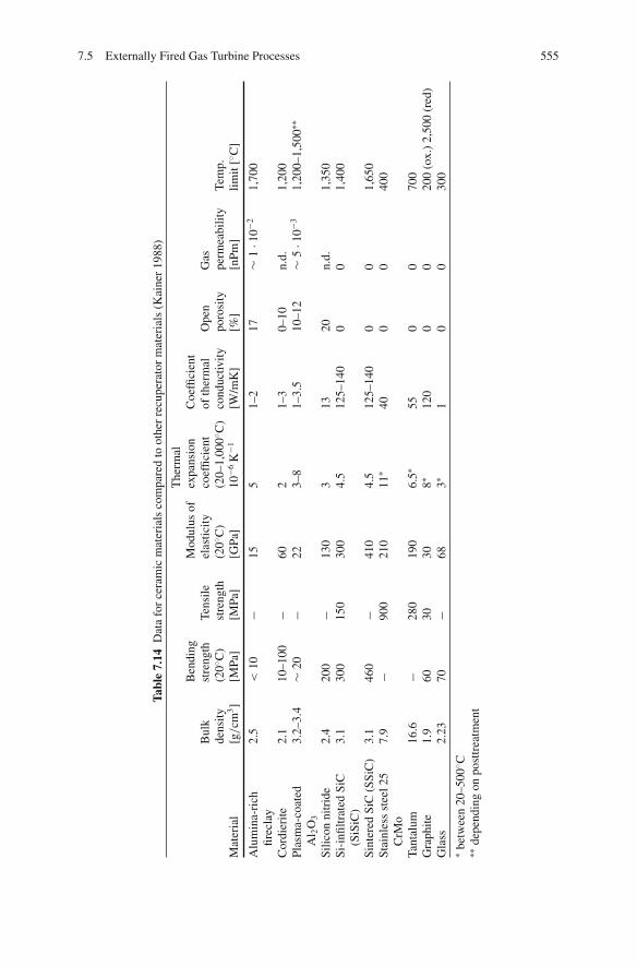
7.5 Externally Fired Gas Turbine Processes 555
Tabl
e7.
14D
ata
for
cera
mic
mat
eria
lsco
mpa
red
toot
her
recu
pera
tor
mat
eria
ls(K
aine
r19
88)
Mat
eria
l
Bul
kde
nsity
[g/cm
3]
Ben
ding
stre
ngth
(20◦ C
)[M
Pa]
Tens
ilest
reng
th[M
Pa]
Mod
ulus
ofel
astic
ity(2
0◦ C)
[GPa
]
The
rmal
expa
nsio
nco
effic
ient
(20–
1,00
0◦ C)
10−6
K−1
Coe
ffici
ent
ofth
erm
alco
nduc
tivity
[W/m
K]
Ope
npo
rosi
ty[%
]
Gas
perm
eabi
lity
[nPm
]Te
mp.
limit
[◦ C]
Alu
min
a-ri
chfir
ecla
y2.
5<
10−
155
1–2
17∼
1·1
0−21,
700
Cor
dier
ite2.
110
–100
−60
21–
30–
10n.
d.1,
200
Plas
ma-
coat
edA
l 2O
3
3.2–
3.4
∼20
−22
3–8
1–3.
510
–12
∼5
·10−3
1,20
0–1,
500∗∗
Silic
onni
trid
e2.
420
0−
130
313
20n.
d.1,
350
Si-i
nfiltr
ated
SiC
(SiS
iC)
3.1
300
150
300
4.5
125–
140
00
1,40
0
Sint
ered
SiC
(SSi
C)
3.1
460
−41
04.
512
5–14
00
01,
650
Stai
nles
sst
eel2
5C
rMo
7.9
−90
021
011
∗40
00
400
Tant
alum
16.6
−28
019
06.
5∗55
00
700
Gra
phite
1.9
6030
308∗
120
00
200
(ox.
)2,
500
(red
)G
lass
2.23
70−
683∗
10
030
0∗
betw
een
20–5
00◦ C
∗∗de
pend
ing
onpo
sttr
eatm
ent

556 7 Coal-Fuelled Combined Cycle Power Plants
et al. 1997) and confirmed by experiments where materials were placed in an electri-cal furnace with synthetic flue gas and ash. Up to 1,300◦C, the monolithic ceramictypes – aluminium oxide, silicon nitride and silicon-infiltrated and sintered siliconcarbide – showed promising corrosion behaviour for the hard coal used. In contrast,carbon fibre strengthened silicon carbide, with mechanical properties better suited tohigh-temperature heat transfer, showed poor oxidation behaviour despite the coating(Baum 2001).
When the materials in the preceding paragraph were tested in a cyclone slag-tap furnace at high flue gas temperatures of 1,500 ◦C, all showed severe damageeven after less than 30 h, which excludes their application in high-temperature heattransfer components. The corrosive attack comes especially from the aggressivemolten slag. The use of ceramic materials under these conditions needs furtherdevelopment. Apart from finding suitable ceramic materials and construction typesfor them, development of how to make adequate connections and joins of ceramicconstructions is necessary. For temperatures below 1,150 ◦C, the oxide dispersionstrengthened (ODS) superalloy PM 2000 seems to be suitable for use. This metallicmaterial, in comparison to monolithic ceramics, has great mechanical property andmanufacturability advantages.
7.5.2.3 Classification of Heat Exchangers
There are primarily two techniques of heat transfer available: recuperative heatexchangers (or recuperators) and regenerators. While recuperators transfer heatfrom one heat-carrying medium to the other via separating walls, regeneratorsexchange heat after a time lag via intermediary media. Figure 7.54 gives an overviewof heat exchanger technologies (Kainer and Willmann 1987). Recuperators workcontinuously in transferring heat, while regenerators, by alternating between heatstorage and heat dissipation, are discontinuous processes.
Only regenerators with many single-storage elements, which, as they circulate,alternate the processes of heat storage and heat dissipation, make quasi-continuousoperation possible. Regenerators with temperature-resistant, thermally conductive
Fig. 7.54 Heat exchanger systems (Kainer 1988)
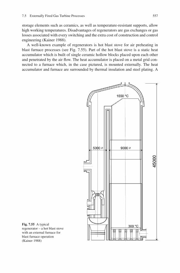
7.5 Externally Fired Gas Turbine Processes 557
storage elements such as ceramics, as well as temperature-resistant supports, allowhigh working temperatures. Disadvantages of regenerators are gas exchanges or gaslosses associated with every switching and the extra cost of construction and controlengineering (Kainer 1988).
A well-known example of regenerators is hot blast stove for air preheating inblast furnace processes (see Fig. 7.55). Part of the hot blast stove is a static heataccumulator which is built of single ceramic hollow blocks placed upon each otherand penetrated by the air flow. The heat accumulator is placed on a metal grid con-nected to a furnace which, in the case pictured, is mounted externally. The heataccumulator and furnace are surrounded by thermal insulation and steel plating. A
Fig. 7.55 A typicalregenerator – a hot blast stovewith an external furnace forblast furnace operation(Kainer 1988)
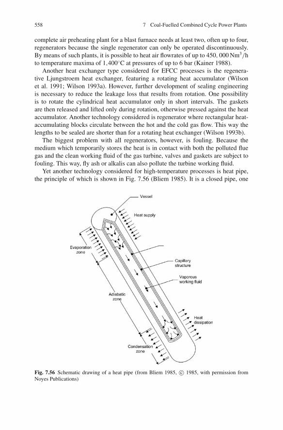
558 7 Coal-Fuelled Combined Cycle Power Plants
complete air preheating plant for a blast furnace needs at least two, often up to four,regenerators because the single regenerator can only be operated discontinuously.By means of such plants, it is possible to heat air flowrates of up to 450, 000 Nm3/hto temperature maxima of 1,400◦C at pressures of up to 6 bar (Kainer 1988).
Another heat exchanger type considered for EFCC processes is the regenera-tive Ljungstroem heat exchanger, featuring a rotating heat accumulator (Wilsonet al. 1991; Wilson 1993a). However, further development of sealing engineeringis necessary to reduce the leakage loss that results from rotation. One possibilityis to rotate the cylindrical heat accumulator only in short intervals. The gasketsare then released and lifted only during rotation, otherwise pressed against the heataccumulator. Another technology considered is regenerator where rectangular heat-accumulating blocks circulate between the hot and the cold gas flow. This way thelengths to be sealed are shorter than for a rotating heat exchanger (Wilson 1993b).
The biggest problem with all regenerators, however, is fouling. Because themedium which temporarily stores the heat is in contact with both the polluted fluegas and the clean working fluid of the gas turbine, valves and gaskets are subject tofouling. This way, fly ash or alkalis can also pollute the turbine working fluid.
Yet another technology considered for high-temperature processes is heat pipe,the principle of which is shown in Fig. 7.56 (Bliem 1985). It is a closed pipe, one
Fig. 7.56 Schematic drawing of a heat pipe (from Bliem 1985, c© 1985, with permission fromNoyes Publications)
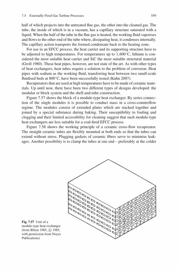
7.5 Externally Fired Gas Turbine Processes 559
half of which projects into the untreated flue gas, the other into the cleaned gas. Thetube, the inside of which is in a vacuum, has a capillary structure saturated with aliquid. When the half of the tube in the flue gas is heated, the working fluid vaporisesand flows to the other end of the tube where, dissipating heat, it condenses internally.The capillary action transports the formed condensate back to the heating zone.
For use in an EFCC process, the heat carrier and its supporting structure have tobe adjusted to high temperatures. For temperatures up to 1,600◦C, lithium is con-sidered the most suitable heat carrier and SiC the most suitable structural material(Groll 1980). These heat pipes, however, are not state of the art. As with other typesof heat exchangers, heat tubes require a solution to the problem of corrosion. Heatpipes with sodium as the working fluid, transferring heat between two small-scalefluidised beds at 800◦C, have been successfully tested (Kuhn 2007).
Recuperators that are used at high temperatures have to be made of ceramic mate-rials. Up until now, there have been two different types of designs developed: themodular or block system and the shell-and-tube construction.
Figure 7.57 shows the block of a module-type heat exchanger. By series connec-tion of the single modules it is possible to conduct mass in a cross-counterflowregime. The modules consist of extruded plates which are stacked together andjoined by a special substance during baking. Their susceptibility to fouling andclogging and their limited accessibility for cleaning suggest that such module-typeheat exchangers are less suitable for a coal-fired EFCC process.
Figure 7.58 shows the working principle of a ceramic cross-flow recuperator.The straight ceramic tubes are flexibly mounted at both ends so that the tubes canextend without stress. Plugging gaskets of ceramic fibres serve to minimise leak-ages. Another possibility is to clamp the tubes at one end – preferably at the colder
Fig. 7.57 Unit of amodule-type heat exchanger(from Bliem 1985, c© 1985,with permission from NoyesPublications)

560 7 Coal-Fuelled Combined Cycle Power Plants
Fig. 7.58 Working principleof a ceramic recuperator(Kainer and Willmann 1987)
one – so as to mount them flexibly while allowing for extension at one end (Kainerand Willmann 1987).
The principle of clamping at one end is also applied in the construction of thedouble-tube recuperator shown in Fig. 7.59. Both tubes are clamped at one endand can freely extend in the other direction. The tubes are suspended vertically sogravity affects the gasket between the housing and the tube flange. The outer tubehas a diameter of about 95 mm, a wall thickness of 6 mm and a length of nearly2,000 mm. The tube is made of SiC (Bliem 1985; Harkins and Ward 1989).
Upper plenum
Ceramic fibercompliant seal
Lowerplenum
Ceramic tubes
Metal headers
Gasket
Air in
Air out
Steel
Ceramic fiberinsulation
Coolingair duct
a) b)
Fig. 7.59 Tube-in-tube recuperators (b from Bliem 1985), c© 1985, with permission of NoyesPublications)

7.5 Externally Fired Gas Turbine Processes 561
Fig. 7.60 Recuperator by Hague International (LaHaye 1989, 1986)
When ceramic heat exchangers are used in an open process with air as the work-ing fluid of the gas turbine, attention must be paid to the pressure difference betweenthe air and the flue gas. Given that ceramic materials, with their minimal ductility,should preferably be loaded with compressive stress, it is logical to conduct thepressure-free flue gas inside and the working fluid outside the tubes of a shell-and-tube heat exchanger. Conducting the slag- or ash-carrying flue gas inside the tubesis a valid counterargument, though.
The heat exchanger concept for EFCC pursued by Hague International is to con-duct the clean working fluid of the gas turbine inside the tubes and the hot flue gasoutside, as shown in Fig. 7.60. The tubes are pre-stressed by means of a system ofsprings in order to be able to load the ceramic material with compressive stress andto seal the tubes. Tube circumferences typically measure between 75 and 100 mmand have a length of about 1,200 mm. Semi-circular fittings and adaptors guaranteethe absorption of shearing forces (lateral extensions) (LaHaye and Feldmann 1986;LaHaye and Zabolotny 1989; Vandervort 1991). A heat exchanger designed for ademonstration power plant is described in Sect. 7.5.3.2.
7.5.3 State of Development
Although the EFCC process has been well known for a long time, only the furtherdevelopment of ceramic materials during the past 10–15 years has given it a new

562 7 Coal-Fuelled Combined Cycle Power Plants
impetus. Ceramic materials for high gas turbine inlet temperatures are indispensableif a higher efficiency of the EFCC process is to be achieved compared to other gasand steam turbine processes or processes with a steam turbine alone. At lower tem-peratures, metallic materials are more advantageous, because of their more suitablemechanical and thermal properties.
7.5.3.1 EFCC Processes with Metallic Heat Exchangers
Development of EFCC processes using metal as the base construction materialbegan more than 70 years ago. In 1939, an experimental plant with a capacityof 2 MWel was put into service by Escher Wyss, Switzerland (Keller 1946). After1945, test operations in Scotland, using coal and peat, followed. In 1956, the firstcommercially operated plant, with an electrical capacity of 2.5 MW, went on-line inRavensburg, Baden-Wuerttemberg (Germany). Further plants followed in Germanyup until 1960 – Coburg, Bavaria, at Haus Aden/Monopol, and in Oberhausen andGelsenkirchen, North Rhine-Westphalia – with electrical capacities between 6.4and 17 MW, and one plant in Moscow, Russia, with 10 MWel manufactured by aconsortium composed of Escher Wyss, Switzerland, and Gutehoffnungshutte andKohlescheidungsgesellschaft, both German (Keller and Gaehler 1961).
The corresponding cycle diagram of the closed gas turbine process using air isshown in Fig. 7.61 (Bammert 1986). The air was compressed to a pressure of 41 barin two steps by an intercooler and subsequently heated up to 450◦C by the hot gasturbine exhaust in a recuperator. In the furnace, the air was heated to a gas turbineinlet temperature of 710◦C. The efficiency of the largest plant reached 31%.
Fig. 7.61 Cycle diagram of the EFCC plant, which has a metal heat exchanger, in Gelsenkirchen(Bammert 1986)

7.5 Externally Fired Gas Turbine Processes 563
Fig. 7.62 Schematic diagram of the EFCC plant in Ravensburg, Baden-Wurttemberg (Keller andGaehler 1961)
The schematic diagram of the combustion plant is shown in Fig. 7.62. The fur-nace was refractory-lined and designed as a two-pass construction. The pulverisedcoal burner was mounted at the furnace top. The air, preheated to 450◦C in therecuperator, was heated by convective heating surfaces arranged in the second passand then by radiant wall heating surfaces. The heating surfaces were designed as inconventional steam generators, with inlet headers, single tubes and outlet headers.The tube dimensions were an inside diameter of 32 mm and a wall thickness of3 mm; the number of single tubes of the 6.6 MWel plant in Coburg was 320 (Kellerand Gaehler 1961). At a gas turbine inlet temperature of 710◦C, the highest tubewall temperatures were between 770 and 790◦C, which austenitic materials couldstill cope with. The highest alloyed material used was austenite of the 16 Cr13Nitype. All plants built in Germany reached 120,000 h of operation; only the plant inCoburg was in service for more than 160,000 h (by 1986) (Bammert 1986).
Another type of EFCC process using metal as a construction material was putinto practice in a model power plant in Volklingen, Saarland (Germany). In it, thein-bed heat transfer surfaces of two fluidised bed modules were used to preheatthe air to about 700◦C. The gas turbine inlet temperature could be raised to 820◦Cby additionally firing a gaseous fuel. The combustion gases of both fluidised bedswere conducted into the pulverised coal firing of the steam generator, while the gasturbine exhaust was made use of as a fluidising medium and oxygen carrier in bothfluidised bed modules and as secondary air for the pulverised coal firing. Toppingthe gas turbine made the efficiency rise to 2% higher than the steam process (Stolland Bleif 1986).
The programme “Combustion 2000”, funded by the US Department of Energy(DoE) for the development of efficient technologies for the generation of powerfrom coal, also pursued the EFCC process as a concept. Contracts were issued to two
564 7 Coal-Fuelled Combined Cycle Power Plants
independent consortia, led by the Foster Wheeler Development Company (FWDC)and United Technologies Research Center (UTRC), respectively. The developmentof the overall process, called “High Performance Power Systems” (HIPPS), how-ever, only relied on currently available technology. The most recent feasible conceptdesign involved a metallic heat exchanger which is used to preheat air, with naturalgas additionally being fed to raise the temperature.
Besides the high-temperature heat exchanger, the Foster Wheeler concept designincluded a pyrolyser and a char-fired combustion system, with heat being transferredto preheat the air and to produce steam. Air is preheated up to 760◦C using tubebanks constructed of alloyed steel; in a topping combustor that is fired with fuelgas from the pyrolyser, air is further heated to a gas turbine inlet temperature of1,288◦C.
The UTRC HIPPS concept was based on a turbine working fluid heat exchangeroutlet temperature of 1,000◦C and a gas turbine inlet temperature of 1,260◦C. Withnatural gas contributing about one third of the thermal power output, an efficiency of50.7% (LHV) was given (Klara 1994a, 1994b; Ruth 1997, 2001). However, PhaseIII of the HIPPS programme, which would have involved construction of a demon-stration plant, was terminated and a demonstration plant will not be built (Benson2000).
7.5.3.2 EFCC Processes with Ceramic Heat Exchangers
In the 1970s and 1980s, several US companies carried out investigations into theuse of ceramic heat exchangers in EFCC processes. The results, however, have notbeen translated into practice in commercial EFCC plants.
In 1977, Solar Turbines Inc., supported by the US Department of Energy andthe Electric Power Research Institute (EPRI), started a project investigating aceramic high-temperature heat exchanger (SolarTurbines 1980). In the course ofthis research project, material tests were carried out in different atmospheres andat different temperatures, followed by a strength test. Furthermore, investigationsinto joining techniques of ceramic heat exchanger components were a subject ofthe research. In the end, a vertical shell-and-tube heat exchanger with a counterflowconfiguration made of silicon carbide tubes was built.
In a subsequent project, this heat exchanger was successfully subjected to1,370◦C hot flue gas from the firing of oil (Ward et al. 1983). There are no sub-sequent publications on tests using coal flue gas, which suggests that operationalproblems arose.
In the area of indirectly fired gas turbine processes, Solar Turbines furtherplanned to use a ceramic high-temperature heat exchanger in waste incineration.The research project was to conclude with field tests using a “high-pressure ceramicheat exchange system” (HiPHES) with a thermal capacity of 10 MW in a wasteincineration plant in Houston, Texas (Harkins and Ward 1989). Again, there are nocurrent publications on their experiences.
From the mid to the end of the 1970s, investigations into high-temperature heatexchangers in coal flue gas atmospheres were carried out by AiResearch with thesupport of the Electric Power Research Institute. For instance, a small recuperator
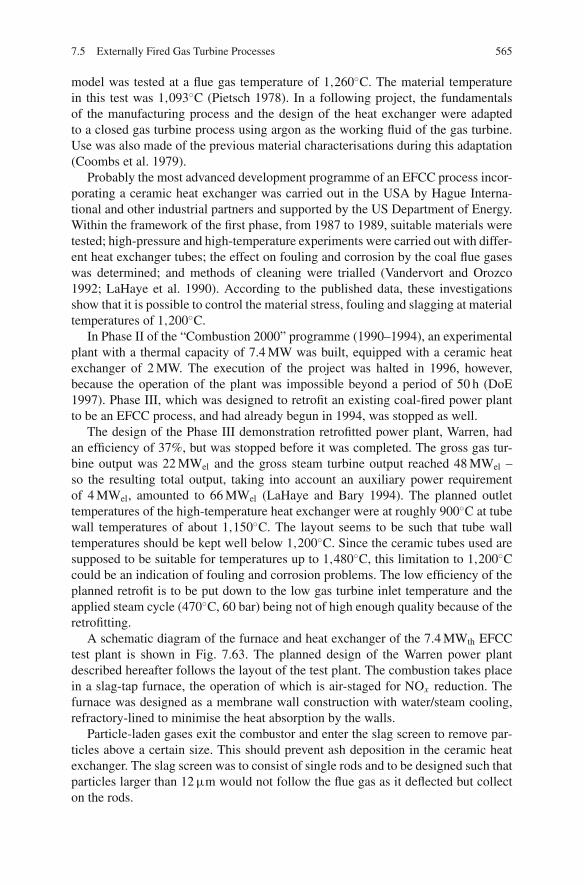
7.5 Externally Fired Gas Turbine Processes 565
model was tested at a flue gas temperature of 1,260◦C. The material temperaturein this test was 1,093◦C (Pietsch 1978). In a following project, the fundamentalsof the manufacturing process and the design of the heat exchanger were adaptedto a closed gas turbine process using argon as the working fluid of the gas turbine.Use was also made of the previous material characterisations during this adaptation(Coombs et al. 1979).
Probably the most advanced development programme of an EFCC process incor-porating a ceramic heat exchanger was carried out in the USA by Hague Interna-tional and other industrial partners and supported by the US Department of Energy.Within the framework of the first phase, from 1987 to 1989, suitable materials weretested; high-pressure and high-temperature experiments were carried out with differ-ent heat exchanger tubes; the effect on fouling and corrosion by the coal flue gaseswas determined; and methods of cleaning were trialled (Vandervort and Orozco1992; LaHaye et al. 1990). According to the published data, these investigationsshow that it is possible to control the material stress, fouling and slagging at materialtemperatures of 1,200◦C.
In Phase II of the “Combustion 2000” programme (1990–1994), an experimentalplant with a thermal capacity of 7.4 MW was built, equipped with a ceramic heatexchanger of 2 MW. The execution of the project was halted in 1996, however,because the operation of the plant was impossible beyond a period of 50 h (DoE1997). Phase III, which was designed to retrofit an existing coal-fired power plantto be an EFCC process, and had already begun in 1994, was stopped as well.
The design of the Phase III demonstration retrofitted power plant, Warren, hadan efficiency of 37%, but was stopped before it was completed. The gross gas tur-bine output was 22 MWel and the gross steam turbine output reached 48 MWel –so the resulting total output, taking into account an auxiliary power requirementof 4 MWel, amounted to 66 MWel (LaHaye and Bary 1994). The planned outlettemperatures of the high-temperature heat exchanger were at roughly 900◦C at tubewall temperatures of about 1,150◦C. The layout seems to be such that tube walltemperatures should be kept well below 1,200◦C. Since the ceramic tubes used aresupposed to be suitable for temperatures up to 1,480◦C, this limitation to 1,200◦Ccould be an indication of fouling and corrosion problems. The low efficiency of theplanned retrofit is to be put down to the low gas turbine inlet temperature and theapplied steam cycle (470◦C, 60 bar) being not of high enough quality because of theretrofitting.
A schematic diagram of the furnace and heat exchanger of the 7.4 MWth EFCCtest plant is shown in Fig. 7.63. The planned design of the Warren power plantdescribed hereafter follows the layout of the test plant. The combustion takes placein a slag-tap furnace, the operation of which is air-staged for NOx reduction. Thefurnace was designed as a membrane wall construction with water/steam cooling,refractory-lined to minimise the heat absorption by the walls.
Particle-laden gases exit the combustor and enter the slag screen to remove par-ticles above a certain size. This should prevent ash deposition in the ceramic heatexchanger. The slag screen was to consist of single rods and to be designed such thatparticles larger than 12 μm would not follow the flue gas as it deflected but collecton the rods.
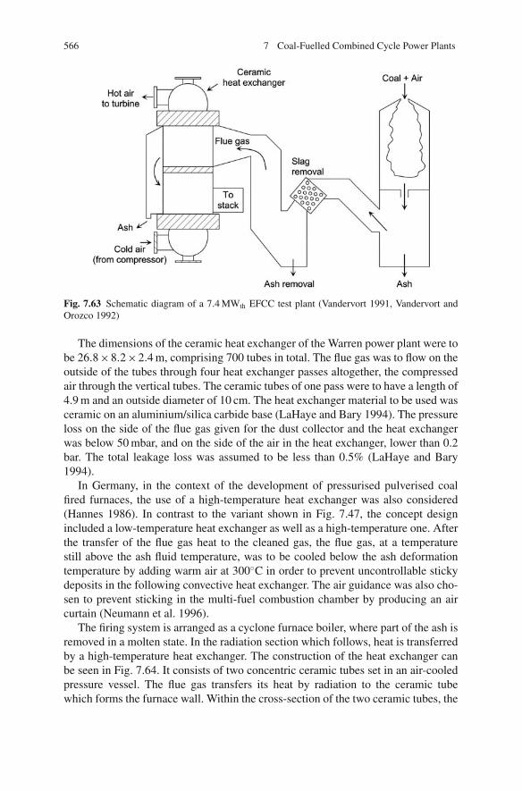
566 7 Coal-Fuelled Combined Cycle Power Plants
Fig. 7.63 Schematic diagram of a 7.4 MWth EFCC test plant (Vandervort 1991, Vandervort andOrozco 1992)
The dimensions of the ceramic heat exchanger of the Warren power plant were tobe 26.8×8.2×2.4 m, comprising 700 tubes in total. The flue gas was to flow on theoutside of the tubes through four heat exchanger passes altogether, the compressedair through the vertical tubes. The ceramic tubes of one pass were to have a length of4.9 m and an outside diameter of 10 cm. The heat exchanger material to be used wasceramic on an aluminium/silica carbide base (LaHaye and Bary 1994). The pressureloss on the side of the flue gas given for the dust collector and the heat exchangerwas below 50 mbar, and on the side of the air in the heat exchanger, lower than 0.2bar. The total leakage loss was assumed to be less than 0.5% (LaHaye and Bary1994).
In Germany, in the context of the development of pressurised pulverised coalfired furnaces, the use of a high-temperature heat exchanger was also considered(Hannes 1986). In contrast to the variant shown in Fig. 7.47, the concept designincluded a low-temperature heat exchanger as well as a high-temperature one. Afterthe transfer of the flue gas heat to the cleaned gas, the flue gas, at a temperaturestill above the ash fluid temperature, was to be cooled below the ash deformationtemperature by adding warm air at 300◦C in order to prevent uncontrollable stickydeposits in the following convective heat exchanger. The air guidance was also cho-sen to prevent sticking in the multi-fuel combustion chamber by producing an aircurtain (Neumann et al. 1996).
The firing system is arranged as a cyclone furnace boiler, where part of the ash isremoved in a molten state. In the radiation section which follows, heat is transferredby a high-temperature heat exchanger. The construction of the heat exchanger canbe seen in Fig. 7.64. It consists of two concentric ceramic tubes set in an air-cooledpressure vessel. The flue gas transfers its heat by radiation to the ceramic tubewhich forms the furnace wall. Within the cross-section of the two ceramic tubes, the

7.5 Externally Fired Gas Turbine Processes 567
Fig. 7.64 An EFCC process with a furnace, heat exchanger and multi-fuel combustion chamber(Neumann et al. 1996)
working fluid of the gas turbine absorbs the dissipated heat, mostly by convection.The annular clearance contains ceramic packing to improve the heat transfer. Theexterior pressure vessel is cooled by conducting air between the exterior ceramictube and the vessel wall, so that the ceramic heat exchanger is not loaded with pres-sure (because both the flue gas and the working fluid of the turbine are pressurised).
A 600 MWel plant needs eight parallel trains each with a furnace and a high-temperature heat exchanger, where the high-temperature heat exchanger has a heightof 12.3 m and the pressure vessel a diameter of 3.5 m. The efficiency depends on thetemperature of the gas cleaning stage. With flue gas cleaning at the cold end, theefficiency is 48%; with hot gas cleaning at 850◦C, the calculated efficiency amountsto 51% (Neumann et al. 1996).
The Italian company Ansaldo Ricerche, in collaboration with its European part-ners, is undertaking a programme which aims to realise a ceramic heat exchangermodule. Initial programmes concentrated on the development of production tech-niques and material development for reliable and cost-effective ceramic tubes foruse in aggressive and high-temperature environments. Research has mainly concen-trated on coated carbon fibre reinforced silicon carbide and one monolithic SiC.Continuation of this research focussed on the design of a high-temperature heatexchanger module.
The design of the heat exchanger and its modules is shown in Fig. 7.65. Theheat exchanger is designed to operate with the flue gas at 1,395◦C and 0.1 MPaand the compressed air at 1.7 MPa with a maximum temperature of 1,300◦C. Theflue gas and compressed air flow in opposite directions through a series of modules.

568 7 Coal-Fuelled Combined Cycle Power Plants
Hot air out 1.7 MPa, up to1300°C
Cool air in
Flue gas outletFlue gas inlet0.1 MPa, 1395°C
Lower tubesheet
Upper tubesheet
Fig. 7.65 Ceramic heat exchanger module (Benson 2000)
Those modules which are only exposed to temperatures below 850–900◦C can beconstructed from heat exchange tubes made from ODS alloys. The tubes in the high-temperature modules are ceramic. The structural elements of the heat exchangerare made from metallic materials and cooled by air. After preheating, the air isconducted through the ceramic tubes, which are suspended in the flue gas, wherethe air is heated to the TIT of 1,300◦C. The flue gas flows directly through themodule, transferring heat to the compressed air.
A ceramic heat exchanger is being tested at a 5 MW multi-fuel boiler burningcoal to generate the flue gas. In the proposed design, the heat exchanger consistsof four modules: two modules containing 42 ceramic U-tube arrangements andtwo modules containing 40 ODS alloy U-tubes. The outer tube dimensions are1.55 m in length by 7.5 cm outer diameter. The modules are spaced 50 cm apart,with soot-blowing equipment incorporated between them. It is planned to initiallyuse monolithic SiC tubes in the ceramic heat exchanger modules and then swap toCMC (ceramic matrix composite) tubes based on C/C-SiC when a suitably devel-oped material becomes available (Benson 2000).
7.5.4 Conclusions
The EFCC process offers the advantage of high efficiency; however, the problemsassociated with the high temperatures are not yet solved. The major bottleneckseems to be the corrosion attack by liquid slag when the ceramic heat exchangers areexposed to temperatures of 1,400–1,600◦C. At temperatures up to 1,300◦C, oxidedispersion strengthened alloys are preferable as they are easier to handle. Whereasfor large-scale coal-fired power stations the technology is not yet applicable, thetechnology could be suitable for smaller biomass-based systems with lower gasturbine inlet temperatures.
7.6 Integrated Gasification Combined Cycle (IGCC) 569
7.6 Integrated Gasification Combined Cycle (IGCC)
7.6.1 History of Coal Gasification
Gasification, in the broadest sense, means the transformation of a solid carbona-ceous fuel into a gas with a useful calorific value. The wider variety of applicationsand the advantages of a gaseous fuel in contrast to solid coal spurred the devel-opment of coal gasification. This development began in the 19th century with thepowering of street lighting by coal gas (1812 saw the first commercial gasworks forilluminating gas production in London), while in later years gasification for heatingpurposes became the dominant motivator. This gas, called town gas, was producedin a discontinuous pyrolysis process similar to a coking process. From about 1880,this method was superseded by the water gas shift reaction, which was then used fortown gas production until the middle of the 20th century. In this process, with thesupply of heat and steam, the solid carbon is transferred into a mixture of carbonmonoxide and hydrogen, as expressed in Eq. (7.37). The rising availability of cheapnatural gas put an end to the consumption of town gas in Europe from about 1970,and coal gasification became limited to niche applications (Higman and van derBurgt 2008).
A step of great importance in the development of gasification was the commer-cialisation of cryogenic air separation by Carl von Linde in the 1920s, which thenmade it possible to operate a continuous, oxygen-blown gasification process for theproduction of synthesis gas (commonly known as syngas) and hydrogen. Develop-ments took place around that period that were the precursors of today’s gasificationtechnologies: the Winkler process (a fluidised bed gasifier process) in 1926, theLurgi process (a fixed bed coal gasification process) in 1931 and the Koppers-Totzekprocess (an entrained-flow process for the gasification of pulverised coal) in 1940.After these processes had been established, there were only minor advances in thefollowing 40 years, save for the rise of a petrochemical industry based on coal gasi-fication and the Fischer – Tropsch synthesis process by the Sasol Company in SouthAfrica.
In the wake of the oil crisis in the 1970s and the feared shortage of natural gasand oil, extensive efforts were undertaken then and in the 1980s to further developand demonstrate gasification technologies for the production of syngas, liquid orgaseous energy sources, or electric power. By way of example, Lurgi and BritishGas developed a molten bath gasifier; Koppers and Shell together worked on apressurised version of the Koppers-Totzek gasifier; and Rheinbraun developed thehigh-temperature Winkler process. As oil prices sunk, however, the interest in coalgasification or liquefaction decreased at the end of the 1980s, restricting furtherdevelopment.
Coal gasification technology for electric power production was demonstrated inEurope in several large-scale plants (Lunen, 170 MW, 1972; Buggenum, 250 MW,1992; Puertollano, 335 MW, 1997) with success. The motivation for pursuing thistechnology in the future is the potential for better environmental performance at alower marginal cost. A broad introduction into the electricity generation market of

570 7 Coal-Fuelled Combined Cycle Power Plants
this technology, however, has not yet taken place due to its cost disadvantages andlow availability.
Nonetheless, there are a great number of gasification plants worldwide at themoment. The cumulative gasification capacity reported for 2008 ranged around70 GWth (Higman and van der Burgt 2008). These plants are mostly designed andbuilt to produce syngas for ammonia, hydrogen or transportation fuel production.The feedstocks in many cases are difficult fuels, such as refinery waste or petrolcoke, which are hard to exploit with other technologies. Here, the advantages of thelow environmental impact of gasification come fully to fruition.
A strong increase over the past 10 years in installed gasification capacities isnoticeable. The various advantages of gasification technology give reason to believethat gasification will see a revival:
– Gasifiers are suitable for a wide range of fuels. In an entrained-flow gasifier forinstance, coal can be used together with biomass and residual material. Besidessolid fuels, liquid fuels can also be used.
– The emissions of all gaseous pollutants and trace components, given that gascleaning has to be installed for process-engineering reasons, are significantlylower than from conventional power plants.
– Using two additional common process steps (a CO shift reactor and CO2 capture),it is possible to separate CO2. The required additional effort is lower, owing to theprocess pressure and the small volumetric flow, than in downstream CO2 scrub-bing following a steam power cycle. Considering this, the advantage in efficiencythat gasification already has would become still greater. The present disadvantageof higher capital costs could be balanced out.
– Gasification technology offers the highest product flexibility. Gasification tog-ether with synthesis gas generation form the first process step to produce liquidfuels (Fischer – Tropsch), gaseous secondary energy sources such as hydrogenor synthetic natural gas, and methanol or ammonia for the chemical industry(Higman and van der Burgt 2008).
7.6.2 Applications of Gasification Technology
7.6.2.1 Generation of Secondary Energy Sources
Gasification technologies are suited to providing a high-energy gas for the produc-tion of basic products for the chemical industry or of secondary energy sources.Figure 7.66 presents an overview of the various possible uses of product gases fromgasification processes.
The synthesis process for the generation of the final product determines the entirecycle and defines the requirements for the gasification process and the gas treatment.The major gas components and allowable gaseous pollutants have to be taken intoconsideration. The requirements differ from process to process but, in general, thelevel to be met is high. The sulphur content by volume, for example, has to be
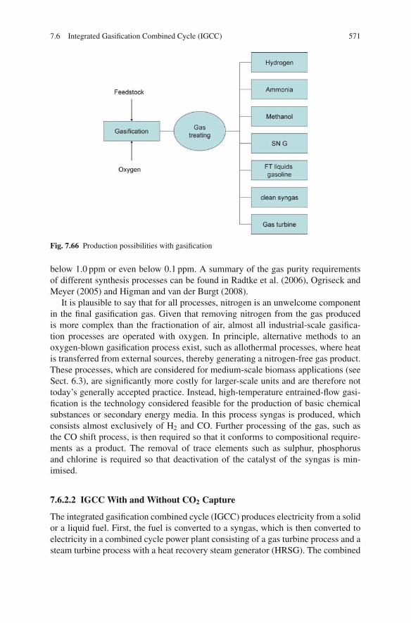
7.6 Integrated Gasification Combined Cycle (IGCC) 571
Fig. 7.66 Production possibilities with gasification
below 1.0 ppm or even below 0.1 ppm. A summary of the gas purity requirementsof different synthesis processes can be found in Radtke et al. (2006), Ogriseck andMeyer (2005) and Higman and van der Burgt (2008).
It is plausible to say that for all processes, nitrogen is an unwelcome componentin the final gasification gas. Given that removing nitrogen from the gas producedis more complex than the fractionation of air, almost all industrial-scale gasifica-tion processes are operated with oxygen. In principle, alternative methods to anoxygen-blown gasification process exist, such as allothermal processes, where heatis transferred from external sources, thereby generating a nitrogen-free gas product.These processes, which are considered for medium-scale biomass applications (seeSect. 6.3), are significantly more costly for larger-scale units and are therefore nottoday’s generally accepted practice. Instead, high-temperature entrained-flow gasi-fication is the technology considered feasible for the production of basic chemicalsubstances or secondary energy media. In this process syngas is produced, whichconsists almost exclusively of H2 and CO. Further processing of the gas, such asthe CO shift process, is then required so that it conforms to compositional require-ments as a product. The removal of trace elements such as sulphur, phosphorusand chlorine is required so that deactivation of the catalyst of the syngas is min-imised.
7.6.2.2 IGCC With and Without CO2 Capture
The integrated gasification combined cycle (IGCC) produces electricity from a solidor a liquid fuel. First, the fuel is converted to a syngas, which is then converted toelectricity in a combined cycle power plant consisting of a gas turbine process and asteam turbine process with a heat recovery steam generator (HRSG). The combined
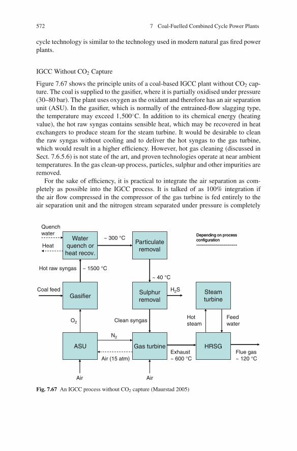
572 7 Coal-Fuelled Combined Cycle Power Plants
cycle technology is similar to the technology used in modern natural gas fired powerplants.
IGCC Without CO2 Capture
Figure 7.67 shows the principle units of a coal-based IGCC plant without CO2 cap-ture. The coal is supplied to the gasifier, where it is partially oxidised under pressure(30–80 bar). The plant uses oxygen as the oxidant and therefore has an air separationunit (ASU). In the gasifier, which is normally of the entrained-flow slagging type,the temperature may exceed 1,500◦C. In addition to its chemical energy (heatingvalue), the hot raw syngas contains sensible heat, which may be recovered in heatexchangers to produce steam for the steam turbine. It would be desirable to cleanthe raw syngas without cooling and to deliver the hot syngas to the gas turbine,which would result in a higher efficiency. However, hot gas cleaning (discussed inSect. 7.6.5.6) is not state of the art, and proven technologies operate at near ambienttemperatures. In the gas clean-up process, particles, sulphur and other impurities areremoved.
For the sake of efficiency, it is practical to integrate the air separation as com-pletely as possible into the IGCC process. It is talked of as 100% integration ifthe air flow compressed in the compressor of the gas turbine is fed entirely to theair separation unit and the nitrogen stream separated under pressure is completely
Waterquench orheat recov.
Particulateremoval
GasifierSulphurremoval
Steamturbine
ASU Gas turbine HRSG
Clean syngas
N2
Air (15 atm)
Air Air
Hotsteam
Feedwater
Coal feed
Hot raw syngas ~ 1500 °C
Heat
Quenchwater
~ 300 °C
~ 40 °C
H2S
O2
Exhaust~ 600 °C
Flue gas~ 120 °C
Depending on processconfiguration------------------------------
Depending on processconfiguration------------------------------
Fig. 7.67 An IGCC process without CO2 capture (Maurstad 2005)

7.6 Integrated Gasification Combined Cycle (IGCC) 573
expanded in the gas turbine. Full integration yields the highest efficiency; partialintegration can result in a higher output and a higher operational flexibility, forexample in the start-up process.
IGCC with CO2 Capture
The IGCC power plant offers favourable conditions for capturing CO2, becausethe separation of CO2 under pressure involves less energy loss than downstreamremoval from the atmospheric flue gas. The capture process of CO2 in an IGCCpower plant needs two additional components, as shown in Fig. 7.68:
• a so-called shift reactor, which converts the CO of the syngas into CO2 and hydro-gen using water vapour, and
• a unit for CO2 removal by chemical or physical absorption, which removes theCO2 from the hydrogen/carbon dioxide mixture.
The gas turbine is thus fed with hydrogen or with a fuel rich in hydrogen.The two additionally necessary process steps are discussed in more detail in
Sects. 7.6.5.4 and 7.6.5.5.In an IGCC process with CO2 capture the efficiency is lower because, due to the
exothermic shift reaction, some of the chemical energy of the fuel is converted into
Fig. 7.68 IGCC process with CO2 capture (Maurstad 2005)
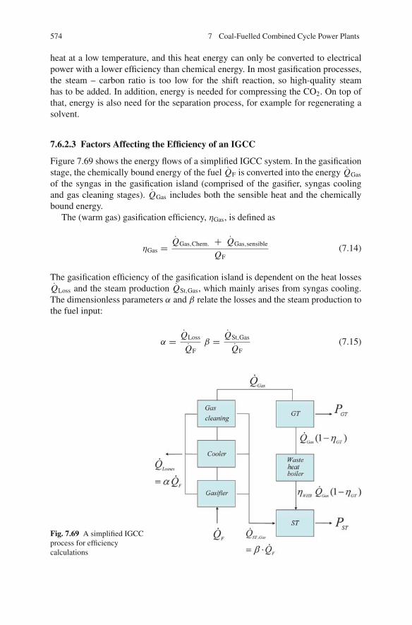
574 7 Coal-Fuelled Combined Cycle Power Plants
heat at a low temperature, and this heat energy can only be converted to electricalpower with a lower efficiency than chemical energy. In most gasification processes,the steam – carbon ratio is too low for the shift reaction, so high-quality steamhas to be added. In addition, energy is needed for compressing the CO2. On top ofthat, energy is also need for the separation process, for example for regenerating asolvent.
7.6.2.3 Factors Affecting the Efficiency of an IGCC
Figure 7.69 shows the energy flows of a simplified IGCC system. In the gasificationstage, the chemically bound energy of the fuel QF is converted into the energy QGas
of the syngas in the gasification island (comprised of the gasifier, syngas coolingand gas cleaning stages). QGas includes both the sensible heat and the chemicallybound energy.
The (warm gas) gasification efficiency, ηGas, is defined as
ηGas = QGas,Chem. + QGas,sensible
QF(7.14)
The gasification efficiency of the gasification island is dependent on the heat lossesQLoss and the steam production QSt,Gas, which mainly arises from syngas cooling.The dimensionless parameters α and β relate the losses and the steam production tothe fuel input:
α = QLoss
QFβ = QSt,Gas
QF(7.15)
Fig. 7.69 A simplified IGCCprocess for efficiencycalculations

7.6 Integrated Gasification Combined Cycle (IGCC) 575
whereas the cold gas efficiency, ηCold Gas
ηCold Gas = QGas,Chem
QF(7.16)
only considers the chemically bound energy of the product gas.In an IGCC system, power is produced in gas and steam turbines. The efficiency
ηIGCC is defined as
ηIGCC = PST + PGT
QF(7.17)
In the gas turbine, the energy QGas is converted into power PGT with the effi-ciency ηGT:
PGT = ηGT QGas = ηGT · ηGas · QF (7.18)
Steam is produced both in the gasification island QSt,Gas and in the waste heatboiler QSt,WHB.
The heat which is not converted into power in the gas turbine is fed to thewaste heat boiler and converted with the efficiency of the waste heat boiler ηWHB
into steam:
QSt,WHB = ηWHB · QGas · (1 − ηGT) = ηWHB · ηGas(1 − ηGT) · QF (7.19)
Both the steam of the waste heat steam generator and the steam from the gasifi-cation island are converted into power with the efficiency ηST via steam in the steamprocess:
PST = ηSt(QST,Gas + QST,WHB) = ηSt(β · QF + ηWHB · ηGas · (1 − ηGT) · QF) (7.20)
The efficiency of the IGCC process as a whole is then given as
ηIGCC = ηGas(ηGT + ηSTηWHB(1 − ηGT)) + ηST · β (7.21)
Using Eq. (7.21), it is possible to discuss the influence of the gasification effi-ciency, ηGas, on the total efficiency, ηIGCC. If the gasification efficiency ηGas deterio-rates, less output is produced in the gas and steam turbines and the efficiency of theIGCC process decreases. Usually an effort is made to utilise the losses occurring inthe gasification island for steam production, the measure of this being the parameterβ. This steam, however, is converted into electrical power only in the steam turbine,not in the more efficient gas and steam turbine process.
The efficiency of the gasification stage in an IGCC power plant means that com-pared to a natural gas fired combined cycle process, the overall efficiency is lower.State of the art in gas cleaning are processes at low temperatures, so that the gas tur-
576 7 Coal-Fuelled Combined Cycle Power Plants
bine is not supplied with sensible heat but only with chemical energy of the syngas.The gasification efficiency, ηGas, corresponds to the cold gas efficiency, ηCold Gas.Using a hot gas cleaning process it would be possible to increase the efficiencyby providing the combined cycle process with additional sensible heat. An addi-tional aim should be to convert the sensible heat into chemically bound energy. Thatis why the evaluation of the energy conversion in gasification processes generallybrings into play cold gas efficiencies. These are typically at about 80%, with high-temperature gasifiers having lower and fluidised bed gasifiers having higher coldgas efficiencies.
The cold gas efficiency includes the carbon conversion, which is also used fordrawing comparisons between gasifiers:
ηcarbon = 1 − cRes[kmol/h]
cFuel[kmol/h](7.22)
where cRes is the carbon in the gasification residue in kmol/h and cFuel is the carbonin the fuel in kmol/h. The carbon conversion in high-temperature entrained-flowgasifiers reaches about 99%; in fluidised bed gasifiers, however, the conversion ofcarbon is lower and is a function of the reactivity and the volatile matter content ofthe fuel.
A further reduction of the efficiency of IGCC power plants comes about as aresult of the energy used by the air separation process. By integrating the air separa-tion unit into the process as a whole, the input energy can be reduced or energy canbe recovered.
For natural gas fuelled IGCC processes, efficiencies of 50–60% are the currentstate of the art. This is the result of Eq. (7.21) if the efficiency ηGas is set at 1 andthe steam fraction β is set at 0. The gas turbine efficiency, ηGT, ranges around 40%;the efficiency of the steam process, ηST, is about 35% and the efficiency of theheat recovery steam generator, ηWHB, about 90%. So the efficiency of the combinedcycle, ηGuD, reaches 59% as a result. If the coal gasification efficiency is around80%, the IGCC efficiency falls to 47% if no steam is produced. Assuming all lossesare used for steam production (β = 0.2), the efficiency could be increased by amaximum of 7%. In practice though, the extra efficiency is significantly lower, beingpartly used up by the air separation process. These considerations clarify the needto achieve a cold gas efficiency as high as possible.
7.6.3 Gasification Systems and Chemical Reactions
7.6.3.1 Allothermal and Autothermal Gasification
Gasification systems can be categorised according to the heat input into autothermaland allothermal gasification processes (Juntgen and van Heek 1981).
The principle of autothermal gasification using steam is depicted in a simpli-fied form in Fig. 7.70. The fuel, depending on the reactor type, is converted attemperatures between 800 and 1,800◦C by means of oxygen and water vapour into
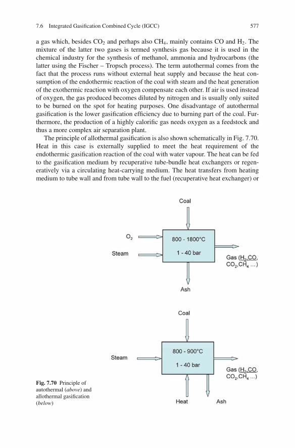
7.6 Integrated Gasification Combined Cycle (IGCC) 577
a gas which, besides CO2 and perhaps also CH4, mainly contains CO and H2. Themixture of the latter two gases is termed synthesis gas because it is used in thechemical industry for the synthesis of methanol, ammonia and hydrocarbons (thelatter using the Fischer – Tropsch process). The term autothermal comes from thefact that the process runs without external heat supply and because the heat con-sumption of the endothermic reaction of the coal with steam and the heat generationof the exothermic reaction with oxygen compensate each other. If air is used insteadof oxygen, the gas produced becomes diluted by nitrogen and is usually only suitedto be burned on the spot for heating purposes. One disadvantage of autothermalgasification is the lower gasification efficiency due to burning part of the coal. Fur-thermore, the production of a highly calorific gas needs oxygen as a feedstock andthus a more complex air separation plant.
The principle of allothermal gasification is also shown schematically in Fig. 7.70.Heat in this case is externally supplied to meet the heat requirement of theendothermic gasification reaction of the coal with water vapour. The heat can be fedto the gasification medium by recuperative tube-bundle heat exchangers or regen-eratively via a circulating heat-carrying medium. The heat transfers from heatingmedium to tube wall and from tube wall to the fuel (recuperative heat exchanger) or
Fig. 7.70 Principle ofautothermal (above) andallothermal gasification(below)
578 7 Coal-Fuelled Combined Cycle Power Plants
to and from the heat-carrying medium (regenerative heat exchanger) are parametersdetermining the size and economy of the process. The fact that fluidised beds arecharacterised by a good heat transfer is the reason why they are taken into partic-ular consideration for allothermal gasification. For greater gasification capacities,however, allothermal gasification is yet to be accepted because of the heat transferproblems. The method is practical for smaller capacities because the additional workand expense of heat transfer is compensated by not having an air separation step.
7.6.3.2 Basic Chemical Reactions
In gasification, similar to combustion (see Sect. 5.1), different phases are distin-guished:
– Heating-up of the fuel– Drying of the fuel– Pyrolysis reactions– Conversion of the solid carbon by gasification in the presence of oxygen, water
vapour or CO2
In the same way as in combustion processes, heat has to be supplied for the partialprocesses of heating-up, drying and pyrolysis. The dominant factor of the gasifica-tion process is the heat demand of the gasification reactions. For this purpose, acorresponding amount of heat has to be fed from outside the process or released bypartial oxidation.
In the entire process of coal gasification, numerous reactions take part. On theone hand, there are heterogeneous reactions in which the gasifying medium andalso the product gases react with the solid matter. On the other hand, homogeneousreactions take place in the gaseous phase where the primary gaseous products gothrough conversion reactions involving both each other and the gasifying agent.The final composition of the gas produced depends on the interaction of all thesereactions.
Despite the very complex molecular structure of coal, it is reasonable whendiscussing the reactions of the coal gasification to consider carbon alone as a firstapproximation, and only then, as a second approximation, the pyrolysis which pre-cedes the gasification process. In the following, the most important heterogeneousand homogeneous reactions of carbon and of the pyrolysis are compiled. These canbe used as basic reactions for describing the complex gasification reactions.
The principle possible pathways for gasifying carbonaceous fuel or fuel-containing hydrocarbon(s) are the partial oxidation reaction according to Eq. (7.23),the Boudouard reaction (Eq. 7.26), the heterogeneous water gas reaction (Eq. 7.27)and the methanation reaction (Eq. 7.28), all compiled in Table 7.15. The Boudouardreaction is of secondary importance in gas production from coal but it is significantfor the blast furnace process. In this process, the carbon dioxide formed from thecombustion reacts when flowing through the layers of coke above to form carbonmonoxide, which for its part becomes oxygenated to form CO2 by reducing the iron

7.6 Integrated Gasification Combined Cycle (IGCC) 579
Table 7.15 Gasification reactions (Higman and van der Burgt 2008), (Juntgen and van Heek 1981)
Combustion reactionsΔh
C + 1/2 O2 ↔ CO −111 MJ/kmol (7.23)CO + 1/2 O2 ↔ CO2 −283 MJ/kmol (7.24)H2 + 1/2 O2 ↔ H2O −242 MJ/kmol (7.25)
Heterogeneous gasification reactions
Boudouard reactionC + CO2 ↔ 2CO +172 MJ/kmol (7.26)Water gas reactionC + H2O ↔ CO + H2 +131 MJ/kmol (7.27)MethanationC + 2 H2 ↔ CH4 −75 MJ/kmol (7.28)
Homogeneous gasification reactions
Homogeneous water gas reactionCO + H2O ↔ CO2 + H2 −41 MJ/kmol (7.29)Steam reformingCH4 + H2O ↔ CO + 3H2 +206 MJ/kmol (7.30)
Pyrolysis reactions
C1HxOy → (1 − y) C + y CO + x/2 H2 +17.4 kJ/mol1) (7.31)C1HxOy → (1 − y − x/8) C + y CO + x/4 H2 + x/8 CH4 +8.1 kJ/mol1) (7.32)1) For gas coal: x = 0.874, y = 0.0794
oxides. The methanation reaction is of great importance in hydrogasification, i.e.the gasification of coal by means of hydrogen. The objective of hydrogasification isto produce methane directly from coal as a substitute for natural gas. In allothermalsteam gasification, the dominant process is the heterogeneous and strongly endother-mic water gas reaction. In order to procure the reaction heat for 1 kg of carbon forsteam gasification, about 0.29 kg of carbon has to be burned into CO2. For mostindustrial gasifiers heated autothermally, the gasification process can be describedby means of the partial oxidation and heterogeneous water gas reactions.
The principle reaction of the gas phase is the homogeneous water gas reaction(Eq. 7.29), where the carbon monoxide (formed previously) and water vapour areconverted into hydrogen and carbon dioxide in an exothermic process. This reactionis used downstream in other industrial processes, not only in gasifiers, to convert COcompletely or partially into hydrogen and to create a suitable feed gas for synthesesor other kinds of use. This step is also termed conversion or the CO shift reaction.
Another important reaction is the endothermic steam-reforming reaction(Eq. 7.30), which serves to convert methane into a synthesis gas. Running in thereverse direction, it is a strongly exothermic methanation reaction, which is used indownstream catalytic processes to produce methane.
The combustion reactions with oxygen (Eqs. 7.23, 7.24 and 7.25) mostly runto completion under gasification conditions, so they need not be considered fordetermining the equilibrium. The three heterogeneous reactions (Eqs. 7.26, 7.27and 7.28) suffice for this purpose. Assuming a complete conversion of carbon as

580 7 Coal-Fuelled Combined Cycle Power Plants
in the case of entrained-flow gasifiers, it is possible to transform the reaction equa-tions (7.26), (7.27) and (7.28) in order to obtain the two reaction equations (7.29)(subtraction of reaction 7.26 from reaction 7.27) and (7.30) (subtraction of reac-tion 7.28 from reaction 7.27). In entrained-flow gasifiers, the temperatures are com-monly so high that in terms of thermodynamics, and in practice, hydrocarbons areno longer able to be found in noticeable concentrations.
So far the first reaction phase in the process of heating the coal up to the reactiontemperature – the so-called pyrolysis reaction – has been ignored. In this phase, thecoal is decomposed to coke and liquid and gaseous substances, which, dependingon the reaction conditions, continue to react with the gasifying agent to form thegasification products. In general, pyrolysis can be described as follows:
Coal → CH4, CmHn, CO, CO2, H2, H2O, tars, char (7.33)
If the pyrolysis products in the gasification reactor convert into the successorproducts of gasification, the following simple reaction scheme is sufficient:
Coal → C + CH4 + CO + CO2 + H2O (7.34)
or for high-temperature processes:
Coal → C + CO + H2 (7.35)
Table 7.15 also includes the pyrolysis reactions, showing the possible processesof conversion into carbon and the gasification products CO and H2 (Eq. 7.41) or CO,H2 and CH4 (Eq. 7.42). It should be noted that the analyses in Eqs. 7.41 and 7.42,in the same way as the previous reactions, are made on a molar basis. For a bitu-minous coal with a weight composition of 85% C, 6% H2 and 9% O2, for instance,the result is a molar elemental formula of C1H0.847O0.0794 and a molar weight of14.12 kg/kmol. The pyrolysis reactions are slightly endothermic.
Besides the components of carbon, hydrogen and oxygen, most fuels also con-tain smaller fractions of sulphur and nitrogen. In the gasification process, sulphur ismainly converted into hydrogen sulphide; COS, CS2 and other sulphur-containingmolecules form only in small quantities. Fuel nitrogen is converted into molecularnitrogen, NH3 and HCN. These compounds have little influence on the principle gascomposition of the synthesis gas. Further information is found in Sect. 7.6.5.1.
7.6.3.3 Considerations of the Thermodynamic Equilibrium
Analyses of thermodynamic equilibrium help to calculate the reaction progressachieved therein, i.e. the greatest possible stable reaction progress of the reactionsinvolved. For the reversible reactions in Table 7.15, chemical equilibrium, whereforward and reverse reactions run at the same rate, is a function of temperature andpressure. Time, however, is not considered as a factor in such analyses, so informa-tion on how fast these states develop is not generated.

7.6 Integrated Gasification Combined Cycle (IGCC) 581
Quantitative information on the conversion and the composition of products isobtained by applying the law of mass action for equilibrium reactions. Each chemi-cal equilibrium reaction can be formulated according to the general form
N∑
i=1
νi Ai = 0 (7.36)
where νi is the molar ratio, or stoichiometric coefficient, and Ai is the substanceinvolved in the reaction.
The state of the chemical equilibrium is described by the law of mass action,which expresses the correlation between the parameters depending on the concen-tration (measured, for instance, as the partial pressure or the volume fraction). Usingthe partial pressures pAi of the substances involved, the result for the equilibriumconstant kp is
kp = NΠi=1
pAiνi (7.37)
The law of mass action can also be applied to heterogeneous reactions. However,since the steam concentration is independent of the concentration of solids, anddepends only on the temperature, this fixed value is included in the equilibriumconstants, so the concentration of the solids need not be taken into account.
For the temperature-dependent equilibrium constant kp, the gas constant R, thetemperature and the reaction enthalpy ΔH , the following relation applies:
dln kP
dT= ΔH
RT 2(7.38)
This means that, for endothermic reactions (ΔH > 0), kp rises with risingtemperatures, i.e. a temperature increase pushes the reaction in the direction of theproducts. Inversely, kp, for exothermic reactions (ΔH < 0), rises with falling tem-peratures, so in this case a decrease in temperature is favourable for the formationof the products.
As the composition of the product gases is of interest in gasification, it makessense to represent the law of mass action as a function of the volume fractions xi .The equilibrium constant kx describes the correlation of the volume fractions xi :
kx = NΠi=1
xiνi (7.39)
Dalton’s law gives the relation between the volume fraction xi and the partialpressure pAi :
xi = pAi
p(7.40)

582 7 Coal-Fuelled Combined Cycle Power Plants
Consequently, the following relation between kx and kp applies:
kx = NΠi=1
xiνi = kp
pΣνi(7.41)
This means that for reactions where the molar ratio Σνi is not changed, the equi-librium constants kx and kp are equal. An example of a consequence of this can beshown for the homogeneous water gas reaction with Σνi = 0:
kP = pCO2 · pH2
pCO2 · pH2O= kx = xCO2 · xH2
xCO · xH2O(7.42)
In reactions with a changing molar ratio, the total pressure p has an additionalinfluence on the equilibrium composition. For the heterogeneous water gas reactionwith a change in the molar ratio Σνi , for instance, the expression is
kx = xCO · xH2
xH2O= kP
p= pCO pH2
pH2O
1
p(7.43)
and for the steam-reforming reaction with a change in the molar ratio of 2, theexpression becomes
kx = xCO · x3H2
xCH4 · xH2O= kP
p2= pCO p3
H2
pCH4 pH2O= 1
p2(7.44)
In both reactions, the equilibrium shifts towards the reactants with increasingpressure; with a temperature increase, it shifts in favour of the products becauseof the endothermic nature of the reactions. This corresponds to the principle of theminimal constraint developed by Le Chatelier, which says that a rise in pressureshifts the equilibrium in the direction of a volume decrease and a lowering of thepressure shifts the equilibrium towards a volume increase.
The equilibrium constants serve to calculate the conversion of the reactant mate-rial or the composition of the product gases. The equilibrium constants can be cal-culated either by experiment, using measured equilibrium concentrations, or usingthermodynamic variables such as enthalpies and entropies.
Another, often applied, calculation method is the minimisation of the free enthalpy,also called the Gibbs free energy:
dG = dH − TdS (7.45)
The method is based on the fact that in the state of equilibrium, a minimum ofthe free enthalpy arises. For the calculation of the free enthalpy of the mixtures, thethermodynamic data of the enthalpy and the entropy has to be known. Software anddatabases are commercially available for this purpose.

7.6 Integrated Gasification Combined Cycle (IGCC) 583
Thermodynamic analyses only describe the reality in gasification processes ifthe reactions run very quickly in comparison to the residence times. This doesapply in some cases, for instance for the homogeneous reactions in entrained-flowreactors, due to the high temperatures of 1,500–1,600◦C involved. Assuming analmost complete conversion of carbon, it is possible to calculate the gas-phasecomposition using Eqs. (7.39) and (7.40). In fluidised bed reactors, with low tem-peratures of 800–900◦C, the gas composition cannot be determined by means ofequilibrium analyses, though they may help to determine qualitative effects. Thereactions involving the solid matter, in particular the gasification reactions of thesolid carbon with steam, are the slowest reactions in the gasification process, so inthis case kinetic analyses are required.
Effect of Pressure and Temperature on Gas Composition and Gasifier Efficiency
High pressures in gasification processes bear many advantages. This is why almostall industrial-scale gasifiers are operated at pressures of between 10 and 100 bar.High pressures reduce the energy demand of the total process, because the com-pressive work needed for the mass flows fed to the gasifier (oxygen, steam, fuel)is less than the work required for compressing the obtained synthesis gas. Further-more, high pressures involve more compact and thus less expensive components.The pressure of the gasifier has to be adjusted to align with the rest of the process asa whole. For the exploitation of the syngas in combined cycle processes, pressuresup to 30 bar are reasonable. For methanol synthesis, pressures from 130 to 180 barwould be advantageous, but such high pressures are not feasible in gasifiers.
Figure 7.71 shows the effect of the pressure on the gas composition from coalgasification at a temperature of 1,000◦C based on thermodynamic equilibriumcalculations. With rising pressure, the fractions of methane, carbon dioxide andsteam increase; conversely, the contents of CO and H2 diminish. This can beexplained by the pressure effect, described above, on the steam-reforming reaction:
CH4 + H2O ↔ CO + 3H2 (7.30)
and on the reaction of methane with carbon dioxide:
CH4 + CO2 ↔ 2CO + 2H2 (7.46)
because the pressure works towards volume reduction. At higher temperatures, theeffect of pressure is smaller, because in endothermic reactions higher temperaturesshift the equilibrium in the direction of the products.
Figure 7.72 shows the effect of the temperature on the equilibrium compositionat a pressure of 30 bar. As low methane contents are desired in the production ofsynthesis gas, temperatures higher than 1,300◦C are required. For an IGCC process,these high temperatures are not necessary in this respect, because methane is ratheradvantageous. However, entrained-flow gasifiers are nevertheless designed for high

584 7 Coal-Fuelled Combined Cycle Power Plants
Fig. 7.71 Variation of syngascompositions with pressure ata temperature of 1,000◦C(from Higman and van derBurgt 2008, c© 2008, withpermission from Elsevier)
Fig. 7.72 Variation of syngascompositions due totemperature at a pressure of30 bar (from Higman and vander Burgt 2008, c© 2008, withpermission from Elsevier)
temperatures, because the fuel’s ash fluid temperature has to be exceeded for safeoperation with molten slag removal.
Knowing the composition of the generated gas product, the gasifier efficienciescan also be determined (assuming a complete conversion of the carbon). Figure 7.73depicts the isolines of a complete carbon conversion for constant gasifier tempera-tures as a function of the necessary amounts of steam and oxygen. The higher thetemperatures in the gasifier, the more the oxygen needed. Higher temperatures meanthat the cold gas efficiency decreases, so in order to achieve an efficiency as high aspossible for IGCC power plants, the temperature should be the lowest possible. Forthe entrained-flow gasifier, however, temperatures below 1,400–1,500◦C, dependingon the coal type, are impossible. The operating mode has to be adjusted so that, with

7.6 Integrated Gasification Combined Cycle (IGCC) 585
Fig. 7.73 Cold gasefficiencies (from Higmanand van der Burgt 2008, c©2008, with permission fromElsevier)
as little oxygen and steam as possible, the carbon is completely converted and thetemperature can be reliably maintained during operation.
7.6.4 Classification of Coal Gasifiers
For coal gasification, a great number of methods have been developed which, interms of process engineering, can be traced back to three basic principles. Analo-gous to combustion methods (see Chap. 5 and Fig. 5.1), the gas/solids reactor typesemployed can be categorised according to the state of motion of the solid matter:
– Fixed bed gasification– Fluidised bed gasification– Entrained-flow gasification (Strauß 2006; Higman and van der Burgt 2008;
Juntgen and van Heek 1981)
Table 7.16 gives an overview of the gasification methods and their characteristics.
7.6.4.1 Fixed Bed Gasifiers
In a fixed bed reactor, the fuel is at rest. The gas flow can be conducted through thebed in co-, counter- or cross-flow. For better heat transfer, the flow of gas is usuallyconducted in a counterflow arrangement, as depicted in Fig. 7.74. In the directionof the fuel flow, three zones thus form in the fixed bed: a drying zone, a gasificationzone and a combustion zone. In the direction of the gas flow, first the combustionof the solid carbon takes place; the rising hot gases then supply the gasificationzone (which lies just above the combustion zone) with heat for the conversion of the

586 7 Coal-Fuelled Combined Cycle Power Plants
Tabl
e7.
16C
hara
cter
istic
sof
diff
eren
tgas
ifica
tion
proc
esse
s
Cat
egor
yM
ovin
g-B
edFl
uid-
Bed
Ent
rain
ed-F
low
Ash
cond
ition
sD
ryas
hSl
aggi
ngD
ryas
hA
gglo
mer
atin
gSl
aggi
ngSl
aggi
ngFe
edin
gsc
rew
scre
wsc
rew
scre
wPn
eum
atic
slur
ryTy
pica
lpro
cess
Lur
giB
GL
Win
kler
,HT
W,
CFB
KR
W,U
-Gas
Shel
l,Si
emen
sE
-Gas
GE
Fee
dch
arac
teri
stic
sSi
ze6–
50m
m6–
50m
m6–
10m
m6–
10m
m<
100
μm
<10
0μ
mA
ccep
tabi
lity
offin
eslim
ited
bette
rth
andr
yas
hgo
odbe
tter
unlim
ited
unlim
ited
Acc
epta
bilit
yof
yes
yes
poss
ibly
yes
yes
yes
caki
ngco
al(w
ithst
irre
r)Pr
efer
red
coal
rank
any
high
low
any
any
any
Ope
rati
ngch
arac
teri
stic
sR
eact
orte
mpe
ratu
re80
0–12
00◦ C
800–
1200
◦ C90
0–10
00◦ C
900–
1000
◦ C>
1400
◦ C>
1400
◦ CO
utle
tgas
425–
650◦ C
425–
650◦ C
900–
1000
◦ C90
0–10
00◦ C
1250
–160
0◦ C12
50–1
600◦ C
tem
pera
ture
Res
iden
cetim
e10
–30
min
10–3
0m
in1–
10m
in1–
10m
in<
1s<
1sC
O2
vol.
%(d
ry)
520
220
CO
vol.
%(d
ry)
5640
6642
H2
vol.
%(d
ry)
2835
2836
N2+
Ar
vol.
%(d
ry)
32
42
CH
4vo
l.%
(dry
)7
30
0C
nH
m2
vol.
%(d
ry)
10
00
Oxi
dant
dem
and
low
low
mod
erat
em
oder
ate
high
high
Stea
mde
man
dhi
ghlo
wm
oder
ate
mod
erat
elo
wlo
wC
old
gas
effic
ienc
yve
ryhi
ghve
ryhi
ghhi
ghhi
ghlo
w(8
2%)
low
(72%
)C
arbo
nco
nver
sion
high
high
low
low
very
high
very
high

7.6 Integrated Gasification Combined Cycle (IGCC) 587
Fig. 7.74 Major types of gasifiers
solid carbon. Subsequently, the residual heat of the rising gases is used to pyrolysethe entering fuel and to dry it.
The advantage of the high level of heat recovery is countered by the disadvantageof the high tar content of the product gas – as the product gas cools down, the tarcondenses. The fraction of the tar components can amount to 25% with respect tothe supplied fuel energy. The gas produced exits the gasifier at a temperature of400–500◦C, with a content of CH4 as high as between 10 and 15%. If the energycontent of the tar is used, the cold gas efficiency may be around 90%, but such waste
588 7 Coal-Fuelled Combined Cycle Power Plants
heat utilisation in a raw gas cooler is problematic because of the very fact of the hightar fractions.
Owing to the long residence time in the fixed bed, the carbon is almost com-pletely converted, while consuming little oxygen. The coal types preferred are non-caking ones with a particle size ranging from 5 to 30 mm; the proportion of solidfuel fines has to be limited to ensure that there is a continuous flow through thefixed bed.
The method developed by Lurgi, called the Lurgi Dry Ash Process, goes backto a patent from 1927 and, for years, was the only pressurised gasification sys-tem. In Sasol, South Africa, 97 of a total of 152 fixed bed gasifiers worldwide arebeing operated at present, being used for the production of a synthesis gas for theFischer – Tropsch process. A modified process is the British Gas/Lurgi slagginggasifier, which has been further developed for molten ash removal.
7.6.4.2 Fluidised Bed Gasifiers
The operation of a fluidised bed is described in principle in Sects. 5.1 and 5.4, andillustrated in Fig. 7.74. The solid particles are either made to float by the upward-directed flow (stationary fluidised bed) or carried out and circulated by the flow(circulating fluidised bed). In the fluidised bed reactor, the intensive solids mixingmeans the temperature is nearly constant. The temperature in the fluidised bed iskept below the deformation temperature of the ash so that the ash does not sticktogether and can be removed in a dry state. In consequence, the fluidised bed temper-ature is specified as a function of the fuel and determines the carbon conversion. Thetypical temperatures for coals range between 950 and 1,100◦C, while for biomass,they are between 800 and 950◦C. Fine coal particles are carried out of the fluidisedbed by the gas flow and thus diminish the carbon conversion. Typical carbon con-version rates lie between 95 and 97% and so are significantly lower than the ratesin entrained-flow reactors. The advantages of fluidised beds compared to fixed bedgasifiers are the small contents of condensable by-products and the potential for useof coals with high ash contents. In contrast to the entrained-flow gasifier, milling isnot needed, as it is sufficient to crush the coal to particle sizes smaller than 10 mm.The fluidised bed process is particularly suited to reactive coal types like lignite andfor biomass; the cold gas efficiency ranges around 85%.
The atmospheric Winkler process was the first modern continuous gasificationprocess with oxygen as the gasifying medium. The process was patented in 1922,and since then about 70 plants of that type have been constructed worldwide. Today,however, the process is only of historical interest, because almost all plants areno longer operated because of economic reasons. The gasifiers were operated attemperatures between 950 and 1,050◦C and a fluidising velocity of 5 m/s. Aftera radiant cooler, the ash flow was removed along with a considerable amount ofcarbon, in the order of 20% of the fuel flow. Rheinbraun, in the 1970s, developedthe high-temperature Winkler process (HTW), the essential characteristic of whichwas the upgrading of the fluidised bed process to handle pressures of up to 30 bar.A test plant of 600 t/day and a pressure of 10 bar was operated for more than 12

7.6 Integrated Gasification Combined Cycle (IGCC) 589
years with availabilities of 84%, the gas being used for methanol synthesis. Today,the HTW process is considered a possibility for IGCC power plants using lignite.
Circulating fluidised beds, with a more intensive gas – solids mixing and theinherent solids recirculation, have a number of advantages over stationary fluidisedbeds. There is, for instance, the higher carbon conversion rate and a performanceinsensitive to the particle size and form. The high gas velocities of 5–8 m/s ensurethat most of the bigger particles are carried out and separated by the cyclone, thenrecirculated via a seal pot. Circulating fluidised beds have been developed by FosterWheeler and Lurgi and are used today almost exclusively for biomass. In this pro-cess, air is used as the gasifying medium; the biomass has to be reduced to a size of25–30 mm.
Allothermal fluidised bed gasifiers have the advantage of being able to pro-duce a highly calorific product gas even without complex air separation. Devel-opments of allothermal coal gasification processes, such as the Mannesmann-Bergbauforschungsverfahren (MBG) (“Mannesmann Mining Research Method”) inthe 1970s and 1980s for example, have aimed at utilising high-temperature heatfrom high-temperature gas-cooled reactors (HTGR). In later concepts, heat pro-duced from fossil fuels was incorporated into the fluidised bed by helium as aheat-carrying medium. With its necessarily large heat exchanger surfaces, how-ever, the process failed to gain popularity. Two-stage allothermal processes, suchas those sometimes used successfully for biomass, have not often been developedfor or applied to coal gasification. The characteristic of the two-stage processes areseparate reactors for combustion and gasification. In the combustion reactor, theresidual coal from gasification is burned and the inert material of the fluidised bedis heated. The sensible heat of the sand, which serves as the heat-carrying medium,is used to gasify the fuel in a second fluidised bed. Two-stage gasifiers for biomassare described in Sect. 6.3.1.
7.6.4.3 Entrained-Flow Gasifier
In an entrained-flow process, finely milled coal with a particle size of less than0.1 mm is fed directly into the reactor and converted in parallel flow with the gasat high temperatures and pressures, as shown in Fig. 7.74. The temperatures inthe reactor are above the ash fluid point; depending on the calorific value of thecoal type, they rise to between 1,400 and 1,600◦C. The pressures of entrained-flowgasifiers in operation are between 20 and 70 bar. Given that the heat is providedthrough the combustion of part of the coal (i.e. an autothermal process), the coldgas efficiency lies below 85%. On account of the high temperatures, the inside wallsof the gasifier are lined with a fireproof material; for high-ash fuels it is possible todo without such lining if the formation of a protecting slag layer on a cooled mem-brane wall can be ensured. The residence time of the coal particles in the reactoris about 1 s. In consequence, significantly higher volumetric power densities resultfor the entrained-flow reactor than for the other two reactor types. The carbon getsconverted almost completely, the conversion rates amounting to more than 99%.Owing to the high reaction temperature, the entrained-flow process is also suitable

590 7 Coal-Fuelled Combined Cycle Power Plants
for less reactive fuels. However, expenditures of energy for the very fine millinghave to be taken into account when considering the viability of this process for suchfuels. High-moisture fuels, too, can be used, but the oxygen demand will rise andthe cold gas efficiency will decrease in this case. About 60% of the ash is removedfrom the reactor in a liquid state, the rest being removed as fly ash from the productgas. Because of the high temperature, the product gas consists mainly of hydrogenand carbon monoxide (synthesis gas) and contains no tars.
Process Variants
The advantages of the autothermal entrained-flow process – the high power density,the production of a tar-free synthesis gas and the fuel flexibility – have meant thatthe vast majority of gasifiers installed worldwide are autothermal entrained-flowtypes. The disadvantages of the high oxygen demand and lower cold gas efficiencycan be limited through the selection of an appropriate process variant. The processesapplied today are distinguished by the fuel feeding method (dry or wet), the coolingmethod for the reaction vessel (membrane wall or refractory lining) and the way thesensible heat of the hot product gas is used (a gas quench, water quench or a synthe-sis gas cooler). Furthermore, a distinction is made between one-stage and two-stagegasifiers. The design has a considerable influence on the cold gas efficiency and theoverall efficiency, in which the effects can differ for IGCC and chemical applica-tions. In the following, attention shall be given to IGCC applications with respect tothe following:
– Wet or dry coal feeding: Wet coal feeding or using very moist fuels diminishesthe cold gas efficiency, because water has to be vaporised and heated and becausethe oxygen demand increases. The more a fuel gets oxidised, the lower the coldgas efficiency will be. Wet coal feeding has the advantages of being simpler andhaving the ability to achieve very high pressures of up to 200 bar. Table 7.17shows a comparison (Radtke et al. 2005; Uhde 2008).Product gas cooling: The product gas heat can be utilised by means of a radiantcooler, which comes in the form of a water- or gas-quench cooler or a chemicalquench. A radiant cooler produces steam which is used in the steam process ofthe combined cycle power plant. As this heat is not fed to the gas turbine, theconversion process runs at the lower efficiency of the Rankine process, so theefficiency is lower than for a natural gas fired combined cycle process. A gasquench in the following radiant cooler lowers the temperature of the waste heatutilisation process, for instance by quenching with recirculated product gas. Aslong as the remaining heat contained in the product gas is sufficient to achievehigh steam temperatures, there are no negative effects from the radiant cooler.For the water quench, the same observations as for the gas quench hold true, butan additional drawback arises through the vaporisation of the water. The energysupplied for the vaporisation loses usefulness as it drops to the temperature ofthe condensation heat. Most satisfactory from the energetic point of view is achemical quench, where the residual heat propels an endothermic reaction, and
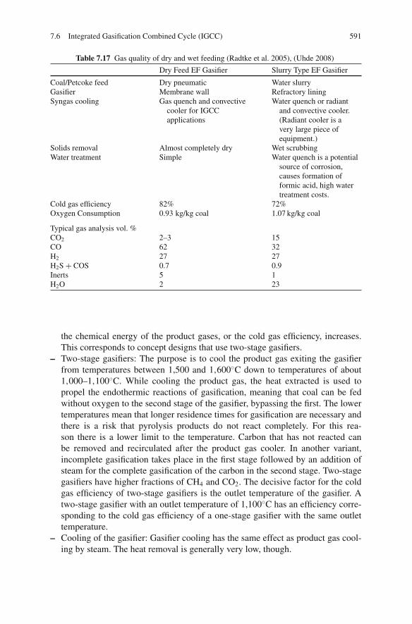
7.6 Integrated Gasification Combined Cycle (IGCC) 591
Table 7.17 Gas quality of dry and wet feeding (Radtke et al. 2005), (Uhde 2008)
Dry Feed EF Gasifier Slurry Type EF Gasifier
Coal/Petcoke feed Dry pneumatic Water slurryGasifier Membrane wall Refractory liningSyngas cooling Gas quench and convective
cooler for IGCCapplications
Water quench or radiantand convective cooler.(Radiant cooler is avery large piece ofequipment.)
Solids removal Almost completely dry Wet scrubbingWater treatment Simple Water quench is a potential
source of corrosion,causes formation offormic acid, high watertreatment costs.
Cold gas efficiency 82% 72%Oxygen Consumption 0.93 kg/kg coal 1.07 kg/kg coal
Typical gas analysis vol. %CO2 2–3 15CO 62 32H2 27 27H2S + COS 0.7 0.9Inerts 5 1H2O 2 23
the chemical energy of the product gases, or the cold gas efficiency, increases.This corresponds to concept designs that use two-stage gasifiers.
– Two-stage gasifiers: The purpose is to cool the product gas exiting the gasifierfrom temperatures between 1,500 and 1,600◦C down to temperatures of about1,000–1,100◦C. While cooling the product gas, the heat extracted is used topropel the endothermic reactions of gasification, meaning that coal can be fedwithout oxygen to the second stage of the gasifier, bypassing the first. The lowertemperatures mean that longer residence times for gasification are necessary andthere is a risk that pyrolysis products do not react completely. For this rea-son there is a lower limit to the temperature. Carbon that has not reacted canbe removed and recirculated after the product gas cooler. In another variant,incomplete gasification takes place in the first stage followed by an addition ofsteam for the complete gasification of the carbon in the second stage. Two-stagegasifiers have higher fractions of CH4 and CO2. The decisive factor for the coldgas efficiency of two-stage gasifiers is the outlet temperature of the gasifier. Atwo-stage gasifier with an outlet temperature of 1,100◦C has an efficiency corre-sponding to the cold gas efficiency of a one-stage gasifier with the same outlettemperature.
– Cooling of the gasifier: Gasifier cooling has the same effect as product gas cool-ing by steam. The heat removal is generally very low, though.

592 7 Coal-Fuelled Combined Cycle Power Plants
Technologies
The development of entrained-flow gasification began with the development of theatmospherically operated Koppers-Totzek process in the 1950s. Commercial plantswere operated in a great number of countries, mainly for ammonia synthesis. Inrecent years, no additional plants that follow this method have been built. Basedon the Koppers-Totzek process, Shell and Koppers developed pressurised versions,first in co-operation and later separately. Both the Shell Coal Gasification Process(SCGP) and the Prenflo Process by Krupp-Koppers (later: Krupp-Uhde, today:Uhde) are one-stage entrained-flow gasifiers with dry coal feeding. Both designsfeed coal in a dense flow to four burners using an inert gas. During the upward flowthrough the bed, where 90% of the particles are smaller than 90 μm, the gasifica-tion of the fine coal particles takes place, with the molten ash flowing down into awater bath where it granulates. The temperatures in the gasifier are typically around1,500◦C and the pressure at about 30–40 bar. The reactor wall is a membrane wallconstruction that is studded and covered with a castable refractory mix in order toprotect the metal wall from direct radiation and from the liquid slag. The tubes ofthe membrane wall are steam-cooled. The heat losses depend on the size of thereactor and on the quality and amount of slag and typically lie in the order of mag-nitude of 2–4% of the fuel heat. The hot product gas gets cooled down to 900◦Cby recirculated cold product gas at 280◦C before exiting the gasifier. By meansof this fast cooling down, cutting through the temperature range between the ashdeformation and ash fluid temperatures, an attempt is made to prevent the formationof agglomerations. In the steam-cooled raw gas cooler, the product gas gets cooledfrom 900 to 280◦C, afterwards being conducted to a particulate removal unit viaceramic filters. About half of the product gas is conducted to the quench cooler byuse of a compressor, while the other half is led to a wet scrubber, becoming the netproduct. The Shell Coal Gasification Process is shown in Fig. 7.75.
In 1994, a 2,000 t/day Shell gasification unit was built for Demkolec (nowNUON) in Buggenum in the Netherlands, using coal as feedstock. In 1997, Krupp-Koppers (now Uhde) built a 3,000 t/day unit for Elcogas in Puertollano, Spain, usinga blend of high-ash coal and petcoke as the feedstock.
The Siemens gasification process is also a one-stage gasification method usinga dry fuel supply. It can be traced back to developments of lignite gasification bythe Deutsches Brennstoffinstitut in Freiberg in the 1970s. The entire fuel flow, steamand oxygen are fed through a burner. The reactor has a downward flow, with bothmolten slag and the hot product gas being discharged at the bottom (see Fig. 7.76).The discharge of slag and product gas together avoids a blocking of the slag out-flow. Depending on the application, partial quenching or full quenching may beemployed. For high-ash fuels, a cooling screen lined with SiC is used, becomingcovered by a protective slag layer during operation. For low-ash fuels, the designincorporates refractory lining.
The GE (formerly Texaco) process for coal gasification uses a slurry-feeddownward-flowing entrained-flow gasifier. The coal is wet milled to a particle size ofabout 100 μm and slurried in conventional equipment, then charged to the reactorwith a membrane pump. The reactor pressure is typically about 30 bar for IGCC

7.6 Integrated Gasification Combined Cycle (IGCC) 593
Quench gas blower
HP steamMP steam
To gas
treatment
Membranewall
Oxygen
Pulverisedcoal
BFW
Slag
Slag
Refractory
Fig. 7.75 The Shell Coal Gasification Process (from Higman and van der Burgt 2008, c© 2008,with permission from Elsevier)
applications; for chemical applications it may be as much as 70–80 bar. The reactorshell is an uncooled refractory-lined vessel.
Syngas cooling can be performed by a radiant boiler or via a total water quench.In the quench configuration, the hot syngas leaves the reactor at the bottom togetherwith the liquid ash and enters the quench chamber. The gas leaves the quenchchamber fully saturated and at a temperature of between 200 and 300◦C, whichare suitable conditions for direct CO shift conversion. In the radiant cooler config-uration, which is part of the Cool Water and Polk IGCC plants, full use is madeof heat recovery for maximum efficiency. The GE gasifier is the most inexpensivegasifier on the market, but is maintenance-intensive. To achieve high availabilitiesof production, a standby reactor is required.
The E-Gas gasifier is currently the only two-stage process with an operatingcommercial-scale demonstration plant. A sub-bituminous coal – water slurry isinjected into the hot gases coming from the first slagging stage, resulting in a tem-perature drop from 1,400 to 1,040◦C. Unreacted char is separated by metallic candlefilters and reinjected into the first slagging stage.
7.6.5 Gas Treatment
The composition of the raw gases produced by gasification differ considerablydepending on the production method. For example, from gasification in a fluidisedbed or an entrained-flow reactor, a raw gas has a high particulate content, whereas
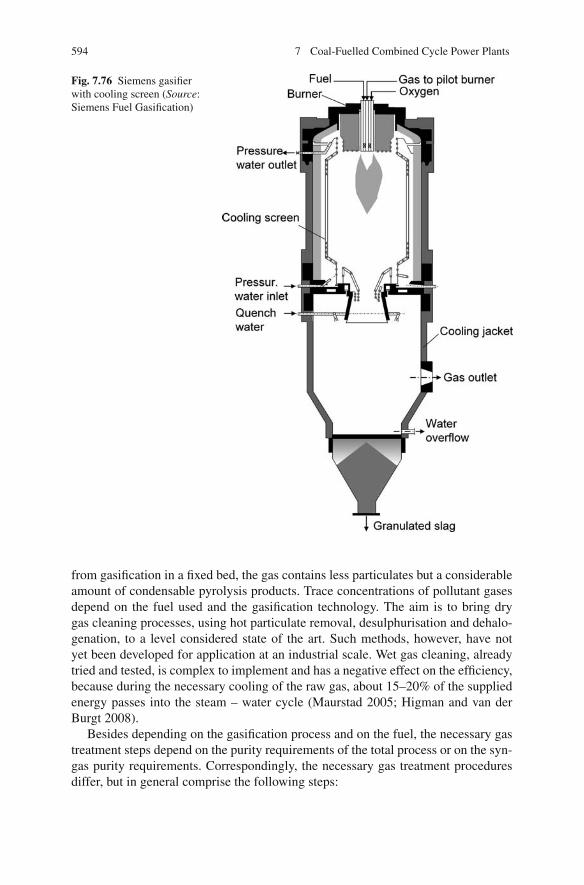
594 7 Coal-Fuelled Combined Cycle Power Plants
Fig. 7.76 Siemens gasifierwith cooling screen (Source:Siemens Fuel Gasification)
from gasification in a fixed bed, the gas contains less particulates but a considerableamount of condensable pyrolysis products. Trace concentrations of pollutant gasesdepend on the fuel used and the gasification technology. The aim is to bring drygas cleaning processes, using hot particulate removal, desulphurisation and dehalo-genation, to a level considered state of the art. Such methods, however, have notyet been developed for application at an industrial scale. Wet gas cleaning, alreadytried and tested, is complex to implement and has a negative effect on the efficiency,because during the necessary cooling of the raw gas, about 15–20% of the suppliedenergy passes into the steam – water cycle (Maurstad 2005; Higman and van derBurgt 2008).
Besides depending on the gasification process and on the fuel, the necessary gastreatment steps depend on the purity requirements of the total process or on the syn-gas purity requirements. Correspondingly, the necessary gas treatment proceduresdiffer, but in general comprise the following steps:
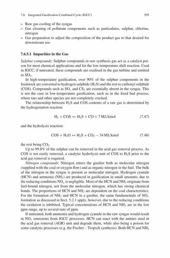
7.6 Integrated Gasification Combined Cycle (IGCC) 595
– Raw gas cooling of the syngas– Gas cleaning of pollutant components such as particulates, sulphur, chlorine,
nitrogen– Gas preparation to adjust the composition of the product gas to that desired for
downstream use
7.6.5.1 Impurities in the Gas
Sulphur compounds: Sulphur compounds in raw synthesis gas act as a catalyst poi-son for most chemical applications and for the low-temperature shift reaction. Usedin IGCC, if untreated, these compounds are oxidised in the gas turbine and emittedas SO2.
In high-temperature gasification, over 90% of the sulphur components in thefeedstock are converted to hydrogen sulphide (H2S) and the rest to carbonyl sulphide(COS). Compounds such as SOx and CS2 are essentially absent in the syngas. Thisis not the case in low-temperature gasification, such as in the fixed bed process,where tars and other species are not completely cracked.
The relationship between H2S and COS contents of a raw gas is determined bythe hydrogenation reaction:
H2 + COS ↔ H2S + CO + 7 MJ/kmol (7.47)
and the hydrolysis reaction:
COS + H2O ↔ H2S + CO2 − 34 MJ/kmol (7.48)
the rest being CO2.Up to 99.8% of the sulphur can be removed in the acid gas removal process. As
COS is not easily removed, a catalytic hydrolysis unit of COS to H2S prior to theacid gas removal is required.
Nitrogen compounds: Nitrogen enters the gasifier both as molecular nitrogen(supplied with the coal or oxygen flow) and as organic nitrogen in the fuel. The bulkof the nitrogen in the syngas is present as molecular nitrogen. Hydrogen cyanide(HCN) and ammonia (NH3) are produced in gasification in small amounts; due tothe reducing conditions NOx is negligible. Most of the HCN and NH3 originate fromfuel-bound nitrogen, not from the molecular nitrogen, which has strong chemicalbonds. The proportions of HCN and NH3 are dependent on the coal characteristics.For the formation of NH3 and HCN in a gasifier, the same fundamentals of NOx
formation as discussed in Sect. 5.2.1 apply; however, due to the reducing conditionsthe oxidation is inhibited. Typical concentrations of HCN and NH3 are in the lowppm range, up to several tens of ppm.
If untreated, both ammonia and hydrogen cyanide in the raw syngas would resultin NOx emissions from IGCC processes. HCN can react with the amines used inthe acid gas removal (AGR) unit and degrade them, while also being a poison forsome catalytic processes (e.g. the Fischer – Tropsch synthesis). Both HCN and NH3

596 7 Coal-Fuelled Combined Cycle Power Plants
have very high solubilities in water and may therefore be easily removed by waterscrubbing.
Chlorine compounds: Chlorine released from the coal is converted to hydrogenchloride (HCl) gas, which in contact with metals can form chlorides, such as sodiumchloride (NaCl), with melting points in the range of 350–800◦C. These metal chlo-rides pose a fouling risk in heat exchangers. Chlorine compounds from the coalwill also react with ammonia to form ammonium chloride (NH4Cl) which is inthe vapour phase at higher temperatures and becomes a solid at around 280◦C. Inaddition to fouling problems, chlorine is a catalyst poison for the low-temperatureshift reaction. Many of the chlorides may be removed in a water scrubber.
Solid carbon and ash: Ash and a small amount of remaining char will always beentrained in the exit flow of the gasifier. The quench or syngas cooler has to ensurethat these particles will be non-sticky so that fouling problems are prevented. Aftercapture in a filter or scrubber, char can be recycled to the gasifier to increase thecarbon conversion efficiency.
Other trace components: Besides the major components, a variety of trace ele-ments such as lead (Pb), mercury (Hg) and arsenic (As) are present in coals. Metalcarbonyls such as nickel carbonyl (Ni(CO)4) and iron carbonyl (Fe(CO)5) can beformed.
7.6.5.2 Raw Gas Cooling
Raw gases exit gasifiers at high temperatures, ranging from 550◦C from a fixed bedgasifier to 1,600◦C from an entrained-flow gasifier. As the cleaning processes forthe removal of these pollutants run at lower temperatures, the syngas needs to becooled down. This cooling is required even for hot gas (or more correctly warmgas) cleaning. Figure 7.77 shows configurations for raw gas cooling and particulateremoval units for different gasification systems.
Particular attention has to be paid to the cooling from gasification temperaturesto temperatures below 900◦C, because the ash is liquid in this temperature rangeand may cause build-ups of slag. For the sake of the continued availability of theprocess, the raw gases should therefore be cooled as fast as possible down to around900◦C, where the ash is present in solid form. For cooling in this range, the follow-ing process variants are used:
– Radiant cooling– Water quenching– Gas quenching– Chemical quenching
In a radiant cooler, the heat of the syngas is transferred to the water – steam-cooled walls by radiation. Due to the high heat transfer rate, saturated steam isproduced exclusively. The radiant cooler is an expensive component and susceptibleto fouling and slagging.

7.6 Integrated Gasification Combined Cycle (IGCC) 597
Fig. 7.77 Process flow diagram for different gasification processes (Maurstad 2005) and additions(a: EF + gas quench, b: EF+ water quench, c: EF + radiant cooling, d: fluidised bed)
A water quench uses the sensible heat of the syngas to vaporise the injected water.With a partial quench, the syngas is cooled down to 900◦C and the sensible heat (butnot the latent heat) can be utilised for steam production. With a full quench, no high-pressure steam is generated and the syngas is saturated with steam. Water quenches,and the full quench in particular, are disadvantageous for IGCC processes withoutCO2 separation, because the heat of evaporation cannot reasonably be used at thelow temperature of condensation. For an IGCC power plant with CO2 separation,the addition of water shifts the equilibrium of the water gas reactions in the directionof higher H2/CO contents.
One example of the use of a gas quench is in the Shell gasifier, where syngasthat has already been cooled is mixed with the 1,500◦C (hot) untreated synthesisgas, thus cooling to 900◦C. This way, the heat is used within an unproblematictemperature range. Apart from the increased power consumption of the recirculationprocess, no other negative efficiency effects arise for an IGCC power plant becauseonly sensible heat, not condensation heat, is produced.
Chemical quenching is advantageous because the gasifier exit temperature is low-ered and thus the cold gas efficiency increased (see also Sect. “Process Variants”).
For the process of further cooling of the flue gas by convective heat exchangers,the factors that should be considered are particulate removal and the behaviour ofcondensing components. The latter can be in the form of tars in biomass gasification,ammonium chloride in coal gasification or, simply, water. Typically, this coolingstage lowers the temperature from 900◦C to about 300◦C. At 900◦C, the ash particlesare no longer sticky; at 300◦C, deposits of NH4Cl do not occur. A distinction is made

598 7 Coal-Fuelled Combined Cycle Power Plants
between water-tube and fire-tube boilers, both of which are in successful service.Fire-tube boilers conduct the synthesis gases inside the tubes, with the water flowingon the outside of them; in water-tube boilers, the high-pressure steam is producedinside the tubes. Typical steam pressures range from 100 to 150 bar for both types,but water-tube boilers can also be designed for even higher pressures. Fouling hasto be taken into consideration for both types, so adequate cleaning facilities have tobe included in the design. Superheating of the steam is possible. In order to limitcorrosion, high-alloy materials are used and the material temperatures are restrictedto values of 500–600◦C.
7.6.5.3 Particulate Removal
A dry particulate removal process should run at temperatures ranging between 300and 500◦C. Only at temperatures below 500◦C do the alkali compounds achievethe maximum possible condensation on the fly ash, so that they are then removedalong with the particulates. Below 300◦C, the filters may be clogged by depositsof ammonium chloride. Cartridge filters are employed. By using topping cyclonesprior to the filter, the filter load can be reduced.
In most existing plants the (remaining) solids are washed out in venturi scrubbersor wash towers. The scrubbing takes place below the dew point of the gas, so thatthe finest solid particles can act as nuclei for condensation, thus ensuring that allsolids are removed effectively. In wet scrubbing the water-soluble gaseous compo-nents such as NH3, HCN, HCl and HF are also separated. The disadvantage of wetscrubbing is that the ash contains many regulated substances such as lead, zinc andcadmium, so the removed components must be disposed of carefully and accordingto relevant directives.
7.6.5.4 CO Shift
In an IGCC configuration with CO2 removal or in a hydrogen production plant,the water gas shift reaction is used to push the chemical composition of the syngastowards a maximum H2 yield:
CO + H2O ↔ H2 + CO2 − 41.2 MJ/kmol (7.29)
According to the reaction, one mole of hydrogen can be produced from everymole of CO. The heating value per mole is less for H2 (241.8 MJ/kmol) than for CO(283.0 MJ/kmol), which means that chemical energy is converted to heat (exother-mic reaction). The reaction itself is equimolar and therefore largely independent ofpressure. The reaction is normally carried out in two stages, a high-temperature shiftand a low-temperature shift. The high-temperature stage has the advantage of highreaction rates, while the low-temperature stage favours an equilibrium for maxi-mum hydrogen production. Typical operating temperatures of the two stages arebetween 200 and 500◦C, depending on the catalyst. The types of catalysts are dis-tinguished by their operating temperature range and the maximum sulphur content
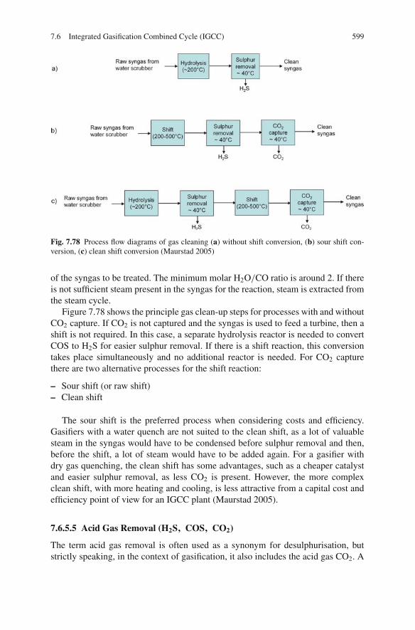
7.6 Integrated Gasification Combined Cycle (IGCC) 599
Fig. 7.78 Process flow diagrams of gas cleaning (a) without shift conversion, (b) sour shift con-version, (c) clean shift conversion (Maurstad 2005)
of the syngas to be treated. The minimum molar H2O/CO ratio is around 2. If thereis not sufficient steam present in the syngas for the reaction, steam is extracted fromthe steam cycle.
Figure 7.78 shows the principle gas clean-up steps for processes with and withoutCO2 capture. If CO2 is not captured and the syngas is used to feed a turbine, then ashift is not required. In this case, a separate hydrolysis reactor is needed to convertCOS to H2S for easier sulphur removal. If there is a shift reaction, this conversiontakes place simultaneously and no additional reactor is needed. For CO2 capturethere are two alternative processes for the shift reaction:
– Sour shift (or raw shift)– Clean shift
The sour shift is the preferred process when considering costs and efficiency.Gasifiers with a water quench are not suited to the clean shift, as a lot of valuablesteam in the syngas would have to be condensed before sulphur removal and then,before the shift, a lot of steam would have to be added again. For a gasifier withdry gas quenching, the clean shift has some advantages, such as a cheaper catalystand easier sulphur removal, as less CO2 is present. However, the more complexclean shift, with more heating and cooling, is less attractive from a capital cost andefficiency point of view for an IGCC plant (Maurstad 2005).
7.6.5.5 Acid Gas Removal (H2S, COS, CO2)
The term acid gas removal is often used as a synonym for desulphurisation, butstrictly speaking, in the context of gasification, it also includes the acid gas CO2. A

600 7 Coal-Fuelled Combined Cycle Power Plants
large number of different processes can be used for acid gas removal, which can becategorised according to the following principles used:
• Absorption or adsorption by a liquid solvent with a subsequent desorption step(chemical or physical washing)
• Absorption or adsorption on a solid material• Diffusion through a permeable membrane
Acid gases such as H2S and CO2 cannot be removed in a water wash processdue to their low water solubilities. For acid gas removal, chemical (absorption) orphysical (adsorption) washes with liquid solvents are normally used. The differentprinciples for removal in gasification environments are illustrated in Fig. 7.79. Theloading capacity of a physical solvent primarily depends on Henry’s law and istherefore proportional to the partial pressure of the component to be removed. Incontrast, the loading capacity of a chemical wash is limited by the quantity of theactive component of the solvent. Generally, the solvent can be regenerated by flash-ing, stripping or reboiling or a combination of these. Both stripping and flashingreduce the partial pressure of the acid component and are used for physical sol-vents. In physical washes, reboiling raises the temperature and thus reduces the acidgas solubility. In chemical washes, the increased temperature breaks the chemicalbonds and releases the components in the same chemical form in which they wereabsorbed.
Criteria for the selection of the appropriate process are as follows:Gas purity: The demands of the syngas purity vary extremely with the applica-
tion. For an IGCC power plant with a limit of 5 ppm SO2 in the flue gas, about40 ppm H2S at the outlet of the AGR is sufficient. For chemical applications such asammonia, methanol or SNG production, 100 ppb may be required.
Raw gas composition: The washing solution must cope with the impurities in theraw gas. HCN in the raw gas, for instance, can react with amines, causing solutiondegradation.
Selectivity: The selectivity of a gas treatment process is the ability to remove H2Swhile leaving CO2 in the synthesis gas.
Fig. 7.79 Loading capacityof physical and chemicalsolvents (from Higman andvan der Burgt 2008, c© 2008,with permission fromElsevier)
Physicalsolvent
Par
tial p
ress
ure
[bar
]
Chemicalsolvent
Loading capacity [kmol/m3 solvent]
7.6 Integrated Gasification Combined Cycle (IGCC) 601
Solutions of amines in water are commonly used for chemical washes; examplesof amines are mono- and diethanolamine (MEA and DEA) and methyldiethanol-amine (MDEA). MDEA is the most widely used amine today. Examples of physicalwashes are the Rectisol, Selexol and Purisol processes. The Rectisol process, whichuses methanol as a solvent, operates between temperatures of −30 and −60◦C. Theprocess can achieve very high gas purities and is used for chemical applicationswhere synthesis catalysts require sulphur removal to less than 0.1 ppmv. The Selexolprocess, which uses dimethyl ethers of polyethylene glycol (DMPEG), is operated at0–40◦C, reducing refrigeration requirements, and can achieve gas purities of 1 ppmH2S and COS, respectively. The Purisol process shows similar characteristics, buthas a higher H2S/CO2 selectivity.
Physical – chemical washes make use of the principles of both physical andchemical removal. They generally use an amine together with an organic physi-cal solvent. An example of this is Shell’s Sulfinol solvent; the modified m-Sulfinolsolvent uses MDEA as the chemical component and is applied at the Buggenumplant.
Sulphur Removal
The sulphur removal process consists of three process steps:
– Acid gas removal (AGR)– Sulphur recovery (SR)– Tail-gas treating (TGT)
The AGR process removes the H2S from the syngas. In present-day IGCC plants,the two preferred processes are chemical washing, based on aqueous methyldi-ethanolamine (MDEA), and the Selexol process, based on a physical solvent. Bothmethods can reduce the total sulphur (H2S + COS) to levels below 20 ppmv inthe cleaned syngas. For deep sulphur removal, required for chemical applications,the more expensive Rectisol process, using a physical solvent, may be applied. ForCO2 capture a second-stage AGR has to be added to remove the CO2 from thesulphur-free syngas.
The purpose of the sulphur recovery unit (SRU) is to convert the H2S into achemical product which can be reused. The most common method for SRU is theClaus process which produces elemental sulphur by sub-stoichiometric combustionwith air or oxygen. Different versions of this process are available. The sulphur maybe fixed as elemental sulphur in liquid or solid form or as sulphuric acid. In orderto achieve high enough degrees of sulphur recovery, the thermodynamics of theClaus process requires some treating of the tail gas, which usually contains mostlyH2S and SO2, but also small amounts of COS, CS2 and elemental sulphur vapours.In the TGT process, the sulphur species are converted to H2S, which can then beabsorbed in a liquid solvent.

602 7 Coal-Fuelled Combined Cycle Power Plants
CO2 Removal
CO2 capture requires a second stage to the AGR process for the treatment of thesulphur-free syngas. A two-stage Selexol process is the preferred option for selectiveremoval of sulphur and CO2. If combined capture of H2S and CO2 is acceptable fora downstream storage or an enhanced oil recovery (EOR) project, significant costreductions are possible because of a simpler AGR process and elimination of theSRU and TGT units in the sulphur removal process.
7.6.5.6 Hot Gas Cleaning
Hot gas cleaning units (HGCUremove particulates, sulphur compounds and otherpollutants at higher temperatures than traditional processes such as water scrubbersand acid gas removal systems. HGCUs provide several advantages in comparison tostate-of-the art cold gas cleaning units (CGCU) operating at ambient temperaturesor below:
– The total process efficiency increases, because syngas cooling is not required andwater does not have to be removed from the syngas.
– Sour water treatment requirements are eliminated. Sour water is produced inCGCUs when syngas is cooled below the dew point of the water.
– Troublesome ash-char water mixtures produced in water quenching or wet scrub-bing of particulates from the syngas can be avoided.
– There is the potential to reduce capital and operating costs (Korens et al. 2002;Holt 2003).
The development of hot gas clean-up systems has been pursued in the USA,Europe and Japan since the 1970s. The development has focussed primarily onsyngas from air-blown gasification, because air-blown gasification systems produceover twice the volume of oxygen-blown systems due to dilution by nitrogen. Con-ventional cold gas cleaning for air-blown gasification incurs a costly and substantialefficiency loss, making it uneconomic. Therefore the success of air-blown gasifi-cation depends on the development of HGCUs. However, hot gas cleaning is alsoapplicable to oxygen-blown gasification and improves its process efficiency in com-parison to cold gas cleaning.
The temperature at which the product gas is used determines the temperature ofthe gas cleaning train. As most HGCU development programs have focussed on hotgas cleaning for IGCC applications, the temperature has been the highest possibleat which the gas turbine fuel control and delivery systems can be designed. Therequirement for very low alkali contents in the flue gas to prevent alkali corrosion ofhot gas turbine components, and the desire to avoid expensive materials and unreli-able refractory-lined pipes, sets this level at about 500–550◦C. At this temperaturethe alkali vapour condenses on particles in the hot syngas which are then removed inthe barrier filters. Since large-scale gasifiers operate at 1,400–1,600◦C, significantcooling, the extent of which depends on the gasifier design and the feedstock, is still
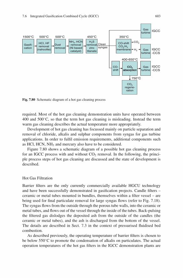
7.6 Integrated Gasification Combined Cycle (IGCC) 603
Gasifi-cation
HCI, HFremoval
(nahcolite)
NH3, HCNremoval
(Ni basedcatalyst)
Dustremoval
H2Sremoval
zinctitanate
CO-shiftCO2/H2
membrane
CO2absorption
CO2regene-ration
CO-shift
Cleansyngas
CO2
H2
Gasturbine
Gasturbine
Gasturbine
1500°C
400-650°C
750°C
IGCC
IGCC-CCS
IGCC-CCS
Gasifi-cation
HCI, HFremoval
(nahcolite)
NH3, HCNremoval
(Ni basedcatalyst)
Dustremoval
H2Sremoval
zinctitanate
CO-shiftCO2/H2
membrane
CO2absorption
CO2regene-ration
CO-shift
Gasturbine
Gasturbine
Fig. 7.80 Schematic diagram of a hot gas cleaning process
required. Most of the hot gas cleaning demonstration units have operated between400 and 500◦C, so that the term hot gas cleaning is misleading. Instead the termwarm gas cleaning describes the actual temperature more appropriately.
Development of hot gas cleaning has focussed mainly on particle separation andremoval of chloride, alkalis and sulphur components from syngas for gas turbineapplications. In order to fulfil emission requirements, additional components suchas HCl, HCN, NH3 and mercury also have to be considered.
Figure 7.80 shows a schematic diagram of a possible hot gas cleaning processfor an IGCC process with and without CO2 removal. In the following, the princi-ple process steps of hot gas cleaning are discussed and the state of development isdescribed.
Hot Gas Filtration
Barrier filters are the only currently commercially available HGCU technologyand have been successfully demonstrated in gasification projects. Candle filters –ceramic or metal tubes mounted in bundles, themselves within a filter vessel – arebeing used for final particulate removal for large syngas flows (refer to Fig. 7.18).The syngas flows from the outside through the porous tube walls, into the ceramic ormetal tubes, and flows out of the vessel through the inside of the tubes. Back-pulsingthe filtered gas dislodges the deposited ash from the outside of the candles (theceramic or metal tubes), and the ash is discharged from the bottom of the vessel.The details are described in Sect. 7.3 in the context of pressurised fluidised bedcombustion.
As described previously, the operating temperature of barrier filters is chosen tobe below 550◦C to promote the condensation of alkalis on particulates. The actualoperation temperatures of the hot gas filters in the IGCC demonstration plants are

604 7 Coal-Fuelled Combined Cycle Power Plants
even lower. The temperatures of the hot gas filters are ∼ 350◦C at Wabash (metal-lic elements) and 250◦C at Buggenum (ceramic elements) and Puertollano. Solidsbridging, candle degradation and breakage and fouling and corrosion of metalliccomponents have been the major problems. Further improvements are still neededto increase the filter element lifetime and to reduce filter installation, operating andmaintenance costs. Upstream cyclones are important components of a hot particleremoval system – minimising the load on the hot filters. Overall, hot gas filtrationoffers definite advantages to IGCC over water scrubbing (Korens et al. 2002; Holt2003).
Alkali Cleaning
There are two main methods employed for cleaning vapour-phase alkali compounds:
• Cleaning at low temperatures. When the gas temperature is lowered below550–600◦C, alkali vapours condense and can be removed by particle removalsystems.
• Syngases with alkali compounds can also be cleaned by passing through alkaligetters, such as activated bauxite or activated alumina, at higher temperatures.Alkali compounds are then physisorbed or chemisorbed on the getter surface,with chemisorption suggested to be the dominant pathway when moisture ispresent. More details can be found in Sect. 7.4.3.
Hot Gas Desulphurisation
Metal oxide sorbents, which come as regenerable or disposable types, are ableto capture H2S at elevated temperatures. Disposable sorbents, such as limestoneor dolomite, are typically calcium based and injected into the gasifier for in situdesulphurisation. H2S reacts with these materials at 950–1,050◦C and pressures over20 bar to form CaS. Due to thermodynamic limitations, only 90% sulphur removalcan be achieved, which means a typical outlet H2S concentration of 300–500 ppmv.These sorbents can only be used once, which increases the amount of solid wasteto be continuously removed from the process. Because CaS is not environmentallystable, it has to be converted to CaSO4, which requires a separate oxidation stage(Atimay 2001).
Regenerable sorbents are usually used in a separate fixed or movable bed reactorafter the gasifier. Having the unit separate makes it easier to regenerate the sorbent.Zinc oxide sorbents give the best results for H2S cleaning at elevated temperatures(in the range 350–750◦C). The desulphurisation reaction is
ZnO + H2S → ZnS + H2O (7.50)
and the regeneration reaction:
7.6 Integrated Gasification Combined Cycle (IGCC) 605
ZnS + 1.5O2 → ZnO + SO2 (7.51)
A great disadvantage of ZnO is the fact that it quickly reduces in reducing fuelgas atmospheres at high temperatures, so that the syngas is polluted with vaporisedzinc. Zinc titanate can achieve the same residual H2S level, but is more stable andshows a better attrition resistance. In general, zinc titanate (Zn2TiO4) is consideredthe best option for H2S removal at high temperatures of up to 850◦C (Aravind 2007).
The only two large-scale hot gas desulphurisation systems have been installed inthe USA. They have never been demonstrated, however. Both systems were basedon the reaction of H2S with zinc oxide/nickel oxide solid sorbents followed byregeneration of the sorbent by contact with air. The regenerator off-gas containedSO2, which had to be converted to elemental sulphur or sulphuric acid in a finalrecovery operation. At the 260 MW coal-fired IGCC in Tampa, the HGCU systemwas designed to treat 10% of the syngas flow. The HGCU was a moving bed absorp-tion process designed for temperatures of 480◦C. One of the reasons for cancellingthe demonstration was the sorbent attrition behaviour, which led to extremely highannual sorbent costs. Interest in HGCU processes such as hot desulphurisation hasbeen decreasing of late, partly because of disappointing results in finding solid sor-bents with the necessary attrition resistance (Korens et al. 2002; Tampa Electric1996).
HCl Removal
Hydrogen chloride has to be removed from the syngas to prevent corrosion in thegas cleaning train and in the gas turbine. Sodium and potassium compounds areeffective for dry removal of HCl and HF from syngas down to the ppm level attemperatures of 600◦C. Higher temperatures result in an increase of gaseous alkalis(Aravind 2007). Nahcolite (naturally occurring sodium bicarbonate, NaHCO3) andsodium carbonate/bicarbonate mixtures are considered for use as sorbents. In thecase of sodium carbonate, the following absorption reaction takes place:
Na2CO3 + 2HCl → 2NaCl + CO2 + H2O (7.52)
If the sorbent is injected before the particle filter, the solid salt can be separatedtogether with the dust.
Mercury Removal
The prospect of stringent mercury emissions standards for coal conversion plantsseriously dampens the outlook for hot or warm gas clean-up. It is believed thatmercury removal becomes more difficult as the syngas temperature increases. If itis necessary to cool the syngas for mercury removal, then the motivation for hot

606 7 Coal-Fuelled Combined Cycle Power Plants
or warm gas desulphurisation disappears unless related economic benefits can bedemonstrated (Korens et al. 2002).
Hot Gas Cleaning at Temperatures Above 1,400◦C
For the process of pressurised pulverised coal combustion, comprehensive inves-tigations have been carried out to develop a gas cleaning system at a temperatureabove the fluid temperature (1,400–1,600◦C). Results of these developments havebeen described in Sect. 7.4. It was proven that it is possible to remove liquid slagand gaseous alkalis down to very low concentrations in the gas. It is assumed thatit will also be possible to apply this technology to gasification systems, to removeliquid ash, alkalis and possibly heavy metals. If such cleaning is needed, the removalof sulphur and chlorine would require temperatures of about 600◦C as describedabove. The higher temperature gas cleaning process would be beneficial for gasifi-cation systems combined with a membrane shift reactor. The requirements for sucha reactor are not yet known. Investigations are currently being carried out in theframework of a research project (Muller et al. 2009; Spliethoff et al. 2009).
7.6.5.7 CO2 Separation at High Temperatures
Figure 7.80 shows a process configuration with hot gas cleaning and a CO2 sepa-ration step at the end of the gas cleaning train, similar to corresponding arrange-ments for cold gas cleaning. For the removal of CO2, a water gas CO shift reactor isrequired prior to the separation to produce a H2/CO2 mixture. There are two optionsfor H2/CO2 separation:
– CO/O2 separation by means of high-temperature membranes. The membranesseparate the syngas, already shifted to H2 and CO2, into nearly pure streams ofthe two gases. In this process, however, the H2 is produced at near-atmospheric
Fig. 7.81 Sorption-enhancedreforming
Gasifier +CO2 absorption
600 – 750°C
Regeneration(calcination)
Fuel(biomass,lignite)
H2O
CaO+ CaOash
O2
Fuel
H2 (CO, CH4)
freshCaCO3
CO2, H2O
CaCO3,char 3
3,

7.6 Integrated Gasification Combined Cycle (IGCC) 607
pressure, requiring compression for use in IGCC or refinery processes. Mostprobably, any hot gas membrane would require the prior removal of all particulatematerial and other trace components that may be corrosive or plug the membranepores, though the gas cleaning requirements depend on the membrane materialand are not yet known. It has to be pointed out that this technology is far frommature and that further development is required before it is applied, mainly dueto the high cost of ceramic membranes. Conceptual designs try to combine thefunctions of the CO shift and membrane separation processes in a water gas shiftmembrane reactor (WGSMR).
– Absorption of CO2 by using solid sorbents at temperatures between 400 and650◦C and regeneration at 750◦C. This process can be applied as a post-combustioncapture technology (termed carbonate looping) and will be discussed in Sect. 8.5.2.
CO2 absorption by CaO and regeneration of CaCO3 can be combined with steamgasification (Weimer et al. 2008; Florin and Harris 2008). This process is knownas lime-enhanced gasification of solid fuels (LEGS), sorption-enhanced reforming(SER) or absorption-enhanced reforming (AER). Figure 7.81 shows a schematicdiagram of the process, which consists of a steam gasification reactor as well asa regeneration reactor. For both reactors, fluidised beds are proposed because oftheir excellent gas/particle contact and the fact that the convenient temperatures areappropriate for fluidised beds.
• In the gasifier, CaO absorbs CO2 and increases the H2 concentration of theproduct gas. In the case of biomass, H2 concentrations of 40–50%, which arereported for steam gasification without CO2 capture, increase to about 80% afterCO2 absorption. The process conditions of the gasification reactor have to beselected according to the carbon conversion and CO2 absorption requirements.Carbon conversion is favoured at high temperatures, whereas the exothermic CO2
absorption is favoured at lower temperatures. To achieve a carbon capture of 80%it is necessary to increase the pressure as the temperature increases, for examplefrom a gasification pressure of 0.1 MPa at 650◦C to 0.9 MPa at 750◦C. Due to thisreason atmospheric gasification and capture is only suitable for biomass, whereasthe utilisation of brown coal requires pressurised conditions. The potential tofurther increase the pressure is limited, because increasing the pressure promotesmethane formation and reduces carbon capture. The exothermic CO2 absorptionreaction provides heat for the endothermic gasification.
• In a second reactor, CO2 is released by calcination of CaCO3, producing a high-purity CO2 stream for storage. The regenerated CaO is recycled to the gasifier. Atatmospheric pressure, the temperature required for regeneration is about 900◦C.Higher pressures require higher temperatures for regeneration, which results inan energy penalty. The heat required for regeneration can be provided by thecombustion of residual char from the gasifier. If a concentrated CO2 stream isrequired, oxygen is needed for combustion.

608 7 Coal-Fuelled Combined Cycle Power Plants
7.6.6 Components and Integration
7.6.6.1 Gas Turbines
Gas turbines are designed for natural gas and liquid fuels, but are also commerciallyavailable for operation using syngas. The two coal IGCC demonstration plants inthe USA (Tampa and Wabash) each use a GE 7FA turbine, while the two Euro-pean plants at Buggenum and Puertollano use the Siemens SGT5-2000E (previouslycalled V94.2) and the SGT5-4000F (previously called V94.3) (Maurstad 2005).
Syngas Combustion
Synthesis gas from high-temperature gasification essentially consists of carbonmonoxide and hydrogen. Hydrogen is very reactive and increases the flame velocity,as opposed to fuels containing hydrocarbons, which decrease it. The calorific valueof syngas from oxygen-blown gasifiers lies between about 8 and 11 MJ/kg, while itlies between 4 and 6 MJ/kg for air-blown gasifiers, which dilute the gas with nitro-gen. These latter values are roughly 4–10 times lower than the calorific values ofcommon gas turbine fuels. Given the lower air demand of H2 and CO, the adiabaticcombustion temperatures – under standard conditions for the combustion air (1 bar,15◦C) – are around 2,040◦C and thus 100◦C higher than in the combustion of naturalgas. By admixing the nitrogen fraction removed in air separation, the adiabatic com-bustion temperatures can be lowered to about 1,580◦C. These flame temperaturesare sufficiently low to limit the formation of thermal nitrogen in diffusion flames(Schetter et al. 1991).
Gas turbines which run on natural gas normally use the so-called dry low-NOx
(DLN) combustors. In these combustion chambers, the fuel is pre-mixed with thetotal air to lower the flame temperatures and reduce the formation of thermal NOx .They are designated “dry” because no injection of water or steam is used to reduceflame temperatures. However, DLN combustors are currently not used with syngasor hydrogen mixtures as fuels because of the danger of flashback caused by thehigh flame propagation speed of hydrogen. The current practice is to use traditionaldiffusion combustors, which require a diluent to reduce flame temperatures for NOx
control. The existing IGCC demonstration plants use nitrogen from the air sepa-ration unit, saturation of syngas with water or a combination of both to dilute thefuel before combustion with air. By these methods it is possible to reach a NOx
concentration of around 10 ppmv (at 15% O2) in the exhaust gas.For coal gas burners, emissions have to be low both for coal gas and for natural
gas firing. Figure 7.82 shows a standard hybrid burner and a modified hybrid burner,the latter of which is used in Buggenum and in Puertollano and operated as a simplediffusion burner. The syngas injection is via an annular swirl nozzle with a largecross-section around the centrally mounted natural gas or crude oil nozzle. Thesyngas flames in Buggenum are stable up to at least a calorific value of 4 MJ/kgand a 40% output and potentially more (Huth et al. 1998; Hannemann et al. 2003).
When a gas turbine is run on syngas, which has a higher share of hydrogen com-pared to natural gas, the exhaust gas may consist of more than the usual 8% by

7.6 Integrated Gasification Combined Cycle (IGCC) 609
Fig. 7.82 A burner for syngas applications (Huth et al. 1998)
volume of water vapour. The water vapour concentration can vary between 5% (forthe Puertollano fuel gas) and 14% (for pure hydrogen). The significance of a highervolume percentage of steam in the exhaust is an increased heat transfer, which raisesthe metal temperatures, thus shortening the lifetime of the turbine materials. Addi-tionally, the increased mass flow through the turbine also results in an enhanced heattransfer.
While there are several gas turbines running on syngas, there are no turbinesrunning solely on hydrogen. For pure hydrogen to be the fuel, the turbine inlettemperature (TIT) of the gas turbine would probably have to be reduced to avoidshorter lifetimes of the turbine blades (both the base materials and the coatings).This reduction in the TIT would reduce the efficiency of the combined cycle. InIGCC applications with CO2 removal, hydrogen can be diluted by water saturationor by nitrogen.
DLN burners for syngas or hydrogen are not state of the art, but their use wouldbe beneficial, because they do not require such a massive dilution for NOx control.Dilution with steam and nitrogen down to hydrogen concentrations of 50–70% isthe countermeasure to control the high flame propagation speed. DLN burners arecurrently under development.
Gas Turbine Power and Compressor Surge
As explained above, syngas use features a higher mass flow in comparison to naturalgas. The increased mass flow of fuel and therefore the higher mass flowrate throughthe turbine will increase the power output from the turbine. If the fuel is dilutedwith nitrogen or water, the potential for increased GT power output is even higher.Depending on the turbine, there may be several limitations to the realisation of the
610 7 Coal-Fuelled Combined Cycle Power Plants
increased power output, such as the risk of compressor surge and limitations on thegas turbine torque and turbine inlet temperatures.
A higher mass flowrate through the turbine stage will increase the pressure atthe turbine inlet and thus also at the compressor outlet, so that the compressor canrun into surge, with the air flow no longer maintained. The amount of pressureincrease the compressor can tolerate is defined as the compressor surge margin,which depends on the design of a given compressor. There are several other possiblestrategies to resolve the surge limitation problem:
• Modify the gas turbine of the GT: The turbine itself can be modified to have anincreased cross-sectional area to allow a higher flowrate.
• Modify the compressor of the GT: With an additional compressor stage the gasturbine can operate at a higher overall pressure ratio without surge problems.
• Bleeding off air from the compressor: This solution is possible for plants with airintegration. Bleeding off more air mass flow than the mass flow of the nitrogenbrought back from the ASU to the turbine reduces the mass flow through theturbine. Air integration therefore provides the potential to use gas turbines whichwould otherwise need to be redesigned to work with syngas (Maurstad 2005).
7.6.6.2 Air Separation Unit (ASU)
The oxygen supply to a gasifier is one of the most expensive single parts of anygasification process. The capital cost of the ASU, with its associated compressors,is about 10–15% of the total plant cost. The commercial technology used for oxygenproduction in IGCC plants is cryogenic air separation, which may be defined as theseparation of air into component gases by distillation at low temperatures. Cryo-genic air separation has single-train O2 production capacities of 3,200 t/day and isrecognised for its high reliability.
The major energy requirement of the process is for the air compression, whichis in the order of magnitude of 5–7% of the gross generator output. Typically, theair to the ASU is compressed to around 5 bar, and the oxygen (typically 95% O2,3.5% Ar and 1.5% N2 by volume) and nitrogen product streams become availableat around 1 bar. The process may also operate at elevated pressure so that part or allof the ASU air is supplied from the gas turbine compressor. In this case, the ASUproduct streams are at around 5 bar, so this reduces the recompression work.
Alternative processes for air separation are limited in capacity and achievableoxygen purity. Pressure swing absorption units are available up to a capacity ofabout 140 t/day, but they can only reach a purity of about 95%. The product qualityobtainable with polymer membrane technology is about 40% oxygen, with capac-ities of up to 20 t/day. Oxygen purity is a limiting factor for chemical applica-tions. Most probable gasification applications for polymer membrane technologyand pressure swing absorption are biomass power applications, where the sizes arealso at the lower end of the scale. Both technologies have the advantage of a quickstart-up compared to cryogenic units (Higman and van der Burgt 2008; Maurstad2005).
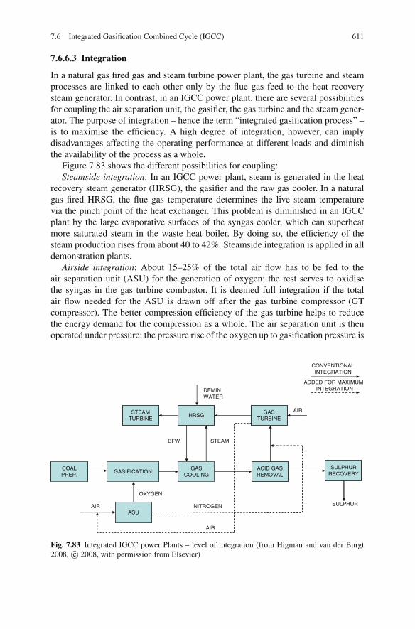
7.6 Integrated Gasification Combined Cycle (IGCC) 611
7.6.6.3 Integration
In a natural gas fired gas and steam turbine power plant, the gas turbine and steamprocesses are linked to each other only by the flue gas feed to the heat recoverysteam generator. In contrast, in an IGCC power plant, there are several possibilitiesfor coupling the air separation unit, the gasifier, the gas turbine and the steam gener-ator. The purpose of integration – hence the term “integrated gasification process” –is to maximise the efficiency. A high degree of integration, however, can implydisadvantages affecting the operating performance at different loads and diminishthe availability of the process as a whole.
Figure 7.83 shows the different possibilities for coupling:Steamside integration: In an IGCC power plant, steam is generated in the heat
recovery steam generator (HRSG), the gasifier and the raw gas cooler. In a naturalgas fired HRSG, the flue gas temperature determines the live steam temperaturevia the pinch point of the heat exchanger. This problem is diminished in an IGCCplant by the large evaporative surfaces of the syngas cooler, which can superheatmore saturated steam in the waste heat boiler. By doing so, the efficiency of thesteam production rises from about 40 to 42%. Steamside integration is applied in alldemonstration plants.
Airside integration: About 15–25% of the total air flow has to be fed to theair separation unit (ASU) for the generation of oxygen; the rest serves to oxidisethe syngas in the gas turbine combustor. It is deemed full integration if the totalair flow needed for the ASU is drawn off after the gas turbine compressor (GTcompressor). The better compression efficiency of the gas turbine helps to reducethe energy demand for the compression as a whole. The air separation unit is thenoperated under pressure; the pressure rise of the oxygen up to gasification pressure is
STEAMTURBINE
HRSGGAS
TURBINE
ACID GASREMOVAL
SULPHURRECOVERY
ASU
BFW
OXYGEN
NITROGEN
AIR
AIR SULPHUR
AIR
DEMIN.WATER
CONVENTIONALINTEGRATION
ADDED FOR MAXIMUMINTEGRATION
GASIFICATION
ASU
GASCOOLING
COALPREP.
STEAM
Fig. 7.83 Integrated IGCC power Plants – level of integration (from Higman and van der Burgt2008, c© 2008, with permission from Elsevier)

612 7 Coal-Fuelled Combined Cycle Power Plants
therefore smaller. The degree of (air) integration is usually defined as the percentageof the total ASU air required coming from the GT compressor. The two existing USIGCC demonstration plants started with 0% integration, while the two Europeanplants had 100% integration.
The possible benefits of integration are an increased efficiency, increased poweroutput and reduced capital cost (e.g. savings on the ASU air compressor). The draw-backs of high integration are a possible reduced availability of the process, lessoperational flexibility, lengthy start-up times and the fact that the ASU cannot startwithout the GT running. An integration of 100% will always yield the maximumefficiency, but not necessarily the maximum power.
Because of the lower process availability and operational flexibility during start-up and shutdown, a partial integration scheme is implemented in newer plants as acompromise between availability and operational flexibility on the one hand andefficiency on the other. In such schemes, only part of the air flow for the ASUis taken from the gas turbine, and the rest of the air is fed by way of a separatecompressor.
Integration on the nitrogen side: In order to reduce the flame temperatures in thegas turbine and the nitrogen oxide emissions, nitrogen is fed before or into the gasturbine combustor. Similarly to air integration, prior pressurisation of the nitrogenreduces the necessary pressure increase up to the gasification pressure. Even if theair integration is 0%, it may still be beneficial to use nitrogen from the ASU for NOx
reduction (Geosits and Schmoe 2005; Higman and van der Burgt 2008; Eurlings andPloeg 1999; Maurstad 2005).
7.6.7 State of the Art and Perspectives
7.6.7.1 IGCC Plants in Operation
The worldwide installed gasification capacity of about 70 GWth predominantlyserves to make chemical products and fuels; only about 20% of the capacity is usedto generate electrical power. For power generation, residues from refinery processesare mostly used – the generation of electrical power by coal in IGCC power plantsworldwide is limited to a few plants with a total fuel capacity of 3 GW (NETL2007; Minchener 2005). IGCC technology for coal was demonstrated, using publicfunding, at several locations in the 1990s in Europe and the USA. The followingplants were part of those demonstrations and are being operated commercially atthe moment:
• In 1994, the 253 MWel (semi-)commercial IGCC power plant Demkolec wascommissioned at Buggenum, the Netherlands. The net generating efficiency ofthis power plant, which uses Shell gasification technology, is 43.2%.
• In 1995, the 252 MWel Wabash River IGCC went into operation in Terre Haute,Indiana (USA), based on the E-Gasification process. Wabash River was a repow-ering of a small steam power plant and not a greenfield project. The IGCC has anet efficiency of 39.9%.
7.6 Integrated Gasification Combined Cycle (IGCC) 613
• In 1996, a 250 MWel IGCC was commissioned in Polk County, Florida (USA).This IGCC power plant, based on Texaco gasification technology, has a net gen-erating efficiency of 38.0% (Tampa Electric 2002; Tampa Electric 2004).
• In 1996, a 318 MWel IGCC went into service at Puertollano (Spain). Until 1998,the power plant was operated using natural gas as a (secondary) fuel (Hannemannet al. 2003; Mendez-Vigo et al. 1998; Cortes 1999). When the gasifier was readyfor operation in 1998, hard coal and petroleum cokes (50/50%) became the mainfuels. Puertollano makes use of Prenflo gasification technology and has a netefficiency of 45%.
The plant data is compiled in Table 7.18. The two European plants, due to theirgas turbines, dry feeding, dry quenching and high degree of integration of the airseparation unit, have a higher efficiency.
7.6.7.2 Description of the Puertollano Plant
The IGCC plant in Puertollano is the biggest coal-based IGCC power plant in theworld, having a net capacity of 305 MWel and a design efficiency of 45% at acondenser pressure of 0.0715 bar. The fuel used is a mixture, consisting half ofa Spanish coal with a very high ash content (47% ash) and half of a high-sulphurpetrol coke. The efficiency is highly dependent on the fuel; running with the petrolcoke alone, an efficiency of only 42% is achieved. Despite the high-sulphur fuel, theemissions of SOx remains below 20 mg/Nm3 (at 6% O2), which is below the EUlimit by one order of magnitude.
The entrained-flow gasifier is fed with oxygen of 85% purity, and at high tem-peratures (above 1,600◦C) the finely milled fuel gets converted. The fuel is blownin pneumatically with a nitrogen stream which is tapped after the air separationunit. The pressure in the reactor is 25 bar; the temperature at the outlet of thegasifier is about 1,600◦C. The employed gasification system is a Prenflo entrained-flow gasifier, which is roughly similar in construction to the Shell gasifier. About30–50% of the cold syngas is recycled to quench the hot syngas from the gasifier toabout 900◦C. A convective heat exchanger further reduces the temperature to about200◦C. The particles are separated from the cooled raw gas in a ceramic cartridgefilter, and there is the potential to return the fly ash to the gasifier by way of alock-hopper system, thus removing almost the entire ash load from the process asunleachable slag. Subsequently, the raw gas is subjected to wet gas cleaning, con-sisting of an MDEA scrubber, an upstream COS hydrolysis unit and a Claus tail-gascleaning process for sulphur production. The residual sulphur content of the coalgas is then less than 25 mg/m3. After the cleaning process, the syngas is dilutedwith nitrogen from the air separation unit and burned in the gas turbine combustor.The flue gases, with a gas turbine entry temperature of 1,150◦C, expand in the gasturbine. The remaining heat of 500◦C as it exits the turbine is used in the HRSG(Coca 2003).
The air separation unit has a high degree of integration and is fed with a par-tial flow from the air compressors. Part of the nitrogen stream produced during air

614 7 Coal-Fuelled Combined Cycle Power Plants
Table 7.18 Data for IGCC power plants in operation (Hannemann et al. 2003; Lako 2004;Tampa Electric 2002; Tampa Electric 2004; Holt 2003; Coca 2003)
IGCC power plant Wabash river Buggenum Puertollano TampaYear (operational) 1995 1994 1998 1996State/Country Indiana/USA The Netherlands Spain Florida/USAFeedstock Hard coal Hard coal Lignite and
petr. cokeHard coal
Secondary fuel – Natural gas Natural gasGasification process E-Gas Shell Prenflo GELevel of integration Low High High Low
Raw gas (after the gasifier)Fuel gas temperature [◦C] 300 300 302 330
H2 [%vol.] 34.4 25.5 22.1 36.4CO [%vol.] 45.3 62.7 60.5 42.8CO2 [%vol.] 15.8 2.2 3.9 14.4N2 [%vol.] 2.9 8.8 12.5 3.3Ar [%vol.] 0.6 0.8 1.0 0.9H2/CO ratio (vol.) 0.76 0.4 0.36 0.85HHV [MJ/m3] 10.3 10.4 10.5 9.9
Fuel gas (fired in the gasturbine)N2 [%vol.] 42.0 53.1H2O [%vol.] 19.1 4.2LHV [MJ/m3] 4.3 4.3
EmissionsSO2 emission [mg/m3] 40 35 25 40NOx emission [mg/m3] 100 25 150 100
IntegrationAir extracted from GTrelated to ASU [%]
0 100 100 0
Related to compressor [%] 0 16 18 0Nitrogen integration [%] 0 100 100 100
OutputGas turbine [MW] 192 156 179 192Steam turbine [MW] 96 128 137 120–135Net power output [MW] 252 253 276 250
Net efficiency [LHV]High-quality hard coal [%] 39.9 43.2 45.0 38.0Lignite and petcoke [%] – – 42.0Petroleum cokes [%] – –Natural gas [%] – 52 52.4
separation is used to transport the dry and milled fuel mixture into the gasifier,while another part of it cleans the raw gas dedusting cartridge filters. The remainingnitrogen stream is mixed in with the cleaned coal gas before entering the gas turbinecombustor to lower the combustion temperature and comply with the NOx emissionlimit without flue gas cleaning.

7.6 Integrated Gasification Combined Cycle (IGCC) 615
In Fig. 7.86, an optimised IGCC configuration based on the configuration of theplant in Puertollano is shown.
7.6.7.3 Process Availability and Costs of IGCC Plants
In all the IGCC power plants in operation, a great number of problems arose inthe first years of operation in relation to the gasifier, the gas turbine and the gascleaning. The high integration degree of the ASU, too, gave rise to difficulties andresulted in the use of new control techniques. Today, the process availabilities ofthe power plants range between about 70 and 80% and are thus markedly lowerthan the availabilities of steam power plants. Figure 7.84 shows this graphically,making it clear that the main problem of this technology is its lower availability. Theability to compete with other power plant technologies requires availabilities higherthan 90%. IGCC plants in refineries show higher availabilities when tried-and-tested technologies and lower degrees of integration are used (Folke 2006; Higman2005). New data from Buggenum with availabilities of 90% underlines that from anengineering point of view it should be possible to achieve similar availabilities thanin conventional power plants.
Another problem is the considerably higher cost of IGCC power plants.Figure 7.85 pits the capital costs of the installed IGCC power plants against thecapital costs of conventional pulverised coal fired steam power plants, using Eurosin 2004 as a basis. The capital costs of the erected plants were between 30 and100% above the costs of conventional steam power plants; currently, it is assumedthat costs are 40% higher. The expectation is, however, that this cost differencewill decrease as advancement along the learning curve for IGCC technology occurs(Lako 2004). In addition, if CO2 capture is considered, it is expected that IGCCpower plants with CO2 capture and steam power plants with CO2 capture will haveroughly the same level of capital costs.
Fig. 7.84 Process availabilityof existing IGCC plants(Folke 2006)

616 7 Coal-Fuelled Combined Cycle Power Plants
Fig. 7.85 Cost of IGCCplants in comparison toconventional steam powerplants (Lako 2004)
Coal
IP Coalpreparation
N2
Coalfeed
Raw gas/Clean gas
heat exchanger
HP
IPRaw gas
Slag
IP
Clean gassaturator
Quench
Waste watertreatment
O2 N2
Airseperation
unit
DiluentN2
Venturi
Cyclone
Candlefilter
Clean gas
COSHydrolysis
Clean gasSulfur
ClausplantMDEA
Air
Diluent N2saturator
Air
TurbineV94.3A
Fuel gas
Gas
Exhaust gas
Reheat
HP
DENOX(SCR)IP
Saturationwater
preheatLP
Condensate
Heat recoverysteam generator
Flue gas
BFW Tank
Make-upwater
Condenser
Steamturbine
HP IP LP G
O2
G
Sulfur
MDEA
Air
Fig. 7.86 Process flow diagram of IGCC 98 (Pruschek 2002)
7.6.7.4 Efficiency Potential
IGCC power plants in operation today achieve electrical efficiencies of up to about45%. Using today’s state-of-the-art technology, without CO2 removal, IGCC powerplants could be designed and built with an electrical efficiency of over 50%. If theclassical single components and the overall IGCC concept were to be further opti-mised, electrical efficiencies of 55% could be achieved within 15 years. Estimatesof efficiency are based both on achieved efficiencies at operating plants (and thepotential to optimise them) and on the expected future advancements in technology,particularly for the gas turbine.

7.6 Integrated Gasification Combined Cycle (IGCC) 617
Extensive studies on the potential of IGCC power plants were carried out byPruschek, who, within the framework of European projects, and comparing to theIGCC plant in Puertollano, investigated the design and the efficiency of an IGCCpower plant feasible in 1998 (Pruschek 1998). Its configuration, shown in Fig. 7.86,is similar to the configuration of the Puertollano IGCC power plant. The entrained-flow gasification is operated at a pressure of 29 bar with 95% oxygen as the oxidiser.The gas exiting the gasifier first gets cooled to about 900◦C with recirculated rawgas, then the remaining flue gas heat is used to generate steam and to reheat thecleaned fuel gas. The air separation unit is fully integrated, so that the fresh air isalso compressed in the gas turbine compressor and part of the waste nitrogen ismixed back into the fuel gas before entering the gas turbine combustor. The wastenitrogen and the cleaned fuel gas are humidified with the necessary water fractionby saturators before the mixing is performed, at a temperature as low as possible.At the given ambient conditions and at a gas turbine entry temperature of 1,250◦C(ISO), the IGCC achieves an efficiency of 51.5%. The efficiency owes its increase,in essence, to the raising of the gas turbine entry temperature to 1,250◦C, as wellas further measures such as the increase of the steam conditions and more intensivefuel gas preheating (Haupt et al. 1998; Pruschek 1998; Pruschek et al. 1997).
Over and above the 1998 IGCC concept design, there are considerable potentialsfor increasing the efficiency of IGCC power plants. Applying the measures shownin Fig. 7.87, efficiencies up to 58% could be achieved. It becomes clear that devel-opment of gas turbines would yield the largest efficiency increases. Hot dry gascleaning would raise the efficiency by about 0.7% (Pruschek 1998).
7.6.7.5 IGCC Concept Designs with CO2 Removal
IGCC power plants can separate CO2 with few additional components and canbe regarded as the most advanced power plant technology for CO2 separation,because the necessary additional components (CO shift and CO2 scrubbing units)
60%
59%
58%
57%
56%
55%
54%
53%
52%
51%
50%
Net
effi
cien
cy(L
HV
)
Time
IGCC 98
Sup
ercr
itica
l ste
am+
0.4
%
Dry
hig
h te
mp.
gas
clea
ning
+ 0
.7%
Fue
l gas
. tem
p.37
5 50
0°C
+ 0
.5%
Reh
eat G
T(T
IT 1
200°
C)
+ 1
.8%
TIT
140
0°C
(Sim
ple
GT
)+
0.9
% TIT
140
0°C
(Reh
eat G
T)
+ 1
.3%
Sta
gedg
asifi
catio
n/ch
emic
alqu
ench
+ 0
.2%
IGF
C(S
OF
C)
+ 0
.2%
IGF
C(S
OF
C)
Fig. 7.87 Potential future development of IGCC power plants (Pruschek 1998)

618 7 Coal-Fuelled Combined Cycle Power Plants
are employed already for the production of hydrogen. An IGCC design with CO2
capture is shown in Fig. 8.22. Expectations are that the efficiency will drop by about8–10% compared to a process without CO2 capture – starting out from the IGCC98 concept, having 52% efficiency, the efficiency decreases to 42%. In Chap. 8, theIGCC technology with CO2 removal is compared to competing methods for CO2
separation during power production.Various projects examining the design and construction of a CO2-free power
plant using IGCC technology are currently in progress, such as the following:
• RWE: Construction of a 360 MWel lignite IGCC-CCS power plant by 2014(Lambertz and Ewers 2006). The current design results in low efficiencies in therange of about 35% because first priority has been given to the plant availability.For this reason proven technologies and a low level of integration have beenchosen.
• FutureGen (USA): Construction of a 275 MWel IGCC-CCS power plant, a projectlasting until 2012 (FutureGen 2007)
• GreenGen (China): Development of its own coal gasification technology by 2009followed by construction of a 400 MWel demonstration plant for hydrogen pro-duction with CO2 capture (Folke 2006).
7.6.7.6 Long-Term Perspectives
Further development must aim to eliminate the disadvantages of IGCC power plants,namely the low availability and the high costs. If these problems can be solved,IGCC could provide a substantial increase in the efficiency of power generationfrom coal.
In gasification, the major part of the fuel energy gets converted into chemicallybound energy and a smaller part into heat. A level of conversion into chemicallybound energy as high as possible and a heat exploitation as efficient as possibleshould be aimed at.
The quality of the conversion into chemically bound energy is described by thecold gas efficiency. The maximum conversion of fuel energy into chemical energycan be achieved using chemical quenches or by internal heat utilisation. Gasificationmethods should be sought that combine the benefit of fluidised bed gasification (highcold gas efficiency) with the benefit of entrained-flow gasification (ash removal, fuelflexibility, compactness).
The utilisation of the heat of hot syngases would be optimal if the gases couldbe fed directly into the gas turbine. However, for gas cleaning, these gases haveto be cooled down to very low temperatures. The heat removed when cooling tothese temperatures can be partly used, being converted into mechanical energy withthe lower efficiency of the steam cycle. On top of this, the requirements of gascleaning involve cooling and heating processes that cause additional exergy losses.In order to avoid them, gas cleaning processes need to be developed that run athigher temperatures and in dry conditions to the greatest possible extent. The aim

References 619
is not to cool the gas below the temperature of the following step in the process, sothat a continuous extraction of useful heat is possible.
A further significant increase in the energy efficiency can be expected by usinghydrogen membranes. With H2 membranes, only a stoichiometric steam-to-CO ratiowould be necessary. This could decrease the demand of steam significantly, whilealso making it possible to avoid the cooling to the thermodynamically necessary lowtemperatures for the shift reaction, thus providing a hotter gas for the burner of thegas turbine. In this respect, high-temperature membrane shift reactors are desired,which, in one unit, perform both the gas conversion (shift) and the gas separation.
The long-term development objective for a CO2-free IGCC power plant with thehighest possible efficiency is therefore a high-pressure, high-temperature gasifierwith integrated hot gas cleaning, H2 separation by catalytic high-temperature mem-branes at the highest possible temperatures and an H2 gas turbine being fed with hotfuel gas.
In the long term, it will also be reasonable to combine gasification and solidoxide fuel cells (SOFCs). The technology suited in particular for this process isallothermal fluidised bed gasification, which utilises the waste heat of an SOFC tosupply gasification heat.
References
Aho, M., Hernberg, R. and Hayrinen, V. (1995). Fuel reactivity and release of pollutants and alkalivapours in pressurized combustion for combined cycle power generation. Final Report, Con-tract JOU2-CT92-0037.
Almhem, P. (1996). PFBC-Heizkraftwerk Cottbus, Wirbelschicht-Kombi-Anlage fur Trocken-braunkohle. VDI-GET Tagung “Entwicklungslinien der Energie- und Kraftwerkstechnik”.Siegen.
Aquaro, D. and Pieve, M. (2007). High temperature heat exchangers for power plants: performanceof advanced metallic recuperators. Applied Thermal Engineering 27(2–3): 389–400.
Aravind, P. V. (2007). Studies on High Efficiency Energy Systems Based on Biomass Gasifiers andSolid Oxide Fuel Cells with Ni/GDC Anodes. Delft, TU Delft. Ph.D.
Asai, A., Izaki, K., Egami, Y., Tsuji, K., Kumagai, S. and Nishijima, Y. (2004). System outline andoperational status of Karita Power Station New Unit 1 (PFBC). JSME International JournalSeries B-Fluids and Thermal Engineering 47(2): 193–199.
Atimay, A. T. (2001). Cleaner energy production with integrated gasification combined cycle sys-tems and use of metal oxide sorbents for H2S cleanup from coal gas. Clean Products andProcesses 2: 197–208.
Bammert, K. (1986). Operating experience and measurements on turbo sets of CCGT-cogenerationplants in Germany. International Gas Turbine Conference, Dusseldorf, ASME-Paper 86-GT-101.
Bannister, R. L., Newby, R. A. and Diehl, R. C. (1992). Development of a direct coal fired com-bined cycle. Mechanical Engineering 114(12): 64–70.
Bannister, R. L., Pillsbury, P. W., Diehl, R. C. and Loftus, P. J. (1990). Recent test results in thedirect coal fired 80 MW combustion turbine program. International Gas Turbine and Aero-engine Congress, Brussels, ASME-Paper 90-GT-58.
Bauer, D. A. and Marocco, M. (1995). Tidd PFBC demonstration plant, summary of operations.Book 3, Part C, Vol. 2, pp. 109–121, Anaheim, USA, Power Gen 95 Americas.

620 7 Coal-Fuelled Combined Cycle Power Plants
Bauer, F., Meier, H. J., Smuda, J. V. and Stuhlmuller, F. (1994). PFBC Development for LigniteFired CC Power Plants. Power-Gen Europe, Koln, Band III, pp. 101–120.
Baum, J. (2001). Untersuchungen zum extern befeuerten Gasturbinenprozeß mit Hochtemper-aturwarmeubertrager. VDI Fortschritt-Berichte Reihe 6 Energietechnik, Nr. 456. Dusseldorf,VDI.
Benson, S. (2000). Ceramics for advanced power generation. London, IEA CoalResearch, CCC/37.
Bliem, C. et al. (1985). Ceramic heat exchanger concepts and materials technology. Park Ridge,NJ, Noyes.
Bohm, H. (1994). Fossilbefeuerte Kraftwerke. Stand, Entwicklungstendenzen. VGB Kraftwerk-stechnik 74(3): 173–186.
Bohn, D. (2005). Technologien fur Gasturbinen der ubernachsten Generation. VGB PowerTech85(7): 65–71.
Bohn, D. (2007). Improved cooling concept for turbine blades of high-temperature gas turbines.VGB PowerTech 87(10): 96–103.
Bonn, B. (1996). On-line Messung von Alkalidampf-Konzentrationen in heißen Rauchgasen.BMBF-Statusseminar Heißgasreinigung. Karlsruhe.
Bunthoff, D. and Meier, H. J. (1987). Umweltfreundliches Kraftwerk mit Druckwirbelschicht-feuerung, Planungskriterien fur die Dampferzeuger. VGB Kraftwerkstechnik 67(8): 751–757.
Bunthoff, D., Rehwinkel, H. and von Wedel, G. (1990). Druckwirbelschichtfeuerung: Fortschrit-tliche Konzepte und aktueller Entwicklungsstand. Technische Mitteilungen 83(1): 25–32.
Chalupnik, R. W., Krautz, H. J., Wirtz, M. and Stuhlmuller, F. (2001). Applied research for a newgeneration of lignite-fired combined cycle power plants using circulating pressurized fluidizedbed combustion. Proceedings of the 16th International Conference on Fluidized Bed Combus-tion. May 13–16, Reno, NV.
Coca, M. (2003). Integrated gasification combined cycle technology – Its actual application inSpain: ELCOGAS- Puertollano. From http://www.elcogas.es/en home set.htm
Coombs, M., Kotchick, D. and Waren, H (1979). High-temperature ceramic heat exchanger. Finalreport EPRI-EP-1127, July 1979. Torrance, CA, AiResearch Mfg. Co.
COORETEC (2003). Forschungs– und Entwicklungskonzept fur emissionsarme fossilbefeuerte Kraftwerke – Bericht der COORETEC-Arbeitsgruppen. Bundesministeriumfur Wirtschaft und Arbeit, December 2003, ISSN 0342-9288 (BMWA-Dokumentation), Fromhttp://www.bmwa.bund.de.
Cortes, J. C. (1999). Puertollano IGCC; operation status. Gasification Technologies Conference.October 12–20, San Francisco CA.
Cowell, L. H. and LeCren, R. T. (1992). Experimental evaluation of a two stage slagging combus-tor design for a coal-fueled industrial gas turbine. International Gas Turbine and AeroengineCongress. Cologne, ASME-Paper 92-GT-259.
Cowell, L. H., Hasen, A. M., LeCren, R. T. and Stephenson, M. D. (1992a). Coal fueled two-stageslagging combustion island and cleanup system for gas turbine application. International GasTurbine and Aeroengine Congress. Brussels, ASME-Paper 90-GT-59.
Cowell, L. H., LeCren, R. T. and Tenbrook, C. E. (1992b). Two-Stage Slagging Combustor Designfor a Coal-Fueled Industrial Gas Turbine. Journal of Engineering for Gas Turbines and Power114(4): 359–366.
Daijou, Y., Suzuki, K., Ishinomori, T., Shigeta, J., Yanagisawa, T. and Tsumita, Y. (1997). Alkali-vapor measurements in the Wakamatsu PFBC plant. Proceedings of the 14th International Con-ference on Fluidized Bed Combustion. Vancouver, Canada.
Dibelius, G. and Pitt, R. (1989). Gasturbinenkonzepte fur Druckwirbelschichtanlagen – Konzepte,Auslegung, Betriebsverhalten. VDI-Berichte 715: 213–236.
DOE (1997). Clean coal technology demonstration program. Washington, DC, October.DOE (2003a). Clean coal technology program, McIntosh Unit 4A PCFB Demonstration Project.DOE (2003b). Clean coal technology program, McIntosh Unit 4B Topped PCFB Demonstration
Project.

References 621
Edelmann, H. and Stuhlmuller, F. (1997). EFCC – Ein zukunftiges Konzept fur Kohle-Kombikraftwerke. VGB Kraftwerkstechnik 77(7): 537–543.
Emsperger, W. and Bruckner, H. (1986). Kombiprozesse mit atmospharischen und druckbetriebe-nen Wirbelschichtsystemen. VDI-Berichte Nr 601: 257–272.
Escobar, I. and Muller, M. (2007). Alkali removal at about 1400 degrees C for the pressurizedpulverized coal combustion combined cycle. 2. Sorbents and sorption mechanisms. Energy &Fuels 21(2): 735–743.
Escobar, I., Oleschko, H., Wolf, K.-J. and Muller, M. (2008). Alkali removal from hot flue gas bysolid sorbents in pressurized pulverized coal combustion. Powder Technology 180(1–2): 51–56.
Eurlings, J. and Ploeg, J. (1999). Process performance of the SCGP at Buggenum IGCC. Gasifica-tion Technologies Conference. October 18–20, San Francisco, CA.
Fichtner (1992). Der Kombiprozeß mit indirekt kohlegefeuerter Gasturbine. Abschlußbericht,BMFT-Forderkennzeichen 0326746, September.
Florin, N. H. and Harris, A. T. (2008). Enhanced hydrogen production from biomass with in situcarbon dioxide capture using calcium oxide sorbents. Chemical Engineering Science 63(2):287–316.
Folke, C. (2006). Kohlvergasung – Option zur CO2-Abtrennung. Kraftwerkstechnisches Kollo-quium Dresden 2006. Vortrag V7.10.
Forster, M., Hannes, K. and Teloken, R. (2001). Combined cycle power plant with Pressurized CoalCombustion (PPCC): State of development and perspectives. VGB PowerTech 81(9): 30–35.
Forster, M., Neumann, F., Teloken, R. and Pavone, D. (2005). Druckkohlenstaubfeuerung:Aktueller Fortschritt des kohlebasierten GuD-Prozesses in Richtung Gasturbinenvertraglichkeitund Stand des Entwicklungsprojektes. VGB PowerTech 85(6): 38–41.
FutureGen (2007). Initial conceptual design report. 2009, from http://www.futuregenalliance.org/publications.stm.
Geosits, R. F. and Schmoe, L. A. (2005). IGCC – The challenges of integration. ASME Turbo Expo2005: Power for Land, Sea and Air, June 6–9, 2005, Reno-Tahoe, NV. Paper GT2005-68997.
Gockel, B. (1994). Ein mathematisches Modell zur Berechnung der Kohlenstaubverbrennung unterBerucksichtigung hoherer Drucke. Dissertation Universitat Bochum.
Goto, H. (1995). Operation experience from the 71 MW Wakamatsu PFBC demonstration plant.Proceedings of the 13th International Conference on Fluidized Bed Combustion. Orlando, FL.2: 911–918.
Gottwald, U., Monkhouse, P. and Bonn, B. (2001). Dependence of alkali emissions in PFB com-bustion on coal composition. Fuel 80(13): 1893–1899.
Groll, M. (1980). Grundlagen und Anwendungen des Warmerohres. Naturwissenschaften 67:72–79.
Hannemann, F. et al. (2003). Pushing forward IGCC technology at Siemens. Gasification Tech-nologies 2003. 13 October 2003, San Francisco, CA.
Hannes, K. (1986). Kohlenstaub-Druckverbrennung. Entwicklungsstand und Anforderungen desProzesses an die Verbrennungsfuhrung VGB-Kraftwerkstechnik 77(5): 393–400.
Hannes, K. (1996). Entwicklungsprogramm Druckkohlenstaubfeuerung. BMBF-StatusseminarHeißgasreinigung. Karlsruhe.
Hannes, K. W. (2002). Kohle-Kombi-Kraftwerke mit Druckkohlenstaubfeuerung: DasDruckflamm-Forschungsprogramm. VGB PowerTech 82(8): 56–60.
Hannes, K. W., Reichert, G. and Weber, E. (1989). Pressurized pulverized coal combustion withmolten ash removal. Conference on Technologies for Producing Electricity in the 21st Century.San Francisco, USA.
Harkins, B. D. and Ward, M. E. (1989). Preliminary design of a high pressure, high temperatureceramic air heat exchanger. In: Waste heat utilization, the winter annual meeting of the ASME.San Francisco, CA, December 10–15, Band HTD-118, pp. 51–61.
Haupt, G., Zimmermann, G., Baumann, H.-R., Ullrich, N., Pruschek, R. and Oeljeklaus, G. (1998).New design of IGGCC for competitive power generation. Gasification Technologies Confer-ence. October 4–7, San Francisco, CA.

622 7 Coal-Fuelled Combined Cycle Power Plants
Higman, C. (2005). The reliability of integrated gasification combined cycle (IGCC) power gener-ation units. Gasification Technologies Conference. San Francisco, CA.
Higman, C. and van der Burgt, M. (2008). Gasification. Amsterdam [u.a.], Elsevier/GPP, GulfProfessional Publishing.
Hippinen, I., Jahkola, A. and Lu, Y. (1991). Pressurized fluidized bed combustion of different typeof solid fuels. Proceedings of the 11th International Conference on Fluidized Bed Combustion.Montreal, ASME.
Hoberg, H. and Gudenau, H. W. (1998). Heißgasreinigung fur Kombiprozesse mit Druckkohlen-staubfeuerung. VGB-Konferenz Forschung in der Kraftwerkstechnik. Essen.
Hokari, N., Miyamoto, T., Ito, O., Mizumoto, M., Tomuro, J., Iwase, T., Yoshioka, S. and Ootani,Y. (2001). Sulfur dioxide removal performance of 250 MW PFBC at Osaki. Proceedings of the16th International Conference on Fluidized Bed Combustion. May 13–16, Reno, NV.
Holt, N. A. H. (2003). Operating experience and improvement opportunities for coal-based IGCCplants. Materials at High Temperatures 20(1): 1–6.
Hubner, K., Miao, J. and Gorner, K. (2003). Untersuchungen zur Alkalisorption mit Unterstutzungelektrischer Felder bei extremen Temperaturen oberhalb von 1300◦C. 21. Deutscher Flammen-tag, Cottbus, VDI.
Hubner, K., Pavone, D., Schmidt, D. and Weber, E. (1988). Moglichkeiten der Gasreinigung imTemperaturbereich oberhalb von 1000◦C. VGB Kraftwerkstechnik 68(9): 931–935.
Hurley, J. P., Seery, D. J. and Robson, F. L. (2003). Experience with an ODS high-temperature heatexchanger in a pilot-scale HiPPS plant. Materials at High Temperatures 20(1): 39–44.
Huth, M., Vortmeyer, N., Schetter, B. and Karg, J. (1998). Verbrennung von Synthesegas in Gas-turbinen. BWK 50(9): 35–39.
Jahraus, B. and Dieckmann, R. (1989). Der Kombiprozeß mit indirekt gefeuerter Gasturbine. VDI-Berichte 1182: 287–300.
Jansson, S.A. (1995a). ABB‘s PFBC technology operation experience and standard products. EPRIConference on New Power Generation Technology. San Francisco, CA.
Jansson, S. A. (1995b). PFBC – clean coal technology – status and experience. Power-Gen Europe’95. Amsterdam, The Netherlands. 4: 97–109.
Jansson, S. A. (1996). Gas turbine tolerance to particulates and chemical constituents. BMBFStatusseminar “Heißgasreinigung in der Kraftwerkstechnik”. Germany, Karlsruhe.
Jansson, S. A. and Svensson, J.-A. (1997). Experiences from the IEA hotgas filter testing project.Proceedings of the 14th International Conference on Fluidized Bed Combustion. Vancouver,Canada.
Jansson, S. and Anderson, J. (1999). Progress of ABB’s PFBC projects. Proceedings of the 15thInternational Conference on Fluidized Bed Combustion. May 16–19, Savannah, GA.
Jansson, S., Kemmer, L. and Flodin, E. (1996). Pressurized fluidized bed power plants. EnergyConference. Haifa.
JBDT (1992). Jahrbuch der Dampferzeugertechnik, 7. Ausgabe, Essen Vulkan.Jopp, K. (2005). Neue Maßstabe im GuD-Prozess. BWK 67(6): 52–54.Juntgen, H. and van Heek, K. H. (1981). Kohlevergasung – Grundlagen und Technische Anwen-
dung. Munchen, Verlag Karl Thiemig.Kail, C. and Rukes, B. (1995). Fortschrittliche Gas- und Dampfturbinenprozesse zur
Wirkungsgrad- und Leistungssteigerung bei GuD-Kraftwerken. VDI-Berichte 1182: 71–87.Kainer, H. (1988). Keramische Warmetauscher. In: Technische Keramik. pp. 325–333 Essen,
Vulkan.Kainer, H. and Willmann, G. (1987). Komponenten fur den Bau keramischer Rekuperatoren –
Moglichkeiten und Beschrankungen. Gas Warme International 36(6): 332–340.Kaser, J. (1996). Alkali Release under PFBC Conditions. Diplomarbeit, Institut fur Verfahrenstech-
nik und Dampfkesselwesen, Universitat Stuttgart und ABB Carbon.Keller, C. (1946). The Escher Wyss-AK closed-cycle turbine, its actual development and future
prospects. Transactions of the ASME 68: 791–822.
References 623
Keller, C. and Gaehler, W. (1961). The coal burning closed-cycle gas turbine. Gas Turbine PowerConference. ASME-Paper 61-GTP-2, Washington, DC
Keppel, W. (1995). Die Gasturbine als Schlusselkomponente in der modernen Kraftwerkstechnik.VDI-Berichte 1182: pp. 1–25.
Klara, J. M. (1994a). High performance power systems for the near-term and beyond. InternationalGas Turbine and Aeroengine Congress and Exposition. Netherlands, ASME-Paper 94-GT-315.
Klara, J. M. (1994b). HIPPS can compete with conventional PC systems. Part II. Power Engineer-ing 98: pp. 33–36.
Kloster, R. (1999). Thermodynamische Analyse und Optimierung von Gas-/Dampfturbinen-Kombi-Kraftwerke mit integrierter Kohlevergasung, VDI-Fortschritt-Berichte Reihe 6, Nr. 409Dissertation Universitat Essen.
Koike, J., Nakamura, S., Watanabe, H. and Imaizumi, T. (2003). Manufacturing and construction,operation of Karita 360 MW unit. Proceedings of the 17th International Fluidized Bed Com-bustion Conference. May 18–21, 2003, Jacksonville, FL.
Korens, N., Simbeck, D. R. and Wilhelm, D. J. (2002). Process screening analysis of alternativegas treating and sulfur removal for gasification. Pittsburgh, CA USDOE.
Kuhn, S. (2007). Funktions- und Betriebssicherheit eines druckaufgeladenen Wirbelschichtver-gasers. Doctoral thesis, Technische Universitat Munchen, Munchen.
Kuhnle, J., Wolf, H., Maile, K., Kußmaul, K., Baum, J., Spliethoff, H. and Hein, K. R. G. (1997).Untersuchungen zum Einsatz und zur Entwicklung eines Hochtemperaturwarmetauschers inKohlenstaubfeuerungen. Abschlussbericht, Stiftung Energieforschung Baden-Wurttemberg,Forderkennzeichen A 000 4793/4893.
LaHaye, P. G. and Bary, M. R. (1994). Effective means of rejuvenation for older coal-fired stations.International Gas Turbine and Aeroengine Congress and Exposition. The Hague/The Nether-lands, ASME-Paper 94-GT-483.
LaHaye, P. G. and Feldmann, B. E. (1986). Externally fired gas turbine/combined cycle. Interna-tional Coal Utilization Conference and Exhibition. Pittsburgh, CA.
LaHaye, P. G., Briggs, G. F., Mazer, J. M. and Seger, J. L. (1990). Results of preliminary coal-firedtests on high pressure ceramic air heater for indirectly-fired gas turbine applications. Proceed-ings of the 7th Annual Coal-fueled Heat Engines and Gas Stream Center (METC).
LaHaye, P. G. and Zabolotny, E. (1989). Externally-fired combined cycle. ASME Cogen-TurboMeeting. Nice, France.
Lako, P. (2004). ‘Coal-fired power technologies.’ Coal-fired power options on the brink of climatepolicies. ECN-C–04-076, October 2004.
Lambertz, J. and Ewers, J. (2006). Clean coal power – Die Antwort der Kraftwerkstechnik auf dieHerausforderungen der Klimavorsorge. VGB PowerTech 86(5): 71–77.
Landfermann, H. and Hausner, H. (1988). Keramische Werkstoffe – Ubersicht, Herstellung –Eigenschaften – Anwendungen. In: Technische Keramik. Essen, Vulkan, pp. 11–15.
Lee, S. H. D. and Carls, K. M. (1990). Measurement of sodium and potassium vapours inpressurized-bed combustion of Beluah lignite. Journal of the Institute of Energy 66(12):203–210.
Lee, S. H. D. and Swift, W. M. (1991). A fixed granular-bed sorber for measurement and controlof alkali vapors in PFBC. 11th International Conference on Fluidized Bed Combustion. pp.1095–1103 Montreal, ASME.
Leufert, J. (1993). Abschlußbericht Verbundprojekt Druckkohlenstaubfeuerung, Phase I,Forschungsteilbereich Kohleumwandlungssystem. BMBF-Forderkennzeichen FKZ 03266.
Mann, M. D. and Ludlow, D. K. (1997). Capture of alkali during pressurized fluidized-bed com-bustion using in-bed sorbents. Proceedings of the 14th International Conference on FluidizedBed Combustion. Vancouver, Canada, ASME.
Martinez Crespo, P. and Menedez Perez, J. A. E. (1995). Operating experiences at the escatronpressurized fluid bed combustion demonstration plant. Power-Europe, Amsterdam, The Nether-lands, Vol. 4, pp. 113–130.

624 7 Coal-Fuelled Combined Cycle Power Plants
Maurstad, O. (2005). An overview of coal based integrated gasification combined cycle (IGCC)technology, from http://lfee.mit.edu/publications.
McMullan, J. (2004). Fossil fuel power generation, State of the art. Power Clean Network.Mendez-Vigo, I., Schellberg, W. and Karg, J. (1998). The Puertollano IGCC plant: status update.
Gasification Technologies Conference. October 4–7, San Francisco, CA.Minchener, A. J. (2005). Coal gasification for advanced power generation. Fuel 84: 2222–2235.Mitchell, S. (1997). Hot gas particulate filtration. London, IEA Clean Coal Centre, IEACR/95.Moersch, O., Nagel, H., Spliethoff, H. and Hein K. R. G. (1999). Influence of various operating
conditions on advanced PFBC with staged combustion. Proceedings of the 15th InternationalConference on Fluidized Bed Combustion. May 16–19, Savannah, GA.
Mojtahedi, W. and Backman, R. (1989). The fate of sodium and potassium in the pressurizedfluidized-bed combustion and gasification of peat. Journal of the Institute of Energy, December,189–196, from http://www.ingentaconnect.com/content/maney/eni.
Monkhouse, P. (2002). On-line diagnostic methods for metal species in industrial process gas.Progress in Energy and Combustion Science 28(4): 331–381.
Monkhouse, P. B., Gottwald, U. A., Davidsson, K. O., Lonn, B., Engvall, K. and Pettersson, J. B. C.(2003). Phase discrimination of alkali species in PCFB combustion flue gas using simultaneousmonitoring by surface ionisation and photofragmentation fluorescence∗. Fuel 82(4): 365–371.
Muller, M. (2008). Freisetzung und Einbindung von Alkalimetallverbindungen in zukunftigen,kohlebefeuerten Kombikraftwerken, RWTH Aachen. Habilitation.
Muller, M., Forster, M. and Pavone, D. (2008). Enforced binding of alkali metals into liquid slagsby weak electrical fields. Proceedings of the 7th International Symposium on Gas Cleaning atHigh Temperatures. Shoal Bay, Australia.
Muller, M., Pavone, D. and Abraham, R. (2009). Hot fuel gas cleaning in IGCC at gasificationtemperature. Proceedings of the 4th International Conference on Clean Coal Technologies forour Future (CCT). Dresden.
Mustonen, J. P., Bossart, S. J. and Durner, M. W. (1991). Technical and economic analysis ofadvanced particle filters for PFBC applications. Proceedings of the 11th International Confer-ence on Fluidized Bed Combustion. Montreal, ASME.
Nagel, H. (2002). Untersuchungen zum Emissionsverhalten und Wirkungsgradpotential vonDruckwirbelschichtfeuerungen der ersten und zweiten Generation. Dusseldorf, VDI.
Nagel, H., Spliethoff, H. and Hein, K. R. G. (1998). Untersuchungen zum Einfluß des Hybrid-konzeptes auf den Betrieb einer Druckwirbelschichtfeuerung. Proceedings of the 10th Interna-tional VGB-Konferenz Forschung in der Kraftwerkstechnik. Essen.
NETL (2007). Gasification database, from http://www.netl.doe.gov/technologies/coalpower/gasification/database/database.html.
Neumann, F., Hannes, K., Wirtz, S. and Kremer, H. (1996). Untersuchungen zur Auslegung einesHochtemperaturwarmetauschers fur die Integration in einem kombinierten Gas- und Dampf-turbinenprozeß mit druckaufgeladener Kohlenstaubfeuerung. VDI-Berichte Nr 1280: 473–498.
Newby, R. A., Lippert, T., Alvin, M. A., Bruck, G. J., Sanjana, Z. N. and Smeltzer, E. E. (2001). Hotgas filter status and innovations for PFBC. Proceedings of the 16th International Conference onFluidized Bed Combustion. May 13–16, Reno, NV.
Newby, R. A., Lippert, T., Bruck, G. J., Alvin, M. A. and Smeltzer, E. E. (1999). Development ofadvanced hot gas ceramic filter systems. Proceedings of the 15th International Conference onFluidized Bed Combustion. May 16–19, Savannah, GA.
Ogriseck, K. and Meyer, B. (2005). Erzeugung wasserstoffreicher Brennstoffe in IGCC-Kraftwerksprozessen fur eine CO2-arme Braunkohlenutzung. VGB Powertech 85(11): 54–59.
Oleschko, H. and Muller, M. (2007). Influence of coal composition and operating conditions onthe release of alkali species during combustion of hard coal. Energy & Fuels 21: 3240–3248.
Parsons, E. L. and Byam, J. W. (1989). Overview of gas turbine coal-fired combustor concepts.Gas Turbine and Aeroengine Congress. Toronto, ASME-Paper 89-GT-252.
Pietsch, A. (1978). Coal fired prototype high temperature continuous flow heat exchanger AF-684research project 545-1. Final report, Feb 1978. Phoenix, AZ, AiResearch Mfg. Co. of Arizona.
References 625
Pillsbury, P. W., Bannister, R. L., Diehl, R. C. and Loftus, P. J. (1989). Direct coal firing for largecombustion turbines: what do economic projections and subscale combustor tests show? JointASME/IEEE Power Generation Conference, Dallas, ASME-Paper 89-JPGC/GT-4.
Preußer, P. and Spindler, K. (1988). Druckkohlenstaubfeuerung: Stand, Wirkungsgrad undEntwicklungsziele. VGB Kraftwerkstechnik 68(9): 917–921.
Pruschek, R. (1998). Improvement of IGCC power plants starting from the state of art, JOF3-CT95-0004, Final Report.
Pruschek, R. (2002). Elektrizitatserzeugung aus fossilen Brennstoffen in Kraftwerken. In: E.Rebhan (ed.) Energiehandbuch: Gewinnung, Wandlung und Nutzung von Energie. Berlin,Springer.
Pruschek, R., Oeljeklaus, G., Haupt, G. and Zimmermann, G. (1997). Kohlekraftwerke derZukunft. Teil 2: Stand und Entwicklungspotentiale von GUD-Prozessen mit integrierterKohlevergasung. BWK 49(11/12): 48–52.
Pruschek, R., Renz, U. and Weber, E. (1990). Kohlekraftwerke der Zukunft – Stand der Entwick-lung, Erprobung und Planung neuer Kohlekraftwerkstechnologien, Ministerium fur Wirtschaft,Mittelstand und Technologie des Landes Nordrhein-Westfalen.
Punjak, W. A., Uberoi, M. and Shadman, F. (1989). High-temperature Adsorption of Alkali Vaporson Solid Sorbents. AIChE Journal 35(7): 1186–1194.
Radhakrishnan, P., Zakkay, V. and Agnone, A. (1986). Alkali and gas emissions from PFB com-bustion of lignite. Combustion Science and Technology 50: 271–281.
Radtke, K. R., Henritz-Adrian, M. and Marsico, C. (2006). New wave of coal-to liquids. VGBPowerTech 86(5): 78–84.
Radtke, K. R., Battensby, D. and Marscio, C. (2005). Renaissance of gasification based on cuttingedge technologies. VGB PowerTech 85(9): 72–77.
Ratcliff, P., Garbett, P. and Fischer, W. (2007). The new Siemens gas turbine SGT5-8000H formore customer benefit. VGB PowerTech 87(9): 128–132.
Rehwinkel, H. (1989). Konzepte, Entwicklungsziele und Einsatzschwerpunkte fur druckaufge-ladene Wirbelschichtfeuerungen. VDI-Berichte 715: 237–258.
Rehwinkel, H., Meier, H.-J. and von Wedel, G. (1993). Stationare und zirkulierende Druck-wirbelschichtfeuerung: Versuchsergebnisse und Anlagenkonzepte. VGB Kraftwerkstechnik73(6): 529–535.
Rehwinkel, H., Meier, H.-J. and von Wedel, G. (1992). Stationare und zirkulierendeDruckwirbelschichtfeuerung: Versuchsergebnisse und Anlagenkonzepte. VGB-KonferenzWirbelschichtsysteme. Essen, VGB-TB 214.
Reichelt, T. (2001). Freisetzung gasformiger Alkaliverbindungen bei atmospharischer und druck-aufgeladenener Verbrennung. Dusseldorf, Fortschritt-Berichte VDI, Reihe 3, Nr. 687, VDI.
Reichert, G., Thelen, F., Schmidt, D. and Weber, E. (1988). Untersuchung an Druckkohlen-staubfeuerungen. VGB Kraftwerkstechnik 68(10): 1017–1021.
Renz, U. (1993). Heißgasfiltration bei Wirbelschichtfeuerungen. VDI-Berichte 1081.Renz, U. (1994). An assessment of PFBC technology, present and future. International Clean Coal
Technology Symposium on PFBC. Japan, Kitakyushu.Riedle, K., Rukes, B. and Wittchow, E. (1990). Die Erhohung des Kraftwerkswirkungsgrades in
der Vergangenheit und in der Zukunft. VGB Konferenz “Kraftwerkstechnik 2000. Essen, VGBTB 120.
Robertson, A., Fan, Z., Goldstein, H., Horazak, D., Newby, R. A. and Bose, A. C. (2005). 2ndgeneration PFB plant with super critical pressure steam turbine. Proceedings of the 22nd Inter-national Pittsburgh Coal Conference. September 12–15.
Robertson, A., Goldstein, H., Horazak, D. and Newby, R. A. (2001). Second-generation PFB plantperformance with W501G gas turbine. Proceedings of the 16th International Conference onFluidized Bed Combustion. May 13–16, Reno, NV.
Rogbeck, J. (1996). Utilisation of residues from PFBC. International Coal Technology Symposiumon Coal Ash Utilisation. Tokyo.
Rukes, B. (1993). Kraftwerkskonzepte fur fossile Brennstoffe VDI-Berichte 1023, pp. 3–40.

626 7 Coal-Fuelled Combined Cycle Power Plants
Ruth, L. A. (1997). The US department of energy’s combustion 2000 program: clean, efficientelectricity from coal. Energy Conversion and Management 38(10–13): 1249–1257.
Ruth, L. A. (2001). Advanced coal-fired power plants. Journal of Energy Resources Technology-Transactions of the ASME 123(1): 4–9.
Sasatu, H., Tazawa, K., Goto, H., Misawa, N. and Sakuno, S. (2001). CTF development at Waka-matsu 71 MWe PFBC combined cycle power plant. Proceedings of the 16th International Con-ference on Fluidized Bed Combustion. May 13–16, Reno, NV, ASME.
Scandrett, L. A. and Clift, R. (1984). The thermodynamics of alkali removal from coal-derivedgases. Journal of the Institute of Energy, from http://www.ingentaconnect.com/content/maney/eni.(Dec): 391–397.
Schemenau, W. (1993). Druckwirbelschichtfeuerung – fortschrittliche Kohleverstromung mitBetriebserfahrung. BWK 45(1/2): 23–26.
Schemenau, W. and Anderson, J. (1992). Druckwirbelschichtfeuerung – betriebsbewahrteKohleverstromung mit geringer Emission und gutem Wirkungsgrad. VGB-KonferenzWirbelschichtsysteme, VGB-TB 214. Essen.
Schemenau, W. and van den Bergh, C. (1993). Betriebserfahrungen bei druckaufgeladenenWirbelschichtfeuerungen und neue Konzepte von Druckwirbelschichtfeuerungsanlagen großerLeistung. VDI-Bericht 1081, VDI: 19–44.
Schetter, B., Becker, B. and Egener, E. G. (1991). Schadstoffarme Kohlegasverbrennung in mod-ernen Gasturbinen. VGB-Konferenz Kohlevergasung 1991. Mai 16–17, Dortmund, VGB.
Schiffer, H. P. (1989). Heißgasentstaubung. VDI-Berichte 715.Scholer, D. (2007). NGF/SGT5-8000H – Gasturbinentechnologie. 39. Kraftwerkstechnisches Kol-
loquium Dresden.Schuknecht, M. (2003). Entwicklungspotential eines Kombikraftwerks mit Druckkohlen-
staubfeuerung, Universitat Essen. Dissertation.Schurmann, H., Unterberger, S., Hein, K. R. G., Monkhouse, P. B. and Gottwald, U. (2001). The
influence of fuel additives on the behaviour of gaseous alkali compounds during pulverised coalcombustion. Faraday Discussions 119: 433–444.
Shimuzu, M. and Itoh, M. (2001). Development and operation results of Osaki 250 MW com-mercial PFBC plant (Osaki 1-1 PFBC Plant). 16th International Conference on Fluidized BedCombustion. May 13–16, Reno, NV.
Singer, J. G. (1991). Combustion fossil power. Windsor, VT, Combustion Engineering.SolarTurbines (1980). Development of a ceramic tube heat exchanger with relaxing joint. Final
report, DOE contract No. EF-77-C-01-2556, FE-2556-30.Spliethoff, H. (2000). Verbrennung fester Brennstoffe zur Strom- und Warmeerzeugung: Verfahren
und Stand der Technik – Wirkungsgrad, Betrieb, Emissionen und Reststoffe. VDI Fortschritt-Berichte, Reihe 6 Energietechnik, Nr. 443. Dusseldorf, VDI.
Spliethoff, H. and Baum, J. (2002a). Externally fired combined cycle – Potential and state of theart (Part 1): BWK 54(5): 70–75.
Spliethoff, H. and Baum, J. (2002b). Externally fired combined cycle-Potential and state of the art(Part 2): BWK 54(6): 52–56.
Spliethoff, H., Meyer, B., Muller, M. and Hack, K. (2009). Investigations on high temperature gasi-fication and gas cleaning – The research project HotVeGas. Proceedings of the 4th InternationalConference on Clean Coal Technologies for our Future (CCT), Dresden.
Stoll, K. E. and Bleif, F. (1986). Entwicklung, Errichtung und Erprobung eines umweltfreundlichenSteinkohlekraftwerkes – Modellkraftwerk Volklingen. BMFT-Forschungsbericht T 86-025.
Strauß, K. (2006). Kraftwerkstechnik: zur Nutzung fossiler, nuklearer und regenerativerEnergiequellen. Berlin [u.a.], Springer.
Stringer, J. (1989). Erosion and corrosion in PFBC systems. VDI-Berichte 715: 57–82.Stuhlmuller, F. and Schauenburg, G. (2001). The gas turbine in a power plant with pressurized
circulating fluidized bed combustion. Proceedings of the 16th International Conference on Flu-idized Bed Combustion. May 13–16, Reno, NV.

References 627
Stuhlmuller, F., Schauenburg, G. and Waldinger, D. (1995). Die Standard-Gasturbine imDruckwirbelschicht-Einsatz. VGB Kraftwerkstechnik 75(12): 1037–1042.
Takahashi, M., Nakabayashi, Y. and Kimura, N. (1995). Aktueller Stand der 350 MW-Wirbelschichtfeuerung Takehara und der 71-MW-Druckwirbelschichtfeuerung Wakamatsu derEPDC sowie der fortschrittlichen Stromerzeugung in Japan. VGB Kraftwerkstechnik 75(5):427–432.
Tampa Electric (1996). The Tampa electric integrated gasification combined-cycle project,From http://www.fossil.energy.gov/programs/powersystems/publications/Clean Coal TopicalReports/topical19.pdf.
Tampa Electric (2002). Tampa electric polk power station IGCC project – Final technical report,August 2002, From http://www.netl.doe.gov/technologies/coalpower/cctc/cctdp/bibliography/demonstration/aepg/baepgig tampaig.html.
Tampa Electric (2004). Project performance summary, clean coal technology demonstra-tion program, June 2004, from http://www.netl.doe.gov/technologies/coalpower/cctc/cctdp/bibliography/demonstration/aepg/baepgig tampaig.html.
Terhaag, U., Renz, U., Dibelius, G., Bohn, D., Reinartz, A. and Steven, H. (1995). Ergebnisse ausdem Betrieb des druckaufgeladenenen Wirbelschicht-Dampferzeugers im Heizkraftwerk derRWTH Aachen. VGB Kraftwerkstechnik 75(3): 243–246.
Thambimuthu, K. V. (1993). Gas cleaning for advanced coal-based power generation. London,IEA Coal Research. ieacr/53.
Thelen, F. (1993). Gas-/Dampfturbinenprozesse fur feste Brennstoffe mit Druckwirbelschicht-feuerung. VGB Kraftwerkstechnik 73(8): 671–677.
Toriyama, A., Higashi, K., Maeno, H., Saito, T., Mori, M. and Hori, J. (1999). Operating resultsof the advanced ceramic tube filter (ACTF) at Wakamatsu 71 MW PFBC demonstration plant.Proceedings of the 15th International Conference on Fluidized Bed Combustion. May 16–19,Savannah, GA.
Turn, S. Q., Kinoshita, C. M., Ishimura, D. M., Zhou, J., Hiraki, T. T. and Masutani, S. M. (1998).A review of sorbent materials for fixed bed alkali getter systems in biomass gasifier combinedcycle applications. Journal of the Institute of Energy 71: 163–177.
Uberoi, M. (1990). The kinetics and mechanism of alkali removal from flue gases by solid sorbents.Progress in Energy Combustion Science 16: 205–211.
Uhde (2008). PRENFLO gasification. Dortmund, Uhde.Vandervort, C. L. (1991). High pressure ceramic air heater for indirectly fired gas turbine appli-
cations. Proceedings of the 8th Coal-Fueled Heat Engines and Gas Stream Cleanup SystemsContractors Review Meeting. Morgantown, WV.
Vandervort, C. L. and Orozco, N. J. (1992). Development status of a utility-scale externally firedcombined cycle. Proceedings of the 9th Annual International Pittsburgh Coal Conference, Pitts-burgh.
Walter, E., Krautz, H. J. and Almhem, P. (1997). Lignite fired combined cycle heat and power plantusing pressurized fluidized bed combustion. Proceedings of the 14th International Conferenceon Fluidized Bed Combustion. ASME, Vancouver, Canada.
Ward, M. E., Metcalfe, A. G. and Dapkunas, S. J. (1983). Ceramic tube heat exchanger tech-nology development for indirect-fired gas turbine cycle. Transactions of the ASME 105:310–316.
Warner, J. and Nielsen, H. (1993). Umfassendes Auswahlverfahren ermoglicht optimale Auslegungvon Kombikraftwerken. ABB Technik, Nr. 8.
Wauschkuhn, A. (1994). Kostenvergleich von Kohlekraftwerken. Studienarbeit, Institut fur Ver-fahrenstechnik und Dampfkesselwesen der Universitat Stuttgart.
Weber, E. and Pavone, D. (1990). Entwicklungslinien der Gasreinigung bei hochsten Gastem-peraturen. Symposium Emissionsminderung mit dem Schwerpunkt Hochtemperatur- undHochdruck-Gasreinigung, Essen.
Weber, E., Hubner, K., Pavone, D., Schulz, R. and Wiggers, H. (1993). Entwicklungsergebnissebei der Druckkohlenstaubfeuerung. VGB Kraftwerkstechnik 73(7): 602–607.

628 7 Coal-Fuelled Combined Cycle Power Plants
Weimer, T., Berger, R., Hawthorne, C. and Abanades, J. C. (2008). Lime enhanced gasification ofsolid fuels: examination of a process for simultaneous hydrogen production and CO2 capture.Fuel 87(8–9): 1678–1686.
Weitzel, P. S. and McDonald, D. K. (1999). PFBC design and arrangement improvements due tothe application of ceramic tube filters. Proceedings of the 15th International Conference onFluidized Bed Combustion. ASME, May 16–19 Savannah, GA.
Weitzel, P. S., McDonald, D. K., Whitney, S. A. and Oda, N. (1996). Directions and trends forcommercial PFBC and hot gas clean up. Pittsburgh, PA, Pittsburgh Coal Conference.
Wen, C. S., Cowell, L. H., Smit, F. J., Boyd, J. D. and LeCren, R. T. (1992). Coal alkali retentionin a slagging combustor. Fuel 71(2): 219–224.
Wheeldon, J. M., Bonsu, A. K., Foote, J. P., Mortan, F. C., Romans, D. E. and Zoldak, F. D.(2001). Commissioning of the circulating PFBC in the Foster Wheeler advanced PFBC train atthe PDSF. 16th International Conference on Fluidized Bed Combustion. May 13–16, Reno, NV.
Willenborg, W., Muller, M. and Hilpert, K. (2006). Alkali removal at about 1400 degrees C forthe pressurized pulverized coal combustion combined cycle. 1. Thermodynamics and concept.Energy & Fuels 20(6): 2593–2598.
Wilson, D. G. (1993a). Low-leakage and high flow regenerators for gas turbine engines. Proceed-ings Institution of Mechanical Engineers 207: 195–202.
Wilson, D. G. (1993b). The supplementary-fired exhaust-heated cycle for coal, wood and refuse-derived fuel. Proceedings Institution of Mechanical Engineers 207: pp. 203–208.
Wilson, D. G., Frenkel, R. G., Kowalick, D. J., Nahatis, H. M., Silverstein, S. M. and Tampe, L.A. (1991). Coal-burning exhaust-heated-cycle gas turbine with a regenerative heat exchanger.international gas turbine and aeroengine. Congress and Exposition, ASME-Paper 91-GT-342Orlando, FL.
Wittchow, E. and Muller, R. (1993). Fortgeschrittene Kraftwerkskonzepte mit druckaufgeladenenKohleumwandlungsverfahren. VDI-Berichte 715, 1989, pp. 21–44.
Wright, I. G., Stringer, J. and Wheeldon, J. M. (2003). Material issues in bubbling PFBC systems.Materials At High Temperatures 20(2): 219–232.
Wu, Z. (2006). Developments in fluidised bed combustion technology. London, IEA Clean CoalCentre.
Zakkay, V., Gbordzoe, E., Radhakrishnan, R., Sellakumar, K. M., Patel, J., Kasinathan, R., Haas,W. J. and Eckels, D. E. (1989). Particulate and alkali capture from PFBC flue gas utilizinggranular bed filter (GBF). Combustion Science and Technology 68: 113–130.
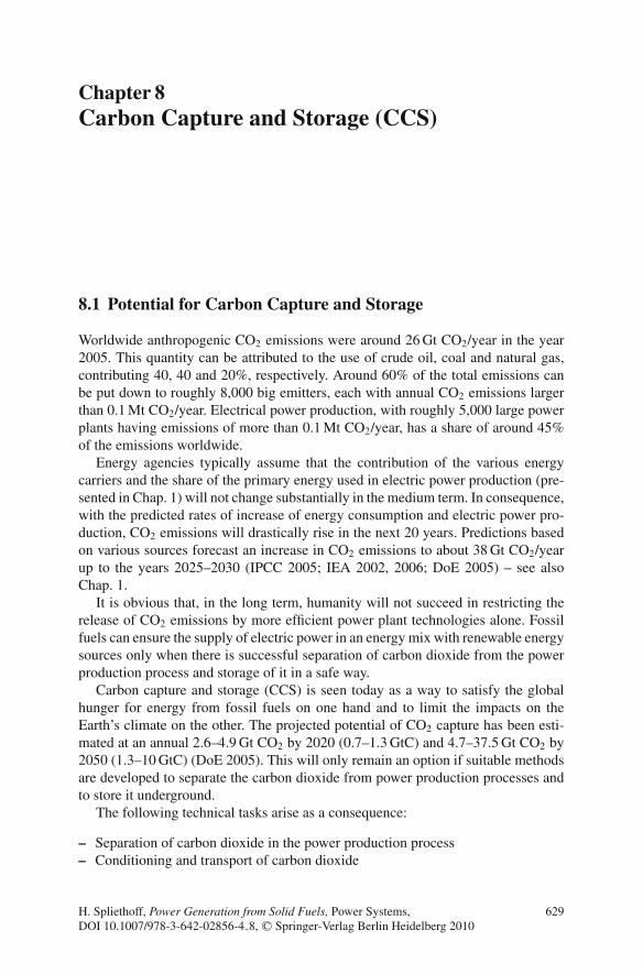
Chapter 8Carbon Capture and Storage (CCS)
8.1 Potential for Carbon Capture and Storage
Worldwide anthropogenic CO2 emissions were around 26 Gt CO2/year in the year2005. This quantity can be attributed to the use of crude oil, coal and natural gas,contributing 40, 40 and 20%, respectively. Around 60% of the total emissions canbe put down to roughly 8,000 big emitters, each with annual CO2 emissions largerthan 0.1 Mt CO2/year. Electrical power production, with roughly 5,000 large powerplants having emissions of more than 0.1 Mt CO2/year, has a share of around 45%of the emissions worldwide.
Energy agencies typically assume that the contribution of the various energycarriers and the share of the primary energy used in electric power production (pre-sented in Chap. 1) will not change substantially in the medium term. In consequence,with the predicted rates of increase of energy consumption and electric power pro-duction, CO2 emissions will drastically rise in the next 20 years. Predictions basedon various sources forecast an increase in CO2 emissions to about 38 Gt CO2/yearup to the years 2025–2030 (IPCC 2005; IEA 2002, 2006; DoE 2005) – see alsoChap. 1.
It is obvious that, in the long term, humanity will not succeed in restricting therelease of CO2 emissions by more efficient power plant technologies alone. Fossilfuels can ensure the supply of electric power in an energy mix with renewable energysources only when there is successful separation of carbon dioxide from the powerproduction process and storage of it in a safe way.
Carbon capture and storage (CCS) is seen today as a way to satisfy the globalhunger for energy from fossil fuels on one hand and to limit the impacts on theEarth’s climate on the other. The projected potential of CO2 capture has been esti-mated at an annual 2.6–4.9 Gt CO2 by 2020 (0.7–1.3 GtC) and 4.7–37.5 Gt CO2 by2050 (1.3–10 GtC) (DoE 2005). This will only remain an option if suitable methodsare developed to separate the carbon dioxide from power production processes andto store it underground.
The following technical tasks arise as a consequence:
– Separation of carbon dioxide in the power production process– Conditioning and transport of carbon dioxide
H. Spliethoff, Power Generation from Solid Fuels, Power Systems,DOI 10.1007/978-3-642-02856-4 8, C© Springer-Verlag Berlin Heidelberg 2010
629

630 8 Carbon Capture and Storage (CCS)
– Safe and long-term storage of carbon dioxide (VGB 2002; IPCC 2005;Linßen et al. 2006; Seifritz 1989; Smith and Thambimuthu 1991; Pruschek andOeljeklaus 1992; Radgen et al. 2005)
8.2 Properties and Transport of CO2
The physical state of carbon dioxide varies with temperature and pressure as shownin Fig. 8.1. At normal temperatures and pressure, carbon dioxide is a gas. At atmo-spheric pressure and temperatures far below ambient temperatures, carbon diox-ide is a solid. With increasing temperature, the solid will sublime directly into thevapour phase – at atmospheric pressure, carbon dioxide sublimes at a temperatureof −78.5 ◦C. At intermediate temperatures between the temperature of the triplepoint (−56.5 ◦C, 5.2 bar) and the temperature of the critical point (31.1 ◦C, 73.9bar), a pressure increase results in a gradual state change as a two-phase gas – liquidmixture. At ambient temperature and pressures above 60 bar, carbon dioxide is aliquid. At temperatures higher than 31.1 ◦C and pressures above 73.9 bar, carbondioxide is in a supercritical state, where it behaves as a gas. The density of carbondioxide is given in Fig. 8.2 as a function of pressure and temperature.
The transport of the carbon dioxide is the tie between the emitter and the CO2
storage location. Depending on the transport and storage mechanisms, CO2 has tohave a certain condition. To give an example, for the injection of CO2 into depletedoil fields or gas reservoirs, the carbon dioxide ought to be provided pressurised in
Fig. 8.1 Phase diagram of CO2 (Ritter et al. 2007)
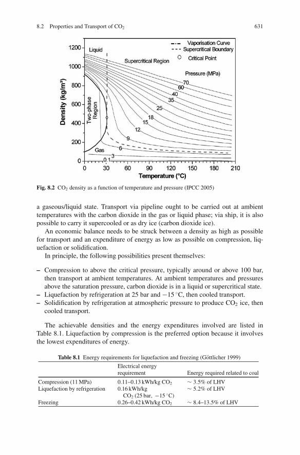
8.2 Properties and Transport of CO2 631
Fig. 8.2 CO2 density as a function of temperature and pressure (IPCC 2005)
a gaseous/liquid state. Transport via pipeline ought to be carried out at ambienttemperatures with the carbon dioxide in the gas or liquid phase; via ship, it is alsopossible to carry it supercooled or as dry ice (carbon dioxide ice).
An economic balance needs to be struck between a density as high as possiblefor transport and an expenditure of energy as low as possible on compression, liq-uefaction or solidification.
In principle, the following possibilities present themselves:
– Compression to above the critical pressure, typically around or above 100 bar,then transport at ambient temperatures. At ambient temperatures and pressuresabove the saturation pressure, carbon dioxide is in a liquid or supercritical state.
– Liquefaction by refrigeration at 25 bar and −15 ◦C, then cooled transport.– Solidification by refrigeration at atmospheric pressure to produce CO2 ice, then
cooled transport.
The achievable densities and the energy expenditures involved are listed inTable 8.1. Liquefaction by compression is the preferred option because it involvesthe lowest expenditures of energy.
Table 8.1 Energy requirements for liquefaction and freezing (Gottlicher 1999)
Electrical energyrequirement Energy required related to coal
Compression (11 MPa) 0.11–0.13 kWh/kg CO2 ∼ 3.5% of LHVLiquefaction by refrigeration 0.16 kWh/kg
CO2 (25 bar, −15 ◦C)∼ 5.2% of LHV
Freezing 0.26–0.42 kWh/kg CO2 ∼ 8.4–13.5% of LHV

632 8 Carbon Capture and Storage (CCS)
Fig. 8.3 Specific compression energy as a function of pressure and CO2 purity (Gottlicher 1999)
Today, pipelines are the main method considered as a reasonable solution fortransporting compressed supercritical carbon dioxide and are considered state of theart. In this process, carbon dioxide is compressed to pressures higher than 100 bar.An alternative is the transport of gaseous, liquid or solid carbon dioxide by ship, butthis is cost-effective only for distances of more than 1,000 km.
For transport in pipelines, it is necessary to avoid impurities in the carbon diox-ide, such as water vapour or sulphur compounds, as this prevents damage of thetransport vessels or pipes through condensation of water and corrosion. When thereare water vapour fractions in the carbon dioxide, undesirable hydrate crystals mayform under high pressure, which can result in blockages in pumps or pipes. Thefraction of noncondensable gases, like nitrogen or oxygen for instance, increasesthe energy required for compression and liquefaction. Figure 8.3 shows the spe-cific compression work as a function of the pressure and the CO2 purity (Gottlicher1999).
8.3 CO2 Storage
The safe and long-term sequestration of carbon dioxide is the prerequisite for theapplicability of CCS technology. What follows is a discussion of the principal pos-sibilities for CO2 storage (IPCC 2005; Radgen et al. 2005; Seifritz 1989).
8.3.1 Industrial Use
Industrial utilisation of carbon dioxide can, in principle, contribute to keeping car-bon dioxide out of the atmosphere by storing it in manufactured products. However,

8.3 CO2 Storage 633
as a measure for mitigating climate change, this option is not of great importancebecause the quantities and duration of carbon dioxide storage are not significant.
The utilisation as a material in industrial processes worldwide amounts to approx-imately 120 Mt/CO2 (excluding the use for EOR (enhanced oil recovery)) and thuslies below 1% of global anthropogenic CO2 emissions. Carbon dioxide is a reactantin urea and methanol production, and it is directly used in various applications inthe horticulture industry, refrigeration, food packaging, welding, beverages and fireextinguishers. Most (two thirds of the total) is used to produce urea, which in turnis used in manufacturing fertilisers and other products.
Most of the carbon dioxide currently used by industrial processes has storagetimes of only days to months; after this period, the stored carbon dioxide is emittedto the atmosphere. Such short timescales do not contribute significantly to climatechange mitigation. Some industrial processes store roughly 20 Mt CO2/year for upto several decades. The amount of long-term storage on a century scale is only inthe order of 1 Mt CO2/year or less, with no prospects for major increases.
8.3.2 Geological Storage
Geological storage is the injection of carbon dioxide in a dense form into a rockformation below the Earth’s surface. The different geological storage options, indepleted oil and gas reservoirs, deep saline formations and unmineable coal seams,are shown in Fig. 8.4. Porous rock formations that hold or have previously heldfluids, such as natural gas, oil or brines, are potential sites for CO2 storage. Coal bedscan also be used for the storage of carbon dioxide wherever it is unlikely that the coalwill later be mined and provided that the permeability is sufficient. The injection ofcarbon dioxide into deep geological formations involves the same technologies thatare applied in the oil and gas exploration and production industry.
Long-term CO2 storage in hydrocarbon reservoirs or deep saline formations hasto take place at depths below 800 m, where, due to the high pressures, carbon dioxide
Fig. 8.4 Options for geological storage

634 8 Carbon Capture and Storage (CCS)
is in a liquid or supercritical state. Under these conditions, the density of carbondioxide ranges from 50 to 80% of the density of water, resulting in buoyant forcesthat drive carbon dioxide upwards. Consequently, a well-sealed cap rock over thestorage reservoir has to be in place to ensure that carbon dioxide remains trappedunderground. When injected underground, the carbon dioxide compresses and fillsthe pore space by partially displacing the fluids that are already present.
Once injected, the storage depends on a combination of physical and geochem-ical trapping mechanisms. Physical trapping occurs by blocking upward migrationof carbon dioxide by the cap rock, typically an impermeable layer of shale andclay rock. Additional physical trapping can be provided by capillary forces thathold carbon dioxide in the pore spaces. Geochemical trapping occurs as the carbondioxide reacts with the fluids and host rock. First, carbon dioxide dissolves in thein situ water. Over timescales of hundreds to thousands of years, the CO2-ladenwater becomes denser and sinks lower into the rock formation. In a timeframe ofmillions of years, a fraction of the injected carbon dioxide will be converted to solidcarbonate minerals. Another type of trapping mechanism is the adsorption of carbondioxide onto coal or organic-rich shales, replacing gases such as methane. In thesecases, carbon dioxide will remain trapped as long as pressures and temperaturesremain stable.
8.3.2.1 Existing CO2 Storage Projects
Geological storage of carbon dioxide is ongoing in industrial-scale projects: theSleipner project in the North Sea, the Weyburn project in Canada and the In Salahproject in Algeria. About 3–4 Mt CO2 that would otherwise be released to the atmo-sphere is captured and stored annually in geological formations.
In addition to the CCS projects currently in place, 30 Mt CO2 is injected annuallyfor EOR, mostly in Texas, USA, where EOR commenced in the early 1970s. Theoption of storing carbon dioxide in coal beds and enhancing methane production isstill in the demonstration phase.
8.3.2.2 Capacity of Storage Sites
Regions with sedimentary basins that are potentially suitable for CO2 storage existaround the world, both onshore and offshore. In comparison to the estimated poten-tial of CCS in 2020 of about 2–5 Gt CO2/year and in 2020 of 5–40 Gt/year, this
Table 8.2 Technical potential of geological storage options (IPCC 2005)
Lower estimate of storage Upper estimate of storageReservoir type capacity (Gt CO2) capacity (Gt CO2)
Oil and gas fields 675 900Unmineable coal seams
(ECBM)3–15 200
Deep saline formations 1,000 Uncertain, but possibly 104
8.3 CO2 Storage 635
would be sufficient to store the sequestable carbon dioxide produced over at leastone century.
8.3.2.3 Risks and Open Questions
Open questions over CCS technology mainly concern the safety of the storage,the impact on the environment and legal aspects. There are two types of leakagescenarios: abrupt leakage, through injection well failure or leakage up throughan abandoned well, and gradual leakage, through undetected faults, fractures orwells. The impacts of CO2 leakage of the reservoir and release into the atmospherecould include lethal effects on plants and subsoil animals and the contamination ofgroundwater. High fluxes in conjunction with stable atmospheric conditions couldlead to local high CO2 concentrations in the air. A concentration of carbon diox-ide greater than 7–10% in air would cause immediate dangers to human life andhealth.
It is expected that local health, safety and environmental risks from geologicalstorage would be comparable to those from the existing activities of natural gasstorage and EOR. CO2 leakages have to be controlled by appropriate site selec-tion, a monitoring programme for CO2 flows in the storage system and the use ofremediation methods. Features of storage sites with a low probability of leakageinclude highly impermeable cap rocks, geological stability, absence of leakage pathsand effective trapping mechanisms. If leakage occurs at a storage site, measures tostop the leakage could involve standard well repair techniques or the interceptionand extraction of the carbon dioxide before it leaks into any shallow groundwateraquifer. Monitoring tools are available from gas and oil exploration and are beingdeveloped in current research activities. The effectiveness of risk management meth-ods still needs to be demonstrated.
No legal and regulatory frameworks for long-term CO2 storage exist today (2009)in any country. Long-term liability issues associated with the leakage of carbondioxide to the atmosphere and local environmental impacts have to be solved.Finally, public acceptance for CO2 storage is required (IPCC 2005).
8.3.2.4 Ocean Storage
A potential CO2 storage option is to inject captured carbon dioxide directly intothe deep ocean at depths greater than 1,000 m. Because mixing between deep oceanwater and surface water is limited, it would be isolated from the atmosphere forat least several hundreds of years, with the fraction retained tending to be higherwith deeper injection. In contrast, the residence time of carbon dioxide in surfacewaters would be only about 100 years. For deep-ocean injection, carbon dioxide istransported as a gas or liquid via pipelines or ships to an ocean storage site where itis injected into the water column of the ocean or at the sea floor. Below a depth ofapproximately 2,600 m, and with a water temperature of 2 ◦C, the density of liquid
636 8 Carbon Capture and Storage (CCS)
carbon dioxide is greater than that of the seawater and the injected carbon dioxidesinks to the seafloor.
Natural exchanges of carbon dioxide occur between the atmosphere and water atthe ocean surface until equilibrium is reached. This means that as the atmosphericconcentration of carbon dioxide increases, the ocean gradually takes up additionalCO2.
In this way, the oceans have taken up about 500 Gt of the total 1,300 Gt of anthro-pogenic CO2 emissions released to the atmosphere over the past 200 years. As aresult of the increased atmospheric CO2 concentrations from human activities, theoceans are currently taking up carbon dioxide at a rate of about 7 Gt CO2/year. Mostof this carbon dioxide is retained in the upper ocean and has resulted in an acidityincrease of about 0.1 pH at the ocean surface because of the acidic nature of carbondioxide in water. To date, however, there has been virtually no change in acidity inthe deep ocean. Models predict that over several centuries the oceans can take upmost of the carbon dioxide released to the atmosphere as carbon dioxide is dissolvedat the ocean surface. An acidity change of more than 0.25 pH at the ocean surface isestimated due to equilibration when the atmospheric concentration of CO2 reaches550 ppm.
Carbon dioxide injected into the deep sea is released again on a millennialtimescale. The amount of carbon dioxide then stored in the ocean will depend onthe equilibrium with the atmosphere.
Adding carbon dioxide to the ocean or forming pools of liquid carbon diox-ide on the ocean floor will change the local chemical environment. Experimentshave shown that sustained high CO2 concentrations would cause mortality of oceanorganisms. The effects of direct CO2 injection into the ocean on ecosystems overlarge ocean areas and long timescales have not yet been studied.
Ocean storage of carbon dioxide is currently not considered as a promising option(IPCC 2005).
8.3.2.5 Mineral Carbonation
Mineral carbonation refers to the chemical fixation of carbon dioxide using alka-line and alkaline earth oxides, such as magnesium oxide (MgO) and calcium oxide(CaO), which are abundant in naturally occurring silicate minerals such as serpen-tine and olivine. Reactions between these materials and carbon dioxide producestable compounds such as magnesium carbonate, MgCO3, and calcium carbonate,CaCO3, known as limestone.
The process of mineral carbonation occurs naturally and is termed “weathering”.The natural reaction is very slow and has to be enhanced for technical applicationsby pre-treatment of the minerals, which at present is very energy intensive. Thecarbonation process is as such: mined material is ground and may require thermalpre-treatment prior to carbonation with carbon dioxide at 187 bar/155 ◦C. Approx-imately 80% of the serpentine (a Mg silicate) is converted to MgCO3 within halfan hour under stoichiometric conditions. The mineral carbonation process would
8.4 Overview of Capture Technologies 637
require 1.6–3.7 t of silicates to be mined per tonne of carbon dioxide and produce2.6–4.7 t of materials to be disposed per tonne of carbon dioxide stored as car-bonates. This would therefore be a large operation, with an environmental impactsimilar to that of current large-scale surface mining operations. The carbonationprocess energy required would be 30–50% of the output from the plant where theCO2 is captured.
Mineral carbonation technology using natural silicates is in the research phase,but some processes using industrial wastes are in the demonstration phase. Assess-ments required include the technical feasibility and the corresponding energy require-ments at large scales and also the fraction of silicate reserves that can be technicallyand economically exploited for CO2 storage (IPCC 2005).
8.4 Overview of Capture Technologies
8.4.1 Technology Overview
The purpose of CO2 capture is to produce a concentrated stream of carbon dioxideat high pressure that can be transported to a storage site. Although, in principle,the entire flue gas stream containing low concentrations of carbon dioxide couldbe transported and injected underground, energy costs and other associated costsgenerally make this approach impractical. It is therefore necessary to produce anearly pure CO2 stream for transport and storage.
There are three main approaches to capture CO2:
Post-combustion systems separate carbon dioxide from the flue gases producedby the combustion of the carbonaceous fuel with air. These systems normallyuse a liquid solvent to capture the small fraction of carbon dioxide (typically3–15% by volume) present in a flue gas stream in which the main constituentis nitrogen.
Pre-combustion systems remove the carbon dioxide prior to combustion. Theycan be used in power plants that employ integrated gasification combinedcycle (IGCC) technology. The primary fuel is converted in a gasifier to a syn-thesis gas consisting mainly of carbon monoxide and hydrogen. The carbonmonoxide reacts in a shift reactor with steam to produce additional hydrogen,together with CO2. The mixture of hydrogen and carbon dioxide can then bedivided into a CO2 gas stream and a stream of hydrogen. The hydrogen isburned to generate power and/or heat. The high concentrations of carbondioxide produced by the shift reactor (typically 15–60% by volume on a drybasis) and the high pressures are favourable for CO2 separation.
Oxy-fuel combustion systems use oxygen instead of air for the combustionof the primary fuel to produce a flue gas that is mainly water vapour andCO2. The water vapour is then removed by cooling and compressing the gasstream. Oxy-fuel combustion requires upstream oxygen separation from air,with a purity of 95–99% oxygen required in most current designs. Further

638 8 Carbon Capture and Storage (CCS)
treatment of the flue gas may be needed to remove pollutants before thecarbon dioxide is sent to storage.
Figure 8.5 is a schematic diagram of the main capture processes. All require astep involving the separation of CO2, H2 or O2 from a bulk gas stream such asflue gas, synthesis gas or air. Separation can be accomplished by means of phys-ical or chemical solvents, membranes, solid sorbents, or by cryogenic separation.The choice of a specific capture technology is determined by the process con-ditions under which it must operate. Typically, post-combustion technology useschemical solvents to remove the carbon dioxide from the atmospheric flue gas; pre-combustion employs a physical solvent to separate carbon dioxide from the high-pressure synthesis gas; and for oxy-fuel combustion, cryogenic air separation is thestandard technology. Membrane technologies are still in the development stage butwould offer a much lower energy requirement for CO2 removal.
The different technologies can capture 85–95% of the carbon dioxide that isproduced from coal-fired power plants. Higher capture efficiencies are possible,but separation devices then become considerably larger, more energy intensiveand more costly. Capture and compression needs roughly 10–40% more energythan an equivalent plant without capture, depending on the type of system. Due
CombustionSteam
generatorPost-comb.
capture
Pre-combustioncapture
Oxygenseparation
Combined cycle
Steamgenerator
Combustion
Combustion
Fuel
Air CO2 depletedflue gas
CO2
Fuel
Air
Air
Fuel
H2
Oxygen depleted air
H2O
liquid H2O
CO2
CO2
O2
Post-combustion
Pre-combustion (IGCC)
Oxyfuel-combustion
Fig. 8.5 Classification of CO2 sequestration technologies

8.4 Overview of Capture Technologies 639
Fig. 8.6 CO2 emissions frompower plants with CO2
capture and storage (IPCC2005)
Emitted
CapturedReference
Plant
Plantwith CCS
CO2 avoided
CO2 captured
CO2 produced (kg/kWh)
Emitted
Captured
CO2 avoided
CO2 captured
Emitted
Captured
to the associated CO2 emissions, the net amount of carbon dioxide captured isapproximately 80–90% – see Fig. 8.6 (IPCC 2005).
8.4.2 Separation Technologies
Different gas separation technologies are applied and integrated in the three CO2
capture systems (post-combustion, pre-combustion and oxy-fuel combustion). Theprinciple separation technologies are given below (Gottlicher 1999; Radgen et al.2005; IPCC 2005).
8.4.2.1 Separation with Sorbents or Solvents
Figure 8.7a shows a general schematic of separation by chemical absorption andphysical absorption and adsorption. The separation process, which uses liquidabsorbents or solid sorbents, consists of two steps – the absorption step and theregeneration step. In the absorber vessel, the CO2-containing gas is brought intocontact with the sorbent that captures the CO2. The sorbent, loaded with carbondioxide, is then transported to a second reactor, where carbon dioxide is released(regeneration) after being heated. The regenerated sorbent is sent back to capturemore carbon dioxide in a cyclic process. A make-up flow of fresh sorbent is alwaysrequired to compensate for deactivation or loss of the sorbent. In some variants ofthis scheme, the sorbent does not circulate between vessels because sorption andregeneration are achieved by cyclic changes in pressure or temperature in the vesselwhere the sorbent is contained.
The separation process is based on the reversibility of the absorption and des-orption reaction. In the absorption step, heat is released (exothermic), while inthe regeneration process the same amount of heat has to be added (endothermic).
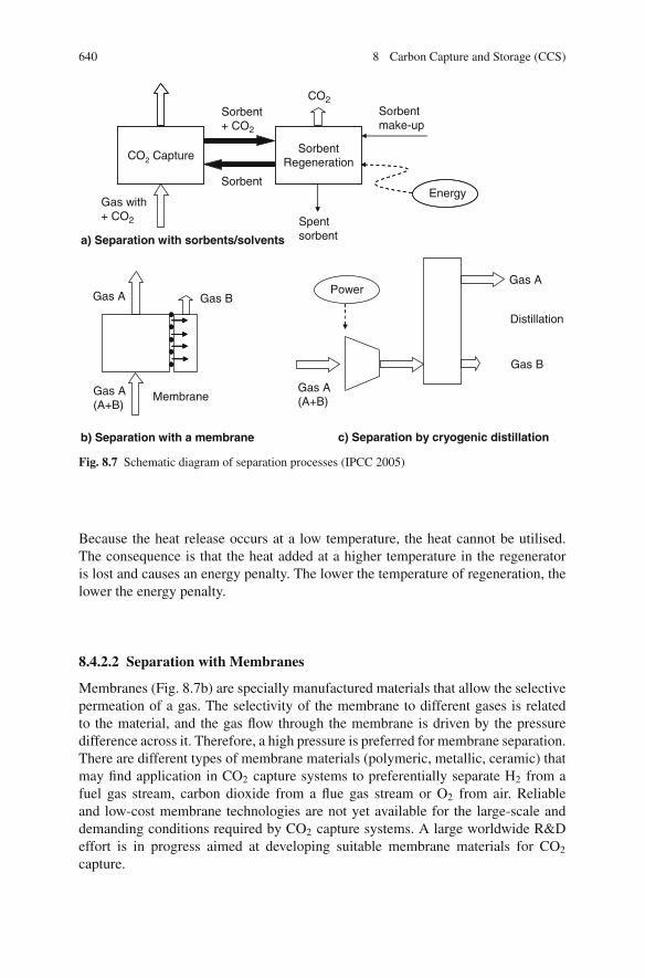
640 8 Carbon Capture and Storage (CCS)
CO2 CaptureSorbent
Regeneration
Sorbent+ CO2
Sorbent
CO2Sorbentmake-up
EnergyGas with+ CO2 Spent
sorbenta) Separation with sorbents/solvents
Gas A Gas B
Gas A(A+B)
MembraneGas A(A+B)
PowerGas A
Gas B
Distillation
b) Separation with a membrane c) Separation by cryogenic distillation
Fig. 8.7 Schematic diagram of separation processes (IPCC 2005)
Because the heat release occurs at a low temperature, the heat cannot be utilised.The consequence is that the heat added at a higher temperature in the regeneratoris lost and causes an energy penalty. The lower the temperature of regeneration, thelower the energy penalty.
8.4.2.2 Separation with Membranes
Membranes (Fig. 8.7b) are specially manufactured materials that allow the selectivepermeation of a gas. The selectivity of the membrane to different gases is relatedto the material, and the gas flow through the membrane is driven by the pressuredifference across it. Therefore, a high pressure is preferred for membrane separation.There are different types of membrane materials (polymeric, metallic, ceramic) thatmay find application in CO2 capture systems to preferentially separate H2 from afuel gas stream, carbon dioxide from a flue gas stream or O2 from air. Reliableand low-cost membrane technologies are not yet available for the large-scale anddemanding conditions required by CO2 capture systems. A large worldwide R&Deffort is in progress aimed at developing suitable membrane materials for CO2
capture.
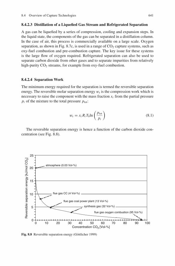
8.4 Overview of Capture Technologies 641
8.4.2.3 Distillation of a Liquefied Gas Stream and Refrigerated Separation
A gas can be liquefied by a series of compression, cooling and expansion steps. Inthe liquid state, the components of the gas can be separated in a distillation column.In the case of air, this process is commercially available on a large scale. Oxygenseparation, as shown in Fig. 8.7c, is used in a range of CO2 capture systems, such asoxy-fuel combustion and pre-combustion capture. The key issue for these systemsis the large flow of oxygen required. Refrigerated separation can also be used toseparate carbon dioxide from other gases and to separate impurities from relativelyhigh-purity CO2 streams, for example from oxy-fuel combustion.
8.4.2.4 Separation Work
The minimum energy required for the separation is termed the reversible separationenergy. The reversible molar separation energy wr is the compression work which isnecessary to raise the component with the mass fraction xi from the partial pressurepi of the mixture to the total pressure ptot:
wr = xi Ri T0ln
(ptot
pi
)
(8.1)
The reversible separation energy is hence a function of the carbon dioxide con-centration (see Fig. 8.8).
0 10 20 30 40 50 60 70 80 90 100
flue gas coal power plant (13 Vol-%)
flue gas oxygen combustion (95 Vol-%)
Concentration CO2 [Vol-%]
25
20
15
10
5
0
atmosphere (0.03 Vol-%)
fluegas CC (4 Vol-%)
synthesis gas (32 Vol-%)
Rev
ersi
ble
sepa
ratio
n en
ergy
[kJ/
mol
CO
2]
flue gas CC (4 Vol-%)
Fig. 8.8 Reversible separation energy (Gottlicher 1999)

642 8 Carbon Capture and Storage (CCS)
CO2 separation from synthesis gases (CO2-vol. fraction 36% after CO shift)
Phys. absorption
Phys.-chem. absorption
Membrane separation
Adsorption
CO2 separation from flue gases (CO2-vol. fraction 11%)
Chem. absorption
Membrane separationAdsorption(PSA/TSA)
0% 5% 10% 15% 20% 25% 30% 35%exergetic efficiency ζ
Fig. 8.9 Exergetic efficiency of CO2 separation processes (Gottlicher 1999). Bars indicate rangeof efficiency
The energy actually required in modern separation processes is many timeshigher than the reversible separation energy. The ratio is given by the exergeticefficiency ζseparation of the scrubbing process:
ζseparation = wr
wG + xi Ri T0 ln(
ptot
pdesorber
) (8.2)
with wG as the real separation work. The term xi Ri T0 ln (ptot/pdesorber) takes thework to compress the component from the desorption pressure pdesorber to the totalpressure ptot into account. Figure 8.9 indicates typical exergetic efficiencies in fluegases and synthesis gases. Absorption of CO2 in the synthesis gas yields the highestexergetic efficiency. Taking into account the low reversible separation energy due tothe high CO2 concentration (see Fig. 8.8), the separation energy in the synthesis gaswill yield the lowest value of the required separation energy (separation energy =reversible separation energy/exergetic efficiency).
8.5 Post-combustion Technologies
8.5.1 Chemical Absorption
Chemical absorption processes based on organic solvents such as amines are cur-rently the preferred option for post-combustion CO2 capture. Absorption processesusing amines are mainly employed in the chemical industry and are commerciallyavailable for post-combustion CO2 capture systems, but not on the scale requiredfor power plant flue gases. As the experience of chemical absorption for coal com-bustion is limited, the interaction between solvents and flue gas constituents is anopen issue, one that needs to be addressed, as it might result in solvent degradation,increased corrosiveness of the solvent or plugging of the absorber or regenerator.
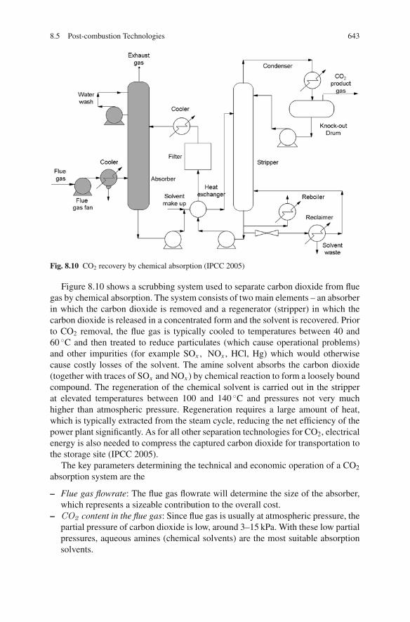
8.5 Post-combustion Technologies 643
Fig. 8.10 CO2 recovery by chemical absorption (IPCC 2005)
Figure 8.10 shows a scrubbing system used to separate carbon dioxide from fluegas by chemical absorption. The system consists of two main elements – an absorberin which the carbon dioxide is removed and a regenerator (stripper) in which thecarbon dioxide is released in a concentrated form and the solvent is recovered. Priorto CO2 removal, the flue gas is typically cooled to temperatures between 40 and60 ◦C and then treated to reduce particulates (which cause operational problems)and other impurities (for example SOx , NOx , HCl, Hg) which would otherwisecause costly losses of the solvent. The amine solvent absorbs the carbon dioxide(together with traces of SOx and NOx ) by chemical reaction to form a loosely boundcompound. The regeneration of the chemical solvent is carried out in the stripperat elevated temperatures between 100 and 140 ◦C and pressures not very muchhigher than atmospheric pressure. Regeneration requires a large amount of heat,which is typically extracted from the steam cycle, reducing the net efficiency of thepower plant significantly. As for all other separation technologies for CO2, electricalenergy is also needed to compress the captured carbon dioxide for transportation tothe storage site (IPCC 2005).
The key parameters determining the technical and economic operation of a CO2
absorption system are the
– Flue gas flowrate: The flue gas flowrate will determine the size of the absorber,which represents a sizeable contribution to the overall cost.
– CO2 content in the flue gas: Since flue gas is usually at atmospheric pressure, thepartial pressure of carbon dioxide is low, around 3–15 kPa. With these low partialpressures, aqueous amines (chemical solvents) are the most suitable absorptionsolvents.

644 8 Carbon Capture and Storage (CCS)
– CO2 removal: Amine absorption can be designed to capture up to 85–95% ofthe carbon dioxide in the flue gas and produce carbon dioxide with a purity ofabove 99.95%. Both the level of recovery and the CO2 purity require economicoptimisation, however. A higher recovery will lead to a taller absorption columnand higher energy penalties and hence increased costs.
– Solvent flowrate: The solvent flowrate will determine the size of most equipmentapart from the absorber. For a given solvent, the flowrate will be fixed by theparameters above and also the chosen CO2 concentrations within the lean andthe rich solutions.
– Energy requirement: The energy consumption of the process is the sum ofthe thermal energy needed to regenerate the solvents and the electrical energyrequired to operate the liquid pumps and the flue gas blower or fan. Energy is alsorequired to compress the recovered carbon dioxide to the final pressure requiredfor transport and storage.
– Cooling requirement: Cooling is needed to bring the flue gas and solvent temper-atures down to the temperatures required for efficient absorption of CO2.
8.5.1.1 Solvents (Amines)
The choice of solvent used for absorption is an issue of optimisation. Important con-siderations include the CO2 loading (mol CO2/mol amine), the solvent concentrationin the aqueous solution, the heat of reaction, the heat of vaporisation, the reactionrate and the temperature required for regeneration. Additionally, the stability of thesolvent can be a problem. Solvents can degrade thermally or by interactions withthe flue gas components, of which oxygen is the most important. Degradation isoften linked with corrosion because degradation products are associated with thecorrosiveness of the solvent. All of these parameters are obviously not optimalsimultaneously for any one solvent; for example high absorption rates generallycause high reaction heat rates.
The commercially available absorbents active enough for the recovery of dilutecarbon dioxide at atmospheric pressure are aqueous solutions of alkanolaminessuch as
– primary amines: monoethanolamine (MEA),– secondary amines: diethanolamine (DEA),– tertiary amines: methyldiethanolamine (MDEA) and– hindered amines.
Alternative solvents are discussed later.
8.5.1.2 Energy Requirements
The energy requirement when using absorption is a key consideration. A largeamount of heat is required, mainly to regenerate the amine, and electricity is con-sumed by the necessary fans and pumps. The absorption solvents active at low
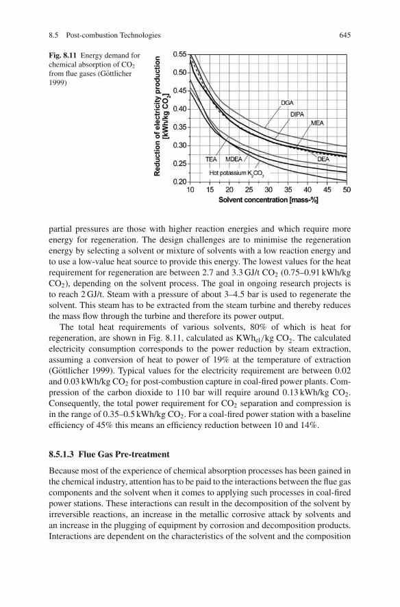
8.5 Post-combustion Technologies 645
Fig. 8.11 Energy demand forchemical absorption of CO2
from flue gases (Gottlicher1999)
partial pressures are those with higher reaction energies and which require moreenergy for regeneration. The design challenges are to minimise the regenerationenergy by selecting a solvent or mixture of solvents with a low reaction energy andto use a low-value heat source to provide this energy. The lowest values for the heatrequirement for regeneration are between 2.7 and 3.3 GJ/t CO2 (0.75–0.91 kWh/kgCO2), depending on the solvent process. The goal in ongoing research projects isto reach 2 GJ/t. Steam with a pressure of about 3–4.5 bar is used to regenerate thesolvent. This steam has to be extracted from the steam turbine and thereby reducesthe mass flow through the turbine and therefore its power output.
The total heat requirements of various solvents, 80% of which is heat forregeneration, are shown in Fig. 8.11, calculated as KWhel/kg CO2. The calculatedelectricity consumption corresponds to the power reduction by steam extraction,assuming a conversion of heat to power of 19% at the temperature of extraction(Gottlicher 1999). Typical values for the electricity requirement are between 0.02and 0.03 kWh/kg CO2 for post-combustion capture in coal-fired power plants. Com-pression of the carbon dioxide to 110 bar will require around 0.13 kWh/kg CO2.Consequently, the total power requirement for CO2 separation and compression isin the range of 0.35–0.5 kWh/kg CO2. For a coal-fired power station with a baselineefficiency of 45% this means an efficiency reduction between 10 and 14%.
8.5.1.3 Flue Gas Pre-treatment
Because most of the experience of chemical absorption processes has been gained inthe chemical industry, attention has to be paid to the interactions between the flue gascomponents and the solvent when it comes to applying such processes in coal-firedpower stations. These interactions can result in the decomposition of the solvent byirreversible reactions, an increase in the metallic corrosive attack by solvents andan increase in the plugging of equipment by corrosion and decomposition products.Interactions are dependent on the characteristics of the solvent and the composition
646 8 Carbon Capture and Storage (CCS)
of the flue gas. Measures to prevent side-effects have to be taken either by advancedflue gas cleaning or by modifying the properties of the solvent.
NOx , SOx : Acid gas components such as NOx and SOx will, similarly to CO2,react with the solvent. This interaction leads to the formation of heat-stable salts andhence a loss in the absorption capacity of the solvent and the risk of solids formationin the solution. Therefore, the reduction of NOx and SOx to very low concentrationsbefore CO2 recovery becomes essential. Depending on the cost of the solvent, SO2
concentrations of around 10 ppm may be required to keep solvent consumption andmake-up costs at reasonable values – which often means that additional flue gasdesulphurisation is needed. For NOx , it is the NO2 which leads to the formation ofheat-stable salts. Because the level of NO2 is usually less than 10% of the overallNOx content in a flue gas, state-of-the-art DeNOx systems are sufficient to achievethe recommended levels of less than 20 ppm.
Fly ash: Careful attention must also be paid to the fly ash and soot present in theflue gas, as they might plug the absorber and increase corrosion and solvent loss bychemical degradation if contaminants levels are too high.
Oxygen: The presence of oxygen in the flue gas can increase corrosion and sol-vent degradation in the absorption system. Uninhibited alkanolamines such as MEAand DEA can be oxidised to produce carboxylic acids and heat-stable amine salts.A solution to this problem is to apply an inhibitor to both passivate the metal andinhibit amine degradation (IPCC 2005; VGB 2002).
Further Development
Various novel solvents are being investigated with the objective of achieving alower solvent regeneration energy consumption. Research is focussed on aqueoussolutions of
– alternative alkanolamines,– amino acid salts,– alkali or earth alkali carbonate solutions and– ammonia.
For a process with chilled ammonia, a 50% lower energy penalty in compari-son to an MEA solvent is indicated. The absorber has to operate at a temperaturebetween 2 and 16 ◦C to minimise ammonia losses.
Research is also being carried out to improve existing process methods and pack-ing types, for example to replace the absorption columns by spray washers in orderto reduce pressure losses in the flue gas path (Davidson 2007).
8.5.2 Solid Sorbents
Post-combustion systems are being proposed that make use of regenerable solidsorbents to remove carbon dioxide at relatively high temperatures. The applicationof high temperatures in the CO2 separation step has the potential to have higher
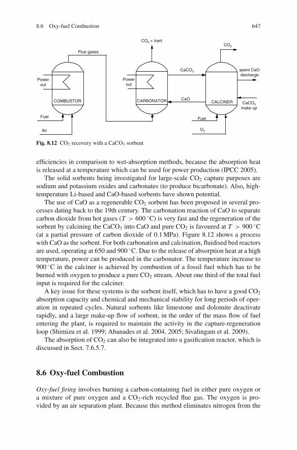
8.6 Oxy-fuel Combustion 647
Flue gases
CO2 + inertCO2
Powerout
COMBUSTOR
Fuel
Air
CARBONATOR CALCINER
Fuel
O2
spent CaOdischarge
CaCO3make up
Powerout
CaCO3
CaO
Fig. 8.12 CO2 recovery with a CaCO3 sorbent
efficiencies in comparison to wet-absorption methods, because the absorption heatis released at a temperature which can be used for power production (IPCC 2005).
The solid sorbents being investigated for large-scale CO2 capture purposes aresodium and potassium oxides and carbonates (to produce bicarbonate). Also, high-temperature Li-based and CaO-based sorbents have shown potential.
The use of CaO as a regenerable CO2 sorbent has been proposed in several pro-cesses dating back to the 19th century. The carbonation reaction of CaO to separatecarbon dioxide from hot gases (T > 600 ◦C) is very fast and the regeneration of thesorbent by calcining the CaCO3 into CaO and pure CO2 is favoured at T > 900 ◦C(at a partial pressure of carbon dioxide of 0.1 MPa). Figure 8.12 shows a processwith CaO as the sorbent. For both carbonation and calcination, fluidised bed reactorsare used, operating at 650 and 900 ◦C. Due to the release of absorption heat at a hightemperature, power can be produced in the carbonator. The temperature increase to900 ◦C in the calciner is achieved by combustion of a fossil fuel which has to beburned with oxygen to produce a pure CO2 stream. About one third of the total fuelinput is required for the calciner.
A key issue for these systems is the sorbent itself, which has to have a good CO2
absorption capacity and chemical and mechanical stability for long periods of oper-ation in repeated cycles. Natural sorbents like limestone and dolomite deactivaterapidly, and a large make-up flow of sorbent, in the order of the mass flow of fuelentering the plant, is required to maintain the activity in the capture-regenerationloop (Shimizu et al. 1999; Abanades et al. 2004, 2005; Sivalingam et al. 2009).
The absorption of CO2 can also be integrated into a gasification reactor, which isdiscussed in Sect. 7.6.5.7.
8.6 Oxy-fuel Combustion
Oxy-fuel firing involves burning a carbon-containing fuel in either pure oxygen ora mixture of pure oxygen and a CO2-rich recycled flue gas. The oxygen is pro-vided by an air separation plant. Because this method eliminates nitrogen from the

648 8 Carbon Capture and Storage (CCS)
comburent, a flue gas mixture is obtained with carbon dioxide and water vapour asthe essential components. The flue gas, after cooling to condense the water vapour,contains about 80–98% carbon dioxide, depending on the oxygen purity, the fuelin use and the particular oxy-fuel combustion process. Impurities in the carbondioxide are gas components deriving from the fuel, such as SOx , NOx , HCl andHg, and gas components, such as nitrogen, argon and oxygen, contained in theoxygen fed into the system or from air leakage. This concentrated CO2 stream canbe compressed, dried or further purified before delivery into a pipeline for storage(IPCC 2005).
The key separation step in oxy-fuel combustion capture systems is air separa-tion. The current methods of oxygen production by air separation are cryogenicdistillation, adsorption using multi-bed pressure swing units and polymeric mem-branes. For oxy-fuel firing requiring less than 200 t O2/day, the adsorption systemwill be economic. For all larger applications, which include power station boilers,the most economic solution is cryogenic air separation in an air fractionation unit.This method in particular causes a significant efficiency loss over the entire processbecause of its considerable energy demand.
Figure 8.13 provides an indication of the electrical energy needed for oxygenproduction in an air separation unit with two columns (Gottlicher 1999). The higherthe purity of the oxygen, the higher will be the expenditure of energy per massof oxygen. For combustion using oxygen, the purities required range between 95and 99%, where the purity chosen is the result obtained by optimisation of theenergy demand. Roughly assuming a net efficiency of 45% of a power plant with-out CO2 separation, about 0.6 kg of oxygen per produced kWhel (excess oxygen10%) is needed for oxy-fuel combustion. With an oxygen purity of 99.5%, anenergy demand of 0.29 kWh/kg O2 for the separation of the oxygen is required.This results in an energy expenditure of 0.175 kWh per kWh of electrical powerproduced, which diminishes the efficiency by almost 8% through the necessary air
Fig. 8.13 Energyrequirement for cryogenic airseparation (Gottlicher 1999)

8.6 Oxy-fuel Combustion 649
fractionation alone. Current oxy-fuel designs assume an oxygen purity of 95% withan energy requirement of 0.23–0.25 kWh/kg O2 (corresponding to a 6.2–6.8% effi-ciency loss). Optimisation of the air fractionation process, for example by introduc-ing a three-column process, could reduce the energy requirements to 0.2 kWh/kgO2 (a 5.4% efficiency loss); a further reduction to 0.16 kWh/kg O2 (a 4.3% effi-ciency loss) is expected by integrating the air fractionation process into the powerplant. However, a further loss of about 3.5% is incurred through the necessary workfor the compression of the CO2 to 110 bar for transport. The total loss in effi-ciency is then about 11–12%, with a potential reduction down to 8% (Kather et al.2007b).
Although elements of oxy-fuel combustion technologies are in use in the alu-minium, iron and steel and glass melting industries today, oxy-fuel technologies forCO2 capture have yet to be deployed on a commercial scale. The so-called oxy-fuelprocess gathered attention in the early 1990s with the increasing interest in carboncapture and sequestration. At that time one of the first investigations into oxy-coalcombustion was carried out by the IFRF (International Flame Research Foundation)(Tan et al. 2005). In recent years, several research initiatives have been started tostudy the effect of oxy-fuel combustion atmospheres on combustion behaviour, heattransfer, emissions and operational behaviour. Vattenfall has constructed an oxy-fuelpower demonstration plant (30 MW pilot plant) at Schwarze Pumpe which went intoservice in 2008 (Burchardt and Radunsky 2007; Kluger et al. 2006; Burchhardt andJacoby 2008).
One of the big advantages of the oxy-fuel process is the simple way a conven-tional coal-fired power-generating design can be adapted to CO2 separation. Withthe existing components being largely kept in place, it is possible in general to per-form a successful retrofit on power plants.
8.6.1 Oxy-fuel Steam Generator Concepts
The combustion of coal in a pure oxygen atmosphere can lead to flame tempera-tures rising above 3,000 ◦C, far too high for typical power plant materials. What ismore, temperatures so high would volatilise a substantial part of the ash and result inheavy fouling of the convective heating surfaces. The actual combustion temperatureshould not exceed 1,500–1,800 ◦C.
Figure 8.14 shows calculated flame temperatures as a function of the oxygen/fuelstoichiometry for different ratios of flue gas recirculation. In principle, there aretwo possible methods to limit the combustion temperature. The first is to controlthe temperature by the suitable admixture of a thermal ballast, for instance in theform of recirculated flue gas, solids or water vapour. The second is to carry outthe combustion process at lower or higher values than the stoichiometric ratio ofoxygen to fuel. Both oxygen and oxygen-deficient combustion result in a reduc-tion of the adiabatic combustion temperature until the stability limit of the flame isreached.

650 8 Carbon Capture and Storage (CCS)
0.125 0.25 0.5 1 2 4 8
Stoichiometry
500
1000
1500
2000
2500
3000
Adi
abat
ic fl
ame
tem
pera
ture
[°C
]
50%
33%
1 2 4 8500
1000
1500
50% Recirculation
33% Recirculation
66% Recirculation
Feasible
75% Recirculation
temperature range
Fig. 8.14 Adiabatic flame temperatures as a function of stoichiometry for different flue gas recir-culation ratios, calculated by Factsage (Bale et al. 2002)
8.6.1.1 Flue Gas Recirculation
Nearly all oxy-fuel combustion concepts considered at present rely on external fluegas recirculation to control the combustion temperature. The goal is to limit com-bustion temperatures to values similar to those in combustion with air. Cool flue gasis extracted either before (wet recirculation, flue gas temperature about 150 ◦C) orafter vapour condensation (dry recirculation, temperature 50 ◦C) and recirculated tothe furnace. Depending on the fuel and the temperature of the recirculated flue gas,differing but high volumetric flowrates are needed to reduce the combustion temper-ature. Assuming a flue gas recirculation temperature between 200 and 300 ◦C, abouttwo thirds of the flue gas produced in the steam generator has to be recirculated toachieve temperatures similar to air combustion. The high volumetric flow that needsto be transported involves an increase in the dimensions of the plant and the auxiliarypower requirement for the recirculation fan. External recirculation is an establishedtechnology, but one that entails a number of problems (e.g. the construction size,wear and tear, corrosion when temperatures fall below the dew point, distributionof the individual flows). Owing to the possibility of retrofitting existing power sta-tions with it, recirculation is a solution at the logical beginning of the realisation ofCO2-emission-free power plants.
Another method is to recirculate the flue gas in the boiler internally. Every con-ventional jet and swirl burner has a well-developed recirculation zone to homogenisethe combustion and to avoid hot spots. Technologies with extensive internal flue gasrecirculation such as flameless oxidation burners have been successfully applied inthe steel industry. For the duty range of power plants, the use of flameless oxidationburners is unknown so far. It remains an open question whether it will be possibleby this technique exclusively to recirculate sufficiently large flue gas quantities to
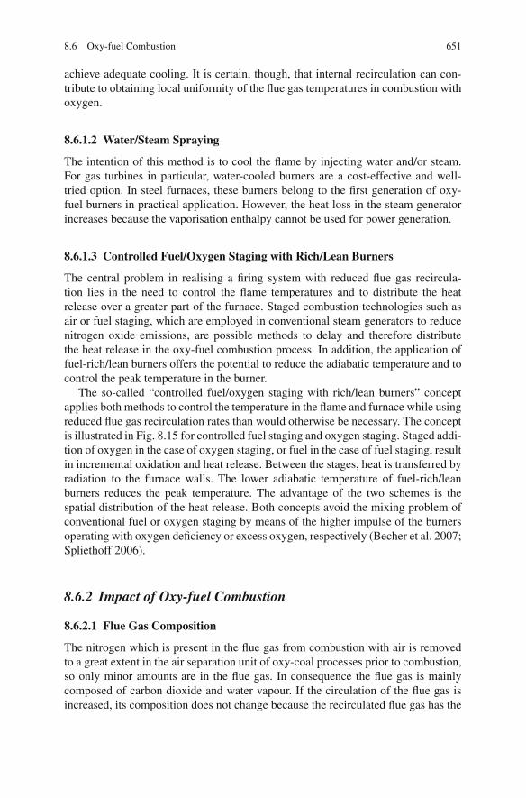
8.6 Oxy-fuel Combustion 651
achieve adequate cooling. It is certain, though, that internal recirculation can con-tribute to obtaining local uniformity of the flue gas temperatures in combustion withoxygen.
8.6.1.2 Water/Steam Spraying
The intention of this method is to cool the flame by injecting water and/or steam.For gas turbines in particular, water-cooled burners are a cost-effective and well-tried option. In steel furnaces, these burners belong to the first generation of oxy-fuel burners in practical application. However, the heat loss in the steam generatorincreases because the vaporisation enthalpy cannot be used for power generation.
8.6.1.3 Controlled Fuel/Oxygen Staging with Rich/Lean Burners
The central problem in realising a firing system with reduced flue gas recircula-tion lies in the need to control the flame temperatures and to distribute the heatrelease over a greater part of the furnace. Staged combustion technologies such asair or fuel staging, which are employed in conventional steam generators to reducenitrogen oxide emissions, are possible methods to delay and therefore distributethe heat release in the oxy-fuel combustion process. In addition, the application offuel-rich/lean burners offers the potential to reduce the adiabatic temperature and tocontrol the peak temperature in the burner.
The so-called “controlled fuel/oxygen staging with rich/lean burners” conceptapplies both methods to control the temperature in the flame and furnace while usingreduced flue gas recirculation rates than would otherwise be necessary. The conceptis illustrated in Fig. 8.15 for controlled fuel staging and oxygen staging. Staged addi-tion of oxygen in the case of oxygen staging, or fuel in the case of fuel staging, resultin incremental oxidation and heat release. Between the stages, heat is transferred byradiation to the furnace walls. The lower adiabatic temperature of fuel-rich/leanburners reduces the peak temperature. The advantage of the two schemes is thespatial distribution of the heat release. Both concepts avoid the mixing problem ofconventional fuel or oxygen staging by means of the higher impulse of the burnersoperating with oxygen deficiency or excess oxygen, respectively (Becher et al. 2007;Spliethoff 2006).
8.6.2 Impact of Oxy-fuel Combustion
8.6.2.1 Flue Gas Composition
The nitrogen which is present in the flue gas from combustion with air is removedto a great extent in the air separation unit of oxy-coal processes prior to combustion,so only minor amounts are in the flue gas. In consequence the flue gas is mainlycomposed of carbon dioxide and water vapour. If the circulation of the flue gas isincreased, its composition does not change because the recirculated flue gas has the
652 8 Carbon Capture and Storage (CCS)
Fig. 8.15 Controlledfuel/oxygen staging in thefurnace. λ is the ratio of thesupplied comburent to thestoichiometric comburentrequirement
same composition as the products of combustion and is not involved in the combus-tion process. An exception is the recirculation of dry flue gas, where water vapouris condensed and extracted.
8.6.2.2 Thermodynamic Properties
The thermodynamic properties of the flue gas from oxy-fuel combustion are differ-ent from those of the flue gas from air combustion, due to the differing composition.The density of the flue gas from oxy-coal processes is greater, because carbon diox-ide (with 44 kg/kmol) has a larger molecular weight than nitrogen (28 kg/kmol).In wet flue gas recirculation, the lower molecular weight of water (18 kg/kmol)can partly compensate the effect of CO2. The molar thermal capacity of the fluegases C p increases due to the higher concentrations of CO2 and H2O. The triatomicmolecules have more degrees of vibrational freedom and can store more heat energy.The specific (mass-related) thermal capacity cp increases as well; due to the highspecific thermal capacity of water vapour, the effect is more pronounced for wetflue gas (see Table 8.3).
The higher concentrations of CO2 and H2O, which are band emitters, in the fluegas intensify the heat transfer by radiation (Gupta et al. 2006). In pulverised coalfired furnaces, though, the emissivity of the hot flue gases in the burner zone isdominated by the solid-state radiation of the char and ash particles. The emissivitygiven for the combustion zone using air as the comburent is between 0.8 and 0.9(Blokh and Viskanta 1988), so only a slight increase is possible using oxygen asthe comburent. With the completion of char burnout above the burner zone, theemissivity drops and a more pronounced effect can be expected.

8.6 Oxy-fuel Combustion 653
Table 8.3 Composition of the flue gases of firing systems with air and with oxygen (fuel: hardcoal, λ = 1.15; gas properties from Kretzschmar et al. 2005)
Air combustion
Oxy-coalcombustiondry recycling
Oxy-coalcombustionwet recycling
N2 [vol.%] 77% 0% 0%CO2 [vol.%] 16% 87% 74%H2O [vol.%] 5% 8% 22%O2 [vol.%] 3% 5% 4%ρ(300 ◦C) [kg/m3] 0.64 0.88 0.81C p,300 ◦C–1,200 ◦C [kJ/kmol K] 27.4 39.0 37.8cp,300 ◦C–1,200 ◦C [kJ/kg K] 0.91 0.94 1.00M [kg/kmol] 30.46 41.3 37.8
8.6.2.3 Heat Transfer
For the design of furnaces, the heat quantities to be transferred in the furnace and inthe convective heat exchangers are the decisive factors. Given that the furnace outlettemperature is defined by the ash deformation behaviour of the fuel, the division ofheat transfer to the furnace walls and to the convective heat exchangers is a functionof the adiabatic combustion temperature and hence substantially depends on the fluegas recirculation rate. This correlation is plotted in Fig. 8.16 and compared with afurnace using air. For the calculations, a furnace outlet temperature of 1,200 ◦C andan air ratio of 1.15 were assumed. This makes it clear that for oxy-coal power plantswith a low flue gas recirculation rate, more heat has to be transferred to the furnace.
It is common practice to choose the recirculation rate so that the furnace outlettemperature and the corresponding heat transfer characteristic are similar to firingsystems using air. In contrast to combustion with air, lower mass flows are produceddue to the higher specific heat capacity, and lower volume flows due to the highermolar heat capacity. If the same volumetric flow as in a furnace firing with air wasrequired, the resulting recirculation rate for a bituminous coal would be 78%. Theoxygen content of the oxidising agent, i.e. the mixture of oxygen and the recirculatedflue gas, would then be 21 vol.%. If setting the same temperatures and heat transfercharacteristic for a bituminous coal, the recirculation rate is 67% (wet recirculation).The absolute volumetric flows are plotted in Fig. 8.17. It shows clearly that for anoxy-coal firing system designed to use the same temperatures as air combustion, thevolumetric flows in the furnace are about 35% lower. The corresponding mass flowis 18% lower and the oxygen content of the oxidising agent is about 32 vol.%.
Due to the lower volumetric flowrate, the cross-section of an oxy-fuel steamgenerator needs to be reduced from air-firing sizes in order to induce velocitiessimilar to those in air combustion, which produce a good heat transfer coefficientin the convective heat transfer region. Assuming heat transfer coefficients similarto air firing, the height of the oxy-fuel boiler has to be increased to install therequired heat exchanger surface. However, both radiative and convective heat trans-fer improve under oxy-fuel conditions, partly reducing the necessary increase ofheight. As previously mentioned, the increased concentrations of CO2 and H2O will

654 8 Carbon Capture and Storage (CCS)
Fig. 8.16 Temperature-heat diagram for different recirculation ratios (wet flue gas recirculation,recirculation temperature 300 ◦C, bituminous coal)
improve the radiative heat transfer in the furnace, but only slightly. In the convectiveheat exchangers the improvement of the heat transfer coefficient by both radiation(due to the emissivity of CO2 and H2O) and convection (due to the higher thermalconductivity of CO2 and H2O) is more pronounced. This results in a more compactconvective heat exchanger (Hellfritsch et al. 2007; Kakaras et al. 2007).
78%0
500
1000
1500
2000
2500
3000
0% 10% 20% 30% 40% 50% 60% 70% 80%Flue gas recirculation
[m3 /
s]
Air firing
Oxyfuel withflue gas recirculation
67%
Flu
e ga
s vo
lum
e flo
w
Fig. 8.17 Flue gas volume as a function of the recirculation ratio for a bituminous coal(1,000 MWFuel)
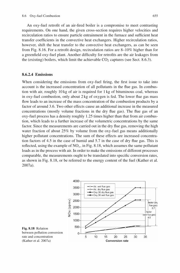
8.6 Oxy-fuel Combustion 655
An oxy-fuel retrofit of an air-fired boiler is a compromise to meet contrastingrequirements. On one hand, the given cross-section requires higher velocities andrecirculation ratios to ensure particle entrainment in the furnace and sufficient heattransfer coefficients in the convective heat exchangers. Higher recirculation ratios,however, shift the heat transfer to the convective heat exchangers, as can be seenfrom Fig. 8.16. For a retrofit design, recirculation ratios are 8–10% higher than fora greenfield oxy-fuel plant. Another difficulty for retrofits are the air leakages fromthe (existing) boilers, which limit the achievable CO2 captures (see Sect. 8.6.3).
8.6.2.4 Emissions
When considering the emissions from oxy-fuel firing, the first issue to take intoaccount is the increased concentration of all pollutants in the flue gas. In combus-tion with air, roughly 10 kg of air is required for 1 kg of bituminous coal, whereasin oxy-fuel combustion, only about 2 kg of oxygen is fed. The lower flue gas massflow leads to an increase of the mass concentration of the combustion products by afactor of around 3.6. Two other effects cause an additional increase in the measuredconcentrations (mostly volume fractions in the dry flue gas). The flue gas of anoxy-fuel process has a density roughly 1.25 times higher than that from air combus-tion, which leads to a further increase of the volumetric concentrations by the samefactor. Since the measurements are carried out in the dry flue gas, removing the highwater fraction of about 25% by volume from the oxy-fuel gas means additionallyhigher pollutant concentrations. The sum of these effects are increased concentra-tion factors of 4.5 in the case of humid and 5.7 in the case of dry flue gas. This isreflected, using the example of NOx , in Fig. 8.18, which assumes the same pollutantloads as in the process with air. In order to make the emissions of different processescomparable, the measurements ought to be translated into specific conversion rates,as shown in Fig. 8.18, or be referred to the energy content of the fuel (Kather et al.2007a).
Fig. 8.18 Relationbetween pollution conversionrate and concentration(Kather et al. 2007a)

656 8 Carbon Capture and Storage (CCS)
The increased concentration of pollutants is counteracted by lower conversionrates of the pollutants from the fuel (and/or comburent) into the flue gas. The con-version rate or the NOx emissions generated per unit of energy can be reduced by upto 70% in oxy-fuel combustion, depending on the burner design and operation. TheNOx reduction is thought to be the result of several mechanisms: a decrease of ther-mal NOx due to the very low concentration of N2 in the comburent, the reduction ofrecycled NOx as it is reburned in the volatile matter release region of the flame andthe reaction between recycled NOx and char. Both homogeneous and heterogeneousreduction reactions are favoured by the higher NO concentrations.
The SO2 emissions per energy from the burned fuel may be lowered through sul-phur retention in both the ash and deposits and are typically lower by 20%, depend-ing on the ash composition. The absolute SO2 concentrations are typically 2.5–3times higher than in air firing, and it has been observed that the conversion ratio ofSO2 to SO3 is higher under oxy-fuel conditions. This higher SO3 concentration inthe flue gas in combination with the higher moisture content increases the dew pointtemperature and limits the waste heat utilisation. Whereas for an air-fired boiler,the typical dew point temperature for a hard coal is in the range of 100–110 ◦C, itincreases to about 140–150 ◦C under oxy-fuel conditions (Scheffknecht and Maier2008).
The effect of oxy-fuel combustion on trace element emissions and mineral mat-ter transformation is uncertain, but it can be expected that the behaviour of certainminerals (in particular carbonates) will be affected by the change in the flue gasenvironment (Wall 2007; Maier et al. 2007).
8.6.3 Oxy-fuel Configurations
Figure 8.19 shows the typical configuration of oxy-coal combustion processes. Forheat transfer purposes, two thirds of the flue gas is extracted after the steam gener-ator and conducted back to the furnace to cool the newly produced flue gases. Theun-recirculated portion of the flue gas, volumetrically two thirds smaller than fromcombustion plants using air, gets dehumidified after flue gas cleaning and is theneither compressed or liquefied.
8.6.3.1 CO2 Purity
The purity of the carbon dioxide has a decisive influence on the energy input nec-essary for the compression process. The fraction of other non condensable gases inthe CO2 after dehumidification is shown as 11% in Fig. 8.19, an amount which isrepeated in various sources. This value can be optimised to a limited extent by thedesign. The calculations in Fig. 8.19 assume an oxygen purity of 99.5%, whereasmost designs are based on 95%.
A large fraction of the inert gases consists of argon and nitrogen, the resultingpercentage depending on the purity of the produced oxygen. An increasing purity
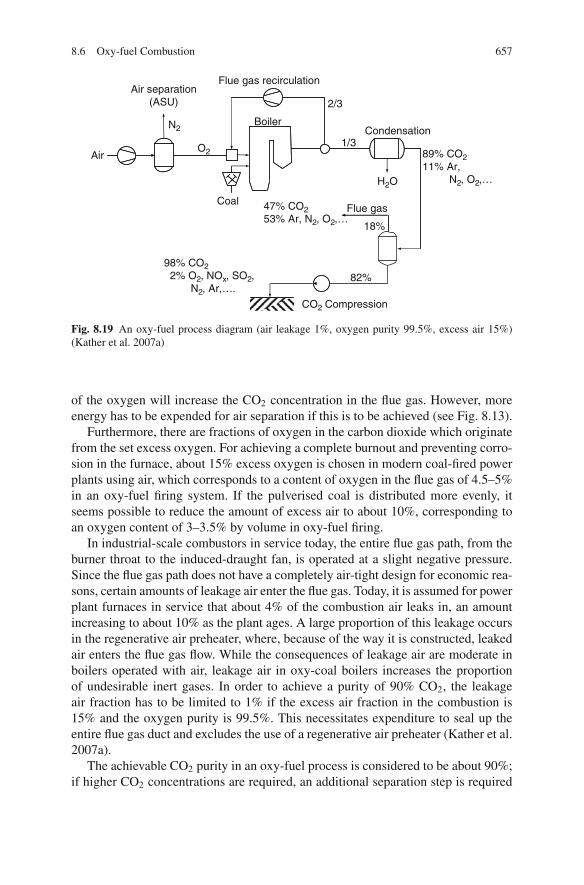
8.6 Oxy-fuel Combustion 657
Air
CoalFlue gas
18%
47% CO253% Ar, N2, O2,…
82%98% CO2
2% O2, NOx, SO2,N2, Ar,….
CO2 Compression
Air separation(ASU)
N2
Flue gas recirculation
2/3
1/3Condensation
89% CO211% Ar,
N2, O2,…H2O
O2
Boiler
Fig. 8.19 An oxy-fuel process diagram (air leakage 1%, oxygen purity 99.5%, excess air 15%)(Kather et al. 2007a)
of the oxygen will increase the CO2 concentration in the flue gas. However, moreenergy has to be expended for air separation if this is to be achieved (see Fig. 8.13).
Furthermore, there are fractions of oxygen in the carbon dioxide which originatefrom the set excess oxygen. For achieving a complete burnout and preventing corro-sion in the furnace, about 15% excess oxygen is chosen in modern coal-fired powerplants using air, which corresponds to a content of oxygen in the flue gas of 4.5–5%in an oxy-fuel firing system. If the pulverised coal is distributed more evenly, itseems possible to reduce the amount of excess air to about 10%, corresponding toan oxygen content of 3–3.5% by volume in oxy-fuel firing.
In industrial-scale combustors in service today, the entire flue gas path, from theburner throat to the induced-draught fan, is operated at a slight negative pressure.Since the flue gas path does not have a completely air-tight design for economic rea-sons, certain amounts of leakage air enter the flue gas. Today, it is assumed for powerplant furnaces in service that about 4% of the combustion air leaks in, an amountincreasing to about 10% as the plant ages. A large proportion of this leakage occursin the regenerative air preheater, where, because of the way it is constructed, leakedair enters the flue gas flow. While the consequences of leakage air are moderate inboilers operated with air, leakage air in oxy-coal boilers increases the proportionof undesirable inert gases. In order to achieve a purity of 90% CO2, the leakageair fraction has to be limited to 1% if the excess air fraction in the combustion is15% and the oxygen purity is 99.5%. This necessitates expenditure to seal up theentire flue gas duct and excludes the use of a regenerative air preheater (Kather et al.2007a).
The achievable CO2 purity in an oxy-fuel process is considered to be about 90%;if higher CO2 concentrations are required, an additional separation step is required

658 8 Carbon Capture and Storage (CCS)
as shown in Fig. 8.19. The costs of an oxy-fuel process are therefore dependent onthe CO2 purity requirements.
8.6.3.2 Waste Heat Recovery
In a conventional plant operated with air, the flue gases can only be cooled to about350–380 ◦C by using feed water as the working fluid, because nowadays, for reasonsof efficiency, the feed water is preheated to temperatures of around 300 ◦C. The fluegas heat is used to preheat the cold combustion air in a regenerative air preheater.
Due to the significantly lower mass flow after the recirculation branch (where therecirculation gas is taken out of the post-furnace flue gas flow), the sensible heat ofthe flue gas, at 300–350 ◦C from oxy-fuel firing, is comparable to a conventionalair-fired boiler at a boiler exit temperature of 130 ◦C. Therefore the sensible heatcontained in the flue gas could in theory be neglected without having a lower steamgenerator efficiency in comparison to an air fuel fired power plant. However, withevery lowering of the flue gas temperature through flue gas heat utilisation afterthe branching into recirculation, the flue gas losses decrease and the efficiency ofthe total process increases. Since the flue gas has to be cooled significantly beforeCO2 liquefaction, not least because of the necessary dehumidification, the potentialfor waste heat recovery is relatively high. The increased concentration of pollutantgases, though, restricts the recovery of waste heat. For example, oxygen preheatingand heat transfer in the high-pressure feed water preheater may be restricted becausethe sulphuric acid dew point, depending on the coal type, may rise to 160 ◦C.
In principle, the heat transfer to the oxygen and to the recirculating flue gasoffers itself as an effective means to utilise the flue gas heat, because the heat, asin conventional processes, is returned directly to the furnace. Preheating the oxygento temperatures above 200 ◦C requires the use of high-quality heat exchanger mate-rials. At the dimensions required in power plants, this is not yet the state of the art(Kather et al. 2007a; Hellfritsch et al. 2004).
8.6.3.3 Flue Gas Recirculation
Various methods for the recirculation of flue gas, differing according to the temper-ature and pollutant load of the recirculated flue gases, are available. The possibletemperatures lie between 100 and 350 ◦C. The lower the temperature of the recir-culated flue gases, the smaller the recirculation flows necessary for furnace coolingand the higher the density of the flue gas. So, owing to the lower volumetric flows,the flue gas ducts can be built with smaller cross-sections. As another consequence,however, the ducts have to be longer.
When considering the pollutant load, one has to distinguish between the recircu-lation of untreated and treated flue gas (see Fig. 8.20). Feeding back treated and coldflue gas is the better variant for operation with a minimum of maintenance becauseflue gas desulphurisation, dust removal and predrying substantially decrease therisk of corrosion and material wear in the entire flue gas and coal-handling system.The drawbacks of using treated flue gas are the construction sizes of the cleaning
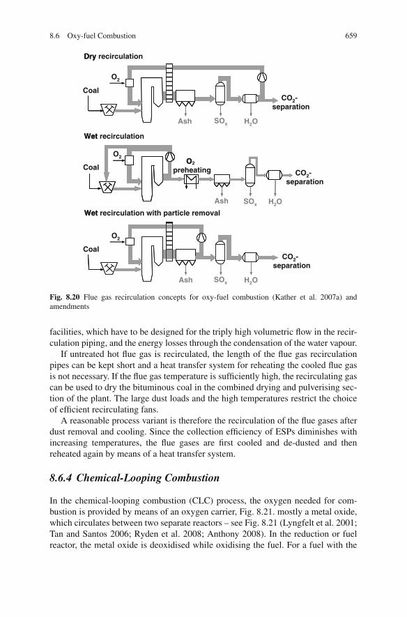
8.6 Oxy-fuel Combustion 659
Dry
Wet
SOx
O2
Ash H2O
Coal
Dry recirculation
CO2-separation
O
Wet
Coal
O2O2
preheating
Ash SOx H2O
CO2-separation
Wet recirculation
SOx
O2
Ash H2O
Coal
Wet recirculation with particle removal
CO2-separation
Fig. 8.20 Flue gas recirculation concepts for oxy-fuel combustion (Kather et al. 2007a) andamendments
facilities, which have to be designed for the triply high volumetric flow in the recir-culation piping, and the energy losses through the condensation of the water vapour.
If untreated hot flue gas is recirculated, the length of the flue gas recirculationpipes can be kept short and a heat transfer system for reheating the cooled flue gasis not necessary. If the flue gas temperature is sufficiently high, the recirculating gascan be used to dry the bituminous coal in the combined drying and pulverising sec-tion of the plant. The large dust loads and the high temperatures restrict the choiceof efficient recirculating fans.
A reasonable process variant is therefore the recirculation of the flue gases afterdust removal and cooling. Since the collection efficiency of ESPs diminishes withincreasing temperatures, the flue gases are first cooled and de-dusted and thenreheated again by means of a heat transfer system.
8.6.4 Chemical-Looping Combustion
In the chemical-looping combustion (CLC) process, the oxygen needed for com-bustion is provided by means of an oxygen carrier, Fig. 8.21. mostly a metal oxide,which circulates between two separate reactors – see Fig. 8.21 (Lyngfelt et al. 2001;Tan and Santos 2006; Ryden et al. 2008; Anthony 2008). In the reduction or fuelreactor, the metal oxide is deoxidised while oxidising the fuel. For a fuel with the

660 8 Carbon Capture and Storage (CCS)
Fig. 8.21 Chemical loopingprocess diagram
Compressed air
Airreactor
Oxygen depleted air
Exit gas CO2/H2O
Heat exchanger
FuelreactorGaseous fuel
Me
MeO
Exit gas CO2/H2O
composition Cn H2m for instance, the following reaction takes place:
Cn H2m + (2n + m)MeO → nCO2 + mH2O + (2n + m)Me (8.3)
The reduced metal is then fed to an oxidation reactor in order to reform a metaloxide using the oxygen in the air:
Me + 1
2O2 → MeO (8.4)
Since the oxidation reactor effects the separation of the oxygen from the air, noenergy-consuming air separation unit is necessary. The oxygen carrier is reducedagain afterwards by the fuel.
The energy released by these two reactions corresponds to the reaction enthalpyof conventional combustion. The advantage of having combustion in two reactorscompared to conventional combustion in a single stage is that the carbon dioxideis not diluted with nitrogen gas but is almost pure after the separation from water,without requiring any extra energy and costly external equipment for CO2 separation(IPCC 2005).
The recycle rate of the solid material between the two reactors and the averagesolids residence time in each reactor control the heat balance and the temperatures inboth reactors. The temperatures in the reactors are within the range of 800–1,200 ◦C.Possible metals for oxidation are those such as iron, nickel, copper and manganese.Particles with diameters from 100 to 500 μm move between the two reactors, beingfluidised in each reactor. This method also ensures efficient heat and mass transferbetween the gases and the particles. One of the beds gets fluidised with air, the otherone with fuel. For this reason, this method is most suitable for gaseous fuels. Thechemical-looping method using natural gas as the fuel is not yet technically mature,although the fundamental idea was known as early as the late 1960s. Work onchemical-looping combustion is currently in the pilot-plant and materials researchstage. A critical issue is the long-term mechanical and chemical stability of the par-ticles that have to undergo repeated cycles of oxidation and reduction. A minimumof material make-up flow must be achieved for the process to be economic. In orderto avoid deposits of carbon in the reduction reactor, it is necessary to incorporatesome steam into the fuel flow.

8.7 Integrated Gasification Combined Cycles with Carbon Capture and Storage 661
The interest in using CLC for solid fuels is huge, because the substantial effi-ciency drop associated with other CO2 removal technologies is considerably reduced.There are different design concepts for using CLC for solid fuels. By an additionalgasification step the solid fuel can be converted into a gas, which allows for gas–solid reactions in the fuel reactor. The gasification steps can be external; devel-opment is ongoing to integrate a gasification step (by H2O or CO2) into the fuelreactor. A disadvantage of gasification in the fuel reactor is the slow gasificationkinetics, which requires a longer residence time to reach a sufficiently completestate. Another problem may be the negative impact of fuel ash on the lifetime of theoxygen carrier (Berguerand and Lyngfelt 2008; Leion et al. 2008; Cao et al. 2006).A novel concept proposes to uncouple the oxygen release and fuel reaction in thefuel reactor. The oxygen is released in an intermediate step after the air reactor todirectly react with the solid fuel (Mattisson et al. 2009).
8.7 Integrated Gasification Combined Cycleswith Carbon Capture and Storage
Integrated coal gasification technology with CO2 removal has been presented indetail in Sect. 7.5. In this section, the efficiency losses will be covered. Figure 8.22shows schematically the design of an IGCC-CCS power plant. Compared to anIGCC power plant without CO2 removal (see Fig. 7.2), it requires two additionalcomponents – a CO shift reactor and a CO2 scrubber.
The liquefaction process included, a decrease of the efficiency by about 8–10%,at a CO2 removal rate of 90%, is the result of adding the extra process steps, takingas a reference the IGCC power plant 1998 with an efficiency of 52% (discussed inSect. 7.5). The efficiency loss can be put down to the following causes:
– Shift conversion: Due to the exothermic conversion reaction, part of the syngasheating value is converted to heat. In the case of a typical synthesis gas from ahigh-temperature gasifier with about 60% carbon monoxide and 30% hydrogen,the heating value of the fuel gas is reduced by about 10%. The arising reactionheat can be utilised at the temperature of the shift reaction. The maximum effi-ciency loss of about 5% can be limited to 2.5% or so by heat exploitation.
– The separation of the CO2 from the syngas requires energy to regenerate thescrubbing agent. Owing to the high partial pressure of the CO2, this input issignificantly lower than for CO2 scrubbing of atmospheric flue gases. The energydemand ranges around 1–2%.
– The separated volumetric CO2 flow does not get expanded in the gas turbine. Theconsequent diminished gas turbine output results in an efficiency loss of about1.2%.
– By compression to 110 bar, the CO2 is turned into a liquid state. The efficiencyloss through the necessary compression energy amounts to about 3–3.5%.

662 8 Carbon Capture and Storage (CCS)
Radiationboiler Convection Boiler
Dust
removal
Venturiscrubber
Pressurefilterunit
H2SRecti-
sol Clean gas shift
Claus
Plant SulphurCO2
Recti-sol
Clean gas
saturator
CoalGasifier
Airseparation
unit
N2
N2
saturatorG
Gas
turbine
HP
IP Wastewater
Heat recoverysteam generator
Condenser
Cooler
LPLP
a 1 2
3
GO
2
Air
21 1
3
a 3
1
2
2
CO2
HP IP
a 3
Fig. 8.22 Schematic diagram of IGCC with CO2 capture (Pruschek 2002)
Figure 8.23 shows the efficiency losses at a CO2 removal rate of 90% calculatedduring a comparative study of the IGCC 98 study. Figure 8.24 shows the efficiencyloss as a function of the CO2 separation rate (Gottlicher 1999). Expectations are thatthe efficiency will drop by about 8–10% compared to a process without CO2 capture.Starting out from the IGCC 98 concept (having an efficiency of 52%), the efficiencydecreases to 42%. The values have to be seen as target values, as designs of actualplants feature much lower efficiencies because of the selection of proven technologyand a low level of integration in order to achieve a high process availability.
Fig. 8.23 Energy losses dueto CO2 capture from IGCCsyngas (Gottlicher 1999)
CO2 Liquefaction
CO-Shift
Lost Gas Turbine Work
CO2 Separation
–1% 0% 1% 2% 3% 4% 5% 6%
Δη Efficiency Reduction (Percentage points)

8.8 Comparison of CCS Technologies 663
Fig. 8.24 Effect of the CO2
capture ratio on the efficiencyloss and the specific energyrequirement (Gottlicher1999)
ISO turbine inlet temperatureTIT = 1250°C
0.01
0.02
0.03
0.04
0.05
0.06
0.07
0.08
0.09
25% 50% 75% 98%
Δη (a
bso
lute
)
Liquefaction
CO -
Lost turbine work
Gas separation
CO2 - separation
ISO turbine inlet temperature TIT = 1250°C
0
Liquefaction
Lost turbine work
Gas separation
CO-Shift
8.8 Comparison of CCS Technologies
A summarising evaluation and a comparison of the different technologies for theseparation of carbon dioxide from coal-fuelled power plants is shown in Table 8.4.The IGCC-CCS power plant has a number of advantages in comparison with othertechnologies, including that it is already available and that it has the highest poten-tial efficiency in the long term. In addition, IGCC-CCS has the flexibility of beingable to produce products other than electricity, such as synthesis gas or liquid fuels.However, the main problem of the low process availability of IGCC power plants inoperation today still has to be solved, and the costs still have to be proven. DesigningIGCC plants for a high reliability will reduce their efficiency at first. The essentialadvantage of downstream CO2 scrubbing is the potential of retrofitting it to existingpower plants, but this comes at the expense of efficiency. The development of thetechnology of oxy-fuel combustion is at the stage of pilot-plant demonstration. Itcould offer a cost-effective method for CCS combined with the reliability of steampower plants; however, costs of an oxy-fuel process are dependent on the CO2 purityrequirements.
In Fig. 8.25, the different technologies are compared with each other in termsof efficiency, capital and operating costs, using brown or hard coal as the fuel
Table 8.4 Comparison of CCS technologies
Flue gas scrubbing IGCC Oxy-fuel
State of the art Pilot scale Large scale (withexception of H2 turbine)
Pilot scale
Potential efficiency costs − + 0− + +
Possibility of retrofit ofconventional power plants
+ − 0

664 8 Carbon Capture and Storage (CCS)
50 36 40
1000 1200
100
46 35
120
Reference Predrying IGCC Power plant with CO2 -separationPower plant without CO2 -separationScrubbing Oxyfuel IGCC
1
Investments costs[€/kW]
[€/kW]
El. productioncosts [%]
~2000
Har
d c
oal
52² 37² 42²
1370²
~160 - 200²
43 36²
120²
Efficiency [%] 1
Investments costs
El. productioncosts [%]
1 including CO2-compression, liquefaction and 300 km transport2 including predrying
~2000²
Bro
wn
co
al
4747
Efficiency [%]
1120
100
47
1160
100
~160 - 200
Fig. 8.25 Comparison of costs and efficiencies of CCS technologies
25 30 35 40 45 50 55 60 65
Efficiency [%]
1,5
1,0
0,5
0
Hybrid-KW
Withscrubbing
Oxyfuel IGCC with CO2-separation
150 MW300 MW
600 MWBoA-Plus
700°C+BoA Plus IGCC
Efficiency increase
Spe
c. C
O2 -E
mis
sion
[ t C
O2/
MW
h]
50 yearsdevelopment until 2020 from 2020
300 MW600 MW
-
50 yearsdevelopment until 2020 from 2020
Status quo:BoA
Fig. 8.26 Future improvement in efficiency of various technologies with CO2 separation usinglignite (Ewers and Renzenbrink 2005)
References 665
(Ewers and Renzenbrink 2005; Linßen et al. 2006; ENCAP 2009). It is evident thatCO2 removal and liquefaction presently result in efficiency losses of at least 10%.It has to be pointed out that the comparison in Fig. 8.25 can only be indicative,and that any concluding assessment recommending a particular technology as bestsuited for CO2 removal is not possible today because of the comprehensive researchand development work still required. Large-scale plants have not yet been built.Figure 8.26 illustrates possible developments of power generation by lignite (Ewersand Renzenbrink 2005).
References
Abanades, J. C., Anthony, E. J., Lu, D. Y., Salvador, C. and Alvarez, D. (2004). Capture of CO2from combustion gases in a fluidized bed of CaO. AIChE Journal 50(7): 1614–1622.
Abanades, J. C., Anthony, E. J., Wang, J. S. and Oakey, J. E. (2005). Fluidized bed combus-tion systems integrating CO2 capture with CaO. Environmental Science & Technology 39(8):2861–2866.
Anthony, E. J. (2008). Solid looping cycles: a new technology for coal conversion. Industrial &Engineering Chemistry Research 47(6): 1747–1754.
Bale, C. W., Chartrand, P., Degterov, S. A., Eriksson, G., Hack, K., Ben Mahfoud, R., Melancon,J., Pelton, A. D. and Petersen, S. (2002). FactSage thermochemical software and databases.Calphad 26(2): 189–228.
Becher, V., Goanta, A., Gleis, S. and Spliethoff, H. (2007). Controlled staging with non-stoichiometric burners for oxyfuel processes. Proceedings of the 32nd International TechnicalConference on Coal Utilization & Fuel Systems. 10–15 July, Clearwater, FL.
Berguerand, N. and Lyngfelt, A. (2008). Design and operation of a 10 kW(th) chemical-loopingcombustor for solid fuels – testing with South African coal. Fuel 87(12): 2713–2726.
Blokh, A. G. and Viskanta, R. (1988). Heat transfer in steam boiler furnaces. Washington, DC,Hemisphere Publishing Corporation.
Burchardt, U. and Radunsky, D. (2007). Erfahrungen aus der Planung und Genehmigung derOxyfuel-Forschungsanlage von Vattenfall. 39. Kraftwerkstechnisches Kolloquium, 11–12Oktober 2007, Vortrag V 18, Dresden.
Burchhardt, U. and Jacoby, J. (2008). Erfahrungen aus der Inbetriebnahme und erste Eregbnisse derOxyfuel-Forschungsanlage von Vattenfall. 40. Kraftwerkstechnisches Kolloquium, Dresden.
Cao, Y., Casenas, B. and Pan, W. P. (2006). Investigation of chemical looping combustion by solidfuels. 2. Redox reaction kinetics and product characterization with coal, biomass, and solidwaste as solid fuels and CuO as an oxygen carrier. Energy & Fuels 20(5): 1845–1854.
Davidson, R. M. (2007). Post-combustion carbon capture from coal fired plants – solvent scrub-bing. London, IEA Coal Research, CCC/125.
DoE (2005). International energy outlook, energy information administration, Department ofenergy, from www.eia.doe.gov/oiaf/ieo/index.html.
ENCAP (2009). Public summary reports. Retrieved 20th May 2009, from http:// www.encapco2.org/publicsumreports.htm.
Ewers, J. and Renzenbrink, W. (2005). Bestandsaufnahme und Einordnung der verschiedenenTechnologien zur CO2-Minderung. VGB PowerTech 85(4): 46–51.
Gottlicher, G. (1999). Energetik der Kohlendioxidruckhaltung in Kraftwerken. VDI-Fortschritt-berichte, Reihe 6 Energietechnik Nr. 421. Dusseldorf, VDI Verlag.
Gupta, R., Khare, S., Wall, T. F., Eriksson, K., Lundstrom, D. and Eriksson, J. (2006). Adaptation ofgas emissivity models for CFD based radiative transfer in large air-fired and oxy-fired furnaces.31. International Technical Conference on Coal Utilization and Fuel Systems. Clearwater, FLCoal Technology Association.
666 8 Carbon Capture and Storage (CCS)
Hellfritsch, S., Gilli, P. G. and Jentsch, N. (2004). Concept for a lignite-fired power plant based onthe optimised oyxfuel process with CO2 recovery. VGB Powertech 84(8): 76–82.
Hellfritsch, S., Kluger, F. and Bergins, C. (2007). Studie eines braunkohlegefeuerten Oxyfuel-Dampferzeugers. 39. Kraftwerkstechnisches Kolloquium, 11–12 Oktober 2007, Vortrag V 21,Dresden.
IEA (2002). World energy outlook 2002. Paris, IEA.IEA (2006). World energy outlook 2006. Paris, IEA.IPCC (2005). IPCC special report on carbon dioxide capture and storage. Working Group Technical
Unit, Intergovernmental Panel on Climate Change. Cambridge [u.a.], Cambridge UniversityPress.
Kakaras, E., Koumanakos, A., Doukelis, A., Giannakopoulos, D. and Vorrias, I. (2007). Oxyfuelboiler design in a lignite-fired power plant. Fuel 86: 2144–2150.
Kather, A., Klostermann, M. and Hermsdorf, C. (2007a). Steinkohlekraftwerke mit CO2-Abtrennung auf Basis des Oxyfuel-Prozesses. 39. Kraftwerkstechnisches Kolloquium. 11–12Oktober 2007, Dresden.
Kather, A., Hermsdorf, C. and Klostermann, M. (2007b). Der kohlebefeuerte Oxyfuel-Prozess.VGB PowerTech 87: 84–91.
Kluger, F., Lysk, S., Altmann, H. and Krohmer, B. (2006). 30 MWth Oxyfuel-Pilotanlage – Unter-suchungsschwerpunkte und Auslegung des Dampferzeugers. 38. Kraftwerkstechnisches Kollo-quium. 24–25 Oktober 2006, Vortrag V 7.5, Dresden.
Kretzschmar, H.-J., Stocker, I., Jahne, I., Knobloch, K., Kleemann, L. and Seibt, D. (2005). Soft-ware for the calculation of the properties of humid gas mixtures. Zittau, Germany, Universityof Applied Sciences of Zittau and Gorlitz.
Leion, H., Mattisson, T. and Lyngfelt, A. (2008). Solid fuels in chemical-looping combustion.International Journal of Greenhouse Gas Control 2(2): 180–193.
Linßen, J., Markewitz, P., Martinsen, D. and Walbeck, M. (2006). Zukunftige Energieversorgungunter den Rahmenbedingungen einer großtechnischen CO2-Abscheidung und Speicherung.Abschlussbericht des FKZ 0326889.
Lyngfelt, A., Leckner, B. and Mattisson, T. (2001). A fluidised-bed combustion process withinherent CO2 separation: Application of chemical looping combustion. Chemical EngineeringScience 56: 3101–3113.
Maier, J., Dhungel, B., Monckert, P. and Scheffknecht, G. (2007). Combustion and emissionbehaviour under oxyfuel conditions. 39. Kraftwerkstechnisches Kolloquium. 11–12 Oktober2007, Vortrag V 20, Dresden.
Mattisson, T., Lyngfelt, A. and Leion, H. (2009). Chemical-looping with oxygen uncoupling forcombustion of solid fuels. International Journal of Greenhouse Gas Control 3(1): 11–19.
Pruschek, R. (2002). Elektrizitatserzeugung aus fossilen Brennstoffen in Kraftwerken. In: E. Reb-han (ed.) Energiehandbuch: Gewinnung, Wandlung und Nutzung von Energie. Berlin, Springer.
Pruschek, R. and Oeljeklaus, G: (1992). CO2-Ruckhaltung und CO2-Entsorgung Dusseldorf, VDI-Berichte Nr. 1016, pp. 103–124.
Radgen, P., Cremer, C., Warkentin, S., Gerling, P., May, F. and Knopf, S. (2005). Bewertungvon Verfahren zur CO2-Abscheidung und -Deponierung Fraunhofer Institut fur Systemtech-nik und Innovationsforschung (ISI), Karlsruhe und Bundesanstalt fur Geowissenschaften undRohstoffe, Hannover, Marz 2005, Abschlußbericht F+E-Vorhaben Nr. 203 41 110 des Umwelt-bundesamtes.
Ritter, R., Holling, B., Altmann, H. and Biele, M. (2007). Konzepte und Ausblick fur eine CO2-Anlage eines Oxyfuel-Kraftwerkes am Beispiel Schwarze Pumpe. 39. KraftwerkstechnischesKolloquium, Dresden.
Ryden, M., Lyngfelt, A. and Mattisson, T. (2008). Chemical-looping combustion and chemical-looping reforming in a circulating fluidized-bed reactor using Ni-based oxygen carriers. Energy& Fuels 22(4): 2585–2597.
Scheffknecht, G. and Maier, J. (2008). Firing issues related to the oxyfuel process. VGB PowerTech 88(11): 91–97.

References 667
Seifritz, W. (1989). Uber die Moglichkeiten einer CO2-Entsorgung. VDI-Berichte Nr. 809, pp.223–245. Dusseldorf.
Sivalingam, S., Gleis, S., Hartmut, S., Yrjas, P. and Hupa, M. (2009). Cyclic carbonation calcina-tion studies of limestone and dolomite for CO2 separation from combustion flue gases. Journalof Engineering for Gas Turbines and Power 131 (1): 011801–011808.
Shimizu, T., Hirama, T., Hosoda, H., Kitano, K., Inagaki, M. and Tejima, K. (1999). A twin fluid-bed reactor for removal of CO2 from combustion processes. Chemical Engineering Research &Design 77(A1): 62–68.
Smith, I. M. and Thambimuthu, K. V. (1991). Greenhouse Gases, Abatement and Control: the roleof coal. IEACR/39. London, IEA Coal Research.
Spliethoff, H. (2006). Advanced steam generator concepts for oxy-fuel processes. Advancesin New and Sustainable Energy Conversion and Storage Technologies, IUC Conference.pp. 23–25 September, Grand Hotel Park, Dubrovnik, Croatia.
Tan, R., Corragio, G. and Santos, S. (2005). Technology review – Oxy-coal combustion withflue gas recycle for the power generation industry. International Flame Research Foundation.Report-No. 23/y/1. Velsen, NL.
Tan, R. and Santos, S. (2006). Technology review – Chemical looping combustion for fossil fuelutilisation with carbon sequestration. Report-No. G 23/y/2. Velsen, NL, IFRF.
VGB (2002). CO2 Capture and Storage. VGB report on the state of the art. Essen, VGB Powertech.Wall, T. F. (2007). Combustion processes for carbon capture. Proceedings of the Combustion Insti-
tute 31(1): 31–47.

Index
AAbsorption, 312, 435, 535,
573, 600, 639Acid gas removal, 599Adsorption, 437, 527, 600, 639Agglomeration, 378, 395, 459, 505Air preheater, 139, 166Air separation unit (ASU), 610Air staging, 279, 371, 453, 508Alkali release and capture, 523Approach, 158Ash
content, 20deposition, 322, 416fusion temperatures, 22, 47utilisation, 344, 376viscosity, 326
Auxiliary power, 66, 75, 172Availability, 77, 107, 271,
403, 476, 615
BBack-cooling, 153Ball mill, 250Beater mill, 251Biomass, 29
feeding, 442potential, 29preparation, 442utilisation, 29
BoilerBenson boiler, 90circulation boiler, 82, 87coal fired boiler, 81design, 121, 470energy from waste boiler, 414, 424once-through boiler, 82, 90Ramsin boiler, 90single-pass, two-pass, 93
Sulzer boiler, 90waste heat boiler (heat recovery steam
generator (HRSG), 470, 473Boiling, 83Boiling crisis, 85Bowl mill, 251Burner, 252, 290By-products of farming, 30
CCarbonate looping, 607Carbon capture and storage (CCS), 11, 629Carnot cycle, 57Ceramics, 553Chemical-looping combustion, 659Chemical quenching, 596Chlorine, 20, 45, 50, 376, 434, 523, 595, 606Cigar burner, 369Classifier, 252Clausius–Rankine cycle, 61CO2
capture, 11, 571, 607, 637compression, 631emissions, 5liquefaction, 631properties, 630separation technologies, 639specific emissions of fuels, 11storage, 632transport, 630
Coal, 15classification, 15composition, 16consumption, 28minerals, 20
Co-combustion, 438concepts, 440fluidised bed, 459pulverised fuel, 446
H. Spliethoff, Power Generation from Solid Fuels, Power Systems,DOI 10.1007/978-3-642-02856-4, C© Springer-Verlag Berlin Heidelberg 2010
669

670 Index
Combined cycle, 469externally fired combined cycle (EFCC),
363, 474, 546integrated gasification combined cycle
(IGCC), 474, 569pressurised fluidised bed combustion
(PFBC), 474, 483pressurised pulverised coal combustion
(PPCC), 474, 518Combined heat and power (CHP), 433Combustion, 223
residual char, 230volatile matter, 230
Condenser pressure, 145, 152Constant-pressure, 97, 101, 175Control
primary, 96secondary, 96tertiary, 96
Convective heating surfaces, 133Cooling range, 158Corrosion, 139, 164, 197, 336, 377, 417, 451,
460, 477, 538, 552CO shift, 598Critical point, 62, 630Cyclone furnace, 261
DDensity of biomass, 48Dioxin, 276, 376, 406, 434, 454Disposal, 35, 271, 349, 373, 402Dry-bottom firing, 254Drying, 224, 249, 409
EEconomiser, 76, 139Efficiency, 79, 106, 141
auxiliary power, 66, 172boiler, steam generator, 64, 162cold gas, 575exergy, 67generator, 66, 171increase, 141, 425net, 64thermal, 65turbine, 65, 161warm gas, 574
Electrostatic precipitator (ESP), 317,492, 521
Emission limits, 275Emissivity, 118, 652Energy crop, 32Energy density, 49Energy from waste (EfW), 401
Erosion, 335, 449, 477, 486, 504Evaporation, 84Evaporative cooling, 153Evaporator, 76, 126
configurations, 87Exergy, 64Exinite, 23Externally fired Combined Cycle (EFCC),
362, 474, 546
FFabric filter, 319, 374, 398, 436, 495Feed water preheating, 76, 147Flue gas cleaning, 141, 278, 307, 314, 373, 435Flue gas desulphurisation, 167, 308, 458Flue gas heat utilisation, 169Fluidised bed
bubbling fluidised bed combustion (BFBC),221, 263
circulating fluidised bed combustion(CFBC), 221, 266
gasification, 383pressurised fluidised bed combustion
(PFBC), 483second-generation PFBC, 515
Fluid temperature, 23Fly ash, 243, 318, 341Fouling, 137, 334, 378, 425, 449, 459, 485,
552Fuel predrying, 179, 204, 214Fuel staging, 279Furnace exit/outlet temperature, 115–116Fusion temperatures, 22
GGas engine, 363Gasification
allothermal, 380, 386, 576autothermal, 380, 576biomass, 379coal, 569entrained-flow gasification, 388, 589fixed bed, 382, 585fluidised bed, 383, 420, 588two-stage, 386, 591waste, 418
Gas quenching, 596Gas treatment and cleaning, 391, 593Gas turbine, 64, 469, 608Grate firing, 221, 271, 368–369, 408Gravity mill, 250Greenhouse effect, 5Gross calorific value (GCV), 21

Index 671
HHarvest ratio, 42Heat release rate
burner-belt, 118cross-sectional area, 117surface, 118volumetric, 117
Helical winding, 128Hemispherical temperature, 23High-dust configuration, 168Higher heating value, 21High-pressure outlet header, 201High-temperature heat exchanger, 551Hot gas cleaning, 480, 490, 520, 602Household waste, 36Hybrid-type cooling, 154Hydrogen, 570
IIgnition, 223, 227Impaction, 477Inertinite, 23Initial deformation temperature, 22Integrated gasification combined cycle (IGCC),
474, 569
JJoule–Thomson process, 58
LLeaching, 347Lifetime, 110Losses, 161
boiler, steam generator, 162generator, 171pipework, 171start-up, shutdown, 178transformer, 171turbine, 161
Low-dust configuration, 168Lower heating value (LHV), 21
MMaceral, 23Mechanical–biological stabilisation (MBS), 38Mechanical–biological treatment (MBT), 38Membrane, 640Membrane wall, 122, 185Methanol, 571Mineral carbonation, 636Mineral matter, 19Miscanthus, 32Mitigation scenarios, 12Moisture
free moisture, 19inherent moisture, 19total moisture, 19
Molten slag removal, 520Municipal solid waste (MSW), 36, 50, 401
NNatural-draught cooling tower, 157Net calorific value (NCV), 21Nitrogen oxide, 234, 375, 452, 503, 512,
608, 656NOx reduction, 277, 457
OOnce-through water cooling, 153Open gas turbine, 59Organic Rankine cycle, 362Oxy-fuel combustion, 637, 647
PParticulate control, 315, 374, 398, 480, 490,
520, 598Petrographic analysis, 23Post-combustion, 637, 642Pre-combustion, 637, 661Pressurised fluidised bed combustion (PFBC),
474, 483Pressurised pulverised coal combustion
(PPCC), 474, 518Primary energy consumption, 1Proximate analysis, 19Pulverised fuel firing, 222, 246, 372Pyrolysis, 225, 237, 286, 382, 388, 418, 441,
569, 578
RR1 criterion, 35, 403, 431Reburning, 280Recovery, 35, 402Reference power plant, 81Reflectance, 23Refuse-derived fuel (RDF), 37, 50, 404, 421Reheater, 76, 133, 430Reserves, 25Residual matter, 340, 455, 504Residual wood, 31Roller mill, 251Rotary kiln, 418
SSecondary recovered fuel, 37Selective catalytic reduction (SCR), 278Selective non-catalytic reduction (SNCR), 278Separation work, 641

672 Index
Sewage sludge, 38, 51, 404, 423Shaft furnace, 366Shell boiler, 81Slagging, 22, 47, 324, 449Slagging indices, 329Slag-tap firing, 257Sliding-pressure, 97, 175Stability, 132Start-up, 102Steam
conditions, 78, 184engine, 362generator, see Boilerpower cycle, 61power plant, 73turbine, 202, 362
Stirling engine, 363Stoker firing, 271, 368Substitution, 10Sulphur oxide, 241, 375, 453, 503, 656Sulzer boiler, 90Superheater, 76, 133Synthetic natural gas (SNG), 570
TTar, 391
catalytic reduction, 396classification, 391guideline, 391measurement, 393scrubber, 395thermal reduction, 398
Temperatureadiabatic flame/combustion, 119, 471boiler exit/outlet, 163, 169, 429furnace exit/outlet, 115mean temperature of heat extraction, 63mean temperature of heat supply, 63softening, 22spherical, 22turbine inlet (TIT), 471
Terminal temperature difference (TTD),151, 158
Thermodynamic equilibrium, 580Thermophoresis, 478
UUCTE, 96Ultimate analysis, 20Underfeed firing, 367
VVertical tubing, 92, 128Vitrinite, 23Volatile matter, 20, 24
WWaste, 35, 49, 401Waste-to-energy (WTE), 405Waste Framework Directive, 35, 403Water cannon, 333–334Water quenching, 596Wet bulb temperature, 154Wood, 29