
Procedural Justice in Dutch Administrative Court Proceedings
Upload
khangminh22Category
view
4download
0
UKRAINIAN CATHOLIC UNIVERSITY
BACHELOR THESIS
Landscape generation using proceduralgeneration techniques
Author:Vladyslav MELNYCHUK
Supervisor:Oles DOBOSEVYCH
A thesis submitted in fulfillment of the requirementsfor the degree of Bachelor of Science
in the
Department of Computer SciencesFaculty of Applied Sciences
Lviv 2020

i
Declaration of AuthorshipI, Vladyslav MELNYCHUK, declare that this thesis titled, “Landscape generation us-ing procedural generation techniques” and the work presented in it are my own. Iconfirm that:
• This work was done wholly or mainly while in candidature for a research de-gree at this University.
• Where any part of this thesis has previously been submitted for a degree orany other qualification at this University or any other institution, this has beenclearly stated.
• Where I have consulted the published work of others, this is always clearlyattributed.
• Where I have quoted from the work of others, the source is always given. Withthe exception of such quotations, this thesis is entirely my own work.
• I have acknowledged all main sources of help.
• Where the thesis is based on work done by myself jointly with others, I havemade clear exactly what was done by others and what I have contributed my-self.
Signed:
Date:

ii
“The trees and the grasses and all things growing or living in the land belong each to them-selves.”
J.R.R. Tolkien

iii
UKRAINIAN CATHOLIC UNIVERSITY
Faculty of Applied Sciences
Bachelor of Science
Landscape generation using procedural generation techniques
by Vladyslav MELNYCHUK
Abstract
This work is about procedural content generation and its applications in video games.Generating a landscape is one of the ways to use procedural generation in games.The goal of this work is to test different techniques and approaches to develop afoundation for a game that is capable of creating beautiful, realistically looking land-scapes. The predefined rules must fully control the generation process. The userinput for the generation will be limited to the seed that defines the initial state of thegeneration, the parameters that control the generation, textures and 3d models. Therest of the work is automated and requires no human interaction. The results of thiswork can be used as a foundation for different types of games.

iv
AcknowledgementsI want to say thank you to my family, university staff and teachers, and everyonewho helped me along this long way.

v
Contents
Declaration of Authorship i
Abstract iii
Acknowledgements iv
1 Introduction 11.1 Procedural generation in game development. . . . . . . . . . . . . . . . 11.2 Relevance . . . . . . . . . . . . . . . . . . . . . . . . . . . . . . . . . . . 11.3 Project goal . . . . . . . . . . . . . . . . . . . . . . . . . . . . . . . . . . . 2
2 Background information 32.1 Procedural Content Generation . . . . . . . . . . . . . . . . . . . . . . . 32.2 Unity3d . . . . . . . . . . . . . . . . . . . . . . . . . . . . . . . . . . . . . 32.3 Random number generation . . . . . . . . . . . . . . . . . . . . . . . . . 42.4 Noise in PCG . . . . . . . . . . . . . . . . . . . . . . . . . . . . . . . . . 4
3 Implementation 73.1 Generating Noise . . . . . . . . . . . . . . . . . . . . . . . . . . . . . . . 73.2 Generating a Mesh . . . . . . . . . . . . . . . . . . . . . . . . . . . . . . 93.3 Terrain shader . . . . . . . . . . . . . . . . . . . . . . . . . . . . . . . . . 113.4 Improving the realism of the mesh . . . . . . . . . . . . . . . . . . . . . 143.5 Forest Generation . . . . . . . . . . . . . . . . . . . . . . . . . . . . . . . 153.6 Instantiating the trees . . . . . . . . . . . . . . . . . . . . . . . . . . . . . 18
4 Combining the Generations 20
5 Results 21
6 Conclusion 23
Bibliography 24

vi
List of Figures
2.1 Noise visualisations . . . . . . . . . . . . . . . . . . . . . . . . . . . . . . 52.2 The impact of noise scaling . . . . . . . . . . . . . . . . . . . . . . . . . 52.3 Gradient vectors . . . . . . . . . . . . . . . . . . . . . . . . . . . . . . . . 6
3.1 Generated noises . . . . . . . . . . . . . . . . . . . . . . . . . . . . . . . 93.2 A mesh formed with triangles . . . . . . . . . . . . . . . . . . . . . . . . 103.3 Wireframe view of the created mesh . . . . . . . . . . . . . . . . . . . . 113.4 The impact of texture blending . . . . . . . . . . . . . . . . . . . . . . . 133.5 Aerial view of the textured mesh . . . . . . . . . . . . . . . . . . . . . . 133.6 Generated noise. . . . . . . . . . . . . . . . . . . . . . . . . . . . . . . . . 143.7 Terrain with the new layer applied. . . . . . . . . . . . . . . . . . . . . . 153.8 Cellular automata . . . . . . . . . . . . . . . . . . . . . . . . . . . . . . . 163.9 Poisson disk sampling . . . . . . . . . . . . . . . . . . . . . . . . . . . . 183.10 Examples of the collections . . . . . . . . . . . . . . . . . . . . . . . . . 193.11 View of the generated forest . . . . . . . . . . . . . . . . . . . . . . . . . 19
5.1 Final results produced by different seeds . . . . . . . . . . . . . . . . . 215.2 A beautiful mountain at the center of an island . . . . . . . . . . . . . . 215.3 An unsuccessful attempt to use simplex noise . . . . . . . . . . . . . . . 225.4 Experimenting with textures, to make the landscape look like an alien
planet. Textures from Yughues Free Nature Materials . . . . . . . . . . 22

vii
List of Abbreviations
PCG Procedural Content GenerationSIGGRAPH Special Interest Group on Computer GRAPHics and Interactive TechniquesLERP Liner Interpolation2D 2 Ddimentional3D 3 DdimentionalVFX Virtual EffectsLOD Level Of DetailGPU Graphics Processing UnitCA Cellular Automata

1
Chapter 1
Introduction
1.1 Procedural generation in game development.
Procedural generation is a powerful tool that is widely used in video game develop-ment. PCG can be used for small-scale endless level generation in 2d hyper-casualmobile games, and in complex 3d open-world games. It allows developers to cre-ate unique and realistic worlds by defining a set of rules that generate landscapes,textures, characters, buildings, etc. This type of generation also allows games tohave infinitely large worlds, as there is no need to store all the data. When the userturns the game on again, everything can just be regenerated. But random generationdoes not necessarily mean that it is procedural, as there is a difference between ran-dom and procedural generation. Random generation uses randomness to generatecontent from already created materials. It could be textures, 3d models, or simplycharacteristics of an in-game item. But they are always picked from a predefinedset of values. Procedural generation, however, uses preset rules to generate unique,new content. In this work, procedural generation will be used.
1.2 Relevance
One of the most popular games in history is Minecraft, with over 180 million copiessold [2011’s Minecraft becomes the second best-selling game of August 2019]. The gameuses advanced procedural generation algorithms to create entire infinite worlds withlandscapes, oceans, caves, towns, and wildlife. It uses seeds to control the rules ofgeneration, allowing users to create 264 unique 3d worlds, that are incredibly real-istic, despite being made entirely of blocks and having pixelated graphics. Anotherpopular video game called No Man’s Sky also uses PCG, but its developers take thegeneration on another level. It uses a unique seed to generate an entire galaxy with264 planets in it to explore. But unlike Minecraft, not only the terrain is procedurallygenerated, but plants and animals too. Each planet is unique, just like in real life.
PCG can also be a great way to make your game stand out. Video game industrygenerates US$134.9 billion worldwide [2018 Global Games Market Report]. A lot of thatmoney comes from the games developed by big companies [Top 25 Public Companiesby Game Revenues]. Using PCG in your video game can make players have moreinterest in it, as generated content is not bound by human imagination or creativity.If fact, the first versions of Minecraft were developed by just one person, and one ofthe reasons that the game became so popular is that the content was not repeatableand unique.

Chapter 1. Introduction 2
1.3 Project goal
The goal of this project is to create a realistic landscape with mountains, valleys,lakes, and then fill it up with trees, to make it look like a real mountain range.
To achieve this, a 3d mesh will be generated and reshaped, so it looks like terrain.Next, this mesh will be coloured and textured. The textures will give it realisticlooks, adding elements like water, sand, gravel, rocks, and grass.
Then the textured landscape will be filled with trees, rocks, and other decorationsthat exist in real forests.
For all these steps, different algorithms, techniques and approaches will be used.Theentire process of creating the landscape will be procedural and it will follow presetrules. However, the trees and other plants or decorations used for this project willbe picked from a preset collection, so they will not be generated, but their placementwill be procedural.

3
Chapter 2
Background information
2.1 Procedural Content Generation
Procedural content generation (PCG) is an automated algorithmic creation of contentwith limited, or no user input [Julian Togelius, 2016]. PCG can be used to generatedata, art, video game content, textures, 3d models, etc. This work focuses on usingPCG in video games. In the context of video games, the word content means every-thing that makes up the game: levels, graphics, in-game items, game rules, music,or maps. [Julian Togelius, 2016] Game developers started using PCG in video gamesearly in the history of video games. Back in the 1980s memory was a huge issue,as computers and game consoles had very little memory. This meant that makinglarger, or more complex games was challenging as developers had to reuse all gameassets continuously, and optimise memory usage. Instead of saving assets to mem-ory, some games started using PCG. This allowed defining rules that generate thegame contents, so not everything had to be directly saved to the memory. One ofthe most famous early games that used PCG is called Rogue [DAHLSKOG, 2016].It was developed for UNIX systems (later ported for other platforms and consoles)and generated a maze-like dungeon. It allowed to have a lot of levels, with big dun-geons, left for the players to explore. The game even gave birth to an entirely newgenre of video games.
Nowadays, memory is not a big issue for computers, and their computationalpower has increased. But the need for PCG in video games has not decreased. De-velopers use more advanced PCG techniques and algorithms to generate more ex-ceptional content. PCG is also great for player retention and the replayability of thegame. Diablo III uses generation to create different dungeons. Having this featureensures that players will play the game more, as there is always something newto explore. The game Spore is capable of generating planets, structures, and evenanimated creatures, who have their own cultures and technologies [DAHLSKOG,2016]. The list of games that use PCG is getting bigger and bigger, and developersfind new ways to use PCG for their games.
2.2 Unity3d
Unity3d is a cross-platform game engine [Unity User Manual]. It offers a lot of usefultools and assets for game development. It takes care of rendering and provides ahigh-level API for video games development. The engine also offers libraries withoptimised implementations of popular algorithms, tools for development, and anextremely intuitive graphical user interface. Unity3d also provides functionality tocreate and modify meshes, which will be useful for this work. A mesh data structureis a representation that organises the vertex, edge, and face data so that these queries

Chapter 2. Background information 4
can be done easily [Gortler, 2012a]. In Unity, a mesh consists of triangles. It alsooffers a Mesh component that can create meshes. It is done by passing it an array ofvertices, UV’s and triangles. After this, the engine takes care of creating the mesh,drawing it to the screen and calculating its normals.
Using Unity3d also makes it is possible to create custom shaders. Shaders are aspecial-purpose program that is written in C-like special language [Gortler, 2012b].Unity’s shader program uses a variant of High-Level Shading Language (HLSL).HLSL is sometimes called CG (C for Graphics), but they are different languages, andUnity does not use CG. [Writing Shaders]. The game engine also has its asset storethat contains a lot of free assets and 3d models. They can be used for the visual partof this work.
Unity also has a large online community, thousands of forum posts, and severalsubreddits, where people ask questions, and share their knowledge of the engine.All these factors make Unity a great choice for implementing this task. It is alsoimportant to note that both Unity3d and Unity refer to the same game engine.
2.3 Random number generation
Random numbers are an essential part of PCG. They are the key to generating thecontent, as they serve as the input to the rules of the generation. Modern computersare not capable of generating truly random numbers. An inefficient way to solve thisis to use some external source like an atomic decay time in nature, as it is random[JamesE.Gentle, 2002]. Although this will work, it is incredibly inefficient. It is alsopossible to use physical processes on the computer to obtain random values.
This is where deterministic pseudo-random generators come useful. They canproduce random numbers that have uniform distribution and appear to be com-pletely random. Before starting, the generator needs to have an initial state. Defin-ing it is done with a seed. A seed is a number or a set of numbers, depending on thetype of generator. A common technique that most generators use is to take the cur-rent time of the device as its seed. In general, this technique works well. However,in some cases, when a function that uses a random number generator is called mul-tiple times, the time values produced by each call of the function will be the same.In Unity3d a seed is an integer value. It serves as the point in the sequence wherea particular run of pseudo-random values begins [Unity Documentation].To be ableto generate different terrains, we can use different seeds, that will produce differentresults.
2.4 Noise in PCG
Noise is a powerful tool for PCG. It can be used to generate textures, simulate hand-writing, clouds, and visual effects (VFX). It also is a great technique to use for terraingeneration.
There are different types and algorithms that generate noise. Random valuenoise is the simplest one. It creates a grid (2d in this case), where each point hasrandom float value between 0 and 1. The problem with using random value noiseis that unlike nature, it has no consistency, meaning each point is independent ofothers. In order to achieve a more natural-looking terrain, the random grid must besmoothed out. This effect can be achieved using linear interpolation. The results,

Chapter 2. Background information 5
however, still usually look jagged.
Perlin noise is a type of noise that was developed in 1983 by Ken Perlin [Per-lin, 1985]. At that time, he was working on an animated sci-fi movie “Tron”. Helater published his work in a SIGGRAPH paper. This type of noise is also some-times called the gradient noise. It uses gradients and pseudo number generation tocreate a smoother and more realistic noise. In 2001 Ken Perlin made an improvedimplementation of the gradient noise and called it Simplex noise [Noise Hardware].Simplex noise is more optimised, has lower computational complexity, can scale tohigher dimensions, and it has no noticeable directional artifacts. In this work, I willtry to use both the original Perlin noise, and the improved Simplex noise. Unity3dhas Perlin noise implemented in its Mathf library. It only works in two dimensions,but this is not a problem for generating landscape.
(A) Random value noise (B) Perlin noise (C) Simplex noise [Source]
FIGURE 2.1: Noise visualisations
The process of generating Perlin noise:
1. To generate a 2d noise with size width * height, we first need to create a gridwith the same size. For this example, let us assume that width and height areequal, so the generated noise grid has a shape of a square. Each value in a gridhas coordinates y and y. It is a common practice to use u and v instead of x andy, when working with noise or textures, so we will use this type of notation.
2. Now the grid can be divided into smaller subgrids to scale the noise. Thedivision factor will be called the scale factor of the noise.
(A) scale = 20 (B) scale = 50
FIGURE 2.2: The impact of noise scaling

Chapter 2. Background information 6
3. Use pseudo generation to generate gradient vectors, that face away from gridunit square.
(A) Random gradient vectors[Understanding Perlin Noise]
(B) Distance from cell to thepoint [Understanding Perlin
Noise]
FIGURE 2.3: Gradient vectors
4. Calculate dot product between gradient vector, and the vector pointing to thepoint, at which noise value is calculated.
5. Do this for all four vertices. The result is four dot products d1, d2, d3, d4
6. Now to calculate the noise value at that pixel with coordinates u and v:
// lerp = linear interpolationfloat x1 = lerp(d1, d2, u)float x2 = lerp(d3, d4, u)float noiseValue = lerp(x1, x2, v)
7. Linear interpolation is cheap, however, it is unnatural, and the results will looktiled. To make the newly generated noise to look better, we can apply an easefunction. It will make the transition between tiles smoother and more natural.The preferred ease curve for this type of noise is 6t5 - 15t4 + 10t3, as defined byKen Perlin. The curve is applied to the coordinates u and v.

7
Chapter 3
Implementation
3.1 Generating Noise
The first step is to generate noise that will be used to form the terrain. But beforegenerating the noise, it is important to initialise the parameters that will control therules of the generation.
• Seed (int) - a number that will initialise the state of the random number generator.For this work, we will set it to 1928371289.
• Size (int) - the size of the terrain that will be generated. Since for this work weset the width and height to be the same, the landscape will have a shape of asquare.
• Scale (float) - a parameter that controls the scale of the generated noise.
• Offset (Vector2) - x and y offset of generated Perlin noise.
• Height multiplier (int) - the generated noise will always be in the range [0, 1]. Ina mesh, a height difference between 0 and 1 will be hard to notice so that eachnoise value will be multiplied by this number.
• Octaves (int) - the number of octaves determines how many layers of noise wewill generate. If we use just one layer of noise to generate terrain, it will notlook realistic. One layered noise will look too smooth. To solve this problem,we need to stack multiple layers of noise together. Because Perlin noise uses apseudo number generation, inputting the same values for multiple times willalways return the same results. This means that each octave will be the same,and despite adding the noise, its final form will not change. This is wherewe have to introduce some random offset, that we will add to the samplingvariables. However, picking a random offset every time we get the noise valueat a point will not work either. Random offsets must be the same for everyoctave. An easy way to solve this problem is to generate random offsets beforewe start sampling the noise. This will ensure that every octave always uses thesame offsets.
Another problem is that simply adding the noise together is not enough. Thenext two parameters will help handle this.
• Persistence (float) - a number in the range [0, 1] that indicates how much eachoctave contributes to the final noise value. With every iteration, it adjusts theamplitude of the noise. At the start, the amplitude will be set equal to 1, andwith every iteration, it will be multiplied by persistence value. Unless persis-tence value is set to 1, with each octave, the impact of the generated noise will

Chapter 3. Implementation 8
be decreasing, as amplitude decreases. For this work let us set the persistencevalue to 0.5.
• Lacunarity (float) - a number that measures how data fills space. This numberdetermines how much detail each octave adds to the final noise value. Thisnumber adjusts the frequency of the noise. Just like with amplitude, frequencyduring each iteration it is multiplied by lacunarity. Setting lacunarity to 1.6 hasshown the best results.
In order to comfortably pass the parameters between different components ofthe application, we will create a struct TerrainParameters that will store all the data.Now that we have the parameters that will define generation rules, we can startgenerating terrain. The first step is to generate the noise. The result is a 2d arraywhere each value is in the range [0, 1].
Noise generation code:
noise = new float[size, size];
for (var y = 0; y < size; y++) {for (var x = 0; x < size; x++) {
float amplitude = 1;float frequency = 1;
float noiseValue = 0;
for (int i = 0; i < octaves; i++) {// adding randomly generated offsets is importantfloat sampleX = x / scale * frequency + offsets[i].x;float sampleY = y / scale * frequency + offsets[i].y;
float rawNoise = Mathf.PerlinNoise (sampleX, sampleY);
noiseValue += rawNoise * amplitude;
amplitude *= persistance;frequency *= lacunarity;
}
noise[x, y] = noiseValue;}
}
The value of noise returned by the Mathf.PerlinNoise function is modified dur-ing the process of adding extra layers of noise, so the values are not guaranteed tobe in the range [0, 1]. To later use the noise for generation, all values must be withinthat range. This means that the noise has to be normalised. This can be done usingMathf.InverseLerp. To do that highest and lowest noise values are needed. They canbe obtained using C#’s LINQ Max and Min queries.

Chapter 3. Implementation 9
float[] castNoise = noise.Cast<float> ();float max = castNoise.Max ();float min = castNoise.Min ();
for (var y = 0; y < size; y++) {for (var x = 0; x < size; x++) {
noise[x, y] = Mathf.InverseLerp (min, max, noise[x, y]);;}
}
Another way to generate noise, as mentioned above, is by using Simplex noise.The noise has an optimised implementation Simplex noise demystified. This approachwas ported to C# in an open-source Simplex Noise implementation. To change the noisetype, we must simply replace the call to Mathf library with the new noise function.However, the results turned out to be too sharp, even with extra layers of noise. Sofor this work, the original Perlin noise type will be used.
(A) Perlin Noise (B) Simplex noise
FIGURE 3.1: Generated noises
3.2 Generating a Mesh
Next step is to transform the 2d noise into a 3d mesh. The mesh must look like aground in real landscapes. The generated noise already contains x and y values (thecoordinates of the grid), so now we need to add another dimension for height. Aswe now work in 3d space, we will interpret the y coordinate of the noise as its zcoordinate in 3d space. And the new y value will be calculated using the noise valueat that point. To calculate this value, we must multiply the noise value by the heightmultiplier – a parameter that was defined earlier.
To create a mesh in Unity3d, we need to define its vertices, texture coordinates(also referred to as UV’s), and the coordinates of the triangles that will form a mesh[Creating a Quad]
To display the mesh, we must create an empty GameObject in our scene, and addtwo components to it: MeshFilter, and MeshRenderer. As their names suggest, themesh filter stores the mesh and its data, while the mesh renderer is responsible fordrawing the mesh to the screen. Mesh renderer also allows to assign a material tothe mesh, and control its shadows. We will leave the shadows parameters at defaultvalues. Now we need to define the mesh data.
Chapter 3. Implementation 10
• Vertices - The first step is to set up vertices that the terrain uses. All vertices willbe stored in an array of type Vector3. The number of vertices in a mesh is equalto size * size. Each vertex will be in a form:
Vector3 (x, noise[x, y] * heightMultiplier, y)
• UV’s - Next, we have to define UV’s of the mesh. In Unity, UV’s are repre-sented as an array of type Vector2. UV’s show how the mesh should betextured. This part is not very important, as we will not directly applya texture to the terrain mesh.Using the same approach as with vertices, we need to divide each co-ordinate by the size of the grid. It is also important to cast the size to afloat, so that the result doesn’t get round up to integer value. We willstore all UV’s in an array. Its size is also size * size. Every UV will be ina form:
Vector2(x / float (size), y / float (size))
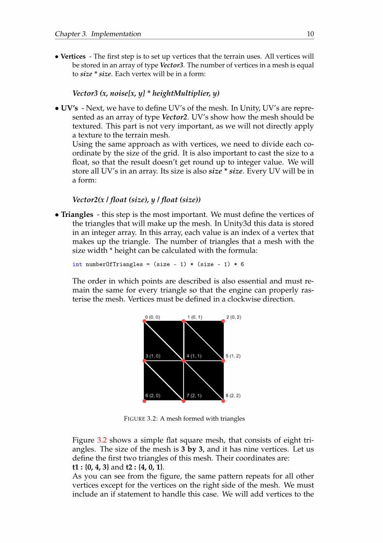
• Triangles - this step is the most important. We must define the vertices ofthe triangles that will make up the mesh. In Unity3d this data is storedin an integer array. In this array, each value is an index of a vertex thatmakes up the triangle. The number of triangles that a mesh with thesize width * height can be calculated with the formula:
int numberOfTriangles = (size - 1) * (size - 1) * 6
The order in which points are described is also essential and must re-main the same for every triangle so that the engine can properly ras-terise the mesh. Vertices must be defined in a clockwise direction.
FIGURE 3.2: A mesh formed with triangles
Figure 3.2 shows a simple flat square mesh, that consists of eight tri-angles. The size of the mesh is 3 by 3, and it has nine vertices. Let usdefine the first two triangles of this mesh. Their coordinates are:t1 : {0, 4, 3} and t2 : {4, 0, 1}.As you can see from the figure, the same pattern repeats for all othervertices except for the vertices on the right side of the mesh. We mustinclude an if statement to handle this case. We will add vertices to the

Chapter 3. Implementation 11
triangles array only if the coordinates (marked in parentheses in theformat (x coordinate, y coordinate) are smaller than size - 1. For everyvertex that satisfies this condition, the triangles that it makes can be cal-culated with the formula:
// i is an index of the vertex in a mesht1 = {i, i + size + 1, i + size}t2 = {i + size + 1, i, i + 1}
The process will be repeated for every vertex which x and y coordinateis less the size - 1, because vertices on the edge of the mesh do not havetriangles to their right (as seen on figure).
After everything that is needed to create the mesh is ready, we can use Unity’smesh component, and pass the vertices, UV’s, and triangles to it. After that, werecalculate the mesh’s normals and tangents, so that the mesh is lit up and displayedproperly. The created mesh object can now be assigned to the Mesh filter componentin the scene. Now Unity will render it to the screen.
var mesh = new Mesh { vertices = Vertices, triangles = Triangles, uv = UVs};
mesh.RecalculateNormals ();mesh.RecalculateTangents ();
FIGURE 3.3: Wireframe view of the created mesh
3.3 Terrain shader
The newly generated mesh looks excellent. It has hills, valleys and plains, but ithas no colours, and for the terrain to look realistic, it must have colours. We willachieve this by creating a custom surface shader. This type of shader uses “surfacefunction” takes any UVs or data you need as input, and fills in output structureSurfaceOutput. SurfaceOutput describes properties of the surface (it’s albedo colour,

Chapter 3. Implementation 12
normal, emission, specularity, etc.) [Surface shader manual]. In our case, we only needthe albedo, as we will use to set the texture. Albedo is a parameter that controls thebase colour of the surface. To texture the mesh, we will use free textures from Unity’sAsset Store or other copyright-free sources.
First we will divide the landscape into 5 separate layers:
1. Water
2. Gravel/Sand
3. Grass
4. Rocks
5. Snow
Now we assign each layer a height value and a texture that will be used to bringcolours to the created terrain. Unity allows accessing the coordinates of a point thatshe shader is currently shading. We can use this to access the height of each point.To do this, we must include a float3 variable named worldPos in the shader’s Inputstruct. Now the engine will automatically fill this variable.
struct Input {...// Now to access the height we can use worldPos.yfloat3 worldPos;}
We are going to have several textures on one mesh. For this to look good, weneed to have some blending between all the textures. The blending effect will addsmoother transitions between heights and their textures. We can control the inten-sity of blending with a float parameter. To properly blend the textures, we will usethe approach suggested on the Unity Forum. It uses a custom struct called blend-ingData. It will store the data about the height that we are currently sampling, andthe resulting data that we will later pass into the albedo. First, we will need to getthe data of the texture that we have assigned earlier. This can be done with thefunction UNITY_SAMPLE_TEX2D. As an input, it takes in the texture, and its UVfloat2 values. After all the textures are initialised, we have to blend them, using theheight parameters that we have defined. Each texture is treated as a separate layer.For each layer, we assign a new height value to our struct. Next, we calculate thecolour value using the blend intensity parameter, and then we use linear interpola-tion of the calculated result with the currently stored result, and the result value ofthe layer that we are currently blending. This process has to be repeated for everytexture. This approach allows us to add or reduce layers.
To make sure that our mesh looks nice even when its size gets big, we will addtexture tiling. Unity’s materials have support for this feature. Instead of projectingan entire texture on the mesh, it will tile in on both axes. The number of tiles isdetermined by user input. Having it set to 10 for both axes gives good results. Butsince we have a lot of water around the edges, let us set the tiling number to 30 forthe water texture, so it does not look too stretched.
Blending function:

Chapter 3. Implementation 13
blendingData BlendLayer(float4 layer, float layerHeight, blendingData bd){
bd.height = max(0, bd.height - layerHeight);float t = min(1, bd.height * _BlendSharpness);bd.result = lerp(bd.result, layer, t);
return bd;}
(A) Blending disabled (B) Blending enabled
FIGURE 3.4: The impact of texture blending
To make Unity use our newly created shader, we must create a new Material[Unity Manual, Materials], and then in the shader dropdown menu, choose theshader that we have just created. Next step is to apply this material to the MeshRen-derer component, and now Unity will use our shader to render this mesh.
FIGURE 3.5: Aerial view of the textured mesh

Chapter 3. Implementation 14
3.4 Improving the realism of the mesh
Terrain now has colours and looks realistic. However, its edges end with slicedmountains. Right now, the landscape consists of just one tile. To fix this, we cangenerate more tiles on each side of the terrain. Having many tiles stacked side byside will make the landscape look massive. This widespread implementation allowsdevelopers to create infinite worlds, as we can add more and more tiles for playersto walk on. However, it is a very computationally heavy task that requires a lot ofoptimisation. Having so many tiles would mean that the GPU would have to do alot of extra work. 3d games with large maps use a technique called "level of detail"(LOD) switching [Computer Graphics, ISY, LiTH]. It allows reducing the number oftriangles of the meshes that are far away from the player so that the GPU load issmaller. LOD switching can be done dynamically [GPU based dynamic geometryLOD]. But for this work, let us choose a different approach - turn this landscape intoan island using another level of artificial noise. This technique is similar to falloffmap - a tool used in game development, computer graphics and textures. The mostcommon use case for the falloff map is reflections.
For this work, we will generate a new layer of noise, and use it to turn the gen-erated terrain tile into an island. To achieve this, we can subtract the values of theextra layer of noise from the values of the generated Perlin noise and re-generate amesh. The noise must significantly decrease the values on the edges of the createdterrain, resembling an island.
I have picked three types of noise to modify the mesh.
(A) Distance to the right edge (B) Distance to the closest edge (C) Distance to the centre
FIGURE 3.6: Generated noise.
The first falloff map [Figure 3.3 A] can be used to create an effect of an edge. Itwill transform the noise to have low values (darker) at the right side, and highervalues on the left side (brighter). Visually the terrain will be textured as water onits left side, making the terrain look like a real edge of the continent. However, thistype of noise only generates high values on one of the sides.
The next two noises are much better for creating islands, as they both have highvalues close to all four edges. The square shape of the second noise [Figure 3.6 (B)]does not look as realistic as the round shaped noise of the third type [Figure 3.6 (C)].Also, it is not as smooth as the third noise type. The third noise type allows theterrain to have higher values closer to the edges and fills up more space with theland. For this work let us choose the circular noise to serve as an extra layer.

Chapter 3. Implementation 15
(A) (B) (C)
FIGURE 3.7: Terrain with the new layer applied.
3.5 Forest Generation
To generate a realistically looking forest, placing trees at random is not enough.There must be consistency, and trees can’t overlap. Also, the y coordinate that repre-sents the height of a tree in a 3d scene must match the y coordinate of the previouslygenerated mesh, so that trees do not float in the air, or grow underground.Cellular automata – a discrete abstract computational system [Cellular Automata,Stanford Encyclopedia of Philosophy], also famous for Conway’s Game of Life [Con-way’s Game of Life FAQ] can be an excellent way to solve this. This system (let usinterpret it as 2d grid, where each cell has coordinates x and y) consists of cells thatcan have two states: active or inactive. By defining rules, we can change the state ofthe system. To change the state, we must iterate through every cell in the grid, andcheck how many neighbours it has (let us call the number of neighbours n). If n issmaller than some threshold integer value (t), then we turn off the cell. Otherwise,when n is larger then the threshold value the cell gets turned on. This process can berepeated multiple times to achieve the best results.
To change the state of the system, we must define some initial state, because ifall points have equal states, then no changes will occur. For this work, we can ran-domly set the states of each cell. Let us introduce another variable p in the range [0,1] that will represent the probability that a cell’s state will be active when the systemstarts.
After the initial state of each cell has been set, we can start to change the stateof the system. The goal is to turn the system into a value noise grid that will definewhere a tree can be placed. We will interpret active cells as cells that have treesand inactive cells as cells that do not have trees or other objects inside. The processof changing the state of the grid can be repeated multiple times to achieve betterresults. A variable k represents the number of iterations that changed the state ofthe system.
int[, ] grid = new int[size, size];
// set the initial statefor (var y = 0; y < size; y++) {
for (var x = 0; x < size; x++) {float chance = Random.value;if (chance < p) {

Chapter 3. Implementation 16
grid[x, y] = 0;} else {
grid[x, y] = 1;}
}}
// change the state k timesfor (var i = 0; i < k; k++) {
for (var y = 0; y < size; y++) {for (var x = 0; x < size; x++) {
int n = GetNeighbours (x, y);if (n > t) {
grid[x, y] = 1;} else {
grid[x, y] = 0;}
}}
}
FIGURE 3.8: Cellular automata
The results [Figure 3.8] look beautiful and realistic. Each green point is a tree,and each white point is an empty space. The trees are connected, and there are for-est openings, which make it look realistic. However, there is a problem with thisapproach. Every tree is represented by a cell in a generated grid, rather than a coor-dinate. Being bound to a cell means that the distance between every tree in the gridwill always be the same, and that is not how trees in real life forests grow. Of course,each tree’s position can be altered by some random offset, but as with the case ofrandom noise for terrain, the results do not look realistic, and it can potentially cre-ate a lot of problems.
Another way to place trees is by using Poisson Disk sampling. This algorithm al-lows placing points on a grid, with any dimensionality procedurally. It also ensuresthat all points are at least r units away from all other points, meaning that no 2 pointscan overlap, and unlike in the previous implementation with Cellular Automata, thepositions are not bound to a fixed grid.In this work, we will use Fast Poisson Disk Sampling in Arbitrary Dimensions [RobertBridson, University of British Columbia]. It is an optimised implementation of this
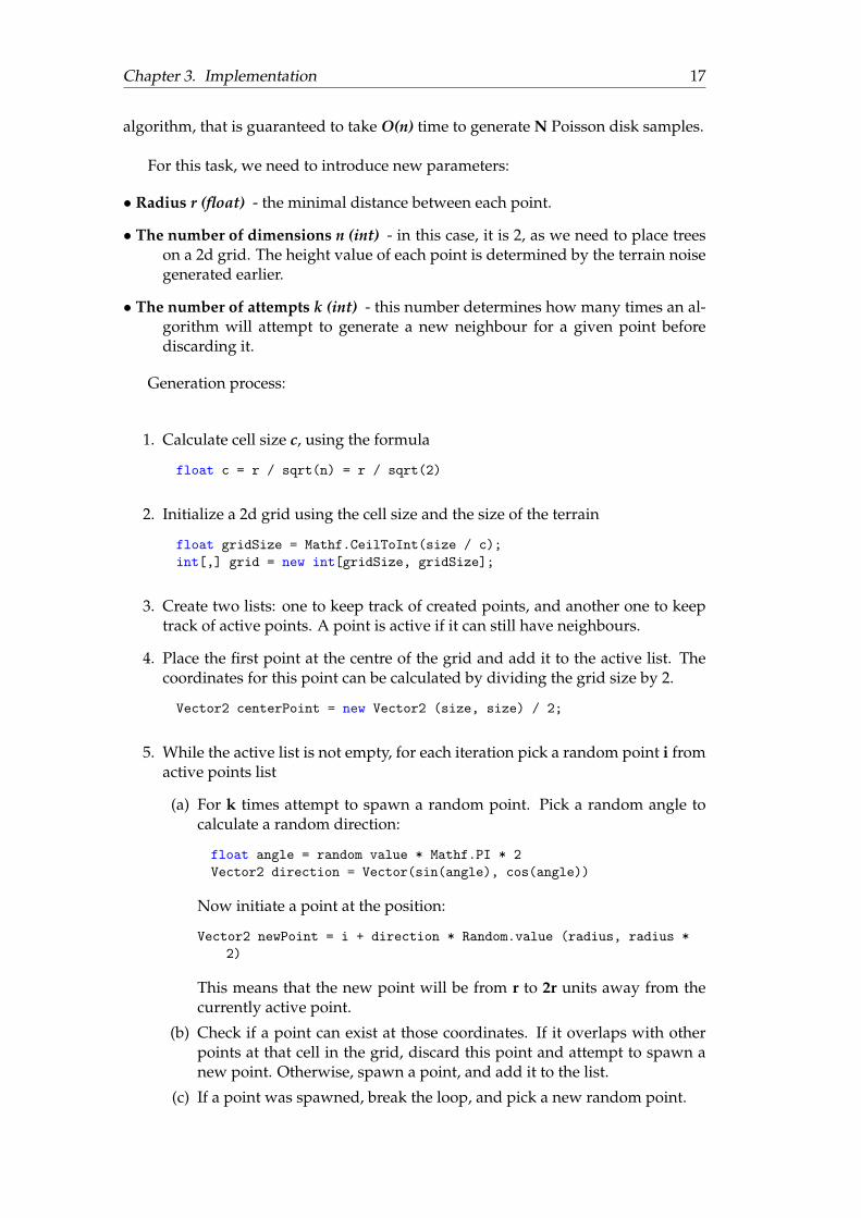
Chapter 3. Implementation 17
algorithm, that is guaranteed to take O(n) time to generate N Poisson disk samples.
For this task, we need to introduce new parameters:
• Radius r (float) - the minimal distance between each point.
• The number of dimensions n (int) - in this case, it is 2, as we need to place treeson a 2d grid. The height value of each point is determined by the terrain noisegenerated earlier.
• The number of attempts k (int) - this number determines how many times an al-gorithm will attempt to generate a new neighbour for a given point beforediscarding it.
Generation process:
1. Calculate cell size c, using the formula
float c = r / sqrt(n) = r / sqrt(2)
2. Initialize a 2d grid using the cell size and the size of the terrain
float gridSize = Mathf.CeilToInt(size / c);int[,] grid = new int[gridSize, gridSize];
3. Create two lists: one to keep track of created points, and another one to keeptrack of active points. A point is active if it can still have neighbours.
4. Place the first point at the centre of the grid and add it to the active list. Thecoordinates for this point can be calculated by dividing the grid size by 2.
Vector2 centerPoint = new Vector2 (size, size) / 2;
5. While the active list is not empty, for each iteration pick a random point i fromactive points list
(a) For k times attempt to spawn a random point. Pick a random angle tocalculate a random direction:
float angle = random value * Mathf.PI * 2Vector2 direction = Vector(sin(angle), cos(angle))
Now initiate a point at the position:
Vector2 newPoint = i + direction * Random.value (radius, radius *2)
This means that the new point will be from r to 2r units away from thecurrently active point.
(b) Check if a point can exist at those coordinates. If it overlaps with otherpoints at that cell in the grid, discard this point and attempt to spawn anew point. Otherwise, spawn a point, and add it to the list.
(c) If a point was spawned, break the loop, and pick a new random point.

Chapter 3. Implementation 18
(d) If after k tries no point was spawned, this means that the point i cannothave new neighbours, so we must remove it from the active list, and picka new point i, if any are available.
(e) If no points are available, then the generation is completed.
We now have a list of points where a tree can be placed. Now we need to addheight to all these points. The height of each tree is obtained using the same Perlinnoise that was used to generate the terrain.
FIGURE 3.9: Poisson disk sampling
3.6 Instantiating the trees
Now that we know where a tree can be placed let us instantiate a 3d mesh of a treeat that point. For the visual part of this work, I will use the free low polygon treemodels from the Unity3d asset store [LowPoly Trees and Rocks] [Low-Poly SimpleNature Pack]. Both packages contain textures, materials, and 3d models of differenttypes of trees and other natural objects. To optimise the performance of the game, letus spawn a preset collection of trees at each point, instead of generating a single tree.The rotation on the Y-axis of each collection will be randomised. This change willensure that the forest looks more like real-life forests. The rotation will be a randomfloat number in the range [0, 360]. Another improvement is to create multiple col-lections, that will be picked randomly during the generation process. As we use thesame seed for initialising the state of the randomiser that places trees, the generatedforest will always look the same, as long as the seed remains unchanged.

Chapter 3. Implementation 19
FIGURE 3.10: Examples of the collections
For the next step, we will need to introduce two new variables: lowerBound andupperBound. They will represent the lowest and the highest points at which a treecan be instantiated. Without them, the entire terrain (including the lower parts thatare textured as water) will be covered with trees and other objects. Since we do notwant that, a tree will only be spawned when its Y-axis coordinate falls within thegiven range. Through experimenting, I have found that setting the lower bound to0.37 and the upper bound to 0.8 produces the best results. The water and the rocky,snowy mountains do not have any trees growing now.
(A) Aerial view (B) Forest zoomed in
FIGURE 3.11: View of the generated forest

20
Chapter 4
Combining the Generations
To combine the two parts of this work (mesh and forest generation), we will needto create a controller that will call the generation functions of each component. Thecontroller will also store the generated noise, as both components use it. Now wewill create controllers for the Mesh Generator and the Forest Generator. They willboth have a Generate method that accepts noise and other parameters as an input.The function that calls the Generate method for other components can be set to exe-cute at the start of the application, or assigned to a button. For debugging purposes,we can also add a boolean variable to turn one of the components on or off. This isuseful for choosing the best generation parameters.
TerrainGenerator’s fields
1. MeshRenderer
2. MeshFilter
3. TerrainParameters (serialized field that we can set from the editor).
4. bool generateMesh - used to turn the generation on or off
ForestGenerator’s fields
1. float lowerBound
2. float lowerBound
3. GameObject[] treeCollections - an array of preset tree collections
4. bool generateForest - used to turn the generation on or off

21
Chapter 5
Results
Now that everything is finished and the components work well together, we canexperiment with the parameters of the generation, to see what kind of results willthe generation produce. Here are the examples of the landscapes generated withapproaches and techniques suggested in this work.
(A) seed = 2 (B) seed = 16 (C) seed = 128
FIGURE 5.1: Final results produced by different seeds
FIGURE 5.2: A beautiful mountain at the center of an island

Chapter 5. Results 22
FIGURE 5.3: An unsuccessful attempt to use simplex noise
FIGURE 5.4: Experimenting with textures, to make the landscape looklike an alien planet. Textures from Yughues Free Nature Materials

23
Chapter 6
Conclusion
The goal of this work was to generate a realistically looking 3d landscape that con-sists of mountains, lakes, plains and is populated with different trees, that make upforests. To achieve this, we split the work into two parts: generating and texturingterrain and then generating a forest. Both parts required us to generate noise or alayout and then transform it into a 3d scene. For the terrain we used Perlin gradientnoise, that was later transformed into a 3d mesh. Next step was applying a materialwith a custom surface shader that brought colours to the terrain. Having texturesallowed the ground to look realistic. The forest was generated by procedurally plac-ing trees using Poisson disk sampling. The algorithm ensures that no two pointsoverlap. Later the points were projected onto the terrain mesh, and at each coordi-nate, trees were placed. A falloff map was used to turn the terrain into an island.It subtracted the noise values at the edges of the grid. The result is a realisticallylooking island that has lakes, grass, sand, mountains with snow on top, and a lot ofdifferent trees that form forests.
This work shows a few ways of using procedural generation algorithms and toolsfor video games. It shows that using PCG for creating in-game content can be veryuseful and can generate creative results. PCG can also save a lot of time for develop-ers, artists, and game designers, and saved time usually means saved money. Nowthe generated landscape can be used for different types of video games. It could bemodified to create an infinite world for a survival game like Minecraft, or we canstick with single or multiple islands, for a survival game like Stranded Deep. An-other great application is using this landscape for a flight simulator game.
Procedural content generation is truly a fantastic tool for game development. Al-though the primary goal of this work was achieved, it can be further expanded withadditional features like an extra layer of noise to indicate the weather (similar tobiomes in Minecraft). We can use fractals to generate the plans and trees, instead ofusing preset 3d models. The possibilities are endless, and this is what is excellentabout PCG.

24
Bibliography
Perlin, Ken (1985). “An Image Synthesizer . Courant Institute of Mathematical Sci-ences New York University”. In: 19.3, pp. 1–10. DOI: https://dl.acm.org/doi/pdf/10.1145/325334.325247.
JamesE.Gentle (2002). “RANDOM NUMBER GENERATION AND MONTE CARLOMETHODS”. In: George Mason University. Chap. 1.1.
Gortler, Steven J. (2012a). “Foundations of 3D Computer Graphics”. In: MIT Press.Chap. 22.2.
— (2012b). “Foundations of 3D Computer Graphics”. In: MIT Press. Chap. 1.1.DAHLSKOG, STEVE (2016). “PATTERNS AND PROCEDURAL CONTENT GEN-
ERATION IN DIGITAL GAMES”. In: Malmo Univercity. Chap. 2.2.Julian Togelius Mark J. Nelson, Noor Shaker (2016). “Procedural Content Generation
in Games”. In: Springer. Chap. 1.9.Benjamin, Ward. Simplex Noise implementation. URL: https://github.com/WardBenjamin/
SimplexNoise.Gustavson, Stefan. Simplex noise demystified. URL: http://staffwww.itn.liu.se/
~stegu/simplexnoise/simplexnoise.pdf.Newzoo. 2018 Global Games Market Report. URL: https://web.archive.org/web/
20191102122939/https://newzoo.com/wp-content/uploads/2016/03/Newzoo_2018_Global_Games_Market_per_Device_Segment.png.
— Top 25 Public Companies by Game Revenues. URL: https://newzoo.com/insights/rankings/top-25-companies-game-revenues.
Perlin, Ken. Noise Hardware. URL: https://www.csee.umbc.edu/~olano/s2002c36/ch02.pdf.
Talbot, Carrie. 2011’s Minecraft becomes the second best-selling game of August 2019. URL:https://www.pcgamesn.com/minecraft/sales.
Unity. Creating a Quad. URL: https : / / docs . unity3d . com / Manual / Example -CreatingaBillboardPlane.html.
— Surface shader manual. URL: https://docs.unity3d.com/Manual/SL-SurfaceShaders.html.
— Unity Documentation. URL: https : / / docs . unity3d . com / ScriptReference /Random.InitState.html.
— Unity User Manual. URL: https://docs.unity3d.com/Manual/index.html.— Writing Shaders. URL: https://docs.unity3d.com/Manual/ShadersOverview.
html.
Copyright © 2022 FDOKUMEN