Water solubility characteristics of current aviation jet fuels
8
1 2 Short communication 4 Water solubility characteristics of current aviation jet fuels 5 6 7 Joseph K.-W. Lam Q1 a,⇑ , Mark D. Carpenter b , Colleen A. Williams b , Janice I. Hetherington b 8 a Airbus Operations Limited, New Filton House, Filton, Bristol BS99 7AR, UK 9 b Cranfield Defence and Security, Cranfield University, Shrivenham, Swindon SN6 8LA, UK 10 12 article info 13 Article history: 14 Received 25 November 2013 15 Received in revised form 25 April 2014 16 Accepted 29 April 2014 17 Available online xxxx 18 Keywords: 19 Water solubility 20 Aviation fuel 21 Dissolved water 22 Aromatics 23 Aircraft fuel systems 24 25 abstract 26 Water solubility-temperature curves were created experimentally for five kerosine fuels and one wide- 27 cut fuel. The Karl Fischer Coulometer method was used to determine the saturated water content of each 28 fuel over a range of temperatures between 5 °C and 25 °C. The affinity for water of each fuel with 29 respect to the other fuels was measured and ranked. The experimental solubility curves are comparable 30 to the water solubility curves of the Jet A-1 and JP-4 fuels reported in the CRC Handbook of Aviation Fuel 31 Properties. There are subtle differences between the experimental solubility curves and the CRC curves. 32 This may be attributed to batch-to-batch variation or recent changes in fuel chemistry owing to the need 33 to exploit less favourable crude oil reserves. A generic equation has been proposed to estimate the water 34 solubility when aromatics content and flash point are known. 35 Ó 2014 Published by Elsevier Ltd. 36 37 38 39 1. Introduction 40 Jet fuel does not have an exact chemical composition; it is pro- 41 duced to meet a set of properties defined by various specifications 42 [1–5]. Its chemical composition will depend on the chemical spe- 43 cies present in the parent crude oil that distil during the physical 44 separation in the kerosine boiling range and on further chemical 45 treatments that may be required to meet the jet fuel specifications. 46 The lack of precise property data is due to the variation of jet fuels, 47 based on the composition of the original crude oil and the refinery 48 methods used. 49 The three major constituent groups of jet fuel are paraffins (sat- 50 urated alkanes), naphthenes (saturated cyclic alkanes) and aromat- 51 ics [6–8]. The proportion of each chemical species varies from 52 batch to batch, but paraffins and naphthenes together account 53 for a minimum of 70%v/v [8]. Aromatics are limited to a maximum 54 of 25%v/v [1] by specifications and to an industry accepted mini- 55 mum of 8%v/v [6] for jet fuels containing synthetic components 56 conforming to the ASTM D7566-13 [9] specification. Olefins 57 (unsaturated hydrocarbons or alkanes) and trace impurities 58 account for less than 5%v/v [8] and are minor constituents of jet 59 fuel. Baena-Zambrana et al. [10] provide an overview of the struc- 60 ture of these classes of hydrocarbons. Further details may be found 61 in Hemighaus et al. [7]. 62 Aromatics are unsaturated hydrocarbons and have characteris- 63 tic benzene rings with delocalized p electron clouds. They are 64 mainly alkyl-benzenes and alkyl-naphthalenes [8]. It has been 65 recognised that extended p electron systems such as those 66 encountered in aromatics, form hydrogen bonds with water [11– 67 13]. The formation of attractive electrostatic interactions between 68 water and extended p electron systems account for the enhanced 69 solubility of water in aromatics relative to both paraffins and 70 naphthenes. 71 Water contamination of jet fuel can result in fuel system icing 72 [14], microbial contamination, corrosion and tank gauging prob- 73 lems. Mathematical models have been developed for studying 74 and predicting the dispersal of water in aircraft fuel systems 75 [15,16], and are used in design to optimise fuel–water manage- 76 ment and ensure that water build up is minimised throughout 77 the system. These models compute the water contamination, due 78 to the principal mechanisms of dissolution, suspension, condensa- 79 tion and transportation. Among other parameters, it is important 80 to have accurate data on the water solubility behaviour in jet fuel 81 to ensure confidence in the model results. 82 Some data on the water solubility behaviour in jet fuel are avail- 83 able in the open literature but this mostly dates back to the 1950s. 84 Even data given in the CRC Handbook of Aviation Fuel Properties [6, 85 Figs. 2–32], were found to pre-date 1984; the actual source of these 86 data could not be verified but look similar to data presented by 87 [17]. To take account of recent changes in fuel chemistry owing 88 to the need to exploit less favourable crude oil reserves [18] and 89 the introduction of non-petroleum-derived fuels, such as Fischer– 90 Tropsch (FT), hydrotreated esters and fatty acids (HEFA) together 91 with other alternatives [19–24], data on the water uptake and 92 solubility in jet fuels needed to be updated. This study was used http://dx.doi.org/10.1016/j.fuel.2014.04.091 0016-2361/Ó 2014 Published by Elsevier Ltd. ⇑ Corres Q2 ponding author. Tel.: +44 1179367028. E-mail address: [email protected] (J.K.-W. Lam Q1 ). Fuel xxx (2014) xxx–xxx Contents lists available at ScienceDirect Fuel journal homepage: www.elsevier.com/locate/fuel JFUE 8085 No. of Pages 8, Model 5G 13 May 2014 Please cite this article in press as: Lam Q1 J-KW et al. Water solubility characteristics of current aviation jet fuels. Fuel (2014), http://dx.doi.org/10.1016/ j.fuel.2014.04.091
-
Upload
independent -
Category
Documents
-
view
1 -
download
0
Transcript of Water solubility characteristics of current aviation jet fuels

1
2
45
6
7 Q1
89
10
1 2
1314151617
18192021222324
2 5
38
39
40
41
42
43
44
45
46
47
48
49
50
51
52
53
54
55
56
57
58
59
60
61
62
63
Q2Q1
Fuel xxx (2014) xxx–xxx
JFUE 8085 No. of Pages 8, Model 5G
13 May 2014
Q1
Contents lists available at ScienceDirect
Fuel
journal homepage: www.elsevier .com/locate / fuel
Short communication
Water solubility characteristics of current aviation jet fuels
http://dx.doi.org/10.1016/j.fuel.2014.04.0910016-2361/� 2014 Published by Elsevier Ltd.
⇑ Corresponding author. Tel.: +44 1179367028.E-mail address: [email protected] (J.K.-W. Lam).
Please cite this article in press as: Lam J-KW et al. Water solubility characteristics of current aviation jet fuels. Fuel (2014), http://dx.doi.org/1j.fuel.2014.04.091
Joseph K.-W. Lam a,⇑, Mark D. Carpenter b, Colleen A. Williams b, Janice I. Hetherington b
a Airbus Operations Limited, New Filton House, Filton, Bristol BS99 7AR, UKb Cranfield Defence and Security, Cranfield University, Shrivenham, Swindon SN6 8LA, UK
a r t i c l e i n f o
2627282930313233343536
Article history:Received 25 November 2013Received in revised form 25 April 2014Accepted 29 April 2014Available online xxxx
Keywords:Water solubilityAviation fuelDissolved waterAromaticsAircraft fuel systems
a b s t r a c t
Water solubility-temperature curves were created experimentally for five kerosine fuels and one wide-cut fuel. The Karl Fischer Coulometer method was used to determine the saturated water content of eachfuel over a range of temperatures between �5 �C and 25 �C. The affinity for water of each fuel withrespect to the other fuels was measured and ranked. The experimental solubility curves are comparableto the water solubility curves of the Jet A-1 and JP-4 fuels reported in the CRC Handbook of Aviation FuelProperties. There are subtle differences between the experimental solubility curves and the CRC curves.This may be attributed to batch-to-batch variation or recent changes in fuel chemistry owing to the needto exploit less favourable crude oil reserves. A generic equation has been proposed to estimate the watersolubility when aromatics content and flash point are known.
� 2014 Published by Elsevier Ltd.
37
64
65
66
67
68
69
70
71
72
73
74
75
76
77
78
79
80
81
82
83
84
85
86
87
88
89
1. Introduction
Jet fuel does not have an exact chemical composition; it is pro-duced to meet a set of properties defined by various specifications[1–5]. Its chemical composition will depend on the chemical spe-cies present in the parent crude oil that distil during the physicalseparation in the kerosine boiling range and on further chemicaltreatments that may be required to meet the jet fuel specifications.The lack of precise property data is due to the variation of jet fuels,based on the composition of the original crude oil and the refinerymethods used.
The three major constituent groups of jet fuel are paraffins (sat-urated alkanes), naphthenes (saturated cyclic alkanes) and aromat-ics [6–8]. The proportion of each chemical species varies frombatch to batch, but paraffins and naphthenes together accountfor a minimum of 70%v/v [8]. Aromatics are limited to a maximumof 25%v/v [1] by specifications and to an industry accepted mini-mum of 8%v/v [6] for jet fuels containing synthetic componentsconforming to the ASTM D7566-13 [9] specification. Olefins(unsaturated hydrocarbons or alkanes) and trace impuritiesaccount for less than 5%v/v [8] and are minor constituents of jetfuel. Baena-Zambrana et al. [10] provide an overview of the struc-ture of these classes of hydrocarbons. Further details may be foundin Hemighaus et al. [7].
Aromatics are unsaturated hydrocarbons and have characteris-tic benzene rings with delocalized p electron clouds. They are
90
91
92
mainly alkyl-benzenes and alkyl-naphthalenes [8]. It has beenrecognised that extended p electron systems such as thoseencountered in aromatics, form hydrogen bonds with water [11–13]. The formation of attractive electrostatic interactions betweenwater and extended p electron systems account for the enhancedsolubility of water in aromatics relative to both paraffins andnaphthenes.
Water contamination of jet fuel can result in fuel system icing[14], microbial contamination, corrosion and tank gauging prob-lems. Mathematical models have been developed for studyingand predicting the dispersal of water in aircraft fuel systems[15,16], and are used in design to optimise fuel–water manage-ment and ensure that water build up is minimised throughoutthe system. These models compute the water contamination, dueto the principal mechanisms of dissolution, suspension, condensa-tion and transportation. Among other parameters, it is importantto have accurate data on the water solubility behaviour in jet fuelto ensure confidence in the model results.
Some data on the water solubility behaviour in jet fuel are avail-able in the open literature but this mostly dates back to the 1950s.Even data given in the CRC Handbook of Aviation Fuel Properties [6,Figs. 2–32], were found to pre-date 1984; the actual source of thesedata could not be verified but look similar to data presented by[17]. To take account of recent changes in fuel chemistry owingto the need to exploit less favourable crude oil reserves [18] andthe introduction of non-petroleum-derived fuels, such as Fischer–Tropsch (FT), hydrotreated esters and fatty acids (HEFA) togetherwith other alternatives [19–24], data on the water uptake andsolubility in jet fuels needed to be updated. This study was used
0.1016/
93
94
95
96
97
98
99
100
101
102
103
104
105
106
107
108
109
110
111
112
113
114
115
116
117
118
119
120
121
122
123
124
125
126
127
Abbreviations
AVTAG aviation wi de-cut turbine fuelAVTUR aviation turbine fuelCOA Certificate of AnalysisCRC Coordinating Research Council, Inc.CTL coal to liquidDi-EGMME Di-Ethylene Glycol Mono-Methyl EtherFBP final boiling pointFSII fuel system icing inhibitorFT Fischer–TropschGTL gas to liquid
HEFA hydrotreated esters and fatty acidsIBP initial boiling pointKF Karl FischerMSEP MicroseparometerNATO North Atlantic Treaty OrganisationPPMCC Pearson product-moment correlation coefficientRH relative humiditySDA static dissipater additiveUV ultraviolet
2 J.K.-W. LamQ1 et al. / Fuel xxx (2014) xxx–xxx
JFUE 8085 No. of Pages 8, Model 5G
13 May 2014
Q1
to assess the water solubility of current aviation jet fuels to fill thatknowledge gap.
128
129
130
131
132
133
134
135
136
137
138
139
140
141
142
143
144
145
146
147
148
149
150
151
152
153
154
155
156
2. Test fuels
The study evaluated the water solubility characteristics of fivejet fuels made to different national standards, which either com-plied with or were very similar to the Jet A-1 fuel specification.The fuels were freshly sourced since fuel compositions may changesubtly with storage due to the formation of polar oxidation com-pounds such as organic acids. One of the fuels was fully synthetic,i.e., not derived from conventional crude oil stocks. The work pro-gramme also included limited tests on a wide-cut fuel conformingto the JP-4 specification; this contains a proportion of lighterhydrocarbon molecules (naphtha or gasoline fraction). The lighterfraction improves the fuel relight ability at altitude and reducesits freezing point but also contributes significantly to the fire riskdue to a low flash point and higher vapour pressure. It is now onlyused in consistently cold climates and availability is limited.
The fuels used in this study are summarised in Table 1. Fuels Ato E may be collectively referred to as kerosine fuels; Fuel F may bereferred to as a wide-cut fuel.
A Certificate of Analysis (COA) was supplied with each fuel asevidence that the fuel conformed to the relevant specification.Chemical composition data and physical test data were given inthe COA. Some key characteristics of the test fuels are listed inTable 2. The fuels were supplied to the normal commercial specifi-cation and included static dissipater additive (SDA), where shown.Fuel F was actually supplied to the NATO F-40 (AVTAG/FSII) spec-ification which includes requirements for lubricity improver, SDAand fuel system icing inhibitor, FSII.
157
158
159
160
161
162
163
3. Experimental
Fuels were filtered using nitrogen gas pressure through aSartorius filter assembly fitted with Millipore HAWP04700(0.45 lm) mixed cellulose filter; fuels were filtered in batches of
164
165
166
167
168
169
170
171
Table 1Test fuels.
ID Fuel & Specification Provenance
A Sasol Fischer–Tropsch fullysynthetic Jet A-1
Sasol, South Africa
B Chinese No. 3 jet fuel PetroChina International (Hong Kong)Ltd., Hong Kong
C Coryton high aromatics Jet A-1 Coryton Advanced Fuels Ltd., UKD Air BP filton airfield Jet A-1 Air BP UK Ltd., Filton, UKE Russian TS-1 aviation kerosine Blended by Coryton; tested/approved
in RussiaF JP-4 wide-cut fuel Coryton Advanced Fuels Ltd., UK
Please cite this article in press as: Lam J-KW et al. Water solubility characterj.fuel.2014.04.091
approximately 1.2 l. Filtered fuels were stored in individual desic-cators and dried over silica gel for at least 24 h. This procedureensured that all the fuels had low concentrations of water initiallyand that re-humidification below ambient temperatures could becarried out without precipitating water. The desiccators werestored inside a fume cupboard to minimise exposure to ambientlight. Fuel B was noted to be particularly susceptible to UV degra-dation, turning a noticeable yellow after a few days. The cause isunknown but many studies have shown that photo-induced degra-dation may be a result of photo-oxidation and microbial degrada-tion [25–29].
The fuels were re-humidified in a closed vessel (a desiccatorcontaining a small amount of distiled water throughout the pro-cess) at the appropriate test temperature; the aim was to achievea 100% relative humidity (RH) environment without introducingfree water. A Mercia Scientific Humidicab was used for tests at orabove 5 �C, as shown in Fig. 1, and a Fisons FE 300H cabinet fortemperatures below 5 �C. To avoid over-saturating the fuels, eachdried fuel sample was cooled to below the nominal conditioningtemperature, transferred to the desiccator containing a smallamount of distiled water and allowed to warm to the test temper-ature. Approximately 300 ml of fuel was treated in this way foreach test. Fuel samples were gently stirred with a magnetic stirrerand the sample left to reach water saturated equilibrium at the rel-evant set temperature for at least 16 h. Previous work had shownthis to be sufficient time for the system to reach equilibrium[30]. The desiccators were fitted with septum caps to allow sam-pling of the fuel without disturbing the equilibrium. A thermocou-ple was located in the fuel so that an accurate reading of the fueltemperature could be taken when sampled.
Karl Fischer (KF) coulometric titration with a Metrohm KF831Coulometer was used to make the measurement of water in fuel.There are a number of test standards covering the use of KFCoulometers, but the most relevant in the context of fuel testingare ASTM E203 [31] and ASTM D6304 [32]. An SGE gas-tight2.5 ml glass syringe with a long stainless steel luer needle was usedfor all injections. The Metrohm Karl Fischer Coulometer with anSGE glass syringe is depicted in Fig. 2. A multiple injectionsequence with the needle tip below the surface of the anolytewas used for making the measurements (see A). The multiple injec-tion procedure had been shown to give a smaller spread of resultsthan the standard single injection technique. Type AG-H anolytesolution manufactured by Sigma Aldrich under the HydranalCoulomat brand was used in the coulometer cell. It gave the mostconsistent results, with the least tendency to form a biphasicsolution of fuel and anolyte.
172
173
174
4. Results and discussion
To generate the water solubility curves, the saturated watercontent of each fuel was measured at nominal temperatures of
istics of current aviation jet fuels. Fuel (2014), http://dx.doi.org/10.1016/

175
176
177
178
179
180
181
182
183
184
185
186
187
188
189
190
191
192
193
194
195
196
197
198
199
200
201
202
203
204
205
206
207
208210210
211
212
213
Table 2Some key characteristics of the test fuels.
Parameter A B C D E F
Aromatics, %v/v 10.7 16.4 24.1 13.7 13.0� 10.3Density @ 20 �C, kg m�3 810.4 785.1 810.8⁄ 792.6⁄ 794.4 779.5⁄
Freezing point, �C �58.1 �54.0 �57.0 �57.0 �64.0 �58.0Kinematic viscosity @ �20 �C, mm2 s�1 5.229 3.661 3.547 3.992 6.238� –MSEP, rating 92 99 92 96 – 62Naphthalenes, %v/v – – 1.89 – – 0.8Olefins, %v/v – 0.7 – – – –Smoke point, mm 29.0 25.0 21.0 27.0 25.2 27.0Sulphur, %m/m <0.01 0.0359 0.029 0.0461 <0.1 <0.01Flash point, �C 46.0 41.0 38.5 41.0 37.0 –IBP, �C 155.0 151.9 147.2 147.6 146.5 38.810%v/v recovered, �C 176.0 167.1 167.7 165.3 159.0 107.150%v/v recovered, �C 197.7 190.4 193.2 198.0 180.0 192.6FBP, �C 261.5 246.2 262.5 280.2 245.0} 244.0
} 98%v/v recovered.� Viscosity @ �40 �C.⁄ Density @ 15 �C.� %m/m.
Fig. 1. Mercia Scientific Humidicab with fuel samples and desiccators in position.
Fig. 2. Metrohm Karl Fischer Coulometer KF 831, with SGE glass syringe and needlein foreground.
J.K.-W. LamQ1 et al. / Fuel xxx (2014) xxx–xxx 3
JFUE 8085 No. of Pages 8, Model 5G
13 May 2014
Q1
�5, 0, 5, 15 and 25 �C. Each fuel was conditioned at the appropriatetemperature and the water content was determined using thestandard procedure given in Section 3. When fuel samples weretaken at test temperatures below 5 �C, the fuel in the conditioningdesiccator tended to gradually warm up, typically by 1–3 �C overthe course of a set of measurements; this was due to the condition-ing chamber door being opened multiple times to allow samples tobe taken. Although individual readings of fuel temperature weremade, for accuracy the KF measurements were always averagedover ten readings and therefore an average temperature is givenfor a set of readings at a particular temperature.
Some of the data sets were repeated because there appeared tobe a larger degree of scatter in the results than was consideredsatisfactory. There are a number of reasons for this; these mightbe related to laboratory temperature and/or humidity and possibly
Please cite this article in press as: Lam J-KW et al. Water solubility characterj.fuel.2014.04.091
condensation on the desiccator septum or syringe needle. It mustalso be remembered that the concentrations of water beingmeasured are very low, so that even traces can significantly skewthe results. For example, there was difficulty discerning the watercontent of the Sasol Fully Synthetic Jet A-1 (Fuel A) fuel attemperatures below 0 �C due to the very low concentration presentand the limitations of the Karl Fischer apparatus.
The KF measurements are displayed graphically in Fig. 3 usingbox plots. Each box plot provides a synopsis of the data distributionof presenting the 5-number summary which consists of the mini-mum, maximum, the upper (or 3rd) quartile, lower (or 1st) quartileand the median [33]. The box plots are plotted with deviation fromthe median as the horizontal axis. It aligns the medians of the boxplots at zero on the horizontal axis for visual comparison.
Since the water absorption characteristics of aviation fuels fol-lows an exponential trend with increasing temperature, expressingwater content on a log-lin graph (a logarithmic scale on the y-axis,and a linear scale on the x-axis) yields a straight line relationship:
S ¼ a exp bTð Þ ð1Þ
S is the solubility of water in fuel expressed in ppm m/m and T is thefuel temperature in �C. The base coefficient, a, is the water solubilityin fuel at 0 �C expressed in ppm m/m whilst the exponent
istics of current aviation jet fuels. Fuel (2014), http://dx.doi.org/10.1016/

214
215
216
217
218
219
220
221
222
223
224
225
226
227
228
229
230
231
232
233
234
235
236
237
238
239
4 J.K.-W. LamQ1 et al. / Fuel xxx (2014) xxx–xxx
JFUE 8085 No. of Pages 8, Model 5G
13 May 2014
Q1
coefficient, b, is the slope of the straight line relationship of the log-lin plot expressed in �C�1.
Data from the five kerosine fuels, Fuels A to E, were plotted withtrend lines in Fig. 4. For comparative purposes, the typical watersolubility of Jet A-1 from the CRC Handbook of Aviation Fuel Proper-ties [6, Figs. 2–32] (the fuel, hereafter, referred to as CRC Jet A-1)has also been added to Fig. 4. Since Fuel F is a wide-cut fuel, it isnot directly comparable to the kerosine fuels and is not includedin Fig. 4.
The ranking of the five kerosine fuels with respect to their affin-ity for water is quite clear from Fig. 4. Fuel A has the lowest affinityfor water with the smallest base coefficient, followed by Fuel D,then Fuel E and Fuel B, with Fuel C having the highest affinity
Fig. 3. Box plots of the KF meas
Please cite this article in press as: Lam J-KW et al. Water solubility characterj.fuel.2014.04.091
and the largest base coefficient. The solubility curves for the fivekerosine fuels generated from the KF determinations have basecoefficients of similar order to that of the solubility curve for theCRC Jet A-1. However, the CRC Jet A-1 has a smaller exponent coef-ficient compared to the five kerosine fuels, i.e., the gradient of theline for CRC Jet A-1 is less than that for the five kerosine fuels. Asnoted in Section 1, the CRC data were found to pre-date 1984.The differences observed may be attributed to recent changes infuel chemistry, or the particular fuel or average of fuels, repre-sented by the CRC plot.
The water solubility curve for Fuel F, the wide-cut fuel, isshown in Fig. 5. For comparison purposes, the typical watersolubility of JP-4 from the CRC Handbook of Aviation Fuel
urements for the test fuels.
istics of current aviation jet fuels. Fuel (2014), http://dx.doi.org/10.1016/

240
241
242
243
244
245
246
247
248
249
250
251
252
253
254
255
256
257
258
259
260
261
262
263
264
265
266
267
268
269
270
271
272
273
274
275
276
277
278
279
280
281
282
283
284
285
286
287
288
289
290
291
292
293
294
295
Fig. 4. Water solubility versus temperature for the five kerosine fuels. Fig. 5. Water solubility versus temperature for the wide-cut fuel.
J.K.-W. LamQ1 et al. / Fuel xxx (2014) xxx–xxx 5
JFUE 8085 No. of Pages 8, Model 5G
13 May 2014
Q1
Properties [6, Fig. 2-32] (the fuel, hereafter, referred to as CRCJP-4) has also been added to Fig. 5. Fuel F has a larger basecoefficient, but a smaller exponent coefficient compared to thefive kerosine fuels. A large base coefficient indicates that Fuel Fhas a higher affinity for water. The solubility curve for Fuel Fhas a similar base coefficient to the solubility curve for theCRC JP-4. However, the solubility curve for CRC JP-4 has a largerexponent coefficient compared to that of Fuel F.
Fuel F was made to the NATO F-40 (AVTAG/FSII) specification.This includes various additives that are used for military fuelsbut are not normally included in fuels for civil aviation purposes.The FSII interacts with free water to form a non-freezing solutionbut it may indirectly also increase water solubility in the fuel. Sucha hypothesis is reasonable given the additive is Di-Ethylene GlycolMono-Methyl Ether (Di-EGMME) which would offer some polarityeven at the low concentrations used in aviation fuel of 0.10–0.15%v/v [1]. It is also known that smaller hydrocarbon molecules, whichwould be present in the wide-cut jet fuel, tend to be slightly betterat holding water in solution [34]. It was clear from the KF tests thatthe Fuel F was less likely to shed water than the kerosine fuels butit was not possible to say whether the effect was mainly due to thesmaller hydrocarbons or the FSII.
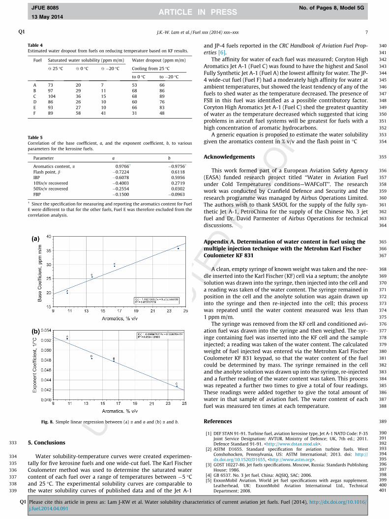
Estimates of the water shed from each fuel at 0 �C and �20 �Con cooling from 25 �C are given in Table 4. The solubility valuesin the table were derived from trend lines on the log-lin plots givenin Figs. 4 and 5.
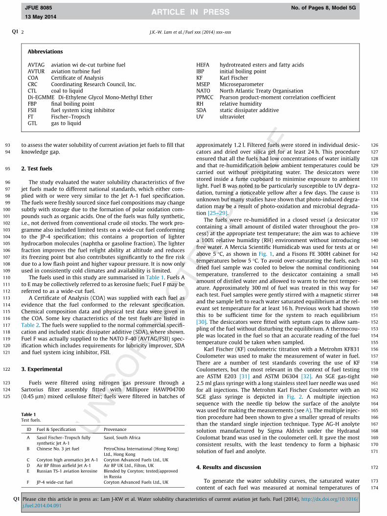
Published data for Russian fuels [35,36] are plotted with Fuel Eand the CRC Jet A-1 for comparison in Fig. 6. Similarly, published
Please cite this article in press as: Lam J-KW et al. Water solubility characterj.fuel.2014.04.091
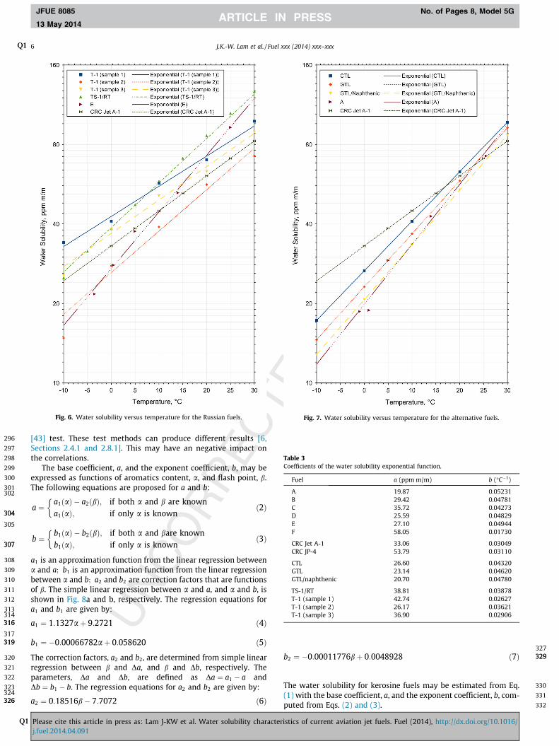
data for some alternative aviation fuels [37] are plotted with FuelA and the CRC Jet A-1 for comparison in Fig. 7. It should be notedthat Fuel E is a Russian specification fuel and Fuel A is a syntheticfuel and they were the most appropriate fuels to be used for com-parison in Figs. 6 and 7, respectively.
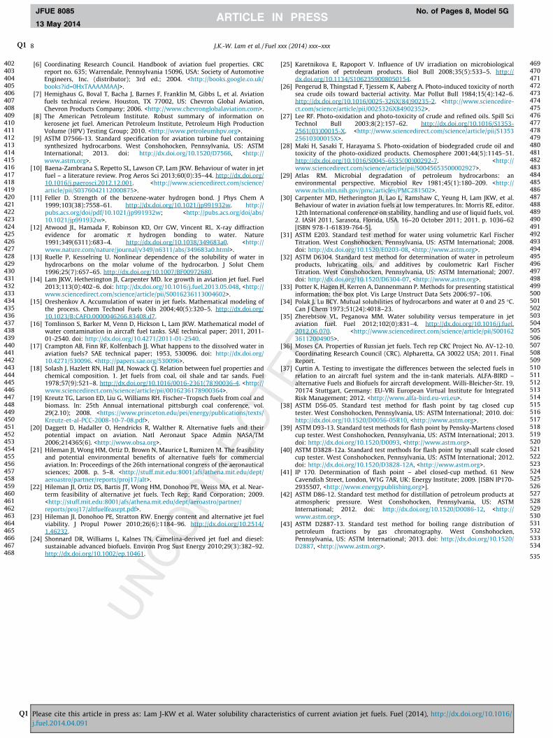
The coefficients of water solubility for a range of fuels, calcu-lated using Eq. (1), are summarised in Table 3. Moses [36] notedthat water solubility increases with aromatics content anddecreases with higher boiling range fuels. Appropriate parametersto characterise higher boiling range fuels may include flash point,and distilation factors such as initial boiling point (IBP), 10%v/vrecovered, 50%v/v recovered and final boiling point (FBP). ThePearson product-moment correlation coefficients (PPMCC) for var-ious fuel parameters are given in Table 5; these relate the basecoefficient, a, and the exponent coefficient, b, with aromatics con-tent and physical characteristic for higher boiling range hydrocar-bons. Both a and b have a high correlation with aromatics content,a, a medium correlation with flash point, b, and IBP, but a weakcorrelation for 10%v/v recovered, 50%v/v recovered and FBP. Apositive correlation is found between a and a, but negativecorrelations between a; b and IBP. This supports the theory thatwater solubility increases with aromatics content and decreaseswith higher boiling range fuels.
The flash point, b, may be measured using a number of standardtest methods (ASTM D56-05 [38], ASTM D93-13 [39], ASTMD3828-12a [40], IP 170 [41]). Similarly, the boiling range distribu-tion (i.e., IBP, 10%v/v recovered, 50%v/v recovered and FBP), may bemeasured using the ASTM D86-12 [42] test or the ASTM D2887-13
istics of current aviation jet fuels. Fuel (2014), http://dx.doi.org/10.1016/
296
297
298
299
300
301302
304304
305
307307
308
309
310
311
312
313314316316
317319319
320
321
322
323324326326
327329329
330
331
332
Fig. 6. Water solubility versus temperature for the Russian fuels. Fig. 7. Water solubility versus temperature for the alternative fuels.
Table 3Coefficients of the water solubility exponential function.
Fuel a (ppm m/m) b (�C�1)
A 19.87 0.05231B 29.42 0.04781C 35.72 0.04273D 25.59 0.04829E 27.10 0.04944F 58.05 0.01730
CRC Jet A-1 33.06 0.03049CRC JP-4 53.79 0.03110
CTL 26.60 0.04320GTL 23.14 0.04620GTL/naphthenic 20.70 0.04780
TS-1/RT 38.81 0.03878T-1 (sample 1) 42.74 0.02627T-1 (sample 2) 26.17 0.03621T-1 (sample 3) 36.90 0.02906
6 J.K.-W. LamQ1 et al. / Fuel xxx (2014) xxx–xxx
JFUE 8085 No. of Pages 8, Model 5G
13 May 2014
Q1
[43] test. These test methods can produce different results [6,Sections 2.4.1 and 2.8.1]. This may have an negative impact onthe correlations.
The base coefficient, a, and the exponent coefficient, b, may beexpressed as functions of aromatics content, a, and flash point, b.The following equations are proposed for a and b:
a ¼a1ðaÞ � a2ðbÞ; if both a and b are knowna1ðaÞ; if only a is known
�ð2Þ
b ¼b1ðaÞ � b2ðbÞ; if both a and bare knownb1ðaÞ; if only a is known
�ð3Þ
a1 is an approximation function from the linear regression betweena and a; b1 is an approximation function from the linear regressionbetween a and b; a2 and b2 are correction factors that are functionsof b. The simple linear regression between a and a, and a and b, isshown in Fig. 8a and b, respectively. The regression equations fora1 and b1 are given by:
a1 ¼ 1:1327aþ 9:2721 ð4Þ
b1 ¼ �0:00066782aþ 0:058620 ð5Þ
The correction factors, a2 and b2, are determined from simple linearregression between b and Da, and b and Db, respectively. Theparameters, Da and Db, are defined as Da ¼ a1 � a andDb ¼ b1 � b. The regression equations for a2 and b2 are given by:
a2 ¼ 0:18516b� 7:7072 ð6Þ
Please cite this article in press as: Lam J-KW et al. Water solubility characterj.fuel.2014.04.091
b2 ¼ �0:00011776bþ 0:0048928 ð7Þ
The water solubility for kerosine fuels may be estimated from Eq.(1) with the base coefficient, a, and the exponent coefficient, b, com-puted from Eqs. (2) and (3).
istics of current aviation jet fuels. Fuel (2014), http://dx.doi.org/10.1016/
333
334
335
336
337
338
339
340
341
342
343
344
345
346
347
348
349
350
351
352
353
354
355
356
357
358
359
360
361
362
363
364
365
366
367
368
369
370
371
372
373
374
375
376
377
378
379
380
381
382
383
384
385
386
387
388
389
390391392393394395396397398399400401
Table 4Estimated water dropout from fuels on reducing temperature based on KF results.
Fuel Saturated water solubility (ppm m/m) Water dropout (ppm m/m)
@ 25 �C @ 0 �C @ �20 �C Cooling from 25 �C
to 0 �C to �20 �C
A 73 20 7 53 66B 97 29 11 68 86C 104 36 15 68 89D 86 26 10 60 76E 93 27 10 66 83F 89 58 41 31 48
Table 5Correlation of the base coefficient, a, and the exponent coefficient, b, to variousparameters for the kerosine fuels.
Parameter a b
Aromatics content, a 0.9766� �0.9756�
Flash point, b �0.7224 0.6118IBP �0.6078 0.595610%v/v recovered �0.4003 0.271950%v/v recovered �0.2554 0.0302FBP �0.1500 �0.0963
� Since the specification for measuring and reporting the aromatics content for FuelE were different to that for the other fuels, Fuel E was therefore excluded from thecorrelation analysis.
Fig. 8. Simple linear regression between (a) a and a and (b) a and b.
J.K.-W. LamQ1 et al. / Fuel xxx (2014) xxx–xxx 7
JFUE 8085 No. of Pages 8, Model 5G
13 May 2014
Q1
5. Conclusions
Water solubility-temperature curves were created experimen-tally for five kerosine fuels and one wide-cut fuel. The Karl FischerCoulometer method was used to determine the saturated watercontent of each fuel over a range of temperatures between �5 �Cand 25 �C. The experimental solubility curves are comparable tothe water solubility curves of published data and of the Jet A-1
Please cite this article in press as: Lam J-KW et al. Water solubility characterj.fuel.2014.04.091
and JP-4 fuels reported in the CRC Handbook of Aviation Fuel Prop-erties [6].
The affinity for water of each fuel was measured; Coryton HighAromatics Jet A-1 (Fuel C) was found to have the highest and SasolFully Synthetic Jet A-1 (Fuel A) the lowest affinity for water. The JP-4 wide-cut fuel (Fuel F) had a moderately high affinity for water atambient temperatures, but showed the least tendency of any of thefuels to shed water as the temperature decreased. The presence ofFSII in this fuel was identified as a possible contributory factor.Coryton High Aromatics Jet A-1 (Fuel C) shed the greatest quantityof water as the temperature decreased which suggested that icingproblems in aircraft fuel systems will be greatest for fuels with ahigh concentration of aromatic hydrocarbons.
A generic equation is proposed to estimate the water solubilitygiven the aromatics content in % v/v and the flash point in �C
Acknowledgements
This work formed part of a European Aviation Safety Agency(EASA) funded research project titled ‘‘Water in Aviation Fuelunder Cold Temperatures conditions—WAFColT’’. The researchwork was conducted by Cranfield Defence and Security and theresearch programme was managed by Airbus Operations Limited.The authors wish to thank SASOL for the supply of the fully syn-thetic Jet A-1, PetroChina for the supply of the Chinese No. 3 jetfuel and Dr. David Parmenter of Airbus Operations for technicaldiscussions.
Appendix A. Determination of water content in fuel using themultiple injection technique with the Metrohm Karl FischerCoulometer KF 831
A clean, empty syringe of known weight was taken and the nee-dle inserted into the Karl Fischer (KF) cell via a septum; the anolytesolution was drawn into the syringe, then injected into the cell anda reading was taken of the water content. The syringe remained inposition in the cell and the anolyte solution was again drawn upinto the syringe and then re-injected into the cell; this processwas repeated until the water content measured was less than1 ppm m/m.
The syringe was removed from the KF cell and conditioned avi-ation fuel was drawn into the syringe and then weighed. The syr-inge containing fuel was inserted into the KF cell and the sampleinjected; a reading was taken of the water content. The calculatedweight of fuel injected was entered via the Metrohm Karl FischerCoulometer KF 831 keypad, so that the water content of the fuelcould be determined by mass. The syringe remained in the celland the anolyte solution was drawn up into the syringe, re-injectedand a further reading of the water content was taken. This processwas repeated a further two times to give a total of four readings.These readings were added together to give the total amount ofwater in that sample of aviation fuel. The water content of eachfuel was measured ten times at each temperature.
References
[1] DEF STAN 91-91. Turbine fuel, aviation kerosine type, Jet A-1 NATO Code: F-35Joint Service Designation: AVTUR. Ministry of Defence; UK, 7th ed.; 2011.Defence Standard 91-91. <http://www.dstan.mod.uk>.
[2] ASTM D1655. Standard specification for aviation turbine fuels. WestConshohocken, Pennsylvania, US: ASTM International; 2013. doi: http://dx.doi.org/10.1520/D1655, <http://www.astm.org>.
[3] GOST 10227-86. Jet fuels specifications. Moscow, Russia: Standards PublishingHouse; 1986.
[4] GB 6537. No. 3 Jet fuel. China: AQSIQ, SAC; 2006.[5] ExxonMobil Aviation. World jet fuel specifications with avgas supplement.
Leatherhead, UK: ExxonMobil Aviation International Ltd., TechnicalDepartment; 2008.
istics of current aviation jet fuels. Fuel (2014), http://dx.doi.org/10.1016/
402403404405406407408409410411412413414415416417418419420421422423424425426427428429430431432433434435436437438439440441442443444445446447448449450451452453454455456457458459460461462463464465466467468
469470471472473474475476477478479480481482483484485486487488489490491492493494495496497498499500501502503504505506507508509510511512513514515516517518519520521522523524525526527528529530531532533534
535
8 J.K.-W. LamQ1 et al. / Fuel xxx (2014) xxx–xxx
JFUE 8085 No. of Pages 8, Model 5G
13 May 2014
Q1
[6] Coordinating Research Council. Handbook of aviation fuel properties. CRCreport no. 635; Warrendale, Pennsylvania 15096, USA: Society of AutomotiveEngineers, Inc. (distributor); 3rd ed.; 2004. <http://books.google.co.uk/books?id=0HxTAAAAMAAJ>.
[7] Hemighaus G, Boval T, Bacha J, Barnes F, Franklin M, Gibbs L, et al. Aviationfuels technical review. Houston, TX 77002, US: Chevron Global Aviation,Chevron Products Company; 2006. <http://www.chevronglobalaviation.com>.
[8] The American Petroleum Institute. Robust summary of information onkerosene jet fuel. American Petroleum Institute, Petroleum High ProductionVolume (HPV) Testing Group; 2010. <http://www.petroleumhpv.org>.
[9] ASTM D7566-13. Standard specification for aviation turbine fuel containingsynthesized hydrocarbons. West Conshohocken, Pennsylvania, US: ASTMInternational; 2013. doi: http://dx.doi.org/10.1520/D7566, <http://www.astm.org>.
[10] Baena-Zambrana S, Repetto SL, Lawson CP, Lam JKW. Behaviour of water in jetfuel – a literature review. Prog Aeros Sci 2013;60(0):35–44. http://dx.doi.org/10.1016/j.paerosci.2012.12.001. <http://www.sciencedirect.com/science/article/pii/S0376042112000875>.
[11] Feller D. Strength of the benzene-water hydrogen bond. J Phys Chem A1999;103(38):7558–61. http://dx.doi.org/10.1021/jp991932w. http://pubs.acs.org/doi/pdf/10.1021/jp991932w; <http://pubs.acs.org/doi/abs/10.1021/jp991932w>.
[12] Atwood JL, Hamada F, Robinson KD, Orr GW, Vincent RL. X-ray diffractionevidence for aromatic p hydrogen bonding to water. Nature1991;349(6311):683–4. http://dx.doi.org/10.1038/349683a0. <http://www.nature.com/nature/journal/v349/n6311/abs/349683a0.html>.
[13] Ruelle P, Kesselring U. Nonlinear dependence of the solubility of water inhydrocarbons on the molar volume of the hydrocarbon. J Solut Chem1996;25(7):657–65. http://dx.doi.org/10.1007/BF00972680.
[14] Lam JKW, Hetherington JI, Carpenter MD. Ice growth in aviation jet fuel. Fuel2013;113(0):402–6. doi: http://dx.doi.org/10.1016/j.fuel.2013.05.048, <http://www.sciencedirect.com/science/article/pii/S0016236113004602>.
[15] Oreshenkov A. Accumulation of water in jet fuels. Mathematical modeling ofthe process. Chem Technol Fuels Oils 2004;40(5):320–5. http://dx.doi.org/10.1023/B:CAFO.0000046266.83408.d7.
[16] Tomlinson S, Barker M, Venn D, Hickson L, Lam JKW. Mathematical model ofwater contamination in aircraft fuel tanks. SAE technical paper; 2011, 2011-01-2540. doi: http://dx.doi.org/10.4271/2011-01-2540.
[17] Crampton AB, Finn RF, Kolfenbach JJ. What happens to the dissolved water inaviation fuels? SAE technical paper; 1953, 530096. doi: http://dx.doi.org/10.4271/530096. <http://papers.sae.org/530096>.
[18] Solash J, Hazlett RN, Hall JM, Nowack CJ. Relation between fuel properties andchemical composition. 1. Jet fuels from coal, oil shale and tar sands. Fuel1978;57(9):521–8. http://dx.doi.org/10.1016/0016-2361(78)90036-4. <http://www.sciencedirect.com/science/article/pii/0016236178900364>.
[19] Kreutz TG, Larson ED, Liu G, Williams RH. Fischer–Tropsch fuels from coal andbiomass. In: 25th Annual international pittsburgh coal conference, vol.29(2.10); 2008. <https://www.princeton.edu/pei/energy/publications/texts/Kreutz-et-al-PCC-2008-10-7-08.pdf>.
[20] Daggett D, Hadaller O, Hendricks R, Walther R. Alternative fuels and theirpotential impact on aviation. Natl Aeronaut Space Admin NASA/TM2006;214365(6). <http://www.obsa.org>.
[21] Hileman JI, Wong HM, Ortiz D, Brown N, Maurice L, Rumizen M. The feasibilityand potential environmental benefits of alternative fuels for commercialaviation. In: Proceedings of the 26th international congress of the aeronauticalsciences; 2008. p. 5–8. <http://stuff.mit.edu:8001/afs/athena.mit.edu/dept/aeroastro/partner/reports/proj17/alt>.
[22] Hileman JI, Ortiz DS, Bartis JT, Wong HM, Donohoo PE, Weiss MA, et al. Near-term feasibility of alternative jet fuels. Tech Rep; Rand Corporation; 2009.<http://stuff.mit.edu:8001/afs/athena.mit.edu/dept/aeroastro/partner/reports/proj17/altfuelfeasrpt.pdf>.
[23] Hileman JI, Donohoo PE, Stratton RW. Energy content and alternative jet fuelviability. J Propul Power 2010;26(6):1184–96. http://dx.doi.org/10.2514/1.46232.
[24] Shonnard DR, Williams L, Kalnes TN. Camelina-derived jet fuel and diesel:sustainable advanced biofuels. Environ Prog Sust Energy 2010;29(3):382–92.http://dx.doi.org/10.1002/ep.10461.
Please cite this article in press as: Lam J-KW et al. Water solubility characterj.fuel.2014.04.091
[25] Karetnikova E, Rapoport V. Influence of UV irradiation on microbiologicaldegradation of petroleum products. Biol Bull 2008;35(5):533–5. http://dx.doi.org/10.1134/S1062359008050154.
[26] Pengerud B, Thingstad F, Tjessem K, Aaberg A. Photo-induced toxicity of northsea crude oils toward bacterial activity. Mar Pollut Bull 1984;15(4):142–6.http://dx.doi.org/10.1016/0025-326X(84)90235-2. <http://www.sciencedire-ct.com/science/article/pii/0025326X84902352>.
[27] Lee RF. Photo-oxidation and photo-toxicity of crude and refined oils. Spill SciTechnol Bull 2003;8(2):157–62. http://dx.doi.org/10.1016/S1353-2561(03)00015-X. <http://www.sciencedirect.com/science/article/pii/S135325610300015X>.
[28] Maki H, Sasaki T, Harayama S. Photo-oxidation of biodegraded crude oil andtoxicity of the photo-oxidized products. Chemosphere 2001;44(5):1145–51.http://dx.doi.org/10.1016/S0045-6535(00)00292-7. <http://www.sciencedirect.com/science/article/pii/S0045653500002927>.
[29] Atlas RM. Microbial degradation of petroleum hydrocarbons: anenvironmental perspective. Microbiol Rev 1981;45(1):180–209. <http://www.ncbi.nlm.nih.gov/pmc/articles/PMC281502>.
[30] Carpenter MD, Hetherington JI, Lao L, Ramshaw C, Yeung H, Lam JKW, et al.Behaviour of water in aviation fuels at low temperatures. In: Morris RE, editor.12th International conference on stability, handling and use of liquid fuels, vol.2. IASH 2011, Sarasota, Florida, USA. 16–20 October 2011; 2011. p. 1036–62[ISBN 978-1-61839-764-5].
[31] ASTM E203. Standard test method for water using volumetric Karl FischerTitration. West Conshohocken, Pennsylvania, US: ASTM International; 2008.doi: http://dx.doi.org/10.1520/E0203-08, <http://www.astm.org>.
[32] ASTM D6304. Standard test method for determination of water in petroleumproducts, lubricating oils, and additives by coulometric Karl FischerTitration. West Conshohocken, Pennsylvania, US: ASTM International; 2007.doi: http://dx.doi.org/10.1520/D6304-07, <http://www.astm.org>.
[33] Potter K, Hagen H, Kerren A, Dannenmann P. Methods for presenting statisticalinformation: the box plot. Vis Large Unstruct Data Sets 2006:97–106.
[34] Polak J, Lu BCY. Mutual solubilities of hydrocarbons and water at 0 and 25 �C.Can J Chem 1973;51(24):4018–23.
[35] Zherebtsov VL, Peganova MM. Water solubility versus temperature in jetaviation fuel. Fuel 2012;102(0):831–4. http://dx.doi.org/10.1016/j.fuel.2012.06.070. <http://www.sciencedirect.com/science/article/pii/S0016236112004905>.
[36] Moses CA. Properties of Russian jet fuels. Tech rep CRC Project No. AV-12-10.Coordinating Research Council (CRC). Alpharetta, GA 30022 USA; 2011. FinalReport.
[37] Curtin A. Testing to investigate the differences between the selected fuels inrelation to an aircraft fuel system and the in-tank materials. ALFA-BIRD –alternative Fuels and Biofuels for aircraft development. Willi-Bleicher-Str. 19,70174 Stuttgart, Germany: EU-VRi European Virtual Institute for IntegratedRisk Management; 2012. <http://www.alfa-bird.eu-vri.eu>.
[38] ASTM D56-05. Standard test method for flash point by tag closed cuptester. West Conshohocken, Pennsylvania, US: ASTM International; 2010. doi:http://dx.doi.org/10.1520/D0056-05R10, <http://www.astm.org>.
[39] ASTM D93-13. Standard test methods for flash point by Pensky-Martens closedcup tester. West Conshohocken, Pennsylvania, US: ASTM International; 2013.doi: http://dx.doi.org/10.1520/D0093, <http://www.astm.org>.
[40] ASTM D3828-12a. Standard test methods for flash point by small scale closedcup tester. West Conshohocken, Pennsylvania, US: ASTM International; 2012.doi: http://dx.doi.org/10.1520/D3828-12A, <http://www.astm.org>.
[41] IP 170. Determination of flash point – abel closed-cup method. 61 NewCavendish Street, London, W1G 7AR, UK: Energy Institute; 2009. [ISBN IP170-2935507, <http://www.energypublishing.org>].
[42] ASTM D86-12. Standard test method for distillation of petroleum products atatmospheric pressure. West Conshohocken, Pennsylvania, US: ASTMInternational; 2012. doi: http://dx.doi.org/10.1520/D0086-12, <http://www.astm.org>.
[43] ASTM D2887-13. Standard test method for boiling range distribution ofpetroleum fractions by gas chromatography. West Conshohocken,Pennsylvania, US: ASTM International; 2013. doi: http://dx.doi.org/10.1520/D2887, <http://www.astm.org>.
istics of current aviation jet fuels. Fuel (2014), http://dx.doi.org/10.1016/