A Preliminary Assessment of Partitioning and Transmutation ...
183
% v : ' y.-r,\ . * J, ORNL/TM-5808 A Preliminary Assessment of Partitioning and Transmutation as a Radioactive Wasto Management Concept A. G.Croff D. W. Tedder J. P. Drago J. O. Blomeke J.J. Perona v-, f-. OAK RIDGE NATIONAL LABORATORY OPERATED B Y U N I O N CA4 ^BIDE C O R P O R A T I O N F O R T H E E N E R G Y R E S E A R C H k p DEVELOPMENT ADMINISTRATION
-
Upload
khangminh22 -
Category
Documents
-
view
1 -
download
0
Transcript of A Preliminary Assessment of Partitioning and Transmutation ...

% v : ' y.-r,\
. * J,
O R N L / T M - 5 8 0 8
A Preliminary Assessment of Partitioning and Transmutation as a
Radioactive Wasto Management Concept
A . G . C r o f f D . W . T e d d e r J . P . D r a g o J . O . B l o m e k e J . J . P e r o n a
v-,
f-. OAK RIDGE NATIONAL LABORATORY O P E R A T E D BY U N I O N CA4̂BIDE C O R P O R A T I O N F O R T H E E N E R G Y R E S E A R C H k p D E V E L O P M E N T A D M I N I S T R A T I O N

ORNL/TM-5808
Contract No. W-7405-eng-26 CHEMICAL TECHNOLOGY DIVISION
A PRELIMINARY ASSESSMENT OF PARTITIONING AND TRANSMUTATION AS A RADIOACTIVE WASTE
MANAGEMENT CONCEPT
A. G. Croff D. W. Tedder J. P. Drago
J. O. Blomeke J. J. Perona*
*Consultant, Department of Engineering, University of Tennessee, Knoxville.
NOTICE This tep.Jit was prepued as an account of worlc sponsored tjy the United S'.jlel Govetnmem. Neither the United States nor the United States Energy
j Research and Development Administration, nor any of | their employees, nor any of their contnetots, ' tubeontrsstors, or their employees, mafcel any
uatranty, eaptess or tmphed, or assumes any legal lability or responsibility for the accuracy, completeness
j or usefulness of any information, apparatus, product or | process disclosed, or represents that its use would not
mfnnge privately owned njtftts.
Date Published: September 1977
N O T I C E This d o c u m e n t conta ins i n f o r m a t i o n o f a p r e l i m i n a r y nature . I t is subject to revis ion or cor rect ion a n d t h e r e f o r e does not represent a f ina l r e p o r t . ,
OAK RIDGE NATIONAL LABORATORY Oak Ridge, Tennessee 37830
operated by UNION CARBIDE CORPORATION
j for the ENERGY RESEARCH A N D DEVELOPMENT ADMINISTRATION
' DISTRIBUTION OF THIS DOCUMENT IS U N U M V n T

BLANK PAGE

i l l
Contents
ABSTRACT I
1. OVERVIEW 2 1.1 Introduction 2
1.1.1 Partitioning , 3 1.1.2 Methods for handling partitioned nuclides 4 1.1.3 Fuel cycle impacts of partitioning-transmutation 5 1.1.4 Analysis of the incentives for partitioning 6
1.2 Summary 7 1.2.1 Partitioning 7 1.2.2 Transmutation II 1.2.3 Fuel cycle impacts of partitioning-transmutation 12 1.2.4 Analysis of the incentives for partitioning 15
1.3 Conclusions and recommendations : 16 1.3.1 Conclusions 16 1.3.2 Recommendations 17
2. CONCEPTUAL ANALYSIS FOR FUEL REPROCESSING WASTE SYSTEMS EMPHASIZING ACT1N1DE RECOVERY 19 2.1 Introduction - 19
2.1.1 Scope and objectives of study 22 2.1.2 Basis of study 24 2.1.3 Overview of required waste management functions 26
2.2 KLLW management and processing 29 2.2.1 Interim storage 29 2.2.2 Exhaustive extraction and Purex modifications 30 2.2.3 Oxalate precipitation and ion exchange (OPIX) cleanup 34 2.2.4 HLLW solidification 38 2.2.5 Alternatives for processing the HLLW 38
2.3 Alternatives for separating actinides from lanthanides 39 2.3.1 Cation exchange chromatography 39 2.3.2 Talspeak solvent extraction 42 2.3.3 Other alternatives for separating actinides and lanthanides 42
2.4 Management of combustible wastes 44 2.5 Salt waste management 50 2.6 Immobilization of liquid waste 52 2.7 Water and acid management 54 2.8 Decontamination of solid waste 62 2.9 Treatment of off-gas 65 2.10 Comparison of target and fuel reprocessing 68 2.11 Other considerations 68
iv
2.12 Ancillary flowsheets 71 2.13 Summary and conclusions 71 2.14 References for Section 2 77
ANALYSIS OF PARTITIONING IN A MIXED-OXIDE FUEL FABRICATION PLANT 83 3.1 Overview 83 3.2 Scrap recovery 84 3.3 Management of combustible wastes 92 3.4 Management of salt waste and immobilization of liquid wastes 95 3.5 Management of acid-water 96 3.6 Decontamination and management of solid wastes 100 3.7 Gas treatment 100 3.8 Comparison of target and fuel fabrication 102 3.9 Summary and conclusions 102 ,3.10 References for Section 3 105
TRANSMUTATION 107 4.1 Review of transmutation literature 107 4 .2 . General considerations 108
4.2.1 Transmutation devices 108 4.2.2 Transmutation candidates 113
. -4.2.3 Long-lived nuclide decontamination requirements 113 4.3 Transmutation of nonactinides 118 4.4 Steady-state actinide transmutation in LMFBRs 119
4.4.1 Assumed steady-state LMFBR transmutation scenario 120 4.4.2 Steady-state waste actinide mass and composition 120 4.4.3 Steady-state waste actinide transmutation rate 126 4.4.4 Steady-state waste actinide specific power 126 4.4.5 Steady-state waste actinide reactivity 126 4.4.6 LMFBR transmutation reactor breeding ratio 130 4.4.7 Neutron activity of waste actinides 130 4.4.8 Steady-state high-level waste toxicity 130 4.4.9 Transmutation of actinides from other reactor types 130
4.5 Transmutation of waste actinides in LMFBRs with a variable nuclcar capacity , . . . ' . 133 4.5.1 Assumed high-level waste actinide iransmutation
scenario with a variable nuclea po ver capacity 133 4.5.2 Accumulation, inventory, and composition of
•waste actinides .' 134 , 4.5.3 Transmutation rate of waste actinides 139
4.5.4 Specific power of waste actinides 139 4.5.5 Reactivity of the waste actinides 141
\ 4.5.6 Neutron activity of transmutation targets 144
V
4.5.7 Toxicity of accumulated high-level waste actinides 144 4.6 Actinide transmutation in thermal reactors 148
4.6.1 Waste actinide transmutation scenario in thermal reactors 148 4.6.2 Steady-state waste actinide transmutation rates 149 4.6.3 Steady-state waste actinide mass and composition 149 4.6.4 Steady-state waste actinide specific power 150 4.6.5 Steady-state reactivity and fissile makeup requirements 150 4.6.6 Steady-state recycle actinide neutron activity 150
4.7 Discussion of waste actinide transmutation 151 4.7.1 Interpretation of transmutation calculations 151 4.7.2 Validity of transmutation calculations 152
4.8 References for Section 4 153
5. FUEL CYCLE IMPACTS OF PARTITIONING-TRANSMUTATION 159 5.1 Fuel cycle impacts of the neutron activity of the waste actinides 159
5.1.1 Impact of neutron activity on fabrication and reprocessing 159 5.1.2 Impact of neutron activity on transportation 160 5.1.3 Impact of neutron activity on reactor refueling operations 160 5.1.4 Impact of neutron activity on waste disposal operations 160 •
5.2 Impact of partitioning-transmutation on effluent releases 161 5.3 Impact of partitioning on current and near-term
fuel cycle operations 162 5.4 Economics of partitioning-transmutation 163 5.5 Impact of partitioning-transmutation on a waste repository 163 5.6 Other impacts of partitioning-transmutation 164 5.7 References for Section 5 167
6. ANALYSIS OF THE INCENTIVES FOR PARTITIONING 169 6.1 Incentives for partitioning-transmutation 169 6.2 Incentives for partitioning and extraterrestrial disposal 170 6.3 Incentives for partitioning and alternate geologic disposal 171 6.4 Other incentives for partitioning 171 6.5 References for Section 6 172

vi
List of Tables
1.1 Tentative partitioning goals for losses to HLW glass 3
1.2 Estimated actinide losses from the reprocessing plant with and without partitioning 9
1.3 Estimated actinide losses from mixed-oxide fuel fabrication
plants with and without partitioning 10
2.1 Nomenclature for Section 2 20
2.2 Description of torn variables 25
2.3 Actinide composition of spent fuel 26
2.4 Composition of combustible trash 47
2.5 Gram-moles of sodium carbonate required to neutralize acidic
off-gases produced during incineration' 47
2.6 Comparison of incineration alternatives 48
2.7 Organic-free, nontritiated aqueous waste streams comprising feed WEF1 59
2.8 Organic-free, tritiated aqueous waste streams comprising feed WEF2 60.
2.9 Anticipated NO* sources to off-gas treatment 67
2.10- Estimated actinide losses during reprocessing without partitioning 69
2.11 -Estimated actinide losses during reprocessing with partitioning 70 i.
3.1 Nomenclature for Section 3 88
3.2 Composition of combustible wastes from a MOX fuel fabrication plant 94
3.3 Acid-water balance of a MOX fabrication plant 98
3.4 Anticipated sources and compositions of streams sent to off-gas treatment 101
3.5 Actinide losses (in grams) from MOX fabrication plants with and without . treatment of contaminated wastes 104 i '

vii
4.1 Summary of fission and fusion reactor transmutation studies 109
4.2 Summary of effective decay times for neutron-induced transmutation of 3H, l4C, 85Kr, and 93Zr N4
4.3 Summary of effective decay times for neutron-induced transmutation
of 90Sr, 137Cs, "Tc, and 129I 115
4.4 Summary of high-level waste decontamination factors 117
4.5 Stream descriptions and steady-state mass flow rates for Fig. 4.1 122
4.6 Steady-state compositions of waste actinide streams in Fig. 4.1 123
4.7 Characteristics of the assumed transmutation scenario with a changing nuclear power capacity 134
4.8 Reduction in toxicity of high-level waste actinides effected by partitioning-transmutation 147

viii
List of Figures
1.1 Flowsheet illustrating the generation of HLLW and. one HLLW management sequence 8
1.2 High-level waste actinide ingestion toxicity with and without waste actinide recycle at steady state -. 14
2.1 Waste management operations required to support a partitioning
fuel reprocessing plant 27
2.2 Major process flows within the waste management systems •• 28
2.3a Conceptual flowsheet for modified Purex operation, summarized from ORNL-5012 31
2.3b Material balances for modified Purex process, summarized from ORNL-5G12 32
2.4 Conceptual flowsheet for oxalate precipitation 35
2.5 Conceptual flowsheet for HLLW cation exchange cleanup 36
2.6 Conceptual flowsheet for HLLW solidification 37
2.7 Conceptual flowsheet for cation exchange chromatography 40
2.8 . Conceptual flowsheet f v r Talspeak 43
2.9 Conceptual flowsheet for management of combustible wastes 46
2.10 Conceptual flowsheet for salt waste management 51
2.11 Conceptual flowsheet for liquid-waste immobilization 53
2.12 Conceptual flowsheet for nop ' iiiated acid and water waste management 55
2.13 Conceptual flowsheet for tritiated acid and water waste management 56
2.14 Conceptual flowsheet for water purification 57
2.15 Conceptual, flowsheet for solids decontamination 63
2.16 Conceptual flowsheet for solids decontamination 64
2.17 . Conceptual flowsheet for off -gas treatment . . 66

ix
2.18 Conceptual flowsheet for neptunium purification 72
2.19 Conceptual flowsheet for TBP solver' purification 73
2.20 Conceptual flowsheet for cooling water demineralization 74
2.21 Conceptual flowsheet for miscellaneous waste treatment 75
2.22 Acid preparation for recycle to the dissolver 76
3.1 Generic waste management systems supporting a MOX fabrication plant 85
3.2 Process flows of waste management functions of MOX plant 86
3.3 Conceptual flowsheet for dirty scrap recovery 87
3.4 Conceptual flowsheet for solvent extraction and solvent cleanup 90
3.5 Conceptual flowsheets for iherrnal denitration 91
3.6 Conceptual flowsheet for combustible1 waste management 93
3.7 Conceptual flowsheets for salt waste management and liquid waste immobilization 95
3.8 Conceptual flowsheet for acid-water recovery 97
3.9 Conceptual flowsheet for miscellaneous waste treatment 99
3.10 Conceptual flowsheet for solid waste decontamination 101
4.1 Schematic diagram of the assumed steady-state LMFBR waste actinide transmutation scenario 121
4.2 Element buildup in fresh transmutation target actinides during steady-state recycle 127
4.3 Specific power characteristics of fresh and spent transmutation targets during steady-state recycle 128
4.4 Reactivity characteristics of fresh and spent transmutation targets during steady-state recycle 129
4.5 Specific neutron activity of waste actinides in fresh transmutation targets during steady-state recycle 131
X
4.6 High-level waste actinide ingestion toxicity with and without waste actinide recycle at steady state 132
4.7 Assumed annual nuclear electricity production rate in a nuclear economy with a variable power capacity 135
4.8 High-level waste actinide accumulations in a repository with a variable nuclear power capacity 136
4.9 Actinide inventory in surface fuel cycle facilities with a
- variable nuclear power capacity 137
4.10. Mass Figure of Merit for Figs. 4.8 and 4.9 : 138
4.11 Element buildup in fresh transmutation target actinides with a variable nuclear power capacity 140
4.12 Waste actinide transmutation rate with a variable nuclear power capacity". .' 141
4.13 Specific power characteristics of fresh and spent transmuution targets with a variable nuclear capacity 142
4.14 Reactivity characteristics of fresh and spent transmutation targets with a variable nuclear capacity 143
4.15 Specific neutron activity of fresh transmutation targets with a variable nuclear power capacity 145
4.16 Hjgh-level waste actinide ingestion toxicity with and without waste • actinide recycle with a variable nuclear capacity 146

1
A PRELIMINARY ASSESSMENT OF PARTITIONING AND TRANSMUTATION AS A RADIOACTIVE WASTE
MANAGEMENT TONCEPT
A. G. 'Croff, D. W. Tedder, J . P. Drago, J. O. Blomeke, and J. J. Perona
ABSTRACT
Partitioning (separating) the actinide elements from nuclear fuel cycle wastes and transmuting (burning) them to fission products in power reactors represents a potentially advanced concept of radioactive waste management which could reduce the long-term (>1000 years) risk associated with geologic isolation of wastes. However, the incentives that may exist for implementing this concept cannot be clearly established until information is acquired that will enable comparisons to be made of the reduction in long-term risk vs the increase in short-term risk that would be incurred from more radiochemical processing and handling greater actinide inventories in the fuel cycle.
The greatest uncertainties lie in the chemical separations technology needed to recover >99% of the actinides during the reprocessing of spent fuels anJ their rcfabrication as fresh fuels or target elements. Preliminary integrated flowsheets based on modifications of the Purex process and supplementary treatment by oxalate precipitation and ion exchange indicate that losses of plutonium in reprocessing wastes might be reduced from about 2.0% to 0.1%, uranium losses from about 1.7% to 0.1%, neptunium losses from 100% to about 1.2%, and americium and curium from 100% to about 0.5%. Mixed oxide fuel fabrication losses may be reduced from about 0.5% to 0.06% for plutonium and from 0.5% to 0.04% for uranium. Americium losses would be about 5.5% for the reference system. Much work is needed, however, to verify many of the assumptions used to construct these flowsheets, a£ well as to demonstrate their ovtrail operability.
Transmutation of the partitioned actinides at a rate of 5 to 7% per year is feasible in both fast and thermal reactors, but additional studies are needed to determine the most suitable strategy for recycling them to reactors and to assess the major impacts of implementing the concept on fuel cycle operations and costs.
It is recommended that the ongoing program to evaluate the feasibility, impacts, costs, and incentives of implementing partitioning-transmutation be continued until a firm assessment of its potentialities can be made. At the present level of effort, achievement of this objective should be possible by 1980.

2
I. OVERVIEW
1.1 Introduction
This report is an analysis of partitioning - transmutation (P-T) as a waste management concept for the nuclear fuel cycle. It includes consideration of (1) the technological aspects of partitioning and transmutation processes, (2) procedures and considerations that would be important in evaluating P-T as a waste management concept, and (3) the research that would be required to perform a reasonable and defensible assessment of P-T as compared with conventional techniques. Such an analysis is necessary because previous work on partitioning and transmutation was conducted at many installations with no central coordination, which resulted in overlapping studies in some areas while other, equally vital areas were ignored. It is hoped that an analysis of all available studies relevant to P-T will serve to put the presently known advantages and disadvantages of the concept into proper perspective and to define in a comprehensive manner those areas requiring further investigation before a credible evaluation of P-T becomes feasible. This report is primarily intended to serve as background information and procedural guidance for a program to evaluate the P-T concept. A multisite program to accomplish this objective is presently under way with ORNL as the lead contractor.
Partitioning, when conducted for waste management purposes, is defined as treatment designed to reduce the levels of chemical elements having undesirable, long-lived isotopes in radioactive wastes to a greater extent than that dictated by normal economic considerations and to ensure the recovery of these elements in. a form suitable for some alternative disposition.
The concept of partitioning the long-lived nuclides is incomplete from a waste management standpoint without specification of a method for handling them after recovery. One such method is transmutation.
Transmutation is defined here as a process whereby long-lived nuclides are converted to shorter-lived or stable isotopes by bombardment with subatomic particles, such as neutrons from nuclear power reactors. Partitioning and transmutation, when taken together, form a waste management conccpt which would be capable of reducing the amounts of certain long-lived, toxic species normally present in radioactive wastes and converting them to shorter-lived or less toxic species. Thus the goal of P-T would be to decrease the long-term (>1000 years).toxicity, and hence the risk, of the radioactive wastes consigned to a repository by recovering and eliminating a major portion of the long-lived nuclides initially present in the wastes.
This section is intended to provide nn overview of the P-T concept for those readers who are not interested in the numerous technical details that must be considered when discussing P-T, and to serve as a convenient summary for those interested in the specific aspects of this concept. Those interested in the technical details of one or more P-T-related areas are also directed to Sects. 2-6. These sections are somewhat encyclopedic in nature because of the different development status of the various areas. Thus, in many, instances, the information in an individual section is easily accessible and readily useful without having to read previous sections.
The results and conclusions outlined here should be considered as tentative since they are, to a significant extent, based on very limited and incomplete experimental work, largely unsophisticated computer studies, and experience that is only partly applicable to these considerations;
3
1.1.1 Partitioning
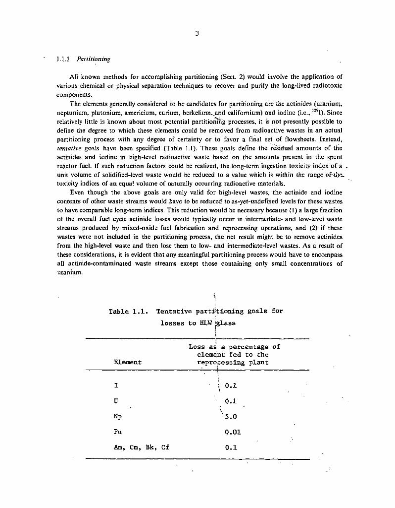
All known methods for accomplishing partitioning (Sect. 2) would involve the application of various chemical or physical separation techniques to recover and purify the long-lived radiotoxic components.
The elements generally considered to be candidates for partitioning are the actinides (uranium, neptunium, plutonium, americium, curium, berkelium,.and californium) and iodine (i.e., 129I). Since relatively little is known about most potential partitioning processes, it is not presently possible to define the degree to which these elements could be removed from radioactive wastes in an actual partitioning process with any degree of certainty or to favor a final set of flowsheets. Instead, tentative goals have been specified (Table 1.1). These goals define the residual amounts of the actinides and iodine in high-level radioactive waste based on the amounts present in the spent reactor fuel. If such reduction factors could be realized, the long-term ingestion toxicity index of a unit volume of solidified-level waste would be reduced to a value which i« within the range of tivx. toxicity indices of an equal volume of naturally occurring radioactive materials.
Even though the above goals are only valid for high-level wastes, the actinide and iodine contents of other waste streams would have to be reduced to as-yet-undefined levels for these wastes to have comparable long-term indices. This reduction would be necessary because (1) a large fraction of the overall fuel cycle actinide losses would typically occur in intermediate- and low-level waste streams produced by mixed-oxide fuel fabrication and reprocessing operations, and (2) if these wastes were not included in the partitioning process, the net result might be to remove actinides from the high-level waste and then lose them to low- and intermediate-level wastes. As a result of these considerations, it is evident that any meaningful partitioning process would have to encompass all actinide-contaminated waste streams except those containing only small concentrations of uranium.
Table 1.1. Tentative partitioning goals for losses to HLW [glass
Element
Loss as a percentage of element fed to the reprocessing plant
I : 0.1 U
Np '5.0 Pu 0.01 Am, Cm, Bk, Cf 0.1

4
The Purex process has been selected as the basis for the development of reprocessing plant partitioning because of its widespread acceptance and use in commercial reprocessing. However, the nature of many of the waste streams that would be produced by currently envisaged Purex flowsheets makes achievement of any meaningful degree of partitioning very difficult or impossible. Therefore, it is not logical to attempt to achieve the goals indicated in Table 1.1 by simply operating on the waste streams produced by the Purex process. Fundamental changes may be required in various stages of the process per se (i.e., dissolution and solvent extraction) to effect the desired separations. It should be noted that partial partitioning might be implemented without altering the reprocessing flowsheet, simply by treating the various waste streams individually to recover as much of their actinide content as practicable. The losses obtained with such an approach would almost certainly be markedly larger than the goals listed in Table 1.1.
Partitioning processes would also be required at mixed-oxide fuel fabrication plants (Sect. 3) because of the plutonium and americium (24lAm) contents of the wastes generated there. Partitioning flowsheets were developed for an LWR mixed-oxide fuel fabrication plant in which uranium and plutonium oxides are mechanically blended and pressed into pellets, and the pellets are then sintered, ground, and inserted into fuel rods. In this plant, scrap is processed and recycled, and all wastes are processed for packaging and shipment off-site.
1.1.2 Methods for handling partitioned nuclides
Transmutation. As was noted previously, the concept of partitioning the actinides and iodine is incomplete from a waste management standpoint without specification of a method for disposing of them after recovery. One method for handling the actinides and iodine would be to transmute them (Sect. 4).
In a generalized P-T scenario, the normal spent-fuel discharge from a nuclear reactor would be allowed to decay for a period of time at the reactor before shipment to the reprocessing plant. On arrival at the reprocessing plant, it would be allowed to decay further before being reprocessed via techniques designed to accomplish partitioning. The reprocessing plant outputs would consist of: (1) the separated economic values that were present in the spent fuel (uranium, plutonium, thorium) in slightly larger , amounts than those obtained in nonpartitioning reprocessing due to the increased recoveries, (2) separated or mixed "Waste actinides" (neptunium, americium, curium, berkelium, and californium) plus the iodine, and (3) radioactive wastes with reduced iodine and actinide contents. The waste would be immobilized and disposed of in a manner appropriate for each waste type. The economic values would be recycled in the normal manner typical of the fuel cycle being considered. The waste actinides and the iodine would be refabricated either homogeneously dispersed in the normal reactor fuel or concentrated in selected fuel rods or assemblies. The radioactive wastes from the fabrication plant would also be partitioned to reduce actinide losses. The waste actinides and iodine from all sources would then be inserted into the transmutation reactor (a conventional nuclear power reactor) and irradiated, transmuting the 1J9I to short-lived 130I and the waste actinides to fission products. After irradiation, the remaining waste actinides and iodine would be stored for an interim period before and after transport to a reprocessing plant. If the waste actinides and iodine were homogeneously dispersed in the normal fuel, the untransmuted portions would be recovered in the fuel reprocessing-partitioning plant and refabricated with new fuel material for recharging to the transmutation reactor. If the Waste actinides and iodine were concentrated into targets, they would
• probably be reprocessed separately from the spent fuel, to avoid dilution with the large actinide mass

5
of different elemental composition. The recovered actinides and iodine would then be refabricated in concentrated form into rods or assemblies and reinserted into the transmutation reactor. In either case (homogeneous or concentrated), the cycle would be closed and the waste actinides would be recycled until they were either transmuted or lost to a waste stream during reprocessing or refabrication.
Alternatives to transmutation. Partitioning is unique in that it would reduce the actinide and iodine contents of radioactive wastes and make the waste actinides and iodine available for disposal (or elimination) by a different method than that for the other radioactive wastes. Although transmutation is the means considered in this report to dispose of the actinides and iodine, at least two other approaches could be pursued: extraterrestrial disposal (Sect. 6.2) and alternate geologic disposal (Sect. 6.3). These alternatives are outside the scope of this report and will be considered' v
only briefly. As presently conceived, extraterrestrial disposal would involve partitioning and fabricating the
recovered waste actinides and iodine into a stable form and rocketing them into space using a space shuttle. The waste would then be launched in a separate vehicle to its final destination. Possible final destinations are high-earth orbit, the moon, and solar orbit. The extraterrestrial concept would be advantageous in that it could handle isotopes which are not amenable to transmutation because of their nuclear properties (e.g., I4C) and would avoid the buildup of waste actinide inventories in the fuel cycle. Potential disadvantages of the concept would be the relatively large number of launches required in an expanded nuclear economy, the high specific cost of transporting the undesirable materials into space, and the reliability of the technique.
Alternate geologic disposal would involve disposal of partitioned materials in a location separate from the bulk of the radioactive wastes, particularly the heat-generating wastes (high-level and fuel-element structural material wastes). The theory behind this concept is based on the assumption that the heat generated by the wastes may increase the probability or consequences of repository failure before the long-lived isotopes could decay to innocous levels. Therefore, it has been proposed that the partitioned (long-lived) isotopes be emplaced in a repository physically removed from the heat-generating wastes to reduce the likelihood of their release. It is important to note that no studies made to date have indicated that heat-generating wastes would impair the integrity of a repository.
1.1.3 Fuel cycle impacts of partitioning-transmutation
The previous subsections considered the two major aspects of P-T, the partitioning and transmutation operations per se. However, implementation of P-T would have additional effects on nuclear fuel cycle operations. The fuel cycle impacts of P-T (Sect. 5) are herein defined as the significant differences that would occur in nuclear fuel cycles with and without P-T, excluding the reprocessing and refabrication plant modifications required to accomplish partitioning and the in-reactor effects of transmutation.
The potential fuel cycle impacts of P-T that have been identified are as follows:
1. increased biological shielding thicknesses due to increased waste actinide neutron activity;
2. increased health effects from operational effluent releases (chemical, radiological, and thermal);
3. delay of near-term fuel cycle operations until P-T could be implemented;

4. higher fuel cycle cost;
5. decreased long-term waste toxicities;
6. the^need for an extensive research, development, and demonstration program to commercialize P-T; ^ s ^
7. conflicts betweetft^w requirements that might result from implementation of P-T and presently ' - existing laws, regulations and treaties;
8. the possible use of the waste actinides (i.e., 238Pu, 242,244Cm, and 252Cf) to "spike" strategic nuclear • materials to reduce the likelihood of diversion, and
9. the importance of lengthened out-of-reactor fuel decay times on FBR fuel inventory doubling times.
It should be emphasized that these are potential fuel cycle impacts of P-T and that some of these effects might be reduced to virtually zero through appropriate technical or political decisions.
The pervasive nature of these impacts, coupled with the problems associated with partitioning and transmutation, results in an extremely complex fuel cycle since a dual actinide recycle (e.g., U + Pu and Np + Am + Cm) is necessary and the impacts could afiect every part of the fuel cycle.
1.1.4 Analysis of the incentives for partitioning
The final phase of an overall evaluation of P-T would involve placing all of the above ramifications on a common basis and comparing them to determine whether implementation of the concept is worthwhile. This phase is designated as an analysis of the "incentives for partitioning" (Sect. 6).
Ideally, determination of the incentives for P-T would be based on a risk-cost/benefit analysis in which the risks and benefits were expressed in monetary terms to place them on the same basis as the costs. This procedure would involve calculating: (1) the increased risk of morbidity and mortality that might result from implementing P-T because of potential increases in emissions of noxious materials during routine operations and as a consequence of accidents, (2) the (presumed) decrease in the risk of morbidity and mortality resulting from a decrease in the long-lived nuclide content ,(i.fe., long-term toxicity)'of the wastes in a repository, and (3) the increase in nuclear fuel cycle costs that would result from building the additional facilities necessary to implement P-T!
Although the general procedure used to determine the incentives for partitioning is clear, the information required to calculate the risks, costs, and benefits of P-T is not presently sufficient to permit a convincing analysis to be performed. Therefore, this report seeks to define the approach that miglit best be taken to determine the incentives for partitioning (given that much pertinent information may be limited, inaccurate, or unavailable) and to identify the critical questions that must be answered before a determination of incentives can be made.
7
1.2 Summary
1.2.1 Partitioning
The partitioning of waste actinides from the wastes containing them may be the most difficult aspect of the P-T concept. The principal reasons for this difficulty are as follows:
1. The streams being partitioned would generally be complex mixtures of many different chemical elements and compounds, with the waste actinides typically present as minor constituents.
2. The intense radioactivity of many of the streams would degrade the reagents used to recover the waste actinides, thereby increasing the losses.
3. Many of these secondary wastes would have to be recycled within the facility, in order to prevent actinide and iodine losses to the secondary waste streams that inevitably result from additional operations on chemical systems. This would result in a highly integrated process flowsheet that may be quite difficult to reduce to practice.
The basic thrust of the partitioning-related portions of this report (Sects. 2 and 3) is the specification of reference partitioning flowsheets that account for all effluent streams from a reprocessing plant handling self-generated piutonium-enriched PWR fuel. However, because of the presently inadequate state of detailed knowledge concerning many of the operations in the reference flowsheets, they necessarily incorporate many unverified assumptions. Despite their 'imitations, these flowsheets serve to partially indicate the present status of processes and to provide direction and background for on-going process studies.
The reference flowsheets incorporate a typical Purex head-end sequence in which the fuel is chopped into small segments and dissolved in nitric acid after interim storage. The uranium, plutonium, and neptunium are then extracted from this solution and separated from each other using additional Purex solvent extraction stages below the feed to reduce the concentrations of these elements to acceptable levels (Fig. 1.1). The residual from this step, which contains the fission product lanthanides and the transplutonium actinides, is diluted with an oxalic acid solution to reduce the nitric acid concentration and to precipitate the remaining actinides (principally americium and curium) and the lanthanides. The aqueous fission product residue from the oxalate pecipitation is processed through a cation exchange cleanup step to remove any remaining actinides and then sent to high-level liquid waste evaporation and solidification. The oxalate precipitate can be destroyed by the addition of peroxide and the actinides separated from the lanthanides using cation exchange chromatography. The lanthanides recovered from this step are combined with the high-level liquid waste evaporation and solidified. The transplutonium actinides are converted to oxides and packaged for shipment to a fabrication facility.
Alternatives exist for many of the steps in this proposed flowsheet. Bidentate extraction might possibly be substituted for the additional Purex cycles (exhaustive extraction), the oxalate precipitation, and the cation exchange cleanup. This change would simplify the flowsheet and represent a potential improvement. Other extractants or inorganic ion exchange media are also ,

8
ORNL DWG 76-17522
SPENT FUEL ELEMENTS
TO GEOLOGIC ISOLATION
' LEGEND
M l H I HLLW
ACTINIDE STREAM
M M H FISSION PRODUCT STREAM
Fig. 1 . 1 . Flowsheet illustrating the generation of HLLW and one HLLW management sequence.
9
possible alternative partitioning techniques. Also, the Talspeak process might find application in separating the lanthanides and actinides. Additional experimental and conceptual analysis is needed to adequately test the reference flowsheets and to identify the most workable system from the available alternatives.
The other waste sireams generated by fuel reprocessing operations would probably al have to be partitioned since they contain significant fractions of the actinides originally in the spent fuel. In the reference flowsheets, combustible wastes are assumed to be oxidized in a fluidized sodium carbonate bed and the ash leached with nitric acid to recover the actinides. Wastes with a high salt content might be partitioned by cation exchange or solvent extraction, depending on the specific salts present. After these streams have been decontaminated from actinides to the desired extent, the residuals would be immobilized and disposed of in an appropriate manner or recycled within the reprocessing plant.
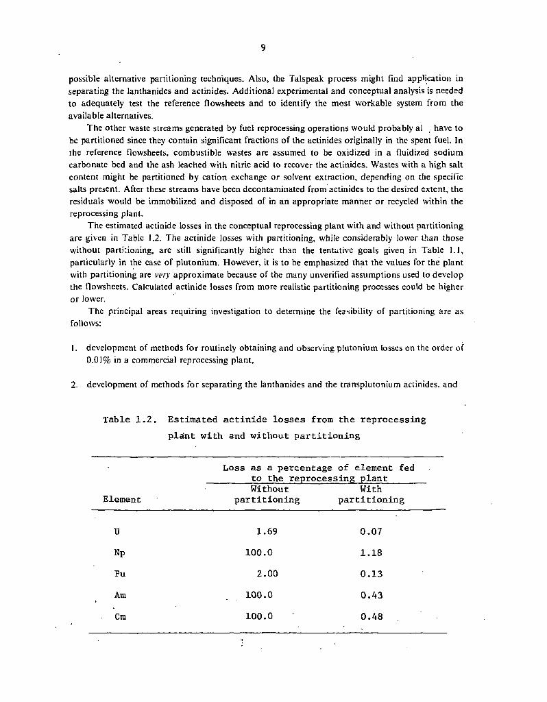
The estimated actinide losses in the conceptual reprocessing plant with and without partitioning are given in Table 1.2. The actinide losses with partitioning, while considerably lower than those without partitioning, are still significantly higher than the tentative goals given in Table 1.1, particularly in the case of plutonium. However, it is to be emphasized that the values for the plant with partitioning are very approximate because of the many unverified assumptions used to develop the flowsheets. Calculated actinide losses from more realistic partitioning processes could be higher or lower.
The principal areas requiring investigation to determine the feasibility of partitioning are as follows:
1. development of methods for routinely obtaining and observing plutonium losses on the order of 0.01% in a commercial reprocessing plant,
2. development of methods for separating the lanthanides and the transplutonium actinides. and
Table 1.2. Estimated actinide losses from the reprocessing plant with and without partitioning
Loss as a percentage of element fed to the reprocessing plant
Element Without
partitioning With
partitioning
U 1.69 0.07 Np 100.0 1.18 Pu 2 . 0 0 0.13 Am 100.0 0.43
Cm 100.0 0.48
10
3. determination of the effect of continuous reprocessing plant waste stream recycle on actinide losses.
In addition, a host 'of uncertainties remain with respect to decontamination of the many non-high-level liquid, solid, and gaseous process streams.
Reference flowsheets were developed (Sect. 3) for a mixed-oxide fabrication plant in which the effluent process streams are assumed to be partitioned in much the same way as those from a reprocessing plant. The dirty scrap is dissolved, filtered, and then routed to solvent extraction where the uranium and plutonium are recovered. The actir.ides leachcd from noncombustible wastes and incinerator ashes would also be routed to the soivent extraction system. The leached incineration ashes would be sent to salt waste management for processing and eventual immobilization. The fabrication plant partitio:j;.ig processes are similar to those in the reprocessing plant in that they are largely untested and extensive experimental investigations would be required to establish their feasibility .and performance. Recovery of the americium (i.e., from 241Pu decay) in the- dirty scrap, although not shown in the reference flowsheet, must be included in a realistic fabi.;-;:ion plant partitioning process.
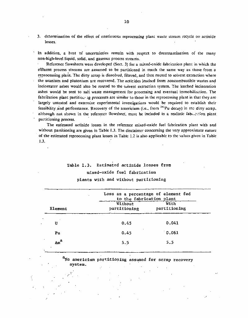
The estimated actinide losses in the reference mixed-oxide fuel fabrication plant with and without partitioning are given in Table 1.3. The disclaimer concerning the very approximate nature of the estimated reprocessing plant losses in Table 1.2 is also applicable to the values given in Table 1.3.
Table 1.3. Estimated actinide losses from mixed-oxide fuel fabrication
plants with and without partitioning
Element
Loss as a percentage of element fed to the fabrication plant
Element Without
partitioning With
partitioning
U 0.45 0.041
Pu 0.45 0.061 . a Am 5.5 5.5
americium partitioning assumed for scrap recovery system.

1.2.2 Transmutation
In contrast with the difficulty and complexity expected with partitioning processes, transmutation of the recovered actinides and iodine appears to be relatively simple, if we assume that these materials can be recovered and fabricated into stable fuel or target forms. The transmutation aspect of the P-T concept has received more attention than other aspects, principally because of the relative ease with which reactor physics calculations can be performed with modern computer systems. Many different types of esoteric transmutation devices have been considered for transmuting the actinides, such as nuclear explosives, high-energy protons, intense neutron generators, and spallation reactors. However, only transmutation in fission power reactors, which are more technologically advanced and probably moie economic than the others, is considered in detail in this report.
As was noted previously, the principal candidates for transmutation are the waste actinides (neptunium, americium, curium, berkelium, and californium) and 129I. Technetium-99 might also be a candidate, but only if truly extraordinary actinide decontamination factors are obtained during partitioning. Other long-lived, nonactinide isotopes (e.g., 3H, l4C, 93Zr) are effectively "nontransmutable" because of their small neutron cross sections or their dilution by stable isotopes of the same element.
Of the many existing and proposed types of commercial nuclear power reactors in the United States, only the LMFBR and the enriched-uranium fueled LWR (LWR-U) show substantial potential for transmuting actinides-and l29I. The projected installed HTGR capacity over the next several decades is much too small to accommodate the anticipated actinide and iodine production from other reactor types. The plutonium-enriched LWR (LWR-Pu) has a lower transmutation rate than the LWR-U because of its lower neutron flux.
Most of the waste actinide transmutation studies conducted to date have emphasized LMFBRs as transmutation reactors, principally on the assumption that an FBR would be superior to an LWR-U in this regard. Based on the available literature, this assumption appears to be valid. Even when concentrated to the point where t rie power density in the waste actinide target is the same as that in the LMFBR core (driver) fuel, the characteristics of the LMFBR are only marginally altered. The breeding ratio and core reactivity change less than 1%, and the change can be positive or negative, depending on the actinide recycle mode selected. At steady state (where the waste actinide mass and composition are constant), the waste actinide mass recycled from an LMFBR and a PWR-U to the LMFBR core would be equivalent to about 1.7 wt % of the LMFBR core fuel. The principal constituents of these actinides would be 237Np (16 to 22%), 238Pu (20 to 24%), 241Am (15 to 18%), and 243Am (15 to 16%). The transmutation (i.e., fission) rate would be about 6.5% per year of irradiation or, assuming 1 year out-of-reactor time and 2 years of irradiation, 4.3% per calendar year. This would cause the waste actinide content of the spent fuel to be increased by about a factor of 15.
The reduction of the long-term waste actinide ingestion toxicity effected by transmutation, as measured by the amount of water required to dilute the actinides to concentrations given in Table II of Title 10, Part 20, of the Code of Federal Regulations, varies from a factor of 250 after 1000 years decay to a factor of 5 after 100 million years.
A second type of actinide transmutation scenario, which has a variable nuclear power capacity as a function of time, is also examined in Sect. 4. In particular, the nuclear power capacity increases 6% annually for the next 105 years, remains constant for 105 years, and then decreases 6% annually for 210 years. This scenario is arbitrarily taken as a simulated growth pattern of the nuclear
12
industry, although the growth rate is much larger than actually expected. In general, the variable-nuclear-power-capacity scenario yields the same results as the steady-state scenario, particularly with respect to the reduction in actinide toxicity.
Waste actinide transmutation in a PWR-U would be roughly similar to that in an FBR except that lower transmutation rates would be expected because of the more substantial self-shielding effects in thermal reactors. However, a PWR-U appears to be feasible as an interim transmutation device until FBRs can assume the burden.
The transmutation of 129I appears to be feasible, although pertinent calculations are very limited. At steady state, the iodine mass would comprise only 0.25 wt % of a PWR-U reactor, and would be a factor of 10.6 greater than that in normal PWR-U fuel.
1.2.3 Fuel cycle impacts of panitioning-transmutation t ;
The fuel cycle impacts of P-T are the least investigated aspects of this concept. This is because ' their analysis requires more detailed information about the partitioning process and the
. transmutation and fuel cycle scenario being considered than is presently available. Neutron-emissions. The increased neutron activity of the recycled actinides (i.e., neptunium,
americium, curium, and their progeny) would require thicker shielding in the facilities handling these actinides. Fuel cycle facilities which might be significantly affected by this increased neutron activity include those portions of the reprocessing plant where the bulk of the fission products in the spent fuel are absent, spent and fresh fuel transportation systems, fuel refabrication plants, reactor refueling facilities, and waste management systems. The magnitude of the neutron activity would be heavily dependent on the type of transmutation reactor and the actinide recycle mode being considered. Specific neutron activities at steady state with a fast transmutation reactor would typically range between 1012 and 1013 neutrons sec"1 (MT recycled actinide metal)"1. For a thermal transmutation reactor, these numbers would be increased to 10u to 1015 neutrons sec"' (MT recycled actinide metal)"1. If the recycled actinides were diluted in the fresh reactor fuel, these specific neutron activities would be reduced 50- to 100-fold. It should be noted that many cycles would be required to reach the relatively high specific neutron activities characteristic of thermal reactors since the principal neutron source is 252Cf, which requires many neutron captures for production.
Health effects. .'The health effects associated with operational effluent releases could be expected to become more severe unless additional treatment steps were incluaed to mai itain present levels. The increased waste chemical and heat production results from the greater number of process steps and chemicals required to partition the actinides. The potential increase in radiological health effects would result from the greatly increased amount of shorter-lived, and thus more toxic,
• actinides (e.g., 238Pu, 242'244Cm) in the fuel cycle. The increased health effects that would actually .occur because of these potential releases from the implementation of P-T could presumably be reduced" to zero by using cooling towers, additional HEPA filters, scrubbers, etc. for decontamination of routine effluent streams, and additional safety systems on accidental release pathways.
Delays in fuel cycle operations. A delay could occur in near-term , fuel cycle operations (e.g., reprocessing or waste isolation) if a decision were made to fully implement P-T. The relatively 'lengthy time that would be needed for implementation would necessitate storage of large amounts of
• either spent fuel assemblies or alpha-bearing wastes until adequate partitioning processes became . available. On the other hand, partial implementation of P-T. might be possible at a significantly
earlier date.

13
Costs. Tl.e implementation of P-T would be expected to increase fuel cycle costs relative to a fuel cycle without P-T. The largest cost increases would probably result from the increased amount of processing and neutron shielding required in fuel reprocessing and fabrication plants. Smaller, but still significant, cost increases are expected in transportation. Cost penalties resulting from the in-reactor behavior of the recycled actinides are expected to be small.
Waste toxicity. One of the most important fuel cycle impacts of P-T would be the reduction of the actinide and iodine toxicities in the waste, since this is the major benefit resulting from P-T. The magnitude of this reduction for high-level waste (HLW) during steady-state actinide recycle is shown in Fig. 1.2. As a measure of toxicity, this figure uses the volume of water required to dilute all radionuclides to the maximum concentrations specified as acceptable for unrestricted use. Comparison of the top and middle curves shows that, after 1000 years of decay, P-T ieduces the HLW toxicity by a factor of 137. This reduction in toxicity decreases further with decay until, at times longer than about 10 million years, the reduction factor is 5. Comparison of the bottom curve with the middle curve shows that about 50% of the total HLW actinide toxicity results from the reprocessing of the recycled actinides, even though these same actinides comprise only about 3% of the HLW actinide mass. Two rather serious limitations to Fig. 1.2 should be noted. First, the toxicity of the waste is a measure of the consequence of releasing the HLW from a repository; however, to determine the risk from a postulated actinide release, the consequences must be multiplied by the probability of release. This probability, which will be very difficult to estimate reliably, is crit:cally important since a zero-release probability means that the long-term benefits of P-T are also zero. The second limitation of Fig. 1.2 is that toxicity (as defined here) may not be a valid measure of the consequences of a postulated accident in which actinides would be released. Other consequence analysis techniques, such as modeling slow migration through the geosphere in water, have been applied to these cases and give radically different results. Thus, the magnitude of the calculated impact of P-T on the consequences of a postulated repository accident is heavily dependent on the analytical methods used.
Research and development requirements. The need for an e\Knsi\ e research, development, and demonstration (R, D & D) prog.am if P-T technology, were to be fully commerciali.'ed is probably self-evident in the light of the previous discussions concerning the proem status of P-T. The magnitude of the R, D & D program could be equivalent to that required to de\elop d new fuel cycle, depending on the methods used to implement and conduct P-T.
Regulatory implications. The policy implications of P-T involve consideration of the conflicts between new requirements that would arise if P-T were to be implemented and presently existing laws, regulations, and treaties. One example of such a conflict is that it might not be possible to solidify the liquid HLW within 5 years after generation and consign to a repository within 10 years after generation, as presently required in the United States, if the waste actinides were to be recovered from all spent fuel and liquid HLW had to be retained to accomplish this objective.
Nuclear safeguards. The safeguarding of strategic nuclear materials (e.g., plutonium, 2j1U, highly enriched 235U) to prevent diversion by terrorist groups or proliferation by other countries is a topic receiving much current attention. One proposal for safeguarding strategic nuclear materials (SNM) is to "spike" the SNM with an agent which will impart a large radiation dose to anyone attempting to handle them without a considerable amount of biological shielding. Spiking agents that have been previously proposed include 60Co and 144Ce-Pr, which emit high-energy gamma rays. However, homogeneous dispersal of waste actinides in fuel containing SNM would appear to offer many of the same advantages with respect to safeguards as using selected spiking agents. The actinide radiations of interest in this application would be the penetrating neutrons from spontaneous fission and (a, n) reactions since the actinide gamma-ray energies are generally weak.

14
t -tfl u o z
UJ Q
I -o <
Ul H CO < £ _J u > Ui
X
10 11
O QC o a>
•5 c
O ^ 1 0 1 0
m
> H
2 1 0 !
X O H
10 '
10
10 6
1 0
i r
0RNL DWG 77-I27RI
1 1 1 1
-Total HLW Actinide Toxicity With No Partitioning
^-Tota'i HLW Actinide Toxicity With Partitioning —
Transmutation
HLW Actinide Toxicity From Spent Transmutotion Targets
1 1 0 1 1 0 3 10® 1 0 7
D E C A Y T I M E ( y e a r s )
10s
Fig. 1.2. High-level waste actinide ingestion toxicity with and without waste actinide recycle at steady state.

15
Fissile inventory doubling times. A parameter of considerable importance in a breeder reactor economy is the fuel cycle inventory doubling time (IDT). IDT is the amount of time required for a breeder to double its fissile inventory, including the fissile maferir1! in the ou.-of-reactor fuel cycle. After this time, enough fissile material would be available to star up another identical breeder and to supply its out-of-reactor inventory requirements. This value wc \ be important in an expanding breeder economy since the economy could not double in a shorter length of time than the IDT. From a partitioning standpoint alone, a long decay time is preferred because of the reduction in the spent-fuel activity and, in turn, the reduction in reagent degradation during reprocessing. However, since the IDT is directly proportional to the total cycle length (in-reactor and out-of-reactor), increasing the spent-fuel decay period w:'.' significantly increase the IDT, potentially restricting the breeder reactor growth rate. This trade-off cannot be made until more information concerning partitioning processes and the structure of any future breeder economy becomes available.
In summary, many of the impacts resulting from the implementation of P-T are not an integral part of either partitioning or transmutation. These impacts are both positive and negative, and their effects on the fuel cycle will probably be very important when evaluating the P-T concept as a whole.
1.2.4 Analysis of the incentives for partitioning
As previously noted (see Sect. 1.1.4), the information required to calculate the risks, costs, and benefits of P-T is not presently adequate to allow a reasonable and defensible analysis of the incentives for partitioning to be performed. The following discussion outlines the procedure to be followed and identifies some of the major problems anticipated in this analysis.
The first step, assuming the required information is available, would be to determine the incremental risk (or risk reduction) for cach individual fuel cycle operation affected by P-T. The effects of P-T on the various individual fuel cycle operations were discussed in Sects. 1.2.1 - 1.2.3. Most of these effects can be grouped into three general categories: (1) increased cost, (2) increased risks during operation of the P-T fuel cycle (i.e., short-term risks), and (3) decreased long-term risks resulting from a reduction in toxicity of the wastes with P-T.
The next step is to put these three categories on a comparable basis. Cost can be converted to a dose or risk basis by using a conversion factor, such as the $1000 per man-rem used in licensing . nuclear reactors, or it can simply be carried as a separate category. However, even if the dollar costs are carried separately, the short-term risks and the long-term benefits must certainly be placed on a comparable basis if the analysis of incentives is to be meaningful. Initially, the risks and benefits will not be on a comparable basis because (1) the benefits would accrue in the distant future, whereas the risks would accrue immediately, and (2) the benefits would presumably persist for millennia, whereas the risks would generally persist only while the P-T fuel cycle was in existence. The first difficulty can be alleviated by using a discount rate to place both risk and benefit on a common temporal basis. The discount rate would reflect the fact that a dollar held today would be worth more than a dollar tomorrow (after accounting for inflation) and this increased amount of money could be used at the later time to reduce the risk to levels lower than those possible today. The second difficulty, which is related to the differing duration of the short-term risk and long-term benefit, would be resolved by considering both the risk and the benefit over the time span where each would be significant.
In summary, the determination of the incentives for partitioning should be relatively straightforward if the required information concerning individual partitioning, transmutation, and
16
other fuel cycle impacts can be developed. However, the results of this determination may be highly controversial and unsatisfying to many individuals.
It should be noted that, even though a careful technical evaluation may indicate that there are no " rea r incentives for partitioning to reduce potential long-term waste hazards, public attitudes and perceptions could supply the necessary impetus for partitioning if implementation were to be required as a condition for the continued use of nuclear power.
1.3 Conclusions and Recommendations
1.3.1 Conclusions
Our conclusions concerning the present status of P-T can be summarized as follows:
1. The presently available data indicate that the P-T concept would be capable of significantly reducing the actinide content of radioactive wastes. However, the incentives for implementing P-T are largely indeterminant since it is not presently possible to calculate the magnitude of the long-term risk reduction and the short-term risk increase.
2. Partitioning-transmutation for waste management purposes should be regarded as an advanced waste management technology that could not be fully implemented for two or three decades, even if proven feasible, because of the time required to develop, demonstrate, and implement adequate long-lived nuclide partitioning and fabrication processes. On the other hand, partial implementation of this concept may be possible at an earlier date.
3. Even if P-T were to be implemented, a geologic repository would still be required for ultimate disposal of the fuel cycle wastes resulting from partitioning, since they would still have far more than the proposed limit of 10 nCi per gram of long-lived alpha activity, as well as substantial quantities of such fission product hazards as ^Sr.
4. The principal difficulties anticipated in developing satisfactory partitioning processes include attaining a very .high plutonium recovery, separating americium and curium from the lanthanide elements, and determining the effects of the recycling process streams within the reprocessing and fabrication plants on the operation of these facilities.
5. The principal difficulties anticipated in developing satisfactory long-lived nuclide fabrication processes involve establishing the processes that will result in irradiation-stable fuel forms containing significant percentages of recycled actinides (i.e., neptunium, americium, and curium) or iodine.
6. The transmutation of actinides recovered from radioactive wastes would be possible almost immediately if adequate partitioning and fabrication processes were. available. Therefore, transmutation per se is probably not a limitation in the implementation of P-T.
7 . The data and analytical techniques required to perform a sophisticated and meaningful ." riskrcost/benefit analysis of the P-T concept are presently not available. Furthermore, this type

17
of analysis will not be possible in the near term because of the lack of operating experience for many fuel cycle facilities.
8. Given somewhat more data on the partitioning processes and the long-term behavior of radioactive wastes in repositories, a reasonable and defensible (albeit incomplete) evaluation of the incentives for partitioning should be possible by 1979 or 1980.
9. The principal negative impacts of implementing P-T would be an increase in nuclear fuel cycle costs and an increase in short-term fuel cycle risks resulting from the continuous recycle and buildup of the actinides and iodine in the fuel cycle.
10. The negative impact of the increased risk of a fuel reprocessing or refabrication plant accident arising from greater process complexity and radionuclide inventories will be difficult to analyze. Although the change in the consequences of these accidents can be analyzed, the probability of the accident is uncertain because of a lack of operating experience in fuel reprocessing and fabrication plants.
11. The principal positive impact of P-T would be a reduction in the long-term risk represented by the actinide-depleted wastes in a repository. The magnitude of this risk reduction is highly variable, depending on the repository release scenario that is hypothesized and the analytical methods used.
12. The analysis of the incentives for P-T will principally involve comparison of item 9 (negative impact) with item 11 (positive impact). The impacts must be integrated over the time span v/here they are significant. In a proper analysis, future risk should be discounted.
13. Incentives may exist for partitioning in the case where the negative impacts outweigh the positive impacts if the benefit accrued is the continued operation of nuclear power plants rather than a decrease in the long-term waste hazard.
14. Recycled actinides could possibly be used to "spike" plutonium- or 233U-enriched reactor fuels as an aid in deterring the diversion of these materials.
15. Extraterrestrial disposal is an alternative to transmutation that may be feasible, particularly for certain nontransmutable nuclides. Potential problem areas concerning extraterrestrial disposal of the actinides include the relatively large number of launches required in a realistic nuclear economy, the high specific cost of transporting wastes into space, and the question of reliability.
16. There is no indication in the studies to date that geological disposal of the partitioned actinides separately from the fission products would be more beneficial than geological disposal of the unpartitioned wastes.
1.3.2 Recommendations
It is recommended that the ongoing program to evaluate the feasibility, costs, impacts, and incentives for partitioning and transmuting the actinides and 129I be continued. This program, which
18
should be concluded by 1980, should represent the best possible analysis of the factors discussed above, consistent with current knowledge of accident probabilities associated with fuel cycle facilities and of the feasibility of partitioning processes. Experimental studies will be required to define viable partitioning processes which are a prerequisite to analyzing the cost and impacts of P-T. Transmutation studies are required to provide fuel compositions for the partitioning studies and actinide neutron activities for the impact analyses, and to examine the sensitivity of calculated results to uncertainties in cross sections.
Other data acquisitions which are required for the evaluation, but which are being supported by the Office of Waste Isolation, include analysis of radionuclide migration rates from realistic geologic repositories and determination of repository accident probabilities and consequences.
Additional studies on the extraterrestrial disposal option are needed to more accurately define the cost, logistics, and reliability of the concept.
Periodic reappraisal of the effects of heat-generating wastes on a waste repository in the light of better geologic information about proposed repositories is desirable to determine whether the conclusion concerning the lack of benefits from geologic disposal of partitioned actinides remains v J id . .
19
2. CONCEPTUAL ANALYSIS FOR FUEL REPROCESSING WASTE SYSTEMS EMPHASIZING ACTINIDE RECOVERY
D. William Tedder
2.1 Introduction
In general, to partition simply means to separate elements, or groups of elements, from some mixture of chemical species. In a nuclear fuel cycle, partitioning occurs mainly during the reprocessing of spent fuel. Since spent fuel contains a large number of chemical elements and these elements may be separated in a large number of combinations, there are a large number of partitioning alternatives which result in different fuel cycle options and waste treatment alternatives. Some of these partitioning and fuel cycle options may be important with respect to maximizing energy conservation, minimizing safeguards risks, facilitating the beneficial utilization of various fission products, or decreasing the long-term waste storage risks.
Partitioning has been viewed as a strategy for waste management, whereby the long-term biological hazard of nuclear waste (after 1000 years of storage) is reduced, or mitigated somewhat, by achieving the highest possible removals of all actinides. After 1000 years in geologic isolation, the actinide concentrations in the stored waste dominate its radiotoxicity; therefore, removal of these elements more completely before isolation will render the waste less harmful, even if it is released to man's environment in the distant future. For the first 1000 years of storage, the radiotoxicity of the high-level waste is largely determined by the fission products. During this time interval, the effects of actinide partitioning vs simple economic recoveries of uranium and plutonium cannot be discerned in terms of reducing the ingestion toxicity. The half-lives of the actinides and their decay daughters are very long, generally speaking, compared with those of the more plentiful fission products in the wastes.
Of course, if the actinides are partitioned from the fission products, they must still be managed responsibly. Three possible strategies for actinide management have been suggested: (1) storage of the partitioned actinides in geologic isolation separately from the fission products, (2) separation of the partitioned actinides from man's environment by extratern • i rial disposal; and (3) fissioning of the partitioned actinides to radionuclides with shorter half-lives or to stable isotopes.
The reference partitioning system chosen for study in this section separates all the transuranics present in spent fuel (neptunium, plutonium, americium, and curium) to a very high degree from the high-level waste and recovers them as highly purified oxides. The processing modifications for this system would be different from those fuel reprocessing modifications required, for example, for the recovery of the fission products strontium and cesium. However, more is presently known about the reference system for commercial reprocessing than about many of the other partitioning alternatives.
Also, the reference system does not consider the recovery of iodine and technetium. In these flowsheets, the iodine is assumed to be immobilized by a conventional silver zeolite adsorption system, which is subsequently packaged and sent to a waste repository. Technetium is assumed to be immobilized in the HLW glass (see Table 2.1 for definitions of terms). So the recycle of these two elements for transmutation, as discussed in Sect. 4, could not be carried out with the systems described here and in Sect. 3. Additional recovery and processing operations would be required.
The head-end operations of a partitioning reprocessing plant would be similar to those required for conventional fuel reprocessing (Fig. 1.1). After a period of cooling, the spent fuel would be
20
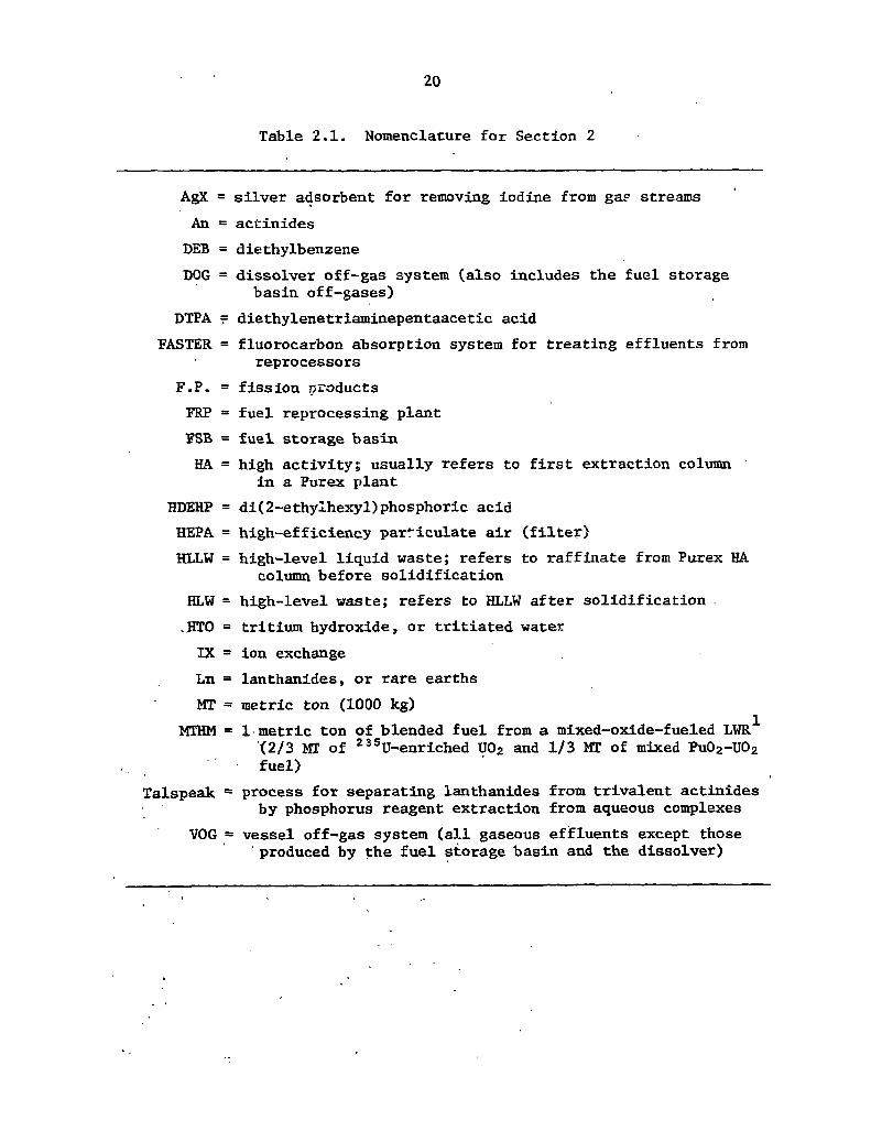
Table 2.1. Nomenclature for Section 2
AgX = silver adsorbent for removing iodine from gap streams An = actinides DEB = diethylbenzene DOG = dissolver off-gas system (also includes the fuel storage
basin off-gases) DTPA = diethylenetriaminepentaacetic acid
FASTER = fluorocarbon absorption system for treating effluents from reprocessors
F.P. = fission products FRP = fuel reprocessing plant FSB = fuel storage basin HA = high activity; usually refers to first extraction column
in a Purex plant HDEHP = di(2-ethylhexyl)phosphoric acid HEPA = high-efficiency particulate air (filter) HLLW = high-level liquid waste; refers to raffinate from Purex HA
column before solidification HLW =• high-level waste; refers to HLLW after solidification .HTO = tritium hydroxide, or tritiated water IX = ion exchange Ln = lanthanides, or rare earths MT = metric ton (1000 kg)
MTHM = 1 metric ton of blended fuel from a mixed-oxide-fueled LWR^ <2/3 MT of 23 5U-enriched U02 and 1/3 MT of mixed Pu02-U02 fuel)
Talspeak = process for separating lanthanides from trivalent actinides by phosphorus reagent extraction from aqueous complexes
VOG = vessel off-gas system (all gaseous efifluents except those produced by the fuel storage basin and the dissolver)
21
chopped up and dissolved in nitric acid. The resulting dissolver solution would be extracted with tributyl phosphate (TBP) to remove the uranium, plutonium, and neptunium. The HA solvent extraction column would probably be modified to incorporate more extraction stages below the feed in order to further decontaminate the HLLW from uranium, plutonium, and neptunium. The current partitioning goals for these three elements are ^ 0 . 1 % uranium, 0.01% plutonium, and ^ 5% neptunium losses to the HLLW.
The raffinate from the HA column would then be proces ed to remove the transplutonium actinides. These actinides could be removed from the HLLW by oxalate precipitation, which would also coprecipitate the lanthanides. Current partitioning goals specify that the americium and curium losses to the HLLW should be 0.1% or less, and this goal may be obtained by an oxalate precipitation step followed by a cation exchange cleanup of the supernate.
Subsequently, the mixture of actinides and lanthanides would be chemically separated, possibly by cation exchange chromatography. In this operation the actinide-Ianthanide mixture recovered from the HLLW would be loaded onto cation exchange resin and eluted with diethylenetriaminepentaacetic acid (DTPA) to separate the americium and curium from the lanthanides. During the elution, the bed effluent vould be divided into separate fractions, and the strip fraction (containing the lanthanides) would be recombined with the HLLW.
In order to achieve the overall partitioning goals, it is desirable to reduce the actinide losses to all secondary Avastes (besides the HLLW) to levels below those achieved in the past. These recovery operations include secondary treatment of streams such as the dissolver solids, failed equipment, cladding hulls, filter media, combustible wastes, and various contaminated aqueous salt waste streams.
With proper operation, the strip fractions from cation exchange chromatography would contain the lanthanides and only trace amounts of actinides. Under these circumstances, the strip fractions could be recombined with the HLLW. Similarly, the dissolver solids would be recombined with the HLLW after repeated nitric acid leachings. This mixture of the HLLW, dissolver solids, and Ianthanide strip fractions would then be solidified directly to produce a glass or ceramic containing only very small amounts of actinides.
The reference reprocessing facility would probably be much more highly integrated than a conventional facility. Acid and water would be recycled to the maximum possible degree in order to minimize actinide losses. The various combustible wastes such as ion exchange resins, general trash, and spent organic solvents would also be incinerated and the ash residues processed for actinide recovery.
Ash and solid effluents from incineration would be treated as salt wastes, along with the waste TBP scrub solutions which contain nitrate and carbonate salts. These salt wastes would be subjected to an initial digestion step to further solubilize and ionize the actinides followed by either extraction or, possibly, cation exchange to recover the actinides as nitrates. The salt waste management system would reject the undesirable phosphate, sulfate, and chloride anions as a decontaminated salt waste which would be immobilized in concrete or handled in some other acceptable manner. The recovered actinide nitrate solution would be recycled to the dissolver.
In addition to the above-mentioned operations, the reference facility would be required to partition the uranium, plutonium, and neptunium recovered in the HA extract from each other. In this system, therefore, the uranium, plutonium, and neptunium would be recovered as separate nitrate streams which would be converted, after additional fission product decontamination, to their respective oxides. The americium and curium recovered from the actinide-Ianthanide separation would also be purified and converted to mixed oxides. So altogether, the reference plant would

22
produce four actinide product streams, a partitioned HLW glass, a partitioned salt waste, and various decontaminated solid wastes. Excess aqueous wastes would either be discharged by vaporization and decontamination through the off-gas treatment system or immobilized in concrete and stored.
The reference system would probably be more difficult to operate than a conventional reprocessing facility. The high degree of recycle within the system would enhance the propagation of process perturbations between the unit operations and might also reduce the operating efficiencies.
In the past, fuel reprocessing has been carried out so as to simply achieve an economic recovery of uranium and plutonium. The first solvent extraction cycle raffinate (HLLW) was treated for storage as waste as quickly as possible. With waste partitioning the strategy would change and the radiation dose received by processing equipment and reagents would be higher. Since neptunium would be coextracted with the uranium and plutonium, the extract leaving the HA column would be less nearly saturated than in the past; therefore, greater amounts of fission products would be present in the extract. Consequently, the secondary uranium, plutonium, and neptunium purification cycles would receive a larger radiation dose, and the rate of solvent degradation would probably be somewhat higher.
The routine releases of radioactivity to the environment would probably not be significantly greater with the reference system than with conventional fuel reprocessing. However, the additional reprocessing unit operations, especially the additional HLLW processing and waste management operations, may result in slightly higher routine occupational exposures to workers. The increased number of actinide handling operations would also tend to increase the occupational risks as well, although estimates of these effects are not currently available.
The reference system would probably experience slightly higher heat-rejection rates to the environment as compared with a similar, conventional reprocessing system. The emission rates of volatile chemical species such as NO*, HC1, SO2, CO2, and CO would probably also be increased, although any I4C released during the initial fuel dissolutioning would be retained and immobilized in a suitable waste form. These effects,, however, are expected to be small. In addition, the off-gas treatment system could probably be modified as needed to meet all EPA standards for emissions of
, chemical species. On the other hand, significant increases in the volumes of low- and intermediate-level wastes could result from waste partitioning, and the estimation of these latter effects is one gual of this study.
All anticipated accident descriptions would be similar to those for a conventional reprocessing facility which only recovers uranium and plutonium. However, the more highly integrated flowsheets for the reference system could lead to the accumulation of various hazardous chemical species, which in turn could lead to accidental fires and explosions. Although estimates of these incremental effects are not currently available, no credible accident scenarios are envisioned which would breach the primary containment and result in the uncontrolled release of radioactivity. The partitioning reprocessing facility is certain to have higher operating costs and capital investment requirements than a conventional facility of the same size. Unfortunately, estimates of these incremental increases are not currently available. ' '
2.1.1 Scope and objectives of study. , 1
The. current ERDA experimental program2 to assess partitioning feasibility is being carried out at several different sites, each of which has demonstrated expertise in its area of investigation. The

23
overall effort is being coordinated at ORNL. The ORNL strategy is to define specific waste systems by assuming the compositions of various secondary wastes, processing these streams, and routing the calculated effluents to the appropriate recycle stations. This system analysis facilitates the identification of subproblems which can be examined experimentally. As the subproblems are verified or modified by experimental investigation, the various input and output streams will be redefined and the system analysis repeated. It is hoped that repeated iteration between the system analysis and the experimental evaluation of specific subproblems will lead to feasible flowsheets in a timely manner. However, even at the completion of the program, the feasibility of the integrated waste system that has finally evolved will not have been demonstrated since the streams produced by the various subsystems will not have actually been recycled.
This section presents reference flowsheets (not necessarily preferred) which were generated as a first attempt in the system analysis, and describes the specific subproblems as well as some of those areas in which experimental work is needed. The analysis assumes that all effluents will be in a ' stable, immobilized form and will be sent to a federal repository for ultimate disposal. The flowsheets are specifically designed to maximize acid and water recycle within the reprocessing plant, and to maximize the recovery of all actinides which enter the plant.
The material balances presented in this section are only preliminary and, in many respects, incomplete. They are intended to serve primarily as a focai point for experimental work required to test the flowsheets, but they also complement earlier studies.3 The material balance calculations for many of the minor stream components have not been included. In addition, the number of significant figures shown in the flowsheets should not be construed as a reflection on accuracy. Instead, these significant figures are carried only as a means of establishing internal consistency between the flowsheets.
The material balances shown should not be regarded as conclusive; neither are they intended to represent an assessment of the ultimate feasibility or infeasibility of actinide partitioning. They are simply a reference point which will hopefully facilitate a more comprehensive and much broader analysis of all aspects of the problem.
Many important aspects of the problem have not been examined even cursorily. Detailed energy balances, for example, have not been completed, although they often interact with the material balances. One example of this is the use of hydrocarbon fuels to achieve the desired bed temperature during fluidized-bed calcination of wastes. Another shortcoming may be the failure to recognize important effects such as phase changes during various process steps. Because of the complexity of the problem, these effects are often not recognized during the initial evaluation, but they may ultimately .dominate the overall process feasibility. Many engineering considerations, such as scale-up and process controllability, also have not been examined. So the reader should bear in mind the preliminary nature of this section and realize that many of the details shown in the figures may be incorrect or technically infeasible.
Several options, some of which have been documented elsewhere,4 are available for the various operations used in fuel reprocessing. This study does not attempt to consider all possible alternatives, although a few are described in the appropriate subsections. Instead, the objective is to find at least one complete, consistent reprocessing system which is feasible in the sense of most nearly achieving all of the previously defined partitioning goals5 (see also Sect. 1).
In choosing flowsheets, the strategy has been to utilize existing, demonstrated technology where possible, unless such technology is known to cause severe waste management or actinide recovery problems. The conventional method for producing actinide oxides, for example, is by calcining precipitates, but this approach leaves a supernate which must be managed as a waste or be recycled.

24
Since thermal denitration to form actinide oxides reduces the waste management problems, it may be an important alternative to precipitation. This method is assumed in the earlier work;6 of course, it may not be possible to utilize thermal denitration for all actinide streams because of the physical properties of the resulting oxides and the constraints placed by fuel and target fabrication. Further work is needed in order to compare these alternatives, and the final flowsheets that evolve from this study may be based entirely on precipitation or some other conversion technologies.
In addition, it should be recognized that the scope of an overall assessment of partitioning is much broader than the scope of study in this section. There are many aspects of this problem which may preclude feasibility, but which are not considered. For example, the accountability problem is especially pertinent since deterministic chemical processes really only exist on paper. In fact, all chemical processing is stochastic in nature, and this feature limits the ability to accurately account for all inventories within the process. Typically, recoveries with the chemical processing industry are only known within a few percent of the production rate because of random variations in the observations. Nuclear fuel reprocessing is no exception to this rule.7 The implication for partitioning, of course, is that three or four significant figures for overall actinide recoveries will probably not be observable except as long-term, operational averages, although it may be possible to measure losses continuously in a meaningful way. It is clear, however, that a serious accountability problem does exist with the implementation of this concept, insofar as all waste effluents must be monitored, and the impacts of such a requirement have not been considered in this study.
Although it may be theoretically possible to partition actinides as desired from the standpoint of the Qhemistry involved, this fact per se is not sufficient to guarantee feasibility for the concept. In addition to observability, the process must also be controllable. Moreover, even if this latter condition is satisfied, more actinides than desired may find their way into fuel eye le wastes because of human error. For this reason, the concept implies the existence of adequate administrative and operational controls, as well as demonstrated chemical and engineering feasibility.
Consequently, because of the stochastic nature of chemical processing and the possibility of human error in operation, it will not be possible to assert unconditionally that the actinide inventories in fuel cycle wastes will always be less than any specified level with partitioning, it may be possible to eventually assign probabilities to the event that actinide inventories in the wastes will be less than a certain level, with and without actinide partitioning. Such an analysis, however, is beyond the scope of this report even though it is clearly an essential element in an overall assessment of partitioning.
2.1.2 Basis of study ; ,
The main reprocessing plant is described briefly in Sect. 2.2.2 and in more detail elsewhere.3 It . processes blended UO2-PUO2 fuel irradiated to 33,000 MWd/ton at a specific power of 30 MW/ton.
The waste systems. described here support such a plant, where the uranium, plutonium, and neptunium are recovered as separate, purified products by modified Purex solvent extraction. All
^analysis shown assumes the steady-state operation o f a five-metric ton/day plant processing 1500 metric tons of spent fuel annually. Equivalent steady-state rates are given for all batch operations. Ideal solutions are assumed, and volume changes during extraction and strippingare neglected.
A £uel reprocessing plant represents a large-scale system which cannot be readily analyzed as a /single -unit. The systems analysis approach undertaken here, therefore, utilizes process
decomposition,8,9 whereby the original unit is broken down into a collection of subproblems.

25
Persistent information recycle occurs explicitly (and implicitly as well) in these flowsheets, insofar a< many of the waste streams are generated by process failures which are not defined in this steady-state analysis. The waste streams produced by such process failures are described by the use of assumed ("torn" or "cut") variables.10'11 In the sense in which they are used here, many cf these "torn" (or assumed) waste streams could be equivalently thought of as representing "contingency." Although considerable urcertainty exists as to their magnitudes, past experience indicates that they are cleaily greater than zero. In the aftermath of a processing maloperation. lor example, their volumes may well exceed the normal capacity requirements for the waste management systems. So these wastes, although difficult to define in a conceptual study, clearly should not be ignored.
In general, the strategy has been to assume "worst cases" and to make assumptions which will hopefully bound the actual plant operation in a systematic way. In particular, the actinide contents of many of the torn waste streams should be higher than would be the case during actual operation. They are summarized in Table 2.2, along with comments about the assumptions.
Table 2.2. Description of torn variables
Torn variable Figure Comments
Kerosene 2.9 Trash 2.9
Anion IX 2.9
Cation IX 2.9
Mixed IX 2.9 .Waste TBP 2.9
TBP scrub 2.10
Analytical waste 2.10
Noncombustible 2.15 trash
Filters 2.16
Jailed equipment 2.16 DOG 2.17
. 2.17 + FRP 2.20
cooling water Canyon cleanup 2.21
Laundry and 2.21 personnel cleanup
Probably not needed. An and F.P. contents are probably much
lower than shown. Bulk mass rate and An content are probably
high. Bulk mass rate and An and F.P. contents are
probably high.(The excess represents contingency.)
Probably not required for water purification. Volumetric rate is about three times greater
than with past operational experience. An content reflects past experience but
could be much lower with modified operation. Assumes 200 samples per day, analyzed by wet
methods. Could be much lower. An and F.P. contents are probably much lower
than shown. An and F.P. contents and filter volumes are
assumed to be higher than past experience to reflect uncertainty in undefined off-gas treatment systems.
Volumetric rate is highly variable. Volumetric ratt depends heavily on
operational characteristics of dissolver. Volumetric rate could be -<uch lower. Not based on a detailed energy balance.
Typical detergent solution; both streams represent contingency.
Typical detergent solution; volume represents contingency.
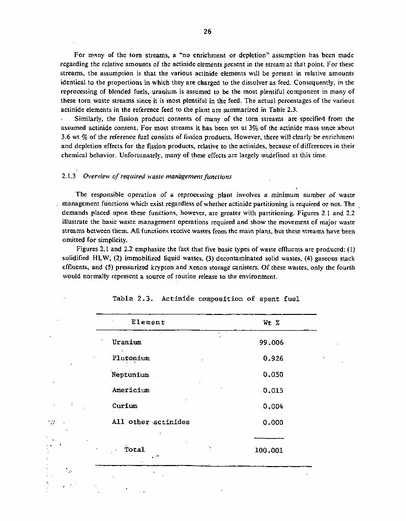
26
For many of the torn streams, a "no enrichment or depletion" assumption has been made regarding the relative amounts of the actinide elements present in the stream at that point. For these streams, the assumption is that the various actinide elements will be present in relative amounts identical to the proportions in which they are charged to the dissolver as feed. Consequently, in the reprocessing of blended fuels, uranium is assumed to be the most plentiful component in many of these torn waste streams since it is most plentiful in the feed. The actual percentages of the various actinide elements in the reference feed to the plant are summarized in Table 2.3.
Similarly, the fission product contents of many of the torn streams are specified from the assumed actinide content. For most streams it has been set at 3% of the actinide mass since about 3.6 wt % of the reference fuel consists of fission products. However, there will clearly be enrichment and depletion effects for the fission products, relative to the actinides, because of differences in their chemical behavior. Unfortunately, many of these effects are largely undefined at this time.
2.1.3 Overview of required waste management functions
The responsible operation of a reprocessing plant involves a minimum number of waste management functions which exist regardless of whether actinide partitioning is required or not. The demands placed upon these functions, however, are greater with partitioning. Figures 2.1 and 2.2 illustrate the basic waste management operations required and show the movement of major waste streams between them. All functions receive wastes from the main plant, but these streams have been omitted for simplicity.
Figures 2.1 and 2.2 emphasize the fact that five basic types of waste effluents are produced: (1) solidified HLW, (2) immobilized liquid wastes, (3) decontaminated solid wastes, (4) gaseous stack effluents, and (5) pressurized krypton and xenon storage canisters. Of these wastes, only the fourth would normally represent a source of routine release to the environment.
Table 2.3. Actinide composition of spent fuel
Element Wt %
Uranium 99.006 Plutonium 0.926
Neptunium 0.050 Americium 0.015 Curium 0.004 All other actinides 0 . 0 0 0
Total 100.001

ORNL DWG 7 6 - I 7 5 2 3 R I
GENERAL TRASH
•X X GASEOUS WASTES
LIQUID WASTES
SOLIDIFIED HLW TO GEOLOGIC ISOLATION
IMMOBILIZED WATER, TRITIUM OXIDE,ASHES, AND STABLE, N0NC0M8USTIBLE SALT WASTE TO GEOLOGIC ISOLATION AS CONCRETE
DECONTAMINATED FAILED EQUIPMENT, HEPA FILTERS, CLADOING HULLS, AND OTHER SOLID WASTES TO GEOLOGIC ISOLATION
DECONTAMINATED STACK EFFLUENTS RELEASED TO THE ENVIRONMENT
PRESSURIZED KRYPTON AND XENON CANISTERS TO GEOLOGIC ISOLATION
- O — o - SOLID WASTES
Fig. 2.1. Waste management operations required to support a partitioning fuel reprocessing plant.

ORNL DWG 7 7 - I 0 8 3 R I
TRASH • ACTIVATED CARBON
TSP TO PUREX
- # » - O F F G A S
FLUIDIZED BED INCINERATOR
EVAPORATOR
FRACTIONATOR
Fig. 2.2. Major process flows within the waste management systems.

29
These figures also emphasize the fact that these waste management functions are highly interrelated. Persistent recycle exists between many of the functions due to the production of secondary wastes. Although options are available which would modify or delete certain of the waste sTeams connecting the various functions shown, it is relatively difficult to envision options which would eliminate any individual function entirely.
2.2 HLLW Management and Processing
The additional processing requirements for the HLLW to meet partitioning objectives are perhaps the most significant modifications imposed on the fuel reprocessor. Figure 1.1 illustrates the generation of HLLW and shows one processing sequence for the waste which might be used in partitioning. The figure also shows an additional block (cation exchange chromatography) which represents one alternative for separating the lanthanides from the transplutonium actinides. The operations shown are discussed in greater detail in the subsections that follow. The fact that other HLLW processing alternatives are discussed in less detail, however, simply indicates that the experimental and engineering evaluations are incomplete.
2.2,1 Interim storage
The interim storage of HLLW has been incorporated into many flowsheets. The Allied-General Nuclear Services (AGNS) Reprocessing Plant12 provides for HLLW interim storage, and HLLW storage has been suggested in earlier conceptual studies on partitioning.13 More recent safety analyses of fuel reprocessing plant designs indicate ihat the trend is toward lower liquid holdups with immediate solidification of liquid wastes where possible.14
With actinide partitioning there is an incentive for intermediate storage either of the spent-fuel elements in a water-cooled fuel storage basin15 before the chop-leach step or storage of the HLLW in order to allow the gamma activity to decay. However, the interim storage of HLLW has several serious disadvantages. First, in order to store the volume of HA raffinate over extended time periods, say for a 1500-MTHM/year plant, it is attractive to substantially reduce the raffinate volume by evaporation. As this volume reduction is achieved, solids tend to come out of solution. This precipitate consists largely of a zirconium-molybdenum compound whose formation becomes kinetically favorable when the solution is heated.16'17 Some plutonium is carried by this precipitate, and although it may be eventually recoverable, the additional solids handling requirements severely complicate the flowsheet.
Second, during the interim storage of HLLW, additional plutonium grows into the solution through curium decay. Consequently, a secondary plutonium recovery operation would be required13, with HLLW interim storage (which can be avoided entirely if the spent fuel elements are stored instead). In addition, it is clear that HLLW interim storage increases the risk of release to the environment, relative to the risk of spent fuel storage, because the fission products are more mobile and the required gaseous purge rates are much greater.
Assuming that the spent fuel is stored 0.5 year at the reactor site, fuel at a burnup of 33,000 MWd/MTHM would be well cooled if an inventory corresponding to 4.5 years of reprocessing were held at the plant site. A 1500-MTHM/year plant processing 4800 assemblies per year would require storage capacity for 21,600 fuel assemblies.18 The storage basin off-gases would be decontaminated
30
through the main plant off-gas treatment facility, and the most significant secondary waste would be the low-level-waste ion exchange resins and regeneration solutions. Waste for such a storage basin could be managed by continuously incinerating about 13 liters of resin waste per MTHM reprocessed. The regeneration solutions would be treated in salt waste management. By way of comparison, the Exxon PSAR includes a spent-fuel storage basin capacity of 7000 MTH M,14 which would provide nearly 5 years storage for the reference design. However, it is not clear that such extended cooling times are really required for waste partitioning.
From the waste management standpoint alone, the storage of spent fuel is preferred over the storage of HLLW. On the other hand, the storage of spent fuel increases the plutonium IDT (see Sect 4.5.8) in a nuclear breeder economy and decreases uranium fuel supplies. Although the reprocessing problems associated with high-burnup, jhort-cooled fuel are probably, not insurmountable, it is clear that reprocessing risks and costs increase with decreasing spent-fuel storage time. The significance of these increases will probably not be fully appreciated until short-cooled fuel is reprocessed on a large scale.
As a third option,19 it may be more desirable to store the actinide-lamhanide mixture obtained from the oxalate precipitation and cation exchange cleanup steps shown in Figure 1.1. (This mixture could also be stored if recovered by another sequence of HLLW processing steps.) This storage alternative has several advantages. First of all, the spent fuel might be more quickly processed for uranium and plutonium recoveries, while the actinide-lanthanide mixture could be allowed to cool for an additional period of time. Therefore, the spent-fuel inventories at the reprocessing plant could be smaller, large volumes of HLLW would not be accumulated for subsequent actinide partitioning, problems with the formation of process solids would be minimized, and the plutonium IDT would not be increased because of actinide partitioning.
In addition, this third option simplifies the implementation of partitioning for existing reprocessing facilities, where partitioning would be carried out in an adjoining facility. In particular, storing the actinide-lanthanide mixture at an adjoint partitioning facility would permit reprocessing operations to begin at a sooner date than if the facility were to begin the actinide-lanthanide separation coincident with fuel reprocessing. With this third option, fuel reprocessing could begin as soon as the adjoint facility were licensed to partition the HLLW and store the actinide-lanthanide mixture. Licensing of the adjoint actinide-lanthanide separation facility, the subsequent purification
• operations, and the nitrate-to-oxide conversion could be done at a' later date. Some difficulties are also encountered with this third option. Storage of a calcined or dried
oxalate would result in additional solids handling problems, and, regardless of its form, continuous •cooling oft the stored material would be required. However, the magnitude of this storage operation would be substantially less than that associated with the HLLW.storage. In addition, the HLW glass produced by fuel reprocessing initially would not contain the lanthanides. So after all operations in the adjoint."facility were licensed and lanthanide fractions for solidification in glass were being produced, it would be riecessary to incorporate the accumulated rare-earth inventory into the glass. These complications, however, are relatively small, and do not .invalidate the incentives for
- examining this option in greater detail. » ' /
I s - , __ 1 2.2.2- Exhaustive extraction and Purex modifications
s ' The basic modifications to the Purex process proposed for partitioning are discussed in detail 'elsewhere,3 but summary flowsheets of the modified process'are shown in Figs. 2.3(a) and 2.3(b).

ORNL DWG 7 7 - 1 0 8 2
LEGEND
£ b •
•
AQUEOUS STREAM
ORGANIC STREAM
EVAPORATOR OR STILL
SOLVENT EXTRACTION COLUMN
I O N EXCHANGE OR SILICA GEL COLUMN
THERMAL DENITRATION KILN
FILTERED DISSOLVER SOLUTION
1
I r L HB
I L *
HA
\i J _ HS
* 1
L t * 1
1 EEW
P u 0 2
PRODUCT
SILIC." GEL CLEANUP BOTTOMS U 0 2
PRODUCT
Fig. 2.3(a). Conceptual flowsheet for modified Purex operation, summarized from ORNL-5012.

" ORNL OWG 77—665 RI
' CLAD ' SPENT FUEL
, 9 5 6 kg U 8 9 4 0 g Pu
_ 4 8 2 g Np 141 g Am
36 .7 g Cm ' 34.4 kg F.P.
BOTTOMS RECYCLE 3590 liters 6 . 0 9 M HNOj
10 ppb HTO 16 ,308 g An
8 8 9 g F.R 4 , 0 3 8 g NaNos
• FROM Fig. 2 .22
RINSE ACID 3 0 0 liters 0.1 M HN03
3 ppb HTO
HAS 1979 l iters 3 . 0 M. H N O | 3 ppb HTO
BASIS'- ONE MTHM REPROCESSED
NET ACID AND WATER DEMAND 43,921 liters 1.35 M H N 0 3
TRITIATEO SOLVENT
17,030 liters 3 0 % T8P
SOLVENT 2 5 , 2 0 6 liters
3 0 % TBP
DISSOLVER. MODIFIED PUREX REPROCESSING I
DISSOLVER. MODIFIED PUREX REPROCESSING I
CLADDING HULLS 0 .3 M 3
1000 g An 4 3 0 g F.R
To Fig. 2.15*
2AW 4 0 9 6 liters 3.2 M. HN0 3
71 g An 4 0 g F.P.
To Fig. 2.12
DISSOLVER SOLIDS 2 5 4 7 g
3 5 0 g An £197 g F.R
To Fig. 2.15
IAW 4 1 9 0 liters 2 . 3 M H N 0 3
918 g An 2 5 0 g F.P.
To Fig. 2.12
DOG
6 0 0 0 moles NOy 3919 g F.P.
To Fig. 2.17
EEW 5 9 0 0 liters
2 .4 M HNOj 3 7 3 . 9 g An 2 8 . 8 kg F.P.
To Fig. 2.4
USED SOLVENT
(HCW) 17,030 liters
3 0 % T B P 3 0 7 0 g An
9 2 g F. P.
\ To Fig. 2.19
USED SOLVENT ( 2BW+1CW+1EW) 2 5 , 2 0 6 liters 3 0 % T B P 2 0 3 0 g An
I g F. P. .
Np PRODUCT 2 6 5 6 liters 0.75 M HN0 3
4 0 g U 4 7 7 g Np
TRACE Put-F.R
To Fig. 2.19 To Fig 2.18
IDW 15,310 liters
1 . 6 M H N 0 3
1002 g An 10 g F.P.
SILICA GEL CLEANUP BOTTOMS
28 l iters 4.3 M H N 0 3
TRACE An + F.P.
I HCU OVERHEADS
17,610 liters 0 . 0 4 M HN0 3
TRACE An + F.P.
To Fig. 2.12 To Fig 2 .12
i To Fig. 2.12
OFF GAS 8347 moles N0 X
U 0 2 PRODUCT 955.24 Kg U
SECONDARY WASTES 8 4 0 9 g An
2 5 0 g F.P.
ro
Pu0 2 PRODUCT
8 9 2 7 g Pu
To Fig. 2.17 To Pockoging ond Tronsportalion
Fig. 2.3(b). Material balances for modified Purex process, summarized from 0RNL-5012.

33
The most important changes are in the operation of the HA column, followed by a supplementary or exhaustive extraction of the raffinate, and the subsequent partitioning of the H A extract. In the conceptual flowsheets developed earlier,6 the raffinate from the HA column is sent directly to a second exhaustive extraction (EE) column where it is further extracted with TBP. The flowsheet conditions are set to maximize the recoveries of uranium, plutonium, and neptunium from the HLLW in this step. Although some additional valence adjustment may be required, the exhaustive extraction modification essentially adds additional extraction stages to the HA column. The extract from the HA column is subsequently stripped first to remove plutonium (HS column) and then to remove neptunium (IB column), so that all three actinides are recovered in separate, highly purified forms.
The ability of TBP to extract uranium, plutonium, and neptunium is well known.20"22 Because this extractant has been thoroughly studied23"27 and has been utilized extensively on a plant scale28"30
to obtain economic recoveries of uranium and plutonium in particular, it is a logical choice for partitioning these three actinides from the HLLW. It could also be used as an extractant for the tiansplutonium actinides,31 although this process is not particularly attractive because of the necessity to heavily salt the aqueous phase. Implementation of this latter option would probably require the development of supplemental processes for recovering the metal nitrate salts from the HLLW and recycling them to the HA raffinate. Otherwise, the salts would greatly increase the volume of HLW glass produced by reprocessing the fuel.
It is attraciive, however, to modify the Purex process in order to achieve higher recoveries of uranium and plutonium and to coextract neptunium as well.32 I r o f a r as 30% TBP solvent can be used, the wastes generated by the exhaustive extraction step will be similar to those produced by the main-line purification and partitioning cycles. Moreover, similar or identical solvent purification steps may be used. Sodium carbonate scrub is the most attractive candidate at this time, primarily because of its widespread use, although other method? have been proposed.33
The principal actinide losses through secondary Purex wastes can probably be controlled by a combination of increased stream recycle and supplementary treatment and decontamination of those waste streams which are not readily amenable to recycle. Actinide losses to aqueous raffinates in the purification and partitioning cycles may be reduced by sending these streams to the acid and water recycle system (see Sect. 2.7), and eventually returning them to the dissolver. It is proposed to manage the losses due to the carbonate liquor by additional processing and solvent extraction or cation exchange as discussed in Sect. 2.5.
Although it is widely recognized34'35 that TBP extraction will yield high uranium and plutonium removals from the HLLW, significant uncertainty still exists as to the magnitude of effects on downstream purification and extraction cycles and on the solvent life. Since the solvent will be less nearly saturated if neptunium is coextracted, more fission products will also be present in the HA extract. This will place an additional burden on the subsequent Purex uranium extraction and uranium purification cycles. The fission products zirconium and ruthenium, in particular, will tend to reflux in the HA and exhaustive extraction columns, and thereby expose the extractant to higher radiation doses than in the past. If a second extraction cycle is used (or additional extraction stages are included in the HA column) to exhaustively extract the HA raffinate from uranium, plutonium, and neptunium, then the solvent exposure to radiation will be substantially greater.
Experimental work is needed to verify the consistent, lower extraction limits which can be routinely obtained by TBP. Cold or hot testing on a laboratory scale will not be sufficient to prove the concept since significant scale-up problems exist relative to the effects of holdup and residence time on valence control and dose. The utilization of high-speed, short-contact mixers to minimize holdup and dose, for example, may result in unacceptable losses due to kinetic effects. Also, it is not

34
possible to conclusively ascertain reagent recycle and long-term effects through short-term, experimental batch campaigns.
In addition, the separation of neptunium and plutonium from uranium should be examined in more detail experimentally since the quantities of uranium reporting to the raffinates in the downstream columns can be significantly greater36,37 than those shown in earlier conceptual studies.3
Consequently, the rates at which uranium, plutonium, and neptunium are recycled to the dissolver may also be significantly greater than shown in the bottoms recycle streams in Fig. 2.3. The recovery
1 of uranium, plutonium, and neptunium in separate streams, however, is not essential to the P-T fuel cycle. In fact, costripping of these three actinides may actually simplify the reprocessing and refabrication flowsheets, as well as improve safeguards against diversion.
2.2.3 Oxalate precipitation and ion exchange (OPIX) cleanup
Figures 2.4 and 2.5 outline one possible processing sequence16 for removing the transplutonium actinides from the HLLW to the level specified by the previously defined partitioning goals. In this sequence the raffinate from exhaustive extraction, the stream EEW, is diluted with oxalic acid solution to reduce the concentration of free nitric acid and precipitate the bulk of the lanthanides and trivalent actinides as oxalates. The supernate from the precipitation-centrifugation shown in Fig. 2.4 is then routed to the ion exchange cleanup column in Fig. 2.5. The effluent from the ion exchange column would be solidified directly, after being combined with the strip fractions produced by the actinide-lanthanide separation and the leached dissolver solids.
- A hydrogen peroxide solution is added to the oxalate slurry in Fig. 2.4, and the mixture is refluxed to destroy the oxalate. Nitric acid is then added to destroy the excess peroxide and to adjust the pH of the stream for subsequent processing. The cation exchange product in Fig. 2.5 is denitrated with formic acid and combined with the product from the oxalate precipitation. This
• solution, containing most' of the lanthanides and trivalent actinides, along with small amounts of plutonium, neptunium, zirconium, barium, and strontium, is then processed to separate the fission products and recover the actinides in a purified form.
Several advantages of this process have been identified.14 First, the oxalate precipitation step greatly reduces the volume of ion exchange resin required to remove the lanthanides and transplutonium actinides, relative to the requirements if ion exchange recovery alone were utilized. Second, the oxalic acid complexes most of the zirconium and iron, so that these species do not compete for the resin sites. This effect further reduces the ion exchange resin requirements since these species would otherwise tend to saturate the capacity of the bed. Third, much of the plutonium entering with the EEW will precipitate, so that the requirements for the solvent extraction removal of plutonium may be somewhat reduced if followed by the oxalate precipitation step.
The principal disadvantages perceived for the oxalate precipitation step relate to the need for reducing the free nitric acid concentration in the EEW and the problems generally associated with the remote processing of solids. In the flowsheet shown, the acid concentration is reduced simply by diluting the EEW with oxalic acid solution. This approach tends to minimize the formation of undesirable solids in the HLLW, but it also results in large volumetric flow rates and evaporators in Fig. 2.6. As an alternative, the EEW could be concentrated by evaporation or denitration, but this
"step results in the formation of substantial amounts of solids.17 A major constituent of the solids is a crystalline compound which contains zirconium . and molybdenum and carries plutonium. Consequently, conditions leading to the formation of solids should be avoided until the HLLW has been adequately decontaminated from plutonium.
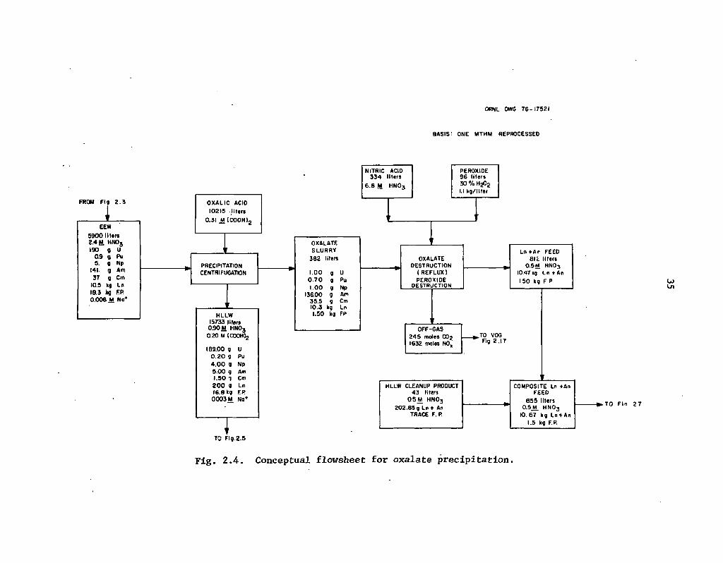
ORNL OWG 7 6 - 1 7 5 2 1
BASIS' ONE MTHM REPROCESSED
TO F ig .2 .5
Fig. 2.4. Conceptual flowsheet for oxalate precipitation.

ORNL DWG 7 6 - 1 7 5 2 4
BASIS' ONE MTHM REPROCESSED
Fig. 2.5. Conceptual flowsheet for HLLW cation exchange clean-up.
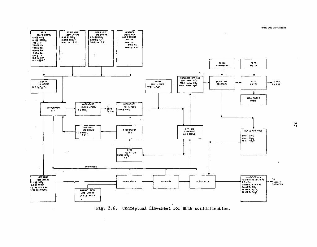
ORNL OWG 76 •173Z3RI
Fig. 2.6. Conceptual flowsheet for HLLW solidification.

38
The oxalate precipitation16 and ion exchange cleanup of the HLLW have been tested on a small scale wiih synthetic solutions, and also with actual waste on a scale of about 200 gof UO2. The hot waste was generated by batch-extracting a quantity of spent fuel that had been irradiated to 31,000 MWd/MTU in the Carolina Power and Light Company's H. B. Robinson Reactor and cooled two years. Gadolinium was added as a solible poison, and conditions were adjusted-to match those anticipated for the operation of the A JNS plant at Barnwell, South Carolina. The raffinate had
. been evaporated to produce a waste concentrate after repeated batch extractions with 30% TBP to remove about 99% of the uranium and plutonium. Following ion exchange treatment, the HLLW contained about 0.01% of the plutonium and about 0.02% of the americium and curium. These results appear very promising, although :he prior salting with gadolinium and waste evaporation would tend to increase the removal of actinides relative to conditions shown in Figs. 2.4 and 2.5.
Additional experimental work is needed, however, to determine how effectively the precipitation and oxalate decantation and purification can be carried out in an open, continuous system. Such a system is more complicated than the batch precipitations performed so far, and many questions remain to be answered. Although the slurry can probably be removed with a centrifuge, a simple settling operation may be more operable. The slurry must also be backwashed to obtain adequate decontamination from the nonlanthanide fission products.
The destruction of the oxalate with hydrogen peroxide has also been demonstrated38 as a small-scale batch operation in glass. However, additional experimental work is needed to show how this destruction might be carried out in an open system. Also, hydrogen peroxide may not be the best method for destroying the oxalate since it reacts vigorously with corrosion products. Nevertheless, it is the preferred reagent for destroying oxalic acid in strip solutions.39
2.2.4 HLLW solidification
After the HLLW has been partitioned from the actinides, it can be immediately combined with the lanthanide strip wastes and dissolver solids, evaporated, and sulidified as a glass. Figure 2.6 shows the approximate material balances from such an operation. This particular flowsheet is untested, although it is derived from verified processes.40 In terms of the overall plant operation, this step is important in that l^fge-quantities of water and acid are recycled from HLLW evaporation. The organic matter in the HLLW may cause safety problems, and the HLLW evaporation condensate must be treated to control fission product contamination of the plant.
In the flowsheet presented here there considerations are aggravated somewhat by the dilution strategy used .to partition the transplutonium elements. The technology for evaporation, solidification, and isolation of the condensates, however, has largely been demonstrated. Although some adverse effects may result from the recycle of these overhead condensates, this problem can only.be examined experimentally through the operation of an integrated hot pilot plant.
2.2.5 Alternatives for processing the HLLW
• Several alternatives are available for processing the HLLW as it is produced by the Purex process. Some of the most promising of these should be examined. These alternatives could be important, especially if they result in more effective decontamination than the flowsheets presented here, or if they offer significantly reduced operating risks. Some.of the alternatives may facilitate the generation of reasonable all-solvent extraction flowsheets.

39
Extraction by neutral organophosphorus41,42 solvents may be an attractive approach for producing a fraction containing the lanthanides and trivalent actinides. A highly efficient extractant has the potential for eliminating the oxalate precipitation, the HLLW cation exchange cleanup, and possibly the exhaustive extraction. In addition, some neutral bidentate extractants do not require low-acid feeds, so the volume of raffinate to the HLLW solidification could be much less than that shown in Fig. 2.6. The bidentate extractant dihexyl-N,N-diethylcarbamylmethylene phosphonate has a water solubility comparable to that of TBP,43 and its use should be examined in detail.
Additional experimental work should be performed to examine other extractants as they might be used in solvent extraction or extraction chromatography.44 In particular, the use of trialkylmethylammonium nitrate salts and dialkyl and dialkylaryl phosphoric acids45'46 should be examined. Specific flowsheets for using these compounds for recovering actinides and technetium are not available at this time.
It may be possible to substitute one or more inorganic ion exchange media for organic resins in several portions of the flowsheet. This alternative could be important since inorganic materials are generally less susceptible to radiation damage. In particular, the use of "titanate," "niobate," and "zirconate" media47'48 should be examined as alternatives for cation exchange cleanup.
It is aiso possible to use a solvent consisting of a mixture of TBP and HDEHP in diluent to extract the americium and curium from the HLLW directly.49 In this process the HLLW is first denitrated with formic acid to precipitate fission product zirconium, which would otherwise extract. After clarification, the HLLW can be extracted with the TBP-HDEHP solvent to recover the lanthanides and transplutonium actinides, which are subsequently separated by a "reverse Talspeak" separation process (see Sect. 2.3.3).
A principal objection to this approach, however, is the need to denitrate the HLLW to a pH of around 2. This type of system is extremely difficult to operate correctly in a remote facility using in-line detectors. Any overshooting during the formic acid pecipitation will also probably precipitate some of the americium and curium. In addition, the zirconium-molybdenum compound which precipitates also tends to carry plutonium.16'17 Although actinide losses to the precipitate may be small and mostly reversible when the system is operated satisfactorily, remote precipitation by acid neutralization should probably be avoided altogether if possible. Consequently, processing alternatives which circumvent evaporation or denitration of the HLLW are definitely favored, especially when they also eliminate the formation of undesirable solids.
2.3 Alternatives for Separating Actinides from Lanthanides
The trivalent actinide-lanthanide separation is an essential element of the partitioning-transmutation corcept since the lanthanides are effective neutron poisons in thermal reactors and comprise 95% or more of the mass to be separated. Because of the importance and difficulty of this separation, several alternatives should be examined experimentally.
2.3.1 Cation exchange chromatography
Of the alternatives known for effecting the actinide-lanthanide separation, cation exchange chromatography (CEC). is the most completely demonstrated. The state of the art is described elsewhere.50 The system outlined in Fig. 2.7 utilizes displacement development to bring about a
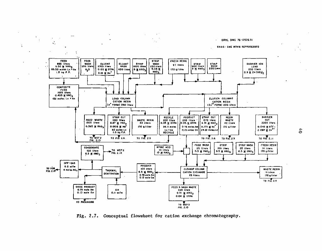
ORNL DWG 7 6 - 1 7 5 2 6 Rl
BASIS ' ONE MTHM REPROCESSED
TO WEFZ
Fig. 2.7. Conceptual flowsheet for cation exchange chromatography.

41
separation between the trivalent actinides and the lanthanides. With this process, the resin is first loaded with a cation barrier ion which has a greater affinity for the complexing agent to be used than the ions to be separated. Zinc is assumed to be the barrier cation in this study, although other barriers are equally effective. The ions to be separated are then loaded onto the column. This step is followed by elution with a suitable chelating agent, such as DTPA, which has different complex stability constants for the cations to be separated. The feed mixture subsequently separates into bands on the column, and the different species are removed in the order of decreasing magnitude of their complex stability constants.51
Displacement chromatography has been demonstrated at Hanford52 on a pilot-plant scale to recover americium and curium from Redox wastes. In this system, a total of nearly 700 g of americium and curium was recovered by elution through a series of conventional ion exchange beds using DTPA to separate these actinides from the rare earths. Nine ion exchange columns were used, each having about 8.5 ft of resin bed length and a diameter of 1 to 14 in. Power densities in excess of 400 W/liter were experienced, and significant pertubations were observed as a result of gas formation on the beds. This system, however, was not operated so as to achieve americium and curium recoveries in excess of 99%.
The ion exchange system illustrated in Fig. 2.7 would probably be pressurized (approx. 900 psig) similar to those at Savannah River,53 which have been used to recover several kilograms of 244Cm. Pressurization eliminates bed disruptions caused by the radiolytic production of gases (a problem with gravity-fed beds) and increases the volumetric flow rates through the beds, which tends to reduce the rate of resin degradation. Of course, this approach does have some drawbacks, especially for large-scale industrial applications. For example, it is inherently a batch operation and bed plugging may not always be prevented. The sustained loss of liquid flow for any reason may present safety problems in addition to those of operability because of the total curies of radioactivity which would rapidly overheat a loaded bed.
The disposal of the barrier cut shown in Fig. 2.7 might represent an objection to the process since this material may interfere with solidification if it is sent to the HLLW. In this analysis, however, this stream is sent to liquid-waste immobilization (see Fig. 2.11) where it is placed in concrete. Compared with the other salt wastes generated during reprocessing, this waste stream is relatively small and not particularly troublesome. In addition, it may be possible to develop recycle schemes whereby the volume of salt waste produced by CEC would be virtually zero.
Band tailing may represent a more serious difficulty because of the extremely high actinide recoveries that are desired. For example, no actinides are assumed to be present in the two strip cuts shown in Figs. 2.6 and 2.7. These streams contain the lanthanides that must be returned to the HLLW for solidification. All overlap between the rare earths and the actinide bands is assumed to be recovered in the recycle cut and directed to the composite feed as shown in Fig. 2.7. However, this aspect of the system operation has not been clearly demonstrated experimentally, and it may be necessary either to recycle substantially greater volumes than shown (to prevent significant actinide losses) or to require secondary ion exchange purification cycles.
In addition, some uncertainty exists as to the actual resin waste rates that will be required to maintain the system. At Savannah River, it was necessary to replace the resin frequently when large quantities of curium were processed. The replacement rates shown in Fig. 2.7 are probably conservative, but additional experimental work is needed to verify these streams and to assess further the extent of organic contamination to other process streams which are produced by the system and are sent to acid and water recycle (see Sect. 2.7). On the other hand, management of the resin wastes should not constitute a problem if the reprocessing plant design includes an adequate incineration system (see Sect. 2.4).

42
Although there is little doubt that some version of Fig. 2.7 can be successfully demonstrated using pressurized ion exchange, experimental work is needed to determine the jverall recoveries for americium and curium which can be routinely expected for this system. In addition, the ultimate disposition of any uranium, neptunium, and plutonium which may enter with the feed needs to be defined more clearly. If gadolinium is used as a neutron poison for the dissolver solutions in the Purex process, the mass of rare earths which must be separated from the actinides will be substantially greater than shown in Fig. 2.7. Under such conditions, the probability of losing actinides due to band overlap during elution would be increased. These problems should be examined experimentally using hot wastes since many of the anticipated problems will not occur with cold solutions.
2.3.2 Talspeak solvent extraction
A reference flowsheet for Talspeak solvent extraction is shown in Fig. 2.8. as derived from earlier studies.54"56 In this system, the lanthanides are extracted preferentially into the organic phase by di(2-ethylhex.yl) phosphoric acid (HDEHP). The trivalent actinides are retained in the aqueous phase by complexation with DTPA and buffered with glycolic acid. The raffinate from the Talspeak partitioning column is then acidified to break up the DTPA complex, and the actinides are extracted with HDEHP to separate them from the glycolic acid and DTPA waste. The conditions shown in Fig. 2.8 are largely untested for this application; thus the flowsheet should be considered as only approximate. In particular, the solvent purification and recycle steps have not been demonstrated.
Talspeak differs from CEC in that it is a continuous, steady-state piocess. The major disadvantages associated with its use are: (1) larger amounts of sodium per MTHM are required for reprocessing, (2) feed adjustment is relatively important and difficult to achieve, and (3) the process is sensitive to nonlanthanide fission product contamination (especially zirconium) in the feed. In addition, the flowsheet shown in Fig. 2.8 assumes the use of essentially two separate solvent extraction cycles. The partition cycle utilizes HDEHP in diethylbenzene. while the extraction cycle utilizes HDEHP in /?-dodecane. It would be highly desirable to combine these two cycles so that a single solvent cleanup system could serve both cycles, but experimental work is needed to find workable conditions.
Although the Talspeak system shows promise, it has not been demonstrated as completely as ' the CEC "rocess. Several'laboratory-scale mixer-settler runs have been completed,57 using eight
countercurent scrub and extraction stages to simulate the Talspeak partition column and the americium-curium extraction column. However, the results are not directly applicable to Fig. 2.8 since different diluents and carboxylic. acids were used in the tests. Although the results were very favorable (greater than 99% recovery), additional experimental work is needed to demonstrate the feasibility of solvent recycle, measure the process sensitivity to feed upsets, and estimate the long-term effects .of radiation degradation and the accumulation of certain fission products in the solvent. Much of this work can be carried out with synthetic waste solutions, but the radiation effects should be evaluated with actual waste.
2.3.3 Other alternatives for separating actinides and lanthanides
The Tramex process has been used routinely57 in the Transuranium Processing Plant58 (TRU) at ORNL to isolate gram amounts of americium and curium. This process separates americium and

ORNL DWG 7 G - 1 7 5 2 7
BASIS * ONE MTHM REPROCESSED
Fig. 2.8, Conceptual flowsheet for Talspeak.
44
curium from the lanthanides by extracting these actinides from an aqueous phase containing lithium chloride into an organic phase containing a long-chain tertiary amine. Stannous chloride may be added as a holding reductant to improve decontamination from cerium, which tends to oxidize to the extractable tetravalent state at higher activity levels. However, radiolysis becomes a problem at power densities much greater than 6 W/liter, and Tramex has not been used to process feeds with power densities nearly as high as those at Hanford where CEC was employed. Although stannous chloride can be used to reduce the radiolytically formed oxidants, the accumulated dosage to the reductant must be less than about 600 W-hr/equivalent. In addition, acid radiolysis causes difficulties.
Although Tramex is useful for processing in the TRU facility, it is not suitable for commercial application. The chloride reagents used require all equipment to be- fabricated from special construction materials. In the TRU facility,57 equipment and piping are made of tantalum and Zircaloy-2, while instrument lines, process water lines, and cell floor pans are made of Hastelloy.
tThe wastes generated by the Tramex process would cause severe management problems in a "commercial operation where most equipment would he fabricated of stainless steel. Chloride wastes would have to be rejected and immobilized in concrete after being processed as a salt waste (see Sects. 2.5 and 2.6). They could not be rejected through the HLLW since the calcination would drive off HC1 to. the off-gas train.
The use of various inorganic ion exchange media47,48 should be examined as alternatives for .'separating the trivalent actinides from the lanthanides. If favorable conditions can be found, chromatography on an inorganic bed may be more practicable than on a conventional organic resin, since these inorganic materials are more radiation-resistant. However, feasible flowsheets are not now available.
There are also several variations of the Talspc =ik process shown in Fig. 2.8 which may be more workable. For example, Talspeak can be operated in an extractive chromatographic mode54'59 which may be more stable to process upsets. Also, the americium-curium extraction column in Fig. 2.8 can be replaced with a cation exchange cycle60 to separate the americium and curium from DTP A and lactic acid. These alternatives should be examined experimentally to assess their relative advantages and disadvantages in more detail.
A "reverse Talspeak" process has also been suggested49 as a method of performing the actinide-lanthanide separation. In this system, the rare earths and actinides are fed to an extraction column in the organic phase along with TBP and HDEHP. The separation is carried out by stripping the actinides into the aqueous phase with a DTPA-lactic acid solution. So the chemistry of the reverse process is similar to that shown in Fig. 2.8; however, instead of extracting the lanthanides, the actinides are stripped. This difference may be advantageous with respect to operability, and this option should also be experimentally evaluated.
2.4 Management of Combustible Wastes
The routine incineration of combustible wastes is an essential waste management function. Although small amounts of combustibles may be tolerated in the ash produced by incineration, the federal repository will* likely require that all radwastes be chemically stable. Low-level general trash,
' for example, consisting of slightly contaminated paper towels, etc., in plastic bags, will probably not be acceptable for geologic isolation. Moreover, the incineration of many combustibles (e.g., trash) generates significant amounts of potentially corrosive materials which must be managed.
45
Chlorinated reagents are banned from use in these reprocessing flowsheets; however, chlorinated plastics are less restricted and the combustible trash will contain sufficient chlorine to produce HC1 in conventional air incineration. The composition and amounts of trash shown in Fig. 2.9 reflect past experience.51 Table 2.4 provides further data on the assumed trash composition. Although the future use of chlorinated plastics and rubbers in reprocessing may be reduced, it will probably not be possible to eliminate them altogether.
The incinerator flowsheet (Fig. 2.9) assumes the use.of a fluidized sodium carbonate bed,62 In this conceptual design, the carbonate bed neutralizes the corrosive gases released by incineration to produce stable salts. Table 2.5 indicates the estimated moles of sodium carbonate bed consumed by neutralization per MTHM reprocessed. The percentage of sodium carbonate consumed is broken down according to elements in the feed and the major anticipated source terms.
Five effluent streams are defined in Fig. 2.9. The slurry filtrate, which is routed to tritiated acid and waste water management (Fig. 2.13), is recovered from the ion exchange slurries sent to incineration. In these flowsheets, the resin wastes are assumed to be slurried to the incinerator area at a density that is approximately half the nominal bed density for the resin. The sluriy filtrate represents the water recovered from filtering these slurries and reconcentrating them to their bed density. Because the amount of water entering the incinerator under these conditions is rather large, additional pretreatment would probably be required. In particular, the resins would probably be dewatered further and then predried prior to incineration.
In a fluidized bed, the ash and the solid waste are recovered in several separate streams. In Fig. 2.9, these streams have been combined and are washed with water to yield a composite ash effluent and a carbonate liquor. Most of the actinides would probably remain with the ash as shown. In addition, it is important that the corrosive, water-soluble salts, which would be discharged from the bed with the ash, be dissolved in the water wash and sent to the carbonate liquor stream. Otherwise, these corrosive salts would be dissolved during the subsequent ash leach and recycled to the dissolver.
The off-gas treatment system for the incinerator yields a condensate and a filtered off-gas. Comparison of the volume of condensate with that of the slurry filtrate indicates that additional pretreatment would be provided to decrease the rate of water vaporization during incineration.
Although fluidized sodium carbonate incineration has been assumed in these flowsheets, it is not clear that this type of incineration is the most desirable for partitioning flowsheets. Table 2.6 summarizes several important considerations. Four types of incineration should be evaluated: (I) conventional air incineration; (2) fluidized sodium carbonate incineration, as shown in Fig. 2.9; (3) molten sodium carbonate incineration; and (4) acid digestion. Each of these has certain advantages and disadvantages, relative to the others.
A wide variety of air incinerators63 have been employed to treat radioactive wastes. These simple systems are easy to operate at relatively high temperatures and produce an ash which cannot be processed for actinide recovery without the use of HF or, possibly, by salt fusion. Although the older incinerator types used large excesses of air (200 to 300%), the volumetric off-gas rates have been more carefully controlled64'65 in later models to reduce these rates. The incineration of chlorinated plastics or sulfonated ion exchange resins will release acidic gases which must be scrubbed with caustic, and the off-gas treatment systems are often fabricated of acid-resistant materials to minimize the long-term maintenance problems. The high temperatures of incineration require refractory linings in the incinerator as well. Although the volumes of ash produced are quite small (since no additional chemical reagents are added), they frequently contain as much as 30 wt % carbon, and carbon- monoxide is usually present in the off-gas train. Since nitric acid has the

ORNL DWG 7 6 - 1 7 5 2 8 Rl
8ASIS- ONE MTHM REPROCESSED
TO F i g . 2 10
Fig. 2.9. Conceptual flowsheet for management of combustible wastes.
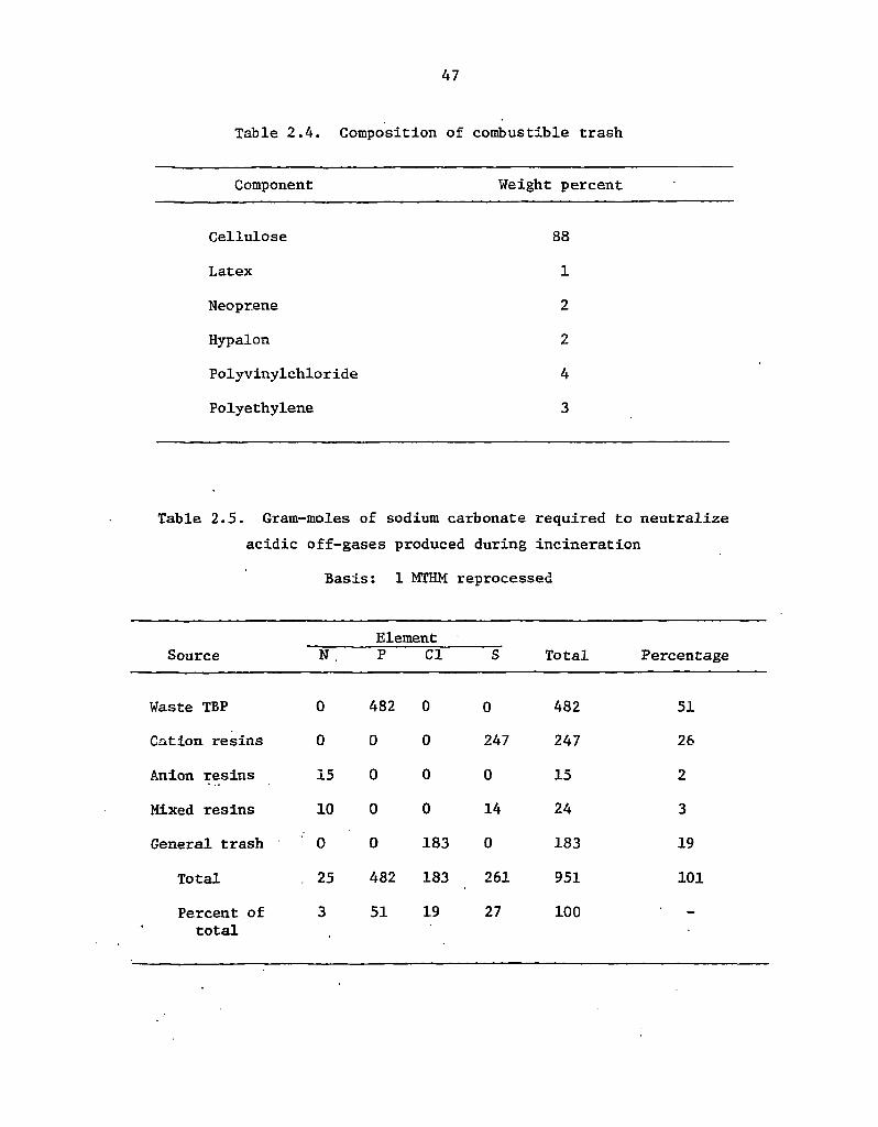
47
Table 2.4. Composition of combustible trash
Component Weight percent
Cellulose 88
Latex 1
Neoprene 2
Hypalon 2
Polyvinylchloride 4 Polyethylene 3
Table 2.5. Gram-moles of sodium carbonate required to neutralize acidic off-gases produced during incineration
Basis: 1 MTHM reprocessed
Element Source N , P CI S Total Percentage
Waste TBP 0 482 0 0 482 51
Cation resins 0 0 0 247 247 26
Anion resins 15 0 0 0 15 2
Mixed resins 10 0 0 14 24 3
General trash 0 0 183 0 183 19
Total . 25 482 183 261 951 101
Percent of total
3 51 19 27 100

Table 2.6. Comparison of incineration alternatives
Characteristic Air incineration
Incinerator type Fluidized Molten Acid sodium sodium digestion
carbonate carbonate
Operating temperature (°C)
Relative operability
Special materials of construction required?
Corrosive off-gas?
Relative volumetric off-gas rates
Carbon-free solid effluents?
Relative solid and liquid waste effluent volumes
Relative actinide solubilities in nitric acid after incineration
1,300
Easy
Yes
Yes
Medium
No
Low
Low
550
Medium
No
No
High
No
High
Low
1,200
Hard
Yes
Yes
Low
Yes
High
Medium
250
Hard
Yes
Yes
Low
Yes
Medium
High
.c-GO

49
potential to react with many carbonaceous species to produce explosive compounds, the combustible carbon content of the ash should be kept very low to ensure that the subsequent acid digestion for actinide recovery is safe and controllable.
The fluidized sodium carbonate incinerator operates at lower temperatures than i conventional air incinerator but is somewhat more complicated to operate. If the bed is overheateo for example, the fluidized particulates melt, stick together, and the bed collapses. However, the low-temperature burn and in situ neutralization of the acidic off-gases permit the incinerator to be fabricated from stainless steel. Compared with the other alternatives, the volumetric off-gas rates are high since the bed is fluidized. The fluidized bed also suffers from the same disadvantages as conventional air incineration in that significant amounts of combustible carbon are often found in the primary waste, and this carbon could react with nitric acid adversely in any subsequent actinide recovery operations. However, since the bed operating temperature is low (less than 700° C), actinide species entering with the feed would not be fired into refractories (greater than 750°C) by the incinerator, so lhat they may be more recoverable. On the other hand, refractory actinides which enter the incinerator will not be solubilized by the process; therefore, the relative actinide solubilities after incineration (item 8 in Table 2.6) are considered low.
A molten-salt incinerator66'67 is somewhat more difficult to operate than either a conventional air incinerator or a fluidized bed since it is operated batchwise and the viscosity of the melt can cause difficulties in the periodic draw-off operations. Also, the incinerator itself and the off-gas train require the use of refractory lining, even though the acidic species released by incineration are neutralized in situ. However, these disadvantages of the moiten-salt incinerator are offset somewhat by its relatively low off-gas rates, noncombustible solid effluent, and relatively high actinide solubility in nitric acid. The low off-gas rates are desired from the standpoint of reducing emissions68
in fuel reprocessing. Both the noncombustible solid effluent (cooled salt bed) and the relatively high actinide solubilities in nitric acid after salt fusion facilitate actinide partitioning and recycle to the dissolver without the use of HF. These factors make the molten-salt incinerator relatively attractive in partitioning flowsheets since such a bed could perhaps also be utilized to solubilize various interfacial cruds and process solids which are produced. If refractory actinides, for example, could be disassociated from noncombustible trash and HEPA filters by ultrasonic leaching and suspended as a colloid, then this suspension could be concentrated and the actinides solubilized by the molten-salt bed. So the molten-salt bed might serve the dual purpose of dealing with combustible wastes and solubilizing various intractable process solids which may contain actinides.
Acid digestion69 is qualitatively similar to molten-salt incineration according to the characteristics outlined in Table 2.6. Concentrated sulfuric acid, with nitric acid added as an oxidant, is used to digest the carbon wastes at relatively low temperatures. Effluent solids are mixtures of sulfates or oxides having a volume of about 2 to 4% of the feed volume. The sulfuric acid is recycled within the process. Corrosive off-gases are scrubbed for NO* and SO2 removal. Many of the system components would be fabricated of glass. Although actinides passing through the acid digestion system are readily recovered from nitric acid leaching, this type of incinerator would probably not be preferred over the molten-salt incinerator unless refractory actinides cannot be solubilized with the molten sodium carbonate salt bed.
In addition, the acid digestion system suffers from the inherent risks associated with nitration reactions. The reference system maintains control over such reactions by keeping the sulfuric-to-nitric -acid ratio greater than 8 and the bed temperature above 120°C. However, it is well known that under the conditions of lower operating temperatures and greater amounts of nitric acid in the digestor, nitration reactions would predominate over the oxidation reactions. Consequently, if

50
poorly operated, the acid digestion .system could lead to violent explosions due to the formation and accumulati.: a of nitrated organics. This addition risk, relative to the alternatives, would probably make the acid digestion system unacceptable for use in a reprocessing plant.
All of the incinerator types discussed here have been demonstrated on a bench scale or in a pilot plant. Additional experimental work is needed, however, to better ascertain the recoverability of actinides from the solid effluents. Actinide losses to the w-gas train must also be considered in the case of the air incinerator. Leach tests should be performed on the simulated ash effluents produced by the various incinerator types to determine the disposition of refractory actinides that may enter the incinerator system. These tests should also measure the disposition of the various corrosive anions which should be rejected to the salt waste, rather than recycled to the dissolver. Also, it may be preferable to place the incinerator ashes into the HLLW glass, rather than incorporate them into the concrete waste as shown in Sect. 2.6.
Finally, the relative advantages of various incineration combinations shpuld also be examined. For example, the best option may be air incineration of the combustibles, followed by a molten-salt fusion of the resulting ash. This combination, which would ten*1 to reduce the volumes of salt wastes, may be adequate from the standpoint of actinide recoveries.
2.5 Salt Waste Management
Salt waste management refers to the handling of all waste streams containing significant amounts of stable, nonvolatile cations but only small amounts of actinides or fission products. Most of the nonvolatile cation wastes are expected to contain only sodium in significant amounts, and these wastes might be decontaminated as shown in Fig. 2.10 using digestion, evaporation, and cation exchange. Wastes containing polyvalent cations such as the barrier cut produced from Fig. 2.7 could also be processed in this manner, but the cations would be recycled to the dissolver and eventually rejected to the HLW glass. In general, this strategy should be feasible as long as these cations are recycled to the dissolver as nitrate salts.
Salt waste management, therefore, has two important functions. The first is to recover actinides and fission products from the various salt wastes produced in fuel reprocessing and partitioning operations, and to recycle these actinides and fission products as a concentrate to the dissolver. In these flowsheets the recycle operation occurs through a series of evaporation steps, where the actinides and fission products are withdrawn as bottoms products which are eventually returned to the dissolver (Fig. 2.3). The second function of salt waste management is to reject all objectionable anions to liquid-waste immobilization.(see Sect. 2.6) as a decontaminated salt waste. Consequently, in all cases it is desired that the cations recycled to the dissolver will exist as nitrate salts, and that all chloride, sulfate, phosphate, or fluoride anions will be routed to the concrete waste.
Figure 2.10 is untested experimentally. Although an attempt has been made to show conditions which are feasible, it should be recognized that many problems exist with the flowsheet as shown. For example, the acidic conditions shown for the digestion step may not be sufficient to break up any actinide complexes which may be present. It may be necessary to add HF to the digestor. On the other hand, the digestion step will probably release significant amounts of corrosive gases to the off-gas train (such as HC1) which are not shown in the material balances. The disposition of precipitates is also unknown, and it would probably be necessary to filter the ion exchange feed, although this step is not shown in Fig. 2.10.
.If/organic matter is present in the waste streams shown, nitration reactions may occur in the digestor and cause additional safety problems. In addition, it is not certain that the recoveries shown

ORNL. DWG 76-17529
BASIS PER MTHM REPROCESSED
Fig. 2.10. Conceptual flowsheet for salt waste management.
52
for actinides and fission products will be attainable. The decontamination factors shown for the resulting salt waste may, in fact, be much lower than in Fig. 2.10; thus the actinide losses could be much higher. Also, anion rejection may not be as complete as indicated.
These uncertainties can only be . clarified by an experimental evaluation of the flowsheet conditions. Initially, work should be carried out with synthetic solutions and tracer amounts of actinides and fission products. Although hot-cell work may not be required to verify this flowsheet, considerable uncertainty will exist since the chemical form of the species entering the system during actual operation may not be the same as the species prepared in the synthetic streams. For example, the chemical form of each actinide entering as feed in Fig. 2.10 is not specified because it is unknown. In the absence of a pilot plant which could be used to generate actual incinerator liquors, etc., the chemical species entering this recycle system are largely speculative. Consequently, recoveries must be inferred from the analysis of synthetic waste processing, using chemical species which represent "worst cases" (e.g., refractory or polymeric plutonium that is relatively intractable).
Variations of the system shown should also be examined experimentally. For example, the TBP scrub solution in Fig. 2.10 contains most of the actinides introduced into the system but only small amounts of chl-.t ide, phosphate, or sulfate anions. It may be more desirable to handle this stream separately from the others, especially since the incinerator liquor and analytical wastes will probably contain much smaller amounts of actinides and much greater amounts of objectionable anions which can complex the actinides.
Alternatives to cation exchange should also be considered. Since the stream is highly salted, TBP extraction31 might be a more effective approach. Also, the use of other extractants, such as neutral bidentates41,42 and dialkylphosphoric acids,45 should be investigated and compared. Flowsheets parallel to Fig. 2.10 should be prepared and evaluated experimentally in order to assess the relative advantages and disadvantages associated with these processing options.
2.6 Immobilization of Liquid Waste
Figure 2.11 is a conceptual flowsheet for immobilizing the liquid wastes. Although the feasibility of this flowsheet has not been tested experimentally, it is modeled after established procedures for preparing concretes.70 However, the quantities of water-soluble salts added to the concrete from the waste streams in Fig. 2.11 will tend to increase the leachability of the resulting solid waste - an effect which should be examined experimentally. In addition, the tritium concentrate added to the concrete would migrate rather quickly if immobilized as shown. Appropriate studies should be carried- out to optimize the concrete mix and to determine the
"ingredients necessary to produce an acceptable waste form. However, these modifications are expected to be minor and will not substantially change the overall waste volume or weight.
Based on this analysis, a fuel reprocessing plant with partitioning is estimated to produce about 3 MT of low-level concrete waste per MTHM reprocessed. The estimated alpha activity for the waste is about 700 nCi/g. If the salts in the waste were simply evaporated to dryness and no concrete
t mix added, then the alpha activity would be on the order of 5000 nCi/ g. By way of comparison, a reprocessing plant operating under flowsheet conditions similar to those discussed here, but without actinide partitioning, might expect to reduce the mass of concrete waste sent to geologic isolation by a factor of 2. This expectation is based on flowsheet modifications eliminating essentially all cation exchange resin incineration and reducing the solvent incineration rate.

O R N L DWG 7 6 - 1 7 5 3 0
BASIS ' ONE MTHM REPROCESSED
DECONTAMINATED SALT WASTE
7 0 0 H U M 4 . 5 5 M N o N O j 0 . 5 4 M NaCI 0 . 3 9 U N O j S 0 4
0 . 4 6 M N S , P 0 4
TRACE K 2 C r 2 0 T
10 g F.P. COO « An
INCINERATOR ASNES
9 0 3 7 « ASH
41 < An
HTO CONCENTRATE
2 4 l i H t t
IS ppm of HTO
CONCRETE MIX 1773 hg DRY
PORTLAND CEMENT MIX
BARRIER CUT 2200 !!><»
106 m o l t * DTPA
ISO m o l a i Zn'*
2 g U 0 . 9 « P«
5 g Np
EVAPORATOR OVERHEADS 2 0 6 0 l l l a r t
TO W E F 2 FIG. 2 .13
MIXER Ui
IMMOBILIZED LIQUID WASTE
1351 l i tara 2 . 0 k g / l l l i r
8 . 7 3 a t % N o N O , 0 . 7 1 B | % NaCI 1 .25 > 1 % N a 2 S 0 4
1.70 wt % NOjP04
0 . 2 9 wt % ASH 1 . 3 4 s t % DTPA 1. 10 > ( % Z H ( N O j ) 2
0 . 0 1 » l * An • F.P. 2 7 . 7 2 « l % WATER 5 7 . 1 5 w t % CEMENT MIX
T / H 3 2 X I 0 " r
TO OEOLOOIC ISOLATION
Fig. 2.11. Conceptual flowsheet for liquid-waste immobilization.
54
2.7 Water and Acid Management
All aqueous secondary wastes are recycled to acid and water waste management (see Figs. 2.1 and 2.2)' unless they contain significant amounts of nonvolatile salts or levels of radioactivity. In these latter cases, the streams are directed either to salt waste management or to the HLLW. However, since water is added via personnel decontamination, showers, etc., and is produced by chemical reaction and incineration in the plant, an equivalent amount of water must be rejected during plant operation. Therefore, a reprocessing plant cannot theoretically operate with total water recycle. On the other hand, total recycle can be very nearly approached since the amount of water that must be rejected is small compared with the amount recycled (about 2.5% with the assumptions made here).
The strategy for recycle outlined in this study consists of several steps:
1. stream classification (organic, solids, tritium, salts, alpha, or other contamination),
2. stream preprocessing as required (e.g., filtration, sedimentation, etc.),
3. acid recovery and purification (evaporation and fractionation),
4. tritium recovery and concentration (acid neutralization, tritium concentration), and
5. water purification (ion exchange, activated carbon filtration).
The major objectives to be met by the recycle strategy are as follows:
1. rejection of salt wastes to immobilization;
2. rejection of radioactivity to the HLLW through the dissolver;
" 3. rejection of organic- or phosphate-contaminated waste to incineration;
4. recovery of purified, tritiated acid for recycle to dissolver, waste management, or primary recovery cycles; .
5. recovery of purified, nontritiated acid for recycle to purification cycles;
6. recovery of purified, tritiated water for recycle to the dissolver, waste management, or primary recovery cycles;
7. recovery of purified, nontritiated water for recycle to purification cycles; and
.8. rejection of tritiated water concentrate to liquid-waste immobilization.
One possible system for attaining these goals is outlined in Figs. 2.12-2.14. These flowsheets • utilize four types of unit operations: (1) evaporation, (2) fractionation, (3) adsorption, and (4) ion
exchange. The first two of these operations have been satisfactorily demonstrated in commercial

O R N L DWG 7 6 - 1 7 5 3 1
BASIS > ONE MTHM REPROCESSED
TO W E F 2 FIG. 2 . 1 3 .
Fig. 2.12. Conceptual flowsheet for non-tritiated acid and water waste management.

Of iNL- DWG 7 6 - 1 7 5 4 4
TO DISSCLVER AND WASTE PARTITIONING
CYCLES
Fig. 2.13. Conceptual flowsheet for tritiated acid and water waute management.
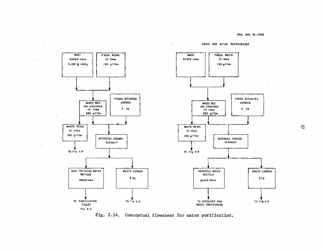
ORNL DWG 7 6 - 1 7 5 3 2
BASIS: ONE MTHM REPROCESSED
TO PURIFICATION
CYCLES
2 . 3
L n
TO Fig 2 . 9 TO OISSOLVER AND WASTE PARTITIONING
TO Fig. 2 . 9
Fi f l
Fig. 2.14. Conceptual flowsheet for water purification.

58
operations and can be considered as part of the existing technology. Adsorption using activated carbon, however, has not been thoroughly demonstrated for this application, and its use should be examined experimentally and compared with various alternatives such as filtration, biological digestion, and reverse osmosis. The ion exchange applications shown in these figures can also be considered as existing technology and thus do not require extensive experimental evaluation.
In the figures shown, those streams containing salt or radioactive wastes have already been classified and sent elsewhere (see Figs. 2.6, 2.10, and 2.11). The composite feeds AWF1 and WEF1 consist of organic-contaminated and organic-free secondary aqueous wastes, respectively, which have not been exposed to tritium. Figure 2.21 and Table 2.7 identify and characterize the streams included in these two feeds. The composite waste stream AWF1 is first decontaminated of organic matter (mostly detergents or organic decontamination solutions) by filtration through activated carbon. The objective of this step is to minimize the risks of organic nitration through subsequent processing and to prevent phosphate detergents from entering the dissolver. (A combination of reverse osmosis and ultrafiltration may be preferred.) The activated carbon is routed to incineration; the filtrate is combined with the waste feed WEF1 and routed to evaporation. The first evaporator, WEI, recovers a I M acid overheads and sends a 7 M acid concentrate to WEF2, the organic-free, tritiated water waste composite feed shown in Fig. 2.13. The reason for this operation is that the actinides present in the bottoms are recovered in the dissolver.1 The overheads from WEI are fractionated conventionally. The recovered water is further purified as outlined in Fig. 2.14 by mixed^bed ion. exchange and filtration through activated carbon. Both of these latter two purification steps may be eventually replaced by reverse osmosis.
The composite feeds AWF2 and, WEF2 shown in Fig. 2.13 are comprised of those organic-contaminated and organic-free streams that have been exposed to tritium. These streams are cither involved with the dissolver, HLLW processing arid solidification, or the various waste management functions, all of which are considered to. utilize tritiated acid and water. The streams comprising feeds AWF2 and WEF2 are identified and characterized in Fig. 2.21 and Table 2.8. The grams of fission products and actinides associated with the various streams are also shown, but the resulting mass rates should only be considered accurate to within an,order of magnitude.
The recycle strategy in Fig. 2.13 is parallel to that in Fig. 2.12 except that tritium recovery is included. The organics, detergents, or decontamination solutions in AWF2 are first removed by passing the. streams through activated carbon. The composite of the filtrate from AWF2 and stream WEF2 is tlien'evaporated so as to recover about a 7 M acid bottoms concentrate and a 1 M acid , overheads. The bottoms from evaporator WE2 'in Fig. 2.13 are returned to the dissolver. The overheads are used to produce 14 M tritiated nitric acid for recycle and water for recycle after tritium recovery. In the conceptual flowsheet (Fig. 2.13), the tritiated water overheads is neutralized with caustic and redistilled before being diverted to the tritium fractionator. It would probably be sufficient to pass the fractionator feed through the mixedrbed ion exchange and activated carbon filter before recovering the tritium (i.e., let the last treatment step in Fig. 2.13 follow the steps shown in Fig: 2.14). . '
.The tritium recovery method outlined in Fig. 2.13 (simple fractionation) is within existing technology, but represents a substantial reprocessing expense. Advanced tritium recovery strategies71
such as voloxidation and laser excitation may be eventually preferred. As an alternative, tritium concentration coil Id be eliminated altogether and the tritum allowed' to achieve a steady-state concentration in the plant by recycle and rejection through the VOG (see Fig. 2.17), the liquid waste immobilization (see Fig. 2.11), and the Freon absorptidn (FASTER) waste (see Fig. 2.17). Tritium from LWR fuels is introduced at the rate of about 20 millimoles per MTHM reprocessed. The water

Table 2.7. Organic-free, nontritiated aqueous waste streams comprising feed WEF1
Stream label Figure for reference
Volume (liters) (M)
An (g) Other
2AW
1AW
1DW
Silica gel cleanup bottoms
HCU overheads
Acid scrub for 2BW, 1CW, 1EW
Acid scrub for 2BW, 1CW, 1EW
Conditioner waste
NPC overheads
DN condensate
Np feed waste
Total
2.3
2.3
2.3
2.3
2.3
2.19
2.19
2.18
2.18
2.18
2.18
4,096
4,190
15,310
28
17,610
9
505
15
2,385
20
301
44,469
3.2
2.3
1.6
4.3
0.04
7.5
0.1
6.51
0.04
1.14
7.02
71
918
1002
Trace
Trace
30
Trace
Trace
Trace
Trace
40
2061
40 g F.P.
250 g F.P.
10 g F.P.
383 g NaN03
300 g F.P.; 383 g NaN03
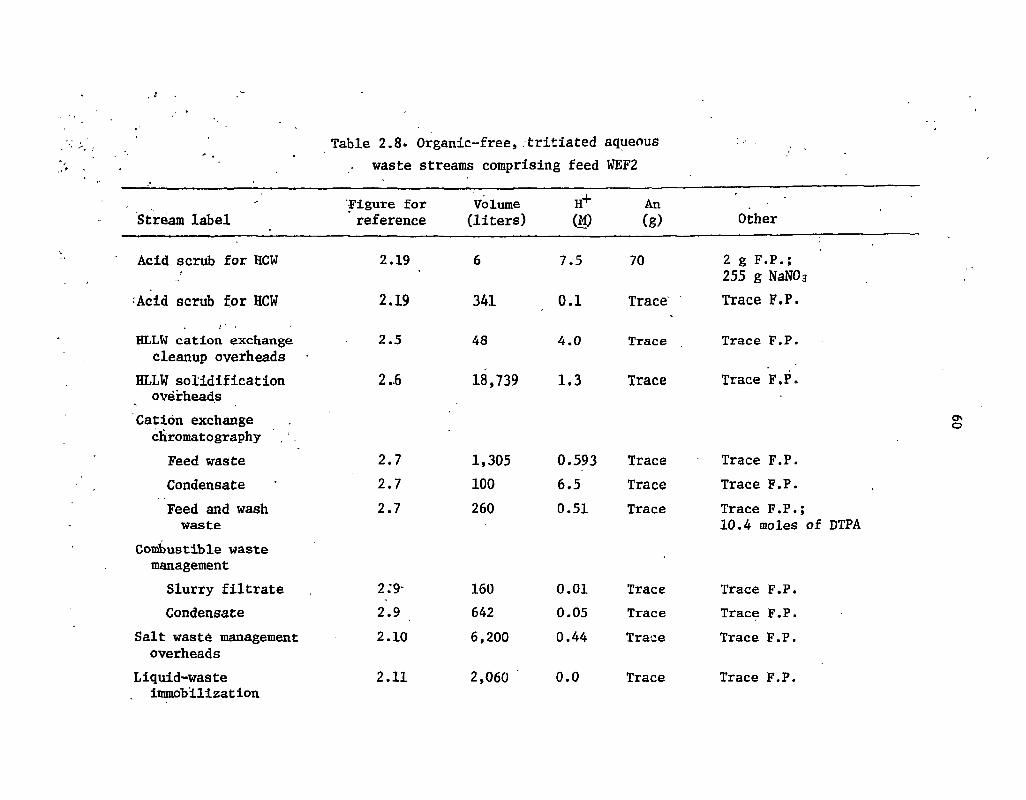
Table 2.8. Organic-free,.tritiated aqueous waste streams comprising feed WEF2
Stream label
Acid scrub for HCW
Acid scrub for HCW
HLLW cation exchange cleanup overheads
HLLW solidification overheads
Cation exchange chromatography Feed waste Condensate Feed and wash waste
Combustible waste management Slurry filtrate Condensate
Salt waste management overheads
Liquid-waste immobilizat ion
Figure for reference
Volume (liters)
H (M)
An (g) Other
2.19
2.19
2.5
2..6
2.7 2.7 2.7
2:9*
2.9 2.10
2.11
341
48
1,305 100 260
160 642 6,200
2,060
7.5
0.1
4.0
18,739 1 .3
0.593 6.5 0.51
0.01 0.05 0.44
0.0
70
Trace
Trace
Trace
Trace Trace Trace
Trace Trace Trace
Trace
2 g F.P.; 255 g NaN03
Trace F.P.
Trace F.P.
Trace F.P.
Trace F.P. Trace F.P. Trace F.P.; 10.4 moles of DTPA
Trace F.P. Trace F.P. Trace F.P.
Trace F.P.
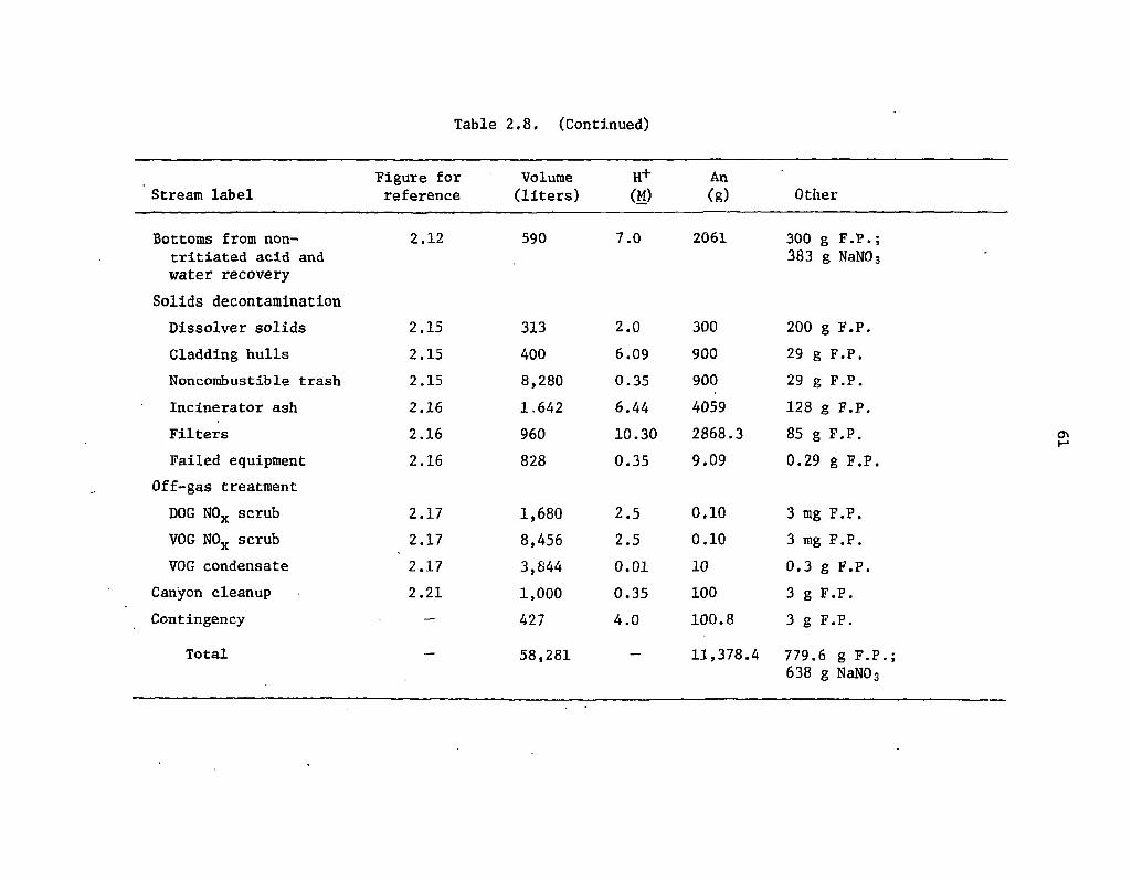
Table 2.8. (Continued)
Stream label Figure for reference
Volume (liters)
H+ (M)
An (g) Other
Bottoms from non-tritiated acid and water recovery
2.12 590 7.0 2061 300 g F.P.; 383 g NaN03
Solids decontamination Dissolver solids 2.15 313 2.0 300 200 g F.P. Cladding hulls 2.15 400 6.09 900 29 g F.P. Nonconibustible trash 2.15 8,280 0.35 900 29 g F.P. Incinerator ash 2.16 1.642 6.44 4059 128 g F.P. Filters 2.16 960 10.30 2868.3 85 g F.P. Failed equipment 2.16 828 0.35 9.09 0.29 g F.P.
Off-gas treatment DOG N0X scrub 2.17 1,680 2.5 0.10 3 mg F.P. VOG N0X scrub 2.17 8,456 2.5 0.10 3 mg F.P. VOG condensate 2.17 3,844 0.01 10 0.3 g F.P.
Canyon cleanup 2.21 1,000 0.35 100 3 g F.P. Contingency — 427 4.0 100.8 3 g F.P.
Total — 58,281 — 11,378.4 779.6 g F.P.; 638 g NaN03
62
effluent rates are about 216, 1264, and 860 liters per MTHM reprocessed from the DOG, VOG, and liquid-waste immobilization systems respectively. At steady state, the tritium concentration in the recycled water and tritiated acid would be about 154 ppb of HTO.
In the conceptual flowsheet, the tritium concentration is held to about 3 ppb of HTO by distillation, and the calculated retention factor for tritium under these conditions is about 100. If the tritium is allowed to achieve a steady-state concentration of 154 ppb of HTO instead of being concentrated, the tritium retention factor woiild be about 2 for the case where 1264 liters of water per MTHM reprocessed is released through the VOG. This retention factor for tritium could be increased by condensing more water from the VOG and immobilizing it in concrete, or by storing it in cylinders with the Freon absorption waste. It might also be increased by scrubbing the VOG'with nontritiated water, but additional tritiated water would still need to be retained. By way of comparison, the immobilization of water released through the VOG would produce an additional 2 m3, or 4 MT, of concrete waste per MTHM.
As a third alternative, the tritiated water condensed from the VOG could simply be stored for a period aind then released to the environment. In order to achieve a retention factor of about 100 (i.e., with about 3 ppb of HTO in the effluent to the environment), the tritiated water would have to be stored for about 72 years. Since a 1500-MTHM/year reprocessing plant would need to store about 1.7 billion liters to meet such a goal, this is probably not a practical solution.
Because most of the water in the reprocessing plant is recycled, the amount of water that can be admitted to the process without accumulation is limited. In this study, the major anticipated water release terms will be the DOG, VOG, and liquid-waste immobilization, which equal about 2340 liters per MTHM reprocessed as condensed water. About 115 and 549 liters of condensed w.ater per MTHM reprocessed are produced through various chemical reactions in the plant and incineration respectively. In addition, there is a net inflow of about 590 liters of water per MTHM reprocessed to the tritiated water system from the WEI evaporator bottoms (see Fig. 2.13). Consequently, of the 2500 liters of water per MTHM reprocessed that is utilized for personnel and laundry decontamination, about 1414 liters must be recycled through the nontritiated water recovery system in order to avoid water accumulation in the plant.
In the above analysis, the tritium is assumed to move quantitatively into the aqueous phase upon dissolution in nitric acid. If the spent fuel is stored for 5 years and cooled in a water pool, significant amounts of tritium may accumulate there. With the storage of 7000 MTHM at the site, the cooling'.water requirements are on the order of 9 million liters processed per MTHM 'reprocessed. Assuming a cooling water inventory of about 50 million liters, the steady-state HTO concentration would be about 196 ppb if the tritium should be quantitatively released into the system (although the occurrence of such an event is unlikely).
• t 2.8 Decontamination of Solid Waste
Various solid wastes must be routinely decontaminated during the operation of the reprocessing plant (see Figs. 2.15 and 2.16). Some of the solid waste streams are defined as torn variables, as explained in Sect. 2.1.2; thus there is considerable uncertainty as to the actinide and fission product mass rates entering with these streams. For these torn variables, mass rates are conservatively estimated from previous experiences.72"75
Some of the solid waste streams are relatively well defined; for example, the dissolver solids and cladding hull wastes in-Fig. 2.15 can probably be adequately leached with nitric acid alone as shown.
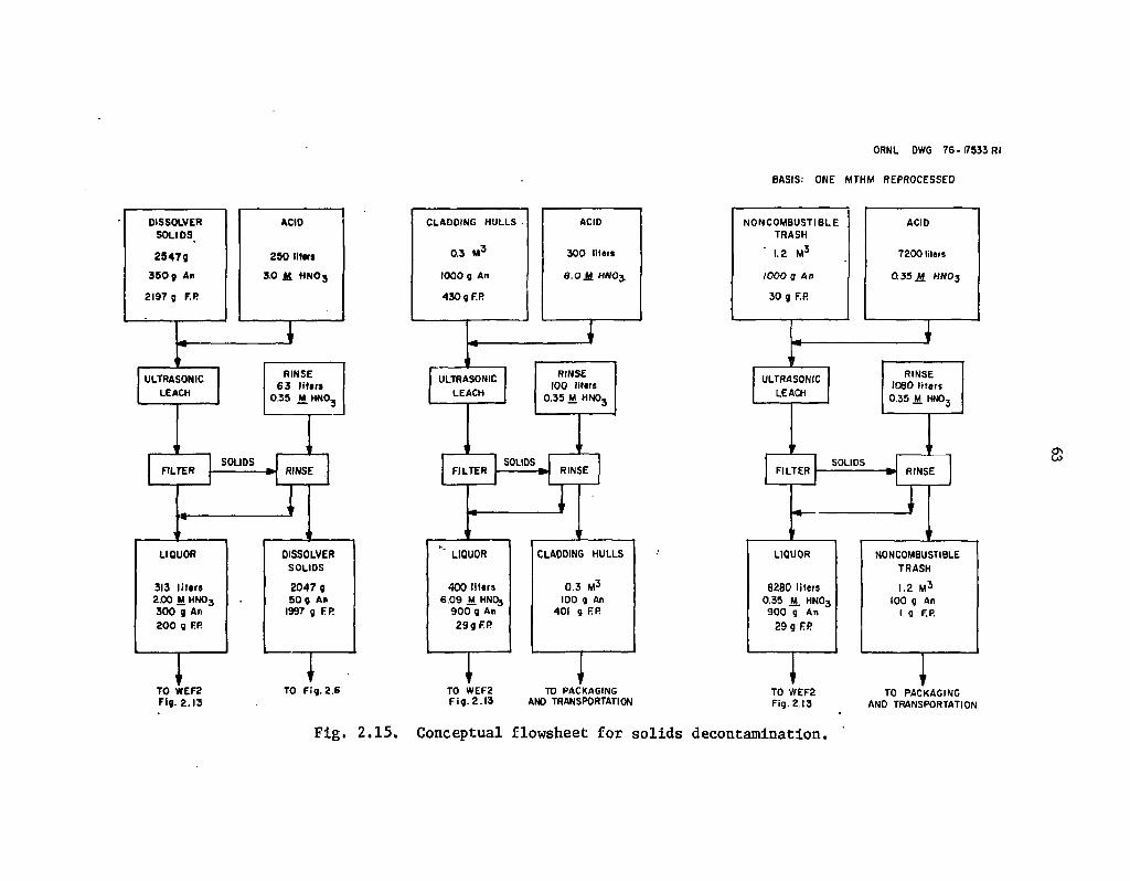
ORNL DWG 76-17533 Rl
BASIS: ONE MTHM REPROCESSED
DISSOLVER SOLIDS
2 5 4 7 9
3 5 0 g An
2197 g F.R
FILTER
ULTRASONIC LEACH
LIQUOR
313 liters 2.00 M HN03
3 0 0 g An 2 0 0 g FR
TO WEF2 Fig. 2.13
ACID
250 lltars
3.0 Jt H N O j
RINSE 6 3 liters
0.35 M.HNOj
SOLIDS RINSE
DISSOLVER SOLIDS
2 0 4 7 g 50 g An
1997 g FR
TO Fig. 2.6
CLADDING HULLS
0.3 M 3
1000 g An
430 g F.R
ACID
300 liters
8.0 M HNOj
ULTRASONIC LEACH
RINSE 100 littrs
0.35 M HNOj
SOLIDS FILTER » RINSE
LIQUOR
400 liters 6.09 M. HNO3
9 0 0 g An 2 9 g E R
TO WEF2 F i g . 2 . 1 3
CLADDING HULLS
0 .3 M 3
100 g An 401 9 RP.
TO PACKAGING AND TRANSPORTATION
TO WEF2 Fig. 2.13
TO PACKAGING AND TRANSPORTATION
Fig. 2.15. Conceptual flowsheet for solids decontamination.

ORNL DWG 7S-17543
BASIS: ONE MTHM REPROCESSED
TO WEF2 Fig. 2 .13
TO Fig. 2.11 TO WEF2 Fig. 2.13
TO PACKAGING AND TRANSPORTATION
TO WEF2 Fig. 2.13
TO PACKAGING ANO TRANSPORTATION
Fig. 2.16. - Conceptual flowsheet for solids decontamination.
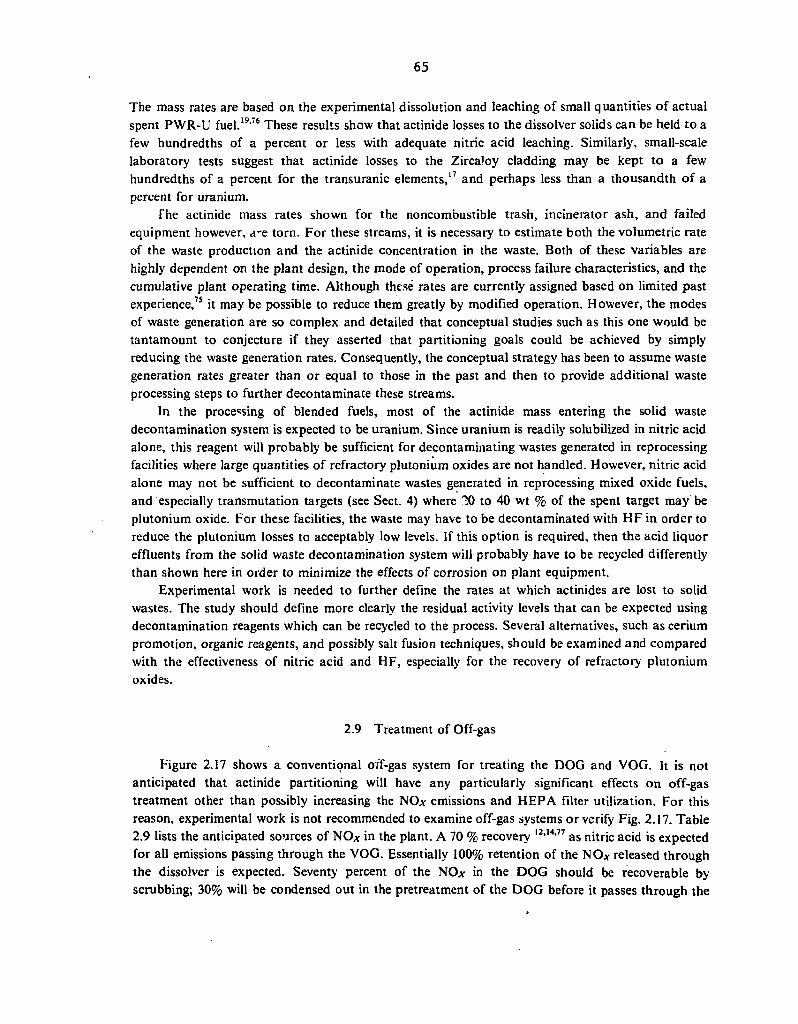
65
The mass rates are based on the experimental dissolution and leaching of small quantities of actual spent PWR-U fuel.19,76 These results show that actinide losses to the dissolver solids can be held to a few hundredths of a percent or less with adequate nitric acid leaching. Similarly, small-scale laboratory tests suggest that actinide losses to the ZircaJoy cladding may be kept to a few hundredths of a percent for the transuranic elements,17 and perhaps less than a thousandth of a percent for uranium.
The actinide mass rates shown for the noncombustible trash, incinerator ash, and failed equipment however, a-e torn. For these streams, it is necessary to estimate both the volumetric rate of the waste production and the actinide concentration in the waste. Both of these variables are highly dependent on the plant design, the mode of operation, process failure characteristics, and the cumulative plant operating time. Although these rates are currently assigned based on limited past experience,75 it may be possible to reduce them greatly by modified operation. However, the modes of waste generation are so complex and detailed that conceptual studies such as this one would be tantamount to conjecture if they asserted that partitioning goals could be achieved by simply reducing the waste generation rates. Consequently, the conceptual strategy has been to assume waste generation rates greater than or equal to those in the past and then to provide additional waste processing steps to further decontaminate these streams.
In the processing of blended fuels, most of the actinide mass entering the solid waste decontamination system is expected to be uranium. Since uranium is readily solubilized in nitric acid alone, this reagent will probably be sufficient for decontaminating wastes generated in reprocessing facilities where large quantities of refractory plutonium oxides are not handled. However, nitric acid alone may not be sufficient to decontaminate wastes generated in reprocessing mixed oxide fuels, and especially transmutation targets (see Sect. 4) where ?JQ to 40 wt % of the spent target may be plutonium oxide. For these facilities, the waste may have to be decontaminated with HF in order to reduce the plutonium losses to acceptably low levels. If this option is required, then the acid liquor effluents from the solid waste decontamination system will probably have to be recycled differently than shown here in order to minimize the effects of corrosion on plant equipment.
Experimental work is needed to further define the rates at which actinides are lost to solid wastes. The study should define more clearly the residual activity levels that can be expected using decontamination reagents which can be recycled to the process. Several alternatives, such as cerium promotion, organic reagents, and possibly salt fusion techniques, should be examined and compared with the effectiveness of nitric acid and HF, especially for the recovery of refractory plutonium oxides.
2.9 Treatment of Off-gas
Figure 2.17 shows a conventiqnal oif-gas system for treating the DOG and VOG. It is not anticipated that actinide partitioning will have any particularly significant effects on off-gas treatment other than possibly increasing the NO* emissions and HEPA filter utilization. For this reason, experimental work is not recommended to examine off-gas systems or verify Fig. 2.17. Table 2.9 lists the anticipated sources of NO* in the plant. A 70 % recovery l2'14'77 as nitric acid is expected for all emissions passing through the VOG. Essentially 100% retention of the NO* released through the dissolver is expected. Seventy percent of the NO* in the DOG should be recoverable by scrubbing; 30% will be condensed out in the pretreatment of the DOG before it passes through the
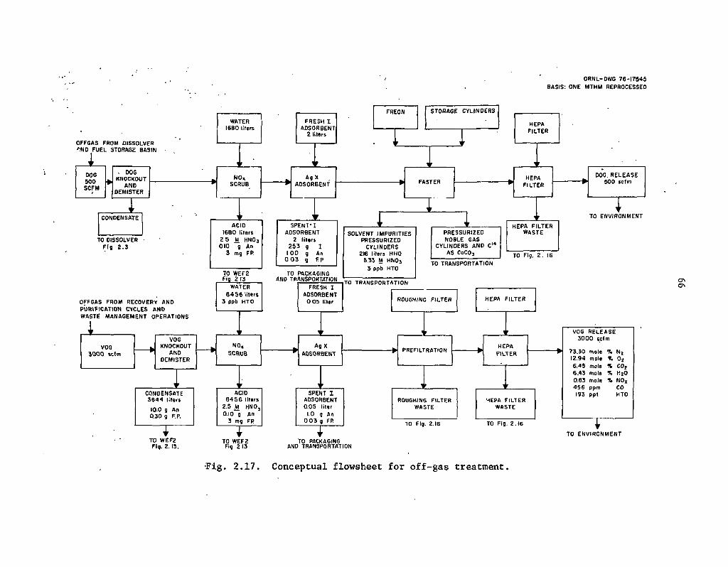
ORNL-DWG 76-17845 BASIS: ONE MTHM REPROCESSED
OFFGAS FROM DISSOLVE!? '.ND FUEL STORAGE BASIN
DOG 5 0 0 » SCFM i
, DOG KNOCKOUT
AND DEMISTER
WATER 1680 liters
. 1
FREON STORAGE CYLINDERS
1
HEPA FILTER
G>>
VOG RELEASE 3 0 0 0 scfm
73.30 mole % N 2
12.94 mole % 0 2
6.45 mo It % CO} 6.43 mole % H2O 0.83 mole 7. NO* 4 5 6 ppm CO 193 pp l HTO
TO WEF2 Fig 213
TO PACKAGING AND TRANSPORTATION
TO Fig. 2 .16
TO ENVIRONMENT
•Fig. 2.17. Conceptual flowsheet for off-gas treatment.
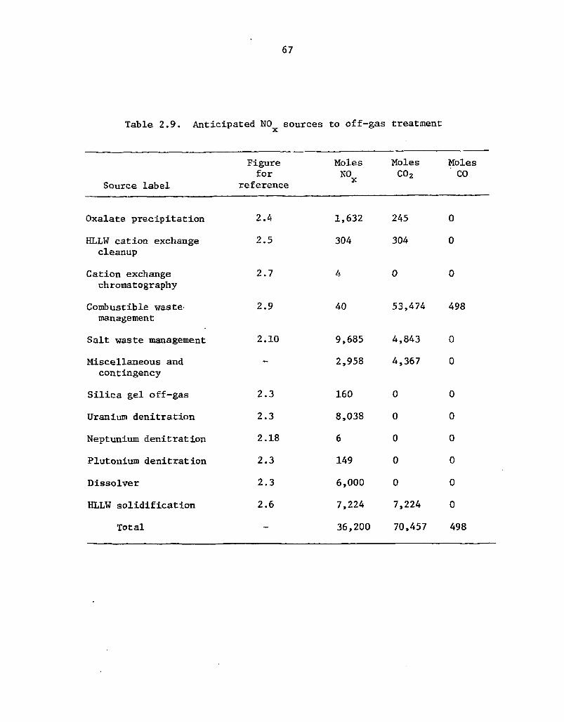
67
Table 2.9. Anticipated NOx sources to off-gas treatment
Source label
Figure for
reference
Moles NO
Moles C02
Moles CO
Oxalate precipitation
HLLW cation exchange cleanup
Cation exchange chromatography
Combustible waste management
Salt waste management
Miscellaneous and contingency
Silica gel off-gas
Uranium denitration
Neptunium denitration
Plutonium denitration
Dissolver
HLLW solidification
Total
2.4
2.5
2.7
2.9
2.10
1,632
304
2.3
2.3
2.18
2.3
2.3
2.6
40
9,685
2,958
160
8,038
6
149
6,000
7,224
36,200
245 0
304 0
0 0
53,474 498
4,843
4,367
0
0
0
0
0
7,224
70,457
0
0
0
0
0
0
0
0
498
68
Freon absorption" system for noble-gas recovery. On this basis, a 5-MTHM/day reprocessing plant should release about 2 MT of nitrogen oxides (calculated as NOz), about 15.5 MT of COi,b and around 70 kg of carbon monoxide per day. It is expected that the particulate retention factors will meet or exceed those achieved in conventional reprocessing (i.e., greater than 108).78 This expectation is predicated on the assumption that off-gas treatment will be tailored to the resulting plant. Additional off-gas treatment prior to that shown in Fig. 2.17 will be available for many of the unit operations. So the flowsheet shown only represents the final off-gas treatment before release to the environment and not the entire treatment system. Figure 2.6 shows one possible initial treatment for off-gas which might be utilized. The volumes of filter waste shown in Fig. 2.16 are also somewhat higher than for conventional processing73 to reflect the increased use of HEPA filters to keep actinide particulates out of the off-gas system.
2.10 Comparison of Target and Fuel Reprocessing
Detailed target reprocessing flowsheets have not yet been prepared; however, they are expected to be very similar to those outlined here and in an earlier study.3 The most important sources of anticipated difference between fuel and target reprocessing is in the composition of the feed, which is expected to be more radioactive and contain larger amounts of transuranics. Target reprocessing may be simpler than fuel reprocessing if the HA extract does not have to be partitioned. The uranium, plutonium, and neptunium might simply be decontaminated from fission products and recovered as a mixture unless this approach causes problems in target fabrication. The method of recovering actinides in target reprocessing will probabi/ be the same as that for the fuel elements. Consequently, most operations outlined in this chapter will be essentially identical for target reprocessing from the structural sense, although differences in mass rates, will exist.
2.11 Other Considerations
Throughout the discussion of the various waste management functions, descriptions have been provided in the various areas where data deficiencies are known to exist. Substantial deficiencies also exist because of uncertainties in unit operation interactions and the effects of persistent recycle, maintenance requirements, and long-term accumulations. These deficiencies will continue to exist until an integrated hot pilot plant is operated and studied for some time.
Based on the assumptions made in this conceptual analysis, it is possible to estimate the actinide losses resulting from a reprocessing plant operating with and without partitioning. These calculated losses are summarized in Tables 2.10 and 2.11. In Table 2.10, all of the neptunium, americium, and curium are lost as shown because these species are not recovered in conventional fuel reprocessing. The calculated losses for uranium and plutonium are somewhat higher than the measured losses at NFS,7 but compare favorably with the calculated losses at NFS, based on long-term operational recoveries. In particular, after more than 630 MT of fuel had been processed, average uranium and plutonium recoveries of 99.0% and 97.6%, respectively, were experienced.79 So the assumptions made in this study with regard tp the torn variables appear to be reasonable, although the assumed
"Estimated Freon release rates are less than 100 g/day. ^Nearly all , 4C would be recovered in the DOG system.
/

Table 2.10. Estimated actinide losses during reprocessing without partitioning
Figure g An for Amount of actinide (wt %) charged to dissolver per liter Toxicity
Stream label reference U Pu Np Am Cm of waste index"
HLV glass 2.6 0.23 0.54 99.90 99.90 99.90 47.64 1.1 X 10¹⁰
Cladding hulls 2.15 0.10 0.10 0.10 0.10 0.10 3.22 5.5 X 10⁶
Noncombustible trasha
2.15 0.10 0.10 - - - 0.80 8.3 X 10 s
Filters 2.16 0.30 0.30 - - - 9.65 1.0 X 10 7
Failed equipment 2.16 1 x 10~3 1 x 10⁻³ - - - 0.02 2.5 X 10⁵
Off-gas to environment
2.17 1 x 10"6 1 x 10~6 - - - 3.4 x io-10 2.5 X IO1*0
AgX adsorbent 2.17 1 x 10""1* 1 x 10-" 1 * 10-" 1 x 10-* 1 x io"4 0.47 8.1 X 10 s
FASTER 2.17 1 x 10"14 1 x lO"14 % 1 x 10⁻⁴ 1 x lO"" 1 x 10-* 0.30 5.0 X 10 5
Concrete waste 2.11 0.96 0.96 - - - 11.95 1.2 X 10 7
Total - 1.69 2.00 100.00 100.00 100.00 - -
Includes Teflon waste and Leaded rubber gloves* The volume of water required to dilute the actinides in a unit volume of waste to their respective radionuclide concentration guide (RCG) valves based on ingestion toxicities.
The volume of air required to dilute the actinides in a unit volume of gaseous waste to their respective RCG values based on inhalation toxicities.
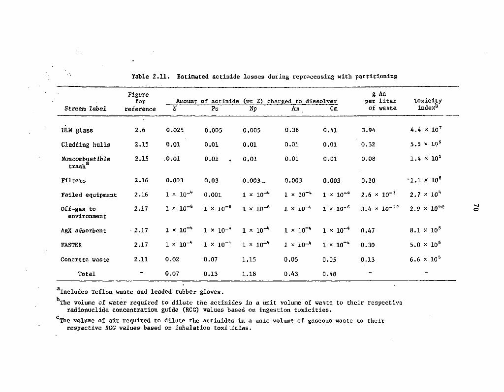
Table 2.11. Estimated actinide losses during reprocessing with partitioning
Figure g An for Amount of actinide (wt %) charged to dissolver per liter Toxicity
Stream label reference U Pu Np Am Cm of waste index"
HLW glass 2.6 0.025 0.005 0.005 0.36 0.41 3.94 4.4 x 10⁷
Cladding hulls 2.15 0.01 0.01 0.01 0.01 0.01 0.32 5.5 x 10 s
Noncombustible trash
2.15 .0.01 0.01 • 0.01 0.01 0.01 0.08 1.4 x 10s
Filters 2.16 0.003 0.03 0.003 _ 0.003 0.003 0.10 -1.1 x 10⁶
Failed equipment 2.16 1 x 10-" 0.001 1 x 10"1* 1 x 10-" 1 x 10-" 2.6 x 10⁻³ 2.7 x 10" Off-gas to environment
2.17 1 x 10⁻⁶ 1 x 10" -6 1 x lO"6 1 x I0"b 1 x io-6 3.4 x lo-10 2.9 x 10"c
AgX adsorbent 2.17 1 x 10"" 1 x 10" _>t 1 x lO-1* 1 x lO-" 1 x lO-" 0.47 8.1 x 10⁵
FASTER 2.17 1 x lO-" 1 x 10" -it 1 x 10-" 1 x iO-1* 1 x io- 0.30 5.0 x 10s
Concrete waste 2.11 0.02 0.07 1.15 0.05 0.05 0.13 6.6 x 10⁵
Total - 0.07 0.13 1.18 0.43 0.48 - -
Includes Teflon waste and leaded rubber gloves. T̂he volume of water required to dilute the actinides in a unit volume of waste to their respective radionuclide concentration guide (RCG) values based on ingestion toxicities.
The volume of air required to dilute the actinides in a unit volume of gaseous waste to their respective RCG values based on inhalation toxicities.

71
distribution of losses to the various waste streams is probably somewhat different than that actually experienced at NFS.
The losses shown in Table 2.11 (reprocessing with partitioning) are less easily defended since there is no comparable commercial experience. Comparison with Table 1.1 in Sect. 1 shows that the calculated uranium losses overall are lower than the desired losses to the HLW glass to meet the stated partitioning goals. The plutonium losses to the HLW glass are also lower than required. The overall neptunium losses are well below the required goals for the HLW glass, while the calculated americium and curium losses are each a factor of 4 greater. These latter losses, however, may be higher than can actually be achieved since the OPIX process reduces the americium and curium losses to about 0.02% when applied to the AGNS flowsheet.16
This analysis suggests, therefore, that the HLLW could be adequately partitioned from actinide contamination, but significant actinide losses will likely occur to the intermediate- and low-level wastes. Although there is no obvious technical reason why such loss reductions cannot be attained, the estimates in Table 2.11 may be overly optimistic by an order of magnitude or more. A satisfactory answer to this question will probably only be attained by the sustained operation of a reprocessing pilot plant.
2.12 Ancillary Flowsheets
Figures 2.18-2.22 represent various operations which are not described either in ORNL-5012 or in Sect. 2. By and large, they are self- explanatory and are referenced here sequentially according to drawing numbers. The nomenclature used in these figures is defined in Table 2.1.
2.13 Summary and Conclusions
Actinide partitioning for the purpose of fissioning all actinides produced within a fuel cycle would have significant impacts on the commercial reprocessing of nuclear fuels. First, it is desirable to reduce the actinide losses from all waste effluents generated by the reprocessing plant. Second, in order to recycle these actinides to nuclear reactors for fissioning, they must be recovered by . t reprocessing plant, concentrated, and converted into a form suitable for either homogeneoi s dispersal into the fuel or fabrication into acceptable transmutation targets. These additional requirements, as well as the usual economic recovery, purification, and concentration specifications for uranium and plutonium recycle, result in the production of numerous secondary waste streams besides the HLLW, which must also be processed for actinide removal.
Consequently, actinide partitioning implies much more than simply decontaminating the HLLW from actinides, insofar as there is ample opportunity for significant actinide losses to many other waste streams as well. In fact, the implementation of actinide partitioning really requires the development of highly integrated waste systems which are subject not only to stringent constraints on the movements of actinides, but also environmental and safety constraints on the movements of fission products and chemical reagents. These systems must be capable of treating a wide variety of waste streams, removing actinide or fission product contamination where necessary, and preparing actinide concentrates for subsequent fabrication, special disposal, or recycle to main-line purification cycles within the reprocessing plant. Chemical reagents must be recycled or rejected as concentrates into suitable waste forms. In addition, the system must also prevent the buildup of undesirable

ORNL OWG 76-17934
BASIS' ONE MTHM REPROCESSED
TO WEF1 Fig. t«2
Fig. 2.18. Conceptual flowsheet for neptunium purification.

ORNL DWG 7 6 " I 7 5 3 5 R I
BASIS i ONE MTHM REPROCESSED
USED SOLVENT (HCW)
Fl« 2 .3 17,030 l i ters 0.002 M NOj
3 0 % TBP TRACE HTO
USED SOLVENT (2BW + ICW +1EW 1
Fig 2.3 2 9 , 2 0 6 lilers_ 0 . 0 0 2 M N O j
3 0 % TBP
SODIUM CARBONATE 170 l i ters
0.2 M N o , CO.
SCRUB
CARBONATE WASTE 170 l i ters
0.10 M NO2 COJ 0 . 2 0 M NoNOj
3 kg An 9 0 g F.P.
TO FIG 2.10
SODIUM CARBONATE 252 l i ters
0 . 2 M N o 2 C O j
• SCRUB
CARBONATE WASTE 252 l i t e rs 0.10 £ NdjCOj
0 . 2 0 M NaNOj 2 kg An Ig F.P.
TO FIG. 2 . 1 0
FILTER WASH (BATCH)
6 t i ter* 8 . 0 £ HNOj
ACID SCRUB 341 liters
0 .20 M HNOj
ACID WASTE 6 l i ters
7.5 M HNOj 0 .5 M NoNOj
7 0 g An 2 g F.P.
TO WEF2 FIG 2.13
FILTER WASH (BATCH)
9 liters 8 . 0 M HNOj
FILTER — '
ACID WASTE 9 l l te .e
7.5 H HNOj 0 . 5 M NoNOj
3 0 g An TRACE F.P.
TO WEF I FIG. 2.12
ACID SCRUB
ACID WASTE 341 l i ters
0 .100 M HNOj
TO WEF2 FIG 2.13
ACID SCRUB 505 l i ters
0 . 2 M HNOj
ACID SCRUB
ACID WASTE 5 0 5 liters
0 .100 M H N O j
FRESH SOLVENT 170 liters 3 0 % TAP
TO EXHAUSTIVE EXTRACTION, WASTE MANAGEMENT AND PRIMARY RECOVERY CYCLES
F i g 2.3
WASTE SOLVENT 170 l i ters
0.002 M NOj 3 0 % TBP
TRACE An
TO FIG 2 .9
FRESH SOLVENT 126 l i ters 3 0 % TBP
I
I I I
i . TO PURIFICATION CYCLES F i g 2 . 3
TO WEF I FIG. 2.12
WASTC SOLVENT 126 l l t e i s 3 0 % TBP
0 . 0 0 2 M N O j TRACE An
TO FIG. 2 .9
Fig. 2.19. Conceptual flowsheet for TBP solvent purification.

ORNL OWG 76- 17536
BASIS: ONE MTHM REPROCESSED
TO Fig. 2.10 TO STORAGE TO Fig. 2.9 POOLS AND
HEAT EXCHANGERS
Fig. 2.20. Conceptual flowsheet for cooling water demineralization.
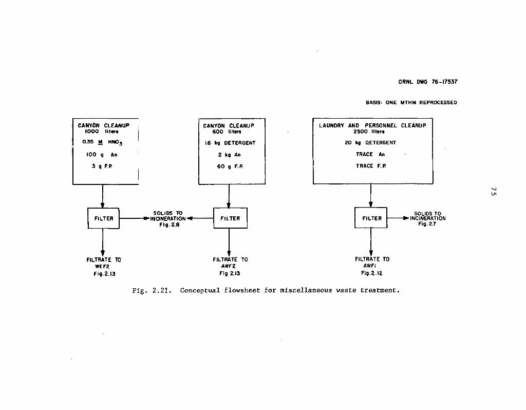
ORNL DWG 76-17537
BASIS'. O N E M T H M REPROCESSED
CANYON CLEANUP IOOO liters
0.35 M HN03
100 g An
3 g FP
FILTER
FILTRATE TO WEF2 Fig.2.13
SOLI OS TO •INCINERATION"
Fig. 2.8
CANYON CLEANUP 6 0 0 iters
1.6 kg DETERGENT
2 kg An
6 0 j F.P.
FILTER
FILTRATE TO AWF2
Fig 2.13
FILTRATE TO AWFI
Fig.2.12
Fig. 2.21. Conceptual flowsheet for miscellaneous waste treatment.

ORNL OWG 7 7 - 6 5 6
Fig. 2.22. Acid preparation for recycle to the dissolver.

77
chemical species which adversely affect the plant operation or safety. Fission product concentrates must also be rejected into suitable waste forms, but the waste forms produced by the plant systems must be chemically and physically stable, and suitable for long-term storage in a geologic formation.
The following conclusions can be drawn from the the study presented here:
1. Actinide partitioning will probably increase the volumes of low- and intermediate-level wastes, as compared with reprocessing for the simple economic recoveries of uranium and plutonium only. Preliminary estimates suggest that these waste volumes may be doubled by partitioning flowsheets.
2. Significant actinide losses occur to the intermediate- and low-level waste streams. This analysis suggests that as much as 75% of the actinide losses in reprocessing may be to these wastes, although the actinide concentrations in these streams are lower than in the HLW glass.
3. Partitioning will increas^the capital investment requirements and operating costs for fuel reprocessing plants, f /
4. Highly integrated/flowsheets which maximize acid and water recycle will be more difficult to operate than equivalent, open systems.
j" 5. Fuel reprocessing and refabrication plants should be co-sited for the following reasons: (a) The
wastes can be more economically treated by common waste management systems, (b) Co-siting may facilitate additional reductions in actinide losses beyond thqse which can be achieved in separate facilities, (c) Co-siting will facilitate additional red unions in waste volumes, (d) Co-siting will improve ^c'id and water management, as well as facilitate higher retention factors for tritium, (e) Co-siting will eliminate the safeguard risks associated with the transportation of highly purifiechplutonium oxides between the reprocessing and refabrication sites.
6. The levels of actinide partitioning that can actually be achieved in commercial operations will remain uncertain until the integrated flowsheets can be demonstrated ih a hot pilot plant.
2.14 References for Section 2
1. Jackson & Moreland & S. M. Stoller Associates, Current Status and Future Technical and Economic Potential of Light Water Reactors, WASH-1082 (March 1968).
2. J. O. Blomeke, "A Program to Establish the Technical Feasibility and Incentives for Partitioning," Proceedings of Nuclear Regulatory Commission Workshop on the Management of Radioactive Waste: Waste Partitioning as an Alternative, NR-CONF-OOl (June 1976).
3. W. D. Bond and R. E. Leuze, Feasibility Studies of the Partitioning of Commercial High-Level Wastes Geneuted in Spent Nuclear Fuel Reprocessing: Annual Progress Report for FY-1974, ORNL-5012 (January i975).

78
4. Alternatives for Managing Wastes from Reactors and Post-Fission Operations, in the LWR Fuel Cycle, ERDA-76-43 (May 1976).
5. Ref. 3, pp. 7-15.
6. Ref. 3, p. 77.
7. L. A. Abrams, "Fuel Reprocessing - Commercial Experience," React. Fuel-Process. Technol. 12(2), 181-94 (Spring 1969).
8. H. A. Taha, Operations Research, An Introduction, Macmillan, New York, 1971.
9. D. F. Rudd and C. C. Watson, Strategy of Process Engineering, Wiley, New York, 1968.
10. R, H. Perry and C. H. Chilton (eds.), Chemical Engineers' Handbook, 5th Ed., pp. 2.97-2.100, McGraw-Hill, New York, 1973.
11. G. S. G. Beveridge and R. S. Schechter, Optimization: Theory and Practice, McGraw-Hill, New York, 1970.
12. Barnwell Nuclear Fuel Plant Separations Facility, Final Safety Analysis Report, Docket 50-332, Allied-Gulf Nuclear Services, Barnwell, S.C., Oct. 10, 1973.
13. Ref. 3, p. 36.
14. Nuclear Fuel Recovery and Recycling Center, Preliminary Safety Analysis Report, Docket 50-564, Exxon Nuclear Company, XN-FR-32 Rev. O.
15. Ref. 4, Vol. 3, pp. 17.1-17.9.
16. D. O. Campbell and S. R. Buxton, U. S. Patent 4,025,602.
17. B. L. Vondra et al., LWR Fuel Reprocessing and Recycle Program Quarterly Report for Period July I to September 30, 1976, ORNL/TM-5660 (November 1976).
18. Ref. 4, Vol. 1, pp. 2.28-2.42,
19. D. O. Campbell, ORNL, personal communication to D. W. Tedder (August 1976).
20. J. J. Katz and-G. T. Seaborg, The Chemistry of the Actinide Elements, Wiley, New York, 1957.
21. J. T. Long,- Engineering for Nuclear Fuel Reprocessing, Gordon and Breach Science . Publishers, Inc., New York, 1967.
^2. W. W. Schulr and G. E. Benedict, Neptunium-237 Production and Recovery, AEC Critical Review Series, USAEC Office of Information Services (1972).

79
23. W. Davis. Jr., and J. Mrochek, "Activities of Tributy] Phosphate in Tributyl Phosphate-Uranyl Nitrate-Water Solutions," pp. 283-95 in Solvem Extraction Chemistry, Proceedings of the international Conference Held at Gothenburg, Sweden, 27 Aug.-! Sept., 1966, ed. by D.Dyrssen, J.-O. Liljenzin. and J. Rydberg, North-Holland. 1967.
24. K. Alcock et al., "Tri-rc-Butyl Phosphate as an Extracting Solvent for Inorganic Nitrates-V. Further Results for the Tetra- and Hexavalent Actinide Nitrates," J . Inorg. Nucl. Chem. 6, 328-33 (1958).
25. M. H. Lietzke and R. W. Stoughton, "A Mathematical Model for the Solvent Extraction of Uranyl Nitrate and Nitric Acid," Nucl. Sci. Eng. 16, 25-30 (1963).
26. F. Baumgartner and L. Finsterwalder, "On the Transfer Mechanism of Uranium(VI) and Plutonium(IV) Nitrate in the System Nitric Acid-Water/Tributylphosphate-Dodecane, " J . Phys. Chem. 74(1), 108-12 (1970).
27. S. K. Patil et al., "Some Studies on the TBP Extraction of Actinides," J. Inorg. Nucl. Chem. 35, 2537-45 (1973).
28. K. Saddington, "Reprocessing Fuel from the Civil Reactors," Nucl. Power J(50), 92-96 (June 1960).
29. A. W. Joyce, Jr., et al., "Design vs. Performance of Process and Equipment in a Large-Scale Radiochemical Separations Plant," Chem. Eng. Prog., Symp. Ser. 5(5(28), 21-29 (1960).
30. E. J. Detilleux et al., "Chemical Reprocessing of Nuclear Fuels, A Technical Status Review," paper presented at the ANS/ENS International Conference in Washington D.C., Nov. 14-19, 1976.
31. M. C. Thompson, Distribution of Selected Lanthanides and Actinides between 30% TBP in n-Paraffm and Various Metal Nitrate Solutions, DP-1336, E. I. du Pont de Nemours & Co., Savannah River Laboratory, Aiken, S.C. (November 1973).
32. R. E. Burns et al., Technical and Economic Feasibility of Partitioning Hanford Purex Process Acid Waste, BNWL-1907, Battelle Pacific Northwest Laboratories, Richland, Wash. (May 1975).
33. H. Goldacker et al., "A Newly Developed Solvent Wash Process in Nuclear Fuel Reprocessing Decreasing the Waste Volume," Kertechnik 10, 426-30 (1976).
34. I. L. Jenkins and A. G. Wain, "Solvent Extraction in the Atomic Energy Industry," Rep. Prog. Appl. Chem. 57, 301-7 (1972).
35. J. Sauteron et al., "Reprocessing of Fast Reactor Fuels in France," Meeting of the Consulting Group on Reprocessing of Fuels in Liquid Metal Cooled Fast Breeders, Leningrad, USSR, 17-20 May 1976, ERDA-TR-206.

80
36. N. Srinivasan et al., Counter-Current Extraction Studies for the Recovery of Neptunium by the Purex Process (Part I), BARC-734, Bhabha Atomic Research Center, Bombay, India (1974).
37. N. Srinivasan et al., Counter-Current Extraction Studies for the Recovery of Neptunium by the Purex Process (Part II), BARC-735, Bhabha Atomic Research Center, Bombay, India (1974).
38. Boyd Weaver, ORNL, unpublished data (May 28, 1976).
39. W. W. Schulz, D2EHPA Extraction Recovery of Neptunium and Plutonium from Purex Acid Sludge Solutions, BNWL-583 (March 1968).
40. Ref. 4, Vol. 2, pp. 6.1-6.62.
41. W. W. Schulz and L. D. Mclsaac, Removal of Actinides from Nuclear Fuel Reprocessing Waste Solutions with Bidentate Organophosphorous Extractants, ARH-SA-217 (August 1975).
42. L. D. Mclsaac, J. D. Baker, and J. W. Tkachyk, Actinide Removal from ICPP Wastes, ICP-1080 (August 1975).
43. L. D. Mclsaac, ICPP, personal communication to D. W. Tedder (January 1977).
44. E. P. Horwitz and C. A. A. Bloomquist, "High Speed-High Efficiency Separation of the Transplutonium Elements by Extraction Chromatography," J. Inorg. Nucl. Chem. 35, 271 (1973).
45. P. F. Peppard et al., "Extraction of Selected Trivalent Lanthanide and Actinide Cations by Bis(hexoxy-ethyl) Phosphoric Acid," J. Inorg. Nucl. Chem. 27, 1683 (1965).
46. G. W. Mason et al., "Extraction of U(VI) and Selected M(I1I) Cations by Bis n-octyl Phosphoric Acid in Two Different Hydrocarbon Diluents," J. Inorg. Nucl. Chem. 32, 3899 (1970).
47. R. G. Dosch, "Ceramics from Ion Exchangers: An Approach to Nuclear Waste Solidification," Trans Am. Nucl. Soc. 22, 355 (1975).
48. R. W. Lynch et al., "The Sandia Solidification Process - A Broad Range Aqueous Waste Solidification Method," Proceedings of the International Symposium on the Management of Radioactive Wastes from the Nuclear Fuel Cycle, Vienna, Austria (March 1976). *
s. - • " 49. G. Koch et al., "Recovery of Transplutonium Element! from Fuel Reprocessing High-Level
Waste Solutions," Symposium on the Management of Radioactive Wastes from Fitel Reprocessing, Organization for Economic Cooperation and Development, Paris (March 1973).
50. D. O. Campbell, "Separation of Lanthanides and Trivalent Actinides with Pressurized Ion Exchange," Sep. Purif. Methods 5(1), 97-138 (1976).
81
51. W. H. Hale, Jr., and C. A. Hammer, "Cation Exchange Elution Sequence with DTPA," Ion Exch. Membr. / , 85-88 (1972).
52. E. J. Wheelwright et al., Simultaneous Recovery and Purification of Pm, Am, and Cm by the Use of Alternating DTPA and NTA Cation Exchange Flowsheets, BNWL-SA-1492 (1965).
53. J. T. Lowe, W. H. Hale, Jr., and D. F. Hallman, "Development of a Pressurized Cation Exchange Chromatographic Process for Separation of Transplutonium Actinides," Ind. Eng. Chem., Process Des. Dev. 70(1), 131-35 (1971).
54. Boyd Weaver and F. A. Kappelmann, Talspeak: A New Method of Separating Americium and Curium from the Lanthanides by Extraction from an Aqueous Solution of an Aminopolyacetic Acid Complex with a Monoacidic Organophosphate or Phosphonate, ORNL-3559 (August 1964).
55. Boyd Weaver and F. A. Kappelmann, "Preferential Extraction of Lanthanides over Trivalent Actinides by Monoacidic Organophosphates from Carboxylic Acids and from Mixtures of Carboxylic and Aminopolyacetic Acids," J. Inorg. Nucl. Chem. JO, 263-272 (1968).
56. Chem. Technol. Div. Annu. Prog. Rep. Mar. 31, 1975, ORNL-5050.
57. R. E. Leuze et al., "Behavior of the Transplutonium Elements in Solvent Extraction Systems," presented at the International Conference on Chemistry of Solvent Extraction of Metals, AERE, Harwell, England, Sept. 27-29, 1965.
58. W. D. Burch, E. D. Arnold, and A. Chetham-Strode, "Production of the Transuranium Elements." Nucl. Sci. Eng. 17, 438 (1963).
59. T. D. Filer, "Separation of the Trivalent Actinides from the Lanthanides by Extraction Chromatography," Anal. Chem. 46(4), 608-10 (April 1974).
60. H. O. Haug, "Final Purification and Concentration of Americium/Curium Separated from High-Level Reprocessing Waste," J. Radioanal. Chem. 21, 187-88 (1974).
61. Ref. 4, Vol. 2, pp. 9.1-9.4.
62. D. L. Ziegler et al., Pilot Plant Development of a Fluidized Bed Incineration Process, RFP-2271 (October 1974).
63. Ref. 4, Vol. 2, pp. 9.7-9.9.
64. Transuranic Waste Research and Development Program, March-June 1973, LA-545I-PR, Los Alamos Scientific Laboratory, Los Alamos, N.M. (November 1973).
65. Transuranic Solid Waste Management Research Programs, October-December 1973, LA-5614-PR, Los Alamos Scientific Laboratory, Los Alamos, N.M. (May 1974).

82
66. D. E. McKenzie et al., Disposal of Transuranic Solid Waste Using Atomics International Molten Salt Combustion Process, AI-ERDA-13151, Rockwell International, Canoga Park, Calif. (May 1975).
67. L. F. Grantham et al., Disposal of Transuranic Solid Waste Using Atomics International Molten Salt Combustion Process, II, Al-ERDA-13169, Rockwell International, Canoga Park, Calif. (March 1976).
68. O. O. Yarbo et al., Effluent Control in Fuel Reprocessing Plants, ORNL-TM-3899 (March 1974).
69. R. E. Lerch, Acid Digestion of Combustible Wastes: A Status Report, HEDL-TME 75-5. Hanford Engineering Development Laboratory, Richland, Wash. (May 1975).
70. 'Ref. 4, Vol. 2, pp. 12.13-12.21.
71. Ref. 4, Vol. 2, pp. 13.21-13.43.
72. Ref. 4, Vol. 2, pp. 5.1-5.8.
73. Ref. 4, Vol. 1, pp. 2.43-2.83.
74. J. A. Ayres (ed.), Decontamination of Nuclear Reactors and Equipment, Ronald Press Co., New York (1970).
75. E. D. North, Solid Waste Generation in Reprocessing Nuclear Fuel, AIChE Symp. Ser. 72(154) (1976).
76. B. L. Vondra et al., L WR Fuel Reprocessing and Recycle Program Quarterly Report for Period April I to June 30, 1976, ORNL/TM-5547 (July 1976).
77. Ref: 4, Vol. 2, pp. 13.44-13.47.
78. O. O. Yarbro, Jr., Supplementary Testimony Related to Fission Product Source Terms and Effluents from the Barnwell Nuclear Fuel Reprocessing Plant, USAEC, BNFP, Docket No. 50-332.
' 79. Nuclear Fuel Services, Inc., Rockville, Md., Safety Analysis Report NFS' Reprocessing Plant, West Valley, New York, Docket 50-201-147. Vol. 1, p. 1-2-3.
83
3. ANALYSIS OF PARTITIONING IN A MIXED-OXIDE FUEL FABRICATION PLANT
J. P. Drago, J. J. Perona, and D." W. Tedder
The processing of relatively large amounts of plutonium during the fabrication of mixed-oxide (MOX) (i.e plutonium-enriched natural or depleted uranium) fuels would be expected to result in the loss of significant amounts of plutonium to the various waste streams generated at the fabrication plant. Since the plutonium loss to such wastes is comparable to that expected to occur in reprocessing plants on a mass basis, partitioning, if implemented, would probably also be required in (MOX) fabrication plants. The very low specific toxicity of wastes from uranium-enriched fuel fabrication plants results in partitioning not being necessary in these facilities. This section represents an initial attempt to conceptually investigate methods for partitioning the actinides in MOX fuel fabrication plants wastes, with the principal end result being tentative reference partitioning flowsheets.
3.1 Overview
The model LWR MOX fuel fabrication plant that led to the development of the partitioning flowsheets presented in this section was based on information from several sources.1"5 The data from these sources were used in specifying the main-line fabrication process steps, mass flow rates, waste types, and waste volumes for the model plant. Although mass rates, operating conditions, and recoveries are stated, they are approximations that must be verified by experimental work.
Also, many of these assumed (torn or cut) waste stream rates are probably low," and overly optimistic. Additional analysis must be carried out to ensure that the reference flowsheets truly represent "worst cases." Consistent with this objective, the torn waste stream rates should be greater than or equal to the expected rates under normal operating conditions. If this design criterion is met, the actinide recycle rates derived from the waste partitioning operations will also exceed normal rates. The resulting design capacity for treating waste systems should then be closer to actual process requirements.
The main-line processing scheme for the model plant can be outlined as follows:
1. receiving and blending of uranium and plutonium oxides,
2. comminution, compaction, and granulation to the desired consistency,
3. pelletizing,
4. sintering,
5. grinding the pellets to finished dimensions,
"The assumed losses without partitioning are about 0.5% of the actinide feed. These losses should probably be assumed to. be approximately 1.5% to more accurately reflect past experience.

84
6. cleaning and drying the pellets, and
7. loading the pellets into fuel rods, decontaminating the rods, and welding the end caps.
The plant is also assumed to reprocess and recycle its own scrap and to process and package all radioactive wastes on-site. All drawings and calculations are based on I metric ton of heavy metal (MTHM) of MOX fuel being fabricated.
The isotopic content of the plutonium oxide feed to the fabrication plant is assumed to be that of third recycle plutonium that has been aged for I year after reprocessing. The heavy-metal makeup of the reference LWR MOX fuel is 95 wt % uranium-5 wt % plutonium. Americium-241, resulting from the decay of 15-year 24 'Pu, is assumed to comprise 0.86 wt % of the plutonium.2 However, americium was not assumed to be partitioned from the scrap wastes.
The generic waste systems supporting the model plant are shown in Fig. 3.1. This figure illustrates the basic waste management functions that would be required in the model plant and the major waste stseam movements between these functions. In addition, it emphasizes the interrelationship of these waste management functions and the recycle that exists between many of the waste management operations due to the production of secondary wastes by each operation.
When Fig. 3.1 is compared with Figs. 2.1 and 2.2, it is clear that many of the refabrication waste support functions are similar, or identical, to those waste functions which support a fuel reprocessing plant. Because of this similarity, many ol the waste systems could be integrated by co-siting fuel reprocessing and refabrication facilities.
The major process flows of the model plant waste management functions arc shown in Fig. 3.2. Table 3.1 defines the abbreviations and acronyms used in Fig. 3.2 and succecding figures in this section. The following waste management functions in Fig. 3.2 will be considered in succeeding subsections: (1) scrap recovery, (2) management of combustible wastes, (3) management of salt wastes and immobilization of liquid wastes, (4) management of acid-water, (5) decontamination and management of solid wastes, and (6) off-gas treatment. Additionally, the differences involved in fabricating waste-actinide targets and normal MOX fuel will be discussed briefly.
3.2 Scrap Recovery
Two scrap recovery operations, one for clean scrap and one for dirty scrap, are carried out in the model plant. Clean scrap consists of defective pellets and grinder fines that do not require chemical purification and thus do not appear in Fig. 3.2. Dirty scrap is MOX powder or pellets that have become contaminated with other materials (such as corrosion or dirt) and must be redissolved and purified by solvent extraction or ion exchange processes.
In the dirty-scrap recoveiy system (Fig. 3.3), the bulk of the MOX fuel processed comes from off-specification pellets contaminated with impurities. This stream, which contains about. 5% of the material fed to the plant (or 50 kg of MOX), is dissolved in nitric acid and filtered. It is estimated that 90% of the uranium and 50% of the plutonium in the dirty scrap dissolve in the primary dissolver. Reference 2 estimates that 80% of the MOX scrap would dissolve in the primary dissolver.
The dissolution rate of MOX or plutonium oxide depends on its history and form, (i.e., sintering temperature, particle size, impurities), and, in the case of MOX, on the degree of homogeneity.' Lerch observed® that increasing the sintering temperature of the mechanically mixed uranium-plutonium oxide pellets reduced the amount of undissolved residue; however, other factors
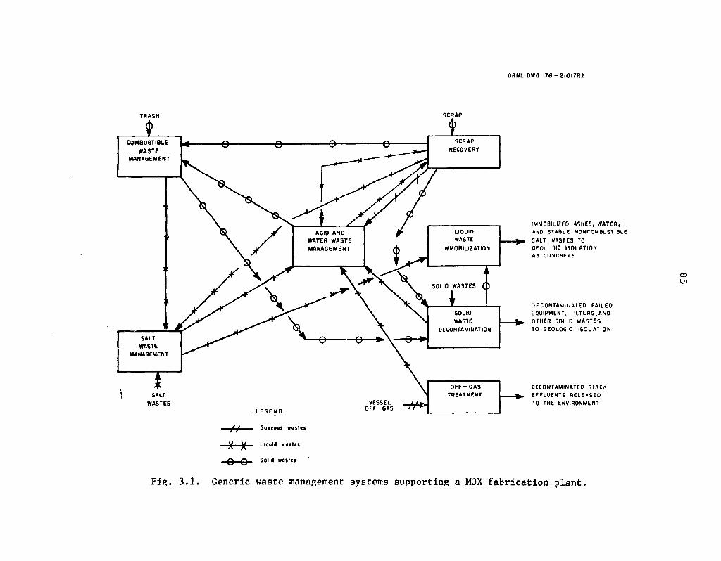
ORNL DWG 7 6 - 2 I O I 7 R 2
TRASH
COMBUSTIBLE WASTE
MANAGEMENT
SCRAP
SALT WASTES
SOLID WASTE
DECONTAMINATION
O F F - G A S TREATMENT
o o
Gaseous wat les
Liquid n a i l e s
Solid arosl t i
IMMOBILIZED ASHES, WATER, AND STABLE, NONCOMBLISTIBLE SALT WASTES TO GEOI I jIC ISOLATION AS CONCRETE
DECONTAMINATED FAILED EQUIPMENT, ' ITERS, AND OTHER SOLID WASTES TO GEOLOGIC ISOLATION
OECONTAMINATED STACK EFFLUENTS RELEASED TO THE ENVIRONMENT
00
Fig. 3.1. Generic waste management systems supporting a MOX fabrication plant.

ORNL DWG 76-2IOI5R1
DIRTY SCRAP
Fig. 3.2. Process flows of waste management functions of MOX plant.
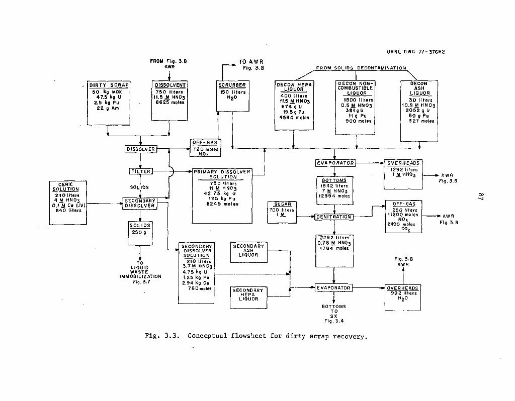
O R N L D W G 7 7 - 3 7 6 R 2
D I R T Y S C R A P
5 0 kg MOX 4 7 . 5 Kg U
2 . 5 kg P u 2 2 g Am
CERIC S O L U T I O N
2 1 0 l i te rs 4 M H N O 3
0.1 M C» IIV) 8 4 0 l i t e r s
FROM F i g . 3 . 8 AWR
D I S S O L V E N T 7 5 0 l i t e r s
1 1 . 5 2 4 H N O 3 8 6 2 5 moles
TO AWR Fig. 3 .8 F R O M S O L I D S O E C O N T A M I N A T I Q N
S C R U B B E R 1 5 0 l i t e r s
H20
D I S S O L V E R
[ F I L T E R H
S O L I D S
1 S E C O N D A R Y D I S S O L V E R
S O L I D S
2 5 0 g
T O L I Q U I D W A S T E
I M M O B I L I Z A T I O N Fig. 3 . 7
D E C O N H E PA L I Q U O R
4 0 0 l i t e r s H5 M.HNO3 6 7 4 g U 19 .5 g Pu
4 5 9 4 moles
O F F - G A S
12 0 moles NOx
P R I M A R Y D I S S O L V E R SOLUTION 7 5 0 l i t e r s 11 M H N C 3
4 2 . 7 5 kg U 1 2 5 kg P u
8 2 4 5 m o l e s
S E C O N D A R Y O I S S O L V E R S O L U T I O N
2 1 0 l i t e r s 3 . 7 M H N O 3 4 . 7 5 kg U 1 .25 kg Pu
2 . 9 4 kg Ce 7 8 0 moles
S E C O N D A R Y ASH
L I Q U O R
S E C O N D A R Y H E P A
L I Q U O R
D E C O N N O N -C O M B U S T I B L E
L I Q U O R 1 8 0 0 l i t e r s
0 . 5 1 H N O 3 3 8 1 g U
11 g Pu 9 0 0 moles
D E C O N A S H
L I Q U O R
3 0 l i t e r s 1 0 . 9 M. H N O 3
2 0 5 2 g U 6 0 g Pu 3 2 7 moles
E V A P O R A T O R
B O T T O M S 1 8 4 2 l i t e rs 7 M HNO3
1 2 8 9 4 moles
?UGAR 7 0 0 l i ters
1 M 1 M * L D E N I T R A T I O N T ) - r
2 2 9 2 l i t e r s 0 . 7 8 M HNO3
1 7 8 4 moles
Fig. 3 . 8 A W R
- H E V A P O R A T O R
B O T T O M S T O S X
F i g . 3 . 4
O V E R H E A D S 9 9 2 l i t e r s
HgO
1 O V E R H E A D S 1 2 9 2 l i t e r s 1 M H N O 3
1 2 9 2 l i t e r s 1 M H N O 3 A W R
F ig . 3 . 8
O F F - G A S 2 5 0 l i t e r s
1 1 2 0 0 moles NOK
8 4 0 0 moles C 0 2
00 -̂ J
A W R Fig. 3 . 8
Fig. 3.3. Conceptual flowsheet for dirty scrap recovery.

88
Table 3.1. Nomenclature for Section 3
A-WR - acid-water recovery
DSR = dirty-scrap recovery
HEPA = high-efficiency particulate air (filter)
HM = heavy metals (actinides)
IX = ion exchange
moles = g-moles of free nitrate
MOX = mixed oxide (95 wt % U, 5 wt % Pu)
MTHM = metric tons of heavy metal (U + Pu)
MWT = miscellaneous waste treatment
SCU = solvent cleanup
SWM = salt waste management
SX = solvent extraction
VOG = vessel off-gas
such as decreasing the particle si7e of the PuC>2 and the degree of mixing also are important. Plutonium dioxide is a very stable compound and, when heated at high temperatures (>750°C), it becomes extremely difficult to dissolve in nitric acid. Therefore, any large particles of PuC>2, or agglomerates of small Pu(>2 particles that are not thoroughly dispersed by the mixing process, will
"lead to a nonhomogeneous material that will be difficult to dissolve in nitric acid without the addition of fluorides.
A secondary dissolver is used to recover the actinides present in the residue from the primary dissolver." The two dissolution promoters considered are fluoride and cerium. The addition of fluoride was considered to be unacceptable because of the severe corrosion problems, its numerous undesirable side reactions with various chemical species, and its volatility. Ceric nitrate was selected because it is nonvolatile, its corrosiveness can be controlled by valence adjustment, and it has fewer side reactions.
Cerium(III) does not attack stainless steels; however, when oxidized to the quadrivalent state, rapid attack of 304 stainless steel was observed.7 Titanium and tantalum, on the other hand, do not appear to be aflected by Ce(IV). Horner7 reported complete dissolution of refractory PuOz and (U-Pu)02 in 4 M HNOr-O.l M Ce(IV) with about twice the stoichiometric amount of Ce(IV)

89
necessary to oxidize all of the Pu(IV) to the divalent state (Pu022+. The reaction during dissolution can be represented by the equation:
2Ce4+ + Pu4+ L 2H 2 0 = PU022+ + 2Ce3+ + 4H+.
The amount of Ce(IV) used in this conceptual flowsheet to treat the dirty-scrap dissolver residue was twice the stoichiometric amount. However, when cerium is continually reoxidized by ozone from the trivalent to the quadrivalent state, the amount of cerium required can probably be reduced. No experimental work has been done to determine the minimum amount of cerium required when reoxidation of cerium by ozone is used, but this amount should be as small as possible in order to maintain a low waste volume and to facilitate the separation of americium from the cerium in the solvent extraction raffinate. Based on experimental work,7 the solids leaving the secondary dissolver are expected to be essentially actinide-free. Under these conditions, they can then be mixed with cement and sent to geologic isolation.
Other recovered MOX streams which are fed to the dirty-scrap recovery system are the decontaminated HEPA liquor, decontaminated noncombustible trash liquor, and the decontaminated ash liquor. These three streams originate in the solid waste decontamination section. As shown in Fig. 3.3, they are combined with the primary dissolver solution, concentrated, and denitrated with sugar prior to being mixed with the secondary dissolver solutions which contain cerium. Sugar denitration in the presence of cerium would produce cerium oxalate precipitation, which is undesirable at this point in the flowsheet.
Although Fig. 3.3 may be feasible, several modifications may be preferred. It would be attractive, for example, to eliminate the sugar denitration step. This objective might be achieved by evaporating the solutions produced by the solids decontamination steps as shown in Fig. 3.3, and subsequently sending the resulting acid concentrate directly to the primary dirty-scrap dissolver. If necessary, the primary dissolver solution could then be adjusted by dilution and evaporation to achieve the desired acid concentrations. This strategy, which is used in Fig. 2.22, reduces the rate of NO* production within the plant.
Figure 3.4 represents a solvent extraction system where the plutonium and uranium are recovered as separate, purified streams. The required solvent cleanup system is also presented. The raffinates from the first solvent extraction column and the solvent cleanup (SCU) system would be sent to salt waste management. The americium in the feed to the dirty-scrap system should not be extracted appreciably by the TBP and is expected to report to the raffinate; it would be sent to salt waste management. Estimated losses of heavy metal (uranium + plutonium) in the first solvent extraction column and the SCU are 0.1 and 0.4%, respectively. Due to significantly lower radiation levels expected in this solvent extraction system compared with reprocessing plants, these loss estimates are probably conservatively high (perhaps as much as an order of magnitude).
The uranium and plutonium recovered in the extract would be subsequently partitioned from each other. The plutonium would be reduced electrolytically and then denitrated thermally as shown in Fig. 3.5. The uranium would be stripped by 0.01 M HNO3. It should be mentioned, however, that the compositions of the uranium and plutonium products shown in Fig. 3.4 are unrealistic since some actinide cross-contamination usually occurs. In addition, co-stripping the uranium and plutonium might be advantageous for several reasons: (1) the solvent extraction system shown in Fig. 3.4 would be simplified, (2) only one thermal denitration train would be required in Fig. 3.5, and (3) the resulting MOX product would probably be more homogeneous and more amenable to the formation of solid solutions.

ORNL OWG 7 6 - 2 1 0 1 3 Rl
3 2 0 L i te rs 2.CTM HNOj
6 4 0 M o l t )
STRIP 3 2 0 L I 1 . i l 2 . 0 M HNOj 6 4 0 Moles
f E E P 1 7 4 0 L i te rs
. 2 . 0 M H N 0 3
5 0 8 8 0 g U
2 9 3 6 g Pu 2 £ . 5 g Am 3 6 4 0 j Ca 3 6 4 0 j Ca
RAFFINATE 2 0 6 0 L i ters
2 M. HNIj 51 o U
3 g Pu 3 6 4 0 g i'« 2 2 . 5 g A m
T
i
STRIP 4 5 0 0 L i te rs 0.01 M hno3
4 8 . M a i n
FROM scu
TO SALT WASTE MANAGEMENT
Fig.3.7
s i
SCRUB 3 0 Li ters
0.2 M NogCOj
SCRUB 6 4 2 Liters 1.0 M HNO,
r I i
| 3 0 % T B P l 1(150 L i te rs I
4_from SCU
- -1 I
. f t Hi o E £ ° « Q « * w z o I <t r u £ o 5 « s -
- 3
z ui > -J a. O 3 U> I _ UJ X X Ul rf UI 2 rr ^
SPLViNt 3 0 % TBP IN N - 0 0
2 8 9 0 Li ters 0 . 2 M H N 0 3
TO PROCESS
\o O I J
Pu PRODUCT 3 2 0 Li ters 2 . 0 JJ H N O j 2 9 2 1 g Pu
T
U PRODUCT 4 5 0 0 Liters
0 .14 | j HNO3
5 0 6 2 6 g U
TO Pu DENITRATION
Fig.3.3
T
RAFFINATE 3 0 L i te rs '
O . l f M N0NO3 0 I I* NOgCOj
I
RAFFINATE 6 4 2 Li ters 0.1 M NN03
TO U DENITRATION
f ig , 3 .5
6 7 2 L i te rs 12 g-moles No NO, 0 . 0 9 M H N O j 2 0 3 g~U
12 g Pu
TO SALT WASTE ' MANAGEMENT
Fig 3.7
Fig. 3.4. Conceptual flowsheet for solvent extraction and solvent cleanup.
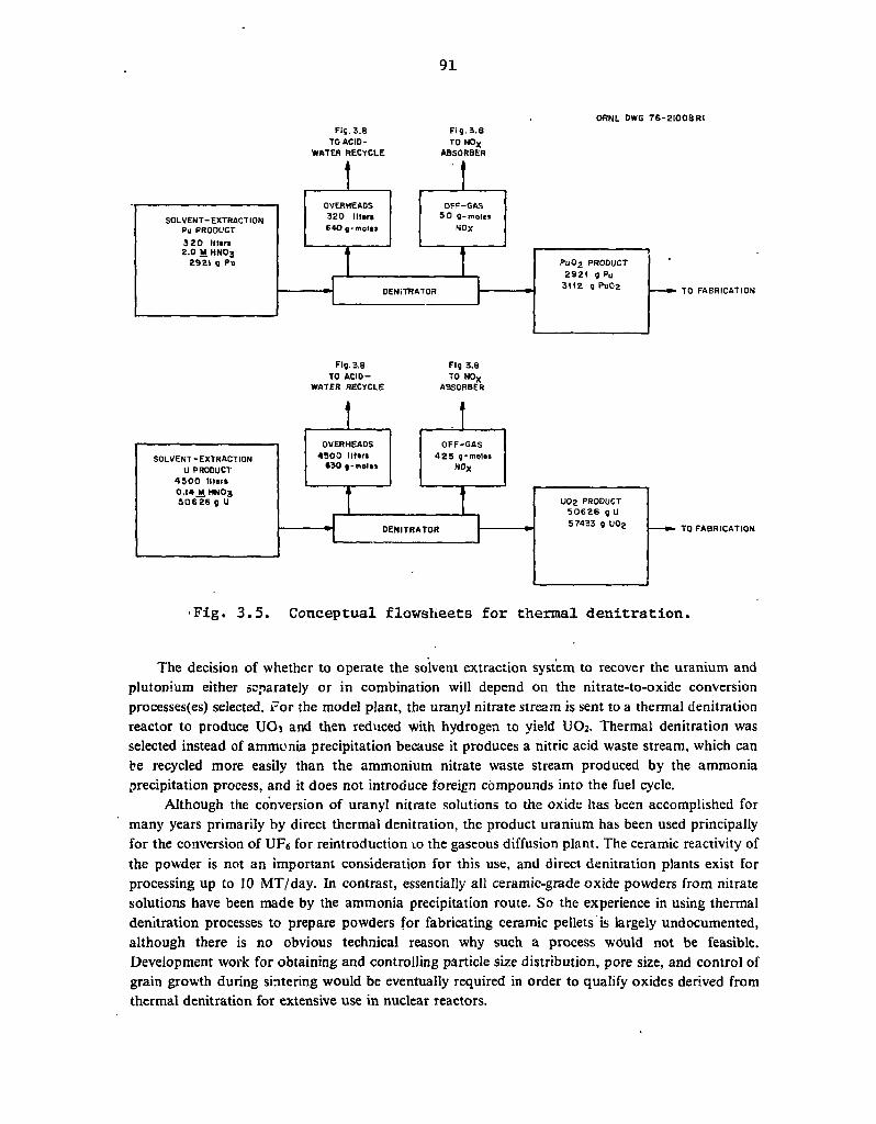
91
ORNL DWG 7 6 - 2 I 0 0 B R I F ig .3 .8 F i g . 3 . 8
TO ACID- TO NOx
WATER RECYCLE ABSORBER
Fig. 3.8 Fig 3.8 TO ACID- TO NO*
WATER RECYCLE ABSORBER
Fig. 3.5. Conceptual flowsheets for thermal denitration.
The decision of whether to operate the solvent extraction system to recover the uranium and plutonium either separately or in combination will depend on the nitrate-to-oxide conversion processes(es) selected. For the model plant, the uranyl nitrate stream is sent to a thermal denitration reactor to produce UOj and then reduced with hydrogen to yield UO2. Thermal denitration was selected instead of ammonia precipitation because it produces a nitric acid waste stream, which can be recycled more easily than the ammonium nitrate waste stream produced by the ammonia precipitation process, and it does not introduce foreign compounds into the fuel cycle.
Although the conversion of uranyl nitrate solutions to the oxide has been accomplished for many years primarily by direct thermal denitration, the product uranium has been used principally for the conversion of UF6 for reintroduction 10 the gaseous diffusion plant. The ceramic reactivity of the powder is not an important consideration for this use, and direct denitration plants exist for processing up to 10 MT/day. In contrast, essentially all ceramic-grade oxide powders from nitrate solutions have been made by the ammonia precipitation route. So the experience in using thermal denitration processes to prepare powders for fabricating ceramic pellets is largely undocumented, although there is no obvious technical reason why such a process would not be feasible. Development work for obtaining and controlling particle size distribution, pore size, and control of grain growth during sintering would be eventually required in order to qualify oxides derived from thermal denitration for extensive use in nuclear reactors.

92
The nitrate-to-oxide conversion systems considered for plutonium are oxalate precipitation-calcination and thermal denitration. The major advantages of direct thermal denitration over the oxalate precipitation route are simplification of the process with a reduction in equipment and elimination of precipitation filtrates and associated filtrate processing. Filtrate processing includes nitric acid or hydrogen peroxide destruction of the excess oxalic acid and recycling this aqueous waste to solvent extraction. The oxalate precipitation process, which is commercially available, was used to prepare the PuOj in the Fast Flux Test Facility (FFTF) fuel.
Thermal denitration has been tested in the laboratory.8 The resulting oxide was subsequently fluorinated and eventually converted to pure plutonium metal. The distinguishing characteristics of the directly calcined oxide, as compared with oxalate-prepared oxides, are the lower density and the larger particle size.7 These characteristics make the oxide orepared by direct calcination relatively unreactive as compared with that produced via calcined oxalate; however, it can probably be milled to produce an acceptably reactive product. Although the preferred conversion approach is direct thermal denitration, the alternative process (prccipitation-calcination) may be required to meet product specifications.
If recovery of the uranium and plutonium from solvent extraction as one stream (no partitioning column) were desired, the options for the nitrate-to-oxide conversion wou'd probably bJ thermal codenitration and coprecipitation-calcination. In the coprecipitation-calcination process, an intimate mixture of plutonium hydroxide and ammonium diuranate is precipitated by the addition of ammonia. The precipitate is filtered, dried, and then calcined to a powder. A portion of the fuel in the FFTF was produced by this process. However, it has two principal disadvantages of (1) requiring treatment of an aqueous, plutonium-contaminated ammonium nitrate waste and (2) inherent difficulties associated with the remote neutralization of acid streams.
Some development work on the codenitration of uranium-plutonium nitrate solution has been performed at Argonne National Laboratory (ANL).8"10 Advantages of the process include the ability to produce a homogeneous MOX powder, an easily managed nitric acid waste stream, and the elimination of foreign chemicals from the system. The feasibility of fluidized-bed denitration and reduction of PUO2-UO3 to PUO2-UO2 was demonstrated in limited testing performed at ANL. Although the calcined powder may need to be modified to ensure optimum pellet pressing and final sintered pellet properties, there are apparently no serious technical obstacles to using this method for PUO2-UO2 powder preparation. Moreover, some variation of this process could probably be developed for the codenitration of the neptunium, americium, and curium with the uranium and plutonium as well. This option could be important with respect to minimizing the waste management problems and also the safeguards risks when used in conjunction with nonproliferation processes.
3.3 Management of Combustible Wastes
The recovery of actinide elements from contaminated combustible materials would be performed routinely in the model piant. The feed to the incinerator includes general paper trash, ion exchange resins, waste solvents, and activated charcoal (Fig. 3.6). The composition, elemental analysis, and amounts of trash fed to the incinerator are shown in Table 3.2. The volumes and weights of the waste shown in this table are 10% greater than the values in ERDA-76-43 in order to allow for miscellaneous recycle streams (i.e., ion exchange resin, TBP, and detergents). These

O R N L DWG. 7 6 - 2 I O I I R I
GENERAL TRASH —
ION EXCHANGE RESINS -
WASTE SOLVENTS
ACTIVATED CHARCOAL •
MISCELLANEOUS
TO LIQUID WASTE
IMMOBILIZATION
Fiq 3 . 7
COMBUSTIBLE FEED
WASTE N o C O ,
4 . 5 m 5 W A S T E 5 4 0 kg W A S T E
2 . 4 kq MOX / 2 . 2 B kg U \ Vo. 12 kg P u /
I g Am
3 . 5 k g - m o l « l ( 3 7 0 k q )
AIR
ISO tcfm
TO HEPA F I L T E R S
I
NONCONDENSABLE O F F - G A S I MT C 0 2
INCINERATOR
CARBONATE S A L T 8 0 0 L i U r «
I 7S k q - m o l M N a 2c 0 3
I 7 5 k q - m a l * i No CI I q Am
6 0 g U 3 g Pu
CARBONATE S A L T AND A S H
C A T A L Y T I C AFTERBURNER
H 2 0 W A S H
BOO L i t e r i
CONDENSER
C O N D E N S A T E
4 0 0 L i t g r i
ASH 5.4 k q A S H
2 . 4 kg MOX / 2 . 2 6 kg 0 \ \ 0 .12 kg P u /
TO
A C I D - W A T E R R E C Y C L E
F iq . 3 . 8
TO
SOLIDS L E A C H Fiq 3.10
Fig. 3.6. Conceptual flowsheet for combustible waste management.

Table 3.2. Composition of combustible wastes from a MOX fuel fabrication plant3 >11•12»13'1 *
Basis: 4.5 m3 waste/MTHM; 541 kg waste/MTHM; 2.4 kg MOX/MTHM
Constituent
Weight Elemental analysis
Constituent kg % of total Element
Weight (kg)
Weight percent kg-moles
Cellulosics (CeHioOs)x 162.2 30.0 C 295.6 54.6 24.6
Natural ruboer (CsHs)x 47.0 8.7 H 41.0 7.6 41.0
Neoprene (Ct,HsC£) X
47.0 8.7 0 80.1 14.8 5.0
Polyethylene (C2H4) X
95.6 . 17.6 CI 124.6 23.0 3.5
PVC (C2H3CJ&) X
186.3 34.4 P 0.3 0.1 0.01
Styrene (CsHa)x 3.2 0.6 S 0.5 0.1 0.02
Miscellaneous3 0.8 0.1
Miscellaneous includes TBP, detergent, and IX resin.

95
miscellaneous waste streams are the sources of phosphorus and sulfur in Table 3.2. The incinerator selected for the model plant is a fluidized sodium carbonate bed.14'15 The maji_r advantages of this incinerator over conventional incinerators are: (1) the relatively low combustion temperature (about 650°C as compared with over I0G0°C), which eliminates the need for refractories; and (2) in situ neutralization of chloride and sulfate ions which minimizes corrosion of the off-gas system and eliminates the disposal problem of contaminated alkaline scrubbing strea' is. The disadvantages include problems relative to separating the ash from the salt, achieving effective decontamination (DF >100) of the actinides from the ash using nitric acid leach solutions, and the potential formation of explosives from the nitration of carbonaceous species in the ash.
No experimental work on leaching this contaminated ash has been performed to date. In Fig. 3.6, the ash is separated from the salt by a water wash, and most of the uranium and plutonium fed to the incinerator should remain with the ash. The ash is then sent to solids decontamination for recovery of these actinides. All the americium fed to the incinerator, 1 g, is assumed to form a water soluble carbonate when the ash is separated from the salt. The amount of sodium carbonate required to neutralize the chlorine from the combustible wastes with 100% excess is 370 kg. The carbonate liquor is sent to liquid waste immobilization (Fig. 3.7).
3.4 Management of Salt Waste and Immobilization of Liquid Wastes
Salt waste management refers to the handling of the solvent extraction and solvent cleanup raffinate streams, as well as the carbonate salt waste from the incinerator. For this conceptual design the raffinates are concentrated and neutralized with sodium hydroxide (Fig. 3.7). The neutral waste
ORNL-DWG 7 7 - 2 4 7 R 2
Fig. 3.7. Conceptual flowsheets for salt waste management and liquid waste immobilization.

96
is then combined with the incinerator's carbonate salt waste and decontaminated incinerator ash, and subsequently mixed with cement.
The amount of cement required for this liquid waste was estimated from established practices.1
However, the feasibility of obtaining a low-leachable concrete which contains water-soluble salts needs to be investigated experimentally. It is estimated that approximately 1900 liters (9 55-gal drums) will be produced per MTHM fed to the plant. This immobilized waste is estimated to contain about 340 g of uranium, 19 g of plutonium, and 24 g of americium.
A conceptual flowsheet for salt waste management in which the americium would be recovered in addition to the urani lm and plutonium would include the following operations: acid digestion, feed preparation, ion exchange, and CEC. The acid digestion with nitric acid would be necessary to convert the actinides into their ionic forms and to destroy the sodium carbonate from the incinerator liquor. Prior to contact with cation exchange resin, the digested solution would undergo a feed adjustment step via the addition of water to obtain a feed composition of less than 1 M sodium ion and 0.5 M free acid. Separation and recovery of the actinides and cerium from the nonactinides wruld be obtained by a series of operations such as loading the column with feed, feed wash, acid strip, and strip wash. The actinide-cerium cut would then be sent to a CEC system similar to the one proposed in the fuel reprocessing plant (Sect. 2.3.1). The significantly lower radiation of this waste from the fabrication plant as compared with that of the reprocessing f jr .s should facilitate the separation. It is estimated that the decontaminated salt streams would probably contain less than 10% of the actinides not recovered in the immobilized liquid waste,
3.5 Management of Acid-Water
Acid-water management refers to the handling of all NOx off-gas streams and pi jcess condensates to produce aqueous nitric acid and demineralized water for reuse (Fig. 3.8). Major unit operations in the acid-water recovery system include an NO* absorber, an acid fractionator, and an ion exchange column.
A detailed acid-water balance for the plant is presented in Table 3.3. Based on 1-MTHM capacity, the plant will require approximately 18,000 g-moles of nitric acid and 5800 liters of demineralized water each day. The total volume of acid and water streams that is sent to the acid-water recovery system is approximately 12,000 liters. This volume does not include the nearly 2500 liters of demineralized water required for operating the NO* absorber column in the acid-water recovery system.
The condensate (weakly-acidic), and the recovered nitric acid streams from the NOx absorber are sent to an acid fractionator. The bottoms from this fractionator are sent to the dirty-scrap di-ssoiver. The overheads are sent to another fractionator in order to obtain a clean, very-low acid stream and a process nitric acid stream for use in operations such as solids decontamination and solvent extraction acid scrub.
A net addition of water and acid is required to operate the plant. This condition follows from the tact that some acid is rejected to the concrete (Fig. 3.7) as a sodium salt, while some is lost to the off-gas train. The makeup acid requirements appear to be nearly 5000 g-moles/MTHM. The makeup water requirements amount to about 680 liters/ MTHM. Moreover, it appears from the assumptions made here that an advantage exists when fuel reprocessing and refabrication facilities are co-sited, since the refabrication plant can utilize some ,of the excess water produced by reprocessing (see Sect. 2.7). Use of this strategy allows the overall retention factor for tritium to be

ORNL DWG 7 6 " 21016 R2
DSR O F F - G A S
11211 g - m o l e s N 0 X
l 3 , 9 0 0 g - m o l B » H20 8 4 0 0 g-moles C02
DENITRATION O F F - G A S
4 7 5 g -mo les N O *
SALT WASTE C O N D E N S A T E
2 4 9 1 l i t e r s 2491 moles
MISCELLANEOUS WASTES
1590 l i ters
INCINERATOR CONDENSATE
DSR CONDENSATE
992 l i tsrs
DEMINERALIZCP WATER
2 4 7 5 l iters
DENITRATION CONDENSATE
4 8 2 0 l iters 0 . 2 6 M H N O j
t 2 7 0 moles
DSR CONDENSATE
1 2 9 2 l i t e r s 1 2 9 2 moles
UNRECOVERED
N O . ABSORBER
3 5 1 1 g-moles N 0 X
CATALYTIC REDUCTION
HEPA FILTERS
VERY LOW ACID
RECOVERED N O .
2 7 2 5 liters
3 M H N O j
8 1 7 5 moles
5 7 8 8 l i t e r s
FRESH RESIN
ION EXCHANGE
WASTE RESIN * T 0 INCINERATOR
F i g . 3.6.
VO
7 7 7 2 l i ters 4 6 0 4 moles
BOT ('QMS 11.5 M HNO] 750 liters
TO DSR
F i j . 3.3
TO PROCESS 5 7 8 8 liters
PROCESS REQUIRES
8 4 5 2 l i t e f i 9 5 7 2 moles
MAKEUP ACID
7.3 M HNO3 4 9 6 8 m o l e s 6 8 0 l i t e r s
Fig. 3.8, Conceptual flowsheet for acid-water recovery.

98
Table 3.3. Acid-water balance of a MOX fabrication plant
Process Volume (liters)
Requirements HN03
g-moles
H 20 Volume (liters)
Dirty-scrap recovery Primary dissolvet-Secondary dissolver Scrobber Sugar
Solvent extraction Scrub Plutonium strip Uranium strip
Solvent cleanup Carbonate scrub Acidic scrub
Incinerator Wash
Salt waste management
Solids decontamination
Miscellaneous waste
NO absorber x Total
750 210
320 320 4,500
642
8,625 11.5 84T 4.0
640 640 45
642
9,202 18,197
Recycle to AWR
2.0 2 . 0 0 . 0 1
1.0
Noncombustibles 1,000 500 0.5 800 400 0.5
HEPA filters 400 4,600 11.5 200 800 4.0
Incinerator ash 30 345 11.5 30 120 4.0
150 700
30
800 43
1,590
2,475
5,788
Dirty scrap recovery Evaporator Evaporator Denitration
Thermal denitration Plutonium
Uranium
Incinerator Condensate
Salt waste Evaporator
Miscellaneous wastes
Total
1,292
250
320
4,500
2,491
8,853
I,292
II,211
640 50 630 425
2,491
16,739
2.0
0.14
992
400
1,590
2,982

99
increased, since the excess water would be immobilized in the refabriation concrete waste rather than being discharged as water vapor from the reprocessing plant.
Laboratory sink drains,3 floor scrub liquor.3 and personnel decontamination solutions16 are handled in the miscellaneous waste treatment system (Fig. 3.9). Following filtration, this waste stream is passed through a bed of activated charcoal before it is routed to the acid and water recovery system. Adsorption using activated charcoal has not been demonstrated for this application and requires experimental verification. Activated charcoal is preferred over ion exchangers because the adsorption system can retain the phosphates and sulfates and prevent their introduction into the process. Ultrafiltration should also be examined as an alternative. Spent ultrafilters would be disposed of as combustible waste. Of course, the personnel decontamination solutions could not utilize tritiated water; thus this factor would reduce slightly the volume of water that could be received from the reprocessing facility if it were co-sited with the fabrication plant.
ORNL DWG 7 6 - 2 1 0 0 9 R 2
Fig. 3.9. Conceptual flowsheet for miscellaneous waste treatment.
100
3.6 Decontamination and Management of Solid Wastes
A variety of contaminated solid wastes must be routinely decontaminated at the plant. These wastes are classified as noncombustible solids, HEPA filters, and incinerator ash. The volumes, activities, and quantities of MOX in nonconibustible solids and HEPA filter wastes were obtained from ERDA-76-43,1 and are probably overly optimistic.
Complete dissolution of the actinides into their ionic states must be accomplished in order to facilitate recovery by solvent extraction or ion exchange. Methods of dissolution considered include nitric acid alone, nitric acid-fluoride addition, nitric acid-cerium addition, and salt fusion. Nitric acid alone dissolves uranium oxides and solid-solution MOX but is not a good solvent for fired Pu02. Plutonium from wastes and off-specification scrap has been traditionally recovered using nitric acid-fluoride mixtures (typically 10 M HNO3-O.5 M HF) at the Los Alamos Scientific Laboratory17 and Rocky Flats.18 Unlike the recovery operations in support of the model MOX fabrication plant where all systems will probably be remotely operated, the bulk of actinide recovery has been glove-box, hands-on systems. Frequent equipment replacement due to severe corrosiveness of the fluorides and the plugging of volatile fluoride species undergoing hydrolysis (SiF6 to SiOz) has been experienced.
Salt fusion methods using, for example, sodium peroxide or sodium carbonate, are sometimes effective for recovering refractory or acid-insoluble contaminated residues. Typically, these operations are employed in analytical laboratories rather than in large-scale recovery efforts. The main disadvantages of the fusion techniques are the high temperatures required (>500°C) and the large excess of salt needed for the melt (approximately ten times the weight of the sample). Another disadvantage is that fusions become less effective as the amount and type of impurities, such as silicon, increase. For these reasons, nitric acid-ceric nitrate has been selected as the preferred solvent because cerium is nonvolatile and its corrosiveness can be controlled by valence adjustments.
A conceptual flowsheet for recovering the actinides from contaminated solids is presented in Fig. 3.10. The primary leach solution is nitric acid. As mentioned in the scrap recovery section concerning the degree of solubility of uranium and plutonium in nitric acid, both the history and the form of the material are very important. Decontamination factors for the primary leaching solution are 10 for uranium and 2 for plutonium (i.e., 90% and 50% of the uranium and plutonium dissolved, respectively). The secondary dissolver solution is nitric acid-cerium nitrate. In the case of the HEPA filters and incinerator ash, 99% of the initial uranium and plutonium is dissolved. No experimental work using nitric acid-cerium nitrate solutions to recover actinides from noncombustible HEPA filters or incinerator ash has been performed.
3.7 Gas Treatment
The gaseous radwaste effluents are treated prior to release to the environment. Treatment includes scrubbers, NO, absorption, and HEPA filtration. The NO* off-gases are routed to the NO* absorption tower in the acid-water recovery system (Fig. 3.8). Anticipated source terms to off-gas treatment are presented in Table 3.4. For this conceptual design, we have assumed 70% recovery of the NO* produced. The unrecovered NO* (0.22 MT of NO2 per MTHM fabricated) would be catalytically reduced to nitrogen and water. Carbon dioxide emissions are expected to be less than 1.5 MT per MTHM fabricated. However, none of this CO2 would contain any 14C.

101
OfiNL DWG 7 7 - 2 3 9
0 . 8 0 m3 4 3 3 U
I I 3 Py O.I g Am
SOLIDS TO
0.03 m 3 DSR
23 g U Fig- 3.3
1 g Pc
1 TO
IMMOBILIZATION Fig. 3 .7
Fig. 3.10. Conceptual flowsheet for solid waste decontamination.
Table 3.4. Anticipated sources and compositions of streams sent to off-gas treatment
Source Figure for
reference NO
X
(g-moles) H20
(liters) CO 2
(g-moles)
Dirty-scrap dissolver 3.3 120 - -
Sugar denitration 3.3 11,200 250 8,400 Plutonium denitration 3.5 50 - -
Uranium denitration 3.5 425 - -
Incinerator 3.6 - - 22,730 Unrecovered N0X absorber (to catalytic reactor)
3.8 3,500 - -

102
3.8 Comparison of Target and Fuel Fabrication
Detailed target fabrication flowsheets for the target elements containing neptunium, americium. and curium have net been prepared at this time. It is expected, however, that such flowsheets would be similar to those outlined in ORNL-5012 and in this report. The significant differences between the target fabrication and fuel fabrication plants are the additional operations required for target fabrication: (1) dry blending of the uranium oxide with the transuranic oxide(s) and (2) the recovery, purification, and nitrate-to-oxide conversion of neptunium, americium, and curium (as well as uranium and plutonium) from the dirty-scrap recovery system. The higher radiation levels in the target fabrication plant, as compared with those experienced in the fuel fabrication plant, would increase the solvent and ion exchange degradation rates. The target plant would be remotely operated and remotely maintained, whereas the fuel fabrication plant would be remotely operated with hands-on maintenance. The problem of dry blending actinide oxide powders remotely while ensuring a solid solution product will be very important wilh regard to producing a pellet that would be soluble in nitric acid without the addition of halides.
At this stage of the preliminary assessment, it is expected thai tlit targets and fuel elements would have approximately the same physical characteristics, such as percept of theoretical density, uniform density, and grain size. The optimal or preferred concentration of each actinide in the target pellet will probably depend on the melting point, the pellet's swelling behavior under irradiation, actinide and fission product redistribution, heat transfer requirements, neutronics, compatibility of the pellet and cladding, and mechanical stability of the target under reactor power cycling. Phase diagrams of the actinide mixture will be required to determine the effect of thermal expansion due to crystallographic changes and also the melting point as a function of the oxygen-to-metal ratio.
Irradiation of the transuranics (excluding plutonium) in the form of targets in power reactors has been very limited. One project19 conducted by Battelle Columbus Laboratories demonstrated the feasibility of fabricating and reprocessing targets for 238Pu production in commercial power reactors from 237Np. The target rod compositions tested varied from about 15 to 70 wt % Np02 with the balance being calcia-stabilized zirconia (10 wt % Ca0-90 wt % ZrO). One problem with this pellet mixture was that the dissolution of the irradiated target required either hot, concentrated HF or fuming H2SO4. These reagents are considered to be unacceptable in the actinide-partitioning reprocessing plant due to their severe corrosiveness. Other diluent candidates such as aluminum and zirconium are also unacceptable because of reprocessing difficulties, low melting points, or poor irradiation performance. For these reasons, uranium dioxide appears to be the preferred diluent.
3.9 Summary and Conclusions
In this section, conceptual partitioning flowshee s were developed for a model MOX fabrication plant. The plant receives uranium and plutonium o> ides, mechanically blends the oxides, presses the powder into pellets, sinters and grinds the pellets, and inserts the finished pellets into fuel rods. In addition, it reprocesses and recycles scrap. All radioactive wastes generated by these operations are processed and packaged on-site.
The uranium and plutonium in the dirty scrap are recovered by solvent extraction after dissolution in nitric acid or nitric acid-cerium.
Combustible wastes are oxidized in a fluidized sodium carbonate bed incinerator. The incinerator ashes, plus other noncombustible wastes, are leached successively with nitric acid and nitric acid-cerium.
103
Solvent extraction raffinates are concentrated, neutralised, and combined with the incinerator"--carbonate liquor and decontaminated ash. and subsequently mixed with cement. About 1900 liters of concrete (nine 55-gal drums) per MTHM fabricated containing 340 g of uranium. !9 y of plutonium. and 24 g of americium are produced. Americium is not recovered from the solvent extraction raffinate wastes because of the difficulties involved in separating about 23 g of amcricium from 3600 g of cerium. However, the amount of cerium suggested in the flowsheets was twice the stoichiometric amount required when no regeneration with ozone is used. It is expected that experimental determination will show the minimum amount of cerium required when regeneration is available to be considerably less than this, perhaps by an order of magnitude. Then the americium might be recovered by CEC. This operation would be similar to that proposed in the fuel reprocessing plant (see Sect. 2.3.1).
Table 3.5 summarizes plutonium losses for three cases: (1) no treatment. (2) the reference design presented in this report, and (3) the GESMO model MOX plant2 with some w^ste treatment. All plutonium losses are based on 1 MTHM of MOX fed to plant. Approximately 226 g of plutonium (0.45 wt % of the plutonium feed) is lost in the "no-treatment"-case plunt. The "reference-design" case partitions the no-treatment case wastes. The estimated plutonium losses in the reference design case are about a factor of 7 lower than those in the no-treatment case. The description of the GESMO model plant is not sufficiently detailed to make an adequate comparison with the conceptual design plant.
The following conclusions also appear relevant:
1. Actinide partitioning will greatly complicate fuel refabrication due to the increased recovery requirements and the additional processing steps.
2. MOX refabrication salt wastes must be treated for actinide removal in order to achievc the overall required actinide recoveries.
3. A partitioning MOX plant will be required to perform the trivalent actinide-lanthanidc separation (see Sect. 2.3) if cerium is used to promote PuO; dissolution.
4. The co-siting of reprocessing and refabrication plants is technically advantageous since mam of the waste treatment steps can be combined, further reductions in wa;te effluent volumes ma\ be possible, higher actinide recoveries may be achievable, and greater overall retention factors tor tritium appear likely.
5. Actinide losses to refabrication wastes cannot be ignored if the overall partitioning effort is to be meaningful.
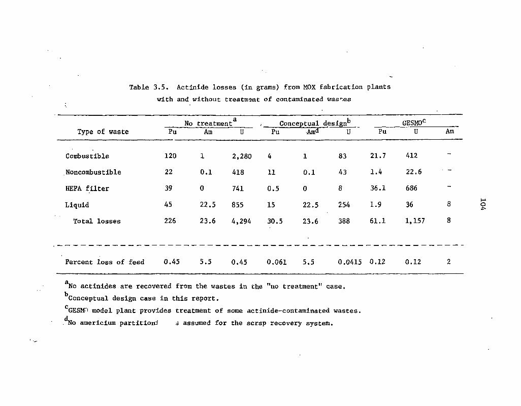
Table 3.5. Actinide losses (in grams) from MOX fabrication plants with and without treatment of contaminated washes
No treatment8 , _ Conceptual design*3 GESMOc Type of waste Pu Am U Pu Amd U Pu U Am
Combustible 120 1 2,280 4 1 83 21.7 412
Noncombustible 22 0.1 418 11 0.1 43 1.4 22.6 • -
HEPA filter 39 0 741 0.5 0 8 36.1 686 -
Liquid 45 22.5 855 15 22.5 254 1.9 36 8
Total losses 226 23.6 4,294 30.5 23.6 388 61.1 1,157 8
Percent loss of feed 0.45 5.5 0.45 0.061 5.5 0.0415 0.12 0.12 2
*No actinides are recovered from the wastes in the "no treatment" case. ^Conceptual design case in this report. c GESMTi model plant provides treatment of some actinide-contaminated wastes. ^No americium partition:)' o assumed for the scrap recovery system.

105
3.10 References for Section 3
1. Alternatives for Managing Wastes from Reactors ami Post-Fission Operations in the LWR Fuel Cycle, ERDA-76^3 (May 1976), Vol. 1, Sect. 2.5.
2. Final Generic Environmental Statement on the Use of Recycle Plutonium in Mixeci Oxide Fuel in Light Water Cooled Reactors, NUREG-002 (August 1976).
3. Westinghouse Electric Corporation, Environmental Report - Recycle Fue's Plant, VJSAEC Docket No. 70-1143, July 1973.
4. W. S. Groenier et al.. Correlation of Radioactive Waste Treatment Costs and the Environmental Impact of Waste Effluents in the Nuclear Fuel Cycle for Use in Establishing "Av Low as Practicable'" Guides - Fabrication of Light-Water Reactor Fuels Containing Plutonium, ORNL-TM-4904 (May 1975).
5. Exxon Nuclear Company, Inc., Nuclear Fuel Recovery and Recycling Center - Preliminary Safety Analysis Report, Docket 50-564, June 1976.
6. R. E. Lerch, Dissolution of Unirradiated Mechanically Blended, Sol Gel, and Coprecipitated Mixed Oxide Fuel, HEDL-TME 72-76, Hanford Engineering Development Laboratory, Richland, Wash. (June 1972).
7. D. E. Horner, D. J. Crouse, and J. C. Mailen. Cerium - Promoted Dissolution of P11O2 and PUO2-UO2 in Nitric Acid, ORNL-TM'4716 (in press).
8. R. E. Felt, Equipment for the Direct Calcination of Plutonium Nitrate, RL-SEP-674 (December 1965).
9. N. Levitz et aU "Continuous Conversion of Uranium Plutonium Nitrates to Oxides." Xucl. Technol. 20. pp. 60-63 (1973).
10. D. S. Webster et al.. Chemical Engineering Division - Fuel Cycle Technology Final Report, March 1973, ANL-7994. Argonnc National Laboratory. Argonnc. 111.. (March 1973).
11. L. K. Arnold, Introduction to Plastics, The Iowa State University Press, Ames. 1968.
12. R. Mulkin, Characterization of Transuranic Solid Wastes from a Plutonium Processing Facility, LA-5993-MS, Los Alamos Scientific Laboratory. Los Alamos, N.M. (June 1975).
13. R. E. Lerch. Acid Digestion of Combustible Wastes: A Status Report, KEDL-TME-75-5, Hanford Engineering Development Laboratory. Richland, Wash.. (May 1975).
14. D. L. Ziegler, A. J. Johnson, and L. J. Meile, Fluid Bed Incineration. RFP-2016, Rocky Flats, Golden, Colo. (June 1973).

106
15. D. L. Ziegler et al.. Pilot Plan, Development of a Fluidized Bed Incinerator Process, RFP-2271, Rocky Flats Plant, Golden, Colo. (October 1974).
16. Exxon Nuclear Company, Inc.. Final Environmental Statement-Mixed Oxide Fabrication Plant. Docket 70-1257, June 1974.
17. E. L. Christensen et al., Plutonium Processing at the Los Alamos Scientific Laboratory, LA-3542, Los Alamos Scientific Laboratory. Los Alamos. N.M. (February 1968).
18. T. C. Johnson, Recovery of Plutonium from Incinerator Ash at Rocky Flats, RFP-2520. Rocky Flats, Golden, Colo. (December 1976).
19. M. Pobereskin et' al., Production of Pu-238 in Commercial Power Reactors: Target Fabrication, Post-Irradiation Examination, ant' Plutonium and Neptunium Recovery, BMI-X-656 (January 1975).

107
4. TRANSMUTATION
A.G. C.off
Transmutation can be defined as "the conversion of one nuclide or element into another either naturally or artificially."1 This definition is quite general since it includes radioactive decay as well as the alchemist's dream of transforming iron into gold. When considering transmutation as it might be applied in practical waste management systems, the following definition is more appropriate: Transmutation is a process in which long-lived nuclides are converted to shorter-lived or less toxic nuclides via bombardment by photons or subatomic particles.
The scope of this section is much more narrow than the discussion above might indicate. The large number of potential photon and subatomic particle sources has resulted in many highly specialized devices being proposed as transmutation devices. To eliminate the space requirements and difficulty that would result from discussing many of the more esoteric processes, only transmutation in fission power reactors will be considered in detail. Long-lived nuclide transmutation in fusion reactors will be briefly discussed in Sect. 4.1. The more esoteric systems such as coulomb exitation, charged-particle transmutation, spallation neutron devices, etc., are discussed in ref. 2.
The type of reaction that would occur during radioactive waste transmutation depends on the characteristics of the undesirable nuclide and its potential neutron reaction products. For isotopes of elements lighter than radium (Z = 88), transmutation would usually consist of converting a long-lived nuclide (e.g., 1Z9I, half-iife = 16 million years) to a near neighbor which is either stable or has a relatively short half-life (e.g., 13Ci, half-life = 12.4 hr). Since long-lived nuclides lighter than radium are relatively scarce, a single transmutation event would usually suffice to eliminate the long-lived nuclide within a relatively short time span. Conversion of isotopes of elements heavier than and including radium to a near-neighbor isotope would generally be pointless since nearly all of these heavy nuclides have one or more long-lived members in their decay chains. Effective transmutation of the heavy nuclides would require that these nuclides be fissioned, generating an entire spectrum of fission products that would typically be much jhorter-iived than the heavy nuclides from which they were produced. Thus, long-lived nuclide transmutation, as referred to in this report, means inducing fissions in the actinides and other, nonfission reactions [e.g., (n, 7). (n,2n)] in the lighter nuclides.
Finally, before discussing the specifics of neutron-induced, long-lived nuclide transmutation, it is important to note that processes for adequately separating the long-lived nuclides that would be transmuted from the waste streams in which they occur (i.e., partitioning processes) are required as a prerequisite to the implementation of transmutation. If partitioning processes are not used to separate the long-lived nuclides from the bulk of the other nuclides in the waste stream before transmutation, then the entire waste stream must be inserted into the transmutation device. With this procedure, the volume of waste being recycled through the transmutation devices would become unwieldy.
4.1 Review of Transmutation Literature
The first documented suggestion that transmutation of radioactive waste constituents might be a useful waste management option was made by Steinberg3 in 1964. Except for another study by

108
Steinberg in 1967 concerning the possible transmutation of fission products with BeV proton-induced spallation neutrons,4 the study of waste transmutation languished until 1972, when a report5 by Claiborne initiated an avalanche of transmutation studies by many different organizations. Table 4.1 gives a list of the principal investgators(s), the investigator's affiliation(s), a brief description of the transmutation studies conducted, and a description of any generally available documentation for the transmutation studies conducted to date. This list has been restricted to those studies principally concerned with transmutation in fission and fusion reactor systems.
The list of transmutation studies presented in Table 4.1 may not be complete, particularly with respect to the non-U.S. contributions. Within the United States, this deficiency is probably a reflection of the large number of organizations conducting transmutation studies without any organized, system for communication and exchange of information. The non-U.S. organizations conducting such studies are typically allied with the national governments. Much of the work done by these organizations has not yet been published, and the published material generally circulate? slowly. The transmutation studies currently being conducted in Japan, Canada, France, Sweden, Italy, Germany, the United Kingdom, and the Netherlands are, for the most part, modest. The largest of the non-U.S. transmutation studies is being conducted at the EURATOM Joint Research center in Ispra, Italy.
Evaluation of the transmutation literature cited in Table 4.1 leads to the conclusion that the transmutation studies conducted thus far have not been coordinated, resulting in considerable duplication in some areas, omissions in others, and an incomplete assessment of partitioning-transmutation (P-T) as a waste management concept. There are exceptions to this, most notably the ERDA-sponsored fast reactor actinide transmutation studies,36"42 the EPRI-sponsored fusion reactor transmutation studies,12"16 and the program at the Joint Research Center in Ispra, Italy,49,50'56"5!' which represent coordinated efforts to investigate the feasibility and effects of P-T. Despite these efforts, the fact that nearly all previous transmutation studies have concentrated on selected in-reactor impacts (transmutation rates, breeding ratio penalties, etc.) mean*; that more information is still required if a defensible evaluation of the incentives for partitioning-transmutation is to be completed.
4.2 General Considerations
4.2.1 Transmutation devices • The large number of proposed transmutation devices (cf. ref. 2) made it necessary to limit the
scope of the literature review to fission and fusion reactors. In considering realistic transmutation scenarios, the number of transmutation devices must be reduced even further to make analysis of the number, of transmutation system tractable. Accordingly, the devices that are discussed in this section are restricted to commercial and projected commercial PWRs and LMFBRs. The fusion reactor was eliminated because of the long-range nature of a fusion reactor economy and the current uncertainty regarding fusion reactor design. Special fission reactor transmutation devices (e.g., a high-flux fast reactor with a thermalized. central region, ref. 21) are not considered because (l)'a detailed reactor design would be required before analysis of the device and its attendant fuel cycle could begin, and (2) the research, development, and demonstration costs of a waste management reactor would be yery large.

109
Table 4.1. Summary of fission and fusion reactor transmutation studies
Investigator(s) (Organization) Description References
W. C. Wolkenhauer (PNL)
CTR Transmutation Systems
Physics of transmuting 90Sr and ,37Cs in a CTR
W. C. Wolkenhauer, B. R. Leonard, B. F. Gore (PNL)
Evaluated potential of a CTR for transmuting fission products and actinides
B. F. Gore, B. R. Leonard (PNL)
Physics of transmuting massive amounts of 3 7Cs in a CTR blanket
8, 9
J. Henely, H. W. Meldner (LLL)
Actinide transmutation in laser-induced fusion reactors
10, 11
J. W. H. Chi, R. R. Holman, R. P. Rose, J. E. Olhaeft, S. Kellman (Westinghouse Fusion Power Systems)
Gary Lang (McDonnell-Douglas); E. L. Draper, T. A. Parish (Univ. of Texas, Austin)
U. Jenquin, B. R. Leonard (PNL)
Ehgineering and physics design of a CTR for actinide transmutation
12-14
Engineering and physics design of a CTR for long-lived fission product transmutation
Physics of transmuting actinides in a CTR blanket
15
16
Thermal Fission Reactor Transmutation Systems
M. Steinberg (BNL)
Physics and economics of transmuting isKr, 90Sr, and 1 3 7' 'Cs
H. C. Claiborne (ORNL)
Discussion of fission product transmutation; investigation of in-reactor and out-of-reactor effects of actinide recycle in a PWR
A. S. Kubo Scoping evaluation of actinide recycle in LVIRs
17
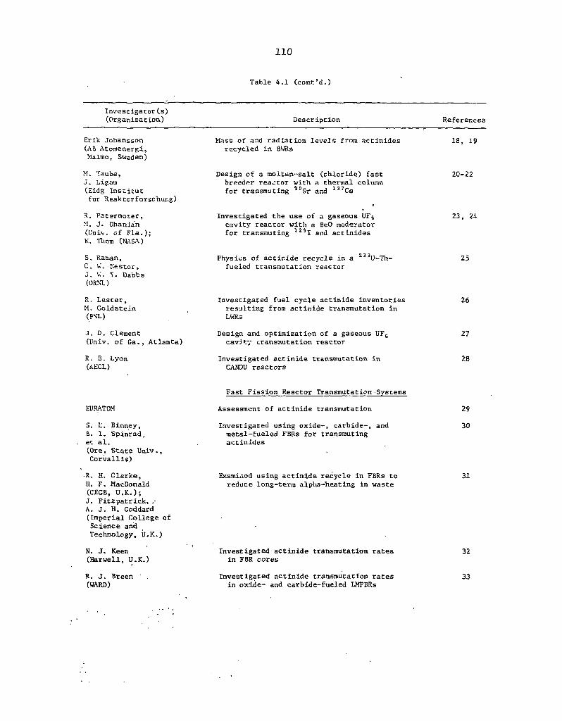
110
Table 4.1 (cont'd.)
Investigator(s) (Organization) Description References
Erik Johansson (AB Atomenergi, Malmo, Sweden)
M. Taube, J . Ligou (Eidg Institut fur Ueaktorforschur.g)
R. Paternoter, >1. J. Ohanian (Univ. of Fla.); K. Thorn (NASA)
Mass of and radiation levels from actinides recycled in 8WRs
Design of a molten^salt (chloride) fast breeder realtor with a thermal column for transmuting 9DSr and l 3 7Cs
Investigated the use of a gaseous UF6 cavity reactor with a BeO moderator for transmuting l 2 SI and actinides
18, 19
2 0 - 2 2
23, 24
S. Raman, C. W. Nestor, J. W. T. Dabbs (ORNL)
R. Lester, M. Goldstein (FNL)
Physics of actir.ide recycle in a U-Th-fueled transmutation reactor
Investigated fuel cycle actinide inventories resulting from actinide transmutation in LWRs
25
26
J. D. Clement (Univ. of Ga., Atlanta)
R. B. Lyon (AECL)
Design and optimization of a gaseous UF6 cavity transmutation reactor
Investigated actinide transmutation in CANDU reactors
27
28
EURATOM
S. L. Binney, B. 1. Spinrad, et al. (Ore. State Univ., Corvallis)
•R. H. Clarke, H. F. MacDonald (CEGB, U.K.); J. Fitzpatrick, A. J. H. Goddard (Imperial College of Science and Technology, U.K.)
N. J. Keen (Harwell, U.K.)
R. J. Breen (WARD)
Fast Fission Reactor Transmutation Systems
Assessment of actinide transmutation
Investigated using oxide-, carbide-, and metal-fueled FSRs for transmuting actinides
Examined using actinide recycle in FBRs to reduce long-term alpha-heating in waste
Investigated actinide transmutation rates in FBR cores
Investigated actinide transmutation rates in oxide- and carbide-fueled LMFBRs
29
30
31
32
33

I l l
TaDle 4.1 (cont'd.)
Investigator(s) (Organization) Description References
S. L. Bearnan (GE)
Investigated physics of transmuting actinides from 3 BWRs and 1 LMFBR in an LMFBR
34-i.
A. Friedman (ANL)
Irradiation and analysis of plutonium samples in EBR-II for actinides through 2lt6Cm
41
J. Prabulos (Combustion Eigineering)
J. Bouchard (CEA)
Investigated actinide transmutation in a carbide-fueled LMFBR
Actinide transmutation in an LMFBR
42
43
W. Bccoia, L. Fritelli, F. Gerd, G. nrossi, A. Mouit., L. Tondinelli (CNEN-CSN)
Investigated actinide transmutation in an FBR and the sensitivity of actinide buildup in LWRs
44
Thermal and Fast Reactor Transmutation Systems
A. S. Kubo (U.S. Army); D. J. Rose (MIT)
A. G. Croff (ORNL)
T. H. Pigford, J. Choi (Univ. Cal.-Berkeley)
E, Schmidt, J. Cametti (JRC-Ispra)
W. Hage, E. Schmidt (JRC-Ispra)
G. Harte (CEGB-Berkeley)
L. Koch, R. Ernstberger, K1. Kammerichs (JRC-Karlsruhe)
Assessment of the incremental cost of actinide transmutation in LWRs and LMFBRs
Parametric study of in-reactor and out-of-reactor effects of actinide recycle for LWRs, HTGRs, and LMFBRs
Examined overall actinide mass reduction from transmutation in PWR and LMFBR
Investigated actinide transmutation in a LMFBR, including lanthanide-contaminated actinide recycle
Detailed review of the in-reactor effects of actinide transmutation; most advanced study to date
Initial studies of long actinide Irradiation durations (20 to 40 years)
Studied actinide formation rates in thermal reactors, actinide transmutation in thermal and fast reactors, and some fuel cycle impacts
45
46, 47
48
49
50
51
52
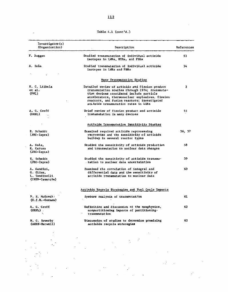
112
Table 4.1 (cont'd.)
Investigator(s) (Organization) Description References
F. Duggan
A. Sola
Studied transmutation of individual actinide isotopes in LWRs, HTRs, and FBRs
Studied transmutation of individual actinide Isotopes in LWRs and FBRs
53
54
R. C. Liikala et al. (PNL)
A. G. Croff (ORNL)
Many Transmutation Studies
Detailed review of actinidc and fission product transmutation studies through 1974; transmuta-tion devices considered include particle accelerators, thermonuclear explosives, fission reactors, and fusion reactors; investigated acilnide transmutation rates in LWRs
Brief review of fission product and actinide transmutation in many devices
55
Actinide Transmutation Sensitivity Studies
E. Schmidt (JRC-Ispra)
A. Sola, K. Caruso (JRC-Ispta)
E. Schmidt (JRC-Ispra)
A. Gandini, 6. Oliva, L. Tondinelli (CNEN-Casaccia)
Examined required actinide reprocessing recoveries and the sensitivity of actinide buildup in several reactor types
Studied the sensitivity of actinide production and transmutation to nuclear data changes
Studied the sensitivity of actinide transmu-• tation to nuclear data uncertainties
Examined the correlation of integral and differential data and the sensitivity of actinide transmutation to nuclear data
56, 57
58
59
60
P. E. McGrath (G.f.K.-German)
A. G. Croff (ORNL)
M. G. Sowerby (AERE-Harwell)
Actinide Recycle Strategies and Fuel Cycle Impacts
Systems analysis of transmutation
Definition and discussion of the nonphysics, nonpartitioning Impacts of partitioning-transmutation
Discussion of studies to determine promising actinide recycle strategies
61
62
63

113
4.2.2 Transmutation candidates The next important task is to establish a list of nuclides which might be candidates for
transmutation. Such nuclides would include those for which the transmutation rate would be many times the natural decay rate and those which would contribute significantly to the waste toxicity. Tables 4.2 and 4.3 compare the time required to eliminate 99.9% of a particular nuclide by both transmutation and decay with that required to eliminate 99.9% of the same nuclide by decay only for eight of the most commonly considered nonactinide transmutation candidates: 3H , l4C, 85Kr, 93Zr, 90Sr, 137Cs, "Tc, and 129I. Typical flux levels for the reactor systems considered are 3 x 10¹³ neutrons cm"2 sec"1 for the PWR and 5 x 10¹⁵ neutrons cm-2 sec"1 for the LMFBR. Evaluation of ihis table leads to several important conclusions. First, ,0Sr and 137Cs, the predominant contributors to high-level waste toxicity for the first 1000 years, would be essentially "untransmutable" in commercial fission power reactors. Thus, even if feasible, transmutation of nuclides in the high-level waste with half-lives comparable to or less than ^Sr and 137Cs (ca. 30 years) would not significantly reduce the overall toxicity of the high-level waste (HLW). This means that both 3H and 85Kr can be eliminated as transmutation candidates because of their relatively short half-lives and small neutron cross sections. Carbon-14 would also be essentially untransmutable because of its extremely small neutron cross section. As a result of these considerations, it is concluded that the toxicity of high-level waste for the first 1000 years would not be amenable to reduction by P-T. Therefore, the list of candidate nuclides will be restricted to nuclides that would contribute significantly to the long-term (> 1000 years) toxicity of the waste.
The most significant contributors to the long-term toxicity of the waste will be the actinides, 1J>1, and "Tc. The next most toxic nuclide, 93Zr, cannot reasonably be considered a candidate for tran-mutation for two reasons. First, this isotope will comprise only 20% of the fission product zirconium and less than 20 ppm of the LWR Zircaloy cladding. The mass of fresh fission product zirconium produced by PWR fuel is about 3300 g/MTHM at a burnup of 33.000 MWd MTHM. 80% of which would be essentially untransmutable because of very small cross suctions. This would result in an intolerable mass buildup during recycle. The second reason for the undesirabiJity of9 3Zr transmutation is its contribution to the total, long-term waste toxicity would be so small that the other, more toxic nuclides could not be removed (partitioned) from the waste to such a degree that 93Zr would become significant. Thus, even though 93Zr possesses characteristics favorable for transmutation, the combination of isotopic dilution and low toxicity would eliminate it as well as other, less toxic nuclides from consideration.
The result of the preceding discussion is that, after elimination of the short-lived, intermediate-lived, and less-toxic, long-lived nuclides, the candidates for transmutation would be the actinides, 1291, and 99Tc. It should be noted that the transmutation of 99Tc would probably not be effective in reducing HLW toxicity unless higher actinide decontamination factors" (DFs) than those currently anticipated could be achieved. These DFs are discussed in more detail in Sect. 4.2.3. Sections 4.3 and 4.4 consider important aspects of the nonactinides and actinides, respectively.
4.2.3 Long-lived nuclide decontamination requirements The degree to which the long-lived nuclide content of high-level waste must be reduced to meet
some arbitrary criterion has been examined by Claiborne64 and by Schmidt.56 The same measure of
"Decontamination factor is defined as the mass of the element entering a process divided by the mass of the element found in the process effluent.
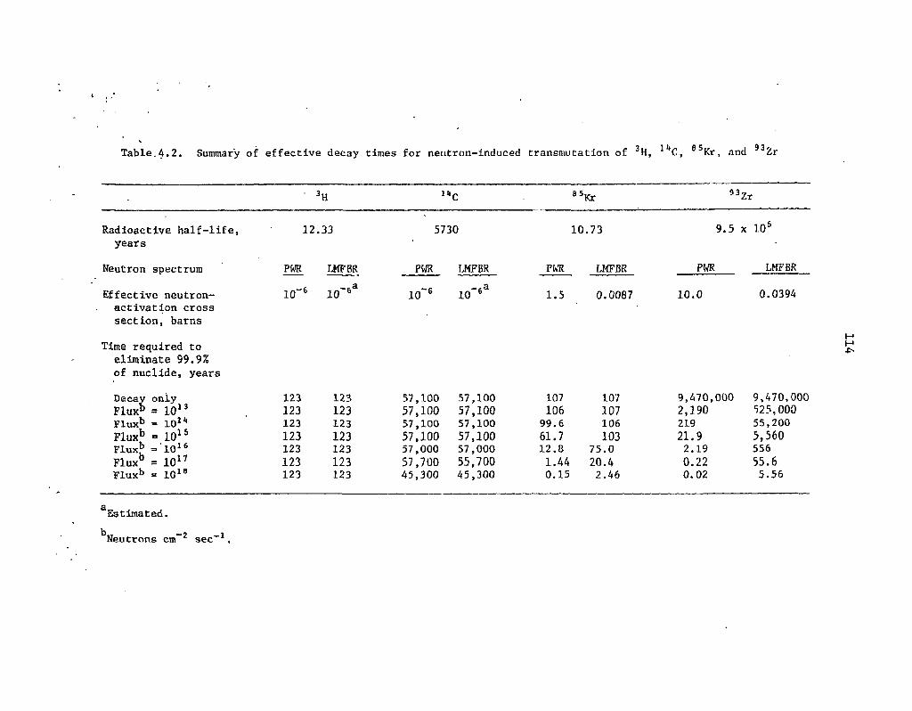
« Jff 65 93^ Table,4.2. Summary of effective decay times for neutron-induced transmutation of H, J*C, Kr, and " Z r
3H i it C 8 5Kr 93 Zr
Radioactive half-life, 12 .33 5730 10.73 9.5 x 10s
years
Neutron spectrum PWR LMFBR PWR LMFBR PWR LMFBR PWR LMFBR
Effective neutron- 10~6 10 6 10~6 -.a
10 6 1.5 0.0087 10.0 0.0394 activation cross section, barns
Time required to eliminate 99.9% of nuclide, years
Decay oniy 123 123 57,100 57,100 107 107 9,470,000 9,470,000 Flux" = 10 1 3 123 123 57,100 57,100 106 107 2,190 525,000 Flux b = 101* 123 123 57,100 57,100 99.6 106 219 55,200 Flux b = 10*5 123 123 57,100 57,100 61.7 103 21.9 5,560 Flux b = 1 0 1 6 123 123 57,000 57,000 12.8 75.0 2.19 556 Flux = 10 1 7 123 123 57,700 55,700 1.44 20.4 0.22 55.6 Flux b = 10 1 8 123 123 45,300 45,300 0.15 2.46 0.02 5.56
a Estimated. I « Neutrons cm sec" .
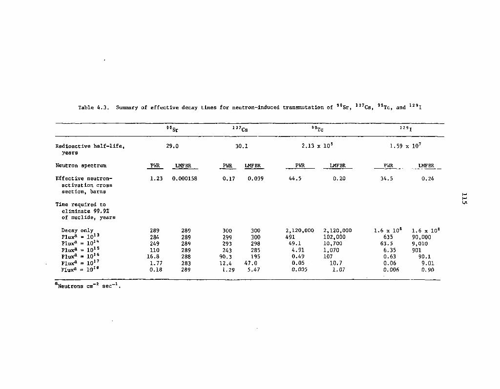
Table 4.3. Summary of effective decay times for neutron-induced transmutation of 9 0Sr, 1 3 7Cs, 99TC, and l 2 9 I
90 Sr 137 CS 99 Tc
Radioactive half-life, years
Neutron spectrum
Effective neutron-activation cross section, barns
Time required to eliminate 99.9% of nuclide, years
Decay only Fluxa = 10 1 3
Flux® = 101" Fluxa = 10 1 S
Fluxa = 10 1 6
Fluxa = 10 1 7
Flux3 = 10 , s
29.0
PWR LMFBR
1.23 0.000158
30.1
PWR LMFBR
0.17 0.039
2.13 x 10⁵
PWR
44.5
LMFBR
0 . 2 0
1.59 x 10'
PWR
34.5
LMFBR
0.24
289 289 300 300 2,120,000 2,120,000 1.6 x 10⁸ 1.6 x 10 284 289 299 300 491 102,000 635 90,000 249 289 293 298 49.1 10,700 63.5 9,010 110 289 243 285 4.91 1,070 6.35 901
16.8 288 90.3 195 0.49 107 0.63 90.1 1.77 283 12.4 47.0 0.05 10.7 0.06 9.01 0.18 289 1.29 5.47 0.005 1.07 0.006 0. 90
Ln
d 2 1 Neutrons cm" sec - .

116
toxicity was used in each of these studies, and it will be called the toxicity index in this report. The toxicity index is the volume of water required to dilute all of the radionuclides in a unit volume of waste to their respective radionuclide concentration guide (RCG) values.55,65 Thus, that index has units of m3 H 2 0/m 3 waste (i.e., it is dimensionless). The toxicity of the waste can then be compared with the toxicity index of naturally occurring radioactive minerals. The toxicity index of pitchblende (70% uranium) is about 10s, while that of high-grade carnotite ore (0.2% uranium) is about 105. Claiborne's high-level waste decontamination criterion is to reduce the toxicity index of the actinides in the solidified, high-level waste to a level comparable with the toxicity index of the long-lived fission products after 99.9% of the iodine has been removed. This results in the toxicity index of the solidified, high-level waste being about 5% of that of pitchblende and about 50 times that of carnotite ore after 1000 years of decay. Schmidt's criterion is to reduce the toxicity index of the high-level waste to a level comparable with that of carnotite ore. These criteria are substantially different, with Schmidt's DFs ranging from 2 to 50 times those of Claiborne and also requiring the recovery of "Tc. A summary of DFs that would be sufficient to meet these criteria for all uranium-plutonium fuel cycle reactor fuels, as determined by Claiborne and Schmidt, is given in Table 4.4 along with DFs that could be attained using current technology. Thorium fuel cycle reactor fuels (e.g., HTGR fuels) would require DFs of 200 for thorium, 20 for protactinium, and 10,000 for uranium based on Claiborne's criterion.
Specification of DFs is important for two reasons:
(1) the DFs represent a set of goals for the development of partitioning processes, and (2) they enable one to examine many of the fuel cycle impacts of P-T while partitioning
processes are still being developed.
It is desirable for the specified DFs to represent as closely as possible the conditions expected to be encountered in actual partitioning processes. This will aid in the development of partitioning processes and the analysis of the fuel cycle impacts of P-T. Based on the partitioning information given in Sect. 2, it appears that the DFs calculated via the Claiborne criterion are much closer to those which be expected from realistic partitioning processes. Therefore, the Claiborne DFs will form the basis of the remainder of this report.
Two observations should be made concerning the Claiborne DFs. First, for a given reduction in the solidified, high-level waste toxicity index there are many combinations of individual element DFs that would produce the desired toxicity index. Thus, if a plutonium DF of 10,000 could not be attained, then the DF of uranium, neptunium, americium, or curium might be increased (within limits) to compensate. The second observation is that the assumed 129I DF of 1000 would not be required to satisfy the criterion of reducing the actinide toxicity index to that of the other long-lived fission products. Claiborne's calculations show that an 12,I DF of about 100 would be sufficient to keep the toxicity index of 1J9I less than that of the actinides.
In summary, a set of partitioning DF goals for high-level waste has been selected to serve as a target for the development of partitioning processes and for calculationally investigating the impact of P-T on the nuclear fuel cycle. However, there are several important aspects of setting DFs which must still be addressed; these are discussed below.
One shortcoming in the specifications of the DFs given in Table 4.4 is that they would apply only to high-level waste. If the same criteria were applied to low- and intermediate-level transuranic contaminated (TRU) wastes, then very little or no partitioning of these wastes would be needed because the actinides and fission products are very dilute in these types of wastes. On the other hand,
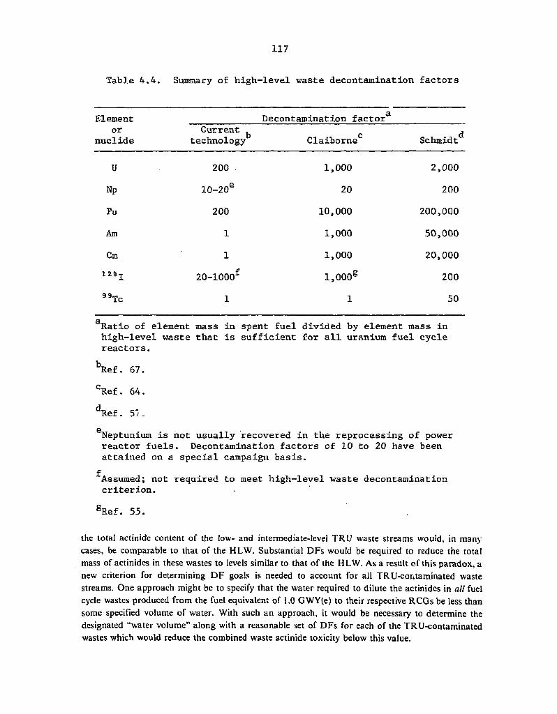
117
Table 4.4. Summary of high-level waste decontamination factors
Element £
Decontamination factor or Current ^
nuclide technology Claiborne0 Schmidt
U 200 . 1,000 2,000
Np 10-20® 20 200
Pu 200 10,000 200,000
Am 1 1,000 50,000
Cm 1 1,000 20,000 1 29 j 20-1000f l,000e 200
"Tc 1 1 50
Ratio of element mass in spent fuel divided by element mass in high-level waste that is sufficient for all uranium fuel cycle reactors.
bRef. 67. cRef. 64. dRef. 57.
Neptunium is not usually recovered in the reprocessing of power reactor fuels. Decontamination factors of 10 to 20 have been attained on a special campaign basis.
^Assumed; not required to meet high-level waste decontamination criterion.
gRef. 55.
the total actinide content of the low- and intermediate-level TRU waste streams would, in many cases, be comparable to that of the HLW. Substantial DFs would be required to reduce the total mass of actinides in these wastes to levels similar to that of the HLW. As a result of this paradox, a new criterion for determining DF goals is needed to account for all TRU-contaminated waste streams. One approach might be to specify that the water required to dilute the actinides in all fuel cycle wastes produced from the fuel equivalent of 1.0 GWY(e) to their respective RCGs be less than some specified volume of water. With such an approach, it would be necessary to determine the designated "water volume" along with a reasonable set of DFs for each of the TRU-contaminated wastes which would reduce the combined waste actinide toxicity below this value.

118
A second required activity relative to the actinide DF goals is to continuously readjust the DFs for individual elements and waste streams to reflect new knowledge in the area jof actinide partitioning processes. For example, if tests or other experience demonstrated that a HLW plutonium DF of 10,000 could not be obtained, then the high-level waste americium IDF or the low-level TRU waste plutonium DF might be increased to compensate. I
Another consideration is the validity of the."dilution to RCG" conccpt as a measure of waste toxicity. This question, which has been discussed at length in the literature, 61-68 is considered in Sect. 515. In summary, the consequences of or the risk from an assumed reprocessing accident can be calculated by more sophisticated (and complex) methodi than "dilution to RCG." These methods tend to give somewhat different results than the "dilution to RCG" method, indicating a different relative actinide risk importance or that the actinides are less important than the residual long-lived fission products or both. Ideally, these methods should be used when calculating the long-lived nuclide decontamination requirements. However, their complexity and site specificity make their use in scoping and feasibility studies prohibitively time-consuming and expensive. Therefore, the "dilution to RCG" method will probably find application in most of the near-term studies, principally because of its calculational simplicity.
4.3 Transmutation of nonactinides
As a result of the elimination process described in Sect. 4.2.2, l29I and 99Tc are the only two nonactinides that would be candidates for transmutation. Unfortunately, information concerning the transmutation and recycle of these nuclides is limited to the steady-state, desk-calculator results given below.
Based on the 129I and 99Tc parameters given in Table 4.3, the period of irradiation that would be required to transmute 99.9% of a given amount of dilute l29l is 211 years in a PWR and 182 years in an FBR. The corresponding periods for dilute ,9Tc are 164 years and 219 years. These times are equivalent to transmutation rates of 3.2%/year in an FBR for 99Tc, assuming continuous irradiation.
A second type of calculation regarding transmutation recycle of 129I and 99Tc is related to the mass buildup of these isotopes at the point where the transmutation plus reprocessing loss rate equals the production rate (i.e., at steady state). One metric tonne of discharged PWR fuel contains about 700 g of 99Tc and 235 g of iodine, of which 185 g are 129I and 50 g are stable 127I. By using the data given in Table 4.3 and a continuous PWR thermal flux level of 3.0 x 10¹³ neutrons cm"2 sec"1, the steady-state mass of 99Tc during transmutation has been calculated to be a factor of 8.3 greater than that in the normal discharged fuel. Thus, during steady-state recycle, there would be 8.3 x 700 = 5810 g of 99Tc per MT of heavy metal, which would be equivalent to about 0.6% of the heavy
- metal mass. The increase factor for iodine would be about 10.6, giving a steady-state recycle mass of 10.6 x 235 = 2510 g of iodine per MT of heavy metal, which would be equivalent to about 0.25% of the heavy-metal mass. The steady-state-to-discharge ratios in an FBR would be 16.0 for 99Tc and 13.5 for iodine. The steady-state recycle 99Tc or iodine concentration in FBR fuels would also be somewhat higher than in PWR fuels because of the higher average fuel burnups in the FBR.
In summary, it appears that transmuting fission product iodine, and also 99Tc if required, would present no. difficulties from a theoretical standpoint. However, several practical transmutation-related problems must be resolved before iodine and 99Tc transmutation could occur. Among these are:
I. the increased xenon production from iodine transmutation,
119
2. the mode of recycling the iodine and "Tc (i.e. homogeneously dispersed in the fuel or as targets, with the attendant degradation of the transmutation rate by self-shielding effects),
3. the chemical form of the recycled iodine and technetium, and
4. the effects of the iodine and "Tc on the fuel behavior in the reactor, particularly in the case where concentrated iodine- or technetium-compound targets are used.
4.4 Steady-State Actinide Transmutation in LMFBRs
The transmutation of actinides for waste management purposes would involve recovery of the noneconomic values (e.g., neptunium, americium, and curium), fabrication of these actinides into fuel elements, and insertion of the fuel elements into a nuclear reactor to fission a fraction of these actinides. The computer modeling of actinide transmutation is much more complicated than the modeling of nonactinide transmutation (see Sect. 4.3) for two reasons: (1) the relationship between actinide recycle for waste management purposes (neptunium, americium, and curium recycle) and actinide recycle for economic purposes (uranium, plutonium recycle) is difficult to define since neptunium, americium, and curium reactions produce uranium and plutonium, and (2) the interaction of the actinides with each other is very complex because of the large number of nuclides present and because the daughter product of some combination of four neutron capa' . cs and two beta decays generally decays by emission of alpha particles to form the parent. For example, neutron captures and beta decays in 2J7Np eventually form 24,Am, which alpha-decays to 237Np. This cffect is called feedback. The former complication will be alleviated by referring to the actinides being transmuted for waste management purposes as "waste actinides" and by carefully defining disposition of the uranium and plutonium during reprocessing. The latter complication means that the actinides arc not amenable to simple thought experiments and desk-calculator computations as nonactinides are. This complication has been overcome by using computer codes which account for the complex interrelationships of the actinides.
As is evident from Table 4.1, a relatively large number of studies of waste actinide transmutation have been conducted. These studies have almost exclusively concentrated on the transmutation scenario wherein the number of reactors being considered is held constant (e.g., the recycle of the waste actinides from three BWRs in an LMFBR 34~40) and the waste actinides are assumed to be recycled until their mass and composition are approximately constant (i.e. at steady-state recycle). This scenario, which is unrealistic in light of the presently increasing amount of nuclear fission power ar.d the inevitable decrease in the amount of nuclear fission power at some future time, is nevertheless useful in many types of parametric studies because of its relative simplicity. The more complex scenario, which has a variable amount of nuclear power as a function of time, is evaluated in Sect. 4.5.
The parameters examined in this section involve principally the "in-reactor" aspects of waste actinide transmutation, including the mass and composition of the waste actinides and the reactivity effects of waste actinide transmutation on the transmutation reactor. Unless otherwise noted, the waste actinide transmutation results described in this report were calculated via modifications of the ORIGEN computer code,69 a zero-dimensional depletion code with a fixed neutron spectrum.
If it is assumed that waste actinides are to be transmuted in LMFBRs, two alternatives exist: waste actinide recycle by homogeneously dispersing the actinides in fresh fuel, or waste actinide recycle in targets. The first alternative would involve recovering the waste actinides from spent

120
reactor fuel and then homogeneously mixing them with the fresh fuel materials before fabrication. The second alternative wculd involve concentrating the recovered waste actinia'es into separate fuel rods or fuel assemblies for insertion in the transmutation reactor. The target recycle approach is more general than the dispersal approach scenario because the sum of the target composition and the normal fuel composition will yield the expected composition of fuel containing homogeneously dispersed waste actinides if self-shielding effects are negligible and no diluent is assumed to be present. Therefore, the target recycle alternative will be used in the following sections, even though the computer codes employed in these studies do not appropriately account for any self-shielding effects that may result from concentrating the waste actinides. Elimination of this approximation by accounting for the self-shielding effects of concentrating the actinides into targets must await the application of more sophisticated reactor physics codes.
4.J 3 Assumed steady-slate LMFBR transmutation scenario A schematic diagram of the assumed fuel cycle scenario in which the waste actinides are
transmuted in an LMFBR and the electricity production rate is constant is shown in Fig. 4.1. The annual mass flows in this assumed fuel cycle are given in Table 4.5 for a normal fuel cycle (no P-T) and for steady-state waste actinide recycle. In this scenario the fuel resulting from the production of 1.0 GWY(ej of electricity (1250 MW(e) at a 80% capacity factor) in a uranium-fueled PWR (PWR-U) is decayed for 1 year and reprocessed. In the case with no partitioning, 99.5% of the uranium and plutonium in the spent fuel is recovered for recycle; the remainder is present in the high-level waste (stream 4) consigned to a repository. In the case with partitioning, the assumed actinide recoveries during reprocessing are based on the Claiborne DFs given in Table 4.4. No actinide losses are assumed to occur in the fabrication process or in the non-high-level reprocessing plant wastes. The recovered uranium and plutonium (stream 3) are recycled in the normal manner, and the recovered waste actinides (neptunium, americium, curium, berkelium, californium) in stream 13 are sent to transmutation target fabrication. Following a similar path and using the same recoveries, an LMFBR producing 1.0 GWY(e) of electricity yields waste actinides (stream 11) to be fabricated. The fresh (unrecycled) waste actinides are combined with previously recycled waste actinides during target fabrication and then charged to the LMFBR transmutation reactor (stream 14) in separate rods or elements. A diluent might be required (stream 15) to reduce the specific power in the waste actinides during irradiation. After the targets have been irradiated for 2 years, they are discharged (stream 6), cooled for I year, and then reprocessed to remove the fission product buildup. The remaining waste actinides, including the uranium and plutonium that accumulated during irradiation and any remaining diluent, are returned to the target fabrication plant as "previously recycled waste actinides" (stream 12). Sixty waste actinide recycles were calculated for the scenario described above using the ORIGEN computer code.69
4.4.2 Steady-state waste actinide mass and composition The actinide compositions of the waste actinide streams shown in Fig. 4.1 (streams 6, 11, 12,13,
and 14) are given in Table 4.6 at near-steady-state conditions (60 recycles). The Fresh Transmutation Targets (stream .14), Spent Transmutation Targets (stream 6), and Previously Recycled Waste Actinides after 'Reprocessing (stream 12) have similar isotopic compositions. The principal
•V'. constituents are 237Np (16 to 22%), 238Pu (20 to 24%),241 Am (15 to 18%), and 243Am (15 to 16%). Other significant constituents are 234U, 23V40,242Pu, and 244Cm. The Fresh PWR-U (stream 13) and LMFBR (stream 11) Waste Actinides have significantly different isotopic compositions because of the different compositions of the fresh fuels in these two reactors. The principal constituent of the

121
ORNL DWG 77- 125
Fig. 4.1. Schematic diagram of the assumed steady-state LMFBR waste actinide transmutation scenario.

122
Table 4.5. Stream descriptions and steady-state mass flow rates for Fig. 4.1
Steady-state annual mass [kg/GWY(e)
flow rate of stream - year]
Stream number Stream description No partitioning
With partitioning and transmutation
1 Fresh PWR-U fuel 34,190 34,190
2 Spent PWR-U fuel 32,998 32,998
3 Recovered FWR-U uranium and plutonium
32,810 32,942
4 PWR-U high-level waste 188 34
5 Fresh LMFBl fuel • 38,027 38,027
6 Spent transmutation targets 0 239
7 Target high-level vaste 0 2
8 IMFBR spent fuel 37,051 37,051
9 Recovered LMFBR uranium and plutonium
36,849 37,000
10 LMFBR high-level waste 202 35
11 Fresh IMFBR waste actinides 0 16
12 Previously recycled waste actinides
0 237
13 Fresh PWR-U waste actinides 0 22
14 Fresh transmutation targets 0 275
15 Diluent to reduce specific power of targets
0 0
Fresh PWR-U Waste Actnides is 237Np (66%), which results from two successive neutron captures in the more plentiful 235U. Other.significant nuclides are 241 Am (15%), 243Am (11%). and 244Cm (7%). The principal constituent of the Fresh LMFBR Waste .Actinides is 241Am (54%) because of the reduced amount of 235U and the relatively large amount of 15-year 241Pu in the fresh fuel. Other major constituents ure 237Np (34%) and 243Am (12%).
Comparison of the Fresh Waste Actinide (streams 11 and 13) compositions with the Fresh Transmutation Target composition (stream 14) shows that one result of actinide recycle is a significant increase in the amount of 238Pu (due to neutron captures in 237Np). A second result is an increase in the amounts of berkelium, californium, and heavier Cm isotopes by five to ten orders of magnitude as compared with those in normal spent fuels because of the continuous recycle of these heavy isotopes. The total waste actinide inventory in the reactor, reprocessing plant, and fabrication plant shown in Fig. 4.1 is about a factor of 15 larger at steady state than in the case with no partitioning.
It should be noted that, even after. 60 cycles, the levels of these heavy isotopes have not yet reached steady state. For instance, the amount of 252Cf recovered for recycle at the end of Cycle 60 is 0.03048 g (Table 4.6, stream 12) and is greater than the amount of 252Cf charged at the beginning of
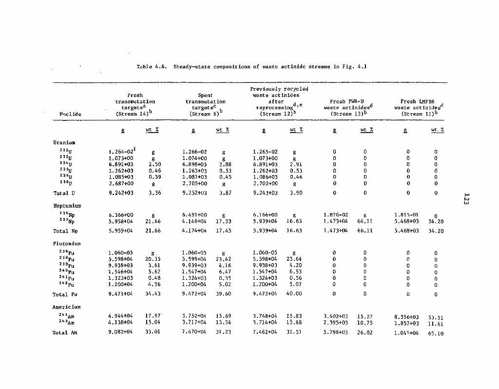
Table 4.6. Steady-state compositions of waste actinide streams in Fig. 4.1
Nuclide
Fresh transmutation
targetsa
(Stream 14)b
Spent transmutation
targets0 , (Stream 6)
Previously recycled waste actinides
after d reprocessing ' (Stream 12)b
Fresh PWR-U wastp actinides1'
(Stream 13)b
Fresh LMFBR waste actinides
(Stream ll)b
& wt % & wt % £ wt % S. wt % 2. wt %
Uranium 1.264-02* 2 3 2u 1.264-02* g 1.266-02 8 1.265-02 g 0 0 0 0
2 3 3 u 1.073+00 g 1.074+00 g 1.073+00 g 0 0 0 0 23*U 6.891+03 2.50 6.898+03 2.88 6.891+03 2.91 0 0 0 0 235u 1.262+03 0.46 1.263+03 0.53 1.262+03 0.53 0 0 0 0 2 3 6 y 1.085+03 0.39 1.087+03 0.45 1.086+03 0.46 0 0 0 0 23®U 2.687+00 g 2.705+00 g 2.702+00 g 0 0 0 0
Total U 9.242+03 3.36 9.252+03 3.87 9.243+03 3.90 0 0 0 0
Neptunium 2 3 6Np 6.366+00 g 6.491+00 g 6.166+00 g 1. 876-02 g 1, .815-01 g 2 3 7Np 5.958+04 21.66 4.146+04 17.33 3.939+04 16.63 1. 473+04 66.11 5. .468+03 34.20
Total Np 5.959+04 21.66 4.174+04 17.45 3.939+04 16.63 1.473+04 66.11 5, .468+03 34.20
Plutonium 2 3 6 p u 1.060-05 g 1.060-05 g 1.060-05 g 0 0 0 0 2 3 8 p u 5.598+04 20.35 5.599+04 23.42 5.598+04 23.64 0 0 0 0 2 3 9 p u 9.938+03 3.61 9.939+03 4.16 9.938+03 4.20 0 0 0 0 2*°Pu 1.546+04 5.62 1.547+04 6.47 1.547+04 6.53 0 0 0 0 2 M p u 1.323+03 0.48 1.324+03 0.55 1.324+03 0.56 0 0 0 0 2 u 2Pu 1.200+04 4.36 1.200+04 5.02 1.200+04 5.07 0 0 0 0
Total Pu 9.471+04 34.43 9.472+04 39.60 9.472+04 40.00 0 0 0 0
Americium 2<t JAm 4.944+04 17.97 3.752+04 15.69 3.748+04 15.83 3. 402+03 15.27 8. .556+03 53.51 2*3Am 4.138+04 15.04 3.717+04 15.54 3.714+04 15.68 2. 395+03 10.75 1, ,857+03 11.61
Total Am 9.082+04 33.01 7.470+04 31.23 7.462+04 31.51 5. 798+03 26.02 1. .041+04 65.10
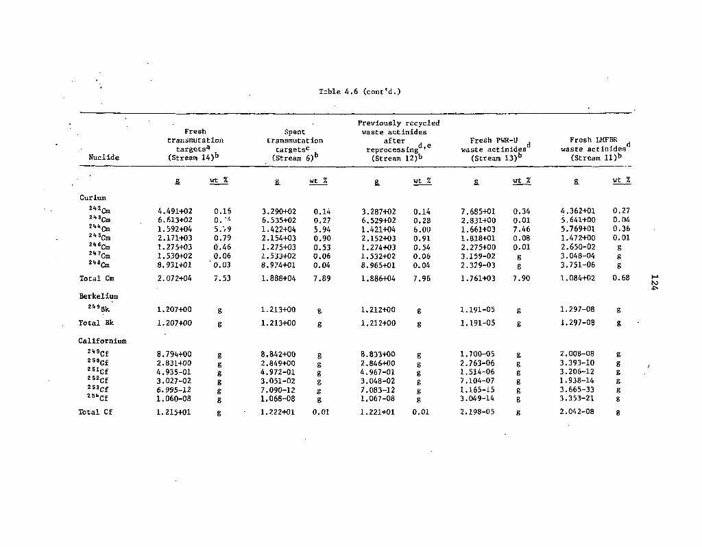
Table 4.6 (cont'd.)
Previously recycled Fresh Spent waste actinides
transmutation transmutation after Fresh PWR-U Fresh LMFBR targets3 targets0 reprocessing ' 6 waste actinides waste actinides
Nuclide (Stream 14)b (Stream 6)b (Stream 12)b (Stream 13)b (Stream ll)b
£ wt % & wt % & wt % £ wt % S. wt %
Curium 2i»2 21* 3 2UU 21(5, 21*6 2̂ 7, 21(8
Cm Cm Cm Cm Cm Cm Cm
Total Cm
4.491+02 6.613+02 1.592+04 2.171+03 1.275+03 1.530+02 8.931+01 2.072+04
0.16 0. -A 5.V9 0.79 0.46 0.06 0.03 7.53
3.290+02 6.535+02 1.422+04 2.154+03 1.275+03 1.533+02 8.974+01
0.14 0.27 5.94 0.90 0.53 0.06 0.04
1.888+04 7.89
3.287+02 6.529+02 1.421+04 2.152+03 1.274+03 1.532+02 8.965+01
1.886+04
0.14 0.28 6.00 0.91 0.54 0.06 0.04 7.96
7.685+01 2.831+00 1.661+03 1.818+01 2.275+00 3.159-02 2.329-03
1.761+03
0.34 0.01 7.46 0.08 0.01 g g 7.90
4.362+01 5.641+00 5.769+01 1.472+00 2.650-02 3.048-04 3.751-06 1.084+02
0.27 0.04 0.36 0.01 g g g
0.68
Berkelium Z!,9Bk.
Total Bk 1.207+00 1.207+00
1.213+00 1.213+00
1.212+00 1.212+00
1.191-05 1.191-05
1.297-08 1.297-08
Californium 2*9Cf 2 5 0
2 5 1
2 5 2
2 5 3 ,
Cf Cf Cf Cf
""Cf Total Cf
8.794+00 2.831+00 4.935-01 3.027-02 6.995-12 1.060-08
1.215+01
g g 8 g
8.842+00 2.849+00 4.972-01 3.051-02 7.090-12 1.068-08
1.222+01
g g g g
8 g
0.01
8.833+00 2.846+00 4.967-01 3.048-02 7.083-12 1.067-08 1.221+01
g g g g
8 g
0.01
1.700-05 2.763-06 1.514-06 7.104-07 1.165-15 3.049-14 2.198-05
2.008-08 3.393-10 3.206-12 1.938-14 3.665-33 3.353-21 2.042-08

Table 4.6 (cont'd.)
Nuclide
Fresh transmutation
targets3 (Stream 14)b
Spent transmutation
targets0 (Stream 6)b
Previously recycled waste actinides
after d reprocessing ' (Stream 12)b
Fresh PWR-U waste actinidesd
(Stream 13)b
Fresh LMFBR waste actinidec
(Stream U ) h
& wt % & wt % 8. wt % S. wt % & wt %
Einsteinium " 3 E S 4 . 8 9 9 - 1 0 g 4 . 9 4 7 - 1 0 g 4 . 9 4 2 - 1 0 g 5 1 , 2 6 5 - 1 4 g 1 , 4 2 9 - 2 1 g
Total Es 5 . 8 6 9 - 1 0 g 5 . 0 0 9 - 1 0 g 5 . 0 0 4 - 1 0 g 9 , , 0 8 7 - 1 1 g 1 . 4 2 9 - 2 1 n O
Total heavy metal
2 . 7 5 1 + 0 5 1 0 0 2 . 3 9 2 + 0 5 1 0 0 2 . 3 6 8 + 0 5 1 0 0 2 , . 2 2 8 + 0 4 1 0 0 1 . 5 9 9 + 0 4 1 0 0
Charged to the transmutation reactor at the beginning of recycle 60.
''Refer to Fig. 7.1 and Table 7.5 for further stream identification.
cDischarged from the transmutation reactor at the end of recycle 60.
^Charged to the transmutation reactor at the beginning of recycle 61. £
Spent transmutation targets after reprocessing-partitioning.
fRfcad as 1.264 x 10~2.
gLess than 0.01 wt %.
N> Ul

126
Cycle 60, namely 0.03027 g (Table 4.6, stream 14). A graph of the buildup of the various elements that comprise the total Fresh Actinide Target mass as a function of a cycle number is shown in Fig. 4.2. The mass of waste actinides being charged to the LMFBR annually at steady state is 275.1 kg, a factor of 7.2 greater than the mass of fresh PWR-U and LMFBR waste actinides being introduced into the .system. The steady-state Fresh Transmutation Target mass of 275.1 kg per year is equivalent to 0.7% of the total fuel, or to 1.7% of the core (driver) fuel charged annually to f ie LMFBR transmutation reactor.
4.4.3 Steady-state waste actinide transmutation rate The calculated transmutation (i.e., fission) rate of the 275.1 kg of steady-state waste actinides is
35.9 kg per cycle. An additional 2.4 kg per cycle is lost from the recycle stream during reprocessing and is ultimately sent to the repository. The transmutation of 35.9 kg of actinides per (2-year) cycle is equivalent to a transmutation rate of 6.5% per year of irradiation or, assuming a 1.0-year out-of-reactor time, to 4.3% per calendar year. The 2.4 kg of waste actinides lost during each cycle is equivalent to 0.9% loss per year of irradiation or 0.6% loss per calendar year. This gives a total actinide removal (fission + loss) rate of 7.4% per year of irradiation; or 4.9% per calendar year.
4.4.4 Steady-state waste actinide specific power Figure 4.3 shows the specific power characteristics of Fresh and Spent Transmutation Targets
during irradiation, along with comparable data for LMFBR driver fuel. Even in the first cycle, the specific power of the waste actinides is larger than that of LMFBR driver fuel, and the difference becomes greater as the waste actinides are recycled. This means that a diluent will be required to reduce the specific power of the waste actinides to a value within the range of specific powers present in the driver fuel. The most obvious diluent, because it is a fertile material and its behavior has been clearly defined, is the same type of uranium that is being used as a plutoriium diluent in the driver fuel. The use of 238U as a diluent has been examined by Be^man37 for a scenario in which the waste actinides from three BWRs are transmuted in an LMFBR. On the other hand, a diluent which is chemically dissimilar from the waste actinides (e.g., MgO or AI2O3) may be desirable to facilitate partitioning.
The second specific-power-related parameter of interest is the change in the specific power of the waste actinides during a single cycle. As shown in Fig. 4.3, the specific power of the waste actinides increases during the first several cycles, with the increase for the first cycle being about 19%. However, the progressively greater influence of the waste actinides that have been previously recycled diminishes this increase until, finally, it becomes negative (i.e., a specific power decrease) after the fifth cycle. The steady-state value is a specific power decrease of 4.9% during a single cycle. This is comparable to a 1.1% decrease in the specific power of the driver fuel during a cycle.
4.4.5 Steady-state waste actinide reactivity The reactivity characteristics, as measured by the infinite neutron multiplication factor (IMF) of
the Fresh and Spent Transmutation Targets, are shown in Fig. 4.4. The IMF of the waste actinides is defined here as the number of fission neutrons produced by the waste actinides divided by the number of neutrons absorbed by the waste actinides. This definition is based oh the assumption that • * no other neutron losses occur.
The IMF of the waste actinides increases rapidly for the first 10 to 15 cycles and then levels off at 1.419 at the beginning of the cycle (BOC) and 1.458 at the end of the cycle (EOC). These values are comparable to the LMFBR driver fuel actinide. IMFs of 1.373 at BOC and 1.384 at EOC if either

127
C Y C L E N U M B E R
Pig. 4.2. Element buildup in fresh transmutation target actinides during steady-state recycle.
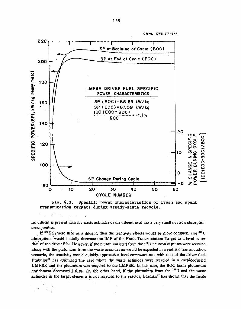
128
22C
200 —
0 03 £ 1 8 0 0 03 JS CJ> •ac
1 6 0 N 1 6 0 £ • J*
CL CO DC 1 4 0 UJ £ O Q_ C> 1 2 0 U- 1 2 0
O UJ Q-tn
100 -
ORNL DW6. 77-94RI
T SP at Begining of Cycle (BOC)
SP at End of Cycle (EOC)
LMFBR DRIVER FUEL SPECIFIC POWER CHARACTERISTICS
SP ( BOC) » 8 8 . 5 9 kW/kg SP (EOC) = 8 7 . 5 9 kW/kg 100 ( E O C - B O C ) .
r r = - 1 . 1 % BOC
SP Change During Cycle I 1
20
10
o UJ
t c i O > UJ O £L <D © z? ~ t r UJ 3 o o
a o m
o 0 m 1 o o Ld O o
10 2 0 3 0 4 0 CYCLE NUMBER
50 60
Fig. 4.3. Specific power characteristics of fresh and spent transmutation targets during steady-state recycle.
no diluent is present with the waste actinides or the diluent used has a very small neutron absorption cross section.
If 238U02 were used as a diluent, then the reactivity effects would be more complex. The 238U absorptions would initially decrease the IMF of the Fresh Transmutation Target to a level below that of the driver fuel. However, if the plutonium bred from the 238U neutron captures were recycled along with the plutonium from the waste actinides as would be expected in a realistic transmutation scenario, the reactivity would quickly approach a level commensurate with that of the driver fuel. Prabulos41 has examined the case where the waste actinides were recycled in a carbide-fueled LMFBR and the plutonium was recycled to the LMFBR. In this case, the BOC fissile plutonium .enrichment decreased ,1.61%. On the other hand, if the plutonium from the 238U and the waste actinides in the target elements is not recycled to the reactor, Beaman37 has shown that the fissile

129
ORNL OWG 77 -92R I
1.5
0.8
I M F at End of Cycle ( EOC)
IMF at Begining of Cycle ( BOC)
LMFBR DRIVER FUEL REACTIVITY
I M F (BOC) = 1.373 I M F (EOC) = 1.384
(EOC-BOC) BOC
= + 0.8%
I M F CHANGE DURING CYCLE
15
10 w o r n o >- ^
l i f o — 0 0
CC I =) U z q O u j W o ^ 0 a: 2 2 W H O a. lHJ
10 2 0 3 0 4 0
CYCLE NUMBER
5 0 60
Fig. 4.4. Reactivity characteristics of fresh and spent transmutation targets during steady-state recycle.
plutonium enrichment of the driver fuel must be increased by 1.4%. However, in either case, it is evident that the effect of waste actinide recycle on the reactivity of an LMFBR transmutation reactor should be relatively minor.
A second reactivity effect of interest is the change in reactivity during irradiation. This is of interest in predicting power peaking and other safety parameters. The calculated IMF of the undiluted waste actinides always increases during irradiation. During the first cycle, this increase is nearly 14%. The magnitude of the shift decreases until, at steady state, it is about 2.75%. The relatively large reactivity shift during the early cycles would be significant and must be accounted for during the reactor safety and neutronic analyses.

130
4.4.6 LMFBR transmutation reactor breeding ratio As with the waste actinide reactivity, the LMFBR transmutation reactor breeding ratio would
be heavily dependent on whether the plutonium bred from the 238U diluent (if present) and the waste actinides were recycled. If the plutonium is recycled, the breeding ratio would increase slightly41 (less than 1%). If it is not recycled, the breeding ratio would decrease by 0.5 to 1%.37 The effect of the waste actinides on the fissile plutonium breeding ratio also depends on whether 238Pu, the predominant plutonium isotope bred from the waste actinides, is considered as a fissile species in the definition of the breeding ratio. In any event, the effect of waste actinide transmutation on the LMFBR transmutation reactor breeding characteristics would probably be small.
4.4.7 Neutron activity of waste actinides The specific neutron activity of the waste actinides is extremely important when examining the
shielding requirements in shipping casks, fuel fabrication plants, and fuel reprocessing plants. The calculated (a, n) and spontaneous fission neutron activities of undiluted Fresh Transmutation Targets are shown in Fig. 4.5 as a function of cycle number. The principal neutron source nuclides, in decreasing order of importance, would be 242Cm, 244Cm, and 23SPu for (a, n) neutrons and 244Cm, 252Cf, 250Cf, and 246Cm for spontaneous fission neutrons. The steady-state specific neutron activity of the Fresh Transmutation Targets is higher than that of fresh and spent driver fuel neutron activities by factors of 20,000 and 3000, respectively. Even if the waste actinides were homogeneously dispersed in the driver fuel, their specific activity (=3.4 x 10¹⁰ neutrons sec"1 MT"1) would dwarf the contributions of the other isotopes in the fuel by a factor of 340 when charged and by a factor of 50 when discharged.
4.4.8 Steady-state high-level waste toxicity The ingestion toxicity of the HLW actinides with and without waste actinide recycle is of
primary concern since it is the parameter that is to be minimized. The toxicity of the waste is defined as the volume of water required to dilute all of the radionuclides in a given (but noi necessarily unit) amount of waste to their respective radionuclide concentration guide values.64 In the present case, the basis for the amount of wa«te is the combined production of 1.0 GWY(e) from a PWR and an LMFBR. In Sect. 4.5, the amount of waste will be based on a postulated variable nuclear capacity forecast.
The total ingestion toxicities of the HLW actinides for the two cases depicted in Fig. 4.1 and Table 4.5 are shown in Fig. 4.6. The HLW actinide toxicity from the actinides resulting from the reprocessing of the "Spent Transmutation Targets" (stream 7, Fig. 4.1) is also shown in Fig. 4.6.
The calculated actinide toxicity reduction effected by P-T ranges from a factor of 100 at an HLW decay time of 1000 years to a factor of 5 after 1 billion years. It is also interesting to note that the toxicity of the 2 kg of Spent Transmutation Target waste actinides is roughly equal to one-half the total toxicity of the 71 kg of spent PWR-U and LMFBR fuel high-level waste actinides.
4.4.9 Transmutation of actinides from other reactor types Two other types of reactors, a plutonium-enriched PWR (PWR-Pu) and an HTGR, might
produce waste actinides requiring transmutation. Parametric studies47 have shown that the composition of the Fresh Transmutation Targets (FTT) reflects the character of the unrecycled actinides being fed into the system. For example, if a PWR-Pu were substituted for the PWR-U in
' the:scenario used;in the preceding sections, the americium and curium contents, as well as the total mass of the FTT, would drastically increase because of the high americium and curium contents and
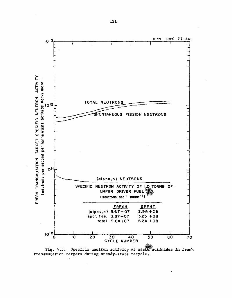
131
I0<3 ORNL DWG 7 7 - 4 R 2
>-1- —
> o H a> O E <
> z o o £ Q: »- a>
TD UJ c z
o o o u. a> o in lli o 0. » to w c V— c Ul o o a. w a> < a . t - T3
C Z o O u a> v> < w
s a> a. V) u> z c < o w a: i - « X CO
C
ID cr u.
I 0 1 °
TOTAL NEUTRONS
PONTANEOUS FISSION NEUTRONS
( a l p h a , n ) NEUTRONS
SPECIFIC NEUTRON ACTIVITY OF 1.(0 TONNE OF LMFBR DRIVER FUEL (neutrons sec"1 tonne"1)
FRESH (a lpha ,n ) 5 .67 + 0 7 spon. fiss. 3 . 97 + 0 7
total 9 . 6 4 + 0 7
SPENT 2 . 9 9 + 0 8 3.25 + 0 8 6 .24 + 0 8
_L 10 2 0 3 0 4 0
CYCLE NUMBER 5 0 60 7 0
Fig. 4.5. Specific neutron activity of wastlFactinides in fresh transmutation targets during steady-state recycle.
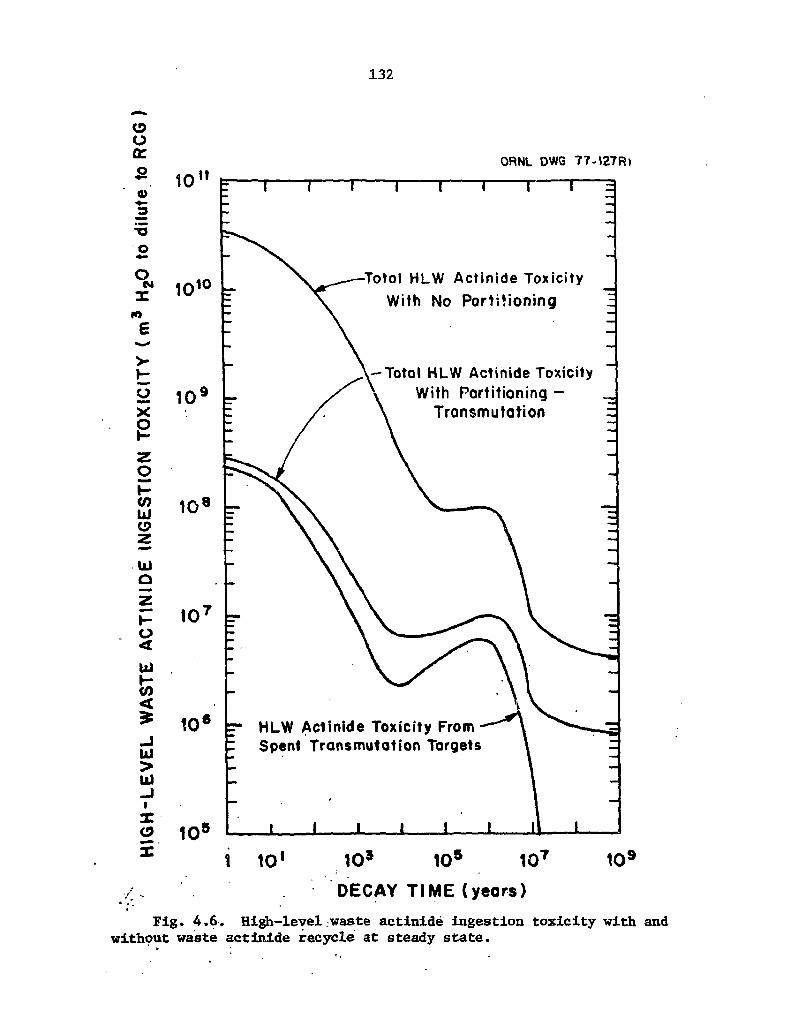
132
O O a :
* 10 0>
•o O
O N
14
>
o
z o p
UJ
UJ o
I -0 <
UJ I -05 < £ J UJ > UJ - I 1
X (9
ORNL DWG 77-J27R) It
10 10
S2 1 0 x
e
10 8
10
10 6
o 105
1 3
-Totol HLW Actinide Toxicity With No Partitioning
Totol HLW Actinide Toxicity With Partitioning -
Transmutation
HLW Actinide Toxicity From Spent Transmutation Targets
1 10' 10 s 105 107
D E C A Y T I M E ( y e a r s )
109
Fig. 4.6. High-level waste actinide ingestion toxicity with and without waste actinide recycle at steady state.
133
the large mass of the waste actinides produced by a PWR-Pu. If an HTGR were substituted for the PWR-U in the preceding sections, the uranium and neptunium contents of the FTT would increase because of the need to transmute the once-highly-enriched 235U which has been irradiated for 8 years in the HTGR.
The transmutation rate of the waste actinides is not a particularly strorfg function of the reactor type(s) producing the waste actinides. Waste actinides from LMFBRs transmute most readily, followed by those from PWRs-Pu, PWRs-U, and HTGRs, in decreasing order. The most readily transmutable (LMFBR) waste actinides are transmuted about 15% faster than those from the HTGR.
The highest waste actinide IMF results from the recycle of PWR-Pu waste actinides, followed by the LMFBR, PWR-U, and HTGR cases in. decreasing order. All waste actinides exhibit the characteristic increase in reactivity duiing irradiation.
Since transmutation scenarios involving these reactor types have not been studied extensively, less detailed information is available concerning the effects of these waste actinides. Considerable work is required to examine the transmutation of PWR-Pu and HTGR waste actinides in an LMFBR in as much detail as the PWR-U case discussed in most of Sect. 4.4. This work will be necessary since both the PWR-Pu and the HTGR are currently expected to comprise significant fractions of the U.S. nuclear capacity in the future.
4.5 Transmutation of Waste Actinides in LMFBRs with a Variable Nuclear Capacity
As was noted at the beginning of Sect. 4.4, consideration of steady-state transmutation, while convenient and somewhat instructive, is probably not realistic. Since the installed nuclear fission power capacity is expected to increase in the immediate future and then decline in the more distant future, steady state will probably never be attained. In an attempt to examine the effccts of a dynamic nuclear power economy, calculations have been performed assuming waste actinide transmutation in LMFBRs with a progressively increasing, constant, and then declining nuclear power capacity.
4.5.1 Assumed high-level waste actinide transmutation scenario with a variable nuclear power capacity
The characteristics of the assumed waste actinide transmutation scenario with a changing nuclear power capacity are summarized in Table 4.7. The basic fuel cycle flowsheet is the same as that- shown in Fig. 4.1 except for the variable nuclear power capacity. The nuclear electricity production rate in the year 2000 was assumed to be 282 GWY(c)/year. This production rate was assumed to increase at the rate of 6% annually for 105 years (35 cycles), then remain constant for 105 years (35 cycles), and finally decrease at 6% per year for 210 years (70 cycles). The resulting annual nuclear electricity generation is shown in Fig. 4.7 as a function of time. The scenario duration of 420 years was selected so as to provide a common denominator for parametric studies and is not intended to reflect nuclear power growth patterns that are to be expected in the future. The 6%/yr electricity production rate increase and decrease used in this scenario was arbitrarily assumed. The reactor mix was assumed to be 50% PWR-U and 50% LMFBR at all times. The high-level actinide masses and compositions from 1.0 GWY(e) equivalent to fresh LMFBR and PWR-U fuel are the same as those given in Table 4.6 for streams 11 and 13 respectively. In the year
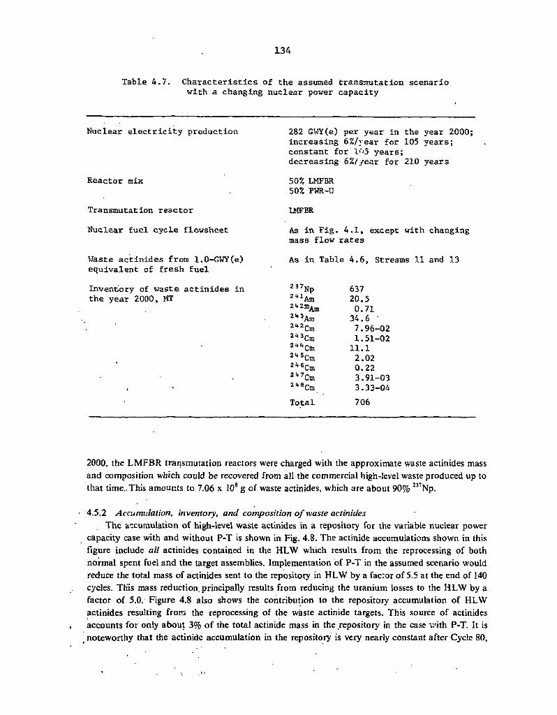
134
Table 4.7. Characteristics of the assumed transmutation scenario with a changing nuclear {tower capacity
Nuclear electricity production
Reactor mix
Transmutation reactor
Nuclear fuel cycle flowsheet
Waste actinides from l.O-GWY(e) equivalent of fresh fuel
Inventory of waste actinides in the year 2000, MT
282 GWY(e) per year in the year 2000; increasing 6%/vear for 105 years; constant for l<'5 years; decreasing 6%//ear for 210 years
50% LMFBR 50% PWR-U
LMFBR
As in Fig. 4.1, except with changing mass flow rates
As in Table 4.6, Streams 11 and 13
2 37Np 637 ^ A m 20.5 21f 2 mAm 0.71 2"3Am 34.6 2"2Cm 7.96--02 2*3Cm 1. Si--02 2 ^ C m ll.1 2"5Cm 2.02 2*fiCm 0.22 2 " C m 3.91--03 2-8Cm 3.33--04 Total 706
2000, the LMFBR transmutation reactors were charged with the approximate waste actinides mass and composition which could be recovered from all the commercial high-level waste produced up to that time..This amounts to 7.06 x 10⁸ g of waste actinides, which are about 90% 237Np.
• 4.5.2 Accumulation, inventory, and composition of waste actinides The accumulation of high-level waste actinides in a repository for the variable nuclear power
capacity case with and without P-T is shown in Fig. 4.8. The actinide accumulations shown in this figure include all actinides contained in the HLW which results from the reprocessing of both normal spent fuel and the target assemblies. Implementation of P-T in the assumed scenario would reduce the total mass of actinides sent to the repository in HLW by a factor of 5.5 at the end of 140 cycles. TKis mass reduction, principally results from reducing the uranium losses to the HLW by a factor of 5.0. Figure 4.8 also shows the contribution to the repository accumulation of HLW actinides resulting from the reprocessing of the waste actinide targets. This source of actinides accounts for only about 3% of the total actinide mass in the repository in the case v.'ith P-T. It is
t noteworthy that the actinide accumulation in the repository is very nearly constant after Cycle 80,
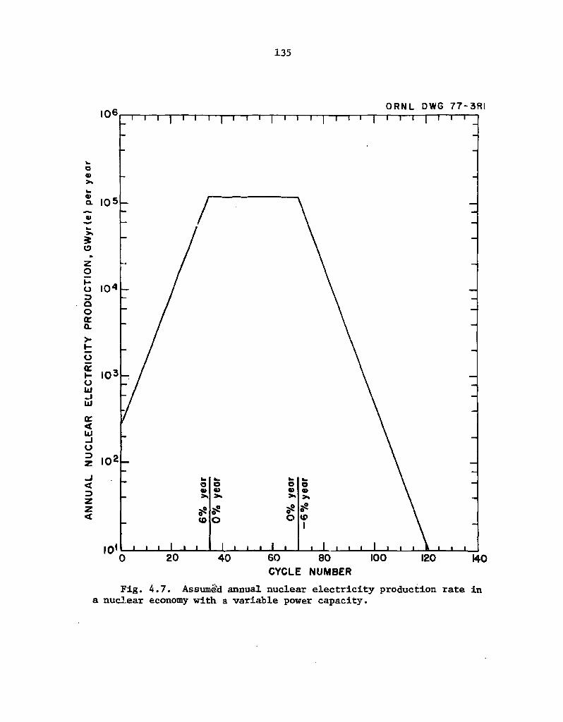
135
Fig. 4.7. Assumed annual nuclear electricity production rate In a nuclear economy with a variable power capacity.

136
CYCLE NUMBER
Fig. 4.8. High-level waste actinide accumulations in a repository with' a variable nuclear power capacity.
even though the scenario continues for 140 cycles. This occurs because of the greatly reduced nuclear power capacity, which in turn reduces the actinide mass in the HLW entering the repository to values that are insignificant as compared with the previously accumulated actinide mass.
Another parameter of interest is the inventory of actinides in surface nuclear fuel cycle facilities. This inventory includes the waste actinides in the target fabrication plant, the reactor, spent fuel storage, and the reprocessing plant ("waste actinides in the fuel cycle"). It also includes all of the actinides in interim liquid or solidified HLW storage ("actinides in HLW"), assuming a 10-year interim storage. The actinide inventories for five different subcases of the variable nuclear power capacity scenario are shown in Fig. 4.9. Curve 1 depicts the surface actinide inventory (waste actinides in the fuel cycle plus actinides in the HLW) for a case with no partitioning and DFs of 200 for uranium and plutonium. Curve 2 shows the surface actinide inventory for a case with P-T using the Claiborne DFs (see Table 4.4). Curve 2 is lcwer than Curve 1 because the amount of uranium reporting to the HLW is assumed to be reduced by an additional factor of 5 (DF = 1000) by
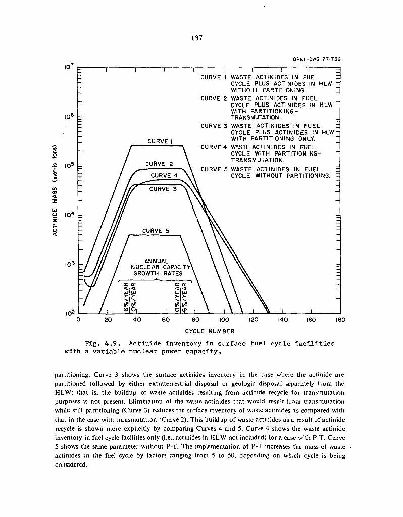
137
ORNL-DWG 77-738
i i r CURVE 1 WASTE ACTINIDES IN FUEL
CYCLE PLUS ACTINIDES IN HLW WITHOUT PARTITIONING.
CURVE 2 WASTE ACTINIDES IN FUEL CYCLE PLUS ACTINIDES IN HLW ' WITH PARTITIONING-TRANSMUTATION.
CURVE 3 WASTE ACTINIDES IN FUEL CYCLE PLUS ACTINIDES IN HLW WITH PARTITIONING ONLY.
CURVE 4 WASTE ACTINIDES IN FUEL CYCLE WITH PARTITIONING-TRANSMUTATION.
CURVE 5 WASTE ACTINIDES IN FUEL CYCLE WITHOUT PARTITIONING. :
80 I00
CYCLE NUMBER
Fig. 4.9. Actinide inventory in surface fuel cycle facilities with a variable nuclear power capacity.
partitioning. Curve 3 shows the surface actinides inventory in the case where the actinide are partitioned followed by either extraterrestrial disposal or geologic disposal separately from the HLW; that is, the buildup of waste actinides resulting from actinide recycle for transmutation purposes is not present. Elimination of the waste actinides that would result from transmutation while still partitioning (Curve 3) reduces the surface inventory of waste actinides as compared with that in the case with transmutation (Curve 2). This buildup of waste actinides as a result of actinide recycle is shown more explicitly by comparing Curves 4 and 5. Curve 4 shows the waste actinide inventory in fuel cycle facilities only (i.e., actinides in HLW not included) for a case with P-T. Curve 5 shows the same parameter without P-T. The implementation of P-T increases the mass of waste actinides in the fuel cycle by factors ranging from 5 to 50, depending on which cycle is being considered.

138
Figures 4.8 and 4.9 are more easily interpreted by calculating a "Mass Figure of Merit" (MFOM), which reflects the effects of waste actinide transmutation. The MFOM is defined as the sum of all waste actinides in surface fuel cycle facilities and the repository (global waste actinide inventory) without transmutation, divided by the sum of all waste actinides in surface fuel cycle facilities and the repository with P-T. Thus, the MFOM measures the fraction of the potential global waste act;nide inventory that was fissioned during the postulated scenario. The MFOM values for Fig. 4.8 and 4.9 aie shown in Fig. 4.10 as a function of cycle number. The MFOM is initially oscillatory due to the effects of the initial (year 2000) waste actinide inventory of 7.1 x 10s g. If the 6% annual growth regime were extended, the MFOM would level off at a value of about 4.4 and would remain there as long as the rate of growth remained unchanged. After the 35th cycle, the MFOM would begin to increase because the assumed transmutation rate would now be greater than the nuclear capacity growth rate (=0%). This increase in the MFOM would continue until the repository waste actinide inventory became much larger than the fuel cycle waste actinide inventory (about 350 cycles required); at this point, the MFOM would reach its asymptotic value of 5.5. Actually, the asymptotic MFOM value of 5.5 is reached more quickly than this because the assumed nuclear capacity decline of 6% per year begins in the 70th cycle. This reduces the fuel cycle waste
z 2 z
II <n z «i q:
ORNL DWG. 7 7 — 90RI
g 6.0
19 Z z o t I-CE
t = « 2 i t u. * o m ui 2 i l o u. p </> » S o Z <
o z 5.0
4.0
u i-10 i < CD O -1
v>
£ < ID O o
3.0
2.0
1.0
ANNUAL NUCLEAR CAPACITY
GROWTH RATES
o: <r
<o S? <0 ' L
20 40 60 80 100 CYCLE NUMBER
120 140
F i g . 4 . 1 0 . Mass F i g u r e of M e r i t f o r F i g s . 4 . 8 and 4 . 9 .

139
actinide inventory very rapidly as compared with the repository waste actinide inventory and the asymptotic value is attained by the 90th cycle.
It is evident that very little is being accomplished after the 90th cycle because of the greatly reduced nuclear capacity. Only a very slight mass penalty (about 2.5%) would be incurred by truncating the assumed 140-cycle (420-year) scenario at the 90th cycle (270 years} and committing the remaining fuel cycle waste actinides to the repository.
The elemental composition of the Fresh Transmutaton Targets as a function of cvcle number is shown in Fig. 4.11. The smooth, monotonic variation in elemental composition evident in the steady-state recycle case (Fig. 4.2) has vanished because of the variation in nuclear capacity growth rates and the assumption of a large initial waste actinide inventory at the beginning of the scenario. However, from the 15th to the 80th cycles, the waste actinide composition shown in Fig. 4.11 roughly corresponds to the steady-state waste actinide concentrations for the principal components. That is, plutonium and americium are most abundant, both comprising 30 to 40 wt %, followed by neptunium at around 20 wt % and curium at around 7%. The uranium content is difficult to characterize because of the magnitude of its oscillations. After about the 60th cycle, the berkelium and californium contents of the waste actinides in Fig. 4.11 exceed those of the steady-state case. This difference increases to a factor of about 100 at the I40th cycle. The substantial variation in the Fresh Transmutation Target composition as a function of cycle in the case with a variable nuclear power capacity indicates that development of a single, "typical" waste actinide composition comparable to the steady-state composition shown in Fig. 4.2 will be very difficult, if not impossible.
4.5.3 Transmutation rate of waste actinides The transmutation (i.e., fission) rate of the Fresh Transmutation Targets as a function of cycle
number is shown in Fig. 4.12. The transmutation rate plotted is the rate per year of irradiation and must be adjusted downward for time spent out of the reactor.
As with the elemental composition curves (Fig. 4.10), the transmutation rau. varies substantially over the course of the 140-cycle scenario. Comparison of the curves in Figs. 4.12 and 4.11 shows that the transmutation rate tends to follow the trends of the plutonium curve in Fig. 4.11 for the first 70 cycles. This is because the plutonium, a major waste actinide constituent, is predominantly composed of 238Pu, which fissions readily in an LMFBR. Beyond the 70th cycle, the transmutation rate curve tends to follow the declining neptunium curve since the depletion of neptunium controls the production rate of 238Pu.
4.5.4 Specific power of waste actinides The specific power characteristics of the Fresh and Spent Transmutationyargets as a function
of c; cle number are shown in Fig. 4.13 for the variable nuclear power ca.p^^^feenario. The specific power characteristics plotted in Fig. 4.13 are the same as those shown in F ig | | | 3 for the steady-state waste actinide recycle case.
One obvious feature of the BOC and EOC specific power curves in Fig. 4.13 is that their shapes are nearly identical to the shape of the transmutation rate curve in Fig. 4.12 and, therefore, to the shapes of the waste actinide plutonium and neptunium curves in Fig. 4.11. This behavior is expected because the fissioning 238Pu, which controls the transmutation rate curve, has a direct effect on the waste actinide power per unit mass during irradiation. The substantial variation in the cycle-to-cycle specific powers indicates that the correct amount of diluent must be determined for each individual cycle. Thus it is not possible to simply specify that X grams of diluent are required for Y grams of waste actinides.

140
Fig. 4.11. Element buildup in fr->sh transmutation target actinides with a" variable nuclear power capacity.
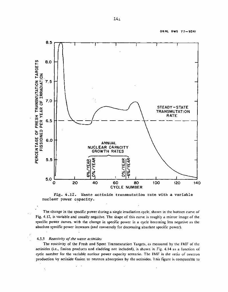
152
ORNL DWG 77—93RI
STEADY-STATE TRANSMUTATION
RATE
ANNUAL NUCLEAR CAPACITY
GROWTH RATES
60 80 CYCLE NUMBER
100 120 140
Fig. 4.12. Waste actinide transmutation rate with a variable nuclear power capacity.
The change in the specific power during a single irradiation cycle, shown in the bottom curve of Fig. 4.12, is variable and usually negative. The shape of this curve is roughly a mirror image of the specific power curves, with the change in specific power in a cycle becoming less negative as the absolute specific power increases (and conversely for decreasing absolute specific power).
4.5.5 Reactivity of the waste actinides The reactivity of the Fresh and Spent Transmutation Targets, as measured by the IMF of the
actinides (i.e., fission products and cladding not included), is shown in Fig. 4.14 as a function of cycle number for the variable nuclear power capacity scenario. The IMF is the ratio of neutron production by actinide fission to neutron absorption by the actinides. T his figure is comparable to

142
ORNL 0W6 77-9IRI
270
250
LEGEND BEGINNING-OF-CYCLE (BOC) SPECIFIC POWER
END-OF-CYCLE (EOC) SPECIFIC POWER
ANNUAL NUCLEAR CAPACITY
GROWTH RATES
130
LMFBR DRIVER FUEL SPECIFIC POWER CHARACTERISTICS
30.0
BOC SPECIFIC POWER= 88.59 kW/kg
EOC SPECIFIC POWER= 87.59 kW/kg
1 0 0 ( E O C - B O C ) BOC
SPECIFIC POWER CHANGE DURING CYCLE
20.0
o u. D 111 Q. VI
10.0
0.0
llJ O z < X o UJ o <
Ul o CE UJ 0.
ujQ J O o m >- s o
o O O Z CD E I Q O
UJ UjO
ou 0.
60 80 CYCLE NUMBER
-10 .0 140
Fig. 4.13. Specif1c•power characteristics of fresh and spent transmutation targets with a variable nuclear capacity.
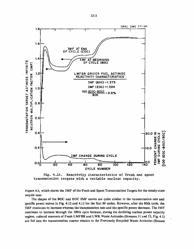
143
1.8 O R N L DWG 7 7 - 1 R 1
T
1.6 —
I M F AT END OF CYCLE (EOC)
1.0
t 0.8
I M F AT BEGINNING OF CYCLE (BOC)
LMFBR DRIVER FUEL ACTINIDE REACTIVITY CHARACTERISTICS
I M F (BOC) =1.373 IMF (EOC) =1.384
100 (EOC-BOC) - 0 Q y BOC " ' °
0.6 —
0.4 —
0.2
0.0.
I M F CHANGE DURING CYCLE
-L 4 0 6 0 8 0 100
CYCLE NUMBER 120
Fig. 4.14. Reactivity characteristics of fresh and spent transmutation targets with a variable nuclear capacity.
Hgure 4.4, which shows the IMF of the Fresh and Spent Transmutation Targets for the steady-state recycle case.
The shapes of the BOC and EOC IMF curves are quite similar to the transmutation rate and specific power curves in Fig. 4.12 and 4.13 for the first 80 cycles. However, after the 80th cycle, the IMF continues to increase whereas the transmutation rate and the specific power decrease. The IMF continues to increase through the 100th cycle because, during the declining nuclear power capacity regime, reduced amounts of Fresh LMFBR and LWR Waste Actinides (Streams 11 and 13, Fig. 4.1) are fed into the transmutation reactor relative to the Previously Recycled Waste Actinides (Stream

144
12, Fig. 4.1). Since the Fresh Actinides are almost totally comprised of 237Np, 24'Am, and y , A m , which do not readily fission in an LMFBR (i.e.. have a low fission-to-capture ratio), reduction of the relative fraction of Fresh Actinides in the Fresh Transmutation Targets decreases the neutron absorptions and increases the IMF.
The change in the IMF during a single cycle, shown in the bottom curve of Figure 4.14, is always positive (i.e., IMF increases during irradiation) but generally becomes less positive as the cycle number increases.
" 5.6 Neutron activity of transmutation targets The (a,n) and spontaneous fission specific neutron activities of the Fresh Transmutation
Targets as a function of cycle number are shown in Fig. 4,15 for the variable nuclear power capacity case.
The specific activity in the variable nuclear power capacity case is roughly equal to that for the steady-state recycle case (Fig. 4.5) for the first 80 cycles. However, during the declining nuclear power capacity regime the spontaneous fission specific neutron activity increases very rapidly to a value of 3.2 x 10¹³ neutrons sec"1 MT"1 after 140 cycles. This rapid buildup is due to the predominance of the Previously Recycled Waste Actinides over the Fresh Waste Actinides during the declining capacity regime as discussed in Sect. 4.5.5. The fact that the Previously Recycled Waste Actinides have received very high burnups results in high concentrations of 232Cf and 25?Cf, which account for the spontaneous fission neutron activity.
4.5.7 Toxicity of accumulated high-level waste actinides The long-term radioactive ingestion toxicity of the actinides in the HLW for the variable
nuclear power capacity case with and without transmutation is shown in Fig. 4.16. For the case without tiansmutation, DFs of 200 are assumed for uranium ana plutonium. The bottom curve of Fig. 4.16 shows the toxicities of the actinides sent to the HLW from the target reprocessing plant. It is important to note that only the toxicity of the actinides and their daughters are considered in Fig. 4.16;'that is, the toxicities of the fission products and the cladding have been ignored. Thus, in the decay period between 1 year and 1000 years, th*; toxicity of the HLW would actually be identical for both cases (with and without transmutation) because it would be controlled by 90Sr and 137Cs, which are very nearly identical in both cases.
When the decay of the HLW actinides is considered, the time period of prime interest is between 103 and 10s years. The factors by which the total HLW actinide toxicity is reduced in the assumed variable nuclear power capacity scenario by P-T are summarized in Table 4.8. Table 4.8 also gives the same reduction factors for the steady-state recycle case shown in Fig. 4.6. Each of these factors can be regarded as a Toxicity Figure of Merit (TFOM) analogous to the Mass Figure of Merit (MFOM) shown in Fig. 4.10, As is evident, P-T is most effective in reducing the toxicity (equivalent to increasing the TFOM) at the shorter decay times. The large toxicity reduction at 103
years is principally the result of reducing the amount of americium (241Atn) reporting to the HLW by a factor of 1000. At 104 years the reduction in the plutonium sent to the HLW is most significant. After 10s years decay both the HLW plutonium and neptunium reductions are important, with the neptunium reductions alone being most significant at 10* years. At the longer decay periods (greater than 10s years), the TFOM approaches 5.0 because the decay of 238U is now controlling and the amount of uranium sent to the HLW has been reduced by a factor of 5.0 via partitioning (see Table 4.4). .

145
1014 ORNL DWG 7 7 - 8 R 2
V t -> 1 -u — < "5
z o
v E
cc a> H •o 3 UJ c z u
o o ® U-o o UJ * Q. (O V
c c
1 - o UJ CD w
a> « a . < 1- T>
c Z o o o
a> y- in < w H a> Zi a . 2 in in c z o < w o : 3 H » C
X ' —
to UJ ac u .
1 0 "
10 10
o n a> a> > •
sS S? o
0 01 > « '
3s! o
D OP >> N s? CD
T
ANNUAL NUCLEAR CAPACITY
GROWTH RATES
TOTAL NEUTRONS
SPONTANEOUS FISSION NEUTRONS
SPECIFIC NEUTRON ACTIVITY OF 1.0 TONNE OF LMFBR DRIVER FUEL (neutrons s e c " ' t o n n e " ' )
FRESH (a lpha,n) 5 .67 + 0 7 spon. fiss. 3 .97 + 0 7
total 9 .64 + 0 7
SPENT 2 . 9 9 + 0 8 3 .25 + 0 8 6 .24 + 0 8
( a l p h a , n ) NEUTRONS
_L 20 4 0 6 0 8 0
CYCLE NUMBER 100 120 140
Fig. 4.15. Specific neutron activity of fresh transmutation targets with a variable nuclear power capacity.
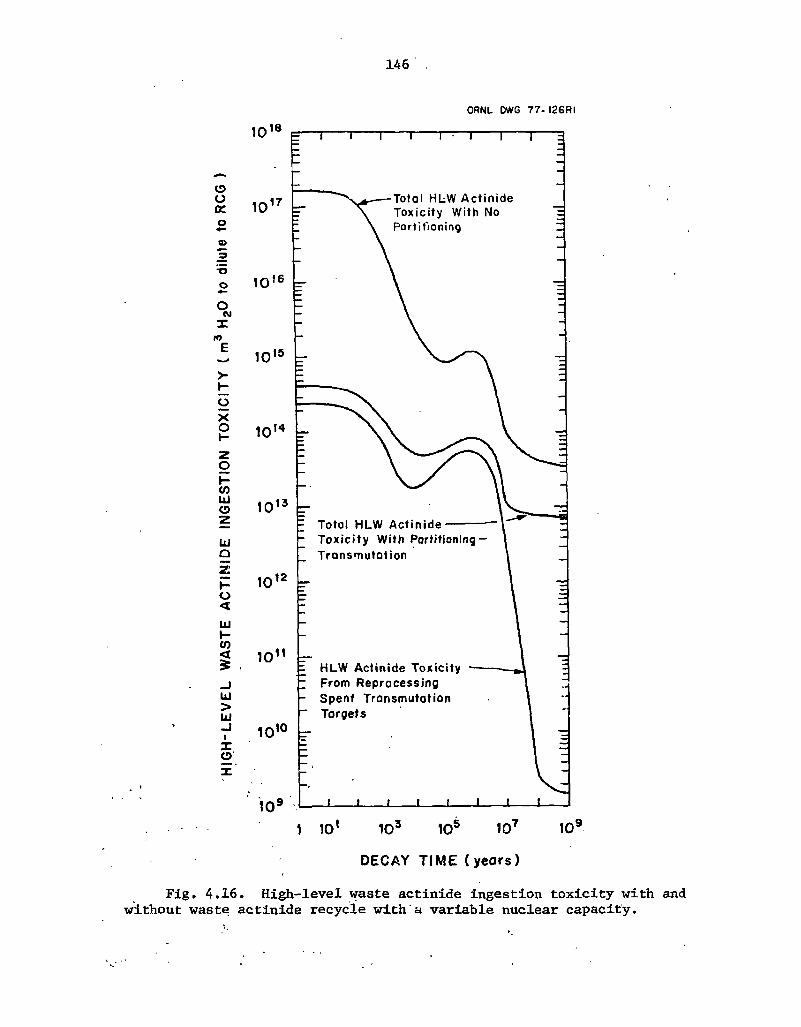
146
ORNL DWG 7 7 - 126 RI
r
o o DC
•o o
O (VI X
w E >-
K O X o z o I -CO UJ e> z
u Q Z
I -O <
UJ I -co < £
LJ > UJ _J I X o
10® 10° 1 0 '
DECAY T I M E ( years )
Fig. 4.16. High-level waste actinide ingestion toxicity with and without waste actinide recycle with a variable nuclear capacity.

147
Table 4.8 also shows that the TFOM values predicted by the variable nuclear power capacity case are nearly identical to those predicted by the steady-state recycle model, except at 103 years decay. This indicates that the TFOM may not be very sensitive to differing nuclear power capacity scenarios. Additionally, this may allow the calculationally simpler steady-state mode! to be used in parametric studies concerning the effects of changing actinide DFs on the TFOM.
Finally, it is very important to note that the actinides resulting from the reprocessing of the Spent Transmutation Targets account for about 50% of the HLW actinide toxicity with P-T at decay times between 103 and 106 years, while only constituting 3.1 wt % of the HLW actinides (see Fig. 4.8). Thus, on a unit-mass basis, the actinides in the Transmutation Targets have a toxicity which is 50/3.1, or approximately 16 times that of the "normal" HLW actinides resulting from the reprocessing and partitioning of the spent LWR and LMFBR fuels. This fact is extremely important when considering the duration of a realistic P-T scenario, since the Transmutation Target actinide mass is at least one-half of the total actinide mass accumulated in the repository at any time through the 40th cycle. Using this value of one-half, the long-term toxicity represented by the transmutation target actinides is a factor of 16/2 or 8 greater than the long-term toxicity of all HLW actinides previously committed to a repository during the first 40 cycles. If the transmutation scenario were abruptly terminated at, for example, the 40th cycle, the 7FOM listed in Table 4.8 would be reduced by a factor of 8; that is, the long-term HLW actinide toxicity with P-T would be increased by a factor of 8. Theiefore, if a commitment were madr 10 partition and transmute actinides, it should be
Table 4.8. Reduction in tc^zi'-y of high-level waste actinides effected by partitioning-transmutation
Ratio of HLW actinide toxicity with partitioning-transmutation to HLW actinide
High-level waste toxicity without partitioning-transmutation decay time Variable nuclear power Steady-state (years) capacity casea case*3
103 250 137
10* 51 51
10s 14 13
106 15 10
107 8.5 6.8
10® 5.1 5.1
109 5.1 5.0
aSee Fig. 4.16. bSee Fig. 4.6.

148
continued until the fuel cycle waste actinide inventory is small compared to the accumulated actinide mass in the repository if any significant reduction in the long-term actinide toxicity is to be achieved. At least 70 cycles would be desirable for the postulated scenario shown in Figs. 4.7 and 4.8.
4.6 Actinide Transmutation in Thermal Reactors
Actinide transmutation in thermal power reactors has been much less extensively studied than transmutation in fast power reactors. The principal reason for this is that most of the investigators have intuitively concluded that a fast power reactor is superior to a thermal power reactor as a transmutation device - a conclusion that appears to be supported by the facts. However, thermal power reactors may have to be used as transmutation devices during the initial phases of transmutation if the waste actinide backlog is to be transmuted because of space limitations in LMFBRs. Relatively simple steady-state recycle studies4' have been conducted in an effort to give preliminary definition to some of the differences between thermal and fast transmutation reactors. These studies are described in this section.
4.6.1 Waste actinide transmutation scenario in thermal reactors The general type of transmutation fue! .ycle scenario depicted in Fig. 4.1 will be assumed,
except that the positions of the PWR-U and LMFBR are reversed. However, two considerations significantly complicate this scenario. First, there are three obvious thermal transmutation reactor types: a uranium-enriched LWR (PWR-U), a self-generated plutonium-enriched LWR (PWR-Pu),' and an HTGR. Second, self-shielding effects which are relatively small in fast reactors become very important in thermal reactors when waste actinide targets are considered. By forming various combinations of transmutation reactor type and waste actinide concentration, many more transmutation scenarios can be postulated than can be or have been analyzed. The following paragraphs will attempt to logically reduce these many scenarios to a few based on limited calculational data.
To begin with, waste actinide recycle in HTGRs does not appear to be realistic. The HTGR appears to be excellent for transmuting actinides because of its relatively high thermal flux. However, the currently projected HTGR capacity in the year 2000 is only 10 GW(e), which is far too small to accommodate either the waste actinide backlog or even the current waste actinide production from LWRs and LMFBRs. Furthermore, the HTGR capacity would not be expected to grow rapidly since it requires fissile makeup in a time period when natural uranium reserves are projected to decline and most plutonium is being used as initial fissile inventories for LMFBRs. Thus, the HTGR is being eliminated from present consideration as a transmutation reactor.
Plutonium-enriched LWRs are not particularly attractive as transmutation reactors because the harder neutron spectrum and somewh?.l lower neutron flux result in calculated PWR-Pu transmutation rates that are only 50 to 60% of those calculated in a PWR-U. However, there is no fundamental reason why a PWR-Pu could not be used as a "last resort" transmutation reactor.
The PWR-U, with its high transmutation rate and large projected capacity, is the best existing thermal power reactor for actinide transmutation.
The question of whether homogeneously dispersed waste actinide transmutation or waste actinide transmutation in concentrated form (targets) is most effective is very important from the considerations of transmutation, partitioning, and fuel cycle impact standpoint. Homogeneous waste actinide recycle in a PWR-U is not desirable because the 232U and 235U resulting from the large amounts of 237Np in the reactor would, under present rules, render the discharged uranium unfit for
149
recycle through a gaseous diffusion plant. Although such uranium might be used without reenrichment in LMFBRs or plutonium-enriched LWRs, this would result in a more restricted uranium supply for the PWR-U. A more general argument against homogeneous waste actinide recycle is that it does not seem prudent or economical to employ extraordinary measures to recover and concentrate the initially dilute waste actinides and then to deliberately redilute them with fresh reactor fuel. Furthermore, the highly neutron- and gamma-active waste actinides will probably require all fuel containing waste actinides to be fabricated remotely. Therefore, waste actinide recycle in targets would seem to be indicated in order to minimize the increased difficulty and expense of having to continuously recover dilute waste actinides and refabricate large amounts of fuel remotely. The disadvantage of waste actinide recycle in targets is that the resulting self-shielding effects significantly reduce the transmutation rate and increase the required fissile enrichment for the thermal reactor.
The net result of the preceding discussion is that the best thermal reactor recycle scenario presently appears to be to use waste actinide targets in a uranium-enriched LWR. The next best alternative is probably to recycle waste actinide targets in plutonium-enriched LWRs, although one study2 noted potential difficulties in achieving the desired burnup in a PWR-Pu. Since thermal reactors would only be used as transmutation reactors until a sufficient number of LMFBRs become available, the additional transmutation rate and enrichment penalties incurred by using waste actinide targets should be acceptable.
Having arrived at the conclusicn that the recycle of waste actinides in thermal reactors should be done in targets, it is interesting to note that only one study2 considered this case. The other studies implicitly assumed homogeneously dispersed recycle by using cross sections which have not been corrected for self-shielding effects. Thus, in the succeeding sections, it will be necessary in many instances to rely on results calculated for the homogeneous case. Needless to say, no variable nuclear capacity scenarios have been studied with thermal transmutation reactors, and all results given are based on steady-state recycle calculations.
4.6.2 Steady-state waste actinide transmutation rates . For the case in which the waste actinides are homogeneously dispersed in a PWR-U, the
calculated steady-state waste actinide transmutation rate per year of irradiation is about 40% greater than that in an LMFBR. Results given in ref. 2 indicate that, in the case where the waste actinides are recycled in targets in the PWR-U, the transmutation rate would be reduced to a value equal to or less than that in the LMFBR. As was noted earlier, homogeneously dispersed actinide transmutation rates in a PWR-Pu are 50 to 60% of those in a PWR-U, which makes homogeneously dispersed transmutation in a PWR-Pu approximately equivalent to that in a LMFBR. If targets are used in the PWR-Pu, the transmutation rates would be considerably lower than in the LMFBR.
4.6.3. Steady-state waste actinide mass and composition It was noted earlier that the composition of the Fresh Transmutation Targets largely reflects the
composition of the Fresh (unrecycled) Actinides from the normal reactor fuel. This maxim is valid for thermal as well as fast reactors. Thus, in Fig. 4.1, the steady-state target composition would be roughly the same, regardless of whether the PWR-U or the LMFBR were the transmutation reactor. The only significant difference is that in the case where the PWR-U is the transmutation reactor the targets contain somewhat more curium and somewhat less americium because, of the, reduced fission-to-capture ratio in the PWR-U. * < •
150
The mass of the Fresh Transmutation Targets is totally dependent on the transmutation rate. Equal time-averaged transmutation rates will result in equal Fresh Transmutation Target masses. Thus, a PWR-U transmutation reactor with targets in Fig. 4.1 would have about the same waste actinide mass as the LMFBR case examined in Sect. 4.4 (i.e., about 275 kg).
If a PWR-Pu is considered as the transmutation reactor, the case is markedly different. The target actinide m°.ss would be somewhat higher just because of the reduced transmutation rate. However, the fact that the Fresh Waste Actinide mass from a PWR-Pu is a factor of 6 greater than that frcm a PWR-U increases the target actinide mass so that it is a factor of 7 larger than the target actinide mass in the PWR-U/LMFBR case. The targets would be about 75% americium and about 20% curium in the PWR-Pu/LMFBR case. An increase of this magnitude will result in any transmutation reactor being charged with Fresh Waste Actinides from a PWR-Pu.
4.6.4 Steady-state waste actinide specific power The steady-state specific power of waste actinides with homogeneous recycle is about 400 kW
per kg of heavy metal in a PWR-U and about 250 kW per kg of heavy metal in a PWR-Pu. Since the average specific power in a PWR is about 38 kW per kg of heavy metal, target rods would probably contain 15 to 20% waste actinides when allowances are made for the reduction in fission rates caused by self-shielding effects in the targets.
4.6.5 Steady-state reactivity and fissile makeup requirements The steady-state waste actinides are substantially subcritical in thermal reactors, and additional
fissile makeup is required in all PWR transmutation reactors. The IMF of the steady-state transmutation targets in a PWR-U typically ranges from 0.45 at BOC to 0.90 at EOC. In the case where a PWR-Pu transmutation reactor is used, the IMF values are lower, ranging from 0.15 at BOC to 0.60 at EOC. The relatively small mass of the steady-state transmutation targets as compared with the normal PWR fuel mass results in about a 1% reduction of the reactor IMF.
A PWR-U with homogeneous waste actinide recycle requires that the fuel enrichment be increased from 3.3 wt % 235U to 3.43 wt % 235U to have the same reactivity as normal PWR-U fuel.2'5
If the waste actinides are concentrated in every tenth fuel rod, the required fuel enrichment increases to about 3.5 wt %'235U.2
4.6.6 Steady-state recycle actinide neutron activity The specific neutron activities of the steady-state waste actinides recycled in PWRs are
considerably higher than those resulting from waste actinide recycle in LMFBRs. At steady state, the specific neutron activity of LMFBR/PWR-U waste actinides being recycled through a PWR-U
*> is about 2 x 10¹⁵ neutrons sec"1 MT"1. This specific neutron activity is about a factor of 1000 larger than that resulting from steady-state waste actinide recycle in an LMFBR (see Fig. 4.5). The steady-state specific neutron activity of LMFBR/PWR-Pu waste actinides being recycled through a PWR-Pu is about 2 x 10¹⁴ neutrons sec"1 MT"1. This value is a factor of 10 lower than that for a PWR-U transmutation reactor, principally because of the much larger steady-state waste actinide mass (factor of 7) in the PWR-Pu/LMFBR system.
The high steady-state specific neutron activity of weste actinides being transmuted in PWRs is a direct result of the low actinide fission-to-capture ratio in thermal reactors, which results in the accumulation of large amounts of 252Cf. In waste actinides recycled in thermal reactors, the neutrons from 252Cf predominate over those from 242Cm and 244Cm by a factor of 1000, whereas in an LMFBR their contributions are roughly equal.

151
4.7 Discussion of Waste Actinide Transmutation
The preceding sections represent an attempt to describe the in-reactor effects of transmuting waste actinides using the best information curren'.iv available. Because the description is somewhat lengthy and complex, this section has been included for the purpose of discussing the interpretation and validity of the material presented. The portion of the discussion dealing with interpretation considers the conclusions which can be drawn from Sect. 4, assuming that the data presented are complete and accurate. The portion concerned with validity considers whether the data presented in Sect. 4 are complete and accurate and, if not, the requirements for making them so.
4.7.1 Interpretation of transmutation calculations The principal conclusion to be drawn from Sect. 4 is that the transmutation oi waste actinides
(i.e., neptunium, americium, and curium), iodine (e.g., 129I), and "Tc would probably be feasible in thermal and fast power reactors, assuming that these elements could be partitioned to the desired extent and fabricated into stable fuel forms. This conclusion is supported by the following:
1. the mass of the long-lived nuclides being transmuted would generally be a small fraction of the normal fuel mass, and
2. the long-lived nuclides would not substantially alter the reactivity, specific power, or breeding (conversion) characteristics of the transmutation reactor.
To be sure, the recycle of the long-lived nuclides would have a significant impact on the transmutation reactor, particularly if it was a thermal reactor. However, these effects would generally be within the variations already present in the reactors and could be accounted for using existing techniques.
A second important conclusion is that an LMFBR would be the preferred type of fission power reactor for waste actinide transmutation. This conclusion is supported by the following:
1. the transmutation rate in an LMFBR would be nearly as good as or better than that in thermal reactors,
2. the recycled waste actinides would have an extremely small effect on the LMFBR reactivity and breeding ratio,
3. waste actinide recycle in an LMFBR would result in a waste actinide specific neutron activity which is a factor of 100 to 1000 less than that resulting from waste actinide recycle in thermal reactors, and
4. the reactor space available for transmutation actinides would be the greatest for LMFBRs in the . post-2000 time frame when P-T might become viable.
Thus, even though thermal transmutation reactors might be required to handle an initial waste actinide backlog around the year 2000, waste actinide transmutation in LMFBRs would clearly be superior to waste actinide transmutation in thermal reactors over the long-term.
152
The third conclusion is that persistent actinide recycle will substantially increase the mass of waste actinides in surface fuel cycle facilities (e.g., reprocessing plants, in-reactor) no matter what transmutation system is being considered. At the same time, the specific toxicity of the waste actinides would be because of the additional shorter-lived nuclides (e.g., 238Pu, "2Cm, w C m ) being produced by irradiating the waste actinides.
The fourth conclusion is that, assuming that "dilution to 10 CFR 20 RCG values" is a valid measure of waste toxicity, P-T would result in a reduction of the long-term HLW toxicity. The magnitude of this reduction would be the largest at decay- times around 1000 years and would become smaller at longer decay times (see Table 4.8). This does not necessarily mean that P-T is desirable, since the negative aspects of P-T have not yet been considered (see Sects. 5 and 6.1) and the "dilution to 10 CFR 20 RCG values" measure of toxicity is not valid for many potential nuclide release pathways (see Sect. 5.3).
One significant negative impact of transmutation would be to increase the inventory of the short-lived waste actinides (e.g., 238Pu, 242' 244Cm) in the fuel cycle. The magnitude of this increase would primarily depend on the time-averaged transmutation rate, with lower transmutation rates giving larger inventories.
The final conclusion is that P-T would increase the specific neutron activity of the previously recycled waste actinides due to the buildup of 242Cm, !44Cm, and 252Cf. The specific neutron activity of the waste actinides could substantially affect shielding requirements during fabrication, fresh fuel (or target) transportation, reactor refueling, spent fuel (or target) transportation, reprocessing, and waste disposal operations. This will be considered in more detail in Sect. 5.
4.7.2 Validity of transmutation calculations The question of the validity of presently existing transmutation calculations can be resolved into
two component questions:
1. Are the transmutation calculations complete?
2. Are the transmutation calculations accurate?
The first question is related to the desire to examine all aspects of transmutation to ensure that they have been included in the analysis or that they are not important. The transmutation calculations performed to date are not complete in many important respects. Some of the major transmutation-related areas which must be examined before a correct conclusion can be reasonably certain are as follows:
1. The in-reactor safety effects of transmuting the long-lived nuclides. Examples of these effects are power peaking factors, the Doppler coefficient, the sodium void coefficient, and control rod worths. The effect of the increased in-core actinide inventory during potential accident situations
. must also be considered.
2. The in-reactor effects of transmuting waste actinides contaminated with lanthanides. The chemical similarity of the lanthanides to the aciinidss could result in a significant fraction of the lanthanides being mixed with the recovered waste actinides. Unless great effort is taken to remove them, the large cross sections of the lanthanides (e.g., neodymium, samarium, europium) will have a negative reactivity impact of an undetermined magnitude.
i5a
3. The in-reactor effects of iodine transmutation. The possible volatility of iodine and the as yet unknown distribution of decay and neutron capture daughters make this area uncertain, particularly under postulated accident conditions.
4. Search for methods that might significantly improve the long-lived nuclide single-cycle burnup. This involves considering methods for extending the core residence time or specific power, or both, by using various core locations, fuel compositions, clad, compositions, etc.
5. Determination of differences between a heavily loaded (> 5% waste actinide) transmutation reactor and a "normal" transmutation reactor. This is~5f interest during the very early and very late stages of a transmutation scenario.
6. The effects of different LMFBR designs on actinid? transmutation rates and waste actinide production rates.
It is clear from the nature of these that considerable work remains to insure completeness. The validity question is related to the accuracy of calculated results. Presently existing reactor
physics codes appear to be more than adequate for determining the feasibility and desirability of P-T, although the accuracy of low-order codes (e.g., ORIGEN) must be verified by more sophisticated calculations. Considerable uncertainty also exists as to the accuracy of many of the cross sections required to perform transmutation calculations. For fast transmutation reactors, isotopes of concern are 241Am, 243Am, 244Cm, and 245Cm. In thermal reactors, these cross sections plus 246~248Cm, 249Bk, and J49"-54Cf are of concern. The nuclides above 245Cm are of interest in thermal reactors because of the production of spontaneously fissile californium isotopes. An evaluation of cross sections up to 10 keV was recently completed70"72 for nuclides through 253Es. These are being extended to 20 MeV using theoretical calculations and will be included in the ENDF/B-V cross section compilation. It would be desirable both to measure the differential cross sections of the above nuclides and to conduct reactor irradiation experiments yielding integral cross sections in order to verify presently existing data, particularly in the region above 10 keV. The ENDF/B-V completion will also include cross-section error estimates which will facilitate sensitivity studies.
4.8 References for Section 4
1. Webster^s Seventh New Collegiate Dictionary, G. C. Merriam Co., Springfield, Mass., 1967.
2. K. J. Schneider and A. . M. Piatt (eds.), High-Level Radioactive Waste Management Alternatives, BNWL-1900 (May 1974), Chap. 9.
3. M. Steinberg, G. Wotsak, and B. Manowitz, Neutron Burning of Long-Lived Fission Products for Waste Disposal, BNL-8558 (September 1964).
4. M. V. Gregory and M. Steinberg, A Nuclear Transformation System for Disposal of Long-Lived Fission Product Waste in an Expanding Nuclear Power Economy, BNL-11915 (November 1967).
154
5. H. C. Claiborne, Neutron-Induced Transmutation of High-Level Radioactive Waste, ORNL/TM-3964 (December 1972).
6. W. C. Wolkenhauer, The Controlled Thermonuclear Reactor as a Fission Product Burner, BNWL-SA-4232 (1972).
7. W. C. Wolkenhauer, B. R. Leonard, Jr., and B. F. Gore, Transmutation of High-Level Radioactive Waste with a Controlled Thermonuclear Reactor, BNWL-1772 (September 1973).
8. B. F. Gore and B. R. Leonard, Jr., Trans. Am. Nucl. Soc. 17, 52-53 (November 1973).
9. B. F. Gore and B. R. Leonard, Jr., Nucl. Sci. Eng. 53, 319-23 (1974).
10. J. Henley and H. W. Meldner, Phys. Rev. C 12, 407-412 (1975).
11. H. W. Meldner, Lawrence Livermore Laboratory, personal communication (April 1976).
12. J. W. H. Chi, S. Kellman, D. Klein, and R. P. Rose, Trans. Am. Nucl. Soc. 23, 262-63 (June 1976).
13. J. W. H. Chi and R. R. Holman, Trans. Am. Nucl. Soc. 23, 26 (June 1976).
14. R. P. Rose, Fusion-Driven Actinide Burner Design Study, EPRI-ER-451 (May 1977).
15. G. Lang (McDonnell-Douglas Astronautics Company), E. L. Draper (University of Texas at Austin), and T. A. Parish (University of Texas at Austin), Determination of Procedures for Transmutation of Fission Product Waste by Fusion Neutrons, EPRI Contract RP-474 (1975-76).
16. U. P. Jenquin and B. R. Leonard, Jr., Trans. Am. Nucl. Soc. 23, 549 (June 1976).
17. A. S. Kubo, "Technology Assessment of High-Level Nuclear Waste Management," Ph.D. thesis, Massachusetts Institute of Technology, Cambridge, Mass. (May 1973).
18. E. Johansson, Recycling of Plutonium and Other Transuranium Elements in Power Reactors, TPM-RF-75-2089 (1975).
19. E. Johansson, Recycling of Transuranium Nuclides Containing Residues of Yttrium and Lanthanides, TPM-RF-76-1206 (November 1976).
20. M. Taube, E. H. Ottewitte, and J . Ligou, A High-Flux Fast Molten Salt Reactor for the Transmutation of Cesium-/. 37 and Strontium-90, EIR-Bericht Nr. 259 (September 1975).
21. M. Taube, J. Ligou, and K. H. Bucher, The Transmutation of Fission Products (Cs-137, Sr-90) in a Liquid Fueled Fast Fission Reactor with Thermal Column, EIR-Bericht Nr. 270 (February 1975).
155
22. M. Taube, Nucl. Sci. Eng. 61, 212-21 (1976).
23. R. Paternoster, M. J. Ohonian, R. T. Schneider, and K. Thom, Trans. Am. Nucl. Soc. 19, 203-4 (October 1974).
24. R. Paternoster, Ph.D. thesis, University of Florida, Gainsville (1974).
25. S. Raman, C. W. Nestor, Jr., and J. W. T. Dabbs, "A Study of the 233U-232Th Reactor as a Burner for Actinide Waste," paper presented at the Conference on Nuclear Cross-Section Technology, Washingion, D.C., Mar. 5-7, 1975.
26. R. Lester and M. Goldstein, Brookhaven National Laboratory, unpublished data (1975).
27. J. D. Clement, Georgia Institute of Technology, Atlanta, personal communication (April 1976).
28. R. B. Lyon, Reduction of Long-Term Potential Hazard of Spent Fuel from CANDU Reactors by Heavy Element Recycles, AECL-5395 (July 1976).
29. Europoische Gemeinschaften Program fur die Bewertschaftung und Lagerung radioaktiver Abfalle, R/1445/75 (ATO 73), (1975).
30. S. E. Binney and B. I. Spinrad, "Oregon State University Studies on Fast Reactors for Destruction of Actinide Wastes," Oregon State University, Corvallis, Ore., personal communication (1975).
31. R. H. Clarke, H. F. MacDonald, J. Fitzpatrick, and A. J. H. Goddard, Ann. Nucl. Energy 2, 451-66 (1975).
32. N. J. Keen, "The Separation and Destruction of the Actinides Arising from the Use of Nuclear Power," paper presented at the Second Meeting of the IAEA Technical Committee on High-Level and Alpha-Bearing Wastes, Vienna, May 5-8, 1975.
33. R. J. Breen, Trans. Am. Nucl. Soc. 21, 262 (June 1975).
34. S. L. Beaman, Trans. Am. Nucl. Soc. 27, 346 (November 1975).
35. Cooperative Nuclear Data and Methods Development First Annual Progress Report for Fiscal Year 1975, GEAP-14073-1 (August 1975).
36. Cooperative Nuclear Data and Methods Development First Quarterly Report July-September 1975, GEAP-14074-1 (October 1975).
37. Cooperative Nuclear Data and Methods Development Second Quarterly Report October-December 1975, GEAP-14074-2 (January 1976).

156
38. Cooperative Nuclear Data and Methods Development Third Quarterly Report January-March 1976, GEAP-14074-3 (April 1976).
39. S. L. Beaman and E. A. Aitken, Trans. Am.Nuci. Soc. 23, 262 (June 1976).
40. S. L. Beaman and H. S. Bailey, Trans. Am. Nucl. Soc. 23, 547 (June 1976).
41. A. Friedman, Argonne National Laboratory, personal communication (April 1976).
42. J. J. Prabulos, Trans. Am. Nucl. Soc. 23, 548 (June 1976).
43. J. Bouchard, M. Darrouzet, and M. Fort, "Actinide Transmutation Studies," paper presented to the First Technical Meeting on the Nuclear Transmutation of Actinides, Ispra, Italy, Mar. 16-18, 1977.
44. W. Bocola, L. Frittelii, F. Gera, G. Crossi, A. Mocia, and L. Tondinelli, "Considerations on Nuclear Transmutation for the Elimination of Actinides", paper IAEA-SM-208I86 presented at the International Symposium on the Management of Radioactive Waste from the Nuclear Fuel Cycle, Vienna, Mar. 22-26, 1976.
45. A. S. Kubo and D. J. Rose, Science 182, 1205 (Dec. 21, 1973).
46. Chem. Technol. Div. Annu. Prog. Rep. Mar. 31, 1975, ORNL-5050, p. I I .
47. A. G. Croff, Trans. Am. Nucl. Soc. 22, 345 (November 1975).
48. T. H. Pigford and J. Choi, Eff"zt of Fuel Cycle Alternatives on Nuclear Waste Management, CONF-761020 (October 1976), pp. 39-57.
49. E. Schmidt and J. Cametti, "On the Neutron-Physical Feasibility of Transmutation of Actinides Other Than Fuel in Nuclear Power Reactors," paper presented at the First Technical Meeting on the Nuclear Transmutation of Actinides, Ispra, Italy, Mar. 16-18, 1977.
50. W. Hage and E. Schmidt, "Reactor Physics Aspects of Burning Actinides in a Nuclear Reactor," paper presented at the First Technical Meeting on the Nuclear Transmutation of Actinides, Ispra, Italy, Mar. 16-18, 1977.
51. G. Harte, "Some Preliminary Investigations of the Incineration of Actinide Waste from the UK and European Nuclear Power Programmes," paper presented at the First Technical Meeting on the Nuclear Transmutation of Actinides, Ispra, Italy, Mar. 16-18, 1977.
52. L. Koch, R. Ernstberger, and Kl. Kammericks, "Formation of Minor Actinides and Requirements of Nuclear Incineration," paper presented at the First Technical Meeting of the Nuclear ..Transmutation of Actinides, Ispra, Italy, Mar. 16-18, 1977.

157
53. F. Duggan, "The Burnup Characteristics of Individual Actinide Isotopes with a View to Nuclear Incineration," paper presented at the First Technical Meeting on the Nuclear Transmutation of Actinides, Ispra, Italy, Mar. 16-18, 1977.
54. A. Sola, "Some Preliminary Results on Actinide Incineration and Transmutation in a Thermal and a Fast Reactor," paper presented at the First Technical Meeting on the Nuclear Transmutation of Actinidcs, Ispra, Italy, Mar. 16-18, 1977.
55. Alternatives for Managing Wastes from Reactors and Post-Fission Operations in the LWR Fuel Cycle, ERDA-76-43 (April 1976).
56. E. Schmidt, "Assessment Studies for Actinide Wastes", paper NEACRP-L-131 presented to the Nuclear Energy Agency Committee on Reactor Physics, Bologna, Italy, June 9-13, 1975.
57. Nuclear Waste Disposal: Research Work Carried Out at the JRC-Ispra - 3rd Activity Report, EUR/C-IS/063/76-e (January 1976), pp. 34-58.
58. A. Sola and K. Caruso, "Sensitivity Studies on Nuclear Data," paper presented at the First Technical Meeting on the Nuclear Transmutation of Aciinides, Ispra, Italy, Mar. 16-18, 197".
59. E. Schmidt, "Influence of Nuclear Data Uncertainties on Results Recycling Actinides Other Than Fuel," paper presented at the First Technical Meeting on the Nuclear Transmutation of Actinides, Ispra, Italy, Mar. 16-18, 1977.
60. A. Gandini, G. Oliva, and L. Tondinelli, "Correlation between Irradiation Experiments and Nuclear Data for Actinide Production," paper presented at the First Technical Meeting on the Nuclear Transmutation of Actinides, Ispra, Italy, Mar. 16-18, 1977.
61. P. E. McGrath, Radioactive Waste Management Potentials and Hazards from a Risk Point of View, KFK 1992 (June 1974).
62. A. G. Croff, "The Technological Impact of Partitioning-Transmutation on the Nuclear Fuel Cycle," paper presented at the First Technical Meeting on the Nuclear Transmutation of Actinides, Ispra, Italy, Mar. 16-18, 1977.
63. M. G. Sowerby, "Nuclear Incineration Strategies," paper presented at the First Technical Meeting on the Nuclear Transmutation of Actinides, Ispra, Italy, Mar. 16-18, 1977.
64. H. C. Claiborne, Effect of Actinide Removal on the Long-Term Hazard of High-Level Waste, ORNL-TM-4724 (January 1975).
65. Code of Federal Regulations, Title 10, Part 20, Col. 2.
66. M. E. La Verne, Appendix I of Ref. 5.

158
W. D. Bond and R. E. Leuze, "Removal of Actinides from High-Level Wastes Generated in the Reprocessing of Commercial Fuels," pp. 423-32 in Transplutonium Elements, 1975, Proceedings of the Symposium at Baden- 'iaden, September 13-17, 1975, North-Holland, Amsterdam, 1976.
C. F. Smith, "Risk Assessments for the Disposal of High-Level Radioactive Wastes," Ph.D. 1 dissertation, UCLA (1975).
M. J. Bell, ORIGEN - The ORNL Isotope Generation and Depletion Code, ORNL-4628 (May 1973).
R. W. Benjamin, F. J. McCrossen, and P. L. Roggenkamp, Conversion of 23SPu and 252Cf Production Chain Cross-Section Data to ENDFlB-lII Format, NP-161, EPRI Project 451 (December 1975).
R. W. Benjamin, F. J. McCrossen, T. G. Gorrell, and V. D. Vandervelde, A Consistent Set of Heavy Actinide Multigroup Cross Sections, DP-1394 (December 1975).
E. J. Hennelly, Nuclear Data for Actinide Recycle, DP-MS-74-62 (March 1975).

159
5. FUEL CYCLE IMPACTS OF PARTITIONING-TRANSMUTATION
A. G. Croff
The fuel cycle impacts of P-T are defined here as the significant differences in conceptual nuclear fuel cycles with and without P-T, excluding the in-reactor effects (discussed in Sect. 4) and the process modifications required for partitioning (described in Sects. 2 and 3). These impacts are related only in that they would result from the implementation of P-T. The magnitude and nature of these impacts are discussed in this section; their comparison and the subsequent determination of the incentives for P-T are considered in Sect. 6.
5.1 Fuel Cycle Impacts of the Neutron Activity of the Waste Actinides
The specific neutron activity of the waste actinides would be considerably greater than that of normal LWR and LMFBR fuels, as was discussed in Sect. 4.4.7 (see Fig. 4.5) and Sect. 4.5.6 (see Fig. 4.14). The principal effect of these neutrons would be to require that the shielding thickness be increased in several nuclear fuel cycle operations. The operations expected to be significantly affected are waste-actinide-containing fuel (or target) fabrication, transportation (fresh and spent), reprocessing, and waste disposal. Crude estimates of these effects have been made and are presented below. However, more detailed information on these will be required before realistic cost and occupational dose estimates can be made.
5.1.1 Impact of neutron activity on fabrication and reprocessing The effect of the increased specific neutron activity of the actinides on fabrication and
reprocessing plants would be to require additional shielding to ensure that the occupational dose remains constant. The analysis is complicated by the large variety of possible neutron source strengths, which are a function of transmutation reactor type (e.g., PWR or LMFBR), and by the concentration of waste actinides (e.g., in targets or homogeneously dispersed in normal fuel). However, estimates of the factors by which the biological shielding thickness would be increased to maintain the same occupational dose rate in reprocessing and refabrication plants with and without partitioning have been made using the ANISN1 code.
The increase in shielding for those portions of the reprocessing plant where fission products would be present is very small or nil for all waste actinide concentrations in an LMFBR transmutation reactor. This is because the shielding thickness required for the gamma rays is adequate for the neutrons, assuming that concrete is the shield material. The same statement is also applicable in the case of homogeneously dispersed waste actinide transmutation in LWR. However, in the case where the waste actinides are concentrated into targets in LWRs, the specific neutron activities of 1014 to 1015 neutrons sec"1 MT"1 would require that the shielding thickness be increased by 30 to 40%.
The increase in shielding for the fabrication plant and those portions of the reprocessing plant which must be shielded only from plutonium and 241Am radiations would be much more substantial. For homogeneous waste actinide recycle in LMFBRs, the shielding thickness would be increased by a factor of about 1.6. This factor would become about 2.7 in the case where concentrated actinides are recycled. In LWR transmutation reactors, the shielding thickness increases would range from

160
about 2.7 in the homogeneous case to about 4.0 in the concentrated case. It should be noted that semiremote operation (i.e., remote processing, "hands-on" maintenance) will probably not normally be possible even in those portions of the reprocessing and fabrication plants where the fission products would not be present if the waste actinides were present. This is principally because of the higher radiation levels of the v/aste actinides.
5.1.2 Impact of neutron activity on transportation The neutron activity of the waste actinides would have a substantial impact on the
transportation of fresh and spent fuel since the iarger amount of shielding that is required must still be portable. A cylindrical shipping cask has been designed for a single PWR fuel element having a specific neutron activity of 1.75 x 10¹³ neutrons sec-1 MT"1. The cask design was based on a spherical shipping cask designed several years ago for the shipment of 252Cf neutron sources.2 The shielding consisted of 0.64 cm of iron (closest to source), 0.96 cm of Boral, 7.94 cm of iron, 53.34 cm of borated limonite concrete (density = 2.88 g/cm3), 1.58 cm of iron, 29.00 cm of borated gypsum, and 2.55 cm of iron. When the PWR fuel element radius is included, the overall cask radius is 110.3 cm (43.4 in.) and the estmated weight is 65,000 kg (144,00 lb). The 252Cf cask designers estimated that the spherical cask could withstand the stringent hypothetical accident conditions described in the Department of Transportation (DOT) regulations.3 Calculations performed using the ANISN shielding code1 indicated a neutron dose rate of 9 mrem/hr at a distance of 6 ft from the cask surface as compared with an allowable value of 10 mrem/hr.3 The fission product gamma-ray dose rate of a spent PWR fuel element in this cask is 0.7 mrem/ hr at 6 ft from the cask surface. By increasing its diameter by about 25 cm and its weight by 50% (to about 100,000 kg), the cask could accommodate a PWR fuel element with a concentrated waste actinide specific neutron activity of 1015 neutrons sec"1 MT"1. Since the neutrons would control the dose rate until the cask source activity is less than about 2 x 10¹² neutrons/ sec, this identical cask would be required for fresh fuel as well as spent fuel containing waste actinides. It should be noted that this cask was not originally designed to handle the high heat loads expected from spent fuels and may not be appropriate in this application. However, the numbers do serve to indicate the substantial impact that the neutrons would have on the transport of PWR transmutation reactor fuel.
The impact of the waste actinides on the transportation of LMFBR fuel r'ements is expected to be less severe because the specific neutron activities would be lower a id the fuel elements are shorter. The neutrons emitted by the waste actinides would be expected to control the dose rate from the spent target element, but only marginally. In the homogeneous case, the fission product gamma emissions from the spent fuel would contribute virtually all of the external dose. However, significant amounts of neutron shielding would still be required to meet the 10-mrem/hr limit. The same casks could also be used to transport fresh LMFBR fuel elements containing waste actinides.
5.1.3 Impact of neutron activity on reactor refueling operations The effects of the fresh- or spent-fuel waste actinide neutrons is expected to be minimal as long
as the fresh fuel is handled in the same manner as the spent fuel. Only 8 to 10 ft of water would be ' required to reduce the neutron dose rate to accoptable levels.
5.1.4 Impact of neutron activity on waste disposal operations . The neutron activity of the waste actinides that are lost to the low-, intermediate-, and
high-level transuranic-contaminated waste streams would be expected to complicate the handling of these wastes during disposal operations. As with the transportation sector, additional portable
161
neutron shielding would be required to handle these wastes during emplacement operations. No estimates of these requirements are currently available.
5.2 Impact of Partitioning-Transmutation on Effluent Releases
The impact of P-T on effluent releases would be of two types: the routine, "as low as reasonably achievable" effluent releases (chemical, radiological, and thermal) that would result from normal fuel cycle operation, and accidental effluent releases that might result from upset conditions. No estimates of these potential impacts have yet been made because the required reprocessing and refabrication plant flowsheets do not presently exist. The following discussion will attempt to qualitatively identify these potential effluent impacts and put them into proper perspective.
The higher volatility of the large fission product inventory in the transmutation reactor, as compared with that of the waste actinides, would probably make the impact of P-T on both routine and accidental effluent releases negligible.
At both the reprocessing and refabrication plants, the additional processing necessary to accomplish partitioning, the increased actinide toxicity, and the larger waste actinide inventories would be expected to increase the routine and accidental effluent release rates as compared with those in facilities with no partitioning provisions. It may be possible to partially or totally eliminate these increased effluents by utilizing additional cleanup procedures. However, as with the transmutation reactor, the waste actinides would probably have a small impact on the overall dose rate because of their low volatility.
The routine effluents from the transportation sector would be in the form of direct radiation (principally neutrons) and are considered in Sect. 5.1.2. The risk from this routine source is expected to be much larger than that from accidental releases.4
The analysis of potential health effects related to routine effluent (radioactive, chemical, and thermal) releases from the reprocessing and fabrication plants should be relatively straightforward, involving calculation of a source term and application of existing effluent transport and health effect models.
The calculation of the (small) dose that would result from a transportation accident should also be straightforward since techniques presently exist for calculating the accident consequences and the probability of a transportation accident is reasonably well established.5 The product of consequence and probability will yield the risk.
The analysis of accidental releases from fuel fabrication and reprocessing plants is expected to be very difficult in the near term. The principal difficulty is in estimating the probability of a particular accident, given that virtually no commercial mixed oxide fuel has been fabricated or reprocessed. Without this probability, the calculated consequences of a particular accident sequence are meaningless. Thus, in the foreseeable future, routine releases may have to suffice as a measure of the potential impact of P-T in these sectors.
The potential impact of partitioning-transmutation on waste repository effluents is considered in Sect. 5.5.

162
5.3 Impact of Partitioning on Current and Near-Term Fuel Cycle Operations
The potential implementation of partitioning at some future time immediately raises the question of what should be done with the existing and to-be-produced spent fuel until that time. The best available estimates indicate that, if a decision were made in 1980 to implement partitioning, the first commercial reprocessing-partitioning plant might be available in about the year 2000 (see Sect. 5.6). When considering the variable nuclear power capacity scenario in Sect. 4.5, it was (u'nrealistically) assumed that the waste actinide backlog which had accumulated up to the year 2000 would be instantaneously partitioned in the year 2000. The purposes of this section are to define and to discuss various alternatives for dealing with this potential problem.
Four obvious interim alternatives are available for dealing with the spent fuel that would be produced up to the time at which partitioning is assumed to be implemented. These are:
1. Reprocess the spent fuel using current technology (99.5% uranium and plutonium recovery); immobilize and dispose of the wastes according to current plan (e.g., a repository).
2. Store the unprocessed spent fuel elements until partitioning is implemented.
3. Reprocess the spent fuel using current technology; hold the wastes either as a liquid or in solid form until partitioning is implemented.
4. Reprocess and partition using current technology; immobilize and dispose of the wastes according to current plan (e.g., a repository).
The first alternative would be quite'attractive from the standpoints of fuel cycle impact and resource utilization since it would allow the uranium and plutonium to be put to immediate use and would not alter the presently conceived fuel cycle until partitioning became available. Assuming a 6%-per-year nuclear power growth rate after the year 2000, the mass and toxicity of all actinides committed to the repository before the year 2000 would be less than 5% of the actinides accumulated in the repository in the year 2120. The availability of plutonium would be mandatory if the LMFBRs that are to be used for transmutation are to be available when partitioning is implemented. This alternative is believed to be satisfactory until the implementation of P-T, since P-T represents a highly advanced waste management technology.
The second alternative,, in which the unreprocessed spent fuel is stored until partitioning becomes available, represents one way in which the waste actinides in the backlog might be recovered for recycle. The disadvantages of this alternative are that many large storage pools would be required for the backlog and that the uranium and plutonium would not be available for recycle and LMFBR startup. This alternative should be regarded as a last resort since the future growth patterns of the nuclear economy (including potential LMFBR transmutation reactors) would be severely restricted. . •" • The third alternative, in which the uranium and plutonium would be recovered for recycle and
the residual streams held for partitioning, is intermediate between alternatives 1 and 2. This alternative would be advantageous in that it would allow the uranium and plutonium to be utilized while still retaining the option to partition when possible. The disadvantages of liquid storage are that a large storage volume is required, such storage is more risky than storage as a solid, and the
163
precipitates that form upon concentration or aging of liquid HLW would be very difficult or impossible to process. Waste storage as a solid would involve conversion to a dissolvable form, such as a calcine. This alternative would substantially reduce the storage volume required and eliminate the more risky liquid storage. The difficulty in this case would be to ensure that the solid waste could be redissolved upon request.
The reprocessing and partitioning of the spent fuel using current technology would probably allow limited partitioning to be introduced significantly earlier than the year 2000 while eliminating the need for storage of large volumes of waste until fully developed partitioning processes became available, as in the third alternative. The disadvantage of the fourth alternative is that the waste actinide DFs would be expected to be relatively small as compared with those expected from fully developed partitioning processes. Thus, even if the long-term benefits of P-T were projected to outweigh the short-term risks for fully developed partitioning processes, the opposite might be true if less-effective processes were used in the near term.
Assuming that partitioning were to be meaningfully implemented, one of these alternatives (or a minor variation thereof) must be used. A rational decision between these alternatives would depend on (1) the projected nuclear capacity growth pattern after the year 2000 (alternative 1), (2) the need for the uranium and plutonium contained in the spent fuel (alternative 2), (3) the ability to safely store liquid radioactive wastes and redissolve precipitates (alternative 3a), (4) the ability to prepare a solid waste product which can easily be redissolved (alternative 3b), and (5) determination of whether the benefits of implementing limited P-T would outweigh the risks (alternative 4). All of these factors, which are presently uncertain, would require considerable attention if partitioning were to be implemented.
5.4 Economics of Partitioning-Transmutation
The cost of P-T is presently unknown; however, based on current knowledge, it is safe to say that the principal cost increases would probably result from the greater neutron shielding thicknesses required and the expanded scope of the fuel fabrication and reprocessing plants. A significant cost penalty would also be incurred in the transportation sector as a result of the increased shipping cask weight and lower payload. Fissile makeup penalties and reactor cost penalties are expected to be small. Therefore, the availability of realistic incremental cost estimates for P-T must await the specification of reasonable fabrication and reprocessing plant designs which include provisions for highly neutron-active waste actinides and for partitioning.
5.5 Impact of Partitioning-Transmutation on a Waste Repository
The potential negative impacts of P-T on a waste repository were considered previously in this section. One significant potential impact, discussed in Sect. 5.1, would involve the neutron activity of the waste actinides on the handling of the encapsulated wastes. Another significant negative impact might result if a decision were made to store either unreprocessed spent fuel, liquid wastes, or solidified wastes pending the implementation of partitioning. This impact was considered in Sect. 5.3.
On the other hand, P-T might have a positive long-term impact because of the reduction of the amount of long-lived nuclides in the waste repository. The question as to the magnitude of this

164
positive impact then arises. The answer to this question is, unfortunately, heavily dependent on the probability of release and the waste hazard measure employed in the analysis.
If the waste toxicity, as measured by the volume of water required to dilute the waste to 10 CFR 20 RCG values,4 is used as the waste hazard measure, the positive impact of P-T would be as summarized in Table 4.8. If partitioning processes which would permit attainment of these toxicity reductions could actually be developed, and if the waste toxicity is a valid measure of the future risk imposed by the waste, the positive long-term impact would clearly be significant. However, as was noted in Sect. 4.2.3, the use of waste toxicity as a measure of waste hazard is only valid in cases where the waste would be directly ingested. Therefore, the use of waste toxicity as a measure of hazard is only applicable to certain types of postulated accidents, generally those in which the actinides are assumed to be leached from the waste form very quickly. Furthermore, the waste toxicity is a measure of the consequences of an accident, not the risk. To determine risk, the consequences must be multiplied by the probability of the accident actually occurring.
A second general class of accidents that might result in radionuclide release from a repository involves the "slow leach and transport by groundwater" incident discussed in Sect. 4.2.3. An analysis of this accident scenario has been performed6 by assuming emplacement of the waste in western desert soil. Important parameters in the analysis are the leachability of the waste form, the time at which leaching begins, the characteristics of the medium through which the water is moving (e.g., length of the migration path, sorption characteristics of media), and the velocity and salt content of the water. For the cases studied in ref. 6, an entirely different set of nuclides (other than the actinides) would become important because the actinides would be heavily sorbed, and their movement thus retarded, by western desert soil. Examples of nuclides which could become important at various waste decay times are "Tc, I4C, 237Np, "Ni, 126Sn, and 13iCs. In the case of a zero-migration path length (i.e., direct ingestion), this type of analysis should give the same result as the use of waste toxicity as a hazard measure. As with the waste toxicity, the "slow leach and migration incident" analysis measures the consequences of an assumed accident. This consequence must be multiplied by the accident probability . obtain risk.
The estimation of accident probability rc-.xes analysis of the long-term risk resulting from burial of wastes in a repository difficult. It is evident that realistic estimates of the behavior of unknown future civilizations or the geologic changes which might occur over the next few hundred thousand years may not be obtainable since the experience upon which to base such estimates is not available. The probability of a repository accident is very important since a zero release probability means that the benefits of partitioning would also be zero.
Although an attempt has been made to analyze the probability of a few repository radioactivity release mechanisms,7 the results were only rough estimates at best, and the probability of several release mechanisms could not be estimated at all. The Office of Waste Isolation is currently sponsoring a significant effort directed at establishing the capability for determining the long-term risk resulting from a waste in a repository. If this effort is successfully concluded, the analytical techniques developed will be directly applicable to estimating the impact of P-T.
5.6 Other Impacts of Partitioning-Transmutation
Many factors must be considered when evaluating a complex waste management technology such as P-T.8 Previous sections of this report have discussed technical feasibility, safety and environmental effects, timing, and cost. However, the following six factors have not been explicitly

165
considered: (1) research, development, and demonstration (R,D,&D) requirements; (2) policy implications; (3) public attitudes; (4) strategic nuclear materials safeguards; (5) the effect of P-T on the doubling time of the LMFBR plutonium inventory; and (6) the availability of transmutation reactor space.
The complex and far-reaching implications of the P-T concept require that success be assured if the concept implemented. Two major areas of uncertainty are (1) how the long-lived nuclides would be removed (partitioned) to the desired extent from all wastes in which these nuclides occur, and (2) how the recovered material would be fabricated into a form suitable for transmutation. Both experimental and conceptual design studies are currently under way to examine various partitioning process alternatives. Paper studies concerning the fabrication of waste actinides are also being conducted, although very little information is available in this area. These studies will only provide enough information to allow a reasonable evaluation of the P-T concept. If the results of this evaluation (including administrative decisions) indicate that the implementation of P-T would be both feasible and desirable, a major R,D,&D program would be necessary to provide sufficient information for the full-scale implementation of partitioning. A realistic schedule for a R,D,&D program leading to the full implementation of P-Y might be as follows:
1979 or 1980 - Completion of evaluation of P-T concept
1980 to 1987 - Development of waste actinide partitioning and fabrication processes
1984 to 1990 - Pilot plant testing of partitioning and fabrication processes; small-scale actinide irradiations
1987 to 1995 - Construction and operation of partitioning and fabrication demonstration facilities
1993 to 2000 - Construction and operation of full-scale reprocessing-partitioning and waste actinide fabrication plants.
Thus, a realistic date for full implementation of P-T might be approximately the year 2000. Three aspects of this schedule should be noted. First, it is assumed that the relatively long lead times currently required for nuclear reactors would also be applicable to other fuel cycle facilities in this time frame and that the required process R,D,&D would be done on a routine (not "crash" program) basis. Second, this schedule is applicable to full implementation of P-T. It is possible that some of the waste actinides might be recovered from some waste streams and transmuted earlier. However, because of the limited scope of this procedure, the overall incentives for doing this, except for demonstration purposes, would probably be small. Finally, although the bulk of the R,D,&D effort would be required to develop waste actinide partitioning and fabrication processes, cross-section measurements, reactor physics studies, fuel cycle impact studies, and irradiation experiments would also be required as a part of the R,D,&D program.
The policy implications of P-T involve consideration of conflicts between new requirements that would arise if P-T were to be implemented and presently existing laws, regulations, and treaties. As an example of this type of conflict, it might not be possible to solidify the liquid HLW within 5 years after generation and consign it to a repository within 10 years after generation, as required in the United States, if the waste actinides were to be recovered from all spent fuel (see Sect. 5.3).
166
Public attitudes toward P-T will be discussed in Sect. 6. The safeguarding of strategic nuclear materials (SNM; e.g., plutonium, 233U, highly enriched
23:>U) to prevent their diversion by terrorist groups or proliferation by other countries is a topic receiving much current attrition. One proposal is to "spike" the SNM with materials which will impart a large radiation io anyone attempting to handle them without a considerable amount of biological shielding. Spiking agents that have been previously proposed include 60Co and U4Ce, which produce copioir- ju mtities of high-energy gamma rays. However, homogeneous dispersal of waste actinides in f v i containing SNM would appear to offer many of the same safeguards advantages as using other diking agents while still transmuting the actinides. The actinide radiations of interest in this application would be the penetrating spontaneous fission and (a,n) neutrons since the actinide gair.m?-ray energies are generally weak. This aspect of P-T has not yet been quantitatively investija v
Another parameter of interest in a breeder reactor economy would be the fuel-cycle IDT. This is the amount of time required for an LMFBR to double its plutonium inventory, including the plutonium in the out-of-reactor fuel cycle (i.e., in the fuel reprocessing and fabrication plants). After this length of time, enough plutonium would be available to start up another identical LMFBR and supply its out-of-reactor plutonium inventory. The IDT would be important in an expanding LMFBR economy, since the economy could not double in a shorter length of time than the IDT. The IDT would be particularly relevant to P-T when consideration is given to long decay times which have been proposed to reduce the spent fuel radiation levels before reprocessing in order that high DFs could be attained. The IDT is directly proportional to the total (in- and out-of-reactor) plutonium inventory.9 As a simple example, consider the LMFBR which has 50% of its fuel replaced annually and which can double its in-reactor plutonium inventory alone in 10 years. If the total out-of-reacior plutonium delay were 1 year (a typical value), as it is in Fig. 1.1, then the IDT would be [(2 + l)/2 x 10 years], or 15 years (equivalent to an annual growth rate of 4.7%). If a 5-year out-of-reactor plutonium delay were assumed, the IDT would become [(2 + 5)/2 x 10 years], or 35 years, which is equivalent to an annual growth rate of 2%. Clearly, any lengthy out-of-reactor plutonium holdup could seriously reduce the LMFBR growth rate at a time when the LMFBR capacity is projected to increase faster than the nuclear power growth rate to displace LWRs, which will then have uranium availability limitations. This factor could very well restrict the available partitioning options to those which involve relatively short (< 2 years) out-of-reactor plutonium delays unless the plutonium were to be immediately separated, with further reprocessing delayed until the residual decays.
The portion of an LMFBR transmutation reactor core that would be occupied by transmutation targets was calculated to be 1.7% for the steady-state case (see Sect. 4.4.1) and would not be expected tc vary substantially from this during most of the variable nuclear power capacity scenario where the nuclear capacity was not assumed to be decreasing. However, during the first several cycles^ problems could occur with the accumulation of waste actinides from the fuel discharged prior to the implementation of P-T. This backlog was assumed to be 706 MT of waste actinides. The currently projected LMFBR capacity in the year 2000 is 32,000 MW(e).10 The driver fuel charged to these reactors would amount to about 425 MT in the year 2000, considerably less than the 706 MT of waste actinides that would be accumulated by that date. Thus, it would be impossible for the LMFBR capacity in the year 2000 to handle the waste actinide backlog immediately.
Three alternatives which would alleviate this problem. The first would be to simply not to recover the waste actinides from previous years but, instead, solidify them after conventional

167
reprocessing and send them to the repository. This option was discussed in Sect. 5.3. The second alternative would be to lengthen the time span over which the 706 MT of waste actinides would be charged to the reactor. The third alternative would be to charge the backlog to both LWRs and LMFBRs. In this case, the large mass of fuel being charged to the LWRs (13,000 MT in the year 2000) would mean that about 5% of the fuel would be waste actinides. If this were stretched out over a period 2 or 3 years, the percentage would be proportionately reduced. Assuming that this backlog is to be transmuted, the most realistic alternative would probably be to begin transmutation in LWRs and switch the waste actinides into LMFBRs as they became available.
During the declining capacity regime, the transmutation reactor space problem could again become aggravated if the rate of capacity decline were greater than the transmutation rate, as it was in the scenario assumed in Sect. 4.5. For example, at cycle 100, 13% of the driver fuel in the LMFBRs would be transmutation targets. If this is not tolerable, then three alternatives would be available. First, if the rate of capacity decline were less than the transmutation rate, the space problem would not occur. Therefore, the rate of capacity decline could be tailored to the transmutation rate. The second solution would be to send some of the excess waste actinides over and above normal partitioning losses to the repository. Even co. sidering their toxicity, the impact of the waste actinides on the long-term HLW toxicity would be small relative to the HLW already accumulated in the repository after the nuclear capacity had declined by a factor of 10 or so. The third solution would be to use supplemental transmutation devices such as fusion reactors, spallation devices, or specially designed fission reactors that could accommodate high waste actinide loadings.
As is evident from the generality of the preceding discussion, relftilely little has been accomplished with regard to this aspect of waste actinide recycle. Investigl^ns concerning the availability of transmutation reactor space are, however, very important and must be pursued since this parameter could impose severe limitations on feasible, long-term transmutation scenarios.
5.7 References for Section 5
1. ANISN, A One-Dimensional Discrete Ordinales Transport Code. RSIC Computer Code, Collection, CCC-82 (June 1973).
2. C. L. Hanson, M. S. Coops, and E. D. Arnold, Shielded Neutron Shipping Cask. UCRL-72445 (July 1970).
3. "Packaging of Radioactive Material for Transport and Transportation of Radioactive Material Under Certain Conditions," Code of Federal Regulations, Title 10, Part 71.
4. Code of Federal Regulations, Title 10, Part 20, Col. 2.
5. D. R. Smith, R. E. Luna, J. M. Taylor, and A. R. DuCharme, Risk Assessment for the Transportation of Radioactive Materials in the U.S.A., SAND-76-5373 (1976).
6. H. C. Burkholder, M. O. Cloninger, D. A. Baker, and G. Jansen, Incentives for Partitioning High-Level Waste, BNWL-1927 (November 1975).

168
7. H. C. Claiborne and Ferruccio Gera, Potential Containment Failure Mechanisms and Their Consequences at a Radioactive Waste Repository in Bedded Salt in New Mexico, ORNL-TM-4639 (October 1974).
8. D. E. Deonigi, "Evaluation Methodology of Waste Management Concepts," Nucl. Technol. 24, 331-38 (December 1974..
9. H. L. Wyckoff and P. Greebler, "Definitions of Breeding Ratio and Doubling Time," Nucl. Technol. 21, 158-64 (March 1974).
10. E. J. Hanrahan, U.S. Energy Research and Development Administration, personal communication to F. P. Baranowski, ERDA (Aug. 19, 1976).

169
6. ANALYSIS OF THE INCENTIVES FOR PARTITIONING
A. G. Croff
An analysis of the incentives for partitioning selected undesirable components from radioactive wastes and subjecting them to alternative treatment involves comparison of the increased risk and cost that would result from the increased handling of these components with the long-term risk reduction which would result from the alternative treatment of the undesirable components. The alternative treatment considered thus far in this report is to transmute the undesirable components (i.e., waste actinides, 129I, and possibly "Tc). Two other alternative treatments which are briefly considered consist of partitioning followed by extraterrestrial disposal and partitioning followed by alternative geologic disposal. Section 6.4 considers public attitudes and the possibility that incentives for partitioning may still exist even if the risks and costs outweigh the anticipated long-term benefits. The consideration given to these alternatives in this section will involve a general discussion of the approach that would be applicable in analyzing the incentives for partitioning, since the information and techniques presently available are entirely inadequate to actually perform a realistic analysis.
6.1 Incentives for Partitioning-Transmutation
The goal of the effort to evaluate the P-T concept is to determine all of the potential impacts (short and long term, chemical, radiological, cost, etc.) of P-T and to put all of these impacts on a common basis so that they can be compared. The most desirable basis for comparison is to estimate the increase in health effects from increased fuel cycle effluents that would result from P-T and to compare this with the long-term reduction in health effects that would result from the reduction of the long-lived nuclide inventory in the repository. The dollar cost would be carried as a separate item. This procedure presents two problems:
1. The capability for determining the risk for many fuel cycle accidents and the long-term risk from repository radioactivity release incidents does not presently exist due to uncertainties concerning the accident probabilities.
2. The method by w1 short- and long-term risk reductions are to be compared (i.e., directly or by discounting) has not been established.
The first of these problems was elaborated on in Sect. 5. The uncertainties concerning accident probabilities result from a lack of operating experience with the systems under consideration. This is particularly true for the repository where the only radioactivity release mechanism would be an accident. The procedure in this case would probably be to estimate "reasonable" upper bounds on these probabilities where possible and then proceed. The same would be true of the analysis of the fuel cycle risk from accidents. Therefore, any near-term evaluation of the P-T concept will necessarily be a rough comparison of risks, costs, and benefits.
The second problem with comparing the short-term risks and long-term benefits involves the temporal differences between the two. In a typical risk-cost/benefit comparison for a nuclear reactor, the risks (e.g., routine -ffl --1 the benefits (e.g., jobs or electricity) are assumed to be short-term, thus r e s u l t in" nee. However, when considering P-T, most of the

170
risks would be short-term while the benefits would accrue after 1000 years of decay. Furthermore, most of the short-term risks would be experienced only for the duration of the nuclear fission power economy, while the long-term benefit would be experienced for a very long time (105 or 10' years), potentially giving a large integral benefit from a small annual risk reduction. It should be noted that the routine actinide effluents from nuclear fuel cycle surface facilities would also impart a long-term dose since they will presumably remain in the biosphere until they decay. Thus, a long-term negative impact must also be considered and balanced against the potential long-term positive impact resulting from the reduction of the actinide inventory in the repository.
If money were being considered instead of dose, the obvious solution to the temporal difference problem would be to discount the future dollars to present dollars using a discount rate based on the cost of money. However, in order for a dollar (or rem) 10,000 years from now to be equal to 1% of a dollar (or rem) today, the required discount rate would be 0.046% per year, which is absurdly low compared with typical monetary discount rates of 5 to 10% per year. This means that the use of any "reasonable" discount rate would reduce the present value of any future benefit to zero. The (ethical) question is related to the validity of discounting dose, which might be viewed as being equivalent to discounting human lives. That is, should a "reasonable" or a zero discount rate be used? The "logical" answer to this question is that the discount rate reflects the fact that a dollar held today would be worth more than a dollar tomorrow (in real terms) and this increased amount of money could be used to further reduce the risk.1 However, any realistic analysis of P-T must consider both cases.
A second aspect of the temporal problem which must be resolved is the differing durations of the short-term risks and benefits and the long-term risks and benefits that would result from P-T. Suppose, for example, the short-term (100 years) risk were 100/year and the long-term (100,000 years) risk reduction (benefit) were -1/year. Then, if the typical 50 year commitment duration were used, the risk would be 5000 and the benefit would be -50, giving a net risk (0% discount rate) of 4950. However, if the long-term integral risk commitments are compared, the short-term risk would be 10,000 and the long-term risk reduction would be -100,000, giving a net risk reduction of -90,000. Since the commonly used "50 year dose commitment" measure was apparently developed for those cases where the durations of the risk and benefit are the same and there is no temporal displacement (e.g., a nuclear reactor), its application to the evaluation of P-T would not be valid. Thus it would be necessary to integrate the calculated short-term risk over the duration of the nuclear economy, and the long-term benefit over the (arbitrary) time span where the wastes are hazardous.
6.2 Incentives for Partitioning and Extraterrestrial Disposal
The.concept of partitioning the undesirable waste components and ejecting them into space (e.g., high earth orbit, the moon, or the sun) has basically the same rationale as P-T, that is, reduction of the long-term waste hazard. This concept is being evaluated by NASA at the Marshall Space Flight Center2 and elsewhere.
The potential advantages of the partitioning and extraterrestrial disposal (P-ETD) concept over P-T are as follows:
'1. Since the waste components being subjected to P-ETD would not be recycled, the losses resulting from repeated reprocessing of the transmutation targets would be zero. This would reduce the long-term waste toxicity by a factor of 2 as compared with P-T (see Figs. 4.6 and 4.16).
171
2. Recycle of the highly neutron-active waste actinides would be eliminated by P-ETD, thus requiring no changes in fuel cycle shielding thicknesses.
3. The nuclear fuel cycle would be unchanged by P-ETD, except for the additional partitioning process steps at fabrication and reprocessing plants; no special target handling facilities would be required.
A major disadvantage of P-ETD would be that it promises to be relatively expensive3 sincc operating and R,D,&D costs would be incurred for the partitioning processes, the space shuttle, and the space tug.
The comparison methodology of the short-term risks and long-term benefits of P-ETD would be quite similar to that for P-T, as discussed in Sects. 5 and 6.1. The principal difference would be that the short-term risk resulting from the potential failure of a space shuttle containing waste must be included.
6.3 Incentives for Partitioning and Alternate Geologic Disposal
The partitioning and alternate geologic disposal (P-AGD) concept would involve partitioning the undesirable components and disposing of these components in a separate location. The rationale for this is that the presence of heat-generating wastes (high-level waste fission products and irradiated fuel assembly structural materials) might make the repository containing them more likely to fail over the long term. Therefore, the long-lived waste components, when separated, would simply be placed in another location which would contain no heat-generating wastes and which w o u l d presumably be less likely to fail. At present, this concept is not being formally evaluated.
i he first fact that must be determined in order to evaluate the P-AGD concept is whether in. generating wastes would have a detrimental effect on the long-term integrity of a repository. If not, then no benefit would accrue from this concept. This evaluation will require a sophisticated interactive thermal-hydrological-chemical-geological-mechanical analysis of a specific repository site, which would neces^iI<iIr i iiiisidcrably more knowledge of these matters than is currently available. Studies > lii' h max iiahle this (xpe of anal' .js to be performed at some future date are being slippOlU II I ' ' , i 1' . .1 11 ioll.4
If il i , i " "ratine , v a s t e s wmild be detrimental to the long-term illt''fMily i,l 'h i i il "i .i ml .i j • u ii!/;;iiing would h: feasible and desirable, the next step would ' .. iinj 1 i: 'i I 1.1 I • i III 1 1 ni:-mutation, extraterrestrial disposal, and ultciimtix i' geiiliigie dr.posal to deleiniiiie the pieleiiLii alternative.
'<,4 O t h e r l i t L j i i i h i I i i i l \ u l i l i u n i i i g
: i.e question addiussed in this htclion is. "Are there any other incentives for partitioning even if our most accurate technical evaluation shows that the short-term risks and costs would far outweigh . .e long-term benefits?" Such a question is difficult to answer since it depends heavih on public attitudes toward nuclear power and the public's perception of risk.
A scenario where "other" incentives for partitioning might be important follows. If the public's perception of the risk from a geologic repository were such that the distant-future hazard of the

172
waste were to be weighted very heavily, then the long-lived waste components might be required to be partitioned and transmuted, ejected into space, or subjected to alternate geologic disposal as a condition for the continued operation of nuclear power plants.
One key concept in this scenario is that the actual (i.e., calculated) risk may not be important, and the public's "perceived" risk may be the controlling incentive. This phenomenon becomes evident when further reduction of the risk from routine radioactive effluents is required even though other normal activities (e.g., driving an automobile) present far greater risks.
The second key concept in this scenario is that the benefit of partitioning would no longer be the reduced long-term risk; instead, it would be the continued operation of nuclear power plants, which would be an extremely important incentive for partitioning.
In summary, public attitudes and perceptions could provide an impetus for partitioning under certain circumstances, even if a careful technical evaluation should indicate that there are no incentives for partitioning from the standpoint of reducing potential long-term waste hazards.
6.5 References for Section 6
1. H. Raiffa, W. Schwartz, and M. Weinstein, Draft chapter "On Evaluating Health Effects of Societal Programs," personal communication (1976).
2. R. E. Burns, Nuclear Energy Waste-Space Transportation and Removal, NASA TM X-64973 (December 1975).
3. K. J. Schneider and A. M. Piatt (eds.), High-Level Radioactive Waste Management Alternatives, BNWL-1900, Chap. 1 (May 1974).
4. C. D. Zerby, The National Waste Terminal Storage Program, Y/OWI/TM-7 (Oct. 7, 1976).