Transmutation of long‑lived fission products in an advanced ...
12
1 Vol.:(0123456789) Scientific Reports | (2022) 12:2240 | https://doi.org/10.1038/s41598-022-06344-y www.nature.com/scientificreports Transmutation of long‑lived fission products in an advanced nuclear energy system X. Y. Sun 1 , W. Luo 1* , H. Y. Lan 1 , Y. M. Song 1 , Q. Y. Gao 2 , Z. C. Zhu 1 , J. G. Chen 3* & X. Z. Cai 3 Disposal of long‑lived fission products (LLFPs) produced in reactors has been paid a lot attention for sustainable and clean nuclear energy. Although a few transmutation means have been proposed to address this issue, there are still scientific and/or engineering challenges to achieve efficient transmutation of LLFPs. In this study, we propose a novel concept of advanced nuclear energy system (ANES) for transmuting LLFPs efficiently without isotopic separation. The ANES comprises intense photoneutron source (PNS) and subcritical reactor, which consist of lead–bismuth (Pb‑ Bi) layer, beryllium (Be) layer, and fuel, LLFPs and shield assemblies. The PNS is produced by bombarding radioactive cesium and iodine target with a laser‑Compton scattering (LCS) γ‑ray beam. We investigate the effect of the ANES system layout on transmutation efficiency by Monte Carlo simulations. It is found that a proper combination of the Pb‑Bi layer and the Be layer can increase the utilization efficiency of the PNS by a factor of ~ 10, which helps to decrease by almost the same factor the LCS γ‑beam intensity required for driving the ANES. Supposing that the ANES operates over 20 years at a normal thermal power of 500 MWt, five LLFPs including 99 Tc, 129 I, 107 Pd, 137 Cs and 79 Se could be transmuted by more than 30%. Their effective half‑lives thus decrease drastically from ~ 10 6 to less than 10 2 years. It is suggested that this successful implementation of the ANES paves the avenue towards practical transmutation of LLFPs without isotopic separation. Nuclear energy provides almost 10% of electricity production in the world 1 . Due to the low carbon release, nuclear energy plays an important role in facing the climate change. However, management of spent nuclear fuel (SNF) is becoming a major concern. Aſter recovering U and Pu from SNF by PUREX process, most of the radioactive hazards leaving in high-level nuclear wastes are radiotoxic transuranics (TRUs) or long-lived fis- sion products (LLFPs; 79 Se, 93 Zr, 99 Tc, 107 Pd, 129 I, 135 Cs, and 137 Cs) 2–4 . While the TRUs inventory can be reduced significantly by recycling and incinerating them in advanced reactors, these LLFPs will likely dominate the long-term dose associated with radionuclide release from the geologic repository, owing to their high solubility in underground water and high activeness to move to the geosphere. To address this problem, transmutation of LLFPs into stable or short-lived isotopes has been suggested, which should follow the principle of “as low as reasonably achievable (ALARA)” 5,6 . Nuclear transmutation relies mainly on either neutron capture reactions or photonuclear reactions 7–10 . Since transmutation of LLFPs is a particle consuming process, high particle flux or intensity is, in principle, needed. ere are two key issues that affect transmutation efficiency of LLFPs: (1) transmutation cross sections; (2) iso- topic compositions and density for sample target. Among these LLFPs, 93 Zr and 137 Cs can hardly be transmuted in a fast or a thermal neutron field since these radionuclides have small neutron capture cross sections 3,11,12 . e photonuclear transmutation becomes fascinating since it utilizes giant dipole resonance (GDR) reactions, which have slowly varied but medium GDR cross sections. Aſter SNF partitioning, the selected seven LLFPs have mixed isotopic compositions 12,13 . Consequently, particle consumption on LLFPs transmutation would be much higher than the case when isotopic separation is adopted since other isotopes also capture or absorb particles. Among the LLFPs that need to be transmuted, 79 Se, 93 Zr, 107 Pd, 135 Cs, and 137 Cs are not suitable for nuclear transmutation due to their relatively small isotopic abundances. To perform an efficient transmutation for interested LLFPs, isotopic separation is then required. However, no isotope-separation system for high-level nuclear wastes is so far technologically and economically feasible on an industrial scale 14 . LLFPs transmutations in pressurized water reactors, fast spectrum reactors and accelerator-driven subcritical systems (ADS) have been studied to address the above-mentioned issues 15–17 . e feasibility of these reactors or OPEN 1 School of Nuclear Science and Technology, University of South China, Hengyang 421001, China. 2 Institute of Modern Physics, Chinese Academy of Sciences, Lanzhou 730000, China. 3 Shanghai Institute of Applied Physics, Chinese Academy of Sciences, Shanghai 201800, China. * email: [email protected]; [email protected]
-
Upload
khangminh22 -
Category
Documents
-
view
0 -
download
0
Transcript of Transmutation of long‑lived fission products in an advanced ...
1
Vol.:(0123456789)
Scientific Reports | (2022) 12:2240 | https://doi.org/10.1038/s41598-022-06344-y
www.nature.com/scientificreports
Transmutation of long‑lived fission products in an advanced nuclear energy systemX. Y. Sun1, W. Luo1*, H. Y. Lan1, Y. M. Song1, Q. Y. Gao2, Z. C. Zhu1, J. G. Chen3* & X. Z. Cai3
Disposal of long‑lived fission products (LLFPs) produced in reactors has been paid a lot attention for sustainable and clean nuclear energy. Although a few transmutation means have been proposed to address this issue, there are still scientific and/or engineering challenges to achieve efficient transmutation of LLFPs. In this study, we propose a novel concept of advanced nuclear energy system (ANES) for transmuting LLFPs efficiently without isotopic separation. The ANES comprises intense photoneutron source (PNS) and subcritical reactor, which consist of lead–bismuth (Pb‑Bi) layer, beryllium (Be) layer, and fuel, LLFPs and shield assemblies. The PNS is produced by bombarding radioactive cesium and iodine target with a laser‑Compton scattering (LCS) γ‑ray beam. We investigate the effect of the ANES system layout on transmutation efficiency by Monte Carlo simulations. It is found that a proper combination of the Pb‑Bi layer and the Be layer can increase the utilization efficiency of the PNS by a factor of ~ 10, which helps to decrease by almost the same factor the LCS γ‑beam intensity required for driving the ANES. Supposing that the ANES operates over 20 years at a normal thermal power of 500 MWt, five LLFPs including 99Tc, 129I, 107Pd, 137Cs and 79Se could be transmuted by more than 30%. Their effective half‑lives thus decrease drastically from ~ 106 to less than 102 years. It is suggested that this successful implementation of the ANES paves the avenue towards practical transmutation of LLFPs without isotopic separation.
Nuclear energy provides almost 10% of electricity production in the world1. Due to the low carbon release, nuclear energy plays an important role in facing the climate change. However, management of spent nuclear fuel (SNF) is becoming a major concern. After recovering U and Pu from SNF by PUREX process, most of the radioactive hazards leaving in high-level nuclear wastes are radiotoxic transuranics (TRUs) or long-lived fis-sion products (LLFPs; 79Se, 93Zr, 99Tc, 107Pd, 129I, 135Cs, and 137Cs)2–4. While the TRUs inventory can be reduced significantly by recycling and incinerating them in advanced reactors, these LLFPs will likely dominate the long-term dose associated with radionuclide release from the geologic repository, owing to their high solubility in underground water and high activeness to move to the geosphere. To address this problem, transmutation of LLFPs into stable or short-lived isotopes has been suggested, which should follow the principle of “as low as reasonably achievable (ALARA)”5,6.
Nuclear transmutation relies mainly on either neutron capture reactions or photonuclear reactions7–10. Since transmutation of LLFPs is a particle consuming process, high particle flux or intensity is, in principle, needed. There are two key issues that affect transmutation efficiency of LLFPs: (1) transmutation cross sections; (2) iso-topic compositions and density for sample target. Among these LLFPs, 93Zr and 137Cs can hardly be transmuted in a fast or a thermal neutron field since these radionuclides have small neutron capture cross sections3,11,12. The photonuclear transmutation becomes fascinating since it utilizes giant dipole resonance (GDR) reactions, which have slowly varied but medium GDR cross sections. After SNF partitioning, the selected seven LLFPs have mixed isotopic compositions12,13. Consequently, particle consumption on LLFPs transmutation would be much higher than the case when isotopic separation is adopted since other isotopes also capture or absorb particles. Among the LLFPs that need to be transmuted, 79Se, 93Zr, 107Pd, 135Cs, and 137Cs are not suitable for nuclear transmutation due to their relatively small isotopic abundances. To perform an efficient transmutation for interested LLFPs, isotopic separation is then required. However, no isotope-separation system for high-level nuclear wastes is so far technologically and economically feasible on an industrial scale14.
LLFPs transmutations in pressurized water reactors, fast spectrum reactors and accelerator-driven subcritical systems (ADS) have been studied to address the above-mentioned issues15–17. The feasibility of these reactors or
OPEN
1School of Nuclear Science and Technology, University of South China, Hengyang 421001, China. 2Institute of Modern Physics, Chinese Academy of Sciences, Lanzhou 730000, China. 3Shanghai Institute of Applied Physics, Chinese Academy of Sciences, Shanghai 201800, China. *email: [email protected]; [email protected]
2
Vol:.(1234567890)
Scientific Reports | (2022) 12:2240 | https://doi.org/10.1038/s41598-022-06344-y
www.nature.com/scientificreports/
systems depends on sufficient neutron excess per fission18–21. Even with isotopic separation, such transmutation on LLFPs needs at least 0.3 neutrons per fission. The ADS, in which high-flux neutrons are produced by spalla-tion reactions with high-current proton accelerator, is designed particularly to produce energy and to transmute high-level nuclear wastes. The ADS availability has been evaluated22–24 and a preliminary ADS facility for studying nuclear transmutation is now being constructed in China25,26.
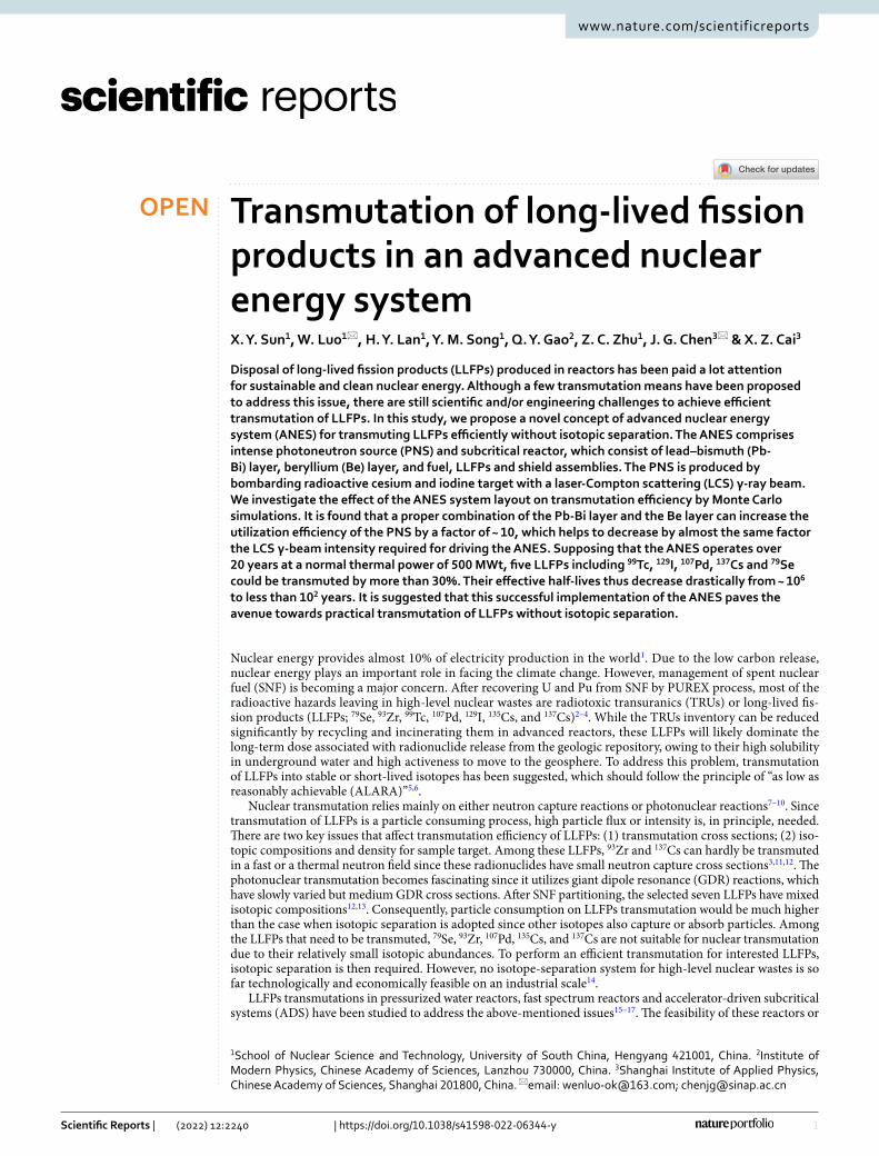
With the inspiration of ADS implementation, we introduce a novel concept on advanced nuclear energy sys-tem (ANES) that is driven by a photoneutron source (PNS) (see Fig. 1). The PNS is produced by bombarding a radioactive cesium and iodine (CsI) target with a laser-Compton scattering (LCS) γ-ray beam. As the LCS γ-ray beam has sufficient high intensity, such bombardment produces an intense PNS and meanwhile realizes photo-transmutation on radioactive cesium and iodine. The ANES is composed of the PNS and the reactor core which consists of lead–bismuth (Pb-Bi) layer, beryllium (Be) layer, and fuel, LLFPs and shield assemblies. In the ANES, both the transmutation and the energy production are accomplished. The fission energy production in the reactor core can be used to balance the energy consumption of PNS during transmutation, which means that the nuclear transmutation can be achieved without the need of external power supply. Moreover, one can expect to balance the initial cost for installing and operating the system, since this system could produce electricity and meanwhile lead to a large amount of heat generation during bombardment, making hydrogen fabrication possible14.
In this study, we present the conceptual design of the ANES for LLFPs transmutation without the require-ment to isotopic separation. In our design, seven LLFPs are loaded in the reactor core for neutron transmutation and radioactive CsI target are handled with photo-transmutation while generating PNS. The implementation of the ANES is first introduced. Then the LCS energy spectrum and the ANES layout are optimized for improv-ing the transmutation capability. In addition, the LCS beam intensity required for drive the ANES is evaluated. The results show that the proposed ANES concept may be a solution for transmuting LLFPs, albeit the existing LCS beam intensity is still a few orders of magnitudes lower than the requirement to drive the ANES at thermal power of 100 s MWt.
Results and discussionsANES layout. The layout of the ANES is shown in Fig. 1. As an LCS γ-ray beam of high intensity irra-diating the transmutation target (e.g., CsI target), a substantial population of neutrons are produced through photoneutron reactions, generating an intense PNS. Such PNS drives the ANES core, which is a subcritical one maintaining its intrinsic safety. The CsI target locates in the center of the ANES core. Considering a long-time irradiation, the cooling of the CsI target is achieved by circulation of liquid Pb-Bi alloy, which can endure higher energy density and longer operation cycle. A Be layer surrounding the Pb-Bi layer is adopted as neutron modera-tor. The combination of a 3 cm Pb-Bi layer and a 21 cm Be layer enhances the external neutron worth through neutron multiplication and moderation, as discussed later. The LLFPs without isotopic separation are loaded and transmuted with the excess neutrons leaked from the fuel assemblies. The keff , is designed to be ~ 0.98. The isotopic compositions of the LLFPs depend on the type of fuel, the neutron spectrum, and the irradiation history. The LLFPs used in this study are obtained from the burnup simulation of uranium dioxide fuel (see Methods).
The thermal power of ANES is designed to be 500 MWt. The ANES core, with a height of 110 cm and a diam-eter of 105 cm, contains 162 fuel assemblies, 78 LLFPs assemblies, and 60 shield assemblies. Each fuel assembly consists of 61 pins composed of uranium dioxide pellets covered by stainless steel cladding. Due to the intrinsic
Figure 1. The concept of the ANES: (a) the generation of PNS and (b) the front view and side view of the ANES layout.
3
Vol.:(0123456789)
Scientific Reports | (2022) 12:2240 | https://doi.org/10.1038/s41598-022-06344-y
www.nature.com/scientificreports/
safety of the subcritical core, the ANES does not need control rods that are mandatorily used in a typical critical reactor. The LLFPs assemblies are arranged with two rows in the core, and the number of assemblies in inner and outer rows is 36 and 42, respectively. Like the fuel assembly, each LLFPs assembly incorporates 61 pins (43 LLFPs pins and 18 YD2 pins). The CsI target has a height of 25 cm and a radius of 3 cm. The shield assembly is made of stainless steel containing 6.48% natural B4C. In the burnup simulation of the ANES core, we use the dynamic refueling to keep a constant neutron flux over 20 years of operation. The detailed design parameters for the ANES are shown in Table 1.
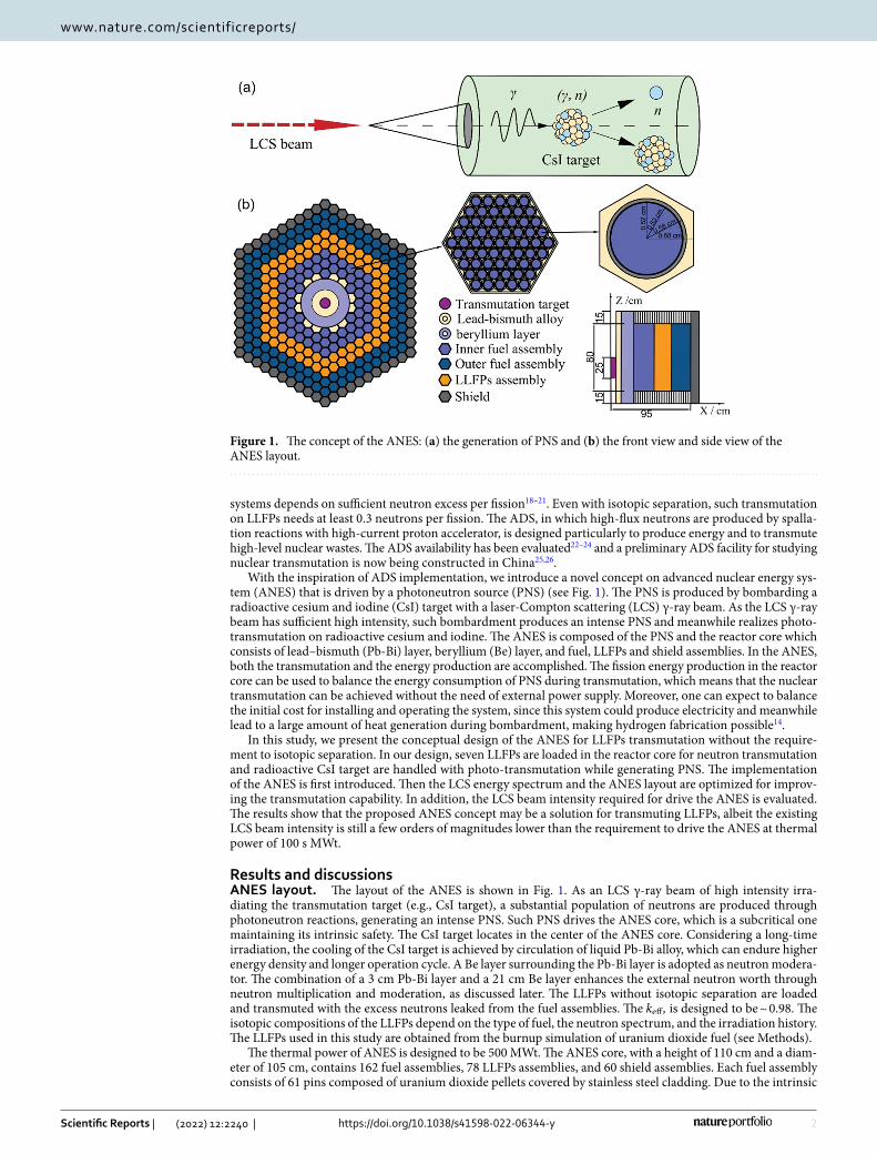
Production of PNS. For the PNS produced by an LCS γ-ray beam, the production rate Pn is highly depend-ent on the γ-ray spectral distribution and the GDR cross section. When neglecting the nonlinear Compton scat-tering effect, the cut-off energy of the LCS γ-ray beam can be obtained with Emax
γ = 4ELγ2/(
1+ 4ELγ /m0c2)
, where EL is the photon energy of the incident laser, γ is the Lorentz factor of the electron beam from an advanced accelerator, and m0c
2 presents the electron energy at rest. To maximize Pn , one can optimize Emaxγ by varying the
Lorentz factor for a fixed EL . Figure 2 shows the dependence of Pn on Emaxγ for varying CsI target thicknesses,
TCsI . The Pn increases first and then decrease with Emaxγ . Due to the convolution between the LCS γ-ray spectrum
and the GDR cross section, the value of Pn is peaked at Emaxγ ~ 20 MeV. When TCsI is larger than 25 cm, the Pn gets
a saturation of 0.01, which is determined by the penetration depth of the LCS γ-ray beam. It is expected to pro-duce γ-ray beam at an extremely high intensity of 1017 photon/s with the state-of-art of LCS facilities along with the advanced designs or concepts27. Consequently, the produced PNS could reach an intensity of 1015 photon/s.
Performance of the ANES. Figure 3 shows the neutron spectrum and power density distributions in dif-ferent assembly regions of the ANES core. In the region of LLFPs, the neutron spectrum is very similar to those in the region of fuel assemblies. The neutron flux decreases along the radial direction. In the shield region, the
Table 1. Design parameters of the ANES used in the simulation. The electric power is obtained supposing a thermal-electrical energy transfer efficiency of 40%.
Main parameters Data used in this study
Type of fuel UO2
Thermal power (MWt) 500
Electric power (MWe) 200
Core height (mm) 1100
Core diameter (mm) 1050
Number of fuel assemblies 60/102 (inner/outer)
Number of pins in each of fuel assembly 61
Pin diameter (mm) 5.8
Pellet diameter (mm) 5.2235U enrichment (%) 23.3
Number of LLFPs assemblies 78
Number of pins in each of LLFPs assembly 61
Number of shield assemblies 60
Figure 2. The Pn (per γ photon) as a function of LCS γ-ray energy Emaxγ . Three kinds of CsI target thicknesses
are used in the simulation while keeping the radius to be 3 cm.
4
Vol:.(1234567890)
Scientific Reports | (2022) 12:2240 | https://doi.org/10.1038/s41598-022-06344-y
www.nature.com/scientificreports/
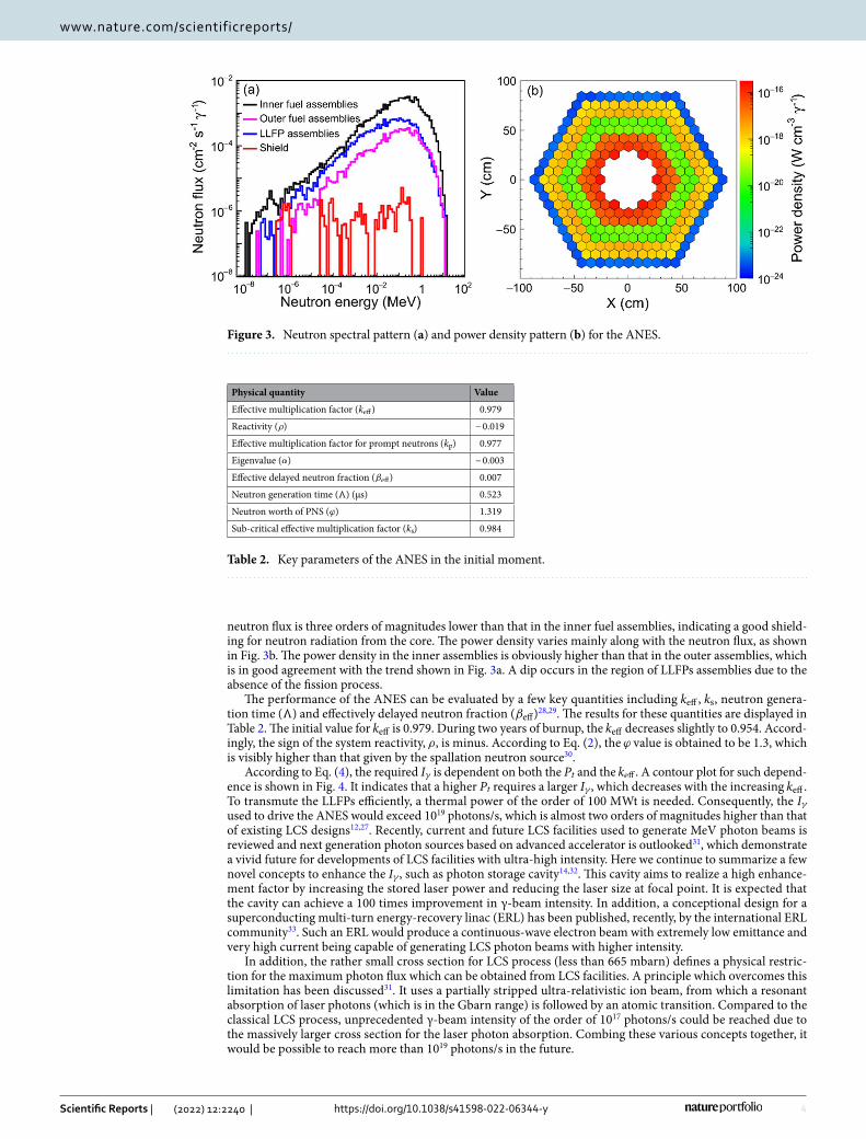
neutron flux is three orders of magnitudes lower than that in the inner fuel assemblies, indicating a good shield-ing for neutron radiation from the core. The power density varies mainly along with the neutron flux, as shown in Fig. 3b. The power density in the inner assemblies is obviously higher than that in the outer assemblies, which is in good agreement with the trend shown in Fig. 3a. A dip occurs in the region of LLFPs assemblies due to the absence of the fission process.
The performance of the ANES can be evaluated by a few key quantities including keff , ks , neutron genera-tion time (Ʌ) and effectively delayed neutron fraction ( βeff)28,29. The results for these quantities are displayed in Table 2. The initial value for keff is 0.979. During two years of burnup, the keff decreases slightly to 0.954. Accord-ingly, the sign of the system reactivity, ρ , is minus. According to Eq. (2), the ϕ value is obtained to be 1.3, which is visibly higher than that given by the spallation neutron source30.
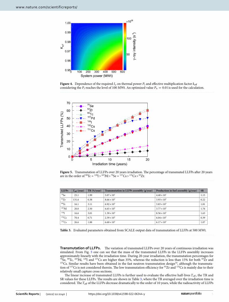
According to Eq. (4), the required Iγ is dependent on both the Pt and the keff . A contour plot for such depend-ence is shown in Fig. 4. It indicates that a higher Pt requires a larger Iγ , which decreases with the increasing keff . To transmute the LLFPs efficiently, a thermal power of the order of 100 MWt is needed. Consequently, the Iγ used to drive the ANES would exceed 1019 photons/s, which is almost two orders of magnitudes higher than that of existing LCS designs12,27. Recently, current and future LCS facilities used to generate MeV photon beams is reviewed and next generation photon sources based on advanced accelerator is outlooked31, which demonstrate a vivid future for developments of LCS facilities with ultra-high intensity. Here we continue to summarize a few novel concepts to enhance the Iγ , such as photon storage cavity14,32. This cavity aims to realize a high enhance-ment factor by increasing the stored laser power and reducing the laser size at focal point. It is expected that the cavity can achieve a 100 times improvement in γ-beam intensity. In addition, a conceptional design for a superconducting multi-turn energy-recovery linac (ERL) has been published, recently, by the international ERL community33. Such an ERL would produce a continuous-wave electron beam with extremely low emittance and very high current being capable of generating LCS photon beams with higher intensity.
In addition, the rather small cross section for LCS process (less than 665 mbarn) defines a physical restric-tion for the maximum photon flux which can be obtained from LCS facilities. A principle which overcomes this limitation has been discussed31. It uses a partially stripped ultra-relativistic ion beam, from which a resonant absorption of laser photons (which is in the Gbarn range) is followed by an atomic transition. Compared to the classical LCS process, unprecedented γ-beam intensity of the order of 1017 photons/s could be reached due to the massively larger cross section for the laser photon absorption. Combing these various concepts together, it would be possible to reach more than 1019 photons/s in the future.
Figure 3. Neutron spectral pattern (a) and power density pattern (b) for the ANES.
Table 2. Key parameters of the ANES in the initial moment.
Physical quantity Value
Effective multiplication factor ( keff) 0.979
Reactivity ( ρ) − 0.019
Effective multiplication factor for prompt neutrons ( kp) 0.977
Eigenvalue ( α) − 0.003
Effective delayed neutron fraction ( βeff) 0.007
Neutron generation time (Ʌ) (μs) 0.523
Neutron worth of PNS ( ϕ) 1.319
Sub-critical effective multiplication factor ( ks) 0.984
5
Vol.:(0123456789)
Scientific Reports | (2022) 12:2240 | https://doi.org/10.1038/s41598-022-06344-y
www.nature.com/scientificreports/
Transmutation of LLFPs. The variation of transmuted LLFPs over 20 years of continuous irradiation was simulated. From Fig. 5 one can see that the mass of the transmuted LLFPs in the LLFPs assembly increases approximately linearly with the irradiation time. During 20-year irradiation, the transmutation percentages for 79Se, 99Tc, 107Pd, 129I and 137Cs are higher than 35%, whereas the reduction is less than 15% for both 93Zr and 135Cs. Similar results have been obtained in the fast neutron transmutation design34, although the transmuta-tion of 137Cs is not considered therein. The low transmutation efficiency for 93Zr and 135Cs is mainly due to their relatively small capture cross sections.
The linear increase of transmuted LLFPs is further used to evaluate the effective half-lives Teff , the TR and SR values for these LLFPs. The results are shown in Table 3, where the TR averaged over the irradiation time is considered. The Teff of the LLFPs decrease dramatically to the order of 10 years, while the radioactivity of LLFPs
Figure 4. Dependence of the required Iγ on thermal power Pt and effective multiplication factor keff considering the Pt reaches the level of 100 MWt. An optimized value Pn = 0.01 is used for the calculation.
Figure 5. Transmutation of LLFPs over 20 years irradiation. The percentage of transmuted LLFPs after 20 years are in the order of 99Tc ≈ 129I > 107Pd > 79Se ≈ 137Cs > 135Cs > 93Zr.
Table 3. Evaluated parameters obtained from SCALE output data of transmutation of LLFPs at 500 MWt.
LLFPs Teff (year) TR (%/year) Transmutation in LLFPs assembly (g/year) Production in fuel assembly (g/year) SR79Se 25.1 1.99 5.07 × 101 4.40 × 101 1.1593Zr 131.6 0.38 8.66 × 10² 3.93 × 10³ 0.2299Tc 16.1 3.11 6.92 × 10³ 3.83 × 10³ 1.81107Pd 20.0 2.50 6.65 × 10² 3.77 × 10² 1.76129I 16.6 3.01 1.39 × 10³ 8.56 × 10² 1.63135Cs 70.4 0.71 2.39 × 10³ 6.04 × 10³ 0.39137Cs 26.6 1.88 6.60 × 10³ 6.17 × 10³ 1.07

6
Vol:.(1234567890)
Scientific Reports | (2022) 12:2240 | https://doi.org/10.1038/s41598-022-06344-y
www.nature.com/scientificreports/
without transmutations can last more than 105 years. For 99Tc, 107Pd, 129I and 137Cs, the TRs can achieve 2–3% per year. Although the TRs are relatively small, they are acceptable because the SRs > 1.0 would be more important for an ANES. In our study, the SRs are larger than 1.0 for 79Se, 99Tc, 107Pd, 129I and 137Cs, indicating the depletion of the LLFPs in the currently designed ANES. For 93Zr and 135Cs, the SRs are less than 1.0 due to small capture cross sections and large fission yields.
In the region of CsI target, hybrid transmutation (i.e., photo-transmutation and neutron transmutation) should be considered due to the mixed field of photons and neutrons. With the thermal power of 500 MWt, the transmutation capability for CsI target is shown in Table 4. The Teff for 129I, 135Cs and 137Cs decrease to less than 0.5 years according to Eq. (5), which includes the contribution of the photon and neutron transmutation. Compared with the only neutron transmutation on the LLFPs assemblies (see Table 3), the hybrid transmutation on CsI target can obtain two orders of magnitudes higher TR. In the photon field, the mass of transmuted 129I is a few times larger than those of transmuted 135Cs and 137Cs, which is mainly caused by the difference in isotope composition. In the neutron field, the transmuted 129I has a mass of 1.24 × 10³ g/year, which is comparable to that transmuted in the photon field (1.88 × 10³ g/year). However, in the 135Cs and 137Cs cases, the transmuted masses (induced mainly by neutron capture reactions on themselves) are less than the produced ones (induced mainly by their isotopes with mass number smaller than themselves). Since the cross section of 134Cs(n, γ) reaction is significantly higher than that of 135Cs(n, γ) reaction, and the isotope composition of 134Cs is increased with the irradiation time, the production of 135Cs can be larger than its consumption. The hybrid transmutation for 129I reaches 3.12 × 10³ g/year, which is almost one order of magnitude higher than those for 135Cs and 137Cs. This is mainly due to a high neutron capture cross section and a large isotope composition (see Table 5).
It should be noted that the TR (averaged over the seven LLFPs) can reach 1.94% per year for the ANES (see Table 3). This is slightly higher than that (1.51% per year) in a fast reactor system34. Meanwhile, the ANES has additional advantage to transmute radioiodine and radiocesium by the hybrid transmutation.
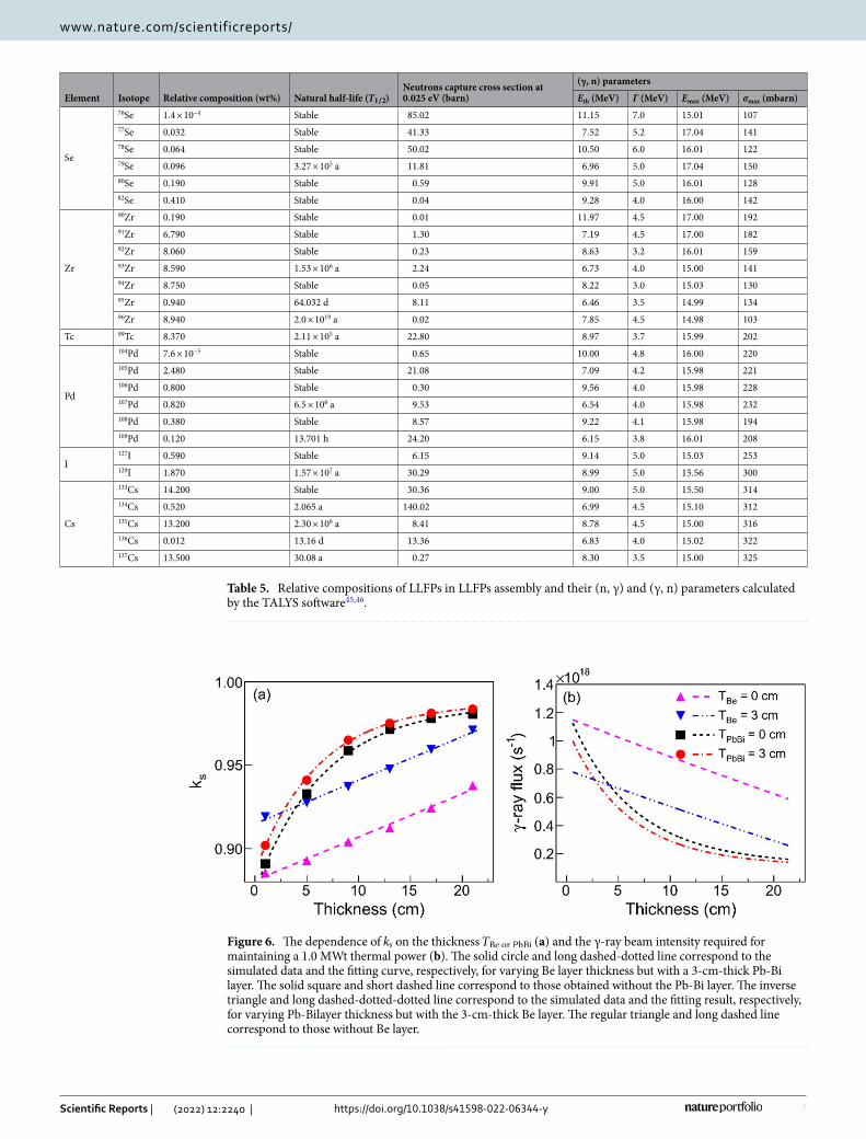
Optimal of the ANES layout. The neutron multiplier and moderator can be optimized in terms of absorp-tion and moderation to ensure that the produced thermal neutrons can be effectively absorbed by the fuel assem-blies in the core, which can thus enhance the neutron worth of PNS, ϕ . A Pb-Bi layer and a Be layer are used for neutron multiplication and moderation, respectively (see Fig. 1). The former also plays a key role in cooling the CsI target. The coolant and moderator dimensions are optimized to obtain a higher ks . Figure 6a presents the dependence of ks on the thickness of either coolant or moderator, TBe or PbBi in units of cm. The fitting results are exponentially correlated functions and can be uniformly expressed as
where a1 , b1 and c1 are fitting parameters. In the absence of the coolant, ks is merely dependent on TBe with a1 = − 0.986, b1 = − 0.112 and c1 = − 0.150. As the coolant thickness is fixed to 3 cm, the value of a1 remains unchanged, whereas b1 increases slightly to − 0.101 and c1 decreases to − 0.162. It is shown a sub-linear trend because the stopping power of neutrons in the moderator increases with the thickness. When the moderator thickness is higher than 15 cm, the value of ks can approach 1.0.
In the absence of the moderator, ks is only dependent on TPbBi and we have a1 = 1.076, b1 = − 0.200, and c1 = − 0.015. When considering a 3-cm-thick moderator, the value of c1 is kept unchanged, whereas a1 increases slightly to 1.101 and b1 increases to − 0.188. In this case, since the product of c1 and TPbBi is much smaller than unity, Eq. (1) can be approximated as ks = a2 + b2 · TPbBi with a2 and b2 being the functions of a1 , b1 and c1 . A quasi-linear trend is seen for the dependence of ks on TPbBi , as shown in Fig. 6a. This trend is caused by the fact that the coolant can also result in (n, xn) reaction, which increases the neutron flux. As a result, the neutron multiplication does not attenuate with the coolant thickness.
According to Eq. (4), one can further obtain the correlation between Iγ and TBe or PbBi , as shown in Fig. 6b. Compared to the Pb-Bi layer, the Be layer has a more significant effect on both ks and Iγ . The Iγ decreases rapidly with TBe and then gets saturated, whereas the ks has an opposite variation trend. When TBe is larger than 21 cm, the required Iγ approaches 1017, which is approximately one order of magnitude lower than that before optimiza-tion (for example, in the absence of both Pb-Bi layer and Be layer).
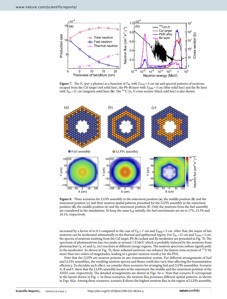
The effects of beryllium thickness on neutron multiplication and on softening of neutron spectrum are obtained and shown in Fig. 7. When TBe increases, the number of fast neutrons declines and that of thermal neutrons rises. The Pn reaches a maximum value for TBe = 13 cm and then decreases slightly due to the significant absorption of the neutrons produced therein. For TBe = 13 cm and TPbBi = 3 cm, the neutron multiplication is
(1)ks = a1 + b1 · exp(c1TBe or PbBi),
Table 4. Evaluated parameters obtained for transmutation of CsI target at 500 MWt. The tabulated data in photon field is obtained from Geant4 simulations, while the data in neutron field is obtained from SCALE simulations. The minus sign in neutron field on 135Cs (137Cs) suggests that the consumption of 135Cs (137Cs) is slower than its production.
LLFPs Teff (year) TR (%/year)
Transmutation in CsI target (g/year)
in photon field in neutron field in hybrid field129I 0.2 254.67 1.88 × 10³ 1.24 × 10³ 3.12 × 10³
135Cs 0.4 123.85 3.85 × 10² − 0.70 × 10² 3.15 × 10²
137Cs 0.3 151.51 9.25 × 10² − 1.07 × 10² 8.18 × 10²
7
Vol.:(0123456789)
Scientific Reports | (2022) 12:2240 | https://doi.org/10.1038/s41598-022-06344-y
www.nature.com/scientificreports/
Table 5. Relative compositions of LLFPs in LLFPs assembly and their (n, γ) and (γ, n) parameters calculated by the TALYS software45,46.
Element Isotope Relative composition (wt%) Natural half-life ( T1/2)Neutrons capture cross section at 0.025 eV (barn)
(γ, n) parameters
Eth (MeV) Γ (MeV) Emax (MeV) σmax (mbarn)
Se
76Se 1.4 × 10⁻⁴ Stable 85.02 11.15 7.0 15.01 10777Se 0.032 Stable 41.33 7.52 5.2 17.04 14178Se 0.064 Stable 50.02 10.50 6.0 16.01 12279Se 0.096 3.27 × 10⁵ a 11.81 6.96 5.0 17.04 15080Se 0.190 Stable 0.59 9.91 5.0 16.01 12882Se 0.410 Stable 0.04 9.28 4.0 16.00 142
Zr
90Zr 0.190 Stable 0.01 11.97 4.5 17.00 19291Zr 6.790 Stable 1.30 7.19 4.5 17.00 18292Zr 8.060 Stable 0.23 8.63 3.2 16.01 15993Zr 8.590 1.53 × 10⁶ a 2.24 6.73 4.0 15.00 14194Zr 8.750 Stable 0.05 8.22 3.0 15.03 13095Zr 0.940 64.032 d 8.11 6.46 3.5 14.99 13496Zr 8.940 2.0 × 10¹⁹ a 0.02 7.85 4.5 14.98 103
Tc 99Tc 8.370 2.11 × 10⁵ a 22.80 8.97 3.7 15.99 202
Pd
104Pd 7.6 × 10⁻⁵ Stable 0.65 10.00 4.8 16.00 220105Pd 2.480 Stable 21.08 7.09 4.2 15.98 221106Pd 0.800 Stable 0.30 9.56 4.0 15.98 228107Pd 0.820 6.5 × 10⁶ a 9.53 6.54 4.0 15.98 232108Pd 0.380 Stable 8.57 9.22 4.1 15.98 194109Pd 0.120 13.701 h 24.20 6.15 3.8 16.01 208
I127I 0.590 Stable 6.15 9.14 5.0 15.03 253129I 1.870 1.57 × 10⁷ a 30.29 8.99 5.0 15.56 300
Cs
133Cs 14.200 Stable 30.36 9.00 5.0 15.50 314134Cs 0.520 2.065 a 140.02 6.99 4.5 15.10 312135Cs 13.200 2.30 × 10⁶ a 8.41 8.78 4.5 15.00 316136Cs 0.012 13.16 d 13.36 6.83 4.0 15.02 322137Cs 13.500 30.08 a 0.27 8.30 3.5 15.00 325
Figure 6. The dependence of ks on the thickness TBe or PbBi (a) and the γ-ray beam intensity required for maintaining a 1.0 MWt thermal power (b). The solid circle and long dashed-dotted line correspond to the simulated data and the fitting curve, respectively, for varying Be layer thickness but with a 3-cm-thick Pb-Bi layer. The solid square and short dashed line correspond to those obtained without the Pb-Bi layer. The inverse triangle and long dashed-dotted-dotted line correspond to the simulated data and the fitting result, respectively, for varying Pb-Bilayer thickness but with the 3-cm-thick Be layer. The regular triangle and long dashed line correspond to those without Be layer.
8
Vol:.(1234567890)
Scientific Reports | (2022) 12:2240 | https://doi.org/10.1038/s41598-022-06344-y
www.nature.com/scientificreports/
increased by a factor of to 0.3 compared to the case of TBe = 1 cm and TPbBi = 3 cm. After that, the major of fast neutrons can be moderated substantially to the thermal and epithermal region. For TBe = 21 cm and TPbBi = 3 cm, the spectra of neutrons emitting from the CsI target, Pb-Bi coolant and Be moderator are presented in Fig. 7b. The spectrum of photoneutrons has two peaks at around 1.0 MeV, which is probably induced by the neutrons from photonuclear (γ, n) and (γ, 2n) reactions at different energy regions. The neutron spectrum softens significantly in the moderator. As shown in Fig. 7b, these softened neutrons can enhance the fission cross sections of 235U by more than two orders of magnitudes, leading to a greater neutron worth ϕ for the PNS.
Note that the LLFPs are neutron poisons in any transmutation system. For different arrangements of fuel and LLFPs assemblies, the resulting neutron spectra and fluxes could also vary, thus affecting the transmutation efficiency. To elucidate such effect, we consider three scenarios for arranging fuel and LLFPs assemblies. Scenario A, B and C show that the LLFPs assembly locates at the outermost, the middle and the innermost position of the ANES core, respectively. The detailed arrangements are shown in Figs. 8a–c. Note that scenario B corresponds to the layout shown in Fig. 1. In these scenarios, the neutron flux possesses different spatial patterns, as shown in Figs. 8d,e. Among these scenarios, scenario B shows the highest neutron flux in the region of LLFPs assembly.
Figure 7. The Pn (per γ photon) as a function of TBe with TPbBi = 3 cm (a) and spectral patterns of neutrons escaped from the CsI target (red solid line), the Pb-Bi layer with TPbBi = 3 cm (blue solid line) and the Be layer with TBe = 21 cm (magenta solid line) (b). The 235U (n, f) cross section (black sold line) is also shown.
Figure 8. Three scenarios for LLFPs assembly in the outermost position (a), the middle position (b) and the innermost position (c) and their neutron spatial patterns presented for the LLFPs assembly in the outermost position (d), the middle position (e) and the innermost position (f). Only the neutrons from the fuel assembly are considered in the simulations. To keep the same keff initially, the fuel enrichments are set to 17%, 23.3% and 24.1%, respectively.
9
Vol.:(0123456789)
Scientific Reports | (2022) 12:2240 | https://doi.org/10.1038/s41598-022-06344-y
www.nature.com/scientificreports/
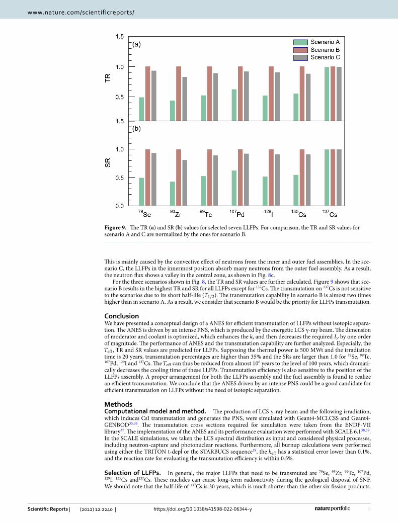
This is mainly caused by the convective effect of neutrons from the inner and outer fuel assemblies. In the sce-nario C, the LLFPs in the innermost position absorb many neutrons from the outer fuel assembly. As a result, the neutron flux shows a valley in the central zone, as shown in Fig. 8c.
For the three scenarios shown in Fig. 8, the TR and SR values are further calculated. Figure 9 shows that sce-nario B results in the highest TR and SR for all LLFPs except for 137Cs. The transmutation on 137Cs is not sensitive to the scenarios due to its short half-life ( T1/2 ). The transmutation capability in scenario B is almost two times higher than in scenario A. As a result, we consider that scenario B would be the priority for LLFPs transmutation.
ConclusionWe have presented a conceptual design of a ANES for efficient transmutation of LLFPs without isotopic separa-tion. The ANES is driven by an intense PNS, which is produced by the energetic LCS γ-ray beam. The dimension of moderator and coolant is optimized, which enhances the ks and then decreases the required Iγ by one order of magnitude. The performance of ANES and the transmutation capability are further analyzed. Especially, the Teff , TR and SR values are predicted for LLFPs. Supposing the thermal power is 500 MWt and the irradiation time is 20 years, transmutation percentages are higher than 35% and the SRs are larger than 1.0 for 79Se, 99Tc, 107Pd, 129I and 137Cs. The Teff can thus be reduced from almost 106 years to the level of 100 years, which dramati-cally decreases the cooling time of these LLFPs. Transmutation efficiency is also sensitive to the position of the LLFPs assembly. A proper arrangement for both the LLFPs assembly and the fuel assembly is found to realize an efficient transmutation. We conclude that the ANES driven by an intense PNS could be a good candidate for efficient transmutation on LLFPs without the need of isotopic separation.
MethodsComputational model and method. The production of LCS γ-ray beam and the following irradiation, which induces CsI transmutation and generates the PNS, were simulated with Geant4-MCLCSS and Geant4-GENBOD35,36. The transmutation cross sections required for simulation were taken from the ENDF-VII library37. The implementation of the ANES and its performance evaluation were performed with SCALE 6.138,39. In the SCALE simulations, we taken the LCS spectral distribution as input and considered physical processes, including neutron-capture and photonuclear reactions. Furthermore, all burnup calculations were performed using either the TRITON t-depl or the STARBUCS sequence39, the keff has a statistical error lower than 0.1%, and the reaction rate for evaluating the transmutation efficiency is within 0.5%.
Selection of LLFPs. In general, the major LLFPs that need to be transmuted are 79Se, 93Zr, 99Tc, 107Pd, 129I, 135Cs and137Cs. These nuclides can cause long-term radioactivity during the geological disposal of SNF. We should note that the half-life of 137Cs is 30 years, which is much shorter than the other six fission products.
Figure 9. The TR (a) and SR (b) values for selected seven LLFPs. For comparison, the TR and SR values for scenario A and C are normalized by the ones for scenario B.
10
Vol:.(1234567890)
Scientific Reports | (2022) 12:2240 | https://doi.org/10.1038/s41598-022-06344-y
www.nature.com/scientificreports/
Nevertheless, 137Cs is included in the transmutation inventory as an isotopic companion of 135Cs. This is because the latter can be transmuted effectively in the ANES without separation of isotopes. Namely, the transmutation of 137Cs can be regarded as a subsidiary of 135Cs. In addition, the CsI target used for the PNS plays an important role in the ANES system. The compositions of LLFPs were obtained from the burnup simulation of uranium dioxide pellets by fast breeder reactor core at 50 GWd/t for two years. The details of these compositions are pre-sented in Table 5. Without isotopic separation, such compositions were used as the initial compositions of the LLFPs in the pins. All LLFPs were considered in metallic forms because their melting points are generally high, and the space volume for loading can be minimized40. Selenium is a metalloid element having a melting point of 221 °C and should be in a liquid phase at the operating temperature (expected to be about 600 °C) of the ANES. Therefore, ZnSe, which has a melting point of 1526 °C and a thermal conductivity of 19.04 W/(m∙K)41,42, was selected as a compound form that would be a solid phase when loaded into the system. Zirconium, Technetium and Palladium are transition metals with melting points of 1852 ℃, 2157 ℃ and 1554 ℃, respectively. Thus, we have chosen metallic forms for 93Zr, 99Tc and 107Pd, which could maintain a solid-state in the system. These metallic forms have thermal conductivities of 22.70, 50.60, and 71.80 W/(m∙K), respectively. Iodine is a halogen element having a melting point of 114 °C, and it is in a gas phase at the operating temperature of the system. BaI2 has a melting point of 711 °C and then was selected as a compound form that becomes a solid phase when loaded into the system. Cesium has a melting point of 28 °C. We chose Cs2CO3 as its chemical form which has a melting point of 610 °C and thermal conductivity of 2.88 W/(m∙K)43. These LLFPs are supposed to be dispersed homogeneously in the pins, which helps to transmute the LLFPs44.
Selection of CsI target. The CsI target was selected for photo-transmutation due to the following con-siderations: 129I and 135Cs are problematic radionuclides since they have high radiotoxicity and long half-lives. The 135Cs strongly need isotopic separation for neutron-induced transmutation and the 137Cs is practically non-transmutable in any neutron field as aforementioned. Meanwhile, both the iodine and cesium elements have GDR cross sections as high as 300 mbarn, which is visibly higher than other elements (see Table 5) and may result in a significant transmutation. From the point of view of target fabrication, the two elements have the most stable chemical form in which three problematic radionuclides can be combined. The coolant temperature of the lead-based fast reactor ranges from 400 to 600 ℃, which is lower than the melting point of the CsI target (~ 620 ℃). In the simulations, the isotopic compositions for CsI target were employed according to SNF of a typical light water reactor12,17. These compositions are 127I (11.49%), 129I (38.51%), 133Cs (25.28%), 134Cs (0.01%), 135Cs (7.92%) and 137Cs (16.80%).
Parameters of ANES. The neutron worth ϕ represents the contribution of photoneutrons to the ANES core relative to fission neutrons47. As discussed above, ϕ is an essential parameter for the system design and can be defined as
where keff is the effective multiplication factor without considering the PNS, and ks is the multiplication factor considering PNS48. In our case, ks indicates the utilization efficiency of the ANES to the PNS. It is expressed by
where F is the creation operator, S0 is the number of photoneutrons, N is the total number of neutrons from nuclear fission and photonuclear process in the ANES, and �s is the total neutron flux in the core. The thermal power of the ANES, Pt , is dependent on the averaged fission energy Ef , the LCS beam intensity Iγ , the produc-tion rate of photoneutrons Pn , and the average number of fission neutrons ν . In our study, it can be given by:
It suggests that the Iγ required for driving the ANES is inversely proportional to the ϕ when keeping Pt constant.
The Teff is defined as the effective half-life of radionuclides considering both transmutation process and natural decay in the core, which is crucial for evaluating the transmutation capability. Here Teff is expressed as
where � and σ are thenatural decay constant and the effective neutron capture cross section for transmuted radionuclides, respectively. Equation (5) can be approximated as Teff ≈ ln2
σ�s as the � are extremely smaller than
the product of σ and �s , indicating that an efficient transmutation can reduce significantly the Teff .For a transmutation system, transmutation rate ( TR ) and support ratio ( SR ) are also two important
parameters34. Here, TR is the ratio of the amount of transmuted LLFPs to those initially loaded in a transmuta-tion system, and SR is the ratio of the amount of transmuted LLFPs to that of produced ones. The expressions of TR and SR are
(2)ϕ =1− 1/keff
1− 1/ks,
(3)ks =�F�s�
�F�s� + �S�=
N − S0
N= 1−
S0
N,
(4)Pt = Ef · Iγ · Pn ·keff
1− keff·1
ν· ϕ.
(5)Teff =ln2
�+ σ�s,
11
Vol.:(0123456789)
Scientific Reports | (2022) 12:2240 | https://doi.org/10.1038/s41598-022-06344-y
www.nature.com/scientificreports/
Here N(0) and t are the total initial atomic number of LLFPs and irradiation time, respectively; Y and M are the LLFPs yield per fission of fuel materials and the total fission rate in the ANES core. When the value of σ�st is small enough, the TR and SR can be simplified as σ�s and N(0)σ�s/YM , respectively. If SR > 1.0, those self-produced LLFPs could be transmuted during the operation of the ANES. In our study, a direct approach to enhancing SR is to increase the number of initially loaded LLFPs. However, the TR will be decreased due to the neutron self-shielding effect in the loaded zone. As a result, it is imperative to balance the TR and SR for LLFPs of great interest.
Received: 16 October 2021; Accepted: 13 January 2022
References 1. León, S. B. World Nuclear Performance Report 2021, https:// www. world- nucle ar. org/. (Accessed: 15th October 2021). 2. Kailas, S., Hemalatha, M. & Saxena, A. Nuclear transmutation strategies for management of long-lived fission products. Pramana
85, 517–523 (2015). 3. Yang, W. S. et al. Long-Lived Fission Product Transmutation Studies. Nucl. Sci. Eng. 146, 291–318 (2004). 4. Wang, H. et al. Spallation reaction study for long-lived fission products in nuclear waste. EPJ. Web Conf. 239, 06003 (2020). 5. Ikeda, K. et al. Technology readiness assessment of partitioning and transmutation in Japan and issues toward closed fuel cycle.
Prog. Nucl. Energ. 74, 242–263 (2014). 6. González-Romero, E. M. Impact of partitioning and transmutation on the high level waste management. Nucl. Eng. Des. 241,
3436–3444 (2011). 7. Wang, X. L. et al. Transmutation prospect of long-lived nuclear waste induced by high-charge electron beam from laser plasma
accelerator. Phys. Plasmas 24, 093105 (2017). 8. Wang, X. L. et al. Photo-transmutation of long-lived radionuclide 135Cs by laser–plasma driven electron source. Laser Part. Beams
34, 433–439 (2016). 9. Rehman, H. U. et al. Comparison of the Laser-Compton scattering and the conventional bremsstrahlung X-rays for photonuclear
transmutation. Int. J. Energ. Res. 42, 236–244 (2018). 10. Rehman, H. U, Lee, J. & Kim, Y. Optimization of the laser-Compton scattering spectrum for the transmutation of high-toxicity
and long-living nuclear waste. Ann. Nucl. Energy 105, 150–160 (2017). 11. Igashira, M. & Ohsaki, T. Neutron economy and nuclear data for transmutation of long-lived fission products. Prog. Nucl. Energ.
40, 555–560 (2002). 12. Rehman, H. U. et al. Photon and neutron hybrid transmutation for radioactive cesium and iodine. Ann. Nucl. Energy 133, 527–537
(2019). 13. Hayakawa, T. et al. Proposal for selective isotope transmutation of long-lived fission products using quasi-monochromatic γ-ray
beams. J. Nucl. Sci. Technol. 53, 2064–2071 (2016). 14. Imasaki, K. et al. Gamma-ray beam transmutation. Energ. Convers. Manag. 49, 1922–1927 (2008). 15. Jin, M. T. et al. Yield of long-lived fission product transmutation using proton-, deuteron-, and alpha particle-induced spallation.
Nucl. Sci. Technol. 32, 1–11 (2021). 16. Ma, K. F. et al. Transmutation of129I in a single-fluid double-zone thorium molten salt reactor. Nucl. Sci. Technol. 31, 1–8 (2020). 17. Setiawan, M. B. et al. Analysis on Transmutation of Long-Lived Fission Product from the PWR Spent Fuel Using a 30-MW (ther-
mal) RSG-GAS Reactor. Nucl. Technol. 443, 1–6 (2020). 18. Tommasi, J. et al. A. Long-lived waste transmutation in reactors. Nucl. Technol. Radiat. 111, 133–148 (1995). 19. OECD. Physics and Safety of Transmutation Systems: A Status Report. OECD Pap. 6, 13–13 (2006). 20. Liu, B. et al. Transmutation of minor actinides in the pressurized water reactors. Ann. Nucl. Energy 64, 86–92 (2014). 21. Wakabayashi, T. Transmutation characteristics of MA and LLFP in a fast reactor. Prog. Nucl. Energ. 40, 457–463 (2002). 22. Medina-Castro, D. et al. Designing a heterogeneous subcritical nuclear reactor with thorium-based fuel. Ann. Nucl. Energy 96,
455–458 (2016). 23. Vega-Carrillo, H. R. et al. Features of a subcritical nuclear reactor. Ann. Nucl. Energy 75, 101–106 (2015). 24. Stanculescu, A. Accelerator Driven Systems (ADSs) for nuclear transmutation. Ann. Nucl. Energy 62, 607–612 (2013). 25. Wang, L. et al. Multiplication characteristics of a gas-cooled ads with fast-thermal coupling configuration. Nucl. Eng. Des. 340,
1–8 (2018). 26. Gu, L., Su, X. Latest research progress for LBE coolant reactor of China initiative accelerator driven system project. Front. Energy
Res. 1–12 (2021). 27. Krasny, M.W. The Gamma Factory proposal for CERN. Proc. Sci.: EPS-HEP2017 1, 249–249 (2018). 28. Nagaya, Y. & Mori, T. Calculation of effective delayed neutron fraction with Monte Carlo perturbation techniques. Ann. Nucl.
Energy 38, 254–260 (2011). 29. Verboomen, B. et al. Monte Carlo calculation of the effective neutron generation time. Ann. Nucl. Energy 33, 911–916 (2006). 30. Shahbunder, H. et al. Subcritical multiplication factor and source efficiency in accelerator-driven system. Ann. Nucl. Energy 37,
1214–1222 (2010). 31. Zilges, A. et al. Photonuclear reactions—From basic research to applications. Prog. Part. Nucl. Phys. 122, 103903 (2022). 32. Shimada, M., Hajima, R. Inverse Compton scattering of coherent synchrotron radiation in an energy recovery linac. Phys. Rev.
Accel. Beams 13, 100701 (2010). 33. Angal-Kalinin, D. et al. PERLE. Powerful energy recovery linac for experiments. Conceptual design report. J. Phys. G. Nucl. Partic.
45, 065003 (2018). 34. Chiba, S. et al. Method to reduce long-lived fission products by nuclear transmutation with fast spectrum reactors. Sci. Rep. 7,
1–10 (2017). 35. Luo, W. et al. A 4D Monte Carlo laser-Compton scattering simulation code for the characterization of the future energy-tunable
SLEGS. Nucl. Instrum. Methods Phys. Res. Sect. A 660,108–115 (2011). 36. Luo, W. et al. Implementation of the n-body Monte-Carlo event generator into the Geant4 toolkit for photonuclear studies. Nucl.
Instrum. Methods Phys. Res. Sect. 849, 49–54 (2017). 37. Grossi, R. M. The database on nuclear power reactors. Available at: https:// pris. iaea. org/ pris/. (Accessed: 15th October 2021).
(6)TR =N(0)− N(t)
tN(0),
(7)SR =N(0)− N(t)
YMt.
12
Vol:.(1234567890)
Scientific Reports | (2022) 12:2240 | https://doi.org/10.1038/s41598-022-06344-y
www.nature.com/scientificreports/
38. Bowman, S. M. SCALE 6: Comprehensive nuclear safety analysis code system. Nucl. Technol. 174, 126–148 (2011). 39. Rearden, B. T. & Jessee, M. A. SCALE code system (No. ORNL/TM--2005/39-V-6.2). Oak Ridge National Laboratory (ORNL)
(2016). 40. Osaka, M. et al. Research and development of minor actinide-containing fuel and target in a future integrated closed cycle system.
J. Nucl. Sci. Technol. 44, 309–316 (2007). 41. Lugueva, N. V. et al. Thermal conductivity of polycrystalline zinc selenide. Phys. Solid State 45, 449–452 (2003). 42. Wakabayashi, T. et al. Study on method to achieve high transmutation of LLFP using fast reactor. Sci. Rep. 9, 1–14 (2019). 43. Kase, T. et al. Takahashi H, et al. Transmutation of cesium-137 using proton accelerator. J. Nucl. Sci. Technol. 30, 911–918 (1993). 44. Anderson, J. L., Mayo, W. & Lantz, E. Reactivity control of fast-spectrum reactors by reversible hydriding of yttrium zones. NASA
Technical note. NASA-TN-D-4615 (1968). 45. Koning, A. J., Hilaire, S. & Duijvestijn, M. C. TALYS: comprehensive nuclear reaction modeling. AIP Conf. Proc. 769, 1154–1159
(2005). 46. Zhu, Z. C. et al. Transmutation of radioactive cesium and iodine using gamma-radiation from light nuclei under proton bombard-
ment. Ann. Nucl. Energy 140, 107158 (2020). 47. Fang, Z. X. et al. Theoretical analysis of long-lived radioactive waste in pressurized water reactor. Nucl. Sci. Technol. 32, 1–17 (2021). 48. Xoubi, N. Neutronic design study of accelerator driven system (ADS) for Jordan subcritical reactor as a neutron source for nuclear
research. Appl. Radiat. Isotopes 131, 71–76 (2018).
AcknowledgementsThis work was supported by the National Natural Science Foundation of China, China (Grant Nos. 11675075 and 11605084), and Youth Talent Project of Hunan Province, China (Grant No. 2018RS3096).
Author contributionsW.L. and X.Y.S. conceived the idea presented in the manuscript. X.Y.S., H.Y.L, and Q.Y.G. carried out the simula-tions. H.Y.L. performed the data analysis. W.L., X.Y.S., H.Y.L., Y.M.S., Z.C.Z., J.G.C., contributed to clarifying physical details and the writing of the manuscript. All authors discussed the results, commented on the manu-script, and agreed on the contents.
Competing interests The authors declare no competing interests.
Additional informationCorrespondence and requests for materials should be addressed to W.L. or J.G.C.
Reprints and permissions information is available at www.nature.com/reprints.
Publisher’s note Springer Nature remains neutral with regard to jurisdictional claims in published maps and institutional affiliations.
Open Access This article is licensed under a Creative Commons Attribution 4.0 International License, which permits use, sharing, adaptation, distribution and reproduction in any medium or
format, as long as you give appropriate credit to the original author(s) and the source, provide a link to the Creative Commons licence, and indicate if changes were made. The images or other third party material in this article are included in the article’s Creative Commons licence, unless indicated otherwise in a credit line to the material. If material is not included in the article’s Creative Commons licence and your intended use is not permitted by statutory regulation or exceeds the permitted use, you will need to obtain permission directly from the copyright holder. To view a copy of this licence, visit http:// creat iveco mmons. org/ licen ses/ by/4. 0/.
© The Author(s) 2022