Fission Technology - International Atomic Energy Agency
34
Fission Technology 8.1 Advanced and Innovative Reactors Research and development activities on advanced and innovative reactors are performed within a domestic programme and international initiatives. The ongoing New Nuclear Fission National Programme is synergic and complementary to the International Nuclear Energy Initiative (INERI) and Euratom framework programmes and is managed by ENEA through a specific agreement signed in June 2007 by the Italian Ministry for Economic Development (MSE). The activities concern an integral advanced pressurised light-water-cooled reactor (IRIS nuclear power plant [NPP]) and several Generation-IV fast reactors: lead-cooled, very high temperature and sodium-cooled. A summary of the main results achieved in 2007 follows. In the framework of the INERI programme ENEA and other Italian organisations are involved in the design of the International Reactor Innovative and Secure (IRIS NPP), particularly in the design certification. An appropriate integral testing programme will be performed in the SPES-3 facility to be built at the SIET laboratories in Piacenza. The facility will be located inside the building of the decommissioned Emilia oil-fired power plant. Once erected, the facility will simulate IRIS at full height, full pressure and temperature, and with volumes and power scaled by factors of 1:100 and 1:150, respectively. The activity will be carried out in a collaboration with Oak Ridge National Laboratory (ORNL), USA under an international initiative concerning cooperation in the field of nuclear-related technologies of mutual interest. In 2007 activities were mainly devoted to the conceptual design of the SPES-3 facility, the development of SPES-3 nodalization and the seismic isolation analysis of the IRIS auxiliary building. SPES-3 facility: conceptual design. SPES-3 (figs 8.1, 8.2) has been designed to be suitable for performing both integral and separate effects-tests. The former is aimed at verifying thermohydraulic interaction among the various safety-related systems during selected accident sequences covering IRIS transients, including double-ended pipe breaks and long-term cooling capability; the latter, at verifying the performance of selected components (steam generators and emergency heat removal system (EHRS) vertical heat exchanger). The test results will provide thermohydraulic data for computer code validation and/or will ensure that new component and system functions important to plant safety are reliable. To carry out these objectives, a multinational group of experts from Westinghouse, ORNL, Croatia University, CIRTEN, Ansaldo Nucleare, Ansaldo Camozzi, SIET and ENEA was set up in mid-2006. As the IRIS reactors are characterised by the thermo-dynamically coupled behaviour of passive safety systems located in the containment and in the International Reactor Innovative and Secure EBT Steam line DVI line Feed line Wet well Cavity RPV ADS quench tank Dry well LGMS SG makeup tank PCC RCP EHRS Fig. 8.1 - Sketch of SPES-3 facility 114 2007 Progress Report
-
Upload
khangminh22 -
Category
Documents
-
view
0 -
download
0
Transcript of Fission Technology - International Atomic Energy Agency
Fission Technology
8.1 Advanced and Innovative Reactors
Research and development activities on advanced and innovative reactors are performed within adomestic programme and international initiatives. The ongoing New Nuclear Fission National Programmeis synergic and complementary to the International Nuclear Energy Initiative (INERI) and Euratomframework programmes and is managed by ENEA through a specific agreement signed in June 2007 bythe Italian Ministry for Economic Development (MSE). The activities concern an integral advancedpressurised light-water-cooled reactor (IRIS nuclear power plant [NPP]) and several Generation-IV fastreactors: lead-cooled, very high temperature and sodium-cooled.
A summary of the main results achieved in 2007 follows.
In the framework of the INERI programme ENEA and other Italian organisations areinvolved in the design of the International Reactor Innovative and Secure (IRISNPP), particularly in the design certification. An appropriate integral testingprogramme will be performed in the SPES-3 facility to be built at the SIETlaboratories in Piacenza. The facility will be located inside the building of the
decommissioned Emilia oil-fired power plant. Once erected, the facility will simulate IRIS at full height, fullpressure and temperature, and with volumes and power scaled by factors of 1:100 and 1:150,respectively. The activity will be carried out in a collaboration with Oak Ridge National Laboratory (ORNL),USA under an international initiative concerning cooperation in the field of nuclear-related technologies ofmutual interest.
In 2007 activities were mainly devoted to the conceptual design of the SPES-3 facility, the development ofSPES-3 nodalization and the seismic isolation analysis of the IRIS auxiliary building.
SPES-3 facility: conceptual design. SPES-3 (figs 8.1, 8.2) has been designed to be suitable forperforming both integral and separate effects-tests. The former is aimed at verifying thermohydraulicinteraction among the various safety-related systems during selected accident sequences covering IRIS
transients, including double-ended pipebreaks and long-term coolingcapability; the latter, at verifying theperformance of selected components(steam generators and emergencyheat removal system (EHRS) verticalheat exchanger). The test results willprovide thermohydraulic data forcomputer code validation and/or willensure that new component andsystem functions important to plantsafety are reliable. To carry out theseobjectives, a multinational group ofexperts from Westinghouse, ORNL,Croatia University, CIRTEN, AnsaldoNucleare, Ansaldo Camozzi, SIETand ENEA was set up in mid-2006.
As the IRIS reactors are characterisedby the thermo-dynamically coupledbehaviour of passive safety systemslocated in the containment and in the
InternationalReactor Innovativeand Secure
EBT
Steamline
DVI lineFeedline
Wet well Cavity
RPV
ADS quenchtank
Dry well
LGMS
SGmakeup
tank
PCC
RCP EHRS
Fig. 8.1 - Sketch of SPES-3 facility
114
2007ProgressReport

integral reactor pressure vessel in order to mitigate small loss-of-coolantaccidents (LOCAs), the facility also simulates the containment system, theprimary system, the secondary system up to the main steam isolation valves, thesafety-related systems and the auxiliary systems.
To simplify the design, the integral layout of the reactor containment was notmaintained, and the containment and safety systems it houses are simulatedwith separated vessels and connecting piping. On the other hand, the integralprimary coolant system layout was maintained, with the exception of the primarypumps. A single pressure vessel, therefore, houses a reactor core simulator(heater rods), a steam generator simulator, a pressuriser, a riser and adowncomer. To well reproduce the thermohydraulic phenomena in the facility,control of energy exchange and losses on component surfaces during atransient is obtained passively by applying insulation material and/or actively byapplying electrical heaters. All facility components (tanks, piping and valves) weredesigned to maintain the same power over mass flow rate, residence time,power over volume ratio and heat fluxes. In addition, the components werelocated at elevations based on the dimensions of IRIS and were adequatelyinstrumented, defining type (temperature, pressure, flow, level, etc.) and location.For the two-flow measurements the activity was limited to defining needs andlocation.
SPES-3 nodalization development. Once the conceptual design was finished,the mechanical component sizing and layout were used to build a numericalmodel for the RELAP5 code to simulate the facility behaviour under selectedaccidents and give feedback information for the final facility design. The activity is still in progress, with 25%completed in the reporting year.
IRIS plant seismic isolation analysis. During the general IRIS meeting held in Santander in November2006, ENEA was assigned the task of investigating the pros and cons related to the use of seismic isolationto prevent earthquake effects on the IRIS buildings and internals. The basic concept of seismic isolation isto disconnect the building from the ground by introducing devices (seismic isolators) capable of “filtering”the energy transmitted by the earthquake fromground to structure and of dissipating a part ofthe energy, thereby strongly reducing the amountentering the structure and the consequentdamage.
Analysis was limited to the IRIS auxiliary building.The finite element model of the non-isolatedbuilding developed by Westinghouse for theABAQUS code was used for parametricalanalyses aimed at optimising isolator featuresafter the required modifications. Different isolatordimensions, layout (fig. 8.3) and isolationfrequencies were analysed. Well-known easy-to-manufacture commercial isolators were chosen.
A time history analysis was performed tocompare the behaviour of the structure with andwithout isolators. The time histories used for theanalyses were generated by Westinghouseaccording to AP1000 documents and American
8. R&D on Nuclear Fission
2007 Progress Report
RWST
EHRSDry-well
LGMS
PSS
RVcavity
RPV
QT
EBT
ADP
Fig. 8.2 - SPES-3 axonometric view
ZY
X
115
Fig. 8.3 - IRIS auxiliary building model. Number of isolators
(red points) ranges from 200 to 250
Fission Technology2007ProgressReport
regulations [8.1–8.4]. The parameters chosen forcomparison were acceleration and maximum displacementcalculated in some points on the structures consideredrelevant for the seismic design, i.e., vessel and roof, whichare characterised by high amplification of the peak groundacceleration (PGA).
The results referring to a PGA of 0.3 g show a reduction inacceleration by a factor of two at vessel level (fig. 8.4) andby a factor of six at roof level. It is also worth noting that thenodes of the roof and vessel move exactly in the same way,thus confirming the rigid-body movement of the structureabove the isolators. The maximum horizontal vessel
displacement, evaluated as the vector magnitude of each displacement along X and Y, is 154 mm, belowthe maximum displacement of the isolators (250 mm). The vertical movement is very limited and themaximum differential displacement is only about 1.5 mm.
A preliminary cost analysis of the whole isolation system was also done. Costs related to acceptance andqualification testing were neglected as they depend on the standard used.
The objective of the European Lead-Cooled System (ELSY) project of the 6th
European Framework Programme (FP6) is to investigate the technical and economicalfeasibility of a 600-MWe power reactor cooled by molten lead and to demonstrate thatit is possible to design a competitive and safe fast critical reactor, capable of recycling
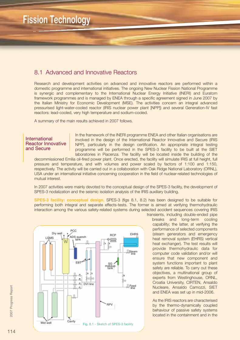
its own nuclear wastes, by adopting simple engineered technical features. The lead fast reactor (LFR) isone of the six innovative systems being considered by the Generation-IV International Forum (GIF) [8.5]) asit could represent a significant step forward for sustainable, safe, non-proliferant and economic nuclearenergy. The LFR features a fast-neutron spectrum and a closed fuel cycle for efficient conversion of fertileuranium (U) and can, in principle, fission part of its wastes, composed of long-lived transuranic (TRU)isotopes, while producing energy at an affordable cost. Figure 8.5 shows the ELSY concept as of end 2007
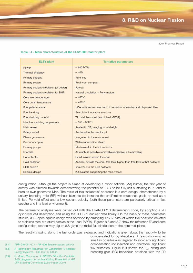
and table 8.I reports a tentative list of the reactorparameters [8.6].
In 2007 ENEA’s main efforts were devoted todefining a consistent reference core configuration,for which ENEA is responsible under the ELSYproject. Actually two options are being investigatedin parallel: the first is based on conventionalwrapped hexagonal fuel assemblies (FAs), typical ofa sodium fast reactor (SFR), where pins andsubassemblies (S/As) are arranged in a triangularlattice; the second consists of open square FAs,typical of a pressurised water reactor (PWR), wherepins and S/As are arranged in a square lattice. ENEAis focussing on the latter, more innovative
[8.1] RG 1.60 – Design response spectra for seismicdesign of nuclear power plants
[8.2] ASCE 4-98 – Seismic analysis of safety-relatednuclear structures and commentary
[8.3] APP-1000-S2C-060 – Time history analysis ofnuclear island shell model
Vessel
Time
Acc
eler
atio
n m
/s2
0 5 10 15 20 25
4
-4
2
-2
0
Isol T=2s-15% dampingFixed base
Fig. 8.4 - Output time history on vessel node
European Lead-Cooled System
Above reactor cell
Access area
Fuel route
Fig. 8.5 - ELSY reactor
116
configuration. Although the project is aimed at developing a minor actinide (MA) burner, the first year ofactivity was directed towards demonstrating the potential of ELSY to be fully self-sustaining in Pu and toburn its own generated MAs. The result of this “adiabatic” approach is a core design, characterised by aunitary breeding ratio (BR) without blankets (to increase the proliferation resistance goal), as well as alimited Pb void effect and a low coolant velocity (both these parameters are particularly critical in fastspectra and in a lead environment).
The parametric analyses were carried out with the ERANOS 2.0 deterministic code, by adopting a 2Dcylindrical cell description and using the JEFF2.2 nuclear data library. On the basis of these parametricstudies, a FA open square design was obtained by arranging 17×17 pins (of which five positions devotedto stainless steel structural pins as in the usual PWRs). Figures 8.6 and 8.7 show the reference FA and coreconfiguration, respectively; figure 8.8 gives the radial flux distribution at the core mid-plane.
The reactivity swing along the fuel cycle was evaluated and indications given about the reactivity to becompensated for by absorbers. A reactivity swing assmall as possible was targeted to avoid any significantcompensating rod insertion and, therefore, significantflux distortion. Figure 8.9 shows the keff swing andbreeding gain (BG) behaviour, obtained with the 2D
117
8. R&D on Nuclear Fission
2007 Progress Report
[8.4] APP-GW-G1-003 – AP1000 Seismic design criteria
[8.5] A Technology Roadmap for Generation IV NuclearEnergy Systems – GIF 002-00 (2002).
[8.6] S. Monti, The support to GENIV LFR within the ItalianR&D programs on nuclear fission, Presented at GIFLFR Steering Committee (Washington 2007)
ELSY plant Tentative parameters
Power ∼ 600 MWe
Thermal efficiency ∼ 40%
Primary coolant Pure lead
Primary system Pool type, compact
Primary coolant circulation (at power) Forced
Primary coolant circulation for DHR Natural circulation + Pony motors
Core inlet temperature ∼ 400°C
Core outlet temperature ∼ 480°C
Fuel pellet material MOX with assessment also of behaviour of nitrides and dispersed MAs
Fuel handling Search for innovative solutions
Fuel cladding material T91 stainless steel (aluminized, GESA)
Max fuel cladding temperature ∼ 550 – 560°C
Main vessel Austenitic SS, hanging, short-height
Safety vessel Anchored to the reactor pit
Steam generators Integrated in the main vessel
Secondary cycle Water-supercritical steam
Primary pumps Mechanical, in the hot collector
Internals As much as possible removable (objective: all removable)
Hot collector Small-volume above the core
Cold collector Annular, outside the core, free level higher than free level of hot collector
DHR coolers Immersed in the cold collector
Seismic design 2D isolators supporting the main vessel
Table 8.I - Main characteristics of the ELSY-600 reactor plant

Fission Technology
118
2007ProgressReport
model in figure 8.7, in a five-year cycle (at full power and without any refuelling). The max keff excursion is700 pcm and the BR remains close to one over the full period. It should be noted that both the keff andthe BG increase in the first three years and decrease in the last two. This behaviour is coherent with theevolving Pu239 equivalent mass.
Figure 8.10 shows the burn-up capability. By considering the mass balances at the fifth year, it is foundthat (in comparison with the beginning of life [BOL]) the amount of U decreases by about 9%; Pu increasesby about 3% and the MAs have exponential behaviour towards an equilibrium content of some 400 kg,about 6% of the Pu mass and 1% of the total heavy metal (HM) inventory. The time constant of theexponential is about 12 years.
For the thermohydraulic (TH) performance of the open square core, the available correlations for pressurelosses and the heat transfer coefficient for heavy liquid metal flow in a rod bundle were investigated duringthe first part of 2007. Based on the investigation, a RELAP5 model of the core, consisting of completelyindependent hot and average assemblies, was used for a conservative TH assessment of the 1500-MWcore in figure 8.7. Due to corrosion constraints, the maximum allowable temperature of the
B4C Rods (70% VF)
(12 As)
Fuel INNER
(132 FAs; Epu= 13.4%)
Fuel INTERMEDIATE
(72 FAs; Epu= 15%)
Fuel OUTER
(68 FAs; Epu= 18.5%)
Pb reflector
Fuel INN
Fue
l IN
T
Fue
l OU
T
Pb
FAS: 132, 72, 68
cm-2
s-1
3.0×10¹⁵
2.0×10¹⁵
1.0×10¹⁵
5×10¹⁴
0
R (cm)0 40 80 120 160 200 240
Fig. 8.9 - ELSY 1500 MWth core: keff swing and
breeding gain behaviour
Fig. 8.7 - 1500 MWth core configuration
Fig. 8.8 - ELSY 1500 MWth core: radial flux distribution at BOL at
the core mid-plane
232.73 mm (17 pins)
232.
73 m
m (
17 p
ins)
22
4 mm clearancebetween FAs
(side FA=236.73 mm)
0.6 0.163.19
8.989.3
10.5
13.6
9 m
m
VF(Pellet)= 32.1% VF(Steel)= 10.2%
(950°C) (480°C) (440°C)
Fig. 8.6 - FA design (90 cm active height)
k eff
t(y) 1 2 3 4 5BG 0.045 0.033 0.019 0.005 -0.008
0 1 2 3 4 5Years
700 pcm
RZ referenceconfiguration
1.004
1.000
0.996
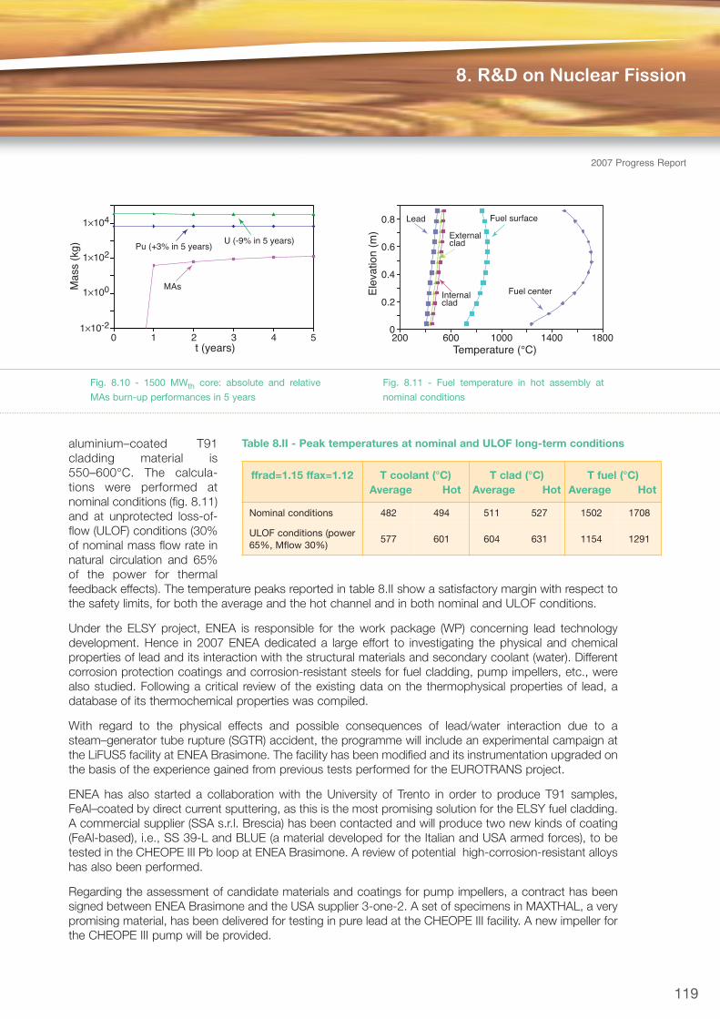
aluminium–coated T91cladding material is550–600°C. The calcula -tions were performed atnominal conditions (fig. 8.11)and at unprotected loss-of-flow (ULOF) conditions (30%of nominal mass flow rate innatural circulation and 65%of the power for thermalfeedback effects). The temperature peaks reported in table 8.II show a satisfactory margin with respect tothe safety limits, for both the average and the hot channel and in both nominal and ULOF conditions.
Under the ELSY project, ENEA is responsible for the work package (WP) concerning lead technologydevelopment. Hence in 2007 ENEA dedicated a large effort to investigating the physical and chemicalproperties of lead and its interaction with the structural materials and secondary coolant (water). Differentcorrosion protection coatings and corrosion-resistant steels for fuel cladding, pump impellers, etc., werealso studied. Following a critical review of the existing data on the thermophysical properties of lead, adatabase of its thermochemical properties was compiled.
With regard to the physical effects and possible consequences of lead/water interaction due to asteam–generator tube rupture (SGTR) accident, the programme will include an experimental campaign atthe LiFUS5 facility at ENEA Brasimone. The facility has been modified and its instrumentation upgraded onthe basis of the experience gained from previous tests performed for the EUROTRANS project.
ENEA has also started a collaboration with the University of Trento in order to produce T91 samples,FeAl–coated by direct current sputtering, as this is the most promising solution for the ELSY fuel cladding.A commercial supplier (SSA s.r.l. Brescia) has been contacted and will produce two new kinds of coating(FeAl-based), i.e., SS 39-L and BLUE (a material developed for the Italian and USA armed forces), to betested in the CHEOPE III Pb loop at ENEA Brasimone. A review of potential high-corrosion-resistant alloyshas also been performed.
Regarding the assessment of candidate materials and coatings for pump impellers, a contract has beensigned between ENEA Brasimone and the USA supplier 3-one-2. A set of specimens in MAXTHAL, a verypromising material, has been delivered for testing in pure lead at the CHEOPE III facility. A new impeller forthe CHEOPE III pump will be provided.
8. R&D on Nuclear Fission
2007 Progress Report
119
ffrad=1.15 ffax=1.12 T coolant (°C)Average Hot
T clad (°C)Average Hot
T fuel (°C)Average Hot
Nominal conditions 482 494 511 527 1502 1708
ULOF conditions (power65%, Mflow 30%)
577 601 604 631 1154 1291
Table 8.II - Peak temperatures at nominal and ULOF long-term conditions
1×10⁴
1×10²
1×100
1×10⁻²
Mas
s (k
g)
t (years)
U (-9% in 5 years)
MAs
Pu (+3% in 5 years)
0 1 2 3 4 5
Fig. 8.10 - 1500 MWth core: absolute and relative
MAs burn-up performances in 5 years
0.8
0.6
0.4
0.2
0
Lead Fuel surface
Fuel centerInternalclad
Externalclad
Ele
vatio
n (m
)
180014001000600200Temperature (°C)
Fig. 8.11 - Fuel temperature in hot assembly at
nominal conditions
Fission Technology
120
2007ProgressReport
The Very High Temperature Reactor (VHTR) is one of the nuclear reactor designsconsidered for the research activity of the Generation-IV International Forum. This reactoris helium-cooled and graphite-moderated, with its design optimised for the industrialutilisation of process heat (e.g., hydrogen production) besides the generation of electricity.Under FP6, the “Reactor for Process Heat, Hydrogen and Electricity Generation
(RAPHAEL) Integrated Project” aims at developing technologies for gas systems with temperatures rangingfrom 850 to 1000°C, which are essential for the development of a European design.
As one of the main partners in the RAPHAEL consortium under FP6, ENEA continued work on thedevelopment and qualification of high-temperature components, the validation of computational tools forthe core physics and the transient analysis for the VHTR.
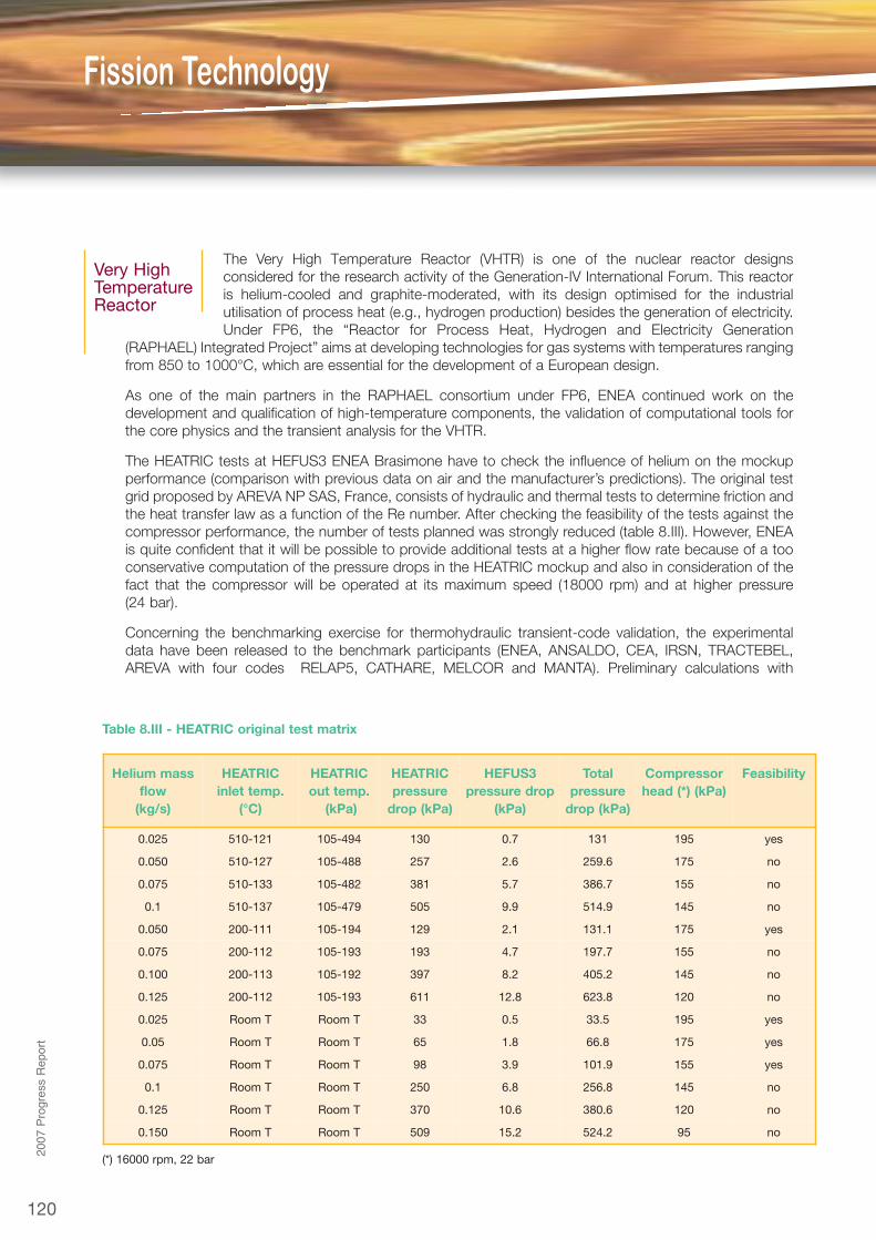
The HEATRIC tests at HEFUS3 ENEA Brasimone have to check the influence of helium on the mockupperformance (comparison with previous data on air and the manufacturer’s predictions). The original testgrid proposed by AREVA NP SAS, France, consists of hydraulic and thermal tests to determine friction andthe heat transfer law as a function of the Re number. After checking the feasibility of the tests against thecompressor performance, the number of tests planned was strongly reduced (table 8.III). However, ENEAis quite confident that it will be possible to provide additional tests at a higher flow rate because of a tooconservative computation of the pressure drops in the HEATRIC mockup and also in consideration of thefact that the compressor will be operated at its maximum speed (18000 rpm) and at higher pressure(24 bar).
Concerning the benchmarking exercise for thermohydraulic transient-code validation, the experimentaldata have been released to the benchmark participants (ENEA, ANSALDO, CEA, IRSN, TRACTEBEL,AREVA with four codes RELAP5, CATHARE, MELCOR and MANTA). Preliminary calculations with
Helium massflow
(kg/s)
HEATRICinlet temp.
(°C)
HEATRICout temp.
(kPa)
HEATRICpressure
drop (kPa)
HEFUS3pressure drop
(kPa)
Totalpressure
drop (kPa)
Compressorhead (*) (kPa)
Feasibility
0.025 510-121 105-494 130 0.7 131 195 yes
0.050 510-127 105-488 257 2.6 259.6 175 no
0.075 510-133 105-482 381 5.7 386.7 155 no
0.1 510-137 105-479 505 9.9 514.9 145 no
0.050 200-111 105-194 129 2.1 131.1 175 yes
0.075 200-112 105-193 193 4.7 197.7 155 no
0.100 200-113 105-192 397 8.2 405.2 145 no
0.125 200-112 105-193 611 12.8 623.8 120 no
0.025 Room T Room T 33 0.5 33.5 195 yes
0.05 Room T Room T 65 1.8 66.8 175 yes
0.075 Room T Room T 98 3.9 101.9 155 yes
0.1 Room T Room T 250 6.8 256.8 145 no
0.125 Room T Room T 370 10.6 380.6 120 no
0.150 Room T Room T 509 15.2 524.2 95 no
(*) 16000 rpm, 22 bar
Table 8.III - HEATRIC original test matrix
Very HighTemperatureReactor
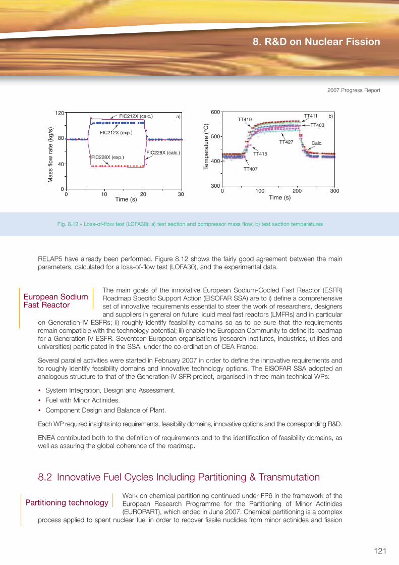
RELAP5 have already been performed. Figure 8.12 shows the fairly good agreement between the mainparameters, calculated for a loss-of-flow test (LOFA30), and the experimental data.
The main goals of the innovative European Sodium-Cooled Fast Reactor (ESFR)Roadmap Specific Support Action (EISOFAR SSA) are to i) define a comprehensiveset of innovative requirements essential to steer the work of researchers, designersand suppliers in general on future liquid meal fast reactors (LMFRs) and in particular
on Generation-IV ESFRs; ii) roughly identify feasibility domains so as to be sure that the requirementsremain compatible with the technology potential; iii) enable the European Community to define its roadmapfor a Generation-IV ESFR. Seventeen European organisations (research institutes, industries, utilities anduniversities) participated in the SSA, under the co-ordination of CEA France.
Several parallel activities were started in February 2007 in order to define the innovative requirements andto roughly identify feasibility domains and innovative technology options. The EISOFAR SSA adopted ananalogous structure to that of the Generation-IV SFR project, organised in three main technical WPs:
• System Integration, Design and Assessment.
• Fuel with Minor Actinides.
• Component Design and Balance of Plant.
Each WP required insights into requirements, feasibility domains, innovative options and the corresponding R&D.
ENEA contributed both to the definition of requirements and to the identification of feasibility domains, aswell as assuring the global coherence of the roadmap.
8.2 Innovative Fuel Cycles Including Partitioning & Transmutation
Work on chemical partitioning continued under FP6 in the framework of theEuropean Research Programme for the Partitioning of Minor Actinides(EUROPART), which ended in June 2007. Chemical partitioning is a complex
process applied to spent nuclear fuel in order to recover fissile nuclides from minor actinides and fission
121
8. R&D on Nuclear Fission
2007 Progress Report
European SodiumFast Reactor
Partitioning technology
0 10 20 30Time (s)
120
80
40
0
Mas
s flo
w r
ate
(kg/
s)
FIC212X (calc.) a)
FIC212X (exp.)
FIC228X (exp.)FIC228X (calc.)
600
500
400
300
Tem
pera
ture
(°C
)Time (s)
0 200 300100
b)TT419
TT411
TT403
TT427
TT415
Calc.
TT407
Fig. 8.12 - Loss-of-flow test (LOFA30): a) test section and compressor mass flow; b) test section temperatures

products [8.7]. The central operation is electro-refining, which takes place in an electrochemical cell wheredissolution of most of the fuel elements occurs. This is followed by selective electro-deposition of theactinides onto a solid and/or liquid cathode by applying an electrochemical difference among elements inmolten LiCl-KCl salt and liquid cadmium (or bismuth) under high-purity argon atmosphere at 460°C(pyroprocessing).
The ENEA Pyrel II facility [8.8], operated at 460°C (fig. 8.13) under an Ar gas atmosphere, was used forelectro-refining experiments on lanthanum (as a stimulant for uranium), which is transported from a fueldissolution basket (FDB), loaded with lanthanum ingots, to a solid steel cathode (SSC), varying the distancebetween anode and cathode, current intensity, cathode surface area, cathode rotation and position of thestirrer in the bath (fig. 8.14).
All the experiments were successful in that a lanthanum deposit occurred in all cases (fig. 8.15),irrespective of the parameters tested. From a visual inspection of the deposit it can be concluded that theconsistency and amount of deposit depend on the applied current intensity and the anode-cathodedistance. All things being equal, a current of 50 mA is much more effective than a current of 300 mA,referring to the Faradic yield of the electrolysis. In detail:
• The closer the cathode to the anode, the higher the amount of deposit (at the same current density).
• A cathode rotating at the same speed as the stirrer (70 rpm) generates a much better deposit equallydistributed along both the length and the circumference of the steel cathode, but its amount is lowerthan that of a fixed cathode.
• When the cathode does not rotate, the depositoccurs mainly on the side facing the anode basket.
• Diameter of the cathodes: to maintain the samecurrent density (1.60 mA/cm2), a current intensity of33.0 mA was applied to the 8-mm-diam cathode,50 mA to the 12-mm-diam cathode, and 85.4 mAto the 20-mm-diam cathode, taking into account
Fission Technology
122
2007ProgressReport
Fig. 8.15 - Examples of cathodes brought outside the
glove-box, and related to the experiments at 50 mA (left)
and with the rotating cathode (right), both positioned
close to the fuel dissolution basket
500
400
300
200
100
-20
Thermocouple temperatures
11:48:09 09:11:39
Fig. 8.13 - Trend of temperatures in PYREL II plant before and
during the electrorefining experiments
Fig. 8.14 - Outline of the different positions for: fuel dissolution basket;
solid steel cathode; stirrer; thermocouples. (one is shown in the photo)
[8.7] T. Nishimura et al., Prog. Nucl. Energy 32, 3/4,381–387 (1998)
[8.8] G. De Angelis and E. Baicchi, A new electrolyzer forpyrochemical process studies, Proceedings ofGLOBAL 2005 (Tsukuba 2005), Paper 048
[8.9] M. Carta, Re-examination of the fuel burnup level ofthe TRIGA RC-1 Casaccia reactor, and pre-TRADEexperimental benchmark specifications,

the fact that all the cathodes were immersed 8.0 cm in the salt bath. The 12-mm-diam cathode had thehighest amount of deposit; the 20-mm-diam, a low deposit.
• The position of the stirrer in the bath seems to have some influence on the cumulation of lanthium onthe cathode. When the stirrer is located on a side, the amount of deposit increases.
In conclusion, based on the experiments performed so far, the maximum quantity of cathode deposit isobtained when a SSC with a diameter of 12 mm is close to the FDB, at a moderate current intensity of50 mA, without cathode rotation, and with the stirrer of the bath positioned on a side. Chemical analysesare under way to get a better evaluation of the experiments and to decide how to address future researchwork.
Activities concerning molten salts were carried out for the European Assessment of Liquid Salts forInnovative Applications (ALISIA) project in the framework of FP6. ENEA’s contribution was focussed onanalysing different options for “salt clean-up” in a molten salt reactor fuel cycle. ENEA’s experience in liquidsalt facilities for solar applications could also be of benefit for nuclear applications and, in this respect, thetests on liquid salt loops could be very interesting for components, welding, safety devices, geometricaland operational parameters, instrumentation, salt control systems, salt selection criteria, etc.
Most of the activities on transmutation were carried out under the EuropeanTransmutation (EUROTRANS) Integrated Project The objectives are todemonstrate experimentally operations and dynamic characteristics of theaccelerator-driven system (ADS), to deliver a conceptual design for the
European Transmutator Demonstrator (ETD), including its overall technical feasibility, and to perform aneconomic assessment.
ENEA’s research was mainly focussed on:
• Neutronic design, pin mechanical analysis, analysis of stress induced by vibrations, and reactor safetyanalysis of a Pb-cooled European facility on an industrial scale transmuter (the European Facility forIndustrial Transmutation [EFIT]) (Domain DESIGN);
• Interpretation of some neutronics measurements performed during the Reactor-Accelerator CouplingExperiments (RACE)-T campaign and electron-beam target design for the RACE-high power (HP)experiment and RACE-Idaho State University (ISU) calculation (Domain ECATS);
• Study, analysis and simulation of the thermo-fluid-dynamic behaviour of the primary system of a heavyliquid metal pool-type nuclear reactor, experimental activities to study interaction of lead alloys withwater and to investigate materials and heavy liquid metal (HLM) technologies, and post-test analysis ofthe MEGAPIE experiment (Domain DEMETRA).
ENEA is also involved in the coordinate research project “Analytical and Experimental Benchmark Analysesof ADSs” coordinated by the International Atomic Energy Agency (IAEA). In particular ENEA coordinates acomputational benchmark named “Pre-TRADE Experimental Benchmark”. The benchmark is focussed onevaluating spatial/energy correction factors to be applied to some selected reactivity estimates performedin the framework of the RACE-T experimental campaign carried out in the 1-MW TRIGA reactor at ENEACasaccia. Reactivity estimates were performed with the use of the so-called Pulsed-Neutron Source (PNS)
Area Ratio and Modified Source Approximation (MSA)methods, at different core configurations, namely SC2(∼ -2500 pcm) and (∼ -5000 pcm) [8.9, 8.10].
EFIT core neutronic design. The neutronic coredesign as reported in the 2006 Progress Report [8.11]was upgraded. Keeping the leading approach “42-0”
123
8. R&D on Nuclear Fission
2007 Progress Report
http://www.triga.enea.it/IAEA_Bench
[8.10] N. Burgio, A. Santagata, M. Carta, Scopingcalculations for the pre-TRADE benchmark,Presented at the IAEA Technical Meeting (ENEAheadquarters Roma 2007)
[8.11] ENEA – Nuclear Fusion and Fission, and RelatedTechnologies Department, 2006 Progress Report,Sect. B1.1
Transmutation systemsand related technology
Fission Technology2007ProgressReport
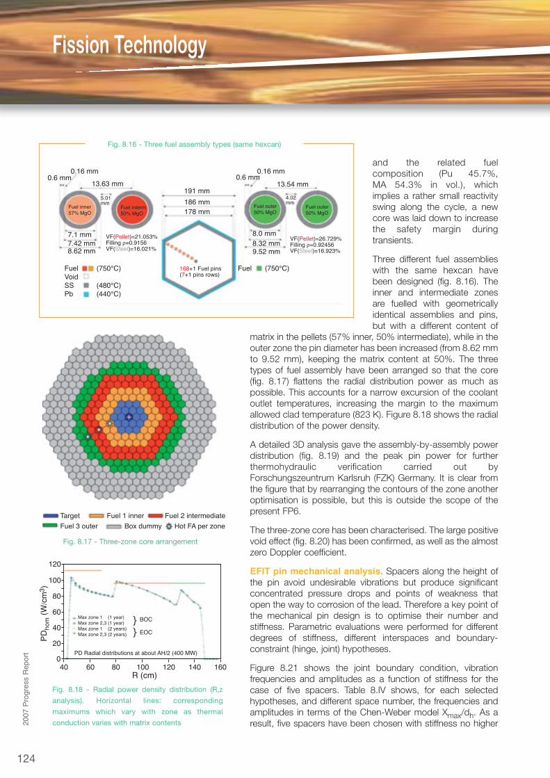
and the related fuelcomposition (Pu 45.7%,MA 54.3% in vol.), whichimplies a rather small reactivityswing along the cycle, a newcore was laid down to increasethe safety margin duringtransients.
Three different fuel assemblieswith the same hexcan havebeen designed (fig. 8.16). Theinner and intermediate zonesare fuelled with geometricallyidentical assemblies and pins,but with a different content of
matrix in the pellets (57% inner, 50% intermediate), while in theouter zone the pin diameter has been increased (from 8.62 mmto 9.52 mm), keeping the matrix content at 50%. The threetypes of fuel assembly have been arranged so that the core(fig. 8.17) flattens the radial distribution power as much aspossible. This accounts for a narrow excursion of the coolantoutlet temperatures, increasing the margin to the maximumallowed clad temperature (823 K). Figure 8.18 shows the radialdistribution of the power density.
A detailed 3D analysis gave the assembly-by-assembly powerdistribution (fig. 8.19) and the peak pin power for furtherthermohydraulic verification carried out byForschungszeuntrum Karlsruh (FZK) Germany. It is clear fromthe figure that by rearranging the contours of the zone anotheroptimisation is possible, but this is outside the scope of thepresent FP6.
The three-zone core has been characterised. The large positivevoid effect (fig. 8.20) has been confirmed, as well as the almostzero Doppler coefficient.
EFIT pin mechanical analysis. Spacers along the height ofthe pin avoid undesirable vibrations but produce significantconcentrated pressure drops and points of weakness thatopen the way to corrosion of the lead. Therefore a key point ofthe mechanical pin design is to optimise their number andstiffness. Parametric evaluations were performed for differentdegrees of stiffness, different interspaces and boundary-constraint (hinge, joint) hypotheses.
Figure 8.21 shows the joint boundary condition, vibrationfrequencies and amplitudes as a function of stiffness for thecase of five spacers. Table 8.IV shows, for each selectedhypotheses, and different space number, the frequencies andamplitudes in terms of the Chen-Weber model Xmax/dh. As aresult, five spacers have been chosen with stiffness no higher
FuelVoidSSPb
(750°C)
(480°C)(440°C)
Fuel168+1 Fuel pins(7+1 pins rows)
(750°C)
VF(Pellet)=21.053%Filling ρ=0.9156VF(Steel)=16.021%
VF(Pellet)=26.729%Filling ρ=0.92456VF(Steel)=16.923%
0.6 mm 0.6 mm0.16 mm 0.16 mm
4.02mm
7.1 mm7.42 mm8.62 mm 9.52 mm
8.32 mm8.0 mm
5.01mm
13.63 mm 13.54 mm191 mm
186 mm178 mm
Fuel interm50% MgO
Fuel inner57% MgO
Fuel outer50% MgO
Fuel outer50% MgO
Fig. 8.16 - Three fuel assembly types (same hexcan)
Target
Fuel 3 outer
Fuel 1 inner Fuel 2 intermediate
Box dummy Hot FA per zone
Fig. 8.17 - Three-zone core arrangement
PD
hom
(W
/cm
3 )
120
100
80
60
40
20
040 60 80 100 120 140 160
R (cm)
Max zone 1 (1 year)Max zone 2,3 (1 year)Max zone 1 (2 years)Max zone 2,3 (2 years)
BOC
EOC
}}
PD Radial distributions at about AH/2 (400 MW)
Fig. 8.18 - Radial power density distribution (R,z
analysis). Horizontal lines: corresponding
maximums which vary with zone as thermal
conduction varies with matrix contents
124
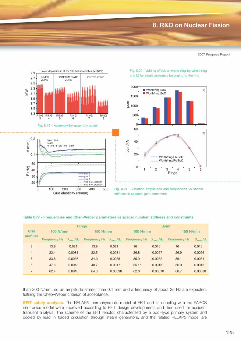
than 200 N/mm, so an amplitude smaller than 0.1 mm and a frequency of about 35 Hz are expected,fulfilling the Cheb–Weber criterion of acceptance.
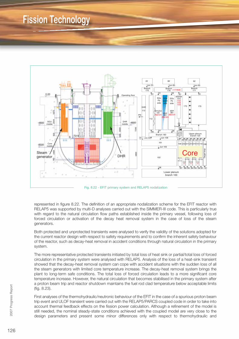
EFIT safety analysis. The RELAP5 thermohydraulic model of EFIT and its coupling with the PARCSneutronics model were improved according to EFIT design developments and then used for accidenttransient analysis. The scheme of the EFIT reactor, characterised by a pool-type primary system andcooled by lead in forced circulation through steam generators, and the related RELAP5 model are
125
8. R&D on Nuclear Fission
2007 Progress Report
Gridnumber
Hinge Joint100 N/mm 150 N/mm 100 N/mm 150 N/mm
Frequency Hz Xmax/dh Frequency Hz Xmax/dh Frequency Hz Xmax/dh Frequency Hz Xmax/dh
3 13.9 0.021 13.9 0.021 16 0.016 16 0.016
4 22.4 0.0081 22.5 0.0081 26.8 0.0057 26.9 0.0056
5 33.8 0.0036 34.0 0.0035 35.9 0.0032 36.1 0.0031
6 47.6 0.0018 48.7 0.0017 55.15 0.0013 56.0 0.0013
7 62.4 0.0010 64.3 0.00098 62.6 0.00010 68.7 0.00088
Table 8.IV - Frequencies and Chen-Weber parameters vs spacer number, stiffness and constraints
pcm
2000
1500
500
0
1000
Worth/ring BoCWorth/ring EoC
a)
Fig. 8.20 - Voiding effect: a) whole-ring-by-whole ring
and b) for single assembly belonging to the ring
A (
mm
)F
(H
z)
0.2
0.1
50
40
30
20
Grid elasticity (N/mm)0 100 200 300 400 500
type 1 joint5 grid0.44 0.78 1.20 1.60 1.98 m
type 1type 2type 3type 1 ref. positiontype 3 ref. position
Fig. 8.21 - Vibration amplitudes and frequencies vs spacer
stiffness (5 spacers, joint constraint)
pcm
/FA
60
20
0
40
1 2 3 4 5 6Rings
Worth/ring/FA BoCWorth/ring/FA EoC
b)
Fig. 8.19 – Assembly-by-assembly power
MW
2.9
2.7
2.5
2.3
2.1
1.9
1.7
1.5
1.3RING
3RING
4RING
5RING
6RING
7RING
8
INNERZONE
OUTER ZONEINTERMEDIATEZONE
Power deposition in all the 180 fuel assemblies (MCNPX)
Fission Technology
126
2007ProgressReport
represented in figure 8.22. The definition of an appropriate nodalization scheme for the EFIT reactor withRELAP5 was supported by multi-D analyses carried out with the SIMMER-III code. This is particularly truewith regard to the natural circulation flow paths established inside the primary vessel, following loss offorced circulation or activation of the decay heat removal system in the case of loss of the steamgenerators.
Both protected and unprotected transients were analysed to verify the validity of the solutions adopted forthe current reactor design with respect to safety requirements and to confirm the inherent safety behaviourof the reactor, such as decay-heat removal in accident conditions through natural circulation in the primarysystem.
The more representative protected transients initiated by total loss of heat sink or partial/total loss of forcedcirculation in the primary system were analysed with RELAP5. Analysis of the loss of a heat-sink transientshowed that the decay-heat removal system can cope with accident situations with the sudden loss of allthe steam generators with limited core temperature increase. The decay-heat removal system brings theplant to long-term safe conditions. The total loss of forced circulation leads to a more significant coretemperature increase. However, the natural circulation that becomes stabilised in the primary system aftera proton beam trip and reactor shutdown maintains the fuel rod clad temperature below acceptable limits(fig. 8.23).
First analyses of the thermohydraulic/neutronic behaviour of the EFIT in the case of a spurious proton beamtrip event and ULOF transient were carried out with the RELAP5/PARCS coupled code in order to take intoaccount thermal feedback effects on the fission power calculation. Although a refinement of the model isstill needed, the nominal steady-state conditions achieved with the coupled model are very close to thedesign parameters and present some minor differences only with respect to thermohydraulic and
0.00
-4800
-7010
-4800
-8500
SGUmiddle
Coremiddle
1870
2544
500
3484
180
50 500
600
3000
7240
4890
Operating floor
DHRmiddle
22
01
01
08 07
07
109 310311 211210111110 108
06
06
05
05
04
04
03
03
02
02
01
01 08
Targ
et lo
op
01
05
Jun 104Jun114
06
112
Pth
DHR
113
0101 0102
82
173 170
SGsPb
side
SGsPb
side
SGswaterside
62
Jun 23 Jun 83
Jun 106
Jun 105
161
102
Jun 63
Branch175
Branch176
Branch171(177/8/9)
annulus181
182/3/4pipe281
282/3/4
pipe381
382/3/4
branch151152153154
Branch 160 Upper plenumbranch 120
Pumpsplenumbranch
121
Pumps
Lower plenumbranch 100
Bypass&
reflectorOuterhot
Outeraverage
Middleaverage
Inneraverage
Middlehot
Innerhot
CoreDHRSteamgenerator
Fig. 8.22 - EFIT primary system and RELAP5 nodalization
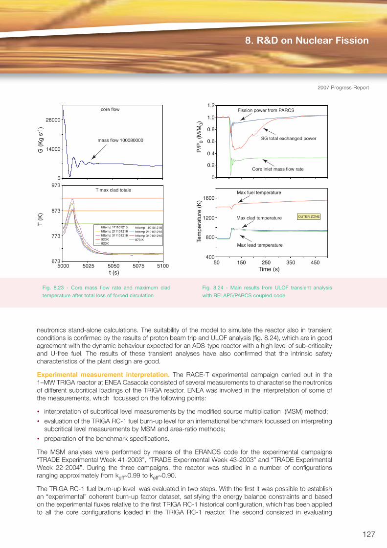
neutronics stand-alone calculations. The suitability of the model to simulate the reactor also in transientconditions is confirmed by the results of proton beam trip and ULOF analysis (fig. 8.24), which are in goodagreement with the dynamic behaviour expected for an ADS-type reactor with a high level of sub-criticalityand U-free fuel. The results of these transient analyses have also confirmed that the intrinsic safetycharacteristics of the plant design are good.
Experimental measurement interpretation. The RACE-T experimental campaign carried out in the1–MW TRIGA reactor at ENEA Casaccia consisted of several measurements to characterise the neutronicsof different subcritical loadings of the TRIGA reactor. ENEA was involved in the interpretation of some ofthe measurements, which focussed on the following points:
• interpretation of subcritical level measurements by the modified source multiplication (MSM) method;
• evaluation of the TRIGA RC-1 fuel burn-up level for an international benchmark focussed on interpretingsubcritical level measurements by MSM and area-ratio methods;
• preparation of the benchmark specifications.
The MSM analyses were performed by means of the ERANOS code for the experimental campaigns“TRADE Experimental Week 41-2003”, “TRADE Experimental Week 43-2003” and “TRADE ExperimentalWeek 22-2004”. During the three campaigns, the reactor was studied in a number of configurationsranging approximately from keff∼0.99 to keff∼0.90.
The TRIGA RC-1 fuel burn-up level was evaluated in two steps. With the first it was possible to establishan “experimental” coherent burn-up factor dataset, satisfying the energy balance constraints and basedon the experimental fluxes relative to the first TRIGA RC-1 historical configuration, which has been appliedto all the core configurations loaded in the TRIGA RC-1 reactor. The second consisted in evaluating
127
8. R&D on Nuclear Fission
2007 Progress Report
5000 5025 5050 5075 5100t (s)
973
873
773
673
T max clad totale
core flow
T (
K)
28000
14000
0
G (
Kg
s-1 )
httemp 111101216httemp 211101216httemp 311101216923K823K
httemp 110101216httemp 210101216httemp 310101216873 K
mass flow 100080000
Time (s)
1.2
1.0
0.8
0.6
0.4
0.2
0
P/P
0 (M
/M0)
Tem
pera
ture
(K
) 1600
1200
800
40050 150 250 350 450
Max fuel temperature
Max clad temperature
Max lead temperature
Fission power from PARCS
SG total exchanged power
Core inlet mass flow rate
OUTER ZONE
Fig. 8.23 - Core mass flow rate and maximum clad
temperature after total loss of forced circulation
Fig. 8.24 - Main results from ULOF transient analysis
with RELAP5/PARCS coupled code

Fission Technology
128
2007ProgressReport
through calculations the energy produced by each element for all the TRIGA RC-1 configurations by meansof the spatial diffusion code TRIGLAV. Once the fuel-elements energy mapping was obtained, the ERANOScode was used to evaluate the relative fuel pin compositions, including the content of plutonium, MAs andfission products.
Finally, the area-ratio and source multiplication methods were used to analyse the reactivity estimates, fordifferent core locations and for three different “clean” (without control rods) subcritical core configurations,namely, SC0 (∼ -500 pcm), SC2 (∼ -2500 pcm) and SC3 (∼ -5000 pcm).
RACE–HP electron beam target and RACE-ISU calculations. The main design constraints for theRACE–HP experiment (an electron accelerator able to achieve a neutron production of 1014 n/s) imposeda careful choice of neutron-source material. To reach the targeted neutron production, uranium waschosen. The main design criteria were addressed. No boiling was expected during heat removal, for amaximum thermal flux of 4 MW/m2.
The thermomechanic criteria are
• maximum thermal stress of the structural parts has to remain below the extended plasticity conditions;
• local plasticity is allowed up to a maximum value of 1%.
Two main designs concepts studied for a 30-kW powerful target were radial and multiplate. Thegeometries were carefully examined as well as the calculated source intensities. The source intensities ofthe low-power RACE-ISU target were evaluated by the MCNPX code, taking into account the followingaspects:
• contribution of the different materials of the target to neutronproduction;
• neutron flux profile in the target;
• energy deposited;
• gamma distribution.
Integral Circulation Experiment. The Integral CirculationExperiment (ICE) is one of the main activities developed by ENEAto study, analyse and simulate the thermo-fluido-dynamicbehaviour of the primary system of a heavy liquid metal pool-typenuclear reactor. The work is carried out within the WP “Large-ScaleIntegral Test” of the Domain DEMETRA and concernsthermohydraulic tests for the use of HLM as reactor coolant onlarge facilities, operated by European institutes within theCommunity.
During 2007 the design of the test section to be installed in theCIRCE facility (fig. 8.25) at ENEA Brasimone was completed(fig. 8.26), i.e., the fuel pin simulator, heat exchanger, pumpingsystem, chemistry control system, and procurement of the maincomponents and instrumentation was begun.
The design of the fuel pin simulator, which has to reproduce thethermohydraulic behaviour of a nuclear pin assembly, required thedevelopment of numerical simulations and experimental supportactivities to analyse and qualify manufacture of the heat source(HS). Several computational fluid dynamic (CFD) simulations wereperformed to evaluate cooling of the HS, calculating the LBE
L.1.3.9 L.1.3.5
L.1.3.4
L.1.2.5
EL2.000
EL5.600
EL6.000
S200
S100
S300
Parameters Value
Outside diameter 1200 mm
Wall thickness 15 mm
Material AISI 316L
Max LBE inventory 90000 kg
Electrical heating 47 kW
Cooling air flow rate 3 Nm3/s
Temperature range 200 to 550°C
Operating pressure 15 kPa (gauge)
Design pressure 450 kPa (gauge)
Argon flow rate 15 NI/s
Argon injection pressure 600 kPa (gauge)
Fig. 8.25 - CIRCE facility: overview

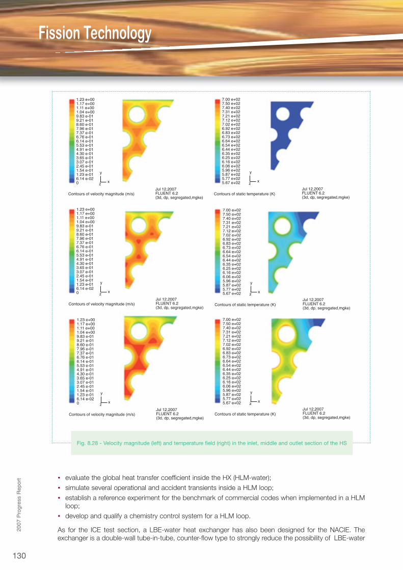
velocity and the clad temperature along the sub-channels. The calculations were performed with the useof the FLUENT CFD code. Figure 8.27 shows the grid adopted for the domain discretization; 1/12 of theoverall domain was analysed, adopting the HS symmetries. Figures 8.28 report the velocity magnitude andthe temperature field as computed in the inlet, middle and outlet section of the HS: the maximum velocityexpected along the sub-channels is 1.23 m/s, while the maximum clad temperature is 760 K. Thesepreliminary results indicate that it is possible to cool the ICE heat source with the adopted parameters(average velocity, p/D ratio, installed thermal power).
To achieve the performance of a nuclear heat source, a pin power density of 500 W/cm3 and a pin heatflux of 100 W/cm2 are required for the electrical rods that simulate the nuclear pins. To get such a highthermal performance, R&D was carried out in collaboration with THERMCOAX, a leading French companyin the field of heating systems. Two different technological solutions were analysed and four prototype pinswere built, a couple for each technical solution. The prototypes will be tested and qualified at the NaturalCirculation Experiment (NACIE) facility at ENEA Brasimone. The facility (fig. 8.29), an 8-m-long, 1-m-widerectangular loop that uses LBE or pure lead as working fluid, was designed, manufactured and installed atBrasimone in 2007. The total HLM inventory of the loop is about 1000 kg, and it has been designed towork up to 550°C, which allows relevant components and systems to be tested for LFR.
The NACIE loop also has the key objectives to
• characterise the natural circulation flow regime in a HLM loop;
• obtain data on the natural circulation heat transfer coefficient in a rod bundle assembly;
• characterise the gas-enhanced circulation in a HLM loop;
129
8. R&D on Nuclear Fission
2007 Progress Report
Cover head
Heat exchanger Heat exchanger
CIRCE main vessel (S100)
CIRCE main vessel (S100)
Riser
FPS
FPS
Riser
Separator
Insulation volume
Dead volume
Dead volume
Fitting volume
Fitting volume
Flow meter
Flow meter
Feeding conduit
Feeding conduit
Coupling flange
Fig.8.26 - ICE test section
Fig. 8.27 - View of the mesh
performed on a section of the HS
Fission Technology
130
2007ProgressReport • evaluate the global heat transfer coefficient inside the HX (HLM-water);
• simulate several operational and accident transients inside a HLM loop;
• establish a reference experiment for the benchmark of commercial codes when implemented in a HLMloop;
• develop and qualify a chemistry control system for a HLM loop.
As for the ICE test section, a LBE-water heat exchanger has also been designed for the NACIE. Theexchanger is a double-wall tube-in-tube, counter-flow type to strongly reduce the possibility of LBE-water
1.23 e+001.17 e+001.11 e+001.04 e+009.83 e-019.21 e-018.60 e-017.96 e-017.37 e-016.76 e-016.14 e-015.53 e-014.91 e-014.30 e-013.65 e-013.07 e-012.45 e-011.54 e-011.23 e-016.14 e-020
Contours of velocity magnitude (m/s)Jul 12,2007FLUENT 6.2 (3d, dp, segregated,mgke)
y
xz
1.23 e+001.17 e+001.11 e+001.04 e+009.83 e-019.21 e-018.60 e-017.96 e-017.37 e-016.76 e-016.14 e-015.53 e-014.91 e-014.30 e-013.65 e-013.07 e-012.45 e-011.54 e-011.23 e-016.14 e-020
Contours of velocity magnitude (m/s)Jul 12,2007FLUENT 6.2 (3d, dp, segregated,mgke)
y
xz
1.23 e+001.17 e+001.11 e+001.04 e+009.83 e-019.21 e-018.60 e-017.96 e-017.37 e-016.76 e-016.14 e-015.53 e-014.91 e-014.30 e-013.65 e-013.07 e-012.45 e-011.54 e-011.23 e-016.14 e-020
Contours of velocity magnitude (m/s)Jul 12,2007FLUENT 6.2 (3d, dp, segregated,mgke)
y
xz
7.00 e+027.50 e+027.40 e+027.31 e+027.21 e+027.12 e+027.02 e+026.92 e+026.83 e+026.73 e+026.64 e+026.54 e+026.44 e+026.35 e+026.25 e+026.16 e+026.06 e+025.96 e+025.87 e+025.77 e+025.67 e+02
Contours of static temperature (K)Jul 12,2007FLUENT 6.2 (3d, dp, segregated,mgke)
y
xz
7.00 e+027.50 e+027.40 e+027.31 e+027.21 e+027.12 e+027.02 e+026.92 e+026.83 e+026.73 e+026.64 e+026.54 e+026.44 e+026.35 e+026.25 e+026.16 e+026.06 e+025.96 e+025.87 e+025.77 e+025.67 e+02
Contours of static temperature (K)Jul 12,2007FLUENT 6.2 (3d, dp, segregated,mgke)
y
xz
7.00 e+027.50 e+027.40 e+027.31 e+027.21 e+027.12 e+027.02 e+026.92 e+026.83 e+026.73 e+026.64 e+026.54 e+026.44 e+026.35 e+026.25 e+026.16 e+026.06 e+025.96 e+025.87 e+025.77 e+025.67 e+02
Contours of static temperature (K)Jul 12,2007FLUENT 6.2 (3d, dp, segregated,mgke)
y
xz
Fig. 8.28 - Velocity magnitude (left) and temperature field (right) in the inlet, middle and outlet section of the HS

interaction due to a pipefailure. To guarantee goodthermal performance for theheat exchanger, the annulusbetween the two pipes will befilled with stainless steelpowder, which assures goodthermal conductivity butallows differential thermalexpansion between the pipes.
The test on the NACIE loopwill be performed in the 2008and will allow definition of thetechnological solution toadopt for the ICE bundle andcollection of experimentaldata on the thermohydraulicbehaviour of HLM flowingthrough a pin bundle.
Interaction of lead alloys with water. Assessment of the effects and possible consequences ofLBE–water interaction caused by a cooling tube rupture inside the steam generator of an XT-ADS (theexperimental demonstration of the technical feasibility of transmutation in an accelerator-driven system)continued. The work includes an experimental programme, using the LIFUS5 facility (fig. 8.30) and relatedmodelling with the SIMMER III code. The modelling activity is performed in collaboration with PisaUniversity. SIMMER III is a 2D, three–velocity–field, multi-component, multiphase, Eulerian fluidodynamiccode coupled with a neutron kinetics model.
131
8. R&D on Nuclear Fission
Expansionvessel
Heating section
Heat exchanger
Fig. 8.29 - NACIE loop: overview
V1
V10
DRAINAGETO
VACUUM PUMP
S3
S1Steam
V8
V12
D1
D2
S5
TC
TC
TC
TC
TC
FA
V6 V15
V13
V3V11
V5
V4 V14
V7
V9V2
V16
Al 1”
Ald 1”Ald 2”
Al 3”Ar 1”Al 10
Al 1/2”
Wa 1/2”
Wa 1/2”
GS2
GS1
S4
LT1
LBE
LBE
LT2
TC
PT12
PT11
DPT1
S2H2O
PT10
PT7
SPTC3
TC2PT5
PT1PT3
PT9
PT6-8
PT2-4
TC1-30
3”
3” 1/2”
Ar Supply
Fig. 8.30 - P&I of LIFUS5
2007 Progress Report

Fission Technology
After the first test on LIFUS5 in 2006, the secondexperimental campaign in 2007 was devoted to exploitingthe consequences of LBE/water interaction in conditionsrepresentative of the ICE activity planned in the CIRCEfacility. The LIFUS5 facility was rearranged to reproduce asaccurately as possible a representative liquid metal pool forCIRCE and for a pool reactor. The second test consistedin injecting pressurised water at 6 bar in the LIFUS5reaction vessel containing LBE at 350°C. The mostsignificant results showed that the maximum pressureexceeded the water injection pressure and that thepressure evolution detected in the gas phase in the freelevel of the reaction vessel followed the same trend as inliquid metal (fig. 8.31).
After developing the 2D geometrical model for the reactionsystem of LIFUS5 (fig. 8.32), SIMMER simulations wereperformed for tests one and two (fig. 8.33). Pre-testsimulations were used to help select the operatingconditions for the experiments, while post-test analysesallowed a better understanding of the experimental results.
In general, the simulations and experimental results agreedquite well, hence proving the capability of SIMMER toreproduce the phenomenology of LBE–water interaction
Experimental and SIMMER results of the second test wereused to support the assessment of the accidental scenarioof a “heat exchanger tube rupture”, considered asreference accident in the safety analysis of the ICE activity.
Test n. 3 should be performed at the beginning of 2009,taking into account the operating conditions chosen forthe XT-ADS steam generator.
Pre
ssur
e (b
ar)
Time (ms)
6
4
2
00 1000 400030002000
Gas
LM
Fig. 8.31 - Experimental results of Test n.2
S5
S1
S2
S1-S5link
S2-S1pipeline
Nocalculation
zone
U tubezone
Littleplate
Injectordevice
Plates
Nozzle
LBE Water Argon
Fig. 8.32 - LIFUS5 computational domain for
simulations with SIMMER
Pre
ssur
e (P
a)
9×10⁶
7×10⁶
5×10⁶
3×10⁶
1×10⁶
00 2 4 6 8 10 12
Time (s)
Calculated
Experimental
Fig. 8.33 - Comparison between experimental and
calculated pressure in Test n.1
2007ProgressReport
132
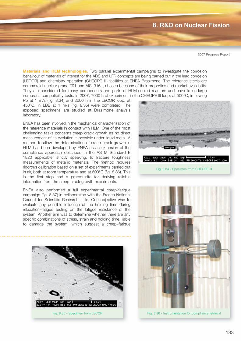
Materials and HLM technologies. Two parallel experimental campaigns to investigate the corrosionbehaviour of materials of interest for the ADS and LFR concepts are being carried out in the lead corrosion(LECOR) and chemistry operation (CHEOPE III) facilities at ENEA Brasimone. The reference steels arecommercial nuclear grade T91 and AISI 316L, chosen because of their properties and market availability.They are considered for many components and parts of HLM-cooled reactors and have to undergonumerous compatibility tests. In 2007, 7000 h of experiment in the CHEOPE III loop, at 500°C, in flowingPb at 1 m/s (fig. 8.34) and 2000 h in the LECOR loop, at450°C, in LBE at 1 m/s (fig. 8.35) were completed. Theexposed specimens are studied at Brasimone analysislaboratory.
ENEA has been involved in the mechanical characterisation ofthe reference materials in contact with HLM. One of the mostchallenging tasks concerns creep crack growth as no directmeasurement of its evolution is possible under liquid metal. Amethod to allow the determination of creep crack growth inHLM has been developed by ENEA as an extension of thecompliance approach described in the ASTM Standard E1820 applicable, strictly speaking, to fracture toughnessmeasurements of metallic materials. The method requiresrigorous calibration based on a set of experiments carried outin air, both at room temperature and at 500°C (fig. 8.36). Thisis the first step and a prerequisite for deriving reliableinformation from the creep crack growth experiments.
ENEA also performed a full experimental creep-fatiguecampaign (fig. 8.37) in collaboration with the French NationalCouncil for Scientific Research, Lille. One objective was toevaluate any possible influence of the holding time duringrelaxation–fatigue testing on the fatigue resistance of thesystem. Another aim was to determine whether there are anyspecific combinations of stress, strain and holding time, liableto damage the system, which suggest a creep–fatigue
133
8. R&D on Nuclear Fission
2007 Progress Report
Acc.V Spot Magn Det WD Exp20.0 kV 5.0 1000x BSE 34.1 823 PM 26005 T91 CHEOPE 500*C 2000
20 μm
19.4 μm
Fig. 8.34 - Specimen from CHEOPE III
Acc.V Spot Magn Det WD 20.0 kV 4.0 1000x BSE 11.6 PM 05203 (316L) LECOR 1000 h 450°C
20 μm
Fig. 8.35 - Specimen from LECOR Fig. 8.36 - Instrumentation for compliance retrieval

Fission Technology
134
2007ProgressReport
interaction process operating in LBE in a certaintemperature range. The tests were first performed at300°C for which the fatigue resistance of the 316L SSis decreased in contact with LBE. However, noinfluence of holding time has so far been proved for the316L fatigued in LBE at 300°C, contrary to what wasfound with T91 steel after a number of relaxation–fatigue tests in LBE.
A large effort has been dedicated to the development of oxygen sensors and control systems as well aspurification systems. An oxygen control system in a pool-type facility was developed on the basis of dataand experience gathered from loop devices. A two-phase experiment was designed, to be performed inthe CIRCE multipurpose facility, in order to assess the most effective integrated system for non-metallicimpurity control and monitoring in a complex pool system. The work was performed in collaboration withthe Institute of Physics and Power Engineering (IPPE) Obnnisk, Russian Federation. A gas closed circuitequipped with mechanical filters, oxygen and water sensors and moisture separation devices will be usedfor oxygen diffusion in the pool experiment, in the first part of the experimental campaign. The second partwill consist in testing a mass exchanger device, together with an open gas circuit, equipped with sensorsand instrumentation. The oxygen sensors for the liquid phase were made by ENEA and IPPE. Theexperiments will test filtering systems for the gas phase, different designs of oxygen sensors, integratedinstrumentation for the gas phase, integrated instrumentation for the liquid phase and gas bubblers.
MEGAPIE experiment post test analysis. Within theframework of the EUROTRANS project (domainDEMETRA), post-test analysis of the MEGAPIE TargetExperiment was performed to assess RELAP5, theENEA reference system code for transient and safetyanalysis of LBE and lead cooling systems. The code,which was used in the design phase to simulate thebehaviour of the target cooling system at differentoperational and off-normal conditions, was first assessedon the single-pin tests at ENEA Brasimone andsuccessively on the MEGAPIE integral tests (MITs) atVilligen, Switzerland. The main result of these activities,described in previous reports [8.11, 8.12], produced theimplementation in the code of a dedicated correlation forsimulation of the LBE-oil heat exchanger (THX).
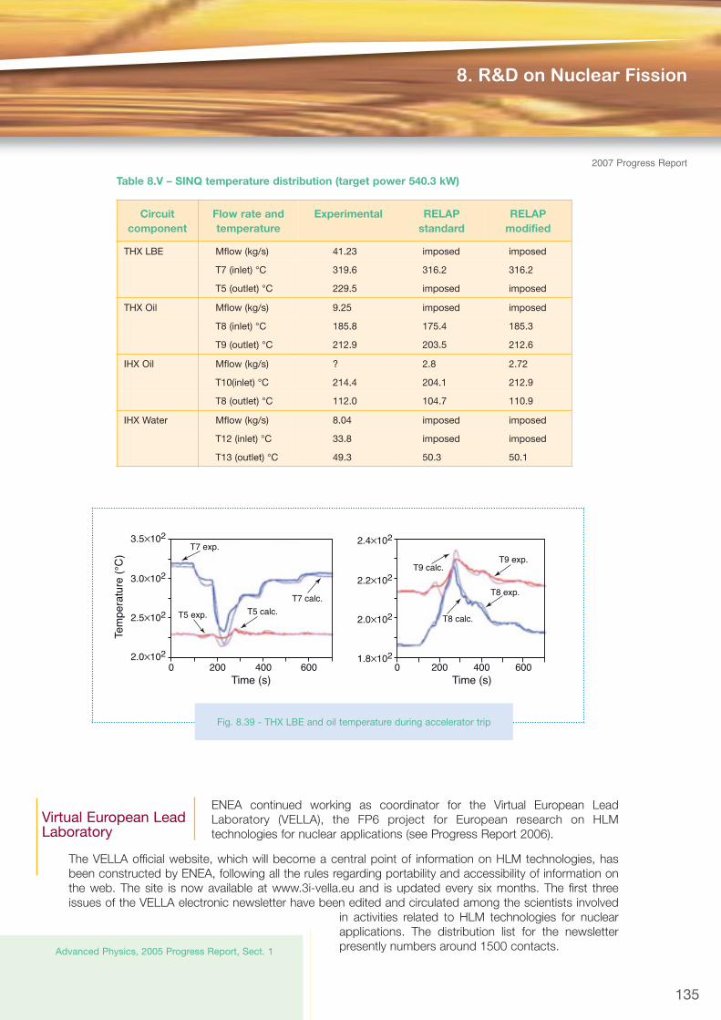
The post-test analysis concerned the thermohydraulicbehaviour of the cooling system in a SINQ (Swiss
spallation neutron source) configuration (fig. 8.38) in steady state and in transient conditions:
• Component calculations confirmed the adequacy at high power (up to 540 kW) of the Gnielinskycorrelation, expressly implemented in the code for the thermal exchange in the THX oil side and alreadyassessed on the MITs at low power (up to 200 kW).
• Cooling loop calculations showed that the code is capable of simulating the thermohydraulicperformance of the circuit (table 8.V) and considers in particular the intermediate cooling loop in oil.Since the uncertainty on LBE mass flow-rate measurements in the target loop is too high, a significantevaluation of the code accuracy cannot be achieved.
Simulation of an accelerator trip event has confirmedthe applicability of the code to the transient conditions(fig. 8.39).
Fig. 8.37 - Creep fatigue setup and sample in HLM
[8.12] ENEA – Technical and Scientific Division for
T5
T7T9
T10
T13 T12
T8
IHX TH
XTa
rget
Byp
ass
Isolationvalve
Isolationvalve
3-wayvalve
Fig. 8.38 - SINQ loop layout
ENEA continued working as coordinator for the Virtual European LeadLaboratory (VELLA), the FP6 project for European research on HLMtechnologies for nuclear applications (see Progress Report 2006).
The VELLA official website, which will become a central point of information on HLM technologies, hasbeen constructed by ENEA, following all the rules regarding portability and accessibility of information onthe web. The site is now available at www.3i-vella.eu and is updated every six months. The first threeissues of the VELLA electronic newsletter have been edited and circulated among the scientists involved
in activities related to HLM technologies for nuclearapplications. The distribution list for the newsletterpresently numbers around 1500 contacts.
135
8. R&D on Nuclear Fission
2007 Progress Report
Circuitcomponent
Flow rate andtemperature
Experimental RELAPstandard
RELAPmodified
THX LBE Mflow (kg/s) 41.23 imposed imposed
T7 (inlet) °C 319.6 316.2 316.2
T5 (outlet) °C 229.5 imposed imposed
THX Oil Mflow (kg/s) 9.25 imposed imposed
T8 (inlet) °C 185.8 175.4 185.3
T9 (outlet) °C 212.9 203.5 212.6
IHX Oil Mflow (kg/s) ? 2.8 2.72
T10(inlet) °C 214.4 204.1 212.9
T8 (outlet) °C 112.0 104.7 110.9
IHX Water Mflow (kg/s) 8.04 imposed imposed
T12 (inlet) °C 33.8 imposed imposed
T13 (outlet) °C 49.3 50.3 50.1
Table 8.V – SINQ temperature distribution (target power 540.3 kW)
Virtual European LeadLaboratory
Advanced Physics, 2005 Progress Report, Sect. 1
Tem
pera
ture
(°C
)
3.5×10²
3.0×10²
2.5×10²
2.0×10²
2.4×10²
2.2×10²
2.0×10²
1.8×10²
Time (s) Time (s)0 200 400 600 0 200 400 600
T5 calc.T5 exp.
T7 calc.
T8 calc.
T8 exp.
T9 calc.T9 exp.
T7 exp.
Fig. 8.39 - THX LBE and oil temperature during accelerator trip
Fission Technology
136
ENEA organised the IV Workshop on Materials for HLM-Cooled Reactors and Related Technologies, heldin Rome on 21-23 May 2007. About 90 researchers from 16 different countries participated in the event,with 20% of the participants coming from outside Europe. The technical programme consisted of invitedplenary and specific technical sessions, organised in eight areas of technical interest (system design andcomponent development; corrosion and structure protection; mechanical behaviour in HLM;physical/chemical properties of HLM and impurity control; oxygen control; irradiation in liquid metals;thermohydraulics; safety and procedures). Around 50 contributions were presented, and are now allavailable on the official VELLA website (at http://192.107.58.30/HLMWORK.htm ). The final proceedingsof the workshop will be published in a special issue of the Journal of Nuclear Materials at the beginning of2008.
Analysis of worldwide research activities on HLM technologies for nuclear applications has been started inorder to find commonalities and synergies among the various programmes, increase technical cooperationand maximise the profit of the ongoing activities.
The first Transnational Access (TA) call has been launched, supporting two accesses to the infrastructures,one of which to the ENEA Brasimone facility CHEOPE III, and two human mobility actions. An instituteexternal to the VELLA consortium has also participated in the activities under the TA. This is a first step increating a large European common laboratory where researchers from every part of the Community havethe possibility to perform their test campaigns.
ENEA also carried out studies on oxygen control, purification, HLM pump development andthermohydraulics in the framework of the Joint Research Activities (JRAs).
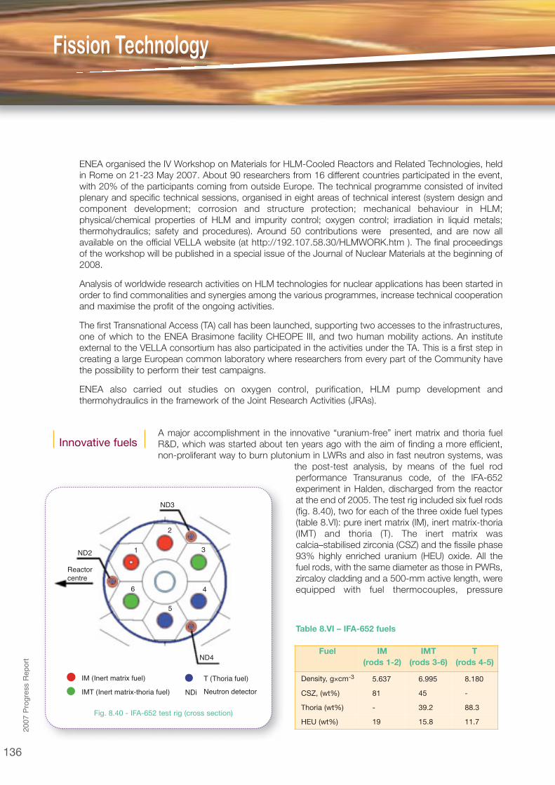
A major accomplishment in the innovative “uranium-free” inert matrix and thoria fuelR&D, which was started about ten years ago with the aim of finding a more efficient,non-proliferant way to burn plutonium in LWRs and also in fast neutron systems, was
the post-test analysis, by means of the fuel rodperformance Transuranus code, of the IFA-652experiment in Halden, discharged from the reactorat the end of 2005. The test rig included six fuel rods(fig. 8.40), two for each of the three oxide fuel types(table 8.VI): pure inert matrix (IM), inert matrix-thoria(IMT) and thoria (T). The inert matrix wascalcia–stabilised zirconia (CSZ) and the fissile phase93% highly enriched uranium (HEU) oxide. All thefuel rods, with the same diameter as those in PWRs,zircaloy cladding and a 500-mm active length, wereequipped with fuel thermocouples, pressure
Fuel IM(rods 1-2)
IMT(rods 3-6)
T(rods 4-5)
Density, g×cm-3 5.637 6.995 8.180
CSZ, (wt%) 81 45 -
Thoria (wt%) - 39.2 88.3
HEU (wt%) 19 15.8 11.7
Table 8.VI – IFA-652 fuels
Innovative fuels
NDi Neutron detector
T (Thoria fuel)
IMT (Inert matrix-thoria fuel)
IM (Inert matrix fuel)
ND3
ND2
ND4
1
2
3
4
5
6
Reactorcentre
Fig. 8.40 - IFA-652 test rig (cross section)
2007ProgressReport
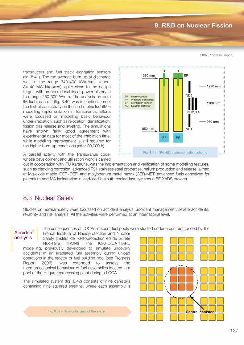
transducers and fuel stack elongation sensors(fig. 8.41). The rod average burn-up at dischargewas in the range 340-400 kWd/cm3 (about34–40 MWd/kgoxeq), quite close to the designtarget, with an operational linear power history inthe range 250-300 W/cm. The analysis on pureIM fuel rod no. 2 (fig. 8.40) was in continuation ofthe first-phase activity on the inert matrix fuel (IMF)modelling implementation in Transuranus. Effortswere focussed on modelling basic behaviourunder irradiation, such as relocation, densification,fission gas release and swelling. The simulationshave shown fairly good agreement withexperimental data for most of the irradiation time,while modelling improvement is still required forthe higher burn-up conditions (after 20,000 h).
A parallel activity with the Transuranus code,whose development and utilisation work is carriedout in cooperation with ITU Karsruhe, was the implementation and verification of some modelling features,such as cladding corrosion, advanced T91 stainless steel properties, helium production and release, aimedat Mg-oxide matrix (CER–CER) and molybdenum metal matrix (CER-MET) advanced fuels conceived forplutonium and MA incineration in lead/lead-bismuth cooled fast systems (LBE-XADS project).
8.3 Nuclear Safety
Studies on nuclear safety were focussed on accident analysis, accident management, severe accidents,reliability and risk analysis. All the activities were performed at an international level.
The consequences of LOCAs in spent fuel pools were studied under a contract funded by theFrench Institute of Radioprotection and NuclearSafety (Institut de Radioprotection ed de SûretéNucléaire [IRSN]) The ICARE/CATHARE
modelling, previously developed to simulate uncoveryaccidents in an irradiated fuel assembly during unloadoperations in the reactor or fuel building pool (see ProgressReport 2006), was extended to assess thethermomechanical behaviour of fuel assemblies located in apool of the Hague reprocessing plant during a LOCA.
The simulated system (fig .8.42) consists of nine canisterscontaining nine squared sheaths, where each assembly is
137
8. R&D on Nuclear Fission
2007 Progress Report
Accidentanalysis
TF ThermocouplePF Pressure transducerEF Elongation sensorNDi Neutron detector
TF TF
PFPF
EF
ND5
ND1
ND2,3,4
1270 mm
930 mm
1100 mm
850 mm
1350 mm
Fig. 8.41 - IFA-652 instrumentation scheme
Central canisterFig. 8.42 - Horizontal view of the system
Fission Technology
138
2007ProgressReport
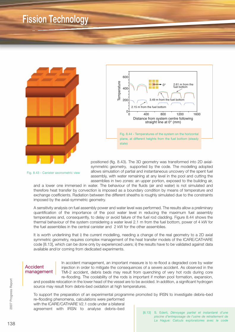
positioned (fig. 8.43). The 3D geometry was transformed into 2D axial-symmetric geometry, supported by the code. The modelling adoptedallows simulation of partial and instantaneous uncovery of the spent fuelassembly, with water remaining at any level in the pool and cutting theassemblies in two zones: an upper portion, exposed to the building air,
and a lower one immersed in water. The behaviour of the fluids (air and water) is not simulated andtherefore heat transfer by convection is imposed as a boundary condition by means of temperature andexchange coefficients. Radiation between the different sheaths is roughly simulated due to the constraintsimposed by the axial-symmetric geometry.
A sensitivity analysis on fuel assembly power and water level was performed. The results allow a preliminaryquantification of the importance of the pool water level in reducing the maximum fuel assemblytemperatures and, consequently, to delay or avoid failure of the fuel rod cladding. Figure 8.44 shows thethermal behaviour of the system considering a water level 2.1 m from the fuel bottom, power of 4 kW forthe fuel assemblies in the central canister and 2 kW for the other assemblies.
It is worth underlining that i) the current modelling, needing a change of the real geometry to a 2D axialsymmetric geometry, requires complex management of the heat transfer models of the ICARE/CATHAREcode [8.13], which can be done only by experienced users; ii) the results have to be validated against dataavailable and/or coming from dedicated experiments.
In accident management, an important measure is to re-flood a degraded core by waterinjection in order to mitigate the consequences of a severe accident. As observed in theTMI-2 accident, debris beds may result from quenching of very hot rods during corere–flooding. The coolability of the rods is important if molten pool formation, expansion,
and possible relocation in the lower head of the vessel are to be avoided. In addition, a significant hydrogensource may result from debris-bed oxidation at high temperatures.
To support the preparation of an experimental programme promoted by IRSN to investigate debris–bedre–flooding phenomena, calculations were performedwith the ICARE/CATHARE V2.1 code under a bilateralagreement with IRSN to analyse debris–bed
Accidentmanagement
[8.13] S. Ederli, Dénoyage partiel et instantané d’unepiscine d’entreposage de l’usine de retraitement deLa Hague: Calculs exploratoires avec le code
600
400
200
0
Tem
pera
ture
0 400 800 1200 1600
2.15 m from the fuel bottom
3.49 m from the fuel bottom
2.61 m from thefuel bottom
0°
Distance from system centre followingstraight line at 0° (mm)
Fig. 8.44 - Temperatures of the system on the horizontal
plane, at different heights from the fuel bottom (steady
state)
Fig. 8.43 - Canister axonometric view
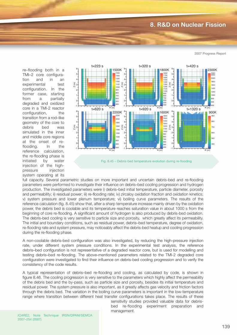
re–flooding both in aTMI–2 core con figura -tion and in anexperimental testconfiguration. In theformer case, startingfrom a partiallydegraded and oxidizedcore in a TMI-2 reactorconfiguration, thetransition from a rod–likegeometry of the core todebris bed wassimulated in the innerand middle core regionsat the onset of re-flooding. In thereference calculation,the re-flooding phase isinitiated by waterinjection of the high-pressure injectionsystem operating at itsfull capacity. Several parametric studies on more important and uncertain debris-bed and re-floodingparameters were performed to investigate their influence on debris–bed cooling progression and hydrogenproduction. The investigated parameters were i) debris–bed initial temperature, particle diameter, porosityand permeability; ii) residual power; iii) re-flooding rate; iv) zircaloy oxidation fraction and oxidation kinetics;v) system pressure and lower plenum temperature; vi) boiling curve parameters. The results of thereference calculation (fig. 8.45) show that, after a sharp temperature increase mainly driven by the oxidationpower, the debris bed is coolable and its temperature reaches saturation value in about 1000 s from thebeginning of core re-flooding. A significant amount of hydrogen is also produced by debris-bed oxidation.The debris-bed cooling is very sensitive to particle size and porosity, which greatly affect its permeability.The initial and boundary conditions, such as residual power, debris–bed temperature, degree of oxidation,re-flooding rate and system pressure, may noticeably affect the debris-bed heatup and cooling progressionduring the re-flooding phase.
A non-coolable debris-bed configuration was also investigated, by reducing the high-pressure injectionrate, under different system pressure conditions. In the experimental test analysis, the referencedebris–bed configuration is not representative of a degraded reactor core, but is used for modelling andtesting debris–bed re-flooding. The above-mentioned parameters related to the TMI-2 degraded coreconfiguration were investigated to find their influence on debris-bed cooling progression and to verify theconsistency of the code results.
A typical representation of debris–bed re-flooding and cooling, as calculated by code, is shown infigure 8.46. The cooling progression is very sensitive to the parameters which highly affect the permeabilityof the debris bed and the by-pass, such as particle size and porosity, besides its initial temperature andresidual power. The system pressure is also important, as it greatly affects gas velocity and friction factorsthrough the debris bed. The variation in the boiling curve parameters is important in the low-temperaturerange where transition between different heat transfer configurations takes place. The results of these
sensitivity studies provided valuable data for debris-bed re-flooding experiment preparation andmanagement.
139
8. R&D on Nuclear Fission
2007 Progress Report
ICARE2, Note Technique IRSN/DPAM/SEMCA2007–254 (2007)
t=223 s t=320 s t=420 s
t=620 s t=920 s t=1320 s
1500K 1800K 2300K
2200K 1600K 900K
6
5
4
3
2
1
0
-1
Z (
m)
R (m)
1500
1400
1300
1200
1100
1000
900
800
700
600
500
400
6
5
4
3
2
1
0
-1
Z (
m)
R (m)
900
800
700
600
500
400
6
5
4
3
2
1
0
-1
Z (
m)
R (m)
15001600
1400
1300
1200
1100
1000
900
800
700
600
500
400
6
5
4
3
2
1
0
-1
Z (
m)
R (m)
6
5
4
3
2
1
0
-1
Z (
m)
R (m)
6
5
4
3
2
1
0
-1
Z (
m)
R (m)
1500160017001800
14001300120011001000900800700600500400
1600
1800
2000
22002300
1400
1200
1000
800
600
400
1600
1800
2000
2200
1400
1200
1000
800
600
400
Fig. 8.45 – Debris-bed temperature evolution during re-flooding

Fission Technology2007ProgressReport
Severe-accident studies are performed under the European Severe Accident Research Networkof Excellence (SARNET). The objective is to enhance the safety of present and future nuclearplants by resolving the most important uncertainties regarding severe accidents.
In the framework of Integrating Activities, ENEA made valuable contributions to the WP “Physical ModelAssessment - Accident Source Term Evaluation Code (PHYMA-ASTEC)” aimed at evaluating the quality ofASTEC models by comparison with experiments, and “Reactor Application Benchmarking (RAB-ASTEC)”to assess and improve the ASTEC capability to simulate reactor accident scenarios, including safetysystems and severe accident management procedures. With regard to PHYMA-ASTEC the results ofcomparison with other codes contributed to building a large validation matrix. For RAB-ASTEC, ASTECwas applied to a type-PWR900 French reactor and the results compared with the MELCOR 1.8.5 code.A large benchmarking matrix and a databank of reference input decks are now under progressiveconstruction.
In the framework of jointly executed research activities (WP “Zircalloy (Zry) Oxidation by Air or by Steam-Air Mixture”), an improvement of the model for oxidation of Zry by air for the ICARE/CATHARE code wasproposed, based on analysis of the MOZART experiments performed by IRSN and the Shanz work on Zryoxidation by steam [8.14]. The new model simulates the pre-breakaway phase of Zry oxidation andhypothesises parabolic behaviour for the oxidation kinetics below a pre-defined temperature value and acubic law for higher values. Figure 8.47 reports the results from simulation of an isothermal MOZART testat 900°C, using the new model. It is worth noting that the proposed model improves the code predictioncapability in assessing the MOZART experiments, compared with the previous model (parabolic law).
Within the WP “Oxidizing Environment Impact onSource Term (OXIDEN)”, aimed at quantifying thesource term, in particular for Ru, under oxidizingconditions/air ingress for HBU and MOX fuel,fission product (FP) release from UO2 fuels wasassessed in order to validate the ELSA/DIVAmodule included in the ASTEC 1.3 rev.0 reactorcode against HCE3 experiments [8.15]. TheHCE3 experiments (Chalk River Laboratories ofAtomic Energy of Canada Limited [AECL]) were
[8.14] G. Schanz, Recommendations and supportinginformation on the choice of zirconium oxidationmodels in severe accident codes, FZKA 6827,SAM–COLOSS-P043 (March 2003)
[8.15] R. D. Barrand, et al., Release of fission products fromCANDU fuel in air, steam and argon atmospheres at1500-1900 °C. The HCE3 experiment, Presented at
Severeaccident
1.0
0.8
0.6
0.4
0.2-0.3 -0.2 -0.1 0
R(m)
Z(m
)
Time (s)300
1
0
1.0
0.8
0.6
0.4
0.2-0.3 -0.2 -0.1 0
R(m)
Time (s)300
1300120011001000
900800700600500400300
Fig. 8.46 - Void fraction,
fluid velocity and steam
temperature in the debris-
bed region at 300 s
Tem
pera
ture
(°C
)
950
930
910
890
870
8502500 3500 4500 55003000 4000 5000
Time (s)
Mas
s ga
in (
g/m
2 )
100
80
60
40
20
0
Calculated mass gain (parabolic behaviour withcorr. based on C. Duriez data)
Measured sample temperatureMeasured mass gain
Calculated mass gain (parabolic + cubic behaviour)
Parabolic
Parabolic only
Cubic
Fig. 8.47 - Simulation of the isothermal MOZART experiment
at 900°C
140
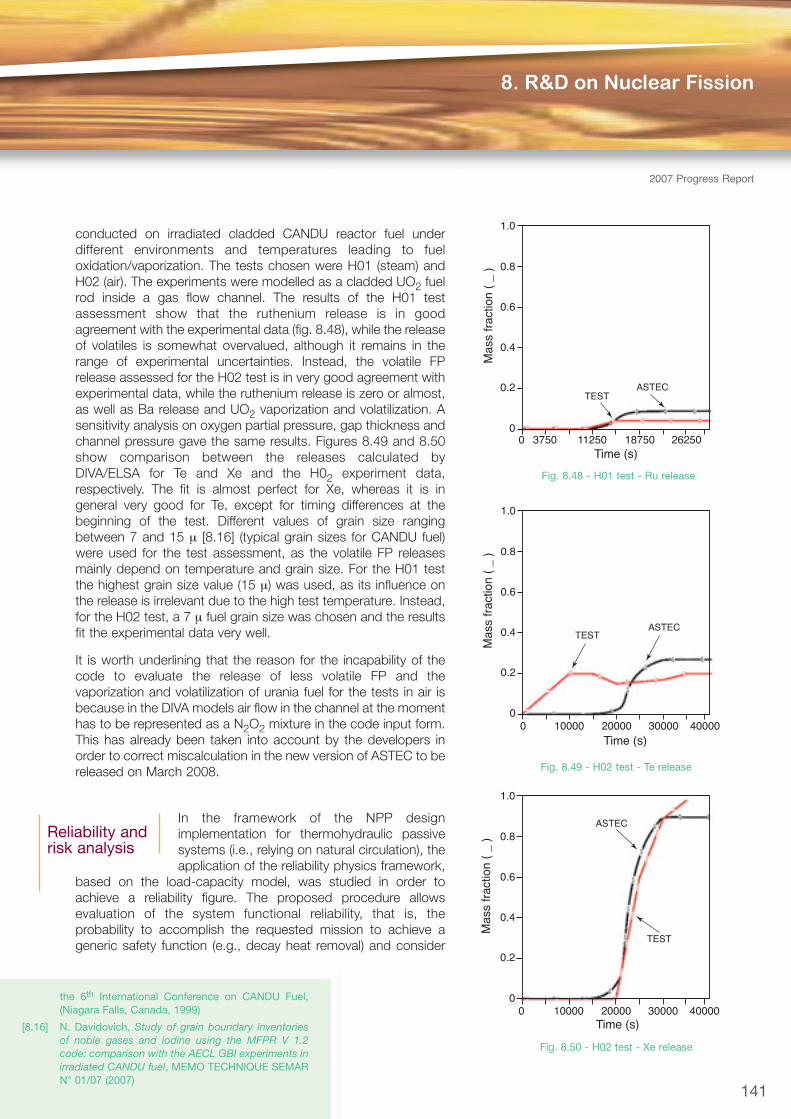
conducted on irradiated cladded CANDU reactor fuel underdifferent environments and temperatures leading to fueloxidation/vaporization. The tests chosen were H01 (steam) andH02 (air). The experiments were modelled as a cladded UO2 fuelrod inside a gas flow channel. The results of the H01 testassessment show that the ruthenium release is in goodagreement with the experimental data (fig. 8.48), while the releaseof volatiles is somewhat overvalued, although it remains in therange of experimental uncertainties. Instead, the volatile FPrelease assessed for the H02 test is in very good agreement withexperimental data, while the ruthenium release is zero or almost,as well as Ba release and UO2 vaporization and volatilization. Asensitivity analysis on oxygen partial pressure, gap thickness andchannel pressure gave the same results. Figures 8.49 and 8.50show comparison between the releases calculated byDIVA/ELSA for Te and Xe and the H02 experiment data,respectively. The fit is almost perfect for Xe, whereas it is ingeneral very good for Te, except for timing differences at thebeginning of the test. Different values of grain size rangingbetween 7 and 15 μ [8.16] (typical grain sizes for CANDU fuel)were used for the test assessment, as the volatile FP releasesmainly depend on temperature and grain size. For the H01 testthe highest grain size value (15 μ) was used, as its influence onthe release is irrelevant due to the high test temperature. Instead,for the H02 test, a 7 μ fuel grain size was chosen and the resultsfit the experimental data very well.
It is worth underlining that the reason for the incapability of thecode to evaluate the release of less volatile FP and thevaporization and volatilization of urania fuel for the tests in air isbecause in the DIVA models air flow in the channel at the momenthas to be represented as a N2O2 mixture in the code input form.This has already been taken into account by the developers inorder to correct miscalculation in the new version of ASTEC to bereleased on March 2008.
In the framework of the NPP designimplementation for thermohydraulic passivesystems (i.e., relying on natural circulation), theapplication of the reliability physics framework,
based on the load-capacity model, was studied in order toachieve a reliability figure. The proposed procedure allowsevaluation of the system functional reliability, that is, theprobability to accomplish the requested mission to achieve ageneric safety function (e.g., decay heat removal) and consider
8. R&D on Nuclear Fission
2007 Progress Report
the 6th International Conference on CANDU Fuel,(Niagara Falls, Canada, 1999)
[8.16] N. Davidovich, Study of grain boundary inventoriesof noble gases and iodine using the MFPR V 1.2code: comparison with the AECL GBI experiments inirradiated CANDU fuel, MEMO TECHNIQUE SEMARN° 01/07 (2007)
Reliability andrisk analysis
1.0
0.8
0.6
0.4
0.2
0
Mas
s fr
actio
n (
_ )
0 3750 11250 18750 26250Time (s)
TESTASTEC
Fig. 8.48 - H01 test - Ru release
1.0
0.8
0.6
0.4
0.2
0
Mas
s fr
actio
n (
_ )
0 10000 20000 30000 40000Time (s)
TESTASTEC
Fig. 8.49 - H02 test - Te release
1.0
0.8
0.6
0.4
0.2
0
Mas
s fr
actio
n (
_ )
0 10000 20000 30000 40000Time (s)
TEST
ASTEC
Fig. 8.50 - H02 test - Xe release
141

Fission Technology
142
2007ProgressReport
that a system is in either a failed or safe state with respect to identified failure modes. The change of state(failed or safe) passes through the limit states, where the values of the parameters involved arerepresentative of failure conditions. The methodology was applied to the isolation condenser of thesimplified boiling water reactor (SBWR). The results of the analysis, in terms of minimum output-parameterrequirement as a function of the desired reliability, will help the designer to determine the allowable limitsfor the system performance parameters, within a probabilistic framework. The uncertainties associatedwith passive system reliability were also studied.
The IAEA co-ordinated research project “Natural Circulation Phenomena, Modelling and Reliability ofPassive Systems that Utilise the Natural Circulation” is aimed at merging the thermohydraulic andprobabilistic aspects of reliability analyses of different passive system designs. In this framework, studieswere carried out on the reliability assessment of the passive features of the Argentinean integral-typeCAREM-like reactor.
In the framework of the network on “Incorporating Ageing Effects into Probabilistic Safety Assessment”, anactivity has started on the development of reliability and availability models of systems and components,incorporating effects of aging.
8.4 Proliferation and Nuclear Security
In 2007 ENEA started to develop an integrated approach toward nuclear security. In this area of strongscientific and industrial competition and cutting-edge technologies, it is necessary to keep abreast with theend-user in understanding requirements, resources and future trends. ENEA has been engaged in security-related activities for several years; however, new technologies and research topics have recently emergedand technical support for the Public Administration has become urgent. ENEA’s activities in this field havefocussed on i) understanding potential internal resources; ii) developing a security culture and an integratedapproach to nuclear security; iii) understanding the needs of the end-users at a national and internationallevel; iv) monitoring scientific activities with a potential impact on security; v) including innovativeapproaches.
A document entitled “Linea Tematica SECURITY” was prepared to serve as a possible roadmap for astrategic project on security for all the ENEA departments. Experts from the departments have regularlyattended meetings held in Europe on research into security matters: from the first, the EuropeanConference on Security Research (SRC 07), to others related to the FP7 call -Theme 10: Security.Considerable efforts have also been dedicated to the preparation of a European project for this call for thedetection of the entire family of actinides, including depleted and enriched uranium and plutonium, hiddenand possibly shielded inside containers. The detection method is based on high-energy photons inducingphotofission on actinides.
Nuclear security is a global issue and as such is dealt with in various international frameworks: the IAEA;treaties on disarmament and non-proliferation, e.g., the Non-Proliferation Treaty and the ComprehensiveNuclear-Test-Ban Treaty; UN resolutions; conventions and initiatives. The latest - the Global Initiative toCombat Nuclear Terrorism - was launched by Presidents Bush and Putin at the St Petersburg G8 summit.Within this initiative, several activities have been identified and experts from ENEA have so far taken partin a number of them to provide technical expertise, gain a better understanding of the technical needs ofthe public administration, and identify or assess new areas of research on security to which ENEA couldcontribute.
Experts from ENEA have also taken part in IAEA initiatives, e.g., combating the illicit trafficking of nuclearmaterials and, in general, the control of nuclear and radioactive material. ENEA will also have the role of
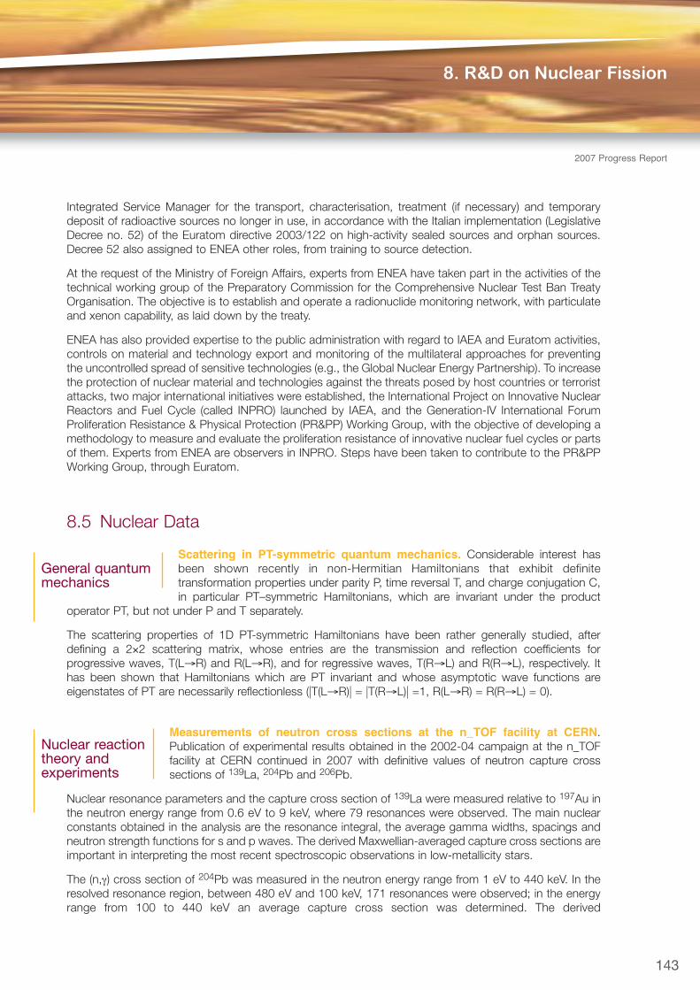
Integrated Service Manager for the transport, characterisation, treatment (if necessary) and temporarydeposit of radioactive sources no longer in use, in accordance with the Italian implementation (LegislativeDecree no. 52) of the Euratom directive 2003/122 on high-activity sealed sources and orphan sources.Decree 52 also assigned to ENEA other roles, from training to source detection.
At the request of the Ministry of Foreign Affairs, experts from ENEA have taken part in the activities of thetechnical working group of the Preparatory Commission for the Comprehensive Nuclear Test Ban TreatyOrganisation. The objective is to establish and operate a radionuclide monitoring network, with particulateand xenon capability, as laid down by the treaty.
ENEA has also provided expertise to the public administration with regard to IAEA and Euratom activities,controls on material and technology export and monitoring of the multilateral approaches for preventingthe uncontrolled spread of sensitive technologies (e.g., the Global Nuclear Energy Partnership). To increasethe protection of nuclear material and technologies against the threats posed by host countries or terroristattacks, two major international initiatives were established, the International Project on Innovative NuclearReactors and Fuel Cycle (called INPRO) launched by IAEA, and the Generation-IV International ForumProliferation Resistance & Physical Protection (PR&PP) Working Group, with the objective of developing amethodology to measure and evaluate the proliferation resistance of innovative nuclear fuel cycles or partsof them. Experts from ENEA are observers in INPRO. Steps have been taken to contribute to the PR&PPWorking Group, through Euratom.
8.5 Nuclear Data
Scattering in PT-symmetric quantum mechanics. Considerable interest hasbeen shown recently in non-Hermitian Hamiltonians that exhibit definitetransformation properties under parity P, time reversal T, and charge conjugation C,in particular PT–symmetric Hamiltonians, which are invariant under the product
operator PT, but not under P and T separately.
The scattering properties of 1D PT-symmetric Hamiltonians have been rather generally studied, afterdefining a 2×2 scattering matrix, whose entries are the transmission and reflection coefficients forprogressive waves, T(L→R) and R(L→R), and for regressive waves, T(R→L) and R(R→L), respectively. Ithas been shown that Hamiltonians which are PT invariant and whose asymptotic wave functions areeigenstates of PT are necessarily reflectionless (|T(L→R)| = |T(R→L)| =1, R(L→R) = R(R→L) = 0).
Measurements of neutron cross sections at the n_TOF facility at CERN.Publication of experimental results obtained in the 2002-04 campaign at the n_TOFfacility at CERN continued in 2007 with definitive values of neutron capture crosssections of 139La, 204Pb and 206Pb.
Nuclear resonance parameters and the capture cross section of 139La were measured relative to 197Au inthe neutron energy range from 0.6 eV to 9 keV, where 79 resonances were observed. The main nuclearconstants obtained in the analysis are the resonance integral, the average gamma widths, spacings andneutron strength functions for s and p waves. The derived Maxwellian-averaged capture cross sections areimportant in interpreting the most recent spectroscopic observations in low-metallicity stars.
The (n,γ) cross section of 204Pb was measured in the neutron energy range from 1 eV to 440 keV. In theresolved resonance region, between 480 eV and 100 keV, 171 resonances were observed; in the energyrange from 100 to 440 keV an average capture cross section was determined. The derived
143
8. R&D on Nuclear Fission
2007 Progress Report
Nuclear reactiontheory andexperiments
General quantummechanics

Fission Technology
144
2007ProgressReport
Maxwellian–averaged cross sections are in agreement with previous experiments at kT=30 keV, but about35% larger than the values reported so far at kT=5 keV.
The (n,γ) cross section of 206Pb was measured in the neutron energy range from 1 eV to 620 keV. Of the130 resonances observed, the parameters of 61, between 3.36 keV and 572 keV, were determined.Compared to the values in the literature, the Maxwellian-averaged cross sections derived from the presentdata are about 20% and 9% lower at kT=5 keV and 30 keV, respectively. The new results have a directimpact on the s-process abundance of 206Pb, which represents an important test for interpretation of thecosmic clock based on the decay of 238U.
Preliminary results on neutron capture by other isotopes, such as 90,91,92,93,94,96Zr, 186,187,188Os, 197Au,234U, 237Np, 240Pu, and neutron-induced fission of 233,235U and 245Cm were obtained and presented atinternational conferences.
Two multi-group coupled neutron and photon cross section libraries based on theJEFF-3.1 Organisation for Economic Cooperation and Development/Nuclear EnergyAgency (OECD/NEA) Data Bank (Issy-les-Moulineaux, France) library of evaluated datawere generated for nuclear fission applications. The libraries, named VITJEFF31.BOLIBand MATJEFF31.BOLIB, were respectively re-processed in AMPX and MATXS format
through the ENEA Bologna revised versions of the NJOY-99.160 and SCAMPI nuclear data processingsystems. A total of 182 files (176 standard files + 6 thermal scattering files for bound nuclides) wereprocessed into the VITAMIN-B6 American library energy group structure (199 neutron groups + 42 photongroups). To update and improve as much as possible the libraries, it was decided to process eightJEFF–3.1 revised files (Bi-209, Ca-46, Cl-35, Cl-37, Cr-52, Fe-58, U-233 and U-234) downloaded from theOECD/NEA Data Bank. This set of files, accepted by the JEFF Working Group of the OECD/NEA DataBank, contains in particular the Ca-46 revised file, prepared in ENEA Bologna and proposed for the futureJEFF-3.2 evaluated data library. A massive data validation of VITJEFF31.BOLIB was performed withtransport codes on about 90 criticality safety benchmark experiments with thermal, intermediate and fastneutron fission spectrums. The discrete ordinate (SN) codes XSDRNPM (1D) and DORT (2D) wereemployed in the calculations. In parallel, the MCNP4C2 code was used with an ENEA Bologna specificallygenerated JEFF-3.1 point-wise (continuous-energy) cross-section library in ACE format in order to havereference results, consistent with the official JEFF-3.1 data validation results, performed by the OECD/NEAData Bank with MCNP4C3. In addition, two similar multi-group coupled neutron and photon cross sectionlibraries, based on the recent ENDF/B-VII.0 American evaluated nuclear data library, were produced. TheVITENDF70.BOLIB and MATENDF70.BOLIB libraries were generated respectively in AMPX and MATXSformat through the ENEA Bologna revised versions of the NJOY-99.160 and SCAMPI nuclear dataprocessing systems. Then, two working libraries of self-shielded cross sections in FIDO-ANISN format inthe energy group structure (47 neutron groups + 20 photon groups) of the BUGLE-96 American librarywere collapsed from VITJEFF31.BOLIB and VITENDF70.BOLIB l in AMPX format, through the ENEABologna 2007 revision of SCAMPI. The two libraries, BUGJEFF31.BOLIB and BUGENDF70.BOLIB, arespecifically dedicated to LWR shielding and pressure vessel dosimetry applications.
The NJOY-99.160 version used in the present data processing of the VITJEFF31.BOLIB,MATJEFF31.BOLIB, VITENDF70.BOLIB and MATENDF70.BOLIB fine-group libraries contains an ENEABologna revised patch for the GROUPR module dedicated to extending the group-wise data processingcapability to the evaluated data files, e.g., 69 JEFF-3.1 nuclear data files, including non-Cartesianinterpolation schemes for secondary neutron energy distributions. An original version of this patch wasprepared in ENEA Bologna in 2006 and sent to the OECD/NEA Data Bank to be used officially for the firsttime with NJOY-99.112.
A specific correction patch dedicated to calculating properly the fluctuation factors for heating in the
Nuclear dataprocessing andvalidation
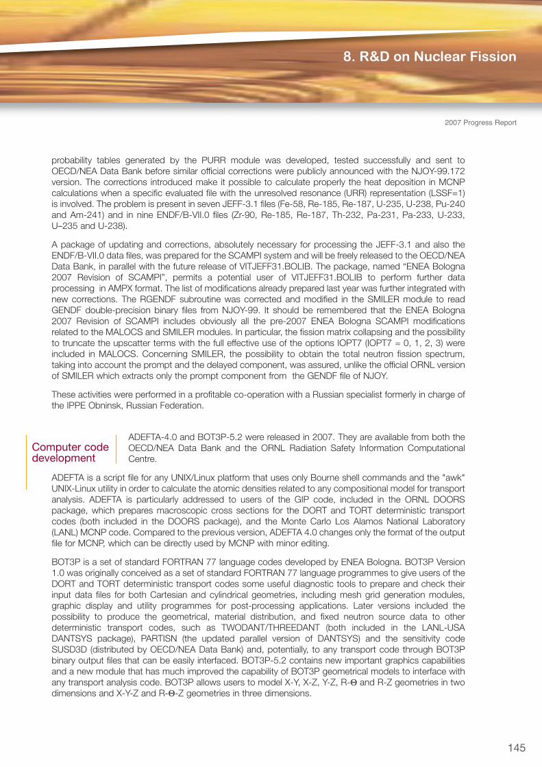
probability tables generated by the PURR module was developed, tested successfully and sent toOECD/NEA Data Bank before similar official corrections were publicly announced with the NJOY-99.172version. The corrections introduced make it possible to calculate properly the heat deposition in MCNPcalculations when a specific evaluated file with the unresolved resonance (URR) representation (LSSF=1)is involved. The problem is present in seven JEFF-3.1 files (Fe-58, Re-185, Re-187, U-235, U-238, Pu-240and Am-241) and in nine ENDF/B-VII.0 files (Zr-90, Re-185, Re-187, Th-232, Pa-231, Pa-233, U-233,U–235 and U-238).
A package of updating and corrections, absolutely necessary for processing the JEFF-3.1 and also theENDF/B-VII.0 data files, was prepared for the SCAMPI system and will be freely released to the OECD/NEAData Bank, in parallel with the future release of VITJEFF31.BOLIB. The package, named “ENEA Bologna2007 Revision of SCAMPI”, permits a potential user of VITJEFF31.BOLIB to perform further dataprocessing in AMPX format. The list of modifications already prepared last year was further integrated withnew corrections. The RGENDF subroutine was corrected and modified in the SMILER module to readGENDF double-precision binary files from NJOY-99. It should be remembered that the ENEA Bologna2007 Revision of SCAMPI includes obviously all the pre-2007 ENEA Bologna SCAMPI modificationsrelated to the MALOCS and SMILER modules. In particular, the fission matrix collapsing and the possibilityto truncate the upscatter terms with the full effective use of the options IOPT7 (IOPT7 = 0, 1, 2, 3) wereincluded in MALOCS. Concerning SMILER, the possibility to obtain the total neutron fission spectrum,taking into account the prompt and the delayed component, was assured, unlike the official ORNL versionof SMILER which extracts only the prompt component from the GENDF file of NJOY.
These activities were performed in a profitable co-operation with a Russian specialist formerly in charge ofthe IPPE Obninsk, Russian Federation.
ADEFTA-4.0 and BOT3P-5.2 were released in 2007. They are available from both theOECD/NEA Data Bank and the ORNL Radiation Safety Information ComputationalCentre.
ADEFTA is a script file for any UNIX/Linux platform that uses only Bourne shell commands and the "awk"UNIX-Linux utility in order to calculate the atomic densities related to any compositional model for transportanalysis. ADEFTA is particularly addressed to users of the GIP code, included in the ORNL DOORSpackage, which prepares macroscopic cross sections for the DORT and TORT deterministic transportcodes (both included in the DOORS package), and the Monte Carlo Los Alamos National Laboratory(LANL) MCNP code. Compared to the previous version, ADEFTA 4.0 changes only the format of the outputfile for MCNP, which can be directly used by MCNP with minor editing.
BOT3P is a set of standard FORTRAN 77 language codes developed by ENEA Bologna. BOT3P Version1.0 was originally conceived as a set of standard FORTRAN 77 language programmes to give users of theDORT and TORT deterministic transport codes some useful diagnostic tools to prepare and check theirinput data files for both Cartesian and cylindrical geometries, including mesh grid generation modules,graphic display and utility programmes for post-processing applications. Later versions included thepossibility to produce the geometrical, material distribution, and fixed neutron source data to otherdeterministic transport codes, such as TWODANT/THREEDANT (both included in the LANL-USADANTSYS package), PARTISN (the updated parallel version of DANTSYS) and the sensitivity codeSUSD3D (distributed by OECD/NEA Data Bank) and, potentially, to any transport code through BOT3Pbinary output files that can be easily interfaced. BOT3P-5.2 contains new important graphics capabilitiesand a new module that has much improved the capability of BOT3P geometrical models to interface withany transport analysis code. BOT3P allows users to model X-Y, X-Z, Y-Z, R-Θ and R-Z geometries in twodimensions and X-Y-Z and R-Θ-Z geometries in three dimensions.
145
8. R&D on Nuclear Fission
2007 Progress Report
Computer codedevelopment

Fission Technology
146
2007ProgressReport
BOT3P has large world-wide diffusion and is currently used by important companies such asWestinghouse Electric Co. OECD/NEA Data Bank received more than 130 dispatch requests of thedifferent versions at up to the end of 2007. BOT3P is designed to run on most Linux/UNIX platforms.
8.6 Cold Neutron Beam Utilisation for Condensed Matter Studies
Activities at the High Flux Reactor of the Institute Laue Langevin (ILL) Grenoble, France concerned researchprojects as well as industrial-type experiments. Funding is mostly provided by national institutes, such asMIUR, and international agencies, such as Euratom. External scientific collaborations were also developedwith Italian laboratories (University of Trieste, University of Bologna, CNR) and with several other Europeanlaboratories (FZK, ENSAM-Paris and CEA-Saclay, ETH-Zürich and PSI-Villingen). Small-angle neutron
scattering (SANS) and neutron diffraction are theexperimental techniques most frequently utilised tocharacterise materials and components of interest fora variety of technical applications. SANS is used tocharacterise microstrucural inhomogeities (such asmicrovoids or precipitates in steels), while neutrondiffraction is used for crystallographic structuredetermination and stress measurements. Neutronsprovide in fact a unique experimental tool for non-destructive bulk investigations, for probing magneticmaterials and for analysing microstructural effectsrelated to the elemental composition of the materialsinvestigated and to the presence of hydrogen. Withregard to SANS, the activities are carried out toimprove and optimise the methods employed toanalyse neutron data and, more specifically, to obtainreliable and relevant microstructural information.Figures 8.51 and 8.52 show the results of the studyon microstructural radiation damage in Eurofer 97martensitic steel neutron irradiated at two differentdose levels, 2.5 and 8.4 displacements per atom(dpa). The increase in the SANS cross section(fig. 8.51) with increasing irradiation dose is due to thegrowth of microvoids. The Fourier transformation ofthese data into the corresponding size distributions ofthe microvoids is shown in figure 8.52: increasing thedose the microvoid average size is nearly unchanged,but their volume fraction increases by a factor of two.Such studies on technologically relevant materialsrequire a significant improvement in the currentlyavailable SANS detector systems in order to reducebackground noise as much as possible. A prototypehigh data rate neutron detector for SANSmeasurements has been developed at ILL in acollaboration which includes ENEA. Such detectors,which are indispensable to better exploit the currentlyavailable neutron sources, will be even morenecessary in view of the future intense spallationsources.
dΣ/d
Ω (
cm-1
ste
r-1 )
100
10-1
10-2
10-110-2
10-3
10-4
Q (Å-1)
D
103
102
101
100
10310210110-1 100
R (nm)
Fig. 8.51 - Nuclear SANS cross sections of the difference
between Eurofer 97 neutron irradiated at 300°C dpa with
8.4 dpa (empty dots) and with 2.5 dpa (full dots) and their
respective reference samples
Fig. 8.52 - Volume distribution functions D(R) (nm-1)
obtained from the nuclear SANS difference between
Eurofer 97 neutron irradiated at 250°C to 8.4 dpa
(continuous line) and to 2.5 dpa (dotted line) and their
respective reference samples

8.7 TRIGA RC-1 Plant Operation for Application Development
Neutron radiography. In 2007 the installation of a second neutron collimator at the tangential port of thereactor was completed and characterised in terms of neutron flux, cadmium ratio, gamma background andcollimating factor. The values measured for these parameters show that the new channel is a greatimprovement on that of the previous TRIGA neutron facility installed at the thermal column and encouragesthe completion of the facility with a beam shutter and bunker.
An iterative method for the tomographic reconstruction problem was developed. The method will allowreconstruction also in the case of an incomplete set of tomographic projections.
To allow remote control, via Internet, of the neutron radiography equipment, a client-server strategy wasdeveloped. With the Web Interactive Neutron Experimental Structure (WINES) all registered users haveaccess to the dedicated computer of the experiment, with full control of acquisition parameters and real-time data access. A plant supervisor can temporarily inhibit access or interaction with the instruments asa function of the plant status or other user priority. Users also have access to the measurement databasewith the acquisition data sheets or image files collected at the imaging instruments.
Neuronal network training. A set of measurements was performed to collect a series of thermohydraulicdata from the reactor core, cooling system, control rod positions and neutron flux for a neural networktraining process. The neural network was successfully tested for monitoring of the reactor behaviourduring its normal operation and for reactivity step experiments.
Thermal column modification design for BNCT applications. The thermal column of the reactor wasre-designed with MNCP techniques in order to obtain the maximum achievable homogeneity in terms ofthermal neutron flux and reaction rate in a leaver model with 10B content comparable with the therapeuticdoses.
In-core test for synthetic single-crystal diamond. In the framework of a bi-lateral collaboration withRome University Tor Vergata, a series of diamond-based prototype neutron detectors was tested underneutron irradiation at high fluxes at the TRIGA RC-1 research reactor of ENEA Casaccia. During theirradiation sequences a fission chamber was used as a reference neutron flux monitor. The excellentagreement between the two detectors encourages further investigations, which will be devoted to verifyingthe detector response with ageing in terms of neutron fluence.
147
8. R&D on Nuclear Fission
2007 Progress Report