йшшшш - International Atomic Energy Agency
75
': ww \у\м] ИМММММИЧШМИС <.<**•: йшшшш ОЬЫ .11)111 lllll.lll И i К I II i N • I Я II .I'M I.I \ 11 ( ( . 11 .1 (> I '• \ 11 И11 HilN I I N S I I I I I I Z^J i-Dk м ( i i. \ k k'i si \k< м .-* wNnMMhMfW.icaan-М''М 5[62]-93 PA! КИЕ СООБЩЕНИЯ ОИЯИ INR RAPID COMMUNICATIONS ДУБНА a "-•"—"" - —— — — • —n,- --1 -и m v i i• | iliniiiii 'И1ГМ» iriDHiT
-
Upload
khangminh22 -
Category
Documents
-
view
0 -
download
0
Transcript of йшшшш - International Atomic Energy Agency
': ww \у\м] И М М М М М И Ч Ш М И С
<.<**• : йшшшш
О Ь Ы .11)111 l l l l l . l l l И i К I I I i N • I
Я I I .I'M I.I \ 11 ( ( . 11 .1 (> I '• \ 11 И11
H i l N I I N S I I I I I I Z^J i-Dk м ( i i. \ k
k'i s i \k< м .-* wNnMMhMfW.icaan-М''М
5[62]-93
PA! КИЕ СООБЩЕНИЯ ОИЯИ
INR RAPID COMMUNICATIONS
ДУБНА a " - • " — " " - —— — — • —n,- --1 -и m v i i• | iliniiiii 'И1ГМ» iriDHiT

РЕДАКЦИОННЫЙ СОВЕТ
А.М.Балдин А.Н.Сисакян Д.В.Ширков С.Г.Стеценко
А.Я.Астахов В.А.Бедняков В.А.Бирюков С.Дубничка В.И.Журавлев И.Звара П.И.Зарубин И.Натканец Б.И.Пустыльник Ю.В.Таран М.Г.Шафранова
председатель зам.председателя зам. председателя ученый секретарь
— члены совета
EDITORIAL BOARD
A.M.Baldin A.N.Sissakian D.V.Shirkov S.G.Sietscnko
A.Ya.Astakhov V.A.Bednyakov V.A.Biryukov S.Dubnicka V.l.Zhuravlev l.Zvara P.I.Zarubin I.Natkaniec B.I.Pustylnic Yu.V.Taran M.G.Shafranova
Chairman Vice-Chairman Vice-Chairman Scientific Secretary
— Members of the Board
© Объединенный институт ядерных исследований Дубна, 1993

• • ) / '
Объединенный институт ядерных исследований Joint Institute for Nuclear Research
5[62]-93
КРАТКИЕ СООБЩЕНИЯ ОИЯИ JINR RAPID COMMUNICATIONS
сборник collection
Дубна 1993
В сборнике ''Краткие сообщении ОИЯИ» помещаются статьи, содержащие оригинальные научные, научно-технические, методические и прикладные результаты, требующие срочной публикации.
Сборник выходит регулярно и имеет статус официальной публикации ОИЯИ.
The collection JINR Rapid Communications includes the articles providing information on original scientific, scientific-technical, methodical and applied science results which arc to be speedily published.
The collection is issued regularly and has the status of official publications of the Joint Institute for Nuclear Research.
References io the articles of the JINR Rapid Communications should contain:
— names and initials of authors, — title of collection, introduced by word "In:", — publication index, — location of publisher (Dubna), — year of publication. — page number.
lor example: Savin I.A., Smirnov O.I. In. JINR Kapid
Communications, N2-84, Dubnu, I9S4, pi.

ОГЛАВЛЕНИЕ CONTENTS
K.D.Tolslov Perspectives of Electronuclear Method of Energy Generation and Nuclear Waste Transmutation К.Д.Толстов Перспективы электроядерного метода генерации энергии и трансмутации радиоактивных отходов 5
И.А.Шелаев Сверхпроводящий циклотрон с разделенными орбитами для электроядерного реактора I.AShelaev Superconducting Separated Orbit Cyclotron for Electronuclear Reactor 16
S.V.Afanasicv, Yu.S.Anisimov, A.l.Malakhov, G.L.Mclkumov, S.G.Reznikov, A.Yu.Semcnov, P.I.Zarubin Test of Scintillation Counters for Multichannel Time-of-Flight System С.В.Афанасьев, Ю.С.Анисимов, А.И.Малахов, Г.Л.Мелкумов, С.Г.Резников, А.Ю.Семенов, П.И.Зарубин Испытания сцинтилляционных счетчиков, предназначенных для создания многоканальных нремяпролетных систем 34
M.Pentia, Gh.Iorgovan, B.Vulpescu Data Reduction and Multiple Coulomb Scattering Error Analysis within Silicon Tracking Detector System М.Пентиа, Г.Иоргован, Б.Вулпеску Редукция данных и анализ ошибок при многократном рассеянии в кремниевых трековых детекторах 42
S.N.Ershov, S.B.Gerasimov, A.S.Khrykin On the Reaction pp -» ppy as a Means of Test for Narrow Dibaryon Structures С.Н.Ершов, С.Б.Герасимов, А.С.Хрыкин О реакции рр -» ppy как средстве обнаружения дибарионных резонансов 54
3

l.V.Pu^ynin, I.V.Aniirkhanov, T.P.Puzynina. E.V.Zemlyaruya The Newtonian Iterative Scheme with Simultaneous Calculating the Inverse Operator for the Derivative of Nonlinear Function И.В.Пузынин, И.В.Амирханов, Т.П.Пуяынина, E. В. Земляная Ньютоновская итерационная схема с одновременным вычислением оператора, обратного к производной нелинейной функции ЬЗ
4
Кратки? снобирнин ОИЯИ Ne5(b2) 9J JINK Rapid Cimimunkulioin No.3(62)QJ УДК 539.16
PERSPECTIVES OF ELECTRONLCLEAR METHOD OF ENERGY GENERATION AND NUCLEAR WASTE TRANSMUTATION
K.D.Tolstov The studies of feasibility of elcctronuclear method of energy generation are
overviewed as well as a current research program in this direction at the Synchrophasotron — Nuclotron accelerator complex the results may be applied for development of new technique of nuclear waste transmutation.
The Investigation has been performed at the Laboratory of High energies, JINR
Перспективы электроядериого метода генерации энергии и трансмутации радиоактивных отходов
К.Д.Толстое Дан обзор исследований осуществимости электроядериого метола гене
рации энергии, а также перспективной программы в этом направлении на ускорительном комплексе синхрофазотрон — Нуклотрон Результаты могут быть использованы для разработки новых методов переработки радиоактивных отходов
Работа выполнена в Лаборатории высоких энергий ОИЯИ
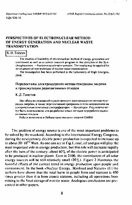
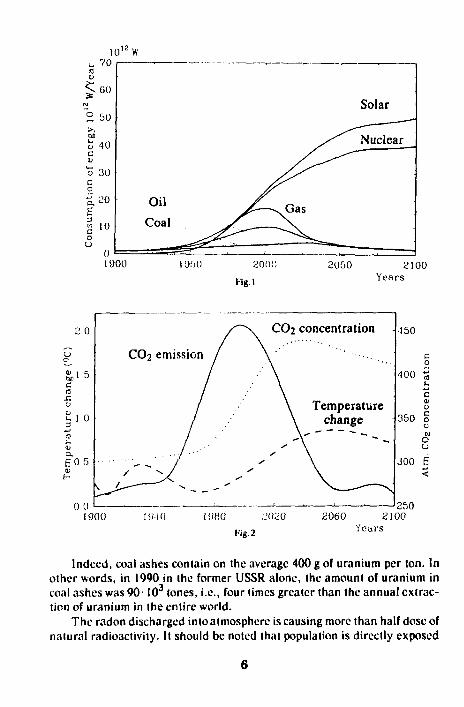
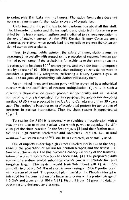
The problem of energy source is one of the most important problems to be solved by the mankind. According to Ihe International Energy Congress, during the next century electric power production is expected to increase up to about 50-10* Watt. As one can see in Fig. 1, coal, oil and gas will play the most important role in energy production, bul Ihis role will decrease rapidly after the turn of the century: about 60% of Ihe electric power is anticipated (o be produced in nuclear plants. Even in 2100, Ihe contribution of all solar energy sources will be still relatively small (20%). Figure 2 illustrates Ihe harmful effects of the current trend in energy production upon people and environment. In the book «Nuclear Energy, Mankind and Nature» |1 | the authors have shown thai the tola! harm to people from coal stations is 400 times greater than it is from atomic stations, including all operations from mining lo the final storage of reactor waste. Analogous conclusions are presented in other papers.
5
10 1 2 W 70
J 60
50
40
о 30 с
о
Oil Coal
y^-—-v<3as
"
Solar
Nuclear
•
1900 1 !)f)0 2001) 2050 2100 Fig.l Years
CO2 concentration
Temperature change
-150
350
1900 19-10 19H0 J020 Fig. 2
2060 2100 Years
400
250
Indeed, coal ashes contain on the average 400 g of uranium per ton. In other words, in 1990 in the former USSR alone, the amount of uranium in coal ashes was 90-103 tones, i.e., four times greater than the annual extraction of uranium in the entire world.
The radon discharged into atmosphere is causing more than half dose of natural radioactivity. It should be noted that population is directly exposed
6
to radon only if it leaks into the houses. The radon from ashes does not necessarily mean any further radon exposure of population.
Unfortunately, the public has too little information about all this stuff. The Chernobyl disaster and the incomplete and distorted information provided by the less competent authors and media led to a strong opposition to the use of nuclear energy. At the 1992 Russian Energy Congress some examples were given when people had laid on rails to prevent the construction of atomic power plants.
Thus, to change public opinion, the safety of atomic stations must be guaranteed, especially with respect to the protection of reactors from an un-limited power ramp. If the probability for accidents to the running reactors
is estimated to be about 10"" reactor years, and even the intent to improve this by a factor of 10—100 is pushed, then ordinary citizens do not want to consider in probability categories, preferring a binary system («yes» or «no») and no game of probability calculation will satisfy them.
An unlimited increase of reactor power will be prevented by a subcritical reactor with the coefficient of neutron multiplication: С f f < 1. In such a
realtor, a chain reaction cannot proceed independently and an external source of neutrons is requested. For this purpose, the accelerator-breeding method (ABM) was proposed in the USA and Canada more than 30 years ago. The method is based on using of accelerated protons for generation of neutrons in nuclear interactions. Thus the chain reactor is supported at
To realize the ABM it is necessary to combine an accelerator with a reactor and also to obtain nuclear data which permit to optimize the eff iciency of the chain reaction. In the first projects |2 | and their further modifications, high-current accelerator and «depleted» uranium, i.e., natural uranium from which most of U has been extracted, were mostly used.
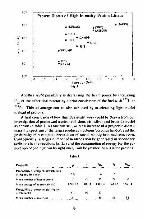
One of impacts to develop high current accelerators is due to the programs of the generation of tritium for neutron weapon and the transmutation of reactor wastes. For this purpose a conceptual study of the transmutation of actinium series members has been made |3 |. The proposed plants consist of a sodium cooled subcritical reactor core with aclinide fuel and tungsten target. This system would transmute about 250 kg actinides annually to produce 246 MW of electric power using a 1.5 GcV proton beam with current of 39 mA. The proposed plant based on the Phoenix concept is intended for the construction of a linear accelerator with a proton energy of 1.6 GeV and a current of 104 mA |4 |. Figure 3 from \5 | gives the data on operating and designed accelerators.
7
10 s
10*
< 103
с
3 и
10'
10°
Present Status of High Intensity Proton Linacs
• (JAERI)
0 0
• (EURAC)
• S1NO
A (SNO) • (ASPUN)
• INR
• TRIUMF
• IPNS • KENS-1
• LAMPF
• (JHP) ISIS
0 1 о G о a i о Unci's Y ((lf>V) Fig.3
1 4 1.6
Another ABM possibility is decreasing (he beam power by increasing 235
C"cff of the subcritical reactor by a prior enrichment of the fuel with U or 239Pu. This advantage can be also achieved by accelerating light nuclei instead of protons.
A first conclusion of how this idea might work could be drawn from our investigation of proton and nuclear collisions with silver and bromide nuclei as shown in table I. As one can see, with an increase of a projectile atomic mass the spectrum of the target produced nucleons becomes harder, and the probability of a complete breakdown of nuclei mainly into nuclcons rises. Consequently, a larger number of neutrons will be generated in secondary collisions in the reaction;, (л, 2n) and the consumption of energy for the generation of one neutron by light nuclei will be smaller than it is for protons.
Tabic I
Projectile
Probability of complete dcstrlbulion of Af and Br nuclei
Mean number of fast neutrons
Mean energy of neutron (MeV)
Probability of complete distribution of Pb nuclei
Mean number of nucleons
P
3%
13
120+12
6%
30
d
21
110*3
10
' l ie
6
25
I38±3
22
_ 45 _
n c
17
28
М8±5
43
"Nc
30
156 + 4
52

uo 90
80
70
60
50
40
30
20
10
0
1
ft\
\\V\
d ^ -1
He
/
г з 4 5 6 energy per nucleoli, GeV
The re lat ive iotiizal.ion l o s s e s Hig.4
It is necessary to take into account the relative ionization losses of energy according to the formula:
x 1 TdE Д =
0 dx exp(-jt/A)</x,
where £« and X are the kinetic energy and the maximum path of the
projectile, A is the mean free path. Figure 4 presents the results of the calculations according to [6 |. From
this figure it follows that for 4He nuclei the losses are smaller than for protons. Thus, it is more efficient to use lighter and faster nuclei for the ABM implementation. An experimental lest of this conclusion has been performed in cooperation with our colleagues from the Kharkov Physical-Technical Institute (Ukraine) al the Dubna synchrophasotron. This lest consisted in an investigation of the interactions of protons and light nuclei with a 50x 50x80 cm lead target. Beam particles were injected into the lead target through a 10x10x20 cm channel. The fission chambers (KNT-8) were 7 cm in diameter with an effective uranium mass of 1.5 mg |7 |. The uranium detectors were 8 mm in diameter and 1 mm thick. They were installed inside the target. The chambers recorded the number of fission while the deteclors registered the reaction (n, y) using y-spectroscopy method.
9

Table 2
p d ' l ie "C
energy (GeV) Energy per nucleoli <GeV)
3.65 8.1 3.65
Relative energy deposition for generation nf one neutron
The ionization energy losses <У„)
1 he decrease of energy in comparison with proton of 3.65 GeV (%)
Projectile Energy per nucleon (GeV)
d 15 4He 2.2 7l.i 2.2
U C 187
1 0.92
8 4
8
Tabic 3
0.89
4
I I
Energy for generation of one
n.y
34.7*3
30.6+10
31.0+8
31.5+5
n,I
30.0+4
27.5+6
34.7+5
32.7 + 4
0.72 0,81
6 I I
28 19
neutron (MeV)
Mean
32.4+3
29.0+8
32.1+6
32.1+4
Mean value 32±5 McV
The projectile particles were monitored by the aluminium detectors. A method combining KNT-8 chambers and movable nuclear emulsions was developed. The experimental results arc published in |9—12 ]. The data on relative efficiencies of neutron generation arc given in table 2. According to this table the amount of energy spent by the 4Hc nuclei for the generation of one neutron is - 3 0 % less than for protons. The absolute value of energy of one neutron has been determined by the detection of neutrons flying out of the target. They were slowed down in a water bath mounted on the upper side of the target. Neutrons were registered by KNT-8 and the uranium detectors. The experiments were carried out with d, He , 7 L i , and ' Cnuclei in an energy interval of 1.5—2.2 GeV per nucleon. The results from [ 13 1 are given in table 3. Both methods gave close results, and the mean value of energy necessary to generate one neutron is £ f j = 32±5 MeV. This value is
smaller than that from |2 |, where £ a 50 MeV was found. Utter 114 | and
the references in 114,15,16 | described corrections which have to be applied to the reaclions in, 2n) by the Monte-Carlo method which finally gave E 2 30 MeV.
10

Our data on Er are important for the ABM as well as for the neutron
protection of accelerators and satellites, the construction of neutron generators and the transmutation of reaclor waste. For further investigation the project «Investigation of Physical Aspects of the Electronuclear Method for Atomic Energy Production» called «Knergiya» is included in the program of the Laboratory of High Energies, JINR, Dubna. Positive conclusions of the project were given by the Ministry of Atomic Energy of Russian Federation, Scientific Center of Kurchatov's Institute, Physics and Energetics Institute and the Institute of Nuclear Energy.
Accoding lo the project, the 2 year program is proposed: • to determine the energy consumption to generate one neutron in
massive targets of different nuclear composition and to obtain an increase of energy yield in the target with fissionable nuclei with beam energy;
• to determine energy and mass of the projectile for the optimization of the efficiency of a chain reaction and the construction of an appropriate accelerator;
• to specify the composition of a perspective fuel in both homogeneous and heterogeneous versions;
• to estimate the running time without fuel change or when U, Pb and Bi are added to the fuel cycle;
• to determine the spectrum of neutrons inside the target and the spectrum of neutrons f lying out of the target.
These data will allow one lo start the construction of a subcritical reactor. A linear dependence of reactor power on beam intensity and С .. < I wil l
provide the reactor safety. The beam-off reactor power will be limited by delayed neutrons. The yield of these neutrons is - 0 . 6 % and their decay times are shorter than one minute. Averaging over the groups of delayed neutrons we obtain the following formula for the time dependence of reaclor power:
W l ) = w 00064 „zoos W{,) " o 0.0064 - p c
wherep is reactivityp = С (( - I. If Ceff = 0.98,
W(l) = WQ0.242 e° 25 f ,
at / = 1 sec Щ\) = 0.19И^0; W(10) = 0.02W(0).
The second goal of nuclear energetics lies in the improvement of its economic efficiency by using more U and allowing a prolonged reactor operation without refueling. At present U is mainly used by the reactors and, hence it has to be extracted from natural uranium lo produce energy. In
11

J
I I Fixing А 1ЧП.Л Л P(r') • Г(п,>) О C(F)
20 30 К) Ы) GO 70 80 Z, cm
Fig.5
the ABM the neutron spectrum will be harder leading to increase of fission of 2J9U while the absorblion of neutrons by fission products will decrease. As a result, the reactor operation becomes more efficient.
Let us now consider the use of the ABM for the reactor waste transmutation. As is shown in 117 | the transmutation by protons or y-quanta isn't promising, because it requires an amount of energy ten times greater than that received from the reactor.
The transmutation by neutrons requires the use of high intensity neutron fluxes or since the required time would be too long. But the intensity of neutron flux in the running reactor is 10 cm" s~\ and a stream of - I016cm s - 1 in the project |4l | demands an accelerator with a very high beam current density.
Our experiment has determined the neutron density inside the lead target. According to Fig.5, neutron density decreases by a factor of 10 at a distance of 50 cm along the beam and by a factor of 5 at 25 cm across the beam (Fig.6). It follows therefore that about half the neutrons and consequently half the energy is released in central zone of the target within a volume of -100. In the fast neutron reactor BN-600 1181 the neutron density was 10 cm s~ . So, if the power of the ABM reactor is equal to that of BN-600, the power in its central zone would be 10 times higher and the
1 С
1 0
0 8
0 0
0 4
0 2
n n
p~^
12

1 2
1 О
0 0
0 6
0 4
0 2
0 0
• Carbon к Protons
- 3 0 - 2 0 •10 10 го l'if.6
30 R, cm
neutron density would be ~ 10 cm s . Consequently, if neutrons are extracted from the reactor core, then the realization of a faster transmutation becomes possible.
The possibilities for the ABM development at the JINR are really unique. The Institute has the beams of protons and light nuclei with enough energy and intensity to allow the determination of the necessary for ABM parameters. Also, the JINR laboratories have the groups of specialists needed for the construction and operation of accelerators. For example the project «Mingen» 119 ] devoted lo the acceleration of dcuterons with energies up lo 2 GeV and a current of 10 niA is carried on by the Laboratory for Nuclear Problems (JINR). The work on the nuclei acceleration project «Nuclotron», with a superconducting magnet system is under comissioning in the LHE. It will give an opportunity lo accelerate light nuclei up lo f> GeV/c per nucleon and heavy nuclei up lo uranium of appropriate energies. As it was mentioned above, the methods for the measurement of the parameters necessary for the ABM have already been developed and tested. 1 he reactor IBR-2 available in the Laboratory of Neutron Physics would enable us lo perform all the necessary studies. The V.S.Barashenkov group has a solid experience in Monte-Carlo calculations of the processes that occur iii reactor systems. Thus, the Institute researchers participating in ihe project «Energiya» have everything lo fulfil this program.
13

We would like to emphasize that our program is aimed at building a reactor with a long term use without changing the fuel and extracting pluto-nium, i.e., only for a peaceful utilization of atomic energy.
Following are the estimated operating parameters of an accelerator — breeding reactor for the production of the 10 MW electrical power, i.e., two times larger than that of the first world atomic station built in Obninsk in 1956.
Current, charge units / Numbcrof He nuclei per second 111 Energy per nucleon e = 1.5 GeV Beamenergy E = 3 / G c V Energy for generating one neutron 32 MeV
Number of neutrons n =
If Ceff = 0.98 than the number of neutrons is N
3 109/ 32 I06
94-0.98 1 - 0.98
94/
= 4600
Number of neutrons per fission Number of fissions Energy per fission Power
2.44 m = 4600/2.44 = 1885 ~ 200 MeV W= lm-200= 37700/MeV W= 6-10~8/»f(f)
If the electric power of the reactor W = \0 MW 10 and the coefficient of heat transformation К = 0.35, then the heat power is W = 2.84-107 Watt. Hence, W = 6-10Л / = 2.8 6 I07 Watt / = 4.8-1014 charge units. The number of 4He nuclei: N = 111 ~ 2.42- 10 l 4s" ' . The beam power: Wlt = 2.42-1014-6 GeV = 230 AW,. The beam intensity: /u = 4.810 l 4x x 1.6 10" |gcharge units, /„ = 0.08 mA.
In conclusion I would like to quote the words by Academician V.l.Veksler, the founder of (he laboratory, USSR State Prize laureate and the USA «Atom for Peace» Prize laureate: «Show that it is possible and necessary and technology will find the means for its realization».
14
References
1. The Nuclear Energetics, Mankind and Nature Atomizdat, 1984. 2. Proceeding of an Juform. Melh. on Accelerator-Breeding, N.-Y.
January, 1977. 3. Takazuka T. et al. — Conceptual Design of Transmutation Plant
JAERY, 319, 1991. 4. Van Tuyle at al. — Driven Subcritical Target Concept for Transmuta
tion of Nuclear Waste, BNL 11913. 5. MizumoloM.J. - A t o m . Soc. JAPAN, 1991. 33, 6. VorobyevG.C.TolslovK.D. — JINR PI-85-352, Dubna, 1985. 7. Dyachenko V.M. et al. — JINR Rapid Communication, 2153 |-92,
Dubna, 1992, p.5. 8. Damdinsuren el al. — Nucl. lnstr. and Mcth., 1990, A-288, p.319. 9. Voronko V.A. et al. — Atomic Energy, 1989, 68, p.2I5.
10. Voronko V.A. ctal. — At.En., 1989, 67, p.291. 11. Voronko V.A. et al. — At.En., 1990, 68, p.449. 12. Voronko V.A. etal. — Al.En., 1991, 71, p.563. 13. Voronko V.A. el al. — JINR Rapid Communications, 2|53 |-92, Dubna,
1992, p.5. 14. Bowman CD. it. al. — LA-UR-9I-260I, 1991. 15. Liahlenslcin P. - iA-UR-89-3014, 1989. 16. BriesmesterJ.A. — LA-UR-7396V,Rev.2, 1986. 17. Tolstov K.D. — JINR P-3-90-583, Dubna, 1990. 18. Atomnaya Nauka i Technika v SSSR, Alomizd.it, 1977. 19. GlazovA.Actal.—JINR P9-8I-734, Dubna, 1981.
The final version of this manuscript was prepared by A.D.Kovalenko and P.l./.arubin in cooperation with V.I.llyuschenko and l.l.Migulina.
Received on December 23, 1993.
15

Кратки? сообщения ОИЯИ ЛМ/6.2 ]-9J JI MR Rapid Communications No.5[b2j 93 УДК 681.384.6
СВЕРХПРОВОДЯЩИЙ ЦИКЛОТРОН С РАЗДЕЛЕННЫМИ ОРБИТАМИ ДЛЯ ЭЛЕКТРОЯДЕРНОГО РЕАКТОРА
Шеласв И.А.
Приведены основные параметры СП-циклотронного комплекса, генерирующего протоны с энергией I ГаВ и интенсивностью 100 мА в непрерывном режиме. Комплекс содержит 180 к:>В 10 мА форинжсктор и 28 М:»В изохронный циклотрон с разделенными секторами, СП 240 МзВ буск'рный и t Т\)В основной циклотроны с разделенными орбитами. Разделение орбит в секторном циклотроне достигаете» применением 6 дуан-товс ВЧ-напряжснием амплитудой 75 кВ. Поворот и фокусировка пучка в СП-циклотрона выполняется системой миниатюрных однотипных дипольных и квалрупольных магнитов, образующих 10 спиральных каналов, размещенных один над другим в общем гелиевом крностате. Инжектированные в ;>ти каналы пучки ит Юсскюрных циклогроное ускоряются 12 объемными теплыми реэонаюрамн с амплитудой 500 кэВ вбустерном циклотроне и 44 — в основном. Изначальное разделение пучка требуемой интенсивности на 10 отдельных каналов обеспечивает устойчивую работу веет комплекса и гибкость в его управлении Стандартизации ВЧ гсиера-юров и резонаторов, СП-магнитов установки и других ее ;»л счетов позво ляет организовать их массовое производство и тем снизить стоимость комплекса
Работа иыполнена в Лаборатории высоких инергнй ОИЯИ
Superconducting Separated Orbit Cyclotron for Elcctronuclcar Reactor
l.A.Shehicv
Main parameters of a cyclolroii facility for generation of I CieV 100 nvS • ro Ion beam in dc modi' are given li includes ISO keV 10 mA inject'.', 2S MeV isochrono'-is separ'.iled sector cyclotron. SC 240 MeV booster separated orlnt cyclotron and 1 OeV main one (frbil separation In the sec lor cyclotron is achieved by app.kation u! 6 dees with 75 kV on e..Kh. Bc.i'n bending an.1 focusing in ihe SOCs is full'"illed by a system of mi.niiiurc dipolcs irid quudrupoies of Ihe same type thai form 10 spiral channels The channels arc placed one on another in common l.He cryoslal. The beams injecitd in Ihe channels bv the It) sector i yclnlror.s arc accelerated by 12 warm 5(K) kV rf cavil, in Ihe booster cyclotron ai:d by 44 cms и the tn.iin SOC. Division of the rci)uirej iiiien-.iH beam at Ihe start of :n \p!c-at'">it in'o 10 separated channels provides si:ih!e operation of the facility and ris control flexibility. Slandurdi/ulinii of tif gencratnrs, cavities, SC magneis ane" oilier eicnu tics of the facility permits .me to organize ni;i:..,-[:r[iiiia-lion nf ir.e -.'• 'ficnts a ltd i" J. ere.it:' it'с о cos1.
I he inv.-.v '^и.-. и has been performed HI the laboratory of High I'nerg'n v JINK
16

Введение
Под электроядерным понимается реактор, в котором реакция делении ядер тяжелых элементов поддерживается незатухающей потоком нейтронов от внешнего источника. Поток нейтронов в рабочей зоне реактора возбуждается быстрыми частицами от ускорителя: протон с энергией I ГэВ в достаточно протяженном блоке U, обогащенном 2 % U, создает до 50 нейтронов и примерно 4 ГэВ тепла |1 |. Еще больше нейтронов и тепла образуют тяжелые ядра |2 |. Разумеется, реакция представит промышленный интерес, если интенсивность падающего пучка достаточно велика. В случае протонов с энергией I ГэВ различные оценки дают величину 100—300 мА. Получение такой интенсивности на линейных ускорителях заставляет многих исследователей считать этот тип ускорителя наиболее перспективным для электроядерного реактора. Но эта интенсивность получена в импульсном режиме, средняя же ее величина оказывается на 2 порядка меньше, поэтому наряду с линейными ускорителями рассматриваются возможности ускорителей другого типа, в частности, циклотроны |3 ].
В данной работе приведены оценки параметров сверхпроводящего (СП) циклотрона с разделенными орбитами (ЦРО) |4,5 I, пригодного для получения пучка протонов с энергией 1 ГэВ и интенсивностью 100 мЛ. В циклотроне сверхпроводимость используется для создания миниатюрной магнитной системы, обеспечивающей при достаточном приросте энергии частиц за оборот вывод ускоренного пучка с эффективностью 100%. Для магнитной системы ЦРО наиболее подходящими оказываются разработанные в ЛВЭ сверхпроводящие магниты с железом )6 ), и ранее изучалась возможность их применения в сильноточном циклотроне |7 |.
В такой установке определяющими являются стоимость, кпд и надежность ВЧ-преобразователя. Циклотрон, являясь наиболее компактной машиной, позволяет получить К П Д передачи ВЧ-мощности пучку на уровне 90% и выше. В нем ВЧ-преобразователь работает в диапазоне 25—50 МГц, в котором промышленностью освоены генераторы с единичной мощностью 1—2 МВт, и для ускорения протонов до энергии 1 ГэВ и интенсивностью 100 мА достаточно иметь 50 таких генераторов.
Для достижения требуемой интенсивности достаточно разделить пучок на 10 параллельных каналов с независимой фокусировкой, что существенно ослабит эффекты, связанные с пространственным зарядом, упростит последующее использование пучка в реакторе и позволит сочетать устойчивую работу ускорителя с гибкостью в его управлении.
17
Н 'рассматриваемом циклотрон^ у, хо|л н;н : :р^оноч v. улих::-.." •"<'-I л м5и этана; 10 7>'плых изохронных циклоплч-.он ,niт\>н !чют .) v () мЛ пучки с .энергией 28 ?'.;зВ л Ю-канальный Г'Л '• б;. гт1-;:|.;>.и |-..'ш> IJ»VI моышамшни их энергию.\о .;4'; М.)В; коне»ц\ ч> .!!-.• ,1гч'ч
i -п'чкн "ОЛ\ чают л <ч:нонном СП ! \VO, также i ivep*a' i icv i .' '•:. ; ' )-.:ьм(>)-. M I H U ' H I J A чаналон. На каждом .'.i.'.c у -о;.1' нис '..ч-ущ.-п ч :• • и Н-пплем алией а >ой же частоты, чо шклю'-.ил .тетери инп ч-
'iMHi.H т . Сравнительно низкая частота КЧ-моля (3! .-.''.' У Гц) обесмечи-.ет высокий К П Л . наименьшую стоимость и надеин; м ;;еали.»уи1*с.» in
• •' -генератора — наиболее дорогом и энергоемком системы -. • косит.-ля
i ) ;<ергетика ллектроядерного редьгорч
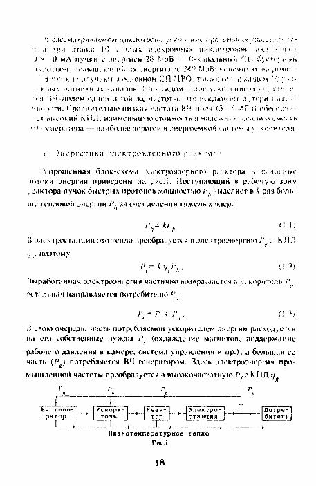
Упрошенная блок-схема электроядерного реактора -1 основные тотоки энергии приведены на рис. I. Поступающий и рабочую зону /еактора пучок быстрых протонов мощностью / ;. иыделяет в к раз больше тепловой энергии t't за счет деления тяжелых ядер:
rh=k,'h. < ! . l ) [5 электростанции это тепло преобразуется в элек гроэнергию Г _ с К ЛЛ
'/ , поэтому
выработанная электроэнергия частично возвращается г; \ч корнтель / ' ,
остальная направляется потребителю/'
/' т Р
ii свою очередь, часть потребляемой ускорителем энергии расходуется на еат собственные нужды /*. (охлаждение магнитов, поддержание
рабочет давления в камере, система управления и пр.), а большая ее часть (/ ' ) потребляется ВЧ-генератором. Здесь электроэнергия промышленной частоты преобразуется в высокочастотную / ' .с К П Д >/
р р р р g » а и г i ГВч" ге'не- I р с к о р н ^ |Рёак-~| ("Электро- [_
| ратор _) ^] тель [ >~~| тор_J ' | станция |~ I Л 1 4 1 * 1 4—
Потребитель
Низкотемпературное тепла Рис I
18
p = p + p = p J» + p . (1.4) a g ь f ig i
ВЧ-мощность поступает в ускоряющий резонатор непосредственно или через фидер связи, где расходуется на возбуждение резонатора и ускорение пучка Р. . Таким образом, справедливо соотношение
где г/. — К П Д передачи мощности генератора пучку протонов.
Комбинируя выражения (1.1 —1.5), получаем
/ » + / • = \кп —) Р.. (1.6)
Последнее соотношение имеет смысл, если в нем выражение в скобке неотрицательно, т.е. если
В выражении (1.7) два коэффициента — г\ и и — имеют хорошо установленные величины. К П Д преобразования тепловой энергии в электрическую лежит в пределах 0,3—0,4, и для оценок г\, можно принять
равным 0,35. К П Д ВЧ-генератора, выполненного на мощных тетродах, в принятом здесь частотном диапазоне, равен 0,6. Таким образом, в распоряжении экспериментатора остаются два коэффициента — к и rj. .
Величиной коэффициента к можно управлять, варьируя ядерный состав мишени или массу быстрых ядер, т.е. выбирая подкритичность реактора. Тогда типом ускорителя определяется только один параметр соотношения (1.7) — п., который можно оценить как
я = р Iр = р lip + р\ (1.8)
где Р — ВЧ-мощность, расходуемая в резонаторах ускорителя на возбуждение ускоряющего поля при нулевой интенсивности пучка, включая потери мощности при передаче от генератора к резонатору.
В линейном ускорителе, имеющем протяженный (порядка 1000 м) резонатор, величина Р приближается к 100 МВт, поэтому rj. принимает
заметную величину (0,6—0,7), когда мощность пучка оказывается порядка 200—300 МВт. Генераторы линейного ускорителя работают в диапазоне 400—600 МГц, где стоимость I Вт мощности гораздо выше.
В циклотроне ускоряющее поле проходится пучком многократно, в силу этого значительно меньше величина Р . В результате п. оказывается порядка 0.Q0—0,92 при значительно меньшей мощности пучка. Как
19
показано ниже, вариант СП-циклотрона с разделенными орбитами действительно позволяет ускорить интенсивный пучок протонов с высоким КПД.
2. Общая схема ускорителя
Исходя из изложенного выше, можно сформулировать следующие основные требования к ускорителю для электроядерного реактора:
— ускоритель поставляет постоянный во времени и управляемый пучок протонов (или ядер) с энергией 1000 МэВ и интенсивностью 100 мА и более;
— ускоритель имеет максимально возможное значение КПД rj преобразователя электрической энергии сеть — ВЧ;
— реализуемость, надежность и ремонтоспособность ВЧ-преобразо-вателя;
— максимальное значение КПД ц. передачи ВЧ-энсргии к пучку;
— минимальные потери пучка при ускорении, выводе и пр.; — минимальная стоимость ускорителя, его компактность, надеж
ность и ремонтоспособность. Работоспособность электроядерного реактора в первую очередь
определяется ВЧ-прсобразователем. Наиболее пригодным для работы в непрерывном режиме представляется преобразователь на жестких лампах в диапазоне 25—50 МГц с мощностью оконечного каскада 2 МВт. Наибольшим КПД обладает схема, в которой ВЧ -генератор расположен рядом с резонатором, т.к. в ней отсутствует передача ВЧ-мощности на расстояние или сложение мощностей отдельных генераторов, сопровождающееся потерями. Это условие определяет общее число резонаторов в установке: для ускорения пучка общей мощностью 100 МВт необходимо не менее 50 резонаторов, возбуждаемых таким же числом генераторов мощностью 2 МВт каждый.
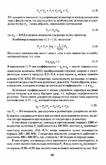
Общая схема ускорителя представлена на рис.2. Сформированный в форинжекторе (ионный источник, электростатический ускоритель и банчер) пучок с энергией 0,255 МэВ инжектируется в центр многоду-антного изохронного секторного циклотрона. Многодуантный вариант позволяет получить примерно I МэВ прирост энергии пучка за оборот при приемлемом напряжении на дуантах, что при низком значении среднего магнитного поля дает необходимое для эффективного вывода разделение орбит на конечном радиусе и обеспечивает достаточно свободного места в центре циклотрона для размещения там инфлектора.
20
Форинжектор ИонныХ
источник И * 1
Электростатический уск
вч-банчер
Секторный цик-лотрон
БустврньПГ СП-циклотрон с разделенными орбитвни
Основной СП-циклотрон с разваленными орбнтани
Рабочая зона
реактора
Рис.2
Форинжектор и секторный циклотрон повторяются 10 раз, и все 10 пучков инжектируются затем в 10-этажный СП-бустсрный ЦРО.
В бустерном ЦРО поворот и фокусировка пучка осуществляется миниатюрной СП-магнитной системой, представляющей собой магнитную систему протонного синхротрона с разделенными функциями поворота и фокусировки. Размещенные по развертывающейся спирали ФОДО периоды магнитной системы ЦРО обеспечивают жесткую фокусировку пучка, недостижимую в секторных циклотронах. В бустерном циклотроне пучок ускоряется ВЧ-полем 12 теплых объемных резонаторов, имеющих форму параллелепипеда. В таком резонаторе амплитуда ускоряющего напряжения достигает 0,5 MB при мищности возбуждения 0,15—0,20 МВт.
Аналогично построен и основной СП ЦРО. В обоих циклотронах используются СП-магниты и линзы, имеющие одинаковые поперечные размеры и отличающиеся только длиной. Это позволяет организовать массовое производство таких магнитных элементов, что снижает их стоимость. Ускорение пучков в основном ЦРО также осуществляется ВЧ-полем объемных резонаторов, число которых здесь выбрано равным 44. Всего же в установке имеется 56 резонаторов, что при условии их равнонагруженности (1,73 МВт/резонатор) определяет конечную энергию бустерного циклотрона.
Многоканальность бустерного и основного СП ЦРО существенно снижает эффекты пространственного заряда в каждом канале, обеспечивая требуемую общую интенсивность установки, а многократность форинжектора обеспечивает практически непрерывную работу всего комплекса, несмотря на ограниченное время жизни ионного источника. Ниже приведены более подробно параметры перечисленных ускорителей.
21
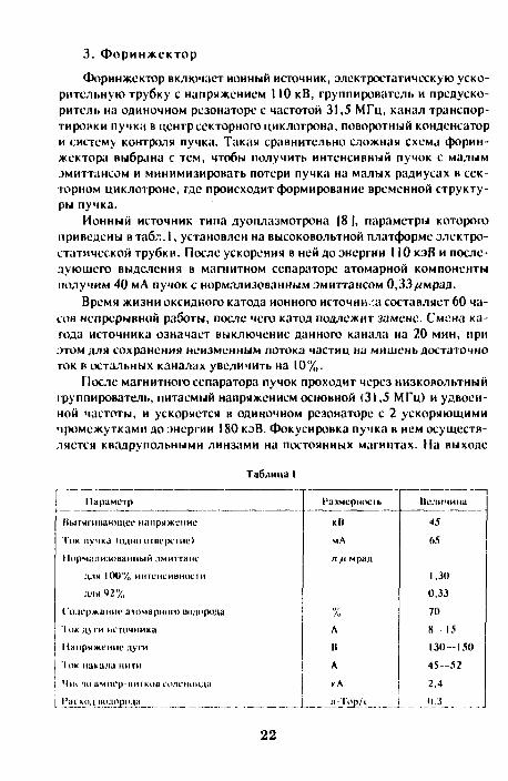
3. Ф о р и н ж е к т о р
Форинжектор включает ионный источник, электростатическую ускорительную трубку с напряжением 110 кВ, группирователь и предуско-ритель на одиночном резонаторе с частотой 31,5 МГц, канал транспортировки пучка в центр секторного циклотрона, поворотный конденсатор и систему контроля пучка. Такая сравнительно сложная схема форин-жектора выбрана с тем, чтобы получить интенсивный пучок с малым эмиттансом и минимизировать потери пучка на малых радиусах в секторном циклотроне, где происходит формирование временной структуры пучка.
Ионный источник типа дуоплазмотрона |8 |, параметры которого приведены в табл. 1, установлен на высоковольтной платформе электростатической трубки. После ускорения в ней до энергии 110 кэВ и последующего выделения в магнитном сепараторе атомарной компоненты получим 40 мА пучок с нормализованным эмиттансом 0,33/<мрад.
Время жизни оксидного катода ионного источни.-.а составляет 60 часов непрерывной работы, после чего катод подлежит замене. Смена катода источника означает выключение данного канала на 20 мин, при этом для сохранения неизменным потока частиц на мишень достаточно ток в остальных каналах увеличить на 10%.
После магнитного сепаратора пучок проходит через низковольтный группирователь, питаемый напряжением основной (31,5 МГц) и удвоенной частоты, и ускоряется в одиночном резонаторе с 2 ускоряющими промежутками до энергии 180 кэВ. Фокусировка пучка в нем осуществляется квадрупольными линзами на постоянных магнитах. На выходе
Таблица 1
Параметр
Ныгчшнакпцее напряжение
Ток пучка (одно отверстие)
Норчалидованмый змнттанс
д.-|я 100% интенсивности
для 42%
Содержание атомарной) водорода
Ток дуги источника
Напряжение дуги
1<ж накала нити
Ч т но ампер-ишков соленоида
Расход водорода
Г'азмержмль
к It
мА
пц мрад
% Л
II
А
к Л
л I 'op/i
Неличина
45
65
1,30
0,33
70
8 - 1 5
1 3 0 - 1 5 0
4 5 - 5 2
2.4
I U _
22
резонатора получим пучок в виде банчей фазовой протяженностью 30— 35°, амплитудой 130 и средним током 10—12 мА. Одиночный резонатор выполнен в виде четвертьволновой коаксиальной линии, свернутой в спираль | 9 | и настроенной на основную частоту 31,5 МГц; напряжение на ускоряющем электроде 35 кВ.
Такая предварительная банчировка минимизирует потери пучка в секторном циклотроне. При этом несколько увеличится эмиттанс пучка, и для дальнейших оценок примем, что нормализованный эмиттанс не превосходит I «мрад.
Цилиндрический конденсатор с зазором 10 мм поворачивает протоны на 90° при разности потенциалов на обкладках ± 18 кВ относительно «земли» и вводит их в медианную плоскость циклотрона. Фокусировка пучка в обеих поперечных плоскостях осуществляется за счет гиперболического профиля пластин конденсатора. Все оборудование форин-жектора размещается во внутренней полости центрального штока ВЧ-резонатора инжекторного циклотрона, поэтому инжекция пучка сопровождается его ускорением на 75 кэВ. Пройдя заземленный промежуток вакуумной камеры длиной I I см, пучок поступит в первый дуант с энергией инжекции 0,255 кэВ. Этот участок оборудован парой квадру-польных линз на постоянных магнитах и конденсатором коррекции угла входа в дуант.
4. М н о г о д у а н т н ы й секторный ц и к л о т р о н
Несмотру на предварительное формирование пучка, можно ожидать потерь порядка 5—15% (или 0,5—1,5 мА) на первых 2—Зоборотах в секторном циклотроне. Если средняя энергия этого пучка равна 2 МэВ, то выделяемая мощность составит i - - Л кВт, ч го исключает применение сверхпроводящей магнитной системы в первом циклотроне, поэтому выбран теплый вариант секторного циклотрона, основные параметры которого приведены в табл.2.
В изохронном циклотроне частота обращения иона ш остается пос
тоянной на любом радиусе г.
w. = vlr = const. (4.|)
Из этого условия следует зависимость радиуса орбиты от энергии w, если последняя выражена в единицах энергии покоя протона,
_ М У-.У(2 + w) Г~ ' 2л(1 + iv) ' (4.2>
23

Таблица 2
Параметр
'Энергии протопоп
Интенсивность
Магнитная жесткость
Среднее машитное иоле
Магнитное поле в секторе
Средний радиус орбиты
11рирост радиуса за оборот
Число секторов магнита
Число дуантов
Число оборотов пучка
Напряжение на дуаитах
Частота ВЦ-напряжения
Частота обращения протонов
Размерность
Mill
мА
K'J M
кЭ
K'J
см
см
к II
MIV
МГц
на входе
0,255
12
0,730
3.447
21,1
26,7
Величина
9,066
6
6
27
75
31.5
5.25
на выходе
28
10
7,703
3,546
217.2
3,5
где Л — длина волны ускоряющего ВЧ-поля, N — номер гармоники. Если прирост энергии за оборот равен dw, то радиус увеличится на dr.
и<1 + и-)(2 + и»)' (4.3)
Из последнего соотношения видно, что прирост радиуса за оборот пропорционален его величине и приросту энергии. Высокий набор энергии за оборот (0,9 МэВ) при умеренном напряжении на дуантах достигается использованием 6 дуантов, питаемых напряжением 6-й гармоники частоты обращения, на которой фаза пролета дуанта равна 180'. Фаза пролета размещенных между дуантами магнитных секторов также равна 180*/ссктор, поэтому ускоряющее напряжение на всех дуантах синфазно и они присоединены к одному штоку, представляющему собой центральный электрод четвертьволновой коаксиальной линии, что существенно упрощает конструкцию ВЧ-систсмы циклотрона. Ось центрального штока проходит через центр ускорителя и ортогональна его медианной плоскости. Диаметр штока, поддерживающего 6-дуант-ную систему с общим диаметром 4,34 м, при таком же диаметре внешнего бака резонатора можно выбрать порядка 2 м, что обеспечит добротность резонатора свыше 10000. На возбуждение в таком резонаторе на-
24

пряжения амплитудой 75 кВ потребуется около 20 кВт. При токе ускоренною пучка 10 мА потребляемая мощность возрастет до 300 кВт, т.е. н 15 раз; К П Д передачи мощности пучку i/. составит 93%.
Напряжение на дуантах выбрано примерно в 2—2,5 раза выше, ч„-м в промышленных циклотронах с непрерывным режимом. Такой выбор основан на следующем. Во-первых, значительно увеличен зазор дуант — камера - - с 14—20 мм до 350. Этот зазор электрически наиболее непрочен, т.к. здесь разряд в обычных циклотронах происходит по магнитному полю; в инжекторном циклотроне дуанты находятся вне поля. Во вторых, увеличены радиусы скругления кромок дуантов, поэтому хотя в центре циклотрона расстояние между кромками дуанта к камерой всего 20 мм, но в этом зазоре рассеянное магнитное поле направлено поперек зазора, что увеличивает его электрическую прочность. С увеличением зазоров уменьшается емкость дуантов, составляющая, по оценкам, 200—250 пф. Наконец, инжекторные циклотроны могут работать в импульсном режиме, при котором из 10 циклотронов 9 всегда поставляют пучки в реактор и лишь один выключен.
Расчет замкнутой орбиты в магните циклотрона матричным методом дает для набега фазы радиальных бстатронных колебаний о на
период величину
cos a = l + b ( 1 8 tl + , g f 2 ) cos д +
<8''| + t g f 2
2 Ъ> ( I - < g f , l g f 2 ) in 9 (4.4)
и вертикальных а
cos о 17 + /1 l g ' | + '««J /t>
+ 2 ^ l g f | l « V (4--S)
Здесь/) — радиус кривизны траектории в магните, д — угол поворота в секторе, f. и «', — углы входа и выхода траектории, / — длина свободного от магнитного поля промежутка. Аналогично вычисляются и другие параметры замкнутой орбиты; результаты приведены в табл.3. Снижение угловой протяженности магнита повышает частоту бетатронных колебаний и упрощает размещение магнитов в центре циклотрона. Рост угловой протяженности секторных магнитов с радиусом компенсирует релятивистский рост массы протона с энергией.
В циклотроне /^-фукнции пропорциональны радиусу кривизны; эмиттанс пучка, напротив, обратно пропорционален радиусу (при ма-
25
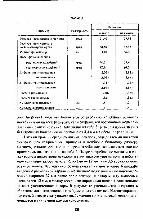
Таблица 3
Параметр
Угловая протяженность магнита Угловая протяженность свободною промежутка Радиус кривизны,/. Набег фалы на период
радиальных колебаний
вертикальных колебаний
/{,-функции минимальная максимальная
/J,-функция минимальная максимальная
Частота радиальная Частота вертикальная
Амплитуда радиальная
Амплитуда вертикальная
Размерность
град
град см
фад
Фад
мм
мм
Вели
на входе
21,40
38,60 8,05
64,6 «2,4
2,20/)
3.30/.
1,74/)
2,19/.
1,066 1,381
1,5 1.3
чина
на выходе
22.13
37,87 85,0
63.8
80.5
2.13/.
3,18/.
1,76/.
2,16/.
1,064 1.342
1,7
1.4
лых энергиях), поэтому амплитуды бстатронных колебаний остаются постоянными на всех радиусах, если сохраняется постоянным нормализованный эмиттанс пучка. Как видно из табл.3, размеры пучка за счет бстатронных колебаний не превышают 3,5 мм в любом направлении.
Низкий уровень среднего магнитного поля, определяемый частотой ускоряющего напряжения, приводит к необычно большому размеру магнита, однако его вес и энергопотребление оказываются вполне приемлемыми, что видно из табл.4. Энергопотребление магнита в инжекторном циклотроне невелико в сичу низкого уровня поля и небольшой величины зазора между полюсами — 12 мм, или 3,5 вертикальных размера пучка. Вес магнитопровода снижается почти вдвое благодаря введению радиальной вариации магнитного поля: поле на кольцевой дорожке шириной 32 мм равно полю сектора, и зазор между полюсами здесь равен 12 мм, а между соседними дорожками тюле в 4 раза меньше за счет увеличенного зазора. В результате уменьшается индукция в обратном магнитопроводе, а с ней уменьшается его нес. Магнитопровод, покрытый вместе с катушками возбуждения тонколистовой медью, размещается в вакуумной камере ускорителя.
26
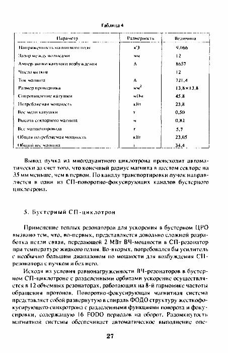
Таблица 4
Н а р н ч п р
Н а п р я ж е н и е м. ча гни m u m 110:1м
*Ja;iiip между па'1нн:ачи
Л ч и е р - н ш к и катушки нозбуллл'пич
Число ь ш к о ц
Ток ч а ш и га
Размер мрошипика
Conpoi и м е н и е к a ry II IK vi
] 1отребляемая чощность
Нее MC; I I I к л у ш к и
Нмеота с е к т о р н о т магнита
Нес чагнитсшрошма
Общая тнрсбляечаи MOII I IHH. I I ,
Общий нес магнита
Раичерносч.
K'J
ч ч
Л
л м ч
мОч
кНг
т
ч
г
к11т
1
Не.пичниа
4,066
12
8657
12
721.4
13,Нх 13.К
45.8
23,8
0,50
0,82
5.7
23,05
34,4
Вывод пучка из многодуантного циклотрона происходит автоматически за счет том , что конечный радиус магнита в шестом секторе на 35 мм меньше, чем в первом. По каналу транспортировки пучок направляется в один из СП-поворотно-фокусирующих каналов бустерного циклотрона.
5. Вустерный С П - ц и к л о т р о н
Применение теплых резонатороп для ускорения в бустерном ЦРО вызвано тем, что, во-первых, представляется довольно сложной разработка петли связи, передающей 2 МВт ВЧ-мощности в СП-резонатор при температуре жидкого гелия. Во-вторых, потребовался бы усилитель с необычно большим диапазоном по мощности для возбуждения С П -резонатора с пучком и без него.
Исходя из условия равнонагруженности ВЧ-резонаторов в бустерном СП-циклотроне с разделенными орбитами ускорение осуществляется в 12 объемных резонаторах, работающих на 8-й гармонике частоты обращения протонов. Поворотно-фокусирующая магнитная система представляет собой развернутую в спираль ФОДО структуру жесткофо-куеирующсго синхротрона с разделенными функциями поворота и фокусировки, содержащую 16 FODO периодов на оборот. Разомкну тость магнитной системы обеспечивает автоматическое выполнение опе-
27
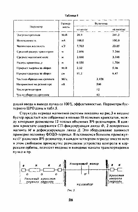
Таблица 5
Параметр
'Знергия протоном
HlltCHCHUHOUli
Машишая жесткость
Средний радиус траскюрии
Среднее магнитное ноле
Радиус кривизны,/J
Прирост энергии за оборот
Прирост радиуса за оборот
Частота обращении протонов
Напряжение на резонаторе
Число резонаторов
Число оборотов протонов
Размерность
M:ill
мА
к»
м
м
м
Mi l l
см
МГц
кВ
на входе
2К,0
100,0
7,703
2.846
2.660
0.550
2,32
И.2
Псличина
3.938
500
12
43
на имходе
241,3
100,0
23,85
7,344
3,248
1.704
5.%
6,47
раций ввода и вывода пучка со 100% эффективностью. Параметры бус-терного ЦРО даны в табл.5.
Структура периода магнитной системы показана на рис.3 и внешне бустер предстает как собранные в кольцо 16 гелиевых криостатов, между которыми размешены 12 теплых объемных ВЧ-резонаторов. В каждом криостате содержится СП-фокусирующая линза </>, 2 поворотных магнита М и дефокусирующая линза Д. Это оборудование занимает примерно половину ФОДО-псриодз. В оставшемся большом промежутке О' размещен ВЧ-резонатор; в каждом четвертом периоде вместо него в этом свободном промежутке размещены устройства контроля и коррекции орбиты, подходят вводные и выводные каналы транспортировки пучка и пр.
ф Н
O-CZTZH: н л
Гелиевый jcpuocmam первого периода^
Ускоряющие яаяор
РЕЗОНАТОР
§ н
04Z Криостат второго !периода
Гис.З
28

i . !0-этажная магнитная система бустерного ЦРО собрана из
_ _ _ _ ^ _ _ _ _ _ _ _ _ _ _ миниатюрных сверхпроводящих " магнитов и кпадрупольных линз.
~~^~~ ' ,ч Поле напряженностью 14 кЭ в таких магнитах формируется С П -
г 5 катушкой и близко расположенным ярмом из магнитномягкот железа. Поперечное сечение магнита показано на рис.4. Низкий уро-
1 1 вснь магнитного поля позволяет -< 31 —>- применить СП-катушку с малым
поперечным сечением (горизон-Рис.4 „ - ,
тальныи размер нитка 2,5 мм) и большим запасом по критическо
му току. Еще меньше поперечные размеры явнополюсной квадруполь-ной линзы при той же апертуре. Простая форма ярма магнита упрошает его высокоточное изготовление, а использопние ярма в качестве шаблона при намотке СП-катушки задает высокую повторяемость параметров серии магнитов. Все магниты и линзы в бустерном циклотроне имеют стандартные поперечные размеры и отличаются лишь длиной. Длина диполя равна 10,7 см при инжекции и 33.3 см на последнем обороте. Собранные в 10-канальнуюстопку высотой 40см магниты и линзы всех оборотов одного периода общим весом 3,4 т помещаются в общий гелиевый криостат.
Анализ бстатронного движения показывает, что фокусировка пучка настолько жесткая (частота бетатронных колебаний 3,25), что его поперечные размеры всюду оказываются менее 15 мм, а наибольшую величину в горизонтальной апертуре занимает саггита — до 8 мм. Другие требования к апертуре, связанные, например, с несовершенством магнитной системы, можно не учитывать, т.к. в ЦРО небольшое число оборотов и на каждом реализуема достаточно развитая система коррекция орбиты.
Пучки ускоряются в прямоугольном резонаторе, в котором возбуждаются колебания простейшей моды типа ТМ. . „ , если выполняется условие
(2/А)2= (1/а)2+(!/Л)2, (5.1) где X — длина волны, a, b — наибольшие стороны параллелепипеда. При :>том распределение электрического поля в резонаторе имеет вид
Ez= £0 мп (лх/а) ьш(лу//>), Е(.= £ = 0. (5.2)
29
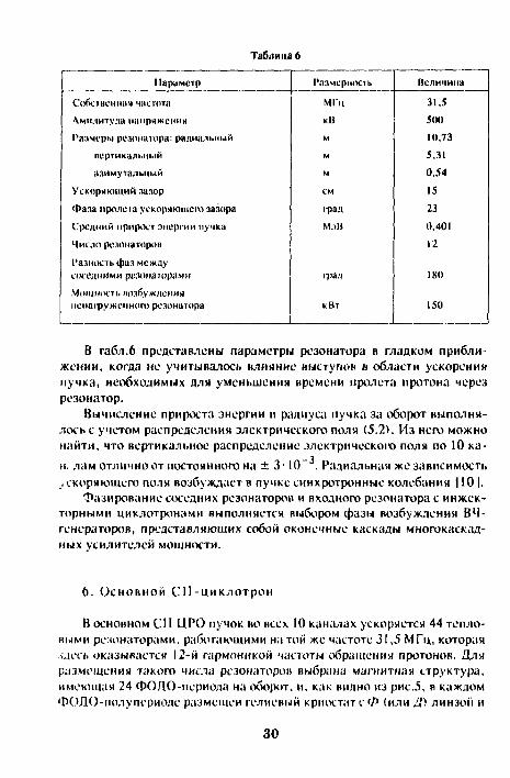
Таблица 6
Параметр
Собо пенная частота
Амплитуда напряжении
Размеры резонатора: радиальный
кортикальный
азимутальный
Ускоряющий зазор
Фаза пролета ускоряющее) зазора
Средний прирост энергии пучка
Число резонаторов
Разность фаз между соседними резонаторами
Мо|цнооь возбуждении нснагруженнот резонатора
Размерность
МГц
к 11 м
м
м
см
i-рад
МдВ
град
кВт
Неличина
31,5 500 10,73 5,31 0,54
15
23 0,401
12
180
150
В табл.6 представлены параметры резонатора в гладком приближении, когда не учитывалось влияние выступов в области ускорения пучка, необходимых для уменьшения времени пролета протона через резонатор.
Вычисление прироста энергии и радиуса пучка за оборот выполнялось с учетом распределения электрического поля (5.2). Из него можно найти, что вертикальное распределение электрического поля по 10 ка-
_ -1
и. лам отлично от постоянного на ± 3 • 10 . Радиальная же зависимость ускоряющего поля возбуждает в пучке синхротронные колебания 110 |.
Фазирование соседних резонаторов и входного резонатора с инжекторными циклотронами выполняется выбором фазы возбуждения ВЧ-генераторов, представляющих собой оконечные каскады многокаскадных усилителей мощности.
6. Основной С П - ц и к л о т р о н
В основном СП ЦРО пучок во всех 10 каналах ускоряется 44 тепловыми резонаторами, работающими на той же частоте 31,5 МГц, которая лдесь оказывается 12-й гармоникой частоты обращения протонов. Для размещения такого числа резонаторов выбрана магнитная структура, имеющая 24 ФОДО-псриода на оборот, и, как видно из рис.5, в каждом ФОЛО-иолупериоде размещен гелиевый криостатс Ф (или Л') линзой и
30

to-i Гелиевый криостат
Ускоряющий зазор Щ
РЕЗОНАТОР
Л М
О CZ Гелиевый криостат
! полупериоеа
1'ис.5
поворотным магнитом М и теплый резонатор. Как и в бустерном ЦРО, здесь в каждом 6-ом периоде опущено по одному резонатору и освободившееся место занято системой контроля и коррекции орбиты и другим оборудованием.
Магнитная система собрана из таких же элементов, что и в бустерном циклотроне, но увеличенной длины. Магниты пролупериодов собираются в 48 криостатов, имеющих в плане форму трапеции с основаниями 0,8 и 1,5 м и высотой 6 м. Наибольший теплоприток к криостату связан с выходами холодных вакуумных камер в теплый резонатор. По зтой причине тсплоприток к одному гелиевому криостату составит 10—12 Вт, а ко всем криостатам бустерного и основного ЦРО в 640—780 Вт, т.е. примерно мощность одной гелиевой установки типа КГУ-1600/4,5 [ I I |. Иными словами, на поддержание рабочей темпера-
таблица 7
Параметр
Энергии проюнов
Интенсивность
Магнитная жесткость
Средний радиус траектории
Среднее магнитное поле
Радиус кривизны,/»
11рирост энергии за оборот
11рирост радиуса за оборот
Частоты обращении протонов
Напряжение на резонаторе
Число резонаторов
Число обороюв протонов
Размерность
М:>Н
мА
кЭ
м
м
м
МлВ
см
МГц
кК
на входе
241,3
100,0
23,85
11.02
2,164
1,704
12,5
19,64
Величина
2,625
500
44
38
на выходе
1000.5
100,0
56,59
15,91
3.557
4,042
19,8
5,05
31
туры всей СП-магнитной системы потребуется около 1 МВт электроэнергии из сети, т.е. I % мощности ускоренного пучка.
Основной ЦРО оборудован такими же резонаторами, что и бустер, для возбуждения которых без пучка потребуется также 150—200 кВт на резонатор, поэтому К П Д передачи ВЧ-энергии от резонатора к пучку во всей установке составит 90%.
Заключение
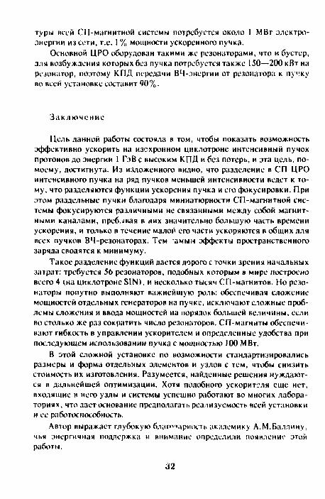
Цель данной работы состояла в том, чтобы показать возможность эффективно ускорить на изохронном циклотроне интенсивный пучок протонов до энергии 1 ГэВ с высоким К П Д и без потерь, и эта цель, по-моему, достигнута. Из изложенного видно, что разделение в СП ЦРО интенсивного пучка на ряд пучков меньшей интенсивности ведет к тому, что разделяются функции ускорения пучка и его фокусировки. При этом раздельные пучки благодаря миниатюрности СП-магнитной системы фокусируются различными не связанными между собой магнитными каналами, пребывая в них значительно большую часть времени ускорения, и только в течение малой его части ускоряются в общих для всех пучков ВЧ-резонаторах. Тем амым эффекты пространственного заряда сводятся к минимуму.
Такое разделение функций дается дорого с точки зрения начальных затрат: требуется 56 резонаторов, подобных которым в мире построено всего 4 (на циклотроне SIN), и несколько тысяч СП-магнитов. Но резонаторы попутно выполняют важнейшую роль: обеспечивая сложение мощностей отдельных генераторов на пучке, исключают сложные проблемы сложения и ввода мощностей на порядок большей неличины, если во столько же раз сократить число резонаторов. СП-магниты обеспечивают гибкость в управлении ускорителем и определенные удобства при последующем использовании пучка с мощностью 100 МВт.
В этой сложной установке по возможности стандартизировались размеры и форма отдельных элементов и узлов с тем, чтобы снизить стоимость их изготовления. Разумеется, найденные решения нуждаются в дальнейшей оптимизации. Хотя подобного ускорителя еще нет, входящие в него узлы и системы успешно работают во многих лабораториях, что дает основание предполагать реализуемость всей установки и ее работоспособность.
Автор выражает глубокую благодарность академику А.М.Балдину, чья энергичная поддержка и внимание определили появление этой работы.
32

Литература
1. Bartholomew G.A., Fraser J.S., Garvey P.M. — Accelerator Breeder Concept. AECL-6383, Chalk River, Ontario, 1978.
2. Tolstov K.D. — Perspectives of Electronuclear Method of Energy Generation and Nuclear Waste Transmutation. In this issue of JINR Rapid Communications.
3. Джелепов В.П., Дмитриевский В.П., Кольга В.В. — Препринт ОИЯИ Р9-9066, Дубна, 1976.
4. Russel F.M. el al. — Nucl. Instr. & Meth., 1963, 23, p.229. 5. Trinks U. — Superconducting Separated Orbit Cyclotron. Proc. of the
Inter. Conf. on Cyclotron. Vancouver, Canada, May 1992. 6. АверичевС.А. и др. — Препринт ОИЯИ FS-11700, Дубна, 1978. 7. Шелаев И.А. — Циклотрон с разделенными орбитами. В сб.: Проб
лемы электроядерногобридинга. МИФИ, Обнинск, 1980, с.46. 8. Shubaly M.P. - AECL-6578, 1979. 9. Schempp A., Klein Н. — Proc. of the 1976 Proton Linear Ace. Conf.
AECL-5677, p.67. !0. Hindercr G., Trinks U. — Das Trilron als Zwidchenbeschleuniger fur
Suse. Technische Universilal, Munchen, 1983. 11. Шелаев И.А., Алфссв B.C., Балдин A.M. и др. — Сообщения ОИЯИ,
Р9 85-593, Дубна, 1985.
Рукопись поступила 13 января 1994 года.
33

Краткие сообщения ОИЯИ №5!62]-9S J1NR Rapid Communications No.5l62]-93 УДК 539.172.8
TEST OF SCINTILLATION COUNTERS FOR MULTICHANNEL TIME-OF-FLIGHT SYSTEM S.V.Afanasiev, Yu.S.Anisimov, A.I.Malakhov, G.L.Melkumov, S.G.Reznikov, A.Yu.Semenov, P.I.Zarubin
The average time rr . Ь.-и . (a) of about 70 ps is obtained for each of four scintillation counts' - r>» » long duration test on the CERN SPS particle beam. The counters were aisembled of 2.4 x 2.4 x 6.0 cm scintillator bars and FEU-87 (CsSh) type photomultipliers, both made in Russia. We observed the nonstability of mean timc-of-flight (TOF) value during the runs. The maximum TOF drift contribution into the time resolution is estimated as (10—15)%.
The investigation has been performed at the Laboratory of High Energies, JINR.
Испытания сцинтилляционных счетчиков, предназначенных для создания многоканальных врсмяпролетных систем С.В.Афанасьев и др.
Н процессе долговременных испытаний набора из четырех ецмптилля-ционных счетчиков на пучке ускорителя SI'S в ЦЕРНк получено среднее временное разрешение (сг) порядка 70 не для отдельного счетчика. Счетчики состояли из сцинтилляторов размерами 2,4 х 2,4 х 6,0CMJ и фотоумножителей типа ФЭУ-87 (CsSb), произведенных в Госсии Мы наблюдали нестабильность среднего значения времени пролета ГГ01") на протяжении измерений. Максимальный вклад дрейфа ТОГ во временное разрешение оценен на уровне 10—15%.
Работа выполнена в Лаборатории высоких энергий ОИЯ11.
1. Introduction
This work was motivated by the planning of the NA49 experiment at CERN to research the new phenomena of Pb-Pb collisions at 200 GeV/amu 111. Upon this Proposal the time-of-flight (TOF) counter system with about 70 ps time resolution is required t i improve a separation of the pions, kaons and protons in momentum range 4+7 GeV/c to strengthen additionally the identification power provided by the time projection chambers.
34
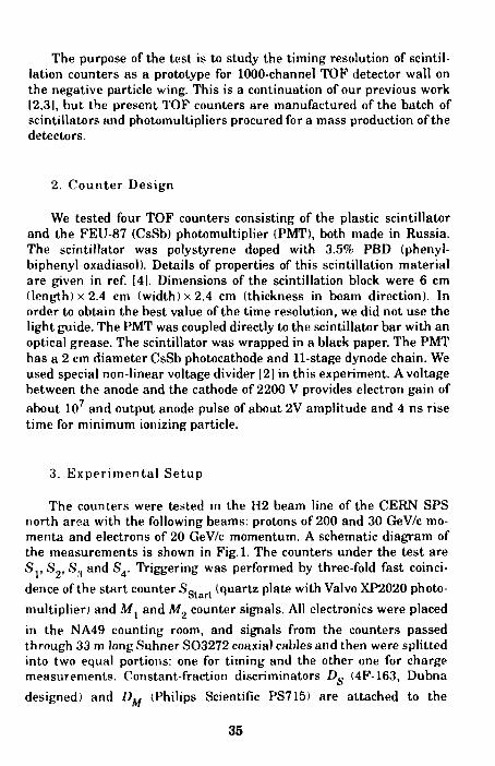
The purpose of the test is to study the timing resolution of scintillation counters as a prototype for 1000-channel TOP detector wall on the negative particle wing. This is a continuation of our previous work 12,31, but the present TOF counters are manufactured of the batch of scintillators and photomultipliers procured for a mass production of the detectors.
2. C o u n t e r Design
We tested four TOF counters consisting of the plastic scintillator and the FEU-87 (CsSb) photomultiplier (PMT), both made in Russia. The scintillator was polystyrene doped with 3.5% PBD (phenyl-biphenyl-oxadiasol). Details of properties of this scintillation material are given in ref. [41. Dimensions of the scintillation block were 6 cm (length) x 2.4 cm (width) x 2.4 cm (thickness in beam direction). In order to obtain the best value of the time resolution, we did not use the light guide. The PMT was coupled directly to the scintillator bar with an optical grease. The scintillator was wrapped in a black paper. The PMT has a 2 cm diameter CsSb photocathode and 11-stage dynode chain. We used special non-linear voltage divider 12] in this experiment. A voltage between the anode and the cathode of 2200 V provides electron gain of
about 10 and output anode pulse of about 2V amplitude and 4 ns rise time for minimum ionizing particle.
3. E x p e r i m e n t a l S e t u p
The counters were tested in the H2 beam line of the CERN SPS north area with the following beams: protons of 200 and 30 GeV/c momenta and electrons of 20 GeV/c momentum. A schematic diagram of the measurements is shown in Fig. 1. The counters under the test are S r S„, S.( and S4 . Triggering was performed by three-fold fast coincidence of the start counter S g l (quartz plate with Valvo XP2020 photo-multiplier) and M. and M„ counter signals. All electronics were placed
in the NA49 counting room, and signals from the counters passed through 33 in long Suhner S03272 coaxial cables and then were splitted into two equal portions: one for timing and the other one for charge measurements. Constant-fraction discriminators D^ (4F-163, Dubna
designed) and DM (Philips Scientific PS715) are attached to the
35

-*• I M,M2 S , S 2 5 . 5 ,
DD DDDD
Fig.l. Schematic diagram of the measurements
counters Sj* S4 and Sg t a r t , Mx, Af2, respectively. Time between a
signal of the start counter and signals of the counters under the test (9gtart_ g.« = 1' 4) as well as integrated charge (Qg) of all signals were
i i
measured by FASTBUS TDC (Philips Scientific 10C6) and QDC (LeCroy 1882F). Data from TDC and QDC were read out by intelligent FASTBUS master AEB (Aleph Event Builder) and then transferred to SUN SPARCstation.
4. Analysis and Results
Processing the data we eliminated a background by rejecting the events with the integrated charge being smaller than the lower bound for minimum ionizing particles (see Fig.2). When the elimination was applied, about 5 10% of the events were excluded from the data.
Some uncertainties in the beam contents and its momentum spread lead to the additional dispersion of the TOF value "?glart_ s measured at
i
a long distance between the start counter and the counters under the test. By this reason as well as in order to exclude the influence of the start counter resolution we deal with the time differences for each two test counters:
% • 'Start- S ^tart- S (1)
36

400
1000 3000 4000 2000 4DC channel
Fig.2. Integrated charge spectrum measured with S2 counter. The arrow shows the bound for elimination of background
Figure 3a shows typical scatter plot Tvs the integrated charge Q, (the average value of T is adjusted to be zero). We observed that the T value depends on Q. even for timing with the constant fraction method. This is the well-known time-walk effect and its magnitude is up to 200 ps in our case. As an attempt to correct the TOF measurements for this effect, fits to the data in the scatter plots were performed for each counter. The following function was used:
ЪОв > = * V P 1,<V P2iQi+ РЗ.Я!+ P4,Q£ D' (2)
where Pn OJ PAl are the parameters for each counter.
Figure 3b shows a scatter plot between the corrected Tand Q. From this scatter plot we see that the time-walk effect has disappeared.
To obtain time resolutions ag_s, (*,./'= 1* 4,i*j) the Ч§_8 • J ' j
spectra were fitted with a Gaussian distribution (see for example Fig.4). Finally, we evaluated optimum values of the time resolutions о for each individual counter using an asymptotic method. Table 1 shows the time resolutions for six runs distributed uniformly in time during 10-days test (about 60 runs), The errors presented are statistical ones.
37

(ЫО
••00
0
fiCO
before l ime-walk с
run #4
z~'^— •
Ipf
.i и-
—-
ti<ni
H )
• - . .
M i l l
i • 5
- M i l
;ifU'r t ime-walk rorrcf.'tion
run Hi . .
Ш»^:-1500 ?r>im
Q D ( : S | c h a i l n < ' l lf.00 250O :J500 4Г1ПО
WK's, channel Fig.3. Scatter pint between the timc-of-flight 7J,- s and the integrated charge Qg before (a) and after (b) the time-walk correction
a f t e r t i i i i r - w n l k c o l l e c t i o n 1200
1 ООН
IT» 10 I Г)Г)0 1 500 1570 10110 I'lJt: channe l
Fig.4. Time-of-flight Ts s spectrum after the lime-walk correction. The solid curve is a Gaussian fit with о = 91 ps. Corresponding time resolutions of S 3 and >S4 counters are o.n = 74 ± 9 ps and o4 = 58 ± 10 ps
We note that the measured time resolutions are rather different for the same counters in various runs. One possible explanation of this fact could be connected with a conspicuous time drift of the counters. Fig-
38
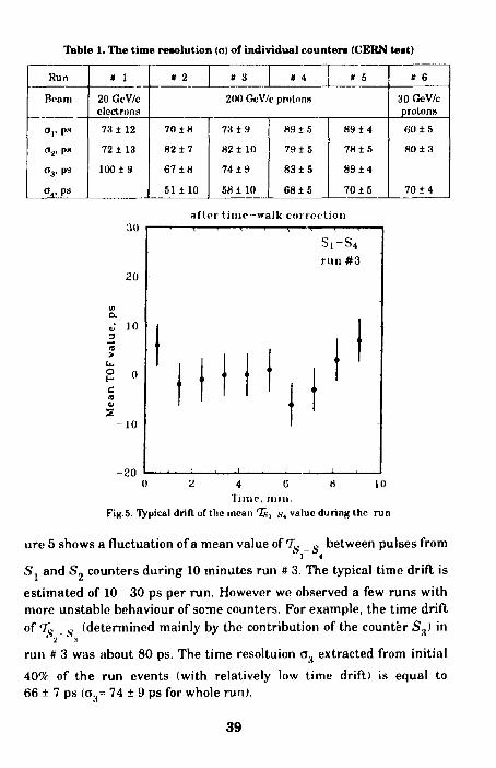
Table 1. The time resolution (a) of individual counter* (CERN teat)
Run
Beam
а,, р.ч
a.e ря
o3, ps
r>4, ps
* 1
20 GcV/c electrons
73 ± 1 2
72 ±13
100 ± 9
« 2
70 ±H
82 ± 7
67 ± 8
51 ± 1 0
» 3 » 4
200 GeV/c protons
73 ± 9
82 ± 10
74 ± 9
58 ± 10
89 ± 5
79 ± 5
83 ± 5
68 ± 5
* 5
89 ± 4
78 ± 5
89 ± 4
70 ± 5
# 6
30 GeV/c protons
60 ± 5
80 ± 3
70 ± 4
after time-walk correction
_3 H > о
-20 I 10 4 a
Time, niin. Fig.5. Typical drill of the mean I s , .s-4 value during the run
ure 5 shows a fluctuation of a mean value of Ts _ s between pulses from ' 1 4
S. and S, counters during 10 minutes run # 3. The typical time drift is estimated of 10 30 ps per run. However we observed a few runs with more unstable behaviour of some counters. For example, the time drift of T0 о (determined mainly by the contribution of the counter S.,) in
run # 3 was about 80 ps. The time resoltuion a.t extracted from initial 40% of the run events (with relatively low time drift) is equal to 66 ± 7 ps (o.H= 74 ± 9 ps for whole run).
39

Table 2. The time resolution (O) of individual counters (Dubna test)
Run
Beam
оя, ps
<V ps
« 1 « 2
6 (k'V/c рГ01оПЯ
681 10
57112
761 У
73 1 10
61 ± 12
741 10
Three months later we had a chance to repeat the TOF measurements with the same S2, S3 S4 counters at the JINR Synchrophasotron beam. The beam was 6 GeV/c protons. Each test run duration was approximately 4 hours. The detector time resolutions obtained by the described before procedure are presented in Table 2. We note that the time resolutions are similar to the measured before.
5. Conclusions We tested the set of four scintillation TOF counters 6.0 cm long, 2.4
cm wide and 2.4 cm thick during a long-term run on the particle beam. The average time resolution (o) of a1 «out 70 ps is estimated for the whole test. This value includes the contribution of the TOF drift and, being corrected on the last one, the time resolution could be improved for up to (10 15)%.
The reproducibility of the timing results was tested and it appeared to be rather satisfactory.
Finally, in this work we have achieved the timing accuracy required by the planned experiment to have a good separation of pions, kaons and protons.
6. Acknowledgements The work has been carried out owing to the support of the NA49
Collaboration members and we are very much obliged to them. Expe-cially, we would like to express our gratitude to Prof. F.Puehlhofer, Drs. A.Piper and F.Eckhardt for this work could not have been done without their assistance.
We wish to thank Prof. A.M.Baldin for continuous support of our research program. The contribution of the SPHERE group (JINR) is acknowledged.
This work has been realized under promotion of the Russian Grant for Fundamental Research (93-02-3773).
40
References
. Large Acceptance Hadron Detector for an Investigation of Pb-Indu-ced Reactions at CERN SPS. NA49 Collaboration, CERN SPSLC 91-31 SPSLC/P264. Afanasiev S.V. et al. — JINR Rapid Communications, No.41551-92, Dubna, 1992, p. 12. Semenov A.Yu. et al.— Improbed Scintillation Counters for Precise Time-of-Flight Measurements (to be published). Matveeva E.N. et al.— Nucl. Instr. and Meth., 1981, 179, p.277.
Received on December 28, 1993.
41
Краткие сообщения ОИЯИ №3/621-93 JINR Rapid Communications NO.S/62/-93 УДК 539.12.05
DATA REDUCTION AND MULTIPLE COULOMB SCATTERING ERROR ANALYSIS WI H1N SILICON TRACKING DETECTOR SYSTEM
M.Pentia*, Gh.Iorgovan*, B.Vulpescu* Particle track reconstruction capabilities of the silicon tracking detector sys
tem have been studied. As Ihe multiple Coulomb scattering (MCS) induces unavoidable uncertainties on the coordinate measurement, the corresponding error estimates and ihe associated correlations have been used to find the besl track fil parameters and their errors. Finally it permits one to find the proper panicle characteristics, as vertex position and resolution, momentum value, flight direction and the corresponding errors.
1'he investigation has been performed at the laboratory of High Energies, JINR.
Редукция данных и анализ ошибок при многократном рассеянии в кремниевых трековых детекторах
М.Пентиа, Г.Иоргован, Б.Вулпеску Изучена возможность реконструкции треков в системе кремниевых де
текторов. Выбор параметров трека и оценка их ошибок проводились с учетом неустранимых неопределенностей в координатах, к которым приводит мноткратнос кулоновское рассеяние. В итоге это позволило найги правильные параметры рожденной частицы, такие как положение и точность нахождения вершины, величину импульса, направление вылета и соответствующие ошибки.
1'абота выполнена в Лаборатории высоких энергий ОИЯИ.
I . Introduction
Design and preparation of any components of a detector system must take care of characteristics and detection performances (efficiency, acceptance, position or energy resolution) necessary for a specific process study. The silicon tracking detector system, in our case, must furnish the best information about Ihe coordinate track intercept of the incident particle on
•Institute of Atomic Physics, P.O.Box MG-6 (20-76400, Bucharest, ROMANIA e-mail: [email protected]
42
0 Q Q 0
Si
z, z2 z3 z4
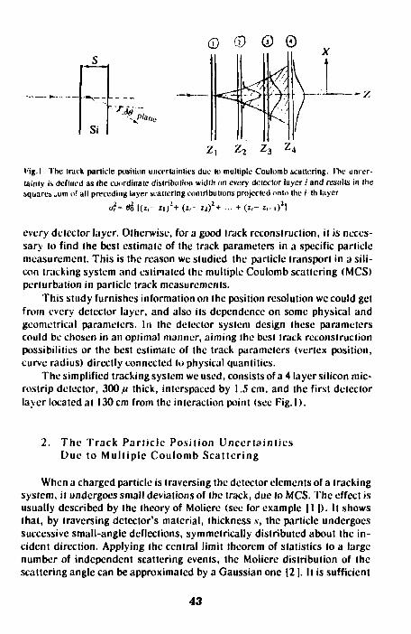
Hig. I. The track panicle position unci'rtaintii's due In multiple Coulomb scattering. I'hc uncertainly is defined as the coordinate distribution width on every detector layer / and results in the square» л ш of all preceding layer scattering contributions projected onto the Mh layer
o?=«tf | ( i , - z , / + (z,- Zi)2+ ... + (2,- 2,-i)2|
every detector layer. Otherwise, for a good track reconstruction, it is necessary to find the best estimate of the track parameters in a specific particle measurement. This is the reason we studied the particle transport in a silicon tracking system and estimated the multiple Coulomb scattering (MCS) perturbation in particle track measurements.
This study furnishes information on the position resolution wc could get from every detector layer, and also its dependence on some physical and geometrical parameters. In the detector system design these parameters could be chosen in an optimal manner, aiming the best track reconstruction possibilities or the best estimate of the track parameters (vertex position, curve radius) directly connected to physical quantities.
The simplified tracking system we used, consists of a 4 layer silicon micros trip detector, 300 ft thick, interspaced by 1.5 cm, and the first detector layer located at 130cm from the interaction point (see Fig. I).
2. The Track Particle Position Uncertainties Due to Mult iple Coulomb Scattering
When a charged particle is traversing the detector elements of a tracking system, it undergoes small deviations of the track, due to MCS. The effect is usually described by the theory of Molicre (see for example 11 I). It shows that, by traversing detector's material, thickness ,v, the particle undergoes successive small-angle deflections, symmetrically distributed about the incident direction. Applying the central limit theorem of statistics to a large number of independent scattering events, the Molicre distribution of the scattering angle can be approximated by a Gaussian one |21. It is sufficient
43
' Г\ры,1с
~z

for many applications to use Gaussian approximation for the central 98% of the plan projected angular distribution. The width of this distribution is the root mean square of the scattering angle |31
13.6 MeV W o " ppc
ZC /I x, 1 + 0.038 In I y -' " ( ; (i>
where p,(ic and z are the momentum, velocity and charge number of the incident particle, and XL is the radiation length of the scattering medium. That is, the plane projected angle в. or в . of the deflection angle в, onto the xOz and yOz planes, where the x and у axes are orthogonal to the 0z direction of motion, shows an approximately Gaussian angular distribution
y/bie, exp J6 plane' (2)
Deflections intoepl tncx and flplane , are independent and identically distri
buted, and в2 -в2, + 02, ' space plane, x plane, у
The angular distribution is translated to a coordinate distribution by particles fly onto every detector layer. The more intersected layers are the larger distribution width is. The coordinate distribution is defined by statistical spread due to MCS, and depends on the number and position of the intersected detector layer elements. It has the same form as angular distribution
Я 1 1 У2Л а exp 2аг dx. (3)
with the mean square deviation (distribution width) as the squares sum of the (/'-1) preceding distribution widths projected onto i-lh detector layer
o2. = (x2) = el | ( z -z . ) 2 + (z -z , ) 2 + ... + (г.- г. ,)21. <4)
For an oblique incidence (fi * 0) the effective path length in the silicon detector is larger, and the same is the position distribution width on the next detector layers. Nevertheless, in this work we will consider only the minimal width (4), as to emphasize the precision limit in particle position measurement with a given silicon tracking system.
44

3. The Monte-Carlo Particle Scattering Description
The change of track parameters is usually described by the <W . )1C
and 66 , , (or (30 and dip) angles and a corresponding displacement plane, у space т ° r ° r
6x .„ „ and dy .„„, in the position, plane •'plane r
Following the stochastic nature of the MCS, we use the Monte-Carlo study by generating the joint (djc . , 66 . ) distribution with independent Gaussian random variables (w,, хЛ |41
ox , = — = - + —=— plane ^|2 2 69 , = wJS,
plane, x 2 0
(5)
The same has been used for the joint (6y , ,66 . ) distribution in 1 v J plane plane, у
>0г plane. Finally we constructed the incidence points distribution (coordinate distribution) on the detector layer No.2, 3 and 4 (see Fig.2 and Table 1), for an incident 500 MeV/c muon.
3 0 0 0 0 LI I t I I I t 1 I I I I T I 1 Г I Г Г Т Т Т Т -
25000 г
-200 -150-100 -50 0 50 100 150 200 l ig 1 The plan projected x-coordmaie point distributions of the scattered 500 McV/c muoni. Incident on detector layer No.2, 3and 4 obtained by Monte-Carlo panicle transport simulation
45
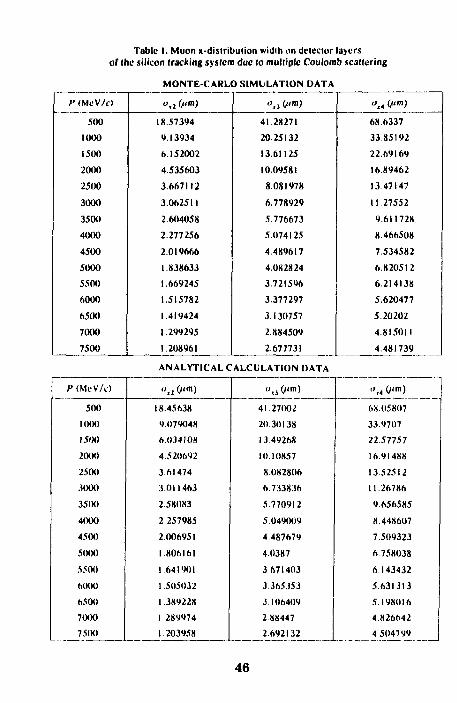
of Table I. Muon x-distribulion width on detector layers
the silicon tracking system due lo multiple Coulomb scattering
И (MeV/i)
500 1000 1500 2000 2500 3000 3500 4000 4500 5000 5500 6000 6500 7000 7500
MONTE-CARLO SIMULATION DATA
ox2 (i im)
18.57394 9.13934 6.152002 4.535603 3.667112 3.062511 2.604058 2.277256 2.019666 1.838633 1.669245 1.515782 1.419424 1.299295 1.208961
<>xi(fim)
41.28271 20.25132 13.61125 10.09581 8.081978 6.778929 5.776673 5.074125 4.489617 4.082824 3.721596 3.377297 3.130757 2.884509 2.677731
ANALYTICAL CALCULATION DATA
oxt («in) 68.6337 33.85192 22.69169 16.89462 13.47147 11.27552 9.611728 8.466508 7.534582 6.820512 6.214138 5.620477 5.20202 4.815011 4.481739
/MMcV/c) 500
1000 1500 2000 2500 3000 35(H) 4000 4500 5000 5500 6<XK) 6500 7000 7500
",l С""») 18.45638 9.079048 6.034108 4.520692 3.61474 3.011463 2.58083 2.257985 2.006951 1.806161 1 641901 1.505032 1.389228 1.289974 1.203958
o() (fim)
41.27002 20 30138 13.49268 10.10857 8.082806 6.733836 5.770912 5.049009 4487679 4.0387 3 671403 3.365353 3.106409 2.88447 2.692132
".,< (/'m) 6X05807 33.9707 2257757 16.91488 13.52512 11.26786 9.656585 X.448607 7.509323 6.758038 6.143432 5.631313 5.198016 4.826642 4504799
46
In Monte-Carlo simulated particle transport the particle position uncertainty on every detector layer has been measured as the variance or the mean square deviation of the scattered track incidence points x about the
unscattercd one.r0
2 £ K r V 2
a v-2< N (6)
•» —, /v
and similar for a variance, for every detector layer. The.x (andv ) are the
coordinates of the scattered track incidence points on detector layer, and N is the total number of generated events.
The distribution widths a . of the muon track jc-coordinate points on detector layer / = 2, 3, 4 and for momentum values from 500 to 7500 MeV/c, are presented in Table 1. There is also the analytical estimation of the same widths of the MCS incidence points distribution on each of the «-detector layer, according to (4)
2 , - ( i - l ) ( 2 i - l ) 2 ( 7 )
°xi~ 6 ( ' V ' <7)
where / is the distance between detector layers ( / = 1.5 cm) and 0(( is the
plane r.m.s. scattering angle (1).
4. Pos i t i on E r r o r C o r r e l a t i o n s
MCS produces errors correlated from one layer to the next. Clearly the scattering in layer 1 produces correlated position errors in layer 2, 3 and so on (see Fig.3). The proper error matrix is non-diagonal, and it must be f ind out.
Let's denote dx. the track deviation .v-coordinate point on the /-th layer,
with respect to the initial incident direction on the detector system, then
<5x, = 0
дх2=д]
дхз=д3\+д2 дх4=6*\ + д42+дУ
(8)
where the individual contributions due to preceding scatterings are
** 1 I A ~~~ \ A * "?
i , , = i . ; &,, — &, ; ^лл—Ь, .
47
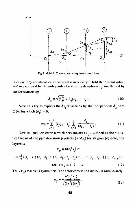
X I
® ф @ 0 -bx't,
Fig 3. Multiple Coulomb scattering error correlations
Because they are statistical variables it is necessary to find their mean value, and to express it by the independent scattering deviations^, unaffected by earlier scatterings
*к*Щ~Ч'к-г*д- (10)
Now let's try to express the dx. deviations by the independent d, ones (10), for which (d ) = 0,
<4 = 2 (Vi"V 2 TZ—r h) (II)
Now the position error (covariance) matrix (FV), defined as the statistical mean of the pair deviation products (дхдх) for all possible detection layers is
V..*(dx&x) =
= в11Ц-*•> <*,•- * . ) + <«,- («г *2) + - + (*,-- v . ) (« r *,-_,) i for / < / = 1,2 n. (12)
The (V.) matrix is symmetric. The error correlation matrix is immediately
(дхдх.)
48
(13)
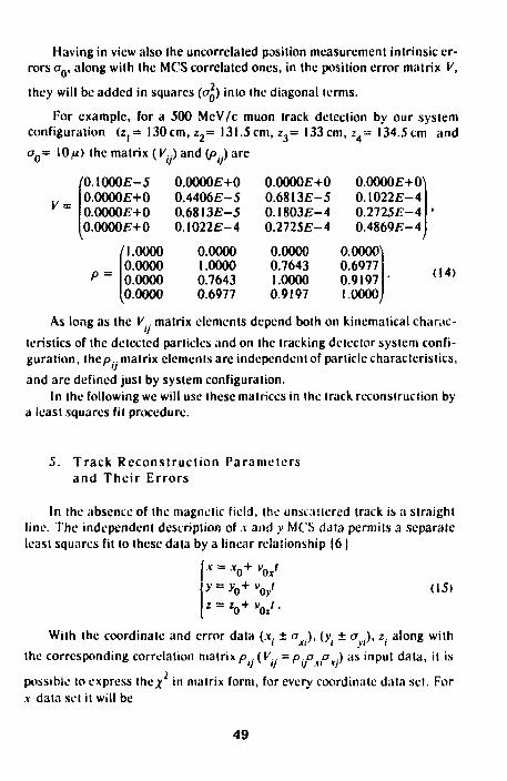
Having in view also the uncorrected position measurement intrinsic errors a „ , along with the MCS correlated ones, in the position error matrix V,
2 they will be added in squares (cC) into the diagonal terms.
For example, for a 500 MeV/c muon track detection by our system configuration (Zj= 130cm, z 2= 131.5cm, z 3= 133cm, z4= 134.5cm and
a Q = 10^) the matrix {V ) and (/>..) are
V =
'0.1000Е-5 0.0000E+0 0.0OO0E+O O.O0O0E+0
P =
/I.OOOO 0.0000 0.0000 0.0000
0.0O0OE+O 0.4406E-5 0.6813£-5 0.I022E-4
0.0000 1.0000 0.7643 0.6977
0.OO0OE+O 0.68I3E-5 0.1803E-4 0.2725E-4
0.0000 0.7643 1.0000 0.9197
O.OOOOE+O^ 0.1022E-4 0.2725E-4 0.4869E-4
0.0000^1 0.6977 0.9197 1.0000,
(14)
As long as the V . matrix elements depend both on kinematical charac
teristics of the delected particles and on the tracking detector system confi
guration, thep.. matrix elements are independent of particle characteristics,
and arc defined just by system configuration. In the following we will use these matrices in the track reconstruction by
a least squares fit procedure.
5. T rack Recons t ruc t i on Parameters and T h e i r E r ro rs
In the absence of the magnetic field, the unscallercd track is a straight line. The independent description of v and у MCS data permits a separate least squares fit to these data by a linear relationship |61
у = y0+ V
1 = zo+ V • (15)
With the coordinate and error data (jr. ± a .), (у. ± а .), z. along with
the corresponding correlation matrix p .(V.. = p.o a ) as input data, it is
possible lo express t he * in matrix form, for every coordinate data set. For xda ta set it will be
49
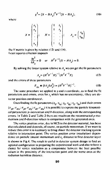
where
X =
X2=(X-HA/V-\X-HAX),
(I
H =
'Л 1 I,
1 /.. the V matrix is given by relation (12) and (14). Least squares criterion imposes
.2
дЛ_ = 0 or HTV \X-HAX)
o.i
0.
(16)
By solving the linear system relative to A we can get the fit parameters
Ax=(HTV '//) 1{HTV '*) (17)
and the errors of these parameters
EAxs(dAx6ATx) = (HTV'//)"'. (18)
The same procedure wc applied to у and z coordinate, as to find the fit parameters and errors, even for z. which has no uncertainty, (they are detector position coordinates).
Ones finding the fit parameters (JCQ, vQx; y0, v0 ; z0, vQz) and their errors
(ax0' CTvOx;" O' av0 •' az0' artz) " ' s P°ss'ble t 0 express the particle kincmati-cal parameters: p-momentum and0-direction, along with the corresponding errors. In Table 2 and Table 3 there arc results on the reconstructed />-mo-mentum and ^-direction values in comparison with the generated ones.
The vertex position error, due to MCS in the detector material, has been also calculated and depends, of course, on particle momentum. If we want to reduce this error it is necessary to bring closer the detector tracking system relative to interaction point. The vertex position error (resolution) dependence on particle (muon) momentum and z. distance to first detector layer is shown in Fig.4. The result is useful in detector system design to find an optimal configuration in preparing the experimental work and also to have a choice for vertex resolution as a compromise between the best possible values in the proximity of the interaction point and the worse ones at the radiation harmless distance.
50

Table 2. Kincmaiical parameters determination and their associated errors by track reconstruction in the silicon tracking system.
Data are based on the muon Monte-Carlo generated events under thela = 15 degree, for a lot of discrete moments
Generated moment (MeV/c)
500
1000
1500
2000
2500
3000
3500
4000
4500
5000
5500
6000
6500
7000
75(K)
Reconstructed
moment (McV/c)
500.53 ±0.44
1001.67 + 1.98
1497.13 + 7.10
1997.32 + 8.39
2501 33+ 15.71
3002.76 + 22.23
3497.56+ 18.74
3998.92 + 23.02
4502.71 +65.78
5003.13 ±48.06
5500.00 ± 117.62
6002.02 + 81.65
6498.90+ 112.23
7002.47 + 141.03
7500.07 ± 136.04
thela (deg)
14.98 ± 0 19
15.02 ±0.42
15.01 + 1.01
14.99 ±0.90
14.99+ 1.34
14.99 ± 1.58
15.00± 1.15
15.00 ± 1.23
14.99 + 3.13
I 5 0 0 ± 2.05
15.02 + 4.57
15.00+ 2.91
14.99 + 3.69
15.00 + 431
15.00 + 3.88
Tabic 3. Kinematical parameters determination and their associated errors by track reconstruction in the silicon tracking system.
Oala arc based on the muon Monte-Carlo generated events with Momenta = 500 MeV, for a lot of discrete polar angles
Generated theta <deg>
5
10
15
20
25
30
35
40
45
Reconstructed
ihcta ldog)
5.04 ± 0.28
10.00 + 0.09
14.99 + 0.22
19.95 + 0.55
24.89 ± 0 . 1 6
30.10 + 0.49
35 03 ± 0.28
40.07 + 0 3 1
45.10 + 0.12
moment (MeV/c )
500.42 ± 0.22
499.88 + 0.14
501.00 + 0.52
503.57 + 1.74
501.17 + 0 . 6 3
494.92 + 2.43
496.65 ± 1.69
495.55 + 2.26
5 0 1 . 5 4 + 1.07
51
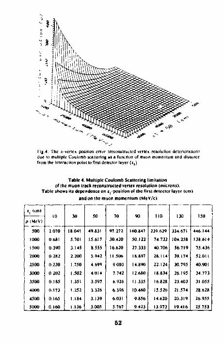
Iig 4 The t-vencx position error (reconstructed vertex rcsoluliun deterioration) due to multiple Coulomb scattering as a function of muon momentum and distance from the Interaction point to first detector layer ( i , )
Table 4. Multiple Coulomb Scattering limitation of the muon track reconstructed vertex resolution (microns).
Tabic shows its dependence on z:-position of the first detector layer (cm)
and on the muon momentum (Me V/c)
i, (cm)
p(McV)
500
1000
1500
2000
2500
3000
3500
4000
4500
5000
10
2070
0.681
0390
0.282
0.230
0 202
0.185
0.173
0.165
0.160
30
18041
5.701
3.145
2 200
1.750
1.502
1 351
1.252
1.184
1.136
50
49 831
15617
8.555
5.942
4.699
4.014
3.597
3326
3.139
3.005
70
97.272
30420
16 620
11.506
9080
7.742
6.926
6.396
6.031
5.767
90
160.847
50 122
27.333
18.897
14890
12.680
11 335
10.460
9856
9423
110
239639
74732
40.706
28.114
22.124
18 834
16.828
15.520
14.620
13.973
130
334.671
104.258
56.719
39.174
30795
26.195
23.403
21.574
20.319
19.416
150
446.144
138.614
75436
52.011
40.901
34.773
31 055
28.628
26955
25.753
52

Z| (cm)
p (McV)
5500 6000 6500 7000 7500
10
0 156 0.153 0.150 0.148 0.147
30
1.099 1.072 1.051 1 034 1.020
50
2 405 2.829 2.771 2.723 2.686
70
5.573 5425 5.310 5.218 5 144
90
9.102 8 859 8.668 8.516 8.394
no
13.494 13 129 12.845 12619 12 436
130
18.747 18.240 17.841 17.527 17 273
150
24.861 24.184 23.658 23.239 22.899
The vertex position resolution along дс-coordinale (or ^coordinate), due to MCS errors combined with the intrinsic detector coordinate uncertainties, could not be belter than the values shown in Table 4. Nevertheless, from Table 4 and Fig.4 we see also thai i l is possible to have a belter vertex position resolution if (he detector (racking system is placed lo a smaller distance from the interaction point.
R eferences
1. S c o l t W . T — R e v . Mod. Phys., 1963, 35, p.231. 2. Klatchko A., Choudhary B.C., Huehn T. — Estimation of the Multiple
Coulomb Scattering Error for Various Numbers of Radiation lengths, FERMlLAB-Pub-92/289. 1992.
3. Lynch G.R., DahlO. l — Nucl. Inslr. and Meih.. 1991, B58, p.6. 4. Particle Data Group, Hikasa K. el al., Review of Panicle Properties,
Phys. Rev. D., 1992, 45 л.11 / I I , p.11115. 5. Bevington P.R. — Data Reduction and Error Analysis for the Physical
Sciences, McGraw-Hi l l Book Сотр . New-York, 1969 6. Slonim V. et ,?i. — A General Algorithm for Track Fitt ing, Solenoidal
Detector Notes, SDC-92-252, 1992.
Received on December 21, 1993.
53

КраткиеС(юбш?>шя ОИЯИ ЛМ/62/-93 JINR Communications Noil62]-9} УДК 539 171.112
ON THE REACTION pp -* ppy AS A MEANS OF TEST FOR NARROW DIBARYON STRUCTURES
S.N.Ershov, S.B.Gerasimov, A.S.Khrykin The location of possible narrow dibaryon resonances in ppy reaction is
discussed. Contributions from the charge (convection) and magnetic (spin) currents of colliding protons are taken into account. It is shown that measurement of the photon energy spectrum is more suitable for observation of possible narrow dibaryon resonances than the widely used detection of all final particles with coplanar momenta.
The investigation has been performed at the Laboratory of theoretical Physics, JINR
О реакции pp -» ppy как средстве обнаружения дибарион-ных резонансов
С.Н.Ершов, С.Б.Герасимов, А.С.Хрыкин Обсуждается проявление возможных узких дибариониых резонансов в
реакции рр -» рру. Учитываются вклады от зарядовых (конвекционных) и магнитных (спиновых) токов сталкивающихся нроюнов. Показано, что измерение энергетического спектра фотонов являс!Ся более эффективным для обнаружения узких дибариониых резонансов, чем обычно иснользус-мая регистрации всех трех конечных частице компланарными имнул)>са-ми.
СабоIа выполнена в Лаборатории теоретической физики О И Я И
1. Introduct ion
Iii ref. 11 | the expedience was stressed of the search for dibaryon resonances [2—71 in ppy reaction. Two bremsstrahlung mechanisms discussed in [I | were there referred to as the «external» and «internal» photon radiation. In the second case, when the clastic decay mode of the dibaryon B,B -» pp, is either strongly suppressed (e.g., by the isospin selection rule, if 1(B) > 2) or strictly forbidden by the Pauli principle, when / (Й) = 1 ,3 ,... and 1(B) = 1, the resonance increase of the two-photon yield in pp -» yB -» yypp is an unambiguous indication of the dibaryon resonance excitation with the mass M(B) < 2m + mT. In a less exotic case
54

of Ihe «external» radiation, when the decay В -* /)/> is allowed, the usual mechanism of photon radiation from the external nucleoli lines of Ihe corresponding Feynman diagrams will dominate.
In 11 | Ihe convection currents of charged particles were only taken into account in a simple explicit formula for the bremsstralilung cross-section near a resonance. This approximation is justified only for the soft photon emission. However, in this case, according to Ihe Liw theorem |8 I, the bremsslrahlung cross-section is fully defined by the «physical» nucleon-nucleon scattering cross-seclion. So, to obtain qualitatively new information, one should concentrate on measurements and calculations of the hard photon production. This, in turn, requires to take account of the photon radiation by magnetic moments of interacting protons which is becoming to dominate over the non-spin-dependeni convection current already at comparatively low photon energies (e.g.. around 40 MeV for / | l b - 300 MeV). Taking into account the spin-dependent (magnetic)
contributions we are able to investigate Ihe influence of different spin-parities of Ihe assumed dibaryon resonance on (he observable cross-sections. We hope also to obtain more pronounced effects of those resonances which are seen mosl clearly in the spin-dependent observables of the polarized proton-prolon scattering.
At last, to estimate sensitivity of bremsstrahlung cross-sections expressed via different sets of kinemalical variables to dibaryon resonances, the calculations will be done wilh the use of Ihe so-called «Harvard set» of variables, the angles of all final particles in the coplanar geometry, almost exclusively used in all experiments on Ihe p/ry reaction we have known.
2. The O u t l i n e of Ca l cu la t i ons and Resul ts
In addition to usual assumptions underlying the potential model calculations of Ihe /VW-bremsstrahlung |9—15 | we consider a hypothelical possibility of the presence in the nucleon-nucleon total Г-nialrix of such resonance contributions which are not described by standard NN- potentials induced by the meson exchanges. The excitation mechanism of these dibaryon resonances may be related wilh Ihe rearrangement (or reclusleri/.alion) of the nucleon constituents (mesons, quarks, etc.) during their interaction in a given reaction. In thai case Ihe apparently small widths Г(В) -» NN of all known candidates for dibaryon resonances with the mass M(B) < 2m + m4 | 2 — 5 | may result from Ihe bad overlap of Ihe wave
functions of (wo final nucleons (i.e., two 3</-clusters) and ihe dibaryon В composed of quite different quark clusters, e.g., composed of Ihe coloured
55

4-quarks and/or diquarks: И -» </4 + ц or И -» 3</ . Then '.he effective interaction-range responsible for the H -» NN transition might be of an order of the quark wave function extension inside the nucleon, that is definitely smaller than the meson potential originating from meson exchanges at the periphery of nucleons.
With this conceivable picture in mind, wc adopt the following scheme of an estimation of the influence of dibaryon resonances on the observed characteristics of bremsstrahlung: a nonresonance (background) photon spectrum is calculated in the framework of the traditional scheme based on realistic meson potentials well-describing the observed «nonresonance» NN scattering phase shifts, while the excitation of the dibaryon resonances is taken into account by introducing a phenomenological resonance term in the amplitudes of NN interaction. Thus, we represenl a partial amplitude Г, of the nucleon-nucleon scattering with a total angular momentum J as a sum of two terms
Tj = Л; + Hr (1)
where ЛЛВЛ corresponds to a nonresonance (resonance) scattering. For the resonance amplitude Bj, presumably related with the short-range part of the NN interaction, we keep its parametrizalion formally coinciding with the usual on-shell scattering amplitude
«, = c liiJ 2lJ
Л м я + ' 2 Г ю , C(A). (2)
where MH is a mass of the dibaryon resonance, Vj (Г)(И) is a partial dotal) width, <p is a relative phase shift between resonance and nonresonance amplitudes,
C(s) = exp / s - M " (3)
We keep the notation and the parametrizalion of the cut-off factor C(Js) suggested in the work |7 |. The off-shell nonresonance amplitude A. is determined by Ihc solution of the Lippmann—Schwinger-type equation 111 —15 | with (he use of the one-boson exchange Bonn potential (OBEPQ) 116 1. Calculations were carried out in the momentum space and the partial waves with ihe total momentum / < 6 were considered. Diagrammatically,
56
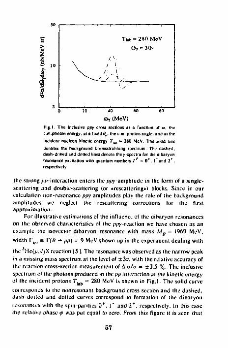
I I ' I 1 1 ' I I
Т|,ь = 280 MeV вт = 30"
/ V
^ ~ ^ ^ _ • " Л ^• ,
0 20 40 60 80
coy (MeV) l-ig.l. The Inclusive ppy cross sections as a (unction of ш, the cm.photon energy, at a fixed в , the cm photon angle, and at the incident nucleon kinetic energy 7"ub = 280 MeV. The solid line denotes the background bremsstrahlung spectrum, the dashed, dash-dotted and dotted lines denote the y-spcclra For the dibaryon resonance excitation with quantum numbers J r = 0*, I "and 2*, respectively
the strong / /'-interaction enters the ppy-amplitude in the form of a single-scattering and double-scattering (or «rcscatlcring») blocks. Since in our calculation non-resonance p/ry amplitudes play the role of the background amplitudes we neglect the rescattcring corrections for the first approximation.
For illustrative estimations of the influence of the dibaryon resonances on the observed characteristics of the ppy-reaction we have chosen as an exampie the isovector dibaryon resonance with mass Mg = 1969 MeV, width ГЦ)| a \"(B — pp) = 9 MeV shown up in the experiment dealing with
the Hc(/>,i/)X reaction |51. The resonance was observed as the narrow peak in a missing mass spectrum at the level of ±3a, with the relative accuracy of the reaction cross-section measurement of Д a/a = ±3.5 %. The inclusive spectrum of the photons produced in the pp interaction at the kinetic energy of the incident protons Г|аЬ = 280 MeV is shown in Fig.l. The solid curve cot responds to the nonrcsonanl background cross section and the dashed, dash-doited and dolled curves correspond to formation of the dibaryon resonances with the spin-parities 0 + , Г and 2 + , respectively. In this case the relative phase <p was put equal to zero. From this figure it is seen that
ft >
a 10
57

Ты, = 280 MeV i % eY = зо°
^ Т 4 < ?—
6 20 40 60 80
©г (MeV) Tig. 2. The inclusive ppy cross-sections al Г,1Ь = 2S0 MeV for ihe dibaryon excitation wilh Jp = 1 " versus Ihe relative phase ф be-iween the background and resonance amplitudes. The solid line is a background spectrum. The dashed, dash dotted and dolled lines are spectra with ф = 0°, 90" and 180', respectively
wilh the chosen parameters of the resonance, the exceeding of the resonance peak above the background is ranging from 40% al Jp = 01" to 100%, al / = 1 ,2 . The influence of Ihe relative phase shift ф on Ihe shape of Ihe resonance spectrum at J ** = I " is shown on Fig.2. The dashed, dash-dotted and doited curves correspond to the values of ф = 0°, 90" and 180', respectively. For Ihe same resonance (i.e., al J p ••- Г ) in Fig.3 the conlribulions from the convection (dashed curve) and the magnetization (doited curve) currents to the total cross section of the resonance excitation (dashed-dotted curve) are shown.
Thus, it is seen that narrow dibaryon resonances should exhibit themselves as the conspicuous resonance-like structures over smooth background in the photon energy spectrum of Ihe /^-reaction. Moreover, the positions of these resonance peaks depend on the energy of incident protons and their calculable and noticeable shifts wilh the controlled changing of the initial proton energy may serve as the decisive argument in favour of those much-disputed dibaryons. Unfortunately, there are no data on the photon energy spectra at present.
As to the popular geometry of Ihe p/jy-experiments with the coplanar detection of ail final particles (the so-called Harvard geometry), one can see thai the specially chosen proton angles should be used to face the dibaryon
30
10
58
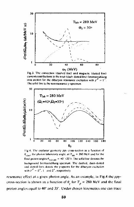
> о
I-
О •о
50
10
1
1 1 1 1 1 1 1 1
Tiab = 280 MeV
л 9 Т - 30о - \ . ' ,
• ^ - ^ / ,
~~ 1 • -i
4 " ~ ~~ ~~ -20 40 60 80
щ (MeV) l'ig.3. The convection (dashed line) and magnetic (dotted line) currctil contributions to the total (dash-dolted line) bremsslrahlung cros section for the dibaryon resonance excitation with Jp = I ". The solid line is the nonrcsonancc y-spectrum
50
О m
I
—i 1 1 1 1 1 1 —
Tiab = 280 MeV (Я1=40°,П2=35°)
•
0 20 40 60 80 100 120 140 160 180
e Y l ig 4. 'fhe coplanar geometry ppy cross-section as a function of "v i«t>' "'L' P ' w l i m laboratory angle, at 7"1шЬ = 280 MeV and for the final proton angles tf|(J| l l b = 40" (35"). The solid line denotes the background bremxslrahlung spectrum. The dashed, dash-dotted and dotted linos denote the y-spectra for the diharyon excitation with J = 0 * , I " and 2 * , respectively
resonance effect at a given photon angle. As an example, in Fig.4 the p/ry-cross-scction is shown as a function of в for T = 280 MeV and the final
proton angles equal to 40° and 35°. Under chosen kinematics one can trace
59

Ihe presence of Ihe dibaryon with mass 1969 MeV' |71. The solid curve corresponds to background, the dashed and the dash-dotted curves correspond to excitaiion of Ihe dibaryon resonance with spin-parity 0 + , 1 " and 2 , respectively. From this figure one can sec thai the influence of the resonance on the cross-section shape may be noticeable but quite different from a local variation commonly expected for a narrow resonance. The kinematic conditions of the most extensive and precise experiments at 280 MeV |9 , I01 were optimized on a search for the off-shell effects in Ihe iV/V-interactions. Nevertheless they do put some restrictions on the parameters of possible dibaryons. In the region invesligaled Ihe resonances with mass ЩВ) < 1940 MeV could only be seen. With the use of available data one can obtain a rough upper bound on Г|о( < 2 MeV.
Above the pion threshold there are also Ihe candidates in the dibaryon resonances. So. the relatively narrow structure with the mass M(B) = 2160 MeV [6,71 was discovered in a measurement of the analysing power Ay in pp-scattering. From a phase shift analysis the resonance parameters were obtained |7 |: Гю( а 10 MeV and Г / Г ю | = 0.15 (0.06) if
the resonance is observed in F3( H^) partial wave. Fig.5 shows the spectra
of the brcmsstrahlung photons in thepp-interaction at T. . = 800 MeV.
U ,0 75 10 13 90 93
(^(MoV) R| 5 The cm. Inclusive cries sections it 7'^ = 800 MeV. The dashed line is a background spectrum. The solid line denotes specinini for the dibaryon resonance excitation in the Jt 3 (a) and J l l 3 (b) partial waves
6 0
Though the use in the calculations of the Bonn potential is not justified at such a high energy, we present the results to demonstrate at least the qualitative picture of the resonance signal to nonresonance background relation in that case. In accomplished calculations all partial waves with J < 9 were taken into account. In Fig.5a(b) the theoretical calculations of the photon spectra with excitation of dibaryon resonance in partial wave 3F'3(3HS) are presented. II is seen that the small elastic widths lead to strong decrease of the resonance-to-background ratio (this ratio reaches only 2% in the case of the resonance in F, wave and less than ! % for H, wave).
Furthermore, to get rid of photons from the л -decays, one should detect all final particles of the ppy reaction to draw the needed photon energy distribution curve.
3. Concluding Remarks
The calculations performed in this work are approximate. In particular, the rescattering and relalivistic spin corrections discussed, respectively, in refs. 114,15 | are not considered. Like all other theoretical works in this field we don't consider the exchange current contributions, which for the ppy-reaclion arc connected with the niullimeson exchanges and which remain basically unexplored till now. We believe, however, that all aforementioned factors cannot qualitatively change (he picture of the dibaryon resonance appearance if they do exist in the considered range of masses.
it appears worthwhile to note also that our scheme of introduction of the resonance effects into consideration has a genera! basis with some of the considered earlier attempts to go beyond the soft photon approximation based of the Low theorem |8 |. Indeed, in 117 |, it was shown on the base of an exactly solvable potential model that one can reach a more accurate description of bremsstrahlung reaction, in comparison with a model-independent soft photon approximation, if the contributions from a peripheral, long-range part of potential arc described exactly, while contributions from the short-range part of strong potential are taken into account according lo the Low theorem, that is, by paramelrization of the corresponding amplitudes through the on-mass-shell scattering phase shifts.
In our case, we identify the peripheral part of potential with a realistic meson NN potential and treat it as accurately as possible. We phenomenologically parametrize the action of an unknown short-range interaction, which is, presumably, originated from the quark rearrangement in the NN system, via the resonance NN amplitudes on mass-shell. To
51

conclude, the more realistic calculations of this work give niore reliable estimation of the possible dibaryon resonance signal over a non-resonant background, thus confirming the main conclusions of 11 | and stressing the urgency of measuring the energy spectra of final photons. The moving «y line», i.e., the dependence of the «resonance» photon energy on the energy of incident protons is also one of the most salient features of the existence of the narrow dibaryon resonance. Of course, for further detailed investigation (determination of the quantum numbers, etc.) different exclusive experiments (see, e.g. | I8 |) and measurements of the spin characteristics of the particles in the considered reaction will be needed as well.
References
1. S.B.Gerasimov, A.S.Khrykin — JINR Rapid Communications, 6157 ]-92, Dubna, 1992, p.24; and Mod. Phys. Lett. A, 1993, 8, No.26, p.2457.
2. B.Tatischeff et al. — In: Relalivistic Nuclear Physics and Quantum Chromodynamics (Proc. of the Int. Seminar on High Energy Physics Problems, Dub.ia, Russia, 1990) Eds. A.M.Baldin, V.V.Burov and LP.Kaptari, World Scientific, Singapore, p.177.
3. Ya.A.Troyan et al. - Yad. Fi/.., 1991, 54, p.1301; JINR Rapid Communications, 13-85, Dubna, 1985, p.12.
4. V.V.Avdeichikov el al. — Yad.Fiz., 1991, 54, p.l 11. 5. B.Tatischeff et al. — Z.Phys., 1987, A 328, p.147. 6. M.Shimizu et al. — Phys. Rev., 1990, C42, p.483. 7. J.Nagata et al. — Mod. Phys. Lett., 1992, A7, p.3573. 8. F.Uw — Phys. Rev., 1958, 110, p.974. 9. P.Kilching et al. - Phys. Rev. Lett, 1986, 57, p.2363. 10. K.Michaeiian et al. - Phys. Rev., 1990, D 41, p.2680. 11. R.LWorkman, H.W.Fearing — Phys. Rev., 1986, С 34. p.780. 12. K.Nakayama - Phys. Rev., 1989, С 39, p. 1475. 13. V.Herrmann, J.Spelh, K.Nakayama- Phys. Rev, 1991, С 43, p.394. 14. V.R.Brown, P.LAntony, J.Franklin — Phys. Rev., 1991, С 44, p.1296. 15. V.Herrmann, K.Nakayama - Phys. Rev., 1992, С 45, p.1450; ibid,
1991, С 44, p.1254; ibid, 1992, С 46, p.2199. 16. R.Machleidt —Adv. Nucl. Phys.,1989,19, p.189. 17. G.E.Bohannon, L.Heller - Phys. Rev. Lett., 1983, 51, p.l 151. 18. V.L.Lyuboshits, M.l.Podgoretsky - Yad. Fiz., 1992, 55, p.2927.
Received on October 28, 1993.
62
Краткие сообщения ОИЯИ №5(62J-93 JINR Rapid Communications No.S[62/-9S УДК 519.613
THE NEWTONIAN ITERATIVE SCHEME WITH SIMULTANEOUS CALCULATING THE INVERSE OPERATOR FOR THE DERIVATIVE OF NONLINEAR FUNCTION
I.V.Puzynin, I.V.Amirkhanov, T.P.Puzynina, E.V.Zemlyanaya The modified Hera live Newtonian procedure for solving nonlinear functional
equation is proposed. The inversion for the derivative of nonlinear function on each Iterative step is replaced by multiplication of some linear operators. On the basis of the proposed procedure an algorithm and a program for solving the eigenvalue problem for integral equation are developed. The calculations demonstrating s convergence of the algorithm and its efficiency for vector computer are performed.
The investigation has been performed at the Laboratory of Computing Techniques and Automation, JINR.
Ньютоновская итерационная схема с одновременным вычислением оператора, обратного к производной нелинейной функции
И.В.Пузынин и др. 11редложен модифицированный ньютоновский итерационный процесс
для решении нелинейного функционального уравнения, в котором обращение оператора производной нелинейной функции заменяется на каждом шаге перемножением вспомогательных линейных операторов. На основе предлагаемой модификации разработаны алгоритм и программа для решения задачи на собственные значения для интегрального уравнения. Проведены численные расчеты, иллюстрирующие сходимость описываемого процесса и его эффективность для векторных вычислительных систем.
Работа выполнена в Лаборатории вычислительной техники и автоматизации О И Я И .
Introduct ion
In the context of the development of vector-parallel computers the problem of elaborating special algorithms and programs for the effective using possibilities of such computers is very actual. An algorithm using some possibilities of these computers is presented. This algorithm is developed on the basis of modified continuous analogue of the Newton's method (1 ]. The
63

inversion of the derivative operator for nonlinear function on each iterative step is replaced by three multiplications of some linear operators.
The idea of such an approach for Ihe finding of inverse matrixes was proposed in Rcfs. |2,3 | in application to the method of the parameter variation. Its advantage is in the absence of the division operations during all calculations. Therefore, the division on a small number is excluded and the accuracy and stability of the calculations increase.
Below the iterative procedure is described for the nonlinear equation in Д-space, the developed on this basis scheme for solving Ihe eigenvalue problem for the integral equation is presented.
The efficiency of the algorithm proposed for system CONVEX С! 20 has been confirmed by testing calculations for the Schrocdingcr integral equation with the Coulomb potential in the impulse space / 4 / .
1. The Modif ied Algorithm
In accordance with the generalized continuous analogue of the Newton method for a nonlinear functional equation in #-space
<p(i) = 0 (I)
we construct the evolutionary equation with respect to additional parameter /
j(<Ht,i(t)) = -<p{,,z(t)), 0 s i < « <2) with the initial condition z(0) = zQ.
A parametrizalion ф = ф(1, z(/)) is performed so that for; = 0 wc have a simple equation
*(0, z(0)) * ф0(г0) = 0,
which can be solved easily and lim ф(1, z(t)) = ф(г). I-.00
One of variants of the parametrization can be performed by introducing ihe scalar function g(t) |51, the so-called «function for including a perturbation»: g(Q) = 0, lim g(t) = I , and representing Ihe function фи, ztt)) as a
sum ФС *(')) = <PQ(z(i)) + g(t) |*(z(0) - #„(*(/)) I
From Eq.(2) designating A(t) = ф (f, z(t)) we obtain
^ = - /»"'(/) [ф(1, z(t)) + Ф,(1, z(t)) |. (3)
64

Since the integral of Eq.(2) is <p(t, z(l)) - e '<p(0, zQ), then for t -» », || <p(t, z(/))||-* 0, and z(t) converges to desired solution z*.
The discrete approximation of Eq.(3) with respect lo the continuous parameter /: (f0, ty... tk)\ l0 = 0, <i+ , - lk = *k is performed in the framework of the Euler method „ . „ . . .. ...
z('*+|)as*<'*> + I*lV (4)
where vk = " *<'*) W'4. *('*)) + *,('*• Z(V> !•
Calculating an iterative correction Vk and step r for each tk, we receive a new approximation z(f. + .) to solution z*.
The iterative procedure should be с inued until the next relation is fulfilled:
lirtf4.«(g)lis«. <5) where e > 0 is a given small number.
The convergence of this iterative procedure is justified in Refs. 11,5 |. Let us turn to the description of the proposed modified iterative proce
dure. Let us consider the following system of functional-operator equations
( л 4 - / = 0, <6>
where A = <p , В = A~\ I is the unit operator. Introducing the continuous parameter i ( 0 s i < <*>) and coming to the
evolutionary equations system, we obtain:
±ф(1, *(/)) = - *(r. z(0),
j-t\B(t)A{t)-l\ = l-B(l)A(t).
After simple transforms we have finally: f ^ i(o = - B(o 1Ф0, z(i)) + *,(/, z(0) I.
j - t A(o = i/ - B(I)(A(O + и'(о) mo
il)
(8)
As a result of discrete approximating of Eqs.(8) by the Euler scheme, z + 1= z(/4+,)and fli + (= S(<4+1) can be calculated on each iterative step if zk and Bk are known:
66

zk + \~ zk+lkVk' r 0 .
*к = "-ьк(\ + Ак,)^к- ( , 0 > Thus, having initial approximations z(), II.., all next approximations z,,
W. can be found sequentially. The iterative procedure is continued until the relation (15) and the fol
lowing relation will be satisfied \\BkAk-l\\<e. ( ID
The practical calculations show that /J()= /l~'(z0) is the best initial approximation for H.
2. Solution of the Eigenvalue Problem for Integral Equation
We consider a following equation: К
<P(z) = y(x) (Q(x) - Д) + a f K(x, x) y(x)dx' = 0, (12) 0
where z = (y(x), Д) and the normalization condition и f >\x)Jx - N = 0. (13) о
Let us introduce parameter /, 0 < / < °° and the function g£t) = 1 - e~'. Then <p(t, z) we represent as follows
*('. *) = № + 8(0 (*(*) - Ф0(*))- <1«> We suppose that Ф0(г) — 0 is some simple function equation with known solulior z„ jeing used as on initial approximation.
Taking into account z(t) = (y{x, /),A(/)) and turning our attention to evolutionary equation, we receive for Eq.(l4):
K W » ) , + so mm)'y - (<р0мщ \\y',= = l* 0 W» + (*(') + 8,(i)) ( *«0 ) - Ф0Ш)) I -
- КФ0Ш))'х + SO ((Ф(4Щ - (#0W)))i) U|(0- <I5)
ее
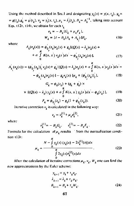
Using the method described in Seel and designating yk(x) = y(x, tk), gk=
= g(tk)<Sk = sOk)< vk = y't(x, lk),fik = ; j ( f t ) , Hk= Ak~l, taking into account
F.qs. (12), (14), we obtain for each ik
"* = - W W*"-Wk=U-Bk(Ak + Ak)\Bk, (16)
i
where
+ a / X(x, *') с4(.х>л' - ^ 0 (zk)vk(x) ], ( i 7 )
i у О
- ф0 (zk)vk(x) I -- *Л(дг) \ик + (Ф0 {zk))t I, (18) У У
Ск = ф0(гк) + (!>к + 8к)Х Я
х KQW ~ A4)>'*(*) + «/*<*, *') yk{x)dx- ф0{гк) ], (19) О
^ = «y**)-**(,+tyz*>>- <20)
Iterative correction v, is calculated in the following way:
"*4l)+>vi2)' < 2 1 > where
*i1)=-'Vv 42)=-V*- <22)
Formula for the calculation of ft. results ' from the normalization condi
tion (13): N-fyk(x)(yk(x)-2^\x))dx
0 nk = й
0 (23)
/ 2у.(л)Л2>(х)«/х о
After the calculation of iterative corrections^,, v., Wk one can f ind the
new approximations by the Euler scheme:
Ук+1=Ук+гк"к> A A + I = V VV Bk+i=Bk+Tkwk- < 2 4 )
67

The numerical approximation of Eq.(l2) on the discrete mesh for x: (0 = x0< * ,< . . .< дг(|= R) reduces to the system of n algebraic equations:
Ф,• = y{Q- A) + a J К у£ (25) /=i
where >•. = y ^ ) , Q. = Q(JC.), K., = K(x., x), £. are coefficients of Ihe quad
rature formula of the numerical integrating. Operators A, Af, F,G in (16) —
(20) are approximated by matrices {a.), {iT.} and vectors (/•".), (Gj corres
pondingly. In particular, the matrix elements a., and a on ktb iterative
step are determined as follows: a.. = a<0)+ g.UQ. - ХЛ6..+ aK | - a{0) |, (26)
tj IJ e * 1 V K i k' ii if] IJ "
Z. = S<°> + g.\(Q. - А.) д.. + a |K. | . - 5*0) | - g, \fi, + 5<0)l |, (27) i; ij e * , v , £ i *' i/ ' if i i) ' "k^k IJ '
where <3.. is the Kronccker symbol, a..' and 3v' arc elements of matrices
approximating Ihe operators ф0 (zk) and [ф0 (z^) ]f correspondingly on the У *
discrete mesh. We note that the additional normalization of function y.(x) for each ite
ration essentially improves the convergence of the iterative procedure.
3. The Program Realization
In order to solve Eq.(l2) numerically two program complexes on the FORTRAN-77 are developed:
а) CANMIM realizes the iterative procedure (3)— (4) with the calculation of matrix B^ = A^' by inverse of A^ on each iteration (with the help of a standard subprogram MATIN2 from the CERNLIB |61).
б) CANMIT realizes the iterative procedure (6) —(10) where H, is parallel calculated in iterations.
Coefficients {f } for the test presented below are selected in accordance with the Gregory formula |7 | . The step r, was calculated by algorithms described in ref. |8 |. Test calculations and comparison of time operation of the two programs are performed.
68

When comparing schemes (3)—(4) and (6) — (10), it can be seen that the scheme (3)—(4) contains one inverse of matrix Л, and in scheme (6)—(10) it is replaced by three matrix multiplications: BA, BAf, \I - BA - BAf \B.
Should be noted we succeeded in finding the conditions in which the number of iterations for two processes is identical. Taking into account that in the scalar variant of the realization the time of the inversion of one matrix is approximately equal to the time of multiplication of two matrixes, the expected calculation time for the scheme (6)—(10) is thrice more than that for the scheme (3)—(4). However, the matrix multiplication is more preferable than the matrix inverse from the point of view of vector representation of operations. It can be expected that algorithm (6)—(10) will give an advantage of time on the vector computer. Naturally, this advantage will be obtained al the expense of additional of the computer memory required for additional matrixes.
4. Numerical Example
In the present paper the proposed method is illustrated by the solving of the Schroedinger equation in impulse representation for the Coulomb potential (41.
This equation is as follows: p + p' *( 2) * (p2-X)y(P) - 1Z J dp'In
о with the normalization condition
p- p yij>') = 0 (28)
j V ( p ) J p = l , о
where z = (y(p), X), X is eigenvalue, X - 2E, E is energy level. One of analytical solutions for Z = 1 is following
ДГ = -1.0, у\(р) -Д 31 (P2+ l)2
To eliminate the singular point p - p' let us transform Eq.(28) in the following way
(P -*)y<J>)-2Zf dp'Xn о
P + P' p-p
69
г W/O - M) - 2Zy(p)t. = 0,

Tabic 2a. Interval |0,10|, n = 101
SCM EMI:
<3> — <4)
(6)- ( IO>
PROGRAM
CANMIM
CANMIT
к 5
5
'* -от -0.997
'* 1.3/Г5
\At:'5
r
42
274
7' IT
3.01
Table 2b. Interval |0, 20|, n = 201
sciiLMt:
(3) —(4)
(h) —(10)
PROGRAM
CANMIM
CANMIT
к 5
5
*. -0.998
-0.998
'* \.\E-$
L IE" 5
T
623
1989
r2/r,
3.19
Table 2c. Interval |0,30|, n = 301
scnicMi:
( 3 ) - ( 4 )
(6) —ПО»
PROGRAM
CANMIM
CANMIT
к
5
5
h -1.0001
-1.000098
\ l.06fc'"s
1.4/Г3
T
1903
5597
7-,/Г,
2.94
solution are presented for VAX 8350. Besides these Tables demonstrate a convergence of eigenvalues of the discrete problem when increasing parameter R. Everywhere A = 0.1, e = 10~4,A0= - 0 . 9 , ^ = 0 . 1 .
As is obvious from the Tables, both algorithms for identical parameters R and h and similar values of residual &k have equal number к of iterations.
It is also seen that the program CANMIT spends thrice more execution time than the program CANMIM.
In order to check up (he possibilities of the vector representation of operations on the level of the operation system CONVEX С120, each program complex was executed twice:
1) without all optimization parameters of translation (TC — time of calculation);
2) with the optimization parameter -02 (TC02 — time of calculation with the vector representation of operations).
In Table 3 the execution times TC and TC02 (sec) and relation TC/TC02 characterizing a property of «accelerating the calculations» are presented for both schemes. Besides, for comparison the execution times for the system VAX 8350 and for SUN Spark Station 2 arc given.
71

Table 3. Interval |0,101. n = 101
SCIIEMK
(3) —(4)
<6)-<IO)
PROGRAM
CANMIM
CAN MIT
VAX
92
274
SUN
15
48
CONVEX
TC
31
91.9
TC02
12
7.8
IC/TC02
• 2.6
m 11.8
From Table 3 it follows that the scheme (6) —(10) is more effective for the vector system using only one of the possibilities of the CONVEX operation system.
In the considered case the vector representation gives a relative acceleration of working this scheme nearly 1.5 limes if comparing with the scheme (3) —(4) .
Much greater advantage is observed if comparing the execution times of vector variant of the CANMlT-program with the scalar variants of this program and the CANMIM-program.
Conclusion
The aim of the performed numerical experiences is to demonstrate advantages of the proposed iterative procedure for its realization on vector computers. Special methods of vector representation of operations for calculations and special features of solved problems such as, for instance, the symmetry of integral operator kernel are not knowingly used in the calculations. Calculations were performed on comparatively sparse meshes in order to compare the work of the programs on different computers including computers with relatively small memory capacity.
The Newton iterative scheme for solving the nonlinear equations with simultaneous iterations of the inversion operator to derivative of nonlinear function is perspective for using on the vector computing systems with sufficiently large memory capacity or a system of external memory with fast access. The efficiency of the corresponding programs can be significantly increased by using special methods of vector and parallel calculations on multiprocessor computers.
We thank the Commission of the European Communities for partial financial support in the frame of the EC-Russia collaboration Contract №ECRU002.
72

References
1. Zhanlav Т., Puzynin I.V. — Compul. Maths Math. Phys., 1992, 32, No.l, p.I.
2. Davydenko D.F. — Doc I. Ac. Nauk SSSR (In Russian), I960, 131, 3, p.500
3. Holbrow W., HassR., Kalaba E., Zagustin E. — University of Southern California, Los Angeles, 1972.
4. Bete G., Salpeter E.E. — Quantum Mechanics with One and Two Electrons, M., Fizmatgiz (in Russian), 1960.
5. Zhanlav Т., Puzynin I.V. — Comput. Maths Math. Phys., 1992, 32, No.6, p.729.
6. CERN Computer Centre, Program Library, Geneva, 1988. 7. Kalitkin N.N. — Numerical Methods, M., Nauka (in Russian), 1978. 8. Ermakov V.V., Kalitkin N.N. — Zh. Vych. Mat. i Mat. Fiz. (in Rus
sian), 1981, 21, p.49. Puzynin I.V., Puzynina T.P., Strizh T.A. —JINR Comm., PI 1-87-332, Dubna, 1987. Amirkhanov I.V., Zemlyanaya E.V., Puzynina T.P. — JINR Comm., PI 1-91-139, Dubna, 1991.
Received on December 17, 1993.
73

Редакторы: М.И.Зарубина, Э.В.Ивашкевич.
Рукопись сборника поступила 14.01.94. Подписано в печать 28.01.94.
Формат 60x90/16. Офсетная печать. Уч.-изд. листов 5,35. Тираж 550. Заказ 46945.
Издательский отдел Объединенного института ядерных исследований Дубна Московской области