WORKING MATERIAL - International Atomic Energy Agency
285
Ь IAEA-lWG-NPPCl-92/3 LIMITED DISTRIBUTION WORKING MATERIAL GUIDELINES FOR CONTROL ROOM SYSTEMS DESIGN operat 1970's increa learne recoram avails expert REPORT OF AN ADVISORY GROUP MEETING ORGANIZED BY THE INTERNATIONAL ATOMIC ENERGY AGENCY AND HELD IN VIENNA, 15-19 JUNE 1992 Instrt possit techni the m£ for T prepar struct docume second 1 prepaj report Reproduced by the IAEA Vienna, Austria, 1992 NOTE The material in this document has been supplied by the authors and has not been edited by the IAEA. The views expressed remain the responsibility of the named authors and do not necessarily reflect those of the govern- ments) of the designating Member State(s). In particular, neither the IAEA nor any other organization or body sponsoring this meeting can be held responsible for any material reproduced in this document.
-
Upload
khangminh22 -
Category
Documents
-
view
3 -
download
0
Transcript of WORKING MATERIAL - International Atomic Energy Agency

- ЬIAEA-lWG-NPPCl-92/3
LIMITED DISTRIBUTION
WORKING MATERIAL
GUIDELINES FOR CONTROL ROOMSYSTEMS DESIGN
operat
1970's
increa
learne
recoram
avails
expert
REPORT OF AN ADVISORY GROUP MEETINGORGANIZED BY THE
INTERNATIONAL ATOMIC ENERGY AGENCYAND HELD IN
VIENNA, 15-19 JUNE 1992
Instrt
possit
techni
the m£
for со
T
prepar
struct
docume
second
1
prepaj
report
Reproduced by the IAEAVienna, Austria, 1992
NOTEThe material in this document has been supplied by the authors and has not been edited by the IAEA. The viewsexpressed remain the responsibility of the named authors and do not necessarily reflect those of the govern-ments) of the designating Member State(s). In particular, neither the IAEA nor any other organization or bodysponsoring this meeting can be held responsible for any material reproduced in this document.

FOREWORD
The importance of man-machine interface for ensuring safe and reliable
operation of nuclear power plants has always been recognized. Since the early
1970"s, the concepts of operator support and human factors have been
increasingly used to better define the role of control rooms. The lessons
learned from experience considerably accelerated the development of
recommendations and regulatory requirements governing the resources and data
available to operators in nuclear power plant control rooms, and specified the
expertise required to assist them in case of need.
The IAEA International Working Group on Nuclear Power Plant Control and
Instrumentation (IWG-NPPCI) considered the question, how and when it would be
possible to give a guidance on the subject and recommended to prepare a
technical document comprising information of different approaches to improve
the man-machine interface and putting emphasis on the development of criteria
for control room design.
The Advisory Group Meeting held in Vienna from 11 to 15 March 1991
prepared an extended outline of a technical document which defines the
structure and contents of the envisaged document. The first draft of the
document was discussed at the Consultants' Meeting in November 1991 and a
second one at an Advisory Group Meeting held from 15 to 19 June 1992.
The present volume contains: (1) issues for discussion, (2) report
prepared by an Advisory Group Meeting held from 15 to 19 June 1992 and (3)
reports preserted by the national delegates.

CONTESTS
I Issues for discussion at the Advisory Group Meeting.
II Guidelines for control room systems design for nuclear power plants. (A
report of an Advisory Group Meeting held in Vienna, 15 to 19 June 1992).
III Papers presented at the Advisory Group Meeting.
1. Presentation of two practical cases, Paul van Gemst
2. Communications and man-machine support systems for control rooms, J. Naser
3. National practices and approaches on control room systems and C&I systems
for Canadian CAKDU nuclear stations, R.A. Olmstead
4. State-of-the-art control room technologies in Japan, Y. Fujita
5. SPDS development for Russian NPPs, A.I. Gorelov, V.A. Proshin
6. Process monitoring systems of Loviisa NFS, E. Rinttila
7. French report, J. Furet
IV List of participants
/jd/1841r

ISSUES FOR DISCUSSION AT THE AGM
by
R.A. Olrastead
1. What are the areas where existing control room design standards (such asIEC 964 and NRC NUREG 700) have fallen behind the rapidly evolvingtechnology?
2. How to address the need for a systematic methodology to assignoperational functions to man or machine.
3. How and to what extent to provide for adequate verification andvalidation of the control room design.
4. Does an all CRT control room leave the operators with an inadequatecapability to see the 'big picture1. Can large scale displays or muralmimics provide the overview?
5. Is there an optimum compromise between an all CRT control room and acontrol room where every action and display is implemented through fixeddiscrete devices.
6. In accident situations, should there be specified minimum time durationduring which the control room operator does not need to take any actionto mitigate the accident. If so, how long?
7. How can the design achieve the maximum degree of context sensitivity inthe control room information presentation.
8. How can computers and graphic CRTs be used to improve the communicationof detailed operating procedures in operating scenarios.
9. Alarm annunciation overload has been a problem in existing powerstations. How can guidelines for control room design help improve thissituation?
10. Since work control and equipment configuration control is a vitalfunction of the operating staff - should facilities for these functionsbe considered part of the scope of the control room design guidelines?
11. Is there a roll for voice annunciation in the model control room?
12. Is there a roll for hypertext information retrieved in the modern controlroom?
13. Is it OK for safety critical operator remote manual functions to beimplemented by a means that involves computer software?
14. Is it OK for safety critical operator remote manual functions to betransmitted over a serial data highway en route to the final actuator?
15. Can guidelines be established to limit the risk from utilization of newtechnology or relatively unproven equipment?

-k-16. How can risk of common mode failure risk associated with electromagnetic
interference be limited without limiting the application of digitalelectronics in the nuclear power station?
17. Given the tools and technology available today and resources available tonuclear steam supply companies, architect engineers and electricutilities, what is the best division of responsibility to perform thecontrol room systems design and implementation scope of work?

GUIDELINES FOR CONTROL ROOM SYSTEMS DESIGN FOR
NUCLEAR POWER PLANTS
REPORT OF AN ADVISORY GROUP MEETING
HELD IN VIENNA, 15-19 JUNE 1992

FORWARD
For the 1990s there are exceptional opportunities to improve nuclear powerplant safety and economics by upgrading the Control Room System design and facilities.These opportunities result from the rapid evolution of new technology in the fields ofcomputing and communications and, at the same time, the significant progress that hasbeen made in understanding human behaviour and how to integrate the two streams ofknowledge.
This document provides a resource for those who are involved in researchingmanaging, conceptualizing, specifying, designing or backfitting power plant ControlRoom Systems. It will also be useful to those responsible for planning or performingreviews or evaluations of the design and facilities associated with existing power plantcontrol room systems.
The ultimate worth of the document will depend upon how well it supportsthese users. Readers are invited to provide comments and observations to the Agency,Division of Nuclear Power. If appropriate, the document will subsequently be re-issued,taking such comments into account.
The technical document is the result of a series of Advisory and Consultants'Meetings held by the IAEA in Vienna in 1991-1992. The document was prepared withthe participation of experts from Canada, France, Germany, Japan, Sweden, USA,Russia and Finland.
Special thanks are due to Mr. R. Olmstead of Atomic Energy of Canada whosdUo'd the document from contributions provided by the working group members.
The officer of the IAEA responsible for preparing this document wasMr. A. Kossilov of the Nuclear Power Engineering Section.

-xC-
TABLE OF CONTENTS
FORWARD
i ABSTRACT
ü EXECUTIVE SUMMARY
Chapter I INTRODUCTION
1.1 Scope1.2 Purpose1.3 Terminology
Chapter П BACKGROUND
2.1 Historical Perspective2.1.1 Three Generations of Control Rooms Systems2.1.2 Development History Before TMI2.1.3 Importance of Human-Machine Interface2.1.4 International Efforts and Standards2.1.5 The Challenge of Control Room Retrofit2.2 Safety Considerations2.3 Coping with Increased Complexity in the Control Room2.4 Operational Experience
Chapter Ш EXISTING CONTROL ROOM SYSTEMS FEATURES
3.1 Control Room Layout3.2 Panels and Displays3.2.1 Human Engineering Enhancements after TMI3.2.2 Use of Modern Information Technology3.3 Alarms and Annunciators3.3.1 Windows and Screen Displayed Alarms3.3.2 Improvements Made with the Feedback from Operating Staff3.3.3 Alarm Avalanche Mitigation3.3.4 Alarm Processing Expert Systems3.3.5 Advanced Control Room Alarm Systems3.4 Operator Support Systems (OSS)3.4.1 Allocation of Functions to OSS3.5 Human Operational Factors3.5.1 Operations Organizational Factors

-üf-
TABLE OF CONTENTS (Continued)
3.5.2 Operations Environmental Factors3.6 Procedures3.7 Communication Systems3.8 Information Configuration Control3.9 Other Control Room Systems3.10 Electro-Magnetic Interference
Chapter IV PRESENT TECHNOLOGY FOR CONTROL ROOM SYSTEMS
4.1 Conventional Hard-Wired Equipment4.2 Computer Systems for Control Room Systems4.2.1 General4.2.2 Computer Architecture4.2.3 Hardware4.2.4 Software4.2.5 Fault Tolerant Architecture4.3 Display Devices4.3.1 Visual Display Units (VDUs)4.3.2 Controls4.3.3 Auditory Devices4.4 Use of Simulators for CRS Design and V&V
Chapter V DESIGN PRINCIPLES AND METHODOLOGIES
5.1 Standards5.2 Teams5.3 Design Requirements5.3.1 Design Objectives5.3.2 Benefits of Automation5.3.3 Safety Critical CRS Functions5.4 Design Process5.4.1 The Fundamental Principle - Task Driven Design5.4.2 Function Analysis5.4.3 Allocation of Functions to Human or Machine5.4.4 Task and Job Analysis5.4.5 Quality Assurance and V&V5.4.5.1 Quality Assurance (QA)5.4.5.2 Verification and Validation5.4.5.3 Evaluation of Existing CRS5.4.6 Application of Human Factors

TABLE OF CONTENTS (Continued)
5.5 Design5.5.1 Conceptual Design5.5.1.1 Design of Main Control Room5.5.1.2 Emergency Response Facilities5.5.2 Detailed Design Process5.5.2.1 VDU Design Guide5.5.2.2 Operation Controls5.5.2.3 Integrating Displays & Mimincs5.6 Design Tools5.7 Bacfcfitting5.7.1 General Backfit Design Considerations5.7.2 Specific Backfit Design Considerations
Chapter VI FUTURE TRENDS
6.1 General Design Trends6.1.1 Centralization of Control and Distribution of Monitoring6.1.2 Integration6.1.3 Increased Operator Support6.1.4 The Impact of New Technology on Training Programs6.2 Technical Trends6.2.1 Increasing Use of Digital Systems for Safety and Non-Safety
Applications6.2.2 Increasing Computer and Networking Capabilities6.2.3 Advanced Human-Machine Interface Technology6.2.4 Increasing Use of Knowledge Engineering and Other Advanced
Information Processing Technology6.2.4.1 Computational Techniques6.2.4.2 Model Based Techniques6.2.5 Better Computer - Aided Tools6.3 Cognitive User Model6.4 Human-Centered Design
Chapter УП CONCLUSIONS AND RECOMMENDATIONS
7.1 General7.2 Recommendations7.3 Conclusions

-Jf-
; " I ; : : TABLE OF CONTENTS (Continued)
Chapter Vm~ "REFERENCES
LIST OF ABBREVIATIONS
LIST OF TABLES
LIST OF FIGURES
APPENDIX A Methodology for Classifying Safety Critical Functions
APPENDIX В Evolution Techniques
APPENDIX С Equipment Status Monitor
APPENDIX D list of Issues for Discussion
ANNEX A National Activity Reports
APPENDIX E Integrating Displays and Mimic

ABSTRACT
The term "Control Room Systems (CRS)" refers to the entire human/machine interfacefor the nuclear stations - including the main control room, back-ups control room andthe emergency control rooms, local panels, technical support centres, operating staff,operating procedures, operator training programs, communications etc.
The IAEA, recognizing the growing importance of the human/machine interface to thesafety and economics of nuclear energy production, convened a cross discipline, crossindustry international group of recognized leaders in the field to produce "Guidelines forControl Room Systems Design".
These guidelines are not intended to describe how to design control room systems orfacilities. The document identifies a short list of the most comprehensive and up-to-dateinternational standards which can be followed to achieve a complete conceptual anddetailed design. Instead the objectives of the report are the following:
1. To provide a broad, up-to-date status of the technology and applications that arerapidly changing the way nuclear plant operators and maintainers interface withthe plant.
2. To identify current issues and trends that require guidance that is not available inthe present day standards.
3. To communicate a number of viewpoints which represent the consensus of thegroup on some important unresolved issues in this field.
The advisory group consists of experts in the relevant technical disciplines (includingplant information system design, human factors, nuclear power plant operation, etc.).Eight countries, specifically Canada, France, Germany, Japan, Finland, Sweden, USA,and Russia, each with a significant operating power reactor program are represented.
As an indicator of the breadth and nature of the status report on technology andapplication, here are some examples of some of the subjects and some of the issues:
1. The new analysis techniques that are now required to ensure that the design ofcontrol room systems is based on tasks that have been pre-defined for theoperations staff in the stations.
2. Practical and potentially useful Operator Support Systems that could be utilizedin operating stations. Consideration of the associated risks and benefits.
3. A systematic and cost effective way to allocate the various control end interfacefunctions to man or machine based on which one can perform the functions mosteffectively.
V2-
4. The use of on-line plant information systems to provide "always up-to-date" plantequipment configuration status.
5. Given the tools and technology available today and resources available to NuclearSteam Supply Companies, Architect Engineers and Electric Utilities, what is thebest division of responsibility to perform the Control Room Systems Design andImplementation scope of work?
6. Is there a practical application for voice communications or voice actuation inpresent day or future nuclear plants?
7. To what extent should the human/machine interface be should be subjected to"safety grade" design/manufacturing requirements?
How can this be accomplished and still maintain a uniform human/machineinterface across all plant systems?

и-
EXECUTIVE SUMMARY
OVERVIEW
The term "Control Room Systems (CRS)" refers to the entirehuman/machine interface for nuclear stations ~ including the main control room, back-up control room and the emergency control rooms, local panels, technical supportcentres, operating staff, operating procedures, operating training programs,communications etc.
These Systems represent an exceptional opportunity for industrial plantdesigners to realize significant gains through cost avoidance, operational reliability andsafety. This opportunity exists because of rapid technological development in computersand electronics, coupled with significant progress in the behavioural sciences that greatlyincreases our knowledge of the cognitive strengths and weaknesses of human beings.
The objectives of these guidelines are:
1. To provide a broad, up-to-date status of the technology and applications that arerapidly changing the way nuclear plant operators and maintainers interface withthe plant.
2. To identify current issues and trends that require guidance that is not available inthe present day standards.
3. To communicate a number of viewpoints which represent the consensus of a groupof experts about some importait unresolved issues in this field.
BENEFITS
A unique and powerful feature of many existing and all new nuclear stationsis the relatively high degree of automation and the fact that the dynamic plant state isrepresented in digital computer memory and logic. Exploiting this advantage and therapid evolution of digital technology, designers can achieve substantial safety andoperational benefits. Some of the most significant features and benefits are thefollowing:
1. Increased time for operators to think and plan - For safety critical plant transients,the period of time for which operator intervention is not required can be extendedso that no operator action is required for several hours.
2. Substantial reduction in panel complexity - Many of the fixed indicators andcontrols can be eliminated from the panels in favour of interactive CRT consoles.Large mimic displays in the control room communicate overall plant status andsupport group decision making. Consequently, information can be grouped to suiteach particular situation.
14-
3. Substantial reduction in instrumentation complexity - The replacement of trunkcabling, relays, timers, comparators, etc. with distributed control processors canresult in a significant reduction in the I&C hardware component count and thediversity of equipment and suppliers.
4. Elimination of error prone tasks - The objective is to relieve the operator fromboring, stressful, time consuming tasks so that he has time to perform as asituation manager. An example is the automation of the periodic testing for thenuclear protection systems.
5. Integrated emergency response information system - This is a safety qualifiedextension of the comprehensive information management facility available in thecontrol rooms. In the unlikely event of an accident, the operating staff will befamiliar with the facility and confident of its availability.
6. Procedure driven displays - The control centre interactive CRT displays aredesigned to support the tasks called for in the station procedures, organization andoperating policies. Since information is no longer fixed geographically on thepanels, it can now be packaged to support the tasks underway at any particulartime.
7. Critical alarms - During major plant disturbances a facility can be provided toprovide operators with a short list of strategically critical diagnostic messages.
STANDARDS
The report recommends the use of five international standards anddocuments to provide guidance for conducting detailed design of control room systems.These are the following:
1. Design for Control Rooms of Nuclear Power Plants; ШС-964, 1989
2. Control Room and Human/Machine Interfaces in NPP IAEA-TECDOC 1990
3. Balancing the Role of Automation and Humans in Nuclear Power Plants; IAEA -TECDOC 1991.
4. Human Factors Guide for Nuclear Power Plant Control Room Development;EPRI report NP-3659, August 1984.
5. EPRI ALWR Requirements, Chapter 10, October 1991.
15-
EXISTING CONTROL ROOM SYSTEMS FEATURES
The report describes the lessons learned from the Three Mile Island andChernobyl accidents and the specific recommendations of the U.S. National RegulatoryCommission to provide control room operators with better support during accidents(5.5.1.2).
The application of new technology to provide useful, retrofittable OperatorSupport System (OSS) is emphasized. The following modern OSS facilities aredescribed:
1. Task oriented displays2. Intelligent alarm handling3. Fault detection and diagnosis4. Safety function monitoring5. Computerized operational procedures presentation6. Performance monitoring7. Core monitoring8. Vibration monitoring and analysis9. Loose part monitoring10. Materials stress monitoring11. Radiation release monitoring12. Condition monitoring maintenance support.
Some, of the most difficult problems with existing CRS designs are identifiedalong with suggestions for resolution. A prime example is the problem of alarmoverload during plant transients and during periods of low power operations andmaintenance. Annex A(l) describes one of the most successful major retrofits for CRSsystems that was carried out at the Lovisa NPP in Finland in 1989/90. Section 5.7 of thereport provides a list of requirements for successful backfitting. The entire contents ofthe report is applicable to facilities with operating power stations where future upgradesare likely.
PRESENT TECHNOLOGY AND APPLICATIONS FOR CONTROL ROOMSYSTEMS
The rapidly evolving technology that is revolutionizing control room systemdesign is described with indication of how and why this hardware and software is beingapplied. This includes computers, data highways, communication devices, many differentinformation display mechanisms, human input/output facilities, software, voiceannunciation and voice actuation systems. The report describes significant design trendsthat result from the application of this technology such bj the use of touch sensitive CRTscreens to enable display and control of actuators to be accomplished through the sameobject on a CRT screen.

16-
DESIGN PRINCIPLES AND METHODOLOGIES
The report recommends a non-traditional division of responsibility for thedesign of CRS systems. This new organizational concept suggests a wider scope ofresponsibility for the end user in the electric utility who .owns the associated nuclearstation. The report also outlines the fundamental principles and subdivisions of thedesign process. It indicates how to establish a safe economical separation of safetycritical CRS functions from those which do not have to meet stringent safety gradequality requirements. The report explains how modern control room systems must besubjected to top down, user driven validation techniques and the increasing need toutilize a full scope training simulator as a vehicle to achieve validation of thehuman/machine interface. A good example is the use mode by EJIF of a full scopesimulator for the design and validation of the N4 Advanced control room (seeSection 4.4).
FUTURE TRENDS
The short term and long term future trends are described. This includestrends towards:
1. Centralization2. Integration of diverse equipment, processes and technologies3. Increased operator support facilities4. Improved information management and network distribution5. Increased use of digital computers6. Application of artificial intelligence7. Application of high density and large screen displays8. Voice recognition and voice actuation9. Alarm avalanche mitigation techniques10. Application of cognitive user models11. Expert system12. Neural networks13. Fuzzy logic
Some of the most recent innovative, technologically advanced improvementsto CRS systems are described. This includes:
1.
3.
An automated equipment status monitoring system in the Darlington CANDUstation that maintains real time operational configuration control for 14,000operable devices on each unit of the four unit station.
An advanced, knowledge based alarm annunciation system designed by Mitsubishifor Japanese PWR stations that reduces the alarm overload by 80% during seriousplant transients.
A computer software based safety critical operator interface system using flatpanels to be commissioned by Tokyo Electric Power at Kashiwizaky 6/7 usingToshiba/Hitachi equipment.

h-
Recommendations
General
During the final Advisory Group Meeting, the-consultants reviewed a list ofcurrent issues associated with control room systems, (see Appendix D). The itemsmarked with an asterisk (*) in Appendix D were selected for intensive discussion whichresulted in a consensus leading to conclusions and recommendation on particularlydifficult issues. Conclusions and recommendations related to other issues resulted fromdiscussion, analysis, and consensus reached in some of the earlier Advisory GroupMeetings.
Section 7.2 summarizes all the conclusions which represent the consensus ofthe Advisory Group with respect to trends and practices that are underway in the nuclearindustry today. The Conclusion represent trends and practices the Advisory Groupconsiders positive for the industry.
The following section summarizes the recommendations of the AdvisoryGroup. Each recommendation represents an area where the Advisory Group believesthere is a need for change. Formulating the specifics of changes and initiating action Isthe responsibility of others in the Nuclear Industry.
Recommendations
1. More specific R&D and nuclear plant operator feedback is needed to determinethe best mix of "soft panels" and fixed physical display/control devices in thenuclear plant control room. For example more work should be done to assess theconcept of distributing CRT displays to better simulate the overview provided bythe old fixed device panel.
2. For new plant designs and backfits to control rooms, electric utility organizationsshould participate more strongly in the definitions specifications andimplementation of the control room systems.
3. More R&D and operator feedback is need to improve the design of overviewmimic diagrams so they will be more effective in offsetting the tendency foroperators to develop "CRT tunnel vision" in control rooms •^use predominantlysoft panel interfaces. • v«w;itv-
4. If there is a requirement for costly verification and validation of safety criticalsoftware, a special operator interface may be necessary for the safety relatedportion of the control room. This has already happened in one of the new nuclearplants being constracted.to obtain an international consensus on this issue.

f8-
7.
10.
In the design of the alarm annunciation and information system portion of theCRS, more attention must be given to the special needs of operating stationsduring plant annual outages and extended periods of off normal (i.e., low power)operation. ,
Us-Full scope simulators are a requirement during the CRS design phaseramtrol roomsystems for new stations and for major backfits on existing stations.
There is a need for more systematic collection and interpretation of operatingexperience related to the incidence of human errors in operation and maintenance.
New and better techniques are required to assure the validity of data used incontrol and safety systems.
More studies should be performed to assess what activities should be added ordeleted from modern control room staff job descriptions in view of the technologynow available.
More R&D is needed to achieve the best allocation of control functions betweenhumans and machines.

Í9-
Chapter I INTRODUCTION
1.1 Scope
This report contains comprehensive technical and methodological informationand recommendations for the benefit of Member States for advice and assistance in"NPP control room systems" design backfitting existing nuclear power plants and designfor future stations.
The term "Control Room Systems (CRS)" refers to the entirehuman/machine interface for the nuclear stations — including the main control room,back-ups control room and the emergency control rooms, local panels, technical supportcentres, operating staff, operating procedures, operating training programs,communications etc.
12 Purpose
The IAEA, recognizing the growing importance of the human/machineinterface to the safety and economics of nuclear energy production, convened a crossdiscipline, cross industry international group of recognized leaders in the field to produce"Guidelines for Control Room Systems Design".
These guidelines do not constitute a standard for detailed design. Thedocument identifies a list of the most comprehensive and up-to-date internationalstandards which can be followed to achieve a complete conceptual and detailed design.
The purpose of this guideline is to provide up-to-date practices andmethodologies useful for the design of NPP Control Room Systems for the plantdesigners, the utilities and the manufacturers of equipment and systems to meetoperational and safety requirements.
1. To provide a broad, up-to-date status of the technology and applications that arerapidly changing the way nuclear plant operators and maintainers interface withthe plant.
2. To identify current issues and trends that require guidance that is not available inthe present day standards.
3. To communicate a number of viewpoints which represent the consensus of thegroup on some important unresolved issues in this field.

The advisory group consists of experts in the relevant technical disciplines(including plant information system design, human factors, nuclear power plantoperation, etc.). Eight countries, each with a significant operating power reactorprogram are represented.
1.3 Terminology
The following are certain terms used in this document that may requireexplanation:
Accident - An event that has the potential for release of significant amount ofradioactive materials, or leading to significant economic consequences.
Acknowledgement - An action taken by operator to indicate that alerted information(e.g., alarm) has been observed.
Alarm - A piece of information presented to alert the operator to a component failure,an out-of-tolerance process condition, or any other component or process status thatrequires the operator to carry out an appropriate operational task (e.g., verification,operation).
Alarm analysis - An analysis of functional or any other relationships among activatedalarms that intends to identify the root cause which has brought about the alarms.
Alarm filtering - Logical or any other dynamic information processing that intends tofilter out less important alarms. Usually, those alarms which are found less importantare either suppressed (see "alarm suppression") or de-emphasized so that more importantones can be given proper operator attention.
Alarm suppression - Elimination of alarms which are identified as less important.
Allocation of function - Assignment of responsibility for performing operations to human(Le., operator) and/or machine in either exclusive or complementary ways so thatfunctional goals are achieved.
Ambient lighting - lighting that produces general illumination.
Ambient noise - Non-information-bearing sound emitted from a variety of sources (e.g.,air conditioner, printer or other office equipment, pumps and other rotatingcomponents).
Annunciator - A system used to present alarms which covers such functions as auditorywarning, ring-back, reflash, acknowledgement, and reset.
Anthropometry - The study and measurement of body dimensions.
-ai-.
Automatic control - Automatic operations made by I&C systems in response to signalsfrom sensors without immediate operator intervention.
Automation - The technology of achieving automatic control. It can also indicate acollection of hardware and/or software used for the technology. (See "machine")
Auxiliary control room - A centralized control centre separated from a main controlroom which covers operational tasks not covered by the main control room and localcontrol points.
Availability - The probability that a system or component functions as intended whenrequired.
Backfit - A change to the constituents of the control room system that intends to correctdeficiencies or add functionality.
Back-up control room - A control centre designed to shutdown the reactor, to cool thecore, to monitor safety conditions in cases where the mam control room cannot beoccupied.
Black Board Architecture (BBA) - A framework used for expert system and/or othersymbolic information processing technology which allows the definition of one or moreagents carrying out specified processing. One or more black boards may be used totransfer information among the agents.
Case-Based Reasoning (СВЩ - A collection of artificial intelligence techniques whichutilizes past experience, as represented by prior cases, for handling current problems.Both successful and unsuccessful prior cases are stored with a variety of knowledgechunks that characterize the cases; particularity, facts, outcome, solution method, contextof solution, links to other cases, etc. These sets of knowledge are looked at to choosethe best case that can be utilized to solve the current problem.
Cathode Ray Tube (CRT) - An electrical tube in which one or more well-defined andcontrollable beams of electrons is directed to an electroluminescent surface to producea visible display.
Controls - Push-button, rotational switch, computer-driven soft switch (e.g., touchsensitive screen) and other devices which are used to send component manipulationdemand signals to I&C system.
Control room - See "main control room".
Control room staff - A group of plant personnel stationed in the main control room.

-Д.2-
Control room system - An integration of human-machine interface (including operatingprocedures), control room staff, training program, and other associated facilities ofequipment which together sustain the proper functioning of the main control room.
Decision-making - A cognitive operation that intends to reach a conclusion aboutoperational actions to be taken.
Deep knowledge - A collection of knowledge to be used by artificial intelligence systemswhich is independent of specific problems of current concern. It includes physicalprinciples, general solution methods, etc. The use of deep knowledge is expected toprovide the ability to handle problems which heuristic knowledge (i.e., shallowknowledge) may not be able to solve correctly.
Design-basis events fDBEs) - A set of postulated events for which the plant design isrequired to secure the maintenance of safety.
Design team - A group of individuals having interdisciplinary technical backgrounds whoare responsible for the design of the control room system.
Displays - Devices used to present information to the operator which include meters,recorders, lamps, CRTs, etc.
Direct digital control - Control technology which utilizes computers for generating andissuing control demands.
Ergonomics - See "human factors".
Event - Any planned or unplanned change of status including transients and accidents.
Expert Systems Shell - A general programming tool that helps develop expert systems.
First-out alarm - An alarm which indicates an automatic safety action (e.g., reactor trip,emergency core cooling). First-out alarms are alarms that are designed to activateautomatic safety actions. First-out alarm and "first-hit" alarm are used interchangeably.
Frame - A form of knowledge representation used for artificial intelligence systemswhich frames a chunk of knowledge representing a "concept". This knowledge mayinclude facts, solution methods, links to other framed concepts. Frames are linkedhierarchically on the basis of abstraction. This abstraction hierarchy provides the abilityof default reasoning.
Function - An activity or role performed by man or automated systems.
Function allocation - See "allocation of function".

Function analysis - An analysis by which functions needed to achieve functional goals areidentified and evaluated in terms of a variety of resources (e.g., human capability,machine capability) for providing a basis for function allocation.
Functional goal - Conceptual performance specifications that must be satisfied to achievethe corresponding function.
Functional requirements - Quantitative specifications that must be satisfied by controlroom system design.
Human errors - Human actions or inactions which lead to an undesired result.
Human factors - A body of scientific knowledge about human abilities/limitations andother human characteristics relevant to design. It also refers to an engineering disciplinein which human factors knowledge is applied to various types of design activities forestablishing effective and comfortable human use. More precisely, terms "human factorsengineering" and "ergonomics" are used to refer to this latter definition. Ergonomics isoften taken as an engineering discipline that focuses on physical characteristics of human(e.g., anthropometry), but it can be used to refer to an engineering discipline that focuseson cognitive characteristics as well (i.e., cognitive engineering). Human factors isconcerned with human's individual factors, but it is sometimes used to refer toorganizational factors.
Human-machine interface - Interface devices through which the operator communicateswith the plant (via I&C system), which includes displays, controls, and OSS interface.It also includes operating procedures and other documents that specify how the operatorshould interface with the plant. It also refers to functions that support communicationbetween the operator and the plant. In this sense, OSS and other computerized systemswhich reduce and/or generate information/signals to be exchanged between the operatorand the I&C system are seen as human-machine interface functions.
Information - What is obtained from signals, data, or verbal communications throughreduction, interpretation, or any other processing that bears meanings in terms ofoperational activities (e.g., confirmation, detection, problem-solving, decision-making).It may be quantitative or qualitative.
Instrumentation and control systems CI&C systems^ - A hardware implementation ofautomatic and manual controls functions which consists of instrumentation, control andinformation systems including associated software.
Job - A specific set of operationally related tasks to be performed by operator. Forgeneral usage, it is also used to refer to the totality of one's role in a given organization,or just a one-time task.
Job analysis - An analysis that intends to identify basic requirements which a job imposeson the control room system.
• * •
Liquid Crystal Display (LCD") - A type of display which utilizes liquid crystal to producea visible display.
Licensee Event Report (LER) - A report of any postulated or unpostulated event. LERsare intended to include the identification and evaluation of the cause of event, bothhardware failure and human errors.
Load follow operation/load following - A mode of operations in which nuclear powerlevel is controlled (changed) in accordance with a pre-specified load pattern.
Machine - A collection of hardware and associated software which includes the I&Csystem, OSS, and other computerized systems. In functional terms, it is often used torefer to "automation" and/or "computerized support functions".
Main control room - A centralized control centre where operators are stationed to carryout jobs assigned to them. Though the scope of the jobs is a matter of design choice,it is assumed that they cover operational tasks essential to nuclear and thermal powergeneration.
Manual control - Operations made by the operator manually using controls.
Monitoring - An operational activities which intends to verify the process or componentstatus for the purpose of confirmation, anomaly detection, etc.
Neural network - A kind of network technique which was originally developed to modelhuman's pattern recognition capability on the neuron level. The technique utilizes nodesand links to memorize relationships between given sets of inputs and outputs whereinputs refer to signal patterns characterizing reference objects, while outputs refer to theobjects themselves. The technique can recognize given objects by feeding inputs to pre-established neural network. The ability to update (Le., learn) the reference input-outputrelationships and the ability to handle incomplete inputs are features of the technique.
Operating crew - A group of individuals consisting of control room operators and theirsupport members (e.g., patroller, auxiliary operators) who normally work on a shift basis.
Operating procedures - A set of written and/or computerized documents specifying tasksfor both normal and abnormal operations which need to be carried out to achievefunctional goals.
Operation - An act of automatic control or manual control.
Operator - Az± individual who is responsible for an operational process and for achievingfunctions allocated to a human. (See "reactor operator", "senior reactor operator", and"senior technical advisor".)

-35-
Operator support system (OSS) - A system that implements functions that supportmental processing tasks assigned to the operator (e.g., fault detection, diagnosis,procedures selection).
Object-oriented programming - A programming environment in which programming isdone in terms of knowledge chunks called "objects" and message passing. Each objectframes relevant data and procedures. These data and procedures are utilized to yielda response by passing messages among objects.
Parameter - Any sets of physical properties (e.g., pressure, level, temperature, frequency)of which values/status reflect functional status of process/equipment.
Plant operational goals - The ultimate purposes of plant operations that are controlledgeneration of electricity and the maintenance of safety.
Plasma display (PD) - An assembly of small neon tubes arranged in matrix form whichis used to produce a visible display.
Population stereotype - Spontaneous psychological or physical reactions that the majorityof a group of people having certain common backgrounds (e.g., nationality)systematically show with respect to colour, figure, directional movement of an object, etc.
Post accident instrumentation - A selected set of instrumentation which provides theoperator with parameters essentially necessary and/or important for post-accidentoperations.
Problem solving - A cognitive operation that intends to understand observed anomaloussymptoms or to identify their cause(s) (e.g., diagnosis) and solutions.
Quality assurance - Systematic effort of securing design quality.
Reactor operator (RO) - An operator who is qualified to manipulate controls in themain control room responsible for operating all Control Room Systems.
Safety functions - Functions that need to be achieved to limit the probability andmagmtude of release of radioactive materials into the environment within allowablelevels established for a set of design basis events.
Safety system - A collection of systems designed to achieve the safety functions. Thesafety system is required to meet safety-grade design criteria.
Safety-related system - A collection of systems that is not categorized as a safety systembut important for the achievement of the safety functions. For safety-related system,special design considerations are made or required to secure its proper functioning.

-16-
Seismic qualification - Validation required to be carried out experimentally orcalculationally to ensure that a system or a component can maintain its properfunctioning during an earthquake with pre-defined intensity.
Senior reactor operator (SRO) - (Also called Shift Supervisor) A qualified reactoroperator who is responsible for supervising the reactor operators and other operatingcrew members. Normally, one is required to possess sufficient experience and to passthe examinations for senior designation.
Senior technical advisor (STA) - A qualified operator who is responsible for supportingthe SRO during transients and accidents. The STA is required to possess an engineeringdegree. In some countries, STA is called a "Safety Engineer".
Task - A set of operations and associated monitoring activities that need to beperformed by the operator to achieve a functional goal.
Task analysis - An analysis that intends to identify basic requirements which a taskimposes on the operator.
Transient - A planned or unplanned abnormal operating condition in which the level ofpower generation changes in a short period of time (e.g., reactor trip).
Truth Maintenance System (TMS) - TMS is a collection of artificial intelligencetechniques which deals with inconsistency caused by incomplete and/or inconsistentknowledge. It has the ability to identify/select candidates for consistent reasoning whenany inconsistency is encountered. There are several types of truth maintenance systems;justification-based, logic-based, assumption-based.
Visual display unit (VDU) - A kind of display incorporating a screen for presentingcomputer driven images (i.e., message text, graphic symbols).
Validation - Testing and/or evaluation that is performed to ensure that a designed object(i.e., system, component) meets pre-defined performance criteria.
Verification - Checking process that is performed to ensure that a designed object isdesigned and/or manufactured as specified.
Workload - The level of activity or effort required of operator to carry out a given setof tasks.

-v-Chapter П BACKGROUND
2.1 Historical Perspective
2.1.1 Three Generations of Control Room Systems
Control Room Systems represent an exceptional opportunity for industrialplant designers to realize significant gains through cost avoidance, operational reliabilityand safety. This opportunity exists because of rapid technological development incomputers and electronics, coupled with significant progress in the behavioural sciencesthat greatly increases our knowledge of the cognitive strengths and weaknesses of humanbeings.
In nuclear power stations, as in most complex industrial plants, control roomsystems design has progressed through three generations.
First Generation systems consist entirely of fixed, discrete components(handswitches, indicator lights, strip chart, recorder, annunciator windows, etc.).Human factors input was based on intuitive common sense factors which variedconsiderably from one designer to another.
Second Generation systems incorporate video display units and keyboards in thecontrol panels. Computer information processing and display are utilized. Thereis systematic application of human factors through ergonomie and anthropométriestandards and cookbooks. The human factors are applied mainly to the physicallayout of the control panels and the physical manipulation performed by theoperators.
Third Generation systems exploit the dramatic performance/cost improvements incomputer, electronic display and communication technologies of the 1990's.Further applications of human factors address the cognitive aspects of operatorperformance. Figure l is a futuristic representation of what a Nuclear Power Plantcontrol room might look like if designers were able to fully exploit computers andgraphic display technology.
2.1.2 Development History Before TMI
Since the beginning of the 1960's, the development of nuclear power plantshas been characterized by a number of reactor types and models and by a markedincrease in rated power. To a large extent this was determined and even imposed by thedesigners or manufacturers of nuclear boilers, who until recently had always wielded apredominant influence on the development of nuclear equipment and on the design andperformance of production units. The influence of American manufacturers has hadrepercussions throughout the market economy countries. The result has been that, forthe majority of LWR units in operation or nearing completion, in the market economy
-18 -
world, the design of control systems for the nuclear steam system was imposed by theNSSS manufacturers, while the design of the overall balance of plant system wasdetermined by industrial architects, architect-engineers, or the relatively specializedbranches of the utility (customer and future operator), such as Electricité de France(EDF) in France, TEPCO in Japan, IVO in Finland, ONTARIO HYDRO in Canada,VATTENFALL in Sweden, RWE in the Federal Republic of Germany and TennesseeValley Authority (TVA) in the USA, with varying degree of communication between twogroups.
Furthermore, from an investment standpoint control equipment representsonly a small percentage of the total cost of the installation, electric utilities generallyhave preferred to use only well tested and proven equipment and technologies.
Moreover, the design and construction of control systems was often based onthe skill and knowledge of the design teams, who were thoroughly knowledgeable aboutthe actual problems and conditions experienced by the operating crews.
The utilities became accustomed to this situation, assuming perhaps, at leastfor the PWRs, that the operation of nuclear units which used this type of reactor wasrelatively easy and could be adapted to a simple, largely manual control system whichhad already been proven effective in marine engineering applications for navalpropulsion and in the first PWR installations for power production in the 1960s.
The situation was completely different for the Gas Cooled Reactor (GCR)and Pressurized Heavy Water Reactor (PHWR) nuclear power plants because then-control systems since the early 1970s, were highly automated and based on softwareprograms in digital control computers. This relatively high degree of automationimproved the safety and operational economics of the specific GCR and PHWR designs.
2.1.3 Importance of Human-Machine Interface
The importance of human-machine interface for ensuring safe and reliableoperation of NPP had been recognized long before TMI and Chernobyl accidents by thenuclear energy community. For instance one of the first Specialists' Meetings sponsoredby IAEA IWG-NPPCI in 1975 concerned the control room design.
The main subjects discussed at that time were:
Use of VDU at primary display interface with the operator because with thesedevices it has become possible to integrate a large amount of information anddisplay in a compact manner.
Eliminate the need for unnecessary operator reach for information by bringingcondensed information to the operator rather than sending him scurrying aroundto collect and correlate individual pieces of data.

Wider use of human factors expertise.
Alarm analysis, alarm suppression, incident diagnosis, identification of desiredresponse patterns.
The concept of operator support and human factors have been increasinglyused to better define the role of control rooms. In the late 1970s the impact of analysisresults from the TMI accident considerably accelerated the development ofrecommendations and regulator requirements governing the resources and data availableto operators in NPP control rooms and specified facilities for teams of experts in aposition to assist them in case of an accident.
The regulatory documents published by US NRC NUREG 0696-0700-0737,which relate mainly to the ergonomics of control boards and panels, resources andfacilities to deal with emergency situations (ERF) and post accident instrumentation,were widely adopted for design improvements made to control room systems of lightwater cooled NPP.
Various different OSS applications are already operational or underdevelopment (see section 3.4).
2.1.4 International Efforts and Standards
The exchange of technical information in the nuclear energy communitypushed by international organizations such as IAEA, ISO, ШС has contributed to therecognition among the utilities, the manufacturers, the designers, the safety authoritiesof the advantage of NPP standardization for economy and safety.
To meet this goal the IAEA and the ШС have produced useful standards anddocuments. The most significant of these guidelines are those which refer to controlroom design and use of computers in systems important to safety.
For instance, this guideline win refer particularly to ШС 964 design forcontrol rooms of NPP. ПЕС-965: Supplementary control points for reactor shutdownwithout access to MCR. IEC-960 functional design criteria for safety parameter displayfor NPP. The information exchange of NPP and fossil plant operational experiencebetween European utilities (eg. UNBPEDE contributed also to the guideline particularlyin the domains of computerized operator support systems and a life extensionreplacement strategy for instrumentation and control).
At the same time the constant evolution of electronic component technologyhas led to a tremendous increase of digital computer usage in the process control ingeneral. This evolution may be reflected in the proceedings of the Specialists' Meetingsor Symposiums suggested by the IAEA. For example:

-30-
Procedures and systems for assisting the operator during normal and abnormalNPP situations.
Use of digital computing devices In systems important to safety.
Computer based aids for operator support in NPP.
'Man-machine interface in the nuclear industry.
Communication and data transfer in the NPP.
Recognizing the evolution of the design of "NPP control rooms" and theimportance of the improvements made in many countries the IAEA commissioned at theend of the 80s an expert to prepare a review report on the basis of visits to NPP andresearch development centres in several countries. A summary of this TECDOC 565report is included in Chapter П of the guideline.
2.1.5 The Challenge of Control Room Retrofits
The economic lifetime of instrumentation and control systems is muchshorter than for the major process equipment and structures such as turbine and pressurevessels.
The main factors which affect the useful life of I&C are technicalobsolescence and functional obsolescence. Increased functionabiliry is achieved mainlythrough software upgrades - consequently there is an increasing need to be able tomodify existing software and build in new software modules.
The retrofit of "control rooms" in many plants in the world will be achallenge in the near future. The cause of this is not only the aging but also the safetymodifications and operational improvements available from new technology.
In the replacement of equipment and systems, developments, technical trendsand supplier policies should be considered particularly with computer based I&Cstandardization, compatibility and open system architecture making gradual upgradingpossible. These points are further considered in Chapter V.
2.2 Safety Considerations
Safety considerations are critical in the design and operation of control roomsystems. The man-machine interface provides the media for communicating the plant
Wherever the term man/machine interface is used it is intended to mean thesame as human/machine interface.

state to the operators and, the mechanisms for the operator to alter the state of theplant. If information is misrepresented because there is a fault in the display systems,the operator may respond incorrectly during a plant upset. Consequently, there may besituations where the correct operation of these systems is critical to ensure public safety.If all of the control room systems were required to meet nuclear grade qualificationrequirements, the costs and time for implementation would be so great that functionalityof these systems would have to be reduced drastically. Nuclear design engineers in allcountries have solved this problem by identifying the small subset of the control roomsystems that are required to provide the plant status feedback and controls to carry outthose operators functions required to respond correctly to the "design basis accident" andProbabilistic Risk Analysis (PRA) scenarios that are analyzed as part of the licensingprocess for the plant. These systems must be subjected to nuclear safety gradequalification requirements. The result of this process is that a relatively small portionof the control room system are dedicated as "safety systems" that are physically,functionally and electrically isolated from the other systems and subjected to morestringent design requirements. The challenge for the control room system designengineer is to provide an interface to the safety and non-safety systems that alleviate anyhuman factors problems resulting from the differences in design. Section 5.3.1.3describes the safety classification process in more detail.
2.3 Coping with Increased Complexity in the Control Room
From the production point of view the economic operation of NPPs isemphasized. For maintaining the high availability of the plant, the design of controlroom and CRS should support the operators in the following:
normal operation including pre-analyzed transients
abnormal transients, especially in early fault detection and diagnosis in order toprevent the situation leading to reactor scrams on the initiation of safety systems
outage operation
The increased size and complexity of NPPs has greatly influenced theoperational requirement for the design of the control rooms and their systems. Plantoperation is centralized in the main control room. More extensive monitoring of theplant r needed to achieve high availability. As a consequence, the number of indicators,alarms and manual controls etc. in the control room has grown substantially. Loadfollowing of the electrical grid is a factor in the operational requirements for utilities ingeographical areas with a high percentage of nuclear power supply to the grid.
The following initiatives have been pursued to solve the problems of growingcomplexity and information overflow in control rooms:
Higher automation levels, i.e. automation of some operator actions.

-32-
Utilization of computer technology e.g. by
reducing irrelevant information by means of hierachization, prioritization,condensing, suppression etc. (see Section 6.2.4)
supporting operators by further data processing,
increased presentation by exception
This development has changed the role of the control room staff fromprocess operation to process management.
2.4 Operational Experience
Since the first commercial nuclear power plant was commissioned in 1956,the nuclear power industry worldwide has accumulated more than 5000 reactor years ofexperience, and to date nearly 20% of the electrical power generated in the world wasproduced in nuclear power plants. More than 430 nuclear power plants are in operationin 26 countries.
The operational experience of plants shows, that for safety and productivityof nuclear power, operator action is very important. Investigations indicate that humanerror is the main contributing factor of the incidents which occurred. Table 1 (referenceIAEA TECDOC 595) shows selected major nuclear power plant accidents related to theman-machine interface.
Accident reports indicate that in addition to procedural and manipulativeerrors operators committed errors in the interpretation of the accident scenario and tookinappropriate actions.
The scenarios of the TMI accident in 1979 and the Chernobyl accident in1986 are well known as several detailed analyses of them have been made and published.Nevertheless, it seems useful to recall the following lessons:
At TMI, because the operators had to base their decisions on a situation whichwas not clear, many of the actions they took to influence the process during theaccident significantly exacerbated the consequences of the initiating events. Oneof the factors, which led to actions being taken which were both inadequate andtoo late, was poor use of the data made available to the operators in the controlroom. They were unable to satisfactorily process the large amounts of dataavailable to them and had difficulty distinguishing between significant andinsignificant information.
At Chernobyl, the main cause of the accident was a combination of the physicalcharacteristics and safety systems of the reactor and the actions and decisions

-p-
taken by the operators: proceeding to test at an unacceptably low power level withthe disabling of automatic trips. Their actions introduced unacceptable distortionsin the control rod configuration, and eventually led to the destruction of thereactor. The root cause of the human error relates to the lack of a safety culturein the station which in turn led to, among other things, inadequate knowledge ofthe basic physics governing the operational behaviour of the reactor.
During the last three decades of reactor operations, the role of control roomoperators has been shifting from the traditional equipment operator to a modern dayinformation manager. As such, the cognitive requirements on control room operationspersonnel to improve availability and reliability and improve safety challenges to theplant have increased. These personnel are working with more complex systems, andresponding to increasing operational and regulatory demands.
As tasks become more complex, involving large numbers of subsysteminterrelationships, the effects of potential errors increase both in magnitude and severity.
As the demand and requirement on the operators intensified, diagnostic andmonitoring errors have all occurred in power plants causing reductions in availability andsubstantial cost consequences. Plant safety has been challenged due tomisinterpretations of data and incorrect assumptions of plant state. Since the ThreeMile Island event, a number of diagnostic aids have been implemented such as criticalparameter displays, saturation and subcooling margins and symptom based emergencyoperating procedures. These have all been useful in assisting humans in making theirdecisions. A number of human factors studies on human-machine interfaces have alsobeen performed. Therefore, reliable, integrated information for operation use is a criticalelement for protecting the utility's capital investment and increasing availability andreliability.
With appropriately implemented digital techniques, human capabilities havebeen augmented substantially in their capacity to monitor, process, interpret and applyinformation, thus reducing errors in all stages of information processing. Takingadvantage of technological and human engineering advances will continue to helpoperations personnel to reduce errors, improve productivity, and reduce risk to plant andpersonnel.
As far as the hardware equipment is concerned, today there are largenumbers of aging control and protection systems in use that many utilities will eventuallydecide to replace. Plant safety has been challenged due to systems getting obsolete andbecoming difficult to maintain because of difficult manual operation and tests. Theavailability and quality of spare parts is another area of concern. System and humanerrors have caused unplanned scrams. In addition, the instrumentation and controlsystems that were designed and built with 1960s technology, have become a majorcontributor to plant operating and maintenance costs. They have become the leadingcause of licensee event reports in the United States.

In recognition of the problems and needs from the operating experience,there, are major industry efforts underway to take advantage of the experiences. One isthe designing and construction of new plants with modern control room systems, suchas the French 1450 MW N4 plant and the Japanese 1300 MW Advanced BWR plant.The other is the upgrading and backfítting of existing control room systems includingcontrol and instrumentation as well as man-machine interface systems.
- J 5 -
Chapter Ш EXISTING CONTROL ROOM SYSTEMS FEATURES
LWR and PHWR are the main consideration here. Some features will betaken from the AGR.
LWRs are provided with CRS which can include the following sub-systems:
Main control roomLocal rooms and local central pointsBack-up control roomRadiation monitoring centreGrid control centreERF, TSCComfort and documentation rooms.
During the last years some of these sub-systems have been added or modifiedafter the first start of the plant due to operational experiences or safety requirements.
3.1 Control Room Layout
There is often a common control room for two units but for the lastgeneration of LWR plants the separation criteria between units are more clearly markedand even separate control rooms have been developed. Part of the reason for this trendis because some utilities have found that their operating staff perform better if they areorganized into teams largely dedicated to individual units.
The control room layout is dependent on the type of the plant, theautomation of the unit, the manufacturers of the NSSS, the operational strategy and theoperator team structure which are themselves also closely dependent on the capabilityof the utility. Generally the layout matches the operator team composition which veryoften is composed of a shift supervisor and two operators for the primary and secondarysides of the unit. (e.g. Brockdorf CR layout - French PWR 1300 HWe5 seephotograph 4). The most modern designs follow the experience of PHWR and AGRwhere the layout of control room is designed for one operator sitting near the maincontrol board - which includes a single integrated control system for the primary andsecondary sides (e.g. Fukushima Daini).
The influence of the manufacturers is pertinent on the control room lay outof the PWR particularly in the USA where there are several NSSS manufacturers andmany small utilities (e.g. Trojan, Diablo Canyon, Waterford, etc.).
Some other similar influences can be observed. For instance, ScandinavianCR inherits German design practices. Russian CR, on the other hand inherits US designpractices.

- 2 6 -
It happens that the same layout concept may be adapted by a single utilityfor different NPP types. Good examples are the Gundremmingen and Mulheim Kaerlichcontrol rooms which are operated by the same utility: RWE (see photograph 4). Anexample of the standardization of the control room human/machine interface for BWRsis TEPCO's operations at the Kashiwazaki station where Toshiba and Hitachi alternatefrom unit to unit.
The control room concept for the AGR allows instant and ready access topreselected information and control by one or two operators from a seated position.The design is based on the principle of modularity, it consists of primary controlworkstation, secondary control workstation, safety workstation, supervisor's workstationand separate engineering and maintenance support stations. These workstations includethe control and displays required for both NSSS and BOP, they also provide usefulinformation for supervision and engineered personnel.
3.2.
being:
Panels and Displays
Generally control room panels are subdivided by systems. The main systems
NSSS - BOP - Safety systems - Electrical systems - Auxiliary systems. Veryoften their location on the control board is divided into three parts:
Main control board used for steady state power operation, power control after hotshutdown and diagnosis in the early stage of abnormal operation.
NSSS auxiliary control boards used for startup and shutdown operations, and post-accident operation of primary systems
Turbine generator auxiliary control boards used for startup and shutdownoperations, and post-accident operation of secondary systems
For LWR this situation is more apparent on the BWR than on the PWR.
The positioning of displays, indicators and controls on the panels or deskshave been based on criteria which have been established more and more clearly sinceTMI.

The decrease in use of semiactive wired mimic diagrams for the plants of the70's has been replaced for the plants of the 80's by an extensive use of colour screendisplays driven by computers which handle input signals associated with control systemsand plant equipment and components. Radical change appears with the development ofAdvanced Control Room design. For instance conventional panels disappearedcompletely in the N4 and Kashinizaki 5/6 control room except for the auxiliary safetypanel, as conventional monitoring and control systems have been eliminated with thereactor being fully operated by computerized control systems.
3.2.1 Human Engineering Enhancements after TMI
Human factors engineering is an interdisciplinary speciality which has aninfluence on the design of equipment, systems, facilities and operational environmentsto promote safe, efficient and reliable operator performance. Ideally human engineeringmethods should be applied throughout the design process, from concept developmentto system implementation. Before TMI the human factors aspects (HFA) were takencare of by the I&C designers without assistance from HFA specialists. Often a newdesign was an evolutionary development of an existing one and operating experiencescombined with common sense were the main inputs. After TMI the human factorsengineering became more structured and more specialists were educated. Specialresearch programmes provided also the required theoretical basis for the designengineering.
Following TMI, since the early 80's, human factors reviews of CR havebecome mandatory in several countries and guidelines for these reviews have beenestablished. The NRC in the United States has issued a requirement to follow astandard Review Plan for human factors (reference 20). Modifications have been madeduring scheduled extended outages in existing plants.
For instance the French 900 MWe series modifications to the layout weredone between 1983 and 1986 on all 28 units of the CPl and CP2 series presently inservice. These modifications were based on studies and interviews of operators andtraining simulator instructors which allowed for the extraction of the principalrequirements. These were then applied to all panels and were further studied using a fullscale simulator. Twenty-one rules or principles for the modifications were identified,including the following examples:
division of panels into clearly identified functional assemblies and their clearidentification,
standardization of the relative position of display and control assemblies,
identification of control functions by the form and position of the escutcheons,
identification of each panel by the use of only one alphanumeric code,

use of active mimic diagrams.
For the plants, such as French 1300 MWe Series, Doel 4, Tihange 3,Brokdorf, Tsuruga 2 being constructed after TMI where the design was in progress,ergonomie studies and panels and desks layout design were done on full scale mock-upsin collaboration with the future owners and the main results were the systematic use ofcolour screens (Brokdorf unit 1, for instance, uses the PRINZ data manipulation andpresentation system developed by Siemens). For the plants, where construction wasnearly complete after TMI, changes were limited to the panels related to safety and postaccident monitoring. Some examples are:
Identification by colour, red or orange, and/or by functional grouping of postaccident measurements
Identification by colour coding of different values or different type of parameterssuch as temperature, pressure, level, neutron flux
Identification by shape of switches used for valve control, pump control or signalselection
Identification by area of instrumentation and replacement of abbreviations withmore complete descriptors
3.2.2 Use of Modern Information Technology
The use of modern information has evolved slowly. Progress in PWRresulted from the development of the ERF and the SPDS. For Canadian PHWR andthe Japanese LWR the use of modern information features has developed rapidly.
For instance nine CRTs are on the panels of the CANDU DarlingtonControl centre units. There are also three on the operator's console. A CRT terminalis used for periodic tests of the ECI. A further two are used to test the two shutdownsystems located on the panel. Using a hierarchical system, 2000 colour graphics pagesrelated to system and equipment on each unit are accessible on CRTs, either bykeyboard or light pen (ordinarily using only two steps). Three hundred graphic pagesare mimics diagrams of systems. From a system mimic diagram, via a light pin, one canaccess a more detailed equipment schematic or other related graphics. Measurementsare shown graphically on bar-graphs with adjustable scales, trend indicators and setpointmargins. There is extensive use of trend charts (on CRTs). A conventional panelapproach is used for safety and maintenance shutdowns. Panels have semi-active mimicdiagrams and functionally divided areas identifying the controls necessary for hot andcold shutdowns.
It seems that the manufacturer GE and Westinghouse influenced the designof many Control Rooms in the United States, Japan and Taiwan but not in Germanyand Sweden.

-I9-
Major advances have been made related to human factors for many NPPsincluding Gundremingen В and C, Forsmark 3, Fukushima Daini 3 and 4, Ohi 3 and 4,etc. For instance, colour CRTs are available for display in Forsmark 3 control room.
Very often a utility or a country has established a common practice forcontrol rooms for different types of conventional NPPs. This can result in that controlrooms for different plants but delivered by different companies are the same. A typicalexample are the control rooms for Fukushima Daini 3 and 4 which are built by Toshibaand Hitachi.
The control room design of Grand Gulf 1 and Susquehanna 1 and 2 are themost advanced in the United States. It is the result of the program for the design of"Advanced Control Rooms" carried out by GE in the 70's, and which has led to thedevelopment of the NUCLENET1000 system. In the Susquehanna control rooms thereare 16 colour CRTs connected to 8 display generators which in turn are connected totwo redundant data processing systems including the display control system, whichcontrols the displays on the screen, and the plant monitor system, which controls processmeasurements, fuel use and the programming of the control rods. More than 200different displays are available on the CRT screen. The display system makes it possibleto display on the various CRTs the main displays associated with the 9 phases of unitoperation: hot shutdown, cold shutdown, start up to the critical state, power ascension,operation at rated power, etc.
The most advanced control room in Russia is Balakovo NPP where 10 CRTs(6 colour, 4 monochrome) are installed. They are used for presentation of corecharacteristics and plant systems. Mostly "non treated" process data is presented butmore intelligent systems are planned (i.e., OSS).
3.3 Alarms and Annunciators
This is an area where much work is being done. Filtering of alarms and datapresentation are continuously being improved due to operational feedback and analysisof the most significant incidents. Improvements are also due in large part to the newcomputerized data handling techniques and most recently due to experiments usingexpert systems and neural networks. As a result, it has increasingly been difficult todistinguish the alarm system from OSSs.
The function of annunciators can be broken down into four decision makingphases: detection, identification, planning and execution. Twenty-five annunciationfunctions have been identified (see Table 3). These functions are grouped by thepredominant decision-making phase. Fifteen of the functions fall within the detectionand identification decision-making phases.

3.3.1 Windows and Screen Displayed Alarms
There are many alarms - approximately 1200 for a 3 loop PWR and thenumber can reach 2500 for a 4 loop PWR. Too often, the alarms are still presented tooperators via different coloured hardwired windows, the result of this is that theoperators are swamped with information.
To relieve this load a colour coded alarm hierarchy has been adopted bysome utilities. A typical scheme is the following:
Red: immediate action required by the operator to correct the fault, with themeans of action being in the control room;
Yellow: action required, the time delay for action being defined by the nature ofthe fault and the location of controls available to the operator;
White: infomiatión indicating a change of state or an automatic action beingtaken;
Green: automatic action being taken by the safety systems, Operators mustimmediately verify that the action requested by the system was done.
Auditory alarms and annunciators with some coded principles have been alsoused. Capabilities and characteristics are usually limited as following: (EEC 964 A4.1.2)range of optimum frequency. 500 Hz to 3000 Hz; levels of intensity between 60 dB and90 dB, for emergency signal up 90 dB to 100 dB. Auditory coding by frequency is usedbut not more than three signals of different frequencies should be recommended.Intensity coding for auditory annunciation have been used in some countries, but thisway is not widely used and cannot be recommended.
The use of computers for data manipulation and display could greatlyreduced the number of windows. That is how the number of alarm windows was reducedfrom 1200 for the French 900 MWe PWR to 300 for the 1300 MWe series. Computersdisplay an additional 2200 alarms on CRTs in the 1300 MWe series plants. Thisreduction is not so drastic for all units. For example: South Texas 2, which has 700hardwired windows in the control room with another 900 windows, related to the safetysystem, driven by a comp- .ter using 1700 digital signals as input. The data handlingsystem of Mulheim Kaerlich (PWR), which uses four computers which handle 4000alarms the majority of which are displayed on CRT, has 400 alarms hardwired towindows with a regrouping of these alarm's at the operator's console.
Identification of the first-out alarm(s) which trips the reactor or the turbo-generator group is done systematically in most plants.
• а р -
3.3.2 Improvements Made with the Feedback from Operating Staff
The improvements made or in the process of being completed on most unitsare the result of feedback from operating staff. Based on the remarks of the operatorsthe following basic concepts have been formulated and applied:
The alarm hierarchization should be established at the conceptual design level i.e.classification according to the degree of urgency of reaction by the operators andnot as a function of the seriousness of the fault.
Any fault occurring, persisting or ending, and any unscheduled change of statemust be signalled and differentiated (by a dual visual and audible process) to bringit to the attention of the operating personnel.
As a corollary, any alarm occurring must correspond to a fault taking into accountthe current state of the unit. This necessitates the operator being aware of thesituation and taking any necessary corrective action. In particular this principleimplies the creation of an inhibit function to eliminate "nuisance" alarms associatedwith reactor shutdown.
When a unit is operating normally and generating power withoutmalfunctioning no alarm signals must be on - this is termed the dark panel concept.This principle has been adopted in many countries, e.g. Canada, Sweden and Japan.
Finally in the event of a trip or when an incident occurs the avalanche of"alarms" caused must be limited to those showing the first fault or faults, the changes ofstate and the resulting safety actions, as well as any deviations in the functioning of theautomatic sequences implemented.
The mixture of window and CRT alarms is increasingly being used, mostoften with additional information associated with the alarm being displayed on the CRT.This is based generally on processing several thousands of digital inputs.
In many units the alarms noted originated from post-accident IE qualifiedinstruments. Some of these alarms are used as inputs to EOPs. For instance, some unitspecific alarm windows indicate the following accidents: Boron concentration too low(based on control rod position) - loss of coolant accident - steam generator tuberupture -low steam pressure.
3.3.3 Alarm Avalanche Mitigation
The problem of "alarm avalanche" has long been a classical problem innuclear power plant (NPP) human/machine interface design. It has been a criticalresearch issue for nearly thirty years. It is a problem that NPP operators face when alarge number of alarms ars presented in a short period of time (e.g., in case of the plant

scram).
When it happens, operators are said to have a great difficulty understandingthe situation and also identifying the root cause of the anomaly. Many referencesdescribe how operators are confused by the alarms, suggesting that they try to interpretwhat the alarm means in the context of the situation and then become confused due tothe great quantity of alarms.
However, a human factors study recently carried out in Japan has shown thatthe nature of the problem is somewhat different (Ref. ?). The study has suggested thefollowing:
1. In a situation where a large number of alarms are activated (e.g., transient), theoperators are overloaded with verification and control tasks. They are sooverloaded that they cannot cany out all tasks immediately and leave some lessimportant verification tasks for a later time. They rarely acknowledge alarms, notto mention that there is not the slightest evidence of their trying to interpretalarms.
2. It can be said from the design and operational viewpoints that the operators do notacknowledge alarms for the following reasons:
There are no operational reasons for the operators to interpret alarms.Nothing of any operational value will be obtained even when alarms areanalyzed.
There are reasons for operators to monitor alarms for verifying componentstatus, but it is more readily done with other displays (e.g., switch lamps).Consequently, there are no reasons for operators to monitor alarms whenthey are overloaded with other more important tasks.
3. It can be said that the confusion is not the real problem of the alarm avalanche.The real problem is the delay in detecting alarms that indicate the fail, ire of somecomponents which are important for mitigating the initial failure that caused thetransient.
These findings can give a significant impact on the choice of remedialmeasures, because they suggest that any attempt at alarms analysis is not operationallymeaningful.
In the same study carried out in Japan, researchers tried to resolve theproblem just by reducing the number of alarms without trying to interpret the semanticrelationships of alarms. This approach has lead them to the successful completion of analarm handling system which uses only simple scenario independent logic. The logic wasformulated based on only three simple rules. The system has achieved the alarmreduction rate of up to 90%. The researchers also successfully demonstrated that the

system can eventually improve operator performance (Ref. 6). The system has been fullyapplied to the latest Japanese PWR (Ohi Unit 3 of Kansai) which will start commercialoperation in 1992. Various dynamic alarm processing systems are being developed inother countries.
This example clearly shows the importance of grasping the true nature of theproblem through careful observation of human operators. Though it is believed that thefindings summarized above hold true to many NPPs all over the world, it isrecommended to carry out a careful human factors study before deciding on anytechnical approaches. There are a number of possibilities (e.g., operational rules) thatmay change the nature of the problem.
In any case, it has to be borne in mind that technology is needed to resolveproblems but the technology itself cannot tell whether or not it makes the right designchoice. It is fair to say that such an innovative approach as "functional alarming" willdemand a total reconsideration of the alarm system itself, rather than mere handling ofexisting alarms alone.
3.3.4 Alarm Processing Expert Systems
Alarm processing expert systems have been recently installed in controlrooms. Generally they use a dedicated computer connected to the centralized dataprocessing and acquisition computers. For example the EXTRA EdF system at theChooz A station minimizes the number of alarm during loss of one or more electricalpower sources. It fulfils three objectives:
continual identification of the availability of the major plant subsystems
diagnosis of the alarms raised and contact driven suggestions of the incidentinstructions to be applied
indication of the limits of the diagnosis carried out and precautions to be takenwhen restoring power.
Good results are anticipated for these alarm processing expert systems, butbefore they can be operational, they need extensive validation tests on simulators.
3.3.5 Advanced Control Room Alarm Systems
In the advanced control room concept alarm sheets are displayed on a CRTscreen. For instance in N4 control room 3300 alarm sheets are available. Each alarmsheet gives to the operator the correct procedure to follow for initiation of control actionand gives access to other information such as operating procedures.
3.4 Operator Support Systems
Operator support systems (OSSs) are discrete computer systems or functionsof the plant process computers that are based on intelligent data processing and are notpart of the basic instrumentation and control. They support but are not necessary for theplant operation or safety. Applications are mostly "real-time" and "on-line", so the off-line systems, such as work planning, were excluded.
In addition to control room operators, users of OSSs include operations staffmanagement, technical specialists (e.g. engineering reactor physicists), maintenance staff,emergency management and sometimes safety authorities.
Even though there often seems to be a long delay from the R&D phase toa practical application, there are several different systems or functions either inoperation or under development phase in the NPPs that can be regarded as OSSs.Those can be classified as follows:
1.2.3.4.5.6.7.8.9.10.11.12.
Task oriented displaysIntelligent alarm handlingFault detection and diagnosisSafety function monitoringComputerized operational procedures presentationPerformance monitoringCore monitoringVibration monitoring and analysisLoose part monitoringMaterials stress monitoringRadiation release monitoringCondition monitoring maintenance support.
In practice systems taken into operation or under development mightcombine functions presented above, e.g. safety functions and procedural guidance.Typically the first seven OSSs listed above are implemented as functions of plant processmonitoring systems (PMS), but diagnosis and safety functions monitoring can be foundas stand-alone applications, even though materials stress monitoring, for example, hasbeen implemented in a PMS as welL Sometimes vibration and loose part monitoring ranin a common computer system.
This integration with PMSs reflects also the types of users and user needs ofOSSs. For the first five OSSs the luain users are control room operators who also utilizethe results of computation programmes (items 6 and 7). Items 8, 9 and 10 are forspecialists and maintenance staff and for OSS (no. 11) emergency staff together withauthorities. No. 12 (condition monitoring maintenance support) is related to theco-operation of maintenance staff and control room operators. Naturally the operationmanagement uses the OSSs as well, especially when the local area network techniquemakes it possible to distribute the information through computer displays around the
- 4 5 -
plant.
In the following, the function and purpose of the OSSs are described withexamples of practical applications and their operational status.
1. Task oriented displays
The function is primarily to present relevant plant information to supportoperators in specific tasks such as start-up, shut down and other transients byoptimizing information type, form and presentation. Typical examples areoperating point (x-y) diagrams and curves for optimum operation in transientsindicating operating area and possible limits and their violation.
There are simple applications operational in many countries and a limited numberof more complicated ones having also safety relevance and perhaps licensingrequirements which are expected to be operational in the near future.
2. Intelligent alarm handling
The function is to support operators to understand the information given by thealarms especially in plant transients, where the alarm overflow often is a problem.This is done by logical reduction and masking of irrelevant alarms, synthesizingthem, dynamic prioritization based on the process state, first alarm indication,displaying the alarm state of subsystems or functional groups of the plant, etc.
Applications of intelligent alarm handling are operational in some countries.Further development is in progress e.g. to improve the degree of alarm reductionand the display philosophy.
3. Fault detection and diagnosis
The function is to alert operators to problems and to aid them to diagnose thosebefore the normal alarm limits are reached, where simple alarm monitoring isimpractical or where complex situations cannot be revealed by alarms or alarmlogic. Examples are:
Fault monitoring of protection logic and associated electrical supplies, fuelpin failure detection and prediction.
Detection and identification of leakages e.g. in primary circuit based on massbalance.
Model-based fault detection for components (e.g. preheaters) andmeasurement loops.
Examples described above are already operational in many countries. Present

-46-
applications are not safety-related but it is obvious that safety issues will berelevant in the future in this developing area.
4. Safety function monitoring
Examples include critical safety function monitoring, SPDS, etc. Their function isto alert the operators to the safety status of the plant. This is based on themonitoring of derived critical safety functions or parameters, so that operators canconcentrate on maintaining those safety functions. The severity of the threat whichchallenges functions as well as guidance in the recovery might be given too. Insome cases relevant emergency procedures are referred and implementation ofcorrective actions are supervised.
Applications are already operational or under development in many countries eventhough sometimes integrated with other operator support functions. Safetyauthorities increasingly require those to be provided but they are not classified assafety grade systems.
5. Computerized operational procedures presentation
The function is to complement written operating and emergency procedures bycomputerized operator support. For instance:
Guiding the operator to the relevant procedure.
Presentation of procedures dynamically and interactively on displays.
Follow-up monitoring of actions required in the procedures.
Simple operator guidance related to safety function monitoring is alreadyoperational in some countries. At least one plant's wide application is underdevelopment. Safety issues will be relevant in the future in areas of fault detectionand diagnosis.
6. Performance Monitoring
The function is to calculate and monitor the efficiency and optimum operation ofmain pumps, turbine, generator, condenser, steam generators, preheaters, etc. inorder to detect developing anomalies. The reactor thermal energy can becalculated as well as heat, electricity and mass balances. The computation is basedon physical equations and plant measurements which must be accurate enough toguarantee reliable results.
Applications are operational in most countries.

-ю-
7. Core Monitoring
The function is to calculate and monitor the operation of reactor and fuel forinstance in order to maximize the energy output of the fuel but still keepingadequate operating margins. Examples are:
Load following and simulation/prediction.
Reactor power distribution and burn-up.
Prediction of Xenon, critical Boron.
Computation is based on reactor physics and in-core measurements (neutron flux,temperature). Applications are operational in most countries.
8. Vibration Monitoring and Analysis
The function is to reveal, in an early phase, failures of rotating machines such asturbines and main pumps by monitoring the shaft vibration using Fourier analysismethods. Systems are operational in most countries. Under development there areexpert systems for aiding the technical specialists to analyze the often voluminousresults of the monitoring system.
Even though systems are typically stand-alone or common with loose partsmonitoring they might be connected to the PMSs to submit information also to thecontrol room operators.
9. Loose Part Monitoring
The function is to detect loose parts in the reactor circuit based on noise analysismethods.
Systems are operational in most countries. Safety authorities sometimes requirethese to be provided but normally there is no acceptance procedure.
10. Materials Stress Monitoring
The function is to monitor and predict cracks in pipes, tanks, vessels, etc. This isbased on counting the thermal transients of the critical points, on theresults/special arrangements, and calculation of stresses and cracks using physicalor empirical algorithms.

Applications are operational in some countries, both real-time and non-real-timesystems. They are mostly dedicated stand-alone systems but can also beimplemented as a function of PMS. Safety authorities typically require those to beprovided but normally there is no acceptance procedure.
11. Radiation Release Monitoring
The function is to monitor in plant emergencies the radiation release to the plantenvironment for the plant emergency staff, authorities, etc. The evaluation is basedon deviation models using radiation measurements of the plant and meteorologicalmeasurements as the source data.
Applications are.operational in almost every country. Safety authorities typicallyrequire them to be provided but normally there is no acceptance procedure.
12. Maintenance Support
The function is to support the maintenance staff and control room operators in theexecution and supervision of maintenance activities. Examples are computerizedwork permits and orders, tagging of components under maintenance, calibrationand testing aids, etc.
These are typically non-real-time functions of larger maintenance computersystems, dedicated systems or functions of process monitoring systems (e.g.automatic calibration).
Various different applications are operational in most countries. Appendix Ddescribes the Equipment Status Monitor functions in a CANDU station.
3.4.1 Allocation of Functions to OSS
It is widely recognized that the OSS is becoming an indispensable elementof human/machine interface. OSSs are expected to play a critical role in decreasingworkload and also in enhancing operator performance. For a totally CRT-based controlboard (e.g. control boards for French N4, Japanese APWR and ABWR), it is no longera mere enhancement, but it is an integral part.
Due to the sophisticated computational techniques used the OSS tends tobehave more like a human rather than a mere machine. Researchers believe that it isnecessary to design OSS in such a way that it functions more like a consultant than aninstructor. Kit is designed as an instructor, operators will become followers. This willcause a variety of problems similar to those caused by irrelevant function allocationbetween human and machine (i.e. automation). For this reason, it is crucially importantto decide function allocation between the human and OSS, and also the form of OSSsuch that OSS remains as a subordinate to the human (i.e. tool).

3.5 Human Operational Factors
As human operators play a primary role in the safe and reliable operationof this nuclear plant, plant control rooms must provide human operators an environmentand organizational system to optimize operator performance and productivity. In thedesign of control room systems, this is referred to as human operational factors whichconsist of organizational factors and environmental factors.
3.5.1 Operations Organizational Factors
The operations organizational factors_generally consist of operator teamstaffing, operator shifting and operator training. Team staffing can differ from countryto country or plant to plant. A possible staffing for the main control room is describedbelow. A common practice is that the team includes also operators for autonomouslocal control rooms. Examples of such local control rooms are:
Electrical grid controlMedium and low waste handlingWater make-up.
Operator team staffing for a control room typically includes two ReactorOperators (RO), a Senior Reactor Operator (SRO), and a Shift Technical Advisor(STA) or a Safety Engineer as called by some countries.
ROs are responsible for monitoring and control of the activities at thecontrol room panels, including manipulations of controls that change the state of plantoperations and stabilize the plant during unanticipated events. There are generally twoROs in each shift with one RO focusing on engineering safeguard and nuclear steamsupply panels and the other RO primarily in charge of the balance of plant and theelectrical panels.
A SRO is typically a shift supervisor responsible for all activities inside thecontrol room during a shift. In addition to supporting ROs as needed, his job requireshim to maintain overall cognizance of the plant status including the monitoring of safetystatus, radiation environment and operating procedures.
An STA or Safety Engineer is an operator who has an engineering degreeand whose main role is to advise and help the shift supervisor in case of abnormaltransient, incident or accident conditions. In some countries the STA is not a memberof the control room team. Very often a STA is a qualified engineer within anotherdepartment who can be called on at short notice.
Operator shifting for a nuclear plant control room typically consists of sixshifts. There are three shifts to cover the twenry-four-hours responsibility of control roomoperations, one shift is on training duties, one shift is on testing and surveillance, and

-50-
the sixth shift is on vacations and resting. The six-shift arrangement has been prevalentthroughout the world nuclear plants primarily for the purpose of reducing the operatorsworkload and to permit improvement of the training and education of control roomoperators.
Operator training, retraining and education have increasingly becomeroutine function of an operator's job. This is a reflection of the recognition of theimportance of the operators's role not only for reliable production of electricity, but alsofor protection of the enormous capital investment and public safety. In many countries,guidelines and criteria have been produced to cover aspects of recruitment, education,training, and qualification of operation personnel as well as training instructors.
An important training tool is the full-scale training simulator. Thesesimulators use powerful minicomputers that are capable of simulating real-time plantdynamics with interactive human/machine interfaces which are replicas of plant controlrooms. During training sessions, operation personnel undergoes various monitoring andcontrol practices for plant start-up, shutdown, and management of transients andaccidents. Many plants and sites are provided with small scale engineering simulatorsor part test simulators for training of special operators aspects.
3.5.2 Operations Environmental Factors
In the existing control rooms, human factors principles and evaluations havebeen applied in establishing ambient environmental conditions, such as illumination,sound, and climate, to promote effective personnel performance. Additionally,habitability feature, such as personal convenience, space, aesthetic considerations,safeguards against common hazards, etc. are specified to promote personnel comfort,morale, and safety.
Lighting uni"- are used to provide adequate illumination to support requiredoperation task performance. The lighting may be varied for different purposes, such asmonitoring of gauge readings from panels, reducing glare and reflection on CRTdisplays, or reading procedures and drawings on operator tables, etc.
Sound can be generated from many sources. In addition to human traffic inthe control room, alarms, Une printers, paging loudspeakers, ventilation equipment aresources of noises that can interface with operator communications and contribute tooperator stress. Operation guides under the responsibility of shift supervisors have beenimplemented to control unwanted noise level.
Distribution and adjustment of heating, cooling and ventilation are commonconcerns that contribute to discomfort. In addition, low humidity in control rooms withcarpeting can produce static electricity which causes shocks and may unstabilize meterreadings, or disrupt the computer system.
Human factors for habitability considerations are also important inexisting control room design. These include working spaces, storage, furnishing, cables

and cords, as well as resting and eating areas, etc.
3.6 Procedures
Procedures are instructions for personnel to perform their tasks. Proceduresfor control room operators include normal operating procedures for start-up andshutdown of the plant, surveillance and testing procedures for equipment, alarm responseprocedures, and emergency operating procedures. These procedures are the mostimportant elements of the human/machine interface for control room operators.
When an alarmed condition occurs, an operator's primary responsibility is toidentify and respond to the deviation. The operating sequence controls are documentedin the alarm response procedure. The procedure guides the operators to diagnose thecause of the alarm and to take the necessary corrective actions. When the deviated plantconditions lead to a number of multiple alarms too large for operators to trace thesources by following the procedures, operators generally rely on their knowledge andrecognition of alarm patterns to design corrective actions.
EOPs are operating procedures that are given special considerations becausethey are part of the safety analysis and documentation which are submitted to nuclearregulatory bodies to license nuclear power plants.
In the past, particularly before TMI in 1979, EOP were "event oriented"because the operator first diagnoses the event causing a plant upset before executing theprocedure designed to mitigate the consequences of the event. Most NPPs are nowmodifying their EOPs so that they are at least partly "symptom oriented". An essentialelement is identifying a small group of plant "vital parameters" from processmeasurements that are critical to plant safety. The symptom oriented procedures monitorthese vital parameters and take into account the availability of the safety and safeguardsystem and instruct the operator to perform actions that stabilize the plant in a safe stateregardless of the nature of the disturbance. On the other hand, the event basedprocedures are sequential in nature. Though they are easier for operators to apply, theyrequire that the operators must diagnose the events correctly. In an accident scenariowith multiple failures, such as the case of the TMI accident, the dynamic phenomena arecomplex and sensor readings can be misleading, the demand of operators to diagnoseevents correctly can be enormous challenges.
A good example is the RD effort mode by EDF since 1981 to generalize theuse of symptom oriented procedures to "Cooldown of the reactor after on unsuccessfuluse of event oriented procedures" in order to satisfactorily resolve all type of potentialaccident situations. These "state based procedures" which have been designed andvalidated, are able to establish:
a. Identification of all possible states of the nuclear steam supply system which arefinite in number. It is impossible to identify all combinations of events.

-32-
b. Diagnosis of the state of the plant which is valid throughout the accident.
c. A direct relationship between each state and the required action.
These new generalized state-oriented procedures have been applied in theFrench PWR 1300 MWe units since 1991 and will be extended soon to the PWR 900MWe units.
Emergency Procedure Guides (EPG) have been produced as a result ofcooperation among nuclear utilities, vendors, and licensing authorities. These EPGs havebeen converted to plant specific EOPs by each plant. Before applications in controlrooms, the EOPs are verified and validated in control room simulators by operators. TheEOPs are used by operators in their training and qualification process and have beenproduced in flow chart or other formats.
3.7 Communication Systems
Communication system design influences the efficiency and effectiveness withwhich information exchange can occur among personnel. Exchanges involving controlroom operators and personnel at remote or local stations (e.g., auxiliary operators andmaintenance technicians) are of primary interest. Such exchanges of informationsupplement or verify displayed information, and advise control room operators ofchanges in plant conditions not reflected by control room displays. Usually, theinformation must be communicated quickly, and without undesirable distortion.
While major emphasis in communications system design is on satisfyinginformation and response requirements derived from task analyses, other communicationneeds are also of interest. For example, personal and security communication needs, aswell as communications required by government regulations such as the Nuclear Datal ink or utility policies and procedures, should be addressed. All such needs areconsidered in producing a well-integrated communications system.
The communications system in a nuclear power plant typically includespaging, conventional, and sound-powered telephones, radios, fax machines, and computernetworks, that enable personnel to send and receive messages. An effective systemincorporates integrated equipment capabilities, permitting the message sender to selectwho will receive it, alerting the receiver to an incoming message, and providing asufficient number of channels for intelligible information exchange.
During backfitting with wireless communication system it has been observedthat such systems can disturb electronic equipment. It is therefore recommended to becareful to instai such an equipment or to instai only in areas without sensitive electronicequipment
Human factor guidelines have been established to enable designers to define

desirable transmission characteristics, recommending noise compensation mechanismsas well as other detailed design features, and defining assessment methods.
Emerging standards such as the EPRI ALWR Requirements (Chapter 10)are calling for communication systems that are 100% wireless and capable of providingcentral managed crisis conferencing amongst diverse individuals at many locations andlevels of authority. In order to provide sufficient capability of communication systems(both verbal and non-verbal, but critical to operator or operational crew performance),these systems have been usually redundant.
3.8 Information Configuration Control
An important concern for control room systems is the accuracy andcorrectness of the data which they use as input. Considerable work has been donedeveloping sophisticated signal validation techniques. However, this is only part of thesolution. Techniques need to be implemented which assure that the correct data is beingaccessed and used. Information sources and documents; such as plant drawings, plantmodels, computer-aided design data bases, equipment descriptions and procedures; mustbe kept up-to-date. On-line real-time data should be time stamped and should bechecked to ensure that the correct parameter and time step are used. Similarly plantarchival and trend data should be checked to ensure that the correct data is being used.Software configuration control is also important to assure that the proper version isbeing utilized.
The importance of supplying the correct information to control room systemscannot be overstated. These systems will perform control and safety functions whichaffect the plant directly. They will also perform monitoring, display, diagnostic anddecision aid functions. The output of these functions will be used by the plant staff tomake their decisions for operating the plant. If the input to the control room systemsis not correct and accurate then the output to these systems will be faulty and the wrongactions will be taken.
3.9 Other Control Room Systems
The control room staff has in many countries the responsibilities for othertasks than process supervision. Typical such tasks are:
Fire detection and fightingAccess controlPreparation for work permits.
In order to carry out these responsibilities equipment is located in the controlroom and very often integrated with other equipment.
-54-
3.10 Electro-Magnetic Interference (EMI)
EMI (Electro-Magnetic-Interference) can cause equipment damage ormalfunctions.
The interference can be introduced in the equipment by electrostatic ormagnetic fields or directly through cables.
As modern digital equipment is sensitive to this kind of interference and atthe same time the EMI level is increasing in NPPs, it is recommended to address thisaspect as early as possible in the design process.
Methodology Depending on the frequency of occurrence the interferencesare divided into two classes:
Normal (frequency more than once per plant lifetime)
Seldom (less than once per lifetime)
The philosophy for the consequences are similar as for earthquakes (OBE,SSE) and this is described here. The methodology to design against EMI is as follows:
1. To reduce the generation of EMI at the sources. (Thyristor equipment, EMP,lightning, wireless communication).
2. To limit the consequences by location of the equipment away from sources.
3. Proper design of the cable installation and selection of cable types.
4. Design of the enclosures to the equipment.
5. Specifying and purchasing equipment qualified for EMI.
6. Administrative procedures limitating the use of wireless communication devices.
It is interesting to observe that EMI is a problem for the whole industry.The use of specific ШС standards may solve part of the problem.
Another observation is that Regulatory bodies are today specifying externalevents such as EMP and Lighting Strokes which shall not influence the safety of theplant. Regulatory bodies are in some cases asking utilities to measure the strength offields in their plants. This is being required to assure that EMI levels will not interferewith electronic equipment

-35-
Conclusion
1.
2.
Protection against EMI shall be an integrated part of the design for the plantlayout, equipment installation and equipment design. •
The EMI aspect shall be addressed as early as possible in the plant design (asopposed to the equipment design).
$6
Chapter IV PRESENT TECHNOLOGY FOR CONTROL ROOM SYSTEMS
4.1 Conventional Hard-Wired Equipment
Even though computerization is growing in the control room, panels andconsoles with dedicated indicators, manual controls, alarm annunciators etc. will still beused, especially in the extension and backfitting of existing systems. Safetyconsiderations may also require the use of hard-wired technology.
Panels and consoles can be connected directly to conventional I&C cabinets,or they can also be driven by computerized I&C systems.
Flexible mosaic tiles are recommended for their flexibility over fixed metalconstructions. However, there may be some problems with seismic qualification.
4.2 Computer Systems for Control Room Systems
4.2.1 General
All new nuclear plants and most operating plants now utilize processcomputers to implement part of the control room information system. As computercosts decrease and reliability increases, computers are being used more extensively. Theincreased functionality provided by computer systems yields significant benefits. The useof computers also creates problems that must be solved by CRS designers. For example,additional costs must be justified, information overload must be avoided and provisionmust be made to deal with the possibility of rapid obsolescence because the technologyis changing so rapidly.
4.22 Computer Architecture
There are 3 classic forms of computer hardware architecture as they areapplied to CRS system design:
1. Centralized Redundant Computers
Figure 2 illustrates a typical dual redundant centralized computer system whereone computer is in control and the other one is running in "hot standby". When afault is detected by the self checking in the controlling computer, the "hot standby"computer takes over.
-J7-
2. Distributed Computing (functional distribution)
Functional distribution provides for multiple computers to dynamically share thetotal computing load. The computing tasks are allocated amongst a number ofseparate control processing units which are interconnected in a communicationnetwork. Although the computing tasks are distributed, the processors are notgeographically distributed to achieve cost saving and simplification in wiring,cabling and termination.
3. Distributed Control (geographic distribution)
Figure 4 illustrates a typical distributed control architecture where the processingis geographically distributed. The processors are located close to the inputs andoutputs to the plant. This architecture can provide substantial cost savings andreliability benefits because the conventional wired analog and relay logic isreplaced by more highly standardized self checking digital system modules. Controlloops must be closed over the data highways. Because such configurations arerelatively new and because they require greater performance and faster response,there is slightly more technical risk in such an architecture.
4.2.3. Hardware
Computer hardware continues to advance as central processor performanceimproves in terms of faster instruction execution times and larger random access memorystorage capability. At the same time, video display unit technology is evolving rapidlyproducing high resolution, high quality, rapidly changeable colour CRT displays. Thesetwo technologies have been packaged together along with a general purpose keyboardto produce what is called a "work station" which provides the CRS designer with apowerful off the shelf graphics display module that can be used as a component in thesystem design.
4.2.4 Software
In recent years there has been significant improvement in basic systemssoftware such as operating systems and data base management systems. Progress hasbeen made in the direction of "open systems" because software is now being written incompliance with industry standard specifications such as the ШЕЕ POSIX standardwhich will make it possible to ran the same software on many different hardwareplatforms. Defacto standards such as the UNIX operating system are even moreimportant to accommodate a wide size of existing platforms and software.

-J8-
Because of the improvements in computer and VDU functionality, computersystem and instrumentation suppliers are now providing application softwaredevelopment tools that essentially provide the basic software building blocks that willpermit an electric utility company to complete the design, implement and validate thedetailed CRS software. These tools do not require extensive software engineering orprogramming expertise. The existence of these tools makes it possible and, in fact,desirable, for utility plant staff to undertake the detailed design, implementation andvalidation of the CRS. The role of the NSSS or his instrumentation subcontractor shouldnow be limited to providing the hardware, system software design and verification. Withthe aid of the full scope training simulators that are now required before start-up, theutility personnel can carry out the CRS validation by confirming that the plant operatorsare able to carry out the prescribed operator training simulator exercises.
4.2.5 Fault Tolerant Architecture
Power plant control system design agencies are creating innovativecombinations of the three basic architectures described in Section 4.2.2 in order toachieve a high degree of fault tolerance: resistance to a single failure and other formsof failures of components, subsystems, software and operator input.
The CANDU distributed control illustrated in Figure 4 is one example.Another example, illustrated in Figure 7, was conceived by the B&W Owners' group inconjunction with EPRI in the United States. Such redundant control systems have alsobeen developed in other countries and installed in new or older power plants.
A triple modular redundant architecture ensures high reliability. Usingvoting logic, the architecture eliminates any one faulty signal out of three withoutinterrupting control signals. The system is also insensitive to the failure of a singlecomputer component, such as a central processing unit, a bus, or a communicationsmodule.
Design studies have identified the critical input signals whose failure duringoperational transient events may lead to a plant trip. These critical signals follow triplyredundant paths. The analog and digital output signals from the three redundant centralprocessing units are voted on before being passed to the actuators, which ensures highlyreliable control signals. To reduce the complexity and cost of the system, adual-redundant configuration handles noncritical input signals.
The designers have selected specific commercial lines of hardware for thedistributed control system and the voter. However, a utility could use competingproducts to implement the generic architecture shown in Figure 7.

-J9-
4.3 Display Devices
4.3.1 Visual Display Units (VDUs)
Several different types of VDUs are available. These include the following:
CRT
Plasma Display (PD)
Liquid Crystal Display LCD)
Among these VDUs, CRT and PD are widely used in the nuclear industry.The CRT is a well established display device which has a number of attractive features:
multi-colour presentation
high visibility
high reliability
powerful software environment (e.g., full graphics control, window management)
The general trend is to replace discrete units for recording and presentationof process values with CRTs.
However, for countries where strict seismic qualification is required, the useof CRT for safety and safety-related functions is more difficult and costly. This is thereason why other display devices such as PD are used for those functions, although, untilrecently, then- display capability was limited (i.e., monochrome). Presently LCD canprovide multi-colour display capability.
4.3.2 Controls
The integration of display and control is believed to facilitate control taskswhich are highly dynamic and done under time pressure. Placing information relevantto control tasks in the vicinity of control device displays may reduce the workloadassociated with verification activities and the occurrence of human errors. It alsocontributes to the design of a compact control board which is believed to have its ownmerits of reducing workload.
For these reasons, integrated displays and controls using touch sensitive CRTscreens is becoming a general trend. It is especially true for non-safety related controltasks. The Advanced BWR and PWR control rooms developed in Japan illustrate thistrend.

-60-
Interacting control can be achieved through many combinations andpermutations of control devices and visual displays. Table 2 provides a compactsummary of the various user input devices available today.
4.3.3 Auditory Devices
Multi-modal interaction may provide a more flexible and robust interfaceenvironment. For instance, the same set of information can be presented to the operatorthrough graphic and auditory media simultaneously. This enables a redundantinformation presentation. Two different sets of information can be presented similarly.This way of presentation may convey more information to the operator in a limited timeperiod. The combination of conventional control devices and an auditory input devicemay facilitate control tasks, enabling the operator to use both his or her hands andvoices.
Among such interface devices that can be used in conjunction withconventional devices, voice announcement system (VAS) is considered a well developedtechnology. VAS has already been applied to the latest Japanese PWRs (i.e. Obi Units3 and 4 of Kansai). Nevertheless, its specific application forms do not seem to be wellstandardized. In case of the Ohi application, VAS is used to announce that break-pointsare reached during automatic start-up and shut-down operations. A different VASapplication is to use it as a means to alert the operator to a very limited number ofcritical situations such as when critical safety functions are threatened. There could bemany other forms of applications. However, it should be borne in mind that theoperator very often fails to acknowledge auditory messages. Therefore, a mean must beprovided to facilitate acknowledgement or to demand a reply. Adding a meaningless,but special sound (e.g., chime) in precedence to auditory messages has beendemonstrated to provide an effective means of facilitating the acknowledgement.
4.4 Use of Simulator for CRS Design
Full scope simulation of the main control functions of the plant is veryeffective to support CRS design and its verification and validation.
In general they are developed for two main purposes:
1. Validation of the functional design of the control room and the control functionfunctions of the plant in accordance with the human factor engineering principlesapplied to operation in normal, incidental and accidental conditions.
2. Training of the Team of Plant Operators
For first and second generation control rooms, simulators were introduced afterthe construction of the plant. Full scale mock ups of control desks and controlpanels were nevertheless used for control-board lay outs, choice of type symbols

-61-
for equipment controls and indicators and they are still used as a working tool forback-fitting of the control room after design reviews for ergonomie improvements.This tool was, for instance, used by EDF for the design of a new layout of acontrol room desk and panels of 28 identical 900 MWe PWR units after the TMIaccident.
For the third generation NPP with an advanced control room, full scalesimulators are systematically needed for the design and V and V of control room. Thesesimulators include computers for the simulation of the entire plant and a full scalemock ups of the CRS with real work stations, including integration of dialogue andprocessing necessary for operation under normal, incidental accidental conditions andalso a mimic board giving overall views of the plant. Verification and validation of thedesign of the control room and also its improvement is made with a great number oftests carried out with several plant operator teams.
The test program must cover all the normal situations of plant operation(from cold shutdown to full power) the major transients, as well as certain incident andaccident situations. Each operator team underwent the same program of operations.During tests ergonomie and technical observers follow the operator's reactions. Thesetests are conducted in 2 phases:
Phase 1 - Concerns the definition of Improvements needed for man/machineinterfaces - Addition of information and alarms, modification of components, integrationof the entry processing and dialogues for operating aids (procedures, operating arealayouts), task preparation and execution, adaptation of operators, flexibility in theframework of the team environment.
During Phase 2 consideration will be given to the feedback from Phase 1 andintegration of improvements will be made. Tests will be made again which the sameoperator teams and some others for validation of improvements. In this phase prioritywill be given also to the assessment of post accident operation.

-&-
Chapter V DESIGN PRINCIPLES AND METHODOLOGIES
5.1 Design standards
There are many national and international design standards that can be usedto perform the detailed design for a new control room or for retrofit changes to existingcontrol rooms.
This document recognizes the following standards that are widely recognizedand used by nuclear industry CRS designers. Each of these documents is either aninternational standard or is recognized worldwide.
1. ШС 9642. ШС 965
3. ШС 9604. ШЕЕ/ANSI 4975. EPRI, NP3659
6. IAEA 50-SG-D87. EPRI ALWR
Design for Control Rooms in Nuclear Power PlantsDesign for Reactor Shutdown outside the main controlroomDesign for Safety Parameter Display SystemsDesign for Post Accident Monitoring SystemsHuman Factors Guide for NPP Control RoomDevelopmentSafely Related Instrumentation and ControlRequirements, Chapter 10
There are two standards that are currently in process. The InternationalStandards Organization is developing an ISO standard to cover ergonomics and humanfactors in control systems. The International Electrotechnical Commission is developinga standard which provides rules to classify nuclear power plant systems, equipment andfunctions according to whether the are safety critical or not.
5.2 Design Teams
5.2.1 Contents of the Design Team
This document uses the term "design team". In this context the term refersto a multi-disciplinary group which is responsible for the planning, design, verification,validation and implementation of the design of the plant, systems and the man-machineinterface. A general problem in the design of control rooms and man-machine interfacesappears to have been that design teams consisted mainly of individuals with control andinstrumentation experience and with academic training in engineering or a similartechnical discipline. This team did not adequately represent the characteristics of thehuman operator or requirements of the operating environment.
An essential requirement for CRS designs is to define the composition of thedesign team. Because there are excellent design standards and design tools available,the team should be small to facilitate communication. It is essential, however, to ensurethat individuals on the team have knowledge and experience in such areas as:

1. Control room area and control panel facilities design2. Instrumentation and control systems design3. Digital information and communications system design4. Human factors engineering and cognitive science5. Nuclear power plant operations management6. Nuclear power plant hands on operations and maintenance experience7. Nuclear safety requirements
The specific mix of disciplines depends on the application.
It is required that the team performs some form of functional analysis at anearly stage in the design. Such analysis is based on the objectives and tasks establishedfor the station operation staff. This analysis will result in design requirements that willgovern the detailed implementation of the design to be carried out by the team.
5.2.2 Division of Responsibilities
Division of responsibilities in the CRS design depends on:
type of project: new plant, retrofit, size capability
capability of the utility
In a new plant an organization is required to take responsibility for thetechnical assembly. The organization may be the utility itself or an architect engineer or,in turn-key projects the vendor of the nuclear steam supply system (i.e. Westinghouse,ABB, etc.).
In retrofits the architect engineer is normally not needed but the utility mayuse a consultant for support.
The following represents an ideal concept for division of responsibilities.
The consulting organization or utility should have responsibility for:
General requirements and functional requirements (normal before signing thecontract)
functional specifications
functional specification and control of detailed design of CR layout, displays andCRS applications software.
Thus the vendor would be responsible for:
technical specifications for the hardware and systems software

-6л-
delivery of systems and tools for implementation
Good cooperation between the design teams is necessary.
The implementation of this concept, in terms of actual assignment of workscope depends on a multitude of factors such as the size and technical capability of theutility. Detailed design will be shared between the utility and the vendor.
The IAEA consultants who prepared this report strongly recommend thisdivision of responsibility because they believe that this will result in the greatest qualityof the resulting design and implementation. An electric utility purchasing a new nucleargenerating plant should possess or be prepared to acquire the skilled resources andfacilities to undertake the responsibility proposed.
5.3 Design Requirements
The standards given in section 5.1 provide the designer with information tocarry out the detailed design for all the CRS. A standard such as IEC 964 should beused as the primary document establishing the requirements and methodology governingthe design. The basic requirements and philosophy behind the standard should beclearly documented at the start of the project. The following sections summarize thefundamental principles behind the detailed requirements of these standards.
5.3.1 Design Objectives
1. Main objectives of the CRS
A control room is provided from which the NPP can be operated safely andefficiently in all plant operational states and accident conditions. The controlroom provides the control room staff with the human/machine interface andrelated information and equipment i.e. the communication interface, which arenecessary for the achievement of the plant operational goals. In addition, itprovides an environment under which the control room staff is able to performtheir tasks without discomfort, excessive stress, or physical hazard.
2. Functional design objectives
The principle objectives of the control room design are to provide the operatorwith accurate, complete, and timely information regarding the functional status ofplant equipment and systems.
The design will allow for all operational states, including refuelling and accidentconditions, and minimize the workload required to monitor and control the plant,and provide necessary information to other facilities outside the control room.
An additional objective of the control room design is to permit station

- 6 5 -
commissioning to take place effectively and to permit necessary modification ofplant design and technological evaluation of the control system.
3. Safety principles
A control room shall be designed to enable the NPP to be operated safely in alloperational states and to bring it back to a safe state after the onset of accidentconditions. Such design basis events are to be considered in the design of thecontrol room.
Equipment controlled from the control room should be designed, as far aspracticable, so that an unsafe manual command cannot be carried out. A typicalmitigation is to use a logical interlock depending on the plant status. No commonmode software design error can be allowed to produce a direct unsafe result.Account shall also be taken of the need for functional isolation and physicalseparation where safety and non-safety systems are brought into close proximity.
Appropriate measures shall be taken to safeguard the occupants of the controlroom against potential hazards such as unauthorized access, undue radiationresulting from an accident condition, toxic gases, and all consequences of fire,which could jeopardize necessary operator actions.
There shall be adequate routes through which the control room staff can leave orreach the control room, or gain access to other control points, under emergencyconditions.
4. Extent of automation
Today, it is recognized that automation is necessary for safe, effective operationof modern nuclear plant. It enhances and extends the capabilities of humanoperators. While automation has a number of desirable attributes, for a numberof reasons, both functional and social, it will never replace human involvement inplant operation or maintenance. There are some functions (i.e. very fast decisiontime) that require machine implementation. Other functions are best implementedby humans (i.e. where there is a requirement to apply judgement, reasoning andexperience).

- 6 6 -
5.3.2 Benefits of Automation and Infoimation Systems Technology in the ControlRoom
A unique and powerful feature of many existing and all new NPP is therelatively high degree of automation and the fact that the dynamic plant state isrepresented in digital computer memory and logic. Exploiting this advantage and therapid evolution of digital technology, designers can achieve substantial safety andoperational benefits. Some of the most significant features and benefits are thefollowing:
1. Increased time for operators to think and plan - For safety critical plant transients,the period of time for which operator intervention is not required can be extendedso that no operator action is required for several hours.
2. Substantial reduction in panel complexity - Many of the fixed indicators andcontrols can be eliminated from the panels in favour of interactive CRT consoles.Large mimic displays in the control room communicate overall plant status andsupport group decision making. Consequently, information can be grouped to suiteach particular situation.
Many functions require shared man machine implementation.
3. Substantial reduction in instrumentation complexity - The replacement of trunkcabling, relays, timers, comparators, etc. with distributed control processors canresult in a significant reduction in the I&C hardware component count and thediversity of equipment and suppliers.
4. Elimination of error prone tasks - The objective is to relieve the operator fromboring, stressful, time consuming tasks so that he has time to perform as asituation manager. An example is the automation of the periodic testing for thenuclear protection systems.
Integrated emergency response information system - This is a safety qualifiedextension of the comprehensive information management facility available in thecontrol rooms. In the unlikely event of an accident, the operating staff will befamiliar with the facility and confident of its availability.
6- Procedure driven displays - The control centre interactive CRT displays aredesigned to support the tasks called for in the station procedures, organization andoperating policies. Since information is no longer fixed geographically on thepanels, it can now be packaged to support the tasks underway at any particulartime.
7- Critical alarms - During major plant disturbances a facility can be provided toprovide operators with a short list of strategically critical diagnostic messages.
5.

-67-
5.3.3 Safety Critical CRS Functions
An essential system design requirement is to identify operator functions thatare required as part of the design bases accident analysis that forms the bases for thesafety and licensing of the associated nuclear station. These functions will thendetermine what portion of the CRS design must be subjected to nuclear safety gradestandards.
At the date of publication, no recognized international standard exists togovern this process. However, a subcommittee of the ШС Reactor InstrumentationStandards Committee (ШС/ТС, 45A working group WG1) is presently drafting aprocedure to classify instrumentation and control systems important to safety for nuclearpower plants. Design or utility organizations considering major CRS design or redesignprojects should consider participating in the drafting and use of that standard.Appendix A is an extract from the draft standard as it was on 28 February 1991. Thisappendix is intended to illustrate the "nature" of the standard. It is likely to changebefore the final version is approved.
5.4 Design Process
ШС 964 describes the requirements for the design process as well as for thesystem design itself. The following sections identify the essential principles of the designprocess.
5.4.1 The Fundamental Principle - Task Driven Design
The most essential philosophical principle is that the design process shouldfirst identify the tasks to be performed by the Control Room Systems, then establish jobdescriptions for the human to perform the tasks, then design the systems and detailedprocedures to carry out the tasks.
5.4.2 Function Analysis
A key component of the assignment process is the analysis of the variousfunctions which are required to be carried out. The analysis must cover areas such asstart-up, shut down, low power operation, etc. Several techniques are available for this,with the exact choice of technique depending upon the nature of the tasks underanalysis, the available skills and resources for analysis and the extent of available plantand operating knowledge (see Appendix C). Where functions have not previously beendefined, it may be necessary to carry out some synthesis based on observations ofexisting functions and other design information.

- 6 8 -
The function analysis should be broad enough to encompass all areas of plantoperation and maintenance and should be carried out with sufficient depth necessary toallow particular automatic features and operator job specifications to be produced.Above all, the analysis must adequately cover operations of the plant under abnormalconditions. The analysis must produce a hierarchy in which the top level functionsrepresent the most general or fundamental objectives of the plant operating staff - i.e.safe, effective generation of electrical power, protection of the public from radiologicalhazards, etc.
The lowest level set of functions are the sub-functions which must beassigned to man or machine using a methodology such as that described in thisdocument. Application of the methodology described will result in lists of automatedfunctions and functions to be performed by the human operators, which will form thebasis for defining operator tasks. It is important that the methodology used and theresults obtained be fully documented. This is tn enable decisions to be re-examinedwhere necessary and to permit them to be audited when required.
5.4.3 Allocation of Functions to Human or Machine
The IEC 964 standard calls for a systematic process to assign functions tohuman or machine in the CRS design, but does not define such a process. Under thesponsorship of the IAEA an international working group produced a design guidelinedocument which proposes a suitable methodology (IAEA TECDOC ). Figure 5illustrates the process diagrammatically.
The principles of the procedures are described as follows:
The basic goal of the task allocation is to:
free the operator from the task be is not suitable for, and
assign those tasks to the operator that benefit from the unique human capabilitiesas pattern recognition, extrapolation, abstraction, planning activities.
The general criteria to be used in ;-~ task allocation are:
human cognitive strengths should be fully exploited by the designers,
automation should be used to protect society from the fallibility and variability ofhumans,
automation should start with the most prescriptive procedural functions first,
automation should be used to reduce human cognitive overload,

-69-
tasks which have been assigned to automation should not be returned to manualwhen the automation fails.
Consequently the functions resulting from the function analysis are classifiedin the four groups.
functions which must be automated, e.g., functions requiring rapid performance,high repeatability or where the consequences of errors are severe,
functions which are better automated, e.g., lengthy tasks, functions requiring highaccuracy or involving a degree of risk to the operator.
functions which should be assigned to humans, as tasks requiring humanistic orinferential knowledge or flexibility. This class also incorporates tasks in extremeabnormal and accuient situations where automation is difficult or impossible.
functions which should be shared between humans and machines. Example forthese are taken where automation is used to detect and annunciate plantconditions or provide pre-processed information based on which the operatormakes judgements and executes control actions.
Of course, the function allocation is strongly influenced by additional factors,such as existing practices and procedures, operating experience, feasibility and cost.Figure 3 illustrates the interaction of these factors.
Practical applications of this approach are still missing. Especially the areaof function sharing between humans and machines using OSS requires considerableR&D effort.
5.4.4 Task and Job Analysis
In addition to recognizing the limitations of the elements in the man-machinesystems, it is also important for human operators to achieve a suitable task loading. Theterm task loading is used to represent the number of tasks and responsibilities which thehuman will be required to undertake at any one time.
The totality of the tasks which are assigned to a single operator must, whenbeing carried out under the worst possible circumstances, allow him to maintain anadequate level of operator performance. Conversely, it is important that the humanshould not be "under-loaded", i.e. given insufficient or inappropriate tasks. In this case,under-loading the operator can result in waste of resources, inattention, boredom, lackof motivation and consequently poor performance. It is therefore important that thefunction analysis and subsequent assignment of functions bears in mind the whole ofeach operator's job, rather than individual tasks and responsibilities. The benefits of, forexample, operator training by inclusion of training systems embedded in the

man-machine interface should be considered.
Inappropriate sharing of tasks between operators must be avoided. Tasksmay be shared between operators in a group or team, but this cannot be done arbitrarily.The role of each person in the system must-be considered and appropriately defined.Ideally, the resulting set or roles and tasks would be fully complementary, with a defineddegree of overlap and, more importantly, no under-lap. In practice, the designer mayhave to take account of limitations on the availability of operators and so allow forflexibility in performing tasks. Where team work is called for, communication mattersand working structures must also be considered.
5.4.5 Quality Assurance, Verification and Validation
5.4.5.1 Quality Assurance (QA)
Control room systems should be developed according to a recognized QualityAssurance (QA) plan and properly defined project plan, describing the purpose of thesystem, the responsibility of each member of the project team, the project segmentation,reviews, hold-points, end-user approval, etc. International QA standards, such as ISO9000 series, should be followed.
The development should be split up in defined phases (e.g, definition,implementation, configuration), including for each phase, the required output (i.e.documentation and test results). In addition, in-service maintenance, development andupgrading should be considered.
Standardization in development helps in obtaining compatibility with othersuppliers, easier maintenance and longer life. Proven methods and tools should be usedespecially in the software development and new methods should first be tested withprototypes. Modular design eases the management of program units.
5.4.5.2 Verification and Validation (V&V)
In the functional design phase, the correct assignment of control roomfunctions between operator and automation should be verified. Next this functionalassignment should be validated to demonstrate that the whole system would achieve allthe functional goals. The V&V of functional assignment is related to the design of newcontrol rooms and major retrofitting projects, where the role of the operator will change.The procedure of V&V should, however, be applied to the design of functionalrequirements of all new systems or functions installed in the control rooms. The outputof this phase is an input to the specification of control room systems.
In the specification phase the functional specifications are verified andvalidated in order to make sure that they fulfil the design principles and technical

-•m-
requirements and the control room systems really support safe and reliable operation.
The use of flexible computerized human/machine interface techniques andsimulators makes it possible to perform the final validation in the implementation phase.Even in the commissioning phase of the implementation in the real plant it is possibleto make modifications to the human/machine interface such as display pictures oroperator support systems.
The process of V&V of control room systems is described in more detail inШС 964. The main considerations are:
V&V should be planned and systematic
Evaluation should be based on predefined criteria and scenarios
The evaluation team should consist of specialists with various expertise, who areindependent from the designers
5.4.5.3 Evaluation of existing control room systems
Periodic evaluations of control systems is to be recommended. Suchevaluations may be performed as a combination of various methods such as those listedbelow:
5.4.6 Application of Human Factors
Human factors efforts in control room design should be based on a firmanalytical foundation. They are most usefully initiated before development decisions aremade that can unnecessarily constrain design freedom. Human factors effortscomplement those of other team participants, resulting in an integrated design thatsupports tasks performed by control room personnel. Human factors principles andcriteria, along with information resulting from analyses, are applied in selecting panelsand consoles, configuring them in relation to other furnishings, and establishing ambientenvironmental conditions (light, sound climate) to promote effective personalperformance. In addition, ability features (personal conveniences, aestheticconsiderations, safeguards against common hazards) are specified to promote personnelcomfort, morale, and safety.
The primary human factors objective in control room design is to increaseoperational effectiveness by ensuring that capabilities and needs of personnel arereflected in coordinated development of interactive design features. Human factorsrecommendations are intended to ensure that the design and placement of consoles andother major items support effective task performance during all operating modes.Recommended layout alternatives facilitate visual and physical access to display/control

-32-
instruments and other needed objects. Recommended environmental conditions supporttask performance.
5.5 Design
5.5.1 Conceptual Design
5.5.1.1 Design Process for Main Control Room (MCR)
This process assumes the CRS design team starts with a reference designfrom a previous control room in a past plant. See Figure 7.
First the design team must identify a basic set of plant functions with then-present allocations (allocated by system designers) and to assess any allocations thatdeviate from the reference plant. This will provide a preliminary indication of taskdifficulties, allowing the team to address major problems early, rather than duringsubsequent more detailed task analyses. In this context it is expected that the CRS willutilize past designs and staffing arrangements as much as possible.
The identification of basic plant functions (function analysis) and thesubsequent review of their allocations (function allocation) will permit designers togenerate a conceptual control centre layout that is in accordance with civil spaceallocations for the control centre. The layout will show panels and workstations in anappropriate arrangement with a list of basic functions attached to each. Using thisinformation, a conceptual picture of the control centre will be developed that shows its3-dimensional nature and assists designers in visualizing and refining the control centreconcept.
The control centre concept will then be subjected to a formal conceptualdesign review that is to include its entire design methodology. This review is a standardpractice and ensures that all design groups associated with the CRS are in agreementwith the general concept. It also provides important management support for theapproach to detailed design and validation before substantial resources are committed.
The detailed plant functions as represented by the various Design Documentswill form the basis for task analyses and preliminary HMI design. The level to whichtask analyses will be completed will vary in accordance with the degree of innovationincorporated into the design. In other words, where existing designs are adopted(including the HMI), little task analysis data will be generated as opposed to designs thathave process design (e.g. automation changes) or HMI innovations. Supporting the taskanalyses is existing operations knowledge in the form of procedures and operator reviewinputs and also the Operator Response Guidelines (ORG) which provides the safetycritical operator function extracted from the safety analysis.

Implementation of the task analyses could take any one of a number of forms(an abundance of formats exist in the Human Factors literature). In order to assistdesigners in selection of an appropriate methodology, a task analysis handbook isavailable.
In the course of this work, preliminary control centre Human MachineInterface design will be mocked-up. The mock-up will be full-scale and quasi dynamic,capable of reproducing the interface features and time based nature of informationdisplay necessary to support walk-throughs of selected segments of preliminaryprocedures (e.g. navigating through a display hierarchy). The mock-up will be used inan iterative fashion to develop, refine and validate HMI. In this role it will serve as theprimary vehicle for establishing, recording and reviewing the conceptual panel layoutsand displays. It is understood that this process will feedback to system design altering,for example, the initial allocations of functions.
As shown in Figure 7 this concludes the generic design phase. Site specificengineering will commence following the identification of a customer. Development ofoperating procedures, maintenance procedures, training programs and final validationwill then be undertaken by Utility personnel with support from the design agency. Finalcontrol centre validation will be accomplished with the use of a full-scope simulator orwith extensive walk-throughs of procedures in the actual control centre. A plan for theseactivities will depend on the customer's needs and circumstances, and will be establishedafter a utility is identified.
In summary, the approach to control centre design is to:
1. make considerable use of existing designs and their associated staffing structures,
2. perform some front-end function analysis and allocation in order to reduce theoccurrence of inappropriate tasks being assigned to operators or automation earlyin the design process, and
3. place substantial emphasis on development, verification and validation of theinnovative aspects of the standard product design through the application of a full-scale mock-up.
5.5.1.2 Emergency Response Facilities (ERF)
The TMI action plan (NUREG-660) calls for improvements in emergencypreparedness through the provision of three separate facilities to be utilized in supportof emergency operations, namely:
1. Technical support centre (TSC), a room near to but separate from the controlroom that will be the focus for technical and strategic support to the control roomoperations staff. The room must provide a plant status information system and

communication facilities.
2. On-site operational support centre (OSC), a marshalling area for operationalsupport personnel (maintenance, security, auxiliary operators, etc.). This facilityalso must contain a plant information status system and communications facilities.
3. Near site emergency operations facility (EOF), the central focal point for planningand co-ordinating all on-site and off-site emergency activities including evacuation,communications with news media organizations, co-ordinating with government andcommunity organizations. A plant information status system and adequatecommunication systems are required.
An essential requirement of the CRS design is that the plant informationsystem that is used by the main control room staff should be the same one that providesplant information in the ERF facilities. The intent is to provide facilities for use innormal day to day operations which will also be useful in emergency situations. Ifstation staff are not used to using a particular facility in day to day operation, they willbe unfamffiar or uncomfortable with it for emergency use.
5.5.2 Detailed Design
5.5.2.1 Visual Display Unit (VDU) Design Guide
A supplement to the ШС 964 standard is being drafted by working groupWG ШС Subcommittee to provide assistance to designers of VDU screen formats. AnISO standard is being developed to guide the design of VDU display for office tasks.
These standards and others will provide some of the guidance necessary tofacilitate the design of high quality VDU screen information presentation and theprocesses by which humans interact with the plant through the CRT. By way ofexample, some of the basic principles for designing VDU displays are the following:
a. Error Tolerance
The VDU system must be able to respond positively to all types of errors modeby the user and be robust hi response to software and hardware errors in the hostcomputer system.
b. Feedback
Each time information is entered there must be immediate, understandablefeedback to the VDU operator confirming correct inclusion of the information.

c. Consistency
Consistent formats, symbols, character types, character sizes, etc., are essential.
d. Task Focus
VDU screens should not contain information that is not directly supportive of thetools for which the display has been designed.
e. Navigable
VDU screens that access data organized in a hierarchy should, for example, belimited to no more than 3 levels in the hierarchy.
f. Consistent with User Expertise Level
The VDU format and interactive procedures should be designed to accommodatethe experience and expertise of the user.
5.5.2.2 Operator Controls
The types of operator interface available for control may be classified intothree groups:
dedicated systems such as push buttons or rotary switchesmultiplexed conventional systems (for seldom-used systems)soft controls such as touch sensitive or cursor-selectable items on screens.
They shall be selected according to the requirements of the task analysis.This involves criteria such as
Frequency of useSpeed of accessSafety relevanceAcceptability of common mode failures, etc.
Controls shall be grouped either according to their functional relationship oraccording to their relevance for process control. Rules about the layout of panels, thepositioning of groups, device layout, relative orientation of switches and coding can befound in a supplement to the ШС964 standard (draft: operator controls in nuclearpower plants) and in the ШС 73 standard.

5.5.2.3 Integrating Displays and Mimics
To counteract the tendency for operators to over focus on the narrow viewgiven by any one CRT display, an Overview Mimic seems to be a valuable facility in thecontrol room. The Overview Mimic must be designed so that it is an integral part of therest of the control room.
The EPRI ALWR requirements document establishes some valuablerequirements and guidelines for integrating Control Room Displays with plant mimicdiagrams. Appendix E paraphrases the description from the EPRI document.
5.6 Design Tools
5.6.1 Evaluation of Existing CRS
Typical reasons for replacing or upgrading the existing systems areobsolescence and need for functional improvements. The evaluation of existing CRSsshould reveal those problems as early as possible in order to reserve enough time for acareful design and implementation of backfitting projects.
Evaluation of existing systems means estimating their expected remaininglifetime and finding out the functional and technical improvements needed, especiallyfrom the end user's (operators) point of view. This is a good way to integrate theoperators in an early phase in the project and to utilize their know how in thespecification and design of new systems as well as to get their acceptance.
CR Layout and Panel Layout Design
Computer aided design (CAD) tools should be used for two (2D) and threedimensional (3D) design of control room layout as well as detailed construction designsof desks, consoles, panels etc. Specific programs and libraries can be developed toenhance the possibilities of commercial CAD tools. By these tools it is easy to generatevarious layout alternatives to be evaluated before the final decision.
Similar tools should be used for the detailed 2D-layout design of panels andconsoles, i.e. panel mimics with indicators, manual controls, annunciators etc.

5.6.2 Display Design
CAD tools can also be used for the design of display pictures such as processmimics, especially if the graphic editor of the process monitoring system is not yetavailable. Also here specific help programs and libraries are useful. Graphic editors ofsome process monitoring systems are already considered with commercial CAD-tools,so the code generated by CAD-tools can be automatically transferred to the processmonitoring system without re-coding.
The layout of many display pictures is typically of standard type, e.g. singlevariable displays, trend groups, bar graphics, sequence logic, etc. The context of thosepictures is defined by configuration tools of the process monitoring system.
5.6.3 Applications
Modern process control and monitoring systems include tools forconfiguration of simple algorithms without programming. Function block or high levelinstruction based programming languages (e.g. C, Pascal, Fortran) are needed forapplications such as reactor performance computation and other operator supportfunctions. Knowledge-based techniques can be used here in addition to traditionalalgorithmic programming methods.
5.7 Backfitting
Typical CR backfitting projects include replacing/upgrading of plant processmonitoring systems (PPMS), installation of new operator support systems stand-alone orintegrated with PPMS and reorganizing of hard-wired CR panels and desks. In thefuture, partial or total replacement of I&C system by Distributed Control Systems (CRS)will take place and result in a complete rebuilding of the existing control room.
Most of the principles and methodologies presented in Chapter 5 are validfor backfitting of existing CRS as well. Here some considerations related to the designand implementation of backfitting projects are emphasized.
5.7.1 General Backfit Design Considerations
It must be recognized that a control system constitutes a changing system.Due to operational experiences, regulatory demands, new technology and other factors,the system will undergo both minor as well as substantial changes.
The overall backfitting process must involve careful consideration of severalfactors, such as those listed below:

Changes should be imbedded in a context involving knowledge of the history ofprevious changes. Ibis process means that the motives and philosophies behindprevious changes should be clearly stated so that new changes do no violateprevious control room philosophies. For instance, labelling, colour coding, newinstructions, etc. should be consistent throughout the system.
Changes should not be treated as isolated events with respect to the knowledgedomains consulted in the design process. Thus, operators, human-factor specialistsand others that can provide information about important design considerationsshould always be considered at an early stage. Involving operators early in thedesign process also promotes acceptance of the change.
It must be realized that changes may have far reaching consequences on workpractices and organizational factors. For instance, the realization ofcomputer-based critical safety function monitoring may change work organizationin the control room. It may also be important to investigate how individual factors(years of experience, age, etc.) may effect the implementation and acceptance ata given change concept.
5.7.2 Specific Backfit Design Considerations
While many technological advances and human factors improvements offerpromise for achieving better control room operations, success in backfitting improvementto existing operating plants presents significant challenges. In a backfit environment,unless the implementation is required by government regulation, the changes in controlroom systems must obtain operator acceptance and provide cost benefit to utilityoperations.
The I&C and control room upgrade plans must consider a modular programwhich permits the utilities to select the upgrades based on their specific needs. Theprogram should allow the utility to determine the best mix of old and new equipmentdesign for their plant based on risk, needs and funding.
Implementing computerized diagnostic and decision aids brings with itconsideration of the reliability of hardware and software utilized by the aid. The changeto computerized diagnostic and decision aids also requires substantial human engineeringeffort to assure usability and usefulness. Seismic qualification and/or electrical andphysical isolation of computers and displays may be needed for aids which are put in theplant. Verification and validation of software will play a significant role in the acceptanceand reliability of man-machine support systems.
Key issues and concerns that should be addressed in technology backfittingto existing control rooms include the following:

• * -
Each upgrade in a plant should result from a systematic evaluation process and beintegrated, (1) within a long-range plan for plant I&C and control room upgrade,(2) within an overall planned network or hierarchy for in-plant datacommunication, and (3) within an overall plant management plan.
Using digital technology to tailor displays and controls to the specific roles andresponsibilities of individual plant staff members.
Defining the role of digital technology in procedure design, plant operationaldocuments, plant design documents, and plant staff training.
Integrating digital technology into the control room environment so that crewinteraction and operator alertness across rotating shifts is enhanced.
The effects of control room environmental conditions such as low luminescence,non-uniformity of lighting, and operator's alertness resulting from the use of digitaltechnology.
Integrating digital technology into the control room environment to improve thequality of information presented to the operating and support staff and incorporatehuman factors engineering principles into the control room design to enhance theplant availability and reliability and plant safety.
Defining the integration of modular replacement schemes for control roomupgrade to meet the utility's schedule for upgrade.
Developing diagnostic and decision aids which are usable and useful to theutilities, emphasizing the role of operators vs. increased capability for automationas well as using capabilities of modern technology for providing improvedutilization of information.
Control room upgrades must accommodate digital system interfacing to analogdisplays and systems since the upgrade program most likely would adopt a phasedreplacement approach.
The man-machine support systems upgrade program must have provisions toextend over the range of all-analog design (existing design) to a fully integrateddigital control, protection, and display system (ALWR plant design) during allchange-out phases of the program.
There is a risk that the nuclear regulatory authority may require software diversityand/or hardware diversity. Consideration of having a hardwired backup system,e.g., maintaining a limited analog system for plant protection systems, may beprudent.

The control room upgrade program must give consideration to equally upgrade theplant simulator. The cost evaluations of an upgrade must take into account thepotential added expense for upgrading the plant simulator. The upgrading of thesimulator may be the first thing the utility wants to do to check the proposedchanges and associated new procedures.
Controls should be designed with fault-tolerance features, not only to automatecertam routine control tasks but also to avoid inadvertent mis-actuation by humanerror. The plant operator should serve as an overseer with skills for understandingand dealing with off-normal behaviour.
The I&C system should assist the operator in calling up the necessary informationto understand any problem situation and to help the operator make appropriatedecisions. In addition to display of overview information, the operator shouldalways be able to obtain more detailed information to focus on any plant area.
Disturbance of backfitting to the plant operation should be minimized. Thismeans reservation of enough time for utilization of refuelling and otherplanned outages for work that cannot be done during normal operation.Parallel use of old and new systems is recommended, where possible, fortesting and validation of new systems. A detailed plan and schedule ofbackfitting project is essential. A phase wise implementation isrecommended in large backfitting projects.
Improvements in the control room should be based on the operators' realneeds and they should not change the control room operational philosophyand operators' role unnecessarily. This means that the new systems shouldbe the same as the old systems where those are considered acceptable. Thenew systems and functions should also be consistent with the other non-replaced CRS.
Space problems should be carefully studied in an early phase of the project.This concerns modifications in the data acquisition systems, computer roomsand the control room. Environmental requirements such as ventilation,lighting, etc. shall be considered.
Training of the end users and technical specialists to the new CRS shall bepart of the backfitting project. This also indicates the need to have the newCRS at the simulator before the implementation in the real plant.
It is recommended that the utility (i.e. plant personnel and other utilityengineering staff) have a central role in the backfitting project, from theearly planning to the specification and implementation of applications.
If a plant-specific full-scale simulator is available, the modifications andinstallation of new systems should first be implemented there. The simulator is anespecially good tool for verification and validation of new CRS.
Annex A is an excellent case study illustrating some of the most successfultechniques for retrofitting a modem digital data acquisition and control system to replace1960 vintage technology at IVOs Loviisa nuclear power station in Finland. Some of thetechmques included:
meticulous planningmodular distributed hardware systems architectureparallel operation of the new and old systemhigh level software toolstests and validation using the training simulator

-fc-
Chapter VI FUTURE TRENDS
6.1 General Design Trends
6.1.1 Centralization of Control and Distribution of Monitoring
A trend has existed for 30 years whereby more and more of the informationand controls are being centralized in the main control room. However, at the sametime, distributed computer networks are being utilized to allow more effective controlin the plant. Local area networks are increasing in use to allow information to bedistributed throughout the plant so that it can be used by whomever needs it. Thisincludes operations staff, safety engineers, maintenance staff, plant engineers andmanagement. Wide area networks will allow information to be available to off-sitelocations. The availability of information exchange requires security measures to ensurethat only authorized utilization of information and functionality can be made. Inaddition, the system must be protected from computer viruses.
6.1.2 Integration
The conventional view of control room and I&C encompasses the sensors,actuators, and control elements that provide both normal control and protection to theplant, including the control panels that serve as the human/machine interface. Thisnarrow view can no longer be maintained, as modern technology (particularly theincorporation of digital computers) is leading the integration of other functions into thespectrum of control room systems.
With increasing automation and OSSs, operators will become informationand system managers with vast amount of information and the possibility to interact withmaintenance and engineering activities to operate the whole plant. This expanded viewof control room operation is depicted in Figure 1.
The computer replacements in existing plants will bring computing platforms,which will make possible the integration of new sophisticated applications with the basicprocess monitoring systems.
Specifically, the integrated control room operation design approach willinclude the following aspects:
1. The incorporation of all diagnostic and monitoring functions to operations staff.This not only includes the traditional plant process computer and more recentsafety parameter display functions, but now includes the monitoring and diagnosticsof plant equipment.
2. The incorporation of operator aids and advisory systems, many of which dependupon the plant "database" within the monitoring systems.

-Мъ -
3. The merging of dynamic plant monitoring information systems with other aspectsof information management such as electronic document management, automatedprocedures, and plant equipment databases.
4. The human/machine interface environment should be common for all systems.This allows the integration of all capabilities rather than using several differenthuman/machine interfaces. It also removes the potential confusion as an operatorgoes between functions.
5. The incorporation of human factors engineering and human reliability in thedesign and development of systems for plant operation. Human factors applies notonly to plant operators but also to plant maintenance and engineering personnel.
6. The communication of real time plant information to off-site personnel fordispatch or monitoring functions.
6.1.3 Increased Operator Support
The extent of R&D projects in various organizations indicates that more newtypes of applications will be taken into operation in working plants in coming years.Better and more user-friendly methods will be developed and computer capacity wülbecome less of a limiting problem. The trend towards open computer architecture wülbe decisive in bringing about this valuable integration.
The following application areas of OSSs can be foreseen as particularlyimportant:
Plant state diagnosis and root cause determination in disturbances and accidents.
Alarm diagnosis/analysis, new alarm sources.
Model-based and knowledge-based systems for fault detection and diagnosis.
Assistance to the operator for operational planning and for enhanced safety.
Advisory systems: model-based and knowledge-based systems for planning ofcontrol strategies and corrective actions for improved productivity, e.g. testing ofplanned actions using predictive simulation.
Computerized procedures in order to decrease the errors in the utilization ofoperating procedures and to increase their usability.
New aids for technical specialists and operation management for evaluating thecondition of the plant systems and components, environment protection, etc.
The increased use of probabilistic safety assessment (PSA) studies mightidentify more areas where OSSs are justified. Because many of the systems will be safety-related, the problems of validation and verification will become more and moreimportant and, if not solved, will constrain OSS development.
The licensing of OSSs and their software might restrict the implementationof new applications in the future, especially when the complexity of the systemsincreases. Proven design practices are needed as well as practical experience of themethods and tools and their reliability, first on non-safety- related applications beforedeveloping those for the safety-related OSSs.
In the long term, there will be an increasing transfer of certain operator tasksto OSSs. This will change the operator's role and one must be very careful to ensure thatthe change will meet the goal of improved safety and efficiency. Problems will arise withguidance given by computers if the tasks which are assigned to human and machine arenot clearly defined. But even if it is clearly stated that the OSS is only a support system,it is natural that the operator in a critical situation will tend to rely on the guidancegiven by OSS and perhaps may not verify that guidance. The important decision of whohas responsibility if incorrect guidance is provided must be taken and stressed. Currentthinking is that the operations staff has final responsibility for all actions and thereforemust verify the guidance given by the OSS.
6.1.4 The Impact of New Technology and Design on Training Programs
Design of a Control Room System should also involve careful considerationof training issues such as training programs and instructions.
There is always risk that instructions and training programs neglects humanfactor issues. For instance, if instructions are written without participation of the usersthey may only reflect technical issues. Thus user participation is strongly recommended.
The way a control room system is organized from a ergonomical and humanfactors point of view effects the way the operators learn to handle the system. Forinstance; clear labelling, coding and demarkation facilitates the learning process and theoperator can spend more time in learning "mental models" about the system rather thanbe occupied with unnecessary cognitive activities related to bad ergonomy.
Maintenance outages may deserve special attention with respect to trainingas a general remark it may be noted that outage operations have been found to createspecial problems from the control room point of view due to high activity in the station.Designer's should focus especially on this phase both with respect to CRS design andtraining.
When retrofits are made it is important that the operators are giveninstructions and procedures related to these changes before they are made.

6.2 Technical Trends
6.2.1 Increasing Use of Digital Systems in Safety and Non-Safety Applications
Evaluation of I&C technology allows the use of digital systems in new plantsand also in retrofitting of existing plants for both safety and non-safety applications. Asa consequence there will be screen-based CRSs not only for monitoring but also foroperation of the plants. Physical and functional separation between safety-grade andnon-safety grade control room systems shall be maintained. The feedback of the use ofdigital technology in control systems and improvement of software tools and V&Vmethodology will facilitate the satisfaction of licensing requirements in the use of digitaltechnology in safety grade systems.
In existing plants digital and analog systems will co-exist. This necessitatesthe ability to integrate these diverse technologies in a manner that they can cooperateand which does not hinder the operator.
6.2.2 Increasing Computer and Networking Capabilities
Computing power and memory capacity are increasing rapidly. The same istrue for the information transmission capacity of networks. There is also a trend towardsdistributed computing architecture as described in section 4. As a result, a large amountof plant information (as many as 20,000 individual plant status points) are available ona communication "highway", or network, which can be easily passed through industrystandard "gateway" interfaces to industry standard networks such as ETHERNET orARCNET. Information from databases and other computerized sources will also beavailable on this communication highway. Because this vast amount of information willnow be available for use by plant staff, it is important to have an informationmanagement capability to verify the correctness of the information used for decisionmaking and other purposes.
The trend towards more open systems communication architectures willfacilitate the integration of systems and the ability to utilize equipment from variousvendors. It will also make easier the job of upgrading equipment in the plant. Theincreasing computation and networking capabilities provide the ability to develop moresophisticated and information intensive operator support systems. An example of thisis the Equipment Status Monitor facility developed in Canada and described inAppendix С
6.2.3 Advanced Human Machine Interface Technology
In addition to the soft-control switches and voice actuation systems discussedin section 4, there are several other advanced interface devices. These are discussedbelow.

1. high-density display
One potential limitation of currently available VDUs is that they can display onlya relatively small amount of information. Although limiting the number ofparameters to be displayed by choosing and integrating functionally relatedparameters is believed to be important in avoiding information overload, it oftenhappens that several of those functional information chunks need to be displayedin combination. However, because of the limitation of display space, not all thechunks can always be integrated into one display format. This causes a trade-offwhich can result in presenting functionally incomplete information chunks.
This problem can be alleviated by high-density display (e.g., High Vision), whichis already commercially available. The high-density display has also several otherattractive features which include:
higher resolution
flat screen
large screen
However, there are several technical questions that need to be answered beforethe high-density display can be used for industrial purposes, especially for nuclearindustry:
reliability
seismic qualification
display software
2. large-scale display
Large-scale graphic panels, based on large screen technology have been used innon-nuclear applications and in future nuclear control room designs. They arebelieved to provide operators with an overview of the plant which can be sharedbetween them.
This idea of "having a common information source" can now be upgraded byutilizing computer-driven large-scale displays which allow fully dynamic graphicpresentations. The quality of commercially available projection type large-scaledisplays seems to have reached a practically usable level for industrial applications.
There are several problems that need to be resolved before the large-scale displayscan be fully applied. These include the following:

Display visibility still requires further improvements.
Higher density displays are desired. Currently available large-scale displayscannot present elaborate overviews because of insufficient informationdensity.
3. voice recognition system (VRS)
The voice recognition system (VRS) has already been used widely in non-nuclearindustries. It is utilized for simple tasks such as sorting transport items. Recentprogress of the VRS has begun to allow more complicated applications. Now itis believed to be quite plausible that up to 5,000 words can be recognized with therecognition rate of more than 95%.
Though the VRS is a potentially attractive interface media, it needs to be carefullystudied before it is actually applied.
6.2.4 Increasing Use of Knowledge Engineering and Other Advanced InformationProcessing Technology
6.2.4.1 Computational Techniques
It is expected that computer technology will continue to provide us withadvanced computational techniques which may supply additional tools with uniqueproperties to help facilitate the design of the human/machine interface and OSSs. Newsoftware techniques including knowledge-based systems, neural networks, fuzzy logic andhigh order languages will be proven and used when appropriate. In many applications,the appropriate solution will be a combination of two or more techniques.
1. Expert Systems (or Knowledge-based Systems) programming
Many of currently available expert system shells have the ability to representknowledge in many forms (e.g. rules, networks, frames, objects).
It is widely accepted that expert system shells, together with a powerful graphicssupport environment, have established a highly flexible and productiveprogramming environment. They will continue to be refined in the future.
There are several other potentially useful expert system capabilities still remainingin the research stage. These include the handling of time-dependent data andreal-time inference and parallel processing. It is expected that these will facilitatehandling more dynamic and large-scale applications.
2. Neural networks
Neural networks have been receiving considerable attention for the past severalyears. It is an attractive technology for several reasons:
It can handle subtle pattern recognition
It has the ability to accumulate experienced patterns (i.e. learning ability)
It is robust to missing data.
The first generation tools are already commercially available which allows us toundertake prototyping and even small-scale applications. The technique isexpected to be useful in such applications as early fault detection, diagnosis ofcomponents and signal validations, etc.
3. Fuzzy logic
Fuzzy logic systems have demonstrated their capability to successfully control awide variety of processes in other industries. These systems have the ability toreason with less precise information which is frequently all that is available. Theycan also successfully reason in cases where some of the data is missing. A sidebenefit of this technique is the ability to compress information which can beimportant when substantial information is utilized.
6.2.4.2 Model-Based Techniques
In the model-based approach, deep knowledge such as detailed knowledgeabout process dynamics and physical first principles is used to model relevant systemsor components. Theoretically the technique could generate correct responses even inunpostulated situations where heuristic rule-based approaches have difficulty. However,in reality, it is often very difficult to obtain deep knowledge for general purposes. Thislimitation can cause the technique to face problems which are even more fatal than oneswith the heuristic approach. It is crucial to carefully analyze the area of applicationswhere the technique can play its maximum role without causing any side effects.
6.2.5 Better Computer-Aided Tools
More computer-aided tools are needed for the development and for theV&V of OSSs. These tools satisfy two needs, improved reliability and reduced softwarecosts. Computer-aided tools support reliability in three ways. First, they allow a higherorder description of the OSS to be given to the computer. This higher order descriptionis easy to verify. Second, they can automate various steps of the software developmentprocess reducing the likelihood of error introduction. Third, they may perform

-Л9-
verification and validation activities in a more comprehensive manner.
The computer-aided tools also support reduced development cost in threeways. First, the automation of software development is more economical. Second, thereduction of errors introduced into the software reduces the costs of laminating theseerrors. Third, using tools for performing V&V reduces the costs of V&V.
In the future, the specifications for these tools will be established. The V&Vtools requirements will come out of the V&V methodologies which are currently beingdeveloped. As these specifications are defined and the associated tools developed, theyshould become part of the normal practice for developing OSSs.
6.3 Cognitive User Model
There are at least two problems to which much attention needs to be paidin the future display design.
One human factors problem associated with the use of a computerizedsystem comes from the difference between human information processing andcomputational processing. Humans are known as "furious pattern matchers" of whichdefault problem-solving framework is considered to be a hypothesis-and-test scheme.On the other hand, computers adopt logically complete and computationally economicstrategies which are very different from the human information processing. Thissometimes causes humans to have difficulties understanding computer outputs. Such acognitive mismatch is envisaged in the use of OSSs which demand a high level ofcomputational information processing.
The VDU has established an information space where functionally relevantparameters are grouped and integrated into a single display format. This undoubtedlyfacilitates the understanding of what those parameters mean about the situation.However, it is technically very difficult to have a set of function-oriented, all-purposedisplays which can fit any situation when some of them are used in combination. Inaddition, there is a tendency among the operators that they prefer task-oriented displaysto function-oriented displays. However, it is not possible to prepare task-orienteddisplays, even when almost every task is identifiable, since the number of displays willbecome unpractically large. Then, what can be obtained is a product of trade-offsbetween the function-oriented and task-oriented approaches. Consequently, idealcognitive matching is not obtained between operator conception and what is shown ondisplays.
Another problem is inherent to humans' information processing mechanisms.Humans possess a remarkably efficient information processing ability. The hypothesis-and-test scheme combined with pattern matching strategy appears to be the secret ofefficiency. Nevertheless, psychologists believe that this is a double-edged sword. Inorder to maintain the efficiency, humans tend to look at only what they want to know.

-Чо-
Once hypotheses are activated, they drive humans. Humans are concept-driven.Consequently, critical information may be overlooked when it is outside the focus ofattention. This is likely to happen more frequently, especially in highly stressfulsituations where humans are short of cognitive resources. Again, there is a mismatchbetween human conception and what is happening in the real-world.
One way of alleviating all these problems of cognitive mismatch is to developa cognitive user model and use it to control information flow between computers andthe operator. There are a number of ways to utilize the model. The following areexamples:
dynamically select information that the operator will find useful at any givenmoment
dynamically select information that the operator is required to verify
dynamically monitor operator's focus of attention and alert operators when theoperator is found to be trapped in inappropriate areas (i.e., mind-set).
6.4 Human-Centred Design
The goal of the control room system design is not to ensure the plantfunctional goals alone. It must also ensure a comfortable and respectable working placefor the operator. This second goal of the control room system design cannot necessarilybe directly related to the plant functional goals. However, failure to reach the goal mayindirectly influence the achievement of plant functional goals since it is believed to beconnected to both psychological (e.g., motivation) and physiological (e.g., arousal level)factors of the operator, which certainly affect his or her performance.
In order to achieve these goals of the control room system design, it isnecessary to pay proper attention to human factors in almost svery phase of the design.EEC-964, a reference standard of this guideline, identifies that human factors arenecessary in the following steps of the control room design:
assignment of functions to human and machine
job design
designing of controls and displays
function allocation to OSS
Of course, many others will be found in the designing of other constituentsof the control room systems (e.g., personnel selection, job education design). Many ofthose are interacting. Therefore, human factors considerations need to be integrated in

-ei -•-
some way. In conclusion:
A comprehensive human factors plan needs to be developed prior to actualdesigning
Observation of established human factors criteria (e.g., ergonomie guidelines)is a prerequisite. However, it does not necessarily guarantee that the integrated systemis satisfactory. There are always interactions and feedbacks which may quite easilyoverride individual human factor considerations. It should also be borne in mind thatlists of human capabilities found in human factors handbooks may not be directlyapplicable to real-world problems since many of them are meaningful only inexperimentally controlled situations. Consequently:
Observation of individual design criteria is prerequisite.
However, consultation with human factors specialists is necessary when applyingthe criteria.
Validation needs to be made interactively at many stages of the design.
Human factors are evolving. Even straightforward ergonomics criteria maybecome obsolete when time passes. Anthropométrie criteria which guarantee 5 to 95percentile of population now may no longer be valid twenty years later. Social consensusmay also change human factors considerably. A high-tech design which looked attractiveten years ago may look very obsolete and shabby, and therefore not at all motivationalto users. What mis suggests is:
Human factors criteria need to be reviewed and if necessary they must be revised.
Existing systems need to be reviewed repeatedly, and deficiencies need to beremoved.
Human factors is cultural. Obviously, physical dimension varies considerablyfrom country to country. This must be taken into account in anthropométrie design.Population stereotype is also a good example. Social factors are of course cultural. Amatter-of-fact consensus in one culture may not be at all acceptable in other countries.This may cause a serious problem because people are very often unaware ofunfavourable natures of then" own socially accepted consensus. Therefore:
Human factors has to take cultural factors into consideration.
However, be aware that not all the social consensus are appropriate.
In the following several paragraphs, topical issues that need to be consideredin the future control room design are discussed.
1. Information selection and generation
As discussed earlier in Section 4, mismatch between human information processingand the computational process needs to be minimized. Utilization of the cognitivemodel for human/machine interfaces isa potentially promising means to be taken.
Another important research issue is the kind of information that best enhancesoperator ability. It seems to be an internationally accepted idea that diagnosticand operational guidance information is useful. However, it is not a proven idea.Potential concerns are:
When diagnostic information is overly detailed from the operationalviewpoint, it may cause unnecessary additional workload.
Having guidance information presented, how can the operator risk his or herown decision by rejecting it, even when his or her own decision looks better?
It is necessary to study the kind of information which best enhances operatorability under a given operational rule. It may come about that presenting reducedinformation which is crucial for making a decision is better than presenting the enddecision alone.
2. Environmental design
The control room must be functional. However, it must also be a comfortable andrespectable working place for the operator. Employers and designers must beaware of the fact that the operator spends most of his or her vocational life in thecontrol room.
Architectural configurations, colour coordinations, lighting and other aestheticfactors are all related to this issue of "amenity". Ambient lighting and noise levelare not only related to psychological conception of the contiol room design, butit is also influential to physiological states of the operator. To keep the operatorin mentally and physiologically good condition is very important.
3. Error prone situations
Error psychologists believe that the same cognitive mechanics generates bothcorrect performance and errors. As discussed earlier in Section 6.3, thecombination of the hypothesis-and-test strategy and pattern matching promiseshighly effective performance. Nevertheless, this combination of problem-solvingstrategies is subject to overlooking or even intentional denial of important piecesof information and mind-set, thereby resulting in various types of erroneousbehaviour.

There are two categories of errors; systematic errors and variability. Variabilityis stochastic and hard to predict. It can be reduced, but cannot be removedcompletely.. On the other hand, systematic errors are easier to predict, andtherefore believed to be easier to remove. In many cases, persons who committedsystematic errors have good reasons to behave that way. At least in their personalviews, there were good reasons for them to behave that way. At least in theirpersonal views, there were good reasons for them to believe that the decisionswere either correct or the best at the moment when they were made. There aresituations where there is no other way to think. These are called error-pronesituations (EPSs). Understanding of EPSs is very important for removingsystematic errors.

-«4-
CHAPTER VII CONCLUSIONS AND RECOMMENDATIONS
7.1 General
During final Advisory Group Meeting, the consultants reviewed a list ofcurrent issues associated with control room systems. (See Appendix D). The itemsmarked with an asterisk (*) in Appendix D were selected for intensive discussion whichresulted in a consensus leading to conclusions and recommendations on particularlydifficult issues. Conclusions and recommendations related to other issues resulted fromdiscussions, analysis, and consensus reached in some of the earlier Advisory GroupMeetings.
Section 7.2 summarizes the recommendations of the Advisory Group. Eachrecommendation represents an area where the Advisory Group believes there is a needfor change. Formulating the specifics of these changes and initiating action will be theresponsibility of others in the Nuclear Industry.
Section 7.3 summarizes all the conclusions which represent the consensus ofthe Advisory Group with respect to trends and practices that are underway in the nuclearindustry today. The conclusions highlight trends the Advisory Group considers positivefor the industry.
7.2 Recommendations
1. More specific R&D and nuclear plant operator feedback is needed to determinethe best mix of "soft panels" and fixed physical display/control devices in thenuclear plant control room. For example more work should be done to assess theconcept of distributing CRT displays to better simulate the overview provided bythe old fixed device panel.
2. For new plant designs and backfits to control rooms, electric utility organizationsshould participate more strongly in the definition specifications andimplementation of the control room systems.
3. More R&D and operator feedback is needed to improve the design of overviewmimic diagrams so they will be more effective in offsetting the tendency foroperators to develop "CRT tunnel vision" in control rooms that use predominantlysoft panel interfaces.
4. If there is a requirement for costly verification and validation of safety criticalsoftware, a special operator interface may be necessary for the safety relatedportion of the control room. This has already happened in one of the new nuclearplants being constructed. More R&D is required and a process should be initiatedto obtain an international consensus on this issue.

-95-
5. In the design of the alarm annunciation and information system portion of theCRS, more attention must be given to the special needs of operating stationsduring plant annual outages and extended periods of off normal (i.e., low power)operation.
6. Full scope simulators are a requirement during the CRS design phase for newstations and for major backfits on existing stations.
7. There is a need for more systematic collection and interpretation of operatingexperience related to the incidence of human errors in operation and maintenance.
8. New and better techniques are required to assure the validity of data used incontrol and safety systems.
9. More studies should be performed to assess what activities should be added ordeleted from modern control room staff job descriptions in view of the technologynow available.
10. More R&D is need to achieve the best allocation of control functions betweenhumans and machines.
7.3 Conclusions
1. The integration of emerging human factors knowledge and practices with newinformation system technology is leading to significant improvement in the nuclearpower plant human/machine interface. Some of the integration that is occurringis the following:
operator behaviour knowledge is influencing control room design;
human factors techniques are being included in the design processes;
VDU interaction e?:perience from other industries is being used by nuclearindustry designers;
systematic user feedback is influencing control room system design to a muchgreater extent;emergency response facility design is being integrated with the rest of thecontrol room displays;
the control room design teams are now being drawn from a wider group oftechnical disciplines.
integrated human/machine interfaces across CRS system boundaries.

2.
3.
4.
5.
6.
7.
10.
Many utilities in the world nuclear industry are upgrading their procedures toprovide symptom orientation and make them easier for operators to follow. Thesechanges will make it easier for eventual computer display and computerimplementation of procedures.
The Human Factors technical discipline is having a positive input on new controlroom design and standards. For example the IEC 964 standard calls for functionalanalysis in the early stages of design.
Many control room designers have realized the need to accommodate factors suchas station staff organization operating philosophy, procedure implementationprinciples, operation work control, operations work organization and personalcommunication amongst the plant operations staff.
Control Room System designers have realized that the nuclear stationshuman/machine interface, unlike other plant systems, is continually evolving andimproving throughout the plant life. Consequently there is a trend to build inexpandability. The trend to application of open architecture (supplierindependent) computer hardware and software is one example.
The need to improve human factors in nuclear plants is greatest in areas such asoperations staff training, organization, job definition and in the fostering of a safetyculture. The members of this Advisory Group did not feel adequately qualifiedto make specific recommendations in these areas.
There were two areas in which the advisory group is aware of major technicalconcerns in the regulatory community. The experience of the group members inthese areas suggests that the actual risks are less than those perceived by theregulators. These areas were:
Electromagnetic Interference.Safety Critical Software.
There is a positive trend for CRS designers to reduce control panel complexity byusing graphic CRTs to provide integrated "soft panel" facilities where informationdisplay and devices control are brought together.
There is R&D activity focused on developing user cognitive models to try toreconcile the considerable differences between how computers solve problems(algorithm solving) and how humans solve problems (hypothesis and test by patternmatching).
At this time there is an unsolved problem with respect to the possibility thatcontrol room operators may have difficulty trusting their own judgement when inconflict with recommendations provided by an Operator Support System -particularly when artificial intelligence techniques are being used. If not solved,
this problem may result in regulatorg restrictions on the use of such systems.
11. In older operating nuclear power plants the proliferation of independent backfitsystems is causing maintenance and operational problems. Organizations thatprovide technical services to utilities are taking steps to assist in the resolution ofthese problems. These include the Electric Power Research Institute in the USA(EPRI), the CANDU Owners Group in Canada and the World Association ofNuclear Operators (WANO), worldwide.

8. REFERENCES
[1] FLOTTA YUSSI, State of the Art Control Room Technologies in Japan.,Mitsubishi Atomic Power Industries, Inc., 4-1, 2-Chome, Shibakoven,Minato-Ku, Tokyo 105, Japan.
[2] International standard. Design for control rooms of nuclear power plants,IEC-964, 1989.
[3] International standard. Supplementary control points for reactor shutdownwithout access to main control room, EEC-965, 1989.
[4] International standard. Functional design criteria for a safety parameterdisplay system for nuclear power stations, IEC-960, 1988.
[5] International standard. Software for computers in the safety systems ofnuclear power station, IEC-880, 1987.
[6] International standard. Programmed digital computers important to safety fornuclear power stations, IEC-987, 1989.
[7] IAEA-TECDOC, The role of automation and humans in nuclear power
plants, 1991.
[8] IAEA Safety guides 50-SG-D3 and D8.
[9] IEEE Conference on Human Factors and Power Plants, June 1985.
[10] IAEA-TECDOC-549 Computer Based Aids for Operator Support in NuclearPower Plants, Vienna, 1990.
[11] IAEA Specialists' Meeting on Communication and data transfer in NuclearPower Plants, 24-26 April 1990, Lyon, France.
[12] Human Factors Guide for Nuclear Power Plant Control Room Development,
EPRI report NP-3659, August 1984.
[13] EPRI Advanced Light Water Reactor Requirements Overview Report.
[14] MANNINEN TEEMU, Computers Replaced at Finland's Loviisa PWR - OnUne and on time, Nuclear Engineering International, July 1980.
[15] Nuclear Power Plant Instrumentation and Control, A Guidebook, IAEA,Vienna, 1984, TRS-23g.
[16] Quality Assurance Organization for Nuclear Power Plants. A Safety Guide,IKEA, Vienna, 1983 No. 50-SG-QA7.
[17] Establishing the Quality Assurance Programme for a Nuclear Power PlantProject, A Safety Guide, IAEA, Vienna, 1987, No. 50-SG-QA1.
[18] Code on the Safety of Nuclear Power Plants: Quality Assurance.No. 50-C-QA, IAEA, Vienna, 1988.
[19] Manual on Quality Assurance for Installation and Commissioning ofInstrumentation, Control and Electrical Equipment in Nuclear Power Plants,IAEA, Vienna, 1989, TRS-301.
[20] Safety Culture, Safety Series No. 75-INSAG-4, IAEA, Vienna, 1991.

\-Ф0-
LIST OF ABBREVIATIONS
AGR Advanced Gas-cooled ReactorANN AnnunciationBWR Boiling Water ReactorCR Control RoomCRS Control Room System(s)ECI Emergency Core InjectionERF Emergency Response FacilityESM Engineering Simulation ModelGCR Gas Cooled ReactorHMI Human/Machine InterfaceI&C Instrumentation and ControlLAN Local Area NetworkLCD Liquid Crystal DisplayL'WR Light Water ReactorMCR Main Control RoomNPP Nuclear Power PlantNSSS Nuclear Steam Supply SystemORC Operator Response GuidelineOSS Operator Support SystemРАМ Post Accident MonitoringPD Plasma DisplayPHWR Pressurized Heavy Water ReactorPMS Process Monitoring SystemPSA Probabilistic Safety AssessmentPWR Pressurized Water ReactorSPDS Safety Parameter Display SystemTMI Three Mile IslandV&V Verification and ValidationVDU Visual Display UnitVAS Voice Announcement SystemVRS Voice Recognition System

1-6)1 -
LIST OF TABLES
Table I Major Nuclear Power Plant Accidents Related to Human/Machine Interface
Table П User Input Devices for Human/Machine Interfaces
Table l u Summary of Annunciation Functions

t-02-
UST OF FIGURES
Figure 1 An Idealistic View of a Future Control Room
Figure 2 Centralized Computer System
Figure 3 Factors Affecting Function Assignment
Figure 4 Distributed Control
Figure 5 Function Assignment Methodology
Figure 6 The EPRI/B&W Fault Tolerant Computer Configuration
Figure 7 Control Centre Design Approach
Photograph 1 First Generation Control Room
LASALLE Generation Station Unit 2 (BWR)Commonwealth Edison Company
Photograph 2 Second Generation Control RoomGentilly 2 Generating StationHydro Quebec, Canada
Photograph 3 Third Generation Control RoomChoose В Generating StationEDF, France
Photograph 4 FUKUSMMA DAINI NPP Units 3 and 4Tokyo PowerToshiba Podia and Hitachi NUCCAM

APPENDIX A
SAFETY CLASSIFICATION METHODOLOGY FOR NUCLEAR SYSTEMSFUNCTIONS AND EQUIPMENT
Symbols and abbreviations
FSE Function and the associated systems and equipmentFMEA Failure Mode and Effect AnalysisIAEA International Atomic Energy AgencyNPP Nuclear Power PlantPIE Postulated Initiating Event
Requirements
I&C FSE of the NPP shall be assigned to categories according to theirimportance to safety. These categories shall then determine the criteria to be used inthe design, manufacture, installation, commissioning and in-service maintenance andtesting of the I&C systems and equipment.
Background
IAEA safety guide 50-SG-Dl establishes the concept of classification of NPPsystems according to their importance to safety, and gives examples of the classificationof the major systems of several types of NPP. Safety guides 50-SG-D3 and 50-SG-D8establish the distinction between the Safety Systems (i.e. those systems provided to assurethe safe shutdown of the reactor and heat removal from the core or to limit theconsequences of anticipated operational occurrences or accident conditions) and SafetyRelated I&C Systems (i.e. those I&C systems important to safety that are not includedin the safety system).
The importance of, and the corresponding requirements on the differentparts of the I&C of the safety systems and safety related I&C systems may be different,so that it is appropriate to assign them to different categories. Other I&C systems canhave a significant effect on safety and therefore require appropriate consideration. SomeI&C systems have intermediate, low or no significance to safety. They havecorrespondingly less stringent requirements for assurance of performance and safetyjustification and have different technical requirements.
This International Standard extends the classification strategy presented inIAEA safety guide 50-SG-Dl and establishes the criteria and methods to be used toassign the I&C systems of an NPP to one of three categories А, В and C, depending onthe importance of the equipment to safety, or to a category of Unclassified forequipment with no direct safety role.

Definition of categories
Category A
Category A is used to denote those FSE which play a principal role in theachievement or maintenance of nuclear safety. These FSE are required to prevent Pffisfrom leading to a significant sequence of events, or to mitigate their consequences.Category A FSEs may be accomplished automatically or via manual actions, providingsuch actions are within the capabilities of human operators. Category A is also used todenote FSE whose failure could directly give rise to a significant sequence of events.Category A FSE usually have high availability requirements and are limited in then-scope and complexity so that high integrity and reliability can be assured to very highconfidence with a minimum expenditure of effort.
Category В
Category В is used to denote those FSE which play a complementary roleto the Category A FSE in the achievement or maintenance of nuclear safety. Theoperation of a Category В FSE may be able to avoid a need to initiate a Category /-.FSE. Category В FSE may also improve the or complement execution of a Category AFSE in mitigating a PIE so that plant or equipment damage or activity release may beavoided or minimized. Category В is also used to denote those FSE whose failure couldinitiate or worsen the severity of а РШ. Because of the presence of Category A FSE toprovide the ultimate prevention or mitigation of Pffis, the integrity of the Category ВFSE need not be as high as that of the Category A FSE. This allows, if necessary, theCategory В FSE to be of greater scope of complexity than the Category A in theirmethod of detecting a need to act or in their subsequent actions.
Category С
Category С is used to denote those FSE which play an auxiliary or indirectrole in the achievement or maintenance of nuclear safety. Category С includes thoseFSE which have some safety significance but are not assigned to Category A or B. Theymay be part of the overall response to an accident but not directly involved in mitigatingthe physical consequences of the accident.
Basis of classification
Control and information functions, and the systems and equipment whichprovide them, shall be assessed in relation to the consequences of their malfunction, suchas failure to operate when required to do so or spurious operation. Maintenance andtesting shall also be taken into account in this assessment. PIEs within the NPP's designbasis shall be considered. The consideration shall include the analysis of significantsequences of events, in order to identify the functions required to be performed by theI&C systems.

I-Ó5-
This consideration of the functions performed by the I&C systems shall resultin the assignment of each FSE which implements the functions to one of Categories A,В or C, or unclassified. An unclassified assignment is made if the FSE is found to benot significant to safety.
The presence of a lower category FSE (respectively В, С or Unclassified)shall not be used to avoid the provision of, or deletion of, a higher category FSE(respectively А, В or C).
National application of the principles and criteria of this document mayassign differing nomenclature to Categories А, В and С (for example Classes IE, 2E, 3Eor Categories 1,2,3 etc.). However, the national application shall be in accordance withthe principles, criteria and associated requirements given in this document. This shallinvolve establishing and documenting an appropriate correspondence to the categoriesdefined.
I&C FSE falling within the boundary of the safety system as defined in IAEASafety Guide 50-SG-D8 will generally be assigned to Category A. I&C FSE defined assafety related in that guide will generally be assigned to Categories В or С
Assignment Criteria
The criteria which shall be applied for assignment of FSE to Categories A,В and С are given below:
a. It is required to prevent а РШ from causing or leading to a significant sequence.
b. Its failure to operate when required to in response to a PIE could result in asignificant sequence of events.
с A fault or failure in the FSE would lead directly to a significant sequence ofevents.
d. It is required to provide information or control capabilities that allow manualactions to be taken to prevent or mitigate a significant sequence of events.
Category В
An I&C FSE shall be assigned to Category В if it falls into any of thefollowing categories and is not otherwise assigned to Category A.
a. It controls the plant such that process variables are maintained within the limitsassumed in the safety analysis.
b. A requirement for operation of a Category A system would result from faults orfailures of the FSE.

c. It is used to prevent or mitigate a minor radioactive release, or minor degradationof fuel, within the N T Design Basis, but of less importance than a significantsequence of events.
d. It is provided to alert control room staff to failures in Category A FSE.
e. It is provided to monitor the readiness of Category A FSE to accomplish theirsafety duties.
f. It is used to reduce considerably the frequency of a PEE.
Category С
An I&C FSE shall be assigned to Category С if it falls into any of thefollowing categories and is not otherwise assigned to Category A or Category B:
a. It is used to reduce the expected frequency of a PIE.
b. It is used to reduce the demands on, or to enhance the performance of aCategory A FSE.
c. It is used to record or monitor conditions of plant systems and equipment, todetermine their safety status (fit for operation, operating, failed or inoperative)especially those whose malfunction could cause a PIE.
d. It is used to monitor and take mitigating action following internal hazards withinthe NPP design basis (eg., fire, flood).
e. It is used to ensure personnel safety during or following events which involve orresult in release of radioactivity on the NPP, or risk of radiation exposure.
f. It is used to warn personnel of a significant release of radioactivity on the NPP orof a risk of radiation exposure.
g. It is used to monitor and take mitigating action following natural events (eg.,seismic disturbance, extreme wind).
h. It is the NPP internal access control.
\w

t-ôi-
Technique
Hierarchical Task Analysis (HTA)
Task Decomposition
APPENDIX Б
EVALUATION TECHNIQUES
Typical Use
Task Identification
Functional Decomposition(EEC Standard 964)
Function Analysis SystemTechnique (FAST)
Time l ine Analysis
Operational Sequence Diagrams
Activity Analysis
Network Analysis
Flow Process Charts
Task Criticality Rating
Selection Analysis
Training Analysis
Decision-making Analysis
Link Analysis
Task Needs Identificationperformance requirementsknowledge requireddisplays and controls
Control Room MMI Design
Function Relationships where noprocedure exists
Work Load
Work Space Layout
Work conditions, team organization, taskorganization
Sequence of Operations
Plots of operator activity or information flowtime sequences
Consequence/Risk Analysis
Determine skills, knowledge, special aptitudeand physiological characteristics needed toperform tasks.
Determine if special training/trainingequipment needed.
Determine types of decisions required ofpersonnel and information needed to makedecisions.
Determine interactions and communicationsbetween people in systems.
Identify Global Objectives

N98-
Behavioural Task Analysis
Equipment Analysis
Functional Analysis
Correlation Matrices
Analysis of t r o u b l e s h o o t i n g andnon-troubleshooting tasks.
Identifying equipment maintenance needs.
Isolating discrete and measurable functions ofequipment.
Summing up all links between operators,work-stations and/or equipment.
и 5

1-09-
APPENDIX С
Equipment Status Monitor
The equipment status monitor is a complete computerization of the workprotection process from initial discussion of work permit requirements, preparation byan operator, authorization, implementation, and finally removal.
The enabling feature of ESM was the bar coding early on of all operabledevices - a far sighted pre-ESM decision. A unique barcode on each device and carefuluse of an impersonal device like a barcode reader, makes it nearly impossible toapproach and unknowingly operate the wrong equipment. Reading these tags istherefore an important part of the ESM process.
A recent actual event that occurred at Darlington Nuclear Generating Stationin the Tritium Removal Plant will be described so that the reader can appreciate thepart played by the barcode reader. The following is an excerpt from a DarlingtonNuclear Generating Station document called a "Report to the Production Manager"; anevent of serious nature but less so than a "Significant Event Report".
"During performance of ОТО 695 KL.power supply 0-53330-MCC052-B3 wasincorrectly opened, tested and tagged. The correct device on ОТО was 0-53330-MCCO-52L-B3".
This mistake is easily made by even a trained operator, but would certainlyhave been picked up by an accurate barcode reader. As a matter of record, theManagers' response was to "give more urgency to installing the ESM system to avoiderrors of this type".
A well accepted data integrity strategy calls for a single source of a data setwith one owner/update person. This principle, and the need to avoid clogging up theESM databases with thousands of more devices, led to a decision to use the officialverified list of air and power supplies resident on the Darlington Nuclear GeneratingStation mainframe storage.
To place a permit on a system requiring isolation, one would bring up thedynamic flowsheet on an ESM terminal, and either start selecting devices into a properlysequenced order to operate, or bring in a previously recorded by relevant version of whatis currently required. Either an original or an edited version can be prepared anddownloaded into a barcode reader as well as its being used to create a permit documentoutput to a laser printer.
Field implementation will involve "walking" the permit with a barcode reader,making all operations AFTER scanning a barcode tag on each field device, thenreturning to the ESM terminal to download the completion status to the server database.Figure 2 illustrates a typical "ОТО".

- цо-
The ESM data source is the equipment database of all of the stationsoperable devices taken from Computer Aided Drafting (CAD) produced flowsheets (seeFigure 3). Once the flowsheet devices are converted to symbols in the database, theirdescription state, and involvement in an existing or pending permit can be displayed onthe high resolution screen. The graphic then becomes a dynamic live flowsheet. Youmay be interested to know that the Darlington Nuclear Generating Station will have atotal of 2350 such flowsheets including those of four units, the common processes, andthe Tritium Removal Plant. Even floor layouts with no operable devices will beincluded. The Darlington breakdown is:
Operating Facility
TRFCommon ProcessesUnits 1 to 4
Total:
#Flowsheets
150600
4 x 400 Approximately 13 operable devices each.
2350

1.
APPENDIX D
LIST OF ISSUES FOR DISCUSSION
What are the areas where existing control room design standards (such as ŒC 964and NRC NUREG 700) have fallen behind the rapidly evolving technology?
2. How to address the need for a systematic methodology to assign operationalfunctions to man or machine.
3. How and to what extent to provide for adequate verification and validation of thecontrol room design.
4.* Does an all CRT control room leave the operators with an inadequate capabilityto see the Trig picture'. Can large scale displays or mural mimics provide theoverview?
5.* Is there an optimum compromise between an all CRT control room and a controlroom where every action and display is implemented through fixed discretedevices.
6. In accident situations, should there be specified minimum time duration duringwhich the control room operator does not need to take any actioxi to mitigate theaccident. If so, how long?
7. How can the design achieve the maximum degree of context sensitivity in thecontrol room information presentation.
8. How can computers and graphic CRTs be used to improve the communication ofdetailed operating procedures in operating scenarios.
9. Alarm annunciation overload has been a problem in existing power stations. Howcan guidelines for control room design help improve this situation?
10. Since work control and equipment configuration control is a vital function of theoperating staff - should facilities for these functions be considered part of thescope of the control room design guidelines?
11. Is there a roll for voice annunciation in the model control room?
12. Is there a roll for hypertext information retrieved in the modem control room?
13.* Is it OK for safety critical operator remote manual functions to be implementedby a means that involves computer software?
14.* Is it OK for safety critical operator remote manual functions to be transmitted

- 1Ф2-
over a serial data highway en route to the final actuator.
15.* Can guidelines be established to limit the risk from utilization of new technologyor relatively unproven equipment?
16. How can risk of common mode failure associated with ElectromagneticInterference be limited without limiting the application of digital electronics in thenuclear power station?
17. Given the tools and technology available today and resources available to NuclearSteam Supply Companies, Architect Engineers and Electric Utilities, what is thebest division of responsibility to perform the Control Room Systems Design andImplementation scope of work?
Wî

APPENDIX E
INTEGRATING DISPLAYS AND MIMICS
Where several individual control or work stations are provided in a room orwork area, the Designer can evaluate the need for and, where necessary, provideintegrated displays and mimics to coordinate the tasks at the various stations.
The displays and mimic will provide a spatially dedicated, continuouslyviewable, integrated presentation of the plant status in a direct manner to a level ofdetail beyond that of summary information to enable the operators to confidently assessthe status of essential equipment operated from the MCR. These spatially dedicateddisplays will supplement and complement the serial presentations of subsets of thisinformation at the work station. Thus, these displays will enhance coordination amongMCR personnel during normal, abnormal and emergency situations, and provide a clear,concise and continuous point of reference for operators to assess frequently and quicklyplant status while performing tasks at the work station. They will also be a useful aidduring shift turnover, for assessing plant maintenance activities, and for training activitiesin the main control room. The facility will provide key parameters and status indicationsindependent of other displays with information which would immediately be availableto all operators and any supporting observers without burdening the normal displayfacilities and without any direct action by personnel other than to look up at the display.
Any display shall be explicitly included in the process of developing the CRSdesign, especially the design of the work or control stations which it services. This shallinclude:
• The specific identification of the functions and tasks assigned to the overviewdisplays;
• The incorporation of the displays into simulators and mockups;
• The specification of the use of the overview displays in the operating procedures.
The CRS design shall include an integrating overview display and mimic inthe main control room. This display shall meet the requirements for integration into theCRS design process. In addition, the following requirements apply:
The MCR overview and mimic shall be included in the plant simulator andMCR functional specification. The suitability of the overview mimic shall be validatedby active simulation.
The overview display shall provide for the display of a limited number of keyoperating parameters. The specific parameters shall be determined in the designprocess; however, the following shall be specifically considered for incorporation:

• Power level;
• Reactor coolant system pressure;
• Reactor coolant system temperatures;
• Margin to saturation;
• Reactor coolant flow rates;
Reactor vessel level (BWR);
Steam generator level (PWR);
Pressurizer level (PWR);
• Steam pressure;
• Steam flow.
The overview display shall provide for the display of the operational status,e.g., flow or no-flow, energized or de-energized, on or off, open or close, etc., of a limitnumber of essential components controlled or monitored from the MCR. The specificdisplays shall be determined in the design process; however, the following shall bespecifically considered for incorporation;
• Reactor coolant pumps (PWR);
• Recirculation pumps (BWR);
• Feedwater and condensate system pumps;
• Isolation valves (e.g., main steam and feedwater);
• Safety systems pumps and valves;
• Decay heat removal pumps and valves;
• Power supply breakers;
• Auxiliary power generators;
• Safety and relief valves;
• Circulating water pumps.

The overview display shall provide for the display of high level derivedquantities, e.g., those which depend on a particular logic algorithm, where the designprocess shows such information directly supports the use of the overview display. Thespecific quantities shall be determined in the design process; however, the following shallbe specifically considered for incorporation:
• Plant mode or state;
Availability of safety systems or functions
The overview display shall provide for the spatially dedicated display ofcertain key alarms or similar alarm-like information which needs to be brought to theoperator's attention. The specific items to be displayed shall be determined in the CRSdesign process for the alarm system.
The design practices and presentation guidelines for the overview mimic shallbe validated by active simulation. These design practices and guidelines shall bedocumented and shall include the following:
• These overview displays shall be visible and usable from the work stations in themain control room as well as from the probable locations of observers or supportpersonnel.
• The status of components shall not be presented by methods which depend entirelyon colour, i.e; shape or position coding shall also be incorporated.
• Labels which are to be read at a distance shall be minimized; however, when thedisplay is viewed from close range, each display quantity should be specificallyidentified by a label readable at the short distance.
• The overview display should provide for routine maintenance from the back of thepanel.
• The overview display shall be arranged so that loss of a single light element willnot result in the loss of information. In addition, all lights shall be testable bysimple controls form the front of the display.
• The design of the overview mimic shall be flexible so that changes in thearrangement can be accommodated.
The overview display shall provide information needed to support use of anymanual system-level actuation controls based on task analysis for events requiring theiruse. This shall include the information needed for the operator to determine thatsystem-level actuation is required. The overview display shall also provide feedbackinformation once the actuation has been performed unless this feedback is provided bydisplays which are part of the manual controls themselves.

List of Figures
Figure 1 An Idealistic View of a Future Control Room
Figure 2 Centralized Computer Sys :sm
Figure 3 Factors Affecting Function Assignment
Figure 4 Distributed Control
Figure 5 Function Assignment Methodology
Figure 6 The EPRI/B&W Fault Tolerant Computer configuration
Figure 7 Control Centre Design Approach
la-

ои
•р
§ишиэ+1
4-1О
0)•н
о-и(Л
га
СП
•н

TYPICAL PLANT COMPUTER SYSTEM CONFIGURATION
DISK
STAND 6YCONTROLCOMPUTER Y
MASTERCONTROLCOMPUTER (X)
Г ANALOG ANO \\DIGITAUNPUTS/
гптпТ С CONTACTSCANNER
ТтТПf ANALOG AND ЛVOIGITA^INPUTS/
t t t t t t tA B C A B C
Figure 2 Centralized Computer System.
О-о

. Wo
engineered safetyoperational safety
hardware & softwarereliability
moraleducation
regulationpolicy
safety marginoccupational.
societal risks
Figure 3 Factors Affecting Function Assianrent
I Я I

\U
DISTRIBUTED CONTROL
SENSORS— VALVE CONTROLLERS — MOTOR CONTROLLERS
LOCALCONTROLLER
LOCALCONTROLLER
LOCALCONTROLLER
DUAL DATA-HIGHWAY CABLES
GROUPCONTROLLER
GROUPCONTROLLER
GROUPCONTROLLER
LOCALCONTROLLER
DISPLAYCOMPUTER
CRT CRT
DISPLAYCOMPUTER
CONTROL PANELS
Figure 4

Identify Global Objeclives ;
TidénUiy Required System
ч;:Д/л Performance: ' -^ .-., '•:•'•
Reviewand agreeresultingoperatorJob des-criptions
IDENTIFY & ASSIGN
All (unctions which must be
carried oui
Function whichmusi be automated
(Tasks)
Functions which arebetter automated
Functions which shouldbe given to Humans
Functions which wouldbe shared
Hyposesised TaskAssignments
Man Machine
(Tasks)
Evaluate atTask & Activity leveito achieve balance:
T
Human &Machine
Capabilities &Limitations
Criteria
INFLUENCINGFACTORS
ExistingPractice/Procedures
Feedback fromExperience
Regulations
Feasibility
Cost
Technical
Policy
Social
Input to Plant & C&lDesign Requirements
Procedures
Staffing Requirements
Training Needs
MMI Design Needs
Final Audit
Overall System Design Process Figure 5 Function Assignment Methodology
IAEA: Advisory Group Meetinp

. The ACS fault-tolerant architecture builds in high reliability through redundant signal paths
and components. It also uses voting logic to eliminate faulty signals without interrupting control signals.
J---L J—L
Centralprocessing
uniti
Critical inputs
"I Signal conditioning
Centralprocessing
unit 2
"• Dual data_« highway
Centralprocessing
unit3
Analogvoter
Digitalvoter Fault-tolerant area
Hand/auto
station
Actuateddevice
000
. Actuateddevice
Nor.critical inputs
Signal conditioning
Operatorworkstation
Гг-
Engineeringworkstation
Monitoringsystem
Othercommunication
Two-waycommunication(read and control)
One-waycommunication(read only)
-I)
f-
Figure 6 The EPRI/BSW Fault Tolerant Conputer Configuration

Annunciation Philosophy
Opentions Experience
Fnan Allocation for New&. Existing Systems
CONTROLCENTRE
CONCEPTS
FNCTNLISTFOR ALLSYSTEMS
(Gross Level)
t Existing Designs
• General Fnan list
' Idas for New Designs (some DCDs)
. Ensure Tbu All Functions Allocated To ОрешопArc Identified (largely complete «s pin ofConcepts)
PANELDESIGN
REVIEW FNCTNALLOCATION
CONCEPTUALMCR LAYOUT
CONCEPTUAL-PICTURE" OF
MCR
FORMALCONCEPTUALDESIGN REVIEW
Ftdiminary Allocatioas Will Have Been Made' By Process Designers (ifais step will icduce
problems later on)
. General Civil Constraints
. MCR Placed in Overall Plant Layout InAccordance Wiih Civil Traffic Analysis
' Lmk Analysis based on General Fnan list(enough deuQ to roughly size panels)
. Shows Panels, Consoles in AppropriateArrangement
' Genual Description of Fncffls at each location
TASKANALYSIS
Detail <*= Innovation
Existing Proccdurcs.-QpetueB
CRTINTRFCEDESIGN
РАМDESIGN'
T
ANN'nDESIGN
Preliminary- HMI
Design
Figure 7 Control Centre Design Approach
Note 1 : There vill be a degree of parallelism betweenT. A. and Preliminaiy HMI design
Note 2: Much of the HMI design will actually occur in•he mockup with this activity generatingconcepts.

List of Tables
Table 1 Major Nuclear Power Plant Accidents Related to Human/Machine Interface
Table П User Input Devices for Human/Machine Interfaces
Table DI Summary of Annunciation Functions
\%<\

TABLE I
SELECTED MAJOR NUCLEAR POWER PLANT ACCIDENTS RELATED TO MAN-MACHINE INTERFACE
PLANT
Windscale
Enrico Fermi
St. LaurentAl
Browns Ferry
TMI-2
St. LaurentA2
Chernobyl
POWER(MWe)
--
150
460
2 x 1067
880
515
950
YEAR
1956
1966
1969
1975
1979
1980
1986
COMPONENTINVOLVED
Fuel
Fuel
Fuel
Instrumental^n and Control
Fuel
Fuel
Fuelcontainment
PERIOD OFUNAVAILABILIT
Y
Decommissioned
4 years
1 year
1.5 years
Indefinite
2 years
Indefinite
INSTRUMENTATION
Unsuitable
Malfunction
Unsuitable
Major failure
Unsuitable
Partly unavailable
PROCEDURES
Very imprecise
Very imprecise
Incomplete
Imprecise
Incomplete
ImpreciseIncomplete
OPERATORBEHAVIOUR
Errors ininterpretation
Errors ininterpretationdelay of 15min in action
Errors ininterpretation
Very goodinterpretationInadequateaction
Errors ininterpretation
Errors ininterpretation
Errors ininterpretationInadequate andunsafe actions

AIR TRAFFICCONTROL
AVIONICS ANALYSTWORK STATION
ELECTRONICINFORMATION SYSTEM
NUCLEARPOWER PLANT
SIMULATIONTRAINING
BATTLEFIELD COMMAND,CONTROL, COMMUNICATIONS
AND INTELLIGENCE (C 3 I)
FLIGHTSCHEDULING
PERSONALCOMPUTER
Table I I
EXAMPLES OF MAN-MACHINE INTERFACES, being used in more and more applications, and aregiving an idea of the wide range of systems that make even appearing in private homes in the form of theuse of such interfaces. Man-machine interfaces are personal computer.
\г

Table 3Summary of Annunciation Functions
No. Function
910П1213ИIS
16
1718
19202122232425
Detection: Inform the users of deviations that have occurred in the plant that affect or could affect the plant operationalgoals:
Direct the user's attention to system and equipment malfunctions.Direct the user's attention to the occurrence of an event.Assist users to track the execution of automatic actions.Alert users of undesirable values and trending of Critical Safety Parameters.Alert users of impending loss of production.Alert users of impending loss oT main plan, functions.Alert users of impending equipment and systems malfunctions.
Identification: Point users to information for evaluating lhe «lent of the abnormality:
Eobancc the user's ability to understand the process status even under fast transient situations.Support users in associating alarm signatures to events.Indicate alarms caused by the malfunction of instrumentation.Help identify the root cause of malfunctions.Alert users of the unavailability of a dormant system-Assist users to determine the system and equipment state.Support users in handling conditions that exceed the design basis for the plant.Support users in handling conditions that may result in failure to comply with operating licence regulations.
Planning: Point users to information for determining corrective actions:
Predict the effects that the user's actions may have on safety and production aspects of the plant.Guide users in the selection of applicable operating procedures.Provide the means to summarize data to support communications between different users.
Execution: Assist in coordinating actions and confirm that actions have corrected the deviations:
Support teamwork in execution of actions.Alert users of off-normal selection of equipment.Annunciate the success or failure of the operator's actions.Record the sequence of events.Support operators in post-accident situations.Support users in testing systems and equipment.Support commissioning of the systems.
"^ 9

ANNEXA
NATIONAL ACTIVITY REPORTS
CONTENTS
1. E. Rintilla Computers replaced at Finland's Loviisa PWR - on-line and
on-time
2. R. Olmstead Control Room and Instrumentation and Control Systems forCANDU
3. Y. Fujita State-of-the-Art of Human Engineering for Control RoomSystems in Japan
4. A. Gorelov SPDS in Russian PlantsVerification of Safety Critical Systems in RussiaInstrumentation and Control Upgrades in RBMK reactors.
5. J. Furet EdF N4 Control Rooms
6. С Hessler Screen Based Control Rooms
7. J. Naser Control Room Systems Upgrades
8. K. Rollenhagen Examples of Control Room Evaluation Techniques

A (A)
Computers replaced at Finland'sl_0viisa PWR — on-line and on-timeBy Teernu Manninen
Replacement of the Loviisa PWR's three process computer systems — among the largestand most advanced in the world — was completed on schedule earlier this year after acomplex and intensive installation programme stretching over three years. Sophisticatedtechniques and meticulous planning, going back to 1984, allowed the new systems to beconnected and tested alongside the old without interfering with their running, the finalexchange being done during normal plant operation.
The new process computer systems atIVO's Loviisa nuclear power station inFinland have been in full operation sincemid-January 1990. In all, three com-plete process computer systems werereplaced in this large project: one foreach reactor and one for the processcomputer system of the on-site full-scope training simulator.WHY NEW COMPUTERS?
The Loviisa station consists of two465MWe PWRS based on the Soviet VVER
•tio design. The old computer systems atthe plant were essentially the technologyof the late 1960s. Due to spare partavailability problems, limitations in thepossibilities for further system exten-sions, and unacceptable response timesfor the operarors, especially duringmajor incidents, the replacement of theprocess computer systems became inevi-table (see N£/ , July 1987).
The main tasks of the process com-puter systems are process monitoringand execution of a huge body of plantperformance and nuclear applicationssoftware. The computer systems play aunusually extensive and central role inplan; operation at Loviisa. This not onlyplaces great demands on the new systemitself but also, because the replacementwas to be carried out with the plantactually running, made careful planningof the upgrading project absolutelycrucial.
A major objective of the new system'sstructure was to achieve a sufficientlyflexible and modular configuration toprovide a cost effective platform for anyexpansion and upgrading that is re-quired in the future. The need for a totalreplacement in future should thus beavoided.
Given the strict availability and per-formance requirements, a distributed
ТУ* ,ш/»г /i Pnjcc, Alawfri IVO РОВ™ 111Sr-tll(illl Vaman. Fiilfam/
highly redundant configuration was seenas an obvious solution.
The man—machine interface was tohave a very high display quality andperformance requirements derived fromthe experiences of the, in many respectsadvanced, old systems.
The parallel operation of the old andthe new system was necessary to allowthorough verification and validation aswell as fast change-over to the newsystem.
High level software tools were re-quired for both effective and safe modifi-cations and updating at both system anduser level.ORGANIZING THE REPLACEMENT
Planning started in 1984. System speci-fications were written in the first half of1985 and the contract was awarded inSeptember 1986.
The new systems were brought intoservice in two phases: at Lovitsa 1 in May1989; and at Loviisa 2 in January 1990.Although the unit 1 computer went online six months later than planned, finalacceptance for the whole project, includ-
ing the simulator replacement, wasachieved on 1 February — exactly inaccordance with the original schedule.The supplier of the systems was Afora,formerly a subsidiary of Nokia, now adivision of ABB Stromberg Power. Thepurchaser, IVO, was responsible for theapplications software, consisting mainlyof the development of the plant andreactor performance calculations soft-ware, and for all display and reportdesign and editing. IVO also procuredthe high resolution full-graphic displayworkstations, for which it developedGKS-based graphics software.
Simultaneous replacement of both theprocess computer system and its processinterface was considered too risky and tobe avoided. By phasing the retrofittingof the analogue process interface (A'Dconversion electronics) to the future, theplant installations were minimized. Alsoon the binary side the process signalswere not touched.
Preparations for the parallel connec-tion of the data acquisition systems weremade during the refuelling periods ofthe plant. Control room desk modifica-
1987.<l5|6|7|8|9HOIH|g|l|2|3|4|5l6l7l8l9llOiHhÍ42|3|4|5|6|7|8l9HG|ll|12
Lowsai
1983
I = Factory acceptance tests
= Qrbste acceptance tests
= Take-ove of a subdelivery
ЦМ1И2
Simulator
1989l2l3l4l5l6l7lBl9Mll|di|2|3|<
(finalacceptance
1 February 199017 Match 1989
In opération
Lmiisa2 ч In operation
30 November 1989
In opoBtion '
A Timetable for replacement of the process computers at Loviisa.

INSTRUMENTATION AND CONTROL
New system gives flexibility and highperformance : '
ÜDDÜDDDGDU! DÜÜÜÜÜOT
jTTie.new processcomputer system configu- v-ration at Lbviisa (shown in the diagram) is ••based on a distributed design consisting of27 VAX (Digital Equipment Co) computerstied together-with an Ethernet-local area . •network, organized into tour segments con-'.. .-nected;.with, each;other via bridges. .The . -
:network_cabnng is redundant ^f:'. " '." 'The computer system of one plant unit
consists of a central computer system withthree VAX 6250 computers in a dusterconfiguration and a redundant massmemory system, -a process 1/0 computersystem with'.redundant MicroWX comput-ers both for analog and binary data acquisi- ':lion, and a man—machine interface system •driven by three MicroVAX computers. Be-cause of the high availability requirements,various redundancy arrangements and de-graded functional modes have been intro-duced into the system.
The-rnan—machine interface systemcomprises Fenanti ' VARS-H full.graphiccolour display systems with eight worksta-tions placed in each of the plant unit controlrooms and ten at the simulator. Gradually "workstations will also be taken into officeareas.. ..-<• ;.-.-.,-• =. The high performance graphics softwareis based on the GKS standard and devel-
f . v é N j f i- oped. tyiWÒ.v Compatibility'with the, X'Window has also been achieved. Improving
-' ' device independence with hardware .rang-' "iiig from the most powerful workstations to.; ordinaryVGAgraphicsPCs.^-'-'-'."--• ••• :
-:-.-.- The software of tliesystem is based on an. I-AFQRA,PMS software- package and .the" VAX/VMS operating system of Digital Equip-
ment Co. The distributed AFORA PMS com-bines the computers of the network into oneintegrated system. An essential part of thissystem is ils network database, which
.makes the .data.in any of „the computers" continuously available to the other comput-
r>-.ers~iri theîietworfc:-Moreover.-due:to the• distributed structure of the software it is
possible to arrange the database and func-tions in the manner which best conforms tothe performance and availability require-ments..- The software package also provides a set
. of tools for systemconfiguration and on-linemaintenance, one of the major improve-ments in the new systems over the old one.The goal of this tool-based approach in the
- • overall design of lhe system is to make itpassible to install, maintain, expand andupgrade the system easily and reliably in achanging environment of technology andoperational requirements.
tions were performed at the same time.It was possible to test data acquisition
at the plant for several months inadvance of the main compurer systeminstallation by using the data acquisitionMicroVAXs as stand-alone subsystems.
The applications software was devel-oped in the client's (IVO's) in-houseADP centre. A test version of the targetsystem database was available for thedatabase interface routine.
The displays were developed by meansoi IVO's CAD system. A remote terminalat the plant was used for validation andfeedback for the display design. Staticparts of the images were transferred(automatic conversion of metafile formatwas developed by 1VO for this purpose)into the target system. Afrer the gr.iphic
tools for the process computer systemhad been developed, the further develop-ment of displays was done locally.
It was possible to test parts of the newsystem and to validate new functionsusing the training simulator. From theoutset it was agreed that the software forthe simulator would be updated contin-uously for the duration of the entirereplacement project in such a way thatthe latest, preliminary, developmentphase would be available there forapplication level validation purposes. Itis also intended that in the future newfeatures will be validated at the simula-tor before installation at the plant.
A thorough comparison of the datafrom the old and the new systems wascarried our during the parallel operation.
Loviisa computerreplacement schedule«.86
12.86
2.87
6.87 (R)
9Л7
8Л7
3.M
7.88 (H)
7.88 (R)
. 9.86-10.88
11-ва-г.аэ
1.89
• 2Л9
' 3.89
3.89-5.89
5.89
S.89
8.89 i Rl
U 9 ( R )
8.89-9.69
9Л9
9.89
11.89
ПЛ9-1.90
1Л0
1.90
Signing of the contractUnit 2 hardware installed at theAfora factoryComputer hardware installed atthe simulatorPreparatory installations for theparallel connection of processinterface at unit 1Process interface MicroVAXsinstalled at unit 1Commencing of preliminary testsof data acquisition software atunitiInstallation of unit 1 computerhardwarePreparatory Installationsforfheparallel connection of processinterface at unit 2Control room installations at unit1 (function keyboards in theoperator desk and monitor -cabling)Factory acceptance test of unit 1system using unit 2 hardwareCommissioning of unit 1 system
Partial installation of monitorsinto the unit 1 control room (oldsystem still fully in operation)Final acceptance tests of unit 1systemTake-over of unit 1 system fromthe supplierFinal validation of IVO'B share olresponsibility, unit 1 (iedisplays.répons, database, applicationssoftware etc.)Factory acceptance of unit 2
Finalizing of control roominstallations and final change-over to the new system at unit 1Control room installations atunit 2Installation of unit 2 hardware
Commissioning at unit 2 system
Partiat installation ol monitorsinto unit 2 control room 'Final acceptance tests of unit 2
Take-over of unit 2 trom supplier
Final validation of IVO share.
Final change-over to the newsystem, unit 2Final test operation andinspection of the whole delivery
1 February 1990 Take-over of the delivery
(R denotes refuelling period)
starting from the lowest levels of thedata acquisition systems. The plantoperators were also actively involved inthis work (most of the new displayscould be easily compared to the old oresin the control room).
PARALLEL OPERATION
Data acquisition from the process wasarranged parallel with the old systemwithout touching the actual processinstrumentation wiring. This could bedone by "listening" to the data scanningof the old system, because the analogdata scanners and the interconnectionrelays on the binary signals were notreplaced. The change over from paralleloperation to the new system was doneduring normal operation of the plant andcaused practically no disturbance tocontrol room operations. The principle

INSTRUMENTATION AND CONTROL
of parallel operation for the data acquisi-tion systems arc as follows:
Common process interface. Analog:By keeping the old л/l) conversion
"electronics, serial lines were available foreasy access to the process information.Biliary: fly keeping the old interfacerelays, the scanning matrix was availablefor interfacing.
Parallel connection principle. Analog:Serial RS2H lines (16) were monitoredusing double the number of serial inputports (32) in the new systems .'Mi-croVAXs) to monitor in both directionsin the RS212 lines. One additional Mi-croVAX was installed specifically forthis "listening" mode of operation.Binary: Eight new binary input scannerswith 32 select lines and 32 parallel datalines were built for each relay cubicle.These had two operating modes: listen-ing to the scanning of the old computersystem; and active scanning mode. Theoperating modes are internal to thescanners; the data acquisition Mi-cro VAXs are not "aware" of the mode.
Change-over (each change-over took lessthan two hours). Analog: Change-overfrom "listening" mode MicroVAX toactive mode MicroVAX. Binary: Re-placement of processor cards in the newbinary scanners with actively scanningones. Opening of cable connectors be-rween relay cubicles and rhe old system.Three hundred special signals (interruptsignals in the old system) were wired inparallel to the old and the new system.These had to be taken into operation(parametered in the database) manually.
EXPERIENCE WITH THE NEW SYSTEM
A major improvement in the new system
compared with the old one has been thacnow the response times are practicallyunaffected by the flow of process infor-mation in various plant incidents.
The new workstation technology hasbrought many useful features into theman-machine communication like win-dowing, zooming etc. This functionallycalls for vector graphics with segmenteddisplay lists in order to be acceptable forprocess monitoring.
Because of the requirement for astandard graphics software interfacewith device independence and the strictresponse time requirements, the graph-ics software was a very demanding taskto implement — especially so in theLoviisa system where the averageamount of dynamic information in thedisplays is exceptionally high. The re-sponse times have gradually been im-proved to the present, extremely accept-able level, but they will be undercontinuous development, especially inthe new X Window environment.
The advanced, user-friendly operatorinterface together with the new worksta-tion technology places a huge amount ofprocess information at the operators'disposal. A good deal of effort hastherefore been put into the displaydesign, with careful use of colours,symbol shapes etc in order to help theoperators concentrate upon essential in-formation during high stress situations.In this respect the new system has met
,*he expectations set for ir very well.Among the major new applications in
the systems are the dynamic logicdiagrams of the plant automatics and thecritical safety function monitoringsystem. The former have been in opera-tion at Loviisa 1 since the last refuellingoutage, while the latter will be takeninto operation during 1990. Both of
these functions are examples of puretool-based design.
Another of the new applications is atest version of the Early Faulc Detectionsystem, being developed by the OECDHalden Reactor Project in co-operationwith IVO. Task orientated displaysconstitute a new, continuously expand-ing area of operator support. The consid-erable extension of available historyinformation has proved to be a veryvaluable improvement in the new systemover the old.
Essencial to the success of the change-over project was the parallel operation ofthe old and the new systems. Thisallowed thorough validation, as well asspeeding up the process.
Full use was also made of the uniqueopportunity afforded by the full-scopetraining simulator to test and validatenew functions and applications.ACHIEVING ACCEPTANCE
The new systems have successfully elimi-nated the problems of the old, ie lack ofspare parts, insufficient computing ca-pacity and long response times.
The experience of using the newsystems has been positive and they havebecome well accepted by the plantoperators as well as by the computersystem staff.
Even though the replacement projectis still partially in progress, it can beconcluded that the new systems havemet the requirements set for them andthat the replacement project has beenvery successful.
The technology now in place atLoviisa has generated considerable inter-est worldwide and is believed to have amarket outside Finland. ABB is cur-rently offering the technology for pro-jects both in Europe and the USA.
Reprinted from Nuclear Engineering International, July 1990

PAPERS PRESENTED AT THE ADVISORY GROUP MEETING

PRESENTATION OF TWO PRACTICAL CASES
by Pau! van Gemst,ABB Atom, Sweden

I Í L J
IAEA: ADVISORY 6R0UP MEETING15-19 June 1992
Presentation of two practical cases.
Paul van GemstABB Atom
1. Retrofitting a Critical Function and Success PathMonitoring Expert System
2. BWR 90 Control Room Design.
ABB Atom BWR 90

IAEA: Advisory Group Meeting15-19 June 1992
Presentation of the:Disturbance Analysis System (SAS II)
based on Expert Technology
ABB AtomPaul van Gemst
The purpose of the SAS П project was to design a disturbance analysis system for theForsmark 2 (BWR) based on expert real time technology. Similar projects have beencarried out for other plants but with conventional computer technology. Forsmark 2 isbuilt by ABB Atom, owned by Forsmark Kraftgrupp AB and operated by Vattenfall.The project was funded as a research project by the Swedish Regulatory Body, theVattenfall Forsmark and Head Quarters organizations and the OECD Halden project.The project was executed by a multi-disciplinary and multi-national team with the projectleader from the Forsmark Technical Department.
The system is based on the existing EOPs (Emergency Operation Procedures) and shallbe a tool for the shift supervisor to follow up the safe shut-down of the plant afterincidents.Four critical safety functions are described in the EOPs. For each critical function a set ofsymptoms and critical process functions are defined.Level monitoring for the symptoms and fault monitoring of the related instrumentationwill result in alarms for:
non critical levels for symptoms or non critical equipment faultscritical symptom levels or multiple equipment faults which shall result inincreasing the alertness of the emergency organizationvery critical symptom levels and multiple equipment faults which shall result instarting up of the emergency organization.
The function of the needed safety systems is supervised by a set of logic for eachredundant train. As the function of safety systems is dependant on the disturbance severalsets of logic can exist for the same system. The logic is initiated by trip signals from theRPS (Reactor protection System). The result of the system supervision is presented asalarms with the same principles as for symptoms.
All signals to the SAS П systems are validated for errors before using them for symptomor system supervision. Different kinds of validations methods are used as:
comparison between redundant instrumentation channels (Eg. four neutron fluxmeasuring channels)comparison between diversified channels ( Eg. pump-motor current and pump-flow)checking of environmental conditions for transducers ( Eg. measurement of RPV( Reactor Pressure Vessel) water level inside containment)
The function of the safety systems is checked by using a pair of diversified logic.
The expert system is connected to the existing plant process computer and the man-machine interface through the plant Ethernet.
Prior to installation in the Forsmark 2 plant the whole system was validated by the shiftsupervisors using simulation of different scenario with a compact simulator.The validation will be repeated with whole shifts and using the full scale simulator.
The displays for the SAS II system are integrated in the existing MMI system and byusing similar principles as for the other displays.
The main conclusion for the SAS П project is that expert systems can be used in real timefor this type of post disturbance analysis.In order to use the expert system more optimum for such tasks more research is requiredto evaluate the typical characteristics of expert systems.

FORSMARK 2: SAS II
EXPERT SYSTEMOPERATOR
CRITICALFUNCTION
MONITORING
EMERGENCYPROCEDURES THE PROCESS
ABB ESK HRP SKI SV HP

FORSMARK 2THE FOUR CRITICAL SAFETY FUNCTIONS
ACTIVITY-RELEASE
RESIDUAL HEATREMOVAL
00
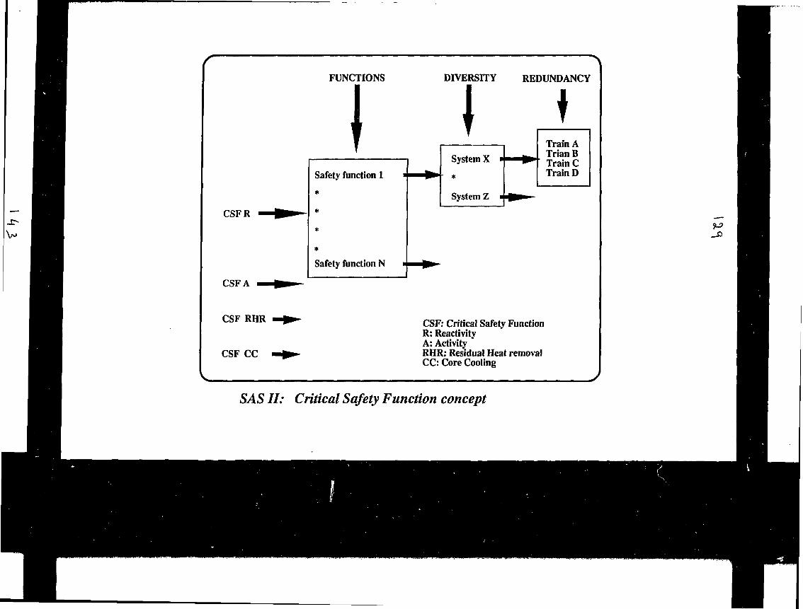
CSFR
CSF A
FUNCTIONS
Safety function 1
Safety function N
DIVERSITY REDUNDANCY
ISystem X
System Z
Train ATrian ВTrain СTrain D
CSF RHR
CSF CC
CSF: Critical Safety FunctionR: ReactivityA: ActivityRHR: Residual Heat removalCC: Core Cooling
SAS II: Critical Safety Function concept

PROCESS-VALUES
EXPERT SYSTEM
Signal-Validation
SYMPTOM SUPERVISION
PLANT STATE VECTOR
SYSTEM SUPERVISIONCREDIBILITYCHECK
Alarm-Generation
CONTROL-ROOM
w0
SAS Ii: Overview of the logic design
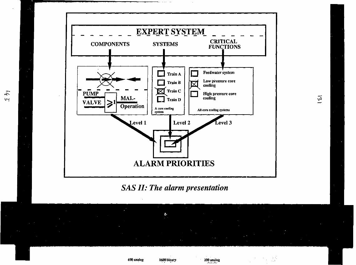
EXPE_RT SYS_TEM_COMPONENTS SYSTEMS
j l Train A
Г П Train В
Train С
Train D
iCRITICAL
FUNCTIONS
ÏPUMP
VALVE^ 1 Operation
1A core coolingsystem
I"*"] Feedwater system
Low pressure corecooling
\ | High pressure corecooling
All core cooling systems
evel 3
ALARM PRIORITIES
SAS II: The alarm presentation

600 analogsignals
1600 binarysignals
200 analogsignals
Processinterface
| i Front end '*
1 Main;i| computer
ETHERNET
ABB The Forsmark 2 computer system

SAS 2The Project Organization
STEERING COMMITTEE
REFERENCEGROUP
IPROJECT GROUP
TJ
WORKINGGROUPS
147

Project leader (Fonmark)Deputy project leader (Farsmark)SecrctarrfESK)
LOGIC SPECIFICATION
I&C Expert (ABB AUTO)OpcraHonal manager (Foranark 2)ShtRniperYinr (Fornnark 2}Reactor operators (Fortmark 1/2)
DISPLAY SPECIFICATION
Hunaa factor tpecIalUt (Stale power)Human bclor ipecUIIit (Ref. Body)ShtRiupcnrbor (Fornnark 2)Reactor operator! (Fonmark 112)
Plant emnpulcr expert (Fonraark)MMIeip«rü(IUIdín)Workitallati experts (Hewlett Packard)
VALIDATION SCENARIOS
Safety expert (ESK)
COMPACT SIMULATOR
Operation (Fornnark)Modification (Fonmark)Modelling (Studjvlk/EuroSIm)
VALIDATION
Suncrvlikm (Fornnark)Teat personnel (Fomnark 1/Z)Human bcUir ipeclalltt (Halden)Human factor ipeclallit (State Powtr)Human factor ipeclalllt (Re|.Bodj)
INSTALLATION
Malnlsnance rtalT (Forimark)
SAS II: The Project Task Teams

IAEA: Advisory Group Meeting15-19 June 1992
Presentation of the:Control Room Design for the
ABB Atom BWR 90
The control room design for the ABB Atom BWR 90 is a further development of dieForsmark 3 and Oskarshamn 3 control rooms. These control rooms are provided withmodern electronic for the I&C with CRTs for operator support functions and for controlof the control rods.The control room for BWR 90 is based on CRTs with a panel for overview presentation.The control room is the upper level of the digital I&C system.Hardware and software components and modules for this I&C are selected from the ABBMaster product family. Such components and modules are in use for many applicationsand can be regarded as proven design.The I&C contains sections and levels.
A typical I&C system has following sections:4 redundant sections for reactor safetyone section for reactor controlone section for turbine controlone section for service systems
With exception of the process interfaces all components including serial links areredundant within each section.
The I&C levels are:Distributed and microprocessor based interface modules to the processcomponents. The interfaces are standardized and one per process actuatoris used ("Component control")Distributed microprocessors for the logic and the signal treatment for processsystems ("System control")Microprocessors for plant control as automatic startup, shut-down or protectionComputer system for plant managementWorkstations for process supervision and operator supportOverview panel.
All levels are connected by redundant serial links.
In principle there are four working places for the operators as for reactor safety, reactorcontrol, turbine control and control of service systems.Workstations belonging to the last three mentioned working places are connected to thesame serial links. Workstations for safety are separated but information is transmitted by"one way" serial links to non safety equipment.
The control room is designed for one man operation during normal power operation.A typical control room shift consists of a turbine operator, a reactor operator, a shiftsupervisor and two field engineers. A safety engineer is on duty and can be called onshort notice.
A special desk is designed for the shift engineer and provided with communicationequipment, plant alarm initiation and CRTs for plant management.
Rooms are provided around the control room for crews comfort, storage fordocumentation, printers, work-permits handling and CRTs terminals for specialists.
Local control can be done from local control rooms or from the remote shut-downfacility. Testing of process components can be performed from the process interfaceunits.

BWR90: I&C SYSTEM
FP
J U L
!;,„ ,1
RPS
LOCALCR
R*not*ihuidowr
SAFETY SYSTEMS4 Identical sections
mJEU-
FPLOCALCR
mREACTOR SYSTEMS
crx:
1SEQUENCE UControl |
LOCALCR - FP
TURBINE SYSTEMS
—---FF-T
FPLOCALCR
SERVICE SYSTEMS
COMPUTER
SpecialInterface
Overviewpanel
CONTROL-ROOM
Workstations
PLANT MANAGEMENT
PLANT CONTROL
PROCESS-SYSTEM-
CONTROL (FP)
INTERFACE-MODULES (PIU)
ACTUATORSSENSORS
!&C LEVELS
ABB AtomASEA BROWN BOVERI

(1) (1)
(8) (7)
• i\—\
\ \-
(6) s11
-
(3)
(1) Safety Division(2) Auxilary Control Area(3) Turbin Control Area(4) Reactor Desk:(5) Control Desk:(6) Turbine Desk(7) IVEain D e s k(8) Electr Equipment
ABB ATOM Existing Forsmark 3 Control Room là II IIASEA BROWN BOVERI

Control Room forBWR 90 Generation

INTRODUCING A NEW CONTROL RQOM TECHNOLOGY
MUSTBE
- "TRANSLATE EXISTING DESIGN BASIS"
- MODIFY DESIGN BASIS TO THE NEWTECHNOLOGY
MAYBE
- INCREASING DIVERSITY
HANDLING OF "OUT OF DESIGN " ACCIDENTS
CANBE
- MORE OPERATOR SUPPORT
- MORE MAINTENANCE SUPPORT
ABB Atom BWR 90

COMMUNICATIONS AND MAN-MACHINE SUPPORT
SYSTEMS FOR CONTROL ROOMS
by J. Naser,Electric Power Research Institute, USA

EPRI/NPD
Communications and Man-MachineSupport Systems for
Control Rooms
Joseph Naser
Presented to IAEA
Instrumentation & Control075V/JAN/rgn 6Í9/92 1
EPRI/NPD
Major Components
Communications and computing architecture
Activities centered integrated workstation
Instrumentation & Control075V/JAN/rgn 6/9/92 2
EPRI/NPD

EPRI/NPD
Objectives of Integrating Systems
Improve plant availability and reliability
Reduce operation and maintenance costs
Reduce safety challenges
Improve performance with existing andnew equipment systems
Instrumentation & Control075V/JAN/rgn 6/9/92 3

EPRI/NPD
Background
Increasingly complex requirements ohoperations, maintenance and engineeringstaffs
Need for reliable, integrated, actual plantstatus information
Technology can be used to assist plantpersonnel and reduce likelihood of errors
Instrumentation & Control075V/JAN/rgn 6/9/92 4

EPRI/NPD
Communications and Computing Architecture
• Basic infrastructure on which I&C digitalupgrades will be integrated
• Allows information to be available whereneeded
• Based on open system protocols
Instrumentation & Control
Vr-f
075V/JAN/rgn 6/9/92 5

EPRI/NPD
Open System Architecture
л /I
(<
Os
Instrumentation & Control075V/JAN/rgn 6/9/92 6
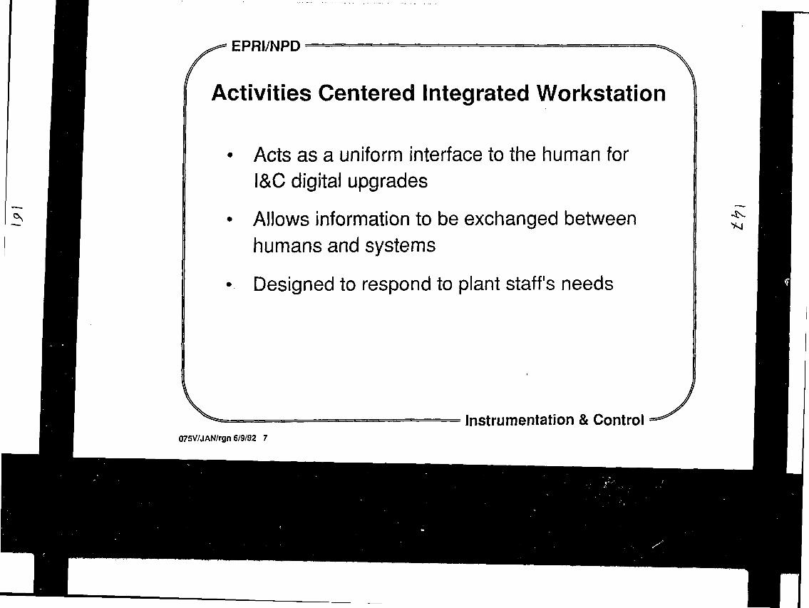
EPRI/NPD
Activities Centered Integrated Workstation
• Acts as a uniform interface to the human forI&C digital upgrades
• Allows information to be exchanged betweenhumans and systems
• Designed to respond to plant staff's needs
Instrumentation & Control
4S.
075V/JAN/rgn 6/9/92 7

EPRI/NPD
Activities Centered Integrated WorkstationEngineering
Instrumentation & Control075V/JAN/rgn 6/9/92 8

EPRI/NPD
Multiple Communications Systems
Digital data highways
Multiplexers
Single instrumentation loops
Strip charts
In situ measurements recorded on plant logs
Instrumentation & Control075V/JAN/rgn 6/9/92 9

EPRI/NPD
Information Increases
Between 1970 and 1985 between 5 to 10 timesmore analog and digital signals in German andFrench plants
Need architecture and man-machine interfaces tosupport higher information loads
Instrumentation & Control075V/JAN/rgn 6/9/92 10
EPRI/NPD

EPRI/NPD
New I&C Systems
Automation and computerization throughevolution rather than overall planning
Each new system viewed as isolated system
- interactions
- compatibility
- duplication
- interface design
Instrumentation & Control
vn
075V/JAN/rgn 6/9/92 11

EPRI/NPD
Current Situation
Isolated islands of computing
Heavily saturated networks
Duplication of information andfunctionality
Ineffective and incompatible networkprotocols
Inconsistent man-machine interfaces
Inappropriate operating systemsand/or hardware platforms •
Instrumentation & Control075V/JAN/rgn 6/9/92 12

EPRI/NPD
Motivation
"Unaddressed, a utility may be awash in a sea ofuncontrolled, single application databases andsystems based on micros, minis, and mainframecomputers. Each system will operate independentlyin its own unique manner, eventually leading tochaos. Only through long-range computerimplementation planning can the utilities avoid thisinevitable problem."
Electrical World
4;
Instrumentation & Control075V/JAN/rgn 6/9/92 13
EPRI/NPDl l ^

EPRI/NPD
Plant Architecture Plan
Acceptable hardware and operating systems
Man-machine interface standards
Network standards
Acceptable network protocols
Supported local area networks
Supported wide area networks
Network management systems
Instrumentation & Control075V/JAN/rgn 6/9/92 14

EPRI/NPD
Analog-Digital Communications Interactions
Plant I&C systems will not be totally converted todigital systems at once, if ever
Analog and digital systems need to work together
Instrumentation & Control075V/JAN/rgn 6/9/92 15

EPRI/NPD
Information Configuration Control
As is equipment and system status
Documentation
Drawings
Databases
Procedures
Automated aids
Human aids
Instrumentation & Control075V/JAN/rgn 6/9/92 16

EPRI/NPD
Architecture Methodology
Develop I&C Upgrade Plan
Determine information functional requirements
Inputs
- information requirements
- implementation schedule
- existing plant equipment
Output
- guidance for plant-specific communications andcomputing architecture
Instrumentation & Control075V/JAN/rgn 6/9/92 17
FPRI/МРП

EPRI/NPD
Status
Generic methodology for determiningplant-specific architecture is ongoing
Plant-specific architectures being developed
- Browns Ferry
- Calvert Cliffs
- Prairie Island
Architecture test bed development initiated
Instrumentation & Control
Ч5-А
075V/JAN//gn 6/9/92 18

ÊPRI/NPD
Activities Centered Integrated Workstation
Present integrated information for operations,maintenance and engineering staff
- Monitoring and control
- Alarms and alarm processing
- Normal, abnormal and emergency operatingprocedures
- * Equipment descriptions and plant drawings
Instrumentation & Control
и
07SV/JAN/rgn 6/9/92 19

EPRI/NPD
075V/JAN/rgn 6/9/92 20
Monitoring and Control
RCP0I4YCI1 RCP COMMANDE PRESSU ET R O P
4Ос Imcpbouüc I
|К1С RCP
ВП Г-
RCU-C
4 0 t
.. г)эие
Cft.lBRC ATROID I'l
[ Г53'8ÏJ
I 34411
I I I Л / 2 I S
i «н• i П . I
Л1МР
H > • П
''h
И l'fh
ft . • fl , A
M I'
..-I-,
ВРЯ 1 •
«СУ t •
Г«Ч
I t -,| |«.ни i s |
р||р
PII
•Ей EAU
0SÎP0 I
054P0 1
. I,
Instrumentation & Control
FPPI/МРП

EPRI/NPD
Alarms
|RCP9G?ftfi| |<NREF-NJ > MflX
р и trntiu" и rti ihim кии
RKfi COrnCCIt RU RCP
.51 PRESENCE flLflPME RCP96>W
flPPLlQUER flIO
.SI HBSCriCC RLflPHC RCP96Jf»
t<nc COIDUHC OuC RRfl ICN CONNECTE Ш RCP
| RBO HQH COf CCfC ЯЦ PCP |
.COMIROLCFt Lfl COnSICIC NlVCW PRtSSU
.CONTROLE» CE K B I T CHPHU, ET OCCHflfiGE
.RfVCHER LE N lutflU PRCSSU Й ЪЙ UflLEUR DC С0И51СКPAR LU HCU272UP CH WtUCL
.ISOLER Lfl 0ССНЙКСЕ SI HCCESSfllPt
.CWTftOLEK L EVOLUTION DCS HIUCOUX PUISfl«DS
.FfllRC U l B I L W DC ruiTC PRIHMIRE
I it.I l-JHiidi
р. .к,..*-."1 •'.
I Г I i
' cmiLgutncci Hi oc LU DCCHMCC
n иI S
r<..biie.itlufi s и Г.аы м е н снмсе iNSurriswi.ruittкипе / «»сп2 ppimtre.rcetc кгигсетят тпнше
EXT|2S Û "•
Jj°l4ftpi 4*O*IT
D Г01 CHHRCE
[*6.7ныЛD DCÇHWGC
«s214
•re211S5
212К
2IS
•S
216
«S
.14 4 4 П M|í|i-ii-ji-ii-ii-i ^
Instrumentation & Control075V/JAN/rgn 6/9/92 21
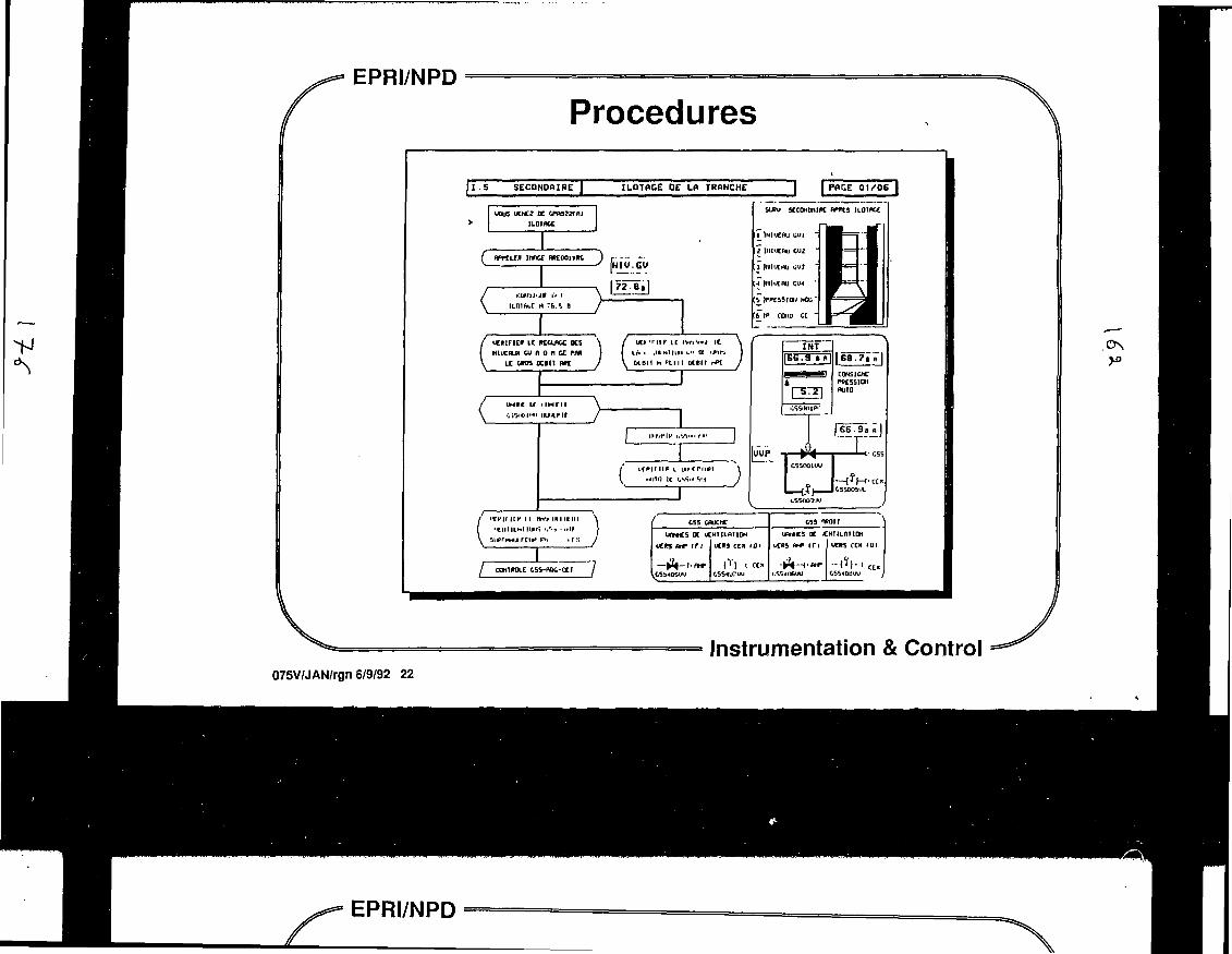
EPRI/NPD
075V/JAN/rgn 6/9/92 22
Procedures
II.S SECONDAIRE I ILOTACE DE LA TRANCHE PACE 01/06
ucus ллг к ичаггнн
С inncc MtcooiriK[HIV.CV
Iисщп» LC ксаясс K SN1UCIUI ШАОЛСЕРЯ
LC «05 m i l me
SUAI 5CCDHDRIK flTttCS НОТИСЕ
uC» •' 1И 1С I'H-I'»I>.I 1С
ÙCBI1 M P U I I LCBII r̂ >t
/ IHIC If ИНГИ
IIP I l ÜI1VII I I I II
CONlROLt C5S-nDC-CCT
\ ШИП DC C'i'i.-f'S'.l j
I
WMCS DC kCHIILRIIOH
-Л-t-fl
URMCS DC JCHIILnilDN
CSS40UUU }
Instrumentation & Control
O N
EPRI/NPD

EPRI/NPD
Equipment Information
Descriptions
Drawings
Actual current status
Procedures
Technical Specifications
\ A )
Instrumentation & Control075V/JAN/rgn 6/9/92 23

EPRI/NPD — — ~ — " "
Activities Centered Integrated Workstation(Continued)
• Control capabilities
• Customized information and display management
• Aids to perform routine activities
Instrumentation & Control075V/JAN/rgn 6/Э/92 24
EPRI/NPD

EPRI/NPD
Activities Centered Integrated Workstation(Continued)
Assistance in diagnosing problems
Aids for decision making
Easily maintained and modified
Free operations, maintenance and engineeringstaff to perform the important aspects or their job
Instrumentation & Control
\ n
075V/JAN/rgn 6/9/92 25

EPRI/NPD
Workstation Access
Workstations located wherever desired
Utilized by operations, maintenance andengineering staff
Main vehicle for upgrading control rooms
Security to assure only intended functionsmay be performed
Instrumentation & Control075V/JAN/rgn 6/9/92 26

EPRI/NPD
Capabilities for Different Users
Engineering
оо о
Уо•
О•
о•
Operations Maintenance
Instrumentation & Control075V/JAN/rgn 6/9/92 27

EPRI/NPD
Opportunity
Plant computer replacements
Advanced workstations beingdeveloped and utilized
- Petrochemical facilities
- Fossil plants
- Foreign nuclear plants
DOE upgrading plants
o o
Instrumentation & Control075V/JAN/rgn 6/9/92 28

EPRt/NPD
Design
Comprehensive design for integrated workstation
- Identify important characteristics
- Allow piecewise enhancements of workstation
- Assure integration of all capabilities
- Allow easy modifications to satisfy user needs
- Include isolation and security capabilities
Instrumentation & Control
ч
075V/JAN/rgn 6/9/92 29

EPRI/NPD
Common Interfaces
Monitoring
Display aids
Diagnostic aids
Decision aids
Control
Instrumentation & Control075V/JAN/rgn 6/Э/92 30
FPRl/NPD

EPRI/NPD
Possible Configurations
Instrumentation & Control065V/JAN/rgn 5/12/92 31

EPRI/NPD
Key Characteristics
Flexibility
Expandability
Toolbox of tools to assist utility staff
Security
Instrumentation & Control075V/JAN/rgn 6/9/92 32

EPRI/NPD
Status
Performing an international survey on relatedtechnology
Developing workstation design
Developing soft control requirements andcapabilities for reactor water cleanup (RWCV)system
Integrating monitoring and control capabilities forreactor water cleanup system
• Integrating computerized aids (e.g. EOPTS, APDS)
Instrumentation & Control075V/JAN/rgn 6/9/92 33

EPRI/NPD
Benefits from Tailored Collaboration Activities
Architecture
-- TVA plant-specific architecture
-- BG&E plant-specific architecture
Workstation
-- SCE&G Operator Assisted Workstationincluding (APDS, REALM)
- TVA EOPTS
- Con Ed KATO
Instrumentation & Control
.;• 1
075V/JAN/rgn 6/Э/Э2 34

NATIONAL PRACTICES AND APPROACHES ON
CONTROL ROOMS SYSTEMS AND C&l SYSTEMS
FOR CANADIAN CANDU NUCLEAR STATIONS
by R.A.OImstead,AECL CANDU, Canada
I?-*-
National Practices and Approaches
Control Room Systems and C&I Systems
for
Canadian CANDU Nuclear Stations
by
R. A. Olmstead
IAEA AGM
on
Guidelines for Control Room Design
Vienna
1992 June 1 5 - 1 9
GE1
Я2ХН/700amai
INTRODUCTION
Atomic Energy of Canada (AECL) has developed an evolutionary Advanced PWR that meets
most of the EPRI APWR requirements Ц ] .
A design team has completed 60% of the detailed design for the CANDU 3 - a 450 MW(e)Pressurized Hesvy Water Reactor (PHWR) that is presently undergoing the NRCprelicensing process. It was realized that advanced digital systems technologycould be applied to achieve substantial benefits for an electrical utility operatinga CANDU 3 plant or retrofitting CANDU 3 technology in older plants.
Some of the benefits that have emerged from the design are the following:
• Operators have several hours to think and plan before they need to take
any action during design basis accidents.
• Virtual elimination of unsafe equipment failures in protection systems
and other safety critical systems.
• Facility for operations staff with no programming experience to define orreconfigure the plant display and communication.
• Reduced frequency of forced outages.
• Fewer maintenance manuals and maintenance procedures because of reducedISC component count and component diversity.
• Obsolescence protection because open architecture principles were pursuedfrom the start.
• Reliability because systems integrate off-the-shelf components that havebeen proven in previous demanding industrial applications.
• Substantial reductions in capital, operating, construction, andsimulation costs.
These benefits have been achieved from the design and application of digitalsystems. The paper will describe these systems in sufficient detail to quantify thebenefits and identify the innovative design and application features from which theywere derived.
CONTROL CENTRE
GENERAL LAYOUT
Like earlier designs, the CANDU 3 control centre is designed to be operable by asingle first operator, who normally interacts with and is supported by additionalstation staff. Sufficient workstations are provided in the main control room toaccommodate a variable staff complement. These workstations provide access to theprincipal control room functions: plant control, safety systems control, monitoringand testing, fuel handling, emergency communications and plant state monitoring anddiagnosis. Multiple redundant access points are provided to the various functions.A centrally located sit-down console provides visual access to other workstationsand has a computerized interface which supports normal plant operation. Figure 1illustrates the general layout. The mezzanine level is an optional feature forutilities that desire extra maintenance, planning, work control and emergencyresponse facilities in close proximity to the control room.
92200VTO0Obsnd

HUMAN FACTORS
In consonance with growing awareness that the human operator is an integral part ofthe overall human-machine system, with special 3trength3 and weaknesses, humanfactors engineering is receiving significant attention in the design of thehuman-machine interface. For the CANDU 3, a Human Factors Engineering Program Plan[2] documents, up-front, the overall HF Engineering process, the associateddocumentation requirements, and the HF engineering standards to be followed in allstages of plant design.
ADVANCED FEATURES
A unique and powerful feature of existing CANDU stations is the relatively highdegree of automation and the fact that the dynamic plant state is represented indigital computer memory and logic. Exploiting this advantage and the rapidevolution of digital technology, CANDU 3 designers have evolved the CANDUhuman/machine interface to achieve substantial safety and operational benefits.Some of the most significant features and benefits are the following:
• Time for Operators to Think and Plan
For the design basis events, the period of time for which operatorintervention is not required has been extended from 15 minutes to over8 hours for the CANDU 3.
• Substantial Reduction in Panel Complexity
Many of the fixed indicators and controls have been eliminated from thepanels in favour of interactive CRT stations. Large mural mimic displaysin the control room communicate overall plant status and support groupdecision making.
• Substantial Reduction in Instrumentation Complexity
The replacement of trunk cabling, relays, timers, comparators, etc. withdistributed control processors has resulted in a significant reduction inthe CSI hardware component count and the diversity of equipment andsuppliers.
• Automation of Error Prone Tasks
The objective is to relieve the operator from boring, stressful, timeconsuming tasks so that he has time to perform as a situation manager.An example is the automation of the periodic testing for the CANDU 3afetysystems.
• Integrated Emergency Response Facilities (ERF)
The CANDU ERF is an extension of the comprehensive information managementfacility available in CANDU control гоотз. In the unlikely event of anaccident, the operating staff will be familiar with the facility andconfident of its availability.
• Procedure Driven Displays
The Control Centre interactive CRT displays are designed to support thetasks called for in the station procedures, organization, and operatingpolicies.
Í23W00(МпжаЛ
mow» ,
922ЯН/700СЛаяаЛ

• Critical Annunciation
During major plant disturbances a facility will be provided to provide
operators with a short list of priority alarms related to a set of
predetermined critical safety parameters and emergency operating
procedures.
PLANT DISPLAY SYSTEM (PDS)
The PDS is the computerised system which forms the interface between the operatorand the digital equipment controlling the plant. The PDS must present displays andcontrols to the operator which will support operational tasks and objectives in asuitable manner. Equally, the PDS must interface with the digital control equipmentsystem of the DCS.
Figure 2 is a schematic diagram of the PDS system. In this design, the two PDS database computers located in the Main Control Area (MCA) and labelled PDS X and PDS Y,obtain most of the plant data through a pre-processing computer from the DCS. Thebalance of the plant data - that associated with the Special Safety Systems - isobtained from the field through a similar set of data base computers called theSafety System Monitor (SSM) . The PDS data base computers transmit plant informationonto redundant Local Area Networks (LANs) and the data on these LANs is used by fiveoperator workstations to produce the display and supervisory control interfacebetween the plant and the operator. Each of these workstations consist of threeCRTs, a function keyboard, and a graphics positioning device.
In a similar fashion, information from the SSM can be routed to two operatorworkstations, one in the MCA and one in the Secondary Control Area (SCA) . Note thatthe workstation in the MCA which is available for SSM information can be switched tothe PDS LAN to operate like any of the other workstations on the PDS LAN.
Utilities will make frequent changes to the plant display system. So this systemmust be based on hardware and software which are open in architecture and adhere tocomputer industry standards. Fortunately, such open systems are readily availableat this point in time as the computer industry moves into portable operating systemsand languages, standard communication interfaces, standard Graphical User Interfaces(GUIs), families of compatible computer hardware and re-usable software components.
The hardware architecture is an open network of computers which provides anexpandable and flexible platform for the PDS software. Each of the nodes on thenetwork are industrially hardened general purpose computers drawn from a family ofcomputer products. The network which connects these computers is an industrystandard LAN. Drawing from a family of computers and using a standard LAN allowsPDS to be adapted as either a small and inexpensive display system or a large andpowerful system.
Once the system design for the PDS has been chosen, drawing the hardware platformfrom a family of computers means that the actual hardware installed at the plant canbe chosen later in the design when the requirements for the PDS have been veryfirmly established. Development work can proceed on a "target" machine with theknowledge that this machine will probably be upgraded later in the deeign cycle.
The LAN backbone to thie design means that additional display capability can beadded to the basic system to accommodate special operating modes and requirements.For example additional display workstations can be brought into play, to accommodatethe work associated with a unit commissioning or unusual shutdown maintenanceactivities.
naot/xnOtmadчтлтатм ,

( îo
The system design is such that the «hole syetem can function in a closely coupledfashion much like a Multiprocessor computer. This combination of features enablesthe standard CftNDU 3 product to be applied to a wide range of operator interfacesituations in other nuclear and. conventional plant applications in addition to thecontrol of a CANDU plant.
In contrast to the experience of previous projects, the cost reductions associatedwith display computer hardware coupled with the wide availability of acceptabledisplay computer products has meant that the software component has come to dominatethe economics of the design. A prime consideration in the choice of hardwareplatform has become the availability of adequate software development and managementtools as well as the existence of operating system,- languages and re-usable softwarepackages conforming to recognized standards.
Widely used commercial, off-the-shelf, software components will be used to constructthe PDS software. For example, for the PDS software, we expect to use the PortableOperating System Interface (POSIX) standards for the Operating System. POSIX is aset of related sub-standards which define those aspects of an operating system whichshould be employed to ensure that applications written for one POSIX compliantoperating system can be easily ported to another such system. At the time ofwriting, one of the POSIX sub-standards, IEEE Std. 1003.1-1988, С LanguageInterfaces to the Operating System, has been issued while other essentialsub-standards such as Shell and Utility Facilities and Realtime Facilities arenear ing completion.
An industry standard windowing environment such as X-Windows and Open Look or Motifwill be adapted to the particular needs of the control room operator. X-Windows hasbecome the standard windowing software for workstation and larger environments whileOpen Look and Motif are the two foremost competitors for the window manager softwarewhich gives the "look and feel" to the windowing environment. Despite the fact thatwe are using standard window software as the display engine, we do not expect theoperator to navigate through the plant displays with overlapping windows and amouse. The display stations will be customized to give the operator a convenientinterface oriented toward the task of power plant operations.
The language of choice used in software development will be one or more of the ANSIstandard language. There are several choices in this category including thelanguage С which is the most widely used language for display software at this time.
The use of open hardware architecture and adherence to computer industry standardswill provide a PDS which will satisfy present applications and provide for futureexpansion and upgrades in computer technology without change to the basic PDS systemdesign.
DISTRIBUTED CONTROL SYSTEM (DCS)
SCOPE
Data acquisition and process control functions for the non-safety systems areperformed by an advanced distributed digital control system.
The scope of the DCS data acquisition functions include change-of-state eventdetection and time stamping, for selected binary input signals, including bufferedbinary input signals from the independent Group 2 systems, and for selected computedbinary signals. The time stamped event data is transmitted to the PDS for alarm andevent reporting functions.
Improveconnectcompren
BENEFll
The us|and pithe fo
922004/700OUmmi
922QM/7OOObnal

The DCS control functions include low-level control and interlocking functions forindividual process devices such as pumps and valves, as well as high-level controland co-ordination functions for groups of devices and systems. Examples of the highlevel group control functions are reactor regulation, heat transport system pressureand inventory control, and steam generator level control. The scope of the DCScontrol functions includes manual and automatic control modes. Control modechanges, setpoint changes, and manual control actions are executed by the DCS inresponse to operator control commands received from the operator interface systemsand devices.
CONCEPT
The DCS consist of a number of signal scanning and processing stations linked byhigh performance data highways. Process instrumentation and control devices areconnected to stations assigned to specific plant areas and functions, in" order toreduce the amount and complexity of plant cabling and wiring. An optimum compromisehas been made between geographic and functional partitioning. In order to provideadequate reliability and minimize the need for separate manual backup, the system isdivided into three separate channels to match the channelization of redundantsensors and process devices. Within each channel, redundancy, self-checking, andautomatic switchover concepts are used to provide a fault tolerant system. Datalinks are provided between the three channels to allow the transfer of signal valuesbetween the channels. These data links are redundant and buffered, to avoidcompromising system reliability.
Figure 3 shows the DCS layout in the CANDU 3 plant and the DCS system.
The specific functions for each process system are implemented by applicationprograms installed in the system. The programs are designed and constructed byprocess control engineers in accordance with the process system design requirements.
BENEFITS
The DCS concept makes a significant contribution to the reduction of project costand schedule. The plant construction and commissioning schedule is reduced by atleast 2 months, due to the reduction in site cabling and wiring, and by morecomplete system testing before installation. The design costs are reduced due tothe use of a functional process control language and computer aided design methods.Equipment cost, design cost and maintenance cost are all reduced by increased use ofup-to-date standardized equipment.
Improved reliability is obtained by the elimination of a large number of wiringconnections, and by the use of proven standard electronic devices, continuouscomprehensive self checking and more comprehensive redundancy and channelization.
DIGITAL PROTECTION SYSTEMS
BENEFITS
The use of computers in nuclear plant safety systems offers a number of operationaland plant maintenance benefits. An improved, computer-based operator interface hasthe following benefits:
Reduces routine operator workload.
Reduces number of operating errors.
9230OV70OOUonaJ

Allows the operator to concentrate on the more technically challenging
issues.
The more significant plant maintenance benefits include the following:
A higher safety system reliability due to reduced equipment wear-out.
The ability to perform on-line self checking and self testing resultingincreased assurance that the system i3 operating satisfactorily.Potentially unsafe failures are converted to safe failures by trippingthe channels in accordance with the fail-safe philosophy.
Flexibility in accommodating different plant operator conditions, thus
optimizing both safety and production margins.
Historically, CANDU was among the first reactors to include computers in safety
systems with the PDCs (Programmable Digital Comparators) used in the CANDU 600
reactors (early 1980s).
The operating statistics indicate a significant contribution to plant safety. Thethree CANDU 600 stations (Wolsong 1, Gentilly 2, and Point Lepreau) have a total of288 PDC-years of operating history without a single unsafe failure reported. AllPDC failures have been safe failures which can be contrasted with the experiencewith the conventional portions of the system where about 1/4 of the failures arepotentially unsafe; i.e. temporarily diminish the redundancy of protection, untilcorrected. This is due largely to the design that employs features such asself-checks, ^continuous" testing, hardware watch-dog timers, etc. which convertdetected unsafe faults into safe failures (i.e. trip the channel) . From theproduction reliability viewpoint, there have been no spurious reactor tripsattributed to PDC related failures.
This experience has confirmed our original reasons for using computers, that theyenhance safety availability (convert unsafe failures into safe ones), and alsoimprove production reliability.
ASSURANCE OF ADEQUATE SOFTWARE QUALITY
Software quality became a major regulatory issue that affected the start-up of the3500 MW Darlington Generating Station in Ontario, Canada. The main issues were:
• no agreed upon, measurable definition of acceptability existed for theengineering of safety critical software;
• no widely accepted and adopted practices for the specification, designverification and testing of safety critical software existed;
• it is not possible to quantify the achieved reliability of the softwarecomponent of a safety system;
• it is not possible to quantify the benefits of из ing diverse software;
• it is not possible to exhaustively test software in all of its possiblemodes; thus it is unclear what constitutes a sufficient degree oftesting.
Because of these issues, obtaining a licence from the regulatory authority, theAtomic Energy Control Board (AECB), for the Darlington shutdown system tripcomputers was difficult. Several additional design and verification processes werebacJcfitted after the original software development process was completed. The keyadditional processes were:
ACK
REE
1 .
922004/700
тагат .Я2ХМ/700Obnad
man» -,

• preparation of a mathematically precise software requirements
specification;
• formal verification of the code against the requirements specification;
• statistically significant trajectory based random testing to demonstrate
that the software reliability wae consistent with the system reliability
requirement;
« hazard analysis of the code to identify failure modes that may lead to an
unsafe event.
The approach adopted by Atomic Energy of Canada and Ontario Hydro is composed of
five distinct processes.
The first process in the C&NDU 3 approach is to establish guidelines forcategorizing software according to the nuclear safety impact of a potential failureand the safety related reliance placed on the system of which the software is part.
The second process in the CANDU 3 approach is the preparation of software standardsand tools. Thera are a large number of existing software standards (IAEA, IEC, IEE,ISO, NUREG and CSA), many of which contain useful elements. However, we have foundthat there is no acceptable, directly applicable standard for the completedevelopment life cycle of safety system software.
The third process is to establish the requirements for safety system software. Thesubset of the software which is critical to safety is restricted to the absoluteminimum and is segregated from non-critical software.
Unambiguous, rigorous specifications are prepared in the early design phases. Suchrigorous specifications can be analysed to ensure that requirements are correct,consistent and complete. This minimizes the transmission of conceptual errors intothe detailed design stages, and facilitate verification of the software against thespecification.
The software is produced according to modern software engineering techniques and aset of established CANDU software design principles to achieve a fail-safe androbust design. Modern software engineering techniques produce, for example, awell-structured design with cohesive software modules and clearly defined minimalcoupling between those modules. The design principles ensure, for example, thatdiversity in software and hardware is used where appropriate to minimize common modeerrors.
Finally, the completed software product is subjected to multiple levels ofsystematic verification and testing. The normal software testing levels of unit,integration and system testing are performed using automatic tools where possible.In addition, each stage in the development process is systematically verifiedagainst the previous stage.
ACKNOWLEDGEMENTS
The author wishes to acknowledge the work of the following individuals at AtomicEnergy of Canada and Ontario Hydro from which the contents of this paper werederived - N.M. Ichiyen, G.J. Hinton, P. Joannou, W.R. Whittall, J. Pauksens,R. Hohendorf, D. Chan, S. Malcolm.
REFERENCES
1. K.R. Hedges, M. Bonechi, E.M. Hinchley, "Meeting ALHR Requirements with theCANDO 3", presented at the Joint ASME/IEEE Power Generation Conference,Boston, Massachusets, 1990, October 21-25.
9Э20О</70ОО Ь а Ы«ЗЛ2ЛИ ,
Окотпаи

2. Beattie, J.D. and Malcolm, J.S. (1991) Development of a Human FactorsEngineering Program Plan for the Canadian Nuclear Industry. Proc. 35th AnnualConference of the Human Factors Society.
3. E.F. Fenton, L.R. Lupton, J. Pauksens, "Evolution of the CANDU Control CentreDesign Process", presented at the Canadian Nuclear Society Annual Conference,Saskatoon, Saskatchewan, Canada, 1991, June.
4. Nuclear Power Oversight Committee, "Strategic Plan for Building New NuclearPower Plants", 1990 November
5. G.J. Hinton, "A Plant Display System to Complement the Distributed ControlSystem in CANDU Nuclear Power Plants", presented at the IAEA Nuclear PowerPlant Control and Instrumentation Specialists' Meeting on Distributed ControlSystems, Communications and Data Transfer within NPP, Lyon, France, 1990April 24-26.
6. G.J. Hinton, S.H. Kendrick, T.W. Shields, S. Schafer, "Use of Computers inCANDU Shutdown Systems - An Overview", presented at the IAEA SpecialistMeeting on the use of computers in Safety Critical Applications in NuclearPower Plants, London, England.
7. P. Joannoou, J. Harauz, D.R. Tremain, L.T. Fong, M.E. Saari, A.B. Clark,Standard for Software Engineering of Safety Critical Software", Rev. 0, 1990December.
8. W.R. Whittall, "Reliability and Safety Features in the Distributed ControlSystem for the CANDU 3", presented at the IAEA Technical Committee Meeting onthe Safety Implications of Computerized Process Control in Nuclear PowerPlants, Vienna, Austria, 1989, November 13-17.
922004/700С Л а
/u
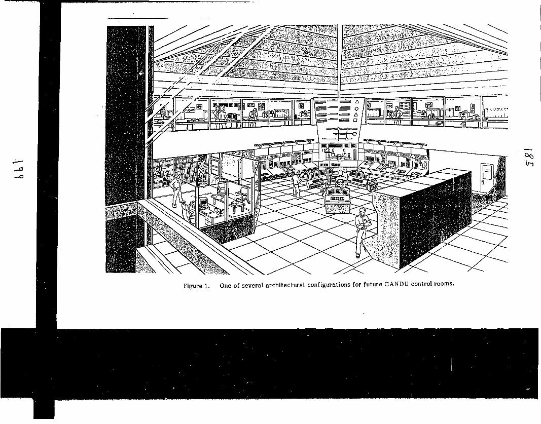
Figure I. One of several architectural configurations for future CANDU control rooms.

DCS DATA HIGHWAY
IPRE4
ROCESSOR
PD
X
MCA
SCA
LANsSUPPLEMENTARYWORKSTATIONS
-im
[
SAFETYSYSTEM
M0N1TORX
OOOOOO
pool FUEL HANDLINGWORKSTATION
OQOJ
ooo
GROUP 1WORKSTATION
GROUP2WORKSTATION
SSMX J ^ л ^ S S M Y
PDS
'
У///////////////Л
SCA WORKSTATION
OOOSSMX SSMY
SAFETYSYSTEM
MONITORY
DCS: Distributed Control SystemMCA: Main Control ArcaPDS: Plant Display SystemSCA: Secondary Control AreaSSM: Safety System Monitor
Figure 1. - Plant Display Systems
Figure 2. Plant Display System Computer Architecture

83-
ADMIN.BLDG.
AUXILIARIESBUILDING
DCS LINKS —
GROUP 2 LINKS "
SAFETY SUPPOFSYSTEMS
REACTORBUILDING
I MAIN•CONTROLJ AREA
(PDS)
TURBINE -GENERATOR
BUILDING
Figure 3. Distributed Control System

STATE OF THE ART CONTROL ROOM TECHNOLOGIES
IN JAPAN
by Y.Fujita,Mitsubishi Atomic Power Industries.Inc.
£ < э £

STATE OF THE ART COHTEOL ROOM TECHHOLOGIES IN JAPAH
Abstract
Both PWR and BWR utilities and vendor groups have completed the
development of new advanced control rooms (ACR) for APWR and BWR. The ACR is
characterized by a compact CRT-based operator console which requires only one
operator to control the whole plant. Touch-sensitive screens are used for
soft-control operations. Results of a validation test indicated that ACR has
a good potential for operational improvements, yet there are some problems
that need to be resolved before actual implementation.
The Kansai Electric Power Company, a leading PWR utility, introduced an
alarm handling- system called DPAS to Ohi Unit-3. DPAS can reduce alarms by up
to 85% during major transients. All the new PWRs will adopt DPAS and
retrofitting to existing plants is being discussed.
Both PWR and BWR vendor groups have recently completed a seven-year
government sponsored project for knowledge-based operator support systems. A
variety of support functions have been developed and tested, and are ready for
production design with some improvements and modifications.
It seems Japan has reached a point where the country begins to seek a
better form of new technologies for actual implementation. More user-oriented
approaches are the key factors in that process.
%оЪ
STATE OF THE ART CONTROL ROOM TECHNOLOGIES IN JAPAN
Yushi FujitaMitsubishi Atomic Power Industries, Inc.
4-1, 2-Chome, Shibakouen, Minato-ku, Tokyo 105, Japan
The purpose of this memo is to give a brief summary of astate of the art control room technologies in Japan. Topicsinclude the following:
- advanced control room- alarm handling system- knowledge-based operator support system- control room environmental design- relevant human factors research
Japan has been and still is very active in the field ofcontrol room and relevant technologies. It seems we have reacheda point where we begin to seek a better form of the control roomtechnologies. What it means is the need for shifting thetechnical emphasis from technology-oriented approach to trulyuser-oriented approach.
Advanced Control Room
Both PWR and BWR utility and vendor groups have completedthe development of new advanced control rooms (ACR) for APWR andABWR. [1],[2]
ACR is characterized by a compact operator console whichrequires only one operator to control the whole plant. Itfeatures the almost total elimination of conventional hard-wiredinstruments. This is accomplished by the soft-controltechnology using a touch-sensitive screen mounted on Cathode RayTube (CRT).
Г*"An experimental validation test using a prototype ACR
developed for A^WR has demonstrated that the new control room hasa good potential for benefiting operators. Nevertheless, thereare some problems that need to be resolved. [3]
Alarm Handling System
The Kansai Electric Power Company (KEPCO)introduced an alarmhandling system called DPAS (Dynamic Priorities Alarm System) to

И.1
Ohi Unit-3, the latest 1,100 MWe four-loop PWR. KEPCO and otherPWR utilities haï?'* decided to introduce DPAS to all the newplants. Retrofit to existing plants is also being discussed.
DPAS features simple scenario independent alarm handlinglogic and a special dynamic color coding scheme.[4] DPAS canreduce the number of alarms up to 85% during major transients.Experimental study has shown that this enhances operatorperformance significantly (e.g., time to detect secondaryfailures is reduced). On-site testing conducted recently duringtransient tests of Ohi Unit-3 has revealed that DPAS functions asintended.
The Tokyo Electric Power Company plans to introduce animproved alarm system to ABWR. [2]
Knowledge-Based Operator Support System
Both PWR and BWR vendors have completed a 7-year governmentsponsored project for knowledge-based operator and maintenancepersonnel support systems in early 1992 (MITI Man-Machine SystemProject).[5] A variety of support systems have been developed.
For PWRs the following systems have been developed:
<Normal Operations>
- planning and follow-up of restart operation following atransient
- planning and follow-up of load-follow operation- follow-up of start-up and shut-down operations
<Abnormal/Accident Operations>
- model-based intelligent interface- diagnosis- guidance- verification of prescribed automatic actions- follow-up monitoring of manual actions suggested by the
system- prediction of several prescribed parameters
An experimental validation test conducted at the end of theproject has shown that many of these functions are potentiallybeneficial and operators liked them. Nevertheless, more effortsneed to be made before actual implementations. [3]
Control Room Environmental Design
The Ohi Unit-3 control room is one of the first control
â*s

rooms which incorporate aesthetic considerations. Colorcoordination and room configurations (e.g., ceilingconfiguration) are designed such that they match operators'subjective preference. The semantic differential method andfactor analysis are used to identify operators' image patterns.
In a government sponsored project recently launched, theeffect of lighting is being studied from the viewpoints ofpsychological and physiological influences.
Relevant Human Factors Research
A variety of human factors research is being conducted bymany organizations which include public/semi-public institutes(e.g., JAERI, NUPEC/IHF), a utility-founded institute (i.e.,CRIEPI), universities, and vendor groups. [6]
One ambitious attempt is being committed by NUPEC/IHF. Ithas launched a 6-year, multi-billion yen project in which alarge-scale experimental facility will be constructed and usedfor a variety of human factors experimental studies.
Topics of these human factors research include:
- collection/validation of human reliability data- development/validation of HRA methodology- development of cognitive models- study of important performance shaping factors [7]- development of design guidelines for advanced human-machine interfaces
- mental workload, etc.
References
[1] T. Nitta and others, "Development of advanced main controlboards for APWR," presented at the OECD/NEA-IAEAInternational Symposium on Nuclear Power PlantInstrumentation and Control, Tokyo Japan, May 18-2Г.
[2] K. Iwasaki and Y. Shirakawa, "Development of ABWR TypeControl Room Panels," presented at the OECD/NEA-IAEAInternational Symposium on Nuclear Power PlantInstrumentation and Control, Tokyo Japan, May 18-21
V.i'W-
[3] Y. Fujita, "Time for tailoring human-machine interfacetechnology to humans," presented at 1992 IEEE FifthConference on Human Factors and Power Plants, Monterey, CA,U.S.A., June 7-11, 1992.
[4] Y. Fujita, "Improved Annunciator System for Japanese
Pressurized-Water Reactors," Nuclear Safety, vol.30, No.2,pp.209-221, April-June, 1989.
[5] N. Naito and others, "Advanced man-machine system for nuclearpower plant operation and maintenance," presented at theOECD/NEA-IAEA International Symposium on Nuclear Power PlantInstrumentation and Control, Tokyo Japan, May 18-2Г.
[6] H. Isoda, title not finalized (as of June 5, 1992), presentedat 1992 IEEE Fifth Conference on Human Factors and PowerPlants, Monterey, CA, U.S.A., June 7-11, 1992.
[7] Y. Fujita, "Ebunka: Do cultural differences matter ?" presentedat 1992 IEEE Fifth Conference on Human Factors and PowerPlants, Monterey, CA, U.S.A., June 7-11, 1992.
2 o?

IAEA CONTROL ROOM DESIGN GUIDELINES
SOME REQUIREMENTS FOR CR DESIGN GUIDELINES
CRS RATHER THAN CR OR CR EQUIPMENTCOGNITIVE FACTORSRELEVANT TECHNOLOGIES ARE EVOLVINGCORE TECHNOLOGY (CR TECHNOLOGY) IS NOTYET FULLY UNDERSTOOD
DESIRABLE FORM OF CR GUIDELINES
MAINTAIN A GENERAL FRAMEWORK FOROVERALL CRS DESIGN WHICH ALLOWS:
• BALANCED APPROACH- CHANGE OF RELEVANT TECHNOLOGIESDUE TO EVOLUTION
-0
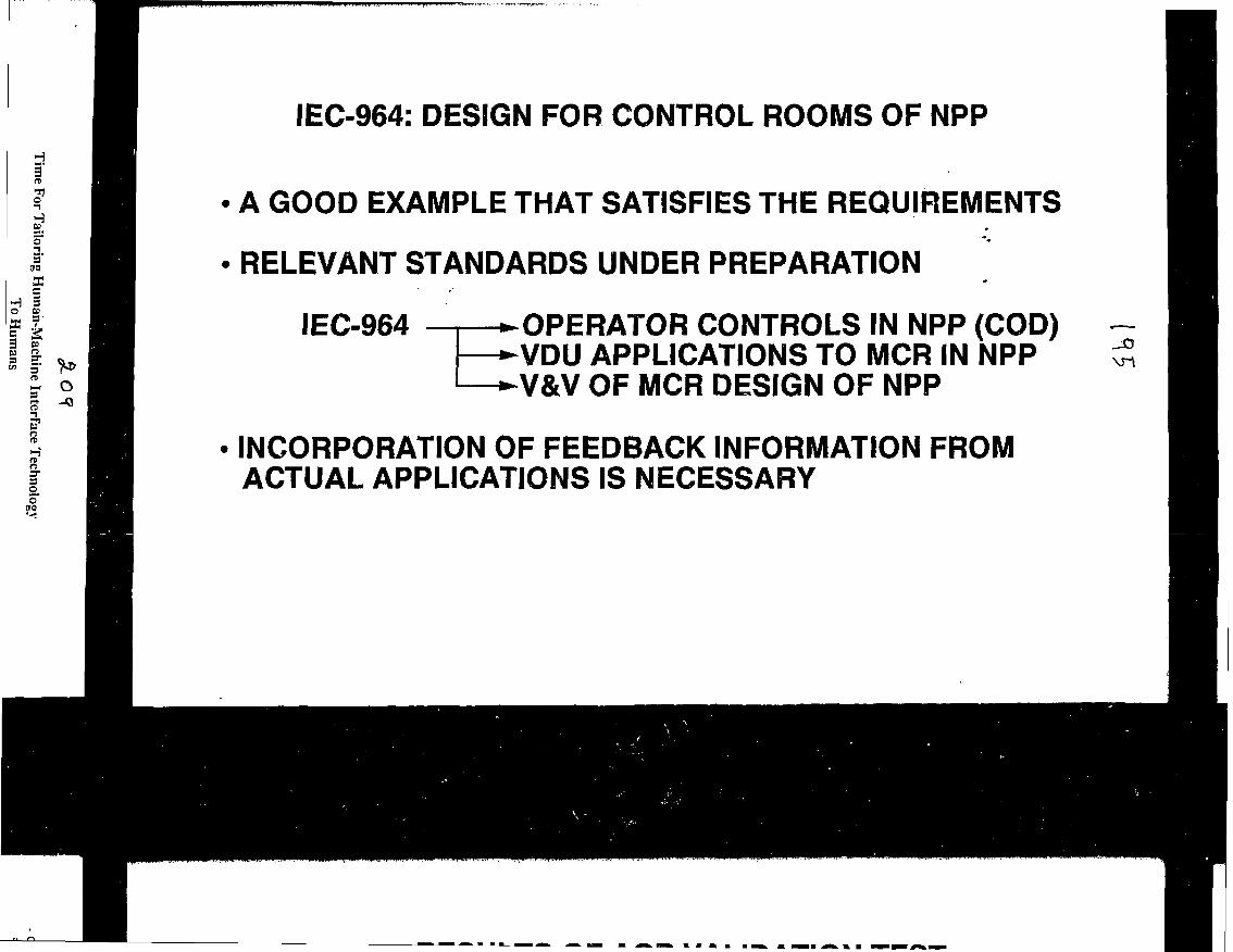
IEC-964: DESIGN FOR CONTROL ROOMS OF NPPH
TI
era
SIс
° If I
* 2S 5
n
5"S3
A GOOD EXAMPLE THAT SATISFIES THE REQUIREMENTS
RELEVANT STANDARDS UNDER PREPARATION
IEC-964 •OPERATOR CONTROLS IN NPP (COD)*VDU APPLICATIONS TO MCR IN NPP*V&V OF MCR DESIGN OF NPP
INCORPORATION OF FEEDBACK INFORMATION FROMACTUAL APPLICATIONS IS NECESSARY
\n

RESULTS OF ACR VALIDATION TEST
ONE OPERATOR CAN CONTROL THE PLANT WITH ACR
PROCEDURAL MONITORING TASKS ARE OMITTED TOA LESSER EXTENT
OVERALL PLANT STATUS MONITORING BECOMESMORE DIFFICULT - DATA SHOWS DELAYEDDETECTION OF SECONDARY FAILURES
SOME CONCURRENTLY DONE CONTROL TASKS NEEDTO BE AUTOMATED
Оч

RESULTS OF KBOSS VALIDATION TESTS
OPERATORS FOUND THE SYSTEM USEFUL, BUTNOT INDISPENSABLE - LIKES AND DISLIKES VARYSIGNIFICANTLY AMONG OPERATORS
MOST USEFUL FOR SUPERVISORS
OPERATOR VARIABILITY TENDS TO BE REDUCED
MORE STUDIES NEED TO BE MADE ON INTELLIGENTINTERFACE

SOME OBSERVED PROBLEMS
SIDE-EFFECT OF CRT BECOMES SALIENT WITH ACR
MAKE OVERALL STATUS MONITORING MOREDIFFICULT
AUTOMATIC SUPERVISION IS CONSIDEREDTO BE EFFECTIVE, BUT ...
USER-DESIGNER MISMATCHES EXIST ON THEDESIGN OF KBOSS
—a

SOME MORE GENERAL CONCERNS
CURRENT TECHNOLOGY-DRIVEN HMI DEVELOPMENTHAS SOME PROBLEMS:
• LIMITATION OR CONDITIONS OF NEW TECHNOLOGIESARE SOMETIMES OVERLOOKED
• TECHNOLOGIES ALONE TEND TO DECIDE THE FpRMOF APPLICATIONS -- CONSISTENCY WITH USERCHARACTERISTICS AND WORK RULES IS NOTNECESSARILY CAREFULLY STUDIED
• NEED FOR IMPROVING WORK RULES IS RARELYDISCUSSED
—о

CONCLUDING REMARKS
IT HAS BEEN SHOWN THAT ADVANCED HMI CANBENEFIT OPERATORS
MORE EMPHASIS NEEDS TO BE PLACED ONUSER-ORIENTED APPROACHES IN FUTURE HMITECHNOLOGY
SUCH HMI TECHNOLOGY MUST BE MOREINDEPENDENT OF INFORMATION TECHNOLOGYAND OTHER RELEVANT TECHNOLOGIES
0
a

CRES PROGRAM
OPERATOR PERFORMANCE• TRAINING SIMULATOR• UTILITY OPERATORS• ACCIDENT SCENARIOS• EXPERT RATING,...
OPERATOR PSF DATA• PSYCHOLOGICAL
INSTRUMENTS• INDIVIDUAL FACTORS• GROUP FACTORS
CORRELATIONS ?

INTERIM CONCLUSIONS OF CRES PROGRAM
JOB AND TRAINING EXPERIENCES ARE SIGNIFICANTJOB PERFORMANCE PREDICTORS (>20%)
THERE ARE SOME OTHER SIGNIFICANT JOBPERFORMANCE PREDICTORS:
SOME COGNITIVE ABILITIESJOB KNOWLEDGEPERSONALITY TRAITSSTRESS & STRESS COPING MECHANISMSLEADERSHIP STYLE
ato

AN ANALYSIS OF PERSONALITY TRAIT
MMPI SCALE-LGOOD IMPRESSIONSOCIAL DESIRABILITY FA
SDB
SCORES ONEXPERT RATINGS
CORRELATIONS ?
о

RESULTS OF CORRELATION ANALYSIS
JOB POSITIONS
SUPERVISOR
REACTOR OPERATOR
TURBINE OPERATOR
VALIDITY COEFFICIENT
UC С
.11
.35
.14
.15
.46
.16
о

PERFORMANCE CRITERIA
EVALUATIONSOCIAL NORM
CONCERTED BEHAVIOR
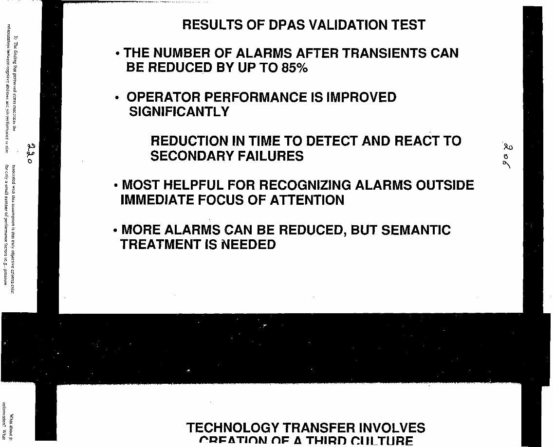
RESULTS OF DPAS VALIDATION TEST
• THE NUMBER OF ALARMS AFTER TRANSIENTS CANBE REDUCED BY UP TO 85%
OPERATOR PERFORMANCE IS IMPROVEDSIGNIFICANTLY
REDUCTION IN TIME TO DETECT AND REACT TOSECONDARY FAILURES
MOST HELPFUL FOR RECOGNIZING ALARMS OUTSIDEIMMEDIATE FOCUS OF ATTENTION
MORE ALARMS CAN BE REDUCED, BUT SEMANTICTREATMENT IS NEEDED
a
TECHNOLOGY TRANSFER INVOLVESC\F Л THIRD CULTURE

toш ш
LLCC
Whai about practical applications of PSF and job performance
information? What does it mean to know something that enhances or
However, the review of cross-cultural research findings reveals
that the need for ensuring a sound technical hasis fnr thp стпчч-

CONCLUSIONS
CULTURAL DIFFERENCES DO EXIST
BUT, WE HAVE TO BE SURE THAT COMPARISON ISMEANINGFUL
DO PERFORMANCE CRITERIA HAVE THE SAMEMEANING ?
DO PERFORMANCE SHAPING FACTORS HAVETHE SAME MEANING ?
TECHNOLOGY TRANSFER INVOLVES THE CREATIONOF A THIRD CULTURE - THIS REQUIRES SOMETHINGBEYOND MERE COMPARISON
ос»

Time For Tailoring Human-Machine Interface Technology
To Humans
Yushi Fujita
Mitsubishi Atomic Power Industries. Inc.4-1,2-Chome. Shibakouen. Minalo-ku, Tokyo 105, Japan
Advanced human-machine interface (HMI) technologies
recently developed for tapanese pressurized water reactors have
demonstrated their potential benefit. Yet, there are problems, some
of which seem critical. These include an inherent problem with
CRTs and some mismatches among users and designers. More
emphasis must be placed on user-oriented approaches when
resolving these problems. Future HMI technology will need to be
looked as a discipline which is more independent of information
processing and other relevant technologies. It also involves more
fundamental efforts such as the simplification of the present
operating rules.
Introduction
Through years of R&D made since the TMI accident, we have
acquired fairly advanced human-machine interface (HMI)
technologies. Many of them are already in use. Many others seem
to be just waiting for suitable applications. Does this mean that all
these new HMI technologies are well matured and ready for actual
implementation ? It seems that more studies need to be made before
these HMI technologies can fit in nicely with the operator
characteristics and the present "control room system." [1]
Recently, a series of experimental tests were conducted for
advanced HMls developed for Japanese pressurized water reactors
(PWRs). It is fair to say that the results of these tests were very
positive and have presented some evidence that they have a good
potential for benefiting operators. Yet, there were some problems.
These problems include side-effects, user-designer mismatches, and
more fundamental issues that are presumably concerned with the
current operating system (rather than HMI technology alone).
The purpose of this paper is to report our experience and
attempt some general discussions which will stress the need for more
emphasis on user-oriented approaches than on the conventional
technology-oriented approaches. This shift of technical emphasis
will require something that is more than the final cosmetic touch on
HMls. It will require researchers to seek the true identity of HMI
technology. It must be more independent of the information
processing technology and other relevant technologies.
In the first half of this paper, a state of the an HMI
technologies recently developed for Japanese PWRs are summarized.
These include a compact advanced control room (ACR), an alarm
handling system, and an integrated knowledge-based operator
support systems (KBOSSs). Then follow discussions about
problems and recommended ft/tare efforts.
State of The Art HMI Technologies
Advanced Control Room
A newly developed ACR for the APWR (advanced PWR)
needs only one operator (plus a supervisor). [2] A fully
computerized compact console enables one operator to control the
whole plant with soft-control technology. Such a compact console is
expected to benefit operators with its ability to present controls and
relevant information in integrated forms, and also to incorporate
supportive information such as diagnosis.
Figure 1 shows an overview of a prototype ACR developed for
a validation test. It consists of a large display panel (LDP), an
operator console, and a supervisor console.
1) LDP is provided to facilitate (1) the understanding of
overall plant conditions, and (2) communications between operator
and supervisor. It consists of three 100-inch projection-type
displays. A plant overview is provided on the right and center
screens in the form of plant systems mimic. It is capable of
presenting alarms. The right screen can be used to present any
display at operator's disposal.
2) The operator console allows one operator to control the
whole plant from a sealed position. It is about 5 meters wide.
There are four Cathode Ray Tubes (CRTs) and two electro-
luminescence flat display panels (FDPs) mounted on the operator
console:
- Two CRTs on the left wing are used for monitoring tasks alone.
They are also used for presenting alarms in detailed forms.
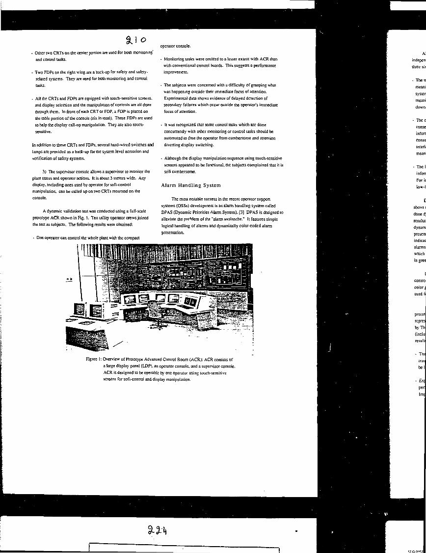
SU©Other two CRTs on the center portion are used for both monitoring
and control tasks.
Two FDPs on the right wing are a back-up for safety and safety-
related systems. They are used for both monitoring and control
tasks.
All the CRTs and FDPs are equipped with touch-sensitive screens,
and display selection and the manipulation of controls are all done
through them. In front of each CRT or FDP, a FDP is placed on
the table portion of the console (six in total). These FDPs are used
to help the display call-up manipulation. They are also touch-
In addition to these CRTs and FDPs, several hard-wired switches and
lamps are provided as a back-up for the system level actuation and
verification of safety systems.
3) The supervisor console allows a supervisor to monitor the
plant status and operator actions. It is about 3 meters wide. Any
display, including ones used by operator for soft-control
manipulation, can be called up on two CRTs mounted on the
console.
A dynamic validation test was conducted using a full-scale
prototype ACR shown in Fig. 1. Ten utility operator crews joined
the test as subjects. The following results were obtained:
- One operator can control the whole plant with the compact
operator console.
- Monitoring tasks were omitted to a lesser extent with ACR than
with conventional control boards. This suggests a performance
improvement.
- The subjects were concerned with a difficulty of grasping what
was happening outside their immediate focus of attention.
Experimental data shows evidence of delayed detection of
secondary failures which occur outside the operator's immediate
focus of attention.
- It was recognized that some control tasks which aie done
concurrently with other monitoring or control tasks should be
automated to free the operator from cumbersome and attention
diverting display switching.
- Although the display manipulation sequence using touch-sensitive
screens appeared to be functional, the subjects complained that it is
still cumbersome.
Alarm Handling System
The most notable success in the recent operator support
systems (OSSs) development is an alarm handling system called
DPAS (Dynamic Priorities Alarm System). [3] DPAS is designed to
alleviate the problem of the "alarm avalanche." It features simple
logical handling of alarms and dynamically color-coded alarm
presentation.
Figure I: Overview of Prototype Advanced Control Room (ACR): ACR consists of
a large display panel (LDP), an operator console, and a supervisor console.
ACR is designed to be operable by one operator using touch-sensitive
screens for soft-control and display manipulation.

SiltAlarm handling logic used for DPAS is simple and scenario- '
independent. The logic is specified in accordance with the foliou ing
three simple rules:
- The mode rule: Alarms relevant to a out-of-service system bear no
meaningful information if there is an alarm that indicates thai the
system is not in service. For instance, a low flow rate alarm is
meaningless when the relevant system has been intentionally shut
down causing all pumps to stop.
- The cause-consequence rule: Alarms which occur as a
consequence of some specific change bear no meaningful
information if there is an alarm thai indicates the change, and the
consequential alarms are not used for any other purposes (e.g.,
interlocks). For instance, a low pump outlet flow alarm is
meaningless when the corresponding pump has been stopped.
- The importance rule: Mulüple-seipomt alarms bear no meaningful
information when higher or lower setpoint alarms are activated.
For instance, a low pressure alarm becomes meaningless when a
low-low pressure alarm is activated.
DPAS alarm handling logic identifies, in accordance with the
above rules, whether a given alarm is meaningful or not. This is
done dynamically. Depending on plant or component conditions, the
resultant status (i.e., meaningful or meaningless) may change
dynamically. Those alarms which are found meaningful are
presented in red (i.e.. red alarms), except those which merely
indicate the actuation of automatic actions: The latter group of
alarms are presented in yellow (i.e., yellow alarms). Those alarms
which are found to be meaningless are de-emphasized and presented
in green (i.e., green alarms). No alarms are suppressed.
DPAS is a concept which can be applied to a various types of
control boards, both existing and future one:. Any computer-driven
color graphic displays or multiple-color annunciator window can be
used for presenting dynamically color-coded alarms.
A dynamic validation test was conducted using a full-scale
prototype DPAS. It was integrated into a full-scale simulator
representing Ohi Unii-3, a 1,100 MWe latest Japanese PWR owned
by The Kansai Electric Company. Nine utility operator crews
(including one observer) joined the test as subjects. The following
results were obtained:
- The level of alarm reduction can be up to 855- during major
transients. The number of red alarms presented then appeared to
be less than twenty.
- Experimental data has shown quantitatively ihat operator
performance would be significantly improved with DPAS.
Improvements include more utilization of alarms for deiectins
secondary failures and quicker operational responses (i.e., deteciion
of secondary1 failures and counteractions).
- DPAS is most helpful in the recognition of alarms which are
outside the immediate focus of attention. [4]
- The reason for the improvements is that DPAS has successfully
reduced the number of alarms (i.e., red alarms) to a level where
operators can allocate their resources to monitoring alarms. Il is
not that it facilitates any kind of analysis of alarms presented. [4]
- Among those presented, there still remain some red alarms which
are not necessarily useful from the operational viewpoint. This
suggests that more reduction might be possible. However, some
sorts of semantic treatment is necessary' to accomplish further
reduction.
DPAS has already been applied to the latest Japanese PWRs.
The first DPAS was installed at Ohi Unii-3. A series of tests
conducted during Ohi Ùnit-З transient lests have shown that DPAS
functions as intended. DPAS will be retrofitted to existing plants.
Integrated KBOSS
A seven-year national project for integrated KBOSS has Ьегп
completed recently. The Ministry of International Trade and
Industry (MITI) sponsored three vendor groups (Mitsubishi group.
Toshiba, and Hitachi) consisting of five companies to develop
knowledge-based operator and maintenance support systems for
PWR and boiling water reactors (BWRs). An integrated KBOSS
developed for PWR features a variety of operator support functions
which are designed Io be applicable to both ACR and conventional
control rooms as briefly described below:
1) For normal operations, the following support functions were
developed:
- planning and follow-up of restart operation following a transient
- planning and follow-up of load-follow operation
- follow-up of start-up and shut-down operations
For abnormal / accident operations:
- model-based intelligent interface: This handles all the information
relevant to other support functions for abnormal / accident
operations. It utilizes an inbuilt operator conceptual model to edil
plant parameters and operator support information and present
them in integrated forms through a special interface. At the onset
of an anomaly, this interface is automatically displayed at ihc
operator console (at the second CRT from the left) and the
services ïor

supervisor console (at the right CRT). It can also be manually
displayed on the right screen of LDP.
• diagnosis (with an explanation function) [6]
• guidance (with an explanation function) [6]
- verification of prescribed automatic actions
course, there are problems. Many of them can be handled with
traditional human factors engineering approaches. Some require the
improvements of devices rather than functional design. (For insiance,
the legibility of LDP needs to be improved. It may be nice to have
larger CRT and FDP which can present a larger amount of
information.) Some others seem to be more essential. In the
following several paragraphs, two of these essential problems are
discussed: side-effect and user-desianer mismatch.
- follov.-up monitoring of manual aciions suggested by lhe system A Side Effect
- prediction of several prescribed parameters
A dynamic validation test was conducted using a prototype
integrated KBOSS integrated into ACR. Ten utility operator crews
(those which participated the validation test of ACR) joined the test
as subjects. Among a variety of findings obtained, the following
seem important;
- Generally, the subject have found the system useful, but not
necessarily indispensable. They characterized the system as a tool
thai would allow them lo cross-check their own judgments after
initial counteractions.
• It was recognized that the system would be most useful for
supervisors. Operators are too busy to refer to supportive
information during highly dynamic operations.
- Experimental data has shown a tendency that the variability 'jf
operator performance would be reduced with the use of the system.
In particular, operator's ability to detect secondary failures is
improved significantly.
• Generally, the diagnostic and guidance functions were well
received. They represent the virtues summarized above. However,
likes and dislikes vary significantly among operators.
- Subjects liked to automate the normal operations, raiher than
manually operate them even if they are provided with support
functions.
- The model-based intelligent interface was not necessarily well
received probably because of irrelevancy of automatic display
features and poor briefings by experimenters.
Some Problems and Concerns
The above-described experience of HMIs development and
their e\aluaiions have given us an enormous amount of valuable
information on the advanced HM1 technologies. First of all. the
results are encouraging enough for us to believe that these
technologies have a good potential for benefiting operators. Of
The CRT is a double-edged sword. It was known to designers
from the early stages of its introduction that CRT had a potential for
hiding information, making it difficult to grasp the overall plant
status and any pieces of importam information that is outside
immediate focus of attention mighl be overlooked. In shon, you can
monitor only what is actually presented. In the applications to
conventional control boards, this problem was alleviated by high
level functional displays which enable overall supervision of the
plant status. One-stroke display call-up switches were also utilized
to facilitate quick access to detailed information. This alleviated the
problem of time consuming information retrieval in a hierarchically
structured display system.
This short coming of CRT seems to have shown up in a much
more evident form in the ACR application. LDP could have been
utilized for overall supervision, but experimental data shows no
evidence of operator's utilizing it effectively. It seems they are too
busy struggling with CRT displays and rarely have chances to look
up and verify lhe overall plant status with the LDP.
On the other hand. CRT has the ability to integrate relevant
information into a single display. As summarized above, ACR
would reduce lhe omission of procedural monitoring tasks. This is
apparently due to this ability of CRT. However, this might result in
excessive concentration on some area, reducing chances of paying
attention to others. Of course, the fact that display switching is
necessary for monitoring other parameters is making the temporary
réallocation of attention more costly, thereby impeding smoother
overall plant status monitoring.
Both designers and operators are thinking that computenzed
operator support functions should be utilized to alleviate this
problem. It means to delegate some supervisory responsibilities to
machine. This idea may noi sound wrong, but there are some
concerns:
- Clear criteria need to be specified for computerized supervision.
Nevertheless, it is seldom possible. Clear cniena are definable
only for very critical siuiaiions. which may not be always useful
for operators. Consequently, the design will tend to have the
machine do only something that can be defined clearly (e.g..

sequence monitoring).
- Delegating supervisory responsibility to a machine may take away
the opportunities of operator's forming appropriate mental models
which is critical when facing unexpected situations that the
machine cannot handle. This is very similar to the traditional
problem of function allocation between humans and machines.
A Mismatch
The integrated KBOSS is designed to support operators on-line
and in real-time. However, as summarized above, the operators
characterized it as a tool that would allow them to cross-check their
judgments after initial counteractions. The direct reason for this
user-designer mismatch is probably the fact that the operators are
much quicker than the system in responding to anomalies.
Nevertheless, there seem to be more fundamental issues lying
behind. These are discussed subsequently.
Some General Concerns
In the proceeding paragraphs, some problems observed in the
validation tests of advanced HMIs were discussed. Here, more
general concerns are discussed.
The present form of HMIs development is technology-driven.
Emergence of new technologies stimulais HMI engineers to think of
possible future applications. Ten years ago, it was CRT. Now,
artificial intelligence (AI), neural networks, large-scale displays,
soft-control, voice announcement and recognition.... This is a
natural process of technical evolution, but this sometimes causes
problems when technical limitations, and the consistency with user
characteristics and work rules are not considered carefully.
Otherwise, problems such as follows can show up as they actually
do:
- Designers tend ю overlook the limitation or conditions of new
technology. A good example is the normative approach.
Availability of complete knowledge is a prerequisite for its use,
out it is seldom satisfied. [6] (The user-designer mismatch
observed in our validation lest is another example of problems
caused by the shortage of knowledge. The slow system response
is neither due to the shortage of computer capability nor to the
inefficiency of information processing method, but it is due to our
inability to obtain clear and fine criteria that allow us to
computerize something that can surpass the operator's cognitive
abilities: detection and diagnosis of anomalous symptoms,
decision of operational coumermeasures).
- Designers naively think that the advanced information technology
will be able to create some sorts of human-like machine behavior
that fits user (human) cognitive characteristics. This is elusive and
dangerous. [7] Mere use of advanced information technologies
does not achieve a match wnh such human cognitive
characteristics as the hypothesis-and-iest and topographic search.
[8] (Refer to Ref. 9 for more elaborate discussions about the
relationships between human-computer interaction and AI.)
- The problems that operators face in very critical situations are
said io be ill-structure~* and ihey are forced to show knowledge-
based behavior. A number of accident reviews report that this is
true. But. why do HMI engineers have to struggle with ill-
structured problems as they are, even when they can be. no mailer
partially it may be, simplified by changing work rules ? It will
make both operator's jobs and HMIs much simpler.
Aren't all these arguments suggesting the need for more user-
oriented approaches ? We cannot use technologies beyond their
limitations. We must not let a technology alone decide the form of
application. It must be decided in such a way that users can accept it
and that it is consistent with the present work rules or change work
rules accordingly.
Conclusions
Owing to the remarkable progress in the information
processing technology and other relevant technologies, the
framework for the next generation control room (i.e., ACR) for the
Japanese PWR has begun to emerge. It is characterized by an
entirely-CRT-based compact operator console. All in all, it is fair to
say that ACR has a good potential for benefiting operators. Yet,
there are some problems and concerns. These include an inherent
problem with CRT and some mismatches among users and
designers. These are not believed to be unique to present
applications, but they can be found with other similar HMIs.
More user-oriented approaches are necessary for resolving
these problems. This shift of technical emphasis also involves more
fundamental efforts such as simplifying the present work rules.
The future HMI technology must be a discipline which is more
independent of information processing and other relevant
technologies. The HMI technology must place itself in a position
where its ripples can be felt across the whole universe of relevant
technoloeies.
References
[ I ] IEC-964. "Design for control rooms of nuclear power
plants." International Elecirotcchnical Commission. !9S9.
[2] T. Nina and others. "Development of advanced main
control boards for APWR. "presented ai lhe OECD/NEA-

SL\lfIAEA International Symposium on Nuclear Power Plani
Instrumentation and Control. Tokyo. Japan. May 18-21,
1992.
[3) Y. Fujiia. "Improved Annunciator System for Japanese
Pressurized-Water Reactors." Nuclear Safety, vol.30. No.2.
pp.209-221. April-June, 1989.
[4] V. Fujiia. unpublished doctoral dissertation, '"Study on the
improvement of man-machine interface for nuclear power
plant'. - The development of annunciator and diagnosis
systems incorporating operator behavioral analysis."
Tokyo University, Tokyo, Japan. 1992. (In Japanese)
[S] N. Nairn and others, "Advanced man-machine system for
nuclear power plant operation and maintenance," presented
at the OECD/NEA-IAEA International Symposium on
Nuclear Power Plant Instrumentation and Control, Tokyo,
Japan. May 18-21,1992.
[6] Y. Fujita and others. "Designing a knowledge-based
operator support system for practical applications,"
Nuclear Technology, vol.95, pp. 116-128. July, 1990.
P] M. Collins. "Artificial Experts - Social knowledge and
intelligent machines," The MIT Press. 1990.
[S] J. Rasmussen, "Information processing and human-
machine interaction - An approach to cognitive
engineering." North-Holland. Ch.6, pp.37-52,1986.
[9] E. Hollnagel, The influence of Artificial Intelligence on
human-computer interaction: Much ado about nothing ?."
in Human-Computer Interaction. J. Rasmussen. H. B.
Anderson, and N. O. Bernsen (eds.). London: Erlbaum,
Ch.6, pp.153-202.1991.
* 3 *

Ebunka: Do Cultural Differences Matter ?
Yushi FujitaMitsubishi Atomic Power Industries. Inc.
4-1, 2-Chome, Shibakouen, Minato-ku, Tokyo 105, Japan
Jody L. Toquam & William B. WheelerBattelle Human Affairs Research Centers
P.O. Box C-S395,4000 NE 41st Seattle, WA 98105-5428, U.S.A.
Mamoru TaniMitsubishi Heavy Industry, Ltd.
4-1, 2-Chome, Shibakouen, Minato-ku. Tokyo 105, Japan
Taizo Mo-oriThe Kansai Electric Power Company. Inc.
3-22,3-Chome, Nkanoshima. Kita-ku, Osaka 530, Japan
A human factors research program currently underway
involves Japanese nuclear power plant operators. Results from this
study suggest that the norm of socially desirable behavior appears to
influence operators' job performance and the perceived value of that
performance (perceived by experts). In Japan, focus on the correct
behavior is viewed as positive. This result represents a sharp
contrast with results from similar research programs conducted on
power plant operators from the United States. Such a collectivistic
behavior (i.e., a focus on social norms and expected behaviors) is
viewed negatively in American culture. A comparison of results
from Japan and from the U.S. may suggest that cultural differences
play a significant role in determining the performance of nuclear
power plant operators. The review of previous cross-cultural research
has revealed the need for ensuring sound technical basis for cross-
cultural research. Namely, the consistency of the value system and
differences in interpretation of performance shaping factors need to
be carefully studied before attempting cross-cultural comparisons.
Otherwise, one may reach misleading conclusions. It is also pointed
out that the most important role of future cross-cultural research in
the nuclear industry is to contribute to smoother and more affective
technology transfer. This requires researchers to go well beyond the
mere explanations of cultural phenomena and to study an effective
way of creating meaningful research tools that transcend culture or
focus on the work culture.
Introduction
For some disciplines, a major focus of research has been to
provide a better understanding of cultural differences. It is crucial to
ensure smoother communications and technology transfer across
different cultures. In the nuclear industry, researchers have begun to
recognize the need for cross- cultural research to answer questions.
such as:
- Why does plant performance differ significantly across countries
(both operations and maintenance), even when plants and
equipment are very similar?
- How can the knowledge of the factors that contribute to better
plant performance in one culture be utilized in other cultures?
In 1987, a consortium of Japanese utilities expressed interest in
studying sources of human factors deficiencies in nuclear power
piant control room operations. Groups of Japanese research
engineers and U.S. scientists were assembled to attack this
challenging research in a program entitled Control Room Evaluation
System (CRES). The design of ihis research program is in sharp
contrast to the traditional engineering approach in which improving
the human-machine interface has been the primary focus of research.
Instead, the CRES focuses on understanding potential human factors
deficiencies associated with individual and group characteristics of
persons supporting and operating the system. This rather unique
approach required a collaboration between Japanese research
engineers and U.S. scientists (psychologists). Although it was not
intended, the CRES provided us with an opportunity to learn a bit
about cultural factors that differentiate Japanese and U.S. utility
control room operators. The purpose of this paper is ю summarize
findings obtained from the CRES and also to provide a general
discussion of cross-cultural research in the nuclear power plant
industry. The first half of this paper presents an overview of the
CRES program. This is followed by discussions of cross-cultural
research, including: (I) cross-cultural differences identified in the
CRES data; (2) general concerns aboui cross-cultural research: and
(3) roles of cross-cultural research.
: Ebunka is a Japanese term which means a different culture or diffemt cultures.

31 tfOverview Of The CRES Program
The primary goal of the CRES is to develop countermeasures
against human factors deficiencies found in current nuclear power
plant control room operating crews. To reach this goal, the research
design included the following steps:
- Identify factors that shape operator performance (i.e.. Performance
Shaping Factors -- PSFs). This is based on the premise that
operator job performance can be explained by a certain number of
critical PSFs.
- Develop individual and group performance models using the
knowledge of critical PSFs. their interactions, and their
relationships wiih job performance scores. These models are used
to predict performance for individuals or for groups.
- Discuss countermeasures against potential human factors
deficiencies predicted by the individual and group models.
The study is based on correlation analyses of job performance
and PSF data. Those PSFs that correlate significantly with job
performance are considered to be critical PSFs. Job performance
data were collected from utility operators who were participating in
training sessions at the Nuclear Training Center (NTC). Data were
collected from operators participating in the following three training
courses:
- Normal Retraining Course: A two-week training course for
operators who had already completed the initial training course at
NTC. Temporal training crews were formed by three trainees from
different plants and possible different utilities. Generally, their
level of job experience was the same. Many of the trainees who
completed this course are reactor operators at their sites. During
the training sessions in the control room simulator, operators
rotated crew positions (i.e., supervisor, reactor operator, and
turbine operator).
- Advanced Retraining Course: A one-week training course lor
trainees who have already completed the normal retraining course
at NTC. As with the normal retraining courses, temporal training
crews were formed by three trainees who have similar levels of job
experience (from reactor operators to supervisors). These
operators also rotated job positions during the training sessions in
the simulator.
- Family Course: A one-day or two-day training course for a group
- Detai
condi
using
discu
as pre
JobP(
These i
Figure 1: Overview of Training Simulator Used for Collecting The CRES Data
-Expe,
NTC
evalu
scena
factor
opera

of trainees who belong to the same crew from the same home
plant. The primary purpose of this course is to offer an educational
opportunity for operators. For this reason, trainees sometimes
rotate job positions. (.When data were collected, however, trainees
played their original job position at the experimenter's request.)
Figure 1 shows an overview of the training simulator. It is a
replica of the Takahama Unii-3 control room, an 840 MWe three
loop pressurized water reactor owned and operated by the Kansai
Electric Power Company. In [he simulator, severa! typical accident
scenarios were presented to crews during the training session (e.g.,
loss of coolant accident, steam generator tube rupture). During each
training session, crew and individual performance was assessed
using a variety of performance scales. Psychological instruments,
selected or developed to collect information about critical PSFs,
were administered to operators during the training sessions or at the
operators' home plants.
The CRES includes the following four steps:
- Pilot Study (1987): Job performance scales (JPSs) and PSF
instruments were selected and refined using data from a small
sample of operators.
- Preliminary Study (1987-1988): Using results from the pilot
study, a broad range of PSF measures were administered and their
correlations with job performance examined. From these data a
more refined list of useful PSFs was identified.
- Detailed Study-I (1989-1991): Using the refined list of PSFs from
the preliminary study, the PSF battery of tests and questionnaires
was refined. These selected PSFs were smdied in greater detail.
- Detailed Study-II (1992-1994): Even more detailed analyses are
conducted to develop individual and group performance models
using results from the first detailed study. This will be followed by
discussions of coumermeasures against human factors deficiencies
as predicted by the models.
Job Performance Scales
A variety of JPSs were constructed and used in this program.
These include the following:
- Expert Ratings: Job performance rating scales that were used by
NTC instructors or experienced start-up engineers to observe and
evaluate operators (trainees) as they performed in accident
scenarios. Performance ratings consisted of five performance
factors for supervisors, four performance factors for reactor
operators and turbine operators, and three performance factors for
crews. Rating scale scores ranged from I (low) to 7 (high).
Performance factors for individuals included:
• understanding plant status
• supervising coordination
• communication
• duty execution
• supportive activities
• spirit
For crews:
• team coordination
• crew performance
• team spirit
Performance ratings obtained from this scale were the most
frequently used in the CRES because the rating instrument
included scales for measuring individual operator performance and
because of its moderately high reliability. I n t enwr agreement
levels ranged from .62 to .97 with a mean value oi ïO (Preliminary
Study) and ranged from .42 to .88 with a mean value of .63
(Detailed Study I).
- Generic Rating Scales: A crew performance measure indicating
the level of correct execution of generic procedures and actions
(e.g., pointing to an annunciator). Experienced engineers observed
operators performing in an accident scenario and count the number
of deviations from prescribed generic procedures.
- Procedural Unit Rating Scales: A crew performance measure
indicating the level of correct execution of specific procedural
tasks. Experienced engineers observe operators performing in an
accident scenario and count the number of deviations from
prescribed procedures.
- Objective Job Performance Scales: This crew performance
measure was calculated from plant process variables. Scores
consist of either an absolute or relative quantitative values. For
example, one score consists of the integral pressure mismatch
between primary and secondary systems; this value represents the
amount of radioactivity flowing out to the secondary system
following a steam generator tube rupture accident.
PSF Instruments
A variety of psychological instruments d~ ''eloped and used in
the U.S. or other western countries were selected or developed to
collect PSF data on operators. The following criteria were used to
select the PSF measures:
£ ? /Appendix В

Table 1 : List of Performance Shaping Factors (PSF1 and PSF Instruments Used in CRES Program
PSF Cateaorv
Cognitive Ability
Personality
Background Stress andStress Coping Measures
Leader Behaviors
Background Experience
Group InteractionsMeasures
PSF Assessed | Instruments
• Perceptual Speed• Perceptual Speed Attention• Knowledge of Job Requirements in Four Areas IncludingBasic. Design. Operations, and Others.
• Adjustment• Dependability•Validity•Stability• impulsive Behavior•Tendency to Strive for Competence in Ones Work•The Level of Intellectual Efficiency Attained•Tt.'dency to Create A Favorable Impression- Potential for Becoming an Effective Leader•Tendency to Intentionally Distort One's Response toLook Good
•Tendency to Strive for Competence in One's Work
• Personal Background Stress• Anxiety, Depression, and Feeling of Helplessness• Extent to Which One Seeks or Avoids Information WhenThreatened and One Distract Oneself When Threatened
• Perceived Stress Coping
•One's Perception of His or Her Superior's Behavior(Performance-oriented or Social)
•One's Perception of His or Her Superior's Behavior(Transformational. Transactional,..
• Experience and other individual characteristics such asage, physical characteristics, academic background, jobexperience, and trainina experience
• Motivation to Work Under Certain Conditions• Group Cohesiveness• Reported Stress from One's Superior or Subordinates
• ETS Number Comparison• Battelle Visual Scanning Test•Job Knowledge Test (specially developed)
• MMPI • Scale 4•MMPI-Scale 7•MMPI-Scale L• MMPI - Ego Strength• MMPI - Impulsiveness• MMPI - Academic Achievement• CP1 - Intellectual Efficiency•CPI - Good Impression•CPI - Managerial Potential•Social Desirability
•Work Orientation• Recent Life Change Questionnaire• Psychiatric Epidemiology ResearchInterview
• Miller Behavioral Style Scale
•Cohen's Perceived Stress Scale• Performance-Maintenance
•Transformational Leadership
• Background Questionnaire (speciallydeveloped)
• Least Preferred Coworker Scale•Group Atmosphere•Job Related Stress
Note 1: ETS: Educational Test Service; MMPI: Minnesota Multiphasic Personality Inventory; CPI: California PersonalityInventory
Note 2: In addition to the above listed PSFs. situaiional stress factors (e.g., task difficulty) were measured.
- Previous research supports their use.
- A Japanese translation was available or little translation was
needed.
- Administration was easy and time required was short.
- Sample data show sound statistical properties (e.g. no ceiling or
floor effects).
In the Preliminary Study, a broad range of PSFs were
examined to ensure full coverage of PSFs that had potential for
predicting job performance. Laler. in the Detailed Study-I, more
specific PSFs were examined. Table 1 presents a list of the PSFs and
PSF instruments administered in the Detailed Study-[.
Results From The CRES Program
General Findings
Results obtained from the Preliminary Study and Detailed
Study-I are summarized as follows:
- Previous job experiences and training experiences are significant
contributors to job performance. (These variables explain up to
20% of job performance score variance).
- Other significant individual PSFs include the following:
• some cognitive ability measures (e.g.. perceptual speed/
attention)
• job knowledge
• personality traits (e.g., social desirability, good impression)
• personal stress and coping mechanisms
- If trainees perceive the training and accident scenarios as stressfull,
this stress moderates the relationships between individual PSFs
(i.e., cognitive ability, experience) and crew performance. Those
groups reponing high levels of stress did not appear to use abilities
and experience as effectively as those who reported experiencing
less stress.
- Leaders who viewed as more directive are more effective in using
their abilities and experience to resolve the accident scenario than
are nondirective leaders.

The degree to which many of these ?SFs contribute to
performance varies by operator role. iThe above results are based on
correlation analyses using the Expert Ratings.)
CRES Findings with Cross-Cultural Implications
The CRES was not designed to examine cross-cultural
differences. Yet. there are some data that touch upon cultural
differences between Japanese and U.S. control room operators.
1) An instrument. Goal Orientation, was designed to measure
one's goal orientation at work (e.g., what are you working for?).
Data for a sample of Japanese control room operators participating in
the Pilot Study indicated that all subjects responded in a very similar
manner They all reported that they were working for the
organization. Results from me U.S. study indicate that individuals
vary in their reported goals. Because of this anomalous response
pattern for the Japanese sample, the GO scale was eliminated from
the CRES PSF battery.
2) In ihe Preliminary Study and Detailed Study-I. several
personality traits appeared to correlate significantly with job
performance (Expert Ratings). Among the personality scales found
lo predict job performance, three were analyzed in greater detail in
lhe Detailed Study-П. $ ] These analyses suggested that some cross-
cultural differences influence control room operator's performance.
- Validity Scale: This 15-item MMPI scale was designed to check
whether subjects are reading each item carefully and responding
honestly. Far those subjects who obtained igh scores on this scale
(above 7), meir personality scores are eliminated from further
analyses because they appear to be distorting their responses.
- Good Impression Scale: A 3&-item CP1 scale which measures
one's tendency to intentionally distort responses to "look good" ю
others.
- Socially Desirable Scale: A 13-item scale which measures one's
tendency to respond in a socially desirable manner.
Scores on each of these scales were computed for three
different job positions: supervisor, reactor operator, and turbine
operator. These scores indicated thai supervisors obtained higher
scores than operators in other job positions on all three scales.
(Supervisors' scores were significantly different from turbine
operators' scares on the three scales. Supervisors scores differed
from reactor operators" scores on the Social Desirability scale.
Reactor operators' mean scores differed significantly from turbine
operators on the Good Impression scale.) These findings suggest
that as operators move up the job progression ladder, there is a
greater tendency for them to describe themselves in socially
desirable terms.
Operators' scores on these personality scales were also
correlated with Experts' ratings of performance. vAH personality
scale scores were factor analyzed and the Validity, Good Impression,
and Socially Desirable scales formed one factor, the Socially
Desirable Behavior factor.) Scores on the Socially Desirable
Behavior facior correlated positively with performance for all
positions. This indicates that operators who behave in a socially
desirable manner received higher ratings than those who scored
lower on the personality scales (validity coefficients ranged from . 15
to .46). This finding contradicts results reported in a U.S. smdy that
also included operators $\. (In the U.S. study, similar personality
scale scores correlated negatively with job performance scores.)
These two findings from the CRES — lack of variance on the
GO scale and positive correlation between socially desirable
behaviors and job performance - are supported by findings from
cross-cultural research on Japanese personality traits. [3], [4] An
overview of this research suggests that to behave in a socially
desirable manner is an inherent response for many Japanese (or
learned over a long period of time). This same variable may have
influenced scores on the Goal Orientation (SO) scale. That is,
operators recognized that the socially desirable response was to
report that working for the organization was the most imponant goal.
Such trait (or behavior) is said to be a natural consequence of
the Japanese social system which is often characterized by
collectivism. Ir such a social system, the responsibility and interests
of the group, rather than the interests of the individual are of primary
concern. This creates an atmosphere that one person's mistake is
everyone's shame. It also indicates that one's job requirements are
not well defined or are loosely defined. In turn, this produces the
following:
- Each group member attempts to cover more area than he or she is
actually responsible for. (This is said to be the reason for higher
group performance.)
- One tends to behave like the other group members, because it is
safer and may result in management percewing them to be better
performers. (This may explain why supervisors tend to obtain
higher scores on the social desirability personality scales.)
This tendency to present one's self in the most positive manner
possible is viewed as negative in the U.S., as demonstrated by the
negative correlation between scores on socially desirable personality
scales and rated performance.

3) The finding that perceived stress moderates the
relationships between cognirve abilities and job performance is also
consistent with expectations about operators from collectivism
society. The perceived lack of harmony (high stress) would be very
disruptive to operalors seeking concensus and agreement on
appropriate actions. A highly directive leader would, however,
provide the group an opportunity to pull together, use cognitive
abilities and experiences to perform more effectively on the job.
Some General Concerns
Despite the scientific rigor used to design and implement any
research program, results may not be meaningful if the basis of the
research is not sound. One general concern about cross-cultural
study is that one may inadvertently compare persons, data, or results
that really are not comparable. A comparison of job performance
and P5F relationships across different culiures or subcultures may
yield misleading conclusions, if the following are not true:
- Job performance measures have consistent values across the
different cultures.
- Job performance criteria are consistent across the differen
cultures.
This is an old argument which has often been raised when
viewing cross-cultural studies conducted in the cognitive psychology
domain. The question is "It is meaningful to discuss relationships
between scores in an intelligence (IQ) test and cultural background
factors without ensuring that lhe IQ lest scores have consistent
values across the cultures that are compared? " An estimate of IQ is
considered to represent basic cognitive abilities in western or
westernized cuhures, but this may not be true for other cultures.
Therefore, one may not be able to conclude that persons in one
culture are different from persons in another culture even if mean
scores are statistically different from one another. In addition, if
correlations between intelligence and job performance differ for the
two cultures, what conclusions should be drawn from this? Does
this imply something about the differences between the measures
administered in (he iwo cultures (PSFs and/or job performance
measures) or does this imply something about the cultural
differences? This may suggest that the vocational value systems and
PSFs are closely related; they are inherently intertwined and depend
on a particular sociological or ecological setting.
It may appear irrelevant to extend this conceptual discussion to
the nuclear power plant operations in which job performance criteria
should be more objectively definable. And I ~.ause nuclear power
plant control rooms and systems are very similar in Japan and the
U.S., performance criteria should also be similar. The problem
associated with this assumption is that truly objective criteria exist
for only a small number of performance factors (e.g.. pressure
mismatch between primary and secondary systems). These criteria
are not necessarily meaningful for use in understanding routine
performance (e.g. under normal operating conditions). As a
consequence, subjective performance criteria need to be introduced.
It is easy to imagine that these criteria involve cultural factors. In
fact, findings from the CRES have shown that social factors play a
role in control room operations. (It is suggested that one of the
determinants of effective job performance is to identify the proper
behavior as defined by some socially desirable norm.) It can be
hypothesized that similar findings would emerge if other power plant
groups participated in a similar study (e.g., maintenance).
In addition, based on interviews with supervisors conducted
during the CRES. we found thai these operators differ greatly in their
views about ways to improved performance. Operator responses and
suggestions differed greatly across utilities and even within the same
plant- This suggests that there are significant variations among sub-
cultural groups. In fact, it is possible to observe different views
about job performance among other sub-cultural groups (e.g.. design
groups, operation management groups, and operator groups).
Previous research in anthropology and cross-cultural psychology
tells us that differences within groups are often much greater than
differences between cultural groups.
A similar argument is applicable to performance shaping
factors. It is important to ensure that these factors have a sound basis
for comparison, or at least it is necessary to understand if the
meaning of these factors differ across cultures. It is worthwhile
noting that there could be interactions between job performance
scores and relevant PSF scores, if they are characterized culturally.
Scores and correlations with job performance criteria for the Socially
Desirable personality scales provide good examples of these cultural
differences.
Unless a sound basis for comparing data across cultures is
assured, we may compare some Job Performance-PSF relationships
that are actually based on very different performance criterion
scores. This would produce differences that are meaningless and
misleading. Therefore, a better understanding of cultural differences
vis-a-vis job performance and PSFs is a prerequisite for conducting
meaningful cross-cultural studies.
Role of Cross-Cultural Research
No doubt, one of the most important roles of cross-cultural
research is to establish Iheoretical and methodological foundations
that can explain and predict cultural phenomena. Although it is of
scientific interest, it is important to ensure sound applications of
scientific knowledge.
Cultural Differenc
Do Cultural Diffe

What about practical applications of PSF and job performance
information? What does it mean to know something that enhances or
detracts from job performance in different cultural groups?
Obviously, technology transfer is the central issue. It is certainly
meaningful to discuss how something that enhances performance in
one culture might be utilized in another culture.
It seems, however, that understanding effective technology
transfer must go well beyond the mere understanding of cultural
phenomena. Research from successful technology transfer studies
tell us that it must involve the creation of a third culture, rather man
the mere absorption or simple borrowing of one culture to another.
One recent study designed to examine technology transfer between a
Japanese auto manufacturer in North America vividly confirms such
a phenomenon. [5] The resultant system was neither Japanese nor
American. Instead, it is a new form of American culture with
Japanese flavors.
Hence, a key question is whether cross-cultural research can
contribute to smoother and more effective technology transfer. It is
the most important role that cross-cultural research can play. It is not
the act of describing existing cultures alone, but involves actively
creating a new culture that combines equipment and a work-practices
system with a social system.
Concluding Remarks
Cultural Differences Do Exit
Analysis of the CRES data suggest that cultural differences do
exist. Some sort of norm exists for socially desirable manners and
this norm seems to influence operator behavior and the evaluation of
this behavior (i.e., a manager's perceived performance effectiveness
level). Deviations from the norm appear to be negatively viewed in
Japan (not presenting a positive image or good impression). This
result is in sharp contrast to results from a similar study conducted in
the U.S. Such collectivism behavior is viewed more negatively in
the U.S.
Although this paper has restricted its discussion to the findings
from the CRES, there are many other specific issues that might also
be considered unique to Japanese nuclear power plant operations and
are, therefore, culturally flavored (e.g., training methods, use of
operating procedures).
Do Cultural Differences Matter?
The existence of cultural differences seem to support an
hypothesis that cultural differences play a significant role in
determining the performance of nuclear power plant operators.
However, the review of cross-cultural research findings reveals
that the need for ensuring a sound technical basis for the cross-
cultural research. In particular, this suggests that research focus on
the consistency of the values systems and differences in
interpretation of performance shaping factors must be carefully
studied before attempting cross-cultural comparisons. Otherwise,
one may reach misleading conclusions.
It is also important to note that differences within a culture are
often much greater that differences between cultures. This means
that gross treatment or examination of cultural differences may not
tell the whole story.
The final point to be made concerns the role of cross-cultural
research in the nuclear industry. It is probably correct to assume that
the most important role is the contribution to smoother and more
effective technology transfer. If this is true, it requires researchers to
go well beyond the mere explanations of cultural phenomena and
study an effective way to create a third culture.
Do cultural differences matter? It seems that we have to
reserve the answer for the moment, until we become more
knowledgeable about all these concerns and meet the requirements
for effective cross-cultural research.
References
[1] J. L. Toquam and Y. Fujita, "Individual differences
measures: Their correlations in process control occupations
in Japan, presented at the Society of Industrial and
Organizational Psychologists conference, Montreal,
Canada. May 1,1992.
[2] M. D. Dunnette and others, "Development and validation
of an industry- wide electric power plant operator selection
system," Report No. 72, Personnel Decisions Research
Institute, Minneapolis, MN, U.S.A.. [981.
[3] T. Shigehisa. and others, "A comparative study of culture:
An introduction to intercultural communication," Tokyo:
Kenpakusha. 1985. (in Japanese).
[4] H. C. Triandis, "The self and social behavior in differing
cultural contexts ," Psychological Review, 96. pp. 506-
520. 1989.
[5] M. Wakabayashi and G.B. Graen, "Cross-cultural human
resource development: Japanese manufacturing firms in
central Japan and central U.S. states." In International
Business and the Management of Change. M. Trevor (éd.),
Bookfield. 1991, Ch. 8., pp. 147-169.

SPDP DEVELOPMENT FOR RUSSIAN NPPS
by A.I.Gorelov and V.A.Proshin,Research and Development Institute of Power
Engineering, Russia
• %ЪЬ

SPDS DEVELOPMENT FOR RUSSIAN'S NPP.
A.I.Goreiov, V.A.Proshin
Research jnd Development Institute
of Power Engineering (RDIPE),
Russia, Moscow
Abstract
1 .Introduction
Serious upgrades and improvements are made and planned in
Russia to enchance safety of the nuclear power plants both with
the WER- and RBMK- reactor types. An important part of these
measures is improvement in the area of safety parameters
presentation. The work is sponsored by (and is made with
participation of) the "Rosatomenergo" - concern and NPP utilities
themselves, and is made for W E R and RBMK with close coordination
and collaboration.
Many specialists from our institute, Kurchatov's institute,
"Gidropress" - development institute, "Atomenergoprojecf-design
institute, institute of electromechanics (VNIIEM), "Spaceflight
control center", "Consyst" - firm, mentioned above sponsors and
participants et al are involved in this activity.
Authors thank all of them for usefull and fruitfull
collaboration.
2.Overview of the system, circumstances.
Safety parameters display system (for RBMK or YVER) is
developed for implementation on the plants and onthe special

operator
safetyengineere
plantsafetymanager
Process
I&C safety systems
SPDS-E
Г
SPDS-M
I
1
Unit 1
I&C systems
system to gatherand communicate
from (to)unit 2,...
ПЛ-S'I to
local crisiscenter (nearthe site) SPDS-L
off-site
SPDS-T
Itechnicalsupportcenter
SPD5-N
Inationalcrisiscenter
fig1. SPDS structure.

services for nuclear safety surveillance and management, on the
operation support centers. Fig.1 illustrates some detailes ol the
SPDS's users structure. Of course, tne SPDS's capabilities are
different for different users, but nuclear unit safety parameters
and functions are dispiaied for all of them. It is seemed this
approach is similar to French one.
The SPDS's development and implementation is made within and
with a large scale actions (wlch include I&C systems upgrades)
towards encnance safety and reliability of nuclear plants In
Russia. This fact influences upon work schedule and requires
special efforts to coordinate various types of activities.
Improvements in safety parameters display as well as in safety
management are based on the use of modern computers, means of
communications and other modern information technologies. There is
a problem to find the optimum balance between aspiration for low
cost and high availability and reliability of the system. There Is
also need to develope the system in a short time to have
sufficient time for V&V. Therefore, it is made decision to uniform
as far as it is possible SPDS hardware and software, as well as
communicatio1' tools for both RBMK and WER.
This article describes the SPDS for RBMK.
Taking into account that this type of reactor and its
features are wide known we do not make plant description. Main
plant equipments are shown on figure in appendix A (the picture Is
copied from NUEEG-1250, Report on the Accident at the Chernobyl
Nuclear Power Station). Major parts of made and planned activités
to improve operation safety and efficiency are done in Appendix В
(this material is borrowed from the paper prepared by E.O.Adamov
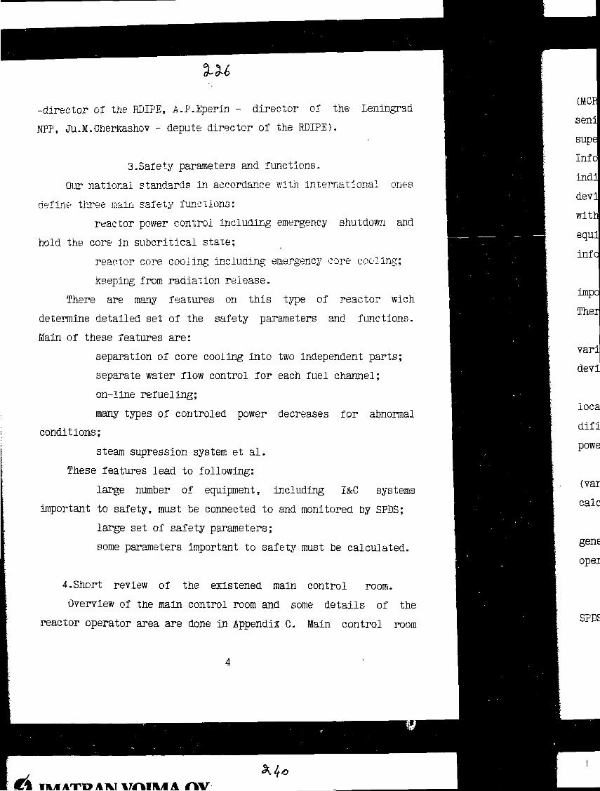
-director of the RDIPE, A.P.Eperin - director oi the Leningrad
NPP, Ju.M.Cherkashov - depute director of the RDIPE).
3.Safety parameters and functions.
Our national standards in accordance with international ones
define three main safety functions:
reactor power control including emergency shutdown and
hold the core in subcritical state;
reactor core coding including; emergency core cooling;
keeping from radiation release.
There are many features on this tзфe of reactor wich
determine detailed set of the safety parameters and functions.
Main of these features are:
separation of core cooling into two independent parts;
separate water flow control for each fuel channel;
on-line refueling;
many types of controled power decreases for abnormal
conditions;
steam supression system et al.
These features lead to following:
large number of equipment, including I&C systems
important to safety, must be connected to and monitored by SPDS;
large set of safety parameters;
some parameters important to safety must be calculated.
4.Short review of the existened main control room.
Overview of the main control room and some details of the
reactor operator area are done in Appendix C. Main control room
1*1
Ifeyf ATO AM VfMH/f A

(MCR) crew consists of four members: senior reactor operator,
senior unit operator, senior turbo-generator operator and shift
supervisor. Main control desk is devited on three parts.
Information is displayed on individual devices, recordes,
indicators, alarm sheets, as well as on computer driven common
devices. Operators make there duties during normal state operation
without overload and can be sitting. But during transients and
equipment faults there are needs in movement activity to gather
information and to make control actions.
Analysis allows to make conclusion: all of the parameters
important or relevant to safety are displayed on the MCR devices.
There are three main deficiencies:
parameters are presented on various types of devices and by
various manner (recorders, light spot and needle devices, digital
devices);
information are scattered on the large area (alarm sheets are
located in four places on the reactor operator area, it is
dificult to observe simultaneously feed-water flow and reactor
power and so on);
it is required to do many actions to receive some information
(various types of individual channel parameters as well as
calculated parameters).
It is need to note this MCR is in operation since 1973. New
generation of the RBMK MCR (Ignalina KPP) is more friendly for
operators.
5.Design basis and principles.
According with conducted analysis there is no need to assign
SPDS (here and below we are taking in the mind SPDS located in the

MGR) control functions. Moreover, following by the Safety Analysis
Report conclusions operator can control reactor and other
equipment during all of the types liable state, transients,
incident as well as under design based events wich lead to
accident. In the other words, we have to conclude that SPDS
failure will not lead to decrease safety in comparison . with the
unit wich is always operaied without SPIG. Designers must take
measures \o provide preparedness ui the operator to make their
decision without 3?üS anel safety decrease.
We are sorry to say there are no full scale examples of SFDS
in our country, designers can partial adopt the development and
operation experience of computerised operator support system wich
was obtained in the Ignalina ГОР.
Many examples of SPDS development and operation are known
thanks to intemationat publications. However, this source does
not give comprehensive and detailed description. The revealed
trands show that SPDS are improving towards computerized procedure
presentation, on-line probabilistic safety assesment and so on
(special review was made to investigate this subject). In most
cases SPDS operate with high reliability.
Our national standards established detailed requirements to
I&G systems, including important to safety. For new designs safety
parameters display integrated to the operator support system and
there are no presented special requirements to implement SPDS on
the operated plants.
International practice gives many examples of such a
standards, rules, guides. The list of them is put in the
guidelines for control room systems design wich is developted now.

Functional requirements are developed on the basis of deep
knoledge of the plant features, safety parameters list,
operational experience instructions and task analisis. In order to
provide operator for large amount information special efforts have
to be made.
Technical requirements mainly are: galvanic isolation,
physical separation sufficient capacity et al. Designer can obtain
detailed Information in the existence standards.
Special group of specialists is involved to solve
"human-factor" problems. Main of the difficulties concernes with
the large amount of safety parameters. Safety parameters are
grouped into three level; besides that number of channels
parameters is decreased by means of calculations.
Attention is also paid to provide comprehensive V&V tests.
Corresponding procedures include.
%k*

Level Regulator
To Turbogenerator
PressurizedCollector
Flow Limiters
Distributing GroupsCollector
ERCS Collector'
V4—Pressure Regulator
Turbogenerator
CondensateI f ' Pump
'From Suppression Pool
Pumps ol Self-CsntainedEmergency Reactor CoolingSystem (ERCS)
Appendix A
Main plant equipments

Appendix В
Major parts of made and planned activités
to Improve operation safety and efficiency
Hi
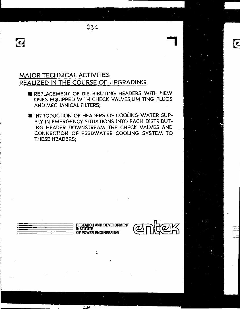
аз 31
MAJOR TECHNICAL ACTIVITESREALIZED IN THE COURSE OF UPGRADING
• REPLACEMENT OF DISTRIBUTING HEADERS WITH NEWONES EQUIPPED WITH CHECK VALVESfUMITING PLUGSAND MECHANICAL FILTERS;
• INTRODUCTION OF HEADERS OF COOLING WATER SUP-PLY IN EMERGENCY SITUATIONS INTO EACH DISTRIBUT-ING HEADER DOWNSTREAM THE CHECK VALVES ANDCONNECTION OF FEEDWATER COOLING SYSTEM TOTHESE HEADERS;
RESEARCH AND DEVELOPMENTINSTITUTEOF POWER ENGINEERING
SLU
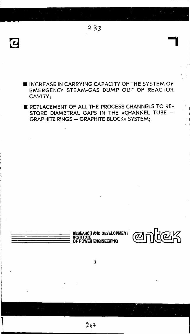
INCREASE IN CARRYING CAPACITY OF THE SYSTEM OFEMERGENCY STEAM-GAS DUMP OUT OF REACTORCAVITY;
REPLACEMENT OF ALL THE PROCESS CHANNELS TO RE-STORE DIAMETRAL GAPS IN THE «CHANNEL TUBE -GRAPHITE RINGS - GRAPHITE BLOCK» SYSTEM;
RESEARCH AND DEVELOPMENTINSTITUTEOF POWER ENGINEERING

Ilk
л
• INCREASE IN THE CONTROL AND PROTECTION SYSTEMEFFICIENCY;
• INTRODUCTION OF NEW INFORMATION-MEASURINGSYSTEM;
• INTRODUCTION OF THE LOWER MONITORING SYSTEMOF PARAMETERS OF GAS REMOVED OUT OF REACTORCAVITY
RESEARCH AND DEVELOPMENTINSTITUTEOF POWER ENGINEERING
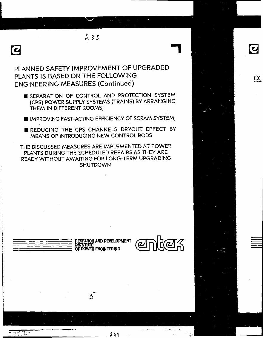
PLANNED SAFETY IMPROVEMENT OF UPGRADEDPLANTS IS BASED ON THE FOLLOWINGENGINEERING MEASURES (Continued)
• SEPARATION OF CONTROL AND PROTECTION SYSTEM(CPS) POWER SUPPLY SYSTEMS (TRAINS) BY ARRANGINGTHEM IN DIFFERENT ROOMS;
• IMPROVING FAST-ACTING EFFICIENCY OF SCRAM SYSTEM;
• REDUCING THE CPS CHANNELS DRYOUT EFFECT BYMEANS OF INTRODUCING NEW CONTROL RODS
THE DISCUSSED MEASURES ARE IMPLEMENTED AT POWERPLANTS DURING THE SCHEDULED REPAIRS AS THEY ARE
READY WITHOUT AWAITING FOR LONG-TERM UPGRADINGSHUTDOWN
ce
RESEARCH AND DEVELOPMENTINSTITUTEOF POWER ENGINEERING
S

CON
CONCLUSIONS
1. UPGRADING THE EMERGENCY CORE COOLING SYS-TEM ALLOWED TO PROVIDE HEAT REMOVAL FROMTHE CORE UNDER RUPTURE OF ANY PRIMARY CIRCUITPIPING OF 300 M M IN DIA. (OR LARGER DIAMETER PIP-ING RUPTURE EQUIVALENT TO IT) FROM BOTH THESUCTION AND PUMP PRESSURE SIDE,
2. INSTALLATION OF MECHANICAL FILTERS AT EACHDGH INLET TOGETHER WITH OPERATING LIMITERS OFTHE FC VALVES MOTION FOR CLOSURE PREVENTSTHE DANGER OF THE COOLANT FLOW LOSS IN ANYFUEL CHANNEL OF THE REACTOR.
RESEARCH AND DEVELOPMENTINSTITUTEOF POWER ENGINEERING

CONCLUSIONS (Continued)
3. EQUIPPING THE SGD OPERATING SYSTEM WITH ANADDITIONAL SAFE-GUARD OF 400 M M IN DIA. IN-CREASED THE SYSTEM CARRYING CAPACITY UP TOSTEAM-GAS MIXTURE FLOW RATE WHICH ARISESUNDER POSTULATED SIMULTANEOUS RUPTURE OF 4CHANNELS INSTEAD OF 2 ONES.
4. REPLACEMENT OF ALL 1693 FUEL CHANNELS AND RES-TORATION OF THE FC-GRAPHITE STACK DIAMETRALGAPS PREVENT FROM WEDGING THE CHANNELS INTHE PROCESS OF FURTHER REACTOR OPERATION,AVERT PREMATURE CRACKING OF GRAPHITE BLOCKSAND, AS A RESULT, ALLOW TO EXTEND THE GRAPHITESTACK LIFE UP TO 30 YEARS.
5. THE REACTOR CONTROL AND PROTECTION SYSTEMEFFICIENCY IS ENHANCED DUE TO THE INCREASE INNUMBER OF CONTROL RODS AND UPGRADING SEV-ERAL OF THEM.
COh
RESEARCH AND DEVELOPMENTINSTITUTEOF POWER ENGINEERING

CONCLUSIONS (Continued)
6. THE NEW «SKÁLA-M» INFORMATION-MEASURING SYS-TEM POSSESSING ADVANCED TECHNICAL AND CONSU-MERS' PERFORMANCES IS INTRODUCED.
7. THE COOLANT LEAKAGE MONITORING SYSTEM BASEDON MONITORING THE PARAMETERS OF GASREMOVED OUT OF LOWER PIPES OF THE CPS CHAN-NELS IS INTRODUCED PARTIALLY. THE SYSTEMALLOWS TO FACILITATE REVEALING LEAKY CHANNELSAND PROVIDES CONFINEMENT OF HUMIDITY SPREADOVER THE REACTOR SPACE UNDER LOWER LEAKS.
RESEARCH AND DEVELOPMENTINSTITUTEOF POWER ENGINEERING

PROCESS MONITORING SYSTEMS OF LOVIISA NPS
by E. Rinttila,Imatran Voima Oy.Finland
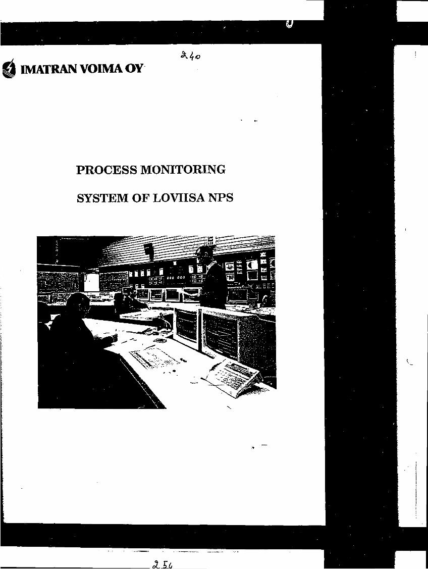
IMATRAN VOIMA OY
PROCESS MONITORING
SYSTEM OF LOVIISA NPS
3 It.

IMATRAN VOIMA OY •IMA/9.11.1990 LOPTK
INFORMATION PRESENTATION
Design principles
Alarm & event displays
Process diagrams
Trend displays
Logic displays
Single variable displays
Parametered lists of variables
Task oriented displays
CSF displays
EFD displays
Reporting
"Static" displays
Windowing, zooming, add-info
Workstations
Printers, hardcopy devices

UNIT 1 SIMULATOR OFFICE UNIT 2
9 VARS-Hworkstations
3 MIcroVAX
10 VARS-Hworkstations
3 MIcroVAX
3 VARS-Hworkstations
1 MIcroVAX
ETHERNET
3 VAX6250
2 HSC70
4 MIoroVAX
2700 analog6000 binaryInputs
ETHERNET
Prooesscomputer1 VAX82501 VAXB3501 HSC70
Simulator1 VAX8700
ttIdinJri\i
I
9 VARS-Hworkstations
3 MIcroVAX
MAN-MACHINEINTERFACE
BRIDGE
ETHER/VET ETHERNET
3 VAX8250
2 HSC70MAIN DATAPROCESSING
4 MIoroVAX
2700 analog6000 binaryInputs
PROCESSINTERFACE
Ko
FIGURE 1 LOVIISA PROCESS COMPUTER SYSTEMS CONFIGURATION

IMATRAN VOIMA OY TMA/9.11.1990 1DPTK
PROCESS MANAGEMENT SYSTEM FUNCTIONS
Data acquisition & preprocessing
Event/alarm handling
Data storing, PMR
Man-Machine interface /Information presentation
"PMS" calculation
Reactor performance calculation
Plant & component performance calculation
Critical safety functions monitoring
Auxiliary support functions of operation
- Monitoring of electrical supplies of safety systems
- Diagnostics of leakages (under development)
- Early Fault Detection (R&D pilot)
- Materials stress monitoring (under development)

PROCESS MANAGEMENTAPPLICATIONS(NUCLEAR)
SOFTWARE/FUNCTIONS
PROCESSMANAGEMENT SYSTEM
SOFTWARE/FUNCTIONS
COMPUTER SYSTEM
., ,̂ .»-С „ ^ ;, ';.-;
OPERATOR SUPPORT FUNCTIONS
TASK ORIENTEO DISPLAYSINTELLIGENT ALARM HANDLINGEARLY FAULT DETECTIONLEAKAGE MONITORINGSAFETY FUNCTION MONITORINGCOMPUTERISED OPERATIONAL PROCEDURES PRESENTATIONPLANT & COMPONENT PERFORMANCE COMPUTATIONREACTOR PERFORMANCE COMPUTATIONFUEL BURN-UP COMPUTATIONVI6RAriaWOirORiG"AND"ARAriaNWOOGLOOSE PART MONITORINGMATERIALS STRESS MONITORINGRADIATION RELEASE MONITORINGMAINTENANCE SUPPORT
Typicallydedicatedsystems
BASIC FUNCTIONSDATAVAUDATIONALARM REDUCTIONDISPUYS (PROCESS DIAGRAMS. TRENDS, OPERATING POINTS. ETC.)REPORTINGMONfTORING O F SEQUENCE AUTOMATICSARCHIVAL & RETRIEVAL OF HISTORICAL PROCESS DATAPOST INCIDENT RECORDING & ANALYSISCONTROL ROD MONITORINGMEASUREMENT CALIBRATIONSTATIC INFORMATION (DOCUMENTS. "HELP1)RADIATION MONITORINGCHEMICAL MONITORINGTRANSFER OF DATA T O MAINTENANCE SYSTEMTRANSFERE/DISPLAY O F DATA TO PLANT MANAGEMENT. AUTHORITIES. ETC.
GENERAL PROCESS MANAGEMENT FUNCTIONSUSER COMMUNICATIONSPROCESS HISTORY / STATISTICSCALCULATIONSLOGICSALARM / EVENT HANDLINGPREPROCESSING & STORINGDATA ACQUISITIONPROCESS INTERFACE
SYSTEM FUNCTIONSAPPLICATION DEVELOPMENT TOOLS• REPORTS- DISPLAYS- CALCULATIONS- LOGICS- DATABASE DEFINITIONGRAPHICS SOFTWAREDATABASE SYSTEMNETWORK SYSTEMSYSTEM MONITORING/DIAGNOSTICSBASIC SYSTEM BUILD-UP TOOLS
COMPUTER SYSTEM HARDWARE
PROCESS INTERFACE HARDWARE
COMPUTER SYSTEM SOFTWAREOPERATING SYSTEM, UTILmES, COMPILERS.COMMUNICATIONS ETC.
PLANT INSTRUMENTATION I & C SYSTEMS SPECIAL SYSTEMS

CONTROL ROOM

ссÍ

Fessenheim Creys-Malville Chooz Bl
Starting YearDigital EntriesAnalog EntriesGraphic ImagesVolume in MBytes
19701500600
0.5
1977800040005004
1984600002500
17000200

SALLE DE COMMANDETRANCHE PWR 900 MW
SURVEILLANCECOBJR «n SITUATIONPOST ACCIDENTELLPANNEAU SURETE
Commandede grappes
Coupleur
Régulation
\
Dilutionboricationj
Pressuriseur I '
Contrôlevoiumétrique s:
chimiqui
Commandesmanuelles
de sauvegardeet dA.U.Conlournfi-
raent turbine1
Eau alimentaire
de secours"
Alimentationnormale des""*"générateursde vapeur
Turbopompesalimentaires
Ecransdu calculateur
Télécommunications
Synoptique
électrique
Panneau isolement enceinte
Panneau de testdes systèmes <T Vde sauvegarde > O
Injection de sécuri té-
Contrôle voiumétrique etchimique du réactsar—
Pressuriseur etpompes primaires
Système de reiroidissement
d:1 réacteur i l'arrê! —
Systèmes auxiliaires
de la turbine
Vide, condenseur
Réchauffeurs
eau alimentaire
Auxiliaires généraux
Ventilation
Enregistreurs
banalisés
Ш////////Л W/ШШ///
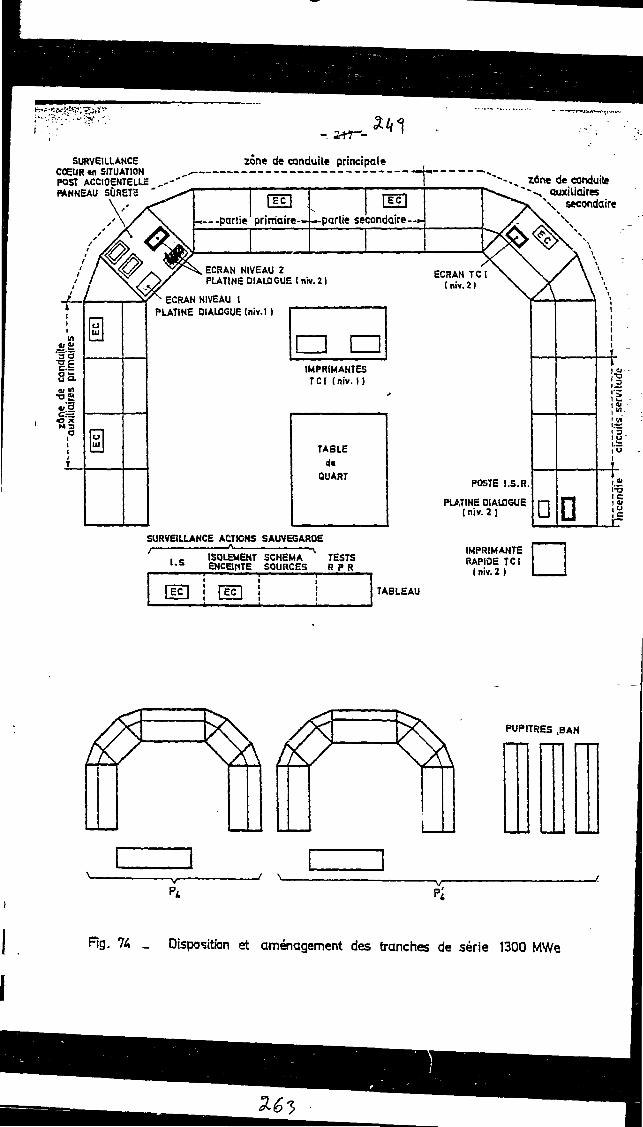
SURVEILLANCECOEUR «л SITUATIONPOST ACCIOENTELLEFANNEAU SURETS '
zône de conduite principale
ГЁс|
-partie1 primaire-.
|EC|
-partie secondaire-
ECRAN NIVEAU 2PLATINE DIALOGUE ( niv.21
zûne
de
cond
uite
•
""
auxi
liair
es p
rim
aire
s *1
lujj
luilujj
ECRAN NIVEAU 1PLATINE DIALOGUE (niv.l )
• •IMPRIMANTESTCI (ni*. 1)
SURVEILLANCE ACTtGHS SAUVEGARDE
t.S ISOLEMENT SCHEMAENCBfiTE SOURCES
TESTSR P R
~-,^ Zûne de conduiteauxiliaires
secondaire
ECRAN TCItniv.21
TABLEAU
POSTE I.S.R.
PUTINE DIALOGUE( niv. 2 )
IMPRIMANTERAPIDE TCI
lniv.2)
D
f
serv
itud
e'
circ
uits
m
is
PUPITRES ,BAN
PI
Rg. 74 _ Disposition et aménagement des tranches de série 1300 MWe

3L

pel
оо 5*3. *§

Diagnostic d'événementChoix de la procédure
Décision actions: Procédures I. A,.H
Diagnostic permanent d'étatContrôle de l'efficacité des
procédures I, A, HDécision dans le choix
de la procédure U
Appel à l'équipe de crise
EVENEMENTPERTURBATEUR
LIMITATION DESCONSEQUENCESDE L'EVENEMENTPERTURBATEUR
ACCIDENTETAT DE
L'INSTALLATIONDEGRADE
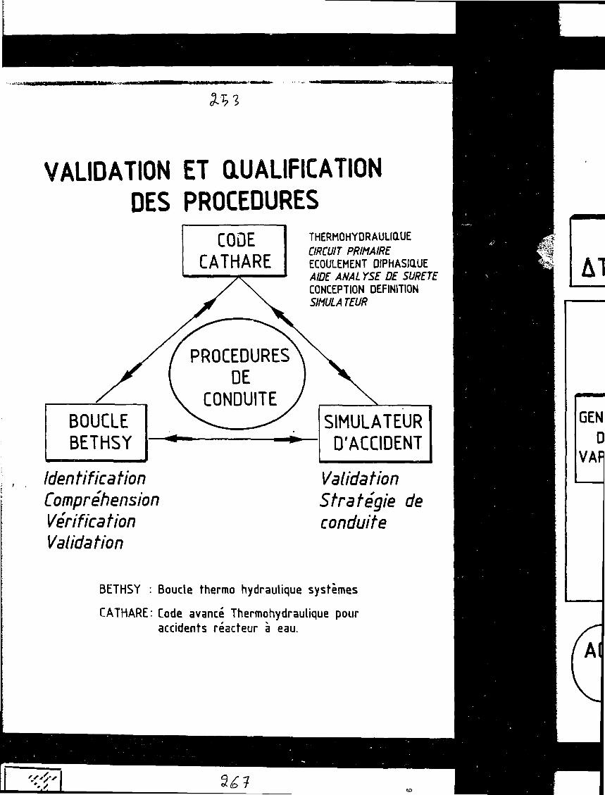
VALIDATION ET QUALIFICATIONDES PROCEDURES
BOUCLEBETHSY
IdentificationCompréhensionVérificationValidation
CODECATHARE
T H E R M O H Y D R A U L I Q L U ECIRCUIT PRIMAIREECOULEMENT DIPHASIQAJEAIDE ANAL YSE DE SURETECONCEPTION DEFINITIONSIMULATEUR
PROCEDURESDE
CONDUITESIMULATEUR
D'ACCIDENT
ValidationStratégie deconduite
BETHSY : Boucle thermo hydraulique systèmes
CATHARE: Code avancé Thermohydraulique pouraccidents réacteur à eau.
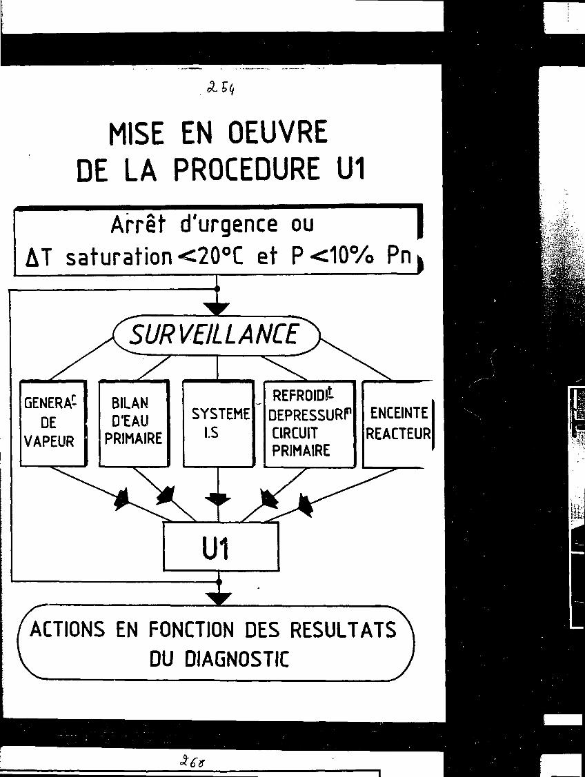
MISE EN OEUVREDE LA PROCEDURE U1
Arrêt d'urgence ou |AT saturation <20°C et P<10% Pn|
GENERA^DE
VAPEUR
XSURVE/LLANCÉJ^
BILAND'EAU
PRIMAIRE
SYSTEMEI.S
— REFROIDitDEPRESSURPCIRCUITPRIMAIRE
ENCEINTEREACTEUR
/ACTIONS EN FONCTION DES RESULTATSV DU DIAGNOSTIC
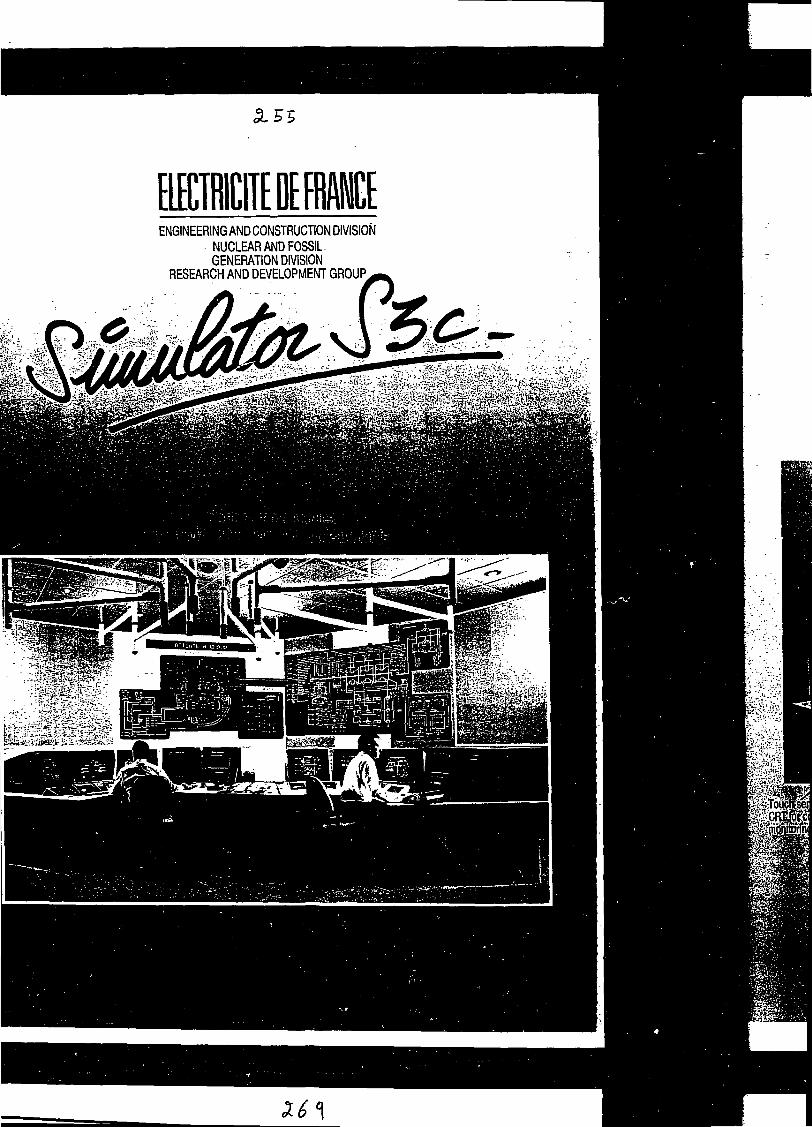
EENGINEERING AND CONSTRUCTION DIVISION
NUCLEAR AND FOSSIL-GENERATION DIVISION
RESEARCH AND DEVELOPMENT GROUP,
X6<\

The control room comprises :. 2 identical workstations for operation. 1 workstation for monitoring only (shiftsuper-
visor-safety engineer) (phase 2). 1 mural mimic-board giving an overall view
of the plant.
Full graphicCRT
Muralmimic-board
tsens.

BUREAU CHEF DE QUART
>f f ». '.'^.41 If. V^ i " . ,
CONTROLEURSPROGRAMMABLES
NIVEAU 1
SALLE DE CONTROLECOMMANDEACTIONS DE
.SAUVEGARDE
(D>3
YNOPTiaUEPANNEAU AUXILIAIRE ANIME-
f BATIMENT TURBINE
REP1400MWeN4 LOCALISATION SALLE DE CONTROLEET SYSTEME CALCULATEURS

Ч-у*•a V >
ARCHITECTURE IS VERY IMPORTANT INSUCCESS OF DESIGN
Development of System Much More Expensive than Cost of System
New Developments Being IncorporatedMicroprocessors Distributed At Many LevelsFast Communication BusesReliable, High Capacity Data Bases
Essential That Architecture Remain Open to EvolutionDesign Lifetimes of -50 Years
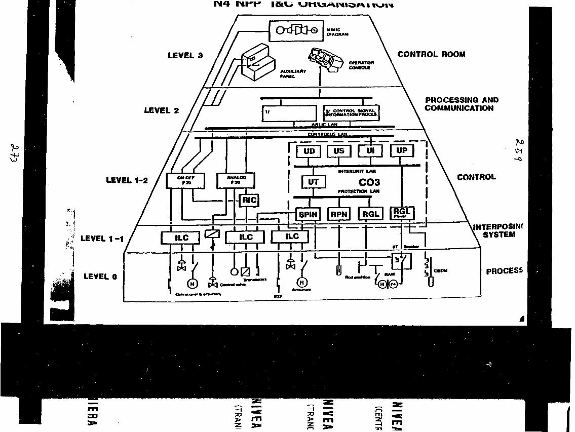
LEVEL 3 CONTROL ROOM
LEVEL 2PROCESSING ANDCOMMUNICATION
LEVEL
LEVEL
LEVEL 1 CONTROL
INTERPOSINÍ\ SYSTEM
PROCESS
з> гп > m

NIVEAU 3(CENTRALE)
NIVEAU 2(TRANCHE)
NIVEAU 1I (TRANCHE)
AIDE A LACONSIGNATION
AIDE A LADETECTION ASSISTANCE]
LOCALISATION PERSON.DEFAUTS D'ENTRETIEN
4
SURVEILLANCE ET CONDUITE (CONTROLE COMMANDE)
сCAPTEURS ACTIONNEURS
7PROCESSUS
ш&
IERARCHISATION DES INFORMATIONS ET TRAITEMENTS

я. é"\
SALLE DE CONTROLE - COMMANDE
SYNOPTIQUEMURALANIME
POSTE DE TRAVAILOPERATEURS
CONDUITETRAITEMENT D'ALARMEAIDE OPERATEUR
PANNEAUAUXILIAIRE
A В(niveau 1)
A В(niveau 1)
a::::•;•..•:•*>-••
BUS SERIE REDONDANTCgMï
Ш^тшШтШШ
NIVEAU 1
ModulesEntrée -Sortie
REP N4 1400 MWe STRUCTURE DU C0NTR3LE COMMANDE

GOALS
Sit-down controlresources concentrationsynthetic presentationevoluted alarm treatmentdiagnostic assistancehomogeneous presentationsame operator station in all conditionson-screen command
* * *
Control informations qualityvalidityconsistency
Distributed
* * *
Functions synergycontrolmaintenanceservicingtechnical management
Duplication
EtherneGKSIEEEVMEUNIX
* * *
Open-endednesson-line modification of power-plant descriptionfunctionalhardware
Software
Slide # 1
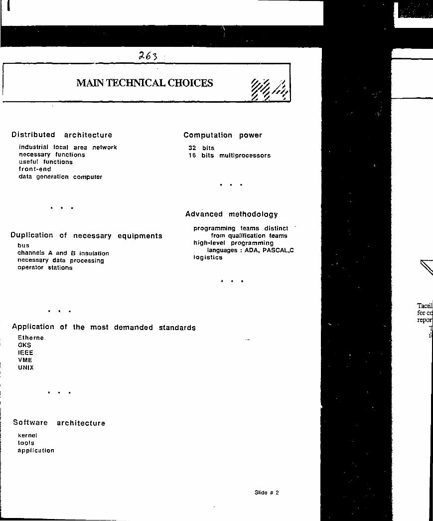
MAIN TECHNICAL CHOICES
Distributed architecture
industrial local area networknecessary functionsuseful functionsfront-enddata generation computer
Computation power
32 bits16 bits multiprocessors
Duplication of necessary equipmentsbuschannels A and В insulationnecessary data processingoperator stations
Advanced methodology
programming teams distinct 'from qualification teams
high-level programminglanguages : ADA, PASCAL.C
logistics
Application of the most demanded standardsEtherne.GKSIEEEVMEUNIX
Software architecture
kerneltoolsapplication
Slide # 2

OPERATOR STATION
Graphic CRT
1 2 3
Tactile screenfor commandreports
Tactile screenfor display calls Tactile screen
for commands
Level 2 г
Level 1 r
Alphanumeric 2-linesdisplay
Control keyboard
Alphanumeric keyboard
Alarmskeyboard
Slide # 3

GENERAL STRUCTUREOF N4 CONTROL
V* Г. л
Controlcomputers
Level 2 network •
Control room
Mimic panel andauxiliary control panei
Level2/level1 communication
Level 1 network"
Automatisms
Operatorstation
Emergency control panei
Sensors
Actuators
Slide # 4

Si 66
GENERAL SYNOPTIC
Technical information rogm _ _ _ ^ _ .'*j * * * * * * * * * * * * * * * * * * * * * * * * * * * * * * * * * * * * * * * * * * * * * * * * * ft * * * * * * \
Control room J
Channel Acomputers
Station
Mimic panel andauxiliary control panel
Station
Front-end
Station Station
Insulation
Channel Aautomatisms
•Ф"insulation
Emergencycontrol panel
Digital / Analogsensors
Channel Вcomputers
Front-end
r w w w мм ч vit w m r a i m m n *t
Channel Вautomatisms
On-off and adjustment actuators
Â
Slide # 5

ARCHITECTURE
other unit level 3 network ARLIC RETINA
technical information room
LEGEND j | GOULD computer \J DLX equipment I 1 Printer
26С ЬАТА G€NFRfi7i'o*) COMPUTER C$ p$
Slide it 6

MAIN FUNCTIONS
Processing and dialogue relative to
actuatorssensorscontrol devicesdisplays
Digital and analog internal points
Processing and dialogue relative to alarms and operativesituations
Procedures follow-up
Control sequences
Reports
Analog recordings
Balances and watch instructions
Maintenance aids
Operation aids
External computers linkage
Archieving
In-core data acquisition and parameters generation
Design status computation
Slide # 7

PERFORMANCES Ü4Digital command :
Delay < 500 ms< 1 s
90% of casesin all cases
Regulation command :
Delay < 300 ms< 1 s
90% of casesin all cases
Avalanche :
1345 status changes in 1 second
Display of an image :. any : Delay < 1,5 s
< 2 s90% of casesin all cases
"memorized" : Delay < 1 s< 1,5 s
90% of casesin all cases
Screen update :
Delay < 800 ms
Slide # 8
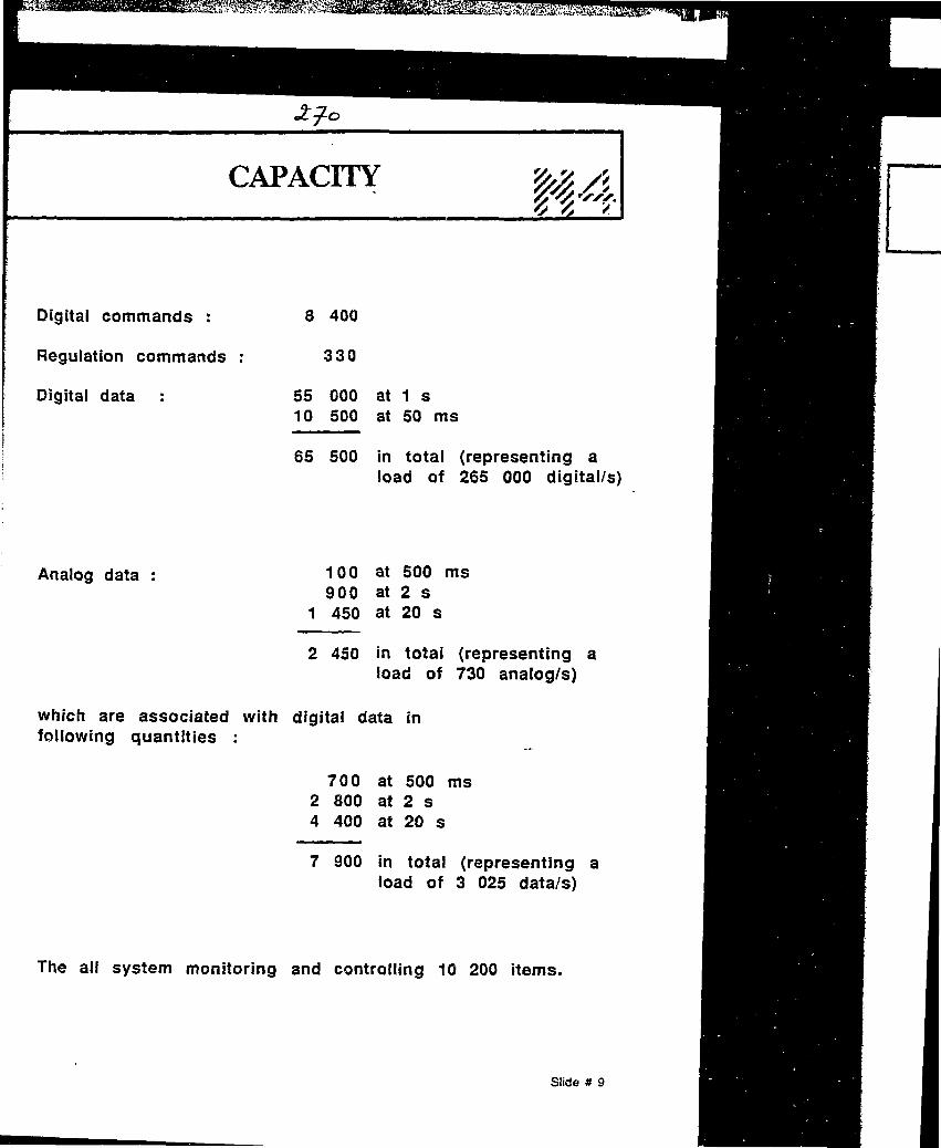
CAPACITY ЩА
Digitai commands :
Regulation commands
Digitai data
Analog data :
8 400
330
55 000 at 1 s10 500 at 50 ms
65 500 in total (representing aload of 265 000 digital/s)
100 at 500 ms900 at 2 s
1 450 at 20 s
2 450 in total (representing aload of 730 analog/s)
which are associated with digital data infollowing quantities :
700 at 500 ms2 800 at 2 s4 400 at 20 s
7 900 in total (representing aload of 3 025 data/s)
The all system monitoring and controlling 10 200 items.
Slide # 9

Command 300
Regulation 100
Monitoring 200
Control assistance 100
Data sheets 9700
Alarms sheets 3300
Pages of procedures 3000
Slide # 10
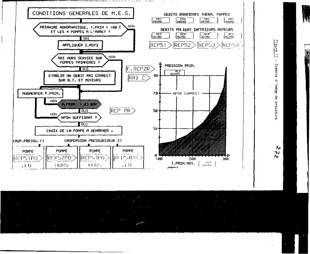
CONDITIONS1GENERRLES DE M.E.S.
XPRIMflIRE MONOPHflSIOUE. T.PRIM > 100 С
ET LES 4 POMPES R L'RRRET ?^
<_
—_ _ _ _ _ _ _ _ _ _ _ _ _ > _ _ _ _ _ _ _ _ • _ • _ _ i
I OUI
DEBITS BRRRIERES THERM. POMPESP'RRT I I HÏÏÎ 1 f " R R I I I ItfVIивьно I UH6MD I Ua/мп l 1з.шш.
NON
flPPLIQUER I.RCP3
DEBITS PflLIERS INFERIEURS MOTEURS
IIBIRCF"
IBIMD1 r"RCp-I I36IMI)
RRI HORS SERVICE SUR \NO N
POMPES PRIMRIRES 1
| OUI
ETflBLIR UN DEBIT RRI CORRECT
SUR B.T. ET MOTEURS
F.RCP2R>
RRÎ~C> 90
PRESSION PRIM.
CHOIX DE LR POMPE fl DEMHRRER i
RSP.PRESSU.1JM.
POMPE
(RSPERSION PRESSURISEUR Z)
N
POMPE
1 Ю\<Ъ
POMPE
|RCPL)1Pf|N>
HIJKS
POMPE
Rf P'.viPM >„I N
100 2 0 0T.PRIM.MOY.
U l l l l l
JRCPjfT> |RCP52> |jïÇPb3J
I RÎT|4Ü?M[I
юс-1n>
•D
ФO.
из•mexn>
•o-sоn<t.a.с
4JЛо

CONTROL ROOM
PLANT COUPUTER
TCI
(NCI
OPERATORS CONTROL DESK
CONVENTIONAL DEVICES
(NCandiE)
CLOSED LOOP CONTROL
BAILEY 9020 <P4)
11 Z (P"«)[ NC FUNCTIONS)
LOGIC PROGRAMMABLECONTROLLERS
CONTROBLOC
(NO » IE FUNCTIONS)
PROTECTION SYSTEM
SPIN
(IE FUNCTIONS)
INSTRUMENTATION AND ACTUATORS
Ra.i
1300 l.«io SERIES. 1 & С ARCHITECTURE
HARDWIRE CONNECTIONS
SUS LINKS (PONT TO POINT UNKS)
/
CO^П•ROLROOM OPERATORSWORKSTATIONS
(IPS. MCI
COMPUTERSYSTEM
OPS-NCI
КЮ
LOGIC i CLOSED LOOPPROGRAMMABLE CONTROLLERS
S C A T (CONTRONICE)
NC1PS-NCFUNCTIONS
KFUNCnONS
CLOSED LOOPCONTROL
GCTA
(lEFUNCTDNS)
LOGICCONTROL
C S 3
(1EFUHCTCNS)
PROTECTIONSYSTEM
SPIN
(IE FUNCTIONS)
INSTRUMENTATION AND ACTUATORS
RQ.2
14O0 MWe SERIES ARCHITECTURE
KARDWIHEUNKS
BUSUMQ
\ /
Canada
Advisory Group Meeting
on
"Guidelines for Control Room Design"
Vienna, 15 - 19 June 1992
LIST OF PARTICIPAHTS
Mr. R.A. OlmsteadAECL CANDUControl Centre Development2251 Speakman DriveMississaugaOntario L5K 1B2Tel: (416) 823 9040Fax: (416) 823 8006
Mr. E. RlnttilaImatran Voima OyP.O. Box 112SF-01601 VantaaTel: +358 0 5081Fax: 358 0 5666235
Mr. J. FuretCEH/FARMICE/Direction de la Surete des
Installations Nucléaires, BP Nr. 692265 Fontenay-aux-Roses Cedex FTel: 33 1 46 54 71 98Fax: (33) 1 42 53 76 42
Mr. С. HesslerSiemens AG KWU
R-242
P.O. Box 3220D-8520 Erlangen
Fax: 09131 189908
Mr. Yushi Fujita
Control Board and Plant ComputerEngineering Team
Mitsubishi Atomic Power Industries Inc.4-1, 2-Chome, Sibakouen, Minato-kuTokyo 105
Tel: 81 3 3433 8251Fax: 81 3 3433 8205

REP N4 1400 MWe STRUCTURE DU CONTROLE COMMANDE
- 2 -
Russian FederationMr. A.I. GorelovResearch and Development Institute ofPower Engineering
2/8 Krasnosel'skaja107113 MoscowTel: 264 44 10 or 975 20 20Fax: 007 095 975 20 19
USA
IAEA
Mr. Paul van GemstABB Atom ABS-721 63 VãsterasTel: 021 10 70 00Fax: 021 12 43 22
Mr. Karl RollenhagenVattenfall ABS-162 87 VallingbyTel: 08 739 50 00Fax: 08 37 01 70
Mr. J. NaserElectric Power Research InstituteHuclear Power Division3412 Hillview Avenue, P.O. Box 10412Palo AltoCA 94303Tel: 415 855 2119Fax: 415 855 1026
Mr. A. KossilovInternational Atomic Energy AgencyDivision of Nuclear PowerWagramerstrasse 5, P.O. Box 100A-1400 Vienna, AustriaFax: 1 234564Telex: 1 12645Tel: 1 2360 2796
AKossilov/jd/1831r1992-06-24