PROCEEDINGS - International Atomic Energy Agency
354
CERN 87-11 ECFA 87/110 12 October 1987 EW DEVELOPMENTS IN A R T I C L E A C C E L E R A T I O N TECHNIQUES PROCEEDINGS Editor: S. Turner Vol. ï ECFA-CAS/CERN-IN2P3-IRF/CEA-EPS WORKSHOP held at Orsay, France 29 June - 4 July 1987
-
Upload
khangminh22 -
Category
Documents
-
view
0 -
download
0
Transcript of PROCEEDINGS - International Atomic Energy Agency

C E R N 87-11 E C F A 87 /110 12 Oc tobe r 1987
E W D E V E L O P M E N T S I N A R T I C L E A C C E L E R A T I O N T E C H N I Q U E S
PROCEEDINGS Editor: S. Turner
Vol. ï
E C F A - C A S / C E R N - I N 2 P 3 - I R F / C E A - E P S W O R K S H O P
held at
Orsay, France
29 June - 4 July 1987

©Copyright C E R N , Genève, 1987
Propriété littéraire et scientifique réservée pour tous les pays du monde. Ce document ne peut être reproduit ou traduit en tout ou en partie sans l'autorisation écrite du Directeur général du CERN, titulaire du droit d'auteur. Dans les cas appropriés, et s'il s'agit d'utiliser le document à des fins non commerciales, cette autorisation sera volontiers accordée. Le C E R N ne revendique pas la propriété des inventions brevetables et dessins ou modèles susceptibles de dépôt qui pourraient être décrits dans le présent document; ceux-ci peuvent être librement utilisés par les instituts de recherche, les industriels et autres intéressés. Cependant, le C E R N se réserve le droit de s'opposer à toute revendication qu'un usager pourrait faire de la propriété scientifique ou industrielle de toute invention et tout dessin ou modèle décrits dans le présent document.
Literary and scientific copyrights reserved in ail countries of the world. This report, or any part of it, may not be reprinted or translated without written permission of the copyright holder, the Director-General of CERN. However, permission will be freely granted for appropriate noncommercial use. If any patentable invention or registrable design is described in the report, C E R N makes no claim to property rights in it but offers it for the free use of research institutions, manufacturers and others. CERN, however, may oppose any attempt by a user to claim any proprietary or patent rights in such inventions or designs as may be described in the present document.
CERN—Service d'Information scientifique—RD/748-3000-Octobre 1987

- i i i -
ABSTRACT
A Workshop organised jointly by the European Committee for Future Accelerators (ECFA),
the CERN Accelerator School (CAS), the Institut National de Physique Nucléaire et de Phy
sique des Particules (IN2P3), the Institut pour la Recherche Fondamentale/Commissariat à
l'Energie Atomique (IRF/CEA) and the European Physical Society (EPS) was held at the Labor
atoire de l'Accélérateur Linéaire (LAL), Orsay, from 29 June to 4 July 1987. Its purpose
was to review current experimental and theoretical developments in charged-particle accele
rator techniques and to address problems related to future very-high-energy machines.
These proceedings contain the great majority of the papers presented at the Workshop,
the corresponding questions and answers, and the round-table discussion. The principal to
pics were semi-conventional high-frequency linacs, transformer acceleration mechanisms,
acceleration using plasma, e +e~ sources including low-emittance production and preserva
tion, final focus and interaction point, and other new ideas. Among the latter were open
accelerating structures, crystal X-ray accelerators, ferroelectrics, and acceleration using
lasers.


- V -
ECFA Advisory Panel
on New Techniques for Particle Acceleration
U. Amaldi
J. Campos
G. Coignet (Chairman)
M. Eriksson
R. Evans
J. Le Duff
S. Tazzari
M.Q. Tran (Secretary)
T. Weiland
CERN, Geneva
Complutense Uni v., Madrid
LAPP, Annecy
Max Lab., Lund
RAL, Chilton
LAL, Orsay
INFN, Frascati
EPF, Lausanne
DESY, Hamburg
Scientific Organising Committee
U. Amaldi, CERN, Geneva
M. Banner, CEN-Saclay
P.O. Bryant, CERN, Geneva
J. Buon, LAL-Ors ay
J. Campos, Complutense Univ., Madrid
G. Coignet, LAPP, Annecy
T. Ekelöf, University of Uppsala
R. Evans, RAL, Chilton
K. Johnsen, CERN, Geneva
J. Le Duff, LAL, Orsay
W. Schnell, CERN, Geneva
S. Tazzari, INFN, Frascati
M. Tran, EPF, Lausanne
S. Turner, CERN, Geneva
T. Weiland, DESY, Hamburg
W. Willis, CERN, Geneva
Local Organising Conittee
M. Banner, CEN-Saclay
J. Boratav, CEN-Saclay
P.J. Bryant, CERN, Geneva
J. Buon, LAL, Orsay
G. Coiqnet, LAPP, Annecy
J. Le Duff, LAL, Orsay
N. Mathieu, LAL, Orsay
S. von Wartburg, CERN, Genevn

- vii -
FOREWORD
In 1982 the European Committee for Future Accelerators (ECFA) in collaboration with
the Rutherford Appleton Laboratory (RAL) organised a Workshop in Oxford on "The Challenqe
of Ultra-high Energies". Two years later, with the help of the CERN Accelerator School
(CAS) and the Istituto Nazionale di Fisica Nucleare (INFN), ECFA ran a Workshop on "The
Generation of High Fields" which took place in Frascati. The present Workshop on "New
Developments in Particle Acceleration Techniques" is the third one in this series. It was
held at the Laboratoire de l'Accélérateur Linéaire (LAL) d'Orsay, and was organised by ECFA
together with CAS, the Institut National de Physique Nucléaire et de Physique des Parti
cules (IN2P3), the Institut pour la Recherche Fondamentale/Commissariat à l'Energie Atomi
que (IRF/CEA) and the European Physical Society (EPS). This series of meetings is comple
mentary to the American series held in Los Alamos 1982, Malibu 1985 and Madison 1986.
Research into new particle acceleration techniques extends from conventional accelera
tor physics into the fields of lasers and plasmas. It was the purpose of the Orsay meeting
to bring together physicists from these different disciplines and to give them the oppor
tunity to discuss the 1atest progress in new or conventional acceleration methods including
particle sources, RF power sources, focalisation and interaction regions and to try to de
fine the most promising areas for further study. Attendance at the Workshop was truly in
ternational ; of the 150 participants about a quarter were from the USA while Australia,
Canada, China, Finland, Japan and USSR were all represented by one or more participants,
CERN Member States participants making up the rest. There was also a good balance of par
ticipants among the different disciplines.
After a short introduction by G. Coignet, the opening address was given by M. Davier,
Director of LAL-Orsay. The meeting then started with a few invited talks. Ch. Llewelyn-
Smith presented the physics motivation for higher energies, underlying the rich rewards ex
pected when constituent particles collide at energies around 1 TeV. The major domains of
activity in new acceleration techniques, going from the nearly conventional methods to the
more futuristic ones were reviewed by H. Henke, S. Aronson and J.L. Bobin. Then R. Palmer
stressed the importance of parameter interdependence and the implication for any type of
acceleration method. J. Seeman and R. Sheppard presented a status report on SLC, which can
be considered as the first practical test for linear colliders. Finally, C. Rubbia under
lined the importance of the complementary approaches, that is /s = 1-2 TeV electron-posi
tron colliders and /s = 20-40 TeV proton-proton colliders. He also stressed that lumino
sity L 1s as important as centre-of-mass energy /s, i.e. L > 1 0 3 3 cm" 2 s" 1 is needed in
both cases. The importance of parallel development of new detectors able to cope with such
a luminosity was also highlighted.

- viii -
During the main part of the meeting, the morning sessions were devoted to the presen
tations of individual contributions and their discussion, while the afternoons were reserv
ed for the activities of the five Working Groups (see programme hereafter). The final
session was used for summary reports from the conveners of each of the Groups and for a
concluding round-table discussion chaired by K. Johnsen.
At the meeting, a variety of new experimental results were presented. In addition,
from the studies performed during the recent years, it now appears that a better under
standing of the problems is emerging. All this leads to the belief that "semi-conventional
1inac" schemes are the way to go to build tomorrow's e +e~ colliders. Work in this direc
tion 1s presently proceeding with the /s = 2 TeV CERN Linear Collider (CLIC) and with the
/s = 1 TeV Stanford Collider (SC) projects. These studies have stimulated worldwide work
on the design of power sources such as superconducting RF cavities, gyrotrons, relativistic
klystrons, lasertrons, etc. Electron gun development is under way and solutions are get
ting close to fulfi 11ing the needs of the semi-conventional linacs. Positron sources, on
the other hand, were barely touched at this meeting but further developments would certain
ly be worthwhile. The required emittances can be provided by damping rings but these are
coming to their limits and new ideas were put forward at the meeting which seem to have
much merit. Near-conventional quadrupole systems seem to be adequate for achieving the fi
nal focus at the interaction point but alternative devices may be necessary to achieve the
ultimate goal. General theoretical studies continue to explore the problems of parameter
interdependence, sealing laws, multibunch operation, final focus and interaction region.
The Workshop also confirmed the flourishing programme on more futuristic approaches.
The wakefield transformer has recently achieved particle acceleration, and for the switched
pulse 1inac effort is concentrated on developing triqgered switches. Many groups work both
experimentally and theoretically on plasma based accelerators, plasma beat-waves, plasma
wakefield, wakeatron, etc. Although these schemes presently look more suitable for the
after-tomorrow multi-TeV colliders, proof of principle experiments are going on, and im
portant steps in understanding the fundamental problems are being made. A more Immediate
output of these plasma schemes could be to use the very strong fields they generate to
focus the beams at the interaction point. Other new ideas for acceleration, still at the
conceptual stage, were also presented.
Final ly, it was underlined on many occasions that it is urgent to develop novel in
strumentation related to the specific problems of these new linear colliders. For example,
measurements of beam spatio-temporal dimensions, beam emittances, component alignment and
associated feedback systems, all need attention.
The above arguments are developed in detai1 in over 60 papers presented in these pro
ceedings, the relatively high number amply demonstrating the current keen interest in this
field. Despite an extremely tight deadline in order for the proceedings to be published
while the subjects presented are sti11 topical, the vast majority of the state-of-the-art
talks and those topics presented only to the Working Groups have been written up.

- ix -
In addition very convenient summaries of the information presented have been prepared by
the conveners of each of the Working Groups and these appear at the beginning of each sec
tion of these proceedings. Some very novel acceleration concepts are also included in the
section entitled "New Ideas". An attempt has also been made to transcribe from tape
recordings the comments made after each of the oral presentations and during the concluding
round-table discussion. However, caution is necessary with the latter since, in the time
available, it has not been possible to check all of the statements with their author.
On behalf of the Organising Committee we thank the sponsors of this meeting ECFA,
CAS/CERN, IN2P3, IRF/CEA and EPS, and also Thomson CSF, Alsthom and Compagnie Générale
d'Electricité. Special acknowledgements are due to the conveners for guiding with enthusi
asm the work and discussions in their Groups and for providing so quickly a synthesis of
the results achieved. The speakers, scientific secretaries and participants and especially
the authors of the papers presented here also deserve our thanks. In particular we
acknowledge the efforts of J. Buon, P.J. Bryant, J. Le Duff and of the senior secretaries
Jacqueline Boratav, Nicole Mathieu and Suzanne von Wartburg, and our hosts at Orsay, all of
whom ensured that the meeting ran so smoothly. Finally, a special word for Barbara
Strasser who corrected or typed all of the proceedings.
G. Coignet Chairman of the Workshop
S. Turner Editor

- x -
WORKSHOP PROGRAMME
09.15
10.15 10.35
I 1.35 11.45
12.45
14.45
15.45 16.05
17.05 17.15
18.15
M o n d a y 2 9 J u n e
T u e s d a y 3 0 J u n e
W e d n e s d a y 1 J u l y
T h u r s d a y 2 J u l y
F r i d a y 3 J u l y
S a t u r d a y 4 J u l y
Opening Address
M. Davier
Parameter Interdependence
R.B. Palmer
S T A T E 0 F Working Group Summaries
Coffee Horizons of
HEP C. Llewellyn-
Smith J. Seeman J. Sheppard
T H E A R T Working Group Summaries
Break RF LINACS and
Power Conversion
U, Menke T A L K S
Summary Round Table. Chairman : X. Johnsen
Lunch Non-resonant
Field Generation S. Aronson
Working Group Organization Working Groups
E X
Working Groups
Tea C Tea Laser and Plasma
Acceleration J.L. Bobin Working Working
u R S I 0 Working
Break Groups Groups
N Groups Issues in the Long Term
Development of CERN
C. Rubbia
Groups Groups Groups
Welcome C o c k t a i l Concert Banquet
tlorki nq/DI s c u s s i on Groups
S u b j e c t Conveners
Semi-conventional high-frequency 1inacs
Transformer acceleration mechanisms
Acceleration using plasma
e+e- sources, low emittance production and preservation
Final focus and interaction point
W. Schnei 1, A. Sessler
T. Weiland, P. Wilson
R. Evans, T. Katsouleas
J. Le Duff, C. Pelleqrini
P. Chen, B. Montague

- xi -
State-of-the-art Talks
SUBJECT SPEAKER
Semi-Conventional Linacs
Conventional power sources for colliders M. Allen Beam dynamics issues in big linear colliders R. Ruth RF pulse distortion in travelling wave linac structures G. Geschonke Parameter choice for linear colliders in multibunch operation J. Claus A study of tolerances for low emittance damping rings P. Krejcik
Transformer Acceleration Mechanisms, Lasertron and Sources
The wake-field transformer experiment at OESY Hollow beam gun Hollow beam measurements Computer simulations for the DESY wakefield transformer
experiment Model measurements for the switched power linac SLAC lasertron Lasertron experiments and high-gradient structures in Japan Accelerator R & D at Orsay Ribbon lasertron: RF power source for TeV linac colliders New idea for laser production of very high electron densities Los Alamos high-brightness electron injector High current density photoemission from metals in nano
and picosecond pulses
T. Weiland W. Bialowons F. Decker
P. Wilhelm J. Knott M. Allen T. Shidara J. Le Duff P. Mclntyre J.P. Girardeau-Montaut R. Jameson
T. Srinivasan-Rao
Plasma Acceleration
UCLA beat-wave accelerator programme Beat-wave acceleration experiments at INRS-Energie Plasma heatwave experiment at RAL CO2 laser-REB interaction: beatwave acceleration Interaction experiments in long & homogeneous plasmas
at the GRECO ILM Theoretical work at UCLA on plasma accelerators Theoretical results on laser acceleration of particles Limitations due to Brillouin and modulation instabilities
for the beatwave accelerator Spatio-temporal energy cascading in the beatwave accelerator The charged particle acceleration by HF-wave field in plasma
C. Joshi F. Martin A. Dymoke-Bradshaw M. Nakatsuka
F. Amiranoff T. Katsouleas P. Mora
D. Pesme C. McKinstrie
Final Focus, New Ideas, Technology
The nature of beamstrahlung P. Chen Applications of high power, intense beams to electron
acceleration J. Nation Ferroelectrics in accelerator, physics K. Zioutas Gyrotron M.Q. Tran Physics of relativistic klystrons S. Yu High-gain FEL's at short wavelengths K.J. Kim Cost optimization of induction linac drivers of linear colliders W. Barletta Plasma lenses for focusing particle beams H. Riege A diffraction radiation model for energy losses for a
simple geometry L. Palumbo

- xiii -
CONTENTS Page
Volume I
Foreword v i i
Opening Address, M. Davier 1
INVITED PAPERS 5
HORIZONS OF HIGH ENERGY PHYSICS, C H . Llewellyn Smith 7
RF LINACS AND POWER CONVERSION, H. Henke 23
NON-RESONANT FIELD GENERATION, S.H. Aronson 48
LASERS AND PLASMAS IN PARTICLE ACCELERATION, J.L. Bobin 58
THE INTERDEPENDENCE OF PARAMETERS FOR TeV LINEAR COLLIDERS, R.B. Palmer 80
STATUS OF THE SLC, J.T. Seeman and J.C. Sheppard 122
GROUP 1: SEMI-CONVENTIONAL HIGH-FREQUENCY LINACS 135
SUMMARY OF WORKING GROUP 1 ON SEMI-CONVENTIONAL HIGH-FREQUENCY LINACS, 137 W. Schnell and A.M. Sessler
BEAM DYNAMICS ISSUES FOR LINEAR COLLIDERS, R.D. Ruth 147
CHOICE OF PARAMETERS FOR LINEAR COLLIDERS IN MULTI-BUNCH MODE, J. Claus 161
DISTORTION OF A SHORT RF PULSE IN TRAVELLING-WAVE ACCELERATING STRUCTURES, 181 G. Geschonke
STUDIES OF A FREQUENCY SCALED MODEL TRANSFER STRUCTURE FOR A TWO-STAGE 188 LINEAR COLLIDER, T. Garvey, G. Geschonke, W. Schnell and I. Wilson
HIGH AVERAGE POWER LINEAR INDUCTION ACCELERATOR DEVELOPMENT, J.R. Bayless 195 and R.J. Adler
POSSIBLE PARAMETERS OF PULSERS FOR LINEAR INDUCTION LINACS, V.l. Bobylev 202
COST OPTIMIZATION OF INDUCTION LINAC DRIVERS FOR LINEAR COLLIDERS, 205 W.A. Barletta
CONVENTIONAL POWER SOURCES FOR COLLIDERS, M.A. Allen 220
HIGH POWER GYROTRONS AS MICROWAVE SOURCES FOR PARTICLE ACCELERATORS, 223 M.Q. Tran
PHASE CONTROL OF THE MICROWAVE RADIATION IN FREE ELECTRON LASER 231 TWO-BEAM ACCELERATOR, Y. Goren and A.M. Sessler
PHYSICS OF RELATIVISTIC KLYSTRONS, S.S. Yu 239
- xiv -
LASERTRON DEVELOPMENT AND TESTS OF HIGH GRADIENT ACCELERATING STRUCTURES 244 IN JAPAN, T. Shidara
ACCELERATOR R & D AT LAL-ORSAY, J. Le Duff 253
LASERTRON COMPUTER SIMULATION AT ORSAY: "RING" CODE, A. Dubrovin and 259 J.P. Coulon
GIGATRON, H.M. Bizek, P.M. Mclntyre, D. Raparia and C A . Swenson 264
THE MICROLASERTRON, R.B. Palmer 272
GROUP 2: TRANSFORMER ACCELERATION MECHANISMS 289
SUMMARY OF WORKING GROUP 2 ON TRANSFORMER MECHANISMS, T. Weiland 291
THE WAKE FIELD TRANSFORMER EXPERIMENT AT DESY, W. Bialowons, H.-D. Bremer, 298 F.-J. Decker, H.-Ch. Lewin, P. Schutt, G.-A. Voss, Th. Weiland and X. Chengde
HOLLOW BEAM GUN FOR THE WAKE FIELD TRANSFORMER EXPERIMENT AT DESY, 308 W. Bialowons, H.-D. Bremer, F.-J. Decker, H.-Ch. Lewin, P. Schutt, G.-A. Voss, Th. Weiland and X. Chengde
HOLLOW BEAM MEASUREMENTS, W. Bialowons, H.-D. Bremer, F.-J. Decker, 317 H.-Ch. Lewin, P. Schutt, G.-A. Voss, Th. Weiland and X. Chengde
COMPUTER SIMULATIONS FOR THE DESY WAKE FIELD TRANSFORMER EXPERIMENT, 327 W. Bialowons, H.-D. Bremer, F.-J. Decker, H.-Ch. Lewin, P. Schutt, G.-A. Voss, Th. Weiland and X. Chengde
FEASIBILITY STUDIES FOR THE SWITCHED POWER LINAC, J. Knott 336
Volume II
GROUP 3: ACCELERATION USING PLASMA 343
SUMMARY OF WORKING GROUP 3 ON ACCELERATION USING PLASMAS, R.G. Evans and 345 T. Katsouleas
EXPERIMENTAL WORK AT UCLA ON THE PLASMA BEAT WAVE ACCELERATOR, C. Joshi, 351 C. Clayton, K. Marsh, R. Williams and W. Leemans
EFFECT OF ELECTRON DENSITY MISMATCH ON THE SATURATION AMPLITUDE OF THE 360 PLASMA BEAT WAVE, F. Martin, J.P. Matte, H. Pe'pin and N.A. Ebrahim
THE IC/RAL BEAT-WAVE EXPERIMENTS, A.E. Dangor, A.K.L. Dymoke-Bradshaw, 375 A. Dyson, T. Garvey, I. Mitchell, T. Afshar-Rad, A.J. Cole, C.N. Danson, C.B. Edwards and R.G. Evans
REB-CO2 LASER INTERACTION PROGRAM, "I PROGRAM", BEAT WAVE ACCELERATION, 386 Y. Kitagawa, H. Fujita, S. Nakayama, K. Sawai, K. Mima, H. Takabe, K. Nishihara, M. Nakatsuka, S. Nakai, C. Yamanaka, N. Ohigashi, T. Minamihata and T. Matsumoto
INTERACTION EXPERIMENTS IN LONG AND HOMOGENEOUS PLASMAS, F. Amiranoff, 392 C. Labaune, C. Rousseaux, B. Mabille, P. Mora, D. Pesme, G. Matthieussent, H. Baldis
ELECTRON DENSITY MEASUREMENT IN A PLASMA BY THREE-WAVE INTERFEROMETRY, 397 L.-P. Says and M. Dupont

- XV -
THEORETICAL WORK ON PLASMA ACCELERATORS AT UCLA, T. Katsouleas, J.M. Dawson, 401 W.B. Mori, J.J. Su and S. Wilks
SATURATION MECHANISMS IN THE PLASMA BEAT WAVE ACCELERATOR, P. Mora 412
LIMITATION OF THE BEAT-WAVE GENERATION DUE TO THE MODULATIONAL AND DECAY 418 INSTABILITIES, 0. Pesme, S.J. Karttunen, R.R.E. Salomaa, G. Laval and N. Silvestre
ENERGY CASCADING IN THE BEAT-WAVE ACCELERATOR, C.J. McKinstrie and 443 S.H. Batha
DEPHASING EFFECTS IN BEAT-WAVE ACCELERATION, R.R.E. Salomaa and 458 S.J. Karttunen
WAKE-FIELD OF CHARGED PARTICLES IN A PLASMA, E.A. Acopian and 472 G.G. Matevossian
CHARGED PARTICLE ACCELERATION BY MICROWAVE FIELD IN PLASMA, E.A. Acopian 476 and G.G. Matevossian
HIGH LONGITUDINAL ELECTRIC FIELDS AND DOUBLE LAYERS IN LASER PRODUCED 480 PLASMAS FOR PARTICLE ACCELERATION, H. Hora, F. Green, S. Eleizer, J.C. Kelly and H. Szichman
GROUP 4: e + e - SOURCES, LOW EMITTANCE PRODUCTION AND PRESERVATION 491
SUMMARY REPORT OF WORKING GROUP 4 ON e +e" SOURCES, LOW EMITTANCE PRODUCTION AND PRESERVATION, C. Pellegrini and J. Le Duff PART I, DAMPING RINGS, C. Pellegrini 493 PART II, HIGH BRIGHTNESS GUNS, J. Le Duff 497
PHOTOCATHODES IN ACCELERATOR APPLICATIONS, J.S. Fraser, R.L. Sheffield, 501 E.R. Gray, P.M. Giles, R.W. Springer and V.A. Loebs
SHORT-PULSE HIGH-CURRENT-DENSITY PHOTOEMISSION IN HIGH ELECTRIC FIELDS, 506 J. Fischer and T. Srinivasan-Rao
NEW IDEA FOR LASER PRODUCTION OF VERY HIGH ELECTRON DENSITIES, 516 J.-P. Girardeau-Montaut and C. Girardeau-Montaut
MULTIPOINT Sip CESIATED PHOTOCATHODES FOR LASERTRON DEVICES, A. El Manouni 525 and M. Querrou
A STUDY OF TOLERANCES FOR LOW EMITTANCE DAMPING RINGS, P. Krejcik 530
NOTES ON THE PRINCIPLES OF LOW-EMITTANCE SOURCES, M. Cavenago 537
LINEAR EMITTANCE DAMPER WITH MEGAGAUSS FIELDS, W.A. Barletta 544
GROUP 5: FINAL FOCUS AND INTERACTION POINT 549
SUMMARY REPORT OF THE WORKING GROUP 5 ON FINAL FOCUS AND INTERACTION POINT, 551 P. Chen and B. Montague
PLASMA LENSES FOR FOCUSING PARTICLE BEAMS, H. Riege 554
NOISE IN PLASMA LENSES FOR HIGH ENERGY PARTICLE BEAMS, R.G. Evans 573
A FLAT BEAM FINAL FOCUS SYSTEM, A. Chao, J. Hagel, F. Ruggiero and B. Zotter 577
A STUDY OF THE FEASIBILITY OF AN OPEN RESONATOR AS A DEVICE FOR FOCUSING 587 A BUNCHED BEAM, E. Brambilla

- xvi -
QUANTUM BEAMSTRAHLUNG FROM GAUSSIAN BUNCHES, P. Chen 593
PARTICLE IN CELL SIMULATIONS OF DISRUPTION, W.M. Fawley and E.P. Lee 605
SMALL DISRUPTION REVISITED, J. Perez Y. Jorba 610
NEW IDEAS 621
APPLICATION OF HIGH POWER, INTENSE ELECTRON BEAMS TO ULTRA HIGH ENERGY 623 ELECTRON ACCELERATORS, J.A. Nation, A. Anselmo and S. Greenwald
OPEN ACCELERATING STRUCTURES, R.B. Palmer 633
CRYSTAL X-RAY ACCELERATOR, T. Tajima and M. Cavenago 642
CRYSTAL AS A LINAC STRUCTURE FOR X-RAYS, T. Tajima and M. Cavenago 649
FERROELECTRICS AND THEIR POSSIBLE USE IN ACCELERATOR PHYSICS, K. Zioutas 660
2 MeV GAMMA RAYS FROM LASER-ACCELERATED ELECTRONS, N.K. Sherman, 675 N.H. Burnett and G.D. Enright
PROGRESS TOWARDS A LASER ACCELERATOR, N.K. Sherman and P.B. Corkum 685
A DIFFRACTION RADIATION MODEL FOR ENERGY LOSSES, L. Palumbo 689
CLOSING ROUND-TABLE DISCUSSION 693
LIST OF PARTICIPANTS 705
OPENING ADDRESS
M. DAVIER
Labora to i re de l ' Accé l é r a t eu r L inéa i re - Orsay - France
Let me varmly welcome a l l of you at Orsay on the campus of our un ive r s i t y . We a r e
extremely honoured to host this workshop and we f ind this p a r t i c u l a r l y f i t t i n g s ince
research on and with acce le ra tors has always occupied a l a rge part of the a c t i v i t i e s ' at
Orsay s ince the very beginning, some 30 years ago.
In 1956, Frédér ic Jo l i o t and Irène Jo l i o t -Cu r i e i n s t a l l e d here the I n s t i t u t e of
Nuclear Physics and a 200 MeV synchrocyclotron was b u i l t . I t i s s t i l l in use, a cce l e r a t i ng
protons and l i g h t ions . At near ly the same time, the construction of the e l ec t ron l i n a c
was undertaken under the leadership of Hans HaIban. It vas b u i l t in s teps , eventua l ly to
reach an energy of 2.3 GeV, the l a rges t l i n ac before SLAC went into operat ion . This was the s t a r t of LAL, the Laboratoire de l ' A ccé l é r a t eu r L inéa i re . Some more a cce l e ra to r s a re
to be found at Saclay only a few kilometers away : the 2 GeV Saturne synchrotron and a 600
MeV e l ec t ron l inac with good duty cyc le . A l a rge concentration of exper t i se there fore
exists in this a rea .
Such an environment has played an important ro le for acce le rator development and
research - we are getting c lose r to the subject of this workshop ! Let me i l l u s t r a t e th i s
with our best example : the development of the technique of e + e _ storage r i n g s .
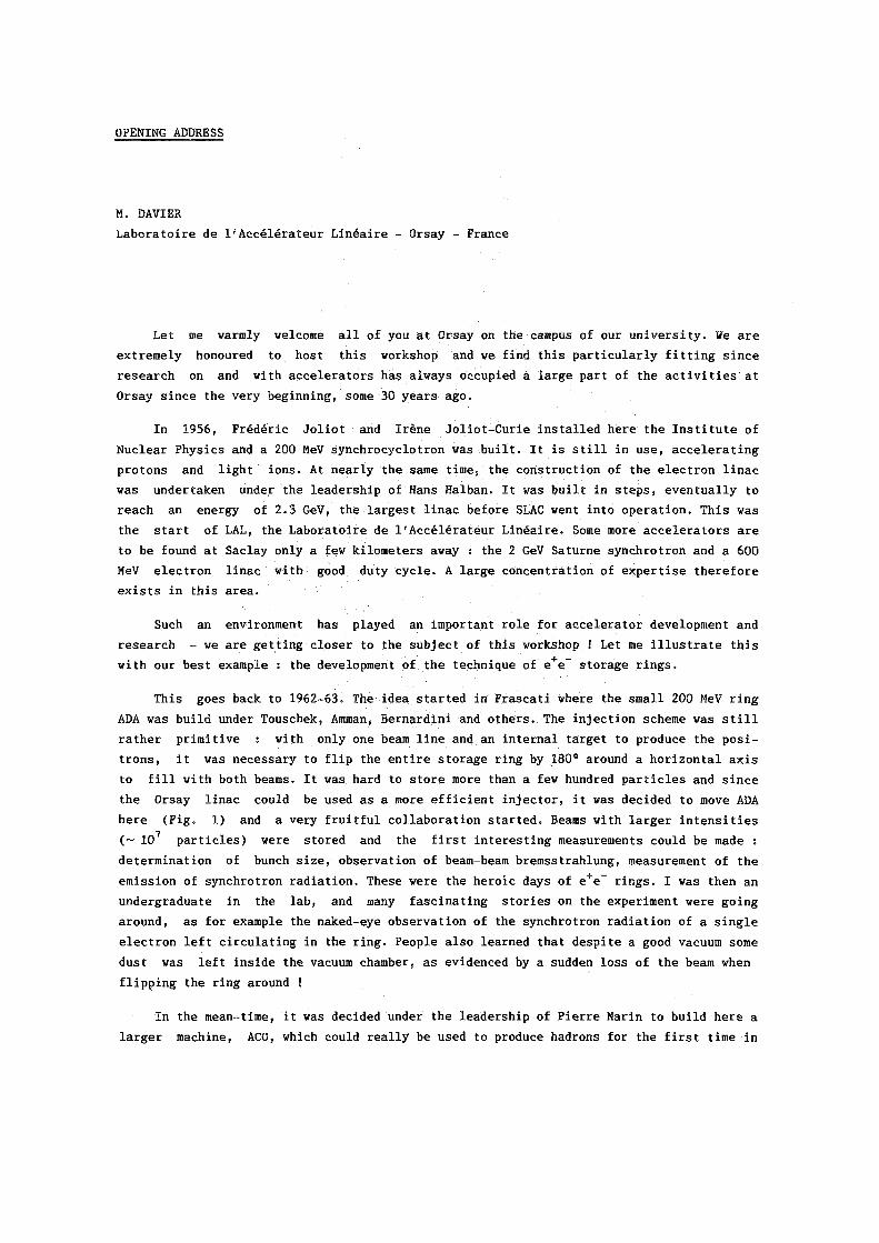
This goes back to 1962-63. The idea s ta r ted in Frascati where the small 200 MeV r ing
ADA was bu i ld under Touschek, Amman, Bernardini and others . The in ject ion scheme was s t i l l
ra ther pr imit ive : with only one beam line and an interna l target to produce the p o s i
t rons , i t was necessary to f l i p the ent i re storage r ing by 180° around a hor i zonta l a x i s
to f i l l with both beams. I t was hard to s tore more than a few hundred p a r t i c l e s and s ince
the Orsay l inac could be used as a more e f f i c i e n t in j ec to r , i t was decided to move ADA
here ( F i g . 1) and a very f r u i t f u l co l l abora t ion s ta r ted . Beams with l a r g e r i n t e n s i t i e s
(~ 10 7 p a r t i c l e s ) were stored and the f i r s t interest ing measurements could be made :
determination of bunch s i z e , observation of beam-beam bremsstrahlung, measurement of the emission of synchrotron rad iat ion . These were the heroic days of e + e ~ r ing s . I was then an undergraduate in the l a b , and many f a sc inat ing s to r i e s on the experiment were go ing
around, as for example the naked-eye observation of the synchrotron rad ia t ion of a s i n g l e
e lect ron left c i r cu l a t ing in the r ing . People a l so learned that despite a good vacuum some dust was l e f t ins ide the vacuum chamber, as evidenced by a sudden loss of the beam when
f l i p p i n g the r ing around !
In the mean-time, i t was decided under the leadership of P ie r re Marin to bu i ld here a
l a r g e r machine, ACQ, which could r e a l l y be used to produce hadrons for the f i r s t time in

- 2 -
F i g . 1 : The 200 MeV ADA s t o r a g e r i n g ( P h o t o LAL-Orsay)
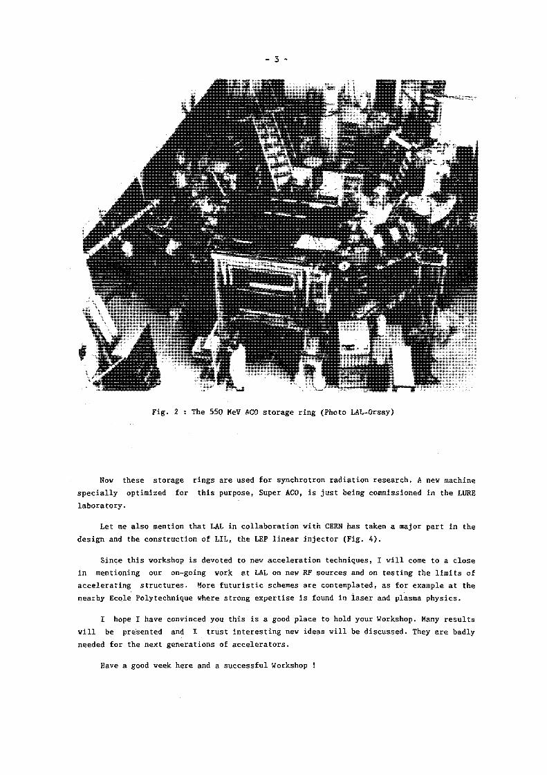
e + e ~ a n n i h i l a t i o n ( F i g . 2 ) . The beam e n e r g y of 550 MeV was i d e a l t o c o v e r t h e l i g h t v e c t o r
m e s o n s . ACO h a s been a v e r y s u c c e s s f u l m a c h i n e . The a c h i e v e d l u m i n o s i t y i n e x c e s s of
1 0 3 2 sounds t e r r i f i c , b u t we s h o u l d remember w i t h modes ty t h a t l u m i n o s i t y used t o be
e x p r e s s e d i n u n i t s of c m - 2 h _ l i n t h o s e e a r l y t i m e s !
Going b i g g e r , t h e n e x t machine was DCI w i t h 1.6 GeV beam e n e r g y ( F i g . 3 ) . A d a r i n g
scheme was t o be used : c o l l i d i n g 4 bunches s i m u l t a n e o u s l y ( e + e ~ a g a i n s t e + e ~ ) from 2
r i n g s so t h a t t h e s p a c e c h a r g e l i m i t co u l d be overcome. T h i s t u r n e d o u t t o be v e r y h a r d t o
o p e r a t e and c o u l d n e v e r be u s e d s u c c e s s f u l l y . Somet imes , c l e v e r i d e a s on p a p e r do n o t work
i n p r a c t i c e . A c c e l e r a t o r p h y s i c s s t i l l r e m a i n s an e x p e r i m e n t a l s c i e n c e .
- 3 -
Nov these storage r ings are used for synchrotron rad iat ion research. A nev machine
s p e c i a l l y optimized for this purpose, Super AGO, i s j u s t being commissioned in the LURE
l abo ra to ry .
Let me a l so mention that LAL in co l l abo ra t i on with CERN has taken a major part in the
des ign and the construction of LIL, the LEP l i nea r in jector (Fig. 4 ) .
Since this vorkshop i s devoted to nev acce le rat ion techniques, I w i l l come to a c lose
in mentioning our on-going work at LAL on nev RF sources and on test ing the l i m i t s of
acce l e ra t ing s t ructures . More f u t u r i s t i c schemes are contemplated, as for example at the
nearhy Ecole Polytechnique vhere strong expert i se i s found in l a se r and plasma physics .
I hope I have convinced you this i s a good place to hold your Workshop. Many r e su l t s
w i l l be presented and I trust in te res t ing new ideas w i l l be discussed. They are badly
needed for the next generations of a cce l e r a to r s .
Have a good week here and a successful Workshop !

F ig . 4 : LIL, the LEP l i nea r p r e - i n j e c to r (Photo CERN)
- s -
INVITED PAPERS

- 7 -
H O R I Z O N S OF H I G H ENERGY P H Y S I C S
C H . L l e w e l l y n S m i t h
D e p a r t m e n t o f T h e o r e t i c a l P h y s i c s , 1, K e b l e R o a d , O X F O R D , 0X1 3NP, E n g l a n d .
A B S T R A C T
A r e v i e w i s g i v e n o f t h e p r e s e n t s t a t e o f p a r t i c l e p h y s i c s , o f
w h a t c a n b e e x p e c t e d f r o m m a c h i n e s now b e i n g c o n s t r u c t e d a n d
o f how f u t u r e m a c h i n e s may c o n t r i b u t e t o f u r t h e r p r o g r e s s . 1. I N T R O D U C T I O N
T a l k s b y t h e o r e t i c a l p a r t i c l e p h y s i c i s t s a t a c c e l e r a t o r m e e t i n g s t r a d i t i o n a l l y b e g i n
w i t h a r e v i e w o f t h e s t a t e o f t h e a r t a n d t h e n g o o n t o c o n s i d e r h o w f u t u r e m a c h i n e s may
c o n t r i b u t e t o f u r t h e r p r o g r e s s . I s h a l l f o l l o w t h i s p a t t e r n b u t I s h a l l p a u s e i n t h e
m i d d l e t o a s k q u e s t i o n s a b o u t t h e u t i l i t y o f t h e e x e r c i s e :
i ) S h o u l d we b e l i e v e i t a t a l l ? T h e r e i s , a f t e r a l l , n o s h r e d o f e v i d e n c e f o r a n y
t h e o r e t i c a l i d e a s i n c e QCD - w h i c h i s now f i f t e e n y e a r s o l d - s o p e r h a p s t h e o r y i s
n o t a h e l p f u l g u i d e .
i i ) A t t h e o t h e r e x t r e m e , c o u l d i t b e t h a t we a r e now n e a r t h e e n d a n d n o l o n g e r n e e d
e x p e r i m e n t ? T h i s i s a p p a r e n t l y t h e v i e w o f some o f t h e new g e n e r a t i o n o f s t r i n g
t h e o r i s t s w h o s t i c k D i r a c ' s d i c t u m t h a t " I t i s m o r e i m p o r t a n t t o h a v e b e a u t y i n o n e ' s
e q u a t i o n s t h a n t o h a v e t h e m f i t e x p e r i m e n t " o n t h e i r w a l l s a n d s e e m t o b e l i e v e t h a t
f u t u r e p r o g r e s s w i l l b e d r i v e n b y p u r e t h o u g h t r a t h e r t h a n e x p e r i m e n t .
i i i ) C o u l d i t b e t h a t t h e "new p h y s i c s e x p e c t e d a t o r b e l o w 1 T e V " , w h i c h i s s o f r e q u e n t l y
i n v o k e d a s a n a r g u m e n t f o r b u i l d i n g f u r t h e r m a c h i n e s , c o u l d b e f o u n d a n d e x h a u s t e d a t
S L C , L E P , HERA a n d t h e T e v a t r o n ?
l v ) F i n a l l y , a t t h e o t h e r e x t r e m e , c o u l d t h e s e m a c h i n e s f i n d n o t h i n g , w h i c h w o u l d make
f u r t h e r m a c h i n e s e s s e n t i a l b u t v e r y h a r d t o s e l l t o t h e p u b l i c ?
2. T H E O R Y - WHERE WE S T A N D
2.a T h e S t a n d a r d M o d e l : O p e n Q u e s t i o n s a n d P o s s i b l e A n s w e r s
T h e S t a n d a r d M o d e l , w h i c h d e s c r i b e s m a t t e r i n t e r m s o f q u a r k s a n d l e p t o n s w h o s e
i n t e r a c t i o n s a r e g o v e r n e d b y t h e u n i f i e d e l e c t r o w e a k t h e o r y , QCD a n d E i n s t e i n ' s t h e o r y o f
g r a v i t y , i s a t p r e s e n t c o n s i s t e n t w i t h a l l t h e d a t a . I n t h o s e c a s e s i n w h i c h we a r e a b l e
t o w o r k o u t i t s c o n s e q u e n c e s t h e y f i t q u a n t i t a t i v e l y a n d t h e r e i s n o r e a s o n t o d o u b t t h a t
I t w o r k s i n o t h e r c a s e s a l s o . N e v e r t h e l e s s , t h e s t a n d a r d m o d e l c a n a t b e s t b e a n
e f f e c t i v e , p h e n o m e n o l o g i c a l , t h e o r y . I t h a s t o o much a r b i t r a r i n e s s a n d t o o many
p a r a m e t e r s , a l b e i t q u a n t i t i e s s u c h a s t h e f i n e - s t r u c t u r e c o n s t a n t a n d t h e r a t i o o f t h e
m a s s e s o f t h e e l e c t r o n a n d p r o t o n w h i c h , i n t h e p a s t , w e r e t h o u g h t o f a s " f u n d a m e n t a l
c o n s t a n t s " r a t h e r t h a n a s p a r a m e t e r s , a n d E i n s t e i n ' s t h e o r y o f g r a v i t y i s i n c o n s i s t e n t

- 8 -
w i t h q u a n t u m m e c h a n i c s . I n s e e k i n g a b e t t e r m o d e l t o r e p l a c e t h e s t a n d a r d m o d e l , we c a n
w o r k f r o m t h e " b o t t o m u p " , a t t e m p t i n g t o i m p r o v e i t s s h o r t c o m i n g s , o r f r o m t h e " t o p d o w n " ,
a t t e m p t i n g t o c o n s t r u c t a f i n a l " t h e o r y o f e v e r y t h i n g i n o n e s t e p " .
T a b l e 1
P r o b l e m s i n t h e S t a n d a r d M o d e l
P r o b l e m
F l a v o u r
U n i f i c a t i o n
Mass
P o s s i b l e S o l u t i o n s
" H o r i z o n t a l " g r o u p C o m p o s i t e n e s s
T o p o l o g y f o r d>4
P r e - G U T GUT
S u p e r G U T / S t r i n g
H i g g s - » S U S Y T e c h n i c o l o u r
R e l e v a n t E x p e r i m e n t s
M o r e q u a r k s a n d l e p t o n s ? M a s s e s , m i x i n g s
R a r e d e c a y s ? " H o r i z o n t a l " b o s o n s ?
S t r u c t u r e ?
W ' , Z ' ? N u c l e ó n d e c a y ?
H i g g s b o s o n ? S u p e r p a r t i c l e s ? T e c h n i p a r t i c l e s ?
S o m e t h i n g f o r E é 1 T e V .
T a b l e 1 c o n t a i n s t h e s t a n d a r d l i s t o f p r o b l e m s a n d s h o r t c o m i n g s o f t h e s t a n d a r d m o d e l .
O n h e a r i n g o f t h e d i s c o v e r y o f t h e muon R a b i a p p a r e n t l y a s k e d "who o r d e r e d t h a t ? " a n d we
m u s t a s k t h e same q u e s t i o n a b o u t t h e t a u , t h e s t r a n g e q u a r k , t h e c h a r m e d q u a r k e t c .
P o s s i b l y t h e d i f f e r e n t f a m i l i e s o f q u a r k s a n d l e p t o n s a r e j o i n e d i n a s i n g l e
r e p r e s e n t a t i o n o f a l a r g e " h o r i z o n t a l " g r o u p . P o s s i b l y t h e y a r e t h e m s e l v e s c o m p o s e d o f
m o r e e l e m e n t a r y o b j e c t s . M a y b e , a s d i s c u s s e d l a t e r , f l a v o u r i s a c o n s e q u e n c e o f t h e
t o p o l o g y o f e x t r a h i d d e n d i m e n s i o n s o f s p a c e - t i m e . E x p e r i m e n t s w h i c h may c a s t l i g h t o n
t h i s p r o b l e m i n c l u d e s e a r c h e s f o r m o r e q u a r k s a n d l e p t o n s , a c c u r a t e m e a s u r e m e n t s o f m a s s e s
a n d m i x i n g s ( w h i c h w i l l a l s o c a s t l i g h t o n t h e p r o b l e m o f t h e o r i g i n o f m a s s ) , s e a r c h e s
f o r r a r e d e c a y s s u c h a s v-*ey m e d i a t e d b y " h o r i z o n t a l " g a u g e b o s o n s , s e a r c h e s f o r t h e
" h o r i z o n t a l " g a u g e b o s o n s t h e m s e l v e s , a n d s e a r c h e s f o r s u b s t r u c t u r e .
G i v e n t h e s e m i - s u c c e s s f u l u n i f i c a t i o n o f e l e c t r o m a g n e t i c a n d w e a k i n t e r a c t i o n s i n
S U ( 2 ) x U ( l ) , i t i s n a t u r a l t o a s k w h e t h e r t h e s e i n t e r a c t i o n s may b e m o r e c o m p l e t e l y
u n i f i e d , f o r e x a m p l e i n a l e f t - r i g h t s y m m e t r i c g r o u p , w h e t h e r , m o r e a m b i t i o u s l y , t h e y m a y
b e u n i f i e d w i t h t h e s t r o n g f o r c e i n a g r a n d u n i f i e d t h e o r y a n d , f i n a l l y , w h e t h e r t h e r e I s
a s u p e r g r a n d u n i f i e d t h e o r y o f a l l t h e f o r c e s , i n c l u d i n g g r a v i t y . L a r g e r g r o u p s
n e c e s s a r i l y i m p l y t h e e x i s t e n c e o f m o r e g a u g e b o s o n s w h i c h c a n m e d i a t e new i n t e r a c t i o n s .
C l e a r l y we s h o u l d l o o k f o r t h e s e e x t r a g a u g e b o s o n s e x p e r i m e n t a l l y a n d a l s o f o r r a r e
p r o c e s s e s t h a t t h e y m i g h t m e d i a t e , s u c h a s n u c l e ó n d e c a y w h i c h i s p r e d i c t e d b y g r a n d
u n i f i e d t h e o r i e s .
T h e l a s t p r o b l e m i s t h e p r o b l e m o f m a s s . How c a n t h e W a n d t h e Z b e s y m m e t r y
p a r t n e r s o f t h e p h o t o n a n d y e t h a v e m a s s e s t h a t a r e a t l e a s t 26 o r d e r s o f m a g n i t u d e
g r e a t e r ? T h e s t a n d a r d a n s w e r i s t h r o u g h t h e H i g g s m e c h a n i s m w h i c h i m p l i e s t h e e x i s t e n c e

- 9 -
o f a t l e a s t o n e H i g g s b o s o n , w h i c h s h o u l d b e s o u g h t e x p e r i m e n t a l l y . H o w e v e r , a s w i l l b e
d i s c u s s e d b e l o w , i t i s d i f f i c u l t t o u n d e r s t a n d h o w t h e c o n v e n t i o n a l H i g g s m e c h a n i s m c o u l d
w o r k u n l e s s t h e r e I s a n u n d e r l y i n g s u p e r s y m m e t r y i n n a t u r e , w h i c h w o u l d i m p l y t h e
e x i s t e n c e o f r e l a t i v e l y l i g h t s u p e r s y m m e t r i c p a r t i c l e s w h i c h c a n b e s o u g h t I n f u t u r e
e x p e r i m e n t s . A n a l t e r n a t i v e p o s s i b i l i t y i s t h a t m a s s e s a r e g e n e r a t e d t h r o u g h
" t e c h n i c o l o u r " I n w h i c h c a s e t e c h n i - p a r t i c l e s s h o u l d s h o w u p a t a r o u n d 1 T e V .
I s h a l l n o w d i s c u s s t h e m a s s p r o b l e m i n m o r e d e t a i l s i n c e i t h a s a n a s s o c i a t e d e n e r g y
s c a l e w h i c h s u g g e s t s t h a t i t m a y b e r e s o l v e d b y e x p e r i m e n t s i n t h e r e l a t i v e l y n e a r f u t u r e .
I s h a l l t h e n e x p l a i n w h y I t h i n k t h a t s u p e r s y m m e t r y d e s e r v e s t o b e t a k e n s e r i o u s l y , b e f o r e
t u r n i n g t o t h e p r e s e n t s t a t e o f s u p e r s t r i n g t h e o r y , w h i c h i s t h e c u r r e n t g r e a t w h i t e h o p e
o f a d v o c a t e s o f a " t o p d o w n " a p p r o a c h .
2 . b T h e S c h i z o p h r e n i c P r o b l e m o f t h e W Mass
T h e p r o b l e m o f t h e W m a s s h a s t w o a s p e c t s . F i r s t , w h y i s t h e W n o t m a s s l e s s , l i k e t h e
p h o t o n ? S e c o n d , g i v e n t h a t i t d o e s h a v e a m a s s , w h y i s i t n o t v e r y m u c h l a r g e r ? T h e
f i r s t p r o b l e m may b e a p p r o a c h e d f r o m a t h e o r e t i c a l a n d f r o m a n e m p i r i c a l p o i n t o f v i e w .
T h e o r e t i c a l l y , g a u g e b o s o n s h a v e o n l y t w o d e g r e s s o f f r e e d o m a n d h e n c e t w o p o l a r i z a t i o n
s t a t e s . W h i l e t h i s i s t r u e f o r t h e m a s s l e s s p h o t o n , a m a s s i v e s p i n-1 p a r t i c l e , s u c h a s
t h e W, m u s t h a v e t h r e e p o l a r i z a t i o n s t a t e s , s i n c e w e c a n g o i n t o i t s r e s t f r a m e a n d
o r i e n t a t e i t s s p i n i n t h r e e p o s s i b l e d i r e c t i o n s . T h e q u e s t i o n i s t h e n , how d i d t h e W
a c q u i r e i t s t h i r d , l o n g i t u d i n a l , p o l a r i z a t i o n s t a t e ? T h e r e a r e t h r e e p o s s i b l e a n s w e r s .
F i r s t , t h e l o n g i t u d i n a l W c o u l d b e a c o m p o n e n t o f a n a d d i t i o n a l e l e m e n t a r y f i e l d - t h e
H i g g s f i e l d ; I n t h i s c a s e , a t l e a s t o n e e x t r a f i e l d m u s t r e m a i n a s a s e p a r a t e o b s e r v a b l e
p a r t i c l e - t h e H i g g s b o s o n . S e c o n d , t h e l o n g i t u d i n a l W c o u l d b e a b o u n d s t a t e o f a
t e c h n i q u a r k a n d a n a n t l t e c h n i q u a r k b o u n d t o g e t h e r b y a n e w , v e r y s t r o n g , t e c h n i c o l o u r
f o r c e . T h i r d , p e r h a p s t h e W i s n o t a g a u g e b o s o n a t a l l .
E m p i r i c a l l y , t h e p r o b l e m c a n b e s e e n b y c a l c u l a t i n g t h e s c a t t e r i n g a m p l i t u d e f o r
l o n g i t u d i n a l l y p o l a r i z e d W b o s o n s . T h e a m p l i t u d e g r o w s r a p i d l y w i t h e n e r g y a n d v i o l a t e s
p e r t u r b a t i v e p a r t i a l w a v e u n i t a r i t y a t a n e n e r g y o f 1 T e V i n t h e c e n t r e o f m a s s ( a s s u m i n g
s t a n d a r d g a u g e t h e o r y v e r t i c e s ; w i t h a n y o t h e r v e r t i c e s , t h e v i o l a t i o n o c c u r s a t a l o w e r
e n e r g y ) . T h i s i m p l i e s o n e o f t w o t h i n g s . E i t h e r p e r t u r b a t i o n t h e o r y f a i l s a n d
l o n g i t u d i n a l Ws b e c o m e s t r o n g l y i n t e r a c t i n g a t 1 T e V , i n w h i c h c a s e new p h e n o m e n a , s u c h a s
r e s o n a n c e s , w o u l d s h o w u p ; t h i s w o u l d o c c u r i n t e c h n i c o l o u r t h e o r y . O r t h e r e i s a n e x t r a
p e r t u r b a t i v e c o n t r i b u t i o n d u e t o H i g g s b o s o n e x c h a n g e . I f M H i s l e s s t h a n 1 T e V ,
p e r t u r b a t i v e u n i t a r i t y w o u l d h o l d a t a l l e n e r g i e s . I f , o n t h e o t h e r h a n d , M H i s l a r g e
c o m p a r e d t o 1 T e V , t h e r e w o u l d b e a r e g i o n b e t w e e n 1 T e V a n d M } ) a t w h i c h p e r t u r b a t i o n
t h e o r y w o u l d f a i l a n d l o n g i t u d i n a l Ws w o u l d b e s t r o n g l y i n t e r a c t i n g . I n a n y c a s e ,
e x p e r i m e n t a l s t u d y o f t h e s c a t t e r i n g o f l o n g i t u d i n a l Ws u p t o a n d b e y o n d 1 T e V i s
e s s e n t i a l l y g u a r a n t e e d t o c a s t l i g h t o n t h e o r i g i n o f m a s s . I t m u s t b e s t r e s s e d , h o w e v e r ,
t h a t t h e p r o b l e m c o u l d b e s o l v e d b y e x p e r i m e n t a s a t m u c h l o w e r e n e r g y e . g . b y t h e
d i s c o v e r y o f a H i g g s b o s o n w i t h a mass o f , s a y , 10 G e V i n t h e d e c a y o f Z .

- 10 -
I f t h e W mass i s g e n e r a t e d b y t h e H i g g s m e c h a n i s m , we t h e n f a c e t h e p r o b l e m t h a t t h e
m a s s s c a l e a s s o c i a t e d w i t h t h e H i g g s f i e l d a n d h e n c e t h e mass o f t h e W c o n t a i n s q u a n t u m
c o r r e c t i o n s 6 M W - g M x , w h e r e M x i s t h e l a r g e s t m a s s s c a l e i n t h e p r o b l e m e . g . t h e m a s s o f
t h e X b o s o n i n a g r a n d u n i f i e d t h e o r y o r t h e P l a n c k mass i n t h e o r i e s i n w h i c h g r a v i t y i s
i n c o r p o r a t e d . I f t h i s w e r e c o r r e c t , i t w o u l d o n l y b e p o s s i b l e t o u n d e r s t a n d t h e o b s e r v e d
m a s s o f t h e W b y i n v o k i n g i n c r e d i b l y a c c u r a t e , a n d h i g h l y a r t i f i c i a l , c a n c e l l a t i o n s
b e t w e e n t h e q u a n t u m c o r r e c t i o n s a n d t h e z e r o t h o r d e r v a l u e o f t h e m a s s . T h e o n l y w a y o u t
o f t h i s d i l e m m a s e e m s t o b e t o i n v o k e s u p e r s y m m e t r y . A c c o r d i n g t o s u p e r s y m m e t r y e v e r y
p a r t i c l e ( P ) h a s a s u p e r p a r t n e r ( P ) w h o s e s p i n d i f f e r s b y h a l f a u n i t , i . e . e v e r y b o s o n
h a s a s u p e r s y m m e t r i c f e r m i o n i c p a r t n e r , a n d e v e r y f e r m i o n h a s a s u p e r s y m m e t r i c b o s o n i c
p a r t n e r . T h e s e p a r t n e r s c o n t r i b u t e t o t h e m a s s o f t h e W w i t h o p p o s i t e s i g n s s o t h a t t h e
c o r r e c t i o n t o t h e m a s s o f t h e W may b e w r i t t e n
ö M w = g E c i í M p j - M p d )
I f w e e x c l u d e l a r g e c a n c e l l a t i o n s a n d m a k e t h e v e r y r e a s o n a b l e r e q u i r e m e n t t h a t ö M ^ M w ,
t h e n t h e mass s p l i t t i n g b e t w e e n e a c h p a r t i c l e a n d i t s s u p e r p a r t n e r m u s t b e l e s s t h a n o r o f
o r d e r 1 T e V .
2 . c S u p e r s y m m e t r y
I n t h e p a r a g r a p h a b o v e w e i n t r o d u c e d s u p e r s y m m e t r y ( S U S Y ) a s a w a y t o s o l v e t h e
h i e r a r c h y p r o b l e m o f t h e c o - e x i s t e n c e o f w i d e l y d i f f e r e n t mass s c a l e s a n d M x . T h i s
r a t h e r t e c h n i c a l r o u t e t o SUSY m a y o b s c u r e t h e o t h e r , v e r y p o w e r f u l , a r g u m e n t s f o r t a k i n g
S U S Y s e r i o u s l y :
i ) SUSY u n i f i e s f e r m i o n s a n d b o s o n s , a n d t h u s a b o l i s h e s t h e d i s t i n c t i o n b e t w e e n
c o n s t i t u e n t s o f m a t t e r a n d c a r r i e r s o f f o r c e s .
i i ) S u p e r s y m m e t r i c t h e o r i e s a r e l e s s d i v e r g e n t t h a n o r d i n a r y t h e o r i e s . A d i v e r g e n c e
u s u a l l y i n d i c a t e s t h a t a t h e o r y i s o n l y a n e f f e c t i v e t h e o r y , t h e c u t - o f f
c h a r a c t e r i s i n g t h e r a n g e o f v a l i d i t y o f t h i s t h e o r y . T h e f e w e r t h e d i v e r g e n c e s , t h e
c l o s e r t h e t h e o r y i s l i k e l y t o b e t o a n u l t i m a t e t h e o r y .
i i i ) T h e g e n e r a t o r s o f SUSY t r a n s f o r m a t i o n s , w h i c h h a v e a f e r m i o n i c c h a r a c t e r a s t h e y c h a n g e
f e r m i o n i c s t a t e s i n t o b o s o n i c s t a t e s a n d v i c e v e r s a , s a t i s f y a n a n t i - c o m m u t a t i o n
a l g e b r a : t h e a n t i - c o m m u t a t o r o f t w o d i f f e r e n t SUSY c h a r g e s i s a t r a n s l a t i o n . A t h e o r y
i n w h i c h SUSY a c t s l o c a l l y , a l l o w i n g d i f f e r e n t SUSY t r a n s f o r m a t i o n s a t d i f f e r e n t
p o i n t s i n s p a c e a n d t i m e , i s t h e r e f o r e i n v a r i a n t u n d e r l o c a l t r a n s l a t i o n s w h i c h a r e
p a r t o f a g e n e r a l c o o r d i n a t e t r a n s f o r m a t i o n . A s a r e s u l t , l o c a l SUSY c a n n a t u r a l l y b e
u n i f i e d w i t h g r a v i t y .
i v ) A c c o r d i n g t o a r a t h e r g e n e r a l t h e o r e m , SUSY i s t h e l a s t p o s s i b l e s y m m e t r y o f t h e
S - m a t r i x . I t w o u l d s e e m t o me v e r y p e c u l i a r i f n a t u r e made u s e o f t h e o t h e r

- 11 -
symmetries ( internal symmetries, gauge symmetries and Poincaré invariance) and not of supersymmetry. Likewise, i t would seem to me odd for there to be elementary p a r t i c l e s with spin-K (the e lec tron e t c . ) , spin-1 (the photon, W and Z), and spin-2 (the gravlton) and not a l so with spin-0 and three ha lves , as there are according to SUSY.
These arguments, e s p e c i a l l y the l a s t , suggest that we should take SUSY very s e r i o u s l y .
The bad news i s , f i r s t , that known fermions do not have the right properties to be the SUSY partners of known bosons, so that i t i s necessary to make the apparently extravagant supposit ion that there i s a SUSY partner for every known p a r t i c l e waiting to be discovered somewhere below 1 TeV, and second that SUSY i s hard to hide, or spontaneously break to use the usual descr ip t ion , as must be done in order to break the degeneracy between p a r t i c l e s and the ir superpartners. The l e a s t contrived models which work invoke the ex i s tence of a s e t of shadow p a r t i c l e s , whose only coupling to the known p a r t i c l e s i s through grav i ty , and the assumption that SUSY i s broken in the shadow world thus:
Our "Shadow World" World - SUSY spontaneously broken
t only coupled by gravity
- transmits SUSY breaking.
2 . d Superstrlngs
In superstring theory p a r t i c l e s are replaced by open s tr ings or c losed loops with dimensions of order 1 0 - 3 3 cm and tension (T) of order the Planck mass. P a r t i c l e s correspond to the d i f ferent modes of e x c i t a t i o n of these s t r i n g s . String theor ies provide the f i r s t cons i s tent quantum theory of extended o b j e c t s . As in c l a s s i c a l t h e o r i e s , where, as pointed out by Lorentz, the divergence of the electromagnetic mass of the e lec tron would be el iminated i f the e lectron i s an extended object , i t turns out that the replacement of p a r t i c l e s by extended s t r ings reduces the divergences - perhaps removing them e n t i r e l y .
The vers ion of the s t r ing theory which i s most l i k e l y to be relèvent to the real world i s the super (Fermi-Bose) s t r ing . I t was not iced many years ago that t h i s theory has a remarkable property in the l imi t that the tens ion T-*°°. In t h i s "rigid" l imi t only the massless modes of the s t r ing remain at f i n i t e energy and they behave as p o i n t - l i k e p a r t i c l e s . I t turns out that there are spin -1 massless modes with exact ly the in teract ions of gauge bosons and spin -2 massless modes with exact ly the interact ions of E ins te in ' s graviton. I t was t h i s discovery that led to the idea that the s t r ing describes gravi ty , among other th ings , and that T i s governed by the Planck mass ( o r i g i n a l l y the s t r ing had been introduced as a model of so f t hadronic process, T being governed by the Regge s l o p e ) . Despite th i s remarkable property, the s t r i n g f e l l out of fashion because i t was thought to be riddled with quantum i n c o n s i s t e n c i e s or anomalies, and because, even at
- 12 -
t h e c l a s s i c a l l e v e l , t h e t h e o r y i s o n l y c o n s i s t e n t i n 10 s p a c e - t i m e d i m e n s i o n s . T h e
r e c e n t d r a m a t i c r e v i v a l o f i n t e r e s t w a s d u e t o t h e d i s c o v e r y b y G r e e n a n d S c h w a r z t h a t t h e
t h e o r y i s a n o m a l y f r e e i f i t h a s a n i n t e r n a l s y m m e t r y g r o u p S 0 ( 3 2 ) o r E ( 8 ) x E ( 8 ) .
A n o m a l y f r e e v e r s i o n s o f t h e s u p e r s t r i n g t h e o r y a r e p r o b a b l y c o m p l e t e l y f r e e o f
d i v e r g e n c e s a n d a r e t h e f i r s t , a n d o n l y k n o w n , c o n s i s t e n t t h e o r i e s o f q u a n t u m g r a v i t y .
T h e y t h e r e f o r e d e s e r v e t o b e t a k e n e x t r e m e l y s e r i o u s l y a l t h o u g h t h e p r e d i c t i o n o f n i n e
s p a c e a n d o n e t i m e d i m e n s i o n s i s a p p a r e n t l y w r o n g . T h i s p r o b l e m i s " s o l v e d " b y a s s u m i n g
t h a t t h e e x t r a s i x s p a c e d i m e n s i o n s c u r l u p , o r " c o m p a c t i f y " , t o s i z e s o f o r d e r 1 0 - 3 3 cm
s o t h a t we a r e u n a w a r e o f t h e i r e x i s t e n c e , j u s t as a t w o - d i m e n s i o n a l s h e e t o f p a p e r m i g h t
c u r l up t o f o r m a d r i n k i n g s t r a w w h i c h w o u l d a p p e a r o n e - d i m e n s i o n a l t o a b e i n g o n l y a b l e
t o r e s o l v e d i s t a n c e s l a r g e c o m p a r e d t o i t s r a d i u s . W h e t h e r o r n o t t h i s c o m p a c t i f i c a t i o n
o c c u r s i s a d y n a m i c a l q u e s t i o n w h o s e a n s w e r i s u n k n o w n . I f , h o w e v e r , we a s s u m e t h a t i t
o c c u r s a n d make s e v e r a l o t h e r q u i t e p l a u s i b l e , p h e n o m e n o l o g i c a l l y m o t i v a t e d , a s s u m p t i o n s ,
i t t u r n s o u t t h a t t h e E ( 8 ) x E ( 8 ) s y m m e t r y ( w h i c h i s p r e f e r r e d t o S O ( 3 2 ) b e c a u s e t h e l a t t e r
i s u n a b l e t o a c c o m o d a t e c h i r a l f e r m i o n s a f t e r c o m p a c t i f i c a t i o n t o f o u r d i m e n s i o n s ) w o u l d
b r e a k d o w n t o E ( 6 ) x E ( 8 ) o n c o m p a c t i f i c a t i o n a n d t h a t p a r t i c l e s g o v e r n e d b y E ( 6 ) w o u l d o n l y
i n t e r a c t w i t h t h o s e g o v e r n e d b y E ( 8 ) t h r o u g h g r a v i t y . A s s u m i n g t h a t SUSY i s s p o n t a n e o u s l y
b r o k e n i n t h e E ( 8 ) s e c t o r , a n d r e c o g n i s i n g t h a t E ( 6 ) ( w i t h S U ( 5 ) a n d S 0 ( 1 0 ) ) i s o n e o f t h e
p o s s i b l e g r a n d u n i f i e d t h e o r i e s , we f i n d t h a t we h a v e r e c o v e r e d t h e s u p e r s y m m e t r y t h e o r y
c o n s t r u c t e d p r e v i o u s l y w o r k i n g f r o m t h e b o t t o m u p l T h i s i s e n c o u r a g i n g : a l t h o u g h a l o t o f
p h e n o m e n o l o g i c a l a s s u m p t i o n s w e r e b u i l t i n , t h - r e s u l t c o u l d h a v e b e e n a n u n a c c e p t a b l e
g r a n d u n i f i e d t h e o r y . I f we d e v e l o p t h e t h e o r y f u r t h e r a n d t r y t o make c o n t a c t w i t h
p h y s i c s w e l l b e l o w t h e g r a n d u n i f i e d s c a l e , i t t u r n s o u t t o b e q u i t e p o s s i b l e - a l t h o u g h
n o t i n e v i t a b l e - t h a t i t p r e d i c t s e x t r a v e c t o r b o s o n s , q u a r k s a n d l e p t o n s w i t h m a s s e s o f
o r d e r M w o r a f e w t i m e s M w .
O n e a t t r a c t i v e f e a t u r e o f t h e c o m p a c t l f i e d s t r i n g t h e o r y i s t h a t i t p r o v i d e s a
p o s s i b l e m e c h a n i s m f o r u n d e r s t a n d i n g t h e o r i g i n o f f l a v o u r . T h e s i x c o m p a c t i f i e d
d i m e n s i o n s a r e i n g e n e r a l a b l e t o s u p p o r t s e v e r a l m a s s l e s s m o d e s , t h e e x a c t n u m b e r
d e p e n d i n g o n t h e i r t o p o l o g y . T h e d i f f e r e n t f l a v o u r s w o u l d b e a s s o c i a t e d w i t h t h e
d i f f e r e n t e x c i t a t i o n s i n t h e h i d d e n d i m e n s i o n s .
3 . I S T H E O R Y A GOOD G U I D E FOR E X P E R I M E N T - AND V I C E V E R S A ?
We s h a l l a d d r e s s t h e s e q u e s t i o n s b y c o n s i d e r i n g t h e h i g h l i g h t s o f t h e l a s t 50 y e a r s o f
p a r t i c l e p h y s i c s , some o f w h i c h a r é l i s t e d i n T a b l e 2 . C l e a n s e d r e t r o s p e c t i v e l y o f w r o n g
e x p e r i m e n t s a n d w r o n g t h e o r e t i c a l i d e a s , we s e e t h a t t h e s u b j e c t h a s p r o g r e s s e d r a t h e r
l o g i c a l l y a n d t h a t t h e r e has b e e n a n i n t i m a t e i n t e r c h a n g e b e t w e e n t h e o r y a n d e x p e r i m e n t :
t h e o r y h a s b e e n r a t h e r s u c c e s s f u l i n a n t i c i p a t i n g d i s c o v e r i e s b u t i t h a s a l m o s t a l w a y s
b e e n d r i v e n v e r y d i r e c t l y b y e x p e r i m e n t a l r e s u l t s . I t i s t r u e t h a t t h e o r y h a s n o t b e e n
p a r t i c u l a r y s u c c e s s f u l i n p r e d i c t i n g w h a t w i l l b e a c h i e v e d b y e x p e r i m e n t s a t new m a c h i n e s
- t h e e x c e p t i o n s b e i n g t h e d i s c o v e r y o f t h e a n t i - p r o t o n a n d t h e W a n d Z . T h e p r e s e n t

- 13 -
T a b l e 2
Some H i g h l i g h t s i n P a r t i c l e P h y s i c s ( d i s c o v e r i e s i n b o x e s w e r e a n t i c i p a t e d t h e o r e t i c a l l y )
1940
1950
1960
1970
E x p e r i m e n t s a t E x p e r i m e n t s t h e E n e r g y F r o n t i e r b e l o w t h e F r o n t i e r
u m
K
R e s o n a n c e s P - V i o l a t i o n
1980
( vu" veJ
m Deep inelastic iNeutral currents]
;.tj Icharrol
T ) g l u o n I
LED
P - V i o l a t i o n V - A R e s o n a n c e S p e c t r o s c o p y CP V i o l a t i o n
T h e o r y
R e n o r m a l i z a t i o n o f QED
Y a n g - M i l l s
S U ( 2 ) x U ( l )
Q u a r k s
QCD
G U T s ? ?
S u p e r s t r i n g ? ?
s i t u a t i o n i s w i t h o u t h i s t o r i c a l p r e c e d e n t h o w e v e r . U n t i l we k n e w t h e n a t u r e o f t h e
s t r o n g a n d w e a k f o r c e s , we c o u l d o n l y w o r k o n t h e a s s u m p t i o n t h a t e x p e r i m e n t s a t h i g h e r
e n e r g i e s / s h o r t e r d i s t a n c e s w o u l d l e a d t o n e w i n s i g h t s . Now we c a n b e m u c h m o r e c o n f i d e n t
t h a t t h i s i s t h e c a s e s i n c e we h a v e a t h e o r y w h i c h w o r k s p e r f e c t l y b u t i s o n l y v a l i d u p t o
1 T e V .
T h e a n s w e r t o t h e q u e s t i o n o f w h e t h e r t h e o r y c a n p r o g r e s s w i t h o u t e x p e r i m e n t s e e m s t o
b e y e s a n d n o . T h e i d e a o f l o c a l g a u g e i n v a r i a n c e c o u l d c e r t a i n l y h a v e b e e n i n t r o d u c e d
m u c h e a r l i e r . T h e i m p l e m e n t a t i o n o f t h i s i d e a i n S U ( 2 ) x U ( l ) a n d QCD c o u l d n o t , h o w e v e r ,
h a v e b e e n a n t i c i p a t e d b y m o r e t h a n a f e w y e a r s s i n c e t h e f o r m e r r e q u i r e d t h e k n o w l e d g e
t h a t w e a k i n t e r a c t i o n s h a v e a V - A s t r u c t u r e w h i l e t h e l a t t e r c o u l d n o t h a v e p r e c e e d e d t h e
d i s c o v e r y o f q u a r k s a n d o f c o l o u r . L i k e w i s e , t h e i d e a b e h i n d t h e q u a r k m o d e l c o u l d h a v e
b e e n a n t i c i p a t e d - i n d e e d i t w a s a n t i c i p a t e d b y F e r m i a n d Y a n g i n t h e e a r l y 1 9 5 0 s a n d
l a t e r d e v e l o p e d b y S a k a t a . T h e q u a r k m o d e l i t s e l f , h o w e v e r , c o u l d n o t h a v e p r e c e e d e d t h e
a c c u m u l a t i o n o f s p e c t r o s c o p i c d a t a i n t h e l a t e 1950s a n d e a r l y 1 9 6 0 s . T h i s s u g g e s t s t h a t
w h i l e t h e r e i s n o n a t u r a l t i m e s c a l e f o r new i d e a s , e x p e r i m e n t a l i n f o r m a t i o n s e t s t h e p a c e
f o r f i n d i n g how n a t u r e may u s e t h e m . T h e q u e s t i o n i s , t h e n , w h e t h e r we h a v e e n o u g h
e x p e r i m e n t a l c l u e s t o c o n s t r u c t a f i n a l t h e o r y now - p r e s u m a b l y b a s e d o n t h e s u p e r s t r i n g
F a m o u s u t t e r a n c e s s u c h a s K e l v i n ' s r e m a r k , j u s t b e f o r e t h e d i s c o v e r y o f t h e e l e c t r o n ,
t h a t " t h e r e i s n o t h i n g t o b e d i s c o v e r e d i n p h y s i c s n o w : a l l t h a t r e m a i n s i s m o r e a n d m o r e
p r e c i s e m e a s u r e m e n t " , s h o w how e a s y i t i s t o i m a g i n e t h a t we h a v e a l l t h e e v i d e n c e we
n e e d . N e v e r t h e l e s s i t i s n o t o b v i o u s l y r i d i c u l o u s t o t h i n k t h a t we h a v e t h e n e c e s s a r y
f a c t s t o e s t a b l i s h t h e " t h e o r y o f e v e r y t h i n g " . F o r t h e f i r s t t i m e s i n c e K e l v i n ' s d a y we
h a v e a p h e n o m e n o l o g i c a l t h e o r y t h a t a p p a r e n t l y f i t s a l l t h e f a c t s . I t may b e t h a t , j u s t
a s t h e d i s c o v e r y o f t h e s t r o n g a n d w e a k f o r c e s s a b o t a g e d t h e p r o g r a m m e o f s e e k i n g a t h e o r y

- 14 -
o f a l l f o r c e s w h i c h u n i f i e s e l e c t r o m a g n e t i s m a n d g r a v i t y , q u i t e n e w p h e n o m e n a a w a i t
d i s c o v e r y - b u t t h e r e i s n o h i n t o f t h i s a n d , i n d e e d , t h e s u c c e s s o f h o t b i g b a n g
c o s m o l o g y s p e a k s a g a i n s t i t . I t t h e r e f o r e seems t o me n o t i n c o n c e i v a b l e t h a t t h e
s u p e r s t r i n g w i l l e v e n t u a l l y b e c o n f i r m e d a s t h e t h e o r y b u t I c a n n o t i m a g i n e b e i n g
c o n v i n c e d t h a t i t i s c o r r e c t w i t h o u t e x p e r i m e n t a l e x p l o r a t i o n o f t h e new p h y s i c s t h a t i t
i s s u p p o s e d t o p r e d i c t a t o r b e l o w 1 T e V .
4 . COULD NEW MACHINES NOW UNDER C O N S T R U C T I O N T E A C H US A L L , OR N O T H I N G ?
I h a v e s k e t c h e d p o s s i b l e d i s c o v e r y l i m i t s f o r L E P 200, H e r a a n d t h e T e v a t r o n i n F i g u r e
1.
2 0 0 G e V
100 G e V > OJ
o o CV1 [ o o
CM I l> I
>
cs c_ OJ zr. » M
cu
0 ( 5 0 0 G e V )
o o CM
t l H q . g i / 7/ w\ z F i g - 1
P o s s i b l e d i s c o v e r y l i m i t s f o r L E P 2 0 0 , HERA a n d t h e T e v a t r o n . T h e b a r s ( - ) r e p r e s e n t
p r e s e n t l i m i t s : t h e f u t u r e l i m i t s w i l l d e p e n d o n w h a t l u m i n o s i t y i s a c h i e v e d . B o t h
p r e s e n t a n d f u t u r e l i m i t s a r e m o r e o r l e s s m o d e l d e p e n d e n t . H e r e t = t h e t o p q u a r k , 1 =
new l e p t o n s , H = t h e s t a n d a r d H i g g s b o s o n , q = a s c a l a r q u a r k , - g = t h e g l u i n o , i = a
s c a l a r l e p t o n , W' = a h e a v i e r W a n d Z ' = a h e a v i e r Z . T h e d a s h e d l i n e s f o r H a t t h e
T e v a t r o n r e p r e s e n t t h e h o p e 1 ) o f s e e i n g H - » T + T ~ i f MJJ < 2 m t . HERA w i l l s e t a l i m i t o f
o r d e r 180 G e V o n t h e sum m¿ + niq.
T h e m o s t l i k e l y p a r t i c l e s t o e x i s t a r e , i n d e c r e a s i n g o r d e r o f p r o b a b i l i t y , t h e t o p
q u a r k , t h e H i g g s b o s o n a n d s u p e r s y m m e t r i c p a r t i c l e s . T h e s u c c e s s o f S U ( 2 ) x U ( l ) r e q u i r e s
t h e mass o f t h e t o p q u a r k t o b e l e s s t h a n 250 G e V . P e r s o n a l l y I w o u l d e x p e c t t h e H i g g s
b o s o n t o h a v e a m a s s o f o r d e r M w o r p e r h a p s G p 1 = 300 G e V a n d I w o u l d g u e s s t h a t i f
s u p e r s y m m e t r i c p a r t i c l e s e x i s t t h e i r m a s s e s m i g h t b e i n t h e same r a n g e . E x p e r i m e n t s a t
t h e m a c h i n e s now u n d e r c o n s t r u c t i o n w i l l t h e r e f o r e e x p l o r e a s i g n i f i c a n t p a r t o f t h e
r e g i o n i n w h i c h n e w p a r t i c l e s m i g h t l i e b u t b y n o means a l l o f i t . I t i s t h e r e f o r e

- I m
p o s s i b l e t h a t we w i l l l e a r n n o t h i n g from t h e s e e x p e r i m e n t s . At t h e o t h e r e x t r e m e , i t
seems t o me very u n l i k e l y t h a t we w i l l l e a r n e v e r y t h i n g . I f t h e Higgs boson i s
d i s c o v e r e d , t h e n i t w i l l be odds on t h a t supersymmetr ic p a r t i c l e s e x i s t a l s o . A l though
some may be found, i t i s d i f f i c u l t t o imagine t h a t we w i l l be a b l e t o u n d e r s t a n d t h e f u l l
spectrum of supersymmetr ic p a r t i c l e s w i t h o u t g o i n g t o h i g h e r e n e r g y .
5 . EXPERIMENTS AT FUTURE COLLIDERS
5 . a P r e l i m i n a r y Remarks
In t h i s s e c t i o n I s h a l l make some remarks about p h y s i c s a t new c o l l i d e r s . I s h a l l
n e i t h e r e n t e r i n much d e t a i l nor a t t e m p t t o p r e s e n t a s y s t e m a t i c s u r v e y s i n c e t h e s u b j e c t
has r e c e n t l y been e x p l o r e d i n v e r y g r e a t depth [21 and, i n any c a s e , I r e v i e w e d t h e
a l r e a d y very l a r g e l i t e r a t u r e o n l y a year ago [ 3 ] . I s h a l l c o n c e n t r a t e on e + e _ and pp
machines s i n c e a purpose b u i l t ep machine i s u n l i k e l y t o be proposed a s t h e f i r s t t o
e x p l o r e a new r e g i o n ( t h e p h y s i c s t h a t can be done w i t h ep machines i s c o n s i d e r e d i n [ 2 ,
3 ] ) .
5 . b E l e c t r o n P o s i t r o n C o l l i d e r s
The n a t u r a l u n i t i n which t o measure e l e c t r o n p o s i t r o n a n n i h i l a t i o n c r o s s - s e c t i o n i s
° p o i n t = ° ( ë e -* MM) = 87nb l y [ E c m ( G e V ) ] *
I s h a l l assume t h a t f u t u r e machines w i l l a c h i e v e l u m i n o s i t i e s
L > ( o p o i n t ) - 1 / d a y = 1 .3 x [ E c m ( T e V ) ] z x l O ^ c i r f ^ s e c " 1 .
Good p h y s i c s c o u l d be done w i t h such l u m i n o s i t y a l t h o u g h , as we s h a l l s e e , h i g h e r v a l u e s
are needed f o r some p u r p o s e s and are h i g h l y d e s i r a b l e . Bear ing i n mind t h a t t h e world
r e c o r d t o d a t e i s
L = 5 x 1 0 3 1 c m _ z s e c - 1 ,
t h i s i s a formidab le r e q u i r e m e n t , but I would imagine t h a t t h e r e i s a l i m i t of s o c i a l
a c c e p t a b i l i t y not f a r below t h i s l u m i n o s i t y which any f u t u r e machine would have t o exceed
- I c e r t a i n l y cannot imagine a machine which would o n l y produce one muon p a i r per year
b e i n g approved. I t might , however, be s e n s i b l e t o c o n s i d e r c o n s t r u c t i n g machines wi th
much lower l u m i n o s i t y i f t h e r e were f i rm r e a s o n s t o e x p e c t new phenomena which would l ead
t o l a r g e r c r o s s - s e c t i o n s [ 3 ] e . g . a new Z or e l e c t r o n s u b - s t r u c t u r e .
A machine w i t h t h e l u m i n o s i t y above c o u l d d i s c o v e r new quarks and l e p t o n s w i t h masses
up t o , p e r h a p s , 80% of t h e beam e n e r g y . I t c o u l d s e a r c h for the t a i l of a Z' w i t h M^i up
- l o
t o a b o u t 4 t i m e s t h e c e n t r e - o f - m a s s e n e r g y a n d f o r d i r e c t c o n t a c t i n t e r a c t i o n s b e t w e e n
q u a r k s a n d l e p t o n s w i t h a s c a l e A u p t o a b o u t 45 t i m e s t h e c e n t r e - o f - m a s s e n e r g y . T h e
s e a r c h f o r s u p e r s y m m e t r i c p a r t i c l e s , h o w e v e r , w o u l d r e q u i r e h i g h e r l u m i n o s i t i e s [ 2 ] d u e t o
t h e f a c t t h a t t h e a s y m p t o t i c c r o s s - s e c t i o n f o r t h e p r o d u c t i o n o f s p i n - 0 p a r t i c l e s i s o n e
q u a r t e r o f t h a t f o r s p l n - K p a r t i c l e s , t h e s l o w e r ( P 3 ) t u r n o n a t t h r e s h o l d , a n d t h e
d i f f e r e n t s i g n a t u r e : i n o r d e r t o r e a c h 8 0 * o f t h e beam e n e r g y , l u m i n o s i t y o f p e r h a p s 5 o r
10 t i m e s ( ° p o i n t ) ~ l w o u l d b e r e q u i r e d .
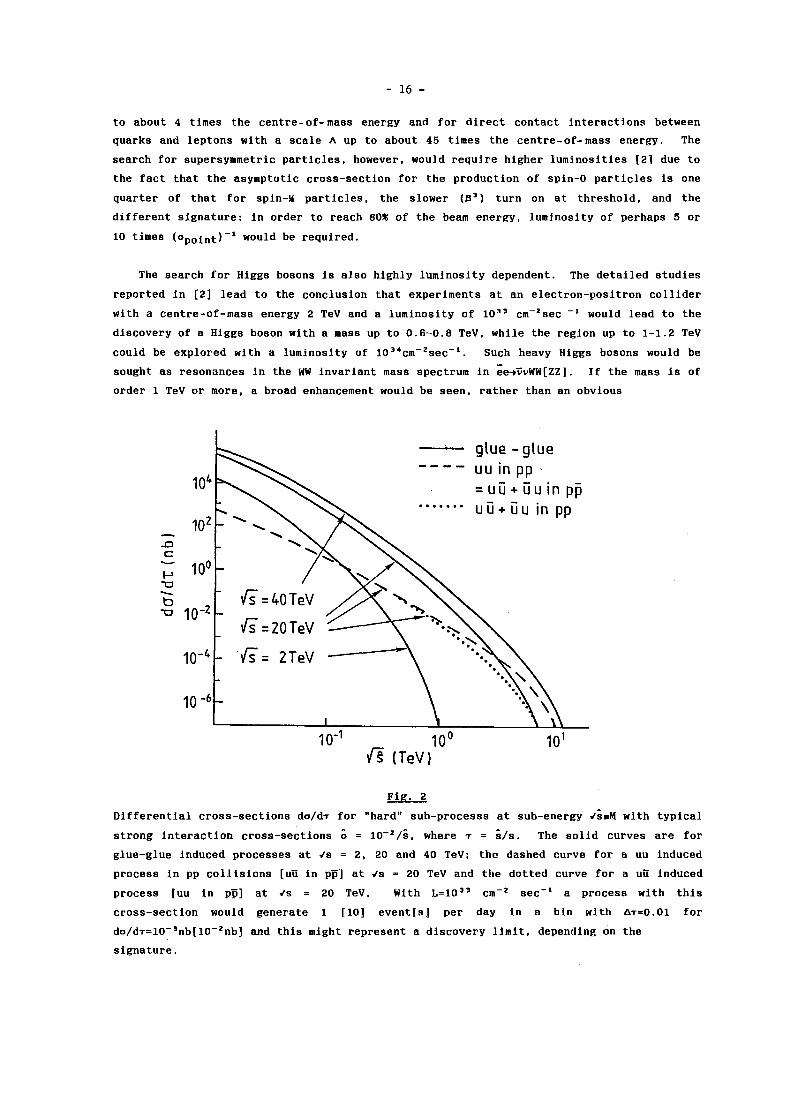
T h e s e a r c h f o r H i g g s b o s o n s i s a l s o h i g h l y l u m i n o s i t y d e p e n d e n t . T h e d e t a i l e d s t u d i e s
r e p o r t e d i n [ 2 ] l e a d t o t h e c o n c l u s i o n t h a t e x p e r i m e n t s a t a n e l e c t r o n - p o s i t r o n c o l l i d e r
w i t h a c e n t r e - o f - m a s s e n e r g y 2 T e V a n d a l u m i n o s i t y o f 1 0 3 3 c m ~ 2 s e c _ 1 w o u l d l e a d t o t h e
d i s c o v e r y o f a H i g g s b o s o n w i t h a m a s s u p t o 0 . 6 - 0 . 8 T e V , w h i l e t h e r e g i o n u p t o 1 - 1 . 2 T e V
c o u l d b e e x p l o r e d w i t h a l u m i n o s i t y o f 1 0 3 * c m ~ z s e c - 1 . S u c h h e a v y H i g g s b o s o n s w o u l d b e
s o u g h t a s r e s o n a n c e s i n t h e WW i n v a r i a n t mass s p e c t r u m i n e e - » v v W W [ Z Z ] . I f t h e mass i s o f
o r d e r 1 T e V o r m o r e , a b r o a d e n h a n c e m e n t w o u l d b e s e e n , r a t h e r t h a n a n o b v i o u s
10" 1 10° 10 1
v l (TeV)
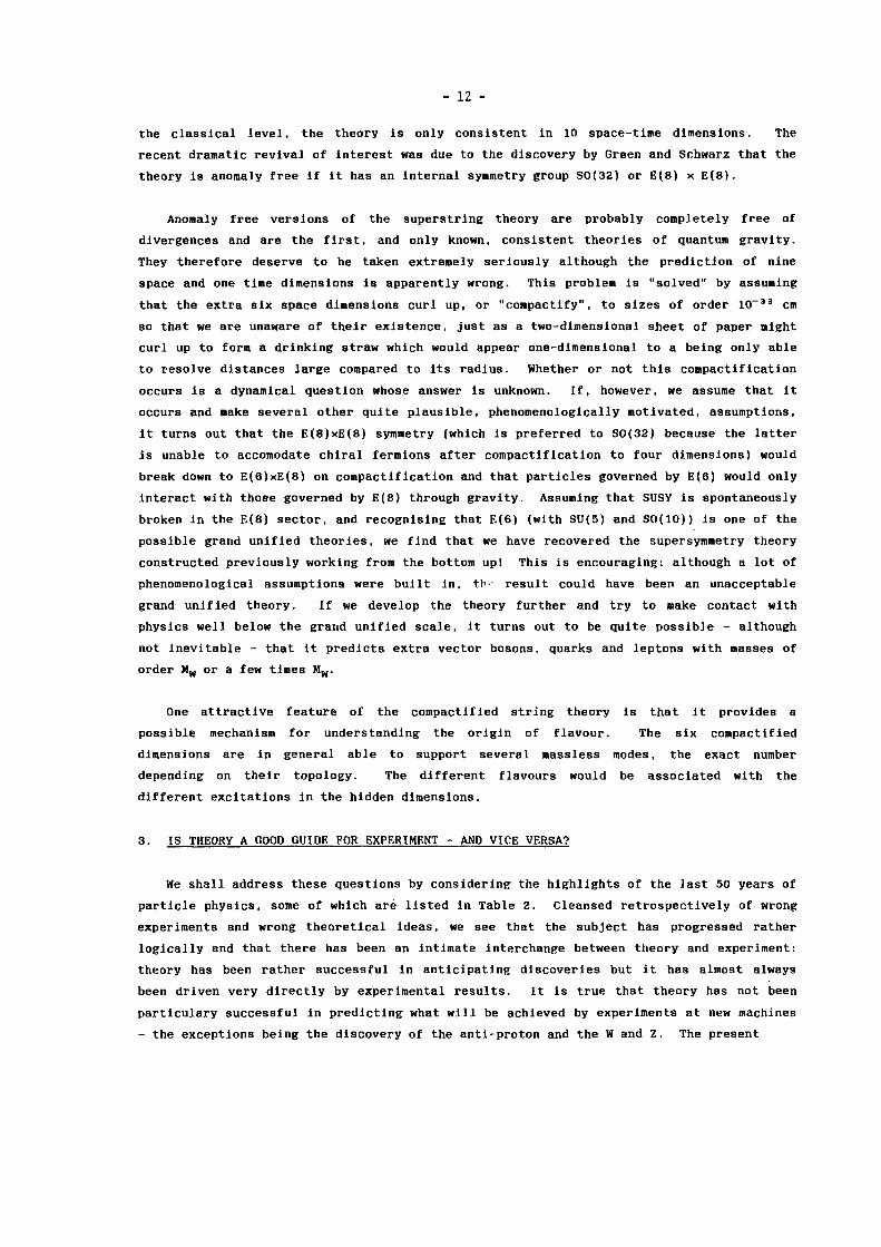
F i g - 2
D i f f e r e n t i a l c r o s s - s e c t i o n s d o / d r f o r " h a r d " s u b - p r o c e s s s a t s u b - e n e r g y vssK w i t h t y p i c a l
s t r o n g i n t e r a c t i o n c r o s s - s e c t i o n s ô = 1 0 ~ * / s , w h e r e T = s / s . T h e s o l i d c u r v e s a r e f o r
g l u e - g l u e i n d u c e d p r o c e s s e s a t v s = 2 , 20 a n d 40 T e V ; t h e d a s h e d c u r v e f o r a u u i n d u c e d
p r o c e s s i n p p c o l l i s i o n s [ u u i n p p ] a t v s = 20 T e V a n d t h e d o t t e d c u r v e f o r a uü" i n d u c e d
p r o c e s s [ u u i n p p ] a t V s = 20 T e V . W i t h L = 1 0 3 3 c m - * s e c - 1 a p r o c e s s w i t h t h i s
c r o s s - s e c t i o n w o u l d g e n e r a t e 1 [ 1 0 ] e v e n t [ s ] p e r d a y I n a b i n w i t h A T = 0 . 0 1 f o r
d o / d T = l 0 _ 3 n b [ 1 0 _ z n b ] a n d t h i s m i g h t r e p r e s e n t a d i s c o v e r y l i m i t , d e p e n d i n g o n t h e
s i g n a t u r e .

- 17 -
r e s o n a n c e , s i n c e t h e w i d t h i n c r e a s e s l i k e Mjj 3 a n d e x c e e d s t h e m a s s f o r m a s s e s a b o v e 1.44
T e V - i n w h i c h c a s e t h e H i g g s b o s o n w o u l d h a r d l y b e a p a r t i c l e . A s d i s c u s s e d i n s e c t i o n
2 , i f a l i g h t H i g g s b o s o n i s n o t f o u n d , s t u d y o f t h e s c a t t e r i n g o f l o n g i t u d i n a l l y
p o l a r i s e d Ws a n d Z s f o r i n v a r i a n t m a s s e s a b o v e 1 T e V w i l l b e t h e w a y t o d e c i d e w h e t h e r
t h e r e i s a v e r y h e a v y H i g g s b o s o n - p o s s i b l y o u t o f e x p e r i m e n t a l r e a c h - o r w h e t h e r t h e W
m a s s i s g e n e r a t e d i n some o t h e r w a y , s u c h a s b y t e c h n i c o l o u r . I t s e e m s t h a t t h i s w i l l
r e q u i r e [ 4 ] e l e c t r o n - p o s i t r o n c o l l i d e r s w i t h e n e r g y o f 5 T e V o r m o r e a n d l u m i n o s i t i e s o f
( ° p o i n t ) _ 1 o r m o r e -
5 . c P r o t o n - p r o t o n C o l l i d e r s
T h e m o s t i m p o r t a n t f e a t u r e o f p p c o l l i s i o n s i s t h a t t h e c o n s t i t u e n t q u a r k s a n d g l u o n s
w h o s e i n t e r a c t i o n s we w i s h t o s t u d y c a r r y o n l y a s m a l l f r a c t i o n o f t h e beam e n e r g y . I f we
c o n s i d e r t h e p r o d u c t i o n o f a g i v e n f i n a l s t a t e b y a " h a r d " c o n s t i t u e n t i n t e r a c t i o n a t
i n v a r i a n t mass M w i t h a c r o s s - s e c t i o n a = 1 0 ~ 2 / M 2 , w h i c h i s t y p i c a l f o r a s t r o n g p r o c e s s ,
a n d c o n v o l u t e t h i s c r o s s - s e c t i o n w i t h t h e q u a r k / g l u o n d i s t r i b u t i o n s , we o b t a i n t h e o v e r a l l
c r o s s - s e c t i o n s h o w i n g i n F i g u r e 2 . F i g u r e 2 s h o w s t h e w e l l - k n o w n f a c t t h a t g l u o n - g l u o n
c o l l i s i o n s a r e m u c h m o r e p r o b a b l e t h a n q u a r k - q u a r k c o l l i s i o n s a n d t h a t q u a r k a n t i q u a r k
c o l l i s i o n s o c c u r a s f r e q u e n t l y i n p p as i n p p c o l l i s i o n s , e x c e p t , i n b o t h c a s e s , f o r t h e
h i g h e s t v a l u e s o f M. T h e p o i n t t o w h i c h I w i s h t o d r a w a t t e n t i o n i s t h a t , f o r a n y
p l a u s i b l e l u m i n o s i t y , t h e d i s c o v e r y l i m i t M m a x i s w e l l b e l o w t h e k i n e m a t i c l i m i t a n d c a n
b e i n c r e a s e d b y i n c r e a s i n g t h e l u m i n o s i t y a s w e l l a s , o r i n a d d i t i o n t o , i n c r e a s i n g t h e
e n e r g y . F o r e n e r g i e s o f o r d e r 20 T e V a n d l u m i n o s i t i e s o f o r d e r l O ^ c i t r ' s e c - ' , a f a c t o r o f
2 i n e n e r g y i n c r e a s e s t h e d i s c o v e r y l i m i t b y t h e same a m o u n t ( a b o u t 6 0 * ) a s a f a c t o r o f 15
i n l u m i n o s i t y a s s u m i n g t h a t t h e e x t r a l u m i n o s i t y c a n b e u s e d . I t i s i m p o r t a n t t o r e a l i s e
t h a t i t i s n o t k n o w n w h e t h e r d e t e c t o r s c a n b e b u i l t t h a t w i l l o p e r a t e a t 1 0 3 3 , e x c e p t f o r
s p e c i a l p u r p o s e d e t e c t o r s , a s t h e c o n d i t i o n s w i l l b e q u i t e d i f f e r e n t f r o m a n y e n c o u n t e r e d
t o d a t e ; f o r e x a m p l e , a t t h e SSC w i t h L = 1 0 3 3 a n a v e r a g e o f 1.4 i n e l a s t i c e v e n t s w i l l b e
g e n e r a t e d a t e a c h b u n c h - b u n c h c r o s s i n g , i . e . ( e v e r y 1 6 n s ) w i t h a n a v e r a g e m u l t i p l i c i t y o f
o r d e r 6 0 . F u r t h e r d e t e c t o r d e v e l o p m e n t i s t h e r e f o r e v e r y i m p o r t a n t i n o r d e r t h a t t h e
p o t e n t i a l o f p p c o l l i d e r s c a n b e e x p l o i t e d , b u t m e a n w h i l e w h e n we s e e d i s c o v e r y p o t e n t i a l s
q u o t e d t h a t a r e b a s e d o n a l u m i n o s i t y o f 1 0 3 3 we s h o u l d l o o k c r i t i c a l l y a t w h a t h a s b e e n
a s s u m e d a b o u t t h e d e t e c t o r s .
I f t h e d i s c o v e r y l i m i t f o r a p a r t i c u l a r p r o c e s s i s r a t e l i m i t e d , a n d i f t h e
c r o s s - s e c t i o n s c a l e s ( o = 1 / E Z f ( M / E ) ) , t h e n t h e I, d e p e n d e n c e o f t h e l i m i t a n d t h e E
d e p e n d e n c e a r e r e l a t e d ; i f t h e l i m i t b e h a v e s a p p r o x i m a t e l y a s E P , t h e n i t w i l l v a r y a s
L ( i - p ) / î j f _ o n t h e o t h e r h a n d , t h e d i s c o v e r y i s b a c k g r o u n d l i m i t e d , t h e a d v a n t a g e o f
i n c r e a s i n g L m a y b e l e s s r e l a t i v e t o t h e a d v a n t a g e o f i n c r e a s i n g E b e c a u s e t h e s i g n a l may
i n c r e a s e m o r e r a p i d l y w i t h e n e r g y t h a n t h e b a c k g r o u n d . I n my t a l k a t t h e B e r k e l e y
C o n f e r e n c e [ 3 ] I r e p o r t e d d i s c o v e r y l i m i t s i n t h e f o r m c o n s t a n t x E a L p w h i c h I o b t a i n e d b y
m a k i n g f i t s t o t h e r e s u l t s i n r e f e r e n c e 5 . C o m p a r i n g t h o s e f i t s w i t h t h e r e s u l t s o b t a i n e d
i n r e f e r e n c e 2 , w h i c h w e r e b a s e d o n d e t a i l e d d e t e c t o r s i m u l a t i o n s , I f i n d t h a t I e r r e d o n
t h e s i d e o f o p t i m i s i m . N e v e r t h e l e s s i t i s c l e a r t h a t t h e LHC w i t h E c m = 17 T e V c a n p r o b e

- 18 -
t h e 1 T e V r e g i o n a l t h o u g h t h e SSC w i t h E c m = 40 T e V w o u l d o b v i o u s l y d o b e t t e r . F o r
e x a m p l e , w i t h L = 1 0 3 3 e x p e r i m e n t s a t t h e LHC s h o u l d d i s c o v e r a H i g g s b o s o n w i t h a mass
b e l o w 0 . 6 T e V w h i l e a t t h e SSC 1 - 1 . 2 T e V s h o u l d b e i n r e a c h . T h e H i g g s b o s o n w i l l b e
s o u g h t i n WW s c a t t e r i n g i n t h e s u b - p r o c e s s qq-»q'q'WW. I n o r d e r t o o v e r c o m e t h e QCD
b a c k g r o u n d , i t w i l l b e n e c e s s a r y f o r b o t h Ws t o d e c a y l e p t o n i c a l l y u n l e s s t h e o u t g o i n g
q u a r k s ( q 1 ) c o u l d b e t a g g e d , i n w h i c h c a s e t h e m u c h m o r e c o p i o u s h a d r o n i c d e c a y s c o u l d b e
u s e d . T h i s w o u l d e x t e n d t h e r e a c h f o r f i n d i n g t h e H i g g s b o s o n a n d m i g h t a l s o make i t
p o s s i b l e t o make q u a n t i t a t i v e s t u d i e s o f t h e s c a t t e r i n g o f l o n g i t u d i n a l Ws a t c e n t r e - o f -
mass e n e r g i e s a b o v e 1 T e V a t t h e S S C , a p r o c e s s w h i c h i s o n t h e e d g e o f o b s e r v a b i l i t y
w i t h o u t t a g g i n g [ 6 ] .
5 . d S u m m a r y a n d C o m p a r i s o n s
E l e c t r o n - p o s i t r o n c o l l i d e r s p r o v i d e a c l e a n u n b i a s e d w a y t o s e a r c h f o r n e w p h e n o m e n a
up t o a n e n e r g y o f o r d e r t h e beam e n e r g y . L u m i n o s i t y o f a t l e a s t ( ° P o i n t ) ~ f w i l l b e
d e s i r a b l e a n d s u b s t a n t i a l l y h i g h e r l u m i n o s i t y w o u l d b e p r e f e r a b l e . F l e x i b i l i t y i n e n e r g y
w h i c h d o e s n o t c o m p r o m i s e t h e l u m i n o s i t y w o u l d a l s o be d e s i r a b l e s i n c e t h e c r o s s - s e c t i o n s
f o r new p h e n o m e n a t e n d s t o p e a k n o t f a r a b o v e t h e t h r e s h o l d b e f o r e d e c r e a s i n g .
P r o t o n - p r o t o n m a c h i n e s s u c h a s t h e LHC a n d SCC w i l l a l l o w u s t o e x p l o r e t h e r e g i o n
b e y o n d 1 T e V . I f t h e r e a c h f o r t h e m o s t l i k e l y d i s c o v e r i e s i n c r e a s e s l i k e E ° - 6 5 , a s
c l a i m e d i n r e f . 3 , t h e SCC w i l l g o 7 0 * b e y o n d t h e LHC f o r t h e same l u m i n o s i t y . We s h o u l d
n o t i n f e r t h a t t h e SCC i s 7 0 * b e t t e r . I f n o t h i n g new i n h a b i t s t h e e x t r a r e g i o n , t h e
a d v a n t a g e w i l l b e r e l a t i v e l y s m a l l ( c f S e r p u k o v a n d t h e PS a n d A G S ) , b u t i f t h e r e a r e new
p h e n o m e n a t h e SSC may b e q u a l i t a t i v e l y b e t t e r ( c f S P E A R a n d A D O N E ) . T h e s i m p l e s c a l i n g
l a w a s s o c i a t e s a n L°• 1 7 b e h a v i o u r w i t h a r e a c h w h i c h g r o w s l i k e E ° ' e s . I f t r u e , a 2 5 - f o l d
a d v a n t a g e i n l u m i n o s i t y c o u l d c o m p e n s a t e f o r t h e l o w e r e n e r g y o f t h e LHC r e l a t i v e t o t h e
S S C . I n p r a c t i c e , h o w e v e r , i n c r e a s e d l u m i n o s i t y c o u l d o n l y c o m p e n s a t e f o r t h e l o w e r
e n e r g y u p t o a p o i n t g i v e n t h e d i f f i c u l t i e s o f d o i n g e x p e r i m e n t s a t v e r y h i g h l u m i n o s i t y .
T h e r e l a t i v e a d v a n t a g e o f e n e r g y a n d l u m i n o s i t y i s t h e s u b j e c t o f c o n t i n u i n g w o r k b y t h e
CERN l o n g - r a n g e p l a n n i n g g r o u p . P r e l i m i n a r y r e s u l t s o n l o o k i n g f o r H-»ZZ w i t h b o t h Z s
d e c a y i n g t o m u - p a i r s a t L = 5 x 1 0 3 * c m - 2 s e c _ 1 , s u g g e s t s t h a t t h e r e a c h w o u l d o n l y b e
e x t e n d e d u p t o 0 . 8 5 T e V a n d s h o w t h a t w h e r e a s t h e s i g n a l w o u l d i n c r e a s e b y a f a c t o r o f 8
i n g o i n g t o t h e SSC t h e b a c k g r o u n d w o u l d o n l y i n c r e a s e b y a f a c t o r o f 2 .
I n o r d e r t o c o m p a r e t h e c a p a b i l i t i e s o f e l e c t r o n - p o s i t r o n a n d p r o t o n - p r o t o n c o l l i d e r s ,
we c a n a p p e a l e i t h e r t o h i s t o r y ( F i g . 3 ) o r t o t h e r e c e n t s t u d y c a r r i e d o u t i n E u r o p e
( F i g . 4 ) . F i g u r e 3 s h o w s t h a t s i n c e 1970 p r o t o n - p r o t o n m a c h i n e s h a v e h a d a n a d v a n t a g e o f
a b o u t a f a c t o r 10 i n c e n t r e - o f - m a s s e n e r g y o v e r e l e c t r o n - p o s i t r o n c o l l i d e r s b u t I b e l i e v e
t h a t i t w o u l d g e n e r a l l y b e c o n c e d e d t h a t t h e i r c o n t r i b u t i o n s t o p h y s i c s h a v e b e e n o f
s i m i l a r i m p o r t a n c e . T h i s f a c t o r o f 10 w a s b o r n e o u t b y t h e E u r o p e a n s t u d y , w h o s e r e s u l t s
a r e s u m m a r i s e d i n F i g . 4 . I t s h o w s t h a t a 2 T e V e l e c t r o n - p o s i t r o n c o l l i d e r ( C L I C ) w o u l d
h a v e a s i m i l a r d i s c o v e r y p o t e n t i a l t o t h e L H C . T h i s f i g u r e a l s o s h o w s t h a t t h e s e m a c h i n e s
h a v e c o m p l e m e n t a r y c a p a b i l i t i e s . T h e r e a c h o f ë e c o l l i d e r s c l e a r l y g r o w s

- 19 -
3000
1950 1960 1970 1980 1990 YEAR
F l g . 3
A v e r s i o n o f t h e L i v i n g s t o n p l o t ( d u e t o K j e l l J o h n s e n ) f o r f i x e d t a r g e t s y n c h r o t r o n s a n d
c o l l i d e r s .
l i n e a r l y ( p r o v i d e d t h e l u m i n o s i t y g r o w s l i k e E 2 ) , s o i f i n d e e d C L I C a n d LHC a r e r o u g h l y
c o m p a r a b l e a n d i f a l s o t h e r e a c h o f p p c o l l i d e r s g r o w s a s E ° - 6 5 , t h e n t h e SSC w i l l b e
c o m p a r a b l e t o a n ë e c o l l i d e r w i t h E c r a = 3 . 5 T e V w h i l e t h e E l o i s a t r o n ( a h y p o t h e t i c a l p p
c o l l i d e r w i t h a c e n t r e - o f - m a s s e n e r g y o f 200 T e V ) w o u l d b e c o m p a r a b l e t o a 10 T e V ë e
m a c h i n e .
6 . C O N C L U D I N G REMARKS
T h e t h e o r e t i c a l a r g u m e n t s f o r e x p e c t i n g t h a t t h e r e a r e new p h e n o m e n a , a t o r b e l o w 1
T e V , a s s o c i a t e d w i t h t h e o r i g i n o f m a s s , a r e v e r y c o m p e l l i n g . I t w i l l b e n e c e s s a r y t o
e x p l o r e t h e s e new p h e n o m e n a e x p e r i m e n t a l l y : d e s p i t e t h e e u p h o r i a o f some s t r i n g t h e o r i s t s ,
p u r e t h o u g h t w i l l n o t b e e n o u g h . I t i s p o s s i b l e t h a t e x p e r i m e n t s a t S L C , L E P , HERA a n d
t h e T e v a t r o n w i l l d i s c o v e r n o t h i n g . I t i s a l s o p o s s i b l e , a n d p e r h a p s m o r e l i k e l y , t h a t
t h e y w i l l u n v e i l t h e e a g e r l y a n t i c i p a t e d "new p h y s i c s a t o r b e l o w 1 T e V " b u t i t seems m o s t
u n l i k e l y t h a t t h e y w i l l e x h a u s t i t . A n y d i r e c t i n f o r m a t i o n a b o u t t h i s p h y s i c s w o u l d p o i n t
t h e w a y t o t h e m o s t f r u i t f u l a v e n u e s f o r f u t u r e e x p l o r a t i o n . M e a n w h i l e t h e R a n d D
p r o g r a m m e i s c l e a r - w o r k i s n e e d e d o n l i n e a r e l e c t r o n - p o s i t r o n c o l l i d e r s a n d a l s o o n
d e t e c t o r s f o r h i g h l u m i n o s i t y p r o t o n - p r o t o n m a c h i n e s .

- 20 -
P i g - 4
S u m m a r y o f t h e p o s s i b l e d i s c o v e r y l i m i t s f o r 12 d i f f e r e n t p r o c e s s e s , c o m p i l e d b y A m a l d i 2 ) ,
f o r a ) p p c o l l i s i o n s w i t h E c m = 16 T e V , L = 1 0 3 3 c m _ 2 s e c ~ l ( L H C ) , b ) e p c o l l i s i o n s w i t h E c m
= 1 . 5 T e V , L = 1 0 3 2 c m _ 2 s e c _ 1 , a n d c ) ë e c o l l i s i o n s w i t h E c m = 2 T e V ( C L I C ) w i t h " l o w " L =
1 0 3 3 c m _ 2 s e c _ l a n d " h i g h " L = 4 x I 0 3 3 c m _ 2 s e c ~ l . F o r c o m p o s i t e n e s s t h e s c a l e h a s b e e n
d i v i d e d b y t e n e . g . C L I C w i t h h i g h L i s e x p e c t e d t o r e a c h A = 100 T e V w i t h t h e u s u a l
d e f i n i t i o n o f A . S e e R e f . 2 f o r f u r t h e r d e t a i l s .

- 21 -
R e f e r e n c e s
1. G . A l v e r s o n e t a l . F E R M I L A B - c o n f . 8 7 / 5 1 , t o be p u b l i s h e d i n P r o c . 1986 S n o w m a s s S t u d y
o n P h y s i c s o f t h e S S C .
2 . P r o c . W o r k s h o p o n P h y s i c s a t F u t u r e C o l l i d e r s , CERN Y e l l o w R e p o r t 8 7 - 0 7 .
3 . C . H . L l e w e l l y n S m i t h P r o c . X X I I I I n t e r n a t i o n a l C o n f e r e n c e o n H i g h E n e r g y P h y s i c s , p . 2 5 5
W o r l d S c i e n t i f i c , 1 9 8 7 .
4 . M . C . B e n t o a n d C . H . L l e w e l l y n S m i t h , N u c l . P h y s . B 2 8 9 , 3 6 , 1 9 8 7 . We o v e r l o o k e d t h e
d a n g e r o u s b a c k g r o u n d f r o m e?-ȑvWZ, v e W Z , p o i n t e d o u t a n d a n a l y s e d i n r e f . 2 , b u t we a r e
h o p e f u l t h a t t h i s b a c k g r o u n d c a n be s u p p r e s s e d e . g . b y u s i n g t h e f a c t t h a t t h e s i g n a l
[ b a c k g r o u n d ] i s d o m i n a t e d b y l o n g i t u d i n a l [ t r a n s v e r s e ] Z s t h a t h a v e a s i n z e * [ c o s z e * ]
d e c a y d i s t r i b u t i o n w h i c h s h o u l d b e e a s y t o e x p l o i t i n t h e d e c a y s Z-ȑe,i5a (we c o n s i d e r e d
WW-»ZZ s c a t t e r i n g w i t h o n e Z d e c a y i n g t o c h a r g e d l e p t o n s - we a c t u a l l y i n c l u d e d T T a n d
f o r g o t t o e x c l u d e c a s e s i n w h i c h t h e o t h e r Z d e c a y s t o v v ; o u r r a t e e s t i m a t e s a r e
t h e r e f o r e o v e r o p t i m i s t i c b y a f a c t o r o f t w o ) .
5 . E. E i c h t e n , I . H i n c h c l i f f e , K. L a n e a n d C. Q u i g g R e v . M o d . P h y s . 5 6 , 5 7 9 , 1 9 8 4 .
6 . M. C h a n o w i t z , L B L - 2 3 1 4 3 , 1 9 8 7 , P r o c . X X I I I I n t e r n a t i o n a l C o n f e r e n c e o n H i g h E n e r g y
P h y s i c s , p . 4 4 5 , W o r l d S c i e n t i f i c 1 9 8 7 , a n d r e f e r e n c e s t h e r e i n .
7 . D. F r o i d e v a u x , p r e s e n t a t i o n t o t h e H i g h L u m i n o s i t y G r o u p o f t h e CERN L o n g R a n g e P l a n n i n g
G r o u p .

- 22 -
Discussion
H. Hora, University of New South Wales
Since this conference is a meeting of conventional high energy physics laser and
plasma experts, I would like to make a comment on your question on "mass of particles".
Today's techniques can provide such high laser intensities in a focus that electrons and
ions (relativistically) oscillate with an energy above several GeV and pair production (e-,
p-) will occur. You cannot distinguish the particles by their mass. This state corre
sponds to the temperatures above 1 0 1 2 K (GeV) where the Gresner-Stocker or Hagedorn models
limit the state of matter [lj. The study of this "proto-matter" with particles undistin
guished by mass and merging the fermion-boson properties [2] may be a further interesting
topic apart from the usual accelerator technology.
|_1J H. Hora, Encyclopedia of Physical Science and Technology (Academic Press, New York,
1987) Vol. 7, p. 99.
[2J S. Eliezer, A.K. Ghatak, H. Hora and E. Teller, Equations of State (Cambridge Univ.
Press, 1986), Chapter 1.5.
P. Chen, SLAC
Would you please comment on the non-uniquess of the internal symmetry group in
superstring.
Reply
It is true that there seem to be two groups in the superstring. The choice is simply
made because one of them does not allow you to have left-handed weak interactions. But
this is the disturbing thing, if you think that the theory should lead you to a theory
which somehow fixes itself. This is rather unsatisfactory.

- 23 -
RF LINACS AND POWER CONVERSION
H. Henke
CERN, Geneva, Switzerland
ABSTRACT The main choices for a high-gradient, high-energy electron linac are presented. These are: the accelerating structure; the beam-induced effects and possible cures; the radio-frequency parameters; the power converters; and the pulse compression devices. Today's possibilities for a superconducting linac are briefly mentioned and compared with the standard, heavily pulsed, normal conducting linac. Finally, the inherent advantages of two-beam linacs and proposals for their realization are given.
I. INTRODUCTION
The aim of this paper is to report on the actual status and the prospects of creating high accelerating fields using conventional methods. I will therefore restrict myself to describing very high-energy linacs and devices which are capable of generating accelerating fields of 50 to 200 MV/m in an efficient way.
A first choice has to be made between two different types of accelerating structures: travelling-wave (TW) and standing-wave (SW). The TW structure delivers a constant accelerating voltage after one filling time, and it represents a matched load for the power source, but it requires an output with an absorber for the leftover power. In the SW case, the voltage builds up exponentially and about 23% of the incident energy is reflected, but it does not require any output load. In practice, the handicap of reflected energy can be more than compensated for by using irises with smaller diameter and nose cones, thus increasing the shunt impedance by 25% to 40%, in comparison with a TW structure. As a consequence, it is not obvious whether a TW or SW structure is better suited for efficient acceleration. The choice has to be made by looking at other issues such as operation, costs, and ease of fabrication.
Owing to the necessary mode separation, a SW structure consists of only a few coupled cells, typically five, whereas a TW structure is one order of magnitude longer. The cell-to-cell coupling in the SW case is small, about 1%, and the structure is more sensitive to errors that have arisen during the manufacturing stage (this can only be overcome by using complicated coupling devices). The main drawback for high-gradient applications is, however, the high ratio of peak to average field, which is 1.6 times more in a n-mode SW structure than in a TW structure. Equally decisive may be a small iris opening causing high transverse wake fields, especially for high-frequency structures. Taking these arguments into account it is probable

- 24 -
that future high-gradient linacs will use TW structures, with the exception of superconducting cavities which will be of the SW type.
After a short discussion of reasons why one would like to use a high operating frequency, this paper addresses the problems of the beam-induced fields and possible cures. Then it is pointed out why the situation is very different for a superconducting RF.
Microwave power tubes are briefly mentioned, especially their expected performance at high frequencies. No matter which tube turns out to be the best, the required very high peak power will probably need a subsequent pulse compression device as well as a large number of power sources. An alternative solution may be one of the different two-beam devices presented at the end of this report.
2 . PRINCIPAL DESIGN PARAMETERS [ 1 ]
As mentioned in the Introduction, TW structures are likely to be the solution for high-gradient, normal conducting linacs. In that case, sections can have constant cross-section (constant impedance, CI), where the field decays exponentially with the distance from the input; or they can be of constant gradient (CG) type, where the cross-section changes so that the field stays constant. The latter case reveals a few, although minor, advantages [ 2 ] . The RF dissipation is constant over the length, thus facilitating the cooling task remarkably. The ratio of peak to average field strength is smaller and the energy gain slightly higher. The structure is less sensitive to frequency deviations and less subject to transient effects. It is also less susceptible to multibunch beam break-up. These advantages must be weighed against the more complicated construction.
For ease of calculation, in the following we will assume a CI structure. However, the conclusions drawn apply also to a CG structure. Then the acceleration field decays exponentially as
whereas the stored energy W'(s), the dissipation P^(s), and the power flow P(s) decay with 2 a (s is the coordinate along the structure, and the prime means per unit length). Shunt impedance R' and quality factor Q are defined as
E(s) = E Q e - O S ( 1 )
R ' = E(s) 2/P¿(s), Q = uW'(s)/P¿(s) . ( 2 )
The group velocity v , equal to the energy velocity v„, follows from g
v = v„ = P(s)/W'(s) ( 3 )

- 25 -
as
v g = u/2aQ (4)
after the use of P¿(s) = -dP(s)/ds = 2otP(s) and Eq. (2). Then the filling time,
T f = l/v g , (5)
is the time a wave front needs to travel through a section of length 1. The total voltage of the accelerator of length L follows from inte
grating Eq. (1):
V = (L/l)f E(s)ds = E oL(l-e" T)/x, x = al . (6) 0
Combining Eqs. (2) to (5), one finds the peak and average RF power, for a given voltage gain V over a length L:
P R F = P 0(L/1) = (V 2/2R'L)x/(l-e-' c) 2 , (7)
? „ „ = í> T xf = (V 2Qf /«R'L)x 2/(l-e~ T) 2 , (8) RF RF f rep rep '
where we assumed a square pulse of duration T^ and a pulse repetition frequency f r ep« The energy transfer efficiency
H t = P b / P R F = (NeuR'L/QV)(l-e" T) 2/x 2 (9)
gives the fraction of the RF power which is transferred into beam power, P . = NeVf ; P - . . , , P „ t , , and n. are shown in Fig. 1 as a function of x, b rep RF' RF' 't 3 ' the attenuation per section. The attenuation x = 1.25 gives the minimum peak power, a working point often used in the past when accelerators were limited by the peak power available. Modern high-energy linacs have to be built with small average consumption, even at the expense of an increased peak power. At SLAC the point chosen is x = 0.57, and x = 0.25 may be the extreme operational point for a 1 TeV linac such as, for instance, the one proposed for CERN [3].
Let us now examine the frequency dependence of the different quantities. For constant E Q and x we find
W , P « w " 2 , P ¿ , Q oc u - L / 2 , R ' « M
L / 2 ,
V g a const, a oc w 3 2 , T f, 1 <x u" 3^ 2, (10)
and consequently
P R F « U " l / 2 , P R F oo (fl""2, n t cc w 2 . (il)

- 2 6 -
Equation (11) shows the strong dependence of the average power on the frequency, whilst savings in peak power can only be made when going to frequencies of at least one order of magnitude higher than the standard 3 GHz.
Although the accelerating fields in future linacs will probably be determined by the available peak power rather than by breakdown, it is still desirable to choose a high frequency where the breakdown limit is high. The breakdown formula for a short RF pulse is [4]
W = V 1 + 4 - 5 / T p 1 / 4 ] - ( 1 2 )
where E^ is given by the Kilpatrick formula for CW operation,
f = 1.643 x 10" 3 E f a e " 8 ' 5 / E b . (13)
Here E^ is in units of MV/m, T p is in [is, and f is in GHz. For high fields (E b > 20 MV/m) and short pulses (T < 20 us) the quantities scale as
E b * f l / 2 , T p a f" 3 / 2, and therefore E b ( T p ) « u 7 / s .
This result is plotted in Fig. 2, which gives the limiting field due to breakdown and to surface heating. A SLAC breakdown measurement [5] is given for comparison.

- 27 -
3 . WAKE FIELDS [ 6 - 8 ]
The co-travelling electromagnetic fields of a bunch are scattered at the surrounding chamber and act back on the beam. Longitudinallly scattered fields lead to energy loss and energy spread. The transverse components deflect particles and may cause emittance blow-up or even beam loss. For highly relativistic beams these fields can be calculated by neglecting the back action on the exciting charge during the passage through a certain component, i.e. the scattered fields are taken into account as external fields. Also, we are not interested in the fields at a fixed point, but in the force acting on a co-travelling charge over a certain interval:
z W(x) = ± j [E + v x B ] ( Q 2 ,<p2 ,z,t) dz .
z i
The position of the exciting charge is (i n cylindrical coordinates) and of the probing charge, Q 2 , < P 2 - The latter travels at t = z/v + x, i.e. a distance xv behind the first. The components of W are called wake potentials. They are normalized with respect to the amount Q of the exciting charge; Figure 3 shows the wake potentials for a 3 0 GHz disk-loaded guide [ 9 ] . The longitudinal wake has a discontinuity at x = 0 followed by a smooth part which gives the short-term, non-resonant effect. Then the wake starts to oscillate, as a result of the superposition of long-term resonant effects. The exciting charge 'sees' half the value of the wake which it creates immediately behind itself. The transverse wake potential behaves in a similar way, except for x = 0 , where the electric and magnetic forces cancel each other and the wake is zero.
For a given structure geometry, the longitudinal and transverse wake potentials per unit scale with frequency as
2 3 W. * W , W cc W (14) L i 1
T T T X T a ) 2a 2b
Fig. 3 a) Longitudinal and b) transverse wake potential of a point charge travelling in a disk-loaded guide.

- 28 -
o. -
-1.
b)
Fig. 4 a) RF voltage plus longitudinal wake potential of a Gaussian bunch; b) transverse offset of the bunch at the end of the linac. Example from Ref. [9].
and can therefore be detrimental in the case of a high frequency. Figure 4 demonstrates these effects, taking as an example a 30 GHz 1 TeV linac [9]. Figure 4a shows the superposition of the longitudinal wake potential and the accelerating voltage. The r.m.s. bunch length is 0.3 mm, and a phase difference of 14° is introduced between the bunch centre and the RF. (The phase difference is required for adequate Landau damping, see next section). This results in a 6.6% decrease of the accelerating voltage and a 5.9% energy spread. In Fig. 4b the transverse shape of the bunch is drawn at the end of the linac. For this purpose the bunch is cut into slices longitudinally, and the dots indicate the transverse position of the centroids of the slice. As can be seen, the 'tail' of the bunch is blown up by a factor of 800.
4. CURES AGAINST WAKE-FIELD EFFECTS
As pointed out in the above section, it would be preferable to use a frequency that is typically one order of magnitude higher than 3 GHz in order to save RF power. But the question is. Can we still cope with the much larger wake-field effects ?
4.1 Structure geometry and bunch length The longitudinal wake fields scale with the iris opening 2a and the
r.m.s. bunch length a as z
W r cc a" 1, a - 1 for a/X. = 0.1,...,0.3, a / X = 0.01, ... ,0.05, (15) L z
but the shunt impedance also goes like
R' - a " 0 - (16)

- 29 -
S o , i n c r e a s i n g a d o e s n o t h e l p . I n c r e a s i n g o z b r i n g s t h e w a k e f i e l d s
d o w n , b u t i t a l s o m a k e s i t h a r d e r t o d e c r e a s e t h e e n e r g y s p r e a d w i t h i n t h e
b u n c h s t r e t c h i n g o v e r a l a r g e r f r a c t i o n o f t h e s i n u s o ï d a l RF v o l t a g e . I n
g e n e r a l , t h e r e i s n o t m u c h t o b e d o n e a g a i n s t t h e l o n g i t u d i n a l w a k e f i e l d s .
T h e t r a n s v e r s e w a k e f i e l d s s c a l e a s
W T <* a - 2 ' 8 , ( 1 7 )
a n d o p e n i n g u p t h e b e a m h o l e h e l p s a l o t .
T h e d e p e n d e n c e o n o z i s m o r e c o m p l i c a t e d . T h e t r a n s v e r s e w a k e f i e l d
W m i s s m a l l f o r v e r y s h o r t b u n c h e s a < 0 . 0 1 X . , s h o w s a m a x i m a f o r i n t e r -
m e d i a t e b u n c h l e n g t h s , a n d g o e s s l o w l y d o w n f o r > 0 . 1 X . . T h e s h o r t b u n c h e s
c a u s e a h i g h WT a n d a r e d i f f i c u l t t o m a k e . T h e l o n g b u n c h e s a r e i n a c c e p t a b l e Li
o w i n g t o t h e i r l a r g e e n e r g y s p r e a d . T h u s o n e w i l l n o r m a l l y f a l l i n t o t h e
r a n g e w h e r e t h e t r a n s v e r s e w a k e i s h i g h e s t .
4 . 2 S t r o n g f o c u s i n g
S i n c e t h e t r a n s v e r s e w a k e f o r c e i s p r o p o r t i o n a l t o t h e t r a n s v e r s e
o f f s e t , o n e o b v i o u s a n d n e c e s s a r y r e q u i r e m e n t i s t o f o c u s t h e b e a m a s m u c h
a s p o s s i b l e . B u t a v e r y s t r o n g f o c u s i n g s y s t e m i s a l s o v e r y s e n s i t i v e t o
q u a d r u p o l e d i s p l a c e m e n t s . I n t h e e x a m p l e o f a 3 0 G H z , 1 TeV l i n a c [ 9 ] , t h e
a l l o w a b l e q u a d r u p o l e d i s p l a c e m e n t j i t t e r i s a b o u t 0 . 1 u.m.
4 . 3 ' F l a t ' b e a m s
S l i g h t l y r e l i e v e d t o l e r a n c e s f o l l o w i n t h e c a s e o f a s l o t t e d i r i s
( p r o p o s e d b y R . P a l m e r o f B N L ) . I n t h e d i r e c t i o n o f t h e s l o t t h e t r a n s v e r s e
w a k e i s s m a l l . T h u s t h e f o c u s i n g c a n b e m a d e w e a k e r , w h i l s t t h e e m i t t a n c e i s
s m a l l . P e r p e n d i c u l a r t o t h e s l o t , t h e l a r g e w a k e f i e l d r e q u i r e s a s m a l l
ß - f u n c t i o n b u t t h e e m i t t a n c e c a n b e m a d e l a r g e r . A s a r e s u l t , t h e t o l e r a n c e s
a r e r e l i e v e d b y a f a c t o r o f 1 . 5 t o 2 i n b o t h p l a n e s w i t h o u t a n y l o s s i n
l u m i n o s i t y .
4 . 4 L a n d a u d a m p i n g [ 7 , 1 0 ]
T h e u s e o f a n e n e r g y s p r e a d a l o n g t h e b u n c h i n o r d e r t o i n h i b i t b l o w - u p
w a s f i r s t d e s c r i b e d i n R e f . [ 1 0 ] . I f t h e ' t a i l ' o f t h e b u n c h h a s a l o w e r
e n e r g y t h a n t h e ' h e a d ' i t w i l l a d v a n c e i n b e t a t r o n p h a s e . On t h e o t h e r h a n d ,
t h e s i g n o f t h e w a k e - i n d u c e d k i c k s i s s u c h a s t o c a u s e t h e ' t a i l ' t o l a g
b e h i n d t h e ' h e a d ' . S o o n e e f f e c t c a n c o m p e n s a t e t h e o t h e r , a n d a n y b l o w - u p
c a n , i n p r i n c i p l e , b e s u p p r e s s e d b y c h o o s i n g t h e r i g h t e n e r g y s p r e a d . T h i s
i s c a l l e d L a n d a u d a m p i n g . F i g u r e 5 s h o w s t h e t r a n s v e r s e b u n c h s h a p e w i t h
d a m p i n g , a s c o m p a r e d w i t h F i g . 4 b w i t h o u t d a m p i n g , a g a i n f o r t h e e x a m p l e o f
a 3 0 GHz 1 TeV l i n a c [ 9 ] . T h e ' h e a d ' p a r t i c l e s , o s c i l l a t i n g f r e e l y a n d w i t h
a n a m p l i t u d e c o r r e s p o n d i n g t o a d i a b a t i c d a m p i n g , a r e o u t o f p h a s e , s o t h a t
t h e i r w a k e s m o r e o r l e s s c a n c e l o u t . T h e c o r e o f t h e b u n c h i s d a m p e d e v e n
m o r e b y c o n s t r u c t i v e c o m p l i c i t y o f t h e w a k e s . T h e e n e r g y s p r e a d , w h i c h i s

- 30 -
i •
Qdiabati i Qdiabati : damp. T 1 ¡
¡
! .
* * * -i •
- 4 . 0. z / 6 — - 4
Fig. 5 Transverse offset of the bunch at the end of the linac in the case with Landau damping, compared with Fig. 4b without damping.
necessary for damping, is 0.5% and 2% for a z A = 0.01 and 0.03, respectively.
4.5 RF focusing [11] As pointed out by R. Palmer, the transverse focusing may by achieved by
transverse RF fields in the structure. An Rf structure with slotted irises has the property that a passing charge 'sees' only a magnetic field in the direction of the slot and is therefore focused. In the perpendicular direction it 'sees' the focusing magnetic force plus a defocusing electric force of twice the magnitude. The effective focusing gradient has been calculated [11] as
G = j^=r sin q> , (18)
with E being the peak accelerating gradient; X. is the RF wavelength and <p is the RF phase angle measured backwards from the top. Such a cavity forms an RF quadrupole of the same peak focusing strength as a conventional quadrupole with 0.6 T pole-tip field, if E = 100 MV/m, X. = 1 cm, and the quadrupole aperture is 1.2 cm. The advantages of an RF focusing system are:
i) the savings that can be made in precision-permanent magnets; ii) the accelerating cavity, now forming the focusing system, may be used
to observe a beam-induced higher mode signal for automatic control; iii) the focusing acts within the bunch scale, i.e. parts of the bunch with
different phase angle <p are focused differently, and the spread in betatron oscillation, necessary for Landau damping, is introduced without a large energy spread; the spread in the betatron wave number is
Ak /k * + cot cpo it o z A = +9% , (19)
for a /X = 0.01, <p = 20° at the bunch centre;

- 31 -
iv) the spread [Eq. (19)] is more than one order of magnitude larger than is achievable through an energy spread. So the focusing strength itself can be reduced, and relieved alignment jitter tolerances are to be expected.
5. STRUCTURE CHOICE [1, 12]
There are many different slow-wave structures capable of accelerating electrons. A few are shown in Fig. 6. In general, they can be classified into forward-wave structures, where group and phase velocities are of the same sign, and backward-wave structures, where group and phase velocities have opposite signs.
Nearly all existing high-energy electron linacs are of the disk-loaded waveguide type (DLG). Even though other structures may present some advantages, such as higher shunt impedance, none of them has so far proved to be as practical as the DLG. High shunt impedance is obtained typically with small beam apertures and/or high group velocities. Small beam apertures yield large transverse wake fields, which is certainly detrimental to our aims (see sections 3 and 4 ) . Group velocities that are higher than necessary require larger distances between feeds, i.e. higher peak power, for efficient operation. No matter which measures are taken to widen the beam aperture and to reduce group velocity, they always reduce the shunt impedance until only a slight advantage, or none at all, remains. Moreover, most structures result in a more complicated fabrication and therefore in
777V/////A77
disk-loaded structure slotted disk structure
cross-bar structure 'jungle gym' structure
fff/./fff/.
7777//ff f /77
'rnutfin tin' structure 'open' disk-loaded structure
Fig. 6 Different slow wave structures for electron linacs.

- 32 -
higher costs. This is especially true for high-frequency structures where mechanical considerations, for instance cooling and fabrication, play a vital role.
For the above-mentioned reasons, the DLG is certainly a good candidate for very high energy linacs. Additionally, it has been proved that it can be built at 35 GHz and that it can stand very high accelerating gradients [13]. The experiment was done with a seven-cell fully equipped 2n/3 mode cavity. The input power was 3.1 MW, resulting in a peak field of 380 MV/m in the input cavity and 190 MV/m average accelerating field.
Apart from the standard DLG special structures, a DLG with a slotted iris or a 'muffin-tin' might be used for specific tasks such as RF focusing. Or, if the urge for multibunch operation becomes overwhelming, one might think of using structures where higher modes are heavily damped, as in the 'open' DLG shown in Fig. 6.
6. SUPERCONDUCTING LINACS [14-16]
Nearly all that has been said in the preceding sections is not valid for superconducting (SC) linacs:
i) SC cavities prefer CW or quasi-CW operation since the filling time is typically 100 ms.
ii) Standing wave cavities are more suitable owing to the small number of coupled cells per unit, no need for a return power-line, and no transient fields,
iii) Low frequencies are preferred since
Q o oc u" 2 , (R/Q) oc u, P¿ oc « . (20)
Another argument in favour of having low frequencies is that this would keep the number of feed lines per unit length as small as possible, which is desirable because they are by far the most expensive parts. Thirdly -- and this is especially important for SC cavities with their long 'memory' -- the shunt impedances for beam-excited higher modes are smaller. A lower frequency limit is given by the cost per unit length and by the transverse dimensions. A compromise is at present thought to lie between 1-2 GHz. Why could an SC approach be attractive in preference to copper
structures at the same frequency ? First, the quality factors are extremely high; today they are typically
Q o > 3 x 10 9. Theoretical work indicates values of Q Q « 1 0 1 2 for Nb 3 Sn at 1.8° K and 350 MHz. Owing to the high Q-values, the stored energy is not dissipated rapidly. Typical time constants are around 100 ms and are much larger than the bunch repetition time. This means that the stored energy has not to be supplied in a short time and that no very high peak power sources

- 33 -
are needed. The delivered RF power goes completely into the beam, the dissipation being negligible.
Secondly, an SC cavity has high accelerating gradients: 5 to 10 MV/m are achieved routinely, 30 MV/m is something of a record. Again, the theoretical predictions are much higher: 60 MV/m for Nb and 100 MV/m for Nb 3Sn, leaving room for development.
Thirdly, higher-order modes can be damped 10 s times as fast as the fundamental mode is dissipated. So multibunch operation is possible. The repetition rate and the duty cycle can be made very small.
Fourthly, the geometry adopted — by now almost universally -- is a simple spherical or elliptical shape (see Fig. 7). This allows easy fabrication from sheet metal, and good surface treatment. The electrical peak surface field is only about twice as high as the average accelerating field (the magnetic peak surface field to the average accelerating field is 30-40 G per MV/m). Multipactoring is largely suppressed.
Fifthly, the iris opening is much larger than for normal conducting cavities. This allows couplers to be placed at the cavity ends (beam tubes) and fabricational tolerances to be relaxed. But the main advantage is that higher modes are less excited and can be more easily damped.
Although SC cavities are today a well-understood technique, there is still much room for development. The main field-limiting effect is thermal breakdown due to surface defects. This can be improved by increasing the thermal conductivity A.. Commercially available Nb has a thermal conductivity of about 30 W/mK. A 150 W/mK has been achieved with an yttrification method at Cornell University [17]. Sputtering Nb or Nb 3Sn on Cu, with X. = 460 W/mK, is expected to reduce thermal breakdown considerably. Additionally, it would allow tube-cooling instead of bath cooling, thus simplifying fabrication and reducing costs. Work is going on in order to obtain clean and defectless surfaces, and to improve further the surface inspection, the cryostat design, and the shaping and welding techniques. High-temperature annealing will be developed and should improve the surface by degassing and homogeneization of bulk material.
Cornell University [15] has worked out the parameters for a 1 x 1 TeV collider. The frequency was chosen to be 3 GHz. The repetition rate of 20 Hz
Fig. 7 Schematic view of a five-cell superconducting cavity and its cryostat module.

- 3 4 -
with a duty cycle of 1% results in an RF pulse of 500 |xs duration. One hundred bunches of 5 x 1 0 1 0 particles are within one pulse with 1.5 km
9
spacing. The quality factor is taken to be 3 x 10 and the accelerating field 30 MV/m.
The relative optimistic value for the accelerating field in the Cornell example shows at the same time the weak point of today's SC linacs: a 30 MV/m accelerating gradient still needs a 40 + 40 km length for a 1 x 1 TeV collider! It should, however, permit a luminosity of 1 0 3 3 cm"2 s"1
with relatively modest RF power. Another serious problem is the cryogenic input power. Assuming an R/Q of 1500 Q/m for the cavity, static cryogenic losses of 1 W/m, and a cryogenic efficiency of 0.1%, the cryogenic input would be 200 MW.
7. RF POWER GENERATION
The creation of accelerating gradients around 100 MV/m requires a very high peak RF power in copper structures. In conventional generators the peak power is limited by voltage breakdown, the cathode current density, and the cathode area. The ultimate breakdown limit is considered to be 500 kV and the upper current density limit is determined by the space charge. 'Child's Law' tells us that the highest possible current density between two parallel, closely spaced electrodes is given by
J s c [A/cm 2] = 2.3 x 10" 6 (V o[V]) 3 / 2/(d[cm]) 2, (21)
where V Q is the voltage and d is the spacing. The limit follows when in a steady-state flow the space-charge field just cancels the external field. The cathode area is related to the wavelength and therefore scales as X2 .
The impressive progress in the past has been achieved by playing with these fundamental parameters. The voltage has been increased as much as possible by shortening the pulse. The cathode area was enlarged and the beam compressed afterwards. Even the RF cavities interacting with the beam became larger by overmoding them. Nevertheless, the basic limitation that the peak
2
power is proportional to X remains.
7.1 Klystrons The 'workhorse' in accelerator technology is still the classical
klystron. Its modular construction allows each part to be optimized in a very efficient way. The cathode system is optimized for high current and high beam energy. The RF part — cavities and drift tube -- is separated and grounded. The collector (also independent) is at or near ground.
This principle allowed tubes to be built which reached 150 MW at 3 GHz for 1 us [18]. The supply voltage was 450 kV. The tube operated with 51% efficiency and a saturation gain of 59 dB.

- 3 5 -
S H E E T B E A M K L Y S T R O N
RF Cavities
CS] I r o n
Fig. 8 Sheet-beam klystron concept.
From these results it seems possible to envisage a supertube at 9 GHz (M.A. Allen, J.M. Paterson, SLAC). A very short pulse of 80 ns duration, and a 1 MV supply voltage obtained by magnetic compression, would yield 700 MW output power.
Instead of increasing the voltage, attempts are also being made to increase the cathode and beam area. This will lead to sheet-beam or ring-beam klystrons (Fig.8) [ 1 9 ] . Development is also going on to increase even further the already high efficiency by an adiabatic RF extraction with a series of output cavities.
Finally, there is a proposal [20] for a quasi-continuous array of rather small tubes, instead of going through the acrobatics of generating extremely high peak power and then redistributing it. Instead of a sheet beam there is an array of beamlets and output cavities, so-called 'klystrinos', each of which is connected to individual or double accelerator cavities (Fig. 9 ) . These klystrinos would operate at a high frequency,
i
Fig. 9 Exploded view of continuous array of 'klystrinos' and n-mode cavities directly connected to them (Ref. [20]).
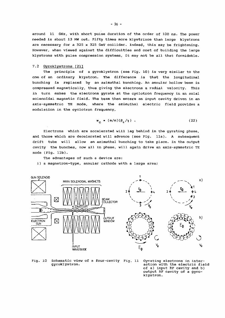
- 3 6 -
around 11 GHz, with short pulse duration of the order of 100 ns. The power needed is about 13 MW out. Fifty times more klystrinos than large klystrons are necessary for a 325 x 325 GeV collider. Indeed, this may be frightening. However, when viewed against the difficulties and cost of building the large klystrons with pulse compression systems, it may not be all that formidable.
7.2 Gyroklystrons [21] The principle of a gyroklystron (see Fig. 10) is very similar to the
one of an ordinary klystron. The difference is that the longitudinal bunching is replaced by an azimuthal bunching. An annular hollow beam is compressed magnetically, thus giving the electrons a radial velocity. This in turn makes the electrons gyrate at the cyclotron frequency in an axial solenoidal magnetic field. The beam then enters an input cavity driven in an axis-symmetric TE mode, where the azimuthal electric field provides a modulation in the cyclotron frequency.
« c = (e/m)(ß o/ V) . (22)
Electrons which are accelerated will lag behind in the gyrating phase, and those which are decelerated will advance (see Fig. lia). A subsequent drift tube will allow an azimuthal bunching to take place. In the output cavity the bunches, now all in phase, will again drive an axis-symmetric TE mode (Fig. lib).
The advantages of such a device are: i) a magnetron-type, annular cathode with a large area;
Fig. 10 Schematic view of a four-cavity Fig. 11 Gyrating electrons in inter-gyroklystron. action with the electric field
of a) input RF cavity and b) output RF cavity of a gyro-klystron.

- o / -
ii) a high-voltage capability; iii) an oversized beam pipe and overmoded cavities breaking the strict
2 relation between interaction area and X. . The problems arise from the oversized RF part where higher modes have
to be suppressed, and from the less stable situation concerning the azimuthal bunching. The efficiency, typically between 35 and 45%, is lower than for a klystron (50 to 65%). This is a consequence of the azimuthal bunching, where the longitudinal energy cannot be completely transferred into azimuthal energy.
An experimental tube is under construction at the University of Maryland [22]. The design is for a 10 GHz tube at a peak power level of 30 MW. The supply voltage is 500 kV, and the pulse duration will be between 1 and 2 u.s. Once the tube works successfully, it seems relatively straightforward to scale to output powers of several hundred megawatts.
7.3 Lasertrons Progress in the field of laser-driven optical cathodes has initiated
studies of directly modulated emission at high frequency. A photocathode is illuminated by an RF-modulated laser. The bunches are accelerated to high voltage and immediately passed through an RF output structure to produce microwave power (Fig. 12). Since the photocathode emits only while illuminated, only a d.c. power supply or a quite simple modulator is needed, leading to a very compact design. The efficiency should be very high. Computer simulations predict about 70%. Hopefully one can make use also of the very high current densities of photocathodes, which are several hundred A/cm2 as compared with the 20 A/cm2 of a thermonic cathode.
However, these potential advantages do not come for free. Photocathodes are far more sensitive to degradation by residual gas. The cathode activation requires various alkali metals and is difficult to achieve. Finally, the laser itself is a complex system and is not easy to modulate at a high frequency.
Such lasertrons are being developed at SLAC [23] and in Japan [24]. The SLAC experiment uses a 400 kV d.c. voltage. It is planned to have an RF power of 35 MW at 3 GHz during 0.3 to 1 u.s. Initially, a GaAs cathode will
F o c u s i n g coil O u t p u t M i c r o w a v e
P h o t o c a t h o d e
Fig. 12 Conceptual drawing of a lasertron (Ref. [24]).

- 3 8 -
be employed in a UHV vacuum of 10" 1 0 Torr. The Japanese tube (Fig. 12) has already produced 1.6 kW RF power at 3 GHz. At the moment it is limited by breakdown at 30 kV supply voltage. The design values are very similar to the SLAC ones.
7.4 Oscillators Different oscillating devices have proved to be capable of creating
very high peak power in the range of gigawatts. Backward wave oscillators are reported [25] with output powers in the range from 100 to 1000 MW at 10 GHz. At the MIT [26], a magnetron has produced 1.7 GW at 3 GHz with a conversion efficiency of 35%. The pulse duration was 30 ns. A review paper [27], lists virtual cathode oscillators which have produced up to 3 GW. However, these devices tend to have rather low efficiencies and produce a broad bandwidth output.
Although different oscillators have demonstrated the high-power levels required for high-gradient accelerators, they have yet to demonstrate the necessary stability and reliability. To achieve a stable phase, the oscillators have to be operated as amplifiers by injection locking. Practical experience with injection locking of magnetrons indicates that the locking power must be of the order of -15 dB with respect to the output power, which means that a tube delivering 1 GW output needs 32 MW locking power.
8. PULSE COMPRESSION SYSTEMS
A very good review article [28] has recently been published. Here I only want to give a short introduction to three RF pulse compression schemes.
8.1 SLED The SLAC energy doubler (SLED) scheme came into being as a result of
measurements on superconducting cavities. It was observed that the power radiated from a cavity that is heavily overcoupled approaches four times the incident generator power immediately after the generator has been switched off. A further increase by a factor of 2 can be gained if the RF source is reversed in phase rather than simply switched off.
Normally the power radiated from the cavity travels backwards to the generator. In the case of SLED, however, the waveguide system is broken, and a 3 dB coupler/dual-cavity assembly (shown in Fig. 13a) is inserted. After the RF pulse is turned on, the fields in the cavities build up and a wave of increasing amplitude is radiated from the cavity ports. The two emitted waves add at the accelerator port of the 3 dB coupler, whilst they cancel at the klystron port. In addition to the wave radiated from the cavities, there is a direct wave from the klystron which is opposite in phase.
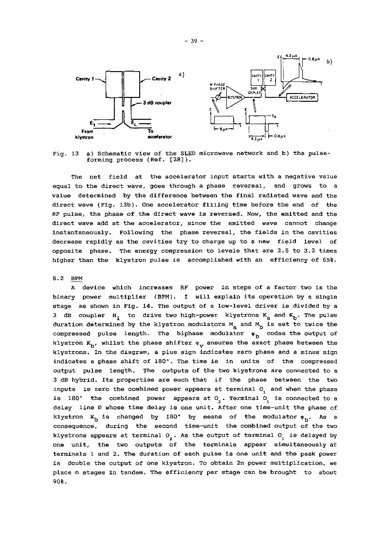
- 3 9 -
Cavity 1 -
From klystron
- Cavity 2
- 3 dB coupler
a )
Jkfc= To accelerator
TT P H A S E
SHirTEH
C«VIIY cuvnr 1 z
3dB ^ COOLER
1.2 ¿18 ,
ACCELERATOR
4.2/1S \— 0.6/1»
Fig. 13 a) Schematic view of the SLED microwave network and b) the pulse-forming process (Ref. [28]).
The net field at the accelerator input starts with a negative value equal to the direct wave, goes through a phase reversal, and grows to a value determined by the difference between the final radiated wave and the direct wave (Fig. 13b). One accelerator filling time before the end of the RF pulse, the phase of the direct wave is reversed. Now, the emitted and the direct wave add at the accelerator, since the emitted wave cannot change instantaneously. Following the phase reversal, the fields in the cavities decrease rapidly as the cavities try to charge up to a new field level of opposite phase. The energy compression to levels that are 2.5 to 3.2 times higher than the klystron pulse is accomplished with an efficiency of 65%.
8.2 BPM A device which increases RF power in steps of a factor two is the
binary power multiplier (BPM). I will explain its operation by a single stage as shown in Fig. 14. The output of a low-level driver is divided by a 3 dB coupler to drive two high-power klystrons K g and K^. The pulse duration determined by the klystron modulators M & and M b is set to twice the compressed pulse length. The biphase modulator <pb codes the output of klystron K b, whilst the phase shifter q>v ensures the exact phase between the klystrons. In the diagram, a plus sign indicates zero phase and a minus sign indicates a phase shift of 180°. The time is in units of the compressed output pulse length. The outputs of the two klystrons are connected to a 3 dB hybrid. Its properties are such that if the phase between the two inputs is zero the combined power appears at terminal 0 i and when the phase is 180° the combined power appears at 0 2 . Terminal 0^ is connected to a delay line D whose time delay is one unit. After one time-unit the phase of klystron Kfa is changed by 180° by means of the modulator <pb> As a consequence, during the second time-unit the combined output of the two klystrons appears at terminal 02 . As the output of terminal 0. is delayed by one unit, the two outputs of the terminals appear simultaneously at terminals 1 and 2. The duration of each pulse is one unit and the peak power is double the output of one klystron. To obtain 2n power multiplication, we place n stages in tandem. The efficiency per stage can be brought to about 9 0 % .

- 4 0
2 -P
- J — O 2 - r—i
0 2 t O 2 t 0 , 2 1 0 , 2 t
I n p u t
Hi Hi Hi Hi
B i p h a s e Modulator
0 2 t 0 2 »
Fig. 14 Diagram of a single-stage binary pulse multiplier (Ref. [28]),
8.3 SES A third technique, based on an active switch at the high-power side, is
the switched energy storage (SES) scheme (Fig. 15a). A storage cavity is connected to the accelerating structure via a X./2 long waveguide stub. Thus the short circuit at the end of the stub is transformed to the centre of the accelerator feed-line (Fig. 15b), yielding a very low coupling between the cavity and the accelerator. When the switch is fired, the short circuit at the end of the stub is moved by Ä./4, which now transforms into an open circuit at the feeding-line centre (Fig. 15c), and produces a heavy coupling between cavity and accelerator. For the switching mechanism, a low-pressure plasma discharge has been proposed. This scheme has the potential of a high-power multiplication.
Fig. 15 a) Schematic view of the switched energy storage device; electric field envelope in the coupling section with b) switch off and c) switch on (Ref. [28]).

- 41 -
9. TWO-BEAM ACCELERATORS (TBAs)
To create a 100 MV/m accelerating gradient in a copper structure, one needs typically 300 MW/m peak RF power at 3 GHz or 100 MW/m at 30 GHz. For the generation of these high-power levels, two different lines of development are being pursued: one is in the range from 3 to 11 GHz, with newly developed klystrons or eventually gyroklystrons or lasertrons followed by a pulse compression system; the other is aiming for the range between 20 and 35 GHz. In this latter range, high-power tubes are not available, nor are they expected to be available in the near future. Additionally, the required repetition rates for a collider will be high (in the kilohertz
- 3 / 2
range), and the short accelerating sections, of length a u ' , result in a high number of generators. A l x l TeV collider, for instance, needs 30,000 generators of 33 MW each when the gradient is 100 MV/m, the operating frequency is 30 GHz, and a section is 0.33 m long.
Instead of tens of thousands of power sources, it has been proposed to use a distributed RF source running parallel to the main linac (Fig. 16). The RF is generated in a periodical arrangement of decelerating units and transferred to the main linac. The energy lost by RF radiation generation is replenished periodically in reacceleration units. Deceleration and reacceleration is done adiabatically so that the distributed RF source is in a steady state. This is the concept of a TBA.
D E C E L E R A T I O N - REACCELERATION UNITS WITH FEEDS
high I
INJECTOR
low I
INJECTOR
MAIN ACCELERATING UNITS low I, high E MAIN BEAM
Fig. 16 Schematic drawing of a two-beam accelerator.
9.1 The original TBA [13, 29] In the original proposal for a TBA, the RF generation was done with a
continuously operated free-electron laser (FEL), i.e. the decelerating units, consisting of single-pass FEL units, created radiation travelling over the whole length of the linac. Conventional induction accelerating units were foreseen for the reacceleration of the beam (Fig. 17).

- 42 -
High Gradient LINAC
É3-Ü3
Wlggler
ll/i i//11
N S N S N S 1 '
Directional Coupler '
Induction Accelerator Module
,11. I l i ¡ I I A ™ s N S N S
til/// 1 1 1 i r1111 s
r i i i / i i k / [//////// s
Accelerating Gap "RF C h o k e '
P
- Blumleln
Fig. 17 Conceptual drawing of a two-beam accelerator which transfers energy from an FEL to a high-gradient linac.
The FEL and the main accelerating structure have been tested at LLNL/LBL. A 10 kA 3-4 MeV beam from an induction linac powered an FEL section. The wiggler, 3 m in length, was tapered. The output radiation was at 35 GHz with a peak power of up to 1.8 GW. As already mentioned in section 5, an accelerating gradient of 190 MV/m was reached with the FEL-generated RF in a seven-cell DLG.
Amongst the problems encountered in this scheme are the control of the RF phase, the inhibition of a side-band instability, and the long-distance transport of a relatively low-energy beam -- subjects of paramount importance. The reason for the low beam energy is the synchronous condition in the wiggler,
*-RF Aw = [ 1 + ( 9 3' 4 V w ) 2 ] / ( 2 < 2 ) ' ( 2 3 )
with the wiggler field B in tesla and the wiggler period X. in metres. So w w
the choice of \ cannot be too high if one wants X.Rp » 1 cm for reasonable wiggler parameters. This typically limits the beam energy to a few tens of MeV.
A modification of this scheme has been proposed elsewhere [30]. There the induction accelerator has been replaced by a 350 MHz superconducting linac. 9.2 The relativistic klystron [31, 32]
The basic difference between a relativistic klystron and the original TBA, is that the FEL is replaced by a beam-cavity interaction, as for normal klystrons. A bunched beam passes through a succession of tuned decelerating

- 4 3 -
cavities, each of which extracts only a small portion of the beam power. The cavity may be a simple single-cell cavity, for low power, or an overmoded cavity or a TW structure for high power. Again, the energy lost is replenished by an induction accelerator.
The advantage of interaction cavities is that the mechanism is simple and well understood, as compared with an FEL. The RF phase automatically comes out right, and the main problem remaining is the long-distance transport of the beam — a beam which has a relatively low energy in order to make full use of the high efficiency of the induction linac.
9 . 3 The two-stage RF linac [ 3 3 ] The two-stage RF scheme (Fig. 18) represents a kind of synthesis of
different ideas about TBAs, the aim being to eliminate weak points. It employs a high-energy drive-beam, around 5 GeV, in order to minimize problems of phase stability and beam transport. The reacceleration cavities are low-frequency ( 3 5 0 MHz) superconducting devices, assuring high efficiency. The RF generation units are 3 0 GHz TW structures. Their group delay is equal to the superconducting RF period, thus keeping the RF energy flow constant between drive-beam bunches. The main linac consists of high-frequency ( 3 0 GHz) disk-loaded waveguides.
The choice of a low-frequency drive linac and a high-frequency main linac has several advantages. First, the main linac needs reduced RF power as pointed out in section 2. Secondly, the 'transformer ratio', i.e. the ratio of the gradient in the main linac to that in the drive linac, is proportional to the ratio of the frequencies:
E . /E, . a w . /u, . . (24) main drive main' drive v '
Thirdly, the low-frequency superconducting cavities have high Q-values and are operated in CW. The generators can be large (1 to 2 MW) high-efficiency klystrons of proven design. Owing to the CW operation, the repetition rate can be very high, around 6 kHz, and is determined by injector considerations only.
•100 m B U N C H L E T S
X R F =85cm
SC REACCELERATION UNIT
350 MHz
"Ii" X=1cm
- ; GeV e" DRIVE LINAC
n
MAIN LINAC 5-1000 GeV
Fig. 18 Two-stage accelerator with superconducting CW drive linac and a microwave main linac (Ref. [ 3 3 ] ) .

- 44 -
The time structure of the drive beam is relatively complicated, and shown in Fig. 19a. The basic cycle, determined by the repetition rate, is 166 u.s. Then, four 350 MHz RF periods of 2.86 ns are needed to make up the 11.2 ns filling time of a main accelerating section. Since the charge
1 2 required in one driving bunch is quite high, 4 x 10 electrons, it probably has to be split into a number of bunchlets spaced at the high-frequency RF period of 33 ps. These bunchlets 'see' a linearly increasing decelerating voltage in the RF generating structure, as shown in Fig. 19b. In order to match this voltage loss with the reacceleration, the bunchlets have to be placed on the rising slope of the sinusoidal reaccelerating field.
Jem
85 cm h—
BUNCHLETS
52 km
a )
b)
REACCELERATING \
VOLTAGE
DECELERATING VOLTAGE
BUNCHLETS
Fig. 19 a) Bunch structure in the drive linac and b) the matching of the decelerating and drive voltage for the device of Fig. 18.
Table 1 gives some possible parameters for a 1 TeV two-stage linac which would allow a luminosity of 1 0 3 3 cm"2 s" 1 in the collider mode. The first column is for an accelerating gradient of 6 MV/m in the superconducting reacceleration cavities, corresponding to the present-day performance. The second column reflects the enormous improvement which can be expected from an increase to 15 MV/m which is likely to occur during the coming years. The third column, finally, refers to the high-gradient superconducting case plus multibunch operation in the main linac. Multibunch operation allows a higher RF-to-beam efficiency and permits higher gradients.

- 45 -
Table 1 Parameters for a 1 TeV two-stage linac
Main linac, 30 GHz: Accelerating gradient (MV/m) 80 160 445 Active length (km) 12. 5 6.25 2.24
Drive linac, 350 MHz : Accelerating gradient (MV/m) 6 15 15 Quality factor 5 x 10 9 5 x 10 9 5 x 10 9
Cryogenic input power (MW) 33 67 186 Active length (km) 2.5 0.8 2.24 R upon Q (Q/m) 270 270 270 Total voltage gain (GV) 15 12 33.6
* * *
REFERENCES
[1] G.A. Loew and R.B. Neal, in Linear Accelerators, eds. P. Lapostolle and A. Septier (North-Ho11and, Publ. Co., Amsterdam, 1970).
[2] R.P. Borghi et al., SLAC-PUB-71 (1965). [3] W. Schnell, CERN LEP-RF/86-06 (1986). [4] P.B. Wilson, SLAC-PUB-3674 (1985). [5] J.W. Wang and G.A. Loew, IEEE Trans. Nucl. Sei. NS-32 (1985) 2915. [6] P.B. Wilson, SLAC-PUB-2884 (1982). [7] K.L.F. Bane, SLAC-PUB-4169 (1986). [8] H. Henke, CERN LEP-RF/86-21 (1986). [9] H. Henke, CERN LEP-RF/87-32 (1987).
[10] V.E. Balakin et al., 12th Int. Conf. on High-Energy Accelerators, Fermilab, 1983, eds. F.P. Cole and R. Donaldson (FNAL,Batavia, 1983), p. 119.
[11] W. Schnell, CERN CLIC Note 34 (1987). [12] J.P. Boiteux et al., CERN LEP-RF/87-25 (1987). [13] D.B. Hopkins et al., LBL-20576 (1986). [14] U. Amaldi, H. Lengeier and H. Piel, CERN/EF 86-8 (1986). [15] R. Sundelin, to appear in Proc. Conf. on Particle Accelerators,
Washington, 1987. [16] H. Piel, Proc. CERN Accelerator School on Advanced Accelerator
Physics, Oxford, 1985 (CERN 87-03, Geneva, 1987), Vol. II, p. 736. [17] H. Padamsee, IEEE Trans. Magn. 21 (1985) 1007. [18] T.G. Lee et al., SLAC-PUB-3619 (1985). [19] K. Eppley, W. Herrmannsfeldt and R. Miller, to appear in Proc. Conf.
on Particle Accelerators, Washington, 1987.

- 4 6 -
[20] G.S. Loew, Stanford AAS Note 22 (1986). [21] V.L. Granatstein, M.E. Read and L.R. Barnett, Measured performance of
gyrotron oscillators and amplifiers, in Infrared and millimeter waves, ed. K. Button (Academic Press, Inc., New York, 1982), Vol. 5, p. 267.
[22] Kwo R. Chu et al., IEEE Trans, on Plasma Sei. PS-13 (1985) 424. [23] C.K. Sinclair, SLAC-PUB-4111 (1986). [24] Y. Fukushima et al., IEEE Trans. Nucl. Sei. NS-32 (1985) 2831. [25] A.S. El'chaninov et al., Sov. Tech. Phys. Lett. 6 (1980) 191. [26] G. Bekefi and T.J. Orzechowski, Phys. Rev. Lett. 37 (1976) 379. [27] D.J. Sullivan, IEEE Trans. Nucl. Sei. NS-30 (1983) 3426. [28] D.L.Birx, Z.D. Farkas and P.B. Wilson, Proc. Conf. on Physics of
Particle Accelerators, SLAC Summer School, 1985, and Fermilab Summer School, 1984 (AIP Conf. Proc. No. 153, New York, 1987), Vol. II, p. 1572.
[29] A.M. Sessler, Proc. Conf. on Laser Acceleration of Particles, ed. P. Channell (AIP Conf. Proc. No. 91, New York, 1982), p. 154.
[30] U. Amaldi and C. Pellegrini, CERN CLIC Note 16 (1986). [31] R. Marks, LBL-20918 (1985). [32] A.M. Sessler and S.S. Yu, UCRL-86083 (1987). [33] W. Schnell, CERN LEP-RF/86-14 (1986).

- 47 -
H. HENKE
Discussion
C. Pellegrini, BNL
1) The new high temperature superconductors might be able to support an accelerating field
in the range of 500 MeV/m; if this is true a linac of this type would be a very good can
didate for a collider. We have to support work in this area.
2) I would like to remark that there is no reason to stop at frequencies of 30 GHz. Still
higher frequencies, in the range of 300 to 600 GHz, offer advantages in terms of average
power needed for a given luminosity. At these frequencies one can use open accelerating
structures. The design of these structures needs more study, but they offer some interest
ing possibilities, for instance reduced transverse wake fields. Also good power sources,
namely the FEL, exist in this frequency range.
Reply
1) So, let us hope that fi lamentation and u-wave loss problems can be mastered, that sur
face coatings make these materials usable in vacuum and that the reported high critical fields can be repeated under operational conditions.
2) You are right, many parameters lead us to higher frequencies. But the transverse wake-
field scales like w 3 and can be reduced by only a factor 2-3 in open structures. Further I
see problems in the excitation and especially in phase control.
H. Hora, University of New South Wales
You mentioned the lasertron and the vacuum problems for the cathodes which may be
overcome by using ultra-violet laser pulses [lj. Since you gave a very positive view about
the lasertron and the problems with FEL's, I would like to ask what are the essential dif
ferences because I could see an ideal and intensive microwave source in the FEL.
H J H. Kuroda et al., Jap. J. Appl. Phys. (Feb.) 1986.
Reply
In the case of the lasertron the problems arise from the cathode technology and the
high DC fields in short gaps. Relatively long rise times, beam dynamics and cathode coat
ing have to be improved.
FELs, in fact, may be a very good microwave source apart from their clumsiness. But
depending on the application, phase locking, phase slippage and control and creation of
sidebands may cause serious problems.

- 48 -
N O N - R E S O N A N T FIELD G E N E R A T I O N
S. H. Aronson
Physics Depar tmen t , B r o o k h a v e n Nat iona l Labora tory , Upton, N Y 11973 , U S A
A B S T R A C T
Produc t ion of fields for par t ic le accelerat ion by pu lse t echnology is r ev iewed .
Special a t tent ion is focussed on several recent ly p roposed schemes for genera t ion
of very h igh g rad ien t s , bo th in metal l ic s t ructures and p l a smas . O n g o i n g and
p lanned expe r imen ta l act ivi t ies in these areas are d iscussed . 1. I N T R O D U C T I O N
At present there are m a n y schemes under discuss ion, s tudy, and deve lopmen t for accelera t ion of
par t ic les to very h igh ene rgy . It is useful in some c i rcumstances to adopt a t a x o n o m i c approach to this b road
and varied field; that is , to classify the schemes into families wi th in wh ich c o m m o n accelera t ion mechan i sms
are used. This approach has the v i r tue of mak ing the field somewhat more comprehens ib l e ; more impor tant ly
it may help identify c o m m o n vi r tues or defects and simplify the study of new spec ies in a rapidly evo lv ing
field.
T h e task of the present pape r is to exp lo re a par t icular class of s chemes g rouped under the rubric "non-
resonant" or "pulsed" field genera t ion . T h e c o m m o n feature is that the accelerat ing field is p roduced wi th one
pu lse (or a few pulses) of e l ec t romagne t i c energy, ra ther than a long train of p u l s e s , such as a m a n y -
wavelength burs t of R F energy .
In sect ion 2 we discuss briefly the vir tues (and defects) of pu l sed field genera t ion in generic t e rms . In
section 3 a number of such schemes current ly under invest igat ion are in t roduced and g rouped according to
their method of genera t ing pu l ses and their me thod of coupl ing the pu l sed field to the accelera ted par t ic les . In
subsequent sect ions the var ious s c h e m e s are presented in more detai l w i th e m p h a s i s on present s tatus and
future possibi l i t ies .
2. A D V A N T A G E S A N D D I S A D V A N T A G E S O F N O N - R E S O N A N T F I E L D G E N E R A T I O N
Schemes e m p l o y i n g very shor t pu lses of energy share (in genera l ) the fol lowing advantageous features:
a) Less heat is built up in s t ructures . Kro l l ' s pape r in the Proceedings of the Mal ibu Conference [1]
shows how this effect goes wi th the n u m b e r of wavelengths in a pulse t ra in , wi th N = 1/2 cor responding to a
single pu lse , as from a swi t ched-power source . For N large the achievable accelera t ing field at the mel t ing
limit decreases wi th the square root of N .
b) Very h igh p e a k p o w e r can be avai lable wi th modes t stored energy . Typ ica l ly the m a x i m u m
accelerat ing fields are found a long the b e a m axis . Accelera t ing gradients in the G e V / m range (on paper )
result .
c) For very short pu l ses H V b reakdown occurs at very h igh fields.
d) Power swi tch ing can in pr inc ip le be very efficient, a l lowing the poss ibi l i ty of systems wi th
reasonable overal l eff iciency.

- 49 -
M a n y of the acce lera t ion schemes fall ing in this c lass suffer f rom the fo l lowing k i n d s of d i f f icul t ies :
a) Va r ious mechan ica l to le rances are often ve ry t ight in order to suppress u n w a n t e d field c o m p o n e n t s :
col inear i ty and h o m o g e n e i t y of laser and par t ic le b e a m s , s y m m e t r y of s t ructures and swi tches , e t c . A n a l o g o u s
p r o b l e m s occur in s chemes where the s t ructure is r ep laced by a p lasma.
b) G o o d re la t ive t iming of p o w e r pu l ses and acce lera ted b e a m (i .e . , low j i t ter) is requ i red . T h i s is
some t imes au tomat i c ; for example a b e a m p u l s e swi tches the power , but in genera l g o o d t iming b e t w e e n
different even t s or c o m p o n e n t s mus t be imposed .
c) P rob l ems (for example wi th instabi l i t ies o r u n w a n t e d wake fields) m a y be wor se wi th the w i d e -
bandwid th inheren t in shor t -pulse opera t ion than in r e sonan t p o w e r sys tems .
d) M a n y schemes put r igorous d e m a n d s on laser sys t ems : short pu l se l eng ths , h igh repe t i t ion ra tes and
very h igh p e a k p o w e r is requi red [2] .
3 . C L A S S I F I C A T I O N O F N O N - R E S O N A N T F I E L D G E N E R A T I O N S C H E M E S
In the present paper we wil l r ev iew the concep ts for pu l sed -power sys tems l is ted b e l o w . T h e l ist is not
exhaus t ive , but perhaps representa t ive of the efforts on-go ing at present :
1. Wakef ie ld Acce lera tor (with off-axis d r iv ing b e a m ) [3]
2 . W a k e a t r o n [4]
3 . P l a sma Wakef ie ld Acce lera tor [5]
4 . Induc t ion Linac [6]
5. Col lec t ive Implos ion Accelera tor [7]
6. Swi t ched -Power Linac [8]
T h e s e pu l sed -power concepts can be g rouped in to sub-classes accord ing to the Tab le be low:
T a b l e 1
Classif icat ion of non- resonan t field generat ion concepts
\ Source of \ Pulse
Coup le r \ or T rans - \ . former \
S W I T C H P A R T I C L E B E A M
M E T A L S T R U C T U R E
Induct ion Linac
Swi tched-Power Linac
Wakefie ld Acce lera tor
Wakea t ron
P L A S M A
Plasma Wakef ie ld Acce lera tor
Col lec t ive Implos ion Accelera tor

- 50 -
W e choose here as charac ter i s t ics the me thod of p roduc ing the e l ec t romagne t i c pu lse and the m e a n s of
coupl ing the pu lse to the acce lera ted b e a m . In sect ions 4 th rough 6 w e d iscuss the concep ts g rouped in the
three filled e lements of T a b l e 1.
4 . I N D U C T I O N L I N A C A N D S W I T C H E D - P O W E R L I N A C
a. In an induct ion l inac (see Fig . 1) an accelera t ing electr ic field a long the axis is p roduced by a t ime-
vary ing magne t i c flux a round the axis . In the f igure, the swi tch p roduces a pu l se in the (pr imary) circuit
pene t ra t ing the magne t i c core ; t he b e a m is in effect the secondary w i n d i n g and sees an accelera t ing vol tage
across the g a p in the b e a m tube .
Th i s is cer ta inly the o ldes t n e w idea in non- resonan t accelera t ion cons ide red in this paper . T h e
history is d iscussed briefly in Ref. 6. A n d a l though one can in pr inc ip le conca t ena t e induct ion acce lera t ion
uni ts to reach high ene rg ie s , it is no t prac t ica l for this appl icat ion. O n the o the r hand , it is wel l -sui ted for the
accelera t ion of very h igh-cur ren t b e a m s . Tab le 2 g ives a typical e x a m p l e .
B E A M -
M O D U L A T O R
Fig . 1 Sketch of the Induc t ion L inac
Tab le 2
FXR Induc t ion Linac
B e a m Energy
B e a m Current
Pulse Leng th
Pulse Energy
R e p . Ra te
N o . of M o d u l e s
M o d u l e Vol tage
Tota l length
A v g . Gradien t
15-24 M e V
1.2-4.0 k A
60 nsec
1-5 kJ
1/sec
62
250-400 k V
4 0 m
375 -600 k e V / m
b . T h e swi tched p o w e r l inacs cons ide red here employ radial t r ansmiss ion l ines to couple the pu l sed
field to the acce lera ted b e a m [9] . T h e idea has been d iscussed by Wil l i s [8] ove r the last several years in the
context of smal l -sca le h igh-grad ien t s t ruc tures . F igure 2 shows a schemat i c p i c tu re of one cell of a swi tched-
p o w e r l inac .

- 51 -
. — . ( 2 L _ . ¡ 2 _ . — Beam A x i s
L i g h t Pulse
Fig . 2 A swi tched-power l inac sec t ion us ing a rad ia l t ransmiss ion l ine
Severa l worke r s are pursu ing l inacs along this l ine , the p r inc ip le difference a m o n g t h e m be ing the
swi tch t echno logy . Wi l l i s and col labora tors [7] are s tudy ing the use of v a c u u m pho tod iodes . Vi l la [10] would
use very h igh-pressure gas swi tches ; Mel i s s inos and M o r o u [11] and T a k e d a [12] are deve lop ing solid state
swi tches . Al l the swi tches men t ioned above are t r iggered wi th very short laser pu l ses (on the order of 10 psec
or less ) .
Very short pu l ses are necessary in order t o ach ieve h igh field wi thout suffering b reakdown . T h e
par t ic le bunches to b e accelerated are short c o m p a r e d to the field pu l ses and have very smal l t r ansverse
d imens ions for luminos i ty cons idera t ions in a h igh ene rgy l inac . T h u s the s t ructure can have qui te smal l
d imens ions , but la rge t ransformer ra t ios . Tab le 3 g ives typ ica l p a r a m e t e r s of the Wil l is vers ion; these are not
very different f rom those of the o ther schemes m e n t i o n e d above :
T a b l e 3
Pro to type Swi t ched -Power L inac Paramete rs
Outer radius
Inner radius
G a p (= disk th ickness )
Pho toca thode capac i tance
Pulse length
Charg ing vol tage
Stored energy
Swi tchable p o w e r
Radial enhancemen t
G a p field
Average gradient
120 m m
1 m m
2 m m
20 p F
10 p s
80 k V
64 mJ (16kJ /km)
6.4 G W
12
0.6 G V / m
0.3 T e V / k m
A n u m b e r of R & D projects n o w under way mus t succeed in order for a vers ion of this s cheme to be
deve loped into a prac t ica l h igh energy l inac. Mos t cr i t ical ly , a swi tch that is fast, efficient and r u g g e d mus t
be demons t r a t ed . W o r k on the v a c u u m pho tod iode swi tch at B N L and at Orsay wi l l be reported at this
W o r k s h o p . In the B N L work a gold-pla ted tungs ten wire p h o t o c a t h o d e ( D C surface field = 6 0 M V / m ) has
p r o d u c e d about 10 k A / c m 2 at photo-eff iciencies of 10" 5 . S imula t ions [13] indicate that nar row field pu l ses
can b e formed and that stored energy can be ext rac ted wi th reasonab le efficiency.
- 52 -
The solid state swi tch unde r deve lopmen t at L L E (Roches ter ) [11] is a lso m a k i n g p rogress . A
p ro to type swi tch 2 m m long has he ld 37 k V D C (under oil) and been switched in less than 100 psec [14] .
M o r e recent ly , the Roches te r g roup has repor ted the observat ion of vol tage e n h a n c e m e n t on a radia l l ine
s t ructure buil t on a 3 " d iamete r s i l icon disk , the per ipheral switch being ac t ivated by a shor t -pulse IR laser
[14] . This is an encourag ing step toward the real izat ion of swi tched-power l inacs .
M a n y other technologica l issues need to be resolved. In order to min imize def lect ing fields on the
b e a m a h igh degree of symmet ry is n e e d e d in the s t ructure , implying t ight cons t ruc t ion and a l ignment
to lerances and uniformity of the swi tching a round the c i rcumference . Mode l measu remen t s of the radial l ine
u n d e r way at C E R N [15] and also to be d iscussed here indicate that h igher mul t ipo les of the az imuthal field
d is t r ibut ion at the per iphery are the center . A l so , measured enhancement factors fit very well wi th the
pred ic t ions of analyt ical ca lcula t ions [16] and numer ica l s imulat ions [17] .
From a system efficiency point of v i ew it is required that the swi tch have high gain (switched
ene rgy » laser energy) and h igh eff iciency (swi tched energy == stored ene rgy) . T h e s e cons idera t ions m a y
de te rmine the choice of swi tch t echnology (assuming more than one type of swi tch works at al l!) .
c. Before leaving this box in Tab le 1 we note the exis tence of two other ideas , o n e emp loy ing radia l
l ine t ransformers and the other based on laser /photodiode swi tches . Al though not str ict ly speak ing pu l sed
p o w e r dev ices , they were inspired by the work on switched p o w e r l inacs at B N L and C E R N men t ioned
above .
Caspers et al. [18] h a v e sugges ted synthes iz ing a high-field pulse at the center of a radia l l ine b>
feeding an appropriately phased set of f requencies at the per iphery . It appears poss ib le to select f requencies
wh ich sum to a very short high-field pu lse at a p rede te rmined repet i t ion f requency, wi th re la t ively low fields
eve rywhere in the structure at all other t imes . One would l ike to use superconduc t ing s t ructures to min imize
losses ; it is hoped that one cou ld exceed the cri t ical field in the superconduc tor wi thout quench ing if the
high-field pulses are sufficiently short . M u c h w o r k needs to be done on the ideas and t echn iques upon which
this scheme is based.
Pa lmer [19] has taken over the l a se r /pho tod iode switch of Wi l l i s ' swi tched p o w e r l inac to p roduce a
p o w e r source , cal led the Micro laser t ron . Here one has a l inear array of pho toca thode wires at the appropria te
spacing in a resonant cavi ty . I l luminat ion of the ca thodes with short laser pu l ses fills the cavi ty wi th C W
power at the wave length de te rmined by the geometry of the pho tod iode array. Tab le 4 lists possible
paramete rs of a Micro laser t ron p roduc ing about a gigawat t at a wave leng th of 6 m m .
Table 4
Micro lase r t ron Sample Parameters
Vol tage suppl ied
G a p
50 k V
.5 m m
Ca thode peak i
Power output
Laser pu lse
Pho toca thode
Charge /pu l se
R F field
.9 psec
4 0 wires , 40 c m total area
8.8 n C / c m 2 ( 1 0 % of sp. chg . l imi t )
150 M V / m
10 k A / c m 2
.78 G W

- 53 -
5. W A K E F I E L D A N D W A K E A T R O N A C C E L E R A T O R S
a. This class of concep t s shares wi th those descr ibed above the use of a meta l l i c s t ructure t o couple the
field pulse to the accelera ted b e a m . In this case , however , a b e a m of par t ic les ra ther than a swi tch is used tc
generate the fields.
The wakefield accelera tor unde r s tudy at DESY [3] employs a radial l ine t ransformer s imilar to the
switched p o w e r l inac . The per iphery of the l ine is exci ted by the passage of a ho l l ow dr iving b e a m and the
wakefield pulse p ropaga tes inward to the axis of the s tructure. The t ransformer rat io of the s tructure provides
the gain. Figure 3 shows the features of the D E S Y exper iment .
jKlystron
- H P Prebuncher Screen Gap Accelerating cavity monitor monitor cavities
Energy ^ modulator
Gap Longitudinal monitor compression
Fig. 3 T h e D E S Y Wakefield Transformer Acce le ra tor
The deve lopment work on the D E S Y scheme is considerably more advanced than that of most other
accelerat ion concepts reported here . T h e latest results are reported at this W o r k s h o p . Effort has been
concent ra ted until n o w on the format ion of the hol low drive beam. In par t icular , the homogene i ty of the
dr iving beam is an impor tant p rob lem, ana logous to the problem of uniformity of swi tch ing in the switched
power l inac . Mechan ica l to lerances and a l ignment are also qual i ta t ively similar , not surprising since the
radial l ine is a c o m m o n feature.
b . T h e use of a radial l ine to provide gain in the D E S Y scheme is one way to beat the "wakefield
theorem" [20J which l imi ts the t ransformer rat io to 2 under certain condi t ions . O the r ways around the limit
involve tai loring the length or profi le of the dr iv ing b e a m bunches . A n appl ica t ion of this approach is found
in the Wakea t ron of the A N L group [4] , shown schematical ly in Figure 4 .
The dr iving b e a m in this case is a short proton bunch. The length of the dr iv ing pulse is the critical
pa ramete r in p roduc ing a t ransformer rat io greater than 2. A typical example from Ref. 4 has 100 GeV
protons in a gaussian bunch wi th a = 3 m m , g iv ing a transformer rat io of 10 and (with 3 x 1 0 " pro tons and
the s tructure geometry g iven in the figure) a gradient of 80 MeV/m. It is c la imed that the use of protons can
make the scheme cost effective and efficient. Protons also (by virtue of their mass ) have a high frequency of
osci l la t ion about the po in t of zero energy loss ; this so-called "mixing" in the dr iver bunch averages the
energy loss over all the par t ic les in the driver bunch and leads to the large t ransformer rat ios.
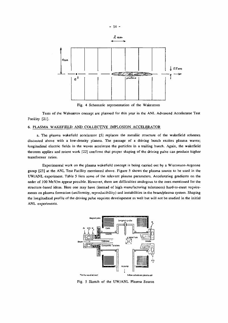
- 54 -
4TNRR
J, 0.5"mvYi
+
Fig. 4 Schemat ic represen ta t ion of the Wakea t ron
Tes t s of the Wakea t ron concept are p l a n n e d for this year in the A N L A d v a n c e d Acce le ra tor Tes t
Faci l i ty [21] .
6. P L A S M A W A K E F I E L D A N D C O L L E C T I V E I M P L O S I O N A C C E L E R A T O R
a. T h e p l a s m a wakefield accelerator [5] rep laces the meta l l ic s t ructure of the wakef ie ld s c h e m e s
d i scussed above wi th a low-dens i ty p l a sma . T h e p a s s a g e of a dr iv ing bunch exci tes p l a sma w a v e s ;
long i tud ina l e lec t r ic fields in the waves accelera te the par t ic les in a t rai l ing bunch . Aga in , the wakef ie ld
t h e o r e m appl ies and recent work [22] conf i rms that p rope r shaping of the dr iv ing pu lse can p roduce h ighe r
t ransformer ra t ios .
Expe r imen ta l work on the p l a sma wakef ie ld concep t is be ing carr ied out by a W i s c o n s o n - A r g o n n e
g roup [23] at the A N L Tes t Facil i ty men t ioned above . F igure 5 shows the p l a s m a source to b e used in t he
U W / A N L expe r imen t . Tab le 5 l ists some of the re levant p l a s m a parameters . Acce le ra t ing gradients on t he
order of 100 M e V / m appear poss ib le . Howeve r , there are difficult ies ana logous to the ones men t ioned for t he
s t ruc ture-based ideas . Here one m a y have ( instead of h igh manufac tur ing to lerances) ha rd- to -mee t r equ i r e
men t s on p l a s m a format ion (uniformity, reproducib i l i ty ) and instabi l i t ies in the b e a m / p l a s m a sys tem. S h a p i n g
the long i tud ina l profi le of the dr iv ing pulse requi res deve lopmen t as wel l but wil l not be s tudied in the ini t ia l
A N L e x p e r i m e n t s .
Fig. 5 Sketch of the U W / A N L P lasma Source

- 55 -
Table 5
P l a s m a Source Character is t ics
dens i ty 1 0 1 2 - 1 0 1 4 / c m 3
p l a s m a wave leng th 3 - 3 0 m m
axial m a g . field 4 0 0 - 800 G
in terac t ion length 1 0 - 2 0 c m
arc vo l tage < 100 V
arc cur rent < 50
neut ra l p ressure < 2 m T o r r
b . A somewha t different idea , the so-cal led Col lec t ive Implos ion Acce le ra to r [24 ] , shares wi th the
p rev ious wakef ie ld s cheme the use of a p l a s m a to couple the power pu l se to the acce le ra ted b e a m . Here ,
howeve r the p l a s m a is c rea ted by a short laser pu lse as dep ic ted in Figure 6. T h e s teps in this s o m e w h a t
compl ica ted scenar io are as fo l lows:
i. A shaped e lec t ron pu l s e ion izes the gas in the accelerator s t ructure and ejects ionizat ion
e lec t rons leaving an ion c o l u m n on axis . T h i s e lec t ron "charging pu l se" m a y be p r e c e d e d by an ioniz ing laser
pu l se .
ii. A short (1 psec ) laser pu l se fo l lowing the sharply cut off tail of the charg ing pu lse ionizes gas
in a w ide reg ion around the ion w a k e . T h e ionizat ion e lec t rons rush in toward the w a k e ; the radial current
pu lse p roduces an az imutha l m a g n e t i c field pu l se which in turn induces an axial e lec t r ic field.
iii. A short b u n c h of e lec t rons t rai l ing the laser pu lse is accelera ted by the implos ion-c rea ted
electr ic field.
I — H i g h E n e r g y E l e c t r o n Pulse Being Accelerated
Ion Column "Wake"
Ejection Of Secondary Electrons
F ield Of Beam
•Electron F l o w In Photoionization P l a s m a
Fig . 6 Depic t ion of the Col lec t ive Implos ion Acce le ra t ion Process
• Picosecond L a s e r Pulse
II/M_ • II
Charging E l e c t r o n Beam
In order to achieve the pa rame te r s which appear poss ib le on p a p e r a n u m b e r of foreseeable
difficulties (and no doubt some unforeseen ones) mus t be dealt wi th : Col inear i ty of all laser and part icle
beams wi th the s tructure is necessary to avoid strong t ransverse forces. P la sma instabil i t ies m a y be present as
in o ther p lasma-based schemes . It is c lear that pos i t ron accelerat ion wil l at least be different, if not harder ,
than e lec t ron accelerat ion.

- 56 -
6. S U M M A R Y
In the p reced ing few sect ions we have l is ted and descr ibed briefly a number of current s chemes for
accelerat ion wi th pu l s ed or non-resonant fields. Many schemes have been left out , and among the ones
included the status of R & D is widely varying from specula t ion and calculat ion on one end to ex tens ive
hardware tes t ing o n the other. I leave induct ion l inacs , a widely appl ied technology , out of this R & D
spec t rum.
A n u m b e r of p rob l ems faced by mos t if not all of the schemes presented here have not been discussed.
These relate m o r e to the col l ider appl icat ion than to the proof-of-pr inciple in each case . These inc lude h igh
repet i t ion rate capabi l i ty of the devices and wal l p lug efficiency of a large sys tem. I n most of the cases
cons idered these issues are somewha t p rematu re , since m a n y ques t ions of technical feasibility have to be
deal t wi th before the sys tems quest ions can be at tacked in a meaningfu l way.
R E F E R E N C E S
1. N . M . Kro l l , P roc . Workshop on Laser Accelera t ion of Par t ic les (Malibu, 1985) , AIP N o . 130, p . 296 [Referred to as "Mal ibu , 1985" below.]
2. D . Lowen tha l and J. Slater, Mal ibu , 1985, p . 5 1 8 .
3 . W . B i a l o w e n s , et al. , Proc . Workshop on A d v a n c e d Acce le ra to r Concep t s (Madison , 1986) , AIP N o . 156, p . 266 . [Referred to as "Madison, 1986" be low.]
4 . A. G. R u g g i e r o , et al. , Mad i son , 1986, p . 2 4 7 .
5. P. C h e n and J. M . Dawson , Mal ibu , 1985 , p . 2 0 1 .
6. D . Keefe , L B L - 2 1 5 2 8 (1986) .
7. D. Keefe , L B L - 2 1 2 5 7 (1986) .
8. W . Wi l l i s , Ma l ibu , 1985 , p . 4 2 1 ; S. Aronson , M a d i s o n , 1986 , p . 2 8 3 .
9. E. C. Ha r tw ig , Proc . Sympos ium on Electron R i n g Acce le ra to r s (Berkeley , 1968) , p . 44 .
10. F . Vi l la , S L A C - P U B - 3 8 7 5 (1986) .
11 . G. M o r o u , et al. , "High-Power Picosecond Swi tch ing in B u l k Semiconduc tor , " in P I C O S E C O N D O P T O E L E C T R I C A L D E V I C E S (Academic Press , 1984) p . 2 1 9 .
12. S. T a k e d a , informal report at Madison , 1986.
13. I . S tumer , p resenta t ion to the C L I C C o m m i t t e e , C E R N , 1986 .
14. A . Me l i s s inos , pr iva te communica t ion .
15. S. A r o n s o n , et al . , p resented by J. Knot t , 1987 Par t ic le Acce le ra to r Conf. (Wash ing ton , D .C . , 1987) .
16. R. E. Cassel l and F. Vil la, S L A C - P U B - 3 8 0 4 (1985) .
17. M . E. Jones , Part ic le Accelera tors 2 1 , 4 3 (1987) .
18. F . Caspe r s , et al. , presented by J. Knot t , 1987 Part icle Acce le ra to r Conf. (Wash ing ton , D.C. , 1987) .
19. R. Pa lmer , S L A C - P U B - 3 8 9 0 R E V (1986) .
20 . K. L. F . B a n e , et al . , S L A C - P U B - 3 5 2 8 (1984) .
2 1 . R. C. F e r n o w , Mad i son , 1986, p . 37 .

- 57 -
22 . P . C h e n , et al . , Phys . R e v . Let t . 5 6 , 1252 (1986) ; T . Ka t sou leas , Phys . R e v . A 3 3 , 2 0 5 6 ( 1 9 8 6 ) .
2 3 . J. R o s e n z w e i g , et al . , M a d i s o n , 1986 , p . 2 3 1 .
24 . R . J. B r i g g s , Phys . Rev . Let t . 5 4 , 2588 (1985) ; L. N . Hand , Mad i son , 1986 , p . 3 9 5 .
* * *
D I S C U S S I O N
B . Zot ter ( C E R N ) : The oldest and m o s t advanced scheme us ing pu l s ed p o w e r acce le ra
t ion is V L E P P in Novos ib i r sk , wh ich is actual ly look ing for project m o n e y at p resen t . W a s it
left out for lack of informat ion?
I apologize for this overs ight . Unfor tuna te ly , the latest informat ion I had avai lab le w a s
the V L E P P status report c o m m u n i c a t e d by A m a l d i to the 1981 Lep ton-Pho ton S y m p o s i u m in
B o n n . I am not famil iar wi th its current s ta tus .
T . Ka tsou leas ( U C L A ) : A c o m m e n t and ques t ion on your d iscuss ion of the F u n d a m e n t a l
Wakef ie ld Theo rem l imit ing the t ransformer ra t io of symmet r ic bunches to R = 2 : Th i s t h e o r e m
fol lows from M a x w e l l ' s Esq. and the p r inc ip le of l inear superposi t ion. T h e second a s sumpt ion
can be re laxed, for non- l inear p l a s m a w a v e s w e have recent ly found that R can be grea ter t h a n
2 for symmet r ic bunches . Migh t the same poss ibi l i ty exist for s t ruc ture-based wakef ie ld
dev ices (if dr iven to non- l inear ampl i tudes )?
T h a n k you for po in t ing out this n e w result . In the case of s t ructure-based dev ices , the
W a k e a t r o n uses symmet r ic p ro ton bunches and achieves R > 2 , a l though this is a different i ssue .
T o m y knowledge n o one has s tud ied t he case of a s t ructure-based device wi th non- l inea r
ampl i tudes ; it is not obv ious to m e that the p l a s m a result you quoted would apply , but I w o u l d
n e e d to give it more thought .
H. Henke ( C E R N ) : 1. Cou ld you c o m m e n t on the dispers ive m e d i u m in the radial l ine?
D o e s n ' t it increase the bunch length if it is pass ive? 2. Wha t is the shunt i m p e d a n c e of the
synthes ized pu lse scheme of Caspers?
I . I am afraid I d o n ' t have detai ls on the Takeda scheme presented at M a d i s o n ; I d o n ' t
k n o w how to provide a m e d i u m in the l ine wh ich compresses the pulse .
2. I have the fol lowing informat ion from Caspers on an U R M E L ca lcula t ion of a l ine
wi th outer radius 250 m m , hole radius 2.5 m m and 10 m m gap: T h e shunt i m p e d a n c e in the
f requency range 0.4 to 4 . G H z changes from 0.023 to 0 .064 M e g o h m s ; from 4 . to 8. G H z it
r ema ins fairly constant in the range 0.065 - 0 .071 M e g o h m s .
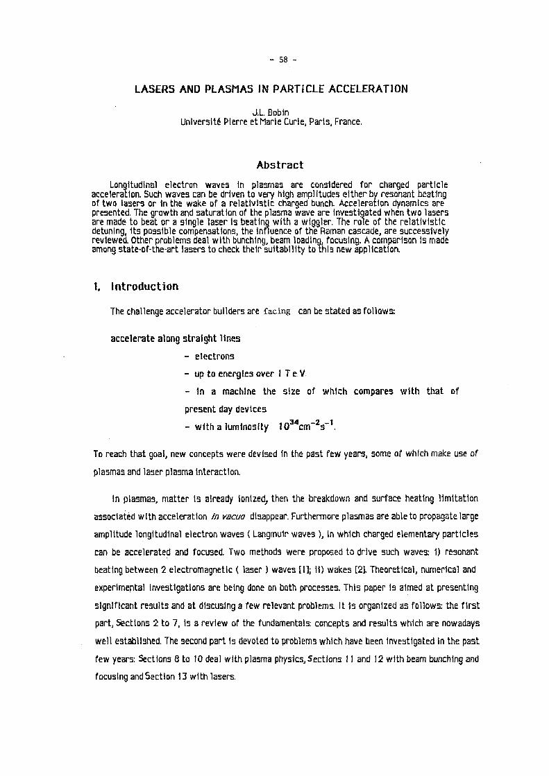
- 58 -
L A S E R S AND PLASMAS IN P A R T I C L E A C C E L E R A T I O N
J.L Bobin
Université Pierre et Marie Curie, Paris, France.
A b s t r a c t Longitudinal electron waves in plasmas are considered for charged particle
acceleration. Such wavea can be driven to very high amplitudes either by resonant beating of two lasers or 1nthe wake of a relativistic charged bunch. Acceleration dynamics are presented. The growth and saturation of the plasma wave are investigated when two lasers are made to beat or a single laser la beating with a wiggler. The role of the relativistic detuning, Its possible compensations, the influence of the Raman cascade, are successively reviewed. Other problems deal with bunching, beam loading, focusing. A comparison is made among state-of-the-art lasers to check their suitability to this new application.
1. I n t r o d u c t i o n
The challenge accelerator builders are facing can be stated as follows:
accelerate along straight lines
- electrons
- up to energies over 1 T e V
- In a machine the size of which compares with that of
present day devices
- with a luminosity I 0 3 4 c m " 2 s - 1 .
To reach that goal, new concepts were devised In the pastTew years, some of which make use of
plasmas and laser plasma Interaction.
In plasmas, matter Is already Ionized, then the breakdown and surface heating limitation
associated with acceleration in vacua disappear. Furthermore plasmas are able to propagate large
amplitude longitudinal electron waves ( Langmuir waves ), in which charged elementary particles
can be accelerated and focused. Two methods were proposed to drive such waves: 1) resonant
beating between 2 electromagnetic ( laser ) waves [I]; 11) wakes [2]. Theoretical, numerical and
experimental Investigations are being done on both processes. This paper is aimed at presenting
significant results and at dlscuslng a few relevant problems. It Is organized as follows: the first
part, Sections 2 to 7, Is a review of the fundamentals: concepts and results which are nowadays
well established. The second part Is devoted to problems which have been investigated In the past
few years: Sections 8 to 10 deal with plasma physics, Sections 11 and 12 with beam bunching and
focusing and Section 13 with lasers.

- 59 -
Fig. 1 Y.t Phase plot, a) acceleration of trapped electrons, b) acceleration of passing electrons.
The figure shows that the following can be accelerated to high energies: 1) electrons with
trapped trajectories and Initial low energy, 11) electrons with sharply defined Initial phase on
passing trajectories associated with velocities greater than the phase velocity of the wave
4* = C V kD- (2-5)
P a r t I: F u n d a m e n t a l s
2. E l e c t r o n a c c e l e r a t i o n i n a l o n g i t u d i n a l p l a s m a w a v e
Assume a longitudinal electron wave propagates with a well defined amplitude and phase
through a cold plasma in the z direction. Denoting by the field amplitude, by o)p the frequency, by
kp the wavenumber and by 0 n an Initial phase, the relativistic equation of motion for an electron is
dv/dt = -(e/ma)( 1 -v V ^ s l n ^ z - U p t *BJ, (2-1 )
where m Q Is the rest mass. The equation is better rewritten in terms of the Lorentz factor
Y = 1/ ( i - v 2 / c 2 ) 1 / 2 (2-2)
and with the similarity variable
Ï^ k n z - U p t (2-3)
One then gets the differential system
d*/dt = - (eEn/mnc)(1-t/if2)1/2sin(^flD)
(2-4)
aX/dt = ck 0(1-1//)1 / 2-u p
from which Is derived the (^j) u phase space " representation displayed 1n Fig. 1.

- 60 -
3. A c c e l e r a t i o n e n e r g y and length
The first-order ordinary differential equation In dv/dÇ resulting from (2-1) Is readily
Integrated to give
ckjjv - U p(v2-1 ) m - c ^ Q * u p(* 0
2-1 ) m = (eE^cXcosïi-cosï;Q). (3-1)
The maximum value of the second factor In the right hand side Is 2. It corresponds to the largest
A)f along a passing trajectory which assuming that both Y 0 and Y are much greater than 1,1s
A * = w 0 * (2eE0/mQcup)§R/( 1 -§R), = ( 1 -1 / Ï R
2 ) , / 2 = u p/ck D. (3-2)
The maximum energy that an electron may acquire in the process Is then
W A = m 0 c 2 A Y « (4eE 0/m 0cu p)m 0c 2 Y R2 = 4eE 0Y R
2c/u p. (3-3)
Now, there exists an absolute maximum for the plasma wave amplitude: density perturbation equal
to the background density, the so called wavebreaklng condition. An equivalent statement Is: all
electrons In the plasma are trapped In the wave. In a reference frame moving with the phase
velocity ( henceforth called " moving frame " ), most of the plasma electrons are traveling with a
velocity - u /ckD. They will be trapped provided the potential energy in the wave Is at least equal P u
to their energy YRmnC 2. Integrating the Poisson equation over half a wavelength and noting that the
particle number 1n a wavelength Is a relativistic Invariant as well as the longitudinal field, one
finds the condition:
2 e W < D = " W 2 1 e- Eo = m 0 aV e - ( 3 " 4 )
Substituting In (3-3), the upper limit for the electron energy turns out to be:
W A m B x = 2 m0<V • ( > 5 )
In the moving frame, electrons are accelerated over at most half a wavelength. Since there Is no
phase locking, electrons In the wave are to be decelerated whenever they propagate beyond that
distance. The corresponding acceleration length 1A 1n the laboratory frame Is given by
W A = eEolA hence 1 A = 2v„2c/up. (3-6)
The length of the accelerating plasma column should not exceed 1A and the extension of the
bunches along the z axis has to be less than a small fraction ( e.g. l/1L7h ) of the wavelength
2n7k0. After (3-3) and (3-6) the accelerating gradient is In general
W A/l A = 2eE 0 = cm 0u p(n/n 0) (3-7)

- 61 -
where n Is the amplitude of the density perturbation. The upper limit is
In all cases, (WA/1A) Is proportional to the square root of the background plasma
density.
The main limitation In the process comes from the acceleration length which results from
wave particle dephaslng. For given plasma and laser conditions, it puts an upper boundary on the
energy a particle may acquire In a single pass. Such an effect can be overcome by superimposing on
the plasma wave a uniform magnetic field whose direction Is perpendicular to the wave-vector.
Thus the particle velocity has a transverse component ( Fig. 2 ). This slightly reduces the
longitudinal component which can be kept equal to the phase velocity uR. An obvious analogy with
surfing, inspired the word " surfatron " coined for this situation [3]. Let x be the coordinate
parallel to the transverse component of the velocity. When phase locking occurs, the accelerated
particle velocity tends to
vx = (c2-u R
2) 1 / 2, vz = uR, (3-9)
while Its energy Increases indefinitely according to
dY/dz - (eB/moc)ifR (3-10)
where B Is the applied magnetic field. The particle travels at an angle 8 with respect to the wave
vector.
c s i n ö \ X
\ e l e c t r o n C
V \ u,, = c c o s b
\
Fig. 2 Particle and wave propagation in the surfatron

- 62 -
4. T h e resonant beat w a v e
When two electromagnetic waves act on an electron, the vxB force has longitudinal components
with the frequency u,-u2. When this difference Is equal to the plasma frequency u p, an electron
plasma wave Is resonantly driven. It la then shown [4] that the longitudinal electric field obeys the
forced oscillator equation
¿Uát? + E = - 2(e/m0)kDA, Ajcosl; (4-1 )
where A, and are the vector potentials of the laser waves. The solution of this equation
has an amplitude unphyslcally growing to Infinity, with a phase locking at TT/2. The actual
amplitude Is expected to saturate, thanks to various possible processes: pump depletion,
wave-breaking, relativistic oscillatory motion of the electrons in the wave, cascading towards
lower frequencies by Raman scattering, colllsional or Landau damping... Let r be some
phenomenologlcal damplnc coefficient. Accounting for relatlvtstlc electron oscillations results In
a negative nonlinear cubic term added to the left hand aide of (4-1) with a phenomenologlcal
coefficient a. Finally one gets a Dufftng'a equation
<?E/dt,2*VûE/ûK * (1-«E2)E = - 2<e/m0)knA1A2cosÇ (4-2)
whose aolutlons are Investigated analytically or numerically [5]. An example Is given in Fig. 6: It
shows, In the absence of damping, that the amplitude varies periodically on a slow time scale:
nonlinear period . There Is no phase locking and numerical simulations have evidenced some
turbulence creeping In after the first maximum [6]. This leads to the use of short laser pulses
whose duration does not exceed the nonlinear period.
Time >•
Fig. 3 Longitudinal plasma wavo amplitudo: growth and saturation by ralativistic detuning ( cubic term in (4-2) ).

- 63 -
5 . Accelerator prospects
The accelerating gradient I.e. the relatlvlstically Invariant longitudinal electric field in the
wave Is simply related to the relative electron density perturbation 6n/n
E=c(m onN/E n)1 / 25n/n (5-1)
where Is the unperturbed plasma density. Introducing the Interaction parameter
A = (e/mDc)2(E,/u1)(E2/u2) (5-2)
and the Lorentz factor K r associated with u R l one gets for the energy In the laboratory frame that an
electron may acquire
W A = 2m n C 2 v R
2(i6A/3) 1 / 3. (5-3)
Note that the phase velocity Is equal to the group velocity of the laser waves with mean
frequency u n ( =(u1-u2)/2 ), and
v R = L ) n / U p . (5-4)
From (5-3) and (3-6) an effective accelerating gradient is derived
W A/l A = mDcup(16A/3)1/3. (5-6)
The above results are valid provided one has
(16A/3) 1 / 3il (5-7)
the equality sign corresponding to wavebreaking. A quantitative summary is presented In Table 1:
the data, laser intensities, acceleration energies and lengths refer to wave-breaking conditions.
They represent absolute maxima.
High laser frequencies associated with low-density plasmas yield data of interest to
high-energy physicists. However, maintaining the required beam Intensity over long distances might
seem unrealistic, even In the case of self focusing.
On the other hand, low frequency lasers Irradiating high density plasmas provide comparatively
modest accelerations but over very short lengths. Such conditions correspond to actual experiments
on laser plasma Interaction being done In many laboratories. Since all numbers shown In Table 1
obey scaling laws, this means that results relevant to particle acceleration can be easily
obtained In present day experiments. Foreseeable accelerators are likely to be made of a
number of stages built according to the intermediate part of Table 1.
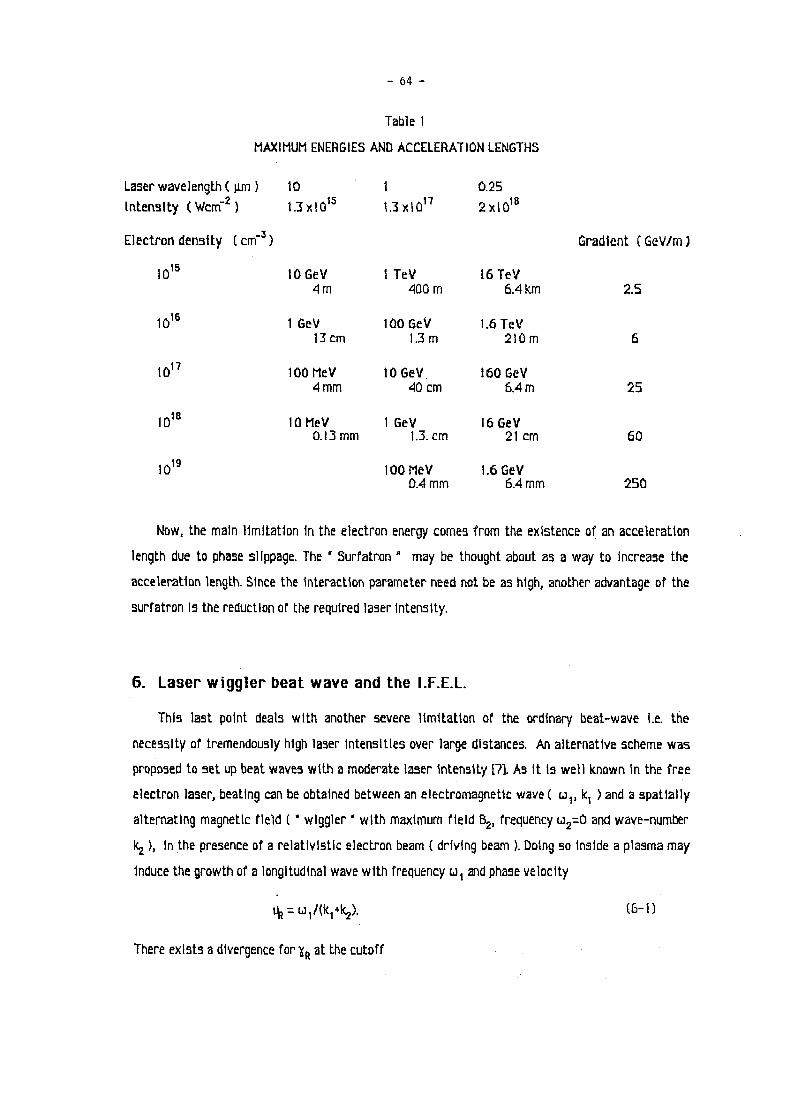
- 64 -
Table 1
MAXIMUM ENERGIES AND ACCELERATION LENGTHS
Laser wavelength ( u.m ) 10 1 0.25
Intensity (Wem - 2) 1.3xlû'5 1.3xtû17 2xlû 1 8
Electron density ( cm"3 ) Gradient ( GeV/rn )
1Û 1 5 10 GeV 1 TeV 16 TeV 4 m 4ÛÛm 6.4 km 2.5
1Û 1 6 1 GeV 100 GeV 1.6 TeV 13cm 1.3m 2IÛm 6
1Û 1 7 100 MeV 10 GeV 160 GeV 4 mm 40 cm 6.4 m 25
10 1 8 10 MeV 1 GeV 16 GeV 0.13 mm 1.3. cm 21cm 60
1Û 1 9 100 MeV 1.6 GeV Û.4 m m 6.4 m m 250
Now, the main limitation In the electron energy comes from the existence of an acceleration
length due to phase slippage. The " Surfatron " may be thought about as a way to Increase the
acceleration length. Since the Interaction parameter need not be as high, another advantage of the
surfatron Is the reduction of the required laser Intensity.
6. L a s e r w i g g l e r beat w a v e and the I . F . E . L .
This last point deals with another severe limitation of the ordinary beat-wave I.e. the
necessity of tremendously high laser Intensities over large distances. An alternative scheme was
proposed to set up beat waves with a moderate laser Intensity [?]. As it h well known in the free
electron laser, beating can be obtained between an electromagnetic wave ( uv k, ) and a spatially
alternating magnetic field ( " wiggler " with maximum field B2, frequency u 2=0 and wave-number
kj ), In the presence of a relativistic electron beam ( driving beam ). Doing so Inside a plasma may
Induce the growth of a longitudinal wave with frequency u, and phase velocity
ife^/flq*^). (6-1)
There exists a divergence for Y r at the cutoff

- 65 -
u p
2 = 2cu,k, - c \ 2 . (6-2)
The problem of the saturation or the longitudinal wave Is the same as before and is dealt with by
the same methods. It turns out that whenu, 1s much greater than the cutoff value, the acceleration
length Is a fraction of the wiggler wavelength. Matching the acceleration length to the wiggler size
requires conditions close to cutoff which will be holding In the following. Taking Into account the
relativistic correction, yields an energy and an acceleration length:
W A = 2moc2((up
2/u1
2)ifR
2.ifRK16A/3)1/3, 1A = 2yR
2c/u,. (6-3)
The interaction parameter is
A = (e/rrLcft^/UjXtykj) (6-4)
where Eykj can easily be made a large number. As lt Is clear from the data presented In Table 2
moderate laser Intensities are Indeed sufficient If one wants to build up a proof-of-pr1nc1ple
experiment using state-of-the-art wigglers.
Table 2
ACCELERATION BY LASER-V/1GGLER BEAT WAVE IN A PLASMA
( Wiggler: X 2 = 10cm, 1A = 1m, l\ = .6T)
LASER TYPE co 2 Nd KrF
Wavelength jim 10 1 0.25
Intensity Wem - 2 5x1û'° 5x10¹² 8x1 Û 1 3
Plasma density cm"3 2x10¹⁵ 2x10¹⁵ 8x10¹⁵
540 1.7x10³ 3.4x10³
W A GeV 0.6 2.3 7
The laser wiggler beat wave In presence of an electron beam is also able to accelerate charged
particles directly thanks to the ponderomottve potential ( Inverse Free Electron Laser as proposed
by C Pellegrini [8]). Indeed, in the right hand side of the equation of motion,
dTf/dt = (e/m0c2)c( 1 -1 /*2)1/230/az*(e2/2mo
2c2ï)3|A2/at (6-5)
the forcing term can also be considered as an equivalent longitudinal electric field whose amplitude Is
' E e q = 2(e/m0Y)(u1/c)A,A2 = 2(u,moc/e)f)A (6-6)

- 6 6 -
and whose periodicity Is the same as that of the driven plasma wave If any. The field Is
proportionnai to A whereas, Ep goes as A 1 / 3 . (6-5) reduces to
dï/dt = (up/Y)Aalfí, itydt = cO^Xl-l/* 2)" 2 - u, (6-7)
which Is readily Integrated to give the maximum increase 1n "¡f
A ï = ( 4 A u 1 / c k 2 + ï 02 ) , / 2 - ï o - ( 6 _ 8 )
This h to be compared w i t h the similar expression obtained with the longitudinal E field In
presence of a plasma
A Y = 4 i u p ï B2 / u | . u , ï R / u p ) ( 1 6 A / 3 ) , / 3 . (6-9)
It turns out that the A Y are equal for a critical value A c which 1s exceedingly large. For A < A c , Eg
Is larger than E . As shown by the two examples of figure 7, the presence of a plasma greatly
enhances the accelerating power of the I.F.E.L. Since the A 1 / 3 dépendance results from the same
saturation mechanism via relativistic detuning, the 2 laser beat wave scheme also rates better
than the Inverse free electron laser for electron acceleration, at least w i t h the available and
predictable laser Intensities.
Loser íreqency = I.77EH4 /s. Wiggler wavelengths 10 cm Electron density = ÍE+15 /c.c. Go m mo R = 512.4757 Gomma zero = 600
a
ID"
I 0 r l.F.t.u/
U L 1 1 1— A
Loser íreqency = 1.77E* 15 /s. Wiggler wavelength = 3 cm Electron density ï IE* 15 /c.c. Gamma R = 170.3242 Gomma zero - 200
lo"
J 1 1 A
i i 1
I D " 1 1 l ° L
Fig. 4 . Energy gain, of an electron in the I.F.E.L. ( lower curves ) and by laser wiggler beating in a plasma (upper curves ). a) CO, laser, b) Nd laser.'

- 6 7 -
7. W a k e f i e l d s
An electric charge travelling with a relativistic velocity through a plasma Induces a wake of
electrostatic oscillations. Consider first the case of a point charge q w i t h velocity u 0 close to c.
The corresponding charge density reads In cylindrical coordinates around the direction of u 0 :
Q q =q(6(r)/2Tir)6(z-u 0 t). (7-1)
The equation for electron density oscillations Is then
^n/at 2 + u p2 n = ( e r ö /mE Q ) Q q = <qu p
2/eu Q) (8(r)/2Tir)6(z-u0t) (7-2)
whose solution Is a Green's function
n = (qUp/eu^slnUpit-z/UaiYit-z/^) = nw5lrxj p(t-z/u 0)Y<t-z/'u n) (7-3)
where Y(t-t') Is Heavlside's step function. Using Polsson's equation, the corresponding electric
field Is found. Its longitudinal component is ( UQ -~ c } [9]
y r . z ) = -(qk 2/2TiE 0 )K 0 (kr)Y(t-z/c)cosu p (t-z/c) - ^ ( t - z / c j c o s u ^ t - z / c ) (7-4)
where k = u p /c and K^kr) is a modified Besael function.
In the case of an extended driving bunch, p(r,z), an Integration of £z has to be performed over
the spatial domain occupied by the charges. Let for Instance \(Ç) be a linear density along öz
(fc=z-ct). Then
E z = - ( ^ ^ n e ^ y k r ^ X C ^ J c o s k C^-Od^ . (7-5)
Taking e.g. X(C) as a half period of sinCk't;), a resonant term Is.found in the Integral which tends to
-(TT/2k)s1n(k^) as k'-*k. The electric field amplitude 1s strongly dependant upon the shape of the
driving bunch. In [10] an optimum " doorstep " bunch 1s found with the peak density at the trailing
edge. In [9] a numerical investigation was made of the bunch shape influence on the electric field
showing a maximum whenever the length of the bunch is an Integer multiple of the wavelength
2 r r c / u p . Now, the driving bunch with length 1 and maximum particle density r^^. undergoes a
retarding electric field whose mean value Is approximated by some coefficient u, times the
maximum E r d . An Important parameter Is the transformer r a t i o R. In a one dimensional
situation there is no on axis divergence of E^, and
* = ^ = « W V (7-6)
The value of R Is a measure of the efficiency of the wakefield as an accelerator. It Is warthwlle to

- 68 -
note that wakefleld erfects were observed long ago when passing molecular ions through thin
metal f o i l s [I I].
P a r t I I : P r o b l e m s
8. G r o w t h and s a t u r a t i o n of the p l a s m a w a v e : c o m p e n s a t i o n o f the r e l a t i v i s t i c detuning
It was shown in [12] that a properly choosen Initial detuning towards higher frequencies can
compensate the progressive detuning towards lower frequencies induced by the negative cubic
term In the Duffing equation (4-2). Cancellation occurs when the field amplitude Is to pass
through Its first maximum which is then enhanced by a factor up to 1.6. Now, in experiments
[13], the electron density Increases with time: a linear approximation was used to account for
this effect. Subsequently, a moderate Increment was found to provide further enhancement Df the
longitudinal field amplitude. Since the beat wave growth Is a convective process, such a model
might also apply to spatially Inhomogeneous plasmas.
Replace, 1n the Dufflng's equation, the constant elgenfrequency squared, by a function of the
similarity coordinate Ç:
ÍE/dt.2 * rdE/dÇ * [f(y-ocE?]E = - FcosÇ. (S-1 )
fdO Is choasen In order to mlmlck the spatial or temporal variations of the electron density, and F
is the amplitude of the external force. Setting
Y = dE/dt„ (8-2)
the modified Dufflng's equation Is rewritten
dY/dÇ = - l"Y - [f (O-oc E 2 ! - Fcost.. (8-3 ) .
(8-2) and (£-3) form a non autonomous differential system of the f i r s t order to be solved
computatlonnally by means of a centered finite difference scheme [14]. In all runs, p*^l and
a=.OD1. As in [13], assume there is no damping and choose a linear f(Ç):
fOX) = 1 + K£; ( I.e. electron density increasing linearly with time ). (8-4)
The results are shown on figure 5. When K Is varied, a sharp transition Is observed for a critical
value slightly above .0077, better seen on the graph of figure 6a: first maximum of the E field

- 69 -
amplitude versus K. Other plots on rigure 6 correspond to increasing damping coefficients. The
transition Is very steep at low damping, much smoother when the damping Is comparatively high.
This Is typical of a fold catastrophe of the kind exhibited by the ordinary Dufflng's equation [15].
The Influence of the damping was Investigated In longer runs. The choosen value for K, I.e.
.001, corresponds to a small enhancement of the f irst maximum. Without damping, the average
value of the amplitude 1s then steadily Increasing, whereas a strong damping Is found to
smooth out the oscillations of the amplitude. When f( 0 is different from linear ( e.g. a parabolic
variation ), the outcome Is quite similar.
Detuning due to the non-1 Inearltles can be compensated in a different way. Indeed one can act
on the driving frequency [16]. Since short laser pulses are needed, one or both of the beating wave
might be produced after some compression technique thus exhibiting a time varying frequency:
chirped putee. The dynamics of the electric field are now described by another modification of
the Dufflng's equation viz.
where g(É;) Is a function choosen to model the time dépendance of the driving frequency. A solution
with a linear g Is displayed on figure 7. Again, a catastrophic transition Is observed.
d*E/dÇ2 + rdE/dt; +(l-ocE2)E = - Fcos[g$)y (8-5)
Fig. 5 Evolution of the plasma wave amplitude K K for a linearly increasing density without damping. Curve labelled R is the reference: neither damping nor relativistic detuning.In curves labelled 0 to 8, K increases from .0070 to .0078 .
0 ,-2 ,-2 C
10 d 10'
Fig.6 a) f=.001 : first maximum of the amplitude vs K; b) T=.01: lst.2nd and 3rd maxima; c) T=.025: 1st and last maxima d) r=.05: maximum vs K.

- 70 -
E
Fig. 7 Linearly decreasing driving frequency ( pulse chirping ) with damping l"=.05. R: reference. 0 to 3: K=7.10""to 10*3.
9. G r o w t h and s a t u r a t i o n of the p l a s m a w a v e : the Raman cascade
A single laser wave Is able to undergo forward Raman scattering whenever Its Intensity 1s
greater than a threshold which depends upon damping mechanisms. The effect goes both ways:
either a photon gives rise to a plasman and a photon with a lower frequency { scattering on the
Stokes side ) or the photon recomblnes with a plasmon to produce a photon with a higher frequency
( scattering on the antlstokes side ). Each of the two laser waves participating in the beat wave
may be scattered either side. This cascade can be described by a system of coupled f i rst order
differential equations dealing with the complex amplitudes of the modes involved.
The relevant equations were set up by Karttunen and Salomaa [17]. Here the similarity
variable E Is of a temporal nature and the equations read for each E.M. mode labelled J:
dA/dE. = ( u / U j X - A ^ A p «• A j + 1 A p * ) ( 9 - 1 )
where u , correspond to the Impinging laser wave with the higher frequency and A^ is the
amplitude of the plasma mode which In turn satisfies the equation
dAp/dï; + W Q Q - U (xlApñAp = S J A J Y , * . ( 9 - 2 )
In the left hand side of ( 9 - 2 ) are added terms dealing with the relativistic detuning and Its
compensation by a time varying density. A single term only is present in the right hand side of the

- 71 -
equations dealing with the modes at both ends of the cascade. These equations are solved
numerically for a finite number of.rnodes, usually 30.
Significant results are shown on figure 8. Energy cascading towards the lower frequencies
Improves the quantum efficiency of the beat wave. However, the phase shifts by n every time one
of the E.M. waves goes to zero. The conservation of coherence Is then questionable. Introducing the
relativistic detuning with a large coefficient changes drastically the dynamics. A nonlinear period
shows up, the detuning dominates the process. A linear compensation enhances the saturation level
of the generated longitudinal plasma wave whilst the electromagnetic spectrum spreads over all
allowed modes. This Is accompanied by a locking of the relative phase between the two pump
waves and the plasma wave. In case or an overcompensation, the relative phase increases
Indefinitely, the spreading of the spectrum is limited and the plasma wave saturates at a lower
level: a kind of steady state takes place.
Fig. 8. The Raman cascade, a) without relativistic detuning nor compensation; b) with relativistic detuning, no compensation; c) relativistic detuning, linear compensation; d) overcompensation of the relativistic detuning.

- 7 2 -
10. P l a s m a c r e a t i o n
In the past few years, preliminary experiments have been set up 1n order to study the plasma
wave resulting from the resonant beating of two lasers and the subsequent electron acceleration.
The plasma has to be fairly uniform, reasonably long and easily usable as a target Tor focused laser
beams. The experiments so far were succesfull, evidencing plasma waves with longitudinal
electric fields in the range 0.3 to 2 G e V / m [18], and Injected electrons being accelerated from
û.64Me V. to about 2 rte.V., however with a large energy spread [19].
The workhorse Is the molecular CC^ laser-, many laslng transitions are allowed. It 1s possible
to easily select two of them in such a way that the frequency difference matches given plasma
densities In the range I 0 1 5 - 1 Q 1 7 cm"3. Plasma creation in such a range can be obtatned either
through the use of laser ( gas breakdown, irradiation Df solid surfaces ), or in electrical
discharges. Table 3 states the advantages and drawbacks of various methods which were proposed
to create plasma suited to electron acceleration.
Table 3
METHODS FOR GENERATING PLASMAS
BYLASERS
Gas breakdown in quiet gas
In gas Jets
Interaction with solid surfaces
Interaction with thin foils
density ( ecm" )
10 1 B-1û"
1 0 1 6 - 1 0 1 7
I O 1 6 - ^ 0
1 0 1 5 - 1 0 2 0
comments
multiphoton ionization produces completely ionized plasmas with a very uniform electron density [20].
uniformity is questionable [21 ]. Plasma in vacuo i.e. good target.
adjustable length. Plasma in vacuo.
short but controlable [22]. In vacuo.
BY ELECTRICAL MEANS
8-plnches 1 0 1 5 - 1 0 1 7 fairly uniform. Plasma in vacuo.
High pressure arcs
Low pressure discharges
1 0 , 5 - 1 0 1 7
1 0 , 3 - 1 0 , i I
simple and efficient but the plasma is turbulent.
suited to long plasma wavelengths ( wakefield studies ) [23].

- 73 -
11. Bunching, beam loading
A specific feature of the longitudinal electron plasma wave as an accelerating structure, is
the small wavelength, typically 100 p.m. As in ordinary cavities, particles to be accelerated have
to be gathered Into bunches the length of which should be much smaller than the wavelength.
Then one can imagine an accelerating device with several stages. In the f i rst one, an electron
beam with a uniform longitudinal density and velocity 4, is bunched within a quarter period and
half wavelength of the plasma wave ( IX space representation on figure 9, a and b ). After
energy filtering, high energy bunches are Injected with proper phasing into successive stages
(figure 9c). An initially spatlaly uniform monoenergetlc electron beam w i t h an energy wel l
above trapping Is slightly bunched with a global energy loss: this 1s the regime which prevails in
free electron lasers ( figure 9d ).
10*- tf
10 • •
0 «3
2K 0 Ii-
8 X
\0
-
c) 1 0
c) 1 0
Fig. 9 Electron behaviour in y.\ phase space, a) initial slate of a completely trapped electrón beam; b) bunching of the trapped electrons of fig. a; c) acceleration of a bunch of passing electrons; d) behaviour of a high energy electrón beam: slight bunching and global energy loss, free electron laser regime.

- 74 -
Now, a particle or a bunch accelerated In a longitudinal plasma wave Induces a wakerleld
which can be calculated as In section 7. For an Infinitely thin charge In a one dimensional
situation
E2 = (o/£0)Y(t-z/c)cosup(t-2/c) (11-1)
which to be compared to the field In the wave FD. It turns out that the two are equal when the
number of elementary charges ( e.g. electrons ) per unit surface to be accelerated Is [24]
where 1s the background density In the plasma and 1s the amplitude of the density oscillation
( both per unit area ). When these charges are properly phased with respect to the plasma wave
there Is no more oscillation behind them. (11-2) indicates the maximum permitted beam loading
in plasma wave acceleration. The energy transfer from the wave to the bunch Is then 1ÛÛ5S
efficient. However there Is a 100S energy spreading inside the bunch. To cope with this drawback,
arrangements of smaller bunches were Investigated [24]. It was also found [25] that bunch shaping
might improve the energy transfer.
12. Beam f o c u s i n g
When a relativistic point charge propagates through a plasma, the electric field in the wake
has a transverse component which Is readily calculated after (7-4), using the Panofsky-Wenzel
theorem [26]. Electric field lines form a 2 dimensional pattern which Is schematically shown on
figure 10.
Fig. 10 Electric field lines in the 2-dirnensional wake of a point charge

- 7 5 -
The transverse component of the electric field Is thus able to alternately • focus and defocus
a bunch of particles to be accelerated. Regions in the wake extending over a quarter wavelength
are both accelerating and focusing. This l3 a very attractive property.
Focusing la also encountered In the resonant beat wave whenever the laser beams have a
suited transverse structure: Ideally a cylindrical symetry with an intensity decreasing
monotonically from the axis. Assuming a parabolic transverse profile for the longitudinal electric
field amplitude
Ez = Ezo(1-r2/r0
2), (12-1)
and since the electric field 1s Irratatlonnal, it has a transverse component whose amplitude is
|Erl = Xr|EZQ|y-nr0
2 (12-2)
where X is the wavelength of the plasma wave. E r and are In quadrature so that the plasma wave
Is both accelerating and focusing over a spatial quarter period only just as 1n wakef lelds.
Preliminary evaluations of the above focusing properties are very promising. T.e.V electrons
could be focused 4 meters after passing through plasmas 25cm long, a considerable Improvement
with respect to conventional magnet techniques.
Another focusing process uses the azimuthal magnetic field produced by a strong cylindrical
current with uniform density. Metal " lenses " of this type are well known [27]. Strong focusing
needs currents which would blow off the metallic conductor. A self pinched plasma can be
maintained during a sufficient time with a fairly uniform current density [28] and prove effective
as a focusing " lens ".
13. R e q u i r e m e n t s f o r l a s e r s
Besides the energy, particle accelerators should provide a sufficient number of expected
events thanks to a high luminosity. This parameter proportional to the repetition rate a
convenient value of which Is l kHz, a requirement the laser should mandatorily match.
A high energy particle accelerator Is obviously expensive. Routine operation Is also costly. It
Is important that the machine be as efficient as possible. To this end, the overall laser
efficiency has to be over 1ÛR.
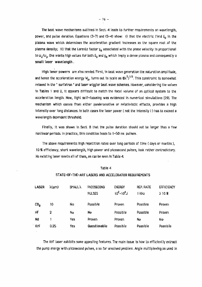
- 7 6 -
The beat wave mechanisms outlined In Sect. 4 leads to further requirements on wavelength,
power, and pulse duration. Equations (3-7) and (5-4) show: i) that the electric field E¡, In the
plasma wave which determines the acceleration gradient Increases as the square root of the
plasma density; II) that the Lorentz factor Y r associated with the phase velocity Is proportional
to u n/u p. One wants high values for both E D and Y r which Imply a dense plasma and consequently a
small laser wavelength.
High laser powers are also needed. First, 1n beat wave generation the saturation amplitude,
and hence the acceleration energy W A, turns out to scale as <JX ) . This constraint Is somewhat
relaxed In the " surfatron " and laser wiggler beat wave schemes. However, considering the values
m Tables 1 and 2,1t appears difficult to match the focal volume of an optical system to the
acceleration length. Now, light self-focusing was evidenced In numerical simulations [29]. The
mechanism which comes from either ponderomotlve or relativistic effects, provides a high
Intensity over long distances. In both cases the laser power ( not the Intensity I ) has to exceed a
wavelength dependent threshold.
Finally, It was shown In Sect. 8 that the pulse duration should not be larger than a few
nonlinear periods. In practice, this condition leads to 1-50 ns pulses.
The above requirements: high repetition rates over long periods of time ( days or months ),
10 S efficiency, short wavelength, high power and picosecond pulses, look rather contradictory.
No existing laser meets all of them, as can be seen in Table 4.
Table 4
STATE-OF-THE-ART LASERS AND ACCELERATOR REQUIREMENTS
LASER X(u.rn) SMALL X PICOSECOND ENERGY REP. RATE EFFlClENt
PULSES 102-104J 1 KHz 1 10 %
co 2 10 No Possible Proven Possible Proven
HF 2 No No Possible Possible Proven
Nd 1 Yes Proven Proven No No
KrF 0.25 Yes Questionable Possible Possible Possible
The KrF laser exhibits some appealing features. The main Issue Is how to efficiently extract
the pump energy with picosecond pulses, a so far unsolved problem. Angle multiplexing as used In

- 77 -
Inertial Fusion 1s conclevable. But, In recomblnlng the beams, one should be very careful about
coherence which Is essential In driving the plasma wave. Table 5 glve3 after J . J . Ewlng [30] the
main properties of both a KrF and a CC^ laser designed for a 10 TeV electron accelerator. The
latter 1s well suited for proof-of-pr1nc1ple demonstrations as shown by preliminary experiments
In the U.S. ( U C L A . ) and Canada ( I.N.R.S. ).
Table 5
DATA FOR A LASER IN A 10 T e V ACCELERATOR
Assume: laser / beat wave conversion efficiency 1s 25 % c o 2 KrF
x 2 - x , 1|im 3 7 A *
Plasma electron density 1 0 1 7 c m - 3 4 x l 0 1 8 c m '
10 68
'A 0.6 cm 3.8 cm
Power for self-focusing 0.47 TW 21 TW
Pulse duration 3 ps 3 pa **
Energy/pulse 1.4 J . 63 J .
Total length 660 m 104m
* feasible by Raman shift in H 2 ** DREAM !
14. C o n c l u s i o n
Acceleration of elementary particles In laser plasma Interaction has been demonstrated on a
very small scale: 1 GeV/m over 1mm only. It Is considered seriously by high energy physicists aa a
very promising way to reach energies beyond a few TeV. However the subject 1s still 1n Its Infancy
The accelerators of the next generation w i l l be designed and built by extrapolating known and
reliable techniques. This leaves about 20 years from now: 1) to Investigate all the physics
relevant to laser-driven acceleration of particles In plasmas; ii) to design laser sources suited
to the Job. If one looks back at the progress in the physics and the technology of high-power lasers
designed for lnertlal Fusion, one sees an Increase In power by 6 orders of magnitude over the past
20 years. This Is Indeed a remarkable achievement. There Is no doubt that, provided the demand and
the motivation exist, a similar evolution wi l l occur: by AD. 2007, laser properties could be close
enough to the requirements of accelerator physics, in time for a future generation of machines.

- 78 -
R e f e r e n c e s
1. T. Tajima & J.M. Dawson, Phys. Rev. Lett. 43 (1979) 267. 2. P. Chen,J.M. Dawson, R.W. Huff, T. Katsouleas, Phys. Rev. L ett. 54( 1985)693. 3. T. Katsouleas & J.M. Dawson, Phys Rev. Lett. 51 ( 1983) 392. 4. M.N. Rosenbluth & CS. Liu, Phys. Rev. Lett. 29 (1972) 701. 5. J.P. Matte, F. Martin and P. Brodeur, MRS preprint ( 1986). see also [ 14]. 6. J.M. Dawson, CAS ECFA Symposium on The Generation of High Fields, Frascati, September
1984, unpublished. 7. J.L. Bobln, Optics Comm. 55 < 1985) 413. 8. C. Pellegrini, 1n The Challenge ofUltra-high Energies, . ECFA-RAL Oxford ( 1982). 9. T. KatsDuleas, Phys. Rev. A33( 1986)2056. 10. K. Bane, P. Chen, P.B. Wl lson, IEEE Trans. Hurt. Set NS-32 ( 1985)3524. 11. D.S. Gemmell et al., Phys. Rev. Lett. 35(1975)1420. 12. CM. Tang, P. Sprangle and R.N. Sudan, App). Phys. Lett. 45 (1984) 375; Phys. Fluids 28
(1985) 1974. 13. F. Martin, P. Brodeur, J.P. Matte, H. Pépin and N. Ebrahlm, S.P. I.E. Proc. 664 ( 1986) 20. 14. J.L. Bobln, In Advanced Accelerator Concepts, A.I.P. Proceedings 156 (1987). 15. Jordan & Smith, Nonlinear differential Equations, (1977)Oxford. 16. C Bordé, private communication.
17. SJ. Karttunen & R.R.E. Salomaa, Phys. Rev. Lett. 56 ( 1986) 604. 18. CE. Clayton, C. Joshl, C Darrow and D. Umstadter, Phys. Rev. Lett. 54 ( 1985) 558. 19. F. Martin, P. Brodeur, J.P. Matte, H. Pépin, N. Ebrahlm, S.PI.E Proc. 664( 1986)20. 20. A.E. Dangor etal. I EEE Trans. Plasma Sei. PS-15 ( 1987)161. 21. F. Martin, P. Brodeur, J.P. Matte, H. Pépin, N. Ebrahlm, IEEE Trans. Plasma Sei.
PS-15(1987)167. 22. F. Amlranoff, E. Fabre, C. Labaune these proceedings.
23. J.B. Rosenzweig et al. In Laser Acceleration of Particles A.I.P. Proceedings 130(1985). 24. S. Wllks, T. KatsDuleas, J.M. Dawson, P. Chen, J.J. Su, IEEE Trans Plasma Sei.
PS-15(1987)210.
25. S. Van der Meer, CERN CLIC note n"3 ( 1985).
26. W. Panofsky, W. Wenzel, Rev. Scl. Instrum. 27(1956)267. 27. F. Mills, private communication.
28. B. Autln et al. IEEE Trans. Plasma Set. PS-15( 1987)226. 29. C Joshl, W. Morl, T. Katsouleas, J.M. Dawson, J.M. Kindel, D.W.. Forslund, Mature, 311(1984)
525.
30. J.J. Ewlng, Workshop on Advanced Accelerator Concepts, Madison August 1986, unpublished.

- 79 -
D i s c u s s i o n
C . J . M c K i n s t r i e , LANL
T h e f o r m u l a f o r t h e n o n l i n e a r f r e q u e n c y s h i f t o f a l a r g e - a m p l i t u d e L a n g m u i r w a v e
d e p e n d s o n r e l a t i v i s t i c n o n l i n e a r i t i e s i n h e r e n t i n t h e n o n r e l a t i v i s t i c f l u i d e q u a t i o n s .
T h e m a g n i t u d e and s i g n o f t h i s f r e q u e n c y s h i f t h a s b e e n t h e s u b j e c t o f some c o n t r o v e r s y i n
t h e l i t e r a t u r e . T h i s c o n t r o v e r s y h a s b e e n r e s o l v e d b y W . B . M o r i ( W o r k s h o p on I n t e r a c t i o n
and T r a n s p o r t i n L a s e r P l a s m a s CECAM, O r s a y , p . 123 ( 1 9 8 5 ) ) and s o L a n g m u i r - w a v e s a t u r a t i o n
i s now w e l l u n d e r s t o o d .
R e p l y
I a g r e e .
B. Z o t t e r , CERN
I s t h e r e t h e same e n e r g y l i m i t a t i o n f o r a p l a s m a I F E L d u e t o s y n c h r o t r o n r a d i a t i o n as
i n t h e n o r m a l I F E L ?
R e p l y
N o , b e c a u s e t h e g r a d i e n t s a r e o r d e r s o f m a g n i t u d e h i g h e r i n a p l a s m a I F E L . T h e
e l e c t r o n w a v e l e n g t h c a n be made s h o r t e r t h a n a w i g g l e r w a v e l e n g t h . No s t u d y o f t h e
l i m i t a t i o n was d o n e s o f a r .
P. C h e n , SLAC
A r e t h e r e a l s o Raman c a s c a d i n g p r o c e s s e s i n y o u r l a s e r - w i g g l e r b e a t - w a v e i d e a ?
R e p l y
N o , b e c a u s e t h e p l a s m a w a v e f r e q u e n c y i s e s s e n t i a l l y e q u a l t o t h e l a s e r f r e q u e n c y .
O n l y h a r m o n i c o p e r a t i o n i s p o s s i b l e i n t h i s a n t i - S t o k e s s i d e w i t h a v e r y l o w e f f i c i e n c y .

- 8 0 -
T H E I N T E R D E P E N D E N C E O F P A R A M E T E R S F O R T E V L I N E A R C O L L I D E R S * )
R. B . P a l m e r
Stanford Linear Accelerator Center, Stanford University, Stanford, California 94305 and Brookhaven National Laboratory, Upton, New York 11973
A B S T R A C T
B u r t R i c h t e r , a t S L A C , h a s cal led for a des ign of a 0.5 + 0.5 T e V e + e _
coll ider w i t h a l u m i n o s i t y of a t least 1 0 3 3 c m - 2 s e c - 1 . In o r d e r t o find w h e t h e r s u c h a m a c h i n e is poss ib le , I h a v e collected h e r e a p p r o x i m a t e form u l a e for m a n y of t h e r e l a t i ons govern ing t h e des ign of a l inear col l ider . I t m u s t b e e m p h a s i z e d t h a t t h e s e a r e often on ly a p p r o x i m a t e r e l a t i ons w h o s e a c c u r a c y is n o t e x p e c t e d t o b e b e t t e r t h a n a b o u t 1 0 % , a n d in s o m e cases m a y b e wor se . U n i t s t h r o u g h o u t will b e m e t e r - k i l o g r a m - s e c o n d (mks) u n less o t h e r w i s e s t a t e d . G i v e n the se r e l a t ions , t he i r i n t e r d e p e n d e n c e is s t u d i e d a n d p a r a m e t e r choices m a d e . A self-consistent so lu t ion is f o u n d t h a t m e e t s R i c h t e r ' s speci f ica t ion a n d does n o t involve a n y exotic t echno log ies .
1. D A M P I N G R I N G
1.1 E m i t t a n c e
I t is a s s u m e d t h a t e l ec t rons a n d p o s i t r o n s a re o b t a i n e d f rom d a m p i n g r ings , a n d t h a t these a re of t h e c o n t i n u o u s wiggler t y p e [1,2]. I t is a s s u m e d t h a t t h e p h a s e a d v a n c e s p e r cell a r e sufficiently smal l a n d t h a t s t r a i g h t sec t ions a r e sufficiently s h o r t so t h a t a s m o o t h a p p r o x i m a t i o n (ß « c o n s t a n t ) can be used . All b e n d i n g m a g n e t s in t h e r i n g cons is t of a t least one i n w a r d b e n d a n d o n e o u t w a r d , so t h a t t he ave rage b e n d i n g field (B¿) is less t h a n t h e local fields B¿ in t h e m a g n e t s . I define
(Bd) = a i B d
Fm = f r ac t ion of r ing filled b y d ipoles
C = v e r t i c a l / h o r i z o n t a l e m i t t a n c e d u e t o m i x i n g .
T h e e m i t t a n c e s b o t h ve r t i ca l a n d ho r i zon t a l a re d a m p e d b y t h e emiss ion of s y n c h r o t r o n r ad i a t i on w i t h a t i m e c o n s t a n t [3]:
8 3 1 Jx,y & ¿ i r m
w h e r e J x , Jy a r e t h e p a r t i t i o n func t ions [3], usua l ly J , « J 5 w 1.
T h e h o r i z o n t a l (x) e m i t t a n c e does n o t r educe t o zero , however , b u t t o a n e q u i l i b r i u m value . A t h i g h energ ies t h i s va lue is se t b y t h e effect of q u a n t u m fluctuations:
2.2 X I P " 1 0 7 ^
qEyn — Í q£zn >
where f is a m i x i n g p a r a m e t e r , ßx is t h e ave rage funct ion (ßx = R/Qx), a n d Qx is t h e t u n e of t he r ing.
*) W o r k s u p p o r t e d b y D e p a r t m e n t o f E n e r g y c o n t r a c t s D E - A C 0 3 - 7 6 S F 0 0 5 1 5 ( S L A C ) a n d D E - A C 0 2 - 7 6 C 0 0 1 6 ( B N L ) .

81
A t lower ene rg ies i n t r a b e a m s c a t t e r i n g se t s a n e q u i l i b r i u m e m i t t a n c e [4]:
^ 1.2 x 10 c^zn ^ zz
c^yn = $ csxn >
dp Ezn = 1 — °z
P
-10 N
Qt{JX+tJy) \ßy
1/2 1/2
(3)
W e n o t e f rom t h e different 7 d e p e n d e n c i e s t h a t t h e r e m u s t b e a n o p t i m u m iQ for w h i c h ce = qe
(see F i g . 1) .
10 J -
10
1 1 1 1 1 1 1 1 1
/ / y 1
1
I
1 1 1 1 1 1 1 1
/ / y 1
~ — ^ 1 -~
/ /
/ /
/ _
1
/
11I 1
0.1 0.2 0.5 1.0 2.0
E e (GeV)
F i g . 1. T h e n o r m a l i z e d e m i t t a n c e of a s a m p l e r i n g , as a func t ion of o p e r a t i n g e l ec t ron energy . As E is va r i ed t h e r i n g is va r i ed t o k e e p t h e b e n d i n g field B¿, t h e focussing field Bq
a n d t h e t u n e Q fixed. A t low energies t h e e m i t t a n c e is d o m i n a t e d b y i n t r a b e a m s c a t t e r i n g , a t h i g h energ ies b y q u a n t u m fluctuations.
w h e r e
% « 2 .1 x 1 0 - 7 NiBy/Bz)1'2
eznBl^{Jx + iJy)1/2Fmk
1
1'\
4/9
( ß q F q )
B q =
Fq =
fcx =
\£XnJ
2/3
fci-y1/2 « k • - > q r q j
q u a d r u p o l e a p e r t u r e
q u a d r u p o l e pole t i p field (w 1.5 Tesla)
f rac t ion of r ing full of q u a d s .2)
.14, for a la t t ice sca led f rom t h e S L A C d a m p i n g r ing .
(4)
(5)
W h e n c o n t r i b u t i o n s f rom b o t h q u a n t u m fluctuations a n d i n t r a b e a m s c a t t e r i n g axe c o m p a r a b l e , t h e n t h e e q u i l i b r i u m e m i t t a n c e is g iven [4] b y

- 82 -
EIN(equilib) = i [qesn + (ae\n + 4 ( :E: 2J N) 1 / 2] , (6)
thus for Q£XN == C^XN
^ „ ( e q u i l i b ) « 1.6 q e x n . (7)
Actual ly a m i n i m u m equil ibrium is obta ined at a ~¡ somewhat be low that g iven b y Eq. (4) and it is a reasonable approximat ion t o use
e x n ss 1.4 q e x n . (8)
T h e wiggle is a s sumed t o consist of a sufficient number of inward and outward b e n d s , so that the contribut ion t o the emit tance from the rate of change of dispersion is negligible. T h i s condit ion requires the m a x i m u m wiggler pole length i w t o satisfy
t w ^ C " = \ / î I T ' ( 9 )
where p is the bending radius in a wiggler and R is the average machine radius . In these examples I assume £«, = l / 3 ( £ ™ a x ) and the contr ibut ion t o the equil ibrium emit tance is then less than 1 /9 .
1.2 Other Requirements
T h e impedance requirement for s tabi l i ty is taken to be:
n S ceN ' ( W )
where
n = — , (11)
\R) = Q * •
Note that the approximat ion for the m o m e n t u m compact ion a also requires condi t ion [Eq. (9)] .
Other relations are: A p 2
(12)
« 4 1.1 X 1 0 - 5 frB)1/2 , (13)
ß2
Dispers ion r¡ « , (14) XL
a Sextupole length Fs « Fq — , (15)
acceptance êxn « 6 X 1 0 ~ 4 *f R ^ , (16) QX
R F V o l t s / t u r n U « 3.2 X 1 0 6 R ~ ) . ( 1 7) TL \QX 0~Z)
where h is the harmonic number of the R F ,
'Y 4
energy l o s s / t u r n V = 5.78 X 1 0 - 9 - ¿ - i . (18) a ' RFm

- 83 -
2. A C C E L E R A T I O N
2.1 A c c e l e r a t i o n C a v i t y
I a s s u m e t h a t acce l e ra t ion t a k e s p lace in a 2 î r / 3 d i s k - l o a d e d - s t r u c t u r e as u s e d in t h e SLAC l inac , b u t fol lowing Z. D . F a r k a s [5], I a l low t h e g r o u p ve loc i ty t o d e p a r t f rom t h a t of t h e SLAC s t r u c t u r e . Since t h e g r o u p ve loc i t y is a func t ion of t h e iris a p e r t u r e d iv ided b y t h e w a v e l e n g t h , w e c a n choose t h e s e p a r a m e t e r s s e p a r a t e l y a n d u s e a n a p p r o x i m a t e fit t o F a r k a s ' c a l c u l a t i o n u s ing t h e p r o g r a m T W A P [5] (see F ig . 2 a ) :
T h e n o r m a l i z e d co r r ec t ed e l a s t a n c e is g iven a p p r o x i m a t e l y b y (see F ig . 2b)
s a t « 5.7 x l O 1 0 / ^ 4 ( V m C - 1 ) . (20)
T h i s n o r m a l i z e d a n d c o r r e c t e d e l a s t ance is r e l a t e d t o t h e u n n o r m a l i z e d e l a s t a n c e b y
Sat = st a 2 , (21)
w h e r e s t is def ined b y
st = — , (22) Wf v '
¿a is t h e a v e r a g e acce le ra t ing field in a sec t ion a n d w¡ is t h e energy , a s s u m i n g n o losses, n e e d e d t o g e n e r a t e t h a t a cce l e r a t i on . T h i s ene rgy is n o t t h e s a m e as t h a t r e q u i r e d (w) t o fully fill t h e sec t ion b e c a u s e s ince t h e p a r t i c l e a n d fields a r e m o v i n g d o w n t h e sec t i on a t finite ve loc i ty , t h e l eng th of t h e r equ i r ed field p u l s e is less t h a n t h a t of t h e sec t ion . T h u s
« / = T J ^ J . (23)
a n d
st = ' { 2 4 )
w h e r e t h e u n c o r r e c t e d e l a s t ance , as defined b y D . F a r k a s is
a = Í S . . (25) w
N o t e also t h a t s is r e l a t e d t o t h e loss p a r a m e t e r defined b y P . Wi l son : [6]
fco = T • (26)

- 84 -
F ig . 2 . P a r a m e t e r s of a SLAC- l ike acce le ra t ing cav i t y as a func t ion of t h e g r o u p ve loc i ty Vg/c = ßg. (a) t h e iris r a d i u s a d iv ided b y w a v e l e n g t h A; (b) t h e n o r m a l i z e d co r r ec t ed e l a s t a n c e sat¡ (c) t h e a t t e n u a t i o n t i m e c o n s t a n t To in ßsec, for A = 10.5 cm; (d) t h e p e a k R F field in t h e c a v i t y £pk d iv ided b y t h e ave rage acce le ra t ing field £ a ; (e) t h e o u t e r cav i ty r a d i u s b d iv ided b y t h e iris r a d i u s a; (f) t h e re la t ive p e a k rf p o w e r . I n each case t h e line is o b t a i n e d f rom Z. D . F a r k a s [5] a n d t h e do t s a re for t h e a p p r o x i m a t i o n u s e d h e r e .
W h e n losses a r e i nc luded , t h e e n e r g y n e e d e d is inc reased . If t h e a t t e n u a t i o n t i m e of t h e R F pulse , p a s s i n g d o w n t h e sec t ion , is def ined as To, t h e n for a sec t ion of l eng th L t h e ene rgy r e q u i r e d for t h e s a m e a v e r a g e acce le ra t ion will b e :
W"F = nP
= Wf ( w ^ ' ( 2 7 a )
w h e r e r¡p is t h e sec t ion efficiency, a n d
L T T =
To vg To (276)
T h i s is for a u n i f o r m s t r u c t u r e (i.e., £a fal l ing off a long its l e n g t h ) . N o t e t h a t as r —» 0, u R F Uf b u t t h e p e a k p o w e r p e r u n i t l e n g t h goes t o oo .
- 8 5 -
T h e a t t e n u a t i o n t i m e To is g iven a p p r o x i m a t e l y b y (see F ig . 2c ) ) :
To « 42 X 1 0 - 6 ( l + 1.29/?¿- 5) A 1 5 , (28)
also (see F i g s . 2d a n d e ) :
« 2 + 6.0/3, , , (29) ta
b- « 1.04 + 0 . 2 9 £ n ( - l ) + . 0 6 8 [ £ n ( ^ ) ] 2 , (30)
w h e r e £pk is t h e m a x i m u m field w i t h i n t h e s t r u c t u r e a n d b is t h e ins ide r a d i u s of t h e cavi ty . In all cases t h e l eng th of a cell is a s s u m e d t o b e A / 3 .
All of t h e a b o v e a p p r o x i m a t e re la t ions were o b t a i n e d b y f i t t ing cu rves s h o w n in F a r k a s a n d Wi l son ' s p a p e r [5].
2.2 Focus s ing in t h e L i n a c
A s s u m i n g a s y m m e t r i c FODO s t r u c t u r e , t h e ave rage s t r e n g t h of t h e focussing is g iven b y
««-l^f&V. ( 3 . ) w h e r e p is t h e p h a s e a d v a n c e p e r half cell ( t aken as 45° ) , Bq is t h e po l e t i p field ( t aken as 1.5 Tes la ) , Fq is t h e f rac t ion of l inear l eng th devo ted t o q u a d r u p o l e s , a n d aq, t h e a p e r t u r e of t h e q u a d , is t a k e n to b e 1.2 X a 0 „ . N o r m a l l y , aav is t h e iris r a d i u s , b u t if t h e iris is e l l ip t ical w i t h r ad i i a a n d b:
(* + *) 1/2 ' (32)
which is t h e r a d i a l d i s t a n c e a t 45° .
3 . E M I T T A N C E P R E S E R V A T I O N
3.1 T r a n s v e r s e W a k e F ie lds
T h e t r a n s v e r s e w a k e field Wt d e p e n d s on t h e g e o m e t r y of t h e cavi t ies . As a funct ion of t h e l eng th z a long t h e b u n c h , t h e wakefield is observed [6] t o h a v e a n ini t ia l l inear r ise:
for z < a : ^{z) « 6.64 X 1 0 1 0 * B , (33) CL A"
a n d a m a x i m u m of
a t z « a : 2Wt{z) « 3.28 x 1 0 1 0 * 8 . (34)

- 86 -
F ig . 3 . T h e scale i n v a r i a n t t r a n s v e r s e wakefield (a3 Wt) a s a func t ion of t h e d i s t a n c e z d iv ided b y t h e iris r a d i u s a for (a) a /A = .105 (as for SLC), a n d (b) a /A = .2
Fo r va lues of W¡ a t i / a < 1, a r e a s o n a b l e fit t o t h e fo rm of W [at leas t for t h e SLAC g e o m e t r y (see F i g . 3)] is o b t a i n e d if we t a k e :
T h e a p p r o x i m a t i o n is seen t o b e r e a s o n a b l e in t h e reg ion z < a.
In t h e case of a n el l ipt ical iris w i t h d i m e n s i o n s a a n d b, I a s s u m e t h e s a m e fo rm as g iven above w i t h t h e s u b s t i t u t i o n of o or 6 acco rd ing t o w h e t h e r we a r e ca lcu la t ing Wt in t h e a; or y d i r ec t ions .
3.2 L a n d a u D a m p i n g
I a s s u m e t h a t t r a n s v e r s e w a k e effects a r e effectively con t ro l l ed b y L a n d a u d a m p i n g [7], p rov id ing a n ene rgy s p r e a d AE is m a i n t a i n e d b e t w e e n t h e f ront a n d b a c k of t h e b u n c h w h e r e , in t h e t w o b u n c h a p p r o x i m a t i o n :
2Eop « AE « ^NWt{2az)ß2 , (36)
w h e r e N is t h e n u m b e r of pa r t i c l e s p e r b u n c h , ß t h e focussing s t r e n g t h in t h e l inac a n d Wt(z) is t h e w a k e field p o t e n t i a l . B o t h Wt a n d ß a r e a l lowed t o b e different in t h e ve r t i ca l a n d h o r i z o n t a l d i rec t ions , b u t chosen so as t o give t h e s a m e r e q u i r e d AE. Fo r to l e rance r easons t h a t will a p p e a r be low, I a s s u m e
ßx,y oc l1'3 , (37)
t h u s
<Tp oc r l l z , (38)
w h e r e £ is t h e l eng th a long t h e l inac . If n o t specified, ß a n d AE a r e given for t h e e n d of t h e l inac —
i.e., a t full energy .
- 87 -
I will a s s u m e t h a t t h e m o m e n t u m s p r e a d dp/p = av r equ i r ed for L a n d a u d a m p i n g is m a i n t a i n e d un t i l t h e e n d of all acce le ra t ion , b u t t h e n r e m o v e d p r io r t o t h e final focus b y a n acce l e ra t ion sec t ion of l eng th £ c o p e r a t i n g a t a p h a s e a d v a n c e of 90° . T h e l e n g t h r equ i r ed is
2ir£ao~z ^ ^
w h e r e p is t h e final m o m e n t u m , A t h e w a v e l e n g t h , £ a t h e acce le ra t ing g r a d i e n t a n d o~z t h e r m s b u n c h l eng th .
3.3 To le rance P r o b l e m s
A severe tolerance p r o b l e m c o m e s f rom t h e effects of t h e finite m o m e n t u m s p r e a d a n d s t r o n g focussing n e e d e d t o L a n d a u d a m p t h e t r a n s v e r s e w a k e field effects. F r o m R . R u t h I t a k e t h e requ i red r m s a l i g n m e n t for p h a s e a d v a n c e p e r cell ip, t o b e [8]:
<*> = " è \fk ' (40)
w h e r e
a n d Nq, t h e n u m b e r of q u a d r u p o l e s , is
L
°, - » . («)
a n d f rom E q . (36) w e h a v e
so
"'-Im- (42)
0
Op oc , (43a)
(dy) oc 1 . (436)
W e see t h a t un le s s t h e ß is r e d u c e d a t lower 7 , t h e to le rances ge t t i g h t e r a t lower 7 . However , t h e q u a d r u p o l e t i p fields n e e d e d t o o b t a i n a g iven ß also fall w i t h 7 [from E q . (31)] .
ß{l) oc , (44a)
so it is n o t difficult t o a s s u m e , for i n s t a n c e :
ß{f) oc 7 1 / 3 « I1!3 , (446)
w h i c h gives
To l e r ances : (dy) = c o n s t a n t ,

- 88 -
L a n d a u : av oc 7 1 / 3 , (44c)
Focus B : Bq oc 7 1 / 3 .
T h e n f rom E q . (42) ,
Nq = 1.5 2 L
^ ( m a x ) ^ ] ' (45)
(dy) « 1.63 ( - ^ - ) 1 / 2
a p ( m a x ) \1L1p J
T h i s t o l e r a n c e conce rns t h e a l i g n m e n t a n d s t ee r ing p rec i s ion w i t h i n t h e l inac . If all c o m p o n e n t s w e r e t r u l y a l i gned t o t h i s accuracy , it w o u l d m e e t t h e r e q u i r e m e n t , b u t it c a n also b e m e t b y a n a p p r o p r i a t e c o m b i n a t i o n of a l i g n m e n t a n d cor rec t ive s t ee r ing t h a t is s o m e w h a t less severe .
A n o t h e r i n t e r e s t i n g q u a n t i t y is t h e c h a n g e in p h a s e a d v a n c e A(j> over t h e m o m e n t u m s p r e a d in te g r a t e d a long t h e full acce le ra to r . If t h i s q u a n t i t y is smal l c o m p a r e d t o 1, t h e n t h e d ispers ive e r ro r s d u e t o m i s a l i g n m e n t a p p e a r a t t h e e n d as a s ingle l a t e r a l d i spe r s ion t h a t cou ld in p r inc ip le b e m e a s u r e d a n d co r rec t ed .
L
= j ^ . (46)
1.5 Lav ( m a x E) ß(maxE)
A t o l e r a n c e of a different k ind concerns t h e a l lowable r a n d o m m o v e m e n t of c o m p o n e n t s f rom pulse t o pu l se . F i x e d m i s a l i g n m e n t s c a n of ten b e co r r ec t ed , b u t r a n d o m m o v e m e n t s c a n n o t . T h e m o s t severe r e s t r i c t i on is o n r a n d o m m o t i o n of t h e l inac focusing q u a d r u p o l e s . For 90° p h a s e a d v a n c e p e r cell:
(dx), (dy) , » § ^ , (47)
w h e r e Nq is t h e n u m b e r of q u a d r u p o l e s f rom E q . (42) or (45) .
3.4 L o n g i t u d i n a l W a k e s
T h e Longitudinal wafcefor ve ry s h o r t b u n c h e s t e n d s t o w a r d s a c o n s t a n t t h a t is d e p e n d e n t on ly [9] on t h e iris a p e r t u r e ' a ' :
z < a : iW = 1.78 X 1 0 1 0 \ . (48)
a
Fo r t h e e l l ip t ica l case , I a s s u m e
z < a : iW = 1.78 X 1 0 1 0 (4 + 4) • (49) VI avJ
For b u n c h e s of l eng th of t h e o rde r of ' a ' one finds [9]:

- 89 -
z « o : 2W = 1.25 x 10 10 C) « ( A )
1/2 (50)
A n d for t h e e l l ip t ical case I a s s u m e
z * a : 2W = 1 . 2 5 X 1 0 - (T)*" (± + ±) (*) \zj \ a x ayJ \XJ
1/2
For i n t e r m e d i a t e va lues of z, a r e a s o n a b l e fit t o t h e SLÀC case is o b t a i n e d (see F i g . 4 ) :
Wt{z) =
(51)
(52)
0.03 "i i r
0.105
J I i I i L
0 1 2 3 4-87 Z/d 5756A4
Fig . 4 . T h e scale i n v a r i a n t l o n g i t u d i n a l wakefield ( a 2 W¿) as a func t ion of t h e l e n g t h z d iv ided b y t h e iris r a d i u s a for (a) a/X = .105 (as for SLAC) , a n d (b) a/X — .2
To p r o p e r l y o b t a i n t h e m o m e n t u m s p r e a d p r o d u c e d in a b u n c h b y t h e l o n g i t u d i n a l w a k e , one shou ld p e r f o r m i n t e g r a t i o n s of t h e w a k e p o t e n t i a l s over t h e c h a r g e d i s t r i b u t i o n of t h e b u n c h [6]. T h e effects a r e re la t ive ly complex :
1) T h e r e is a n ave rage ene rgy loss of t h e b u n c h (zero th o r d e r ) .
2) T h e r e is a g r e a t e r loss t o t h e b a c k of t h e b u n c h c o m p a r e d w i t h t h e f ront (first o r d e r ) .
3) If t h e b u n c h is long t h e r e is a s ignif icant second o rde r t e r m w i t h t h e r a t e of c h a n g e of m o m e n t u m falling a t t h e back .
4) T h e r e is a s ignif icant t h i r d o r d e r t e r m t h a t ar ises if t h e b u n c h is G a u s s i a n r a t h e r t h a n un i fo rm in c u r r e n t dens i ty .
Since all t h e s e a r e s ignif icant , t h e m i n i m u m n u m b e r of s u b - b u n c h e s t h a t w e c a n u s e t o a p p r o x i m a t e t h e whole is four. I use four equa l b u n c h e s : t w o a t ± 1 . 4 az a n d t w o a t ± . 2 c r z . ( T h e s e give cor rec t az
a n d ( | z | ) ) . T h e ene rgy losses of t h e four b u n c h e s a re t h e n :

- 90 -
Vi =
v2 =
V 3 =
Ne 4£a
Ne 4£a
Ne 4£a
Ne
{W(0)} ,
{W{0)+W{1.2az)} ,
{W{0)+W{.4az)+W{1.6az)} ,
(53)
V* = TT {W{Ö)+W(1.2aM)+W{l.naM)+W{2.8aM)}
T h e s e va lues a r e c o m p a r e d w i t h a full i n t e g r a t i o n in F i g . 5 .
100
80
F i g . 5 . T h e l o n g i t u d i n a l wakefield g e n e r a t e d m o m e n t u m s p r e a d g e n e r a t e d in a G a u s s i a n b u n c h p a s s i n g t h r o u g h a SLAC-like s t r u c t u r e . T h e s m o o t h l ine is a ca l cu la t ion b y P . Wi l son [6]. T h e d o t s r e p r e s e n t t h e r e su l t s of t h e f o u r - b u n c h a p p r o x i m a t i o n u s e d h e r e . T h e s e p o i n t s h a v e b e e n n o r m a l i z e d t o t h e P . Wi l son ca l cu l a t i on .
T h e a v e r a g e s lope gives a A p a t la of
•2(V 3 - Vg) + 1.4(V 4 - Vi) . . . . 10p = - - . (54)
T h e half s p r e a d d u e t o t h e second o r d e r effect is:
(V3 + V 2 ) - ( V 4 + V l ) 2CTp = , (05)
a n d t h e half s p r e a d f rom t h i r d o rde r :
•87(V 3 - V a ) + .13(V 4 - Vi) 3<7P = 2 (56)
T h e first a n d second of t h e s e effects c a n in p r inc ip l e b e cance l led b y t h e R F . T h e first o r d e r effect

- 91 -
be ing cance l l ed b y a p h a s e shift in t h e R F g iven b y
1 A t a n < p c o r = — - i<Tp — . (57)
¿IT cr z
Howeve r , s o m e m o m e n t u m s p r e a d is r e q u i r e d for L a n d a u d a m p i n g so t h a t t h e p h a s e r e q u i r e d a t t h e e n d
is, i n s t e a d , g iven b y
t a n 4>c0r = ^- (i<7„ — cT„(Landau)) — . (58) ¿ir az
T h e n e t s e c o n d o r d e r m o m e n t u m s p r e a d , i n c l u d i n g t h e R F is
a*, (total) = t*,- \ ( ^ r ) • (59)
For t h e p u r p o s e s of des ign ing t h e final focus s y s t e m , I a s s u m e t h a t t h e first o r d e r t e r m is fully
cance l led b y t h e R F a n d u se :
av (focus) = j 2 0 p ( t o t a l ) 2 + 3 e r p 3 + Ea\ j , (60a)
w h e r e
sav = 22- , ( 6 0 6 ) 1o-z
w h i c h is t h e c o n t r i b u t i o n t o t h e m o m e n t u m s p r e a d f rom t h e finite l o n g i t u d i n a l e m i t t a n c e in t h e d a m p i n g
r ing .
4. F I N A L F O C U S
T h e p a r a m e t e r s for t h e final focus a re o b t a i n e d b y sca l ing o n e of t w o des igns p r o v i d e d b y K . B r o w n
[10]. In b o t h cases t h e m i n i m u m ß^ is c a l cu l a t ed for a g iven m o m e n t u m s p r e a d a s s u m i n g n o c h r o m a t i c
co r rec t ion . T h e v a l u e of ß* t h a t c a n b e o b t a i n e d w i t h c h r o m a t i c co r rec t ion is less t h a n ß$ b y a fac tor S
ß* > § • (61«)
5, in a des ign s imi l a r t o t h a t in t h e SLC is e x p e c t e d [10] t o sca le :
s = ? - T • m T h i s r e l a t i on gives a factor of e igh t for ap = ± . 5 % as is o b t a i n e d for t h e SLC.

- 92 -
G=50 G = 50 G = 50 G = 50
2.8 1.2 0.3
I . I 0.15 0.3
G =33.3 G = 21
2.5 2.5 2.5 0.6
F i g . 6. F i n a l focus lens des igns u s e d (a) for so lu t ions r equ i r i ng a r o u n d focal s p o t a n d (b) for so lu t i ons r e q u i r i n g a flat b e a m .
T h e t w o des igns u s e d a r e s h o w n in F i g . 6 . T h e t r i p l e t is u s e d for t h e s y m m e t r i c case a n d t h e
d o u b l e t for al l a s y m m e t r i c cases . T h e sca l ing involves t h e modi f ica t ion of all l e n g t h d i m e n s i o n s b y one
factor a n d all t r a n s v e r s e d i m e n s i o n s b y a n o t h e r . We define scale fac tors / * a n d a*, a* is t h e a p e r t u r e
in t h e first q u a d r u p o l e , a n d t h e ' i d e a l ' focal l e n g t h is / * :
r
(Bp) E/e
1/2
(62)
B* is t h e po le t i p field in t h e first q u a d , E/e is t h e b e a m energy in e l ec t ron Vol t s , a n d c is t h e veloci ty of l ight .
For a n y m a g n e t s y s t e m w e c a n n o w express t h e p e r f o r m a n c e in t e r m s of t he se sca l ing p a r a m e t e r s , a* a n d / * , a n d of i n v a r i a n t c o n s t a n t s (Tx, Ty, Ax, Ay a n d L). T h e c o n s t a n t s d e p e n d o n t h e deta i ls of t h e m a g n e t s y s t e m cons ide red .
Given / * a n d a* for a n y m a g n e t s y s t e m scaled f rom t h e or ig inal des ign (all l o n g i t u d i n a l d i s tances
sca led w i t h / * , all t r a n s v e r s e d i s t a n c e s sca led w i t h a*, all po le t i p fields t h e s a m e ) t h e n we c a n wr i t e
ßL,y = TXiy2ap-r , (63)
¿x,y = - r ^ - p , (64)
ti = Lf* , (65)
w h e r e l\ is t h e free s p a c e before t h e first q u a d , 8 is t h e m a x i m u m a n g u l a r a c c e p t a n c e , ap is t h e r m s
dp/p m o m e n t u m s p r e a d . T h e def in i t ions a r e s u c h t h a t for a n ' i dea l ' focuss ing s y s t e m t h a t c a n focus in
b o t h d i rec t ions ( such as a l i t h i u m or p l a s m a lens) T « A « L « 1.

- 93 -
C o m b i n i n g E q . (63) w i t h E q . (61) , one o b t a i n s :
a* _ ( T g . y Ax>y) Eje 0x¡y 2
Values for TXly a n d Ax,y for t h e t w o focus des igns given a r e :
T r ip l e t Q u a d r u p o l e Tx 2.96 7.2
Ty 2.96 1.1 Ax 4.3 3.6
Ay 3.2 2.0 L 1.36 1.1
TyAy 9.47 2.2
So 0.04 0.04
W e n o t e t h a t t h e p r o d u c t TyAy w h i c h d e t e r m i n e s t h e ß* o b t a i n a b l e is over four t i m e s smal le r for t h e q u a d r u p o l e so lu t i on .
T h e m a x i m u m a c c e p t a n c e angle 0 is con t ro l led b y t h e d i s r u p t i o n ang les or b e a m size d e p e n d i n g
on w h e t h e r t h e c ross ing is h e a d - o n or a t a finite ang le . In t h e h e a d - o n case t h e d i s r u p t i o n angles are
d iscussed in t h e n e x t sec t ion a n d w e t a k e
K,y = Se6D(x,y) , (67)
w h e r e Sg is a safe ty fac tor t a k e n t o b e t h r e e . In t h e finite ang le case
w h e r e S$, t h e safe ty fac tor , is n o w t a k e n t o b e six.
5. I N T E R A C T I O N P O I N T
5.1 L u m i n o s i t y
W h e n t h e t w o b u n c h e s col l ide, t h e luminos i ty o b t a i n e d is
Air ax Oy
w h e r e
ax¡y = ( ^ ^ ) 1 / 2 , (70)

- 9 4 -
a n d r¡L is a n efficiency fac tor t o a l low for effects of b o t h a finite ang le of cross ing a n d a ß* n o t v e r y m u c h la rger t h a n t h e b u n c h l e n g t h az.
IL =
oo
fj -{-(*)" H (infra.)]}
1 + ( * / & ) dz (71)
w h e r e 8¿ = ox¡oz is t h e d i a g o n a l ang le , 6C is t h e c ross ing ang le , a n d ßx is t h e ß* a t t h e final focus .
HX a n d HY in E q . (69) a r e e n h a n c e m e n t f ac to r s d u e t o t h e p i n c h effect. I h a v e a s s u m e d he re t h a t t he se e n h a n c e m e n t s c a n b e fac tor ized a n d t h a t
Hx,y — f{Dx,y) ,
w h e r e D x > y a r e d i s r u p t i o n p a r a m e t e r s defined b y
Jx,y
(72)
(73)
a n d fx¡y a r e t h e effective focal l eng th of t h e focuss ing of one b u n c h on t h e o t h e r , c a l c u l a t e d for t h e cen te r of G a u s s i a n b u n c h e s .
A s s u m i n g a b e a m in w h i c h ax > ay t h e n [11]
reNoz
Dy « I K 1 +
(74)
For r o u n d b e a m s D x = D y , b u t for flat b e a m s w i t h ax » ay, D x « 0. I n t h e i n t e r m e d i a t e reg ion we t a k e [11]
reNaz 2
lot
T h e e n h a n c e m e n t s a r e g iven a p p r o x i m a t e l y [12] b y
HX¡Y = 1 + 1.37
1 +
1 + D~5-5
1/2
(75)
(76)
For r o u n d b e a m s t h e m o r e c o n v e n t i o n a l e n h a n c e m e n t fac to r H = HXHY = [HY)2. T h i s , c a l cu l a t ed b y th i s a p p r o x i m a t i o n , is p l o t t e d in F ig . 7 a g a i n s t D a n d c o m p a r e d w i t h va lues g iven b y o t h e r s i m u l a t i o n s [12].
1 1 1 1 1 1111 I I I I 11111 I
— Yokoya x Hollebeek
= • Fit * - r » x n ••
y x -
* — I M i l I i I I I i i 11 I
0.2 0.5 I.O 2 D
5 I0 20 5756A7
Fig . 7. T h e luminos i t y e n h a n c e m e n t HD for r o u n d b e a m s as a func t ion of t h e d i s r u p t i o n p a r a m e t e r D . T h e s m o o t h line shows t h e r e su l t s of K . Yokoya ' s ca l cu la t ion [13]; t h e crosses a r e Hol lebeck ' s ; t h e do t s a r e t h e a p p r o x i m a t i o n u s e d h e r e .

- 95 -
5.2 D i s r u p t i o n Ang les
W i t h o u t p i n c h , t h e m a x i m u m Disruption ang le is g iven [13] b y
•j _ 2Nre
°z,y — —— • kx,y , (77)
w h e r e for
(a) ax = Oy k « .45
« .75 ( 7 8 ) .25 .
(b) °* > '» U « 1.:
However , t h e s i t u a t i o n is s o m e w h a t different in t h e t h r e e cases . Fo r 0X a n d for 0y in r o u n d b e a m s a well-defined m a x i m u m ang le o c c u r s for pa r t i c les a t a finite i m p a c t p a r a m e t e r n e a r a. B u t for dy in flat b e a m s t h e deflect ing field r i ses t o a p l a t e a u a n d t h e m a x i m u m angle o c c u r s on ly for pa r t i c l e s in t h e e x t r e m e t a i l of t h e d i s t r i b u t i o n . As a r e su l t , t h e m e a n va lue is m u c h less in t h i s case .
W i t h p i n c h , t h e r o u n d case h a s b e e n s t u d i e d b y M i n t e n a n d Y o k o y a [13] a n d t h e d i s r u p t i o n is e n h a n c e d by a fac to r Hg
He « -p- . (79)
(oAn*) + ("+&r F i g u r e 8 shows t h i s func t ion t o g e t h e r w i t h M i n t e n a n d Yokoya ' s s i m u l a t i o n .
i 1 i 1 r — Yokoya
x Hollebeek, Minten • Fi
0 2 4 6 4 - 8 7 D 5 7 5 6 A 8
Fig . 8. T h e e n h a n c e m e n t of d i s r u p t i o n angles Hg for r o u n d b e a m s . T h e l ine is Yokoya ' s ca lcu la t ion ; t h e crosses a r e Hol lebeek a n d M i n t e n ' s ; a n d t h e do t s t h e a p p r o x i m a t i o n used .
For flat b e a m s t h e e n h a n c e m e n t of m a x i m u m deflection in t h e ve r t i ca l (y) d i rec t ion shou ld no t occur . T h i s is b e c a u s e t h e field for a c u r r e n t shee t is n o t a func t ion of i ts t h i c k n e s s . However , Yokoya h a s d e m o n s t r a t e d t h a t w i t h a G a u s s i a n b u n c h , a s t r o n g s u p p r e s s i o n of t h e a v e r a g e ver t ica l d i s rup t ion angle t akes p lace for l a rge D d u e t o t h e osci l la t ion of a pa r t i c l e in t h e field i n s t e a d of a un id i rec t iona l deflect ion. In p r i nc ip l e t h e deflect ion of t h e e x t r e m e ta i l of t h e d i s t r i b u t i o n is s t i l l n o t changed a n d m y p r o g r a m does n o t i nc lude t h i s Y o k o y a [13] suppres s ion .
In t h i s d i scuss ion I h a v e n o t inc luded q u a n t u m fluctuations in t h e d i s r u p t i o n p rocess . T h e r e is a finite p r o b a b i l i t y t h a t a n e l ec t ron r a d i a t e s a h a r d p h o t o n a n d is t h e n , b e c a u s e i t h a s a low m o m e n t u m , d i s r u p t e d b y a m u c h l a rger ang le :

- 96 -
Ou ( q u a n t u m )
'["•Ac fac tor Ee/(Ee — E^) c a n b e l a rge a n d t h e r e su l t i ng d i s r u p t i o n w o r l d b e a se r ious p r o b l e m . I n r o u n d b e a m s t h e r e s eems l i t t le t h a t c a n b e d o n e a b o u t it a n d l a rge r q u a d s a n d t h e r e su l t i ng w e a k e r focus w o u l d h a v e t o b e e m p l o y e d . B u t w i t h finite c ross ing angles o n e c a n e m p l o y a b e n d i n g m a g n e t t o sweep t h e low e n e r g y d i s r u p t e d e lec t rons a w a y f rom t h e q u a d r u p o l e (Fig . 9 ) .
B = 0
x —
\ 5 7 5 6 A 1 0
Fig . 9. T h e u s e of a sweep ing m a g n e t t o r e t u r n d i s r u p t e d pa r t i c l e s t o t h e ax i s . Such co r r ec t i on will w o r k i n d e p e n d e n t of t h e b e a m s t r a h l u n g ene rgy loss a n d r e su l t i ng e n h a n c e m e n t of t h e d i s r u p t i o n ang le .
T h e field l e n g t h r e q u i r e d t o r e t u r n e lec t rons t h a t h a d t h e m a x i m u m d i s r u p t i o n angle Or) is:
&D is:
_ J D (E/e) «-sweep — * B~c '
w h e r e Eft is t h e b e a m ene rgy in e lec t ron v o l t s , B is t h e co r r ec t i on field a n d c t h e ve loc i ty of l ight .
5.3 B e a m s t r a h l u n g
T h e b e a m s t r a h l u n g ca lcu la t ions a r e t a k e n f rom t h e w o r k of R . Noble [14]. T h e f rac t iona l loss of ene rgy of o n e b u n c h pas s ing t h r o u g h t h e o t h e r is g iven b y
Fi r\ N2 7 °* K) 2
(82)
w h e r e Fi « .22, re « 2.82 x 1 0 - 1 5 m . In t h i s fo rm I h a v e r ep l aced t h e e n h a n c e m e n t fac tor HD t h a t cou ld a c c o u n t for t h e p i n c h effect b y rep lac ing t h e u n p i n c h e d s p o t sizes (ax a n d ay) b y effective ' p i n c h e d ' va lues (a'x a n d ay)

- 97 -
In t h e s y m m e t r i c case HxHy = Hp. F o r a flat b e a m , ax ~S> ay:
jjrg 4 o « , . .o tir ,
l\2 (84)
a n d is n o t a func t ion of ay. N o t e a lso t h a t in t h i s flat b e a m case Hx is u sua l l y n e a r t o u n i t y ( t he re is l i t t l e d i s r u p t i o n in t h e w i d e d i r e c t i o n ) , a n d t h u s t h e r e is n o p i n c h e n h a n c e m e n t of t h e b e a m s t r a h l u n g .
T h e p a r a m e t e r Ht is a co r rec t ion for q u a n t u m effects [14]:
2
Hr « ( * Y V1 + 1 . 3 3 T 2 / 3 ;
(85)
w h e r e
1 + 2*
w h e r e
F» .43 , 2.82 x H T 1 5 , 3.86 x 10 - 1 3 m
(86a)
(866)
N o t e aga in t h a t I h a v e exp re s sed T as a func t ion of t h e effective s p o t d i m e n s i o n s ox a n d oy. A n d w e also n o t e a g a i n t h a t for o'x » o'y, T is a func t ion on ly of o'x a n d t h a t t h i s is not s ignif icant ly e n h a n c e d b y p i n c h . T h i s is a g a i n a reflection of t h e fact t h a t t h e fields in a flat b e a m a r e a func t ion of t h e w i d t h of t h a t b e a m , b u t n o t of i ts ve r t i c a l t h i c k n e s s .
T h e a p p r o x i m a t i o n u s e d in E q . (85) is c o m p a r e d w i t h Nob le ' s p lo t in F ig . 10.
1 1 1
ä Hi*
1 1 1
T H T
- / \ y / \ ~- •-
_ / /
/ /
1 1 1 1 1 \ 1
i c r 2 i o ° I O 2 I O 4
4-87 T 5756A9
Fig . 10. T h e b e a m s t r a h l u n g factor i f x as a func t ion of T as s h o w n b y R . Nob le (line) a n d t h e funct ion u s e d he r e ( d o t s ) .
6. R O U N D V E R S U S F L A T B E A M S
A genera l choice concerns w h e t h e r w e al low t h e b e a m s t o b e a s y m m e t r i c a l , i.e., flat.^Initially it a p p e a r s m o r e n a t u r a l t o h a v e r o u n d b e a m s , a n d if w e ca lcu la te t h e l u m i n o s i t y for g iven p o w e r in t h e t w o cases , we a p p e a r t o see a n a d v a n t a g e .

- 98 -
F o r r o u n d b e a m s (R = 1) a n d fixed b e a m s t r a h l u n g 6, u s i n g E q s . (69) , (70) , (82) , (83):
w h i c h for a r e a s o n a b l e d i s r u p t i o n p a r a m e t e r D « 10 gives
HXH9 , (87)
L - 6 0 W'W*' (881
Fo r flat b e a m s , R » 1, w e find:
P ~ 2 ( f f B / ? . ) ! / » • ^
T h e fac to r of 1/2 c o m e s f rom t h e t e r m 2 / [ l + {o'xlay)\ m E q . (82) . T h i s t e r m goes t o o n e for r o u n d b e a m s b u t t w o for flat b e a m s . T h e a b s e n c e of Hx reflects t h a t for a flat b e a m negl igible d i s r u p t i o n can b e o b t a i n e d in t h e h o r i z o n t a l d i rec t ion . Fo r Dy « 10, t h e n Hy » \ / 6 . 0 a n d
¡L « I 22 f(6'~l'a*ï fqnl P i ' - , ® * ' ( W )
a n d we see t h a t for t h e s a m e e m i t t a n c e a n d final ß * we h a v e lost a f ac to r of five in l uminos i t y for given p o w e r .
H o w e v e r , it t u r n s o u t t h a t t h e r e a r e a n u m b e r of r a t h e r s t r o n g a d v a n t a g e s in t h e a s y m m e t r i c case t h a t c a n o v e r c o m e t h i s in i t i a l d i s a d v a n t a g e .
1) D a m p i n g r i ngs a r e n a t u r a l l y a s y m m e t r i c . W i t h o u t m i x i n g t h e ve r t i ca l e m i t t a n c e w o u l d d a m p to ze ro . I t is q u i t e r e a s o n a b l e t o a s s u m e m i x i n g of on ly a b o u t 1%, t h u s g iv ing a m u c h sma l l e r ver t ica l e m i t t a n c e .
2) In a n R F s t r u c t u r e t h e r o u n d irises cou ld b e r ep l aced b y el l ipses or s lots w i t h g rea t ly r educed t r a n s v e r s e w a k e fields in one d i rec t ion , t h u s a l lowing t h e t r a n s p o r t of a n a s y m m e t r i c a l b e a m w i t h o u t b l o w i n g u p i t s sma l l ve r t i ca l e m i t t a n c e .
3) T h e c h r o m a t i c c o r r e c t i o n sec t ion p r io r t o t h e final focus wil l involve d ipole m a g n e t s t h a t will, t h r o u g h s y n c h r o t r o n r a d i a t i o n , b low u p t h e b e a m e m i t t a n c e . B u t t h i s b low u p wil l occur in only o n e d i r e c t i o n . A v e r y sma l l ve r t i ca l e m i t t a n c e n e e d n o t p u t a d d i t i o n a l c o n s t r a i n t s on t h e des ign.
4) T h e final focus , if i t uses c o n v e n t i o n a l q u a d r u p o l e s is in t r ins i ca l ly a s y m m e t r i c a l . W i t h a q u a d r u p o l e it is ea sy t o focus in o n e d i rec t ion if w e do n o t w o r r y a b o u t t h e o t h e r . M u c h w e a k e r focusing is pos s ib l e if s y m m e t r y is r equ i r ed .
5) A t t h e final i n t e r s e c t i o n p o i n t for fixed 6 w i t h r o u n d b e a m s w e h a v e [from E q . (87)]
— oc — r - . (91)
B u t w e a lso find, a g a i n a s s u m i n g fixed 6,
N<x(£nß*)i/> , (92)

- 99 -
so h i g h l u m i n o s i t y c a n on ly b e o b t a i n e d for s m a l l n u m b e r s of pa r t i c l e s p e r b u n c h , w h i c h r e q u i r e for r e a s o n a b l e efficiency low a c c e l e r a t i n g w a v e l e n g t h a n d ser ious w a k e field effects.
W i t h flat b e a m s , E q . (91) b e c o m e s
? K f c ^ • ( 9 3 )
B u t E q . (92) is n o w :
iVoc {E^ßlfl2 . (94)
T h e t w o e q u a t i o n s a r e n o w d e c o u p l e d a n d w e a r e free t o keep N, a n d t h u s t h e w a v e l e n g t h , u p by keep ing (enxß*) » (enyßy).
6) T h e final a d v a n t a g e in u s i n g a flat b e a m is t h a t it a l lows a finite ang le c ross ing a t t h e in te r sec t ion p o i n t . W i t h zero ang le c ross ing t h e q u a d r u p o l e a p e r t u r e s h a v e t o b e m a d e l a rge e n o u g h t o accept t h e d i s r u p t e d pa r t i c l e s f rom t h e o n c o m i n g b e a m . I n p r a c t i c e t h i s ang l e is far l a rge r t h a n t h a t t a k e n u p b y t h e in i t i a l b e a m . W i t h finite ang le c ross ing we a r r a n g e t h a t t h e d i s r u p t e d b e a m passes o u t s i d e t h e o p p o s i t e final q u a d r u p o l e . T h u s t h e q u a d r u p o l e a p e r t u r e c a n b e se t b y t h e i n c o m i n g b e a m size. As a r e su l t of t h e sma l l e r a p e r t u r e r e q u i r e m e n t , t h e field g r a d i e n t c a n b e l a rge r a n d t h e focus ing s t r e n g t h g r e a t e r .
I n t h e fol lowing sec t ion t h e choice of p a r a m e t e r s for a flat b e a m case wil l b e d i scussed in de ta i l . T h e l u m i n o s i t y o b t a i n e d is 1 0 3 3 . A s imi l a r p r o c e d u r e w a s followed for a r o u n d b e a m case , b u t t h e final l u m i n o s i t y ach ieved w a s on ly of t h e o r d e r of 1 0 3 2 , a full o r d e r of m a g n i t u d e less t h a n for a c o m p a r a b l e flat b e a m e x a m p l e . A n a p p r o x i m a t e b r e a k d o w n of t h e c o n t r i b u t i o n s t o t h i s difference is g iven below:
Loss / G a i n
Losses
(1) f rom L / P c a l c u l a t i o n for fixed 6 1/2
(2) f rom loss of h o r i z o n t a l e n h a n c e m e n t Hx 1/2
G a i n s
(1) f rom a s y m m e t r i c d a m p i n g r ing X 3
(2) f rom u s e of q u a d r u p o l e focusing X 2
(3) f rom finite ang le c ross ing X 2
(4) f rom u s e of l a rge r N X 2
(5) f rom u s e of h i g h e r g r o u p ve loc i ty s t r u c t u r e X 2
N e t G a i n 12
7. P A R A M E T E R C H O I C E S
7.1 I n t r o d u c t i o n
In t h e a b o v e sec t ions w e h a v e d i scussed each of t h e coll ider c o m p o n e n t s s e p a r a t e l y . W e h a v e no ted , however , t h a t in m a n y cases t h e r e q u i r e m e n t s of o n e c o m p o n e n t conflict w i t h t h o s e of a n o t h e r . I will d iscuss t he se conflicts o n e - b y - o n e , a l t h o u g h t h e i n t e r w o v e n n a t u r e of t h e p r o b l e m g e n e r a t e s difficulty in se lec t ing t h e o r d e r . In each case , I will a t t e m p t t o sugges t r e a sonab l e choices a n d t h u s o b t a i n an e x a m p l e p a r a m e t e r l is t .
I will leave d iscuss ion of t h e w a v e l e n g t h t o t h e n e x t sec t ion . Here I wil l a t t e m p t t o m a k e choices
t h a t will b e r e a s o n a b l y i n d e p e n d e n t of w a v e l e n g t h .
- 100 -
T h e e n e r g y of t h e col l ider s t u d i e d will b e
£cofm = -5 + . 5 T e V (95a)
7.2 A c c e l e r a t i n g G r a d i e n t
A h i g h g r a d i e n t wil l r e d u c e t h e overa l l l e n g t h of t h e acce l e ra to r a n d m a y b e e x p e c t e d t o r educe a l inear c o m p o n e n t of i ts cos t . However , a h i g h e r acce l e ra t i ng g r a d i e n t will i m p l y a h ighe r s to red e n e r g y a n d h i g h e r cos t s a s soc i a t ed w i t h t h e R F p o w e r s u p p l y . T h e b e s t g r a d i e n t t o m i n i m i z e cos ts will t h e n d e p e n d o n t h e r e l a t i v e l i nea r a n d s t o r e d ene rgy r e l a t e d cos t s . A n u p p e r b o u n d will exist on t h e acce l e r a t i on g r a d i e n t se t b y b r e a k d o w n , excessive h e a t i n g or b e a m deflect ions d u e t o uncon t ro l l ed field emiss ion in t h e s t r u c t u r e .
F i g u r e 11 i l l u s t r a t e s a) t h e e s t i m a t e d l imi t s [15] o n acce l e ra t i ng g r a d i e n t , a n d b) e s t i m a t e d lines of c o n s t a n t cos t for b o t h l inear a n d s t o r e d ene rgy c o s t s . In b o t h cases t h e d e p e n d e n c e is s h o w n as a func t ion of t h e a c c e l e r a t i n g g r a d i e n t a n d w a v e l e n g t h . T h e a s s u m p t i o n s w e r e :
L inea r cos t p e r m e t e r R F sou rce cos t p e r J o u l e
g r o u p ve loc i ty fill t i m e / a t t e n u a t i o n t i m e
a v e r a g e acce le ra t ing g r a d i e n t / m a x
Ct « 4 0 K $ / m Cy « 2.4 K $ / J (Sec. 8.5) ßg « .08 c (Sec. 7.3)
T « .25 (Sec. 7.4) T)a « 0.8 .
W i t h t h e s e a s s u m p t i o n s t h e l inear cos t
5 X 1 0 1 0
£ a ( M e V / m )
a n d t h e R F e n e r g y cos t
(956)
$ R F = C 3 • (f) -I , (96) St \ £ a j T]a '
w h i c h w i t h t h e a b o v e a s s u m p t i o n s gives
$ R P « 7.4 X 1 0 5 A ( c m ) 2 £ a ( M e V / m ) . (97)
T h e m i n i m u m cos t wi l l t h e n b e for a n acce le ra t ing g r a d i e n t . . . . 2 6 0 M e V / m . x £ a ( m m . cost) « — — ¿ — . (98)
A (cm) v '
T h i s r e l a t i on is a l so i l l u s t r a t e d in F ig . 1 1 . A t th i s g r a d i e n t , t h e acce l e r a to r a n d p o w e r sou rce cost wou ld b e :
$ ¿ + $ R F » -38 A (cm) (B$) . (99)
T h e n u m e r i c a l c o n s t a n t in E q s . (98) a n d (99) s h o u l d n o t b e t a k e n t o o ser iously, b u t a r e p r o b a b l y a c c u r a t e e n o u g h t o i n d i c a t e t h a t for a n y r ea sonab l e choice of w a v e l e n g t h ( i .e . , A > 1 c m ) , t h e o p t i m u m acce l e ra t i ng g r a d i e n t is wel l be low t h e e s t i m a t e d m a x i m u m g r a d i e n t . C o s t s will n o t b e lowered b y h igher acce l e ra t ion g r a d i e n t s un l e s s one first finds w ay s t o lower t h e p o w e r sou rce cos ts .
H i g h a c c e l e r a t i n g g r a d i e n t s c a n b e i m p e r a t i v e if t h e r e is a l i m i t a t i o n in t h e l eng th a t a p a r t i c u l a r s i te . A t S L A C , for i n s t a n c e , t h e longes t l inear coll ider poss ib le is a b o u t 7 k m . If a center -of -mass energy

- 101 -
~ 1-0 I 0.8 CD - 0.6
0.4 0.3
0.2
< CE O
1 -< ce
o o < 0.1
0.5
0.5 BI
100 60 40 30 20 W A V E L E N G T H X ( m m )
F i g . 1 1 . Lines of c o n s t a n t cos t for l ) R F p o w e r , a n d 2) l eng th of acce le ra to r , as a func t ion of acce le ra t ing g r a d i e n t a n d w a v e l e n g t h . T h e d o t t e d l ine ind ica tes acce le ra t ing g r a d i e n t s chosen t o m i n i m i z e overa l l cos t . B r e a k d o w n a n d surface m e l t i n g l imi ts o n acce le ra t ing g r a d i e n t a r e a lso g iven.
of 1 T e V is r e q u i r e d a n d a l lowances a r e m a d e for p h a s e a d v a n c e , filling fac to r s , etc., t h e n a r ea sonab le m i n i m u m g r a d i e n t wil l b e
£ a - 1 8 6 M e V / m (100)
F r o m E q . (98) one sees t h a t t h i s choice is a t t h e e s t i m a t e d va lue for m i n i m u m cos t if t h e wave l eng th w e r e fixed a t
14 m m (101)
a n d w e will , in fac t , b e cons ider ing w a v e l e n g t h s of t h i s o r d e r of m a g n i t u d e . T h u s , for o u r example s it will n o t b e u n r e a s o n a b l e t o use t h e a s s u m p t i o n of E q . (100) .
7.3 R F S t r u c t u r e G r o u p Veloci ty
In E q . (99) we see t h a t t h e s t o r e d ene rgy a n d cos t of a col l ider is r e l a t e d t o t h e wave l eng th ; b u t a s h o r t e r w a v e l e n g t h in gene ra l impl ies a sma l l e r iris ho le , a n d a sma l l e r iris ho le will c a u s e larger wakefields t h a t give all k inds of p r o b l e m s . Fo r s h o r t b u n c h e s t he se wakefields a r e d e p e n d e n t p r i m a r i l y on t h e iris r a d i u s ' a ' a n d on ly weak ly o n t h e w a v e l e n g t h . W e c a n t h u s a s s u m e t h a t t h e wakefield p rob l ems imp ly a b o u n d on ly on 'a' a n d n o t on 'A' .
Fo r a given va lue of ' a ' t h e R F e n e r g y r e q u i r e d p e r m e t e r is g iven b y E q s . (21)- (27) .
i 2a 2
Sat (102)

- 102 -
w h e r e t h e d e p e n d e n c e o n t h e g r o u p ve loc i ty ß g is c o n t a i n e d in t h e n o r m a l i z e d a n d co r r ec t ed e las tance
s a t w h i c h is p l o t t e d a g a i n s t t h e g r o u p ve loc i ty in F ig . 2 b .
T h e d e p e n d e n c e s h o w n is , of cou r se , d e p e n d e n t o n t h e p a r t i c u l a r choice of acce le ra t ing s t r u c t u r e
cons ide red (in t h i s case a SLAC- l ike iris l oaded cy l indr ica l s t r u c t u r e w i t h 2ir/3 p h a s e a d v a n c e pe r cell) .
T h e e l a s t a n c e is s e e n t o r ise ( a n d t h u s t h e r e q u i r e d R F e n e r g y t o fall) m o n o t o n i c a l l y w i t h increas ing
g r o u p veloci ty . B u t if a h i g h e r g r o u p ve loc i ty is chosen , t h e p e a k e l ec t ron field w i t h i n t h e cav i ty [£pk) r ises (see F i g . 2 d ) . ( T h e R F i n s t a n t a n e o u s p o w e r PR$ a l so r i ses , b u t n o t se r ious ly ) . F r o m F ig . 11 we
m i g h t c o n c l u d e t h a t t h e h i g h e r fields in t h e cav i t y a r e n o t a p r o b l e m , b u t s o m e r e a s o n a b l e c o m p r o m i s e
m u s t sti l l b e m a d e . F o r t h i s e x a m p l e I will select
ß g = .08 (103)
w h i c h gives
^ « 2.6 , (104)
sat « 21 x 1 0 9 V m C - 1 . (105)
7.4 Fi l l T i m e
F r o m E q . (27) w e see t h a t t h e R F ene rgy r e q u i r e d d e p e n d s o n t h e p a r a m e t e r T:
1 r 2
tURF OC r)p (1 - e x p { - r } ) 2
T T = T o >
(106)
w h e r e T is t h e fill t i m e a n d To t h e a t t e n u a t i o n t i m e . Fo r r < l t h e n a p p r o x i m a t e l y
lüRF oc (1 + r ) , (107)
PRF OC i i i . (108)
A c o m p r o m i s e m u s t b e r e a c h e d b e t w e e n t h e s t o r e d e n e r g y WRF t h a t falls w i t h r a n d t h e p e a k
p o w e r PR$ t h a t r ises (see F i g . 12) . Fo r th i s e x a m p l e I t a k e
T = 2 5 I ' (109)
y ie ld ing
rip = .783 . (110)
7.5 D a m p i n g R i n g I m p e d a n c e Z/n
F r o m E q s . (2) a n d (3) w e found t h a t t h e equ i l i b r i um e m i t t a n c e of a d a m p i n g r ing will a lways b e
lower if Q, t h e t u n e , c a n b e r a i s ed . B u t f rom E q s . (10) a n d (12) w e a lso f o u n d t h a t a h igh t u n e impl ied
a smal l a a n d c o r r e s p o n d i n g l y smal le r i m p e d a n c e r e q u i r e m e n t Zjn.

- 103 -
F i g . 12. A v e r a g e a n d p e a k p o w e r r e q u i r e m e n t s as a func t ion of t h e fill t i m e p a r a m e t e r T. T = fill t i m e / a t t e n u a t i o n t i m e .
As a r o u g h c o n s t r a i n t o n t h e a l lowable t u n e , I a s s u m e
> .5 n (111)
7.6 E m i t t a n c e R a t i o ex/ey
I n t h e a b s e n c e of i n t r a b e a m s c a t t e r i n g , t h e ve r t i ca l e m i t t a n c e in a d a m p i n g r i n g w i t h n o mix ing w o u l d go t o ze ro . I t is c lear ly des i r ab le t o use th i s s i m p l e fact . T h e l imi t wil l b e se t b y h o w low a mix ing c a n b e o b t a i n e d . F o r all flat b e a m cases , I h a v e chosen 1% a s a r e a s o n a b l e a i m for t h i s m ix ing , a n d t h u s
I* = l o o (112)
O n e s h o u l d n o t e t h a t w e do n o t ga in t h e full fac tor of 100. T h e lower ve r t i ca l e m i t t a n c e increases t h e i n t r a b e a m s c a t t e r i n g a n d increases t h e ex. However , a ga in of a t lease -v/100 is o b t a i n a b l e since if ex is i nc reased b y t h i s a n d t h u s i n t r a b e a m s c a t t e r i n g will r e m a i n t h e s a m e .
7.7 F i n a l F o c u s P o l e T i p F ie ld
W e wil l see f rom o u r example s t h a t t h e r e q u i r e d q u a d r u p o l e a p e r t u r e s a r e v e r y smal l (of t h e o rde r of .2 m m d i a m e t e r ) . U n d e r t h e s e c i r c u m s t a n c e s it is n o t r e a s o n a b l e t o u s e s u p e r c o n d u c t i n g coils. P u l s e d m a g n e t s cou ld b e bu i l t t o t h e s e d imens ions b u t it w o u l d b e h a r d t o avoid mechan ica l mo t ions ( t he q u a d s n e e d t o b e s t e a d y t o a few  ) . For t h e s e r e a s o n s , I a m a s s u m i n g t h a t conven t iona l i ron q u a d s a r e e m p l o y e d a n d l imi t t h e po le t i p fields t o
1.4 Tes l a (113)

- 104 -
7.8 C r o s s i n g Ang le
W i t h finite ang le c ross ing w e w i s h t h e o n c o m i n g d i s r u p t e d b e a m t o p a s s wel l c lear of t h e final q u a d r u p o l e . If I a s s u m e negl ig ible b e a m a t s ix t i m e s t h e ca l cu l a t ed m a x i m u m d i s r u p t i o n ang le , t h e n t h e full c ross ing angle 0C m u s t b e
Oc > 6 0Dx + 0Qx , (114)
w h e r e 0Q is t h e ang le s u b t e n d e d b y t h e o u t s i d e of t h e final q u a d r u p o l e . Howeve r , a q u a d r u p o l e c a n b e left o p e n o n i t s s ides (see F i g . 13) a n d t h u s , p r o v i d i n g t h e ve r t i ca l d i s r u p t e d size 0r>y is s m a l l , 0QX c an b e ze ro . Neve r the l e s s , s o m e a l lowance for t h e q u a d r u p o l e is n e e d e d a n d for t h e s e ca l cu la t ions I have a s s u m e d
F ig . 13 . Cross sec t ion a t t h e s t a r t of t h e first final focus q u a d r u p o l e s h o w i n g i n c o m i n g a n d d i s r u p t e d b e a m s .
A l uminos i t y loss will occur if t h i s ang l e is sma l l c o m p a r e d t o t h e ang le of t h e d i agona l of t h e
b u n c h , i.e., w e r equ i r e
Oc < < W = — • (116)
7.9 Pa r t i c l e s p e r B u n c h N
H a v i n g fixed t h e w a v e l e n g t h , iris ho le d i a m e t e r a n d acce le ra t ing g r a d i e n t w e c a n n o w choose t h e n u m b e r of pa r t i c l e s p e r b u n c h a n d t h u s t h e load ing [r\) of t h e cav i ty , defined b y
rj = N es oc (117)

- 105 -
where s is the elastance [see Eq. (25)] . r\ represents the fraction of energy s tored in the cavity that is transferred to the bunch . C o m m o n sense would indicate that a higher t] wil l g ive a higher luminosity, but it is more complicated.
T h e luminos i ty [from Eqs. (69) and (70)] , for fixed ex/ey and ßx/ßy is:
N2
t oc — . (118)
But from Eq. (3) the emi t tance , if l imited by intrabeam scattering, is
s oc N1/2 . (119)
From Eqs . (52) and (55) the uncorrectable m o m e n t u m spread
ov > zav oc N . (120)
Using Eq. (66) w e have for the final focus
ß* oc a\ 0 b e a m (121a)
1/2 öbeam K GF) ( 1 2 1 6 )
ß* oc 4 ' 3 e 1 / 3 « ^ 4 / 3 ^ 1 / 6 « N3'2 . (121c)
Combining Eqs. (118) , (119) and (121c):
N2
¿ K
N l / 2 N Z / 2 = C O n S t a n t ' ( 1 2 2 )
i .e., , w h e n w e work it through w e find the luminosi ty is not dependent o n N or r¡ !
T h e above is only true if the final focus is indeed l imited by m o m e n t u m spread. If the m o m e n t u m spread is too small , the tolerance requirements will b e c o m e excessive and the dependence of Eq. (122) will fail. A not unreasonable lower b o u n d on av (focus) is taken at about one third of the SLC value; i.e., w e assume Eq. (121c) val id only if
CTp (focus) > 0.15% . (123)
This m o m e n t u m spread can come either from wakefield effects [er p(wake)] or from the intrinsic longitudinal emit tance of the b e a m [er p (emittance)] . If we fix these relative contr ibut ions , e.g., if
R e m i t t a n c e ) = ^ ffp(wake)
then
/ , \ ^ ffp(focus) .15% av (wake) > ; = . PK Vi + 0 .72 Vl + 0 .72 ( 1 2 5 )
« .12% .
Given the other assumpt ions o n iris diameter and bunch length, the above requirement on the longitudinal wake can b e interpreted as a bound on the loading parameter r¡
V > 1.2% . (126)
- 106 -
I t c o u l d b e t e m p t i n g t o choose a la rger l o a d i n g if it w e r e n o t for a n o t h e r c o n s t r a i n t . T h e m o m e n t u m s p r e a d n e e d e d for L a n d a u d a m p i n g is a lso p r o p o r t i o n a l t o N [from E q s . (36) a n d (33)]
a p ( L a n d a u ) oc JV ( ^ ) /Jgnac , (127)
a n d t h e d i s t a n c e t o r e m o v e t h i s m o m e n t u m s p r e a d [from E q . (39)]
lc oc ^ . (128)
T h u s
tc oc Nßl^X-3 . (129)
N o w f r o m E q . (31)
ap ( L a n d a u ) oc ^ • ^ ,
a n d t h u s for fixed azf\ (see Sec t ion 7.10)
(130a)
(1306)
(130c)
So a h i g h v a l u e of r\ impl ies a long d i s t a n c e n e e d e d t o fix t h e L a n d a u d a m p i n g m o m e n t u m s p r e a d . In o u r e x a m p l e w e find if r¡ = 1.2%, t h e n t c « 200 m w h i c h is a l r e a d y r a t h e r long . I the re fore select ,
r, « 1.2% (131)
7.10 B u n c h L e n g t h az
T h e b u n c h l e n g t h is a v e r y sens i t ive p a r a m e t e r a n d m u s t sat isfy m a n y s i m u l t a n e o u s cond i t i ons . I t
does n o t , h o w e v e r , for o u r e n e r g y m a c h i n e , h a v e m u c h effect o n t h e b e a m s t r a h l u n g .
A t low ene rg ie s , w h e n T •< 1 [see E q . (86)] , t h e n t h e b e a m s t r a h l u n g p a r a m e t e r [Eq. (82)]
6 oc t r " 1 . (132a)
A t h i g h e r energies w h e n t h e p a r a m e t e r T » 1, t h e n t h e b e a m s t r a h l u n g p a r a m e t e r [from (82) , (85)
a n d (86)]
6 oc al/3 . (1326)
B u t in t h e ene rgy reg ion a b o u t .5 T e V w e find t h a t for az b e t w e e n 5 \i a n d 100 ß, t h e b e a m s t r a h l u n g
is r a t h e r i n d e p e n d e n t of az (see F ig . 10) .
az d o e s , howeve r , effect o t h e r t h i n g s . I t s h o u l d b e k e p t s m a l l b e c a u s e
(1) L u m i n o s i t y is lost w h e n az « ß*, or l a rge r .
- 107 -
(2) L u m i n o s i t y is los t if (o-z/o~x) « ^crossing, o r l a rge r .
(3) T r a n s v e r s e w a k e s oc az.
(4) T h e d i s r u p t i o n p a r a m e t e r D oc az, a n d ins tab i l i t i e s m a y o c c u r if t h e d i s r u p t i o n p a r a m e t e r D is m u c h l a rger t h a n t e n .
H o w e v e r az s h o u l d b e k e p t l a rge b e c a u s e
(1) F o r fixed m o m e n t u m s p r e a d a sma l l az impl ies a sma l l l o n g i t u d i n a l e m i t t a n c e ez wh ich will inc rease t h e e q u i l i b r i u m e m i t t a n c e in t h e d a m p i n g r i n g ey b y E q . (3 ) . I t s h o u l d also no t d e v i a t e t o o far f r o m a c o n v e n t i o n va lue of t h e o r d e r of .02 m , o r else t h e R F necessa ry t o o b t a i n t h e n e e d e d long b u n c h l e n g t h b e c o m e s difficult.
(2) If az is t o o s m a l l , t h e d i s r u p t i o n p a r a m e t e r D cou ld fall be low t w o , a n d t h e d i s r u p t i o n enh a n c e m e n t w o u l d b e los t .
(3) If az is l a rge , i t is h a r d e r t o co r r ec t t h e l o n g i t u d i n a l m o m e n t u m s p r e a d in t h e l inac .
It is t h i s las t c o n s t r a i n t t h a t s e e m s t o l imi t h o w s m a l l o~z c a n b e , so I will d i s cus s it fu r the r . T h e first o r d e r m o m e n t u m s p r e a d f rom t h e l o n g i t u d i n a l w a k e , for s h o r t b u n c h e s , is a p p r o x i m a t e l y [Eqs. (48) , (53) , (54) a n d (117)]
I N N <Tp(wake) oc — oc —^ oc ÍJ (133)
T h e m o m e n t u m s p r e a d r e q u i r e d for L a n d a u d a m p i n g , f rom E q . ( 1 3 0 b ) ,
ffp ( L a n d a u ) a 1 -r- • A
T h e p h a s e t o m a i n t a i n t h e s p r e a d r e q u i r e d for L a n d a u d a m p i n g is t h u s
t a n f l oc — [<Tp(wake) — ap(Landau)]
(134)
(135)
oc
If w e r e q u i r e t h a t t h e a c c e l e r a t o r l e n g t h is n o t inc reased b y m o r e t h a n 1 0 % , t h e n
coso > .9 (136)
w h i c h , w i t h t h e o t h e r a s s u m p t i o n s , gives
1.5 x 1 0 - 3
(137)
7.11 L inac F o c u s i n g
T h e t r a n s v e r s e w a k e b low u p of t r a n s v e r s e e m i t t a n c e c a n b e c o n t r o l l e d b y t h e i n t r o d u c t i o n of a

- 108 -
l o n g i t u d i n a l m o m e n t u m s p r e a d av ( L a n d a u ) w h e r e [Eq. (36)]
dWt U p ( L a n d a u ) oc az N ß2 , (138)
w h e r e ß is t h e a v e r a g e focus s t r e n g t h in t h e l i nac . I n o r d e r t o keep ar s m a l l , it is des i r ab le t o h a v e as
s m a l l a ß a s p o s s i b l e . I a s s u m e w e use q u a d r u p o l e s w i t h t h e l eas t poss ib le po l e t i p r a d i u s a n d p lace t h e
q u a d s b e t w e e n a c c e l e r a t o r s ec t ions . I a s s u m e
a ( q u a d r u p o l e ) = 1 .26 a ( i r i s ) (as a t S L A C )
q u a d r u p o l e f r a c t i o n o f I = 5%
q u a d r u p o l e p o l e t i p field = 1.4 T e s l a
p h a s e a d v a n c e p e r c e l l = 9 0 °
F r o m t h e a b o v e a n d f r o m E q . (31)
ß oc y/ä oc V\ . (140)
F r o m E q . (33)
f rom E q . (137)
f rom E q . (126) a n d (117)
W e h a v e
(139)
dWt 1 . . ~dz~ t X Ä* ' ( 1 4 1 >
oz oc A , (142)
N oc A 2 . (143)
« T p ( L a n d a u ) oc i A A 2 (V X)2 = c o n s t a n t , (144)
a n d o n e finds t h a t t h e m o m e n t u m s p r e a d for L a n d a u d a m p i n g is i n d e p e n d e n t of A. In o u r case
O p « .8 x 1 0 ~ 3 . (145)
7.12 F o c u s A s y m m e t r y ß*Jß\
I n Sec t ion 7.7 w e specified t h e final focus m a x i m u m po l e t i p field, a n d us ing E q . (66) we can
d e t e r m i n e t h e m i n i m u m ß* a s s u m i n g t h a t t h e q u a d r u p o l e a p e r t u r e is d e t e r m i n e d b y t h e ve r t i ca l b e a m
size By. I t is i m p o r t a n t t h a t t h e a p e r t u r e is n o t d e t e r m i n e d b y t h e ho r i zon t a l b e a m size or else t h e ß* will
b e c o m p r o m i s e d a n d t h e l uminos i t y o b t a i n a b l e for g iven b e a m s t r a h l u n g will b e r e d u c e d [see Sect ion 6
a n d E q . (90)] . I n o r d e r t o a s su re t h i s we m u s t choose a sufficiently h i g h r a t i o of ßx/ßy-
W e n o t e t h a t t h e r a t i o of b e a m d ive rgence angles a t t h e in te r sec t ions will b e
F o r t h e flat b e a m cases t h e r a t i o of r equ i r ed a p e r t u r e in t h e final focus is g r e a t e r t h a n t h i s b e c a u s e of
t h e n a t u r a l a s y m m e t r y of t h e q u a d r u p o l e s y s t e m

- 109 -
W e r e q u i r e t h a t
a n d t h u s
ax < 1
Since in Sec t ion 7.5 we se lec ted ex/ey
Py £y
100 w e o b t a i n
> 324
(148)
(149)
(150)
H ighe r va lue s cou ld b e u s e d a n d w o u l d r e d u c e t h e b e a m s t r a h l u n g , if t h a t w e r e r e q u i r e d , b u t 324 is a l r e a d y a l a rge a s y m m e t r y a n d t h e use of a n even l a rger va lue w o u l d p r o b a b l y i n t r o d u c e to l e rance p r o b l e m s . T h u s I will u se :
8*
| = 3 2 4 (151)
7.13 W a l l P o w e r
In t h e des igns be ing cons ide red , t h e r e is n o s t r o n g c o n s t r a i n t o n t h e r e p e t i t i o n r a t e excep t for t h e overa l l a v e r a g e p o w e r c o n s u m p t i o n . For t h e s e e x a m p l e s , I h a v e a s s u m e d
Wal l P o w e r = 100 M W a t t s (152)
T h e r e is n o s t r o n g jus t i f i ca t ion for t h i s choice . I t s h o u l d d e p e n d o n e lect r ica l p o w e r cos t , p o t e n t i a l r u n n i n g t i m e p e r yea r a n d s o m e r ea sonab lenes s c r i t e r ion . D o u b l e t h e p o w e r will d o u b l e t h e l uminos i ty a n d r e p e t i t i o n r a t e , a n d ease t h e v i b r a t i o n r e q u i r e m e n t s .
I wil l a s s u m e t h e R F p o w e r sou rce efficiency.
F R r i p n r v = 3 6 % (153)
R F power sou rce efficiency = 3 6 %
as e s t i m a t e d for a re la t iv is t ic k ly s t ron (see Sec t ion 8.5).
8. C H O I C E O F W A V E L E N G T H
8.1 I n t r o d u c t i o n
I h a v e , u s ing t h e a s s u m p t i o n s of Sect ion 7 , g e n e r a t e d p a r a m e t e r se ts for different w a v e l e n g t h s
A = 35.01 m m ( 8.56 G H z = 3xSLAC) A = 26.26 m m (11.42 G H z = 4XSLAC) A = 17.51 m m (14.14 G H z = 6xSLAC) A = 11.67 m m (25.70 G H z = 9xSLAC)
T h e s e p a r a m e t e r l ists a re g iven in full in A p p e n d i c e s I a n d I I . Here I will e x a m i n e different a spec t s of t he se p a r a m e t e r s in t u r n , a n d n o t e re la t ive a d v a n t a g e s a n d d i s a d v a n t a g e s .

- 110 -
8.2 L u m i n o s i t y a n d B e a m s t r a h l u n g
F i g u r e 14 shows l ines of poss ib le c o m b i n a t i o n s of l u m i n o s i t y a n d b e a m s t r a h l u n g for t h e four wave l e n g t h s . In e a c h case t h e s t a n d a r d s o l u t i o n is g iven b y t h e d o t . H i g h e r b e a m s t r a h l u n g is o b t a i n e d if /?*//?* is chosen t o b e less t h a n t h a t g iven in Sec t ion 7.12, b u t n o g a i n in l u m i n o s i t y is o b t a i n e d — a futi le exerc ise . Lower b e a m s t r a h l u n g c a n b e o b t a i n e d b y lower ing t h e n u m b e r of pa r t i c l e s p e r b u n c h (as i n d i c a t e d in t h e figure), b u t in t h e s e cases I h a v e a s s u m e d t h a t n e i t h e r t h e focus o r d a m p i n g r ings are modif ied a n d t h a t n o a d v a n t a g e is t a k e n f rom t h e lower wakefields a n d i m p e d a n c e r e q u i r e m e n t s . I a m a s s u m i n g t h a t o t h e r l imi t s n o w a p p l y (see d iscuss ion in Sec t ion 7.9) .
2
M 0 .8 CM 'I 0 . 6
ro
O 0.4 x \
0 . 2
0.1
0.5 0 . 2 0.1 0 . 0 5
5 7 5 6 A , „ B E A M S T R A H L U N G 8 6 . 8 7
Fig . 14. L u m i n o s i t y v e r s u s b e a m s t r a h l u n g for different w a v e l e n g t h so lu t i ons .
F i g u r e 15 s h o w s t h e p e a k l u m i n o s i t y a n d l u m i n o s i t y a t 8 = . 1 , a s a func t ion of t h e wave leng th . A t w a v e l e n g t h s a b o v e 20 m m t h e r e is l i t t l e ga in in m a x i m u m l u m i n o s i t y a n d a b ig loss in luminos i ty a t fixed 8. Below 20 m m t h e p e a k l u m i n o s i t y falls s ignif icantly, b u t t h e l u m i n o s i t y a t low b e a m s t r a h l u n g r ises . I w o u l d c o n c l u d e f rom t h e s e c o n s i d e r a t i o n s
10 m m < X < 20 m m . (154)

- I l l -
8.3 F i n a l F o c u s C r i t e r i a
I n Sec t ion 7.10 in d i s cus s ing t h e b u n c h l eng th choice , a n u m b e r of c r i t e r i a w e r e l i s ted , b u t only one u sed . T h r e e of t h e s e c o n c e r n e d t h e final focus a n d I n o w e x a m i n e h o w wel l t h e s e a r e satisfied (see T a b l e I ) .
T A B L E I .
W a v e l e n g t h ( m m ) C r i t e r i o n
35 26 17 12
?" < 1 (1.08) .85 .61 48
Across < j *d iag
(1.18) .69 .3 15
3 < D < 10 (23) (14) 6 3
W e see h e r e t h a t t h o u g h all t h e s e c r i t e r i a a r e well sat isf ied for t h e 17 m m a n d 12 m m cases , t hey a r e v io l a t ed for 35 m m a n d on ly m a r g i n a l for 26 m m . I t h u s c o n c l u d e
A < 20 m m . (155a)
T o avo id t h e loss of a d i s r u p t i o n e n h a n c e m e n t w h e n D < 3 , w e also n e e d
A > 12 m m . (1556)
A n o t h e r c r i t e r i on c o n c e r n s t h e poss ib le need t o use a d ipo le field t o s w e e p low m o m e n t u m d i s r u p t e d e lec t rons a w a y f rom t h e first q u a d r u p o l e (see Sect ion 5.2) . T h e l e n g t h r e q u i r e d for t h i s s h o u l d cer ta in ly b e less t h a n t h e s p a c e ava i l ab l e . W i t h t h e a s s u m p t i o n s m a d e , see T a b l e I I .
T A B L E I I .
W a v e l e n g t h ( m m ) C r i t e r i o n
35 26 17 C r i t e r i o n
35 26 17 12
L e n g t h t o first q u a d (m) .47 .43 .39 .35
L e n g t h t o sweep (m) ^sweep (.84) (.56) .30 17
O n c e a g a i n , t h e r e q u i r e m e n t is v io l a t ed for t h e t w o longer w a v e l e n g t h e x a m p l e s a n d w e requi re
A < 20 m m . (156)
8.4 To le rances
T w o k i n d s of t o l e r a n c e h a v e b e e n defined in Sect ion 3 .3 .
a) A l i g n m e n t t o l e r a n c e s c a n b e satisfied if b e a m pos i t ion m o n i t o r s h a v e a c c u r a c y significantly below t h e t o l e r a n c e a n d if feedback is e m p l o y e d t o con t ro l t h e a v e r a g e o r b i t . T h e va lues of to le rance r e q u i r e d a r e c a l c u l a t e d [using E q . (40)] a n d s h o w n in T a b l e I I I b e l o w .
T h e r e q u i r e m e n t s a r e s ignif icant ly m o r e severe for t h e s h o r t w a v e l e n g t h example s t h a n for t he longer w a v e l e n g t h cases .

- 112 -
T h e s e a l i g n m e n t r e q u i r e m e n t s c a n b e re l ieved b y t h e u s e of e l l ipt ical i r ises. I n t h e 12 m m case t h e c a l c u l a t e d t o l e r a n c e is on ly 160 ß w i t h a 2:1 e l l ip t ica l i r i s — b u t t h e u s e of s u c h a s y m m e t r i c s t r u c t u r e s is a n o t h e r sub jec t . B u t , l a rge r w a v e l e n g t h s a r e sti l l p re fe r red , a n d if w e r e q u i r e to le rances g r e a t e r t h a n 50 /x, w e o b t a i n :
A > 15 m m . (157)
b) T h e s e c o n d k i n d of t o l e r a n c e c o n c e r n s v i b r a t i o n . A n y l inac q u a d r u p o l e m o t i o n t h a t occu r s b e t w e e n o n e p u l s e a n d t h e n e x t c a n n o t b e co r r ec t ed , even if it c a n b e m e a s u r e d . F r o m E q . (47) t h e r m s a l lowab le r a n d o m m o t i o n f rom o n e pu l s e t o t h e n e x t is also g iven in T a b l e I I I , be low.
T A B L E I I I .
W a v e l e n g t h ( m m ) C r i t e r i o n
35 26 17 12
B e a m size ay (¡x) .93 .77 .60 .45
N u m b e r of q u a d s Nq 336 387 478 579
A l i g n m e n t t o l e r ance ( A j , ) 0 (¿i) 122 9 3 66 44
V i b r a t i o n t o l e r a n c e ( A j , ) 0 (¿t) .02 .016 .011 .008
/ (Hz) 55 100 220 500
( A » ) g r o u n d M .002 .001 .0005 .0002
( ^ ï ) t o l e r a n c e / ( A » ) g r o u n d 10 16 22 40
W e n o t e a g a i n t h a t t h i s t o l e r a n c e is m o r e s t r i n g e n t for t h e s h o r t w a v e l e n g t h cases t h a n for t h e long w a v e l e n g t h case . However , t h e r e p e t i t i o n f requency / is h i g h e r for t h e s h o r t w a v e l e n g t h cases a n d t h u s se rv ing is eas ie r . If, for i n s t ance , we look a t a t y p i c a l g r o u n d v i b r a t i o n [16], we see t h a t t h e a m p l i t u d e s a t h i g h f requencies a r e m u c h sma l l e r t h a n a t lower f requencies . As a r e su l t t h e r a t i o of t o l e rance t o g r o u n d v i b r a t i o n is b e t t e r for t h e s h o r t w a v e l e n g t h e x a m p l e s , so a s m a l l w a v e l e n g t h is p re fe r red .
I t m a y , howeve r , b e n o t e d t h a t t h e g r o u n d v i b r a t i o n is in all cases less t h a n t h e t o l e r ance , so t h e r e is n o rea l c o n s t r a i n t o n t h e w a v e l e n g t h .
8.5 D a m p i n g R i n g C r i t e r i a
S o m e of t h e d a m p i n g r ing p a r a m e t e r s for t h e different w a v e l e n g t h so lu t ions a r e s h o w n in T a b l e IV.
T A B L E I V .
W a v e l e n g t h ( m m )
C r i t e r i o n 35 26 17 12
H o r i z o n t a l e m i t t a n c e ( 1 0 - 6 m ) ex 4.4 3.5 2.5 1.8
L o n g e m i t t a n c e (m) ez .044 .033 .022 .015
B u n c h l eng th (cm) az 3.4 2.4 1.5 1.0
R i n g r a d i u s (m) R 12.3 14.6 18.2 23.3
T u n e (Hor izonta l ) Qx 18 21 25 32
I m p e d a n c e (fî) Z 183 300 600 1200

- 113 -
T h e lower w a v e l e n g t h s o l u t i o n s r e q u i r e d a m p i n g r i ngs w i t h lower e m i t t a n c e , o b t a i n e d b e c a u s e of t h e lower n u m b e r of pa r t i c l e s p e r b u n c h . As a c o n s e q u e n c e , howeve r , t h e low w a v e l e n g t h cases r equ i r e l a r g e r d i a m e t e r , h i g h e r t u n e , a n d wil l b e m o r e cos t ly a n d h a v e t i g h t e r t o l e r a n c e s .
O n t h e o t h e r h a n d , w e n o t e t h a t t h e s o l u t i o n s w i t h longer w a v e l e n g t h i n v o l v e r e l a t ive ly large l o n g i t u d i n a l e m i t t a n c e a n d c o r r e s p o n d i n g l y l ong b u n c h e s . T h i s in t u r n will m e a n v e r y low f requency R F s y s t e m s t h a t m a y b e l a rge , m o r e cos t ly , a n d poss ib ly m o r e of a n i m p e d a n c e p r o b l e m . T h i s p r o b l e m is c o m p o u n d e d b e c a u s e t h e i m p e d a n c e r e q u i r e m e n t for t h e full r i ng (even t h o u g h Z/n is t h e s a m e for al l cases) is far m o r e severe for t h e long w a v e l e n g t h ca ses .
O n b a l a n c e , t h e s h o r t e r w a v e l e n g t h s o l u t i o n s a r e p r o b a b l y m o r e r e a s o n a b l e . If I r e q u i r e a b u n c h l e n g t h less t h a n 2 c m , I o b t a i n
A < 24 m m . (158)
8.6 R F P o w e r Source C o s t
If w e a s s u m e t h a t t h e l inac is filled b y a n i n d u c t i o n - l i n a c - p o w e r e d re la t iv i s t i c k l y s t r o n t h e n we a r e in a p o s i t i o n t o m a k e a v e r y r o u g h first guess a t t h e cos t . Le t u s a s s u m e t h a t t h e i n d u c t i o n l inac is of t h e t y p e n o w o p e r a t i n g a t L i v e r m o r e . I t w o u l d t h e n cons is t of s o m e m u l t i p l e s of k l y s t r o n u n i t s c o n s i s t i n g of
1 D C p o w e r s u p p l y (50 K $ ) 1 880 J o u l e , 1 usee, m o d u l a t o r (80 K $ ) 1 M a g n e t i c c o m p r e s s o r (175K $ ) 3 2 K A i n d u c t i o n u n i t s (500K $ )
F o c u s i n g m a g n e t s (50K $ ) B u n c h i n g a n d e x t r a c t i o n cavi t ies (100K $ )
I do n o t w i s h t o ru l e o u t t h e T w o - B e a m Acce le ra to r c o n c e p t in w h i c h t h e k l y s t r o n b e a m is r e a c c e l e r a t e d , a n d e n e r g y e x t r a c t e d , m a n y t i m e s . I n s u c h a case t h e "klystrons" r e fe r red t o h e r e w o u l d b e m e r e l y a d d e d t o g e t h e r . N o l a rge cos t differential w o u l d b e e x p e c t e d .
Such a s y s t e m m i g h t b e e x p e c t e d t o h a v e a n overa l l efficiency of 3 6 % ( m o d u l a t o r 9 0 % , i nduc t i on l inac 9 0 % , f rac t ion of pu l s e flat 6 6 % , k l y s t r o n ene rgy e x t r a c t i o n 6 6 % ) . T h e e n e r g y o u t w o u l d t h e n b e 320 J o u l e s .
T h e cos t s l i s ted a b o v e a r e t h o s e g iven b y D a n B i r x for t h e c o n s t r u c t i o n of s ingle u n i t s ; t h e y do n o t inc lude eng inee r ing , o v e r h e a d o r c o n t i n g e n c y cos t s .
If I a s s u m e a fac tor of 1.6 t o cover t h e s e e x t r a e x p e n s e s , b u t a l low a 5 0 % cos t r e d u c t i o n f rom mass p r o d u c t i o n t h e n I o b t a i n a cost p e r o u t p u t J o u l e of
$ / J o u l e = 7 6 ° g $ = 2.4 K%lJoule . (160)
T h e L i v e r m o r e des ign , w i t h m i n o r mod i f i ca t ions , cou ld del iver a n R F p u l s e l e n g t h a n y w h e r e be t w e e n 100 nsec t o ~ 14 nsec , w i t h o u t s ignif icant cos t differential (a 1 0 % increase cou ld b e i ncu r r ed for t < 25 nsec t o p r o v i d e a ferr i te i n s t e a d of m e t g l a s s final pu l se c o m p r e s s i o n s t a g e ) . A s ingle u n i t could t h u s p r o v i d e p e a k p o w e r b e t w e e n 3.2 G W a t t s a n d 21 G W a t t s w i t h o u t s ignif icant cos t differential . I t is t h e cos t pe r s t o r e d ene rgy t h a t d o m i n a t e s .

- 114 -
U s i n g E q . (22) a n d a l lowing for e x t r a l eng th b e c a u s e of p h a s e a d v a n c e [Eq. (136)] a n d t h e l eng th n e e d e d t o c o r r e c t t h e L a n d a u m o m e n t u m s p r e a d [Eq. (130c)] , I n o w e s t i m a t e t h e R F s y s t e m s requi red as a func t ion of w a v e l e n g t h in T a b l e V .
T A B L E V .
W a v e l e n g t h ( m m ) C r i t e r i o n
35 26 17 12
T o t a l s t o r e d e n e r g y (kJ ) 650 370 164 72
P u l s e l e n g t h (nsec) 70 4 6 25 14
N u m b e r of "klystrons" a) 2030 1160 512 225
E s t i m a t e d cos t B $ 1.56 .89 .39 .19 *l
m e t e r s p e r "klystron" a) 3.3 5.9 13.3 30
a ) n u m b e r of i n d u c t i o n u n i t s is a p p r o x i m a t e l y t h r e e t i m e s t h i s . b ) i n c l u d i n g 1 0 % inc rease t o cover poss ib le cos t s a s s o c i a t e d w i t h 14 nsec pu l s e l eng th .
W h e n c o m p a r e d t o a poss ib le l inear cost for a 7 K M l inac of t h e o r d e r of . 3B$ , it w o u l d a p p e a r t h a t t h e R F cos t s for b o t h 35 m m a n d 26 m m w a v e l e n g t h s a r e excess ive (see F i g . 16) .
A n a l t e r n a t i v e w a y of j u d g i n g w h a t is r e a s o n a b l e o r u n r e a s o n a b l e is t o cons ide r t h e n u m b e r of "klystrons" p e r m e t e r .
F o r t h e 35 m m w a v e l e n g t h case w e w o u l d n e e d a c o m p l e t e u n i t e v e r y 3.3 m . Since each one is a b o u t 6 m long , t h e y w o u l d h a v e t o b e a r r a n g e d s ide -by-s ide in a 6 - m w i d e co r r ido r pa ra l l e l w i t h t h e e n t i r e acce l e ra to r . T h i s s e e m s n o t r e a s o n a b l e .
2
O
0.2
0.1
1 1 1
\ \ 3 5
1 i
V\ 2 2
\ \ - L i n e a r + R F -
\ 17
^ N _ I 2
V \ \ * "
R F O n l y — ' .
Vs.
i , i
V"" \
1 1
4 0 2 0 10 6
6 - 8 7 (mm) 5 7 5 6 A 1 6
F i g . 16 . C o s t of R F p o w e r s u p p l y a s a funct ion of t h e w a v e l e n g t h . Also , t h i s cos t t o g e t h e r w i t h a n a s s u m e d l inea r c o m p o n e n t . T h e d o t t e d l ines i n d i c a t e u n c e r t a i n t y in cos t e s t i m a t i o n in a r eg ion of p u l s e l eng ths less t h a n 15 nsec .

- 115 -
F o r t h e w a v e l e n g t h s less t h a n 17 m m t h e i n d u c t i o n u n i t s cou ld b e pa ra l l e l w i t h t h e m a i n acce le ra to r a n d t a k e u p o n l y a coup le of m e t e r s of w i d t h . T h u s f r o m t h i s , or f rom a r e q u i r e m e n t t h a t t h e p o w e r sou rce cos t n o m o r e t h a n t h e l inear cos t , w e o b t a i n
A < 17 m m . (161a)
T h e r e i s , h o w e v e r , a n a r g u m e n t a g a i n s t go ing be low 12 m m s ince pu l s e s of less t h a n 14 nsec h a v e n o t y e t b e e n ach i eved .
A > 17 m m . (1616)
8.7 W a v e l e n g t h Conc lus ion
R e v i e w i n g t h e c o n s t r a i n t s o n w a v e l e n g t h , w e h a v e :
E q . (154) 10 m m < A < 20 m m E q . (155a) A < 20 m m E q . (155b) 12 m m < A E q . (156) A < 20 m m E q . (157) 15 m m < A E q . (158) A < 24 m m E q . (161a ,b) 17 m m < A < 17 m m
F r o m w h i c h w e see t h a t t h e on ly w a v e l e n g t h t h a t satisfies all cond i t i ons is
A « 17 m m .
T h i s conc lus ion s h o u l d n o t b e i n t e r p r e t e d as a n e x a c t s t a t e m e n t . B y a d j u s t i n g t h e p a r a m e t e r choices a n d c r i t e r i a of Sec t ion 7, o n e cou ld c lear ly c o m e u p w i t h so lu t ions for o t h e r w a v e l e n g t h s . B u t if a w a v e l e n g t h s ignif icant ly different is r e q u i r e d , t h e n s o m e p r i ce in luminos i ty , b e a m s t r a h l u n g , cos t , l eng th or o t h e r p a r a m e t e r w o u l d h a v e t o b e p a i d .
9 . C O N C L U S I O N S
9.1 W a r n i n g s
T h i s s t u d y h a s m a d e m a n y a s s u m p t i o n s t h a t a r e u n c e r t a i n , a n d in s o m e cases c lear ly un rea l i s t i c . I t w a s not i n t e n d e d t o yie ld a des ign of a r ea l col l ider . I n p a r t i c u l a r w e n o t e :
(1) N o e m i t t a n c e d i lu t i on h a s b e e n inc luded in t h e ca l cu la t ion . F i n i t e m i s a l i g n m e n t s , wakefields , s y n c h r o t r o n r a d i a t i o n a n d h ighe r o r d e r a b e r r a t i o n s will lower t h e effective e m i t t a n c e s a n d lower t h e l uminos i t y for fixed p o w e r .
(2) T h e L a n d a u d a m p i n g ca l cu la t ion uses on ly t h e t w o - b u n c h a p p r o x i m a t i o n a n d is n o t exac t .
(3) T h e wakefield express ions used m a y n o t b e co r r ec t for t h e s h o r t b u n c h e s t h a t t h e s t u d y p r o p o s e s t o u se .
(4) Pu l se - to -pu l se v a r i a t i o n s in t r a n s v e r s e fields in t h e acce le ra t ing s t r u c t u r e m a y b e a severe p r o b l e m , a n d it h a s n o t b e e n i nc luded .
C lea r ly m u c h m o r e s t u d y is r e q u i r e d a n d t h i s w o r k s h o u l d b e t a k e n on ly as a g u i d e t o w h a t m a y b e poss ib le .

- 116 -
9.2 E n c o u r a g e m e n t
O n t h e o t h e r h a n d , t h i s s t u d y h a s left o u t m a n y fea tu res t h a t co u l d m a k e t h i n g s m u c h b e t t e r . In p a r t i c u l a r :
(1) M o r e t h a n 100 M W cou ld b e u s e d , t h u s g iv ing b o t h m o r e l u m i n o s i t y a n d r e p e t i t i o n r a t e .
(2) A s y m m e t r i c i r i ses cou ld b e e m p l o y e d in t h e l inac t o r e d u c e t h e v e r t i c a l wakefields a n d , as a r e s u l t , r e d u c e t h e a l i g n m e n t t o l e r ances .
(3) H i g h e r o r d e r c h r o m a t i c co r r ec t i on in t h e final focus cou ld p r o b a b l y b e e m p l o y e d . Alex C h o u [17] h a s s h o w n t h a t w h e n co r r ec t i on is on ly r e q u i r e d in o n e d i r e c t i o n , oc tupo l e s c a n improve t h e c o r r e c t i o n b e y o n d t h a t a s s u m e d h e r e .
(4) S u p e r d i s r u p t i o n [18] is a c o n c e p t t h a t uses t w o closely s p a c e d b u n c h e s , so t h a t t h e first ac ts t o focus p a r t i c l e s of t h e s e c o n d b u n c h a n d gives a n i nc rea se i n l u m i n o s i t y . I n ou r case , t w o b u n c h e s w o u l d n o t b e p r a c t i c a l , b u t s h a p i n g of t h e b u n c h e s ( t h e f ron t s h o u l d h a v e a larger r a d i u s t h a n t h e b a c k ) cou ld p r o b a b l y h e l p .
(5) L o n g i t u d i n a l s h a p i n g of t h e b u n c h w o u l d lower t h e u n c o r r e c t a b l e t h i r d o rde r m o m e n t u m s p r e a d a n d h e l p t h e final focus .
(6) O t h e r focus s c h e m e s u s i n g p l a s m a s o r o t h e r h i g h field m a g n e t s c o u l d lower t h e final focus ß*.
(7) T h e u s e of R F focuss ing e l e m e n t s in t h e l inac o r final focus c o u l d e l i m i n a t e t h e need for a L a n d a u m o m e n t u m s p r e a d co r rec t ion sec t ion . T h i s idea is b e i n g s t u d i e d a t C E R N [19].
(8) M u l t i p l e b u n c h e s in t h e l inac cou ld d r a m a t i c a l l y inc rease t h e b e a m c u r r e n t a n d luminos i ty . T h e long t e r m t r a n s v e r s e wakefields m a k e th i s imposs ib l e w i t h a c o n v e n t i o n a l cavi ty , b u t s t u d ies a r e u n d e r w a y o n cav i t i e s t h a t w o u l d d a m p t h e t r a n s v e r s e m o d e s a n d al low s u c h ope ra t ion .
10. F I N A L R E M A R K S
T h i s s t u d y , w i t h m a n y a s s u m p t i o n s , h a s g e n e r a t e d a se l f -consis tent a n d semi -conven t iona l p a r a m e te r list for a .5 o n .5 T e V e+e~ col l ider w i t h a l uminos i t y a b o v e 1 0 3 3 c m - 2 s e c - 1 . I t is t r u e t h a t m a n y of t h e a s s u m p t i o n s a r e o p t i m i s t i c (see Sect ion 9 .1) , b u t i t is a l so t r u e t h a t m a n y ideas were no t i nc luded t h a t c o u l d m a k e t h i n g s m u c h b e t t e r (see Sect ion 9 .2) . O n b a l a n c e , I be l ieve t h e s t u d y is very e n c o u r a g i n g .
M u c h w o r k r e m a i n s t o b e d o n e , b u t I be l ieve n o w t h a t a col l ider w i t h t h e p r o p o s e d specification c a n b e b u i l t in t h e n o t t o o d i s t a n t f u t u r e . T h e phys ics p o t e n t i a l s of s u c h a faci l i ty a r e wel l k n o w n . T h e r e l a t ive ease of p e r f o r m i n g e x p e r i m e n t s w i t h s u c h a m a c h i n e c o m p a r e d w i t h t h e difficulties of work ing w i t h s u c h l uminos i t i e s in a h a d r o n col l ider h a v e f requent ly b e e n n o t e d .
Fo r t h e s e r e a s o n s , a n d b e c a u s e of t h e phys ics differences, e l ec t ron p o s i t r o n coll iders h a v e always c o m p l i m e n t e d h a d r o n m a c h i n e s o p e r a t i n g in a s imi la r ene rgy r e g i m e . T h e col l ider desc r ibed he re cert a i n l y a p p r o a c h e s t h e r e g i m e of t h e S S C a n d w o u l d b e a n a p p r o p r i a t e c o m p l i m e n t t o i t . O n e h o p e s t h a t t h e r e m a i n i n g u n c e r t a i n t i e s c a n b e reso lved a n d a p r o p o s a l c a n soon b e m a d e for t h e cons t ruc t i on of s u c h a facil i ty.
- 117 -
I w o u l d l ike t o t h a n k t h e m a n y m e m b e r s of t h e g r o u p s a t S L A C , C E R N , K E K , L B L a n d L ive rmore
w h o h a v e c o n t r i b u t e d t o t h e s e s t u d i e s . I n p a r t i c u l a r , I w o u l d t h a n k C . B a n e , K . B r o w n , D . Fa rkas ,
R . R u t h , a n d P . W i l s o n a t S L A C for t he i r m a n y c o n t r i b u t i o n s a n d h e l p in t h i s w o r k .
R E F E R E N C E S
1. K . Steffen, "The Wiggler Storage Ring," I n t e r n a l R e p o r t D E S Y P E T 7 9 / 0 5 (1979) .
2 . R . P a l m e r , "Cooling Rings for TeV Colliders," S L A C - P U B - 3 8 8 3 (1985) , P r o c . S e m i n a r on New T e c h n i q u e s for F u t u r e Acce le ra to r s , Er i ce , I t a ly , M a y 1 1 - 1 7 , 1986. '
3 . M . S a n d s , "The Physics of Storage Rings," S L A C - P U B - 1 2 1 (1979) , p . 110.
4 . J . B i s o g n a n o et al., "Feasibility Study of Storage Ring for a High Power XUV Free Electron Laser, " L B L - 1 9 7 7 1 (1985) . [Note t h a t t h e factor four i n E q . (6) is m i s s i n g in b o t h th i s reference a n d Ref. 4.]
5 . Z. D . F a r k a s , P . B . Wi l son , "Comparison of High Group Velocity Accelerating Structures," SLAC— P U B - 4 0 8 8 (1987) .
6. P . B . W i l s o n , "Linear Accelerators for TeV Colliders," S L A C - P U B - 3 6 7 4 (1985); P r o c . 2nd Works h o p on L a s e r Acce le ra t ion , M a l i b u , C A , A I P Conf. P r o c . 1 3 0 (1985) .
7. K . L . F . B a n e , "Landau Damping in the SLC Linac," S L A C - P U B - 3 6 7 0 (1985); P r o c . Acce lera tor Conf., V a n c o u v e r B . C . , C a n a d a , M a y 1 3 - 1 6 , 1985.
8. R . R u t h , "Emittance Preservation, " t o b e p u b l i s h e d .
9 . I n Ref. 6, t h e d e p e n d e n c e is g iven as W oc a _ 1 - 7 A - - 3 . H o w e v e r , f rom theo re t i ca l cons idera t ions t h e r e s h o u l d b e n o A d e p e n d e n c e for sufficiently s h o r t b u n c h e s . See S L A C I n t e r n a l R e p o r t A A S - 2 3 (1986) .
10. K . B r o w n , p r i v a t e c o m m u n i c a t i o n .
1 1 . P . B . W i l s o n , "Future e + e - Linear Colliders and Beam-Beam Effects," S L A C - P U B - 3 9 8 5 (1986); P r o c . S t a n f o r d L i n e a r Acce le ra to r Conference , J u n e 2 - 6 , 1986. [Note t h a t in t h i s p a p e r a n enh a n c e m e n t of t h e b e a m s t r a h l u n g is inc luded inco r rec t ly in t h e flat b e a m case.]
12. R . Hol lebeek a n d A . M i n t e n , S L A C I n t e r n a l R e p o r t C N - 3 0 2 (1985) .
13 . A . M i n t e n , S L A C I n t e r n a l R e p o r t , C N - 3 0 5 (1985) , a n d K . Y o k o y a S L A C I n t e r n a l R e p o r t A A S - 2 7 (1987) ; P . C h e n a n d K. Yokoya , Maximum Disruption Angles from Beam-Beam Interactions in Linear Colliders, S L A C - P U B - 4 3 3 9 , 1987 ( to b e p u b l i s h e d ) .
14. R . J . N o b l e , S L A C - P U B - 3 8 7 1 (1986).
15 . P . W i l s o n , "Linear Accelerators for TeV Colliders," La se r Acce le ra t ion of P a r t i c l e s , A I P Conf. P r o c . # 1 3 0 , p . 560 . See also S L A C - A A S - N o t e # 2 .
16. G . E . F i s c h e r , "Ground Motion and Its Effects in Accelerator Design," S L A C - P U B - 3 3 9 2 R e v . a n d P r o c . P a r t i c l e Acce le r to r Conf., B a t a v i a , I l l inois , A u g 1984.
17. A lex C h o u , r e p o r t e d a t t h i s W o r k s h o p .
18. R . B . P a l m e r , S L A C - P U B - 3 6 8 8 .
19. Wol fgang Schne l l , r e p o r t e d a t t h i s W o r k s h o p .

- 118 -
A P P E N D I X I . P a r a m e t e r s I n d e p e n d e n t o f W a v e l e n g t h
Cen te r -o f -mass e n e r g y E = 1.0 (TeV) M a x i m u m acce le ra t ing g r a d i e n t Sa = 186 M e V / M Overa l l l e n g t h (exc lud ing final focus) I = 6.8 k m B u n c h l e n g t h / w a v e l e n g t h az¡\ = 1.5 X 1 0 ~ 3
F i n a l s p o t w i d t h / h e i g h t R = 180 Ver t i ca l d i s r u p t i o n e n h a n c e m e n t HD = 2 .37 Cross ing a n g l e / m a x i m u m d i s r u p t i o n ang l e ec/eD = i 2 F i n a l focus q u a d r u p o l e po l e t i p fields Bq = 1.4 Tes l a M o m e n t u m s p r e a d a t final focus t r p ( f o c u s ) = . 1 5 % tr p ( f rom long e m i t t a n c e ) / o p ( f rom wakefields) Fap = .7 ß * (ho r i zon ta l ) f ß * (ver t ica l ) ßi/ß* = 324 Ver t ica l ß * r e d u c t i o n f rom c h r o m a t i c co r r ec t i on 27 H o r i z o n t a l ß * r e d u c t i o n f rom c h r o m a t i c co r rec t ion .5
L i n a c
L inac q u a d po le t i p fields, Btq = 1.4 (Tesla) Q u a d f rac t ion of l e n g t h Ftq = 5 % L inac q u a d a p e r t u r e / l i n a c iris a p e r t u r e Rqa = 1.26 P h a s e a d v a n c e p e r cell <f>i = 90°
M o m e n t u m s p r e a d for L a n d a u d a m p i n g O p ( L a n d a u ) = . 8 x 1 0 - 3
P h a s e a d v a n c e t o m a i n t a i n ap ( L a n d a u ) ¿ = 27° L e n g t h a t e n d t o co r r ec t ap ( L a n d a u ) ic = 210 m L inea r m o m e n t u m s p r e a d f rom w a k e s l O p = . 5 8 % Second o r d e r m o m e n t u m s p r e a d f r o m w a k e s 2 O p = . 0 1 % T h i r d o r d e r m o m e n t u m s p r e a d f rom w a k e s 3 O p = . 1 2 % Second o r d e r m o m e n t u m s p r e a d f rom acce le ra t ion negl ig ible
R F S y s t e m
R F S t r u c t u r e g r o u p ve loc i ty Vg/C = ßg = .08 P e a k R F field/acceleration g r a d i e n t £pk/£a = 2 .6 N o r m a l i z e d e l a s t a n c e S o t = 2 .1 x 1 0 1 0 V m C - 1
Fil l t i m e / a t t e n u a t i o n t i m e T = .25
Fi l l efficiency Vp = .78 R F s t r u c t u r e l oad ing f) = 1.2% R F sou rce efficiency E R F = 3 6 % Wal l p o w e r c o n s u m p t i o n , Wwall = 100 M W
D a m p i n g R i n g
D a m p i n g r i n g l o n g i t u d i n a l i m p e d a n c e , Zt/n = .5 H
D a m p i n g r ing r a t i o of e m i t a n c e s ex/ey = 100
B e n d i n g fields Bd = 2 T e s l a D a m p i n g r ing focus p e a k fields Bq = 1.4 T e s l a A p e r t u r e adr — 12 m m
B e t a r a t i o : v e r t i c a l / h o r i z o n t a l ßx/ßy = 4
P a r t i t i o n funct ions Jxi Jyt Jz = 1) 1 | 2

- 119 -
A P P E N D I X II. Parameters Dependent on Wavelength
Wavelength ( m m ) C r i t e r i o n
35 26 17 12
M a x L u m i n o s i t y 1 0 3 3 c m - 2 s e c - 1 -£max 1.7 1.7 1.3 1.0
B e a m s t r a h l u n g E loss S (.5) .33 .17 .10
B e a m s t r a h l u n g q u a n t u m p a r a m e t e r T 2.0 1.8 1.5 1.2
F r e q u e n c y Hz 55 100 220 500
F i n a l s p o t size (ver t ica l ) ( n m ) °y 1.5 1.3 1.0 .8
F i n a l s p o t size (ho r i zon ta l ) ( ß m ) ox .27 .23 .19 .15
Pa r t i c l e s p e r b u n c h ( 1 0 1 0 ) N 3.2 1.8 .8 .35
B u n c h l e n g t h ( m m ) Oz .053 .04 .026 .018
Ver t ica l D i s r u p t i o n Dy (24) 14 6 3
F i n a l F o c u s
F i n a l focus (ver t ica l ) ß * ( m m ) ßy .051 .047 .043 .038
F i n a l focus (ho r i zon ta l ) ß * ( m m ) ßx 17 15 14 12
M a x i m u m h o r i z o n t a l d i s r u p t i o n ang le ( m r a d ) OxD 24 14 6 3
F i n a l c o n v e r g e n t ang l e (hor i zon ta l ) ( m r a d ) Of* .016 .015 .014 .012
F i n a l c o n v e r g e n t ang l e (ver t ica l ) ( m r a d ) efy .030 .027 .025 .022
B u n c h d i a g o n a l ang l e ( m r a d ) ödiag 5.1 5.8 7.3 8.3
Cross ing ang le ( m r a d ) Oc (6) 4 2.2 1.2
F i r s t q u a d a p e r t u r e ( m m ) Ctq .15 .13 .10 .08
L e n g t h t o first q u a d (m) t .47 .43 .39 .35
L e n g t h t o s w e e p q u a n t u m d i s r u p t i o n (m) I. (.84) (.56) .30 .17
Wakes
T r a n s v e r s e w a k e p o t e n t i a l V p C - 1 m ~ 2 Wt(2oz) 1.5k 3.7k 12k 43k
Ave rage ß in l inac (m) Ainac 19 17 14 11
D e l t a p h a s e a d v a n c e ( r a d i a n s ) A<f> .16 .18 .22 .27
N u m b e r of q u a d s in l inac Nq 340 390 480 580
Ver t ica l a l i g n m e n t t o l e r a n c e ( ß m ) <Ay) 122 9 3 66 44
L o n g i t u d i n a l w a k e (a t z = 0) V p C - 1 m - 2 Wt(0) 580 l k 2.3k 5.2k
D a m p i n g R i n g
N o r m a l i z e d e m i t t a n c e (ver t ica l ) 1 0 ~ 8 m eny 4.4 3.5 2.5 1.8
N o r m a l i z e d e m i t t a n c e (ho r i zon ta l ) 1 0 ~ 6 m £nx 4.4 3.5 2.5 1.8
L o n g i t u d i n a l e m i t t a n c e m Sz .044 .033 .022 .015
E n e r g y (GeV) Ei, 0.98 1.0 1.04 1.09
R i n g r a d i u s (m) R 12.3 14.6 18.2 23.3
T u n e (ho r i zon ta l ) Qy 17.7 20.7 25.3 31.8
T u n e (ver t ica l ) Qx 4.4 5.2 6.3 7.9
B u n c h l e n g t h (cm) Oz (3.4) (2.4) 1.5 1.0
M p m e n t u m s p r e a d ( 1 0 - 3 ) ap .68 .69 .70 .72
E loss V o l t s / t u r n ( M V ) U .17 .22 .29 .40
D a m p i n g t i m e c o n s t a n t (msec) T 2.35 2.28 2.20 2.11
I m p e d a n c e r e q u i r e m e n t (Q) z (183) 300 600 1200

- 120 -
A P P E N D I X I I , c o n t i n u e d
W a v e l e n g t h ( m m ) C r i t e r i o n
35 26 17 12
R F S y s t e m
W a v e l e n g t h ( m m ) A 35 26 17 12 E l a s t a n c e V p C - 1 m - 2
St 440 800 1760 3960
Q Q 8.3k 7.2k 5.8k 4.8k Ir is r a d i u s ( m m ) a 6.93 5.2 3.46 2 .31 Ins ide c a v i t y r a d i u s ( m m ) b 14.9 11.2 7.4 5.0 R F pu l se l e n g t h (nsec) t 71 45 25 (14) L e n g t h p e r feed (m) L 1.8 1.2 .65 .35 P e a k p o w e r p e r m ( G W ) wpkß 1.4 1.2 1.0 .82 T o t a l p e a k p o w e r ( T W ) wpk .92 .80 .66 .53 T o t a l R F energy (kJ) J (652) (367) 164 72
P a r e n t h e s i s e d va lues h a v e s o m e difficulty or ob jec t ion .
* *
D i s c u s s i o n
B. M o n t a g u e , CERN
I h a v e s e r i o u s m i s g i v i n g s a b o u t m a i n t a i n i n g a l a r g e e m i t t a n c e r a t i o down t h e l i n a c i n
t h e f a c e o f c o u p l i n g e f f e c t s b e t w e e n t r a n s v e r s e p l a n e s d u e t o w a k e f i e l d s , m i s a l i g n m e n t s ,
e t c . , o r t o a s y m m e t r i c i r i s e s i f u s e d . T h e s i t u a t i o n i s d i f f e r e n t f r o m t h a t i n s t o r a g e
r i n g s .
R e p l y
I n d e e d , we a l l h a v e o u r r e s e r v a t i o n s . My h u n c h , h o w e v e r , i s t h a t t o k e e p m i x i n g b e l o w
1% s h o u l d n o t be s o d i f f i c u l t . PEP has o p e r a t e d i n s u c h a mode and a 3 km l o n g l i n a c i s
e q u i v a l e n t t o o n l y a f e w t u r n s i n P E P . I t i s t r u e t h a t a c i r c u l a r m a c h i n e i s d i f f e r e n t
f r o m a l i n a c , b u t n o t s o d i f f e r e n t w h e n o n l y t h r e e t u r n s a r e c o n s i d e r e d .
G . C o i g n e t , LAPP
I n p r o t o n - p r o t o n m a c h i n e s f o u r o r s i x i n t e r a c t i o n r e g i o n s c a n be a c c o m m o d a t e d . One
c r i t i c i s m o f t e n made w i t h l i n a c s i s t h a t o n l y o n e i n t e r a c t i o n r e g i o n i s f o r e s e e n . I n t h e
SLAC S t u d y G r o u p , h a v e y o u d i s c u s s e d t h e p o s s i b i l i t y o f s h a r i n g t h e l u m i n o s i t y o r r e - u s i n g
t h e beams f o r m o r e t h a n o n e i n t e r a c t i o n r e g i o n ?

- 121 -
R e p l y
I c a n n o t s p e a k f o r a f o r m a l "SLAC S t u d y G r o u p " b u t c e r t a i n l y t h e r e h a s b e e n p l e n t y o f
d i s c u s s i o n . My p e r s o n a l v i e w i s t h a t i t w o u l d be b e t t e r f o r t h r e e e x p e r i m e n t s e a c h t o h a v e
f u l l l u m i n o s i t y o n e t h i r d o f t h e t i m e t h a n t o h a v e t h r e e w i t h 1/3 l u m i n o s i t y a l l t h e t i m e .
I w o u l d t h u s f a v o u r a s y s t e m f o r m o v i n g e x p e r i m e n t s i n and o u t o f o n e r e g i o n r a t h e r t h a n
m u l t i p l e r e g i o n s .
B. Z o t t e r , CERN
L o n g i t u d i n a l w a k e f i e l d s w e r e d i s c u s s e d f o r t h e i r i n f l u e n c e on t o l e r a n c e s , b u t n o t f o r
t h e e n e r g y l o s s w h i c h i n c r e a s e s s t r o n g l y f o r s h o r t e r b u n c h e s . Was t h i s i n c l u d e d a n d f o u n d
n e g l i g i b l e ?
R e p l y
N o , i t was n o t i n c l u d e d , b u t Y E S i t w a s c a l c u l a t e d and f o u n d t o be l e s s t h a n 1% w i t h
o u r p a r a m e t e r s .
E. K e i l , CERN
When c o m p a r i n g e m i t t a n c e r a t i o s b e t w e e n PEP and f u t u r e d a m p i n g r i n g s o n e s h o u l d
r e m e m b e r t h a t t h e f o c u s i n g i n PEP i s r e l a t i v e l y w e a k .
R e p l y
Y e s , o f c o u r s e , o n e h a s t o d o t r a c k i n g o f t h e l i n a c w i t h s i m u l a t e d n o n l i n e a r i t i e s a n d
p o s i t i o n i n g e r r o r s . T h i s h a s n o t b e e n d o n e y e t .

- 122 -
S T A T U S O F T H E SLC*
J . T . S e e m a n a n d J . C . S h e p p a r d
Stanford Linear Accelerator Center, Stanford University, Stanford, California 94305
A B S T R A C T
T h e c o n s t r u c t i o n p ro jec t for t h e S L A C L inea r Col l ider (SLC) w a s officially c o m p l e t e d in Apr i l 1987 , following a successful t e s t in M a r c h of p a s s i n g 46-G e V p o s i t r o n a n d e l ec t ron b e a m s t h r o u g h t h e col l ider ha l l o n t h e s a m e ac c e l e r a t o r p u l s e . Since t h a t t i m e , c o m m i s s i o n i n g of t h e S L C h a s c o n c e n t r a t e d o n m a k i n g t h e s t ab i l i ty , i n t ens i t y a n d t r a n s v e r s e d i m e n s i o n s of b o t h b e a m s s u i t a b l e t o g e n e r a t e useful l u m i n o s i t y n e a r t h e c e n t e r of m a s s e n e r g y of 93 G e V .
1. I N T R O D U C T I O N
T h e S L C is t h e first l inear col l ider a n d w a s des igned t o p r o v i d e h i g h l u m i n o s i t y e l ec t ron -pos i t ron coll is ions for s t u d y i n g t h e p r o d u c t i o n of t h e Z°. A s c h e m a t i c l a y o u t of t h e S L C is s h o w n in F ig . 1. T h e bas i c des ign p a r a m e t e r s a r e s h o w n in T a b l e 1. T h e des ign l u m i n o s i t y is a m b i t i o u s a n d will r equ i re several y e a r s t o ach i eve . I t is f o r t u n a t e t h a t i n t e r e s t i ng phys i c s of t h e Z" c a n b e o b t a i n e d w i t h a l uminos i ty of 6 x 1 0 2 7 c m _ 2 s e c _ 1 w h i c h is o u r in i t ia l goal for Fal l 1987. T h e p r e s e n t l y ach ieved cond i t i ons a r e also s h o w n in T a b l e 1. S t e a d y p rog re s s is be ing m a d e , a n d t h e e x p e c t a t i o n s t h a t we will m e e t o u r in i t ia l goal a r e h i g h . T h e s t a t e of each s u b s y s t e m of t h e S L C is r ev iewed h e r e c o n c e n t r a t i n g o n a reas of p r e sen t s t u d y .
F ig . 1. S c h e m a t i c l a y o u t of t h e S L C .
2. C O M M I S S I O N I N G O F T H E S L C
B e a m t e s t i n g of c o m p o n e n t s a n d S L C s u b s y s t e m s h a s b e e n a n o n g o i n g e n t e r p r i s e s ince t h e fall of 1980 w h e n t h e in i t i a l s t u d i e s of t h e c o n t r o l s y s t e m a n d in jec tor b e g a n . In M a y 1986, commis s ion ing of t h e full S L C b e g a n w i t h t h e goal of t y i n g t h e va r ious s u b s y s t e m s t o g e t h e r . B y A u g u s t 1986, d a m p e d elect r o n b e a m s w e r e b e i n g e x t r a c t e d f rom t h e n o r t h d a m p i n g r i n g for r o u t i n e o p e r a t i o n in t h e d o w n s t r e a m p o r t i o n s of t h e m a c h i n e . T w o e l ec t ron b u n c h e s o n a s ingle R F p u l s e w e r e in jec ted a n d s t o r e d in t h e n o r t h d a m p i n g r i n g d u r i n g O c t o b e r 1986. P o s i t r o n b u n c h e s w e r e first acce le ra ted t o t h e d a m p i n g r ing e n e r g y of 1.21 G e V in t h e following m o n t h , N o v e m b e r . D u r i n g D e c e m b e r , e l ec t rons w e r e first acce le ra ted t o a n e n e r g y of 5 0 G e V a t t h e e n d of t h e l inac . E l e c t r o n s w e r e s u b s e q u e n t l y t r a n s p o r t e d t o t h e final focus
* W o r k s u p p o r t e d b y t h e D e p a r t m e n t of E n e r g y , c o n t r a c t D E - A C 0 3 - 7 6 S F 0 0 5 1 5 .
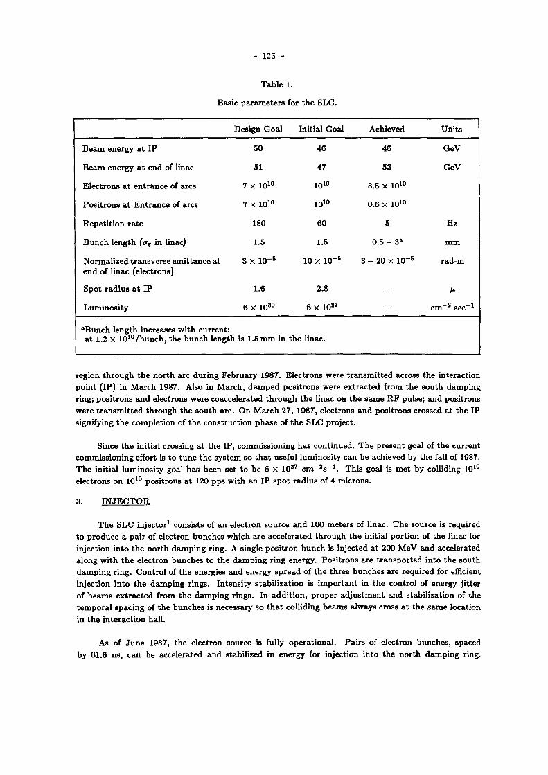
- 123 -
T a b l e 1.
Bas ic p a r a m e t e r s for t h e S L C .
Des ign G o a l In i t i a l G o a l Ach ieved Uni t s
B e a m e n e r g y a t I P 50 46 46 G e V
B e a m e n e r g y a t e n d of l inac 51 47 53 G e V
E l e c t r o n s a t e n t r a n c e of a rcs 7 x 10 1 0 10 1 0 3.5 x 10 1 0
P o s i t r o n s a t E n t r a n c e of a r c s 7 x 10 1 0 10 1 0 0.6 X 10 1 0
R e p e t i t i o n r a t e 180 60 5 Hz
B u n c h l e n g t h (az in l inac) 1.5 1.5 0.5 - 3 a m m
N o r m a l i z e d t r a n s v e r s e e m i t t a n c e a t e n d of l inac (e lec t rons)
3 x 10~ 5 10 X l u - 5 3 - 20 x 10 - 5 r a d - m
S p o t r a d i u s a t I P 1.6 2.8 ß
L u m i n o s i t y 6 X 10 3 0 6 X 10 2 7 c m - 2 s e c - 1
" B u n c h l e n g t h increases w i t h c u r r e n t : a t 1.2 X 10 1 0 / b u n c h , t h e b u n c h l eng th is 1.5 m m in t h e l inac .
r eg ion t h r o u g h t h e n o r t h a r c d u r i n g F e b r u a r y 1987. E l e c t r o n s w e r e t r a n s m i t t e d ac ross t h e i n t e r ac t i on p o i n t ( IP ) in M a r c h 1987. Also in M a r c h , d a m p e d p o s i t r o n s w e r e e x t r a c t e d f rom t h e s o u t h d a m p i n g r i n g ; p o s i t r o n s a n d e l ec t rons w e r e coacce l e ra t ed t h r o u g h t h e l inac on t h e s a m e R F pu l se ; a n d p o s i t r o n s w e r e t r a n s m i t t e d t h r o u g h t h e s o u t h a r c . O n M a r c h 27, 1987, e l ec t rons a n d p o s i t r o n s c rossed a t t h e I P s ignifying t h e c o m p l e t i o n of t h e c o n s t r u c t i o n p h a s e of t h e S L C p ro j ec t .
S ince t h e in i t i a l c ross ing a t t h e I P , c o m m i s s i o n i n g h a s c o n t i n u e d . T h e p r e s e n t goal of t h e c u r r e n t c o m m i s s i o n i n g effort is t o t u n e t h e s y s t e m so t h a t useful l u m i n o s i t y c a n b e ach ieved b y t h e fall of 1987. T h e in i t i a l l u m i n o s i t y goal h a s b e e n se t t o b e 6 x 10 2 7 c m ~ 2 s _ 1 . T h i s goal is m e t b y col l iding 10 1 0
e lec t rons o n 10 1 0 p o s i t r o n s a t 120 p p s w i t h a n I P s p o t r a d i u s of 4 m i c r o n s .
3 . I N J E C T O R
T h e S L C i n j e c t o r 1 cons i s t s of a n e l ec t ron sou rce a n d 100 m e t e r s of l inac . T h e sou rce is r equ i red t o p r o d u c e a p a i r of e lec t ron b u n c h e s w h i c h a r e a c c e l e r a t e d t h r o u g h t h e in i t ia l p o r t i o n of t h e l inac for in jec t ion i n t o t h e n o r t h d a m p i n g r ing . A s ingle p o s i t r o n b u n c h is in jec ted a t 200 M e V a n d acce le ra ted a long w i t h t h e e l ec t ron b u n c h e s t o t h e d a m p i n g r i n g ene rgy . P o s i t r o n s a r e t r a n s p o r t e d i n t o t h e s o u t h d a m p i n g r i n g . C o n t r o l of t h e energ ies a n d ene rgy s p r e a d of t h e t h r e e b u n c h e s a r e r e q u i r e d for efficient in jec t ion i n t o t h e d a m p i n g r i n g s . I n t e n s i t y s t a b i l i z a t i o n is i m p o r t a n t in t h e c o n t r o l of ene rgy j i t t e r of b e a m s e x t r a c t e d f rom t h e d a m p i n g r i n g s . I n a d d i t i o n , p r o p e r a d j u s t m e n t a n d s t ab i l i z a t i on of t h e t e m p o r a l s p a c i n g of t h e b u n c h e s is neces sa ry so t h a t co l l id ing b e a m s a lways cross a t t h e s a m e loca t ion in t h e i n t e r a c t i o n ha l l .
As of J u n e 1987, t h e e lec t ron source is fully o p e r a t i o n a l . P a i r s of e l ec t ron b u n c h e s , spaced b y 61.6 n s , c a n b e acce le ra ted a n d s tab i l i zed in e n e r g y for in ject ion i n t o t h e n o r t h d a m p i n g r ing .

- 124 -
A t b u n c h c u r r e n t s g r e a t e r t h a n a b o u t 7.5 X 1 0 1 0 i n t e n s i t y j i t t e r b e c o m e s a p r o b l e m . A t p r e s e n t , t h e sou rce is o p e r a t e d t o p r o d u c e e l e c t r o n b u n c h in tens i t i e s b e t w e e n a b o u t 5 x 1 0 9 a n d 3 x 1 0 1 0 par t ic les p e r p u l s e a c c o r d i n g t o t h e d e m a n d s of t h e d o w n s t r e a m u s e r s . O p e r a t i o n a t 1 x 1 0 1 0 e l ec t rons p e r pulse is n o t a p r o b l e m .
P o s i t r o n t r a n s m i s s i o n t h r o u g h t h e in jector reg ion d e p e n d s u p o n t h e in i t i a l p o s i t r o n l a u n c h condit ions . A n increased" p o s i t r o n b u n c h l e n g t h enlarges t h e energy s p r e a d which resu l t s in p o o r t r ansmi s s ion a n d in jec t ion i n t o t h e s o u t h r i n g . B e s t cond i t i ons ach ieved so far r e s u l t e d in 6 0 % t r a n s m i s s i o n t h r o u g h t h e in jec tor i n t o t h e r i n g . T r a n s m i s s i o n efficiencies of 4 0 % a r e t yp i ca l ly a ch i eved .
W h e r e a s d o u b l e e l e c t r o n b u n c h o p e r a t i o n h a s b e e n t e s t e d , o n l y s ingle b u n c h e s a r e rou t ine ly acc e l e r a t e d t h r o u g h t h e in jec to r r e g i o n . T w o - b u n c h o p e r a t i o n is a w a i t i n g t h e i n s t a l l a t i o n of a t w o ' b u n c h e x t r a c t i o n k icker in t h e n o r t h d a m p i n g r i n g . S imi lar ly , t h e low r e p e t i t i o n r a t e of t h e S L C (10 p p s in t h e l inac) h a s n o t p e r m i t t e d t e s t i n g of t h e full t h r e e - b u n c h acce le ra t ion in t h e in jec tor . Tes t i ng of t h r ee b u n c h o p e r a t i o n is s c h e d u l e d for t h e fall of 1987 a n d is n o t e x p e c t e d t o b e a p r o b l e m .
4 . P O S I T R O N S O U R C E
T h e S L C p o s i t r o n s o u r c e 2 cons i s t s of a W - R e t a r g e t , flux c o n c e n t r a t o r , 200 M e V of acce lera t ion , a n d a 2000 m t r a n s p o r t l ine . A t t h e t w o - t h i r d s p o i n t i n t h e l inac , 30 G e V e l e c t r o n s a r e deflected o n t o t h e t a r g e t . P o s i t r o n s i n t h e r e s u l t a n t s h o w e r a r e acce le ra t ed t o 200 M e V in a s - b a n d , h igh g rad ien t c a p t u r e sec t ion fol lowed b y t h r e e s t a n d a r d S L A C sec t ions . T h e 200 M e V p o s i t r o n s a r e t r a n s p o r t e d t o t h e b e g i n n i n g of t h e l i nac for s u b s e q u e n t acce le ra t ion t o 1.21 G e V a n d in jec t ion i n t o t h e s o u t h d a m p i n g r ing .
In i t i a l p l a n s ca l led for a r o t a t i n g , w a t e r cooled t a r g e t . T e s t i n g of t h e dev ice r e s u l t e d in a v a c u u m fai lure of t h e r o t a t i n g sea l ; t h e fa i lure c a u s e d d a m a g e t o t h e h i g h g r a d i e n t s ec t i on . A t p r e s e n t , a fixed t a r g e t h a s b e e n i n s t a l l e d a n d t h e h i g h g r a d i e n t sec t ion is o p e r a t e d a t 20 M e V p e r m e t e r i n s t ead of t h e des ign goal of 50 M e V / m e t e r . T h e fixed t a r g e t is l im i t ed in p o w e r d i s s i p a t i o n t o t h e equiva len t of 2 x 1 0 1 0 i n c i d e n t e l e c t r o n s p e r p u l s e a t a r e p e t i t i o n r a t e of 120 p p s . So leno ids ins ta l l ed a r o u n d t h e c a p t u r e sec t ion h a v e d e v e l o p e d t u r n - t o - t u r n s h o r t s r e su l t i ng in a r e d u c t i o n of t h e fields in t h e c a p t u r e reg ion .
T h e fa i lure of t h e h i g h g r a d i e n t sec t ion a n d r e d u c e d so leno ida l field dec reases t h e e lec t ron t o p o s i t r o n efficiency. T h e r e s t r i c t i o n of t h e m a x i m u m in t ens i t y o n t a r g e t , f u r t h e r l imi t s p o s i t r o n p r o d u c t i on . P l a n s cal l for r e p l a c e m e n t of t h e so lenoids a n d h i g h g r a d i e n t sec t ion in t h e fall of 1987. T h i s will r e su l t in g r e a t e r p o s i t r o n y i e ld s . D e v e l o p m e n t of a r o t a t i n g t a r g e t t o a b s o r b g r e a t e r e lec t ron fluxes is n o t a n t i c i p a t e d u n t i l s o m e t i m e in 1988 .
W i t h t h e r e d u c e d c o n d i t i o n s , a y i e ld of o n e p o s i t r o n in jec ted i n t o t h e l i nac f r o m t h e s o u t h d a m p i n g r i n g for eve ry t w o e l e c t r o n s i n c i d e n t o n t a r g e t h a s b e e n ach ieved . T h e m a x i m u m n u m b e r of pos i t rons s t o r e d in t h e s o u t h r i n g h a s b e e n a p p r o x i m a t e l y 1 x 1 0 1 0 pa r t i c l e s in a s ing le p u l s e . In o r d e r t o acc o m p l i s h t h i s y ie ld , careful t u n i n g of t h e p o s i t r o n b u n c h l e n g t h w a s r e q u i r e d . T h i s t u n i n g w a s d o n e by v a r y i n g t h e R F p h a s e in t h e c a p t u r e sec t ion , t u n i n g t h e s u b s e q u e n t d o w n s t r e a m R F a n d t r a n s p o r t line m a g n e t s , w h i l e o b s e r v i n g t h e b u n c h l e n g t h u s ing a s t r e a k c a m e r a . F o r t u i t o u s l y , t h e yie ld p e a k s w h e r e t h e b u n c h l e n g t h is m i n i m i z e d . T h e s m a l l e s t ach ieved b u n c h l e n g t h s a r e a p p r o x i m a t e l y 1.5 t i m e s longer t h a n c a n b e e x p e c t e d t o fit i n s ide t h e d a m p i n g r ing ene rgy a p e r t u r e , a f ter acce l e ra t ion t h r o u g h t h e in jec tor . T h i s i nc rea se is a t t r i b u t e d t o a longer t h a n e x p e c t e d b u n c h l e n g t h of e l ec t rons e x t r a c t e d from t h e n o r t h d a m p i n g r i n g s .
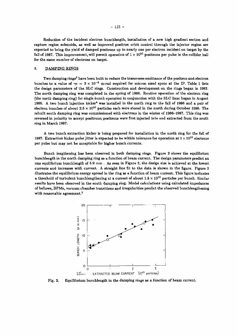
- 125 -
R e d u c t i o n of t h e i n c i d e n t e l ec t ron b u n c h l e n g t h , i n s t a l l a t i on of a n e w h i g h g r a d i e n t sec t ion a n d c a p t u r e reg ion so leno ids , a s wel l as i m p r o v e d p o s i t r o n o r b i t c o n t r o l t h r o u g h t h e in jector region are expec t ed t o b r i n g t h e y ie ld of d a m p e d p o s i t r o n s u p t o n e a r l y o n e p e r e l ec t ron inc iden t o n t a r g e t b y t he fall of 1987. T h i s i m p r o v e m e n t , will p e r m i t o p e r a t i o n of 1 x 1 0 1 0 p o s i t r o n s p e r pu l s e in t h e coll ider hal l for t h e s a m e n u m b e r of e l ec t rons o n t a r g e t .
5 . D A M P I N G R I N G S
T w o d a m p i n g r i n g s 3 h a v e b e e n b u i l t t o r e d u c e t h e t r a n s v e r s e e m i t t a n c e of t h e p o s i t r o n a n d electron b u n c h e s t o a va lue of 7£ = 3 x 1 0 - 5 m - r a d r equ i r ed for m i c r o n s ized s p o t s a t t h e I P . T a b l e 1 lists t h e des ign p a r a m e t e r s of t h e S L C r ings . C o n s t r u c t i o n a n d d e v e l o p m e n t o n t h e r ings b e g a n in 1982. T h e n o r t h d a m p i n g r i n g w a s c o m p l e t e d in t h e s p r i n g of 1986. R o u t i n e o p e r a t i o n of t h e e lec t ron r ing ( the n o r t h d a m p i n g r i ng ) for s ingle b u n c h o p e r a t i o n in c o n j u n c t i o n w i t h t h e S L C l inac b e g a n in Augus t 1986. A t w o b u n c h in jec t ion k i c k e r 4 w a s ins ta l l ed in t h e n o r t h r ing in t h e fall of 1986 a n d a pa i r of e lec t ron b u n c h e s of a b o u t 2.5 x 1 0 1 0 pa r t i c l e s each were s t o r e d in t h e n o r t h d u r i n g O c t o b e r 1986. T h e rebu i l t s o u t h d a m p i n g r i n g w a s c o m m i s s i o n e d w i t h e lec t rons in t h e w i n t e r of 1986-1987 . T h i s r ing was reversed in p o l a r i t y t o a c c e p t p o s i t r o n s ; p o s i t r o n s were first in jec ted i n t o a n d e x t r a c t e d f rom t h e s o u t h r i n g in M a r c h 1987.
A t w o b u n c h e x t r a c t i o n k icker is b e i n g p r e p a r e d for i n s t a l l a t i o n in t h e n o r t h r ing for t h e fall of 1987. E x t r a c t i o n k icker p u l s e j i t t e r is e x p e c t e d t o b e w i t h i n t o l e r a n c e for o p e r a t i o n a t 1 x 1 0 1 0 e lect rons p e r pu l s e b u t m a y n o t b e a c c e p t a b l e for h ighe r b u n c h c u r r e n t s .
B u n c h l e n g t h e n i n g h a s b e e n obse rved in b o t h d a m p i n g r i n g s . F i g u r e 2 s h o w s t h e equ i l ib r ium b u n c h l e n g t h in t h e n o r t h d a m p i n g r ing as a func t ion of b e a m c u r r e n t . T h e des ign p a r a m e t e r s p red ic t an r m s e q u i l i b r i u m b u n c h l e n g t h of 5.9 m m . As seen in F i g u r e 2 , t h e des ign size is ach ieved a t t h e lowest c u r r e n t s a n d inc reases w i t h c u r r e n t . A s t r a i g h t l ine fit t o t h e d a t a is s h o w n in t h e figure. F i g u r e 3 i l lus t ra tes t h e e q u i l i b r i u m e n e r g y s p r e a d in t h e r ing as a func t ion of b e a m c u r r e n t . T h i s figure indica tes a t h r e s h o l d of t u r b u l e n t b u n c h l e n g t h e n i n g a t a c u r r e n t of a b o u t 1.5 x 1 0 1 0 pa r t i c l e s p e r b u n c h . Similar r e su l t s h a v e b e e n o b s e r v e d in t h e s o u t h d a m p i n g r ing . M o d e l c a l cu l a t i ons u s i n g ca l cu la t ed impedances of be l lows , B P M s , v a c u u m c h a m b e r t r a n s i t i o n s a n d i r regu la r i t i e s p r e d i c t t h e obse rved b u n c h l e n g t h e n i n g w i t h r e a s o n a b l e a g r e e m e n t . 5
2 0 i 1 • 1 1 H
z> 0Ü
0 1 1 . 1 1 1 0 I 2 3
Í 7 2 2 A H E X T R A C T E D B E A M C U R R E N T (|0'° particles)
F i g . 2 . E q u i l i b r i u m b u n c h l e n g t h in t h e d a m p i n g r i ngs as a func t ion of b e a m c u r r e n t .

- 126 -
F i g . 3 .
0 1 2 3 • m » Extracted Beam Current ( l 0 1 0 particles)
E q u i l i b r i u m ene rgy s p r e a d in t h e d a m p i n g r ings as a func t ion of b e a m c u r r e n t .
T h e b u n c h l e n g t h e n i n g r e d u c e s t h e m a x i m u m u s a b l e b e a m c u r r e n t t o a b o u t 2 x 1 0 1 0 pa r t i c l e s p e r p u l s e . E v e n t h o u g h it is poss ib le t o e x t r a c t h i g h e r c u r r e n t s f rom t h e r i ng , it is n o t poss ib le t o compres s t h e l a rge b u n c h l e n g t h s in t h e t r a n s p o r t l ine l ead ing f rom t h e r ings t o t h e l inac ( R T L ) b e c a u s e of energy a p e r t u r e r e s t r i c t i o n in t h e R T L s . F u r t h e r m o r e , t h e m i n i m u m ach ievab le b u n c h l e n g t h is l imi ted b y t h e e q u i l i b r i u m e n e r g y s p r e a d w h i c h increases a b o v e t h e t u r b u l e n c e t h r e s h o l d . A n inc rea sed l ong i tud ina l b e a m size r e su l t s in inc reased sens i t i v i ty t o t r a n s v e r s e wakefields in t h e l inac . In a d d i t i o n , t h e increased s c a v e n g e r b u n c h l e n g t h r e su l t s in i nc reased p o s i t r o n b u n c h l e n g t h s w h i c h a r e s u b s e q u e n t l y difficult t o inject i n t o t h e s o u t h d a m p i n g r i n g b e c a u s e of a n e n l a r g e d ene rgy s p r e a d .
Severa l s h o r t t e r m so lu t ions a r e b e i n g c o n s i d e r e d for t h e fall of 1987. T h e s e inc lude sh ie ld ing t h e r i n g be l l ows , e n l a r g i n g t h e R T L e n e r g y a p e r t u r e , a n d inc reas ing t h e ava i lab le R F v o l t a g e in t h e r ing . S o m e p r e c o m p r e s s i o n in t h e r i ngs is poss ib le b y l a u n c h i n g a l o n g i t u d i n a l q u a d r u p o l e osc i l la t ion in t h e r i n g s h o r t l y before e x t r a c t i o n a n d e x t r a c t i n g t h e b e a m w h e n a m i n i m u m in t h e b e a m size o c c u r s . T h e s e fixes a n d p r o c e d u r e s a r e e x p e c t e d t o inc rease t h e m a x i m u m useful b e a m c u r r e n t t o n e a r l y 5 x 1 0 1 0
pa r t i c l e s p e r b u n c h . F o r o p e r a t i o n a t 1 x 1 0 1 0 p a r t i c l e s p e r pu l se , t h e p r e s e n t s y s t e m is a d e q u a t e .
6. L I N A C
T h e t w o mi le S L A C l inac h a s b e e n u p g r a d e d 6 t o acce le ra te t i gh t l y focused b e a m s of p o s i t r o n s a n d e lec t rons o n t h e s a m e R F p u l s e w i t h o u t s ignif icant e m i t t a n c e inc reases . O v e r 200 n e w 67 M W k l y s t r o n s h a v e b e e n ins ta l l ed in t h e l inac , a n d b e a m energies of 53 G e V h a v e b e e n m e a s u r e d . 7 R o u t i n e c o m m i s s i o n i n g o p e r a t e s a t 47 G e V p e r b e a m . 3.5 x 1 0 1 0 e lec t rons a n d 0.6 x 1 0 1 0 p o s i t r o n s p e r b u n c h h a v e b e e n acce le ra t ed w i t h o u t loss.
B e a m t ra jec to r i e s a r e c o r r e c t e d u s ing d ipo le m a g n e t s a n d b e a m pos i t i on m o n i t o r s loca ted every 12 m e t e r s (closer in t h e first 300 m e t e r s ) . E l e c t r o n t r a j ec to r i e s a r e r o u t i n e l y c o r r e c t e d t o e r ro r s of 125 \i r m s . W h e n b o t h b e a m s a r e c o r r e c t e d s i m u l t a n e o u s l y , t yp i ca l t r a j e c t o r y e r ro r s a r e 300 ß r m s for each b e a m . T h e s e t r a j e c t o r y e r ro r s h a v e b e e n s t ead i ly dec reas ing as t h e mi sa l i gned q u a d r u p o l e s a n d e r r a n t e lec t ron ic m o d u l e s h a v e b e e n d i scovered a n d fixed.
T h e t r a n s v e r s e s h a p e s of t h e b e a m s a t t h e e n d of t h e l inac d e p e n d o n t h e q u a d r u p o l e l a t t i ce , t h e ene rgy-acce le ra t ion profile of t h e l inac , e n t r a n c e c o n d i t i o n s f rom t h e R T L s , a n d t r a n s v e r s e wakefields. T h e b e a m d i m e n s i o n s h a v e b e e n s h o w n t o r e m a i n c o n s t a n t as long as t h e u p s t r e a m c o n d i t i o n s d o n o t c h a n g e . T h e t r a n s v e r s e b e a m e m i t t a n c e s h a v e b e e n m e a s u r e d a t h i g h ene rgy a s a func t ion of b e a m c u r r e n t , a n d a s u m m a r y is s h o w n in T a b l e 2. A b o v e a b o u t 0.8 x 1 0 1 0 e lec t rons p e r pu l s e t h e b u n c h l e n g t h increases d u e t o t h e d a m p i n g r ing w h i c h increases t h e b e a m ' s ene rgy s p e c t r u m d r a m a t i c a l l y in t h e l inac . T h i s causes s h a r p l y inc reased t r a n s v e r s e wakefields a n d c h r o m a t i c p h a s e d i l u t i o n effects t o

- 127 -
T a b l e 2.
M e a s u r e d l inac i nva r i en t e m i t t a n c e s a t 4 3 - 4 7 G e V . T h e u n i t s a r e in r a d i a n - m e t e r s x l O - 6 .
I x 1 0 1 0 H o r i z o n t a l Ver t i ca l D a t e
0.4 7 ± 1 2 ± 1 2 / 8 7
0.4 8 ± 1 3 ± 1 8 / 8 7
0.8 12 ± 4 1.1 ± 0 . 3 2 / 8 7
1.0 25 ± 5 2 ± 1 2 / 8 7
1.5 20 ± 5 4 ± 1 2 / 8 7
9-87 5863AIO
F i g . 4 . D ig i t i zed b e a m s h a p e m o n i t o r a t t h e e n d of t h e l inac u s e d for m a i n t a i n i n g l inac cond i t i ons . T h e left i m a g e s a r e u s e d t o m o n i t o r t h e v e r t i c a l p h a s e s p a c e of t h e e l ec t rons , t h e r i g h t images t h e h o r i z o n t a l . T h i s m o n i t o r uses less t h a n o n e p e r c e n t of t h e l inac pu l ses a t 120 Hz .
a p p e a r . I m p r o v e m e n t s t o t h e d a m p i n g r i ngs s h o u l d r e d u c e t h i s effect. T h u s , t h e a p p a r e n t e m i t t a n c e inc rease a b o v e 1 0 1 0 pa r t i c l e s will i m p r o v e .
A n on l ine m o n i t o r of t h e b e a m s h a p e s a t t h e e n d of t h e l inac h a s b e e n bu i l t . F o u r off-axis profile m o n i t o r s a n d four low r e p e t i t i o n r a t e p u l s e d d ipoles s a m p l e t h e b e a m a t o n e h e r t z . T h e r e su l t i ng images of t h e b e a m s h a p e s a r e d ig i t ized a n d s t o r e d . T h e i m a g e s a r e u s e d b y t h e o p e r a t o r s t o verify t h a t l inac c o n d i t i o n s h a v e n o t c h a n g e d . T h e sc reens w e r e i n s t a l l ed so t h a t p a i r s of m o n i t o r s w e r e 90 degrees in b e t a t r o n p h a s e s p a c e a p a r t a l lowing a g o o d check of t h e p h a s e el l ipse o r i e n t a t i o n of b o t h p l a n e s of b o t h b e a m s . A n e x a m p l e of t h i s d i sp lay is s h o w n in F i g . 4 .
M a n y checks of t h e t r a n s v e r s e a n d l o n g i t u d i n a l w a k e f i e l d s 8 ' 9 in t h e l inac h a v e b e e n m a d e . T h e m e a s u r e d effects ag ree w i t h t h e p r e d i c t i o n s t o w i t h i n a fac to r of t w o . O n e of t h e t e s t s is p a r t i c u l a r l y en l i gh t en ing d i sp l ay ing t h e fact t h a t t h e h e a d of t h e b u n c h t r a n s v e r s e l y d r ives t h e t a i l of t h e b u n c h . T h e b e a m is m a d e t o osci l la te ver t ica l ly u s ing a d ipo le n e a r t h e f ront of t h e l inac . T h u s , ve r t i ca l wakefield

- 128 -
effects should increase the vertical size of the beam. To separate the head from the tail , the bunch was accelerated off the crest of the RF waveform so that the head of the bunch had more energy after acceleration t h a n the tai l . T h e head and the tail were then separated at the e n d of the linac by bending the b e a m into the beginning of the arc where there is horizontal dispersion. T h e b e a m was viewed by a profile monitor . T h e image o n the screen shows energy horizontally and beta tron mot ion vertically. T h e experimental se tup is s h o w n in F ig . 5 . The results are shown in Fig . 6. As the dipole magnet was varied u p and d o w n , the head of t h e b e a m did not change posi t ion very m u c h but the tail , driven by wakefields, m o v e d dramatical ly and w i t h the same s ign as the dipole. Furthermore , it is clear that the particles in each longitudinal 'slice' of the bunch are driven in the same w a y a n d n o internal growth of emittance in each slice is present . T h i s fits theory very nicely.
T h e launch of b o t h positrons and electrons into the linac from the damping rings and into the arcs from the linac m u s t b e controlled w i t h feedback sys tems . Present ly the position and angle of electrons into and out of the linac are controlled once per minute by so-called s low feedback processes. T h e energy is also controlled once per minute . T h e processes for positrons are now just starting t o b e commissioned. A fast feedback on the e n e r g y 9 of the electrons operating on a pulse basis has been shown t o work well and is now being incorporated in the online control sys tem. Fast pulse-by-pulse feedback on the positron energy and the wakefield induced b e a m tails is under development . It is expec ted in the fall.
7. A R C S
T h e north arc (electrons) has been under continual s tudy since December 1986. T h e south arc (positrons) has been studied only briefly in March during the t w o b e a m coll is ion test .
T h e goals for the a r c s 1 0 are t o transport the SLC beams to the final focus w i thout loss and without increasing the b e a m s ' emit tances and t o provide suitable betatron and dispersion functions at the end which are correctable b y finite adjustments in the final focus. Electrons have been transmit ted to the

- 129 -
Increasing Energy •* Bunch Tail Bunch Head
Fig . 6. Exper iment demonstrat ing that the b u n c h head drives the tail due t o transverse wakefields.
final focus wi thout losses as can b e seen in F ig . 7, w h i c h shows the trajectory a n d intens i ty through the north arc after correction. Three hundred micron rms trajectory errors can n o w b e easily achieved.
T h e goal to provide correctable be ta tron a n d dispersion functions has not been m e t . Part of the problem of the b e a m m i s m a t c h is due t o changing condit ions in the linac and to m a g n e t al ignment problems in the linac-to-arc transi t ion region. However , substant ia l errors arise from problems in the arcs. Mechanical hysteresis , b inding , shaft s l ipping, and ball and socket a l ignment problems of the magne t movers m a k e trajectory correction uncerta in and irreproducibie. Solut ions for m o s t of these problems are in hand , and corrections are be ing m a d e . Some of the b e a m pos i t ion moni tor cables have intermittent connect ions which cause non-apparent 3 m m offsets in the readouts . T h e combinat ion of discrete rolls of the achromats in the arcs (planned) and errors in the phase advance per cell (unplanned) causes horizontal-vertical coupl ing which mixes t h e phase space of the b e a m and can produce betatron amplification. A n example of this is s h o w n in Fig . 8 where a vertical mover in achromat N 0 4 w a s changed t o produce a vertical betatron osci l lat ion. After several achromats , a horizontal osci l lat ion appears and grows quite large b y the end of the arc. Horizontal t o vertical coupl ing is also observed. T h e solut ion

- 130 -
3 E JE 0
X -3 3
1 JE 0
-3 ^ v 6 CT)
O X
s—( 0
9-87 5863A 5
BPM vs z Electrons x,y RMS=0.328 0.256
, ,V r~^iyM,'.viWi+^^
Ilii 1 f . " ' • r.t..'r;,i -i IiIIJ1 - •i"j-<iJli*. ~" "Xj " k !
N0¿ ÍN0-J IwOO ÍN0n [non Nil ¡N13 INIO IN'.7 ¡N19 IN21
10-MAY- 1987 08=23:12.8
F i g . 7. E l e c t r o n t r a j e c t o r y in t h e n o r t h a r c c o r r e c t e d b y
a n a u t o m a t i c p r o c e d u r e u s i n g t h e m a g n e t m o v e r s .
t o t h i s p r o b l e m is t o c o r r e c t t h e p h a s e a d v a n c e p e r cell local ly for e a c h achromat . P h a s e cor rec t ion is c o m p l i c a t e d b y t h e s ex tupo le t e r m in t h e a r c m a g n e t s a n d t h e m o v e m e n t p r o c e d u r e of t h e m a g n e t s b u t h a s b e e n successful ly a p p l i e d t o severa l achromats .
£ o
* -3 „ 3 E J 0
BPM vs z Electrons x , y RMS=0.636 0.669 3
rf 2 "3
% ? T Vertical ~x Deflection - n l l l l Í u | H M ^ M | i i i i i i [i i i) i j lililí i |, i
Li3elwe» m e s 1x84 m m Ihm(MIO luis luit IHI« IN&S IKSS INSS I
5863A7 20-JUN-87 13=55:55
F i g . 8. B e t a t r o n coupl ing in t h e n o r t h a rc c a u s e d b y u n c o r r e c t e d p h a s e a d v a n c e s p e r a c h r o m a t .
8. F I N A L F O C U S
In F e b r u a r y 1987 , t h e in s t a l l a t i on of t h e m a g n e t s , c o n t r o l s a n d i n s t r u m e n t s n e e d e d t o t r a n s p o r t b o t h b e a m s t o t h e col l is ion p o i n t w a s c o m p l e t e d . O n l y a few c o m p o n e n t s r e q u i r e d t o t a k e t h e b e a m s to t h e i r r e s p e c t i v e d u m p s a n d severa l co l l ima to r s r e m a i n t o b e ins t a l l ed . I n M a r c h , a p r o g r a m was u n d e r t a k e n t o a c c e l e r a t e b o t h p o s i t r o n s a n d e lec t rons a n d p a s s t h e m t h r o u g h t h e col l ider ha l l on t h e

- 131 -
s a m e l inac cycle . T h i s goa l w a s r e a c h e d o n M a r c h 27 , 1987 , a t 4:45 p . m . w h e n 4 x 1 0 9 e l ec t rons a n d 4 x 1 0 8 p o s i t r o n s p a s s e d t h r o u g h e a c h o t h e r . A p h o t o g r a p h of t h e t w o b e a m s as seen o n a pos i t i on m o n i t o r a t t h e i n t e r a c t i o n p o i n t is s h o w n in F i g . 9 . B o t h b e a m s h a d energ ies of 46 G e V . T h e b e a m sizes w e r e t o o l a r g e t o m a k e a n i n t e r e s t i n g l u m i n o s i t y , b u t t h e e v e n t m a r k e d t h e e n d of t h e S L C c o n s t r u c t i o n .
F i g . 9 . S igna ls on t h e b e a m p o s i t i o n m o n i t o r a t t h e i n t e r a c t i o n p o i n t s h o w ing e l ec t rons (left) a n d p o s i t r o n s ( r igh t ) co l l id ing o n t h e s a m e l inac cycle .
T h e a r e a s of w o r k u n d e r w a y a r e t h e r e d u c t i o n of b e a m i n d u c e d noise in t h e b e a m p o s i t i o n m o n i t o r s , b e a m t r a j e c t o r y a n d t r a n s m i s s i o n c o r r e c t i o n a n d b e t a t r o n a n d d i spe r s ion m a t c h i n g of t h e b e a m from t h e n o r t h a r c . A typ i ca l b e a m t r a j e c t o r y in t h e l a t e r n o r t h a r c a n d t h e final focus is s h o w n in F ig . 10. S t u d i e s 1 1 s o o n t o s t a r t i nc lude s ize , ang le a n d c h r o m a t i c s h a p e co r rec t ions of t h e e lec t rons a t t h e collision p o i n t . A t p r e s e n t t h e sma l l e s t s p o t sizes m e a s u r e d a r e 100 m i c r o n s h o r i z o n t a l l y a n d 30 ver t ica l ly . A m o v i n g w i r e s c a n n e r w a s u s e d t o d e t e r m i n e t h e b e a m size. T h e s e la rge b e a m s sizes a r e be l i eved t o b e c a u s e d b y m i s m a t c h e d d i spe r s ion a n d b e t a t r o n func t ions ex i t i ng t h e n o r t h a r c .
T h e p r e s e n t i n s t r u m e n t s a t t h e i n t e r s e c t i o n p o i n t i nc lude a sc reen profile m o n i t o r (40 mic ron r e s o l u t i o n ) , a n x-y w i r e s c a n n e r (20 a n d 7 m i c r o n w i r e s ) , a n d a p o s i t i o n m o n i t o r (50 m i c r o n r e so lu t ion ) . After t h e M K I I is ins ta l l ed , t h e r e will b e a n x-y wi re s c a n n e r a t t h e I P w i t h s even m i c r o n w i r e s , a v e r t e x b e a m p o s i t i o n m o n i t o r w i t h a b o u t 100 m i c r o n r e s o l u t i o n , b e a m s s t r a h l u n g m o n i t o r s for b o t h b e a m s a n d e q u i p m e n t for m e a s u r i n g b e a m - b e a m def lect ions . I n s t r u m e n t s loca ted a t low b e t a t r o n func t ions ou t s ide t h e i m m e d i a t e coll ision reg ion t o m e a s u r e t h e b e a m s h a p e a r e u n d e r i nves t i ga t i on .
9 . S L C F U T U R E P L A N S
T h e g e n e r a l p l a n for c o m m i s s i o n i n g t h e S L C a s of J u n e 1987 is t o c o n c e n t r a t e o n e l ec t ron s tud ies in t h e n o r t h a r c a n d final focus t o p r o d u c e a n a c c e p t a b l e b e a m (size a n d b a c k g r o u n d ) for coll isions a n d , as t i m e a l lows , t o p u r s u e inc reased p o s i t r o n p r o d u c t i o n , p o s i t r o n i n t ens i t y in t h e s o u t h d a m p i n g r ing
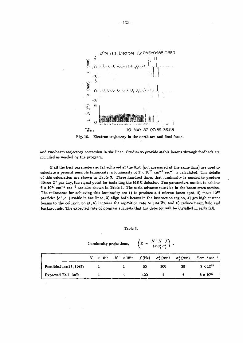
- 132 -
E £ O
x - 3
_ 3
- O
B P M v s z E l e c t r o n s x , y R M S = 0 . 4 8 8 0 . 3 8 0
J,, .J-M.k-Jv,J,,l.,JU+,l,.iiJ„-v,,iü jiJL- i - T - Ji. T»irr'
Kl'", ll-! «i IUI/ lui fi IN Kl llL'O Ii UM
S 88 6 7 3A 8 I O - M A Y - 8 7 0 7 : 3 9 : 3 6 . 5 8
F i g . 10. E l e c t r o n t r a j e c t o r y in t h e n o r t h a r c a n d final focos .
a n d t w o - b e a m t r a j e c t o r y c o r r e c t i o n in t h e l inac . S t u d i e s t o p r o v i d e s t a b l e b e a m s t h r o u g h feedback a re i nc luded as n e e d e d b y t h e p r o g r a m .
If al l t h e b e s t p a r a m e t e r s s o far ach ieved a t t h e S L C (no t m e a s u r e d a t t h e s a m e t i m e ) a r e used to c a l c u l a t e a p r e s e n t pos s ib l e l u m i n o s i t y , a l u m i n o s i t y of 2 x 1 0 2 5 c m - 2 s e c - 1 is c a l c u l a t e d . T h e de ta i l s of t h i s c a l c u l a t i o n a r e s h o w n in T a b l e 3 . T h r e e h u n d r e d t i m e s t h a t l u m i n o s i t y is n e e d e d t o p r o d u c e fifteen Z" p e r d a y , t h e s i g n a l p o i n t for ins ta l l ing t h e M K I I d e t e c t o r . T h e p a r a m e t e r s n e e d e d t o achieve 6 x 1 0 2 7 c m - 2 sec~l a r e a l so s h o w n in T a b l e 1. T h e m a i n a d v a n c e m u s t b e in t h e b e a m cross sect ion. T h e m i l e s t o n e s for a c h i e v i n g t h i s l u m i n o s i t y a r e 1) t o p r o d u c e a 4 m i c r o n b e a m s p o t , 2) m a k e 1 0 1 0
pa r t i c l e s ( e + , e~) s t a b l e in t h e l i nac , 3) a l ign b o t h b e a m s in t h e i n t e r a c t i o n r e g i o n , 4) ge t h igh c u r r e n t b e a m s t o t h e col l i s ion p o i n t , 5) i n c r e a s e t h e r e p e t i t i o n r a t e t o 120 H z , a n d 6) r e d u c e b e a m h a l o a n d b a c k g r o u n d s . T h e e x p e c t e d r a t e of p rog re s s sugges t s t h a t t h e d e t e c t o r will b e i n s t a l l ed in ear ly fall.
T a b l e 3 .
L u m i n o s i t y p ro jec t ions , ( £ = — -
N+ x 1 0 1 0 N- x 1 0 1 0 / ( H z ) a* H «r; (Mm) £ c m - 2 s e c - 1
Poss ib l e J u n e 2 1 , 1 9 8 7 : 1 1 60 100 30 2 x 1 0 2 5
E x p e c t e d Fa l l 1987: 1 1 120 4 4 6 x 1 0 2 7

- 133 -
A C K N O W L E D G E M E N T S
T h e a u t h o r s a c k n o w l e d g e t h e d i scuss ions w i t h m a n y peop le w h i c h h a v e e n t e r e d i n t o t h i s r e p o r t o n t h e s t a t u s of t h e S L C . W e t h a n k K . B a n e of t h e D a m p i n g R i n g G r o u p for p r o v i d i n g F i g u r e 3 . T h e O p e r a t i o n s G r o u p h a s b e e n p a r t i c u l a r l y helpful in t h e commis s ion ing effort of t h e S L C .
* * *
R E F E R E N C E S
1. J . C . S h e p p a r d et al., C o m m i s s i o n i n g t h e SLC Injec tor , P r o c . P a r t i c l e Accel . Conf. ( W a s h i n g t o n , D . C . , M a r c h 1987) .
2. F . Bu los et al., Des ign of a H i g h Yie ld P o s i t r o n Source , I E E E T r a n s . N u c l . Sei . N S - 3 2 , 1832 (1985) .
3 . G. E . F i s che r et al., A 1.2 G e V D a m p i n g R i n g C o m p l e x for t h e S t a n f o r d L i n e a r Col l ider , P r o c . 12 th I n t . Conf. o n H igh E n e r g y Accel . , F N A L , 37 (1983).
4 . L . B a r t l e s o n et al., K i c k e r for t h e S L A C D a m p i n g R i n g s , P r o c . P a r t i c l e Accel . Conf. (Wash ing ton , D . O . , M a r c h 1987) .
5 . K . L . B a n e , P r i v a t e C o m m u n i c a t i o n .
6. J . T . S e e m a n e t a l . , E x p e r i m e n t a l B e a m D y n a m i c s in t h e S L C L i n a c , P r o c . P a r t i c l e Accel. Conf. ( W a s h i n g t o n , D . C . , M a r c h 1987) .
7. M. Al len e t a l . , P e r f o r m a n c e of t h e S tan fo rd L inea r Col l ider K l y s t r o n s a t S L A C , P r o c . Pa r t i c l e Accel . Conf. ( W a s h i n g t o n , D . C . , M a r c h 1987) .
8. J . T . S e e m a n e t a l . , T r a n s v e r s e Wakefield C o n t r o l a n d F e e d b a c k in t h e S L C L i n a c , P r o c . Pa r t i c l e Accel . Conf. ( W a s h i n g t o n , D . C . , M a r c h 1987) .
9 . G. A b r a m s e t a l . , F a s t E n e r g y a n d E n e r g y S p e c t r u m Feedback in t h e S L C L i n a c , P r o c . Pa r t i c l e Accel . Conf. ( W a s h i n g t o n , D . C . , M a r c h 1987) .
10. G. F i s che r e t a l . , S o m e E x p e r i e n c e s f rom t h e C o m m i s s i o n i n g P r o g r a m of t h e S L C Arc T r a n s p o r t S y s t e m , P r o c . P a r t i c l e Accel . Conf. ( W a s h i n g t o n , D . C . , M a r c h 1987) .
1 1 . P . B a m b a d e , B e a m D y n a m i c s in t h e S L C F i n a l Focus S y s t e m , P r o c . P a r t i c l e Accel . Conf. (Washi n g t o n , D . C . , M a r c h 1987) .

- 134 -
Discussion
U. Amaldi, CERN
You have by now a lot of experience in getting bunches having e n ~ 2 * 10" 5 m
through a long accelerator. Could you comment on how you see the performance of the same
operations 10 years from now, at linear colliders with e n ~ 2 x 10" 6 m, e n ~ 2 * 1 0 - / m,
e n ~ 2 * 10-* m.
Reply
Our main observations have been made using two dimensional phosphor profile monitors
which have a 30-50 micron resolution. With emittances several orders of magnitude below 3
x 10- b m, new instruments need to be made to work at that size. Also, work will be needed
to improve beam position monitor absolute and relative accuracies. Two-dimensional profile
monitors are better than one-dimensional monitors (wire scanner) as the pulse-by-pulse
shape changes and non-gaussi an tai Is make one-dimensional measurements less useful.
Furthermore, second-order effects of the beam shape have not yet been addressed and may
provide new tolerances.

- 135 -
WORKING GROUP 1
SEMI-CONVENTIONAL HIGH-FREQUENCY LINACS

- 137 -
SUMMARY OF WORKING GROUP 1
ON "SEMI-CONVENTIONAL" HIGH-FREQUENCY LINACS
W. Schnell,
CERN, Geneva, Switzerland
A.M. Sessler,
LBL, Berkeley, California, USA
Participants in Working Group
M. Allen, B. Aune, M. Barletta, 3. Bayless, V. Bobylev, D. Boussard, R. Dölling, D. Edwards, F.C. Erné, L. Ferrucci, 3. Fontana, M. Fruneau, T. Garvey, G. Geschonke, H. Henke, D. Hülsmann, R.A. Jameson, D. Keefe, E. Laziev, P. Lapostolle, F. Leboutet, P. Mclntyre, A. Mosnier, 3. Nation, W. Neumann, C. Pagani, R. Palmer, R. Ruth, U. Schryber, 3. Seeman, 3. Sheppard, T. Shidara, D. Sutter, P. Tallerico, M.Q. Tran, F. Willeke, C. Willmott, 3 . Wurtele, S. Yu
1. INTRODUCTION
Radio-frequency linear accelerators consist of two main parts: the accelera
ting structure and the source of rf power. The first topic includes all ques
tions of type of structure, choice of frequency, wake fields, alignment tole
rances, focusing and the choice of basic collider parameters. The second topic
includes different types of dc to rf power converters and two-beam schemes. Our
discussions proceeded along these main lines.
There was complete agreement that a superconducting main accelerating struc
ture would be the ideal solution if it could be given an accelerating gradient at
least approaching 100 MeV/m at acceptable refrigeration power. Basic development
work on rf superconductivity (including the new high-temperature materials) should
be much encouraged, therefore. However, given the very limited gradients
obtained with present-day technology and proven materials the discussion then
turned to normal-conducting (Cu) main structures exclusively. Superconducting
cavities are, however, interesting candidates for drive linacs in two-beam
schemes.
2 . ACCELERATING STRUCTURES
There appeared to be a complete consensus that travelling-wave structures are
the best choice for the main linac. The reasons are not fundamental but the
practical advantages over standing-wave structures make travelling waves the
method of choice at the high frequencies and short fill times required in an rf
linear collider.

- 138 -
The we l l - known d i s c - l o a d e d gu ide i s s t i l l a good cho ice of s t r u c t u r e a t the
h igh f r e q u e n c i e s c o n s i d e r e d here as i t o f f e r s a good compromise - p r o b a b l y the
b e s t o b t a i n a b l e - between the c o n f l i c t i n g r equ i rements of high shunt impedance,
h igh shunt impedance over Q, low r a t i o of p e a k - t o - a x i a l f i e l d s and a c c e p t a b l e wake
f i e l d s r e q u i r i n g the l a r g e s t p o s s i b l e a p e r t u r e . D i s c - l o a d e d s t r u c t u r e s f o r up to
35 GHz have been made and t e s t e d . F a b r i c a t i o n may be by e l e c t r o f o r m i n g or by
b r a z i n g t e c h n i q u e s . Assembly from r a d i a l , c o m b - l i k e , segments spanning the f u l l
l e n g t h of a s e c t i o n has a l s o been p r o p o s e d .
At any chosen f requency the b eam-ape r tu r e (which i s a l s o the c o u p l i n g a p e r
t u r e ) shou ld be i n c r e a s e d over s c a l e d d imensions from e x i s t i n g l i n a c s , a l though
t h i s means a s a c r i f i c e in shunt impedance and p e a k - t o - a c c e l e r a t i n g f i e l d r a t i o .
The main reason i s the predominant r o l e of the beam-induced wake f i e l d s d i s c u s s e d
b e l o w . Another reason i s the need of a h igh group v e l o c i t y r e q u i r e d to a r r i v e at
a r e a s o n a b l e s e c t i o n l e n g t h in s p i t e o f a shor t f i l l t ime .
I n t e r e s t i n g v a r i a n t s of the d i s c - l o a d e d gu ide may have asymmetric a p e r t u r e s
( even s l i t s , thus forming a " m u f f i n - t i n s t r u c t u r e " ) fo r c r e a t i n g a n i s o t r o p i c wake
f i e l d s or for r f f o cus ing or s i d e - s l i t s p r o p a g a t i n g d e f l e c t i n g modes. Th i s w i l l
be d i s c u s s e d b e l o w .
3 . THE CHOICE OF FREQUENCY
Norma l - conduc t ing a c c e l e r a t i n g s t r u c t u r e s have to be pu l s ed and cannot con
s e r v e s t o r e d energy from one p u l s e to the n e x t . The re f o r e an upper l i m i t to the
r f - t o - b e a m e f f i c i e n c y of energy t r a n s m i s s i o n i s the f r a c t i o n T) of s t o r e d energy
e x t r a c t e d by a beam p u l s e . This f r a c t i o n i s g iven by
eNur ' E a c c
" = — { T o — )
where the term in b r a c k e t s ( t h e r a t i o of a c t u a l a c c e l e r a t i n g f i e l d E a c c # over
the f i e l d Eg at v a n i s h i n g beam l o a d i n g ) w i l l a lways be made c l o s e to u n i t y . The
p u l s e p o p u l a t i o n N ( t h e bunch p o p u l a t i o n in s i n g l e - b u n c h o p e r a t i o n ) i s l i m i t e d by
beam-beam i n t e r a c t i o n in the f i n a l f ocus and i s in the 0 .5 to 1 x 1 0 1 0 range in
most d e s i g n s . The shunt impedance per un i t l eng th over Q, r ' , i s p r o p o r t i o n a l to
f requency OJ making T) p r o p o r t i o n a l to u> / E a c c .
Thus, i n e s c a p a b l y , r e a c h i n g a h igh a c c e l e r a t i n g g r a d i e n t at good e f f i c i e n c y
i m p l i e s go ing to the h i g h e s t f r equency p o s s i b l e .

- 139 -
The c h o i c e of f requency i s , however , c o n d i t i o n e d by other c o n s i d e r a t i o n s ,
Tab le 1 g i v i n g an o v e r v i e w . The most s e r i o u s l i m i t a t i o n to an i n c r e a s e of f r e
quency comes from wake f i e l d s .
Tab l e 1
C o n s i d e r a t i o n s in the c h o i c e of f requency
7 / 8 1. A c c e l e r a t i o n g r a d i e n t ~ f
Peak power
Ave rage power
E f f i c i e n c y
~ f 1/2
( h i g h f requency p r e f e r r e d )
( h i g h f requency p r e f e r r e d )
( h i g h f requency p r e f e r r e d )
( h i g h f requency p r e f e r r e d )
5. S t r u c t u r e f a b r i c a t i o n complex i ty ( l ow f requency p r e f e r r e d )
W a k e - f i e l d e f f e c t s w L ~ f
w T ~ f ;
( l o w f requency p r e f e r r e d )
4 . WAKE FIELDS
Each bunch induces l o n g i t u d i n a l and t r a n s v e r s e - d e f l e c t i n g wake f i e l d s as i t
p a s s e s through the a c c e l e r a t i n g s t r u c t u r e . The wakes l e f t behind by downstream
p a r t i c l e s act on the upstream pa r t of the same bunch. L o n g i t u d i n a l wakes l e ad to
energy l o s s and energy s p r e a d . D i p o l e wakes may ampl i fy a c c i d e n t a l t r a n s v e r s e
o s c i l l a t i o n s ( due to misa l ignment of a c c e l e r a t i n g s t r u c t u r e s or q u a d r u p o l e s ) so as
to cause s e v e r e emit tance b low -up or even beam l o s s .
o
For g i v e n s t r u c t u r e geometry l o n g i t u d i n a l wake p o t e n t i a l s s c a l e wi th u ,
t r a n s v e r s e ones w i th u ; however i t i s more l o g i c a l to s c a l e at f i x e d a p e r t u r e ,
s i n ce the wakes depend almost e n t i r e l y on a p e r t u r e and o the r parameters change
only s l o w l y w i th f requency at f i x e d a p e r t u r e .
Up to at l e a s t 30 GHz - g e n e r a l l y c o n s i d e r e d an upper p r a c t i c a l l i m i t f o r the
c h o i c e of f requency - the e f f e c t s of t r a n s v e r s e wakes can be c a n c e l l e d by the
i n t r o d u c t i o n of a l a r g e sp read in t r a n s v e r s e wave number ( "Landau d a m p i n g " ) .
This sp read i s most n a t u r a l l y ob ta ined v i a the n a t u r a l ch romat i c i t y of the
f o cu s ing l a t t i c e by c r e a t i n g or t o l e r a t i n g an energy s p r e a d . A l a r g e s p r e a d
might a l s o be o b t a i n e d d i r e c t l y , w i thout r e q u i r i n g a concomitant energy s p r e a d , by
r f f o c u s i n g . In any c a s e , however , a l a r g e sp r ead in t r a n s v e r s e wave numbers
w i t h i n the bunch a g g r a v a t e s the problem of a l i gnment t o l e r a n c e s , d i s c u s s e d b e l o w .

- 140 -
5. ALIGNMENT TOLERANCES
The f o cus ing e lements a long the l i n a c have to be kept a l i g n e d w i t h i n very
t i g h t t o l e r a n c e s in o rde r to conse r ve the minute v a l u e s of no rma l i zed t r a n s v e r s e
emit tance ( f rom a few t imes 1 0 - 6 m down to a few t imes 1 0 - 8 m) r e q u i r e d in a l i n e a r
c o l l i d e r . An automat ic c o n t r o l system, sampl ing o r b i t s dur ing a few beam p u l s e s
and c o r r e c t i n g subsequent ones , i s r e q u i r e d in any c a s e . P u l s e - t o - p u l s e j i t t e r i s
not f e l t to be a fundamental problem in view of the r a p i d d e c r e a s e of ampl i tude
w i th f requency in t y p i c a l s p e c t r a of ground v i b r a t i o n .
I f the sp read of t r a n s v e r s e wave numbers w i t h i n the bunch i s sma l l an o r b i t
d e v i a t i o n of many t imes the t r a n s v e r s e beam r a d i u s can be a l l owed b e f o r e even tua l
measurement and c o r r e c t i o n . I f , however , the f r a c t i o n a l spread of wave numbers i s
l a r g e , an i n i t i a l l y cohe rent o s c i l l a t i o n r a p i d l y smears out i n t o i r r e c o v e r a b l e
emi t t ance b l o w - u p . To avo id t h i s , a t o l e r a n c e s m a l l e r than the beam r a d i u s - o f
the o rder o f a micrometre - has to be kept and i t has yet to be demonstrated that
t h i s i s p o s s i b l e in p r a c t i c e . Th i s i s , in f a c t , the s i t u a t i o n around 30 GHz
a c c e l e r a t i n g f requency where the damping of t r a n s v e r s e wake f i e l d s r e q u i r e s
t r a n s v e r s e sp r eads of s e v e r a l per cent at l e a s t .
6 . COLLIDER PARAMETERS
The c o n s i d e r a t i o n s conce rn ing the cho ice of f r equency , wake f i e l d s and
t o l e r a n c e s have l ed to two t y p i c a l c h o i c e s of p a r amete r s , g i v e n in T a b l e 2.
Tab l e 2
T y p i c a l cho i c e s of c o l l i d e r pa rameters f o r s i n g l e - b u n c h o p e r a t i o n
Energy per l i n a c
Frequency
Al ignment t o l e r a n c e ( a p p r o x . )
Energy e x t r a c t i o n
Bunch p o p u l a t i o n
R e p e t i t i o n r a t e
Beam power
Norma l i zed emit tance
Ampl itude func t i on at c o l l i s i on po in t
Beam s i z e at c o l l i s i o n po in t
Bunch l e n g t h
Energy spread ( a f t e r c o r r e c t i o n )
Luminos i ty
(o/2 it
N
f
rep
P b e n x y ß *
a*
x > y ° z AE/E*
500
17
40
1 .2
8 x 1 0 9
200
0.13
.5x10- 6 /2 .5 x10-
20/0.04 190/1
26
0.15
1 . 3 x 1 0 3 3
1000
29
1
8
5.4x10 '
5800
5 8 3x10 _ 6
3 65
3 0 0 . . .500
0 . 5 . . .2
1 .0x10 3 3
GeV
GHz
um
Hz
MW
m
mm nm
urn
cm s

- 141 -
The f i r s t cho i ce ( p e r t a i n i n g to a p o s s i b l e SLAC c o l l i d e r for which 11.4 GHz
f requency i s a l s o be ing s e r i o u s l y c o n s i d e r e d ) puts the main emphasis on f e a s i b l e
l i n a c a l i gnment t o l e r a n c e s and a sma l l f i n a l energy s p r e a d , so as to f a c i l i t a t e
the des i gn of the f i n a l focus system. This d e s i g n f e a t u r e s a 100/1 h o r i z o n t a l - t o -
t r a n s v e r s e emit tance r a t i o , a very f l a t beam at the f i n a l focus and a sho r t
bunch. On the other hand, the low energy e x t r a c t i o n and concomitant low beam
power l e ad to very smal l v a l u e s of the v e r t i c a l em i t t ance , of the v e r t i c a l v a l ue
of ß* and, e s p e c i a l l y , of the he i gh t of the f i n a l beam s p o t .
The second cho ice ( f o r CLIC at CERN) emphasizes h igh r f - t o - b e a m e f f i c i e n c y
and beam power at the expense of very t i g h t t r a n s v e r s e t o l e r a n c e s a long the l i n a c .
I t w i l l be noted that the d i v e r g ence of op in i on about the cho ice of f requency
has shrunk to about a f a c t o r of two. The cho ice i s , however , i n f l u e n c e d by o n e ' s
p r e f e r e n c e fo r a p a r t i c u l a r power s o u r c e , i n d i v i d u a l dc to r f c o n v e r t e r s be ing
f avoured by a low f r equency , two-beam schemes by a high one .
7 . MULTIBUNCHING
Other t h i n g s be ing equa l the l uminos i t y cou ld be i nc r ea sed by a s u b s t a n t i a l
f a c t o r i f m u l t i p l e bunches per beam p u l s e cou ld be employed. I t a p p e a r s , how
e v e r , that r e g e n e r a t i v e beam b r eak -up due to wake f i e l d s makes t h i s very d i f f i
c u l t . To overcome t h i s problem a p r o p o s a l was made to equip the a c c e l e r a t i n g
s t r u c t u r e w i th l o n g i t u d i n a l s l i t s in the oute r w a l l , so as to l e t t r a n s v e r s e
d e f l e c t i n g modes be p ropagated away. T r a n s v e r s e Q f a c t o r s w i l l have to be
dep re s sed to v a l u e s of a few tens at most, but t h i s does not seem i m p o s s i b l e .
The l o n g i t u d i n a l s l i t s might be c r e a t ed by assemb l ing an a c c e l e r a t i n g s e c t i o n from
p r e c i s i o n machined comb - l i ke segments.
8. FOCUSING
The prob lems of t r a n s v e r s e f ocus ing and concomitant d i a g n o s t i c s were d i s
c u s s e d . Permanent magnet quadrupo les form a conven ient s o l u t i o n but pose p r o b
lems i f - as i s l i k e l y - an energy range of more than t w o - t o - o n e has to be cove red
w i thout major r e c o n s t r u c t i o n .
Rad io -F requency Quadrupole (RFQ) f o c u s i n g , by means of asymmetric a p e r t u r e s
be ing p l a ced a l t e r n a t e l y v e r t i c a l l y and h o r i z o n t a l l y at s u i t a b l e pe r i od l e n g t h s ,
would o b v i a t e the need for p r e c i s i o n quad rupo l e s and g i ve a l a r g e energy range
a u t o m a t i c a l l y . The RFQs might p rov ide t h e i r own d i a g n o s t i c s in the form of beam-
induced h i ghe r modes. The main f e a t u r e of r f f ocus ing i s a very l a r g e spread of
t r a n s v e r s e wave numbers w i th in the bunch. This might be seen as an advantage
( f o r damping the wake f i e l d s ) or a d i s a d v a n t a g e ( f o r t o l e r a n c e s ) depending on the
parameters chosen .
- 142 -
9 . DC TO RF POWER CONVERTERS
T r a d i t i o n a l l y l i n e a r a c c e l e r a t o r s a re powered by a l a r g e number of dc to r f
power c o n v e r t e r s d i s t r i b u t e d a l ong the l i n a c . In o rder to extend t h i s scheme to
the h i ghe r f r equency , s h o r t e r p u l s e and much h i ghe r t o t a l peak power of a l i n e a r
c o l l i d e r a l a r g e v a r i e t y of s o l u t i o n s has been p roposed , i n c l u d i n g : K l y s t r o n s ,
Sheet Beam K l y s t r o n s , " K l y s t r i n o s " ( s m a l l k l y s t r o n s merged w i th the a c c e l e r a t i n g
s t r u c t u r e ) , L a s e r t r o n s , M i c r o l a s e r t r o n s , Ribbon L a s e r t r o n s , Free E l e c t r o n L a s e r s ,
Cyc l o t r on Auto Resonance Nlasers e t c .
A Gy rok l y s t r on fo r 10 GHz and 40 MW, with a p u l s e l e n g t h of 2 LIS , i s under
development at Mary land U n i v e r s i t y . I t i s expected that t h i s tube w i l l have a
g a i n of 60 dB and be more than 45K e f f i c i e n t . I t i s expected to a ch i eve 155 r f
phase s t a b i l i t y . Ex tens ion t o 100-300 MW shou ld be p o s s i b l e in the next g e n e r a
t i o n (which w i l l not d i f f e r s i g n i f i c a n t l y from the tube p r e s e n t l y under d e v e l o p
ment) .
R a d i o - f r e q u e n c y p u l s e compress ion must be added to conve r t exces s p u l s e
l e n g t h i n t o i n c r e a s e d peak power ( S L A C ) . No te , however , tha t p u l s e compress ion
r e q u i r e s very long l e n g t h s of l o w - l o s s wavegu ide . Thus 1 LB r e q u i r e s » 1,00 f t
per compress ion u n i t . P u l s e compress ions a re needed fo r r e g u l a r k l y s t r o n s and
for g y r o k l y s t r o n s .
A FEL has g i ven w e l l ove r 1 GW p u l s e power at 35 GHz, and with a p u l s e width
( de te rmined by the d r i v e beam) o f 15 n s . The e f f i c i e n c y of c o n v e r s i o n from beam
power to r f power was 40S5. Thus the FEL has a l r e a d y been demonstrated ( i n c o n
t r a s t wi th the o ther schemes c o n s i d e r e d h e r e ) to produce cop i ous amounts of power .
L a s e r t r o n s , a l b e i t at f r e q u e n c i e s below 10 GHz, a re under development at KEK,
LAL, Orsay and SLAC. The l a s e r t r o n demands a very good vacuum ( s o as to mainta in
the photo ca thode ) and, hence , n e c e s s i t a t e s "w indows" f o r the r f and c a r e f u l
vacuum t e c h n i q u e s . Whether or not modulators a re r e q u i r e d , so as to be a b l e to
ho ld the a c c e l e r a t i n g v o l t a g e , i s s t i l l to be de te rmined . S ince a major aspect
of the l a s e r t r o n concept i s to do away with the modulators ( s o as to save on
c o s t ) , i t i s important to s e t t l e t h i s p o i n t . Above 10 GHz a s h e e t - b e a m - l a s e r t r o n
i s r e q u i r e d ( s o as to break the t y p i c a l s c a l i n g law of a l l t u b e - l i k e dev i c e s and
ge t l a r g e power from the l a s e r t r o n ) . Development work on t h i s conecpt i s under
way in Texas .
A SLAC/LLNL/LBL c o l l a b o r a t i o n aims at employing the beam from a 1.5 MeV
i n d u c t i o n un i t for k l y s t r o n - t y p e power g e n e r a t i o n in the 10 GHz r a n g e . Th i s
might be viewed as a t r a n s i t i o n to the R e l a t i v i s t i c K l y s t r o n Two-Beam scheme d e
s c r i b e d b e l o w . A common problem wi th i n d i v i d u a l dc to r f c o n v e r t e r s i s the very
l a r g e number of c o n v e r t e r s r e q u i r e d to power a t y p i c a l c o l l i d e r .

- 143 -
1 0 . TWO-BEAM ACCELERATORS
I n s t e a d o f the multitude o f pulsed dc generators , c a t h o d e s and electron guns,
a c o n t i n u o u s drive beam running along the main linac (or at least a good fraction
of it) may be employed . The drive beam s u p p l i e s energy to the main linac a t
regular i n t e r v a l s via t r a n s f e r structures. The drive beam energy i s r e s t o r e d , at
t h e same or different intervals, by a c c e l e r a t i n g structures forming a "drive
linac" . F r e e electron lasers (FEL) and direct rf decelerating sections have b e e n
proposed a s t r a n s f e r s t r u c t u r e s , induct ion u n i t s and superconduct ing rf
accelerating c a v i t i e s a s drive linacs.
In the original Two Beam Accelerator (Fig . 1 ) of LBL/LLNL t h e drive linac i s
formed by induction u n i t s and t h e t r a n s f e r structure by FEL wigglers, t h e micro
wave radiation being collected in an overmoded smooth waveguide. P u l s e d power at
the g i g a w a t t l e v e l h a s indeed been extracted from an FEL unit and a f i v e - c e l l high
gradient structure has been powered to 180 MV/m. Difficulties are being encoun
tered with phase control, microwave extraction from the waveguide and the
necessity of letting the collector waveguide t r a v e r s e the g a p s of the induction
unit.
T h e s e difficulties might be avoided by bunching the low-energy drive beam and
extracting energy by means of the longitudinal fields of r e s o n a n t cavities, t h i s
s c h e m e being c a l l e d the Relativistic Klystron (Fig. 2 ) . Longitudinal and t r a n s
v e r s e beam d y n a m i c s and t r a n s f e r cavity design are being studied at LLNL/LBL.
Superconducting c a v i t i e s at low UHF frequency (Fig. 3 ) , drive beam energies
in t h e gigavolt range and travelling wave s e c t i o n s as transfer s t r u c t u r e s are the
main f e a t u r e s of the Two-Stage rf s c h e m e s t u d i e d at CERN. The superconducting
d r i v e cavities hold the promise of high efficiency , e v e n e n e r g y recuperation from
the high gradient structure. The ultra-relativistic d r i v e beam avoids all p r o b
l e m s of p h a s e control and the complications of longitudinal dynamics, provided the
tightly b u n c h e d high e n e r g y drive beam can b e efficiently generated. The travel
ling-wave transfer structure is under study at CERN; Fig. 4 shows a scale model.
1 1 . CONCLUSIONS
D u r i n g t h e l a s t few years i m p r e s s i v e progress h a s been made in understanding
the d e t a i l s of radio-frequency linear colliders. The consensus of opinion about
b a s i c design p a r a m e t e r s has sharpened to about the span covered by Table 2 . The
mos t fundamental outstanding questions concern the choice of rf power source from
a large variety of proposals and t h e general problem of t r a n s v e r s e alignment
t o l e r a n c e s throughout the linac and in the final f o c u s .

- 144 -
T h e T w o Beam Accelerator (TBA) consists of a high power microwave
30-F-1086-23S6
F i g . 1 Two-beam a c c e l e r a t o r c o n s i s t i n g o f i n d u c t i o n u n i t s a s d r i v e l i n a c and
FEL u n d u l a t o r s a s t r a n s f e r s t r u c t u r e .
O S - - B - 0 3 8 7 - O t S ä
F i g . 2 R e l a t i v i s t i c k l y s t r o n c o n s i s t i n g of i n d u c t i o n u n i t s a s d r i v e l i n a c a n d
d e c e l e r a t i n g c a v i t i e s a s t r a n s f e r s t r u c t u r e .

- 145 -
SCHEMATIC VIEW OF S.C. CAVITY AND CRYOSTAT MODULE
F i g . 3 F o u r - c e l l , 350 MHz, s u p e r c o n d u c t i n g c a v i t y ( t h e LEP 2 p r o t o t y p e )
s u i t a b l e f o r an RF d r i v e l i n a c .
F i g . 4 S c a l e m o d e l o f a t r a v e l l i n g wave t r a n s f e r c a v i t y d e v e l o p e d a t CERN.

- 146 -
Discussion
H. Hora, Sydney
Since there was the question about wiggler-free FELs, I would like to mention the
scheme of inverting our experiment [1J where up to 80% efficiency can be achieved from
pumping the laser amplifier by the kinetic energy of electrons or clusters, radially
injected into the laser pulse [2J.
Llj B.W. Boreham and H. Hora, Phys. Rev. Lett. 42, 776 (1979).
L2J H. Hora et al. "Beams 83" Conf. Sept. 83, Briggs & Toepfer eds ( L L N L ) .
H. Hora et al. "Ist Colloq. X-ray lasers" Aussois, April 86, P. Jaegle ed. 47, C6-165
(1986).
K.-J. Kim, LBL
Are copper linacs thought to be better than superconducting linacs at the present
time?
Reply
Currently, superconducting linacs do not have enough gradient, and thus are not prac
tical. The room temperature superconductor might be promising for high gradient in the
future, but nobody knows yet.

- 147 -
B E A M D Y N A M I C S I S S U E S F O R L I N E A R C O L L I D E R S * '
R o n a l d . D . R u t h
Stanford Linear Accelerator Center, Stanford University, Stanford, California 94305
A B S T R A C T
I n th i s p a p e r w e discuss va r ious b e a m d y n a m i c s issues for l inear coll iders . T h e e m p h a s i s is t o explore b e a m d y n a m i c s effects w h i c h lead t o a n effective d i l u t i o n of t h e e m i t t a n c e of t h e b e a m a n d t h u s t o a loss of l u m i n o s i ty . T h e s e cons ide ra t i ons lead t o va r ious to le rances w h i c h a r e e v a l u a t e d for a p a r t i c u l a r p a r a m e t e r se t .
1. INTRODUCTION
In t h i s p a p e r w e s t u d y t h e b e a m d y n a m i c s issues r e l evan t t o t h e p r e s e r v a t i o n of t h e effective e m i t t a n c e or l u m i n o s i t y of a l inear coll ider. I t is conven ien t t o d iv ide t h e acce le ra to r i n t o several d iscre te sect ions . F i r s t w e h a v e a d a m p i n g r ing for t h e p r o d u c t i o n of t h e t r a n s v e r s e a n d long i tud ina l e m i t t a n c e a t t h e a p p r o p r i a t e in t ens i ty . T h e b u n c h t h e n m u s t b e p r e p a r e d for in jec t ion i n t o t h e m a i n l inac w i t h a t least t w o b u n c h r o t a t i o n s a n d a p re -acce le ra t ion at some s u b - h a r m o n i c of t h e l inac frequency. Next comes acce le ra t ion b y t h e m a i n l inac , a n d finally t h e final focus t o focus t h e b e a m s t o a smal l s p o t for collision. In t h i s p a p e r t h e focus is en t i re ly o n t h e m a i n l inac . All of t h e o t h e r s u b - s y s t e m s h a v e s imilar b e a m d y n a m i c s p r o b l e m s b u t t h e s e will n o t b e discussed h e r e .
In t h e first sec t ion t h e e q u a t i o n s of m o t i o n a r e i n t r o d u c e d a long w i t h t h e s m o o t h a p p r o x i m a t i o n . In Sect ion 3 w e discuss t h e c h r o m a t i c effects on t h e cen t r a l t r a j ec to ry . W e e x a m i n e t h e effect of coheren t b e t a t r o n osci l la t ions in t h e a b s e n c e of wakefields a n d also look a t t h e effects of misa l igned quad rupo le s a n d t r a j ec to ry e r ro r s . T r a n s v e r s e wakefields a n d b e a m b r e a k - u p a r e d i scussed in Sect ion 4 w h e r e t h e two par t i c le m o d e l is u s e d t o de r ive a c r i te r ion for ' L a n d a u d a m p i n g ' t h e ins t ab i l i ty . I n Sect ion 5 we t u r n pu lse t o p u l s e c h a n g e s o r jitter. T h i s does n o t c h a n g e t h e e m i t t a n c e of t h e b e a m , s t r ic t ly speak ing , b u t r a t h e r h a s t h e effect of c aus ing t h e b e a m s t o miss each o t h e r a t t h e i n t e r a c t i o n p o i n t . Var ious possible sources of j i t t e r a r e cons ide red . F ina l ly in t h e las t sec t ion w e a p p l y t h e r e su l t s t o a specific example .
2. T H E EQUATIONS OF MOTION
T h e e q u a t i o n s of m o t i o n for t h e t r a n s v e r s e d i s p l a c e m e n t of a p a r t i c l e in a c o n s t a n t m a g n e t i c field
a re given b y
d*x + p0K(s)x __ eAB ds2 p pc
w h e r e K(s) is t h e focus ing func t ion , AB is t h e b e n d i n g field o n t h e des ign o rb i t inc lud ing all e r rors a n d cor rec t ions , po is t h e des ign m o m e n t u m , a n d p is t h e m o m e n t u m of t h e pa r t i c l e . In (2.1) t h e va r ia t ion of t h e m o m e n t u m d u e t o acce le ra t ion h a s been neglec ted . T h i s c a n b e t a k e n i n t o a c c o u n t b y ad iaba t i c
«) W o r k s u p p o r t e d b y D e p a r t m e n t o f E n e r g y , c o n t r a c t D E - A C 0 3 - 7 6 S F O 0 5 1 5 .
- 148 -
d a m p i n g a n d wil l b e inc luded w h e n re l evan t . I t is conven ien t t o define
S HE (2.2) P
w h i c h is a m e a s u r e of t h e dev i a t i on of t h e m o m e n t u m f rom t h e des ign m o m e n t u m . W i t h t h i s change E q . (2.1) b e c o m e s
X" + K ( s ) ( l - S ) x = ^ ^ - , (2.3)
w h e r e p(s) is t h e a c t u a l i n s t a n t a n e o u s b e n d i n g on t h e des ign orb i t for a pa r t i c l e of t h e des ign m o m e n t u m inc lud ing all e r ro r s a n d co r rec t ions .
T h e so lu t i on of E q . (2.3) c o n t a i n s al l t h e i n fo rma t ion necessa ry t o eva lua t e t h e effects of e r ro r s a n d t he i r co r rec t ions o n t h e effective e m i t t a n c e of t h e b e a m in t h e absence of t r a n s v e r s e wakefields.
T o m o t i v a t e t h e analys is a n d t o m a k e a connec t ion w i t h t h e s t a n d a r d a p p r o a c h cons ider t h e case w h e n S = 0 . In t h i s case t h e so lu t i on of E q . (2.3) is usua l ly spl i t i n to t w o p a r t s , a so lu t ion of t h e i n h o m o g e n e o u s e q u a t i o n p lus a so lu t ion of t h e h o m o g e n e o u s e q u a t i o n as follows:
x = xß{s) + x0(s) (2.4)
w h e r e Xß a n d XQ sat isfy
x" + K{s)xQ = —L.
P M (2.5) x"ß + K{s)xß = 0 .
I n a s t o r age r ing xo is t h e closed o rb i t a n d is u n i q u e l y defined b y t h e r e q u i r e m e n t t h a t it b e pe r iod ic . T h e b e t a t r o n osci l la t ion, Xß, is cen te red o n t h e closed o r b i t . T h e r m s e m i t t a n c e e of t h e b e a m of par t i c les is r e l a t e d t o t h e b e t a t r o n a m p l i t u d e b y
(*/0™ = 4 = Pi*)* (2.6)
w h e r e ß(s), t h e C o u r a n t - S n y d e r a m p l i t u d e func t ion , is a per iodic funct ion of a s ince t h e pa r t i c l e enc o u n t e r s t h e m a g n e t i c la t t ice pe r iod ica l ly as i t c i rcu la tes in t h e s to r age r ing .
I n t h e case of a l inac one c a n once a g a i n spl i t t h e so lu t ion of E q . (2.3) i n to t h e t w o p a r t s s h o w n in E q . (2.5) . In t h i s case t h e so lu t ion of t h e i nhomogeneous equa t ion is un ique ly specified b y t h e ini t ia l pos i t i on a n d s lope r a t h e r t h a n t h e r e q u i r e m e n t of per iodic i ty . For th i s r ea son we refer t o t h i s as t h e central trajectory. However , if t h e b e a m is e x t r a c t e d f rom a d a m p i n g r ing t h e n t h e ini t ia l cond i t ions for t h e cen t r a l t r a j ec to ry a re d e t e r m i n e d f rom t h e va lue of t h e closed o rb i t in t h e d a m p i n g r ing a t t h e e x t r a c t i o n p o i n t .
For t h e so lu t ion t o t h e h o m o g e n e o u s e q u a t i o n i t is somet imes useful t o i n t r o d u c e a b e t a funct ion for t h e l inear acce le ra to r in ana logy t o t h e b e t a func t ion for a c i rcu lar acce le ra to r . However , in th is case t h e b e t a func t ion is d e t e r m i n e d b y t h e in i t ia l cond i t ions r a t h e r t h a n t h e r e q u i r e m e n t of per iodic i ty . T h i s l eads t o ques t ions of m a t c h i n g a n d for a n i l l-defined source c a n lead t o s o m e a m b i g u i t y . B u t in t h e case of a l inear acce le ra tor w i t h a d a m p i n g r ing injector , t h e b e t a func t ion in t h e l inear acce lera tor is un ique ly defined b y t h e per iod ic l a t t i ce p a r a m e t e r s (ß a n d ß') of t h e d a m p i n g r i n g a t t h e ex t r ac t i on p o i n t . M o r e precisely, t h e b e t a func t ion is un ique ly defined b y t h e m a g n e t i c e l e m e n t s in t h e d a m p i n g r ing a n d l inear acce le ra tor i n d e p e n d e n t of t h e b e a m be ing t r a n s p o r t e d .

- 149 -
In t h e a p p r o x i m a t i o n of l inear m a g n e t i c focusing a n d 6 = 0, t h e r e is in p r inc ip le n o e m i t t a n c e d i lu t ion; however , if t h e r e a r e m i s m a t c h e s in t h e l inear op t ics w h i c h a r e ou t s ide t h e r a n g e of correct ion e l e m e n t s , t h i s c a n l ead t o a n effective increase in t h e e v e n t u a l s p o t size a t t h e final focus. In add i t i on , if t h e m a g n e t i c e l e m e n t s v a r y in p o s i t i o n o r field f rom pu l se t o pu l s e t h e n t h i s causes t h e cen t r a l t ra jec tory t o va ry f rom p u l s e t o pu l se a n d t h u s cause a n effective increase in t h e e m i t t a n c e . T h e ef fects of th i s jitter will b e t r e a t e d in Sect ion 5.
For t h e case of nonze ro 6 it is useful t o dev i a t e s l ight ly f rom t h e s t a n d a r d p r a c t i c e of defining a d ispers ion func t ion D(s). In th i s case we s imply spl i t t h e m o t i o n as before except t h a t xq a n d Xß satisfy
x"ß + K{8)(\-6)xß = 0 .
T h u s , t h e c e n t r a l t r a j ec to ry h a s a c h r o m a t i c d e p e n d e n c e (as does t h e b e t a t r o n osci l la t ion a b o u t t h a t o r b i t ) . In t h e n e x t sec t ion w e e x a m i n e t h e effective e m i t t a n c e d i lu t ion from these c h r o m a t i c effects.
3. CHROMATIC EFFECTS
T h e c h r o m a t i c effect on t h e b e t a t r o n osci l la t ions , t h e h o m o g e n e o u s equa t ion , is r a t h e r smal l in t h e l inac . F o r th i s r e a s o n we t r e a t only t h e e q u a t i o n for t h e c e n t r a l t r a j ec to ry in th i s sec t ion . To s t u d y t h e c h r o m a t i c effects o n t h e cen t r a l t r a jec to ry it is useful t o s m o o t h t h e focusing s y s t e m while keeping the d iscre te n a t u r e of t h e b e n d i n g e r r o r s a n d cor rec t ions . T h u s , E q . (2.7) is rep laced b y
xl + k \ l - 6 ) * x o = ^ - ^ - (3.1)
w h e r e k is t h e b e t a t r o n wave n u m b e r a n d is r e l a t ed t o t h e a v e r a g e b e t a funct ion b y
• (3-2)
3 . 1 T H E C H R O M A T I C E F F E C T OF A C O H E R E N T B E T A T R O N O SCILLATION
T h e so lu t i on of E q . (3.1) leads t o a c h r o m a t i c c en t r a l t r a jec to ry . Pa r t i c l e s of different m o m e n t u m t r ave l on different o rb i t s d o w n t h e l inac . As we shal l see m o s t of t h e c h r o m a t i c d i lu t ion of t h e e m i t t a n c e comes f rom t h e va r i a t ion of t h e b e t a t r o n p h a s e a d v a n c e w i t h m o m e n t u m r a t h e r t h a n from t h e s p e c t r o m e t e r effect of t h e b e n d i n g fields on t h e des ign o rb i t . T o see t h i s consider t h e ef fect of one single mi sp l aced q u a d r u p o l e (or some o t h e r l oca l i zed b e n d i n g field). F o r t h i s single kick t h e b e n d i n g r ad iu s is given b y
J L = - s í ) , (3.3)
w h e r e 6(s) is t h e D i r a c de l t a funct ion . If we a s s u m e a n u n p e r t u r b e d t ra jec to ry u p s t r e a m of t h e kick, t h e n t h e so lu t ion of E q . (3.1) is g iven b y
X i = 0 ( 5 ~ S i ) k j r ^ s ) B i n ~ 6 ) { s ~ S i ) ] • ( 3 - 4 )
w h e r e @(s) is t h e s t e p funct ion.

- ISO -
T o u n d e r s t a n d t h e bas ic m e c h a n i s m of t h e d i lu t ion of e m i t t a n c e d u e t o t h e c h r o m a t i c cen t ra l t ra jec tory , it is useful t o s t u d y th i s simplif ied m o d e l s o m e w h a t . T o d o t h i s cons ider t h r e e t e s t slices of t h e b e a m in m o m e n t u m a t ë = 0 , —erg, erg. I n t h e absence of c h r o m a t i c effects t h e c e n t r a l t r a j ec to ry is s imp ly a cohe ren t b e t a t r o n osc i l la t ion . In t h e p re sence of ene rgy s p r e a d t h e different slices in m o m e n t u m slowly get o u t of p h a s e s ince t h e t ra jec to r ies osci l la te a t s l ight ly different f requencies . Cons ide r t h e t h r ee slices m e n t i o n e d a b o v e a t a d i s t a n c e d o w n t h e l inac given b y
* = 8i + 2lk- ^ In th i s case t h e slices a t ±crg h a v e m o v e d =FTT/2 in p h a s e , a n d t h u s if t h e in i t ia l o rb i t size is la rger t h a n t h e b e a m size, t h e b e a m e m i t t a n c e is g r e a t l y d i l u t ed .
Before go ing a n y fu r the r it is poss ib le specify a to l e rance cond i t ion o n a n u n c o r r e c t e d b e t a t r o n osci l la t ion of t h e c e n t r a l t r a jec to ry . If t h e chromatic va r i a t i on of t h e p h a s e a d v a n c e of t h e b e a m is g rea te r t h a n or t h e o r d e r of u n i t y , t h e n t h e p e a k of a n unco r r ec t ed b e t a t r o n osci l la t ion, XQ, m u s t b e locally sma l l e r t h a n t h e b e a m size t o avo id e m i t t a n c e d i lu t ion . Genera l ly ,
ß(*) ^ 1 ' ( 3 . 6 ) o t h e n XQ o~ß
In t h e case of a sma l l c h r o m a t i c effect we c a n e s t i m a t e t h e to l e rance t o first o r d e r in 6 b y us ing E q . ( 3 . 4 ) . T h e c h r o m a t i c p a r t of t h e o r b i t is t h e n given b y
Xi(6) - x , ( 0 ) = 8 ( s - 3i)xSk{s - Si) cos k(s - s¿) . ( 3 . 7 )
A t t h e e n d of t h e l inac th i s effect m u s t b e smal l c o m p a r e d t o t h e b e a m size t o avo id d i lu t ion of t he effective e m i t t a n c e . T h i s l eads t o t h e t o l e r a n c e for a n u n c o r r e c t e d b e t a t r o n osci l la t ion for weak ch romat i c effects:
whe re ip is t h e p h a s e a d v a n c e pe r cell , Nq is t h e n u m b e r of q u a d r u p o l e s in t h e l inac , a n d Oß{L) is t h e b e a m size a t t h e e n d of t h e l inac . I n t h i s case t h e c h r o m a t i c t o l e r ance h a s b e e n weakened . In add i t ion , s ince b y a s s u m p t i o n t h e effect is smal l a n d therefore l inear in 6, it c a n b e m e a s u r e d a n d possibly cor rec ted .
3 . 2 T H E C H R O M A T I C E F F E C T O F A C O R R E C T E D O R B I T
Now we wou ld like t o ca lcu la te t h e effect of a set of r a n d o m m i s a l i g n m e n t s of q u a d r u p o l e s which, however , h a v e been co r rec t ed so t h a t t h e b e a m orb i t is w i t h i n some to l e r ance . I t is i m p o r t a n t t o emphasize t h a t t he se a r e fixed m i s a l i g n m e n t e r rors cor rec ted b y fixed co r r ec to r s . T h e case of pulse t o pulse a l i g n m e n t j i t t e r , w h i c h c a n n o t b e co r r ec t ed b y fixed cor rec tor s e t t i ngs , will b e d i scussed in Section 5.

- 151 -
A d i s t ingu i sh ing cha rac t e r i s t i c of t h e co r r ec t ed o rb i t is t h a t it does n o t g r o w as we p r o c e e d d o w n t h e l inac b e c a u s e cor rec to r s a r e u s e d t o s u p p r e s s t h e g r o w t h . T h i s is n o t t r u e of a n u n c o r r e c t e d r a n d o m a l i g n m e n t e r ro r w h i c h yie lds a n ever g r o w i n g o r b i t . T h e key difference he r e is t h a t t h e e r rors a n d co r rec to r s a r e co r re l a t ed .
T o m o d e l t h i s effect, cons ider first t h e following p r o b l e m . Cons ider a m o d e l l inac (no accelera t ion) in w h i c h q u a d r u p o l e s h a v e a b e a m pos i t i on m o n i t o r ( B P M ) in t h e m a n d a cor rec to r s u p e r i m p o s e d . In o n e q u a d r u p o l e , let t h e B P M b e misp l aced r e l a t ive t o t h e q u a d cen t e r , a n d let all t h e q u a d s b e a l igned perfect ly. S teer t h e b e a m t o zero t h e m e a s u r e d o rb i t . T h e perce ived o rb i t is t h e n a s t r a i g h t line; however , t h e a c t u a l o rb i t h a s a b u m p in it a t t h e loca t ion of t h e mi sp l aced B P M .
T o ach ieve th i s a p p a r e n t l y zero o rb i t , i t w a s necessa ry t o use 3 co r rec to r s , one a t t h e b a d B P M a n d t h e t w o ad jacen t t o i t . A par t i c l e w i t h t h e n o m i n a l b e a m energy h a s a zero o rb i t for t h e res t of t h e l inac; however , a n off m o m e n t u m pa r t i c l e h a s a n o r b i t g iven t o first o rde r in 6 b y
xs = x(8)-x(0) = (Ax)iß6sm(ks(l-6)-tl>/2), ks>ip (3.9)
w h e r e A x is t h e B P M p l a c e m e n t e r ro r a n d rj> is t h e p h a s e advance for o n e cell.
T h u s , o f f - m o m e n t u m par t i c les follow a non -ze ro t r a j ec to ry w h i c h c a n lead t o e m i t t a n c e d i lu t ion . To e s t i m a t e t h e effect for a l inac , cons ide r a r a n d o m sequence of misp laced B P M ' s a n d the i r assoc ia ted o rb i t b u m p s a n d c h r o m a t i c res idua l s . T h i s leads t o a n o rb i t wh ich b e c a u s e of t h e cor re la t ions does n o t g r o w w i t h s. However , t h e c h r o m a t i c effects do n o t cance l a n d so yield a ne t c h r o m a t i c b e a m size. T h e o rb i t for a n off m o m e n t u m par t i c l e is g iven b y
Nq
xs = £ ( A s ) i V ^ s i n ( A : ( a - Si)(l -S)- J,/2)e(a - s , - jj/k) (3.10) ¿ = i
w h e r e Nq is t h e n u m b e r of q u a d r u p o l e s in t h e l a t t i ce . T h e squa re of t h e b e a m size is g iven b y
N
x} = Y, A x t - A x ^ V S s - S y e ( s - SÍ - i/>/2)9(s - s}- - j>/k) (3.11) i,3
w h e r e S{ s t a n d s for
sin(fc(s - Si) (1-6)- V-/2) . (3.12)
Now consider a n ensemble ave rage over a n u n c o r r e c t e d sequence of A x , ' s . In th i s case on ly t e r m s w i t h i = j in t h e s u m c o n t r i b u t e ; w h i c h yie lds
N,
(x¡) = ^ ( A x 2 ) V > V sin 2 (fc(« - S i ) ( l - ë ) - V / 2 ) 0 ( S - a,- - rß/2) (3.13) ¿ = i
R e p l a c i n g t h e s u m w i t h a n in tegra l , we o b t a i n
(xs)rms = ( A i ) r m s # . (3.14)
For t h e p a r t i c u l a r m o d e l chosen ( A x ) r m ( is t h e r m s B P M m i s a l i g n m e n t ; however , it cou ld h a v e been e i the r t h e q u a d r u p o l e p l a c e m e n t e r ro r o r t h e r m s e r r o r in t h e pos i t ion m e a s u r e m e n t .

- 152 -
T o specify a t o l e r ance , w e r equ i r e t h a t t h i s effect b e smal l c o m p a r e d t o t h e b e a m size a t t h e end of t h e l inac , o-ß(L). T h i s y ie lds a t o l e r ance o n A z r m s g iven b y
C o m p a r i n g w i t h E q . (3.8) t h e effect of a sequence of r a n d o m cor rec t ed e r ro r s leads t o a smal le r d i lu t ion of t h e e m i t t a n c e t h a n a n u n c o r r e c t e d b e t a t r o n osci l la t ion a n d t h u s t o m u c h w e a k e r o rb i t to le rances . E q u a t i o n (3.15) is modif ied on ly s l ight ly if a d i a b a t i c d a m p i n g a n d t a p e r of t h e b e t a funct ion w i t h energy is inc luded . T h e s e effects a r e i nc luded in Sect ion 5.
4 . T H E T R A N S V E R S E WAKEFIELD A N D BEAM B R E A K - U P 1
4 . 1 T H E T R A N S V E R S E W A K E
Cons ider t w o pa r t i c l e s t r ave l l ing d o w n a l inac s t r u c t u r e . If t h e leading pa r t i c l e is offset t ransverse ly , it induces a deflecting field b e h i n d i t . T h i s deflecting force is cha rac t e r i zed b y t h e t r a n s v e r s e wakefield, t h e va lue of w h i c h d e p e n d s u p o n t h e long i tud ina l d i s t ance b e h i n d t h e first pa r t i c l e . T h e typ ica l s h a p e is s h o w n in Ref. 1 a n d cons is t s of a n ini t ia l r ise f rom zero followed b y osc i l la t ions . T h e kick felt b y t h e t ra i l ing pa r t i c l e is g iven b y
d?z2 _ eW(z2)XlQ ds2 E { >
where Q is t h e c h a r g e of pa r t i c l e 1, x i is t h e offset of par t i c le 1, zi is t h e l ong i tud ina l s epa ra t i on of t h e t w o par t i c les , a n d E is t h e energy .
To scale t h e effect for different w a v e l e n g t h s , n o t e t h a t if w e scale all d i m e n s i o n s
3
W = W°
However , d u e t o t h e s h a p e of t h e long i tud ina l wake , t h e wakefield a lso d e p e n d s sensi t ively on the s epa ra t i on of t h e t w o pa r t i c l e s or m o r e precisely on t h e l eng th of t h e b u n c h be ing s tud i ed . Frequent ly , over a l imi ted r a n g e , th i s d e p e n d e n c e is a p p r o x i m a t e d by a l inear va r i a t i on in t h e long i tud ina l s epa ra t ion or b u n c h l eng th .
T h i s dec rease in t h e t r a n s v e r s e w a k e for smal l d i s tances c a n b e exp lo i t ed . If we scale t o shor te r wave leng ths , t h e increase in t r a n s v e r s e wakefield c a n b e pa r t i a l l y offset b y a dec rease in t h e b u n c h length (beyond s imple sca l ing) .
A n o t h e r m e t h o d for decreas ing t h e t r a n s v e r s e wake cons is t s of o p e n i n g t h e iris holes in t h e linac s t r u c t u r e . T h e wakefield a t s h o r t d i s t ance b e h i n d t h e b e n d i n g pa r t i c l e is d o m i n a t e d b y t h e closest piece of me t a l . T h e s h o r t w a k e is i n d e p e n d e n t of t h e d i s t ance t o t h e o u t e r wal l of t h e cavi ty . T h a t is, if a is t h e iris size in t h e l inac , t h e n
W(z « A) = W°(z « A) (j^j (4.3)
O n e m u s t b a l a n c e t h e t r a n s v e r s e benefit of increas ing t h e iris size w i t h t h e increased rf power necessary t o d r ive t h e s t r u c t u r e .

- 153 -
4 . 2 Transverse Beam Break-up
To see t h e effects of t h e t r a n s v e r s e w a k e , let u s cons ider a t w o - p a r t i c l e m o d e l . W e p lace 1/2 of t h e charge in t h e b u n c h i n t o each m a c r o - p a r t i c l e a n d s e p a r a t e t h e par t i c les b y a d i s t a n c e I w h i c h shou ld b e set t o a b o u t 2cr 2 w h e n c o m p a r i n g t o a c t u a l b u n c h d i s t r i b u t i o n s . T h e d i s t a n c e b e t w e e n t h e par t ic les is fixed s ince t h e y b o t h t r a v e l a t c, t h e speed of l ight ; the re fore , t h e wakefield a t t h e t r a i l i ng pa r t i c l e is fixed. T h e e q u a t i o n s of m o t i o n for t h e t w o par t i c les in t h e p resence of t h e e x t e r n a l focusing s y s t e m are
x'[ + k2xi = 0 (4.4)
^ + (* + A * ) « = £ - « ( 4 . 5 )
where N is t h e t o t a l n u m b e r of par t ic les in t h e 2 m a c r o pa r t i c l e s , a n d W(l) is t h e wakefield a t t h e second pa r t i c l e .
Not ice t h a t t h e e x t e r n a l focusing h a s once aga in b e e n s m o o t h e d as in E q . 2 . 1 , a n d t h e second par t i c le feels a different focus ing force cha rac t e r i zed b y t h e p a r a m e t e r Ak. T h i s m i g h t b e d u e t o a difference in ene rgy f rom t h e f ront t o t h e b a c k of t h e b u n c h ; in th i s case , E q . 2 .1 yie lds
Ak = -Sk . (4.6)
M o r e precisely, for a gene ra l l a t t i ce we need t o eva lua t e a n ave rage c h r o m a t i c i t y £ defined b y
For typ ica l l a t t i ces Ç is close t o - 1 , a n d t h u s t h e s m o o t h a p p r o x i m a t i o n is n o t t o o b a d .
I t is a lso poss ib le t o v a r y t h e focusing funct ion a long t h e b u n c h b y t h e u s e of R F focusing. T h i s decouples t h e focusing field f rom t h e energy s p r e a d b u t couples it t o p o s i t i o n w i t h i n t h e b u n c h .
N o w let u s cons ide r t h e so lu t ion of E q . (4.5) in w h i c h b o t h pa r t i c l e s h a v e t h e s a m e ini t ia l offset, x. For sma l l Ak/k, t h e so lu t ion for t h e difference b e t w e e n t h e t r a n s v e r s e pos i t ions is g iven b y
x2(s) - Ms) = * ( 2 - ¿ ™ ) ."sin (4.8)
To s t u d y E q . (4.8) i t is useful t o consider 3 different cases :
Case 1 . Ak = 0
In th i s case t h e difference grows l inearly
. , , , .e2NWxs i k s , x
x2(s)-x1(s) = - t etk* . (4.9)
Th i s yields a n ampl i f ica t ion factor given by
xt-xi _ e2NWs x ~ 4Ek
(4.10)
T h e l inear g r o w t h is s imp ly d u e t o a l inear osci l la t ion d r i ven o n r e s o n a n c e . In a n a c t u a l b e a m , t h e g rowth of t h e t a i l of t h e b e a m is m u c h faster a n d h a s b e e n ca l cu l a t ed in Ref. 2 .

- 154 -
5 . PULSE TO PULSE CHANGES: JITTER
In a l inear coll ider t h e effective s p o t size c a n b e e n h a n c e d b y pu l se t o pu l s e changes in t h e cen t r a l t ra jec tory . I t is obv ious t h a t t h e s e m u s t b e k e p t sma l l c o m p a r e d t o t h e b e a m size a t t h e final focus or else t h e b e a m s w o u l d neve r collide. In fact , it is t h e local b e a m size w h i c h se ts t h e scale for t h i s p r o b l e m since t h e final focus de-magnif ies t h e j i t t e r of t h e s p o t as well as t h e s p o t itself. T h e t i m e scale for j i t t e r is set b y t h e r e p e t i t i o n r a t e . Slow c h a n g e s w h i c h c a n b e s a m p l e d well c a n b e co r r ec t ed b y feedback, a t e c h n i q u e wh ich is u s e d extensively a t t h e S L C a t S L A C . All t hose effects wh ich h a p p e n t o o fast t o b e c u r e d b y feedback a r e l u m p e d i n t o t h e c a t e g o r y of jitter.
C a s e 2 . Ak ^¿ 0 Ak v e r y s m a l l .
I n t h i s case t h e l inear g r o w t h is t u r n e d over l ead ing t o a m a x i m u m ampl i f ica t ion fac tor of
* 2 - * ! _ f 2 « W \ ¿NW
x V 2EkAkJ 2EkAk K ' '
t h e g r o w t h s tops a t s = TT/ A& a n d t h e r e is a b e a t i n g a t t h e m a x i m u m a m p l i t u d e .
C a s e 3. " L a n d a u D a m p i n g "
I n t h i s case , if w e e x a m i n e E q . (4 .11) , w e see t h a t t h e ampl i f ica t ion c a n b e set t o ze ro p rov ided t h a t
Ï B K Ï - 1 -T h i s yie lds n o g r o w t h a t all; in fact s i m u l a t i o n s of a c t u a l b e a m d i s t r i b u t i o n s s h o w g e n u i n e d a m p i n g of t h e o sc i l l a t i on . 1 T h i s effect is loosely refer red t o as L a n d a u d a m p i n g ; however , it is real ly on ly a cousin t o L a n d a u d a m p i n g . L a n d a u d a m p i n g refers t o t h e lack of g r o w t h of cohe ren t osci l la t ions w h e n t h e r e is s o m e u n c o r r e l a t e d s p r e a d in t h e osci l la t ion f requencies of t h e pa r t i c l e s in t h e b u n c h . I n t h i s case , we see t h e lack of g r o w t h of a p a r t i c u l a r m o d e of osc i l la t ion . Since t h e b u n c h e s in a l inac a r e qu i t e s h o r t , it is likely t h a t offsets occur t o b o t h t h e h e a d a n d t a i l s imul taneous ly . If, however , t h e h e a d a n d ta i l were offset on oppos i t e s ides of t h e ax is , t h i s exac t cance l l a t ion w o u l d n o t t a k e p lace , a l t h o u g h t h e a m p l i t u d e is l imi ted b y a fac tor s imi la r t o t h a t in E q . (4 .11) .
T h e lack of g r o w t h is s imply d u e t o a cance l l a t ion of forces. T h e wakefield force is exac t ly cancel led b y t h e add i t i ona l focus ing force for a t r a i l i ng p a r t i c l e of s l ight ly lower m o m e n t u m . I t is useful t o r ewr i t e t h e cond i t ion for t h e case of m o m e n t u m s p r e a d :
I n th i s case 6L is t h e half s p r e a d in ene rgy r e q u i r e d for L a n d a u d a m p i n g a n d t h e a v e r a g e b e t a funct ion ß h a s b e e n u s e d r a t h e r t h a n t h e w a v e n u m b e r k.

- 155 -
5 . 1 I N J E C T I O N J I T T E R
Let u s cons ide r t h e p o s i t i o n j i t t e r as w e e n t e r t h e m a i n l inac . Cons ide r a n a b r u p t c h a n g e of pos i t ion Axo- T h e n t o keep t h e h e a d of t h e b u n c h col l iding w e r equ i r e t h a t
A 2 0 « oß(Q). (5.1)
w h e r e 0)3 (0) is t h e b e a m size a t t h e b e g i n n i n g of t h e l inac . If w e a r e u s ing L a n d a u d a m p i n g t o supp re s s t h e g r o w t h of t h e t a i l , t h e n t h i s is t h e final s to ry . O t h e r w i s e t h e t a i l effect m a y b e amplif ied w i t h t h e ampl i f ica t ion fac tor in E q . (4 .11) . If w e t r a c e u p s t r e a m t o t h e s o u r c e of t h e j i t t e r in t h e in jector , t h e n it m u s t c o m e f rom t h e t i m e v a r i a t i o n of s o m e b e n d i n g field l ead ing t o s o m e v a r i a t i o n in b e n d i n g angle A X Q . In o rde r for t h i s t o b e a sma l l effect it m u s t b e smal l c o m p a r e d t o loca l d ivergence of t h e b e a m , t h a t is
Ax'0 « ^ . (5.2)
Of course , if t h e r e a r e severa l sources of j i t t e r , t h e n t he se m u s t b e a d d e d t o g e t h e r w i t h t h e a p p r o p r i a t e p h a s e s . T h e effect of l a rge n u m b e r s of e l emen t s is cons ide red in t h e n e x t sec t ion .
5 . 2 Q U A D R U P O L E A L I G N M E N T J I T T E R
If w e cons ide r t h e c h a n g e s d u e t o t h e m o t i o n of o n e q u a d r u p o l e , t h e n w e a r r ive a t t h e s a m e conclusions as in t h e p r e v i o u s sec t ion s ince t h e b e t a t r o n osc i l la t ion j u s t p r o p a g a t e s d o w n t h e l inac . Therefore , in t h e a b s e n c e of L a n d a u d a m p i n g t h e tai l is ampl i f ied acco rd ing t o E q . (4.11). If we use L a n d a u d a m p i n g for t h e t a i l , t h e n t h e g r o w t h of t h e ta i l is con t ro l led ; h o w e v e r , w e sti l l m u s t con t ro l t h e h e a d of t h e b u n c h .
F o r a g e n e r a l s equence of m i s a l i g n m e n t s w e m u s t s u p e r i m p o s e t h e b e t a t r o n osci l la t ion of each m i s a l i g n m e n t t o o b t a i n
x{s) = Qidißisink{s - s , ) 0 ( s - s¿) (5.3) t
where c¿ is t h e inverse focal l e n g t h of t h e ith q u a d r u p o l e a n d a\ is t h e c h a n g e in t h e pos i t ion of t he q u a d r u p o l e o n t h e p r e s e n t p u l s e . I n th i s e q u a t i o n w e h a v e s m o o t h e d t h e focusing a n d ignored accelera t ion . T o inc lude acce le ra t ion w e m u s t inc lude t h e a d i a b a t i c d a m p i n g of t h e b e t a t r o n osci l la t ions a n d also inc lude t h e profile of q u a d r u p o l e s t r e n g t h s a n d b e t a func t ions . F o r a gene ra l la t t ice t h e o rb i t due t o a sequence of m i s a l i g n m e n t s is
x(s) = '£qidi\ß(*M*i)}1/i
i
where
^Si)=Sw)ds'- (5-5)
Si
.-rto.
3.t t
s i n [ V > ( s , 5 ¿ ) ] e ( 5 - « , ) (5.4)
To b e specific let u s cons ider a la t t ice in wh ich
- 156 -
T h i s sca l ing c a n b e rea l ized b y sca l ing t h e l e n g t h of t h e cell a n d t h e l eng th of all q u a d r u p o l e s as
4 e U « 7 1 / 2 (5.7)
w h i c h y ie lds a p h a s e a d v a n c e p e r cell w h i c h is c o n s t a n t . T h i s scal ing of t h e b e t a func t ion a n d i n t e g r a t e d focus ing s t r e n g t h s w a s se lected b e c a u s e it y ie lds a L a n d a u d a m p i n g c r i te r ion w h i c h is i n d e p e n d e n t of energy . T h e o rb i t in t h i s case is g iven b y
i
-,1/4
7(a) s i n [ ^ ( s , s í ) ] e ( s - . s < ) (5.8)
Le t u s n o w cons ide r a r a n d o m sequence of u n c o r r e l a t e d m o v e m e n t s a\. T o e s t i m a t e t h e effect w e pe r fo rm a n e n s e m b l e a v e r a g e as in Sect ion 2 t o o b t a i n
<* 2(3)>=X> 0V>$ s
-, 1/2
7 W s m 2 [ i p { s , S i ) ] ® { s - S i )
F o r a la rge n u m b e r of m a g n e t s w e c a n r ep lace t h e s u m b y a n in tegra l t o o b t a i n
x{L)rms = qoßodrm»
(5.9)
(5.10)
T h e d i s p l a c e m e n t a t t h e e n d of t h e l inac m u s t b e s m a l l c o m p a r e d t o t h e b e a m size t h e r e . T h i s yields a t o l e r a n c e o n random magnet-to-magnet jitter g iven b y
r m s goßo V N (5.11)
T h e t o l e r ance a b o v e is p r o b a b l y a ve ry pess imis t i c one . G r o u n d m o t i o n is far f rom be ing unco r r e l a t e d f rom m a g n e t t o m a g n e t . A m o r e rea l is t ic ca l cu la t ion wou ld s t a r t f rom t h e no ise s p e c t r u m d u e to g r o u n d m o t i o n a n d filter t h a t w i t h t h e r e s p o n s e func t ion of t h e m a g n e t s u p p o r t s .
5 . 3 J I T T E R OF TRANSVERSE K ICKS IN AC C E L E R A T I O N SECTIONS
I t is well k n o w n t h a t d u e t o va r ious e r ro r s a n acce le ra t ion sec t ion in a l inac typ ica l ly gives t h e b e a m a sma l l t r a n s v e r s e kick. T h e s e kicks m a y b e d u e t o coupler a s y m m e t r y , fixed m i s a l i g n m e n t s or s y m m e t r y e r ro r s in c o n s t r u c t i o n . In add i t i on , it h a s r ecen t ly b e e n p o i n t e d o u t t h a t field emiss ion c u r r e n t s m a y also c a u s e la rge e n o u g h deflecting fields t o c a u s e a p r o b l e m . 3 If t h e kicks, f rom w h a t e v e r source , a r e c o n s t a n t in t i m e , t h e o rb i t c a n s imply b e co r rec t ed b y d ipo le m a g n e t s t o t h e r equ i red t o l e r ance . However , if t h e kick var ies f rom pu l se t o pu l se , t h i s c a n c a u s e t h e b e a m s t o miss in t h e s a m e w a y t h a t a m o v i n g q u a d r u p o l e c a n .
As a n e x a m p l e cons ider a n acce le ra t ion sec t ion wh ich is r o t a t e d e n d t o e n d b y a smal l angle a. T h e n t h e t r a n s v e r s e m o m e n t u m kick is r e l a t e d t o t h e long i tud ina l b y
Ap_i_ = aAp , (5.12)
w h e r e A p is t h e m o m e n t u m ga in in t h e sec t ion . In a n a c t u a l acce le ra tor a will v a r y f rom sect ion t o sec t ion b u t r e m a i n fixed in t i m e p r o v i d e d t h e r e is l i t t le a l i g n m e n t j i t t e r . In th i s case , t h e t r a n s v e r s e j i t t e r is a lmos t en t i re ly d u e t o t h e j i t t e r in t h e ene rgy ga in of t h e acce lera t ion sec t ion , t h a t is
<5(Ap x ) = 6p± = a6(Ap) . (5.13)
N o t e t h a t d u e t o u n f o r t u n a t e p o o r p l a n n i n g , S in t h i s sec t ion refers t o t h e j i t t e r of a q u a n t i t y r a t h e r t h a n a re la t ive m o m e n t u m dev ia t ion .

- 157 -
T o ca lcu la te t h e effect for a r a n d o m sequence of t r a n s v e r s e kicks we can follow t h e p rev ious sect ion w i t h on ly s l ight modi f ica t ions . As in E q . (5.4) t h e o rb i t change d u e t h e c h a n g e in t r a n s v e r s e kicks t h r o u g h o u t t h e l inac is
: Pi
7(3.) 7(3)
1 / 2
sin[V>(s,s .)]e(s-5 T ) . (5.14)
w h e r e N, is t h e n u m b e r of acce le ra t ion sec t ions in t h e l inac . If we scale t h e l a t t i ce as in t h e p rev ious sec t ion , t h e orb i t in t h i s case is g iven b y
N.
=(3) = £ T O
. 7 /
1 / 2
ßo (Sp±)i
Po
7(3) 7(3,)
1 / 4
sin[V>(3,3 T)]0(s-s,) (5.15)
If we n o w cons ider a n u n c o r r e l a t e d r a n d o m sequence a n d ensemble average as in t h e p rev ious sect ion, we find
c[L)r
PO ' i f
I t is useful t o w r i t e t h i s in t e r m s of A p , t h e m o m e n t u m change p e r sec t ion, wh ich yields
, n _ {Sp±)rms ßf
(5.16)
(5.17)
for 7 / ~> l o . T h i s o rb i t c h a n g e m u s t b e smal l c o m p a r e d to t h e b e a m size a t t h e e n d of t h e l inac which yields a to le rance on t h e j i t t e r of t r a n s v e r s e kicks in accelera t ion sect ions given b y
(Sp±) Ap
rms < O,
Pf
(5.18)
6. A NUMERICAL E X A M P L E
In th i s sec t ion w e eva lua te t h e va r ious to le rances for t h e example s h o w n in T a b l e 1. T h i s example is t a k e n from Ref. 4 wh ich a p p e a r s in t he se p roceed ings a n d is a self cons i s ten t p a r a m e t e r se t . R a t h e r t h a n s imply p lugg ing in n u m b e r s , we will briefly discuss each to le rance a n d eva lua t e it in t h e case given in Tab le 1. I n t hose cases in wh ich t h e b e a m size sets t h e to le rance , it is q u o t e d for t h e vertical direc t ion; t h e co r r e spond ing to le rance for t h e ho r i zon ta l d i rect ion is a factor of 10 larger d u e t o t he larger e m i t t a n c e .
6 . 1 L A N D A U D A M P I N G
T h i s sect ion is t a k e n ou t of t u r n b e c a u s e we wou ld like t o specify t h e energy s p r e a d before t h e next sect ion on c h r o m a t i c effects. T h e cond i t i on for L a n d a u d a m p i n g is given Eq . (4.13). For t h e p a r a m e t e r s s h o w n in Tab le 1, t h e cor re la ted half ene rgy s p r e a d is
i l = 8 x 1 0 ~ 4 . (6.1)
T h e b e a m also h a s a n uncor re l a t ed p a r t d u e t o r e s idua l b e a m loading energy s p r e a d a n d a res idual long i tud ina l e m i t t a n c e from t h e d a m p i n g r ing . T h e long i tud ina l energy s p r e a d left f rom t h e init ial long i tud ina l e m i t t a n c e is d a m p e d t o th i s level in t h e first 1/10 of t h e l inac . T h e s p r e a d d u e t o t he long i tud ina l wake is also a b o u t t h e s a m e size as t h e cor re la ted s p r e a d a b o v e . 4 There fore , in t he s u b s e q u e n t sect ions w e a s sume a S g iven b y t h a t for L a n d a u d a m p i n g .

- 158 -
T A B L E 1 . S e l f - C o n s i s t e n t P a r a m e t e r s f r o m R e f . 4
P a r a m e t e r S y m b o l V a l u e
Cen te r -o f -mass ene rgy E 1.0 T e V
M a x L u m i n o s i t y 1 0 3 3 c m - 2 s e c - 1 1.3
B e a m s t r a h l u n g E loss 6 .17
M a x i m u m acce le ra t ing g r a d i e n t £. 186 M e V / M
L i n a c l e n g t h (exc luding final focus) L 3.4 k m
F r e q u e n c y Hz 220
F i n a l s p o t size (vert ical) (nm) o, 1.0
F i n a l s p o t size (hor izonta l ) (ßm) ox .19
P a r t i c l e s p e r b u n c h ( 1 0 1 0 ) N .8
B u n c h l e n g t h ( m m ) Ox .026
W a v e l e n g t h A 17 m m
T r a n s v e r s e w a k e p o t e n t i a l V p C - 1 m - 2 Wt(2az) 1.2 X 1 0 4
A v e r a g e ßf in l inac (m) ßf 14
N u m b e r of q u a d s in l inac Nq 620
N u m b e r of acce le ra t ion sec t ions N. 5230
In jec t ion E n e r g y lome1 5 G e V
N o r m a l i z e d e m i t t a n c e (hor izonta l ) 1 0 - 6 m 2.5
N o r m a l i z e d e m i t t a n c e (vert ical) 1 0 - 8 m 2.5
6 . 2 C H R O M A T I C E F F E C T S
F i r s t w e n e e d t o e v a l u a t e t h e c h r o m a t i c p h a s e a d v a n c e . T h i s is g iven b y
L Sir = s f ^ , (6.2)
o
which for t h e v a r i a t i o n of t h e b e t a funct ion in E q . (5.6) y ie lds
2SL , . S t ¡ ) T ~ — , 6.3
Pf
where ßf is t h e b e t a func t ion a t t h e e n d of t h e l inac . I n t h e case s h o w n in Tab le 1 t h e ch roma t i c p h a s e a d v a n c e is s m a l l e n o u g h t o use Eq . (3 .8) . T h i s yields t h e t o l e r ance o n a n unco r r ec t ed b e t a t r o n osci l lat ion g iven b y
x 0 < 2.6<7<j = 1.5ßm . (6.4)
To e s t i m a t e t h e t o l e r a n c e on q u a d r u p o l e m i s a l i g n m e n t or e r ro r s in pos i t i on m e a s u r e m e n t we t u r n t o Eq . (3.15) t o find
A x r m t < 45oß = 27ßm . (6.5)
W i t h careful m e a s u r e m e n t a t t h e e n d of t h e l inac , we m a y b e ab le t o con t ro l t h e coheren t oscil lat ion effects b y con t ro l l ing t h e l a u n c h a t t h e beg inn ing of t h e l inac .

- 159 -
6 . 3 I N J E C T I O N J I T T E R
F r o m E q . ( 5 . 1 ) t h e j i t t e r in pos i t ion m u s t b e m u c h less t h a n t h e s p o t size
Axo < 2p . (6.6)
To m a k e m u c h m o r e prec ise s t a t e m e n t s o n inject ion j i t t e r w e rea l ly n e e d t o k n o w m o r e de ta i l s a b o u t t h e inject ion s y s t e m . However , if w e look u p - s t r e a m t o a poss ib le sou rce of j i t t e r , w e find t h e kicker m a g n e t in t h e d a m p i n g r i n g as a n i m p o r t a n t c a n d i d a t e . T o a m e l i o r a t e t h e p r o b l e m t h e r e , it is des i rable t h a t t h e kick ang le b e as sma l l as poss ib le . T h e j i t t e r of t h e kick ang le is d o m i n a t e d b y p o w e r s u p p l y j i t t e r w h i c h gives a fixed f rac t ion of t h e t o t a l a n g u l a r kick. T h e kick angle s h o u l d b e r e d u c e d un t i l t h e a n g u l a r j i t t e r is s m a l l c o m p a r e d t o t h e b e a m divergence a t t h e k icker . I t is s t i l l poss ib le t o e x t r a c t t h e b e a m in t h i s case . If t h e j i t t e r is 1 0 ~ 3 of t h e kick a n d w e se t t h i s t o b e 1 / 1 0 of t h e b e a m divergence, t h e n we c a n kick t h e b e a m b y lOOoß if w e look ÎT/2 d o w n s t r e a m in b e t a t r o n p h a s e .
6 . 4 Q U A D R U P O L E A L I G N M E N T J I T T E R
T o ca lcu la t e t h e t o l e r ance on q u a d r u p o l e j i t t e r we use E q . ( 5 . 1 1 ) . I n a t h i n lens cell w i t h a TT/2 p h a s e a d v a n c e , t h e p r o d u c t of qoßo is g iven b y
w h e r e ßo h e r e is t h e ave rage of ßmax a n d ßmin in t h e cell. T h i s yie lds a to l e rance for t h e example in
A l t h o u g h t h i s is q u i t e s m a l l recal l t h a t t h i s m o t i o n m u s t occur a t h i g h f requency a n d in a n uncor re l a t ed
qoßo = 2 V 2 , (6.7)
T a b l e 1 of
arms < 0.03oy?(£) s* .02pm . (6.8)
fashion f rom m a g n e t t o m a g n e t .
6 . 5 J I T T E R O F T R A N S V E R S E K I C K S IN A C C E L E R A T I O N S E C T I O N S
W e e v a l u a t e t h e j i t t e r in t r a n s v e r s e m o m e n t u m kick re la t ive t o t h e m o m e n t u m ga in in a typ ica l sect ion u s ing E q . ( 5 . 1 8 ) . T h i s yields
(Sp±)r Ap
rms < 3 x 1 0 - 6 . (6.9)
T h i s s a m e to l e r ance eva lua t ed for t h e SLC a t S L A C is
Ap rms < 6 X 10~ 5 . (6.10)
This se t s t i g h t t o l e rances on sect ion a l i gnmen t a n d a s y m m e t r i e s i n d u c e d b y a s y m m e t r i c couplers or c o n s t r u c t i o n e r r o r s .

- 160 -
7. CONCLUSION and A C K N O W L E D G E M E N T S
Var ious b e a m d y n a m i c s issues h a v e b e e n t r e a t e d he r e t o i n t r o d u c e t h e r e a d e r t o t h e var ious t o l e r ance r e q u i r e m e n t s for t h e m a i n l inac in a l inear coll ider. T h i s t r e a t m e n t h a s n o t b e e n exhaus t i ve , b u t h igh l igh t s t h e m a i n effects. O n e i m p o r t a n t effect w h i c h h a s no t been d iscussed is t h e t o l e r ance on a l i g n m e n t of t h e acce le ra t ion sec t ions . Fo r t y p i c a l p a r a m e t e r s th i s t o l e rance is u sua l ly m u c h weaker t h a n t h o s e p r e s e n t e d he re . T h e t r a n s v e r s e kicks o n t h e ta i l of t h e b u n c h a r e L a n d a u d a m p e d .
I n a d d i t i o n , n o t h i n g h a s b e e n sa id of t o l e rances or b e a m d y n a m i c s issues in o t h e r s u b - s y s t e m s . In t h e d a m p i n g r ing t h e r e q u i r e m e n t of sma l l ve r t i c a l e m i t t a n c e p u t s t i gh t to le rances o n t h e ve r t i ca l orb i t . However , P E P a t S L A C , t h e V U V r ing a t B N L , a n d o the r s h a v e achieved the se e m i t t a n c e r a t io s so th is seems p laus ib le . In t h e b u n c h compres so r s e m i t t a n c e d i lu t ion d u e t o c h r o m a t i c effects m u s t b e avoided. In t h e final focus t h e r e will b e t i g h t to le rances o n o rb i t s t h r o u g h sex tupoles t o avo id coup l ing a n d also t i g h t to le rances o n t h e j i t t e r of t h e final q u a d r u p o l e s .
F ina l ly , I w o u l d like t o t h a n k K a r l B a n e , Alex C h a o , P h i l M o r t o n , B o b P a l m e r a n d J o h n Seeman for useful d iscuss ions .
REFERENCES
1. K. L. F . B a n e , in Physics of Particle Accelerators, A I P Conf. P r o c . 153, E d . M . M o n t h a n d M . Dienes (1987) 9 7 1 , a n d references c i t ed t h e r e i n .
2 . A. C h a o , B . R ich t e r , a n d C. Yao , Nucl. Instr. and Meth. 1 7 8 (1980) 1.
3 . F . Vil la, p r i v a t e c o m m u n i c a t i o n .
4 . R . B . P a l m e r , S L A C - P U B - 4 2 9 5 , a n d in t h e s e p roceed ings .

- 161 -
C H O I C E O F P A R A M E T E R S F O R L I N E A R C O L L I D E R S IN M U L T I - B U N C H M O D E *
J. Claus
(Brookhaven Nat iona l Labora to ry)
Abst rac t
T h e ene rgy eff iciency of a l inear col l ider in mul t i -bunch m o d e is ca lcu la ted for
the case that the b u n c h e s in each of the t w o interact ing beams are ident ica l in all
in terac t ion po in t s , a conf igurat ion w h i c h can be rea l ized b y t ak ing advan tage of
the b e a m - b e a m effect b e t w e e n b e a m s of oppos i te electr ic charge . T h e m a x i m i z a
t ion of the efficiency is d iscussed, the m a x i m u m appears to inc rease near ly
l inearly wi th b e a m br igh tness and accelera t ing gradient , and about quadra t ica l ly
wi th the l eng th of the IR. T h e o p t i m u m opera t ing f requency for the l inacs
increases a l so , wh i l e the pu lse repet i t ion rate and the b e a m current n e e d e d for
fixed luminos i ty , dec rease . T h e increasing br ightness and the dec reas ing cur rent
needed for h ighe r eff iciency lead to smal le r t ransverse spots izes in t he c ross ing
po in ts ; this imposes t ighter to lerances o n the relat ive t ransverse coord ina tes of
the t w o b e a m - a x e s . P i l lbox or s imilar resonators , exc i ted in the T M 0 1 m o d e ,
may be preferable to quadrupoles for t ransverse focusing, at the h i g h f requencies
and gradien ts that s e e m desirable , par t icular ly in the final focus .
1. I N T R O D U C T I O N
Mul t ibunch opera t ion of l inear col l iders has been d iscussed before [1 ,2 ,3] . It occurs if each of the two
interact ing par t ic le b e a m pu lses is c o m p o s e d of several bunches , ra ther than of a s ingle one , as is m o r e
usually considered. It offers some f reedom in the choice of the opera t ing f requency of the two l inacs , wh ich
can be exploi ted to min imize the rf ene rgy required for a specif ied l uminos i ty and leng th of interact ion
region . This subject was t rea ted in [2] unde r the assumpt ion that the b e a m - b e a m interact ion in the IR could
be neglec ted , wh ich is clearly no t real is t ic . This work was ex tended , n o w keep ing account of the b e a m - b e a m
effect, for the case that the bunches in each beam are all identical to each o the r in all interact ion po in t s . It is
found, as expec ted from S L A C ' s d is rupt ion and R . B . P a l m e r ' s Superd i s rup t ion s tudies [ 4 ] , that the b e a m -
b e a m effect is benef ic ia l . It appears again, that the efficiency ( luminos i ty pe r uni t rf power ) can b e
max imized by p rope r choice of the opera t ing f requency. Both the eff iciency and the op t imum frequency
increase wi th increas ing b e a m br ightness and increas ing accelera t ing grad ien t , w h i l e the b e a m current and
pu lse repet i t ion ra te requi red for f ixed luminos i ty , decrease . T h e re la t ion b e t w e e n efficiency and br ightness
is very nearly p ropor t iona l , as is that be tween efficiency and gradient , it is therefore impor tant to p u s h both .
It is even more impor tan t to choose the pu lse length , i.e. the length of the IR, as long as is acceptable to the
exper imenters because the re la t ion be tween efficiency and it is near ly quadra t ic . T h e s e calcula t ions will
have to be revised if a substant ia l fraction of the spent rf energy is r ecovered , par t icular ly if the efficiency is
low.
•Work performed under the auspices of the U.S. Dept. of Energy

- 162 -
2 . I N T E R A C T I O N A R E A
2.1 B e a m self fields and t ransverse focus ing
S tudies of t he b e a m - b e a m effect in s torage r ings , and of the socal led b e a m disrupt ion in the c ross ing
po in t of the S L C , show that the net t ransverse force felt by the indiv idual par t ic les f rom the self fields of
h ighly re la t iv is t ic b e a m s is non-neg l ig ib le in the reg ions w h e r e the par t ic le dis t r ibut ions of the t w o o p p o s i n g
b e a m s over lap and very smal l e l sewhere . In the s imple case of t w o bunched b e a m s wh ich m o v e wi th equa l
ve loci t ies in oppos i t e d i rec t ions a long a c o m m o n axis , the reg ions where bunches can over lap are s ta t ionary
in space . In pass ing th rough an oppos ing b u n c h each par t ic le is exposed to its fields for a t ime in terva l
At = l { } / (2ßc), wi th l b the length of the b u n c h and ßc the par t i c le ve loc i ty , thus the effective long i tud ina l
ex tent of the b u n c h field is l g f f = 0.5 1^. T h e loca t ion w h e r e the first par t ic le of a bunch first encoun te r s an
o p p o s i n g b u n c h is half a bunch leng th d o w n s t r e a m of where its last one does so . The selffield of the
oppos ing b u n c h has e lectr ic and magne t i c c o m p o n e n t s , desc r ibed by:
E r (r) = A-r/(47r£ op 2), B 0 ( r ) = u JkA- r / (2 j cp 2 ) (2 .1 .1)
if the cha rge densi ty dis t r ibut ion is t ransverse ly un i fo rm and the bunch is long c o m p a r e d to its d iamete r .
Here A is the l ineal charge densi ty [C/m] in the bunch and p the b e a m rad ius . A par t ic le of charge e and
ve loc i ty Vj = ßjC exper iences in that field a force:
F r = e ( E r - P l c B e ) = ^ ( 1 - ß i ß ) = ( 1 - ß t ß ) (2 .1 .2)
If ß j » ß = = 1, i.e., if par t ic le and bunch h a v e about equa l veloci t ies in the s ame di rec t ion, F r = 0, if the i r
ve loc i t ies h a v e oppos i te d i rec t ions ß j = - ß , ß = 1 and
u . e a r F r = 2 - 2 — (2.1 .3)
2np2
wi th i the ins tan taneous current in the bunch . T h e force is focusing, s ince it is p ropor t iona l to r; it is t ru ly
focusing if the charges of par t ic le and b u n c h h a v e oppos i te s igns , mak ing F r nega t ive , as occurs w h e n , e .g. ,
e lec t ron b u n c h e s interact wi th pos i t ron b u n c h e s . F f changes r' = dr/dz, where z represents d i sp lacement
a long the ax is , at a rate:
dr 1 Voc i r = - = F r - ± 2 (2 .1 .4) d z m c 2 Y ß 2 r Y E o 2 î t p 2
where the + s ign appl ies if the interact ing b u n c h e s have equa l , and the — sign if they have oppos i t e
po lar i t i es ; J is the Lorentz factor. If the change in the test pa r t i c l e ' s r r emains d is regardably smal l wh i l e it
t ravels th rough the oppos ing bunch , that b u n c h acts as a thin lens wi th an inverse focal l eng th q g i v e n by :

- 163 -
f i C i f U. C i
where i is the b e a m current averaged over a r.f. pe r iod and X the r.f. w a v e l e n g t h (= d is tance b e t w e e n
success ive bunch centers ) . i-X is a m e a s u r e for the charge in the b u n c h , as is Jvdz . T h e in tegra t ion interval in
this integral is the effective axial l eng th of the bunch field, thus hal f a b u n c h l e n g t h l f e , as men t ioned before .
Therefore : 2 j i d z = i-X. T h e lens is centered on the b e a m axis , and the lens act ion deflects the o p p o s i n g
b e a m s towards each o ther ( beams of oppos i te polar i t ies ) or away f rom each o the r (equa l polar i t ies ) if they
do not t ravel a long the same axis .
In real bunches t he current d is t r ibut ion is neve r uni form, as a s sumed , t h o u g h general ly bel l shaped .
Th i s makes F r non- l inea r in r, h o w e v e r , F r (r) r emains an odd function of r if i ( r ) is even , as is l ike ly . T h e
impl ied circular cyl indr ical s y m m e t r y can not be t aken for g ran ted e i ther . A n y quadrupo le focusing a long
the route from source to in terac t ion area wi l l tend to in t roduce a car tes ian s y m m e t r y . W e wil l d i s regard
these cons idera t ions in this d i scuss ion .
It is convenient to express q in t e rms of the b e a m br ightness B, defined as B = i / e 2 w h e r e e is the
invariant emi t tance of the b e a m , and the local ampl i tude function ß:
s ince p 2 = eß/y. T o p reven t poss ib le confusion due to confl ict ing uses of ß , this s y m b o l wil l no longer b e
used to represent v /c , but on ly for Twis s and F r a n k ' s ampl i tude funct ion. For v /c w e shall wr i te :
v/c = ( l - l / y 2 ) 1 ' 2 s l - l / ( 2 y 2 ) = 1 for y » 1 .
2 .2 . Tra ins of bunches
T h e interact ion be tween t ra ins of bunches is complex because the in teract ion be tween any par t icular
bunchpai r , e .g. , the k * one from the left and the 1 t h one from the r ight , is de t e rmined by the, genera l ly
different, his tories of each . H o w e v e r , if the two b e a m s have oppos i te po la r i t i es , it appears poss ib le to m a k e
all b u n c h e s of each b e a m , ident ica l to each other in all crossing po in t s . In that case each b e a m forms a
per iod ic focusing sys t em for the oppos ing one . If that b e a m is p roper ly m a t c h e d to the focusing sys tem, its
bunches wil l all have the s ame radius in all of the cross ing po in t s , p resen t ing equa l ly spaced focusing lenses
of equal s t rengths to the coun te r s t reaming ones . Ach iev ing this requi res on ly that each beam en te r the
interact ion reg ion wi th the p rope r ini t ial condi t ions (and that the bunches of each b e a m carry equa l charges) .
Apply ing s tandard l inear opt ics one finds for the value of ß in the midp lanes of the lenses and for the phase
advance pe r cell A*F of such a pe r iod ic sys tem wi th lens strength q and a d is tance / be tween success ive lens
centers in the thin l ens approx imat ion :
ß = = , s in( l /2 A f ) = 1/2^/q (2.2.1) V/q(l - 1/4 /q)
Subst i tu t ion of / = 1/2 X and of express ion (2.1.6) for q yields a pa i r of coup led equa t ions for the ma tched
ß ' s of the two b e a m s :

- 164 -
% .Aß, ß , = , , ß 7 = , (2 .2 .2)
1 ^Xa2(2ß 2 - 1/4 X Ä J ) 2 ^Xaj (2ßj - 1/4 Aa,)
whe re the subscr ip ts 1 and 2 refer t o the t w o b e a m s , and w h e r e
3J = qJßJ = S T M"* ' J = 1 ' 2 ( 2 - 2 3 >
Separa t ion y ie lds :
x ? / 2 - 1/4 a^Xa¡ x¡ + 1/4 Aa¿ x * / 2 - (A 2 /aJ/^Aa¡ = 0 (2 .2 .4)
whe re x¡ s t ands for:
Xi = 2ßj - 1/4 Xa¡
and whe re i = 1, j = 2 , o r i = 2 , j = 1. Equa t ions (2.2.4) h a v e at least one rea l root fo rx j , wh ich h a s for b o t h
b e a m s the s imple form:
x = A/a (2 .2 .5)
if a, = aj = a; th i s appl ies , e.g. , w h e n the t w o b e a m s h a v e equa l br ightnesses and currents , and y ie lds for ß :
ß = 1/2 X. (1/a + 1/4 a) (2 .2 .6)
I h a v e found n o conven ien t analyt ic solut ion for x , 2 if a , * a j , but numer ica l exper imenta t ion sugges t s that
the t w o b e a m s can b e ma tched to each o ther e v e n so ; I surmise that that is still t rue if they have t w o
t ransverse axes of symmet ry , ins tead of be ing ci rcular cy l indr ica l .
2 .3 Luminos i t y
T h e luminos i ty p roduced by the in teract ions be tween t w o t ra ins of ident ical bunches tha t m o v e in
oppos i te d i rec t ions a long a c o m m o n axis can now be es t imated . W e calcula te first the t ime in tegra ted
luminos i ty (T IL , £ = ÍLdt) f rom two interact ing bunches . T h e T I L from the t w o t ra ins , each N bunches l o n g ,
is N 2 t i m e s that from a s ingle bunch pair , s ince each bunch in each train interacts wi th all of the bunches in
the o ther . If the p roces s is repeated at a rate f per unit t ime the t ime average luminos i ty b e c o m e s : L = f N 2 £ .
T h e T I L from a s ingle bunch pa i r may be descr ibed by:
4 K C 2 4*eß 4 * ß ( 2 3 1 )
where n^ is the n u m b e r of par t ic les per bunch and s the r m s bunch radius unde r the assumpt ion that the
t ransverse d is t r ibut ion is Gauss ian . Subst i tu t ion of (2.2.6) and (2.2 .3) yields an express ion for the integrated
luminos i ty f rom a s ingle pu l se , which , for the case of equa l b r igh tnesses and currents , m a y be wr i t ten in t he
form:
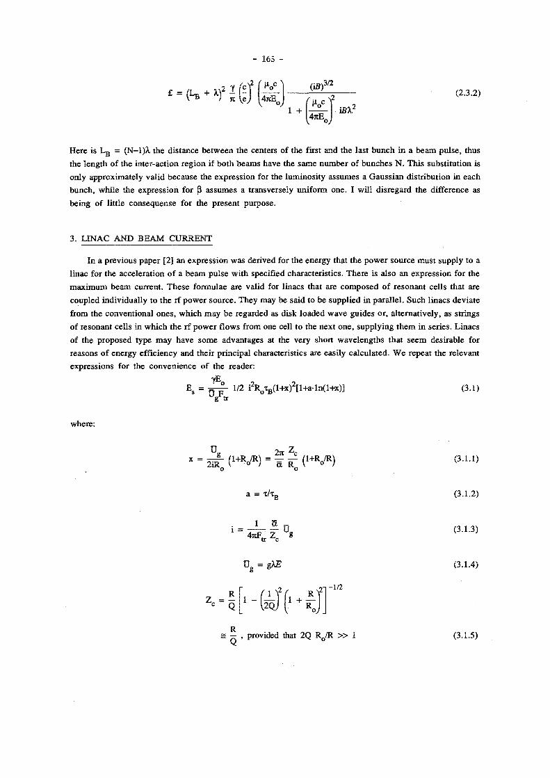
- 165 -
£ = = ( L B + *r -2 T c
n Ve 4TCE„
(ifi) 3/2
(2.3.2)
1 + 4nE.
Here is Lg = ( N - l ) X the d is tance be tween the centers of the first and the last b u n c h in a b e a m p u l s e , thus
the l eng th of the in ter-act ion r eg ion if b o t h b e a m s have the s ame n u m b e r of b u n c h e s N . Th i s subst i tu t ion is
only approximate ly va l id because the express ion for the luminos i ty assumes a Gauss i an d is t r ibut ion in each
bunch , wh i l e the express ion for ß a s sumes a t ransversely uni form one . I wil l d i s regard the difference as
be ing of lit t le consequense for the p resen t purpose .
3 . L I N A C A N D B E A M C U R R E N T
I n a p rev ious pape r [ 2 ] an express ion was der ived for the energy that the p o w e r source mus t supply to a
l inac for the accelerat ion of a b e a m pu l se wi th specified character is t ics . The re is a l so an express ion for t he
m a x i m u m b e a m current . T h e s e formulae are val id for l inacs that are c o m p o s e d of r e sonan t cel ls that are
coupled individual ly t o the rf p o w e r source . They may be said to be suppl ied in para l l e l . Such l inacs devia te
from the convent iona l ones , wh ich m a y b e regarded as disk loaded w a v e gu ides or , a l ternat ively , as s tr ings
of resonant cells in wh ich the rf p o w e r flows from one cell to the next one , supply ing t h e m in ser ies . Linacs
of the p roposed type m a y have some advantages at the very short wave leng ths that s e e m desirable for
reasons of energy efficiency and the i r pr inc ipa l characterist ics are easi ly ca lcula ted . W e repeat the re levant
express ions for the conven ience of the reader :
yE
E s = = - ^ - 1/2 i 2 R 0 x B ( l + x ) 2 [ l + a l n ( l + x ) ] (3.1) g tr
where :
O. x = - I f - ( 1 + R / R ) = = ( 1 + R / R )
2iR„ \ ° I R R„ v o I (3.1.1)
a = (3.1.2)
4 * F t r Z c 8
(3.1.3)
O g = gÀE (3.1 .4)
V*'
°J J
-1/2
= — . provided that 2 Q RQ/R » 1 (3.1.5)
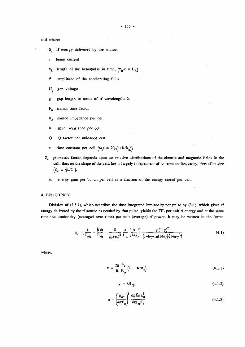
- 166 -
a n d w h e r e :
E g rf ene rgy del ivered by the source ,
i b e a m c u r r e n t
Tg l e n g t h o f the beampu l se i n t i m e , ^ x ß c = L g )
E ampl i tude of the accelera t ing field
U g a p vo l tage
g g a p l eng th in t e rms of rf wave leng ths X
F t t t ransi t t ime factor
R Q source impedance pe r cell
R shunt res is tance per cel l
Q Q factor per un loaded cell
% t i m e cons tant per cel l (<orT = 2Q/(1+R/R Q ) )
Z c geomet r i c factor, depends u p o n the re la t ive d is t r ibut ions of the e lectr ic and magne t i c fields in the
cel l , t hus on the shape of the cell , but is l a rge ly independen t of i ts resonant f requency, thus of i ts s ize
(zc = VL/C ).
5c ene rgy ga in per b u n c h per cell as a fraction of the energy stored p e r cel l .
4 . E F F I C I E N C Y
Divis ion of (2 .3 .1) , wh ich descr ibes the t ime in tegra ted luminos i ty pe r pu lse by (3 .1) , wh ich g ives rf
ene rgy de l ivered by the rf source as needed by that p u l s e , y ie lds the T I L pe r uni t rf energy and at the same
t ime the luminos i ty (averaged over t ime) per uni t (average) rf power . It m a y be wri t ten in the form:
_ L _ j¿dt _ 8 a ( x f y ( l + y ) 2
L P r fs E r f s u 0 ( e c ) 2 L B U+xJ [ l+b-y- ln( l+x)] - ( l+a-y 3 )
where :
2* £ (4.1.1)
y = 7JLB (4.1.2)
a = 4 n E A
ag£ß4 (4 .1 .3)

- 167 -
b = 2 / 5 (4 .1 .4)
and whe re the pa rame te r s y , a, and b have been in t roduced for reasons of c o n v e n i e n c e . Inspec t ion shows
that T\L is p ropor t iona l wi th a/Lg, and that it can be max imized by p rope r cho ice of x and y .
The oppor tuni t ies for the max imiza t i on of a / L ß are somewha t l imi ted . T h e field E in the cavi t ies is
restr ic ted to n o m o r e than a few G V / m , depend ing on frequency and pu l se leng th , by surface effects at the
cavi ty wal ls (field emis s ion and p h o t o emiss ion , due to synchro t ron l igh t , of e l ec t rons , t he rma l effects d u e
to d iss ipat ion) .
T h e b e a m br igh tness B is res t r ic ted by the source , and can be r educed ser ious ly by t ransverse
wakef ie lds and by non- l inear i t ies in the t ransverse mot ion . As a measure of the dens i ty in four d imens iona l
t ransverse phase space it is expec ted t o depend less on the beam current than the emi t t ance does . T h e va lue
of g/Fjj. de te rmined by the des ign of the l inac , leaves little choice : j t /4.5 á g / F t t < j i /4 for phase advances p e r
cel l be tween (2/3)rc and n , and decreases quickly for smal ler p h a s e advances .
The cavi ty load ing factor ö is l imi ted to pe rhaps 5 < 0.05 ( S L A C n u m b e r ) by cons idera t ions of b e a m
stabili ty (wake fields) and m o m e n t u m spread (constraint imposed by the use rs ) , a l imit that m a y well depend
on bunch l e n g t h A , b e c o m i n g smal le r for shor ter bunches .
T h e length of the in teract ion r eg ion L ß should be chosen as l ong as is still accep tab le to the users , w h o
should be aware that its choice affects the efficiency quadrat ical ly: doub le the source l eng th g ives four t imes
the luminos i ty for the same m o n e y if the efficiency is low, as is l ikely.
T h e efficiency can be m a x i m i z e d for g iven values of a/Lg by p rope r choice of the source impedance R Q
and the wave leng th X, in v iew of (4 .1 .1) and (4.1.2) . Since analyt ic express ions for the m a x i m i z e d
efficiency and the va lues for R Q and X at the m a x i m u m appeared to be inconven ien t w e calculated a n u m b e r
of examples numer ica l ly . Our resul t s are shown in Figs . ( 1- 7 ) . T h e b e a m br igh tness B was chosen as
independent pa ramete r in all cases because w e are least certain about wha t i ts va lue m i g h t be . That is also
the reason for the la rge interval of var ia t ion chosen. It contains the br igh tness that is expec ted for the S L A C
l inear col l ider (B = 3- 1 0 1 0 A / ( r a d - m ) 2 ) . A l though cont inuous curves are shown, on ly the poin ts associa ted
wi th B's wh ich yie ld X = L g / ^ - l j , w i th n b the number of bunches p e r p u l s e , are val id, because the
interact ion region is an in teger n u m b e r of wave lengths long.
Figures ( 1 - 3) represent resul t s obta ined for the parameter set Ë = l G V / m , L ß = lern, 5 = 0 .05 .
Most of them are bounded on the left s ide by the considerat ion that A. < L g ; this condi t ion is violated if B is
chosen too smal l . T h e crucial curve in these graphs is the one for 1/T|¿ (Fig. 1), wh ich describes the rf —20 0 7R
p o w e r required pe r uni t luminos i ty . It behaves approximately as 1/T|¿ = 2.0 10 B , and shows , e.g., that
a facility wi th a luminos i ty of L = 10 3 5 cm~ 2 sec~ ' = 10 3 9 m " 2 s e c - 1 , wou ld requi re a rf p o w e r of 5 0 G W if the
b e a m br ightnesses are B = 1 0 n A / ( r a d - m ) 2 , whi le only 2 7 M W would b e needed if B = 1 0 , 5 A / ( r a d - m ) 2 cou ld
be achieved.
T h e curve labe led l / y j id t ( m " 2 s e c _ 1 ) gives the TIL pe r pulse , it is useful for ca lcula t ing , e.g., the pu lse
repe t ion rate f v ia the relat ion f = L/ÍL dt . It is evident that f decreases wi th increas ing y and increasing B. A
luminosi ty of 1 0 3 5 c m ~ 2 s e c 1 at a final energy of 5.11 T e V (y = 1 0 7 in the case of an e + - e" coll ider) in each

- 168 -
b e a m , w o u l d d e m a n d f = 1 0 3 9 / ( 1 0 7 - 4 - 1 0 2 6 ) = 250 k H z at B = 1 0 H A / ( r a d - m ) 2 , whi le f = 20 k H z w o u l d b e
adequa te at B = 1 0 1 5 A / ( r a d - m ) 2 . W e note that S L A C ' s S L C is expec ted to opera te at B = 2 . 5 - 1 0 1 0 A / ( r a d - m ) 2
and f = 180 H z .
P s ( M W ) represents the rf p o w e r dur ing the pu l se .
T s (psec) is the pu lse length of the rf source , as seen from a s ingle cell , whi le t ß (psec) is t he l eng th of
the b e a m pu l se , T ß = L ß / c ; t s - T B is the filling t ime for that cel l . At least one p o w e r source mus t be act ive
as long as the pu lse is still in the l inac , thus the rf energy de l ivered per pu l se is at least E g = P^ j / iE-F ),
whe re Ef is the final energy in eV.
X < L g (cm) is the wave leng th of the rf.
F igure 2 g ives the behav iour of the b e a m current I b , averaged over the pu l se , and that of its invar iant
emi t t ance e. A l s o shown are the beam radius a ^ y in the cross ing poin ts and the va lue of ß that mus t b e
p roduced by the final focusing system in order to es tab l i sh the ma tched condi t ion on which this d i scuss ion is
based.
F igu re 3 g ives the beta t ron phase advance A y b e t w e e n two success ive crossing po in t s and r j ^ a
pa rame te r that indicates wha t fraction of the incident rf ene rgy ends up in the b e a m (the remainder , I - T J ^ , is
e i ther reflected back towards the p o w e r source or d iss ipa ted) . N o t e that this figure is l inear in the A y and T ) R F
axes .
F igure 4 shows the behaviour of l / t j ¿ as a funct ion of X for f ixed B, Lg , 5 and E. X is chosen and the
source i m p e d a n c e is adjusted for a m i n i m u m in l / r ) ¿ . It m a y b e seen that devia t ions of X w i th in a factor of
two f rom the o p t i m u m value causes deter iora t ion of \lf\L by factors larger than three. It is thus impor tan t
that X be chosen correct ly , if at all poss ib le . However , the shape of this curve m a y depend on the choice of
the pa rame te r s B, Lg , 5 and E, and the sensit ivi ty to dev ia t ions of X from its op t imum may b e different. T h e
pa ramete r s for the curve shown are:
B = 1 0 1 6 A / ( r a d - m ) 2 , L ß = lern, ä = 0.05, Ë = lGV/m.
Figures ( 5— 7) show h o w l/r\L, 1/yfLdt, P s , x g and X r e spond to changes in the choice of pa ramete r s . T h e y
only i l lustrate what can be seen from ( 4 . 1 ) : r educ t ions i n fi, £ and L g all lead to increases in the p o w e r
needed for a specified luminosi ty . In par t icular : a reduct ion of Lg , the length of the interact ion region from
l c m to 1 m m is only poss ible (in this m o d e of opera t ion) if a br ightness of at least 1-10 A/ ( rad-m) is
avai lable ; for that br ightness 1/T) ¿ = 2.7-10 2 9 W m 2 s e c , whi le it is 1/T|¿ = 1 . 1 1 0 " 3 0 W m 2 s e c for the s ame
br igh tness and Lg = l c m , a factor 25 bet ter . No te that the o p t i m u m wavelength increases a l i t t le , from X = 0.
7 2 m m for L g = l c m to X - 1mm for L g - 1mm.
5. T R A N S V E R S E M O T I O N
The p rev ious discussion is based on the assumpt ion that the two par t ic ipat ing beams m o v e in opposi te
d i rect ions a long a c o m m o n axis . In prac t ice , each b e a m starts from a source and is gu ided towards the
in teract ion reg ion by a t ransverse focusing sys tem which is incorporated in each l inac and in each b e a m
transport sys tem. Steering e lements are p rov ided to p lace and direct the b e a m as desired at par t icular

- 169 -
locations, e.g., in the interaction area. There, the distance between the two beams must be small compared to
the smallest beam radius, e.g., 0.1 p , and their axes may not deviate from parallelness by more than a small
fraction of the half angular spread in each beam, e.g., 0.1 p ' . The coordinates of the beam axes will vary
with time in response to, e.g., temporal displacements of the source and of the focusing elements. Servo
systems, that redirect the beams in réponse to measured deviations from target values, can be introduced to
minimize the magnitude of this random motion of the beam axes, but cannot eliminate it because of noise,
timedelays and limited bandwidths in the loops, and the position and direction of each beam axis will still
change from pulse to pulse. The magnitude of this residual motion must be kept within acceptable bounds.
Figure 2 shows that, at y = 10 7 , the beam has a diameter of a half urn or so in the crossing points, even at
the lowest brigthness and also that it decreases with brightness as B~°'5, implying the need of a relative
position control of better than 25nm to 25pm.
We discuss the focusing conditions in linacs and interaction region separately because they are so very
different. The linacs represent systems that stretch over several km ' s each, and the diameter of the beam is
not of much consequence, provided that it fits everywhere inside the available effective aperture. They are
the sources that supply the interaction region with beams and must meet the requirement that the deviations
of the coordinates of each beam axis remain small compared to the beam emittance in xx'yy'-space at the
interfaces with the interaction region. If this region can be kept relatively small in extent, it may be possible
to decouple it from the outside world as a unit. The final focusing systems, which convert the incident
beams to the ones wanted in the interaction region, would be part of that unit.
5 .1. Linac cells as focusing elements
The transverse motion is usually controlled by means of quadrupoles. The high fields and short
wavelengths that characterize the linacs under discussion suggest the use of similar structures as focusing
elements. In the TM01 mode there exists in each linac cell a toroidal transverse magnetic field, that is
independent of the axial position z and that behaves transversely approximately as
B 9 (r) = i £ E Jj(kr) (5.1.1)
k 2 _
ÖB 9/ar = i - £ [ J 0 (kr ) -J 2 (kr ) ] - i — E JQ(kr) - (5.12)
= i Jj- E, provided that kr = 2jtrA, « 1
in the case of a cylindrical pillbox resonator and as k k _
B x (y) = - i - E cos(kx)sin(ky), B y (x) = i - E sin(kx)cox(ky) (5.1.3)
k 2 _ k 2 _ 3B x /3y = - i — E cos(kx)cos(ky), D B ^ x = i — E cos(kx)cos(ky) (5.1.4)
• • • . It - . K _
" - 1 IX E ' ~ l c X E '
* Note added in proof: Seat-ion 5.1 on focusing properties of tinao oeVls is based on an over simplified model. The author has recently become aware of a calculation by D. Neuf fer, FNAL, (private communication) which shows that the fields in the vicinity of the beam passage holes in the resonator walls act to essentially cancel the focusing effect described. This leaves such devices without practical merit for this purpose.

- 170 -
provided that kx = JF^2 X/X, « 1, ky = JC^2 y/A., « 1, in the case o f a pi l lbox resonator of square cross-
section. In these expressions E is , as before, the electric field on the axis , harmonic time dependence with
frequency (Ü/2K, free space wavelength X, and operation at the resonant frequency is understood, i = ^fÄ. . E
and B 6 ( X y differ in phase by n/2 rad, thus the principal difference between accelerating cel ls and focusing
cel ls is the phase with which they are run relative to the beam bunches. The average focusing gradient can
be related to the instantaneous ones g iven, by transit time factors FXJ, 2/JI <FU < 1, which account for the
changes in the cell fields that occur during the time spent by a bunch in a cavity o f finite length.and for the
field distortions that exist in the vicinity of the holes for beam passage in the cavity side walls . Do ing so w e
obtain for the focusing gradient B' = 3B/3r , where r stands for r = ( x 2 + y 2 ) 1 / 2 :
B' = ¿X E F* (5-L5)
Approximating Fa with F^ => sin(7tg)/(rcg), with g defined as before, one finds with E = 1 0 9 V / m , X = 0 .1mm,
g = 0.5: B' = ö ^ l O ^ / m , equivalent to the gradient in a quadrupole with a poletip field o f IT and a throat
circle radius o f 16p.m. One advantage o f a linac section as focusing element is, that it focuses (or defocuses ,
depending on the phase with which it is driven) equally in both transverse d i rec t ions , while a quadrupole
focuses in one , but defocuses in the other. Th is makes the linac section more effective than combinations of
quadrupoles with the same gradient for some application, e.g. the final focus.
5 .2 . Choice of parameters
A discussion of some of the effects of misalignments o f focusing elements in a linac is g iven in
appendix A. It appears that the tolerances on the alignment decrease with increasing beam brightness, and
that they are maximized by us ing all o f the available aperture everywhere. That aperture is a fraction of the
wavelength, 0.25X.-0.2À, or so , depending on the structure; the ( 2 . 5 a ) diameter of the beam can only be a
fraction of that, perhaps 1/3, thus the effective beam radius p can be no more than a few percent of the
wavelength: p = 0.04A.. O n e m a y see from Figs. 1 and 2, that the behaviour of X and of e as functions of
B m a y be crudely approximated by:
X « 2 6 . 0 2 Ä - 0 - 3 4 , s » 6 3 8 . 7 B - 0 - 6 7 (5 .2 .1)
for Lg = l e m , & = 0 .05, Ë = l G V / m . It fo l lows, that the ß wanted at the exi t o f the linac is practically
independent of B and proportional to f.
ß = YP 2/£ » 0.0004Y, if p = 0.02A. (5 .2 .2)
so that ß = 4 0 0 0 m at y = 1 0 7 . This ß must be matched to the ß ^ in the interaction region, 1/4A upstream of
the first crossing point, which behaves approximately as :
ßmn ~ 6 . 6 8 I B " 0 3 3 (5 .2 .3)
as shown by Fig. 1 3 . The final foci must therefore h a v e transfer functions with linear (de)magnif ica t ion
factors of ( ß / ß m n ) S / 2 = 2 4 ß 1 / 6 , e.g., about 940 atB= 1 0 1 0 A / ( r a d - m ) 2 and about 8400 at B = 1 0 1 6 A / ( r a d - m ) 2 .
This is achieved if they have transfer matrices of the form

- 171 -
lMLac-*IR = 0 W ß )
o
1/2
:-»IR ( M )
1/2
1/2
1 / (24Ä 1 / 6 )
0
- ( ß / ß m „ ) 1 / 2 0 - 1 / ( 0 . 0 0 2 7 J B ~ ° 3 3 )
24Ä 1/6
0.0027y£
0
-0.33
(5 .2 .4)
(5 .2 .5)
Numer i ca l ly w e ob ta in for y = 1 0 7 and B = 1 0 1 0 A / ( r a d - m ) 2 :
Mlinac-:-»ÏR
1/967
0
0
9 6 7 or Mjinac-:-»IR
0 3.30
-1 /3 .30 0
and for y = 1 0 7 and B = 1 0 1 6 A / ( r a d - m ) 2 :
Mlinac--»nt
1/8600
0
0
8600 N U . :-»IR
0 0.33
-1 /0 .33 0
The anti diagonal matrix can be realized with a single triplet of thick quadrupoles and also with a l inac
section/The magnitude of the m 1 2 e lement is restricted by the available focusing gradient, which limits the
achievable demagnification. Nearly arbitrarily large demagnification factors can be obtained from more
complex systems. They might have a diagonal transfer matrix and their lengths would increase with
decreas ing available gradient. This would affect their sensitivity for misalignments unfavourably; it fo l lows
that h igh gradients are desirable.
REFERENCES
[1] B . W. Montague, CLIC Notes 11, 17, CERN, January, M a r c h 1986
[2] J. Claus, "Energy Efficiency and Choice of Pa rame te r s for Linear Colliders," paper presented at the "Seminar on N e w Techniques for Future Accelerators," Erice, Sici ly, Italy, May 11-17, 1986, Proceedings to be published in the "Ettore Majorana International Science Series," by Plenum Press, N e w York, September 1987
[3] B . W . Montague, "Self-focusing multi bunch crossings," unpublished paper presented at the Conference on "Critical Issues in the Development of N e w Linear Colliders," Madison, Wisconsin, August 2 7 - 2 9 , 1986
[4] R. B . Palmer, SLAC-PUB-3688 , M a y 1985

( r a d - m )
5 ( A / ( r a d - m ) 2 )
Fig. 2 e, O>/Y, I b and ß m n as functions of B for optimized values of X and R 0 .
E = 109V/m, Lg = lcm, ä = 0.05

Fig. 3 Ay and tl r f as functions of B for optimized values of X and RQ. Fig. 4 llr\L = f(X) for B = 1016A/(rad-m)2, RQ optimized.
E = 109V/m, Lg = lcm, a = 0.05

Fig. 5 l/n„ l lük, K P.. t . and t B as functions of B lot optimized values of X. and R . , i 8 * X ' * B Fig. 6 llr\L, ^ jidt, X, P8, T, and t B as functions o f B for optimized values of X and R 0 .
2 = lO'v/m, L g = O J x m , S = 0.05 E = 258V/m, L B = 1cm, S = 0.05 „ 9

- 175 -
(W m 2 sac î
I Q " 2 6 ,
fit A / ( r a d - m ) 2 )
Fig. 7 1IT\L, ^ {tdt, X, Ps, TS and t B as functions of B for optimized values of X and R 0 .
E = 10 9V/m, L B = lcm, 5 = 0JM

- 176 -
A p p e n d i x A
M I S A L I G N M E N T S IN L I N A C
W e cons ide r some of the consequences of mi sa l ignmen t s of the quadrupoles of a l inac . W e t reat the
quad rupo le s as thin l enses , and a s sume that there is n o coupl ing be tween the two or thogonal c o m p o n e n t s
("hor izonta l" and "vert ical" or "x" and "y") of the t ransverse mot ion . The quadrupoles are d i sposed and
exc i ted to form a per iodic focusing sys tem, h o w e v e r , the constants of that sys tem m a y change g radua l ly , i.e.,
ad iabat ica l ly , a long the length of the l inac. T h e half cell l eng th /, the inverse focal l eng th q of t he
quad rupo l e s , the be ta t ron phase advance per cel l A y and the ampl i tude functions ß f and ß d in the focus ing
and defocus ing quadrupoles of a convent iona l F O D O latt ice are related accord ing to :
sin(A\|//2) = sn - / q / 2 ( A . l a )
/ (I + snY / 2
a I (I - snV / 2
T h e d isp lacement of a quadrupole wi th inverse focal length q over a d is tance x from its re ference
pos i t ion is equivalent to the in t roduct ion of a d ipole momen t qx and causes an addi t ional def lect ion x ' = qx
in the trajectories of all par t ic les . It is conven ien t to descr ibe this deflect ion in a p h a s e space in w h i c h
d i sp lacements and deflect ions are t rea ted equal ly and independent of energy: t\ = x - ( y / ß ) 1 / 2 , i;' = x ' - ( y ß ) 1 / 2 ,
wi th ß the local ampl i tude function; in this sys t em coordinate pai rs for any par t ic le fall on a c i rcle
wi th rad ius £ 1 / 2 , wi th £ the invariant emi t t ance of the par t ic le , if the mot ion is l inear . Us ing the p rev ious
express ions , we obtain for in t e rms of the emi t t ance radius:
2 Ax A ^ s n V " m = 2 A x ( A . 2 )
where p = ( e ß j / g ) 1 / 2 is the (local) half b e a m wid th , wi th £ the emi t tance , and where subscr ipts f and d refer
to focusing and defocusing quads . T h e errors appear at the exit of the l inac rotated by the their appropr ia te
phase advances and contr ibute amounts ^'sinvj/ and i ; ' cosy to the errors in pos i t ion and di rec t ion at that
po in t . The s u m of all quadrupole misa l ignment er rors is therefore: S = 2 £ ' k s i n y k , S ' = X ^ c o s y ^ . T h e
are r a n d o m var iables , because their or ig ins , the x k , are so , y = kAy/2 , with k the n u m b e r of half cel ls to the
l inac exit .
It m a y be seen, that for fixed x, the cont r ibu t ion to the error decreases with increas ing b e a m half wid th
p and wi th decreas ing phase advance A y . T h e m a x i m u m poss ible va lue for p is res t r ic ted to a smal l fraction
of the operat ing wave leng th of the l inac by its phys ica l structure, and is constant th roughout its l eng th . The
avai lable aperture is fully exploi ted if the b e a m wid th matches it everywhere . This can be done by k e e p i n g
ß/y constant , thus , at constant A y , by mak ing the half cell length / p r o p o n i o n a l to the average energy in that
cel l . / wi l l increase along the length of the l inac in consequence , and the energy gain per cell wi th it. It
fol lows that the total energy gain increases exponen t ia l ly wi th the number of cel ls , this can be used to
de te rmine the number of half cells n in the mach ine : n = C ln^y f i n /y i n ) , where C is a constant of in tegra t ion,
de te rmined by the required focusing s t rength, y f i n is the final energy and y i n the inject ion energy . T h e va lue
of C m a y be calculated as fol lows. The ene rgy gain in the k * half cell is:

- 177 -
A E k = (Y k - Y k _ i ) E 0 = Y ^ C e x p C l / c H ) =
where ¥^ß represents the net accelerating gradient. For / k one m a y write:
lk = p\_!snV[(l - snyXl + sn)] = T ^ l P "WK 1 - sn)/(l + sn)]/e,
if one assumes that the change in ene rgy in a half cel l may be d i s regarded in compa r i son wi th the average
energy: ( Y k _ i - Y k ) « (Y k _i+Y k)- Th i s yields an express ion for C :
C = 1/ln ( P2 V A - snV / 2l
1 + — -Tr- sn (A .3a ) v £ E 0 [l + sn) )
£ E 0 1 (1 + snY / 2 .t p 2 V (1 - s n \ m
%
= - r —•= — - , if — —— sn « 1 (A. 3b)
p2 F^E sn 11 - sn) £ E 0 1,1 + s n j
The approximat ion appears to b e acceptable for the cases unde r d i scuss ion he re . W i t h C ava i lab le , the
n u m b e r of half ce l ls , thus the n u m b e r of quadrupo les , can b e ca lcu la ted and es t imates of the er ror
expecta t ions due to quad rupo le misa l ignmen t s be m a d e . A s s u m i n g that the e r rors x are uncor re la ted and
have equal rms va lues A x ^ , we obta in:
U = ( l { ^ k s i n V k ) 2 ) 1 / 2 = ( I ( ^ k s i n v k ) 2 ) 1 / 2 (A.4)
This y ie lds after some manipu la t ion :
^rms A x . = 2
£ % 1 (1 + sn) 1/2 p [ p2 F^E sn ( 1 _ s n )
3/2 I n YfinT
1/2 (A .5)
This form can be m i n i m i z e d by choos ing sn = (-\/3-l)/2 = 0 .3660, i .e. , by c h o o s i n g the phase advance per
cel l A\|/ = 43°; the m i n i m u m is not very cri t ical however , choos ing A y = 9 9 " ins tead of 43° increases f j j ^
wi th a factor 1.35. It is also ev ident that most of the damage is done at l ow ene rgy , increas ing the final
energy by a factor 10 increases ^ r m s only wi th a factor 1 .517. Subs t i tu t ing some n u m b e r s , w e take
Yfij/Yin = 1 0 4 , sn = 0 .3660 , F & = 2 /3 , E = 1 0 9 V/m and p = 0.02A, and ob ta in :
^rms
T
Ax_ = 1000 (A .6 )
T h e d isp lacement of the b e a m axis as a fraction of the half b e a m wid th and its d i rect ional devia t ion as a
fraction of the ha l f angu la r spread are bo th equal to ÇA/E. It m a y be seen from (5 .2 .1 ) , that , c rude ly speak ing ,
E/A2 is constant ; for the cond i t ions shown: E/A2 = 1. Us ing this w e find
^rms ^ rms Ax„ 1000 0.34 (A.7)

- 178 -
where B is t he b r igh tness of the b e a m , as def ined ear l ier . Fo r a j i t ter in the coord ina tes of the axis of
Ç /Vë < 0 . 1 , < 0 . 0 0 2 6 5 " 0 3 4 has to be rea l ized , thus < l.u.m at B = 1 0 1 0 A / ( r a d - m ) 2 , and A ^ =
9 n m at B = 1 0 , 6 A / ( r a d - m ) 2 .
A l inac cou ld also be focused by l inac sec t ions as desc r ibed in Sect ion 5.2. A s imilar ca lcu la t ion for
tha t case y ie lds :
sn = s in(Ay) = 0.5>//q (A.8)
2sn( l - s n 2 ) 1/2 ( A . 9 )
C = 1/ln l+2sn ( l - s n 2 ) — eE„
2f> V sn( l - sn2) 1/2
(A. 10)
eE„
2 P V sn( l - s n 2 ) 1 / 2 Yin
(A .11)
rms ^ rms ^Sms £E„ sn
P V ( l - s n 2 ) 3/2
In Yfin
1/2
(A. 12)
N o w it s eems best to choose sn , thus the p h a s e advance pe r cel l smal l . It cannot be chosen arbi t rar i ly smal l
howeve r , because ß mus t h a v e a p rede te rmined va lue : ß = p 2 e / y , w e d o not deve lop this subject any further
he re . A n o t h e r mat te r is , that the choice of a fixed phase advance per cel l c o m b i n e d wi th a var iab le cel l
length , w a s arbi t rary: a fixed cell length and a va r iab le p h a s e advance seems equal ly poss ib le a n d m a y be
advan tageous .

- 179 -
A p p e n d i x B
F I N A L F O C U S
Cons ide r a final focusing sys tem wi th t ransfer ma t r ix (for the x coordina te) : |Mj = ^ j r e la t ive to
its ax is . T h e sys t em m a y consis t of severa l lenses and drift spaces , but is regarded as a s ing le , r ig id dev i ce ,
tha t m a y b e t ransverse ly misa l igned re la t ive to some ex te rna l reference sys tem. Its axis is s t ra ight , and the
d i s t ance be tween en t rance and exit p l anes , measu red a long that axis , is D. Le t this sys tem axis b e mi sa l i gned
by 2jg and , re la t ive to the re ference , in the en t r ance p l ane . Its coord ina tes ( ^ , ^ ' i ) e x in the exi t p l ane are
then : | | , | = ^ | | , . T h e coord ina tes ( x , x ' ) e Q of a s ample par t ic le , re la t ive to the reference at the sy s t em
e n t r a n c e f a r e t ransformed to (x,x') at its exi t acco rd ing to :
\t - u a ti. * u n IL It fo l lows that the misa l ignment changes the coord ina te s of the b e a m axis by
at the exi t of the sys tem. It is ev ident that the axis m o v e s as m u c h as the sys tem does in cases of sy s t em
t rans la t ion (!;' = 0), and that it is ro ta ted in addi t ion .
T h e r e are t w o , p re sumab ly ident ical , such final foci in a l inear col l ider , one for each b e a m . E a c h of
t h e m affects its associa ted b e a m in the m a n n e r descr ibed above , a l though it has to b e kep t in mind , that
t r ansverse d i sp lacements are coun ted pos i t ive in oppos i t e direct ions for beams that m o v e in oppos i t e
d i rec t ions . T h e changes in d is tance 8x and angle Sx ' be tween the two b e a m s in r e sponse to changes in t he
coord ina tes of the final foci are therefore:
whe re subscr ipts j and r label the left hand and r ight hand sides of the cross ing point . T h e misa l ignmen t s
(i;>C')en a re l ikely to be uncorre la ted r a n d o m var iab les if the two final foci are phys ica l ly separa te uni t s and
the s tandard devia t ions of the differences in the coord ina tes of the beamaxes §x, 5x ' , Sy and Sy' wi l l b e
cont ro l led by the s tandard deviat ions in the mi sa l i gnmen t s : fy¡2, r\^2 and T]'^2. This changes if they can
b e in tegra ted into a s ingle phys ica l uni t . Express ing £j and Ç'j f as t ransla t ions and rota t ions £ and of that
c o m b i n e d unit w e obtain:

- 180 -
Ç, = Ç + DÇ'
%, = - % +
In terms of these new variables the relative misalignment of the be am axes becomes:
D—R DC'
L 1
(B.4)
8x
Sx' (B.5)
It may be seen, that the beam misalignment is primarily affected by rotations of the final focusing system, and that it is important to keep it short, i.e., D small, to minimize the sensitivity to such rotations.
A similar calculation for a final focus with a transfer matrix of the form
Sx x a j + x a ,
Sx' xa'j+xa'j
1+A
0 1+1/A
1+A D
0 1+1/A
M = [{
DC"
0
I/A| Y I yielded:
(B.6)
so that:
Sx 1 D =
Sx* 0 1/A 0 (B.7)
which emphasizes again the importance of keeping the length D and the angular misalignment t,' small.

- 181 -
DISTORTION OF A SHORT RF PULSE
IN TRAVELLING-WAVE ACCELERATING STRUCTURES
G. Geschonke
CERN, Geneva, Switzerland
ABSTRACT
Travelling-wave accelerating structures for high-energy linear
colliders necessitate very short RF pulses. The effect of
the structure's dispersion properties on the travelling RF
waves is analysed using Fourier analysis. 1 . INTRODUCTION
For linear e + e - colliders in the TeV range the use of travelling-wave radio-
frequency accelerating structures has been proposed [ 1 - 3 ] . Since high beam
power is required in these schemes in order to reach a luminosity of at least 3 3 2 1
1 0 cm" s , a good efficiency of power transfer from the RF generating devices
to the beam is important.
In existing linacs the RF attenuation per section length has usually been
chosen so as to minimize the necessary peak power. In the high-energy regime,
however, a compromise has to be made between peak power and average efficiency.
Since the particles are injected once the structures are filled with RF
energy, the RF pulse length has to be at least one filling time t. For high
average efficiency the power dissipation during the fill time has to be small.
In Ref. [ 3 ] an attenuation coefficient (for stored energy) per section length of
a = 0 . 5 is suggested rather than the classical one of a - 2 . 5 . (a = t o « T / Q with
a) = 2 «n'frequency, 1 = structure filling time, Q = quality factor). This leads
to RF pulse lengths of only several hundred RF cycles if structure parameters
scaled from the SLAC design are taken. The relative width Af/f of the passband
of accelerating waveguides ranges from a few per cent for SLAC-type disc-loaded
circular waveguides [ 4 , 5 ] to 3 0 - 4 0 % for crossbar and ladder-type structures [ 6 ] .
These and the dispersion characteristics of the accelerating waveguide can lead to
a deformation of the wave travelling down the structure and hence a reduction of
efficiency. These effects were studied numerically using Fourier analysis. All
examples have been calculated for constant impedance structures.
2 . FORMALISM USED IN COMPUTER CODE
The wave train distortion has been studied by Fourier analysis. The fre
quency spectrum of the RF pulse is calculated and each frequency component within
the structure bandwidth is delayed by a certain phase shift <j> according to the
dispersion characteristics of the structure before the pulse is reconstructed in
time domain.

- 182 -
2 . 1 F o u r i e r a n a l y s i s
The RF p u l s e i s a s s u m e d t o b e a c o s s i g n a l o f N c y c l e s a t f r e q u e n c y wg/2 x
e x t e n d i n g from t i m e - T / 2 t o + T / 2 .
E 0 ' C O S ü ) 0 t f o r l t l < T / 2 E ( t ) = { 1 1
e l s e w h e r e .
The F o u r i e r s p e c t r u m of s u c h a s i g n a l i s g i v e n by
c , . ñl~ r- s i n ( g i 0 - ü ) ) T / 2 E(w) = / 2 / n • E o •
2 . 2 D i s p e r s i o n o f t h e a c c e l e r a t i n g w a v e g u i d e
The d i s p e r s i o n r e l a t i o n o f t h e a c c e l e r a t i n g s t r u c t u r e i s a p p r o x i m a t e d by a
c o s f u n c t i o n a s shown i n F i g . 1 .
F i g . 1 D i s p e r s i o n of a c c e l e r a t i n g
w a v e g u i d e TT kL
u ( k ) = C O S <j> + ( l ) m
w h e r e
k =
L =
u = m B r
kL
2 V X, X = w a v e l e n g t h i n s t r u c t u r e
c e l l l e n g t h
m i d - b a n d f r e q u e n c y
b a n d w i d t h
The d e s i g n p h a s e s h i f t p e r c e l l o f t h e s t r u c t u r e w h e r e t h e p h a s e v e l o c i t y
Vp = ur j /k e q u a l s t h e s p e e d of l i g h t c a t t h e o p e r a t i n g f r e q u e n c y U Q , c a n be
c h o s e n f r e e l y .
2 . 3 R e c o n s t r u c t i o n o f RF p u l s e i n w a v e g u i d e
F o r t h e r e c o n s t r u c t i o n i n t i m e d o m a i n of t h e p r o p a g a t i n g wave from i t s s p e c
t r a l c o m p o n e n t s o n l y t h e f r e q u e n c y c o m p o n e n t s i n s i d e t h e s t r u c t u r e ' s b a n d w i d t h a r e
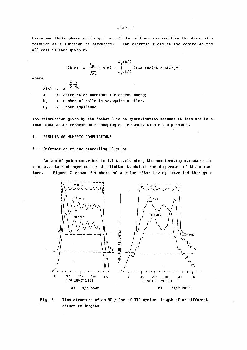
- 183 - '
taken and t h e i r phase s h i f t s ij> from c e l l to c e l l a r e d e r i v e d from the d i s p e r s i o n
r e l a t i o n as a f u n c t i o n of f r equency . The e l e c t r i c f i e l d in the cen t r e o f the
n t h c e l l i s then g i v e n by
u m+B / 2
E ( t , n ) = — • A(n ) • / E(u) c o s ( w t - n •*( o>) )da>
•T; <VB/2
where a n
A(n) = 6 * * 8
ot = a t t e n u a t i o n cons tant f o r s t o r e d energy
N g = number o f c e l l s i n waveguide s e c t i o n
E Q = i n p u t a m p l i t u d e
The a t t e n u a t i o n g i v e n by the f a c t o r A i s an approx imat ion because i t does not t a k e
i n t o account the dependence of damping on f requency w i t h i n the pas sband .
3 . RESULTS OF NUMERIC COMPUTATIONS
3.1 De format ion o f the t r a v e l l i n g RF p u l s e
As the RF p u l s e d e s c r i b e d i n 2.1 t r a v e l s a long the a c c e l e r a t i n g s t r u c t u r e i t s
time s t r u c t u r e changes due to the l i m i t e d bandwidth and d i s p e r s i o n o f the s t r u c
t u r e . F i g u r e 2 shows the shape of a p u l s e a f t e r hav ing t r a v e l l e d through a
F i g . 2 Time s t r u c t u r e o f an RF p u l s e o f 330 c y c l e s ' l e n g t h a f t e r d i f f e r e n t
s t r u c t u r e l e n g t h s

- 184 -
structure with a relative bandwidth referred to midband frequency of 655. The RF
pulse length is 330 cycles, which corresponds to an attenuation constant of
a = 0.5 and a structure Q of 4147 at 29 GHz. The different graphs show various
structure lengths from 0 to 100 cells ; For the top curve the bandwidth of the sig
nal was already clipped to 6%. The square-shaped input pulse is shown as a dot
ted line.
Figure 2a) shows the case of a structure with a it/2 phase shift per cell,
Fig. 2b) that of 2it/3. In Fig. 3a and 3b) the corresponding frequency spectra of
the pulse within the passbands are shown.
BANDWIDTH: 0.06 RF CYCLES:3 3 0 M0DE:TT/2
BANDWIDTH: 0.0 6 RF CYCLES: 3 3 0 MODE-. 2 T T / 3
a) it/2-mode b) 2it/3-mode
Fig. 3 Fourier spectrum within structure passband
Figure 4 shows the variation of pulse width at design field between the
rising and the falling edge with structure length for different bandwidths and
3 3 0 -
320
310
300-
2 9 0 -
2 8 0 -
2 70
2 6 0
2 50-
2 4 0 -
2 30
2 20 Fig. 4 Width of an RF pulse of 330
cycles as a function of structure length
B A N D W I D T H MODE [TT]
1 0,510 1/2 2 0,510 2/3 3 0,254 1/2 4 0,254 2 / 3 5 0,128 1/2 6 0,128 2 / 3 7 0,06 1/2 8 0,06 2/3 9 0,03 1/2
1 0 0,03 2 / 3
10'
0 100 200 300 400 500 C E L L S
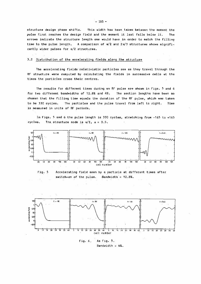
- 185 -
s t r u c t u r e d e s i gn phase s h i f t s . Th i s width has been taken between the moment the
p u l s e f i r s t r e aches the d e s i gn f i e l d and the moment i t l a s t f a l l s be low i t . The
a r rows i n d i c a t e the s t r u c t u r e l e n g t h one would have in o rde r to match the f i l l i n g
time to the p u l s e l e n g t h . A comparison of it/2 and 2it/3 s t r u c t u r e s shows s i g n i f i
c a n t l y w ide r p u l s e s f o r it/2 s t r u c t u r e s .
3.2 D i s t r i b u t i o n o f the a c c e l e r a t i n g f i e l d s a l ong the s t r u c t u r e
The a c c e l e r a t i n g f i e l d s r e l a t i v i s t i c p a r t i c l e s see as they t r a v e l through the
RF s t r u c t u r e were computed by c a l c u l a t i n g the f i e l d s in s u c c e s s i v e c e l l s at the
t imes the p a r t i c l e s c r o s s t h e i r c e n t r e s .
The r e s u l t s for d i f f e r e n t t imes dur ing an RF p u l s e a r e shown in F i g s . 5 and 6
f o r two d i f f e r e n t bandwidths of 12.8% and 4 S . The s e c t i o n l e n g t h s have been so
chosen that the f i l l i n g t ime equa l s the d u r a t i o n of the RF p u l s e , which was taken
to be 330 c y c l e s . The p a r t i c l e s and the p u l s e t r a v e l from l e f t to r i g h t . Time
i s measured in u n i t s o f RF p e r i o d s .
In F i g s . 5 and 6 the p u l s e l eng th i s 330 c y c l e s , s t r e t c h i n g from -165 to +165
c y c l e s . The s t r u c t u r e mode i s n/2, oc = 0 . 5 .
20 40 60 SO 100 . 120 20 10 60 80 100 120 2 0 40 60 80 100 120 20 40 60 80 100 120
c e l l n u m b e r
F i g . 5 A c c e l e r a t i n g f i e l d seen by a p a r t i c l e at d i f f e r e n t t imes a f t e r
s w i t c h - o n of the p u l s e . Bandwidth = 12 .8 % .
f = - 8 0 t = 80 f = 1 6 5 t = 3 4 0
1 1 i i i i i
125
1.
025 ai
§ 0. - O Í S
5 10 15 20 25 30 35 40 5 10 15 20 25 30 35 40 5 10 15 20 25 30 35 40 5 10 15 20 25 30 35 40 c e l l n u m b e r
F i g . 6 . As F i g . 5 .
Bandwidth = 4%.

- 186 -
3 . 3 Energy gain of particles
The t o t a l e n e r g y g a i n per section l e n g t h i s shown a s a f u n c t i o n o f i n p u t
phase f o r s t r u c t u r e s w i t h d i f f e r e n t b a n d w i d t h s and a d e s i g n p h a s e s h i f t o f T/2 i n
F i g . 7 a ) and o f 2 n / 3 i n F i g . 7 b ) . The d o t t e d l i n e g i v e s t h e t h e o r e t i c a l e n e r g y
g a i n i f t h e RF wave had t h e d e s i g n a m p l i t u d e i n a l l cells ( a t t e n u a t i o n b e i n g t a k e n
i n t o a c c o u n t ) . The p a r t i c l e s a r e i n j e c t e d after t h e f i l l i n g t i m e x.
- 5 0 - 4 0 -30 - 2 0 -10 0 10 20 30 40 50 I N P U T P H A S E [ D E G ]
a ) i t / 2 - m o d e
>-ID a.
-50 - 40 -30 -20 -10 0 10 20 30 4 0 50 I N P U T P H A S E [ D E G ]
b) 2 n/3-mode
F i g . 7 Energy g a i n i n one s e c t i o n f o r an a m p l i t u d e o f t h e i n p u t RF p u l s e o f 1 ,
s o t h a t t h e e n e r g y g a i n w o u l d be u n i t y per c e l l w i t h an i d e a l p u l s e and
no a t t e n u a t i o n . a - 0 . 5 , p u l s e w i d t h 330 c y c l e s .
F i g u r e 7 s h o w s t h a t 2 * / 3 structures not o n l y g i v e less e n e r g y g a i n but a l s o
i n t r o d u c e a p h a s e s h i f t a s i s a l s o shown i n a d i f f e r e n t analysis u s i n g Laplace t r a n s f o r m a t i o n [7 ] . The r e d u c t i o n AE/E i n e n e r g y g a i n due t o t h e s e e f f e c t s i s
g i v e n i n t h e f o l l o w i n g t a b l e :
2%
R e l a t i v e b a n d w i d t h
455 635 855 1055
AE/E
AE/E
for
for
i t /2 s t r u c t u r e
2n/3 s t r u c t u r e
3%
7 .1Ä
1.255 0.355
4.255 355 1 .855 1.255

- 187 -
Ii. CONCLUSION
These results show that dispersion effects lead to a loss in energy gain of
several per cent. This is particularly pronounced for structures with the
conventional choice of 2it/3 phase shift per cell. The use of accelerating
structures with bandwidths of « 55» for -n/2-mode and « 1055 for 2n/3-mode reduces
this loss considerably. Disk-loaded waveguides with large beam holes - although
with reduced shunt impedance - or other structures such as crossbar, jungle gym,
ladder etc. could be used for this purpose.
* * *
REFERENCES
1 ) A.M. Sessler, Proc. Conf. on Laser Acceleration of Particles, Los Alamos, 1982 (ed. J.D. Channel, AIP Conf. Proc. No. 91 , 1982) , 154.
2) P.B. Wilson, SLAC-PUB-3674 (1985).
3) W. Schnell, CERN-LEP-RF/86-06 (1986) .
4) G.A. Loew et al., in "The Stanford Two Mile Accelerator" (W.A. ßenjamin, New York, 1968).
5) G. Bienvenu et al., Proc. 1984 Linac Conf. (Darmstadt, 1984) , GSI 84-11 , 463.
6) J.P. Boiteux et al. , CERN-LEP-RF/87-25 (1987).
7 ) J.E. Leiss, in "Linear Accelerators", eds. P. Lapostolle and A. Septier (North Holland, 1970) , 147.

- 188 -
STUDIES OF A FREQUENCY SCALED MODEL TRANSFER STRUCTURE
FOR A TWO-STAGE LINEAR COLLIDER
T. Garvey, G. Geschonke, W. Schnell and I. Wilson
CERN, Geneva, Switzerland
ABSTRACT
Results are reported of bench-top measurements of the RF and
electromagnetic properties of a travelling waveguide struc
ture. These measurements are performed with the aim of
assessing the suitability of this device for playing the role
of a transfer structure in a two-stage RF linear collider.
1. INTRODUCTION
In the two-stage RF linear collider proposal of Schnell [1 ] it is envisaged
that the extraction of energy from the low-energy (< 5 GeV), low-frequency drive
beam will be by direct deceleration in an RF structure. This "transfer struc
ture" would essentially consist of small sections of travelling waveguide linking
alternate drive beam accelerating structures and would be coupled to the high
energy (1 TeV) high frequency (29 GHz) linac by short runs of waveguide. Results
are presented here of a dimensionally scaled-up model of a structure which may be
suitable for this purpose. The results presented here were obtained with a 12-
cell model and represent an extension of work previously carried out on a four-
cell device. A preliminary account of this work is given in Ref. [2 ].
2. THE TRANSFER STRUCTURE
Although the structure will be required to be resonant at the same frequency
as the main linac the model structure was machined for 2 GHz nominal operation.
This obviated the need for machining and working with small structures and allowed
us to operate within the frequency range of available sources and detectors. The
device consists of a comb-like structure in rectangular waveguide rather like a
linear magnetron (Fig. 1). The teeth of the comb however do not extend across
the full height of the guide so allowing adjacent eelIs to couple through both
electric and magnetic fields. As the device is desired to operate in the ir/2
mode the cell spacing was set at X/4 (where X is the free space wavelength)
resulting in an overall length of 450 mm. A complete geometrical description of
the structure can be found in Ref. [2 ].
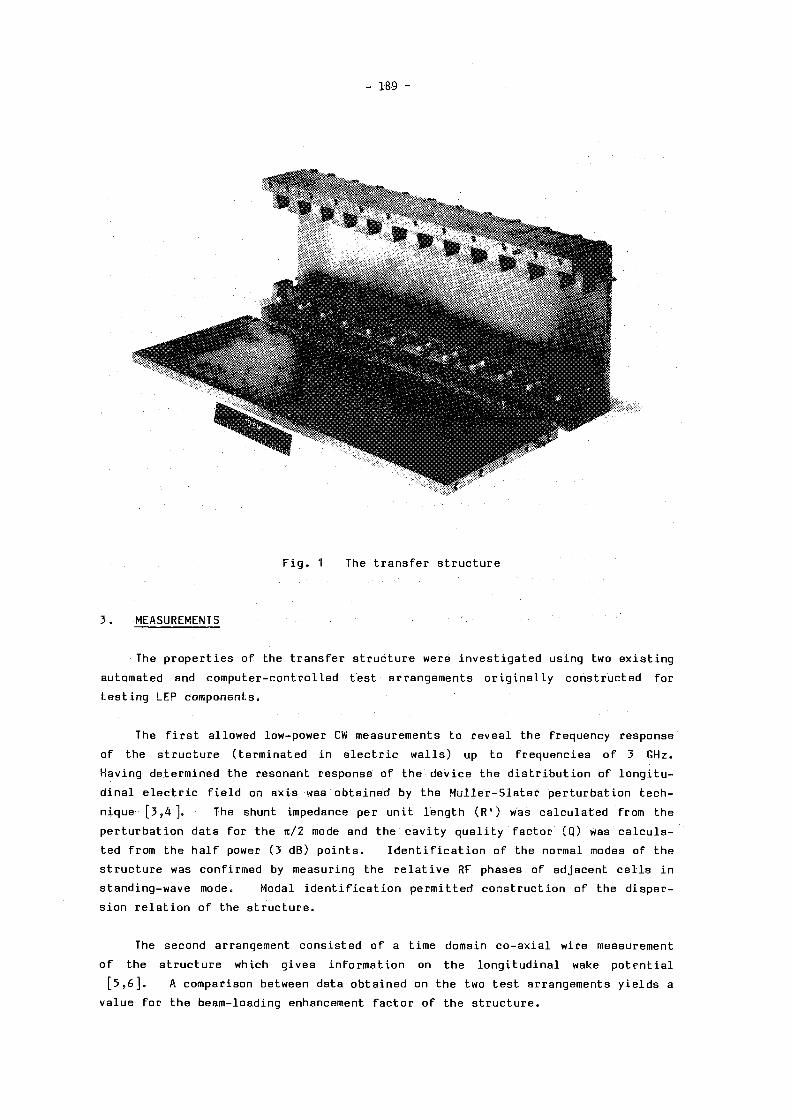
- 189 -
Fig. 1 The t r a n s f e r s t r u c t u r e
3 . MEASUREMENTS
The p r o p e r t i e s of the t r a n s f e r s t r u c t u r e were i n v e s t i g a t e d us ing two existing automated and c o m p u t e r - c o n t r o l l e d t e s t a r rangements o r i g i n a l l y cons t ruc t ed for
testing LEP components.
The first a l l owed low-power CW measurements to r e v e a l the frequency response
of the s t r u c t u r e ( t e rm ina ted in e l e c t r i c walls) up to f r e q u e n c i e s o f 3 GHz.
Having determined the resonant response of the d e v i c e the d i s t r i b u t i o n of l o n g i t u
dinal e l e c t r i c f i e l d on a x i s was o b t a i n e d by the M u l l e r - S l a t e r p e r t u r b a t i o n t e c h
nique [ 3 , 4 ] . The shunt impedance per un i t l e n g t h ( R ' ) was c a l c u l a t e d from the
p e r t u r b a t i o n da ta fo r the i t / 2 mode and the c a v i t y q u a l i t y f a c t o r (Q ) was c a l c u l a
ted from the h a l f power ( 3 dB) p o i n t s . I d e n t i f i c a t i o n of the normal modes of the
s t r u c t u r e was conf i rmed by measuring the r e l a t i v e RF phases of ad jacent cells in
s t a n d i n g - w a v e mode. Modal i d e n t i f i c a t i o n p e r m i t t e d cons t ruc t ion of the dispersion r e l a t i o n o f the s t r u c t u r e .
The second arrangement c o n s i s t e d of a time domain c o - a x i a l w i re measurement
o f the s t r u c t u r e which g i v e s i n f o rmat i on on the l o n g i t u d i n a l wake potential [ 5 , 6 ] . A comparison between data o b t a i n e d on the two t e s t arrangements y i e l d s a
v a l u e f o r the beam- load ing enhancement f a c t o r of the s t r u c t u r e .

- 190 -
4. RESULTS
4.1 CW measurements
The 12-cell structure would normally be expected to exhibit 11 eigen-modes
corresponding to travelling-wave phase shifts of m*/12 (m = 1, 2, 3, ....11) from
cell to cell. Transmission tests, however, revealed a much richer spectrum.
Subsequent perturbation analysis of each resonance in turn indicated that the
resonances could be grouped in pairs which exhibited identical field distribut ions
along the faces of the combs, despite having distinctly different distributions on
axis. These resonance pairs were believed to be due to the normal modes but with
each pair corresponding to a situation in which the opposite combs, considered as
coupled oscillators, resonated either in anti-phase or in phase with respect to
each other. In contrast to the in-phase modes the anti-phase modes have non-zero
magnetic fields on axis and these fields considerably complicate the signals ob
tained during perturbation runs with a metal bead (sensitive to contributions, of
opposing sign, from electric and magnetic fields). In order to avoid the effects
of magnetic fields the perturbation runs were repeated with a dielectric bead
(sensitive only to electric fields) for the perturbing object. For the in-phase
modes the field distribution of the m^h mode has m nulls while the anti-phase
mode has m-1 nulls and all modes were duly identified from the observed distribu
tions.
Another consequence of anti-phase modes is that the on-axis fields are purely
transverse in contrast to the in-phase modes where the on-axis fields are always
longitudinal. This situation was verified by performing perturbation measure
ments with disc- and needle-shaped objects which are sensitive to field polarity.
For some modes coupling to and from the cavity appeared weak and the resul
ting perturbation signals were not clean enough to unequivocally identify a mode.
In this case the variation in phase between adjacent cells confirmed the identity
of the resonance. The resulting dispersion diagram of the transfer structure is
shown in Fig. 2.
Frequency tuning of the structure was carried out by altering the length of
the teeth of the combs. The correct length was obtained empirically on the four-
cell structure and interpolation of the data resulted in the 12-cell device having
an in-phase it/2 mode resonant at 1 .992 GHz.

- 191 -
F r e q u e n c y (GHz) 2 . 2 -•
4 2 4
F i g . 2 D i s p e r s i o n of 1 2 - c e l l t r a n s f e r s t r u c t u r e
( a ) i n - p h a s e mode, ( b ) a n t i - p h a s e mode
In the usua l theory of p e r t u r b a t i o n a metal bead of r a d i u s r l o c a t e d at a
p o i n t in the c a v i t y where the l o c a l e l e c t r i c f i e l d i s E and the magnetic f i e l d i s
ze ro causes a f requency s h i f t , Af', from the unper turbed r e sonant f r equency , f,
where
Af _ « r 3 EQ E 2
f " W
where eg i s the p e r m i t t i v i t y of f r e e space and W i s the ave rage c a v i t y s t o r e d
energy .
Th i s r e s u l t s in a phase s h i f t between g ene r a to r and c a v i t y , A<¡>, g i v e n by
tan A ij) = 2Q Af/f ( 2 )
where Q i s the r e sona to r q u a l i t y f a c t o r for the mode in q u e s t i o n .
The automated equipment used to make the p e r t u r b a t i o n runs i n c o r p o r a t e s a
computer program which per forms a p o i n t - w i s e i n t e g r a t i o n over the measured phase

- 192 -
s h i f t s [7 ] . Th i s i n t e g r a l i s then used to compute the s t and ing -wave impedance of
the r e s o n a t o r ( s u i t a b l y c o r r e c t e d for t r a n s i t t ime e f f e c t s ) .
The s t a n d i n g - w a v e shunt impedance of the u/2 mode was found to be 94 k Q n " 1
(±5SS) and the measured Q was 2860. The l a t t e r was ob ta ined by va ry ing the
e x c i t a t i o n f requency u n t i l the 3 dB p o i n t s were found .
4 .2 Pu l s ed measurements
These measurements were made by sending a s h o r t ( ~ 1 1 0 ps FWHH) e l e c t r o m a g
n e t i c p u l s e down a c o a x i a l w i r e threaded through the t r a n s f e r s t r u c t u r e so s i m u l a
t i n g the pa s s age of a r e l a t i v i s t i c bunch. This i s done for both the s t r u c t u r e
and fo r a r e f e r e n c e l i n e which i s e s s e n t i a l l y a l e n g t h of unloaded waveguide whose
d imensions a r e equa l to those of the s t r u c t u r e in the absence of combs. Tapered
waveguide i s used to match in to and out of the s t r u c t u r e and to p rov ide connec
t i o n s for the c a b l e c a r r y i n g the f a s t p u l s e . In p r i n c i p l e the change in p u l s e
de fo rmat ion between the s t r u c t u r e and the r e f e r e n c e y i e l d s the va lue of the t o t a l
l o n g i t u d i n a l l o s s f a c t o r , k [ 5 , 6 ] . The t r a n s m i t t e d cu r r en t p u l s e s a re fed to a
f a s t r i s i n g sampl ing s cope , a n a l o g - t o - d i g i t a l conve r t ed and the data then s t o r e d
in a desktop computer which c o n t a i n s a program for computing the l o s s f a c t o r [6 ] .
Repeated measurements of the l o s s f a c t o r i n d i c a t e that i t has a va lue o f
< 0.055 V/pC. This co r r e sponds to a l o s s f a c t o r per un i t l e n g t h , k ' , where
k' < 0 .122 V/pCm.
F o l l o w i n g the d e f i n i t i o n of the fundamental l o s s f a c t o r , kg, we have [8 ] ,
u R ' ' , x
k 0 = ( 3 ) 0 4 Q
where u> = 2itf. This y i e l d s ( u s i n g the p e r t u r b a t i o n d a t a ) a va lue of 0.1 V/pCm
fo r the t r a n s f e r s t r u c t u r e which, when s u i t a b l y c o r r e c t e d for a pu l s e of 110 ps
FWHH, g i v e s
k¿ = 0.071 V/pCm.
The l o n g i t u d i n a l beam l oad ing enhancement f a c t o r B i s then g iven by
k' B = — < 1.72.
5. DISCUSSION
An immediate consequence of the l a r g e t r a n s v e r s e a p e r t u r e of the s t r u c t u r e i s
the wide bandwidth ( = 20%) and co r r e spond ing high group v e l o c i t y of the s t r u c t u r e

- 193 -
( F i g . 2 ) . As the f i l l t ime of the s t r u c t u r e must equa l the p e r i o d of the l o w -
f requency d r i v e l i n a c ( 2 . 8 6 ns ) a h igh group v e l o c i t y i s r e q u i r e d to p revent the
s t r u c t u r e be ing i n c o n v e n i e n t l y shor t [1 ] . This l a r g e t r a n s v e r s e a p e r t u r e i s a l s o
b e n e f i c i a l i n terms of r educ ing the e f f e c t s of t r a n s v e r s e wakes .
The measured v a l u e of r'/Q. i s 32 O n ~ 1 which s c a l e s to g i v e 900 Qm~ 1 f o r a
t r a v e l l i n g wave at 29 GHz. Th i s va lue a l though smal l i s not l e s s than tha t r e
q u i r e d for the t r a n s f e r s t r u c t u r e . I n t e r p o l a t i n g between the da ta p o i n t s o f
F i g . 2 one can e a s i l y e s t ima te the group v e l o c i t y of the f o rward wave s t r u c t u r e
us ing the r e l a t i o n
1 du c dk *-A<t> ' 2f 1C
2
( 4 )
For the s t r u c t u r e under i n v e s t i g a t i o n we have Vg/c = 0 . 1 4 .
The va lue o b t a i n e d fo r B can be taken to be a measure of the e f f i c i e n c y o f
energy t r a n s f e r to the fundamental mode r e l a t i v e to a l l o the r p o s s i b l e l o n g i t u d i
na l modes. The f a c t tha t t h i s r a t i o i s not too f a r from un i t y must be c o n s i d e r e d
to be encourag ing a l though one has to bear in mind the p o s s i b l e e r r o r s which
t y p i f y c o a x i a l w i r e measurements.
6. CONCLUSIONS
P r e l i m i n a r y measurements on the dev i ce d i s c u s s e d i n t h i s paper i n d i c a t e t h a t
i t may be a s o l u t i o n to the geometry r e q u i r e d of a t r a n s f e r s t r u c t u r e for the
l i n e a r c o l l i d e r p r o p o s a l of Ref . [ 1 ] . Fur ther s t u d i e s a re nece s sa ry however b e
f o r e p roceed ing w i th a more formal d e s i g n . In p a r t i c u l a r , computat iona l s t u d i e s
of the model would p r o v i d e complementary i n f o rmat i on to tha t o b t a i n e d by the
measurements. Indeed t h r e e - d i m e n s i o n a l codes are now a v a i l a b l e for computing
such geomet r i e s and runs to c a l c u l a t e the normal mode f r e q u e n c i e s of the s t r u c t u r e
are in e x c e l l e n t agreement ( b e t t e r than 3S) wi th the v a l u e s ob t a ined exper imen
t a l l y [ 9 ] .
ACKNOWLEDGEMENTS
We a re i ndeb ted to H. Henke for p r o v i d i n g the means to per form the c o a x i a l
w i r e t e s t s and fo r h i s adv i c e on the measurement t e c h n i q u e s . He i s the author of
the computer code for the é v a l u â t ion of the l o s s f a c t o r .

- 194 -
REFERENCES
[ 1 ] W. S c h n e l l , C E R N - L E P - R F / 8 6 - 2 7 ( 1 9 8 6 )
[ 2 ] T . G a r v e y e t al., C E R N - L E P - R F / 8 6 - 3 5 ( 1 9 8 6 ) *
[ 3 ] 3. M u l l e r , H o c h f r e q u e n z - t e c h n i k u n d E l e k t r o a k u s t i k , 5 4 , p a r t I I ( 1 9 3 9 ) 1 5 7
[ 4 ] 3 . C . S l a t e r , M i c r o w a v e E l e c t r o n i c s ( D . Von N o s t r a n d Company I n c . , P r i n c e t o n , N . J . ) ( 1 9 5 0 )
[ 5 ] M. S a n d s a n d 3. R e e s , S t a n f o r d L i n e a r A c c e l e r a t o r n o t e , P E P - 9 5 ( 1 9 7 4 )
[6] H. H e n k e , C E R N - L E P - R F / 8 6 - 2 1 ( 1 9 8 6 )
[ 7 ] 3.P. B o i t e u x a n d G. G e s c h o n k e , C E R N - L E P - R F / 8 6 - 3 3 ( 1 9 8 6 )
[ 8 ] P . B . W i l s o n , S L A C - P U B - 2 8 8 4 ( 1 9 8 2 )
[ 9 ] T . W e i l a n d a n d A . K h u r s h e e d , p r i v a t e c o m m u n i c a t i o n .
* N . B . The t o p f i g u r e o f p a g e 5 f r o m t h i s r e f e r e n c e s h o u l d h a v e t h e d i m e n s i o n 1 5 0 mm r e p l a c e d by 1 4 2 mm.

- 195 -
HIGH AVERAGE POWER LINEAR INDUCTION ACCELERATOR DEVELOPMENT
John R. Bayless and Richard J. Adler Pulse Sciences, Inc.
5330 Derry Ave., Suite J, Agoura Hills, CA, USA 91301
ABSTRACT
There is increasing interest in linear induction accelerators (LIAs) for applications including free electron lasers, high power microwave generators and other types of radiation sources. Lawrence Livermore National Laboratory has developed LIA technology in combination with magnetic pulse compression techniques to achieve very impressive performance levels. In this paper we will briefly discuss the LIA concept and describe our development program. Our goals are to improve the reliability and reduce the cost of LIA systems. An accelerator is presently under construction to demonstrate these improvements at an energy of 1.6 MeV in 2 kA, 65 ns beam pulses at an average beam power of approximately 30 kW. The unique features of this system are a low cost accelerator design and an SCR-switched, magnetically compressed, pulse power system.
1. INTRODUCTION
The linear induction accelerator (LIA) concept, which is illustrated in Fig. 1, was first proposed in 1958. It has been extensively developed at Lawrence Livermore Laboratory (LLNL) and Pulse Sciences, Inc. (Ref. 1, 2, 3). This accelerator operates in many respects like an electrical transformer. A pulsed voltage, which is only a small fraction of the final beam voltage, is applied to a series of ferrite cores contained within accelerator cells. The electron beam, which is equivalent to the secondary of a transformer, passes through the cells where it is accelerated in the gaps between grounded electrodes to attain a final voltage that is the sum of the cell voltages. Thus, high beam voltage is achieved without requiring comparable voltages in the system. Furthermore, the use of a pulsed drive means that the cell voltage is present only a small fraction of the time (<0.1%). Thus, voltage breakdown issues are greatly reduced in comparison to other types of accelerators. Because LIAs readily operate at peak currents in the kiloampere range, high electrical efficiency can be achieved. High average power is attained by repetitively pulsing the system. Because of these characteristics, the LIA is the only type of accelerator capable of providing the combination of high beam voltage and current, high average power, high efficiency, and low cost that is required for applications including free electron lasers, high power microwave generators and two-beam accelerators.
The major elements of a LIA system are the power supply, the pulsed power source and the LIA. Pulse lengths of less than 100 ns are necessary to achieve reasonable accelerating gradient, size and cost. For high average power systems, voltage pulses with this duration are generated using thyratron or SCR switches and a series of capacitors coupled through saturable inductors. These magnetic compression (MC) stages act to compress the pulses to

- 196 -
the final pulse length. A step-up transformer is employed to obtain the final charging voltage. Other devices such as spark gaps can be used as the primary switch; however, they are not appropriate for systems where life, repeatability, and reliability are critical. The combination of LIA and MC technology yields a concept which is inherently scalable to high beam energies and high average power levels with good efficiency. Furthermore, the concept is simple, and tolerances and tuning are not critical.
Fig. 1. The LIA concept.
Over ten major LIA systems have been constructed in the U.S. and others have been developed in the USSR and the PRC. Many of these machines have been designed to demonstrate the feasibility of inertial confinement fusion, charged particle beam concepts and high power free electron lasers. These machines have operated at beam energies up to 50 MeV, peak beam currents in the range of amperes to 250 kA, pulse lengths from 20 ns to more than 1 ys, and pulse repetition rates exceeding 100 Hz. Accelerating gradients have typically been on the order of 1 MV/m. The early LIA systems used spark gap switches; however, recent designs have incorporated magnetic pulse compression. The use of magnetic pulse compressors, which facilitates the use of long life switch elements, is the key factor that now makes LIA systems attractive for high average power applications (Ref. 4).
2. LIA DEVELOPMENT AT PULSE SCIENCES
Our goals in extending LIA/MC technology are, in order of priority, to achieve: (1) high reliability corresponding to more than 6000 hrs/year of operating time; (2) low installed system cost; (3) low operating and maintenance costs and (4) power line to electron beam conversion efficiencies of greater than 50%. We have focused on the energy range of

- 197 -
1-10 MeV as required for many applications. An accelerator system design has been developed to meet these goals. In order to demonstrate this design, we are currently building a 1.6 MeV prototype LIA/MC system which will operate at an average beam power of up to 30 kW. Major portions of this prototype system are currently operational and we expect to begin operation of the complete system in July 1987.
2.1 Accelerator System Parameters
A LIA consists of a series of acceleration cells as shown in Fig. 1. One cell design can be used for a wide range of beam energies; cells are simply connected in series to give the desired output beam energy. We have chosen to build LIAs in modules which contain a number of cells. An accelerator module of <1 MeV gives us the flexibility to address a variety of applications in a multi-module system.
The energy per cell and the pulse length are based on the unique properties of the MAG I type of magnetic compressor developed by LLNL (Ref. 4). This device takes an input of 25 kV in 5 ys pulses and delivers ~800 J in 75 ns, 150 kV pulses with greater than 80% electrical efficiency. To be conservative we chose 140 kv/cell as our operating voltage, and 6 cells per module for a total output of 840 kV/module.
The pulse current is chosen by balancing considerations of core loss, beam stability, focusing, accelerator length, cost, and relevant applications. Operation at pulse lengths less than 100 ns dictates the use of ferrite core material in order to minimize losses. Suitable material is available commercially. An assembly of cores with an overall outer diameter of 50 cm and an inner diameter of 10 cm is used to construct the accelerator cells. At a selected beam current of 2 kA the resultant accelerator efficiency (pulsed electrical power input to electron beam power output) is greater than 80%. A solenoidal magnetic guide field of about 1 kG serves to maintain a beam diameter of 2 cm. This guide field is pulsed in order to minimize the power required to generate it. A block diagram of the prototype system is shown in Fig. 2 and the partially completed system is shown in Fig. 3. Each of the major system elements is discussed below.
Cryopump Compressor Cooling
Cathode Heater Supply
SCR Modulator
8 inch Cryopump
840 keV Injector
MAG I Magnetic Compressor
_ 3 L
840 keV LIA
Module
3 = I "
2:1 Transformer
Radiation Shield
3z_ Beam Dump
1 U
Magnet Power Supply
Fig. 2. Block diagram of the prototype LIA system

- 198 -
2.2 Electron Beam Injector
The injector, which is shown in Fig. 4, is designed as a modified accelerator section and operates at 840 kV. This total voltage is applied across the central gap between the Pierce corrected electron source and the drift tube anode. An M-type dispenser cathode is
2 used since this type of cathode is capable of supplying >25 A/cm with long life. A conservative pulsed vacuum field stress level of E < 100 kV/cm is maintained at all points in the diode region. Independently controlled pulsed magnetic field coils are provided to facilitate optimum beam focusing. As will be discussed more in the next section, the entire injector, including cores, is placed in two oil-filled tanks with vacuum pumping in the connecting tube. This assembly is 57 inches long. The beam is compressed by the converging magnetic field in the injector, and exits with a diameter of approximately 3 cm.
O i l - F i l l e d
S t e e l T a n k
c o n t a i n i n g c o r e s
2 kA D i o d e w i t h
F i e l d - F r e e C r y o D u m c e d
C a t h o d e - , r R e g l o n
R e m o v a b l e C o n d u c t i n g
R o d s m a k e c o n n e c t i o n t o
Beam L i n e E l e c t r o d e s
L R e m o v a b l e
Beam L i n e
^ 2 0 i n c h OD P E - 1 1 B
F e r r i t e C o r e s
F i g . 4 . I n j e c t o r c o n f i g u r a t i o n

- 199 -
2.3 Accelerator Modules
A diagram of a single 840 kV module is shown in Fig. 5. At the present time, we are fabricating the injector and one accelerating module. A 5 MeV machine, for example, would consist of 5 accelerating modules plus the injector and would be about 8 m long.
4 20-inch OD PE-11B Ferrite Cores
Oil-Filled Steel Tank Containing Cores
1.9 inch ID Beam Pipe
Electron Beam
/-Magnetic Solenoid
-Accelerating LRemovable L- High Voltage Gap Beam Line Insulator
Fig. 5. 840 kV linear induction accelerator module.
The module is made from two separable pieces: the tank in which the cores for 6 cells are mounted, and the removable beam line. The tank is filled with transformer oil and voltage pulses are delivered to the module by six, 50 Í2, 200 kV DC high voltage calbes. The cables are connected to a bus bar, which runs the length of the module. Conducting rods provide the connection between the bus and the beam line electrodes. The overall length of a module is 40 inches.
The beam line itself includes all the stainless electrodes, drift tubes, magnetic field coils, vacuum insulators, etc. required to transport the beam. It is held together with insulated bolts. Circulating oil is brought in through fittings on the beam line to provide cooling. At the planned operating frequencies of ~100 Hz, the waste heat per module is estimated to be ~2000 Watts; we expect to be able to run at up to 600 Hz with this design without excessive ferrite core heating. This type of construction has considerable advantages in cost and ease of maintenance over conventional cylindrical cell designs.

- 200 -
2.4 Power System
There are two key components in the power system: the SCR modulator and the MAG I magnetic compressor. We regard the use of SCRs in this application as a major advance since thyratrons are subject to unscheduled failure, and replacement was expected to be a major cost over the accelerator life. An SCR modulator of the type we have demonstrated also eliminates the need for a separate power supply and charging inductor.
A simplified schematic of the SCR modulator is shown in Fig. 6. The power train starts at the input power line with 3 phase, 208 V power. In our prototype modulator, a 3-phase SCR bridge (SCRl) charges the capacitors C^ to ±160 V. The pulse capacitors are resonantly charged to ~550 Volts after the SCR2 pulse. SCR2 is the primary switch. The pulse generated when it is triggered is stepped up to 26 kV by the transformer and the two magnetic compression stages shorten the pulse to approximately 4 ys. The output of this modulator is then delivered to the MAG I.
Fig. 6. SCR modulator circuit
Figure 7 illustrates the MAG I circuit. This unit has been modified slightly from the original LLNL design to deliver 70 kV, 65 ns,200 J pulses. A 2:1 ferrite pulse transformer will be used to step the MAG I output up to the 140 kV LIA module drive voltage. No compensation is provided in the present design to offset the effects of the variation in LIA core magnetization current with time. Thus, we expect the beam current and voltage to vary about ±10% during the pulse "flat-top" period of 30-40 ns. Improved pulse voltage and/or current flatness can be achieved as required by using compensating circuit elements, tapering the output impedance of the MAG I or by controlling the injector current such as to offset the magnetization current variation.
Based on our preliminary results at 200 J/pulse, we expect the efficiency of the SCR modulator to be greater than 80% and that the overall efficiency of the power system will be greater than 70%. The overall efficiency for the prototype system is expected to be greater than 55%. At higher power levels, the wall plug to electron beam efficiency should exceed 60%.

- 201 -
Step-up Transformer
INPUT 260 J
4 ys 26 kV
Compression Reactor
65 ns 2 Ohm Transmission Line
1st Stage Energy Storage
Output Compression Reactor
OUTPUT 200 J 65 ns 70 kV '
Fig. 7. The modified MAG I magnetic pulse compressor circuit.
3. CONCLUSIONS
Linear induction accelerators operating in the energy range of 1-10 MeV are attractive for a variety of scientific and commercial applications which require high beam current and/ or average beam power levels in the range of 50-500 kW. LIA systems driven by all-solid state power sources are attractive for these applications since they can provide high reliability, high efficiency, low capital and operating costs, and a high degree of flexibility. Furthermore, such machines are simple in construction and do not have severe tuning, tolerance or high voltage insulation requirements.
ACKNOWLEDGMENTS
Gratitude is expressed to J. Aborn, A. Bachman, J. Mullane, R. Smith and W. Andrews for their assistance in the design, fabrication and assembly of the prototype system.
This work is supported by the U.S. Department of Energy under Contract No. DE-AC03-86ER80238.501.
REFERENCES .
1. "Induction Linear Accelerator for the Free-Electron Laser," in Energy and Technology Review, Lawrence Livermore National Laboratory, December 1986.
2. J. J. Ramirez, et al., "The Four Stage HELIA Experiment," Proceedings of the 5th IEEE Pulsed Power Conference, Arlington, VA, 1985.
3. R. J. Adler and J. R. Bayless, "Linear Induction Accelerators for Radiation Processing," 1987 Particle Accelerator Conference, Washington, D'.C., March 1987.
4. D. L. Birx, E. G. Cook, S. A. Hawkins, M. A. Newton, S. E. Poor, L. L. Reginato, J. A. Schmidt and M. W. Smith, "The Use of Induction Linacs with Nonlinear Magnetic Drive as High Average Power Accelerators," Lawrence Livermore National Laboratory, Report No. UCRL-90898, August 20, 1984.

- 202 -
POSSIBLE PARAMETERS OF PULSERS FOR LINEAR INDUCTION LINACS
V.l. Bobylev
Institute of Theoretical and Experimental Physics, Moscow, USSR
Induction linacs allow ion beams of high intensities to be achieved comparatively
easily. The output energy is limited (at the same pulse duration) practically only by the
quantity of accelerator modules, I.e. sequences of 1:1 transformers [1]. Modern technology
requires ion beams with energies up to 50 and more MeV and currents of several kA with
pulse lengths varying from 10-20 to 100-200 ns. Such energies demand the use of enormous
quantities of powerful pulse generators operating practically in parallel to the acceler
ated beam. The accelerator LIU-5/5000 (USSR, ITEP), for example, uses 56 thyrotron genera
tors, [2]. To achieve reliable operation of the accelerator and stable parameters of ion
beam pulses it is necessary to use almost absolutely reliable pulse generators with strict
time synchronisation. As a consequence power sources, pulse generators, circuits of mag
netic compression and transmission 1ines occupy approximately 80% of the whole accelerator
faci1ity. Generators with thyrotrons and/or spark dischargers but without magnetic com
pression have some negative features:
1. Necessarily lowered pulse steepness, due to the inductance of the capacitor plates.
2. Rather long (from 20-30 to 100 ns) anode current rise times slowing down the pulse
front and, as a consequence, under use of the cores' possibilities.
3. Unstable delay of thyrotron start relative to the firing pulses as a function of oper
ating conditions. This disadvantage makes it practically impossible to start normal
operation of the linac from the "first pulse".
Elimination of these negative features is possible nowadays by two promising technical
methods. The first and more used is the pulse-length compression or power "transformation"
[2 -4 J. This method allows a reduction in the requirements for peak amplitudes of currents
triggered by thyrotrons, and to increase their duration to values longer than times of
delay and propagation of gas discharge. But magnetic compression can solve only a part of
these problems and leads to additional expense: every magnetic compression section with a
compression factor of 3-5 requires ferromagnetic materials and capacitors of volumes
approximately equal to those of the induction system of the linac. So, to achieve pulse
lengths of 50-100 ns from thyrotrons usually operating with pulses of 5-10 u.s it is neces
sary to use ferromagnetic materials and capacitors"exceeding the quantities of those used
in the linac. In addition, magnetic generators are rather sensitive to instabilities of
feed voltage and even the values of the load. The latter may result in difficulties during
alignment of the linac.

- 2 0 3 -
The second method is the use of inductive storage of the energy. It is known that
inductive storage allows the use of energy "densities" approximately a thousand times more
than in capacitors [5]. The simplest circuit of a generator with inductive storage con
sists of a tube or a gas-discharged tube with two-way control of current and an inductive
storage device in series. Stored energy is thus transmitted into the load beginning at the
moment of blocking the tube. Tubes capable of controlling currents of more than 1 kA with
a peak forward anode voltage of more than 50 kV are now available [6]. There 1s some
information [7j on the possibility of gas-discharge devices with two-way control of cur
rent. If such tubes are used to supply power to separate accelerator sections the total
inductance is
2 AW L =
h i 2
where AW is the beam energy increase at the section in joules, I the peak current of the
tube and h the efficiency of the section. If partial discharge of the storage is required
L should be increased. The inductance voltage after the moment of blocking the tube is
Rl Ui = U H (1 + >
where Ui is the peak voltage at the load and inductance, U ri the voltage at the active
part of the inductive storage before the moment of blocking the tube, R r] the active
resistance of the inductive storage and R] the load [ 8 ] . The usefulness of generators
with inductive storage should be noted, in particular in connection with the recent
developments in high-temperature superconductivity. The use of superconductive storage
wi 11 allow us to improve the parameters of generators and to increase output voltages with
constant feeding voltages.
Comparable parameters of generators of both types are given in Table 1. In the cases
where it will be necessary to study the discussed parameter in detail there is an interro
gation mark in the corresponding column. The signs "+" and "-" ascribe to the parameter a
positive or negative feature. It is clear that the qenerator with inductive storaqe
possesses some serious advantages. Taking into account not only the advantages ennumerated
in the table, but also the qualitative ones mentioned in the text, it is possible to state
that generators with Inductive storage may find wide use in induction linacs for high
energy beams.

- 204 -
Table 1
Comparison of the advantages and disadvantages of magnetic generators and inductive storage
No. Parameter Magnetic generators Inductive storage
1 Waveform of the pulse
Necessity for correction (? ) Rectangular (with partial discharge)
(+)
2 Reliability High (+) Unknown (? )
3 Availability Available (+) Unknown (?)
4 Weight Large (-) Small (+)
5 Dimensions Large (-) Small (+)
6 Possibility to increase pulse repetition
No (-) Yes (+)
7 Values of feeding voltages
High (-) Low (+)
8 Necessity for further studies
(?) Yes (-)
* * *
REFERENCES
[lj Richard J. Briggs, "Linear Induction Accelerators", LLNL, USA Nat. Particle Accel. Conf. 1987, USA.
[2] V. Bobylev et al., "The possibilities of reconstruction of the LIU-5/5000 high voltage pulse sources", the Xth USSR National Seminar on linear accelerators, Kharkov, 1987.
[3j L.A. Meerovitch, "Magnetic Pulse Generators", Moscow, Sov. Radio, 1968.
[ 4 ] G.V. Dolbilov et al., "Modulator of induction linac of electron-ion rinqs", JINR, No. P9-86-156, Dubna, 1986.
[5j G.A. Messiats, "Powerful nanosecond pulse generation", Moscow, Sov. Radio, 1974.
[6j V.l. Bobylev and A.M. Raskopin, "Powerful modulator tube operation with peak pulse duration", ITEP, Moscow, 1976.
[7 ] I.I. Bakaleinik, "Grid blocking of high current discharges for nanosecond intervals", Plasma Physics, v. 6, No. 1, 1980.
[8J S.G. Guinzburg, "Problems of transients in electric circuits", Moscow, Visshaya Shcola, 1967.

- 205 -
Cost Optimization of Induction Linac Drivers for Linear Colliders*
William A. Barletta
University of California, Lawrence Livermore National Laboratory, Livermore, CA 94550, USA.
ABSTRACT
Recent deve lopments in high reliability components for linear induction accelerators (LIA) make possible the use of these devices as economical power drives for very high gradient linear colliders. A particularly attractive realization of this "two-beam accelerator" approach is to configure the LIA as a monolithic relativistic klystron operating at 10 to 12 GHz with induction cells providing periodic reacceleration of the high current beam. Based upon a recent engineering design of a state-of-the-art, 10- to 20-MeV LIA at Lawrence Livermore National Laboratory, this paper presents an algorithm for scaling the cost of the relativistic klystron to the parameter regime of interest for the next generation high energy physics machines. The algorithm allows optimization of the collider luminosity with respect to cost by varying the characteristics (pulse length, drive current, repetition rate, etc.) of the klystron. It also allows us to explore cost sensitivities as a guide to research strategies for developing advanced accelerator technologies.
1. INTRODUCTION
The desire of high energy physicists to investigate phenomena at TeV energies has lead accelerator designers to consider new classes of machines that can achieve accelerating gradients >100 M e V / m in structures suitable for high repetition rate operation. The approach should be highly reliable and highly energy efficient if the costs of machine operation are to remain within currently acceptable bounds. In general, the accelerating gradient can be increased and the energy required per meter of accelerator structure reduced by scaling 1 the (effective) rf-structure of the accelerator to high frequencies (>10 GHz.) The practical limits of this approach for conventional rf-cavities are set by the electron-induced breakdown limit and the surface heating limit, with little gain in gradient being achievable for frequencies exceeding 30 GHz. Considering that the cost of the rf-structure is likely to increase once it is miniaturized beyond a scale size of about 2 cm, we can select 10 to 30 GHz as the best frequency range for an advanced linear collider.
At the low end of this range w e can employ many conventional klystrons to power the collider. More novel approaches, however, may offer the same performance at substantially lower cost. The two-beam accelerator (TBA) is a concept for using the high peak current beam produced with a linear induction accelerator (LIA) to excite an rf-generating structure at high frequency; the high peak power rf is then fed via a transfer structure to the miniaturized rf-cavities of the accelerator of the high energy beam. One variant of the TBA 2 employs a free-electron laser amplifier to transform the kinetic energy of the high current beam to high peak power microwaves. Another v a r i a n t 3 , more suitable to the frequency range from 10 to 15 GHz, converts the LIA into a monolithic relativistic klystron that runs the length of the high frequency rf-accelerator.
* Work performed jointly under the auspices of the U.S. Department of Energy by the Lawrence Livermore National Laboratory under contract No. W-7405-Eng-48 and for the Department of Defense; SDIO/BMD-ATC MIPR #W31-RPD-53-A127.

- 206 -
This paper describes a cost model developed to compare the relativistic klystron approach to powering a 12-GHz rf-accelerator with one powered by multiple klystrons. The considerations presented, however, are more general and can be used to estimate LIA costs over a wide range of operating parameters consistent with the constraints of beam dynamics and properties of materials. The scaling variables for the LIA include beam voltage (V), beam current (I), pulse length (T p ) , repetition rate (f), and gradient (G) in the induction modules. The cost model is based upon the engineering design of a multistage, high repetition rate, induction linac (ETA II) n o w under construction at Lawrence Livermore National Laboratory (LLNL).
2. BASIS O F C O S T MODEL
The basis of any cost optimization study must be an accurate model of the scaling of accelerator cost with operating characteristics. The cost of LIAs is often assumed 1 to scale linearly with the number of volt-seconds in the accelerator cores; another frequently heard scaling is that LIAs cost $1 per volt. Although the cost algorithm developed below substantiates the rough linearity of cost with machine voltage, these and other rules of thumb can be grossly misleading. In particular, the cost per volt (C) can vary by nearly an order of magnitude depending upon the actual operating specifications of the accelerator.
2.1. General Considerations
The cost analysis begins with the division of the LIA into its primary subsystems: an induction-driven injector, the accelerator cells, beam transport, and ancillary systems.
Caccel = Qnj + Qell + Ctran + C s y s . (1)
The injector and accelerator cells consist of nonresonant, axisymmetric gap structures that enclose toroidal cores of ferrimagnetic material. A drive voltage impressed across the gap by the power drive changes the flux in the core, inducing an axial electric field that accelerates the electrons. In general, the electron injector and accelerator cells have similar power drive networks (Fig. 1): a dc-power supply charges a set of intermediate storage capacitors via a command resonant charging circuit. These intermediate stores are discharged through the primary commutators—thyratrons (or SCRs)—into low impedance magnetic pulse compressors (MAG). 4 Each compressor can power a number of accelerator cells connected in parallel. Although the high current beam (~lkA) forms the primary load for the pulse compressors, a parallel compensation network maintains a constant accelerating voltage throughout the beam pulse. The fundamental limits to the operating characteristics of the LIA are set by beam transport physics, material properties, and primary commutator recovery t imes. 5
The injector scaling assumes a gridless, constant perveance design with space charge limited emission, i.e., the injector voltage (V¡nj) is given by
Vinj = k (Ibeam) 2 / 3 ' ( 2 )
where Vj nj is in MeV, Ibeam is in kA, and k = 0.75 (1.45) for high current (brightness) beams. The scaled designs employ a thermionic (dispenser) cathode. The primary cost components include the injector induction structure, focusing, MAG drives, intermediate stores and power supplies, alignment fixtures, and vacuum.
Ancillary systems include vacuum and gas handling systems, l o w and extremely low conductivity water (LCW), electrical fluids such as insulating fluids and compensation loads, alignment fixtures, miscellaneous fixtures and structures, and instrumentation and controls. Based

D C P O W E R S U P P L I E S
M A G I D P U L S E P O W E R U N I T
4 O H M W A T E R M|| ( ) F I L L E D C A B L E S
\ / A C C E L E R A T O R C E L L S
Figure 1. Schematic of baseline design of induction linac

- 2 0 8 -
o n r e v i e w of a d e t a i l e d i n s t a l l a t i o n s c h e d u l e , w e f i n d t h a t t h e c o s t of i n s t a l l a t i o n , s u p p o r t e n g i n e e r i n g , a n d i t s a s s o c i a t e d s u p p l i e s a n d e x p e n s e s is e a c h a n e a r l y c o n s t a n t p e r c e n t a g e of t h e h a r d w a r e cos t ( - 1 0 % ) . T h e a c t u a l p e r c e n t a g e w i l l d e p e n d u p o n t h e l a b o r r a t e a t t h e a c c e l e r a t o r s i te . S e p a r a t e s u p p o r t fac i l i t ies a r e n o t i n c l u d e d , i .e . , t h e h a r d w a r e cos t a s s u m e s a n e x i s t i n g t e c h n i c a l i n f r a s t r u c t u r e i n t h e v i c i n i t y of t h e a c c e l e r a t o r s i t e .
2.2. Acce lerator C e l l a n d D r i v e D e s i g n
T h e b a s i s for s c a l i n g t h e d e s i g n of t h e a c c e l e r a t o r cel ls a n d d r i v e s i s t h e p r o t o t y p e of t h e E T A II ce l l , i l l u s t r a t e d i n F ig . 1, t h e M A G - I D 6 p u l s e c o m p r e s s o r , a n d i t s a s s o c i a t e d t h y r a t r o n - s w i t c h e d i n t e r m e d i a t e s t o r e s . T h e m o s t i m p o r t a n t cel l c h a r a c t e r i s t i c s a r e t h e g a p w i d t h ( w ) , t h e i n n e r r a d i u s of t h e cel l (r¡) , t h e r a d i u s of t h e b e a n p i p e (b ) , a n d t h e v o l t - s e c o n d s of c o r e m a t e r i a l . T h e co re s
c o n s i s t of t o r o i d s of f e r r i t e ( T D K P E - 1 1 ) , w h i c h h a s m i n i m a l c o r e l o s s e s for s h o r t s a t u r a t i o n t i m e s (<1 u s ) . T h e g a p s i z e a n d s h a p e is s e l e c t e d t o m i n i m i z e t h e Q of t h e cell a n d t h e c o u p l i n g (Z) of t h e b e a m t o t r a n s v e r s e ( b e a m b r e a k u p ) m o d e s of t h e cel l . T h e b a s e l i n e d e s i g n h a s a g a p w i d t h (w) of 0 .635 c m fo r a c o n s e r v a t i v e l y c h o s e n g a p f i e ld s t r e s s ( E g ) of 175 k V / c m . T h e i n s u l a t o r , w h i c h s e p a r a t e s t h e v a c u u m f r o m t h e i n s u l a t i n g fluid (FC-75) , is s e t a t a n a n g l e s u c h t h a t a l l T M cav i ty m o d e s w i l l p a s s t h r o u g h t h e i n s u l a t o r w i t h o u t r e f l ec t i on t o b e a b s o r b e d b y t h e f e r r i t e . T h e s l i gh t r e e n t r a n t d e s i g n of t h e g a p s h i e l d s t h e i n s u l a t o r f r o m s t r a y b e a m e l e c t r o n s . T h e d i f f e r e n c e b e t w e e n t h e p i p e s i z e a n d i n n e r cel l r a d i u s (~2 c m ) i s a c c o u n t e d for b y t h e s i z e of s t e e r i n g m a g n e t s a n d f o c u s i n g m a g n e t s ( a b o u t 1 t o 3 k G ) a n d s p a c e r s t o a l l o w i n s u l a t i n g fluid t o flow a l o n g t h e i n n e r b o u n d a r i e s of t h e fe r r i t e .
T h e c h o i c e of i n n e r r a d i u s (7.5 c m ) for t h e b a s e l i n e d e s i g n w a s se t t o k e e p t h e b e a m b r e a k u p (BBU) g r o w t h b e l o w 10 i n a n a c c e l e r a t o r fo r a m o n o - e n e r g e t i c , 3 - k A b e a m t r a n s p o r t e d w i t h q u a d r u p o l e s t h r o u g h ~ 1 0 3 g a p s ( a c c e l e r a t i n g c a v i t i e s ) . W i t h s u c h a f o c u s i n g s y s t e m , t h e b e a m b r e a k u p g r o w t h (S) w i l l sca le a s
Ferrite
3-kG solenoid
A l u m i n a insulator
F i g u r e 2. C r o s s s e c t i o n of a t y p i c a l l o w - g a m m a 10-cell m o d u l e of t h e n e w 150-kV
a c c e l e r a t o r cell

- 209 -
S ~ Ibeam ( w / b 2 ) (In N g ) I m P a (cû) / B E g , (3)
w h e r e N g i s t h e n u m b e r of g a p s a n d B is t h e (ef fec t ive) f i e ld s t r e n g t h of t h e m a g n e t i c t r a n s p o r t . T y p i c a l l y , w e c a n r e p l a c e b i n E q . (3) w i t h r i fo r t h e p u r p o s e of s c a l i n g cos t s . T h e q u a n t i t y I m Pi(co) i s t h a t p a r t of t h e c a v i t y r e s p o n s e f u n c t i o n t h a t p r o d u c e s g r o w t h of T M i n U b e a m b r e a k u p m o d e s . T o s u p p r e s s B B U w e m i n i m i z e I I m Pi(cû) I b y a r r a n g i n g t h a t t h e b e a m i n d u c e d f ie lds i n t h e c a v i t y a r e p u r e l y o u t g o i n g . T h a t i s , w e s h a p e t h e g a p s o a s t o a p p r o x i m a t e a p e r f e c t l y m a t c h e d r a d i a l l ine . I n t h a t c a s e , 7 I I m P i (co) I i s a s l o w l y v a r y i n g v a l u e of w / b a n d is r o u g h l y l i n e a r o v e r t h e r a n g e 0.1 < w / b < 1;
I I m Pi(co) I - 0.71 - 0.33 w / b . (4)
T y p i c a l l y , i n L I A s b u i l t t o d a t e , b i s s e v e r a l c e n t i m e t e r s , a n d w / b - 0 . 3 . I n c o n t r a s t , t h e r e l a t iv i s t i c k l y s t r o n v a r i a n t of t h e T B A w i l l r e q u i r e a p i p e s i z e < 1 c m ( b e y o n d cutoff ) , i n w h i c h c a s e w / b > 1. T w o f a c t o r s s u p p r e s s t h e B B U i n t h i s c a s e : F o r t h e a c c e l e r a t o r ce l l s , w / b = 3 , a t w h i c h v a l u e I I m P i ( co ) I i s of o r d e r 1 0 - 2 . H o w e v e r , t h e B B U g r o w t h d u e t o t h e b e a m i n t e r a c t i o n w i t h t h e
k l y s t r o n c a v i t y is r a p i d . A l m o s t a s r a p i d is t h e g r o w t h of t r a n s v e r s e m o t i o n d u e t o t h e r e s i s t i v e w a l l i n s t a b i l i t y . 8 F o r t u n a t e l y , t h e l a r g e s p r e a d i n t h e b e a m ' s b e t a t r o n f r e q u e n c y d u e t o t h e l a r g e e n e r g y s p r e a d i n d u c e d b y t h e k l y s t r o n a c t i o n a n d / o r b y l a s e r - g u i d e d t r a n s p o r t 7 a l l o w s s h r i n k i n g t h e p i p e s i z e b e l o w cut-off (r¡ = 2.5 c m ) as is r e q u i r e d for t h e o p e r a t i o n of t h e k l y s t r o n .
T h e o u t e r r a d i u s of t h e cel l i s d e t e r m i n e d b y t h e a c c e l e r a t i n g v o l t a g e ( V a c c ) a n d t h e cel l l e n g t h (z) v i a t h e m a g n e t i c i n d u c t i o n e q u a t i o n ,
Vacc T p = A (AB) , (5)
w h e r e A is t h e c r o s s - s e c t i o n a l a r e a of t h e f e r r i t e , AB is t h e t o t a l f lux s w i n g (0.6 W b / m 2 ) , a n d Tp is
t h e p u l s e d u r a t i o n . W r i t i n g t h e cel l l e n g t h (z) i n t e r m s of t h e ef fec t ive g r a d i e n t (G) a n d t h e p a c k i n g
f rac t ion for t h e fe r r i t e s (p) w e c a n r e c a s t Eq . (5) a s
r 0 = n + ( G T p / p ) / AB . (6)
T y p i c a l l y , t h e p a c k i n g f r a c t i o n is 0 .8 . T h e e f f e c t i v e g r a d i e n t ( G ) fo r t h e b a s e l i n e d e s i g n is 0.75 M e V / m .
F o r e a s e i n d e s i g n i n g t h e b e a m t r a n s p o r t s y s t e m , i t i s n e c e s s a r y t h a t t h e w a v e f o r m of t h e a c c e l e r a t i n g v o l t a g e v a r y b y n o m o r e t h a n 1% o v e r t i m e . I n t h a t c a s e t h e l e n g t h of t h e cel l a n d t h e p r o p e r t i e s of t h e f e r r o m a g n e t i c m a t e r i a l a r e sub j ec t t o a n a d d i t i o n a l c o n s t r a i n t . T h e r e g i o n b e t w e e n t h e h i g h v o l t a g e d r i v e b l a d e a n d t h e b a c k w a l l of t h e i n d u c t i o n c a v i t y s h o u l d b e d e s i g n e d to b e a c o n s t a n t i m p e d a n c e t r a n s m i s s i o n l i n e l o a d e d w i t h a h i g h u m a t e r i a l t o s l o w t h e w a v e s p e e d . E v e n if t h e t r a n s v e r s e d i m e n s i o n of t h e c a v i t y is su f f i c i en t ly l a r g e t o a v o i d a s a t u r a t i o n w a v e f o r m i n g i n t h e c o r e , t h e t r a n s i t t i m e i n t h e l o n g i t u d i n a l d i r e c t i o n m u s t e q u a l o r e x c e e d t h e p u l s e l e n g t h . T h a t i s ,
z > T p ( u e ) V 2 . (7)
M o r e o v e r , t h e r e q u i r e m e n t t h a t t h e t r a n s m i s s i o n l i n e h a v e a c o n s t a n t i m p e d a n c e d i c t a t e s t h a t t h e c o r e m u s t b e c o m p o s e d of a m a t e r i a l l i k e f e r r i t e r a t h e r t h a n w o u n d m e t a l l i c g l a s s t a p e s . Fo r h i g h f ide l i ty f e r r i t e s
( u e ) 1 / 2 - 100 ; (8)
- 210 -
hence, Eq. (5) can be written as
c (r 0 -r i ) / (Li£)V2^(v /AB) . (9)
If the core geometry is such that the value of the magnetic field in the core varies inversely with radius, then, to avoid saturation anywhere in the core, Eq. (9) should be modified to
c(r0-ri) / (u£)l/2 > [ in ( r 0 / r i ) ] (V/AB) . (10)
For both compactness and convenience in installation and maintenance, the accelerator cells are packaged in blocks of ten. Each block of cells is attached to a strongback structure, which is the primary means of assuring accelerator alignment to better than 0.5 mm. If the beam transport is provided by a laser-ionized channel or if the energy spread in the beam is large, as in the case of the relativistic klystron, the structural demands on the strongback are eased considerably, because the cell blocks are shorter and lighter.
The constraint to minimize operating costs of high luminosity linear colliders requires us to keep core magnetization (hysteresis) losses small. The same design consideration allows us to minimize beam energy variations during the pulse (AE/E < 1%). In practical terms, the magnetization current should not exceed 20% of the beam current, i.e.,
Im = (1 /L) J V a c c dt < 0.2 W t , (11)
where the core inductance (L) is given by
L = (n/ 2 7 c)zln(r 0 /r i) . (12)
Then, the core loss (joules per volt) is
9t = ( j c /u . )GT p 2( lnr 0 / r i ) - l . (13)
For the baseline design of the core T p = 75 ns and 51 = 16 J/MV; reducing T p to 50 ns would reduce 9? to < 9 J/MV. For relativistic klystrons designed to power large linear colliders (~4 GV of induction cells per TeV of high energy linac), the incentives to lower T p are clear.
The accelerator cells are driven by Freon-cooled MAG-lDs (Fig. 3) that consist of metallic glass, nonlinear inductors that operate from the unsaturated to fully saturated state in the pulse compression process. For linear colliders operating at repetition rates between 100 to 1000 Hz, the MAG-ID pulse compressors are capable of continuous operat ion 5 and have been tested for hundreds of millions of pulses without change in operating characteristics. The cost model assumes that the thyratron switches used in the intermediate stores are ceramic envelope tubes (by English Electric Valve Corp.) capable of continuous 1-kHz operation. For collider operation at 100 to 200 Hz, glass envelope tubes (from multiple manufacturers) could be used with a cost savings of about a factor of three.
3. C O S T S C A L I N G RELATIONS
3.1 Scaling Principles
By breaking down each subsystem into a set of components and their internal constituents (if necessary), we can arrive at a descriptive level at which scaling relations can be assigned on the basis of basic physical characteristics. For example, the cost of the accelerator cell housing is
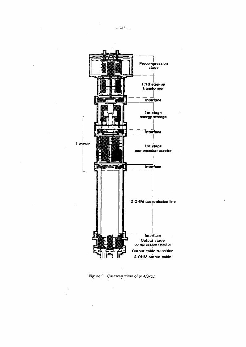
- 211 -
Precompres s ion s t a g e
1 meter Iststage compression reactor
2 O H M transmission line
interface O u t p u t stage
compression reactor O u t p u t cable transition 4 O H M output cable
Figure 3. Cutaway view of M A G - I D

- 212 -
determined by the quantity of metal and, more significantly, by the length of machining, finishing and welding time involved in the cell manufacture. This time scales linearly with the surface area to be machined, finished, welded, and inspected. The baseline cost estimate includes no reduction for the use of production engineering techniques, such as large scale metal casting and robot welding. Such techniques might reduce the cost of the accelerator cell housings by more than 30%. A complete set of components, internals, and scaling determinants of the accelerator subsystem are listed in Table 1.
In similar fashion, w e can assign scaling determinants to the components included among the ancillary systems. These characteristics, listed in Table 2, require some qualifying comments: As the cell size decreases, the vacuum system will become conductance limited rather than pumping speed limited. Consequently, the system cost will then scale with machine length rather than with the pumping volume. Over the range of accelerator sizes of interest for linear colliders, the cost of the instrumentation and control system is assumed to be a "buy-in" fixed cost plus a percentage of the accelerator cell costs.
Table L
Scaling principles for accelerator cell components.
Component Internals Scaling
Power Supplies D C supplies C R C s
Average Power
Intermediate stores Capacitors Thyratrons
Pulse energy Average current, pulse energy
Magnetic compressors M A G - I D Pulse energy
Accelerator cells Ferrites Cell housing, gap
Volume (Vacc, T, G) Surface area (ri, r0, G) Total voltage
Strongback Cell weight and length
Table 2. Cost scaling determinants for ancillary systems.
Component Scaling
L C W and E L C W Pulse energy, average power
V a c u u m Pumping volume
Insulating fluids Average power
Fixtures and Alignment Length
Instrumentation and Controls System complexity
B e a m d u m p Average power into d u m p

- 213 -
T h e in jec tor s u b s y s t e m c o n s i s t s o f a c o l l e c t i o n o f c o m p o n e n t s s i m i l a r t o t h o s e of the a c c e l e r a t i n g ce l l s . In a d d i t i o n , t h e injector i n c l u d e s s o m e separate anc i l lar i e s s u c h a s v a c u u m , f o c u s i n g , a n d a l i g n m e n t f ix tures . T h e s u b s y s t e m i s charac ter i zed b y a n a n o d e - c a t h o d e v o l t a g e (Vi n j ) , w h i c h is re lated to the b e a m current b y Eq. (2). The sca l ing of the cos t of the injector f o l l o w s f rom the s a m e p h y s i c a l c o n s i d e r a t i o n s as for the accelerator cel ls .
T h e m o s t c o m p l e x s c a l i n g a p p l i e s to t h e b e a m transport s y s t e m as s evera l a l t ernat ive focus ing s c h e m e s are poss ib le :
a) c o n t i n u o u s s o l e n o i d , b) s o l e n o i d s in the first 20 M e V f o l l o w e d b y a q u a d r u p o l e lattice, a n d c) laser g u i d i n g .
The g u i d i n g pr inc ip le in the spec i f i ca t ion of the transport s y s t e m is that the B B U g r o w t h parameter (S) in Eq. (3) i s k e p t constant . Equat ion (3), h o w e v e r , a s s u m e s a m o n o - e n e r g e t i c b e a m w i t h uni form betatron frequency(kß) . C o n s e q u e n t l y , s ca l ing the transport s c h e m e s is c o m p l i c a t e d b y the d e g r e e of e n e r g y s p r e a d , C = ( A E / E ) , of the e lec tron b e a m . For the relat ivist ic k lys tron , C < 1% for the first 15 t o 4 0 M e V of i n d u c t i o n m o d u l e s ; f o l l o w i n g the k l y s t r o n c a v i t y i n t e r a c t i o n , C i n c r e a s e s to a b o u t 50%. W i t h s u c h a large e n e r g y s p r e a d , the betatron f r e q u e n c y s p r e a d for the b e a m wi l l be suff ic iently large that the p h a s e m i x i n g of the b e a m is m o r e rapid than the m a x i m u m p o s s i b l e BBU g r o w t h rate. That i s , the transverse m o d e for a 3-kA b e a m wi l l actual ly d a m p e v e n for r D as smal l as 2.5 c m if the s o l e n o i d a l f ie ld is k e p t cons tant t h r o u g h o u t the accelerator at 3 kG, the v a l u e for the b a s e l i n e l inac d e s i g n . Therefore , the c o s t of p o w e r i n g the c o n t i n u o u s s o l e n o i d a l transport can b e sca led in p r o p o r t i o n to the total f ie ld v o l u m e a n d the square of the b e a m current. T h e cost of the m a g n e t w i n d i n g s is proport iona l to the accelerator l ength , the current, a n d the inner rad ius r¡.
For i n d u c t i o n l inacs d e s i g n e d for o ther app l i ca t ions , B B U constraints m a y b e r e l a x e d , or they m a y b e c o m b i n e d w i t h o t h e r c o n s t r a i n t s o n the t ranspor t s y s t e m s u c h as t h e r e d u c t i o n of c o r k s c r e w i n g of the b e a m . 7 In s u c h al ternate cases the o p t i m u m transport s trategy m a y require the var ia t ion of B w i t h the b e a m e n e r g y . T h e n the sca l ing re la t ion s h o u l d b e recast in t erms of an appropriate a v e r a g e v a l u e of the m a g n e t i c f ield.
The u s e of a q u a d r u p o l e latt ice b e t w e e n the accelerat ing cells w i l l r e d u c e the a v e r a g e gradient in the i n d u c t i o n l inac b y as m u c h as 50%. Th i s cons iderat ion a l o n e m a k e s the u s e of s o l e n o i d s in the first 20 M e V f o l l o w e d b y a q u a d r u p o l e lat t ice ( s c h e m e b a b o v e ) re la t ive ly u n i n t e r e s t i n g for the driver of a l inear col l ider.
Laser g u i d i n g 9 ( s c h e m e c a b o v e ) i n t r o d u c e s a n u m b e r of d e s i g n e l e m e n t s fore ign to all l inacs s a v e one—the A d v a n c e d Tes t A c c e l e r a t o r ( A T A ) . Th i s t e c h n i q u e , u s e d d a i l y t o t ransport h i g h current b e a m s t h r o u g h the A T A , m a y r e d u c e the cost of the transport i n the i n d u c t i o n l inac b y an order of m a g n i t u d e . The transport c o m p o n e n t s i n this a p p r o a c h are a v e r y l o w angu lar jitter, near-di f fract ion- l imited , repet i t ion-rated KrF laser («1 J per p u l s e in »20 n s ) , a g a s h a n d l i n g s y s t e m to ma in ta in a partial pres sure of =10~4 Torr of b e n z e n e , a n d m a g n e t i c transi t ion s ec t ions to m a t c h the e lectron b e a m o n t o ( a n d off of) the l a ser - ion ized gas channel . For repet i t ion rates <250 H z , suitable KrF lasers are ava i lab le c o m m e r c i a l l y . Di f fract ion wi l l e v e n t u a l l y r e d u c e the laser f iuence b e l o w the l e v e l n e e d e d (<0.2 J / c m 2 ) to i o n i z e a su i tab ly large fraction of the b e n z e n e ; therefore , a n e w laser b e a m m u s t b e r e i n t r o d u c e d in to the l inac e v e r y »125 m . T h e b e a m l i n e m u s t h a v e per iod ic ch icanes w i t h dif ferent ial p u m p i n g a n d m a t c h i n g m a g n e t s to a c c o m m o d a t e i n t r o d u c t i o n of the laser p u l s e . For this s c h e m e , cos t w i l l sca le in proport ion to the l e n g t h of the l inac.
In a d d i t i o n t o the f o c u s i n g c o m p o n e n t s d i s c u s s e d a b o v e , all s c h e m e s w i t h m a g n e t i c transport m u s t i n c l u d e s t e e r i n g m a g n e t s at p e r i o d i c i n t e r v a l s , the l e n g t h of w h i c h is d e t e r m i n e d b y a l i g n m e n t r e q u i r e m e n t s . A l l t ransport s c h e m e s require a m a t c h i n g s e c t i o n b e t w e e n the injector o u t p u t a n d the m a i n accelerator transport.

- 214 -
3.2. S c a l i n g E q u a t i o n s
Variables to be used in t h e scaling equations include the total accelerating voltage (V) in MV, the the total volt-seconds of core (W = V T p ) , the gap stress (Eg) in kV/cm, the single p u l s e energy (E = V IbeamTp) in joules, the average power (P = f E) in MW, the effective gradient (G) in M V / m , and the inner radius (n) in cm. In the scaling equations italicized quantities refer to injector voltage, power, p u l s e energy, etc. Costs are specified in constant FY87 thousands of dollars.
3.2.1 In jec tor S u b s y s t e m
The scaling equation for the injector is divided into five separate components:
Cjnj = [724 ( W / 0 .17)] œ u s + [475 (E / 450)]mag
+ [450 (P / 2.25)] i Sps + [165 (V I 3)3 ] v a c + [60 ] a l ign • (14)
As each arm of the linear collider is driven by a separate induction linac, this injector cost must b e doubled in the estimate of total hardware cost. For most variants of the two-beam accelerator approach this cost is a small fraction of the total.
3.2.2 B e a m T r a n s p o r t S u b s y s t e m s
For solenoidal transport, the cost has three separate components:
Csoi = [(57 + 81 (ri/7.5) (1/3000) ) (V/1.5) 0/3000) (r-,/7.5) (0.75 /G)]f O C us
+ [42 (V/1.5) (ri/7.5) ( 0 . 7 5 / Q W + [ 78 W e h • (15)
For the alternative laser guiding scheme the scaling equation is
Ciaser = 7.5 V G"* , (16)
which includes laser, gas handling, and matching magnet costs for f < 250 Hz.
3.2.3. Acce lera tor C e l l S u b s y s t e m s
The cell block cost is
Cblock = 234 (V / 1.5) (r 0 / 20)2 (0.75 / G) (175 / E g ) , (17)
where r 0 is related to n by Eq. (6). The ferrite cost is given by
Cferrite = 44 ( W / 0.225) [(r 0 + r¡ ) / 27.5] . (18)
where w e have used the relation between the area and volume of the ferrite, Vol = TC A ( r 0 + ri). The cost of intermediate stores and power supplies scales as
Qsps = 698 (P / 3.2) + 5 (E / 630) . (19)
The scaling for the magnetic pulse compressors is
Cmag = 2 4 1 ( E / 6 3 0 ) (20)
- 215 -
F o r p o w e r s y s t e m s d e l i v e r i n g p u l s e s a t r e p e t i t i o n r a t e s =100 H z t h e m a g n e t i c m o d u l a t o r s a n d i n t e r m e d i a t e s t o r e s c a n b e r e e n g i n e e r e d t o r e d u c e cos t s b y n e a r l y a f ac to r of t w o . T h e cos t of t h e s t r o n g b a c k a l i g n m e n t s t r u c t u r e is
Qtrong = 450 (V / 12.5) ( r 0 / 20)2 (0.75 / G) K , (21)
w h e r e t h e c o n s t a n t K d e p e n d s o n t h e f o c u s i n g s c h e m e ; n a m e l y ,
K = 1.0 for q u a d r u p o l e s , = 0.6 for s o l e n o i d s , = 0.5 for l a s e r g u i d i n g . (22)
3.2.4. Ancillary Subsystems
T h e c o s t for l o w a n d e x t r e m e l y l o w c o n d u c t i v i t y w a t e r wi l l s c a l e a s
Cfcw = 90 C P / 13.1) , (23)
for f > 100 H z . F o r f < 100 H z w e s h o u l d u s e t h e v a l u e of Q c w a t f = 100 H z . T h e v a c u u m s y s t e m is s c a l e d a s if i t w e r e p u m p i n g - s p e e d l i m i t e d (va l id for r¡ > 2.5 c m ) :
C v a c = 660 (V / 12.5) (ri / 7.5)2 (n.75 / G) K . (24)
w h e r e K is g i v e n b y E q . (22). T h e cos t of e lec t r ica l fluids is p r o p o r t i o n a l t o a v e r a g e b e a m p o w e r ;
Cfluid = 542 (P / 13.1) . (25)
T h e s c a l i n g of d u m p c o s t s i s s i m i l a r t o t h a t for r e a c t o r s , i .e. , $ 1 p e r w a t t of b e a m p o w e r i n t o t h e d u m p (Pd) . F o r t h e r e l a t i v i s t i c k l y s t r o n , w e a s s u m e t h a t t h e a v e r a g e b e a m v o l t a g e a t t h e d u m p (V<j) is 35 M e V , h e n c e , P d = V d T p I b e a m f •
T h e c o l l i d e r , t h e r e f o r e , h a s t w o d u m p s of cos t ,
Cdump = 1 0 0 0 P d . (26)
T h e cos t of f i x t u r e s i s p r o p o r t i o n a l to t h e l e n g t h of t h e i n d u c t i o n l i n a c ;
Cfixture = 20 (V / 12.5) (0.75 / G) . (27)
T h e cos t of t h e i n s t r u m e n t s a n d c o n t r o l s sca les a s a f ixed v a l u e p l u s a p e r c e n t a g e of t h e cos t of t h e h a r d w a r e t o b e m o n i t o r e d a n d c o n t r o l l e d ;
C i & c = 3000 + 0.04 (Cinj + Cceii + Cfocus) • (28)
S u m m i n g t h e c o s t e q u a t i o n s ((14) t h r o u g h (21), a n d (23) t h r o u g h (28)) y i e l d s t h e t o t a l h a r d w a r e cos t for t h e i n d u c t i o n l i n a c d r i v e r .
3.2.5 Installation and Engineering Support
T h e i n s t a l l a t i o n c o s t s for t h e b a s e d e s i g n w e r e e s t i m a t e d o n a c o m p o n e n t b y c o m p o n e n t b a s i s ; for e s t i m a t i n g p u r p o s e s t h e i n s t a l l a t i o n c o s t s c a n b e t a k e n a s a f i x e d p e r c e n t a g e of t h e t o t a l h a r d w a r e cos t s a d j u s t e d t o t h e f u l l y - l o a d e d l a b o r r a t e (R) i n $ K / m a n - m o n t h .

- 216 -
Qnsta l l = 0.09 Chardware (R / 10) . (29)
S i m i l a r l y , a c o s t fo r e n g i n e e r i n g m a n a g e m e n t a n d s u p p o r t i s e s t i m a t e d a s a p e r c e n t a g e of t h e h a r d w a r e c o s t s , i .e.,
(30)
S u p p l i e s a n d e q u i p m e n t u s e d for e n g i n e e r i n g a n d i n s t a l l a t i o n i n c r e a s e s t h e to ta l cos t b y 1 0 % ;
A d d i n g t h e s e i n s t a l l a t i o n c o s t s t o t h e h a r d w a r e c o s t y i e l d s a t o t a l c o s t t h a t i n c l u d e s =10% c o n t i n g e n c y d i s t r i b u t e d ( u n e v e n l y ) a m o n g t h e v a r i o u s c o s t c e n t e r s .
4. A P P L I C A T I O N O F T H E S C A L I N G A L G O R I T H M
4.1. D r i v e r C o s t for a Linear C o l l i d e r
T h e s c a l i n g a l g o r i t h m d e v e l o p e d i n t h e p r e c e d i n g s e c t i o n c a n b e a p p l i e d t o e s t i m a t e t h e h a r d w a r e c o s t s of t h e i n d u c t i o n l i n a c d r i v e r fo r a h i g h l u m i n o s i t y , 4 0 0 G e V - o n - 4 0 0 G e V l i n e a r c o l l i d e r d e s c r i b e d i n Ref. 3 . T h e i n d u c t i o n d r i v e r i s c o n f i g u r e d a s a r e l a t i v i s t i c k l y s t r o n p r o d u c i n g 1.4 G W / m of =11 .4 G H z rf p o w e r . T h e r e s u l t s , g i v e n i n T a b l e 3 , u s e t h e b a s e l i n e v a l u e s for t h o s e c o m p o n e n t c h a r a c t e r i s t i c s n o t s p e c i f i e d . T h e t o t a l h a r d w a r e c o s t , $ 4 8 3 M , t r a n s l a t e s t o 1 0 " 4 $ / r f - w a t t , w h i c h is m u c h s m a l l e r t h a n t h e c o s t of rf p o w e r d e l i v e r e d b y c o n v e n t i o n a l k l y s t r o n s ( 1 0 " 2 $ / r f - w a t t ) , a n d w h i c h c o m p a r e s q u i t e f a v o r a b l y w i t h e a r l i e r e s t i m a t e s 2 of t h e r e q u i r e m e n t s t o m a k e h i g h g r a d i e n t c o l l i d e r s p r a c t i c a l . M o r e o v e r , if t h e a n t i c i p a t e d s a v i n g s f r o m u s i n g s t a n d a r d p r o d u c t i o n e n g i n e e r i n g t e c h n i q u e s c a n b e r e a l i z e d , t h e h a r d w a r e c o s t s c a n b e r e d u c e d b y 2 5 % .
4.2. C o s t S e n s i t i v i t i e s a n d O p t i m i z a t i o n
H a v i n g o b t a i n e d e n c o u r a g i n g r e s u l t s f r o m t h i s i n i t i a l e s t i m a t e , w e c a n p r o c e e d t o u s e t h e s c a l i n g r e l a t i o n s t o s t u d y t h e s e n s i t i v i t y of d r i v e r cos t t o i t s d e s i g n c h a r a c t e r i s t i c s . T h e r a t i o n a l e for s e n s i t i v i t y s t u d i e s is t o s u g g e s t h o w w e m i g h t o p t i m i z e t h e spec i f i ca t i on of t h e d r i v e r for t h e l i n e a r c o l l i d e r . O n e w a y t o p r o c e e d is v a r y t h e i n d u c t i o n d r i v e r s p e c i f i c a t i o n s s o a s t o m a x i m i z e t h e c o l l i d e r l u m i n o s i t y p e r u n i t c a p i t a l cos t . A n a l t e r n a t i v e w o u l d b e t o f o r m u l a t e a m e a s u r e t h a t a c c o u n t s fo r b o t h c a p i t a l a n d o p e r a t i n g cos t , a n d t h e n m a x i m i z e t h e l u m i n o s i t y p e r u n i t m e a s u r e .
T h r e e e x a m p l e s of t h e c o s t s e n s i t i v i t i e s i n d i c a t e t h e d i r e c t i o n s o f f e r e d b y t h e f i r s t a p p r o a c h . F i g u r e s 4 , 5 , a n d 6 s h o w t h e v a r i a t i o n of d r i v e r c o s t p e r v o l t w i t h p u l s e l e n g t h , g r a d i e n t , a n d r e p e t i t i o n r a t e , r e s p e c t i v e l y . F o r c o n s t a n t g r a d i e n t d e s i g n s t h e c o s t s a r e s e e n t o r i s e q u a d r a t i c a l l y w i t h p u l s e l e n g t h . A t c o n s t a n t p u l s e l e n g t h t h e cos t s r i s e q u a d r a t i c a l l y w i t h g r a d i e n t . L o w e r i n g t h e r e f e r e n c e d e s i g n v a l u e f r o m 60 n s t o 50 n s w o u l d r e d u c e d r i v e r cos t s b y g r e a t e r t h a n 2 2 % , a s s u m i n g t h a t t h e v o l t a g e r i s e t i m e c a n b e s h o r t e n e d i n p r o p o r t i o n t o t h e p u l s e l e n g t h . T h i s a s s u m p t i o n is v a l i d f o r 30 < T p < 80 n s . F o r t h e d r i v e r t o p r o v i d e t h e s a m e p o w e r p e r u n i t l e n g t h t o t h e rf-s t r u c t u r e , t h e i n d u c t i o n l i n a c v o l t a g e ( a n d g r a d i e n t ) w o u l d h a v e t o r i s e b y 12%. T h e n u m b e r of rf f e e d l i n e s w o u l d h a v e t o i n c r e a s e . A s t h e s e f e e d l i n e s a r e i n e x p e n s i v e , w e s h o u l d e x p e c t t h i s o p t i m i z a t i o n a p p r o a c h to r e a l i z e a n e t s a v i n g s of - 5 % ( = $ 2 5 M ) o v e r t h e e s t i m a t e of T a b l e 3 . A d i f f e r en t t a c k m i g h t b e t o i n c r e a s e t h e c u r r e n t t o c o m p e n s a t e for t h e s h o r t e r p u l s e l e n g t h . I n t h a t ca se , t h e s a v i n g s s h o u l d e x c e e d $50M.
C s & e = 0.1 Chard-L ware (31)

- 2 1 7 -
T a b l e 3 .
Induction linac cost for relativistic k l y s t r o n driver of linear collider.
S u b s y s t e m C o m p o n e n t C o s t T o t a l s ( $ K ) Production
engineered
Injector injector (2) 1,363 1,363
T r a n s p o r t laser guide 19,688 19,688
Accelerator cell blocks 230,344 161,241 cells ferrites 26,133
M A G - I D 131,211 i.s. and p.s. 11,776 strongback 26,578 18,605
426,042 322,832
Ancillary V a c u u m 9,240 systems Fixture and Align 4,200
L C W 303 Elec. fluids 1,825 I & C 19,820 D u m p (2) 81
35,468
T o t a l c o m p o n e n t s 482,561 379,351
Install 43,430 34,142 Engineering support 60,320 47,419 S & E 48,256 37,935
T O T A L (as of12/24/86) 634,567 498,846
A c c e l e r a t o r S p e c i f i c a t i o n s
Voltage (MV) 3500 Grad (MV/m) 1
Current (A) 1750 R a d i u s - i n n e r (cm) 2.5 Pulse (ns) 60 Radius-outer (cm) 15.00 Frequency (Hz) 120 Packing 0.8

Gradient (MeV/m)
Figure 5. Driver cost vs gradient

- 219 -
The electrical p o w e r requirements for the reference collider design (at 120 Hz) are 60 M W . If the
allowed p o w e r consumption is 120 M W , the luminosity of the collider can be doubled at a less than
1% increase in the capital cost by designing the driver to operate at 240 H z .
Finally, a plot of relative cost vs Eg (Fig. 7) shows the impact in advancing pulsed-power
technology so that the electrical stress in the accelerating gap can be increased from the baseline
value of 175 k V / c m . Doubling the allowed stress w o u l d reduced the driver cost by =10%.
5. C O N C L U S I O N S
The costs of induction linacs can be estimated over a wide range of operating specifications
relevant to driving large linear colliders. The estimates, based o n scaling the costs of the E T A II
n o w under construction at L L N L , s h o w that the relativistic klystron has the potential to produce rf-
power at <10"5 $/rf-watt. This value is both strongly cost-competitive with conventional means
of powering rf-structures at frequencies about 10 to 20 G H z and is sufficiently low to m a k e practical
high gradient linear colliders with T e V center-of-mass energies. Initial cost sensitivity studies
indicate that the driver characteristics can be optimized to reduce costs at least an additional 20%.
* * *
B E F E H E N C E S
1) R.A. Jameson, " N e w Linac Technology for S S C and Beyond", in Proc. 12th International Conf. on High Energy Accelerators, FERMILAB, Aug. 11-13, 1983, pp. 497 -50.
2) D.B. Hopkins, A . M . Sessler, and J.S. Wurtele, "The T w o - B e a m Accelerator," Nuc. Inst. & Meth. for Phys. Res., 228, pp. 15-19 (1984).
3) S.S. Y u and A . M . Sessler, The Relativistic Klystron Two-Beam Accelerator, Lawrence Livermore
National Laboratory, Livermore, C A , UCRL-96083 (1987), submitted to Phys. Rev. Lett.
4) D. Birx, "The Applications of Magnetic Switches as Pulse Sources for Induction Linacs", IEEE Transactions in Nuclear Science, NS-30, 4, Aug., 1983.
5) D.L. Birx, G.J. Caporaso, L.L. Reginato, Linear Induction Accelerator Parameter Options,
Lawrence Livermore National Laboratory, Livermore, C A , UCID-20786 (1986).
6) D.L. Birx, A Collection of Thoughts on the Optimization of Magnetically Driven Induction
Linacs for the Purpose of Radiation Processing,, Lawrence Livermore National Laboratory, Livermore, C A , UCRL-92828 (1985).
7) G.J. Caporaso, "Control of B e a m Dynamics in High Energy Induction Linacs," in Proc. of LINAC '86 Conference, SLAC, July, 1986.
8) G.J. Caporaso, W . A . Barletta, and V.K. Neil, 'Transverse Resistive Wall Instability of a
Relativistic Electron Beam," Particle Accelerators, 11, pp. 71-79, (1980).
9) G.J. Caporaso, "Laser Guiding of Electron Beams in the Ad v a n c e d Test Accelerator," Phys. Rev. Lett., 57,13, (1986).

- 220 -
C O N V E N T I O N A L P O W E R SOURCES FOR COLLIDERS*
M . A . A L L E N
Stanford Linear Accelerator Center
Stanford University, Stanford, California, 94805
A B S T R A C T
A t S L A C w e a r e deve lop ing h i g h p e a k - p o w e r k ly s t rons t o exp lo re t h e l imi t s
of u s e of c o n v e n t i o n a l p o w e r s o u r c e s in fu tu re l inear col l iders . I n a n expe r i
m e n t a l t u b e w e h a v e ach ieved 150 M W a t 1 psec pu l s e w i d t h a t 2856 MHz.
I n p r o d u c t i o n t u b e s for S L A C L i n e a r Col l ider (SLC) w e r o u t i n e l y ach ieve
67 M W a t 3.5 psec pu l s e w i d t h a n d 180 p p s . O v e r 200 of t h e k l y s t r o n s
a r e in r o u t i n e o p e r a t i o n in S L C . A n e x p e r i m e n t a l k l y s t r o n a t 8.568 G H z is
p r e s e n t l y u n d e r c o n s t r u c t i o n w i t h a des ign object ive of 30 M W a t 1 psec.
A p r o g r a m is s t a r t i n g o n t h e re la t iv i s t i c k l y s t r o n w h o s e p e r f o r m a n c e will
b e a n a l y z e d in t h e e x p l o r a t i o n of t h e l imi t s of k l y s t r o n s a t v e r y s h o r t pu l s e
w i d t h s .
1. I n t r o d u c t i o n
A col l iding l inear acce le ra to r is b e i n g cons ide r ed for t h e S t an fo rd L inea r Acce le ra to r C e n t e r (SLAC) .
I t is likely t h a t a p r o p o s a l will b e w r i t t e n in 1990 for c o n s t r u c t i o n of a 0.5 - 1 T e V c m . collider.
T h i s L a r g e L inea r Col l ider (LLC) will cons i s t of severa l cr i t ical i t e m s , o n e of w h i c h is t h e t y p e of
p o w e r sou rce . E a r l y c o n c e p t u a l des igns sugges t l inacs of 3 k m in l eng th a n d for 0.5 T e V th i s requires
g r a d i e n t s of 166 M e V / m . F r o m t o t a l p o w e r c o n s i d e r a t i o n s , h ighe r f requencies t h a n t h e S L A C frequency
(2.856 GHz) a r e p re fe r red a n d des igns h a v e b e e n sugges t ed a t f requencies of four t i m e s S L A C frequency
a n d h i g h e r . P e a k p o w e r r e q u i r e m e n t s t h e n a r e in excess of 500 M W / m e t e r . N o c o n v e n t i o n a l power
sou rces exis t w h i c h c a n s u p p l y t h i s p o w e r in u n i t s w h i c h cou ld energize o n e m e t e r or m o r e of t he
p r o p o s e d acce l e ra to r s . T h e S L A C L inea r Col l ider (SLC) p re sen t ly be ing c o m m i s s i o n e d is successfully
e m p l o y i n g over 200 k l y s t r o n s t o acce le ra te a s t a b l e b e a m m e e t i n g S L C specif ica t ions t o over 50 GeV.
[l] T h e s e k l y s t r o n s p r o d u c e over 65 M W e a c h in 3.5 psec pu lses a n d use R F pu l se compres s ion t o reach
a b o u t 200 M W p e a k p o w e r over 1 psec. Also in a n e x p e r i m e n t a l t u b e 150 M W h a s b e e n achieved
in 1 psec pu l s e w i d t h s . T h u s k l y s t r o n s a r e a p o t e n t i a l c a n d i d a t e for L L C p o w e r sources . A scal ing of
ex i s t ing k l y s t r o n s sugges t s t h a t 100 M W p e a k p o w e r a t 10 G H z is poss ib le w i t h a p u l s e w i d t h of 2 psec.
T o exp lore th i s p o w e r r a n g e a r e sea r ch a n d d e v e l o p m e n t p r o g r a m is u n d e r w a y a t S L A C . T h e first s tage
of t h a t p r o g r a m is a 30 M W p e a k p o w e r k l y s t r o n a t X - B a n d . If it t u r n s o u t t h a t 100 M W t u b e is
feas ible , it m i g h t b e poss ib le t o c o m p r e s s t h e 2/xsec R F pu l se t o p r o d u c e a p e a k p o w e r in excess of 500
M W . T h i s pu l s e compres s ion requ i res t h e d e v e l o p m e n t of low-loss de lay l ines w h i c h a r e c u m b e r s o m e ,
expens ive a n d suffer m o d e coup l ing p r o b l e m s of a v e r y fo rmidab le n a t u r e . T h u s a n o t h e r a p p r o a c h is
* Work supported by the Department of Energy, contract D E - A C 0 3 - 7 6 S F 0 0 5 1 5 .

- 221 -
n e e d e d . O n e w a y w o u l d b e t o c o m p r e s s t h e e n e r g y p u l s e before t h e R F is g e n e r a t e d . T h e pe r fo rmance
of t h e k l y s t r o n t y p e i n t e r a c t i o n a t v e r y s h o r t p u l s e w i d t h s h a s n o t b e e n exp lo red b u t t h e r e a r e reasons
t o be l i eve t h a t m u c h h ighe r p e a k p o w e r is a t t a i n a b l e as t h e pu l s e w i d t h decreases . Single b u n c h l inear
col l iders a t X - B a n d r equ i r e p e a k p o w e r s of 500 M W / m e t e r b u t on ly for a b o u t 50 n s p e r pu l se . If
pu l s e s of a d e q u a t e q u a l i t y (fast-r ise t i m e , g o o d flat t o p ) c a n b e p r o d u c e d , t h e sca l ing laws for long pulse
( > 1/xsec) wi l l n o t app ly . P r e v i o u s b r e a k d o w n s t u d i e s sugges t t h a t h igh electr ic fields c a n b e m a i n t a i n e d
for n a n o s e c o n d p u l s e s . If t h e s e pu l ses c a n b e m a i n t a i n e d , t h e n t h e r e s p o n s e t i m e of t h e k lys t rons t o
s h o r t pu l s e s b e c o m e s i m p o r t a n t a n d requ i res s t u d y .
2 . S h o r t P u l s e P r o d u c t i o n
I n m o d u l a t o r s for m ic rosecond pu l se t u b e s , c o m p r e s s i o n is d o n e b y us ing pu l se fo rming ne tworks
cons i s t ing of de l ay l ines fo rmed f rom a n a r r a y of c a p a c i t o r s a n d chokes . Recen t ly , a t t h e Lawrence
L i v e r m o r e L a b o r a t o r i e s n e w fe r ro -magne t i c me ta l l i c g lass m a t e r i a l s h a v e b e e n u s e d t o p r o d u c e pulse
c o m p r e s s i o n . [2j T h i s is a high-efficiency m e t h o d w h i c h p r o d u c e s fast r i se - t ime pulses in t h e t ens of
n a n o s e c o n d r a n g e . T h e s e h a v e b e e n app l i ed successfully in i n d u c t i o n l inear acce le ra to r s t o p r o d u c e
M V / k A b e a m s . T h i s t e c h n i q u e m a k e s feasible t h e p r o d u c t i o n of s h o r t -p u l s e b e a m s for k ly s t ron inter
ac t i ons . T h e s e b e a m s w o u l d b e in excess of 1 M V a n d if p r o p e r l y b u n c h e d a n d m a d e t o i n t e r ac t w i th
e x t r a c t i o n cav i t i e s , v e r y h i g h p e a k R F p o w e r w o u l d b e p r o d u c e d . T h i s descr ibes re la t iv is t ic k lys t ron
ampl i f iers ( R K A ) .
3. R e l a t i v i s t i c K l y s t r o n s
T h e r e ex is t s in L a w r e n c e L ive rmore N a t i o n a l L a b o r a t o r y (LLNL) a n ongo ing p r o g r a m in induc t ion
l inear acce l e r a to r s p r o d u c i n g a n d acce le ra t ing h i g h v o l t a g e ( > 1 M e V ) a n d h igh c u r r e n t ( > 1 kA) shor t
p u l s e ( < 1 0 0 ns ) e l ec t ron b e a m s . Some of t h i s w o r k is a l so b e i n g d o n e in co l l abora t ion w i t h Lawrence
Berke ley L a b o r a t o r i e s (LBL) . A t S L A C t h e r e is a n o n g o i n g p r o g r a m of d e v e l o p m e n t of h i g h p e a k power
k l y s t r o n s a t u p t o t h e 10 G H z r a n g e of f requencies . Since t h e t h r e e l abo ra to r i e s a re in t e res t ed in R F
p o w e r sources for h i g h g r a d i e n t l inacs , a co l l abora t ive p r o g r a m h a s b e e n s t a r t e d b e t w e e n t h e l abora to r ies .
T h i s p r o g r a m is d i scussed in t h e W o r k s h o p b y S i m o n Y u . [3] A va r i e ty of h i g h vo l t age , h igh cu r r en t
b e a m s p r o d u c e d b y i n d u c t i o n acce le ra t ion a n d b u n c h e d b y ve loc i ty m o d u l a t i o n or o t h e r m e a n s and
us ing R F e x t r a c t i o n cavi t ies a r e be ing exp lo red t o p r o d u c e t h e necessa ry g igawa t t s of R F power for
L L C .
T h e p r o g r a m h a s t h r e e m a i n a p p r o a c h e s . T h e y a r e :
a. T h e p r o d u c t i o n of a 1 M V , 1 k A s h o r t pu l s e b e a m b y m a g n e t i c compress ion in a convent ional
k l y s t r o n amplif ier a n d e x t r a c t i o n f rom th i s 1 G W b e a m of a t least 5 0 % of t h e p o w e r a t R F
f requency. T h i s w o u l d give in excess of 500 M W p e a k p o w e r f rom a single u n i t .
b. In a sma l l i n d u c t i o n l inear acce le ra tor t h e p r o d u c t i o n , b u n c h i n g a n d acce le ra t ion of a 10 G W
b e a m . T h i s b e a m could b e n o m i n a l l y 5 M e V a n d 2 k A . T h i s b e a m w o u l d drift t h r o u g h a series
of R F e x t r a c t i o n cavi t ies w i t h each of t h e m e x t r a c t i n g 1 G W of R F p o w e r . T h i s m o d u l e would
energ ize 10 m e t e r s of L L C in a single u n i t .

- 222 -
c. I n t r u e t w o - b e a m acce l e ra to r [4] a n i n d u c t i o n l inear acce le ra to r w o u l d acce l e r a t e nomina l ly 20 k A
of b e a m u p t o 50 M e V for a 1 T W b e a m a n d b y us ing a ser ies of R F e x t r a c t i o n cavi t ies 1 G W
w o u l d b e e x t r a c t e d f rom e a c h cav i ty . T h i s w o u l d energ ize 1 k m of L L C in a s ing le u n i t .
T h e feasibil i t ies of all t h r e e a p p r o a c h e s a r e be ing s t u d i e d a n d e x p e r i m e n t s a r e b e i n g p l a n n e d uti l izing
i n d u c t i o n acce le ra to r s in o p e r a t i o n a t L L N L .
4 . Conclusion
P r o s p e c t s for u s i n g s o m e de r iva t ive of a re la t iv i s t i c k l y s t r o n in l a rge l inear col l iders look p romis ing
a n d a r e b e i n g exp lo red .
T h i s r e p o r t t o t h e W o r k s h o p is a br ief s u m m a r y of w o r k in p r o g r e s s . T h e r e a r e a large n u m b e r
of p e o p l e c o n t r i b u t i n g t o t h i s S L A C / L L N L / L B L co l l abo ra t i on a n d t h e i r w o r k wil l b e r e p o r t e d in t he
a p p r o p r i a t e m a n n e r in t h e f u t u r e .
5 . R e f e r e n c e s
[1] M . A . Al len , W . R . F o w k e s , R . F . K o o n t z , H . D . S c h w a r z , J . T . S e e m a n , A . E . Vl ieks . "Per fo rmance
of t h e S L A C L i n e a r Col l ider K l y s t r o n s , " S L A C - P U B - 4 2 6 2 . T o b e p u b l i s h e d in 1987 I E E E Par t i c l e
Acce l e r a to r Confe rence P r o c e e d i n g s .
[2] D . L . B i r x , E . G . C o o k , S.A. H a w k i n s , M . A . N e w t o n , S.E. P o o r , L .L . R e g i n a t o , J . A . S c h m i d t and
M . W . S m i t h , " T h e Use of I n d u c t i o n Linacs w i t h N o n l i n ea r M a g n e t i c D r i v e as H igh Average Power
Acce le ra to r s , " L a w r e n c e L i v e r m o r e N a t i o n a l L a b o r a t o r y , R e p o r t N o . U C R L - 9 0 8 9 8 , 1984.
[3] S. Y u , "Phys i c s of Re la t iv i s t i c K l y s t r o n s , " t h i s W o r k s h o p .
[ 4 ] A . M . Sessler , S.S. Y u , "Re la t iv i s t i c K l y s t r o n T w o - b e a m Acce le ra to r , " P h y s i c a l Review Le t t e r s ,
Vol . 5 8 , P a g e 2439 , J u n e 1987.
* * * Discussion
J . Nation, Cornell University
Will you please comment on the choice of the klystron for the TeV power source in the
context of extensive alternative source development. There are extensive investigations of
the phase stability at the 100's of MW level, in TWT amplifiers, Cerenkov devices,
magnetrons and gyroklystrons, in progress in several laboratories.
Reply
In my talk I described the relativistic klystron work at SLAC/LLNL/LBL. Other labora
tories are developing other power sources. If they prove suitable for TeV linear colliders
we wi11 propose them for our collider. In particular the gyroklystron has great promise
and the work at the University of Maryland is of great interest.
- 223 -
HIGH POWER GYROTRONS AS MICROWAVE SOURCES FOR PARTICLE ACCELERATORS
M.Q. Tran
Centre de Recherches en Physique des PI asmas, Association Euratom - Confédération Suisse,
Ecole Polytechnique Fédérale de Lausanne, 21, Av. des Bains, CH-1007 Lausanne/Switzerland
ABSTRACT
A reasonable extrapolation from the existing radio frequency linac
towards the TeV col 1ider would require microwave sources in the fre
quency range of 10-30 GHz with peak power around 300 MW. A promising
microwave source meeting these specifications is a gyroklystron
amplifier. A review of existing experiments on high peak power gyro-
tron ose i 1lators and amplifiers wi 11 be presented in this paper.
Their potentialities as microwave sources for the future accelerators
will also be discussed.
1. INTRODUCTION
The development of high power microwave sources has been greatly stimulated by applica-
tions in control led thermonuclear fusion (CTF) research and, potentially, in accelerators
for high energy physics (HEP). Requirements of the sources are quite different for both app
lications. For heating and non-inductive current drive in CTF, continuous wave (CW) ose i 1 la-
tors and amplifiers with power per unit of the order of 1-5 megawatts are needed in the fre
quency range of 8-10 GHz and of 60-600 GHz. Accelerators for HEP demand more chailenging performances on peak power (hundreds of megawatts) but only for at most 1-2 \is (using pulse
compression techniques) and at a repetition rate of 1000-500 Hz. Thus the average power is
considerably reduced compared to the previous case. Another important mandatory feature is
the ab i 1 i ty to control precisely the phase of the radi o frequency (RF) wave since hundreds
or thousands of tubes distributed along the accelerator wi 11 be needed.
The very high power required (hundreds of MW) leads naturally to the use of very high
voltage beam fVfj ~ 500 kV with a relativistic factor y = 2). Many instabi 1 ities can
generate microwave such as stimulated Cerenkov rad i at i on of electron beams, cyclotron maser
instability (for a discussion of the physics of the various mechanisms, see for example
Ref. 1). Using high energy electron beam, powers in the hundred megawatt range were reportedA Among these devices, gyrotrons were the most studied ones both theoretically and experimentally.
The paper wi11 include first a brief review of the electron cyclotron maser instabili
ty. The various relevant experiments will then be discussed. Although gyrotrons, using
weakly relativistic electron beams (V D < 100 keV, y < 1.2), have now achieved high power
(P ~ 650 kW) at very high frequency (f ~ 150-250 GHz)2*, these will not be discussed since
the requirements useful for accelerators are quite different. The last part wi11 be devoted to a general discussion on the potentialities of gyro devices for accelerators.

- 224 -
2 . THE PHYSICS OF ELECTRON CYCLOTRON RESONANT MASER INSTABILITY
In a gyrotron, the microwaves are generated through the interaction of a relativistic
electron beam guided by a static magnetic field B 0 with the electromagnetic (EM) wave.
The EM wave frequency is close to the relativistic cyclotron frequency QR = eS0/ym or
its harmonic n Q R. e, m e and y are respectively the electron charge, rest mass and re
lativistic factor. The source of free energy is the rotational energy of the electrons
around the field line BQ. A net energy output occurs due to the bunching of the electron
in the momentum plane (p x»Py) (Fig. 1) : this process is known as phase bunching. We have
assumed that the B 0 field 1ine in the z direction, £ is the momentum and al1 the electrons
are supposed to have the same perpendicular momentum p A = ( p x
2 + p y 2 ) 1 / 2 . The phase
bunching is due to the variation of QR with the particle y. Electrons los ing (resp. gain
ing) energy through the interaction with the EM wave wi 11 have a 1 arger (resp. smaller)
relativistic cyclotron frequency S R. If the wave frequency u is siightly less than Q R , the electrons wi 11 bunch in the region of the (p x»Py) plane where energy is transferred
from the electron beam to the EM wave. This effect leads to the so-called electron cyclotron
resonant maser (ECRM) instability of EM waves in presence of a relativistic electron beam
immersed in a static field B 0 .
As in other electron tubes, the interaction between the electron beam and the RF occurs
in an appropri ate resonant structure. Within the bandwidth of the ECM instability, the RF
frequency is determined by Q R (i.e. the magnetic field). Overmoded cavity which resonates
the desired frequency w, can then be used. Cyl indrical resonators operating in the T E ^
modes are generally considered although T M m n modes have also been excited 1' .
(a) (b)
F i g . 1 a ) P a r t i c l e d i s t r i b u t i o n i n t h e ( p x > P y ) p l a n e a t t h e b e g i n n i n g o f t h e
i n t e r a c t i o n . T h e e l e c t r o n s a r e u n i f o r m l y d i s t r i b u t e d o n a c i r c l e o f r a d i u s
Pj.0 = ( P x 2 + P y 2 ) 1 / 2 -
b ) Due t o t h e i n t e r a c t i o n w i t h t h e EM w a v e , t h e r e l a t i v i s t i c f a c t o r y o f d i f f e r e n t
e l e c t r o n s c h a n g e s . T h e y a r e n o l o n g e r u n i f o r m l y d i s t r i b u t e d o n t h e c i r c l e b u t a r e
" b u n c h e d " i n t h e p o s i t i v e p x h a l f - p l a n e w h e r e a n e t t r a n s f e r o f e n e r g y f r o m t h e
e - b e a m t o t h e w a v e o c c u r s .

- 225 -
3. HIGH PEAK POWER GYROTRONS
High peak power gyrotrons energized by pulse 1ine have been developed for more than ten years (cf. Table 1). In 1975, Granatstein et a l r e p o r t e d an output power of 1 GW at 8 GHz
using a beam of 3.3 MeV and 80 kA. In the Soviet Uni on,5'experiments using high power relati
vistic electron beams (V^ ~ 400 keV-1200 kV, I5 = 1-10 keV) have yielded powers in many
tens of megawatts in frequencies between 10 GHz to 107 GHz. The group in the Lebedev
Institute has achieved power of 60 MW at 10 GHz 6' 7' and up to 40 MW at 40 GHz 8' 9'. In al 1 these experiments the beam voltage was 400 kV with a current of 1-2 kA. In one experiment6j
the electron beam was neutral ized by a low density pi asma (plasma density n = 2 • 1 0 u c m - 3 )
to overcome the 1 imiting current in vacuum : the maximum current reached in presence of
plasma was nearly twice the one without plasma whereas the output power increased by an
order of magnitude.
In the frequency range around 35 GHz, the experiment of the Naval Research Labora
tory 1 0 | U ) yields two important results. Firstly, 100 MW at 35 GHz in the T E 6 2 mode
("whispering gal 1 e ry" mode) was reported. Secondly, stepwise tunabi1ity between 28 and
49 GHz was ach ieved by tuning the magnet i c field: the cavity mode was T E m 2 , wi th the
azimuthal index m varying between 4 and 10.
In the previous experiments, the cavity operated in the TE mode. Bratman et al. 1 '3^ have
reported that the electron beam can also occur with the TM mode of a cavity. The efficiency
is however low,around a few percents.
Table 1
Characteristics of high peak power gyrotrons
FREQUENCY POWER NODE E F F I C I E N C Y REFERENCE
3.1GHz 3 GW 30% [5]
8 GHz 1 GW T E 0 , 1 .4% [4]
10 GHz 60 MW T E 1 , 3 15% [6]
10 GHz 25 MW T E 1 , 3 20% [7]
35 GHz 100 MW T E 6 , 2 8% [ 1 0 , 1 1 ]
(Step tunable between 28-49 GHz)
T E m , 2 4 « m < 10
40 GHz 40-25 MW T E 1 , 3 6% [8,9]
79 GHz
88 GHz
107 GHz
20-30 MW
20-30 MW
20-30 MW
TM. l.n
3 4 n 4 10
<3%
»1%
»1%
j [1,3]
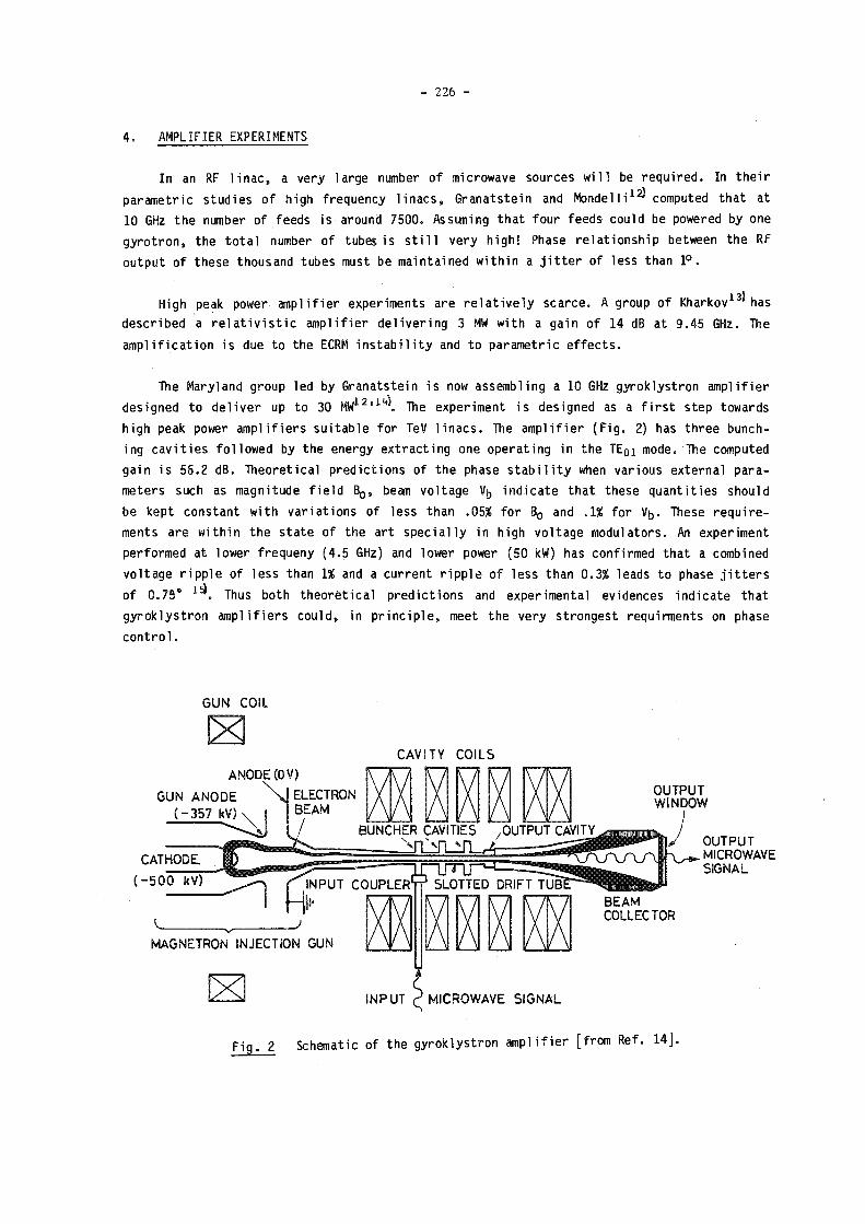
- 226 -
4. AMPLIFIER EXPERIMENTS
In an RF 1 inac, a very large number of microwave sources wi 11 be required. In their
parametric studies of high frequency 1 inacs, Granatstein and Mondell i 1 2^ computed that at
10 GHz the number of feeds is around 7500. As sun ing that four feeds could be powered by one
gyrotron, the total number of tubes is s t i l l very high! Phase relationship between the RF
output of these thousand tubes must be maintained within a jitter of less than 1°.
High peak power ampl if ier experiments are relatively scarce. A group of Kharkov 1 3' has
described a relativistic amplifier delivering 3 MW with a gain of 14 dB at 9.45 GHz. The
amplification is due to the ECRM instability and to parametric effects.
The Maryland group led by Granatstein is now assembling a 10 GHz gyroklystron ampl if ier
designed to deliver up to 30 The experiment i s designed as a first step towards
high peak power amplifiers suitable for TeV 1inacs. The amplifier (Fig. 2) has three bunch-
i ng cav i ties followed by the energy extracting one operating in the T E 0 1 mode. The computed
gain i s 56.2 dB. Theoretical predictions of the phase stab i 1ity when various external para
meters such as magnitude field B 0, beam voltage Vh indicate that these quantities should
be kept constant with variations of less than .05% for B 0 and .1% for Vb. These require
ments are within the state of the art specially in high voltage modulators. An experiment
performed at lower frequeny (4.5 GHz) and lower power (50 kW) has confirmed that a combined
voltage ripple of less than 1% and a current ripple of less than 0.3% leads to phase jitters
of 0.75 . Thus both theoretical predictions and experimental evidences indicate that
gyroklystron amplifiers could, in principle, meet the very strongest requirments on phase
control.
G U N COIL
C A V I T Y C O I L S A N O D E (OV)
G U N A N O D E ( - 3 5 7 kV)
O U T P U T W I N D O W
BUNCHER CAVITIES 7 0 U T P U T CAVITY^
CATHODE.
( - 5 0 0 kV)
M A G N E T R O N I N J E C T I O N GUN
L3 I N P U T r1 M I C R O W A V E S I G N A L
O U T P U T MICROWAVE SIGNAL
F i g . 2 Schematic of the gyroklystron ampl if ier [from Ref. 1 4 ] .

- 227 -
The Maryland gyroklystron designed specifications are comparable to the relativistic
klystron under development 1 0' 1 7* at the Stanford Linear Accelerator Center (SLAC)
(cf. Table 2). A detailed analysis of the gyroklystron parameters 1 7 reveals that this type
of tube could be scaled to higher power (~ 300 MW), mainly because the low electric field in
the space between the electron gun and the electrodes (91 kV/min.) allow to increase the
beam voltage and thus the tube power.
Table 2
Characteristics of the Maryland gyroklystron and the SLAC klystron.
(The specifications of the SLAC klystron are 1 isted in Ref. 17.)
Gyroklystron Klystron
Frequency 10 GHz 8.568 GHz
Power 36-48 MW 30 MW
Gain > 60 dB 50 dB
Efficiency 45-40% 60%
5. DISCUSSION
High efficiency microwave generation from relativistic electron beam has been shown by
many experiments (Fig. 3). These osci1lator studies have yielded valuable information on
the important issue of the mode stabi1ity. At high power (P > 300 MW) and/or high frequency
(f > 10 GHz) an overmoded cavity wi11 be required. A 300 MW-10 GHz gyroklystron would likely
use TEQ2 or T E 0 3 cavities 1 6*. Th i s requirement is due to the need of keeping the voltage drop
AV across the electron beam and the beam depression Vn at reasonable value. For higher
frequency (f ~ 30 GHz) the heat load due to ohmic dissipation becomes an important factor.
For a given cavity mode, the power loss per area Py scales as a w 5 / 2 0 _ 1 / 2 ( c o ) Q P
where a is the conductibi1ity, P the output power, Q the quality factor. Note that the con
duct i bi 1 ity a is anomalous at high frequency18*: at 35 GHz a is about 13% lower than the DC
value. Wi th this seal ing law, the peak value P w at 300 MW and 35 GHz would be around
2.40 MW/cm 2, using the value of 100 kW/cm 2 at 300 MW and 10 GHz given in Ref. 14. Even at a
duty cycle of 10" 3, this value gives an average wall loss of 2.4 kW/cm 2 which is excessive.
Moreover since both AV and Vn are inversely proportional to the average electron beam
radius, these quantities wi 11 also increase proportionally with the frequency if the cavity
mode is kept fixed. These two considerations lead to the use of a high order mode cavity, such
as TEo3, T E 1 3 [Ref. 6-9] or T E 6 2 [Ref. 10-11]. The main problem in such a configuration is the
suppression of unwanted mode in the amplifier cavities and drift space. Some possible solu
tions are discussed in Ref. 14. The new high temperature superconductors, if they could be

- 228 -
10 G W
5 G W
1 G W
5 0 0 M W
100 M W
5 0 M W
10 M W
5 M W
l G
1 M W
5 0 0 k W
1 0 0 k W « 1 1 1 1 1 1 1 1 1 1
0.5 1 2 5 10 2 0 5 0 1 0 0 2 0 0 5 0 0
F R E Q U E N C Y ( G H z )
F i g . 3 P e r f o r m a n c e s o f h i g h p e a k p o w e r g y r o t r o n s . T h e a s t e r i k s ( * ) r e p r e s e n t s
o s c i l l a t o r s , t h e ( A G ) t h e g y r o k l y s t r o n a m p l i f i e r o f t h e U n i v e r s i t y o f M a r y l a n d , a n d
t h e f u l l c i r c l e ( § ) t h e a m p l i f i e r d e s c r i b e d i n R e f . 1 3 . F o r c o m p a r i s o n we h a v e
i n c l u d e d t h e S L A C r e a l a t i v i s t i c k l y s t r o n ( • K ) .
used at RF frequency and in the presence of an important RF magnetic field, could free the
designer from the limitations of the thermal loading of the cavity [for a discussion of RF
properties of superconductors, see Ref. 19]. The question of unacceptably large Vp and AV
will then be the major criterium in the design of the RF circuit.
The problem of operating hundreds or thousands of high power tubes are common to linacs
fed from separated sources, as opposed to the two-beam accelerator approach. This would mean
a very precise control of the high voltage applied to the gun so that no voltage difference
larger than 0.1% would exist between them. Reliability will also be an important issue. The
characteristics of the high peak power gyrotron ampl if ier are too different from the gyro-
tron ose i 11ator for CTF to allow any conclusion to be drawn from this field. On the other hand,
a large number of klystrons have been produced and put into operation. Gyro devices use basi
cally the same technology and it could be expected that a similar degree of reliability can
be achieved.
The 36 MW-10 GHz gyroklystron development at the University of Maryland represents an
important step in the development of high power sources for HEP accelerators. The state-of-
the-art klystron delivers 150 MW at f = 2.87 GHz 2 0^, and the one under development at SLAC is
designed to achieve comparable power at slightly reduced frequency. Although the peak power
of 36 MW is already a thousand fold larger than the one obtained with an existing gyrokly
stron amplifier, a useful tube would sti11 need another factor of 5-10 in power. Considering
the steady progress made in the development of gyrotrons for CTF during the 1ast decade, and
drawing on the expertise avai1 able, one can be confident that, if needed, gyroamplifiers
could be built to meet the requirements of RF 1inacs.

- 229 -
ACKNOWLEDGEMENTS
It i s a pleasure to acknowledge enligthening discussions with Prof. V.L. Granatstein
who has given us many detaiIs of his experiment. We would also 1 ike to thank
Prof. G. Coignet who has brought to our attention Ref. 19 on the application of the high
temperature superconductor in RF cavities.
* * * * *
REFERENCES
1) V.L. Bratman, G.G. Denisov, M.M. Of itserov, S.D. Korovin, S.D. Polevin and V.V. Rostov, IEEE Trans. Plasma Science PS15, 2 (1987).
2) K. Kreischer and R. Temkin, Massachusetts Institute of Technology, Report PFC/JA-87-15 (April 1987).
3) J.E. Botvinnik, V.L. Bratman, G.G. Denisov and M.M. Of itserov, Pi ' sma Zh. Tekhn. Fiz. W, 792 (1984).
4) V.L. Granatstein, M. Herndem, P. Sprangle, Y. Carmel and J.A. Nation, Plasma Phys. 17, 23 (1975).
5) A.N. Didenko, A.G. Zherlitsyn, V.l. Zelentsov, A.S. Sulakshin, G.P. Fomenko, Yu. G. Shtein and Yu. G. Yushkov, Sov. J. Plasma Phys. 2, 283 (1976).
6) V.I. Krementsov, M.I. Petelin, M.S. Rabinovich, A.A. Rukhadze, P.S. Strelkov and A.G. Shkvarunets, Sov. Phys. JETP 48, 1084 (1978).
7) N.S. Ginzburg, V. I. Krementsov, M.I. Petel in, P.S. Shelkov and A.K. Shkvarunets, Sov. Phys. JETP 48, 218 (1979).
8) S.N. Voronkov, V.l. Krementsov, P.S. Shelkov and A.G. Shkvarunets, Sov. Phys. Tech. Phys. 27, 68 (1982).
9) V.V. Bogdanov, S.N. Voronkov, V.I. Krementsov, P.S. Strelkov, V.Yu. Shafer and A.G. Shkvarunets, Sov. Phys. Tech. Phys. 28, 61 (1983).
10) S.H. Gold, A.W. Fliflet, W.M. Manheimar, W.M. Black, V.L. Granatstein, A.K. Kinread, D.L. Hardesty and M. Sucy, IEEE Trans. Plasma Sei. PS13, 374 (1985).
11) S.H. Gold, A.W. Fliflet, W.M. Manheimer, W.M. Black, R.B. McCowan, V.L. Granatstein, A.K. Kinkead, D.L. Hardesty and M. Sucy, Proc. Int. Conf. on Infrared and Mi 1 lime ter Waves, Pisa, Italy, 351 (1986).
12) V.L. Granatstein and A. Mondel 1 i in "Physics of Particle Accelerators" ed. by M. Month and M. Dienes (AIP Conference Proceedings 153, N.Y. 1987) p. 1505-1571.
13) Yu.V. Tkach, E.A. Lemberg, Yu.P. Bliokh, I.N. Onishchenko and V.V. Dyatlova, Sov. J. Plasma Phys. 8, 42 (1982).
(14) K.R. Chu, V.L. Granatstein, P.E. Latham, W. Lawson and Ch.D. Striffler, IEEE Trans. Plasma Sei. PS13, 424 (1985).
(15) J. McAdoo, W.M. Bol len, A. Mc Curdy, V.L. Gr an at stein and R.K. Parker, Int. J. Electronics 61, 1025 (1986).

- 230 -
16) V.L. Granatstein, P. Vitello, K.R. Chu, K. Ko, P.E. Latham, W. Laws on, C D . Striffler and A. Drobot, IEEE Trans. Nuclear Sei. NS32, 2957 (1985).
17) V.L. Granatstein in "High Power Microwave Sources" ed. by V.L. Granatstein and I. Alexeff (Artech. House, Dedham, 1987).
18) F.J. Tischer, IEEE Trans. Microwave Theory Tech. MTT24, 853 (1976).
19) M. Hagen, M. Hein, N. Klein, A. Michalki, G. Müller, H. Piel and R.W. R o t h , F.M. Muel 1er, H. Sheinberg and J.-L. Smith. To be published in J. Magnetism and Magnetics Material also Preprint WUB 87-12 (1987) if the Fachbereich Physik, Bergische Universität, Gesamthochschule Wuppertal (F .R.G.). H. Piel in the Lecture given at the "Seminar on New Techniques for Accelerators", Erice, Italy, May 1987. Preprint WUB 87-13.
20) T.G. Lee, G.T. Konrad, Y. Okazaki, M. Watanabe and H. Yonezawa, IEEE Trans. Plasma Sei. PS13, 545 (1985).
* * *
Discussion
U. Amaldi, CERN
What would be the cost of a gyrotron of 300 MW peak power?
Reply
The cost of the existing bare tube is relatively modest (order of a few hundred
thousand Swiss Francs). However, to this amount one must add the cost of ancillary systems
such as magnets, power suplies for the magnets and the high voltage production. Eventually
mass production of these items could lead to a substantial cost reduction.

- 231 -
PHASE CONTROL OF THE MICROWAVE RADIATION IN FREE ELECTRON LASER TWO-BEAM ACCELERATOR
Y. Goren and A.M. Sessler
Lawrence Berkeley Laboratory, University of California, Berkeley, CA 94720
Abstract A phase control system for the F.E.L. portion of Two-Beam Accelerator is proposed. The control keeps the phase error within acceptable bounds. The control mechanism is analyzed, both analytically in a "resonant particle" approximation and numerically in a multi-particle simulation code. Sensitivity of phase errors to the F.E.L. parameters has been noticed.
1. INTRODUCTION
The two-beam accelerator (T.B.A.) which utilizes the free electron laser (F.E.L.) has been proposed for future high gradient linear colliders.^ To operate the T.B.A. a tight electro-magnetic phase control in its F.E.L. portion is needed.2>3) phase deviation results from accumulating errors in the F.E.L. section. Error sources are continuous current loss, wiggler field inaccuracy, or spatial fluctuation of the accelerating voltages across the induction units. Of particular concern is phase deviation resulting from shot-to-shot jitter in current, magnetic wigglers, and accelerating voltages. In this paper we propose a solution to the phase error caused by shot-to-shot jitter, via a "phase injection" mechanism. In this mechanism a number of correction stations will be spaced along the F.E.L. drift tube. At each station the microwave power flow will be replaced with microwave radiation of the same intensity, but with the phase expected from an ideal run (Fig. 1). In Section 2 we represent an analytical solution in the resonant particle approximation. A multi-particle numerical analysis is given in Section 3. In this section the results for phase error evolution from 1000 particles 1-D F.E.L. code will be presented and compared with the analytical results.
wrong phase
Fig. 1 Conceptual configuration of the phase injection system.
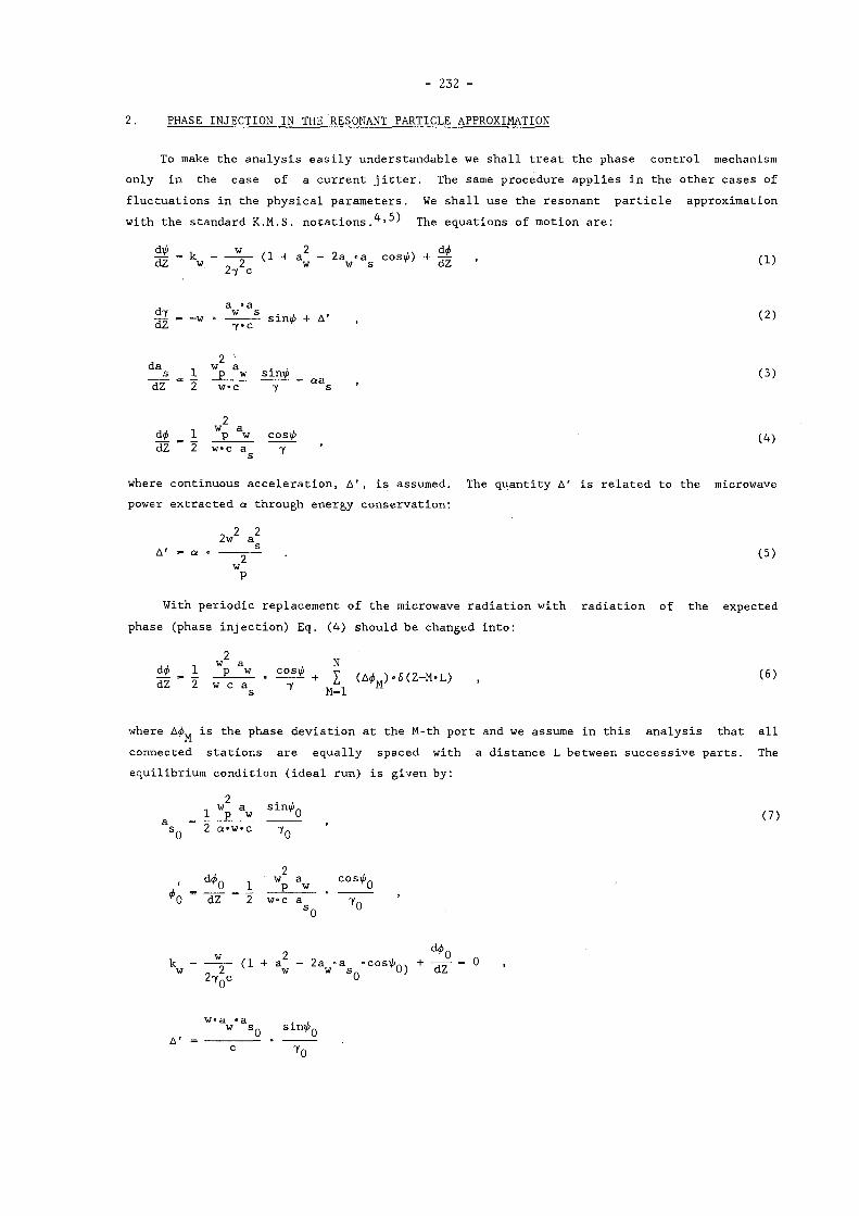
- 232 -
2. PHASE INJECTION IN THE RESONANT PARTICLE APPROXIMATION
To make the analysis easily understandable we shall treat the phase control mechanism only in the case of a current jitter. The same procedure applies in the other cases of fluctuations in the physical parameters. We shall use the resonant particle approximation with the standard K.M.S. notations.^' The equations of motion are:
dip , w ... , 2 „ ,. , dip - k (1 + a - 2a «a cosip) + , ni dZ w 2 w w s r dZ 2"i c
a • a d7 w s . , , , i T \ —L «, _ w . smV> + A , dZ 7»c
da _ w a . . ... s 1 p w smv> (3)
dZ 2 w«c 7 s
2 dp 1 p w cos í / 1 (4) dZ 2 w«c a 7 ' s
where continuous acceleration, A', is assumed. The quantity A' is related to the microwave power extracted a through energy conservation:
o 2 2 2w a A' = a • • (5)
w P
With periodic replacement of the microwave radiation with radiation of the expected phase (phase injection) Eq. (4) should be changed into:
s M=l
connected stations are equally spaced with a distance L between successive parts. The equilibrium condition (ideal run) is given by:
2 • , .. w a sirai.
a _ i P w 0 _ (7) S q 2 a»w»c 7 q
• _ 0 _ 1 Wp Sw . C O S^0 ^0 dZ 2 w c a 7 -
S0 °
2 d^0 k sp- (1 + a - 2a -a «cos^n. + -rry = 0 w 0 2 w w s r0) dZ 27 Qc 0
w>a «a . , w s 0 sin*0

- 233 -
We now study phase errors by assuming a small change from equilibrium or ig inat ing from a small deviat ion Ç — — in the inj ected current. Expanding a l l dynamical var iables in Ç,
0
we may write :
- tf0 + + r -i>2 + • • • (8)
7 - 7Q + + T *7 2 +
a - a + C»a, + C -a . + . . . s 0 1 2
+ r-tf, + r «tf, +
To f i r s t order in f, we obtain four l inear equations:
d ^
2 c 7 ; - 25, «U. + 2a «a sin^.tó, - 2a • cos i í . 'a , I +
1 0 w s 0 0 1 w r 0 1 Ï
(9)
~dZ~
_ w_ dZ " W CT^
a, • sinrá. - í , a • s ini¿„ + ib. a »cosi/i. 1 0 1 S Q 0 1 SQ 0 (10)
da. ., a "w 1 1 w p dZ 2 w c«7_
- sinV> 0 - S^tmpç + i>1cosi>Q L - aa. (H)
AA 2
d®. , w «a 1 1 p w dZ 2 wc7_a
0 s,.
- cosVv. - - — c o s i i - - 5 . c o s ^ „ 0 a 0 1 0 S 0
(12)
+ ¿ A ^ ( 1 ) . S ( Z - M . L )
where we use the notat ions:
U. = 1 + a - 2 a "a «cosrà. 0 w w S Q 0
SI - V 7 0
and have assumed the following expansion for the phase deviat ion:
A *M - f ' A * M ( l ) + f ^ M ( 2 ) + ••• • (13)

- 234 -
The phase i n j e c t ed term in Eq. (12 ) acts as a p e r i o d i c d r i v i n g f o rce i n i t i a t i n g spa t i a l
o s c i l l a t i o n s of the dynamical v a r i a b l e . We expand the pe r tu rba ted v a r i a b l e s (Eqs. ( 9 ) - ( 1 2 ) )
in a d i s c r e t e Four ier expansion of the form:
n - 1 »(Z) - I 6 -exp . i l c - Z
m (14)
where k - 2w»M/L ,
n L - i k Z f i e
m i (Z)
L 0 dZ
We obta in the four a l g e b r a i c equat ions :
ik i>x - 2 í l V - 2 - v , — + » — c o t ¿ . + ikt^. (15)
ik»5 1 Ir
— + S 1 - ^ - e o t ^ S 0
(16)
i k - a 1 - a a g ( - 1 - & 1 + ^ cotV>0) (17)
1 + + S l + * l c o t * o ' ( 1 ) (18)
where we drop the s u b s c r i p t *'m" in the dynamical v a r i a b l e s and the wave number k, and we
assume the same phase dev i a t i on , to f i r s t order in f, i n each sec t i on L. The so lut ion for
the e lectromagnetic phase s h i f t ^ in terms of the equ i l i b r ium parameters i s given from
Eqs. ( 1 5 ) - ( 1 8 ) :
^m^lm 1 • COtl^ n 1 - i "0 A'
7 o V c o t ^ n 1 -
i (1 - iP «cotiM 1 - i 047m
- i — t a n ^ 1 -
F — cottf. 1 - i ni q 0 7„q ^am O -ym
1 + i Q. 7 am U *7m
• — [ l - iP c o t ^ J + P tan,*. — „q q m r 0 \ m 0 q 0H7m 4am L J ^am . +
A<4 ( 1 ) (19)

- 2 3 5 -
where we use the fol lowing notat ions :
iq - ik - — , 7m m 7 n
.. A' . w U 0 A' . lq . - lk + 1 • — • cotvu
iq — ik + a + iaa am m
(1 - lP cot¿_) + J.acoti/> »P 0 0 701
and
ra q , 7-
. w U0 1 ¿77 — + c o t * o
0 n 7m
For the zero o s c i l l a t i o n mode, m - 0, the l . h . s . of Eq. (19) vanishes and we end up with an equation for the phase s h i f t :
A *<1) - L *ó 1 + i q a s 7 0 " q 7 0
H a s — [1 - i P 0 c o t ^ 0 ] +
s (20)
+ p o t a n ^ o
In our parameter region (see Table 1) the wave numbers q , q , q. and the parameter a 0 7 0 *"o
PQ can be approximated by:
. A' q — 1 —
7 0 7 0
q, =< i Uncotún , r0 C 7 0 0 r0
(21)
q « 2ice a 0
P Q - - i tantfQ
The average phase deviat ion, to f i r s t order in f, i s given by subs t i tu t ing Eq. (21) in Eq. (20):
(22)
Hence the peak to peak phase o s c i l l a t i o n i s :
A¿ • 2 i j - Ç'U>' PP (23)
In the next s ec t ion we present numerical r e s u l t s from a many p a r t i c l e simulation code. We s h a l l see that analyt ica l approximation given in Eq. (23) i s in a good agreement with the numerical r e s u l t s .

- 236 -
3. MANY PARTICLE SIMULATION
In this section a many particle simulation code is used to study the behaviour of the electromagnetic phase in the phase injection scheme. Detailed description of the code is found in Ref. 6. The simulation uses discrete replenishment of the beam energy in the F.E.L. section. The code simulates the microwave propagation for different initial conditions and according to our phase injection scheme it replaces, at each correction station, the electromagnetic phase with the phase calculated from the optimum run.
In Fig. 2 we present the evolution of the phase error with distance along the F.E.L. drift tube, for the case of initial current deviation C - 0.13% and without phase correction. The parameters of the run are given in Table 1. In Fig. 3 a phase injection has been applied at correct stations 60 m apart. One can see from the figure that the phase is confined in this case to A<6 < 8.8°. The analytical prediction for this set of parameters, given from Eq. (23), is A<4^ - 7.4°. Each phase correction initiate a synchrotron oscillations, which results from the phase shift between the bunch center of gravity and the center of the potential well. The power extraction, represented by the parameter a in Eq. (3), tends to suppress these oscillations. We can see from the figure that after 3 to 4 e folds (15 to 20 m) the oscillations disappear and the phase deviation increases linearly with Z up to the next correction station.
Table 1
Parameters of the F.E.L. portion in two-beam accelerators
Average beam energy (units of mc') 40 Beam current 2.4 kA Bunch length 6 m Wiggler wavelength 27 cm Peak wiggler field 3.2 kG Average beam power 48 Gw Power production 2.4 Gw/m
z - m e t e r s
Fig. 2 Phase error vs. distance for 0.13% error in current I_ = 2.4 kA.
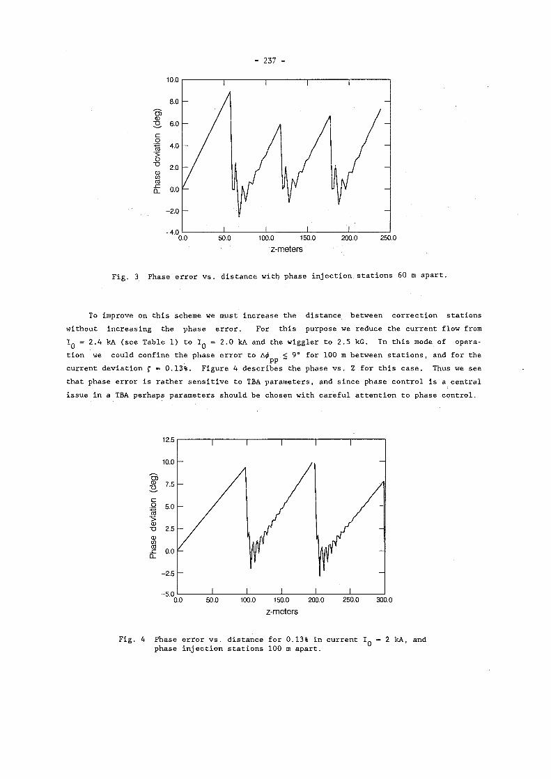
- 237 -
0.0 50.0 100.0 150.0 200.0 250.0 z - m e t e r s
Fig. 3 Phase error vs. distance with phase injection, stations 6 0 m apart.
To improve on this scheme we must increase the distance between correction stations without increasing the phase error. For this purpose we reduce the current flow from I Q = 2 . 4 kA (see Table 1 ) to I Q = 2 . 0 kA and the wiggler to 2 . 5 kG. In this mode of operation we could confine the phase error to Ad> < 9 ° for 1 0 0 m between stations, and for the
PP ~ current deviation Ç - 0 . 1 3 % . Figure 4 describes the phase vs. Z for this case. Thus we see that phase error is rather sensitive to TBA parameters, and since phase control is a central issue in a TBA perhaps parameters should be chosen with careful attention to phase control.
' 0.0 50.0 100.0 150.0 200.0 250.0 300.0 z - m e t e r s
Fig. 4 Phase error vs. distance for 0 . 1 3 % in current I Q - 2 kA, and phase injection stations 1 0 0 m apart.

- 238 -
ACKNOWLEDGEMENT
This work was supported by the U.S. Department of Energy under Contract No. DE-AC03 76SF00098.
REFERENCES
1) A.M. Se s s l er , "The Free Electron Laser as a Power Source for a High Gradient Accelerating Structure," in Laser Acceleration of P a r t i c l e s , AIP Conf., Proc. No. 91, New York (1982); A.M. Sess l er , IEEE Trans. on Nucl. Se i . NS-30 No. 4, 3145 (1983); A.M. Sess ler , Proc. of the 12th Int . Conf. on High Energy Accelerators , Fermilab, p. 445 (1983).
2) R.W. Kuenning, "T.B.A. Phase Considerations," Lawrence Berkeley Laboratory Internal Report T.B.S. Note 12 (1984).
3) R.W. Kuenning, A.M. Sess ler , and J . S . Wurtele, "Phase and Amplitude Considerations for the Two-Beam Accelerator." In Laser Accelerat ion of Par t i c l e s II, AIP Conf. Proc. , New York (1985).
4) N.M. Knoll, P.L. Morton, and M.W. Rosenbluth, IEEE Journal of Quantum Electronics QE-17<, 1436 (1981).
5) R.W. Kuenning, A.M. Sess ler , and E.J. Sternbach, "Radio Frequency Phase in the F.E.L. Sect ion of a T.B.A.." In Symp. on Advance Accelerator Concept, Madison, WI, August (1986). LBL-22301
6) E.J. Sternbach and A.M. Sess l er , "A Steady-State F.E.L.: Part ic le Dynamics in the F.E.L. Portion of a Two-Beam Accelerator." In Proc. of the 7th Int . Free-Electron Laser Conf., Tahoe City, CA. LBL-19939, September (1985).

- 239 -
PHYSICS OF RELATIVISTIC KLYSTRONS*
S. S. Yu
Lawrence Livermore National Laboratory, University of California
Livermore, California, USA
ABSTRACT
There has been much activity on the development of relativistic klystrons since the beginning of 1987 by many people at Stanford Linear Accelerator Center (SLAC), Lawrence Berkeley Laboratory (LBL), and Lawrence Livermore National Laboratory (LLNL). The following paper 1s one worker's summary of the status of the work. While many of the Ideas described have come from the work of other individuals, the author takes responsibility for possible errors and particular viewpoints expressed in this paper.
Considerations of cost and efficiency for large colliders have led to the choice of
short rf wavelengths (T to 3 cm).[1] Two consequences of the higher frequency,
high-gradient accelerator on the power source are the increase of required peak power
(to ~1 GW/m) and the reduction of pulse length (i 50 nsec). This dual requirement makes
high-current Induction linacs a natural match as a power source. Present induction
machines [2] typically produce electron pulses of the order of 50 nsec, and the peak power
in these relativistic beams 1s well in excess of GWs. As a power source, induction
machines together with recent developments in pulse power, have the desirable features of
being reliable and efficient (> 5OX, wall plug to beam).
The relativistic klystron presents a straightforward mechanism to convert the
high-peak power in the intense electron beam to rf power. When a high-current beam,
bunched at the appropriate frequency, 1s made to traverse resonant cavities, ample rf
power will be produced. Klystron tubes and induction linacs are both matured technology.
The relativistic klystron is a natural Integration of the two technologies.
The design of an rf accelerator structure 1s to a certain extent affected by the
power source under consideration. The relative ease of attaining high-peak power and
short pulse length in relativistic klystron concepts lead naturally to disk-loaded
structures with high-group velocity. These structures have some advantages in reducing
wall losses and, hence, in Increasing efficiency. In addition the associated enlarged
irises lead to reduction of wakefield effects in the high-gradient structure.
The parameters of the intense electron beam depend on the details of design. But
generally we are considering beams of 1 to 2 kA. From the point of view of induction cell
economics, one might, 1n fact, wish to go to higher currents (e.g., the Advanced Test
•Performed jointly under the auspices of the U.S. DOE by LLNL under W-7405-ENG-48 and for the DOD under DARPA, ARPA Order No. 4395, monitored by NSWC.

- 240 -
Accelerator (ATA) at LLNL is capable of operating at > 10 kA). The reason for staying at
the 1- to 2-kA level comes from the desire to match to conventional klystron cavities with
reasonable (R/Q) and quality factor Q. High current also accentuates transport and
beam-stability problems.
At present, beyond these general considerations a continuum of concepts is under
study, ranging from the two-beam-accelerator (TBA) approach (1 or a few power-sources for
each rf accelerator) [3] to much smaller devices where the role of the induction
accelerator and associated pulse power is to provide an advance injector for a
"conventional" klystron tube. [4] Each concept has its own merits as well as associated
physics issues.
The TBA 1s a long device where a bunched beam is made to go through rf cavities and
induction cells alternately. The energy lost to rf cavities is replenished by inductive
reacceleration. The TBA approach is attractive primarily because of efficiency and cost
considerations. A simple way of understanding the efficiency advantages is credited to
W.K.H. Panofsky [5] who first proposed the relativistic klystron version of the TBA. The
TBA may be viewed as an extension of the conventional klystron, where instead of wasting
half of the beam energy on the collector plate, one uses the beam over and over again.
The beam to rf efficiency is, therefore, close to 100%, in contrast to conventional
klystrons, where one has to work quite hard to get the efficiency much above 50%. The
cost trade-off between the TBA and a large number of smaller klystrons is that of
replacing sets of induction cells with injectors of approximately twice the beam power.
While the long-term advantages of TBA are evident, experimental demonstration of its
feasibility requires a much-longer-term investment than do the smaller devices. The major
issues that require experimental demonstration can be categorized under bunched beam
formation, rf power transfer, induction cell interaction, and high-current beam dynamics.
The formation of bunched beams from a direct-current (dc) beam is a required first
step in any relativistic klystron experiment. We are not aware of any go/no-go issue
here. The considerations are primarily that of engineering convenience. The devices
under consideration are typically ones in which the dc beam is injected Into cavities
where rf modulation (either longitudinal or transverse) is induced. The beam then goes
through magnetic bends and/or various focusing/defocusing elements where the rf
modulations give rise to path-length differences, and hence bunching at corresponding
frequencies. There are also considerations of chopping schemes that consist of apertures
intercepting beams at some prescribed phase Interval over the rf cycle. Such bunching and
chopping experiments were in fact conducted at LLNL years ago at frequencies much lower
than what is presently considered. [6]
The critical issue in rf power transfer is surface breakdown. There is no
experimental data on breakdown characteristics of short pulses (~50 nsec) at these
frequencies, and quantitative information here is essential both for klystron cavity
operation as well as for high-gradient-structure design. Experimental data on mode

- 241 -
c o n t e n t a n d p h a s e stability a r e a l s o r e q u i r e d . C o n c e p t u a l l y , p h a s e stability i n a
relativistic k l y s t r o n T8A 1s much l e s s o f an issue t h a n i t s f r e e - e l e c t r o n laser (FEL)
c o u n t e r p a r t . T h i s d i f f e r e n c e r e s u l t s f r o m t h e f a c t t h a t k l y s t r o n c a v i t i e s i n v o l v e
primarily s t a n d i n g w a v e while an FEL TBA i n v o l v e s w a v e s t h a t p r o p a g a t e w i t h the b e a m .
W h i l e beam b u n c h i n g a n d r f p o w e r t r a n s f e r a r e i s s u e s common t o a l l r e l a t i v i s t i c
k l y s t r o n c o n c e p t s , i n d u c t i o n c e l l i n t e r a c t i o n is an I s s u e s p e c i f i c t o T B A s . H e r e , t h e
g o a l 1s t o m i n i m i z e r f p o w e r d r a i n f r o m i n d u c t i o n c e l l s a n d t o minimize e f f e c t s on
b e a m - b r e a k u p (BBU) i n s t a b i l i t y . T h e beam p i p e s a r e r e q u i r e d b y r f c u t o f f c o n s i d e r a t i o n s
t o be v e r y n a r r o w ( r < 1 cm f o r 11.4 G H z ) , and c o m p l e t e l y new i n d u c t i o n c e l l s n e e d t o b e
designed t o w o r k in t h i s new r e g i m e .
Beam d y n a m i c s 1s p e r h a p s t h e m o s t c r i t i c a l I s s u e i n t h e TBA c o n c e p t . T h e f i r s t I s s u e
h a s t o d o w i t h w h e t h e r o n e c o u l d k e e p t h e p a r t i c l e s b u n c h e d o v e r long d i s t a n c e s , s i n c e
t h e r e a r e s p a c e - c h a r g e d e b u n c M n g and f i n i t e e m i t t a n c e e f f e c t s t h a t t e n d t o d e g r a d e t h e
b u n c h e d b e a m . O u r c a l c u l a t i o n s I n d i c a t e t h a t o n e c o u l d k e e p the p a r t i c l e s c o n t i n u o u s l y
b u n c h e d if r f o u t p u t c a v i t i e s a r e I n d u c t i v e l y d e t u n e d . T h e p a r t i c l e s w i l l t h e n p e r f o r m
s y n c h r o t r o n o s c i l l a t i o n s i n s t a b l e b u c k e t s . F o r t y p i c a l TBA p a r a m e t e r s , the r e g i o n o f
stability i s q u i t e l a r g e .
T h e n a r r o w p i p e g i v e s r i s e t o v e r y s e r i o u s t r a n s v e r s e i n s t a b i l i t y p r o b l e m s . B o t h t h e
r e s i s t i v e w a l l i n s t a b i l i t y as w e l l a s t h e BBU I n s t a b i l i t y a r e d r a s t i c a l l y e n h a n c e d w i t h
d e c r e a s i n g p i p e r a d i u s . F o r t u n a t e l y , p a r t i c l e s o s c i l l a t i n g in s y n c h r o t r o n b u c k e t s h a v e a
l a r g e e n e r g y s p r e a d w h i c h may be e n o u g h t o s u p p r e s s t h e I n s t a b i l i t i e s t o t a l l y b y L a n d a u
d a m p i n g .
T h e s y n c h r o t r o n p e r i o d a s w e l l as t r a n s v e r s e i n s t a b i l i t y g r o w t h d e p e n d s t r o n g l y on
e n e r g y . A 5- t o 10-m TBA e x p e r i m e n t a t > 5 MeV c a n p r o v i d e s i g n i f i c a n t t e s t s o f beam
b u n c h i n g a n d beam s t a b i l i t y . S u c h an e x p e r i m e n t 1s b e i n g p l a n n e d a t L L N L .
As a f i r s t p h a s e o f t h i s TBA e x p e r i m e n t , we w i l l a t t e m p t t o e x t r a c t as much o f t h e
beam e n e r g y a s p o s s i b l e w i t h o u t r e a c c e l e r a t i o n . I f a s e r i e s o f o u t p u t c a v i t i e s a r e
a p p r o p r i a t e l y s p a c e d , we may be a b l e t o r e d u c e t h e a v e r a g e e n e r g y o f t h e beam
a d i a b a t i c a l l y , m a i n t a i n i n g s t a b l e b u c k e t s d u r i n g t h e e n e r g y e x t r a c t i o n p r o c e s s . S u c h a
p u r e d e c e l e r a t o r w o u l d n o t be quite as e f f i c i e n t a s a TBA p r o p e r b u t s h o u l d h a v e
efficiencies much h i g h e r t h a n c o n v e n t i o n a l k l y s t r o n s .
W h i l e t h e TBA c o n c e p t has p o t e n t i a l l o n g - t e r m a d v a n t a g e s , t h e r i s k i s a l s o h i g h e r .
I t seems a v e r y s e n s i b l e a p p r o a c h , t h e r e f o r e , t o s t a r t w i t h smaller d e v i c e s t h a t w i l l g i v e
e n d - p r o d u c t s in t h e m s e l v e s in a r e l a t i v e l y s h o r t t i m e a n d a l s o p r o v i d e i n c r e m e n t a l
information t o w a r d s f u t u r e e f f i c i e n c y u p g r a d e s . T h e " u p g r a d e d k l y s t r o n , " as p r o p o s e d b y
M a t t A l l e n a n d o t h e r s a t S L A C , [4] 1s, t h e r e f o r e , a r a t h e r n a t u r a l s t e p i n t h i s
d i r e c t i o n . T h e i d e a h e r e i s t o build " c o n v e n t i o n a l " h i g h - p o w e r k l y s t r o n s w i t h an I n p u t
c a v i t y , a n o u t p u t cavity, a n d t h r e e o r f o u r i d l e r c a v i t i e s , i n much t h e same w a y as

- 242 -
existing S-band tubes. Induction machines a r e used to provide the front-end of the
tube. Bunching by longitudinal velocity-modulation and drift is possible for beam
energies < 3 MeV.
While the tube technology 1s well known, some physics Issues need to be addressed in
the new regime. First, the rf pulse-length of the new device 1s of the order of 50 nsec,
in contrast to existing tubes with pulse lengths of several y s e c . The fill-time to
reach peak rf power, which 1s generally a small fraction of the pulse length in usee
tubes, may no longer be a negligible effect in 50-nsec tubes. The fill-time in existing
S-band tubes has been measured to be ~ 40 nsec. [4] This is consistent with the
calculated Q-values, which are of the order of 100, and come primarily from beam loading.
However, the beam-loaded Q increases drastically with beam energy and becomes much too
large at 1.5 MeV. To bring the rise-time to a more reasonable length (< 10 nsec),
external loading [7] must be added to the Idler cavities to reduce the Q.
Another problem has to do with the BBU Instability through the idler cavities. The
high-Q idler cavities, which give high gain in the axisymmetric bunching, also lead to
high gain in transverse deflections. Gain in transverse displacement through a 5
five-cavity tube has been calculated to be -10 . Roger Miller [ 8 ] has proposed
stagger-tuning the deflecting modes in the cavities to reduce BBU. Calculations indicate
that 10 to 2OX spread in the dipole frequencies in the cavities can reduce the growth to
less than 100. BBU growth can be further reduced by phase-mixing effects, and also by
employing additional schemes such as making the cavity spacing a multiple of the betatron
wavelength. [9]
Complicatlons associated with idler cavities can be bypassed if one starts with a
strong Input drive (~MW). There is no existing X-band drive at these power levels, but
5-MW C-band klystrons (5.7 GHz) are in use. Since the bunched beam from a strong rf drive
(-500 to 700 kV) is rich 1n harmonics, one can get second and third harmonic current of
several hundred amperes with relative e a s e . Hence, a strong C-band drive followed by
an output cavity allows one to extract power of several hundred MW at the fundamental
(5.7 GHz), the second harmonic (11.4 GHz), or the third harmonic (17.1 GHz). The
frequency at which power is extracted 1s control led by the resonant frequency of the
output cavity. Driving at C-band has the additional advantage that one can accommodate a
larger pipe diameter over most of the tube, easing the transport problem associated with
narrow pipes. Both the high-gain and low-gain experiments are being planned at the
Accelerator Research Center (ARC) at LLNL as a joint project with SLAC.
ACKNOWLEDGEMENTS
There are many who have contributed to the relativistic klystron development effort.
It 1s impossible to provide an exhaustive 11st; however, among these are D. Birx,
G.A. Westenskow, D.S. Prono, W.C. Turner, L.L. Reginato, R.J. Briggs, W.A. Barletta,
M. Caplan, W.M. Fawler, V. Kelvin Neil, A.C. Paul, G.J. Caporaso, A.G. Cole, J.K. Boyd,

- 243 -
and K. Witham from LLNL; A. Sessler, D.B. Hopkins, Y. Goren, and 0. Witham from LBL; and
H. Allen, R. Ruth, R. Miller, T. Lee, W.K.H. Panofsky, G. Loew, P. Wilson,
W. Herrmansfeldt. P. Morton, A Vliecke, K. Eppley, E. Patterson, and R. Palmer from SLAC.
REFERENCES
1) R. Palmer, Proceedings, present Workshop.
2) L. L. Reginato, IEEE Trans. Nucl. Sei. NS-30. 2970 (1983).
3) A. Sessler and S.S. Yu, Phys. Rev. Lett. Vol. 56, 23 (1987).
4) M. Allen, Proceedings, present Workshop.
5) W.K.H. Panofsky, private communication.
6) V.K. Neil, IEEE Trans. Nuc. Science, NS-20. 347 (1973).
7) R. Ruth, Proceedings, present Workshop.
8) R. Miller, private communication.
9) V.K. Nei1, private communication.
* * *
Discussion
J. Nation, Cornel 1 University
How does your beam brightness requirement compare with that achieved to date in ETA
and ATA?
Reply
The beam brightness requirement is very weak, and is well within what is presently
achieved. The reason is that the stable particle buckets for relativistic klystrons are
very big (as compared, for example, to FEL buckets). Thus one can accommodate large spread
in v i i s which in turn implies weak requirements on transverse emittance.
M. Cavenago, INFN, Pisa
How is the typical shape of the accelerating potential necessary for longitudinal
phase stability achieved by the induction accelerator?
Reply
The phase stabi1lty is achieved not by the accelerating potenti al but by the rf cavi
ties. The stable region of phase space is determined by the amount of inductive detuning
in the klystron cavities. If there is no inductive detuning, there is no stable bucket.
However, if the detuning angle is several tens of degrees the stable bucket is larger.

- 244 -
LASERTRON DEVELOPMENT AND TESTS OF HIGH GRADIENT ACCELERATING STRUCTURES IN JAPAN
T. Shidara
Nat iona l Laboratory for High Energy Physics, KEK, Oho-machi, Tsukuba-gun, I b a r a k i , 305, Japan
ABSTRACT Experiments on a high power lasertron and high gradient acce l e ra t ing
structures are current ly under way by the Japanese L inear Collider Study Group with the aim of applying these in future e + e l i n ea r
colliders. With the l a s e r t r o n , a maximum power of 79 kW at 2856 MHz
has been obtained with an e f f i c i ency of 2.5 X. An average
acce le ra t ing gradient of 104.5 MV/m on beam axis was attained for a
f i v e c e l l structure operated at th is same frequency in the 2ir/3
t rave l ing wave mode.
1 . INTRODUCTION
An e+e l i nea r C o l l i d e r in the TeV reg ion i s one of the var ious proposals for future
acce le ra to rs beyond LEP energy. I t r equ i res high power microwave sources with a peak output
power of about 1 GW and t r ave l ing wave acce le ra t ing structures operat ing at a f i e l d gradient
of about 100 MV/m or more.
Such high peak power i s much beyond the l e v e l which can be achieved with conventional
technology. There are severa l candidates for this power source such as k ly s t rons , gyrotrons 1) 2) and photocathode microwave sources , e t c . Among these, we began studies on the l a se r t ron
Figure 1 shows a conceptual drawing of a l a s e r t r on . A microwave modulated beam i s produced.
by d i r ec t emission modulation of a photocathode with a microwave modulated o p t i c a l beam.
Compared with a k lys t ron , i t has the po tent i a l merit of producing higher peak power with
higher e f f i c i ency in a more compact dev ice .
Focusing coi
Power Feeder
Output Microwave
- H V Mode locked aser light
)utput Cavity
Photocathode
F ig . 1 A conceptual drawing of the l ase r t ron

- 245 -
We p r o v e d t h e l a s e r t r o n p r i n c i p l e by t e s t i n g s e v e r a l s m a l l l a s e r t r o n a a t S-band
f r e q u e n c y . E x t e n d i n g t h e s e s t u d i e s , a new R/D p rog ram h a s s t a r t e d t o c o n s t r u c t a MW and 3)
t e n MW l a s e r t r o n . D e t a i l s of 2 MW l a s e r t r o n e x p e r i m e n t s w i l l b e d e s c r i b e d i n s e c t i o n 2 .
High g r a d i e n t f i e l d a c c e l e r a t i n g s t r u c t u r e s h a v e b e e n a l r e a d y t e s t e d by S L A C ^ ' ^ and
V a r i a n A s s o c i a t e s I N C . ^ ' ^ I n t h e SLAC e x p e r i m e n t , an a c c e l e r a t i n g s t r u c t u r e was e x c i t e d i n
a s t a n d i n g wave mode. The p e a k s u r f a c e f i e l d was c a l c u l a t e d t o be 318 MV/m, a round t h e
beam h o l e i n t h e d i s k . A' s i n g l e - c e l l c a v i t y was u s e d i n t h e V a r i a n e x p e r i m e n t . A p e a k
s u r f a c e f i e l d of 239 MV/m was r e a c h e d .
A l t h o u g h t h e s e s t a n d i n g wave mode e x p e r i m e n t s may g i v e some measure of t h e h i g h g r a d i e n t
f i e l d b e h a v i o r , d i r e c t t e s t s on a s t r u c t u r e i n a t r a v e l i n g wave mode i s p r e f e r a b l e f o r t h e
f i n a l d e s i g n of a f u t u r e l i n e a r c o l l i d e r . E x p e r i m e n t a l r e s u l t s of an S-band s t r u c t u r e
o p e r a t e d i n t h e 2i t /3 t r a v e l i n g wave mode w i l l b e d e s c r i b e d i n s e c t i o n 3 .
2 . LASERTRON EXPERIMENT
2 . 1 EXPERIMENTAL SET-UP OF LASERTRON
The l a s e r t r o n c o n s i s t s of a l a s e r s y s t e m , a m o d u l a t o r power s u p p l y , a c o a x i a l c a b l e t o
s u p p l y c h a r g e t o t h e p h o t o c a t h o d e , a c a t h o d e chamber , an o u t p u t c a v i t y and a beam c o l l e c t o r
a s shown i n F i g . 2 .
Mode-locked Laser
P 2.5m J
F i g . 2 E x p e r i m e n t a l a r r a n g e m e n t of l a s e r t r o n
8) The l a s e r sy s t em was d e v e l o p e d by an o u t s i d e company. The c o n f i g u r a t i o n of t h i s
s y s t e m i s shown i n F i g . 3 . A cw m o d e - l o c k e d Nd : YAG o s c i l l a t o r p r o d u c e s a c o n t i n u o u s t r a i n
of 85 p s i n f r a r e d o p t i c a l p u l s e s ( F i g . 4 - a ) w i t h 5 . 8 n s s e p a r a t i o n . A waveform s h a p e r g i v e s
t h e n e c e s s a r y t r a n s m i s s i o n waveform by a p p l i n g a programmed waveform t o an o p t i c a l s h u t t e r
( P o c k e l s 1 c e l l ) . T h i s made i t p o s s i b l e t o g e n e r a t e a l o n g , f l a t - t o p p e d p u l s e t r a i n from
s e v e r a l g a i n - s a t u r a t e d Nd : YAG a m p l i f i e r s t a g e s . F o l l o w i n g t h e SHG (Sub-Harmonic G e n e r a t o r )
c r y s t a l , t h e i n f r a r e d beam i s f r e q u e n c y d o u b l e d i n t o t h e g r e e n 532 nm 60 p s o p t i c a l p u l s e s
40 m J ) . A m i r r o r sy s t em i n c r e a s e s t h e f r e q u e n c y by a f a c t o r of 16 t o form a 2856 MHz o p t i c a l
p u l s e t r a i n ( F i g . 4 - b ) . A GaAs w a f e r w i t h an a c t i v e a r e a of 20 mm i n d i a m e t e r was u s e d f o r
t h e p h o t o c a t h o d e . The quantum e f f i c i e n c y was ^ 5 2 .

- 246 -
cw ML Nd: YAG OSC cw WAVEFORM SHARER
— g g — I }—tzs—
x / 4 I D— AMPI
DP EXP 4 5 ° FARADAY ROTATOR - O J ö gsH h a — —
EXP - O AMP3
FARADAY ROTATOR 45* — E H BZa D —
AMP 2
45" EXP SHG DM
_ n _
178.5 MHz
EXP
x 16 ¡ MP h-
DM 2856 MHz
F i g . 3 The configuration of the laser system for lasertron experiment. AMP, amplif ier; DP, d i e l e c t r i c polarizer; EXP, expander or reducer; SHG, second-harmonic generator; DM, dichroic mirror; MP, multiplexer
H B
• • S I N
H l i l u u n K i i R I S BBAUBSHBAFIBRUBFL IMIHW* ;JM1
9 1 1 » L. -
• • • • I
EFFIITIWR r*~*~™ 1111111111111111111111111 i w n I MINI M 1111
i '
3 5 0 p s
Fig. 4-a 178.5 MHz opt ica l pulses of 1.06 ym with a width of 85 ps .
Fig. 4 -b 2856 MHz opt ica l pulses of 532 nm with a width of 60 p s .
2.2 EXPERIMENTAL RESULTS AND DISCUSSIONS
Figure 5 shows a curve of beam current, I , as a function of beam vol tage , V. Below 50 KV, the beam current exhibi ts the normal diode character i s t i c s of a typical klystron
3/2 (I=constant-V ) . On the other hand, above 50 kV, the beam current i s proportional to beam voltage (I«constant«V). This l inear dependence of the beam current i s a character is t ic
9) property for bunched beam from the gun. Below 50 kV, there e x i s t s more than one bunch between the anode and cathode area, leading to normal diode c h a r a c t e r i s t i c s .

- 247 -
Fig. 6 Picture of power output (upper) Fig. 5 Beam current versus accelerat ing voltage and beam current (lower)
When a 5 Us 150 kV pulse was applied to the lasertron, a peak power output of 79 kW with a peak current of 21 A was generated (Fig. 6 ) . The conversion e f f i c iency from beam power to microwave power (~2 .5 % in t h i s case) i s not as high as we expected for the lasertron . This might be due to the debunching e f f ec t of space charge forces . We are now working to get a good ef f ic iency and high power output.
3 . HIGH GRADIENT FIELD EXPERIMENT
3 . 1 SET-UP OF HIGH GRADIENT FIELD EXPERIMENT
The schematic diagram of the experimental set-up i s shown in Fig. 7 . The t e s t accelerating structure was inserted in a resonant r ing. The klystron output power (30 MW with a pulse width of 2 v s ) i s fed into the ring through a 6 . 04 dB coupler. This coupling was adjusted to obtain a maximum c irculat ing power P c ins ide the ring (y 120 MW) . The ring has a stub-tuner sect ion and a phase sh i f t er to suppress the reverse c irculat ing power and to adjust the phase length. Two Bethe-hole type direct ional couplers are located just before and after t h e accelerating structure t o monitor t h e c irculat ing power. An analyzer magnet of 45° bending angle was put jus t behind t h e t e s t sect ion to measure the energy spectrum of t h e f i e l d emission current.

- 248 -
F i g . 7 A s c h e m a t i c s e t - u p of h i g h g r a d i e n t f i e l d e x p e r i m e n t
The a c c e l e r a t i n g s t r u c t u r e c o n s i s t s of t h r e e r e g u l a r c e l l s and two c o u p l e r c e l l s a t each
end ( F i g , 8 ) . The r e g u l a r s e c t i o n i s a c o n v e n t i o n a l d i s k - l o a d e d s t r u c t u r e w i t h a beam
a p e r t u r e of 16 mm d i a m e t e r . P a r a m e t e r s of t h e a c c e l e r a t i n g s t r u c t u r e a r e summarized i n
T a b l e 1 . The a v e r a g e a c c e l e r a t i n g f i e l d Eacc i s e s t i m a t e d by u s i n g
Eacc (MV/m) - 9 . 4 2 ^Pc(MW) (1)
where Pc i s t h e f o r w a r d c i r c u l a t i n g power l e v e l i n MW.
F i g . 8 G r o s s - s e c t i o n a l d r a w i n g s of t h e a c c e l e r a t i n g s t r u c t u r e

- 249 -
Table 1
Parameters of the Accelerating Structure
Phase Sh i f t /Ce l l 2W/3
Structure Length 17.5 cn
Beam Hole Diameter (2a ) 1.6 cm Cavity Diameter (2b) 8.132 cm
Resonant Frequency (f) 2856.15 MHz Q 13330
Shunt Impedance (r) 63.1 MÛ/m
Attenuation 0.7017 Neper/m Group Ve loc i ty (Vg/c) 0.0032
3.2 EXPERIMENTAL RESULT
Af te r about 500 hours of integrated microwave conditioning (20 Hz, 2us p u l s e s ) , an
accelerating field gradient of 104.5 MV/m (Pc - 123 MW) was stably achieved without any
baking of the s t ruc ture . This l e v e l is limited only by the maximum available klystron power. At this gradient, the accelerating structure could be operated quite stably for 10 hours as shown in Fig. 9.
Fig. 9 A picture of the microwave power in the ring built up to 123 MW (upper) and microwave power of the klystron (lower)
The electron energy spectra of the field emission current are shown in Fig. 10. The maximum electron energy values agree with those values calculated with q. (1) and the structure length of 17.5 cm. The scallops that appeared on the spectrum may be due to acceleration over the five-cell structure.

- 250 -
F i g . 10 Electron energy spectra at var ious acce le ra t ing gradients
10-'*
T < 5 A / t M V / m ) "
y a = 260
a \ y ß = Î2-2
1 1 \ :
i 4 5 6 7 8 9 10 11
1/Ep ( x ) O ' 1 m / M V )
Fig . 11 Fower-Nordheim p l o t of the f i e l d emission current

- 251 -
The f i e l d emission currents 1^ on the beam axis were plot ted in a modified Fowler-Nordheim diagram as shown in Fig. 11. The Fowler-Nordheim formula i s expressed as follows :
I - , , - 1 0 . 1 . 5 f „ -1.34x10 <fr , 0 N - Cexp g g — * (2) E P P
where C i s a constant, <j> i s the workfunction of the copper, ß i s the microscopic f i e l d enhancement factor , and E^ i s the maximum f i e l d on the surface which i s 2.1 times Eacc by the SUPERFISH ca lcu la t ion .
The slope (1) shows that the f i e ld enhancement factor , ß, in the conditioned region by microwaves reached f i n a l l y ¡5=122, which i s very c lose to the value obtained at SLAC. On the other hand, the slope (2) with a larger value (ß - 260) indicates that a new domain was reached.
ACKNOWLEDGEMENTS
The author wishes to express h i s gratitude for the encouragement and f inancial support received from director T. Nishikawa. He also wishes to express h i s thanks to Prof. Y. Kimura, organizer of the Linear Collider Study Group, for the guidance and continuous encouragement. He would a l so l ike to thank Prof. G. Horikoshi, leader of the lasertron study group, for h i s encouragement and valuable d iscuss ions .
This report i s based on the work of the members of the Linear Collider Study Group ; Y. Fukushima, H. Matsumoto, H. Mizuno, T. Shintake, K. Takata, S. Takeda, Y. Yamazaki and M. Yoshioka.
The author i s much indebted to Profs. S. Anami, A. Asami, Drs. A. Ban, S. Sasaki and Mr. H. Honma for the ir help in the present experiments.
* * * REFERENCES
1) P.B. Wilson, SLAC-PUB-2884 (1982)
2) Y. Fukushima et a l . , Nuclear Instruments and Methods in Physics Research A238, 215 (1985)
3) Y. Fukushima et a l . , IEEE Trans. NS-32, 2831 (1985)
4) J.W. Wang et a l . , SLAC-PUB-3597 (1985)
5) J.W. Wang et a l . , SLAC-PUB-3940 (1986)
6) E. Tanabe, IEEE Trans. NS-30 3551 (1983)
7) A.H. McEuen et a l . , IEEE Trans. NS-32 2972 (1985)
8) H. Imoto et a l . , Proc. Conf. on Lasers and Electro-Optics , Baltimore, Maryland, 26 April - 1 May (1987)
9) H. Nishimura, Proc. of the 1984 Linear Acc. Conf., Darmstadt, West Germany, 7-11 May (1984)
10) H. Matsumoto e t a l . , Proc. of the 1987 IEEE Part ic le Accelerator Conference, Washington DC, USA, 16-19 March (1987)

- 252 -
Discussion
N.K. Sherman, NRC, Ottawa
There are at least three reasons for the smearing of time response of photocathode:
Single-bunch space charge, multi-bunches in flight simultaneously and response of the
photocathode material.
1) How many bunches are in f1ight at once?
2) Is secondary emission the cause of the response of the photocathode?
Reply
1) In our lasertron experiment, the distance between the cathode and anode is 2 cm. So,
there is only one bunch between them when we apply more than 50 kV.
2) No, I do not think so. I think the drift velocity of excited electrons inside the
photocathode mater i al is a problem. Since the skin depth of GaAs is of the order of 1 nm
in green, the response time from the deepest part to the surface is estimated at about
1 ns. This is probably the cause of bad time response of the photocathode material.
M. Boussoukaya, LAL
1) Do you think that diffusion in the ceasiated CdAs is partially responsible for a part
of the pulse length?
2) What is the contribution of space charge to the "bad" photo-response time that you got?
Reply
1) nee the carrier density of our photocathode is very high, I think there is no problem
it a 11 for the charge supply. Actually, the beam current shape has almost the same shape
with the laser pulse comb in the 1 p-s region. It seems to me that the low dr i ft velocity
of an excited electron inside the GaAs is the main cause of the bad response time.
?) According to our simulation, space charge effect increases the pulse width of a bunch
from 60 ps up to 200 ps when we apply 100 kV. This surely decreases the conversion effi-
ciency from beam power to microwave power. But I do not think this space charge effect is
the main cause of the "bad" photo-response time.

- 253 -
ACCELERATOR R & D AT LAL-ORSAY*
J. Le Duff
LAL, Orsay, France
ABSTRACT
An R & D programme was launched at LAL/Orsay at the end of 1985 as a con
tribution to the short term future. The programme mostly concentrates on
conventional technologies for which improvements can still be made in
terms of power efficiencies in the frame of very high energy linear
colliders.
1. INTRODUCTION
LAL has recently been involved in the design and construction of LIL (LEP injector
linacs). Consequently, new experience was gained in modern linac technologies which moti
vated the present research and development programme on future linear colliders.
This programme is based essentially on improvements and extensions of conventional
technologies, and a start was made possible due to some major equipment being provided by
SLAC and CERN. The main items of this R & D programme are:
- Beam dynamics simulation
- Generation of short-pulse, high-peak currents
- RF power source: LASERTRON
- High gradient warm structures
2. SIMULATION OF BEAM DYNAMICS IN THE LASERTRON [1-3]
A computer code, named RING, has been specially written to simulate the beam dynamics
in the lasertron, but can also be used to design laser-triggered guns. The main features
of this code are:
- Time is the independent variable
- Relativity is considered, but radiating fields are ignored
- Each bunch is split into disks (z coordinates) and each disk is made of rings (r
coordinate). Both z and r are tracked for each particle and the velocity v^ is
obtained from Busch's theorem ( 2 1 / 2 D code)
- Transient bunch behaviour is studied in the gun and drift regions
- Steady state is considered in the output cavity of the lasertron
- The code is relatively fast since high precision is obtained with only a few
particles (for example 45 minutes c.p.u. for 100 electrons on a VAX 11/785).
* Work supported by IN2P3 and DRET

- 254 -
More details on the physics of this code and examples of computer runs are given in a
contribution from A. Dubrovin and J.P. Cou Ion to this Workshop. In particular the code has
been used to des i gn a prototype Lasertron at Orsay, with the characteristics and theoreti
cal performance summarized in Table 1 .
Table 1
Design parameters of the Orsay prototype Lasertron
RF frequency 6 GHZ
RF power 2 0 MW
Efficiency 7 5 %
Beam power 2 5 MW
Acc. voltage 4 0 0 kV
Average current 5 2 A
Charge/micro pulse 1 0 nC
Cathode area 1 cm 2
Magnetic field 2 . 8 kG
Optical frequency UV
Micropulse length 3 5 ps
Micropulse energy 1 MJ
An interesting result from the simulation study is the optimum geometrical configuration of
the gun region corresponding to a non-focusing geometry but giving a maximum uniformity of
the accelerating field. The latter, for a short pulse, leads to a minimum distortion of
the bunch with respect to the distance r to the axis, since al 1 particles achieve almost
the same velocity.
3 . MICROPULSED PHOTOCATHODES STUDIES [ 4 - 6 ]
The Lasertron programme has led to specific experimental studies of high-current,
pulsed photoemission, with the aim of achieving the best choice of photocathode. For
instance, a good compromise between quantum efficiency and 1ifetime seems necessary. The
first experimental apparatus consisted of:
- A picosecond Nd: YAG laser providing short bursts of a few 1 0 mJ in the IR, green
and UV regions.
- A small ultra-high vacuum tank in which the distance between the cathode and anode
could be adjusted and fitted with a 1 0 kV high voltage supply. The cathode support
was especially designed to handle metallic needles and arrays of needles.

- 255 -
The first experimental results were obtained with sinole U needles and an arrav of
Nb 3 Ti needles. These results are shown in Table ?, where AT is the microDulsed current
width as measured with a 1 GHz bandwidth oscilloscope. Note that each laser macrooulse
(burst) is made of seven micropulses whose theoretical width is expected to be 3 5 D S. Tf
the microoulse current shaoe fol lows the liant Dulse we should exoect, in fact, much hiqher peak currents. In these exoeriments the hiah voltaae is adiusted to he sliahtlv below the field emission threshold. Hence the required laser pulse enerav needed for electron
extraction becomes smaller (photo-field emission).
Table 2
Experimental results from micro emitters
Photocathode I peak [ A ] A T [ns] Laser burst enerqy [iij]
Sinqle W needle Green 2 < 1 4 0
UV .fi i n
Nb 3 Ti arrav) IJV i n < •1 7n (400 needles)
Since these first results were quite encouraaina a more soohist.icat.eH ultra-hinh vacuum tank is beinq built to handle a much hiqher voltaqe (150 kV) such that photo-field
emission can be tested in a more realistic HV environment. This tank (Pia. 11 should he ready before the end of 1987. In order to control the acceleratinq field at the needle, an
intermediate anode is included in the aun reqion.
It is believed that just by chanoinq the ceramic insulator, it. should he nossihle to
ooerate the same tank at up to 400 kV. In that case, with little modification, it will
serve as a prototype Lasertron. In view of this future experiment the tank has been
desiqned to allow easy access to the anode reqion. Finallv, the experimental work is
scheduled as follows:
a) Hiqh current photo-field emission tests. Extracted charaes will he measured hv
usinq a wide band coaxial Faraday cup behind the anode.
b) Space charqe effects. The microoulse current will be measured usina a transient
radiation monitor such that a picosecond streak camera can make the comparison
with the incident laser pulse width.
c) RF efficiency. The previous monitors will be replaced with an extraction cavity.
However, this experiment will only be possible after modification of the laser in order to get a lonq train of micro pulses with little amplitude modulation.

Fig . 1 High voltage, u l t ra - h i g h vacuum tank for photocathode experiments
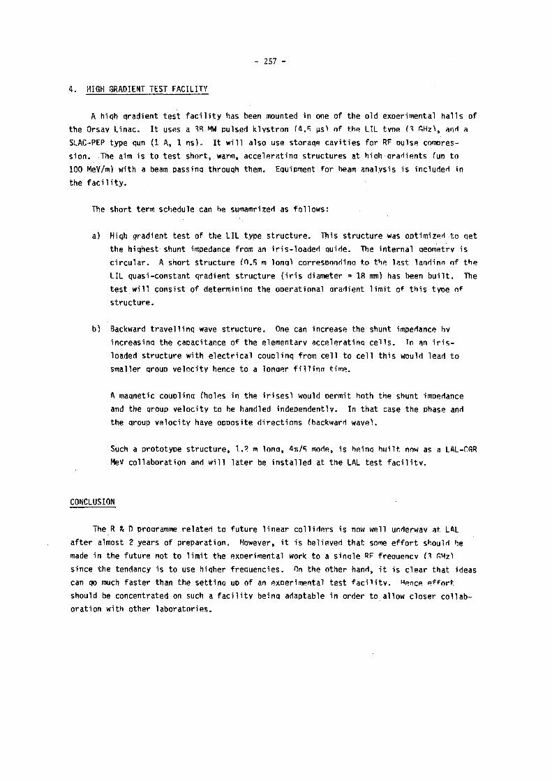
- 257 -
4 . HIGH GRADIENT T E S T F A C I L I T Y
A h i q h g r a d i e n t t e s t f a c i l i t y h a s b e e n m o u n t e d i n o n e o f t h e o l d e x p e r i m e n t a l h a l I s o f
t h e O r s a y L i n a c . I t u s e s a W MW p u l s e d k l y s t r o n ( 4 . 5 u s ) o f f.bc. Ill t v n e H G H z ) , and a
S L A C - P E P t y p e qun (1 A , 1 n s ) . I t w i l l a l s o u s e s t o r a q e c a v i t i e s f o r RF o u l s e c o m p r e s
s i o n . T h e a im i s t o t e s t s h o r t , w a r m , a c c e l e r a t i n a s t r u c t u r e s a t h i ah G r a d i e n t s f u n t o
100 MeV/m) w i t h a beam p a s s i n g t h r o u q h t h e m . E q u i p m e n t f o r beam a n a l y s i s i s i n c l u d e d i n
t h e f a c i l i t y .
The s h o r t t e r m s c h e d u l e c a n he s u m a m r i z e d as f o l l o w s :
a ) Hiqh g r a d i e n t t e s t o f t h e L I L t y p e s t r u c t u r e . T h i s s t r u c t u r e was o p t i m i z e d t o q e t
t h e h i q h e s t s h u n t impedance f r o m an i r i s - l o a d e d q u i r t e . The i n t e r n a l a e o m e t r v i s
c i r c u l a r . A s h o r t s t r u c t u r e ( 0 . 5 m l o n g ) c o r r e s o o n d i n a t o t h e l a s t l a n d i n n o f t h e
L I L q u a s i - c o n s t a n t q r a d i e n t s t r u c t u r e ( i r i s d i a m e t e r = 18 mm) has b e e n b u i l t . T h e
t e s t w i l l c o n s i s t o f d e t e r m i n i n a t h e o p e r a t i o n a l G r a d i e n t l i m i t o f t h i s t y p e o f
s t r u c t u r e .
b ) B a c k w a r d t r a v e l 1 i n q w a v e s t r u c t u r e . One c a n i n c r e a s e t h e s h u n t i m p e d a n c e h v
i n c r e a s i n a t h e c a p a c i t a n c e o f t h e e l e m e n t a r y a c c e l e r a t i n q c e i l s . Tn an i r i s -
l o a d e d s t r u c t u r e w i t h e l e c t r i c a l c o u o l i n q f r o m c e l l t o c e l l t h i s w o u l d l e a d t o
s m a l l e r q r o u o v e l o c i t y h e n c e t o a l o n a e r f i l l i n a t i m e .
A m a q n e t i c c o u o l i n q ( h o l e s i n t h e i r i s e s ! w o u l d p e r m i t b o t h t h e s h u n t i m p e d a n c e
a n d t h e q r o u p v e l o c i t y t o he h a n d l e d i n d e p e n d e n t l y . I n t h a t c a s e t h e p h a s e and
t h e q r o u p v e l o c i t y h a v e o p p o s i t e d i r e c t i o n s f b a c k w a r d w a v e ) .
Such a p r o t o t y p e s t r u c t u r e , 1.2 m l o n a , 4it/5 m o d e , i s h e i n a b u i l t now as a LAL-OGR
MeV c o l l a b o r a t i o n and w i l l l a t e r be i n s t a l l e d a t t h e LAL t e s t f a c i l i t y .
CONCLUSION
T h e R & D o r o a r a m m e r e l a t e d t o f u t u r e 1 i n e a r c o l l i d e r s i s now w e l l u n d e r w a y a t L A L
a f t e r a l m o s t 2 y e a r s o f p r e p a r a t i o n . H o w e v e r , i t i s b e l i e v e d t h a t some e f f o r t s h o u l d be
made i n t h e f u t u r e n o t t o l i m i t t h e e x p e r i m e n t a l w o r k t o a s i n a l e RF f r e q u e n c y H G H z )
s i n c e t h e t e n d a n c y i s t o u s e h i q h e r f r e q u e n c i e s . On t h e o t h e r h a n d , i t i s c l e a r t h a t i d e a s
c a n qo much f a s t e r t h a n t h e s e t t i n a uo o f an e x p e r i m e n t a l t e s t f a c i l i t y . Hence e f f o r t ,
s h o u l d be c o n c e n t r a t e d on s u c h a f a c i l i t y b e i n q a d a p t a b l e i n o r d e r t o a l l o w c l o s e r c o l l a b
o r a t i o n w i t h o t h e r l a b o r a t o r i e s .

- 258 -
REFERENCES
[1] P.J. Tallerico and J.P. CouIon, A ring model of the Lasertron, LAL-RT 87-02 (March 1987).
[2j A. Dubrovin and J.P. Coulon, Simulation des performances du lasertron, SERA 87-116 (Orsay, May 1987).
[3j A. Dubrovin and J.P. Coulon, Lasertron computer simulation at Orsay: "Ring Code" (contribution to this Workshop).
[4J M. Boussoukaya et al., Emission de photocourants à partir de photocathodes à pointes, LAL RT/86-04 (September 1986).
[5j M. Boussoukaya et al., Photoemission in nanosecond and picosecond regimes obtained from macro and micro cathodes; LAL RT/87-03, Orsay, March 1987.
[6] M. Boussoukaya, Photoemission and photofield emission: some results, Proceeding of the ICFA workshop held at BNL, March 20-25 1987 (to be published).

- 2 5 9 -
L A S E R T R O N C O M P U T E R S I M U L A T I O N A T O R S A Y : " R I N G " C O D E
A . D u b r o v ! n a n d J . P C o u I o n
L a b o r a t o i r e d e l ' A c c é l é r a t e u r L i n é a i r e , O r s a y . FRANCE.
A B S T R A C T
A 2 D ^ c o d e , " R I N G " , h a s b e e n w r i t t e n 1 ^ t o s i m u l a t e t h e
e l e c t r o n d y n a m i c s i n h i g h p e a k c u r r e n t m I c r o p u I s e d RF 2 )
s o u r c e s , s u c h a s a l a s e r t r o n . T h e s ¡ m u I a t I o n s ' s h o w t h e
l i m i t a t i o n s o f s u c h d e v i c e s i n t e r m s o f m a x i m u m c u r r e n t
g e n e r a t i o n f r o m t h e p h o t o c a t h o d e , b e a m p o w e r a n d R F
e x t r a c t i o n e f f i c i e n c y . T h e s t a r t i n g c o n d i t i o n s a n d
c o m p a r i s o n s b e t w e e n 3 a n d 6 G H z d e v i c e s w i l l b e d i s c u s s e d .
1 . I N T R O D U C T I O N
A s t h i s c o d e w a s i n t e n d e d t o w o r k o n a V A X 8 6 0 0 , w e t r i e d t o o b t a i n t h e b e s t c o m p r o m i s e
b e t w e e n a c c u r a c y a n d r a p i d i t y o f e x e c u t i o n , t h e r e f o r e , w e c h o s e a 2 0 ^ s i m u l a t i o n ( r , z ) f o r
c y l i n d r i c a l s y m m e t r y , u s i n g t i m e a s t h e i n d é p e n d a n t v a r i a b l e . T h e e l e c t r o n s a r e c o n s i d e r e d a s
p o i n t s f o r t h e d y n a m i c s a n d a s r i n g s f o r t h e s p a c e c h a r g e f o r c e s ( G r e e n f u n c t i o n s ) , t h e
s i n g u l a r i t y o f t h e f i e l d s b e i n g a v o i d e d b y i n t e g r a t i n g t h e r i n g s o v e r a f i n i t e v o l u m e .
A p p r o x i m a t e b u t f a s t e r s p a c e c h a r g e e v a l u a t i o n s a r e a v a i l a b l e a n d e x t e r n a l s t e a d y s t a t e
f i e l d s ( g u n , c a v i t y , m a g n e t i c f o c u s i n g ) a r e a n a l y t i c a l y c o m p u t e d o r i n c l u d e d f r o m e x t e r n a l
c o d e s s u c h a s " H E R M A N N S F E L D T , S U P E R F I S H , P O I S S O N S e l f c o n s i s t e n t i t e r a t i o n s a r e m a d e o v e r
t h e m t o d e t e r m i n e t h e R F c a v i t y g a p v o l t a g e o r s h u n t i m p e d a n c e .
A n o t h e r p r o g r a m f o r l a s e r t r o n s , " P A R A D E " , i s u n d e r d e v e l o p m e n t a t L . A . u s i n g m i x e d
f i n i t e e l e m e n t e v a l u a t i o n o f t r a n s i e n t f i e l d s .
2. P R O G R A M B E H A V I O U R
We o b s e r v e d l e s s t h a n 1/5 c h a n g e i n R F e f f i c i e n c y w h e n u s i n g 1 0 e l e c t r o n s i n s t e a d o f 1 0 0 .
T h i s p r o v i d e s u s w i t h a c o m m o n s i m u l a t i o n u s i n g t h r e e i t e r a t i o n s o v e r R F f i e l d s w i t h a b o u t
5 m i n u t e s C . P . U t i m e o n a V A X 8 6 0 0 , a n d l e s s t h a n 1 . 5 X d i f f e r e n c e i n R F e f f i c i e n c y c o m p a r e d
w i t h t h e s a m e c a s e s i m u l a t e d w i t h t h e MASK c o d e ( a b o u t 1 h o u r o n a C R A Y 1 ) .
T h i s g o o d a g r e e m e n t i s m a i n l y d u e t o t h e u s e o f a v e r y h i g h D . C v o l t a g e ( 4 0 0 k V ) a n d
s h o r t p u l s e s t h a t m i n i m i z e w a k e f i e l d s w i c h c a n t h e n b e n e g l e c t e d . O n t h e o t h e r h a n d , R I N G i s
a b l e t o s h o w t h e c h a r g e e x t r a c t i o n l i m i t d u e t o s p a c e c h a r g e e f f e c t s i n a s i n g l e b u n c h ( s e e
S e c t i o n 5 ) .

- 260 -
3 . E F F E C T S O F F R E Q U E N C Y O N P A R A M E T E R S : 3 A N D 6 G H z D E V I C E S
We w e r e i n t e r e s t e d t o c o m p a r e 3 a n d 6 G H z l a s e r t r o n s k n o w i n g t h a t t h e f r e q u e n c y o f
f u t u r e l i n a c s s h o u I d b e n e a r e r 6 G H z t h a n 3 G H z . T h e r e f o r e , w e d e s i g n e d a n d c o m p u t e d a 6 G H z
p r o t o t y p e t o g i v e t h e s a m e R F e f f i c i e n c y a s t h e S L A C 3 G H z l a s e r t r o n f o r a 3 0 p s l a s e r
i m p u l s i o n l e n g t h .
F i g u r e s 1 t o 4 i l l u s t r a t e t h e g e o m e t r i e s a n d t h e s i m u l a t i o n r e s u l t s i n b o t h c a s e s . A I I
t h e p o i n t s o n t h e s e f i g u r e s w e r e o p t i m i s e d ( b y c h a n g i n g t h e s h u n t i m p e d a n c e ) t o o b t a i n t h e
b e s t i n t e r a c t i o n b e t w e e n t h e b e a m a n d t h e R F c a v i t y , t h e c a s e o f a g i v e n c a v i t y i s d e s c r i b e d
i n F i g . 4 b y t h e b r o k e n - l i n e s . We s e e t h a t t h e 6 G H z c a s e n e e d s t w i c e a s m u c h m a g n e t i c
f o c u s i n g , g u n a n d R F f i e l d s , a n d t h a t l a s e r i m p u l s i o n l e n g t h d u r a t i o n s g r e a t e r t h a n 6 0 p s
h a v e i o b e a v o i d e d .
90
2 . S L A C L A S E R T R O N 3 G H Z .400 KV 4. O S S A Y l A S E R T R O I V 6 G H Z . 4QQ K V
F i g u r e s 1 - 4 : 3 a n d 6 G H z g e o m e t r i e s a n d s i m u l a t i o n r e s u l t s

- 261 -
4 . GUN G E O M E T R Y O P T I M I S A T I O N
We f i r s t s t a r t e d w i t h a W e h n e l t g u n a s w e w i s h e d t o u s e l o w e x t e r n a l m a g n e t i c f i e l d s
( a r o u n d 1 . 5 k G ) a n d s q u e e z e t h e b u n c h r a d i a l l y a s m u c h a s p o s s i b l e . H o w e v e r , s i m u l a t i o n s
s h o w e d t h a t t h e c u r v a t u r e o f t h e e q u i p o t e n t i a i s s t r o n g l y p r o v o k e s a l o n g i t u d i n a l s p r e a d i n g
o f t h e b u n c h a n d c a u s e s a l o s s o f a b o u t 15 % I n R F e f f i c i e n c y ( f o r t h e s a m e b e a m p o w e r )
c o m p a r e d w i t h t h e f l a t c a s e . T h e u s e o f a P i e r c e g u n m i n i m i z e d t h i s e f f e c t , b u t t h e i n i t i a l
I o n g i t u d i n a I d e I a y c a n c e l l e d t h e g a i n o f a m o r e u n i f o r m a c c e l e r a t i o n s o t h a t w e o b t a i n e d
a I m o s t t h e s a m e d e b u n c h i n g a s i n t h e W e h n e l t c a s e . F i n a l l y , t h e m a g n e t i c f i e l d s r e q u i r e d
f o r t h e f I a t c a s e a r e n o t t r e m e n d o u s ( a r o u n d 3 k G ) a n d t h e r e t a i n e d b e a m d e n s i t i e s r e q u i r e
t h a t t h e s e f i e l d s b e t w i c e a s h i g h a t t h e R F g a p t h a n a t t h e c a t h o d e ( a r o u n d 1 . 5 k G ) , w h e r e
t h e W e h n e l t e l e c t r o s t a t i c f o c u s i n g n o l o n g e r a c t s .
F o r a l l t h e s e r e a s o n s ( i n a d d i t i o n t o t h e o n e e x p l a i n e d a t S e c t i o n 5 ) , t h e f l a t g u n
t u r n s o u t t o b e t h e b e s t f o r a l a s e r t r o n .
5 . C A T H O D E C H A R G E E X T R A C T I O N L I M I T S
T h e r e a r e t w o m a i n l i m i t s t o c h a r g e e x t r a c t i o n f r o m t h e c a t h o d e .
F i r s t w e h a v e t o c o n s i d e r w h e t h e r a l l t h e e l e c t r o n s e x p e c t e d h a v e s u f f i c i e n t t i m e t o
l e a v e t h e c a t h o d e b e f o r e t h e l a s e r I I I u m i n a t i o n s t o p s . T h e a n s w e r m u s t t a k e a c c o u n t o f m a n y
p a r a m e t e r s s u c h a s t h e e l e c t r o n s p e e d i n t h e g i v e n m a t e r i a l , t h e l a s e r a c t I v e d e p t h , t h e
t o t a I c a t h o d e v o l u m e , I o c a I f i e l d s ( n e e d I e e m i s s i o n ) . . . b u t t h e s e a r e n o t c u r r e n t l y
i n c l u d e d i n o u r c o d e .
T h e o t h e r l i m i t i s d u e t o s p a c e c h a r g e r e p u l s i o n b e t w e e n t h e e l e c t r o n s a l r e a d y
e m i t t e d a n d t h e o n e s w h i c h a r e j u s t l e a v i n g t h e c a t h o d e . I f t h e l a s e r l i g h t i n t e n s i t y a n d
c a t h o d e e f f i c i e n c y a r e v e r y e f f e c t i v e , i t a p p e a r s p o s s i b l e t o r e a c h t h e s t a t e w h e r e t h e
e m i t t e d e l e c t r o n s , i n s p i t e o f t h e i r r e m o v a l f r o m t h e c a t h o d e , a r e n u m e r o u s e n o u g h t o f o r b i d
a n e w e m i s s i o n . T h i s e f f e c t i s d e s c r i b e d b y R I N G i n l o a d i n g t h e e x p e c t e d c h a r g e i n m a n y t i m e
s t e p s f r o m t h e b e g i n n i n g t o t h e e n d o f l a s e r i l l u m i n a t i o n , t a k i n g i m a g e c h a r g e s i n t o a c c o u n t .
We o b s e r v e d , f o r a l a s e r i m p u l s i o n d u r a t i o n a r o u n d p e r i o d / 1 0 , a n u p p e r l i m i t f o r t h e l o a d e d
c h a r g e w h i c h i s a b o u t 65 n C f o r t h e S L A C 3 G H z l a s e r t r o n , 2 0 n C f o r o u r f l a t 6 G H z l a s e r t r o n
a n d 6 n C f o r a 6 G H z l a s e r t r o n u s i n g a W e h n e l t g u n , a s i n t h i s c a s e t h e a v e r a g e f i e l d o n t h e
c a t h o d e i s l o w e r ( s o m a k i n g i t i m p o s s i b l e t o o b t a i n 2 5 MW w i t h s u c h a d e v i c e ) . N o t e t h a t
u s i n g n e e d l e e m i s s i o n s h o u l d s t r o n g l y r e d u c e t h i s l i m i t a t i o n s i n c e t h e l o c a l f i e l d s w o u l d b e
t r e m e n d o u s .
6 . I N I T I A L C O N D I T I O N S : L A S E R L I G H T S H A P E A N D I N I T I A L S P E E D
We m a d e t h e c o d e a b l e t o s i m u l a t e a n y k i n d o f l a s e r p u l s e s h a p e b y t r a n s l a t i n g 11 i n t o
e m i s s i o n d e l a y t i m e s . T h e g a I n , w h e n c h a n g i n g f r o m a r e c t a n g u l a r t o a g a u s s i a n b u n c h s h a p e ,
w a s o n l y a r o u d 2 % f o r o u r f r e q u e n c i e s , s i n c e t h e e l e c t r o n s i n t h e c e n t r e o f g a u s s i a n b u n c h e s

- 262 -
a r e s o c l o s e t h a t t h e d e n s i t y q u i c k l y b e c o m e s u n i f o r m . We a l s o e x a m i n e d t h e e f f e c t s o n c h a r g e
e x t r a c t i o n a n d R F e f f i c i e n c y o f t h e i n i t i a l s p e e d o f t h e e l e c t r o n s . T h i s w e t h o u g h t w o u l d b e
j u s t i f i e d i n t h e c a s e o f a l a s e r w h e r e h i s g r e a t e r t h a n t h e p o t e n t i a l e x t r a c t i o n b a r r i e r ,
t h e d i f f e r e n c e b e i n g a r o u n d 1 e V , w h i c h i s e q u i v a l e n t t o 5 . 8 1 0 s m/s s p e e d . D i f f e r e n t s p a t i a l
d i s t r i b u t i o n s o f t h i s i n i t i a l e n e r g y w e r e s i m u l a t e d , b u t i n a l l c a s e s t h e e f f e c t w a s v e r y l o w
( a r o u n d 0 . 3 % o n R F e f f i c i e n c y ) . T h i s i s d u e t o t h e s t r o n g a c c e l e r a t i o n o f t h e m o t i o n t h a t
r a p i d l y r a i s e s t h e e l e c t r o n s p e e d t o t w o t h e n t h r e e o r d e r s o f m a g n i t u d e g r e a t e r t h a n t h e
i n i t i a l o n e .
7. E S T I M A T I O N O F O R S A Y L A S E R T R O N P A R A M E T E R S
R F f r e q u e n c y 6 G H z
R F p o w e r 2 5 MW
R F e f f i c i e n c y 7 5 55
C a t h o d e a r e a 1 . 1 3 c m 2
C h a r g e / m i c r o p u t s e 1 5 n C
A v e r a g e c u r r e n t 9 0 A
A c c e l e r a t i o n D . C v o l t a g e 4 0 0 k V
M a g n e t i c f i e l d s ( m a x i m u m ) 3 k G
O p t i c a l f r e q u e n c y U . V .
M i c r o p u l s e I e n g t h 3 5 p s
M i c r o p u I s e e n e r g y 1 JfJ
8 . F U T U R E I M P R O V E M E N T S T O T H E " R I N G " C O D E
T h e s i m u l a t i o n o f n e e d l e e m i s s i o n i s u n d e r d e v e l o p m e n t . F a s t e r m e t h o d s o f s p a c e c h a r g e
c o m p u t a t i o n a r e u n d e r s t u d y s o t h a t m u l t i p l e c a v i t i e s a n d t h e e s t i m a t i o n o f s p a c e c h a r g e
f o r c e s b e t w e e n p e r i o d i c b u n c h e s c a n b e t a k e n i n t o a c c o u n t w i t h t h e s m a l l e s t t i m e e x p e n s e .
A C K N O W L E D G E M E N T S
We t h a n k P r o f e s s o r J . P e r e z y J o r b a a n d D o c t o r J . L e D u f f f o r c o n s t a n t s u p p o r t .
R E F E R E N C E S :
1 ) P . J . T a l l e r i c o a n d J . P . C o u l o n , "A r i n g m o d e l o f t h e l a s e r t r o n " , L A L R T - 8 7
O R S A Y F R A N C E
2 ) A . D u b r o v i n a n d J . P . C o u l o n , " S i m u l a t i o n d e s p e r f o r m a n c e s d u l a s e r t r o n " , L A L
R T - 8 7 O R S A Y F R A N C E
3 ) G . L e M e u r , "A m i x e d f i n i t e e l e m e n t m e t h o d f o r p a r t i c l e s i m u l a t i o n i n
l a s e r t r o n " , L A L R T - 8 7 - 0 1 O R S A Y F R A N C E

- 263 -
GRAPHICAL OUTPUT EXAMPLE
LASERTRON SERA - L.A.L - ORSAY
CANON ! <¡ la¡sceQU> = 76.98A , période = 167.1 pjec tension = 400.00 Kv
IrocÜon = 0.80 freq. = 5.986 Ghz perv. = 9.62 microPerv
MOO eus : champ E stol.= herra chad"esp.canon = 2D champ B s!ot.= br. res. chad"esp>f = 20 champ HF = super fish
LASES : ¡ pulse : 642.96 A , charge cu paquet : 12.9 nC durée d"eclairemeaí : 20.Ö psec forme ái piise loser : rectangle :
SORTIE HF : R/Q = 100.0 Ohms Fo = 5.986 Ghz res.shunl = 7573.0 Ohms Vqap = 600000.0 V phil = -0.007 <¡¡ induit> = 79.2J A
PUISSANCE DISPO. = 2J768.07 K« RENDEMENT HF = 77.19 X
tBtp(tac).n 211 JB. <tt
SO electrons
BimaiftTniix J482.8I 609.00 Brinajriri» - & M -ME.fi BphhnxAih'rria' O.CO -M.B Uibt»Ù — Br. - Bpkc _ - .
net 630
PlK-UlyiSs-lpefc)
E L E C T R O N T R A J E C T O R I E S
coiíík ! { {
imps= i a. a ¡a s sa m. M. n i s a t a m a m 2 a ÎW. m a i m 3& m j t s . a.
40.0
35.0 +
3ao +
25.0
20.0
15.0
B.0
5.0
.- 1 * / >-
M
i i i i i i i i i ^ i i i i i i i i i i i i i i i i i i i i i i i i i i i i i i n i i i i i h i i i i i i i i i i i n i i i i
5 B 15 20 25 50 55 40 45 50 55 60 S5 Z MOMENTUM
70 75
APPENDIX

- 2 6 4 -
GIGATRON
Hana M. Bizek, Peter M. Mclntyre, Deepak Raparía, Charles A. Swenson Department of Physics, Texas A&M University, College Station, Texas, USA.
ABSTRACT The gigatron i s a new rf amplifier tube designed for l i n a c
c o l l i d e r appl icat ions . Three design features permit extension of the lasertron concept to very high frequencies . F i r s t , a ribbon beam geometry m i t i g a t e s space charge depression and f a c i l i t a t e s e f f i c i e n t output c o u p l i n g . Second, a t r a v e l i n g wave o u t p u t coupler i s used to obtain optimum coupling to a wide beam. Third, a gated f i e l d - e m i t t e r array i s employed for the c a t h o d e . A prototype device i s currently being developed.
1. INTRODUCTION
The gigatron i s a design for a compact, e f f i c i e n t microwave power amplifier tube. It employs the lasertron concept,^ ^ in which a bunched e l e c t r o n beam i s e x t r a c t e d from a modulated cathode and a c c e l e r a t e d through a DC diode structure as shown in Fig. 1. The result ing beam i s fu l ly modulated at high energy without the requirements of a modulator and d r i f t reg ion that c h a r a c t e r i z e a l l conventional amplifier tubes. RF energy i s then extracted from the beam in an output coupler. Because there i s no DC component to the beam current, very high ef f ic iency can in principle be obtained.
A major motivation to develop the g i g a t r o n a r i s e s in current e f f o r t s to des ign a + - 2 ) multi-TeV e e l i n a c c o l l i d e r for e lementary p a r t i c l e physics. The performance of a
l inac co l l ider improves substant ia l ly as the frequency of the l inac structure i s increased. Severa l current des ign concepts would operate at frequencies from 10 to 30 GHz. One key
VACUUM PUMP —
i—OUTPUT COUPLER
>-COLLECTOR
Fig. 1 Cross-sect ional view of the gigatron

- 265 -
challenge for future linac colliders is to develop a compact, efficient source for >100 MW peak power, 20 GHz. Technologies that are being explored in this connection include the
3 4) 5) 6) lasertron, the gyroklystron, the free-electron laser, and the relativistic 7)
klystron.
The gigatron has been designed to extend the advantages of previous lasertron designs to very high frequency and high peak power. Three developments make this possible. First, a ribbon beam geometry is adopted instead of the conventional round beam. Second, a
8 ) traveling wave output coupler is used to obtain optimum coupling across a wide beam.
9) Third, a gated field enitter array is employed for the cathode; this appears to offer a simpler and more reliable modulated cathode than the laser-modulated photocathode of previous designs.
A preliminary design has been prepared for a prototype gigatron. It is designed to produce 10 MW peak power at 20 GHz with an efficiency of "70?. Major specifications are summarized in Table 1. The prototype design is readily extended to produce à 100 MW/m peak power. The following text describes several novel features of the gigatron and presents the results of beam transport and rf field calculations for the prototype design.
2. RIBBON BEAM GEOMETRY
The ribbon beam geometry is used to eliminate several limitations of round-beam devices for high power operation at high frequency. High output power requires large beam current. Large beam current in a round beam entails substantial space charge depression and consequently a transit time spread in the diode region. The resulting phase spread limits high frequency performance. Large beam current also requires a transverse beam size that becomes comparable to wavelength at high frequency, so that output coupling becomes inefficient.
These problems are mitigated by adopting a ribbon beam geometry. Space charge depression for a given beam current is reduced by a factor equal to the transverse aspect ratio (w/1). High beam currents are readily achieved. The narrow (height) dimension can be kept small to facilitate efficient output coupling. Extension to higher power can be achieved simply by making the entire device wider. The wide dimension of the beam raises special problems for output coupling, which have been solved by the invention of the traveling wave coupler structure described in the following section.
The ribbon beam geometry is produced from a standard Pierce rectilinear diode. }^ The diode voltage is 200 kVDC; the diode spacing is 1 . 8 cm; and the emission current density is 65 A/cm*. The cathode is a ( .4 x 14)cm2 ribbon.
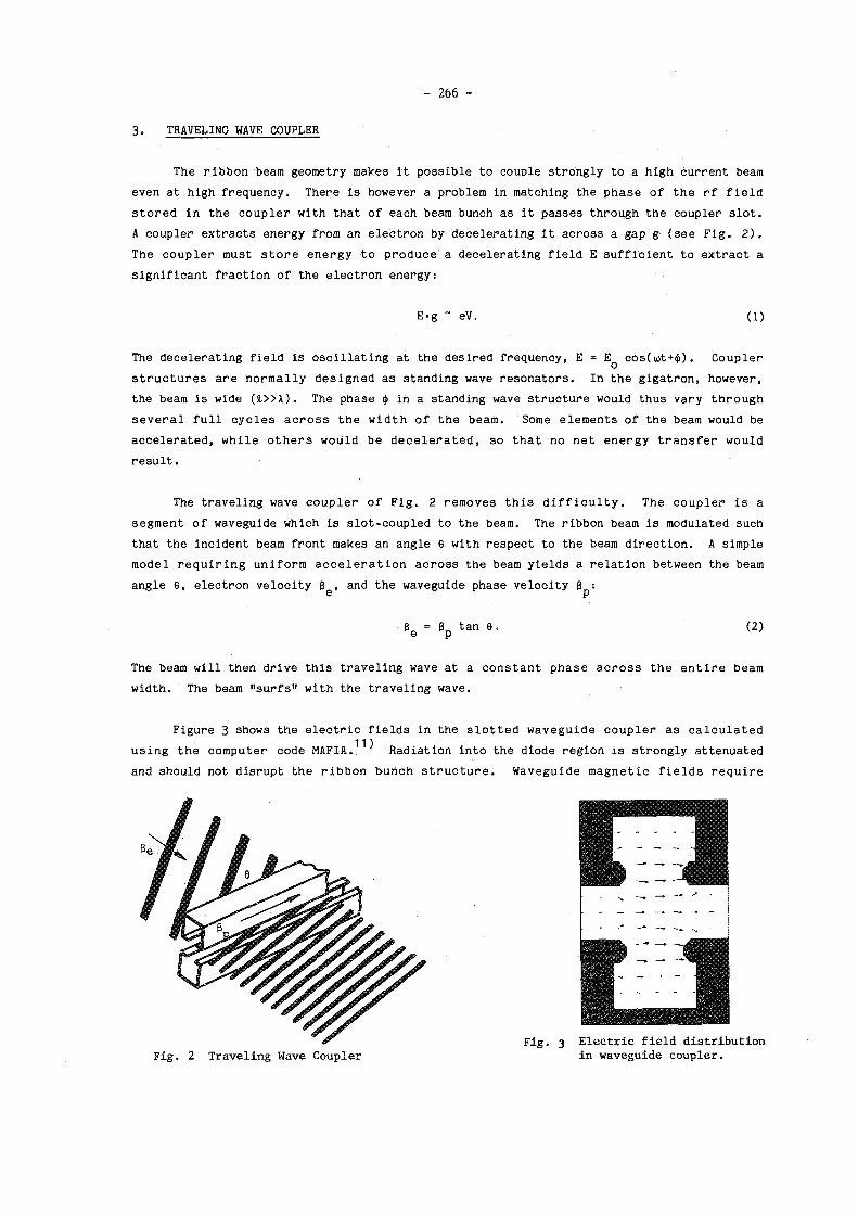
- 266 -
3. TRAVELING WAVE COUPLER
The ribbon beam geometry makes it possible to couple strongly to a high current beam even at high frequency. There is however a problem in matching the phase of the rf field stored in the coupler with that of each beam bunch as it passes through the coupler slot. A coupler extracts energy from an electron by decelerating it across a gap g (see Fig. 2). The coupler must store energy to produce a decelerating field E sufficient to extract a significant fraction of the electron energy:
E-g - eV. (1)
The decelerating field is oscillating at the desired frequency, E = E q cos( iot+$). Coupler structures are normally designed as standing wave resonators. In the gigatron, however, the beam is wide (i»X). The phase <j> in a standing wave structure would thus vary through several full cycles across the width of the beam. Some elements of the beam would be accelerated, while others would be decelerated, so that no net energy transfer would result.
The traveling wave coupler of Fig. 2 removes this difficulty. The coupler is a segment of waveguide which is slot-coupled to the beam. The ribbon beam is modulated such that the incident beam front makes an angle 6 with respect to the beam direction. A simple model requiring uniform acceleration across the beam yields a relation between the beam angle 6, electron velocity S , and the waveguide phase velocity B :
e p ß = gn tan 6. (2)
The beam will then drive this traveling wave at a constant phase across the entire beam width. The beam "surfs" with the traveling wave.
Figure 3 shows the electric fields in the slotted waveguide coupler as calculated using the computer code MAFIA.11^ Radiation into the diode region is strongly attenuated and should not disrupt the ribbon bunch structure. Waveguide magnetic fields require
Fig. 2 Traveling Wave Coupler in waveguide coupler.

- 267 -
further refinements to this simple model. Each beam component is bent sideways by an angle ? due to the in phase magnetic field (B = E/ß^c) of the traveling wave:
Í B . d i t _ g E o C O S < l >
V 1/mïv ß /EüT 2 ¡ t ° ' ( 3 )
•J D
This effect can be partially compensated by a static vertical dipole magnetic field across the coupler beam exit. The magnetic effects are being studied numerically.
The coupler must return sufficient beam energy back into its input to generate the required decelerating field. This can be accomplished by 1) shorting the waveguide at each end and slot coupling output power at one end (only one traveling wave component will be driven by the tilted beam); 2) linking two traveling wave couplers end-to-end in a resonant loop; or 3) configuring the waveguide in a circular ring driven by a helical beam. The required Q is
Q = M [Stored Energy] _ ^ [e„E02g2at/2b] = 1 2 5 Q ( 4 )
[Output Power] P •
The unloaded Q for the TE 1 0 mode is:
Q - x [1+ - (—) 2]" 1 = 3000 (5) o a u
where 6 = .53 um is the skin depth of copper at 18 GHz.
4. THE GATED FIELD-EMITTER CATHODE
3) 4) Present lasertron designs utilize either a photocathode or a field-emitter brush which is excited by a modulated laser beam. Several problems attend these approaches. First, Cs-doped GaAs deteriorates in frequency response above "1 GHz because the charge mobility is inadequate to clear the depletion depth during an rf cycle. Second, the laser and particularly the photocathode represent significant uncertainties for reliable continuous operation in an accelerator system. The gated field-emitter array appears to offer an attractive alternative.
9) CA. Spindt et al. have developed microfabrication techniques by which they can
prepare planar arrays of gated field-emitting points as shown in Fig. 4. Electrons are field-emitted from an array of metal point cathodes. Each point is situated within a metal gate structure. Application of a modest gate-cathode voltage (Vg~ 30V) results in full modulation of emission current. Currents of >100A/cm2 have been routinely achieved. There is no evidence of in-service deterioration during extended life tests. A different ap-
12) proach has been developed by H. Gray at the Naval Research Laboratory. He uses directional etching techniques to produce atomically sharp needle and knife-edge arrays directly on silicon.

- 268 -
Several modifications will be required for the gigatron application. First, the gate layer, which currently is deposited as a uniform sheet with holes for each tip, must instead be fabricated as a pattern of ring electrodes surrounding each tip and connected by lines. In this way the gate capacitance could be reduced from 1500 pF/em2 to _< 100 pF/cm2. While the cathode would still represent a very capacitive load (XQ ~ 1 Q mm), it could be adequately modulated using GaAs MMIC amplifier chips bonded along the edge of the cathode structure.
Second, the gate layer must be configured as a suitable point-to-parallel optical lens. The electrons leave each cathode tip in a wide-angle cone. The effective electron transverse temperature is T,~eV = 3 0 e V . The gate field geometry is being modeled in an
8
effort to transform this cone into a nearly uniform, parallel beam before acceleration in the diode. Figure 'lb shows the modified cathode design.
Fig. 4 Gated field-emitter cathode (a) thin-film field-emission cathode array; (b) modified array for gigatron application.
5. PERFORMANCE CALCULATIONS FOR THE PROTOTYPE DESIGN
We have calculated beam transport through the gigatron. Calculations were performed 13)
using the MASK computer code. Figure 5 shows the trajectories of two successive ribbons through the coupler structure. Trajectories are shown on five points across each ribbon. Both transverse position and energy are shown for each trajectory. Slot width and height, coupler peak field, rf phase and beam phase width were varied to optimize rf efficiency while transporting residual beam to the collector. For the optimized parameters rf conversion efficiency of 70% is obtained. No beam is intercepted before entering the collector structure.

- 269 -
Sí
o
u a
<u
60
t u c w c o
8 1 2 1 6
Position mm
Fig. 5 Electron energy and bunch motion through the waveguide coupler.
6. CONCLUSION
In conclusion, a preliminary design for the gigatron has been studied. It appears to offer a number of attractive features for high frequency, high power amplifier applications. Further work will focus on the development and evaluation of the individual systems - the gated cathode, the traveling wave coupler, and the ribbon diode.
It should be noted that the gigatron could also be configured either as a circular device, using a thin cylindrical beam, or as two flat ribbons. The choice of geometry would be determined by the application for the device. For a stand-alone amplifier, a cylindrical geometry might be simpler to build. For a linac collider, rf power must be distributed along kilometers of linac length. The ribbon geometry offers the intriguing possibility of integrating the entire rf drive structure into the same envelope with the linac structure itself to make a single, essentially continuous structure as shown in Fig. 6. The power capability ("100 MW/m) of the prototype device is appropriate for such a configuration.

- 270 -
Table 1
Parameters of Prototype Ribbon Lasertron
u/2ir rf frequency 18 GHz P0
rf peak power 10 MW efficiency >60?
V beam voltage 200 kVDC I peak beam current 360 A
rf phase 230° Aó beam phase width 60° I ' w cathode size 14 x .4 cm2
a • b waveguide coupler (WR42) 1.1 x .it cm* g,h slot width, height .24, .3 cm
K electron velocity/c .70 ß
P
phase velocity/c 1.37 e ribbon tilt angle 27° E 0
peak rf field 125 MV/m X cathode/anode spacing 1.8 cm
ACKNOWLEDGEMENTS
It is a pleasure to acknowledge stimulating discussions with W.B. Herrmannsfeldt, K.R. Eppley, R. Miller, R. Taylor, J. Welch of SLAC, C.A. Spindt of SRI, K. Chang, D.L. Parker of Texas A&M, and H. Gray of NRL. This work is supported by U.S. Department of Energy contract No. DE-ACO2-85ER40236.

- 271 -
REFERENCES
1) M.T. Wilson and P.J. Tal ler icu , U.S. Patent #4,313,072 (1982).
2) P.B. Wilson, SLAC-PUB-3674 (1985). W. Schnell, CERN-LEP-RF/86-06 (1986).
3) C.K. S inc la ir , SLAC-PUB-4111 (1986). Y. Fukushima et a l . , Nucl. Ins tr . Math A238, 215 (1985). R.B. Palmer, SLAC-PUB-3890 (1986).
4) J. LeDuff, LAL/RT/85-04 (1985).
5) W. Lawson et a l . , A High Peak Power, X-Band Gyroklystron for Linear A c c e l e r a t o r s , Proc. 1986 Linac Conference.
6) A.M. Sessler and D.B. Hopkins, LBL-21618 (1986).
7) K.R. Eppley e t a l . , Design of a Wiggler-focused, Sheet Beam X Band Klystron, Proc. Part. Acc. Conf. Washington (1987).
8) P.M. Mclntyre, U.S. patent applied for (1987).
9) C.A. Spindt et a l . , Field Emission Array Development, Proc. 33rd Int . Field Emission Symp. (1986).
10) J.R. Pierce, Theory and Design of Electron Beams, D. Van Nostrand, Pr ince ton , 174 (1954).
11) T. Weiland, Part. Accl. 17, 227-42 (1985).
12) D.J. Campisi, R. Green, and H. Gray, Proc. 1986 Int . Elect . Dev. Meeting, p. 776. D.J. Campisi and H. Gray, Proc. Mat. Res. Soc. Meeting. 1986.
13) A. Palevsky and A.T. Drobot, Application of E-M P.I.C. Codes to Microwave Devices, Proc. 9th Conf. on Num. Sim. of Plasmas, PA-2, Northwestern U n i v e r s i t y , Evanston, 111. (1980).
* * *
Discussion
M.Q. Tran, EPFL
Did you consider the stability of the ribbon beam?
Reply
Probably at the edge there are some fringe effects at the two ends of the beam. We
have not been able to calculate those end effects. Along the length of the beam it is
stable. We have studied the phase dispersion and that is taken into account; we have also
studied the magnetic effects since we are dealing with a travelling wave that we are excit
ing. The magnetic and electric fields are in phase so there is a magnetic effect on the
beam as well. One of the things about a ribbon beam geometry in a compact structure like
this is that immediately after it runs through the cavity you don't have to worry about
stability.

- 272 -
T H E M I C R O L A S E R T R O N *
A N E F F I C I E N T S W I T C H E D - P O W E R S O U R C E O F M M W A V E L E N G T H R A D I A T I O N
R . B . P A L M E R
Stanford Linear Accelerator Center, Stanford, CA 94305 and
Brookhaven National Laboratory, Upton, Long Island, New York 11973
A B S T R A C T
A n e x t e n s i o n of W . Wi l l i s ' Switched Power Linac[l}is s t u d i e d . P u l s e d laser l ight falls on a p h o t o c a t h o d e w i r e , o r w i res , w i t h i n a s imp le r e s o n a n t s t r u c t u r e . T h e r e su l t i ng pu l sed e lec t ron c u r r e n t b e t w e e n t h e w i r e a n d t h e s t r u c t u r e wal l d r ives t h e r e s o n a n t field, a n d rf ene rgy is e x t r a c t e d in t h e m m t o c m w a v e l e n g t h r a n g e . Var ious geome t r i e s a r e p r e s e n t e d , i nc lud ing one consis t ing of a s i m p l e a r r a y of p a r a l l e l w i re s over a p l a n e c o n d u c t o r . R e s u l t s f r o m a one -d imens iona l s imu la t ion a r e p r e s e n t e d .
I N T R O D U C T I O N
T h e r a d i o f r equency p o w e r t h a t c a n b e g e n e r a t e d b y a l a s e r t r o n is b o u n d e d b y t h e b e a m power , i .e. , b y t h e a v e r a g e c u r r e n t t i m e s t h e app l i ed a n o d e v o l t a g e . If a s u i t a b l e c a t h o d e can b e found t h e n t h i s a v e r a g e c u r r e n t is l imi ted on ly b y s p a c e c h a r g e c o n s i d e r a t i o n s . I n a s imp le d iode t h e m a x i m u m c h a r g e p e r a r e a (qtc) t h a t c a n b e t a k e n f rom t h e c a t h o d e is
Qsc = e0 £
w h e r e £ is t h e acce le ra t ing field. T h e t r a n s i t t i m e r t o c ross a g a p g is
Since w e c a n n o t s t a r t a n o t h e r c h a r g e u n t i l t h e first h a s c rossed t h e g a p (if w e d id , t h e n E q . (1) w o u l d n o t b e va l id ) , t h e m a x i m u m a v e r a g e c u r r e n t p e r u n i t a r ea is qsc/r a n d t h e m a x i m u m p o w e r o u t p u t is
t h u s t h e r e is a s t r o n g m o t i v a t i o n for u s ing h i g h acce l e ra t i ng fields £ .
T h e m a x i m u m fields t h a t c a n b e s u s t a i n e d c o n t i n u o u s l y in a v a c u u m a r e on ly of t h e o rde r of 100 K V / c m (10 M V / m ) . B u t for s h o r t pu l ses a n d s m a l l g a p s v e r y m u c h h ighe r fields can b e o b t a i n e d . F o r i n s t a n c e , W a r r e n et al. [3] h a v e r e p o r t e d fields of 160 M V / m across a 1 m m g a p for 5 nsec p u l s e s , a n d J ü t t n e r et al. [4¡ r e p o r t 3,000 M V / m ac ross 27 p. for 1 nsec pu l ses .
T h e p u l s e l e n g t h r e q u i r e d for a l inac , falls as t h e w a v e l e n g t h t o t h e 3 / 2 p o w e r ; so for sho r t w a v e l e n g t h s long pu l ses a r e n o t r equ i red . F o r i n s t a n c e , a t a w a v e l e n g t h of 6 m m t h e natural fill t i m e of a n acce l e ra t i ng cav i t y is on ly of t h e o r d e r of 5 nsec a n d t h u s fields of 100 M V / m could b e e m p l o y e d ac ross a g a p of t h e o rde r of 1 m m , w i t h o u t b r e a k d o w n .
A p p l y i n g s u c h a field t o E q . (1) impl ies a m a x i m u m p o w e r o u t p u t of t h e o rde r of a G W p e r c m 2 of c a t h o d e ( c o m p a r e d w i t h a p p r o x i m a t e l y 10 M W / c m 2 for c o n v e n t i o n a l fields a n d g a p s ) . T h i s h i g h p o w e r p e r u n i t a r e a wou ld , howeve r , b e offset b y t h e sma l l n a t u r a l b e a m a rea in a l a s e r t r o n d e s i g n e d for s h o r t w a v e l e n g t h s . W h a t is n e e d e d is a l a s e r t r o n des ign for w h i c h t h e t o t a l b e a m a r e a does n o t fall w i t h t h e w a v e l e n g t h . I t is t h e s o l u t i o n t o t h i s p r o b l e m t h a t t h i s p a p e r a d d r e s s e s .
(1)
(2)
. W o r k s u p p o r t e d in p a r t b y t h e D e p a r t m e n t of E n e r g y , c o n t r a c t s D E - A C 0 3 - 7 6 S F 0 0 5 1 5 (SLAC) a n d D E - A C 0 2 - 7 6 C 0 0 1 6 ( B N L ) .
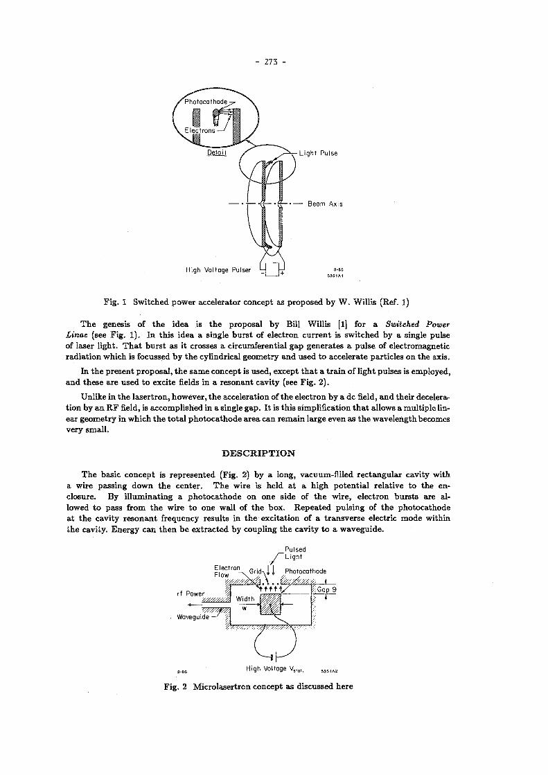
273 -
H i g h V o l t a g e Pulser
•r?— • — B e a m A x i s
L i g h t P u l s e
3 - 8 6 + 5 3 5 1 A 1
F i g . 1 S w i t c h e d p o w e r acce le ra to r c o n c e p t as p r o p o s e d b y W . Wil l i s (Ref. 1 )
T h e genesis of t h e i d e a is t h e p r o p o s a l b y Bill Wil l i s [1] for a Switched Power Linac (see F i g . 1 ) . I n t h i s i d e a a s ingle b u r s t of e l ec t ron c u r r e n t is s w i t c h e d b y a s ingle pu l se of laser l igh t . T h a t b u r s t as it c rosses a c i r cumfe ren t i a l g a p g e n e r a t e s a p u l s e of e l ec t romagne t i c r a d i a t i o n w h i c h is focussed b y t h e cy l indr ica l g e o m e t r y a n d u s e d t o a c c e l e r a t e pa r t i c l e s on t h e axis .
In t h e p r e s e n t p r o p o s a l , t h e s a m e c o n c e p t is u s e d , excep t t h a t a t r a i n of l igh t pu l s e s is emp loyed , a n d t h e s e a r e u s e d t o exc i t e fields in a r e s o n a n t c av i t y (see F i g . 2 ) .
Unl ike in t h e l a s e r t r o n , h o w e v e r , t h e acce le ra t ion of t h e e l ec t ron b y a d c field, a n d t he i r decelerat i o n b y a n R F field, is a c c o m p l i s h e d in a s ingle g a p . I t is t h i s s impl i f ica t ion t h a t a l lows a m u l t i p l e linea r g e o m e t r y in w h i c h t h e t o t a l p h o t o c a t h o d e a r e a c a n r e m a i n l a rge even a s t h e w a v e l e n g t h becomes v e r y s m a l l .
T h e bas i c c o n c e p t is r e p r e s e n t e d (F ig . 2) b y a long, vacuum-f i l l ed r e c t a n g u l a r cav i ty w i t h a w i r e p a s s i n g d o w n t h e c e n t e r . T h e w i r e is he ld a t a h i g h p o t e n t i a l r e l a t ive t o t h e enc losure . B y i l l u m i n a t i n g a p h o t o c a t h o d e o n o n e s ide of t h e w i r e , e l e c t r o n b u r s t s a re allowed t o p a s s f r o m t h e w i r e t o o n e wal l of t h e b o x . R e p e a t e d p u l s i n g of t h e p h o t o c a t h o d e a t t h e c a v i t y r e s o n a n t f r equency r e su l t s in t h e exc i t a t i on of a t r a n s v e r s e e lec t r ic m o d e w i th in t h e cav i ty . E n e r g y c a n t h e n b e e x t r a c t e d b y coup l ing t h e c a v i t y t o a w a v e g u i d e .
D E S C R I P T I O N
3 - 8 6 H i g h Voltage V s l a t . 5 3 5 1 A 2
F i g . 2 M i c r o l a s e r t r o n c o n c e p t as d i scussed h e r e
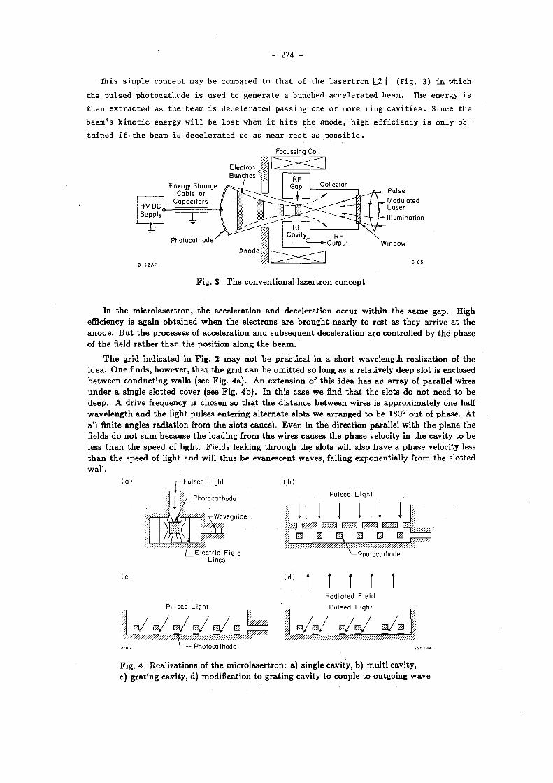
- 274 -
This simple concept may be compared to that of the lasertron l_2j (Fig. 3) in which the pulsed photocathode is used to generate a bunched accelerated beam. The energy is then extracted as the beam is decelerated passing one or more ring cavities. Since the beam's kinetic energy will be lost when it hits the anode, high efficiency is only obtained if the beam is decelerated to as near rest as possible.
Focussing Coil
F i g . 3 T h e c o n v e n t i o n a l l a s e r t r o n c o n c e p t
I n t h e m i c r o l a s e r t r o n , t h e acce l e ra t ion a n d dece le ra t ion occu r w i t h i n t h e s a m e g a p . High efficiency is a g a i n o b t a i n e d w h e n t h e e lec t rons a r e b r o u g h t n e a r l y t o r e s t as t h e y a r r ive a t t h e a n o d e . B u t t h e p rocesses of acce l e ra t ion a n d s u b s e q u e n t dece le ra t ion a r e con t ro l l ed b y t h e p h a s e of t h e field r a t h e r t h a n t h e p o s i t i o n a long t h e b e a m .
T h e g r i d i n d i c a t e d in F i g . 2 m a y n o t b e p r a c t i c a l in a s h o r t w a v e l e n g t h r ea l i za t ion of t h e i d e a . O n e finds, howeve r , t h a t t h e g r id c a n b e o m i t t e d so long as a re la t ive ly deep s lot is enclosed b e t w e e n c o n d u c t i n g wal l s (see F i g . 4 a ) . A n e x t e n s i o n of t h i s i dea h a s a n a r r a y of pa ra l l e l wires u n d e r a s ingle s l o t t e d cover (see F ig . 4 b ) . I n t h i s case w e find t h a t t h e s lo ts d o n o t n e e d t o b e d e e p . A d r i v e f requency is chosen so t h a t t h e d i s t a n c e b e t w e e n wi re s is a p p r o x i m a t e l y one half w a v e l e n g t h a n d t h e l ight pu l ses e n t e r i n g a l t e r n a t e s lo t s w e a r r a n g e d t o b e 180° o u t of p h a s e . A t al l finite ang les r a d i a t i o n f rom t h e s lo ts cance l . E v e n in t h e d i r ec t ion pa ra l l e l w i t h t h e p l a n e t h e fields d o n o t s u m b e c a u s e t h e load ing f rom t h e wi re s causes t h e p h a s e ve loc i ty in t h e cav i t y t o b e less t h a n t h e s p e e d of l igh t . F ie lds l eak ing t h r o u g h t h e s lo ts will a lso h a v e a p h a s e ve loc i ty less t h a n t h e s p e e d of l ight a n d will t h u s b e e v a n e s c e n t w a v e s , fall ing e x p o n e n t i a l l y f rom t h e s lo t t ed w a l l .
( o ) P u l s e d L i g h t
P h o t o c a t h o d e
W a v e g u i d e
E l e c t r i c F i e l d
L i n e s
( b )
P u l s e d L i g h t
1 1 1 1 I &//////, V////M
P h o t o c a t h o d e
P u l s e d L i g h t
.. w w t~, -, ~, -
\—( - P h o t o c a t h o d e
" ' l i l t ! R a d i a t e d F i e l d
P u l s e d L i g h t
F i g . 4 Rea l i za t i ons of t h e m i c r o l a s e r t r o n : a) s ingle cav i ty , b ) m u l t i cav i ty , c) g r a t i n g cav i ty , d) mod i f i ca t ion t o g r a t i n g c a v i t y t o co u p l e t o o u t g o i n g w a v e

- 275 -
I h e aDove o b s e r v a t i o n l eads t o a fu r the r ex t ens ion of t h e i dea (see F i g . 4c ) . N o w t h e u p p e r cover of t h e c a v i t y h a s b e e n r e m o v e d , t h e p h o t o c a t h o d e s p l a c e d o n t h e r e m a i n i n g sur face a n d t h e p u l s e d l ight b r o u g h t d o w n a t a n ang le b e t w e e n t h e w i r e s . A g a i n , b e c a u s e of t h e p re sence of t he wi res , t h e p h a s e ve loc i ty a l o n g t h e surface is less t h a n t h e s p e e d of l i gh t , a n d t h e field exc i ted will b e evanescen t , fal l ing e x p o n e n t i a l l y f rom t h e sur face .
As in t h e s ingle w i r e ca se , e l e c t r o m a g n e t i c ene rgy cou ld b e t a k e n o u t of t h e m u l t i w i r e cavi t ies b y coup l ing t h e m t o w a v e g u i d e s . I t is poss ib le , howeve r , a n d p e r h a p s m o r e c o n v e n i e n t , t o a r r a n g e t h a t t h e y coup l e t o p l a n e pa ra l l e l w a v e s e m a n a t i n g f rom t h e su r face . I n case of F i g . 4c , t h i s can b e ach ieved b y d i s t u r b i n g t h e pe r i od i c i t y of t h e wi res (see F i g . 4 d ) .
\ G r o u n d P l a n e T e r m i n a t e d E n d R e f l e c t o r s J B e f o r e E n d of B a r s
F i g . 5 M i c r o l a s e r t r o n g e o m e t r y , i n c l u d i n g c a v i t y e n d des ign
I n t h e a b o v e d i scuss ion w e h a v e n o t m e n t i o n e d h o w t h e cavi t ies w o u l d b e e n d e d a t t h e e n d of t h e w i r e . T o i n v e s t i g a t e t h i s q u e s t i o n a r a d i o f requency m o d e l w a s m a d e a t a w a v e l e n g t h of 5 c m . I t w a s f o u n d t h a t if t h e c a t h o d e p l a n e w a s t e r m i n a t e d wel l before t h e w i r e e n d s (see F ig . 5) t h e n t h e fields w e r e effectively c o n s t r a i n e d t o t h e a r e a a b o v e t h i s p l a n e a n d n o loss of p o w e r occur red a long t h e wi re s b e y o n d i t .
T h e a t t r a c t i o n of t h e m i c r o l a s e r t r o n is i t s s impl ic i ty , a n d t h u s t h e poss ib i l i ty of sca l ing it d o w n t o p r o d u c e v e r y s h o r t w a v e l e n g t h s . I t a lso a p p e a r s f rom t h e fol lowing ana lys i s t h a t ve ry h igh p o w e r s a n d efficiencies m a y b e o b t a i n a b l e .
A N A L Y S I S
EQUIVALENT CIRCUIT
U n d e r t h e c o n d i t i o n s w h e r e
9 (gap) < w ( g a p w i d t h )
v (e lec t ron veloci ty) <. c (vel.of l igh t )
w (gap w i d t h ) <C A ( w a v e l e n g t h )
t h e n t h e dev ice of F i g . 2 m a y b e t h o u g h t of as a s e p a r a t e d i o d e g a p c o u p l e d t o a r e s o n a n t circui t (see F i g . 6 ) . '
Fo r o u r p u r p o s e s w e c a n t h i n k of h i as a n infini te i n d u c t a n c e t h a t a l lows a dc c u r r e n t ipc t o flow f rom t h e h i g h v o l t a g e s u p p l y Vetat- C"i m a y b e t h o u g h t of as a n inf ini te c a p a c i t o r t h a t isolates t h e dc f rom t h e r e s o n a n t c i rcu i t .
I n t h e fol lowing d i scuss ion we will cons ide r a n equ iva len t c i r cu i t w h i c h will a l low u s t o m a k e a p p r o x i m a t e c a l c u l a t i o n s of p e r f o r m a n c e . T h e ana lys i s is s t r i c t l y a p p l i c a b l e on ly t o t h e p lane pa ra l l e l e x a m p l e s of F i g s . 2 , 4c a n d 4 d a l t h o u g h s imi la r r e su l t s a r e p r o b a b l y o b t a i n a b l e for t h e cases of F i g s . 4 a a n d 6.

- 276 -
'rf "de
F i g . 6 E q u i v a l e n t c i r cu i t of m i c r o l a s e r t r o n
T h e c u r r e n t t m a y b e d iv ided :
ï — %res "i" í t i
w h e r e i r e s is a r e s o n a n t osc i l l a to ry c u r r e n t a s s o c i a t e d w i t h t h e r e s o n a n t c i rcu i t of L\ a n d (C\ + C 3 ) ; a n d t« w h i c h is a s s o c i a t e d w i t h m o t i o n of c h a r g e s in t h e g a p .
*'« = q v/g
w h e r e q is t h e c h a r g e in t h e g a p a n d v t h e ve loc i t y of t h a t c h a r g e ac ross t h e g a p .
W i t h t h e s e def in i t ions w e h a v e
ÍRF = IRF s in(wt + 0) + q v/g .
T h e v o l t a g e V ac ross t h e g a p will a g a i n h a v e t w o c o m p o n e n t s :
V = VRF cos(wi + 0) + V,tat •
(4)
(5)
VRF m a y , of cour se , v a r y if t h e r e is a n e t t r ans f e r of e n e r g y t o t h e s y s t e m . T h e ene rgy t r ans f e r r ed p e r cycle wil l b e
A/c
(6) AE = A ^ " ^ 2 = j iv{t)VRFcos(ujt + 6) dt
w h e r e Z is t h e i m p e d a n c e of t h e r e s o n a n t s y s t e m . T h e p h a s e 0 m a y also b e p e r t u r b e d . T h e c h a n g e in p h a s e p e r cycle will b e
~Q t a n X
w h e r e
t a n x
X/e
J iv(t) s'm(u>t)dt _o
f iv(t) c o s ( w t ) d i 0
(7)
(8)

- 277 -
If d r i v e n a t t h e r e s o n a n t f requency w 0> t h e n c lear ly x m u s t b e e q u a l t o ze ro . B u t if t h e d r iven f r equency is off t h e r e s o n a n c e , t h e n w e h a v e
w - w 0 = A8 • ^- = ^ t a n \ • ( 9 )
EFFICIENCY
T h e e n e r g y u s e d f rom t h e dc sou rce p e r cycle wi l l b e
X/c
AE^ = j ivV,tat dt = q V,tat , 0
t h e difference b e t w e e n t h i s a n d AEre„ t h e ene rgy go ing i n t o t h e rf field, is lost as h e a t in t h e a n o d e as e l ec t rons a r r i v e w i t h f i n i t e k i n e t i c e n e r g y . Thus ,
AEde - AEre, = I ™ v)
w h e r e Vf is t h e ve loc i ty w i t h w h i c h t h e e lec t rons h i t t h e a n o d e , m is t h e e lec t ron m a s s a n d e i ts c h a r g e . T h u s t h e efficiency e of t r ans fe r r i ng ene rgy f rom t h e dc sou rce t o t h e r e s o n a n t c i rcui t is
1 - £ =
1 - £
\ e ) 2 c* V, (10)
.51 10 s
2 C 2 Vstat (mks)
T o ge t vf w e o b t a i n first t h e acce le ra t ion of a c h a r g e in t h e g a p w h i c h will b e
dv e m
£ , + Í Í J J P C O S ( W Í + <f>) (lia)
w h e r e £, = Vgtat/g, £RF — VRF/9 &nd <j> is i n t r o d u c e d as a n a r b i t r a r y p h a s e so t h a t w e can define t — 0 a s t h e t i m e w h e n t h e c h a r g e is ini t ia l ly re leased f rom t h e c a t h o d e . I n t e g r a t i n g E q . (11a) we o b t a i n t h e ve loc i ty of t h e e lec t rons a t t i m e t:
v(t) = — b - ^ s in (wi + <f>) + — sin./ . m l w w
(116)
I n t e g r a t i n g a g a i n w e o b t a i n t h e d i s t ance t r ave led :
T l-4- - % c o s M + *) + £RF sin<£ (11c)
S e t t i n g x = g in E q . ( l i e ) will give t h e t r a n s i t t i m e r = t w h i c h w h e n s u b s t i t u t e d in to E q . ( l i b ) gives t h e final ve loc i ty v¡ a n d t h u s t h e energy loss a n d efficiency us ing E q . (10) .
LOW R F FIELD CASE
If £RF <C £tttu> t h e n
9 « £,tat TQ ¿m

- 278 -
a n d 1/2 / „ \ 1/2
T h i s m a y b e c o m p a r e d w i t h t h e cycle t i m e A/c a n d w e define th i s r a t i o a s :
i / ' / i \ 1/2
( 1 \ ! / 2 —J I (mks) . (126)
We wil l c o n t i n u e t o u s e t h i s def ini t ion of FT even w h e n £RF is n o t less t h a n £,tat- FT t h e n becomes a useful sca l ing fact o r r a t h e r t h a n a n a c t u a l r a t i o of t r a n s i t t i m e t o cycle .
SHORT TRANSIT TIME APPROXIMATION
If w e a s s u m e
FT < 1 (13)
t h e n w r < l a n d E q . ( l i e ) r e d u c e s t o
er2
S « ^ ( í ( - £RF COS <f>) (Ua)
a n d
v/ « — r (£, - £RFcoe<f>) . (14b) m
M a x i m u m efficiency is rea l ized if Vf is m i n i m u m , i.e., t h e least k ine t i c e n e r g y is d u m p e d on t h e a n o d e . T h i s will occu r for <j> = 0. Refe r r ing t o E q . (6) a n d n o t i n g t h a t t h r o u g h o u t t h e t r a n s i t wt « tj>, w e see t h a t t h i s m a x i m u m efficiency cond i t i on also impl ies x = 0 , i .e., t h a t t h e s t r u c t u r e is d r i ven o n r e s o n a n c e : w = w 0 .
So for 4> = 0, a n d r e m e m b e r i n g t h a t r = FTX/c w e o b t a i n
1 - , « 1 . 0 2 10« ( f ) ' ^ i - („* , ) . ( I l l )
If, for e x a m p l e , w e chose A = 6 m m , g = .5 m m , £ = 5 0 % a n d FT = . 38 , t h e n w e r equ i r e
Vstat « 5 0 , 0 0 0 V
a n d
£ , « 100 M V / m .
Now f rom t h e references q u o t e d b y Wil l is [ l ] , w e n o t e t h a t [3] for t i m e s less t h a n 5 nsec , vol tages as h i g h a s 160,000 V h a v e b e e n h e l d over 1 m m — 2 m m g a p s (£ = 160 M V / m ) a n d for t i m e s less t h a n 1 nsec [4], 80,000 vo l t s cou ld b e h e l d across a 27 M g a p (3000 M V / m ) . T h u s , a l t h o u g h t h e va lues of o u r e x a m p l e a r e h i g h , t h e y a r e b y n o m e a n s u n r e a s o n a b l e for t i m e s less t h a n 5 nsec .
T h e a b o v e e x a m p l e , h o w e v e r , a s s u m e d a n efficiency of on ly 5 0 % . H i g h e r efficiencies wou ld s e e m t o i m p l y e v e n h i g h e r fields. I t a l so a s s u m e d a t r a n s i t t i m e r a t h e r long (.38) c o m p a r e d w i t h t h e cycle t i m e . T h i s h a r d l y satisfies C o n d i t i o n (13) . Clear ly , w e s h o u l d ca l cu l a t e t h e effect of finite t r a n s i t t i m e s .

- 279 -
O N E - D I M E N S I O N A L S I M U L A T I O N
T o s t u d y t h i s p r o b l e m for finite t r a n s i t t i m e s , a s m a l l c o m p u t e r p r o g r a m w a s w r i t t e n t h a t w o u l d e m i t a n d t r a c k t h e e lec t rons as a func t ion of t i m e in t h e va ry ing fields. Ini t ia l ly , w e cons ide r s h o r t p u l s e s a n d ignore s p a c e c h a n g e effects.
WITH SHORT PULSES X = 0 (ON R E S O N A N C E )
K e e p i n g t h e d r iv ing p h a s e x = 0> i-e., d r i v i n g a t a f requency equa l t o t h e cav i t y r e s o n a n t f requency , w e ca l cu l a t e t h e efficiency as a func t ion of t h e r a t i o of £RF¡£stat- T h e r e su l t s a r e s h o w n in F i g . 7 a for t h e case w h e r e FT (defined b y E q . (12)) is 0.38 (e.g. , for V = 50,000 v , g = .5 m m ) . As e x p e c t e d , t h e efficiency 1) r ises as t h e R F field r i ses a n d 2) is s o m e w h a t less t h a n t h a t expec ted for FT —* 0 ( d o t t e d l ine) . ( D u e t o t h e finite t r a n s i t t i m e , t h e e lec t rons d o n o t feel t h e m a x i m u m d e c e l e r a t i o n field over t he i r full t r a n s i t . ) W h a t is s u r p r i s i n g , however , is t h a t t h e efficiency r e m a i n s finite e v e n w h e n £RF is g r e a t e r t h a n £etat-
1.0
0.5
e 0 1.0
0.5
0
1 - ( a )
/ / • —
— / / ßf
/ / a S 1
1 x = o _
b
1
_ ( b ) c d
/ X _ 1
) 1.0 2.0
90 60 30 0
3 - 8 6 ^rf/^StOt. 5 3 5 1 A 7
F i g . 7 Efficiency vs . s t r e n g t h of R F field a ) for p h a s e a d v a n c e \ :
b) p h a s e a d v a n c e ad ju s t ed t o give m a x i m u m efficiency 0 a n d
If w e e x a m i n e t h e v a r i a t i o n of e l ec t ron ve loc i ty ( a n d t h u s c u r r e n t ) as a func t ion of t h e R F p h a s e for a case of low R F field (e.g., £RF¡£» = -5 , see F i g . 8 a ) , t h e n we see t h e ve loc i ty r is ing m o r e o r less l inear ly a n d h i t t i n g t h e a n o d e a t i t s m a x i m u m . T h i s t h e n is m u c h as p r ed i c t ed b y E q . ( 14b ) .
F o r h i g h e r va lues of t h e R F field t h e s i t u a t i o n b e c o m e s m o r e c o m p l i c a t e d (Fig . 8b for £RF/£stat = 1.5). Now t h e par t i c les a r e s t a r t e d a t a p h a s e w h e n t h e R F field is he lp ing t h e s t a t i c field. T h e e lec t rons a r e t h u s in i t ia l ly acce l e ra t ed , t h e n dece le ra ted for awhi le , a n d finally a c c e l e r a t e d a g a i n t o a r r ive a t t h e a n o d e a t a p h a s e w h i c h aga in c o r r e s p o n d s t o t h e £RF he lp ing t h e £ttat-
SHORT PULSE DRIVEN OFF RESONANCE
As w e n o t e d a b o v e (Eq . (7)) , i t is n o t n e c e s s a r y t o o p e r a t e a t x = 0. If we dr ive t h e p h o t o c a t h -o d e a t a f requency w different f rom t h e r e s o n a n t f r equency wo, t h e n t h e s t a b l e p h a s e x is finite. If w e a d j u s t w a n d t h u s x t o give m a x i m u m efficiency (i .e. , m i n i m u m ar r iva l e l ec t ron ve loc i ty ) , t h e n w e o b t a i n efficiencies as p l o t t e d on F ig . 7 b .
N o w w e obse rve t h a t efficiencies of a 100% a r e ach ieved as £RF « 2£,. W e e x a m ine t h i s case in F ig . 8c . T h e pa r t i c l e s a r e a g a i n ini t ia l ly acce le ra ted a n d t h e n decelera t e d . T h e p a r a m e t e r s , however , a r e s u c h t h a t t h e e lec t rons c o m e t o r e s t j u s t as t h e y arr ive a t t h e a n o d e . W e n o t e fu r the r t h a t for t h i s magic case t h e e lec t rons a r e n o t only a t r e s t a s t h e y t o u c h t h e a n o d e b u t t h a t t he i r acce l e ra t ion is also zero . T h i s s i t u a t i o n shou ld b e c o n t r a s t e d w i t h t h a t o b t a i n e d a t a n even h i g h e r R F field (e.g., £RF/£» = 2 .5 , F ig . 8d ) .

- 280 -
I n t h i s case t h e e l ec t rons a r e a lso a t r e s t as t h e y a p p r o a c h t h e a n o d e , b u t t h e y a r e a t t h a t po in t b e i n g dece le ra t ed . A n e l ec t ron t h a t j u s t mi s sed t h e a n o d e w o u l d m o v e a w a y f rom i t a n d on ly ar r ive s o m e t i m e l a t e r a n d a t a finite ve loci ty . T h i s is a less des i r ab le o p e r a t i n g p o i n t t h a n t h e mag ic one of F ig . 8c .
E > to O
E
- 9 0 0 9 0
P H A S E ¡p (degrees)
- 9 0 0 9 0
P H A S E <j> (degrees)
F i g . 8 M o t i o n of e lec t rons in t h e g a p as func t ion of R F p h a s e , w i t h e lec t r ic field a n d e lec t ron ve loc i ty a lso s h o w n :
a) Fo r ¿RF/Setat = -5 a n d x = 0.
h) F o r ¿RF/Sstat = 1.5 a n d x = 0 .
c) Fo r £RF/¿stat = 2 a n d x a d j u s t e d for m a x i m u m efficiency. T h i s r e p r e s e n t s t h e magic cond i t i on .
d) £Rr/£ttat — 2 .5 a n d x a d j u s t e d for m a x i m u m efficiency.

- 281 -
90
60 | en CU •o
30 X
0 0 0.1 0.2 0.3 0.4 0.5
3-86 5351A9
F i g . 9. Va lues of £RFlestât a n d t h e p h a s e a d v a n c e x t o give t h e magic c o n d i t i o n for different t r a n s i t t i m e fac tors FT
All of t h e a b o v e ana lys i s w a s d o n e for Fr = .38. W e find a different m a g i c p o i n t for e a c h va lue of FT a n d t h e s e a r e p l o t t e d o n F i g . 9. R e m e m b e r t h a t FT is t h e f rac t iona l cycle t i m e t a k e n for t r a n s i t in t h e a b s e n c e of a n R F field. FT —• 0 c o r r e s p o n d s t o v e r y h i g h fields a n d a s m a l l g a p . I n t h a t case 100% efficiency is o b t a i n e d a t £RF/£S = 1 a n d n o p h a s e lag x is n e e d e d . F o r la rger t r a n s i t t i m e s a p h a s e lag is r e q u i r e d a n d l a rger R F fields a r e n e e d e d t o o b t a i n t h e m a g i c c o n d i t i o n . I n o u r fol lowing s t u d i e s w e wil l a s s u m e
FT = .38 .
FINITE PULSE LENGTHS T h e a b o v e ca l cu la t ions h a v e al l b e e n p e r f o r m e d for e lec t rons e m i t t e d a t o n e p h a s e , i.e., for
l igh t pu l ses o n t h e p h o t o c a t h o d e of a r b i t r a r i l y s h o r t d u r a t i o n . If pu l ses of finite e x t e n t a r e u s e d t h e n it is n o longer poss ib le t o b r i n g all t h e e l ec t rons t o r e s t a t t h e a n o d e , a n d t h e efficiency var ies a s a func t ion of t h e in i t i a l p h a s e of e a c h p a r t of t h e b u n c h (see F i g . 10). W e see t h a t for t h e m a g i c c o n d i t i o n ( C u r v e a) t h e v a r i a t i o n is v e r y r a p i d w i t h t h e efficiency d r o p p i n g t o 5 0 % w h e n t h e p h a s e is w r o n g b y on ly + 4° or — 10° f r o m t h e m a g i c v a l u e . A t lower va lues of t h e R F field, a l t h o u g h t h e m a x i m u m efficiency is less , t h e sens i t i v i ty t o p h a s e is w e a k e r ( C u r v e s b a n d c ) . As a r e su l t a p lo t of efficiency vs £RF for finite p u l s e l e n g t h s (F ig . 11a) s h o w s m a x i m u m efficiencies b e i n g o b t a i n e d a t p rogress ive ly lower va lues of £RF- F i g u r e 12a s h o w s t h e m a x i m u m efficiencies as a func t ion of p u l s e d u r a t i o n (A<j>) in degrees . F o r a n e x a m p l e w e wil l cons ider a pu l s e d u r a t i o n (A(f>) of 18°, for w h i c h t h e efficiency w o u l d b e as 9 0 % .
-20 -10 0 10 20 R E L A T I V E P H A S E (degrees)
Fig . 10 Efficiency v s . r e l a t i ve p h a s e for:
a) T h e m a g i c c o n d i t i o n w i t h £RF¡£»tat — 2.0;
6) £RF/£,tat = 1.5;
c) £RF/£stat = 1-0.

- 282 -
F i g . 12 M a x i m u m efficiencies a n d c o r r e s p o n d i n g p h a s e a d v a n c e s x a s a func t ion of a) pu l s e l e n g t h a n d b) c h a r g e
SPACE CHARGE EFFECTS
If a c h a r g e d e n s i t y q in c o u l o m b s / m 2 ex i s t s j u s t a b o v e t h e c a t h o d e surface t h e n t h e i nduced e lec t r ic field b e h i n d t h i s c h a r g e £ t c is g iven b y
Ose —
w h e r e e 0 is t h e d ie lec t r i c c o n s t a n t of free s p a c e in m k s u n i t s (8 .855 1 0 - 1 2 ) .
T h e m a x i m u m c h a r g e t h a t c a n b e acce le ra t ed w i t h a g iven s t a t i c field £stat is t h e n
q*c - £ttat to
a n d w e def ine a sca le i n v a r i a n t f rac t ion F,c

- 283 -
Clearly, if Fsc «C 1 t h e effect of s p a c e c h a r g e will b e negl ig ib le . As F,C i nc reases t h e ea r l i e r cha rges will b e acce le ra t ed m o r e a n d t h e l a t e r c h a r g e s less t h a n in t h e s m a l l c h a r g e c a s e . As a r e su l t it again becomes imposs ib l e t o bring all charges t o r e s t a t t h e anode and t h e efficiency suffers.
Figure l i b shows the efficiency for different a m o u n t s of charge FTE and different SRF. As wi th t h e long p u l s e case , m a x i m u m efficiency occu r s a t fields less t h a n t h e m a g i c v a l u e . F i g u r e 12b shows m a x i m u m efficiencies as a f u n c t i o n of t h e c h a r g e .
A t first i t w o u l d s e e m n a t u r a l t o p ick a c h a r g e of t h e o r d e r of .4 t i m e s t h e s p a c e c h a r g e l imi t , for which the efficiency w o u l d s t i l l remain above 70% even w i t h a pulse length of 18°. Such a large charge, however , w o u l d have t w o difficulties:
(1) T h e current dens i ty in our example (V = 50 K V , g = .5 m m , A = 6 m m ) wou ld be 44 K A / c m 2 wh ich m a y b e excess ive .
(2) T h e instantaneous vol tage drop of the wire would b e large. In a c losed device a s i l lustrated in Fig . 4a or 4 b , assuming equal gaps above and be low the wire, t h e n the fractional voltage drop wou ld b e q/(2 q,c) or 20%. In the open structure case of F ig . 4c or 4 d the capacity is only half and the vo l tage drop w o u l d be 40%.
T h u s for an e x a m p l e w e wil l chose a somewhat smaller value of qjq,c, such as 0 . 1 , for which the result ing inefficiency is very smal l .
A P O S S I B L E P A R A M E T E R L I S T
THE CAVITY
I wil l consider an o p e n structure of the ty pe il lustrated in Fig. 4d , w i t h 1 m m square wires and a tota l area of 10 c m b y 10 c m . For a wave length of ~ 6 m m the wires w o u l d b e placed about 2.5 m m apart. T h u s there w o u l d b e ~ 40 wires. T h e total photo cathode area is about 40 c m 2 . I will consider a pulse length of 18° and q/qse = 0 .1 . I then obtain:
V,tat = 50 K V
ç = = .5 r u m
S t t a t = 100 M V / m
A = 6 m m
A/c = 18 p sec
W = - 9 p sec (18°)
q s e = 8.8 1 0 ~ 4 c / m 2
Fse = .1
q = 8.8 1 0 _ s c / m 2
Qpulse = 3.5 1 0 ~ 7 coulombs
£ R F = 150 M V / m
£ = 80%
<f> = - 1 3 0 °
X = - 38°
peak iphot0 cathode - 10 K A / c m 2
ave. iphoto cathode = 5 0 0 A / c m 2
Woutp*t = -78 1 0 9 w a t t s .
T h e t i m e for the microlasertron t o fill requires knowledge of b o t h the stored energy in the structure and the average efficiency during the fill, neither of which w e have . R o u g h estimates sugges t :
floe Jul « -8 nsec .

- 284 -
If t h i s p o w e r s o u r c e is t o fill a s e m i c o n v e n t i o n a l a cce l e r a t i ng c a v i t y t h e n t h e pu l s e d u r a t i o n m u s t b e less t h a n t h e n a t u r a l fill time of t h a t cav i ty . If w e sca le f rom S L A C ' s r¡m = .8 psec a t A = 10 c m t h e n for A = 6 m m :
TACC /m = 12 nsec .
Re fe rence 3 , h o w e v e r , sugges t s t h a t b r e a k d o w n co u l d occu r af ter a b o u t 5 nsec a n d t h u s t h e pu lse l e n g t h a n d e n e r g y p e r pu l s e w o u l d h a v e t o b e r e d u c e d t o :
r ss 5 nsec
n c y c u s « 250
Joutput « 3.9 J o u l e s .
T h i s s t i l l r e p r e s e n t s a la rge t o t a l e n e r g y o u t p u t for s u c h a n a p p a r e n t l y s i m p l e device .
LASER A N D P H O T O G A T H O D E REQUIREMENTS
T h e lase r w o u l d b e r e q u i r e d t o del iver 1 psec pu l ses a p p r o x i m a t e l y 18 psec a p a r t for t r a i n s l a s t i n g of t h e o r d e r of 5 n sec . T h e op t i c f requency a n d p o w e r r e q u i r e d w o u l d d e p e n d on t h e p h o t o c a t h o d e s . If a c o n v e n t i o n a l S 20 t y p e of c a t h o d e co u l d b e e m p l o y e d a n d if e q = 10% q u a n t u m efficiency is a s s u m e d a t a w a v e l e n g t h of t h e o r d e r of 500 n m e t e r s (V„ = 2.5 vo l t s ) t h e n t h e power r e q u i r e d w o u l d b e
, _ JRF vv i Jopt - — • —
= 2.4 mJI t r a i n of pu l ses ( e . f . 3.9 J o u l e s o u t p u t )
= .06 % J R F .
S u c h a t r a i n of pu l s e s cou ld , for i n s t a n c e , b e g e n e r a t e d b y m u l t i p l e x i n g a s ingle psec pu l s e gene ra t ed b y a m o d e locked d y e laser . If t h e who le t r a i n w e r e finally ampl i f ied b y a XeF laser t h e overal l efficiency m i g h t b e e x p e c t e d [9] t o b e a b o u t 2%. I n t h i s case t h e p o w e r going t o t h e laser wou ld b e negl ig ib le c o m p a r e d t o t h a t go ing t o t h e e lec t r ica l s u p p l y ( ~ 3%) .
I t is un l ike ly , h o w e v e r , t h a t a c o n v e n t i o n a l p h o t o c a t h o d e c o u l d c a r r y t h e r e q u i r e d c u r r e n t or s u r v i v e long in t h e e x p e c t e d e n v i r o n m e n t . A m o r e r u g g e d p h o t o c a t h o d e w o u l d b e r equ i red a n d lower q u a n t u m efficiencies a r e t o b e expec t ed . If t h e p o w e r t o t h e laser is t o r e m a i n less t h a n half t h e t o t a l t h e n a q u a n t u m efficiency of t h e o r d e r of 1% is n e e d e d .
I t h a s b e e n r e p o r t e d [5] t h a t a CSI p h o t o c a t h o d e c a n give t h e r e q u i r e d c u r r e n t densi t ies a n d q u a n t u m efficiency if U V l ight is u sed , b u t i ts l i fet ime is n o t k n o w n . Very h i g h c u r r e n t densi t ies a n d q u a n t u m efficiencies [6] h a v e also b e e n r e p o r t e d f rom a b r u s h - l i k e p h o t o c a t h o d e b u t t h e t i m e r e s p o n s e a n d m e c h a n i s m in th i s case is ye t t o b e d e t e r m i n e d . L a n t h a n u m h e x a b o r i d e is a n o t h e r p o s s i b l e c a t h o d e . A t low fields a n d U V l ight it h a s b e e n o b s e r v e d t o give a q u a n t u m efficiency [7] of 10"" 3 a n d m a y b e e x p e c t e d t o h a v e h ighe r efficiency a t t h e field levels e m p l o y e d in ou r e x a m p l e .
P e r h a p s t h e m o s t p r o m i s i n g a p p r o a c h w o u l d b e t o u s e a m e t a l p h o t o c a t h o d e a n d U V l ight . I t is o b s e r v e d [8] t h a t t h e q u a n t u m efficiency of m o s t m e t a l s p e a k s a t a b o u t 2500 A a n d t h a t t h i s efficiency is g iven v e r y a p p r o x i m a t e l y b y t h e r e l a t i o n
e « 3 x 10~z(Vß-Wtff)z
w h e r e Vß ¡=s 5 V for 2500 Â a n d W is t h e w o r k func t ion of t h e m e t a l . T a b l e I gives s o m e examples . I t is r e a s o n a b l e t o a s s u m e t h a t t h e q u a n t u m efficiency w o u l d b e r a i s ed in a h i g h field d u e t o t h e S c h o t t k y r e d u c t i o n of t h e effective w o r k func t ion
O n t h i s a s s u m p t i o n va lues a r e g iven in T a b l e I for e x p e c t e d q u a n t u m efficiencies for some values of su r face fields.

- 285 -
T a b l e I . W o r k func t ions W in vo l t s a n d q u a n t u m efficiencies for « 2500 A l ight a t different su r face fields. T h e ze ro field va lues a r e m e a s u r e d a n d t h e o t h e r s e x t r a p o l a t e d .
M e t a l W (Volts)
N a
Ce
T w
Zr
T a
C n
2.1 - 2.5
2.8 - 4 .2
3.4 - 3.6
3.7 - 4 .3
4.0 - 4.2
4.4
P e r c e n t a g e Q u a n t u m Efficiency for £(MV/m) =
0 50 100 200 500 1000
6
2
1.2
.3
.15
.08
7.9
2.9
1.9
.6
.35
.22
8.9
3.5
2.3
.8
.48
.32
13.6
4.2
2.8
1.1
.68
.47
13.6
6.1
4 .3
1.9
1.3
1.0
18
8.8
6.5
3.2
2.4
1.9
If w e t a k e a Z i r c o n i u m p h o t o c a t h o d e t h e n w i t h a field of 100 M V / m w e c a n a s s u m e a q u a n t u m efficiency of . 8 % . T h e op t i ca l p o w e r t h e n r e q u i r e d for ou r e x a m p l e is 60 m J / t r a i n of pu l ses wh ich is a s ignif icant f rac t ion of t h e o u t p u t p o w e r (1 .5%) .
A KrF E x e m e r laser a t a f r equency of 2480 A , however , cou ld b e u s e d a n d s u c h lasers h a v e g iven [9] 1 5 % in t r inc ic efficiency.If we a s s u m e a n overa l l laser efficiency of 9% t h e n t h e electr ical p o w e r r e q u i r e d for t h e laser is s t i l l on ly 1 7 % of t h e o u t p u t p o w e r .
S C A L I N G
B R E A K D O W N
T o d iscuss t h e sca l ing of t h e m i c r o l a s e r t r o n , w e need a t heo re t i ca l m o d e l of t h e electrical b r e a k d o w n . In T a b l e II we give p u b l i s h e d va lues for t h e b r e a k d o w n fields for different gaps a n d t i m e s ( r ) . I n all cases l i s ted t h e e l ec t rodes w e r e of c o p p e r or b r a s s . Fo r c o m p a r i s o n w e give also t h e t r a n s i t t i m e (t) for a c o p p e r ion a n d t h e r a t i o n of t h e b r e a k d o w n t i m e t o t h i s t r a n s i t .
W e n o t e t h a t for a fixed v o l t a g e V t h e r a t i o n is re la t ive ly insens i t ive t o t h e g a p a n d t h u s t h e field. Fo r lower vo l t ages n is h ighe r , a n d for h ighe r vo l t ages n seems t o t e n d t o w a r d s 1. Th i s o b s e r v a t i o n c lear ly sugges t s t h a t t h e b r e a k d o w n in t h e s e cases w a s a r e su l t of a c a s c a d e process involv ing t h e re lease , b y e l ec t ron i m p a c t , of ions a t t h e a n o d e , the i r m o v e m e n t b a c k t o t h e c a t h o d e a n d re lease t h e r e of m o r e e l ec t rons . T h e n u m b e r of ion t r a n s i t s r equ i r ed for b r e a k d o w n wou ld b e d e p e n d e n t on t h e n u m b e r s of ions a n d e l ec t rons re leased by t h e i m p a c t s , a n d t h e s e w o u l d d e p e n d on ly o n t h e vo l t age . T h i s is as o b s e r v e d . F o r sca l ing p u r p o s e s , therefore , w e a s s u m e t h a t t h e t i m e for b r e a k d o w n is a fixed m u l t i p l e of t h e ion t r a n s i t t i m e s a t fixed vo l t age V .
T a b l e I I . O b s e r v e d b r e a k d o w n t i m e s for c o p p e r or b r a s s e lec t rodes a n d different g a p s a n d vo l t ages .
V 9 £ T t n Ref.
(KV) ( m m ) ( M V / m ) (nsec) (nsec)
40 1 40 24 5.7 4.2 3
80 2 40 22 8 2.8 3
80 1 80 11 4 2.8 3
80 .057 1400 .57 .23 2.5 4
160 2 80 5 5.6 .9 3
160 1 160 5 2.8 1.8 3

- 286 -
WAVELENGTH SCALING I t is r e a s o n a b l e t o keep t h e r e l a t ive g e o m e t r y c o n s t a n t , i .e.,
I = cons t (.083)
FT = ^ Y = cons t (.38)
AO = cons t (18°)
— = cons t (.1) . Çac
T h e n f rom E q . (12b)
Vstat « 10 6 — = cons t (SOKV) T0C
F r o m t h e b r e a k d o w n sca l ing of Sec. 6.1 w e o b t a i n t h e t i m e before b r e a k d o w n t o b e
(IM g\1/2 . breakdown = « H 1 T7 1 CC A
a n d t h e n u m b e r of R F cycles before b r e a k d o w n ( U R J ? )
3 1 0 5 3 10" / a \ n R F = nM YRJF ( j j = c o n s t ( « 400)
Since t h e g a p g is p r o p o r t i o n a l t o X t h e field, for fixed v o l t a g e
f o c i ,
t h e s p a c e c h a r g e l imi t p e r u n i t a r ea 1
qsc o c -
a n d t h e a v e r a g e c u r r e n t p e r u n i t a r e a
1 TAVC OZ 9scW OC ,
a n d t h u s t h e a v e r a g e p o w e r p e r u n i t of c a t h o d e a r e a
W o c t V o c ^
a n d t h e o u t p u t e n e r g y in Jou les
J o c WT OC i
U s i n g t h e s e r e l a t i o n s w e o b t a i n for a 10 c m X 10 c m device a s d e s c r i b e d in Sec. 5, b u t w i t h different w a v e l e n g t h s .
X £ W W<mt TBREAKDOVM Jout
3 c m 20 M V / m 20 A / c m 2 30 M W 36 n sec .8 Jou les 1 c m 70 M V / m 200 A / c m 2 300 M W 10 n sec 2.3 Jou les
3 m m 200 M V / m 2 K A / c m 2 3 G W 3.6 n sec 8 J ou l e s
T h e a d v a n t a g e in go ing t o s h o r t w a v e l e n g t h s is r e m a r k a b l e . I t wil l b e l imi ted , p r e s u m a b l y , b y coo l ing , p h o t o c a t h o d e , o r nonsca l ing b r e a k d o w n p h e n o m e n a .

- 287 -
C O N C L U S I O N
T h e a b o v e ana lys i s h a s s h o w n t h a t a m i c r o l a s e r t r o n m i g h t b e a sou rce of powerfu l m m r a d i a t i o n b u t t h e r e a r e m a n y a s s u m p t i o n s t h a t n e e d t o b e d e m o n s t r a t e d :
(1) F i r s t l y w e h a v e a s s u m e d t h a t a g r a d i e n t of t h e o r d e r of 100 M V / m c a n b e m a i n t a i n e d over a .5 m m g a p for 5 nsec . T h i s is cons i s t en t w i t h e x t r a p o l a t i o n s f rom e x p e r i m e n t a l r e su l t s us ing m e t a l e l ec t rodes b u t m a y n o t b e poss ib le if o n e of t h e e lec t rodes h a s a low w o r k funct ion sur face ( p h o t o c a t h o d e ) . E x p e r i m e n t a l w o r k is r e q u i r e d .
(2) We h a v e a s s u m e d c u r r e n t dens i t i es of t h e o r d e r of 10 K a m p s / c m 2 for 1 psec pu l ses , a n d a v e r a g e c u r r e n t s of t h e o r d e r of 500 A / c m 2 for t h e o rde r of 5 nsec . B o t h va lues a r e h ighe r t h a n o b s e r v e d w i t h a c o n v e n t i o n a l p h o t o c a t h o d e . Values of t h e r equ i red o r d e r h a v e been o b s e r v e d f rom m e t a l p h o t o c a t h o d e s , b u t w i t h low q u a n t u m efficiency.
(3) T h e ana lys i s ignores t h e finite w i d t h of t h e d i o d e g a p s a n d a lso ignores t h e d i rec t r a d i a t i o n f r o m t h e e lec t rons i n t o t h e cav i ty . Fu l l t w o - d i m e n s i o n a l n u m e r i c a l ca lcu la t ion is r equ i red .
(4) De ta i l s of sw i t ch ing t h e p r i m a r y c u r r e n t h a v e n o t b e e n d iscussed . Laser a c t i v a t e d solid s t a t e swi t ches m a y b e s u i t a b l e , b u t m u c h w o r k r e m a i n s t o b e d o n e .
(5) De ta i l s of R F w i n d o w s , h e a t r e m o v a l a n d a t h o u s a n d o t h e r ques t ions h a v e n o t y e t been a d d r e s s e d .
D e s p i t e t h e s e ques t ions t h e p o t e n t i a l of t h e p r o p o s e d device s eemed t o jus t i fy i ts p r e s e n t a t i o n n o w . W o r k o n m a n y of t h e s e p r o b l e m s is be ing p u r s u e d a t va r ious l abs a n d fu tu re p u b l i c a t i o n will hopefu l ly a n s w e r s o m e of t h e q u e s t i o n s .
I w o u l d like t o t h a n k W . Will is w h o s e o r ig ina l idea s t a r t e d t h i s w o r k a n d w h o s e con t i nued i n t e r e s t a n d sugges t ions h a v e n u r t u r e d i t . I a l so w i s h t o t h a n k J . C l a u s , U . S t u m e r , V . R a d e k a , T . R a o , a n d m a n y o t h e r s for t he i r c o n t r i b u t i o n s .
R E F E R E N C E S
1. W . Wil l i s , Switched Power Linac, Lase r Acce l e r a t i on of P a r t i c l e s (Ma l ibu , 1985), A I P Conf. P r o c . I S O , p . 242 .
2 . E . L . G a r w i n et al., An Experimental Program to Build a Multimegawatt Lasertron for Super Linear Colliders, 1985 P a r t i c l e Acce l e r a to r Conf. ( to b e p u b l i s h e d in I E E E T r a n s . N u c l . Sei. N S - 3 2 ) ; a lso S L A C - P U B - 3 6 5 0 . Y . F u k u s h i m a , et al., Lasertron, a Photocathode Microwave Device Switched by Laser, 1985 P a r t i c l e Acce le ra to r Conf. ( to b e p u b l i s h e d in I E E E T r a n s . Nuc l . Sei. N S - 3 2 ) .
3 . F . T . W a r r e n , et al., Current Evolution in a Pulsed Overstressed Radial Vacuum Gap, I E E E T r a n s . E lec . I n s u l a t i o n E I - 1 8 N o . 3 , p . 226 (1983) .
4 . B . J u t t n e r , et al., Zerstörung und Erzeugung von Feldemittern auf ausgedehnten Metalloberflächen,1 B e i t r a g e für P l a s m a p h y s i c k 1 0 , p . 383 (1970) .
5 . F . Vi l la ( S L A C ) , p r i v a t e c o m m u n i c a t i o n .
6. M . B o u s s o u k a y a , et al., L A L (Orsay ) i n t e r n a l r e p o r t L A L - R T / 8 6 - 0 4 .
7. M . B e r g e n e t , et al., (Orsay) i n t e r n a l r e p o r t L A L - R T - 8 4 - 1 0 .
8. Ultraviolet Radiation, Lewis R . Kol le r , J o h n Wi l ey & Sons .
9 . C . B . E d w a r d s , et al., App l i ed P h y s i c s L e t t e r s , 3 6 , 617 (1980) .

- 289 -
W O R K I N G G R O U P 2
TRANSFORMER ACCELERATION MECHANISMS

- 291 -
S u m m a r y , of W o r k i n g G r o u p 2 o n
Transformer M e c h a n i s m s
T.Weiland
Deutsches Elektronen-Synchrotron D E S Y
Notkestr. 85, 2000 H a m b u r g 52, Germany
P a r t i c i p a n t s i n W o r k i n g G r o u p
J . F i s h e r , B N L A . R a o , B N L , W . W i l l i s , C E R N , V . B h a r a d w a j , F N A L , S . P e g g s , L B L / S S C , L . P a l u m b o ,
U n i v . R o m a , X i a o C h e n g d e , D E S Y , P . S c h ü t t , D E S Y , P . W i l s o n , S L A C
1 I n t r o d u c t i o n
T h e p r i n c i p l e o f u s i n g t r a n s f o r m e r m e c h a n i s m s o r i g i n a t e d f r o m t h e o b s e r v a t i o n t h a t , w a k e fields i n e x i s t i n g
a c c e l e r a t o r s c a n p r o d u c e e n o r m o u s l y s t r o n g d e c e l e r a t i n g w a k e p o t e n t i a l s . F i g u r e 1 s h o w s a t y p i c a l w a k e
p o t e n t i a l o f a s h o r t g a u s s i a n b u n c h o f p a r t i c l e s c a u s e d b y t h e i n t e r a c t i o n o f i t s fields w i t h t h e s u r r o u n d i n g
w a v e g u i d e s t r u c t u r e . H o w e v e r , t h e m a x i m u m a c c e l e r a t i n g p o t e n t i a l b e h i n d t h e b u n c h c a n n o t e x c e e d
t w i c e t h e m a x i m u m d e c e l e r a t i n g p o t e n t i a l i n s i d e . T h i s i s t h e c a s e f o r s h o r t a n d l o n g i t u d i n a l l y s y m m e t r i c
b u n c h e s . T h u s s u c h a n a c c e l e r a t o r i s n o t v e r y e c o n o m i c a l , t a k i n g i n t o a c c o u n t t h a t t h e c h a r g e i n t h e
f o l l o w i n g b u n c h m u s t b e m u c h s m a l l e r t h a n t h e o n e i n t h e d r i v i n g o n e .
T h e s i t u a t i o n i s s i g n i f i c a n t l y i m p r o v e d b y u s i n g t h e m e c h a n i s m o f wake field transformation [1]. T h e
r a t i o o f a c c e l e r a t i n g w a k e t o d e c e l e r a t i n g w a k e c a n b e i n c r e a s e d t o a l m o s t a n y v a l u e b y h a v i n g t h e d r i v i n g
b e a m a n d t h e a c c e l e r a t e d b e a m t r a v e r s i n g t h e s t r u c t u r e a t d i f f é r e n t l o c a t i o n s . T h e m o s t s i m p l e t r a n s f o r m e r
g e o m e t r y ( a n d a l s o t h e o n l y o n e t h a t , c o u l d p r o p e r l y b e a n a l y z e d w h e n first p r o p o s e d i n 1982) i s t h e c i r c u l a r
s y m m e t r i c h o l l o w b e a m t r a n s f o r m e r . F i g u r e 2 s h o w s t h e p r i n c i p l e o f t h i s d e v i c e . A n e l e c t r o n r i n g o f 1 0 c m
d i a m e t e r ( s a y ) , 2mm r n i s m i n o r r a d i u s , a n e n e r g y h i g h e n o u g h t o b e r e l a t i v i s t i c a n d a t o t a l c h a r g e o f
1 ¡i C e x c i t e s w a k e field w h i l e t r a v e r s i n g t h e t r a n s f o r m e r t h r o u g h t h e s l o t n e a r t o t h e o u t e r d i a m e t e r .
T h e g e n e r a t e d w a v e p a c k e t first r u n s r a d i a l l y t o w a r d t h e o u t e r b o u n d a r y , i s r e v e r s e d t h e r e i n i t s s i g n
a n d s u b s e q u e n t l y t r a v e l s t o w a r d t h e c e n t e r . A s t h e t o t a l v o l u m e c o n t a i n i n g t h e e l e c t r o m a g n e t i c e n e r g y i s
t h e r e b y r e d u c e d , t h e field s t r e n g t h i s i n c r e a s e d . W h e n t h e w a v e h a s r e a c h e d t h e c e n t e r , t h e a c c e l e r a t i n g
field a t t h i s l o c a t i o n c a n b e 10 t o 20 t i m e s h i g h e r t h a n t h e d e c e l e r a t i n g field s e e n b y t h e p a r t i c l e s i n t h e
d r i v i n g h o l l o w b u n c h .
J u s t t o g i v e s o m e i d e a o f t h e s t r e n g t h o f t h e s e fields, figure 3 s h o w s a l l p o t e n t i a l s i n t h e a b o v e m e n t i o n e d
d e v i c e p r o d u c i n g a n a c c e l e r a t i n g g r a d i e n t o f 188 MeV¡m. I n p r i n c i p l e o n e m a y a l s o i m p r o v e t h e t r a n s f o r
m a t i o n r a t i o i n a c o l i n e a r s t a n d a r d c a v i t y s t r u c t u r e b y m a k i n g t h e d r i v i n g b e a m l o n g i t u d i n a l l y a s y m m e t r i c .
H o w e v e r , figures f o r t h e c h a r g e s n e c e s s a r y t o p r o d u c e h i g h g r a d i e n t s y i e l d s o m e w h a t u n p h y s i c a l d e n s i t i e s
o f u p t o t w o o r d e r s o f m a g n i t u d e h i g h e r t h a n u s e d i n t h e h o l l o w b e a m d e v i c e [2].
A n e x p e r i m e n t w i t h a h o l l o w b e a m w a k e field t r a n s f o r m e r s e t u p a t D E S Y [3] h a s r e c e n t l y s h o w n f o r
t h e first t i m e , t h a t t h i s m e c h a n i s m w o r k s a n d a l s o h a s p o i n t e d o u t w h a t t h e m a j o r t e c h n i c a l d i f f i c u l t i e s
a r e d u e t o . I n a ( n o t a t a l l o p t i m i z e d ) first " p r o o f o f p r i n c i p l e " e x p e r i m e n t a b u n c h o f 1cm r m s l e n g t h a n d
100)?C c h a r g e h a s b e e n p r o d u c e d a n d a c c e l e r a t e d t o a b o u t 8Jlíf V . W i t h a c e n t r a l w i t n e s s b e a m a g r a d i e n t
o f 8MeV/m h a s b e e n m e a s u r e d i n a s h o r t w a k e field t r a n s f o r m e r u s i n g five s u b s e q u e n t , h o l l o w b u n c h e s i n
o n e p u l s e .
T h e g e n e r a t i o n o f t h e h o l l o w d r i v i n g b e a m w a s ( b y m a n y p e o p l e ) c o n s i d e r e d a v e r y d i f f i c u l t t a s k . O n e
i d e a t o r e p l a c e t h e b e a m i s t o h a v e h i g h v o l t a g e s t o r a g e d e v i c e s a t t h e o u t e r l o c a t i o n a n d t o s w i t c h t h e m
s e q u e n t i a l l y t o p r o d u c e t h e c o l l a p s i n g w a v e s t r u c t u r e j4.. F i g u r e 4 s h o w s t h e p r i n c i p a l a r r a n g e m e n t w i t h
h i g h v o l t a g e w i r e s w h i c h a r e t r i g g e r e d b y a l a s e r p u l s e . T h e c i r c u l a r c u r r e n t p r o d u c e s a c o l l a p s i n g p u l s e
s i m i l a r t o t h e b e a m g e n e r a t e d w a v e p a c k e t i n t h e W a k e F i e l d T r a n s f o r m e r .
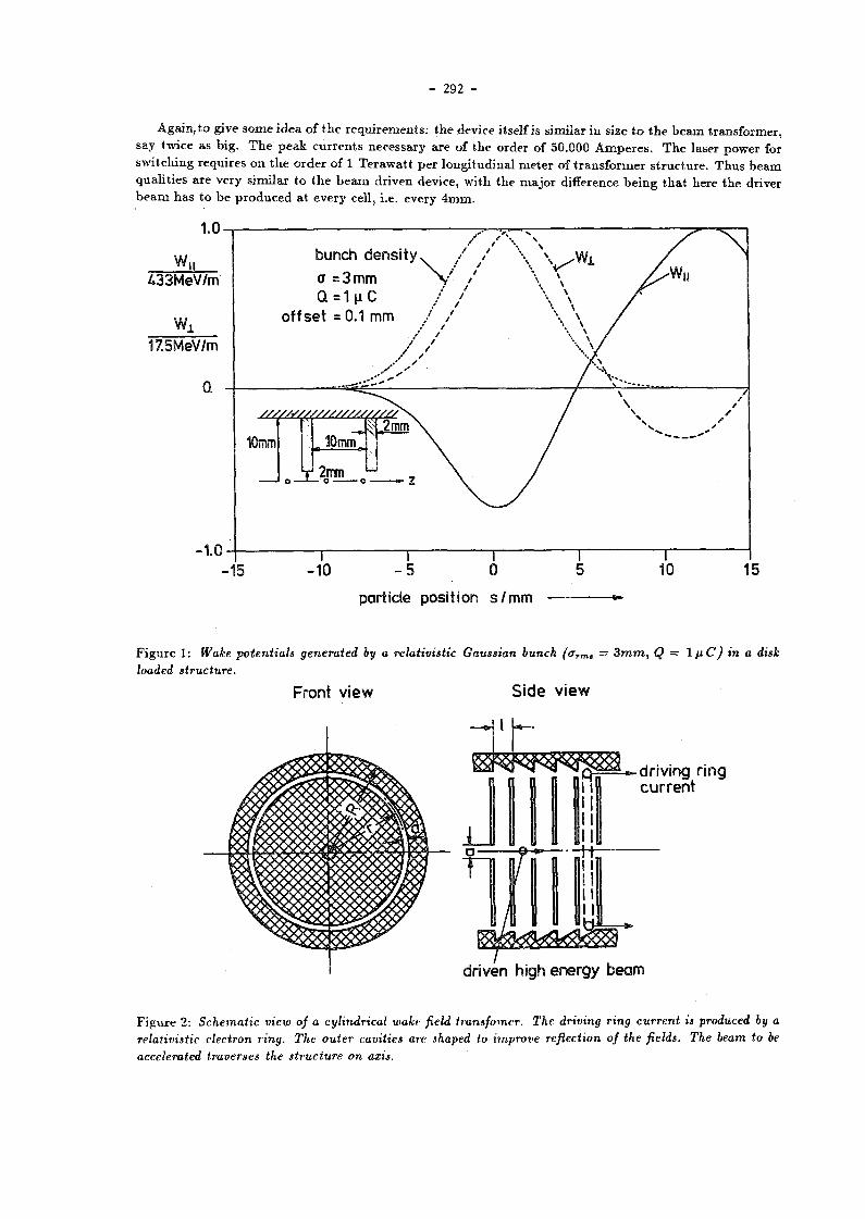
- 292 -
Again , t o give some idea of t h e r e q u i r e m e n t s : t h e device itself is s imi lar in size t o t h e b e a m t rans former , say twice as b ig . T h e p e a k c u r r e n t s necessa ry a re of t he order of 50.000 A m p e r e s . T h e laser power for swi t ch ing requ i res on t h e o r d e r of 1 T e r a w a t t pe r long i tud ina l m e t e r of t r a n s f o r m e r s t r u c t u r e . T h u s b e a m qua l i t i e s a re very s imi lar t o t h e b e a m dr iven device, w i th t h e ma jo r difference b e i n g t h a t here t h e driver b e a m h a s t o b e p r o d u c e d a t every cell, i .e. every 4 m m .
1.0-
w II ¿33MeV/m
17.5MeV/m
0.
-1.0
BUNCH DENSITY
a = 3 M M Q =1 |i C
OFFSET = 0.1 M M
Y / \ \
10mm ÎOmm,
V 2mm u
1 o o —
•10 I 0
T 5 10 15
PARTICLE POSITION S/MM
F i g u r e 1: Wake potentials generated by a relativistic Gaussian bunch (aTm, = 3 m m , Q — 1 fiC) in a disk loaded structure.
FRONT VIEW SIDE VIEW
DRIVING RING CURRENT
DRIVEN HIGH ENERGY BEAM
F i g u r e 2: Schematic view of a cylindrical wake field transfomer. The driving ring current is produced by a relativistic electron ring. The outer cavities are shaped to improve reflection of the fields. The beam to be accelerated traverses the structure on axis.

- 293 -
F igu re 3: Wake P o t e n t i a l s in a Cyl indr ica l Wake Field Trans former
Driving beam: Q — 1 \iC', 0Vm» = 2 mm, beam radius= 50 m m accelerated beam: Q -- 0.01 / i C ,
^ r m i — 2 m m driving beam density driving beam decelerating wake potential, W m ; „ = 2 0 M e F / T O
accelerating wake potential for electrons on axis, Wmax — 157MeV'/rn accelerated beam density decelerating wake potential of the accelerated beam,Wmin — 7.3MeV/m accelerating wake potential for positrons, Wmax = 110MeV/m
F i g u r e 4: The Switched Power Linac An arrangement of charged wires provides stored energy which released by a very short laser pulse (3ps ) into a 50^.4 current pulse. This high current pulse generates wave packet travelling toward the center producing a very high accelerating field on the symmetry axis up to 300McV/m.

- 294 -
2 W o r k i n g G r o u p R e p o r t
- 1 I I I i
0 1 2 3
particle position behind the driving bunch s/m "
F i g u r e 5: Long Range Wake Potential on axis produced by a hollow driver hunch
As can he seen, there is no dramatic decay of wake potential behind the driving beam due to dispersion. The
typical decay due to wall losses corresponds to about W times the time interval displayed here. Thus up
to 100 ring pulses can be run subsequently through the transformer at proper distance producing an almost
linear increase of the single pulse wake potential by a factor of 100.
T h e work ing g r o u p spen t a b o u t half. of t h e available t i m e w i t h d iscuss ions a n d p resen ta t ions in o the r g roups , especial ly wi th t h e p l a s m a accelera tor g roup because t h e y were i n t e r e s t ed in p l a s m a wake field acce lera t ion . Also , a s t rong i n t e r ac t i on was necessary w i t h t h e source g r o u p as one of t h e key p rob lems in t r ans fo rmer technology is t h e gene ra t ion of these h igh current ; shor t p u l s e , b e a m s .
A very p r e l i m i n a r y c o m p a r i s o n of t h e two t r ans fo rmer concepts , t h e Swi tched Power Linac (SPL) a n d t h e Wake Fie ld T rans fo rmer ( W F T ) was per formed us ing exis t ing figures for t h e geometr ies . T h e idea was t o list all i ng red ien t s of b o t h schemes a n d c o m p a r e t h e m to an o r d i n a r y disk loaded s t r u c t u r e (DLS) .
As was done i n t h e e x p e r i m e n t a t DESY, b o t h schemes c o u l d b e r u n i n a m u l t i - p u l s e mode. A
sequence of d r i v e r p u l s e s a t a p r o p e r d i s t a n c e would e a s i l y add up to a much h i g h e r g r a d i e n t ,
o r f o r a c o n s t a n t g r a d i e n t , t h e y would l e a d t o g r e a t l y r e d u c e d r e q u i r e m e n t s f o r t h e d r i v e r
beams . T h i s can b e s e e n from f i g u r e 5 where t h e wake p o t e n t i a l f a r b e h i n d t h e d r i v i n g beam
does n o t show any s i g n i f i c a n t d e c r e a s e i n a m p l i t u d e . F o r a c o p p e r t r a n s f o r m e r t h e t y p i c a l
decay t ime c o r r e s p o n d s t o a b o u t 100 p u l s e s i n a t r a i n of h o l l o w bunches g e n e r a t e d i n a 500 MHz
l i n a c .
For t h e case of t h e S P L th i s c a n n o t b e a s s u m e d at t h e p resen t s t a t e of knowledge . T h e majo r difficulty comes from t h e fact t h a t w i t h t h e S P L the re is no s imple t e r m i n a t i o n of t h e r ad ia l l ine a t t he ou t e rmos t r a d i u s . T h u s reflection of pulses causes degrada t ion . More deta i led s tudies ab o u t th i s opera t ion m o d e are necessary before m a k i n g any relevant s t a t e m e n t s as to w h e t h e r or not it is poss ible to bui ld a mul t i pulse S P L .
For b o t h schemes energy recovery m e a n s have been discussed. For t h e S P L no s t ra ight forward solut ion was found, bu t th i s was ma in ly d u e t o t h e fact t h a t not m u c h t h o u g h t h a d gone i n t o t h a t p rob lem before.

- 295 -
W F T S P L
disk r a d i u s b/mm 45 120 b e a m hole r ad iu s a/mm 2 1
gap be tween disks g/mm 4 2 disk th ickness t/mm 1 2
geomet r ic t r ans fomer r a t i o . R8 10 12
single b u n c h charge Q/ßC 1 -pulse w i d t h T /ps 16 10
decelera t ing g rad ien t G-/(MV/m) 20 25 accelera t ing g rad ien t G+/(MV/m) 200 300 s to red e n e r g y / p u l s e • W/J 20 25
e las tance ' >/({V/pC)/m) 2000 3600 e las tance of a DLS of s a m e sDLS/((V/pC)/m) 1600 6400
b e a m hole r ad iu s refigerator power of t h e Pref/(kW/m) 40 -
r epe t i t i on frequency f/kHz 2 -s u p e r c o n d u c t i n g dr ive l inac
rf power f rom wall p lug PTj/{kW/m) 80 -laser power for swi t iching PLaSer/{TW/m) - 1
laser efficiency IL - 2.2 1 0 - 2
q u a n t u m efficiency Vg - 5 1 0 " 3
to ta l dr iver efficiency from Vdrive 0.33 0.10 m a i n s t o accelera t ing field
to ta l efficiency of a D L S r/DLS 0.3 0.3
Tab le 1: Comparison of single pulse Switched Power Linac SPL with single Wake Field Transformer ( WFT) and a disk loaded structure (DLS). Various parameters have been assumed, such as a superconducting drive linac with a gradient of bMeV/m, common figures for the wall plug to rf conversion efficiency etc. Note that, the mains -to-rf accelerating field efficiency is quite high in the WFT scheme.

- 296 -
However , for t h e W F T the re is a n easy way of e x t r a c t i n g energy left b e h i n d t h e accelera ted bunches a n d t o s tore it b a c k i n t o t h e hol low b e a m drive l inac . U n d e r t h e a s s u m p t i o n t h a t t h e hollow b e a m dr iver is a s u p e r c o n d u c t i n g 500MHz or 1 G H z l inac , one m a y have a t r a i n of energy t ransfer bunches following r ight b e h i n d t h e acce le ra ted b u n c h . T h e s e energy t ransfe r b u n c h e s will b e acce le ra ted by the r ema in ing wake field pulses in t h e t r ans fo rmer . T h e y will follow t h e h igh energy b u n c h a n d t rave l t h r o u g h t h e dr iver l inac cavi t ies . T h e r e , t h e h igh ene rgy b u n c h will be acce le ra ted b y a smal l a m o u n t . T h e d is tance t o t h e following t r a i n of ene rgy t ransfer b u n c h e s can b e chosen such t h a t t h e y ar r ive a t t h e p h a s e where t h e dr iver field is n e a r t h e m i n i m u m . T h u s t h e y will be dece le ra ted , i.e. energy will b e recovered in to t he driver l inac f u n d a m e n t a l m o d e . No deta i led s t u d y was per formed on h o w m u c h of t h a t energy c a n b e recovered. T h i s is u n d e r s t u d y right now a n d t h e r e is h o p e to increase t h e overall efficiency by a significant a m o u n t .
3 O u t l o o k
A l t h o u g h t r a n s f o r m e r technology was considered t o b e technica l ly very difficult a t t h e t i m e it was first p r o p o s e d in 1982, it h a s now been p roven to work exper imenta l ly . A W F T mul t i -pu l se ope ra t ion w i t h five pu l ses was s t u d i e d successfully in t h e D E S Y e x p e r i m e n t . Theo re t i ca l inves t iga t ions w i t h m a n y m o r e pulses a r e unde rway . T h e y p romise t o significantly re lax t h e b e a m qua l i ty r equ i r emen t s such as t he a z i m u t h a l s y m m e t r y a n d t h e e lec t ron charge densi ty .
C o m p a r e d t o quas i -convent iona l app roaches need ing e x t r e m e n u m b e r s of very h igh power sources , t he t echn ica l feasibil i ty of a W F T collider seems to b e s o m e w h a t closer t o reali ty. T h e basic ingred ien ts a re conven t iona l d r iver l inacs , e i ther s u p e r c o n d u c t i n g or n o r m a l copper s t r u c t u r e s , r u n n i n g a t t o d a y ' s g rad i e n t s . T h e t r a n s f o r m e r section itself is very s imple in c o n s t r u c t i o n a n d needs m u c h less fine mach in ing t h a n e.g. 30GHz cavi t ies . F u r t h e r m o r e , t h e r e is no p h a s i n g necessary be tween t h e dr iver a n d the acce lera ted b u n c h as is needed in a rf l inac .
T h e S P L is i n a m o r e theore t ica l s t a g e a n d some e x p e r i m e n t is u rgen t ly needed t o show t h a t t he se h igh vo l t age l ines w i t h field s t r e n g h t s u p t o IGV/m c an b e real ized in p rac t ice .
R e f e r e n c e s
[1] G .-A.Voss a n d T .Wei land , D E S Y M-82-10, Apr i l 1982. a n d P roceed ings of t h e E C F A - R A L W o r k s h o p , Oxford , S e p t e m b e r 1982, E C F A 8 3 / 6 8 a n d D E S Y 82-074 November 1982.
[2] K . B a n e , P . C h e n , P .Wi lson , I E E E NS-32, No .5 , p . 3 5 2 4 .
[3] W.B ia lowons , H . D . B r e m e r , F . J .Decke r , H .C .Lewin , P . S c h u t t , Xiao C h e n g d e , G.-A.Voss, T .Wei l and , t h i s v o l u m e .
[4j W.Wi l l i s , A I P (103) , 1985, p . 421 .

- 297 -
Discussion
U. Amaldi, CERN
I have three questions about the wake field accelerator:
(1) What is the total acceleration voltage for the hollow drive beam?
(2) Do you have a feeling for the wakefield effects in hollow bunches in the multibunch
beam?
(3) What is the minimum emittance of the main bunches that can be accelerated, taking
into account the possible azimuthal asymmetry of the hollow bunches?
Reply
(1) It is the final energy divided by the transformation ratio and the number of driving
bunches. With our superconducting cavities you can have large driving beams that
allow a transformation ratio of 15. With 10 bunches this gives you 6 GeV for a TeV
collider.
(2) This problem is under study right now.
(3) It is of the same order as in a linac with 30 GHz and 4 mm beam hole diameter, but
detailed studies have been delayed until the first experimental results were available
and that happened just a few weeks ago.
- 298 -
T h e W a k e Fie ld Transformer E x p e r i m e n t at D E S Y
W.Bialowons.H.-D.Bremer, F.-J.Decker, H.-Ch.Lewin,
P.Schütt, G.-A.Voss, Th.Weiland, Xiao Chengde *
Deutsches Elektronen-Synchrotron D E S Y
Notkestr. 85, 2000 H a m b u r g 52, G e r m a n y
A b s t r a c t
The basic principle of Wake Field Transformation is to use imploding electromagnetic waves generated by high density electron bunches. One of the most simple structures for a Wake Field Transformer is the cylindrical pill-box excited by a hollow beam. The fundamental mechanism will be briefly reviewed. A Proof of Principle experiment has been set up at DESY by a group of scientists with collaborators from China, Japan and USA. The layout of the experiment is presented together with a status report and most recent results. Several bunches each of 50 to 100 nC charge have been produced and accelerated to an energy of 8 MeV and bunched down to a length of 1 cm. With a central witness beam a gradient of 8 MeV/m has been measured in a short Wake Field Transformer using six subsequent hollow bunches in one pulse.
I n t r o d u c t i o n
T h e p r inc ip l e of t h e wake field acce lera t ion m e c h a n i s m h a s been descr ibed in deta i l in o the r p a p e r s [1,2]. T h u s , we recal l only t h e bas ic po in t s of i n t e r e s t : A h igh charge dr iv ing b e a m of 1 pC (say) a n d a cen t ra l low c h a r g e d r iven b e a m of 0.01 ßC b o t h t r a v e r s e a special k ind of mult i-cel l cavi ty which we call a Wake Field Transformer. In th i s t r ans fo rmer t h e d r iv ing b e a m exci tes wake fields t h a t lead t o i t s dece lera t ion . B y p r o p e r s h a p i n g of t h e t r a n s f o r m e r g e o m e t r y t h e d r iv ing b e a m excites a wave packet t h a t is subsequen t ly spa t i a l l y f o c u s e d . T h u s , t h e r e is an inc rease i n field s t r e n g t h p r o p o r t i o n a l t o t h e inverse squa re roo t of t h e v o l u m e con ta in ing t h e wake fields. A second pu l se of par t ic les en te r ing t h e t r ans fo rmer focal l ine w i t h p r o p e r delay t r averses th i s c o n c e n t r a t e d wake field a n d exper iences a n accelera t ion which is m u c h g r e a t e r t h a n t h e dece le ra t ion of t h e d r iv ing b e a m . T h e r a t io of accelera t ion t o decelera t ion we call i t s transformation ratio. Values for t h e t r a n s f o r m a t i o n r a t i o of a r o u n d 10 a re expec ted in ou r e x p e r i m e n t . T h u s , one could accelera te a b u n c h of e lec t rons t o 1 TeV us ing t h e wake fields of a 100 GeV d r iv ing b e a m a n d a c c o r d i n g t o our ca lcu la t ions t h e acce le ra t ing g rad ien t will exceed 100 MeV pe r me te r .
T h i s scheme is cons idered t o b e a c a n d i d a t e for t h e next TeV e l ec t ron-pos i t ron collider. I t could b e bu i l t w i t h i n a t o t a l l eng th of a b o u t 10 km if t h e p r e d i c t e d g rad i en t s can b e reached .
A n e x p e r i m e n t wi th a hol low b e a m Wake Field Transformer h a s been set u p a t D E S Y . A laser dr iven e l e c t r o n g u n p roduces a h igh cur ren t hol low b e a m of 10 c m d i a m e t e r . T h e b e a m is b u n c h e d i n a pre-b u n c h e r a n d acce lera ted in t h e following l i nac . T h i s whole u n i t is in a solenoid guid ing field. T h e final l o n g i t u d i n a l compress ion is achieved in t h e h igh energy b u n c h e r . Final ly , t h e b e a m is fed in to t h e Wake F ie ld T rans fo rmer . T h e ene rgy of t h e cen t r a l wi tness b e a m pass ing t h r o u g h th is t r ans fo rmer on axis is a n a l y z e d in a spec t rome te r adjacent t o t h e t r a n s f o r m e r .
* On leave from Tsinghua University, Beijing, People's Republik of China

- 299 -
1 Experimental Set Up
H o l l o w B e a m G u n . A laser dr iven g u n was chosen for wh ich t h e p h o t o n energy of t h e laser l ight is m u c h lower t h a n t h e work funct ion of t h e c a t h o d e m a t e r i a l . T h e inf ra red l ight b e a m (wave l eng th 1 .064/ im) p r o d u c e d b y a Q-swi tched Nd :YAG laser (peak power > 100 MW) is f o c u s e d o n t o a r ing at t h e conical t a n t a l u m c a t h o d e a n d is a b s o r b e d ins ide a very t h i n layer . T h u s , since t h e surface t e m p e r a t u r e increases , t h e r m i o n i c emiss ion a n d the rmion ic s u p p o r t e d pho toe lec t r i c emiss ion is poss ib le . T h e e m i t t e d e lec t rons are e x t r a c t e d by a pu l sed h igh vol tage a n d guided b y a solenoid field (field s t r e n g t h ~ 0.2 T) t h r o u g h a slit in t h e a n o d e . A m o r e de ta i l ed descr ip t ion of t h e gun a n d t h e emiss ion m e c h a n i s m a n d some e x p e r i m e n t a l resu l t s a re given in a s e p a r a t e con t r i bu t ion t o these p roceed ings [6].
L i n e a r A c c e l e r a t o r . T h e l inac consists of a p r e b u n c h e r a n d a cha in of four 3-cell cavit ies powered by a 1 MW k ly s t ron (500 MHz) which is pu l sed at 25 Hz w i t h 1 0 0 ¡ l s d u r a t i o n . T h e p r e b u n c h e r cons is t s of a single-cell cavi ty a n d a following drift space . T h e zero cu r r en t energy gain is 8 MeV a n d the m e a s u r e d shun t i m p e d a n c e of t h e acce lera t ing cavit ies is 20 Mil/m. Solenoid coils s u r r o u n d t h e cavit ies w h e r e v e r poss ib le . All cavi t ies a r e m o u n t e d wi th a per iodic i ty of A / 2 . A d d i t i o n a l p h a s e shifters enab le t he phases to b e cont ro l led . T h e first p h a s e shifter be tween t h e p r e b u n c h e r cavi ty a n d t h e first accelera t ing cavi ty ad jus t s t h e in ject ion p h a s e . A second p h a s e shifter be tween t h e first a n d t h e second cavi ty corrects for t h e delay in p h a s e owing t o t h e subre la t iv is t ic energy of t h e in jec ted e lec t rons . T h e t h i r d p h a s e shifter a t t h e four th cavi ty al lows us t o gene ra t e a var iable energy sp r ead which is needed for t h e h igh energy b u n c h i n g m e c h a n i s m in t h e an t i so leno id . As cavities a re loca ted in t h e m a g n e t i c field of t h e solenoid, m u l t i p a c t o r i n g is m u c h m o r e severe t h a n usua l .
J Klystron
Pulsed
Jd 117¿7 " A \ w f ^ T A ~x /ill r Screen Gap Accelerating^ Energy Gap Lor
Prebunche
cavity monitor monitor cavities
Longitudinal modulator monitor compression
Radial compression
0 S 10 ler>9thlm
F i g u r e 1: Overa l l layout of t he Wake Fie ld T rans fo rmer expe r imen t at D E S Y .
Shown from left to right: The infrared light beam produced by a Q-switched Nd-Yag laser (peak power > 100MW) is focused onto a ring shaped tantalum cathode. The emitted thermionic- and photoelectrons are extracted by a voltage of about 100 kV and guided by solenoid fields of 0.2 T into the linac. Firstly, the hollow beam is compressed longitudinally in a prebuncher. Then, four 3-cell cavities /o00 MHz) accelerate it to 8 MeV. A pulsed klystron (peak power 1 MW) feeds the cavities. In the antisolenoid further longitudinal compression is achieved. Then the ring is radially compressed by increasing solenoid fields. Finally, the electron ring enters the actual Wake Field Transformer, consisting of SO cylindrical cells arranged one after another. For monitoring and adjustment of the ring beam, several beam monitors have been set up.
In o rde r t o s t u d y t h e p r o b l e m s associa ted wi th t h e Wake Field Tramfomer concept we have assembled an e x p e r i m e n t [3,4,5] u s ing a comple te l inac for gene ra t ion of t he d r iv ing b e a m . W e chose a cylmdrical ly s y m m e t r i c t r a n s f o r m e r since it should provide high t r a n s f o r m a t i o n ra t ios a n d s ince it was t he only one t h a t could p rope r ly b e ana lyzed when first p r o p o s e d in t h e year 1982.
T h e d r iv ing hol low b e a m has a d i ame te r of 10 c m . W h e n e x t r a c t e d from t h e g u n the charge shou ld be 1 fxC over a pu l se l e n g t h of I n s . T h u s , we need 1 kA e lec t ron cu r r en t . T h e design peak value of t he pu l sed c a t h o d e vol tage is 150 kV, T h e b e a m is acce le ra ted t o a b o u t 8 MeV a n d compressed before en te r ing t h e Wake Field Transformer. T h e overall l ayou t of t he e x p e r i m e n t is s h o w n in Fig. 1 a n d the m a j o r c o m p o n e n t s will b e descr ibed below.
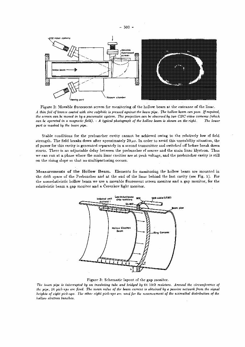
- 300 -
F i g u r e 2: Movab le fluorescent screen for m o n i t o r i n g of t he hol low b e a m at t h e e n t r a n c e of t h e l inac . A thin foil of bronze coated with zinc sulphide is pressed against the beam pipe. The hollow beam can pass. If required, the screen can be moved in by a pneumatic system. The projection can be observed by two CDC video cameras (which can be operated in a magnetic field). - A typical photograph of the hollow beam is shown on the right. The lower part is masked by the beam pipe.
S t a b l e cond i t ions for t he p r e b u n c h e r cavi ty c a n n o t be achieved owing t o t h e re la t ively low rf field s t r e n g t h . T h e field b r e a k s down after a p r o x i m a t e l y 20 fis. In o rde r t o avoid th i s u n s t a b i l i t y s i t ua t i on , t h e r f -power for t h i s cavi ty is g e n e r a t e d s e p a r a t e l y in a second t r a n s m i t t e r a n d swi tched off before b reak down s t a r t s . T h e r e is a n ad jus t ab le delay b e t w e e n t h e p r e b u n c h e r rf source a n d t h e m a i n l inac k lys t ron . T h u s we c a n r u n a t a p h a s e where t he m a i n l inac cavi t ies a r e a t peak vol tage , a n d t h e p r e b u n c h e r cavi ty is still o n t h e rising s lope so t h a t n o m u l t i p a c t o r i n g o c c u r s .
M e a s u r e m e n t s o f t h e H o l l o w B e a m . E l e m e n t s for m o n i t o r i n g t h e hol low b e a m are m o u n t e d in t h e drift space of t h e P r e b u n c h e r a n d a t t h e e n d of t he l inac b e h i n d t h e las t cavi ty (see Fig . 1). For t h e nonre la t iv i s t i c hol low b e a m we use a m o v a b l e fluorescent screen m o n i t o r a n d a g a p m o n i t o r , for t h e re la t iv i s t i c b e a m a g a p m o n i t o r a n d a Ce renkov l ight m o n i t o r .
F i g u r e 3: S c h e m a t i c layout of t h e g a p mon i to r . The beam pipe is interrupted by an insulating tube and bridged by 64 10 fi resistors. Around the circumference of the pipe, 16 pick-ups are fixed. The mean value of the beam current is obtained by a passive network from the signal heights of eight pick-ups. The other eight pick-ups are used for the measurement of the azimuthal distribution of the hollow electron bunches.

- 301 -
A projection of the hollow beam is produced by a fluorescent screen which can be moved into the beam pipe if required and observed by C D C video cameras. The layout of this device is shown in Fig. 2.
A gap moni tor ( F i g . 3) measures the w a l l c u r r e n t induced i n the beam p i p e . The tube i s
s imply i n t e r r u p t e d by an i n s u l a t i n g r i n g and b r i d g e d by r e s i s t o r s . The v o l t a g e drop a c r o s s
the r e s i s t o r s i s p r o p o r t i o n a l to the w a l l c u r r e n t . For measuring the p u l s e l e n g t h of s h o r
t e r bunches a tferenkov monitor has been d e s i g n e d . A p a r t of the h o l l o w beam e x c i t e s í í eren-
kov r a d i a t i o n i n a smal l quartz wedge. With a l i g h t c o l l e c t i o n sys tem c o n s i s t i n g of two
mirrors and t h r e e l e n s e s the l i g h t p u l s e i s guided to the imaging s l o t o f a s t r e a k camera.
The correspond ing peak c u r r e n t must be d e r i v e d from the s i g n a l of t h e gap monitor mounted
near b y .
H i g h E n e r g y B u n c h e r . The final longitudinal compression of the hollow beam is achieved in an anti-solenoid. The field strength of the solenoid and of the antisolenoid are equal. The region where the field is radial must be very short. Therefore iron plates are inserted between the coils.
T h e total effect on the beam of the longitudinal field of the solenoid and the radial end fields is to cause the ring to rotate arround its symmetry axis. As some of the particle energy is now in the circular mot ion , the longitudinal velocity decreases. The phase of the fourth cavity is adjusted such that the earlier particles are accelerated less than the later ones. Thus the ring can be bunched even at high energies, where classical bunching mechanisms fail.
At the end of the antisolenoid, the rotation is stopped by another inversion of the solenoid field.
W a k e F i e l d T r a n s f o r m e r . The central part of the whole experiment is the Wake Field Transformer. A cross-sectional drawing is shown in Fig. 4. An electron ring of 10 cm diameter, 2 mm minor radius, at an energy high enough for it to be relativistic and of total charge 1 fj,C excites wake field while traversing the transformer through the slot near the outer diameter. T h e generated wave packet first runs radially towards the outer boundary, is reflected there with reversed sign and subsequently travels towards the center. As the total volume containing the electromagnetic energy is thereby reduced, the field strength is i n c r e a s e d i n v e r s e p r o p o r t i o n a l l y to the square r o o t t o the volume c o n t a i n i n g the wake f i e l d s . Thus, when the wave has reached the c e n t r e , the a c c e l e r a t i n g f i e l d a t t h i s l o c a t i o n can be 10 to 20 t imes h i g h e r than the d e c e l e r a t i n g f i e l d s e e n by the p a r t i c l e s i n the d r i v i n g h o l low bunch. J u s t to g i v e some idea of the s t r e n g t h of t h e s e f i e l d s , F i g . 5 shows a l l wake p o t e n t i a l s i n the above mentioned d e v i c e producing an a c c e l e r a t i n g g r a d i e n t of 157 MeV/m.
*100 ! 4 0 0 8 2
Figure 4: Cross section of one part of the Wake Field Transformer.
On the inner wall of the beam tube rebates are turned, on which wake fields are excited by the driving hollow beam. The wake fields are guided by the disks into the centre of the beam tube where they interact with the driven beam. The disks are held together by metal strips and form a stack lying normal to the axis of the tube. All parts are made from stainless steel.

- 302 -
F i g u r e 5: Wake P o t e n t i a l s in a cyl indrical Wake Field Transformer.
Driving beam: Q = 1 ftC, c r r m # = 2 mm, beam radius = 50 mm accelerated beam: Q = 0.01 pC, <rrms = 2 mm
driving beam density driving beam decelerating wake potential, Wmin = 20 A Í e V / m accelerating wake potential for electrons on axis, Wmax = 157MeV/m accelerated beam density decelerating wake potential of the accelerated beam,Wmin — l.ZMeVjm accelerating wake potential for positrons, Wmax = llOMeV/m
C o m p u t e r S i m u l a t i o n s . T h e D E S Y Wake Field Transformer expe r imen t h a s a lways been accompan ied by theore t ica l s tud ies a n d c o m p u t e r s imula t ions . T w o codes a r e used for t h e numer i ca l s tud ies : WAKTRACK[7], a fast t r ack ing code inc lud ing collective effects, is used as a n o p e r a t i n g too l in paral le l w i t h t h e e x p e r i m e n t . It will also b e u s e d for inves t iga t ions on t h e feasibili ty of a fu tu re TeV collider. M o r e de ta i l ed inves t iga t ions , especially in t h e low e n e r g y r e g i o n (y < 20) , a r e car r ied ou t w i t h TBCI-SF[8], a n e w part ic le- in-cel l code . B o t h p r o g r a m s are descr ibed in more de ta i l in a n o t h e r con t r ibu t ions t o these p roceed ings [9].
2 S t a g e - 1 E x p e r i m e n t
In o rde r t o inves t iga te s t e p by s t ep t h e p r o b l e m s concerned wi th hollow b e a m d y n a m i c s we first o m i t t e d t h e h igh energy b u n c h e r a n d set u p a stage-1 expe r imen t t o get a first proof of the Wake Field Transformation concep t . T h e layout of th i s e x p e r i m e n t is shown in Fig . 6.
W e a re us ing a t r ans fo rmer which is op t imized for t h e hollow b e a m size b u n c h e d by t h e l inac . T h e s e p a r a t i o n of t h e p la te s is 1 cm a n d t h e thickness 2 m m . T h e p la te s a re he ld by four long i tud ina l sticks n e a r t h e slot for t h e hol low b e a m . T h e tes t b e a m is p r o d u c e d by a field emiss ion g u n which uses t h e first t r ans fo rmer p l a t e as anode . T h e c a t h o d e consis ts of a po in t ed t a n t a l u m need le . Since t h e b e a m was nourelat ivist ic . on ly a shor t t r a n s f o r m e r could be used: Slow par t ic les a r e no t ab le t o s t a y in p h a s e wi th t h e wake field pulse r u n n i n g a t t h e speed of l ight . T h e o p t i m u m t r ans fo rmer consis ts in th i s case of two cells. T w o lead blocks p rov ide shielding aga ins t e lectrons from t h e hollow b e a m a n d pa ras i t i c e lec t rons . T h e energy of the e lec t rons acce le ra ted by t h e excited wake fields is m e a s u r e d by a dece le ra t ing gr id m e t h o d . Only par t ic les w i t h energy g rea te r t h a n the gr id vol tage p e n e t r a t e t o t h e zinc su lph ide screen a n d can b e de t ec t ed by a pho tomul t ip l i e r . F r o m t h e difference wi th t he test g u n vol tage we can d e t e r m i n e t h e energy rise in t h e t r ans fo rmer .

- 303 -
Figure 6: Overal l layout of t h e stage-1 Wake Field Transformer expe r imen t a t D E S Y .
A Cerenkov l ight m o n i t o r m e a s u r e s t h e pu lse w i d t h of t h e hol low b e a m a n d a gap m o n i t o r m e a s u r e s t h e charge of t h e subsequen t bunches of a pu l se . T h e surface of t h e first l ead block is used as a fluorescent screen for m o n i t o r i n g t h e a d j u s t m e n t of t h e hollow b e a m rela t ive t o t h e slot.
3 E x p e r i m e n t a l R e s u l t s o f t h e L i n e a r A c c e l e r a t o r
T h e s t u d y of t h e p r o p e r t i e s of t h e l inear acce lera tor involved m a n y m e a s u r e m e n t s . W e have chosen t h r e e typ ica l ones for t h i s r e p o r t .
A z i m u t h a l d i s t r i b u t i o n o f t h e h o l l o w b e a m . T h e m o m e n t a of t h e charge d i s t r i bu t ion w i th in t he hol low b e a m re la t ive t o t h e centre of t h e b e a m p i p e c a n b e m e a s u r e d by t h e gap m o n i t o r us ing t h e signal he igh t s of t h e eight p ick-ups m o u n t e d a r o u n d t h e c i rcumference of t h e m o n i t o r . T h e signals for two different c u r r e n t s a re shown in F ig . 7. In o rde r t o get t h e cor rec t a z i m u t h a l d i s t r i bu t ion of t h e hollow b e a m t h e different d a m p i n g of t h e eight signals d u e t o t h e different l eng th of t h e l ines a n d t h e cross ta lk be tween one s ignal a n d t h e o the r s mus t b e t a k e n in to accoun t . T h e re la t ive d ipole m o m e n t of t h e hollow b e a m is less t h a n 20 % in th is example .
t / n s t / n s
Figure 7: Az imu tha l d i s t r i bu t i on of t h e hollow b e a m for two different cu r r en t s .
Eight signals around the circumference of the gap monitor are delayed by delay lines, added by a passive resistor network and measured by one channel of an oscilloscope. Thus it is possible to measure the eight signals of one pulse simultaneously. On the left photograph a distribution is shown for a hollow beam current of 22 A and on the right photograph for 39 A.
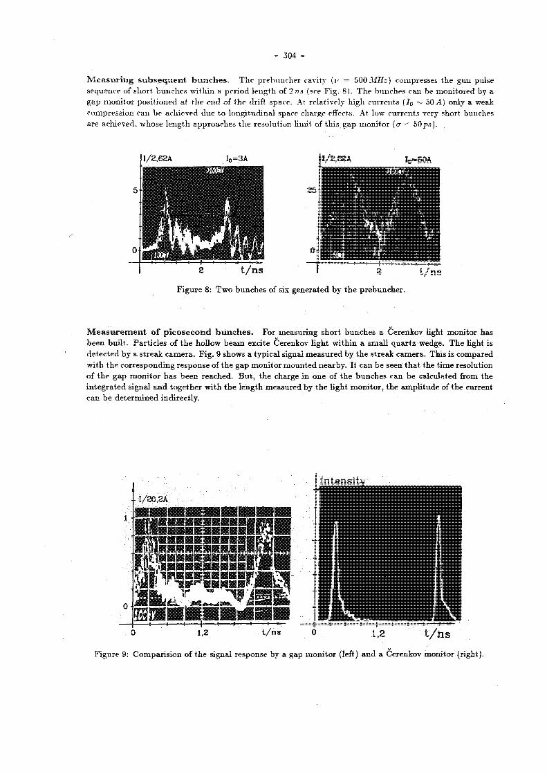
- 304 -
M e a s u r i n g s u b s e q u e n t , b u n c h e s . T h e p r e b u n c h e r cavity (v = 500 MHz ) compresses t he gun pulse sequence of shor t b u n c h e s wi th in a pe r iod l eng th of 2 ns (see F ig . 8) . T h e bunches can be mon i to red by a g a p m o n i t o r pos i t ioned at t h e end of t he drift space . At re la t ively high cu r r en t s ( 7 0 ~ 50.4) only a weak compress ion can b e achieved due t o l ong i tud ina l space charge effects. At low cu r r en t s very short bunches a re achieved, whose l e n g t h a p p r o a c h e s t h e resolu t ion l imit of t h i s g a p m o n i t o r (tr •- 50ps).
I / 2 . 6 2 A
• m
I 0 = 3 A I / 2 . 6 2 A
1 # S H
I 0 - 5 0 A
t / n s
F i g u r e 8: T w o b u n c h e s of six genera ted by t h e p r e b u n c h e r .
t / n s
M e a s u r e m e n t o f p i c o s e c o n d b u n c h e s . For measur ing s h o r t b u n c h e s a Cerenkov light m o n i t o r has b e e n bu i l t . Pa r t i c l e s of t h e hol low b e a m exci te Cerenkov l ight w i t h i n a smal l q u a r t z wedge. T h e light is d e t e c t e d by a s t r e a k c a m e r a . F ig . 9 shows a typ ica l signal m e a s u r e d by t h e s t r eak c a m e r a . Th i s is compared w i t h t h e co r r e spond ing r e sponse of t h e g a p m o n i t o r m o u n t e d nea rby . It can b e seen t h a t t h e t i m e resolut ion of t h e gap m o n i t o r h a s been reached . B u t , t h e charge in one of t h e b u n c h e s can b e ca lcula ted from t h e i n t e g r a t e d signal a n d t o g e t h e r w i t h t h e l eng th measu red by t h e l ight m o n i t o r , t h e a m p l i t u d e of t he cur rent can b e d e t e r m i n e d indi rec t ly .
F igu re 9: C o m p a r i s i o u of t h e signal r e sponse by a gap m o n i t o r (left) a n d a Cerenkov m o n i t o r ( r ight ) .

- 305 -
4 F i r s t E x p e r i m e n t a l P r o o f o f W a k e F i e l d A c c e l e r a t i o n
U / v U / v
100 200 t / r ' n s 100 200 t / r ' n s
Figu re 10: Pho tomu l t i p l i e r s ignal of l ight p r o d u c e d by electrons t r ave r s ing t h e final po t en t i a l bar r ie r .
Left: Background signal due to secondary photons created by scattered electrons of the driving beam. Right: Signal from particles accelerated in the wake field transformer.
In t h e stage-1 e x p e r i m e n t a l set u p as descr ibed above , we first t r ied t o s t u d y t h e p r o b l e m s concerned w i t h s teer ing t h e hol low b e a m t h r o u g h t h e t r a n s f o r m e r . We were able t o g e n e r a t e a cu r r en t pulse of r m s l eng th 1cm a n d a p e a k cu r r en t in excess of 500 .4 . T h e co r respond ing g u n cu r ren t was 55A, t he gun vo l t age 85kV. T h e hol low b e a m consis ts of a t r a i n of six subsequent e lec t ron b u n c h e s s e p a r a t e d by t h e rf wave leng th of t h e dr ive l inac (60cm) . W a k e fields exc i ted in t he t r a n s f o r m e r t r ave l con t inous ly back a n d fo r th rad ia l ly w i t h a reversa l in sign after each reflection a t t he o u t m o s t r ad i a l b o u n d a r y . T h e t rave l t i m e for a wake field pu l se in t h e t r a n s f o r m e r used in th i s expe r imen t was exac t ly one fou r th of t h e pe r iod of t h e l inac frequency. T h u s subsequent, r i ng pulses gene ra t e a wake field which a d d s cons t ruc t ive ly . For t h e field at. t h e center t h e r e is no difference be tween six pulses a n d one pulse w i t h six t i m e s t h e charge .
T h e b e a m r a d i u s could be ad ju s t ed b y m e a n s of add i t i ona l power suppl ies hooked o n t o t h e t h r e e las t so lenoids . T h e b e a m p e n e t r a t e d t h r o u g h t h e t r a n s f o r m e r w i thou t significant loss i n in tens i ty .
At t h e e n d of t h e l inac t h e hol low b e a m b u n c h e s a re m u c h longer t h a n t h e 2 m m t h a t we i n t e n d t o achieve w i t h t h e h igh energy b u n c h i n g scheme . T h u s , wake fields exci ted by t h e s e b u n c h e s a re significantly weaker t h a n t h e y will b e in t h e final set u p as desc r ibed in Section 1. E v en w i t h six b u n c h e s we could no t expec t a change in energy in a t r a n s f o r m e r p laced a t t h i s loca t ion in t h e b e a m l ine t o b e h igh e n o u g h t o b e de t ec t ab l e w i t h a cen t ra l wi tness b e a m r u n n i n g all a long the l inac . T h i s is b e c a u s e b e a m load ing of t h e hol low b e a m a n d o t h e r effects c r ea t e a n energy j i t t e r in t h e wi tness b e a m which is j u s t of t h e s a m e m a g n i t u d e as t h e expec t ed acce lera t ion .
I n o rde r t o b e able t o de tec t even smal l changes in energy we decided t o ins ta l l a s e p a r a t e wi tness b e a m g u n wi th a well defined a n d low energy. T h e wi tness b e a m dc cur ren t was in jec ted a t an energy of 20kV i n t o t h e t r ans fo rmer .
T h e low energy of t h e wi tness b e a m however h a s o t h e r severe d i s a d v a n t a g e s . Pa r t i c l e s a t 20keV are m u c h t oo slow t o s t ay in p h a s e w i t h t h e wake field pulse r u n n i n g a t t h e speed of l igh t . In a t r ans fo rmer which is a few t imes longer t h a n t h e w i d t h of t h e wake field pulse , t h e ne t ene rgy ga in of wi tness par t ic les would average ou t t o zero . T h e only way t o avoid th i s effect is t o m a k e t h e t r a n s f o r m e r as sho r t as t h e pu lse w i d t h . Following a n o p t i m i z a t i o n p r o c e d u r e of max imiz ing the energy ga in as a func t ion of t r an fo rmer l e n g t h we o b t a i n e d a n o p t i m u m for a l e n g t h be tween 2 a n d 3cm. We o p t i m i z e d t h e pe r iod l eng th , slot he igh t , cen t ra l b e a m hole r ad iu s a n d u p p e r cavi ty d e p t h for a bunch l eng th of 1cm a n d o b t a i n e d a two-cell s t r u c t u r e , each cell be ing l c m long a n d s e p a r a t e d by a 2 m m thick meta l l ic disk.
W e r a n t h e l inac for t he above m e n t i o n e d b e a m p a r a m e t e r s a n d in jec t ing t h e wi tness b e a m in to t h e t r ans fo rmer . F i r s t we swi tched off t h e cen t r a l b e a m in o rde r t o see t he b a c k g r o u n d d u e t o secondary p h o t o n s p r o d u c e d by t h e hollow drive b e a m pa r t i c l e s . F ig . 10shows the b a c k g r o u n d s ignal of t h e pho tomul t i p l i e r t u b e .
W e t h a n swi tched on the wi tness b e a m a n d slowly increased t h e stopping vo l t age on t h e gr id (see Fig . 6) b e h i n d the t r ans fo rmer . W e expec ted a m a x i m u m accelera t ion of a r o u n d 30keV, which we ca lcu la ted u n d e r
- 306 -
the pess imis t i c a s s u m p t i o n tha t t he c a p t u r e efficiency of the drive l inac is only 50 % arid t h a t the r ing shape is G a u s s i a n 1 in t h e l ong i tud ina l d i rec t ion. At a vol tage of 70kV we were l imi ted by t h e power supplies bu t could no t yet see any significant decrease of t h e clear signal f rom t h e wi tness b e a m par t ic les , see F ig . 1 0 .
T h u s we .no t only h a d a clear signal of t he first par t ic les acce le ra ted by t h e m e c h a n i s m of Wake Field Transformation bu t we also found an accelera t ion h igher t h a n expec t ed at least m o r e t h a n 50keV. T h u s t he cha rge c a p t u r e efficiency was b e t t e r t h a n a s s u m e d a n d / o r t he b u n c h s h a p e was nar rower t h a n in a Gauss ian d i s t r i b u t i o n . T h i s acce lera t ion of oOkeV over 2 .4cm (which is t h e l e n g t h of t he t r ans fo rmer inc luding two of t h e t h r e e disks) yields a grad ien t of 2 M e V / m for 20keV pa r t i c l e s .
It is re la t ive ly s t r a igh t fo rward t o eva lua te by m e a n s of c o m p u t e r s imula t ion t h a t relat ivist ic par t ic les wou ld b e acce le ra ted by these fields at a r a t e of 8 M e V / m .
5 SUMMARY T h e first e x p e r i m e n t a l proof of t h e new accelera t ion m e c h a n i s m of Wake Field Transformation has been c o m p l e t e d a t D E S Y . T h e expe r imen t did show t h a t th i s scheme is technica l ly feasible.
A n u m b e r of effects concerned w i t h t h e u n u s u a l b e a m d y n a m i c s of h igh dens i ty hollow bunched b e a m s were s t u d i e d . T h e cha rge densi t ies achieved in th i s first (not a t all op t imized ) expe r imen t a re a r o u n d 1/10 of t h e or ig ina l des ign values .
M e a n s t o i m p r o v e th i s s i tua t ion , such as inc reas ing t h e laser power , increas ing t h e g u n vol tage, increasing t h e w i d t h of i l l u m i n a t e d c a t h o d e a rea , rep lac ing t h e p resen t b u n c h e r by a s u b h a r m o n i c one e t c . , are u n d e r inves t iga t ion .
T h e stage-S e x p e r i m e n t will ma in ly b e concerned wi th t h e l o n g i t u d i n a l b u n c h compress ion in t h e ant i so lenoid region . In th i s compressor t h e b u n c h e s will also t h e significantly i m p r o v e d in the i r a z imu tha l s y m m e t r y s ince a local a s y m m e t r y a t a specific angu la r pos i t ion will b e smeared ou t (due t o t h e energy s p r e a d p r o d u c e d in t h e las t l inac cavi ty) over all t h e b u n c h c i rcumference . Th i s nex t s tep will p r e s u m a b l y i nc rea se t h e p e a k in tens i t i es by a factor of five a n d t h e peak values of t h e wake fields even by a factor of t e n .
I n t h e case of a mul t i -pu l se o p e r a t i o n which is now be ing cons ide red , t h e b u n c h charge exper imenta l ly ach ieved is in fact h i g h enough for a scheme w i t h 10-20 pulses or even too h igh in a scheme wi th m o r e pu l se s .
A l so , t h e m u l t i - p u l s e ope ra t i on re laxes m a n y b e a m qua l i ty r e q u i r e m e n t s . W h e r e a s long i tud ina l wake fields a d d u p coherent ly , in genera l t h i s is no t so for t r ansve r se deflecting wake fields since t h e two classes of m o d e s do no t h a v e t h e s ame frequencies. T h u s for such a m u l t i pu l se W F T w i t h m o r e t h a n 20 bunches t h e ex i s t ing e x p e r i m e n t a l s e tup a l r eady fulfills t h e r e q u i r e m e n t s for a real ITeV Wake Field Tranformer l i nea r coll ider.
ACKNOWLEDGEMENT O v e r t h e years f rom 1982 to 1987 a la rge n u m b e r of peop le have c o n t r i b u t e d t o t he design a n d cons t ruc t ion of t h i s e x p e r i m e n t . We wish t o express o u r deep t h a n k s t o ou r c o l l a b o r a t o r s f rom K E K , S .Ohsawa a n d K .Yokoya w h o b o t h spen t a year work ing a t D E S Y , Prof. S .L .Wang f rom t h e Univers i ty of Bejing, K . B a n e f rom S L A C a n d G . R o d e n z from L A N L .
Our t h a n k s a r e a l s o due t o many c o l l e a g u e s a t D E S Y w h o were m e m b e r s of t h e wake field g roup d u r i n g t h e des ign p h a s e a n d worked on t h e b e a m dynamics a n d t h e l ayou t of t h e exper imen t : H . C . D e h n e , M . L e n e k e , J . R o s s b a c h a n d F .Wil leke .
Spec ia l t h a n k s a re also due t o M . v . H a r t r o t t (now a t B E S S Y , Ber l in) w h o was wi th our g roup for a p e r i o d of one yea r a n d w h o designed t h e ana lyz ing a p p a r a t u s wh ich , as descr ibed above was successful.
A grea t p o r t i o n of t h e success of t h e e x p e r i m e n t was due t o t h e in tens ive help by all t he technical g roups a t D E S Y : T h e rf g r o u p h e a d e d by H.Musfe ld t , t h e controls g r o u p h e a d e d by F . P e t e r s , t he power supp ly g r o u p h e a d e d by H.Narc iss a n d W . B o t h e , t h e inject ion g r o u p h e a d e d by A.Febel , t h e civil engineer ing g r o u p h e a d e d b y K . S i n r a m a n d the v a c u u m g r o u p headed by J . K o u p t s i d i s .
F ina l ly , we would like t o t h a n k D . B a r b e r for c a r e f u l r e a d i n g of t h e m a n u s c r i p t .
' T h e a c t u a l s h a p e as o b s e r v e d is steeper t h a n a G a u s s i a n b u n c h a n d t h u s p r e s u m a b l y creates s t r o n g e r w a k e fields.

- 307 -
R e f e r e n c e s
Yes.
I : G.-A.Voss a n d T.Weiland, Particle. Acceleration by Wake Fields, D E S Y M-82-10 . Apr i l 1982.
[2j G.-A.Voss a n d T.Weiland, Wake Field Acceleration Mechanism, Proceedings of the ECFA-RAL Workshop, Oxford , S e p t e m b e r 1982, E C F A 8 3 / 6 8 and D E S Y 82-074 N o v e m b e r 1982.
[3] W.Bia lowons , H . D e h n e , A.Febe l , M.Leneke , H .Musfe ld t , J .Ros sbach , R . R o s s m a n i t h , G.-A.Voss, T . W e i l a n d , F .Wi l leke , A Wake Field Transformer Experiment, P r o c e e d i n g s of t h e 12-th In t e rna t iona l Conference on High Ene rgy Acce le ra tors , Chicago a n d D E S Y M-83-27 , Augus t 1983.
[4] W7 .Bialowons, H . D . B r e m e r , F . J .Decke r , R . K l a t t , H .C.Lewin , S .Ohsawa, G.-A.Voss , T . W e i l a n d , Wake Field Work at DESY. I E E E T r a n s a c t i o n s on Nuclear Science, Vol. NS 32-5,2 (1985) , pages 3471-3475 a n d D E S Y M-85-08 .
[5] W.B ia lowons , H . D . B r e m e r , F . J . Decker , M .v .Ha r t ro t t , H . C . Lewin, G.-A.Voss , T .Wei l and , P .Wi lhe lm, Xiao C h e n g d e a n d K.Yokoya , Wake Field Acceleration, P roceed ings of t h e I n t e r n a t i o n a l L inear Acce lera tor Conference , S L A C (1986) a n d S y m p o s i u m of Advanced Acce le ra to r Concep t s , Wiscons in (1986) a n d D E S Y M-86-07 .
[6] W.Bia lowons , H . - D . B r e m e r , F . - J .Decker , H. -Ch.Lewin , P .Schü t t , G. -A.Voss , T h . W e i l a n d , Xiao C h e n g d e , Hollow Beam Gun, t hese proceedings .
[7] T h . W e i l a n d a n d F .Wi l leke , Particle Tracking with Collective Effects in Wake Field Accelerators, Proceed ings of t h e 12- th I n t e r n a t i o n a l Conference on High Ene rgy Acce le ra to r s , Chicago , 1983, p p . 457-459 a n d following i m p r o v e d vers ions by G a r y R o d e n z (on leave f rom Los Alamos) a n d K a o r u Yokoya ( K E K ) .
[8] P e t r a S c h u t t , Zur Dynamik eines Elektronenhohlstrahls, Thes i s , I I . I n s t i t u t für Expe r imen ta lphys ik der Univers i t ä t H a m b u r g ( to b e pub l i shed ) .
[9] W.Bia lowons , H . - D . B r e m e r , F . - J .Decker , H . -Ch .Lewin , P .Schü t t , G.-A.Voss , T h . W e i l a n d , Xiao C h e n g d e , Computer Simulations for the DESY Wake Field Transformer Experiment, these proceedings .
* * * Discussion
A. Sessler, LBL
Did you have the opportunity to reduce the number of driving rings from 5 to 1?
Reply
No, not yet. The laser pulse is too long and we have not yet been able to make it shorter.
P. Mcintyre, Texas A and M University
Do you have the capability in your Phase I experiment to measure off-axis fields in
the wake-field structure?
Reply

- 308 -
H o l l o w B e a m G u n
for the Wake Field Transformer Experiment at DESY
W.Bialowons, H.-D.Bremer, F.-J.Decker, H.-Ch.Lewin, P.Schütt, G.-A.Voss, Th.Weiland, Xiao Chengde *
Deutsches Elektronen-Synchrotron D E S Y Notkestr. 85, 2000 Hamburg 52, Germany
A b s t r a c t
Most of the future accelerator concepts require new types of electron guns. A short pulse high current electron gun is needed for wake field accelerators. A group at DESY is investigating the possibility of accelerating particles with a high gradient in a Wake Field Transformer. This paper will focus on the hollow beam gun developed for this experiment. A laser driven gun was chosen which uses the general Richardson effect. The theory of this effect is described and compared with experimental results. At a cathode voltage of nearly 100 kV, the gun produces a hollow beam of 10cm diameter with a space charge limited current of about 100 A over a pulse length of a few nanoseconds.
I n t r o d u c t i o n
The principle of the wake field acceleration mechanism [1,2] and the Wake Field Transformer experiment at D E S Y [3,4,5] has been described in detail in other papers. Thus, here we recall only the basics of interest for the electron gun. A relativistic hollow beam of high charge excites wake fields in the transformer. This wave packet is spatially focused in the centre. At the proper time and position a second pulse of particles follow the driving beam and will be accelerated by the increasing electrical field inside . the excited wave packet.
The driving hollow beam has a diameter of 10 cm. When extracted from the gun the charge should be 1 fiC over a pulse length of 1 ns. Thus, we need 1 kA electron current. The design peak value of the pulsed cathode voltage is 150 kV. On the one hand this peak value is necessary to reach a sufficiently high space charge limited current and on the other hand to obtain favourable initial conditions for the following linear accelerator.
A laser driven gun with a tantalum cathode was chosen. The photon energy of the laser light is much lower than the work function of the cathode material. For the opposite case we needanin situ activated photo cathode and an excellent ultra high vacuum (below 10 1 0 m e a r ) [6]. In order to avoid both of these difficulties we have decided upon a more complex process. In this case the emission mechanism is explained by the generalized Richardson effect. The light of a short pulse high power laser is absorbed inside a very thin layer of the cathode. Thus, since the surface temperature increases, thermionic emission and thermionic supported photoelectric emission is possible. The calculation of the surface temperature by solving the heat diffusion equation and the extracted electron current by using the generalized Richardson equation is compared with experimental results. The characteristics of the hollow beam gun were measured and are compared with calculations of the limit of emission by space charge effect in the gun.
' O n l e a v e f r o m T s i n g h u a U n i v e r s i t y , B e i j i n g , People's R e p u b l i k o f C h i n a

- 309 -
1 L a y o u t o f t h e G u n
Figu re 1: Cross section of the laser dr iven hol low b e a m gun .
The infrared light beam (wavelength 1.064pm) produced by a Q-switched Nd:YAG laser (peak power > 100 MW ) is focused on a ring at the conical tantalum cathode. The optical train consists of a viewing port, a focusing lens and a conical mirror. The. conical mirror is a glass cylinder with a polished inverse cone at the top, making usi of the total reflection at the glass vacuum surface. The emission mechanism is explained by the generalized Richaidson effect (pure thermionic emission and thermionic supported multiphoton photoelectric effect). The emitted dirt runa are extracted by a pulsed high voltage (design peak value 150 kV) and guided by a solenoid field (fiild strength 0.L' T ) through a slot hole in the anode. In order to increase the breakdown voltage, the insulating ceramic is surroitndt d by SF$ gas at atmospheric pressure. The optical train is scperated from the gas by an insulating tubt.
A cross-sectional d r a w i n g of t h e hollow b e a m g u n is shown in F ig . 1. A Nd:YAG laser m a d e by Quan ta Ray is used as l ight source . It cons is t s of a Q-swi tched osci l lator w i t h an u n s t a b l e r e sona to r a n d an amplifier. T h e laser r od yields in f ra red l ight ( w a v e l e n g t h 1 .064ßm) over a pu lse l eng th of 1 0 n i a n d a m a x i m u m energy of 900 m J pe r pu l se can b e ob t a ined . Due to t he out le t m i r r o r of t h e r e sona to r t he laser b e a m has a doughnut p r o f i l e of 8 mm o u t e r d i a m e t e r w i t h a 4 mm h o l e i n t h e c e n t r e . T h i s p r o f i l e i s w e l l s u i t e d f o r f o rming a l a r g e and t h i n l i g h t r i n g .
T h e laser l ight en t e r s t h e v a c u u m sect ion of t h e gun t h r o u g h a c o m m o n viewing p o r t . T h e b e a m will b e en la rged by a conical m i r r o r a n d f o c u s e d on a r ing a t t h e conical t a n t a l u m c a t h o d e by a lens . T h e conical m i r r o r is a glass cy l inder w i t h a pol i shed inverse cone at. t h e t o p , m a k i n g use of t h e t o t a l reflection a t t he glass v a c u u m surface. T h e c a t h o d e was m a n u f a c t u r e d ou t of a 0.5 mm th ick t a n t a l u m p la t e . T h e reasons for choosing th i s m a t e r i a l is t h e h igh vapor iz ing poin t of t a n t a l u m ( ~ 5700 A") a n d t h e relat ive ease of mach in ing which is s imi lar t o s ta in less steel. T h e e lec t rons a re e x t r a c t e d from the m e t a l v ia hea t ing a n d photoefFect. T h e s e e lec t rons a re accelera ted by t h e h igh vol tage a n d follow t h e m a g n e t i c field l ines. T h e en t i re g u n is e m b e d d e d in a solenoid field, which guides t h e e lec t rons t h r o u g h a slot hole in t he anode . T h e field a t t h e c a t h o d e is necessary t o gene ra t e a n o n r o t a t i n g hollow b e a m ins ide a guiding field. It also allows us t o use a conical c a t h o d e a n d thus t o simplify t h e opt ics for t h e laser b e a m . In order t o reach the design value of 150 kV for t h e pu l sed c a t h o d e vol tage t h e i n s u l a t i n g ceramic of t h e g u n is s u r r o u n d e d by a n in su la t ing gas for wh ich S F 6 is used . Since t he h igh power laser l ight m u s t no t p e n e t r a t e t he gas . because o the rwi se glass surfaces would be e tched , it t rave ls in air ins ide an insu la t ing t u b e (see Fig . 1). T h e p e a k value of t h e pu l s ed h igh vol tage is l imi ted by t h e m i n i m u m c a t h o d e a n o d e d is tance of 1 cm a n d a d d i t i o n a l l y r e d u c e d by s w i t c h i n g on t h e s o l e n o i d f i e l d . D u r i n g f i r i n g of t h e gun f o r some n a n o s e c o n d s

- 310 -
the voltage depends on the capacity close to the cathode. I n order to achieve high currents we have provided a coaxial structure wi th a low impedance (Z = 9ß) compared to the load impedance. The advantage of a coaxial device is a constant cathode voltage over twice the t r a v e l l i n g time i n the tube.
2 P r i n c i p l e o f L a s e r G e n e r a t e d E l e c t r o n E m i s s i o n
The characteristic of the laser driven hollow beam gun is that the work function of the used cathode material (Ta: <Í>A = 4.12 eV) is much higher than the photon energy of the laser light (hut = 1.165 eV). Thus common photoelectric emission is not possible. But in our arrangement the parameters of the Nd:YAG laser are sufficient for heating the cathode surface. I f the illuminated area at the cathode is small enough, the temperature can exceed the melt ing point (Ta: 3269 K ) . S igni f icant thermionic emission and thermionic supported photoelectr ic emission is possible.
2.1 Surface T e m p e r a t u r e Calculations Inside a metallic plate a light quantum will be absorbed by the photo effect. The energy transfers totally to an electron of the conduction band. I f this electron does not leave the solid it collides with an ion after the drift time. A part of its energy transfers to the lattice. For conductors the drift time is in the order of 0.1 ps. That means the energy of a nanosecond light pulse will be nearly immediately transfered to the lattice and classical heat diffusion calculation can be used.
The temperature of a laser irradiated cathode can be calculated by solving the homogeneous heat diffusion equation with constant, coefficients. We assume that the specific heat capicity cv, the thermal conductivity y and the optical reflection R of the metallic surface are independent of the temperature and we neglect the penetration of the light into the metallic plate. Employment of the Green's function method leads to the integral equation for the surface temperature [7]
T.(i) = T 0 + (1 - R)lJ--— f h(i - T)J- dr, (1) Y 7TJCvp Jo V T
where T0 is the initial temperature and p the specific mass. The intensity of the laser light in terms of the temporal distribution is I0h(t). This integral expression is valid for time differences for which the transversal heat diffusion can be neglected. For nanosecond laser pulses the condition is always achieved.
For a rectangular time dépendance of the laser intensity Equation ( 1) yields the peak value of the surface temperature
t = T0 + 2(1 -R)lJ-J2-, (2) V iryCvP
where ip is the laser pulse length. Assuming an absorbed laser intensity of 50 MW/cm2 and a pulse length of 3.5 ns from this relationship we obtain a maximum surface temperature difference A T , — T, — To ~ 2887 K for a tantalum plate.
2.2 G e n e r a l i z e d R i c h a r d s o n E q u a t i o n In a simple model the conduction electrons are moving without any interaction inside the metal and a potential step prevents them from leaving the solid. At the temperature zero point the electrons occupy every energy level up to the Fermi energy Ep, higher energies are not occupied. The difference between this energy and the border of the potential step is the work function 4>A- At higher temperatures energy levels above the Fermi energy are also occupied. I f the temperature is high enough some electrons are able to leave the solid. Additionally the electrons can absorb the photon energy hio of penetrating light. The condition for electrons leaving the metal is for the thermionic emission and for the thermionic supported photoelectric emission
-~v] -I n EF + <pA n = 1,...,N -r 1 ,
where mo is the rest mass of an electron, v±_ the thermionic velocity of an electron normal to the surface of the cathode and N the largest integer less than 4>A¡hu>, and n is the number of photons absorbed by

- 311 -
o n e e lec t ron . T h i s condi t ion toge ther wi th t he Pau l i pr inciple a n d Fermi s ta t i s t ics leads t o t he general ized R i c h a r d s o n e q u a t i o n for t h e cur ren t densi ty
AÍ+1
3 = E i"' (3)
w i t h
j „ = A T ? a n r n i n ( l + e6»-*)dx; 6 n = (4) Jo KBI,
w h e r e A is t h e R i c h a r d s o n cons tan t a n d I (1 — R)I0h(i) t h e a b s o r b e d laser in tensi ty . j 0 r ep resen t s t h e p u r e t h e r m i o n i c emiss ion , for n > 0 , j „ r ep resen t s t h e n - p h o t o n photoe lec t r i c emission a n d a n a re t h e a p p r o p r i a t e coefficients r e l a t e d t o t h e m a t r i x e lement of q u a n t u m n - p h o t o n process . At typica l t e m p e r a t u r e s a n d for n < N t h e e x p o n e n t i a l t e r m of t h e i n t ég ra l a s m u c h less t h a n one a n d t h e cur rent dens i ty is a p p r o x i m a t e l y
Jn A T ? a n r e 6 " n = 1 , . . . , A 7 , (5)
a n d for n = 0 t h e express ion is t h e well k n o w n Ri char d son - D u s h m a n equa t ion . At sufficiently h igh t emp e r a t u r e s t h e thermionic , emission domina t e s t h e cu r ren t densi ty . If we use t h e p a r a m e t e r s f rom Section 2.1 we c a n expec t a p u r e t he rmion ic cur ren t dens i ty of 180 A / c m 2 a t a c a t h o d e surface t e m p e r a t u r e of 3200 K .
2.3 Characteristics of a G u n . '
A n e lec t ron leaves t h e solid if i ts k ine t ic energy is h igh enough a n d if it h a s a velocity c o m p o n e n t n o r m a l t o t h e surface of t h e m e t a l . B u t a free e lectron causes an electric field a t t h e surface, which d e c e l e r a t e s t he following pa r t i c l e s . Al ready for very low cu r r en t densi t ies t h e emiss ion will b e to ta l ly s t opped . We need a n e x t e r n a l electr ic field for ex t r ac t ing a sufficiently h igh c u r r e n t . A cur ren t is called space charge l imi ted , if i t c o m p e n s a t e s t h e ex te rna l field a t t h e act ive c a t h o d e surface. T h e dependence of t he cu r ren t on t h e a p p l i e d vol tage for different c a t h o d e surface t e m p e r a t u r e s (i.e. laser energies per pulse) will be called t he cha rac t e r i s t i c s of a g u n . For sufficiently h igh emiss ion at t h e t o t a l act ive c a t h o d e surface t h e dependence of t h e b e a m c u r r e n t I on t h e appl ied vol tage U is r ep re sen t ed b y t h e Ch i ld -Langmui r law
I = - p U * ' \ (6)
w h e r e p is t h e pe rveance of a gun , which is a geomet r ic factor . For a n electron b e a m thick c o m p a r e d to t h e a n o d e c a t h o d e d i s tance d t he perveance of t h e g u n is
a A A
P = 2 . 3 3 4 ^ - , (7)
w h e r e A is t h e emiss ion surface a t t h e c a t h o d e . For a t h i n hol low b e a m t h e pe rveance will b e app rox ima te ly e n h a n c e d by a fac tor 0.6yJ2d/A, where A is t h e wall th ickness of t h e hollow b e a m . Assuming a th ickness of 0.5 m m we will expec t a space charge l imi ted cu r r en t of 85 A a t a c a t h o d e vol tage of 50 k V for an a n o d e c a t h o d e d i s t ance of 1.5 c m and 440 A a t 150 k V .
At h igh vo l tage t h e cur rent depends on t h e emiss ion. T h e dependence of t h e b e a m cu r r en t on t he vo l t age can b e der ived from the Scho t tky effect a n d is,for t he rmion i c emission a n d the rmion ic s u p p o r t e d pho toe l ec t r i c emission,
I = I . e " " ^ . (8)
T h e cross ing b e t w e e n these two regions will b e a p p r o x i m a t e l y descr ibed by [7]
u • I = T o i l - (9)
T h i s express ion is only valid for a hollow b e a m g u n .

- 312 -
3 E x p e r i m e n t a l R e s u l t s
Figure 2: Hea t ing of a meta l l ic surface by a pulsed high power laser This photograph shows the thermal radiation of a Nd:ÏAG laser -irradiated tantalum surface. This surface is extremely heated (in the range of the vaporizing point), which can be seen from an intense blue shining radiation.
A p a r t of t h e r a d i a t i o n is gu ided t h r o u g h a m o n o c h r o m a t o r at t h e c a t h o d e of a pho tomul t i p l i e r . Using th is device we m e a s u r e d t h e d e p e n d e n c e of t h e peak r a d i a t i o n in tens i ty for a wave l eng th of 450 nm on the laser energy pe r pu l se . For th i s m e a s u r e m e n t we need not. know t h e spec t r a l t r ansmiss ion of t h e m o n o c h r o m a t o r a n d t h e spec t ra l sensivi ty of t he pho tomul t ip l i e r . Using t h e P l a n c k formula for the r ad i a t i on of a black b o d y for hu> > kgT a n d E q u a t i o n ( 2 ) l e a d s t o t he dependence of t h e r a d i a t i o n in tens i ty pe r frequency in te rva l on t h e laser energy pe r pu l se
ÉL - h u ) 3
r-h»/kB{To+aE) n m
We have fitted t he m e a s u r e d po in t s for t a n t a l u m a n d t u n g s t e n wi th th is theore t ica l dependence (see F ig . 3) a n d d e t e r m i n e d the cons tan t a for b o t h ma te r i a l s . A r emarkab le resul t is t h a t t h e cons t an t for t a n t a l u m i s much h i g h e r t h a n t h e c o n s t a n t f o r t u n g s t e n which means t h a t f o r i d e n t i c a l p a r a m e t e r s t h e t e m p e r a t u r e a t a t a n t a l u m s u r f a c e i s much h i g h e r t h a n t h e t e m p e r a t u r e a t a t u n g s t e n s u r f a c e . Th i s was one r e a s o n f o r c h o o s i n g t a n t a l u m . A n o t h e r r e s u l t i s t h a t we can r e a c h peak t e m p e r a t u r e s i n t h e r a n g e be tween t h e m e l t i n g and v a p o r i z i n g p o i n t .
To s t u d y t h e l a s e r g e n e r a t e d e lec t ron emiss ion and t h e p roper t i e s of t h e hol low b e a m g u n several e x p e r i m e n t s were made . W e have chosen t h r e e typical e x p e r i m e n t s for th is r e p o r t . F i r s t we descr ibe a s imple a r r a n g e m e n t for m e a s u r i n g t h e surface t e m p e r a t u r e of laser i l lumina ted-meta l l i c p l a t e s . Second we have m e a s u r e d t h e t e m p o r a l cu r ren t d i s t r i b u t i o n of t h e g u n in t he emission l imi ted region a n d c o m p a r e d i t w i t h t h e o r e t i c a l p r e d i c t i o n s , and t h i r d we have measu red and examined t h e c h a r a c t e r i s t i c s of t h e h o l l o w beam g u n .
3.1 Surface Temperature Measurements W i t h a s imple e x p e r i m e n t we can test t h e surface t e m p e r a t u r e ca lcula t ions [8]. A N d : Y A G laser i r r ad ia te s meta l l i c s amples . T h e surface will b e ex t r eme ly h e a t e d , which can be seen from in t ense visible r ad i a t i on (see F ig . 2) .

- 313 -
300 400 500 600 700 E / m J 300 400 500 600 7 0 0 E / m J
F i g u r e 3 : T h e r m a l r a d i a t i o n of l a se r i r r a d i a t e d surfaces .
The dépendance of thermal radiation intensity on the energy per laser pulse are measured for tantalum and tungsten. The solid curves are the fitted theoretical values given by Equation (10). The points represent experimental intensities.
3 . 2 Longitudinal Current Distribution
In th i s a n d t h e following sect ion we will d iscuss t h e d e p e n d e n c e of t h e m e a s u r e d l o n g i t u d i n a l cu r r en t d i s t r i b u t i o n on t h e laser pu lse s h a p e a n d t h e d e p e n d e n c e of t h e p e a k cu r r en t on t h e laser ene rgy pe r pu l se . In t h e drift space of t h e p r e b u n c h e r we ins t a l l ed a g a p m o n i t o r for t h e cu r ren t m e a s u r e m e n t . A g a p m o n i t o r m e a s u r e s t h e i n d u c e d wall cu r r en t of t h e b e a m p i p e . The re fo re t h e t u b e will be i n t e r r u p t e d by a n i n su l a t i ng r ing a n d b r i d g e d b y res i s to rs . T h e vol tage d r o p across t h e res is tors is p r o p o r t i o n a l t o t h e wall c u r r e n t . A typ ica l hol low b e a m cu r r en t versus t i m e m e a s u r e d b y t h e g a p m o n i t o r is shown in F ig . 4 for a c a t h o d e vo l t age of 60 kV a n d a laser energy of 350 mJ p e r pu l se . At these p a r a m e t e r values t h e hol low b e a m g u n is work ing in t h e emiss ion l imi ted region a n d i t is poss ib le t o c o m p a r e t h e m e a s u r e d pu lse s h a p e w i t h t h e o r e t i c a l ca lcu la t ions . T h e ca lcula ted surface t e m p e r a t u r e a n d cu r ren t a r e shown in F ig . 5 . T h e m e a s u r e d c u r r e n t pu l se s h a p e is nea r ly in ag reemen t w i t h t h e ca l cu l a t ed pu l se s h a p e . T h e difference be tween t h e pu lse s h a p e s can b e exp la ined by l inear t heo ry for t h e ca lcu la t ion of t h e surface t e m p e r a t u r e (1) . Pa r t i cu la r ly , t h e ref lect ion R d e p e n d s s t rong ly on the t e m p e r a t u r e . B u t f rom t h e compar i s ion of t h e ca l cu la t ed pu l se s h a p e w i t h t h e m e a s u r e d pu lse s h a p e it is n o t poss ib le t o d e c i d e w h e t h e r a t he rmion ic emiss ion o r a t he rmion ic s u p p o r t e d pho toe lec t r i c emiss ion is t h e m a j o r c o m p o n e n t of t h e laser d r iven c u r r e n t .
F i g u r e 4 : Measu red long i tud ina l cur ren t d i s t r i b u t i o n of t h e hollow b e a m for a c a t h o d e vo l tage of 60 kV a n d a laser energy of 350 mJ pe r pu lse .
This photograph shows two subsequent pulses due to the long exposure time.

- 314 -
1.0
0.0
1.0
T = 2 0 0 0 K
j Tríerrríionifc ciirreht j i T • ! " : ; : i
. •,. ; : : : \ :TernDeri3tune
; ! ; ; Ç
¿ '• l\ I \ » ; • ; / :
i i i i i. i,.
• ' " í ' " \ i i l ; : *i : i i
\h I W[ M ! 1
1.0
25 5 0 t/ní
0.0
j Photoelectric carrent i i
: M a á e r j ', • i • i i ;
'"••]T""":;--\r M M j
j i bjj. Iii 1 ! ! ! í Y j..«._!..i. : : <:
; 1 ¡i ; fi\ j i i j t l ^ j i j i
0.0
1.0
25 - . / 0.0 5 0 t / n s 0
T = 3 0 0 0 K
i : : i'" : : : i' ! ' I i T ; • : ; • ; ' ; 7 ; '
i ! / : i i ï j
i i /i ï i V1 ! ! ! 25 5 0 t / n
í \ ; A ! 1 1 L I i ! h /i
• • < : ("V"! : i K " i i i /.I ;
i /•* '• '• '• '• i ! h /i • • < : ("V"!
: i K " i i i /.I ;
f)¿ r 1 ! 1 : : i : :
i j j 25 50 t / r ns
F i g u r e 5: C a l c u l a t e d surface t e m p e r a t u r e a t t h e c a t h o d e a n d l o n g i t u d i n a l cu r r en t d i s t r i bu t ion for a given lase r pu lse .
The surface temperature (dash-dotted line) is calculated by using Equation (1) for a given time dependence of the laser intensity (dashed line) and normalized to the maximum surface temperature (2). The upper solid curves show the thermionic current distribution for a maximum surface temperature of 2000 K on the left side and for 3000 K on the right side. The lower solid curves show the thermionic supported photoelectric current for both temperatures. For the calculations, tantalum with a work function <¡>¿ = 4.12 eV was taken as cathode material and Nd: Y A G laser light with a photon energy hu> = 1.165 eV.
3 . 3 Characteristics o f the H o l l o w B e a m G u n
T h e charac te r i s t i c s of t h e hol low b e a m gun a re shown in F ig . 6. T h e p o i n t s r ep resen t t h e m e a s u r e d cur ren t f rom t h e c a t h o d e . T h e curves a r e fitted t heo re t i ca l values given b y E q u a t i o n (9) . For laser energies of up t o 450 mJ p e r pu l se t h e g u n c u r r e n t is l imi ted by t h e emission. D u e t o th i s r ea son these curves are fitted theo re t i ca l values g iven by E q u a t i o n (8) for h ighe r c a t h o d e vo l tages . T h e pe rveance of t h e hollow b e a m g u n is p = 4.1 pA/V1* wh ich is der ived f rom t h e p a r a m e t e r values of t h e fitted curve for t h e m a x i m u m lase r energy p e r p u l s e . For a hollow b e a m th ickness of 0.5 mm t h e theo re t i ca l ca lcu la ted pe rveance is po = 7.6 pA/V15. T h u s t h e i l l u m i n a t e d th ickness on t h e c a t h o d e is m u c h lower.
F r o m t h e C h i l d - L a n g m u i r l aw (6) it can b e seen t h a t t h e m a x i m u m cu r r en t can b e e n h a n c e d by inc reas ing t h e c a t h o d e vo l tage a n d t h e i l l u m i n a t e d a rea . In t h e first case t h e cu r ren t is p r o p o r t i o n a l t o Í7 1 B a n d in t h e second case t o U°s. Since t h e vo l tage is l imi ted by v a c u u m breakdown a h igher value of e m i t t e d c u r r e n t is only poss ib le if t h e pu lse l e n g t h of t h e c a t h o d e vo l tage is shor t ened . Increas ing t h e i l l u m i n a t e d a r e a r equ i r e s a h ighe r laser in tens i ty . T h e in tens i ty is l i m i t e d by t h e self-focusing effect i n t he glass b o d y of t h e conical m i r r o r . A higher vo l t age shou ld be t h e r igh t way to proceed a n d a factor of two seems poss ib le .
T h e m a x i m u m c u r r e n t dens i ty for t h e different laser energies c a n b e t a k e n from the fitted curves . T h e s e values, w i t h o u t cons ide ra t i on of t h e S c h o t t k y effect, versus t h e ca lcu la ted surface t e m p e r a t u r e are s h o w n in F ig . 7. T h e solid cu rve is t h e theore t i ca l themion ic c u r r e n t dens i t y a n d t h e dashed curve is t he t h e r m i o n i c s u p p o r t e d pho toe l ec t r i c cu r ren t dens i ty respectively. F r o m t h e compar i son it follows t h a t for lower t e m p e r a t u r e s t h e pho toe lec t r i c emiss ion is t h e ma jo r c o m p o n e n t of t h e laser dr iven cu r ren t a n d for h i g h e r t e m p e r a t u r e s it is t h e t he rmion i c emiss ion .
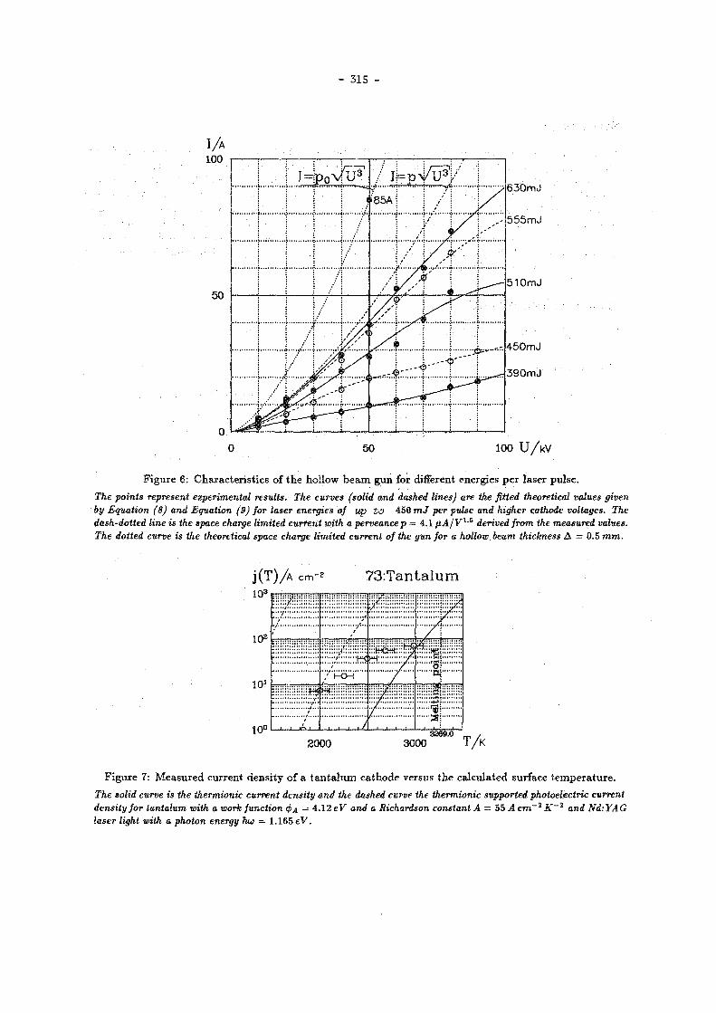
- 315 -
F i g u r e 6: Cha rac t e r i s t i c s of t h e hol low b e a m gun for different energies p e r laser pu l se .
The points represent experimental results. The curves (solid and dashed lines) are the fitted theoretical values given by Equation (8) and Equation (9) for laser energies of up to 450 mj per pulse and higher cathode voltages. The dash-dotted line is the space charge limited current with a perveance p = 4.1 ßA/V1-5 derived from the measured values. The dotted curve is the theoretical space charge limited current of the gun for a hollow beam thickness A = 0.5 m m .
F i g u r e 7 : M e a s u r e d cur ren t dens i ty of a t a n t a l u m c a t h o d e versus t h e ca lcu la ted surface t e m p e r a t u r e .
The solid curve is the thermionic current density and the dashed curve the thermionic supported photoelectric current density for tantalum with a work function 4>A — 4 .12 eV and a Richardson constant A = 55 A cm"2 K~2 and Nd:YAG laser light with a photon energy hu = 1 .165 eV.

- 316 -
S u m m a r y
A laser dr iven hol low b e a m g u n was developed for t h e W a k e Fie ld T r a n s f o r m e r exper imen t a t D E S Y . T h e m a i n p r o p e r t y of t h e g u n is t h a t t h e work funct ion of t h e c a t h o d e m a t e r i a l is m u c h higher t h a n t h e p h o t o n ene rgy of t h e u s e d lase r l igh t . In th i s case t h e emiss ion m e c h a n i s m is exp la ined by t h e general ized R i c h a r d s o n effect. T h e r m i o n i c emiss ion is t he m a j o r c o m p o n e n t of t h e laser d r iven cu r ren t . At a c a t h o d e vo l tage of nea r ly 100 fcV, t h e g u n p r o d u c e s a hol low b e a m of 10 c m d i a m e t e r w i t h a space charge l imi ted c u r r e n t of a b o u t 100 A over a pu l s e l eng th of a few n a n o s e c o n d s . T h e vo l t age is l imi ted by v a c u u m b reak d o w n b e t w e e n c a t h o d e a n d a n o d e . If t h e pu lse l eng th of t h e vo l tage w o u l d b e sho r t ened a n inc rease of t h e p e a k value shou ld b e poss ib le a n d therefore a n e n h a n c e m e n t of t h e s p a c e charge l imi ted cu r r en t by a fac tor of two t o t h r e e shou ld b e o b t a i n e d .
A c k n o w l e d g e m e n t
W e wou ld like t o t h a n k G a r y R o d e n z for carefully r e a d i n g t h e m a n u s c r i p t .
R e f e r e n c e s
[1] G.-A.Voss a n d T . W e i l a n d , Particle Acceleration by Wake Fields, D E S Y M-82-10, Apri l 1982.
[2] G.-A.Voss a n d T . W e i l a n d , Wake Field Acceleration Mechanism, Proceedings of the ECFA-RAL Workshop, Oxford , S e p t e m b e r 1982, E C F A 8 3 / 6 8 a n d D E S Y 82-074 N o v e m b e r 1982.
[3] W . B i a l o w o n s , H . D e h n e , A.Febel , M.Leneke , H.Musfe ld t , J . R o s s b a c h , R . R o s s m a n i t h , G.-A.Voss, T . W e i l a n d , F .Wi l l eke , A Wake Field Transformer Experiment, P r o c e e d i n g s of t h e 12-th In t e rna t iona l Conference on High Ene rgy Acce le ra to r s , Ch icago a n d D E S Y M-83-27 , Augus t 1983.
[4] W . B i a l o w o n s , H . D . B r e m e r , F . J .Decke r , R . K l a t t , H .C .Lewin , S .Ohsawa , G.-A.Voss, T .Wei land , Wake Field Work at DESY, I E E E Transac t ions o n Nuclear Science, Vol. NS 32-5,2 (1985) , pages 3471-3475 and D E S Y M-85-08 .
[5] W . B i a l o w o n s , H . D . B r e m e r , F . J . Decker , M . v . H a r t r o t t , H . C . Lewin , G.-A.Voss , T .Wei land , P .Wi lhe lm, X iao C h e n g d e a n d K.Yokoya , Wake Field Acceleration, P r o c e e d i n g s of t h e In t e rna t i ona l L inear Acce le ra tor Conference , S L A C (1986) a n d S y m p o s i u m of A d v a n c e d Acce le ra to r Concep t s , Wiscons in (1986) a n d D E S Y M-86-07 .
[6] C .K.S inc la i r a n d R.H.Mi l le r , A High Current Short Pulse, RF Synchronized Electron Gun for the Stanford Linear Accelerator, S L A C - P U B - 2 7 0 5 , F e b r u a r y 1981 .
[7] W i l h e m Bia lowons , Hohlstrahlkanone für das Wake Field Transformatorexperiment bei DESY, T h e sis, I I . I n s t i t u t für E x p e r i m e n t a l p h y s i k der Univer s i t ä t H a m b u r g ( to b e pub l i shed ) .
[8] S .M.Ryvk in , V . M . S a l m a n o v a n d I .D.Yaroshetsk i i , Thermal Radiation from Silicon Illuminated by a Laser Beam, Soviet Phys ics - Solid S t a t e , Vol. 10, No . 4 , O c t o b e r 1968, pages 807-809.

- 317 -
Hol low B e a m M e a s u r e m e n t s
W. Bialowons, H.-D. Bremer, F.-J. Decker, H.-Ch. Lewin, P . Schutt, G . - A . Voss. Th. Weiland, Xiao Chengde *
Deutsches Elektronen-Synchrotron DESY Notkestr. 85. 2000 Hamburg 52, Germany
A b s t r a c t
High current t ight ly b u n c h e d b e a m s are needed t o drive wake field accelerators . Inves t igat ions of the b e a m qual i t ies are necessary t o understand all poss ib le effects in detail and t o control t h e m . Here, the measurements of the hol low b e a m for the Wake Fie ld Transformer E x p e r i m e n t at D E S Y are presented. Bes ide high peak current and short bunch length other parameters such as the az imuthal dis tr ibut ion and radial thickness of the hol low b e a m have t o b e observed. W i t h fluorescent screens the transverse pos i t i on and the radial thickness can b e measured . Effects of the longi tudinal and radial space charge forces have b e e n observed. Gap moni tors measur ing the induced wal l current on the b e a m p ipe are used t o determine the azirnuthal and long i tudina l d i s tr ibut ion and the peak current. T h e long bunch (7ns) behind the gun as well as the bunching effect in the prebuncher sect ion have been invest igated. Shorter bunches at the end of the l inac have been detec ted by a Cerenkov monitor . In a small quartz wedge Cerenkov radiat ion is exc i ted and observed by a streak camera. W i t h this arrangement a lso radial osci l lat ions w i th in the bunch have been detected.
I n t r o d u c t i o n
T h e pr inciple m e c h a n i s m of t h e par t ic le accelera t ion by wake fields, especially by a wake field t ransformer a re descr ibed in ¡1,2]. T h e basic i d e a is t h a t in a cylindrically symmet r i c t r ans fo rmer section a short
2 m m r m s ) hollow dr iv ing b e a m wi th h igh charge ( « 1 /nC) excites wake fields t h a t lead t o decelerat ion (s ; 20 M e V / m ) . Be tween t h e p la tes an e lec t romagnet ic wave packet is spat ia l ly concen t r a t ed t o t he centre . T h e r e , a following second b e a m bunch can b e accelerated wi th a gradient of ab o u t 200 M e V / m . The field concen t ra t ion due t o t h e geometr ica l compress ion leads to a t r a n s f o r m e r r a t i o of a b o u t 1 0 .
At D E S Y a n expe r imen t [3,4,5] h a s been set u p to s t u d y the creat ion a n d behav io r of a hollow b e a m and t h e technica l possibi l i ty of wake field t r ans former accelerat ion. F igu re 1 shows t h e overall layout a n d the loca t ion of t he m e a s u r i n g equ ipment of the exper imen t . A l a s e r d r i v e n gun p r o d u c e s a hollow b e a m wi th r a d i u s i? ft; 5 c m a n d an energy of u p to 100 keV. In t he p r e b u n c h e r section the b e a m is b u n c h e d d u e t o t h e 500 M H z s t r u c t u r e of t he R F and then in t h e following four 3-cell cavities accelera ted t o a b o u t 7 M e V . To increase t he electric field a r o u n d the hollow b e a m a n d the excited wake fields in a t r ans fo rmer , t h e b e a m will b e longi tudinal ly and radial ly compressed by a special a r rangement of t he gu id ing solenoid field behind t h e end of t he l inac .
* O n leave f r o m T s i n g h u a U n i v e r s i t y , B e i j i n g , People's R e p u b l i k o f C h i n a
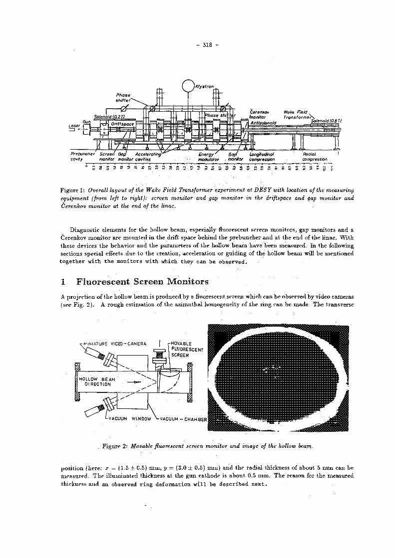
- 318 -
/Klystron
Prebuncher Screen Goß Accelerating cavity monitor monitor cavities
Longitudinal modulator monitor compression
-j r~ o n m o» m" uf <o to io* <0*
Figu re 1: Overall layout of the Wake Field Transformer experiment at DESY with location of the measuring equipment (from left to right): screen monitor and gap monitor in the driftspace and gap monitor and Cerenkov monitor at the. end of the linac.
Diagnos t i c e l emen t s for t he hollow b e a m , especial ly fluorescent screen m o n i t o r s , gap m o n i t o r s a n d a Cerenkov m o n i t o r a re m o u n t e d in t h e drift space b e h i n d t h e p r e b u n c h e r a n d a t t h e end of t he l inac . W i t h these devices t h e behav io r a n d t h e p a r a m e t e r s of t he hollow b e a m have been m e a s u r e d . In t h e following sect ions specia l effects due t o t h e c rea t ion , acce lera t ion or gu id ing of t h e hollow b e a m will b e m e n t i o n e d t o g e t h e r w i t h t h e m o n i t o r s w i t h which t h e y c a n b e o b s e r v e d .
1 F l u o r e s c e n t S c r e e n M o n i t o r s
A pro jec t ion of t h e hollow b e a m is p roduced by a f luorescent screen which can b e observed by video camera s (see F ig . 2 ) . A r o u g h es t ima t ion of t h e a z i m u t h a l homogene i ty of t h e ring can b e m a d e . T h e t r ansve r se
•MINIATURE VICE) - C A M E R A MOVABLE FLUORESCENT SCREEN
||pP
VACUUM WINDOW VACUUM - CHAMBER
\ * i
1 1
: I b * j j
F i g u r e 2: Movable fluorescent screen monitor and image of the hollow beam.
pos i t ion (he re : x = (1.5 ± 0.5) m m , y = (3.0 ± 0.5) m m ) a n d t h e r ad i a l th ickness of ab o u t 5 m m can b e m e a s u r e d . T h e i l l umina t ed thickness a t t he g u n c a t h o d e is about. 0.5 m m . T h e reason for the m e a s u r e d th ickness a n d an observed r ing deformation w i l l be descr ibed next .

- 319 -
F i g u r e 3 : Cross section of the hollow beam gun.
R i n g T h i c k n e s s . In t he gun t h e acce lera t ing electric field is not para l le l t o t h e gu id ing magne t i c field of t h e solenoids (see F ig . 3) . T h i s causes a gy ra t ion of t he e lec t rons on a helix a r o u n d the field lines of t he m a g n e t i c gu id ing field B. T h e r a d i u s of t he helix is Rh = w i th t he t r ansve r se m o m e n t u m p± a n d the e l e m e n t a r y charge e. A gun vol tage of 80 keV leads t o a m o m e n t u m p — 300 k e V / c of t he e lect rons . W i t h p± ft; p / 4 a n d B = 0.18 T is Rh ~ 1.4 m m . O t h e r reasons for an exc i ta t ion of even larger gyra t ions a re t h e t r a n s v e r s e fields in t he cavi t ies a n d the deformat ions of t h e gu id ing m a g n e t i c field a t some unavoidab le gaps in t h e solenoid s t r u c t u r e .
W i t h a very low b e a m cur ren t of I ft; 1 A a t h in r ing of a b o u t 1 m m can b e achieved. By changing t h e s t r e n g t h of t h e m a g n e t i c field or t h e height, of t h e gun vol tage t h e r ad iu s of t h e t h i n r ing varies be tween R — Rh a n d R + Rh- In F ig . 4 a p a r t of t h e r ing is shown for b o t h t h e s e cases. T h e exper imenta l value of Rh is abou t 1.3 m m . D u e to t h e l ong i tud ina l space charge forces t h e l eng th of t h e hel ix is different be tween par t i c les a t t h e h e a d a n d a t t h e t a i l of t h e bunch . Therefore a t t h e screen t h e whole a rea between R — Rh a n d R + Rh is i l l u m i n a t e d a n d a 3 m m thick r ing is observed. In F ig . 2 t h e m a g n e t i c field at t h e gun has been decreased , so t h e whole r ing can be seen by one camera a n d t h e th ickness increases to abou t 5 m m .
F i g u r e 4: Part of the hollow electron beam showing the gyration effect: Varjing the B-field changes the helix length and thus arrival radius of the electrons on the screen. This photo was 'double exposed with the maximum and minimum in arrival radius.

- 320 -
R i n g D e f o r m a t i o n . Iii o r d e r tr . i u w n g - a r - - a n o t h e r space cha rce effect a h i g h c u r r e n t . l o w v o l t a g e gun ,
iov.' maeiM ' t ic field, a long f i i p l n l e n g t h a m i & s t rong a z i n i u t h a l i n h o m o g e n e i t y has been used (see F i g . O i .
I n t h e rest f r ame a h o l l o w b e a m w i t h a r a d i u s R a n d a cha rge p e r l e n g t h Q/L leads t o a r a d i a l e lec t r i c
f i e l d Er = Q/(2TT€0Lr) f o r r __ R. W i t h t h e g u i d i n g f i e l d B. t h e e lec t rons s t a r t t o drift i n t h e a z i m u t h a l
d i r e c t i o n sp w i t h t h e v e l o c i t y r v (see e.g. |6'¡): i\- ~ W i t h v, = c / 3 (30 k e V ) , B- = 0 .1 T a n d
Í * 5 A (=? Q/L « 50 n C / m ) is t v = 0.0016 • r... F o r a l e n g t h o f 6.5 m u p t o t h e e n d o f t h e l i n a c t he
o u t e r p a r t i c l e s have d r i f t e d a b o u t 10 m m i n ^ - d i r e c t i o n . I f t h e r e is a n a z i m u t h a l g a p i n t h e b e a m t h e dr i f t ,
d i r e c t i o n changes a n d t h e r i n g is d e f o r m e d (see F i g . 5 ) .
F i g u r e 5: Part of the Ring: Due to the E x B drift of the electrons the shape of the ring has changed near a gap produced by a tag holding the inner part of the gun anode.
2 G a p M o n i t o r s
T h e b e a m induces a w a l l c u r r e n t o n t h e b e a m p i p e . T h e a m p l i t u d e o f t h i s c u r r e n t a n d i t s a z i m u t h a l
a n d l o n g i t u d i n a l d i s t r i b u t i o n can be m e a s u r e d w i t h a g a p m o n i t o r . T h e b e a m p i p e is i n t e r r u p t e d b y a
c e r a m i c ring. T h e gap is b r i d g e d b y 64 res i s to rs , 10 O each (see F i g . 6 ) .
A z i m u t h a l D i s t r i b u t i o n . I f t h e b e a m is cen te red i n t h e p i p e t he a z i m u t h a l d i s t r i b u t i o n o n t h e w a l l
c a n be m e a s u r e d w i t h t h e s igna l h e i g h t o f e i gh t p i c k ups a r o u n d t h e c i r cumfe rence o f t h e p i p e (see F i g 7 ) .
I n o r d e r t o get. t h e cor rec t a z i m u t h a l d i s t r i b u t i o n o f t h e h o l l o w b e a m f r o m t h e w a l l c u r r e n t d i s t r i b u t i o n
t h e f o l l o w i n g co r rec t i ons m u s t be cons ide red :
a) D i f f e r e n t d a m p i n g o f t h e s ignals due t o t h e d i f f e ren t de lay l e n g t h o f t h e cables,
b ) C ross t a l k b e t w e e n one s igna l a n d t h e o the rs at t h e m o n i t o r ,
c) D i f f e r e n c e b e t w e e n t h e h o l l o w b e a m r a d i u s a n d t h e b e a m p i p e r a d i u s .
F o r t h e p o i n t s b ) u n d c) we m a k e first a m u l t i p o l e e x p a n s i o n o f t he e lec t r i c field p r o d u c e d b y a d i sp l aced
filament b e a m :
w h e r e a is t h e d i sp lacemen t a n d 6 t h e p i p e r a d i u s . A d i sp laced filament b e a m w i t h a = R can be l o o k e d
at as a m a x i m a l i nhomogeneous h o l l o w b e a m w i t h r a d i u s R. A l l r e l a t i ve m o m e n t s E"/E° (n > 1) h a v e

F i g u r e 7: Eight pick up signals, each delayed by 20 ns show the azimuthal distribution of the wall current for two different currents of tî A (left) and 39 A (right).
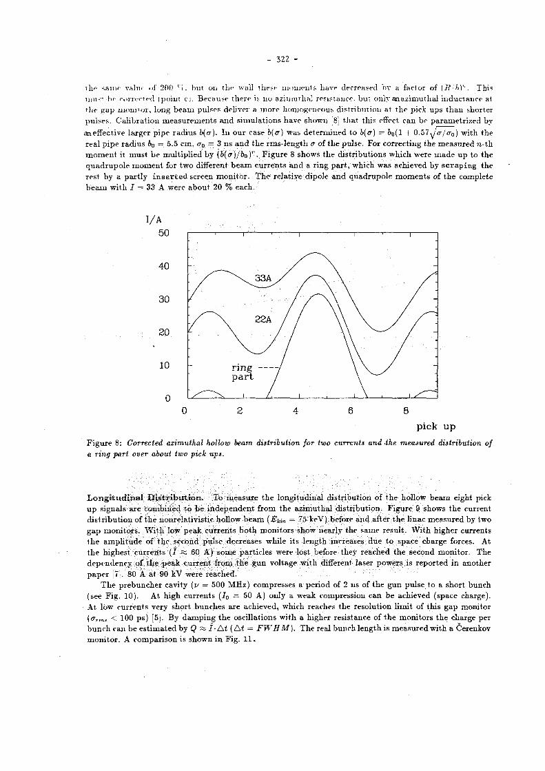
- 322 -
t h e s a i n ' value of 2(10 ''<. bu t on t h e wall these m o m e n t s have decreased by a factor of {R-'h)". Th is m u s t be correc ted (point ci . Because t he re is n o azi iuutl ial res i s tance , bu t only an az imut hal i n d u c t a n c e a t t h e g a p m o n i t o r , long b e a m pulses deliver a m o r e homogeneous d i s t r ibu t ion at t h e pick ups t h a n shor te r pu l ses . C a l i b r a t i o n m e a s u r e m e n t s a n d s imu la t i ons have shown [8j t h a t th i s effect can b e p a r a m e t r i z e d by an effective la rger p ipe r a d i u s b(a). In our case b(a) was d e t e r m i n e d to b(a) = b0(l + 0.57 ^ja / a0) w i th t h e rea l p i p e r a d i u s b0 = 5.5 cm, cr0 = 3 ns a n d t h e r m s - l e n g t h <r of t h e pulse . For cor rec t ing t he m e a s u r e d « - t h m o m e n t it m u s t b e mul t ip l i ed by (b(a)/b0 ) " . F i g u r e 8 shows t h e d i s t r i bu t ions which were m a d e u p to t h e q u a d r u p o l e m o m e n t for two different b e a m c u r r e n t s a n d a r ing p a r t , which was achieved by s c r a p i n g , t h e rest by a p a r t l y i n s e r t e d screen m o n i t o r . T h e re la t ive dipole a n d q u a d r u p o l e m o m e n t s of t h e comple te b e a m w i t h I = 33 A were a b o u t 20 % each .
I / A
5 0
4 0
3 0
2 0
1 0
0
0 2 4 6 8
pick u p
F i g u r e 8: Corrected azimuthal hollow beam distribution for two currents and the measured distribution of a ring part over about two pick ups.
L o n g i t u d i n a l D i s t r i b u t i o n . To m e a s u r e t h e long i tud ina l d i s t r ibu t ion of t h e hollow b e a m eight pick u p signals are combined to b e i n d e p e n d e n t f rom the az imu tha l d i s t r ibu t ion . F i g u r e 9 shows t h e cur rent d i s t r i b u t i o n of t h e noiirelativistic. hollow b e a m ( E h i n = 75 keV) before a n d after t h e l inac m e a s u r e d by two g a p m o n i t o r s . W i t h low peak cu r r en t s b o t h m o n i t o r s show near ly the s ame resul t . W i t h h ighe r cur ren ts t h e a m p l i t u d e of t h e second pulse decreases whi le i ts l eng th increases d u e t o space charge forces. At t h e highest cu r r en t s ( I =s 60 A) some pa r t i c l e s were lost before they reached t h e second mon i to r . T h e d e p e n d e n c y of t h e peak cur ren t f rom t h e g u n vol tage wi th different laser powers is r e p o r t e d in ano the r p a p e r [7]. 80 A at 90 kV were r eached .
T h e p r e b u n c h e r cavi ty (y = 500 M H z ) compresses a per iod of 2 ns of t h e gun pulse t o a shor t b u n c h (see Fig . 10). At h igh cu r ren t s ( J 0 = 50 A) only a weak compress ion can be achieved (space charge) . At low cu r r en t s very shor t bunches a re achieved, which reaches t he resolu t ion l imit of th is g a p moni to r (ffrms < 100 ps ) [5]. By d a m p i n g t h e osci l la t ions wi th a h igher res is tance of t h e m o n i t o r s t he charge per b u n c h can be e s t i m a t e d by Q « I • A t ( At = FWHM ). T h e real bunch l eng th is m e a s u r e d wi th a Cerenkov m o n i t o r . A compar i son is shown in F ig . 1 1 .

- 3 2 3 -
Figure 10: Tuto bunches compressed at different peak currents.
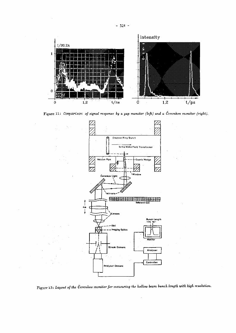
- 324 -
« a s I / 20 .2A
m m sr Tir
m . , ir »•••••••••!
1,2 t / n s t / p s
F i g u r e 11 : Comparison of signal response by a gap monitor (left) and a Cerenkov monitor (right).
Figu re 1 2 : Layout of the Cerenkov monitor for measuring the hollow beam bunch length with high resolution.
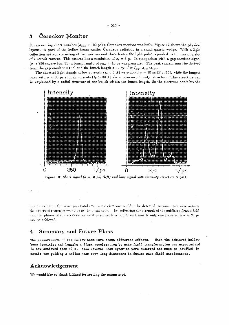
- 3 2 5 -
3 C e r e n k o v M o n i t o r
quf.rt? ve í ih :;• the *aiij'- point and e v r i : M O W electrons- couldli't l v detected, because thev were outside tut- < •}'.•.f-rvfd region >>;• W<T»- Jost a t i h r - beam pi]»'. By. adjusting ill'- strength of the gui dins: solenoid fit-id and the phases of the accelerating c a v i t y properly a bunch with mostly only one pulse with f ft 30 ps can be achieved.
4 S u m m a r y a n d F u t u r e P l a n s
The measurements of the hol low beam have shown d i f f e rent e f f e c t s . With the achieved hol low beam dens i t i es and lengths a f i r s t acce le ra t ion by wake f i e l d transformation was expected and i s now achieved (see £ 9 3 ) , Also severa l beam dynamics were observed and must be studied in d e t a i l f o r guiding a hollow beam over long distances in future wake f i e l d acce l e r a to r s .
A c k n o w l e d g e m e n t
W e would like t o t h a n k L .Hand for r e a d i n g t h e m a n u s c r i p t .
For measuring short bunches (<7 r m j < 100 ps) a Cerenkov monitor was built. Figure 12 shows the physical layout. A part of the hollow beam excites Cerenkov radiation in a small quartz wedge. With a light collection system consisting of two mirrors and three lenses the light pulse is guided to the imaging slot of a streak camera. This camera has a resolution of a, = 5 ps. In comparison with a gap monitor signal (<r A 150 ps, see Fig. 11) a bunch length of uçer ft; 40 ps was measured. The peak current must be derived from the gap monitor signal and the bunch length <7 C e r by: / ft I g a p • <Tgap¡aCer-
The shortest light signals at low currents (I0 < 3 A) were about a = 10 ps (Fig. 13), while the longest ones with <7 ft; 80 ps at high currents (Ia > 30 A) show also an intensity structure. This structure can be explained by a radial strusture of the bunch within the bunch length. So the electrons don't hit the

- 326 -
R e f e r e n c e s
[1] G.-A.Voss and T . W e i l a n d , Particle Acceleration by Wake Fields, D E S Y M-82-10, A p r i l 1982.
[2] G.-A.Voss and T . W e i l a n d , Wake Field Acceleration Mechanism, Proceedings of the ECFA-RAL Workshop, Oxford, September 1982, E C F A 83/68 and D E S Y 82-074 November 1982.
[3] W.Bialowons, H Dehne, A.Febei, M.Leneke, H.Musfeldt, J.Rossbach, R.Rossmanith, G.-A.Voss, T .Wei land, F.Willeke, A Wake Field Transformer Experiment, Proceedings of the 12-th International Conference on High Energy Accelerators, Chicago and D E S Y M-83-27, August 1983.
¡4] W.Bialowons, H.D.Bremer, F.J.Decker, R.Klatt, H.C.Lewin, S.Ohsawa, G.-A.Voss, T .Wei land, Wake Field Work at DESY, I E E E Transactions on Nuclear Science, Vol. NS 32-5,2 (1985), pages 3471-3475 and D E S Y M-85-08.
[5] W.Bialowons, H.D.Bremer, F.J. Decker, M.v.Hartrott, H.C. Lewin, G.-A.Voss, T .Wei land, P.Wilhelm, Xiao Chengde and K.Yokoya, Wake Field Acceleration, Proceedings of the International Linear Accelerator Conference, S L A C (1986) and Symposium of Advanced Accelerator Concepts, Wisconsin (1986) and D E S Y M-86-07.
[6] J. D. Jackson, Classical Elektrodynamics, John Wi ley & Sons, Inc., 1975.
¡7] W.Bialowons, H - D . B r e m e r , F.-J.Decker, H.-Ch.Lewin, P.Schiitt, G.-A.Voss, Th.Wei land and Xiao Chengde, Hollow Beam Gun for the Wake Fula Transformer Experiment at DESY , these proceedings.
[8] F.-J . Decker, Zur experimentellen Bestimmung der Dichteverteilung von Elektronenringen am Wake Field Transformator Experiment bei DESY, Thesis, 11. Institut für Experimentalphysik der Universität Hamburg (to be published).
|9] W.Bialowons, H.-D.Bremer, F.-J.Decker, H.-Ch.Lewin, P.Schütt, G.-A.Voss, Th.Wei land and Xiao Chengde, The Wake
Field Transformation Experiment at DESY, these proceedings.

- 327 -
C o m p u t e r S imula t ions for t h e D E S Y Wake Fie ld Transformer E x p e r i m e n t
W.Bialowons, H.-D.Bremer, F.-J.Decker, H.-Ch.Lewin, P.Schütt, G.-A.Voss, Th.Weiland, Xiao Chengde *
Deutsches Elektronen-Synchrotron DESY Ñotkestr. 85, 2000 Hamburg 52, Germany
Abstract The Wake Field Transformation Experiment at DESY has always been accompanied
by theoretical studies including numerical analysis of beam dynamics. In the last two years, these investigations have focused on the dynamics of the high current, hollow driving beam of the Wake Field Transformer. The computer code WAKTRACK, which has been used for this purpose, will be described and some example output will be shown. This code will be used for investigations on the feasibility of a future TeV collider. Additionally, more detailed investigations of the bunching and shaping process of the ring in the low energy region will be necessary. For this purpose TBCT-SF, a particle-in-cell code, has been developed. It will also be discussed here and its applications for the wake field transformation linac as well as for other subjects will be indicated.
I n t r o d u c t i o n
T h e pr inc ip le of t h e Wake Field acce lera t ion m e c h a n i s m [1,2} a n d t h e Wake Field Trans former exper imen t a t D E S Y [3,4,5] have been descr ibed in de ta i l in o the r p a p e r s . Here we will focus on t h e c o m p u t a t i o n a l m e t h o d s which a re u s e d for t h e a c c o m p a n y i n g theore t i ca l s tud ies . T w o s imula t ion codes are discussed and some resul t s are p resen ted . More de ta i led descr ip t ions of t he p r o g r a m s a n d more resu l t s will b e publ i shed e lsewhere [6].
T h e dynamics of t h e hollow b e a m a n d of t h e cen t ra l b e a m can b e s tudied wi th W A K T R A C K [7]. Th i s t r a c k i n g code inc ludes t he cavity fields as ca lcu la ted by U R M E L [8], a r b i t r a r y m a g n e t i c fields as calcula ted by P R O F I [9] a n d wake fields as ca lcu la ted by T B C I [10]. Using known charac ter i s t ics of t h e t ra jec tor ies a n d some a p p r o x i m a t i o n s th is code is very fast a n d can b e used for op t imiza t ion s tudies para l le l t o t h e e x p e r i m e n t . I t can general ly be app l ied t o h igh cur ren t l inacs .
For m o r e deta i led inves t iga t ions in t h e low energy region (7 < 20) , especially of t h e t r ansverse dynamics , a n d for op t imiza t ion of t h e r ing forming process a part icle- in-cel l code has been developed. In th i s code Maxwel l ' s equa t ions a n d the Lorentz e q u a t i o n are solved s imul taneously . T h e e lec t romagne t ic field is implemented on a t v o - d i m e n s i o n a l - z - m e s h w h e r e a s t h e p a r t i c l e t r a j e c t o r i e s a r e c a l c u l a t e d t h r e e -d i m e n s i o n a l l y . Resonant c a v i t y f i e l d s a r e p r e c a l c u l a t e d w i t h URMEL. S t a t i c f i e l d s can be supe r imposed a s c a l c u l a t e d by PROFI. The code is g e n e r a l l y a p p l i c a b l e t o h i g h c u r r e n t gun d e s i g n , b u n c h e r dynamics , d e s i g n of RF power s o u r c e s , etc.
*On leave from Tsinghua University, Beijing, People's Republik of China

- 3 2 8 -
1 W A K T R A C K
T h e c o m p u t e r code W A K T R A C K is a t r a c k i n g code: t h e pa r t i c l e t r a j ec to r i e s are i n t eg ra t ed e lement by e l ement in a given s t r u c t u r e . T h e i n d e p e n d e n t var iable is z, t h e axis of t h e l inac . T h e t i m e t , Lorentz fac tor 7 , t h e t r a n s v e r s e coo rd ina t e s x a n d y a n d the i r der ivat ives jf a n d ^ a r e i n t e g r a t e d for each par t ic le .
T h e e lement by e l e m e n t s t r u c t u r e is over layed by t h e field of solenoid coils which m a y s u r r o u n d t h e e q u i p m e n t . E x t e r n a l fields a r e ca lcula ted in a very soph is t i ca ted m a n n e r a n d collective forces of t h e o the r pa r t i c l e s in t h e b u n c h a r e t a k e n in to accoun t .
In o rde r t o speed u p t h e in t eg ra t ion of t h e t ra jec to r ies , an ana ly t i ca l so lu t ion of t h e Lorentz force e q u a t i o n for t h e case E || B || £ is used. In t h e ma jo r p a r t of t h e e x p e r i m e n t t he se a re t h e d o m i n a n t fields. T h i s ana ly t i ca l so lu t ion c a n b e derived w i t h o u t any fur ther a p p r o x i m a t i o n s . T h e forces of t h e t ransverse fields B x , B y , E x a n d E y a r e t r e a t e d in a kick a p p r o x i m a t i o n : In each s t e p , t h e m o m e n t u m is corrected acco rd ing t o t he se fields. T h e s t ep l eng th m a y still b e fairly la rge ( u p t o 3 c m ) as long as t h e t ransverse fields a r e smal l c o m p a r e d t o t h e long i tud ina l fields. T h e kick a p p r o x i m a t i o n is n o longer a p p r o p r i a t e if t h e t r a n s v e r s e fields a r e in t h e same o rde r of m a g n i t u d e as t h e l ong i tud ina l fields. In th is case, a R u n g e K u t t a i n t e g r a t i o n s cheme is used .
T h e choice of m o d e l s for t h e calculat ion of ex t e rna l fields is governed by t h e needs for t h e s imula t ion of t h e e x p e r i m e n t a l set u p . T h e solenoid field is ca lcu la ted as a supe rpos i t i on of t h e fields of ind iv idua l coils which m a y h a v e different s h a p e s and different c u r r e n t s . T h e field of each coil is ca lcu la ted in a second order a p p r o x i m a t i o n n e a r t h e axis . Th i s fast eva lua t ion is poss ib le , as t h e r a d i u s of t h e coils in t h e exper imen t is a b o u t 10 t i m e s t h e r a d i u s of t h e hollow b e a m .
In t hose e l emen t s of t h e l inear accelera tor , whe re t h e field s h a p e is d e t e r m i n e d by i ron , i t is ca lcula ted by P R O F I . In ou r app l i ca t i on , th is code solves t h e m a g n e t o s t a t i c field equa t i ons on a 2-dimensional , cyl indr ica l ly s y m m e t r i c r -z -mesh . This field is t h e n i m p l e m e n t e d in W A K T R A C K on a local m e s h in t he e l ement a n d l inear ly i n t e r p o l a t e d be tween t h e m e s h p o i n t s .
T h e R F cavi ty fields m a y b e ob ta ined in two different m a n n e r s : A fast m e t h o d is t o use a s imple mode l a n d t o ca lcu la te t h e field ac t ing on a par t i c le a t pos i t ion z a n d t i m e t as
Ez = EZto sin kz sinwi
a n d t h e t r a n s v e r s e fields cor respondingly so as t o f u l f i l Maxwel l ' s e q u a t i o n s . For m o r e sophis t ica ted inves t iga t ions of t h e d y n a m i c s inside a cavity, t h e field s h a p e of t h e acce le ra t ing m o d e in t h e cavi ty m a y b e ca l cu la t ed by U R M E L o n a 2-dimensional r -z -mesh. T h e field ac t ing on a par t i c le is t h e n given by
E - Ev sin íüirt
w h e r e t h e spa t i a l p a r t is i n t e rpo l a t ed be tween m e s h p o i n t s , a n d t h e f requency u> is also given by U R M E L . Col lect ive fields of t h e par t ic les inside a b u n c h a re space charge fields a n d wake fields. T h e s e are t r ea t ed
in a G r e e n s funct ions a p p r o a c h . T h e folding of t h e ac tua l b u n c h s h a p e w i t h Greens funct ions is done in a b i n - b i n m e t h o d r a t h e r t h a n calcula t ing t he pa r t i c l e t o par t i c le i n t e r ac t i on . T h e charge d i s t r i bu t ion wi th in a b u n c h is p ro j ec t ed o n t o a 2-dimensional m e s h . T h e n t h e field a t a ce r t a in pos i t ion ins ide th i s m e s h can b e ca lcu la ted as s u p e r p o s i t i o n of the fields of t h e charges in t h e m e s h cells.
For t h e special case of a ring-shaped charge in a long c o n d u c t i n g p i p e , t h e Greens funct ion can be ca lcu la ted analyt ica l ly . For all o ther cases, space charge a n d wake fields in m o r e complex s t ruc tu re s , a p s e u d o Greens funct ion is ca lcula ted by T B C I . In th i s app l i ca t ion , T B C I ca lcula tes t h e wake po ten t i a l s of a sho r t rigid b u n c h ( sho r t as compared t o t h e b u n c h s imu la t ed in W A K T R A C K ) which passes t h e given s t r u c t u r e o n a p a t h pa ra l l e l t o t he z axis w i t h cons tan t velocity.
T h e G r e e n s func t ions a p p r o a c h in W A K T R A C K impl ic i t ly uses several a p p r o x i m a t i o n s : As z is t he i n d e p e n d e n t var iab le of t h e in tegra t ion , a spa t i a l d i s t r i bu t ion of t h e cha rge in t h e b u n c h m u s t b e calcula ted f rom t h e t i m e a n d ene rgy d i s t r ibu t ion of t h e par t ic les . T h i s impl ies t h a t t h e par t ic les pass t h e s t r u c t u r e a t c o n s t a n t velocity. T h e use of a Greens funct ion is a p p r o p r i a t e only if t h e re la t ive pos i t ion of t h e par t ic les does no t c h a n g e signif icantly in t he t ime pe r iod t h e field needs t o t rave l f rom t h e source t o t h e par t ic le it a c t s u p o n . T h i s c a n b e a s s u m e d in t he h igh energy region of t h e l inac , where all t he par t ic les move on para l le l t r a j ec to r i e s a t t h e speed of l ight . B u t t h e a s s u m p t i o n is w r o n g in t h e low energy region, where m a j o r p a r t s of t h e s t r u c t u r e a re designed t o s h a p e a n d b u n c h t h e r ing . For m o r e detai led inves t iga t ions in th i s reg ion , a par t ic le- in-cel l code has been developed.
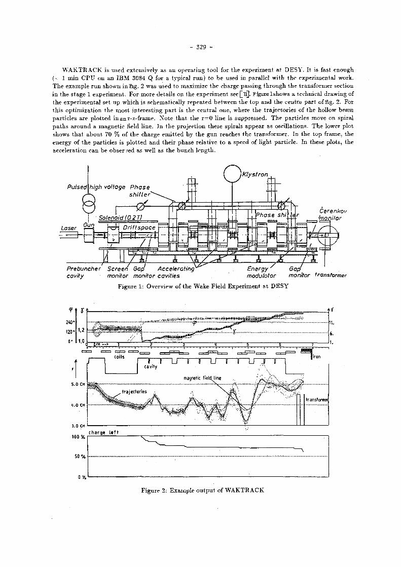
- 329 -
W A K T R A C K is u s e d extens ive ly as an o p e r a t i n g tool for t he expe r imen t at D E S Y . It is fast e n o u g h (< 1 m i n C P U on an I B M 3084 Q for a typical r u n ) t o b e used in para l le l wi th t h e e x p e r i m e n t a l work. T h e e x a m p l e r u n s h o w n in Pig. 2 was used to m a x i m i z e t h e charge pass ing t h r o u g h t h e t r a n s f o r m e r sect ion in t h e s t age 1 e x p e r i m e n t . For m o r e de ta i l s on t he e x p e r i m e n t seej^lf]. F igu re l shows a t echn ica l d r a w i n g of t h e e x p e r i m e n t a l set u p wh ich is schemat ica l ly r e p e a t e d be tween t h e t o p a n d t h e cen t re p a r t of l ig . 2. For th i s o p t i m i z a t i o n t h e m o s t i n t e r e s t i ng p a r t is t he cen t r a l one , where t h e t r a j ec to r i e s of t h e hollow b e a m par t i c l e s a re p l o t t e d in an r -z - f rame. N o t e t h a t t h e r = 0 l ine is suppressed . T h e pa r t i c l e s m o v e on sp i ra l p a t h s a r o u n d a m a g n e t i c field l ine . I n t h e pro jec t ion t he se spirals a p p e a r as osc i l la t ions . T h e lower p lo t shows t h a t abou t 70 % of t h e charge e m i t t e d by t h e g u n reaches t h e t r a n s f o r m e r . I n t h e t o p f rame, t h e ene rgy of t h e par t i c les is p l o t t e d a n d the i r p h a s e re la t ive t o a speed of l ight pa r t i c l e . In these p lo t s , t h e acce le ra t ion can b e o b s e r / e d as well as t h e b u n c h l e n g t h .
Pulsed
Klystron
high voltage Phase shifter
Cerenkov ^monitor
Prebuncher Screen Gap Accelerating cavity monitor monitor cavities
Energy Gap modulator monitor transformer
F i g u r e 1: Overv iew of t h e W a k e F ie ld E x p e r i m e n t a t D E S Y
F igu re 2: E x a m p l e o u t p u t of W A K T R A C K

- 330 -
2 T B C I - S F
'¡.1
r,=o.
T E..Ï
Figu re 3: Al loca t ion of field c o m p o n e n t s
P u t t i n g all u n k n o w n electric field c o m p o n e n t s i n t o a vec tor
e = (Er,i,--,E^N,E^-¡,...,E^N,EzA,...,EZtNy,
t h e m a g n e t i c field c o m p o n e n t s i n t o b a n d the c u r r e n t dens i ty i n t o j l eads t o t h e following m a t r i x e q u a t i o n s (cf. [16,17]), r ep l ac ing Maxwel l ' s equa t ions
R e = - b (1)
R b = D e è + j . (2)
B r e a k i n g u p t h e t i m e axis i n t o pieces wi th l e n g t h bt, u s ing t h e cen t ra l difference o p e r a t o r for t h e t i m e de r iva t ive w i t h t h e n o t a t i o n / " : = f(n • êi) a n d e q u a t i n g e , b a t hal f t i m e s teps a n d è , b a t full t i m e s t eps , we o b t a i n a n a l t e r n a t i n g explicit t i m e scheme first i n t r o d u c e d by Yee [18] ( the leap frog scheme of Maxwel l ' s e q u a t i o n s ) :
b" = b" 1 - í í R e " " 1 / 2 (3)
e n+i/ 2 = e " - 1 / 2 + e i D r ^ R h " - j " ) . (4)
D e e p e r d i scuss ions of th i s a lgo r i t hm can be found e lsewhere [10,19].
T h e p r o g r a m T B C I - S F is a par t ic le- in-ce l l code. T h i s m e t h o d of solving Maxwel l ' s equa t ions a n d t h e Loreri tz e q u a t i o n sel f-conaistently h a s been deve loped in p l a s m a phys ics [12] a n d recen t ly is be ing used i n acce le ra to r phys i c s for h igh cu r r en t b e a m s [13,14]. T B C I - S F h a s been developed as a n ex tens ion of T B C I [10]-
After t h e in i t i a l cond i t i ons have been fixed, t h e following t h r e e s t eps a re carr ied ou t in t u r n :
• C a l c u l a t e t h e c u r r e n t dens i ty a t t h e mesh p o i n t s which c o r r e s p o n d s t o t h e m o t i o n of t he pa r t i c l e s .
• A d v a n c e fields i n t i m e us ing th i s cur ren t dens i ty as a d r iv ing t e r m , (equivalent t o 1 s t ep in T B C I )
• A d v a n c e p a r t i c l e t ra jec to r ies accord ing t o t h e Loren tz force.
2 . 1 F i e l d E v a l u a t i o n
Using t h e finite i n t e g r a t i o n t h e o r y [15], t h e fields a n d t h e cu r r en t dens i ty a re l oca t ed in t h e m e s h as shown in Fig. 3 .

- 331 -
2 . 2 P a r t i c l e P u s h e r
T h e charge d i s t r i b u t i o n in t h e b u n c h is desc r ibed in T B C Í - S F by m a c r o p a r i i c l e s wh ich r ep re sen t a r igid cha rge d i s t r i bu t i on in a vo lume co r r e spond ing t o a b o u t one cell of t h e field m e s h . T h e s e m a c r o p a r t i c l e s a re charac te r i zed by the i r pos i t ion r ,z a n d the i r r ap id i ty u = (ur,u,f,,uz) = j j ^ . T h e pos i t ion m a y b e a n y w h e r e ins ide t h e region covered by t h e m e s h , t h e r a p i d i t y is t r e a t e d fully 3-dimensional ly . T h e Loren tz force e q u a t i o n can be w r i t t e n as
d — x = v dt
= — ( E + v x B ) . dt mc
Simi lar t o t he Maxwel l ' s e q u a t i o n s , th i s sys t em is solved by a l e ap frog scheme ass ign ing t h e pos i t ion t o half t i m e s teps a n d t h e r a p i d i t y t o full t i m e s t eps .
x " + l / 2 = x - l / 3 + St-Vn
u " + 1 = u n + St • — • ( E n + 1 / 2 + - ( v n + 1 + v " ) x B n + 1 / 2 ) . mc 2
O n t h e right h a n d side of t h e second equa t ion , a t i m e average of t h e velocit ies m u s t b e used . Addi t iona l ly , t h e m a g n e t i c field h a s b e e n ass igned t o full t i m e s teps a n d therefore m u s t b e a v e r a g e d here . T h e second e q u a t i o n is impl ic i t . I n T B C I - S F it is rep laced by a n explicit a l g o r i t h m : In t h e first s t ep , t h e r a p i d i t y is advanced by 1/2 St u s ing only t h e electric field. T h e n t h e r o t a t i o n in t h e m a g n e t i c field is ca lcu la ted a n d finally t h e second half s t ep of acce le ra t ion is ca r r ied ou t .
u " = u " + - - ? - E " ^ 2
2 m c u ' = u~ + u~ x T
u + = u " + u ' x S
2 m c T h e following a b b r e v i a t i o n s were used :
_ B n + l / 2 2 T
T = S t - — and S = 2 r n 7 n + l / 3 1 + T T
2.3 W e i g h t i n g
I n o rde r t o decrease noise a m p l i t u d e s , p y r a m i d - s h a p e d par t ic les a r e used . T h i s al lows a s m o o t h approx i m a t i o n of any cha rge d i s t r i b u t i o n a t t h e cost of second order t e r m s in t h e c u r r e n t dens i ty ca lcu la t ion .
A charge-conserv ing scheme is used for t h e d e t e r m i n a t i o n of c u r r e n t dens i t i es in t h e m e s h . T h i s is t he s a m e one which is u sed in ISIS [21] a n d was first descr ibed by B u n e m a n [20]. T h e cu r ren t is ca lcu la ted as a s u m of charges which p a s s a cell wall du r ing one t i m e in terva l :
1
3 = Ä r T t ^ U U q ' •
T h e field a t t h e pa r t i c l e pos i t i on is ca lcula ted as a weighted m e a n of t h e fields a t m e s h p o i n t s which a re covered by t h e charge cloud rep resen ted by a par t ic le . For t e s t p u r p o s e s , t h e field of t h e nea res t grid po in t can b e used as well as a l inear in t e rpo la t ion .
2.4 Internal Tests
Only t w o of t h e four Maxwel l ' s equa t ions are needed to advance t h e fields in t i m e . T h e o the r s m u s t b e fulfilled implici t ly .
IIiv B da = 0
J(V)
/i,DdCT = JJJrPdV
T h e second of these equat ions , Gauss ' Law, must be used to correct the fields if the current calculat ion is not
charge conserving. In TBCTSF , b o t h are used to check the results every few t i m e s teps .

- 332 -
2.5 E x t e r n a l F i e l d s
E x t e r n a l fields c rea ted by sources different f rom t h e b u n c h cu r ren t itself often cause p rob l ems in par t ic le -in-ce l l codes . S o m e t i m e s , s t a t i c fields are not foreseen a n d R F cavity fields can only b e p r o d u c e d by s i m u l a t i n g t h e who le filling pe r iod or by us ing o the r a p p r o x i m a t i o n s .
T B C I - S F allows ex t e rna l fields to b e given as s t a r t va lues of t he e l ec t romagne t i c field i m p l e m e n t e d on t h e m e s h . O n c e they a re set u p , t h e y do no t need to b e t r e a t e d specially a n y longer .
S t a t i c fields m a y b e p reca l cu la t ed by P R O F I . T h e P R O F I mesh m u s t b e iden t ica l t o t h e T B C I - S F m e s h or t o p a r t of it in o r d e r t o avoid numer i ca l e r ro r s d u e t o t he i n t e r p o l a t i o n . Resonan t fields a r e p r e c a l c u l a t e d by U R M E L w i t h t h e s ame res t r i c t ion on t h e m e s h . B o t h electr ic a n d magne t i c fields a re t a k e n f rom U R M E L resu l t s . There fore , in i t ia l p h a s e a n d a m p l i t u d e of t h e R F field m a y b e ad ju s t ed s epa ra t e ly .
2.6 C P U T i m e
T h e C P U t i m e needed for t h e s imula t ion is a funct ion of t h e n u m b e r of m a c r o p a r t i c l e s used U M a n d of t h e n u m b e r of m e s h p o i n t s nj>:
TIM , n p . n u m b e r of s t eps trpu = (a h 0 ) • •
v 1000 1 0 0 0 ; 1000
Typ ica l ly np a n d TIM a re in t h e s a m e o rde r of m a g n i t u d e . O n an I B M 3084 Q t h e coefficients a re a R= IZ.bsec a n d b « 160sec .
2 .7 E x a m p l e o u t p u t
TBCI - SF RUN « 8
t=5 ns
0.5 1.0 1.5 z l m
t = 1 0 n s
0.5 1.0 1.5 zlm
F i g u r e 4: E x a m p l e o u t p u t of T B C I - S F : B u n c h e s a re be ing formed in a c a v i t y wi th drift

- 333 -
T h e first e x a m p l e (Fig. 4) shows t h e b u n c h i n g of t he hol low b e a m in t h e b u n c h e r sect ion of t he D E S Y e x p e r i m e n t . T h e cavi ty h a s ini t ial ly been filled wi th a R F field ca lcu la ted by U R M E L . A n overall solenoid field ho lds t h e pa r t i c l e s on p a t h s para l le l t o t h e z axis . T h e c u r r e n t s n a p s h o t s in Fig. 5 show m o r e qua l i ta t ively t h e b u n c h i n g efficiency.
TIME* 2502. PS
TBCI - SF RUN «
TIME* 5003.PS T1 HE = 7505.PS
TIME» 10007.PS T!ME= 12509.PS TIME» I50I0.PS
-35.
2. 0 Z/M 2. 0.
F igu re 5: C u r r e n t snapsho t s in t h e b u n c h e r region
TBCI-SF can also be applied to other problems. Figure 6 shows a simulation of the SLAC lasertron. The electrostatic field in the gun was calculated by PROFI, the RF fields by URMEL in order to simulate the steady state. The results are in good agreement with a corresponding MASK simulation [_22j.
Figure 6: T B C I - S F : s imula t ion of a l a se r t ron

- 334 -
3 S u m m a r y a n d C o n c l u s i o n
T w o s u p p l e m e n t a r y c o m p u t e r codes have been developed for fu ture s tudies of a W a k e Fie ld Accelera tor . W A K T R A C K is a fast design tool for h igh c u r r e n t , h igh energy l inear acce le ra to r s . T h e ca lcula t ion
inc ludes ex te rna l fields in grea t deta i l a n d collective fields in a h igh energy a p p r o x i m a t i o n . T h e par t i c le in cell code T B C I - S F h a s been developed for more deta i led s imu la t ions of t h e low energy
reg ion of a h igh cur rent l inac . It is general ly app l icab le t o h igh cu r ren t , low energy devices like guns , b u n c h e r , R F sources , e tc .
T h e numer i ca l resul t s of b o t h p r o g r a m s have been verified by expe r imen ta l d a t a . Toge the r t h e y provide t h e c o m p u t a t i o n a l tools for t h e design of a whole l inear accelerator from t h e g u n u p t o t h e i n t e r ac t ion p o i n t .
R e f e r e n c e s
[1] G.-A.Voss a n d T .Wei land , Particle Acceleration by Wake Fields, D E S Y M-82-10, Apr i l 1982.
[2] G.-A.Voss a n d T .Wei land , Wake Field Acceleration Mechanism, Proceedings of the ECFA-RAL Workshop, Oxford, Sep t ember 1982, E C F A 8 3 / 6 8 a n d D E S Y 82-074 November 1982.
[3] W.Bia lowons , H .Dehne , A.Febel , M.Leneke , H.Musfeldt , J .Ros sbach , R . R o s s m a n i t h , G.-A.Voss, T .Wei l and , F .Wil leke , A Wake Field Transformer Experiment, P roceed ings of t h e 12- th In t e rna t ional Conference on High E n e r g y Acce le ra to r s , Chicago a n d D E S Y M-83-27 , A u g u s t 1983.
[4] W.Bia lowons , H .D .Bremer , F . J .Decke r , R . K l a t t , H.C.Lewin, S .Ohsawa, G.-A.Voss , T .Wei l and , Wake Field Work at DESY, I E E E Transac t i ons on Nuclear Science, Vol. N S 32-5,2 (1985) , pages 3471-3475 and D E S Y M-85-08.
[5] W.Bia lowons , H .D .Bremer , F . J . Decker , M . v . H a r t r o t t , H .C . Lewin, G.-A.Voss , T . W e i l a n d , P .Wi lhe lm, Xiao C h e n g d e a n d K.Yokoya, Wake Field Acceleration, P roceed ings of t h e I n t e r n a t i o n a l L inea r Acce lera tor Conference, S L A C (1986) a n d S y m p o s i u m of Advanced Acce le ra to r C o n c e p t s , Wiscons in (1986) a n d D E S Y M-86-07.
[6] P e t r a Schutt, Zur Dynamik eines Elektronenhohlstrahls Thes i s , I I . I n s t i t u t für Expe r imen ta lphys ik der Univers i tä t H a m b u r g ( to be p u b l i s h e d ) .
[7] T h . W e i l a n d a n d F .Wil leke , Particle Tracking with Collective Effects in Wake Field Accelerators, Proceed ings of t he 12-th I n t e r n a t i o n a l Conference on High Energy Acce le ra to r s , Ch icago , 1983, p p . 457-459 a n d following improved vers ions by G a r y Rodenz (on leave f rom Los A lamos ) a n d K a o r u Yokoya ( K E K ) .
[8] T h . W e i l a n d , On the computation of resonant modes in cylindrically symmetric cavities N I M 216 (1983) , 329-348
[9] H.Eule r , U . H a m m , A . J a c o b u s , J . K r ü g e r , W . M ü l l e r , W.R .Novende r , T h . W e i l a n d , R . W i n z , Numerical Solution of ê- or 3-Dimensional Nonlinear Field Problems by the Computer Program PROFI Archiv für E lek t ro tech . (AfE), Vol .65(1982) , p p . 299 ff.
[10] T h . W e i l a n d , Transverse beam cavity interaction part 1: short range forces N I M 212 (1983) , 13-21
[11] T h . W e i l a n d , The Wake Field Transformation Experiment at DESY t he se p roceed ings
[12] C.K. Birdsal l a n d A. L a n g d o n , Plasma Physics via Computer Simulation, McGraw-Hi l l 1985
[13] S.Yu, Particle in Cell Simulation of High Power Klystrons S L A C / A P - 3 4 ( S e p t e m b e r 1984).
¡14] G.Gisler , M . E . J o n e s . C .M.Snel l . ISIS: A New Code for PIC Plasma Simulation Bul l . A m . Soc. 29 (1984)

- 335 -
[15] T h . W e i l a n d , Eine Methode zur Lösung der Maxwellschen Gleichungen für sechshomponentige Felder auf diskreter Basis, A E Ü 31 (1977), 116-120
[I6j T h . W e i l a n d , On the numerical solution of Maxwell's equations and applications in the field of accelerator physics, P a r t . Acc. 15 (1984), 245-292, a n d references t he r e in , C E R N / I S R - T H / 8 0 - 4 6 , November 1980.
[17] T h . W e i l a n d , Numerical Solution of Maxwell's Equation for Static, Resonant and Transient Problems, P r o c e e d i n g s of t h e U .R .S . I . I n t e rna t i ona l S y m p o s i u m in E l e c t r o m a g n e t i c T h e o r y , B u d a p e s t , H u n g a r y , A u g u s t 1986, 537 ff. a n d D E S Y M-86-03 (Apr i l 1986)
[18] K.S.Yee, Numerical solution of initial boundary value problems involving Maxwell's equation in isotropic media, I E E E Vol. A P - 1 4 (1966), 302-307
[19] T h . W e i l a n d , On the computation of electromagnetic fields excited by relativistic bunches of charged particles in accelerator structures, C E R N / I S R - T H / 8 0 - 0 7 , J a n u a r y 1980
[20] O . B u n e m a n in Relativistic Plasmas, ed i ted by O . B u n e m a n a n d W . P a r d o , B e n j a m i n , New York, 1968, p .205
[21] M . E . J o n e s , private communication.
[22] W . B . H e r r m a n n s f e l d t Lasertron Simulation with a Two Gap Output Cavity, S L A C / A P - 4 1 , Apr i l 1985

- 336 -
FEASIBILITY STUDIES FOR THE SWITCHED POWER LINAC * )
J. Knott CERN, Geneva, Switzerland
ABSTRACT
Some technical aspects concerning the r e a l i z a t i on of the switched power l inac have been studied . We present experimental r e su l t s on the poss ib le vo l tage gain of th i s concept and summarize the present status of other r e l a ted work going on a t BNL and CERN.
1 . INTRODUCTION
The Switched Power Linac (SPL) as proposed by W. W i l l i s [ 1 ] may achieve very high acce lerat ing gradients by switching an e lectron burst with a s u f f i c i e n t l y f a s t l a s e r pulse from previously charged photodiodes on the circumference of a d isk st ructure (F i g . 1 ) . The electromagnetic pulse increases in amplitude as i t t r ave l s r a d i a l l y towards the centre, where i t acce lerates pa r t i c l e s on the a x i s .
Photocathode Electrons
Fig . 1 P r i nc i p l e of the switched power l inac
Assuming the photodiode to be charged with a 50 to 100 kV pulse for about 1 nsec and then discharged by a cor rec t ly timed l a se r pulse into a 1 mm wide gap, we can expect acce lerat ing f i e l d s of the order of one MV per mm to be held for only 10 psec. This would r e su l t in a compact acce le rator with small s t ructures , featur ing high peak power for low stored energy.
* ) Work car r ied out in co l l abora t ion with S. Aronson, BNL, F. Caspers, H. Haseroth, W. W i l l i s , CERN.
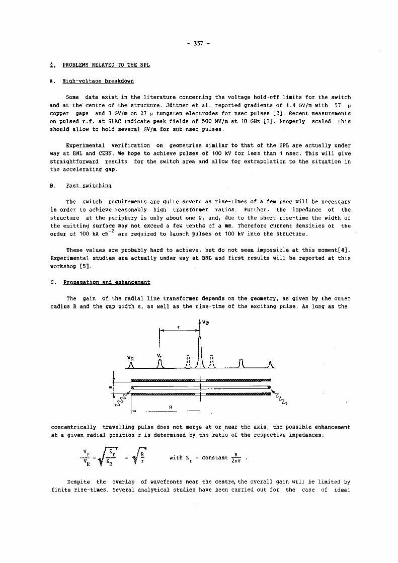
- 3 3 7 -
2, PROBLEMS RELATED TO THE SPL
A. Hiah-vo l taae breakdown
Some data e x i s t in the l i t e r a t u r e concerning the vo l tage ho ld -o f f l im i t s for the switch and at the centre of the s t ructure . Jiittner et a l . reported gradients of 1.4 GV/m with 57 p
copper gaps and 3 GV/m on 27 p tungsten e lect rodes for nsec pulses [ 2 ] . Recent measurements on pulsed r . f . a t SLAC indicate peak f i e l d s of 500 MV/m at 10 GHz [ 3 ] . Proper ly sca led th i s should a l l ow to hold severa l GV/ra for sub-nsec pu l ses .
Experimental v e r i f i c a t i o n on geometries s imi l a r to that of the SPL are a c tua l l y under way at BNL and CERN. We hope to achieve pulses of 100 kV for l e ss than 1 nsec. This w i l l g i ve s t ra ight forward r e su l t s for the switch area and a l l ow for extrapo lat ion to the s i tua t i on in the acce l e ra t ing gap.
B. Fast switching
The switch requirements are qui te severe as r i se - t imes of a few psec w i l l be necessary in order to achieve reasonably high transformer r a t i o s . Further, the impedance of the st ructure a t the periphery i s only about one Q, and, due to the short r i s e - t ime the width of the emitting surface may not exceed a few tenths of a mm. Therefore current dens i t i e s of the
- 2 order of 100 kA cm are required to launch pulses of 100 kV into the s t ructure .
These values are probably hard to achieve, but do not seem impossible at th i s moment [ 4 ] .
Experimental studies are ac tua l l y under way at BNL and f i r s t r e su l t s w i l l be reported a t th i s workshop [ 5 ] .
C. Propagation and enhancement
The gain of the r ad i a l l i n e transformer depends on the geometry, as g iven by the outer radius R and the gap width s, as we l l as the r i s e - t ime of the exc i t ing pu lse . As long as the
r V(8
VR
A V
/ r i a
V /\ A A
concentr ica l ly t r a v e l l i n g pulse does not merge a t or near the ax i s , the poss i b l e enhancement at a given rad ia l posit ion r i s determined by the r a t i o of the respect ive impedances:
with Z = constant -~— r 2trr
Despite the overlap of wavefronts near the centre, the overa l l gain w i l l be l imited by f i n i t e r i s e - t imes . Several ana ly t i ca l studies have been car r ied out for the case of i dea l
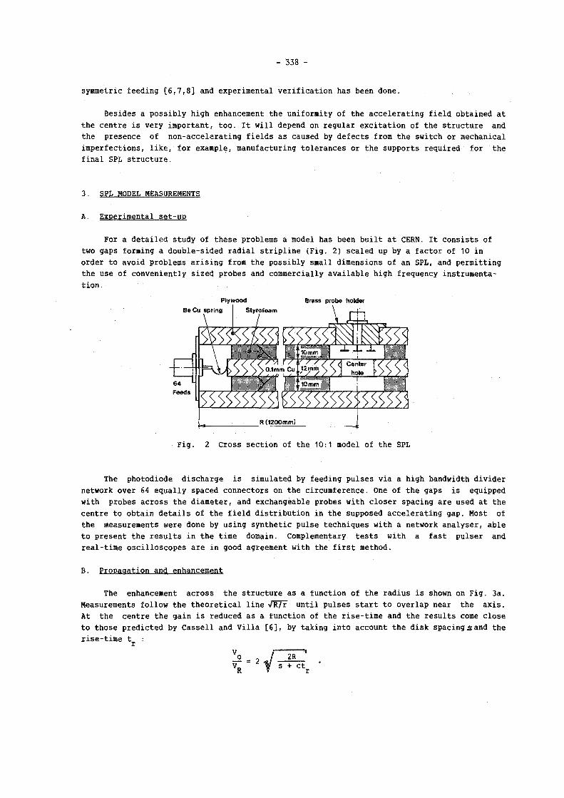
- 338 -
symmetric feeding [ 6 , 7 , 8 ] and experimental v e r i f i c a t i o n has been done.
Besides a poss ib ly high enhancement the uniformity of the acce l e ra t ing f i e l d obtained at the centre i s very important, too . I t will depend on regu lar exc i t a t i on of the structure and the presence of non-acce lerat ing f i e l d s as caused by defects from the switch or mechanical imperfections, like, for example, manufacturing to lerances or the supports required for the f ina l SPL s t ructure .
3. SPL MODEL MEASUREMENTS
A. Experimental se t -up
For a de ta i l ed study of these problems a model has been b u i l t a t CERN. I t consists of two gaps forming a doub le -s ided r ad i a l s t r i p l i n e (F ig . 2) sca led up by a factor of 10 in order to avoid problems a r i s i n g from the poss ib ly small dimensions of an SPL, and permitting the use of conveniently s ized probes and commercially available high frequency instrumentation.
Plywood Brass probe holder Be Cu spring Styrofoam
r / y v / 1
> 0.1mm Cuj l2rnm
<
, 10 mm
< Center hole E S
R (1200mm)
Fig . 2 Cross sect ion of the 10:1 model of the SPL
The photodiode discharge i s simulated by feeding pulses v ia a high bandwidth d iv ider network over 64 equa l ly spaced connectors on the circumference. One of the gaps i s equipped with probes across the diameter, and exchangeable probes with c lose r spacing are used at the centre to obtain d e t a i l s of the f i e l d d i s t r i bu t i on in the supposed acce le ra t ing gap. Most of the measurements were done by using synthetic pulse techniques with a network analyser , ab le to present the r e su l t s in the time domain. Complementary tes t s with a fas t puiser and rea l - t ime osc i l l o scopes are in good agreement with the f i r s t method.
B. Propagation and enhancement
The enhancement across the st ructure as a function of the radius i s shown on Fig . 3a. Measurements fo l l ow the theo re t i ca l l i n e /R/r unt i l pulses s t a r t to over lap near the ax i s . At the centre the gain i s reduced as a function of the r i s e - t ime and the resu l t s come c lose to those predicted by Casse l l and V i l l a [ 6 ] , by taking into account the disk spacing s and the r i s e - t ime t :

- 3 3 9 -
o-l M 1 1 1 1 1 — i i 4- 1 1 1 1 - + 1 — A
0 1 2 7.5 17.5 37.5 60 90 110 120 c m M o d e l (TO• D — 2 0 50 100 210 310 600 630 ps
SPL { 1 * 0 — 2 5 10 20 pt
Fig. 3a Enhancement vs radius Fig. 3b Enhancement vs rise-time for d i f f e r en t r i s e - t imes for d i f f e r en t geometries
On Fig. 3b the enhancement at the centre i s p lot ted as a function of the rise-time. An empi r ica l ly corrected curve, using the equiva lent hal f -wavelength instead of c . t r , g ives
a be t te r fit to the measured values and permits an extrapolation to shorter r i s e - t i m e s . As a r e s u l t enhancements around 15 seem f e a s i b l e for a rise-time of 5 psec, but i t a l s o shows how important the s t a b i l i t y of the rise-time w i l l be for the r epe t i t i ve performance of a future switched power l i nac .
C. Non-uniform feeding
Defects of the switch discharge are simulated by disconnecting or delaying some of the feeds. Dipole and quadrupole exc i ta t ion have been used as extreme cases of asymmetric feeding. Apart from the loss caused by the missing feeds the distribution of the longitudinal field component as measured near the axis is quite smooth [ 9 ] .
unfortunately we have not yet succeeded in making probes with better directional capabilities in order to measure the resulting radial field components. This probably requires e i ther improved probe design or bet ter methods for calibration or in te rpre ta t ion of data.
4. CONCLUDING REMARKS
With the data obtained we can specify the geometry for the accelerating structure of the switched power linac. For charge vo l tages between 50 and 100 kV and enhancements from 12 to 20 according to the chosen R/s we can expect average acce lerat ing f i e l d s ranging from 0.3 to 1 GV/m. Consequently the length of a 1 TeV acce le ra to r would come down to 1 to 3.3 km. In order to achieve these performances we need of course to master the switch technology, in pa r t i cu l a r to demonstrate the required current dens i t i e s and the short and stable rise-times. Other important aspects like the vo l tage ho ld -o f f and the measurements of non-acce lerat ing fields need to be followed up. assuming that the practical realisation of the structure and the alignment present the same degree of d i f f i c u l t y as other very high gradient acce le ra to rs ac tua l l y under consideration, the switched power p r inc ip l e requires pa r t i cu l a r at tent ion on how to i l luminate uniformly kilometers of acce le ra t ing s t ructure .

- 340 -
REFERENCES
1) W. W i l l i s , Proc.Workshop on Laser Acce lerat ion of P a r t i c l e s (Na l i bu , 1985), AIP N*.130, p.421.
2) B. Jüttner, W. Rohrbeck, H. Wolf, Be i t räge zur Plasmaphysik, 10, p.383 (1970) .
3) J.W. Wang, G.A. Loew, SLAC-PUB-4247 (1987) .
4) H. Bergeret , M . Boussoukaya, R. Chehab, B . Leblond, LAL/RT/85-10, Orsay (1985).
5) T. Sr inivasan-Rao, High Current Density Photoemission. This workshop.
6) R.E. Ca s se l l , F. V i l l a , SLAC-POB-3804 (1985) .
7) I . Stumer. Presentat ion to the CLIC Committee, CERN (1986) .
8) M.E. Jones, P a r t i c l e Acce lerators 21, p.43 (1987) .
9) S. Aronson, F. Caspers, H. Haseroth, J. Knott, W. W i l l i s , CERN/PS 29 ( L I ) . Presented at the 1987 P a r t i c l e Acce le rator Conference, Washington, D.c.
* * *
D i s c u s s i o n
M . C a v e n a g o , I N F N , P i s a
I s t h e t r a n s m i s s i o n l i n e a B l u m l e i n l i n e ? If n o t , how much p o w e r i s r a d i a t e d o u t w a r d ?
R e p l y
T h e SPL s t r u c t u r e i s a r a d i a l s t r i p l i n e w h i c h i s e x c i t e d a t t h e p e r i p h e r y . T h e p o w e r
i s t h e n e x p e c t e d t o t r a v e l i n w a r d s a n d a f t e r c r o s s i n g t h e c e n t r e i t w i 11 a r r i v e a g a i n a t
t h e b o u n d a r y a n d some o f i t may be r a d i a t e d t o t h e o u t s i d e . B u t o u r a c t u a l m o d e l i s n o t a
r e a l l y o p e n s t r u c t u r e a n d d o e s n o t p e r m i t t o m e a s u r e t h e s e l o s s e s .
G . C o i g n e t , LAPP
C o u l d y o u p l e a s e comment on t h e p r e c i s i o n u n i f o r m i t y o f t h e c i r c u l a r d i s c h a r g e n e e d e d
f o r p a r t i c l e a c c e l e r a t i o n .
A n y p e r t u r b a t i o n i n t h e d i s c h a r g e w i l l r e d u c e t h e a c c e l e r a t i n g v o l t a g e . C o n c e r n i n g
t h e u n i f o r m i t y o f t h e f i e l d d i s t r i b u t i o n n e a r t h e a x i s we h a v e m e a s u r e d w i t h as f e w as 16
( e q u a l l y s p a c e d ) f e e d s w i t h o u t a n y n o t i c a b l e d i s t o r t i o n o f t h e l o n g i t u d i n a l c o m p o n e n t . B u t
t h i s i s n o t r e l e v a n t f o r t h e r a d i a l f i e l d c o m p o n e n t s w h i c h may d e f l e c t t h e a c c e l e r a t e d p a r
t i c l e s . T h e r e f o r e we n e e d t o i m p r o v e o u r m e a s u r e m e n t s f o r t h e s e t r a n s v e r s e f i e l d s .

- 341 -
N.K. Sherman, NRC, Ottawa
How well does the impedance of the beam match the impedance of the hole in the
plates? If the match is not good, power wi11 reflect back outward, radially.
Reply (from W . Willis)
The beam loading wi11 be limited to smal1 values by considerations of preservation of
emittance against wakefield effects, and energy will indeed be reflected. We have con
sidered schemes to recover that energy by an appropriate switch.