MASTER - International Atomic Energy Agency
264
DISCLAIMER This report •» prepared *s aa acjoum of work ipoawred by aa ageacy of I k Hailed Slate CoverniKnt. Neither Ihc (Jailed Sum GowraaHd aor aay ayacy thereof, aor jay of their ANL/PHy-84-2 employees, miles aay mtmaly. exprctc or Mplted, or ascaaws aaw k g d Kabiiky or rtrpoau bility for the *Kur*:>'. owiplelesra., «wuaeftimett. of aay iafcrmaiioa, apptnlav, piwlafl. or process disclosed, or reprewatj; that its we would aot iafriate frintdy owned ri^bu Refar- cace herein to my spedfic in—crr-iil pradocl,, praccK, or semcc b> m d e aanc, tndeaurt. •nanufaclurer, or Mhermme does aot mrrrunriiy coattiuie or Mfly >•» E9doneaKat. reroo- mendalkM, or farariag t>} I k Hailed Sum Coveraateal or aay jgnacy thereof The new* aad opintont of avlhore cipmted here» 4o aot acocaariiy stale or reflect time of the United Statec Govermnent or M> afieacy thereof PROCEEDINGS Workshop 1983 tCL/T.VZ—?• of the INTERNATIONAL NUCLEAR TARGET DEVELOPMENT SOCIETY September 7, 8, 9, 1983 Argonne, Illinois, U.S.A. Editor G. ThoM«s Sponsored by: Argonne National Laboratory Organized by: Physics Division, Argonne Rational Laboratory U. S. Department of Energy MASTER
-
Upload
khangminh22 -
Category
Documents
-
view
4 -
download
0
Transcript of MASTER - International Atomic Energy Agency
DISCLAIMER
This report • » prepared *s aa acjoum of work ipoawred by aa ageacy of I k Hailed SlateCoverniKnt. Neither Ihc (Jailed S u m GowraaHd aor aay ayacy thereof, aor jay of their ANL/PHy-84-2employees, miles aay mtmaly. exprctc or Mplted, or ascaaws aaw kgd Kabiiky or rtrpoaubility for the *Kur*:>'. owiplelesra., «w uaeftimett. of aay iafcrmaiioa, apptnlav, piwlafl. orprocess disclosed, or reprewatj; that its we would aot iafriate fr intdy owned ri^bu Refar-cace herein to my spedfic in—crr-iil pradocl,, praccK, or semcc b> mde aanc, tndeaurt.•nanufaclurer, or Mhermme does aot mrrrunriiy coattiuie or Mf ly >•» E9doneaKat. reroo-mendalkM, or farariag t>} I k Hailed S u m Coveraateal or aay jgnacy thereof The new*aad opintont of avlhore cipmted here» 4o aot acocaariiy stale or reflect time of theUnited Statec Govermnent or M> afieacy thereof
PROCEEDINGS
Workshop 1983 tCL/T.VZ—?•
of the
INTERNATIONAL NUCLEAR TARGET DEVELOPMENT SOCIETY
September 7, 8, 9, 1983
Argonne, Illinois, U.S.A.
Editor
G. ThoM«s
Sponsored by: Argonne National Laboratory
Organized by: Physics Division, Argonne Rational Laboratory
U. S. Department of Energy
MASTER
FOREWORD
Workshop 1983 of the International Nuclear Target Development
Society was held at Argonne, Illinois, on September 7, S and 9. It *t,is
preceded Uy a Board Meeting of the IKTDS held at 2:00 p.m. and an Informal
Gathering of the Society from 7:00-9:30 p.m. at the Uillowbrook Holiday Inn,
both on Septenber 6. It was a pleasure for the Argonne National laboratory to
sponsor the Workshop which was organized by the Physics Division.
The total registration was 39. This number was quite gratifying
since it was the first trial for the Society to have a wezkshop every other
year. This relatively snail number included a significant fraction of all
those who are target makers in k V United States as well as representatives
front three other countries.
Remarks of welcome were extended by Dr. B. S. tewnellj Director of
the Physics Division at Argonne National Laboratory.
The subjact matter of the workshop was highlighted by four invited
papers describing new heavy ion accelerators now being used and the roll of
the target maker at these facilities, which are located in Canada, West
Germany, and two in the United States.
Several contributed papers were given concerning the fabrication and
problems associated rflth producing targets to be used at these heavy lea
accelerators. Other papers were presented concerning new techniques for
producing targets. In addition, there were those which described new ideas
for future production of now impossible-co-produce targets. Isotope separation
using lasers, introduction of coaputer-controlled target storage systens, and
others. Our thanks to all those who presented papers.
The three .iscussion group sessions on carbon stripper foils,
problems in producing heavy ion targets, and the one on problems in producing
general type targets were quite well received. If the future, aore allotment
of tine for this type of session «ay be useful.
iii

The Workshop Dinner was held on the evening of the first day of the
Workshop. It was, In pjtr£leular, held to honor both our outgoing President,
E. 0. Kohlsk and also our new President, J. Van Audenhove. The address of the
evening, given by our outgoing President, reviewed awny of the significant
advances *ad developments with which he was associated in producing targets.
There was alse a tour on the first day of the neeting o*l the ATLAS
Facility at the Laboratory.
The afternoon of the second day consisted of » trip to Chicago to
v'iw the skyliae by boat, visit the Art Institute and other places of
interest, and see the city by sight.
After the close of the Workshop, a group led by Frank Karasek t. k a
tour of the Feral National Accelerator Laboratory to see this interesting
facility.
In preparing these Proceeding: we would like to thank Harold Adalr,
Eugene Newman, and Hans Haier for reviewing the presented papers. Their
efforts were certainly appreciated.
Thanks is also given to Miriam Holden and her Conference Planning
staff at Argonne who directed the housing and travel accommodations and
coordinated nost of the physical arrangements of the conference.
We wish to gratefully acknowledge the efforts of Bavld Kurth,
illustrator of the Physics Division, vho is responsible for the cover design
of both the Conference Prcgrara as well as that of the Proceedings and Mho
<".<ccessfully guided it's printing and asseably through the Graphic Arts
Division at the Laboratory.
Finally, it is a pleasure to thank Margot Snlth for being Conference
Secretary. She assisted in putting together the Proceedings and typing soae
of its various parts as well as that of the Workshop Progrsn, sent out the
several Mailings and letters, and attended to «an>* of the tasks associated
with having the Workshop.
G. E. ThomasConference Chairaan
iv
Dr. D. Gemm«ll,, DirectorPhysics Division, Argonne National Laboratory
!'• happy to have the chance to welcome you here on behalf of Argonne
National Laboratory. As most of you probably know, since Its Inception -"bout
40 years ago, the Physics Division at Argonne has been very heavily Involved
la experimental nuclear physics with accelerators and over this time we have
had an intense interest in and have participated In the development of targets
for these experiments. We are very much aware, ** I'm sure you all are, of
the very central role of these targets. Without good targets the Most fancy
accelerator* and spectrometers are practically useless. This point comes even
more into focus now with respect to the newest generation of heavy-ioi
machines that are under construction. At Argoune we are building ATLAS, a
superconducting heavy-ion accelerator that we expect to be completed early in
1985. You'll have a chance to visit the ATLAS construction site. ATLAS Is a
typical example of Modern heavy-ion accelerators producing extremely high
quality beams. The demands that this type of beam sets ou the targets that
are needed are very severe indeed. With heavy ions, the energy loss (stopping
power), the straggling, and the multiple scattering effects are auch More
pronounced than they are with light ions. And this imposes correspondingly
more stringent restrictions on the targets that one can use In order to
exploit the capabilities of these beams. So it's extreaely important that we
create very thin targets of high uniformity in order to get good energy and
angle resolutions.
Perhaps I can just take one minute to tell you a brief story about ay own
first venture into target staking, tfhen I became a graduate student in
Australia in 1956, I showed up at the university and the Professor said
"Gemnell, we want you to measure the 9Be(py) reaction". He went over to a
cabinet and brought out a little glass vial of beryllium powder, very finely
divided beryllium powder, handed it to me and said "go and see what you can do
with this." I went down to the evaporator and after an embarrassingly long
time (it took me several weeks of experimentation, evaporating the stuff and
then claanlng out the bell jar with a Kleenex and so on) I managed to come up
with some very nice mirror-like beryllium targets and we used the* In the
experiments. Then a couple of years later somebody remarked to me that
beryllium was toxic. I didn't believe it at first because X was sure I'd have

been dead long ago. But I looked up a book on toxic Materials aal sure enough
It said that one aicrograa per cubic meter of air is the tolerance lercl for
beryl H I M . I figured I swat have breathed or swallowed about a gram of the
atuff at least! So I vent down into the lab where this bottle had been placed
In a drawer and said to the guy In eherge of the lab, "That atuff Is
poisonous* you know?". And he said "Nonsense!" Anyway, we went and found the
bottle. It waa in a drawer tucked away there. So we opened the drawer up and
in the intervening couple of years this bottle of berylliuM powder had fallen
over and the top had cone off and there's a big sort of plune of berylllun
powder across the bottom of the drawer. And I said "Good grieif,, we've sot a
first-class disaster here!" And he said **0h, don't worry about it, I'll take
care of it." So he emptied out the other contents of the drawer, put as ruch
of the berylliim powder back Into the bottle aa he could, and then took the
drawer outside with a little hand broom and dusted it out! Veil. I don't knew
how aany people contracted beryllitK poisoning as a result, hut I'm amazed
that - - - well sometimes I don't feel too good, I guess.
Anyway, things have a come a long way since then. It has been
fascinating to watch target-waking techniques develop. The use of electron
beans, laaer beans, various chemical reduction techniques, etc, is now an
extremely sophisticated business. Aa I said earlier, this whole technology Is
absolutely central and vital to the successful use of modern-day accelerators.
So with those few remark*, I'd like to once again welcome you here and
hope that you have a very fruitful three days at Argonne.
vi

TABLE OF CONTENTS
Pace
Session I
1-1 ATLAS BEAM PROPERTIES: SOME IMPLICATIONSFOR TARGET MAKING
R. Pardo 1
1-2 SPECIAL ASPECTS ON NUCLEAR TARGETS FOR HIGH-ENERGY,HEAVY-ION ACCELERATOR EXPERIMENTS
H. Folger , 15
1-3 HEAVY IONS, TARGETS, AND RESEARCH AT HHIRFJ. L. C. Ford 43
1-4 SOhE METHODS AND PROBLEMS ASSOCIATED UITH HAKINGTHHX (1 «*/c«2) 28»29»30SILICON TARGETS
G*:rvas H. Hinn S9
1-5 FIRST OPERATION AND EXPERIENCE UITH GLOWDISCHARGE CARBON STRIPPER FOILS IN THE DAKES80RYTANDEM ACCELERATOR (not presented orally)
D. U. L. Tolfree, 103
1-6 General Discussion - STRIPPER FOILS(Led by H. Adair) 105
Session II
II-1 ECONOMICAL PREPARATION OF EXTREMELY HOMOGENEOUSNUCLEAR ACCELERATOR TARGETS
H. J. Haier 109
II-2 SOME EXPERIMENTS UITH HEAVY-ION ACCELERATORSR. V. F. Janasens .....119
II-3 General Discussion - PROBLEMS ASSOCIATED UITH THEPRODUCTION OF HEAVY ION TARGETS
(Led by E. H. Kobiak) 135
Workshop Banquet
A BRIEF HISTORY OF TARGET PREPARATIONE. H. Kobi.sk (Retiring INTDS President) 137
vii

Pace
Seaalon III
III-l A NEU TOIL STRETCHER FOR RECOIL DISTANCETARGETS AND STOPPERS
D. C. Radford 139
III-2 COMPUTER CONTROLLED TARGET STORAGE SYSTEMB. G. Mardl and J. N. Vorthiacton 153
III-3 LASER ISOTOPE SEPARATION TECHNIQOES FORTARGET AND OTHER MATERIALS
Vlllla* H. KcCulla..... 163
III-4 ALTERNATIVE ISOTOPE ENRICHMENT PROCESSF5J. W« Terry ..189
III-5 General Ptacuaaion - PROBLEMS ASSOCIATED WITHPRODUCING GENERAL TYPE TARGETS
(Led by J. C. Guraky) 205
Seaalon IV
IV-1 THE PREPARATION OF 2 3 5BIr 2 TARGETS FOR USEIN g-FACTOR MEASCREHENTS OK FISSION ISOMERS
U. D. Riel 207
IV-2 PROGRESSIVELY BETTER TECHNIQUES FOR THECONVERSION OF *XKC1 to 4 1K0H
R. Lczovaki and John A. Kraek 213
IV-2a THOUGHTS ON SOLID TARGETS FOR THE ICCfSTORAGE AND COOLER RING (not preaented orally}
Villia* R. LozoHakt 215
IV-3 THE ROLE OF THE NUCLEAR PHYSICS TARGET LABORATORYIN THE NEW CHALK RIVER HEAVY ION FACILITY
J. L. Gallant 219
IV-4 PREPARATION OF CONDUCTIVE POLYPROPYLENE FILMSFOR PARALLEL PLATE AVALANCHE COUNTERS
P. Dvjrtrenko , 227
IV-5 THIN SELF-SUPPORTING ISOTOPIC Dy, Er, Gd and YbTARGETS FOR CHARGED PARTICLZ SPECTROSCOPY
Donald J. Yaraakavltch 231
viii

Pace
IV-6 FABRICATION OF SELF-SUPPORTED OXIDE TARGETS BTCATIONIC ADSORPTION IN CELLOLOSIC MEMBRANESAND THERMAL DECOMPOSITION
Thonas C. Qulnby 235
IV-7 EXPERIENCE WITH A SADDLE FIELD lOST SOURCEFOP. SPtriTERZNG
George E. Thoaaa 249
IV-8 Workshop 1983 Closing ttnuiikiJ. Van Audenhove...................................257
List of Attendees 261
SESSION I
WEDNESDAY MORNING, SEPT.CHAIRPERSON: H. ADAIR
7, 1983

ATLAS Beam Properties: Some Implications for Target Making
Richard Pardo
Argonne national Laboratory. Argonne, IL 60439
Abstract
The expansion of the tandeifr-linae booster Into the
Argonne Tandem-Linac Accelerator System, ATLAS, Is approximately
40% couplete. When completed, the facility will provide beams of
heavy lona fro* lithium to tin with energies eventually, up to 25
HeV/amu. The existing facility continues to provide beans for the
experimental program in nuclear and atomic physics during the
construction phase. The booster sytem is capable of accelerating
Ions as heavy as selenium, providing beam energies of 10 MeV/anu
for the lifter Ions.
The good beam quality provided by the Ifnae means that
multiple scattering, energy straggling, and target; Inhomogenieties
are major factors la the resolution attainable In experiments.
The beam properties that can be expected from ATLAS will be
discussed and the present state of high resolution experiments
will be reported.
by • cwimcnr <X MM U.S. C w m w lundo eomract No. W-3M0»ENG-3LAcconKntfy. t l» U.S. GoMnamM i m m a
or npradun th . put***! fcxnt <* * «connibutHn. or »Ko«« o«««n TO <*>« . "«U. S. Gowmmm puipoat.
In this paper I would like to first describe the heavy ion tandem-
linac accelerator that will soon becoae known as ATLAS. Then I will discuss
some of the areaa in which target Making is critical for the proper
functioning of this accelerator. Finally, I will discuss some results that
we've had with the accelerator in terms of attempting to wake use of the
rather unique beam properties possessed by this accelerator.
The accelerator that is in existence today first accelerated a bean
in 1978. Since its birth, it has grown, like any baby, at a rather rapid
pace, starting out with only a couple of resonators and then expanding on to
four, ten, twelve, and finally to the present configuration of twenty-four
accelerating resonators. In addition to the superconducting linear
accelerator, the complete accelerator consists of an inverted sputter ion
source, a three-element bunching system that produces bean pulses of
approximately 100 ps into the linac, and a tandem accelerator that operates in
a linac injection node with a terminal voltage of 8.5 megavolts. The linac
operates today with eleven "low beta" resonators which provide optimum
acceleration to particles that have a velocity of .06c - the "matched
velocity". Following those eleven, are thirteen additional "high beta"
resonators that have a matched velocity of 0.1c.
The ATLAS expansion of this system consists of an additional
eighteen resonators in three cryostats, a new building housing the expanded
linac and a much larger experimental hall, and some other items including a
new ion source with a 300 KV pre-acceleration injection voltage for improved
bunching and transmission through the tandem for the higher mass ious. The
new resonators will consist of nine additional high beta (0.1c) resonators and
nine resonators of a new class. This new class of resonators, knowa as "super
high beta", will have a matched velocity of 0.16c./The ability of this

machine to Hake optimal use of the accelerating fields for heavy ion
acceleration results from the fact that the phase of each resonator is
Independently adjustable. This feature allows a variable velocity profile
through the accelerator *a opposed to facilities of a more conventional
design, such as the Berkeley KILAC, which has a fixed velocity profile and
therefore fixed maximum energy per nucleon.
Figure 1 shows the superconducting split ring resonator. The
resonator housing is of a composite material of niobium, the superconductor,
on the interior which has been explosively bonded to a copper outer skin.
Copper provides cooling of the housing by thermal conduction to the base where
the liquid helium system Is* attached. The loading arm and drift tube assembly
Cor the resonator consists of pure niobium. The loading i n and drift tubes
are hollow. Liquid helium flows Into the base of the loading arms and
serially through each drift tube providing the cooling which maintains the
resonator temperature near the liquid helium boiling point of 4.5"K. The on-
line effective accelerating fields achieved are generally 2.5 to 3.5 MT/m.
Accelerating fields in off-line tests of over 8 NT/m have been achieved. The
resonators and superconducting solenoids are mounted on a skeletal "ladder"
assembly which provides structural support as well as a pathway for the helium
cooling and is mounted into eryostats as shown in Figure 2. Pairs of these
independently phased resonators are separated by superconducting solenoids
which provide the transverse focusing properties of the accelerator.
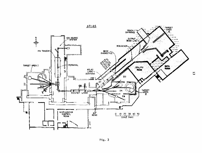
The overall fiocrplan of the facility Is shown In Figure 3. The
existing facility is shown in white background and the ATLAS construction area
is shown in cross hatched area. The building which is nearing completion,
will provide a second large experimental hall and a new data acquisition room.

In addition to one of the first successful applications of
superconductivity for acceleration, another feature that is somewhat unique to
this accelerator is its computer control system. The linac is completely
under the cortrol of a PDP-11/34. An example of the level of automation that
the computer control system provides is the tuning of the lleac for a new
beam. Since these resonators are independently phased!, one has to determine
the proper operating phase angles. The procedure for measuring the maximum
energy gain of each resonator and determining the proper operating phase angle
of each resonator is completely automated. This task Mould take many hours
without the use of a computer-control system but is generally accomplished in
one to two hours at present. Once tuned, those results are stored. These
parameters can be recalled and the linac can be set to the old values in Just
a few seconds. Once the linac has been tuned, the experimenter, to a large
degree, takes over the operation of the accelerator. The computer allows the
experimenters to change energies by just requesting the desired energy. If a
resonator deconditions and can no longer operate at a previous setting, the
computer will calculate the new parameters for the accelerator with that
resonator operating at a new level and set the accelerator to those values.
As ATLAS becomes operational, the list of automatic and computer controlled
functions will greatly expand.
The beams that have been accelerated at the Tandem-Linac during the
past year is shown in Figure 4. Lithium is the lightest ion that we
accelerate, mostly due to the problems of radiation shielding for light
ions. Also ions such as helium are not at all well suited for acceleration
became the velocities are too high to efficiently match to the resonators.
Heavy ions which can presently be provided for the experimental programs cover
the periodic table from lithium to selenium. Beam energies available range
fro* about 11 HeV/amu for l2C and 160 down to about 7.5 MeV/amu for 58Hi.
When ATLAS la fully operational, heavy Ions through tin will be provided.
An important design requirement for ATLAS m s that this accelerator
should provide tandem-like beam properties. The accelerator should provide
good energy resolution, good *»?iase space, and easy energy variability as well
as a wide selection of heavy Ions at the design energies. In order to achieve
these properties using a linear accelerator, the Injected beam Mist be bunched
to a tine width which is .1 snail fraction of the total RF period. For ATLAS,
this requires that the bean must be bunched to approximately 100 ps FUHN prior
to injection into the llnac. This is accomplished with a 3-stage bunching
system which consists of a pre-tandem harmonic buncher, an rf bean chopper,
and a superconducting resonator buncher. The beam is bunched at 48.5 Mhz
yielding « pulse period of 20.6 nanoseconds. We are presently developing a
new bunching system tfr.it will continue to allow operation at 20.6 ns * "t will
provide pulse periods of 82.4 ns with only a small degradation in bunching
efficiency. The longitudinal exittance of the beam, that la the beam's «nergy
spread times the time spread, for oxygen is 20 keV-ns and for nickel Is
approximately 40 keV-ns. The transverse emittanct for this beam is
approximately 19* mm-mrad - MeV"2. This transverse emittsnee allows spot
3ir.es on target of approximately 2 millimeters diameter.
For bunched beams- the rime resolution and the energy resolution are
coupled in such a way that the two dimensional area of AE&t must be
conserved. It is possible, using a separate superconducting resonator, to
manipulate the phase space of the beam in order to achieve either the best
energy resolution or the best timing resolution for a particular situation.
He have conducted a number of tests to measure the performance of the
rebunsher/debuncher in achieving either good timing or gcod energy resolution
en target. The results of the teats are indicated in Table I. These results
are obtained In elastic scattering on gold at forward angles. The timing
results are consistent tilth the geometry of our experimental area and the
assumed phase space of the beam fro* the linac. In energy resolution tests
using the Enge split-pole spectrograph, ve have obtained an energy resolution
of 150 keV for elastlcally scattered L2C ions of 107 HeV.
Heavy-ion accelerators such as ATLAS hare requirements which involre
the art of target maker* in at least three areas. First the beaut currents and
variety of isotopes being requested by experimenters place a high premium on
the performance of the ion source used. A very important aspect of beam
development Is understanding the optimum chemical form for a particular
element and any special preparation techniques which can enhance beam currents
from the source. Ve have found that target purity and surface preparation can
be critical for certain elements In determining source output. The proper
technique of hydrogen loading for certain elements, such as calcium and
titanium, in order to optimize the yield of the negative hydride of these
elements has been shown to be critical for acceptable beams. Finally, the use
of expensive 1sotopic materials means that one wants to be very efficient ie
their usage. All of these issues Involving the ion source can benefit from
the expertise of a trained target maker.
The next area that is mist critical is the charge changing carbon
stripper foils employed by the tandem preaccelerator and at other locations in
the linac. The most critical stripper foil location Is the terminal of the
tandem because that Is the ons that Intercepts the beam at very low velocity
and therefore produces large multiple scattering and bean straggling as well
as the shortest lifetime. The requirements placed on these foils are first
long lifetimes and, second, good thickness uniformity combined sith the

thinnest possible foils. For heavy ions, the foil lifetime Is largely United
by the decrease in transmission through the accelerator due to increasing '.'oil
thickness and degradation in foil uniformity. For ATLAS, the above properties
are needed for very thin foils whose thickness is generally 2-5 |ig«/cm .
The tandem stripper foils in normal use at Argonne are 2 jjgm/cm
thick carbon arc evaporated foils. These foils are counted on a foil holder
that is then reduced in diameter to produce a slackening of the foil. Ve find
that slackening gives approximately an order of Magnitude increase in the foil
lifetine. The lifetime that we currently experience for nickel is of the
order of 5 pna-hours on target. This corresponds to approximately 1.0 pma-
hours of beam on the foil because of beam attenuation due to double stripping
and other transmission losses.
Other carbon foil production methods have been tried including the
ethylene cracked glow discharge methods. Although a number of these nethods
seem to provide improved lifetimes when compared to arc evaporated foils when
the foil thickness is 10-15 pgm/cm2, for a foil thickness in the 2-5 vgrn/em2
range, no method seems superior to the arc evaporated foil. In fact, all
nethods seem to produce about the same foil lifetimes for these very thin
foils.
The energy loss of heavy ions in the energy range of 2-25 HeV/amu is
large compared to the desired experimental energy resolution. The energy-loss
3traggling of heavy ions in these targets soon becomes a significant problem
and can dominate the energy spread in the beam for these heavy ions. This
effect is shown in Table II where Hie best possible resolution is given
assuming that oaiy the intrinsic beam energy spread and the enesgy-lo**
straggling contribute to the resolution. For light 5~na such as oxygen, the
beam energy spread is the dominant effect, but for nickle and heavier ions the

8
enargy loaa straggling dominates. Therefor* thin, uniform targets must be
used when high resolution is demanded.
In order to approach the resolution indicated in Table II targets
aust be highly unifora. Honunifornity of targets is an effect which adds
linearly to the resolution quoted in Table II. A 250 uga/caz gold target
which is unifora to ± 10Z over the beaa region would ha?e an expected
resolution of 770 keV for nickel ions at 400 HeV and nearly 2 HeV for tin ions
at 1000 HeV. The target mat not only be produced with a high degree of
uniformity but «Uit be resistant to beaa Induced non-uniformity and changes in
total thickness over the course of the data acquisition. These atringent
requirements have caused an increase in efforts to develop gas targets of
various types and present a real challenge to the Maker of solid targets in an
effort to reduce the effects of non-unifora target thickness.
To conclude, * LAS and other heavy-Ion accelerators that are coming
on line such as Stonybrook and Oak Ridge are providing beaas of extreaely high
quality that require the K&xiaua of ingenuity froa the target aakers and the
experimenters in order to aake full use of the beaa quality being provided.
This challenge will re uire the development of new target production method*
and target designs which have not been contemplated up to now.
This research was supported by the »J. S. Department of Energy under
Contract V-3l-109-Eog-38.

Table I. Results of timing and energy resolution tests with the superconducting linac system. Elasticscattering on gold 91-b « 20*.
Ion
12C5+
12C5+
1606+,8+
1606+,8+
28S18+.13+
34S8+,13+
37cl8+,i3+
LlnacEnergy(MeV)
104.0
107.0
108.7
140.0
229.0
163.0
260.0
Pre-tandembunchertiming(ns)
0.80
1.0
1.1
1.3
Measuredtimingresolutionon tatget(psee)
107
105
its
210
Measuredenergy
resolution(KeV)
150
295
620
Beantiming
resolution(corrected)
(psec)
94
93
117
194
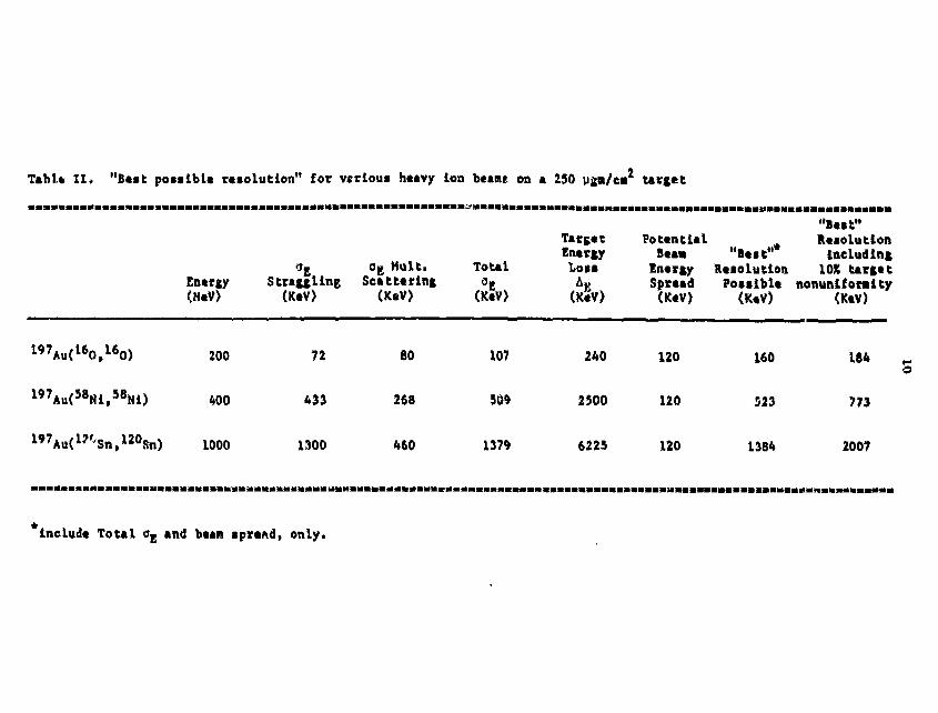
Table II, "Best po«»ibl« resolution" for verious heavy ion beams on a 230 uga/ea2 target
Entrgy<M«V>
9* 0g Mult,Straggling Scattering
(KaV) (K«V)
Total3.
TargetEnergyLoii
(KeV)
Potential ResolutionBeaa "Beit" including
Energy Keiolution 10X targetSpread Possible nonuniionity(KeV) <KeV) (KeV)
1 9 7Au( l 60 tl 60)
l97Au<58Ml,58Mi)
200
400
1000
72
433
1,100
SO
268
460
107
309
1379
240
2300
622S
120
120
120
160
523
1384
184
773
2007
include Total o* and beam spread, only.

0I
Cu-NbCOMPOSITE
10I
20I
30I
40I
DEMOUNTABLEJOINTS,
FAST_ V T U N E R Rf- POWER""^ INPUT -
STAINLESS STEELCLAMPING RINGS
LIQUID HELIUM"" INLET
SCALE (cm)
Fig, 1
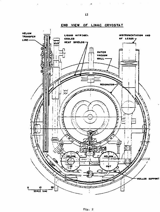
12
END VIEW OF LINAC CRYOSTAT
HELIUMTRANSFERLINE
INSTRUMENTATION ANOLEAPS-z
LIQUIOCOOLEOMEAT SHIELDS
ROLLER SUPPORT
SCALE
Fig. 2
ATLASTARGET
AREA
m
Fig. 3

t- LPQ.
ll tO* °° o
CD
X
<
00
I I I I
o> Q
IOI
CJ COCO
_oCVJ
-o
in o in o3IN II 9NllVd3dO IVIOI dO %

15
Contribution to the MORKSMP 1983 of the INTERNATIOfJAL fiU'CLEAR TARGET DE-VELOPMENT SOCIETY, Argonne National Laboratory, Arganne, Illinois 60439,U.S.A., September J993
SPECIAL ASPECTS ON NUCLEAR TARGETS FOR MI6H-ENER6Y HEAVY-IQW ACCELERATOREXPERIMENTS
H. Follger, W. Hartuann, J . «OL ,»in and M. Thalheiiaer
Geseilschaft fiir Schwerionenforschung, P l a n c k s t r . l , 6<0E Darmstadt, FRG
A B S T R A C T
Important facts about the GSI UNllAC accelerator are reviewed under thespecial aspects of target and stripper foil applications including generalrange consi aerations as seen after the upgrading of the eacfaine to an ener-gy of 20 MeV/u f~- all ions up to uranimra.
It is also reported about current works and recent developments in targetpreparations at GSI divided into four main groups of preparation procedureswith sufficient overlap: cold rollings, carbon sublimation-condensations,focussed heavy-ion sputter deposition, and the wide field of high-vacuumevaporation-condensations. Among others, a Ca reduction-distillation pro-cedure is described, a new assembly is shown for sublimation-condensationsof uniform C layers of 0,1 to 0.76 rag/cm area densities.
A selection of only a few applications of targets at t*>e UNILAC can begiven. Improved actinide targets are discussed, in-beam measurements of pro-perties of targets on rotating wheels are explained, and a large-areatarget wheel with a circumference of nearly one.meter is shown. SEH micro-graphs of damaged targets are: given ard explained.
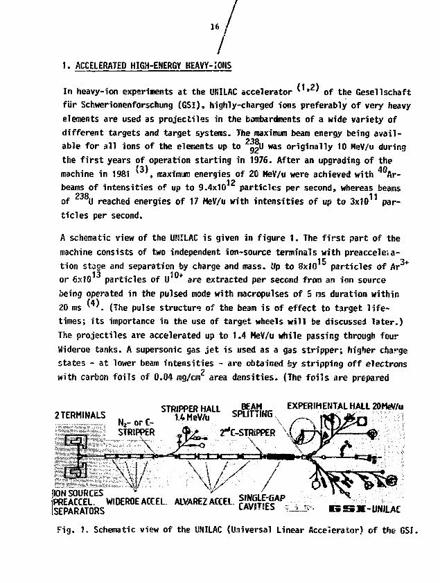
1. ACCELERATED HIGH-ENERGY HEAVY-IOHS
In heavy-ion experiments at the UNILAC accelerator *' ' of the Gesel1schaftfur Schwerionenforschung (GSI), highly-charged ions preferably of very heavyelements are used as projectiles in the bombardments of a wide variety ofdifferent targets and target systems. The maximum beam energy being avail-able for all ions of the elements up to ||u was originally 10 HeV/u duringthe first years of operation starting in 1976. After an upgrading of themachine in 1981 * , maximum energies of 20 MeV/u were achieved with Ar-
12beams of intensities of up to 9.4x10 particles per second, whereas beams238 11
of U reached energies of 17 MeV/u with intensities of up to 3x10 par-ticles per second.
A schematic view of the UNILAC is given in figure 1. The first part of themachine consists of two independent ion-source terminals with preacceleia-tion stage and separation by charge and mass. Up to 8x10 particles of Aror 6x10 particles of U are extracted per second from an ion sourcebeing operated in the pulsed mode with macropulses of 5 cits duration within20 ms . {The pulse structure of the be3m is of effect to target life-times; its importance in the use of target wheels will be discussed later.)The projectiles are accelerated up to 1.4 MeV/u while passing through fourWideroe tanks. A supersonic gas jet is used as a gas stripper; higher chargestates - at lower beam intensities - are obtained by stripping off electronswith carbon foils of 0.04 mg/cm area densities. (The foils are prepared
2TERMINALSSTRIPPER HALL BEAM EXPERIMENTAL HALL 20MeV/u
i.4MeV/u SPLITTING
STRIPPER
f[ION SOURCES v
'PREACCEL. WIDEROE ACCEL. ALVAREZ ACCELSEPARATORS CAVSTIES -UNJLAC
Fig . 1 . Schematic view of the UNILAC (Universal Linear Accelerator) of the GSI.

17
by direct resistance-heating of carbon rods in a sublimation-condensationprocess.) One charge state of the particle current is deflected into thestripper hall, where 10 experiments have been set up for investigations withbeams of an energy of 1.4 HeV/u. - The main charge state is selected forfurther acceleration in 4 Alvarez tanks up to an energy of 11.4 HeV/u. Asecond stripper, equipped with C-foils of 0.1 to 0.4 mg/cm , is placed intothe beam line if the highest possible energies and (or) the highest chargestates of a projectile of interest are required. (These foils are being pre-pared in a sublimation-condensation procedure using an electron-beam gun.)A series of single-gap cavities ' ' is built in for the final energy adjust-ment, allowing deceleration or acceleration within the total limits of 2 to20 MeV/u.
About ?0 different experiments have been installed and connected to the mainbranches of the beam transporting system in the experimental hall (see fig.1).A beam splitting system enables the operators to distribute the particlecurrent over the three main lines, so that up to three independent experi-ments can be performed at the same time if the same type of projectile andenergy is acceptable.
The maximum projectile energies are plotted as a function of the projectilemasses for some heavy-ion accelerators in figure 2. Additionally, the mini-
200
flOO| 60* 40 ^ ...
WIU& (651!GAHIl
-I — imsEi warn
40 80 120 160 200PROJECTILE HASS ( u j
240
solid lines.:W OPERATION
Fig 2. Projectile-energy vs. projectile-mass diagrams for some heavy-ionaccelerators. Curve for PHASE I from J. Ford (6), ANL data fromR. Pardo (7). The Coulomb barrier for U targets is drawn in as afunction of the projectile mass.

18
mum energies for nuclear reactions between heavy ions and uranium targets,Eg j( U), are drawn in. Thereafter, many experiments can be performed atenergies above the Coulomb barrier. The comparision cf data for existingand planned accelerators shows also the tendency to reach even higher ener-gies in the near future. It can be seen from figure 2 that the UHILAC iswell suited for investigations with high-energy beams of the 'very heavy*ions. Consequently, ions of 2 0 8Pb, 2 0 9Bi, 2 3 2Th, and especially of 2 3 8Uare playing a very important part in the research program of the GSI. Amongthe 46 different beams, which were already accelerated at the UNILAC ' ,there is another group of important projectiles: very expensive enrichedstable isotopes were needed here as an ion-source material to produce high-intensity beams of Ca, Ti, Cr, and Fe. In various compound reactionswith targets of Pb and Bi the heaviest new elements have been produced andthe search for super-heavy elements was extended to investigations of col-liding systems with Ca beans and actinide targets.
The highly-energetic heavy-ion beams have only a short range in target ma-terials. Values for the ranges in H, C, Ge, Eu, and (I are plotted versus themasses of tO-MeV/u-projectiles in the upper left part of figure 3. There ar*»large slopes in the range curves for beams from the proton to argon-ions,whereas only minor fluctuations have to be taken into consideration for allthe heavier projectiles which are of main interest for experiments at GSIThe ranges of Q,U ions of theenergy of 10 HeV/u correspond in C to 20 tag/or(103 um), in Ge to 36.5 mg/cm (68.6 pi), and in U to 67.6 mg/cm (35.5 urn);it means that relatively thin foils can already be regarded as 'thick tar-gets' and as a beam stopper. The ranges in target materials of H, C, Ge, Eu,
23ft
and U are drawn in as a function of the increasing energies of g«u Projec-tiles in the upper right section of figure 3. The first part of the curves -up to about 2.5 HeV/u - is strongly influenced by nuclear and electronicinteractions, at higher energies the electronic stopping is only of importance.
The numerical data for the range R at a given energy E are taken from theRange and Stopping-Power Tables of L.C. Northcliffe and R.F. Schilling (8).The 'electronic' range is defined there by the equation:
R(E) = I (-dC/dx)'1 dE,

19
"fc II
Si5
i
\
tt
»J
m
<r*
MA ,
• « !
Iitl
DMtiu'illl
V"
u • i» mKAS5 Of 1K»-»Wti-#R0 (lull
m ran
dHIWVol
Fig. 3. Range vs. projectile-mass (left) and range vs. projectile-energy(right) diagrams; upper graphs up to 10 NeV/u, lower ones up to100 MeV/u. After data from (8,9).
where -dE/dx is the 'stopping power' in the material-thickness x. The au-thors (8) discuss and describe their correction for the "nuclear stopping'.Ranges for new accelerator generations with projectile energies of up to100 MeV/u have been tabulated by F. Hubert, A. Fleury, R. Binbot andD. Gardes (9). Their basic equation consists of two terms:
».sR(E) JZ.l
S"1 + / S"1 dE.0 7 2.5
R = range; E = energy; S = -dE/ox = stopping power.
Values o to 2.5 MeV/u include nuclear as well as electronic stopping, takenessentially from (8); the second term was newly calculated by the authors.The ranges in targets of C, Ge, Sn, and U fo» projectiles of 100 MeV/u are
2 7expressed in terms of g/cm rather than in units of mg/cm , as can be seenfrom the lower left diagram in figure 3. The range in a U target, for in-stance*, comes up to 0.742 g/cm (389 urn) for increasing energies of U ionsof up to 100 MeV/u, as shown in the lower right of figure 3.The definition for 'thin targets' as layers of less than 0.1 mg/cm willremain uneffected by all these considerations.

20
The manifold effects of energy loss, thermal effects,damage processes, etc.,occuring during a heavy-ion bombardment have been described in detail byH. Adair and E.H. Kobisk ' ' only recently. Therefore, just one example forthe energy deposition in a 'thick' target at GSI should be mentioned: a beamof 3-1011 particles per second of 2 3 8U ions of 17-5 MeV/u transmits a totalkinetic energy of about 2(?8 watts. If the beam is focused to an area ofabout 0.2 cm , the resulting specific energy depositions amounts to 1 kW/cm .
2Host of the heavy-ion targets are thin targets of 0.01 to 0.1 mg/cm areadensities, or 'relatively" thin targets with area densities of 0.1 to 2.0mg/cm . Here only a fraction of the primary beam reacts with the targetatoms, while most of the projectiles pass the target layer undisturbed. Reac-tion products "leave the target material also nearly undisturbed, so that itis possible to investigate their masses, energies, velocities, angular dis-tributions, nuclear and atomic radiations, ranges, and otiiier properties,using appropriate instruments in the experimental set-ups.
2. RECENT DEVELOPMENTS IN TARGET PREPARATIONS AT GSI
A large number of different target layers, backings, C stripper-foils, ab-sorbers, monitor foils, etc., has to be provided for all the experimentsbeing performed at the UNILAC. The high intensity of the bean, and especial-ly the frequent acceleration of the very heavy iors, cause severe radiationdamages in the targets, so that they mostly can be used only once. The life-time of targets or stripper foils is occasionally limited to hours, and stacksof targets have to be available for single beam-times. In some cases, targetwheels with large target areas of a circumference of nearly one meter aresuccessfully built into the experimental set-ups in order to handle higherion currents at reasonable life-times of the targets. Low melting-pointelements like Pb or Bi are sandwiched between C layers for the use on tar-get wheels, thus extending the stability and life-tine for several reasonswhich will be discussed later.

21
2.1. Target Frames and Target Statistics
Many different shapes and sizes of target frames are in use at GSI> or theyare being provided here with various types of target layers for experimentsat other accelerators. A collection of miscellaneous frames is shown in theleft part of figure 4, together with the 'standard* types of frames outlinedon the right-hand side of this figure. The "standards" were taken over fromthe Target Laboratories or the HPI-Heidelberg, of the Univ. of Munchen, andof the Techn. Univ. of Mvnchen. (The first 3.000 frames were obtained fromP. Maier-Komor's ' ' supplier of frames in 1973; meanwhile own tools withslight changes as compared to the originals have been manufactured by a near-by company having produced about 75,000 target frames since then.) The newframes for target wheels have the shape of a sector of an annulus, they are'banana-like'; it seems that this development is not yet at an end.
The numbers of targets being prepared yearly do not exhibit details on dif-ficulties in target preparations but they are an important criterion forthe ieed of a certain (large) amount of targets. Therefore, the productionrates are mentioned for the last few years:
Targets/Year: 6500/1980 5300/1981 11000/1982 7000-9000/1983 (estim.)
The numbers include thick and thin foils, enriched isotopes and natural oc-curing target materials, raetals and compounds, as well as 'real' targetsand stripper foils, absorbers, and monitors. Large fails are normalized inthis consideration to pieces of 20x20 mm. - A more detailed informationcan be taken from figure 5: The production rates are compiled there in ablock diagram, which is divided into 4 groups for the nain different targetpreparation procedures, containing the data for the last three years. Coldrollings, carbon sublimations, and high-vacuum evaporations are in a widerange comparible with respect to their production rates; t.-3 high-vacuumsputtering with a focused ion beam is a special process fos small amountsof complicated and very important targets. Obviously there is a dip in somerates for 1981, because the UNILAC was in its upgrading phase in the secondhalf of the yaar. Last year the demand for targets increased tremendously;for this year estimated production rates (not included in fig.5) indicatea tendency towards a normalization of the target situation.

22
25mm
Fig. 4. Collection of miscellaneous target frames in comparisicn with the3 mostly used "standard' types of frames made of 0.3 on thick AlMg3.
NUMBER
TARGETSMOO
3000
2000 —
1000
'M "82 ?0 VI -82 « 1 t 1 2 10 1112 YEAR
Fig. 5. Production of heavy-ion targets at GSI in 1980-1982.
23
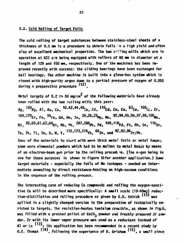
2.2. Cold Rolling of Target Foils
The cold rolling of target substances between stainless-steel sheets of athickness of 0.5 mm is a procedure to obtain foils in a righ yield and oftenalso of excellent mechanical properties. The two ruling mills which are inoperation at GSI are being equipped with rollers of 80 mm in diameter at alength of 120 and ISO ma, respectively. One of the machines has been im-proved recently with success: the sliding bearings have been exchanged forball bearings. The other machine is built into a glove-box system which isrinsed with high-purity argon down to a partial pressure of oxygen of 0.05$
/12)during a preparation procedure .
7
Metal targets of 0.2 to 50 mg/cm of the following materials have alreadybeen rolled with the two rolling mills this year:
Ag, 109Ag, Al, Au, Ca, ^ 4 2 , 4 4 , 4 8 ^ ^ 1 1 6 ^ £o> ^ 63 C u > 1 6 0 ^ ^
164,170^ Fe> 56 F e j Mf Ho> ln% 24,25,26^ ^ 92,94,95,96,97,98,100^
HI. 58,60,61,62,64^ ^ ph 207,208^ pd> 108,110^ ^ ^ ^
Ta, Th, Ti, Tm, U, W, Y, "2J73,174 y b > 66^,^ am, 92,93,96Zr/pb
Some of the materials to start with were thick metal! foils or ratal lumps;some were elemental powders which had to be molten to metal beads by meansof an electron-beam gun prior to the rolling procedi-e. (The e-gun being inuse for those purposes is shown in figure 10for another application.) Sometarget materials - especially the foils of Ho isotopes - needed an inter-mediate annealing by direct resistance-heating on high-vacuum conditionsin the sequence of the rolling process.
The interesting case of reducing Ca compounds and rolling the oxygen-sensi-tive Ca will be described more specifically: A small scale (10-40mg) reduc-tion-distillation and rolling procedure as given by E.H. Kobisk ^13' wasapliied in a slightly changed version in the preparation of isotopically en-riched Ca targets. The resistive-heated tantalum crucible, as shown in fig.6,was filled with a pressed pellet of CaCOg powder and freshly prepared Zr pow-der. Zr with its lower vapor pressure was used as a reductant instead ofAl or La *• '; its application has been recommended in a recent study by;
G.E. Thomas * '. Following the experience of B. Grisham '*5% a small piece
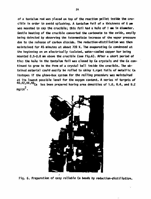
of a tantalum rod was placed on top of the reaction pellet inside the cru-cible in order to avoid splashing. A tantalum foil of a thickness of 6 pwas mounted to cap the crucible; this foil had a hole of t nm in diameter.Gentle heating of the crucible converted the carbonate to the oxide, easilybeing detected by observing the intermediate increase of the vapor pressuredue to the release of carbon dioxide. The reduction-distillation was thenmaintained for 45 minutes at about 720 K. The evaporating Ca condensed atthe beginning on an electrically isolated, water-cooled copper bar beingmounted 0.5-0.8 mm above the crucible (see fig.6). After a short period oftima the hole in the tantalum foil was closed by Ca crystals and the Ca con-tinued to grow in the form of a crystal ball inside the crucible. The ob-tained material could easily be rolled to shiny target foils of metallic Caisotopes if the glove-box system for the rolling procedure was maintainedat its lowest possible level for the oxygen content. A series if targets of40,42,44,48Ca has been prepared having area densities of 1.0, 0.4, and 0.2
2mg/cm «
Fig. 6. Preparation of easy rollable Ca beads by reduction-distillation.
25
2.3. Carbon Foils from Sublimation-Condensation Processes
From all the substances in the periodic table of the elements, carbon is theone being involved in nearly every heavy-ion experiment, somehow. To coverthe wide range in the demands for the various thicknesses of carbon foils,two different preparation procedures had to be installed in this laboratory.
The thin foils of 0.002 to 0.1 mg/cra area densities can be obtained by di-rect resistance-heating of spectrographite rods of 3 mm in tiiar.eter; thesublimed carhon is hereby collected on betain-saccharose treated glass-plates of 100x100 mm in size. The carbon foils have to be floated off in
(12)the usual manner. The process has been described recently * ' in more de-tail; it is a variation of the procedure originally introduced by P. Haier-Komor I'6'. Nearly 4,000 foils have already been prepared by tJie method thisyear, the majority of them was needed in thicknesses of around 0.02 to 0.04mg/cm area densities. The C layers are to be used as targets, backings, de-graders, catchers, and stripper foils at the UNILAC (0.04 mg/cm ; 1.4HeV/u;see fig.1). •The determinations of area densities of thick C foils (*0.05 mg/cm) arebeing performed by weighing measured areas; the results are trustworthy butby far more time-consuming than the determinations made by an optical methodfor thin foiis. So the thickness of every single thin C foil is being de-terwinded by measuring the absorption of light at 800 ran by means of adouble-beam spectrophotometer. This apparatus has been calibrated by mea-suring absorption values for foils of known area densities from weighingmeasured areas.
A new series of thick carbon foils having area densities from 0.1 up to 0.76mg/cm is now being prepared at GSI in a high-vacuum sublimation-condensationprocedure. A schematic view of the new arrangement is given in figure 7.Spectrographite is sublimed from a water-cooled copper health by means ofan electron-beam being generated in a 6 kW e-gun, type ESV-6, Leybold-Heracus, Hanau, FRG. The sublimed C is condensed onto glass-plates beingtreated with betain-saccharose as mentioned above, The rate of condensationis measured by means of a quartz thickness-monitor. - Of great importance

26
Substrate
position
top
12
3
4
all
Substrate plates of 100x100mm
Measured
samples
13x16mm
41
40
4242
42
207
M'-n
thicknessyg/cm2
43.4
41-5
40.139.9
43.1
41.6 !
Ktean
deviation
W/cm2 (%)
+1.1(+2.6)
+1.0(+2.4)
+1.5(+3.7)+1.3(+3.2)
+0.9(+2.3)
+1.9(+4.5)
Center <
Measured
samples
13x16nm
6
566
6
29
if plates,
Mean
thickness
ug/cm2
44.7
42.9
41.3
41.1
44.3
42.9
39x32mm
Mean
deviation
ug/cm2 (£)
+0.3(+0.6)
^3.3(40.8)
+0.3(+0.8)*0.5(+1.1)
+O.3(*0.6)
+1.6{+3.7)
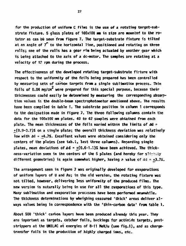
Tab. 1 . Thickness distribution on rotating target substrates from a subli-
mation of carbon using an electron-beam-gun heating.
tB&mz
TOP VIEW JSCrtEMATICJ
6"-pumping ; BASE PUWE
Fig. 7. Electron-beam-gun evaporator with rotating target-substrate fixture.
27
for the production of unifora C films is the use of a rotating target-sub-strate fixture. 5 glass plates of 100x100 ran in size are Mounted to the ro-tator as can be seen from figure 7. The target-substrate fixture is tiltedat an angle of 7° to the horizontal line, positioned and rotating on threerolls; one of the rolls has a gear rim being actuated by another gear whichis being attached to the axis of a dc-motor. The samples are rotating at avelocity of 12 rpm during the process.
The effectiveness of the developed rotating target-substrate fi/ture withrespect to the uniformity of the foils being prepared has been controlledby measuring sets of carbon targets from a single sublimation process. Thinfoils of 0.04 mg/cm were prepared for this special purpose, because theirthicknesses could easily be determined by measuring the corresponding absorp-tion values ir. the double-beam spectrophotometer mentioned above. The resultshave been compiled in table 1. The substrate position in column 1 correspondsto the designation made in figure 7. The three following columns contain thedata for the 100x100 mm plates. 40 to 42 samples were obtained from eachplate. The mean thicknesses of the foils varied witiiin the limits of M =4X0.9-3.7)% on a single plate; the overall thickness deviation was relativelylow with ad = +4.7%. Excellent values were obtained considering only thecenters of the plates (see tab.*, last three columns). Regarding singleplates, mean deviations ofJd = ±(0.6-1.1)2 have been achieved. The thick-ness-variation seen in the centers of the 5 plates (and hereby for s K ^ t i ydifferent geometries) is again somewhat higher, having ? value of dd = +3.7*.
The arrangement seen in figure 7 was originally developed for evaporationsof uniform layers of U and Au; in the old version, the rotating fixture wasnot tilted, however, delivering less uniformity of the produced films. Thenew version is naturally being in use for all the evaporations of this type.Many sublimation and evaporation processes have been performed meanwhile.The thickness determinations by wheighing ireasured 'thick" areas deliver al-ways values being in correspondence with the 'thin-carbon data" from table 1.
About 500 'thick' carbon layers have been produced already this year. Theyare important as targets, catcher foils, backings for actinide targets, post-strippers at the UNILAC at energies of 8-11 MeV/u (see fig.1), and as charge-transfer foils in the production of highly charged ions, etc.

28
2.4. Sputter Depositions with Focused Heavy-Ion Beams
Beams of 1 mA of Ar+ at 10 kV are being focused to a diameter of abcut I moonto the cathode of a sputter apparatus of the Sletten-type * '. t. view ofthe main parts of the machine is given in. figure 8 schematically. The opera-tional conditions have been described and discussed in a survey * ' togeth-er with a complete list of all sputtsr depositions at 6SI until 1982.
C _ EUBPILASMATIROIN[ION SOURCE
-SPUHES-OMMQBE
ROTATINGSUBSTRATE FIXTURE
| — * H f -ADJUSTMENT
TOVAtMUM SYS*XM
Fig. 8. Apparatus for focused heavy- Fig. 9. Rotating target-substrate fix-ion-beam sputter depositions. ture with "positron frames'HS).
Preferably small amounts of high melting-point substances are being spat-tered, i.e. in general, isotopically enriched materials. Thus only 2.3 rogof Zr were consumed in the preparation of 5 targets of 0.1 rag/cm on 0.03mg/cm thick C-backings of a diameter of 15 mm. Self-supported sputter-lay-ers of k O t»' w> | O Dy Of Q.2 to 0.5 mg/on , which are obtained after dissolv-ing a copper substrate, are nearly being regarded as standard targets in themeantime. In another case, 2x4 mm spots of Ta had to be sputtered to C of0.03 mg/cm on specially shaped holders {see fig.9); the targets were usedin the search of spontaneous positrons in heavy-ion collisions *"*'.
The list of different types of targets, being prepares by sputter deposi-tions so far this year, is as follows:
Ag/C, Nb/C, Ni, 6 0 f 6 2Ni, Pt/C, Pt/Ta, 1 8 5 > 1 8 7Re, l02Ru/C, 96Ru/Ta, Si/C,
!, Ti/C,
29
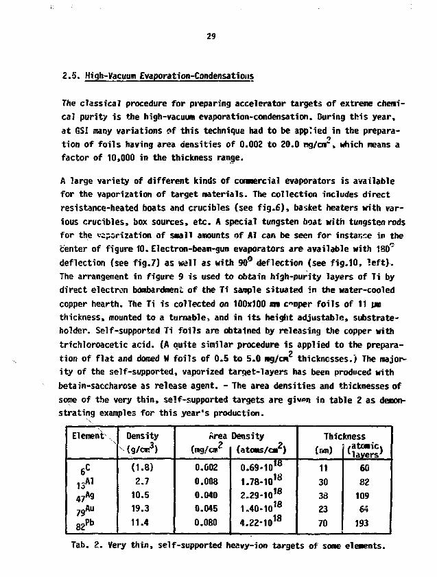
2.5. High-Vacuum Evaporation-Condensations
The classical procedure for preparing accelerator targets of extreme chemi-
cal purity is the high-vacuum evaporation-condensation. During this year,
at GSI many variations of this technique had to be applied in the prepara-
tion of foils having area densities of 0.002 to 20.0 rag/cm*", which means a
factor of 10,000 in the thickness range.
A large variety of different kinds of commercial evaporators is available
for the vaporization of target materials. The collection includes direct
resistance-heated boats and crucibles (see fig.6), basket heaters with var-
ious crucibles, box sources, etc. A special tungsten boat with tungsten rods
for the vaporization of small amounts of Al can be seen for instance in the
center of figure 10. Electron-beam-gun evaporators are available with 180°
deflection (see fig.7) as well as with 90° deflection (see fig.10, left).
The arrangement in figure 9 is used to obtain high-purity layers of Ti by
direct electron bombardment of the Ti sample situated in the water-cooled
copper hearth. The Ti is collected on 100x100 mm cooper foils of 11 urn
thickness, mounted to a turnafole, and in its height adjustable, substrate-
holder. Self-supported Ti foils are obtained by releasing the copper with
trichloroacetic acid. (A quite similar procedure is applied to the prepara-
tion of flat and domed M foils of 0.5 to 5.0 ng/cfi thicknesses.) The major-
ity of the self-supported, vaporized target-layers has been produced with
betain-saccharose as release agent. - The area densities and thicknesses of
some of the very thin, self-supported targets are given in table 2 as demon-
strating examples for this year's production.
ElemenK
6C
13A1
47Ag
7gAu
82 P b
Densityv (g/cm3)
(1.8)
2.710.5
19.3
11.4
Area
(mg/cm2
0.002
0.008
0.040
0.045
0.080
Density
(atoms/cm2)
0.69-1018
1.78-1018
2.29-1018
1.40-1018
4.22-1018
Thickness
(r-m)
11303d2370
/atomic)1layers'
608210964193
Tab. 2. Very thin, self-supported heavy-ion targets of some elements.

30
Fig.10. Electron-beam-gun evapnration of Ti (left) and evaporation of Alfrom a tungsten boat (center) to a turnable target-substrate fix-ture being provided to carry 8 substrate plates of 100x100 ran (19),
31
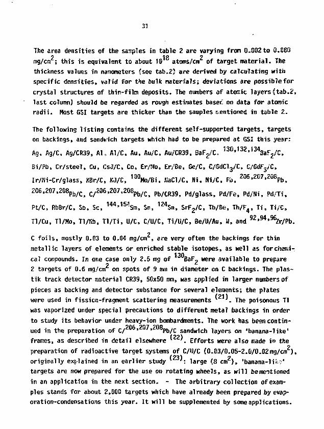
The area densities of the samples in table 2 are varying from 0.002 to O.Img/cm ; this is equivalent to about 10 atoms/cm of target material. Thethickness values in nanometers (see tab.2) are derived fey calculating withspecific densities, valid for the bulk materials; deviations are possible forcrystal structures of thin-film deposits. The numbers of atoaic layers (tab.2,last column) should be regarded as rough estimates baser: on data for atonicradii. Most GSI targets are thicker than the samples mentioned in table 2.
The following listing contains the different self-supported targets, targetson backings, and sandwich targets which had to be prepared at GSI this year:
Ag, Ag/C, Ag/CR39, Al,, Al/C, Au, Au/C» Au/CR39, BaF2/C,
Bi/Pb, Cr/steel, Cu, CsJ/C, Co, Er/Mo, Er/Be, Ge/C, C/GdCWC, C/GdF,/C,
Ir/Ni-Cr/glass, KBr/C, KJ/C, 100Mo/Bi, WaCl/C, Hi, Hi/C, Pi), 2 0 6» 2 0 7' 2 0 8pb,
206,207,208pb/Cj c/2Q6,207,2Q8pb/Cj Pb/mQf Pd/glass, Pd/Fe, Pd/Ni, Pd/Ti,
Pt/C, RbBr/C, Sb, Sc, 144'15<3Sui, Sn, 124Sn, SrFg/C, Tb/Be, Th/F4, Ti, Ti/C,
Tl/Cu, Tl/Mo, Tl/Nb, Tl/Ti, U/C, C/U/C, Ti/U/C, Be/U/Au, M, and 9 2 * 9 4 > 9 % T b .
C foils, mostly 0.03 to 0.04 mg/cm , are very often the backings for thinmetallic layers of elements or enriched stable isotopes, as well as for chemi-cal compounds. In one case only 2.5 mg of BaF, were available to prepare
22 targets of 0.6 mg/cm on spots of 9 mm in diameter on C backings. The plas-tik track detector material CR39, 50x50 mm, was spplied in larger numbers ofpieces as backing and detector substance for several elements; the plates
towwere used in fission-fragment scattering measurements x '. The poisonous Tlwas vaporized under special precautions to different metal backings in orderto study its behavior under heavy-ion bombardments. The work has beencontin-
Pflfi ?fi7 ?0ftued in the preparation of C/ * ' Pb/C sandwich layers on 'banana-like'(29)
frames, as described in detail elsewhere v . Efforts were also made in theo
preparation of radioactive target systems of C/U/C (0.03/0.05-2.0/0.02mg/cm ),originally explained in an earlier study v ': large (8 cm ) , 'banana-liks'targets are now prepared for the use on rotating wheels, as will bemeitionedin an application in the next section. - The arbitrary collection of exam-ples stands for about 2,000 targets which have already been prepared by evap-oration-condensations this year. It will be supplemented by some applications.

32
3. SOME APPLICATIONS OF TARGETS IN HEAVY-ION BOMBARDMENTS AT THE GSI UNILAC
24«3.1. Cm Targets in the Search of Spontaneous Positrons at the EPOS
The emission of positrons froa collisions of high-energy heavy-icns withtarget atoms is of special interest if quasiatoms are generated havingcharges of Z.+Iy > "Icr * 173- As an exeaple, the internuclear distance fora bombardment of 2 3 8U with 5.9 MeV/u of 2 3 8U of a Z u n i t e d = 184 is given asa function of time in the upper part of figure 11. In such overcritical sys-tems the 1s.yo level may exceed twice the binding energy of an electron thusdiving into the Dirac sea, the negative energy continuum. In case this stateis empty, an electron of the negative continuum occupies the vacant 1s.,,state and a positron is emitted spontaneously at a characteristic energy(fig.11, bottom). Due to the fast cfeange of the Coulomb potential during thetine of the collision, several transitions between bound and continuum stateswill be induced. This dynamically induced positron production, in particular,contributes the dominating part to the intensity of a positron spectrum.
The EPOS transport system is one of the three positron spectrometers beingin operation at GSI to investigate supercritical heavy-ion collision systems.(The orange positron-spectrometer Mill be mentioned with an application inthe next section.) The EPOS set-up is a double a m solenoidal transport sys-tem; all relevant positron and electron energies are measured simultaneouslyby means of Si(Li) detectors, together with nuclear jf-radiation, in coinci-dence with both scattered ions. A comprehensive description of the apparatushas been given by H. Bokemeyer et al. * '
Typical positron spectra from an interaction of U projectiles at an ener-gy of 6.05 MeV/u with Cm target-atoms are shown in figure 12. The sharpline structure on top of the induced positron spectrum (fig.12, top) beingobserved only under specific scattering conditions, represents a candidatefor the spontaneous positron emission.
Target systems of Ti/( On)/C of 0.6/0.3-0.5/0.03 mg/cm area densities248with Cm spots of 5 mm in diameter were prepared in cooperation with the
Nuclear Chemistry Group of the University of Mainz, FRG. The "°Cu! depositson Ti backings were obtained in a molecular plating procedure from isopropyi

33
159MeV/u) b=0fmr-T -7-7-1—
-0.5)
L
Kjd-cSroNHiMllBJUS.i j POSITRONS
POSITRONS « a
-oo -30 -10 -1 0 A j.*10 *30«n
t [10si
Fig,11. Internuclear distance (top) Fig.12.and binding energies of threequasiatomic levels (bottom)as a function of time assumingRutherford scattering.
alcohol as a solvent as described recently by fi. Tr«sutnann et al.
20© m 6OT 800 ten imE,. [keVJ
Positron spectra from colli-sions of 6 MeV/u of Z38y onZ 4 8Qa for kinematic selectionswith different scattering an-gles (top: 1Guo-sflc.m.'c130
o;bottom: 50O^e c < m.<80O). (24)
(25)
the mean-time improvements were made in the preparation of C layers of forinstance 0.12-0.15 mg/cmZ area densities (see sect.2.3.); such foils couldbe applied already successfully as backings for 2 4 8Cn targets in a modifiedversion of tha mentioned molecular plating procedure resulting also in im-proved qualities for the performance of the heavy-ion bombardments. - The
Cm is on loan from Oak Ridge National Laboratory unrfar the DOE contractWC-EU 241.
The special form of the target frame which was constructed for the EPOS ex-peri-nent can be seen in figure 9; there, Ta layers ar^ -^uttered to 0.03mg/cm thick C backings for calibration purposes at the spectrometer. Thethin target frame and the long thin support are necessary in order to reduceinteractions of the spiralling positrons in the magnetic field with non-target materials.

34
3.2. Monitoring Properties of Targets on Rotating Wheels in the Synthesis
of Mew Elements at the SHIP and in Positron Spectroscopy at the Orange
The heaviest element, so far, with a charge of 2 =109 can be synthesized in58
bombardments of Bi targets with the "lighter" heavy-ions-of the isotope Fe
at energies only slightly above the Coulomb barrier for tiiis reaction; it
is around 5 MeV/u. * ' The reaction cross section is of the order of nano-
barns only, so that the highest possible beam intensities of about ZOO pnA
are needed in such a heavy-element run from the UNILAC accelerator. The tar-
gets in question are fiade of the low melting-point element Pb. They are
mounted to a rotating wheel in order to enlarge the active target surface.
Of extreme importance for the detection of the reaction products is the ve-
locity filter SHIP.1 ' It separates the rest of the primary beam particles,
after passing the target area, frao the snail amount of compound nuclei and
reaction pro r. These particles can be detected in an extremely sensitive(28)
detection systeri. "
The second experiment is completely different as compared to the one des-
cribed above. It uses, however, in one series of experiments the same tar-
get wheel and a similar target monitoring procedure. This is the reason for
discussing both experiments in one section.
The emission of positrons from superfoeavy quasiataras has been mentioned al-
ready in the previous section as a type of experiments, which are investi-
gated at the UNILAC with much effort. In one of the experiments am iron-free
B-spectrometer of the 'orange'-type x ' is used. Of large interest are here238 3fi238 3fi
colliding systems like U*' U at energies at the Coulorsb barrier, i.e.,
at projectile energies of 5.9 KeV/u (see schematic in fig.11). The positrons
emitted during the collision are focmssed with the magnetic field of the
orange and transported into the focal detection system where they are reg-
istered. Target changes due to irradiation damages cause uncertainties in
the interpretation of experimental data, so a rotating target-wheel was used
in a series of experiments instead of a single target in order to reduce
these effects. In the colliding systen mentioned above (see also fig.II),
inner shell electrons are ejected as well with continuous energy distribu-
tions, known as <f-rays. This radiation was observed with an energy far higher
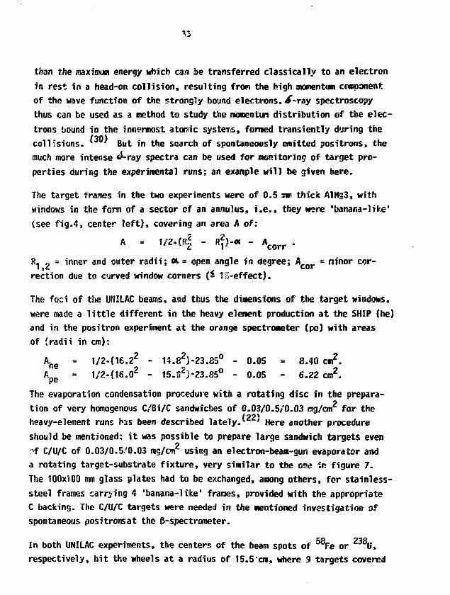
than the maximum energy which can be transferred classically to an electronin rest in a head-on collision, resulting from the high momentum componentof the wave function of the strongly bound electrons, *f-ray spectroscopythus can be used as a method to study the momentum distribution of the elec-trons bound in the innermost atomic systems, formed transiently during thecollisions- * ' But in the search of spontaneously emitted positrons, themuch more intense d-ray spectra can be used for monitoring of target pro-perties during the experimental runs; an example will be given here.
The target frames in the two experiments were of 0.5 mm thick AlMg3, withwindows in the form of a sector of an annulus, i.e., they were "banana-like"(see fig.4, center left), covering an area A of:
R§A 1/2. (R§ - R2)-« -
R, , = inner and outer radii; «. = open angle in degree; A___ = minor cor-iyc cor
rection due to curved window corners (- 12-effect).
The foci of the UNILAC beams, and thus the dimensions of the target windows,were made a little different in the heavy element production at the SHIP (he)and in the positron experiment at the orange spectrometer (pc) with areasof (radii in cm):
A h e - 1/2-(16.22 - 14.£2)-23.85° - 0.05 = S.40 cm2.A.o = 1/2-(16.02 - 15.02)-23.85° - 0.05 = 6.22 cm2.pe
The evaporation condensation procedure with a rotating disc in the prepara-tion of very homogenous C/Bi/C sandwiches of 0.03/0.5/0.03 mg/crn2 for theheavy-element runs has been described lately. ' Here another procedureshould be mentioned: it was possible to prepare large sandwich targets evenof C/U/C of 0.03/0.5/0.03 mg/cm using an electron-beam-gun evaporator anda rotating target-substrate fixture, very similar to the one in figure 7.The 100x100 mm glass plates had to be exchanged, among others, for stainless-steel frames carrying 4 "banana-like" frames, provided with the appropriateC backing. The C/U/C targets were needed in the mentioned investigation ofspontaneous positrons at the ^-spectrometer.
In both UNILAC experiments, the centers of the beam spots of 58Fe or 2 3 8U,respectively, hit the wheels at a radius of 15.5'cm, where 9 targets covered
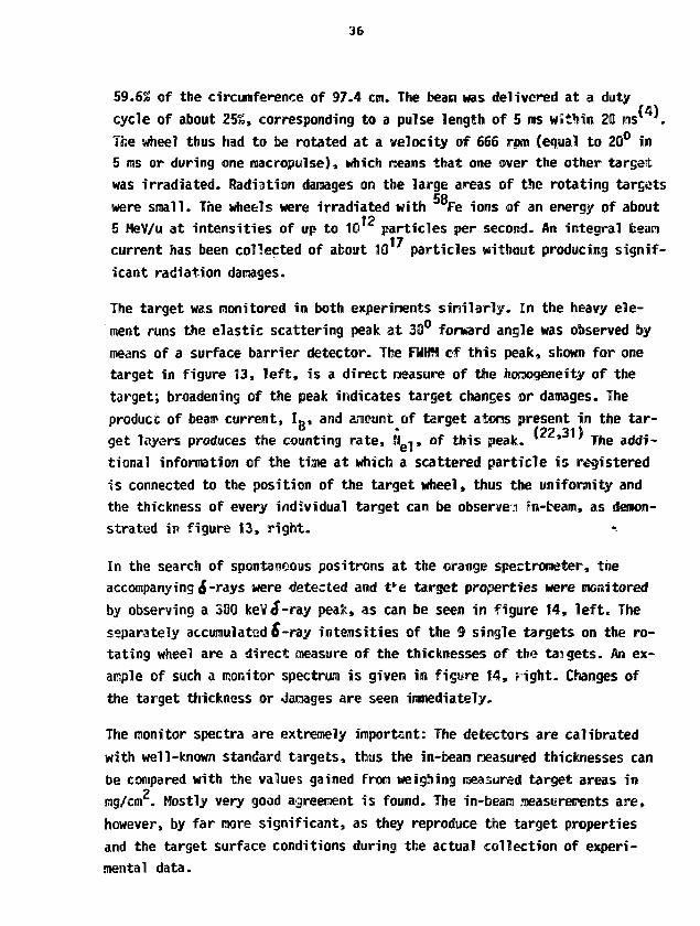
36
59.6% of the circumference of 97.4 cm. The beam was delivered at a duty(41cycle of about 25%, corresponding to a pulse length of 5 ms within 20 ms* .
The wheel thus had to be rotated at a velocity of 666 rpm (equal to 20° in5 ms or during one macropuise), which oeans that one over the other targetwas irradiated. Radiation damages on the large areas of the rotating targets
58were small. The wheels were irradiated with Fe ions of an energy of about125 MeV/u at intensities of up to 10 particles per second. An integral beam
current has been collected of about 10 particles without producing signif-icant radiation damages.
The target wes monitored in both experiments similarly. In the heavy ele-ment runs the elastic scattering peak at 30° forward angle was observed bymeans of a surface barrier detector. The FMHW cf this peak, shown for onetarget in figure 13, left, is a direct measure of the horaogeneity of thetarget; broadening of the peak indicates target changes or damages. Theproduct of beam current, IB, and amount of target atoms present in the tar-get layers produces the counting rate, SI -j, of this peak. **-«-»••*"' j|,e addi-tional information of the time at which a scattered particle is registeredis connected to the position of the target wheel, thus the uniformity andthe thickness of every individual target can be observes in-teann, as demon-strated in figure 13, right.
In the search of spontaneous positrons at the orange spectrometer, theaccompanying &-rays were detected and t*e target properties were monitoredby observing a 30Q kev£-ray peak, as can be seen in figure 14, left. Theseparately accumulated S-ny intensities of the 9 single targets on the ro-tating wheel are a direct treasure of the thicknesses of the targets. An ex-ample of such a monitor spectrum is given in figure 14, right. Changes ofthe target thickness or damages are seen immediately.
The monitor spectra are extremely important: The detectors are calibratedwith well-known standard targets, thus the in-beara measured thicknesses canbe compared with the values gained from weighing treasured target areas inmg/cm . Mostly very good agreement is found. The in-beam raeasureipents are,however, by far more significant, as they reproduce the target propertiesand the target surface conditions during the actual collection of experi-mental data.

37
SffcMt 58ft on otaig/ai?
KM M 3W M M
» TMIGETS/WHCEl n0.60 M
UJZ
0 4 0 ^
BEAM DO5E
Fig.13. Measured elastic scattering peak (left) and integrated intensitiesof scatter peaks of 9 targets on a rotating wheel (right) allow adirect control of bean and target properties.(22,31)
ENERGY/OUMNEL rimer mmnas
Fig.14. The spectrua of /-ray electrons (left) and the accumulated S-rayyields of 9 targets on a rotating wheel (right) nake direct obser-vation of target properties possible.(33)
38
3.3. Improved Rotating Target-Disc for Fragmentation-Reaction Experiments
Light mass products (2Q*A*40) from fragmentation reactions are known to beformed in relativistic proton-induced and heavy-ion-induced reactions atenergies that are now available at the GSI UNILAC. In the search of frag-mentation products from collisions of Au+Au at projectile energies of 15HeV/u such liyht mass nuclei are abundantly produced; corresponding angular
(•to)
and velocity distributions were measured. " 'The targets for the investigation of this reaction had to be made of 1.8mg/cm of Au, and they had to withstand high intensities of pulsed beams ofAu of energies between 10 and 15 MeV/u. For this purpose a target disc wasassigned, originally used in the preparation of sets of 13 "banana-like*targets * ' of the type mentioned in section 3.2. New, especially longframes could be constructed to carrv the strong Au foils. The windows of theframes have the fora of a sector of an annulus as the ones described in theprevious section (3.2.); the dimensions with the wider open angle are:
= 1/2-O6.Q2 - 15.02)-38.52° - 0.05 = 9.60 cm2 .
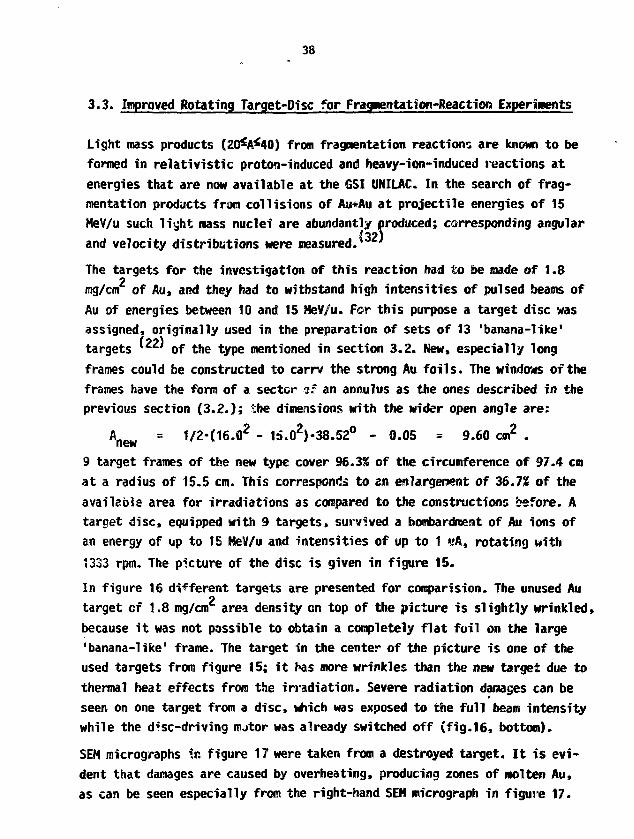
9 target frames of the new type cover 96.3% of the circumference of 97.4 cmat a radius of 15.5 cm. This corresponds to en enlargement of 36.7% of theavailable area for irradiations as compared to the constructions before. Atarget disc, equipped with 9 targets> survived a bombardment of Au ions ofan energy of up to 15 HeV/u and intensities of up to 1 «A, rotating with1333 rpm. The picture of the disc is given in figure 15.
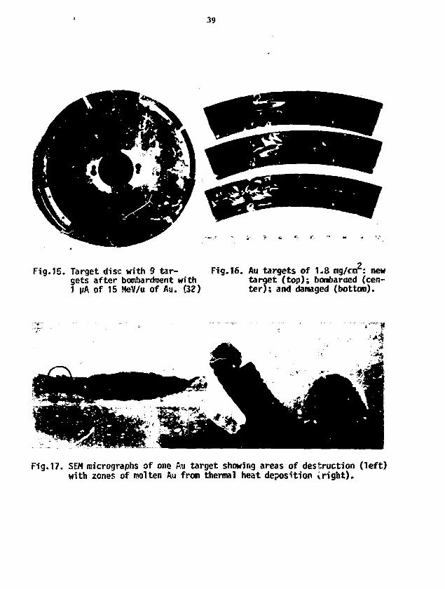
In figure 16 different targets are presented for consparision. The unused Autarget of 1,8 mg/cm area density on top of the picture is slightly wrinkled,because it was not possible to obtain a completely flat foil on the large'banana-like' frame. The target in the center of the picture is one of theused targets from figure 15; it has more wrinkles than the new target due tothermal heat effects from the irradiation. Severe radiation damages can beseen on one target from a disc, which was exposed to the full beam intensitywhile the d^sc-driving nutor was already switched off (fig.16, bottom).
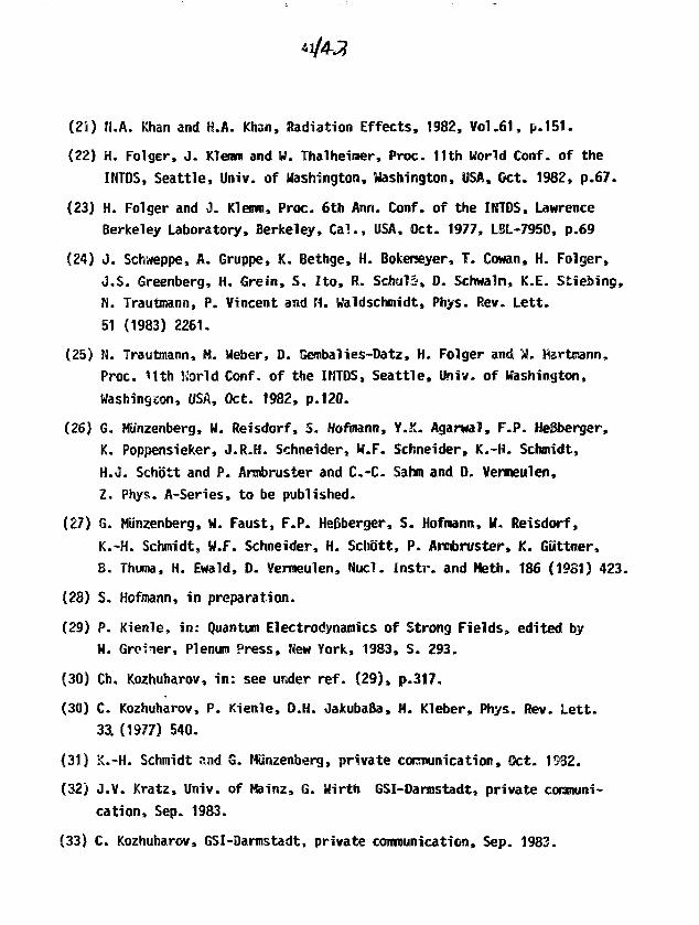
SEM micrographs in figure 17 were taken from a destroyed target. It is evi-dent that damages are caused by overheating, producing zones of molten Au,as can be seen especially from the right-hand SEN micrograph in figure 17.
39
Fig.15. Target disc with 9 tar-gets after bombardment with1 JJA of 15 MeV/u of Au. (32)
Fig.16. Au targets of 1.8 mg/cnr: newtarget (top); bombarded (cen-ter); and damaged (bottom).
Fig.17. SEM micrographs of one Aw target showing areas of destruction (left)with zones of molten Aw from thermal heat deposition iright).

References
(1} Ch. Schmelzer, Proc. of the Prot. Lin. Ace. Conf., Brookhaven,New York, USA, r-d.
(2) N. Angert and Ch. Schmelzer, Kerntechnik 11 (1969) 690.
(3) N. Angert, Proc. of the Int. Engineering Congress, ISIAT "83 &IPAT '83, Kyoto, Japan, Sep. 1984, p.595.
C4) M. Wilier, IEEE, Voi.NS-30, No.2, Apr. 1983, p.1499.
(5) U. B'ohne, Proc. of the Part. Ace. Conf., Washington, D . C . USA, 1969.
(6) J. Ford, priv. coron., Sep. 1983, and contribution to this Workshop.
(7) R. Pardo, priv. comtn., Sep. 1983, and contribution to this Workshop.
(8) L.C. Northcliffe and R.F. Schilling, Nucl. Data Tables, A7, 233, 1970.
(9) F. Hubert, A. Fleury, R. Bimbot and D. Gardes, SuppH. aux Ann. Phys.,Fr., Vol.5, 1980.
(10) H. Adair and E.H. Kobisk, IEEE, Vol.NS-30, Ho.2, Ap3. 1983, p.1555.
(11) P. Maier-Komor, Techn. Univ. Hunchen, Phys. Oept. E-12, Hunchen, FRG.
(12) H. Folger, W. Hartmann, J. Klemm and W. Thalheimer, Proc. 10th WorldConf. of the INTOS, Rehovot, Israel, Oct. 1981, p.224.
(13) E.H. Kobisk, Proc. Seminar on the Prep, and Standardisation of IsotopicTargets and Foils, A.E.R.E., Harwell, England, Oct. 1965, p.103.
(14) G.E. Thomas, Nucl. Instr. a.id Heth. 200 (1S82) 27.
(15) B. Grisham, priv. comm., ORNL, Oak Ridge, Tenn., USA, Oct. 1982.
(16) P. Haier-Komor, Nucl. Instr. and Heth. 102 (1972) 485.
(17) G. Sletten and P. Knudsen, Nucl. Instr. and Heth. 102 (1972) 459.
(18) H. Folger, J. Klemm and N. Killer, IEEE, Vol.NS-30, Apr. 1983, p.1568.
(19) A. Zschau, Fotoiabor, GSI, Planckstr. 1, 6100 Darmstadt.
(20) H. Bokemeyer, K. Bethge, H. Folger, J.S. Greenberg, H. Grein, A. Gruppe,S. Itr, R. Schuie, 0. Schwalm, J. Schweppe, N. Trautirann, P. Vincent,M. Waldschmidt, in: Quantum Electrodynamics of Strong Fields, editedby W. Greiner, Plenum Press, New York, 1983, p.273.
(21) N.A. Khan and H.A. Khan, Radiation Effects, 1982, Vol.61, p.151.
(22) H. Folger, J. Klenrn and W. Thalheiraer, Proc. 11th World Conf. of theXNTDS, Seattle, Univ. of Washington, Washington, USA, Oct. 1982, p.67.
(23) H. Folger and J. Klemm, Proc. 6th Ann. Conf. of the INTDS, LawrenceBerkeley Laboratory, Berkeley, Call.. USA, Oct. 1977, LBL-7950, p.69
(24) J. Schweppe, A. Gruppe, K. Bethge, H. Bokerseyer, T. Cowan, H. Folger,J.S. Greenberg, H. Grein, S. Ito, R. Schwls, D. Schwaln, K.E. Stiebing,H. Trautmann, P. Vincent and ML Waldschmidt, Phys. Rev. Lett.
51 (1983) 2261.
(25) N. Trautmann, M. Weber, ID. Gembalies-Datz, H. Folger and W. Hartaann,Proc. 11th World Conf. of the IHTDS, Seattle, Univ. of Washington,Washington, USA, Oct. 1982, p.120.
(26) G. Mtinzenberg, W. Reisdorf, S. Hofmann, Y.2C. Agarwal, F.P. He&berger,K. Poppensieker, J.R.H. Schneider, M.F. Schneider, K.-H. Schmidt,H.J. Schdtt and P. Armbruster and C.-C. Sahm and D. Veraeulen,Z. Phys. A-Series, to be published.
(27) G. Miinzenberg, U. Faust, F.P. He&berger, S. Hofmann, W. Reisdorf,
K.-H. Schmidt, W.F. Schneider, H. Schott, P. Anabruster, K. Guttner,B. Thuma, H. Ewaid, 0. Vermeulen, ftacl. Instr. and Meth. 186 (1931) 423.
(28) S. Hofmann, in preparation.
(29) P. Kiertie, in: Quantum Electrodynamics of Strong Fields, edited byW. Gretner, Plenum Press, New York, 1983, S. 293.
(30) Ch. Kozhuharov, in: see under ref. (29), p.317.
(30) C. Kozhuharov, P. Kienle, O.H. JakubaBa, H. Kleber, Phys. Rev. Lett.33. (1977) 540.
(31) K.-H. Schmidt and G. Nunzenberg, private cocrounication, Oct. 1932.
(32) J.V. Kratz, Univ. of Mainz, IS. Wirth GSI-Darmstadt, private communi-cation, Sep. 1983.
(33) C. Kozhuharov, GSI-Darmstadt, private communication, Sep. 1983.
IN HEHORTAM
WP were saddened to learn of the death of Jim Ford. Jia was a researchstaff aeaber in the Physics Division of the Oak Ridge National Laboratorywhere he had been employed for 21 years uutll his death on January 16,1984. During this time, he had co-authored more than 100 papers on hisresearch in nuclear phvsics. In addition, he had made many significantcontributions in the area of instrumentation design and development.
In 1983, Jin was made group leader of the experimental support group at th"Hollifield Heavy Ion Research Facility (UHIRF). In his role as groupleader, he served as a liaison officer to the HHIRF users organization.
Jim received his Bachelor of Science degree ii» 1955 from the University ofMontana. Both his Master's degree in 1959 and his Doctorate in 1962 werefroci the California Institute of Technology.
lie was a fellow of the Anericau Physical Society and a recipient of theAlexander von Hudboldt Fellowship at the Max Planck Instltut, Germany, ini.973 and 1974. Jin was a aember of the Program Advisory Committee for th?Brookhaven Tandem Van de Graaff Facility from 1980 to 1982.
Jim made a significant contribution to the success of the 1983 AJiL IKTDSWorkshop through his presentation and participation ID discussions. Hewill be missed by his many friends and colleagues.

45
Heavy Ic is , Targets and Research at HHIRF
J . L. €. Ford
Oak Ridge National Laboratory*, fflalk Ridge, Tennessee 37820
Abstract
The Holifield Heavy Ion Research Facility (HHIBF) typifies a new
generation of heavy ion accelerators capable of producing high resolu-
tion beams with sufficient energy to study nuclear reactionr across
the periodic table. Exploiting the capabilities of the nacftine
depends on the availability of thin foils at each stage of the experi-
mental process. Rugged carbon foils are needed in the tandem and
cyclotron to strip injected ions up to high charge states.
Experimental success largely depends on the availability of a suitable
target for bombardntent which imposes new demands on the target maker.
Hany experiments use large solid angle gaseous counters wi*h ver> thin
foils as windows. The accelerators,.experimental apparatus, and beam
characteristics will be described. Target requirements demanded by
different types of experiirsants will be discussed. These requirements
have lead to the construction of specialized apparatus such as the
supersonic gas jet target end the single crystal goniometer for
blocking measurements.
By aceapMcc* of this areicl*, th»publi«h*f or recipient •cknowteitt* • U.S. GovwnniMnt'i right toretain • nooMcUinivt. royalty <r«alicanH in and to any copyrightCOWHM tfM A

I. Introduction
The Holifield Heavy ion Research Facility (HHIRF) »2 at Oak
Ridge, centered around a new large tandem accelerator, typifies a new
generation of machines capable of producing heavy ion beams with the
high resolution, low emittance, and ease of energy variability asso-
ciated with electrostatic accelerators. The Atlas tandsEn-linac at
Argonne National Laboratory and the Daresbury tandem are other major
new facilities with these characteristics. Exploiting the higher
resolution capabilities of these accelerators demands targets of the
highest quality.
II. The Holifielr: Facility
The heavy ion facility at Oak Ridge is based on two accelerators:
a new NEC Pelletron electrostatic tandem and the Oak Ridge Isochronous
Cyclotron (ORIC) which dates back to the early 196Q"s. The tandera is
designed to operate potentials »o to 25 MV. This accelerator,which is
shown schematically in Fig. 1, is a folded tandem in which the ions
are injected from the negative ion source, stripped to positive ions
in the terminal before being deflected through 180° and accelerated
back to ground potential. A view down the 3.3 HI diarseter, 23.7 m high
column structure inside the pressure vessel appears if! Fig. 2.

47
The cyclotron can operate as an independent accelerator or serve
as a booster to the tandem. In the booster mode the beam from the
tandem is brought to the center region of the cyclotron where it «s
upstripped to a higher charge state for further acceleration.
It is obvious that operation of these machines depends critically
on stripping the ions to higher charge states in both the tandem and
cyclotron. In the tandem either gas or foil stripping is available at
the terminal and a foil stripper 1/3 of the way down the high energy
accelerating tube can also be used. Foil strippers aret of course,
advantageous in th-i tandem since higher charge states and so higher
energies can be reached. Studies of the lifetimes and failure mecha-
nisms of thin carbon foils under heavy ion bombardment have con-
sequently received a oreat deal of attention including work at Oak
Ridge3. The foil magazine in the HHIRF tandem contains 180 foils,
5-10 ugm/cm2 in thickness, made by the glow discharge technique.
Although it has been clear that slackened foils have substantially
increased lifetimes, the difficulty of making such foils by shrinking
the diameter of the mounting ring has prevented their routine use at
ORNL. Recently our target group has started to make foils by mounting
them while still wet in an airstream so that the foils can slip on
their frames to become slackened1*. This technique has proven to be a
reliable and easy method for preparing large numbers of slackened
foils.
48
The lifetime of a slackened glow-discharge foil when bombarded by
a 10 mm2 diameter, 1 MA injected 1 2 7I beam at a terminal voltage of 25
HV is expected to be only the order of 1 hr. Therefore, further
improvements in foil lifetimes are needed although, unfortunately,
don't appear likely.
The performance of the HHIRF accelerators is shown in Fig. 3
where the ion energy per nucleon is plotted as a function of the ion
mass. For the tandem it was assumed that there was a gas stripper in
the terminal, a foil stripper l/3rd down the nigh energy tube, and a
charge state selected at each stripper that yields a beam intensity of
1/10 the intensity corresponding to the most probable charge state.
The function calculated for the cyclotron again assumed a charge state
selection 1/10 that for the most intense beam yielding a final inten-
sity of 1011 particles/second.
To date the tandem has not operated at its designed voltage.
Although the accelerator has been conditioned to 22 MV and operated
with beam at 20 MV, tube damage and spark-induced deconditioning have
limited general operation to voltages below 18 MV. Several .-mechanisms
which may lead to tube danage have been identified and a major
overhaul of the machine is now underway in which approximately 2/3 of
the tube sections will be replaced,. This replacement together with
other improvements planned for this time lead us to anticipate opera-
tion at 20 MV or above fcllowing the shutdown.

49
Already a Targe number of experiments have been performed at
HHIRF u t i l i z i ng a wide range of ion species and energies. This is
i l lus t ra ted in Table I which l i s t s beams and energies provided by the
tandem or coupled accelerators for research. This year the f a c i l i t y
has been staffed for 21 shif ts per week operation with beam on target
averaging about 100 hours per week for experiments. These experiments
have been performed in a variety of state-of-the art and often unique
apparatus. These are shown in Fig. 4 which is a layout of the f ac i -
l i t y . Included in the l i s t of available experimental devices are two
in-beam gamma-ray f a c i l i t i e s , i 0.8-m-and a 1.6-m-diiameter general
purpose scattering chambers, two magnetic spectrographs (one equipped
with a windowless supersonic gas je t target ) , a t ime-of- f l ight system
equipped with a large-area detector array, and an on-line isotope
separator (UNISOR). The spin spectrometer is a closely packed array
of 72 7"-deep, equal area, Nal detectors used to make total energy and
gamma-ray mul t ip l ic i ty measurements on an event-by-event bas.s. The
velocity f i l t e r is a separated element e1ectric/tr.agnetic f i e ld device
used as a beam trap to allow measurement of reaction products at zero
degrees. Much of the work on these devices, part icular ly the la t ter
two, was in concert with members of the strong users group associated
with the f a c i l i t y .
50
III. Targets
None of this impressive array of accelerators and experimental!
apparatus bears fruit without suitable targets. Since the energy
loss, energy loss straggling and nultiple scattering are all large for
heavy ions, good resolution heavy ion research imposes extremely dif-
ficult target requirements for many experiments. The sources of
finite resolution in heavy ion work due to the target material have
been discussed in a number of papers 5" w and so only the salient
points will be presented Jtere.
It is difficult to intake valid generalizations concerning target
needs for experimental nuclear physics. Typically each experiment
will present its own requirements as to what target thicknesses,
backings, compounds, and impurities are acceptable. However, studying
what has been used at Oak Ridge at energies between about 5 and
25 KeV/nucieon gives the impression that experiments tend to fall into
three classes:
I) Energy resolution of little or no importance. At Oak Ridge
such experiments usually involve studies of rare nuclei off the stabi-
lity line. The reaction products front the heavy ion bonbardme.it «««;••
recoil into a helium jet which sweeps them away and deposits them on
catcher foils which are assayed by counters remote from the reaction
chamber (helium jet appartus), or the recoils are caught within the
ion source of the on-line isotope separator (UHISOfi). In either case
the target thickness must be less than the range of the recoiling
Miclei, and the compromise that must be made is between keeping the

51
target thin enough to get the maximum number of recoils cut and thick
enough to have an adequate production rate. The thickness chosen, of
course, depends or the masses of the target and projectile and the
incident energy involved. However, such targets usually have
thicknesses between abwut 0.5 and 5 mg/cm2 and are rolHed. While
impurities are not a major concern in this work they can complicate
the interpretation of the data. These experiments can use all the
beam that the targets can withstand and incident currents range
between about 0.5 to 5 electrical uamps. As a result target heating
can be a problem and efforts are made to diffuse the beam on the
target.
2) Energy resolution about 1/2 to 1%. The needs of many heavy
ion experiments fall into this category such as measurements of fusion
cross sections not involving detailed structure in the excitation
functions, deep inelastic scattering, aid elastic scattering, as well
as most Y-ray studies. Experiments involving charged particle detec-
tion need sufficient energy resolution to resolve the elastic peak and
to permit adequate Z, or Z and A identification. For masses up to A »
60, an energy resolution of 1/2 to 2% is required for particle iden-
tification, and, fortunately, this is what is obtainable with the
large ionization chambers which are the mainstay for much of this
research. A target thickness of ~ 50 to 300 jigm/cm2 tends to be com-
patible with these requirements, but target purity is now essential
as reaction products from light impurities, for example, are easily
confused with evaporation residues from fusion reactions.
52
In typical gamma ray experiments such as Coulomb excitation or (HI,
Xn) measurements one would prefer to have the recoiling nucleus decay
in vacuum rather than brought to rest within the target in order to
reduce the spread in recoil velocities and thus decrease the Doppler
broadening of the observed peaks. Consequently target thicknesses of
a few mg/cm2 are typical. Impurities are agai»» undesirable since the
general background under peaks of interest should i>e low even if coin-
cidence techniques are used to eliminate peaks arising from
impurities. Rolled, evaporated and sputtered targets are employed
here. Beam heating is no problem since these experiments generally
involve processes with large cross sections like the fusion case
and/or apparatus su. tending large solid angles such as the spin
spectrometer and so a few electrical nanoamps are usually adequate.
3) Energy resolution approximately O.lt or better. Here the real
challenge appears. Inelastic scattering and transfer reactions to
separated states, molecular and fine structure in excitation func-
tions, and Coulomb excitation measurements by charged particle detec-
tion are examples where the energy resolution mist be a few hundred
keV or better. However, serious problems associated with the target
are encountered in high resolution heavy-ion experiments. The
limiting effects are summarized in Fig. 5.

53
Not all ions of a znonenergetic beam lose the sane amount of
energy in passing through a target foi l . The energy spread due to
straggling was estimated from the formula, shown in Fig. 5, where Z
and A are the atomic and mass numbers of the stopping .«tei->al, t its
thickness in tig/cm2, and q the equilibrium charge of the moving ion.
The above expression is an approximation for th> equation reported by
Williams11. For heavy ions incident on very thin targets the energy
spread due to straggling will approach the average energy loss in the
target. For a target thickness of 0.5 mtg/curi and q = 40 then <5E = 0.6
MeV or SE/E = 0.1% for a 600 MeV heavy ion beam.
Since a beam passing through a target experiences angular
spreading due to multipla small angle Coulomb scattering, and since
the energy of emitted particles in heavy ion reactions typically
depends sensitively on the scattering angle, multiple scattering
within the target introduces an energy uncertainty given by Eqn. 2. of
Fig. 5, where 66f4s i s t n e nris full-angle for multiple scattering, 6E/E
the energy spread within this angle and k a parameter depending on the
reaction kinematics. The values of SQfis may be approximated by the
expression12 shown in Fig. 5, where t is again the target thickness in
eg/cm2, Z and A the target charge and mass numbers, z the atomic
number of the projectile, and t the incident energy ir. JteV. More
exact calculations show that for heavy ions and thin targets the
distributions are not Gaussian in shape. Instead for a given incident
ion energy and target thickness the distributions have increasingly

narrower widths accompanied by larger and longer tails at large angles
as the target and/or projectile mass are increased. As a result
multiple scattering becomes a limiting factor for the resolution that
can be obtained for very heavy ions.
As pointed out by Alonso and Harvey5, in their paper dealing with
problems of high resolution heavy ion experiments, a surface irregu-
larity of only 20 atoms represents a thickness variation of about 10
pgm/cm2 for a 50 ugm/on2 thick gold target* The uniformity of thin
targets then presents a major problem in heavy ion research.
The energy of a reaction product emerging from a target foil will
depend on the location of the reaction site within the foil.
Particles produced at different sites will have varying energie~ since
both t e incident projectile and the reaction product will traverse
varying amounts of target material!. These effects can sosetines be
corrected by a suitable orientation of the target angle, however, the
angle required may often be too large to be practical. Thf.- energy
difference between reaction products produced at the front and back of
the target foil tray be taken as a measure of the energy spread intro-
duced by this effect.
Of course, to the above taratt sources of finite resolution must
be added those due to the finite emittance of the incident beam the
effects of which are coupled to the characteristics of the detection
system. However, target effects are listed in Table II (calculated at
20°) for a variety of targets and ions which appear feasible with the
new ORNL tandem. The .lues shown for energy spreading due to

55
straggling are those obtained by multiplying the results from Eq. 1 by
a factor of 1.6 in order to include the effect due to charge-exchange
straggling13, although in cases this may be an overestimate. The
contribution due to target non-uniformities Mas taken to be 10X of the
energy loss in the target for 50 ugm/cm2 thick targets, and 20% of the
energy loss for 10 vgm/cm1 thick targets.
As the mass of the incident projectile is increased, then the
entries in Table II for elastic scattering show that the contributions
due to straggling and multiple scattering, in particular, rapidly
limit the energy resolution feasible for even the thinest practical
self-supporting targets (about 50 pgni/cm2 for »sost materials). If
instead the targets are placed on carbon oackings, then multiple scat-
tering, especially in the carbon backing, is often the limitation.
The last three rows in Table II demonstrate that path length dif-
ferences can become significant for cases inhere the incoming end
outgoing reaction channels are different. Indeed as the various
masses involved in a reaction increase, the contribution due to patl
length differences can become as large as hundreds if KeV.
Table II illustrates both the difficulty of performing high reso-
lution heavy-ion measurements and the importance of obtaining very
thin and uniform targets for such work. Nevertheless, it is clear
56
from Table II that high resolution spectroscopy is feasible with
energetic, light-heavy ions (i.e. 1 O » U B , 1 2 . 1 3 C J i«»N> 16O) available
from HHIRF since target effects still permit a value for the resolu-
tion E/AE of at least 2000.
Measured examples, include the 1 2C (160, a) spectrum measured
with a split-pole spectrometer at the ORNL EN tandem11* (Fig. 6). The
target thickness was 10 ugm/cm2 and even though the incident energy is
relatively low, 46 MeV, the energy resolution of about 50 KeV is pri-
marily due to the target thickness.
Figure 7 is an inelastic spectrum at 17° (lab) obtained by scat-
tering 176 MeV 1 4N ions from the cyclotron from a 100 pgm/cm2 thick
target evaporated on a 20 jipan/cm carbon backing . The spectrum
was measured with a vertical drift detector mounted at the focal plane
of the modified Elbek spectrometer. The width of the elastic peak is
110 KeV (FWHH) and includes significant contributions from magnet
aberrations, incident beam energy spread, and beam wander on tne
target. An even more impressive example15 appears in Fig. £ where the
tarqet has been bombarded by 400 MeV 1 60 ions from the coupled tandem
+ cyclotron accelerators. In this case the focal plane counter was a
position sensitive solid state detector. The resolution of ~ 115 KeV,
which is somewhat obscured in the figure due to channel sunning
before plotting the data, corresponds to an overall resolution of
E/AE ~ 3500.
57
Such examples make it clear that with proper targets many doors
for research with heavy ions can be opened. But, obviously, a good
target developer is indespensible in our business. Our target raker,
Dave Galbraith, selected for me, from the list of many excellent
targets he has prepared over the years, those shown in xable III as
examples he felt were unusual due both to the difficulty in producing
them and their high quality. The targets prepared by the sputter
technique are exceptionally uniform. A 300 jigm/cm2 thick Si target
bombarded by 93 MeV n B ions from the tandem yielded an energy resolu-
tion of < 150 KeV, a value almost completely accounted for if the
nonuniformity is assumed to be negligible. The properties of the
tungsten targets used in an experiment with the recoil mass spectro-
meter were first analyzed with backscattered 2 MeV **He ions from a 2
HV Van de Graaff accelerator. They were found to be uniform to better
than 2% over an area comparable to that of the 1 to 2 mm diameter beam
spot from the HHIRF tandem.
IV. Special Solutions
Despite such beautiful targets, rasearch problems motivate novel
solutions to many target problems. I will discuss a number of these
used in our laboratory as they illustrate both the need and some of
the techniques for producing extremely thin and pure targets in our
field.
The first example, shown in Fig. 9, shows a 2"*°Pu spectrum again
measured at the EN tandem with a split-pole spectrometer. The states
have been Coulomb excitaterf by back scattering a particles16.
Isotopically pure targets of even-even actinides were prepared by
implanting the material in a backing using an electromagnetic isotope
separator. Approximately 1 ug of the target material was collected in
a 1 mm x 6 mm rectangular spot to produce a 20-30 ugm/cm2 thick target
i'pi ante ~ 1 ugm/cm2 deep in the target backing. The resulting
energy resolution was about 0.1%. The backing for this spectrun was a
1.27 x 10"^ cm thick Ni foil, and although the peak to background
ratio for the elastic peak is exceptional, the background below the
2topu 4+ state which arises from ~ 40 ppm of Pb and other heavy-
element impurities uniformly distributed in the Ki backing tends to
obscure the weak higher lying states. In contrast, Fig. 10 displays a
2 3 2Th spectrum in which the target backing is a ^ngm/cm2 carbon
foil. The background is reduced by at least a factor of two yielding
a peak to background ratio (elastic) of approximately 20,000 to 1.
Nevertheless, the presence of an impurity due to about 1/2 ng of 181Ta
which was collected as the Ta 1 6O 3 5Cl + molecular ion at the 2 3 2Th
position in the isotope separator is appare«.<;. These subtle effects
emphasize the need for isotopically pure targets. The recent deve-
lopment at ORNL of the vertical drift chamber as a high resolution
heavy ion focal plane detector13 has prompted us to consider extending
this type of Coulomb excitation study to heavy ions at HHIRF.
59
The cri t ical need for purity in target* used for fusion measure-
ments led to the construction of the gas cell shown in Fig. I I 1 7 . The
effective target length and density is a function of the scattering
angle. In a typical experiment with, for exanple, 2J)Ne gas at 100
torr and an angle of 10° the target length is about 1 cm yielding a
thickness of ~95 pgm/cm2. This figure *lso i l lustrates how inten-
sively thin foils as windows are now employed in heavy ion physics.
The entrance window of the gas cell is typically 1 mg/cm2 Ni or
0.5 mg/cm2 aluminized mylar, and the exit window ~ 50 ngm/cm2
stretched polypropylene film18. The counter shown in the figure is
indicative of the dependence on large gaseous counters with volumes
which approach 1 m3 and i l lus t .a tes the need for large windows with
very thin films. Here is yet another example of how important spe-
cialized skill in preparing and handling thir foils is to a nuclear
physics laboratory.
Although this gas cell provides the high purity targets required
for fusion experiments i t is not suitable for high resolution measure-
ments. An instrument capable of high resolution experiments with high
purity gaseous targets is the windowless, supersonic gas jet target
now installed at one of the magnetic spectrometers at HHIRF19. The
schematic of this device, shown in Fig. 12, i l lustrates how the gas
enters through a convergent-divergent Laval nozzle to form a film-like
sheet before being recaptured by a multi-stage pumping system {-4QY of
the gas is pumped by the first stage 600 1/sec roots blower). The
incident beam enters through a set of s l i t s , intersects the gas foil
just above the Laval nozzle, and the reaction products exit through a
second s l i t system which can be rotated between 0 and £0°. Our

pumping speeds allow the target fiidkimess to be varied between a frac-
tion of a ugro/ci")2 up to about 30 pgo/cmP. Figure 13 is a photograph
of the gas jet mounted m the scattering chamber of the spectroreieter
(which extends to the right H yond the photograph]! and shows the two
mechanical pumps and two cyrepunps used for the four stage pimping
system. Figure 14 demonstrates the capabilities of this device for
nuclear physics as i t displays a "*°Ar C16©» 17(01) spectrum measured at
100 HeV and 13°. The target thickness -was 10.5 pgm/coi2 and the reso-
lution of ~ 150 KeV (AE/E = 0.15*} was limited by the position resolu-
tion of the hybrid-ionizatior* chamber20 used as the focal plane
detector. Tests with a position sensitive solid state detector
yielded an energy resolution of 50 KeV at lliO HeV (&E/E = 0.055). A
vertical drift chamber will be constructed for this spectrometer in
order to fully exploit the capabilities of the gas j e t . Important
features of this target sre summarized in Fig. 15. T'le ^as jet has
yet anothpr characteristic which we are presently implementing21.
Figure 12 shows how a laser will be brought vertically through the gas
jet stream exiting the Laval nozzle. The jet will be an inert carrier
gas, probably N2 or He, seeded with atoras of 151Eu and/or 153Eu.
Optical pumping will then be used to polarize the Europiun nuclei so
that effects in nuclear reactions due to the orientation of deformed
nuclei can be studied. A target with an « 90% nuclear spin polariza-
tion and a thickness in excess of 1015 atoms/cm2 (~ 0.25 ygm/cm2) is
expected.
Solid targets can have their own unique features such as crystal
structure. This structure can be used to sttdy channelling effects of
ions such as measurinq very short lifetimes by the c-ystai blocking
technique. The principle of this method is shown in fig. 16. The
detector system is mounted so that it views ue crystal with an extre-
mely high angular resolution. If the compound nucleus formed by the
collision of an incident ion with a lattice atom decays promptly then
the decay products will be blocked at angle 9g by the row of atoms
along this angle (see Fig. 16). Consequently a dip in the angular
distribution should occur for this angle, along with less pronounced
reductions at other angles which coincide with planes of the three
dimensional crystal structure. If instead the nucleus recoils into
the channel before decay then the dip at angle 6 Q is filled in
yielding a measure of the lifetime of the emitting nucleus. Figure 17
shows a typical two-dimensional blocking pattern observed for the
elastic scattering of 103 MeV 1 60 ions from a single Ge crystal about
4.3 rng/cm2 thick. The axial blocking dip can clearly be seen in the
center or the figure along with a radiating star-like pattern due to
various planes of the crystal. This technique was recently used to
measure teexcitation times of evaporation residue? formed by the bom-
bardment of diamond crystals by 1 60 ions down to 4 x 10"19 sec, which
ccr-resonds to the smallest direct ti>>« measurement reported for
nuclear reactions22. The successful application of this promising
technique in nuclear physics clearly depends on the skill with which
single crystal targets can be made.
62
V. Summary
New accelerators such as those at HHIRF provide opportunities to
do research with a wide range of different ion species accelerated
with high energy resolution. Difficulties in obtaining adequate
energy resolution with heavy ions are created by stopping and
straggling effect within the targets themselves. With suitable
targets, high resolution heavy ion experiments are possible, and a
variety of techniques have been utilized to produce both solid and
gaseous targets for this purpose. Research defends should continue to
•rake target development an interesting and challenging field.
•Operated by Union Carbide Corporation under contract W-7405-eng-26
with the U.S. Department of Energy.
63
References
1 . J . B. Ba l l , Proc. of Seventh Conf. on the Applications of
Accelerators in Research and Industry, Denton, Texas,
Nov. 8-10, 1982, to be published in IEEE Trans. Uucl. Sci.
2. C M . Jones e t . a l . , Proc. of the 6th Tandera Consf., Chester,
England, April 18-22, 1983, to be published.
3. R. L. Auble, Proc. of the 3rd In t . Conf. on Electrostatic
Acceleratory Technology, Oak Ridge, Tennessee, -Spril 1981, IEEE
81CH1639-4, p.158.
4. R. L. Auble and D. Gaibraith, private comminication.
5. J . R. Alonso and B. G. Harvey, Lawerence Berkeley Laboratory,
LBL-1698, Hay 1973.
6. J . R. Erskine, Proc. of the Fourth Ann. I n t . Comp. of the Nuclear
Target Development Society, Argonne National Laboratory, 1975,
ANL/PHY/MSO-76-1, 1976, p. 141.
7. J . L. C. Ford, J r . , H. A. Enge, J . R. Erskine, 0 . L. Hendrie, and
M. J . LeVine, Oak Ridge National Laboratory, ORNL/TH-5687, 1977.
8 . J . Yntena and F. Nickel, Lecture Notes in Physics, Vol 83,
(Springer-Verlag, Berlin Heidelberg Hew York) 1978, p. 206.
9. T. Waicher, Lecture Notes in Physics, Vol 83 (Springer-Verlag,
Berlin Heidelberg New York) 1978, p. 236.
64
10. G. Sletten, Preparation of Nuclear Targets for Particle
Accelerators, Ed. Jozef Jakiovsky (Pienun Press, New York London)
1981, p. 239.
11 . E. J . Williams, Phys. Rev. Sol. A135, 105 (1972).
12. T. Joy, Nucl. Instr . Heth. ^06 . 237 (1973).
13. J . Barrette, P. Braun-Hunzi^er, and C. K. Gelblke, Nucl. Instr .
Heth. ^26, 181 (1975).
14. J . L. C. Ford, J r . , J . Gomez del Campo, R. L. Robinson,
P. H. Steison, and S. T. Thornton, Nucl. Phys. A226, 189 (1974).
15. T. P. Sjoreen, J . L. C. Ford, J r . , «1. L. Biankenship, R. L.
Aubie, F. E. Bertrand, E. E. Gross, 0. C. Hensley, 0. Schull, and
H. V. Hynes, to be published.
16. C. E. Bemis, J r . , F. K. McGowan, J . L. C. Ford, J r . , M. T.
Milner, P. K. Stelson, and R. L. Robinson, Phys. Rev. _CS, 1465
(1973).
17. 0 . Shapira, R. Dayras, J . L. C. Ford, J r . , J . Gomez del Campo, A.
H. Snell , P. H. Stelson, and R. G. Stokstad, Nucl. Instr . Neth.
163, 325 (1979).
18. D. H. Barrus and R- L. Blake, Rev. Sci. Instr . 48 , 116 (1977).

65
19. J . I . C. Ford, J r . , J . Gomez del Campo, J . M. Johnson, D»
Shapira, J . E. Weidley, S. T. Thornton and R. L. Parks, Phys.
Div. Ann. Prog. Rep. Dec. 3 1 , 1978, ORNL-5498 (June 1979) p. 45;
J . L. C. Ford, J r . , D. Shapira, R. Novotny, R. L. Parks and
S. T. Thornton, Phys. 01v. Ann. Prog. Rep. June 30, 1981,
ORNL-5787 (Nov. 1931) p 128; and to be published.
20. 0 . Shapira, G. L. Bomar, J . L. C. Ford, J r . , J . Gomez del Caropo,
and L. C. Dennis, Mucl. Instr . Heth. J£9 , 77 (1980).
2 1 . B. Shivakunar, J . R. Beene, C. E. Bern's, J r . , K. A. Erb,
0 . L. C. Ford, J r . , and D. Shapira, Proc. of the Conf. on Lasers
in Nuclear Physics, Oak Ridge, April 1982, Ed. C. E. Bemis, J r . ,
and H. K. Carter (Harwood Academic Press, Chur, London, New York
1982) p. 385.
22. J . Gomez del Campo, 0. Shapira, J . A. Biqgerstaff t C. 0. Hoak,
P. 0. Mi l le r , N. Neskovic, R. W. Fearick and J . P. F. Sellschop,
Phys. Rev. Lett , j j l , 451 (1983).
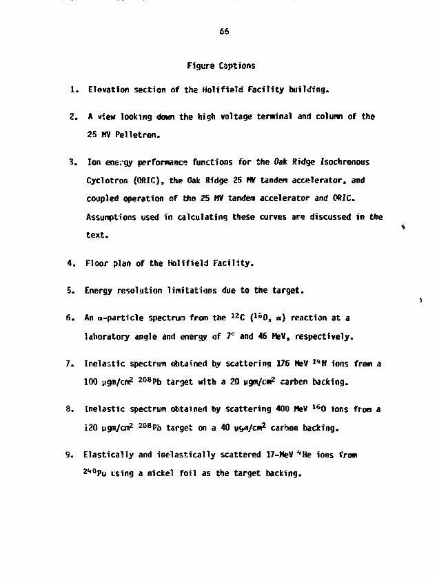
66
Figure Captions
1. Elevation section of the Holifield Facility building.
2. A view looking down the high voltage terminal and column of the
25 MV Pelletron.
3. Ion energy performance functions for the Oak Ridge Isochronous
Cyclotron (ORIC), the Oak Ridge 25 HV tandem accelerator, and
coupled operation of the 25 MV tandem accelerator and ORIC.
Assumptions used in calculating these curves are discussed in the
text.
4. Floor plan of the Holifield Facility.
5. Energy resolution limitations due to the target.
6. An a-particle spectrum from the 1 2C (l60, o) reaction at a
laboratory angle and energy of 7° and 46 HeV, respectively.
7. Inelastic spectrum obtained by scattering 176 HeV 1 4N ions from a
100 ugni/cm? 2 0 8Pb target with a 20 ugm/cni2 carbcn backing.
8. Inelastic spectrum obtained by scattering 400 HeV 1 60 ions from a
i20 ugm/cm2 208Pj> target on a 40 ug-s/cm2 carbon backing.
9. Elasticaily and inelastically scattered 17-MeV *He ions from
240pu USing a nickel foil as the target backing.

67
10. Elastically and ineiastically scattered 17-HeV %Ke ions from
2 3 2Th using a carbon foil as the target backir.q.
11. Schematic drawing of the gas cell along with a typical setup
during data acquisition. The relative dimensions (dianieter 2.5
cm, length 12 cm) of the gas cell are much smaller than shown
here.
12. Schematic of the gas jet target.
13. Photograph of the gas jet mounted at the split pale spectrometer
at HHIRF.
14. An 40Ar (160, ll0) spectrum measured with a 1<D.5 pgm/cm2 thick
target from the gas j e t .
15. Advantages of a gas je t target for heavy ion research.
16. Schematic illustrating blocking techniques for neausuring short
lifetimes.
17. Blocking pattern observed by elastically scattering 103 MeV lbG
ions from a Ge crystal.

68
Table I
HHIRF BEANS PROVIDED FOR EXPERIHENTS
Beams
*BenB12c160
170180
19F2<*Mg25Mg26Mg28Si32S
3-s35C137C148 T i
5UTi
S6Fe58 N1
60 Ni61*Ni63Cu
"Br109Ag1 16Q^J
l20Sn
*C = Coupled
T = Tandem
Maximum Energy(HeV)
158
71126405
381
345
190
129
132132
200
679
150445
160
229
230
821
889
228
285
189
1000
733
494
631
240
100
Hod
C
TTC
C
cTTTTTCTCTX
TCCTTTC
cccIT
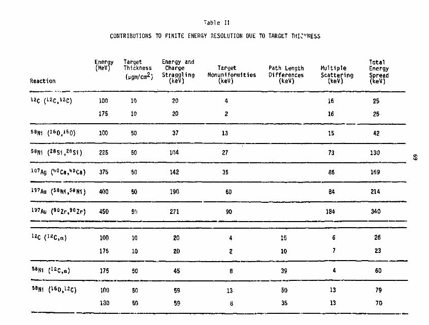
Table II
CONTRIBUTIONS TO FINITE ENERGY RESOLUTION DUE TO TARGET THINNESS
Reaction
12c (12C,12C)
5BN1
Energy Target Energy and(MeV) Thickness Charge
(ugm/cm2) " { g j } 1 ^
100
175
10
10
100
130
50
50
TargetNonuniformities
(keV)
20
20
59
59
13
8
Path LengthDifferences
(keV)
50
35
MultipleScattering
(keV)
16
16
13
13
TotalEnergySpread(feeV)
25
25
58Ni (160,160)
i"7Ag ('* Ca **"Ca)
">Au <»N1."N1)
l 7Au (^Zr,^Zr)
U c <" c" 1
58Ni (uC,o)
100
225
375
400
450
100
175
175
50
50
50
50
50
10
10
50
37
104
142
190
271
20
20
45
13
27
35
60
90
4
2
8
15
10
39
15
73
86
84
184
6
7
4
42
130
169
214
340
26
23
60
79
70

70
Table III
SOME INTERESTING TARGETS HADE AT HHIRF TARGET LABORATORY
Element Weight
Si
182184 W186
Ho
Ru
208Pb
0.2-1.3mg/cm2
0.7-2.65mg/cm2
50-80yg/cm2
55Mg/cm2
425Mg/cm2
0.470-2.0mg/cm2
17OEr2 O3 200Mg/cm2
Backing
None
None
30
30 ng/cm2C
None
None
20 ug/cw2
C
EvaporationTechnique
Sputter20kV Ar
Sputter20kV Ar
Sputter20ky Ar
Sputter0kV Ar
Sputter20kV Ar
Mo Boat
E-Gun
Remarks
Cr plated steel substrate30 wg/cm2 NaCl parting agent
Glass Substrate100 iig/cm2 'laC\ partingagent
Glass Substrate100 pg/cm2 NaCl partingacent
Glass Slides were dipped insolution of 50% polystyreneQ-Oope and 50% toluene.Foils parted after beingimmersed for several hoursin toluene. This partingmethod resulted in no oxyda-tion of the foils.
17oEr2 O3 was pressed intopellet before alectron bom-bardment

71
MNL-OWG 75-13264
ELEVATOR SHAFTAND TANK PORTSROTATED S I 0 FROMTRUE POSITION
TOP VIEW
13-TON MONIIAIL
SECTIONAL ELEMTM
Fig. 1
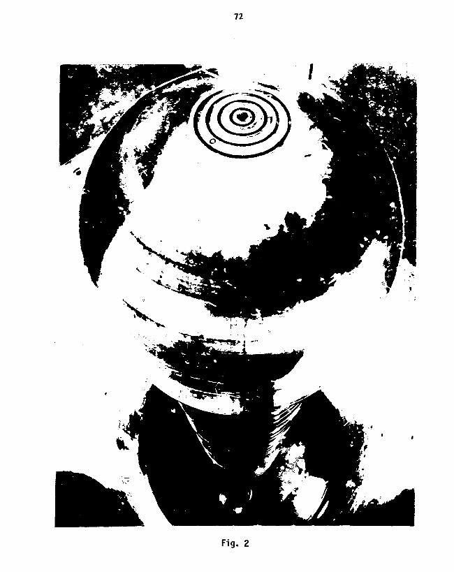
72
Fig. 2
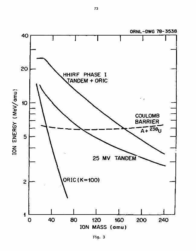
73
400RNL-0WG 78-3538
I I
20
3
O
0>
5UJz10
10
HHIRF PHASE ITANDEM + ORIC
25 MV TANDEM
COULOMBBARRIER- A 7 2 3 8 *U
I 1 I I40 80 120 160
ION MASS (amu)200 240
Fig. 3
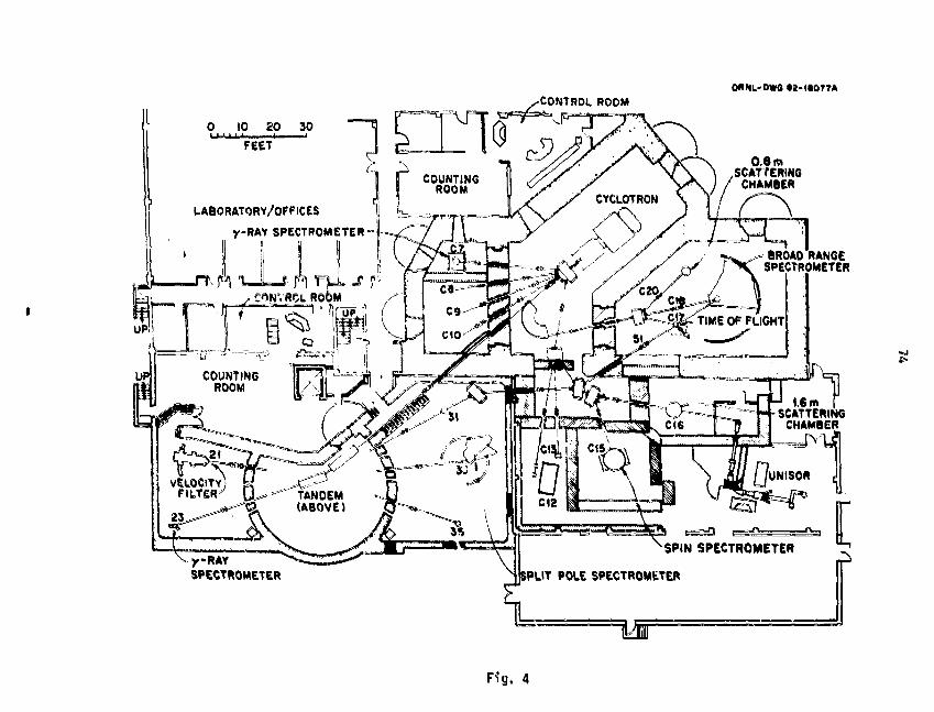
OfthL-DWC tt-ttO77A
o to ep 30FEET '
LABORATORY/OFFICES
y-RAY SPECTROMETER =
0.8 m.SCATTERING
/ CHAMBER
_ ^ BROAD RANGEf>< SPECTROMETER
y-RAY
SPECTROMETER
1,6 mSCATTERING
CHAMBER
SPLIT POLE SPECTROMETER
, 4

73
Fig. 5
jft Energy Loss Straggling
Honoenergetic ions lose varying amounts of energy passing through a
foil.
«E = 0.95q I t I keV (1)[{ t]IB Multiple Small Angle Scattering
Angular spreading from multiple small angle scattering produces arc
energy spread due to the strong angular dependence of the energy of
particles emitted in heavy ion reactions.
^ = 2 kfieMC (2)
* 0.5 F z ( z * 1) tl k i- nilliradians (3)
_C Target Uniformity
Variations ?n the target thickness introduce additional energy
spreads. Nonuniformities cf 10% may be expected for thin targets
{< 100 ygm/cm2).
£ Reaction Site
If the incident and detected ions have significantly different
stopping powers than the observed energy of the final product depends
on the location vithin the target where the reaction occurs.
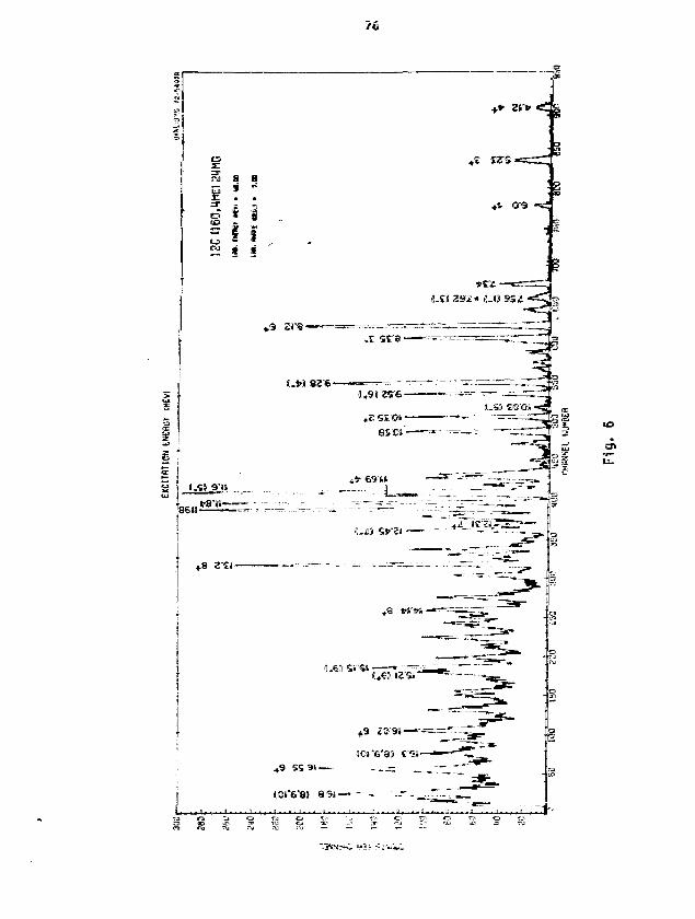
< g
.#£ WS<
rasaii n n *
X • a
i ! !(CM i» m
~ a S
0T9
-8
. i see •
(1*91)25-6-
«2 SECU-
SS'US"'
U
•J.iS
1-63 SI'S» =«—-==([*63 I2'S»
# 9 SS 91 —-
10»"6"81 8 9» — •
j j , • » • • 'I • i . H a * i.. . II .c:u o t . i -. ;
am

77
ORNL-DWG 82-18064
g.s.110 keV FWHM(0.88 mm)
208pb(14N 14N»j208pb
1950 2050 2150
CHANNEL NUMBER
Fig. 7
2250

78
100
90
80
70
jjj 60z
0RNL-DW681-6197R
2 0 8Pb( l 60/60V0 8PbEiso=4OOMeV
o'ob _ .^«
I I
atoz
i
+>
FWHM
. At \10 20 30 40 50 60 70 80 90
CHANNEL NUMBER
Fig. 8
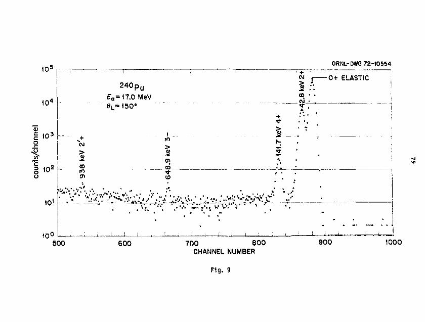
10'
a
f .••g 102
u
1
10'
10°
2 4 0 p u
£Q=17.0 MeV
l
0RNL-DWG 72-10554
5 • •00 • •
0+ ELASTIC
.1h
*• *
CO•6
4
• * *
**—*"-.—»*
4
* «*
s
j
** V * * ^.
J i .
*
**
* *
a *
* ,
\
•
•
*
500 600 700 800CHANNEL NUMBER
900 1000
Fig. 9

105
104
0>
§ 103
gio2
ORNL-DWG 72-10552
2 3 2 T h
, = 17.0 MeV
ro
O
10'
10°500
*w""ftiro
311irt Jf *
> —Ai
to • ooo > K
T I ' ! !f. ELASTIC 0 +
1
49.4 keV 2+
_i ft
5
- —* - — 4 _
J !. 1 .. i
. m
! i 1
**
*
!
* *
• • •*
. . . . - , - . » , .
I J J 1
600 700 800CHANNEL NUMBER
900 1000
Fig. 10

GAS OUT GAS IN
ORNL-DWG 78-12435
ANTI-SCATTERINGSLITS-
COLLIMATORCENTER ,
OF CHAMBER7
MONITOR (L)
MONITOR (R)
AE,E POSITIONSENSITIVE TELESCOPE
Fig. 11

82
ORNL-OWG 83-10642
LEYBOLD HERAEUS C
WAU 2000600 L/S
KINNEY KMBD*401140 L/s
DIFFERENTIALPUMPING SLITS
LASERCRYOPUMP
2500 L/s
TANDEM BEAM
DIFFERENTIALLYPUMPED VOLUMES
-+• DETECTORS
PRESSURESENSORS
CRYOPUMP1400 L/s
ORNL SUPERSONIC GAS JET TARGETSCHEMATIC SIDE VIEW
Fig. 12
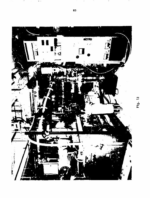
83
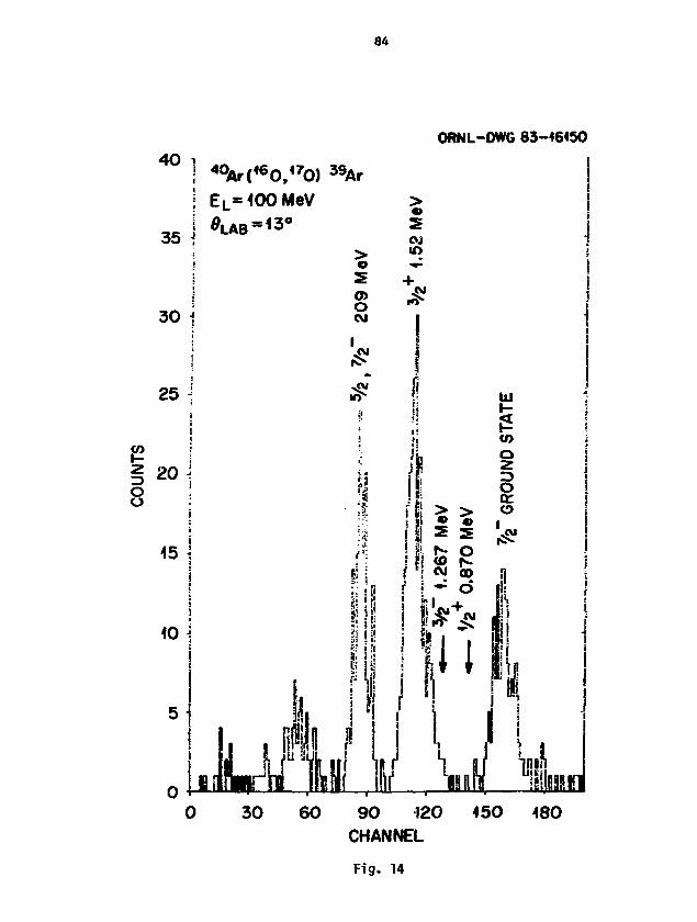
ORNL-DWG 83-46450
8
40
35
] 40Ar(<60,'70)EL=100MeV
30 60 90 120CHANNEL
150 180
Fig. H
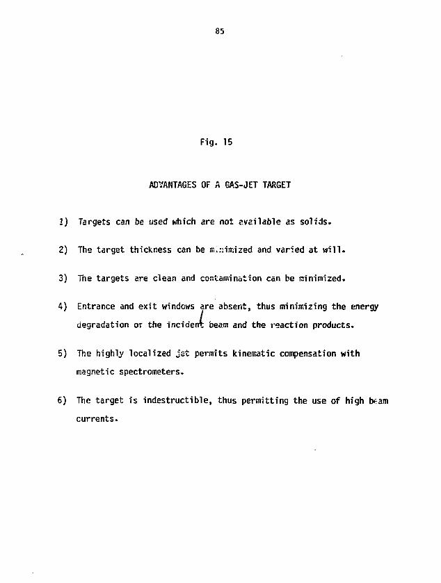
85
Fig. 15
ADVANTAGES OF A GAS-JET TARGET
1) Targets can be used which are not evailable as solids.
2) The target thickness can be m.r.insized and varied at will.
3) The targets are clean and contamination can be minimized.
4) Entrance and exit windows are absent, thus minimizing the energy
degradation of the incident beam and the reaction products.
5) The highly localized jet permits kinematic compensation with
magnetic spectrometers.
6) The target is indestructible, thus permitting the use of high beam
currents.
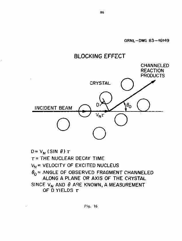
86
ORNL-DWG 83~«6449
BLOCKING EFFECT
CHANNELEDREACTIONPRODUCTS
CRYSTAL
INCIDENT BEAM
D= VN (SIN 8)T
T= THE NUCLEAR DECAY TIME
VN= VELOCITY OF EXCITED NUCLEUS
6Q= ANGLE OF OBSERVED FRAGMENT CHANNELEDALONG A PLANE OR AXIS OF THE CRYSTAL
SINCE VN AND 8 ARE KNOWN, A MEASUREMENTOF D YIELDS r
Fig. 16

ORNL-DV/G 83-16*48
81
61
41
21 -
ELASTIC SCATTERING OFEL= 103 MeV0 L = 2 2 . 3 "
FROM Ge
110 30 50 70
CHANNEL90 110
Fig. 17

Soae Hrthods and Problees Associated with Making
Thidfc (I ag/ca*) *••*•*'"silicon Taints
Gervas M. Hinn
Nucl«ar Physics Laboratory, GL-1O, University of Washington
Seattle, Washington 9*195 U.S.A.
ABSTRACT: The unique difficulties of evaporating enriched silicon starting
with the oxide are cited ind the literature reviewed and discussed
briefly. A procedure ia repotted which has shown I I W degree of success.
1. INTRODUCTION
Silicon is second in abundance to oxygen in the earth's crust, about
B7% of which is composed of silica and silicates.1 Blammtal silicon exists
as a gray-purple crystaline lustrous Material or as a black aaorphous
glass-like material. Structurally there xm no difference between the two;
both exhibit the diaaond structure.
A great deal of work has been reported in the literature on silicon
and its compounds because of its iaportarjce to the semiconductor industry
as a thin fila. A great deal of work, sore recently, has been reported due
to the development and industrial use of ion implantation. Hucfr of ttte
developnent of ion isf>lantation as a successful technology has depended
largely on the ability to anneal out the daswje produced by the
implantation process. At sufficiently high doses dii rete iiawn-jff regions
produced by each ion can overlap to fora continuous asjtrptKHjs layers.
Furnace heating will cause the aaorphous silicon to crystalizc by solid-
phase epitaxy at the aaorphous-crystal interface, and in thim way, single
crystal Material can be grown with dopants incorporated in the crystalline
lattices.2 Solid phase crystalieation mna~?9 because aaorphous Si im
thersodynanically less stable than crystalline Si. Crystal growth does not
occur at roan temperature because of kinetic barriers to atoa swtion.
Silicon films deposited on substrate teaperatures below 6OO°C are
90
asorphous.3 ttw MinisuM aubitiata tsMperatur* for good single crystalline
filMS is within a rang* of 1IOO°C to 125O°C, the exact value depending on
the rat* of deposition.* If the substrate teaperature is below X1OO°C gray
polycrystalline filMS result. It is claiMd that at substrate tesperatuxe*
greater than 1100°C, silicon dioxide forssd at the surface reduces to
silicon and silicon Monoxide, silicon Monoxide being volatile at
temperatures «bova HOO^C* One author observes that if the substrate
teMpezatuxe is above 1125°C single crystalline growth occurs at 2 x
lO~*torr. Best filMS ar* grown when fast deposition rates (1/2 to l ft
•in"*) are used.
Very good VACUUM is always important and pressures Must be better
than 1.3 x io~* Pa (1 x KT'torr) and Maintained at no worse than 1.3 x 10
"* Pa (1 x 10"*iorr) or SiO Mill fora on the substrate rather than
elemental Si.*
Only one reference ha3 been found which describes a Method for Makincj
greater than one (1) mg thick elenental silicon frrw the enriched oxide.7
TantaluM powder vas usec? as the reducing agent and the reduction
evaporation was done in one step with the formation of black a«orphouH Si.
as the end product. A tantaluM shielc was used aw a focusing diaphrasu
All other references deal sainly with rfw production of thin SO-loopg/as2
thick silicon fU*s with large wxirce to substrate to distances (3O em'i.0
Itiis however requires Uizge asounts of the reduced •lesental silicon to
produce thick (1 •}) targets.
Recently several authors have described Methods for reducing enriched
silicon dioxide*'10 to produce elemental enriched silicon pellets fee
sputter source use. these author? used sagnesiuai aetal fillinos to reduce
the oxide to its eleewntal fora.
stress or Mechanical effects develop easily in silicon and a great
deal has been written in the literature about the causes as well as methods
for relieving the stresses once they are fosMsd in fila. There are
stresses due to internal factors, tberaal factors, cospressive factors and
ispurity factors." Also structural defects xcm frozen in during deposition
of the fil*.A*
Annealing or slowly reducing the tesperature of the substrata after
deposition is on* way of allowing stresses to be relieved by allowing the
rearrangement of the structure as well as formation or larger crystals.
Recently laser annealing and pulsed electron beast annealing to relieve
stcuctural stresses in the ion isolation field "nas drawn such interest in
the silicon solar cell industry. **
Making enriched elemental *••*••'^Silicon targets lias all of the
problems of Making thin silicon filsts plus the problcst of usually starting
with a snail quantity (200-300 ag} of the oxide from which production of a
thick 1 ag target is expected. Sometimes even tfce oxide itself is nut
available frcm the usual sources, so that one say haw* only one chance to
make it w*".i it is available. A method has been developed at the
University of Washington which has produced enriched *••*•*lo*ilicon
targets with some degree of reproducibility.
2. METHOD
2.1 The Apparatus
The apparatus used for the production of thick elemental enriched
silicon in a modified Neatgaard and Bjornhola electron gun <Fig. 1). this
apparatus is housed in a CVC type DCI—14 vacuum system with a four-inch
diffusion pump backed by a Welch duo-seal mechanical pump. The power
supply used to provide wish d.c. voltage to the Mestgaard and Bjornfcolm «-
gi>n is a 3 Kv 500 milliampsi power supply modified such that when the
current exceeds 5OO milliampa the voltage is interrupted. This allows for
quick shcixt heating as the e-gun draws -. arrent and tl»e crucible heats up to
temperature. The entire cycle is restarted manually each time giving a
pulsed heating effect.
£.2 Substrate
The substrate is a O.3 mil copper foil mounted on a copper mask
(Fig. 2) which is then clamped to a water-cooled copper beam stop block.
The foil sits loosely between the copper mask and cooled copper block.
This is so the copper foil can contract as deposition occurs. An immersion
oil heater is also allowed to remain in contact with the top of the copper
block. This is so the copper block can be heated for long overnight

annealing under vacuum at SOO°C. This allows for solid phase
recrystallization of any amorphous silicon after deposition. **
2.3 Tantalum Reduction CcucJJble
The tantalus reduction crucible consists of a tantalum tube 50MM long
with an inner diaMter of ssai and a vail thickness of 1MM. die ctucible is
Machined fro* solid tantalum zod and has two screw-on caps also Made Ceoa
tantalus; rod {Pig. 3. center). The bottom cap has a small diameter tn»le on
the bottom outside w».ll to allow insertion of a 0.635-SMI tungsten supputt
wice. This reduction crucible can be heateC in the Hestgaaxd and SjornhulM
apparatus or ii. can be heated in a copper water-cooled thisble of an
electron gun.
2.4 Isotope Sample Preparation and Deduction
To reduce *••*•*9OsiOa to elemental ****•''^silicon, freshly ground
hyperpure Magnesiua Metal is used as a reductant. A Mall circular file is
attached to a hand drill and as fine a Magnesiua powder as possible is
ground for each reduction. Starting with 2OO mq of the enriched oxide and
nixing 170 Mg of the freshly ground aagnesius, the Mixture was loaded into
the tantalum reduction crucible where it was coMpressed into the tootttm
with a three-ton Arbor press. A large excess of My swst be avoided to
preclude formation of Hg^Si instead of Si.10 The solid cap is screwed on
and the crucible and its contents are slowly heated to 1OOO°C for one hour
and allowed to reach a vacua* of 1 x lo~*torr (1.3 x 1O~* Pa). TtuJ* keeps
the entire reaction Mixture in a closed container under vacuua during
reduction. After one hour the reduction tantalus crucible is taken fro*
the bell jar and both ends of the crucible are resoved to facilitate
emptying of the contents
The reaction products are placed in a solution of 2H HC1 for 48 hours
to extract the reaction product, Hgo. It is then washed with hot water and
dried at 1.3 Pa and healed to looo°C in a sMaller tantaluM crucible
<Pig. 3. right) in a vacuum chasber held at 3.3 x JO"* Pa (1 x iO~atorr).
Otiis treatment reMoves HC1 residues and Makes the Melt less full of gas.
The end product is a fine-grained purple-gray powder which looks brown when
wet. The overall yield is about 7O%.

2.5 Evaporation
About 7O-8O mg of the reduced material is necessary to make a 1 agi
target. If the experimenter ia sensitive to tantalum a carbon crucible is
used, if not a tantalum crucible (Fig. 3, left) ia used in the Hestgaacd
and Bjornbolm apparatus {Fig. 4). The reduced silicon is placed in the
bottom ,i the crucible and a wadded-up piece of tantalum foil is placed on
top of the crucible during initial heating in order U» Keep ttie reduced
silicon fron blowing itself out o£ the crucible. As soon as the silicon is
nelteO together and outgassed the tantalum wad is removed.
The 0.3 nil coppar substrates axe preveiqhed and placed on the M^BM.
(Fig. 2) in contact with the. cooled cofper block. The boat to substrate
distance is 35nm\ which produces four targets fro* ontt evaporation. Some
experimentat ion is required to see what proper block temperature is
required. Circulating hot water or even cool water ma.'/ be necessary, lite
substrate is heated to 9O0° to 1QOO°C by the close proxiaity <35 M M ) of the
substrate to the source. Tisis high teaperaturs is Measured! by the fact
that the .3 mil copper (m.p, Cu 10ZS"C} substrate «ell0 if the te«perature
of the source is allowed to becane too hot. Copper Kelts at about 1OOO9C
so an initial layer is deposited at lower teaperatures (around 900*C) and
then the temperature increased. If pitting or bum-up of the copper foil
substrata occurs increase cooling. if curling occurs its the deposit
thickens, increase heating Jby slowing water flo*r. The system should be
tested in advance by using hyperpure 99.999% natural silicon. It is also
very iinporbaRt to have the best vacuum possible (5 x JO"'torr) before
starting bo minimize SiO forwafcion. The evaporation rate should be as high
as possible to produce the best filjws. nine entire system is preheated and
outgassed overnight with the oii aimersion heater in onder to provide a
clean system. It is pre-beated to around 4OO°C.
After the evaporation t>»e inversion heater is used (and the water
shut c-ff) to keep the entire system at 50O°C overnight for annealing
purposes to allow for solid phase recrystalization of suy amorphous silicon
after deposition, ihe entire system is allowed to cool slowly to room
tenqperafcure.
*Bie copper sub3trate containing the deposited enriched silicon may

•94
curl if proper tifttatuw has not lmn Maintained during evaporation anil
annealing (Fig. 5, left bottoM). If this occurs, it say still be used if
it can be uncurled and glued to a plastic insert using supezglue (Fig. s,
top center). If proper temperature has been Maintained it will be sttess-
free and flat (Fig. 5, bottoa right). It is still glued to a plastic
insert and then floated in a copper etch consisting of aasonia, water and
trichloroacetic acid. It is then Mounted between two standard aluminum or
tantalus inserts. It usually is stored in VACUUM, or argon.
3. SHELF LIFE NMD PURITY
Moat of the 1 mg targets produced in the above M&nnec had to be used
prior to two weeXsj otherwise they would slowly curl and fractwte
(Fig. 6). This curling is attributed to the fact that there are mme
impurities present in the targets which are trapped on deposition ant?
produce stresses. If the target was left on the cooper for storage it
would curl and was recoverable after further annealing. Sose degree of pin
hole formation also occurs with this Method as ca-i be seen in Fig. 6
It is conjectured that annealing in an electron beam at BOO°C-9OO°C
for two hours would allow the impurities to move and also allow restructure
of the crystal lattice as well as the formation of larger crystals. This
is an avenue of research which will be pursued further in the near future.
Rutherford scattering was performed on targets produced in this
Manner and showed the contaminants to be Ta {0.1-0.2*), cu (0.03%), oxygen,
carbon less than 0.3%. the targets survived heavy ion bombardMent but
tended to have only a two-week shelf life.

1. J. Klainberg, W. j. Arotrainqer. E Griswoid, Inorganic Chemstry,
D.C. Heath and Co., Boston (196G) 364.
2. J. H. Poate. Kuc. Xnstru*. Methods 2O9/21O (1983) 211.
3. G. Haas, Z. Anorg. Che*. 257 ;194B) 166.
4. L. I. Haiasel, R. Glang. Bandbock o£ Ihin Tixm Tectin., McGraw Bill
Inc. (1970) 1O-21.
5. A. P. Bale, Vacuua l£ (1961) 93.
6. A. M. Sandorfi, I., ft. Killius. J. I*. Gallant, Hue. Instrun. Methods
136 (1976) 395-396.
7. I. Bezecz, v. Karolyi, A. Szalay, Nuc. Znsfccu*. Methods 33 (1965)
364.
8. Sun Shu-hua, Su Shio-chun, Chen-Quny-wany, G. Shen-xen, X. Gu»-ji,
Preparation of Nuclear Targets for Particle Accelerators, Plenum
Press, New York (1981) 200.
9. V. K. Peng, INTO? Newsletter (1979).
10. II. J. Haier, Hue. Xnstrua. Methods 200 (1?82) 1X3-12O.
11. c. H. s. Dupuy, A. cachand, Physics of NonMetalllc Thin TUMS. Plenua
Press, New Yorlc (1976) 273 (whole chapter).
12. K. I.. Chopra, Thin Fila Pheno*ena, R. E. JUringer Publishing Co., Mew
York (1979) 266.
13. A. Robinson, Science 2Q1 ((1978) 333.
14. J. s. Williams, Nuc. Instrusi. Methods 20/210 (1983) 219,

Figure Captions
1. Apparatus for the production of elemental *•'*•« 3OSi.
2. 0.3 ail copper foil substrate on heavy capper Mask.
3. Tantalus crucibles
a. Left: evaporation tantalum crucible for reduced *******°S1.
b. center: Reduction crucible for reducing **'**'*°SxOz to elemental
*•»*••33si with Bagnesiua powder.
c. Right i Saaller crucible for outgassing and diyiog reduced
4. Showing tantalvm crucible in position ready for evaporation.
5. Topi Deposit of z**»>*°si on copper substrate glued to plastic
insert xeaOy for copper etching between two altatinu« covering
inserts.
Bottom left: z*Si deposit showing curling on substrate with imgioget
heating.
Bottom rights xmSx deposit showing unstressed state on copper
substrate before etching.
6. "silicon showing curling after two wec&s.
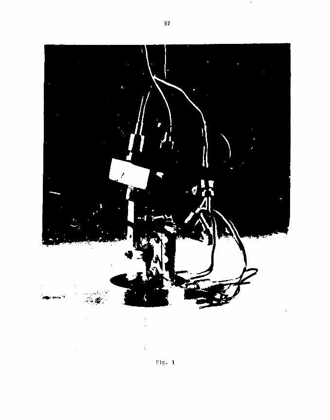
97
Fis. 1
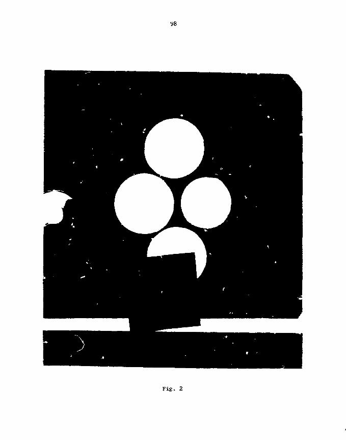
Fig. 2

Fig. 3

Fig.

Fig. 5

Fig. 6
103
First Operation and Experience with Ghsv Discharge Cartoon Stripper Boils
in the Daresbary Taraslea accelerator
D.H.L. TolfreeDaresbury Laboratory
Abstract withdrawn

105
STRIPPER TOILS - SUMMARY OF GENERAL DISCUSSION
By
H. L. Adair, Session CfeaSrnan
Stripper foils play a very important role lira the successful operation
of electrostatic accelerators and the increasing nuaber of [heavy ion
accelerators has resulted in renewed efforts directed at developing
stripper foils with improved lifetime characteristics. Ttse objective of
the general discussion on stripper foils was to review the subject and
assess the seed and directions for further research and development
efforts in this area. As a brief introduction to the topic, the
importance, desirable characte .?tics, and nethods of fabrication of
stripper foils were reviewed.
Although several materials have been used as stripper foils, carbon
has proven to be the most successful. Carbon foils are nased in heavy ion
accelerators to strip electrons fron the incident projectiles, thereby
producing higher charge states and consequently provide core energetic
ions for target bonbardnent. Electron stripping using carbon foils has
advantages over gas stripping in that more energetic ions are produced,
thus effectively increasing the useful energy range of the accelerator.
Carbon or any foils that comld be used as stripper foils should be thin,
uniform, and have infinite lifetime. Obviously, all of these specific
characteristics have not yet been achieved.
The fabrication techniques that have been used asost often in
preparing carbon stripper foils have included decomposition of organic

compounds, sputtering, and vacuum evaporation. Various authors, soce of
whoa were present at this meeting, have presented data that would indicate
that there is a preferred technique* Obvious «pe.3tf<a>ms that should be
addressed in evaluating the present status of stripper foil fabrication
are listed below.
1. Have there been significant improvements in stripper foil
fabrication in the past several years?
2. Is there a best fabrication cethod?
3. What are the areas that need attention Im stripper foil
fabrication?
Although attempts have been trade to use cither foil materials as
strippers, none of the proposed materials have been as successful as
carbon in seeting the thickness, uniformity, and lifeticie requirements.
It was hoped that the polyitaide foils, which were developed specifically
for use as substrate materials, could possibly be used as stripper foils.
However, results, thus far, indicate that the foils (~3t> pg/c»^) celt.
Perhaps if these foils could be f3bricated to ttdekraesses <10 pg/cn ,
results cay be different.
The specific fabrication techniques for carbon stripper foils have
seemed to progress from the carbon-arc cethod, to the electron bean
evaporation technique and more recently to the glow discharge fabrication
technique. Kach technique has specific advantages and papers have been
presented extolling tine virtues of each of these techniques as being
superior if, for example, heated substrates or the slackening techniques
were employed.

Much of tine data presented in tine literature for carbon stripper
foils cannot be. compared because, for tine crast part, different beans, fep-n
energies and current densities have been used. For exanple, data obtained
using alpha particle beans Biawe been compared with data ©fotaiiEeti fron
krypton beams, but with l i t t l e basis for quantitatively understanding, tllte
differences in foil characteristics.
In suraiaary, tSiere have beam tLn^Taveasnts isi the prejparatiom of catrltom
stripper foils during the past few years. These iaproweceirats Jtawe mot
been the result of one specific fainricatifflin technidjue, but Ibawe cttee afcotnt
by closely examining tine specific parameters iSiuclh as «tejj©siti©m rate,
substrate surface, substrate temperature, stripper foil! stnuctoirt*, anitS am
some instances using slackened carbon foils;. Ta icalke a valid c©rajparis©n
of each of the fabrication techniques, the carbon stripper foils; should be
exposed to the same particle bearas and beam intensities* The general
consensus reached was that detailed chenical analyses of carbon foils
prepared by the different techniques, together with l ifet ice ceasujretreijts
;aade using identical projectile beans and bean intensities, should help to
clarify much of the literature data that presently exists.

••"t-
SESSION n
WEDNESDAY ATERNOON, SEPT.7, 1963CHAIRPERSON: H. FOLGER
ECONOMICAL PREPARATION OF EXTREMELY
HOMOGENEOUS NUCLEAR ACCELERATOR TARGETS
H. J. MAIER
Sektion Physik, Univeraitat Muncfeen, 8046 Garching, West Germany
Techniques for target preparation with a Minima consumption ofisotopic material are described. The rotating substrate method,which generates extremely homogeneous targets, is discussed insome detail.
1. IntroductionConsidering the high cost of isotopically enriched material, there is a
strong necessity to prepare nuclear accelerator targets in Che most economicalway. In the case of evaporated targets, material consumption can be Minimizedby choosing either a small source to substrate distance or a large substratearea. In both cases, however, a considerable thickness variation across thetarget has to be taken into account. The present paper will demonstrate howrotating the substrate during evaporation can be used to significantly improvetarget homogeneity while preserving a reasonable collection efficiency.
2. Review of static Methods
2.1. HOT CRUCIBLE EVAPORATIONA common economical evaporation geometry for a hot crucible source is shown
in fig. 1. It produces a vapor stream angular distribution
which leads to a thickness distribution of
d(sx) - d0 • M • fe) 2 2
on the target. L ' J
The relative collection efficiency is given by
These formula predict, for instance, an average thickness of 186 /.g/c«2 p e r ^gof evaporant for a 10-am diameter target, which is prepared at a typical sourceto substrate distance of h * 15 oa. The relative thickness variation across thetarget is expected to be 232. For h = 20 ma, thickness and inhonogeneity arecalculated to be 110 Ug/cn^*og and 142, respectively.

110
Because of the small source to substrate distance the source temperature islimited to approximately 1500eC. This is, however, sufficient to vaporizee.g., actinide ha1ides or high vapor pressure aetals like Be, Cr, Te, Tl, or Fb.
2.2. COLD CRUCIBLE ELECTRON BEAM EVAPORATIONFor the evaporation of low vapor pressure Materials with vaporization tem-
peratures between 1500 and 3000d>C, cold crucible electron bombardment heatingis required. In this case, a ninimum source to substrate distance of 10 enmust be observed in order to prevent the electron beam £rosa striking thesubstrate. Hence, the oniy remaining material-saving measure is to increasethe condensation area. A substrate holder which allows the simultaneous pre-paration of thirty ta -$ets of rare isotopes is shown i:. fig. 2. The collec-tion efficiencies and target inhcaogeneities shown in fig. 2 were calculatedfor a distance of 15 en and for assuxaed vapor stream distributions<J>(»J) = 4>Q • cos
11 & (n » I for low, n = 2 for high evaporation rates). In caseswhere target homogeneity is not crucial, the simultaneous preparation of canytargets of one rare isotope has proven to be especially useful and economicalfor the target supply of long-term research projects and for target exchangeprograms with out-of-town customers.
3. Substrate rotation
3.1. THEORETICAL BACKGROUNDIt is well known from the literature that excellent film thickness homogeneity
can be achieved with a rotating substrate. The geometry of the correspondingsecup is shown in fig. 3. The substrate is located at a horizontal distance rand a vertical distance h from the source and rotated around its axis, whicnis parallel to the source axis. During film formation, every point of thesubstrate traverses several tines through regions of different vapor strearadensity, which results in the desired thickness uniformity.Calculations of the film thickness distribution on rotating substrates have
'•ten published, e.g., by Behrndt.') Assuming a vapar stream originating fro*<- point source with an angular distribution <$(#) =« «t>o-cosr Behrndt expressest te film thickness at a distance sx froa the axis of rotation as a function ofthe parameters r end h (fig. 3):
d(Sx, , s_ t-2 • "•' * '2 • °»2>J[« "X
2)2 _ * . 2 r2
with m 3 evaporated mass and P * density of evaporant.
This formula has been used to calculate the thickness variations quoted infig. 3 for s target with a radius 3 = 1 cm, assuming different values for theparameters h and r. The term Ad m a x/d stands for the traxieaum relative thick-ness variation

Ill
A («x)
where d(s x) a a x * aaxiaura thickness value for 0 < sx <_ m,
d<sK)min * ainiautt thickness value for t* _< ax »,
and d(sx) » average thickness value for 0_< s x £ s.
It is easily verified that there is a "best ratio" r/fa 0.7 which generatesa minimum relative thickness variation far below IX across the target.Looking at these data, ona should be aware, however, that they are based ©nideal conditions concerning the evaporant flux, the syawetry off the setup, andthe sticking coefficient on the substrate. Nevertheless, it seeais to berealistic to attain inhonogeneities of about IS in practical applications.The collection efficiencies for the three different rotating substrate
geometries have been determined by experiment and are also presented in fig. 3.They will be discussed in more detail in section 4 of this paper.
3.2. PRACTICAL ASPECTSIn fig. 4, a rotating substrate device is shown, which is designed for a
vertical source to substrate distance of h = 30 era. It consists of a stain-less steel plate which carries eight rotating copper substrate holders,arranged on a circle of 7.1 cm radinis. Each substrate holder is able toaccept either one of our standard target frames of 25 x 20 *»^ with a IS-tmdiameter hole or other substrates like aetal foils or glass discs up to35-mm diameter. A quartz crystal oscillator for thickness atonitoring duringevaporation :s installed behind the 20-nta diaw^ter hole in the center of thecarrier plate. Rotation of t>e :ight substrate holders is accomplished vith asmall de-electromotor^) in coneinaCion with a chain drive.
Similar devices have been built for vertical source to substrate distancesof 3 and 5 era, respectively, eaofa of them carrying four rotating substrateholders.
3.3. HOMOGENEITY TESTS
In order to prove the benefit of the rotating substrate setup, comparativethickness distribution taeasurements of I5-an dianeter Au layers on C backingswhich were vacuum condensed with and without rotation were made. The thick-ness of the Au films and C backings was 100 and 30 g/c»2, respectively. Theevaporations were perforned from a pinhole-fcype tantalum boat, which approxi-mates a cos vapor stream distribution.Thickness profile determination was accomplished by Measuring the fluores-
cence yield of the characteristic x-rays of Au at seven different spots acrossa target diameter. The direction of this diaaeter was arbitrary for therotated targets and was chosen along, the line of maximum thickness variationin the case of the nonrotated refersnee samples.
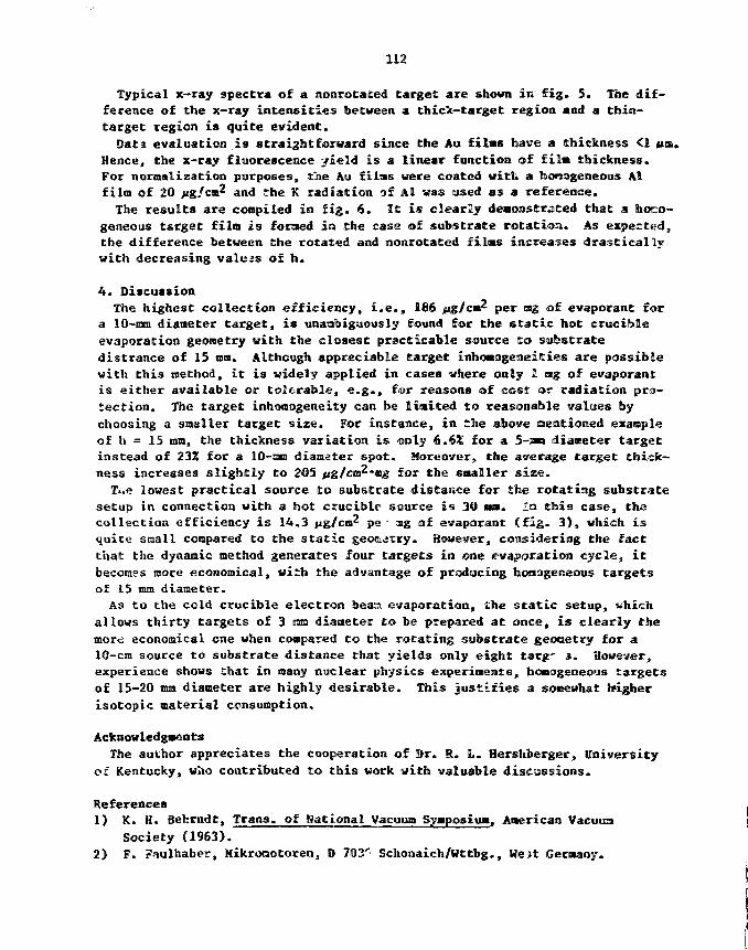
112
Typical x-ray spectra of a nonrotaced target are shown in fig. 5. The dif-ference of the x-ray intensities between a thick-target region and a Chin-target region is quite evident.Data evaluation is straightforward since the Au films have a thickness <1 urn.
Hence, the x-ray fluorescence yield is a linear function of film, thickness.For normalization purposes, the Au films were coated with a toonageneous Alfilm of 20 >ig/cni2 an<] jj,e K radiation of Al was used as a reference.The results are compiled in fig. 6. It is clearly demonstrated that a homo-
geneous t&rget film is foraed in Che case of substrate rotation. As expected,the difference between the rotated and norarotated films increases drasticallywith decreasing values of h.
4. DiscussionThe highest collection efficiency, i.e., 186 jpjg/cm per fflg of evaporant for
a 10-mm diameter target, is unambiguously found for the static hot crucibleevaporation geometry with the closest practicable source to substratedistrance of 15 mm. Although appreciable target inhomogeneities are possiblewith this method, it is widely applied in cases where only 1 atg of evaporantis either available or tolerable, e.g., for reasons of cost or radiation pro-tection. The target inhomogeneity can be limited to reasonable values bychoosing a smaller target size. For instance, in the above mentioned exampleof h = 15 mm, the thickness variation is only 6.6% for a 5-an diameter targetinstead of 23% for a 10-SBJ diameter spot. Moreover, the average target thick-ness increases slightly to 205 ffg/cm^'ag for the smaller size.
T«.e lowest practical source to substrate distance for the rotating substratesetup in connection with a hot crucible source is 30 na. In this case, thacollection efficiency is 14.3 jjg/cm pe - ag of evaporant (fig. 3), which isquite small compared to the static geortdcry. However, considering the factthat the dynamic method generates four targets in one evaporation cycle, itbecomes more economical, with the advantage of producing tiostogeneous targetsof 15 mm diameter.
As to the cold crucible electron bean evaporation, the static setup, whichallows thirty targets of 3 ma diameter to be prepared at once, is clearly themort economical one when compared to the rotating substrate geooetry for a10-cm source to substrate distance that yields only eight targ' 3. However,experience shows that in many nuclear physics experiments, homogeneous targetsof 15-20 mm diameter are highly desirable. This justifies a somewhat higherisotopic material consumption.
Acknowledgments
The author appreciates the cooperation of 3r. R. L. Hershberger, Universityof Kentucky, who contributed to this work with valuable discussions.
References
1) K. H. Behrndt, Trans, of National Vacuum Symposium. American Vacuum
Society (1963).2) F. Faulhaber, Mikromotoren, D 703' Schonaich/Wttbg., We>t Germany.
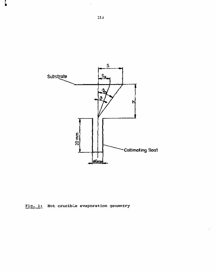
Substrate
CoUimating 3oat
Fig. It Hot crucible evaporation geometry

16cm
Substrate Holder with 30 Positions
Source- Substrate Distance = 15cm
Vapour Stream Density Distribution 5 Id) ~ cos* |
Inner Circle4cm*i, Positions
Middle Circle3cm •10 Positions
Outer Circle12cm •16 Positions
Collection
1.412.0
1.2
1.0
N.8
Us
Efficiency
jug/em2
rog
/ug/cm5
mg
mg
Target Inhomegeneity
2.8 13.5%
5.3 1 6.6%
7.3 I 9.2%
Fig. 2; Mulfci target substrate holder for eold erueible oleetronbeam evaporation.

Rotated Substrote
v Source
Target Inhomogeneities for h= 10 cm, s= I cm
rlcmj 0 2 l> 6 7,1 8
«] 2.0 1.7 1.1 0.3 <ai 0.2
i.6&5mg
Target lnhomogemii.^s for h= Sem, ss Um
rtcm) 0 I 2 3 J,5 A
.l 7.8 &7 AJ 1.3 «tt2 0.7
Target Irshomogeriities )f>r i s 3em, s B icm
rlcm) 0 1 , ? 2.25 2.S
^ 1%) 21,0 14.0 2.0 «Q.4 2.2
mgU.3
Rotating substrate set up £©v homogeneous vaeuum condensed tarqets

Pig. 4; Rotating substrate a) rotating disesb) DC motor with chain drive

Al
Au
J
Au Test Targetx-Ray SpectrumThin Target Region
AuL«
*"****«^AJ
AuLY
L
Au
Al
6 0 10 M I I 16 10
x-Ray Energy ikeV)
Au Test Target
x-Roy SpectrumThick Target Region
AuLp
Lv
x-Rey Energy ikeV]
5t x"ray spaetra ©f a non rotated target. Left part: thin tarqefe region,Right part: thiek target region.
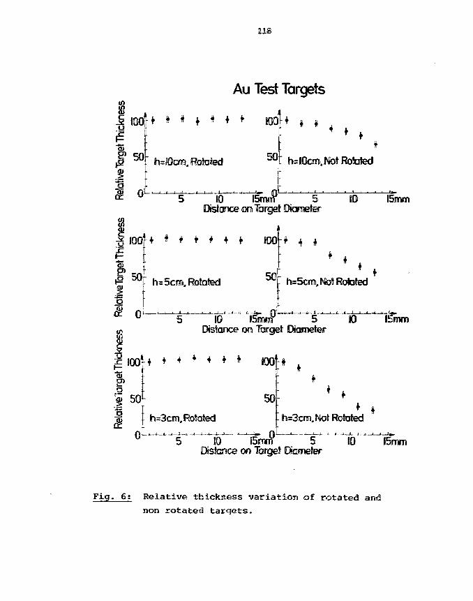
118
Au Test Targets
100
50
• • • • # • • •
h=IOcm, Rotated 50
o L -
4 4 4• t ,
4
h=IOcm,INtot Rotated
s
5 10 BSnrrf 5Distance on Target Diameter
KO 15mm
100:
f| 5 05!I
* # * # # ! 800
s 5cm, Rotated 50
• t •
h=5cm,IMo!t Rotated
5 10 ISmnf 5 K)Distance on Target Diameter
15mm
g J O O f 4 * * * * * * K M '
150;
0
50
h=3crni,Rotated h=3cm,INlot Rotated
5 10 i5mfT 5 10 15mmDistance on Target Dtometer
Fig. 6; Relative thickness variation of rotated and
non rotated targets.
119 KSOME EXPERIMENTS WITH HEAVY ION ACCELERATORS
R. V. F. Janssens
Argonne National laboratory, Argonne, IL 60439
Abstract
Studies of nuclear structure at high angular etoaantua
are currently one of the main research topics at the Argoine
Superconducting Linac. Some of the techniques used in Y-
spectroscopy are discussed. Target properties required
experiments are reviewed. Sone recent results are preseni
r the
ed.
Th« sutroititrf nwwicript #w« btcn *uby a contractor of the U.5. Govcnrntniunder compact No. W-3M09-EMG-3&Accordinfllv. tbft U- S- Gcwmment «et»Ins anorw«.ciusjvr, *ov»1ty-iTee lic«nff to pubVshor rfpfacfucv the puWithcd form ofl t&sconttibuiion. or atlow others to do » , *c*U. S. Gowmnwni purpoaK.
1210)
1. Introduction
The activations of the organizers of this nice conference in having
a physicist talk to you about his work were not clear to me when I was first
asked to give this presentation. I understand that the explanation lies in
our frequent contacts with our target maker. Generally, our discussions cover
not only the targets to be prepared but also the experiments in which these
targets will be used. Xn this way, an opportunity is given to share our
concerns and our exciteaent about the problems we address. Hence, I consider
it to be ray task to share with you sone of this excitement as veil as sose of
the physics we are currently involved in here at ANL.
The Y-ray spectroscopy prograa at the Tande»-Hitiac accelerator
concentrates mainly on the study of nuclear properties at high angular
momentum. With a suitable nuclear reaction, a nuclear systea is formed which,
11
ideally, contains as auch excitation energy and angular ttoaentua as it
possibly can without undergoing fission. By observing the deexcitation of the
nucleus -in this case through 7-ray emission - information is gained on
structure properties under these extreme conditions.
The first section of the talk covers soae of the sore technical
aspects of this sort of work. A brief description is given of the nuclear
reactions and of the detection techniques coaaonly used. Hie iaroct the
latter may have en the required properties of the target is Illustrated. In
the second part, soae recent results are presented. Eaphasis is placed on
soae general characteristics of the behavior of heavy nuclei at high spin,
such as the interplay between single particle degrees of freedon and
collective notion and the occurence of shape changes with increasing
rotational frequency.
121
2. Reaction, Uetector and Target Considerations
The study of high spin states in nuclei was initiated In the
sixties1 by the observation that discrete T-raya can be detected in the
deexcitatlon of nuclei produced by (charged particle, xny) reactions. It was
soon realized that the use of heavy projectiles adds to the potential of these
reactions because of the large angular raomentu* transferred. Consider, for
example, the reaction 30Si on 122Sn at 155 MeV. The energy of the 30Si
projectile Is chosen such that upon collision Kith a 122Sn target nucleus, the
two partners stick together and fuse into a new nucleus "*Gd. Often formed,
the * 2Gd nucleus acquires the excitation energy and the angular r.orentun
brought in by the projectile. The initial step in the deexcltation then
consists in the emission of a number of particles. For heavy nuclei, neutron
emission is favored over that of charged particles by the presence of a large
Coulomb barrier. In the exanple chosen here, five neutrons are eaitted on the
average, although smaller parts of the fusion cross section are also located
in other channels (such as 3- 4- or 6- neutron evaporation). The particle
evaporation process implies the loss of large anounts of excitation energy (8-
10 MeV per emitted particle) but of little angular Nowentu* (1-2K). Hence,
the final nucleus **'Gd is fomed in an initial state of very high angular
momentum. Its deexcitation towards the groundstate will then proceed through
electromagnetic decay, i.e. through emission of Tf-raya and/or convet ion
electrons. The characteristics of this emission are the object of oi*
studies.
Numerous different experiments can be designed with the ai« of
measuring the properties of the T-emission and so a standard T-ray set-up as
such does not exist. However, figure 1 represents one of the experimental

122
arrangements often used at the ANL tandea-llnac facility. The target is
surrounded by a large Nal(Tl) crystal (sum-spectrometer) which Is divided in
two halves, each containing 4 sectors. This device covers a large fraction of
the space around the target (~ 75Z of the geometrical solid angle) and allows
the measurement, with aoderate resolution of the total energy released in the
forts of Tf-rays. The number of sectors firing also provides an indication of
the average number of "if-rays ealtted in the reaction. Precise energy
measurements are performed with Ge or Ge(li) detectors which are of lower
efficiency than NaI(T£) scintlllators but have superior energy resolution.
Several of these detectors are often used In the experiments (as shown in
Fig. 1). For example, crucial information about the sequence in which T-rays
arc emitted (and hence about the location of the nuclear states from which the
emission occurs) is obtained from y-y coircidence measurements where the
energy deposited in two of the Ge detectors is Measured together with the tiae
difference between detection in the two counters. Such measurements are often
done with the requirement that a given amount of energy is also detected in
the sum spectrometer, hereby ensuring further selection of the events of
interest. In other experiments, the angle between a Ge detector and the beam-
direction will be changed periodically in order to measure the angular
distribution of the Y-rays or the bean-energy will be changed in order to
observe intensity variations as a function of bombarding energy. As aentioned
above, many other types of experiments are often perforaed. Their description
is beyond the scope of this presentation.
The requirements of l-ray experiments with respect to targets are
generally rather easy to raeet. In many cases, 1-3 mg/car highly enriched
isotopic material will be used.. This thickness can be regarded as a good
compromise between the need for a sufficient reaction rate and the demand of
123
Halted energy loss of Che beam In the target. As Mentioned above, Ge
counters have rattier low detect ton efficiency and a w-ray flux corresponding
to ~ 5-10 x IQ^ counts/s Is necessary. On the other hand, If the beam loses
tens of MeV In the target, reaction channels Involving enlss^ -. of fewer
particles become more probable as the projecciles pass through the material.
Hence, Y-rays from nuclei other than the one of Interest will constitute a
strong, undesirable background In the spectra, If the target is too thick.
In many cases, a 10-15 ag/cur- layer of natural Pb is evaporated onto
the back of the target in order to stop recoiling nuclei. Ira the fusion
reactions described above, t?»e compound nucleus also acquires a recoil
velocity of a few percent of the velocity of light. Without an appropriate
stopper most of the Y-deexcitation would occur outside the target during
recoil in flight and vould thus be aissed by the counters. In cases where s.
detector is placed at 0° (as in Fig. 1), the bean Itself Is also stopped at
the target location by the addition of another thick natural Ft foil
(SO-100 mg/cm^). the choice of a fa'gh-Z material such as Fb Is dictated by
the fact that the bean energy must not exceed the Coulomb barrier for the
combination (projectile + stopper) and so that no unwanted nuclear reaction
occurs.
Not all targets used in y-ray spectroscopy necessarily correspond to
the description given above. Special experiments may have particular needs,
such as very thin targets, very well-stretched targets, targets backed with
some special alloys, etc. These will not be described here but an example can
be found in a presentation to this conference by D. C. Radford.2

124
3. Some Properties of Nuclei at High Spin
The first example froa our research progra* that I will discuss Is
that of 147Gd, a nucleus we have studied using Che reaction (30SI, 5n)
nentioned above* The level sclheae deduced fro* the measurements^ is given In
Figure 2. This nucleus presents a favorable case for high spin
spectroscopy. The occuremce of a 550 ras Isoaer (see Fig. 2) provides a clear
tag for transitions feeding the iscwer. The experimental arrangement
consisted of 4 Ge detectors and 16 Na.lf.TV) crystals, among these the 8 sectors
of the sua-spectroneter. Xn-foeaa events In the Ge detectors were accepted
only if they were accompanied by (i) a prompt cascade in the NaI(T£) arra> of
multiplicity > 2 and (li) at least one delayed Nal(Tt) event. The first
condition enhances the events corresponding to the deexcitation of states of
very high spin while the second selects uniquely the nucleus Gd through the
presence of the isooer- It can be seen (Fig. 2) that scates up to ~ 17 MeV
excitation energy have been identified, i.e. 2-3 MeV higher than any
previously known yrast state in a heavy nucleus (by yrast state we nean the
state lowest in energy for a given spin - the yrast line is the line that
joins these states)•
Up to the highest states observed In the experiment, the transition
energies are very irregular along all the cascades present In tha nucleus.
This is one of tne strongest indications for partlcle-allgment, on<* of the
basic nodes through which angular aonentua build-up can take place. Inside
the nucleus, the nucleons are known to be paired in such a way that their
individual spins add up to zero. In other wards, in each pair the spins of
the partners are parallel but point In opposite directions. In the particle-
alignment node, gain In spin originates fro* the breaking of pairs with

125
subsequent alignment of the Individual spins along the ay—rtry axis. With
increasing spin, the number of broken pair Increases and ao does the angular
monentum gained In the process.
It is worthwhile to note that this nechanisn has a'.so an influence
on the deformation of the entire nucleus. As more nucleons are aligned along
the symmetry axis to build up the angular nonentun, they polarize the core and
so induce oblate deformation (this ahape corresponds to a slightly compressed
sphere, comparable to that of the earth). Ths occurence of this sizable
oblate deformation at higher spins is Illustrated by the 55® ns, 49/2"*' Iscr.er
(Fig. 2) for which a number of experimental data* - spin, parity, magnetic and
quadrupole moments - all corroborate this property. It had been suggested
that the oblate deformation could be sufficient to render another nuclear mode
favorably energetically, namely collective rotation around an axis
perpendicular to the symnetry axis. Experimental signatures for such
collective phenomena will be discussed below. They were not observed here and
our study indicates that up to at least 17 MeV the allgned-particle
configurations persist on the yrast line up to the highest states observed and
any connection to collective structures remains to be found.
The second example to be discussed here places more emphasis on the
shape of the nucleus. Figure 3 presents the low excited states observed in
the light Hg isotopes. In 190Hg, a sequence of level* O+t 2
+, 4 + ... develops
with energy differences > 400 keV increasing somewhat with spin. Similar
bands are also present in the lighter isotopes but a second band appears with
a very different structure. As can be seen from Fig. 3, another 0 + state
exists at 824 keV in l88Hg. The corresponding state drops in excitation
energy with decreasing mass: it is located at 522 keV in 186Hg and at 375 keV
in 18*Hg. Above this 0 + state, a sequence of levels develops with even spins

126
Increasing by 2 units each time. Furthera&re, the excitation energies are
found to be proportional to 1(1 + 1), where I denotes the spin of a given
state. These characteristics are clear signatures for rotation of a prolate
nucleus around an axis perpendicular to its symmetry axis. A prolate shsjie is
one which is analogous to that of a cigar or a football. The deformation is
then measured in terms of a narameter & which is related to the ratio between
the lengths of the axis of smallest and largest elongation. The picture that
emerges from the coexistence of two different band structures in the light Hg
isotopes is suggested in Fig. 4, where the potential energy surface is given
for 186Hg. This quantity is obtained from calculations discussed in Ref. 6.
In their respective greundstatea, all the Hg Isotopes have very
small oblate deformation {& < -0.1) and the bands build on the 0 + states are
spherical or vibratioral In character. Or the other hand, a second Minimum
exists for large prolate deformation (& ~ 0.3) and a rotational band built on
this minimum is observed in the spectra. So, at low spin, the light Hg
isotopes are so soft that two different deformations are energetically
possible.
Our experiments at Argonne were aimed at studying the behavior of
le6Hg at high spins in order to gain more inforoatlon on Its collective motion
and its nuclear shape under these conditions. These studies were performed
with the 156Gd(34S,4n) reaction at 165 MeV.7 The main results are presented
in Figure 5. The low spin states discussed above are observed in the
experiment. In particular, the two bands corresponding f> motion within the
two shapes are clearly seen. The prolate band (band 2) is now established up
to 20+. Its rotational character is reemphasized by the regular pattern that
it displays. Indeed, the successive levels are linked by E2 transitions (I.e.
transitions tsking away 2 units of spin) increasing smoothly with spin except

127
perhaps Cor a snail Irregularity between 14+ and IS*". This effect is seen in
rainy prolate nuclei throughout the entire rare earth region for states of
comparable angular aoaenta and la well understood (see Ref. 7 for a
discussion)« More surprising to us vas the discovery of yet another band
(band 3 In Fig. 5) which intersects band 2 near spin 16 with very little
interaction between the two bands. A clear sign cf the absence of interaction
is given by the fact that no T-deeay fas observed for states from band 3(2} to
levels in band 2(3). In Ref. 7, more arguments are presented that together
with the lack of interaction strongly suggest that the bands axe as different
in nature as bands 1 and 2 at lower spin. The exact nature of band 3 is not
clear, but the best interpretation available at the moment supposes that yet
another shape occurs and Is responsible for the new level sequence. In this
model, the nucleus is characterized at the highest spins by » so-called
triaxia.1 shape, i.e., a shape without cylindrical symmetry, the three axis
having different lengths. The occurence of this trlaxial shape is thought s.©
be due to the polarization of the soft core by high-J quasipartictes (see Ref,
6 for a discussion), an effect similar to (tfist discussed above in the case of
l*7Gd.
In conclusion, I hope tc have demonstrated through the two exarples
that the spectra of heavy nuclei at high spin display interesting phenomena.
Some of these can be ascribed to the behavior of Individual nucleons Inside
the nucleus while others indicate that nuclei as * whole can undergo
collective notion. Interplay between these two Modes has been observed but
was not discussed here. Thes<: phenonena have an Influence on the shape of the
nucleus.
128
I would like to Mention here ay collaborators In this work; 0.
Frekers, P. Chowdhury, T. L. Khoo end D. C. Radford at Argonne, R. Broda,
Y. H. Chung, P. Daly and Z. Grabovaki at Purdue University, G. Sletten, J.
B$rggre«n, J. Pederson and S. Bjornh$lm at the Niels Bohr Institute in
Copenhagen. This research was supported *•/ fc'.e 0. S. Department of Energy
under Contract W-31-109-Eng-33.
References
1. !!. Morlnaga and P. C. Gugelot, Nucl. Phys. 6_ (1963) 21.
2. D. C. Radford, contribution to this conference.
3. G. Slelten, S. Bjcirnh$l*, J. B$rggreen, J. ?edersen, P. Chowdhury, H.
Enllng, D. Frekers, R. V. F. Janssens, T. L. Khco, Y. H. Chung and H.
Kortelahti, Phys. Lett, in press.
4. 0. Hausaex et al., Phys. Rev. Lett. kj*_ (19SC) 132; 0. Hiusser et al.,
Phys. Rev. Lett. j»2 (1979) 1451.
5. J. H. Hani1ton, Nukleonika 2U_ (1979) 561 and references therein.
6. S. Frauendorf and V. V. Pashkevich, Phys. Lett. 55S (1975) 365.
7. R. V. F. Janssens, P. Chowdhury, H. Eallng, 0. Frelers, T. L. Khoo, V.
Kuhn, Y. H. Chung, F. J., Daly, Z. V. Grabowskl, H. Kortelahti, S.
Frauendorf, J. Y. Zhang,, Phys. Lett. 131B (1983) 35.
129
Figure Captiona
Fig. 1. Example of a typical arrangement used to perform a 1-1 coincidence
experiment. Special attention i s given to the description of t'.ie
target (see text for de ta i l s ) .
Fig. 2. Level scheme of **'cd as obtained from studies with "he
1 2 2 Sn{ 3 0 Si , 5n) reaction™ The data are taken from Bef. 3.
Fig. 3. The near spherical and deforaed bands in 18*-18Sj3g ajl(j a n e a r
spherical ban?! in ^®Hg., This compilation Is taken frtw Ref. 5.
Fig, 4 . Potential energy surface for 186Hg as calculated Jim Ref.
. 5. Level schene of 186Hs as obtained from studies with the
156Gd(34S, itn) reaction. The data are taken frow Ref. 7.

130
30,
V
Si-BEAM
SUM SPECTROMETER
Nal(TI)
4 SECTORS
TARGET:
Img/cm2
'22Sn
)0mg/cm2
Nat Pb
Fig. 1
BEAM-STOP50mg/cm2
Nat Pb

131
Mft.-fMr.3M
16778 K938 •79/2.
75/273/Z73/2
7/2"
64Gd83
FiE. 2

132
O 111 CO] <0
fO
\
o»
iEUJ
mo
h
CVl
00 to
sID
*OI
loo
i *«•
!2l
£
6rie
+OD C\t| "bi
ool
<oloo
8flOl
rol
IWIO
mi
UJKa>

133
ANL-P-17,306
0 0.1 0.2 0.30
Fig. 4
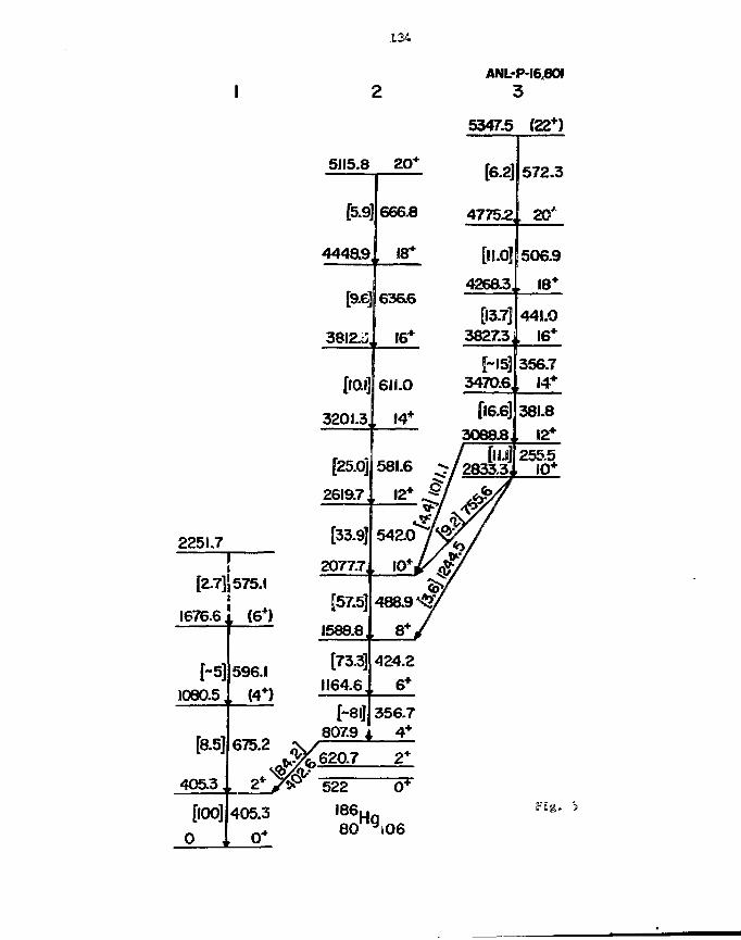
134
2251.7
12-7]
1676.6
[-5]1080.5
[8.5]
405.3,
[100]
0 ,
1
1i
575.1
, (6*)
596.1(4*)
675.2
2*'
405.3
0*
#
5115.8
[5-9
4448.9
[9.6
3812^
[10.1
3201.3
[25.0]
2619.7
[33.9]
2077.7
[57.5]
1588.8
[73.3]1164.6,
[~8I]807.9 4
620.7
522
2
20*
666.8
18*
636.6
16*
6IL0
, 14*
581.6 -^
* i,>"/ <54Z07^
4sa9^y8*/
424.26*
356.74*
2*
0*
80 yJ06
ANL-P-I680I3
5347.5 (22*)
[6.2
4775.2,
[11.(942683
[13.73827.3
[-15]3470.6
[16.6]3088J8
f 2833.3.
vf7
572.3
, 20J
506.9
18*
441.0, 16*
356.7, 14*
381.812*
255.5, iO*
Fig.

135
PROBLEMS ASSOCIATE© SWITM WE PROPWCTIOIJ OIF I1EAOT 10S TARGETS
General DiscussJion - Led by E. B. Kntoisk
Endemic to heavy ion experiments is the deposition of very Biigh energy withinthe target or in the substrate needed to support the target material. Inlistening to the four papers comcarmed with such heavy ion experiaecits, itseem that many problems are associated with recoil-type targets: wolds occurringin multi-layer samples, maintenance of extreme flatness requirements, andavoidance of the oxidation and/or vaporization <o£ the target aateriai. Suchproblems were briefly described by Dr. Jamssen.
With regard to multi-layer targets, G. Thomas offered the imfomsatiom ttaait agold flash on gadolinium foils provided a more adherent surface uhem the (foilwas bonded to lead. Such multiconponemt interfaces Bnawe been described im theliterature and have been used by persons in target preparation! for csiiray years.However, the total explanation for the successful tomdimg is mot Emilyunderstood; perhaps "diffusion bonding"* is enhanced by the addition ©f selectivetrace materials (gold, in this case). Because of the oimute aaommt off goldused, it would seem that the bond is not achieved by step-wise «i>r gradedbonding, but rather that increased nobility of tine target T>r the srotosttratematerial is realised, the gold acting as a "flux".
In discussions involving vaporization or oxidation problems with heavy iorotargets, the use of overcoatings seems to have alleviated soace detrinentaleffects. For example, target makers reported their techniques for thedeposition of highly reactive aetais, eg., uranium, calcium, and lanthanides,onto carbon substrates with subsequent deposition of a thin protective layer ofa metal or carbon. Additional features of suc»i multi-layer targets appear to betheir enhanced thermal and/or electrical conductivity. Both thermal gradientsand electrical charge generated in or on the target during bonbardnent appear itbe sh/inted to the relatively heavy frame surrounding the target. This improvedenergy transfer tended to significantly increase target lifetime underbombardment. Accumulation of energy was also reported to cause local celting ofthe target material as evidenced by significant broadening of scattering peaks.Use of Rutherford backscattering equipment shoved the target Chiclkness to varyunder bombardment, apparently because of Migration of "nelted" target materP.al.
A lively discussion ensued when the .question was asked, "Khat is an appropriatecover layer to protect lithiua metal targets?" Representatives froa ArganneNational Laboratory indicated their partial success using a thin layer of coppsr(ca. 500 iig/cni2 or less). With this protection, it was observed to take fiveminutes before any significant amounts of oxygen or aoisture were detected. Tfceminimum thickness of copper required was indefinite, but "it could possibly beas thin as 100 ug/cm2". The overcoating was successful with lithium layers of500 ug/cm2 on pin-hole free nickel substrates.
Another suggested alternative protective coating for lithium was gold; hon«ewer,others in the group indicated only marginal success with gold coatings. Thethickness suggested for the gold layer was 30-40 ug/cn2. Another problea withgold was the interference of this nuclide with the ultimate expericental results— because of the mass of the nuclide. Other alternative metals that weresuggested included nickel and titaniun depending upon the needs of theexperimentalist. The "ultimate" overcoating was suggested to ~>e beryllium, butagain, the presence of the light nuclide: might influence the experimentalresults. Even carbon was suggested if the expertoent could tolerate itspresence. Final selection of the appropriate protective layer was obviously

136
dependent upon Che experiment, but it seened that the discussion participantswere in agreement that protection of lithium aetal could be achieved.
One major discussion point which was unanimously agreed upon was the necessityof the target maker to constantly coonunieite with the experimenter. Especiallyin the making of heavy ion targets, the experimentalist is the ultiaate"sounding board" for alternative preparative aethods since only he/she candetermine the effect of extraneous nuclides and the effect of oassive energytransfer to the target.
A discussion arose involving implantation of hel£ust-3 in various substratematerials* One method discussed was the sorption of trititra — subsequent decayof the radionuclide would generate the helima iaplant. However, at rooatemperature, sorption would be minimal; furthermore, residual tritium wasthought to be a major contamination problem in the use of the target. Inclusionof helium in carbon layers formed by glow discharge deposition uas offered as analternativa method.
Implantation of other nuclei in carbon films was briefly discussed. Oneindividual from the University of Pennsylvania studied istplamtation of sulphurin carbon using an accelerator ion source, tftien vapor-deposited carbon foilswere used, only small amounts of sulphur could be implanted before breakageoccurred. Substitution of glow discharge carbon foils of 3© tsgjfcml thicknessproved more successful. Possibly the polymeric structure ©£ the carbon film mayhave been responsible for this increased strength. Further discussion suggested!that bombardment of glow discharge carbon foils released occluded hydrogen andmight make the structure more receptive to implanted ions. Many persons feltthe glow discharge carbon films were generally superior for implantationpurposes and as substrates for other target layers deposited by vacuumevaporation methods.
Finally, much discussion centered upon the preparation of cesium targets byvapor deposition. Initially, the discussion pointed cut the (jrobleas usingcesium compounds, e.g., the acetate, iodide and axyiodide. Problems encounteredwere directly related to the hygroscopic nature of irhim layers of thesecompounds. "Immediately after removing the target from the bell jar, theyturned to liquid!" To avoid this phenomenon, sone persons attempted to keep theprepared foils in the vacuum chamber until used and then transfering thea incapsules which were loaded under vacuum. Even this precautionary measure wasonly marginal! successful since the targets were observed to "bubble" under beanDombardtnent. An alternative method of preparing the targets on a thin alu»inu»backing of 3 mg/cni2 was reported. The deposited cesiua material was, overcoatedwith aluminum. In this case, cesi'im acetate was used since the iodide nucleuscould not be tolerated and the hydroxide had too strong SM affinity for icoisture(even with the aluminum overcoating). A thickness of 50 ug/cia2 of aluminumovercoating was used. Electron microscopic examination of the aluminumover-layer showed it to be discontinuous. Wse of e gold layer of 100-209 ug/ca2was suggested to achieve continuous coverage. Another suggestion to perform theexperiment in Los Alraos was oade because "it is very dry there".
In situ target preparation in the scattering chanber of the accelerator facilitywas also discussed. Several attendees had used this approach to avoid watercontamination of cesium layers. However, success was only achieved if liquidnitrogen traps were used and continued to be used during the experiment itself.If the traps were allowed to lose their coolant, instant destruction of thetargets resulted.
; ? • •' vtiff
•*%./£.. ••was*,7 - . ' , . . ^ * - * * . i . > ^sy, jRj.ff
. "&• ; ^ * 4
WORKSHOP BANQUETWEDNESDAY EVENING, SEPT. 7 , 1963RIPPLES RESTAURANT, DARIEN, ILL.BANQUET ADORESS: E.K KOBISK

137/f 30
A BRIEF HISTORY OF TARGET PREPARATION
£. H. Kobisk (Retired)Oak Ridge National Laboratory
Upon Invention of the accelerator, I he era of tlie "target catier"" began;generally, the increase in sophistication of target aaklng paralleled theIncreasingly coaplex developments in accelerator and nuclear physics. A"target" is an array of defined nuclei having knoun orientation and quantitysuch that impinging, veil-defined radiation might interact with the containednuclei causing nuclldic transformations, scattering and/or the production oidetectable radiations characteristic of tfce interaction. It is the targetpreparer who must provide the defined condition of the target saaple — acomplicated process involving the disciplines of chemistry, physics, metallurgy,ceramics and material science.
Targets prepared in the 195Q*s were poorly defined and were frequentlypolynuciidic. With the advent of mass separators, in particular the calutrons,high purity mononucHdic materials foecaae available for target preparations andprecise nuclear reaction joeclhanisns could be studied. Early im the 1960"s,separated isotopes of uranius, jaliutoniun, thoiiiun, aaericiun, and curlun becacaeavailable in sufficient quantities with high purity and at reasonable cost towarrant their use as target materials. However, preparative aethods used forstable isotopes were totally inadequate far use with these highly radioactive,hazardous elements. Subsequent development of reaote preparative aethods weresuccessful in solving these fabrication proMeas, but the high costs ofequipment and facilities needed prohibited general use of the technology.
It became clear to the nuclear physics community that the cost and cocsplexityassociated with Isotope target preparation requiTeu some centralization of Chefunction. Only the relatively straight-forward preparations could beeconomically perforaed in the small laboratories associated with the variousaccelerator sites. Centralization of target preparation at a few nationallaboratories in the United States (in particular, at Oak Ridge NationalLaboratory), in Chalk River, Canada, and at two oajor locations in Europe (theCentral Bureau of Nuclear Measurements, Gecl, Belgium and A.E.C.L., Harwell,United Kingdom) was eventually realized. Not only was the icapetus for thiscentralization the result of economics, but also of the necessity to preservethe rare and costly Isotopes available for this use. Subsequently,sophisticated target specimens were prepared for purchase, at cost, by theresearch community on an international basis.
Because of the amount of research, development, and invention required in targetpreparation, a nev? group of scientists evolved having unique technicalbackgrounds in a wide variety of scientific disciplines. These professionalpersonnel required that information regarding their technical developaeots becommunicated to avoid duplication of expensive and tisce-consizsing researchefforts. As a result, target makers derived the concept of the InternationalNuclear Target Development Society (INTDS) for the stated purposes of enhancedcommunications, transmittal of technical developnents, and personal involvementat an annual meeting where free discussions could ke achieved. Hinder formalcharter and incorporation, the INTDS has been the successful caediun of thetarget maker for twelve years and is a truly international organization. Of themore than two hundred members, at least thirteen countries are represented. Todate, annual ireatings have been held in the United States, Canada, England,Belgium, Germany, and Israel.

139
A NEW FOIL STRETCHER FOR RECOIL DISTANCE
TARGETS AND STOPPERS
D. C. Radford
Argonne National laboratory, Argonne. IL 60439
Abstract
A new deaign for & ca^et holc'er to produce stretched
foils for recoil-distance ("plunger'*) life tine measurements Is
described. The foil tension is obtained by concession of an C-
ring in contact with the foil, which is thereby stretched over an
aluminum tube, one end of which has been optically poli'.ied. The
new stretchers have been used in an actual neasurenent with the
ANL plunger apparatus, and were found to be fully satisfactory.
Using two gold foils, a minimum distance of 3 wm Mas achieved
before electrical contact wa,s obtained. The nain advantage of the
new holders is the ease and reliability with which good quality
stretched foils can be produced. Using evaporated gold foils of
about 2 tng/cm2 thickness, s, success rate of close to 100% caa be
achieved with a little practice.
The s-Jbmitt^i rpsr"*CTJj>t has been authoredbv a contractor o* the U. S. Govetrw-ensunder convwt No. W-31-109-ENG-38Acc*>'dir*3lv, the U- S. Govei*.ment retains aoonejtciusw, ioy^!¥-'tee l:.--:nse to pubitshcr reproduce the published Icrm d thiscontribution, or allow others to do so. (?TU. S. Gortrreneni iwrpojes.

140
The recoil distance, or "Plunger", aethod (RDM) for Measuring
lifetimes of excited nuclear levels1 Js most coaaonly used foe swan lives In
the range 1 p* t 1 ns. Its successful application at the shorter Halt of
this range depends on the Manufacture of very flat, stretched target foils.
This report describes a fail holder and stretching technique that have been
developed at Argonne National laboratory that allows easy, reliable production
of good quality stretched foils for use as target? 2nd stoppers in RDM
experiments.
The principle of the technique is Illustrated sdhenaticnlly in
Fig. 1. The excited nucleus is produced In target Material evaporated onto
the down-stream side of a thin stretched foil. This target rust be thin
enough to allow the nucleus to recoil out into vacuuM while still retaining
moat of the energy inparced to it by the kinematics of the reaction. If the
excited state decays while the nucleus Is In this state of free flight, and
the de-excitation Y-ray Is detected at an angle © to the direction of motion
of the recoiling nucleus, the Boppler effect will cause the observed "if-ray
energy to be (in first order)
E - Eo (1 + W e ) cos 9) (1)
where V is the recoil velocity of the nucleus, Eo Is the unshlfted Tf-ray
energy, and c is the velocity of light.
Now a stopper Is introduced at a distance D along the bea« axis. In
our experiments, this stopper Is another thin stretched foil, but other groups
have used thick metal stoppers or "plungers". Gaswe-rays observed from
excited states decaying after the recoiling nucleus hits this stopper and
cones to rest have the unshlfted energy Eo. if « H of the recoiling excited
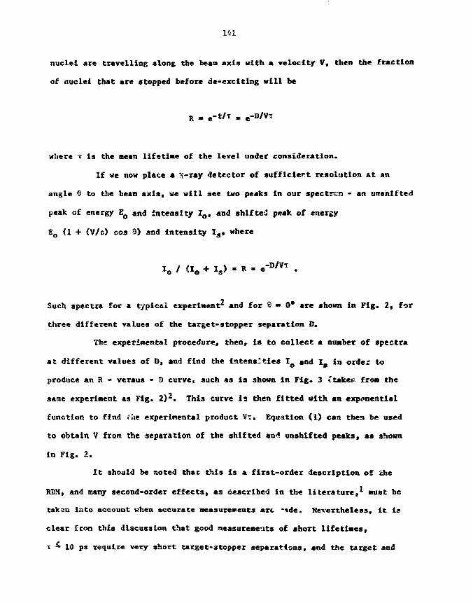
141
nuclei are travelling along the beam axis with a velocity V, then the fraction
of nuclei that are stopped before de-exciting will be
where x is the mean lifetime of the level under consideration.
If we now place a *if-ray detector of sufficient resolution at an
angle 0 to the bean axis, we will see two peaks in our spectrim - an unshifted
peak of energy EQ and intensity Zo, and shifted peak of energy
Eo {1 + (V/c) cos 0) and intensity Ia, where
-B/VT
Such spectra for a typical experiment2 and for 6 - 0 * are shown in Fig. 2, for
three different values of the target-stopper separation D.
The experimental procedure, then, is to collect a number of spectra
at different values of D, and find the intensities IQ and I3 in order to
produce an R - versus - D curve, such AS is shown in Fig. 3 (taken from the
sane experiment as Fig. 2) 2. This curve is then fitted with an exponential
function to find .ae experimental product VT, Equation (1) can then be used
to obtain V from the separation of the shifted an-» unshlfted peaks, as shown
in Fig. 2.
It should be noted thac this is a first-order description of the
RDM, and many second-order effects, as described in the literature, must be
taksn into account when accurate measurements arc -*de. Nevertheless, it is
clear from this discussion that good measurements of short lifetimes,
x £ 10 ps require very short target-stopper separations, and the target and

Mi 2
stopper must both be very flat In order for a unique value of D to be
applicable. For example, at a typical recoil velocity of V * 0.02 c and for a
nean life T ~ 1 ps, the mean distance D - V* travelled by t&e recoiling nuclei
before de-exciting will be about 6 w». This aa!:es the reliable production of
very flat foils agential I"" the development cf a progran of routine RDM
measurements-
Hie new Argonne foil stretchers are illustrated scheaatlcally in
Figure A. Figure 5 Is a photograph of a disassembled stretcher, and Figure 6
shows two stretched foils, one target and one stopper, together with a scale
to show the sise of the holders*
The stretching technique relies on the compression of an **0"-ring
between two surfaces; that of the mount Itself and the lower surface of the
tapered ring (part "B" in Fig. 4). Itie foil is first carefully placed over
this "0"-ring, as flat as possible, and the tapered ring then carefully
lowered onto it. Four 0-80 screws are then inserted iato holes in the ring,
and screwed into the mount; these screws are easily visible in Fig. 6. They
should be tightened, until there Is no more slack., but not so tight that the
foil cannot easily slide between the "Q'-ring and the tapered ring. Khen that
is done, a stretching tube (part "C" in Fig. 4) is pushed up the center of the
mount, and clamped there with three 0-80 screws. This tube pu?ls the foil up
Into a shallow truncated cone, and lifts the flat part of the foil (that
across the top of tha tube) above the surface of the ring The top of the
tube is optically polished to provide a flat, planar stretching surface; the
quality of this polish and the cleanliness of the surface, together with the
quality and cleanliness of the foil to be stretched, finally determine the
quality of the stretched foil that can be obtained.

Finally, the four screws are slowly and evenly tightened, clamping
the foil against the "O"-ring. As the O-ring gets compressed, the foil Is
drawn down and stretched across the polished surface of the tube. If they are
over-tightened, the foil will of course break, but it is easy to obtain good
stretching for the flat part of most foils before this happens. Indeed, for
gold foils of between 2 and 10 rag/cm , a success rate of virtually 100% can be
achieved with very little practice.
If care is taken to ensure optimum cleanliness of both the foil and
the polished surface of part "C", the resulting foils are generally of very
good quality. This can be seen in a nersurenent of the absolute target-
stopper distance at electrical contact, f->r two conducting foils* In the
Argonne RDM chamber, the capacitance between the foils can be treasured as a
function of distance, and, when a stray capacitance is subtracted, this is
found to be accurately inversely proportional to the distance between the
foils, for short distances. One such neasureaent, for tuo gold foils, is
shown in Fig. 7, where the maximum capacitance achieved before contact
corresponded to a distance of just over 3 M .
The main advantage of the present system is that, in the author's
exparience, with adequate care to ensure cleanliness, high quality RDM targets
and stoppers can be produced reliably and easily, without the risk of too many
broken foils. The foils also seea to stay nicely stretched, even when target
material is evaporated onto then; nor has any problem with slackening been
observed during RDM measurements with such cargets and stoppers due to bean
heating.
The author gratefully acknowledges helpful discussions and
encouragement from Drs. T. L. Khoo and R. V. F. Janssens. This research was
supported by the U. S. Department of Energy under Contract W-31-109-Eng-38.
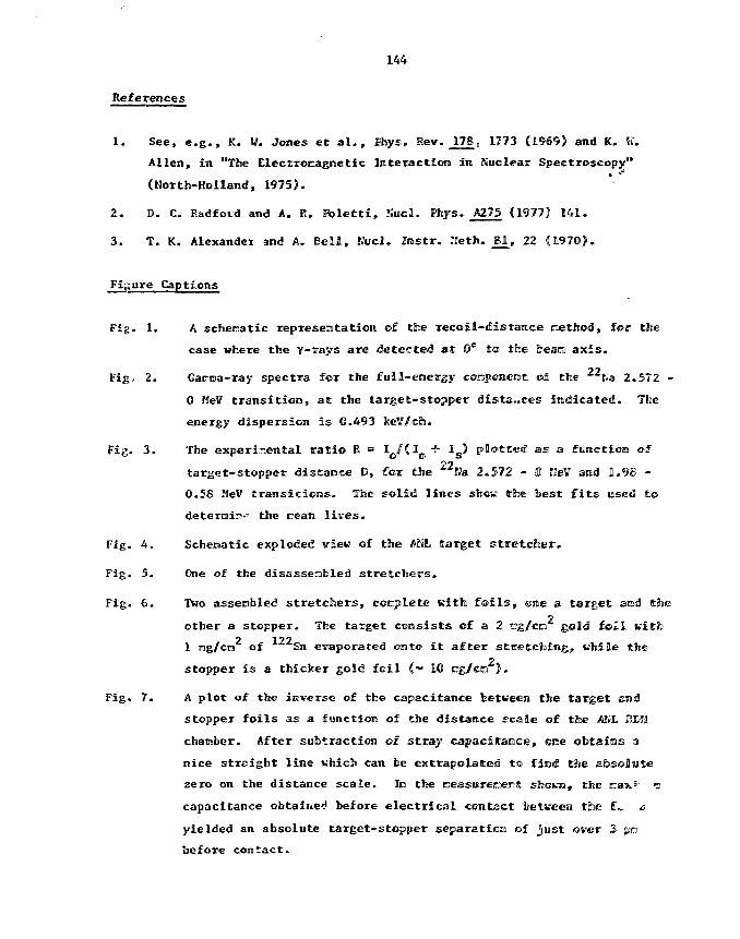
144
References
1. See, e . g . , K. V. Jones e t a l . , Fhys. Rev. 178. 1773 (1969) and K. W.
Allen, in "The Electromagnetic Interaction in Kuclear Spectroscopy"
(North-Holland, 1975).
2. D. C. Radfoid and A. R. ftolctt i , IIucl. Whys. A275 (1977) 141.
3. T. K. Alexander and A. Bel l , Ntrcl. Ins t r . Iletln. £ 1 , 22 C197O}.
Fi,;ure Captions
Fig. 1. A schematic representation of the recoi l -dis tance ne t ted , for the
case where the y-rays are detected at 0° to the bean a x i s .
Fig, 2. Gacna-ray spectra for the full-energj- eonpcnerat of the 2*Ra 2.572 -
0 MeV t rans i t ion , a t the target-stopper distances indicated. Tfee
energy dispersion i s 0.493 keV/ch.
Fig. 3 . The experimental r a t i o R = I o /Cl o + ISJ plot ted as a function of
target-stopper distance D, for the 22Ka 2.572 - 0 KeV and 1.9B -
0.5S MeV t r ans i t i ons . The solid l ines shew the best f i t s used to
the ream l ives-
Fig, i*. Schematic exploded view of the <AHL (target stretcder.
Fig- 5. One of the disassembled stretchers.
Fig. 6. Two assenbled stretchers, complete with foils, cite a target arod the2other a stopper. The target consists of a 2 rg/co gold foil with
2 122
1 ng/cm of Sn evaporated onto i t a f te r stretcfaimg, while the2stopper i s a thicker gold foi l (•» 10 rag/cn ) .
Fig. 7. A plot of the inverse of the capacitance between the target s»«J
stopper foi ls as a function of (the distance scale of the AKi. KEJJ
chamber. After subtraction oi s tray capacitance, one obtsims a
nice s t ra ight l ine which can be extrapolated to find the absolute
zero on the distance scale . In the neasturecepS: shovn, tBte CJSXS' o
capacitance obtaii«e<i before e l ec t r i ca l contact between tine f«. <s
yielded an absolute target-stopper separation ©f jus t over 3 JJB
before contact-
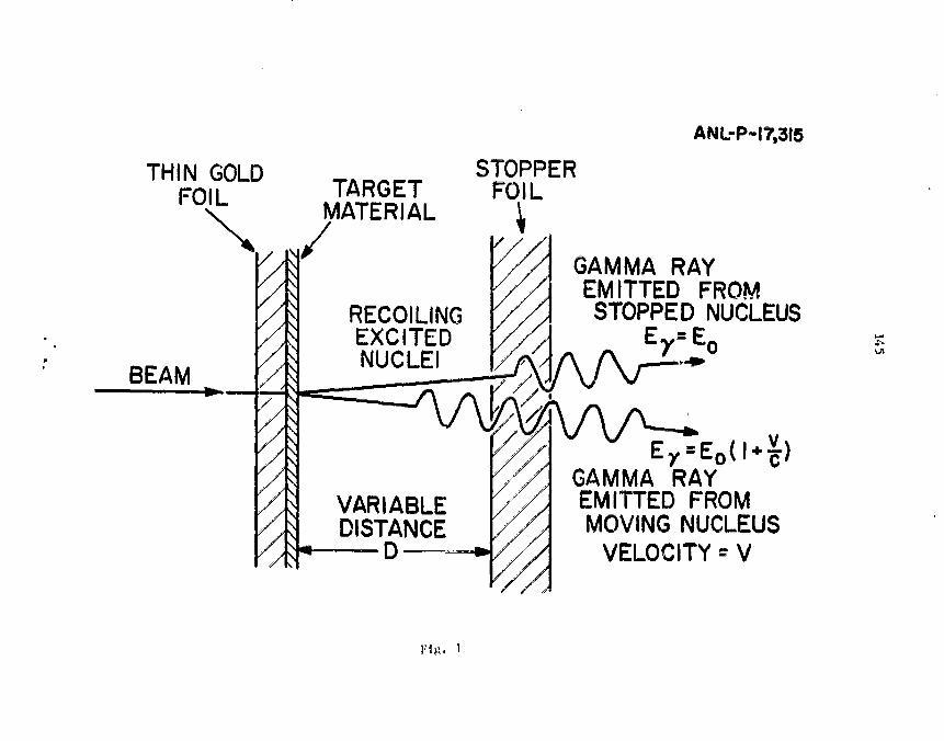
ANL-PH7.3I5
THIN GOLDFOIL TARGET
MATERIAL
BEAM
GAMMA RAYEMITTED FROMSTOPPED NUCLEUSRECOILING
EXCITEDNUCLEI
VARIABLEDISTANCE
D
y4GAMMA RAYEMITTED FROMMOVING NUCLEUS
VELOCITY * V
Fin-

146
V/C = 0-32 %
5140 5180 5220CHANNEL NUMBER
Fig. 2

147
j i ' ; i i i + " +< r - CO
i
1
1
i
5
1 ^ >
cn
^.
CMCM
t
CM
CO <x>IT)
1 . • 1 I I l iiLLo CM
oLOO
CMO 5 5§ CM
OCD
Q:
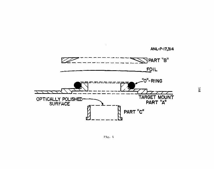
ANL-P-17,314
FOIL
H/-\H
\ \ \ \ \ X
O-RING
OPTICALLY POLISHED-SURFACE
"TARGET MOUNTPART "A"
11,01PART "C
g
Fig.

t149
Fig. 5

150
Fig. 6
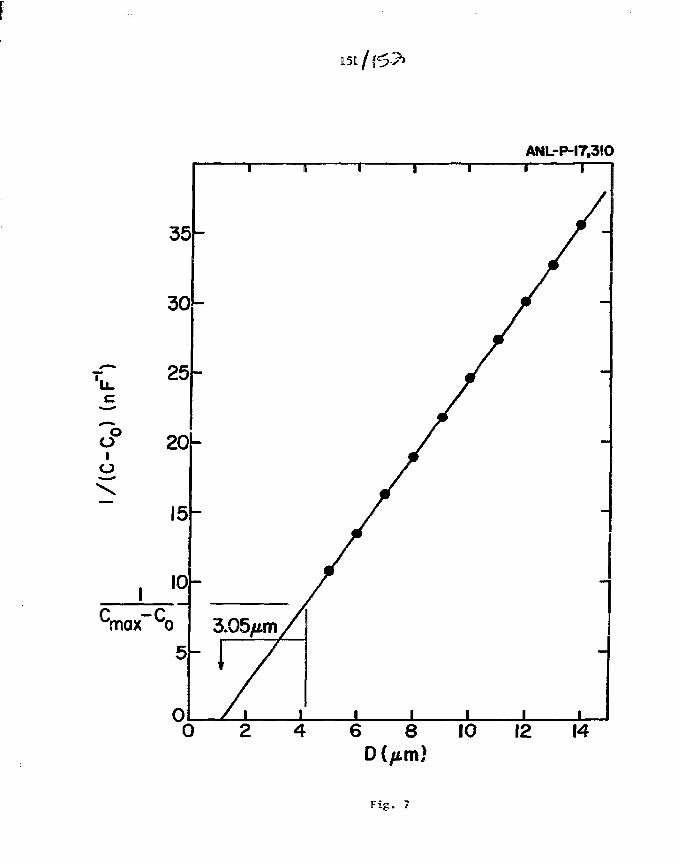
151
ANL-P-I7,3!O
cmax~co
8 10 12 14
Fig. 7
SESSION m
THURSDAY MORNING, SEPT. 8, 1963CHAIRPERSON: W. LOZOWSKI

153
COMPUTER CONTROLLED TARGET STORAGE SYSTEM
B. G. Nardl and J. N. Wortliiragton
Argonne National Laboratory. Argonne, IL 604?"
Hygroscopic or readily oxidizing tar<:»ts need an appropriate and secure
storage system. This is a description of a computer controlled! target storage
facility.
The target storage facility at Argonne's Physics Division «as originally
built around 1970 (see Figure 1). 100 targets were stored under vacuum in a
20" diameter chamber. A transfer chamber was used to transport targets under
vacuum, into and out of the storage chamber. If the experimental apparatus
had a suitable flange, targets could be transferred from storage to ttie
experiment under vacuum.
The vacuum system consisted of a roughing punp £.»f a water cooled
diffusion punp. During the years the punping systen «Ic»eloped many
problems. Water cooling often stopped because of plugged pipes and the
diffusion pumps required more maintenance with age. Oil contamination from
the storage system into the experimental apparatus was also a concern.
The safety and control systen was also plagued with problens. Connectors
to the thermocouples would loosen and cause initernfttent operation of
valves. The worst prohlen occureti when a target was being renoved fron the
storage chamber and valve A2 (Fig. 2) would slan shut on the transfer chamber
rod. This usually occured very early in the oorning.
Because of the above conditions a decision vas made to update the
facility. A turbo punp was installed to nininize the attention the vacuun
system needed, and to provide a cleaner environment. An electrically
operated, pneumatic valve evacuation systen was installed to allow full
computer control. The safety and control circuits were replaced with new ion
gauge controllers and a computer operated control system.

154
The new facility had to provide protection in several areas. Vacuum
Integrity was necessary 26 hours a day. Personnel errors were to be prevented
if possible. Recovery fron system failures (loss of air pressure, power
failure, vacuum pump failure) was also necessary. An additional feature was
added which would report system status or failures over the phone lines to the
appropriate people.
Figure 2 is a schematic representation of the vacuum systen. Figure 3
shows the front panel simplicity.
When power fails, all valves close and all electrical equipnent scops.
The only exception is the computer which has battery backup. The computers
real time clock keeps track of how long the power fail has lasted. This gives
some indication of the vacuum situation when power returns. Restoration of
power alerts the computer. All valve solencids remain closed because their
solid state relays were turned off by the computer Innediately after power
failure. All pumps and gauges will turn on automatically. (Refer to Figure 2
and 3)
If TC2 senses a poor vacuum, mechanical punp 2 will puop out the chanber
through restrictor valve M4 (via A6). This prevents target damage by gas out-
rush. When the clamber is at a vacuum level where gas out-rush is not a
problem A6 will close and pumping will continue through A4 for inproved
conductance.
Mechanical pump 1 and the turbo punp start on power return. TCI and IG1
indicate this pressure to the conptiter. Vhen the chamber vacuun (TC2) and
turbo vacuum (TCI and IG1) are at a suitably low pressure, M closes and valve
Al opens. The system then returns to normal operation.

155
During nornal operation targets are removed in the following Banner. The
blank off (Figure 2) is nornally Installed and purped out through A3 and K2
with A2 closed. H2 is closed and the bleed valve on the blank off is
opened. The blank off is then removed, and the transfer chamber is
Installed. TC4 on the transfer chamber is cor.aected to the systen and the
bleed valve is closed. A3 is normally open. Opening H2 pucps out the space
between the storage chanter and transfer chamber. The front panel ready light
(Figure 3} indicates vhen T O has reached adequate vacuun to open nanual valve
Ml. This will pump out the transfer chamber. The ready light will blink when
vacuum is adequate to open A2. Valve M2 should be closed (isolates eech. punp
2} and the front panel open push button depressed. This will opera valve A2.
The transfer chamber rod can now be pushed in to renove a target. A new
feature is the rod position sensor and source located between A2 and TC3. The
rod position is sensed when it interrupts the pulsed infrared bean between the
source and sensor. When the transfer chamber rod passes between source and
sensor the large rectangular LED on the front panel will blink to warn the
user and computer not to close A2. When the target is attached to the rod end
removed to the transfer chamber tha red light will stop blinking. How A2 cam
be closed by pushing the front panel close button. Closing Ml will isolate
the target in the transfer chamber's vacuum. The transfer chanber can be
renoved after venting. The blank off should now be installed and M2 opened.
The control chassis consists of a microprocessor system and interface
cards. (see Figure U) The microprocessor system consists of four printed
circuit boards manufactured by Onset Computer Corp., N. Falnouth Mass.
The CPU-80C85 contains the 80C85 micro processor and the interfaces to
the other 3 boards. It also has 2K (2048 bytes) of programable read only
memory (PROM) and 2K of volatile random access oenory (RAM) 24 lines of input-
output information are also available.
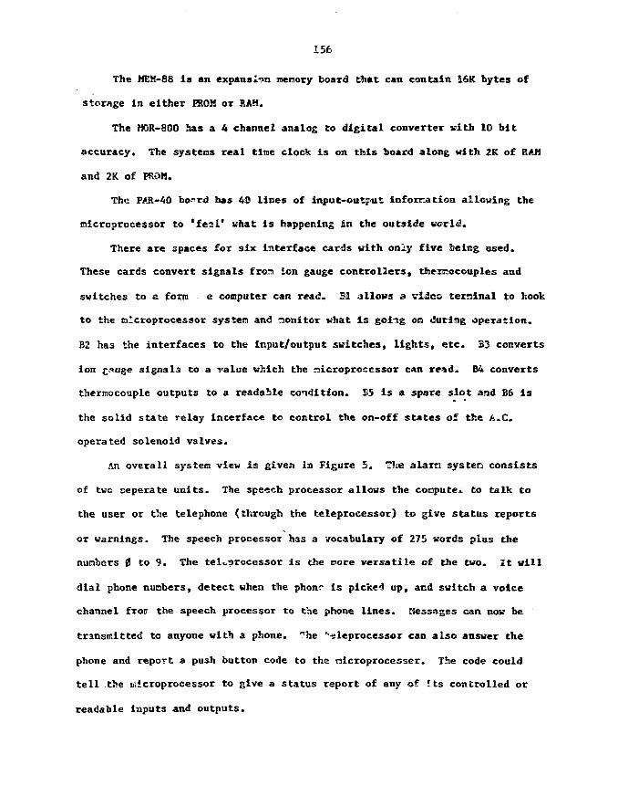
156
The MEM-88 is an expansion memory board tiiat can contain 16K bytes of
storage in either PROM or RAH.
The HOR-800 has a 4 channel analog to digital converter with 10 bit
accuracy. The systens real tine clock is on this board along with 2K of RAM
and 2K of FROM.
The PAR-40 bo-rd has 40 lines of input-output information allowing the
microprocessor to *£eal* what is happening in the outside world-
There are spaces for six interface cards with only five being used.
These cards convert signals from ion gauge controllers, thermocouples and
switches to & form . e computer can read. 31 allows a video terminal to hook
to the microprocessor system and monitor what is going on during operation.
B2 has the interfaces to the input/output switches, lights, etc. B3 converts
ion c«uge signals to a value which the microprocessor can read. E4 converts
thermocouple outputs to a readable condition. B5 is a spare slot and B6 is
the solid state relay interface to control the on-off states of the A-C.
operated solenoid valves.
An overall system view is given in Figure 5. The alam system consists
of two seperate units. The speech processor allows the compute to talk to
the user or the telephone (through the teleprocessor) to give status reports
or warnings. The speech processor has a vocabulary of 275 words plus the
numbers 0 to 9. The teleprocessor is the pore versatile of the two. It will
dial phone numbers, detect when the phonr is picked up, and switch a voice
channel froir the speech processor to the phone lines. Messages can nov be
transmitted to anyone with a phone. The "-^leprocessor can also answer the
phone and report a push button code to the microprocessor. The code could
tell the ir.icroprocessor to give a status report of any of its controlled or
readable inputs and outputs.

157
Hopefully this facility will he an improvement over Its predecessor- The
only time it should need attention is when It cannot solve a problen by
itself.
TTftffRfc* a"'^Sn
1^r.,: dr-.T.-csr-
.^.•:v. n*» W- S
•an
Cc
O. S. G ^ « r . T3.3,
fcr«5 Co tfr> so.
•:>'- .
J
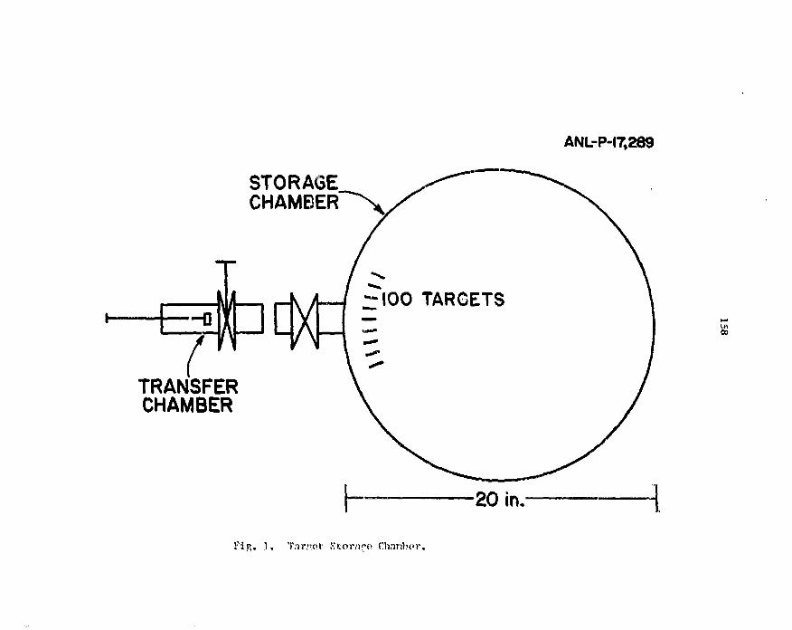
ANL-P-17,289
STORAGECHAMBER"^
TRANSFERCHAMBER
-100 TARGETS
Pip,. 1. Target Storn^o Chimhvr.

ANL-P-I7.29J
STORAGECHAMBER
BLEEDERROD POSITION
SOURCE
ROD POSITIONSENSOR
COLDTURBO I BAFFLEPUMP
TRANSFER CHAMBERSchematic Layout of tho Vno.uun f'yatcn.Al « AUTOMATIC VALUE 3 T.G.I T:!f\"OCnUPLK IMl - MANUAL "AM!F ] r.r.j v jnN d'A'T ]
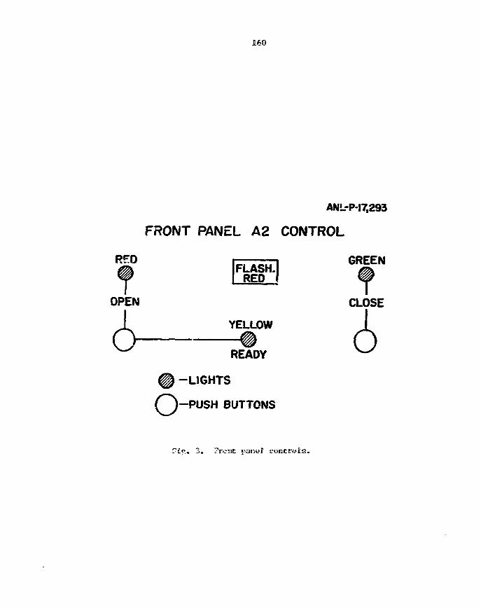
160
ANL-P-17,293
FRONT PANEL A2 CONTROL
REDFLASH.
RED
GREEN
OPEN CLOSE
6 YELLOW I
Dr«nv V-/READY
% -LIGHTS
Q - P U S H BUTTONS
?£«% 3 . 7roiiC p

ANL-P-17,290
CONTROL CHASSIS
^-PROCESSOR SYSTEM
cpu80C85
MEM800
FM0R800
PAR40
INTERFACES
RS232
I ,'o
I ,\
T.C.
SPARE
S,S.R.
Control Chasrsis printed circuit enrd layout.

ANL-P-17,292
T.C.3
T.C.
T.C.
4
5
T.C.
T.C.
2
1
1.6.
1.6.
2
1
BA
T
I{
CONTROLCHASSIS
VACUUMSYSTEM
BA
T
ALARM SYSTEM
SPEECH PROCESSOR275 WORDS a NUMBERS
TELEPROCESSOR
Tin. 5, rtvernl] Systen Vi
163
OfLASER ISOTOPE SEPARATION TECHNIQUES =OR TARGET AND OTHER MATERIALS
W. H. McCulla
Oak Ridge Gaseous Oiffusion Plant,* Process Support Division, P.O. Box
P, Oak Ridge, Tennessee 37830, U.S.A.
An overview of both atonic and Molecular laser isotope separation
techniques is presented. With the exception of araniura, nost colecu'ar
experimental efforts have been concenitrated on isotopes of Z S IS.
Some of these efforts are reviewed along with successful", atonic
methods on isotopes of eleir.ents o2 Z - 18. The general application of
laser isotope separation to isotopes in target and special nuclear
materials preparation is discussed.
Introduction
The application of photochemical and photophysical technique to iso-
tope separation has been of interest since shortly after isotopes were
first disco\Tured in 1913. Merlon and Hartley cade an unsuccessful
attempt to separate chlorine isotopes in 1922. In 1935, K. Suber was
able to separate mercury 2CQ and 202 by selectively filtering the
2537A line of a mercury arc with mercury vapor. Later successes ware
achieved for chlorine, carbon, oxygen, and hydrogen isotopes using
nonlaser sources filtered by isotopically enriched absorbers. But the
general application of photo techniques to isotope separation had to
await the invention of the laser in its raany different forais in ti;e
1960s. By the late 1960s, after the invention of the C0_ laser anal the
dye laser, substantial advances in laser photochemistry uexe realized.
By the sarly 1970s, the isotopes of H, B, C, Zl, 3, and Cl had been
separated by a number of different laser rcethcds, but the isotopes
that were separated during this period which created the greatest
interest were those of oranion. Since then, a large body of information
*ias been assembled regarding the photophysical and photochemical
interactions of atoras and molecules in intense electromagnetic fields.
•Operated by Onion Carbide Corporation, Nuclear Division for the O.S.Department of Energy under Contract No. K-7405-eng-26.

164
Although the laser is not a particularly efficient light source, it
does possess some very unique properties. The laser cam prowi.de a very
intense photon source in a narrow spectral bandwidth that also has a
very low divergence and very high coherence for propagation and
focusing. Thus, the entire output nay be utilized on the selected
isotope and efficient use of the photon can be realized through large
f-number optical systems to keep the unreacted wolur.e to a nininan.""
Isotopic effects
One of the first principles of quantum cseciianics is that an aton or a
molecule can absorb energy only in discrete tunics. This is because the
atom has only a finite number of discrete energy states, each cine
representing a particular configuration of its electron cloud. Absorp-
tion or radiation of energy transforms the aton erect one state to3
another but intermediate states are forbidden.
In Figure 1 the response an atom or nolecule nay beve to absorption of
different wavelengths of electronagmatic radiation is depicted. In an
atom, since there are no transitions associated with vibration or
rotation, all transitions are associated with the electronic state of
the atom. Except for transitions involving just electron spin, these
transitions are generally of higher energy than vibrational or rota-
tional transitions in molecules. Thus, we see in Figure 1 that in the
microwave portion of the speetrusi we excite rotation in a colecale, irs
the infrared the vibrations! states of nolecules are excited and in che
visible to ultraviolet region, the electronic states af both ateas and
molecules are excited. If the excitation is sufficient, the species is
carried to ioni.'ation. The characteristic spectra of both atoms and
molecules are subtly influenced by tine details of nuclear structure.
The . overall reduced mass of the atoms and the bond distances in the
molecules influence the rotational energy levels in molecules and
again the mass of the atoms involved in vibration affects the vibra-
tional energy levels. At low atomic nass, the effect is quite large
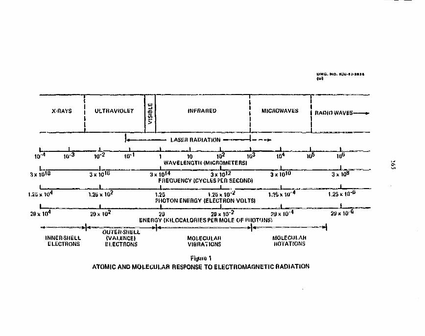
DVVC. NO. K/G«J1»>»(Ul
X-RAYS INFRARED MICROWAVES j RADIO WAVESI
i
LASER RADIATION
I I _L
10" 10-3 10=2
1
10"1 1 10 102 103
WAVELfNGTH (MICROMf TiRS)105 106
I3x10™
1,25 x10⁴
3x10 IG
1
3 x 1 0 1 2
FREOUiNCY(CYCLiSPIR SICOND)3x10»°
I
3x
1.2B x 102 1.2BPHOTON INEROY JILEUTRON VOLTS)
1,26 x 1,25x10=fi
29 a 2D x 102 29 20 x I t ) ' 2 20 x 10=4
iN IROY (KILQCALORliS PiR MOLE OF PHOTONS}29 x 1 0 6
INNER-SHELLELECTRONS
OUTERSHELL(VALENCE)ELECTRONS
^
MOLECULARVIBRATIONS
MOLECULARROTATIONS
Figure 1
ATOMIC AND MOLECULAR RESPONSE TO ELECTROMAGNETIC RADIATION

166
for isotopic substitution as in E and H, but as the nass increases
the effect decreases rapidly, in electronic spectra the nuclear effect
is even more subtle but the isocopic influence is observed on the
electron cloud configuration through the aass, volume, and shape of
the nucleus. The magnitude of the isotopic effect does not decrease
regularly with mass in the electonic levels but is a function of a
number of interacting nuclear parameters affecting :.-»itial and final
electronic levels.
The basic requirements for a laser isotope separation (LIS1 process
are that there must be an isotopic shift in an absorption ban'; for the
element of interest, and the shift must be large enough, and competing
processes in other isotopes small enough, that the target isotope is
preferentially excired. This preferentially excited species then is
generally carried £o a physically or chemically different product and
a selective product separation process is accomplished. The principle4
methods that have resulted in separated isotopes are described below:
1. Photodef lection. A molecule or atom in a bean is deflected out of
the beam by momentum transfer from absorbed photons. Since the
absorbed photon's momentum is in the direction of the laser
propagation and the photon, as the excited species returr.s to the
ground state, is emitted isotropically, the net momentum results
in a deflection of the species in the direction of the laser beam
propagation.
2. Photoionization. This can be a single photon process but often is
a two or more photon process in which an atcm is first selectively
excited by a very narrow bandwidth laser and then carried to
ionization by additional photons. The ion is then separated from
the atomic beam by magnetic or electrostatic fields onto a
collector.
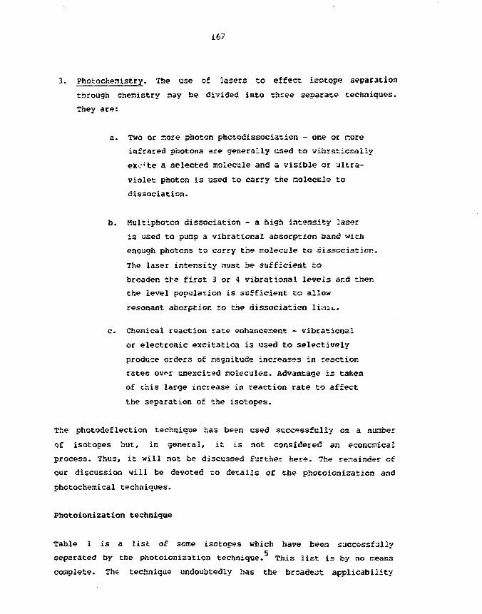
167
3. Photochemistry. The use of lasers to effect isotope separation
through chemistry may be divided into three separate techniques.
They are:
a. Two or aiore photon photodissociation - one or r.ore
infrared photons are generally used to vibrationally
excite a selected molecule and a visible or ultra-
violet photon is used to carry the molecule to
dissociation.
b. Hultiphoton dissociation - a high intensity laser
is used to pump a wibrational absorption band with
enough photons to carry the tuolecale to dissociation.
The laser intensity must be sufficient to
broaden the first 3 or 4 vitarational levels and then
the level population is sufficient to allow
resonant aborpticr. to the dissociation liait.
c. Chemical reaction rate enhancement - vibrational
or electronic excitation is used to selectively
produce orders of nagnitude increases in reaction
rates ovnr anexcited molecules. Advantage is taken
of chis large increase in reaction rate to affect
the separation of the isotopes.
The photodeflection technique has been used successfully on a nuatber
of isotopes but, in general, it is not considered an economical
process. Thus, it will not be discussed further here. The remainder of
our discussion will be devoted zo details of the photoioaization and
photochemical techniques.
Photoionization technique
Table 1 is a list of some isotopes which have been successfully
separated by the photoionization technique. This list is by no neans
complete. The- technique undoubtedly has the broadest applicability
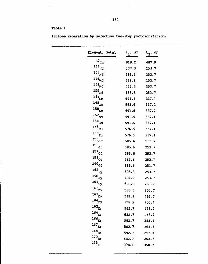
161
Table 1
Isotope separation by selective two-step photoionization.
Eleaent, metal
40Ca
1 4 2Nd
1 4 4Nd
1 4 6Nd
1 4 8Nd
1 5 0Nd
1 4 4Sm148_
Sm
1 5 0Sm
152Sn,
1 S 4Sm
1 5 1EU
1 5 3EO
1 5 5Gd
1 5 6Gd
1 5 7Gd
1 5 8Gd
1 6 0Gd15V1 6 0Dy
1 6 1Dy
1 6 2Dy
1 6 3Oy1SV1 6 2Er
"Er166,,
Er167,,
Er
1 6 8Er
170Er
Aj, nn
616.2
58ft-3
588.8
5S3.3
588.3
588.8
591.6
591.6
591.6
591.6
591.6
576.5
576. S
585.6
585.6
585.6
585.6
585.6
598.9
598.9
598. S
598.9
598.9
598.9
582.7
582.7
582.7
582.7
532.7
582.7
378.1
A , , ran
487.9
253.7
253.7
253.7
253.7
253.7
337.1
337.1
337.1
337.1
337.1
337.1
337.1
253.7
253.7
253.7
253.7
253.7
253.7
253.7
253.7
253.7
253.7
253.7
253.7
253.7
253.7
253.7
253.7
253.7
350.7
169
since all elements except helium can be ionized by successive absorp-
tion of photons and, depending on the nagnitude of the isotopic shift,
would allow the isotopic separation. The primary consideration is the
ease with which an atomic vapor of the element nay be fora*?:?. The
vapor is created by evaporating the substance in an oven inside an
evacuated chamber. In tne vapor the thermal action of the atoas is
random but for some applications formation of a bean by colligation
with slits or apertures is desirable. This produces a bean of atoas
all moving in the same direction. irf the bean is irradiated
orthogonally to its propagation direction by a laser (or lasers),
tuned to the resonant transitions for a selected isotope, then an
electron on the atom can be raised into the continuum and ar. ion is40
formed. A typical two photon ioniza ion of Ca is depicted in Figure
2. Since the irradiation direction is orthogonal to the beam propa-
gation direction then Doppler broadening of the transition is niniaized
since the atom's velocity in the laser beam's direction is low. The
ion formed is extracted from the atoaic beam by electrostatic or
magnetic deflection. In Figure 3, a schematic of a typical atomic
vapor laser isotope separation prccejs is depicted. The principle
difficulties involve the oven. Many of the metal elements have very
high melting points, thus asking it difficult to obtain substantial
vapor pressure. Also, many of the molten metals become very corrosive
leading to problems in containment. Methods of evaporation also affect
the population of low energy states within the atomic vapor, thus
affecting the number of atoms available for resonant transitions from
the ground state. This situation is shown in Figure 4- Electron bean
evaporation of calcium results in a significant population of the
excited P state rather than having all vaporized atoms in the ground
"S state. Thus, two photon ionization originating fron the ? stateo o
is Dossible.
Some of the remaining difficulties are the loss of selectivity due to
exchange through collisions of the ion with other isotopic species and
the selection of appropriate transitions and measurement of the isotopic
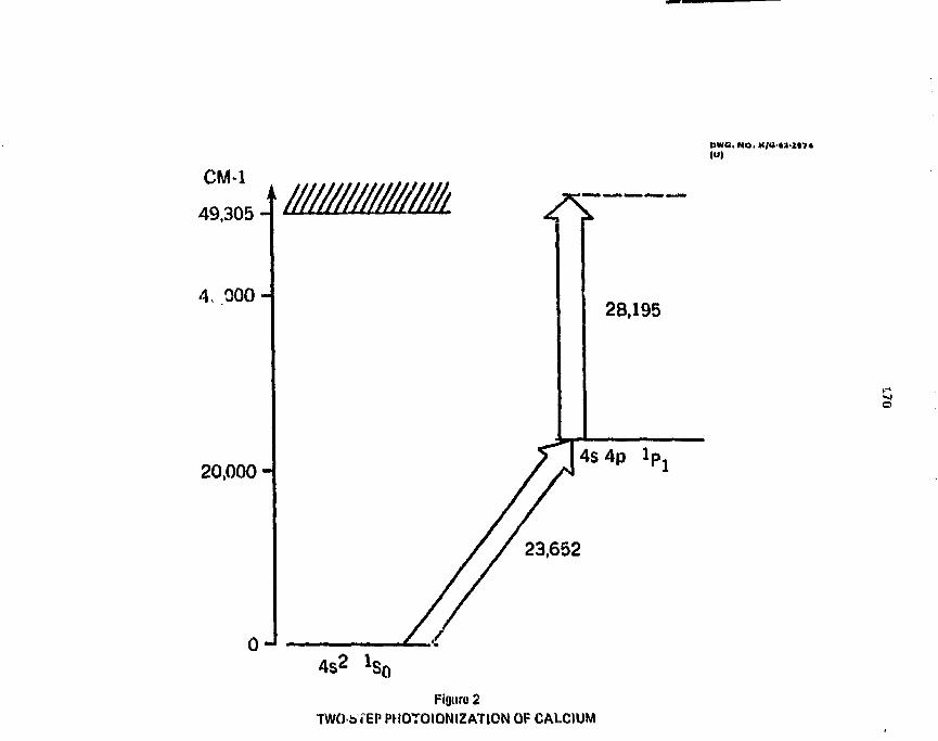
Due. NO, K/e-ta-a«i4
CM-1
49,305 H
A, 000 H
////mmm
20,000 H
28,195
4s4p
23,652
Figure 2TWObTEPPH0T0I0N12AT10NOF CALCIUM

DWG. HO. K/G-I1-SM2
LASER SYSTEM
SEPARATORSYSTEM
DYE MASTEROSCILLATOR
PRODUCT-COLLECTOR
Fiyuro 3
SCHEMATIC OF TYPICAL PHOTOIONIZATION PROCESS
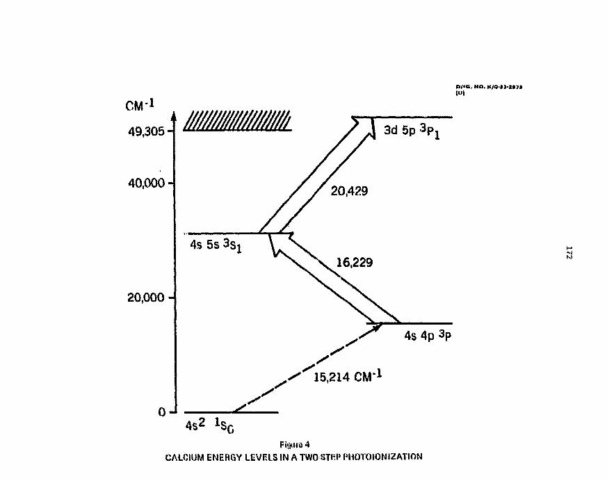
DWC. NO, K/O»»-1»J*
C M 1
49,305-
40,000-
20,000 -
4S2
Fiouro 4
CALCIUM ENERGY LEVELS IN ATWOSTRP PMOTOIONIZATION
173
shift fron the many available transitions. For high throughput a niam
vapor pressure is desired but this increases tine probability of
collision and thus in iom exchange- Hence, a cospronise in vapor
pressure is required to maintain a cream free path sufficient to
extract the ion without collision. As for the selection of appropriate * *
transitions. Figure 5, showing the energy lewels available in uranium,
give.? some idea of the complexity with which one is faced. This
complexity is not as great for tine lighter elements as shown by
hydrogen in Figure 6 but increases rapidly as one coves toward higher
atomic number. The measurement of tto»» isotopic shift is often cost
difficult requiring high resolution and high sensitivity, especially
for isotopes of low abundance. Tn figure 7, the isotopic structure of
the 535.6 nm transition in gadolinium is shown. The transitions for
the more a"?ur>iant isotopes 156, 158, and ISO are easily discernable
but the transition for the isotopes .154 and 152 are comparable to the
noise in the region 0 to 4 GHz- This 535.6 mn transition has been used
to separate gadoliaaiu:n in a two step photoionization process, but the-1 8
scheme started from the 999 cs> level rather than the ground state.9
A three photon scheme for gadolinium beginning fron the B^ groundq *
state is depicted in Figure 8. This scheme is under consideration for
the separation of Gd using a tixe-of-fligfat nass scecs.rcr.eter as a
detector. Since the third step is to an autoionizaticn state, efficiency
should be high.
Photochemistry technique
As discussed previously, the photochemistry technique :r.ay fee subdivided
into three principal techniques - the one or two photon photodissoci-
ation, the multiphoton dissociation I single color 1 and the chesical
reaction rate enhancement. The principals of all three nay fee illus-
trated in Figure 3. This figure depicts potential energy curves for a
single vibrational mode in a rcoleculs- In a two-step photndissosi-
ation, the selective step is the absorption of a photcn specific for a
vihrational transition for the isotope of interest. This is followed

EXCITATION (10 3 cm*1)inOO arc O o a O t n O u i O c J t O o i
i r
i i m it \
8Eo
* I *
III! [Tj,
!i
o
-a iJRSXVSNVS
inriir f dl
r~u m i _ >linn \\
rs
531m " I F
sis
5JCVVVVSXV
HYDROGEN IC
I 1ro
EXCITATION (eV)

175
OWS. MO. K/a-»3O»»»
.ibNIZATiON CONTINUUM
3 =5-4-
<x
UJ
I
•— » •» 3 * *
a -j o s a
•IN •a u» . j ^ a
s s s 3 !
tABSORPTtON
EMISSiON
14
13
12
11
8
ENERGY7 (ELECTRON
VOLTS)
Figure 6TRANSITIONS BETWEEN STATES IN HYDROGEN

nwo. HO,
UJ
tu>
UJ
4 6ISOTOPIC SHIFT
8 GHz
Figure 7
ISOTOPIC STRUCTURE OF OPTICAL TRANSITION OF 6(1
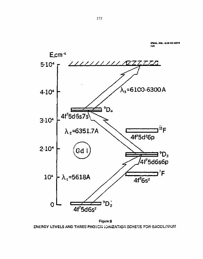
377
owa. wo.
E.cnr1
5-io4 r /////// /' // /
2I04
0L
A,=6100-6300 A
4f75d6s73
A 2 =6351
- A1=56ISA
= z f i 24f75d6s
Figure 3
ENERGY LEVELS AND THREE PHOYCu iQMIZATSON SCHEME FOB GADOUMIOUWI

t5OS1X1ZUJ
EXCITED-STATEDISSOCIATION
LIMITBOUNDEXCITED-STATE
POTENTBAL-ENERGYCURVE
VJBRATIONAI
REPULSIVEPOTENTIAL
CURVELASER-INDUCEDTRANSITIONS(SINGLE ULTRAVIOLETOR VIS58I.E PHOTON)
GROUND-ELECTRONIC STATEDSSSOCBATiON LIMIT
,fl-3UND-STATEPOTEWTIML-SNERGY CURVE
J VS8RATJ0NALLEVELS
MULTIPLE 8MFRAREDPHOTON ABS0RPT30N
INTERATOMIC DISTANCE
F;gure9PHOTOEXCITATION OF SIMPLE MOLECULE

179
by a photon in the visible or ultraviolet to puusp the nolecule either
to an electroncially excited bound state as in A or directly to a
repulsive state as in B. The excited boand state crosses to the
repulsive state and the nolecule unimolecularly dissociates. The result-
ing product is then separated by appropriate techniques. In the
multiphoton technique a single color laser tuned to the specific
vibrational transition of the isotope of interest excites a -/ibrational
transition as in the previous technique bat the intensity of the laser
is such that additional photons are absorbed froa the laser laddering
the molecule out of the potential well o,^ shown in c. If ertocgh
photons are absorbed the dissociation linit is reached and again the
molecule comes apart and the product separated. Any mixture of these
two techniques may be applied including a single photon dissociation
or a highlj vibrationally excited nolecule carried to dissociation by
a second color photon. Tables 2 and 3 list scna isotopes separated byn
these techniques along with pertinent parameters." In the nultiphoton
technique, the very high intensities necessary to accatplish the-
dissociation are demonstrated by the values in gigawatts en * shewn in
Table 3 for most of the mol-?cules.
The chemical reaction rate enhancement method begins alsc by selec-
tively absorbing a photon to give a vibrationally or electronicalUv
excited specific isotope. One or more photons may be absorbed but the
molecule is not carried to the dissociation limit. The excited nolecule
is "hot" and thus may enhance a particular reaction of the nolecule
with some other species. This technique has been applied to the
separation of H, " N, Cl, and 'el. It is important to realise that
not all excited states of the molecule may enhance reactions and in
some molecules, excited states may inhibit reaction. Thas, the tech-2
nique has had only limited application.
In each of the preceding methods, the selective step involves promoting
a vibrational transition in only the isotope of interest. For the
light isotopes (Z S. 13) the isotopic* shift is large enough that a

Table 2
LASER ISOTOPE SEPARATION BY SELECTIVE PHOTODISSOC»ATION
SPECIES ENRICHED
D
D
D
12C
fl1Br
H, D, | 4N1 5 N 1 2 C 1 3 C
12 c ' l3 c
235g
MIXTURE IRRADIATED
H2CO/D2CO,
H2CO/D2CO,
H2CO/HDCO,
(H21 2CO/H2
1 3CO) +NO,
Br2 + HI,7 90r:8 1Br70B r .81B r
s-C2N4l l 2 + C6H6
NATURAL,
NATURAL
NATURAL UF6
LASER
347.2 PULSED 2 xRUBY
363 nm PULSED 2 xRUBY 2 xNd; GLASS
325.03 nm, CW HeCd
303.2 nm, PULSED2xDYE
558 AND 532 NM
PULSED 2 xNd:YAG
663 rm
PULSEDDYE
552 nmCWDYE
16 urn AND 249 nm
DWG. NO. K/6-tt-tTla
ANALYSIS
MASS SPECTROSCOPY
MASS SPECTROSCOPY
MASS SPECTROSCOPY
MASS SPECTROSCOPY
IR CHEMILLUMINESCENCE
LASER FLUORESCENCE AND
ABSORBTION
MASS + ABSORBTION
SPECTROSCOPY
MASS SPECTROMETRY
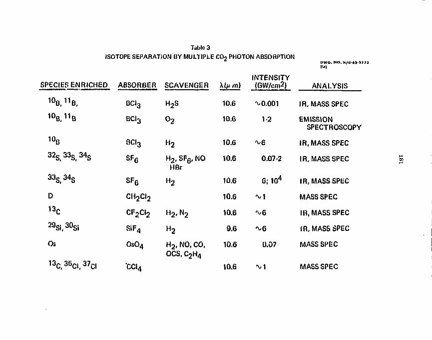
Table 3
ISOTOPE SEPARATION BY MULTIPLE C02 PHOTON ABSORPTIONDWG. NO. K/li
INTENSITYSPECIES ENRICHED ABSORBER SCAVENGER X(/u m) (GW/cm2) ANALYSIS
1°B, H B , BCI3 H2S 10.6 %0.001 IR, MASS SPEC
/IISSIONSPECTROSCOPY
m 111UB, n B BCI3 O2 10.6 1-2 EMISSION
10B BCI3 H 2 10.6 ^ 6 IR, MASS SPEC
32s,33S. 34S SF6 H2,SF6,NO 10.6 0.07-2 IR, MASS SPEC £HBr
3 3S,3 4S SF6 H2 10.6 6;104 IR, MASS SPEC
O CH2CI2 10.6 M MASS SPEC
13C CF2CI2 H2 , N2 10.6 've IR, MASS SPEC
29Si, 30Si SiF4 H2 9.6 %6 IR, MASS SPEC
Os OsO4 H2 , NO, CO, 10.6 0.07 MASS SPECOCS, C2H4
13C(35C((37C | -CQ{ l 0 i 6 ^ 1 MASS SPEC
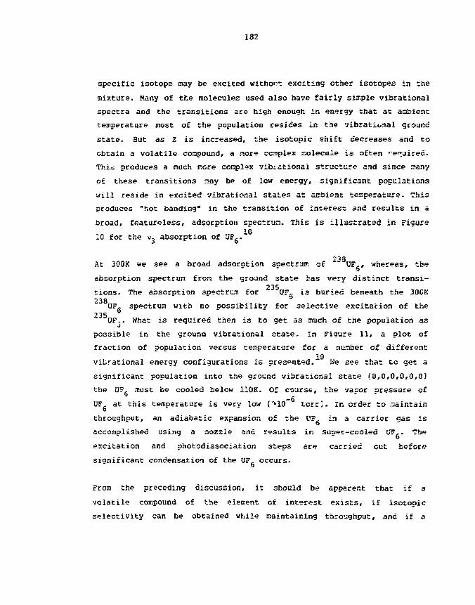
182
specific isotope may be excited withoi'": exciting other isotopes in the
mixture. Many of tfee molecules used also have fairly simple vibrational
spectra and the transitions are high enough in energy that at anbient
temperature most of the population resides in trie vibrational ground
state. But as Z is increased, the isotopic shift decreases and to
obtain a volatile compound, a more complex molecule is often '-e^uired.
Thii produces a much more complex vibiationai structure and since siany
of these transitions may be of low energy, significant populations
will reside in excited vibrational states at ambient temperature. This
produces "hot banding" in the transition of interest and results in a
broad, featureless, adsorption spectrura. This is illustrated in Figure
10 for the u- absorntion of OF,.
2* 8At 300K we see a broad adsorption soectrum of " OF,» whereas, the
D
absorption spectrum from the ground state has very distinct transi-
tions. The absorption spectrum for OF, is buried beneath the 300K238
UF, spectrum with no Dossibility for selective excitation of the235 5
UF.. What is required then is to get as ciuch of the population as
possible in the ground vibrational state. In Figure 11, a plot of
fraction of population versus temperature for a number of different
viLrational energy configurations is presented." We see that to get a
significant population into the ground vibrational state (0,0,0,0,0,0)
the a?, must be cooled below 110K. Of course, the vaoor aressure of-6
OF at this temperature is very low C-10 torr). In order to maintaino
throughput, an adiabatic expansion of the OF, in a carrier aas is
accomplished using a nozzle and results in suoer-cooled UF,. The
excitation and photodissociation steps ace carried out before
sianificant condensation of the OF, occurs.
From the preceding discussion, it should be apparent that if a
volatile compound of the element of interest exists, if isotopic
selectivity can be obtained while maintaining throughput, and if a
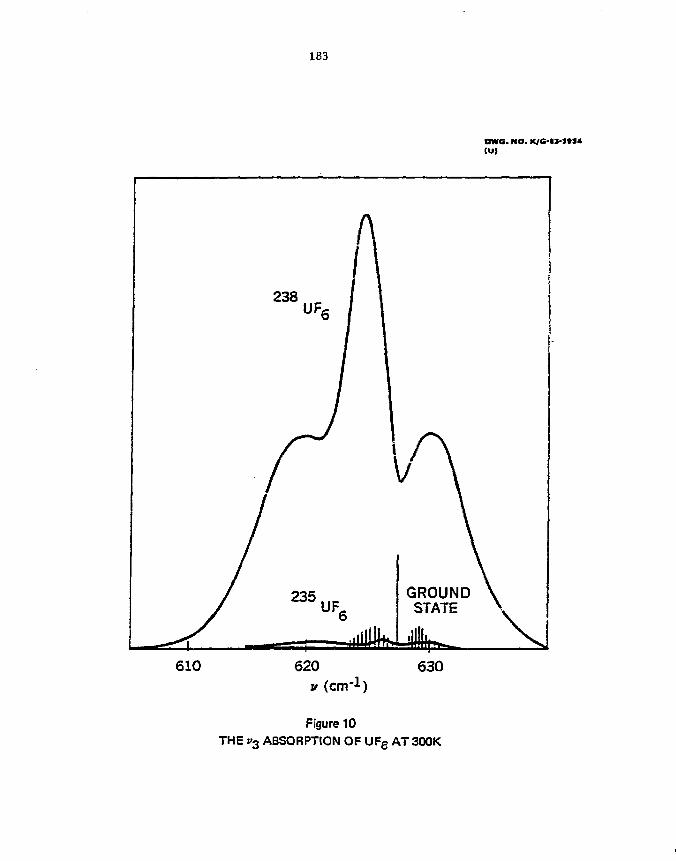
183
OW6. HO. K/G-«J-J»J*
610
Figure 10THE s>3 ABSORPTION OF UFe AT 300K
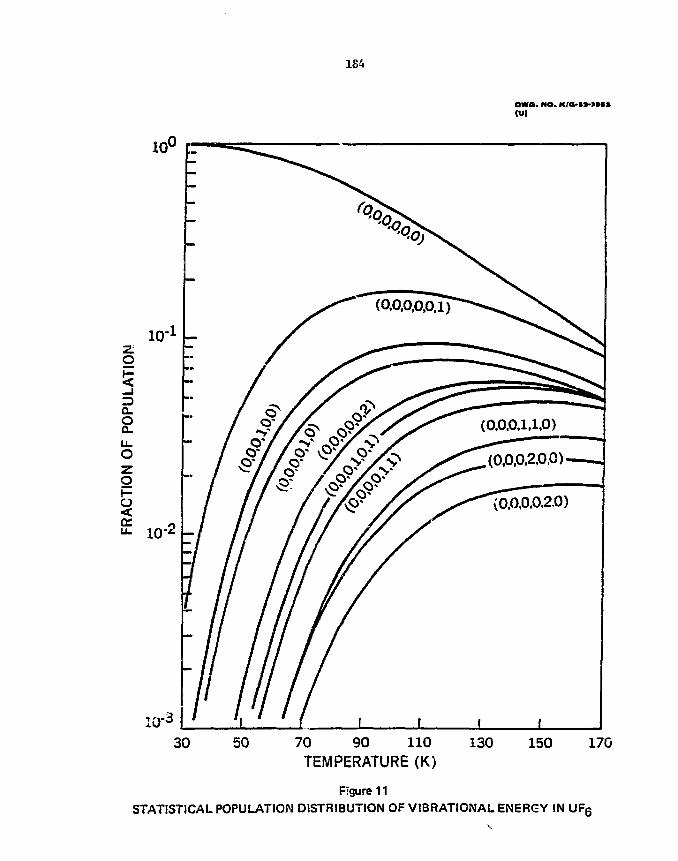
184
OWS. HO. XfO-IMHl(U)
(0,0.0,1.1,0).(0,0,0.2.0,0)
30 50 70 90 110TEMPERATURE (K)
130 150 170
Figure 11STATISTICAL POPULATION DISTRIBUTION OF VIBRATIONAL ENERGY IN UF6

185
laser of sufficient intensity, frequercy and bandwidth to overlap the
desired vibrational transition exist?, then the photochemical method
is likely to result in the most efficient LIS method for that isotope.
Unfortunately, the number of elements that raeec the first two require-
ments are limited. At present, continuously tunable lasers from the
far IR to the near IR with intensities sufficient for economical LIS
processes do not exist. Thus, with few exceptions, the photochemical
method has been limited to the non-metals of 2 — 18.
Conclusion
We have attempted to present the general principals of laser isotope
separation with specific descriptions of th<? major techniques. The
photoionization technique is probably the most general for eii elements
and, depending on difficulties with the vapor source, offers the
advantages of multiple element separations with only minor changes to
a separation system. The major disadvantages are principally with the
source, i.e., obtaining sufficient vapor pressure, containment of the
molten element, and throughput without loss in selectivity.
The photochemical technique has been shown to consist of three separate
processes: (l) a photodissociative process, (2} a multiphoton dissocia-
tion process, and 13) a chemical reaction rate enhancement process. In
most cases, except in single photon photodissociation, the selective
step is through vibrational excitation. For elements of 2 <. 18 this
process has proved to be the more efficient of those LIS methods
considered. As a general technique though, the number of elements that
meet the requirements of volatility, selectivity, and laser source
availability at present are limited for efficient photochemical laser
isotope separation.

186
Acknowledgements
This wo.k was sponsored by the 0.3. Department of Energy under
Contract No. W-7405-eng-26 with Onion Carbide Corporation.
By acceptance of this article, the publisher or recipient acknowledges
the U. S. Government's right to retain a ncn-exclvsive, royalty-free
license in and to any copyright covering the article.

References
113 R. H. Berras in "separation of Isotopes," H. London Ed., GeorgeNewnes Limited, London, 1362, p.431.
12] J. P. Aldridge, J. H. Birely, C. 0. Cantrell, and D. C.Cartwritht, in "Lasers Photochemistry, Tunable Lasers, and OtherTopics,* Stephen P. Jacob, Hurray Sargent, Marlon <0. Scully, eidCharles T. Walker, Editors, Addison-Wesley Publishing Co.,London, 1976, p.58.
13] Richard N. Zare, Scientific American, Vol. 236, No. 2, 86119771.
;4] Keith Boyer in "Laser Photochemistry, Tunable Lasers, and OtherTopics," Stephen F. Jacobs, Murray Sargent, Marlon O. Scully,and Charles T. Walker, Editors, Addison Wesley Publishing Co.,London, 1976, p.1.
[5] N. V. Karlov, B. B. Krynetskii, and V. A. Misfcin, Trudy Ordenatenina Fizicheskogo Institiuta iw. P. N. Lebedeva Akadeajj MamieSSSR, Vol.114, 50119793; V. Brinkmann, W. Kortig, H. Telle, andH. Walther, Applied Physics, 5, 109J2974J; J- P. Aldridge, jr. a.Bireiy, c. D. Cantrell, and D. C. Cartwright in "LaserPhotochemistry, Tunable Lasers, and other Topics,", Stephen F.
^Jacobs, Hurray Sargent, Parian O. Scully, and Charles T. Walker,Editors, Addison-Hesley Publishing Co., London, 1976, p.56.
16] James -. Davis in "Recent D«veloprx=nts in Uranium Enrichment,"J. H. Hftzismn and M. Benedict, Edi-ors, American Institute ofChemical Engineers, New York, 1982, P.~l.
17] V. BrinStmann, M. Eartig, H. Telle, and H. Halther, AppliedPhysics, 5, 109(11974).
18] N. V. Karlov, B. B. Krymetskii, and V. A. Miskin; Trudy OrdenaLenina Fiicheskago Ir.stituta in P. t). Lebedeva Afcademizi HaukSSSR, Vol 114, 50U979).
!9] G. I. Bekov, V. S. Letokhov, 0. I. Matveew, and !f. l. Miskin,JETP Lett., Vol 28, Mo. S, 283, (September 5, 1978J.
[10] S. aockwood in "Tunable Lasers and Applications," A. Mooradian,T. Jaeger, and P. Stonseth, Editors, Springer-Veirlag, Berlin,1976, p.140.
uALTERATIVE ISOTOPE ENRICHMENT PROCESSES*
J . W. Terry
Operations Div is ionOak Ridge .National laboratory
Oak Ridge, Tennessee 37830
For presentat ion at the Workshop 1983 of the Internat ional NuclearTarget Development Soc i e ty , September 7 -9 , 1983, Argonne, I l l i n o i s .
l no .w
*Research sponsored by tlie Office of Basic Energy Science, U. S.Department of Energy undttr contract M-7405-eng-26 with the UnionCarbide Coporation.

190
ALTERNATIVE ISOTOPE ENRICHMENT PROCESSES
J . H. Terry
ABSTRACT
Alternat ive processes such as gas c e n t r i f u g a t i o n , plasmaseparat ion , and l a s e r e x c i t e d separat ion are evaluatedfor use at the ORM. Stable Isotope Enrichment F a c i l i t y .The applicabi l i ty of each process to the Isotople enrich-ment of the calutron feed Material and to the se lect iveproduction of Isotopes Is determined. The process energydemands are compared to those of the ex is t ing f a c i l i t i e s .The isotoplc enrichment of the feed .material prior tte af irs t -pass through the calutrons can result in a s i g n i f i -cant saving in energy.
1. INTRODUCTION
The Oak Ridge National Laboratory (OKN.) electromagnetic isotope
separation f a c i l i t y began In 1944 as one of the Calutron buildings in
the Y-12 plant for the wartime effort to isolate lar&e quantities of
uranium-235. The original configuration was two 33-meter-long
parallel arrays of separators. The 36 separators in each array or
track were linked by a common magnetic f i e l d .
To wake the f a c i l i t y suitable for the separation of the Isotopes
of more than two elements simultaneously, ten separators were reaoved
and magnetic yokes were instal led in their places as shown in Figure
1. This upgrade work was dor> In 1959. Presently only two segments
of separators are in service .
Modifications have been mad<t to seven of the original 180" homo-
geneous f ie ld Calutrons to obtain higher isotopfc resolution at the
expense of throughput. Six of the modified separators are of tlie 255"
inhomogeneous f i e ld type. The original Calutrons and the 255" types
191.
have both source and collector/receiver within the analyzing Magnetic
field. The third type ->f separator available is a 180" inhomogeneous
field node! with source and receiver outside the analyzing Magnetic
field. Fur the purpose of this paper «jn!y the MM" homogeneous
field separators will be discussed furtlier as they are the primary
production aachines.
2. STABLE ISOWiPE i.WENTOKY
T»K? present CIKJuL catalog Isotopes: Products and Services 1 lists
225 electronagnetiralfy separated isotope-*. Of these isotopes fewer
thaa 5 comprise nor*» ihun 70 percwant of the annual production. The
effort required to supply this demard at present operating levels pre-
vents the inventory from reaching n^uilibriun. That is, at present,
isotopes are not t*sin£ replaced as rapidly as tliey are being distributed.
A protean is presently under way to add Materials to the inventory
at an accelerated rate. The new addition rate is being achieved
through the difficult process of running more than ons element per
sequent of separators. In spite of t^e Magnitude of the present
effort, the rate of depletion of the inventory is sloped but not
stopped.
A possible solution to tile present problem would be the restora-
tion of the Calutron facility to Its full operating capacity. Should
funding become available immediately, it would take approximately one
year co locate and train an operating crew.
Surveys conducted by Zisman^ and Laabrecht^ Indicate a substantial
increase in the use of stable isotopes by 1986. The projected use of

L92
one isotope of low natural abundance is such that it would require die
entire annu&l effort of this facility. This is quite possibly an '
overly optimistic projected use, but it serves to point Co the need
for augmenting the Calutton separation capabilities.
The electromagnetic separation process is unique in its ability to
separate all the isotopes of a «ultl-lsoroplc element concurrently.
This process Is, however, ion current United. To obtain gram quantities
of Isotopes of lov natural abundance. It is necessary to increase the
concentration of that Isotope to 10 to 2S atom percent of tlie Calutron
feed material. Methods to perform! this Isotopic enrichment of the
feed in an efficient fashion are u-tder investigation. A .specific *»oal
is to obtain the desired quantities of highly enriched material at
costs substantially below those presently in effect.
3. CALUTRON ISOTOPE SEPARATIONS
Before discussing the processes that seem best fitted to work
with the Calutron program, it seems appropriate to discuss the
electromagnetic separation process. In this process, t*ie atoms of a
given element are loaded into the separator la elemental or compound
form; vaporized; converted to singly charged positive ions; accelerated
through a 35 kV potential difference; directed by the analyzing magnet
through an arc of radius 61 cm; captured as the desired isotopes;
removed from the separator; extracted from the collection system;
purified chemically; analyzed for isotopic and chenical content; and
placed in inventory. The operating conditions and degree of dif-
ficulty vary considerably from element to element. The typical

193
throughput for an electromagnetic separator Is approximately 0.03 mole
per day for a 10 IA beaut current. The typical production of the
desired isotope way he decerained by nultlplyiinj; the daily production
by the natural Isotopic .ibmndanc**.
The electromagnetic separation process i s very energy intensive.
This can he i l lustrated by the separation of vanadium-50. Ic wi l l he
assured that i t i s desired to obtain one fttam of vanadi<\m-5itf enriched
to 36 aton percent. To account for transmission losses , ft wil l be
necessary to ionize 2.5 grams of wanadiira-50. This, in tarn, translates
to the vaporization and ionization of one kilogram of elenentai vanadium
requiring about 11 Ml and 13 MJ, respectively. Accelerating the
kilo«rara of vanadium through 35 kV requires 66 GJ. The average total
ion current reaching the collector i s 36 nA. The analyzing magnetic
field does no work on the particles , but i t wist he maintained.
Maintaining the field while seDarating the gran of va::adi«jn-50
requires 4.3 TJ. Thus, total energy requirement i s approximately
4.4 TJ.
Some applications require larger isotopic enrichments than those
obtained in the process outlined above. Frequently these requirements
are for the enrichment to greater than 95 atom percent of isotopes
with natural abundances less than 5 percent. The desired enrichment
csn be achieved by using the separated isotope as the source material
for a second separation.
However, this isotopic enrichment of the feed material i s costly
and therefore the cost of second-pass products i s approximately 10
tines the cost of f irst-pass material. This cost Increase results
from tlte large quantity of enriched material not collected, roughly 90

percent of the feed, and from the additional time a separator i s in
use for the second-pass. Therefore, more e f f i c i e n t , l e s s costly
methods of separation are inquired and are being investigated.
4 . ALTERNATIVE ISO-TOPE SEPARATION PROCESSES
The three alternative Isotope separation processes under i n v e s t i -
gation arc atomic vapor laser isotope separation, gas centrifugation
and plasma Isotope separation. Each process requires a high capacity
vacuum system. A rough approximation of the energy requirements for
each process w i l l be given a; suaing the same energy demands for a l l
tlie vacuum systems.
The atomic vapor laser Isotope separation (AVLIS) process i s
applicable to a l l elements. I t i s , however, spec i f i c to one isotope
at a t ine . The atoms of the desired Isotope are ionized in a
multistep process and co l l ec ted . Figure 2 i s a schematic represen-
tat ion of the AVLIS process for the separation of vana'jiu*-50.
The vaporization, ionization and co l l ec t ion of one gran of
vanadium-50 requires a re la t ive ly small amount of energy in pr inc iple .
I t i s necessary to vaporize 400 g of natural abundance vanadium to
obtain 1 g of vanadium-50 vapor. This requires approximately 4.6 HI
of energy. The energy required to Ionize one gram of vanadium-50 i s
about 13 kJ. More than 13 kJ must be expended to gain the gram of
var.3dium-50 ions because one step ionization i s not isotope s e l e c t i v e .
A more r e a l i s t i c model assures the simultaneous arrival of three
photons, two photons of approximately 2.5 eV for two step resonance
excitat ion and one photon of approximately 2.0 eV for resonance
195
ionization. If one assumes a 12 pump laser eff iciency, a 10Z dye
laser efficiency and a IQtX to 100X ut i l izat ion of photons for excita-
tion and ionization, the energy requirements are. in the range 9.5-95
MJ for excitation and Z.H-3H tu for ionization. The ions are ac-
celerated through a potential difference of 10 to 100 V to remove them
rapidly from the laser interaction region. The energy required for
swift ion removal Is estimated to oe between 19 t.id 19(9 kJ. Tre
overall energy use i s In the range 1-138 HI. A well designed system
to obtain vanadiua-50 at 19 atom percent should have am energy
requirement that i s toward the lover end of this ran^.
Tilt- gas centrifugattoti isotope separation process i s applicable to
t!'ose elements that wil l form conpounds that have high vapor pressures
near room temperature. To gain the highest isotopic purity, the com-
pound should contain only one other element and i t should he monolsotopic.
The compounds most often used are fluorides. The gas centrifuge i s
operated under vacuum and this places an additional constraint on
usable compounds; the compound oust he sufficiently massive to remain
in the centrifuge during operation.
There does exist a vanadium compound that sa t i s f i e s the above
require merits. Vanadium pentaflouride has a mass of 145.93 arm and
a boiling point of 111.2 °C at 758 Torr4. Ignoring the very corrosive
properties of vanadium compounds, a theoretical value for the produc-
tion of 1 leg of vanadium-50 enriched to 10 atom percent was calculated
by Mailing5* T h e energy needed for the separation was given as
approximately 10 Hrf hr. Scaling this number for the production of 1
gram and converting to Joules gives roughly 36 HI per gram of
vanadius-50 enriched to 10 atom percent.
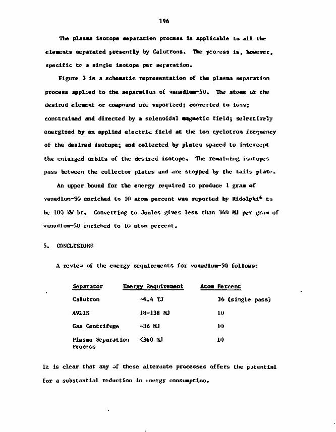
196
The plasma Isotope separation process Is applicable to a l l the
elements separated presently by Calutrons. the process i s , however,
spec i f i c to a s ingle isotope per separation.
Figure 3 i s a schematic representation of tlie plasma separation
process applied to the separation of vanadliM-50. The atoms of the
desired element or compound are vaporized; converted to ions;
constrained and directed by a solenoidal Magnetic f i e l d ; s e l ec t i ve ly
energized by an applied e l e c t r i c f i e l d at tlie Ion cyclotron frequency
of the desired isotope; and col lected by plates spaced to intercept
the enlarged orbi ts of the desired i sotope . The remaining isotopes
pass between the co l l ec tor plates and are stopped by the c a l l s p la te .
An upper bound for the energy required to produce 1 gram of
vanadium-50 enriched to 10 atom percent was reported by Ridolphi6 t-j
be 100 KW hr. Converting to Joules gives l e s s than 360 MJ per gram of
vanadium-50 enriched to 10 atoa percent.
5. CONCLUSIONS
A review of the energy requirements for vanadlujt-50 fol lows:
Separator
Calutron
AVLIS
Gas Centrifuge
Energy Requirement
~ft.4 TJ
18-138 KI
-36 MJ
Plasaa Separation <360 MJProcess
Atom Percent
36 (single pass)
10
10
10
It is clear that any a£ these alternate processes offers tlie potential
for a substantial reduction in tnergy consumption.

19
It may tie Instructive to determine the energy requirements for
acquiring >95 atom percent vanadium-50 by using the most energetically
demanding alternate process to provide feed Material for the Calutron.
A typical source would contain about 100 g of lit atom percent
vanadiun-50 which would require about 36 GJ for production.
The enriched vanadium-50 would then be approximately 40 times more
abundant in the Calutron feed than In the case of naturally occurring
feed material, the >95 atom percent vanadium-50 could then be
collected approximately 40 times faster than from natural abundance
feed.
following the previous calculations for Calutron production we
have: vaporization — 290 kJ, lonlzation — 320 k j , acceleration — 1.7 GJ
and magnetic f ield — 108 GJ. The Calutror. energy requirement i s
roughly 110 GJ. Adding the -36 GJ for feed production, the total
energy consumption i s approximately 146 GJ. This Is about 3 percent
i>f the energy necessary to obtain I gram of 36 atom percent v?nadium-5F.
Clearly the enrichment of the calutron feed material b" one or
any combination of the alternate enrichment processes can result in a.
substantial reduction in energy consumption. The production of highly
enriched Material at a mare rapid pace can serve to ameliorate the
depletion of the stable isotope inventory.

198
REFERENCES
/ /1. Isotopes: Products and Services; OakyRidge Nlatlonal Laboratory,
Isotope Distribution Office; U.S. tfepartaent of Energy; January1983; pp.II-1 - 11-52. ;
2. M.S. Zisaan, "National Uses and .Needs for Separated StableIsotopes In Physics, Chenistry and Geosclence Research";Separated Isotopes: Vital Tools for Science and Medicine; RationalAcademy Press; Wash., D.C.; 1982; pp. 81-17S.
3. R. M. Laabrecht, "iCooedlcal Research Applications ofElectromagnetically Separated Enriched Stable Isotopes"; SeparatedIsotopes: Vital Tools for Science and Medicine; ISational AcademyPress; Wash., O.C.; 1982; pp. 385-246.
4. CRC Handbook of Chenistry and Physics, S9tii Editim, 1,M-19T^;CRC Press, Inc. West Pain Beach, Fla; p. S-1WJ.
5. G. F. Mailing, private cownuiilcatiore; Oak Ridge (Saseous BiffmsioroPlant; Oak Ridge, TN.
6. F. Ridolphl, private <-o»aunlcation; TKW Energy SystemsRedondo Beach, rA.
199
ACKNOWLEDGMENTS
1 would like to thank W. A. Bell , Jr. and J. G. Tracy for numerousenlightening conversations about the Calutron f a c i l i t y . For nanyhelpful discussion on the AVL1S process, thanks are given to W. H.NcCuil-i. G. H. Mailing and fl. E. Mlchels must receive thanks fortheii ^,*.i.~Z-*i.Ions nnd lnforaation regarding the alternate Isotopeenrichiaent processes.

200
Figure Captions
Figure 1. ORML Electromagnetic Isotope Separators.
Figure 2. Atomic Vapor Laser Isotope Separation Principle.
Figure 3. The Plasma Separation Process.

ORNL-DWG 83-13233
SEPARATOR
MAGNET EXCITATIONCOIL
©STABLE ISOTOPE SEPARATIONS©RADIOACTIVE ISOTOPE SEPARATIONS
180 255
MAGNET YOKE
SEPARATORS IN USE:180°; RADIUS 61 cm225°; RADIUS 51 cm,/?*0 .5180°; RADIUS 61 cm,
Fig . 3
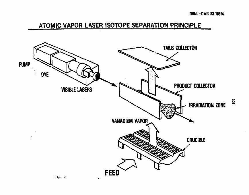
ORNL-DWG 83-15694
ATOMIC VAPOR LASER ISOTOPE SEPARATION PRINCIPLE
TAILS COLLECTOR
PUMP
DYE
VISIBLE LASERSPRODUCT COUECTOR
IRRADIATION ZONE
VANADIUM VAPOR
Fig. 2FEED
CRUCIBLE
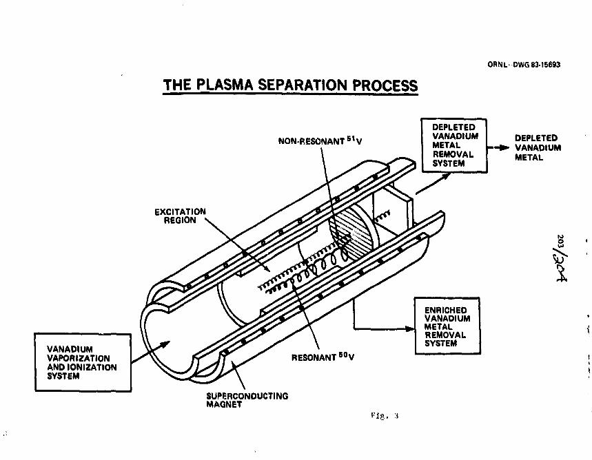
ORNL-DWG 83-15693
THE PLASMA SEPARATION PROCESS
VANADIUMVAPORIZATIONAND IONIZATIONSYSTEM
NON-RESONANT S 1V
EXCITATIONREGION
SUPERCONDUCTINGMAGNET
DEPLETEDVANADIUMMETALREMOVALSYSTEM
DEPLETEDVANADIUMMETAL
ENRICHEDVANADIUMMETALREMOVALSYSTEM
Fig. 3
205
PROBLEMS ASSOCIATED WITH PRODUCING GENERAL TYPE TARGETS
General DiscussIon - Led by J. C. Gursfcy
A beryllium bean has been successfully produced from a Mixture of berylliumoxide and silver. Apart from this information, the topic of the discussionwas the eternal problem of fabricating high-purity targets from, snailquantities of isotopes. The methods touched on were:
1. electron gun - magnetically and electrostatically focused2. saddle - field ion source3. focused ion bean sputtering4. laser bean heating5. induction heating
All of these tend to be fairly low in efficiency. An important problem isoverheating of the substrate by a large, molten ball of material. Use of aninorganic stripping agent is frequently useful, as is cooling the s-ibstrateor backing it with a heat sink. A small quantity of isotopic material, say25 rag, can be used if the electron beam focus is very small.
A particular design of electron gun, such as the Pierce, small Varlan orlarge Temescal, may be optimum for certain materials. Great care must betaken to avoid evaporation of copper when electron beam heating very smallquantities of Material in a water-cooled copper hearth. Some elements canbe evaporated from a refractory crucible in the hearth.
The new saddle-field ion source produces a tiny beam, as does focusedsputtering using duoplasmatron or PIG sources. These sputtering systemsare of course designed for very small amounts of material, with littleheating of substrates. Laser heating has also been described.
Induction heating can be used on a pellet of compressed powder such asboron. The water-cooled pedestal may be only 3-5 an in diameter. Themolten area can be confined to the top of the pellet, resulting in a veryclean evaporation.

SESSION I E
FRIDAY MORNING, SEPT. 9 , 1983CHAIRPERSON: G. HINN

Reprinted with permission of:Nuclear Inurnment k aaJ Mrihodt 2M> OSfii MI-ANona-Holland Publishuif Company
207
THE PREPARATION OF l l 5Ulr, TARGETS FOR USE IN jr-FACTOR MFJUSUREMENTS OFFISSiON 1SOMERS*
C. ALONSO-ARIAS •*. E. DAFNI ••*. M.H, RAFAILOVICH \ W.D. R1EL.G. SCHATZ * *. G.D. SPROUSE. S. VAJDA and S.Y. ZHU! " * *
' *4 Physics. Stale Vmrmin'iif AVr York. Stair Bnwk, Xtv Ymrik 11794, IZ&.A,
Rccicved6 September J9S2
The cubic, nonparanugnetic alloy. s"L1lr2. « t faunu to DM a food hot! (of the pmnvMion of macfaur atawimtnn in the ,«;-fjKt>:wnKHHiremeal of the r •> i r ^ !0) m fitficm iKwaer of :'*Pu. Tint. p»pcr di«ci«»«*, an detail, the pittnw.«m« rf Ae Iliun-Silm iW]ptt« n»nlin this nieasurenKnl. These techniques » « e found to apply u* <«<m- namiilir aniaHfe atomp* Mich aw IVpRm;.
1. latraAtdioa
The fission isomers which were disoowmd in (he1960s offer a unique opportunity to study nuclear slruc-IUK at very fcnge deformation. In order to determine thespins of the odii-A isomers several attempu have beenmade to measure the magnetic moments of some of thelonger lived cases [1-3). However, the dual problems ofparamagnetic relaxation and radiation damage havethwarted many efforts in this field. We have recentlypublished a successful ^-factor measurement (<( of theT « 122(10; ns isomer in :rTPu, The Pu nuclei wereproduced and aHgned wit'i a pulsed 25 MeV « paniclebeam via the reaction iisL"(«, 2n)~"Pu. The Larmorprecession of tlte fission fragment angular distributionwas then observed in an external transverse magnelh:field using the technique of TOPAD (5). The properchoice and preparation of (he hosl for performing thismeasurement and other similar ones is the subject of(his present work.
I.I. Relaxation processes in acimide elements
(a) Since the actinide elements have an unfilled f-clectron shell, they tend to form local moments when
* Supported in part by the National Science Foundation.** Present address; Dept. Fisica. Comuion Nacicmal tk
Energia Atomica. Buenos Aires, Aratniiaa.*** Present address: The Weizmaiui Institute. Rthowt, lsijd.
* Present address: BrooMiaven National Laboratory. Up-ton. New York 11973. U.SJV.
* * Konsutu Univeraty. Konsianz. Wen Gennany.* * * Present address: Institute of Atomic Energy, Beijing.
PRC.
present »v dilute impurities in nuetak J*J, Cothe effective field at the nucleut will he the sum of thec«tenul field. JV and a stputicsuit hvpeffinc Krltl com-ponenl. For temperature* abmie appro*. 10 K the effec-tive nuclear lirld i« fiven h\ the Curie law JTJ, i / ( D =B^a * fi/T% where the cc nvtantv m and fi depend onthe effective impurity charge " Ule and the size of thelocal moment. In general, neither of thete quantities canhe predicted theoretically for the actinide* and muvt bedetermined hv further experiment*. A« can be «een fromthe exwasive literature on the subject (I-4]. thece e»-perimentt are usually difficult and time-consuming,.
A more serious problem related to the formation of alocal moment is (he time-dependent fluctuations of theelectronic spin. These couple to the nurfear spin andrelax the initial nuclear alignment. A-,, aexxmiing lo Iheexpression (7J.
where wHF and r,. are respectively, the nudeir hj-perfinefrequency and the spin-flip correlation lime. For mostactinide impurities aUF is in the GHz range. Shreter elal. [8] have sho»n that for N>Pb. rc~ 1 0 " ' and ihealignment is loci within the fust 40 ns following implan-tation.
«b) Due to their large deformation, fission isomershave quadrupole moments of approximately 30 b. sig-nificantly larger than those of the more common r-iso-mcrs. As a result, they interact very trongty with elec-tric field gradients present in Ihe host. These gradientsarise from the intrinsic crystal symmetry of the hostand/or from radiation damage produced by the re-coiling impurity nucleus. Previous work (9] has shown
OI67-S087/83/0000-0000/S03.00 e 1983 North-Holland
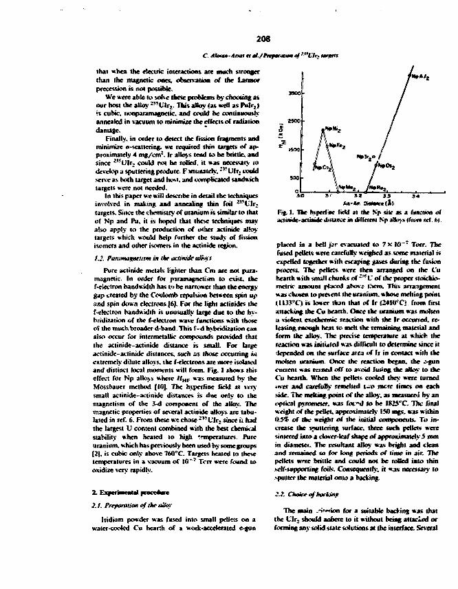
208
C Akmta-Anaf a il./hiw/mMiimaf1*'Ulr. untrtt
that when the electric interactions are much strongerthan the magnetic ones, observation of (he Lannofprecession is not possible.
We mere able to solve these problems by choosing a*our host the alloy -"Ulr,_ This alloy (as well as Pulr2)is cubic, iionparamagnetic. and could he continuouslyannealed in vacuum to minimize the effects of radiationdamage.
Finally, in order to detect the fission fragments andminimize a-scattering. we required thin targets of ap-proximately 4 mg/enr. Ir alloys lend to he brittle, andsince 2'JUlr2 could not be rolled, it was necessary todevelop a sputtering produrc. F minutely. :"t'lr. couldserve as both target and host, and complicated sandwichtargets were not needed.
In this paper we will desenbe in detail the techniquesinvolved in making and annealing thin foil ^UHijtargets. Since the chemistry of uranium is similar to thatof Np and Pu, it is hoped that these techniques mayalso apply to the production of other actinide alte*.targets which would help further the study of fissionisomm and other isomers in the actinide region.
1.2. PanimagHeusm in the uctimtic aUms:
Pure actinide melals lighter than Cm are not para-magnetic. In order for piramagnelt«m to exist, thef-eleclron bandwidth has V> be narrower than the energy-gap created by the Coulomb repulsion between spin upand spin tkwn electrons (6]. For the light actinides thef-electron bandwidth is unusually large due to the hy-bridization of the f-eleciron wave functions with thoseof the much broader d-band. This f-d hybridization canalso occur for intermetallic compounds provided thaithe actinide-aclinide distance is small. For Urgeactintde-aclinide distances, such as those occurring inextremely dilute alloys, the f-electrons are more isolatedand distinct local moments will form. Fig. I shows thiseffect for Np alloys where //,„ was measured by theMossbauer method |IO], The hyperfine field at ««ysmall aclinide-actinide distances is due only to themagnetism of the 3-d component of the alloy. Themagnetic properties of several actinide alloys are tabu-lated in ref. 6. From these we chose -"L"lr, since it hadthe largest U content combined with the best chemicalstability when healed to high —mperatures. Pureuranium, which has previously been used 'by some groups[2], is cubic only above 760cC. Targets heated to thesetemperatures in a vacuum of 10"' Terr were found tooxidize very rapidly.
MOO
MOO
53©
2.1. Preparation ofthe olio?
Indium powder was fused into small pellets on awater-cooled Cu hearth of a work-accelerated e-gun
I. The Anpcifuc field at the Kjp sle a« a (vmmem ofacliinide-acliMat diflaiwe in uWferral N> illmy tfwm rcf. 6t.
placed in a bell jjsir evacuated talx ia~" Torr. Thefused pellets were carefully weighed as tome material i«expelled together with ocaping gases during the fusionprocess. The prlless were then arranged on the Cuhearth with small chunks of 2?? V of the proper stoichio-metric amount placed abov£ Ctcm. This arrangementwas choien to prevent the uranium, whmc melting point< m r C » is lower than that of Ir «24I0"C» from firstattacking the Cu hearth. Once the uranium was moltena violent exothermic reaction with the Ir occurred, re-leasing enough heat to melt the remaining material andform the alloy. The precise temperature at which thereaction was initialed was difficult to determine since itiepemjed on the surface area of Ir in contact with themolten uranium. Once the reaction began, the --guncurrent was Mined off to avoid fusing the alloy to theCu hearth. When the pellet* cooled they were turned«M>er and carefully remdled i -o mere limes on eachside. The melting point of the alloy, as meaturcJ by anoptical pyrometer, was fix -d lo be IKZS C. The finalweight of the pellet, approximately ISO mgs. was within0.5% of the weight of the initial components. To in-crease the sputtering surface, three Mich pellets weresintered into a dower-leaf dupe of approximately 5 mmin diameter. The resultant alloy was bright and deanand remained so for long periods of time in air. Thepellets w-rrc brittle and could not he rolled into thinself-supporting foils. Consequently, it was necessary 10\puller the material onto a hacking.
ZZ Choke of backing
The main .'••"ion for a suitable backing was thaithe L'lr, should aobere lo it without being attached orforming any solid state solutions at the interface. Several

209
C. Alnmm-A "fir.
backings whose phase diagrams [II] showed that theywere relatively immiscible with either V or Ir were tried,these Here: Pi, Mo. Ni, Fe. Ti. V. and Se. Among themonly Mo remained inert and retained the alloy's integr-ity after healing to IO0O°C. To minimize a-hacfc«ratfer-ing Ihe Mo was rolled to a thickness of 4 mg/«nr in 301stainless steel packs on a 5" x 8" mill running two high.The foils were then vacuum-annealed hy healing nesis-tively for 1 h at 130G'C. Foils thinner liian 4 mg/cnfwere unable to withstand the strains introduced duringIhe annealing stages of the alloy, due lo the differentthermal expansion coefficients of l l r , and Mo.
2.3. Sputtering procedure
Due to the high melting point and low vapor pres-sure of the alloy, it was (leaded thai evaporation withan e-gun was impractical and could result in excessiveoxidation of Ihe pellet In contrast, focussed ion beamsputtering, being a kinematic process, could depositmaterial at lower temperatures with lass oxidation. Itwas also possible, as X-ray analysis proved, to transfermaterial ssoichiomeJrically ;see fig. 2).
Sputtering was carried out using a duoplasmalronwith an ein?et lens to provide a Kr* beam of 2.5 m\.with an extraction voltage of 20 K.V. The annealed Mobacking foils were cut into I" squares and clamped onto1/4" thick brass holders which also served as heatsinks. The brass holders were placed 2" above the Vlx2
pellet on a conical mounting along with a quartz crystalmonitoring unit. A thickness of 4 mg/cnr of ih • alloywas chosen so that fission products from the rear n f thetarget could still reach the detectors. Thicker tar ^tswould only result in an increase of the hackscalterirg.
The depositions were carried out at — 3 X 10 * iorrand typically required 9 h for 4 mg/enr. The Kr *beam energy was high enough for reasonable sputteringrates yet low enough so as not to raise the temperatureof the pellets or targets excessively. The targets thusproduced had a mirror finis}) and were cut to sue in airafter cooling in Ar. Sputtering times with the lighterAT* beam were three times longer.
X-ray analysis of the freshly sputtered targets showedno peaks indicating a high degree, of disorder in the
Fig. J. Ifcr etpnriimcnu] dumber n«cd for mratunracnM. atflf-(»aair* at fmkm iwnner*. ll\* » detailed e*| IMUIM-I., sec tct4*
Satike. Therefore, in order to .study the hvperfine imer-aciion in an unperturbed envinioi.ient, the targets hadlo be annealed.
2.4. Afxalms, metiaad
The annealing proce«« was cumducted m-htam dur-ing dat» luUftfuon. Two urjds were mounted on »heater rod and inserted in the experimental chambershown in fig. X The targets were reunively heated toapproximately W C and Ar-r temperature was mea-sured with an optical pyrometer.. The retinivitv of thetargets was monitored continuously during heating.Structural annealing WTK. demonstrated by a gradualdecrease in resistivity during the first flute hours. If thechamber vacuum were good, further annealing for »lleast 4$ h produced no change in resistivity. Continuousannealing of the target was necewary to minimize theeffects of radiation damage described in ref. ft. Toprevent oxidation of the Urgrt wnile they were beingheated, it was important to maintain a vacuum of2 x 1 0 ' Torr or heller in the chamber. This wasachieved by surrounding the heater rod m-ilh a Cu shieldcooled with liquid nitroaen and by pumping on the
Fig. 2. Cninier X-rav photographs: |a> of an snneakd ~w«Jlr; ur)Kt; (hi of the aHoy peMet Item shich the l**M ia («i was *r :. -redNote that the extra lines appearing in (a) are mainlv from the Ma backing.

210
C Ahmso-Ahmt ti tl./rnfarmmmef^'Clr.
4O 3O70 CO
29Fig. 4, Hart-reflection X-ray diffraction <ntenut*ck for three differcwt u » f fli* diet teun. The taiyct r.ro (at » M alh«« r*»Xi*t*r*>c«J u n » fthe Ciuinier techiu<|ue Jiwl is «JKi»i>in in % 2a.
chamber with both a cm-pump and an ion pump,Target foils healed in good vacuum for longer irun 40min showed shwp l l r . X-ray lines ( ce fig. 4a), Thciiappearance was shiny and they temlrJ to curt with (heMo side out. Brief excursions of the chamber vacuumcaused hy warming of the Cu shield resulted in anincrease of the target resistivity. Even though thesetargets appeared metallic, they did not curl and theirX-rays showed Ulr. as well as Ulr, and t,\<X, lines(fig. 4b). High magnification microscope photographsrevealed the break-up of the alloy into bubbles or""islands' on the surface of the foils of approximatelySO pm in size (fig. 5). These effects were believed to becaused by the oxidation of the uranium component ofUIr:. leaving excess iridium and forming Ulr,. Furtheroxidation of the targets also caused the break-up ofUlr, into free Ir and several uranium oxides <see figs,4H, c).
•?..£ ">ampk characlerizatum
The crystalline structure of the annealed target wasanalyzed using X-ray diffraction. Two different meth-ods were used: transmitted X-rays with a Guinicr cameraand diffracted X-rays with an X-ray diffractonieler.
The Guinier camera was a front reflection or trans-mission camera which used a Cu X-ray tube and aquartz monochromator. The X-ray exposure times weretypically 1 h for a lube voltage and current of 52 IcV
and 21 mA. The sample was rotated conttanll} i«»average over all oodtationtu The diffracted raw fromtine specimen were focu«ed on Mingle tided X-ray film(Kodak, France) to amid double imaging. The analvMVof photographs Ule lho*e Jx«i> in fig«u 2a. b » JV madeb> measuring the poMlion of (he diffraction line» mm thefilm and deducing the Unite racing* form the usualcantera cquaiions given in ref. 12. The resultt werecompany to standards tabulated for different wb*-tance« in ref. IX
The diffractoMneler wa« » GExROS «|uippal with aCu lube. The tpecuncn support was mechanically cou-pled to the detector support so that a rotation of thecounter through 2f degrees was automatically accompa-nied by rotation of nhc target through # degree*. Therange analyzed wa» from # *2O'-12««.
In the back reflection leduiiquc the X-rays couldonly probe the top 02$ mg/enr of the target at low-angles to a maunum of 1.37 mg/cnr at t - 90°. Theloul target thittn.-** was 4-5 ag/enr. In contrast, theGuinier tnmsmizjtm photographs probed the entirethickness of the target. Gmpanton of figs. 2a and 4aallow that the Ksaks of the two technique* aie similarand demonstrate the unifonnity of the targets. In addi-tion, comparison of these figures with fig. 2b shows thatthe annealed sputtered targets have the same crystallinestructure as the original 2*}Ulr2 pellet. Completelyunannealed samples stowed no crystalline structure v. jtheither X-ray lechnkiue.
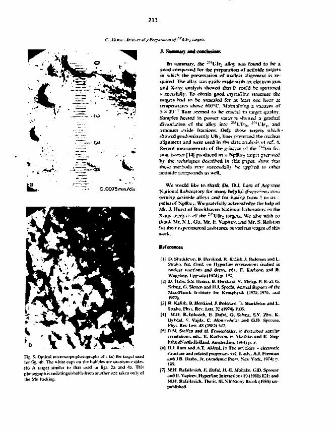
211
C Atmx>-Arias <o dof.//V»jvwaw'.«i ff^l'lr*
X SuaMun —d
Xf
0.0075 mm/diw
Fig. 5. Optical microscope photographs of : (a) (he large! usedfor fig. 4b- The white caps on the bubWes are uranium oxides.)b) A target similar lo that used in fig1-- 2a and 4a. Thisphotograph is indistinguishable from another er.s taken only ofthe Mo backinc.
In anmur . ; the ' ' l l f ; alloy «as found la be agood c<?mr»um3 for the preparation of asrtinide targes*in which the pme&rirvaliwni of niK-Iear alicjunenl is re-quired. The allay was easily mode with am etectron gunand X-ray jn jh si* showed that ij could be spdrtlered
l},". T<o> <o*«ain gaod cijsiallllHine strotlmre thehad to he annealed Cor 31 Cca$l one fciiar at
and
5 X W"1 Tern .seemed to be cinuial «o Barges •SampJes iMsited nn pwwteir vacui'rn sfc<r»iftS a
of the alloy inim I n t r l f ; . -^Oli&i>t««ie fraiuwns. Only utowsf
sllttwud preAmijaaimtlly Ulr, II » « e u?ed in rtw dstia a A A oJ ref. 4.
: tneammmenlf «HT line jc-tawir «?I site r"*Am Ks-irion iMmeir JHJ piriiMjaticd in a NpRoju nargtil freparedby the techniques deu£Triil>ed So this psper. sJirow" thatthese mraeitliiods imaj- swcc&iitfflx he sippi'sti tw snh&cactinide niampminds as welL
We wamtd lite io dliank Dir. DJ . LamNational lahcraKny foe many helpful dism^-nwi. co«-txming aciliniile aBms am] fiov (hsifrE Cvaiu <! »*» ai« -pellej of NpRaju. We ipnajefuilly a£*BMmWje the help ofMr. J. Ifnret «J BnwUiaven Klaiiooal Lalioratorv in theX-ray amaHysis #f the I!"lUlrj gaigeK. We also wish tothank Mr. XX. Gu. Mr. R, Vapwev. aaul Mr. S. Rofelowfor their uMperinKntal affiance at laif.ous »:a^fs nf «h;vwork.
IH D. ShacUcKm. B. HCTAMMI. R. KsHsto, J. Pfflkusro and l_Strata, InL C«af. ICTO Hjjwifine wtattHaos: stadiaS innudew rMrtic«s and «S«*j-. «ls_ E. K*J?^5.<« ami R»>pj>lins. tn|Fjps»ll»(|ll9T4j)p, IIJJ.
121 D. Hatw. SS. ll*«ua», ». HwsMad, V. Meu», P. P."* G.Schsii?, G. Sifciien aad H J. Sjpedst, Amnaisill Repwts uf fixMaK-PUwck Ir.stitule for Kfmplhy»lt (197$. 1976. asid1977J,
(J| R. Katli&b. 0. H«5i«n<JI, J. tfedmen. 'A ,Sfcwrlk5«i »»J LSlraKw. Phy&. Rev. U«IL 32 (1974) OfflW.
14) M.H, Rvfaiknich, E D*foi, G. Sd»B. S.V. Zhu. K.D ) M J 1 , S. Vsjda. C. ASon«>Aim»s aj«a G.D. Sprewn*.Ph>-s, Rev Uti. 4S <l*«2il V*2.
(5] EM. SJefftn and H. Fmtimleiiiei, is ftenu*«J 3O£ulii'cwrrel»tic«!v mis.. K. Kartssom. fe. M»J!li»s and K. Siej-tahn DNonh-lIolbiwl, AroMwJUm, B%4ji p. 3.
(6) DJ. Lwn and A X AWMKI, in The areiaiifs - cfcrtrcoicsuueture and retued prqpenjrs, x«A. 1. «>3s.. A.I. Freemanand J.B. D«by. Jr. JAsademic HWSS. %"»• Y M * . 1OT4) ->.JI09.
J7J M.H. Raf*.k»K*. E Djifnj, H.-E MsJwte, G.D. 5j?K«j*am) K. Vapirev. Hvptifunc Inloracuran MS (DQ8I) KI; andM.H. Rafailovk*. Thesis, SUNY-SIOTJ- Br«* KI9S0) ua-puMisbed.

212
C Alamo-Anas ttal./PirfamiKmgf'BL~lrz
18] V, Sehreterand R Kalivh, Ph>* Rev. Lcit.4S«19ft2»SM, JJJ]19] G. Schatt. M.H, lUfaitowcfc, W.A. I'.itlt and CD.. Fkimtor DifTrxtiKn
SprouK, Phys. Rev. Lett, ?5O97JJ BOt , gi4j| MLH. lUfjulwucfe. S. Vagda. S.Y. Zhu and S(10] B.D, Dunlap and CM, K«J«iin. Mil. 2 nrf n l «>., p. 237. tdtagiiuid lo the AjnAmo D;i»t»«ul Mctunf of111] F.A. Rounh and AA. Bauer. CnaMHtulittnal dii^raiat rf Amniiraa M>i«c*l Sodct).
uranium jnd ihrnuin aBoj>s (JAddisrm-We^p.1. Xcw Yoirli).J32] B.D, CuU'uy. Ekracnis mi X-irav dijfocniimo UAAIison-
' 1956),

211
PROGRESSIVELY BETTER TECHNIQUESFOR THE CONVERSION OF 41KCl to
W. R. LOZGWSKI and J. A. KRSEK
Indiana University Cyclotron Facility, Bloonington, Indiana 47405, M.S.A.
After much effort to convert KC1 to chlorine-free KOH by fsiraimga mercury/potassium amalgam, this pursuit was abandoned In favorof a simple electrochemical cell in which silver fHLl was usedas a sacrificial anode. Recently, we have acm"?" ad greaterknowledge of the use of exchange resins and nave, .here fore,joined the mainstream.
1. IntroductionThe conversion of KC1 to KOH Msimg an ion exchange resim ClERj) seesDS quite
straightforward. One method has been described ray G. Slattern") in 1980.However, there are many subtleties involved in tine use of these resins. Priorexperience with a batch treatment: conwursioti (Na^'ci t o ica37ct with 78Zefficiency) caused the avoidance of the use of IERS in favor of "e"em easier,higher yield" techniques for KCl and KOH. Tw© of the methods attempted andthe problems encountered vtll be bri,.r*y described.
2. MethodsThe first effort involved an attempt to develop a scaled-dowro version of a
widely-used commercial method. *!ost general chemistry texts mention the taseof a DeNora cell to convert KCl to KOH on a large scale. In this cell, A tltaimlayer of mercury (the cathode) covers the bottom and graphite anodes are hungfrom the lid. As the KCl is electrolysed, potassium forms an amalgam with themercury. When the amalgam is brought into contact with water outside thecell, the potassium is released to form a pure solution of KOH. Althoughnumerous variations of this basic scheme were iried, including the use of nanydifferent diaphragms and aeabranes, pure KOH (without KClQ^) and a high yieldwere not simultaneously achieved.
The second method attempted involved an alternatively simple idea with anotherelectrochemical cell. The method developed involved dissolving the KCl imwater and using a graphite cathode and a sacrificial anode >f silver foil(0.G25 mm thick). The presumably insoluble AgCl was then filtered and centri-fuged out of the potassium hydroxide solution. Extractions with ethyl etherindicated that very little unconverted KCl was present after running the cellat 0.5 amperes for 90 minutes.
*This work was supported in part by the National Science Foundation.

214
To satisfy an exigent deadline, only one trial run was made before makingthe conversion with 200 «g of 41KC1. Both worked satisfactorily.Many months later, the latter described technique was used to do the follow-
up work for a paper. It was found that a snail, variable amount of solublesilver chlorate was now being foraed in the cell. Several cycles of thefollowing procedure were necessary to obtain pure KOH: drying the KOHthoroughly, exposing it to strong light to decompose the AgClO4, redissolvingit in a small amount of water, and centrifuging the solution.These additional steps significantly extended the time necessary to do the
conversion; hence, ion exchange resins were again considered. In retrospect,the real problem with IERs was that the reference texts that were used did nothave application information. A telephone call to Fisher Scientific providedthe necessary contact who answered questions about how the resins night beused effectively for small-scale conversions. ) The contact, who was aresearch chemist, recommended a publication entitled Anberlite Ion ExchangeResins Laboratory Guide^) - available without cost froa Rohm and Hass Company.This booklet favors colurn exchange operations; the text covers precautions,charging a column, backwashing, conditioning, concentrations of solutions, andrecommended flow rates.
3. ConclusionIn conclusion, the conversion of KC1 to KOH by an IPR i:; the easy, high
yield method which was sought. Perhaps this account of developmental misstepswill serve to forewarn.
References1) G. Sletten, Ninth World Conf. of the International Wuclear Target Develop-
ment Society, Gatlinburg, Tennessee, 1980 (North-Holland Publishing Co.,Amsterdam, 1982), p. 19.
2) V. Taraseko (private conversation).3) Amberlite Ion Exchange Resins Laboratory Guide, (Rohn and Hass Co.,
Philadelphia, PA 19105).
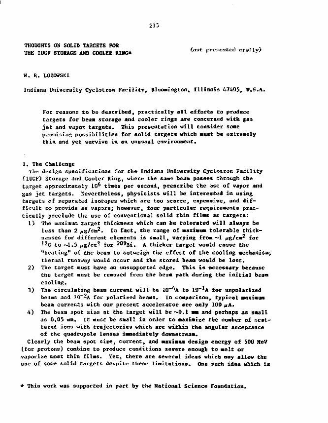
215
THOUGHTS ON SOLID TARGETS FORTHE IOCF STORAGE AND COOLER RIMG* C n ° £ P « s e n E e d
W. R. LOZOWSKI
Indiana University Cyclotron Facility, Blooaington, Illinois 47405, U.S.A.
For reasons to be described, practically all efforts to producetargets for beam storage and cooler rings are concerned with gasjet and vapor targets. This presentation will consider somepromising possibilities for solid targets which must be extremelythin and yet survive in an unusual environment.
1. The ChallengeThe design specifications for the Indiana (University Cyclotron Facility
(IUCF) Storage and Cooler Ring, where the sane bean passes through thetarget approximately 10^ tines per second, prescribe the use of vapor andgas jet targets. Nevertheless, physicists will be interested in usingtargets of separated isotopes which are too scarce, expensive, and dif-ficult to provide as vapors; however, four particular requirements prac-tically preclude the use of conventional solid thin films as targets:
1) The maximum target thickness which can be tolerated will always beless than 2 g/cm'. In fact, the range of Maximum tolerable thick-nesses for different elements is snail, varying from ~1 ^ig/c«2 for12c to ~1.5 |ig/cm? for 209Bi. A thicker target would cause the"heating" of the beam to outweigh the effect of the cooling mechanism;thermal runaway would occur and the stored beam would be lost.
2) The target must have an unsupported edge. This is necessary becausethe target must be removed fron the beam path during the initial beancooling.
3) The circulating beam current will be 10~*A to lO'^A for unpolarizedbeams and 1Q~^A for polarized beans. In comparison, typical maximumbeam currents with our present accelerator are only 100 «A.
4) The beam spot size at the target will be*~Q.l mm and perhaps as smallas 0.05 mm. It must be small in order to maximize the number of scat-tered ions with trajectories which are within the angular acceptanceof the quadrupole lenses immediately downstream.
Clearly the beam spot size, current, and maximum design energy of 500 HeV(for protons) combine to produce conditions severe enough to melt orvaporize most thin films. Yet, there are several ideas which may allow theuse of some solid targets despite these limitations. One such idea which is
This work was supported in part by the National Science Foundation.
216
pivotal to the successful use of solid targets is that it should be possibleto intercept the edge of the beam (i.e., only a small fraction of the totalcurrent) with c!:e edge of the target, thus enabling the use of significantlythicker (structurally stronger) targets by aeans of active control of theinteraction rate. If this node of operation proves to be impractical, thenefforts to produce solid targets for the Cooler may be altogether unproduc-tive. Assuming that the "grazing" Method is possible, one is encouraged bythe expectation that the required size of a target will be Much smaller thanthe 10 am diaaeter required for our present accelerator.
Two other features of the Cooler support hope for solid targets:1) The improved energy resolution expected with the Cooler will facili-
tate increased use of compounds and alloys. Accordingly, using these,one can tailor more easily the physical properties of a thin film toenable it to survive in the bean.
2) A Rutherford scattering setup will provide continuous monitoring ofthe luminosity; hence, the target thickness need not remain constantthroughout an experiment.
The idea of having an unsupported edge of a sufficiently thin foil (orevaporated strip) as a target is not wholly ludicrous, assuming a tinytarget area which is grazed with the beam; however, the most promising wayto provide solid targets for the Cooler is to concentrate effort on fibersand whiskers of high melting point elements and compounds.
2. FibersWith regard to fibers, SiO2 and C are likely candidates. Quartz fibers of
0.5 x 10~3 to 2 x 10~3 ma diameter are very strong and relatively easy tomake. Boys^) first published the technique in 1887. Strong^) wrote indetail on making and handling thin quartz fibers. Smith^) used SiOj to taggammas in the Cambridge Electron Accelerator and reported on in-beam experi-ence with the fibers. In addition, Smith-*) described a clever variation onmaking and collecting very thin fibers.Carbon fibers of 7 x 1Q~3 mu diaaeter are available from Union Carbide and
The Stackpole Corporation. Union Carbide provided the author with technicalinformation and evaluation samples of "Thocnel" 300 carbon fiber grade WY.PIS 1/0. It was found that individual strong and flexible filaments could beeasily separated from the 6,000 filament yarn.The 7 x 10~3 mm carbon fibers (the thinnest the author has been able to
obtain) are ~975 jig/cm , and 0.5 x 10"-' sn quartz fibers are ~80 ^g/cm^.Both are too thick for total iw.ersion in the beam, but they may be usefulsubstrates for vacuum evaporated or sputtered coatings of desired targetmaterials. If grazing is precisely controllable, an overcoats fiber targetinvites more speculation.1) The thicker the coating, the fewer times that incident ions will
interact with nuclei of the fiber material.2) If the coating is vaporized slowly in the beam, the fiber would pro-
bably survive and could be repositioned to expose "fresh" coating.
217
Heyer (IUCF) has suggested that it sight be possible to thin some fibersby heating then. Sublimation of a portion of a Mounted fiber should bepossible via an electron gun. Although the rate would be lower, sputteretching via a neutral atomic beaa of Ar from a saddle field ion source wouldhave an advantage in that heat-induced Mechanical stress would not be pro-duced in the fiber. Drinkwater^) has reported on the addition of reactivegases to increase the etch rate by as much as a factor of 12 (for dielectrics).
3. Whisker*Whiskers which are 0.1 x 10~3 to 0.5 x 10~3 not thick and long enough to
allow total immersion in the beaa have been reported in the literature.5,6,7,8)The thinnest of these, which possesses a low vapor pressure near a high weltingpoint, will be desirable for over-coating - as with fibers. By positioning acoated whisker with the target {i.e., coating) on the back side with respect tothe incident beam, the recoil reaction products would not be lost in thewhisker. In addition, an isotopically enriched coating would not be needed ifan enriched whisker could be grown. Perhaps fragile whiskers would not have tobe detached from the substrate on which they are grown if one mounted thesubstate edgewise to the beaa.Much research on whiskers was done and many conferences on the results were
held front the early 1950s through the 1960s. In a. review article, Coleman^)gives the following examples:
1) Metallic whiskers grownon plated substrates and alloys,on electrodes placed in electrolytic solutions,from condensation from the vapor phase,from reduction reactions of salts in a Hj atmosphere;
2) metallic salt whiskers grown from solution on a cleaved surface of a bulkcrystal; and
3) oxide whiskers grown by heating metallic substrates in various atmospheresat high temperatures.
A list of whiskers which appears to be feasible, useful, adequately long, and<0.01 nun thick includes5.6»7»8): BeO, B4C, C, HgO, AI2O3, Si, KBr, Cr2O3,
NiO, ZnO, "S2C» M0O3, and
4. SummaryThe IUCF storage and cooler ring will be completed in late 1986 and is
expected to be an important probe of nuclear structure. In the interveningthree years, attempts to reduce the "dream factor" associated with the use ofsolid targets will be pursued by attempting to fabricate samples and subjectingthem to various tests. Fibers and whiskers seen to offer an opportunity forsuccess.

218
Acknowledgment*
The author would like to thank Professor R. Pollock, Professor H. Meyer, andT. Ellison of IUCF tor helpful discussions. Also, «any of the facts relating tothe Cooler were obtained froa The IUCF Cooler-Tripler Proposal.9) I am therebyindebted to msny people at IUCF whose hard work produced it, especiallyProfessor Pollock.
References1) C. V. Boys, Phil. Mag. 23, (1887) 489.
2) J. Strong, Procedures in Experimental Physics (Prentice-Hall, EnglewoodCliffs, New Jersey, 1938) pp. 188-216.
3) S. R. Smith, D. H. Frisch, 5. W. Gray, D. £. Newman, and £. I. Shibata,Production of tagged ganmas using a thin internal synchrotron target, Kucl.Instruca. Methods 86 (1970) 291-299.
4) R. J. Drinkwater, Proc. 11th World Conf. on the International Nuclear Target
Development Society, Seattle (1982) 220.5) R. V. Coleman, The growth and properties of whiskers, Metallurgical Reviews
9 (1964) 261-304.6) Crystal Growth, Proceedings of an International Conference on Crystal Growth,
Boston 1966, Edited by H. S. Peiser (pergaaon Press Ltd. 1967).7) Crystal Growth 1974, Proceedings of the Fourth International Conference on
Crystal Growth, Tokyo, Japan, Edited by K. A. Jackson, N. Kato, and J. 5.Nulling (North-Holland Publishing Co., Amsterdam, 1974).
8) G. I. Etifarov, Solid State Physics (MIR, Moscow, 1979).9) The HiCF Cooler-Tripler Proposal, Indiana University Physics Department,
Bloomington, IS 47405, 1980.
219
THE ROLE OF THE NUCLEAR PHYSICS TARGET LABORATORYIN THE NEW CHALK RIVER HEAVY ION FACILITY
J. L. GALLANT and F. DMYTRENKO
Chalk River Nuclear Laboratories, Chalk River, Ontario, Canada KOJ 1J0
The new Chalk River Heavy Ion facility will consist of a 13-MV MPTandem Accelerator injecting into a K*52Q (ME/q^) superconductingcyclotron. Physics research will be carried out in such fields asthe study of nuclei far from beta stability, heavy ion reactions,study of nuclei with very high spin, atonic physics, etc. "Dielaboratory will supply not only targets needed for the experiments,but also the large quantity of carbon stripper foils for thecyclotron and the large polypropylene windows needed for variousdetectors and counters. It will supply such Materials as carbon-14and tritium targets to other laboratories on a limited basis.
1. IntroductionAfter five years of successful researci in nuclear physics with the Chalk
River MP Tandem Accelerator, it was suggested in 1972 that a heavy ion super-conducting cyclotron be constructed*) as a post accelerator. A full-scalemodel of the cyclotron magnet was built and transformation of this model to aworking cyclotron began in 1978, when approval of phase I was obtained.Building construction started in 1979 and first bean from the coupled acceler-ators is projected for the sunnier of 1984.Phase I includes components necessary to accelerate a beam in the revised
MP tandem; transport this bean to the cyclotron; and to accelerate, analyze,and transport it to a temporary target location. A by-pass line is includedwhich permits the tandem beam to be transported directly to the temporary-target location. Phase II will provide the beam transport to five cargetrooms (fig. 1).The cyclotron, shown schematically in fig. 2, is used as an energy i.oster
for the MP tandem accelerator; it is basically a conventional iron eye otronwhose magnetic field of 2 to 5 Tesla is produced by superconducting coils.Trimming of the radial field is achieved by positioning the thirteen trim rodslocated in each of the flutter poles. The radiofrenueacy structure consistsof four dees excited to 100 kV peak RF voltage and a copper liner covering thehills at ground potential. The superconducting cyclotron is designed toaccelerate all ions from lithium (up to 50 HeV/u) to uranium (up to 10 MeV/u).
2. The target laboratoryIn the past years, the Chalk River Target Laboratory provided the
researchers with most of the targets and materials required for tbeir exten-sive nuclear physics experiments.

22®
;Jith the start of the new heavy ion facility, the laboratory will again pro-vide routine and exotic materials for physics and expand into new avenues suchas the chemical vapor deposition of refractory metals, fabrication and total-izing of large polypropylene windows,2) and preparation of carbon stripperfoils for the superconducting cyclotron.
The target preparation laboratory is situated in the Tandem AcceleratorSuperconducting Cyclotron (TASCC) building adjacent to the control room andhas i- laboratory staff of two. It is equipped with four vacuum depositionstations, all units having resistance heating, electron bombardment, and glow-discharge facilities. The units have 30- and 50-cm dia-.eter cellars and bell-jars. The largest deposition station has a 60-cm diameter stainless steelbell-jar and is used to produce carbon films and carbon stripper foils conmer-cially. The laboratory is also equipped with a dual power rolling mill.
Host of the activities in the target laboratory involve the production ofthin films of aost metals t>y vacuum deposition, fabrication of carbon films byelectron bombardment, resistance heating, arc and glow-discharge crackingof hydrocarbons, reduction of rare-earths and other metal oxides, and therolling of resultant metals to the required thickness.The laboratory also has an active area facility where tritium, carbon-14,
and other target sources can be prepared. The more recent developaenc at thelaboratory is the chemical vapor deposition of tungsten in an attempt to pro-duce a. thin epitaxial film of the metal.
3. The chemical vapor deposition proceaaPreparing films by the chemical vapor deposition process {CVD) is almost
nonexistent in the field of target preparation. To our knowledge, the subjectis not mentioned in any proceedings o£ the nuclear target development societyand yet, because of the nature of the process, very small quantities of xetalssuch ar tungsten, tantalum, and molybdenum can b? used in miniature systems toproduce such films.It is presuued that, because of the reactive mature of the chemical process
and Che complexities involved in preparing some of the conpeunds, targetlaboratories have chosen more conventional methods.
4. The chemical vapor deposition of tungstenThe laboratory vas asked several months ago to look into the possibility of
producing thin single crystals of tungsten and of eventually preparing suchfilms using separated stable tungsten isotopes.In a process used by Jerom J. Cuono,^) International Business Machines
Corporation, Thomas J. Watson Research Center, a dilute mixture of hydrogenand tungsten hexafluoride is flowed through a quartz cfcanber which contains agraphite susceptor on which a quartz single crystal is heated to about 500°Cby induction heating. The compound its reduced at the srusceptor and tungstendeposited onto the quartz single crystal.
221
In a laboratory test at Chalk River, a quarts treating l*«p was used to heatthe susceptor to 5<£I0"C. Unfortunately, because of the purity of the tungstenliexafluoride used or because of insufficient heat, epitaxial growth was notachieved. However, good quality tungsten films were produced, sooe greaterthan 2 rag/cm^ thick.It ia therefore possible to prepare films of tungsten by usi. ~ a flat
graphite susceptor with a salt parting agent "vaporated on both sides, Byusing induction heating, only small quantities of materials are used sinceonly the susceptor attains reduction temperatures. It is also possible tcsimply deposit the tungsten by the thermal cracking of the tungsten hexa-fluoride; in the reduction process, hydrogen reduces the hexafluoride and alsosweeps away the reduction by-product fluorine. The laboratory will eventuallyinvestigate chemical vapor deposition of metals such a molybdenum, tantalum,etc. nd nonmetals such as silicon and boron. It would certainly be veryvaluable in the case of very expensive isotopes of silicon.
5. Carbon stripper foils for the cyclctronBeams of ions that will be injected in the aid-plane of the superconducting
cyclotron will be intercepted near the center by a carbon stipper foil. Sincethe stripper position defines the fir.se orbit, the carbon stripper foil oustbe uniform, accurately positioned, and stable. To this end, foils must beflat since ripples increase the effective source thickness and thereby degradethe performance. It is intended to use foils prepared by the glow-dischargecracking of ethylene gas since they are known to be more stable under bombard-ment.Foils will be mounted at fixed intervals on a continuous bicycle chain that
passes down through the hollow cente.. conductor of the upper coaxial-tuner andinto the upper half of the dee via the dee stem. Predicted lifetimes varyfrom several minutes to several hours. When a foil fails, the chain isadvanced to the next foil. Damaged foils are carried by the chain to the topof the yoke and replaced from a magazine that can itself be replaced through avacuum lock. The foils are positioned in the required radial range b;-advancing or reversing the chain (fig. 3).
6. ConclusionThe status of the new heavy-ion facility at Chalk River and the role played
by the target laboratory has been described briefly.
An attempt has also been nade to interest members of this InternationalNuclear Target Development Society in new avenues of target development suchas the chemical vapor deposition technique.
Acknowledgment
The author wishes to thank Dr. Gordon Ball for his permission to use sons ofthe material in "The Hew Chalk River Heavy Ion Facility: A TASCC for the 80s."

222
Reference*
I. J.S. Fraser and P.R. TunnicHiffe ^editors)
A Superconducting Heavy Ion Cyclotron as a Post-accelerator for
the "TCP Tandem
AECL-4913 (1975).
2. Preparation of Conductive Polypropylene Films for Parallel Plate
Avalanche Counters
P. Dmytrenko, J. Gallant, D. Horn and M.<5. Steer
Proceedings of International Nuclear Target Society Workshop
held at Argonne National Laboratory, Sept. 6-9, 1983 (to be
published).
3. J.J. Cuomo in Proceedings of the Third International Conference
on Chemical Vapour Deposition edited toy F.A. Glaski (The
Anerican Nuclear Society) HindaJe, 111., 1972 pg. 270.
Figure Captions
Figure 1: Schenatic layout of TASCC shoving details of the
experimental area.
Figure 2: Isometric view of the heavy ion superconducting cyclotron.
Figure 3: Schematic diagram of the foil changing nechamisn.
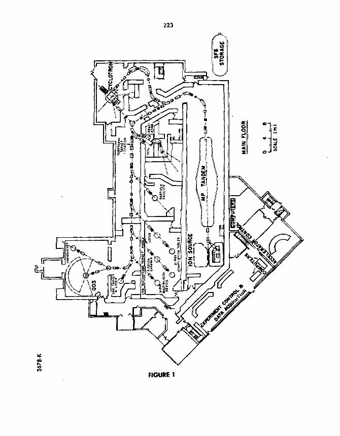
223
FIGURE 1
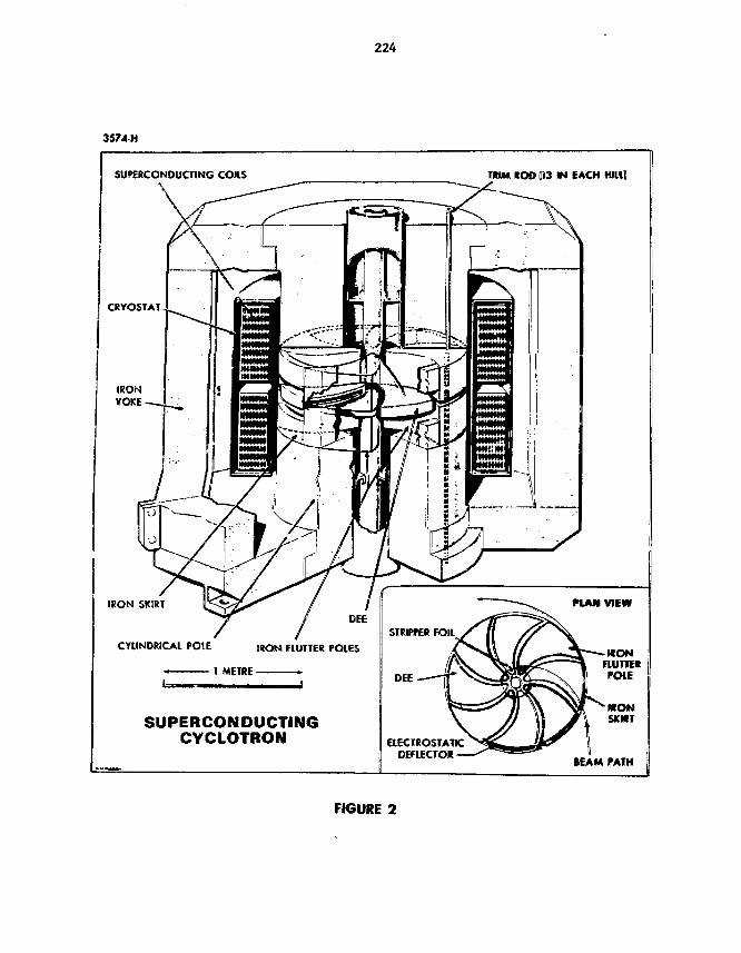
224
3574 H
SUPERCONDUCTING COH.S
CRYOSIAT
IRONYOKE-
IRON SKIRT
CYLINDRICAL POIE
TKtM «O0 (|i3 m EACH Hllll
SUPERCONDUCTINGCYCLOTRON ELECTROSTATIC
DEFIECTO* •
nAM VIEW
-IKONRUTTEKPCHE
H O NSKNtr
IEAM PATH
FIGURE 2
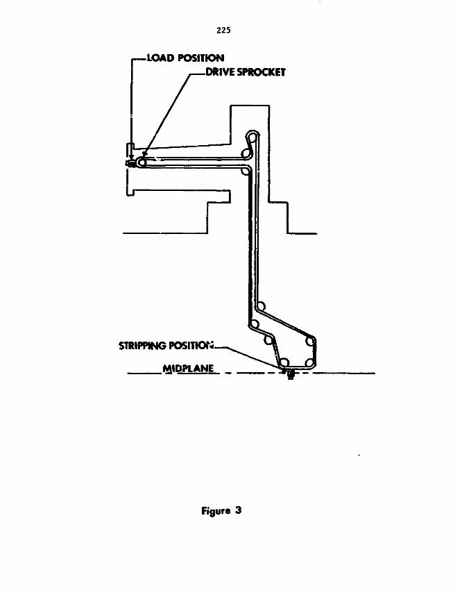
225
•LOAD POSITION.DRIVE SPROCKET
STRIPPING POSITION
MIDPLANE _
Figure 3

227
PREPARATION OF CONDUCTIVE POLYPROPYLENEFILMS FOR PARALLEL PLATE AVALANCHE COUNTERS
P. 0MYTRENKO, J. L. GAiXAlNT, 0. HORN, and ML G. STEER
Chalk River Nuclear Laboratories, Chalk River, Ontario, Canada K0J 1.15?
A technique is described for evaporating a conductive cnjating onstretched polypropylene fili»s. These are used as electrodes in aparallel plate avalanche counter for heavy ions. IBie stretchingtechnique is briefly described. Stretched polypropylene filmsalso have applications as windows Tor high-vacnuts isolation,soft x-ray proportional counters, gas absorption cells, andenergy-loss nuclear detectors.
1. IntroductionA parallel plate avalanche counter is being developed at Chalk River Nuclear
Laboratories for the detection of heavy ions. The device will fee necessarywhen heavy-ion beams up to 0 become available with the completion of a super-conducting cyclotron facility in 1984. Ion-transparent electrcdes fabricatedfrom stretched polypropylene are utilized in i he design of the counter.
The apparatus used to stretch polypropylene is similar t<o> t.«a£ used byBarrus and Blake and described at the Fifth Target Bevelopaenit Conference heldin Los Alamos.''') The films produced with this apparatus have applications insoft x-ray proportional counters, gas absorption cells, energy-loss nucleardetectors, and high-vacuum isolation.2,3,4j
2. Procedure
.The technique for stretching polypropylene makes use of a heated, teflon-coated, 4.5-cm diameter aluaiuura disc hydraiulically positioned against asecured hoop of 25 raicron polypropylene filim^) (fig. 1). A uniform tempera-ture gradient of +5°C was maintained across the disc with the outer edge being105°C, the middle portion li5°C, and the center 125*C. The procedure requireda slow uniform upward notion of the disc. The stopping point of piston Rationwas determined by its height and by visual observation of Newton rings deve-loped during the stretching. Measurements o£ an areal density of filmsstretched in this way indicated a thickness ox approximately 75 fig/cm^. Amaluminum ring 30-cm diameter by 0.5-ca thick., to which vas glued a 0.95-cndiameter loop of surgical rubber tubing, was used to transfer the stretchedfcil from the apparatus. The surgical rubber tubing was coated with rubbercenent to act as an adhesive for the film. T^e ring was thea pressed finallyonto the film and the disc lowered slightly to reduce tension before thepolypropylene was cut below the edge of the disc.
228
After excess film vas trimmed from the edge of the surgical rubber tubing,the film was coated with a 10 g/ca2 layer of cellulose nitrate on the side tobe conductively coated. The cellulose nitrate layer increases resistance toheat damage during the vac m m evaporation process. When dry, the film vastransferred to a rack in the vacuum evaporation chamber. This rack centrallypositioned the film 50 cat above evaporation sources Chat contained chromiumand gold. The chamber was evacuated to a pressure of 10~* Pa. Chromium vasevaporated onto the film to a thickness of 5 fig/cmr- in two equal steps with ashort cooling period between steps. Chroaium was used to provide betteradherence of gold to the film. Then gold was evaporated onto the film to athickness of 20 jig/cm2 in three equal steps. Attempts at single step evapora-tions to these thicknesses were unsuccessful because of rupturing of the foildue to heat damage. To minimize heat damage, both evaporation sources werebrought quickly up to predetermined evaporation temperatures. Upon removalcrora vacuum, the films were tested for conductivity using a simple multi-meter.
3. SummaryThe method described produces films of suitable uniformity and conductivity
for use in parallel plate avalanche counters. Conductive and nonconductivestretched polypropylene films produced by Chalk River Nuclear Laboratorieswill soon be produced on a commercial basis for all interested parties
References1) D. M. Barrus and R. L. Blake, Rev. Sci. Instrurn., Vol. 48, No. 2, (1977).2) B. L. Henke and M. A. Tester, Adv. X-Ray Anal. 18 (1973) 76.3) A. J. Burek and R. L. Blake, Adv. X-Ray Anal. 16 (1973) 37.4) A. J. Caruso and H. H. Kim, Rev. Sci. Instrum., 39 (1968) 1059.5) Exxcri Chemical Co., Elizabeth, NJ 07207, Film PP-11.

2291.J."
ATOMIC ENERGY OF CANADA LTD - AESCAfttH CO 8 3 0 4 - 1 5 8 0 3 - 5
Fig. 1 Polypropylene stretching apparatus

231
THIN SELF-SUPPORTING ISOTOPIC Dy, Er, Gd AND Vb
TARGETS FOR CHARGED PARTICLE SPECTROSCOPY
D. J. TfARASKAVITCH AND X. K. PENG
Tandem Accelerator Laboratory, McMaster (University, Hamilton, Ontario,
Canada L8S 4iCl
A technique is described for the production of 100 toself-supporting isotopic Dy, Er, Gd and Yb targets. The targetsare prepared by a simultaneous metailotSieraic redaction of theoxide and vapor desposition onto a NaCl substrate. Specialtechniques are described for stripping and mataiitiiijg of the self-supporting targets. Exnples of the improvement in the resultsfor self-supporting compared with carbon-backed targets are shown.
1. IntroductionIn the past at oar laboratory, Aim targets of isotopic rare earths have been
deposited onto thin carbon backings ©E 20 to 40 g/cna^. The presence of thiscarbon backing produces bzoaS structures in the reaction product spectra, largeenough to obscure oilier weaker peaks of interest. In an effort to reduce theeffects of the carbon backing, a method of producing self-supporting targets hasbeen developed.
The procedure for producing self-supporting targets consists of the aetallo-thermic reduction of the oxide, vapor deposition directly onto a NaCl substrate,and subsequent mounting and handling of the self-supporting target.
The reduction of background using self-supporting targets instead of car-bon backed targets will be illustrated..
2. ProcedureThe equipment -«sed for this procedure was a Wariaa M200Q Series WHS diffusion
pump system, a Varian 2 kW single-source electron gun, a high current resistiveheating system, a substrate heater, and a crystal thickness aanitor.The fabrication of self-supporting tiy, Er, Gd and "b targets was accomplished
in several steps without removing the substiate £ron the vacuun system. Thisinvolved the deposition of the Nad parting agent, out-gassing of the substrateprior to the ccetallothersiic reduction, and the deposition of the metal on thesubstrate, followed by the removal of the target substrate fron the system,mounting, and target treatment prior to storage. The systea was set up vith aresistively-heated Ta boat that contained NaCl for deposition of the partingagent, an e-gun for the reduction astl deposition of the rare earth, and asubstrate heater.
The substrates were glass microscope slides which were ultrasonically cleanedin a methanol bath, dried, fire polished, and mounted onto a movable feedthroughin such a way that the slides could °ae moved both vertically and horizontally.
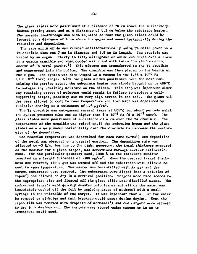
232
The glass slides were positioned at a distance of 20 cm above the resistively-heated parting agent and at a distrance of 0,5 cm below the substrate Cieater.The movable feedthrough was also adjusted so that the glass slides could belowered to a distance of 4 cm abc.e the e-gtin and atoved horizontally during thereduction and deposition.
The rare earth oxide was reduced aetallothermically using Tt> setal power in aTa crucible that was 7 no in diameter and 1.8 cm in length. The crucible washeated by an e-gun. Thirty to fifty milligrams of oxide was dried over a flamein a quartz crucible and when cooled was saixed with twice the stecfoicnetricamount of Th metal powder.'-) This mixture was transferred to the Ta crucibleand compressed into the bottom, the crucible was then placed OBJ the Inearth ofthe e-gun. The system was then pumped to a vacuum in the 1.33 x 10""* Pa(1 x 1Q-6 torr) range. With the glass slides positioned over ttie boat con-taining the parting agent, the substrate heater was slowly brought up to 4Q0eCto out-gas any remaining Moisture on the slides. This step was iajportcrat sinceany remaining traces of moisture would result in failure to produce a self-supporting target, possibly due to very high stress in the foil. The glass sli-des were allowed to cool to room teaperature and then NaCl was deposited byresistive heating to a thickness of ~25 jig/cws.
The Ta crucible was out-gassed several tines at SOO^C for short periods untilthe system pressure rise was no higher than 8 x 1D~5 pa (6 x 10~7 torr). Theglass slides were positioned at a distance of 4 cm over the Ta crucible. Thetemperature of the crucible was raised until the reduction began and the glassslides were slowly moved horizontally over the cruciiila to increase the unifor-mity of the deposition.
The reaction temperature was determined for each rare ea^th^) and depositionof the metal was observed on a crystal Monitor. The deposition rate wasadjusted to —5 K/s, but due to the tight geometry, the total thickness Measuredon the monitor for a given target, was determined through earlier calibrationruns. For the particular geoaetry used, 1000 A1 on the thickness monitorresulted in a target thickness of ~3U0 jig/cm . Hhen the desired target thick-ness was reached, the e-gun was turned off and the substrates were allowed tocool to room temperature. The system was bar^-filled with Ar gas and thetarget substrates were removed. The substrates were dipped into a solution ofzapon^) and allowed Co dry in a vertical position. Targets were then scored Cothe appropriate size and floated off the glass slide ©nl© distilled water. Theindividual targets were quickly aounted onto fracaes and all of the water wasimmediately washed off the foil by applying drops of ssethanol with a snailsyringe to the underside of the target. It was important that all of the waterbe removed or pinholes and foil breakage would occur during dryinj. Next: thezapon film vas removed with droplets of methanol-^) and the targets: were allowedto dry in a desiccator. The targets were stored under vacuum or in an Aratmosphere until used.

233
3. ReaultsSelf-supporting isotopic By, Er, Gd and Yb targets with thicknesses of 100 to
100 fig/ca? have l-een prepared in the manner described with a success rate of—80S. By moving the substrates horizontally over t*ie crucible, at a depositiondistance of 4 cm, target uniformity adequate for our experiments waf achieved,while economizing on the amount of rare earth aaterial used. Highe* uniformitynay De obtained by increasing the deposition distance. It is very important inthe fabrication of the targets to out-gas the glass slides to reaove anymoisture, as well as to remove all of the water froa the target and frame withmethanol.
The self-supporting targets if* re used in recent tritium bean experimentsstudying the (t,p) reaction. Tm« effects of a carbon backed target on thespectrura for the * 1fb(t,p)*''**¥b reaction are seen in fig. 1.*) Large ^C ana16(3 structures are se»m at -4800 and ~21"*Q keW, which obscure any weaker reac-tion peaks. For a self-supporting target, the spectruo in fig. 2-*) shows thel C and! '^0 structures greatly reduced, which allowed quantitative measurementsto be made on the weaker reaction peaks.
Acknowledgments
Financial support was provided by the Natural Sciences and EngineeringResearch Council of Canada. The authors wish to thank Or. IB, G. Burke for hisvaluable discussions and for providing spectra.
References1) L. Westgaard and S. BjornlaolTa, Nucl. Inst. and Meth. 42 (1966) 77-80.2) L. Yaffe, Ann. Rev. Nucl. Sci. a (1962) 113.3) J. L. Gallant, Nucl. lust, and Metli. 102 (1972) 477-483.4) D. G. Burke, E. Hamaeren, and 1. Nowikow, McMaster Accelerator Laboratory
Annual Report, McMaater University, Hamilton, Ontario, 1979, p. 57.5) D. G. Burke, I. Novikow, Y. K. Peng, and J. C. Yanch, C«n. J. Phys. 61 (1983)
462.
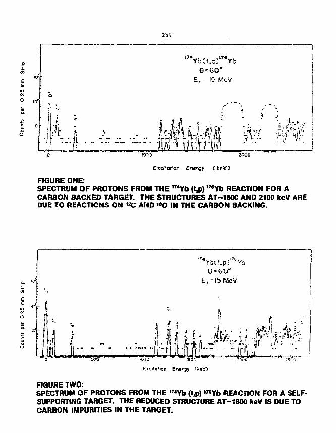
234
o.
E
ID
CO
11000 2000
Excifotton
FIGURE ONE:SPECTRUM OF PROTONS FROM THE 174Yb (t,p)176Yb REACTION FOR ACARBON BACKED TARGET. THE STRUCTURES AT-180C AND 2100 keV AREDUE TO REACTIONS ON **C AND «O IN THE CARBON BACKING.
Ea
CO
o
cio
rsoo
Excrtolioe Energy (HkeVD
zwo
FIGURE TWO:SPECTRUM OF PROTONS FROM THE "«Yb (t,p) "«Yb REACTION FOR A SELF-SUPPORTING TARGET. THE REDUCED STRUCTURE ATM800 keV IS DUE TOCARBON IMPURITIES IN THE TARGET.
235
FABRICATION OF SELF-SUPPORTED OXIKE TARGETS BY CATIOfolC ADSORPTION
IN CELLULOSIC MEMBRANES AIvU THERMAL DECOMPOSITION*
t. C. quinby
Oak Ridge National LaboratoryP. O- Box X
Oak Kidge, Tennessee 37830
Operations Division
q nhe arr.i -He.
Research sponsored bj1 the Division of Basic Energy Sciences, U. S.Department of Energy, under contract W-7405-eng-26 with the UnionCarbide Corporation.

237
FABRICATION OF SELF-SUPPORTED OXIDE TARGETS BY CATICffilC ADSOKPIIUN INCJ-XIULGSIC MEMBKAtiES AINU THERMAL DECOMPOSITION*
Thonas C. Quiraby
OaJc Kidge national LaboratoryP. 0. iiox X
Oak Ridge, Tennessee 37830
ABSTRACT
Techniques for producing relatively durable oxide files ofvarious elements will be described. Area! densities of tilesproduced to date have ranged from ISO /jg/cat to 2.S tag/era ,and are virtually transparent. Films produced by this techniquewere weighed directly and mounted on frames. General parametersfor use of this technique will be described.
Introduction
The target fabrication technique to be described in this report is
based on the adsorptivity of cellulosic materials. This phenomenon has
been utilized by nan for centuries, being the Mechanism for M s first
recordings on papyrus and tiie dyeing of cotton fabrics. In 1&85,
Carl von Welsbach used this effect to produce the first practical incan-
descent gas mantle for illumination. Woven cotton was soaked in a
solution of thoriun nitrate and burned off in the flaoe to leave a nantle
of thorium oxide.
On several occasions it has been observed that cation bearing
polyaers, when therxally decomposed, would produce ceratsic materials with
very unusual characteristics. The ceramic remnants froB decooposed cation
loaded ion-exchange co-polymers and polymerized phenollcs of cations
*Research sponsored by the Office of Basic Energy Sciences, ID. S.Department of Energy, under contract M-7405-eng-26 with the Unio-iCarbide Corporation.

23S
exhibited relatively high strengths and in sone cases vere virtually
transparent. The cohesion of these ceramic naterials could not be
explained by their theraal treatment since the temperatures involved were
well belov those normally required ior sintering. At present it is
believed that the binding force of the oxides so produced is a result of
the initial chemical bonding of the cations within the polyraers.
Based on these observations it appeared obvious tBcac thin, self-
supporting oxide films light be produced by this technique. To accooplish
this a thin membrane form of polymeric material was required which would
adsorb elements of interest and undergo thermal decomposition witliout
change in physical fora. One material with these properties is
carboxy-methyl-cellulose, which is the weobrane us^d in this effort.
AlthougJ1! the technique requires refinement and further development,
it holds obvious practise as a means of prorfucir.g targets not possible by
other means.
Target Characteristics
Self-supported oxide targets of various Materials have been prepared
with areal densities from 100 jtg/cm2 to 7.6 •g/cus2 {in fabric fern). This
range of concentration is not considered the ultimate limit of this
technique, but represents the results of the initial tests of this
technique with the limited thicknesses of membranes available for this
work. All of the oxide films within this range were easily handled
during the functions or weighing and counting. A parlEal list ol
targets produced by this technique is shown in the following table.
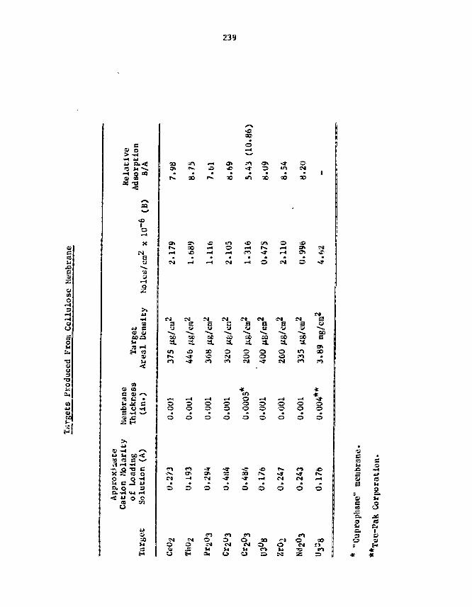
239
qjfa
x>Bm
ao
a2•aao3•aou
CO
IN
a
.9
01
fa
a
toU (0a a* <->a m •u j£ a
ai x:
a as c • --
X S es oO QTla. O 3S f i u H
•o
9« IN.
IN 00
• * OCM
(3ta (^^t .i^^i li^Ti ^^7 ^^^ *^3^ L^^JJJ>» 3 0 "™* O 1 <^ l t***> i ^ 9 ^ i NI
? j » - ^ « i r > i » H i O ! > i o - - 3 r
pj SM r<lB S S•u -JI u
a. a
oo
o o
C3
O
S
so
mi
BuCO
a.oo
oCO
ooSSI
at
•3.
m
6it
• ^ O •-« •-* -r-*o o o o oo o © o o
-a-• *
O
>
O O
Omu
omoCMfa
OOJfa
o* ofa
o
oa(3fa
XiaoB
o
fa
s.fa"
a. JC
& Iu a
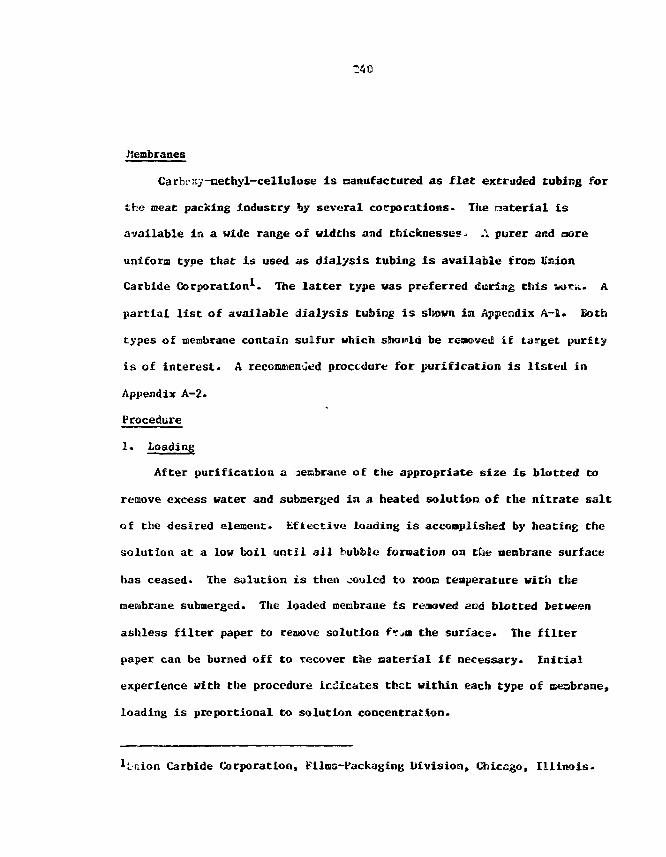
Membranes
Carbexy-iaethyl-cellulose is nanufacCured as flat extruded tubing for
the meat packing Industry by several corporations• The material is
available in a wide range of widths and thicknesses* ,\ purer and core
uniform type that is used as dialysis tubing is available froa Union
Carbide Corporation1- The latter type vas preferred during this V O K . A
partial list of available dialysis tubing is shown in Appendix A-l. Both
types of membrane contain sulfur which should be renewed if target purity
is of interest. A reconunenutid procedure for purification is listed in
Appendix A-2.
Procedure
1. Loading
After purification a aembrane of the appropriate size is blotted to
remove excess water and submerged in a heated solution of the nitrate salt
of the desired element. Effective loading is accomplished by heating the
solution at a low boil until all bubble formation on clie membrane surface
has ceased* The solution is then cooled to roots tenperature with the
membrane submerged. The loaded caenbrane is raaoved and blotted between
ashless filter paper to remove solution t>>n the surface. The filter
paper can be burned off to recover the oaterial if necessary. Initial
experience with the procedure indicates thct within each type of neobrane,
loading is proportional to solution concentration.
Carbide Corporation, Films-Packaging Division, Chicago, Illinois.
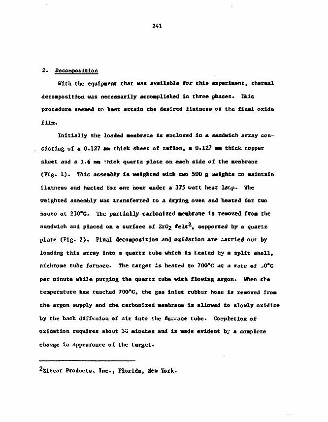
241
2. Decomposition
With the equipment that was available for this experiment, thermal
decomposition vas necessarily accomplished in three phases. This
procedure seemed to best attain the desired flatness of the final oxide
film.
Initially the loaded membrace is enclosed in a sandwich array con-
sisting of a 0.127 am thick sheet of teflon, a 0.127 mm thick copper
sheet and a 1.6 mm thick quartz plate on each side of the meabrane
(Fig. 1). This assembly is weighted with tin 500 g weights Co maintain
flatness and heated for one hour under a 375 watt heat lar p. The
weighted assembly was transferred to a drying oven and heated for two
hours at 230"C. The partially carbonized membrane is removed from the
sandwich and placed on a surface of ZtO^ felt2, supported by a quartz
plate (Fig. 2). Final decomposition and oxidation are carried out by
loading this array into a quarts tube which is heated Ssy a split shell,
nichrome tube furnace. The target is heated to 700*C at a rate of >0*C
per alnute While purging the quartz tube with flowing argon. When the
temperature has reached 700*C, the gas inlet rubber hose is removed from
the argon supply and the carbonized membrane is allowed to slowly oxidize
by the back diffusion of air into the fucrace tube. Completion of
oxidation requires about 30 minutes and is made evident by a complete
change in appearance of the target.
22ircar Products, Inc., Florida, New York.
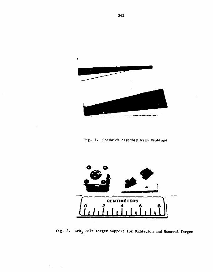
242
Fig. 1. Sardwicb Assembly With Membrane
o a.
CENTIMETERSO 2 A 6 8
/ i M . h h 1.1,1,1
Fig. 2. ZrO2 7elt Target Support for Oxidation and Mounted Target

243
3. Metrology
Areal density determinations were Bade in Che usual Banner by
weighing Che target filas and Measuring the surface areas. If a target
film is moved about the laboratory, it should be covered to prevent; th»
effects of air currents. Lifting of the oxide filas was best acconplished
on the blade of a spatula.
4. Mounting
All of the films which were Mounted during this experiment were
clamped between tuc Hatching fracaet (Fig. 2). Teie fraaes were spaced
apart by placing cut strips of gunned paper labels around the outer edges
of the joining faces. Tne thickness of th*.s spacer material (0.1 mis)
was sufficient to prevent crushing of the oxide films.
Results
None of the nitrate salt solutions used in preparing the
described in this report were assayed analytically, buL -ere based on
the weights of the salts added to make the solutions. All of these
sales are highly hydrated and some are hygroscopic—properties which
are not conducive to accurate weighing. Despite the probable inaccuracy
of the solution concentration shown, fair agreement of target densities
from one type to another la indicated by the data. This agreement
indicates that ultimate target density is a function of the solution
concentration alone and is nonselective for particular elements. If
this is correct, target density should also be linear with membrar?
thickness for a given solution concentration. Unfortuuctely, th^s
could not be substantiated because the limited range of membranes
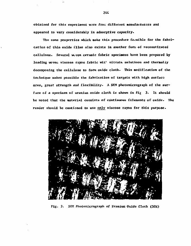
244
obtained for this experiment ware froo different manufacturers and
appeared to vary considerably in adsorptive capacity.
The same properties which make this procedure feasible for the fabri-
cation of thin oxide films also exists in another fore of reconstituted
cellulose. Several vcven ceramic fabric specimens have been prepared by
loading woven viscose rayon fabric wit nitrate solutions and thermally
decomposing the cellulose to form oxide cloth. This modification of the
technique makes possible the fabrication of targets with high surface
area, great strength and flexibility. A SEM photoaicrograph of the sur-
face of a specimen of uranium oxide cloth is shown in Fi£ 3. It should
be noted that the material consists of continuous filaments of oxide. The
reader should be cautioned to use only viscose rayon for this purpose.
Fig. 3. SEM Photomicrograph of Uraniuo Oxide Cloth (50X)

245
"Celenese" rayon (cellulose acetate) will not undergo thermal decom-
position without melting and profuse gas evolution. Cotton fabrics have
been used for this purpose, but do nut produce continuous ceranic
filaments.
Conclusions
Although ouch developnent work remains to be done, the technique
described will allow the fabrication of oxide film targets which have
previously been impossible. These targets nay he economically fabricated
t
in terms of equipment* materials required, and tine. By utilizing the
wide range of membrane thicknesses which are available and by variation of
solution concentration, virtually any practical target density should be
attainable.
The method of target fabrication offers great flexibility and
versatility in that it allows the fabrication of nixed element targets and
solid dilutions of costly isotopes with oxides of elements which are
benign and acceptable to the target user.
Acknowledgments
The author gratefully expresses appreciation to the following persons
for their expedious contributions to this work. U. S. Aaron, Isotope
Research Materials Laboratory, Oak Ridge INatloaal Laboratory, for the
scanning electron nicroscopy and x-ray diffraction. Michelle V. Buchanan,
Analytical Chemistry, Oak Ridge National Laboratory, who initially Iden-
tified several membranes by infrared analysis. John t- Caton, Jr.,
Analytical Chemistry, Oak Ridge National Laboratory, who generously
allr ed rae access to his supply of dialysis nenbranes.

246
APPENDIX A-l
Dialysis MenbraneUnion Carbide Corporation
Designation
a
20
2?
36
1-7/8
Average DryFlat Widthin. am
0.4
1.0
1.3
1.7
3.0
10
25
33
43
76
Average DryThickness
in.
0.002
O.QOOtt
0.0009
0.0008
0.0016
RollLength
ft.
100
100
100
100
50
No. offRolls l>erCarton
10
2w
20
20
10
CartonPrice inDollars
311.00
231.00
257.00
299.00
185.00
MininuoShipmentQuantity
in Cartons
1
1
1
1
1

247
APPENDIX A-2
Purification Treatment for Dialysis Membranes
"The materials in the dialysis tubing other than cellulose (cotton
lirters) which are present in more than trace amounts are glycerine and
sulfur compounds* The glycerine can be renewed by washing the tubing in
running wat<r for 3-4 hours• Removal of sulfur compounds nay be
accomplished by treating the tubing with sodlun sulfide solution (0.3%) at
80°C for 1 minute, wash ulth hot water (6G°C) for 2 minutes, followed
by acidification with sulfuric acid (0.2,4,), and -washing with hot water to
remove the acid*"
Courtesy Union Carbide CorporationFilas-Packaging Division
Chicago, Illinois

249
EXPERIENCE WITH A SADDLE FIELD ION SOURCE FOR SPUTTERING
George F. Thoaas
Argonne National Laboratory, Argonne, IL 60439
Abstract
A discussion Is presented concerning the method of
setting jp a saddle field ion source for sputtering thin filws.
Preliminary results will be presented for sputtering rate* of
different materials.
The submitted ir*nuscflnpi h u be^n authoredbv a conwattsw of «he U . S . Governmentund« osmiact Kxs. W 31-109-EK(i-3S.
, ttw U. S- Gowtnment cctl'.TO aOV»lIV**f« WcfflSe to pvt>"t!*(he publahed 'orm o* *^s
contnbut«on. or Mow oihers 10 da so. lorU. S. Govtinn^ni puiposft.

250
The theory and principles of the operation of a saddle field source
have been previously described by both "'ranks1' and by Drinkwater.2' Some of
the unique properties of this source ^ nay wake it quite useful for producing
particular types of thin films. Some of these include:
1. Beans contain a high percentage of energy neutrals. Therefore
cne can sputter insulating, as well as electrically conducting naterials.
2» The source produces a bean of about 2 mm diameter, allowing one
to use snail amounts of separated rare isotopes.
3. The source uses a cold filament which produces a temperature
rise of the evaporant of only ~ 10* C, Insuring no damage to substrate or
release agent from heat. The substrate can be placed very close to the
source, thus Insuring a high efficiency for sputtering.
4. There is no nagnet.- field, only an electrostatic one.
The schematic drawing of Fig. 1 shows the general principles of
operation of the sputter source. Electrons oscillate between the two cathodes
through a central anode under the Influence of the dc field. Argon introduced
into the source is readily ionized, positive ions produced are attracted to
the cathodes, and the emerging beam contains a percentage of neutrals which
depends on the distance of the sputter gun from the material being evaporated.
This paper presents several set-up and sputter procedures which we
have found quite useful toward the successful operation of this saddle field
:jn source. It is very important that all components of the gun are carefully
aligned so that the Argon bean will pass accurately through the center of the
gun as misalignment usually shorts out the source, making it totally
Inoperable. A tool Is available for this aligning procedure.
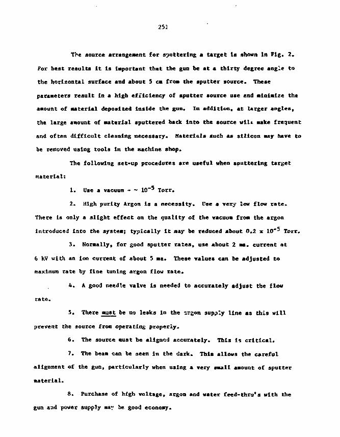
251
The source arrangement for sputtering a target la shown In Fig. 2.
For best results It Is Important that the gun be at a thirty degree angle to
the horizontal surface and about 5 CM froai the sputter source. These
parameters result In a high efficiency of sputter source use end nlnlolze the
aaount of aaterial deposited inside the gun. In addition, at larger angles,
the large anount of Material sputtered back Into the source will wake frequent
and often difficult cleaning necessary. Materials such ** silicon nay have to
be removed using tools In the machine shop.
The following set-up procedures are useful when sputtering target
material:
1. Use a vacuum - ~ 10"' Torr.
2. High purity Argon is a necessity. Use a very low flow rate.
There is only a slight effect on the quality of the vacuum from the argon
introduced into the systen; typically it nay be reduced about 0.2 x 10 Terr.
3. Normally, for good sputter rates, use about 2 ma. current at
6 kV with an ion current of about 5 na. These values can be adjusted to
maximum rate by fine tuning argon flow rate.
4. A good needle valve is needed to accurately adjust the flow
rate.
5. There must be no leaks in the irgon supply line as this will
prevent the source from operating properly.
6. The source oust be aligned accurately. This is critical.
7. The beam can be seen in the dark. This allows the careful
alignment of the gun, particularly when using a very saall aaount of sputter
material.
8. Purchase of high voltage, argon and water feed-thru*s with the
gun and power supply nay be good economy.

252
TABLE I. Preliminary sputter rates *ar different Materials.
Element Glover*(pg/«2/hr)
Drinkwater2
(pg/c«Z/hr)Ours
(jig/c«2/hr)
Au
Co
Fe
Mn
Hi
Os
Pb
Pt
Si
Sn
W
Zn
22
44
12
13
45
14
10
26.3
40
3.9
S.6
5.3
8.0
25.2
14.6
12.5
44
It can be readily seen that the aputt«r rates are very low.
However, it taV.es about one half hour to stabilize the system for sputtering, a
target but after this is completed it can be left virtually unattended
overnight and usually for several days vith only slight adjustments.
In conclusion, this type sputter source has the advantage of
producing a cold deposition with no image to the substrate, the release
agent, or the deposited material. In addition, it produces good adherent
deposits and with the proper sputter parameters a small degree of implantation

253
raay be obtained. Further, It -day be used for ion Milling. Alchough the
system has a high efficiency for evaporation it has a low sputter rate with
United target size. This type gun May be quite useful particularly for
sputtering relatively small amounts of Material for special applications.
Footnotes and References
This research was supported by the U. S. Department of Energy under
Contract W-31-lO9-Eng-38.
1. J. Pranks, International Journal of Mass Spectronetry and Ion Physics, ji6_
(1983) 343-346.
2. R. J. Drinkwater, Proc. 11th World Conf. Intl. Nuclear Target Developnent
Society (1982), ed. G. M. -linn, held at Seattle, VA, Oct. 6-8, 1982
(University of Washington, Nuclear Physics Laboratory).
3. Saddle Field FAB11NU source and B50 power supply produced by Ion Tech LTD.,
2 Park Street, Teddington, Middlesex TVllOLD, England and purchased fros
VCR Group, 68 Meadowbrook Drive, San Francisco, CA 94132. Our thanks to
Vincent Carlino at the VCR Group for several useful consultations in
setting up the system.
4. Kate Glover, AERG Harwell, Oxfordshire, 0X110RA, United KlngdoM, supplied
these preliminary results by private coaMunication.

254
Figure Caption*
Figure 1. Schematic drawing shoving the general principles of operation of
a saddle field sputter source.
Figure 2. Schematic drawing of a typical arrangement for producing a
sputtered target.

ANL-P-17,339
-ANODE
CATHODE
\ r CATHODEto
I
NEUTRALS ARGON
~l

ANL-P-17,357
BEAM INTENSITYCOLLECTOR
ARGONSOURCE
HIGHVOLTAGE
257
J. Van Audenhove, C.B.N.M., B-2440 Geel, Belgium
Closing ^CBBZICS - INTDS Workshop 1983
This is the first Workshop we have had since we decided to have only one
every two years and if we look through the papers that have been presented -ad
discussed and the discussions that followed, Z think that we can conclude that
we are going in the right direction with this new type of aeetin*.
We have had several papers on isotope seperation techniques and we
increase our understanding of the problems, costs and feasibility of preparing
seperation of isotopes by means of new techniques. Several speakers explained
and stressed the need for good targets and stripper foils in order to be able
to do sensible measurements with the very Inportant new nachines that have now
become more and more common case all over the world. Last, hut not least, our
traditional subject being target preparation, or we can als-> call it
technology, has been treated by several speakers. From this Workshop we
realize how important the future challenge reoalns in order to prepare better,
more difficult and more sophisticated targets based on new eaterials and new
technologies. We have seen several new exciting techniques especially here
today as well as the other days of the Workshop. Some of the preparation
techniques presented can be considered as such.
I would like to thank the Workshop attendees for their high quality
contributions as well as the Session Chairman for their help. I especially
thank again George and the staff of Argonne National Laboratory. I wish you
ail a good year of work giving a lot of personal satisfaction and I hope to
see everybody back at Antwerp in September next year. Thank you.

Informal gathering of seme of the attendees.

261
FINAL LIST OF PARTICIPANTS
WORKSHOP 1983 OF THE INTERNATIONAL
NUCLEAR TARGET SOCIETY
Septamber 7-9, 1983
Argonne National Laboratory
262
Mr. Harold L. AdairIsotope Research Materials LaboratoryOak Ridge National LaboratoryBuilding 3047P.O. Box XOak Ridge, TN 37830
Mr. trying L. Feigenbau*Department of PhysicsBrookhaven National LaboratoryBuilding 901AUpton. *>Y 11973
Mr. lrshad AhmadChemistry DivisionArgonne Rational Laboratory9700 South Cass AvenueArgonnc, IL 60439
Mr. Helmut A. FoigerTarget LaboratoryGSIPlanckstr. 16100 DarmstadtWEST GERMANY
Mr. Ray BarnesChemistry OivisionArgonne National Laboratory9700 South Cass AvenueArgonne, II. 60439
Mr. James FordOat: Ridge National LaboratoryP.O. Box XOak Ridge, TN 37830
Mr. Laszio CsihasDepartment of PhysicsUniversity of Pennsylvania209 South 33rd StreetPhiladelphia, PA 19104
Mr. Joseph I. GallantDepartment of Nuclear PhysicsAtomic Energy of Canada LimitedChalk P.iver, OntarioCANADA KOJ 1J0
Mr. Peter Dmytrer.koNuclear Physics Branch Station 49Atomic Energy of Canada LimitedChalk Rfver huclear LaboratoriesChalk Rtver, OntarioCANADA KOJ iJO
Mr. Donald S. GemmellPhysics DivisionArgonne National Laboratory97GQ South Cass AvenueArgonne, IL £0439
263
Ms. Judith C. GursfcyDepartment of PhysicsLos Alamos National LaboratoryMSO 456Los Alamos, HH 87S45
Mr. £. H. KobiskOak Ridge Rational LaboratoryP.O. Box XOak Ridge, TN 37830
Ms. Joanne Kargaret HeagneyMicromatter CompanyRoute 1P.O. Box 72-8Eastsound, WA 98245
Mr. Ed KowaiskiHedi-Physics Inc.3350 North Ridge AvenueArlington Heights, IL 60004
Mr. Gervas H. HinnDepartment of Nuclear PhysicsNuclear Physics Lab GL-20University of WashingtonSeattle, WA 98195
Mr. Charles I . KriegerIntense Pulsed Neutron SourceArgonne National Laboratory9700 South Cass AvenueArgonne, IL 50439
Mr. Robert V. Jansse.isPhysics DivisionArgonne National Laboratory9700 South Cass AvenueArgonne, IL 60439
Mr. Victor E. XrohnPhysics DivisionArgonne National Laboratory9700 South Cass AvenueArgonne, IL 60439
Mr. Frank J. KarasekMaterials Science and TechnologyArgonne Nations Laboratory9700 South Cass AvenueArgjnne. IL 60439
Mr. Robert H. LeonardDepartment of PhysicsFlorida State UniversityNRB-51Tallahassee, FL 32306

264
Mr. Will Jan R. LozewsiciCyclotron FacilityIndiana UniversityHilo 8. Sampson LaneBloomington, IK 47405
Mr. Richard C. PardoPhysics DivisionArgonne National Laboratory9700 South Cass AvenueArgonne, Illinois 60439
Mr. M. H. McCuil?Oak Ridge National LaboratoryP.O. Box XOak Ridge, TN 37830
Mr. Vincent PatriziPhysics DivisionArgonne National Laboratory9700 South Cass AvenueArgonne, IL 60439
Mr. Hans-Jcg KaierSeJction Physik derUniversitat Munchen Technologisches
LaboratoryAm Coulombwall 18046 GarchingWEST GERMAHY
Hr. Ruggero PengoPhysics DepartmentLaboratori Nazionali LegnaroVia Roaea 41-35020 LegnaroITALY
Mr. Bruce G. NsrdiPhysics DivisionArgonne National Laboratory9700 South Cass AvenueArgonne, IL 60439
Hr. Thorns C. QuinbyIsotopes Research Hateriais LaboratoryOak Ridge National LaboratoryBuilding 3550P.O. Box XOak Ridge. TN 37830
Mr. Eugene Ne>.-anSection Head, Isotope SectionOperations DivisionOak Ridge National LaboratoryP.O. Box XOak Hidge. TN 37830
Hr. David Clarice RadfonlPhysics DivisionArgonne National Laboratory9700 South Cass AvenuArgonne. IL 60439
265
Mr. Joseph Edward RatledgeIsotope DistributionOak Ridge National LaboratoryBuilding 3037P.O. Box XOak Ridge. TN 37830
Mr. George E. ThosasPhysics DivisionArganne Rational Laboratory9700 South Cass AvenueArgonne. IL 60439
Mr. William 0. RielDepartment of PhysicsState University of New YorkStony Brook, NY J1794
Hr. Jan Van AudenhoveDepartment of Scruple PreparationC.B.N.H.Steenweg naar Retie8-2440 GeelBELGIUM
Mr. John U. StinsonDepartment of Physics (XHR)National Research Council of CanaoaBuilding M-35Montreal RoadOttawa, OntarioCANAOA K1A OR6
Hr. James N. WorthingtonPhysics DivisionArgonne National Laboratory9700 South Cass AvenueArgonne, IL 60439
Hr. Suehiro TakeuchiPhysics DivisionArgonne National Laboratory9700 South Cass AvenueArgonne, IL 60439
Hr. Donald J. YaraskavitchDepartment of PhysicsHcHaster UniversityHamilton, OntarioCANAOA L85 4K1
Mr. James M. TerryStable Isotope EnrichmentOak Ridge National LaboratoryP.O. Box YOak Ridge, TN 37830
267
Distribution for ANL/PHY-84-2
Internal;
Participants (29)G. E. Thomas (31)K. Thayer (2)ANL Libraries (2)TIS Files (3)ANL Patent DepartmentK. KliewerG. KlimczakR. SpringerL. Bo1 lingerW. ChildsG. T. GarveyW. HenningH. JacksonD. KurathJ . Schiffer
External:
Part ic ipants (25)DOE-TIG (27)Manager, Chicago Operations Office, DOEChief, Office of Patent Counsel, DOE-CHW. J. McGonnagle, New Brunswick Lab., DOEG. il. Peterson, Long Beach, CAPhysics Division Review Committee:
E. Adelberger, University of Washington, Seattle, WAU. Fano, The University of Chicago, Chicago, K>L. C. Feldman, Bell Laboratory, Hurray Hill, NJJ. D. Fox, Florida State University, Tallahassee, FLW. Happer, Jr., Princeton University, Princeton, NJP. Kienle, GSI, Darmstadt, GermanyS. E. Koonin, California Institute of Technology, Pasadena, CAD. F. Measday, University of British Columbia, Vancouver, B.C., CanadaS. A. Rico, The University of Chicago, Chicago, IL
INTDS Members:V. Avona, Isotec, Inc., Dayton, OHW. Bakalinski, Kolon Trading Co., Inc., New York, NYG. Baker, Medi-Physics, Inc., Emeryville, CAD. Balzer, Oberhasli, SwitzerlandS. Bashkin, University of Arizona, Tucson, AZJ. W. Behrens, National Bureau of Standards, Washington, DCH. C. Bonetti, C.E.N., Bruyeres-Le-Chatel, FranceH. Caudill, Oak Ridge National Laboratory, Oak Ridge, TXA. Cecchi, Inst. Nazionale Fisica Nucleare, Firenze, ItalyC. Cimetiere, C.E.A., Oris, FranceD. Cline, University of Rochester, Rochester, NYS. R. Dahl, Sloan Kettering Institute, New York, NYJ. A. Dresser, Research Chemicals, Phoenix, AZ

268
D. R. Ebeling, Australian A.E.C., Sutherland, AustraliaL. Einarsson, Tanden Accelerator Lab., Uppsala, SwedenE. B. Fehr, Yale University, Mew Haven, CTG. Frick, Centre de Recherches Nucleaires, Strasbourg, FranceT. Gee, Lawrence Berkeley Lab., Berkeley, CAI. Gilatb, Sorec Nuclear Research Center, Yavne, IsraelK. N. Glover, AERE Harwell, Oxfordshire, United KingdonK. Grabisch, Hahn Heitner Institute, Berlin, Vest GermanyE. Graper, LeBow Corp., Goleta, CAG. E. Griggs, Lawrence Livemore Natl. Lab., Live more, CAD. Hammond, King Faisal Specialist Hosp., Riyadh, Saudi ArabiaJ. S. Heagney, MicroMatter Co., Eastsound, VAH. Hodde, Inst. fur Strahlen und KernPhysik, Bonn, Vest GermanyG. H. Jaffe, Inter Tech Associates, Inc., Verona, NJMrs. Dr. Kemmerich, Karlsruhe, Vest GermanyM. J. Kwinta, C.E.A., Bruyeres-Le-Chatel, FranceL. Lemay, University of Montreal, Montreal, CanadaR. W. Lougheed, Lawrence Livermore Natl. Lab., Livernore, CAP. Maier-Komor, Techn. Universitat Munchen, Munich, Vest Germany
G. Manente, I.N.F.N., Legharo, ItalyA. J. Michielsen, Rijksuniversiteit Utrecht, Utrecht, The NetherlandsA. H. F, Muggleton, The Australian Natl. University, Canberra, AustraliaM.-K. Nacke, Techn. Universitat Munchen, Munich, West GermanyJ. Pauwels, C.B.H.M., Geel, BelgiumA. A. Peck, Queens University, Kingston, Ontario, CanadaM. Rebak, University of WItwatersrand, Johannesburg, Republic of South AfricaJ. B. Reynolds, Merseyside, United KingdonV. Riech, Universitat Hamburg, Hamburg, Vest GermanyJ. G. Romo, Jr., Lawrence Livermore Natl. Lab., Livernore, CA
M. A. Saettel, Centre de Recherches Nucleaire, Strasbourg, FranceL. Sapir, Weizmann Institute, Rehovot, IsraelW. A. Seale, Institute de Fisica-Pelletron, Sao Paulo, BrazilL. Skaggs, King Faisal Specialist Hosp., Riyadh, Saudi ArabiaJ. 0. Stoner, Jr., University of Arizona, Tucson, AZIs&o Sugai, University of Tokyo, Tokyo, JapanP. Tassano, Lawrence Livermore Natl. Lab., Livernore, CAD. U. L. Tolfree, Daresbury Laboratory, Cheshire, United KingdomT. W. Tuintjer, Kernfysisch Versneller Inst., Groningen, The Netherlands
E. Ventura, C.N.E.A., Buenos Aires, ArgentinaJ. Weed, Lawrence Livermore Natl. Lab., Livernore, CAK. Wiederspahn, Vrije Unlversiteit, Amsterdam, The NetherlandsH. L. Hirth, MPI fur Kernphysik, Heidelberg, Vest GermanyK.~C. Zell, Universitat zu Koln, Koln, West GermanyC. R. Westerfeldt, Duke University, Durham, KC