
WORKING MATERIAL - International Atomic Energy Agency
292
INIS-XA--208 1AEA/NSNI LIMITED DISTRIBUTION WORKING MATERIAL COORDINATED RESEARCH PROGRAM ON SAFETY OF RBMK TYPE NPPs IN RELATION TO EXTERNAL EVENTS (VOLUME 1) J7-10.08 PRESENTED DURING THE SECOND RESEARCH COORDINATION MEETING St. Petersburg, Russian Federation 5 - 9 July 1999 RC-679.2 Reproduced by the IAEA Vienna, Austria, 1999 NOTE The material in this document has been supplied by the authors and has not been edited by the IAEA. The views expressed remain the responsibility of the named authors and do not necessarily reflect those of the govemment(s) of the designating Member State(s). In particular, neither the IAEA nor any other organization or body sponsoring this meeting can be held responsible for any material reproduced in this document. 30-47
-
Upload
khangminh22 -
Category
Documents
-
view
3 -
download
0
Transcript of WORKING MATERIAL - International Atomic Energy Agency

INIS-XA--208
1AEA/NSNILIMITED DISTRIBUTION
WORKING MATERIAL
COORDINATED RESEARCH PROGRAM
ON
SAFETY OF RBMK TYPE NPPs INRELATION TO EXTERNAL EVENTS
(VOLUME 1)
J7-10.08
PRESENTED DURINGTHE SECOND RESEARCH COORDINATION MEETING
St. Petersburg, Russian Federation
5 - 9 July 1999
RC-679.2
Reproduced by the IAEAVienna, Austria, 1999
NOTE
The material in this document has been supplied by the authors and has not been edited by the IAEA.The views expressed remain the responsibility of the named authors and do not necessarily reflectthose of the govemment(s) of the designating Member State(s). In particular, neither the IAEA norany other organization or body sponsoring this meeting can be held responsible for any materialreproduced in this document.
3 0 - 4 7

TABLE OF CONTENTS
Introduction
Workplan for 1998-99
List of participants
Agenda
Individual Workplans for 1999-2000
Progress Reports/Presentations:
1. Past VNIIAM experience related to RBMK equipment testing and calculations of seismicresistance - S. Kaznovsky
2. Soil-Structural interaction analysis of RBMK type NPP for seismic event - EQE Bulgaria
3. Seismic response analysis of Sosnovy Bor NPP - M. Jordanov
4. Seismic stability of NPPs in Eastern Europe - Y. Ambriashvili
5. Dynamic Analysis of Leningrad Nuclear Plant - F.O. Henkel
6. Safety Assurance of RBMK-type NPPs against explosion effects - VS. Beliaev, O. A.
Zverev
7. Probabilistic assessment of NPP Safety under aircraft impact - A.N. Birbraer
8. Aircraft impact qualification of RBMK systems and components - M. Zola, R. Pellegrini
9. Effects from airplane crashes and gas explosions to Leningrad Nuclear Plant - P. Varpasuo10. The analysis of the containment building of WWER-440 NPP for global effects of aircraft
crash - P. Varpasuo
11. Safety of RBMK type NPP in relation to external events - L. Kabanov
12. The 3D-FEM modeling of the LAES unit 1 reactor building for extreme external effects -CKTI/SbP FORTUM Engineering
13. Screening of the external hazards for NPP with bank type reactor - V. Kostarev

INTRODUCTION
The Coordinated Research Programme on Safety ofRBMK type NPPs in relation toexternal events had the second Research Coordination Meeting in St. Petersburg, July 5-9,1999. Aside from the contract and agreement holders, there were also many observers in themeeting participating in the discussions.
The present volume is a collection of three sets of material; (1) Meeting material such asparticipants list, agenda and minutes of the meeting and work plans (prepared during themeeting), (2) Progress reports which have been submitted to the IAEA (not all participantshave submitted a progress report because of different dates for contracts), (3) Presentations atthe RCM.
There is no particular sequence to the contributions to the Working Material, except thatthe seismic related papers are presented first and man-induced event (explosions and airplanecrash) later.
Once more material is compiled, a better arrangement will be made in presenting thismaterial.
A. Giirpinar
Project Officer
Head, Engineering Safety Section

CRP ON SAFETY OF RBMK TYPE NPPs IN RELATION TO EXTERNAL EVENTS
Workplan for 1998/1999
During the first RCM of the subject CRP held in Moscow, during 27 - 30 April 1998, theparticipants and future participants of the Programme have prepared a joint workplan clearly definingtheir own contributions. These are summarised below.
IVO (Finland)
1. IVO PE will prepare the global 3D analytical model of the RBMK Reactor Building for thecalculation of global vibratory effects of aircraft crash and explosions.
2. The model will include (if possible) the impacting object as deformable body.
3. The model will include (if possible) the most important secondary system so that the anchoringforces and vibratory motion of the secondary system can be directly monitored.
4. The analysis will be carried out using direct integration time history method and the localnonlinear effects will be taken into account in the vicinity of the impact point and in the support ofsecondary system (if possible).
5. The soil properties and the SSI effects will be taken into account using a simplified method. In soilmodelling, IVO PE will co-operate with EQE-US and EQE-BUL.
6. In load modelling and vibratory response estimation IVO PE will co-operate with WoelfelConsulting Engineers.
7. The plant information will be acquired from VNIPIET through Dr. Boutorin.
8. If needed, the model can also be utilised for seismic response analysis.
EOE-(USA)/EOE-(BUL)
EQE will concentrate on the seismic behaviour of the main building complex of a RBMK typeNPP. The scope of work for the first year effort will be the development of the 3D finite elementmodel of the Leningrad NPP main building complex to be used in future seismic SSI analyses. Thesoil properties of the site will be reviewed and used to develop a soil model for the SSI analyses. It isEQE's intention to work together withVNIPlET and NIKTET in the development of the buildingmodels. EQE will support IVO in the definition of a single soil model to be used in the aircraft crashbuilding model. The main goal of the seismic analyses will be the generation of floor response spectraand global forces throughout the complex. Thus, the model will be developed with enoughrefinement for this purpose.
To perform this task, EQE will require the following information:
- structural drawings
- foundation drawings
- soil reports or soil layer profile definition
- material properties
- location, weights of major equipment including primary loop items, drum separators,refuelling machine, cranes, major tanks, etc. If other participants develop simplified model of theequipment, they will be incorporated in the building model.
- live load specification
- standards and design codes
NIKIET (RF) and ICNS (RF)
1. Comparative analysis of airplane crash risk with earthquake hazard for the first generation RBMKtype NPPs (in co-operation with St. Petersburg institutions).
2. Analysis of seismic and shock capacity of large diameter piping (>300 mm) for the RBMK typeNPPs (in co-operation with St. Petersburg institutions).
3. Analysis of impact capacity of metal elements of the RBMK reactor.

VNIPIET (RF)
The drum separator is one of the most important and heaviest safety related components of theRBMK NPP. There are significant difficulties with the supports of the drum separator and itsprotection from seismic and shock type loading. An appropriate calculational model of the drumseparator needs to be developed including all attachments and piping for carrying out seismic andimpact analysis.
WOELFEL, WBI (Germany))
General
WBI will bring in its German experience with extreme external events into the RBMK researchprogramme.
In Detail
- rVO will develop a 3D model of the building, details of the model will be discussed betweenIVO and WBI.
- IVO and WBI will correspond about load modelling and vibration response effects.
- WBI and Dr. Birbraer (AEP St. Petersburg) will correspond about some details (e.g. frictionfactor, load angle) of the airplane crash.
- ISMES and WBI will correspond about their respective activities.
WBI Analyses
When the structural and reinforcement drawings are available, WBI will perform a non-linearanalysis of the local impact of blast or airplane crash. At the moment a solution to the inverseproblem of blast (i.e. what load can be safely sustained the concrete wall surrounding the reactor) ismore realistic than the local impact of an airplane crash using a crash code.
ISMES (Italy), in co-ODeration with AEP (Moscow). VNIIAM (RF) and WBI (Germany)
Input for structural analysis

- thickness, material properties,
- reinforcement percentage (bending and shear)for the following structural elements:
. outside panels
.precast floors
. monolithic concrete structure
. steel slab over reactor compartment
Input for equipment assessment
- test spectrum,
- natural frequencies,
- damping factors,
- functionality limit, for the following equipment and components:
. reactor
. drum separator
. main circulation pump
. electrical cabinets
.primary loop (main piping)
Activities
- ISMES will provide preliminary evaluation about the need for a specific airplane crashrequalification of safety related equipment and components.
- ISMES will provide global evaluation on airplane crash vulnerability of RBMK structures.
- WBI will co-operate with the team in order to provide global evaluation of the vulnerabilityof RBMK structures to blast loading.
- AEP will provide input data and will present a comparison between different generations ofRBMK reactors.
- VNIIAM will provide previous test data on safety related equipment.
Deadlines
Input will be provided by the end of 1998. The final report will be prepared by ISMEScollecting the contributions of all participants.
RCCC (RF) and LNPP CRF)
1. The analysis of. potential sources (inside and outside the plant boundary) of explosions will becarried out for the Leningradskaya NPP including the potential of hazard originating in the Gulf ofFinland.
2. An evaluation will be made for the dynamic loading due to the explosion shock wave initiated byblasts on the civil structures of the NPP.
3. The comparison of loading levels with design limits will be made.
CKTI (RF) and AEP (St. Petersburg)
(Development of complex calculational model of main circuit piping system for shock and seismicanalysis)
The calculational model will include all principal piping, equipment and systems that providecirculation of water and steam-water flow for the reactor circulation system, namely, main piping,main circulation pump, collectors, drum separators and valves. All four loops of the circulationsystem will be considered with 4 main pumps, 4 cold legs, 4 hot legs, etc. The model will properlyreflect all peculiarities of support-hanger-anchorage system to provide the possibility of non-linearanalysis of system response under seismic excitation and shock loads.
(Development of probabilistic assessment methodology for airplane perforation to RBMK NPPbuilding structures)
In accordance with the recommendations of the IAEA Safety Guide 5O-SG-S5, airplane crashneeds to be considered on the basis of probabilistic analysis, taking into account the total probabilityof airplane crash on safety related building structures.In addition, the methodology should considerthe following random factors:
- type of airplane

- mass of airplane
- velocity of impact (collision)
- place of impact
- angle of collision with the building structure
As an example, the methodology will be applied to an RBMK type NPP building structure.
VNIIAM (RF)
1. A generalised report will be prepared on the results of past dynamic tests and calculations ofdifferent equipment for seismic resistance at Kurskaya NPP (Units 2, 4) and Chernobilskaya NPP(Units 1, 2, 3).
2. A list will be prepared for all the equipment to be tested next year (from Leningradskaya andSmolenskaya NPPs).
3. VNIIAM will participate in the analysis of the equipment stability under airplane crash. Theequipment to be analysed will include, vertical vessels and vertical heat exchangers, taking intoaccount differences between seismic and impact type loadings.
Stevenson & Associates (USA and Czech Republic)
1. Comparison of design criteria for external events of Russian and American practice.
2. Preparation of generic technical guidelines.
Participating Russian Organisations:
NIKEET/ENES, VNIPIET, Leningradskaya NPP, AEP (Moscow), AEP (St. Petersburg),Scientific Research of Capital Construction (St. Petersburg), International Nuclear SafetyCenter (Minatom), CKTI-Vibroseism (St. Petersburg), VNIIAM

Preliminary List of RCM Participants
IAEA andIAEA Contractors
1. A. Guerpinar, IAEA
2. V. Kostarev, CVS3. J. Stevenson, S&A4. P. Varpasuo, Fortum5. Ms. Pellegrini, ISMES6. A. Asfura, EQE7. F. Henkel, Woefel8. M. Jordanov, EQE-Bul9. L. Kabanov, INSC10. M. Bakirov, VNHAES11. M. Malov, VNIPIET12. S. Kaznovsky,VNIAM13. 0 . Zverev, RCCC14. Y.Ambriashvili,MAEP
RCM Consultants andInstitute Representative1. R. Masopust, S&A-Cz2. A. Birbraer, SpbAEP3. V. Belyaev,RCCC4. A. Arjaev, NIKIET5. V. Butorin, VNIPIET6. S. Petersburg AEP7. "RosEnergoAtom"8. "GosAtomNadzor" RF9. North-West GAN RF10. Moscow AEP11. CVS
Representatives ofRBMK NPPs
1. Sosnovy Bor LNPP2. Smolenskaya NPP3. KurskayaNPP4. IgnalinaNPP5. Chernobyl NPP
Total expected number of participants have to be around 30-35.

RCMON SAFETY OF RBMK TYPE NPPS IN RELATION TO EXTERNAL
EVENTS
St. Petersburg
5-9 July 1999
Scientific Secretary:Mr. A. GUERPEVARHead, Engineering Safety SectionDivision of Nuclear Installation SafetyIAEAP. O. Box 100A-1400 ViennaAustriaTel. + 43 1 2600 X22671Fax +43 1 26007Email: [email protected]:Mr. V. KOSTAREVCKTI Vibroseism (CUS)3/6 Atamanskaya StreetSt. Petersburg 193167Russian FederationTel. +7 812 277 2940Fax +7 812 395 1338e-mail: [email protected]
List of Participants
Mr. Y. AmbriashviliInstitute AtomenergoprojectDynamic and Seismic DepartmentBakuninskaya str. 7, Bid. 1107815 MoscowRussian FederationTel.+7 095 261 4187Fax +7 095 491 7746(at present Washington Tel. +1 202 986 7699Fax +1 202 5220393or Mobile+1202 812 6613)
Mr. A. AsfuraEQE International111 Broadway, 10thFloorOakland, California 94607-5500

USATel.+1(510)817-3106Fax +1 (510)663-1046Email: [email protected]
Mr. M. BakirovVNIIAES25 Fetganskaya street109507 MoscowRussian FederationTel.+7 095 376 1315Fax +7 095 020 164
Mr. F. HenkelWoelfel Beratende Ingenieure GmbHOtto Ffahn Strasse 2AD-97204 HochbergGermanyTel.+49 93149708 0Fax +49 93149708 15Email: [email protected]
Mr. M. JordanovEQE Bulgaria Ltd.Christo Smirnenski 1, 11th Floor1421 SofiaBulgariaTel. +35 9 2963204/650039Fax +35 9 2660417/669025Email: [email protected]
Mr. L. KabanovINSC of Russian MinatomP.O.Box 788Malaya Krasnoselskaya 2/8Moscow 101000Russian FederationTel.+7 095 263 7331 (7309)Fax +7 095 264 4010Email: [email protected]
Mr. S. KaznovskyVNIIAMCosmonaut Volkov Street, 61125171 MoscowRussian FederationTel.+7 095 150 8287Fax +7 095 150 8279Email: [email protected]

Mr. M. MalovState Unitary Enterprise, VNIPIETDepartment of Engineering and CalculationsSavushkin Str., 82St. Petersburg 197228Russian FederationTel. +7 812 430 1154Fax +7 812 430 0966
Ms. Rita PellegriniISMES SPAStructures and Plants DepartmentVia Pastrengo 924068 Seriate, BergamoItalyTel.+39 035 307111Fax +39 035 302999Email: [email protected]
Mr. J. StevensonStevenson and Associates9217 Midwest AvenueCleveland, OH 44125USATel. +1 216 587 3808Fax +1 216 287 2205
Mr. P. VarpasuoIVO Power Engineering LtdRajatorpantie 8, VantaaSF-01019IVOFinlandTel. +358 9 856 1567Fax +358 9 5668204Email: [email protected]
Mr. O. ZverevResearch Center of Capital Construction1 Gangutskaya str.191187 St. PetersburgRussian FederationTel.+7 812 273 47 51Fax +7 812 279 75 30
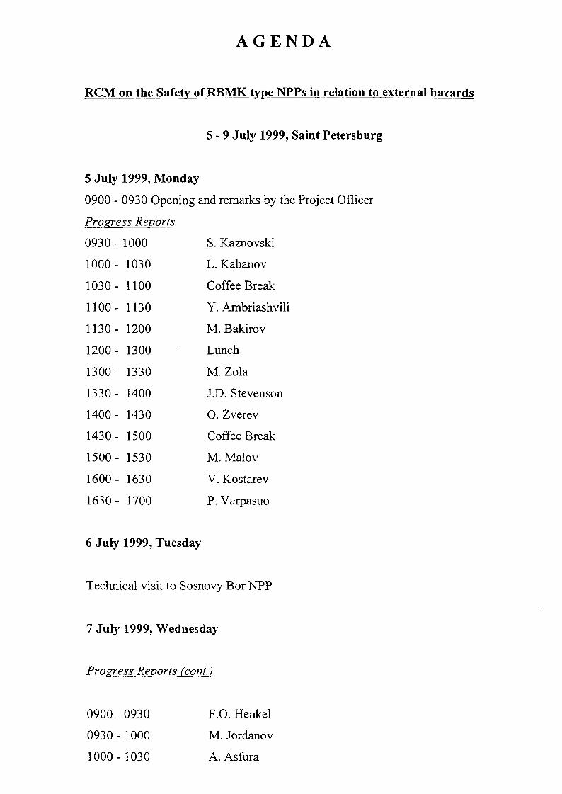
AGENDA
RCM on the Safety of RBMK type NPPs in relation to external hazards
5 - 9 July 1999, Saint Petersburg
5 July 1999, Monday
0900 - 0930 Opening and remarks by the Project Officer
Progress Reports
0930 - 1000 S. Kaznovski
1000- 1030 L. Kabanov
1030- 1100 Coffee Break
1100- 1130 Y. Ambriashvili
1130- 1200 M. Bakirov
1200- 1300 Lunch
1300- 1330 M.Zola
1330- 1400 J.D.Stevenson
1400- 1430 O. Zverev
1430- 1500 Coffee Break
1500- 1530 M. Malov
1600- 1630 V. Kostarev
1630- 1700 P. Varpasuo
6 July 1999, Tuesday
Technical visit to Sosnovy Bor NPP
7 July 1999, Wednesday
Progress Reports (cont.)
0900 - 0930 F.O. Henkel
0930-1000 M. Jordanov
1000-1030 A. Asfura

1030-1100 Coffee Break
1100 - 1200 Presentations by observers
1200-1300 Lunch
1300 - 1700 RT discussion on next year's program
8 July 1999, Thursday
0900 - 1200 RT discussion on next year's program
1200-1300 Lunch
1300 - 1700 Presentations on next year's program
9 July 1999, Friday
0900 - 1200 Presentation's on next year's program
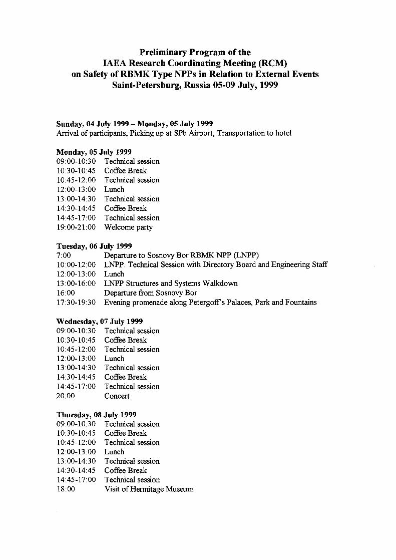
Preliminary Program of theIAEA Research Coordinating Meeting (RCM)
on Safety of RBMK Type NPPs in Relation to External EventsSaint-Petersburg, Russia 05-09 July, 1999
Sunday, 04 July 1999 - Monday, 05 July 1999Arrival of participants, Picking up at SPb Airport, Transportation to hotel
Monday, 05 July 199909:00-10:30 Technical session10:30-10:45 Coffee Break10:45-12:00 Technical session12:00-13:00 Lunch13:00-14:30 Technical session14:30-14:45 Coffee Break14:45-17:00 Technical session19:00-21:00 Welcome party
Tuesday, 06 July 19997:00 Departure to Sosnovy Bor RBMK NPP (LNPP)10:00-12:00 LNPP. Technical Session with Directory Board and Engineering Staff12:00-13:00 Lunch13:00-16:00 LNPP Structures and Systems Walkdown16:00 Departure from Sosnovy Bor17:30-19:30 Evening promenade along PetergofFs Palaces, Park and Fountains
Wednesday, 07 July 199909:00-10:30 Technical session10:30-10:45 Coffee Break10:45-12:00 Technical session12:00-13:00 Lunch13:00-14:30 Technical session14:30-14:45 Coffee Break14:45-17:00 Technical session20:00 Concert
Thursday, 08 July 199909:00-10:3 0 Technical session10:30-10:45 Coffee Break10:45-12:00 Technical session12:00-13:00 Lunch13:00-14:30 Technical session14:30-14:45 Coffee Break14:45-17:00 Technical session18:00 Visit of Hermitage Museum

Friday, 09 July 199909:00-10:3 0 Technical session10:30-10:45 Coffee Break10:45-12:00 Technical session12:00-13:00 Lunch13:00-16:00 Preparing of RCM conclusions and final documents18:00-21:00 Evening party and Boat trip
Saturday 10, July 1999Departure of participants

Proposals for section "Analysis of structures, equipment, building"
To create a group of representatives of General designer (VNIPIET), GeneralConstructor (NIKIET) and some other organizations (CKTI-VIBROSEISM) underthe co-ordination of International Nuclear Safety Center of Russian Minatom(RINSC-L.Kabanov) to joint effort and exchange of information in the area of thissection.To continue work on contract 10653 "Seismic analysis for RBMK-1000 steam andfeed water pipelines" (chief scientific investigator Dr. L. Kabanov) for period(October 1999-2000) in two main directions:A) Analyzing of limiting loads for steam/feed water pipelines in boundaries of
reactor building;B) Complete development of a methodology of evaluation of the probability of
aircraft crash onto the most important buildings (including different parts ofmain building) of the first generation of RBMK NPPS.
Leonid Kabanov
8/07/1999

Dynamic Analysis of Reactor Building
— FORTUM will revise and update the model of reactor building
• Upgrading reactor hall• Add soil model• Add heaviest equipment (e.g. drum separators)
(Leningradskaya NPP - Sireyschikov, VNIPIET - Butorin)
— Mr. Boutrin's group agreed to receive the input of FORTUN's model and check itaccording to mass and stiffness
• Help to add drum separators• Provide with aircraft crash impact locations and characteristics
— Prof.Beliaev/Dr.Birbrear will develop load time functions of blast andtornadoes/storm
— WBI will calculate with a different program and other analysis type as FORTUM
• Displacements• Internal forces• Floor response spectra for external events
— ISMES will use the FRS to investigate safety-related equipment. Tworepresentative cases will be developed as master guide by ISMES
P. Varpasuo
08.07.99

Standards, Norms and Guides in Relation to External Events forRBMK-Type NPPs
Scope of works:
(1) Collection and summary of older and currently valid Russian (Soviet) documents(standards, norms and guides)
(2) Collection and summary of relevant applicable western and internationaldocuments (standards, norms and guides) (IAEA, US NRC and other, KTA, IECetc.)
(3) Comparison study— General requirement for existing RBMK NPPs,— Requirements in relation to civil structure— Requirements in relation to equipment:
• Mechanical equipment components of pipes;
• Electrical and INC equipment.
Members of Working Group:
1. Masopust, R.(S&A, CZ)
2. Kostarev, V.V.(CKTI-Vibroseism, St. Petersburg)3. Belyaev, V.S.(SRCC, St. Petersburg)4. Birbraer A.,A.N.( St. Petersburg)5. Stevenson J.D. (S&A - E)6. Representative (ENES, Moscow)7. Representative (INSC, Moscow)Schedule:
1) Progress report (next RCM in 2000)2) Final report (-2001)
R.Masopust
08.07.99

Proposal for section "Plant information"
(1) To develop a list of the following components on the basis of study of LeningradNPP (unit 1) drawings: walls, columns, main equipment material properties,constructions in a form:— Length, width, thickness with connection to design lay-out;— Mass characteristics of equipment with link to co-ordinates;
Components of building constructions with a link to co-ordinates;— List of material properties.
(2) Also it is possible to prepare:— Soil properties— Sets of 3-component accelerograms (upon regional micro-seismic data).
A.Popov (VNIPIET)
08.07.99

IAEA - ProgramSafety of RBMK type Nuclear Power Plant in relation to external events
IAEA Research Contract No10324/Regular Budget Fund
External events analysisfor RBMK - 1000 steam drum separators
Detailed work plan for second year:
1) Calculation of rigidity characteristics of primary loop system pipelines adjoiningto the steam drum separators of Leningrad NPP unit 1.
2) Calculation of rigidity characteristics of support structures of steam drumseparators of Leningrad NPP unit 1.
3) Creation of complex of designed models for assessment of steam separatorsstability under external impacts on the reactor building of Leningrad NPP unitl.
4) Creation of complex of designed models for assessment of strength of steamseparators support structures and adjoining pipelines under external impacts on thereactor building of Leningrad NPP unit 1.
VNIPIET
08.07.99

Proposals of VNIIAM and AEP, RFfor inclusion in Workplan of IAEA "Coordinated Research Program on Safety ofRBMK Type NPPs in Relation to External Events" on 2000 year
1. General OpinionAll united efforts of participants in 2000 must be directed on investigation atLeningrad NPP. It is possible that works for Leningrad NPP will not be finished in2000 and 2001 (or part of 2001) will be necessary for full completion.
2. Sphere of activity:As usually - checking up and ensuring of different types of technological equipmentseismic resistance on the base of walkdown and dynamic testing.
3. Actual Task for the 2000.3.1 Analysis of already available results from Kursk, Chernobyl and Smolensk NPP.
Preliminary stage for the future analysis and inside testing should be carried out inthis year.
3.2 First stage of analysis for the capacity of technological equipment against airplanecrash and earthquake impacts (starting in 2000 and completing in 2001).
3.3 In case of necessity on request and coordination with Leningrad NPP theperforming of dynamic inside tests of equipment.
S. Kaznovsky, Dr., prof., Head of Dept. of VNIIAM.Y. Ambriashvili, Dr., prof., Head of Dept. of AEP

EQE Working Plan
During the period the following tasks will be performed.
Development of a 3D Finite Element Model (FEM) of the Reactor Building of aRBMKNPP.
Development of a soil model. With the soil properties of the Leningrad NPP a soilmodel will be developed to perform Soil-Structure Interaction (SSI) analysis ofthe RBMK NPP reactor building.
Performance of seismic SSI analysis. The analysis will be performed with the 3Dfinite element and soil models. The results of these analyses will bedisplacements, forces and floor response spectra at selected locations andstructural elements.
Blast analysis. As an optional task, EQE will perform blast analysis of the reactorbuilding. The blast load will be provided by other participants. The results will beobtained in the same manner as these from seismic analysis.

Minutes of meeting
St. Petersburg 08.07.1999 15:45 - 16:45
prof. Beliaev LNPP, Research Center of Capital Construction
Mr. Boutorin VNIPIETDr. Henkel WBIMr. Syreyschikov LNPP
MINIMUM REQUIRED DATA FOR ANALYSIS OF REACTOR BUILDING
It was discussed what data is necessary to build 3D finite element model of the RBMKReactor Building. LNPP is taken as a reference plant.The data is distinguished in two levels.- Priority 1: Data necessary to build a model of the Reactor Building itself.- Priority 2: Data necessary to model the Reactor Building in more details and to add the
intermediate buildings (between Reactor Building & Turbine Hall) and the Turbine Hallitself.
DATALayout drawingsCross sections in longitudinaldirectionCross sections in transversedirectionLayout of foundations
Typical connections in detailprecast to monoliticsteel to monoliticsteel to precast
Trusses, columns, bracesMasses of heavy equipmentand their locations
Distributed masses of otherequipmentRoof panels and panelattachmentsCladding panels and panelattachmentsMaterial properties
PRIORITY 1Where principle changes inthe buildings occur in vertical,longitudinal and transversedirection
To identify thickness
If possible
Reactor Building and its roofDrum separators, refuelingmachine, reactor core, pumps,cranes (with their typicallocations)Given as ...tons/m2 at eachfloorReactor Building
Reactor Building
Required
PRIORITY 2At more floors and axes AH-...
and axes 13-K.. and otherbuildings
To identify joints and crosssectionsAll
Turbine HallOthers
Turbine Hall
Other buildings
Mr. Boutorin in cooperation with Mr. Syreyschikov will support the working groups with theinput data of Priority 1 within 4 months.
XA9952880
ALL-RUSSIA SCIETIFIC RESEARCH INSTITUTEOF ATOMIC MACHINE CONSTRUCTION
(VNIIAM)
PAST VNIIAM EXPERIENCE RELATED TO RBMKEQUIPMENT TESTING AND CALCULATIONS OF
SEISMIC RESISTANCE
Presentation on Meeting in St.- Petersburg (5-9 July 1999).
Stanislav KAZNOVSKIYDr., professor, Head of NPP equipment seismic resistance Dept. of VNIIAM
Moscow, Russian Federation1999

During 1988-1990 specialists of VNIIAM and Kabardin-Balkar StateUniversity carried out inspection, dynamic tests, and seismic resistancecalculations of different type equipment at Kursk and Chernobyl NPPs. For allseismic instable units of equipment the concrete recommendations were workedout. Lists of checked equipment are very extensive.
41 types of equipment were checked at Units 2, 4 Kursk NPP: heatexchangers, filters, valves, fast-acting reducing installations, tanks, ventilators,tube passages. In addition CKTI (St.- Petersburg) at VNIIAM's request carried outcalculations of seismic resistance of turbine, separator-steam superheater deaeratortank 120 m3, deaerator installation DP-1000-6.
103 types of equipment were checked at Units 1, 2, 3 of Chernobyl NPP: heatexchangers, filters, valves, tanks, ventilators, pumps, compressors, bridge cranes,loading-unloading machines, tube passages.
Methods and technical means used in works at RBMK type NPPs weredescribed in detail in our previous publications and reports for IAEA duringrealization of "Co-Ordinated Research Programme on Benchmark Study for theSeismic Analysis and Testing of WWER-Type Nuclear Power Plants".
Calculations of seismic resistance of tested at Kursk NPP equipment showedthat the following types of equipment do not answer to demands:
- separate storage tanks,
- condensate storage tanks,
- condenser of gas contour MCGC-17,
- heater of low pressure PN-1800,
- 3 types of tube passages from 9 inspected types (1325-08, 1325-09,1325-10).
At Chernobyl NPP the following types of inspected equipment do not answerto demands of seismic resistance:
- filters of ionic installations AFI-2,4,
- passage for 2 pipes with diameter 600 mm 1325-12,
- horizontal passage for 3 pipes D=300 mm 1325-10,
- horizontal passage for 11 pipes D=300 mm 1325-09,
- vertical hermetical passage for 8 pipes D=300 mm 1325-08,
- heat-exchangers of cooling system of scheme "L",
- heat-exchanger of cooling of reactor control and protection system "SUZ",
- PVBD-type containers of reactor emergency cooling system,
JUN.-24'99(THU) 22-05 EQE INTERNATIONAL TEL:510-663-1046 P. 003
illXA9952881
BULS&RIJl
BULGARIA
SOIL-STRUCTURAL INTERACTION ANALYSIS OFRBMK TYPE NPP FOR SEISMIC EVENT
IAEA Coordinated Research Programme"Safety of RBMK Type NPP in Relation to External Events'
PROGRESS REPORT
Prepared for: INTERNATIONAL ATOMIC ENERGY AGENCYContract No. 9974/RB
EQE-Bulgaria Report No : 0705-R-01REVISION :ODATE: 24.06.1999
EQE-Bulgaria
Safety, Engineering and Management ConsultantsHEAD OFFICE: Christo Smimenski 1. Eleventh Floor, 1421 SOFIA, BULGARIA
TEL/FAX (559-2) 963-2049, 66-04-17. 66-90-25, 65-00-39E-MAIL: [email protected]
TOPCALL FAX A:TF033398 F85 99-06-25-07:11 page 3

- centrifugal pump of cooling and cleaning system of water keeping pool3H-6K-1,
- centrifugal pump of organized leakings receiving and cooling HP90/49,
- filters of feeding assembly,
- reverse turning valve D=800 mm,
- throttle valve D=800 mm.
Detailed results of inspections of equipment at Kursk and Chernobyl NPPsare presented in the Final Report of VNIIAM prepared in 1998 and passed toIAEA. The Report includes the full lists of inspected equipment, results ofdynamic tests and calculations of seismic resistance, conclusions about seismicresistance, reasons of seismic instability, recommendations for ensuring of seismicresistance, illustrations.
Apparently this Report will be published by IAEA in the next WorkingMaterials.
Kursk and Chernobyl NPPs are RBMK-type stations of the secondgeneration. Smolensk NPP applies to the same generation. It gives the possibilityof wide using of obtained results for evaluation of Smolensk NPP equipmentseismic resistance.
Now we carry out the detailed revise of types of equipment inspected atKursk and Chernobyl NPPs with analogous equipment mounted at Smolensk NPP.As it was expected, the majority types of equipment are fully identic.
Discrepancies in types (trademarks) were discovered only for 9 positions:heat-exchanger of intermediate contour system D=1200 mm, 3 types of valves, and4 types of centrifugal pumps.
Leningrad NPP is the station of the first generation. Here a marked differencewith Kursk and Chernobyl NPPs is possible. It applies to types of equipment, itscompositions, fastening, construction of supports.
For using of past experience of VNIIAM for seismic analysis of LeningradNPP the careful study of technical documentation is necessary. It is necessary tonote that equipment of reserve sources of electric supply (such as diesel generatorstation) and equipment of fire putting out system was not checked by VNIIAM inthe past.
Dynamic testing and seismic analysis of these positions at Leningrad NPPwill be useful and important for all RBMK-type NPPs.
VNIIAM is ready to carry out the examination of above-mentioned system atLeningrad NPP in 1999.

JUN.-24'99(THU! 22:05 EQE INTERNATIONAL TEL:510-663-1046 V. UU4
PROJECT: Safety of KBMK Type NPP in Relation
to External Events
TITLE: SSI Response Analysis of a B.3MK Type
NPP for Seismic Event - RC 9974/R
SHEET
BY
1
MJJ
OF
DATE
24.oe
a
.1999
PROGRESS REPORT
TITLE OF PROJECT
Soil-Structure Interaction Response Analysis of
RBMK Type NPP for Seismic Event
RESEARCH INSTITUTE
EQE~Bulgaria
CHIEF SCIENTIFIC INVESTIGATOR
Mar in Jordanov Jorriar.ov
TIKE PERIOD COVERED
1 July 1998 - 30 June 1999
TOPCALL FAX A:TF033398 F85 99-06-25-07:11 Pa9e
-24'99(THU) 22:05 EQE INTERNATIONAL TEL:510-663-1046 P. 005
PROJECT: Safety of RBMK Type NPP in Relation SHEET 2 OF 8
to External Events BY NIJJ DATE
TITLE: SSI Response Analysis of a RBMK Type 24.05.1999
NPP for Seismic Event - RC 9974/R
1. SCIENTIFIC BACKGROUND AND SCOPE OF THE STUDY
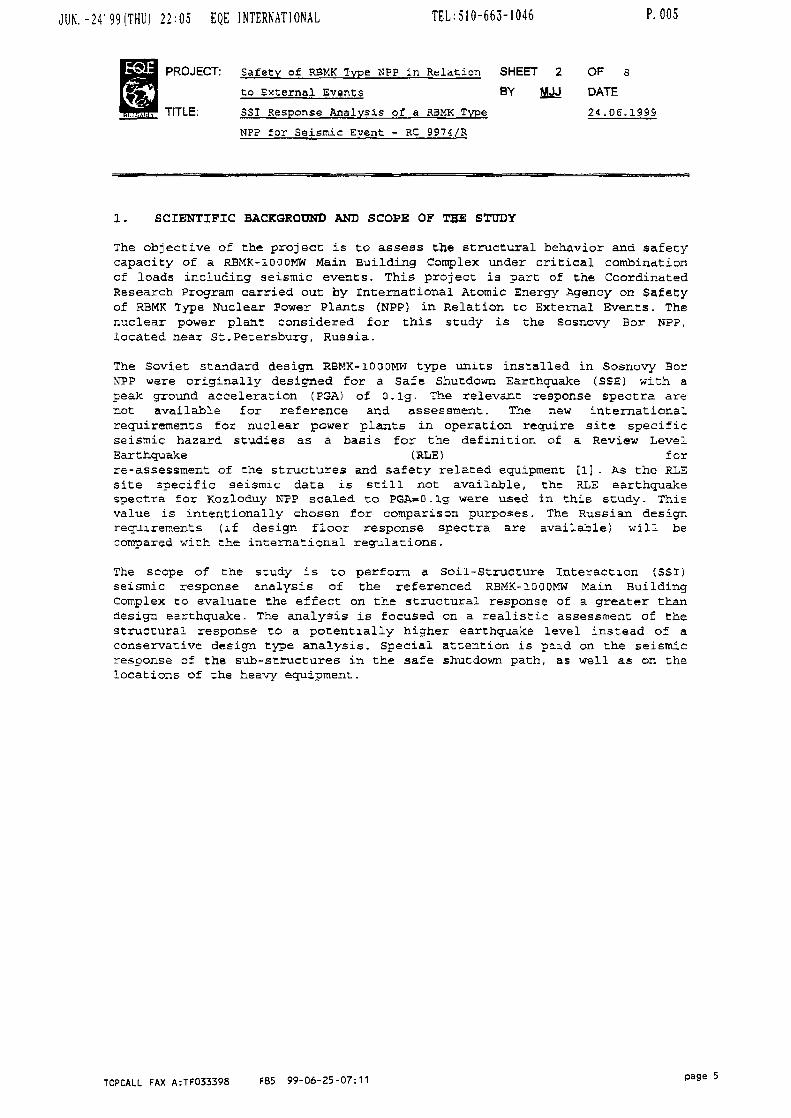
The objective of the project is to assess tiie structural behavior and safetycapacity of a RBMK-IQQOWW Main Building Complex under critical combinationof loads including seismic events. This project is part of the CoordinatedResearch Program carried out by International Atomic Energy Agency on Safetyof RBMK Type Nuclear Power Plants (NPP) in Relation to External Events. Thenuclear power plant considered for this study is the Sosnovy Bor NPP,located near St.Petersburg, Russia.
The Soviet standard design RBMK-iOOOMW type units installed in Sosnovy BorNPP were originally designed for a Safe Shutdown Earthquake (SSE) with apeak ground acceleration (PGA) of O.lg. The relevant response spectra arenot available for reference and assessment. The new internationalrequirements for nuclear power plants in operation require site specificseismic hazard studies as a basis for the definition of a Review LevelEarthquake (RLE) forre-assessment of the structures and safety related equipment [1] . As the RLEsite specific seismic data is still not available, the RLE earthquakespectra for Kozloduy NPP scaled to PGA=0. ig were used in this study. Thisvalue is intentionally chosen for comparison purposes. The Russian designrequirements (if design floor response spectra are available) will becompared with the international regulations.
The scope of the study is to perform a Soil-Structure Interaction (SSI)seismic response analysis of the referenced R3MK-1O0DMW Main BuildingComplex co evaluate the effect on the structural response of a greater thandesign earthquake. The analysis is focused on a realistic assessment of thestructural response to a potentially higher earthquake level instead of aconservative design type analysis. Special attention is paid on the seismicresponse of the sub-structures in the safe shutdown path, as well as on thelocations of the heavy equipment.
TOPCALL FAX A:TF033398 F85 99-06-25-07:11

JUN. - 2 4 ' 99(THU) 2 2 : 0 5 EQE INTERNATIONAL TEL:5l0-663-1046 P. 006
PROJECT: Safety of KBMK Type NPP in Relation
bo External Events
TITLE: s s i Response Analysis of a RBMK Type
NPP for Seismic Event -RC9974/R
SHEET
BY
3
MJJ
OF
DATE
24 .06
8
.1999
2. EXPERIMENTAL METHOD
From the studies that have been done on Paks and Kozloduy NPPs [2] , [3], ithas been concluded that the soil-structure interaction modeling is much moreimportant than the structure model details. Due to the lack of thestructural drawings and construction details a simplified equivalent stickmodel is developed for assessment of the seismic structural response usingSSI techniques. The present soil-structure interaction model of Soeonovy BorNPP does not assess the consequences of structure-to-structure interactionand multiple support excitation, on the structural response.
Substructure and direct methods of SSI analysis of the structures areusually applied for assessment of the seismic response of the ReactorBuildings in nuclear power plants. A simplified three dimensional model ofthe Main Building Complex of Sosnovy Bor KP? is developed based on thelimited structural drawings available. The soil properties at Sosnovy BorNPP site [4] are incorporated into appropriate soil profile model. The EQScomputer code CLASSI [5], which calculates impedance and scatteringfunctions as well as seismic response of the structures in frequency domain,has been used in this study. The SSI analysis is conducted for the SosnovyBor NPP using the RLE earthquake for Kozloduy NPP scaled to PGA=0.ig [6].The response analysis includes the development of in-structure responsespecura and generation of envelope floor response spectra.
TOPCALL FAX A:TF033398 F85 99-06-25-07:11 page 6

JUN. -24' 99 (THU) 22:05 EQE INTERNATIONAL TEL = 510-663-1046 P. 007
PROJECT: Safety of RBMK Type NP? in Relation SHEET 4 OF 3
to External Events BY MJJ DATE
TITLE: SSI Response Analysis of a RBMK Type 24.C6.1999
N?? for Seisnic Event - RC 9974/R
3. WORK CARRIED OUT
The scope of the study was covered splitting the study into the followingsteps;
• Generation of time histories consistent with nhe chosen RL3 spectra,-
• Development of an equivalent stick model for the Main Building structure;
• Development of a site soil model;
• Development of high strain soil properties,-
• Development of a foundation model,-
• Development of SSI parameters including generation of impedance andscattering functions for the foundation model and foundation inputmotion;
• Performance of SSI seismic response analyses varying soil properties ,-
• Generation of response time histories £t the preselected locations ofinterest;
• Generation of corresponding floor response spectra;
• Broadening and enveloping of the generated floor response spectra.
Each of the above steps is briefly described in the following sections ofthis report.
TOPCALL FAX A:TFO33398 F85 99-06-25-07:11 Pa9e 7

JUN. -24' 99(THU) 22:06 EQE INTERNATIONAL TEL:510-663-1046 P. 008
PROJECT: Safety of RBMK Type NPP in Relation
to External Events
TITLE: SSI Response Analysis of a RBMK Type
NPP for Seismic Event - RC 9974/R
SHEET
BY5
MJJ
OF
DATE
24-06
8
.1999
3 . 1 SEISMIC INPUT MOTION TIME HISTORIES
The Kozloduy NPP si te specific free field response spectra have been used asa RLE earthquake motion for the seismic response analysis of Sosnovy BorNPP. The Kozloduy NPP spectra have beer, scaled by factor of 0.5 and a set oftime histories with response spectra consistent with, the target responsespectra was generated. The duration of the Kozloduy NPP input motion is SOsec. In the study of Sosnovy Bor NPP i t was accepted 40 sec duration of theseismic input motion.
3 - 2 STICK MODEL OF MAIN BUILDING
A simplified stick model for the Main Building structure has been developed based onthe limited input data for the plant (a layout and typical cross-sections) . Themodel is not representative enough for the structural demand-Co-capacity assessmentbut i t is useful for the study of the SSI effect-S 6n the seismic response of thestructure. Also a sensitivity study for over-all seismic response of the structurewas carried out varying different dynamic response parameters. Further improvementson the model characteristics are foreseen in the future activities.
3 . 3 SOIL PROFILE MODEL
Based on the presented soil data for the Sosnovy Bor NPP site [4] a soilprofile model has been developed. It was assumed that a stiff rock underliesthe soil deposit.
3 . 4 DEVELOPEMENT OF HIGH STRAIN SOIL PROPERTIES
A set of general degradation curves for typical soil deposits [7] was usedto assess the non-elastic behavior of the soil deposit during a strongground motion. Relevant high strain soil properties were developed and usedin the consequent analyses for generation of impedance and scatteringfunctions.
3 . 5 DEVELOPMENT OF FOUNDATION MODEL
Tiie Main Building structure of Sosnovy BOr NPP was assumed surface founded.The embedment of about 7m of the structure was neglected. A foundation modelwas developed assuming rigid massless foundation. The model has been -usedfor generation of the impedance and scattering functions.
TOPCALL FAX A:TF033398 F85 99-06-25-07:11 page 8
JUN.-24'99(THU) 22:06 EQE INTERNATIONAL TEL:510-663-1046 P. 009
PROJECT: Safety of RBMK Type NP? in Relation SHEET 6 OF a
to External Events BY MJJ DATE
TITLE: SSI Response Analysis of a RBMK Type 24.06.1999
NPP for Seismic Event - RC 9974/R
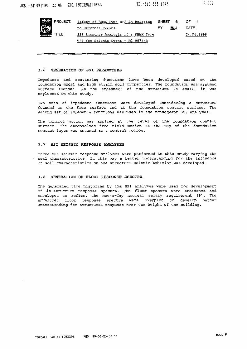
3.6 GENERATION OF SSI PARAMETERS
Impedance and scattering functions have been developed based on thefoundation model and high strain soil properties. The foundation was assumedsurface founded. As the embedment of the structure is small, it wasneglected in this study.
Two sets of impedance functions were developed considering a structurefounded on the free surface and at the foundation contact surface. Thesecond set of impedance functions was used in the consequent SSI analyses.
The control motion was applied at the level of the foundation contactsurface. The deconvolved free field motion at the top of the foundationcontact layer was assumed as a control motion.
3.7 SSI SEISMIC RESPONSE ANALYSES
Three SSI seismic response analyses were performed in this study varying thesoil characteristics. In chis way a better understanding for the influenceof soil characteristics on the structure seismic behavior was developed.
3.8 GENERATION OF FLOOR RESPONSE SPECTRA
The generated time histories by the SSI analyses were used for developmentof in-structure response spectra. The floor spectra were broadened andenveloped to reflect the now-a-day nuclear safety requirement [a] . Theenveloped floor response spectra were overplot to develop betterunderstanding for structural response over the height of the building.
TOPCALL FAX A:TFO33398 F85 99-06-25-07:11 pa9e 9

JON. -24 ' 99tTHU) 2 2 - 0 6 EQE INTERNATIONAL TEL:510-663-1U40
PROJECT: Safety of RBMK type NPP in Relat ion
to External .Events
TITLE: SSI Response Analysis of a RBMK Type
NPP for Seismic Event - RC 9974/R
r. uiu
SHEET
BV
7
MJJ
OF
DATE
2k. oe
8
.1999
4. WORK PLAN
As pare of the scope of the work under the research program of the projectit is foreseen over all improvement of the structural model. It is planed torefine the finite element model of the representative RBMK-1000 MW unitusing plant design structural drawings, constructional details and technicalspecifications for heavy equipment. The Main Building Complex model willalso include simplified models of the Turbine Hall and Electrical Building(if necessary) to account for the structure-to-structure interaction effectsduring seismic loading. A detailed 3-D model for assessment of the localbehavior of the structural elements and heavy equipment components is alsoforeseen to be developed if a requested input data is available.
A new seismic input motion is expected to be defined by the RussianAuthorities in agreement with IAEA. The new input motion should be based onan analysis of the site seismic hazard. As a consequence new seismicresponse analyses are foreseen to be carried out.
If new soil degradation curves are available the relevant analyses should bealso carried out. The influence of the soil characteristics on. thestructural seismic response will be studied additionally by variation of therelevant parameters. The effects of the embedment on the overall structuralresponse could also be considered if necessary.
New soil-structure interaction analyses will be performed to develop floorresponse spectra at different elevations and to calculate seismic forces instructural elements. The floor response spectra could be used for seismicreevaluation of the plant equipment and commodities. A comparison betweenthe newly generated floor response spectra and the design response spectra(if available) is foreseen to be performed. From seismic forces,Demand-to-Capacity (D/C) ratios for critical structural elements could bedeveloped. This could be used by plant operator to design structuralretrofit to improve the seismic safety of the structure.
TOPCALL FAX A:TF033398 F85 99-06-25-07:11 Page 10

JUN. -24' 99(THU) 22:06 EQE INTERNATIONAL TEL:510-663-1046 P. Oil
Safety of RBMK Type NPP in Relation
•zo External Events
SSI Response Analysis of a RBMK Type
NP? for Seismic Event - RC 9974/R
SHEET
BY
8
MJJ
OF
DATE
24.06
8
.1999
5. REFERENCES
[1] IAEA Safety Series 5O-SG-S1, ll Earthquakes and Associated Topics inRelation to Nuclear Power Plant Siting" , Rev.l, International AtomicEnergy Agency, Vienna, 1991
[2] structural Response of Paks NPP WWSR-440 M W Main Building Complex toBlast input Motion, IAEA Coordinated Research Program " Benchmark Studyfor Seismic Analysis and Testing of WWER-Type Nuclear Power Plants" ,Final Report No.0702-R-03, SQS-Bulgaria, May 1997
[3] Structural Response of Kozloduy NP? WWER-1000 MW Unit, IAEACoordinated Research program " BenchmarJc study for Seisir.ic Analysis andTesting of WWER-Type Nuclear Power Plants" , Final Report No.07D1-R-02,SQE-Bulgaria, 1994
[4] Sosnovy Bor NPP Soil Data, Personal correspondence withProf.v.Beliaev, Research Center of Capital Construction,St.Petersburg, Russia
[5] K.L.Wong, J.E.Luco, " Soil - Structure Interaction: A Linear ContinuumMechanics Approach (CLASSI)" , CE 79-03, University of SouthernCalifornia, Los Angeles, CA, 19S0
[6] w Seismic Safety Review Mission on Design Basis Earthquake for SeismicSafety Upgrading of Kozloduy NPP (2nd Mission)" , Final Report,Project:BUL/9/0l2-14 of IAEA, Sofia, Bulgaria 26-29 May, 1992
[7] H.3.Seed, I.M.Idriss, * Soil Moduli and Damping Factors for DynamicResponse Analysis", Report No. EERC-70/10, Earthquake EngineeringResearch Center, University of California, Berkeley, December 1970
[a] U.S. Nuclear Regulatory Commission, Standard Review Plan, NUREG-QSOO,Revision 2
TOPCALL FAX A:TF033398 F85 99-06-25-07:11

XA9952882
SEISMIC RESPONSE ANALYSISOF SOSNOYY BOR NPP
(RBMK-IOOOMW MAIN BUILDING COMPLEX)
Marin J. JordanovEQE-Bulgaria
Sofia, Bulgaria
International Atomic Energy AgencyCoordinated Research Program on Safety of RBMK Type NPP's in
Relation to External Events
St. Petersburg, Russia, July 5-9,1999
Scope of the Study
Assessment of the Main Building response to theseismic input excitation
Assess the effects of site-specific soil conditions onthe dynamic structural response of the buildingstructure

Description of the Study
Development of 3-D stick model of MainBuilding structureSite-specific soil conditions- Low-strain soil properties
Median estimate(Soil data provided by Prof. V. Beliaev)
Seismic excitation time histories- Acceleration time histories developed for
Kozloduy NPP, scaled to 0.1 g
R V 1. I! A K I A
Description of the Study (Cont.)
Deconvolution of seismic free field surfacemotion
Modeling of structure foundation andgeneration of impedance and scatteringfunctions
Fixed base frequencies and mode shapesextraction
Soil-structure interaction analysis using CLASSIchain of computer programs
Floor acceleration time histories generation ^ ^
Floor response spectra generation RiD
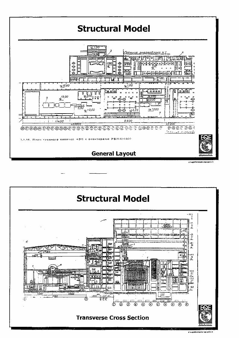
Structural Model
e
•2.60
IUEI
jnepeoffy?Q)ca N I
SKI? JP00.01 Is00-01
it—-aJ
ix:
12,00
2L-.
y y wxv.
rzJ.J.00 rlir!!
sio.oo Q
3^0.00
' - • r , T , T t T * T i n
-©
"•• \ H i^ T f f > ^ T T T
:±02000
5 600
40 200
-S:-1i-'S'?r;®'-^s-5-g'2 '?:3- :5 S;©©-S ̂ •? ^
l.i .1 fi. n.-jan r-ji rcoDnvcn A3C c rs i PB;V.K-1900
General Layout
Structural Model
I L
Transverse Cross Section
p WoQ/WsVOCVSJtKj-npp ppl/rv 6

Structural Model
Longitudinal Cross Section
p WograiiVdc\o«k5-npp ppfrv 7
Structural Model
FIXED-BASE MODESMAIN BULIDING MODEL FREQUENCIES AND
MASS PARTICIPATON COEFFICIENTSMode
no12345678g1011121314151617181920
freq[Hz]4.694.789.2910.5311.6412.4115.9317.3820.6121.8323.3024.8626.2328.1129.0130.4031.0433.3933.6834.65
Damp.ratio.070.070.070.070.070.070.070.070.070.070.070.070.070.070.070.070.070.070.070.070
Total pet mass
X
71.2370
14.426000
7.6920
4.66700
0.45600
0.13900
1.09400
99.711
y
074.282
013.437
000
7.4590
3.269000
0.02700
0.3320
0.9150
99.721
z
00000
78.655000000
9.2530000000
87.908
X X
084.335
02.755
000
0.1910
0.064000
7.10200
2.3120
0.0940
96.853
yy
85.2340
0.84000
0.7430
0.2400
2.29400
4.7932.407
00.001
00
96.552
z z
0000
81.43500000
5.07900000000
8.16394.677
p Wugr»tV/OcV*a*s-rif>o ppt/rv S

Local Soil Description
Low strain soil propertiesBest estimate: Assumed following soil data suppliedprof. V. Beliaev
No.
1
2
3
4
5
6
EHS
Thickness
[m]
2
4
4
20
30
120
Density
[t/mA3]
1.7
1.8
1.9
2.2
2.3
2.4
3
3
Sh.Velocity
[m/s]
180
250
350
350
450
650
3400
>3400
P.Velocity
[m/s]
400
1100
1500
2000
2200
2500
5800
>5800
Poisson's
0.37
0.47
0.47
0.48
0.48
0.46
0.24
G-modulus
[MPa]
55.08
112.50
232.75
269.50
465.75
1014.00
34680.00
Deg.Curve
[assumed]
1
1
2
2
1
2
3
Soil Type
a
b
c
d
e
f
9
>y
p twugrafsVOtfpakt-npp ppl/rv 9
Seismic Input Ground Motion
X M J
.0 . 1 .2 .3 .A ,S . *
Free-field accelerationtime histories
Kozloduy NPPFree Field Surface MotionSeismic Acceleration Time HistoriesScaled to O.lg
(i Wuf!'*lsVdC\pai>s-fiep PPW 10

Seismic Input Ground Motion
s
«
3
2
It
4
3
2
1
X-Direction Component
r-
/~^/
/
wifi
n r ^,
i \\
-1 Q i
1 10 10 10frequency (Hz)
2-Direct ion Component
.10
/
/\/ H\
i n 1
^
in
.5
.3
Y-Direction Componerrt
/
J
1J
Fi1 i
\\\
\\
i l l
rti
1
110 10
Frequency (Hz)
10
Free-field accelerationresponse spectra
NOTES:Seismic Ace. Spectra5% Spectral DampingAcceleration in g's
Kozloduy NPP, Free-Field Spectra,Seismic Input Acceleration TimeHistories scaled to 0.1 g B H I. I . A R I A
0 \vugralsVdc\poKs-npp ppl/irv 1
Blast Excitation Ground Motion
• Cross Correlation Coefficients Between Time Histories
X & YX&ZY&Z
CXY=0.06992
Cxz=0.09321CYZ=0.10967
It U I. i ; A K U
p Vvu9/«lsV<K\0«K3-npp P
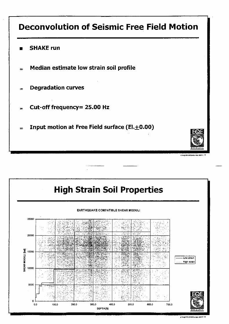
Deconvolution of Seismic Free Field Motion
SHAKE run
Median estimate low strain soil profile
Degradation curves
Cut-off frequency= 25.00 Hz
Input motion at Free Field surface (El.±0.00)
p Wugrafs\rdtiiM*s-fX>0 00Vr* 13
High Strain Soil Properties
EARTHQUAKE COMPATIBLE SHEAR MODULI
25000
20000
15000
10000
5000
0.0
s^sm•'vf-;/!?*.'^
V : ' : ^ . - : ; ^ ^ ;
- Low strain
High strain
100.0 200.0 300.0 400.0 500.0
DEPTH [ft]
600.0 700.0
p WugrafsVtkApaks-npp ppfrv 14
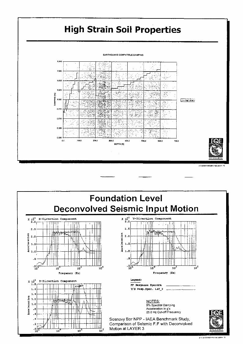
High Strain Soil Properties
EARTHQUAKE COMPATIBLE DAMPING
. . A • , J • ;' : -
'rSH1 : . . • . : • : - • • . > ? • • • . - •
SimilSiflti
• ' ' . ' • ^ '
:••". r-—^
.'•/';":. '"'4-:L
•••' " r —
-". v : l - ".* iy •.'
• - • . ' • ' ' v / • ( . • • ' /
••.v.r.-'-:.
0.0 100.0 200.0 300.0 «0.0 500.0 600.0 700.0
DEPTH [rq
S S
n ii i. <; A H i
Foundation LevelDeconvolved Seismic Input Motion
X io X-Direction Component:3 . 0
a 2.0h
a i.sh
.s/
k/
If
i
s \^ A\
10 10" 10*
(EzJ
1 0 '
X IO 1 Z-Direction Component1.8 , -
1.6
1.4a3 1.2
S 1.0V
8 "s
ij .6
10 10
2 . 5
s5 2.0eI 1.5V
3 1.0
.5
.0
/
/
/
l
—V\
!
j tI
i10" 10-
(Hz)
10
Legend:
TT Response SpeccraT/H Reap.Spec. LAT_3
NOTES:5% Spectral DampingAcceleration in g's25.0 Hz Cut-off Frequency
Sosnovy Bor NPP - IAEA Benchmark Study,Comparison of Seismic F.F with Deconvolved
2 Motion at LAYER 3

Model of Structure Foundation
x : o "
2 0•
, . 5
: . o
J
R-
i . 0
H-
1
- .5 • — 0
+
-t-! T
.5 1.0X
•Surface founded structure
•rvigiG rounuoiion
•Elevation of foundation= -8.80m•Thickness of foundation=-2.50m•Dimensions 72x66m
Sosnovy Bor NPP -IAEA Benchmark Study,Seismic Response AnalysisMain Building, Surface Founded,Impedances Calculation, BE Soil | 5 ^ j
HO11 i: 1 .<; A K 1 A
Impedance and Scattering Functions
• Frequency range: 0.05 to 40.0 Hz• Refernce parameters
G-modulus=224MPa. Vsh=343 m/s
Characteristic length=24.87m--: Number of frequencies = 36
Damping = 1.4%• Impedance and scattering functions calculated for:E3 Vertically propagating SH and P waves
n v i. <; A K i A
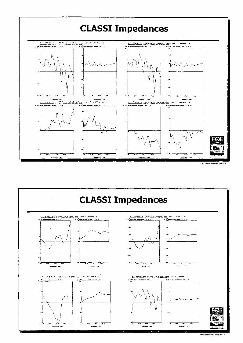
CLASS I Impedances
i f TUCMl CHgHW K( 1 I to* l iw») CMMUMK et i. 1
Iu10.
\
1
V
, /AAA
o io. a
m
• .OX*. T • J l *
/A
so.o IO.s
IHI—J 1*1
B*Q1 • «B
•t C( 1, I)
vy v
\) \
rjftSSSii S5B - ••"•
~A
CLASSI Impedances
t5 3 t5 n
^ \ /
ti SS—
1• •
. . .
k A/
/\ /v
• •
. . .
^ , . « . . _ ,
/ — ^ — *
•5—»z—ii^—•ss
. . .»»c. •» - ^.-••^j.-^r
B V 1. I! A K 1 A
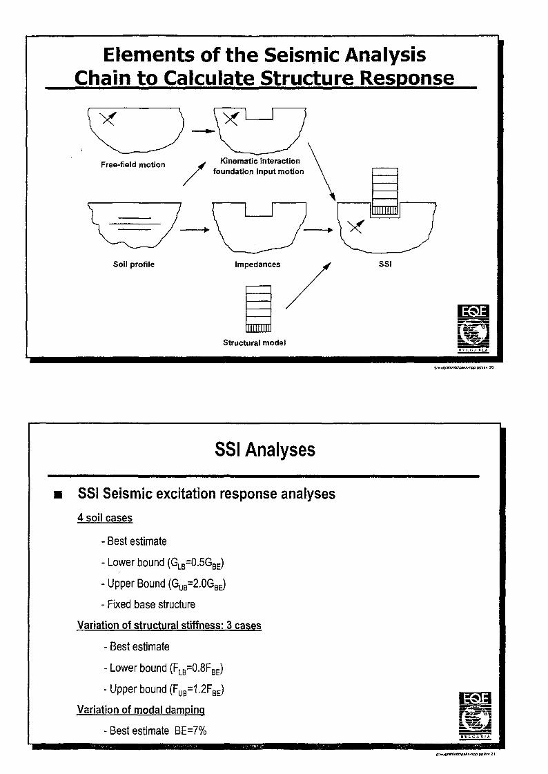
Elements of the Seismic AnalysisChain to Calculate Structure Response
Free-field motion
Soil profile
Kinematic interactionfoundation input motion
SSI
Structural modelI I tr i. <;,\ it I
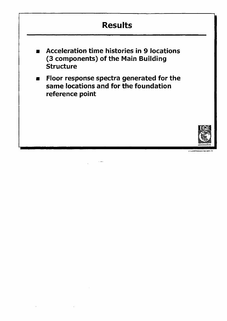
SSI Analyses
SSI Seismic excitation response analyses4 soil cases
- Best estimate
- Lower bound (GLB=0.5GBE)
- Upper Bound (GUB=2.0GBE)
- Fixed base structure
Variation of structural stiffness: 3 cases
- Best estimate
- Lower bound (FLB=0.8FBE)
- Upper bound (FUB=1.2FBE)
Variation of modal damping
- Best estimate BE=7%t U L i; A K I A
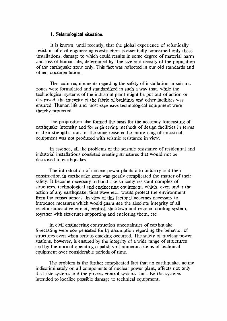
Results
Acceleration time histories in 9 locations(3 components) of the Main BuildingStructure
Floor response spectra generated for thesame locations and for the foundationreference point
p.\vugraf*v<ic\p»k»-npp opVirv 22

XA9952883
ATOMENERGOPROJECT
Research Contract: " Seismic Stability of Nuclear PowerPlants in Eastern Europe ".
FINALE REPORT
Ref: 302-J7-RUS-10126 B5-RUS-26794
Chief Scientific Investigator: Y. AmbriashviliHead, Dynamic and SeismicDepartment.
ft
Period: from 15. 04. 1998 to 15. 04. 1999
Moscow

COTENTS
Introduction
1. Seismological situation
2. Seismic qualification for buildings and equipment of RBMK NPP.
3. Structures.
3.1 Reactor buildings.3.2 Turbine hall and Electrical building.3.3 Storage buildings.
4 Equipment.4.1 Dynamic calculation and analyses of piping system.4.2 Pipelines Equipment.
4.3 Electrical Equipment.
Conclusions
References

INTRODUCTION
General scientific scope of the presented program is assessment ofstability and functionality of the nuclear power plants with RBMK typereactors in relation to External Evens including following:
-seismic capacity of structures, equipment and distribution systems;
-capacity of structures for impact type loading;
-capacity of structures for blast type loading;
For the analyses only structures, equipment and distribution systemswhich are responsible for safety shutdown path will be used.
Since 1980 Atomenergoproject has been participated in developmentand carrying out the Research Program related to investigation of seismicstability of RBMK NPPs. In general this investigation was done forSmolensk and Kursk NPPs.
It is known that the design basis of seismic analyses is investigation ofdynamic characteristic ( main frequencies and main modes ) of structures,equipment and distribution systems. Therefore the assessment of capacity ofstructures and systems can be based on the results of seismic stabilityinvestigations.
In the present final report some main results of dynamic analysesreactor building, electrical buildings, storage building, pipe lines, separators,electrical equipment's and etc. are described.
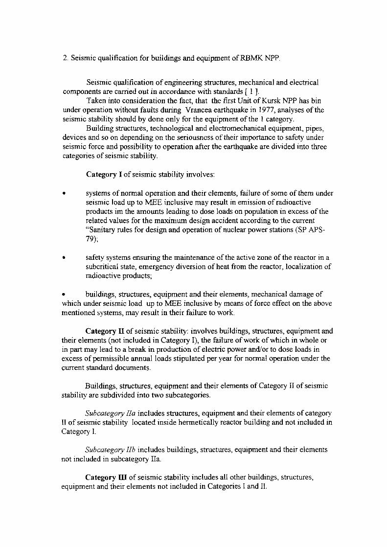
1. Seismological situation.
It is known, until recently, that the global experience of seismicallyresistant of civil engineering construction is essentially concerned only theseinstallations, damage to which could results in some degree of material harmand loss of human life, determined by the size and density of the populationof the earthquake zone only. This fact was reflected in our old standards andother documentation.
The main requirements regarding the safety of installation in seismiczones were formulated and standardized in such a way that, while thetechnological systems of the industrial plant might be put out of action ordestroyed, the integrity of the fabric of buildings and other facilities wasensured. Human life and most expensive technological equipment werethereby protected.
The proposition also formed the basis for the accuracy forecasting ofearthquake intensity and for engineering methods of design facilities in termsof their strengths, and for the same reasons the entire rang of industrialequipment was not produced with seismic resistance in view.
In essence, all the problems of the seismic resistance of residential andindustrial installations consisted creating structures that would not bedestroyed in earthquakes.
The introduction of nuclear power plants into industry and theirconstruction in earthquake zone was greatly complicated the matter of then-safety. It became necessary to build a seismically resistant complex ofstructures, technological and engineering equipment, which, even under theaction of any earthquake, tidal wave etc., would protect the environmentfrom the consequences. In view of this factor it becomes necessary tointroduce measures which would guarantee the absolute integrity of allreactor radioactive circuit, control, shutdown and residual cooling system,together with structures supporting and enclosing them, etc .
In civil engineering construction uncertainties of earthquakeforecasting were compensated for by assumption regarding the behavior ofstructures even when serious cracking occurred. The safety of nuclear powerstations, however, is ensured by the integrity of a wide range of structuresand by the normal operating capability of numerous items of technicalequipment over considerable periods of time.
The problem is the further complicated fact that an earthquake, actingindiscriminately on all components of nuclear power plant, affects not onlythe basic systems and the process control systems but also the systemsintended to localize possible damage to technical equipment.

Using such approach and data from the results of calculations,experience of earthquakes, according to our old standards structure can bebuild without special measures for the seismic protections if the seismicity ofthe area is less then 6 by MSK-64 scale.
According to the old map of seismicity seismological situation aroundthe Leningrad, Kursk, Smolensk, Ignalina and Chernobl NPPs in that timewas accepted less then 5 by MSK scale and therefore for the units thosenuclear power plants were designed without seismic load and specialprotections of the equipment.
After Vracea earthquake in 1977 new standard of calculation anddesign of NPPs was prepared, and it was necessary to review the mainposition of the old standards, including analysis of the seismologicalsituations.
In this case since 1980 the program of seismological investigations ofall RBMK sites has been accepted.
By the results of investigation, which was done after 1981 using theliterature data, the new set of designed accelerograms was accepted with thefollowing data:
- for Smolensk and Chernobyl the long period accelerograms wereaccepted from Carpathians earthquakes with the level of intensityS2 -6 ( 0.05g ) and SI -5 ( 0.025g ) by MSK scale;
- for Kursk two acellerograms were accepted: the short periodearthquake accelerograms with intensity S2-7 ( 0. lg ) and longperiod SI - 6 ( 0.05g).
Complimentary investigations, which were done starting from 1983 onthe base site, the investigation data shows that the waiting intensities are: forthe long period earthquake - maximum acceleration 0.04g and for the shortperiod - 0.05g.
Therefore all new designs were accepted for reconstructions and newunits should be calculated using data for Kursk NPP :
- SI- recorded in Scope from Vracea Earthquake with the maximumacceleration 0. lg.
- S2- Short period Artificial Accelerogram with the maximumacceleration 0.5g.
2. Seismic qualification for buildings and equipment of RBMK NPP.
Seismic qualification of engineering structures, mechanical and electricalcomponents are carried out in accordance with standards [ 1 ].
Taken into consideration the fact, that the first Unit of Kursk NPP has binunder operation without faults during Vrancea earthquake in 1977, analyses of theseismic stability should by done only for the equipment of the 1 category.
Building structures, technological and electromechanical equipment, pipes,devices and so on depending on the seriousness of their importance to safety underseismic force and possibility to operation after the earthquake are divided into threecategories of seismic stability.
Category I of seismic stability involves:
• systems of normal operation and their elements, failure of some of them underseismic load up to MEE inclusive may result in emission of radioactiveproducts im the amounts leading to dose loads on population in excess of therelated values for the maximum design accident according to the current"Sanitary rules for design and operation of nuclear power stations (SP APS-79);
• safety systems ensuring the maintenance of the active zone of the reactor in asubcritical state, emergency diversion of heat from the reactor, localization ofradioactive products;
• buildings, structures, equipment and their elements, mechanical damage ofwhich under seismic load up to MEE inclusive by means of force effect on the abovementioned systems, may result in their failure to work.
Category II of seismic stability: involves buildings, structures, equipment andtheir elements (not included in Category I), the failure of work of which in whole orin part may lead to a break in production of electric power and/or to dose loads inexcess of permissible annual loads stipulated per year for normal operation under thecurrent standard documents.
Buildings, structures, equipment and their elements of Category II of seismicstability are subdivided into two subcategories.
Subcategory Ha includes structures, equipment and their elements of categoryII of seismic stability located inside hermetically reactor building and not included inCategory I.
Subcategory lib includes buildings, structures, equipment and their elementsnot included in subcategory Ha.
Category III of seismic stability includes all other buildings, structures,equipment and their elements not included in Categories I and II.

Elements of one functional system may refer to different categoriesundertaking special measures to divide them (cutting off, regulating fittings, etc.).Elements and joints used for division refer should be related to a higher category ofearthquake resistance.
Equipment, components and structures are done and designed in such a waythat failure of elements of a lower category does not lead to a failure of damage ofelements of a higher category. In an opposite case they should be referred to a highercategory.
Buildings, structures, equipment and their elements of Category I of seismicstability should fulfill their functions in ensuring safety of AS during and after anearthquake of an intensity up to MEE inclusive. At an earthquake up to DE and afterit should maintain possibility to operation.
Buildings, structures and equipment and their elements of Category II ofseismic stability should retain their possibility to operation after an earthquake of anintensity up to DE inclusive.
The designing of buildings, structures and equipment of Category III ofseismic stability is made in accordance with the current standard documents
The following structures and equipment I category was calculated and tested:
- Reactor buildings;- Turbine hall and Electrical building;- Storage buildings;- Main Circulation Circuit;- Separator drums;- Pipe lines;- Electrical Equipment. .
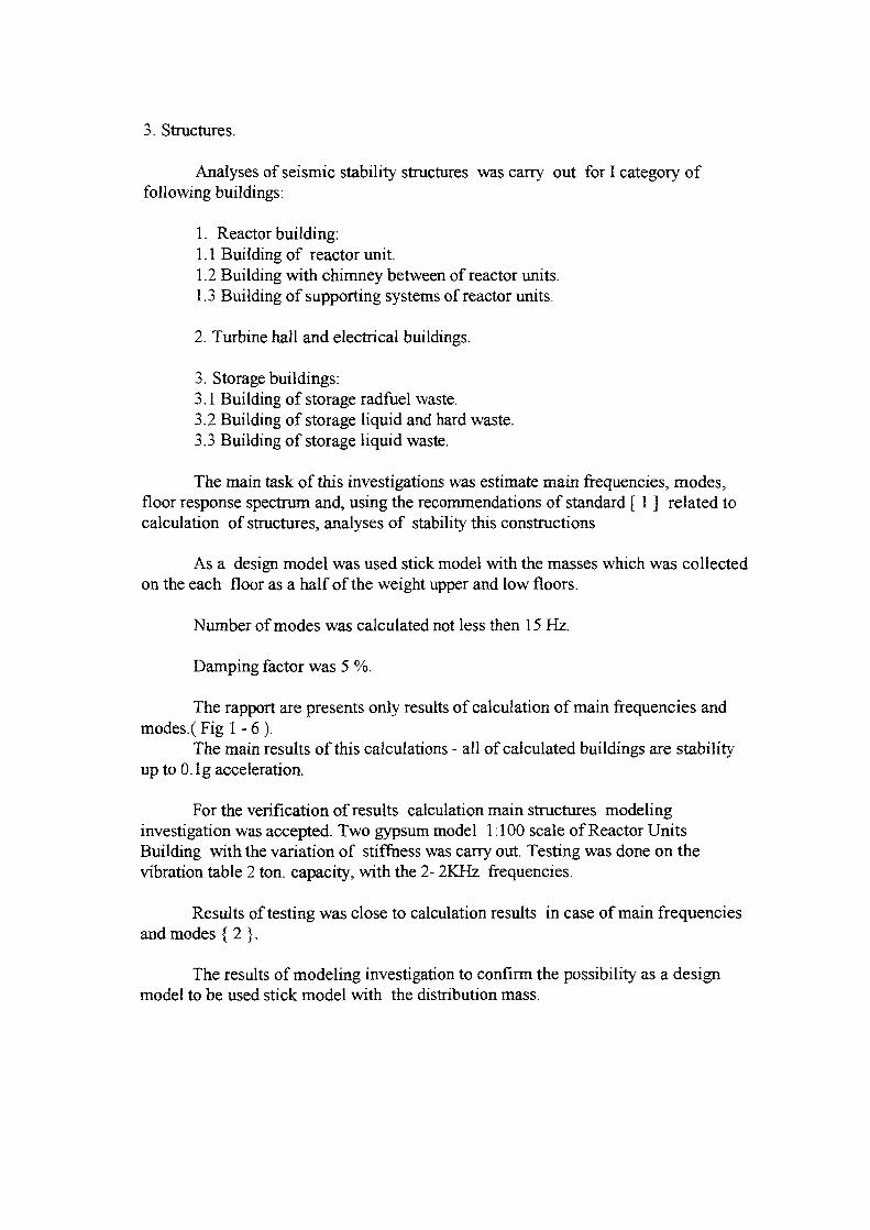
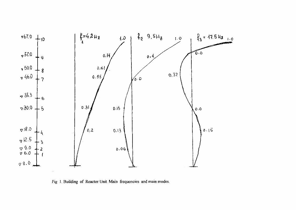
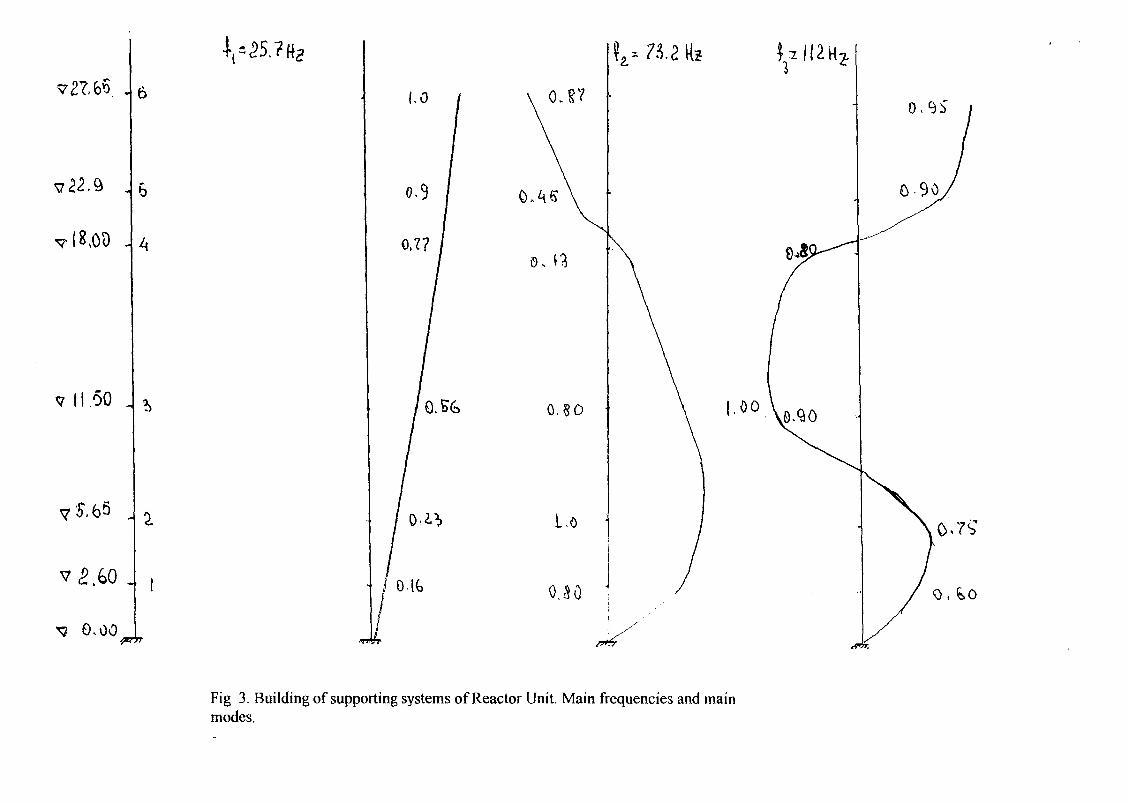
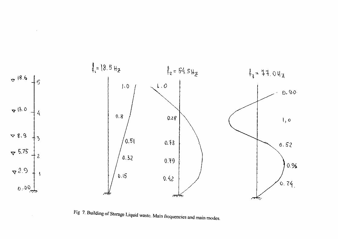
3. Structures.
Analyses of seismic stability structures was carry out for I category offollowing buildings:
1. Reactor building:1.1 Building of reactor unit.1.2 Building with chimney between of reactor units.1.3 Building of supporting systems of reactor units.
2. Turbine hall and electrical buildings.
3. Storage buildings:3.1 Building of storage radfuel waste.3.2 Building of storage liquid and hard waste.3.3 Building of storage liquid waste.
The main task of this investigations was estimate main frequencies, modes,floor response spectrum and, using the recommendations of standard [ 1 ] related tocalculation of structures, analyses of stability this constructions
As a design model was used stick model with the masses which was collectedon the each floor as a half of the weight upper and low floors.
Number of modes was calculated not less then 15 Hz.
Damping factor was 5 %.
The rapport are presents only results of calculation of main frequencies andmodes.(Fig 1-6).
The main results of this calculations - all of calculated buildings are stabilityup to 0. Ig acceleration.
For the verification of results calculation main structures modelinginvestigation was accepted. Two gypsum model 1:100 scale of Reactor UnitsBuilding with the variation of stiffness was carry out. Testing was done on thevibration table 2 ton. capacity, with the 2- 2KHz frequencies.
Results of testing was close to calculation results in case of main frequenciesand modes { 2 }.
The results of modeling investigation to confirm the possibility as a designmodel to be used stick model with the distribution mass.
-~\0
50.0
- - 4
7 6,0
8
7
-~b
Fig 1. Building of Reactor Unit. Main frequencies and main modes.

99.0
55,0
•.3 .7
(7
(1
10
-I 5A
• 2. . 1
{^•2 Hz 0..4&
Fig 2. Building between two Reactor Units. Main frequencies and main modes.
7 11.50 „
6
0.7?
O-lfe
0. 8D
L.o
0J0
oo
0,9s
Fig 3. Building of supporting systems of Reactor Unit. Main frequencies and mainmodes.

20. 2.
v 4,
0,00
I-16.1 Ha
Fig 4 Turbine Hall and Electrical Building. Main frequencies and main modes.

= 6.0 «
o.oo
0,(5
O.bO
Fig 5. Building of Storage Radfuel waste. Main frequencies and main modes.

25.2
0,00
i.O
Fig 6. Building of Storage Liquid and Hard waste. Main frequencies and main modes.
4 6
tt.OMl
v ff>
0,00,+ *-ll It's
Fig 7. Building of Storage Liquid waste. Main frequenceencies and main modes.

4. Equpment.
4.1 Dynamic calculation and analyses of piping systems.
Design of pipelines is carried out in two stages:- analyses of dynamic characteristic pipeline;- verification of seismic resistance;Traditionally for calculation pipeline 1 category it is necessary dynamic
methodology of analyses using accelerograms.For practical purposes, wide use is made of a procedure in which a dynamic
piping system reduces to a static one. Its essential point is that the forces due to massloads are sustained by equivalent forces due to seismic loads, if it is assumed that thedirection of the seismic load coincides with the direction of the maximumdisplacements due to the mass load, and for this reason the dynamic analysis makesuse of the rate and shape of the oscillations obtained for the maximum displacementsalong all three axes due to the mass load.
In this procedure the following arbitrary notations and definitions have beenadopted: a - standard nominal stresses permitted in the metal of the piping; a2 -normalized stresses determined for the sums of general or local component membranestresses and general bending stresses (without allowance for compensation stresses);C T ^ - maximum normalized stress in the piping due to dead weight. It is determinedby the ratio maximum moment M (due to the mass load) to the section modules ofbending W; x, y, z -the main co-ordinates; fi>x (y,z) - frequency of the first mode of thenatural oscillations of the piping; (a,W) - amplitude-frequency characteristic of theseismic load on the foundation of the building; k -a damping coefficient taking thevalues recommended by the standards or based on the results of full-scaleexperiments; kh - a coefficient characterizing the dynamic character of the building inwhich the piping system is located. IT is equal to the ratio of the maximum value ofthe acceleration of the corresponding floor accelerogram (obtained for a specificbuilding structure at the maximum elevation of the attachment of a stationary pipingsupport) to the value of the calculated acceleration for the accelerogram at the base.This is a coefficient of the variation in vertical acceleration of the building.a° max, x (y,z) is a dimensionless coefficient corresponding to the value of accelerationin fractions of the acceleration of gravity according to the response spectrum for aspecific component of seismic load at the level of the base of the building; ann.x (y,z)is the same, for the corresponding elevation of the attachment of a stationary pipingsupport; a°n.x (y,z) is a dimensionless coefficient corresponding to the value ofacceleration in fractions of the acceleration of gravity for the corresponding frequencyof the first mode of vibration according to the response spectrum, for a specificcomponent of seismic load, for the corresponding elevation of the attachment of astationary piping support; (as)s2 is the stresses due only to the seismic load.
Piping which has gone through the construction stages and strength analysisunder static and cyclical loads are than analyzed for strength under seismic loads.The effective stresses (a 2) and (a$ )s2 *n the piping can be determined from the effectof the non-seismic loads of the first stage (internal pressure, dead weight) and of theseismic loads.
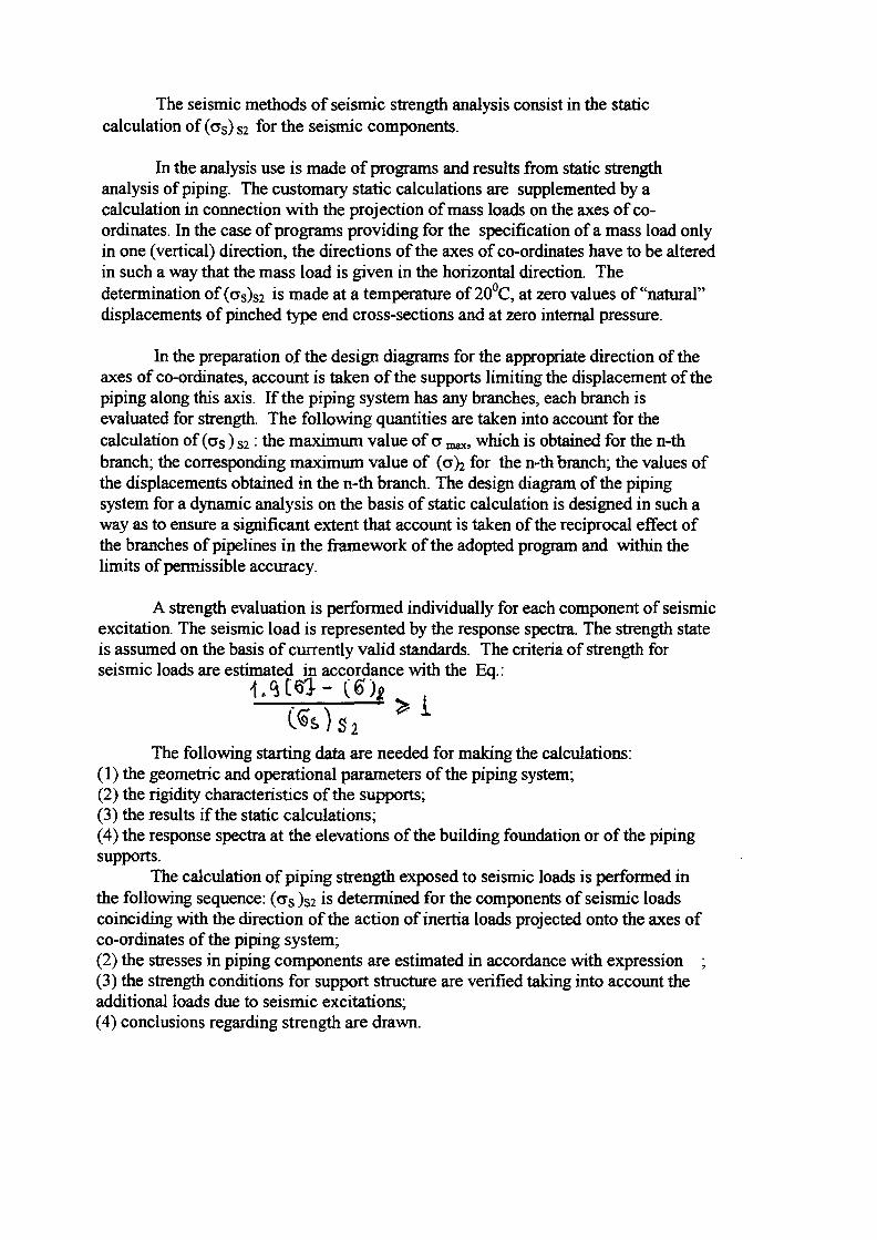
The seismic methods of seismic strength analysis consist in the staticcalculation of (as) S2 for the seismic components.
In the analysis use is made of programs and results from static strengthanalysis of piping. The customary static calculations are supplemented by acalculation in connection with the projection of mass loads on the axes of co-ordinates. In the case of programs providing for the specification of a mass load onlyin one (vertical) direction, the directions of the axes of co-ordinates have to be alteredin such a way that the mass load is given in the horizontal direction. Thedetermination of (cs)s2 *s m a ( te at a temperature of 20°C, at zero values of "natural"displacements of pinched type end cross-sections and at zero internal pressure.
In the preparation of the design diagrams for the appropriate direction of theaxes of co-ordinates, account is taken of the supports limiting the displacement of thepiping along this axis. If the piping system has any branches, each branch isevaluated for strength. The following quantities are taken into account for thecalculation of (as) S2 • the maximum value of a „ „ which is obtained for the n-thbranch; the corresponding maximum value of (a)2 for the n-th branch; the values ofthe displacements obtained in the n-th branch. The design diagram of the pipingsystem for a dynamic analysis on the basis of static calculation is designed in such away as to ensure a significant extent that account is taken of the reciprocal effect ofthe branches of pipelines in the framework of the adopted program and within thelimits of permissible accuracy.
A strength evaluation is performed individually for each component of seismicexcitation. The seismic load is represented by the response spectra. The strength stateis assumed on the basis of currently valid standards. The criteria of strength forseismic loads are estimated in accordance with the Eq.:
Ai«i (6)
The following starting data are needed for making the calculations:(1) the geometric and operational parameters of the piping system;(2) the rigidity characteristics of the supports;(3) the results if the static calculations;(4) the response spectra at the elevations of the building foundation or of the pipingsupports.
The calculation of piping strength exposed to seismic loads is performed inthe following sequence: (crs )s2 is determined for the components of seismic loadscoinciding with the direction of the action of inertia loads projected onto the axes ofco-ordinates of the piping system;(2) the stresses in piping components are estimated in accordance with expression ;(3) the strength conditions for support structure are verified taking into account theadditional loads due to seismic excitations;(4) conclusions regarding strength are drawn.
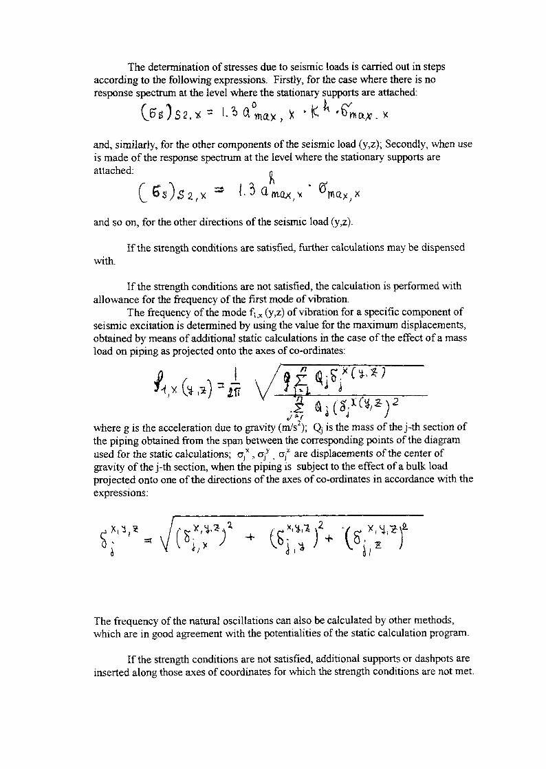
The determination of stresses due to seismic loads is carried out in stepsaccording to the following expressions. Firstly, for the case where there is noresponse spectrum at the level where the stationary supports are attached:
and, similarly, for the other components of the seismic load (y,z); Secondly, when useis made of the response spectrum at the level where the stationary supports areattached: p
and so on, for the other directions of the seismic load (y,z).
If the strength conditions are satisfied, further calculations may be dispensedwith.
If the strength conditions are not satisfied, the calculation is performed withallowance for the frequency of the first mode of vibration.
The frequency of the mode fijX (y,z) of vibration for a specific component ofseismic excitation is determined by using the value for the maximum displacements,obtained by means of additional static calculations in the case of the effect of a massload on piping as projected onto the axes of co-ordinates:
»
where g is the acceleration due to gravity (m/s2); Q, is the mass of the j-th section ofthe piping obtained from the span between the corresponding points of the diagramused for the static calculations; a*, of ; OjZ are displacements of the center ofgravity of the j-th section, when the piping is subject to the effect of a bulk loadprojected onto one of the directions of the axes of co-ordinates in accordance with theexpressions:
s M,«
The frequency of the natural oscillations can also be calculated by other methods,which are in good agreement with the potentialities of the static calculation program.
If the strength conditions are not satisfied, additional supports or dashpots areinserted along those axes of coordinates for which the strength conditions are not met.
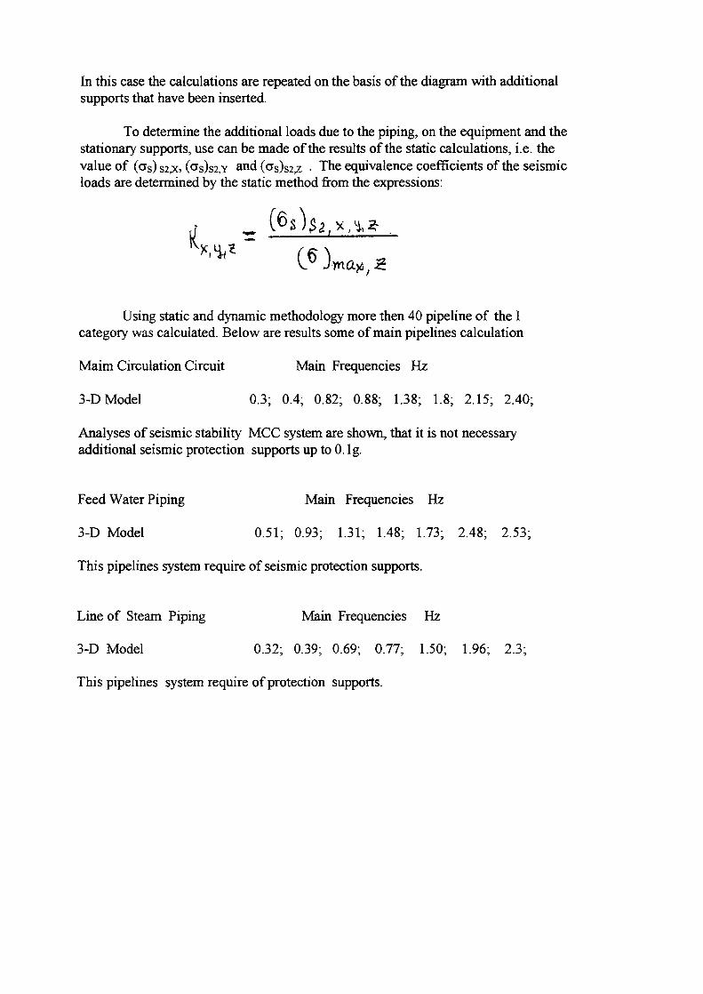
In this case the calculations are repeated on the basis of the diagram with additionalsupports that have been inserted.
To determine the additional loads due to the piping, on the equipment and thestationary supports, use can be made of the results of the static calculations, i.e. thevalue of (as) S2,x, (SS)S2,Y and (as)s2,z • The equivalence coefficients of the seismicloads are determined by the static method from the expressions:
Using static and dynamic methodology more then 40 pipeline of the Icategory was calculated. Below are results some of main pipelines calculation
Maim Circulation Circuit Main Frequencies Hz
3-D Model 0.3; 0.4; 0.82; 0.88; 1.38; 1.8; 2.15; 2.40;
Analyses of seismic stability MCC system are shown, that it is not necessaryadditional seismic protection supports up to 0. lg.
Feed Water Piping Main Frequencies Hz
3-D Model 0.51; 0.93; 1.31; 1.48; 1.73; 2.48; 2.53;
This pipelines system require of seismic protection supports.
Line of Steam Piping Main Frequencies Hz
3-D Model 0.32; 0.39; 0.69; 0.77; 1.50; 1.96; 2.3;
This pipelines system require of protection supports.

4.2 Pipelines Equipment.
RBMK pipelines equipment are similar of WWER equipment, accept of MainCirculation Pump, Separator Drum ect. In this case many of results testing andcalculation of pumps, valves, ventilation systems, motors ect. was used for analysesof similar RBMK systems.
One of the complicated problem was analyses of dynamic characteristic, behavior andreaction on the seismic load of Separator Drum.by calculation. In this case was donemodeling investigation of the model 1:8.5 scale. Metallic model with two separatordrum, rolling and telescoping supports, all of connecting pipelines ( about800 connections ) was carry out. Investigation of main modes, frequencies, dampingfactors and displacement different parts of Separators was done by testing the modelon the 50 ton. capasity seismic platform .
A the main results of this investigation - main frequency is between 0.3-0.5Hz and damping factor about 2 %. Value of displacement to depend on frequencyarrange of accelerograms.
On the base of results this investigations was developed recommendation ofupgrading of seismic stability sepataror drum up to 0. lg.

4.3 Electrical Equipment.
Results of Testing some main Electrical equipment
Table 4.3
Item
1
Functionaldescription
2F, Hz
3
Without
4
Seismic protection
Type of failure5
KTP-SN-0.5 Provision ofenergy for ownneeds
8-14 5-24
KTP-SN-1000-10/0.4
KRU KE-6/40 10-18 3-5
RT30-69 5-10 5-40
ShPT-9-11 48 V powersupply panel foremergencylighting andsignaling,constitution of thediesel generatorcontrol
7-20 5-10
Spurious activation of RT-40 relay of the RU-21annunciation in the circuitbreaker of the AP-50-2MTtransformer, the RT-40relay, damage to the E378voltmeter, and to the AS-220 fitting
Damage to metalconstructions, faults in RV-123 time relay, failure ofRT-40 relay
Spurious actuation of EV-235 time relay, RT-40relay, PAE-411 and PME-071 magnetic starters;failures of AS-220apparatus

1
Control andprotectionsystem,panels PIV-1,PSP-1, ROM-2, PP-18,PAK-1, PRK-1, PP-19,PGU-3, PFS-1, PRS-1,PKU-1, PSU-2, ARM-5S
Continuousfeed set
SN-16-1152
Continuouspower supplysets, 16-800 kWcapacity
PT6, 3/160 Electric pump set
SK-16 Accumulator
401,402,426-P
6-25
13-15
4-12
5-15
6
3
Failure of signalingequipment, voltmeter,damage to cableinstallation, weakening ofplug joints
Weakening of volt unions
Detachment of plates,precipitation of lead oxide,destruction of cell jar
Traces of electrolyte onbody
Section of cable 7-12 2-5
Amax . acceleration the cabinetsKi - Dynamic coefficient and can be calculate as
Amax. ground acceleration

CONCLUSIONS
1. On the basis of the data site seismological investigation, calculationsand different type of testing structures and equipment it was accepted, thatthe RBMK NPP is the Seismic Stability NPP up to 6 intensity by MSK-64 scale.
2. The results of calculation and testing investigations can be use forthe dynamic analyses on the external events blast and impact loading.
3. Using the results the probability analysis should be done.
Ref.[ 1 ] Standards design of seismic stability of NPPs.
A3 T - 5 - 006 - 87.
{ 2 } Seismic Stability of Nuclear Power Station.Yu. K. Ambriashvili. Energoatomizdat,
Moscow 1985.

Report No.: Z049/01
Date: June 14 th, 1999
Generated by. F.-O. Henkel
REPORT
XA9952884
WolfelBeratende Ingenieure
Subject:
Dynamic Analysis of Leningrad Nuclear Plant
Reference:
International Atomic Energy AgencyResearch Coordination Meeting, 5 - 9 July 1999, St. Petersburg
Summary: No. of Pages: \ \ Enclosures: \ 8
Within the scope of this study a preliminary dynamic analysis for the detonationexplosion and earthquake load cases was carried out for the Leningrad Nuclear PowerPlant.
A soil model was added to the three-dimensional shell model which was taken overfrom IVO.
During this Research Program the model was translated into the STARDYNE programand was investigated by means of time history modal analysis.
Since the status quo of the documentation available at that time had to be completedthrough useful technical assumptions this report only considers exemplaryselected results.
Hints:
Distributor Revisions: Index Date
Participants of RCM
Wolfel Beratende Ingenieure GmbH+Co * Postfach 1264 * D-97201 Hochberg " Otto-Hahn-StraBe 2a " D-97204 HochbergTelefon (0931) 49708-0 • Telefax (0931) 49708-15 * Email: [email protected] • Internet: www.woelfel.deSeirat: Prof. Dr.-lng Horst P. Wolfel" Geschaftsfuhrer Dr.-lng. Fritz-Otto Henkel. Dr.-lng. Klaus-Georg Krapf, Jurgen PreiSinger (kfm.)Kommanditgesellschaft AG WO HRA 4087 • Pers. haft. Ges.: WSIfel Beratende Ingenieure Verwaltungs GmbH. Hachberg. AG WO HRB 3885Dresdner Bank AG Wurzburg. Konto-Nr. 3 161 493 00, BLZ 790 800 52, SWIFT-Code : DRESDEFF790Kreissparkasse Wurzburg. Konto-Nr.10105575, BLZ 790 501 30 • Umsatzsteuer-ID Nr.: DE 134 165 548

Report No. Date Page
Z049/01 June 14 t h , 1999 2Beratende Ingenieure
Table of Contents
1. Introduction
2. Finite-Element-Model of the Leningrad NPP
3. Materials
4. Loads
5. Analysis
6. Results
7. Conclusions
8. References

\&g"tg , Report No. Date Page
W0!*6! Z049/01 June 14*, 1999 3Beratende Ingenieure
1. Introduction
Within the scope of the ,,IAEA Benchmark on Safety of RBMK-type Nuclear Power Plants in Relation to
External Events" a first dynamic analysis of the Leningrad Nuclear Plant is performed, which is our
contribution to the work plan HI agreed to during the first RCM held at Moscow during 27 - 30 April 1998,
and which covers the interfaces in addition to the work of IVO (cp. sect. 2 "Model") and of ISMES (cp.
sect. 4 "Blast Loading" and sect. 6 "Results").
Within the time available it was not possible to collect the extensive data necessary for a complete analysis,
so that in numerous general and detailed aspects we were obliged to use technical assumptions. Neverthe-
less, the analysis has been drawn up in a manner so that in the course of future programs it will be possible
to repeat or complete the analysis, provided respective data will then be available.
« . , . . „ , , Report No. Date PageYVOSfe! Z049/01 June 14th, 1999 4
Beratende Ingenieure
2. Finite-Element-Model of the Leningrad NPP
By means of drawings of Sosnovy Bar (the Leningrad NPP) which IVO managed to collect, they generated
- at a very early stage - a 3D shell model of the reactor building 161. On the basis of these drawings avail-
able, no other principal 3D model could be developed.
Within the scope of the envisaged co-operation IVO provided WBI with this model (cp. page Al), and we
seize this opportunity to express our very thanks to IVO for their kind assistance.
IVO generated the model by means of the FEMAP pre-processor. For the analysis they used
MSC/NASTRAN.
For the benchmark we translated the model - via FEMAP - into the STARDYNE program, an alternative
analysis program that we chose for benchmark purposes.

Report No. D a t e P a 8 e
Z049/01 June 14^, 1999 5Beratende ingenieure
3. Materials
The material properties of concrete and steel have remained unchanged from the values used by IVO. IVO
modelled the base slab of the building as fixed in all six degrees of freedom, meaning a neglect of the
influence of the ground, which is a practical assumption for the airplane crash load case.
Via IAEA we received soil characteristics of the site, showing a continuously growing stiffness with the
depth up to 180 m. This relatively homogeneous soil allows - as a first approach - a soil model from the
theory of the elastic half space. The frequency-independent soil stiffnesses and damping are shown on
page A2.

Report No. Date PageZ049/01 June 14 th, 1999 6
Beratende Ingenieure
4. Loads
Airplane crash loads as well as blast loads are given in the IVO-report.
4.1 Detonation Explosion
From an exchange of correspondence with Professor V. Beliaev we learnt that the gravest danger for a
reactor building is the detonation explosion of 10 hydrogen receivers on the NPP site, at which an impact
wave of Pf s 30 KPa and T, = 0.012 sec is formed. From this information we focussed a triangular load
time function (cp. page A3) with a total time of 60 ms, the peak load of 30 KPa is reached at 12 ms. With
this load time function the building is loaded in Y-direction in this investigation.
4 2 Earthquake
From the earthquake we know from the same correspondence, that the SSE on the Leningrad NPP site is of
magnitude 7 according to the MSK scale, it corresponds the peak acceleration equal to 0.1 g. As no
spectrum was given we assumed that the typical USNRC spectrum derived from Californian earthquakes is
not characteristic for an earthquake at the Finnish belt. Therefore we chose an earthquake spectrum given in
Ghost 17516.1-90 /4/, which is shown on page A4. Then we generated a set of artificial time histories,
whose spectra matched with the spectra given (cp. page A5).

«!* " Report No. Date Page
OllS! Z049/01 June 14th, 1999 7Beratende Ingenieure
5. Analyses
While between the two different methods available for a transient response calculation in the time domain
IVO chose the direct integration method, we chose the time history modal analysis for our study in the
scope of this benchmark.
This modal method utilises the structural mode shapes to reduce and to uncouple the equations of motion.
Experienced engineers are used to thinking in mode shapes and these intermediate results are an efficient
way to control the model and to predict the results of the forced vibrations.
During this mathematical uncoupling process damping is neglected. Later, for the forced vibration, it is
added as modal damping to the eigenvectors. This modal damping is calculated by weighting the different
damping values of the building and the soil proportional to the deformation energy of the mode shape.
Page A6 gives an overview about the first 100 natural frequencies of the model and pages A7 - A l l show
some selected mode shapes. Pages 7 - 9 show the horizontal and rocking mode in y-direction and in
x-direction as well as the vertical mode. Mode 9 and mode 10 in the frequency range of 5 Hz indicates first
vibration of the reactor hall, the stiffness of which is not as stiff as that of the building below.

Report No. D a t e , P a S e
Z049/01 June 14 th, 1999 8Beratende Ingenieure
6. Results
From the huge amount of results which one can gain from a 3D shell model only a few principal selected
ones are given hereinafter:
6.1 Explosion Load Case
The maximum displacements along a vertical edge of the building are given on page Bl for the explosion
load case. By means of the curve it is obvious that the upper part shows less stiffness. The maximum linear
displacement is 0.6 mm at the bottom and 2.8 mm at the top.
For element 2496 - which is directly hit by the explosion load (cp. page A3) - page B2 shows the time his-
tory of the internal force Fx, which goes in global vertical direction. This force as well as the other forces
and moments can be combined for an analysis of the bending and shear reinforcement necessary to with-
stand the load case.
Page B3 shows the necessary bending reinforcement in the local x-direction on the negative side (inner side)
of the element. If the real reinforcement in the building is higher than this calculated reinforcement, the
building will withstand the explosion load case, and no deeper non-linear plastic analysis is necessary.
62 Earthquake Load Case
For comparison purposes to the displacements resulting from the explosion load case page B4 shows the
displacements - along the same vertical edge of the building - for the earthquake load case. The results for
the earthquake load case exceed those for the explosion load case by approx. factor 5.
Pages B5 - B7 show the floor response spectra for the earthquake load case.
Page B5 shows the floor response spectrum along the edge of the building considered in the y-direction.

Report No. Date PageZ049/01 June 14th, 1999 9
Beratende Ingenieure
Page B6 does again refer to the spectra for the top and bottom floor, showing peaks at the substantial
frequencies of the building. In addition to the damping for D = 0.04 calculation was done for D= 0.07 as
well, in order to show the sensitivity with regard to damping.
Page B7 shows respective spectra in vertical direction. They are identical along the stiff edges of the build-
ing for top and bottom floor, which is not true for ceiling regions.

Report No. D a 'e PageZ049/01 June 14*, 1999 1 0
Beratende Ingenieure
7. Conclusions
Within the scope of this study a preliminary dynamic analysis was carried out for the Leningrad Nuclear
Plant for the detonation explosion and earthquake load cases. Selected results were documented.
The analysis does rather serve example purposes since the status quo of the documentation available at the
time of the analysis had to be completed through useful technical assumptions. Plans of reinforcement -
which would have allowed a local investigation of airplane crash and explosion loads - were not available.
In the further process of the Research Program the documentation should therefore be completed and the
load cases significant for this site should be elaborated.
However, with this method of analysis it is possible to investigate any problem that can be responded to by
means of the application of a 3D-model.

Report No. D a t e P a 8 e
Z049/01 June 14*, 1999 11Beratende Ingenieure
8. References
III Working Material, Research Coordination Meeting, Safety of RBMK Type NPPs in Relation toexternal events, IAEA, Moscow , 2 7 - 3 0 April 1998
HI External man-induced events in relation to nuclear power plant siting, A Safety Guide, Safety seriesNo. 50-SG-S5, International Atomic Energy Agency, Vienna, Austria, 1981
/3/ Seismic design and qualification for nuclear power plants, A Safety Guide, Safety series No.50-SG-D15
/4/ Ghost 17516.1-90, Allgemeine Anforderungen im Bereich der Festigkeit gegen extern einwirkendemechanische Faktoren, Elektrotechnische Erzeugnisse
151 STARDYNE Release 5.11, Research Engineers
16/ Effects from airplane crashes and gas explosions to Leningrad Nuclear Plant, IVO-A-08/98,29.12.1998

.. A .? •
Beratende IngenteureSafety of RBMK type NPP
Analysis model

WttfeJBeratende Ingenieure
Safety of RBMK type NPP
A l
Soil characteristics:
ofihc layer
1~>
_ • >
456"7
H,m
24
4
2030120
Cpl m/s
4001 10015002000220025005800
Cs, m/s
1802503503504506503400
p.g/cm3
1,701,801,902,202,302,403,00
Dp
0,550,500,40
0,150,100,050,0
Dk
0,600,600,500,400,350,050,0
Determination of soil stiffness:
Dyn. shear modulus
Poisson's ratio
specific weight
Area of base mat
Moment of inertia about x-Axis
Moment of inertia about y-Axis
vertical, horizontal mass
torsional rotational mass
rotational mass about x-Axis
rotational mass about y-Axis
vertical soil spring
horizontal soil spring
rotational soil spring about x-Axis
rotational soil spring about y-Axis
torsional soil spring
vertical soil damping
horizontal soil damping
rotational soil damping about x-Axis
rotational soil damping about y-Axis
torsional soil damping
G =V =
Y =
A =
'xx =
=
=
=
_
0.25 *106
0.3
20
4.489 *103
1.7* 106
1.7*106
0.16* 106
0.122 *109
0.17* 109
0.17 *109
kN/m2
kN/m3
m2
m4
m4
t
tm2
tm2
tm2
c, =
D, =
0.54 *108
0.46 *108
0.54*10"
0.54*1011
0.75*1 OH
0.8286
0.5183
0.2281
0.2281
0.2025
kN/m
kN/m
kNm/rad
kNm/rad
kNm/rad

Beratende IngenieureSafety of RBMK type NPP
Load case: explosion0,03
/
/
KN
0 10 20 30 40 50 60
t[10'3s]
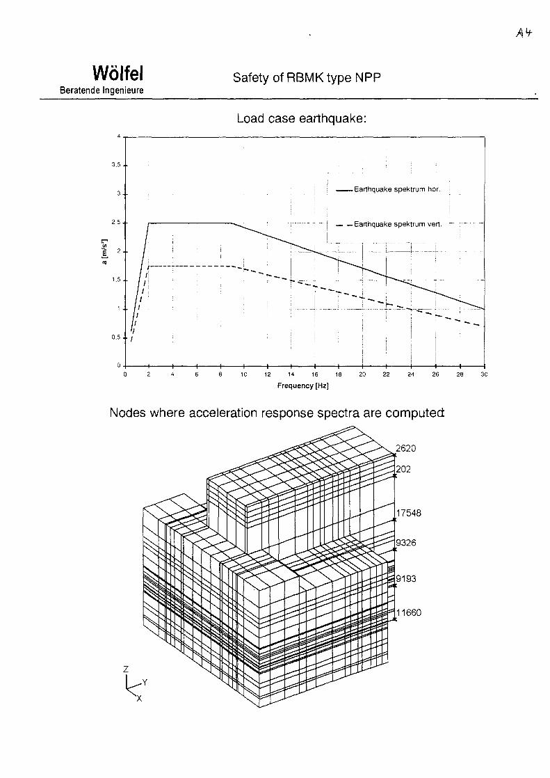
WolfelBeratende Ingenieure
Safety of RBMK type NPP
Load case earthquake:
3 . 5 . .
3 . .
2,5 . .
0 . 5 . . /
-Earthquake spektrum hor.
— Earthquake spektrum vert.
• — ,
I
H 1 1 1 1 1 1 1 1 1 1 h H H10 12 14 16 18 20 22 24 26 28 30
Frequency [Hz]
Nodes where acceleration response spectra are computed

AS
WolfelBeratende Ingenieure
Safety of RBMK type NPP
Load case earthquake: generated time history curve for horizontal direction
Load
time [s]
case earthquake: spectrum computed out of this time history curve
3,5.
3 .
2,5 .
(0
1 2 .o
1,5 .
1 .
0,5.
0 .
I- • V
r = !—i—i—i—i—i—i—i—i
1
t
j
! i
i D=0.05 j
| - - - Earthquake spektrumi
i!
ii
i 1
~*
- -
-L
^
i 1 i 1i 1
. —
i8 10 12 1416 16
Frequency [Hz]20 22 24 26 28 30

WolfelBeratende Ingenieure
Safety of RBMK type NPP
Table of natural frequencies
MODENO
1234567891011121314151617181920212223242526272829303132333435363738394041424344454647484950
NATURALFREQUENCY
[Hz]1.4631.5002.4022.8253.6643.6774.1444.4545.0725.4055.9546.5146.5886.9007.1057.4237.7288.2068.2988.3658.7548.8028.9579.4369.4659.82310.01510.35910.49610.74710.81011.38711.40111.48111.59411.85911.90512.17712.24312.46012.59212.80813.09013.16013.21013.42613.73813.89913.93314.537
MODENO
51525354555657585960616263646566676869707172737475767778798081828384858687888990919293949596979899100
NATURALFREQUENCY
[Hz]14.59414.87014.94915.14715.30115.49415.77815.88016.12016.13116.46216.68316.74717.08117.28017.33517.41617.49617.50817.68617.76317.79317.90917.94918.16418.21818.31018.39818.43218.55118.65618.72718.87218.99619.18319.59919.73119.81819.90520.08820.30920.46920.53620.72420.73720.84620.91121.07221.12721.174

WolfelBeratende Ingenieure
Safety of RBMK type NPP
-Y
Output Set: Mode 1 1.463247 Hz, Deformed(1.112): Total Translation
Output Set Mode 1 1.463247 Hz, Deformed(1.112): Total Translation
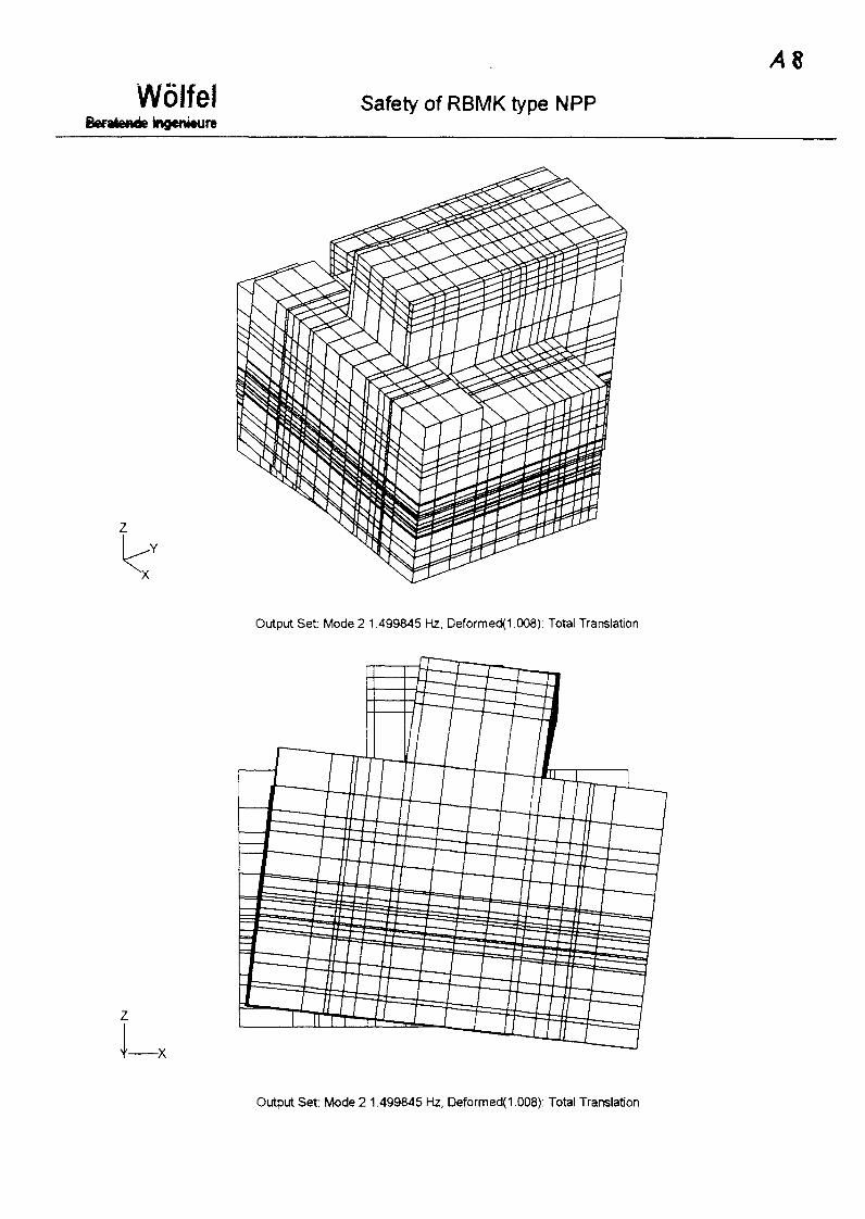
Wolfel Safety of RBMK type NPP
Output Set: Mode 2 1.499845 Hz, Deformed(1.008): Total Translation
Output Set: Mode 2 1.499845 Hz, Deformed(1.008): Total Translation

A3
WolfelEferatonde bgenieure
Safety of RBMK type NPP
Output Set: Mode 4 2.825482 Hz, Deformed( 1.003): Total Translation
Output Set Mode 4 2.825482 Hz, Deformed(1.003): Total Translation
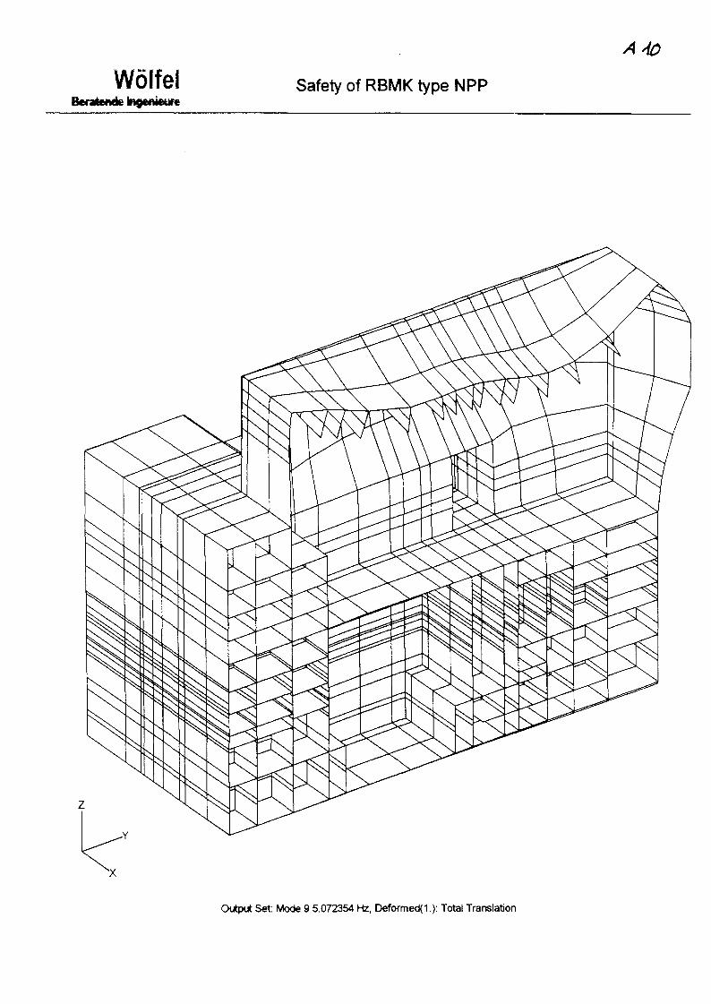
Wolfei Safety of RBMK type NPP
Output Set: Mode 9 5.072354 Hz, Deformed(1.): Total Translation

WolfelBtratende Ingwiwure
Safety of RBMK type NPP
Output Set Mode 10 5.405268 Hz, Deformed(l): Total Translation
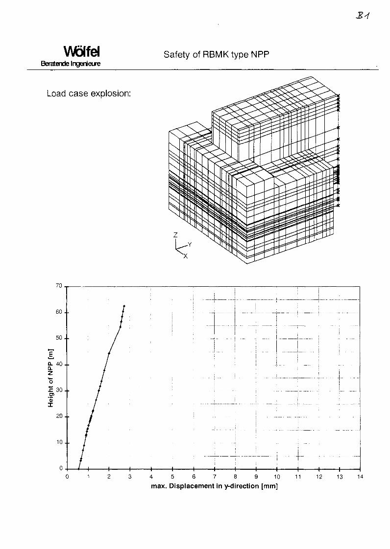
WblfeiBeratende Ingenieure
Safety of RBMK type NPP
Load case explosion:
x
6 0 .
50 .
CL 40 -
a.zo£ 30.
Hei
<
20 .
10-
0 -
I | ii '• I I :
/
• /
• f • • •
1
.... ..
1 : :
I _...j
i -
• • - • : • —
-
. : ; .., .... : . L.--
/—| 1 1 1 1 1 1 1 1 1
.
...
.... ..... L.
. .
- . ;
1 14 5 6 7 8 9 10max. Displacement in y-direction [mm]
11 12 13 14
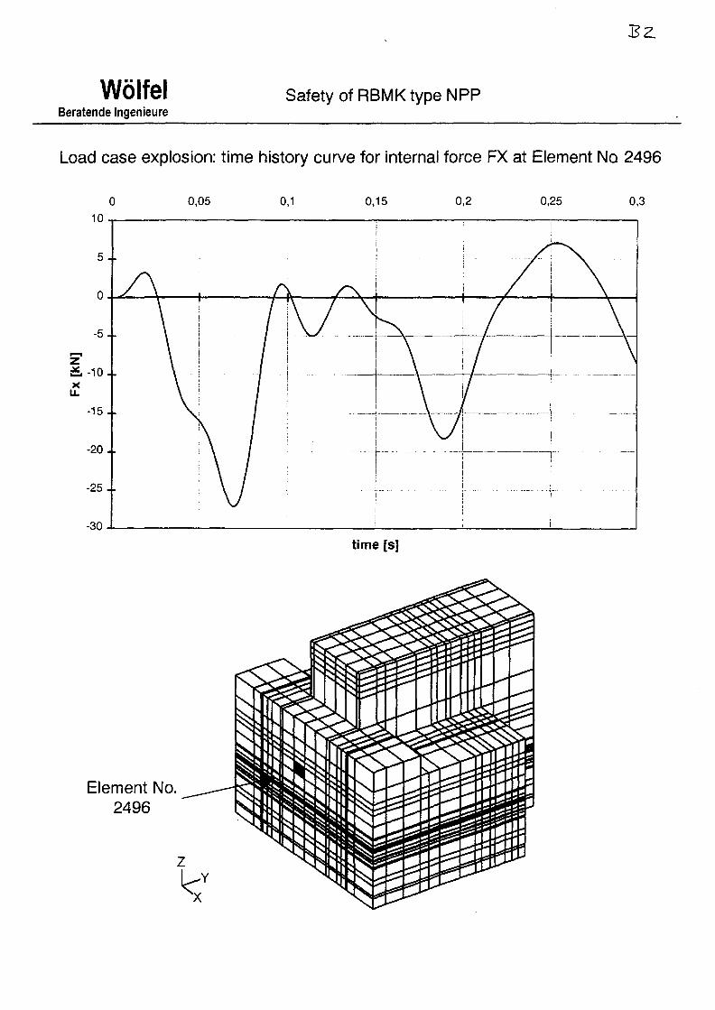
WolfelBeratende Ingenieure
Safety of RBMK type NPP
Load case explosion: time history curve for internal force FX at Element No 2496
-30
0,05 0,1
Element No.2496
time [s]

Beratende IngenieureSafety of RBMK type NPP
Design of reinforcement
Materials:
concrete: B25
steel: ps = 220 N/mm2
(yield strength)
25.
20.
15.
10.
Olltnnt SAI- Roinfnrromont frm2/m1 P.riforfcr h/lAY AY .7CAPI:

WolfelBeratende Ingenieure
Safety of RBMK type NPP
Load case earthquake: Z62O
4 5 6 7 8 9 10max. Displacement in y-direction [mm]
11 12 13 14

B5"
Beratende IngenlsureSafety of RBMK type NPP
Load case earthquake: acceleration response spektra in global y-direction (hor.)
Node 202, D=0.04
Node 2620, D=0.04
Node 9193, D=0.04
Node 9326, D=0.04
— Node 11660, D=0.04
— Node 17548, D=0.04
00,1 10 100
Frequency [Hz]
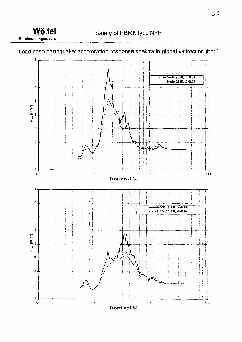
WolfelBeratende Ingenieure
Safety of RBMK type NPP
Load case earthquake: acceleration response spektra in global y-direction (hor.)
7 . .
6 . .
5 . .
I4J.
3 . .
2 . .
1 . .
0,1
0,1
-Node 2620, D=0.04
Node 2620, D=0.07
-1..J...
U-
100
Frequency [Hz]
8 _
7 .
6.
5.
V)
1 4 .0
(#
3 .
2 .
1 .
n.
I I • Ii
| i
i i
\
j
!
I
•— i j - . ..! __j ....Node 11660, D=0.04
- - - Node 11660, D=0.07j
-
|I
i
|i
i
I1
i
I
ji
i
1 : • —
—
-
!1
—
...
10 100Frequency [Hz]

WolfelBeratende Ingenieure
Safety of RBMK type NPP
Load case earthquake: acceleration response spektra in global z-direction (vert.)8
7 . .
6 . -
5 . -
3 . -
2 . .
1 . .
0,1
7 . .
6 . .
5 - •
V)
r
34-
2 . .
1 . .
I ]i
-Node 2620, D=0.04Node 2620, D=0.07
.. j . I
...„..; . ^ .
..1.4i
-i
i
100
Frequency [Hz]
I i
Node 11660, D=0.04- - - Node 11660, D=0.07
10 100Frequency [Hz]
XA9952885
SAFETY ASSURANCE OF RBMK-TYPENPPS AGAINST EXPLOSION EFFECTS
V.S.Beliaev; Yu.V.Garusov; OA.Zverev;V.P.Kuz'michiov; V.G.Romanov; V.A.Syreyshchikov
(Leningradskaya NPP, Research Centre of Capital Construction)
Reporton IAEA specialists conference
SAINT - PETERSBURGJune, 5-9,1999.

1. Concept of RBMK-TYPE NPPs safety under special impacts
Designing and construction of Russian RBMK-type NPPs has beenperformed according to the Construction Norms and Standards, acceptedin the former USSR. In accordance with these Norms and Standards theconstruction responsibility was taken into account through the use of thereliability factor. The best reliability factor value, equal to 1.0, had beenassigned to the NPP reactor building only. Seismicity of the sites of all theRBMK-type NPPs has been assessed as not higher than 6 as per MSKscale, and, as a consequence, when designing such NPPs the seismicconstruction requirements were not taken into account. The peak value ofsoil horizontal acceleration at such intensity earthquakes is not more than0.05 g. These circumstances were the reason for widespread use of highlyefficient lightened building constructions at RBMK-type NPP construction.
hi former USSR in 1986-87 safety requirements on the NPP beingunder design increased sharply. This was in full accord with the IAEAposition and common world practice of NPP construction.
New Norms and Standards had been developed due to classificationof NPP buildings and structures taking into account their responsibility fornuclear and radiation safety, expanding the list of specific loads and effectsunder consideration, detennining the object categories due to the seismicstability required. Necessity to fulfill the Norms and Standardsrequirements has resulted in substantial modification of buildingconstructions of NPPs under design, for example in mandatory applicationof protective shells. Simultaneously serious changes had been introducedin supporting documentation for designing NPP equipment to increase itsreliability and safety.
Immediately this new Norms and Standards had evolved the StateManaging and Supervisory Boards in the domain of nuclear powerengineering has set the task of safety assessment of the existing NPP,including the cases of specific external impacts. Safety assessment ofCategory 1 buildings and structures is to be conducted in consideration ofthe following natural extreme effects with a frequency 1 time every 10000years:
safe-shutdown earthquake,hurricanes and storms,waves and floods,extreme wind and snow effects.
Beyond this point for such structures special provisions should be made totake into account the effects related to human activity. Among these are:airplane crash and air impact wave at explosion of firm substances or gassteam and air mixtures on the plant site and outside it.
Assessment of structures of Category 2 buildings and constructionsshould be conducted for less intensive inputs. So, in this case for suchstructures the operating basis earthquake effect with frequency 1 timeevery 100 years is considered.
In its essence assessing the existing RBMK-type NPPs safety is acomplicated scientific and engineering problem. Successful solution of thisproblem should finally provide for the whys and wherefores of theadditional protective measures for the plants, development of designsupporting documentation for strengthening the elements of internal andoutside structures, as well as development of the Norms and Standards forNPP reconstruction. Such work has been carrying out for more than 10years for Russian NPP with reactors of various types: VVER, liquid-metaland RBMK. Our organization together with such Institutes as Saint-Petersburg's Atomenegroprojekt, VNIPIET, Projektstalkonstrukzda, withsuch Companies as "Atom-Dynamik", "Ost-Seism", "ZKTI-Vibroseism"participates in the program of Russian NPP technical rearmament andmodernization, including RBMK-type NPPs: Leningradskaya andKurskaya NPPs. We specialize on the problems of power units safetyassessment under special impacts.
At the initial stage of solving the safety assessment problem ofRBMK-type NPP particular concerns were related to consideration of theairplane crash effect. Even the results of the preliminary analysis appearedto be utterly disappointing. Thus, the crash of even easy airplane such asSessna resulted in through punching of building constructions of Category1 buildings and structures. The only appropriate and, fortunately, highlyeffective way under Russian conditions appears to be the IAEA-recommended technique of establishing the marginal distance value. As isknown, marginal distance value for airplane danger is the calculateddistance between the NPP and various-type airplane flight routes. Theroute distance selection excludes with probability no less than 10"7 thepossibility of impact of airplanes, as well as elements of their structure inNPP Category 1 buildings and structures with terms of their service no lessthan 80 years. Actually, the calculations carried out according to speciallydeveloped techniques had indicated, that the required routes distance ispractically entirely realized in conditions of RBMK-type NPP sitesplacement. Design deviation of existing flight corridors for civil andmilitary airplanes, for example for Leningradskaya NPP makes up from 5to 15 km. Necessity to observe the requirements on the flight corridorsdeviation is assured by administrative measures. Therefore in case ofRBMK-type NPPs the scripts of airplane or its structures collision withCategory 1 buildings and structures are excluded from consideration.

Other types of natural and man-triggered extreme effects were analyzeddue to peculiarities of each plant locations.
It is necessary to emphasize, that in these years substantialseismicity revaluation of the sites for RBMK-type NPP construction tookplace. Accumulation of seismotectonic and seismic geological data and,especially, advent of the concept of dissipated seismicity, not related toany particular seismic active structure has changed earlier approved ideson the absence of seismic danger for NPP buildings and structures. As aconsequence, structures of buildings, equipment and their elements of theseismic Categories 1 and 2 were tested for the effect of safe-shutdown andoperating basis earthquakes respectively. As already noted, previously nospecial requirements on seismic stability has been imposed upon thesestructures and equipment.
Developing a NPP safety concept and integral working program onsafety increasing requires a complicated and methodically organizedapproach. Such approach should include the following works to beaccomplished in step-by-step way:• Verification of parameters of specific effects on all NPP Category 1
buildings and structures, including service water supply hydraulicengineering works of the safety system. In this condition the parametersof seismic input for each Category 1 building and structure aredetermined taking into account the real geology of the site, air impactwave load for the extended script of possible explosions, among theother things, with due regard for possible scattering of missiles fromstorage facility, category IB storm load, action of continuous and tidalwaves, flood.
• Development of design models of Category 1 buildings and structuresfor specific loading effects taking into account actual state of theirstructures. Under this condition at the first stage the design models areto be developed from the design data, then verification of certainparameters of the design models on a basis of structure state inspectionand, finally, forming the design models of buildings and structures arecarried out.
• Structural analysis of all Category 1 buildings and structures on specificdynamic load inputs (earthquake, air impact wave, storm, flood) due totheir refined parameters. On the basis of these calculation results anintegrated evaluation of stability of all the complex of buildings iscarried out and recommendations on safety assurance of buildingconstructions, including offers on structure strengthening, relocation ofload sources, administrative measures etc. are developed.

• Stability assessment of Category 1 technical and processing equipment(according to the list agreed) for specific dynamic load effects. Suchassessment provides for a series of sequential procedures for eachparticular specimen of the power unit equipment. These procedures areas follows: determining the loads in equipment installation positions,developing (if necessary) design equipment models, then designevaluation of equipment serviceability at existing state of buildingconstructions, as well as taking into account realization of therecommendations on safety assurance of building constructions and, inthe final analysis, preparation of offers on equipment additionalprotection.
• After sequential operations due to system approach has been completedassessment of preservation of MPP normal operation systems and safetysystems at specific impacts is carried out and a working program ontheir preservation provision is developed.
Realization of such a integral approach involves considerablefinancial, material and other resources. In spite of real limitation of,mainly, financial resources the works are already conducted at all theRBMK-type plants with participation of the specialists of ourorganizations.
On the basis of the distributions of investigation avenues for theprogram "Safety of RBMK-type Nuclear Rower Plant in Relation toExternal Events" which was accepted by participants and approved by theauthorities the problem of such type NPP safety assurance at the effect ofexternal explosive loads had been considered. Analysis approach andprocedures, which are common for Russian practice, are demonstrated onthe example of Leningradskaya NPP. Situation of Leningradskaya NPP isquite typical for the RBMK-type plants. The main peculiarity ofLeningradskaya NPP (LNPP) site, which is also to be taken intoconsideration when assessing explosive dangers, is its immediate vicinityto marine water area of the Gulf of Finland.
2. Analysis of potential sources of air impact wave for RBMK-typeNPP Category 1 buildings and structures
2.1. Analysis of explosive danger sources located on the LNPP site
Among the explosive danger sources on the LNPP site the first to benoted are the sites, on which hydrogen and nitrogen receivers are placed.Hydrogen receivers are located at open space, their volume is 20 m3 andpressure is 100 kPa. Mass of hydrogen in one receiver is 18 kg. Altogetherthere are 10 receivers. Characteristics of nitrogen receivers are the same,

there are 5 nitrogen receivers all in all. Amount of hydrogen in the 50-mm-diameter pipe connections is less than in one receiver. Hydrogen isproduced in electrolysis buildings, their capacity is 80 m3/hour. At accidentthe possible volume of accumulated hydrogen will not exceed 200 cubicmetres indoors.
Close to the diesel buildings underground diesel oil storage facilities(100 cubic metres each) and smaller tanks in separate rooms (10 and 6.3cubic metres) are located. There are tanks with volume of 8 m3 on thesurface. In case of diesel oil tanks depressurization and its evaporationunder normal atmospheric conditions due to low speed of evaporationexplosive concentration of fuel-air mixture is not formed. Under fireconditions in the diesel building, when temperature near the tanks canexceed critical limit diesel oil steams simply burn up without explosion.The tanks which are located in the vicinity are spaced on a fire safedistance and can't be depressurized. If in this condition depressurization ofseparate tanks does not take place, then steam internal pressure can'tdestroy tank, since their strength is designed just for such an accident.Therefore diesel oil storage facilities are of no explosive risk.
What is more, on the LNPP territory there is a large number ofpetroleum products (transformer, turbine, machine oils) which are thesources of fire explosive risk. Explosive risk of tanks or other reservoirswhich contain such materials is mainly determined both by their locationand embedment level, as well as their filling level.
The most important among such sources are transformers, located inthe immediate vicinity of the main building on the side of machine hall.Transformer oil is not an explosive material, but is of certain fire hazard.The transformers noted are supplied with a special safety system, whichensures pressure relief. If transformer has been depressurized and oilpressure has dropped, the system would de-energized and emergencycooling would brought into use. If as a result of oil overheating due tosharp temperature increase at breakdown or short circuit the pressure rises,then pressure relief system comes into action (what is more, it is an easilydumped structure). Therefore power transformers can't be considered asmain sources of air impact waves.
Auxiliary rooms, shops, industrial occupancies can have places forstoring standard acetylene bottles for gas welding operations (5.3 kg ofacetylene each). The bottles are stored in one place at a rate of less than 10pieces. If operating conditions are observed the bottles are consideredexplosive-proof.
In depots and garages there is a very small amount of petrol, whichcontinuous storing in significant amounts is not provided whereas a petrol

station is located near the settlement area, this station services LNPPtransport shop.
2.2. Analysis of explosive danger sources on ground transportmain roads
In the area adjoining LNPP there is a number of explosive dangersources on transport main roads. Thus according to the official dataexplosive substances can be transported via main road in the amount up to30 kg in TNT equivalent, and via railway - up to 180 tons.
Besides up to 20 bottles with acetylene (5.3 kg of acetylene each) orwith propane (20 kg of propane each) can be transported simultaneouslyvia motor roads. Travel of fuel servicing truck of 25.8 M3 volume withpetrol of gross weight up to 16 tons is possible. But the most often case isa travel of petrol refuellers with tanks of about 5 M3 volume.
Aside from explosives, propane-butane, petroleum in standard tankswith a volume up to 60 M3 can be transported via railways.
Since at accident substantially larger amount of propane than that ofpetrol can entry into atmosphere the design is based on emergencydepressurization of tanks with propane.
2.3. Analysis of explosive danger sources outside the LNPP territory
According to Russian Norms and Standards the explosive dangersources should be analyzed for 5-km zone around the NPP Category 1buildings. Analysis results had shown that all potential explosive dangersources, located in this zone, satisfy the level of marginal distance valueand may be ignored when assessing NPP safety.
2.4. Analysis of sources of explosive danger from marine water area
The special feature of the LNPP site is its location on marine shore.Even now via the fairway "river-sea"-type tank ships transport petrol up to5000 tons each. In the future after completion of construction of oil tankingterminals transportation of mazute, raw oil and diesel oil in oil tank shipswith volume of 30000 tons will be carried out.
When assessing the places of possible oil ships accidents the vesselmotion routes both to the ports under construction, and to the ports now inoperation were taken into account. All these vessels pass via the fairways,systems of motions and shipping routes bottlenecks, where possible oilship accident under adverse meteorological conditions can affect LNPPsafety. East part of the Gulf of Finland is a difficult area for navigation

because of shallow depths and numerous banks. Vessel navigation takesplace on the basis of partitioned motion systems via recommended routesand fairways, width of which varies from 1 to 0.1 km., that give rise topreconditions of ships collisions. When a collision takes place, inaccordance with ship-building design only one tank of an oil tank ship canbe destroyed, since the distance between the tanks is found from theconditions of non-destruction of two tanks when collision of ships takesplace in the sea. The most probable points of emergency collisions arevessel route bottlenecks (branches or crossings). In the area underconsideration 6 such places are established.
The most dangerous and close place of collision is a point at a rangeabout 15 km from the LNPP. Other places of possible collisions are furtheraway. After the collision took place vessel drift due to loss ofcontrollability (in the worst case the drift is in the direction of LNPP) ispossible. When assessing the safety the worst case of taking the bottomnear the shore of LNPP which can be realized under storm conditions isaccepted. In this case fuel-air mixture cloud is not formed because of highwind. But when collision of oil ships takes place or in case of fire in theport a fuel-air mixture cloud will be formed (wind is less than 5 m/s) andits wind drift is necessary to account for. It is assumed, that if the weatheris fair and the run is lost for some reason the oil ship drift can always bestopped either by its crew (with the help of the second anchor) or byrescue vessel. In case a ship takes the bottom petroleum spreading ispossible from two tanks simultaneously. A number of oil ships (HO-40,HO-28-30, HX-10, HX-3 etc.) had been analyzed. It was shown, that theheaviest danger is related to the HX-3-type oil ships with possibleexplosion of 150000 kg of petroleum at taking the bottom (the depth isnear 5 m) or at accident in the port.
As for petroleum the closest location of terminal constructions isdesigned in 14 km from the LNPP. Here a number of tanks with diesel oil(20000 M3), petrol (2000 M3) and oils (up to 400 M3) will be located. Theheaviest danger is due to explosion of evaporated petrol (86 tons).
From the water area of Gulf of Finland a heavy danger can bepresented by warships, on which ammunition and weapons are carried bysea, as well as by old floating mines. Nowadays when the situation is notstable, uncontrolled shipment of weapons and ammunition withinternational rules violation is quite probable. This fact increasesprobability of such explosive incident. Also, it is to be noted systematicoccurrence of various sort of floating mines even in the Kronshtadt area.The most often case is catching the mines with power up to 200 kg in TNTequivalent. But hypothetic occurrence of mines of more new type with
power of explosion about 1400 kg in TNT equivalent at the shore shouldnot be excluded.
The analysis conducted has indicated, that hypothetic taking thebank by Rank 3-4 ships (depth 4.5-6 m) with power of explosion up to 4tons, and Rank 1-2 ships (depth more than 6 m) with power of explosionup to 10 tons in TNT equivalent is possible.
Transportation of weapons and ammunition can be carried out onvarious class vessels. In case emergency taking the bottom by smallvessels (depth up to 4.5-6 m) and with power of explosion about 100 tonsin TNT equivalent is possible. For large vessels similar accident can takeplace on 6 m depths with power of explosion up to 250 tons.
Studying the explosive danger sources at the shore had allowed todetermine another sea danger in the form of sunk ships with ammunition.However quantitative estimations of air impact wave formation underexplosions of single or group ammunition on the ships allowed forrecommendation to ignore them as explosive danger sources for the LNPP.
3. Analysis of loads, acting on Category 1 RBMK-type NPP buildingconstructions at spontaneous explosion
Analysis of loads which act at spontaneous explosion has beenconducted on the main building example of the LNPP first phase.Calculation of the parameters of air impact wave, approaching fromvarious potential sources, which had been described in section 2, isperformed on the basis of "Procedure for determination of parameters ofair impact waves, generated by spontaneous explosion". This procedure isapproved for use by Russia's GOSATOMNADZOR at the performance ofworks on the LNPP reconstruction. Values of air impact wave parameterssuch as pressure drop in incident wave front AP^ and duration of
compression phase in wave xe are listed in Table 1. Values of theparameters has been received in the main building points, located at shortrange from explosion sources.
Analysis of potential explosion sources on the territory of the NPPsite and outside it revealed the most dangerous versions of possibleemergency explosions for the reactor building.
They are as follows:1) Detonation explosion of hydrogen, emerged from ten receivers
simultaneously.2) Explosion of petrol tanks with total volume more than 5 m3 on the
motor road (maximum distance to the reactor building is 200 meters).

3) Explosion of 160 tons of explosives on a railway (minimum distanceto the main building is 1420 meters).
4) Explosion of a "drifting" mine (1400 kilos of TNT) at 220 metersdistance to the main building.
5) "Drifting" of a vessel with highly explosive load from the fairwayand spontaneous explosion in the vicinity of the waterside line. Designversions are as follows: explosion of 250 tons of explosives at 1200 metersdistance to the main building and explosion of 100 tons of explosives at400 meters distance.
Table 1
1.2.3.
4.5.
6.
7
8.
Explosive danger source
Explosion of 1 receiverExplosion of 10 receiversDestruction of receiver withcompressed nitrogenElectrolysis stationDiesel oil depot:- embedded tank- shallow tankMotor road (from front)- 20 bottles with propane- TNT (30 kg)- petrol (5 M3)Railway (from front)- 1 tank with propane- 5 tanks with propane- TNT (160 t)Water area of the Gulf of Finland- floating mine (1400 kg of TNT ata range of 220 m-100 t of TNT at a range of 400 m- 250 t of TNT at a range of 1200 m
kPa4.912.14.04
6.5
1.41.7
73.61.7
12.5
2.26.01.8
6.67
20.266.65
%>m/s8.114.67.79
17.9
16.75.1
0.00942.516.3
95.0138.040.9
84.3
163.0467.0
Calculation of the loads on main building supporting structures due to airimpact wave action has been carried out from the effects of reflection, flowand shielding. For the case of hydrogen receivers spontaneous explosion,when mutual position of explosion source and the buildings is fixed, the airimpact wave loads for structure elements were calculated taking into
10
account the real distance to the source of explosion. Among the otherthings, non-simultaneous load action on the elements which are located ondifferent distance is taken into account. Main building layout was byconvention separated into elements and for each of them the air impactwave parameters were determined due to their actual distance from thesource of explosion. The load in terms of air impact wave parameters inthe model points was determined in the form of time history.
As for the situations of spontaneous explosion of movable sources(on motor road, railway, the Gulf of Finland water area) their locationrelatively buildings and structures can't be determined without ambiguity.Therefore when calculating the loads a conservative evaluation was used.For all points of the face surface (with reference to the source ofexplosion) of the plant structures the value AP^ was accepted as maximum
(25.0 kPa - for motor road, 9.0 kPa - for railway and 13.4-43.9 kPa - forthe Gulf of Finland water area (depending on the distance and the type ofsource)). Similarly on the side surface of a building the loads weredetermined from the peak values of pressure on the incident wave front Te.
Loading of all the points of face and side surface of a building wasaccepted as simultaneous.
Main building is a multi-storied multi-span structure, performedfrom reinforced concrete (monohthic and modular) and metal. The buildingconsists of four units:- two reactor units (units A, B);- auxiliary devices unit (unit C);- unit of machine hall with deaerator rack (D unit).Units A, B, C are connected with unit D with the help of floor cross-barswith hinged support at the elevations -1.2, 3.6, 7.2, 10.8, 14.4, 19.2, 22.8,26.4, 30, 35 m.
Structural layouts of reactor units A and B are identical and includeparts which differ substantially in their stiffness and inertial properties:monolithic reinforced concrete part, prefabricated-monolithic part andsteelworks of the unit "dome".
Unit D is performed form steelworks in the form of braced frame. Inthe longitudinal direction the unit is divided into three temperaturecompartments.
Unit C is performed as frame-monolithic reinforced concretestructure.
The gaps between the buildings (temperature compartments) are: inlongitudinal direction (in the OX direction) - 100 mm, in lateral direction(in the OY direction) - 60 mm. Design model takes into account the
n

opportunity of contact interaction of separate building units and their partsat seismic load input and at air impact wave action.
Soils of the main building basement by their physical-mechanicalproperties are related to Category 2 soils due to their seismiccharacteristics.
4. Comparison of loading level and design limits
Unit dynamics analysis at air impact wave effect has been carriedout on the basis of finite-element procedure.
Reactor building dynamics analyses from the methodological pointof view were carried out (for all types of load input) in two phases. At thefirst phase the units of building were considered as independentstructures, i.e. their contact interaction was excluded. The purpose of thesecalculations was, first, to assess the opportunity of contact interaction ofunits on the basis of comparative analysis of unit displacement fields attheir independent motion; approximate evaluation (in case of contact) ofinterval of collision speeds; second, preliminary evaluation of mainsupporting element strength.
At the second phase calculations were carried out taking intoaccount real gaps between the main building units and opportunity ofcontact interaction. To receive conservative evaluations damping in thebuilding supporting structure was not taken into account.
4.1. Explosion of hydrogen receivers
Detonation explosion of hydrogen, which is simultaneouslydischarged from all 10 receivers is considered. Air impact wave directlyinfluence units D and A. Pressure drop peak values at the impact wavefront are:- for unit D-11.9 kPa;- for unit A-10.61 kPa.
Duration of structures loading (phases of compression at the wavefront) depending on their distance from the source of explosion alterswithin 0.0152-0.0183 s.
Dynamic load design of main building had shown, that there is nocontact interaction of units, strength of structure supporting elements ispreserved.
12

4.2. Explosion on motor road and railway
The most dangerous situation of explosion on motor road isexplosion of petrol tank with a volume of 5 m3. Values of air impactwave parameters make up AP^=12.5 kPa, xe=0.0163 s. During analysis of
calculation results it was revealed that supporting element strength ispreserved, no contact interaction of the units was observed.
For the case of emergency explosion on railway explosion of 160 tof explosives is accepted as a design explosion. Values of incident airimpact wave parameters for the main building are equal to AP^=4.5 kPa,
xe =0.465 s. Results of dynamic and strength analyses had indicated, thatthe given effect can cause destruction of supporting structures ofdeaerator rack.
To work out practical recommendations to ensure reactor buildingstability under action of air impact waves, generated by spontaneousexplosion on a railway, a series of building dynamic load designs has beenconducted when the distance to the place of explosion and quantity ofdetonating explosives varied.
4.3. Explosions on the Gulf of Finland water area
The most dangerous for main building of LNPP phase 1 are thefollowing situations:
a) explosion of mine (1400 kg of TNT) at a range of 220 m from themain building;
b) explosion of 100 t of explosives on a ship at a distance of 400 mfrom the main building;
c) explosion of 250 t of explosives on a ship at a distance of 1200 mfrom the main building.
When assessing the state of main building of the LNPP phase 1under air impact wave action from the side of the Gulf of Finland thesituations listed above were accepted as initial. Furthermore, versions ofship explosion beyond the 5-km security zone has been considered andsafe distance for the case of mine explosion has been determined.
4.3.1. Explosion of 100 t of TNT at a range of 400 m
Values of parameters are AP^ =20.26 kPa, xe=0.163 s. Analysis of
calculation had shown, that in the case being considered the air impact
13

wave effect can result in considerable destructions of unit D. Among theother things some machine hall support columns, machine hall trusses,deaerator rack columns and cross-bars do not meet the conditions ofstrength. While under loading the contact interaction on upper elevationsof unit D with structures of units C, A, B takes place.
4.3.2. Explosion of 250 t of TNT at a range of 1200 m
Values of parameters of incident air impact wave are AP^ =6.65 kPa,
xe=0.163 s. At spontaneous explosion of 250 t of explosives at a distanceof 1200 m from the main building destructions of some machine hallsupport columns, machine hall floors, deaerator rack columns and cross-bars can take place. Contact interaction of the building units (in lateraldirection) is possible.
4.3.3. Explosion of 250 t of TNT beyond 5-km security zone
If explosion occurs on the boundary of security zone the values ofair impact wave parameters are AP^l .33 kPa, xe =0.954 s. Dynamics
analysis of the building units has shown that no contact interaction wasobserved. Most of structures preserves their bearing capacity. The onlyexception is some machine hall columns and brick partition walls ofdeaerator rack. Destruction of columns is caused by the fact that spanshave no window openings and, as a consequence, air impact wave load ona column has been considerably increased. Partition walls lose theirbearing capacity under streaking air impact wave action. It is to be noted,that strengthening of partition walls can be carried out by a simple way andwithout considerable expenditures.
By way of iterations a minimum distance to the source of explosionat which machine hall and deaerator rack building constructions preservetheir bearing capacity has been determined. It is 17 km.
4.3.4. Explosion of mine (1400 kg of TNT)
For initial calculation version (explosion at a distance of 220 m) thevalues of incident air impact wave parameters are AP$=6.67 kPa,
t e =0.084 s. Evaluation of building construction strength of the mainbuilding had shown, that a number of elements of unit D loses their bearingcapacity. Contact interaction of the main building units was not observed.
14

From the results of iterative calculations allowable distances fromexplosion source had been determined.
On the basis of comparative analysis of possible versions ofspontaneous explosions and design results we had developed the followingadministrative and technical measures to protect the main building of theLNPP first phase against air impact wave action:
1. It is necessary to move the railway a distance no less than 3500meters from the main building of the first phase of the Leningrad nuclearpower plant and to limit the transport of explosives to the volume of 20tons (for one train) in the course of the railway operation.
2. It is essential to organize monitoring of the Gulf of Finland waterarea near the site of the LNPP in order to detect the facts of violating therules of navigation timely (ships leaving the fairway and their approach theLNPP site - the mioimum distance from the LNPP site to the fairway is 21kilometer).
3. It is absolutely necessary to organize a technical service forprevention of ships entering the safety zone of the LNPP, among themwarning the ships on the violating the rules, towing the emergency vesselsto a safe harbourage and other measures. Safety zone boundary is 5kilometers from the main building of the LNPP first phase.
4. In the coastal zone of the LNPP special provisions should bemade to create a system of boom defence which prevent the mine enteringover a dangerous distance. For the reactor building of the LNPP first phasethe distance to the boom defence is 500 meters.
5. Relying on the results of the design feasibility studies thenecessary initial data for development of design documentation had beengiven and the following designs had been performed:
- design for strengthening the brick masonry which fill the openingsin the inner wall which separates the machine hall room from the deaeratorrack;
- design for placing window openings in the machine hall instead ofexisting reinforced concrete panels.
5. Conclusions
1. According to calculation data the effect of air impact wave fromexisting potential sources of explosions can be dangerous for RBMK-type NPP buildings and structures. The level of active loads onstructure of buildings and structures substantially depends on locationand properties of spontaneous explosion sources on a NPP site.
2. Preliminary assessment had shown that strengthening the buildingsupporting structures up to the level required for safety is connected
15
with carrying out considerable amount of works. As an alternate we canpropose to develop a complex of administrative and technical measuresfor decreasing the air impact wave loads on the basis of marginaldistance principle. This avenue under the conditions of RussianRBMK-type NPP appears to be the most effective in many cases.
3. When receiving non-conservative and practically appropriate solutionsfor strengthening of existing structures experimental testing of theiractual stability against environmental effects takes on greatsignificance. Testing machines of our organization ensure theperformance of seismic stability test assessment of buildingconstructions and equipment with mass up to six hundred tons, as wellas structure stability against the effect of missiles and air impact wavesof various rate, the failure mode of brick partition walls, inner walls,machine hall of the LNPP when reproducing the air impact waveactions, caused by explosion in the water area.^Dimensions of thepartition walls, material and technology of their manufacturing areentirely identical to those used on the nuclear power plant. During theexperiments the ranges of loads which correspond to elastic, plastic anddestructive deformation stages had been revealed. In the immediatefuture we plan to cany out similar testings of partition walls which aremade as window glass panel assemblies and testings of suspended wallpanels.
Experimental data will hereinafter allow to specify design models ofbehaviour of RBMK-type NPP buildings and structures under spontaneousexplosion effect.
16
XA9952886
PROBABILISTIC ASSESSMENT OF NPP SAFETYUNDER AIRCRAFT IMPACT
A.N. BirbraerHead of Scientific Development Department
A. J. RolederChiefResearcher
S.B. ArhipovEngineer
St. Petersburg Design & Research Institute "Atomenergoproekt"St. Petersburg, RUSSIA
Methodology of probabilistic assessment of NPP safety under aircraft impact is described below. Theassessment is made taking into account not only the fact of aircraft fall onto the NPP building, but another casualparameters too, namely an aircraft class, velocity and mass, as well as point and angle of its impact with thebuilding structure.
This analysis can permit to justify the decrease of the required structure strength and dynamic loads on theNPP equipment. It can also be especially useful when assessing the safety of existing NPP.
1. Introduction
Accidental aircraft impact is one of the most hazardous external man-induced eventsconsidered in NPP designing. Depending on this load required dimensions and strength of exteriorbuilding structures are often chosen. Whether the load should be taken into account is decided onthe probabilistic grounds which are either the immediate determination of aircraft impactprobability, or "screening distance value" approach, the distance being determined on theprobabilistic basis too (Ref. [1], [2]).
As a result of this evaluation, one of the following two alternative resolutions is acceptedtoday: either this load is not taken into account at all, or it is assumed that the most unfavorablecase of impact will take place. The latter means that aircraft mass and velocity are assumed to bemaximal, the impact is applied at the most critical point of the structure and at the most hazardousangle.
But in reality the aircraft velocity and mass, as well as the point of its impact and thecollision angle are casual parameters, and the probability of simultaneous realization of their mostunfavorable values is very small. Because of this, a more accurate probabilistic assessment of theevent can be made taking into account not only the fact of aircraft fall onto the NPP building, butother casual parameters too. This analysis can permit to justify the decrease of the requiredstructure strength and dynamic loads on the NPP equipment. It can also be especially useful whenassessing the safety of existing NPP.
The methodology of such probabilistic analysis is described below.
2. Considered random parameters and their probability characteristics
Probability analysis will be performed taking into consideration the following randomfactors:
• aircraft fall recurrence;• load vector direction in space;• value of load acting at the building structure, which depends on the aircraft class, mass
and velocity.Li principle, probability characteristics of these should be determined by means of the
airspace situation analysis in the NPP neighborhood. To explain the methodology described below,these characteristics are specified on the basis of the world statistics and technical publication data.
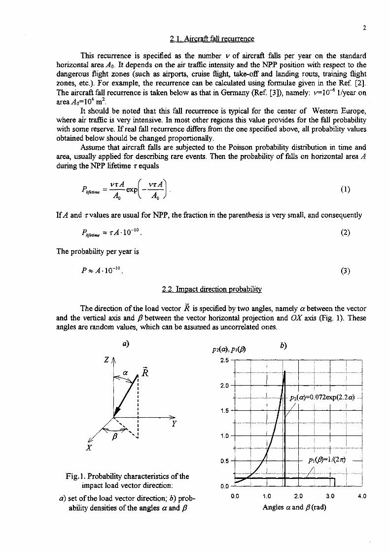
2.1. Aircraft fall recurrence
This recurrence is specified as the number v of aircraft falls per year on the standardhorizontal area Ao. It depends on the air traffic intensity and the NPP position with respect to thedangerous flight zones (such as airports, cruise flight, take-off and landing routs, training flightzones, etc.). For example, the recurrence can be calculated using formulae given in the Ref. [2].The aircraft fall recurrence is taken below as that in Germany (Ref. [3]), namely: v=l(T6 I/year onarea^40=104m2.
It should be noted that this fall recurrence is typical for the center of Western Europe,where air traffic is very intensive. In most other regions this value provides for the fall probabilitywith some reserve. If real fall recurrence differs from the one specified above, all probability valuesobtained below should be changed proportionally.
Assume that aircraft falls are subjected to the Poisson probability distribution in time andarea, usually applied for describing rare events. Then the probability of falls on horizontal area Aduring the NPP lifetime r equals
P,lifetime
VTA ( VTA
Ac, V An j(1)
If A and rvalues are usual for NPP, the fraction in the parenthesis is very small, and consequently
P <*TA-IQ~X0. (2)
The probability per year is
P ~ A . in~10 (X\
2.2. Impact direction probability
The direction of the load vector R is specified by two angles, namely a between the vectorand the vertical axis and J3 between the vector horizontal projection and OX axis (Fig. 1). Theseangles are random values, which can be assumed as uncorrelated ones.
a MR
Fig.l. Probability characteristics of theimpact load vector direction.
a) set of the load vector direction; b) prob-ability densities of the angles a and J3
2 . 0 -
1 .5-
1 .0-
0 . 5 -
n n k*/
j\\
71/ i
•H
/
I:
/(2tti
T~ !i I i
0.0 1.0 2.0 3.0
Angles a and y!?(rad)
4.0

Probability density of the angle /? should be in principle set in conformity with the NPP siteposition with respect to air traffic routs. For lack of other information it is assumed below that theapproach of aircraft to NPP from any side is equiprobable, i.e. the angle /? is uniformly distributedin (0, 2TC) interval. So, its probability density is:
(4)
The angle a probability density was determined by analysis of Aircraft Accident Digest,Ref. [4]. The obtained probability density is:
p2 (a) = 0.072 exp(2.2a).
Probability densities pi(JJ) and P2(«) are shown in Fig. \,b.To calculate joint probability density p(a, ft) it
should be taken into account that the probability ofload vector R application inside the "pyramid"(a, a+da, fi, p+dfi) is proportional to the solid anglebounded by it. This angle equals
(5)
i.e.
dS = since da d0, (6)
dP = CPi(P)p2(a)dS =1 (7)
= C—0.072exp( 22a)sinadadj3
The proportionality factor C is determined using thenorming condition:
2 it ic/2
The calculating of the integral gives:
p(a,0) = 1.315-10~2 exp(2.2a)sina .
Fig. 2. Pattern for determination of aand /?joint probability density
(8)
(9)
2.3. Load on building structure caused bv impact
Load R(f) on the building structure caused by an aircraft impact can be calculated usingwell known Riera's formula (Ref. [5]):
(10)
where x(t) is the length of the crushed part of fiiselage, Pj[x(t)] is the fuselage longitudinal strengthdistribution, and ju[x(f)] is its m a s s distribution. So, the load is dependent on the aircraft class (i.e.its mass and strength) and impact velocity. All the parameters are random ones and should bedetermined by means of the analysis of flight tasks and airspace situation near NPP. The data usedfor the example below correspond to the impact of the aircraft Phantom RF-4E. Smoothed andsomewhat simplified loads depending on the aircraft total mass m and velocity v0 are shown inFig. 3a-d.

R(f), MN200.00
160.00
120.00
80.00
40.00
0.00
m= 22000 kg
18000 kg
R(f), MN80.00
60.00
40.00
20.00
0.000.00 0.04 0.08
Time t, s0.00 0.02 0.04 0.06
Time t, s0.08
R(f), MN160.00
m= 22000 kg
18000 kg
12000 kg
R(t), MN50.00-
<*)
40.00
30.00
20.00
10.00
0.00 0.00
I IVo=9O m/s
m=22000 kg
18000 kg12000 kg
0.00 0.02 0.04 0.06 0.08Time t, s
o.oo 0.04 0.08
Time f, 5
Fig. 3. Load on building structure caused by Phantom RF-4E impactdepending on aircraft mass m and velocity v0
a)
1.00
0.80
0.60
0.40
0.20
0.00-
t
/
/
JI
f
//f
/
PJjn)0.50
0.40
0.30
0.20
0.10
50 100 150 200 250Velocity vo, m/s
0.00
0.12
0.12
1\ I\j/
I V|
i\\ \
12000 14000 16000 18000 20000
Mass m, kg
Fig.4. Probability distribution of aircraft Phantom RF-4E mass and velocity (adapted from [3]):
a) velocity cumulative probability distribution Pv(vo); b) mass probability density pmQn)
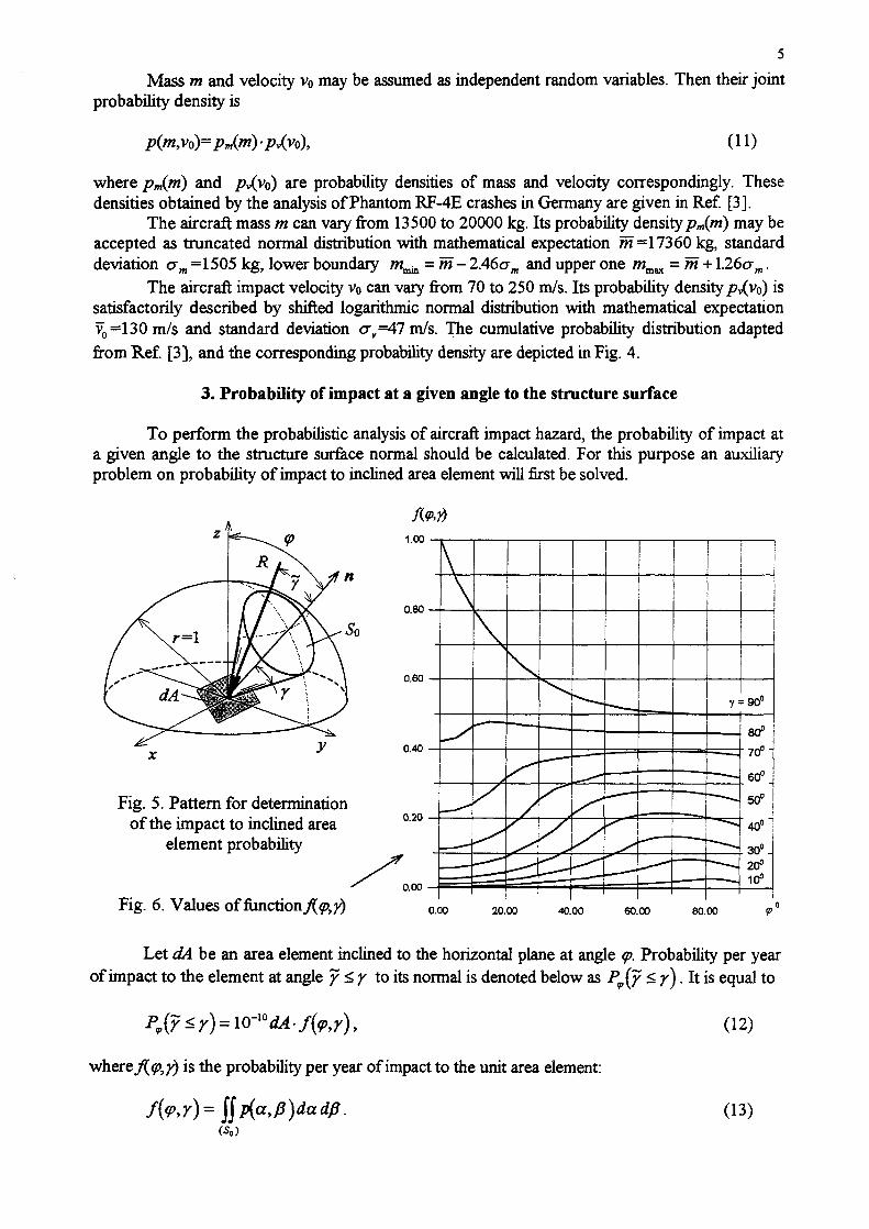
Mass m and velocity v<> may be assumed as independent random variables. Then their jointprobability density is
where pm{ni) and /?v(vo) are probability densities of mass and velocity correspondingly. Thesedensities obtained by the analysis of Phantom RF-4E crashes in Germany are given in Kef [3].
The aircraft mass m can vary from 13500 to 20000 kg. Its probability densitypm(rri) may beaccepted as truncated normal distribution with mathematical expectation m =17360 kg, standarddeviation am =1505 kg, lower boundary mmin = m- 2.46am and upper one wmax = m + \26am.
The aircraft impact velocity v0 can vary from 70 to 250 m/s. Its probability density/?v(v0) issatisfactorily described by shifted logarithmic normal distribution with mathematical expectationv0 =130 m/s and standard deviation aY =47 m/s. The cumulative probability distribution adaptedfrom Ref. [3], and the corresponding probability density are depicted in Fig. 4.
3. Probability of impact at a given angle to the structure surface
To perform the probabilistic analysis of aircraft impact hazard, the probability of impact ata given angle to the structure surface normal should be calculated. For this purpose an auxiliaryproblem on probability of impact to inclined area element will first be solved.
<P
Fig. 5. Pattern for determinationof the impact to inclined area
element probability
Fig. 6. Values of ftmctionj{q>,y) 0.00 20.00 40.00 60.00 80.00
Let dA be an area element inclined to the horizontal plane at angle <p. Probability per yearof impact to the element at angle y < y to its normal is denoted below as P9(y < y). It is equal to
(12)10-" dA-f(<p,y),
where J{<p,y) is the probability per year of impact to the unit area element:
(13)

The integral is calculated over the area So of solid angle bounded by a circular cone, whose axiscoincides with the element normal and the generatrix is inclined at the angle y (see Fig. 5). When<p +y>n/2, the part of angle So located below horizontal plane XOY is not taken into account. Thefunction_/($?,?) is plotted in Fig. 6 and tabulated (Appendix 2).
Using Eqs. (12)-(13), the probability of an impact at angle /with different kinds of surfacesmay be calculated. Three kinds of surfaces are typical of NPP building structures, namely a plane,a cylinder with vertical axis, and a spherical segment (the last two surfaces are typical of reactorbuilding containments).
On impact with an inclined plane of area A the angle <p is the same at any of its point. Forthis reason the probability per year of an impact with plane at angle y < y is equal to
= lO-iOA-f(<p,y). (14)
By analogy, the probability of an impact with a cylindrical surface of area A with a vertical
axis is
(15)
To calculate the probability of an impact with a spherical segment of radius p bounded by acone with a vertical axis and vertex angle J(Fig. 7,a), the following should be taken into account.This probability is the same for all the points belonging to the spherical layer with normal ninclined at angle <p. Its area is dA(<p)=2n/?sin<pd<p. Consequently, the probability of an impact is
(16)
where r is the containment radius (see Fig. 6,a), and the function fi(5,y) is:
2 s
sin(17)
The function/i(£,?) values are depicted in Fig. l,b and tabulated (Appendix 3).
1.20
n
0.80
0.40
Fig. 7. Determination of impactprobability with spherical dome:
a) spherical segment pattern;b) function fi(S,y) values
0.00
0.00 20.00 40.00 60.00 80.00

4. Building structures failure probability
Let event 5? be the building structure failure, i.e. its inadmissible damages (perforation,inadmissible cracking, etc.). Methodology of failure probability P(p) calculation is presented here.Assume first that the class of the impacting aircraft is known. For definiteness it is assumed herethat the aircraft is Phantom KF-4E. The way of different aircraft classes fall account will bedescribed below.
4.1. Aircraft mass and velocity probability
Suppose that aircraft velocity and mass vary in ranges vmin<vo<vmax and ww^m^/Wmaxcorrespondingly. To calculate the probability of their different values these ranges should bedivided into intervals Av and Am. Then the probability of an impact of an aircraft at velocity v0 andmass m is equal to [see (11)]:
P(v0, (18)
4.2. Impact load value probability
The impact load value R(v0, m, t) is uniquely dependent on the aircraft mass and velocity.Consequently the conditional probability of its value P(i?|v0, rri) is the same as mass and velocityprobability, i.e. is calculated using Eq. (18).
4.3. Failure probability of the building structure under impact with a given point
If a building structure is impacted at any angle to its surface, its strength is primarilydependent on the normal load component. Because of that, for simplification sake, as the firstapproximation the tangential load component can be neglected when assessing the structure failureprobability. This simplified methodology is described below.
R(m,v0>t)
kR(m,vo,f) =R(m,v0,t)cosy
Fig. 8. Determination of themaximal angle between theload and the surface normal atwhich the building structurewill collapse
If the strength of a building structure, loaded by force R(v0, m, t) which is applied in thez-th point normally to the structure surface is enough, then failure probability P,{^)=0.
If the building structure strength is not enough, a fraction of force R(y0, m, t) should bedetermined which can be borne by the structure. In other words, the maximal value of thereducing factor 0<k<l has to be determined, so that if the building structure is loaded by forcekR(y0, m, t) normally to the surface, its strength will be enough. Obviously, k=cosy (see Fig. 8),where y is the vertex angle of the cone where the load applied inside will cause the structurefailure. The angle equals
y= arccosfc (19)
It means that conditional probability P(?\R) of failure caused by the given load R can be calculatedusing Eq. (12), i.e. it equals
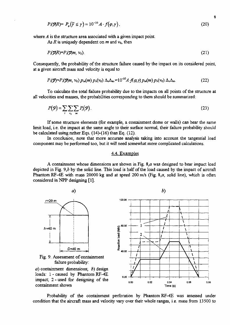
* r) = (20)
where A is the structure area associated with a given impact point.As R is uniquely dependent on m and vo, then
, vo). (21)
Consequently, the probability of the structure failure caused by the impact on its considered point,at a given aircraft mass and velocity is equal to
, vo)pm(ni)pv(y0) AvAm =IO'1{)A-J{<p,y) pm(m) p^vo) AvAm. (22)
To calculate the total failure probability due to the impacts on all points of the structure atall velocities and masses, the probabilities corresponding to them should be summarized:
(23)i vn m
If some structure elements (for example, a containment dome or walls) can bear the samelimit load, i.e. the impact at the same angle to their surface normal, their failure probability shouldbe calculated using rather Eqs. (14)-(16) than Eq. (12).
In conclusion, note that more accurate analysis taking into account the tangential loadcomponent may be performed too, but it will need somewhat more complicated calculations.
4.4. Examples
A containment whose dimensions are shown in Fig. 8,a was designed to bear impact loaddepicted in Fig. 9,b by the solid line. This load is half of the load caused by the impact of aircraftPhantom RF-4E with mass 20000 kg and at speed 200 m/s (Fig. 8,a, solid line), which is oftenconsidered in NPP designing [1].
r=20m 120.00
Fig. 9. Assessment of containmentfailure probability:
a) containment dimensions; b) designloads: 1 - caused by Phantom RF-4Eimpact; 2 - used for designing of thecontainment shown
_ 80.00
2
40.00
0.00
i
2 ^
i
11
1
1////
\
/
f
//
/
/
v
1
}
v*\\\\\
\ \\
\ \Y
—
0.00 0.02 0.04
Time (s)
0.06 0.08
Probability of the containment perforation by Phantom RF-4E was assessed undercondition that the aircraft mass and velocity vary over their whole ranges, i.e. mass from 13500 to

20000 kg and velocity from 70 to 250 m/s. It was assumed that 30% of the containment surfacecylinder part was shielded by other NPP buildings.
Calculations show that probability of thecontainment perforation equals to 0.9210"7, i.e. it islower than the threshold probability level M0"7
beginning from which this event should be taken intoaccount in NPP design.
As follows from Eq. (20), a structure failureprobability is proportional to its surface area. Forexample, German NPP "Biblis" containment describedin Ref. [6] has dimentions shown in the Fig. 10. Withthe same initial data as above its failure probability is1.7-10"7, i.e. it is somewhat higher than the thresholdprobability level. To decrease it the containment shouldbe designed to withstand heavier impact load. Also onemay take into consideration that part of thecontainment is in the shadow of other NPP buildings,so the real probability is somewhat less.
r=30mS
1h=35 m
ID=60 m
•< =•
Fig. 10. German NPP "Biblis"containment dimentions(adapted from Ref [6])
As one can see, the larger building the heavier design load should be applied to provide thesame its failure probability. Conversely, the smaller building the less design load may be used.
4.5. Taking into account of aircraft class
Denote random event "the k-th class aircraft fall" by /h- To take into account thepossibility of different class aircraft impacts, the fall recurrence interval and corresponding fallprobability P(s4k) for every of them should be determined.
Aircraft of any class gives specific load to the building structure. Using the described aboveroutine, one should first calculate the structure conditional failure probability Ptykl^k) due to theA-th aircraft class impact. Then the total failure probability of the structure P(?) taking intoaccount all possible aircraft classes can be calculated by use of the total probability formula:
(24)
5. Development of floor response spectra under aircraft impact
Floor response spectra values are random ones depending on parameters considered insection 2. At aircraft impact their specific feature is that they have very high accelerations at thebuilding points near the impact point, but they decrease rapidly as the distance between thesepoints increases. Therefore when the spectra values probability is assessed the distance from theimpact point should be considered as an additional random parameter.
When floor response spectra are calculated, the building is modelled as a linear elasticsystem. So, on the impact at the given place, floor response spectra are proportional to the impactload value. Because of that the following simplified routine can be used to develop them.
Let the maximal impact force corresponding to the maximal aircraft mass and velocity be^max(0- For the simplification sake assume, that at any another mass m and vo the force isproportional to i?m«(0> i-©-
, m, 0=*(v0, (25)
where k(v0, m) is the reducing factor, k(v0, m)<l. Probability P(v0, m) of its realization is calculatedusing Eq. (18).

10
First, response spectra Smu. for all structure levels of interest should be calculated, providedthat the force i?nux(0 is applied along the structure surface normal which is inclined at angle <p.Then, by use of those spectra, spectra can be obtained for the force inclined to the normal. In sodoing, influence of the force tangential component may be neglected as the first approximation. Ata given m and vo, i.e. at the force value R(v0, m, t) and its inclination angle y, the spectrum equals
S^Smu. cosy- k(y0, m), (26)
Probability of the spectrum is
ps=10-10M-P(r,<pyP(v«, m), (27)
where AA is the impacted structure area associated with the considered impact point; P(y, <p) is theangle y probability. The latter can be obtained by using Eq. (12), for which purpose y variationrange (0, 2it) should be divided into intervals. If yi<y<y^\, then
P{<P,Y) = PV{Y^YM)-P,{Y ±Ti) • (27)
This routine should be repeated for all impact points and aircraft classes. Then responsespectra Sp can be developed satisfying the condition mat the probability of the unexceeding oftheir values will be equal Xops.
REFERENCES
1. External Man-Induced Events in Relation to Nuclear Power Plant Siting. A Safety Guide.No 50-SG-S5. IAEA, Vienna, 1981.
2. Kobayashi, T. Probability Analysis of an Aircraft Crash to a Nuclear Power Plant - NuclearEngineering and Design, 110 (1988), pp. 207-211.
3. Zom, W.F., and Shueller, G.F. On the Failure Probability of the Containment under AccidentalAircraft Impact - Nuclear Engineering and Design, 91 (1986), pp. 277-286.
4. Aircraft Accident Digest//ICAO Circular. No 16.1.88-AN/74 - N o 29.191-AN-116.5. Riera J.D. On the Stress Analysis of Structures Subjected to Aircraft Impact Forces - Nuclear
Engineering and Design, 8 (1968), pp. 415-426.6. KrutzikN.J. Reduction of the Dynamic Response by Aircraft Crash on Building Structures -
Nuclear Engineering and Design, 110 (1988), pp. 191-199.

11
Appendix 1
Cumulative probability distribution (adapted from Ref. [3])and probability density of aircraft Phantom RF-4E velocity
Aircraft velocityv0, m/s
708090100110120130140150160170180190200210220230240250
Cumulative probabilitydistribution P^v0)
00.00160.00920.0290.0600.1110.1750.2510.3340.4270.5200.6160.7060.7870.8590.9190.9640.993
1
Probability densityPv(v0)
00.0003190.0014890.0027660.0042550.0055320.0067020.0079790.0089360.0094680.0095740.0092550.0086170.0077660.0067020.0053190.0035110.001915
0

12
Appendix 2
Values of function f{<p,y)= \\p(a,/3)dadfi
Area elementinclination
angle0
0.08730.17450.26180.34910.43630.52360.61090.69810.78540.87270.95991.04721.13451.22171.30901.39631.48351.5708
<P05010°15°20025°30°35°40°45°50°55°60°65070°75080085°90°
0...(....
0000000000000000000
0.087350
0.00020.00030.00040.00060.00070.00080.00100.00120.00150.00180.00220.00260.00320.00380.00460.00560.00680.00820.0046
0.1745100
0.00080.00100.00150.00210.00260.00320.00400.00480.00590.00720.00870.01050.01280.01550.01880.02280.02760.02510.0170
Functio
0.2618150
0.0020.00220.00300.00420.00560.00720.00890.01090.01340.01630.01990.02420.02940.03570.04330.05250.05310.04630.0356
0.2618200
0.00400.00430.00540.00710.00960.01250.01580.01970.02420.02970.03630.04420.05380.06540.07940.08410.08020.07140.0589
dues when angle y
0.349125o
0.00710.00750.00900.01140.01480.01940.02490.03130.03890.04790.05870.07170.08740.10640.11540.11520.10940.09950.0859
0.436330°
0.01160.01220.01420.01740.02220.02850.03660.04640.05790.07170.08820.10810.13210.14560.14910.14690.14030.12970.1157
is:0.5236
3500.01800.01890.02150.02590.03230.04080.05190.06570.08250.10260.12660.15560.17360.18090.18230.17920.17220.16160.1476
0.6109400
0.02710.02820.03170.03750.04610.05760.07240.09110.11430.14240.17630.19870.20970.21470.21520.21170.20480.19440.1809
0.7854450
0.03950.04100.04560.05340.06480.08010.09990.12480.15590.19400.22080.23520.24350.24730.24740.24400.23750.22780.2150
Area element
inclinationangle0
0.08730.17450.26180.34910.43630.52360.61090.69810.78540.87270.95991.04721.13451.22171.30901.39631.48351.5708
<P05°10°15020025°30°35040°45050055060°65°70075080085090°
0.8727500
0.05660.05860.06470.07510.09010.11030.13650.16970.21090.24030.25750.26880.27560.27880.27880.27590.27000.26120.2495
0.9599550
0.08000.08260.09070.10430.12420.15090.18560.22930.26050.27870.29130.30030.30620.30910.30930.30690.30190.29430.2839
FunctionX&T) values when angle
1.0472600
0.11190.11540.12600.14400.17020.20550.25120.28330.30170.31450.32380.33070.33550.33820.33870.33700.33300.32670.3178
1.1345650
0.15560.16020.17420.19810.23270.27920.31120.32850.34040.34910.35560.36050.36400.36630.36710.36610.36310.35810.3510
1.221770°
0.21600.22210.24060.27220.31790.34790.36240.37180.37840.38340.38730.39020.39240.39380.39450.39410.39210.38840.3829
1.3090750
0.30060.30880.33340.37540.40010.40850.41270.41520.41690.41810.41920.42010.42080.42130.42150.42120.42010.41770.4138
y is:
1.3963800
0.42260.43350.46660.48000.47670.47100.46550.46070.45700.45420.45220.45070.44970.44900.44850.44790.44720.44590.4435
1.4835850
0.60910.62400.61350.58690.56220.54140.52460.51130.50100.49310.48720.48280.47970.47750.47590.47480.47400.47340.4723
1.5708900
10.88320.80150.73500.68110.63800.60380.57710.55620.54010.52800.51900.51240.50770.50450.50240.50120.5005
0.5

13
Appendix 3
Values of function f}(y,S) = 2 jf(y,<p)sin<p d<p
AngleS
00.08730.17450.26180.34910.43630.52360.61090.69810.78540.87270.95991.04721.13451.22171.30901.39631.48351.5708
05°
' 10°15°20°25°30°35°40°45°50°55°60°65°70°75°80°85°90°
0......
0000000000000000000
0.08735°
0.000200.000290.000370.000450.000530.000630.000740.000880.001040.001250.001490.001800.002170.002640.003230.003970.004910.006110.00718
0.1745
l6°0.000800.000960.001220.001580.001960.002390.002870.003440.004130.004950.005960.007200.008730.010640.013030.016040.019860.023990.02748
Function./K^ values when angle y ii
0.2618
is6
0.002000.002230.002630.003280.004120.005120.006270.007600.009200.011120.013460.016330.019870.024280.029800.036740.044610.052250.05899
0.349120s
0.004000.004340.004890.005820.007150.008880.010950.013410.016360.019900.024210.029500.036030.044150.054300.065970.077880.089310.09998
0.4363"25ff
0.007100.007550.008290.009610.011480.014010.017220.021150.025910.031680.038710.047330.057990.071240.086520.102430.118250.133750.14888
0.523630°
0.011600.012230.013270.015060.017640.018880.025690.031420.038500.047160.057770.070830.086980.105600.125120.144800.164490.184270.20424
0.610935s
0.018000.018890.020300.022740.026250.031020.037240.045170.055140.067470.082700.101510.123140.145830.168780.191950.215500.239660.26478
0.698140°
0.027100.028150.030120.033440.038110.044550.052950.063690.077260.094240.115350.139610.164980.190600.216510.242950.270270.298890.32930
0.7854w"
0.039500.041040.043660.047980.054310.062950.074210.088610.106840.129720.156080.183540.211170.239030.267470.296930.327910.360980.39680
AngleS
00.08730.17450.26180.34910.43630.52360.61090.69810.78540.87270.95991.04721.13451.22171.30901.39631.48351.5708
05°10°15°20°25°30°35°40°45°50°55°60°65°70°75°80°85°90°
0.8727
"W"""0.056600.058670.062110.067770.076340.087850.102880.122080.146390.174280.203110.231910.260870.290410.320990.353220.387710.425170.46642
0.9599— 55°0.080000.082610.087580.094940.106180.207190.141440.166960.196110.225680.254770.283830.313410.344100.376500.411250.449060.490790.53742
Function^ (S,y) values when angle y
1.0472600
0.111900.115500.121420.131670.146670.166980.193440.223390.253180.281870.310120.338710.368350.399780.433620.470600.511540.557370.60928
1.134565° "
0.155600.160220.168530.181990.201710.228690.258880.287960.315360.341840.368490.396120.425440.457220.492200.531160.574980.624730.68174
1.221770°
0.216000.222310.232890.251090.277400.306750.333680.358160.381650.405120.429630.455880.484590.516490.552350.593030.639500.692940.75486
1.309075*
0.300600.307820.323130.347530.373510.395900.415120.433330.452000.471840.493780.518320.546190.577990.614530.656690.705600.762510.82914
• is:
1.396380° j
0.422600.434100.453180.471430.484150.494120.503680.514540.527660.543280.562180.584700.611410.642880.679890.723330.774430.834620.90574
1.483585°
0.609100.623520.623290.617130.610020.605440.603920.606230.612760.623360.638490.658350.683360.714080.751220.795680.848750.911970.98740
1.570890°1
0.883980.848640.810990.779950.756580.739960.730100.726910.729680.738650.753880.775570.804190.840410.885110.939571.005461.08500

XA9952887
COORDINATED RESEARCH PROGRAMME ON SAFETY OF RBMK-TYPENUCLEAR POWER PLANTS IN RELATION TO EXTERNAL EVENTS
ST. PETERSBURG RESEARCH COORDINATION MEETTNG
AIRCRAFT IMPACT QUALIFICATION OF RBMKSYSTEMS AND COMPONENTS
TECHNICAL REPORT
REVISION 00MAY 1999
Prepared for:The International Atomic Energy Agency
ismesspavia Pasttengo 9,24068 Seriate (BG)
tel. +39-035/307.111 fex+39-O35/302.999Email: [email protected] Website: http:/AvwwJsmes.il/
INTERNATIONAL ATOMIC ENERGY AGENCYCOORDINATED RESEARCH PROGRAMME ON
SAFETY OF RBMK-TYPE NUCLEAR POWER PLANTSIN RELATION TO EXTERNAL EVENTS
St. Petersburg Research Coordination MeetingAircraft Impact Qualification of RMBK Systems and Components
Technical ReportProject BA00.02; Doc. RAT-STR-673/99
on behalf of IAEA - Vienna
document of 70 pages
00
rev
May 1999 ̂
date written
V^Zo1a
verified
R. Pellegrini
approved Issuing Authorization
ISSUING UNIT
Proj. BA00.02ST. Petersburg Research Coordination Meeting Doc. RAT-STR-673/99Aircraft Impact Qualification of RBMK Systems and Components rev. 00Technical Report
pag.2
Revision Description
Rev. 00: first issuing
Distribution List
IAEA - Vienna
ST. Petersburg Research Coordination Meeting Doc. RAT-STR-673/99Aircraft Impact Qualification of RBMK Systems and Components rev. 00Technical Report
pag.3
0. SUMMARY
In the present report, the problem of qualification procedures of electrical equipment with respect to
the dynamic excitation subsequent to an aircraft impact (ACC) on a Nuclear Power Plant (NPP) is
approached, within the context of IAEA Benchmark on vulnerability of equipment and structures of
RBMK-type NPP against the aircraft impact. After a short description of the main objectives of the
work and the relevant area of concern (Chapter 1), the safety related equipment more commonly
installed in a NPP are grouped in few classes, according to widely accepted classification criteria
and the relevant failure modes are described (Chapter 2). Taking as reference a deeply studied
RBMK reactor (Ignalina NPP), an overview of its main characteristics and of the equipment
ensemble housed in is given in Chapter 3. An overview of the worldwide most used qualification
standards for safety related equipment for NPPs is reported in Chapter 4, and a comparison of the
practices used in Europe for the qualification of safety related electrical and I&C equipment is
described with special attention to seismic and impact qualification (Chapter 5). In the hypothesis
that the equipment to qualify against impact excitation has been already qualified against seismic
excitation, the problems relevant to the different nature of earthquake and shock phenomena are
listed, together with the main criteria to implement a procedure which, based on standardized shock
pulses, could be applied for ACC qualification purposes (Chapter 6). Consequently, a possible ACC
qualification procedure is outlined (Chapter 7) and the interface data (data coming from numerical
analysis and seismic qualification, to be used for ACC qualification purposes) are listed (Chapter 8).
Finally, the main conclusions of the work are described (Chapter 9). The main references are listed
in Chapter 10.
This report has 70 pages.
..IISIT1ESProj. BA00.02
ST. Petersburg Research Coordination Meeting Doc. RAT-STR-673/99Aircraft Impact Qualification of RBMK Systems and Components rev. 00Technical Report
pag. 4
TABLE OF CONTENTS
page
0. SUMMARY 3
1. INTRODUCTION 6
2. GROUPING OF SAFETY RELATED EQUIPMENT AND
RELEVANT FAILURE MODES 8
2.1 General considerations 8
2.2 Failure modes of various types of equipment 10
2.3 Equipment classification with respect to the ACC vibrations 18
3. RBMK-TYPE NPP: THE REFERENCE CASE 19
3.1 Typical equipment 23
3.2 The "as-built" status of the equipment for the reference case 25
3.3 Some data about electrical cabinets 26
4. AN OVERVIEW OF THE QUALIFICATION PROCEDURES
AND RULES FOR SAFETY RELATED ELECTRICAL
COMPONENTS 27
4.1 Standards and codes for new NPPs 27
4.1.1 General Criteria for qualifying Class IE Equipment 27
4.1.2 General Criteria for seismic qualification of Class IE Equipment 28
4.1.2.1 Introduction... 28
4.1.2.2 IEEE Standard 344-1987 28
4.1.2.3 IAEA5O-SG-D15 30
4.1.2.4 EEC 68-3-3 32
4.1.2.5 USNRCR.G. 1.100 34
4.1.2.6 IEC980-1989 35
4.1.2.7 Comments 36
4.1.3 Specific Qualification criteria 37
4.2 Standards and codes for already existing plants 38

ST. Petersburg Research Coordination Meeting Doc. RAT-STR-673/99Aircraft Impact Qualification of RBMK Systems and Components rev. 00Technical Report
pag.5
5. A COMPARISON OF EUROPEAN PRACTICES FOR THE
QUALIFICATION OF SAFETY RELATED ELECTRICAL
AND I&C EQUIPMENT 40
5.1 Seismic qualification 40
5.2 Impact qualification 43
5.3 Impact qualification procedure for ALTOLAZIO NPP 44
5.4 Previous examples of shock (impact) qualification on equipment 45
5.5 Aircraft Impact: the approach in the Russian Federation 46
6. BASIC PROBLEMS RELEVANT TO THE
QUALIFICATION OF ELECTRICAL AND I&C
EQUIPMENT AGAINST SEISMIC AND ACC
EXCITATIONS 48
6.1 Problems relevant to the shock qualification 48
6.2 Excitation phenomena 50
7. PROPOSAL FOR IMPACT/SEISMIC EXPERIMENTAL
QUALIFICATION PROCEDURE 52
7.1 General approach 52
7.1.1 Structural qualification 56
7.1.2 Functional qualification 60
7.2 Proposal for ACC qualification of equipment already seismically
qualified 66
7.2.1 Mechanical equipment 66
7.2.2 Active electrical equipment 67
8. INTERFACE DATA FOR IMPACT/SEISMIC
EXPERIMENTAL QUALIFICATION 67
9. CONCLUSIONS 67
10. REFERENCES 70

Proj. BA00.02ST. Petersburg Research Coordination Meeting Doc. RAT-STR-673/99Aircraft Impact Qualification of RBMK Systems and Components rev. 00Technical Report
pag. 6
1. INTRODUCTION
Within the context of IAEA Benchmark on vulnerability of equipment and structures of RBMK-
type Nuclear Power Plants (NPPs) against the aircraft impact, ISMES has been nominated as
Coordinator to study the feasibility of the extension of qualification methodologies consolidated in
seismic environment to the field of aircraft impact (see ref [22]).
In order to introduce the topic concerned, it has to be underlined that standard testing procedures for
safety related equipment (SRE) currently applied in European Countries are not uniform and not
specialized for impact analysis; moreover, equipment and components have different limit states
(functionality, integrity, dissipation, etc.), often disregarded in the standards. The acceptance
criterion cannot be based upon a simple comparison of spectra: the damage in fact has to be
correlated with many input parameters to avoid misleading conclusions.
On the other side, the qualification of mechanical components and electrical equipment requires as
input some interface data with the structural response, namely: floor response spectra (FRS, in
terms of acceleration and/or displacement), time histories (TH), power spectral density (PSD),
energy spectral density (ESD), etc. However, numerical models are usually generated with more
emphasis on structural stability than on floor response calculation.
The study presented in this report is structured in three different topics:
• the identification of main classes of safety related equipment with their associated failure modes
• a review on the current practice on the seismic qualification methodologies and on the impact
qualification methodologies (when they are available)
• the identification of an approach for impact qualification of equipment already qualified w.r.t.
seismic actions, for which hence qualification data already exists
• verification of the feasibility of the application of the impact qualification approach on the
typical equipment housed in a RBMK-type NPP.
In the first phase of the activity, the most common SRE have been grouped in few classes,
homogeneous with respect to failure mode and structural behaviour, with identification of
criticalities in terms of frequency range, fatigue cycles and operability.

Proj.ST. Petersburg Research Coordination Meeting Doc. RAT-STR-673/99Aircraft Impact Qualification of RBMK Systems and Components rev. 00Technical Report
pag.7
In the second step, a review on current practice of the seismic/impact qualification methodologies is
the essential starting point to better define:
- the best output from structural FE models and the associated degree of uncertainty (to improve
standard simplified approaches like spectrum broadening or shifting);
- the special constraints to be applied to FE models in order to guarantee the required accuracy to
FRS (e.g. local grid refinements on floors, localization of impact area, etc.);
- an approach for impact qualification of equipment already qualified w.r.t. seismic actions, for
which hence qualification data already exists
The third phase is relevant to the identification of a coherent experimental procedure for the impact
qualification of different classes of components, with specific reference to components already
qualified against seismic induced actions. A clear correlation between the two qualification
approaches is in fact essential for the requalification of existing plants.
As a final step, the criteria on the feasibility of the application of the abovementioned procedure to
the typical equipment housed in a RBMK-type NPP have been described, taking into account the
experience gained by ISMES during the walkdown visits performed at Ignalina Nuclear Power
Plant (Lithuania) within the framework of an EBRD Project.
It has to be underlined that the procedures outlined in the present document have been designed to
approach the problem of impact qualification of the safety related elctromechanical equipment only
(typically safety related electrical cabinets and the relevant components housed in), for which there
is a good confidence that seismic and standardized pulse qualification data exist, either in nuclear or
in non-nuclear field.
Main piping, main coolant pumps, separator drum (which is a unique feature of the RBMK-type
NPPs) and the reactor (i.e. graphite blocks, control rods mechanisms, fuels channels, pressure tubes,
etc.) have not been taken into account for the following reasons:
• these types of equipment have been specifically designed for nuclear applications;
• a similarity analysis with reference to non-nuclear application is not feasible (see previous
point);

ST. Petersburg Research Coordination Meeting Doc. RAT-STR-673/99Aircraft Impact Qualification of RBMK Systems and Components rev. 00Technical Report
pag.8
• the recommended approach for these types of components, due to their essential importance, is
a direct qualification w.r.t. the ACC (being the tests feasible only on portions of them, due to
their large size), involving a detailed analysis of the dynamic response of the buildings where
they are located, including local effects, non-linear phenomena, etc., computing in this way the
response spectra at their base and estimating, in a classical stress analysis approach, their
strength w.r.t. the forces relevant to the ACC event. The indirect approach presented hereinafter
for the electrical equipment is not considered applicable
2. GROUPING OF SAFETY RELATED EQUIPMENT AND RELEVANT FAILURE
MODES
2.1 General considerations
In order to approach the problem of ACC qualification of safety related equipment of a NPP some
base hypotheses have to be established:
- the concerned equipment have been already seismically qualified, from both structural and
functional point of view, i.e. with respect to the seismic excitation, they have demonstrated to
perform their safety functions during and after the seismic event;
- it is possible to discriminate between the structural qualification (assessment of the structural
integrity) and the functional qualification (assessment of the maintaining of their functionality);
- the weakest point, from the structural point of view, of the equipment concerned is located at the
anchorage level.
The first hypothesis states that a certain degree of ruggedness of the equipment has been achieved
with respect to a dynamic event such as an earthquake.
The second item is based on the consideration that no influence is caused on the structural integrity
by the occurrence of a loss of functionality of the equipment, whereas the loss of the structural
integrity could imply the loss of the safety functions. In other words, the assessment of the

Prqj. BA00.02ST. Petersburg Research Coordination Meeting Doc. RAT-STR-673/99Aircraft Impact Qualification of RBMK Systems and Components rev. 00Technical Report
pag. 9
structural integrity is a necessary but not sufficient condition in order to achieve the qualification of
the equipment.
The third item is essentially based on the statement that a properly anchored equipment has
adequate capacity with respect to the seismic excitation (see ref. [3] and [6]); although this
statement has been demonstrated correct from experience data in the seismic field, it seems to be
reasonable to extend it to other dynamic excitations such as ACC.
For what concerns the classification of safety related equipment with respect to their behaviour in
the case of ACC vibrations, no reference documentation has been found and the relevant experience
is very limited too. The classification relevant to seismic standards could be adopted, in order to
have a starting point. Different classifications have been proposed, relevant to various standards
examined.
For safety related equipment for which procedures of seismic verification have been developed in
the frame of qualification of existing plants where it is not possible for various reasons (equipment
not previuosly qualified already installed, increment of seismic demand, etc.) to perform a complete
process of environmental qualification (see docs. [3] and [6]), the various types of equipment have
been categorized as follows:
- motor control centers;
- low voltage switchgears;
- medium voltage switchgears;
- transformers;
- horizontal pumps;
- vertical pumps;
- fluid operated valves;
- motor-operated and solenoid-operated valves;
-fans;
- air handlers;
- chillers;
- air compressors;
- motor-generators;
- distribution panels;
- batteries on racks;
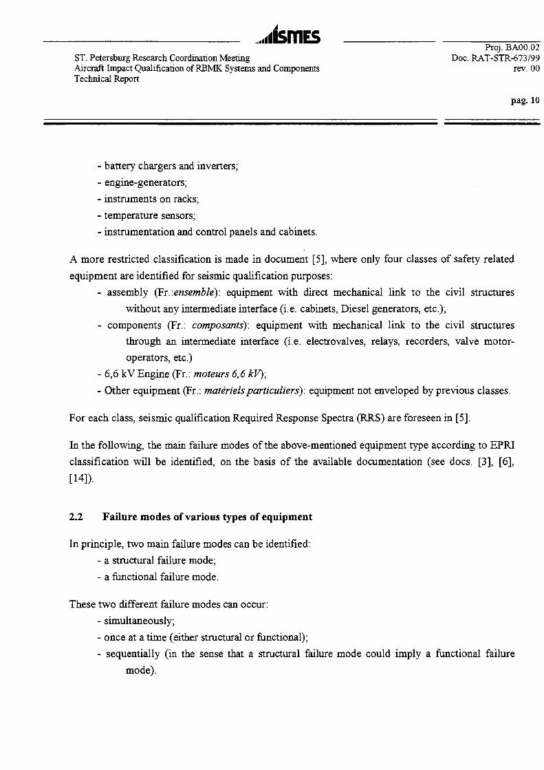
,i<isiTlESProj. BA00.02
ST. Petersburg Research Coordination Meeting Doc. RAT-STR-673/99Aircraft Impact Qualification of RBMK Systems and Components rev. 00Technical Report
pag. 10
- battery chargers and inverters;
- engine-generators;
- instruments on racks;
- temperature sensors;
- instrumentation and control panels and cabinets.
A more restricted classification is made in document [5], where only four classes of safety related
equipment are identified for seismic qualification purposes:
- assembly (Fr..ensemble): equipment with direct mechanical link to the civil structures
without any intermediate interface (i.e. cabinets, Diesel generators, etc.);
- components (Fr.: composants): equipment with mechanical link to the civil structures
through an intermediate interface (i.e. electrovalves, relays, recorders, valve motor-
operators, etc.)
- 6,6 kV Engine (Fr.: moteurs 6,6 kV);
- Other equipment (Fr.: materielsparticuliers): equipment not enveloped by previous classes.
For each class, seismic qualification Required Response Spectra (RRS) are foreseen in [5].
In the following, the main failure modes of the above-mentioned equipment type according to EPRI
classification will be identified, on the basis of the available documentation (see docs. [3], [6],
2.2 Failure modes of various types of equipment
In principle, two main failure modes can be identified:
- a structural failure mode;
- a functional failure mode.
These two different failure modes can occur:
- simultaneously;
- once at a time (either structural or functional);
- sequentially (in the sense that a structural failure mode could imply a functional failure
mode).
Proj. BA00.02ST. Petersburg Research Coordination Meeting Doc. RAT-STR-673/99Aircraft Impact Qualification of RBMK Systems and Components rev. 00Technical Report
pag. 11
A structural failure mode can occur caused by two different mechanisms (in this context, all the
structural failure modes relevant to thermal and/or creep effects are disregarded, as it is assumed
that the external loads on equipment act in an environment not affected by temperature):
- an equivalent "static" failure mechanism;
- a fatigue failure mechanism.
The equivalent "static" failure mechanism is relevant to the fact that the internal stresses caused by
load conditions (static and/or dynamic) are greater than (or equal to) the yield stress or ultimate
stress (depending upon the ductile or brittle behaviour of the constitutive material). In this case, no
fatigue effects are considered. The internal stresses can be originated by a static load or by a
dynamic load (i.e. an impact load in a certain area of the plant or a seismic load at the base of the
plant: both these loads will be transferred to the base of the equipment concerned, conditioned by
the transfer functions of the structural elements located between the excitation area and the
equipment concerned).
The fatigue failure mechanism is relevant to the fact that the internal stresses due to the load
conditions (in general, dynamic), although lower than the yield/ultimate stress of the constitutive
material, are cyclic; the damage accumulated (and estimated through a damage accumulation rule,
i.e. Miner rule) during the excitation period can cause a fatigue failure. In the case of impact or
seismic phenomena, the effects associated to the input waveforms are, in general, relevant to the
low-cycle fatigue.
The functional failure mode depends upon the type of electrical equipment concerned and the
relevant safety function accomplished.
The categories of equipment for which failure modes have been identified, have been determined
within the frame of the research project described in detail in ref. [14]. All components are
considered to include their supports to the point of interface with the building structure. Electro- or
active-mechanical devices such as motor-operated valves, pneumatic- and hydraulic-operated
valves and motor-, turbine- and diesel-driven pumps, include the complete assemblies normally
furnished by the component suppliers. Thus, valve operators, pumpmotors, and ancillary equipment
for cooling and lubrication are included as part of the component category. External control
systems, power supplies, and connecting electrical cables are not included as part of the component
and are considerered in separate categories.

.rismESPrqj. BA00.02
ST. Petersburg Research Coordination Meeting Doc. RAT-STR-673/99Aircraft Impact Qualification of RBMK Systems and Components rev. 00Technical Report
pag. 12
In the following list, the category in italics indicates an equipment or component which can be
considered inherently rugged with respect to the seismic loads. For each category, the relevant
equipment and the main failure modes rugged with respect to the seismic event are listed, in order
of probability of occurrence of that failure.
Reactor core assembly
Equipment included in the category: fuel rods, core support structure, control rod assemblies,
spacers grids1;
Main failure modes w.r.t. the seismic event: crushing of grid spacers; deformation of control
rod assemblies;
Reactor coolant system vessels
Equipment included in the category: pressure vessel2, steam generators, pressurizer3
Main failure modes w.r.t. the seismic event: nozzle-to-pipe weld joints failure; failure of the
supports
Reactor coolant pumps •
Equipment included in the category: reactor coolant pumps
Main failure modes w.r.t. the seismic event: failure of ancillary equipment; failure of the
supports
Piping
Equipment included in the category: piping of all sizes, elbows, tees, butt welds, reducer
sections, etc.
Main failure modes w.r.t. the seismic event: ductile failure
Large vertical storage vessels with formed heads
Equipment included in the category: accumulator tanks, volume control tanks
1 Not present in RBMK-type NPP
2 Not present in RBMK-type NPP
3 Not present in RBMK-type NPP

..illSTTlES ^--Proj.
ST. Petersburg Research Coordination Meeting Doc. RAT-STR-673/99Aircraft Impact Qualification of RBMK Systems and Components rev. 00Technical Report
pag. 13
Main failure modesiw.r.t. the seismic event: support failure
Large vertical flat bottom storage tanks
Equipment included in the category: borated water storage tanks, condensate storage tanks
Main failure modes w.r.t. the seismic event: failure of anchor bolts and subsequent buckling
on the compression side and rupture of the wall-to-bottom joint on the tensile side
Large horizontal vessels and heat exchangers
Equipment included in the category: large storage tanks, residual heat storage tank,
component cooling water heat exchanger, pressurizer relief tank, diesel oil storage tank
Main failure modes w.r.t. the seismic event: failure of anchor bolts and subsequent buckling
on the compression side and rupture of the wall-to-bottom joint on the tensile side
Small to medium vessels and heat exchangers
Equipment included in the category: i.e. boron injection tank
Main failure modes w.r.t. the seismic event: either the support/tank interface or
support/building interface;
Large vertical centrifugal pumps with motor drives
Equipment included in the category: service water pumps, fire pumps, condenser coolant
pumps
Main failure modes w.r.t. the seismic event: failure of the supports.
Motor-driven pumps and compressors
Equipment included in the category: auxiliary feedwater system pumps, residual heat removal
pumps, safety injection pumps, centrifugal charging pumps, containment spray and
recirculation pumps, diesel lube oil pumps.
Main failure modes w.r.t. the seismic event: support failure
Valves"
Large motor-operated valves
A It is common to test complete valve assemblies only for the smaller valves and to test only the electrical operators on
the larger valves. The valve itself is then qualified for seismic service by analysis.
Proj. BA00.02ST. Petersburg Research Coordination Meeting Doc. RAT-STR-673/99Aircraft Impact Qualification of RBMK Systems and Components rev. 00Technical Report
pag. 14
Equipment included in the category: isolation valves, flow control valves
Main failure modes w.r.t. the seismic event: binding due to permanent deformation of
the yoke-neck-stem assemblies; electrical failure of the operator assembly;
fracture of the pipe-to-valve nozzle joint
Large relief and check valves
Equipment included in the category: Large relief and check valves
Main failure modes w.r.t. the seismic event: electrical failure of the power actuator
Large hydraulic- and air-actuated valves
Equipment included in the category: main steam isolation valves, power-operated relief
valves on the pressurizer
Main failure modes w.r.t. the seismic event: failure of electrical signal, binding of stem
or actuator, failure of air or hydraulic lines
Small Motor-operated valves
Equipment included in the category: isolation valves, flow control valves for piping of
less than 4-in diameter
Main failure modes w.r.t. the seismic event:binding, electrical failure
Miscellaneous small valves
Equipment included in the category: all type of small valves excluding small motor-
operated valves
Main failure modes w.r.t. the seismic event: failure of the actuator or failure of the
air/hydraulic lines
Horizontal motors
Equipment included in the category: large-capacity electric drive motors for cooling fans and
equipment drives, motor-generators sets
Main failure modes w.r.t. the seismic event: distorsion in the motor casing or shaft; motor
supports failure at the motor/structure interface; bearing failure and seizure.
Generators
Equipment included in the category: large diesel-powered generators
Main failure modes w.r.t. the seismic event: failure of the ancillary equipment
Batteries and battery racks
Equipment included in the category: emergency dc power

...lismESProj. BA00.02
ST. Petersburg Research Coordination Meeting Doc. RAT-STR-673/99Aircraft Impact Qualification of RBMK Systems and Components rev. 00Technical Report
pag. 15
Main failure modes w.r.t. the seismic event: battens or rack-to-building interface
Switchgear
Equipment included in the category: active and passive electrical devices housed in a
structural assembly, including transformers, relays, breakers, capacitors, buses
Main failure modes w.r.t. the seismic event: failure to function for active electrical
components (i.e. relays and breakers); support failure, either at the switchgear-to-
building interface or the switchgear transformer supports
Dry transformers
Equipment included in the category: 4160/480 V auxiliary transformers and 480/120 V
transformers
Main failure modes w.r.t. the seismic event: structural/mounting failures
Control and instrument panels and racks
Equipment included in the category: electrical instrumentation and control equipment
Main failure modes w.r.t. the seismic event: failure to function of an electrical control device
or instrument; structural failure of the supporting rack or panel itself, at the holddown
bolts at the interface of the rack-to-building structure or local failure; electrical leads
failure at the interface point with the racks
Auxiliary relays cabinets
Equipment included hi the category: cabinets housing electrical relays and switchgears,
including transformers
Main failure modes w.r.t. the seismic event: functional failure modes; failure of the cabinets
or supports
Local instruments
Equipment included in the category: process instrumentation (temperature, pressure) from
sensor to gage or dial indicator through wiring
Main failure modes w.r.t. the seismic event: loosening of fasteners, failure of the pickup leads
Motor control centers (MCQ
Equipment included in the category: MCC for all the emergency safety systems pumps and
valves

.iilSTTlESProj. BA00.02
ST. Petersburg Research Coordination Meeting Doc. RAT-STR-673/99Aircraft Impact Qualification of RBMK Systems and Components rev. 00Technical Report
pag. 16
Main failure modes w.r.t. the seismic event: functional failure modes; failure of the cabinets
or supports
Light fixtures
Equipment included in the category: emergency lighting
Main failure modes w.r.t. the seismic event: structural or component breakage
Communication equipment
Equipment included in the category: annunciators
Main failure modes w.r.t. the seismic event: dislodging of components
Inverters
Equipment included in the category: passive electrical devices converting dc to 125 V ac
Main failure modes w.r.t. the seismic event: electrical component malfunction; failure of
either internal or external supports at the inverter-building interface
Cable trays
Equipment included in the category: supporting electrical power and I&C wiring
Main failure modes w.r.t. the seismic event: structural failure of a tray support at a threaded
connection; cable damage at termination points due to excessive relative displacement
of the trays w.r.t. electrical equipment or junction boxes
Circuit breakers
Equipment included in the category: circuit breakers of different sizes and capacities*
Main failure modes w.r.t. the seismic event: inadvertent opening
Relays
Equipment included in the category: relays in electrical control cabinets*
Main failure modes w.r.t. the seismic event: relay chatter
* All sizes and types of breakers are included in this category.
* All sizes and types of relays are included in this category
...iisrriEsST. Petersburg Research Coordination Meeting Doc. RAT-STR-673/99Aircraft Impact Qualification of RBMK Systems and Components rev. 00Technical Report
pag. 17
Ceramic insulators
Equipment included in the category: used in the connection between off-site power and
switchyard
Main failure modes w.r.t. the seismic event: structural failure
Air handling units
Equipment included in the category: containment cooler system fans
Main failure modes w.r.t. the seismic event: rubbing of the fan blades on the fan housing or
rubbing of the motor rotor on the motor housing
Ductwork
Equipment included in the category: critical cooling air, exhaust, etc.
Main failure modes w.r.t. the seismic event: relative motion between the ducting supports and
the equipment with which the ducting interfaces; local support failure due to the
excessive motion of the building structure; total severance of a ducting joint.
Hydraulic snubbers and pipe supports
Equipment included in the category: rigid-rod-type supports (carrying deadweight + vertical
seismic loads), lateral supports (only seismic loads)
Main failure modes w.r.t. the seismic event: welded connections
It is possible to resume the most probable failure modes affecting the behaviour of the equipment
listed above, disregarding all the systems not directly involved in this study, i.e. those equipment
relevant to the main coolant loop, as core assembly, coolant system vessels, coolant pumps, piping,
vessels, heat exchangers, and other equipment such as light fixtures, communication equipment,
ceramic insulators, local instruments, hydraulic snubbers and pipe supports. The result of this
categorization is the following:
Inherently rugged equipment (not sensitive to seismic loads):
- large relief and check valves
- large hydraulic- and air-actuated valves;
- small motor-operated valves;
- miscellaneous small valves;
- generators;
- batteries and battery racks;

ST. Petersburg Research Coordination Meeting Doc. RAT-STR-673/99Aircraft Impact Qualification of RBMK Systems and Components rev. 00Technical Report
pag. 18
- dry transformers;
- inverters;
- ductwork;
Equipment whose main mode of failure is the support failure:
- large vertical centrifugal pumps with motor drives;
- motor-drive pumps and compressors;
- cable trays;
Equipment whose main mode of failure is the electrical malfunctioning:
- switchgear;
- control and instrument panels and racks;
- auxiliary relays cabinets;
-MCC;
- circuit breakers;
- relays;
Equipment whose main mode of failure is the excessive motion between internal parts:
- large motor-operated valves;
- horizontal motors;
- air handling units;
2.3 Equipment classification with respect to the ACC vibrations
The following classification of the equipment with respect to the ACC vibrations can be proposed,
relevant to the different modes of failure highlighted in the previous paragraph:
Mechanical Equipment whose main mode of failure is the support failure:
- large vertical centrifugal pumps with motor drives;
- motor-drive pumps and compressors;
- cable trays;
Electrical Equipment whose main mode of failure is the electrical malfunctioning:
- switchgear;
- control and instrument panels and racks;

..•lisrriEsProj. BA00.02
ST. Petersburg Research Coordination Meeting Doc. RAT-STR-673/99Aircraft Impact Qualification of RBMK Systems and Components rev. 00Technical Report
pag. 19
- auxiliary relays cabinets;
- MCC;
- circuit breakers;
- relays;
Mechanical Equipment whose main mode of failure is the excessive motion between internal parts:
- large motor-operated valves;
- horizontal motors;
- air handling units;
For each of the categories listed above, a specific ACC qualification procedure will be assessed in
Chapter 7.
3. RBMK-TYPE NPP: THE REFERENCE CASE
As a very general consideration, it has to be underlined that the procedure outlined in the present
report, can be applied, in principle, to any equipment already qualified w.r.t. the seismic excitation,
without any particular constraint due to the type of plant where they are housed.
Nevertheless, in order to have a very general idea of the equipment which potentially need an ACC
qualification (assuming that a seismic qualification has been already performed either through direct
qualification methodologies or through experience-based methodologies or through GIP-like
procedures), housed in a RBMK-type NPP, lacking specific plant information, it has been
considered as a reference case, the Ignalina NPP (Lithuania); this plant was extensively studied
during walkdown visits performed in the framework of an EBRD Project concerning the seismic
upgrading of the relevant equipment.
It has to be considered that Ignalina NPP belongs to the last generation of RBMK reactor and has
some unique features which the previous generations of RBMK do not have. The following
description is drawn from ref. [20].
The Ignalina NPP contains two RBMK-1500 reactors. This is the most advanced version of the RBMK
reactor design series (actually the only two of this type that were built). Compared to Chernobyl NPP, the
..•ISfTlESST. Petersburg Research Coordination MeetingAircraft Impact Qualification of RBMK Systems and ComponentsTechnical Report
Proj. BA00.02Doc. RAT-STR-673/99
rev. 00
pag. 20
Ignalina NPP is more powerful (1500 MW versus 1000 MW) and is provided with an improved Accident
Confinement System (ACS). In most other respects, the plants are quite similar to their predecessors. They
have two cooling loops, a direct cycle, fuels clusters are loaded into individual channels rather than a single
pressure vessel, the neutron spectrum is thermalized by a massive graphite moderator block. The plant can
be refueled on line and uses slightly enriched nuclear fuel.
The status of the RBMK plants (at mid 1994) is sinthesized in the following table (St. Petersburg
plants are in bold characters, Ignalina plants are in italics):
TABLE 1
Plant
Ignalina 1Ignalina 2
Chernobyl 1Chernobyl 2Chernobyl 3Chernobyl 4
Kursk 1Kursk 2Kursk 3Kursk 4Kursk 5
St Petersburg 1St. Petersburg 2St. Petersburg 3St. Petersburg 4
Smolensk 1Smolensk 2Smolensk 3
Generation 4
221122112231122222
Status
operationaloperationaloperationalShutdown
operationalShutdown
operationaloperationaloperationaloperational
Under constructionoperationaloperationaloperationaloperationaloperationaloperationaloperational
Number of channels
211211179179211211179179211211223191
179 (191)211211211211211
Number of fuelchannels
1661166116931693166116611693169316611661
-1693169316611661166116611661
From the data published, the comparison between St. Petersburg 1-4 and Ignalina 1-2, can be
summarized as follows 5 (from 1997 World Nuclear Industry Handbook, published by Nuclear
Engineering International):
4 the term "Generation" pertains to the initial design or an updated version of the initial design.
5 Where the data are not present (marked with "-") they are not applicable or not available from the source cited.

..lISfTlESST. Petersburg Research Coordination MeetingAircraft Impact Qualification of RBMK Systems and ComponentsTechnical Report
Proj. BA00.02Doc. RAT-STR-673/99
rev. 00
pag. 21
TABLE 2
CORE AND FUELActive core height
(m)Active core
diameter (m)Fuel inventory
(tHM)Total number of
assembliesRod pitch (cm)Assembly pitch
(cm)Peak core power
density (kWt/lher)Average corepower density
(kWt/lher)Fuel material
Fuel formEnrichment, initial
core(%)Enrichment,reloads (%)
Number of rodsper assembly
Pin height (mm)Pin outside
diameter (mm)Pellet height (mm)
Pellet diameter(mm)
Pellet insidediameter (mm)
Average linear fuelrating (kW/m)Peak linear fuelrating (kW/m)
Max. cladtemperature (°C)Max. centreline
temperature (°C)Clad material
Clad thickness(mm)
Average assemblydischarge burnup
JMWd/tU)Peak assembly
discharge bumup(MWd/tU)
Axial blanketsAxially zoned fuel
Axialry zonedburnable poisons
VESSELMaterial
Shape
St Petersburg 1
HHHHliHI7
11,8
192
1661
350700
-
UO2Pell
1,8-2,4]
2,4 avg
18
34713,63
1511,5
-
14,5
30,1
325
1400
Zr/l%Nb0,9
22200
NoNoNo
• • • 1Zr/2,5%NbTubes
I St Petersburg 2
7
11,8
192
1661
350700
-
UO2Pell
1,8-2,4]
2,4 avg
18
34713,63
1511,5
-
14,5
30,1
325
1400
Zr/l%Nb0,9
22200
NoNoNo
• • • • •Zr/2,5%Nb
Tubes
St Petersburg 3
• • • • • H I7
11,8
192
1661
350700
-
UO2Pell
1,8-2,4]
2,4 avg
18
34713,63
1511,5
-
14,5
30,1
325
1400
Zr/l%Nb0,9
22200
NoNoNo
HBHMZr/2,5%Nb
Tubes
I SL Petersburg 4mmmmm7
11,8
192
1661
350700
-
UO2Pell
1,8-2,4]
2,4 avg
18
34713,63
1511,5
-
14,5
30,1
325
1400
Zr/l%Nb0,9
22200
NoNoNo
Zr/2,5% NbTubes
Ignalina 1mnasaam7
11,8
178,7
1607
364738
485
218
UO2-2
2
36
36413,6
1211,5
2
21,8
48,5
335
1900
Zr/Nb0,825
15000
21600
YesNoNo
Zr/2,5%NbTubes
Ignalina. 2
ffiMMillllllllll7
11,8
178,7
1607
364738
485
218
UO2-2
2
36
36413,6
1211,5
-
21,8
48,5
335
1900
Zr/Nb0,825
15000
21600
YesNoNo
Zr/2,5% Nb 1Tubes |
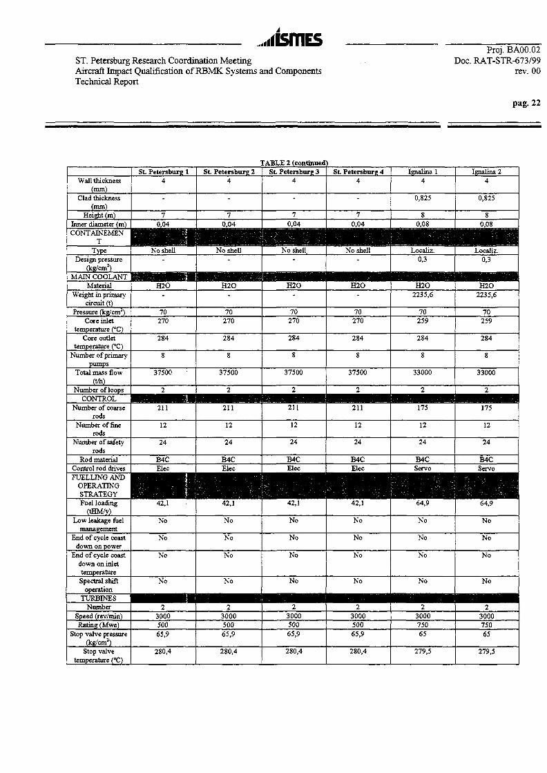
...iismEsST. Petersburg Research Coordination MeetingAircraft Impact Qualification of RBMK Systems and ComponentsTechnical Report
Proj. BA00.02Doc. RAT-STR-673/99
rev. 00
Wall thickness(mm)
Clad thickness(mm)
Height (m)Inner diameter (m)CONTAINEMEN
TType
Design pressure(kg/cm2)
MAIN COOLANTMaterial
Weight in primarycircuit (t)
Pressure (kg/cm2)Core inlet
temperature (°C)Core outlet
temperature (°C)Number of primary
pumpsTotal mass flow
(t/h)Number of loops
CONTROLNumber of coarse
rodsNumber of fine
rodsNumber of safety
rodsRod material
Control rod drivesFUELLING AND
OPERATINGSTRATEGYFuel loading
(tHM/y)Low leakage fuel
managementEnd of cycle coast
down on powerEnd of cycle coast
down on inlettemperatureSpectral shift
operationTURBINES
NumberSpeed (rev/min)Rating (Mwe)
Stop valve pressure(kg/cm2)
Stop valvetemperature (°C)
St Petersburg X4
-
70,04
No shell-
H2O
70270
284
8
37500
2
211
12
24
B4CElec
in42,1
No
No
No
No
2300050065,9
280,4
St Petersburg 24
-
70,04
No shell-
•HOnHHHH2O
_
70270
284
8
37500
2
211
12
24
B4CElecmm42,1
No
No
No
No
2300050065,9
280,4
:ABLE 2 (continuedSt Petersburg 3
4
-
70,04
MiNo shell
"
H2O
70270
284
8
37500
2
211
12
24
B4CElec
SB42,1
No
No
No
No
wmmmmm2300050065,9
280,4
<St Petersburg 4
4
-
70,04
No shell-
mmmmmmH2O-
70270
284
8
37500
2
211
12
24
B4CElec
BH42,1
No
No
No
No
2300050065,9
280,4
Ignalina 14
0,825
80,08
MMLocal iz.
0,3
H2O2235,6
70259
284
8
33000
2
175
12
24
B4CServomm64,9
No
No
No
No
• • • • • •2300075065
279,5
Ignalina 24
0,825
80,08
Localiz.0,3
H | j | | | | p H | H t t |H2O2235,6
70259
284
8
33000
2
• • • •175
12
24
B4CServo• •64,9
No
No
No
No
2300075065
279,5

ST. Petersburg Research Coordination MeetingAircraft Impact Qualification of RBMK Systems and ComponentsTechnical Report
Proj. BA00.02Doc. RAT-STR-673/99
rev. 00
pag. 23
3.1 Typical equipment
In the following table the equipment and components safety related inspected during a walkdown
visit at Ignalina NPP are listed (ref. [17]).
TABLE 3
code I Equipment and components localization Note1. Main circulation circuit (MCC)
1.11.21.31.41.51.61.71.81.91.101.11
Main circulation pumpsPressure pipesSuction pipes
Pressure headerSuction header
Group distribution headersWater pipes
Steam and water pipesSeparator drums
DowncomersPipes between separator drums
Main buildingMain buildingMain buildingMain buildingMain buildingMain buildingMain buildingMain buildingMain buildingMain buildingMain building
2. Reactor Control and Protection System (CPS)2.12.22.3
CPS instrumentation cubiclesCPS rods control cubicles
CPS power supply cubicles
Electrical buildingMain building
Main building/electrical building3. Emergency Core Cooling System (ECCS)
3.13.23.33.43.5
3.63.7
3.8
3.9
BallonsECCS pipes
ECCS headersECCS pumps
Pipes between ECCS pumps and ECCSheaders
Emergency feed pumpsPipes between emergency feed pumps
and separator drumsPipes between ECCS headers and
group distribution headersPipes between feedwater system and
ECCS headers
Main buildingMain buildingMain building
Turbine buildingTurbine building
Main building
Electrical building
4. Feedwater Supply System4.14.24.34.44.5
4.6
Feedwater pumpsFeedwater pump pressure pipesFeedwater pump suction pipes
Feedwater supply systemsPipes between Feedwater supply
systems and separator drumsDeaerators
Turbine buildingTurbine buildingTurbine building
Electrical buildingMain building
Electrical building

,,iismESST. Petersburg Research Coordination MeetingAircraft Impart Qualification of RBMK Systems and ComponentsTechnical Report
Proj. BA00.02Doc. RAT-STR-673/99
rev. 00
pag. 24
5. Steam Pipelines from Steam Separator Drums to the Main Steam Valves5.15.2
Steam pipes between separator drumsHigh pressure rings
Main buildingMain building
6. Steam Relieve Valves (SDV-A and Main Safety Valves)6.1 Main relief valves and relief valves to
accident confinement system (ACS)Main building
7. Accident Confinement System (ACS) Components which carry out active operations following anaccident
7.17.27.3
ACS heat exchanger pumpsACS heat exchangers
ACS heat exchanger pipes
.Main buildingMain buildingMain building
8. Emergency Power Supply System8.18.2
8.3
8.4
8.58.68.78.88.9
8.108.11
Diesel-generatorsCable overpass from diesel-generators
to unit 1 main buildingCable tunnels from diesel-generators to
unit 2 main building6 kV switchgears
Uniterrupted power supply setsAccumulator batteries
0,4 kV switchgearsDC switchgears
Cable rooms
Cable pitsCable tunnels
Electrical building/turbinebuilding
Electrical buildingElectrical building
Electrical building/main buildingElectrical building
Electrical building/mainbuilding/turbine building
Electrical building/main building
9. Service Water System (SWS)9.19.29.3
SWS pumpsSWS pipes
ACS heat exchanger SWS pipesElectrical building/main buildingElectrical building/main building
10. Intermediate circuit system (ICS)10.110.2
ICS pumpsICS pipes
Water facilityWater facility/main building ICS water supply
to ECCS pumps11. Control safety systems including Redundant Control Systems
11.1
11.211.3
Technological protectioninstrumentation cubicles
Main control room panels and consolesEmergency control room panels
Electrical building
Electrical buildingElectrical building
12. Spent fuel system12.112.212.312.4
Spent fuel pond hallSpent fuel ponds
Transmission channelsHot cell transmission channel
Main buildingMain buildingMain buildingMain building
13. Purification and cooling system (PCS)13.113.213.3
Regenerators, coolersPCS pipes
PCS pumps
Water facilityWater facility/ Main building
Water facility

...iismESST. Petersburg Research Coordination MeetingAircraft Impart Qualification of RBMK Systems and ComponentsTechnical Report
Proj. BA00.02Doc. RAT-STR-673/99
rev. 00
pag. 25
14. Automatic fire fi14.114.214.314.414.514.614.714.814.9
14.1014.1114.1214.1314.1414.15
Unit 1 water AFFS pumpsUnit 1 water AFFS reseiverUnit 1 foam AFFS pumps
Unit 1 foam AFFS reseiverUnit 1 foam solution storage tanks
Unit 1 foam stiring pumpUnit 1 compressorWater storage tank
Unit 1 water and foam AFFS headers
Unit 2 water and foam AFFS pumpsUnit 1 water and foam AFFS reseiver
Unit 2 foam solution storage tanksUnit 2 foam stiring pump
Unit 2 compressorUnit 2 water and foam AFFS headers
gating systems (AFFS)FF facilityFF facilityFF facilityFF facilityFF facilityFF facilityFF facility
Electrical buildingElectrical building/Turbine
building
Electrical building/Turbinebuilding
It can be supposed, lacking other specific information, that the above listed types of equipment are
present in St. Petersburg plants also, apart from the ACS equipment (which are present in Ignalina
but not in St. Petersburg, see Table 2, topic CONTAINMENT), i.e equipment 6.1, 7.1, 7.2, 7.3, 9.3, see
Table 3.
3.2 The "as-built" status of the equipment for the reference case
Following the WDV at INPP, some considerations related to the general plant conditions were
addressed. In fact the recommended seismic upgradings of the selected safety related equipment and
components (see [18]) could not be made without taking into account the as built conditions of the
whole plant. Moreover, the implementation of the following recommended upgradings (or, in any
case, the verification that they existed) could be considered beneficial against the aircraft impact
too. The following is based on the hypothesis that the as-built conditions in St. Petersburg plants are
similar to those found during the WDVs at INPP.
In some areas (mainly where the Emergency Power Supply System, the Emergency Core Cooling
System and the Accident Confinement System are located), actions were recommended to upgrade
the general structural status to balance the plant safety during its normal operation with that reached
when the proposed seismic upgrading actions will be implemented.

..itsmESProj. BA00.02
ST. Petersburg Research Coordination Meeting Doc. RAT-STR-673/99Aircraft Impact Qualification of RBMK Systems and Components rev. 00Technical Report
pag. 26
The following actions were suggested in order to get a higher structural performance in the
following inspected areas (see [17]): .
• welding at the junctions between beams of the same structure (steel frame, supports, anchorage
structures);
• integrity of supports/steel frames which appeared to be broken or decoupled from the civil
structure anchorage;
• the cable routing/cable penetrations/cable identification; assure as minimum the separation of
independent safety related trains;
• the anchorage of pumps, heat exchangers, headers, panel boards, piping;
• the anchorage between supports/steel frame and the civil structure (both concrete and steel
frame);
• repairing/maintenance where past operation had promoted damage/cracks and temporary (still
living) actions had been implemented;
• walkdown frames, in-service inspection frames for equipment also in congested plant layout
areas;
• inspection of piping/headers/exchangers/tanks actual thickness to evaluate erosion/corrosion
damages, which may promote unexpected weakness in the structure.
3.3 Some data about electrical cabinets
The following data about the dynamic characteristics of typical electrical cabinets have been
communicated by VNILAM (see ref. [21]):
• dynamic coefficient (i.e. the amplification of base motion): K = 2-H5;
• natural frequencies (of the cabinets and internal components): 2-^50 Hz.
The abovementioned data depend on the type of construction, structure and dimensions of the
cabinets themselves.

...iismESProj. BA00.02
ST. Petersburg Research Coordination Meeting Doc. RAT-STR-673/99Aircraft Impact Qualification of RBMK Systems and Components rev. 00Technical Report
pag. 27
Data about the dynamic behavior of the reactor and the main equipment (main circulation pumps,
main piping, separator drum) are available at the following Russian Federation Institutes (see [21]):
• N3KIET, Moscow: worker out of RBMK reactors;
• VNIPIET, St. Petersburg: Designer of RBMK-type NPPs of first generation;
• AEP, Moscow: Designer of RBMK-type NPPs of second generation.
4. AN OVERVIEW OF THE QUALIFICATION PROCEDURES AND RULES FOR
SAFETY RELATED ELECTRICAL COMPONENTS
4.1 Standards and codes for new NPPs
4.1.1 General Criteria for qualifying Class IE Equipment
The seismic qualification of electrical equipment for NPPs can be seen in the more general context
of the environmental qualification.
The primary role of a qualification process is to ensure that Class IE equipment can perform its
safety functions with no failure mechanism that could lead to common cause failures under
postulated service conditions. A potential for causing common cause failures of Class IE equipment
is the degradation with time (thermal, radiation and vibration aging), followed by exposure to the
environmental extremes cf temperature, pressure, humidity, radiation, vibration (seismic and non-
seismic) or chemical spray resulting from design basis events.
The reference standards, internationally recognized, for this section are assumed to be IEEE 323-
1983 and IEC 780-1984. ;

..•ASIDESProj. BA00.02
ST. Petersburg Research Coordination Meeting Doc. RAT-STR-673/99Aircraft Impact Qualification of RBMK Systems and Components rev. 00Technical Report
pag. 28
4.1.2 General Criteria for seismic qualification of Class IE Equipment
4.1.2.1 Introduction
The reference standards for this section are:
- IAEA Safety Guide 50-SG-D15 "Seismic Design and Qualification for NPPs"
- IEEE Standard 344-1987 "Recommended Practices for Seismic Qualification of Class IE
Equipment for NPGS"
- IEC Publication 980, 1989 "Recommended Practices for Seismic Qualification of Electrical
Equipment of the Safety System for Nuclear Power Generating Stations"
- USNRC Regulatory Guide 1.100: "Seismic Qualification of Electric and Mechanical equipment
for NPPs"
- IEC Publication 68-3-3 "Environmental Testing. Part 3: Guidance. Seismic Test Methods for
Equipment"
Although the DEC Publ. 68-3-3 is not particularly aimed to equipment in NPPs, its general
principles are reported, because it could be used for qualification of equipment of safety class lower
than IE. In the following, the main requirements of the cited standards are summarized.
4.1.2.2 IEEE Standard 344-1987
The IEEE Std. 344-1987 gives general criteria on which a NPGS safety related equipment
qualification program could be stated. The safety related equipment are required to be functional
during and after the time period in which they are subjected to the dynamic forces of a Safe
Shutdown Earthquake (SSE).
This can be performed by analysis, by test, by combination of test and analysis or through
experience data.
The qualification by analysis is recommended for simple equipment, for which it's possible to build
and tune a reliable mathematical model and it's sufficient, for seismic qualification, to demonstrate

P r o j E A 0 0 0 2
ST. Petersburg Research Coordination Meeting Doc. RAT-STR-673/99Aircraft Impact Qualification of RBMK Systems and Components rev. 00Technical Report
pag. 29
only the structural integrity. The general procedure suggested is articulated on the definition of the
equipment dynamics 6, on the computation of the response to the design loads (in general, RRS), on
the verification of the stress state and on the final verification of the relevant safety related
functions of the equipment.
The qualification by test (proof testing7 or fragility8 testing) is particularly applicable in the case of
complex equipment and systems for which it's necessary to verify, both during and after the
experimental activity, both the structural integrity and the functionality or, when required, the
operability. The Standard gives the requirements for the mechanical and electrical interfaces of the
equipment on the shaking table, the monitoring required during the tests in order to verify the right
functionality, the procedures to be followed in performing natural frequencies search tests and
qualification tests and the test acceptance general criteria.
Requirements about the frequency bandwidth, the number and duration of the seismic events
OBE/SSE, the tests method (single frequency, i.e. sine dwell, sine beat, damped sine, sine sweep or
multifrequency, i.e. time history, random, random with sine beat)and the type of excitation
(monoaxial, biaxial, triaxial) are given.
The qualification by combination of tests and analysis is suggested when the equipment is too large
and/or heavy for existing shaking table or when the equipment is too complex and it's not possible
to perform only the qualification by analysis.
The qualification by combination of tests and analysis is based on an experimental activity aimed to
determine the dynamic parameters of the equipment under test (natural frequencies, mode shapes,
modal dampings) and the non-linearities in the dynamic response of the equipment itself and to
verify the failure modes, if any, and the functional requirements; this is very important in order to
choose the right damping coefficients to use in the qualification by analysis.
6 modal shapes, natural frequencies and modal dampings
7 for a specific position in the plant
8 determination of its extreme functionality capabilities

...iismESProj. BA00.02
ST. Petersburg Research Coordination Meeting Doc. RAT-STR-673/99Aircraft Impact Qualification of RBMK Systems and Components rev. 00Technical Report
pag. 30
The qualification by use of extrapolations from experience data must be based on the concept of
dynamic similarity, i.e. on the similarity of excitation (i.e. spectral characteristics, duration,
directions of excitation axes, locations of measurement) and of the physical systems (physical
dimensions, weight and its distribution, centre of gravity, structural load transferring, base
anchorage strength, interfaces). Experience data may be derived from analysis or test data from
previous qualification programs, from documented data from equipment in facilities that have
experienced earthquakes or from data on operating dynamic loading or other dynamic
environments.
4.1.2.3 IAEA S0-SG-D15
Seismic qualification of items important to safety can be performed by the use of one or more of the
following methods: analysis, testing, earthquake experience, or comparison. It is possible to use
combinations of these methods or indirect means. Seismic qualification also generally includes
structural integrity qualification as well as operability or functional qualification. Seismic
quahfication are made directly on actual or prototype items, or indirectly on a reduced scale model,
a reduced scale prototype or a simplified item, or by means of similarity where this can be
established between a candidate and a reference item and direct quahfication has been performed on
the latter.
The quahfication by analysis is generally applied to items which are unique and are of such a size or
scale as to preclude quahfication by testing. A dynamic modal analysis, as well as a dynamic direct
time integration analysis of a lumped mass model (normally linear) or other models with many
degrees of freedom, may be used. An equivalent static analysis of items may be performed using the
peak of applicable acceleration response spectrum as input for cantilever and other items supported
at no more than two points along their long axis. For items supported at more than two points along
their long axis, a factor of 1,5 times the peak of the applicable acceleration response spectrum is
recommended.
Mechanical and electrical components are usually represented by a concentrated mass models,
either single mass or multimass system attached to the supporting building. For components not
modelled together with the supporting structure, the input for analysis is the floor response spectrum
or the floor response time history. The damping factors used in the analysis of the equipment should
be based on field testing and experience. The operability of the active components may be also

...lismESProj. BA00.02
ST. Petersburg Research Coordination Meeting Doc. RAT-STR-673/99Aircraft Impact Qualification of RBMK Systems and Components rev. 00Technical Report
pag. 31
analysed when their potential failure modes can be identified in terms of stress, deformation
(including clearances) or loads. Otherwise, the use of testing or earthquake experience is required
for the qualification of active components.
The qualification by test is needed to prove or to assist directly or indirectly in qualifying the item,
if the integrity or functional capability of the actual item cannot be demonstrated with a reasonable
degree of confidence by analysis,.
The types of seismic testing can be type approval test (fragility test), acceptance test (proof test),
low impedance test (dynamic characteristics test) and code verification test.
Apart from type approval (fragility) and acceptance (proof) tests (see the relevant footnotes), the
code verification test is used in order to verify structural computer codes, by using an adequate
number of test results; the low impedance tests are usually made on items in situ in order to define
dynamic, including support, characteristics which can be used in analysis or other tests to qualify
the item.
Other considerations about type of waveform of ther seismic input (multifrequency, single
frequency, multi-axis, single-axis, number of repetions of time histories, vibration investigation and
verification of functional requirements during and/or after the seismic event) are very similar to
those described in DEEE Std. 344-1987 and EEC 980-1989.
The qualification by earthquake experience requires that seismic excitation of the item at its point
of installation in the building structure effectively envelopes the reference or required seismic
design input motion. It also requires that the item being qualified and the one which underwent the
strong motion earthquake be the same model and type or have the same physical characteristics and
have similar support or anchorage characteristics. In the case of active items it is also necessary in
general to show that the item in the earthquake perfonned the same functions during or following
the earthquake, including the potential aftershock effects as would be required to the category 1
item.
The indirect method of seismic qualification employs the analysis, test or earthquake experience
methods applied to the direct qualification of the reference item. The indirect method involves
establishing the similarity of a candidate item to a reference item previously qualified and thereby
seismically qualifying the candidate item. The similarity involves the physical and support

- ...rismESProj. BA00.02
ST. Petersburg Research Coordination Meeting Doc. RAT-STR-673/99Aircraft Impact Qualification of RBMK Systems and Components rev. 00Technical Report
pag. 32
conditions, the functional characteristics for active items, the enveloping of the seismic input of the
candidate item by the seismic input of the reference item.
4.1.2.4 IEC 68-3-3
This standard is a general guidance to the performance of experimental seismic tests: that is, the
document deals solely with the seismic testing of a full size equipment which can be tested on a
vibration table. The seismic testing of an equipment is intended to demonstrate its ability to perform
its safety function during and/or after the time it is subjected to the stresses and displacements
resulting from an earthquake.
The test methods depend on the categorization of the equipment subjected to the seismic loads (see
para. 3.4.1.1), that is the Generic Seismic Class and the Specific Seismic Class.
The Generic Seismic Class does not include the safety related electrical equipment for NPGS but its
test methods can be for lower safety classes of equipment.
The test type can be selected from sine sweep, sine beat, time history, continuous sine. Single-axis
test is recommended for sine sweep and sine beat, whereas multi-axis is recommended for time
history. ;S
The test methods for the recommended test types depend on the conditions of use of the equipment:
the standard amplitude conventional test (conditions unknown) and the calculated amplitude test
(conditions sufficiently known).
In the standard amplitude conventional test, the test acceleration is determined from a performance
level (corresponding to tabulated values of floor accelerations: 6-̂ -15 m/s^ for horizontal direction
and 3V7.5 m/s^ for vertical direction), a wave factor (0,3-^0,8 for continuous sine and sine sweep
and 1 for sine beat, depending on the damping of the equipment) and a geometric factor (1 for
single-axis excitation with no interaction with the other axis and 1,5 for single-axis excitation with
interaction with the other axis).
In the calculated amplitude test, the test acceleration amplitude is determined from a ground
acceleration (2-̂ 5 m/s^, depending on the Richter or MSK scales intensity of the earthquake), a

...iisrriESProj. BA00.02
ST. Petersburg Research Coordination Meeting Doc. RAT-STR-673/99Aircraft Impact Qualification of RBMK Systems and Components rev. 00Technical Report
pag. 33
i
superelevation factor (1-5-3, depending on the installation and mounting stiffness), a direction factor
(1 for horizontal and 0,5-*-! for vertical), a wave factor and a geometric factor (see above).
The duration of a seismic test should be appropriate to that of the strong part of a time history of the
earthquake.
For sine beat tests, the duration depends upon the test frequency, number of beats and pauses. For
sine sweep tests, the duration depends upon the required frequency range, the sweep rate, the
number of sweep cycles and the number of test directions involved. For continuous sine tests, the
duration should be sufficient to reach at least five cycles at maximum acceleration amplitude.
For the Specific Seismic Class, it is necessary, to define a required response spectrum and, if
applicable, the duration of the earthquake, a required time history, the number of SI or S2
earthquakes whose effects are to be simulated, as well the load conditions (other than seismic) to be
taken into account.
The allowable test waves are the multifrequency waves (time histories natural, synthesized or
random, when the vibration spectrum is broad-band) and the single frequency waves (sine sweep9,
sine beat10, continuous sine11, when the vibration spectrum is narrow-band (the ground motion is
filtered by one of the structural modes). The multifrequency waves in multi-axis testing are
preferred.
In general, the test sequence can be the following one:
- vibration response investigation, with a single-axis sine sweep test at low level (1 or 2 m/s^) in
order to detect the dynamic characteristics of the equipment (natural frequencies and associated
dampings)
9 according to E C Publication 68-2-6.
10 according to E C Publication 68-2-59
11 according to E C Publication 68-2-6

ST. Petersburg Research Coordination Meeting Doc. RAT-STR-673/99Aircraft Impact Qualification of RBMK Systems and Components rev. 00Technical Report
pag. 34
- a number of multi-axis multifrequency SI earthquakes (i.e. five) synthesized from the
corresponding required response spectrum characterized by a damping ratio similar to that
measured in the response investigation
- one multi-axis multifrequency S2 earthquake synthesized from the corresponding required
response spectrum characterized by a damping ratio similar to that measured in the response
investigation.
4.1.2.5 USNRC R.G. 1.100
This R.G. describes a method acceptable to the NRC staff for complying with NRC's regulations
with respect to seismic qualification of electric and mechanical equipment. The seismic
qualification of Class IE equipment is covered by IEEE Std 344-1987, which reflects the state-of-
the-art technology; the NRC has extended on an interim basis the application of this Standard to the
qualification of mechanical equipment (such as valves, valve operators, pumps, compressors,
chillers, air handlers, fans, blowers, fuel rod assemblies, and control rod drive mechanisms), upon
the issuing of ASME Standard on seismic qualification of mechanical equipment. This R.G. covers
the safety-related electric (Class IE) equipment, the safety-related mechanical equipment and the
non-safety-related equipment whose failure can prevent the satisfactory accomplishment of safety
functions.
The procedures described by IEEE Std 344-1987 are acceptable to the NRC staff for satisfying the
Commission's regulations pertaining to seismic qualification of electric and mechanical equipment,
provided that, for mechanical equipment, thermal distorsion effects on operability should be
considered, and loads imposed by the attached piping should be accounted for. If dynamic testing of
a pump or a valve assembly is impracticable, static testing of the assembly is acceptable provided
that:
(1) the end loadings are applied and are equal to or greater than postulated event loads
(2) all dynamic amplification effects are accounted for
(3) the component is in the operating mode during and after the application of loads
(4) an adequate analysis is made to show the validity of the static application of loads.
..ril_MllE_ _ _ _ _ _ST. Petersburg Research Coordination Meeting Doc. RAT-STR-673/99Aircraft Impact Qualification of RBMK Systems and Components rev. 00Technical Report
pag. 35
4.1.2.6 IEC980-1989
The approach to the qualification of this International Standard is very similar to that of EEEE-
344/1987 (see para. 4.1.2.2). Also in this Standard, information and criteria on earthquake
environment and equipment response, seismic qualification requirements, seismic qualification
through analysis and testing are given.
The main concept is that the seismic qualification shall demonstrate the safety system equipment's
ability to perform its required function during and/or after the time it is subjected to the forces
resulting from one S2 earthquake; the equipment should also withstand the effects of a number of
SI earthquakes prior to the application of an S2 earthquake.
The process of seismic qualification requires the identification of the equipment to be qualified
(electrical and mechanical boundaries, the operating loading and aging conditions), the specification
of the seismic requirements (time duration, frequency range and acceleration values), the
specification of the acceptance criteria, the specification of the qualification methodologies ( test,
analysis, experience) and the specification on the documentation to be issued in order to
demonstrate the qualification of the equipment.
The qualification by analysis is foreseen to be performed through a static equivalent load or a
dynamic analysis.
In the static equivalent load method, for each main orthogonal axis, the fundamental frequency of
the equipment or of its sub-assembly is established by calculation, modal testing or analysis; the
applicable RRS is used to determine the maximum peak value (MPV) within the interval of
uncertainty of the fundamental frequency and this MPV is multiplied by 1,5 (or less, if justified) to
account for the effects of neglected modes. The equivalent accelerations are applied to the masses
of equipment to simulate the seismic loading and the same effects along each main orthogonal axis
are superimposed, according to the square root of the sum of the squares.
In the dynamic analysis method, the modal parameters are computed; a mathematical model of the
structure is established and the response of the structure under the seismic loading is computed,
through direct integration, modal superposition or response spectrum method.
Proj. BA00.02ST. Petersburg Research Coordination Meeting Doc. RAT-STR-673/99Aircraft Impart Qualification of RBMK Systems and Components rev. 00Technical Report
pag. 36
The seismic test is recommended for complex assemblies or for equipment in which possible
malfunctions are related to functional performance. Therefore the equipment should be tested under
simulated operating conditions. The seismic test shall be performed by subjecting the specimens to
a vibratory motion which conservatively simulates that the equipment has to withstand in its
mounting location during the seismic event. The seismic load is, in general, described by a RRS of
SI and S2 earthquakes, from which acceleration time histories are derived with suitable algorithms.
The input motions can be single-frequency or multi-frequency, single-axis or multi-axis, in
dependence upon the forecasted dynamic characteristics of the specimen or characteristics of the
allowable shaking tables.
4.1.2.7 Comments
The review of the general seismic qualification criteria on electrical equipment, related to the
Standards described in the previous paragraphs, leads to the following comments:
1) the seismic qualification can be performed by test, analysis, combination test/analysis,
earthquake experience but, due to the problem of verification of the operability of electrical
equipment during and after the seismic event, the qualification by test is preferred
2) for equipment used in NPPs, in which the data about the seismic environment should be more
precise than in other plants (availability of ground response spectra, structural models of buildings,
data on materials, etc.), the preferred testing methodology is based on multifrequency (time history),
multi-axis tests although other testing methodologies, if justified, can be allowed
3) in this case, the preferred sequence of tests forecasts:
- preliminary inspections in order to check the integrity of the equipment
- functional checks (prior to the test)
- vibration response investigations (exploratory test)
- seismic qualification test including functional checks, with the application of a number of Si
earthquakes in order to simulate also the seismic fatigue effects on materials, followed by the
application of one S2 earthquake

Prqj. BA00.02ST. Petersburg Research Coordination Meeting Doc. RAT-STR-673/99Aircraft Impact Qualification of RBMK Systems and Components rev. 00Technical Report
pag. 37
- functional check (after the test)
- final checks
4) all the standards examined forecast that the seismic qualification be performed on aged
equipment, in order to verify the safety function during the design basis event also at the end of the
qualified life.
4.1.3 Specific Qualification criteria
The criteria exposed in para. 4.1.2 are general criteria applicable to the seismic qualification of all
electrical equipment used in NPGS. Moreover, Standards issued mainly by IEEE and by USNRC
are aimed to cover particular aspects concerning the seismic qualification of certain electrical
equipment and mechanical components. For example, these standards deal with functional
requirements to fulfill during the seismic tests, choice among different qualification methodologies,
severity of the seismic loads, which are specific for certain electrical equipment and mechanical
components.
These specific standards are listed as follows, with the indication, if exists, of the relevant USNRC
endorsement:• IEEE 317-83 Electric penetration Assemblies in containment structures for NPGS• IEEE 334-74 Type tests of Continuous Duty Class IE motors for NPGS• IEEE 382-85 Qualification for Actuators for Power Oper. Valves Assemblies with Safety-
Related Functions for \NPP (USNRC Regulatory Guide 1.73 Rev. 1/1974: "Qualification testsof electric valve operators installed inside the containment ofNPPs")
• EEEE 420-82 Trial-use guide for Class IE control switchboards for NPGS• IEEE 535-86 Qualification of Class IE lead storage batteries for NPGS (USNRC Regulatory
Guide 1.158 Rev. 2/1989: Qualification of safety-related lead storage batteries for NPPs)• IEEE 572-85 Qualification of class IE connection assemblies for NPGS (USNRC Regulatory
Guide 1.156, Nov. 1987: "Environmental Qualification of Connection Assemblies for NuclearPower Plants'")
• IEEE 628-87 Criteria for the Design, installation, qualification of raceway systems for Class IEcircuits for NPGS
• IEEE 649-91 Qualifying Class IE Motor Control Centers for NPGS• IEEE 650-90 Qualification of Class IE static battery chargers and inverters for NPGS• IEEE C37.81-89 Guide for seismic qualification of Class IE Metal-enclosed power switchgear
assemblies• IEEE C37.98-78 IEEE 501-78 Seismic Testing of Relays (Updated issue 1987)

...itsmEsST. Petersburg-Research Coordination MeetingAircraft Impact Qualification of RBMK Systems and ComponentsTechnical Report
Proj. BA00.02Doc. RAT-STR-673/99
rev. 00
pag. 38
4.2 Standards and codes for already existing plants
The only documentation available on the seismic upgrading of electrical equipment (and
mechanical components) of older NPPs is the Generic Implementation Procedure (GIP) developed
by the SQUG (Seismic Qualification Utility Group).
The GIP summarizes the technical approach and provide generic procedures and documentation
requirements which can be used by owners/operators of operating NPPs to verify the seismic
adequacy of the mechanical and electrical equipment needed to bring the plants to a safe shutdown
condition following a SSE.
The GIP covers an ensemble of 22 classes of equipment which define the major types of mechanical
and electrical equipment within the scope of USI A.46, as listed in the table 3-1 of the paragraph
3.3.1 (equipment classes) of Part II (Generic procedure for plant - specific implementation) of the
GIP. Those ones are the specific classes of equipment for which earthquake experience data or
generic seismic testing data are available; hi fact, the GEP is based on a data base concerning a
number of equipment and components used in USA industrial plants that experienced earthquakes.
The electrical equipment and mechanical components covered by the GIP are the following ones:
#I
Ii
Iii
Iv
V
EQUIPMENT CLASSMOTOR CONTROL CENTERS (MCC)
LOW VOLTAGE SWITCHGEAR
MEDIUM VOLTAGE SWITCHGEAR
TRANSFORMERS
HORIZONTAL PUMPS
EQUIPMENT TYPES• motor control center• wall or rack-mounted motor controllers• low voltage draw-out switchgear (typically
600 V)• low voltage disconnect switches (typically
600 V)• unit substations• medium voltage draw-out switchgear
(typically 4160 V• medium voltage disconnect switches
(typically 4160 V)• unit substations• liquid-filled medium/low voltage
transformers (typically 4160/480 V• Dry-type medium/low voltage
transformers (typically 4160/480 V)• Distribution transformers (typically
480/120 V)• Motor-driven horizontal centrifugal pumps• Engine-driven horizontal centrifugal
pumps• Turbine-driven horizontal centrifugal
pumps• Motor-driven reciprocating pumps

..lisrriEsST. Petersburg Research Coordination MeetingAircraft Impact Qualification of RBMK Systems and ComponentsTechnical Report
Proj. BA00.02Doc. RAT-STR-673/99
rev. 00
pag. 39
Vi
Vii
Viii
Ix
X
Xi
Xii
XiiiXiv
Xv
Xvi
XviiXviii
Xix
Xx
XxiXxiiXxiii
VERTICAL PUMPS
FLUID-OPERATED VALVES
MOTOR-OPERATED AND SOLENOIDOPERATED VALVES
FANS
AIR HANDLERS
CHILLERS
AIR COMPRESSORS
MOTOR-GENERATORSDISTRIBUTION PANELS
BATTERIES ON RACKS
BATTERY CHARGERS AND INVERTERS
ENGINE-GENERATORSINSTRUMENTS ON RACKS
TEMPERATURE SENSORS
INSTRUMENTATION AND CONTROLPANELS AND CABINETS
TANKS AND HEAT EXCHANGERSCABLE AND CONDUIT RACEWAYS
OTHERS
• Vertical single-stage centrifugal pumps• Vertical multi-stage deep-well pumps• Diaphragm-operated pneumatic valves• Piston-operated pneumatic valves• Spring-operated pressure relief valves« Motor-operated Valves• motor-operators• Blowers• Axial fans• Centrifugal fans• Cooling coils• Water-cooled air handlers• Refrigerant-cooled air handlers (including
enclosed chiller)• Heaters
• Water chillers• Refrigerant chillers• Reciprocating-piston compressors• Centrifugal compressors• Motor-generators• Distribution panelboards (120-480 V, AC
&DC)• Distribution switchboards (120-480 V, AC
&DC)• Lead-cadmium flat plate batteries• Lead-calcium flat plate batteries• Plante' (Manchex) batteries• Battery racks (2 tiers or less)• Solid state battery chargers• Solid state static inverters• Piston engine-generators• Transmitters (pressure, temperature, level,
flow)• Wall-mounted sensors/transmitters• Rack-mounted sensors/transmitters• Supporting racks• Thermocouples• RTD• Wall-mounted and rack-mounted
instrumentation and control panels• Wall-mounted and rack-mounted
instrumentation and control cabinets• Dual switchboard instrumentation and
control cabinets• Duplex switchboard & benchboard (walk-
in) instrumentation and control boards---
The main steps used in the GIP for the majority of the equipment listed above are:- selection of Seismic Evaluation Personnel (SEP)- identification of Safe Shutdown Equipment- screening verification and walkdown- outlier identification and resolution

Proj. BA00.02ST. Petersburg Research Coordination Meeting Doc. RAT-STR-673/99Aircraft Impact Qualification of RBMK Systems and Components rev. 00Technical Report
pag. 40
Particular approaches were developed for the following items:- relay functionality review- tanks and heat exchangers review- cable and conduit raceways review
As a general comment, it has to be underlined that the requirements and procedures contained in the
GTP are guidelines and have not to be intended as fixed rules. Sound engineering judgement has to
be exercised, in particular during screening verification and walkdown.
5. A COMPARISON OF EUROPEAN PRACTICES FOR THE QUALIFICATION OF
SAFETY RELATED ELECTRICAL AND I&C EQUIPMENT
5.1 Seismic qualification
In the following table (table 6.1.4 of ref. [2]), the main data on the seismic qualification
methodologies for qualifying SRE and I&C equipment important to safety for NPPs, used in
Belgium, Finland, France, Germany, Spain, Sweden and United Kingdom are shown:

...iismEsST. Petersburg Research Coordination MeetingAircraft Impact Qualification of RBMK Systems and ComponentsTechnical Report
Proj. BA00.02Doc. RAT-STR-673/99
rev. 00
pag. 41
MAIN
DATA
Basic Stds. used
N. of axes
Frequency range
Modalities
Duration
Acceleration level
Damping selected for
electrical products
Equipment energized
Countries
Belgium
IEEE344,
time history
method
biax (or triax)
1*100 Hz
5 OBE (2) + 1
SSE(perbi'ax)
—20 s for each
OBE/SSE
1 envelope
spectrum for
all sites and
all areas or
less severe if
justified
4%
YES
Finland
(5)
(5)
(5)
(5)
(5)
(5)
(5)
(5)
France
IEC 980 time
history
method
-
biax
1+35 Hz (up
to 50 Hz)
5 OBE+1
SSE (per biax)
~20 s for each
OBE/SSE
8 envelope
spectra
depending on
the equipment
and on its
location (3)
2% or 5% in
most cases
YES
Germany
DIN, KTA
3505 and
2201.4 sine
sweep
mono (in most
cases)
5-35 Hz
continuous
sine 5-35 Hz;
1 cycle per
axis
10min/axis(l
oct/min)
generally 1,5
g and
sometimes 5 g
(forl&C
equipment)
2% or 5% in
most cases
YES
Spain
IEEE344
accelerogram,
sine sweep for
pipe mounted
biax
1-33 Hz
PWR;
1+100 Hz
BWR
5 OBE+1
SSE (per biax)
~20 s for each
OBE/SSE
envelope
spectra
applicable to
each
equipment
locations
generally 2%
for OBE and
5% for SSE
(7)
YES
Sweden
IEEE 344
time history
method
mono
2+33 Hz
1 SSE
30 s
1 envelope
spectrum
(ZPA = 0,15
g)
2% to 10%
YES
UK
IEEE 344
time history
method
triax preferred
(or biax)
1+50 Hz
5OSE(1)+1
SSE (per biax)
~12 s for each
OSE/SSE
spectra
applicable to
equipment
location (4)
generally 5%
YES
NOTES
(1) OSE level: 20% SSE level

alllSfTIESProj. BA00.02
ST. Petersburg Research Coordination Meeting Doc. RAT-STR-673/99Aircraft Impact Qualification of RBMK Systems and Components rev. 00Technical Report
pag. 42
(2) OBE level: 50% SSE level
(3) see appendix 1
(4) see appendices 2.1, 2.2, 3.1 and 3.2
(5) to be defined for the future NPPs
(6) in special cases, time history method
(7) 3 % for pressure transmitter:; in BWR
Two main methodologies are used in Europe:
- the multifrequency accelerogram method described in EEC 980 and IEEE 344;
- the sine sweep monoaxiel method (used only in Germany).
Generally, biaxial tests are performed or occasionally triaxial test is undertaken. In Germany,
monoaxial test is the norm for device qualification whilst in the UK the majority of testing is
triaxial.
Typically, the seismic methodology consists of applying 5 OBE (or OSE in UK) and 1 SSE tests,
where OBE = 50% SSE and OSE = 20% SSE. In Germany, load cycles of OBE are covered by the
test duration of SSE test.
The spectra used for seisrric qualification in each country depend upon many factors including:
- the nature of the ground on which the plant is located;- the peak ground acceleration for the SSE. This parameter is principally linked to the seismiccharacteristics of the site(s) concerned;- whether enveloping or location specific qualification is required;- the methods used to calculate seismic spectra and building response, etc.;- the phenomena considered, such as hydrodynamic loads from the pressure suppression pool ofBWR combined with seismic.
The methods, procedures and seismic test levels provided in the table indicate that the seismic
testing reflects the seismicity levels associated with each European plant and the different methods
of analysis used to calculate the seismic loadings applicable to the equipment.

ST. Petersburg Research Coordination MeetingAircraft Impact Qualification of RBMK. Systems and ComponentsTechnical Report
Proj. BA00.02Doc. RAT-STR-673/99
rev. 00
pag. 43
5.2 Impact qualification
For what concerns the qualification of equipment relevant to an aircraft impact, there is not any
specific qualification methodology adopted by European countries. In some cases, as in France and
Germany, the vibrations due to this phenomenon are dealt with in various ways as mechanical
ageing. The position of these countries is the following:
France: the aircraft crash' vibrations are included in a mechanical ageing which also takes into
account the effects of both the self-induced vibrations (i.e. on reciprocating machinery) and the
vibrations transmitted via hydrodynamic loads. The test is systematically performed on all
equipment important to safety whether located in a harsh or mild environment.
Germany: A test representing the aircraft crash and explosion waves is performed.
The main characteristics of the tests are described in the following table:
NOTE:
MAIN
DATA
Basic. Std. used
N. ofaxes
Frequency range
Modalities
Duration
Acceleration level
Countries
France
IEC68.2.6
mono
10-500 Hz (up to 2000 Hz, if required)
SCANNING:30 min to 2 hr for each axis
ENDURANCE: 30 min to 90 min for each
resonance frequency
see previous item
1 g, 2 g or 5 g
Germany
mono
5-100 Hz
sine sweep
1 cycle/axis (~lmin) (1)
5g
(1) performed together with seismic test
In Belgium, the aircraft crash vibrations are included in the seismic test conditions.

..liSTTIESProj. BA00.02
ST. Petersburg Research Coordination Meeting Doc. RAT-STR-673/99Aircraft Impact Qualification of RBMK Systems and Components rev. 00Technical Report ;
pag. 44
5.3 Impact qualification procedure for ALTOLAZIO NPP
As anticipated above, no specific qualification methodology for ACC vibrations exists in the
environmental qualification processes performed by the European Countries included in the ref.
doc. [2]. A specific qualification methodology was developed in Italy during the Eighties, in the
frame of qualification foreseen for SRE to be installed in the Altolazio NPP: nevertheless, this
methodology was not experimentally verified, due to the stop of nuclear activities after the
Chernobyl accident. In order to have a complete overview of the different possibilities for ACC
qualification, some main data relevant to the aforementioned methodology are listed hereinafter.
The basic reference document is [10].
In the case of Altolazio NPP, the basic design approach to meet SEC requirements (SEC= Special
Emergency Condition, an acronym to indicate the loading condition due to the ACC vibrations),
had been to add a dedicated SEHR (Special Emergency Heat Removal) system with adequate
supporting systems, with the objective of not modifying the existing design and not impairing the
safety performance against the existing design basis events. The Special Emergency Conditions
were those conditions postulated to exist following extreme external events of non-natural origin
and which could occur when the plant was in any design normal operating mode, including
refueling.
As a general principle, the SEHR equipment had to be Class IE equipment, for which the SEC
qualification had to be performed after the Class IE qualification. From each impact condition,
three response spectra along the three principal directions of the plant (RAF building) were
computed and two RRS, one for horizontal directions and one for vertical direction, were
developed. The SEC qualification was composed by three consecutive load application (two
horizontal and one vertical). The total duration and peaks distribution for SEC responses in the time
domain obviously depended upon both the location inside the building and the mounting conditions
of the equipment concerned. In particular floor and/or wall-mounted equipment, pipe-mounted
equipment and panel and/or rack-mounted equipment were foreseen.
The effective duration and the number of the equivalent peak acceleration cycles considered to be
appropriate for the time history definition were 200 ms/ 3 equivalent peak acceleration cycles for
floor and/or wall-mounted equipment and 500 ms/ 3 equivalent peak acceleration cycles for
pipe/panel/rack-mounted equipment.

ST. Petersburg Research Coordination Meeting Doc. RAT-STR-673/99Aircraft Impact Qualification of RBMK Systems and Components rev. 00Technical Report
pag. 45
Due to the possible limitations of shaking tables existing in the first half of Eighties, it was
considered that it could be difficult to reproduce the SEC event in terms of the duration foreseen
(20CH-500 ms); in general, much longer effective time duration of the input waveform was required
(e.g 5 s) and a corresponding significant number of peak acceleration cycles (e.g. 10 cycles). The
10% margin envelope, suggested for seismic and non-seismic vibrations spectra by some
international regulations, was not required. The computation of the TRS had to be performed with
1/3 octave or narrower bandwidth resolution in the frequency range defined by RRS (1-H00 Hz). It
was accepted that some points of TRS could be below the RRS by an amount of 10% provided that
these points were 2/3 octave apart and that their number was not greater than 5. The lack of the
envelope of the RRS could be justified taking into account the dynamic characteristics of the
equipment tested. For what concerns the operability requirements, they were synthesized as follows,
depending upon the type of equipment and its safety functions:
a) the capability of the equipment to perform its safety functions immediately after and not during
the transient response of the main structures;
b) the capability of the equipment to avoid an unexpected change of state with subsequent spurious
actuations.
It has to be noted that SEC spectra originated from two different dynamic loading conditions,
Faulted I and Faulted II, where Faulted I was the combination of SSE + SRVDA + LOCA* while
Faulted II was the envelope of the seismic portion of Faulted I + the high frequency excitation due
to an ACC. The RRS for impact qualification were built by processing the Faulted II spectra,
removing the low frequency contribution of seismic motion.
5.4 Previous examples of shock (impact) qualification on equipment
There is not any specific regulation in the nuclear field concerning the qualification of equipment
against base motions caused by the impact of an aircraft in a given location of the NPP, while a lot
A SRVD = Safety Relief Valve Discharge
# LOCA = Loss Of Coolant Accident

...iismES _ _ _ST. Petersburg Research Coordination Meeting Doc. RAT-STR-673/99Aircraft Impact Qualification of RBMK Systems and Components rev. 00Technical Report
pag. 46
of reference standards exists for what concerns the qualification (experimental/analytical/combined)
against seismic actions. Nevertheless, an extensive testing program (SAFEGUARD program) with
respect to the shock actions relevant to blast loading, to demonstrate the acceptable reliability of
power and process equipment installed in a hardened radar installation, was performed in the past
by the US Army Corps of Engineers (see ref. [9], whose detailed description of the main
conclusions is given in [3]). Some 400 component and system tests were conducted in support of
the qualification of some 30000 critical items in the SAFEGUARD installation. The equipment was
very similar to equipment installed in NPPs. The terminology "shock tests" was used in the
SAFEGUARD program to describe a complex time history input of 2 to 5 second duration. The
tests were not performed applying single shock pulse inputs, but the input consisted of several
superimposed sine beats that would result in the required response spectrum.
Two different shock spectra were used, one for hard mounted mechanical equipment and one for
shock mounted electrical equipment. These spectra are characterized by a constant spectral
acceleration respectively of 20 g in the frequency band 10+1000 Hz and of 4 g in the frequency
band 4+1000 Hz. These spectra show the high frequency, high spectral acceleration regions typical
of blast loading and contain very little response to frequencies below 5 Hz about.
The SAFEGUARD program results can be summarized as follows:
- mechanical and passive electrical equipment: the failures observed are consistent with those
highlighted in earthquakes; the weakest links are the anchorages and the electrical functions;
- electrical cabinets (MCC, switchgears, panels): the weakest points are essentially the anchorage,
the relay chatter and the breaker trip.
5.5 Aircraft Impact: the approach in the Russian Federation
The following has been drawn from ref. [19]:

ST. Petersburg Research Cooidination MeetingAircraft Impact Qualification rfRBMK Systems and ComponentsTechnical Report
Proj. BA00.02Doc. RAT-STR-673/99
rev. 00
pag. 47
"According to the Standard 1 2 aircraft impact shall be taken without fail into consideration for Nuclear
Heating Plants. For NPP of other types this event shall be taken into account in dependance on the aircraft
situation in the site neighbourhood or on Customer requirements.
Aircraft of 20000 kg mass and 200 m/s velocity is considered. Used force-time and impact area-time
diagrams are plotted in the Rgure (omissis). The most unfavourable impact angle in the range from 10° to
45° to horizontal plane shall be used.
At least one train of protection systems and one barrier of the accident localization system shall remain in
operation after aircraft impact. Non-linear behaviour of reinforced concrete is admitted; the width of the
cracks is not limited ( provided they can not lead to the release of the radioactive products); spading of
concrete inside of structure s not admitted; any requirement concerning the maintain of a tight of the inside
layer is not applied. Strength limits of concrete and reinforcement materials are taken according to the
Standard (see the relevant footnote), i.e. they are increased for explosions.
Dynamic analysis of structure shall be carried out to generate in-structure response spectra."
Ap
Apmax
t,s
12 PBJa RU AS-89: Nuclear Safety Rules for Reactors of Nuclear Plants, approved by the USSR State Atomic Energy
Supervision, 1990

ST. Petersburg Research Coordination Meeting Doc. RAT-STR-673/99Aircraft Impact Qualification of RBMK Systems and Components rev. 00Technical Report
pag. 48
6. BASIC PROBLEMS RELEVANT TO THE QUALIFICATION OF ELECTRICAL
AND I&C EQUIPMENT AGAINST SEISMIC AND ACC EXCITATIONS
6.1 Problems relevant to the shock qualification
Although the shock tests are generally performed on electrical equipment as part of a qualification
process, this mainly concerns equipment relevant to aerospace, defence, railways, etc., more than to
nuclear field. Moreover, the characteristics of those shock environments are quite different from the
shock environment subsequent to an aircraft crash on a large building, filtered by the building itself,
acting at the base of the equipment concerned. In fact, they are relevant to phenomena such as
bump, blast, handling, transportation by ship, aircraft, truck, etc.: the experimental simulation
involves the application at the base of the equipment of a number of pulses of very limited duration
(i.e. 10+-30 ms), very high peak acceleration (>50 m/s^) and well-defined shape (i.e. halfsine is the
most popular shape used). These characteristics are ruled by international standards (see for
example [12] and [13]). The characteristics of the vibration relevant to an ACC are quite different:
the order of magnitude of the duration is 4CH-100 ms (see ref. [23]) in the case of primary
excitation, and towards higher values considering also the free vibration of the structure at the
location concerned; the peak acceleration is lower; the time history of the pulse applied has a
complex shape and it is not possible to reduce it to a standardized shape.
Nevertheless, a common factor between these two different shock types exists: both involve a high
frequency content, generally speaking above the frequency range which is excited by seismic
phenomena. Then, it is possible to perform a first approximation qualitative analysis on the
functional behaviour of the electrical equipment, with respect to an ACC base excitation,
considering the behaviour with respect to a standardized pulse excitation, for what concerns the
occurrence of either mulfunctioning (checked at the end of the tests)* or structural failure.
# In general, International Standards on shocks foresee that the functional checks are performed at the end of the tests;
the monitoring during the tests is not foreseen.

ST. Petersburg Research Coordination Meeting Doc. RAT-STR-673/99Aircraft Impact Qualification of RBMK Systems and Components rev. 00Technical Report
pag. 49
ISMES has performed a lot of shock tests on various types of electrical equipment, according to the
most popular international standards, and a large data base on the behaviour of such equipment
exists. From this data base, it is possible to draw the following considerations:
- all the equipment tested in ISMES laboratories with respect to a standardized shock excitation
withstood the loads without structural failure, with the exception of few components;
- the same equipment did not experience any failure from the functional point of view, i.e. they
performed their functions after the application of the pulses.
For what concerns the simulation of the vibrations consequent to an ACC, an example of such a test
is illustrated in the ref. doc. [11]. The tested equipment was a Representative Sample Cabinet of the
Backup Protection System. The impact qualification was performed after the completion of seismic
qualification with respect to upset and faulted conditions, performed following international
standards. The excitation was applied along a single axis and successively performed in X, Y and Z
directions and was preceeded and followed by resonance frequency searches. The reference
spectrum was the same for all the excitation directions, with 5% damping. The spectrum was
obtained as an envelope of the impact spectra (X, Y and Z) calculated by ISMES by means of a FE
code, having as a reference the collocation of the cabinet into a specified building of the NPP (see
ref. doc. [8]). The corresponding time history to apply at the base of the equipment was synthesized
by using 6 components per octave, in the frequency range 2-̂ -100 Hz. The duration of the
synthesized motion was about 500 ms with a peak acceleration of 35 m/s^. No damage was found
by visual inspections at the end of impact tests. No significant variation of resonance frequencies
was found. The functional monitoring of the equipment was performed both during and after the
impact tests, directly by the Customer: no malfunction was detected. It has to be highlighted that
this is one (and maybe the unique) of few tests performed (at least at ISMES) of the simulation of a
dynamic excitation of such a type.
It can be useful to compare the characteristics of both an ACC time history and of a standardized
shock pulse. The comparison is made on both the undamped shock spectrum and the Fourier
transform of the signals. The following is shown only as an example, but it is possible to generalize
the conclusions thereof. .
The ACC time history taken as reference is the vertical component of the excitation in a certain
location on a reactor building for which the undamped shock spectrum and the Fourier transform

.rllSITlESProj. BA00.02
ST. Petersburg Research Coordination Meeting Doc. RAT-STR-673/99Aircraft Impact Qualification of RBMK Systems and Components rev. 00Technical Report
pag. 50
have been computed. The total duration of this time history is 0,561 s. A shock pulse has been
created, with a peak acceleration of 50 m/s^, a total duration of 0,561 s (for sake of comparison), a
halfsine shape and a pulse duration assuming the values of 11 ms, 22 ms, 33 ms and 50 ms. The
best envelope occurs at 22 ms in terms of both response acceleration and frequency content. The
term "envelope" is used in a very late sense: in fact, in this case, the spectrum of halfsine pulse is
much higher than the ACC spectrum, due to the halfsine peak acceleration of 50 m/s^ compared to
the ACC peak acceleration of 5,7 m/s^. The maximum halfsine spectral acceleration is 90 m/s^ at
35,9 Hz and the maximum ACC spectral acceleration is 62,5 m/s^ at 28,6 Hz: as it is known (see
[13]) the ratio between the maximum spectral acceleration and the peak acceleration of halfsine
pulse is 1,8: in order to have the same spectral acceleration in both cases (equal to ACC spectral
acceleration), the corresponding halfsine peak acceleration would be about 35 m/s^ (62,5/1,8).
Nevertheless, in the practice of shock tests through standardized waveforms (see table on ISMES
shock tests), the minimum peak acceleration is always greater than (or equal to) 90 m/s2. It can be
shown that the abovementioned enveloping is good for halfsine pulse with a maximum duration
(upper bound) of 33 ms.
Hence, generally speaking, it is possible to conclude that an electrical equipment "rugged" with
respect to a standardized shock pulse, has to be considered "rugged" also with respect to a shock
(i.e. an ACC shock) whose characteristics, at least in terms of response spectrum and Fourier
spectrum, are enveloped by those of the standardized shock pulse.
6.2 Excitation phenomena
The dynamic environment involved in the study is relevant to two main phenomena, aircraft impact
and seismic excitation; in the following, the excitation is seen as an in-structure spectrum (i.e. the
spectrum associated with the dynamic excitation at the base of the equipment, corresponding to the
primary excitation* conditioned by the structural transfer function between the excitation area and
* Primary excitation: in the following, the primary excitation is defined as the phenomenon that originates the vibratory
environment for the whole plant; in case of earthquake, the primary excitation is the Ground Response Spectrum (GRS)
at the NPP site. In case of ACC, the primary excitation is the shock spectrum or, alternatively, the time history of the
aircraft impact in a certain area of the plant.

ST. Petersburg Research Coordination Meeting Doc. RAT-STR-673/99Aircraft Impact Qualification Of RBMK Systems and Components rev. 00Technical Report
pag. 51
the position of the concerned equipment inside the plant) which is characterized by the following
main items:
- aircraft impact: generally, it is described as a shock spectrum rich in frequency content between
about 5 and 500 Hz, with a duration of about some seconds and ZPA quite high;
- seismic excitation: the frequency content is normally peaked in the 2+10 Hz, with the peaks being
fairly narrow; the duration is between 20-30 s.
It is quite evident that the simple envelope of a TRS associated with a given equipment already
seismically qualified, by the ACC FRS corresponding to the location where the same equipment
will be installed in a new plant, is not sufficient to assure that the equipment is also qualified (and
only from the structural point of view) to the ACC due to the differences in nature between the two
excitations. Moreover, from the functional point of view, an active (electrical) equipment qualified
against the seismic actions, could be not qualified against ACC actions, due to the different
frequency bands involved in these two phenomena that could adversely affect the functional
behaviour (i.e. for relay chatter).
It has to be taken into account the frequency ranges involved in the two phenomena, earthquake and
ACC: for earthquake, a frequency range 1+20 Hz can be estimated, whereas for ACC the frequency
range is 20+40 Hz. Following a practice consistent with the experience, the mechanical components
such as pumps, motors and valves can be seismically qualified through:
- a static analysis, if it can be demonstrated that their natural frequency is greater than 33 Hz: in this
case, the anchorages are verified;
- an equivalent static analysis (response spectrum method applied on a FEM model) if the previous
requirement is not met.
The same procedure can be used for the ACC qualification of these equipment, paying attention to
the fact that, considering the different frequency range involved, the lower bound value for a static
analysis should be at least 40+45 Hz.
For electrical cabinet, where the functional qualification is an essential part of the overall
qualification assessment, it is not possible to perform an analytical qualification w.r.t. the ACC; this
can be done in order to assess the structural strength of the cabinet, considering the inner
ST. Petersburg Research Cooidination Meeting Doc. RAT-STR-673/99Aircraft Impact Qualification of RBMK Systems and Components rev. 00Technical Report
pag. 52
components only as concentrated masses. Unfortunately, the components, besides their inertial
loading, perform also electrical functions and its impossible to take them into account via analytical
computations, also if the same equipment have been already functionally qualified w.r.t. the seismic
excitation: the reason is in the different frequency bandwidths involved in the ACC phenomenon
w.r.t. the earthquake; in this case, the behaviour of electrical components (i.e. relays) can be
different from that verified in seismic tests.
7. PROPOSAL FOR IMPACT/SEISMIC EXPERIMENTAL QUALIFICATION
PROCEDURE
7.1 General approach
A proposal for the ACC qualification of active electrical equipment already qualified w.r.t. the
seismic excitation has to d^al with two different aspects (see ref. [16]):
- the structural behaviour;
- the functional behaviour.
For sake of example, if the equipment concerned by the ACC qualification is a generic cabinet with
a frame-type structure containing active components (i.e. relays, circuit breakers, etc.), its failure
could concern:
- the loss of its structural integrity, i.e. the breaking of either its anchorages or its frame structure;
- the loss of its safety functions, i.e. the structural breaking or the malfunctions of the active
components inside the equipment.
The first problem can be approached with a procedure which takes into account the damage caused,
in terms of fatigue cycles, by the time history of the dynamic response of the equipment itself with
respect to the floor response to an ACC shock, in the most stressed locations of the structure of the
equipment.

...ItSTTlESProj. BA00.02
ST. Petersburg Research Cooi'dination Meeting Doc. RAT-STR-673/99Aircraft Impact Qualification of RBMK Systems and Components rev. 00Technical Report
pag. 53
The second problem can only be faced as an experience-based approach, using the results of
standardized shock tests on equal or similar equipment and assessing the similarity of the excitation
characteristics between ACC shock and a standardized shock pulse (i.e. halfsine).
A structural qualification approach can be used for the mechanical equipment whose main mode of
failure is limited to the supports, i.e. large vertical centrifugal pumps with motor drives, motor-drive
pumps and compressors, and cable trays.
For those mechanical equipment whose main mode of failure is the excessive motion between
internal parts, i.e. large motor-operated valves, horizontal motors, air handling units, an analytical
verification of the displacement with respect to the allowable ones, in an ACC environment, is
necessary.
A functional qualification approach can be used for the electrical equipment whose main mode of
failure is the electrical malfunctioning, i.e. switchgear, control and instrument panels and racks,
auxiliary relays cabinets, MCC, circuit breakers, relays.
The main components inside these equipment could be:a - relaysb - switchgearc - electronic cardsd- batteries
In the previous list, the items a and b require a separate approach w.r.t. the items c and d.
In fact, the main difference between these two different groups of items (a+b and c+d) lies in the
functioning principles which, for relays and switchgears is essentially linked to the displacement of
moving parts (anchor for relays and circuit breaker for the switchgear), whereas for electronic cards
and batteries, where there are not movable parts, the function can be seen as strictly related to the
structural strength of elementary components (diodes, resistors, capacitors, transistors, etc.): from
this point of view (and disregarding, at the moment, the influence that an aging not related to non-
mechanical phenomena such as radiation, temperature, humidity, can have on the function of
elementary components) the way to face the problem of functional qualification could be turned on
the structural qualification approach.

ST. Petersburg Research Coordination MeetingAircraft Impact Qualification of RBMK Systems and ComponentsTechnical Report
Proj. BA00.02Doc. RAT-STR-673/99
rev. 00
pag. 54
In order to avoid a complete qualification process (with respect to the ACC excitation) on a whole
cabinet, which is costly and time-consuming, the following approaches can be carried out (for the
terminology, see the sketch shown hereinafter):
component(relay)
equipment (cabinet)
anchorages
a) structural qualification
The combined experimental/analytical approach is based on the data acquired during the seismic
qualification of the same electrical equipment.
Assuming that:
- the weakest points of a cabinet are shown to be the anchorages;
- the data acquired during seismic qualification include transfer functions (in the frequency range up
to 40-r45 HZ) between the base acceleration and some positions inside the cabinet, where the
electrical components are located;
it is possible to compute the ACC response in the center of gravity of the equipment (cabinet) by
deconvolution of ACC base time history with a simple SDOF transmissibility function where the
dynamic parameters (fundamental frequency and associated damping factor) are derived from the
resonance search investigation performed in the frame of the seismic qualification process.
The dynamic loads at the anchorage level are then computed and the associated fatigue damage is
estimated: if the cumulative damage is lower than 1, the structural qualification of anchorages is

Proj. BA00.02ST. Petersburg Research Coordination Meeting Doc. RAT-STR-673/99Aircraft Impact Qualification of RBMK Systems and Components rev. 00Technical Report
; pag. 55
achieved (for conservative reasons, it is better to assume an upper bound of 0,5 for the cumulative
damage).
b) functional qualification
The approach can be twofold:
1) a combined experimental/analytical approach;
2) an experience-based approach.
The first approach is a classical procedure foreseen also in international standards (see, for example,
para. 4.1.2.2.4 for IEEE 344). The basic steps are similar to those already described for the
structural qualification, i.e. the computation of the ACC response at the component level, via a
deconvolution of ACC base time history with a simple SDOF transmissibility function or with the
experimental transmissibility function measured during the resonance search investigation
performed in the frame of the seismic qualification process. This time history can be experimentally
applied to the component via shaking table tests. This procedure could be applied when it is not
possible to perform a similarity analysis between the actual equipment (or component ) and a
component already qualified to a standardized shock pulse for another dynamic environment.
The second approach (experience-based) is based on the following assumptions:
- an equipment identical or similar has to be identified (this equipment is identified as the reference
equipment); the reference equipment has to be already qualified with respect a standardized shock
pulse (i.e. halfsine) in a different environment (military, aerospace, transportation, etc.). The
similarity analysis shall include, at least, the following aspects:
- functions of the equipment;
- dimensions and mass;
- main components of equipment;
- shape of the pulse;
- maximum acceleration and duration of the main pulse;
- results of the tests, from both structural and functional point of view;
- any other information relevant to the application concerned.

ST. Petersburg Research Coordination Meeting Doc. RAT-STR-673/99Aircraft Impact Qualification of RBMK Systems and Components rev. 00Technical Report
pag. 56
The similarity analysis requires a lot of information about equipment and, in practice, the only way
to collect them is to refer to the equipment manufacturers, considering that the general trend is to
supply, for NPPs, equipment manufactured for conventional plants or for different environment,
maybe with some modifications for the specific use.
- if through the similarity analysis it can be concluded that the actual equipment is similar to the
reference equipment already qualified with respect to the standardized shock pulse, an analysis on
the characteristics (in terms of shock spectrum, Fourier transform, number of cycles contained in
the signal) of the response of the equipment at the component level to both the standardized shock
pulse and the ACC excitation has to be performed, in order to assure the enveloping of this
excitation with respect to the ACC excitation. The response can be computed by the deconvolution
of the base time history (acc/pulse) with a simple SDOF transmissibility function or with the
experimental transmissibility function measured during the resonance search investigation
performed in the frame of the seismic qualification process.
If the previous steps have been successfully performed, the equipment has to be considered
functionally qualified with respect to the ACC excitation.
7.1.1 Structural qualification
The base of the method is that a particular equipment, already seismically qualified, has to be
qualified against dynamic load due to an aircraft impact in a certain area of the NPP. If the
structural failure mechanism has been recognized as the main failure mode of that equipment and
the relevant impact required response spectrum and associated time history are available,
numerically estimated, to apply to the base of the equipment in order to qualify it against ACC
loads, the following procedure can be proposed:
1 - the equipment can be represented as a single-degree-of-freedom (SDOF) system, taking into
account its first natural frequency (or pulsation) cow and the associated damping ratio C,: these two
parameters could be available from the initial exploratory tests performed before the seismic
qualification (i.e. sine sweep) or, in the case they are not available, through tabulated data (see for
example Fig. 3). The dynamic behaviour of the equipment is modelled through its transmissibility
function which gives the relationship, in the frequency domain, between the base acceleration and
the absolute response acceleration in its centre of gravity, according to the following formula:
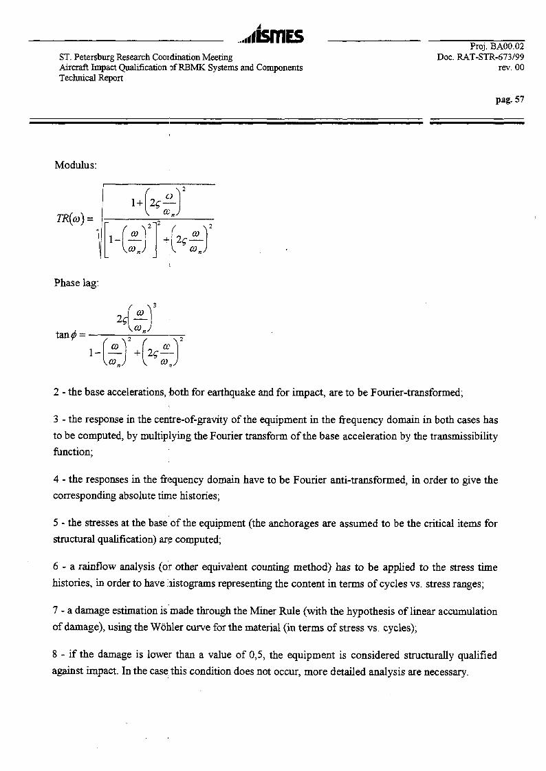
..illSTTlESST. Petersburg Research Cooidination MeetingAircraft Impact Qualification of RBMK Systems and ComponentsTechnical Report
Proj. BA00.02Doc. RAT-STR-673/99
rev. 00
pag. 57
Modulus:
TR(co) =
C)
-O 3 .
Phase lag:
HfJ'-(fr-te-r
2 - the base accelerations, both for earthquake and for impact, are to be Fourier-transformed;
3 - the response in the centre-of-gravity of the equipment in the frequency domain in both cases has
to be computed, by multiplying the Fourier transform of the base acceleration by the transmissibility
function;
4 - the responses in the frequency domain have to be Fourier anti-transformed, in order to give the
corresponding absolute time histories;
5 - the stresses at the base of the equipment (the anchorages are assumed to be the critical items for
structural qualification) are computed;
6 - a rainfiow analysis (or other equivalent counting method) has to be applied to the stress time
histories, in order to have Jiistograms representing the content in terms of cycles vs. stress ranges;
7 - a damage estimation is made through the Miner Rule (with the hypothesis of linear accumulation
of damage), using the Wohler curve for the material (in terms of stress vs. cycles);
8 - if the damage is lower than a value of 0,5, the equipment is considered structurally qualified
against impact. In the case this condition does not occur, more detailed analysis are necessary.

...iismESST. Petersburg Research Coordination Meeting Doc. RAT-STR-673/99Aircraft Impact Qualification of RBMK Systems and Components rev. 00Technical Report !
pag. 58
If the Wohler curve for the material is not available, or if the equipment is too complicated for the
simple calculation of anchorage stresses outlined above, it may be sufficient to repeat the steps l-=-4
and 6 for the earthquake time history to which the equipment has been qualified, in order to
compare the histograms cycles vs. ranges in the centre of gravity of equipment for both seismic
excitation and ACC excitation, taking into account that to the high stresses relevant to the ACC
phenomenon are associated very few cycles. This implies that the relevant damage may be
considered as negligible, as for what concerns the damage associated with the low stresses, where
the number of cycles cannot be neglected, the seismic excitation causes a damage greater than the
ACC excitation. If this occurs, the equipment already qualified with respect to seismic excitation
can be considered qualified also with respect the ACC excitation.
The procedure outlined for the structural qualification is described in the following flow diagram.
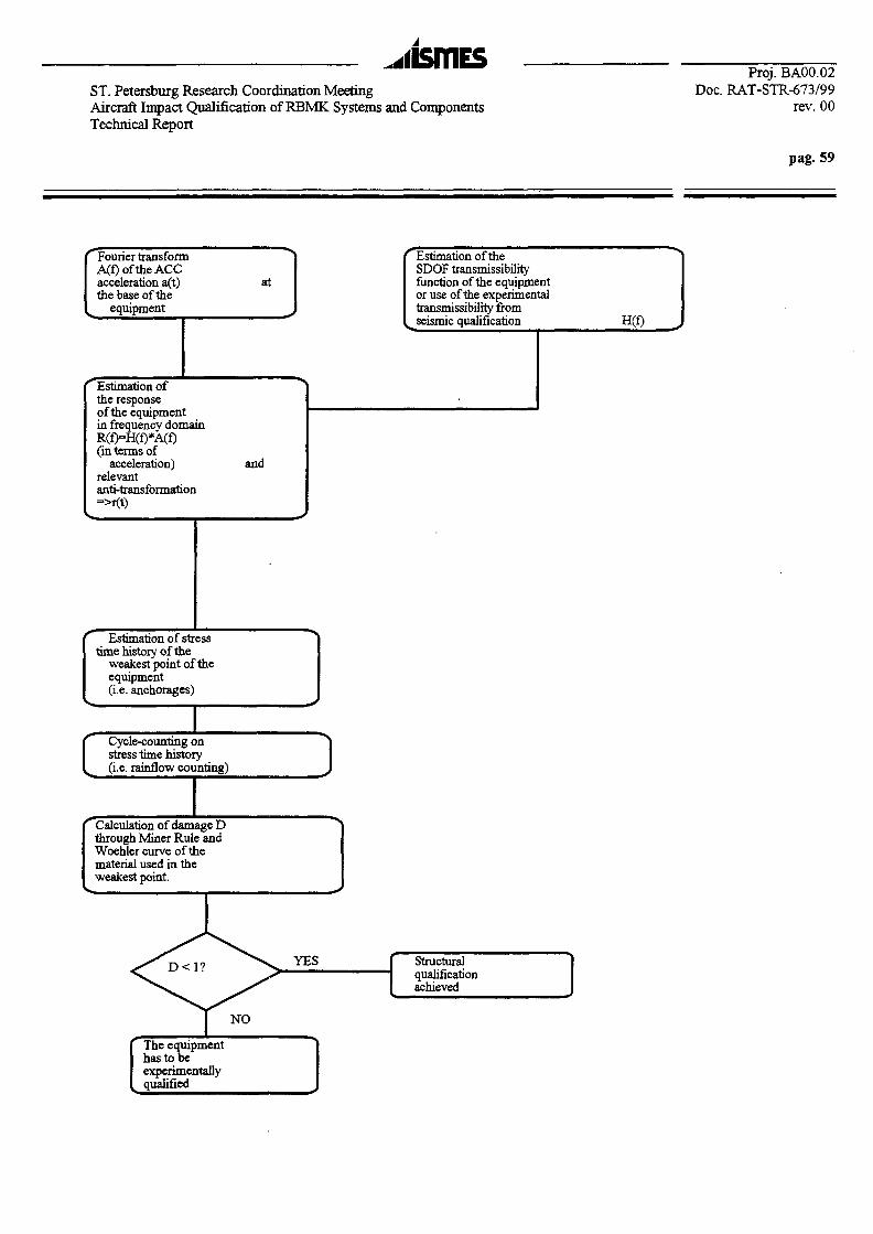
...iisrnEsST. Petersburg Research Coordination MeetingAircraft Impact Qualification of RBMK Systems and ComponentsTechnical Report
Proj. BA00.02Doc. RAT-STR-673/99
rev. 00
pag. 59
Fourier transformA(f)oftheACCacceleration a(t)the base of the
equipment
at
Estimation of theSDOF transmissibilityfunction of the equipmentor use of the experimentaltransmissibility fromseismic qualification H(f)
Estimation ofthe responseof the equipmentin frequency domainR(f)=H(f)*A(f)(in terms of
acceleration)relevantanti-transformation=>r(t)
and
Estimation of stresstime history of the
weakest point of theequipment(i.e. anchorages)
Cycle-counting onstress time history(i.e. rainflow counting) J
Calculation of damage Dthrough Miner Rule andWoehler curve of thematerial used in theweakest point.
YES Structuralqualificationachieved
NO
The equipmenthas to beexperimentallyqualified
...liSTHESProj. BA00.02
ST. Petersburg Research Coordination Meeting Doc. RAT-STR-673/99Aircraft Impact Qualification of RBMK Systems and Components rev. 00Technical Report
pag. 60
7.1.2 Functional qualification
A different and more complicated approach has to be followed when the failure mode of an
equipment has been recognized to be a functional failure mode, i.e. when the equipment is not
subjected to any structural failure but to malfunction i.e. to loss of its safety function : the most
common and evident failure mode of this type is associated to relays, where chatter can cause loss
of contact (for a NC relay) for durations affecting the safety functions of relevant trains (typically
for duration greater than 1-2 ms) or, in the worst cases, the opening of NC contacts. In this case, the
simple procedure outlined above (which is based on a cumulative structural damage assessment)
can not be used to assess the behaviour during the dynamic phenomenon, since for the item
concerned, the frequency content of the excitation is more important. The following flow diagram
illustrates the way of solution of this problem:

ST. Petersburg Research Coordination MeetingAircraft Impact Qualification of RBMK Systems and ComponentsTechnical Report
Proj. BA00.02Doc. RAT-STR-673/99
rev. 00
pag. 61
electrical equipmentseismicallyqualified
Is the qualificationrequired w.r.t.the shock (ACC)excitation ?
similarity analysisbetween the equipment:oncemed and the ;equipment in the database;
Database of elecricalequipment qualified w.r.t.std. Pulse excit
Electrical, physical,restraint data
Std. Pulse test data
perform the experimentalqualification w.r.t. the
shock excitation
comparison betweenthecharact. of std.pulse and the actualshock environment
Std. pulse charactenvelope actualshock environ.
perform the qualificationw.r.t. shock excitation
'END \ SHOCK QUALIFICATION
V^ / ACHIEVED

,.ibmEsProj. BA00.02
ST. Petersburg Research Coordination Meeting Doc. RAT-STR-673/99Aircraft Impact Qualification of RBMK Systems and Components rev. 00Technical Report
pag. 62
The critical point of the procedure outlined in the flow diagram shown above is essentially the
demonstration that an ACC excitation could be enveloped, in terms of amplitude, frequency content
and number of cycles, by a standardized shock pulse. This should be very important, as the
mulfunction of a component (i.e. a relay) can be related, besides the amplitude and frequency
content, to the number of stress reversals (or cycles).
It has to be taken into account that an active electrical component inside an equipment (typically, an
item part of a cabinet, such as a relay or a switchgear) will experience an excitation which will be
the excitation at the base of the equipment filtered by the transmissibility function of the equipment
structure, between the base and the location of the item. The item excitation (which can be also
represented, for practical qualification purposes, as a QDRS - Qualification Device Response
Spectrum) is ruled mainly by the dynamic characteristics of the equipment structure (i.e by its
transmissibility function which, if the equipment dynamic behavior is centered on its fundamental
frequency, can be represented as a SDOF system). By simplifying, the absolute response of the
equipment can be identified as the excitation of the component: both in case of ACC shock and of
standardized pulse shock, these signals are very similar, both in shape and in frequency content.
In the following flow diagram, a procedure to assess the similarity of a standardized pulse shock
(performed on equipment qualified for environments other than the nuclear one) and of an ACC
shock is outlined. '.

...nsmESST. Petersburg Research Coordination MeetingAircraft Impact Qualification of RBMK Systems and ComponentsTechnical Report
Proj. BA00.02Doc. RAT-STR-673/99
rev. 00
pag. 63
r\ std. shock pulse,(from qualificationother than nuclear)
ACC shock
transmissibilityfunction of a SDOFsystem (equipment)
absolute responseof the SDOF system
componentexcitation
for i=l,Nfreq
KHz)
BANDPASSfiltering
(fo is the centralfrequency)
absolute response of theSDOF system, relevantto the fo harmonic
Rainflow counting, inorder to obtain the Niof cycles at fieq. fi forthe relevant amplitudeAi
Ai,fi,Ni
Ai
The same procedureis applied
\zconstruction of cumulative:ycles diagrams(CCD):low many cycles with range
greater than or equal to agiven range are containedin the freq. band, excited ?
construction of cumulativecycles diagrams(CCD):low many cycles with rangegreater than or equal to agiven range are containedin the freq. band, excited ?
Does theCCD of std. pulse
envelop the CCD ofACC?
An experim. ACCqualification isrequired
Qualificationw.r.t. ACC isachieved

...iismEsProj. BA00.02
ST. Petersburg Research Coordination Meeting Doc. RAT-STR-673/99Aircraft Impact Qualification of RBMK Systems and Components rev. 00Technical Report
pag. 64
Starting from the hypothesis that an equipment can be represented as a SDOF system, is it possible
to consider functionally qualified w.r.t. an ACC shock an equipment similar to that which will be
installed in an NPP and already qualified w.r.t. a standardized shock pulse ? The question has to be
limited to those components inside the equipment whose behavior w.r.t. a dynamic excitation
cannot be represented through analytical models, i.e. relays and swithgear; according to the main
regulations in nuclear and non-nuclear fields for these components the main qualification method is
foreseen to be the test. Nevertheless, let's consider that somewhere a similar equipment containing
similar components has been qualified w.r.t. a std. shock excitation (for example, for military,
transportation, packaging, etc.). Which are the items that could allow the assumption that the
equipment already qualified w.r.t. to a std. shock pulse should be considered qualified w.r.t. to an
ACC shock also?
The following has to be demonstrated, for a component:
1 - the peak acceleration of the response of the SDOF system (with the fundamental
frequency of the equipment and the associated damping) to a std. shock pulse is greater
than the peak acceleration of the response of the same system to the ACC;
2 - the response spectrum of the std. shock response of the equipment envelops in the whole
range of interest the response spectrum of the ACC response;
3 - the Fourier spectrum of the std. shock response envelops in the whole range of interest the
Fourier spectrum of the ACC response;
4 - the number of the cycles associated with each frequency (or frequency band) contained in
the std. shock response has to be, at least, equal to the number of the cycles associated
with the corresponding frequency (or frequency band) contained in the ACC response.
Items 1 and 2 guarantees that, from the overall excitation point of view, the std. shock pulse is more
conservative than the ACC.
Item 3 guarantees that all the frequencies that could be excitated during an ACC are also contained
in the std. shock pulse: this means that the critical frequencies of components can be excited in both
the environments.
Item 4 guarantees that the number of the excitation repetitions that could bring to a malfunction of
an electrical component is, at least, the same in both cases; in particular, for relays and switchgears,
the chatter or the change of state can depend upon the different number of repetitions of a given
ST. Petersburg Research Coordination Meeting Doc. RAT-STR-673/99Aircraft Impact Qualification of RBMK Systems and Components rev. 00Technical Report
pag. 65
level of excitation at a certain frequency: this characteristics is widely known by the relays
manufacturers.
In fact, if we consider a SDOF system with given fundamental frequency and damping factor,
excited by a sinusoidal force at that frequency, the level of the response of the equipment (i.e. a
cabinet), which can be considered as coincident with the excitation of the component (i.e. a relay or
switchgear), will depend by the number of cycles contained in the excitation, beyond the dynamic
parameters of the system itself. As an example, the acceleration response of a SDOF with
fundamental frequency of 20 Hz and damping factor of 5%, excited by a sinusoidal force of 10000
N at 20 Hz, lasting 1 s, has been computed: in a first case, the excitation is composed by 3 full-
amplitude cycles, after which the excitation is zeroed. In the second case, the excitation is
composed by 20 full-amplitude cycles, which fully cover the total duration 1 s. It can be
demonstrated that in the first case, the response does not reach the stationary motion and by
consequence, the component is excited only by a fraction of the stationary value, i.e. about 60%.
The number of excitation cycles of the component could then be an important item in order to
decide the suitability of the whole comparison method of qualification. This is the reason why, in
the method presented hereinafter, also the number of cycles corresponding to given frequency
bandwidths has been investigated and it is considered as one of the parameters to control when a
comparison qualification (standardized shock pulse vs. ACC shock) is adopted.
In order to compare the effects of the standadized shock pulses and of ACC pulses, it is convenient
to convert the data tabulated in diagrams more understandable: one of the possible representation is
a cumulative cycle diagram, which is widely used, in aerospace field, to define the fatigue load
spectra of a component.
According to this representation, for each frequency band relevant to the excitation concerned, an
XY diagram where the abscissa is representing the excitation ranges (in this case, in terms of
acceleration) and the ordinate is the cumulative cycles, is built: the meaning is that, for a range
value Ri, there are Nj cycles with a range greater than or equal to Rj. The goal of this type of
processing is to show if the cumulative cycle diagram of the standardized pulse shock envelops the
corresponding diagram of the ACC shock.
The rationale is the following:

Proj. BA00.02ST. Petersburg Research Coordination Meeting Doc. RAT-STR-673/99Aircraft Impact Qualification of RBMK Systems and Components rev. 00Technical Report
pag. 66
1 - a component (i.e. a relay inside a cabinet, represented by a SDOF system) is sensitive, for what
concerns its functionality, to a given frequency (or frequency band) contained in its excitation
(which is the response of the SDOF), to which corresponds a particular level of load (in terms, for
example, of acceleration): this implies that a mulfunction can occur (i.e. relay chatter or opening if
the relays is normally closed) when the excitation, at that frequency, reaches a given level of
acceleration RMF for a given number of cycles;
2 - for the ACC excitation, at the frequency corresponding to a malfunctioning, there are NACC
cycles with ranges (or amplitudes) greater than or equal to RMF ;
3 - for a standardized shock pulse of the characteristics shown above, to which a similar component
has been subjected, without failures or malfunctioning, in a different qualification environment
(military, aerospace, transportation, etc.), in correspondence with the same frequency or frequency
band, there are NSTD cycles (with NSTD >_NACC) with ranges (or amplitudes) greater than or equal to
RMF ',
If the item 3 is verified, it can be concluded that a component or equipment previously qualified
w.r.t. a standardized shock pulse of given characteristics, can be considered qualified, from the
functional point of view, also w.r.t. an ACC environment.
The main conclusion which is possible to draw is that, if an equipment (containing critical items
such relays and switchgear) has been qualified with respect to a standardized shock pulse (i.e.
halfsine) with a pulse duration not greater than 22 ms and a peak acceleration not lower than 50
m/s2, the same equipment can be considered fully qualified, from the functional point of view, with
respect to an ACC shock pulse.
7.2 Proposal for ACC qualification of equipment already seismically qualified
7.2.1 Mechanical equipment
Equipment concerned: large vertical centrifugal pumps with motor drives, motor-drive pumps and
compressors, and cable trays.
Qualification methodology: structural qualification of anchorages.

Proj. BA00.02ST. Petersburg Research Coordination Meeting Doc. RAT-STR-673/99Aircraft Impact Qualification of RBMK Systems and Components rev. 00Technical Report
pag. 67
Qualification procedure: see para. 7.1.1.
7.2.2 Active electrical equipment
Equipment concerned: switchgear, control and instrument panels and racks, auxiliary relays
cabinets, MCC, circuit breakers, relays.
Qualification methodology: structural qualification of anchorages for overall equipment, functional
qualification for electrical components;
Qualification procedure: see para. 7.1.2.
8. INTERFACE DATA FOR IMPACT/SEISMIC EXPERIMENTAL QUALIFICATION
The expression interface data comprises, in the context of this report, all the inputs required for the
ACC qualification of SRE. From the items previously described, the data necessary for the
application of the identified qualification methodologies are:
- from seismic qualification previously performed on the same equipment:
- transmissibility function up to 45+50 Hz at the component level;
- fundamental frequency and associated damping factor of the equipment;
- floor response spectra and relevant time histories at the base of equipment;
- from ACC FEM analysis:
- floor response spertra and relevant time histories at the base of equipment.
9. CONCLUSIONS
In the present report, the problem of qualification procedures of electrical equipment with respect to
the dynamic excitation subsequent to an ACC on a NPP has been faced, taking into account the
lacking of standards ruling the problem. It has been assumed that the equipment have been already
qualified with respect to the seismic excitation and that they have to be assessed with respect to the
...iismEsProj. BA00.02
ST. Petersburg Research Coordination Meeting Doc. RAT-STR-673/99Aircraft Impact Qualification of RBMK Systems and Components rev. 00Technical Report
pag. 68
ACC excitation, avoiding., if possible, a complete cycle of qualification and taking into account the
data coming from the seismic qualification.
In order to do this, the safety related equipment more commonly installed in a NPP have been
grouped in few classes, according to widely accepted relevant failure modes: the aim is to define the
most suitable qualification procedures depending by the failure modes.
A survey of the qualification standards and practices for both seismic and, when exists, impact
environment has been performed, in order to assure which data, useful for an ACC qualification, are
available from the normally performed seismic qualification procedures.
Consequently, for each group of safety related equipment with identified structural/functional
failure modes, different qualification procedures with respect to the ACC phenomenon have been
established.
In order to apply the procedures described in the present report to equipment installed in a RBMK-
type reactor (such as St. Petersburg NPP), it is necessary to collect the relevant input data, such as:
1. List of equipment safety related for which the qualification is required (i.e. list of cabinets);
2. List of components housed into the abovementioned equipment (i.e. the essential relays);
3. Information on the actual as-built mounting conditions of the equipment;
4. Dynamic characteristics of the equipment (i.e. transfer functions or natural frequencies/mode
shapes/associated dampings) from the seismic tests;
5. Equipment experimental data relevant to the standardized pulse tests.
The topics 4 and 5 could' refer to equipment/components equal or similar to those for which the
ACC-qualification is required.
The data relevant to topics. 1 and 2 can be supplied by the utility (in this case St. Petersburg NPP).
The data relevant to topic 3 can be collected through a survey of the mounting conditions of the
cabinets, in order to guarantee that, from a structural point of view, there is not any problem
concerning their anchorage (this is essentially based on the statement that a properly anchored

,,iismEsProj. BA00.02
ST. Petersburg Research Coordination Meeting Doc. RAT-STR-673/99Aircraft Impact Qualification of RBMK Systems and Components rev. 00Technical Report
pag. 69
equipment has adequate capacity with respect to the seismic excitation, see para. 2.1); the survey
has to take into account ;the actual as-built mounting conditions and can be performed through
dedicated and detailed waAk-down visits into the St. Petersburg NPP. The walkdown visits have also
the aim to collect all the geometrical and mass data on the cabinets and the mounting data of the
components.
The data relevant to topics 4 and 5 can be supplied by the research organizations such as AEP
(Atomenergoproject) and VNIIAM.
..•lismESProj. BA00.02
ST. Petersburg Research Coordination Meeting Doc. RAT-STR-673/99Aircraft Impact Qualification of RBMK Systems and Components rev. 00Technical Report
pag. 70
10. REFERENCES
[I] Code not assigned
[2] Commission of the European Communities, Qualification Benchmark Group: A Comparison
of European Practices for the Qualification of Electrical and I&C Equipment Important to
Safety for LWR Nuclear Power Plant, Contract ETNU-CT92-0049, December 1992
[3] EPRI Electric Power Research Institute: A Methodology for Assessment of Nuclear Power
Plant Seismic Margin, EPRINP-6041, Project 2722-1, Final Report, October 1988
[4] Code not assigned
[5] EDF Electricite de France: Specification d'essai de tenue aux seismes des materiels
electriques classes de surete des centrales nucleaires. Essai bi-axial par accelerogrammes,
Specification technique EDF HN 20-E-53, 2eme edition, Octobre 1994
[6] SQUG Seismic Qualification Utility Group: Generic Implementation Procedure (GIP) for
Seismic Verification of Nuclear Plant Equipment, Rev. 2, February 1992
[7] Code not assigned
[8] ISMES RAT-DMM-666/95: Induced vibrations dur to aircraft impact on reactor and
auxiliary building. Structural response. Original AP600 design. Totally decoupled structure.
Locally decoupled structure. Numerical analysis and engineering evaluation., Prog. ASP-
8231.10, Rev.00, on behalf of ENEL/ATN Roma, May 1995
[9] US Army Corps of Engineering: Subsystem Hardness Assurance Report, Volumes I and II,
HNDDSP-72-156-ED-R, June 1975 (cited in [3])
[ 10] Ansaldo Impianti: Electrical and I&C Equipment Qualification Against SEC Excitation, Doc.
168TS0054, Rev.0, July 1984
[II] ISMES RAT-STR-436/96: Seismic and impact qualification tests of a backup protection
system for New Generation Nuclear Reactors. Test Report, Proj. STR-8679, on behalf of
CISE, Segrate, Italy; Jan. 1996
[12] Department of Defense (USA): Environmental test methods and engineering guidelines, Mil
Std 810E, method 516.4: Shock, July 1989
[13] EEC 68-2-27 Basic Environmental testing procedures. Part 2: Tests - Test Ea and guidance:
Shock. 3rd edition, 1987
[14] NUREG/CR-3558, UCRL-53455 Handbook of nuclear power plant seismic fragilities.
Seismic safety margins research program, Lawrence Livermore National Laboratory, June
1985
[15] Code not assigned

Proj. BA00.02ST. Petersburg Research Coordination Meeting Doc. RAT-STR-673/99Aircraft Impact Qualification of RBMK Systems and Components rev. 00Technical Report
pag. 71
[16] ISMES doc. RAT-STR-2695/96: ETUDES DE MECANIQUE DES STRUCTURES
RELATIVES A LA CHUTE D 'AVIONETA LA REPONSE SISMIQUE. Task 3: Qualification
procedures for equipment, rev. 00, Proj. STR-9197, 15.04.1997, on behalf of EDF/SEPTEN,
Villeurbanne (F) and ENEL/ATN, Rome (I)
[17] ISMES doc. RAT-DIS-276/95: INPP/B-2.2 IGNALJNA NUCLEAR POWER PLANT.
ENGINEERING STUDY. Seismic upgrading of safety related equipment. Walkdown visit on
IgnalinaNPP Units 1 and2. Finalreport, rev. 00, Proj. ASP-7378, 24.03.1995, on behalf of
EBRD
[18] ISMES doc. RAT-DIS-420/95: INPP/B-2.2 IGNAUNA NUCLEAR POWER PLANT.
ENGINEERING STUDY. Seismic upgrading of safety related equipment. Technical
Specifications, rev. 01, Proj. ASP-7378, 23.06.1995, on behalf of EBRD
[19] A.N. Birbraer, Russian Standards and Design Practice of Ensuring NPP Reliability under
Severe External Loading Conditions, in the framework of Upgrading of Existing NPPs with
440 and 1000 MW WER type Pressurized Water Reactors for Severe External Loading
Conditions, organized by IAEA, Vienna, August, 23rd-251h, 1993
[20] K. Almenas, A. Kaliatka, E. Uspuras: Ignalina RBMK-1500. A source book, Ignalina Safety
Analysis Group, Lithuanian Energy Institute, Litterae Universitatis Vytauti Magni, Kaunas,
1994
[21] VNIIAM (Moscow): e-mail message to ISMES, March, 19th, 1999
[22] Research Coordination Meeting. Safety of RBMK type NPPs in Relation to External Events.
Working Material. Notes, Organized by the International Atomic Energy Agency and held in
Moscow, Russian Federation, 27-30 April, 1998, Vienna, 1998
[23] A.N. Birbraer, A.J: Roleder, G.S. Shulman: Probabilistic Approach to Requalification of
Existing NPPs under Aircraft Crash Loading, in the framework of Upgrading of Existing
NPPs with 440 and 1000 MW WER type Pressurized Water Reactors for Severe External
Loading Conditions, organized by IAEA, Vienna, August, 23rd-25th, 1993
Gruppo Enel
INTERNATIONAL ATOMIC ENERGY AGENCYCOORDINATED RESEARCH PROGRAMME ON
SAFETY OF RBMK-TYPE NUCLEAR POWER PLANTSIN RELATION TO EXTERNAL EVENTS
ST. PETERSBURG RESEARCH COORDINATION MEETING5 to 9 July 1999
AIRCRAFT IMPACT QUALIFICATIONOF RBMK SYSTEMS AND COMPONENTS

^j^lsmesGruppo Enel
INTRODUCTION (I)(MAIN STEPS FOR THE ACC QUALIFICATION)
The study has to tackle four different topics:1. the identification of main classes of safety related
equipment with their associated failure modes2. a review on the current practice on the seismic
qualification methodologies and on the impact qualificationmethodologies
3. the identification of an approach for impact qualificationof equipment already qualified w.r.t. seismic actions
4. verification of the feasibility of the application of theimpact qualification approach on the typical equipmenthoused hi a RBMK-type NPP.
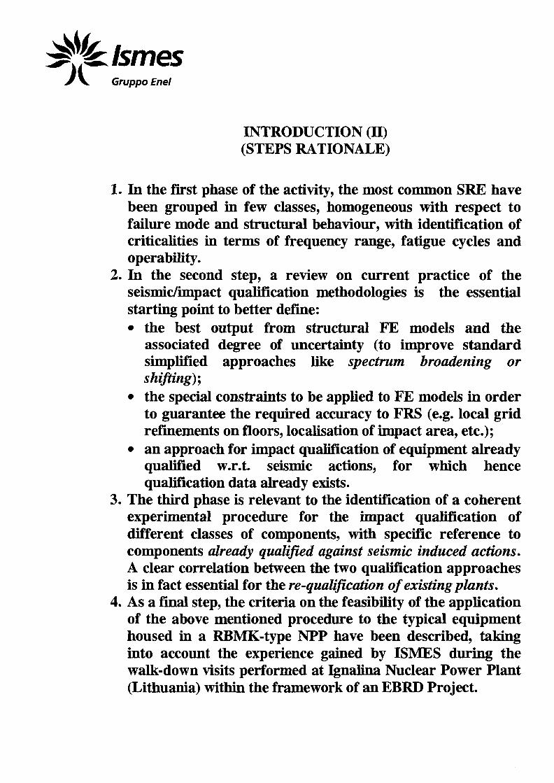
Gruppo Enef
INTRODUCTION (II)(STEPS RATIONALE)
1. In the first phase of the activity, the most common SRE havebeen grouped in few classes, homogeneous with respect tofailure mode and structural behaviour, with identification ofcriticalities in terms of frequency range, fatigue cycles andoperability.
2. In the second step, a review on current practice of theseismic/impact qualification methodologies is the essentialstarting point to better define:• the best output from structural FE models and the
associated degree of uncertainty (to improve standardsimplified approaches like spectrum broadening orshifting);
• the special constraints to be applied to FE models in orderto guarantee the required accuracy to FRS (e.g. local gridrefinements on floors, localisation of impact area, etc.);
• an approach for impact qualification of equipment alreadyqualified w.r.t. seismic actions, for which hencequalification data already exists.
3. The third phase is relevant to the identification of a coherentexperimental procedure for the impact qualification ofdifferent classes of components, with specific reference tocomponents already qualified against seismic induced actions.A clear correlation between the two qualification approachesis in fact essential for the re-qualification of existing plants.
4. As a final step, the criteria on the feasibility of the applicationof the above mentioned procedure to the typical equipmenthoused hi a RBMK-type NPP have been described, takinginto account the experience gained by ISMES during thewalk-down visits performed at Ignalina Nuclear Power Plant(Lithuania) within the framework of an EBRD Project.

Gruppo Enel
1.INTRODUCTION (III)
(NUCLEAR MECHANICAL COMPONENTS)
Mam piping, main coolant pumps, separator drum (which is aunique feature of the RBMK-type NPPs) and the reactor (i.e.graphite blocks, control rods mechanisms, fuels channels,pressure tubes, etc.) have not been taken into account for thefollowing reasons:• these types of equipment have been specifically designed for
nuclear applications, thus a similarity analysis with referenceto non-nuclear application is not feasible;
• the recommended approach for these types of components,due to their essential importance, is a direct qualificationw.r.t. the ACC (being the tests feasible only on portions ofthem, due to their large size), involving a detailed analysis ofthe dynamic response of the buildings where they arelocated, including local effects, non-linear phenomena, etc.,computing in this way the response spectra at their base andestimating, in a classical stress analysis approach, then*strength w.r.t. the forces relevant to the ACC event;
• the indirect approach presented hereinafter for the electricalequipment is not considered applicable.

Gruppo Enel
1.GROUPING OF SAFETY RELATED EQUIPMENT AND
RELEVANT FAILURE MODES(CRITERIA)
In order to approach the problem of ACC qualification of safetyrelated equipment of a NPP some base hypotheses have to beestablished:- the concerned equipment have been already seismicallyqualified, from both structural and functional point of view, i.e.with respect to the seismic excitation, they have demonstrated toperform then- safety functions during and after the seismicevent;- it is possible to discriminate between the structuralqualification (assessment of the structural integrity) and thefunctional qualification (assessment of then* functionality duringand after the event);- the weakest point, from the structural point of view, of theequipment concerned is located at the anchorage level.

Gruppo Enel
1.GROUPING OF SAFETY RELATED EQUIPMENT AND
RELEVANT FAILURE MODES(LIST)
Safety related equipment have been categorised as follows:- motor control centres;- low voltage switch-gears;- medium voltage switch-gears;- transformers;- horizontal pumps;- vertical pumps;- fluid operated valves;- motor-operated and solenoid-operated valves;•fans;- air handlers;- chillers;- air compressors;- motor-generators;- distribution panels;- batteries on racks;- battery chargers and inverters;- engine-generators;- instruments on racks;- temperature sensors;- instrumentation and control panels and cabinets.

Gruppo Enel
1.FAILURE MODES OF VARIOUS TYPES OF EQUIPMENT
(CRITERIA)
In principle, two main failure modes can be identified:- a structural failure mode;- a functional failure mode.
These two different failure modes can occur:- simultaneously;- once at a time (either structural or functional);- sequentially (in the sense that a structural failure mode
could imply a functional failure mode).
A structural failure mode can occur caused by two differentmechanisms:
- an equivalent "static" failure mechanism;- a fatigue failure mechanism.

Gruppo Enel
1.FAILURE MODES OF VARIOUS TYPES OF EQUIPMENT
(LIST OF SENSITIVE COMPONENTS ANDRELEVANT SEISMIC FAILURE MODES)
Reactor core assemblyEquipment included in the category: fuel rods, core support
structure, control rod assemblies, spacers grids*;Main failure modes: crushing of grid spacers; deformation
of control rod assemblies;Reactor coolant system vessels
Equipment included in the category: pressure vessel^,steam generators, pressurizer-*
Main failure modes: nozzle-to-pipe weld joints failure;failure of the supports
PipingEquipment included in the category: piping of all sizes,
elbows, tees, butt welds, reducer sections, etc.Main failure modes: ductile failure
Large vertical storage vessels with formed headsEquipment included in the category: accumulator tanks,
volume control tanksMain failure modes: support failure
1 Not present in RBMK-type NPP
2 Not present in RBMK-type NPP
3 Not present in RBMK-type NPP
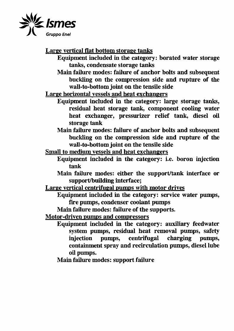
Gruppo Enel
Large vertical flat bottom storage tanksEquipment included hi the category: borated water storage
tanks, condensate storage tanksMam failure modes: failure of anchor bolts and subsequent
buckling on the compression side and rupture of thewall-to-bottom joint on the tensile side
Large horizontal vessels and heat exchangersEquipment included in the category: large storage tanks,
residual heat storage tank, component cooling waterheat exchanger, pressurizer relief tank, diesel oilstorage tank
Mam failure modes: failure of anchor bolts and subsequentbuckling on the compression side and rupture of thewall-to-bottom joint on the tensile side
Small to medium vessels and heat exchangersEquipment included hi the category: i.e. boron injection
tankMam failure modes: either the support/tank interface or
support/building interface;Large vertical centrifugal pumps with motor drives
Equipment included hi the category: service water pumps,fire pumps, condenser coolant pumps
Main failure modes: failure of the supports.Motor-driven pumps and compressors
Equipment included in the category: auxiliary feedwatersystem pumps, residual heat removal pumps, safetyinjection pumps, centrifugal charging pumps,containment spray and recirculation pumps, diesel lubeoil pumps.
Main failure modes: support failure
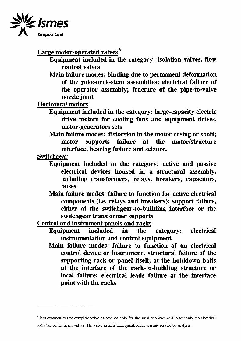
Gruppo Enel
Large motor-operated valvesA
Equipment included in the category: isolation valves, flowcontrol valves
Mam failure modes: binding due to permanent deformationof the yoke-neck-stem assemblies; electrical failure ofthe operator assembly; fracture of the pipe-to-valvenozzle joint
Horizontal motorsEquipment included in the category: large-capacity electric
drive motors for cooling fans and equipment drives,motor-generators sets
Mam failure modes: distorsion hi the motor casing or shaft;motor supports failure at the motor/structureinterface; bearing failure and seizure.
SwitchgearEquipment included in the category: active and passive
electrical devices housed hi a structural assembly,including transformers, relays, breakers, capacitors,buses
Main failure modes: failure to function for active electricalcomponents (i.e. relays and breakers); support failure,either at the switchgear-to-building interface or theswitchgear transformer supports
Control and instrument panels and racksEquipment included hi the category: electrical
instrumentation and control equipmentMain failure modes: failure to function of an electrical
control device or instrument; structural failure of thesupporting rack or panel itself, at the holddown boltsat the interface of the rack-to-building structure orlocal failure; electrical leads failure at the interfacepoint with the racks
A It is common to test complete valve assemblies only for the smaller valves and to test only the electrical
operators on the larger valves. The valve itself is then qualified for seismic service by analysis.

IfjklsmesGruppo Enel
Auxiliary relays cabinetsEquipment included in the category: cabinets housing
electrical relays and switchgears, includingtransformers
Main failure modes: functional failure modes; failure of thecabinets or supports
Local instrumentsEquipment included in the category: process
instrumentation (temperature, pressure) from sensorto gage or dial indicator through wiring
Main failure modes: loosening of fasteners, failure of thepickup leads
Motor control centers (MCC)Equipment included in the category: MCC for all the
emergency safety systems pumps and valvesMain failure modes: functional failure modes; failure of the
cabinets or supportsLight fixtures
Equipment included in the category: emergency lightingMain failure modes: structural or component breakage
Communication equipmentEquipment included in the category: annunciatorsMain failure modes: dislodging of components
Cable travsEquipment included in the category: supporting electrical
power and I&C wiringMain failure modes: structural failure of a tray support at a
threaded connection; cable damage at terminationpoints due to excessive relative displacement of thetrays w.r.t. electrical equipment or junction boxes
Circuit breakersEquipment included hi the category: circuit breakers of
different sizes and capacities*Main failure modes: inadvertent opening
' All sizes and types of breakers are included in this category.

Gruppo Enel
RelaysEquipment included in the category: relays in electrical
control cabinets*Main failure modes: relay chatter
Ceramic insulatorsEquipment included in the category: used in the connection
between off-site power and switchyardMam failure modes: structural failure
Air handling unitsEquipment included in the category: containment cooler
system fansMain failure modes: rubbing of the fan blades on the fan
housing or rubbing of the motor rotor on the motorhousing
Hydraulic snubbers and pipe supportsEquipment included in the category: rigid-rod-type
supports (carrying dead weight + vertical seismicloads), lateral supports (only seismic loads)
Main failure modes: welded connections
' All sizes and types of relays are included in this category

Gruppo Enel
1.FAILURE MODES OF VARIOUS TYPES OF EQUIPMENT
(FAILURE MODES TYPES)
Inherently rugged equipment (not sensitive to seismic loads):- large relief and check valves- large hydraulic- and air-actuated valves;- small motor-operated valves;- miscellaneous small valves;- generators;- batteries and battery racks;- dry transformers;- inverters;- ductwork;
Equipment whose main mode of failure is the support failure:- large vertical centrifugal pumps with motor drives;- motor-drive pumps and compressors;- cable trays;
Equipment whose main mode of failure is the electricalmalfunctioning:
- switch-gear;- control and instrument panels and racks;- auxiliary relays cabinets;-MCC;- circuit breakers;- relays;
Equipment whose mam mode of failure is the excessive motionbetween internal parts:
- large motor-operated valves;- horizontal motors;- air handling units.

Gruppo Enel
1.EQUIPMENT CLASSIFICATION WITH RESPECT TO THE
ACC VIBRATIONS
Mechanical Equipment whose main mode of failure is thesupport failure:
- large vertical centrifugal pumps with motor drives;- motor-drive pumps and compressors;- cable trays;
Electrical Equipment whose main mode of failure is theelectrical malfunctinninfl:
- switch-gear;- control and instrument panels and racks;- auxiliary relays cabinets;-MCC;- circuit breakers;- relays;
Mechanical Equipment whose main mode of failure is theexcessive motion among internal parts:
- large motor-operated valves;- horizontal motors;- air handling units;

WGruppo Enel
2.GENERAL CRITERIA FOR QUALIFYING CLASS IE
EQUIPMENT
The reference standards, internationally recognized, for thissection are assumed to be IEEE 323-1983 and EEC 780-1984.

tonesGruppo Enel
2.GENERAL CRITERIA FOR SEISMIC QUALIFICATION OF
CLASS IE EQUIPMENT
- IAEA Safety Guide 50-SG-D15 "Seismic Design andQualification for NPPs"- EEC Publication 980, 1989 "Recommended Practices forSeismic Qualification of Electrical Equipment of the SafetySystem for Nuclear Power Generating Stations"- DEC Publication 68-3-3 "Environmental Testing. Part 3:Guidance. Seismic Test Methods for Equipment"- USNRC Regulatory Guide 1.100: "Seismic Qualification ofElectric and Mechanical equipment for NPPs"- IEEE Standard 344-1987 "Recommended Practices forSeismic Qualification of Class IE Equipment for NPGS"
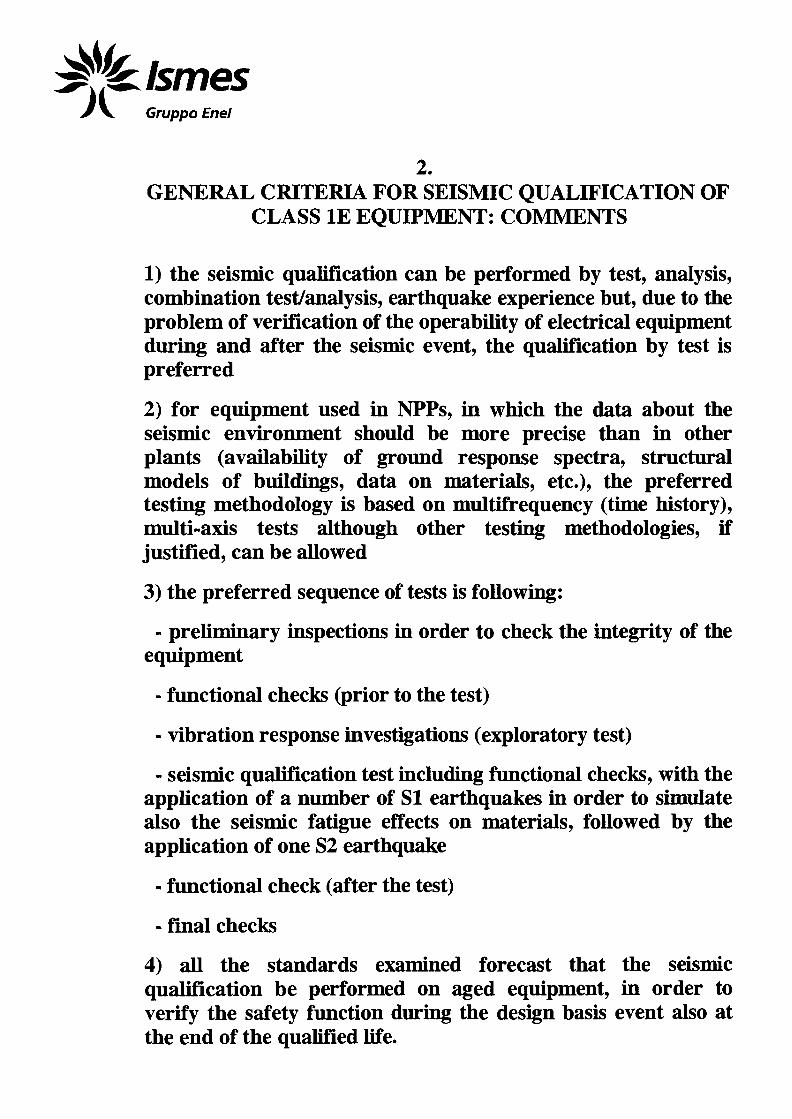
Gruppo Enel
2.GENERAL CRITERIA FOR SEISMIC QUALIFICATION OF
CLASS IE EQUIPMENT: COMMENTS
1) the seismic qualification can be performed by test, analysis,combination test/analysis, earthquake experience but, due to theproblem of verification of the operability of electrical equipmentduring and after the seismic event, the qualification by test ispreferred
2) for equipment used in NPPs, hi which the data about theseismic environment should be more precise than hi otherplants (availability of ground response spectra, structuralmodels of buildings, data on materials, etc.), the preferredtesting methodology is based on multifrequency (time history),multi-axis tests although other testing methodologies, ifjustified, can be allowed
3) the preferred sequence of tests is following:
- preliminary inspections in order to check the integrity of theequipment
- functional checks (prior to the test)
- vibration response investigations (exploratory test)
- seismic qualification test including functional checks, with theapplication of a number of SI earthquakes in order to simulatealso the seismic fatigue effects on materials, followed by theapplication of one S2 earthquake
- functional check (after the test)
- final checks
4) all the standards examined forecast that the seismicqualification be performed on aged equipment, in order toverify the safety function during the design basis event also atthe end of the qualified life.
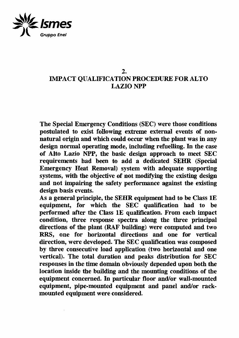
Gruppo Enel
2.IMPACT QUALIFICATION PROCEDURE FOR ALTO
LAZIO NPP
The Special Emergency Conditions (SEC) were those conditionspostulated to exist following extreme external events of non-natural origin and which could occur when the plant was in anydesign normal operating mode, including refuelling. In the caseof Alto Lazio NPP, the basic design approach to meet SECrequirements had been to add a dedicated SEHR (SpecialEmergency Heat Removal) system with adequate supportingsystems, with the objective of not modifying the existing designand not impairing the safety performance against the existingdesign basis events.As a general principle, the SEHR equipment had to be Class IEequipment, for which the SEC qualification had to beperformed after the Class IE qualification. From each impactcondition, three response spectra along the three principaldirections of the plant (RAF building) were computed and twoRRS, one for horizontal directions and one for verticaldirection, were developed. The SEC qualification was composedby three consecutive load application (two horizontal and onevertical). The total duration and peaks distribution for SECresponses in the time domain obviously depended upon both thelocation inside the building and the mounting conditions of theequipment concerned. In particular floor and/or wall-mountedequipment, pipe-mounted equipment and panel and/or rack-mounted equipment were considered.

Gruppo Enel
2.PREVIOUS EXAMPLES OF SHOCK (IMPACT)
QUALIFICATION ON EQUIPMENT(SAFEGUARD)
The SAFEGUARD program results can be summarized asfollows:- mechanical and passive electrical equipment: the failuresobserved are consistent with those highlighted in earthquakes;the weakest links are the anchorages and the electricalfunctions;- electrical cabinets (MCC, switchgears, panels): the weakestpoints are essentially the anchorage, the relay chatter and thebreaker trip.

Gruppo Enel
3.PROBLEMS RELEVANT TO THE SHOCK
QUALIFICATION(SHOCK TEST VS ACC)
The characteristics of shock tests are ruled by internationalstandards and the characteristics of the vibration relevant to anACC are quite different: the order of magnitude of the durationis 40-rlOO ms in the case of primary excitation, and towardshigher values considering also the free vibration of the structureat the location concerned; the peak acceleration is lower than 50m/s2 ; the tune history of the pulse applied has a complex shapeand it is not possible to reduce it to a standardised shape.

Gruppo Enel
3.PROBLEMS RELEVANT TO THE SHOCK
QUALIFICATION
An electrical equipment "rugged" with respect to astandardised shock pulse, has to be considered "rugged" alsowith respect to a shock (i.e. an ACC shock) whosecharacteristics, at least in terms of response spectrum andFourier spectrum, are enveloped by those of the standardisedshock pulse.

^fjjkbmesGruppo Enel
3.EXCITATION PHENOMENA
(SEISMIC VS ACC EXCITATION)
The envelope of a TRS associated with a given equipmentalready seismically qualified by the corresponding ACC FRS isnot sufficient to assure that the equipment is also qualified (andonly from the structural point of view) to the ACC due to thedifferences in nature between the two excitations. Moreover,from the functional point of view, an active (electrical)equipment qualified against the seismic actions, could be notqualified against ACC actions, due to the different frequencybands involved in these two phenomena that could adverselyaffect the functional behaviour (i.e. for relay chatter).

Gruppo Enel
3.PROPOSAL FOR IMPACT/SEISMIC EXPERIMENTAL
QUALIFICATION PROCEDURE
A proposal for the ACC qualification of active electricalequipment already qualified w.r.t. the seismic excitation has todeal with two different aspects:- the structural behaviour;- the functional behaviour.

IsmesGruppo Enel
3.STRUCTURAL QUALIFICATION
component(relay)
equipment (cabine
anchorages
The combined experimental/analytical approach is based on thedata coming from the seismic qualification of the same electricalequipment.Assuming that:- the weakest points of a cabinet are shown to be theanchorages;- the data acquired during seismic qualification include transferfunctions (in the frequency range up to 40-*45 Hz) between thebase acceleration and some positions inside the cabinet, wherethe electrical components are located;it is possible to compute the ACC response in the centre ofgravity of the equipment (cabinet) by deconvolution of ACCbase time history with a simple SDOF transmissibility functionwhere the dynamic parameters (fundamental frequency andassociated damping factor) are derived from the resonancesearch investigation performed in the frame of the seismicqualification process.

^{klsmesGruppo Enel
3.STRUCTURAL QUALIFICATION
Fourier transformA(f) of the ACCacceleration a(t)the base of the
equipment
at
Estimation of theSDOF transmissibiHtyfunction of the equipmentor use of the experimentaltransmissibilty fromseismic qualification
Estimation ofthe responseof the equipmentin frequency domainR(f)=H(f)*A(f)(in terms of
acceleration)relevantanti-transformation=>r(t)
and
H(f)
Estimation of stresstime history of the
weakest point of theequipment(i.e. anchorages)
Cycle-counting onstress time history(i.e. rainflow counting) J
Calculation of damage Dthrough Miner Rule andWoehler curve of thematerial used in theweakest point
YES Structuralqualificationachieved
The equipmenthas to beexperimentallyqualified
Gruppo Enel
3.FUNCTIONAL QUALIFICATION
The approach can be twofold:1) a combined experimental/analytical approach;2) an experience-based approach.The first approach is a classical procedure foreseen also ininternational standards (see, for example, para. 4.1.2.2.4 forIEEE 344). The basic steps are similar to those alreadydescribed for the structural qualification, i.e. the computation ofthe ACC response at the component level, via a de-convolutionof ACC base time history with a simple SDOF transmissibilityfunction or with the experimental transmissibility functionmeasured during the resonance search investigation performedin the frame of the seismic qualification process. This tunehistory can be experimentally applied to the component viashaking table tests. This procedure could be applied when it isnot possible to perform a similarity analysis between the actualequipment (or component) and a component already qualifiedto a standardised shock pulse for another dynamicenvironment.The second approach (experience-based) is based on thefollowing assumptions:- an equipment identical or similar has to be identified (thisequipment is identified as the reference equipment); thereference equipment has to be already qualified with respect astandardised shock pulse (i.e. half-sine) hi a differentenvironment (military, aerospace, transportation, etc.). Thesimilarity analysis shall include, at least, the following aspects:
- functions of the equipment;- dimensions and mass;- main components of equipment;- shape of the pulse;- maximum acceleration and duration of the main pulse;- results of the tests, from both structural and functional
point of view;- any other information relevant to the application
concerned.

iflklsmesGruppo Enel
3.FUNCTIONAL QUALIFICATION
electrical equipmentseismicaUyqualified
Is the qualificationrequired w.r.t.the shock (ACC)excitation ?
dmilarity analysisbetween the equipment;oncerned and thejquipment in the database
Database of elecricalequipment qualified w.r.tstd. Pulse excit.
Electrical, physical,restraint data
Std. Pulse test data
NO perform the experimentalqualification w.r.t. the
shock excitation
YES
comparison betweenthe charact of std.pulse and the actualshock environment
Std. pulse charactenvelope actualshock environ,haract. ?
perform the qualificationw.r.t. shock excitation
SHOCK QUALIFICATION
ACHIEVED
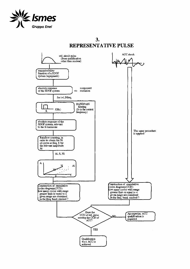
IsmesGruppo Enel
3.REPRESENTATIVE PULSE
std. shock pulse(from qualificationother than nuclear)
ACC shock
transmissibilityfunction of a SDOFsystem (equipment)
absolute responseof the SDOF system
componentexcitation
fori=l,Nfreq
Inf(Hz)
BANDPASSfiltering
(f o is the centralfrequency)
absolute response of theSDOF system, relevantto the fo harmonic
Rainflow counting, inorder to obtain the Niof cycles at freq. fi. forthe relevant amplitude
The same procedureis applied
\7construction of cumulative:ycles diagrams(CCD):low many cycles with rangegreater than or equal to agiven range are contained
^ in the freq. band, excited ?
construction, of cumulative:ycles diagrams(CCD):low many cycles with rangegreater than or equal to agiven range are contained
^in the freq. band, excited ?
Does theCCD of std. pulse
envelop the CCD of
YES
Qualificationwxt ACC isachieved

Gruppo Enel
4.RBMK-TYPE NPP: THE REFERENCE CASE
TABLE 1
Plant
Ignalina 1Ignalina 2
Chernobyl 1Chernobyl 2Chernobyl 3Chernobyl 4
Kursk 1Kursk 2Kursk 3Kursk 4Kursk 5
St. Petersburg1
St Petersburg2
St Petersburg3
St. Petersburg4
Smolensk 1Smolensk 2Smolensk 3
Generation4
22112211223
1
1
2
2
222
Status
operationaloperationaloperationalShutdown
operationalShutdown
operationaloperationaloperationaloperational
UnderconstructionOperational
Operational
Operational
Operational
operationaloperationaloperational
Numberof
channels211211179179211211179179211211223
191
179 (191)
211
211
211211211
Number offuel
assemblies1661166116931693166116611693169316611661
-
1693
1693
1661
1661
166116611661
(from 1997 World Nuclear Industry Handbook, published by Nuclear EngineeringInternational):
4 The term "Generation" pertains to the initial design or an updated version of the initial design.

Gruppo Enel
4.THE "AS-BUELT" STATUS OF THE EQUIPMENT FOR THE
REFERENCE CASE(RECOMMENDED UP-GRADING)
• welding at the junctions between beams of the same structure(steel frame, supports, anchorage structures);
• integrity of supports/steel frames which appeared to bebroken or decoupled from the civil structure anchorage;
• the cable routing/cable penetrations/cable identification;assure as minimum the separation of independent safetyrelated trains;
• the anchorage of pumps, heat exchangers, headers, panelboards, piping;
• the anchorage between supports/steel frame and the civilstructure (both concrete and steel frame);
• repairing/maintenance where past operation had promoteddamage/cracks and temporary (still living) actions had beenimplemented;
• walkdown frames, in-service inspection frames for equipmentalso in congested plant layout areas;
• inspection of piping/headers/exchangers/tanks actualthickness to evaluate erosion/corrosion damages, which maypromote unexpected weakness in the structure.

Gruppo Enel
4.SOME DATA ABOUT ELECTRICAL CABINETS
The following data about the dynamic characteristics of typicalelectrical cabmets have been communicated by VNIIAM:• dynamic coefficient (i.e. the amplification of base motion): K
= 2---15;• natural frequencies (of the cabinets and internal
components): 2-r50 Hz.

Gruppo Enel
4.INTERFACE DATA FOR IMPACT/SEISMIC
EXPERIMENTAL QUALIFICATION
- from seismic qualification previously performed on the sameequipment:
- transmissibility function up to 45-r50 Hz at the componentlevel;
- fundamental frequency and associated damping factor ofthe equipment;
- floor response spectra and relevant time histories at thebase of equipment;
- from ACC FEM analysis:- floor response spectra and relevant time histories at the
base of equipment.

Gruppo Enel
4.INTERFACE DATA FOR IMPACT/SEISMIC
EXPERIMENTAL QUALIFICATION:CONCLUSIONS
1. List of equipment safety related for which the qualification isrequired (i.e. list of cabinets); (NPP Utility)
2. List of components housed into the above mentionedequipment (i.e. the essential relays); (NPP Utility)
3. Information on the actual as-built mounting conditions of theequipment; (Walk-down visit)
4. Dynamic characteristics of the equipment (i.e. transferfunctions or natural frequencies/mode shapes/associateddamping) from the seismic tests; (AEP & VNTIAM)
5. Equipment experimental data relevant to the standardisedpulse tests (AEP & VNIIAM).

XA9952888
IAEA program
CfiP"Safety of RBMK Type Nuclear Power Plan in relation to external events'̂ .
IAEA Research Contract Ml0653 ":
Seismic analysis for RBMK-1000 steam line and feed water" pipelines.
Chief Scientific Investigator Dr.L.Kabanov f r/^^L'J
Phase 1 (1999)
T, VA//P/£T, S Pi TV,Task 1 - analysis of input data related to pipeline
Task 2 - analysis of input data related to risk of aircraft crash.
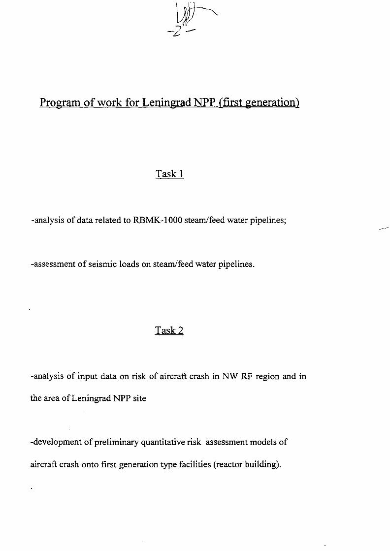
-2
Program of work for Leningrad NPP (first generation)
Taskl
-analysis of data related to RBMK-1000 steam/feed water pipelines;
-assessment of seismic loads on steam/feed water pipelines.
Task 2
-analysis of input data on risk of aircraft crash in NW RF region and in
the area of Leningrad NPP site
-development of preliminary quantitative risk assessment models of
aircraft crash onto first generation type facilities (reactor building).
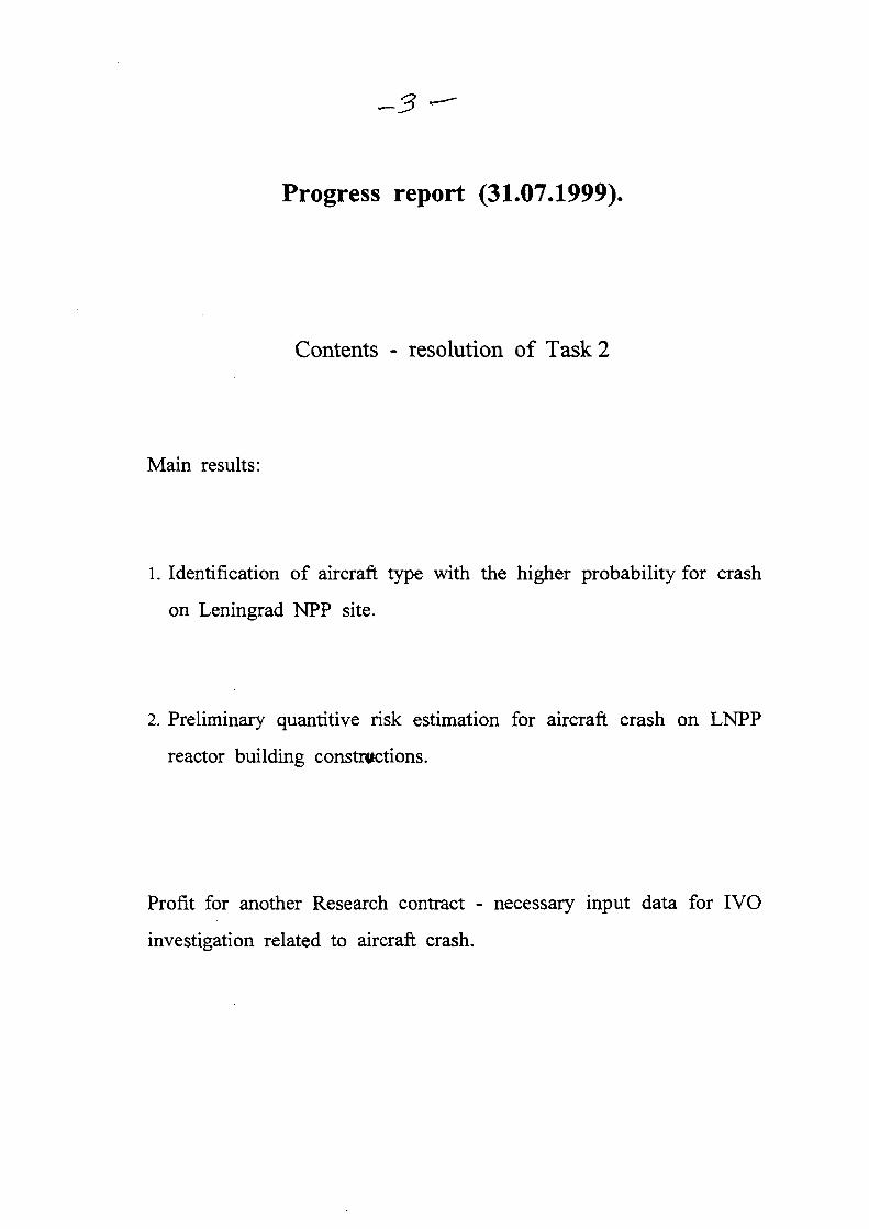
-5
Progress report (31.07.1999).
Contents - resolution of Task 2
Main results:
1. Identification of aircraft type with the higher probability for crash
on Leningrad NPP site.
2. Preliminary quantitive risk estimation for aircraft crash on LNPP
reactor building constructions.
Profit for another Research contract - necessary input data for IVO
investigation related to aircraft crash.
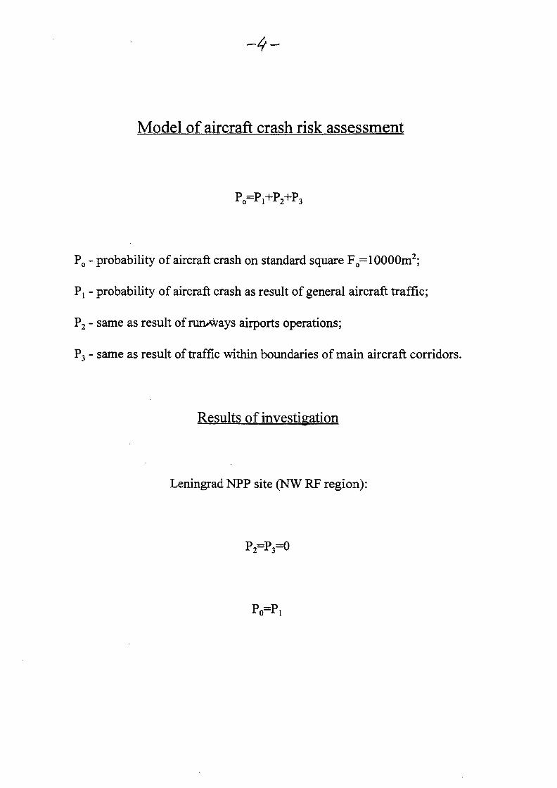
Model of aircraft crash risk assessment
P O = P 1 + P 2 + P 3
Po - probability of aircraft crash on standard square Fo= 10000m2;
Pj - probability of aircraft crash as result of general aircraft traffic;
P2 - same as result of runways airports operations;
P, - same as result of traffic within boundaries of main aircraft corridors.
Results of investigation
Leningrad NPP site (NW RF region):
P2=P3=0
Po=Pi

Classes of aircraft under discution
-plane of 1st-2ndclass;
-plane of 3rdclass;
-plane of 4th class;
- helicopter of 1st - 2nd class;
- helicopter of 3rd class;
- bomber;
- battleplane;
- airfighter.
Results of investigation.
Leningrad NPP site:
Po=510"8 I/year for 4th class of plane (type "Sessna") weight ffSS 6000 kg.
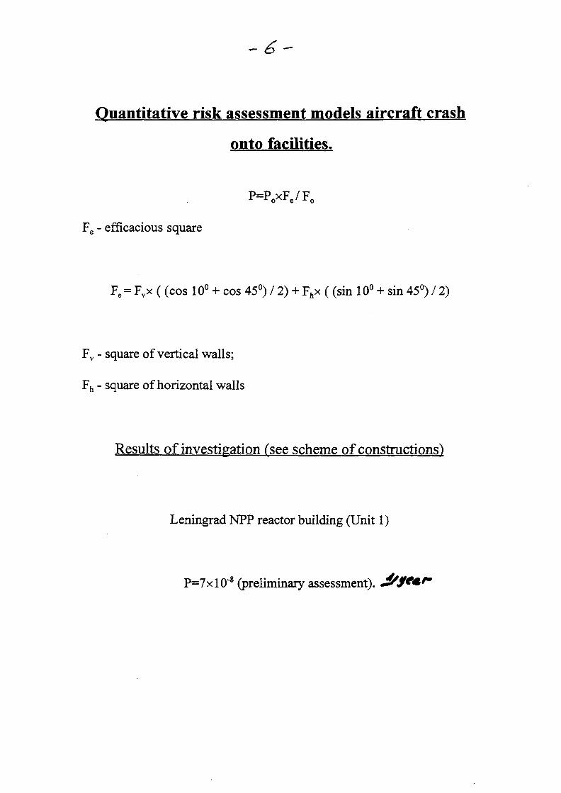
Quantitative risk assessment models aircraft eras!
onto facilities.
P=PoxFe/F0
Fe - efficacious square
Fe = Fvx ( (cos 10° + cos 45°) / 2) + Fhx ( (sin 10° + sin 45°) / 2)
Fv - square of vertical walls;
Fh - square of horizontal walls
Results of investigation fsee scheme of constructions)
Leningrad NPP reactor building (Unit 1)
P=7xlO"8 (preliminary assessment).
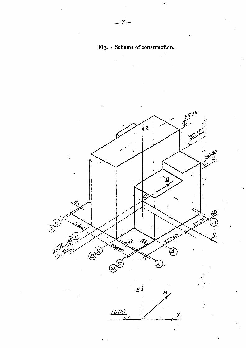
Fig. Scheme of construction.

Fig. •••. Cross section on mark 0.00.
T
£300
crea?
i/ooo SCO
5M
1
..H
I HOOD •1
(ZOO QOQ0 £/O0O
S5J20
30.0
fr.QO
aoo
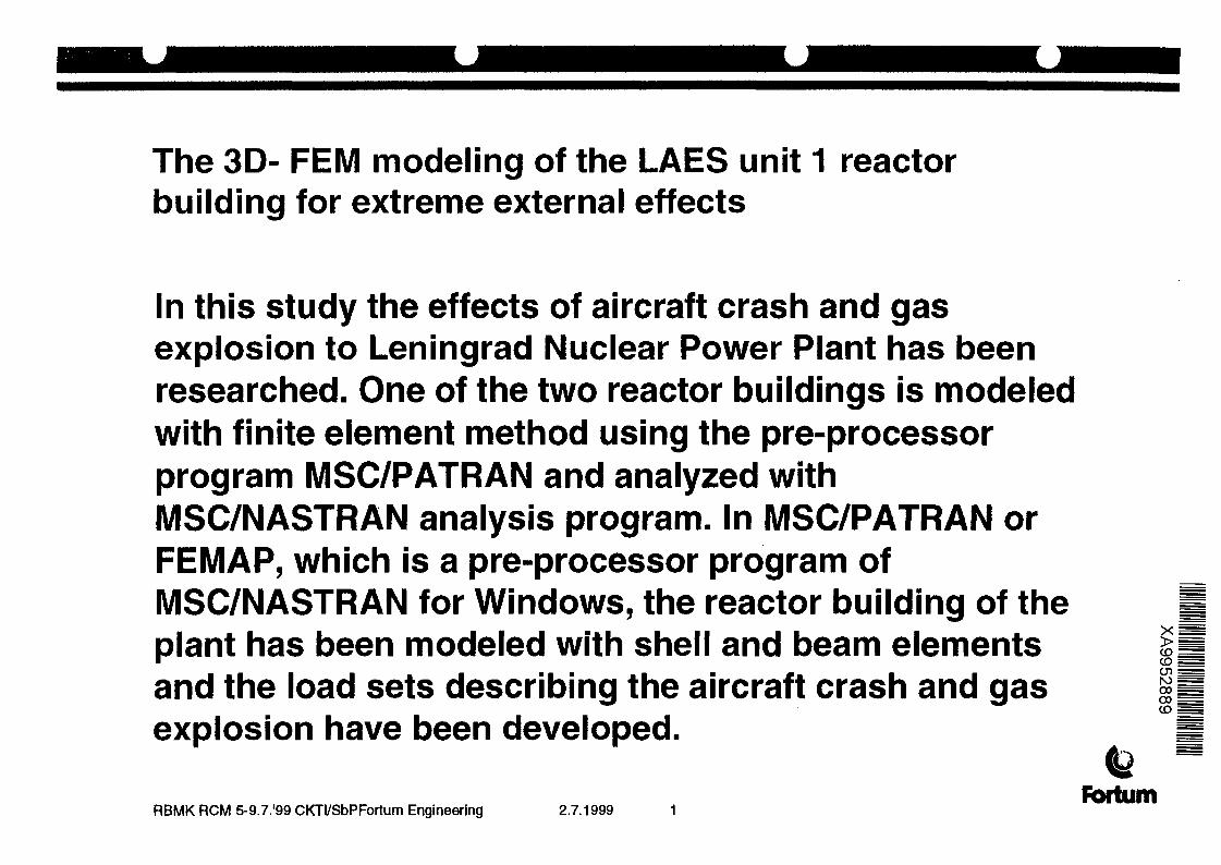
The 3D- FEM modeling of the LAES unit 1 reactorbuilding for extreme external effects
In this study the effects of aircraft crash and gasexplosion to Leningrad Nuclear Power Plant has beenresearched. One of the two reactor buildings is modeledwith finite element method using the pre-processorprogram MSC/PATRAN and analyzed withMSC/NASTRAN analysis program. In MSC/PATRAN orFEMAP, which is a pre-processor program ofMSC/NASTRAN for Windows, the reactor building of theplant has been modeled with shell and beam elementsand the load sets describing the aircraft crash and gasexplosion have been developed.
co;CD
oo0 0 |CD i
RBMK RCM 5-9.7.'99 CKTI/SbPFortum Engineering 2.7.1999Fortum

The 3D- FEM modeling of the LAES unit 1 reactorbuilding for extreme external effects
The crash loads are from Cessna 210 civil airplane crashwith impact velocity 360 km/h and maximum impactforce of 7 MN and Phantom RF-43 military airplane crashwith impact velocity 215 m/s and with maximum impactforce of 110 MN. The gas explosion pressure wavesimulates the deflagration wave with maximum pressureof 0,045 MPa. Seven Cessna 210 airplane crashlocations, two Phantom RF-43 airplane crash locationsand one gas explosion load case is modeled. Airplanecrash loads were from different directions and todifferent points of impact in the reactor building.
RBMK RCM 5-9.7.'99 CKTI/SbPFortum Engineering 2.7.1999Fortum

The 3D- FEM modeling of the LAES unit 1 reactorbuilding for extreme external effects
The gas explosion load was assumed to affect thereactor building from one side parallel to one of the
global coordinate axes of the model. WithMSC/NASTRAN reactions from loads are analyzed. All
loads were time-dependent; their magnitude varied withtime and consequently the analysis was carried out with
the aid of transient response analysis. Time step inCessna 210 analysis was 0,003 s and in Phantom RF-43
and gas explosion analyses 0,01 s.
RBMK RCM 5-9.7.'99 CKTI/SbPFortum Engineering 2.7.1999Fortum
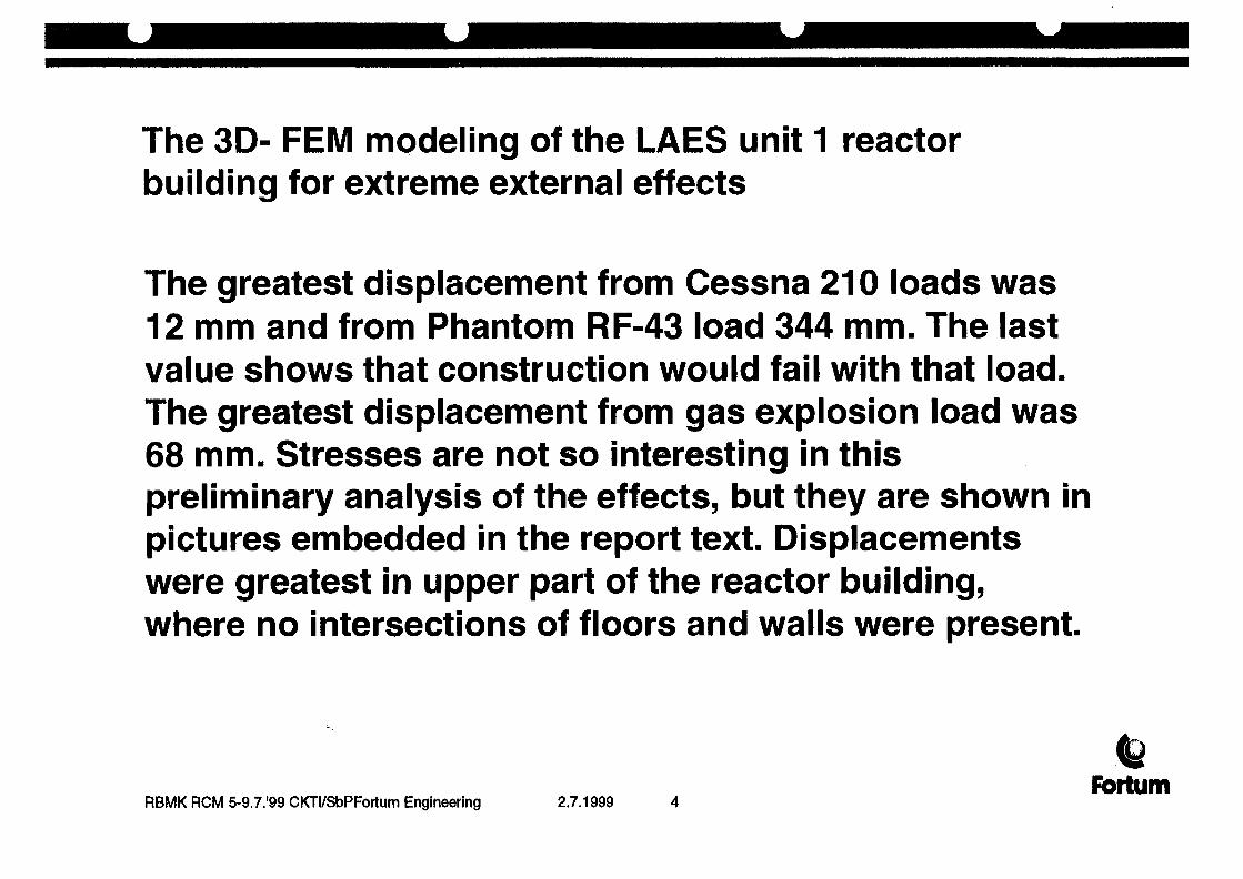
The 3D- FEM modeling of the LAES unit 1 reactorbuilding for extreme external effects
The greatest displacement from Cessna 210 loads was12 mm and from Phantom RF-43 load 344 mm. The lastvalue shows that construction would fail with that load.The greatest displacement from gas explosion load was68 mm. Stresses are not so interesting in thispreliminary analysis of the effects, but they are shown inpictures embedded in the report text. Displacementswere greatest in upper part of the reactor building,where no intersections of floors and walls were present.
RBMK RCM 5-9.7.'99 CKTI/SbPFortum Engineering 2.7.1999Fbrtum
The 3D- FEM modeling of the LAES unit 1 reactorbuilding for extreme external effects
The conclusion is that the intersections stiffen thestructure considerably. In lower part, where manyintersections exist, displacements were significantlysmaller. In conclusion, the lower part can resist theinvestigated loads such as high-speed military aircraftcrash loads much better than upper part.
RBMK RCM 5-9.7.'99 CKTI/SbPFortum Engineering 2.7.1999Fortum
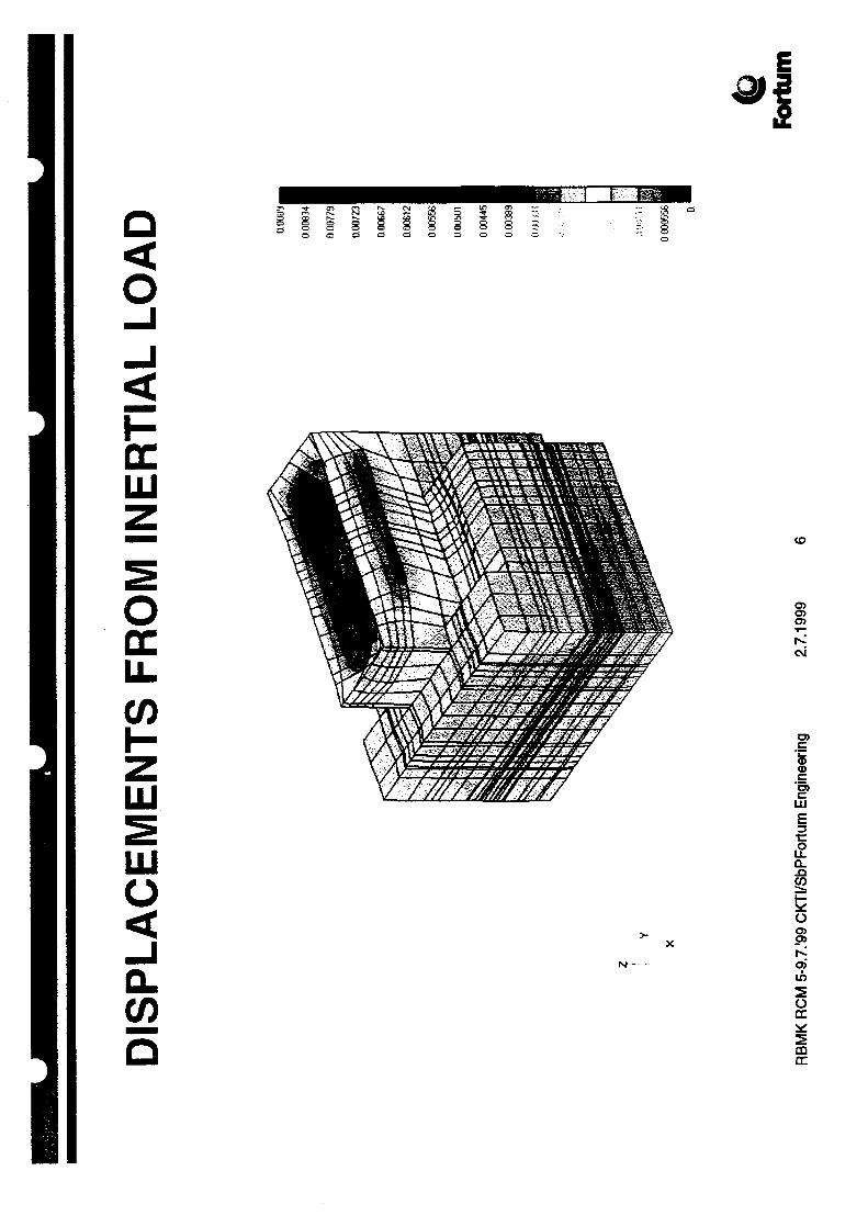
Q<O
DCHI
ODCLLCO
LU
LUo
CO
CTO>
oj
CD
iLLJ
|
Ia.<8o
2Occ

MAJOR PRINCIPAL STRESS FROMINERTIAL LOAD
54.411
50991
47.5$ I
44141
40 721
37 31
33.881
30.451
27.031
23 61
;•''! I ' : I
3.075 i
•0 3471
RBMK RCM 5-9.7.'99 CKTI/SbPFortum Engineering 2.7.1999fortum
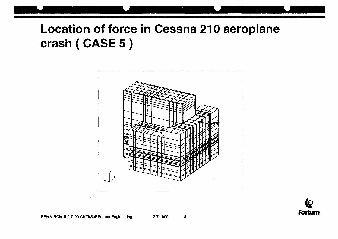
Location of force in Cessna 210 aeroplanecrash ( CASE 5 )
RBMK RCM 5-9.7.'99 CKTI/SbPFortum Engineering 2.7.1999Fortum

Displacements from Cessna 210 aeroplanecrash ( CASE 5)
9.09-04
8.49-04
7.88-04
7.28-04
6.67-04
6.06-04
5.46-04
4.85-04
4.24-04
3.64-04
3.03-04
2.43-04
1.82-04
1.21-04
6.06-05
1.09-10dalaulLFringe:
Max 9.09-04 «Nd 601Min 0. «Nd1defaulLDeformation:
Max 9.09-04 «Nd 601
lil
RBMK RCM 5-9.7.'99 CKTI/SbPFortum Engineering 2.7.1999Fortum

Dis
1p2O-O3ac
1*00-03me
tfbO-04
s
d.00-04
r4300-04
o "• 1n oa1
LEGENDNode 601: Displacements, Translation^, MAG
wVv5.50-02 1.10-01 1.65-01 2.20-01 2.75-01 3.30-01
Time
RBMK RCM 5-9.7.'99 CKTI/SbPFortum Engineering 2.7.1999 10Fbrtum
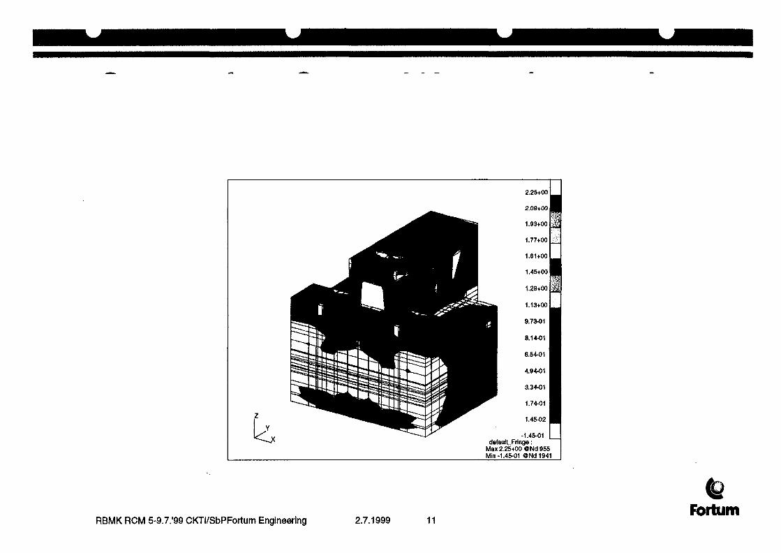
2.25+001
2.09+00
1.93+001
1.77+001
1.61+001
1.45+00
1.29+001
1.13+001
9.73-01
8.14-01
6.54-01
4.94-01
3.34-01
1.74-01
1.45-02
-1.45-01defaulLFringe:
Max 2.25+00 ©Nd 955Min -1.45-01 @Nd1941
RBMK RCM 5-9.7.'99 CKTI/SbPFortum Engineering 2.7.1999 11Fortum

LEGENDElement 6750: Stress Tensor, MAJOR
6.00-01
4860-01tr
ss
t^O-01
ens o.or
-1.-50-01
-3.00-010. 5.50-02 1.10-01 1.65-01 2.20-01 2.75-01 3.30-01
Time
RBMK RCM 5-9.7."99 CKTI/SbPFortum Engineering 2.7.1999 12Fortum

RBMK RCM 5-9.7.'99 CKTI/SbPFortum Engineering 2.7.1999 13Fortum

DISPLACEMENTS FROM PHANTOM RF-43AEROPLANE CRASH
MSC/PATRAN Version 7.6 03-Dec-88 13:06:28Fringe: k>ad7, Tlme=0.35: Displacements, Translatlonal-(NON-LAYERED) (MAQ)
1.92-02
1.79-02
1.66-02
1.53-02
1.41-02
1.28-02
1.15-02
1.02-02
8.95-03
7.67-03
6.39-03
5.12-03
3.84-03
2.56-03
1.28-03
1.63-09defaulLFrlnge:
Max 1.92-02 ONd 3973Mln 0. ONd 1default. Deformation :
Max 1.92-02 ONd 3973
RBMK RCM 5-9.7.'99 CKTI/SbPFortum Engineering 2.7.1999 14Fortum

LEGENDNode 3973: Displacements, Translational, MAQ
[T10-02
ac1875-02meMo-02
S
V.05-02Tr
7800-03ns
d.50-03dt
2.00-01 4.00-01 6.00-01 8.00-01 1.00+00 1.20+00
Time
RBMK RCM 5-9.7.'99 CKTI/SbPFortum Engineering 2.7.1999 15Fbrtum

RBMK RCM 5-9.7.'99 CKTI/SbPFortum Engineering 2.7.1999 16Fbrtum
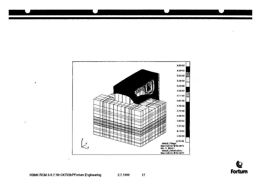
6.85-02
6.39-02
5.93-02
5.48-02
5.02-02
4.56-02
4.11-02
3.65-02
3.19-02
2.74-02
2.28-02
1.83-02
1.37-02
9.13-03
4.56-03
•2.79-09default_Fringe:
Max 6.85-02 ONd 3973M!n 0. ONd1delaulLDeformatlon:
Max 6.85-02 ONd 3973
RBMK RCM 5-9.7.'99 CKTI/SbPFortum Engineering 2.7.1999 17Fortum
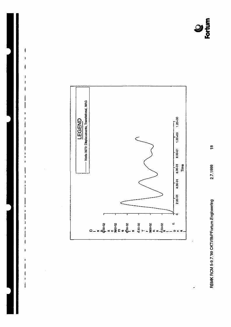
00
c\i
TO
I<D
£
o
O(X
mDC

CONCLUSIONSimplified assumptions for crash analyses.
• The impacting load in airplane crash analyses is modeled to affect onlyone node point in the model. In reality the force is distributed to alarger area and affects the structure more like a distributed pressureload.
• The effects of possible secondary missiles resulting from disintegratingairplane are not taken into account.
• Thepossible fire induced by crashing airplane is not taken intoaccount.
• The cracking of concrete is not taken into account.
• The non-linear effects, whatever is their cause, are not taken intoaccount.
RBMK RCM 5-9.7.'99 CKTI/SbPFortum Engineering 2.7.1999 19Fortum

Simplified assumptions for gas explosion.
• In modeling the gas explosion load the effect of the load was taken intoaccount only for one wall i. e. the incident wave causes the pressureload only for the wall directly in the path of the pressure front. In realitythe pressure loads envelopes also the side walls and the wall inleeward side.
• Modeling has been linear; responses depend linearly from loads. Inreality, many non-linear effects are present. Examples of them arecracking of concrete and yielding of steel.
CONCLUDING REMARKS
• the structure is less stiff in the upper part of the building andconsequently this part needs most attention.
• The lower part of the structure is so stiff, that it can withstand also high-speed military airplane crash.
FortumRBMK RCM 5-9.7.'99 CKTI/SbPFortum Enqineerlng 2.7.1999 20

XA9952890
Prepared for:Revision 0International Atomic Energy Agency,Wagramer Strasse 5,P.O. Box 100,A-1400 Vienna, Austria
Prepared by:
CKTI-VIBROSEISM Co Ltd.,3, ATAMANSKAYASTR.,ST. PETERSBURG 193167, RUSSIA.
Report No. RepO1-99.iaea
May 1999
Contract No.: 10125/ Regular Budget Fund
Screening of the External Hazards for NPPwith Bank Type Reactor
MODELING OF SAFETY RELATED SYSTEMS AND EQUIPMENT FOR RBMK.PROBABILISTIC ASSESSMENT OF NPP SAFETY ON AIRCRAFT IMPACT.
Progress Report
Chief Scientific Investigator:
Investigators:
Dr. V. Kostarev (CKTI-Vibroseism)
A. Schukin, (CKTI-Vibroseism)A. Berkovski, (CKTI-Vibroseism),Dr. A. Birbraer (Atomenergoproekt)S. Arkhipov (Atomenergoproekt)
Number of pages: 29

CKTI-VIBROSEISM3, Atamanskaya str.. St. Petersburg 193167, Russia.
Report No. RepO1-99.iaeaRevision 0May 1999
Document Title:Modeling of Safety Related Systems and Equipment forRBMK. Probabilistic Assessment of NPP Safety onAircraft Impact.
Document No.:RepO1-99.iaea
Document Type:
Criteria, Report Interface Specification Drawing OtherMethodology
• •Project Title:
Screening of the External Hazards for NPPwith Bank Type Reactor
Client: International Atomic Energy Agency
THIS DOCUMENT HAS BEEN PREPARED IN ACCORDANCE WITH THE CVSQAP MANUAL AND PROJECT REQUIREMENTS
Revision 0
Total number of pagesincluding this sheet: 29
Prepared by
Checked by
Approved by
Name
Alexei Berkovski
Alexander Schukin
Victor Kostarev ^
Signature Date
21.05.1999
21.05.1999
21.05.1999
Revision Record
RevisionNo.
123456
Prepared by&Date
Checked by&Date
CVS
CKTI-VIBROSEISM
Approved by&Date
Description of Revision
DOCUMENTCOVER SHEET
PROJECT No.
10125/RegularBudget Fund
CKTI-VIBROSEISM Report No. RepO1-99.iaea3, Afcamanskaya str., St. Petersburg 193167, Russia. Revision 0
May 1999
C O N T E N T S
1 INTRODUCTION 4
2 PRINCIPAL DESIGN OF RBMK 5
3 DEVELOPING OF PRIMARY LOOP SYSTEM MODEL FOR RBMK 8
4 DEVELOPING OF SAFETY RELATED EQUIPMENT MODELS
OFRBMK 12
4.1 CONTROL AND PROTECTION SYSTEM FOR CHECKING OF FUEL ASSEMBLY SHELL'SINTEGRITY, TYPE PBM-K7CE61 12
4.2 CONTROL ROD DRIVE MECHANISM (HANGERS RJK&PIK) 14
5 DEVELOPING OF SAFETY RELATED EQUIPMENT MODELS OF EGP-6TYPE REACTOR (BILEBINSKAYA NUCLEAR CO-GENERATED HEATAND POWER PLANT) 16
6 PROBABILISTIC ASSESSMENT OF NPP SAFETY ON AIRCRAFTIMPACT 19
6.1 INTRODUCTION 196.2 CONSIDERED RANDOM PARAMETERS AND THEIR PROBABILITY CHARACTERISTICS 196.3 PROBABILITY OF IMPACT AT A GIVEN ANGLE TO THE STRUCTURE SURFACE 236.4 BUILDING STRUCTURES FAILURE PROBABILITY 256.5 DEVELOPMENT OF FLOOR RESPONSE SPECTRA AT AIRCRAFT IMPACT 27
REFERENCES 29

CKTI-VIBROSEISM Report No. RepO1-99.iaea3, Atamanskaya str., St. Petersburg 193167, Russia. Revision 0
May 1999
1 INTRODUCTION
This Progress Report has been developed in the frame of IAEA Research Project "Screening of theExternal Hazards for NPP with Bank Type Reactor" and covers the following tasks:
• Developing of Primary Loop System Model for RBMK• Developing of Safety Related Equipment Models of RBMK.• Developing of Safety Related Equipment Models of EGP-6 type Reactor (Bilibinskaya Nuclear
Co-generated Heat and Power Plant).• Probabilistic Assessment of NPP Safety on Aircraft Impact.

CKTI-VIBROSEISM3, Atamanskaya str., St. Petersburg 193167, Russia.
Report No. RepO1-99.iaeaRevision 0May 1999
2 PRINCIPAL DESIGN OF RBMK
The Soviet designed RBMK is a pressurized water reactor with individual fuel channels and usingordinary water as its coolant and graphite as its moderator. It is very different from most otherpower reactor designs as it was intended and used for both plutonium and power production. Thecombination of graphite moderator and water coolant is found in no other power reactors. Figures2 . 1 - 2.3 show the principal design and main parts of NPP with RBMK type reactor.
Figure 2.1 Principal Design of NPP with RBMK- type Reactor.
The RBMK reactor
SIsee enlargement
Tcontainment
I Iturbine generator
Figure 2.2 Principal Scheme of RBMK Reactor.

CKTI-VIBROSEISM3, Atamanskaya str., St. Petersburg 193167, Russia.
Report No. RepO1-99.iaeaRevision 0May 1999
graphitemoderator
steamseparator
pressure,tube
fuel rod
pump
controlrod
watercoolant
Reactor core enlargement
Figure 2.3. Reactor Core.
Fuel rodsPellets of enriched uranium oxide are enclosed in a zircaloy tube 3.65m long, forming a fuelrod. Two sets of 18 fuel rods are arranged cylindrically in a carriage to form a fuel assembly ofabout 10-m length. These fuel assemblies can be lifted into and out of the reactor mechanically,allowing fuel replenishment while the reactor is in operation.Pressure tubesWithin the reactor each fuel assembly is positioned in its own pressure tube or channel. Eachchannel is individually cooled by pressurized water.Graphite moderatorA series of graphite blocks surround, and hence separate, the pressure tubes. They act as amoderator to slow down the neutrons released during fission. This is necessary for continuousfission to be maintained. A mixture of helium and nitrogen gas enhances conductance of heatbetween the blocks.Control rodsBoron carbide control rods absorb neutrons to control the rate of fission. A few short rods,inserted upwards from the bottom of the core, even the distribution of power across the reactor.The main control rods are inserted from the top down and provide automatic, manual oremergency control. The automatic rods are regulated by feedback from in-core detectors. Ifthere is a deviation from normal operating parameters (e.g. increased reactor power level), therods can be dropped into the core to reduce or stop reactor activity. A number of rods normallyremain in the core during operation.CoolantTwo separate water coolant systems each with four pumps circulate water through the pressure
CKTI-VIBROSEISM Report No. RepO1-99.iaea3, Atamanskaya str.. St. Petersburg 193167, Russia. Revision 0
May 1999
tubes. Ninety-five percent of the heat from fission is transferred to the coolant. There is also anemergency core cooling system, which will come into operation if either coolant circuit isinterrupted.Steam separatorSteam from the heated coolant is fed to turbines to produce electricity in the generator. Thesteam is then condensed and fed back into the circulating coolant.ContainmentThe reactor core is located in a concrete lined cavity that acts as a radiation shield. The uppershield or pile cap above the core, is made of steel and supports the fuel assemblies. The steamseparators of the coolant systems are housed in their own concrete shields.

CKTI-VIBROSEISM3, Atamanskaya str., St. Petersburg 193167, Russia.
Report No. RepO1-99.iaeaRevision 0May 1999
3 DEVELOPING OF PRIMARY LOOP SYSTEM MODEL FOR RBMK
The following figures present the main circuit piping systems.
Downtaking Pipes
Main Circuit Pipelines
Figure 3.1. Main Circuit System (General View)
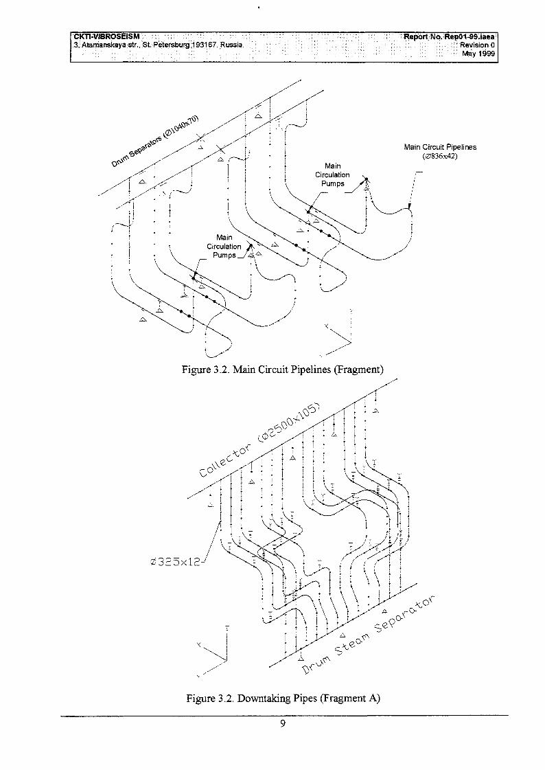
CKT1-VIBROSEISM3, Atamanskaya str., St. Petersburg 193167. Russia.
Report No. RepO1-99.iaeaRevision 0May 1999
Main Circuit Pipelines(0836x42)
Figure 3.2. Main Circuit Pipelines (Fragment)
0325x12--
f \\s~\ i \ t \
Figure 3.2. Downtaking Pipes (Fragment A)

CKTI-VIBROSEISM3, Atamanskaya str., St. Petersburg 193167, Russia.
Report No. RepO1-99.iaeaRevision 0May 1999
.0325x12
Figure 3.3. Downtaking Pipes (Fragment B)
r eecl Water Pipes
0426x18
Figure 3.4.Feed Water Pipes
10

CKTl-VIBROSEISM3, Atamanskaya str., St. Petersburg 193167, Russia.
Report No. RepO1-99.iaeaRevision 0May 1999
Collector (02500x105)
0377x42
Drur; Separators (01040x70)
/ Steam Lines
0426x22
Figure 3.5.Main Steam Pipelines
11
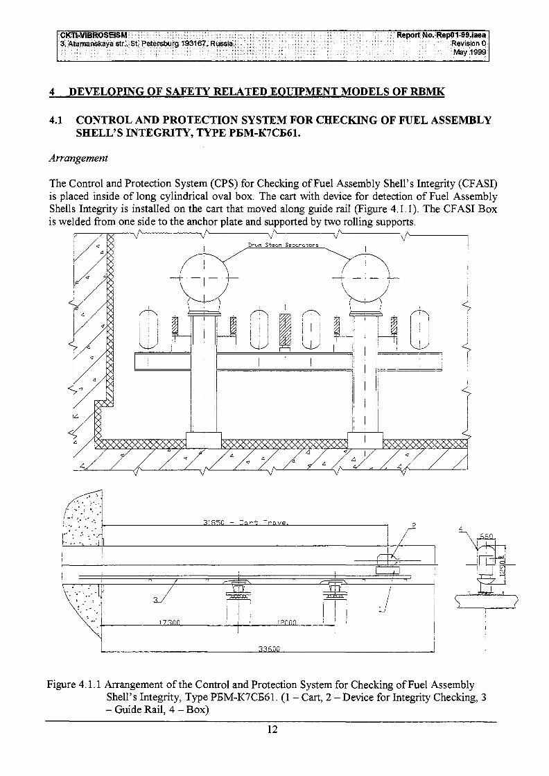
CKTt-VIBROSEISM3, Atamanskaya str., St. Petersburg 193167, Russia.
Report No. RepO1-99.iaeaRevision 0May 1999
4 DEVELOPING OF SAFETY RELATED EQUIPMENT MODELS OF RBMK
4.1 CONTROL AND PROTECTION SYSTEM FOR CHECKING OF FUEL ASSEMBLYSHELL'S INTEGRITY, TYPE PBM-K7CB61.
Arrangement
The Control and Protection System (CPS) for Checking of Fuel Assembly Shell's Integrity (CFASI)is placed inside of long cylindrical oval box. The cart with device for detection of Fuel AssemblyShells Integrity is installed on the cart that moved along guide rail (Figure 4.1.1). The CFASI Boxis welded from one side to the anchor plate and supported by two rolling supports.
Figure 4.1.1 Arrangement of the Control and Protection System for Checking of Fuel AssemblyShell's Integrity, Type PEM-K7CB61. (1 - Cart, 2 - Device for Integrity Checking, 3- Guide Rail, 4 - Box)
12

CKTI-VIBROSEISM3, Atamanskaya str., St. Petersburg 193167, Russia.
Report No. RepO1-99.iaeaRevision 0May 1999
Calculation Model
Beam Finite Element Calculation Model of considered system is shown on Figure 2.
Box
a) General View
2122
rGuide Rail
art with Device
32 31
b) Fragment
Figure 4.1.2 Calculation Model of the Control and Protection System for Checking of FuelAssembly Shell's Integrity, Type PBM-K7CB61
13

CKTI-VIBROSEISM3, Atarnanskaya str., St. Petersburg 193167, Russia.
Report No. RepO1-99.iaeaRevision 0May 1999
Seismic Criteria
The following items have to be checked for seismic loading:
• Strength Capacity of CFASI Box;• Strength Capacity of flange connection;• Load Capacity of Supporting System;• Operability of Cart with CFASI Device (during seismic input cart the shall remain on the guide
rail);• Strength Capacity of Guide Rail and its supporting system.
4.2 CONTROL ROD DRIVE MECHANISM (HANGERS RBK & PIK).
Arrangement
Control Rod Drive Mechanism provides insertion of boron carbide control rods in the reactor core.Assembly of RIK & PIK hangers includes the following parts: The hanger itself is the bar (pipe012x2, 08X18H10T) with flange connections between the parts. Ionization Chamber is attached tothe lower end of hanger. Bar and chamber are placed inside of cover (pipe 058x2, CAB-2) with capon the its lower end. The Upper end of cover is attached to the bearing flange. The whole assemblyof the hanger then is placed to the special cartridge rigidly connected with reactor structure (insidediameter is 81 mm).
Calculation Models
Figures 4.2.1 - 4.2.3 present three calculation models (combination of finite and compoundelements) of the different modification of control rod hangers.
Chamber
Figure 4.2.1 Calculation Model of RBMK Control Rod Drive System (Hangers RIK & PIK)_

CKTI-VIBROSBSM3, Atamanskaya str., St. PeJersburg 193167, Russia.
Report No. RepO1-99.iaeaRevision 0May 1999
Channel
Chamber
Figure 4.2.2 Calculation Model of the hanged fission chamber.
Channel
Figure 4.2.3 Calculation Model of RBMK Control Rod Drive System (3-zone Hanger RIK).
15
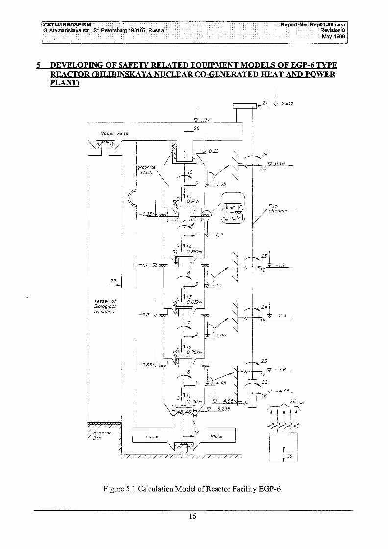
CKTI-VIBROSEISM3, Atamanskaya str., St. Petersburg 193167, Russia.
Report No. RepO1-99.iaeaRevision 0May 1999
5 DEVELOPING OF SAFETY RELATED EOUIPMENT MODELS OF EGP-6 TYPEREACTOR (BILIBINSKAYA NUCLEAR CO-GENERATED HEAT AND POWERPLANT)
Vessel ofBiologicalShield in a
///////7 7/, 7/7/77/777/ 30 j
Figure 5.1 Calculation Model of Reactor Facility EGP-6.
16

CKT1-VIBROSEISM3, Atamanskaya str., St. Petersburg 193167, Russia.
Report No. RepO 1-99-iaeaRevision 0May 1999
Drum of SmallR o ta tin ff Oesak
Figure 5.2 Calculation Model of the Central Rotating Deck (Horizontal Direction)
traf Rotating D&ck
a,
s
Figure 5.3 Calculation Model of the Central Rotating Deck (Vertical Direction)
17
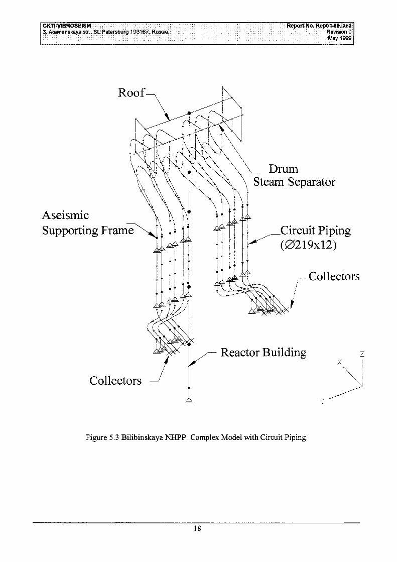
CKTI-VIBROSEISM3, Atamanskaya str., St. Petersburg 193167, Russia.
Report No. RepO1-99.iaeaRevision 0May 1999
Roof
AseismicSupporting Frame
Collectors
DrumSteam Separator
Circuit Piping(0219x12)
r— Collectors
Reactor Building
A
Figure 5.3 Bilibinskaya NHPP. Complex Model with Circuit Piping.
18

CKTi-VIBROSEISM Report No. RepO1-99.iaea3, Atamanskaya str., St. Petersburg 193167, Russia. Revision 0
May 1999
6 PROBABILISTIC ASSESSMENT OF NPP SAFETY ON AIRCRAFT IMPACT
6.1 INTRODUCTION
Accidental aircraft impact is one of the most hazardous external man-induced events considered inNPP designing. Depending on this load required dimensions and strength of exterior buildingstructures are often chosen. Whether the load should be taken into account depends on theprobabilistic grounds which are either the immediate aircraft fall probability assessment, or safety-distance-approach, the distance being determined on the probabilistic basis too (Ref. [1], [2]).
As a result of this consideration, one of the following two alternative resolutions is accepted today:either this load is not taken into account at all, or the most unfavorable case of impact is taken intoaccount. The latter means that aircraft mass and velocity are assumed to be maximal, the impact isapplied in the most critical point of the structure and at the most hazardous angle.
But in reality aircraft velocity and mass, as well as point of its impact and collision angle are casualparameters, and the probability of simultaneous realization of their most unfavorable values is verysmall. Because of this, more accurate probabilistic assessment of the event can be made taking intoaccount not only the fact of aircraft fall onto the NPP building, but another casual parameters too.This analysis would permit to justify the decrease of the required structure strength and dynamicloads on the NPP equipment. It also can be useful when assessing the safety of existing NPP.The methodology of such probabilistic analysis is described below.
6.2 CONSIDERED RANDOM PARAMETERS AND THEIR PROBABILITYCHARACTERISTICS
Probability analysis will be performed taking into consideration the following random factors:
• aircraft fall recurrence;• load vector direction in space;• value of load acting at the building structure, which depends on the aircraft class, mass
and velocity.
In principle, probability characteristics of these should be determined by means of the airspacesituation analysis in the NPP neighborhood. To explain the methodology described below, thesecharacteristics are specified on the basis of the world statistics and technical publication data.
Aircraft fall recurrence
This recurrence is specified as the annual number v of aircraft falls on the standard horizontal areaAQ. It depends on the air traffic intensity and the NPP position relatively to the dangerous flightzones (such as airports, cruise flight, take-off and landing routs, training flight zones, etc.). Forexample, the recurrence can be calculated using formulae given in the Ref. [2]. The aircraft fallrecurrence is taken below as that in Germany (Ref. [3]), namely: v=10~6 I/year on area Ao=lO4 m2.
It should be noted that this fall recurrence is typical for the center of West Europe, where air trafficis very intensive. In most other regions this value provides for the fall probability with somereserve. If real fall recurrence differs from the one specified above, all probability values obtainedbelow should be changed proportionally.
19
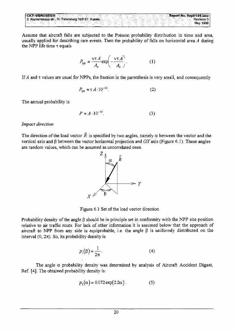
CKTI-VIBROSEISM3, Atamanskaya str., St. Petersburg 193167, Russia.
Report No. RepO1-99.iaeaRevision 0May 1999
Assume that aircraft falls are subjected to the Poisson probability distribution in time and area,usually applied for describing rare events. Then the probability of falls on horizontal area A duringthe NPP life time x equals
vxA vxA(1)
If A and x values are usual for NPPs, the fraction in the parenthesis is very small, and consequently
The annual probability is
Impact direction
V-10
(2)
(3)
The direction of the load vector R is specified by two angles, namely a between the vector and thevertical axis and P between the vector horizontal projection and QZaxis (Figure 6.1). These anglesare random values, which can be assumed as uncorrelated ones.
Z A ra
Figure 6.1 Set of the load vector direction
Probability density of the angle P should be in principle set in conformity with the NPP site positionrelative to air traffic routs. For lack of other information it is assumed below that the approach ofaircraft to NPP from any side is equiprobable, i.e. the angle P is uniformly distributed on theinterval (0, 2ri). So, its probability density is:
(4)
The angle a probability density was determined by analysis of Aircraft Accident Digest,Ref. [4]. The obtained probability density is:
p2(a) = 0.072 exp(2.2a). (5)
20

CICP-VIBROSEISM Report No. RepO1-99.iaea3, Atamanskaya str., St. Petersburg 193167, Russia. Revision 0
May 1999
To calculate puit probability density p(a, p) it should be taken into account that the probability ofload vector R application inside the "pyramid" (a, a+da, P, P+^P) is proportional to the solidangle bounded by it. This angle equals
dS = since da. d$ (6)i.e.
dP = Cp:($)p2(a)dS = C—0.072 exp(2.2a) since tfoc Jp (7)
The proportionality factor C is determined using the normalization condition:
271 n/2
\- (8)
3=0a=0
The calculating of the integral gives:
(a ,p)= 1.315- 10"2exp(2.2a)sina . (9)
Load on building structure caused by impact
Load R(t) on the building structure caused by an aircraft impact can be calculated-using well knownRiera's formula (Ref. [5]):
[] (10)
where x(i) is the length of the crushed part of fuselage, P^x(t)] is the fuselage longitudinal strengthdistribution, and p.[x(7)] is its mass distribution. So, the load is dependent on the aircraft class (i.e.its mass and strength) and impact velocity. All the parameters are random ones and should bedetermined by means of the analysis of flight orders and airspace situation near NPP. The data usedfor the example below correspond to the impact of the aircraft Phantom RF-4E. Smoothed andsomewhat simplified loads depending on the aircraft total mass m and velocity v0 are shown inFig. 2a-d.
Mass m and velocity v0 may be assumed as independent random variables. Then their jointprobability density is
p(m,vo)=pm(m)- p^yo), (11)
where pm(m) and pv(vo) are probability densities of mass and velocity correspondingly. Thesedensities obtained by the analysis of Phantom RF-4E crashes in Germany are given in Ref. [3].
Probability density pm(m) may be accepted as truncated normal distribution with mathematicalexpectation /w"=17360 kg, standard deviation a m =1505 kg, lower boundary zwmin = m - 2.46a m
and upper one 7wmax = m + 1.26a m.
The aircraft impact velocity vo can vary from 70 to 250 m/s. Its probability density pv(v0) issatisfactorily described by shifted logarithmic normal distribution with mathematical expectation
21

CKT1-VIBROSEISM3, Atamanskaya str., St. Petersburg 193167, Russia.
Report No. RepO1-99.iaeaRevision 0May 1999
vo=13Om/s and standard deviation av=47m/s. The cumulative probability distribution adaptedfrom Ref. [3], and the corresponding probability density are depicted on Figure 6.3.
R{t), MN200.00
160.00
120.00
80.00
40.00
0.00
1- - vo=24C
If/
m/s
IIj
\/I
77r
— i / /1/
1r—m= 22000\ J^
y\18000
/12000
wX \ \
\
\ \! \1 I
k g -
kg
kg
0.00 0.02 0.04 0.06
Time t, s0.08
R(t), MN160.00-
c)
120.00-
80.00-
40.00-
0.00-
vo=215 m/si= 22000 kg
J\
/ \ T 18000 kg
12000 kg -i
I I
0.00 0.02 0.04 0.06
Time f, s0.08
R(t), MN80.00-
60.00.
Vo=15O m/sI !
40.00-
20.00-
0.00.
. m- 22000 kg J
I
i 18000 kg -1
12000 kg
0.00 0.04 0.08
Time t, s
R(t), MN50.00-^ „„ ,
VQ=90 m/s
d)
40.00 - j - m = 22000 kg-
_ 18000 kg-30.00
20.00
10.00
0.00-
E2.r
£112000 kg.
I I
0.00 0.04 0.08
Time t, s
Figure 6.2 Load on building structure caused by Phantom RF-4E impactdepending on aircraft mass m and velocity vo
0.12
0.12
22

CKTUVIBROSEISM3, Atamanskaya str., St. Petersburg 193167, Russia.
Report No. RepO1-99.iaeaRevision 0May 1999
21
/
/
/
/
1
/
/
/
1
|
008
006
002
QOQ
i
h1
/
! /
/
7 1
\
\
\!
1
i/
\
\1
j
\
\
\
50.00 100.00 150.00 200.00 250.0050.00 100.00 150.00 200.00 250.00
Velocity v0, m/s Velocity v0, m/s
Fig. 6.2.3 Probability characteristics of the aircraft Phantom RF-4E velocity:
a) cumulative probability distribution <^(v0) (adapted from Ref. [3]); b) probability density pv(vo)
6.3 PROBABILITY OF IMPACT AT A GIVEN ANGLE TO THE STRUCTURESURFACE
To perform the probabilistic analysis of aircraft impact hazard, the probability of impact at a givenangle to the structure surface normal should be calculated. For this purpose an auxiliary problem onprobability of impact to inclined area element will first be solved.
Let dA be an area element inclined to the horizontal plane at angle <p. Annual probability of impact
to the element at angle y < y to its normal is denoted below as Pv [y < y). It is equal to
(12)
where./((P>y) is the annual probability of impact to the unit area element:
/(<P,Y)= (13)(•So)
The integral is calculated over the area So of solid angle bounded by a circular cone, whose axiscoincides with the element normal and the generatrix is inclined at the angle y (see Fig. 4). When(p •+JY>n/2, the part of angle So located below horizontal plane XOY is not taken into account. Thefunction_/(<P,Y) is plotted on Figure 6.5.
23

CKTI-VIBROSEISM3, Atamanskaya str., St. Petersburg 193167, Russia.
Report No. RepO1-99.iaeaRevision 0May 1999
Figure 6.4 Pattern for determinationof the impact to inclined area
element probability
Figure 6.5 Values of functionary)
0.00 20.00 40.00 60.00 80.00 100.00
Using Eqs. (12)-(13), the probability of an impact at angle y with different kinds of surfaces may becalculated. Three kinds of surfaces are typical of NPP building structures, namely a plane, acylinder with vertical axis, and a spherical segment (the last two surfaces are typical of reactorbuilding containment).
On impact with an inclined plane of area A the angle cp is the same at any of its point, for this reasonthe annual probability of an impact with plane at angle y < y is equal to
Ppl(y <y) = (14)
By analogy, the probability of an impact with a cylindrical surface of area A with a vertical axis is
05)
To calculate the probability of an impact with a spherical segment of radius p bounded by a conewith a vertical axis and vertex angle 5 (Fig. 6,a), the following should be taken into account. Thisprobability is the same for all the points belonging to the spherical layer with normal n inclined atangle (p. Its area is dA((p)=2np2sirupd<p. Consequently, the probability of an impact is
(16)
where r is the containment radius (see Fig. 6,a), and the function/i(5,y) is:
24

CKTT-VIBROSEISM3, Atamanskaya str., St. Petersburg 193167, Russia.
Report No. RepO1-99.iaeaRevision 0May i999
J5(5,Y) = -:sin" 8 'Y ) s i n ( P rf<P • (17)
The function/i(S,y) values are depicted on Figure 6.6,Z>.
a)
n
Figure 6.6 Determination ofimpact probability with spherical
dome:
a) spherical segment pattern;b) function/i(5,y) values
1.20
0.80
0.40
o.oo
0 0 0 20.00 40.00 60.00 80.00
6.4 BUILDING STRUCTURES FAILURE PROBABILITY
Let event J^be the building structure failure, i.e. its inadmissible damages (perforation, inadmissiblecracking, etc.). Methodology of failure probability P{<0j calculation is presented here. Assume firstthat the class of the impacting aircraft is known. For defmiteness it is assumed here that the aircraftis Phantom RF-4E. The way of different aircraft classes fall account will be described below.
Aircraft mass and velocity probability
Suppose that aircraft velocity and mass vary in ranges vmin^ v< vmax and mmin< m< /Mmax
correspondingly. To calculate the probability of their different values these ranges should bedivided into intervals Av and Am. Then the probability of an impact of an aircraft at velocity vo andmass m is equal to [see (11)]:
P(v0, m)=p(m,vo)AvAm= PmQn) pv(v0)
Impact load value probability
(18)
The impact load value R(vo, m, t) is uniquely dependent on the aircraft mass and velocity.Consequently the conditional probability of its value P(R\vo, m) is the same as mass and velocityprobability, i.e. is calculated using Eq. (18).
25

CKP-VIBROSEISM3, Atamanskaya str., St. Petersburg 193167, Russia.
Report No. RepO1-99.iaeaRevision 0May 1999
Failure probability of the building structure on impact with a given point
If a building structure is impacted at any angle to its surface, its strength is primarily dependent onthe normal load component. Because of that, for simplification sake, as the first approximation thetangential load component can be neglected when assessing the structure failure probability. Thissimplified methodology is described below.
R(m,vo,t)
kR(m,vo,i) = R(m,v0,f)cosy
Figure 6.7 Determination of the maximal anglebetween the load and the surface normal atwhich the building structure will collapse
If the strength of a building structure, loaded by force R(vo, m, f) which is applied in the /-th pointnormally to the structure surface is enough, then failure probability P,(^=0.
If the building structure strength is not enough, a fraction of force R(vo, m, t) should be determinedwhich can be borne by the structure. In other words, the maximal value of the reducing factor0<&<l has to be determined, so that if the building structure is loaded by force kR(v0, m, t) normallyto the surface, its strength will be enough. Obviously, A=cosy (see Fig. 7), where y is the vertexangle of the cone where the load applied inside will cause the structure failure. The angle equals
Y = arccosA:. (19)
It means that conditional probability P(£f\R) of failure caused by the given load R can be calculatedusing Eq. (12), i.e. it is equal to
• /(cp,y ),^ Y) = 101
where A is the structure area associated with a given impact point.
As R is uniquely dependent on m and vo, then
, v0).
(20)
(21)
Consequently, the total probability of the structure failure caused by the impact on its consideredpoint, at a given aircraft mass and velocity is equal to
, vo)pm(m)pv(vo) AvAm. (22)
To calculate the failure probability due to the impacts on all points of the structure, the probabilitiescorresponding to them should be summarized.
26
CKTl-VIBROSEISM Report No. RepO1-99.iaea3, Atamanskaya str., St. Petersburg 193167, Russia. Revision 0
May 1999
If some structure elements (for example, a containment dome or walls) can bear the same limit load,i.e. the impact at the same angle to their surface normal, their failure probability should becalculated using rather Eqs. (14)-(16) than Eq. (12).
In conclusion, note that more accurate analysis taking into account the tangential load componentmay be performed too, but it will need somewhat more complicated calculations.
Taking into account of aircraft class
Denote random event "the £-th class aircraft fall" by ^ . To take into account the possibility ofdifferent class aircraft impacts, the fall recurrence interval and corresponding fall probability P(**4t)for every of them should be determined.
Aircraft of any class gives specific load to the building structure. Using the described above routine,one should first calculate the structure conditional failure probability P(J%\^) due to the £-thaircraft class impact. Then the total failure probability of the structure P{^ taking into account allpossible aircraft classes can be calculated by use of the total probability formula:
k)- (23)
6.5 DEVELOPMENT OF FLOOR RESPONSE SPECTRA AT AIRCRAFT IMPACT
Specific feature of floor response spectra at aircraft impact is their very high accelerations when thespectra are calculated at building points near the impact place, and rapid decreasing of theaccelerations as the distance to these points increases. When floor response spectra are calculated,the building is modeled as a linear elastic system. So, on the impact at the given place, floorresponse spectra are proportional to the impact load value. Because of that the following simplifiedroutine can be used to develop them.
Let the maximal impact force corresponding to the maximal aircraft mass and velocity be i?max(0-For the simplification sake assume, that at any another mass m and v0 the force is proportional to
R(vQ, m, t)=k(v0, ™)#max(0, (24)
where k(v0, m) is the reducing factor, k(v0, m)<\. Probability P(VQ, m) of its realization is calculatedusing Eq. (18).
First, response spectra 5max for all structure levels of interest should be calculated, provided that theforce Rm3Jt) is applied along the structure surface normal which is inclined at angle cp. Then, by useof those spectra, spectra can be obtained for the force inclined to the normal. In so doing, influenceof the force tangential component may be neglected as the first approximation. At a given m and vo,i.e. at the force value R(v0, m, t) and its inclination angle y, the spectrum equals
27

CKTI-VIBROSEISM Report No. RepO1-99.iaea3, Autmanskaya str., St. Petersburg 193167, Russia. Revision 0
May 1999
k(v0, m), (25)
Probability of the spectrum is
ps=\0-10AA- P(y,<p> P(v0, m\ (26)
where AA is the impacted structure area associated with the considered impact point; P(y,q>) is theangle y probability. The latter can be obtained by using Eq. (12), for which purpose y variationrange (0, 2%) should be divided into intervals. If y,<y<Y;+i, then
P(cp,y) = P,(y <y , + 1 ) -P , (y<y , ) . (27)
This routine should be repeated for all impact points and aircraft classes. Then response spectra Sp
can be developed satisfying the condition that the probability of the unexciting of their values willbe equal to ps.
28
CKT1-VIBROSEISM Report No. RepO1-99.iaea3, Aijmanskaya str., St. Petersburg 193167, Russia. Revision 0
May 1999
REFERENCES
1. External Man-Induced Events in Relation to Nuclear Power Plant Siting. A Safety Guide. No 50-SG-S5. IAEA, Vienna, 1981.
2. Kobayashi, T. Probability Analysis of an Aircraft Crash to a Nuclear Power Plant - NuclearEngineering and Design, 110 (1988), pp. 207-211.
3. Zorn, W.F., and Shueller, G.F. On the Failure Probability of the Containment under AccidentalAircraft Impact - Nuclear Engineering and Design, 91 (1986), pp. 277-286.
4. Aircraft Accident Digest // ICAO Circular. No 16.1.88-AN/74 - No 29.191-AN-l 16.5. Riera J.D. On the Stress Analysis of Structures Subjected to Aircraft Impact Forces - Nuclear
Engineering and Design, 8 (1968), pp. 415-426.
29