Atmanirbhar Bharat: Transmutation from Privation to Exuberance
Upload
inter-islamCategory
view
0download
0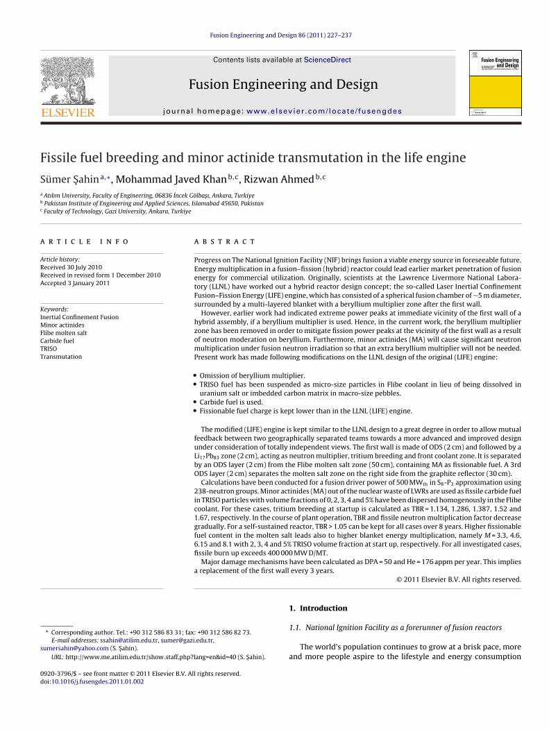
F
Sa
b
c
a
ARRA
KIMFCTT
s
0d
Fusion Engineering and Design 86 (2011) 227–237
Contents lists available at ScienceDirect
Fusion Engineering and Design
journa l homepage: www.e lsev ier .com/ locate / fusengdes
issile fuel breeding and minor actinide transmutation in the life engine
ümer Sahina,∗, Mohammad Javed Khanb,c, Rizwan Ahmedb,c
Atılım University, Faculty of Engineering, 06836 Incek Gölbası, Ankara, TurkiyePakistan Institute of Engineering and Applied Sciences, Islamabad 45650, PakistanFaculty of Technology, Gazi University, Ankara, Turkiye
r t i c l e i n f o
rticle history:eceived 30 July 2010eceived in revised form 1 December 2010ccepted 3 January 2011
eywords:nertial Confinement Fusion
inor actinideslibe molten saltarbide fuelRISOransmutation
a b s t r a c t
Progress on The National Ignition Facility (NIF) brings fusion a viable energy source in foreseeable future.Energy multiplication in a fusion–fission (hybrid) reactor could lead earlier market penetration of fusionenergy for commercial utilization. Originally, scientists at the Lawrence Livermore National Labora-tory (LLNL) have worked out a hybrid reactor design concept; the so-called Laser Inertial ConfinementFusion–Fission Energy (LIFE) engine, which has consisted of a spherical fusion chamber of ∼5 m diameter,surrounded by a multi-layered blanket with a beryllium multiplier zone after the first wall.
However, earlier work had indicated extreme power peaks at immediate vicinity of the first wall of ahybrid assembly, if a beryllium multiplier is used. Hence, in the current work, the beryllium multiplierzone has been removed in order to mitigate fission power peaks at the vicinity of the first wall as a resultof neutron moderation on beryllium. Furthermore, minor actinides (MA) will cause significant neutronmultiplication under fusion neutron irradiation so that an extra beryllium multiplier will not be needed.Present work has made following modifications on the LLNL design of the original (LIFE) engine:
• Omission of beryllium multiplier.• TRISO fuel has been suspended as micro-size particles in Flibe coolant in lieu of being dissolved in
uranium salt or imbedded carbon matrix in macro-size pebbles.• Carbide fuel is used.• Fissionable fuel charge is kept lower than in the LLNL (LIFE) engine.
The modified (LIFE) engine is kept similar to the LLNL design to a great degree in order to allow mutualfeedback between two geographically separated teams towards a more advanced and improved designunder consideration of totally independent views. The first wall is made of ODS (2 cm) and followed by aLi17Pb83 zone (2 cm), acting as neutron multiplier, tritium breeding and front coolant zone. It is separatedby an ODS layer (2 cm) from the Flibe molten salt zone (50 cm), containing MA as fissionable fuel. A 3rdODS layer (2 cm) separates the molten salt zone on the right side from the graphite reflector (30 cm).
Calculations have been conducted for a fusion driver power of 500 MWth in S8-P3 approximation using238-neutron groups. Minor actinides (MA) out of the nuclear waste of LWRs are used as fissile carbide fuelin TRISO particles with volume fractions of 0, 2, 3, 4 and 5% have been dispersed homogenously in the Flibecoolant. For these cases, tritium breeding at startup is calculated as TBR = 1.134, 1.286, 1.387, 1.52 and
1.67, respectively. In the course of plant operation, TBR and fissile neutron multiplication factor decreasegradually. For a self-sustained reactor, TBR > 1.05 can be kept for all cases over 8 years. Higher fissionablefuel content in the molten salt leads also to higher blanket energy multiplication, namely M = 3.3, 4.6,6.15 and 8.1 with 2, 3, 4 and 5% TRISO volume fraction at start up, respectively. For all investigated cases,fissile burn up exceeds 400 000 MW D/MT.Major damage mechanismsa replacement of the first wall
∗ Corresponding author. Tel.: +90 312 586 83 31; fax: +90 312 586 82 73.E-mail addresses: [email protected], [email protected],
[email protected] (S. Sahin).URL: http://www.me.atilim.edu.tr/show staff.php?lang=en&id=40 (S. Sahin).
920-3796/$ – see front matter © 2011 Elsevier B.V. All rights reserved.oi:10.1016/j.fusengdes.2011.01.002
have been calculated as DPA = 50 and He = 176 appm per year. This impliesevery 3 years.
© 2011 Elsevier B.V. All rights reserved.
1. Introduction
1.1. National Ignition Facility as a forerunner of fusion reactors
The world’s population continues to grow at a brisk pace, moreand more people aspire to the lifestyle and energy consumption
228 S. Sahin et al. / Fusion Engineering and Design 86 (2011) 227–237
liftvpttipm
(
(
Early reports had estimated that ∼1700 tons of reactor grade pluto-
Fig. 1. General view of the National Ignition Facility (NIF) [1].
evels of industrialized countries. The world’s energy needs arencreasing rapidly, but supplies of the most convenient forms ofuel are finite. Commercial fusion power has the potential to fillhe gap between supply and demand by providing an affordable,irtually limitless source of energy. But first, the technology mustass a series of tests demonstrating that self-sustaining fusion reac-ions can be achieved and reproduced in the laboratory. Researcheams worldwide have been working on this science and engineer-ng grand challenge for decades. Fusion energy research for theurpose of industrial power production is being pursued on twoainline approaches:
1) Magnetic fusion energy (MFE) uses strong magnetic fields toconfine a low-density deuterium and tritium (DT) plasma toachieve sustainable conditions to generate fusion energy. Onthat line, the first macro scale MFE project, called InternationalTokamak Experimental Reactor (ITER) is expected to producefusion power in the 400–500 MWth range, and is on design.
2) Inertial fusion energy (IFE) can use laser beams or heavy ionbeams to compress a capsule containing a mixture of DT ice andgas, either by direct illumination or by indirect illumination. TheNational Ignition Facility (NIF) at Lawrence Livermore NationalLaboratory (LLNL) is the world’s largest, most energetic laser,and is the next major step towards making fusion a viableenergy source. This most advanced macro scale IFE projectis expected to become fully operational early 2011, produc-ing fusion energy in the 40–50 MWth range with simultaneousoperation of all 192 laser beams. Fig. 1 shows the general viewof the NIF site [1]. NIF experiments are designed to achieve igni-tion through indirect-drive, inertial-confinement fusion. NIF’s192 beams are focused through a hole in the top and bottom
of a gas-filled, gold hohlraum, a centimeter-size enclosure thattraps radiation. Fig. 2 shows the main components of one of the192 laser beam lines, which all converge in the target chamber[2].Fig. 2. Main components of a laser beam lin
Fig. 3. NIF target design (a) target and illumination geometry for baseline NIF targetdesign and (b) an artistic view [1].
In the center of the hohlraum is a 2-mm-diameter pellet filledwith nuclear fuel in both gas and solid forms, Fig. 3 [1,3]. Duringa shot, laser beams strike the internal walls of the cryogenicallycooled hohlraum and are converted to X-rays that irradiate and heatthe outer layer of the fuel pellet. As this layer expands and ablates,it rapidly compresses the pellet’s core, driving it to temperaturesand pressures greater than those in the interior of the Sun. Theseextreme conditions cause the fuel’s nuclei to fuse and release farmore energy than that was necessary to initiate the reaction [3].
NIF ignition experiments will most likely demonstrate ignitionand net energy gain. This will be a milestone for inertial fusion onmacro-scale and focus the world’s attention on IFE as a real andattractive energy production technology.
1.2. Nuclear waste minor actinides as potential fuel in fusionreactors
Nuclear power plants are producing nuclear waste materials insubstantial quantities, which can be classified as minor actinides(MA), fission products and structural materials. MA can be definedas the most hazardous radioactive waste products because of theirlong term, high level radioactivity. Table 1 shows the compositionof MA in the spent fuel of a light water reactor, adopted from ref.[4]. A significant fraction of reactor waste MA consists of diverseplutonium isotopes, which represents serious public and politicalconcern with respect to misuse of this plutonium and also acci-dental release of highly radiotoxic material in to the environment.
nium would be accumulated by ∼2000 [5–7]. An August 2001 datedreport cites “In August 1996 there were 439 nuclear power plants in32 countries. The world’s power reactors consume the equivalentof 60,000 tons of uranium each year. The total amount of plutonium
e of The National Ignition Facility [2].
S. Sahin et al. / Fusion Engineering and Design 86 (2011) 227–237 229
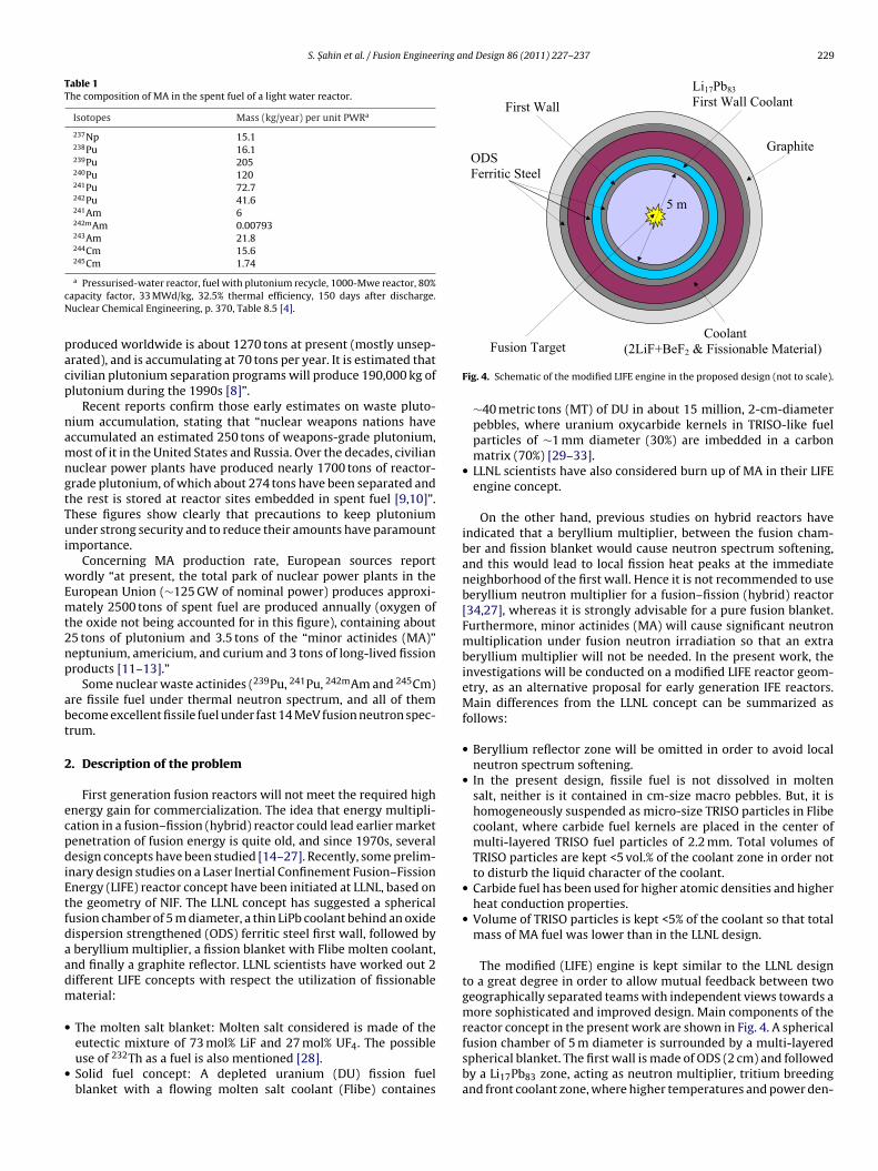
Table 1The composition of MA in the spent fuel of a light water reactor.
Isotopes Mass (kg/year) per unit PWRa
237Np 15.1238Pu 16.1239Pu 205240Pu 120241Pu 72.7242Pu 41.6241Am 6242mAm 0.00793243Am 21.8244Cm 15.6245Cm 1.74
cN
pacp
namngtTui
wEmt2np
abt
2
ecpdiEtfdaadm
•
•
5 m
First Wall
ODSFerritic Steel
Graphite
Li17Pb83
First Wall Coolant
a Pressurised-water reactor, fuel with plutonium recycle, 1000-Mwe reactor, 80%apacity factor, 33 MWd/kg, 32.5% thermal efficiency, 150 days after discharge.uclear Chemical Engineering, p. 370, Table 8.5 [4].
roduced worldwide is about 1270 tons at present (mostly unsep-rated), and is accumulating at 70 tons per year. It is estimated thativilian plutonium separation programs will produce 190,000 kg oflutonium during the 1990s [8]”.
Recent reports confirm those early estimates on waste pluto-ium accumulation, stating that “nuclear weapons nations haveccumulated an estimated 250 tons of weapons-grade plutonium,ost of it in the United States and Russia. Over the decades, civilian
uclear power plants have produced nearly 1700 tons of reactor-rade plutonium, of which about 274 tons have been separated andhe rest is stored at reactor sites embedded in spent fuel [9,10]”.hese figures show clearly that precautions to keep plutoniumnder strong security and to reduce their amounts have paramount
mportance.Concerning MA production rate, European sources report
ordly “at present, the total park of nuclear power plants in theuropean Union (∼125 GW of nominal power) produces approxi-ately 2500 tons of spent fuel are produced annually (oxygen of
he oxide not being accounted for in this figure), containing about5 tons of plutonium and 3.5 tons of the “minor actinides (MA)”eptunium, americium, and curium and 3 tons of long-lived fissionroducts [11–13].”
Some nuclear waste actinides (239Pu, 241Pu, 242mAm and 245Cm)re fissile fuel under thermal neutron spectrum, and all of themecome excellent fissile fuel under fast 14 MeV fusion neutron spec-rum.
. Description of the problem
First generation fusion reactors will not meet the required highnergy gain for commercialization. The idea that energy multipli-ation in a fusion–fission (hybrid) reactor could lead earlier marketenetration of fusion energy is quite old, and since 1970s, severalesign concepts have been studied [14–27]. Recently, some prelim-
nary design studies on a Laser Inertial Confinement Fusion–Fissionnergy (LIFE) reactor concept have been initiated at LLNL, based onhe geometry of NIF. The LLNL concept has suggested a sphericalusion chamber of 5 m diameter, a thin LiPb coolant behind an oxideispersion strengthened (ODS) ferritic steel first wall, followed byberyllium multiplier, a fission blanket with Flibe molten coolant,nd finally a graphite reflector. LLNL scientists have worked out 2ifferent LIFE concepts with respect the utilization of fissionableaterial:
The molten salt blanket: Molten salt considered is made of theeutectic mixture of 73 mol% LiF and 27 mol% UF4. The possibleuse of 232Th as a fuel is also mentioned [28].Solid fuel concept: A depleted uranium (DU) fission fuelblanket with a flowing molten salt coolant (Flibe) containes
Fusion Target Coolant
(2LiF+BeF2 & Fissionable Material)
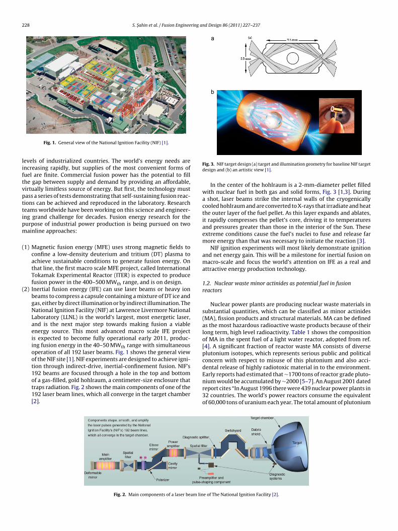
Fig. 4. Schematic of the modified LIFE engine in the proposed design (not to scale).
∼40 metric tons (MT) of DU in about 15 million, 2-cm-diameterpebbles, where uranium oxycarbide kernels in TRISO-like fuelparticles of ∼1 mm diameter (30%) are imbedded in a carbonmatrix (70%) [29–33].
• LLNL scientists have also considered burn up of MA in their LIFEengine concept.
On the other hand, previous studies on hybrid reactors haveindicated that a beryllium multiplier, between the fusion cham-ber and fission blanket would cause neutron spectrum softening,and this would lead to local fission heat peaks at the immediateneighborhood of the first wall. Hence it is not recommended to useberyllium neutron multiplier for a fusion–fission (hybrid) reactor[34,27], whereas it is strongly advisable for a pure fusion blanket.Furthermore, minor actinides (MA) will cause significant neutronmultiplication under fusion neutron irradiation so that an extraberyllium multiplier will not be needed. In the present work, theinvestigations will be conducted on a modified LIFE reactor geom-etry, as an alternative proposal for early generation IFE reactors.Main differences from the LLNL concept can be summarized asfollows:
• Beryllium reflector zone will be omitted in order to avoid localneutron spectrum softening.
• In the present design, fissile fuel is not dissolved in moltensalt, neither is it contained in cm-size macro pebbles. But, it ishomogeneously suspended as micro-size TRISO particles in Flibecoolant, where carbide fuel kernels are placed in the center ofmulti-layered TRISO fuel particles of 2.2 mm. Total volumes ofTRISO particles are kept <5 vol.% of the coolant zone in order notto disturb the liquid character of the coolant.
• Carbide fuel has been used for higher atomic densities and higherheat conduction properties.
• Volume of TRISO particles is kept <5% of the coolant so that totalmass of MA fuel was lower than in the LLNL design.
The modified (LIFE) engine is kept similar to the LLNL designto a great degree in order to allow mutual feedback between twogeographically separated teams with independent views towards amore sophisticated and improved design. Main components of the
reactor concept in the present work are shown in Fig. 4. A sphericalfusion chamber of 5 m diameter is surrounded by a multi-layeredspherical blanket. The first wall is made of ODS (2 cm) and followedby a Li17Pb83 zone, acting as neutron multiplier, tritium breedingand front coolant zone, where higher temperatures and power den-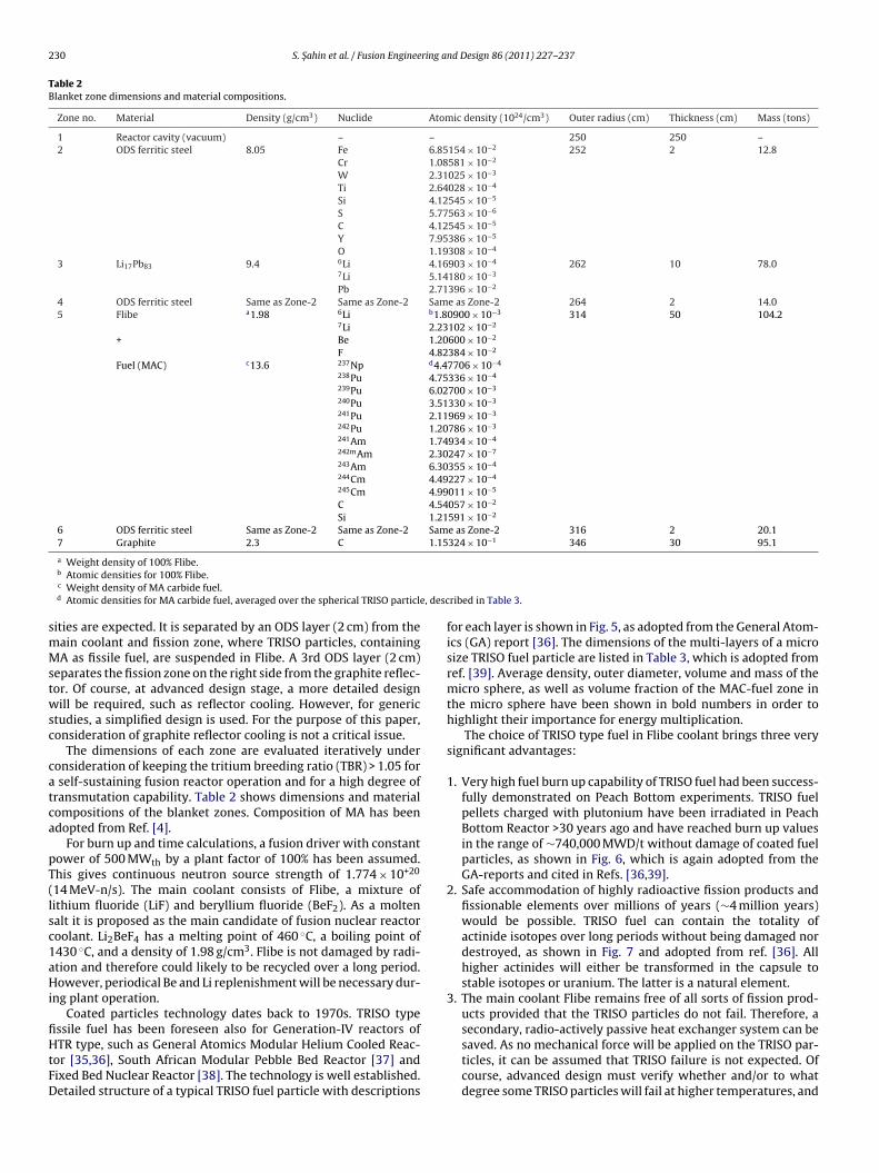
230 S. Sahin et al. / Fusion Engineering and Design 86 (2011) 227–237
Table 2Blanket zone dimensions and material compositions.
Zone no. Material Density (g/cm3) Nuclide Atomic density (1024/cm3) Outer radius (cm) Thickness (cm) Mass (tons)
1 Reactor cavity (vacuum) – – 250 250 –2 ODS ferritic steel 8.05 Fe 6.85154 × 10⁻² 252 2 12.8
Cr 1.08581 × 10⁻²
W 2.31025 × 10⁻³
Ti 2.64028 × 10⁻⁴
Si 4.12545 × 10⁻⁵
S 5.77563 × 10⁻⁶
C 4.12545 × 10⁻⁵
Y 7.95386 × 10⁻⁵
O 1.19308 × 10⁻⁴
3 Li17Pb83 9.4 6Li 4.16903 × 10⁻⁴ 262 10 78.07Li 5.14180 × 10⁻³
Pb 2.71396 × 10⁻²
4 ODS ferritic steel Same as Zone-2 Same as Zone-2 Same as Zone-2 264 2 14.05 Flibe a1.98 6Li b1.80900 × 10−3 314 50 104.2
7Li 2.23102 × 10⁻²
+ Be 1.20600 × 10⁻²
F 4.82384 × 10⁻²
Fuel (MAC) c13.6 237Np d4.47706 × 10−4
238Pu 4.75336 × 10⁻⁴
239Pu 6.02700 × 10⁻³
240Pu 3.51330 × 10⁻³
241Pu 2.11969 × 10⁻³
242Pu 1.20786 × 10⁻³
241Am 1.74934 × 10⁻⁴
242mAm 2.30247 × 10⁻⁷
243Am 6.30355 × 10⁻⁴
244Cm 4.49227 × 10⁻⁴
245Cm 4.99011 × 10⁻⁵
C 4.54057 × 10⁻²
Si 1.21591 × 10⁻²
6 ODS ferritic steel Same as Zone-2 Same as Zone-2 Same as Zone-2 316 2 20.17 Graphite 2.3 C 1.15324 × 10⁻¹ 346 30 95.1
e, desc
smMstwsc
catca
pT(lsc1aHi
fiHtFD
a Weight density of 100% Flibe.b Atomic densities for 100% Flibe.c Weight density of MA carbide fuel.d Atomic densities for MA carbide fuel, averaged over the spherical TRISO particl
ities are expected. It is separated by an ODS layer (2 cm) from theain coolant and fission zone, where TRISO particles, containingA as fissile fuel, are suspended in Flibe. A 3rd ODS layer (2 cm)
eparates the fission zone on the right side from the graphite reflec-or. Of course, at advanced design stage, a more detailed designill be required, such as reflector cooling. However, for generic
tudies, a simplified design is used. For the purpose of this paper,onsideration of graphite reflector cooling is not a critical issue.
The dimensions of each zone are evaluated iteratively underonsideration of keeping the tritium breeding ratio (TBR) > 1.05 forself-sustaining fusion reactor operation and for a high degree of
ransmutation capability. Table 2 shows dimensions and materialompositions of the blanket zones. Composition of MA has beendopted from Ref. [4].
For burn up and time calculations, a fusion driver with constantower of 500 MWth by a plant factor of 100% has been assumed.his gives continuous neutron source strength of 1.774 × 10+20
14 MeV-n/s). The main coolant consists of Flibe, a mixture ofithium fluoride (LiF) and beryllium fluoride (BeF2). As a moltenalt it is proposed as the main candidate of fusion nuclear reactoroolant. Li2BeF4 has a melting point of 460 ◦C, a boiling point of430 ◦C, and a density of 1.98 g/cm3. Flibe is not damaged by radi-tion and therefore could likely to be recycled over a long period.owever, periodical Be and Li replenishment will be necessary dur-
ng plant operation.Coated particles technology dates back to 1970s. TRISO type
ssile fuel has been foreseen also for Generation-IV reactors ofTR type, such as General Atomics Modular Helium Cooled Reac-
or [35,36], South African Modular Pebble Bed Reactor [37] andixed Bed Nuclear Reactor [38]. The technology is well established.etailed structure of a typical TRISO fuel particle with descriptions
ribed in Table 3.
for each layer is shown in Fig. 5, as adopted from the General Atom-ics (GA) report [36]. The dimensions of the multi-layers of a microsize TRISO fuel particle are listed in Table 3, which is adopted fromref. [39]. Average density, outer diameter, volume and mass of themicro sphere, as well as volume fraction of the MAC-fuel zone inthe micro sphere have been shown in bold numbers in order tohighlight their importance for energy multiplication.
The choice of TRISO type fuel in Flibe coolant brings three verysignificant advantages:
1. Very high fuel burn up capability of TRISO fuel had been success-fully demonstrated on Peach Bottom experiments. TRISO fuelpellets charged with plutonium have been irradiated in PeachBottom Reactor >30 years ago and have reached burn up valuesin the range of ∼740,000 MWD/t without damage of coated fuelparticles, as shown in Fig. 6, which is again adopted from theGA-reports and cited in Refs. [36,39].
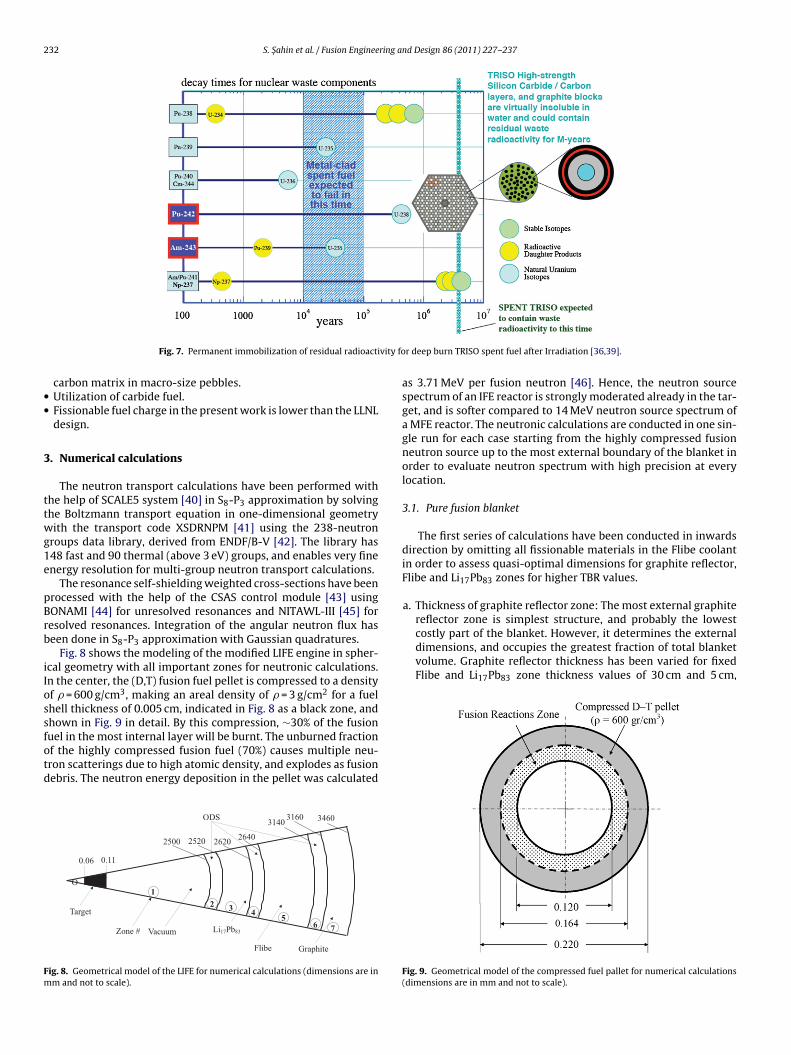
2. Safe accommodation of highly radioactive fission products andfissionable elements over millions of years (∼4 million years)would be possible. TRISO fuel can contain the totality ofactinide isotopes over long periods without being damaged nordestroyed, as shown in Fig. 7 and adopted from ref. [36]. Allhigher actinides will either be transformed in the capsule tostable isotopes or uranium. The latter is a natural element.
3. The main coolant Flibe remains free of all sorts of fission prod-ucts provided that the TRISO particles do not fail. Therefore, a
secondary, radio-actively passive heat exchanger system can besaved. As no mechanical force will be applied on the TRISO par-ticles, it can be assumed that TRISO failure is not expected. Ofcourse, advanced design must verify whether and/or to whatdegree some TRISO particles will fail at higher temperatures, and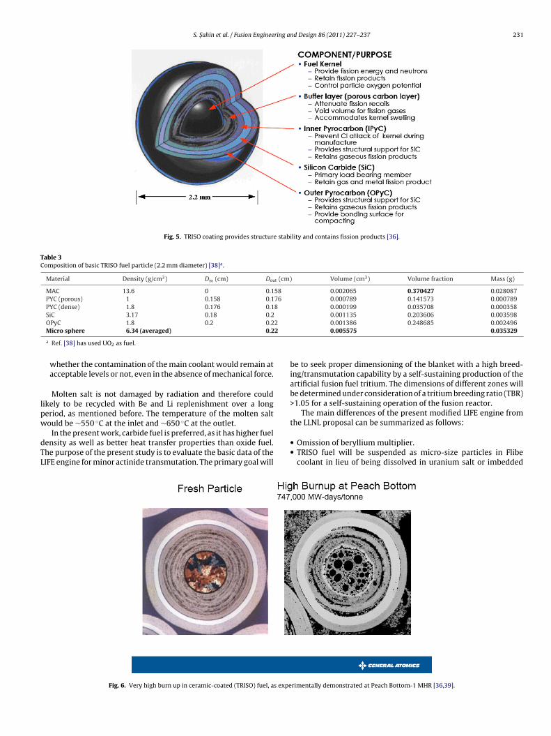
S. Sahin et al. / Fusion Engineering and Design 86 (2011) 227–237 231
Fig. 5. TRISO coating provides structure stability and contains fission products [36].
Table 3Composition of basic TRISO fuel particle (2.2 mm diameter) [38]a.
Material Density (g/cm3) Din (cm) Dout (cm) Volume (cm3) Volume fraction Mass (g)
MAC 13.6 0 0.158 0.002065 0.370427 0.028087PYC (porous) 1 0.158 0.176 0.000789 0.141573 0.000789PYC (dense) 1.8 0.176 0.18 0.000199 0.035708 0.000358SiC 3.17 0.18 0.2 0.001135 0.203606 0.003598
22
lpw
dTL
OPyC 1.8 0.2 0.2Micro sphere 6.34 (averaged) 0.2
a Ref. [38] has used UO2 as fuel.
whether the contamination of the main coolant would remain atacceptable levels or not, even in the absence of mechanical force.
Molten salt is not damaged by radiation and therefore couldikely to be recycled with Be and Li replenishment over a longeriod, as mentioned before. The temperature of the molten salt
ould be ∼550 ◦C at the inlet and ∼650 ◦C at the outlet.In the present work, carbide fuel is preferred, as it has higher fuelensity as well as better heat transfer properties than oxide fuel.he purpose of the present study is to evaluate the basic data of theIFE engine for minor actinide transmutation. The primary goal will
Fig. 6. Very high burn up in ceramic-coated (TRISO) fuel, as expe
0.001386 0.248685 0.0024960.005575 0.035329
be to seek proper dimensioning of the blanket with a high breed-ing/transmutation capability by a self-sustaining production of theartificial fusion fuel tritium. The dimensions of different zones willbe determined under consideration of a tritium breeding ratio (TBR)>1.05 for a self-sustaining operation of the fusion reactor.
The main differences of the present modified LIFE engine from
the LLNL proposal can be summarized as follows:• Omission of beryllium multiplier.• TRISO fuel will be suspended as micro-size particles in Flibe
coolant in lieu of being dissolved in uranium salt or imbedded
rimentally demonstrated at Peach Bottom-1 MHR [36,39].
232 S. Sahin et al. / Fusion Engineering and Design 86 (2011) 227–237
vity fo
••
3
ttwg1e
pBrb
iIossfotd
Fm
reflector zone is simplest structure, and probably the lowestcostly part of the blanket. However, it determines the externaldimensions, and occupies the greatest fraction of total blanketvolume. Graphite reflector thickness has been varied for fixedFlibe and Li17Pb83 zone thickness values of 30 cm and 5 cm,
Fig. 7. Permanent immobilization of residual radioacti
carbon matrix in macro-size pebbles.Utilization of carbide fuel.Fissionable fuel charge in the present work is lower than the LLNLdesign.
. Numerical calculations
The neutron transport calculations have been performed withhe help of SCALE5 system [40] in S8-P3 approximation by solvinghe Boltzmann transport equation in one-dimensional geometryith the transport code XSDRNPM [41] using the 238-neutron
roups data library, derived from ENDF/B-V [42]. The library has48 fast and 90 thermal (above 3 eV) groups, and enables very finenergy resolution for multi-group neutron transport calculations.
The resonance self-shielding weighted cross-sections have beenrocessed with the help of the CSAS control module [43] usingONAMI [44] for unresolved resonances and NITAWL-III [45] foresolved resonances. Integration of the angular neutron flux haseen done in S8-P3 approximation with Gaussian quadratures.
Fig. 8 shows the modeling of the modified LIFE engine in spher-cal geometry with all important zones for neutronic calculations.n the center, the (D,T) fusion fuel pellet is compressed to a densityf � = 600 g/cm3, making an areal density of � = 3 g/cm2 for a fuelhell thickness of 0.005 cm, indicated in Fig. 8 as a black zone, andhown in Fig. 9 in detail. By this compression, ∼30% of the fusion
uel in the most internal layer will be burnt. The unburned fractionf the highly compressed fusion fuel (70%) causes multiple neu-ron scatterings due to high atomic density, and explodes as fusionebris. The neutron energy deposition in the pellet was calculated12 3 4
56 7Zone # Li17Pb83Vacuum
Flibe Graphite
2500 2520 2620 2640
31403160 3460
Target
O
ODS
0.110.06
ig. 8. Geometrical model of the LIFE for numerical calculations (dimensions are inm and not to scale).
r deep burn TRISO spent fuel after Irradiation [36,39].
as 3.71 MeV per fusion neutron [46]. Hence, the neutron sourcespectrum of an IFE reactor is strongly moderated already in the tar-get, and is softer compared to 14 MeV neutron source spectrum ofa MFE reactor. The neutronic calculations are conducted in one sin-gle run for each case starting from the highly compressed fusionneutron source up to the most external boundary of the blanket inorder to evaluate neutron spectrum with high precision at everylocation.
3.1. Pure fusion blanket
The first series of calculations have been conducted in inwardsdirection by omitting all fissionable materials in the Flibe coolantin order to assess quasi-optimal dimensions for graphite reflector,Flibe and Li17Pb83 zones for higher TBR values.
a. Thickness of graphite reflector zone: The most external graphite
Fig. 9. Geometrical model of the compressed fuel pallet for numerical calculations(dimensions are in mm and not to scale).

S. Sahin et al. / Fusion Engineering and Design 86 (2011) 227–237 233
Table 4Effect of graphite reflector thickness on TBR (100% Flibe, Flibe thickness = 30 cm).
Graphite thickness (cm) Li17Pb83 (5 cm) Flibe TBR
<6Li(n,�)T> <7Li(n,�)T> <6Li(n,�)T> <7Li(n,�)T>
10 0.0506 0.0082 0.8520 0.0558 0.9666
b
b
stbcwi
TE
20 0.0506 0.008230 0.0507 0.008240 0.0506 0.008250 0.0506 0.0082
respectively. Table 4 shows the differential and integral TBRvalues in detail. One can see clearly that graphite reflector haspractically no effect on tritium breeding in the most internalLi17Pb83 zone and on the threshold reaction 7Li(nn′,�)T with fastneutrons. It has only minor effects on the 6Li(n,�)T with ther-mal neutrons. However, this modest increase of �TBR = 0.0142and 0.0188 from Tgr = 10 cm to 20 cm and 30 cm, respectively,becomes important if one considers that the required excess tri-tium for a self-sustaining operation is only �TBR > 0.05. In thecourse of this study, Tgr = 30 cm will be used. In Table 4, inte-gral reaction rates for a graphite reflector thickness of Tgr = 10 cmhave been shown in bold numbers to highlight their choice in therest of the study.
. Thickness of Li17Pb83 and Flibe zones: The above selecteddimensions for Li17Pb83 and Flibe zones will not be able toproduce sufficient tritium for the fusion driver. Higher TBRshould be sought. An increase of Li17Pb83 zone thickness from5 to 10 cm brings TBR very close to the desired value of 1.05.One observes almost a doubling of 6Li(n,�)T and 7Li(nn′,�)Treaction rates. As Li17Pb83 has a high weight density, it willrequire higher pumping power. Also, metallic coolant is sub-ject to MHD effects. Hence, Flibe zone will be increased. Table 5shows TBR values for the investigated cases. Increase of Flibezone from 30 cm to 40 and 50 cm leads to important increase ofTBR.
Under those considerations, following blanket dimensions haveeen used in the course of this study:
Thickness of Li17Pb83 zone: 10 cm.Thickness of Flibe zone: 50 cm. In Table 5, integral reaction ratesfor 50 cm Flibe zone have been shown in bold numbers to highlighttheir choice in the rest of the study.Thickness of graphite reflector: 30 cm.
By these dimensions and without fissile fuel in the Flibe moltenalt, tritium breeding per fusion reaction becomes TBR = 1.134. Fur-
her increase of Flibe zone would bring some enhancement to TBR,ut the LIFE engine would be too bulky. Previous work had cal-ulated the asymptotic value of tritium breeding in fusion blanketsith Flibe coolant as TBR = ∼1.27 [47] and TBR = ∼1.25 [48], but thiss not needed for the present work.
able 5ffects of Flibe and coolant thickness on TBR (100% Flibe, reflector thickness = 30 cm).
Flibe thickness (cm) Coolant (Li17Pb83) zone thickness = 5 cm
Li17Pb83 Flibe TB
T6 T7 T6 T7
30 0.0507 0.0082 0.8706 0.0559 0.40 0.0506 0.0082 0.9362 0.0587 1.50 0.0505 0.0082 0.9674 0.0598 1.
0.8661 0.0559 0.98080.8706 0.0559 0.98540.8726 0.0559 0.98730.8739 0.0559 0.9886
3.2. Blanket with minor actinides
During the second phase, MA will be introduced to the coolantas fissionable fuel in the kernel of the TRISO particles, and will bemixed with Flibe molten salt homogenously at increasing volumefractions. By all scenario, the TBR > 1.05 criterion for self-sustainingfusion reactor operation will be preserved. Calculations have beenconducted for the following cases:
% 2 MAC + % 98 Flibe (5.05 tons of fissionable material at startup).
% 3 MAC + % 97 Flibe (7.57 tons of fissionable material at startup).
% 4 MAC + % 96 Flibe (10.1 tons of fissionable material at startup).
% 5 MAC + % 95 Flibe (12.62 tons of fissionable material at startup).
Fissionable material (MA) mass values for corresponding com-positions have been calculated, based on data in Tables 2 and 3, asfollows: (Density of MAC) × (volume of spherical Flibe zone shellwith Din = 264 cm and Dout = 314 cm) × (volume fraction of TRISOparticles in the molten salt) × (volume fraction of fuel kernel in theTRISO particle) × (weight fraction of MA in MAC). Fraction of TRISOparticles in the molten salt has been limited by % 5 in order not toperturb fluid character of the coolant excessively.
At start up, the atomic densities N0 of the fissionable fuel iso-topes are determined according to the isotopic composition of theinitial LWR spent fuel, given in Table 1, as adopted from Ref. [4].In the course of SN transport calculations with the XSDRNPM code,the implemented 238-neutron group activity cross sections of thesame data library in the SCALE package has been used in orderto calculate the production and depletion reactions of all fission-able fuel isotopes as corresponding activities per cm3 s in the samerun. A constant fusion driver power of 500 MWth and a plant factorof 100% have been assumed for time dependent calculations. Thechanges in actinides atomic densities �N are described with thehelp of Eqs. (1) and (2), and are calculated externally with a sepa-rate code. Then, the new densities are given as an input to another
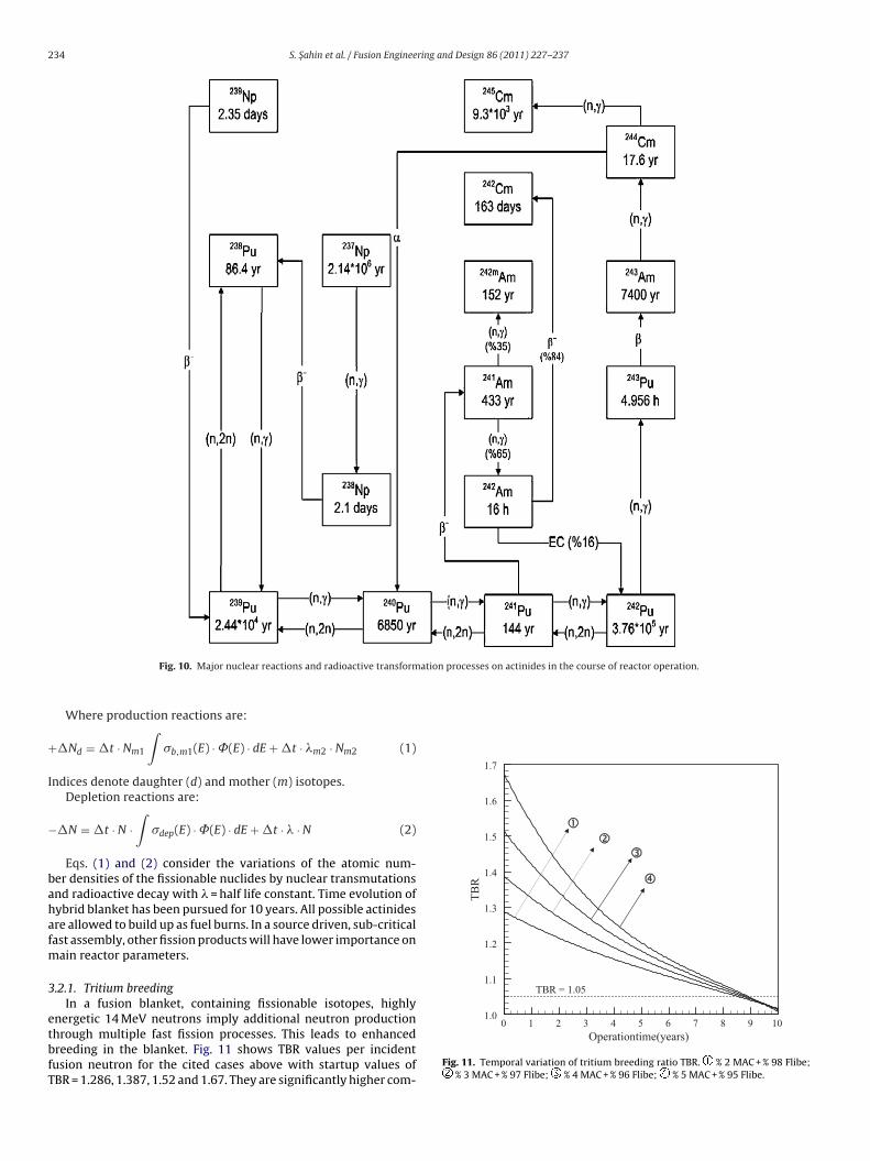
XSDRNPM run, starting with resonance self-shielding calculationsfor each individual case, and this process is repeated for every dis-crete time interval �t = 30 days. The re-evaluation of the atomicdensities N of fissionable fuel isotopes is done under considerationof all possible nuclear reactions, shown in Fig. 10, in detail.Coolant (Li17Pb83) zone thickness = 10 cm
R Li17Pb83 Flibe TBR
T6 T7 T6 T7
9854 0.1066 0.0149 0.8861 0.0372 1.04480537 0.1065 0.0149 0.9466 0.0389 1.10690859 0.1064 0.0149 0.9739 0.0396 1.1348
234 S. Sahin et al. / Fusion Engineering and Design 86 (2011) 227–237
ation processes on actinides in the course of reactor operation.
+
I
−
bahafm
3
etbfT
TB
R
1.1
1.2
1.3
1.4
1.5
1.6
1.7
TBR = 1.05
Fig. 10. Major nuclear reactions and radioactive transform
Where production reactions are:
�Nd = �t · Nm1
∫�b,m1(E) · ˚(E) · dE + �t · �m2 · Nm2 (1)
ndices denote daughter (d) and mother (m) isotopes.Depletion reactions are:
�N = �t · N ·∫
�dep(E) · ˚(E) · dE + �t · � · N (2)
Eqs. (1) and (2) consider the variations of the atomic num-er densities of the fissionable nuclides by nuclear transmutationsnd radioactive decay with � = half life constant. Time evolution ofybrid blanket has been pursued for 10 years. All possible actinidesre allowed to build up as fuel burns. In a source driven, sub-criticalast assembly, other fission products will have lower importance on
ain reactor parameters.
.2.1. Tritium breedingIn a fusion blanket, containing fissionable isotopes, highly
nergetic 14 MeV neutrons imply additional neutron productionhrough multiple fast fission processes. This leads to enhancedreeding in the blanket. Fig. 11 shows TBR values per incidentusion neutron for the cited cases above with startup values ofBR = 1.286, 1.387, 1.52 and 1.67. They are significantly higher com-
Operationtime(years)0 1 2 3 4 5 6 7 8 9 10
1.0
Fig. 11. Temporal variation of tritium breeding ratio TBR. % 2 MAC + % 98 Flibe;% 3 MAC + % 97 Flibe; % 4 MAC + % 96 Flibe; % 5 MAC + % 95 Flibe.
S. Sahin et al. / Fusion Engineering and Design 86 (2011) 227–237 235
Operation time (years)
Ene
rgy
mul
tiplic
atio
nfa
ctor
0 1 2 3 4 5 6 7 8 9 102
3
4
5
6
7
8
9
FF
pafhto
3
nfnmea
M
T
ak�dn
chtiasas4r∼lr
Fuel
burn
upgr
ade
(GW
D/M
T)
0
50
100
150
200
250
300
350
400
450
500
isotopes in the blanket over 10 years in a closed cycle operationscenario for a TRISO volume fraction of 5%. One observes a rapiddecrease of 239Pu isotope via fission and neutron capture. The lat-ter keeps the 240Pu level in the coolant fairly constant for ∼5 years.
Mas
s(k
g)
1000
2000
3000
4000
5000
6000
7000
239Pu
240Pu
241Pu
242Pu
238Pu
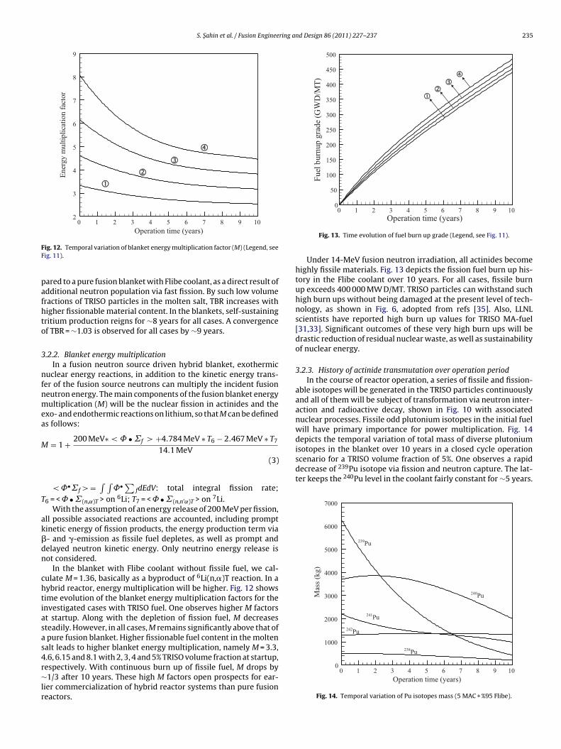
ig. 12. Temporal variation of blanket energy multiplication factor (M) (Legend, seeig. 11).
ared to a pure fusion blanket with Flibe coolant, as a direct result ofdditional neutron population via fast fission. By such low volumeractions of TRISO particles in the molten salt, TBR increases withigher fissionable material content. In the blankets, self-sustainingritium production reigns for ∼8 years for all cases. A convergencef TBR = ∼1.03 is observed for all cases by ∼9 years.
.2.2. Blanket energy multiplicationIn a fusion neutron source driven hybrid blanket, exothermic
uclear energy reactions, in addition to the kinetic energy trans-er of the fusion source neutrons can multiply the incident fusioneutron energy. The main components of the fusion blanket energyultiplication (M) will be the nuclear fission in actinides and the
xo- and endothermic reactions on lithium, so that M can be defineds follows:
= 1 + 200 MeV∗ < ˚ • ˙f > +4.784 MeV ∗ T6 − 2.467 MeV ∗ T7
14.1 MeV(3)
< ˚•˙f > =∫ ∫
˚• ∑fdEdV: total integral fission rate;
6 = < ˚ • ˙(n,˛)T > on 6Li; T7 = < ˚ • ˙(n,n’˛)T > on 7Li.With the assumption of an energy release of 200 MeV per fission,
ll possible associated reactions are accounted, including promptinetic energy of fission products, the energy production term via- and �-emission as fissile fuel depletes, as well as prompt andelayed neutron kinetic energy. Only neutrino energy release isot considered.
In the blanket with Flibe coolant without fissile fuel, we cal-ulate M = 1.36, basically as a byproduct of 6Li(n,�)T reaction. In aybrid reactor, energy multiplication will be higher. Fig. 12 showsime evolution of the blanket energy multiplication factors for thenvestigated cases with TRISO fuel. One observes higher M factorst startup. Along with the depletion of fission fuel, M decreasesteadily. However, in all cases, M remains significantly above that ofpure fusion blanket. Higher fissionable fuel content in the molten
alt leads to higher blanket energy multiplication, namely M = 3.3,.6, 6.15 and 8.1 with 2, 3, 4 and 5% TRISO volume fraction at startup,
espectively. With continuous burn up of fissile fuel, M drops by1/3 after 10 years. These high M factors open prospects for ear-ier commercialization of hybrid reactor systems than pure fusioneactors.
Operation time (years)0 1 2 3 4 5 6 7 8 9 10
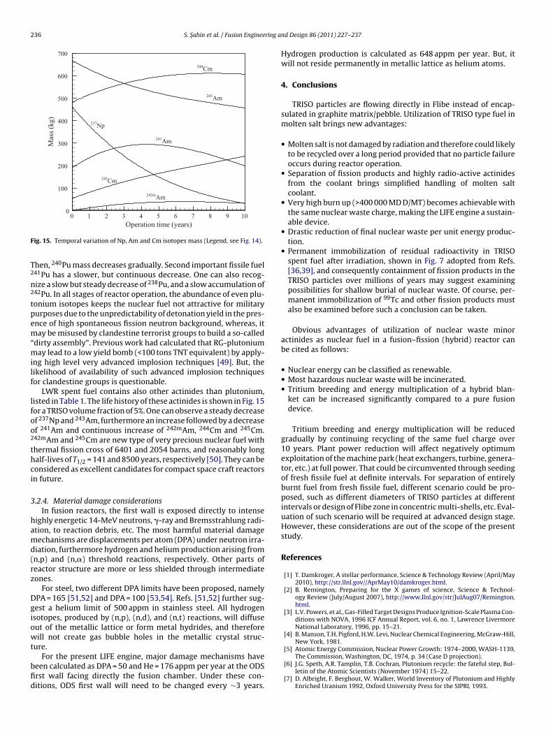
Fig. 13. Time evolution of fuel burn up grade (Legend, see Fig. 11).
Under 14-MeV fusion neutron irradiation, all actinides becomehighly fissile materials. Fig. 13 depicts the fission fuel burn up his-tory in the Flibe coolant over 10 years. For all cases, fissile burnup exceeds 400 000 MW D/MT. TRISO particles can withstand suchhigh burn ups without being damaged at the present level of tech-nology, as shown in Fig. 6, adopted from refs [35]. Also, LLNLscientists have reported high burn up values for TRISO MA-fuel[31,33]. Significant outcomes of these very high burn ups will bedrastic reduction of residual nuclear waste, as well as sustainabilityof nuclear energy.
3.2.3. History of actinide transmutation over operation periodIn the course of reactor operation, a series of fissile and fission-
able isotopes will be generated in the TRISO particles continuouslyand all of them will be subject of transformation via neutron inter-action and radioactive decay, shown in Fig. 10 with associatednuclear processes. Fissile odd plutonium isotopes in the initial fuelwill have primary importance for power multiplication. Fig. 14depicts the temporal variation of total mass of diverse plutonium
Operation time (years)0 1 2 3 4 5 6 7 8 9 10
0
Fig. 14. Temporal variation of Pu isotopes mass (5 MAC + %95 Flibe).
236 S. Sahin et al. / Fusion Engineering a
Mas
s(k
g)
0
100
200
300
400
500
600
700
244Cm
243Am
237Np
241Am
245Cm
242mAm
F
T2
n2
tpem“milf
lfoo2
thci
3
hamd(rz
Dgiowt
bfid
Operation time (years)0 1 2 3 4 5 6 7 8 9 10
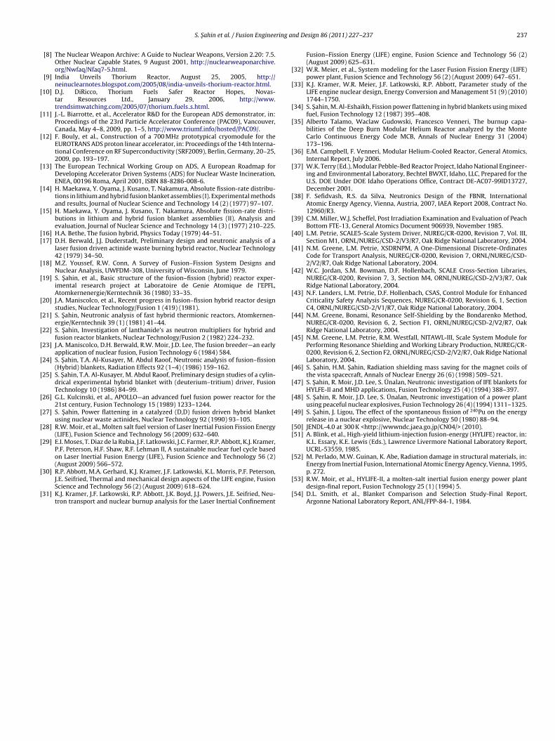
ig. 15. Temporal variation of Np, Am and Cm isotopes mass (Legend, see Fig. 14).
hen, 240Pu mass decreases gradually. Second important fissile fuel41Pu has a slower, but continuous decrease. One can also recog-ize a slow but steady decrease of 238Pu, and a slow accumulation of42Pu. In all stages of reactor operation, the abundance of even plu-onium isotopes keeps the nuclear fuel not attractive for militaryurposes due to the unpredictability of detonation yield in the pres-nce of high spontaneous fission neutron background, whereas, itay be misused by clandestine terrorist groups to build a so-called
dirty assembly”. Previous work had calculated that RG-plutoniumay lead to a low yield bomb (<100 tons TNT equivalent) by apply-
ng high level very advanced implosion techniques [49]. But, theikelihood of availability of such advanced implosion techniquesor clandestine groups is questionable.
LWR spent fuel contains also other actinides than plutonium,isted in Table 1. The life history of these actinides is shown in Fig. 15or a TRISO volume fraction of 5%. One can observe a steady decreasef 237Np and 243Am, furthermore an increase followed by a decreasef 241Am and continuous increase of 242mAm, 244Cm and 245Cm.42mAm and 245Cm are new type of very precious nuclear fuel withhermal fission cross of 6401 and 2054 barns, and reasonably longalf-lives of T1/2 = 141 and 8500 years, respectively [50]. They can beonsidered as excellent candidates for compact space craft reactorsn future.
.2.4. Material damage considerationsIn fusion reactors, the first wall is exposed directly to intense
ighly energetic 14-MeV neutrons, �-ray and Bremsstrahlung radi-tion, to reaction debris, etc. The most harmful material damageechanisms are displacements per atom (DPA) under neutron irra-
iation, furthermore hydrogen and helium production arising fromn,p) and (n,�) threshold reactions, respectively. Other parts ofeactor structure are more or less shielded through intermediateones.
For steel, two different DPA limits have been proposed, namelyPA = 165 [51,52] and DPA = 100 [53,54]. Refs. [51,52] further sug-est a helium limit of 500 appm in stainless steel. All hydrogensotopes, produced by (n,p), (n,d), and (n,t) reactions, will diffuseut of the metallic lattice or form metal hydrides, and thereforeill not create gas bubble holes in the metallic crystal struc-
ure.For the present LIFE engine, major damage mechanisms have
een calculated as DPA = 50 and He = 176 appm per year at the ODSrst wall facing directly the fusion chamber. Under these con-itions, ODS first wall will need to be changed every ∼3 years.
nd Design 86 (2011) 227–237
Hydrogen production is calculated as 648 appm per year. But, itwill not reside permanently in metallic lattice as helium atoms.
4. Conclusions
TRISO particles are flowing directly in Flibe instead of encap-sulated in graphite matrix/pebble. Utilization of TRISO type fuel inmolten salt brings new advantages:
• Molten salt is not damaged by radiation and therefore could likelyto be recycled over a long period provided that no particle failureoccurs during reactor operation.
• Separation of fission products and highly radio-active actinidesfrom the coolant brings simplified handling of molten saltcoolant.
• Very high burn up (>400 000 MD D/MT) becomes achievable withthe same nuclear waste charge, making the LIFE engine a sustain-able device.
• Drastic reduction of final nuclear waste per unit energy produc-tion.
• Permanent immobilization of residual radioactivity in TRISOspent fuel after irradiation, shown in Fig. 7 adopted from Refs.[36,39], and consequently containment of fission products in theTRISO particles over millions of years may suggest examiningpossibilities for shallow burial of nuclear waste. Of course, per-manent immobilization of 99Tc and other fission products mustalso be examined before such a conclusion can be taken.
Obvious advantages of utilization of nuclear waste minoractinides as nuclear fuel in a fusion–fission (hybrid) reactor canbe cited as follows:
• Nuclear energy can be classified as renewable.• Most hazardous nuclear waste will be incinerated.• Tritium breeding and energy multiplication of a hybrid blan-
ket can be increased significantly compared to a pure fusiondevice.
Tritium breeding and energy multiplication will be reducedgradually by continuing recycling of the same fuel charge over10 years. Plant power reduction will affect negatively optimumexploitation of the machine park (heat exchangers, turbine, genera-tor, etc.) at full power. That could be circumvented through seedingof fresh fissile fuel at definite intervals. For separation of entirelyburnt fuel from fresh fissile fuel, different scenario could be pro-posed, such as different diameters of TRISO particles at differentintervals or design of Flibe zone in concentric multi-shells, etc. Eval-uation of such scenario will be required at advanced design stage.However, these considerations are out of the scope of the presentstudy.
References
[1] T. Damkroger, A stellar performance, Science & Technology Review (April/May2010), http://str.llnl.gov//AprMay10/damkroger.html.
[2] B. Remington, Preparing for the X games of science, Science & Technol-ogy Review (July/August 2007), http://www.llnl.gov/str/JulAug07/Remington.html.
[3] L.V. Powers, et al., Gas-Filled Target Designs Produce Ignition-Scale Plasma Con-ditions with NOVA, 1996 ICF Annual Report, vol. 6, no. 1, Lawrence LivermoreNational Laboratory, 1996, pp. 15–21.
[4] B. Manson, T.H. Pigford, H.W. Levi, Nuclear Chemical Engineering, McGraw-Hill,New York, 1981.
[5] Atomic Energy Commission, Nuclear Power Growth: 1974–2000, WASH-1139,The Commission, Washington, DC, 1974, p. 34 (Case D projection).
[6] J.G. Speth, A.R. Tamplin, T.B. Cochran, Plutonium recycle: the fateful step, Bul-letin of the Atomic Scientists (November 1974) 15–22.
[7] D. Albright, F. Berghout, W. Walker, World Inventory of Plutonium and HighlyEnriched Uranium 1992, Oxford University Press for the SIPRI, 1993.
ring a
[
[
[
[
[
[
[[
[
[
[
[
[
[
[
[
[
[
[
[
[
[
[
[
[
[
[
[
[
[
[
[
[
[
[
[
[
[
[
[
[[
[
S. Sahin et al. / Fusion Enginee
[8] The Nuclear Weapon Archive: A Guide to Nuclear Weapons, Version 2.20: 7.5.Other Nuclear Capable States, 9 August 2001, http://nuclearweaponarchive.org/Nwfaq/Nfaq7-5.html.
[9] India Unveils Thorium Reactor, August 25, 2005, http://neinuclearnotes.blogspot.com/2005/08/india-unveils-thorium-reactor.html.
10] D.J. DiRicco, Thorium Fuels Safer Reactor Hopes, Novas-tar Resources Ltd., January 29, 2006, http://www.trendsimwatching.com/2005/07/thorium fuels s.html.
11] J.-L. Biarrotte, et al., Accelerator R&D for the European ADS demonstrator, in:Proceedings of the 23rd Particle Accelerator Conference (PAC09), Vancouver,Canada, May 4–8, 2009, pp. 1–5, http://www.triumf.info/hosted/PAC09/.
12] F. Bouly, et al., Construction of a 700 MHz prototypical cryomodule for theEUROTRANS ADS proton linear accelerator, in: Proceedings of the 14th Interna-tional Conference on RF Superconductivity (SRF2009), Berlin, Germany, 20–25,2009, pp. 193–197.
13] The European Technical Working Group on ADS, A European Roadmap forDeveloping Accelerator Driven Systems (ADS) for Nuclear Waste Incineration,ENEA, 00196 Roma, April 2001, ISBN 88-8286-008-6.
14] H. Maekawa, Y. Oyama, J. Kusano, T. Nakamura, Absolute fission-rate distribu-tions in lithium and hybrid fusion blanket assemblies (I). Experimental methodsand results, Journal of Nuclear Science and Technology 14 (2) (1977) 97–107.
15] H. Maekawa, Y. Oyama, J. Kusano, T. Nakamura, Absolute fission-rate distri-butions in lithium and hybrid fusion blanket assemblies (II). Analysis andevaluation, Journal of Nuclear Science and Technology 14 (3) (1977) 210–225.
16] H.A. Bethe, The fusion hybrid, Physics Today (1979) 44–51.17] D.H. Berwald, J.J. Duderstadt, Preliminary design and neutronic analysis of a
laser fusion driven actinide waste burning hybrid reactor, Nuclear Technology42 (1979) 34–50.
18] M.Z. Youssef, R.W. Conn, A Survey of Fusion–Fission System Designs andNuclear Analysis, UWFDM-308, University of Wisconsin, June 1979.
19] S. Sahin, et al., Basic structure of the fusion–fission (hybrid) reactor exper-imental research project at Laboratoire de Genie Atomique de l’EPFL,Atomkernenergie/Kerntechnik 36 (1980) 33–35.
20] J.A. Maniscolco, et al., Recent progress in fusion–fission hybrid reactor designstudies, Nuclear Technology/Fusion 1 (419) (1981).
21] S. Sahin, Neutronic analysis of fast hybrid thermionic reactors, Atomkernen-ergie/Kerntechnik 39 (1) (1981) 41–44.
22] S. Sahin, Investigation of lanthanide’s as neutron multipliers for hybrid andfusion reactor blankets, Nuclear Technology/Fusion 2 (1982) 224–232.
23] J.A. Maniscolco, D.H. Berwald, R.W. Moir, J.D. Lee, The fusion breeder—an earlyapplication of nuclear fusion, Fusion Technology 6 (1984) 584.
24] S. Sahin, T.A. Al-Kusayer, M. Abdul Raoof, Neutronic analysis of fusion–fission(Hybrid) blankets, Radiation Effects 92 (1–4) (1986) 159–162.
25] S. Sahin, T.A. Al-Kusayer, M. Abdul Raoof, Preliminary design studies of a cylin-drical experimental hybrid blanket with (deuterium–tritium) driver, FusionTechnology 10 (1986) 84–99.
26] G.L. Kulcinski, et al., APOLLO—an advanced fuel fusion power reactor for the21st century, Fusion Technology 15 (1989) 1233–1244.
27] S. Sahin, Power flattening in a catalyzed (D,D) fusion driven hybrid blanketusing nuclear waste actinides, Nuclear Technology 92 (1990) 93–105.
28] R.W. Moir, et al., Molten salt fuel version of Laser Inertial Fusion Fission Energy(LIFE), Fusion Science and Technology 56 (2009) 632–640.
29] E.I. Moses, T. Diaz de la Rubia, J.F. Latkowski, J.C. Farmer, R.P. Abbott, K.J. Kramer,P.F. Peterson, H.F. Shaw, R.F. Lehman II, A sustainable nuclear fuel cycle basedon Laser Inertial Fusion Energy (LIFE), Fusion Science and Technology 56 (2)
(August 2009) 566–572.30] R.P. Abbott, M.A. Gerhard, K.J. Kramer, J.F. Latkowski, K.L. Morris, P.F. Peterson,J.E. Seifried, Thermal and mechanical design aspects of the LIFE engine, FusionScience and Technology 56 (2) (August 2009) 618–624.
31] K.J. Kramer, J.F. Latkowski, R.P. Abbott, J.K. Boyd, J.J. Powers, J.E. Seifried, Neu-tron transport and nuclear burnup analysis for the Laser Inertial Confinement
[
[
nd Design 86 (2011) 227–237 237
Fusion–Fission Energy (LIFE) engine, Fusion Science and Technology 56 (2)(August 2009) 625–631.
32] W.R. Meier, et al., System modeling for the Laser Fusion Fission Energy (LIFE)power plant, Fusion Science and Technology 56 (2) (August 2009) 647–651.
33] K.J. Kramer, W.R. Meier, J.F. Latkowski, R.P. Abbott, Parameter study of theLIFE engine nuclear design, Energy Conversion and Management 51 (9) (2010)1744–1750.
34] S. Sahin, M. Al-Eshaikh, Fission power flattening in hybrid blankets using mixedfuel, Fusion Technology 12 (1987) 395–408.
35] Alberto Talamo, Waclaw Gudowski, Francesco Venneri, The burnup capa-bilities of the Deep Burn Modular Helium Reactor analyzed by the MonteCarlo Continuous Energy Code MCB, Annals of Nuclear Energy 31 (2004)173–196.
36] E.M. Campbell, F. Venneri, Modular Helium-Cooled Reactor, General Atomics,Internal Report, July 2006.
37] W.K. Terry (Ed.), Modular Pebble-Bed Reactor Project, Idaho National Engineer-ing and Environmental Laboratory, Bechtel BWXT, Idaho, LLC, Prepared for theU.S. DOE Under DOE Idaho Operations Office, Contract DE-AC07-99ID13727,December 2001.
38] F. Sefidvash, R.S. da Silva, Neutronics Design of the FBNR, InternationalAtomic Energy Agency, Vienna, Austria, 2007, IAEA Report 2008, Contract No.12960/R3.
39] C.M. Miller, W.J. Scheffel, Post Irradiation Examination and Evaluation of PeachBottom FTE-13, General Atomics Document 906939, November 1985.
40] L.M. Petrie, SCALE5-Scale System Driver, NUREG/CR-0200, Revision 7, Vol. III,Section M1, ORNL/NUREG/CSD-2/V3/R7, Oak Ridge National Laboratory, 2004.
41] N.M. Greene, L.M. Petrie, XSDRNPM, A One-Dimensional Discrete-OrdinatesCode for Transport Analysis, NUREG/CR-0200, Revision 7, ORNL/NUREG/CSD-2/V2/R7, Oak Ridge National Laboratory, 2004.
42] W.C. Jordan, S.M. Bowman, D.F. Hollenbach, SCALE Cross-Section Libraries,NUREG/CR-0200, Revision 7, 3, Section M4, ORNL/NUREG/CSD-2/V3/R7, OakRidge National Laboratory, 2004.
43] N.F. Landers, L.M. Petrie, D.F. Hollenbach, CSAS, Control Module for EnhancedCriticality Safety Analysis Sequences, NUREG/CR-0200, Revision 6, 1, SectionC4, ORNL/NUREG/CSD-2/V1/R7, Oak Ridge National Laboratory, 2004.
44] N.M. Greene, Bonami, Resonance Self-Shielding by the Bondarenko Method,NUREG/CR-0200, Revision 6, 2, Section F1, ORNL/NUREG/CSD-2/V2/R7, OakRidge National Laboratory, 2004.
45] N.M. Greene, L.M. Petrie, R.M. Westfall, NITAWL-III, Scale System Module forPerforming Resonance Shielding and Working Library Production, NUREG/CR-0200, Revision 6, 2, Section F2, ORNL/NUREG/CSD-2/V2/R7, Oak Ridge NationalLaboratory, 2004.
46] S. Sahin, H.M. Sahin, Radiation shielding mass saving for the magnet coils ofthe vista spacecraft, Annals of Nuclear Energy 26 (6) (1998) 509–521.
47] S. Sahin, R. Moir, J.D. Lee, S. Ünalan, Neutronic investigation of IFE blankets forHYLFE-II and MHD applications, Fusion Technology 25 (4) (1994) 388–397.
48] S. Sahin, R. Moir, J.D. Lee, S. Ünalan, Neutronic investigation of a power plantusing peaceful nuclear explosives, Fusion Technology 26 (4) (1994) 1311–1325.
49] S. Sahin, J. Ligou, The effect of the spontaneous fission of 240Pu on the energyrelease in a nuclear explosive, Nuclear Technology 50 (1980) 88–94.
50] JENDL-4.0 at 300 K <http://wwwndc.jaea.go.jp/CN04/> (2010).51] A. Blink, et al., High-yield lithium-injection fusion-energy (HYLIFE) reactor, in:
K.L. Essary, K.E. Lewis (Eds.), Lawrence Livermore National Laboratory Report,UCRL-53559, 1985.
52] M. Perlado, M.W. Guinan, K. Abe, Radiation damage in structural materials, in:
Energy from Inertial Fusion, International Atomic Energy Agency, Vienna, 1995,p. 272.53] R.W. Moir, et al., HYLIFE-II, a molten-salt inertial fusion energy power plantdesign-final report, Fusion Technology 25 (1) (1994) 5.
54] D.L. Smith, et al., Blanket Comparison and Selection Study-Final Report,Argonne National Laboratory Report, ANL/FPP-84-1, 1984.
Copyright © 2022 FDOKUMEN