
SCARAB MINOR Euro 3 - Polovni automobili
32
-
Upload
khangminh22 -
Category
Documents
-
view
4 -
download
0
Transcript of SCARAB MINOR Euro 3 - Polovni automobili

drivemanVM.fm Page -1 Tuesday, August 19, 2003 11:43 AM

drivemanVM.fm Page 0 Tuesday, August 19, 2003 11:43 AM

SCARAB MINOR Euro 3Amdt. 1
Amdt.1 - 19 August 2003 Operator’s Manual Page 1
OPERATOR’S MANUAL
SCARAB MINOR Euro 3
When re-ordering this document, please quote the following Part Number:Manual Z026027
Original Issue ...................... Jan. 2002
Amdt. 1 .............................. Aug. 2003
This manual is published by the Technical Publications Department of Scarab SweepersLimited and every effort is made to ensure that the information it contains is correct at thetime of publication. Due to a policy of continuous development, however, the Companyreserves the right to alter the specification and to supply when so altered withoutreference to illustrations and descriptions in this manual.
Scarab Sweepers LimitedPattenden Lane, Marden, Kent TN12 9QD
Telephone: 01622 831006 Fax: 01622 832417International: +44 1622 831006 International +44 1622 832417e-mail: [email protected] Web site: www.scarab-sales.com
Publication Z026027 © Scarab Sweepers Limited 2002
drivemanVM.fm Page 1 Tuesday, August 19, 2003 11:43 AM

SCARAB MINOR Euro 3
Page 2 Operator’s Manual Original Issue - 19 August 2003
GENERAL INFORMATIONWEIGHTS, DIMENSIONS AND CAPACITIESGross Vehicle Weight (GVW) . . . . . . . . . . . . . . . . . . . . . . . . . . . . . . . . . . . . . . . Refer to VIN plateUnladen Weight (Standard)* . . . . . . . . . . . . . . . . . . . . . . . . . . . . . . . . . . . . . . . . . . . . . 2.49 tonnesUnladen Weight (Hi-Tip)*. . . . . . . . . . . . . . . . . . . . . . . . . . . . . . . . . . . . . . . . . . . . . . . . . 2.61 tonnesOverall Length . . . . . . . . . . . . . . . . . . . . . . . . . . . . . . . . . . . . . . . . . . . . . . . . . . . . . . . . . . . 4230 mmFront Overhang . . . . . . . . . . . . . . . . . . . . . . . . . . . . . . . . . . . . . . . . . . . . . . . . . . . . . . . . . . 1148 mmRear Overhang . . . . . . . . . . . . . . . . . . . . . . . . . . . . . . . . . . . . . . . . . . . . . . . . . . . . . . . . . . 1053 mmWheelbase . . . . . . . . . . . . . . . . . . . . . . . . . . . . . . . . . . . . . . . . . . . . . . . . . . . . . . . . . . . . . . 2020 mmOverall Width . . . . . . . . . . . . . . . . . . . . . . . . . . . . . . . . . . . . . . . . . . . . . . . . . . . . . . . . . . . . 1650 mmOverall Height (hopper lowered) . . . . . . . . . . . . . . . . . . . . . . . . . . . . . . . . . . . . . . . . . . . 2360 mmOverall Height (hopper raised) . . . . . . . . . . . . . . . . . . . . . . . . . . . . . . . . . . . . . . . . . . . . . 3213 mmTurning Circle (curb to curb) . . . . . . . . . . . . . . . . . . . . . . . . . . . . . . . . . . . . . . . . . . . . . 8.50 metres
Hopper . . . . . . . . . . . . . . . . . . . . . . . . . . . . . . . . . . . . . . . . . . . . . . . . . . . . . . . 2.0 m3 - Hi-tip 1.6 m3
Fuel Tanks . . . . . . . . . . . . . . . . . . . . . . . . . . . . . . . . . . . . . . . . . . . . . . . . . . . . . . . . . . . . . . . . 60 litresEngine Oil . . . . . . . . . . . . . . . . . . . . . . . . . . . . . . . . . . . . . . . . . . . . . . . . . . . . . . . . . . . . . . . 5.90 litresCoolant. . . . . . . . . . . . . . . . . . . . . . . . . . . . . . . . . . . . . . . . . . . . . . . . . . . . . . . . . . . . . . . . . . 18 litresHydraulic Tank . . . . . . . . . . . . . . . . . . . . . . . . . . . . . . . . . . . . . . . . . . . . . . . . . . . . . . . . . . . . 15 litresWater Tank . . . . . . . . . . . . . . . . . . . . . . . . . . . . . . 450 litres - Street Wash Conversion = 1000 litresBrake System . . . . . . . . . . . . . . . . . . . . . . . . . . . . . . . . . . . . . . . . . . . . . . . . . . . . . . . . . . . . 0.70 litresHigh-pressure Water Pump . . . . . . . . . . . . . . . . . . . . . . . . . . . . . . . . . . . . . . . . . . . . . . . . . 0.55 litres* Dependent upon specificationTOWING & TRANSPORTATIONSERIOUS DAMAGE TO TRANSMISSION WILL RESULT IF VEHICLE IS TOWED WITH PROP-SHAFT CONNECTED.If towing is considered necessary, it is imperative that the prop shaft is removed before any attempt to tow the vehicle.
When transporting the vehicle, it shall be secured to the transporter by means of suitable straps as follows:Front Wheels ............................ One Strap per Wheel to a REARWARD lashing point.Rear Wheels............................. One Strap per Wheel to a FORWARD lashing point.Front of Body ........................... One Strap each end of Front Bumper to a FORWARD lashing
point.Rear of Body............................ One Strap over each Rear Spring Hanger to an OPPOSITE
REARWARD lashing point.
IDENTIFICATION PLATESThe SERIAL NUMBER PLATE is located on the outside rear face of the cab, at floor level to the right hand side. All Scarab Minors have a four-digit number with the prefix H.The VIN PLATE is located above the serial number plate.The CHASSIS NUMBER is stamped on the top face of the right hand chassis rail beneath the cab/tank.The LOAD APPORTIONING VALVE (LAV) PLATE is located on the outer face of the left or right hand chassis rail (according to driving position).
drivemanVM.fm Page 2 Tuesday, August 19, 2003 11:53 AM

SCARAB MINOR Euro 3
Amdt.1 - 19 August 2003 Operator’s Manual Page 3
TABLE OF CONTENTSPara Title Page
General Information ......................................................................................................... 2Table Of Contents (this page) ......................................................................................... 3Health and Safety Advice................................................................................................ 4Operator’s Routine Maintenance................................................................................... 5Scarab Parts & Service Providers..................................................................................... 6Tilting the Cab.................................................................................................................... 8Key Maintenance Procedures......................................................................................... 9
Cleaning the Suction Fan........................................................................................... 8Suction Nozzle Clearances....................................................................................... 10Setting up the Brushes & Skirts .................................................................................. 10Fluid Levels.................................................................................................................. 12Recommended Lubricants & Consumables.......................................................... 13Manual Greasing....................................................................................................... 14
Description of Sweeping Controls ................................................................................. 15Limitations of Use ............................................................................................................. 17Operating Procedure - Drive Mode.............................................................................. 17Operating Procedure - Sweep Mode........................................................................... 18
Reducing Noise Levels & Fuel Consumption.......................................................... 19RDS Sweeper Monitors ................................................................................................... 20Wander Hose ................................................................................................................... 20Hopper Operating Procedure ....................................................................................... 21Rear Door ......................................................................................................................... 22Using the Low-pressure Water Pump ............................................................................ 22Using the High-pressure Water Pump............................................................................ 23
Oil Level ...................................................................................................................... 24Draining ...................................................................................................................... 24
Explanation of Operating Symbols................................................................................ 24Supplementary Information (Dual Sweep & Street Wash Controls).......................... 26
Figures PageFig. 1 Main Features of the Scarab Euro 3 Minor .................................................... 7Fig. 2 Cab-tilt Locking Mechanism ........................................................................... 8Fig. 3 Inspecting & Cleaning the Suction Fan ......................................................... 9Fig. 4 Suction Nozzle Clearance - Factory Set-up................................................. 10Fig. 5 Brush Tilt Adjustment ....................................................................................... 10Fig. 6 Front Brush Adjustment................................................................................... 11Fig. 7 Quick-release Brush Hub Alignment ............................................................. 12Fig. 8 Cab Interior Arrangement - Fluid Reservoirs ................................................ 13Fig. 9 Engine & Hydraulic Tank Fluids...................................................................... 13Fig. 10 Manual Grease Point Locations.................................................................... 14Fig. 11 Control-panel Layout (LHD) .......................................................................... 15Fig. 12 Driving Controls ............................................................................................... 17Fig. 13 Control-panel Layout (LHD) .......................................................................... 18Fig. 14 The Scarab ‘Wizard’ Sweeper Monitor ........................................................ 20Fig. 15 RDS Monitor ..................................................................................................... 21Fig. 16 Use of the Blanking Plate ............................................................................... 22Fig. 17 Correct Use of the Hopper Prop ................................................................... 23Fig. 18 Low-pressure Water Pump Arrangements ................................................... 24Fig. 19 High-pressure Water Pump Arrangements .................................................. 25Fig. 20 Dual Sweep & Street Wash Controls ............................................................ 28
drivemanVM.fm Page 3 Tuesday, August 19, 2003 11:43 AM
SCARAB MINOR Euro 3
Page 4 Operator’s Manual Original Issue - 19 August 2003
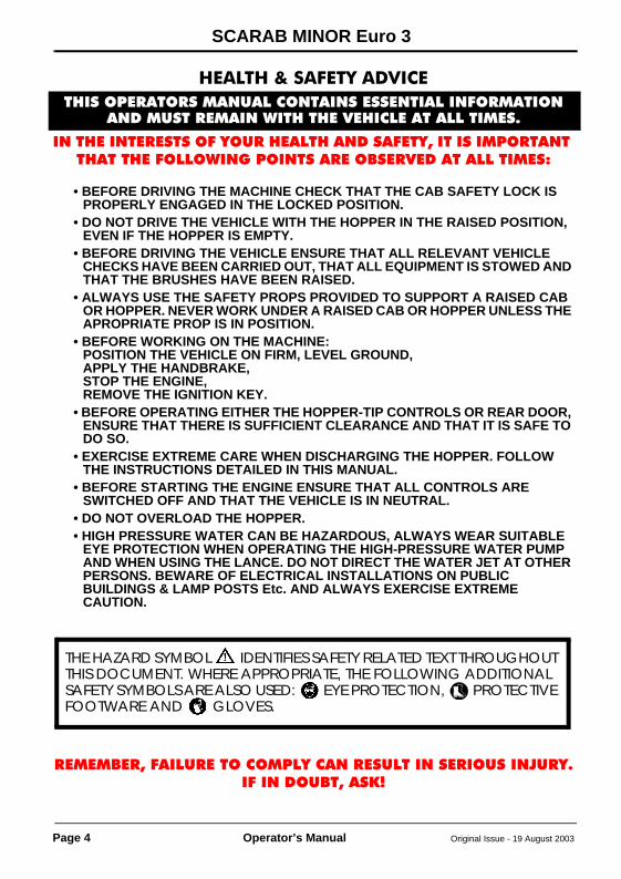
HEALTH & SAFETY ADVICETHIS OPERATORS MANUAL CONTAINS ESSENTIAL INFORMATION
AND MUST REMAIN WITH THE VEHICLE AT ALL TIMES.
IN THE INTERESTS OF YOUR HEALTH AND SAFETY, IT IS IMPORTANT THAT THE FOLLOWING POINTS ARE OBSERVED AT ALL TIMES:
• BEFORE DRIVING THE MACHINE CHECK THAT THE CAB SAFETY LOCK IS PROPERLY ENGAGED IN THE LOCKED POSITION.
• DO NOT DRIVE THE VEHICLE WITH THE HOPPER IN THE RAISED POSITION, EVEN IF THE HOPPER IS EMPTY.
• BEFORE DRIVING THE VEHICLE ENSURE THAT ALL RELEVANT VEHICLE CHECKS HAVE BEEN CARRIED OUT, THAT ALL EQUIPMENT IS STOWED AND THAT THE BRUSHES HAVE BEEN RAISED.
• ALWAYS USE THE SAFETY PROPS PROVIDED TO SUPPORT A RAISED CAB OR HOPPER. NEVER WORK UNDER A RAISED CAB OR HOPPER UNLESS THE APROPRIATE PROP IS IN POSITION.
• BEFORE WORKING ON THE MACHINE:POSITION THE VEHICLE ON FIRM, LEVEL GROUND,APPLY THE HANDBRAKE,STOP THE ENGINE,REMOVE THE IGNITION KEY.
• BEFORE OPERATING EITHER THE HOPPER-TIP CONTROLS OR REAR DOOR, ENSURE THAT THERE IS SUFFICIENT CLEARANCE AND THAT IT IS SAFE TO DO SO.
• EXERCISE EXTREME CARE WHEN DISCHARGING THE HOPPER. FOLLOW THE INSTRUCTIONS DETAILED IN THIS MANUAL.
• BEFORE STARTING THE ENGINE ENSURE THAT ALL CONTROLS ARE SWITCHED OFF AND THAT THE VEHICLE IS IN NEUTRAL.
• DO NOT OVERLOAD THE HOPPER.• HIGH PRESSURE WATER CAN BE HAZARDOUS, ALWAYS WEAR SUITABLE
EYE PROTECTION WHEN OPERATING THE HIGH-PRESSURE WATER PUMP AND WHEN USING THE LANCE. DO NOT DIRECT THE WATER JET AT OTHER PERSONS. BEWARE OF ELECTRICAL INSTALLATIONS ON PUBLIC BUILDINGS & LAMP POSTS Etc. AND ALWAYS EXERCISE EXTREME CAUTION.
REMEMBER, FAILURE TO COMPLY CAN RESULT IN SERIOUS INJURY.IF IN DOUBT, ASK!
THE HAZARD SYMBOL IDENTIFIES SAFETY RELATED TEXT THROUGHOUT THIS DOCUMENT. WHERE APPROPRIATE, THE FOLLOWING ADDITIONAL SAFETY SYMBOLS ARE ALSO USED: EYE PROTECTION, PROTECTIVE FOOTWARE AND GLOVES.
drivemanVM.fm Page 4 Tuesday, August 19, 2003 11:43 AM
SCARAB MINOR Euro 3
Original Issue - 19 August 2003 Operator’s Manual Page 5
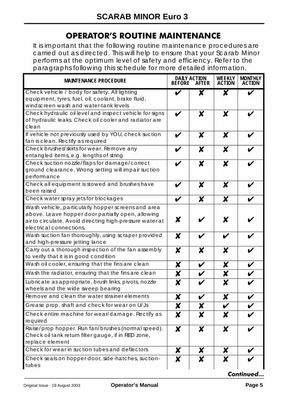
OPERATOR’S ROUTINE MAINTENANCEIt is important that the following routine maintenance procedures are carried out as directed. This will help to ensure that your Scarab Minor performs at the optimum level of safety and efficiency. Refer to the paragraphs following this schedule for more detailed information.
MAINTENANCE PROCEDURE DAILY ACTIONBEFORE R AFTER
WEEKLY ACTION
MONTHLY ACTION
Check vehicle / body for safety. All lighting equipment, tyres, fuel, oil, coolant, brake fluid, windscreen wash and water-tank levelsCheck hydraulic oil level and inspect vehicle for signs of hydraulic leaks. Check oil cooler and radiator are cleanIf vehicle not previously used by YOU, check suction fan is clean. Rectify as requiredCheck brushes/skirts for wear. Remove any entangled items, e.g. lengths of stringCheck suction nozzle/flaps for damage/correct ground clearance. Wrong setting will impair suction performanceCheck all equipment is stowed and brushes have been raisedCheck water spray jets for blockagesWash vehicle, particularly hopper screens and area above. Leave hopper door partially open, allowing air to circulate. Avoid directing high-pressure water at electrical connections.Wash suction fan thoroughly, using scraper provided and high-pressure jetting lance Carry out a thorough inspection of the fan assembly to verify that it is in good conditionWash oil cooler, ensuring that the fins are cleanWash the radiator, ensuring that the fins are cleanLubricate as appropriate, brush links, pivots, nozzle wheels and the wide sweep bearingRemove and clean the water strainer elementsGrease prop. shaft and check for wear on U/JsCheck entire machine for wear/damage. Rectify as requiredRaise/prop hopper. Run fan/brushes (normal speed). Check oil tank return filter gauge, if in RED zone, replace elementCheck for wear in suction tubes and deflectorsCheck seals on hopper-door, side-hatches, suction-tubes
Continued...
drivemanVM.fm Page 5 Tuesday, August 19, 2003 11:43 AM

SCARAB MINOR Euro 3
Page 6 Operator’s Manual Original Issue - 19 August 2003
Check hopper and subframe-to-chassis mounting pointsCheck wiring and hoses for security of attachment and for signs of chafing. Rectify as necessaryCheck oil level in high-pressure pump, top up as necessaryClean air cleaner (more often if working in dusty conditions)IN FROSTY WEATHER
CAUTIONDo not, under any circumstances, operate the high pressure pump without water.
Drain the water tank (by removing the water strainers).Open the drain taps on each water pump.Switch on the water sprays and run the low pressure pump until dry.Remove the water-strainer elements.Leave the hopper slightly raised with rear & side doors slightly open. This allows air to circulate and prevents damage caused by seals freezing to their mating faces.
MAINTENANCE PROCEDURE DAILY ACTIONBEFORE R AFTER
WEEKLY ACTION
MONTHLY ACTION
AUSTRALIARosmech2 Newfield RoadPara Hills West SA 5096Tel: 08 8260 5855BELGIQUEMOL Cy nvVDK Waste SystemsDikstmuidesteenwegB-8830HoogledeTel: 32 51 701681DEUTCHLANDTerra-Trade Import/Export GmbHTerra-Vertlieb & Kundendienst WestKruger & Co KGGewerbegebiet NordLauchaer HöheD-99880 WaltershausenTel: 49 3622 6410ESPAGNEPiquer Maquinaria, SAApartado de Correos, 307104080AlmeriaTel: 34 950 62 50 60FRANCEDominique Declercq DistributionAvenue d’Immercourt ZI Est62000ArrasTel: 33 3 212 27590
GREECED F Sarantopoulos210 Lenorman Street104 43 AthensTel: 30 1 51 46 411IRELANDMotor Distributors Ltd.Nass RoadDublin 12Tel: 3531 4503333ITALIAEnterprise CDS srlVia Biancospini, 1920146MilanoTel: 39 02 93568801NORTHERN IRELANDMcCreath Taylor (NI) Ltd.Flush Park, Knockmore Ind. Est.LisburnCo. Antrim BT28 2DXTel: 01846 662756NEDDERLANDSDHMHoutstraat 2A8471 ZX WolvegaTel: 31 561 611 611PORTUGALSilvia Ltd.Avenida Infante Santo, 53, r/c Esq1300 LisboaTel: 351 1 397 40 18
SCARAB PARTS & SERVICE PROVIDERSSCANDINAVIAREN VÄG ABGronbogartan 2503 68 BorasTel: 46 33 106460SCOTLANDApplied Sweepers Ltd.Bankside, FalkirkFK2 7XETel: 01324 611666UK (Northern England)Londonderry Garage Ltd.Londonderry, NorthallertonNorth Yorkshire DL7 9NBTel: 01677 424627 / 422185UK (England & Wales)Scarab Sweepers Ltd.Pattenden LaneMardenKent TN12 9QDTel: 01622 831006
drivemanVM.fm Page 6 Tuesday, August 19, 2003 11:43 AM
SCARAB MINOR Euro 3
Original Issue - 19 August 2003 Operator’s Manual Page 7
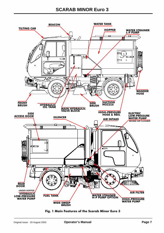
Fig. 1 Main Features of the Scarab Minor Euro 3
TILTING CABBEACON
FRONT SIDE
HOPPER
HYDRAULIC
WATER TANK
WANDER
MAIN HYDRAULIC
SUCTION
AIR INTAKE
AIR FILTERFUEL TANK
REAR
WIDE SWEEP
SIDESILENCER
HOSE
NOZZLEBRUSH
VALVE BLOCKOIL TANK
BRUSH
BRUSH
DOOR
ACCESS DOORHIGH-PRESSURE
HOSE & REEL
LOW-PRESSUREWATER PUMP
UNDER HOPPER
HYDRAULIC
LOW-PRESSUREWATER PUMP
ELECTRIC
BEHIND AIR CLEANER
HIGH-PRESSUREWATER PUMP
WATER STRAINERL-P PUMP
WATER STRAINERH-P PUMP OPTION
drivemanVM.fm Page 7 Tuesday, August 19, 2003 11:43 AM

SCARAB MINOR Euro 3
Page 8 Operator’s Manual Original Issue - 19 August 2003
TILTING THE CABCAUTION
Before tilting the cab, ensure that there is sufficient space to do so and that all loose items are safely stowed.1. Operate the cab-locking lever (located between the seats) by
moving it through approximately180°(see Fig. 2).2. Close the cab door and raise the cab safety latch, simultaneously
lifting the rear of the cab until it reaches its maximum tilt position.3. Deploy the cab prop, locating it in its retaining pocket on the
chassis rail.CAUTION
Before lowering the cab, ensure that area below it is clear of any items or equipment used while the cab was in the raised position.4. Lower the cab and engage the locking lever.
WARNINGBEFORE DRIVING THE VEHICLE, ENSURE THAT THE CAB LOCKING LEVER IS FULLY ENGAGED IN THE LOCKED POSITION.
Fig. 2 Cab-tilt Locking Mechanism
CAB SAFETY
CAB LOCKING LEVER
LATCH
drivemanVM.fm Page 8 Tuesday, August 19, 2003 11:43 AM

SCARAB MINOR Euro 3
Original Issue - 19 August 2003 Operator’s Manual Page 9
KEY MAINTENANCE PROCEDURESCLEANING THE SUCTION FAN
WARNINGS: FAILURE TO COMPLY COULD RESULT IN SERIOUS INJURY.1. BEFORE WORKING ON THE MACHINE POSITION IT ON FIRM, LEVEL GROUND, APPLY HANDBRAKE, STOP ENGINE & REMOVE IGNITION KEY.2. ALWAYS USE THE HOPPER PROP TO SUPPORT A RAISED HOPPER.3. THE FAN IS AN EXTREMELY HEAVY ROTATING MASS. NEVER ATTEMPT TO SLOW OR STOP ITS ROTATION BY USING THE HANDS OR BY INSERTING ANY ITEM INTO THE FAN CHAMBER, EVEN AT LOW SPEEDS. 4. BEFORE REMOVING THE SUCTION FAN ACCESS PANELS, ENSURE THAT THE ENGINE IS OFF AND THAT THE IGNITION KEY HAS BEEN REMOVED.5. ALWAYS WEAR SUITABLE EYE PROTECTION WHEN USING THE HAND LANCE.
1. Raise the hopper and deploy the hopper prop.2. Switch off the engine and remove the ignition keys.3. Remove the outer inspection cover from the hopper and the inner
cover from the fan housing to expose the fan (Refer to Fig. 3).4. Using high-pressure water from the jetting lance and the special
scraper, as necessary, thoroughly clean the fan. Pay particular attention to the inside curve of each impellor blade and to the area around the fan hub.
5. Refit the inspection covers and lower the hopper.
WARNING:LOOSE PARTICLES FROM THE CLEANING PROCESS CAN BE EJECTED FROM THE FAN CASING VIA THE HOPPER COVER WHEN THE FAN IS RESTARTED. ENSURE THAT THE AREA AROUND THE MACHINE IS CLEAR BEFORE RESTARTING.
Fig. 3 Inspecting & Cleaning the Suction Fan
PAY PARTICULAR ATTENTION TO INNER CURVE OF BLADES
To remove the hopper cover for cleaning and inspection of the fan exhaust duct area, release the five clips arrowed above.
drivemanVM.fm Page 9 Tuesday, August 19, 2003 11:43 AM
SCARAB MINOR Euro 3
Page 10 Operator’s Manual Original Issue - 19 August 2003
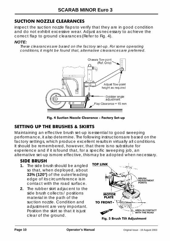
SUCTION NOZZLE CLEARANCESinspect the suction nozzle flaps to verify that they are in good condition and do not exhibit excessive wear. Adjust as necessary to achieve the correct flap to ground clearances (Refer to Fig. 4).NOTE:
These clearances are based on the factory set-up. For some operating conditions, it might be found that, alternative clearances are preferred.
SETTING UP THE BRUSHES & SKIRTSMaintaining an effective brush set-up is essential to good sweeping performance, it also determine. The following instructions are based on the factory settings, which produce excellent results in virtually all conditions.It should be remembered, however, that there is no substitute for experience and if it is found that, for a specific sweeping job, an alternative set-up is more effective, this may be adopted when necessary.
SIDE BRUSH1. The side brush should be angled
so that, when deployed, about 33% (120°) of the outer/leading edge of its circumference is in contact with the road surface.
2. The rubber skirt adjacent to the side brush collects / positions material in the path of the suction nozzle. Condition and adjustment are very important. Position the skirt so that it is just clear of the ground.
Fig. 4 Suction Nozzle Clearance - Factory Set-up
Fig. 5 Brush Tilt Adjustment
TO FRONT120°
AREA IN CONTACTWITH THE ROAD
BRUSHADJUSTMENTPOINTS
TOP LINK
MOTORPLATE
KICK BACK
drivemanVM.fm Page 10 Tuesday, August 19, 2003 11:43 AM

SCARAB MINOR Euro 3
Original Issue - 19 August 2003 Operator’s Manual Page 11
FRONT BRUSHES1. There are two sweeping configurations with the Front Brushes.
(a) When both brushes are lowered straight down onto the road.(b)When the curb-side brush is extended outwards to the gully.On dual sweep machines, both brushes can be extended.
2. On single sweep machines, front brush tilt-angle differs from side to side. For general sweeping duties, a greater proportion of the outward-extending brush is in contact with the road surface.
3. To set the correct tilt angles, adjust the Top Link and/or swivel the Motor Plate, to obtain a satisfactory setting as follows:
4. Extending Brush. Set the brush so that about 40% (150°) of its circumference, at the outer/leading edge, is in contact with the road surface, when the brush is in the extended position.
5. Non-extending Brush. Adjust so that about 33% (120°) of its circumference, at the outer/leading edge, is in contact with the road surface.
Fig. 6 Front Brush Adjustment
Continued...
drivemanVM.fm Page 11 Tuesday, August 19, 2003 11:43 AM

SCARAB MINOR Euro 3
Page 12 Operator’s Manual Original Issue - 19 August 2003
FRONT BRUSHES (Continued)Dual Sweep Machines1. Adjust the Top Link and/or Motor Bracket of each brush, until about
40% or 150° of its circumference, at the outer/leading edge, is in contact with the road surface.
CAUTION:An incorrect front brush set-up affects not only sweeping efficiency, but can also greatly influence the rate of brush wear.
REMOVING / REFITTING THE BRUSH HEADSThe Scarab Minor Euro 3 is fitted with quick-release brush hubs. These hubs incorporate slotted holes. Brush removal is accomplished by loosening the four flange nuts and rotating the brush, until the nuts align with the holes. The brush can then be taken off and/or refitted without removing the nuts from the brush bolts. All Scarab supplied replacement brushes now have captive bolts and are supplied with new flange nuts.CAUTION:
Care should be taken to ensure that when fitting/refitting brushes they are correctly positioned on the hubs, in accordance with the illustrated alignments (see Fig. 7).
FLUID LEVELSFor coolant and hydraulic filler points refer to Fig. 8.The brake and screen-wash reservoirs are in the cab. Access to the brake fluid reservoir is gained via a flap on top of the dash panel.For engine oil filler and dipstick refer to Fig. 9.
SWEEPING FAULTS - DIAGNOSIS & RECTIFICATION
FAULT SOLUTION
LIGHT MATERIAL IS CARRIED ROUND SIDE BRUSH & DEPOSITED BACK IN CHANNEL
THE SIDE BRUSH IS SET TOO FLAT ON THE ROAD SURFACE. CHECK/RESET BRUSH ANGLE
A TRAIL OF SMALL STONES IS LEFT BEHIND THE SUCTION NOZZLE
1. SUCTION NOZZLE FLAPS ARE SET TOO HIGH2. SUCTION NOZZLE TOW-POINT SET TOO HIGH3. FAN SPEED IS TOO LOW
Fig. 7 Quick-release Brush Hub Alignment
drivemanVM.fm Page 12 Tuesday, August 19, 2003 11:43 AM

SCARAB MINOR Euro 3
Original Issue - 19 August 2003 Operator’s Manual Page 13
RECOMMENDED LUBRICANTS AND CONSUMABLE PARTS
Fig. 8 Cab Interior Arrangement
Fig. 9 Engine & Hydraulic Tank Fluids
DESCRIPTION SPECIFICATION SCARAB PARTHYDRAULIC OIL DERWENT 32 005005MULTI-PURPOSE GREASE (GREASE POINTS) SUPER LITHIUM 2 005007MOTOR OIL (HIGH-PRESS WATER PUMP) 15W/50 005001REPLACEMENT BRUSH DISCS (WIDE SWEEP) - 023471REPLACEMENT SPACERS (WIDE SWEEP) - 023472REPLACEMENT SIDE BRUSH - 023470REPLACEMENT FRONT BRUSH - 023469RUBBER SKIRT (2 SLOT), SIDE BRUSH - 012216RUBBER SKIRT (3 SLOT), SIDE BRUSH - 010247FRONT SKIRT, WIDE SWEEP - 022516SUCTION TUBE - 023154FLAP KIT, SUCTION NOZZLE - 011593
SCREEN WASHRESERVOIR
BRAKE
BRAKE FLUIDRESERVOIR
OIL FILLER CAPOIL DIPSTICK
CAB PROP
COOLANTRESERVOIR
HYDRAULIC TANK FILLER
RETURNFILTERGAUGE
Continued...
drivemanVM.fm Page 13 Tuesday, August 19, 2003 11:43 AM

SCARAB MINOR Euro 3
Page 14 Operator’s Manual Original Issue - 19 August 2003
MANUAL GREASING
CLAMP (LONG), SUCTION NOZZLE - 011592CLAMP (SHORT), SUCTION NOZZLE - 013615GOBBLER ROD, SUCTION NOZZLE - 011811SPRING, SUCTION NOZZLE BOX - 010521SEAL, SUCTION NOZZLE - HOPPER - 013601SEAL, REAR DOOR - 010544SEAL, SIDE LOADING HATCH - 013599SEAL, FRONT APERTURE - 013594WANDER HOSE - 010119ELEMENT, HYDRAULIC RETURN FILTER - 011972ELEMENT, WATER FILTER - 010121DISC PAD SET - 020138
Fig. 10 Grease-point Locations
DESCRIPTION SPECIFICATION SCARAB PART
Hopper Auto-Blanking
Suction Nozzle
Propshaft
Widesweep Assembly
Side Brush
Mechanism (Optional Fitting)
AssemblyFront BrushAssembly
Assembly
Carry out manual greasing in accordance with the appropriate schedule (OPERATOR’S ROUTINE MAINTENANCE on page 5)and by referring to Fig. 10
drivemanVM.fm Page 14 Tuesday, August 19, 2003 11:43 AM

SCARAB MINOR Euro 3
Original Issue - 19 August 2003 Operator’s Manual Page 15
DESCRIPTION OF SWEEPING CONTROLS
SWEEP MODE SWITCH. Two-position key switch.CAUTION:
Before selecting Sweep Mode, turn the suction fan OFF. The engine will stall if Sweep is selected with fan ON with engine-speed controller at 0.
Position 1 (Sweep) - gives a sweep-speed range of 0 - 10 mph (0 - 16 kph). The green Sweep Mode indicator will illuminate.Position 0 (Drive) - gives a driving-speed range of 0-25mph / 0-40 kph). When Drive Mode is selected the Sweep Mode indicator will extinguish.CAUTION:
Always turn the Sweep Mode Switch to 0 after sweeping operations.ENGINE-SPEED ADJUST. Rotary potentiometer used to preset engine-speed for sweeping, it has a bezel marked 1 to 10. Turning clock-wise increases engine speed. Used with the Sweep Monitor (page 20).
Fig. 11 LHD Control Panel Layout (right-hand-drive panel is mirror image of this)
FUELGAUGE
GLOW PLUGINDICATOR
IGNITIONLIGHT
BRUSHSIDE BRUSH
WIDE SWEEPON/OFF SUCTION
FAN ON/OFF
NEARSIDE FRONTBRUSH ON/OFF
OILLIGHT
BRAKEFLUID
SWEEP MODE
CRUISE CONTROLINDICATOR
CRUISE CONTROLBUTTON
SIDE BRUSHSPRAY
FRONT BRUSHSPRAY
WIDESWEEPSPRAY
HOPPER TIP
WORKLIGHTS
HIGH-PRESSURE
FORWARD/
REAR FOG LAMPS
ENGINESPEED
SWEEP MODEKEY SWITCH
BEACON
RADIO
WATER
MAIN BEAM WARNING
PUMP*
REVERSE LEVER
GOBBLER FLAP
FRONT BRUSH SWING OUT
TURN INDICATOR REPEATER
TEMP
ON/OFFMASTERSWITCH
SWEEPMONITOR
HEATER FAN
SWITCHES ON DOOR
NOTE:The control panel illustrated is for a Left Hand Drive machine. Right hand Drive panels are the reverse of this layout.
& INDICATORS
OFFSIDE FRONTBRUSH ON/OFF
AIR CON
Continue...
drivemanVM.fm Page 15 Tuesday, August 19, 2003 11:43 AM
SCARAB MINOR Euro 3
Page 16 Operator’s Manual Original Issue - 19 August 2003
SUCTION FAN SWITCH. Two-position (ON/OFF) switch. Switch insert illuminates when ON.FRONT BRUSH SWITCHES - NEARSIDE & OFFSIDE. Two-position (ON/OFF) switch. Switch inserts illuminates when ON.FRONT BRUSH SWING OUT SWITCH. Two position (ON/OFF) switch. Switch insert illuminates when ON.SIDE BRUSH SWITCH. Two-position (ON/OFF) switch. Switch insert illuminates when ON.WIDESWEEP SWITCH. two-position (ON/OFF) switch. Switch insert illuminates when ON.WATER SPRAY SWITCH (Side Brush/Suction Box). Two-position (ON/OFF) switch. Switch insert illuminates when ON.WATER SPRAY SWITCH (Front Brush). Two position (ON/OFF) switch. Switch insert illuminates when ON.WATER SPRAY SWITCH (Wide Sweep Brush). Two-position (ON/OFF) switch. Switch insert illuminates when ON.HIGH-PRESSURE PUMP SWITCH. Two-position (ON/OFF) switch. Switch insert illuminates when ON. BEACON SWITCH. Two-position (ON/OFF) switch. Switch insert illuminates when ON.HOPPER RAISE/LOWER SWITCH. Three-position (ON/OFF) switch detented to the central position.Press the Top of the switch to RAISE the Hopper.Press the Bottom to LOWER the Hopper. Switch insert illuminates when ON.BRUSH MASTER SWITCH. Three-position (ON/OFF) switch detented to the central position.Press the Top of the switch to STOP & RAISE all sweeping equipment.Press the Bottom to LOWER & START the sweeping equipment configuration pre-selected on the control panel. Switch insert illuminates when ON.GOBBLER FLAP SWITCH. Three-position (ON/OFF) switch.Use the Centre position for normal sweeping conditions.Press the Top of the switch to momentarily raise the Gobbler, this is spring loaded and will return to normal position when released.Press the Bottom of the switch to raise the Gobbler permanently. Switch insert illuminates when ON.CRUISE CONTROL BUTTON. Press the Cruise Control Button (Red indicator lamp illuminates). The Drive system will maintain the current sweeping speed until disengaged. To DISENGAGE - Press the Cruise Control Button again or apply the brakes.
drivemanVM.fm Page 16 Tuesday, August 19, 2003 11:43 AM

SCARAB MINOR Euro 3
Original Issue - 19 August 2003 Operator’s Manual Page 17
LIMITATIONS OF USEThe Scarab Minor is classed as an Urban/Precinct Road Sweeper and, as such, is intended only for operation in the sweeping and associated roles for which it has been expressly designed.
OPERATING PROCEDURE - DRIVE MODE1. Ensure that the Forward/Reverse lever is in the NEUTRAL position
and that the hand brake is applied.2. Start the engine and select Drive Mode (0) on the Key Switch.3. Select FORWARD or REVERSE on the Forward/Reverse lever.4. Release the handbrake and slowly depress the throttle pedal to
move the vehicle in the appropriate direction of travel.NOTE:In Drive Mode, the vehicle is controlled, by means of the throttle and brake pedals, in a similar manner to a vehicle fitted with automatic transmission. Releasing the throttle pedal at normal road speeds produces a conventional automotive-style deceleration/over-run.
Fig. 12 Driving Controls
HORN &INDICATORS
HEADLAMPMAIN/DIP WINDSCREEN
WASH/WIPE
HEADLAMPS& SIDELAMPS
HAZARD INDICATORS(On top of steering column)
CAB HEATER
BRAKE PEDAL
THROTTLE PEDALFUSES &RELAYS
DRIVE/SWEEP MODEKEY SWITCH
drivemanVM.fm Page 17 Tuesday, August 19, 2003 11:43 AM

SCARAB MINOR Euro 3
Page 18 Operator’s Manual Original Issue - 19 August 2003
OPERATING PROCEDURE - SWEEP MODE
CAUTIONS:The vehicle MUST be brought to a complete standstill, the handbrake applied and Neutral selected BEFORE Sweep Mode is selected.1. Stop the vehicle, release the foot throttle and apply handbrake.2. Engage NEUTRAL on the Forward/Reverse Lever.3. Ensure that the suction fan is OFF and turn the Key Switch to
Position 1. The Sweep Mode indicator will illuminate (GREEN), confirming Sweep Mode (the sweep controls are now active).
4. Press the symbol on the RDS Sweep Monitor, until engine RPM is displayed (page 20) and rotate the Engine Speed Control clockwise until the required engine speed is achieved (1380 rpm is the most efficient setting for normal sweeping duties.)
Fig. 13 LHD Control Panel layout (right-hand-drive panel is mirror image of this)
FUELGAUGE
GLOW PLUGINDICATOR
IGNITIONLIGHT
BRUSHSIDE BRUSH
WIDE SWEEPON/OFF SUCTION
FAN ON/OFF
NEARSIDE FRONTBRUSH ON/OFF
OILLIGHT
BRAKEFLUID
SWEEP MODE
CRUISE CONTROLINDICATOR
CRUISE CONTROLBUTTON
SIDE BRUSHSPRAY
FRONT BRUSHSPRAY
WIDESWEEPSPRAY
HOPPER TIP
WORKLIGHTS
HIGH-PRESSURE
FORWARD/
REAR FOG LAMPS
ENGINESPEED
SWEEP MODEKEY SWITCH
BEACON
RADIO
WATER
MAIN BEAM WARNING
PUMP*
REVERSE LEVER
GOBBLER FLAP
FRONT BRUSH SWING OUT
TURN INDICATOR REPEATER
TEMP
ON/OFFMASTERSWITCH
SWEEPMONITOR
HEATER FAN
SWITCHES ON DOOR
NOTE:The control panel illustrated is for a Left Hand Drive machine. Right hand Drive panels are the reverse of this layout.
& INDICATORS
OFFSIDE FRONTBRUSH ON/OFF
AIR CON
drivemanVM.fm Page 18 Tuesday, August 19, 2003 11:43 AM

SCARAB MINOR Euro 3
Original Issue - 19 August 2003 Operator’s Manual Page 19
NOTE:The maximum engine speed for ‘full-load, up-hill’ sweeping should not exceed 1800 rpm. Operating the engine beyond this level consumes more fuel without giving further performance advantage.5. Select the desired sweeping equipment combination (including
Beacon) by operating the appropriate switches on the control panel.
6. Select Suction Fan ON and then deploy the sweeping equipment by operating the Brush Master Switch.
NOTE:The suction fan speed is preset to reach maximum RPM at normal engine operating speed (1380 rpm), therefore, suction performance cannot be improved by increasing engine speed beyond the values stated inparagraph 4.7. Select FORWARD on the FORWARD/REVERSE lever and release the
handbrake.NOTE:In Sweep Mode, the vehicle is controlled, principally, by means of the throttle. The brakes are only necessary when manœuvring in very confined areas. Releasing the throttle pedal at sweeping speeds produces marked deceleration with very little over-run, affording precise control while sweeping.8. When Reverse is selected in Sweep Mode, all sweeping equipment
in use will stop and lift automatically. This will revert to the selected sweeping configuration when NEUTRAL or FORWARD is re-selected.
9. Upon completion of the sweeping run, operate the Brush Master Switch to stop and raise the sweeping equipment permanently to the stowed position (the selected sweeping configuration will remain active and may be redeployed by returning this switch to the ON position).
10. Turn the suction fan OFF.
REDUCING NOISE LEVELS & FUEL CONSUMPTION Although the most efficient engine operating speed is 1380 rpm, there are times when it is possible to reduce engine speed, thereby reducing noise levels. This is most beneficial when sweeping at night, or in areas sensitive to noise pollution.Sweeping with reduced engine speeds can be achieved most satisfactorily when sweeping light or sparsely distributed materials. Experience will enable the operator to vary the selected engine speed according to sweeping conditions.It should be noted that the operator also benefits from reduced noise levels within the cab and that any reduction in engine speed, also results in a corresponding reduction in fuel consumption.
drivemanVM.fm Page 19 Tuesday, August 19, 2003 11:43 AM

SCARAB MINOR Euro 3
Page 20 Operator’s Manual Amdt.1 - 19 August 2003
RDS SWEEPER MONITORSCurrent machines are fitted with the latest version of this instrument which is known as the Scarab Wizard. For details of the original version please refer to page 21.
SCARAB WIZARD MODELDESCRIPTION
The monitor will illuminate as soon as the vehicle’s ignition is switched on. Initially, the display will show the software type, issue and revision details before defaulting to either Position 1 - Forward Speed (if in Transit mode) or Position 6 - Engine Speed (if in Sweep Mode i.e. Master Key Switch ON).
CONTROLS1. CHANNEL SELECTOR. This enables the selection and display of the
various operating channels, when used in normal operating mode. When the monitor is in programming mode, this control enables the setting of the required digits for each channel’s numerical default value.
2. METRIC/IMPERIAL SELECTOR. This enables the selection and display of either metric (Km) or imperial (Miles) units of measurement for appropriate operating modes e.g. Forward Speed. Operating the switch toggles between the metric and imperial settings.
Fig. 14 The Scarab ‘Wizard’ Sweeper Monitor
CHANNEL INDICATOR1 - Forward Speed2 - Engine Hours3 - Sweeping Hours4 - Total Distance (x10)5 - Sweeping Distance6 - Engine RPM
METRIC/IMPERIAL INDICATOR
CHANNEL SYMBOLS
METRIC/IMPERIAL SELECTOR
PROGRAM ENABLE
CHANNEL SELECTOR
SHOW FAN SPEED
RESET BUTTON
Channels 1 - 6 / Left - Right
drivemanVM.fm Page 20 Tuesday, August 19, 2003 11:43 AM

SCARAB MINOR Euro 3
Amdt.1 - 19 August 2003 Operator’s Manual Page 21
3. PROGRAM ENABLE. This enables access to the calibration factors (CAL Mode 1). This mode is only accessible when the security link in in position and is used to set the calibration factors for each channel.
4. FAN SPEED SELECTION. This enables the current speed of the Suction Fan to be displayed. When pressed, fan speed will be displayed, remaining on-screen for a brief period (approximately 5 sec) before reverting to the default channel display
5. RESET - This resets either the Work Hours or Work Distance display to ZERO, dependent upon the channel selected. The security link must be in position for this procedure.
ORIGINAL MODELDESCRIPTION
1. CHEVRON BUTTON - Used to select and display the monitor’s various channels/functions. This is achieved by pressing, and holding down, the Chevron Button until the Chevron Pointer moves to the required channel position.
2. The Engine Speed display is accessed by pressing, and holding down, the Chevron Button until the Chevron Pointer moves to the channel six position, this becomes the active channel.
3. When engine speed adjustment is completed, reselect Channel One (Forward Speed).Alternatively, the instrument will default to Forward Speed mode automatically as soon as a speed of approximately 9 mph / 15 kph is achieved in Drive Mode.
Fig. 15 The RDS Sweeper Monitor
METRIC/IMPERIALINDICES
DISPLAYCHANNELS 1 to 6
CHANNEL SELECTIONINDICATOR (Chevron)
1 - Forward Speed
2 - Engine Hours
3 - Sweeping Hours
4 - Total Distance (x 10)
5 - Sweeping Distance
6 - Engine Speed
CHANNEL SELECTIONBUTTON
CHANNEL FUNCTIONS
drivemanVM.fm Page 21 Tuesday, August 19, 2003 11:43 AM

SCARAB MINOR Euro 3
Page 22 Operator’s Manual Amdt.1 - 19 August 2003
WANDER HOSEWARNINGBEFORE CONNECTING THE WANDER HOSE, ENSURE THAT THE SUCTION FAN IS TURNED OFF.
1. Remove the blanking plate from one of the wander hose apertures in either the hopper rear door, or the appropriate side loading flap and stow it on the spare fasteners located below the aperture.
2. Attach the wander hose over the exposed aperture.NOTE:
The wander hose can be used at the same time as the other sweeping equipment. For maximum suction, however, set engine speed to at least 1700 rpm and blank off the suction nozzle(s). On machines with auto-blanking, this is done by raising the sweeping equipment. On all other machines it is necessary to fit the special blanking-plate between the Hopper and Water Tank.BLANKING PLATE3. Refer to RAISING THE HOPPER on page 22.4. Release the securing pins and
remove the blanking plate from its stowage position on the nearside rear mudguard.
5. Fit the blanking plate over the upper aperture of the suction tube i.e. on top of the water tank (Refer to Fig. 16).
6. Refer to (LOWERING THE HOPPER on page 23).
7. Turn on the suction fan.
HOPPER OPERATING PROCEDUREWARNINGALWAYS USE THE HOPPER PROP WHEN THE HOPPER IS RAISED. FAILURE TO DO SO COULD RESULT IN SERIOUS INJURY.BEFORE RAISING THE HOPPER, ENSURE THAT THE VEHICLE IS ON FIRM, LEVEL GROUND AND THAT THERE ARE NO OVERHEAD OBSTRUCTIONS.DO NOT DRIVE THE VEHICLE WHILE THE HOPPER IS RAISED.
RAISING THE HOPPERNOTE:
When discharging the hopper, the recommended technique is to release the door clamp while the suction fan is running, position the vehicle, raise the hopper and then turn the suction fan OFF, thereby allowing the door to open and the hopper to discharge.
1. From inside the cab, operate the Hopper switch by pressing and holding down the TOP of the switch.
Fig. 16 Use of the Blanking-plate
drivemanVM.fm Page 22 Tuesday, August 19, 2003 11:43 AM
SCARAB MINOR Euro 3
Amdt.1 - 19 August 2003 Operator’s Manual Page 23
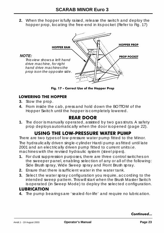
2. When the hopper is fully raised, release the switch and deploy the hopper prop, locating the free-end in its pocket (Refer to Fig. 17)
LOWERING THE HOPPER3. Stow the prop.4. From inside the cab, press and hold down the BOTTOM of the
Hopper Switch until the hopper is completely lowered.
REAR DOOR1. The door is manually operated, assisted by two gas struts. A safety
prop deploys automatically when the door is opened (page 22).
USING THE LOW-PRESSURE WATER PUMPThere are two types of low-pressure water pump fitted to the Minor.The hydraulically driven single-cylinder Hardi pump as fitted until late 2001 and an electrically driven pump fitted to current units i.e. machines with the revised hydraulic system (steel pipes).1. For dust suppression purposes, there are three control switches on
the sweeper panel, enabling selection of any or all of the following:Side Brush spray, Wide Sweep spray and Front Brush spray.
2. Ensure that there is sufficient water in the water tank.3. Select the water spray configuration you require, according to the
intended sweep pattern. This will start when the Brush Master Switch is operated (in Sweep Mode) to deploy the selected configuration.
LUBRICATION4. The pump bearings are ‘sealed-for-life’ and require no lubrication.
Fig. 17 - Correct Use of the Hopper Prop
HOPPER RAM
PROP POCKETNOTE:This view shows a left hand drive machine, for right hand drive machines the prop is on the opposite side.
HOPPER PROP
Continued...
drivemanVM.fm Page 23 Tuesday, August 19, 2003 11:43 AM

SCARAB MINOR Euro 3
Page 24 Operator’s Manual Amdt.1 - 19 August 2003
DRAINING5. It is vital that pumps are totally drained when air temperature is
expected to fall to 0°C or below. If a pump is allowed to freeze it is likely that damage will be incurred resulting in seizure.
6. Drain the water tank and open the drain valve (Fig. 18). Switch on all sprays and run the Hardi water pump until dry.
7. The electric pump is self-draining.
USING THE OPTIONAL HIGH-PRESSURE WATER PUMPWARNINGHIGH PRESSURE WATER CAN BE HAZARDOUS, ALWAYS WEAR GOGGLES OR SUITABLE EYE PROTECTION WHEN OPERATING WITH HIGH PRESSURE WATER. EXERCISE EXTREME CARE WHEN USING THE LANCE, DO NOT DIRECT THE JET AT OTHER PEOPLE.WHEN CLEANING PUBLIC BUILDINGS OR STREET FURNITURE, ENSURE THAT NO ELECTRICAL CONNECTIONS ARE EXPOSED.FAILURE TO COMPLY CAN RESULT IN SERIOUS INJURY.
CAUTIONS:Do not direct the high pressure jet directly at paint work or at electrical connections, this could result in damage to the vehicle.This pump should NEVER be permitted to run dry, as this will quickly destroy the piston seals and cause the pump to fail.1. Ensure that there is sufficient water in the water tank (and the street
wash bag-tank if fitted).2. Switch on the high pressure pump.3. Set engine speed to 1700 rpm.4. If the machine is fitted with a front-mounted high-pressure spray bar,
Fig. 18 Low-pressure Water Pump Arrangements
THE HARDI PUMP
AIR VALVEPULSATION DAMPER
DRAIN VALVETHE ELECTRICPUMP
drivemanVM.fm Page 24 Tuesday, August 19, 2003 11:43 AM

SCARAB MINOR Euro 3
Amdt.1 - 19 August 2003 Operator’s Manual Page 25
adjust the ball valves (Refer to Fig. 19) to supply the spray bar or the hand-lance as required.
OIL LEVEL5. The level of the oil in the pump’s crankcase should be checked on a
regular basis (See “OPERATOR’S ROUTINE MAINTENANCE” on page 5.) and topped up as necessary. There is a combined filler cap/dipstick on the top of the pump body (Refer to Fig. 19).
DRAININGCAUTION:
This pump should NEVER be permitted to run dry, as this will quickly destroy the piston seals and cause the pump to fail.It is vital that the pump is drained of all water whenever the ambient temperature is expected to fall to 0°C or below. If the pump is allowed to freeze it is likely that damage will be incurred resulting in seizure.6. Drain the water tank (refer to OPERATOR’S ROUTINE
MAINTENANCE on page 5),7. To drain the high-pressure side of the pump, open the ball valve
(plated lever).8. To drain the low-pressure side of the pump, open the lower valve
(Red Tap).
Fig. 19 High-pressure Water Pump Arrangement
DIPSTICK/FILLER CAP
L-P DRAIN VALVE
BALL VALVE TO FRONTH-P SPRAY BAR
BALL VALVEH-P BLEED/DRAIN
Continued...
drivemanVM.fm Page 25 Tuesday, August 19, 2003 11:43 AM

SCARAB MINOR Euro 3
Page 26 Operator’s Manual Amdt.1 - 19 August 2003
OPERATING SYMBOLS
WARNING LIGHTS
ENGINE GLOW-PLUGS WARNING
ENGINE OIL LEVEL WARNING
TURN INDICATORS REPEATER
BRAKE FLUID LEVEL WARNING
HEADLAMP MAIN BEAM WARNING
POWER ON INDICATOR
SWEEP-MODE INDICATOR
MAIN SWEEPING PANEL SWITCHES (FROM LEFT TO RIGHT & TOP TO BOTTOM)
MASTER SWITCH - LOWERS/ACTIVATES/RAISES PRE-SELECTED SWEEP GEAR
SIDE BRUSH (SECOND SWITCH ADDED TO SPARE PANEL FOR DUAL SWEEP)
WIDE SWEEP BRUSH
NEARSIDE FRONT BRUSH
OFFSIDE FRONT BRUSH
SUCTION FAN
SIDE BRUSH WATER-SPRAY (SECOND SWITCH ADDED FOR DUAL SWEEP)
drivemanVM.fm Page 26 Tuesday, August 19, 2003 11:43 AM

SCARAB MINOR Euro 3
Amdt.1 - 19 August 2003 Operator’s Manual Page 27
WIDE SWEEP WATER SPRAY
FRONT BRUSHES WATER SPRAY
HOPPER TIPPED
WORK LIGHTS
HIGH-PRESSURE WATER PUMP
DOOR PANEL SWITCHES
SUCTION NOZZLE - GOBBLER FLAP
FRONT BRUSH SWING IN/OUT (SECOND SWITCH ADDED FOR DUAL SWEEP)
BOTH SIDE BRUSHES SIMULTANEOUSLY (DUAL SWEEP OPTION ONLY)
LEFT OR RIGHT-HAND SIDE (CHANNEL) BRUSH (DUAL SWEEP OPTION ONLY)
AUXILIARY LIGHTING PANEL SWITCHES
HIGH-INTENSITY REAR LIGHTS
WARNING BEACONS / LIGHT BAR
OPERATING SYMBOLS
drivemanVM.fm Page 27 Tuesday, August 19, 2003 11:43 AM

SCARAB MINOR Euro 3
Page 28 Operator’s Manual Amdt.1 - 19 August 2003
SUPPLEMENTARY INFORMATION
Fig. 20 Dual Sweep & Street Wash Controls
RIGHT-HAND DRIVEDASH PANEL LAYOUT
SLEWING STREET-WASHSPRAYBAR CONTROL STICK
Typical LocationHIGH PRESSURE PUMP
Panel layout is a mirror image of the LHD panel(refer to pages 12 or 15 for details.
SWITCH PANEL ONDRIVER’S DOOR
FRONT BRUSHSWING-OUT
SUCTION NOZZLEGOBBLER FLAP
SELECT RH OR LHSWEEPING
SIMULTANEOUSDUAL SWEEP
drivemanVM.fm Page 28 Tuesday, August 19, 2003 11:43 AM

drivemanVM.fm Page 29 Tuesday, August 19, 2003 11:43 AM

Scarab Sweepers LimitedPattenden Lane, Marden, Kent TN12 9QD
Telephone: 01622 831006 Fax: 01622 832417International: +44 (0)1622 831006 International +44 (0)1622 832417e-mail: [email protected] Web site: www.scarab-sales.com
Publication Z026027 © Scarab Sweepers Limited 2002
drivemanVM.fm Page 30 Tuesday, August 19, 2003 11:43 AM