
Preliminary Design Report
285
SUSTAINABLE TRANSPORT FOR A BETTER CITY. Blanchardstown to City Centre Core Bus Corridor Scheme April 2022 Preliminary Design Report
-
Upload
khangminh22 -
Category
Documents
-
view
0 -
download
0
Transcript of Preliminary Design Report

Clongri�n toCity CentreScheme
SUSTAINABLE TRANSPORT FOR A BETTER CITY.
Blanchardstown to City Centre Core Bus Corridor SchemeApril 2022
Preliminary Design Report
National Transport Authority Blanchardstown to City Centre Core Bus Corridor Scheme Preliminary Design Report
| Issue | 7 May 2022
\\GLOBAL\EUROPE\DUBLIN\JOBS\268000\268401-00\4. INTERNAL\4-04 REPORTS\4-04-03 INFRASTRUCTURE\PRELIMINARY DESIGN REPORT\CBC 5\ISSUE MAY
2022\BCIDC-ARP-PMG_PD-0005_XX_00-RP-ZZ-0001_ISSUE.DOCX
Contents Page
List of Acronyms 1
1 Introduction and Description 5
1.1 Introduction 5
1.2 Scheme Aims and Objectives 6
1.3 Project Background 7
1.4 Proposed Construction Procurement Method 9
1.5 Stakeholder Consultation 9
1.6 Audit of the Existing Situation 10
1.7 Purpose of the Preliminary Design Report 10
1.8 Report Structure 11
1.9 Preliminary Design Drawings 12
2 Policy Context and Design Standards 16
2.1 Policy Context 16
2.2 Design Standards 16
3 The Proposed Scheme 18
3.1 Proposed Scheme Description 18
3.2 Associated Infrastructure Projects and Developments 26
3.3 Integration with Ballymun/Finglas to City Centre CBC 26
4 Road Geometry 29
4.1 Principal Geometric Parameters 29
4.2 Accessibility for Mobility Impaired Users 32
4.3 Mainline Cross-Section (Lane Widths) 33
4.4 Design Speed and Speed Limit 63
4.5 Alignment Modelling Strategy 66
4.6 Summary of Horizontal Alignment 67
4.7 Summary of Vertical Alignment 71
4.8 Forward Visibility 73
4.9 Corner Radii and Swept Path 75
4.10 Kerbing 76
4.11 Bus Provision 77
4.12 Cycling Provision 79
4.13 Pedestrian Provision 82
4.14 Bus Stops 83
4.15 Parking and Loading 94
4.16 Turning Bans and Traffic Management Measures 97
4.17 Deviations from Standard 102

National Transport Authority Blanchardstown to City Centre Core Bus Corridor Scheme Preliminary Design Report
| Issue | 7 May 2022
\\GLOBAL\EUROPE\DUBLIN\JOBS\268000\268401-00\4. INTERNAL\4-04 REPORTS\4-04-03 INFRASTRUCTURE\PRELIMINARY DESIGN REPORT\CBC 5\ISSUE MAY
2022\BCIDC-ARP-PMG_PD-0005_XX_00-RP-ZZ-0001_ISSUE.DOCX
4.18 Road Safety and Road User Audit 102
5 Junction Layout 104
5.1 Overview of Transport Modelling Strategy 104
5.2 Overview of Junction Design 104
5.3 Junction Geometry Design 105
5.4 Junction Modelling 118
6 Ground Investigation and Ground Condition 123
6.1 Ground Investigation Overview 123
6.2 Desk Study 123
6.3 Summary of Ground Investigation 125
6.4 Ground Summary and Material Properties 125
6.5 Overview of Soil and Bedrock Classification 132
6.6 Groundwater 132
6.7 Hydrogeology 133
6.8 Geotechnical Input to Structures 133
7 Pavement, Kerbs, Footways and Paved Areas 141
7.1 Pavement 141
7.2 Kerbs, Footways and Paved Areas 154
8 Structures 159
8.1 Overview of Structures Strategy 159
8.2 Summary of Existing Structures 159
8.3 Summary of Principal Structures 163
8.4 Summary of Miscellaneous Structures 167
9 Drainage, Hydrology and Flood Risk 172
9.1 Overview of Drainage Strategy 172
9.2 Existing Watercourses and Culverts 172
9.3 Existing Drainage Description 173
9.4 Overview of Impacts of Proposed Works on Drainage/Runoff 175
9.5 Preliminary Drainage Design 178
9.6 Drainage at New Bridge Structures 188
9.7 Flood Risk 189
10 Services and Utilities 191
10.1 Overview of Utilities Strategy and Survey 191
10.2 Overview of Service Diversions 192
10.3 Summary of Recommended Diversions 193
11 Waste Quantities 201
11.1 Introduction 201

National Transport Authority Blanchardstown to City Centre Core Bus Corridor Scheme Preliminary Design Report
| Issue | 7 May 2022
\\GLOBAL\EUROPE\DUBLIN\JOBS\268000\268401-00\4. INTERNAL\4-04 REPORTS\4-04-03 INFRASTRUCTURE\PRELIMINARY DESIGN REPORT\CBC 5\ISSUE MAY
2022\BCIDC-ARP-PMG_PD-0005_XX_00-RP-ZZ-0001_ISSUE.DOCX
11.2 Waste Calculation Assumptions 201
11.3 Waste Estimate Summary 210
12 Traffic Signs, Lighting and Communications 215
12.1 Introduction 215
12.2 Traffic Signage Strategy 215
12.3 Traffic Signage and Road Markings 216
12.4 Public Lighting 217
12.5 Traffic Signals 218
12.6 Communications 221
12.7 Traffic Monitoring 222
12.8 Real-Time Passenger Information 222
12.9 Roadside Variable Message Signs 224
12.10 Safety and Security 224
12.11 Maintenance 224
13 Land Use and Accommodation Works 226
13.1 Summary of Land Use 226
13.2 Summary of Compulsory Land Acquisition 228
13.3 Summary of Impacted Properties 228
13.4 Demolition 233
13.5 Summary of Accommodation Works and Boundary Treatment 233
14 Landscape and Urban Realm 235
14.1 Overview of Landscape and Urban Realm 235
14.2 Consultation with Local Authority 236
14.3 Landscape and Character Analysis 236
14.4 Arboricultural Survey 237
14.5 Hardscape 237
14.6 Softscape 239
14.7 Proposed Landscape and Urban Realm Design 242
15 How are we achieving the Objectives 277
Appendices
Appendix A
Designer’s Risk Assessment

National Transport Authority Blanchardstown to City Centre Core Bus Corridor Scheme Preliminary Design Report
| Issue | 7 May 2022
\\GLOBAL\EUROPE\DUBLIN\JOBS\268000\268401-00\4. INTERNAL\4-04 REPORTS\4-04-03 INFRASTRUCTURE\PRELIMINARY DESIGN REPORT\CBC 5\ISSUE MAY
2022\BCIDC-ARP-PMG_PD-0005_XX_00-RP-ZZ-0001_ISSUE.DOCX
Appendix B
Preliminary Design Drawings
B1 Site Location Map and Site Location Plan
B2 General Arrangement
B3 Mainline Plan and Profile
B4 Typical Cross Sections
B5 Landscaping General Arrangement
B6 Pavement Treatment Plans
B7 Fencing and Boundary Treatment
B8 Traffic Signs and Road Markings
B9 Street Lighting
B10 Junction Systems Design
B11 Proposed Surface Water Drainage Works
B12 IW Foul Sewer Asset Alterations
B13 ESB Asset Alterations
B14 GNI Asset Alterations
B15 IW Water Asset Alterations
B16 Telecommunications Asset Alterations
B17 Combined Existing Utilities Records
B18 Bridges and Major Retaining Structures
B19 Buildings / Architecture
Appendix C
Deviations / Departures / Relaxations from Standards
Appendix D
Arboricultural Impact Assessment Report
Appendix E
Ground Investigation Report

National Transport Authority Blanchardstown to City Centre Core Bus Corridor Scheme Preliminary Design Report
| Issue | 7 May 2022
\\GLOBAL\EUROPE\DUBLIN\JOBS\268000\268401-00\4. INTERNAL\4-04 REPORTS\4-04-03 INFRASTRUCTURE\PRELIMINARY DESIGN REPORT\CBC 5\ISSUE MAY
2022\BCIDC-ARP-PMG_PD-0005_XX_00-RP-ZZ-0001_ISSUE.DOCX
Appendix F
Existing Structures Impact Assessment Report
Appendix G
Parking Survey Report
Appendix H
Bus Stop Review Report
Appendix I
Accessibility Audit
I1 Accessibility Audit Report
I2 Accessibility Audit Designer’s Response
Appendix J
Structural Design
J1 Preliminary Design Report – Tolka River Bridge
J2 Preliminary Design Report - Mill Road Bridge
J3 Preliminary Design Report - Retaining Walls
J4 Preliminary Design Report – Sign Gantries
Appendix K
Drainage Design Basis
Appendix L
Junction Design Report
Appendix M
Road Safety Audits
M1 Emerging Preferred Route – Road Safety Audit
M2 Stage 1 Road Safety Audit
Appendix N
Flood Risk Assessment
Appendix O
Preliminary Design Guidance Booklet
Appendix P
Bus Interchange Design Statement

National Transport Authority Blanchardstown to City Centre Core Bus Corridor Scheme Preliminary Design Report
| Issue | 7 May 2022
\\GLOBAL\EUROPE\DUBLIN\JOBS\268000\268401-00\4. INTERNAL\4-04 REPORTS\4-04-03 INFRASTRUCTURE\PRELIMINARY DESIGN REPORT\CBC 5\ISSUE MAY
2022\BCIDC-ARP-PMG_PD-0005_XX_00-RP-ZZ-0001_ISSUE.DOCX
Page 1
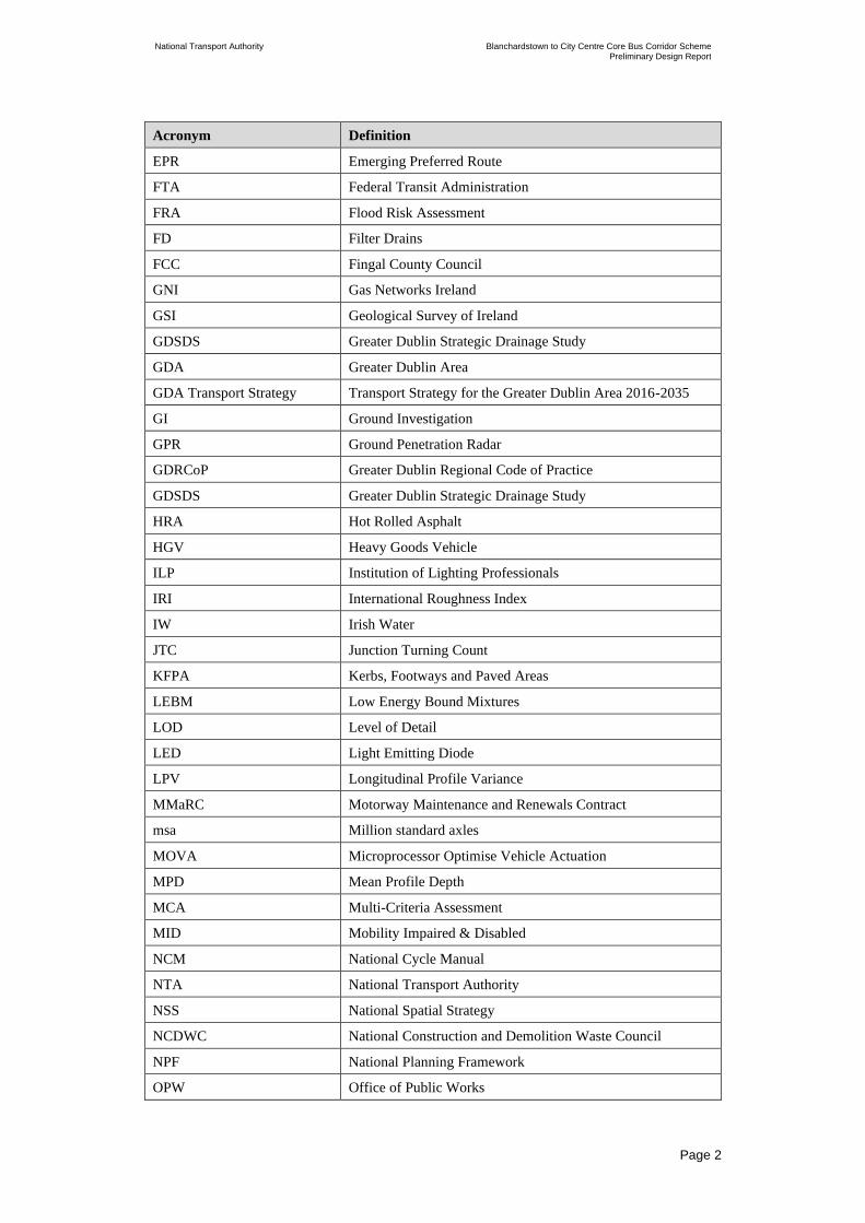
List of Acronyms
Acronym Definition
AC Asphalt Concrete
AIAR Arboricultural Impact Assessment Report
ASLs Advance Stacking Locations
AVL Automatic Vehicle Location
AP Attenuation Ponds
AT Attenuation Tanks
AVLS Automatic Vehicle Location System
AlluvMIN Alluvial(mineral)
BCPDGB BusConnects Preliminary Design Guidance Booklet
BEP Building Information Modelling (BIM) Execution Plan
BGL Below Ground Level
BJTR Bus Journey Time Report
BminDW Deep well drained (Mainly basic)
BminPD Mineral poorly drained (Mainly basic)
CBR California Bearing Ratio
CBC Core Bus Corridor
CSC Characteristic Skid Coefficient
CIRIA Construction Industry Research and Information Association,
CPO Compulsory Purchase Order
CCTV Close Circuit Television
DB 32 Design Bulletin 32
DSRC Dedicated Short Range Communications
DCC Dublin City Council
DLAM Dublin Local Area Model
DLRCC Dún Laoghaire-Rathdown County Council
DM Do Minimum
DMURS Design Manual for Urban Roads and Streets
DCP Dynamic Cone Penetrometer
DEHLG Department of Environment, Heritage and Local Government
DART Dublin Area Rapid Transit
DTTAS Department for Transport, Tourism and Sport
DS Do Something
ESB Electricity Supply Bord
ED Engineering Designer
EIAR Environmental Impact Assessment Report
National Transport Authority Blanchardstown to City Centre Core Bus Corridor Scheme Preliminary Design Report
| Issue | 7 May 2022
\\GLOBAL\EUROPE\DUBLIN\JOBS\268000\268401-00\4. INTERNAL\4-04 REPORTS\4-04-03 INFRASTRUCTURE\PRELIMINARY DESIGN REPORT\CBC 5\ISSUE MAY
2022\BCIDC-ARP-PMG_PD-0005_XX_00-RP-ZZ-0001_ISSUE.DOCX
Page 2
Acronym Definition
EPR Emerging Preferred Route
FTA Federal Transit Administration
FRA Flood Risk Assessment
FD Filter Drains
FCC Fingal County Council
GNI Gas Networks Ireland
GSI Geological Survey of Ireland
GDSDS Greater Dublin Strategic Drainage Study
GDA Greater Dublin Area
GDA Transport Strategy Transport Strategy for the Greater Dublin Area 2016-2035
GI Ground Investigation
GPR Ground Penetration Radar
GDRCoP Greater Dublin Regional Code of Practice
GDSDS Greater Dublin Strategic Drainage Study
HRA Hot Rolled Asphalt
HGV Heavy Goods Vehicle
ILP Institution of Lighting Professionals
IRI International Roughness Index
IW Irish Water
JTC Junction Turning Count
KFPA Kerbs, Footways and Paved Areas
LEBM Low Energy Bound Mixtures
LOD Level of Detail
LED Light Emitting Diode
LPV Longitudinal Profile Variance
MMaRC Motorway Maintenance and Renewals Contract
msa Million standard axles
MOVA Microprocessor Optimise Vehicle Actuation
MPD Mean Profile Depth
MCA Multi-Criteria Assessment
MID Mobility Impaired & Disabled
NCM National Cycle Manual
NTA National Transport Authority
NSS National Spatial Strategy
NCDWC National Construction and Demolition Waste Council
NPF National Planning Framework
OPW Office of Public Works

National Transport Authority Blanchardstown to City Centre Core Bus Corridor Scheme Preliminary Design Report
| Issue | 7 May 2022
\\GLOBAL\EUROPE\DUBLIN\JOBS\268000\268401-00\4. INTERNAL\4-04 REPORTS\4-04-03 INFRASTRUCTURE\PRELIMINARY DESIGN REPORT\CBC 5\ISSUE MAY
2022\BCIDC-ARP-PMG_PD-0005_XX_00-RP-ZZ-0001_ISSUE.DOCX
Page 3
Acronym Definition
OSI Ordnance Survey Ireland
OD Ordinance Datum
OSP Oversize Pipes
PDR Preliminary Design Report
PSCI Pavement Surface Condition Index
PMG Project Management Guidelines
PMC People Movement Calculator
RSES Regional Spatial and Economic Strategies
RC Rotary Core
RMO Road Maintenance Office
RSA Road Safety Audit
RTPI Real Time Passenger Information
SMA Stone Mastic Asphalt
SuDS Sustainable Urban Drainage Systems
SCOOT Split Cycle Offset Optimisation Technique
SDCC South Dublin County Council
SCATS Sydney Coordinated Adaptive Traffic System
SSD Stopping Sight Distance
TII Transport Infrastructure Ireland
TSM Traffic Signs Manual
TP Trial Pit
UCD University College Dublin
VMS Variable Message Signs
WCC Wicklow County Council
National Transport Authority Blanchardstown to City Centre Core Bus Corridor Scheme Preliminary Design Report
| Issue | 7 May 2022
\\GLOBAL\EUROPE\DUBLIN\JOBS\268000\268401-00\4. INTERNAL\4-04 REPORTS\4-04-03 INFRASTRUCTURE\PRELIMINARY DESIGN REPORT\CBC 5\ISSUE MAY
2022\BCIDC-ARP-PMG_PD-0005_XX_00-RP-ZZ-0001_ISSUE.DOCX
Page 4
Executive Summary
This Preliminary Design Report has been prepared for the Blanchardstown to City
Centre Core Bus Corridor and builds on the previous Feasibility and Options
Report and Preferred Route Options Report for the Blanchardstown to City Centre
scheme.
This report summarises the project background and the need for the scheme in the
context of National and Local Planning Policy, summarises the existing physical
conditions and documents the surveys undertaken in developing the design.
The report also details the preliminary design, sets out traffic management
proposals and outlines the traffic modelling undertaken and the outputs from the
junction modelling.
The land use and acquisition requirements are summarised in this report, along
with details of affected landowners and property owners, and proposed
accommodation works.
The report concludes that the design of the Blanchardstown to City Centre Core
Bus Corridor scheme wholly achieves the scheme objectives. In doing so, it fulfils
the aim of providing enhanced walking, cycling and bus infrastructure on a key
access corridor in the Dublin region, enabling the delivery of efficient, safe, and
integrated sustainable transport movement along the corridor.

National Transport Authority Blanchardstown to City Centre Core Bus Corridor Scheme Preliminary Design Report
| Issue | 7 May 2022
\\GLOBAL\EUROPE\DUBLIN\JOBS\268000\268401-00\4. INTERNAL\4-04 REPORTS\4-04-03 INFRASTRUCTURE\PRELIMINARY DESIGN REPORT\CBC 5\ISSUE MAY
2022\BCIDC-ARP-PMG_PD-0005_XX_00-RP-ZZ-0001_ISSUE.DOCX
Page 5
1 Introduction and Description
1.1 Introduction
BusConnects is the National Transport Authority’s (NTA) programme to improve
bus and sustainable transport services. It is a key part of the Government’s
policies to improve public transport and address climate change. The NTA
established a dedicated BusConnects Infrastructure team (the BusConnects
Infrastructure team) to advance the planning and construction of the Core Bus
Corridor (CBC) Infrastructure Works. It comprises an inhouse team including
technical and communications resources and external service providers procured
from time-to-time to assist the internal team in the planning and design of the
twelve Proposed Schemes.
The CBC Infrastructure Works involves the development of continuous bus
priority infrastructure and improved pedestrian and cycling facilities on twelve
radial core corridors in the Greater Dublin Area (GDA), across the local authority
jurisdictions of Dublin City Council (DCC), South Dublin County Council
(SDCC), Dún Laoghaire-Rathdown County Council (DLRCC), Fingal County
Council (FCC), and Wicklow County Council (WCC). Overall, the CBC
Infrastructure Works encompasses the delivery of approximately 230km of
dedicated bus lanes and 200km of cycle tracks along sixteen of the busiest
corridors in Dublin.
Blanchardstown to City Centre Core Bus Corridor of the CBC Infrastructure
Works (herein after called the ‘Proposed Scheme’) measures approximately 10.9
km from end to end.
The Proposed Scheme commences at Junction 3 (Blanchardstown / Mulhuddart)
southbound off-slip from the N3. The corridor proceeds along the R121
Blanchardstown Road South into the Blanchardstown Shopping Centre.
From a new terminus to the north-west of Blanchardstown Shopping Centre the
Proposed Scheme is routed onto the N3 Navan Road via the Snugborough Road
junction and follows the N3 and Navan Road as far as the junction with the Old
Cabra Road. From here, the Proposed Scheme is routed along Old Cabra Road,
Prussia Street, Manor Street and Stoneybatter to the junction with Brunswick
Street North.
The Proposed Scheme is then routed via Blackhall Place as far as the junction
with Ellis Quay and Arran Quay, where it joins the prevailing traffic management
regime on the North Quays.
At the Stoneybatter / Brunswick Street North junction, cyclists proceed along
Brunswick Street North, George’s Lane and Queen Street as far as Ellis
Quay/Arran Quay.
Refer to Figure 1.1 for overall layout of the Proposed Scheme.

National Transport Authority Blanchardstown to City Centre Core Bus Corridor Scheme Preliminary Design Report
| Issue | 7 May 2022
\\GLOBAL\EUROPE\DUBLIN\JOBS\268000\268401-00\4. INTERNAL\4-04 REPORTS\4-04-03 INFRASTRUCTURE\PRELIMINARY DESIGN REPORT\CBC 5\ISSUE MAY
2022\BCIDC-ARP-PMG_PD-0005_XX_00-RP-ZZ-0001_ISSUE.DOCX
Page 6
Figure 1.1: Proposed Scheme Route Overview
1.2 Scheme Aims and Objectives
The aim of the CBC Infrastructure Works is to provide enhanced walking, cycling
and bus infrastructure on key access corridors in the Dublin region, which will
enable and deliver efficient, safe, and integrated sustainable transport movement
along these corridors.
The objectives of the CBC Infrastructure Works are to:
• Enhance the capacity and potential of the public transport system by
improving bus speeds, reliability and punctuality through the provision of bus
lanes and other measures to provide priority to bus movement over general
traffic movements.
• Enhance the potential for cycling by providing safe infrastructure for cycling,
segregated from general traffic wherever practicable.
• Support the delivery of an efficient, low carbon and climate resilient public
transport service, which supports the achievement of Ireland’s emission
reduction targets.
• Enable compact growth, regeneration opportunities and more effective use of
land in Dublin, for present and future generations, through the provision of
safe and efficient sustainable transport networks.
• Improve accessibility to jobs, education and other social and economic
opportunities through the provision of improved sustainable connectivity and
integration with other public transport services.
• Ensure that the public realm is carefully considered in the design and
development of the transport infrastructure and seek to enhance key urban
focal points where appropriate and feasible.

National Transport Authority Blanchardstown to City Centre Core Bus Corridor Scheme Preliminary Design Report
| Issue | 7 May 2022
\\GLOBAL\EUROPE\DUBLIN\JOBS\268000\268401-00\4. INTERNAL\4-04 REPORTS\4-04-03 INFRASTRUCTURE\PRELIMINARY DESIGN REPORT\CBC 5\ISSUE MAY
2022\BCIDC-ARP-PMG_PD-0005_XX_00-RP-ZZ-0001_ISSUE.DOCX
Page 7
1.3 Project Background
The Transport Strategy for the Greater Dublin Area 2016 – 2035 sets out a
network of the bus corridors forming the “Core Bus Network” for the Dublin
region. Sixteen indicative radial CBCs were initially identified for redevelopment.
This is shown in Figure 1.2 below (extract from Transport Strategy for the Greater
Dublin Area 2016-2035).
Figure 1.2: 2035 Core Bus Network – Radial Corridors
These corridors currently have dedicated bus lanes along only less than one third
of their lengths which means that for most of the journey, buses and cyclists are
competing for space with general traffic and are negatively affected by the
increasing levels of congestion. This results in delayed buses and unreliable
journey times for passengers. Following the completion of feasibility and options
studies sixteen radial corridors were taken forward.
In June 2018, the NTA published the Core Bus Corridors Project Report. The
report was a discussion document outlining proposals for the delivery of a CBC
network across Dublin. The Proposed Scheme is identified in this document as
forming part of the Radial Core Bus Network, designated as Blanchardstown to
City Centre CBC.
In the context of the proposed planning applications for the CBC Infrastructure
Works, the initial sixteen radial CBCs have been grouped as twelve individual
Schemes. The twelve Schemes that will be the subject of separate applications to
An Bord Pleanála for approval are listed below:
• Clongriffin to City Centre Core Bus Corridor Scheme;
• Swords to City Centre Core Bus Corridor Scheme;

National Transport Authority Blanchardstown to City Centre Core Bus Corridor Scheme Preliminary Design Report
| Issue | 7 May 2022
\\GLOBAL\EUROPE\DUBLIN\JOBS\268000\268401-00\4. INTERNAL\4-04 REPORTS\4-04-03 INFRASTRUCTURE\PRELIMINARY DESIGN REPORT\CBC 5\ISSUE MAY
2022\BCIDC-ARP-PMG_PD-0005_XX_00-RP-ZZ-0001_ISSUE.DOCX
Page 8
• Ballymun / Finglas to City Centre Core Bus Corridor Scheme;
• Blanchardstown to City Centre Core Bus Corridor Scheme;
• Lucan to City Centre Core Bus Corridor Scheme;
• Liffey Valley to City Centre Core Bus Corridor Scheme;
• Tallaght / Clondalkin to City Centre Core Bus Corridor Scheme;
• Kimmage to City Centre Core Bus Corridor Scheme;
• Templeogue / Rathfarnham to City Centre Core Bus Corridor Scheme;
• Bray to City Centre Core Bus Corridor Scheme;
• Belfield / Blackrock to City Centre Core Bus Corridor Scheme; and
• Ringsend to City Centre Core Bus Corridor Scheme;
The twelve radial routes that form the CBC Infrastructure works is shown in
Figure 1.3.
Figure 1.3: BusConnects Radial CBC Network

National Transport Authority Blanchardstown to City Centre Core Bus Corridor Scheme Preliminary Design Report
| Issue | 7 May 2022
\\GLOBAL\EUROPE\DUBLIN\JOBS\268000\268401-00\4. INTERNAL\4-04 REPORTS\4-04-03 INFRASTRUCTURE\PRELIMINARY DESIGN REPORT\CBC 5\ISSUE MAY
2022\BCIDC-ARP-PMG_PD-0005_XX_00-RP-ZZ-0001_ISSUE.DOCX
Page 9
1.4 Proposed Construction Procurement Method
The Proposed Scheme will proceed on the basis of procurement through a Design-
Build tender process.
Consequently, the design information presented in this report ensures that the
objectives of the Proposed Scheme are met, in accordance with current design
standards and guidance documents. It further ensures that sufficient land will be
acquired during the Compulsory Purchase Order process in order to construct a
CBC that will fulfil the design requirements.
1.5 Stakeholder Consultation
Three rounds of non-statutory public consultation have taken place over the
following dates;
• 14 November 2018 to 29 March 2019 - Consultation on Emerging Preferred
Route;
• 4 March 2020-17 April 2020 - Consultation on Preferred Route Option; and
• 4 November 2020 - 16 December 2020 - Consultation on Preferred Route
Option.
Refer to the Blanchardstown to City Centre Core Bus Corridor Preferred Route
Option Second and Third Public Consultation Submissions Summary Report for
information on the non-statutory consultation.
Consultation with the principal project stakeholders (i.e. Dublin City Council
(DCC), Fingal County Council (FCC), Transport Infrastructure Ireland (TII), An
Garda Síochána, Office of Public Works (OPW) and Utility companies) has taken
place to date in order to:
• Inform the scheme development process at particular locations;
• Identify constraints and opportunities within the study area, scheme corridor
and route options considered;
• Further refine the scheme objectives;
• Discuss potential mitigation measures and options; and
• Identify planning requirements, conditions and implications with respect to the
proposed scheme design measures.
Specific scheme requirements have been discussed and agreed during workshops,
with the Local Authorities, and meetings, at Steering Group and Programme level.
The BusConnects Infrastructure Team has taken cognisance of any specific
requirements and recommendations emerging from this process when exploring
feasible scheme options and preparing the preliminary design.
In addition to the principal project stakeholders, consultations have taken place
with:
• Representative Groups;

National Transport Authority Blanchardstown to City Centre Core Bus Corridor Scheme Preliminary Design Report
| Issue | 7 May 2022
\\GLOBAL\EUROPE\DUBLIN\JOBS\268000\268401-00\4. INTERNAL\4-04 REPORTS\4-04-03 INFRASTRUCTURE\PRELIMINARY DESIGN REPORT\CBC 5\ISSUE MAY
2022\BCIDC-ARP-PMG_PD-0005_XX_00-RP-ZZ-0001_ISSUE.DOCX
Page 10
• Chartered Landowners (i.e. owners of lands at any specific locations); and
• Directly Impacted landowners.
1.6 Audit of the Existing Situation
A number of audits, surveys and assessments have been carried out, and includes
the following:
• Problem Identification Audit;
• Accessibility Audit;
• Route Infrastructure Audit;
• Existing Pavement Inspection Audit;
• Existing Structures Impact Assessment;
• Existing Route Collision Analysis;
• Cellar Survey;
• Private Landings Survey;
• Baseline Tree Survey;
• Arboricultural Impact Assessment;
• Cycle Journey Time Survey;
• Pavement condition;
• Phase 1 Utility Survey;
• Bus Stop Survey including boarding and alighting and AVL;
• Traffic Survey (JTC, pedestrian and cyclists counts);
• Parking survey; and
• Bus Journey Time.
These surveys have been supplemented with secondary record data to include
utility information, OPW CFRAM Flood Models, Irish Water (IW) Drainage
Models and existing traffic signal data from DCC.
A number of environmental surveys have also been carried out by the
Environmental Impact Assessment (EIA) team. Refer to the Environmental
Impact Assessment Report for further information.
1.7 Purpose of the Preliminary Design Report
The Preliminary Design Report sets out the preliminary design of the Proposed
Scheme, and supports the Compulsory Purchase Order (CPO) documentation and
Environmental Impact Assessment Report (EIAR) which form part of the
Planning Application to An Bord Pleanála.

National Transport Authority Blanchardstown to City Centre Core Bus Corridor Scheme Preliminary Design Report
| Issue | 7 May 2022
\\GLOBAL\EUROPE\DUBLIN\JOBS\268000\268401-00\4. INTERNAL\4-04 REPORTS\4-04-03 INFRASTRUCTURE\PRELIMINARY DESIGN REPORT\CBC 5\ISSUE MAY
2022\BCIDC-ARP-PMG_PD-0005_XX_00-RP-ZZ-0001_ISSUE.DOCX
Page 11
During the preparation of the preliminary design, a designer’s risk assessment was
undertaken, details of these are included in Appendix A.
The purpose of the risk assessment is to identify significant design risks and
mitigate them as part of the design process.
1.8 Report Structure
The structure for the remainder of this report is set out as follows:
• Chapter 2: Policy Context and Design Standards – This chapter identifies the
policies and design standards reviewed and applied to the preliminary design;
• Chapter 3: The Proposed Scheme – This chapter describes the five sections of
the Proposed Scheme in more detail;
• Chapter 4: Road Geometry – In this chapter, the geometrical alignment and
cross-section of the scheme are described, along with an overview of the
operational safety process which has been implemented;
• Chapter 5: Junction Layout – The junction design methodology and modelling
process is then set out for the major, moderate and minor junctions along the
length of the route in this chapter;
• Chapter 6: Ground Investigation and Ground Condition – This chapter
provides an overview of the ground investigation process and ground
conditions;
• Chapter 7: Pavement, Kerbs, Footpaths and Paved Areas– This chapter gives
an overview of the existing pavement situation and proposed pavement, kerbs,
footpaths and paved areas design for the scheme;
• Chapter 8: Structures – In this chapter an overview of the structures strategy is
provided, along with a summary of principal and miscellaneous structures,
retaining walls and embankments;
• Chapter 9: Drainage, Hydrology and Flood Risk – This chapter is an overview
of the drainage strategy includes descriptions of existing watercourses and
culverts alongside a summary of the drainage design for each catchment along
the scheme, including the consideration of drainage at structures and the
maximisation of SuDS features;
• Chapter 10: Services and Utilities – This chapter shows the Utilities design
strategy documents surveys undertaken to date, identifies conflicts and
recommends a number of diversions;
• Chapter 11: Waste Quantities – This chapter provides an overview of the
waste quantities for the Proposed Scheme;
• Chapter 12: Traffic Signs, Lighting and Communications – In this chapter the
design strategy for traffic signs, road markings, lighting and communications
equipment is outlined, alongside descriptions of how these elements can be
maintained and monitored safety and securely;

National Transport Authority Blanchardstown to City Centre Core Bus Corridor Scheme Preliminary Design Report
| Issue | 7 May 2022
\\GLOBAL\EUROPE\DUBLIN\JOBS\268000\268401-00\4. INTERNAL\4-04 REPORTS\4-04-03 INFRASTRUCTURE\PRELIMINARY DESIGN REPORT\CBC 5\ISSUE MAY
2022\BCIDC-ARP-PMG_PD-0005_XX_00-RP-ZZ-0001_ISSUE.DOCX
Page 12
• Chapter 13: Land Use and Accommodation Works – This chapter outlines
land use and acquisition requirements, affected land and property owners, and
proposed accommodation works;
• Chapter 14: Landscape and Urban Realm – This chapter is an overview of the
landscape and urban realm design strategy focussing on the existing trees and
proposed mitigation;
• Chapter 15: How we are achieving the Objectives – This chapter sets out the
manner in which the Proposed Scheme achieves its objectives; and
• Appendices – Various appendices and background information as referenced
throughout the report.
1.9 Preliminary Design Drawings
A set of preliminary design drawings have been prepared to convey the scheme
design principles for each discipline and should be read in conjunction with this
Preliminary Design Report. Table 1.1 provides a description of the drawings and
relevant design content displayed in each of the series as applicable for the
Scheme. The drawings have been included in Appendix B for reference.
The file naming conventions for the Drawing Series and Volume Codes are as set
out in the Building Information Modelling (BIM) Execution Plan (BEP)
developed for the CBC Infrastructure Works.
Table 1.1: Preliminary Design Drawings
Drawing Series
Volume Code
Drawing Series
Description/Scale
Design Content
SPW_KP/SPW_
ZZ
Site Location Map
(1:12500@ A1) &
Site Location Plan
(1:2500@A1)
Defines the full extent of the works & planning
red line boundary. Outlines the scheme
chainage structure and provides context for the
locality of adjacent Schemes and other notable
locations along the route.
SPW_BW Fencing and
Boundary Treatment
(1:500@A1)
To be read in conjunction with the GEO_GA
General Arrangement series and GEO_CS
typical cross section series. Provides an
indication of the locations for the proposed
boundary modification works along the route.
GEO_GA General Arrangement
(1:500 @ A1)
Displays information for conveying the
overarching scheme design intent, providing
information on the proposed pedestrian/cycle/
bus/traffic regime, indicative ultimate tree
arrangement (existing trees retained &
proposed trees), bus stop/shelter locations, key
heritage feature locations, parking and loading
arrangements, turn bans, side road treatments in
addition to identification of specific items of
note to the scheme (structures or significant
features which may be further described on
other drawing series)

National Transport Authority Blanchardstown to City Centre Core Bus Corridor Scheme Preliminary Design Report
| Issue | 7 May 2022
\\GLOBAL\EUROPE\DUBLIN\JOBS\268000\268401-00\4. INTERNAL\4-04 REPORTS\4-04-03 INFRASTRUCTURE\PRELIMINARY DESIGN REPORT\CBC 5\ISSUE MAY
2022\BCIDC-ARP-PMG_PD-0005_XX_00-RP-ZZ-0001_ISSUE.DOCX
Page 13
Drawing Series
Volume Code
Drawing Series
Description/Scale
Design Content
GEO_CS Typical Cross
Sections (1:50 @ A1)
To be read in conjunction with the GEO_GA
General Arrangement series. Provides an
indication of the proposed cross section works
in comparison to the existing road geometry.
Indicative pavement/kerbing, boundary
treatments and key street furniture are also
provided for context.
GEO_HV Mainline Plan and
Profile (1:500@A1)
To be read in conjunction with the GEO_GA
General Arrangement series. Provides an
indication of the proposed modification works
to the mainline vertical alignment with
supplementary information on
earthworks/retaining walls and other notable
structures along the route (as required).
ENV_LA Landscaping General
Arrangement
(1:500@A1)
Provides information relating to urban realm
and landscaping proposals including
identification of trees to be removed resulting
from the arborist assessments, proposed
tree/planting regime, proposed footpath surface
finishes, locations of proposed SUDs features
and proposed boundary treatment and key street
furniture notes.
DNG_RD Proposed Surface
Water Drainage
Works (1:500@A1)
Displays information for conveying the design
intent for the drainage portion of the works
including identification of SuDS
measures, requirements for allowable discharge
rates to the existing
networks (attenuation/detention/flow control)
where applicable, catchment assessments
and outline design for the proposed drainage
discharge strategy along the route.
UTL_UC Combined Existing
Utilities Records
(1:500@A1)
Displays information regarding existing
Statutory Undertakers records along the length
of the scheme with the proposed scheme
features shown as background information for
context.
UTL_UD IW Foul Sewer Asset
Alterations
(1:500@A1)
Provides an indication of the existing trunk foul
sewer network and proposed indicative
modification/diversion works (where
identified) along the route. The existing and
proposed kerb lines have been displayed for
scheme context.
UTL_UW IW Water Asset
Alterations
(1:500@A1)
Provides an indication of the existing trunk
potable water network and proposed indicative
modification/diversion works (where
identified) along the route. The existing and
proposed kerb lines have been displayed for
scheme context.

National Transport Authority Blanchardstown to City Centre Core Bus Corridor Scheme Preliminary Design Report
| Issue | 7 May 2022
\\GLOBAL\EUROPE\DUBLIN\JOBS\268000\268401-00\4. INTERNAL\4-04 REPORTS\4-04-03 INFRASTRUCTURE\PRELIMINARY DESIGN REPORT\CBC 5\ISSUE MAY
2022\BCIDC-ARP-PMG_PD-0005_XX_00-RP-ZZ-0001_ISSUE.DOCX
Page 14
Drawing Series
Volume Code
Drawing Series
Description/Scale
Design Content
UTL_UE ESB Asset
Alterations
(1:500@A1)
Provides an indication of the existing trunk
electrical network (above and below ground)
and proposed indicative modification/diversion
works (where identified) along the route. The
existing and proposed kerb lines have been
displayed for scheme context.
UTL_UL Telecommunications
Asset Alterations
(1:500@A1)
Provides an indication of the existing trunk
telecommunications network and proposed
indicative modification/diversion works (where
identified) along the route. The existing and
proposed kerb lines have been displayed for
scheme context.
UTL_UG GNI Asset Alterations
(1:500@A1)
Provides an indication of the existing trunk gas
network and proposed indicative
modification/diversion works (where
identified) along the route. The existing and
proposed kerb lines have been displayed for
scheme context.
LHT_RL Street Lighting
(1:500@A1)
Provides an indication of the proposed
modification works to the existing street
lighting infrastructure along the route in
addition to identification of any key heritage
lighting column features.
TSM_SJ Junction Systems
Design (1:250@A1)
Provides a more detailed overview of the
proposed junction arrangements for
pedestrians, cyclists, buses and general traffic
with an indication of the proposed junction
staging and associated signal head
arrangements for key signalised
junctions/signalised crossings along the route.
TSM_GA Traffic Signs and
Road Markings
(1:500@A1)
Provides an indication of the proposed key
signage (information/directional/regulatory)
design requirements and the design intent for
the proposed lane marking arrangements along
the route.
PAV_PV Pavement Treatment
Plans (1:500@A1)
Provides an indication of the proposed
pavement treatment works along the length of
the route.
STR_GA Bridges and Major
Retaining Structures
Provides details relating to proposed bridge
structure/underpass works in addition to
structural retaining walls and overhead sign
gantries along the route.
BLD_AR Buildings /
Architecture
Provides details relating to proposed Bus
Interchange and driver welfare facility
including architectural layouts and site
elevations and sections.

National Transport Authority Blanchardstown to City Centre Core Bus Corridor Scheme Preliminary Design Report
| Issue | 7 May 2022
\\GLOBAL\EUROPE\DUBLIN\JOBS\268000\268401-00\4. INTERNAL\4-04 REPORTS\4-04-03 INFRASTRUCTURE\PRELIMINARY DESIGN REPORT\CBC 5\ISSUE MAY
2022\BCIDC-ARP-PMG_PD-0005_XX_00-RP-ZZ-0001_ISSUE.DOCX
Page 15
The planning red line boundary has been displayed on the Site Location Map and
Site Location Plan drawing series SPW_KP/SPW_ZZ (in Appendix B) as
designated by the solid red line ‘SITE EXTENTS’. For clarity the various
discipline general arrangement drawing series have been displayed with the
permanent extent of works boundary line as designated by the solid red line ‘SITE
BOUNDARY LINE’. Where construction access or accommodation works are
required to facilitate the permanent works, this has been displayed by the dashed
red line ‘TEMPORARY LAND ACQUISITION’. Construction site compounds
outside the ‘SITE BOUNDARY LINE’ are also captured within the dashed red
line ‘TEMPORARY LAND ACQUISITION’.
Full details of the compulsory land acquisition required to construct the Proposed
Scheme are provided on the various Deposit Maps, Server Maps and associated
CPO schedules/documentation for the Proposed Scheme as part of the statutory
application documentation.
National Transport Authority Blanchardstown to City Centre Core Bus Corridor Scheme Preliminary Design Report
| Issue | 7 May 2022
\\GLOBAL\EUROPE\DUBLIN\JOBS\268000\268401-00\4. INTERNAL\4-04 REPORTS\4-04-03 INFRASTRUCTURE\PRELIMINARY DESIGN REPORT\CBC 5\ISSUE MAY
2022\BCIDC-ARP-PMG_PD-0005_XX_00-RP-ZZ-0001_ISSUE.DOCX
Page 16
2 Policy Context and Design Standards
2.1 Policy Context
The following national, regional and local policies have been reviewed and
considered in the development of the Proposed Scheme:
• Project Ireland 2040;
• Department of Transport: Statement of Strategy (2016 ‐ 2019);
• Smarter Travel: A Sustainable Transport Future (2009 – 2020);
• National Cycle Policy Framework (2009);
• Road Safety Strategy (2013 – 2020);
• Building on Recovery: Infrastructure and Capital Investment Plan (2016-
2021);
• The Sustainable Development Goals National Implementation Plan (2018-
2020);
• Climate Action Plan (2019);
• Eastern & Midland Regional Assembly, Regional Spatial & Economic;
Strategy (2019-2031);
• Greater Dublin Area Cycle Network Plan;
• Transport Strategy for the Greater Dublin Area (2016-2035);
• Dublin City Council Development Plan (2016-2022); and
• Fingal County Council Development Plan (FCC) (2017 – 2023).
For further information on how the Proposed Scheme meets the policies outlined
above, refer to Blanchardstown to City Centre Core Bus Corridor Planning
Compliance Report.
2.2 Design Standards
Design standards applied on the Proposed Scheme are stated within the applicable
chapters of this report. In addition to national design standards the CBC
Infrastructure Works has developed the BusConnects Preliminary Design
Guidance Booklet (BCPDGB), contained in Appendix O; its purpose is to provide
guidance for the various design teams involved in CBC Infrastructure Works, to
ensure a consistent design approach across the twelve Proposed Schemes.
The BCPDGB complements existing guidance documents relating to the design of
urban streets, bus facilities, cycle facilities and urban realm. A non-exhaustive list
of these guidelines is as follows:
• The Design Manual for Urban Roads and Streets (DMURS);
• The National Cycle Manual (NCM);

National Transport Authority Blanchardstown to City Centre Core Bus Corridor Scheme Preliminary Design Report
| Issue | 7 May 2022
\\GLOBAL\EUROPE\DUBLIN\JOBS\268000\268401-00\4. INTERNAL\4-04 REPORTS\4-04-03 INFRASTRUCTURE\PRELIMINARY DESIGN REPORT\CBC 5\ISSUE MAY
2022\BCIDC-ARP-PMG_PD-0005_XX_00-RP-ZZ-0001_ISSUE.DOCX
Page 17
• TII Publications;
• The Traffic Signs Manual (TSM);
• Guidance on the use of Tactile Paving;
• Building for Everyone: A Universal Design Approach, and
• Greater Dublin Strategic Drainage Study (GDSDS).
The BCPDGB focuses on the engineering geometry and Proposed Scheme
operation. It is recognised that the Proposed Scheme is being planned and
designed within the context of an existing city, with known constraints.
The BCPDGB provides guidance; however, a more flexible approach to the
design of the Proposed Scheme, utilising engineering judgement, may be
necessary in some locations due to these constraints.
Where it has been necessary to deviate from the parameters set out in the relevant
national design standards or design guidance, these deviations have been noted
within Section 4.17.

National Transport Authority Blanchardstown to City Centre Core Bus Corridor Scheme Preliminary Design Report
| Issue | 7 May 2022
\\GLOBAL\EUROPE\DUBLIN\JOBS\268000\268401-00\4. INTERNAL\4-04 REPORTS\4-04-03 INFRASTRUCTURE\PRELIMINARY DESIGN REPORT\CBC 5\ISSUE MAY
2022\BCIDC-ARP-PMG_PD-0005_XX_00-RP-ZZ-0001_ISSUE.DOCX
Page 18
3 The Proposed Scheme
3.1 Proposed Scheme Description
The Proposed Scheme is approximately 10.9 km long, commencing at Junction 3
(Blanchardstown/Mulhuddart) eastbound off-slip from the N3 and terminating at
the junction of Blackhall Place and Ellis Quay. The General Arrangement
drawings and associated Typical Cross Sections drawings in Appendix B show
the extent of the infrastructure proposed to deliver the Proposed Scheme. The
Proposed Scheme has been broken down into five sections and the works
contained within them are described accordingly.
N3 Blanchardstown Junction to Snugborough Road:
The Proposed Scheme commences at Junction 3 (Blanchardstown / Mulhuddart)
eastbound off-slip from the N3. It is proposed to alter the existing off-slip road
from the N3, from two general traffic lanes to one general traffic lane and one bus
lane. At the junction of Blanchardstown Road North / Navan Road, it is proposed
to introduce a protected style junction to enhance safety for cyclists. Proposals for
the N3 on-slip junction, immediately to the south of this junction, include for the
provision of a left turn filter lane with the northbound cycle track being moved to
alongside the verge.
In the vicinity of the N3 overbridge, the relocation of cycle tracks to alongside
footpaths, which cross adjacent to pedestrian crossings at slip-roads to avoid
conflict with vehicular traffic, is proposed.
After crossing the N3 overbridge, a westbound bus lane, alongside a general
traffic lane is proposed along Blanchardstown Road South towards the
Blanchardstown Shopping Centre via the Blakestown Way junction. The proposal
also includes two eastbound general traffic lanes along Blanchardstown Road
South. It is proposed to include a cycle track along each side of Blanchardstown
Road South. A new retaining wall is proposed between the cycle track / footpath
and the shopping centre, extending from the westbound bus stop to the N3 off-slip
junction and further south towards the Crowne Plaza hotel. It is also proposed to
replace the small retaining wall and railing between Whitestown Grove and
Blanchardstown Road South, due to a reduction in footpath levels. The new wall
and railing will match existing.
A bus layover ‘layby’ is proposed to be located north of the shopping centre on
Blanchardstown Road South, with a proposed driver welfare facility in close
proximity to the bus layover.
A new access, in the form of a signalised junction, will be provided from
Blanchardstown Road South into the northern car park at Blanchardstown
Shopping Centre.
The Blanchardstown Road South / Blakestown Way junction will be converted
from a roundabout to a signal-controlled junction. The proposals for the road
linking the Blanchardstown Road South / Blakestown Way junction to the western
junction of the Bus Interchange include a bus lane and general traffic lane in each

National Transport Authority Blanchardstown to City Centre Core Bus Corridor Scheme Preliminary Design Report
| Issue | 7 May 2022
\\GLOBAL\EUROPE\DUBLIN\JOBS\268000\268401-00\4. INTERNAL\4-04 REPORTS\4-04-03 INFRASTRUCTURE\PRELIMINARY DESIGN REPORT\CBC 5\ISSUE MAY
2022\BCIDC-ARP-PMG_PD-0005_XX_00-RP-ZZ-0001_ISSUE.DOCX
Page 19
direction, with an additional left turn filter lane into the shopping centre. A single
cycle track along the eastern side of this road becomes a two-way cycle track on
the approach to the shopping centre. The area adjacent to the western junction of
the Bus Interchange will facilitate 35 bicycle stands.
The existing roundabouts in the vicinity of the shopping centre are proposed to be
converted to signalised junctions.
Within the Blanchardstown Shopping Centre site, it is proposed to upgrade the
existing bus laydown area to a more formal Bus Interchange with improved
passenger waiting facilities. The new Bus Interchange will include six bays for
boarding / alighting and an additional seven alighting bays for buses. The
interchange will also include six bus shelters with roof canopies of two different
heights providing shelter for external circulation.
An existing entrance (at Chainage F85) into the northern car park at the Shopping
Centre will be removed as a result of the proposed Bus Interchange.
A two-way cycle track will continue along the southern side of the interchange as
part of the proposals.
The existing northbound bus lane on the northern corner of Blanchardstown
Shopping Centre site (adjacent to the Crowne Plaza Hotel) is proposed to be
maintained. This will merge with a new northbound bus lane on the N3 off-slip
leading to Blanchardstown Road South. It is also proposed to provide a two-way
cycle track adjacent to the northbound bus lane.
A new bus stop for inter-urban buses is proposed on the Northbound N3 off-slip
adjacent to the Crowne Plaza Hotel.
Between the junction adjacent to the Crowne Plaza Hotel entrance and the Liberty
Insurance building, it is proposed that a bus lane and general traffic lane be
provided in each direction with a two-way cycle track along the southern edge of
the carriageway. Retaining walls are required between the southern footpath and
the adjacent car park between chainage A200 and A400 approximately. New bus
stops are also proposed in each direction in this area, including modification of an
existing bus stop layby to accommodate inter-urban buses.
An existing exit from a bus park at Chainage A415 will be removed to
accommodate a proposed bus stop. The bus parking layout will be revised in
conjunction with buses exiting using an existing access road at Chainage A390.
Modification of the existing roundabout junction adjacent to the Liberty Insurance
Building on the L3020 to a fully signalised crossroads junction is proposed,
allowing for bus lanes in both directions each side of this junction. It is also
proposed to widen the road between the existing junction and the tie-in with the
Snugborough Interchange Upgrade scheme to accommodate improved cycling,
pedestrian and bus stop facilities. A new bus layby (for inter-urban buses) is also
proposed on the westbound carriageway on the L3020, which will require a short
section of retaining wall to be constructed to the rear of the proposed cycle track
at this location.

National Transport Authority Blanchardstown to City Centre Core Bus Corridor Scheme Preliminary Design Report
| Issue | 7 May 2022
\\GLOBAL\EUROPE\DUBLIN\JOBS\268000\268401-00\4. INTERNAL\4-04 REPORTS\4-04-03 INFRASTRUCTURE\PRELIMINARY DESIGN REPORT\CBC 5\ISSUE MAY
2022\BCIDC-ARP-PMG_PD-0005_XX_00-RP-ZZ-0001_ISSUE.DOCX
Page 20
Following this Section, it is intended to route the bus lane through the
Snugborough Road junction. The Proposed Scheme will be coordinated with the
Snugborough Interchange Upgrade scheme being undertaken by Fingal County
Council (FCC). The Snugborough Interchange Upgrade scheme involves the
widening of the Snugborough Road bridge and the L3020 to accommodate
additional bus lanes and general traffic lanes, and new cycle tracks.
The scheme proposals include for five proposed bus stops with four existing bus
stops to be retained and four existing bus stops to be removed along this section of
the route. This does not include for the existing bus stops at the location of the
proposed Bus Interchange. There is also one existing bus stop layby to be retained
and one proposed bus stop layby for inter-urban buses.
Snugborough Road to N3/M50 Junction:
This Section of the Proposed Scheme commences at the tie-in with the
Snugborough Junction Upgrade scheme on the N3 citybound slip-road. There is a
proposed bus lane along the N3 Snugborough Road junction on-slip and off-slip
ramps. It is proposed to construct a bus lane along the extremities of the N3
corridor in both directions. This will result in the widening of the BR01 River
Tolka Bridge beneath the N3 off-slip and also BR02 Mill Road Bridge.
An emergency refuge layby and two maintenance laybys are proposed alongside
the outbound carriageway and two maintenance laybys are proposed alongside the
inbound carriageway of the N3.
On the N3 inbound carriageway, the Scheme proposal includes for relocating the
overhead variable messaging sign, modification to an existing overhead sign
gantry, provision of a new overhead sign gantry and removal of an existing
overhead sign gantry. On the N3 outbound carriageway, it is proposed to provide
two new overhead sign gantries.
Additional inbound and outbound bus stops will be provided on the N3 with
pedestrian access to and from Mill Road. Access from Mill Road to the new bus
stops is proposed via pedestrian ramps and steps. Retaining walls will be
constructed to support the pedestrian ramps and steps.
Retaining walls are also required at the back of verge along sections of both the
inbound and outbound N3 carriageways. This includes a retaining wall to the rear
of a bus stop layby on the inbound carriageway between River Road and the M50
roundabout. A section of new retaining wall is also required between the inbound
and outbound N3 carriageways immediately to the west of the M50 roundabout.
Existing noise barriers are also required to be relocated along the outbound
carriageway back of verge.
It is proposed to have a speed limit of 60km/h for the inbound and outbound bus
lane of the N3 carriageway section.
The inbound bus lane is proposed to be directed onto the Connolly Hospital off-
slip road and onto the N3 Navan Road.
National Transport Authority Blanchardstown to City Centre Core Bus Corridor Scheme Preliminary Design Report
| Issue | 7 May 2022
\\GLOBAL\EUROPE\DUBLIN\JOBS\268000\268401-00\4. INTERNAL\4-04 REPORTS\4-04-03 INFRASTRUCTURE\PRELIMINARY DESIGN REPORT\CBC 5\ISSUE MAY
2022\BCIDC-ARP-PMG_PD-0005_XX_00-RP-ZZ-0001_ISSUE.DOCX
Page 21
The proposals include a bus lane in both the eastbound and westbound directions
on the gyratory over the M50 (Junction 6).
The scheme proposals include for four proposed bus stops (one being a layby)
with an existing bus stop layby to be removed along this section of the route.
There is also one existing bus stop layby to be retained and one proposed bus stop
layby for inter-urban buses.
N3/M50 Junction to Navan Road/Ashtown Road Junction:
It is intended to construct a new section of inbound bus lane between the eastern
side of the gyratory and the Auburn Avenue junction.
New bus stops are proposed immediately to the east of Auburn Avenue junction
with the R147 Navan Road, along both the inbound and outbound carriageways.
A short retaining wall is proposed to the rear of the outbound bus stop.
A bus lane is proposed along the existing inner lane of the inbound and outbound
R147 Navan Road, with the bus lane terminated on the inbound carriageway
between Morgan Place and the Navan Parkway off-slip junction to allow left
turners to enter the nearside lane to leave the main carriageway. At the Navan
Road Parkway junction, it is proposed that buses be routed off the mainline and
along the on and off slip roads (widened to carry bus lanes) to the junction
overbridge.
As part of measures to improve road safety, it is proposed to reduce the inbound
carriageway cross-section from four general traffic lanes and a bus lane to two
general traffic lanes and a bus lane before the existing pedestrian crossing west of
Morgan Place. This will reduce potential conflict between vehicle movements,
between Morgan Place and the Navan Parkway off-slip junction.
Commensurate with the suburban nature of Navan Road between Auburn Avenue
and Phoenix Park Avenue junctions, it is proposed to implement a consistent
60kph speed limit, to reflect the presence of bus stops and pedestrian crossings,
and the need for general traffic to carry out merging and weaving actions to access
side roads. East of Phoenix Park Avenue junction, Navan Road enters an
urbanised environment (including pedestrian crossings) and hence a 50km/h speed
limit is proposed, which is consistent with the speed limit on Navan Road east of
Ashtown Road. The existing 50km/h speed limit along the Navan Parkway on and
off-slip ramps will remain in place, with their proposed extents adjusted slightly.
Due to a proposed change in lane positions on Navan Road between Phoenix Park
Avenue and Auburn Avenue, it is proposed to modify the three existing overhead
sign gantries on the outbound carriageway of the R147.
New bus stop lay-bys for inter-urban buses are proposed on both the inbound and
outbound Navan Parkway off-slip ramps, with a new inline bus stop located on
the inbound on-slip ramp, replacing the existing inline bus stop located on the
inbound off-slip ramp. A retaining wall is proposed to the rear of the outbound
bus stop lay-by. New inbound and outbound bus stop lay-bys and relocated bus
stops are also proposed adjacent to Phoenix Park Avenue junction.

National Transport Authority Blanchardstown to City Centre Core Bus Corridor Scheme Preliminary Design Report
| Issue | 7 May 2022
\\GLOBAL\EUROPE\DUBLIN\JOBS\268000\268401-00\4. INTERNAL\4-04 REPORTS\4-04-03 INFRASTRUCTURE\PRELIMINARY DESIGN REPORT\CBC 5\ISSUE MAY
2022\BCIDC-ARP-PMG_PD-0005_XX_00-RP-ZZ-0001_ISSUE.DOCX
Page 22
The Proposed Scheme has a Quiet Street Treatment proposed for cyclists on
Castleknock Manor to integrate with secondary route 4A of the GDA Cycle
Network Plan. It is also proposed to modify the Auburn Avenue / Castleknock
Manor roundabout to provide enhanced pedestrian and cyclist crossing facilities.
On the scheme corridor between Castleknock Manor and Ashtown Road junction,
the proposal includes a two-way cycle track along the outer edge of the
westbound (outbound) carriageway, which will provide good connectivity for
cyclists from existing and planned residential areas.
At the Ashtown Road junction, it is proposed to terminate the two-way cycle
track, west of the junction, and to transition to a one-way cycle track on each side
of the Navan Road carriageway east of the junction.
The two left-in / left-out junctions on opposite sides of Navan Road at Phoenix
Park Avenue are proposed to be amended to operate as a staggered signal-
controlled junction, which will allow left and right turns out of the side roads, left
turns into the side roads and right-turns from the west into Phoenix Park Avenue.
The central median between Phoenix Park Avenue junction and Ashtown Road
junction will be removed to provide additional space for footpath and cyclist
facilities and landscaped verges.
At the Navan Road / Ashtown Road junction, the proposals include for the
existing roundabout to be modified to a signal-controlled crossroads, with
separate pedestrian and cyclist crossings.
The Blackhorse Avenue / Ashtown Gate Road junction to the south of the core
bus corridor is proposed to be signalised to allow improved traffic management,
and in particular to minimise use of side roads by through traffic.
The scheme proposals include for five proposed bus stops with three existing bus
stops to be retained and two existing bus stops to be removed along this section of
the route. There are also four proposed bus stop laybys for inter-urban buses.
Navan Road/Ashtown Road Junction to Navan Road/Old Cabra Road
Junction:
From Ashtown Road junction to Old Cabra Road junction (also referred to as
Ratoath Road junction), the proposals generally consist of a bus lane and general
traffic lane in each direction, with one-way cycle tracks alongside the proposed
inbound and outbound bus lanes. Land take is required from a number of
residential properties along this section to accommodate these facilities.
The proposals also cater for re-grading of a number of driveways to facilitate the
Proposed Scheme alignment. Further details are provided in Chapter 13 ‘Land
Use and Accommodation Works’ of this report.
Enhanced cyclist and pedestrian facilities are proposed at each junction along this
section of the Proposed Scheme.
Proposed revised junction layouts include the removal of the right turn filter lane
from Navan Road (westbound) into Kempton Avenue and Ashtown Grove,
although the right turn movement is permitted.

National Transport Authority Blanchardstown to City Centre Core Bus Corridor Scheme Preliminary Design Report
| Issue | 7 May 2022
\\GLOBAL\EUROPE\DUBLIN\JOBS\268000\268401-00\4. INTERNAL\4-04 REPORTS\4-04-03 INFRASTRUCTURE\PRELIMINARY DESIGN REPORT\CBC 5\ISSUE MAY
2022\BCIDC-ARP-PMG_PD-0005_XX_00-RP-ZZ-0001_ISSUE.DOCX
Page 23
The scheme proposals include for four proposed bus stops with nine existing bus
stops to be retained and seven existing bus stops to be removed along this section
of the route.
Navan Road/Old Cabra Road Junction to Ellis Quay:
The Proposed Scheme will limit the use of Old Cabra Road to local access traffic,
buses, taxis and cyclists as follows:
• No through traffic in the southbound direction at the northern end of Old
Cabra Road (at its junction with Navan Road), except for buses, taxis and
cyclists, which precludes general traffic from Navan Road travelling to
Stoneybatter along Old Cabra Road; and
• No through traffic in the northbound direction except for buses, taxis and
cyclists, due to proposed introduction of a Bus Gate at the railway overbridge
on the Old Cabra Road, which precludes general traffic from Stoneybatter and
the North Circular Road from travelling along Old Cabra Road through to
Navan Road. Local traffic in the northbound direction will have access as far
as the Bus Gate.
On Old Cabra Road, the extent of the outbound bus lane will be limited to an
approximate 110m section just south of the Navan Road junction.
Glenbeigh Road / Old Cabra Road junction is proposed as a signal-controlled
junction, with the introduction of toucan crossings on the Old Cabra Road.
It is proposed to include two one-way cycle tracks on each side of Old Cabra
Road. The traffic lanes, bicycle infrastructure and footpaths will be
accommodated within the existing road bridge width over the Heuston Station /
Connolly Station railway line.
To provide an alternative route for general traffic to and from the City Centre
(along Cabra Road, North Circular Road, Infirmary Road and Conyngham Road),
the design includes a proposed alteration to the Cabra Road / North Circular Road
junction. This junction is to be modified to allow right turns from Cabra Road to
North Circular Road and left turns from North Circular Road onto Cabra Road.
On Prussia Street, between North Circular Road and the entrance to the Park
Shopping Centre, the proposed road layout has one southbound general traffic
lane; one northbound ‘straightahead only’ lane for local traffic, taxis and buses
travelling to Old Cabra Road; and one left turn lane from Prussia Street to North
Circular Road. Right turn movement from Prussia Street to North Circular Road is
proposed to be removed.
The proposal for the junction of Prussia Street and North Circular Road is to
upgrade the signalised junction to provide separate crossing facilities for cyclists
and pedestrians, and to ban right turns from Prussia Street to minimise delay to
buses travelling straight ahead (to Old Cabra Road).
Along Prussia Street, a traffic lane in both directions is proposed, carrying buses
and local traffic only. It is also proposed to modify St Joseph’s Road to include a
one-way section (in an eastbound direction) at its eastern end in order to avoid

National Transport Authority Blanchardstown to City Centre Core Bus Corridor Scheme Preliminary Design Report
| Issue | 7 May 2022
\\GLOBAL\EUROPE\DUBLIN\JOBS\268000\268401-00\4. INTERNAL\4-04 REPORTS\4-04-03 INFRASTRUCTURE\PRELIMINARY DESIGN REPORT\CBC 5\ISSUE MAY
2022\BCIDC-ARP-PMG_PD-0005_XX_00-RP-ZZ-0001_ISSUE.DOCX
Page 24
traffic using this street to avoid the southbound Bus Gate at Prussia Street / Manor
Street junction.
A short section of southbound cycle track is proposed on Prussia Street from its
junction with North Circular Road before cyclists merge with general traffic just
north of Park Shopping Centre. In the northbound direction, the cycle track
commences approximately 50m south of the junction with St Joseph’s Road.
At the junction of Manor Street / Prussia Street with Aughrim Street, the proposal
includes the following:
• In the northbound direction, a Bus Gate is proposed to be located on Prussia
Street just north of Aughrim Street junction, such that all northbound general
traffic will be required to turn left onto Aughrim Street;
• In the southbound direction, a Bus Gate is proposed to be located on Prussia
Street / Manor Street just south of the Aughrim Street junction – and any
general traffic travelling southbound on Prussia Street at this location will be
required to turn right onto Aughrim Street; and
• Retention of a loading bay outside Kavanagh’s Public house.
The proposed junction will be modified to include a signal-controlled cycle
crossing, along with public realm improvements. The proposed layout includes a
raised junction to assist pedestrians crossing. The proposal also includes a
southbound Bus Gate on Aughrim Street, preventing any general traffic from
travelling from Aughrim Street onto Manor Street.
South of the Aughrim Street junction with Manor Street and Prussia Street, the
proposal includes traffic signal controls at the Manor Street / Kirwan Street /
Manor Place staggered junction. The signal-controlled junction also includes a
pedestrian crossing of Manor Street. It is also proposed to restrict movements out
of Kirwan Street to left turn only, which will remain one-way westbound as at
present. At the junction with Manor Street, Manor Place is proposed to be altered
to a one-way street (eastbound towards Manor Street), to limit use of Manor Place
and Oxmantown Road by through traffic.
On Manor Street and Stoneybatter, the proposal consists of two general traffic
lanes and a cycle track in both directions to the junction with Brunswick Street
North. The proposed layout includes protected parking bays on both sides of the
road, and two loading bays.
In the northbound direction on Blackhall Place, the proposal consists of a bus lane
and a single general traffic lane, as far as the junction with King Street North. It is
proposed that northbound general traffic wishing to progress onto Manor Street
turn right onto King Street North (which will remain one-way eastbound), and
then turn left onto George’s Lane to travel westbound along Brunswick Street
North.
This proposal also allows for signal-controlled priority for buses in the
northbound direction at the Stoneybatter / Brunswick Street North junction.
It is also proposed to have a cycle track in each direction along Brunswick Street
North.

National Transport Authority Blanchardstown to City Centre Core Bus Corridor Scheme Preliminary Design Report
| Issue | 7 May 2022
\\GLOBAL\EUROPE\DUBLIN\JOBS\268000\268401-00\4. INTERNAL\4-04 REPORTS\4-04-03 INFRASTRUCTURE\PRELIMINARY DESIGN REPORT\CBC 5\ISSUE MAY
2022\BCIDC-ARP-PMG_PD-0005_XX_00-RP-ZZ-0001_ISSUE.DOCX
Page 25
The proposals include for general traffic exiting Arbour Hill to turn right only at
the Stoneybatter junction. General traffic into Arbour Hill is proposed from
Manor Street direction or Brunswick Street North only.
A southbound general traffic lane is proposed along Stoneybatter between
Brunswick Street North and King Street North, with general traffic being required
to turn left into King Street North, as a result of a southbound Bus Gate at
Blackhall Place / King Street North junction. It is proposed that buses are
permitted to continue travelling straight ahead along a southbound bus lane on
Blackhall Place. This matches the current situation.
A loading bay is proposed along the northern side of King Street North.
On Blackhall Place between Blackhall Street and Arran Quay, the proposed
carriageway arrangement consists of a bus lane and general traffic lane in each
direction.
On Blackhall Street, the proposed road layout has been revised to include one lane
for general traffic, a two-way cycle track, and angled parking.
In the proposed layout, George’s Lane is to have one northbound general traffic
lane, with proposed new signal controls at the junction of Grangegorman Street
Lower and Brunswick Street North.
It is proposed that westbound general traffic from the City Centre on the eastern
section of King Street North (east of George’s Lane) be restricted to left turns
only, into Queen Street.
On Queen Street, the proposed layout of two southbound general traffic lanes,
from King Street North will reduce to one southbound general traffic lane from
Blackhall Street to Ellis Quay / Arran Quay, with a two-way cycle track on the
eastern side of Queen Street from King Street North to Ellis Quay / Arran Quay.
The scheme proposals include for five proposed bus stops with six existing bus
stops to be retained and six existing bus stops to be removed along this section of
the core bus corridor. There are also four existing bus stops at the Cabra Road /
North Circular Road junction to be retained.
Traffic management measures in the form of sections of one-way street and / or
turn bans have been devised to minimise traffic impacts on roads adjacent to the
proposed core bus corridor due to any rerouting of traffic (which may occur due to
the priority given on the bus corridor scheme to pedestrians, cyclists and buses).
A short one-way northbound section is proposed on Annamoe Road at its junction
with Annamoe Terrace and on Charleville Road at its junction with North Circular
Road.
No access is proposed from Phisborough Road onto Phibsborough and Monck
Place, along with the introduction of right turn bans onto Phibsborough Road.
A short one-way southbound section is also proposed at the northern end of
Cowper Street with Aughrim Place becoming one-way southbound. There is also
a short one-way westbound section at the western end of Swilly Road.

National Transport Authority Blanchardstown to City Centre Core Bus Corridor Scheme Preliminary Design Report
| Issue | 7 May 2022
\\GLOBAL\EUROPE\DUBLIN\JOBS\268000\268401-00\4. INTERNAL\4-04 REPORTS\4-04-03 INFRASTRUCTURE\PRELIMINARY DESIGN REPORT\CBC 5\ISSUE MAY
2022\BCIDC-ARP-PMG_PD-0005_XX_00-RP-ZZ-0001_ISSUE.DOCX
Page 26
3.2 Associated Infrastructure Projects and
Developments
The Proposed Scheme will interface with the following under construction or
proposed developments:
• Snugborough Junction Upgrade Scheme
The Snugborough Interchange Upgrade scheme is being undertaken by Fingal
County Council and includes the construction of a second bridge over the N3
national primary route as well as new bus lanes, footpaths, protected cycle tracks
and traffic lanes giving improved accessibility to Blanchardstown Shopping
Centre and the Dublin Enterprise Zone in Mulhuddart. The scheme has been
designed to address network congestion issues and deliver significant
improvements for pedestrians, cyclists and bus services.
• Park Shopping Centre redevelopment
The Park Shopping redevelopment proposes the demolition of the existing Park
Shopping Centre and construction of a new mixed-use District Centre, Student
Residential Housing development. The redevelopment is planned to include a new
pedestrian and bicycle street connecting Prussia Street with the emerging
Grangegorman SDZ campus.
• Navan Parkway development
This involves the redevelopment of lands to the north and south of the R147
Navan Road at Navan Parkway on a 45.8 hectare site.
3.3 Integration with Ballymun/Finglas to City Centre
CBC
The Ballymun/Finglas to City Centre CBC scheme proceeds along the
Phisborough Road and interacts with proposed implementation of traffic
management measures for the Blanchardstown to City Centre CBC scheme at
Monck Place and Phibsborough junctions.
Works proposed to the junctions include the introduction of short one-way
sections, kerbline realignment and uncontrolled raised crossings, along with
landscaping and a cycle track at Monck Place junction.
The design teams of both schemes have coordinated the respective scheme
designs to provide flexibility in the proposals such that construction sequencing
and physical works can be coordinated or delivered in sequence should both
schemes be implemented.
Figure 3.1 shows the proposed junction layouts as part of the Blanchardstown to
City Centre CBC scheme where the scheme ties into the existing Phisborough
Road layout. Figure 3.2 shows a coordinated design solution where both schemes
are implemented.

National Transport Authority Blanchardstown to City Centre Core Bus Corridor Scheme Preliminary Design Report
| Issue | 7 May 2022
\\GLOBAL\EUROPE\DUBLIN\JOBS\268000\268401-00\4. INTERNAL\4-04 REPORTS\4-04-03 INFRASTRUCTURE\PRELIMINARY DESIGN REPORT\CBC 5\ISSUE MAY
2022\BCIDC-ARP-PMG_PD-0005_XX_00-RP-ZZ-0001_ISSUE.DOCX
Page 27
Figure 3.1: Proposed Blanchardstown to City Centre CBC scheme layout at R108
Phisborough Road / Phisborough junction and R108 Phisborough Road / Monck
Place junction, tying into the existing Phisborough Road layout.

National Transport Authority Blanchardstown to City Centre Core Bus Corridor Scheme Preliminary Design Report
| Issue | 7 May 2022
\\GLOBAL\EUROPE\DUBLIN\JOBS\268000\268401-00\4. INTERNAL\4-04 REPORTS\4-04-03 INFRASTRUCTURE\PRELIMINARY DESIGN REPORT\CBC 5\ISSUE MAY
2022\BCIDC-ARP-PMG_PD-0005_XX_00-RP-ZZ-0001_ISSUE.DOCX
Page 28
Figure 3.2: Proposed Design solution at R108 Phisborough Road / Phisborough
junction and R108 Phisborough Road / Monck Place junction for coordination
between Blanchardstown to City Centre CBC scheme and Ballymun/Finglas to City
Centre CBC scheme

National Transport Authority Blanchardstown to City Centre Core Bus Corridor Scheme Preliminary Design Report
| Issue | 7 May 2022
\\GLOBAL\EUROPE\DUBLIN\JOBS\268000\268401-00\4. INTERNAL\4-04 REPORTS\4-04-03 INFRASTRUCTURE\PRELIMINARY DESIGN REPORT\CBC 5\ISSUE MAY
2022\BCIDC-ARP-PMG_PD-0005_XX_00-RP-ZZ-0001_ISSUE.DOCX
Page 29
4 Road Geometry
The following chapter outlines the process by which the geometrical design of the
Proposed Scheme was undertaken. This chapter discusses the design speed, cross-
section, horizontal and vertical alignment design, stopping sight distance,
alignment modelling, active travel provision and corner radii and swept path of
the Proposed Scheme.
4.1 Principal Geometric Parameters
The BCPDGB in Appendix O has been used to form the basis of design. Section
2.2 of this PDR lists the standards referenced within the BCPDGB.
The road geometry design of the Proposed Scheme was undertaken in accordance
with the Design Manual for Urban Roads and Streets (DMURS) as published by
the Department for Transport, Tourism and Sport (DTTAS), with the exception of
the N3 Carriageway, the R147 Navan Road (from Auburn Avenue junction to
Phoenix Park Avenue junction) and the associated merge/diverge junctions. This
section has been designed in accordance with the Transport Infrastructure Ireland
(TII) Publications (Standards). In particular, adherence to the following standards
forms the basis of the road geometry design:
• DN-GEO-03031 – Rural Road Link Design;
• DN-GEO-03036 – Cross Sections and Headroom;
• DN-GEO-03060 – Geometric Design of Junctions (priority junctions, direct
accesses, roundabouts, grade separated, and compact grade separated
junctions);
• DN-GEO-03044 – 2009 TII addendum to UK DMRB TD 50/04 – The
Geometric Layout of Signal-Controlled Junctions and Signalised
Roundabouts; and
• TII Standards Commission Draft Publication (Literature and Scheme Review
Note) - Bus Lanes on Dual Carriageways and Motorways.
The Proposed Scheme requires the reconfiguration of the existing carriageway
and where practicable the existing geometry has been maintained to respect the
existing site constraints. Where the existing road geometry does not meet the
above design standards, this has been highlighted within Section 4.17.

National Transport Authority Blanchardstown to City Centre Core Bus Corridor Scheme Preliminary Design Report
| Issue | 7 May 2022
\\GLOBAL\EUROPE\DUBLIN\JOBS\268000\268401-00\4. INTERNAL\4-04 REPORTS\4-04-03 INFRASTRUCTURE\PRELIMINARY DESIGN REPORT\CBC 5\ISSUE
MAY 2022\BCIDC-ARP-PMG_PD-0005_XX_00-RP-ZZ-0001_ISSUE.DOCX
Page 30
Table 4.1 summarises the principal geometric design parameters applicable to all
urban roads designed in accordance with DMURS contained within the Proposed
Scheme.
Table 4.1: Geometric Design Parameters for Urban Roads designed to DMURS
Road
Type
Design
Speed
(km/h)
Minimum
Curve Radius
(m) without
Superelevation
Minimum
Curve Radius
(m) with 2.5%
Superelevation
Minimum
Longitudinal
Gradient
(%)
Maximum
Longitudinal
Gradient
(%)
Minimum
Sag
Curve
Value (K)
Minimum
Crest
Curve
Value (K)
Urban
Road
with
30
km/h
Speed
Limit
30 26 - 0.5 5 2.3 N/A
Urban
Road
with
50
km/h
Speed
Limit
50 104 82 0.5 5 6.4 4.7
Urban
Road
with
60
km/h
Speed
Limit
60 178 136 0.5 5 9.2 8.2

National Transport Authority
Blanchardstown to City Centre Core Bus Corridor Scheme
Preliminary Design Report
| Issue | 7 May 2022
\\GLOBAL\EUROPE\DUBLIN\JOBS\268000\268401-00\4. INTERNAL\4-04 REPORTS\4-04-03 INFRASTRUCTURE\PRELIMINARY DESIGN REPORT\CBC 5\ISSUE MAY 2022\BCIDC-ARP-PMG_PD-0005_XX_00-RP-ZZ-0001_ISSUE.DOCX
Page 31
Table 4.2 summarises the key geometric design parameters applicable to all urban roads designed in accordance with TII Publications
contained within the Proposed Scheme.
Table 4.2: Geometric Design Parameters for roads designed to TII Publications
Road Type Design
Speed
(km/h)
Minimum Curve
Radius (m) without
Superelevation
Minimum Curve
Radius (m) with 5%
Superelevation
Minimum
Longitudinal
Gradient (%)
Maximum
Longitudinal
Gradient (%)
Minimum Sag
Curve Value
(K)
Minimum
Crest Curve
Value (K)
National Road
N3 Carriageway
from Snugborough
Junction to River
Road Junction
85 1440 510 0.5 3 26 55
N3 Merge and
Diverge Slip Roads
60 720 255 0.5 6 13 17
National /Regional Roads
N3/R147 Navan
Road from River
Road Junction to
Phoenix Park
Avenue Junction
70 1020 360 0.5 4 20 30
R147 Navan
Parkway
Interchange Merge
and Diverge Slip
Roads
60 720 255 0.5 6 13 17
National Transport Authority Blanchardstown to City Centre Core Bus Corridor Scheme Preliminary Design Report
| Issue | 7 May 2022
\\GLOBAL\EUROPE\DUBLIN\JOBS\268000\268401-00\4. INTERNAL\4-04 REPORTS\4-04-03 INFRASTRUCTURE\PRELIMINARY DESIGN REPORT\CBC 5\ISSUE MAY
2022\BCIDC-ARP-PMG_PD-0005_XX_00-RP-ZZ-0001_ISSUE.DOCX
Page 32
4.2 Accessibility for Mobility Impaired Users
The proposed CBC Infrastructure Works will include the provision of enhanced
walking and cycling infrastructure along the route of the Proposed Scheme.
The design process has included an Accessibility Audit of the existing road
corridor environment, which is enclosed in Appendix I. The audit provided a
description of the key accessibility features and potential barriers to mobility
impaired people based on good practice, and identified the following issues to be
addressed in the design process:
• Accessible Parking - On-street Disabled Parking Space layout should be to the
appropriate standard, with dropped kerb access between the parking space and
footpath;
• Access Routes on Footpaths - Width of footpaths should be clear of clutter,
such as street furniture, and allow unimpeded access for the mobility
impaired, and in doing so, meet the minimum standards for widths;
• Drainage - All footpaths should have sufficient cross-fall for drainage
purposes but without affecting the ability of mobility-impaired people to move
safely along the corridor;
• Guardrails - Guardrails should be located only where needed for safety
purposes – and care should be taken not to create narrow spaces which create
difficulties for movement;
• Pedestrian Crossing Points - Pedestrian crossing points should be laid out in
accordance with standards and make it convenient and safe for mobility
impaired users to negotiate crossing of carriageways;
• Controlled and Uncontrolled Crossings - Controlled and Uncontrolled
Crossings should have tactile paving laid out correctly to provide tactile and
visual assistance to mobility-impaired users approaching crossing points;
• Changes in Level - Any changes in level should be addressed in the design
process to ensure that all changes in level, where practicable, comply with
standards;
• Shared pedestrian/cyclist areas - Shared pedestrian/cyclist areas should be
well laid out, with clear visual and tactile elements included, to ensure that
these areas are safe for mobility-impaired users, pedestrians and cyclists;
• Surface Material - Footpath materials should be selected to ensure surfaces are
free of undulations, with no trip hazards where there is a transition between
surface materials – or where the Proposed Scheme ties into the existing
infrastructure; and
• Street Furniture - All poles for signs and street lighting should be carefully
located to minimise the effect on the safe and convenient passage of
pedestrians and cyclists, with due cognisance to the safe movement of
mobility impaired users.

National Transport Authority Blanchardstown to City Centre Core Bus Corridor Scheme Preliminary Design Report
| Issue | 7 May 2022
\\GLOBAL\EUROPE\DUBLIN\JOBS\268000\268401-00\4. INTERNAL\4-04 REPORTS\4-04-03 INFRASTRUCTURE\PRELIMINARY DESIGN REPORT\CBC 5\ISSUE MAY
2022\BCIDC-ARP-PMG_PD-0005_XX_00-RP-ZZ-0001_ISSUE.DOCX
Page 33
Measures to address the noted issues are noted in the Accessibility Audit -
Designers Response in Appendix I.
The assessment of the existing street infrastructure and its ability to support access
for disabled users have been based mainly on the Irish Wheelchair Association
[IWA] ‘Best Practice Guidelines, Designing Accessible Environments’ and The
National Disability Authority’s [NDA] ‘Building for Everyone: A Universal
Design Approach’.
In addition, the Bus Interchange has been designed in accordance with
BS8300:2009 +A1:2010 Design of buildings and their approaches to meet the
needs of disabled people – Code of practice.
4.3 Mainline Cross-Section (Lane Widths)
4.3.1 Design Guidance and Requirements
All the roads contained within the Proposed Scheme are urban in location and
setting. The proposed road cross sections have been developed based on the
guidance outlined in DMURS and DN-GEO-03036. For roads which have not
been designed in accordance with TII Publications, traffic lane widths follow the
guidance outlined in DMURS, with the preferred minimum width of traffic lanes
on the Proposed Scheme being:
• 3.0m in areas with a posted speed limit ≤ 60 km/h; and
• Traffic lane widths of 2.75m are permissible in DMURS but are not
desirable. Reduced lane widths have only been applied on straight road
sections with very low HGV traffic and where all desirable minimum
widths for footpaths, cycle tracks, parking, bus lanes are not achievable
without impact on third-party land.
For roads listed in Table 4.2, traffic lane widths have been based on the standards
detailed in DN-GEO-03036 for urban dual carriageways (Table 4.3) and TII’s
Draft Publication on Bus Lanes on Dual Carriageways and Motorways.

National Transport Authority Blanchardstown to City Centre Core Bus Corridor Scheme Preliminary Design Report
| Issue | 7 May 2022
\\GLOBAL\EUROPE\DUBLIN\JOBS\268000\268401-00\4. INTERNAL\4-04 REPORTS\4-04-03 INFRASTRUCTURE\PRELIMINARY DESIGN REPORT\CBC 5\ISSUE MAY
2022\BCIDC-ARP-PMG_PD-0005_XX_00-RP-ZZ-0001_ISSUE.DOCX
Page 34
Table 4.3: Urban All- Purpose Roads – Dimensions of Cross-Section
Elements Including: Slip Road, Interchange Links and Loops
Notes:
1. Central reserve dimensions are minimum values: any reduction is a
Departure from Standard.
2. Carriageway and hard strip dimensions are fixed values: any reduction or
increase in the width of these elements is a Departure from Standard, unless
the increase results from the requirements for pavement widening on curves
as detailed in DN-GEO- 03031.
3. Verge width shall be determined to take account of the uses and clearances
required.
4. For details of offside verges at divided structures, see Table 5.1. of DN-GEO-
03036
5. The Nearside hard strip on a Type 1 Single and Dual Carriageway shall have
a width of 1.50m and on a Type 2 or 3 Single and Dual Carriageway shall
have a width of 1.00m.
Nearside Offside
Verge (3)
Hard Strip (2)
Carriageway (2)
Hard
Strip (2)
Verge (1,4)
Central
Reserve (1,4)
Mainlines
Single Carriageway
Relief Road
Varies
-
6.00 to 7.00
-
-
-
Dual Carriageway
Relief Road
Varies
-
7.00
-
-
1.80
Dual 2 Lane Varies - 7.30 - - (4) 1.80
Dual 3 Lane Varies - 11.00 - - (4) 1.80
Slip Roads, Interchange Links and Loops: Merges and Diverges
1 Lane Varies 1.50 4.00 0.50 Varies -
2 Lane Varies 1.00
(Type 2/3) 5
1.50
(Type 1) 5
7.30 - Varies -
Slip Roads: Diverge Only
2 Lane Varies 1.00
(Type 2/3) 5
1.50
(Type 1) 5
6.00 - Varies -

National Transport Authority Blanchardstown to City Centre Core Bus Corridor Scheme Preliminary Design Report
| Issue | 7 May 2022
\\GLOBAL\EUROPE\DUBLIN\JOBS\268000\268401-00\4. INTERNAL\4-04 REPORTS\4-04-03 INFRASTRUCTURE\PRELIMINARY DESIGN REPORT\CBC 5\ISSUE MAY
2022\BCIDC-ARP-PMG_PD-0005_XX_00-RP-ZZ-0001_ISSUE.DOCX
Page 35
6. For guidance on selection of slip roads and interchange link and loop roads,
see DN-GEO-03060 for the design of Grade Separated Junctions.
7. All dimensions are in metres.
8. For graphic representation of these cross-sections, refer to the appropriate
Standard Construction Detail for road type and cross section on the TII
Publications website.
9. Table 6.1 of DN-GEO-03031 does not apply to Urban Roads. Refer to UK
DMRB TA 79 for guidance on assessing the Traffic Capacity of Urban Roads.
For roads designed to DMURS, bus lanes widths are a minimum of 3m as detailed
in the BCPDGB. On roads designed to TII Publications, the proposed bus lane
width shall be a minimum of 3.25m. On the N3 Dual Carriageway, between
Snugborough junction and River Road junction, a 3.5m bus lane width is
proposed with a 0.3m wide separation from adjacent traffic lanes. The separation
zone will be formed by road markings.
Figure 4.1 summarises the optimum road cross section, while Table 4.4, Table 4.5
and Table 4.6 present the geometric cross section requirements for roads design to
TII Publications and the BCPDGB.
Figure 4.1: Optimum CBC Infrastructure Works Cross Section for this section
comprising a traffic lane, bus lane, cycle track and footpath in each direction
The National Cycle Manual (NCM) indicates the desirable minimum width for a
single-direction, with-flow, raised-adjacent cycle track is 2.0m which includes a
0.25m kerb. This arrangement allows for two-abreast cycling. Based on the NCM
Width Calculator this allows for overtaking within the cycle track. The minimum
width is 1.5m, which, based on the NCM Width Calculator, allows for single file
cycling. Localised narrowing of the cycle track below 1.5m may be necessary
over very short distances to cater for local constraints (e.g. mature trees).
The desirable minimum width for a two-way cycle track is 3.25m. In addition to
this, a desirable minimum buffer of 0.5m, with an absolute minimum of 0.3m,
should be provided between the two-way cycle track and the carriageway. Using
the NCM width calculator, reduction of these desirable minimum widths can be
considered on a case-by-case basis, with due cognisance of the volume of cyclists
anticipated to use the route as well as the level of service required. The preferred
arrangement for a two-way cycle track is for cyclists to ‘cycle on the left ‘as it

National Transport Authority Blanchardstown to City Centre Core Bus Corridor Scheme Preliminary Design Report
| Issue | 7 May 2022
\\GLOBAL\EUROPE\DUBLIN\JOBS\268000\268401-00\4. INTERNAL\4-04 REPORTS\4-04-03 INFRASTRUCTURE\PRELIMINARY DESIGN REPORT\CBC 5\ISSUE MAY
2022\BCIDC-ARP-PMG_PD-0005_XX_00-RP-ZZ-0001_ISSUE.DOCX
Page 36
provides improved legibility, and this has been implemented on the Proposed
Scheme. Similarly, TII publication DN-GEO-03036 indicates a minimum two-
way cycleway width of 3.0m, which has been adopted on the R147 between the
Ashtown roundabout and Castleknock Manor. This standard also recommends
that a minimum of a 1m grassed verge is provided between the cycleway and
carriageway. Refer to Table 4.4 and Table 4.6 for cycle track widths
recommended by TII and DMURS.
TII Publications, DMURS and Building for Everyone: A Universal Design
Approach indicate a 2m wide footpath as the recommended limit / desirable
minimum width. This width should be increased in areas catering for significant
pedestrian volumes where space permits. DMURS defines the absolute minimum
footway width for road sections as 1.8m based on the width required for two
wheelchairs to pass each other. At specific pinch points, Building for Everyone: A
Universal Design Approach, defines acceptable minimum footpath widths as
being 1.2m wide over a 2m length of path (Figure 4.2). Similarly, this is reflected
within DN-PAV-03026. This minimum of 1.2m allows one wheelchair to pass.
Refer to Table 4.4 and Table 4.5 for footpath widths recommended by DMURS
and TII Publications.
Figure 4.2: Recommended absolute minimum footpath widths allowable over a
short section

National Transport Authority Blanchardstown to City Centre Core Bus Corridor Scheme Preliminary Design Report
| Issue | 7 May 2022
\\GLOBAL\EUROPE\DUBLIN\JOBS\268000\268401-00\4. INTERNAL\4-04 REPORTS\4-04-03 INFRASTRUCTURE\PRELIMINARY DESIGN REPORT\CBC 5\ISSUE MAY
2022\BCIDC-ARP-PMG_PD-0005_XX_00-RP-ZZ-0001_ISSUE.DOCX
Page 37
Table 4.4: BCPDGB Cross-Section Design Parameters Design
Element
Desirable Minimum Absolute
Minimum
Permitted Reductions at
Constraints
Footpath 2.0m 1.8m 1.2m over a 2m length of
path (2)
Cycle
Track
(one-way)
2.0m 1.5m Local narrowing below
1.5m may be necessary
over short distances to
cater for local constraints
Cycle
Track
(two-way)
3.25m+
0.5m (buffer)
Refer National
Cycle Manual
width calculator.
0.3m (buffer)
Bus Lane 3.0m N/A N/A
Traffic
Lane
Preferred Width:
3.0m where speed ≤ 60
km/h
3.25m where speed limit
> 60 km/h
2.75m (3) Matches
1) Deviations from the desirable minimum parameters in the table have been
tabulated in Appendix C.
2) Building for everyone: A Universal Design Approach.
3) Traffic lane widths of 2.75m are permissible but not desirable and should
only be permitted on straight road sections with very low HGV percentage
and where all desirable minimum widths for footpaths, cycle tracks,
parking, bus lanes are not achievable without impacting on third-party
lands.
Table 4.5: TII Publications Cross-Sectional Design Parameters - Footway
Design
Element
Recommended
limits(m)
Extreme
Limits(m)
Design Standard
Footway 2.0 1.3 DN-PAV-03026 - Footway Design
Jan 2005

National Transport Authority Blanchardstown to City Centre Core Bus Corridor Scheme Preliminary Design Report
| Issue | 7 May 2022
\\GLOBAL\EUROPE\DUBLIN\JOBS\268000\268401-00\4. INTERNAL\4-04 REPORTS\4-04-03 INFRASTRUCTURE\PRELIMINARY DESIGN REPORT\CBC 5\ISSUE MAY
2022\BCIDC-ARP-PMG_PD-0005_XX_00-RP-ZZ-0001_ISSUE.DOCX
Page 38
Table 4.6: TII Publications Cross-Section Design Parameters - Cycle tracks and
vehicle lanes
Design Element Desirable
min (m)
One step
below
Desirable
min (m)
Design Standard
Cycle Track
(two-way high
volume)
3.0 2.5 DN-GEO-03036 -
Cross Sections and Headroom -
May 2019
Bus lane width
for motorways
and dual
carriageways
3.50 N/A TII Standards Commission - Bus
Lanes on Dual Carriageways and
Motorways -Literature and Scheme
Review Note - Draft
Bus lane width
for urban
motorways and
Dual
carriageways
3.25 N/A TII Standards Commission - Bus
Lanes on Dual Carriageways and
Motorways -Literature and Scheme
Review Note - Draft
Traffic lane
(Dual
Carriageway
Relief Road)
3.5 N/A DN-GEO-03036 -
Cross Sections and Headroom -
May 2019
4.3.2 Proposed Design
N3 Blanchardstown Junction to Snugborough Road
The geometric design of this section of the Proposed Scheme has been sub-
divided into Alignments A to F and L to account for the ‘mainline’ alignment
string (Alignment A) and various ‘side road’ alignment strings (Alignments B to
F and L).
Main Blanchardstown-Snugborough Link (Alignment A)
The existing carriageway linking the Blanchardstown Town Centre area with the
Snugborough Road Junction (Ch. A0+200 to A0+900) will be widened to
facilitate a bus lane, 3.0m in width, in each direction linking the Bus Interchange
with the N3 dual carriageway. The existing accesses, including those to the
Blanchardstown Shopping centre car park, along this section will be retained with
a series of intermittent breaks in the bus lanes and right-turn pockets incorporated.
Additionally, the cross-section will comprise of a two-way cycle track (3.0m
width, 0.5m buffer) along the northbound carriageway with a footpath, 2.0m
minimum width, proposed in both directions. The proposed layout will tie-in with
the Snugborough Junction upgrade scheme. Traffic lanes along this section of the
Proposed Scheme are to be 3.0m wide.
The section of carriageway between the N3 Mulhuddart off slip/Blanchardstown
Road South (Ch. A0+000) and Crowne Plaza (Ch. A0+200) will largely remain as
existing with bus-only access travelling north via a 3.0m (minimum) wide bus

National Transport Authority Blanchardstown to City Centre Core Bus Corridor Scheme Preliminary Design Report
| Issue | 7 May 2022
\\GLOBAL\EUROPE\DUBLIN\JOBS\268000\268401-00\4. INTERNAL\4-04 REPORTS\4-04-03 INFRASTRUCTURE\PRELIMINARY DESIGN REPORT\CBC 5\ISSUE MAY
2022\BCIDC-ARP-PMG_PD-0005_XX_00-RP-ZZ-0001_ISSUE.DOCX
Page 39
lane and southbound access-only for vehicles exiting the N3 carriageway, as
existing. The widening works will incorporate a 3.0m wide two-way cycle track
and 2.0m footpath to maintain existing connectivity.
The existing roundabout junctions will be replaced by signalised junctions (Ch.
A0+200 & A0+600).
The existing bus stop lay-bys along this section of the route will be retained in
addition to the provision of new inline bus stop locations; an exception being the
existing bus stop opposite the Crowne Plaza Hotel which will be removed. The
existing bus stop lay-bys will be modified with a new layout measuring 3.0m
wide and 18m long. A 20m long entry taper and 15m long exit taper will facilitate
access and egress from the lay-by.
Blanchardstown South-North (Alignment B)
The existing Blanchardstown Road South (Ch. B0+000 to B0+600) will be
revised to accommodate a 2.0m wide cycle track (minimum) and 2.0m wide
footpath in both directions.
The main carriageway itself will consist of two eastbound traffic lanes (3.0m
wide) to replace the existing 3.0m bus lane and 3.0m traffic lane. In the
westbound direction, a traffic lane and bus lane, both 3.0m in width, will be
provided similar to the existing. New bus layover spaces incorporated within an
overall 115m long x 4m wide lay-by will be provided.
A retaining wall will be required immediately adjacent to the bus layover spaces
to minimise land-take. At this location, the footpath will be located alongside the
bus lay-by to facilitate bus drivers accessing and egressing buses. Here, the cycle
track will increase to 2.4m in width due to the provision of a retaining wall
alongside the cycle track.
A new access to the Blanchardstown Centre will be provided at Ch. B0+300 and
will require the installation of a signalised junction at this location.
The existing roundabout junction at Ch. B0+100 will be replaced by a new
signalised junction. This junction will incorporate a segregated left-turn lane
(3.0m minimum width) dedicated for buses travelling from Blanchardstown Road
South towards the Bus Interchange.
The revised Blanchardstown Road South layout will tie in to the existing
Mulhuddart Overbridge. It is proposed to relocate the existing eastbound cycle
lane immediately adjacent to the eastbound footpath. In order to minimise any
impact to the existing overbridge structure the carriageway, cycle track and
footway widths will be maintained as existing. The resulting eastbound layout will
consist of a 2.0m minimum footpath, 2.0m wide cycle track, 3.25m minimum
traffic lanes while the westbound layout will consist of a 2.5m minimum footpath,
1.5m minimum cycle lane, a 3.0m wide traffic lane, a 2.75m traffic lane and a
2.5m wide right-turn filter lane.

National Transport Authority Blanchardstown to City Centre Core Bus Corridor Scheme Preliminary Design Report
| Issue | 7 May 2022
\\GLOBAL\EUROPE\DUBLIN\JOBS\268000\268401-00\4. INTERNAL\4-04 REPORTS\4-04-03 INFRASTRUCTURE\PRELIMINARY DESIGN REPORT\CBC 5\ISSUE MAY
2022\BCIDC-ARP-PMG_PD-0005_XX_00-RP-ZZ-0001_ISSUE.DOCX
Page 40
Mulhuddart (Alignment C) and N3 Inbound Diverge (Alignment L)
The existing junction to the north of the N3 Overbridge will be amended to a
protected junction for cyclists.
The existing nearside traffic lane of the N3 inbound diverge at Mulhuddart will be
redesignated as a 3.5m wide bus lane. No widening works will be required to
facilitate this.
An additional left-turn lane is proposed at the existing N3 citybound on-slip.
These works will include an upgrade to the northbound cycle track provision
increasing the cycle track width to 2.0m with appropriate uncontrolled crossing
facilities provided at the junction.
N3 Outbound Mulhuddart Interchange (Alignment D)
The existing N3 outbound off-slip at Mulhuddart will be modified to facilitate a
bus stop at its junction with the main Blanchardstown-Snugborough alignment
(Ch. D0+000). At Ch. D0+100, the junction with Mulhuddart will be modified to
facilitate a left-turn bus lane. All bus and traffic lane widths will maintain a
minimum of 3.0m and tie in with the existing N3 off-slip and on-slip lanes. Along
this stretch the existing footpath and cycleway provisions will be improved with a
3.0m wide two-way cycle track and 2.0m wide footpath.
Blanchardstown Road South – Bus Interchange Link (Alignment E)
The existing Blakestown Way carriageway linking Blanchardstown Road South
with the Bus Interchange (Ch. E0+000 to E0+380) will largely remain as existing
however the proposed cross section will see lane widths reduced to 3.0m traffic
lanes and bus lanes. A 2.0m cycle track and 2.0m footpath will be provided in
each direction to the toucan crossing (Ch. E0+190).
From Ch. E0+190 to 0+380, a two-way cycle track (3.0m in width and 0.5m
buffer) is proposed in the eastbound direction. Cyclists will be accommodated by
a toucan crossing point located at Ch. E0+190. A central median of 2.0m will be
provided between the carriageways through here and this separation strip will be
landscaped similar to existing.
Bus Interchange (Alignment F)
The proposed Bus Interchange will see the existing two-way carriageway layout
revised to accommodate a central pedestrianised area, 7.5m minimum in width at
the main interchange area. Dedicated bus lanes circulating around the
pedestrianised area will facilitate a series of boarding and alighting bus stop
locations and provide a terminus point allowing buses to return in the opposite
direction along their intended route. To accommodate the bus manoeuvres around
the interchange the dedicated bus lanes will be widened from 3.0m on the entry
access roads to 7.5m (minimum) through the interchange. A 3.0m minimum width
will be provided for traffic lanes, through the interchange area while a two-way
cycle track, 3m in width including a 0.5m buffer, and opposing footpaths are
proposed, 2.5m minimum on the westbound side and 3.0m eastbound side.

National Transport Authority Blanchardstown to City Centre Core Bus Corridor Scheme Preliminary Design Report
| Issue | 7 May 2022
\\GLOBAL\EUROPE\DUBLIN\JOBS\268000\268401-00\4. INTERNAL\4-04 REPORTS\4-04-03 INFRASTRUCTURE\PRELIMINARY DESIGN REPORT\CBC 5\ISSUE MAY
2022\BCIDC-ARP-PMG_PD-0005_XX_00-RP-ZZ-0001_ISSUE.DOCX
Page 41
Snugborough Road to N3 / M50 Junction
On the N3 carriageway an additional bus lane in each direction is proposed
between Snugborough Road Junction at Ch. 1+140 and River Road Junction at
Ch. 1+960. The bus lanes will be 3.5m in width with a 0.3m wide separation from
the nearside traffic lane. The separation strip will be formed of road markings.
Three traffic lanes in each direction are proposed between the junctions; the traffic
lanes on both the eastbound and westbound carriageways are 3.5m in width. A
0.6m offside hard strip will be provided on both the eastbound and westbound
carriageways. The existing central reservation will be reduced in width as detailed
in Section 4.6 below. The minimum width of the central reservation will be 2.76m
at Ch. 1+580.
A bus stop is proposed at Ch. 1+590 on the eastbound carriageway and Ch. 1+650
on the westbound carriageway. The provision of bus stops along a dual
carriageway is not an aspect of design covered by TII publications however
principles of a ‘Type C Lay-by’ in accordance with DN-GEO-03046 have been
adopted with a 2m wide physical traffic island proposed at the bus stops to
provide a higher level of segregation from the adjacent traffic lanes. A 2m wide
physical traffic island is proposed at the bus stops to provide a higher level of
segregation from the adjacent traffic lanes. The traffic islands will be formed of
kerbs with a 0.6m offset to the nearside traffic lane and 0.3m offset to the bus
lane.
At the Snugborough Road junction the bus lane from the N3 will continue along
the westbound off-slip and the existing mainline lane drop will be retained. An
additional auxiliary lane on the slip road will be developed matching the existing
provision.
The proposed cross section will tie into the cross section for the Snugborough
Interchange design at Ch. 1+020 with minor alterations proposed to the road
markings to ensure the bus lane will continue to the stop line at Snugborough
Road. On approach to Snugborough Road, additional traffic lanes will be
developed on the nearside and offside of the carriageway, resulting in two right
turn lanes onto Snugborough Road eastbound, a single left turn lane onto
Snugborough Road westbound and a single bus lane and traffic lane for vehicles
heading straight through the junction. On the eastbound on-slip to the N3 an
additional bus lane is proposed which continues along the N3. The traffic lane on
the slip road will merge with the N3 mainline at Ch. 1+350, matching the existing
provision.
The bus lane will continue from the N3 along the eastbound diverge. To
accommodate the bus lane and minimise the impact on the existing retaining wall
structure in the nearside verge, the existing traffic lane will move into the existing
offside verge. The slip road will tie into the existing cross section at the junction
for Connolly Hospital. The westbound merge at River Road will consist of two
3.5m traffic lanes with the nearside traffic lane merging with the offside traffic
lane at Ch. 1+780. A 3.25m bus lane, with a developing 0.3m separation from the
traffic lane, will commence at the junction with Navan Road and continue
westbound along the N3. A bus layby with two bus stops will be provided at Ch.
1+950.

National Transport Authority Blanchardstown to City Centre Core Bus Corridor Scheme Preliminary Design Report
| Issue | 7 May 2022
\\GLOBAL\EUROPE\DUBLIN\JOBS\268000\268401-00\4. INTERNAL\4-04 REPORTS\4-04-03 INFRASTRUCTURE\PRELIMINARY DESIGN REPORT\CBC 5\ISSUE MAY
2022\BCIDC-ARP-PMG_PD-0005_XX_00-RP-ZZ-0001_ISSUE.DOCX
Page 42
From the Connolly Hospital - River Road junction, the nearside traffic lane will
be redesignated as a 3.5m minimum width bus lane and continue across the N3
Overbridge at River Road. The proposals will see the existing carriageway width
widened by a maximum of 1.4m across this bridge in the inbound direction.
A traffic lane will be provided in each direction (minimum width of 3.5m) where
carriageway widening will be required to facilitate this at the Connolly Hospital
junction. From the River Road Overbridge (Ch. 2+200) the inbound bus lane will
continue on to the M50 roundabout (Ch. 2+400) with an additional entry lane
created specifically for buses. A segregated left-turn bus lane at the River Road
Overbridge signalised junction is proposed while a new bus stop lay-by will be
provided at Ch. 2+280. The general traffic lanes leading into the M50 roundabout
will consist of 3.5m lanes. Widening to the roundabout entry arm will be required
to facilitate the additional bus lane.
In the westbound direction, from the M50 junction (Ch. 2+400) to the N3
westbound merge at River Road (Ch. 2+000), a nearside bus lane of 3.5m
minimum width is proposed alongside the existing two-lane carriageway. Due to a
number of junctions along this section, right-turn and left-turn traffic lanes will be
accommodated in a revised layout. All lanes will have a minimum width of 3.5m.
The two carriageways will be separated by a median of 2.2m minimum width.
(including hard strips). Due to a difference in level of the carriageways, a form of
retention for the inbound carriageway will be required similar to the existing
scenario.
The existing M50 roundabout junction will see the nearside traffic lane
redesignated as a 3.5m bus lane with intermittent breaks in the bus lane at the
entry and exit points of the roundabout to facilitate general traffic movements.
N3 / M50 Junction to Navan Road / Ashtown Road Junction
Travelling from the M50 Roundabout to Auburn Avenue Junction, a new bus lane
with a 3.25m minimum width will be provided from Ch. 2+670 to Auburn
Avenue junction, Ch. 2+900. To facilitate the existing traffic lanes and minimise
impact on the existing constraints in this area, the proposal will require widening
to the existing carriageway running beneath the N3-R147 inbound ramp resulting
in a 6.5m carriageway (3.25m traffic lane and 3.25m bus lane) through this stretch
where the existing reduced speed limit of 50km/h will be retained. The existing
traffic lane will reduce to a minimum of 3.25m in the vicinity of the existing
overbridge structure to minimise any resulting widening impacts on the structure.
The bus lane will then deviate from the existing carriageway and tie in with the
N3 inbound carriageway at the upgraded Auburn Avenue junction. All lane
widths at the junction will reduce to a minimum width of 3.25m to facilitate the
introduction of the bus lane.
In the outbound direction, travelling from Auburn Avenue Junction to the M50
roundabout an existing traffic lane will be redesignated as a 3.65m bus lane.
Widening to the existing roundabout entry width will be required to facilitate an
additional bus signal. At both junction locations, lane widths will be reduced to a
minimum of 3.5m to minimise impact on existing infrastructure.

National Transport Authority Blanchardstown to City Centre Core Bus Corridor Scheme Preliminary Design Report
| Issue | 7 May 2022
\\GLOBAL\EUROPE\DUBLIN\JOBS\268000\268401-00\4. INTERNAL\4-04 REPORTS\4-04-03 INFRASTRUCTURE\PRELIMINARY DESIGN REPORT\CBC 5\ISSUE MAY
2022\BCIDC-ARP-PMG_PD-0005_XX_00-RP-ZZ-0001_ISSUE.DOCX
Page 43
Changes to the existing R147 Navan Road between Auburn Avenue Junction and
Ashtown Road Junction (Ch. 2+900 to 4+850) will see the provision of dedicated
inbound and outbound bus lanes, apart from a short length of the inbound section
between Ch. 3+300 and Ch. 3+550. It is proposed to provide 2.0m minimum
footpaths along the majority of each side of the carriageway. There is no footpath
proposed alongside the R147 westbound carriageway parallel to Castleknock
Manor, apart from access to bus stops. Between Auburn Avenue Junction and Ch.
3+400 pedestrians and cyclists will be diverted onto the existing Castleknock
Manor. An additional length of footpath will be provided adjacent to the outbound
carriageway linking with a new bus stop at Ch. 2+960. Additionally, over a
section of footpath in the eastbound direction between Ch. 3+090 and 3+690, the
footpath width will be reduced to a minimum of 1.8m to minimise impact on the
existing footpath and a 52 m length of boundary along this section, with 1.5m
widths on entry to accesses which is as per existing.
A 3.0m two-way cycle track with 0.5m minimum buffer, is proposed along the
southern side of the R147 carriageway. The bus lanes, cycle track and footpaths
will divert off the main carriageway to the Navan Parkway junction facilitating
connectivity to Navan Parkway Railway Station. Hard strips of 0.75m are
proposed on the nearside carriageway edge which will, in conjunction with a 0.5m
buffer, offer a 1.25m total segregation width for cyclists on the two-way cycle
track. On the merge and diverge slip roads of Navan Parkway junction, where the
speed limit will be reduced to 50km/h, this hard-strip width will reduce to 0.5m to
minimise carriageway widening and hence scheme land take requirements.
General traffic lanes of 3.25m width are proposed along the R147 from Auburn
Avenue junction to Phoenix Park Avenue junction at Ch. 4+500. On the inbound
carriageway, four lanes merge to two lanes beyond the Auburn Avenue Junction
and in advance of the pedestrian crossing at Ch. 3+200. Beyond the Navan
Parkway diverge junction, the two-lane carriageway will merge to a single-lane
carriageway before merging traffic joins the carriageway from the Navan Parkway
eastbound on-slip. The outbound proposal consists of two 3.25m traffic lanes
provided from Ch. 4+250 to Auburn Avenue junction. Additional lanes will be
provided at the Auburn Avenue junction to facilitate right and left turning
movements.
The proposed cross-section represents a reduction in the existing lane widths from
3.65m to 3.25m. In conjunction with this lane width reduction and the provision
of a cycle track alongside the outbound carriageway, it is proposed to remove the
existing 80km/h zone along a portion of this R147 and extend the 60km/h speed
limit zone from Auburn Avenue junction (Ch. 2+890) to Phoenix Park Avenue
junction (Ch. 4+500).
At Phoenix Park Avenue, a right turn pocket, 3.0m in width, is provided for right-
turning traffic into Phoenix Park Avenue along the inbound carriageway.
Between Phoenix Park Avenue junction and Ashtown Road junction, the existing
central median will be removed. A general traffic lane and bus lane is proposed in
each direction and lane widths will reduce from 3.25m to 3.0m (lane width
reduction is achieved over a 150m length across Phoenix Park Ave junction). A
2.0m footpath will be provided on both sides of the carriageway while a 3.0m

National Transport Authority Blanchardstown to City Centre Core Bus Corridor Scheme Preliminary Design Report
| Issue | 7 May 2022
\\GLOBAL\EUROPE\DUBLIN\JOBS\268000\268401-00\4. INTERNAL\4-04 REPORTS\4-04-03 INFRASTRUCTURE\PRELIMINARY DESIGN REPORT\CBC 5\ISSUE MAY
2022\BCIDC-ARP-PMG_PD-0005_XX_00-RP-ZZ-0001_ISSUE.DOCX
Page 44
wide two-way cycle track (with additional 0.5m buffer) will continue alongside
the outbound carriageway.
At the Navan Parkway interchange, the existing Navan Parkway Overbridge
structure will remain as existing with three lanes of traffic, 3.25m each with a
1.0m separation strip between opposing lanes. 1.75m cycle tracks with 1.5m
minimum footpaths will also be provided in each direction. The bus lane and
traffic lane on the Navan Parkway merge and diverge ramps are proposed as
3.25m wide lanes.
The existing Ashtown Roundabout will be replaced with a signalised junction
with segregated cyclist and pedestrian crossing facilities.
The Blackhorse Avenue / Ashtown Gate Road junction to the south of the core
bus corridor is proposed to be signalised to allow improved traffic management.
Navan Road / Ashtown Road Junction to Navan Road / Old Cabra Road
Junction
Commencing at Ashtown Road junction, Ch. 4+900, the cross section comprises
of a 3.0m traffic lane, 3.0m bus lane, 2.0m cycle track and 2.0m footpath in each
direction. The width of the footpath will vary based on the location and position
of existing boundary walls, however a minimum width of 2.0m will generally be
achieved. On the eastern approach to Ashtown Road junction an additional 3.0m
traffic lane will be developed.
An existing grass verge, with trees, will be maintained between the cycle track
and footpath from Ch. 5+190 to Ch.5+420. The footpath width will vary along
this section with a minimum width of 1.55m being achieved.
From Ch. 5+450 a 3.0m traffic lane, 3.0m bus lane, 2.0m cycle track and 2.0m
footpath is proposed in each direction as far as the junction with Kinvara
Avenue/Baggot Road at Ch. 5+900. On the eastern approach to this junction, an
additional 3.0m wide traffic lane will be developed for right turning vehicles to
match the current junction layout.
To the west of St John Bosco’s School and Our Lady Help of Christians Church at
Ch. 6+170, a parking layby will be retained on the eastbound side of Navan Road.
The parking layby is approximately 24m long. Over the length of the layby the
cycle track width will reduce to 1.5m and increase to the desirable minimum of
2.0m in advance of the toucan crossing. Due to local constraints, the proposed
layout of the cycle track and parking layby is not in accordance with the
BCPDGB.
The 3.0m traffic lane, 3.0m bus lane, 2.0m cycle track and 2.0m footpath in each
direction will continue to the Hampton Green Junction, Ch. 7+100, where an
additional 3.0m lane will be developed for right turning vehicles. Beyond the
Hampton Green junction, the additional traffic lane will continue for right turning
vehicles into the library and shopping centre at Ch. 7+250, and the existing central
reservation will be removed. At the junction at Ch. 7+250m, a traffic island is
proposed in the eastbound direction between the traffic lanes and bus lane to

National Transport Authority Blanchardstown to City Centre Core Bus Corridor Scheme Preliminary Design Report
| Issue | 7 May 2022
\\GLOBAL\EUROPE\DUBLIN\JOBS\268000\268401-00\4. INTERNAL\4-04 REPORTS\4-04-03 INFRASTRUCTURE\PRELIMINARY DESIGN REPORT\CBC 5\ISSUE MAY
2022\BCIDC-ARP-PMG_PD-0005_XX_00-RP-ZZ-0001_ISSUE.DOCX
Page 45
accommodate the proposed bus signal which will allow buses to cross from the
nearside lane on approach to the junction to the offside lane after the junction.
From the library junction, Ch. 7+250, to the junction with Old Cabra Road, Ch.
7+400, a bus gate is proposed on the offside lane to remove general traffic from
accessing Old Cabra Road. A single traffic lane will continue eastbound through
the junction along Cabra Road, and an additional traffic lane will be developed at
Ch. 7+340 for traffic turning left on to Ratoath Road. Westbound from the
junction with Old Cabra Road, Ch. 7+400, to the junction with the library at Ch.
7+300, a 3.0m traffic lane and 3.0m bus lane will continue from Old Cabra Road
onto Navan Road. A central reservation is proposed between the eastbound and
westbound carriageways, between the noted junctions replicating the existing
arrangement.
Traffic management measures are proposed along Swilly Road at the junction
with Ratoath Road in the form of junction improvements to promote a short
section of one-way, with associated turn bans.
Off-route junction improvement works are also proposed at the North Circular
Road and Cabra Road junction to remove the existing turn bans and facilitate all
vehicular movements. All lane widths are provided as 3.0m minimum.
Navan Road / Old Cabra Road Junction to Ellis Quay
Commencing at the Navan Road/Old Cabra Road junction, Ch. 7+400, the
Proposed Scheme will continue south-east along Old Cabra Road with a 3.0m bus
lane in the eastbound direction and a 3.0m traffic lane and 3.0m bus lane in the
westbound direction, with the bus lane developing at Ch. 7+550 in advance of the
Cabra Junction. At Ch. 7+550, the designated bus lane in the eastbound direction
terminates and becomes a 3.0m traffic lane continuing along Old Cabra Road.
In general, a cycle track 2.0m in width and a 2.0m wide footpath will be provided
in both directions throughout this section, with exceptions noted below. The
footpath will be continuous from Ch. 7+400 to Ch. 9+492 at Ellis Quay.
At a number of locations in both directions along the Old Cabra Road the cycle
track widths will be reduced to a minimum of 1.5m in width. Due to existing
property boundaries the footpath widths reduce, over a short distance, to a
minimum of 1.7m, while at the railway overbridge structure, the footpath width
on the western side will reduce locally to 1.3m at each end of the bridge.
At the Old Cabra Road railway overbridge (eastbound direction) it is proposed to
amend the existing kerbline. The proposals will see the footpath narrowed locally
by a maximum of 0.5 m to facilitate a shared bus stop landing.
This cross section will continue through the junction with Glenbeigh Road to Ch.
7+750. At the railway overbridge, Ch. 7+790, a bus gate will be introduced on the
outbound carriageway which will permit access for buses and taxis only.
On the outbound approach to the North Circular Road junction from Prussia
Street, a left turn filter lane will be developed at Ch. 8+250. At this point, the
inbound cycle lane (1.5m in width) will terminate and cyclists will join the main
carriageway. The proposed corridor will consist of an inbound and outbound

National Transport Authority Blanchardstown to City Centre Core Bus Corridor Scheme Preliminary Design Report
| Issue | 7 May 2022
\\GLOBAL\EUROPE\DUBLIN\JOBS\268000\268401-00\4. INTERNAL\4-04 REPORTS\4-04-03 INFRASTRUCTURE\PRELIMINARY DESIGN REPORT\CBC 5\ISSUE MAY
2022\BCIDC-ARP-PMG_PD-0005_XX_00-RP-ZZ-0001_ISSUE.DOCX
Page 46
traffic lane, two footpaths and an outbound cycle track will continue along Prussia
Street to Ch 8+550. Cyclists heading outbound along Prussia Street from the
Aughrim/Manor Street Junction will merge with general traffic between
Ch.8+650 and 8+550.
A raised table is proposed at the Prussia Street/Aughrim Street/ Manor Street
junction. The junction layout will divert outbound general traffic (from
Stoneybatter) and inbound general traffic (from Prussia Street) onto Aughrim
Street. At this location, the outbound cycle track will terminate, and cyclists will
re-join the carriageway. A landscaped area is proposed between the traffic lanes
and outbound cycle track.
The Proposed Scheme will continue south-east along Manor Street with a 3.0m
traffic lane and 2.0m cycle track in each direction through Stoneybatter. Parking
bays are proposed on the outbound side of Manor Street between Ch. 8+730 and
Ch. 8+780, which includes a disabled parking bay, and between Ch 8+870 and Ch
8+910. Parking bays are also proposed on the inbound side of Manor Street
between Ch 8+860 and Ch 8+880 and between Ch 8+925 and Ch 8+950 which
includes a disabled parking bay. Existing loading bays on Aughrim Street, close to
the Aughrim St /Manor St junction and on the inbound side of Stoneybatter,
between Ch 9+060 and Ch 9+078, will be retained, with the latter loading bay
proposed to be extended to Ch 9+086. A loading bay on the outbound side of
Manor Street at Ch 8+910 is also proposed.
At the junction with Brunswick Street North, Ch. 9+100, the cycle tracks will
terminate along the main CBC and will be diverted onto Brunswick Street North,
George’s Lane and onwards to Queen Street. Along Blackhall Place, a bus lane is
proposed in the inbound direction beyond King Street North with general traffic
being diverted onto King Street North. This inbound bus lane will continue to
Ellis Quay. A general traffic lane will be reintroduced south of Blackhall Street
junction for inbound traffic leading to Ellis Quay. In the outbound direction along
Blackhall Place and Stoneybatter, a 3.0m bus lane will be implemented along this
full stretch from Ellis Quay to Brunswick Street North, while a 3.0m general
traffic lane is proposed as far as the junction with King Street North. General
traffic will be diverted onto King Street North with a right-turn lane.
On Brunswick Street North, the proposed cross-section will consist of a one-way
3m wide westbound lane in conjunction with a 1.5m wide cycle track and footpath
on each side of the carriageway. The eastbound footpath width will match the
existing along Brunswick Street North (1.5m minimum width) and will be
reduced below the desirable 2.0m due to the back of footpath tying into existing
property frontages.
The cross section of George’s Lane will consist of a single northbound 3.0m wide
traffic lane and a 3.25m wide two-way cycle track on the east side of the
carriageway. Widening will be applied to the traffic lane on the curve from King
Street North and the curve to Brunswick Street North to facilitate the swept path
of larger vehicles.
A loading bay is proposed on the east side of the traffic lane to match the existing
provision. There is a large area of public realm proposed on the east side of
George’s Lane and a minimum 2.0m wide footpath on the west side.

National Transport Authority Blanchardstown to City Centre Core Bus Corridor Scheme Preliminary Design Report
| Issue | 7 May 2022
\\GLOBAL\EUROPE\DUBLIN\JOBS\268000\268401-00\4. INTERNAL\4-04 REPORTS\4-04-03 INFRASTRUCTURE\PRELIMINARY DESIGN REPORT\CBC 5\ISSUE MAY
2022\BCIDC-ARP-PMG_PD-0005_XX_00-RP-ZZ-0001_ISSUE.DOCX
Page 47
A single eastbound traffic lane will be provided on King Street North from the
junction with Blackhall Place which will widen to two 3.0m traffic lanes on
approach to the junction with George’s Lane and Queen Street. A minimum 2.0m
wide footpath, with the introduction of a loading layby will be provided on the
north side of King Street North and minimum 2.0m wide footpath will be
provided on the south side. Two 3.0m wide inbound traffic lanes are proposed on
Queen Street from King Street North as far as Blackhall Street, and the existing
King Street North cycle track will be diverted from the westbound carriageway to
form a link with a 3.25m wide two-way cycle track along the eastern side of
Queen Street. It is also proposed to widen the eastern and western footpaths along
Queen Street.
A traffic lane will be dropped on Queen Street at the junction with Blackhall
Street and a single 3.5m wide traffic lane will continue alongside the two-way
cycle track from Blackhall Street through the Hendrick Street and Benburb Street
junctions to Ellis/Arran Quay.
On Blackhall Street, a single 3.0m westbound traffic lane is proposed with
parking bays proposed north and south of the traffic lane. A 3.0m wide two-way
cycle track is proposed on the north side of the street with varying width footpaths
on the north and south sides. The existing loading bay at the west end of Blackhall
Street will be retained.
Traffic management measures in the form of sections of one-way street and / or
turn bans will be implemented to minimise traffic impacts on roads adjacent to the
proposed core bus corridor due to any rerouting of traffic (which may occur due to
the priority given on the bus corridor scheme to pedestrians, cyclists and buses).
A short one-way southbound section is proposed on Annamoe Road at its junction
with Annamoe Terrace and on Charleville Road at its junction with North Circular
Road. At both locations, junction improvements are proposed to facilitate the
turning bans with a short length of 2.0m wide cycle track proposed to facilitate
cyclist movements through the junction towards the CBC.
Short one-way eastbound sections are also proposed on Phibsborough and Monck
Place at its junction with Phibsborough Road, along with the introduction of right
turn bans onto Phibsborough Road. Improvements to the junction layout are
proposed to facilitate the turning bans and, additionally, a 2.0m wide cycle track
provided within the junction bellmouth at Monck Place.
Short one-way southbound sections are also proposed at the northern end of
Cowper Street and Aughrim Place. At Cowper Street, junction improvements are
proposed to facilitate the turning ban and a short length of 2.0m wide cycle track
is proposed to facilitate cyclist movements through the junction towards the CBC.
The cross sections within each section of the Proposed Scheme are summarised in
Table 4.7. Where the proposed CBC cross-section parameters do not satisfy the
desirable criteria set out within this section this is considered a deviation from
standard. Refer to Section 4.17 for details of Deviations from Standard. Cross-
section parameters less than the desirable minimum where the Proposed Scheme
ties into existing are not included in the Deviations from Standard in Appendix C.

National Transport Authority Blanchardstown to City Centre Core Bus Corridor Scheme Preliminary Design Report
| Issue | 7 May 2022
\\GLOBAL\EUROPE\DUBLIN\JOBS\268000\268401-00\4. INTERNAL\4-04 REPORTS\4-04-03 INFRASTRUCTURE\PRELIMINARY DESIGN REPORT\CBC 5\ISSUE MAY 2022\BCIDC-ARP-PMG_PD-0005_XX_00-RP-ZZ-0001_ISSUE.DOCX
Page 48
Table 4.7: Proposed Scheme Cross-Section Widths
Location
Westbound/Outbound Carriageway Eastbound/Inbound Carriageway
Notes Footpath
Width (m)
Cycle Track
Width (m)
Bus Lane
Width (m)
Traffic Lane
Width (m)
Traffic Lane
Width (m)
Bus Lane
Width (m)
Cycle Track
Width (m)
Footpath
Width (m)
N3 Blanchardstown Junction to Snugborough Road
Main Blanchardstown-Snugborough Link (Alignment A) (Design Speed / Speed Limit = 60km/h; unless otherwise stated)
CH. A0+000 to
CH. A0+110 2.0 3.0* 3.0 min** N/A 3.0 min** N/A N/A N/A
*Two-way cycle track. 3.0m in width
with an additional 0.5m buffer.
**Local curve widening to facilitate
vehicle swept-path.
CH. A0+110 to
CH. A0+200 2.0 3.0* 3.0 N/A 2 x 3.0 N/A N/A N/A
*Two-way cycle track. 3.0m in width
with an additional 0.5m buffer.
Design speed / Speed Limit = 50
km/h
CH. A0+200 to
CH. A0+600 2.0 3.0* 3.0 3.0 3.0 3.0 N/A 2.0 min
*Two-way cycle track. 3.0m in width
with an additional 0.5m buffer.
Design speed / Speed Limit = 50
km/h
CH. A0+600 to
CH. A0+750 2.0 3.0* 3.0 3.0 3.0 3.0 N/A 2.0
*Two-way cycle track.
Blanchardstown Road South-Blanchardstown Road North (Alignment B) (Design Speed / Speed Limit = 60km/h)
CH. B0+000 to
CH. B0+100 4.0 2.0 3.0** 3.0 3.0* 3.0*** 2.0 2.0
*Three lanes introduced at junction.
**Bus lane introduced at CH B0+040

National Transport Authority Blanchardstown to City Centre Core Bus Corridor Scheme Preliminary Design Report
| Issue | 7 May 2022
\\GLOBAL\EUROPE\DUBLIN\JOBS\268000\268401-00\4. INTERNAL\4-04 REPORTS\4-04-03 INFRASTRUCTURE\PRELIMINARY DESIGN REPORT\CBC 5\ISSUE MAY 2022\BCIDC-ARP-PMG_PD-0005_XX_00-RP-ZZ-0001_ISSUE.DOCX
Page 49
Location
Westbound/Outbound Carriageway Eastbound/Inbound Carriageway
Notes Footpath
Width (m)
Cycle Track
Width (m)
Bus Lane
Width (m)
Traffic Lane
Width (m)
Traffic Lane
Width (m)
Bus Lane
Width (m)
Cycle Track
Width (m)
Footpath
Width (m)
***Bus lane terminates at CH
B0+050
CH. B0+100 to
CH. B0+200 2.0 2.0* 3.0* 3 x 3.0 2 x 3.0 N/A 2.0 2.0
*Curve widening provided at junction
to facilitate vehicle swept path.
CH. B0+200 to
CH. B0+320 2.0 2.0 3.0 3.0*
2 x 3.0
** N/A 2.0 2.0
*Lane width tapering to introduce
additional lanes on approach to
junction.
**Right turn filter lane introduced at
junction.
CH. B0+320 to
CH. B0+400 2.0 2.0 N/A 2 x 3.0 2 x 3.0 N/A 2.0 2.0 min
CH. B0+400 to
CH. B0+570 2.0 2.4 3.0* 3.0 2 x 3.0 N/A 2.0 2.0
*Bus/coach layover parking provided
from Ch. 0+470 to 0+600, 4.0m in
width.
CH. B0+570 to
CH. B0+660 2.0 2.4 3.0* 2 x 3.0** 2 x 3.0*** N/A 2.0 2.0
* Bus/coach layover parking
provided from Ch. 0+470 to 0+600,
4.0m in width.
**Two lane merge.
***Two left-turn filter lanes develop
on approach to junction.

National Transport Authority Blanchardstown to City Centre Core Bus Corridor Scheme Preliminary Design Report
| Issue | 7 May 2022
\\GLOBAL\EUROPE\DUBLIN\JOBS\268000\268401-00\4. INTERNAL\4-04 REPORTS\4-04-03 INFRASTRUCTURE\PRELIMINARY DESIGN REPORT\CBC 5\ISSUE MAY 2022\BCIDC-ARP-PMG_PD-0005_XX_00-RP-ZZ-0001_ISSUE.DOCX
Page 50
Location
Westbound/Outbound Carriageway Eastbound/Inbound Carriageway
Notes Footpath
Width (m)
Cycle Track
Width (m)
Bus Lane
Width (m)
Traffic Lane
Width (m)
Traffic Lane
Width (m)
Bus Lane
Width (m)
Cycle Track
Width (m)
Footpath
Width (m)
CH. B0+660 to
CH. B0+760
(bridge)
2.0** 1.5 N\A 1 x 2.5*
2 x 2.75 min 3 x 3.25 N/A 2.0 1.8 min**
*Right-turn filter lane on overbridge
structure
** Existing
CH. B0+760 to
CH. B0+820 2.0 2.0 N/A 2 x 3.0 min 3 x 3.0* N/A 2.0 2.0
*Additional lane develops at
junction.
CH. B0+820 to
CH. B0+895 2.0 min*** 1.5 min 3.0* 3.0** 2 x 3.25 N/A 1.75 2.0
*Bus lane terminates on approach to
junction
**Additional lane develops at
junction
*** reduces to 1.5 m from Ch.0+870
to Ch. 0+895
Location
Northbound / Outbound Carriageway Southbound / Inbound Carriageway
Notes Footpath
Width (m)
Cycle Track
Width (m)
Bus Lane
Width (m)
Traffic Lane
Width (m)
Traffic Lane
Width (m)
Bus Lane
Width (m)
Cycle Track
Width (m)
Footpath
Width
(m)
N3 Inbound Diverge (Alignment L) (Design Speed / Speed Limit = 60km/h)
CH. L0+000 to CH.
C0+195 N/A N/A N/A N/A 3.5 3.5 N/A N/A
Bus lane
commences at
CH.0+055

National Transport Authority Blanchardstown to City Centre Core Bus Corridor Scheme Preliminary Design Report
| Issue | 7 May 2022
\\GLOBAL\EUROPE\DUBLIN\JOBS\268000\268401-00\4. INTERNAL\4-04 REPORTS\4-04-03 INFRASTRUCTURE\PRELIMINARY DESIGN REPORT\CBC 5\ISSUE MAY 2022\BCIDC-ARP-PMG_PD-0005_XX_00-RP-ZZ-0001_ISSUE.DOCX
Page 51
Location
Northbound Carriageway Southbound Carriageway
Notes Footpath
Width (m)
Cycle Track
Width (m)
Bus Lane
Width (m)
Traffic Lane
Width (m)
Traffic Lane
Width (m)
Bus Lane
Width (m)
Cycle Track
Width (m)
Footpath
Width (m)
Mulhuddart (Alignment C) (Design Speed / Speed Limit = 60km/h)
CH. C0+000 to
CH. C0+120 N/A 2.0** N/A 2 x 3.0 3.0 N/A 2.0** 2.0*
*As existing
** Cycle track width reduces
to 1.5m min. at tie-in.
CH. C0+120 to
CH. C0+250 N/A 2.0 N/A 3.0 min.* 3.0 min N/A 2.0 2.0 min
*Additional lanes develop at
junction
CH. C0+250 to
CH. C0+270 N/A 2.0 N/A 3.25* 3.0 min N/A 2.0 2.0 *As existing
CH. C0+270 to
CH. C0+340 N/A 2.0 N/A 3.25 min 2 x 3.0 N/A 2.0 2.0
CH. C0+340 to
CH. C0+480
N/A 2.0 N/A 2 x 3.0 2 x 3.25 min.* N/A 2.0 2.0 **As existing
N3 Outbound Mulhuddart Interchange (Alignment D) (Design Speed / Speed Limit = 60km/h)
CH. D0-000 to
CH. D0+050 2.0 3.0** 3.0 2 x 3.0* N/A N/A N/A N/A
*As existing
**0.5m buffer between cycle
track and carriageway
CH. D0+050 to
CH. D0+100 2.0 3.0** 3.0 2 x 3.25* N/A N/A N/A N/A
*Third lane developed on
approach to junction
**0.5m buffer between cycle
track and carriageway

National Transport Authority Blanchardstown to City Centre Core Bus Corridor Scheme Preliminary Design Report
| Issue | 7 May 2022
\\GLOBAL\EUROPE\DUBLIN\JOBS\268000\268401-00\4. INTERNAL\4-04 REPORTS\4-04-03 INFRASTRUCTURE\PRELIMINARY DESIGN REPORT\CBC 5\ISSUE MAY 2022\BCIDC-ARP-PMG_PD-0005_XX_00-RP-ZZ-0001_ISSUE.DOCX
Page 52
Location
Northbound Carriageway Southbound Carriageway
Notes Footpath
Width (m)
Cycle Track
Width (m)
Bus Lane
Width (m)
Traffic Lane
Width (m)
Traffic Lane
Width (m)
Bus Lane
Width (m)
Cycle Track
Width (m)
Footpath
Width (m)
CH. D0+100 to
CH. D0+170 2.0 N/A N/A 2 x 3.65 N/A N/A N/A N/A
Location
Westbound/Outbound Carriageway Eastbound/Inbound Carriageway
Notes Footpath
Width (m)
Cycle
Track
Width (m)
Bus Lane
Width (m)
Traffic
Lane
Width (m)
Traffic
Lane Width
(m)
Bus Lane
Width (m)
Cycle Track
Width (m)
Footpath Width
(m)
Blakestown Way Link (Alignment E) (Design Speed / Speed Limit = 60km/h)
CH. E0+000 to CH.
E0+100 2.0 2.0 N/A 3.65* 2 x 3.0 N/A 2.0 2.0 *As existing.
CH. E0+100 to CH.
E0+190 4.0 2.0 3.0* 2 x 3.0 3.0 3.0 2.0 2.0
*Bus lane terminates on approach to
junction allowing traffic to merge.
CH. E0+190 to CH.
E0+250 2.0 min N/A 3.0 3.0 3.0 3.0 3.0* 2.0
*Two-way cycle track. 3.0m in width
including a 0.5m buffer.
CH. E0+250 to CH.
E0+350 2.0 min N/A 3.0 3.0 2 x 3.0 3.0 3.0* 2.0
*Two-way cycle track. 3.0m in width
including a 0.5m buffer.

National Transport Authority Blanchardstown to City Centre Core Bus Corridor Scheme Preliminary Design Report
| Issue | 7 May 2022
\\GLOBAL\EUROPE\DUBLIN\JOBS\268000\268401-00\4. INTERNAL\4-04 REPORTS\4-04-03 INFRASTRUCTURE\PRELIMINARY DESIGN REPORT\CBC 5\ISSUE MAY 2022\BCIDC-ARP-PMG_PD-0005_XX_00-RP-ZZ-0001_ISSUE.DOCX
Page 53
Location
Westbound/Outbound Carriageway Eastbound/Inbound Carriageway
Notes Footpath
Width (m)
Cycle
Track
Width (m)
Bus Lane
Width (m)
Traffic
Lane
Width (m)
Traffic
Lane Width
(m)
Bus Lane
Width (m)
Cycle Track
Width (m)
Footpath Width
(m)
Bus Interchange (Alignment F) (Design Speed / Speed Limit = 30km/h)
CH. F0+000 to CH.
F0+150 2.5 3.0* 4.25 min 3.0 3.5 6.0 min N/A 3.0
*Two-way cycle track. 3.0m in width
including a 0.5m buffer.
CH. F0+150 to CH.
F0+260 2.5 3.0* 7.5 min 3.0 3.0 min 7.5 min N/A 3.0
*Two-way cycle track. 3.0m in width
including a 0.5m buffer.
CH. F0+260 to CH.
F0+350 2.5 3.0* 5.5 min 3.0 3.0 3.5min N/A 3.0
*Two-way cycle track. 3.0m in width
including a 0.5m buffer.
Snugborough Road to N3 / M50 Junction (Design Speed = 70 km/h, Speed Limit = 60km/h; unless otherwise stated)
N3 merge -
Snugborough N/A N/A N/A N/A 3.5 3.5* N/A N/A
*0.3m separation provided between
bus lane and traffic lanes.
N3 diverge –
Snugborough N/A N/A 3.5* 3.5 N/A N/A N/A N/A
*0.3m separation between bus lane and
traffic lanes is gradually removed at
the tie-in location along the diverge on
approach to Snugborough.
N3 Carriageway
CH. 1+200 to CH.
1+900
N/A N/A 3.5*(**) 3 x 3.5 3*3.5 3.5* N/A N/A
*0.3m separation provided between
bus lane and traffic lanes. This
increases to 2.0m at bus stop locations.
(**) Bus lane width reduced to 3.25m
along N3 merge as it passes properties
at Old River Road
N3 merge - River
Road 2.0* N/A 3.25** 2 x 3.5 N/A N/A N/A N/A
*Footpath terminates at bus stop.
**0.3m separation provided between
bus lane and traffic lanes.
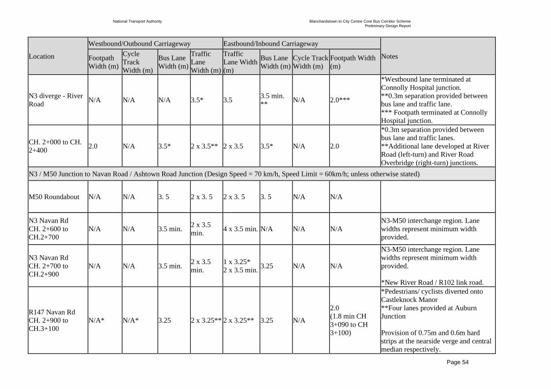
National Transport Authority Blanchardstown to City Centre Core Bus Corridor Scheme Preliminary Design Report
| Issue | 7 May 2022
\\GLOBAL\EUROPE\DUBLIN\JOBS\268000\268401-00\4. INTERNAL\4-04 REPORTS\4-04-03 INFRASTRUCTURE\PRELIMINARY DESIGN REPORT\CBC 5\ISSUE MAY 2022\BCIDC-ARP-PMG_PD-0005_XX_00-RP-ZZ-0001_ISSUE.DOCX
Page 54
Location
Westbound/Outbound Carriageway Eastbound/Inbound Carriageway
Notes Footpath
Width (m)
Cycle
Track
Width (m)
Bus Lane
Width (m)
Traffic
Lane
Width (m)
Traffic
Lane Width
(m)
Bus Lane
Width (m)
Cycle Track
Width (m)
Footpath Width
(m)
N3 diverge - River
Road N/A N/A N/A 3.5* 3.5
3.5 min.
** N/A 2.0***
*Westbound lane terminated at
Connolly Hospital junction.
**0.3m separation provided between
bus lane and traffic lane.
*** Footpath terminated at Connolly
Hospital junction.
CH. 2+000 to CH.
2+400 2.0 N/A 3.5* 2 x 3.5** 2 x 3.5 3.5* N/A 2.0
*0.3m separation provided between
bus lane and traffic lanes.
**Additional lane developed at River
Road (left-turn) and River Road
Overbridge (right-turn) junctions.
N3 / M50 Junction to Navan Road / Ashtown Road Junction (Design Speed = 70 km/h, Speed Limit = 60km/h; unless otherwise stated)
M50 Roundabout N/A N/A 3. 5 2 x 3. 5 2 x 3. 5 3. 5 N/A N/A
N3 Navan Rd
CH. 2+600 to
CH.2+700
N/A N/A 3.5 min. 2 x 3.5
min. 4 x 3.5 min. N/A N/A N/A
N3-M50 interchange region. Lane
widths represent minimum width
provided.
N3 Navan Rd
CH. 2+700 to
CH.2+900
N/A N/A 3.5 min. 2 x 3.5
min.
1 x 3.25*
2 x 3.5 min. 3.25 N/A N/A
N3-M50 interchange region. Lane
widths represent minimum width
provided.
*New River Road / R102 link road.
R147 Navan Rd
CH. 2+900 to
CH.3+100
N/A* N/A* 3.25 2 x 3.25** 2 x 3.25** 3.25 N/A
2.0
(1.8 min CH
3+090 to CH
3+100)
*Pedestrians/ cyclists diverted onto
Castleknock Manor
**Four lanes provided at Auburn
Junction
Provision of 0.75m and 0.6m hard
strips at the nearside verge and central
median respectively.

National Transport Authority Blanchardstown to City Centre Core Bus Corridor Scheme Preliminary Design Report
| Issue | 7 May 2022
\\GLOBAL\EUROPE\DUBLIN\JOBS\268000\268401-00\4. INTERNAL\4-04 REPORTS\4-04-03 INFRASTRUCTURE\PRELIMINARY DESIGN REPORT\CBC 5\ISSUE MAY 2022\BCIDC-ARP-PMG_PD-0005_XX_00-RP-ZZ-0001_ISSUE.DOCX
Page 55
Location
Westbound/Outbound Carriageway Eastbound/Inbound Carriageway
Notes Footpath
Width (m)
Cycle
Track
Width (m)
Bus Lane
Width (m)
Traffic
Lane
Width (m)
Traffic
Lane Width
(m)
Bus Lane
Width (m)
Cycle Track
Width (m)
Footpath Width
(m)
R147 Navan Rd
CH.3+100 to
CH.3+400
N/A* N/A* 3.25 2 x 3.25 2 x 3.25 3.25** N/A 1.8 min
*Diverted onto Castleknock Manor
**Bus lane terminates in advance of
accesses at Ch. 3+310 allowing traffic
to merge.
Provision of 0.75m and 0.6m hard
strips at the nearside verge and central
median respectively.
R147 Navan Rd
CH.3+400 to
CH.3+550
2.0 3.0* 3.25 2 x 3.25 3 x 3.25 N/A N/A 1.8min
*Two-way cycle track. 3.0m in width
with an additional 0.5m buffer.
**Two-lanes merging to a single-lane
Provision of 0.75m and 0.6m hard
strips at the nearside verge and central
median respectively.
R147 Navan Rd
CH.3+550 to
CH.4+200
N/A N/A N/A 2 x 3.25 3.25* N/A N/A N/A *Two-lanes merging to a single-lane
R147 Navan
Parkway
Overbridge
1.7* 1.75* N/A 2 x 3.25 3.25 N/A 1.75* 1.7* *As existing.
R147 Navan
Parkway
Interchange
(Merges &
Diverges)
2.0 3.0* 3.25 3.25 3.25 3.25 N/A 2.0**
*Two-way cycle track. 3.0m in width
with an additional 0.5m buffer.
**Localised reduction to 1.8m min.
(130m in length along inbound
diverge).
Provision of 0.5m hard strips at the
nearside verge.

National Transport Authority Blanchardstown to City Centre Core Bus Corridor Scheme Preliminary Design Report
| Issue | 7 May 2022
\\GLOBAL\EUROPE\DUBLIN\JOBS\268000\268401-00\4. INTERNAL\4-04 REPORTS\4-04-03 INFRASTRUCTURE\PRELIMINARY DESIGN REPORT\CBC 5\ISSUE MAY 2022\BCIDC-ARP-PMG_PD-0005_XX_00-RP-ZZ-0001_ISSUE.DOCX
Page 56
Location
Westbound/Outbound Carriageway Eastbound/Inbound Carriageway
Notes Footpath
Width (m)
Cycle
Track
Width (m)
Bus Lane
Width (m)
Traffic
Lane
Width (m)
Traffic
Lane Width
(m)
Bus Lane
Width (m)
Cycle Track
Width (m)
Footpath Width
(m)
(Design Speed = 60 km/h, Speed Limit
= 50km/h)
R147 Navan Rd
CH.4+200 to
CH.4+250
2.0 3.0* 3.25 2 x 3.25 2 x 3.25** 3.25 N/A 2.0
*Two-way cycle track. 3.0m in width
with an additional 0.5m buffer.
**Lane merging from Navan Parkway
Interchange.
Provision of 0.75m and 0.6m hard
strips at the nearside verge and central
median respectively.
R147 Navan Rd
CH.4+250 to
CH.4+500
2.0 min. 3.0* 3.25 3.25 2x3.25** 3.25 N/A 2.0 min.
*Two-way cycle track. 3.0m in width
with an additional 0.5m buffer.
**2 traffic lanes merge into 1 at CH
4+290
Provision of 0.75m and 0.6m hard
strips at the nearside verge and central
median respectively.
R147 Navan Rd
CH.4+500 to
CH.4+850
2.0 min. 3.0* 3.0 3.0 3.0** 3.0 N/A 2.0 min.
*Two-way cycle track. 3.0m in width
with an additional 0.5m buffer.
**Additional lane develops on
approach to Ashtown Junction.
(Design Speed / Speed Limit =
50km/h)

National Transport Authority Blanchardstown to City Centre Core Bus Corridor Scheme Preliminary Design Report
| Issue | 7 May 2022
\\GLOBAL\EUROPE\DUBLIN\JOBS\268000\268401-00\4. INTERNAL\4-04 REPORTS\4-04-03 INFRASTRUCTURE\PRELIMINARY DESIGN REPORT\CBC 5\ISSUE MAY 2022\BCIDC-ARP-PMG_PD-0005_XX_00-RP-ZZ-0001_ISSUE.DOCX
Page 57
Location
Westbound/Outbound Carriageway Eastbound/Inbound Carriageway
Notes Footpath
Width (m)
Cycle
Track
Width (m)
Bus Lane
Width (m)
Traffic
Lane
Width (m)
Traffic
Lane Width
(m)
Bus Lane
Width (m)
Cycle Track
Width (m)
Footpath Width
(m)
Navan Road / Ashtown Road junction to Navan Road / Old Cabra Road Junction (Design Speed / Speed Limit = 50km/h)
(Note: all cycle track widths in this section include a 0.25m kerb/buffer to the carriageway unless otherwise stated)
Navan Road
Ch.4+900 to
Ch.5+100
2.0 min. 2.0 3.0 3.0 3.0 3.0 2.0 2.0 min.
Additional 3.0m wide traffic lane
developed westbound on approach to
Ashtown Junction.
Navan Road
Ch.5+100 to
Ch.5+190
2.0 min. 2.0 3.0 3.0 3.0 3.0 2.0 2.0 min.
Navan Road
Ch.5+190 to
Ch.5+420
1.55 min. 2.0 3.0 3.0 3.0 3.0 2.0 2.0 min.
Verge provided between cycle track
and footpath in westbound direction
and localised areas in eastbound
direction.
Navan Road
Ch.5+420 to
Ch.5+900
2.0 min. 2.0 3.0 3.0 3.0 3.0 2.0 2.0 min.
Navan Road
Ch.5+900 to
Ch.6+170
2.0 min. 2.0 3.0 3.0 3.0 3.0 2.0 2.0 min.
Additional 3.0m wide traffic lane
developed westbound on approach to
Kinvara Avenue/Baggot Road
junction.
Navan Road
Ch.6+170 to
Ch.6+250
2.0 min. 2.0 3.0 3.0 3.0 3.0 1.5 2.0*
*Localised reduction to 1.9m at Ch
6+210
Navan Road
Ch.6+250 to
Ch.6+950
2.0 min* 2.0 3.0 3.0 3.0 3.0 2.0 2.0
* Localised reduction to 1.8m from Ch
6+535 to Ch 6+550
Navan Road
Ch.6+950 to
Ch.7+120
2.0 min. 2.0 3.0 3.0 3.0 3.0 *2.0 2.0 min.
Additional 3.0m wide traffic lane
developed eastbound on approach to
Hampton Green junction.
*Inbound narrowing to a shared bus
stop has been extended to 21.5m to

National Transport Authority Blanchardstown to City Centre Core Bus Corridor Scheme Preliminary Design Report
| Issue | 7 May 2022
\\GLOBAL\EUROPE\DUBLIN\JOBS\268000\268401-00\4. INTERNAL\4-04 REPORTS\4-04-03 INFRASTRUCTURE\PRELIMINARY DESIGN REPORT\CBC 5\ISSUE MAY 2022\BCIDC-ARP-PMG_PD-0005_XX_00-RP-ZZ-0001_ISSUE.DOCX
Page 58
Location
Westbound/Outbound Carriageway Eastbound/Inbound Carriageway
Notes Footpath
Width (m)
Cycle
Track
Width (m)
Bus Lane
Width (m)
Traffic
Lane
Width (m)
Traffic
Lane Width
(m)
Bus Lane
Width (m)
Cycle Track
Width (m)
Footpath Width
(m)
maintain footpath width at a pinch
point
Navan Road
Ch.7+120 to
Ch.7+260
2.0 min. 2.0 3.0 3.0 3.0 3.0 2.0 2.0 min.
Additional 3.0m wide traffic lane
developed eastbound on approach to
Cabra Library junction.
Navan Road
Ch.7+260 to
Ch.7+400
2.0 min. 2.0 3.0 3.0 3.0* 3.0 2.0 2.0 min.
Central island introduced between EB
and WB carriageways.
*Additional 3.0m wide traffic lane
developed eastbound on approach to
Old Cabra Road junction. Navan Road / Old Cabra Road junction to Ellis Quay (Design Speed / Speed Limit = 30km/h)
(Note: all cycle track widths in this section include a 0.25m kerb/buffer to the carriageway unless otherwise stated)
Old Cabra Road
Ch.7+400 to
Ch.7+500
2.0 min. 2.0 3.0 3.0 N/A 3.0 2.0 2.0 min.
Old Cabra Road
Ch.7+500 to
Ch.7+560
2.0 min. 2.0 N/A* 3.0 N/A 3.0 2.0 2.0 min. *WB Bus lane developed between Ch
7+540 to Ch 7+500
Old Cabra Road
Ch.7+560 to
Ch.7+620
2.0 min. 2.0 N/A 3.0 3.0 N/A 2.0 2.0 min.
Old Cabra Road
Ch.7+620 to
Ch.7+660
1.8 – 2.0 2.0 N/A 3.0 3.0 N/A 1.75 2.0 min.
Old Cabra Road
Ch.7+660 to
Ch.7+700
1.8 - 2.0 2.0 N/A 3.0 3.0 N/A 1.5 2.0 min.
Old Cabra Road
Ch.7+700 to
Ch.7+840
1.3 - 2.0 1.75 N/A 3.0 3.0 N/A 1.5 2.0 min.

National Transport Authority Blanchardstown to City Centre Core Bus Corridor Scheme Preliminary Design Report
| Issue | 7 May 2022
\\GLOBAL\EUROPE\DUBLIN\JOBS\268000\268401-00\4. INTERNAL\4-04 REPORTS\4-04-03 INFRASTRUCTURE\PRELIMINARY DESIGN REPORT\CBC 5\ISSUE MAY 2022\BCIDC-ARP-PMG_PD-0005_XX_00-RP-ZZ-0001_ISSUE.DOCX
Page 59
Location
Westbound/Outbound Carriageway Eastbound/Inbound Carriageway
Notes Footpath
Width (m)
Cycle
Track
Width (m)
Bus Lane
Width (m)
Traffic
Lane
Width (m)
Traffic
Lane Width
(m)
Bus Lane
Width (m)
Cycle Track
Width (m)
Footpath Width
(m)
Old Cabra Road
Ch.7+840 to
Ch.7+990
2.0 2.0 N/A 3.0 3.0 N/A 2.0 2.0 min.
Old Cabra Road
Ch.7+990 to
Ch.8+200
1.7 -
2.0min* 1.5 N/A 3.0 3.0 N/A 1.5 1.7 - 2.0 min*
* Localised reduction to 1.7m min at
existing property boundary walls
Location
Northbound/Outbound Southbound/Inbound
Footpath
Width (m)
Cycle Track
Width (m)
Bus Lane
Width (m)
Traffic
Lane
Width (m)
Traffic
Lane Width
(m)
Bus Lane
Width (m)
Cycle Track
width (m)
Footpath Width
(m) Notes
Prussia Street
Ch. 8+200 to
Ch. 8+250
2.0 min. 2.0 N/A 2 x 3.0* 3.0 min. N/A 1.5** 2.0 min. *Straight ahead lane and left-only lane.
**Cycle track terminates at bus stop.
Prussia Street
Ch. 8+250 to
Ch. 8+530
2.0 min. 2.0 N/A 3.0 3.0 N/A N/A 2.0 min.
Prussia Street
Ch. 8+530 to
Ch. 8+660
2.0 min. N/A N/A 3.0 3.0 N/A N/A 2.0 min.
Prussia Street
Ch. 8+660 to
Ch. 8+680
2.0 min. 2.0 N/A 3.0 3.0 N/A N/A 2.0 min.
Prussia Street
Ch. 8+680 to
Ch. 8+700
2.0 min. 2.0 3.0 N/A 3.0 N/A N/A 2.0 min.
Manor Street
Ch. 8+700 to
Ch. 8+720
2.0 min. 2.0* N/A 3.0 3.0 min** 3.0 N/A 2.0 min.
*Cycle track is remote from
carriageway and separated with grass
verge
**Right turn lane only.

National Transport Authority Blanchardstown to City Centre Core Bus Corridor Scheme Preliminary Design Report
| Issue | 7 May 2022
\\GLOBAL\EUROPE\DUBLIN\JOBS\268000\268401-00\4. INTERNAL\4-04 REPORTS\4-04-03 INFRASTRUCTURE\PRELIMINARY DESIGN REPORT\CBC 5\ISSUE MAY 2022\BCIDC-ARP-PMG_PD-0005_XX_00-RP-ZZ-0001_ISSUE.DOCX
Page 60
Location
Northbound/Outbound Southbound/Inbound
Footpath
Width (m)
Cycle Track
Width (m)
Bus Lane
Width (m)
Traffic
Lane
Width (m)
Traffic
Lane Width
(m)
Bus Lane
Width (m)
Cycle Track
width (m)
Footpath Width
(m) Notes
Manor Street
Ch. 8+720 to
Ch. 8+950
2.0 min. 2.0 N/A 3.0 3.0 N/A 2.0 2.0 min.
Manor Street/
Stoneybatter
Ch. 8+950 to
Ch. 9+050
2.0 min. 2.0 N/A 3.25* 3.25* N/A 2.0 2.0 min. *Curve widening to facilitate vehicle
swept-path.
Stoneybatter
Ch. 9+050 to
Ch. 9+100
2.0 min. 2.0 N/A 3.0 3.0 N/A 1.75 2.0 min.
Stoneybatter
Ch. 9+090 to
Ch. 9+150
2.0 min. N/A 3.0 min. N/A 3.0 min. N/A N/A 2.0
Blackhall Place
Ch. 9+150 to
Ch. 9+310
2.0 min. N/A 3.0 3.0 N/A 3.0 N/A 2.0 min.
Blackhall Place
Ch. 9+310 to
Ch. 9+490
2.0 min. N/A 3.0 3.0 3.0 3.0 N/A 2.0 min.
Queen Street
Ch. G 0 + 000 to
Ch. G 0+200
2.2 min N/A N/A N/A 3.5 N/A 3.25* 2.5 min
*Two-way cycle track. 3.25m in width
with an additional a 0.5m buffer.
Queen Street
Ch. G 0 + 200 to
Ch. G 0+330
2.2 min N/A N/A N/A 2 x 3.0 N/A 3.25* 2.5 min
*Two-way cycle track. 3.25m in width
with an additional a 0.5m buffer.
Queen Street
Ch. Ch. G 0+330
to
G 0+380
N/A N/A N/A N/A 3.5 N/A N/A 3.0 min
George’s Ln Ch. K
0+000 to Ch. K
0+080
2.5 min N/A N/A 3.5 min N/A N/A 3.25* 4.2 min
* Two-way cycle track 3.25m in width
with an additional 1m buffer to
adjacent on-street loading bay. In

National Transport Authority Blanchardstown to City Centre Core Bus Corridor Scheme Preliminary Design Report
| Issue | 7 May 2022
\\GLOBAL\EUROPE\DUBLIN\JOBS\268000\268401-00\4. INTERNAL\4-04 REPORTS\4-04-03 INFRASTRUCTURE\PRELIMINARY DESIGN REPORT\CBC 5\ISSUE MAY 2022\BCIDC-ARP-PMG_PD-0005_XX_00-RP-ZZ-0001_ISSUE.DOCX
Page 61
Location
Northbound/Outbound Southbound/Inbound
Footpath
Width (m)
Cycle Track
Width (m)
Bus Lane
Width (m)
Traffic
Lane
Width (m)
Traffic
Lane Width
(m)
Bus Lane
Width (m)
Cycle Track
width (m)
Footpath Width
(m) Notes
addition, localised areas of cycle track
are remote from carriageway and
separated with grass verge.
Location
Westbound/Outbound Carriageway Eastbound/Inbound Carriageway
Footpath
Width (m)
Cycle Track
Width (m)
Bus Lane
Width (m)
Traffic Lane
Width (m)
Traffic Lane
Width (m)
Bus Lane
Width (m)
Cycle
Track
width (m)
Footpath
Width (m) Notes
Brunswick Street
North
Ch H 0+000 to
Ch. H 0+170
1.4 min 1.5 N/A 3.0 N/A N/A 1.5 2.0 min
Blackhall Street
Ch. J 0+000 to
Ch. J 0+140
1.5 min 3.0* N/A 3.5 N/A N/A N/A 2.5 min
*Two-way cycle track. 3.0m in width
with an additional 1m buffer to
adjacent on-street parking.
Provision of on-street parking on both
the right and left of the traffic lane.

National Transport Authority Blanchardstown to City Centre Core Bus Corridor Scheme Preliminary Design Report
| Issue | 7 May 2022
\\GLOBAL\EUROPE\DUBLIN\JOBS\268000\268401-00\4. INTERNAL\4-04 REPORTS\4-04-03 INFRASTRUCTURE\PRELIMINARY DESIGN REPORT\CBC 5\ISSUE MAY 2022\BCIDC-ARP-PMG_PD-0005_XX_00-RP-ZZ-0001_ISSUE.DOCX
Page 62
Location
Westbound/Outbound Carriageway Eastbound/Inbound Carriageway
Footpath
Width (m)
Cycle Track
Width (m)
Bus Lane
Width (m)
Traffic Lane
Width (m)
Traffic Lane
Width (m)
Bus Lane
Width (m)
Cycle
Track
width (m)
Footpath
Width (m) Notes
King Street
North
Ch.G 0+380 to
Ch. G 0+420
2.2 min N/A N/A N/A 2 x 3.0 N/A N/A 3.0 min
King Street
North
Ch.G 0+420
to
Ch. G 0+490
2.2 min N/A N/A N/A 4.0 min N/A N/A 2.4 min

National Transport Authority Blanchardstown to City Centre Core Bus Corridor Scheme Preliminary Design Report
| Issue | 7 May 2022
\\GLOBAL\EUROPE\DUBLIN\JOBS\268000\268401-00\4. INTERNAL\4-04 REPORTS\4-04-03 INFRASTRUCTURE\PRELIMINARY DESIGN REPORT\CBC 5\ISSUE MAY 2022\BCIDC-ARP-PMG_PD-
0005_XX_00-RP-ZZ-0001_ISSUE.DOCX
Page 63
4.4 Design Speed and Speed Limit
As outlined in DMURS ‘Design speed is the maximum speed at which it is
envisaged/intended that the majority of vehicles will travel under normal conditions’.
Therefore, the design speed proposed for urban roads is aligned with the proposed speed
limit. For most cases along the urban CBC network, the existing speed limits will be retained
with the exception of the Bus Interchange at Blanchardstown, and the Navan Road / Old
Cabra Road junction to Ellis Quay section of the CBC, with a proposed speed limit of 30
km/h in each location. A 350m section of the R147 from Phoenix Park Avenue junction to
Ashtown junction will also see a reduction in speed limit to 50 km/h from 60 km/h in
conjunction with a change in road classification from urban dual to urban single carriageway.
Over the length of the R147 (from Auburn Avenue junction to Phoenix Park Avenue
junction) and N3 carriageway, the design speed is higher than the proposed speed limit as
indicated in Table 4.8. The proposed speed limit on the section of N3 Carriageway, between
River Road junction and Snugborough Road junction, of the CBC will see an 80km/h limit
imposed for general traffic lanes with a separate 60km/h speed limit imposed for the bus lane.
For the adjoining N3 link roads (River Road to Auburn Avenue) the existing speed limits will
be maintained. The proposed speed limits largely represent a retention of the existing speed
limits in this area with the exception of the R147 (from Auburn Avenue junction to Phoenix
Park Avenue junction), where the existing section of 80 km/h will be reduced to 60km/h to
facilitate a change in carriageway cross-section as outlined in Section 4.3.2. The design
speeds are therefore determined to be 85 km/h on the N3 Dual Carriageway and 70 km/h on
the adjoining N3 link roads and R147, from Auburn Avenue junction to Phoenix Park
Avenue junction. In accordance with DN-GEO-03060, a design speed of 60 km/h has been
assigned to the slip roads of the grade-separated junctions along the route: Navan Parkway
interchange along the R147 in addition to N3 junctions at Mulhuddart, Snugborough and
River Road.
The design speeds used for the proposed mandatory speed limits are detailed in Table 4.8.
Table 4.8: Maximum Design Speeds for Mandatory Speed Limits
Speed Limit km/h Design Speed km/h Design Standard
30 30 DMURS
50 50 DMURS
60 60 DMURS
50 60 DN-GEO-03031
60 70 DN-GEO-03031
80 85 DN-GEO-03031
All slip roads have been designed in accordance with design speeds specified in DN-GEO-
03060 Table 7.6 Connector Road Design Speed. An Urban Type 1 Dual Carriageway with a
design speed of 85km/h specifies a 60km/h design speed for slip roads. Table 4.9 indicates
the speeds limits proposed for all roads within the Proposed Scheme.
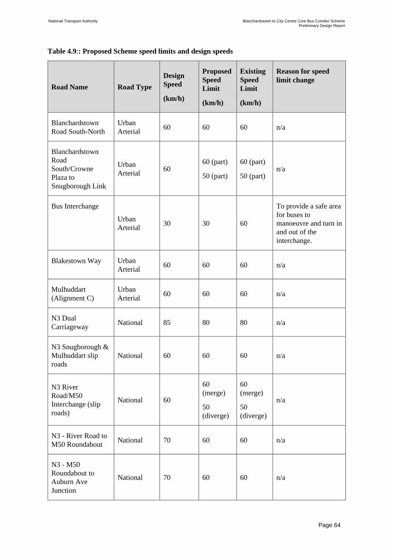
National Transport Authority Blanchardstown to City Centre Core Bus Corridor Scheme Preliminary Design Report
| Issue | 7 May 2022
\\GLOBAL\EUROPE\DUBLIN\JOBS\268000\268401-00\4. INTERNAL\4-04 REPORTS\4-04-03 INFRASTRUCTURE\PRELIMINARY DESIGN REPORT\CBC 5\ISSUE MAY 2022\BCIDC-ARP-PMG_PD-
0005_XX_00-RP-ZZ-0001_ISSUE.DOCX
Page 64
Table 4.9:: Proposed Scheme speed limits and design speeds
Road Name Road Type
Design
Speed
(km/h)
Proposed
Speed
Limit
(km/h)
Existing
Speed
Limit
(km/h)
Reason for speed
limit change
Blanchardstown
Road South-North
Urban
Arterial 60 60 60 n/a
Blanchardstown
Road
South/Crowne
Plaza to
Snugborough Link
Urban
Arterial 60
60 (part)
50 (part)
60 (part)
50 (part) n/a
Bus Interchange
Urban
Arterial 30 30 60
To provide a safe area
for buses to
manoeuvre and turn in
and out of the
interchange.
Blakestown Way Urban
Arterial 60 60 60 n/a
Mulhuddart
(Alignment C)
Urban
Arterial 60 60 60 n/a
N3 Dual
Carriageway National 85 80 80 n/a
N3 Snugborough &
Mulhuddart slip
roads
National 60 60 60 n/a
N3 River
Road/M50
Interchange (slip
roads)
National 60
60
(merge)
50
(diverge)
60
(merge)
50
(diverge)
n/a
N3 - River Road to
M50 Roundabout National 70 60 60 n/a
N3 - M50
Roundabout to
Auburn Ave
Junction
National 70 60 60 n/a

National Transport Authority Blanchardstown to City Centre Core Bus Corridor Scheme Preliminary Design Report
| Issue | 7 May 2022
\\GLOBAL\EUROPE\DUBLIN\JOBS\268000\268401-00\4. INTERNAL\4-04 REPORTS\4-04-03 INFRASTRUCTURE\PRELIMINARY DESIGN REPORT\CBC 5\ISSUE MAY 2022\BCIDC-ARP-PMG_PD-
0005_XX_00-RP-ZZ-0001_ISSUE.DOCX
Page 65
Road Name Road Type
Design
Speed
(km/h)
Proposed
Speed
Limit
(km/h)
Existing
Speed
Limit
(km/h)
Reason for speed
limit change
Auburn Ave
Junction to Phoenix
Park Ave Junction Regional 70 60
80 (part)
60 (part)
To provide a
consistent speed limit
along this section and
to improve safety for
side road access and
weaving.
Navan Parkway
Merge and Diverge
Ramps
Regional 60 50 50
Extent of proposed
speed limit amended
to standardise extents
on all four
merge/diverge arms
and to facilitate new
bus stop layby on
outbound diverge.
Phoenix Park Ave
Junction to
Ashtown Road
Junction
Urban
Arterial 50 50 60
To reflect the urban
nature of this section
(with signal junctions
and pedestrian
crossings)
Ashtown Road
Junction to Old
Cabra Road
Junction
Urban
Arterial 50 50 50 n/a
Old Cabra Road
Urban
Arterial 30 30 50
To reflect the
relatively constrained
corridor width and
hence to provide safe
conditions for cyclists
in particular.
Prussia Street
Urban
Arterial 30 30 50
To reflect the
relatively constrained
corridor width and
hence to provide safe
conditions for cyclists
in particular.
Manor Street and
Stoneybatter Urban
Arterial 30 30 50
To reflect the
relatively constrained
corridor width and

National Transport Authority Blanchardstown to City Centre Core Bus Corridor Scheme Preliminary Design Report
| Issue | 7 May 2022
\\GLOBAL\EUROPE\DUBLIN\JOBS\268000\268401-00\4. INTERNAL\4-04 REPORTS\4-04-03 INFRASTRUCTURE\PRELIMINARY DESIGN REPORT\CBC 5\ISSUE MAY 2022\BCIDC-ARP-PMG_PD-
0005_XX_00-RP-ZZ-0001_ISSUE.DOCX
Page 66
Road Name Road Type
Design
Speed
(km/h)
Proposed
Speed
Limit
(km/h)
Existing
Speed
Limit
(km/h)
Reason for speed
limit change
hence to provide safe
conditions for cyclists
in particular.
Blackhall Place Urban
Arterial 30 30 30 n/a
Brunswick Street
North Urban Link 30 30 30 n/a
King Street North Urban Link 30 30 30 n/a
Blackhall Street Urban Link 30 30 30 n/a
Hendrick Street Urban Link 30 30 30 n/a
George’s Lane Urban Link 30 30 30 n/a
Queen Street Urban Link 30 30 30 n/a
4.5 Alignment Modelling Strategy
As part of preliminary design, the 3D road alignment design has been developed on the
principles of the Preferred Route Option. The proposed alignment has also taken into
consideration public consultation, traffic impact and environmental impact assessments, in
addition to a peer review exercise in collaboration with the other Engineering Designers
(EDs), for the Proposed Scheme.
The 3D highway design, including the horizontal and vertical alignments, 3D modelling
corridors and the associated highways related design features required for all roads included
in this preliminary design, has been developed using Civil 3D software. In collaboration with
the other EDs for the other CBC schemes, the 3D models have been produced in accordance
with the BusConnects BEP.
As part of the alignment design process, the horizontal and vertical design has been optimised
to minimise impact to the existing road network and adjoining properties where feasible.
Horizontal and vertical alignments have been developed to define the road centrelines for the
proposed route layout while also taking cognisance of the existing road network. For the
purposes of the alignment and modelling design process, it has been necessary to develop a
separate set of 3D alignments, which differ from that of the global alignment used as a
reference for the general arrangement layout of the preliminary design.
In terms of the horizontal alignments, due consideration has been given to aligning the
centrelines as close to existing as practicable. However, the over-riding determining factor for

National Transport Authority Blanchardstown to City Centre Core Bus Corridor Scheme Preliminary Design Report
| Issue | 7 May 2022
\\GLOBAL\EUROPE\DUBLIN\JOBS\268000\268401-00\4. INTERNAL\4-04 REPORTS\4-04-03 INFRASTRUCTURE\PRELIMINARY DESIGN REPORT\CBC 5\ISSUE MAY 2022\BCIDC-ARP-PMG_PD-
0005_XX_00-RP-ZZ-0001_ISSUE.DOCX
Page 67
locating the horizontal alignment is to ensure it is positioned in the centre of the proposed
carriageway. This is ideally along a central lane marking on the carriageway, in order to
minimise rideability issues for vehicles crossing the crown line.
In the case of developing the vertical alignment along the route, a refinement process has
been undertaken to minimise any impact to existing road network and develop the proposed
carriageway levels as close to existing as practicable. In most circumstances however, due to
a change in cross-section, due consideration is given to the resulting level difference at the
outer extents of the carriageway, particularly through urban areas where a difference in
existing and proposed footpath levels will require additional temporary land-take to facilitate
tie-in.
Existing ground levels have been obtained using a triangulated surface (the existing ground
model) produced from the topographical survey covering the route. This existing ground
model is used to inform the differences in levels between the proposed and existing ground
while at the scheme boundary it is also used to ensure an appropriate means of tie-in to
existing levels. Furthermore, at junctions linking to existing side roads, the existing ground
model is used to determine dwell area gradients and lengths to facilitate junction realignment.
The developed alignment design sets parameters for development of other design elements
such as drainage, determination of earthworks, utility/services placement etc.
4.6 Summary of Horizontal Alignment
The Proposed Scheme commences at Junction 3 (Blanchardstown/Mulhuddart) eastbound
off-slip from the N3 and continues east towards the City Centre terminating at Ellis Quay.
The horizontal alignment of the Proposed Scheme will generally follow the existing
carriageways with any amendments to the alignment as described below.
Generally, all carriageways have been designed in camber with a fall of 2.5% from the
centreline of the road. Superelevation has been applied where the proposed curve radius is
below the minimum values specified in Section 4.10.
In a number of locations crossfalls/superelevation have been implemented to match the
existing scenario where the geometry allows, to minimise the impact of the Proposed Scheme
on the existing corridor.
In the sections from Ashtown Road junction to Blackhall Place, the existing road crossfalls
will be maintained as far as practicable to minimise the impact on adjacent properties,
driveways and existing drainage and utility apparatus.
The following section summaries the horizontal geometry of the carriageways associated
with the CBC. All horizontal alignments have been designed using the appropriate set of
design guidelines/standards as outlined in Section 4.10. In instances where the desirable
minimum parameters defined by the appropriate guidance have not been met, these locations
have been detailed within Section 4.17, Deviations from Standard.
This section should be read in conjunction with the Mainline Plan and Profile drawings in
Appendix B.
N3 Blanchardstown Junction to Snugborough Road
The proposal through this section of the Proposed Scheme will upgrade a number of existing
routes around the Blanchardstown Shopping Centre area providing bus, cyclist and pedestrian

National Transport Authority Blanchardstown to City Centre Core Bus Corridor Scheme Preliminary Design Report
| Issue | 7 May 2022
\\GLOBAL\EUROPE\DUBLIN\JOBS\268000\268401-00\4. INTERNAL\4-04 REPORTS\4-04-03 INFRASTRUCTURE\PRELIMINARY DESIGN REPORT\CBC 5\ISSUE MAY 2022\BCIDC-ARP-PMG_PD-
0005_XX_00-RP-ZZ-0001_ISSUE.DOCX
Page 68
linkage from the Mulhuddart Interchange and Blanchardstown Shopping Centre areas to
Snugborough Junction and onwards towards Dublin City Centre.
The alignment will generally maintain a similar geometry to the existing with a design speed
of 60km/h, with the exception of the Bus Interchange area where the design speed is reduced
30km/h to reflect the speed limit. However, to facilitate widening and cross-sectional changes
at certain locations, the horizontal geometry will deviate from that of the existing, particularly
where the roundabout junctions are to be replaced with signalised junctions. Specific changes
to the existing geometry are outlined in the following paragraphs.
Main Blanchardstown-Snugborough Link (Alignment A)
The horizontal alignment of the main Blanchardstown-Snugborough Link Road will largely
maintain a similar geometry to existing. However, the carriageway centreline will shift
approximately 2.0m west from Ch. A0+200 to facilitate carriageway widening consisting of a
two-way cycle track. A series of superelevated horizontal curves (R=230m and R=255m at
approximate Ch. 0+500 to 0+620 and Ch. 0+660 to Ch. 0+760 respectively) are proposed
through the current roundabout junction on approach to the tie-in with the Snugborough
Junction design.
Blanchardstown South-North (Alignment B)
The proposed horizontal alignment of the main Blanchardstown South and North roads will
deviate slightly from the existing through Ch. B0+060 to B0+500 to account for the
additional cross-section widening. The principles of the geometric parameters however will
remain similar with two R=1020m right-hand curves separated 55m apart beyond the altered
junction at Ch. 0+100.
The alignment over the Mulhuddart N3 Overbridge structure will remain unchanged, so as
not to impact on the structure.
Bus Interchange (Alignment F)
The proposed layout of the Bus Interchange will see this area widened towards the existing
shopping centre car park. To facilitate the proposals, the main through-route for traffic
heading westbound will be similar to existing. An additional alignment will be created for the
eastbound traffic lane and westbound bus-lane, which will tie into the main through-route
alignment at each end. The existing roundabouts at either end of the proposed Bus
Interchange will be replaced with signalised junctions.
Snugborough Road to N3 / M50 Junction
The section commences at Snugborough Road overbridge, and joins the N3 for a short
distance before following the River Road slip roads, terminating at the M50 Junction 6
roundabout. The proposed horizontal alignment of the N3, and the proposed slip roads and
link roads between the N3 and the M50 Junction 6 Roundabout, will generally follow the
horizontal alignment of the existing carriageways.
The horizontal alignment of the N3 dual carriageway has been developed in accordance with
the geometric standards applicable to a design speed of 85 km/h urban dual carriageway as
identified in Section 4.1. The cross section for this section of road is described in Section
4.3.2.
The alignments of the westbound and eastbound carriageways of the N3 are proposed to be
amended to move a section of both carriageways into the existing central reservation. The

National Transport Authority Blanchardstown to City Centre Core Bus Corridor Scheme Preliminary Design Report
| Issue | 7 May 2022
\\GLOBAL\EUROPE\DUBLIN\JOBS\268000\268401-00\4. INTERNAL\4-04 REPORTS\4-04-03 INFRASTRUCTURE\PRELIMINARY DESIGN REPORT\CBC 5\ISSUE MAY 2022\BCIDC-ARP-PMG_PD-
0005_XX_00-RP-ZZ-0001_ISSUE.DOCX
Page 69
width of the central reserve is proposed to be reduced from approximately 8.8m to 2.7m at its
narrowest point at Ch. 1+580. The westbound edge of carriageway (offside) moves north a
maximum of 5.1m at Ch. 1+580 with the eastbound edge of carriageway (offside) moving
south a maximum of 3.1m at Ch. 1+440. The current alignment will be amended, and the
central reserve width will be reduced in order to minimise the impact of the provision of
additional bus lanes, bus stops and pedestrian ramps and steps on Millstead Estate, the
properties at Herbert Road and the existing River Tolka culvert structure, adjacent to BR02
Mill Road Bridge.
The proposed alignment of the N3 eastbound merge slip road and N3 westbound diverge slip
road will follow the existing alignment. Both slip roads have been developed to a design
speed of 60 km/h as noted in Section 4.4. The cross section for this section of road is
described in Section 4.3.2. The slip roads have been designed to tie into the horizontal
alignment of the revised slip roads proposed as part of the Snugborough Interchange Upgrade
Scheme. The eastbound merge slip road will tie in with the Snugborough Interchange slip
road at side road chainage 0+000. The westbound diverge slip road will tie in with the
Snugborough Interchange slip road at Ch. 1+020.
The proposed alignment of the N3 eastbound diverge slip road, including beyond the
Connolly Hospital Junction and across the River Road Overbridge, and the N3 westbound
merge slip road will follow the existing alignment. Both slip roads have been developed to a
design speed of 60 km/h as noted in Section 4.4. The cross section for this section of road is
described in Section 4.3.
The geometry of the existing carriageway linking the N3 merge and diverges to the M50
roundabout junction will remain largely unaltered. The additional bus lane provision will
involve offside and nearside widening, however due to the extent of changes between River
Road overbridge (Ch. 2+200) and the M50 roundabout, a relocation of the central median
will be required resulting in a maximum shift to the north of approximately 1.6m shift. This
length of central median will also reduce in width to a minimum of 2.2m (including hard
strips) to accommodate the additional provisions.
N3 / M50 Junction to Navan Road / Ashtown Road Junction
The Proposed Scheme continues along the roundabout of the M50 junction where sections of
the existing nearside traffic lane will be redesignated as a bus lane with no proposed
alignment changes.
Beyond the roundabout junction, the Proposed Scheme will continue to Auburn Avenue
junction and along the existing R147 Navan Road. The creation of an inbound bus lane will
involve a new stand-alone alignment commencing at the widened M50 roundabout exit arm
and tying into Auburn Avenue junction. Due to the existing constraints of the M50-N3
interchange and associated structures, this proposed alignment will include a series of sub-
standard superelevated horizontal curves (R=45m S=5.0%, R=80m S=2.5%). The proposed
incorporation of the westbound/outbound bus lane along this stretch will involve the
redesignation of an existing traffic lane, therefore no changes in horizontal alignment will be
required.
Beyond Auburn Avenue junction, between chainages Ch. 2+900 and Ch. 4+250, the existing
alignment of the R147 will be retained with online widening to both nearside and offside,
accounting for the additional bus and cyclist provisions proposed. The carriageway widening
proposed along this section of the CBC will be an extension of the existing carriageway

National Transport Authority Blanchardstown to City Centre Core Bus Corridor Scheme Preliminary Design Report
| Issue | 7 May 2022
\\GLOBAL\EUROPE\DUBLIN\JOBS\268000\268401-00\4. INTERNAL\4-04 REPORTS\4-04-03 INFRASTRUCTURE\PRELIMINARY DESIGN REPORT\CBC 5\ISSUE MAY 2022\BCIDC-ARP-PMG_PD-
0005_XX_00-RP-ZZ-0001_ISSUE.DOCX
Page 70
crossfalls. Similarly, this principle will apply to the alignments along the slip roads of the
Navan Parkway Interchange.
From Ch. 4+500, as the Proposed Scheme passes through the constrained corridor on
approach to the Ashtown Road junction, the proposed layout will see the central median of
the existing carriageway removed and the road will change to single carriageway
classification in conjunction with a speed limit reduction from 60km/h to 50km/h beyond
Phoenix Park Avenue junction towards the city centre. Lane widths will be also reduced as
outlined in Section 4.2. Subsequently, the applicable design speed between Ch. 4+500 to the
Ashtown Road junction will be 50km/h and DMURS will apply. The proposed alignment will
tie into the new layout proposed at Ashtown Road junction, which will replace the existing
roundabout.
Navan Road / Ashtown Road Junction to Navan Road / Old Cabra Road Junction
This section generally follows the existing horizontal alignment of the R147 Navan Road
commencing at Ashtown Road junction and terminating at the Navan Road/Old Cabra Road
junction. Where the proposed horizontal alignment of the R147 Navan Road deviates from
the existing road alignment, the horizontal geometry has been developed in accordance with
the geometric standards applicable to a design speed of 50 km/h identified in Section 4.1. The
cross section for this section of road is described in Section 4.3.2.
From Ch. 6+450 to Ch. 6+600m, west of Nephin Road junction, the proposed alignment of
Navan Road deviates from the existing by moving 2m north to allow for the increased road
width. The change in alignment is accommodated by the provision of reverse 510m radius
curves and a large radius 4,420m curve to gradually reduce the deviation from the existing
alignment. A 250m radius reverse curve is then adapted to tie the alignment into existing.
Navan Road / Old Cabra Road junction to Ellis Quay
This section generally follows the existing horizontal alignment starting at Old Cabra Road
and continuing on to Prussia Street, Manor Street, Stoneybatter and Blackhall Place where
the Proposed Scheme terminates at Ellis Quay. There is a parallel side road alignment
running from King Street North to Queen Street which terminates at Arran Quay. There are
additional proposed side road alignments connecting Blackhall Place and Queen Street at
Blackhall Street and Brunswick Street North. Where the proposed horizontal alignment
deviates from the existing road alignment, the horizontal geometry has been developed in
accordance with the geometric standards applicable to a design speed of 50 km/h noted in
Section 4.4. The cross section for this section of road is described in Section 4.3.2.
At Old Cabra Road, from Ch.7+400 to Ch. 7+550 the alignment of the road is proposed to be
moved south, with the existing central reserve being removed, to provide bus lanes in each
direction. The proposed alignment ties into the existing centreline of Old Cabra Road at Ch.
7+600. Although the alignment of the road will change through this area, the boundary of the
road will remain unchanged.
At Manor Street / Stoneybatter from Ch. 8+770 to Ch. 9+000, it is proposed to alter the
existing alignment to accommodate the proposed on-street parking, bus stops and cycle
tracks. The curve radius through this section has been reduced which moves the alignment to
the north with the alignment gradually tying back into the existing centreline at Ch. 9+000.
National Transport Authority Blanchardstown to City Centre Core Bus Corridor Scheme Preliminary Design Report
| Issue | 7 May 2022
\\GLOBAL\EUROPE\DUBLIN\JOBS\268000\268401-00\4. INTERNAL\4-04 REPORTS\4-04-03 INFRASTRUCTURE\PRELIMINARY DESIGN REPORT\CBC 5\ISSUE MAY 2022\BCIDC-ARP-PMG_PD-
0005_XX_00-RP-ZZ-0001_ISSUE.DOCX
Page 71
4.7 Summary of Vertical Alignment
The following section summaries the vertical geometry of the carriageways associated with
the CBC. All vertical alignments have been designed using the appropriate set of design
guidelines/standards as outlined in Section 4.1
The vertical geometry of the proposed CBC takes cognisance of the existing road layout and,
particularly through highly constrained locations, the proposed vertical alignment has been
developed to match the existing route.
In instances where the desirable minimum parameters defined by the appropriate guidance
have not been met, these locations have been detailed within Section 4.17 Deviations from
Standard.
This section should be read in conjunction with the Mainline Plan and Profile drawings in
Appendix B.
N3 Blanchardstown Junction to Snugborough Road
The layout of this section of the route will involve reconstruction of the existing carriageways
with online widening required at certain locations. To facilitate this the proposed vertical
alignments have been developed to match existing. This will ensure, so far as is reasonably
practicable, that much of the existing carriageway can be incorporated into the works. This
will also minimise level difference between the existing and proposed levels, and in doing so
reduce impact on adjacent land.
The design generally falls from a level of 57.8m AOD at the Mulhuddart Interchange (East)
to the tie-in with the proposed Snugborough Junction realignment at a level of 55.8m AOD.
At the N3 Mulhuddart interchange overbridge, the existing levels will be replicated, in order
to mitigate any impact on the existing structure.
The proposed works to the Bus Interchange, and particularly the creation of the central
pedestrian area, where crossfalls are restricted to 2-3%, will see minor deviations in the
vertical alignment from existing, to achieve the desired crossfalls. This will result in an
increase in levels through this area, However the portion of the interchange widened towards
the existing car park will see the level difference minimised and graded out to the existing
levels in the car park area.
There are no locations in this section where the K value for sag and crest curves fall below
the minimum values specified by DMURS.
Snugborough Road to N3 / M50 Junction
The vertical alignment in this section will generally match the existing road level to minimise
impact on adjacent properties and existing structures. The vertical geometry for the N3
mainline has been developed in accordance with the geometric standards applicable to a
design speed of 85 km/h, and the merge and diverge slip roads for the N3 have been
developed to a design speed of 60 km/h as identified in Section 4.4. The cross section for this
section of road is described in Section 4.3.2.
The proposed level on the N3 at its western end commences at an elevation of 52.3m AOD,
rising to an elevation of 52.8m AOD before reducing to an elevation of 50.3m AOD at its
eastern end. The vertical alignment of the N3 westbound carriageway complies with the
minimum requirements identified in Table 4.2. The vertical alignment of the N3 eastbound

National Transport Authority Blanchardstown to City Centre Core Bus Corridor Scheme Preliminary Design Report
| Issue | 7 May 2022
\\GLOBAL\EUROPE\DUBLIN\JOBS\268000\268401-00\4. INTERNAL\4-04 REPORTS\4-04-03 INFRASTRUCTURE\PRELIMINARY DESIGN REPORT\CBC 5\ISSUE MAY 2022\BCIDC-ARP-PMG_PD-
0005_XX_00-RP-ZZ-0001_ISSUE.DOCX
Page 72
carriageway includes a crest curve with a K value of 30 at the eastern tie-in with the existing
N3 alignment. This is a one-step relaxation from the requirement outlined in Table 4.2.
The proposed vertical alignment of the N3 westbound diverge and N3 eastbound merge slip
roads will follow the existing vertical alignment. The N3 westbound diverge will rise from
the N3 mainline to tie into the proposed design for the Snugborough Interchange.
The N3 eastbound merge will fall from the Snugborough Interchange to tie in with the
proposed level of the mainline N3 eastbound carriageway. The vertical alignment of the slip
roads will comply with the minimum requirements identified in Table 4.2.
The proposed vertical alignment of the N3 eastbound diverge slip road follows the existing
alignment, tying in with the existing junction to Connolly Hospital. The existing levels will
be retained to minimise the impact on the retaining wall in the nearside verge and to minimise
alterations to the existing junction. Continuing along the eastbound diverge the existing levels
and sub-standard vertical geometry (concurrent crest curves of k value 15 and 13) will be
retained to minimise impact on the existing overbridge at River Road. The N3 westbound
merge slip road will follow the existing vertical alignment to minimise the impact on the
residential properties at Old River Road. The vertical alignment of the slip roads will comply
with the minimum requirements identified in Table 4.2.
The proposed vertical alignment of the M50 roundabout entry and exit arms will also follow
the existing to ensure appropriate tie-in with the existing roundabout.
N3 / M50 Junction to Navan Road / Ashtown Road Junction
To minimise impact on the existing road network, and due to the nature of the additional
widening works required to facilitate the Proposed Scheme, the proposed vertical alignment
through this section will also generally match the existing.
The sections of both northbound and southbound carriageway running from M50 roundabout
through Auburn Avenue junction and on to Ashtown Road junction will largely remain as per
existing with online widening accounting for the majority of the construction works. The
proposed level of this section will fall from an elevation of 57.2m AOD at the M50
roundabout to 51.6m AOD at the Ashtown Road junction.
At the west end of this section, the vertical alignment of the M50 roundabout will remain
unaltered, similarly Auburn Avenue junction will remain at approximately 53.3m AOD.
Changes to the Auburn Avenue junction layout will accommodate the widened section of
carriageway on the entry arms. It is proposed to largely maintain the existing vertical
geometry of the carriageways around the Auburn Avenue junction with minor variations
required to achieve tie-in at the intersection of the widened carriageway edges.
The proposed vertical alignment of the new section of bus lane in the inbound direction,
linking the M50 roundabout with Auburn Avenue junction will tie into the existing
roundabout exit arm at the north end (51.2m AOD), and Auburn Avenue junction at the south
end (53.3m AOD). To facilitate the vertical tie-in over a relatively short alignment, a series of
sub-standard vertical crest (minimum K value of 10) and sag (minimum K value of 9) curves
are proposed.
The Proposed Scheme along the R147 Navan Road will fall from an elevation of 53.3m AOD
at Auburn Avenue junction to 51.6m AOD at the Ashtown Road junction.

National Transport Authority Blanchardstown to City Centre Core Bus Corridor Scheme Preliminary Design Report
| Issue | 7 May 2022
\\GLOBAL\EUROPE\DUBLIN\JOBS\268000\268401-00\4. INTERNAL\4-04 REPORTS\4-04-03 INFRASTRUCTURE\PRELIMINARY DESIGN REPORT\CBC 5\ISSUE MAY 2022\BCIDC-ARP-PMG_PD-
0005_XX_00-RP-ZZ-0001_ISSUE.DOCX
Page 73
The proposed vertical alignment of the Navan Parkway interchange will remain largely as per
existing with all levels on the overbridge structure remaining as per existing. At this location,
the level of the mainline R147 carriageway is 48.9m AOD while the overbridge carriageway
level is 55.8m AOD.
Navan Road / Ashtown Road Junction to Navan Road / Old Cabra Road Junction
The vertical alignment in this section will generally match the existing road profile/level to
minimise the impact on adjacent properties. The vertical geometry has been developed in
accordance with the geometric standards applicable to a design speed of 50 km/h identified in
Section 4.1. The cross section for this section of road is described in Table 4.7.
The proposed level in this section will fall from 51.5m AOD at Ashtown Road junction to
40.5m AOD at Old Cabra Road junction. There are no locations in this section where the K
value for sag and crest curves will fall below the minimum values specified by DMURS.
However, there are six locations where the minimum gradient will be below 0.5%. The
vertical alignment in this section will generally follow the existing vertical alignment,
therefore the gradients proposed in the design are similar to existing gradients. There is
limited opportunity to increase the gradients due to proximity of adjacent properties and
driveways where any significant change to the existing level would affect access. Lowering
of the existing levels to increase the gradients to a minimum of 0.5% would result in
additional full depth pavement reconstruction and impact on utility apparatus, resulting in
additional protection measures or utility diversions. To ensure that the areas where the
gradient falls below 0.5% drain effectively, a minimum of 2% crossfall has been applied to
the carriageway to ensure surface water reaches the proposed drainage system. There are no
locations in this section where the K value for sag and crest curves fall below the minimum
values specified by DMURS.
Navan Road / Old Cabra Road Junction to Ellis Quay
The vertical alignment in this section will generally match the existing road level to minimise
the impact on adjacent properties. The vertical geometry has been developed in accordance
with the geometric standards applicable to a design speed of 30 km/h identified in Section
4.1.The cross section for this section of road is described in Table 4.7.
The proposed level in this section will fall from 40.5m AOD at Old Cabra Road to 3.45m
AOD at the tie-in point at Ellis Quay with the proposed gradients replicating the existing.
There are no locations in this section where the K value for sag and crest curves will fall
below the minimum values specified by DMURS.
4.8 Forward Visibility
Forward visibility (or Stopping Sight Distance, SSD) has been assessed along the extent of
the proposed route against the criteria outlined within the relevant applicable standards of
DMURS and TII DN-GEO-03031 for the design speeds listed in Section 4.4
The desirable minimum forward visibility requirements have been achieved across the
majority of the Proposed Scheme. Where the desirable minimum forward visibility
requirements will not be achieved, details are provided in Deviations from Standard, refer to
Section 4.17. A summary of the locations that will have a reduction in forward visibility is
noted within Appendix C.

National Transport Authority Blanchardstown to City Centre Core Bus Corridor Scheme Preliminary Design Report
| Issue | 7 May 2022
\\GLOBAL\EUROPE\DUBLIN\JOBS\268000\268401-00\4. INTERNAL\4-04 REPORTS\4-04-03 INFRASTRUCTURE\PRELIMINARY DESIGN REPORT\CBC 5\ISSUE MAY 2022\BCIDC-ARP-PMG_PD-
0005_XX_00-RP-ZZ-0001_ISSUE.DOCX
Page 74
Table 4.10 and Table 4.11 summarise the key geometric design parameters applicable to all
urban roads designed in accordance with DMURS and those roads designed in accordance
with TII Publications respectively.
Table 4.10: Forward Visibility/SSD Parameters for roads designed to DMURS
Road Type Design
Speed
(km/h)
Forward
visibility
(m)
Forward
visibility on Bus
Routes (m)
Urban Road with 30 km/h Speed Limit 30 2.3 N/A
Urban Road with 50 km/h Speed Limit 50 6.4 4.7
Urban Road with 60 km/h Speed Limit 60 9.2 8.2
Table 4.11: Forward Visibility/SSD Parameters for roads designed to TII Publications
Road Type Design Speed
(km/h)
Desirable
min. SSD
(m)
One step
below
desirable
min. SSD
(m)
National Roads
N3 Dual Carriageway from Snugborough
Junction to River Road Junction
85 160 120
N3 Merge and Diverge Slip Roads 60 90 70
National / Regional Roads
N3/R147 Navan Road from River Road
Junction to the Phoenix Park Avenue Junction
70 120 90
R147 Navan Parkway Interchange Merge and
Diverge Slip Roads
60 90 70
4.8.1 Junction Visibility
An assessment of visibility at major and minor junctions has been completed along the route.
In accordance with DMURS, the SSD parameters for relevant design speeds has been
adopted as the Y-Distance visibility to be achieved while an X-Distance of 2.4m (reduced to
2.0m as a relaxation) has been implemented.
An assessment of the junction visibility at accesses serving individual properties and single
dwellings has been undertaken, ensuring that the existing visibility splay “X” and “Y” are
maintained or improved.
Details and locations where the desirable minimum junction visibility will not be achieved
are available within the Deviations from Standards in Appendix C.
4.8.2 Junction Intervisibility
In the absence of DMURS guidance with respect to visibility at signalised junctions, the
principles and parameters of ‘Junction Intervisibility’ from DN-GEO-03044 (The Geometric
Layout of Signal-Controlled Junctions and Signalised Roundabouts) has been adopted as a
benchmark to assess the intervisibility at all signalised junctions.

National Transport Authority Blanchardstown to City Centre Core Bus Corridor Scheme Preliminary Design Report
| Issue | 7 May 2022
\\GLOBAL\EUROPE\DUBLIN\JOBS\268000\268401-00\4. INTERNAL\4-04 REPORTS\4-04-03 INFRASTRUCTURE\PRELIMINARY DESIGN REPORT\CBC 5\ISSUE MAY 2022\BCIDC-ARP-PMG_PD-
0005_XX_00-RP-ZZ-0001_ISSUE.DOCX
Page 75
As many of the junctions along the Proposed Scheme will involve retrofitting of the existing
layout in an urban environment to provide additional NMU provisions in addition to the
requirements to facilitate vehicle swept-paths, junction intervisibility will be impacted.
Details and locations where the junction intervisibility do not meet the requirements of DN-
GEO-03044 for those roads designed to TII Publications are noted in Appendix C.
4.9 Corner Radii and Swept Path
Generally, on junctions along the Proposed Scheme, corner radii of between 6m and 10m will
be implemented. This will generally accommodate the swept-path of the design vehicles
along the route without the swept-path crossing the centre line of the intersecting road.
However, where swept-path analysis has identified constrained areas and larger vehicles are
anticipated to make up a higher portion of the usage (i.e. bus lanes, HGV service areas etc.) a
combination of localised carriageway widening, and increased corner radii has been provided
to facilitate this.
Although swept-path analysis is used to inform the junction design, it is not the determining
factor. There are a number of additional factors relating to the junction design which are
considered in the overall methodology including junction intervisibility, speed of turning
vehicles and in particular pedestrian safety. Corner radii along the route will be less than 6m
at some locations in order to lower the speed at which vehicles can turn corners and increase
inter-visibility between users e.g. Fingall Place (see DMURS Section 4.3). Reduced corner
radii will also assist in the creation of more compact junctions, which align crossing points
with desire lines and reduce crossing distances.
It is accepted that at minor type junctions and residential accesses, larger vehicles may have
to cross the centreline; however, usage is expected to be infrequent.
A summary of the vehicles used as part of the overall Swept Path Analysis are outlined
below:
• (Design Bulletin) DB32 Private Car – Analysis undertaken at private residential
properties;
• DB32 Refuse Vehicle – Analysis undertaken to ensure refuse vehicles can make turns
in/out of all side roads and entries concerning residential/commercial properties;
• 14.1m Double Decker Regional Bus – Analysis undertaken along the main alignment of
the route concerning bus lanes, including the Bus Interchange area and at junctions;
• Rigid Truck – Analysis undertaken along the main alignment of the route including
Blackhall Place/Queen Street, Stoneybatter and the Proposed Scheme around
Blanchardstown area; and
• FTA Design Articulated Vehicle (1998) – Analysis undertaken ensuring the vehicle can
access the CBC from side roads between the start of the scheme at N3 Blanchardstown
junction to M50 junction. From the M50 junction to the North Circular Road junction,
this vehicle has been used to auto-track the CBC only. Between the M50 junction and
North Circular Road, the Ashtown Road junction & Kinvara Avenue/Baggot Road
junction were tracked to ensure they were suitable for this design vehicle.
Section 4.16 of this report details areas of turning bans along the Proposed Scheme.

National Transport Authority Blanchardstown to City Centre Core Bus Corridor Scheme Preliminary Design Report
| Issue | 7 May 2022
\\GLOBAL\EUROPE\DUBLIN\JOBS\268000\268401-00\4. INTERNAL\4-04 REPORTS\4-04-03 INFRASTRUCTURE\PRELIMINARY DESIGN REPORT\CBC 5\ISSUE MAY 2022\BCIDC-ARP-PMG_PD-
0005_XX_00-RP-ZZ-0001_ISSUE.DOCX
Page 76
4.10 Kerbing
The kerbing type selected along the Proposed Scheme is primarily dependent upon the
presence of a cycle track alongside the carriageway. Where cycle tracks will be present
adjacent to the carriageway, the cycle track will be separated by the typical 250mm wide
BusConnects kerb, which will have a 120mm upstand to the carriageway and a 60mm
upstand to the cycle track (120mm upstand where cycle track is not raised) as shown in
Figure 4.3.
Figure 4.3: Typical Kerb Arrangement
Where this kerb will cross at an uncontrolled junction and at direct accesses, the Raised Table
Priority Junction Treatment (Figure 4.4) will be implemented at the majority of locations. At
these locations, the kerb will be lowered to a 60mm upstand while the cycle track will be
raised throughout. At some locations, where it is necessary to retain the cycle track at
carriageway level (e.g. due to cobblestone heritage feature), the kerb will transition to
carriageway level and/or terminate as required.
At controlled and signalised junctions, the cycle track will be ramped down to the
carriageway level and the kerb will be transitioned to carriageway level and terminated.
Figure 4.4: Kerb Treatment at Raised Table Priority Junction

National Transport Authority Blanchardstown to City Centre Core Bus Corridor Scheme Preliminary Design Report
| Issue | 7 May 2022
\\GLOBAL\EUROPE\DUBLIN\JOBS\268000\268401-00\4. INTERNAL\4-04 REPORTS\4-04-03 INFRASTRUCTURE\PRELIMINARY DESIGN REPORT\CBC 5\ISSUE MAY 2022\BCIDC-ARP-PMG_PD-
0005_XX_00-RP-ZZ-0001_ISSUE.DOCX
Page 77
At locations where a footpath will be located adjacent to a cycle track, a half battered kerb
with a 60mm upstand is proposed. This 60mm high vertical kerb will be required to ensure
that the kerb is properly detectable by visually impaired pedestrians using the footpath.
At locations where a cycle track is not present, and the footpath is adjacent to the
carriageway, a standard 125mm upstand is proposed. Dropped and transition kerbs will be
provided at driveways and pedestrian crossings.
At locations along the N3 and the R147, where kerbs are proposed and where a cycle track
and footpath are not proposed adjacent to the carriageway, kerbs with a maximum upstand of
80mm are proposed.
Where levels and proposed carriageway cross-sections will not change across major
overbridge structures along the Proposed Scheme, it is proposed to retain the existing kerb
provisions, (including N3 Mulhuddart Overbridge and Navan Parkway Overbridge).
At the existing N3 overbridge structure on River Road (inbound direction) it is proposed to
use a trief kerb due to carriageway widening, in order to minimise the extent of change to
footpath crossfall.
4.11 Bus Provision
One of the main objectives of the Proposed Scheme is to enhance the capacity and potential
of the public transport system by improving bus speeds, reliability and punctuality through
the provision of bus lanes and other measures to provide priority to bus movement over
general traffic movements.
The proposed bus provision is shown on the General Arrangement drawings within Appendix
B. This provision will increase the bus priority along the Proposed Scheme and is shown
below as a percentage of the overall scheme length (10.9km)
• 10% Existing bus priority (outbound) (10% physical);
• 40% Existing bus priority (inbound) (40% physical);
• 97% Proposed bus priority (outbound) (83% physical – 14% virtual); and
• 98% Proposed bus priority (inbound) (84% physical – 14% virtual).
This increased bus priority will enhance the capacity and potential of the public transport
system meeting one of the main objectives of this Proposed Scheme.
4.11.1 Full Bus Priority
Full Bus Priority uses a dedicated lane within the carriageway for the bus to travel
unhindered from the general traffic. For full priority the provision will continue through
junctions and remain unbroken for left turning traffic. Over the majority of the route, as per
the guidance for traffic lane widths outlined in DMURS, a 3m lane will be provided for bus
use only, apart from the section between Snugborough Road and Phoenix Park Avenue
junction. Increased lane widths have been designed where the swept path of the bus requires a
greater width to undertake the manoeuvre.
Where continuous bus lanes will not be provided due to constraints, measures such as signal
controlled priority and bus gates are proposed to be introduced where feasible.

National Transport Authority Blanchardstown to City Centre Core Bus Corridor Scheme Preliminary Design Report
| Issue | 7 May 2022
\\GLOBAL\EUROPE\DUBLIN\JOBS\268000\268401-00\4. INTERNAL\4-04 REPORTS\4-04-03 INFRASTRUCTURE\PRELIMINARY DESIGN REPORT\CBC 5\ISSUE MAY 2022\BCIDC-ARP-PMG_PD-
0005_XX_00-RP-ZZ-0001_ISSUE.DOCX
Page 78
4.11.2 Signal Controlled Bus Priority
Signal Controlled Bus Priority uses traffic signals to enable buses to get priority ahead of
other traffic on single lane road sections, but it is only effective for short distances. This
typically arises where the bus lane cannot continue due to obstructions on the roadway. An
example might be where a road has pinch-points where it narrows due to existing buildings or
structures that cannot be demolished to widen the road to make space for a bus lane. It works
through the use of traffic signal controls (typically at junctions) where the bus lane and
general traffic lane must merge ahead and share the road space for a short distance until the
bus lane recommences downstream. The general traffic will be stopped at the signal to allow
the bus pass through the narrow section first and when the bus has passed, the general traffic
will then be allowed through the lights.
Locations where signal-controlled bus priority have been provided on the Proposed Scheme
are noted in Table 4.12.
Table 4.12: Signal-controlled bus priority locations
Location Reason for Mitigation
Stoneybatter/ Brunswick St North junction
(Outbound)
To provide priority for buses in the Stoneybatter
Village area, while providing wider footpaths,
cycle tracks and reducing overall general traffic
in this area.
4.11.3 Bus Gate
A Bus Gate is a sign-posted short length of stand-alone bus lane. This short length of road is
restricted exclusively to buses, taxis and cyclists plus emergency vehicles. It facilitates bus
priority by removing general through traffic along the overall road where the bus gate is
located. General traffic is directed by signage to divert away to other roads before they arrive
at the Bus Gate. Locations where 24-hour bus gates are proposed are summarised within
Table 4.13.
Table 4.13: Proposed Scheme bus gate locations
Location Reason for Mitigation
Navan Road at junction with Ratoath Road /
Cabra Road / Old Cabra Road (inbound)
This is to restrict inbound general traffic from
using the Old Cabra Road as a through-route.
Railway overbridge at Old Cabra Road
(outbound)
This is to restrict outbound general traffic from
using the Old Cabra Road as a through-route.
Manor St at junction with Prussia St and
Aughrim St (inbound and outbound)
This is to restrict inbound and outbound traffic
from travelling between Prussia Street and
Manor Street and hence, to discourage general
traffic from travelling through Stoneybatter
Village.
Aughrim Street at junction with Prussia St and
Manor St (inbound)
This is to restrict inbound general traffic from
travelling from Aughrim Street on to Manor
Street to discourage general traffic from
travelling through Stoneybatter Village.
Blackhall Place at junction with King Street
North (outbound)
This is to discourage outbound general traffic
from using Manor Street as a through-route.

National Transport Authority Blanchardstown to City Centre Core Bus Corridor Scheme Preliminary Design Report
| Issue | 7 May 2022
\\GLOBAL\EUROPE\DUBLIN\JOBS\268000\268401-00\4. INTERNAL\4-04 REPORTS\4-04-03 INFRASTRUCTURE\PRELIMINARY DESIGN REPORT\CBC 5\ISSUE MAY 2022\BCIDC-ARP-PMG_PD-
0005_XX_00-RP-ZZ-0001_ISSUE.DOCX
Page 79
Location Reason for Mitigation
Stoneybatter at junction with King Street North
(inbound)
This is to restrict inbound general traffic from
using Blackhall Place as a through-route. This is
retention of an existing bus gate.
4.12 Cycling Provision
One of the core objectives of the Proposed Scheme is to enhance the potential for cycling by
providing safe infrastructure for cycling, segregated from general traffic wherever
practicable. Physical segregation ensures that cyclists are protected from motorised traffic as
well as being independent of vehicular congestion, thus improving cyclist safety and
reliability of journey times for cyclists. Physical segregation can be provided in the form of
vertical segregation, (e.g. raised kerbs), horizontal segregation, (e.g. parking/verge protected
cycle tracks), or both.
The ‘preferred cross-section template’ developed for the Proposed Scheme consists of
protected cycle tracks, providing vertical segregation from the carriageway to the cycle track
and vertical segregation from the cycle track to the footpath.
The principal source for guidance on the design of cycle facilities is the National Cycle
Manual (NCM), published by the National Transport Authority.
The desirable minimum width for a single-direction, with-flow, raised-adjacent cycle track is
2.0m. This arrangement allows for two-abreast cycling. Based on the NCM Width Calculator,
this allows for overtaking within the cycle track. The minimum width is 1.5m, which based
on the NCM Width Calculator, allows for single file cycling.
Localised narrowing of the cycle track below 1.5m may be necessary over very short
distances to cater for local constraints (e.g. mature trees).
The desirable minimum width for a two-way cycle track is 3.25m. In addition to this, a buffer
of 0.5m should be provided between the two-way cycle track and the carriageway. Using the
NCM width calculator, reduction of these desirable minimum widths can be considered on a
case-by-case basis, with due cognisance of the volume of cyclists anticipated to use the route
as well as the level of service required.
The Proposed Scheme is approximately 10.9km long from end to end. The General
Arrangement drawings included within Appendix B show the improved extent of cycle
provision, which is summarised below:
• 48% Existing cycle priority (outbound) (14% mandatory cycle lane, 23% advisory, 11%
cycle-track);
• 38% Existing cycle priority (inbound) (15% mandatory cycle lane, 16% advisory, 7%
cycle-track);
• 80% Proposed cycle priority (outbound) (80% cycle track); and
• 77% Proposed cycle priority (inbound) (77% cycle track).
Details of the proposed cycle tracks and cycle lanes throughout the extent of the Proposed
Scheme are provided below.

National Transport Authority Blanchardstown to City Centre Core Bus Corridor Scheme Preliminary Design Report
| Issue | 7 May 2022
\\GLOBAL\EUROPE\DUBLIN\JOBS\268000\268401-00\4. INTERNAL\4-04 REPORTS\4-04-03 INFRASTRUCTURE\PRELIMINARY DESIGN REPORT\CBC 5\ISSUE MAY 2022\BCIDC-ARP-PMG_PD-
0005_XX_00-RP-ZZ-0001_ISSUE.DOCX
Page 80
4.12.1 Segregated Cycle Track
A segregated cycle track is a cycle track which is physically segregated from the adjacent
traffic lane and/or bus lane horizontally and/or vertically, as shown in Figure 4.5, taken from
the BCPDGB.
To reduce impact on a number of driveways, between Ashtown Road junction and Skreen
Road junction, and direct accesses (e.g. cobblestone heritage feature), it is proposed to lower
the cycle track to align with carriageway level.
Figure 4.5: Fully Segregated Cycle Track
A full height 120mm upstand kerb between the carriageway and the cycle track is proposed.
This will result in a 120mm kerb height on the bus lane side and 60mm kerb height on the
cycle track side (120mm kerb height where cycle track is not raised). This provides increased
protection of the cycle track as well as allowing for side entry drainage systems where
applicable. The 60mm high minimum vertical kerb is required on the footpath side of the
cycle track to ensure that the kerb is properly detectable by visually impaired pedestrians
using the footpath.
Cycle track construction guidance is given in Section 5.6 of the NCM. The use of machine
laid asphalt for cycle tracks has proven to be an effective way of providing a high level of
service with a safe, smooth and continuous surface.
Existing bridge deck details necessitate the use of industry-standard cycle lane separators
(‘Armadillos’) instead of the segregated kerbs at:
• N3 Overbridge at Mulhuddart; and
• Old Cabra Road Railway overbridge
A short section of cycle lane is proposed on approach to bus stop southbound at Rathdown
Square / Prussia Street junction. Inbound cyclists share the carriageway beyond this point.

National Transport Authority Blanchardstown to City Centre Core Bus Corridor Scheme Preliminary Design Report
| Issue | 7 May 2022
\\GLOBAL\EUROPE\DUBLIN\JOBS\268000\268401-00\4. INTERNAL\4-04 REPORTS\4-04-03 INFRASTRUCTURE\PRELIMINARY DESIGN REPORT\CBC 5\ISSUE MAY 2022\BCIDC-ARP-PMG_PD-
0005_XX_00-RP-ZZ-0001_ISSUE.DOCX
Page 81
4.12.2 Offline Cycle Track
There are no cycle tracks routed away from the road edge in the form of a segregated offline
route.
4.12.3 Quiet Street Treatment
Offline options may include directing cyclists along streets with minimal general traffic other
than car users who live on the street. They are called Quiet Streets due to the low volume of
general traffic and are deemed suitable for cyclists sharing the roadway with the general
traffic without the need to construct segregated cycle tracks or painted cycle lanes. The Quiet
Street Treatment would involve appropriate advisory signage for both the general road users
and cyclists.
A quiet street cycle route is proposed along Castleknock Manor which connects to the two-
way cycle track on the R147 Navan Road. This links directly with the GDA Cycle Network
Plan Secondary Route 4A, while reducing the need for landtake and removal of trees.
4.12.4 Treatment of Constrained Areas
At some locations along the Proposed Scheme, desirable minimum width of cycle tracks
cannot be achieved, and localised narrowing will be required. All locations where desirable
minimum widths will not be achieved are recorded and presented in Appendix C.
Due to the width available, cyclists share the carriageway at the following locations along the
Proposed Scheme:
• Prussia Street (inbound Ch. 8+250 to Ch. 8+700 and outbound Ch. 8+670 to Ch. 8+550);
and
• Manor Street (inbound Ch. 8+700 to Ch. 8+730).
4.12.5 N3 Dual Carriageway
The Proposed Scheme along the main N3 dual carriageway from Auburn Avenue to
Snugborough Road will not include cyclist facilities. Cyclists will instead be routed via
Castleknock Manor and Blanchardstown Main Street, routes 4A and 5 of the GDA Cycle
Network Plan.
4.12.6 Queen Street
A two-way cycle track is proposed on Queen Street, which is parallel to the bus corridor
along Blackhall Place. This routing via Queen Street will provide a high-quality route for
cyclists and will align with the GDA Cycle Network Plan, route 4D. The two-way cycle track
will link in with the Liffey Cycle Route Scheme.
4.12.7 Cycle Parking Provision
Cycle stands will be provided, where practicable, at island bus stops and key additional
locations as noted in the Landscaping General Arrangement Drawings, in Appendix B.

National Transport Authority Blanchardstown to City Centre Core Bus Corridor Scheme Preliminary Design Report
| Issue | 7 May 2022
\\GLOBAL\EUROPE\DUBLIN\JOBS\268000\268401-00\4. INTERNAL\4-04 REPORTS\4-04-03 INFRASTRUCTURE\PRELIMINARY DESIGN REPORT\CBC 5\ISSUE MAY 2022\BCIDC-ARP-PMG_PD-
0005_XX_00-RP-ZZ-0001_ISSUE.DOCX
Page 82
4.13 Pedestrian Provision
Footpath widths will be a standard 2.0m wide where practicable. It is recorded in Appendix C
where this will not be achieved.
Pedestrian crossings have been designed to accommodate a moderate flow of foot traffic
along the mainline desire line where practicable, with a minimum width of 2.4m at both
signalised junctions and zebra crossings.
Pedestrians will share their movements with cyclists when using toucan crossings, which will
be provided at signalised junctions which cannot accommodate segregated cycle crossings.
Mid-block toucan crossings are also proposed at certain locations along the Proposed
Scheme.
To facilitate road users who cannot cross in a reasonable time, the desirable maximum
crossing length without providing a refuge island is 19m. Where this is not possible, refuge
islands a minimum of 4m wide are proposed to allow those who cannot cross in a reasonable
time to make the journey in two phases. Louvres will be added on green far-side pedestrian
aspect if necessary to avoid potential ‘see through’ by pedestrians waiting to cross the
nearside crossing.
At signalised junctions and standalone pedestrian crossings, the footpath will be ramped
down to carriageway level to facilitate pedestrians who require an unobstructed crossing. At
minor junctions, raised tables are proposed to raise the road level up to footpath level and
facilitate unimpeded crossing, where practicable. Tactile paving is proposed at the mouth of
each pedestrian crossing to alert visually impaired persons of the crossing point and will be
designed in accordance with standards. Audio units will be provided on each traffic signal
push button.
Formal crossing points are proposed at bus stop islands, consisting of an on-demand
signalised pedestrian crossing with appropriate tactile paving, push button units and LED
warning studs.
4.13.1 Footpath Crossfall
Crossfalls have generally been assigned to footpaths in accordance with DN-PAV-03026,
Table 2.3 (extract inserted as Table 4.14) which recommends a crossfall of 2%-3.3%. This
gradient will allow the footpath to suitably drain without affecting the ability of mobility-
impaired people to move safely along the corridor.
In certain circumstances dictated by the constraints of existing land boundaries and
(particularly at existing residential accesses) to minimise impacts to adjacent properties it has
been necessary to deviate from these values in the proposed design. In most cases the
maximum crossfall applied to footpath design is 4.0% over a short distance.

National Transport Authority Blanchardstown to City Centre Core Bus Corridor Scheme Preliminary Design Report
| Issue | 7 May 2022
\\GLOBAL\EUROPE\DUBLIN\JOBS\268000\268401-00\4. INTERNAL\4-04 REPORTS\4-04-03 INFRASTRUCTURE\PRELIMINARY DESIGN REPORT\CBC 5\ISSUE MAY 2022\BCIDC-ARP-PMG_PD-
0005_XX_00-RP-ZZ-0001_ISSUE.DOCX
Page 83
Table 4.14: Geometric Parameters for Footpaths
4.13.2 Longitudinal Gradient
The longitudinal gradient of the footpaths along the Proposed Scheme is constrained by the
longitudinal gradient of the proposed carriageway. DN-PAV-03026, Table 2.3 recommends a
longitudinal gradient along footpaths of 1.25%-5%. However, in all scenarios of the Proposed
Scheme, the footpath gradient is dictated by that of the main carriageway. Similar to the
crossfall, the longitudinal fall in the road has been designed to ensure it can suitably drain
without affecting the ability of mobility-impaired people to move safely along the corridor.
4.14 Bus Stops
This section of the report presents a summary of the Bus Stop Review process.
The purpose of the review is to assess the location of the existing Dublin Bus stops to
determine whether a stop should be removed, relocated, or remain where it is currently
located. This exercise has been carried out to optimise the performance of the bus services
travelling along the route by reducing the journey time of the bus service, to increase the
walking catchment of the bus stops and to ensure key trip attractors located along the route
are sufficiently covered within the catchment of bus stops.
Existing bus stops will therefore be rationalised based on best practice principles related to
bus stop placement. The outcome of this study is to develop a more efficient route which will
attract more passengers by creating a wider population catchment and offer a shorter journey
time to destinations.
4.14.1 Methodology
The methodology followed as part of this review is set out in the ‘Bus Stop Review
Methodology Report’ which is appended to the Bus Stop Review Report in Appendix H. It
outlines the methodology to be followed for the bus stop reviews, the various considerations

National Transport Authority Blanchardstown to City Centre Core Bus Corridor Scheme Preliminary Design Report
| Issue | 7 May 2022
\\GLOBAL\EUROPE\DUBLIN\JOBS\268000\268401-00\4. INTERNAL\4-04 REPORTS\4-04-03 INFRASTRUCTURE\PRELIMINARY DESIGN REPORT\CBC 5\ISSUE MAY 2022\BCIDC-ARP-PMG_PD-
0005_XX_00-RP-ZZ-0001_ISSUE.DOCX
Page 84
required when assessing a stop location, and the background reasoning for those
considerations.
The main principles considered as part of the review were as follows:
• Aim to achieve a bus stop spacing of 400m in suburban locations, and 250m in urban
centres;
• Locate bus stop as close as possible to nearest junction/pedestrian crossing;
• Locate bus stop downstream of junction rather than upstream;
• Consider space requirements to provide bus stop including shelter, waiting area, cycle
lane and footpath provision and information displays;
• Review existing and proposed boarding and alighting volumes to determine the usage of
the bus stop; and
• Consider the potential for interchange with orbital bus services proposed as part of the
New Dublin Area Bus Network.
The above principles were considered to determine whether a bus stop should remain where it
is, be relocated or be removed.
Following the review of bus stop locations, the catchment analysis was run to review the
impact of the changes on the bus network. The proposed catchments are presented in Figure
4.6 and Figure 4.7 with population numbers presented in Table 4.15 to Table 4.18.
Figure 4.6: Proposed Inbound Bus Stop Catchments

National Transport Authority Blanchardstown to City Centre Core Bus Corridor Scheme Preliminary Design Report
| Issue | 7 May 2022
\\GLOBAL\EUROPE\DUBLIN\JOBS\268000\268401-00\4. INTERNAL\4-04 REPORTS\4-04-03 INFRASTRUCTURE\PRELIMINARY DESIGN REPORT\CBC 5\ISSUE MAY 2022\BCIDC-ARP-PMG_PD-
0005_XX_00-RP-ZZ-0001_ISSUE.DOCX
Page 85
Figure 4.7: Proposed Outbound Bus Stop Catchments
Table 4.15: Inbound Residential Catchment Populations
Catchment Existing Proposed Difference
0-5 21600 22700 1100
0-10 46800 48400 1600
0-15 80900 82200 1300
0-20 117500 118100 600
Table 4.16: Inbound Workplace Catchment Populations
Catchment Existing Proposed Difference
0-5 12500 13000 500
0-10 24700 25400 700
0-15 43600 44200 600
0-20 71800 71800 0
Table 4.17: Outbound Residential Catchment Populations
Catchment Existing Proposed Difference
0-5 23100 23100 0
0-10 49000 49300 300
0-15 81600 82100 500
0-20 119100 119400 300

National Transport Authority Blanchardstown to City Centre Core Bus Corridor Scheme Preliminary Design Report
| Issue | 7 May 2022
\\GLOBAL\EUROPE\DUBLIN\JOBS\268000\268401-00\4. INTERNAL\4-04 REPORTS\4-04-03 INFRASTRUCTURE\PRELIMINARY DESIGN REPORT\CBC 5\ISSUE MAY 2022\BCIDC-ARP-PMG_PD-
0005_XX_00-RP-ZZ-0001_ISSUE.DOCX
Page 86
Table 4.18: Outbound Workplace Catchment Populations
Catchment Existing Proposed Difference
0-5 13000 13000 0
0-10 24500 24500 0
0-15 42800 42900 100
0-20 70100 70100 0
From the tables above, it is noted that the proposed bus stop locations result in an increase in
both residential and workplace catchments for the inbound and outbound directions. The
residential population increases more than the workplace populations, which is likely due to
the largely suburban nature of the area through which the route passes.
Each of the study components and proposed bus stops are discussed in more detail in the Bus
Stop Review Report in Appendix H.
4.14.2 Route Summary
Table 4.19 and Table 4.20 below presents a summary of the outcome of the bus stop review
process.
Table 4.19: Blanchardstown to City Centre Inbound Route Summary
Number of Existing Stops 26
Number of Stops Moved 8
Number of Stops Removed 4
Number of Stops Added 6
Table 4.20: Blanchardstown to City Centre Outbound Route Summary
Number of Existing Stops 23
Number of Stops Moved 9
Number of Stops Removed 4
Number of Stops Added 8
4.14.3 Bus Shelter
Bus shelters provide an important function in design of bus stops. The shelter will offer
protection for people from poor weather, with lighting to help them feel more secure. Seating
will be provided to assist ambulant disabled and older passengers and accompanied with Real
Time Passenger Information (RTPI) signage to provide information on the bus services. The
locations of the bus shelters are presented on the General Arrangement drawing series in
Appendix B. The optimum configuration that provides maximum comfort and protection
from the elements to the travelling public is the 3-Bay Reliance ‘mark’ configuration with
full width roof. This shelter is a relatively new arrangement which has been developed by
JCDecaux in conjunction with the NTA. The shelter consists mainly of a stainless-steel
structure with toughened safety glass and extruded aluminium roof beams. Figure 4.8 below
provides an example image of the preferred full end panel shelter arrangement. The desirable

National Transport Authority Blanchardstown to City Centre Core Bus Corridor Scheme Preliminary Design Report
| Issue | 7 May 2022
\\GLOBAL\EUROPE\DUBLIN\JOBS\268000\268401-00\4. INTERNAL\4-04 REPORTS\4-04-03 INFRASTRUCTURE\PRELIMINARY DESIGN REPORT\CBC 5\ISSUE MAY 2022\BCIDC-ARP-PMG_PD-
0005_XX_00-RP-ZZ-0001_ISSUE.DOCX
Page 87
minimum footpath/island widths required to accommodate the full end panel shelter is 3.3m
with an absolute minimum width of 3m to facilitate a minimum 1.2m clearance at the end
panel for pedestrians. Alternative arrangements for more constrained footpath widths are
considered below.
Figure 4.8: Example of a 3-Bay Reliance full end panel bus shelter (Source: JCDecaux)
The cantilever shelter using full width roof and half end panel arrangement provides a second
alternative solution for bus shelters in constrained footpath locations. Figure 4.9 below
provides an example of this type of shelter. Advertising panels in this arrangement are
normally located on the back façade of the shelter compared to the full end panel
arrangement. The desirable minimum footpath/island widths required to accommodate the
full end panel shelter is 2.75m with an absolute minimum width of 2.4m to facilitate a
minimum 1.2m clearance at the end panels for pedestrians.
Figure 4.9: Example of a 3-Bay Reliance Cantilever Shelter with full width roof and half end
panels (Source: JCDecaux)
Two alternative narrow roof shelter configurations (Figure 4.10) are also available which
offer reduced protection against the elements compared to the full width roof arrangements.
These shelter configurations are not preferred but do provide an alternative solution for
particularly constrained locations where cycle track narrowing to min 1m width has already
been considered and 2.4m widths cannot be achieved to facilitate the full width roof with half
end panel shelter. The desirable minimum footpath widths for the narrow roof configuration
are 2.75m (with end panel) and 2.1m (no end panel). The absolute minimum footpath widths
for these shelters are 2.4m (with end panel) and 1.8m (no end panel) to allow for boarding

National Transport Authority Blanchardstown to City Centre Core Bus Corridor Scheme Preliminary Design Report
| Issue | 7 May 2022
\\GLOBAL\EUROPE\DUBLIN\JOBS\268000\268401-00\4. INTERNAL\4-04 REPORTS\4-04-03 INFRASTRUCTURE\PRELIMINARY DESIGN REPORT\CBC 5\ISSUE MAY 2022\BCIDC-ARP-PMG_PD-
0005_XX_00-RP-ZZ-0001_ISSUE.DOCX
Page 88
and alighting passengers in consideration of wheelchair, pram, luggage and other such similar
spatial requirements.
Figure 4.10: Example of a 3-Bay Reliance Cantilever shelter with narrow roof configuration
with and without half end panels (Source: JCDecaux)
The siting of bus shelters also requires due consideration on a case-by-case basis. Ideally bus
shelters should be located on the island bus stop boarding/alighting area where space permits.
Where this is not feasible, the shelters should be located perpendicular to the island to the
rear of the footpath. Where bus shelters cannot be located directly on the dedicated island or
perpendicular to the island due to spatial and or other constraints, they should ideally be
located downstream of the stop area. This will inherently promote eye to eye contact between
boarding passengers and oncoming cyclists and buses when signalling the bus and also
improve the courtesy arrangement for segregation of boarding and alighting
passengers.
Figure 4.11, Figure 4.12 and Figure 4.13 illustrate each of these scenarios.
Figure 4.11: Preferred Shelter Location (on island)

National Transport Authority Blanchardstown to City Centre Core Bus Corridor Scheme Preliminary Design Report
| Issue | 7 May 2022
\\GLOBAL\EUROPE\DUBLIN\JOBS\268000\268401-00\4. INTERNAL\4-04 REPORTS\4-04-03 INFRASTRUCTURE\PRELIMINARY DESIGN REPORT\CBC 5\ISSUE MAY 2022\BCIDC-ARP-PMG_PD-
0005_XX_00-RP-ZZ-0001_ISSUE.DOCX
Page 89
Figure 4.12: Alternative Shelter Location back of footpath (narrow island with adequate
footpath widths)
Figure 4.13: Alternative Shelter Location downstream of island (narrow island with narrow
footpath widths at landing area)
4.14.4 Island Bus Stops
Where sufficient space is available, Island Bus Stops have been proposed, which will help to
reduce the conflict between users departing the bus and cyclists. The two types of island bus
stops which accommodate for one way and two cycle lanes are shown within Figure 4.14 and
Figure 4.15 respectively. The following features reduce conflict between pedestrians and
cyclists while addressing accessibility for mobility impaired users:
• To address the pedestrian/cyclist conflict, a pedestrian priority crossing point will be
provided for pedestrians accessing the bus stop area. Part-time signals will enable
controlled crossing when required. Visually impaired pedestrians may call for a fixed
green signal when necessary and the cycle signal will change to red;
• The cycle track should be deflected behind the bus stop sufficiently to reduce cycling
speed for safety through the crossing area so cyclists can give way to pedestrians crossing
to the bus stop area. The cycle track will rise in level to meet the footpath level. (Yellow
bar markings could also be provided to alert approaching cyclists but the narrowing and
deflection should suffice when the approaching cycle track is the nominal 2m width);
• Appropriate signage and lighting will be provided at these locations to ensure that all road
users are aware of the potential conflicts in this area; and
• The cycle track will narrow from 2.0m to 1.5m for single file cycling through the bus
stop, as overtaking is not required in this area.

National Transport Authority Blanchardstown to City Centre Core Bus Corridor Scheme Preliminary Design Report
| Issue | 7 May 2022
\\GLOBAL\EUROPE\DUBLIN\JOBS\268000\268401-00\4. INTERNAL\4-04 REPORTS\4-04-03 INFRASTRUCTURE\PRELIMINARY DESIGN REPORT\CBC 5\ISSUE MAY 2022\BCIDC-ARP-PMG_PD-
0005_XX_00-RP-ZZ-0001_ISSUE.DOCX
Page 90
Figure 4.14: Island Bus Stop Arrangement
Figure 4.15:: Island Bus Stop Arrangement with 2-way cycle-track
The island bus stops and their locations are listed within Table 4.21 below.
Table 4.21: Island Bus Stops
Stop
Number Stop Name
Inbound /
Outbound Chainage Bus Shelter
Reason for moving stop
7475
Blanchardstown
Road South Inbound B450 Yes
To be moved 40m north
to facilitate the left turn
manoeuvre into the
service yard downstream,
and to tie-in to new
infrastructure for bus
layover.
1906 Cabra Cross Inbound A7475 Yes Not Applicable.
1713
Stanhope Street
Convent Inbound A8890 Yes
Not Applicable.
1649 Aughrim Street Outbound A8800 Yes
Moving 20m north, this
location facilitates the
provision of a toucan
crossing at the location of
the existing stop.
1660 Nephin Road Outbound A6560 Yes Not Applicable.
1807
Phoenix Pk
Avenue Outbound A4440 Yes
Moved 150m East. This
location better serves the
catchment at Phoenix
Park Avenue side road.
7167 Parkway Station Outbound A3920 Yes Not Applicable.
New Stop
New stop -
Blanchardstown
Town Centre Outbound A420 Yes
New Stop

National Transport Authority Blanchardstown to City Centre Core Bus Corridor Scheme Preliminary Design Report
| Issue | 7 May 2022
\\GLOBAL\EUROPE\DUBLIN\JOBS\268000\268401-00\4. INTERNAL\4-04 REPORTS\4-04-03 INFRASTRUCTURE\PRELIMINARY DESIGN REPORT\CBC 5\ISSUE MAY 2022\BCIDC-ARP-PMG_PD-
0005_XX_00-RP-ZZ-0001_ISSUE.DOCX
Page 91
4.14.5 Shared Bus Stop Landing Zone
Shared landing zones, as shown in Figure 4.16 are used where there is insufficient space to
provide an island bus stop. The cycle track width will be reduced to 1.0m on the approach to
slow cyclists and a 1.0m island will be provided for bus users arriving and departing; this is
to prevent bus users stepping directly into the cycle track. Appropriate tactile kerbing will be
provided to ensure that visually impaired users are aware of crossing areas. The proposed
Shared Bus Stop Landing Zone locations are indicated within Table 4.22.
Figure 4.16: Shared Bus Stop Landing Zone Arrangement
Table 4.22: Shared Bus Stop Landing Zones
Stop
Number Stop Name
Inbound /
Outbound Chainage
Bus
Shelter
Reason for moving
stop
unknown
Old Navan Road (Slip Rd
Eastbound) Inbound C250 Yes
Not Applicable.
4362 Blanchardstown Road South Inbound B50 Yes Not Applicable.
1696 Ashtown Roundabout Inbound A5010 Yes Not Applicable.
1698 Ashtown Grove Inbound A5485 Yes Not Applicable.
1700
Kinvara Avenue Inbound A5970 Yes
Moved 20m East to
facilitate the bus
stop design layout
(while minimising
conflict with
driveways)
1701 Our Lady's Church Inbound A6270 Yes Not Applicable.
1703 Nephin Road Inbound A6700 Yes Not Applicable.
1905 Skreen Road Inbound A7040 Yes Not Applicable.
1907 Railway Bridge Inbound A7750 Yes Not Applicable.
1909 North Circular Road Inbound A8250 Yes
Move 30m south.
This location allows
for more space for
waiting passengers
to congregate
1911 Drumalee Outbound A8280 Yes Not Applicable.
1914 Glenbeigh Road Outbound A7820 Yes
Move 150m south.
This location serves
as a replacement for
both stops 1913 and
1914
1805 Dunard Outbound A7350 Yes
Move 85m west.
This location brings
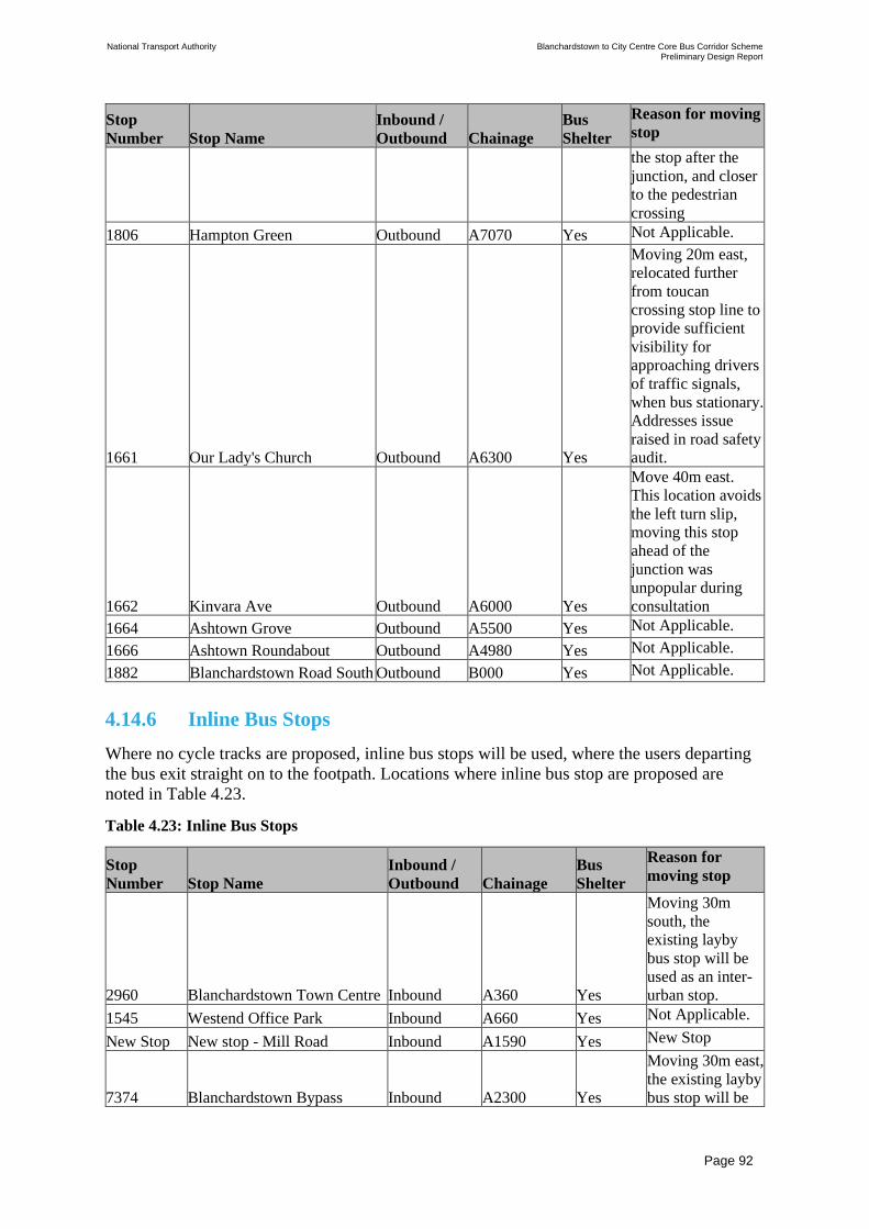
National Transport Authority Blanchardstown to City Centre Core Bus Corridor Scheme Preliminary Design Report
| Issue | 7 May 2022
\\GLOBAL\EUROPE\DUBLIN\JOBS\268000\268401-00\4. INTERNAL\4-04 REPORTS\4-04-03 INFRASTRUCTURE\PRELIMINARY DESIGN REPORT\CBC 5\ISSUE MAY 2022\BCIDC-ARP-PMG_PD-
0005_XX_00-RP-ZZ-0001_ISSUE.DOCX
Page 92
Stop
Number Stop Name
Inbound /
Outbound Chainage
Bus
Shelter
Reason for moving
stop
the stop after the
junction, and closer
to the pedestrian
crossing
1806 Hampton Green Outbound A7070 Yes Not Applicable.
1661 Our Lady's Church Outbound A6300 Yes
Moving 20m east,
relocated further
from toucan
crossing stop line to
provide sufficient
visibility for
approaching drivers
of traffic signals,
when bus stationary.
Addresses issue
raised in road safety
audit.
1662 Kinvara Ave Outbound A6000 Yes
Move 40m east.
This location avoids
the left turn slip,
moving this stop
ahead of the
junction was
unpopular during
consultation
1664 Ashtown Grove Outbound A5500 Yes Not Applicable.
1666 Ashtown Roundabout Outbound A4980 Yes Not Applicable.
1882 Blanchardstown Road South Outbound B000 Yes Not Applicable.
4.14.6 Inline Bus Stops
Where no cycle tracks are proposed, inline bus stops will be used, where the users departing
the bus exit straight on to the footpath. Locations where inline bus stop are proposed are
noted in Table 4.23.
Table 4.23: Inline Bus Stops
Stop
Number Stop Name
Inbound /
Outbound Chainage
Bus
Shelter
Reason for
moving stop
2960 Blanchardstown Town Centre Inbound A360 Yes
Moving 30m
south, the
existing layby
bus stop will be
used as an inter-
urban stop.
1545 Westend Office Park Inbound A660 Yes Not Applicable.
New Stop New stop - Mill Road Inbound A1590 Yes New Stop
7374 Blanchardstown Bypass Inbound A2300 Yes
Moving 30m east,
the existing layby
bus stop will be

National Transport Authority Blanchardstown to City Centre Core Bus Corridor Scheme Preliminary Design Report
| Issue | 7 May 2022
\\GLOBAL\EUROPE\DUBLIN\JOBS\268000\268401-00\4. INTERNAL\4-04 REPORTS\4-04-03 INFRASTRUCTURE\PRELIMINARY DESIGN REPORT\CBC 5\ISSUE MAY 2022\BCIDC-ARP-PMG_PD-
0005_XX_00-RP-ZZ-0001_ISSUE.DOCX
Page 93
Stop
Number Stop Name
Inbound /
Outbound Chainage
Bus
Shelter
Reason for
moving stop
used as an inter
urban bus stop.
New Stop New stop - Auburn Avenue Inbound A2950 Yes New Stop
1845 Morgan's Place Inbound A3270 Yes Not Applicable.
7166 Parkway Station Inbound A3920 Yes
Move 100m east.
Moving the stop
after the junction
improves the
operation of the
bus route
1847 Phoenix Pk Avenue Inbound A4550 Yes
Move 160m west.
This location
better serves the
catchment at
Phoenix Park
Avenue
1714 Brunswick Street Inbound A9175 Yes
Move 100m
south. Under the
proposed design,
there is
reasonable space
in this location,
and it places the
stop after the
junction, where
the road becomes
bus-only.
1715 Blackhall Street Inbound A9400 Yes Not Applicable.
1647 Law Society Outbound A9350 Yes Not Applicable.
1648 Arbour Place Outbound A9125 Yes
Move 115m
south. In this
location, there is
more space
created due to the
new road layout.
This location also
achieves better
spacing from the
next stop
1808 Peck's Lane Outbound A3200 Yes Not Applicable.
New Stop New stop - Auburn Avenue Outbound A2975 Yes New Stop
New Stop New stop - Mill Road Outbound A1650 Yes New Stop
661 Westend Office Park Outbound A675 Yes
Moving 65m
west, this location
brings the stop
closer to the
junction to the
west.
New Stop Crowne Plaza Off-slip Outbound D000 Yes New Stop

National Transport Authority Blanchardstown to City Centre Core Bus Corridor Scheme Preliminary Design Report
| Issue | 7 May 2022
\\GLOBAL\EUROPE\DUBLIN\JOBS\268000\268401-00\4. INTERNAL\4-04 REPORTS\4-04-03 INFRASTRUCTURE\PRELIMINARY DESIGN REPORT\CBC 5\ISSUE MAY 2022\BCIDC-ARP-PMG_PD-
0005_XX_00-RP-ZZ-0001_ISSUE.DOCX
Page 94
4.14.7 Lay- By Bus Stops
Consideration has been given to locations where private coaches may be required to stop
along the Proposed Scheme, which could require longer dwell time to allow passengers to
load/unload their luggage. In these cases, and where space has permitted, a separate lay-by
bus stop is proposed as shown in Figure 4.17.
Figure 4.17: Lay-by Bus Stop Landing Zone Arrangement (Private Service Coaches)
Lay-by Bus Stops are proposed at a number of locations, as shown in Table 4.24.
Table 4.24: Lay-by Bus Stops
Stop
Number Stop Name
Inbound /
Outbound Chainage
Bus
Shelter
Reason for
moving stop
New Stop
New Stop – adjacent to stop
2960 - Blanchardstown Town
Centre Inbound A340 Yes
Not Applicable.
New Stop
(adjacent to
existing
stop 7374) Junction 6 Inbound A2250 Yes
New Stop
New Stop Navan Road Parkway Station Inbound A3790 Yes New Stop
New Stop Phoenix Park Avenue Inbound A4400 Yes New Stop
New Stop Phoenix Park Avenue Outbound A4550 Yes New Stop
New Stop Navan Road Parkway Station Outbound A3950
Yes
New Stop
7389 Navan Road Outbound A1925 Yes
Move 60m east.
This location is
closer to the
connection to Old
River Road
New Stop
New Stop - Navan Road
(adjacent to existing stop
7389) Outbound A1925 Yes
New Stop
New Stop Westend Office Park Outbound A700 Yes New Stop
4.15 Parking and Loading
With the Proposed Scheme infrastructure in place, the impacts of the change on on-street
parking have been considered and are summarised below. Refer to Figure 4.18 and Table
4.25.
This considers the parking impact on the corridor in the context of parking supply on the
CBC and on adjacent streets close-by (within 200m). The associated mitigation effects of the
Proposed Scheme and other measures are also summarised.

National Transport Authority Blanchardstown to City Centre Core Bus Corridor Scheme Preliminary Design Report
| Issue | 7 May 2022
\\GLOBAL\EUROPE\DUBLIN\JOBS\268000\268401-00\4. INTERNAL\4-04 REPORTS\4-04-03 INFRASTRUCTURE\PRELIMINARY DESIGN REPORT\CBC 5\ISSUE MAY 2022\BCIDC-ARP-PMG_PD-
0005_XX_00-RP-ZZ-0001_ISSUE.DOCX
Page 95
Navan Road: The change in parking will involve removal of approximately 19 unregulated
spaces, and retention of approximately 4 of an existing 5 spaces (on Navan Road between
Ashtown Road and Nephin Road). Aspects of the Proposed Scheme and network proposals
are expected to mitigate the reduction in parking by reducing reliance on private cars due to
availability of an improved bus network with journey reliability, by availability of improved
cycling infrastructure, and by continued and managed use of private off-street parking at, for
example, local churches and schools.
Similarly, most houses have driveways and residents should be encouraged to utilise their
available off-road space for parking (rather than seek to park on-street). It is concluded that
the overall impact of loss of parking space on Navan Road is limited and will be largely
offset by the cumulative effect of mitigations.
Aughrim Street / Prussia Street / Manor Street / Stoneybatter: The parking impact
assessment indicates that although all 10 parking spaces (only available from 10am onwards
during the day) will be removed on Prussia Street, on-street parking on adjacent side streets
will continue to provide a parking supply for local use. Along Manor Street, Stoneybatter,
Manor Place and Aughrim Street, there will be a reduction of 53 spaces. The reduction in
parking spaces along this section of the corridor is 19% including side streets, for both
residential and commercial parking activity. Aspects of the Proposed Scheme and network
proposals are expected to mitigate the reduction in parking by reducing reliance on private
cars due to availability of an improved bus network with journey reliability, and by
availability of improved cycling infrastructure. Improved compliance with parking and
loading bay regulations, and management of loading activities will also assist in offsetting the
reduction in on-street parking spaces. It is concluded that the overall impact of loss of parking
spaces on Prussia Street and Manor Street is limited and will be largely offset by the
cumulative effect of mitigations.
Blackhall Place: The parking impact assessment indicates that this section of the Proposed
Scheme and its surrounding areas will lose approximately 6% of parking spaces for both
residential and commercial usage. Aspects of the Proposed Scheme and network proposals
are expected to mitigate the reduction in parking by reducing reliance on private cars due to
availability of an improved bus network with journey reliability, and by availability of
improved cycling infrastructure. Improved compliance with parking and loading bay
regulations, and management of loading activities will also assist in offsetting the reduction
in on-street parking spaces. It is concluded that the overall impact of loss of parking space on
the Blackhall Place corridor section is limited and will be largely offset by the cumulative
effect of mitigations.
Other issues and design considerations will also have an impact on parking availability and
usage:
• Commercial premises will need to consider adapting their loading arrangements – for
example by loading at night-time or early morning (and also considering using smaller
vans in Paid-for spaces); and
• Cycle parking is included in the Proposed Scheme – which will enhance the ability of
residents to cycle instead of driving and parking a car to use local services.

National Transport Authority Blanchardstown to City Centre Core Bus Corridor Scheme Preliminary Design Report
| Issue | 7 May 2022
\\GLOBAL\EUROPE\DUBLIN\JOBS\268000\268401-00\4. INTERNAL\4-04 REPORTS\4-04-03 INFRASTRUCTURE\PRELIMINARY DESIGN REPORT\CBC 5\ISSUE MAY 2022\BCIDC-ARP-PMG_PD-
0005_XX_00-RP-ZZ-0001_ISSUE.DOCX
Page 96
Figure 4.18: Proposed preliminary Parking Survey Study Areas
4.15.1 Summary of Parking Changes
With the Proposed Scheme infrastructure in place, there will be an associated need to remove
some parking spaces to provide improved facilities for pedestrians, cyclists, and buses –
which inevitably requires some reallocation of parking road space. The proposed changes in
parking provision are summarised in Table 4.25, Table 4.26 and Table 4.27. To ensure
disabled parking bays required as part of the Proposed Scheme are accessible, all disabled
parking bay have been designed to Chapter 7 of the Traffic Signs Manual. Typical disabled
parking bays layouts are indicated in Figure 4.19.
Figure 4.19: Typical disabled parking layout
Refer to Parking summary from the Parking Survey Report in Appendix G.

National Transport Authority Blanchardstown to City Centre Core Bus Corridor Scheme Preliminary Design Report
| Issue | 7 May 2022
\\GLOBAL\EUROPE\DUBLIN\JOBS\268000\268401-00\4. INTERNAL\4-04 REPORTS\4-04-03 INFRASTRUCTURE\PRELIMINARY DESIGN REPORT\CBC 5\ISSUE MAY 2022\BCIDC-ARP-PMG_PD-
0005_XX_00-RP-ZZ-0001_ISSUE.DOCX
Page 97
Table 4.25: On-Street Parking Spaces Change Impact Summary (Navan Road) Ashtown Road
to Old Cabra Road
Ashtown Road to Old Cabra Road
Existing Parking Facilities Baseline Scheme Proposed Change
Informal Parking Spaces 24 4 -20
Total Change 24 4 -20
Table 4.26: On-Street Parking Spaces Change Impact Summary (Prussia Street, Manor Street,
Stoneybatter, Manor Place and Aughrim Street)
Prussia Street, Manor Street, Stoneybatter and Aughrim Street
Existing Parking Facilities Baseline Scheme Proposed Change
Designated Paid & Permit
Parking Spaces 80 16 -64
Disabled Permit Parking Spaces 2 2 0
Loading / Unloading Spaces (in
Designated Loading Bays) 6 7 +1
Total Change 88 25 -63
Table 4.27: On-Street Parking Spaces Change Impact Summary (Blackhall Place and adjacent
streets)
(Blackhall Place and adjacent streets)
Existing Parking Facilities Baseline Scheme Change
Designated Paid & Permit
Parking Spaces 54 42 -12
Loading / Unloading Spaces (in
Designated Loading Bays) 3 4 +1
Total Change 57 46 -11
4.16 Turning Bans and Traffic Management Measures
Turning bans and other traffic management measures will be implemented on the route to
direct traffic away from either the Proposed Scheme corridor (to maximise bus journey time
reliability) or to limit use of side streets as a short-cut route by through traffic. All these
measures are shown on the General Arrangement Drawings, and are listed in Table 4.28 and
Table 4.29. Existing turn bans and traffic management measures are not included in these two
tables.

National Transport Authority Blanchardstown to City Centre Core Bus Corridor Scheme Preliminary Design Report
| Issue | 7 May 2022
\\GLOBAL\EUROPE\DUBLIN\JOBS\268000\268401-00\4. INTERNAL\4-04 REPORTS\4-04-03 INFRASTRUCTURE\PRELIMINARY DESIGN REPORT\CBC 5\ISSUE MAY 2022\BCIDC-ARP-PMG_PD-
0005_XX_00-RP-ZZ-0001_ISSUE.DOCX
Page 98
Table 4.28: Core bus corridor traffic management measures and turning bans
Location TM measure
implemented
Reason for
Mitigation Impact of Mitigation
New shopping
centre entrance
on
Blanchardstown
Road South
New signalised junction
To reduce car park
traffic movement in
the vicinity of the
new Bus
Interchange
Improved reliability for bus
journey times in and out of
the Bus Interchange.
Eastern
approach to
Blanchardstown
Bus
Interchange
No right turn movement
allowed for general traffic
into Bus Interchange from
the east
To allow access to
buses only
Improved reliability for bus
journey times along this
section of the corridor.
Blanchardstown
car park
entrance to east
of Bus
Interchange
No right turn movement
from car park access
To allow for bus
priority
Improved reliability for bus
journey times along this
section of the corridor.
Eastern
approach to
Blanchardstown
Bus
Interchange
Bus Priority Signal To allow for bus
priority
Improved reliability for bus
journey times along this
section of the corridor.
R147 Outbound
/ Auburn
Avenue
Junction
Bus Priority Signal To allow for bus
priority
Improved reliability for bus
journey times along this
section of the corridor.
R147 Outbound
/ Ashtown
Business Centre
/ Phoenix
Industrial Park
Junction
No right turn movement
allowed from R147 Navan
Road into Ashtown
Business Centre / Phoenix
Industrial Park
To allow for bus
priority
Improved reliability for bus
journey times along this
section of the corridor.
Navan Road
Inbound / Cabra
Library
Junction
Bus Priority Signal To allow for bus
priority
Improved reliability for bus
journey times along this
section of the corridor.
Navan
Road/Old
Cabra Road
junction
Bus Gate: No turning
movement allowed for
general traffic from Navan
Road / Ratoath Road /
Cabra Road on to Old
Cabra Road
To allow for bus
priority on Old
Cabra Road
Inbound general traffic is
redirected on to Cabra
Road.
Old Cabra Road
Bus Gate: No straight-
ahead general traffic
movement allowed on Old
Cabra Road at Railway
Bridge (outbound). Right
turn movements from
Cabra Drive also restricted
for northbound through-
traffic.
To allow for bus
priority on Old
Cabra Road
Outbound through-
movements of general
traffic will be removed from
Old Cabra Road.
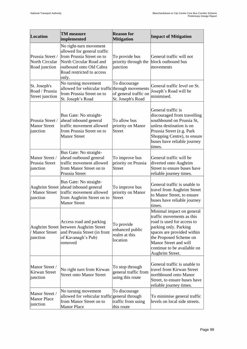
National Transport Authority Blanchardstown to City Centre Core Bus Corridor Scheme Preliminary Design Report
| Issue | 7 May 2022
\\GLOBAL\EUROPE\DUBLIN\JOBS\268000\268401-00\4. INTERNAL\4-04 REPORTS\4-04-03 INFRASTRUCTURE\PRELIMINARY DESIGN REPORT\CBC 5\ISSUE MAY 2022\BCIDC-ARP-PMG_PD-
0005_XX_00-RP-ZZ-0001_ISSUE.DOCX
Page 99
Location TM measure
implemented
Reason for
Mitigation Impact of Mitigation
Prussia Street /
North Circular
Road junction
No right-turn movement
allowed for general traffic
from Prussia Street on to
North Circular Road and
outbound onto Old Cabra
Road restricted to access
only.
To provide bus
priority through the
junction
General traffic will not
block outbound bus
movements
St. Joseph's
Road / Prussia
Street junction
No turning movement
allowed for vehicular traffic
from Prussia Street on to
St. Joseph’s Road
To discourage
through movements
of general traffic on
St. Joseph's Road
General traffic level on St.
Joseph’s Road will be
minimised.
Prussia Street /
Manor Street
junction
Bus Gate: No straight-
ahead inbound general
traffic movement allowed
from Prussia Street on to
Manor Street
To allow bus
priority on Manor
Street
General traffic is
discouraged from travelling
southbound on Prussia St,
unless destination is on
Prussia Street (e.g. Park
Shopping Centre), to ensure
buses have reliable journey
times.
Manor Street /
Prussia Street
junction
Bus Gate: No straight-
ahead outbound general
traffic movement allowed
from Manor Street on to
Prussia Street
To improve bus
priority on Prussia
Street
General traffic will be
diverted onto Aughrim
Street to ensure buses have
reliable journey times.
Aughrim Street
/ Manor Street
junction
Bus Gate: No straight-
ahead inbound general
traffic movement allowed
from Aughrim Street on to
Manor Street
To improve bus
priority on Manor
Street
General traffic is unable to
travel from Aughrim Street
to Manor Street, to ensure
buses have reliable journey
times.
Aughrim Street
/ Manor Street
junction
Access road and parking
between Aughrim Street
and Prussia Street (in front
of Kavanagh’s Pub)
removed
To provide
enhanced public
realm at this
location
Minimal impact on general
traffic movements as this
road is used for access to
parking only. Parking
spaces are provided within
the Proposed Scheme on
Manor Street and will
continue to be available on
Aughrim Street.
Manor Street /
Kirwan Street
junction
No right turn from Kirwan
Street onto Manor Street
To stop through
general traffic from
using this route
General traffic is unable to
travel from Kirwan Street
northbound onto Manor
Street, to ensure buses have
reliable journey times.
Manor Street /
Manor Place
junction
No turning movement
allowed for vehicular traffic
from Manor Street on to
Manor Place
To discourage
general through
traffic from using
this route
To minimise general traffic
levels on local side streets.

National Transport Authority Blanchardstown to City Centre Core Bus Corridor Scheme Preliminary Design Report
| Issue | 7 May 2022
\\GLOBAL\EUROPE\DUBLIN\JOBS\268000\268401-00\4. INTERNAL\4-04 REPORTS\4-04-03 INFRASTRUCTURE\PRELIMINARY DESIGN REPORT\CBC 5\ISSUE MAY 2022\BCIDC-ARP-PMG_PD-
0005_XX_00-RP-ZZ-0001_ISSUE.DOCX
Page 100
Location TM measure
implemented
Reason for
Mitigation Impact of Mitigation
Blackhall Place
/ King Street
North /
George's Lane /
Brunswick
Street North
Brunswick Street North
modified to be one-way
westbound, buses only on
outbound section of
Stoneybatter north of King
Street North
To discourage
general traffic
through movements
in Stoneybatter
Outbound general traffic
will be redirected to King
Street North / George's Lane
/ Brunswick Street North.
King Street
North /
George’s Lane
Westbound general traffic
from on the eastern section
of King Street North (east
of George’s Lane) to be
restricted to left turns only,
into Queen Street.
To discourage
general traffic
through movements
from King Street
North (east of
George's Lane)
towards and through
Stoneybatter.
Westbound general traffic
on King Street North (east
of George's Lane) wishing
to travel north will have to
travel south on Queen Street
- but then can travel
northwards via Blackhall
Street / Blackhall Place.
Stoneybatter /
Arbour Hill
junction
No left-turn movement
allowed from Arbour Hill
on to Blackhall Place
To discourage
general traffic
through movements
in Stoneybatter
General traffic is
discouraged from travelling
northbound on Manor
Street, and hence to ensure
buses have reliable journey
times.
Stoneybatter /
Brunswick
Street North
junction
(outbound)
Signal Controlled Priority
To allow for bus
priority along
Stoneybatter /
Manor Street
General traffic is
discouraged from travelling
northbound on Manor
Street, and hence to ensure
buses have reliable journey
times.
Blackhall Place
/ King Street
North junction
(outbound)
Bus Gate: No straight-
ahead outbound general
traffic movement allowed
beyond this junction. Right
turn only for general traffic
at this point.
To discourage
general traffic
through movements
in Stoneybatter
Outbound general traffic
will be redirected to King
Street North / George's Lane
/ Brunswick Street North.
Stanley Street /
Brunswick
Street North
junction
No left turn movement
from Stanley Street onto
Brunswick Street North.
Brunswick Street
North is westbound
only.
To facilitate two one-way
cycle tracks and maintain
one traffic lane.
Table 4.29: Turning bans offline from main Core Bus Corridor
Location TM measure
implemented
Reason for
Mitigation Impact of Mitigation
Ratoath Road /
Swilly Road
junction
No turning movement
allowed for vehicular traffic
from Ratoath Road on to
Swilly Road
To discourage
general through
traffic from using
this route.
To minimise general traffic
levels on local side streets
Cowper Street
(between
Lucky Lane
No access from Cowper
Street onto Aughrim Street
To discourage
general through
To minimise general traffic
levels on local side streets

National Transport Authority Blanchardstown to City Centre Core Bus Corridor Scheme Preliminary Design Report
| Issue | 7 May 2022
\\GLOBAL\EUROPE\DUBLIN\JOBS\268000\268401-00\4. INTERNAL\4-04 REPORTS\4-04-03 INFRASTRUCTURE\PRELIMINARY DESIGN REPORT\CBC 5\ISSUE MAY 2022\BCIDC-ARP-PMG_PD-
0005_XX_00-RP-ZZ-0001_ISSUE.DOCX
Page 101
Location TM measure
implemented
Reason for
Mitigation Impact of Mitigation
and Aughrim
Street)
traffic from using
this route.
Aughrim Place
(between
Lucky Lane
and Aughrim
Street)
One-way southbound only
To discourage
general through
traffic from using
this route.
To minimise general traffic
levels on local side streets
Annamoe Road
/ Annamoe
Terrace
junction
One-way northbound only
for vehicular traffic at
Annamoe Road / Annamoe
Terrace junction.
To discourage
general traffic
travelling through
the Annamoe Estate
as a means of
bypassing Old
Cabra Road
To minimise general traffic
levels on local side streets
Charleville
Road
Northbound movement only
for vehicular traffic on
Charleville Road between
Annamoe Parade and North
Circular Road
To discourage
general traffic
travelling through
Charleville Road as
a means of
bypassing Old
Cabra Road
To minimise general traffic
levels on local side streets
Cabra Road
/North Circular
Road junction
New right turn from Cabra
Road to North Circular
Road and new left turn from
North Circular Riad to
Cabra Road to be
introduced
To provide a route
for general traffic
from Navan Road to
the Quays (and thus
avoiding Old Cabra
Road &
Stoneybatter)
Provides an access route for
local general traffic between
Cabra and the Quays.
Cabra Road
/North Circular
Road junction
New left turn from North
Circular Road to Cabra
Road to be introduced
To provide a route
for general traffic
from the Quays to
Navan Road (and
thus avoiding
Stoneybatter and
Old Cabra Road)
Provides an access route for
local general traffic between
the Quays and Cabra.
Phibsborough
No access for general traffic
from Phisborough Road on
to Phisborough (existing
right turn ban from northern
approach being retained)
To discourage
general traffic
travelling through
Phibsborough from
Phibsborough Road
To minimise general traffic
levels on local side streets
Phibsborough No right-turn on to
Phibsborough Road
To discourage
general traffic
travelling through
Phibsborough from
North Circular Road
To minimise general traffic
levels on local side streets

National Transport Authority Blanchardstown to City Centre Core Bus Corridor Scheme Preliminary Design Report
| Issue | 7 May 2022
\\GLOBAL\EUROPE\DUBLIN\JOBS\268000\268401-00\4. INTERNAL\4-04 REPORTS\4-04-03 INFRASTRUCTURE\PRELIMINARY DESIGN REPORT\CBC 5\ISSUE MAY 2022\BCIDC-ARP-PMG_PD-
0005_XX_00-RP-ZZ-0001_ISSUE.DOCX
Page 102
Location TM measure
implemented
Reason for
Mitigation Impact of Mitigation
Monck Place
No access for general traffic
from Phisborough Road on
to Monck Place
To discourage
general traffic
travelling through
Monck Place from
Phibsborough Road
To minimise general traffic
levels on local side streets
Monck Place No right-turn on to
Phibsborough Road
To discourage
general traffic
travelling through
Monck Place from
North Circular Road
To minimise general traffic
levels on local side streets
Castleknock
Road /
Blackhorse
Avenue
junction
No through road from
Castleknock Road to
Blackhorse Avenue
To discourage
general traffic using
Blackhorse Avenue
as an alternative to
the Navan Road /
Old Cabra Road.
To minimise general traffic
levels on local side streets
North Circular
Road /
Oxmantown
Road junction
No left-turn for vehicular
traffic from North Circular
Road on to Oxmantown
Road
To discourage
general traffic
travelling through
Oxmantown Road
from North Circular
Road
To minimise general traffic
levels on local side streets
4.17 Deviations from Standard
The design has been developed in accordance with the standards and guidance listed within
Section 4.1. However, in some circumstances, it has been necessary to digress from the
desirable minimum geometric parameters identified.
A schedule of deviations from BCPDGB and departures and relaxations from TII Design
Standards, relating to the individual aspects of Road Geometry is included within Appendix
C.
4.18 Road Safety and Road User Audit
The TII Publication ‘GE-STY-01024 Road Safety Audit’ document provides an outline of the
typical stages for road safety audits and are noted below as follows:
• Stage F: Route selection, prior to route choice;
• Stage 1: Completion of preliminary design prior to land acquisition procedures;
• Stage 2: Completion of detailed design, prior to tender of construction contract. In the case
of Design and Build contracts, a Stage 2 audit shall be completed prior to construction taking
place;
• Stage 1 & 2: Completion of detailed design, prior to tender of construction contract, for
small schemes where only one design stage audit is appropriate;

National Transport Authority Blanchardstown to City Centre Core Bus Corridor Scheme Preliminary Design Report
| Issue | 7 May 2022
\\GLOBAL\EUROPE\DUBLIN\JOBS\268000\268401-00\4. INTERNAL\4-04 REPORTS\4-04-03 INFRASTRUCTURE\PRELIMINARY DESIGN REPORT\CBC 5\ISSUE MAY 2022\BCIDC-ARP-PMG_PD-
0005_XX_00-RP-ZZ-0001_ISSUE.DOCX
Page 103
• Stage 3: Completion of construction (prior to opening of the scheme, or part of the scheme
to traffic wherever possible); and
• Stage 4: Early operation at 2 to 4 months’ post road opening with live traffic.
Part 2 of a Stage F Road Safety Audit (RSA) was carried out at EPR stage (i.e. once the
option had been chosen). A Stage 1 RSA, including a supplementary road safety audit, has
been undertaken on the preliminary design, and designer’s responses and appropriate changes
made.
Both RSA’s considered matters that have an adverse effect on road safety and considered the
perspective of all road users.
Refer to RSA reports in Appendix M.

National Transport Authority Blanchardstown to City Centre Core Bus Corridor Scheme Preliminary Design Report
| Issue | 7 May 2022
\\GLOBAL\EUROPE\DUBLIN\JOBS\268000\268401-00\4. INTERNAL\4-04 REPORTS\4-04-03 INFRASTRUCTURE\PRELIMINARY DESIGN REPORT\CBC 5\ISSUE MAY 2022\BCIDC-ARP-PMG_PD-
0005_XX_00-RP-ZZ-0001_ISSUE.DOCX
Page 104
5 Junction Layout
5.1 Overview of Transport Modelling Strategy
The design and modelling of junctions has been an iterative process to optimise the number
of people that can pass through each junction, with priority given to pedestrian, cycle and bus
movements.
The design for each junction within the Proposed Scheme was developed to meet the
objectives of the scheme and to align with the geometric parameters set out in Section 4.1, in
conjunction with the junction operation principles described in the BCPDGB. Various traffic
modelling tools were used to assess the impact of the proposals on a local, corridor and
surrounding road network level which is further described in Section 5.4.
A traffic impact assessment has been undertaken for the Proposed Scheme in order to
determine the predicted magnitude of impact Proposed Scheme measures may have against
the likely receiving environment. The impact assessments have been carried out using the
following scenarios:
• ‘Do Minimum’ – This scenario represents the likely conditions of the road network with
all major committed transportation schemes in place that will impact on the use of public
transport and private car, without the Proposed Scheme.
• ‘Do Something’ – This scenario represents the likely conditions of the road network with
all major committed transportation schemes in place that will impact on the use of public
transport and private car, with the Proposed Scheme (i.e. the ‘Do Minimum’ scenario
with the addition of the Proposed Scheme) in place.
Both scenarios above comprised of an assessment at opening year (2028) and opening year
+15 years (2043). In developing the design proposals for the Proposed Scheme, the 2028 year
flows were determined to provide the higher volume of traffic flows for the most part and as
such has been generally adopted as the design case scenario for junction development. The
final junction design flows have been supplemented with additional cycle volumes to ensure
a minimum 10% cycle mode share in terms of people movement at each junction can be
achieved in line with the National Cycle Policy Framework.
5.2 Overview of Junction Design
The purpose of traffic signals is to regulate movements safely with allocation of priority in
line with transportation policy. For the Proposed Scheme, a key policy is to ensure
appropriate capacity and reliability for the bus services so as to maximise the overall
throughput of people in an efficient manner. The junctions will provide safe and convenient
crossing facilities for pedestrians with as little delay as possible. Particular provisions are
required for the protection of cyclists from turning traffic, as well as ensuring suitable
capacity for a rapidly increasing demand by this mode.
The design of signalised junctions, or series of junctions, as part of the Proposed Scheme has
been approached on a case-by-case basis. There have been a number of components of the
design development process that have influenced the preliminary junction designs including:
• The junction operational and geometrical principles described in the BCPDGB;

National Transport Authority Blanchardstown to City Centre Core Bus Corridor Scheme Preliminary Design Report
| Issue | 7 May 2022
\\GLOBAL\EUROPE\DUBLIN\JOBS\268000\268401-00\4. INTERNAL\4-04 REPORTS\4-04-03 INFRASTRUCTURE\PRELIMINARY DESIGN REPORT\CBC 5\ISSUE MAY 2022\BCIDC-ARP-PMG_PD-
0005_XX_00-RP-ZZ-0001_ISSUE.DOCX
Page 105
• Integration of pedestrian and cycle movements at junctions;
• Geometrical junction design for optimal layouts for pedestrians, cyclists and bus priority
whilst minimising general traffic dispersion where practical;
• People Movement Calculator (PMC) to inform junction staging and design development;
• LINSIG junction modelling to assess junction design performance and refinement;
• Micro-Sim modelling to assess and refine bus priority designs; and
• Cyclist quantification.
5.3 Junction Geometry Design
5.3.1 Pedestrians
The junction design approach is to minimise delay for pedestrians at junctions, whilst
ensuring high quality infrastructure to ensure pedestrians of all ages including vulnerable
users can cross in a safe and convenient manner. Pedestrian crossings will be placed as close
to pedestrian desire lines as possible. Where pedestrians are required to cross a cycle track,
this is proposed to be controlled by traffic signals to manage potential conflicts.
The preferred arrangement for pedestrians at junctions is to have a wraparound pedestrian
signal stage at the start of the cycle. In some instances, this will not be feasible i.e. due to
crossing distances and the associated intergreen time for pedestrians to safely clear the
junction. A “walk with traffic” system is therefore proposed at certain junctions, in particular
where refuge islands have been introduced for a two-stage pedestrian crossing. At these
locations, controlled crossings for pedestrians are provided across part of the junction, whilst
some of the traffic movements that are now in conflict with the pedestrian movement, are
allowed to run at the same time. This facility has the advantage of allowing pedestrians to
cross during the cycle whilst having less effect on traffic capacity.
5.3.2 Cyclists
The provision for cyclists at junctions is a critical factor in managing conflict and providing
safe junctions for all road users. The primary conflict for cyclists is with left turning traffic.
Based on international best practice, the preferred layout for signalised junctions is the
“Protected Junction”, which provides physical kerb build-outs to protect cyclists at junctions.
The key design features and considerations relating to this junction type are listed below:
• The traffic signal arrangement will remove any uncontrolled conflict between pedestrians
and cyclists, assigning clear priority to all users at different stages within a traffic signal
cycle;
• Kerbed corner islands should be provided to force turning vehicles into a wide turn and
remove the risk of vehicles cutting into the cycle route at the corner, which is a cause of
serious accidents at junctions. The raised islands create a protective ring for cyclists
navigating the junction, improving safety for right turning cyclists;
• Cycle tracks that are protected behind parking or loading bays will return to run along the
edge of the carriageway approaching the junction. Consideration has been given to
remove any parking or loading located immediately at junctions to enhance visibility
between motorists and cyclists;

National Transport Authority Blanchardstown to City Centre Core Bus Corridor Scheme Preliminary Design Report
| Issue | 7 May 2022
\\GLOBAL\EUROPE\DUBLIN\JOBS\268000\268401-00\4. INTERNAL\4-04 REPORTS\4-04-03 INFRASTRUCTURE\PRELIMINARY DESIGN REPORT\CBC 5\ISSUE MAY 2022\BCIDC-ARP-PMG_PD-
0005_XX_00-RP-ZZ-0001_ISSUE.DOCX
Page 106
• The cycle track will be typically ramped down to carriageway level on approach to the
junction and will proceed to a forward stop line. A secondary cycle stop line is also
proposed at an advanced location to the vehicular stop line at a number of junctions to
cater for right turning cyclists, which will also place the cyclists within viewing of traffic
waiting at the junction. Cycle signals will control the movement of cyclists including the
second stage movement i.e. right turners; and
• Cyclist and pedestrian crossings will be kept as close as possible to the mainline desire
line. However pedestrian and cyclist crossings will be separated where feasible; in these
instances, 2-3m separation should be provided between crossings. This is to ensure
motorists infer a clear differentiation between a cycle lane crossing through the junction
and a pedestrian crossing across the same arm.
In some junction locations, constraints in respect of physical space and junction configuration
have meant that deflection of cycle tracks with kerbed corner islands is not feasible. In these
cases, the cycle track will be aligned alongside the adjacent traffic lane on a straight-through
path, with box-turns provided for right turning cyclists where appropriate.
5.3.3 Bus Priority
The Proposed Scheme design at junctions is based on typical layouts described in the
BCPDGB document, which sets out four different types of junctions, referred to as Junction
Types 1-4 (in Section 7.4 Signalised Junction Operation of BCPDGB). The following
subsections provide an overview of the context and principles for applying all or part of the
junction type layouts for the Proposed Scheme design.
5.3.3.1 Junction Type 1
Junction Type 1 (Section 7.4.1 of BCPDGB) comprises a dedicated bus lane on both inbound
and outbound directions which will continue up to the junction stop line. Due to space
constraints, general traffic travelling both straight ahead and turning left will be restricted to
one lane. Junction Type 1 is typically chosen for the following reasons:
• Volume of left turning vehicles greater than 100 PCUs per hour; and
• Urban setting, no space available for dedicated left turning lane / pocket.
In this instance, mainline cyclists will proceed with the bus phase. The bus lane gets red,
allowing the general traffic lane to proceed. If the volume of turning vehicles is greater than
150 PCUs, then the cyclists should also be held on red. If the volume of left turners is approx.
100 – 150 PCUs, left turners will be controlled by a flashing amber arrow and cyclists should
receive an early start.
A full Junction Type 1 has not been applied to the Proposed Scheme, however the Proposed
Scheme has a number of ‘hybrid’ junctions, which comprise of a Junction Type 1 and another
junction type, as shown in Figure 5.1 below.
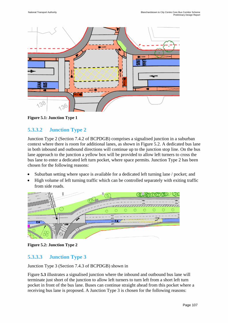
National Transport Authority Blanchardstown to City Centre Core Bus Corridor Scheme Preliminary Design Report
| Issue | 7 May 2022
\\GLOBAL\EUROPE\DUBLIN\JOBS\268000\268401-00\4. INTERNAL\4-04 REPORTS\4-04-03 INFRASTRUCTURE\PRELIMINARY DESIGN REPORT\CBC 5\ISSUE MAY 2022\BCIDC-ARP-PMG_PD-
0005_XX_00-RP-ZZ-0001_ISSUE.DOCX
Page 107
Figure 5.1: Junction Type 1
5.3.3.2 Junction Type 2
Junction Type 2 (Section 7.4.2 of BCPDGB) comprises a signalised junction in a suburban
context where there is room for additional lanes, as shown in Figure 5.2. A dedicated bus lane
in both inbound and outbound directions will continue up to the junction stop line. On the bus
lane approach to the junction a yellow box will be provided to allow left turners to cross the
bus lane to enter a dedicated left turn pocket, where space permits. Junction Type 2 has been
chosen for the following reasons:
• Suburban setting where space is available for a dedicated left turning lane / pocket; and
• High volume of left turning traffic which can be controlled separately with exiting traffic
from side roads.
Figure 5.2: Junction Type 2
5.3.3.3 Junction Type 3
Junction Type 3 (Section 7.4.3 of BCPDGB) shown in
Figure 5.3 illustrates a signalised junction where the inbound and outbound bus lane will
terminate just short of the junction to allow left turners to turn left from a short left turn
pocket in front of the bus lane. Buses can continue straight ahead from this pocket where a
receiving bus lane is proposed. A Junction Type 3 is chosen for the following reasons:

National Transport Authority Blanchardstown to City Centre Core Bus Corridor Scheme Preliminary Design Report
| Issue | 7 May 2022
\\GLOBAL\EUROPE\DUBLIN\JOBS\268000\268401-00\4. INTERNAL\4-04 REPORTS\4-04-03 INFRASTRUCTURE\PRELIMINARY DESIGN REPORT\CBC 5\ISSUE MAY 2022\BCIDC-ARP-PMG_PD-
0005_XX_00-RP-ZZ-0001_ISSUE.DOCX
Page 108
• Volume of left turning vehicles is less than 100 PCUs per hour; and
• Urban setting, no space available for a dedicated left turning lane / pocket.
In this instance, mainline buses and general traffic (including left turners) will proceed
together, but before they do, mainline cyclists will be given an early start of approximately 5
seconds to assist with cyclist priority and to minimise potential conflicts. When this early
start is complete, the mainline cyclists can still proceed, assuming turning traffic volumes are
less than 150 PCUs per hour. Left turning vehicles from the left turn pocket will be given a
flashing amber.
Figure 5.3: Junction Type 3
5.3.3.4 Junction Type 4
Junction Type 4 (Section 7.4.4 of BCPDGB) (is a signalised junction with an inbound and
outbound bus lane, but also positions the pedestrian crossings on the inside of the cycle lanes
across the arms of the junction, as shown in Figure 5.4). Pedestrian crossing distances will be
minimised as a result. Signalised pedestrian crossings are proposed across the cycle tracks to
allow pedestrians to cross from the footpath to the pedestrian crossing landing areas, thus
avoiding uncontrolled pedestrian – cyclist conflict. Other key design features are that left
turning cyclists can effectively bypass the junction, while giving way to pedestrians crossing
as well as cyclists already on the orbital cycle track, and the number of crossings for
pedestrians is increased as pedestrians must cross the cycle track to access the central signal-
controlled area.
Junction Type 4 is chosen for the following reasons:
• High incidence of HGV movements e.g. at industrial estates or where two major regional
roads meet;
• Suburban setting and lower pedestrian volumes; and
• Appropriate space at junction corners to provide cycle tracks and pedestrian corner
islands.
There are no Type 4 junctions within the Proposed Scheme.

National Transport Authority Blanchardstown to City Centre Core Bus Corridor Scheme Preliminary Design Report
| Issue | 7 May 2022
\\GLOBAL\EUROPE\DUBLIN\JOBS\268000\268401-00\4. INTERNAL\4-04 REPORTS\4-04-03 INFRASTRUCTURE\PRELIMINARY DESIGN REPORT\CBC 5\ISSUE MAY 2022\BCIDC-ARP-PMG_PD-
0005_XX_00-RP-ZZ-0001_ISSUE.DOCX
Page 109
Figure 5.4: Junction Type 4
5.3.4 Staging and Phasing
The optimum staging for each junction is determined by the junction configuration and the
level of demand for each movement. One of the key considerations in the design of the
signalised junctions is the conflict between left turning traffic and buses, cyclists and
pedestrians continuing along the main corridor. The following presents an overview of the
design approach:
• Cyclists travelling through the junction across the side road will run with straight ahead
traffic movements, including buses in a dedicated bus lane;
• A short early start for straight-ahead cyclists on the main corridor will enable cyclists to
advance before general traffic. The amount of green given to cyclists is subject to
junction dimensions and signal operation;
• Cycle movements along the main corridor, crossing the side road, can run simultaneously
with the bus stage in the same direction, so long as the bus is not permitted to turn left
from the bus lane; and
• Cycle movements at junctions are to be controlled by cycle signal aspects where there is
an advance stop line ahead of the traffic signals including for hook turns at the far side of
the side street crossing. Additional cycle signals are provided for right turning cyclists.
5.3.5 Junction Design Summary
A detailed junction assessment has been undertaken in line with the principles described in
Section 5.3. The following summary tables provide an overview of the key design principles
adopted at each junction location. More detailed information for each junction location can be
found in the Junction Design Report in Appendix L.

National Transport Authority Blanchardstown to City Centre Core Bus Corridor Scheme Preliminary Design Report
| Issue | 7 May 2022
\\GLOBAL\EUROPE\DUBLIN\JOBS\268000\268401-00\4. INTERNAL\4-04 REPORTS\4-04-03 INFRASTRUCTURE\PRELIMINARY DESIGN REPORT\CBC 5\ISSUE MAY 2022\BCIDC-ARP-PMG_PD-
0005_XX_00-RP-ZZ-0001_ISSUE.DOCX
Page 110
The traffic signal junctions considered as having ‘major’ changes are listed in Table 5.1. This
categorisation is based upon the size of the junction; the extent of physical work required to
establish them; and the degree of change compared to the existing layout.
Table 5.1: Major Signalised Junctions
Drawing Name Summary
BCIDC-ARP-
GEO_GA-
0005_XX_00-
DR-CR-0003
Crowne Plaza / N3
off-slip
The junction is based on a Junction Type 1
layout and is proposed to be modified to provide
signal priority for buses entering the slip road
from the side road, and a short bus lane is also
proposed to be provided on the slip road.
BCIDC-ARP-
GEO_GA-
0005_XX_00-
DR-CR-0003
Blanchardstown Road
South / Shopping
Centre car park
A new signal-controlled access junction (based
on a Junction Type 3 layout) will be provided to
Blanchardstown Shopping Centre’s northern car
park – in order to divert car park traffic away
from the existing entrance (which will tend to
reduce congestion and allow buses to travel
freely in and out of the Bus Interchange). The
junction will operate as a three-stage signal
junction. Left turning vehicles on the mainline
will cross the bus lane path on Blanchardstown
Road South, 20m from the junction and will
operate in the same stage as buses. Crossings of
Blanchardstown Road South for pedestrians and
cyclists will be provided within the signal
staging.
BCIDC-ARP-
GEO_GA-
0005_XX_00-
DR-CR-0004
Blanchardstown Road
South / Blakestown
Way
The roundabout junction of the Blanchardstown
Road South and Blakestown Way is proposed to
be modified to a four‐arm signal‐controlled
junction (based on a Junction Type 3 layout).
Left turning vehicles will cross the outbound bus
lane path on Blakestown Way (south), 20m from
the junction. A segregated left turn lane and
separate bus lane are to be provided for the
movement from Blanchardstown Road South
heading south towards the Bus Interchange /
Shopping Centre.
BCIDC-ARP-
GEO_GA-
0005_XX_00-
DR-CR-0004
Bus Interchange
Western Access
The roundabout junction immediately to the
west of the Bus Interchange is proposed to be
modified to a four-arm signal-controlled
junction (based on a Junction Type 1 layout).
Bus lanes will be provided on the access road to
the west of the junction. A two-way cycle track
will be set adjacent to the inbound bus lane.
Shared areas will be provided at toucan crossing
points for both cyclists and pedestrians to use.
BCIDC-ARP-
GEO_GA-
0005_XX_00-
DR-CR-0005
Bus Interchange
Eastern Access
The existing car park access junction will be
upgraded to a signal-controlled junction which
will incorporate bus lanes in and out of the
proposed Bus Interchange (based on a Junction

National Transport Authority Blanchardstown to City Centre Core Bus Corridor Scheme Preliminary Design Report
| Issue | 7 May 2022
\\GLOBAL\EUROPE\DUBLIN\JOBS\268000\268401-00\4. INTERNAL\4-04 REPORTS\4-04-03 INFRASTRUCTURE\PRELIMINARY DESIGN REPORT\CBC 5\ISSUE MAY 2022\BCIDC-ARP-PMG_PD-
0005_XX_00-RP-ZZ-0001_ISSUE.DOCX
Page 111
Drawing Name Summary
Type 1 layout). Pedestrian crossings to the
interchange will also be provided.
BCIDC-ARP-
GEO_GA-
0005_XX_00-
DR-CR-0005
Crowne Plaza The junction adjacent to the access to Crowne
Plaza hotel is proposed to be modified to a four-
arm signal-controlled junction. A bus lane to the
stop line will be provided on the approach arm
from the L3020 / Liberty Insurance junction
(based on a Junction Type 1 layout). The bus
lane on the interchange access road will be
curtailed 20m prior to the junction to manage
capacity at the junction (based on a Junction
Type 3 layout). Cycle facilities will be provided
by a dedicated off-road two-way cycle track
which comes from the Bus Interchange area and
heads towards Snugborough Road junction.
Shared space will be provided at the crossing
areas for pedestrians and cyclists.
BCIDC-ARP-
GEO_GA-
0005_XX_00-
DR-CR-0007
L3020 / Liberty
Insurance
The junction adjacent to the Liberty Insurance
Building is proposed to be modified to a four-
arm signal-controlled junction (based on a
Junction Type 3 layout). Bus lanes will be
provided on the eastern and western approaches
to the junction, which will be curtailed 20m
prior to the junction to manage capacity at the
junction. A two-way cycle track will be
provided along the southern side of the road.
The side roads will be provided with cycle lanes
to lead users in / out of the main cycle track, via
the toucan crossings.
BCIDC-ARP-
GEO_GA-
0005_XX_00-
DR-CR-0020
Navan Road /
Phoenix Park Avenue
The Phoenix Park Avenue staggered junction
with the Ashtown Business Centre access is
proposed to be signalised as per a Junction Type
3 layout (instead of the present left-in / left-out
junction). Signalisation will allow right turns out
of the side roads, and into Phoenix Park Avenue,
but will prevent right-turn movements into
Ashtown Business Centre from Navan Road.
Bus lanes will be provided on both Navan Road
approaches and will be curtailed 20m from the
junction. Cyclist facilities will be provided via a
two-way cycle track to the south of Navan Road.
BCIDC-ARP-
GEO_GA-
0005_XX_00-
DR-CR-0021
Navan Road /
Ashtown Road
The existing roundabout is proposed to be
converted to a signalised junction (based on a
Junction Type 3 layout). Bus lanes are proposed
on the Navan Road approaches; these will be
curtailed 20m from the junction to allow for left
turning movement. A shared area will be
provided on the southwest corner where the two
way cycle track (from the west) will split to

National Transport Authority Blanchardstown to City Centre Core Bus Corridor Scheme Preliminary Design Report
| Issue | 7 May 2022
\\GLOBAL\EUROPE\DUBLIN\JOBS\268000\268401-00\4. INTERNAL\4-04 REPORTS\4-04-03 INFRASTRUCTURE\PRELIMINARY DESIGN REPORT\CBC 5\ISSUE MAY 2022\BCIDC-ARP-PMG_PD-
0005_XX_00-RP-ZZ-0001_ISSUE.DOCX
Page 112
Drawing Name Summary
become a one-way track on the east side of the
junction.
BCIDC-ARP-
GEO_GA-
0005_XX_00-
DR-CR-0029
Old Cabra Rd /
Glenbeigh Road
The Old Cabra Road / Glenbeigh Road T-
junction will be signalised to enable side road
traffic entering from Glenbeigh Road to be
controlled and limited in volume (by use of
short green times), as per a Junction Type 1
layout. Cycle turning will be provided by toucan
crossings here rather than through specific cycle
crossing points.
BCIDC-ARP-
GEO_GA-
0005_XX_00-
DR-CR-0033
Manor Street /
Aughrim Street
It is proposed to modify the junction to include
signal control and introduce a Bus Gate, with a
Junction Type 1 approach, which will require all
southbound and northbound general traffic to
divert onto Aughrim Street. Only buses, taxis
and cycles will be permitted to head south from
Prussia Street to Manor Street and north from
Manor Street to Prussia Street. A Bus Gate will
also be introduced for buses arriving (and
travelling south) on Aughrim Street; thus will
effectively stop general traffic from travelling
south from Aughrim Street to Manor Street.
BCIDC-ARP-
GEO_GA-
0005_XX_00-
DR-CR-0033
Manor Street /
Kirwan Street
This junction is proposed to be signalised to
allow traffic entering from Kirwan Street and
Manor Place to be controlled thereby limiting
short-cutting traffic along side streets. A no-
right turn ban will be introduced on Kirwan
Street, and access to Manor Place from Manor
Street will be restricted– to limit traffic using
side roads as short cut routes. The junction
layout does not include bus lane priority, as
traffic management measures and bus gates to
the north and south of Manor Street will reduce
general traffic movements at this location.
There are a number of junctions where the proposed changes are moderate – and are mainly
reallocations of space to provide the bus and cyclist facilities, where the overall physical
layout will remain largely the same. Table 5.2 summarises these junctions.

National Transport Authority Blanchardstown to City Centre Core Bus Corridor Scheme Preliminary Design Report
| Issue | 7 May 2022
\\GLOBAL\EUROPE\DUBLIN\JOBS\268000\268401-00\4. INTERNAL\4-04 REPORTS\4-04-03 INFRASTRUCTURE\PRELIMINARY DESIGN REPORT\CBC 5\ISSUE MAY 2022\BCIDC-ARP-PMG_PD-
0005_XX_00-RP-ZZ-0001_ISSUE.DOCX
Page 113
Table 5.2: Moderate Junctions
Drawing Name Summary
BCIDC-
ARP-
GEO_GA-
0005_XX_0
0-DR-CR-
0001
Old Navan Road /
Mulhuddart Slip
Road
The signal-controlled junction where the N3 off-
slip meets Old Navan Road will be modified to
reallocate the left lane as a bus lane, with a
separate bus lane signal stage (based on a Junction
Type 1 layout)
BCIDC-
ARP-
GEO_GA-
0005_XX_0
0-DR-CR-
0001
Blanchardstown
Road North / Old
Navan Road
The existing signal-controlled junction will be
modified by removing the left-turn slip lane from
Old Navan Road, while retaining the segregated
left-turn lane from Blanchardstown Road North
towards the N3 slip road on Old Navan Road.
Realigned cycle track crossings will be provided,
with signal-controlled crossings across the left-
turn slip roads.
Maintaining the flow of buses through the
junction will be achieved by the presence of a bus
lane on the Blanchardstown Road North approach,
a bus lane on the access from Blanchardstown Bus
Interchange past the Crowne Plaza Hotel, and
allowing buses from the west (on Old Navan
Road) to turn right from the straight-ahead traffic
lane.
BCIDC-
ARP-
GEO_GA-
0005_XX_0
0-DR-CR-
0003
Blanchardstown
Road South / N3
off-slip
The existing signal-controlled junction will be
modified to include a left-turn bus lane on the
approach from the Crowne Plaza / N3 westbound
off-slip – connecting directly to the bus layover
layby (as per a Junction Type 1 layout). Nearside
cycle tracks will be provided through the junction
on both directions on Blanchardstown Road
South.
BCIDC-
ARP-
GEO_GA-
0005_XX_0
0-DR-CR-
0012
N3 eastbound off -
slip / Connolly
Hospital Access
The existing signal-controlled junction will be
modified to provide an additional lane for buses
on the nearside of the N3 off-slip road, on the
approach and exit carriageway (based on a
Junction Type 1 layout)
BCIDC-
ARP-
GEO_GA-
0005_XX_0
0-DR-CR-
0012
Navan Road / Old
Navan Road
The existing signal-controlled junction has a
proposed additional outbound bus lane on the
nearside of the outbound carriageway. A
pedestrian footpath will be provided on the south
side of the N3 to provide access on foot to the bus
stop east of the Connolly Hospital access junction.
A left-turn lane on the outbound approach to the
junction will be retained outside the new bus lane
– accessed by general traffic crossing the bus lane
east of the junction (as per a Junction Type 2
layout).

National Transport Authority Blanchardstown to City Centre Core Bus Corridor Scheme Preliminary Design Report
| Issue | 7 May 2022
\\GLOBAL\EUROPE\DUBLIN\JOBS\268000\268401-00\4. INTERNAL\4-04 REPORTS\4-04-03 INFRASTRUCTURE\PRELIMINARY DESIGN REPORT\CBC 5\ISSUE MAY 2022\BCIDC-ARP-PMG_PD-
0005_XX_00-RP-ZZ-0001_ISSUE.DOCX
Page 114
Drawing Name Summary
BCIDC-
ARP-
GEO_GA-
0005_XX_0
0-DR-CR-
0012
Navan Road / N3
Eastbound off-slip
The existing signal-controlled junction will be
modified by addition of a left-turn bus lane on the
nearside of the hospital access road, and an
outbound bus lane (as an additional lane alongside
three general traffic lanes) on the nearside of the
outbound N3 carriageway (based on a Junction
Type 1 layout). A signal-controlled pedestrian
crossing of the N3 will be provided to improve
pedestrian access to the inbound bus stop from
areas to the south.
BCIDC-
ARP-
GEO_GA-
0005_XX_0
0-DR-CR-
0013
Navan Road / M50
Junction 6
The existing gyratory interchange is signal-
controlled. Bus lanes are proposed as additional
lanes on the nearside of outbound and inbound
roundabout entry junctions from Navan Road to
the east and west, with bus lanes to the stop line
(based on a Junction Type 1 layout). On the
gyratory carriageway, one of the three existing
lanes will be allocated for use as a bus lane.
BCIDC-
ARP-
GEO_GA-
0005_XX_0
0-DR-CR-
0014/0015
Navan Road /
Auburn Avenue
The existing signal-controlled junction is
proposed to be modified by provision of an
additional lane for buses in the inbound direction,
and to replace the existing left-turn lane with a
bus lane in the outbound direction (based on a
Junction Type 1 layout). Pedestrian crossing
facilities are proposed across Navan Road on the
east side of the junction.
BCIDC-
ARP-
GEO_GA-
0005_XX_0
0-DR-CR-
0018
R147 Eastbound
off-slip / Parkway
Bridge (northern
junction)
The existing signal-controlled junction is
proposed to be modified by extending the bus lane
on the eastbound off-slip road to the stop line
(based on a Junction Type 1 layout). An inline bus
stop and a bus stop layby is proposed (for long
distance buses) each side of the junction.
BCIDC-
ARP-
GEO_GA-
0005_XX_0
0-DR-CR-
0018
R147 Westbound
off-slip / Parkway
Bridge (southern
junction)
The existing signal-controlled junction is
proposed to be modified by extending the bus lane
on the westbound off-slip road to the stop line
(based on a Junction Type 1 layout). An inline bus
stop and separate bus stop layby (for long distance
buses) is proposed on the slip road approach to the
junction.
BCIDC-
ARP-
GEO_GA-
0005_XX_0
0-DR-CR-
0022
Navan Road /
Kempton Avenue
Nearside bus lanes will be provided in both
directions through the junction, with the inbound
bus lane curtailed 20m from the junction to allow
for left turn traffic (based on a Junction Type 3
layout). Cyclist and pedestrian crossing facilities
will be provided, and an advanced stop line for
cyclists will be provided on the side road.

National Transport Authority Blanchardstown to City Centre Core Bus Corridor Scheme Preliminary Design Report
| Issue | 7 May 2022
\\GLOBAL\EUROPE\DUBLIN\JOBS\268000\268401-00\4. INTERNAL\4-04 REPORTS\4-04-03 INFRASTRUCTURE\PRELIMINARY DESIGN REPORT\CBC 5\ISSUE MAY 2022\BCIDC-ARP-PMG_PD-
0005_XX_00-RP-ZZ-0001_ISSUE.DOCX
Page 115
Drawing Name Summary
BCIDC-
ARP-
GEO_GA-
0005_XX_0
0-DR-CR-
0023
Navan Road /
Ashtown Grove
Nearside bus lanes will be provided in both
directions through the junction, with the inbound
bus lane curtailed 20m from the junction to allow
for left turn traffic (based on a Junction Type 1
layout). Cyclist and pedestrian crossing facilities
will be provided, and an advanced stop line for
cyclists will be provided on the side road.
BCIDC-
ARP-
GEO_GA-
0005_XX_0
0-DR-CR-
0024
Navan Road /
Baggot Road
Nearside bus lanes will be provided in both
directions through the junction, with the inbound
bus lane curtailed 20m from the junction to allow
for left turn traffic (based on a Junction Type 1
layout). Cyclist and pedestrian crossing facilities
will be provided, and an advanced stop line for
cyclists will be provided on the side roads due to
space constraints. A right-turn pocket will be
provided on Navan Road for traffic turning in to
Kinvara Avenue.
BCIDC-
ARP-
GEO_GA-
0005_XX_0
0-DR-CR-
0026
Navan Road /
Nephin Road
The existing signal-controlled junction is
proposed be modified by extending existing
nearside bus lanes in both directions up to the stop
line (based on a Junction Type 3 layout). Right
turns from Navan Road (east) will be banned (as
existing). The constrained junction location will
require the use of right turn bays and non-
protected kerbed cycle lanes on the southern side
of the junction in order to maintain the consistent
cycle route throughout. An advanced stop line will
be provided for cyclists on each arm of Nephin
Road.
BCIDC-
ARP-
GEO_GA-
0005_XX_0
0-DR-CR-
0027
Navan Road /
Skreen Road
This existing T-junction is proposed to be signal-
controlled – with nearside bus lanes being
provided in both directions (up to the stop line, as
per a Junction Type 1 layout). Cycle tracks will be
provided adjacent to bus lanes, with separate cycle
and pedestrian crossing facilities proposed.
BCIDC-
ARP-
GEO_GA-
0005_XX_0
0-DR-CR-
0028
Navan Road /
Hampton Green
This existing signal-controlled junction will be
modified to provide nearside bus lanes in both
directions, with the inbound bus lane brought to
the junction stop line (as per a Junction Type 3
layout) and the outbound bus lane curtailed 20m
to provide for left turn movements (as per a
Junction Type 3 layout). Cycle tracks will be
provided adjacent to bus lanes, with separate cycle
and pedestrian crossing facilities proposed.
BCIDC-
ARP-
GEO_GA-
0005_XX_0
Navan Road /
Cabra Library
This existing signal-controlled junction will be
modified to provide nearside bus lanes in both
directions, with the inbound lane brought to the
junction stop line (as per a Junction Type 3
layout) and the outbound curtailed 20m short of
the stop line to provide for left turn movements

National Transport Authority Blanchardstown to City Centre Core Bus Corridor Scheme Preliminary Design Report
| Issue | 7 May 2022
\\GLOBAL\EUROPE\DUBLIN\JOBS\268000\268401-00\4. INTERNAL\4-04 REPORTS\4-04-03 INFRASTRUCTURE\PRELIMINARY DESIGN REPORT\CBC 5\ISSUE MAY 2022\BCIDC-ARP-PMG_PD-
0005_XX_00-RP-ZZ-0001_ISSUE.DOCX
Page 116
Drawing Name Summary
0-DR-CR-
0028
(as per a Junction Type 3 layout). Cycle tracks
will be provided adjacent to bus lanes, with
separate cyclist and pedestrian crossing facilities
proposed.
BCIDC-
ARP-
GEO_GA-
0005_XX_0
0-DR-CR-
0028
Navan Road / Old
Cabra Road
The existing signal-controlled junction will be
modified to include a ban on general traffic
turning from Navan Road into Old Cabra Road.
An outbound bus lane will be provided from Old
Cabra Road to Navan Road (as per a Junction
Type 1 layout). One way cycle tracks will be
provided north and south of the junction with a
two-way crossing proposed across the junction.
Toucan crossings will be provided alongside
shared space areas to enable pedestrians and
cyclists to cross together.
BCIDC-
ARP-
GEO_GA-
0005_XX_0
0-DR-CR-
0031
Prussia Street /
North Circular
Road
The existing signal-controlled junction will be
modified to provide more space for cyclist and
pedestrian crossing facilities. General traffic
movement from Prussia Street will be banned
from turning right to ensure buses travelling to
Old Cabra Road are not delayed.
BCIDC-
ARP-
GEO_GA-
0005_XX_0
0-DR-CR-
0034
Stoneybatter /
Brunswick Street
North
The existing junction will be signal-controlled. An
outbound bus lane is proposed on approach to the
junction (as per a Junction Type 1 layout). Traffic
from Brunswick Street North will turn left
towards Blackhall Place or right towards Manor
Street (but will be restricted by short green times
to minimise through traffic on Manor Street).
Segregated cycle lanes will be provided on either
side of Manor Street and Stoneybatter leading to
Brunswick Street North.
BCI BCIDC-
ARP-
GEO_GA-
0005_XX_0
0-DR-CR-
0034
Blackhall Place /
King Street North
The existing signal-controlled junction is
proposed to be altered to provide an outbound bus
lane, and an inbound bus lane on the Blackhall
Place (south) exit (as per a Junction Type 1
layout). All outbound general traffic from
Blackhall Place will turn right into King Street
North. All inbound general traffic from
Stoneybatter will turn left into King Street North.
BCIDC-
ARP-
GEO_GA-
0005_XX_0
0-DR-CR-
0034
Brunswick Street
North /
Grangegorman
Lower
The existing signal-controlled junction is
proposed to be modified such that Brunswick
Street North is an exit only for one-way traffic
(westbound) and with added cycle track provision
from Brunswick Street North to George’s Lane
and improved crossings for cyclists and
pedestrians.

National Transport Authority Blanchardstown to City Centre Core Bus Corridor Scheme Preliminary Design Report
| Issue | 7 May 2022
\\GLOBAL\EUROPE\DUBLIN\JOBS\268000\268401-00\4. INTERNAL\4-04 REPORTS\4-04-03 INFRASTRUCTURE\PRELIMINARY DESIGN REPORT\CBC 5\ISSUE MAY 2022\BCIDC-ARP-PMG_PD-
0005_XX_00-RP-ZZ-0001_ISSUE.DOCX
Page 117
Drawing Name Summary
BCIDC-
ARP-
GEO_GA-
0005_XX_0
0-DR-CR-
0034
King Street North /
Queen Street
The existing signal-controlled junction is
proposed to be modified to remove the turning
movement for general traffic from King Street
North to George’s Lane. A proposed two-way
cycle track will connect through the junction to
Queen Street.
BCIDC-
ARP-
GEO_GA-
0005_XX_0
0-DR-CR-
0035
Blackhall Place /
Blackhall Street
The existing junction is proposed to be altered by
realignment of the bellmouth from Blackhall
Street to remove the existing central splitter
island. The junction will continue to operate as a
signal-controlled junction (as per a Junction Type
1 layout), with pedestrian crossings proposed on
all arms of the junction.
BCIDC-
ARP-
GEO_GA-
0005_XX_0
0-DR-CR-
0035
Queen Street /
Blackhall Street
The existing junction is proposed to be altered by
replacement of a traffic lane with a two-way cycle
track on the eastern side of Queen Street. Access
to the Blackhall Street cycle route will be via a
Toucan crossing.
BCIDC-
ARP-
GEO_GA-
0005_XX_0
0-DR-CR-
0036
Blackhall Place /
Benburb Street
The existing signal-controlled junction is
proposed to be modified by provision of a
northbound bus lane (in addition to the existing
southbound bus lane), as per a Junction Type 1
layout
BCIDC-
ARP-
GEO_GA-
0005_XX_0
0-DR-CR-
0036
Queen Street /
Benburb Street
The existing signal-controlled junction is
proposed to be modified by removal of two (of
three) southbound traffic lanes on Queen Street
and will be replaced by a two-way cycle track and
wider footpaths.
5.3.6 Minor and Priority Junctions
There is a total of 34 (not including access points for properties) minor junctions without
signal control proposed across the Scheme. These are shown in the General Arrangement
drawings series in Appendix B.
5.3.7 Roundabouts
The N3 / M50 Junction 6 / Navan Road is included in Table 5.2 as part of the junction
operation and modelling summaries and will operate as a signal-controlled gyratory.

National Transport Authority Blanchardstown to City Centre Core Bus Corridor Scheme Preliminary Design Report
| Issue | 7 May 2022
\\GLOBAL\EUROPE\DUBLIN\JOBS\268000\268401-00\4. INTERNAL\4-04 REPORTS\4-04-03 INFRASTRUCTURE\PRELIMINARY DESIGN REPORT\CBC 5\ISSUE MAY 2022\BCIDC-ARP-PMG_PD-
0005_XX_00-RP-ZZ-0001_ISSUE.DOCX
Page 118
5.4 Junction Modelling
5.4.1 LinSig Modelling
Junction modelling using industry standard LinSig software (version 3.2.40) was undertaken
to assist the junction design process, as follows:
• To formulate appropriate signal staging for all movements at signal-controlled junctions;
• To understand delays / capacity characteristics for bus movements; and
• To ensure that appropriate timings are included within the signal cycle to accommodate
the necessary pedestrian and cyclist crossing times.
The LinSig analyses and junction layout design were undertaken on an iterative basis – with
each junction subject to a design development process to achieve bus priority and enhanced
provision for walking / cycling movements. In respect of general traffic, LinSig analysis was
used to ensure that traffic movements could be practically accommodated within the junction
signal staging, but without seeking to minimise delays to traffic.
The following assumptions were generally applied in the LinSig modelling:
• Cycle Time of 120s;
• Minimum Pedestrian Green Time 6s;
• Pedestrian Intergreen based on a walking speed of 1.2m per second plus a 2 second safety
buffer;
• Cyclist Cruise Speed 15km/h; and
• Cyclist Early Start 5s on the majority main CBC arms, with 3s minimum. On the side
roads of junctions, 3s cyclist early start.
Table 5.3 provides an overview of the LinSig junction analysis results. The Junction Design
Report in Appendix L provides details of LinSig junction modelling outputs. It is noted that
the LinSig models produced provide a basis for finalising junction designs, but that
implementation of the proposed junctions will require detailed signal controller specifications
and associated phasing plans to be produced.
Table 5.3: Proposed Scheme Signalised Junctions
Junction Name Proposed Cycle
Time (Seconds)
Practical Reserve Capacity
(%)
AM peak
Hour
PM Peak
Hour
Old Navan Road / Mulhuddart Slip Road 120 276% 331%
Blanchardstown Road North / Old Navan Road 120 28% 68%
Blanchardstown Road North / N3 off-slip 120 52% 26%
Blanchardstown Road South / Shopping Centre car
park 120 80% 120%
Blanchardstown Road South / Blakestown Way 120 -3% 24%
Bus Interchange Western Access 120 285% 142%
Bus Interchange Eastern Access 120 196% 144%
Crowne Plaza 120 193% 139%
Crowne Plaza / N3 off-slip 120 210% 225%

National Transport Authority Blanchardstown to City Centre Core Bus Corridor Scheme Preliminary Design Report
| Issue | 7 May 2022
\\GLOBAL\EUROPE\DUBLIN\JOBS\268000\268401-00\4. INTERNAL\4-04 REPORTS\4-04-03 INFRASTRUCTURE\PRELIMINARY DESIGN REPORT\CBC 5\ISSUE MAY 2022\BCIDC-ARP-PMG_PD-
0005_XX_00-RP-ZZ-0001_ISSUE.DOCX
Page 119
Junction Name Proposed Cycle
Time (Seconds)
Practical Reserve Capacity
(%)
AM peak
Hour
PM Peak
Hour
L3020 / Liberty Insurance 120 25% 85%
Snugborough Road / L3020* 120 -33% -4%
Snugborough Road / N3 (Southbound on-ramp) * 120 60% 61%
Snugborough Road / Waterville Road* 120 -10% -25%
N3 Eastbound off-slip / Connolly Hospital Access 120 101% 67%
Navan Road / Old Navan Road 120 99% 67%
Navan Road / N3 Eastbound off-slip 120 105% 67%
Navan Road / M50 Junction 6 90 58% 77%
Navan Road / Auburn Avenue 120 -26% -1%
R147 Westbound off-slip / Parkway Bridge 120 112% 130%
R147 Eastbound off-slip / Parkway Bridge 120 109% 130%
Navan Road / Phoenix Park Avenue 120 17% 28%
Navan Road / Ashtown Road 120 -5% -8%
Navan Road / Kempton Avenue 120 43% 4%
Navan Road / Ashtown Grove 120 17% 10%
Navan Road / Baggot Road 120 21% 24%
Navan Road / Nephin Road 120 7% 43%
Navan Road / Skreen Road 120 24% 10%
Navan Road / Hampton Green 120 117% 93%
Navan Road / Cabra Library 120 27% 42%
Navan Road / Old Cabra Road 120 31% 36%
Old Cabra Road / Glenbeigh Road 90 383% 452%
Prussia Street / North Circular Road 90 13% 50%
Manor Street / Aughrim Street 90 893% 585%
Manor Street / Kirwan Street 90 231% 286%
Stoneybatter / Brunswick Street North 90 96% 60%
Brunswick Street North / Grangegorman Lower 90 139% 198%
Blackhall Place / King Street North 90 94% 128%
King Street North / Queen Street 90 104% 72%
Blackhall Place / Blackhall Street 90 88% 23%
Queen Street / Blackhall Street 90 131% 69%
Blackhall Place / Benburb Street 90 132% 188%
Queen Street / Benburb Street 90 104% 125%
*Junction is part of the Snugborough Interchange being implemented by Fingal County Council
Overall, the junction analyses show that all junctions along the corridor have feasible and
functional signal staging plans which will ensure that buses will be able to proceed along the

National Transport Authority Blanchardstown to City Centre Core Bus Corridor Scheme Preliminary Design Report
| Issue | 7 May 2022
\\GLOBAL\EUROPE\DUBLIN\JOBS\268000\268401-00\4. INTERNAL\4-04 REPORTS\4-04-03 INFRASTRUCTURE\PRELIMINARY DESIGN REPORT\CBC 5\ISSUE MAY 2022\BCIDC-ARP-PMG_PD-
0005_XX_00-RP-ZZ-0001_ISSUE.DOCX
Page 120
corridor with delays minimised, and that high quality crossing facilities are provided for
cyclists and pedestrians. Locations where some overcapacity issues are noted are:
• Snugborough Road / L3020: This junction is being upgraded by Fingal County
Council, and for forecast flows does show some approach arms as overcapacity – but
delays to buses are minimised, and provision for cyclists and pedestrians are much
improved.
• Navan Road / Auburn Avenue Junction: The junction analysis indicates overcapacity
on some approach arms in the AM peak. However, it is noted that the signal cycle
includes for a right-turn signal phase from Navan Road to Dunsink Lane will only
operate occasionally on a vehicle-actuated detection basis (as the forecast movement
is less than 10 vehicles per hour). When this right-turn phase is not ‘called’ the
overcapacity effects at the junction are much reduced.
5.4.2 Forecast Traffic Flow Data for Junction Modelling
The EIA process for the Proposed Scheme included a traffic and transport assessment based
on strategic area-wide modelling, utilising a Local Area Model (LAM) for the CBC corridor,
which was a subset model of the NTA’s Eastern Regional Model (ERM). The LAM outputs
provide projected traffic flows for the situation with the Proposed CBC Scheme in place (the
‘Do Something’ scenario), which were input to the LinSig junction models for purposes of
refining junction designs. An iterative process was followed in which successive draft outputs
from LinSig junction modelling (in respect of staging plans and timings) were coded into the
LAM and the resultant LAM forecast traffic flow outputs were inputted to the LinSig models
(for the AM and PM peak periods for the projected year of opening in 2028).
The Junction Design Report in Appendix L provides summaries of LinSig junction modelling
outputs. The LinSig outputs show that the Proposed Scheme junction designs will operate
effectively for the forecast flow scenarios with buses not subject to delay, and with
appropriate provision within the signal operation for crossing movement of pedestrians and
cyclists.
The EIA investigations also included development of a microsimulation model developed for
the Proposed Scheme corridor. The LinSig outputs (in respect of staging plans and timings)
were inputted to the corridor micro simulation model, which also assisted in assessing and
optimising the junction designs and traffic control strategies. Figure 5.5 provides an overview
of the LinSig and transport modelling processes for the proposed scheme.

National Transport Authority Blanchardstown to City Centre Core Bus Corridor Scheme Preliminary Design Report
| Issue | 7 May 2022
\\GLOBAL\EUROPE\DUBLIN\JOBS\268000\268401-00\4. INTERNAL\4-04 REPORTS\4-04-03 INFRASTRUCTURE\PRELIMINARY DESIGN REPORT\CBC 5\ISSUE MAY 2022\BCIDC-ARP-PMG_PD-
0005_XX_00-RP-ZZ-0001_ISSUE.DOCX
Page 121
Figure 5.5: Scheme Transport Modelling Hierarchy
5.4.3 People Movement through Junctions
The design process for junctions has included assessments of the potential people movement
throughput at each junction on the Proposed Scheme. For this purpose, a bespoke People
Movement Calculation tool was developed, in which the number of people that can
theoretically be carried through each junction by each mode was assessed, based on the signal
green times allocated to each movement and the person-capacity of the car and bus motorised
modes. This approach represents a policy-led influence on design iterations, and ensured that
the focus of design was to maximise the number of people able to travel through each
junction (rather than cars), with priority given in the design process to sustainable modes i.e.
walking, cycling and bus – with a lesser priority given to general traffic movements by car.
The information used for the purposes of People Movement Calculation includes the
following:
• Number of buses planned to travel on the corridor (informed by the BusConnects network
design proposals);

National Transport Authority Blanchardstown to City Centre Core Bus Corridor Scheme Preliminary Design Report
| Issue | 7 May 2022
\\GLOBAL\EUROPE\DUBLIN\JOBS\268000\268401-00\4. INTERNAL\4-04 REPORTS\4-04-03 INFRASTRUCTURE\PRELIMINARY DESIGN REPORT\CBC 5\ISSUE MAY 2022\BCIDC-ARP-PMG_PD-
0005_XX_00-RP-ZZ-0001_ISSUE.DOCX
Page 122
• Estimated cycling demand (from the ERM), with consideration also to a higher policy-
based cycle mode share;
• Pedestrian crossing width and resultant crossing timing requirements; and
• Vehicular capacity at each junction (derived by LinSig).
The Junction Design Report in Appendix L provides summaries of total theoretical
movement capacity by each mode at each junction.

National Transport Authority Blanchardstown to City Centre Core Bus Corridor Scheme Preliminary Design Report
| Issue | 7 May 2022
\\GLOBAL\EUROPE\DUBLIN\JOBS\268000\268401-00\4. INTERNAL\4-04 REPORTS\4-04-03 INFRASTRUCTURE\PRELIMINARY DESIGN REPORT\CBC 5\ISSUE MAY 2022\BCIDC-ARP-PMG_PD-
0005_XX_00-RP-ZZ-0001_ISSUE.DOCX
Page 123
6 Ground Investigation and Ground Condition
6.1 Ground Investigation Overview
Following a review of the proposed alignment, a desk study was undertaken along the
proposed route. A Ground Investigation (GI) was scoped and designed based on the findings
of the desk study review. The following sections outline the desk study sources, the
anticipated ground conditions, the scoped GI, the GI results and their interpretation. A
separate section presents hydrogeological information. The last section presents the
geotechnical considerations relevant to the proposed structures along the route.
Refer also to Ground Investigation Report contained in Appendix E.
6.2 Desk Study
The site setting and geotechnical information for the site were obtained from publicly
available information. The publicly available sources of information reviewed are as follows:
• 1836 – 1842 Historic map 6 inch (Geohive);
• 1888 – 1913 Historic map 25 inch (Geohive);
• 1830 – 1930 Historic map 6 inch – Cassini (Geohive);
• Contour map (EPA);
• Geological Survey of Ireland (GSI);
• Quaternary Sediments and Geomorphology map (GSI);
• Teagasc Soils map (GSI);
• Unconsolidated Sediments map (GSI);
• Bedrock, Geology100k map (GSI);
• Karst Features map (GSI);
• Depth to Bedrock map (GSI);
• Groundwater Aquifer map (GSI);
• Groundwater Vulnerability map (GSI);
• Groundwater Wells and Springs map (GSI);
• Groundwater Recharge map (GSI);
• Subsoil Permeability map (GSI);
• Active and Historic Pits and Quarries map (GSI);
• Mineral localities map (GSI);
• Historic Ground Investigations map (GSI);
• In-house Ground Investigations database; and
• Rivers of Dublin (C.L. Sweeney, 1991).

National Transport Authority Blanchardstown to City Centre Core Bus Corridor Scheme Preliminary Design Report
| Issue | 7 May 2022
\\GLOBAL\EUROPE\DUBLIN\JOBS\268000\268401-00\4. INTERNAL\4-04 REPORTS\4-04-03 INFRASTRUCTURE\PRELIMINARY DESIGN REPORT\CBC 5\ISSUE MAY 2022\BCIDC-ARP-PMG_PD-
0005_XX_00-RP-ZZ-0001_ISSUE.DOCX
Page 124
6.2.1 Existing Ground Conditions
The EPA contour map shows that the alignment drops from approximately 60m OD at
Blanchardstown Road down to 40m OD at Old Cabra Road. From there, the elevation
continues dropping up to 10m OD close to River Liffey.
The GSI Quaternary Geomorphology map shows a number of glacial features the majority of
which are noted at the northern part of the Proposed Scheme. A glaciofluvial terrace is
present under the N3 at Blanchardstown, immediately north and south of Junction 3. A
historic meltwater channel underlies the River Tolka. Hummocky sands and gravels intersect
the Proposed Scheme at the Junction of Blanchardstown Road South and Blakestown Way to
the west of Blanchardstown Shopping Centre. Another glaciofluvial terrace intersects the
Proposed Scheme at Junction 2 of the N3 and extends east and west underlying the Tolka
River Valley Park and the green urban area northeast of Main Street in Blanchardstown. A
localised pocket of hummocky sands and gravels is recorded underlying the N3 at Talbot
Court, south of the N3/M50 Junction. Going further south a glaciofluvial terrace is present
east of the N3/M50 Junction underlying New River Road to River Road. The last glacial
feature (glaciofluvial terrace) intersects the Proposed Scheme along the R805 between King
Street North and Blackhall Court.
The GSI Quaternary Subsoil map shows that the alignment is underlain mainly by Till
derived from Limestone with localised areas of Gravels derived from Limestone and
Alluvium. Along the River Tolka pockets of Gravels derived from Limestone, Alluvial
deposits and Bedrock subcrop/outcrop are noted. Gravels derived from Limestone intersect
the Proposed Scheme west of Blanchardstown Shopping Centre, at St. Brigid’s Church
Blanchardstown, at Talbot Court south of the N3/M50 Junction and on the eastern side of the
N3/M50 Junction. There is a large pocket of Alluvium which intersects the Proposed Scheme
west of Nephin Road, Cabra. Moving further south towards the city centre, Gravels derived
from Limestone are recorded along King Street North. A pocket of Alluvium intercepts the
Proposed Scheme at Hendrick Street to Ellis Quay and also the area underlying Croppies
Arce Memorial Park. Urban fill is recorded from King Street North to the River Liffey.
The GSI bedrock- geology 100k map states that the rock type along the examined Route is
calcareous shale of Tober Colleen Formation and Limestone of Lucan Formation (locally
known as Calp Limestone). The Tober Colleen Formation is shown at two locations along the
proposed route. The first location is northeast of Blanchardstown Shopping Centre. The
second location extends from approximately Mill Road underpass to N3/M50 Junction. The
Lucan Formation is shown to be present along the remaining part of the proposed route. The
GSI bedrock- geology 100k map shows two faults crossing the examined route. The former is
noted close to Blanchardstown Shopping Centre and the latter at M50 Junction. An anticline
fold structure is shown to intersect the Proposed Scheme adjacent to Talbot Court south of
the Navan Road.
The GSI Depth to Bedrock map presents rockhead to typically range from 0 to 10m BGL
apart from the northern and southern ends of the alignment where it increases up to 15 and
20m BGL, respectively.

National Transport Authority Blanchardstown to City Centre Core Bus Corridor Scheme Preliminary Design Report
| Issue | 7 May 2022
\\GLOBAL\EUROPE\DUBLIN\JOBS\268000\268401-00\4. INTERNAL\4-04 REPORTS\4-04-03 INFRASTRUCTURE\PRELIMINARY DESIGN REPORT\CBC 5\ISSUE MAY 2022\BCIDC-ARP-PMG_PD-
0005_XX_00-RP-ZZ-0001_ISSUE.DOCX
Page 125
6.3 Summary of Ground Investigation
6.3.1 Field Investigation
Following a review of the alignment and the findings of the desk study, a GI was specified.
The initial GI scope for the Proposed Scheme included the following field investigation:
• 10 No. Trial Pits (TPs) to a maximum depth of 3m BGL;
• 6 No. Rotary Coring (RC) boreholes to a maximum depth of 13m;
• In situ testing (i.e. standard penetration test (SPT)); and
• 2 No. standpipe installations with groundwater monitoring.
The initial GI scope was reviewed and updated. The final GI scope comprised:
• 13 No. Trial Pits (TPs) to a maximum depth of 2.2m BGL;
• 6 No. Rotary Coring (RC) boreholes (BH) to a maximum depth of 17.3m;
• 4 No. Cable Percussion (CP) with follow-on rotary boreholes to a maximum depth of
35.2m;
• In situ testing (i.e. SPTs); and
• 2 No. standpipe installations with groundwater monitoring.
6.3.2 Geotechnical Laboratory Testing
Scheduled geotechnical and geo-environmental laboratory testing laboratory tests for the
Proposed Scheme included the following:
• 9 No. Moisture content;
• 7 No. Particle size distribution;
• 7 No. Atterberg limits;
• 2 No. Organic matter content;
• 22 No. Geo-Environmental testing (Waste Acceptance Criteria (WAC) assessment);
• 11 No. Unconfined compressive strength;
• 22 No. Point Load; and
• A geotechnical factual report.
6.4 Ground Summary and Material Properties
According to the available TP and BH logs the stratigraphy comprised Topsoil and/or Made
Ground over Cohesive Deposits. The RC logs recorded Mudstone and/or Limestone as the
underlying rock type. Table 6.1 presents the encountered stratigraphy along the Proposed
Scheme.

National Transport Authority Blanchardstown to City Centre Core Bus Corridor Scheme Preliminary Design Report
| Issue | 7 May 2022
\\GLOBAL\EUROPE\DUBLIN\JOBS\268000\268401-00\4. INTERNAL\4-04 REPORTS\4-04-03 INFRASTRUCTURE\PRELIMINARY DESIGN REPORT\CBC 5\ISSUE MAY 2022\BCIDC-ARP-PMG_PD-
0005_XX_00-RP-ZZ-0001_ISSUE.DOCX
Page 126
Table 6.1: Summary of GI Results
Stratum Description Depth (m
BGL)
Thickness
(m)
Topsoil Brown to greyish brown to dark greyish
brown slightly sandy slightly gravelly
Topsoil with occasional to frequent
rootlets
0.0 0.0 to 0.2
Made Ground Brown to greyish brown to brownish grey
to grey slightly sandy slightly gravelly to
gravelly Clay with some angular to
subangular cobbles, occasional boulders,
occasional rootlets. Occasional fragments
of plastic, rope, concrete, wood, cloth,
tarmacadam, brick and organic matter
noted in a few exploratory locations OR
Brown gravelly clayey fine to coarse Sand
with occasional angular to subrounded
cobbles, rootlets and occasional fragments
of metal, plastic and red brick
Grey to light grey to dark grey sandy
GRAVEL with occasional rootlets
0.0 to 0.2 0.0 to 5.0
Cohesive
Deposits
Firm to stiff to very stiff brown to greyish
brown to grey slightly sandy slightly
gravelly to gravelly CLAY with
occasional cobbles
0.0 to 5.0 0.0 to 9.2**
Granular
Deposits
Dense grey angular to subangular fine to
coarse GRAVEL with some angular to
subangular cobbles
OR
Dark brown fine to coarse SAND***
2.0 to 8.2 0.0 to 4.3**
Weathered
Rock
Brown to brownish grey sandy clayey
GRAVEL with some cobbles
0.0 to
8.05
0.0 to 0.7
Bedrock Grey fine-grained argillaceous
LIMESTONE
OR Dark grey fine-grained calcareous
Mudstone
0.7 to
8.5**
N/A
* At the top 2.8m of R05-CP05 the layer is described as soft to very soft.

National Transport Authority Blanchardstown to City Centre Core Bus Corridor Scheme Preliminary Design Report
| Issue | 7 May 2022
\\GLOBAL\EUROPE\DUBLIN\JOBS\268000\268401-00\4. INTERNAL\4-04 REPORTS\4-04-03 INFRASTRUCTURE\PRELIMINARY DESIGN REPORT\CBC 5\ISSUE MAY 2022\BCIDC-ARP-PMG_PD-
0005_XX_00-RP-ZZ-0001_ISSUE.DOCX
Page 127
** At R05-CP05 the thickness of the overburden is significantly greater than anywhere else.
BH completed at 35.2m BGL without encountering rockhead.
*** Granular Deposits are only encountered at one Rotary Coring borehole (R05-RC01) and
at one follow-on rotary borehole (R05-CP05). In most of the cases the recovery is poor. The
recovered material is likely not to be representative of the actual in situ layer.
6.4.1 Contaminated Land
The works will mostly be carried out in made ground since most of the alignment is classified
as discontinuous urban fabric, with sections being described as industrial-commercial units
and green urban areas.
Also, there are multiple historic quarries and pits close to the alignment and made ground is
mentioned in the recent and historical boreholes.
In the recent ground investigation carried out from October 2020 to March 2021 by GII Ltd.
(Project No:9754-07-20 R5, Rev D, 18 June 2021), geoenvironmental testing was undertaken
on 22 No. samples, in natural ground and made ground, from eight ground investigation
locations. No signs of contamination were noted on borehole, trial pit and slit trench logs and
all environmental test results suggest an ‘Inert’ WAC classification.
However, the ground investigations do not cover the whole alignment and contamination is a
possibility. Potential sources are listed in the Ground Investigation Report (GIR) in Appendix
E.
6.4.2 Summary of Ground Investigation Report
As stated earlier the GI along the examined route encountered Topsoil, Made Ground,
Cohesive Deposits, Weathered Rock and Limestone/Mudstone.
6.4.2.1 Topsoil
No interpretation is required for Topsoil. Wherever encountered, it will be excavated and
removed.
6.4.2.2 Made Ground
No interpretation is required for Made Ground. Wherever encountered it will be excavated
and removed. However, in cases where the Made Ground does not include waste materials
and the engineering properties, such as strength and stiffness, are acceptable then Made
Ground could be left in place.
6.4.2.3 Cohesive Deposits
Cohesive deposits are encountered in the majority of the exploratory locations. The
laboratory classification tests, and the soil descriptions as included in the logs indicate that
this material is predominantly a low plasticity brown to grey clay with silt, sand, gravel and
boulder content. At R05-CP01 the cohesive deposits show a higher percentage of silt content.
The cohesive deposits described above are known as Dublin Boulder Clay which is a
subdivision of till derived from limestone.

National Transport Authority Blanchardstown to City Centre Core Bus Corridor Scheme Preliminary Design Report
| Issue | 7 May 2022
\\GLOBAL\EUROPE\DUBLIN\JOBS\268000\268401-00\4. INTERNAL\4-04 REPORTS\4-04-03 INFRASTRUCTURE\PRELIMINARY DESIGN REPORT\CBC 5\ISSUE MAY 2022\BCIDC-ARP-PMG_PD-
0005_XX_00-RP-ZZ-0001_ISSUE.DOCX
Page 128
The following parameters will be provided for the Dublin Boulder Clay. It should be noted
that these parameters correspond to stiff to very stiff Dublin Boulder Clay. Very soft to soft
material will be excavated and removed. Testing will be undertaken to confirm the formation
is acceptable.
Weight density
In the absence of laboratory testing which could measure the weight density (γ) directly or
indirectly reference is made to BS8002: 2015. According to this document a clay with high to
very high undrained shear strength, like the one examined herein, has a weight density which
typically varies from 18 to 24kN/m3. A value of 21kN/m3 is adopted.
In situ stress
No in-situ testing or laboratory testing in which K0 is directly or indirectly measured was
carried out as part of the GI. Long & Menkiti (2007) recommended a K0 value in the range of
1.0 to 1.5 for design. Taking the above into account, a value of 1.5 is chosen.
Total strength
The soil descriptions in the logs at the geotechnical report are in accordance with
BS5930:2015. The logs describe the stiffness of the Boulder Clay primarily as stiff to very
stiff. A stiff to very stiff clay, according to BS5930:2015, has a cu value which varies from
75 to 300kPa. The recorded SPTs values shown at the borehole logs range from 28 to refusal.
A value of SPT N equal to 35 is selected. The classification testing carried out at samples
taken from this stratum showed a PI varying from 17% to 23%. Based on Stroud and Butler
graph (1975) such PI values correspond to an f1 value of around 5.5. The cu can be
calculated as “SPT N x f1” which will lead to 192kPa. Taking the above into account a cu
value of 190kPa is chosen for design.
Effective strength
No effective stress shear strength laboratory testing was carried out on samples of Dublin
Boulder Clay as part of this GI. Long and Menkiti (2007) report a value of 44° for the peak
compressive angle of shearing resistance (φ´p) for all formations of the Dublin Boulder Clay.
Long and Mentiki (2007) also report a value of 36° for the critical state angle of shearing
resistance (φ´cs). This value of φ´cs compares favourably with the findings of Lehane and
Faulkner (1998) and Farrell and Wall (1990) who report values of 34°±1° and 35°
respectively. In all cases a c´= 0kPa is recommended. Taking the above into account a value
of φ´p = φ´cs = 34° is chosen for design.
Stiffness
For stiff consolidated clays, the soil undrained stiffness (Eu) can be calculated based on the
relationship with undrained shear strength. Published data suggests a value of Eu between
500 cu and 1000 cu. In the examined case the Eu will be calculated as follows:
Eu = 500 x cu = 95MPa
The drained stiffness (E´) can be approximated by taking 80% of this value which leads to a
value of approximately 76MPa.

National Transport Authority Blanchardstown to City Centre Core Bus Corridor Scheme Preliminary Design Report
| Issue | 7 May 2022
\\GLOBAL\EUROPE\DUBLIN\JOBS\268000\268401-00\4. INTERNAL\4-04 REPORTS\4-04-03 INFRASTRUCTURE\PRELIMINARY DESIGN REPORT\CBC 5\ISSUE MAY 2022\BCIDC-ARP-PMG_PD-
0005_XX_00-RP-ZZ-0001_ISSUE.DOCX
Page 129
6.4.2.4 Granular Deposits
Granular Deposits are only recorded at two drillholes. The logs state that the recovery is poor,
and the layer descriptions are based on driller’s notes. Considering the above, the layer
descriptions are likely not be totally accurate. Furthermore, the recovered material is not
representative of the actual in situ conditions. Thus, laboratory testing could not provide
meaningful results.
The following parameters will be provided for the Granular Deposits.
Weight density
Based on the available GI results this stratum is typically described as gravel or sand below
groundwater level. Most of the SPT N values are above 30 which, according to BS5930,
corresponds to a dense layer. This leads to a γ value ranging between 19 to 23kN/m3
(BS8002: 2015). A value of 20kN/m3 is adopted.
In-situ stress
As described in previous sections the K0 will be calculated as a function of φ.
K0 = 1 - sinφ = 0.40*
*φ value is presented below as φ´cv,k
Effective strength
Peck et al established a relationship between the SPT N and φ´cv,k for coarse-grained soils.
Following from that, a graph was introduced corelating the above parameters. Several SPT
tests were completed within the Granular Deposits. The results ranged from 19 to above 50
(refusal). The geotechnical report mentions that the lower values occurred due to blowing
conditions. Thus, they will be ignored. The remaining SPT N values vary from 29 to above
50 with the majority of them exceeding a value of 35. This value is selected for the design.
An SPT N value of 35, according to the graph mentioned above, corresponds to a φ´cv,k of
approximately 37°.
The approach presented in BS8002: 2015 cannot be applied in the examined case as the soil
recovery is poor and most likely does not realistically represent the ground conditions. A
φ´cv,k value of 37° is selected. Due to the nature of this layer (coarse-grained) c´= 0kPa.
Stiffness
For the estimation of the stiffness the following empirical relationship will be used:
E´ = 1.5 SPT N (in MPa) which leads to an E´ of 52.5MPa.
6.4.2.5 Weathered Rock
Weathered Rock is recorded above competent Limestone/Mudstone in a few exploratory
locations. The logs typically describe it as Gravel. The properties and the behaviour of the
Weathered Rock is expected to be similar to a gravel layer.
The following parameters will be provided for the Weathered Rock.

National Transport Authority Blanchardstown to City Centre Core Bus Corridor Scheme Preliminary Design Report
| Issue | 7 May 2022
\\GLOBAL\EUROPE\DUBLIN\JOBS\268000\268401-00\4. INTERNAL\4-04 REPORTS\4-04-03 INFRASTRUCTURE\PRELIMINARY DESIGN REPORT\CBC 5\ISSUE MAY 2022\BCIDC-ARP-PMG_PD-
0005_XX_00-RP-ZZ-0001_ISSUE.DOCX
Page 130
Weight density
Based on the available GI results this stratum is described as dense Gravel. It is not clear if it
is encountered above or below the groundwater table. This leads to a γ value ranging between
18 to 23kN/m3 (BS8002: 2015). A value of 21kN/m3 is adopted.
In-situ stress
As described in previous sections the K0 will be calculated as a function of φ.
K0 = 1 - sinφ = 0.41*
*φ value is presented below as φ´cv,k
Effective strength
An SPT test was carried out within the examined stratum and an SPT N value of 50 was
recorded. This value, according to the Peck et al graph mentioned in a previous section,
corresponds to an angle of shearing resistance (φ´cv, k) of approximately 41°.
An alternative approach of calculating φ´cv, k is presented in BS8002: 2015. According to it
φ´cv, k could be calculated by the following relationship:
φ´cv,k=30°+φ´ang+φ´PSD
where
φ´ang is contribution to φ´cv,k from the angularity of the particles
φ´PSD is contribution to φ´cv,k from the soil’s particle size distribution.
The angularity of the stratum is described as angular to sub-angular which corresponds to a
φ´ang value of 3°. No PSD test was carried out at samples taken from the examined layer
therefore φ´PSD will be considered as 0°. Taking the above into account a φ´cv,k value of
36° is selected.
Stiffness
For the estimation of the stiffness the following empirical relationship will be used:
E´ = 1.5 SPT N (in MPa) which leads to an E´ of 75MPa. This value is based on a single SPT
test. Therefore, a slightly reduced value of E´ equal to 60MPa will be adopted.
6.4.2.6 Bedrock
All the drillholes, apart from R05-CP05, recorded Bedrock. The Bedrock is mainly described
as medium strong to strong grey/dark grey fine to medium grained laminated Limestone
locally interbedded with weak black fine grained laminated Mudstone or Clay and weak to
medium strong thinly laminated dark grey fine grained calcareous Mudstone.
Bedrock parameters except weight density, were determined based on the Generalized Hoek-
Brown Criterion presented in “Practical Rock Engineering” by Evert Hoek.
Weight density
11 No Unconfined Compressive Strength tests were carried out on rock samples and Bulk
Density were measured for each sample as a part of the test.

National Transport Authority Blanchardstown to City Centre Core Bus Corridor Scheme Preliminary Design Report
| Issue | 7 May 2022
\\GLOBAL\EUROPE\DUBLIN\JOBS\268000\268401-00\4. INTERNAL\4-04 REPORTS\4-04-03 INFRASTRUCTURE\PRELIMINARY DESIGN REPORT\CBC 5\ISSUE MAY 2022\BCIDC-ARP-PMG_PD-
0005_XX_00-RP-ZZ-0001_ISSUE.DOCX
Page 131
Based on the available GI results γ value ranging between 26 to 28kN/m3, a value of
26kN/m3 is adopted.
Hoek Brown Classification
Intact Uniaxial Compressive strength (σci)
11 no. of Unconfined Compressive Strength tests (UCD) and 22 no. of Point Load tests were
carried out on rock samples.
UCS test result range is between 15MPa to 59MPa.
Point Load Testing (Is (50)) was determined on axial and dimetral samples. The relationship
UCS = f* Is (50) (MPa), where f = 20 (although may range between 20 and 24) is commonly
used for Dublin Basin (Lucan Formation) Limestones. Point load test results (Is (50)) are
ranging between 0.8 to 8 (UCS=16MPa to 160 MPa).
A value of 20MPa is adopted for Intact Uniaxial Compressive Strength.
Geological Strength Index (GSI)
Based on core photos and rock descriptions, surface condition of the rock adopted as Fair to
Good, and structure adopted as Very Block to Blocky to be conservative. Based on surface
condition and structure, Geological Strength Index (by Hoek) value was determined to be
between 35 to 75. A value of 35 is adopted.
Hoek-Brown Constant (mi) and Disturbance Factor
Hoek Brown Constant is adopted based on rock type. The bedrock is mainly described as
Limestone and Mudstone. A value of 4 is adopted for Hoek Brown Constant for mudstone to
be conservative.
Rock assumed to be excavated with an excavator and disturbance to rock expected to be
minimal. Based on this assumption, disturbance factor is adopted as 0.
Intact Modulus
Intact modulus (Ei) was estimated by using the following relationship:
Ei=MR*σci
A value of 250 is adopted for Modulus Ratio (MR). A value of 5000MPa is adopted for Intact
modulus.
Rock Mass Parameters
Effective strength
Effective strength parameter was determined by using Mohr Coulomb fitting by using
RocLab (Version 1.032).
Cohesion value is adopted as 80kPa and 50° is adopted as friction angle. These parameters
are only related with rock mass. Strength along discontinuities and joints should be reviewed
to confirm if it is suitable for its intended use.

National Transport Authority Blanchardstown to City Centre Core Bus Corridor Scheme Preliminary Design Report
| Issue | 7 May 2022
\\GLOBAL\EUROPE\DUBLIN\JOBS\268000\268401-00\4. INTERNAL\4-04 REPORTS\4-04-03 INFRASTRUCTURE\PRELIMINARY DESIGN REPORT\CBC 5\ISSUE MAY 2022\BCIDC-ARP-PMG_PD-
0005_XX_00-RP-ZZ-0001_ISSUE.DOCX
Page 132
Stiffness
For the estimation of the stiffness the following empirical relationship will be used:
Erm (MPa) = Ei*((0.02+(1-D/2) /(1+e((60+15D-GSI)/11))
A value of 550MPa is adopted.
6.4.2.7 Geotechnical parameters
Table 6.2 summarises the geotechnical parameters for the strata encountered during the GI
for the examined route.
Table 6.2: Geotechnical parameters
Stratum γ (kN/m3) K0 cu
(kPa)
φ
(°)
c´
(kPa)
UCS
(MPa)
Eu
(MPa)
E´ (MPa)
Topsoil No geotechnical parameters will be provided for these layers
Made Ground
Dublin Boulder Clay* 21 1.5 190 34 0 N/A 95 76
Granular Deposits 20 0.40 N/A 37 0 N/A N/A 52.5
Weathered Rock 21 0.41 N/A 36 0 N/A N/A 60
Limestone/Mudstone 26 N/A 50 80 20 N/A 550
*Parameters correspond to stiff to very stiff layer
6.5 Overview of Soil and Bedrock Classification
The ground conditions along the Proposed Scheme are as follows:
• Topsoil and/or made ground is expected to be present along examined route;
• Granular Deposits are expected to be encountered mainly at the northern part of the
proposed alignment;
• Dublin Boulder Clay is expected to be present below Topsoil, Made Ground and/or
Granular Deposits along the majority of the proposed route;
• Weathered Rock is expected be sporadically recorded along examined route; and
• Limestone and/or Mudstone is expected to be present along the proposed route.
6.6 Groundwater
2 No. standpipe installations was carried out during the ground investigation. Groundwaters
were measured only one tie per borehole. Measured groundwater depts are listed as follows:

National Transport Authority Blanchardstown to City Centre Core Bus Corridor Scheme Preliminary Design Report
| Issue | 7 May 2022
\\GLOBAL\EUROPE\DUBLIN\JOBS\268000\268401-00\4. INTERNAL\4-04 REPORTS\4-04-03 INFRASTRUCTURE\PRELIMINARY DESIGN REPORT\CBC 5\ISSUE MAY 2022\BCIDC-ARP-PMG_PD-
0005_XX_00-RP-ZZ-0001_ISSUE.DOCX
Page 133
• R05-RC01 5.7m below ground level
• R05-RC04 3m below ground level
Groundwater was only encountered at R05-CP03 during the drilling of boreholes and
excavation of trial pits. Groundwater was encountered at 3m below ground level at R05-
CP03.
6.7 Hydrogeology
The GSI Groundwater Aquifer map states that the proposed alignment is mainly underlain by
a locally important aquifer described as Bedrock which is moderately productive only in local
zones. The northern part of the proposed alignment is also underlain by a poor aquifer where
Bedrock is generally unproductive except for local zones. A fault crosses the proposed route
between Snugborough and Blanchardstown Road. According to the relevant GSI map the
groundwater vulnerability varies highly. The groundwater vulnerability is classified as low at
the southern section of the proposed alignment changing to moderate at approximately the
corner of Cabra Road and Old Cabra Road. North to Ashtown roundabout it appears as high.
Extreme groundwater vulnerability is noted northwest to Phoenix Park Avenue, at M50
Roundabout, around Mill Road, close to Snugborough Road and at the northern section of the
proposed route. Areas where rock at or near surface are sporadically presented at the northern
part of the proposed alignment. Based on the relevant GSI map the subsoil permeability is
typically classified as low. High subsoil permeability is noted in a localised area between
M50 Roundabout and Snugborough Road. It is noted that the permeability has not been
mapped/assessed for parts of the central and northern section. The GSI Wells and Springs
map shows a feature (borehole) approximately 350m east to Stoneybatter. Another well, also
presented as a borehole, is noted around 850m south to the M50 roundabout.
6.8 Geotechnical Input to Structures
The Proposed Scheme includes widening of existing carriageway and construction of new
footpath and cycle track pavements. In the absence of in-situ testing such as California
Bearing Ratio (CBR) tests, the CBR values will be estimated taking into account the existing
GI results. The anticipated CBR values are expected to typically range from 2.5 to 3.0%.
These values will be confirmed at detailed design stage.
The Proposed Scheme also includes the construction of four gantries, the modification of four
gantries, the construction of five retaining walls and the widening of two bridges. The
following sections present in detail each structure and the geotechnical input at the
corresponding locations, where GI is available. A preliminary bearing capacity is provided
for each retaining wall and bridge. The preliminary bearing capacity will require to be
updated during detailed design stage.
6.8.1 Gantries
As part of the Proposed Scheme, new overhead sign gantries will be modified or installed
along the N3 and R147 sections. Refer to Figure 6.1.

National Transport Authority Blanchardstown to City Centre Core Bus Corridor Scheme Preliminary Design Report
| Issue | 7 May 2022
\\GLOBAL\EUROPE\DUBLIN\JOBS\268000\268401-00\4. INTERNAL\4-04 REPORTS\4-04-03 INFRASTRUCTURE\PRELIMINARY DESIGN REPORT\CBC 5\ISSUE MAY 2022\BCIDC-ARP-PMG_PD-
0005_XX_00-RP-ZZ-0001_ISSUE.DOCX
Page 134
Figure 6.1: Sign Gantries Locations
The GI scope did not include exploratory locations at the proposed gantry areas. Therefore,
no geotechnical input is included herein.
The foundation solution of the new sign gantries is expected to be pads. The pads will be
founded on Dublin Boulder Clay, Gravel Deposits or Bedrock. If soft/loose material is
encountered at founding level, then the excavation will have to extend to deeper depth till a
suitable layer is encountered.
One of the next GI stages will have to include exploratory locations adjacent to the proposed
gantry locations to confirm that pad foundation will be the most suitable foundation solution.
6.8.1.1 Gantry 01
Gantry 01 will be modified at approximate ITM coordinates 708097:E, 738835:N. According
to the desk study the ground conditions comprise Made Ground, Alluvium, Glacial Gravel,
Till derived from Limestone and Calcareous Shale. The Bedrock is shown to be shallow. A
meltwater channel is noted in the vicinity of the proposed gantry location.
6.8.1.2 Gantry 02
Gantry 02 will be constructed at approximate ITM coordinates 708370:E, 738606:N. Based
on the desk study findings the ground conditions consist of Made Ground, Till derived from
Limestone and Calcareous Shale. The Bedrock is expected to be shallow.
6.8.1.3 Gantry 03
Gantry 03 will be modified at approximate ITM coordinates 709332:E, 737926:N. The desk
study shows Made Ground over till derived from Limestone over Calcareous Shale. The

National Transport Authority Blanchardstown to City Centre Core Bus Corridor Scheme Preliminary Design Report
| Issue | 7 May 2022
\\GLOBAL\EUROPE\DUBLIN\JOBS\268000\268401-00\4. INTERNAL\4-04 REPORTS\4-04-03 INFRASTRUCTURE\PRELIMINARY DESIGN REPORT\CBC 5\ISSUE MAY 2022\BCIDC-ARP-PMG_PD-
0005_XX_00-RP-ZZ-0001_ISSUE.DOCX
Page 135
Bedrock is shown to be shallow. R05-TP08A which was excavated close to the proposed
gantry location verified the overburden stratigraphy.
6.8.1.4 Gantry 04
Gantry 04 will be constructed at approximate ITM coordinates 707995:E, 738915:N. The
desk study noted presence of Made Ground, Alluvium, Glacial Gravel, Till derived from
Limestone, Limestone and Calcareous Shale. A fault and a meltwater channel is noted in the
vicinity of the proposed gantry location.
6.8.1.5 Gantry 05
Gantry 05 will be retained at approximate ITM coordinates 709188:E, 738025:N. According
to the desk study the ground conditions comprise Made Ground, Till derived from Limestone
and Calcareous Shale. The Bedrock is expected to be shallow.
6.8.1.6 Gantry 06
Gantry 06 will be modified at approximate ITM coordinates 709613:E, 737762:N. Based on
the desk study findings the ground conditions consist of Made Ground, Till derived from
Limestone and Calcareous Shale. The Bedrock is expected to be shallow.
6.8.1.7 Gantry 07
Gantry 07 will be constructed at approximate ITM coordinates 708360:E, 738585:N. The
desk study shows made ground overlying Till derived from Limestone over Calcareous
Shale. The Bedrock is shown to be shallow. A meltwater channel is noted in the vicinity of
the proposed gantry location.
6.8.1.8 Gantry 08
Gantry 08 will be constructed at approximate ITM coordinates 707902:E, 738964:N. The
desk study shows Made Ground. Alluvium, Glacial Gravel and Till derived from Limestone
overlying Limestone and Calcareous Shale. The Bedrock is shown to be shallow. A
meltwater channel and a fault are noted in the vicinity of the proposed gantry location.
6.8.1.9 Gantry 09
Gantry 09 will be modified at approximate ITM coordinates 710091:E, 737523:N.
The desk study shows Topsoil, Alluvium, and Till derived from Limestone overlying
Limestone and Calcareous Shale. The Bedrock is shown to be shallow.
R05-CP03 which was drilled close to the proposed gantry location verified the overburden
stratigraphy, Alluvium was not noted in this exploratory hole. R05-CP03 is drilled at the top
of the existing embankment and Alluvium shall be excavated and replaced during the
construction of the embankment.

National Transport Authority Blanchardstown to City Centre Core Bus Corridor Scheme Preliminary Design Report
| Issue | 7 May 2022
\\GLOBAL\EUROPE\DUBLIN\JOBS\268000\268401-00\4. INTERNAL\4-04 REPORTS\4-04-03 INFRASTRUCTURE\PRELIMINARY DESIGN REPORT\CBC 5\ISSUE MAY 2022\BCIDC-ARP-PMG_PD-
0005_XX_00-RP-ZZ-0001_ISSUE.DOCX
Page 136
6.8.2 Retaining Walls
The Proposed Scheme includes the construction of five retaining walls, with an earth
retaining height greater than 1.5m. Refer to Figure 6.2.
Figure 6.2: Retaining Walls Locations
Taking into account the ground conditions at each retaining wall and the height of the
proposed retaining walls, a slope of 1:2 is proposed for the initial calculations of the land
take.
In case localised softer material is encountered during construction works this material will
have to be excavated and replaced with a granular fill material (i.e. Class 6N fill).
6.8.2.1 Retaining Wall 01 (RW01)
RW01 will be constructed adjacent to Blanchardstown Road South at approximate ITM
coordinates 706861:E, 739684:N. Based on the desk study the ground conditions comprise
Made Ground over Till derived from Limestone over Limestone. The two closest exploratory
locations, namely R05-TP01 and R05-CP01, verify this stratigraphy. The thickness of Made
Ground varies from approximately 1.3m to 3.4m. Based on the log descriptions the Made
Ground is likely to be reworked Boulder Clay. The SPT tests show that the Made Ground is
very stiff. The thickness of Dublin Boulder Clay ranges from around 0.3m to 1.6m. The
proposed retaining wall is expected to be founded on Dublin Boulder Clay or reworked
Dublin Boulder Clay. Table 6.3 summarises the geotechnical input to RW01.

National Transport Authority Blanchardstown to City Centre Core Bus Corridor Scheme Preliminary Design Report
| Issue | 7 May 2022
\\GLOBAL\EUROPE\DUBLIN\JOBS\268000\268401-00\4. INTERNAL\4-04 REPORTS\4-04-03 INFRASTRUCTURE\PRELIMINARY DESIGN REPORT\CBC 5\ISSUE MAY 2022\BCIDC-ARP-PMG_PD-
0005_XX_00-RP-ZZ-0001_ISSUE.DOCX
Page 137
Table 6.3: Geotechnical input parameters – RW01
Stratum γ (kN/m3) K0 cu
(kPa)
c
(kPa)
φ (°) Eu
(MPa)
E´
(MPa)
Dublin
Boulder Clay
OR reworked
Dublin
Boulder Clay
21 1.5 190 0 34 95 76
Based on the above geotechnical parameters a preliminary bearing capacity of 250kPa is
selected.
6.8.2.2 Retaining Wall 03 (RW03)
RW03 will be constructed adjacent to Navan Road, close to Auburn Avenue at approximate
ITM coordinates 709301:E, 737937:N. Based on the findings of the desk study the local
stratigraphy comprises Made Ground over Till derived from Limestone over Limestone. As
part of the site specific GI two trial pits, namely R05-TP08A and 09, were excavated close to
the proposed RW03 location.
The GI results verify the stratigraphy of the overburden (rockhead and rock type was not
verified). The logs present Topsoil (0.2m thick) over Made Ground (0.6m to 1.2m thick) over
Till derived from Limestone (Dublin Boulder Clay, 0.0m to 1.4m thick). The nature of the
Made Ground varies highly. R05-TP08A encountered granular Made Ground while R05-
TP09 recorded cohesive material which is likely to be reworked Made Ground. The proposed
retaining wall is expected to be soil nail wall with a 20-degree inclination to the vertical.
Table 6.4 introduces the geotechnical input to RW03.
Table 6.4: Geotechnical input parameters – RW03
Stratum γ (kN/m3) K0 cu (kPa) c (kPa) φ (°) Eu (MPa) E´ (MPa)
Dublin Boulder
Clay
21 1.5 100 0 34 50 40
6.8.2.3 Retaining Walls 07A & B (RW07A, 07B)
The retaining walls will be constructed close to Mill Road Bridge. RW07A and B will be
located at approximate coordinates 708209:E, 738697:N and 708206:E, 738752:N,
respectively. The desk study shows that the ground conditions at the proposed locations
consist of Made Ground over Till derived from Limestone over Mudstone. The desk study
also presents areas where Bedrock outcrops. R05-TP05B and TP06 were excavated close to
the proposed structures. The TPs encountered Topsoil and Made Ground or Till derived from
Limestone. Both TPs were completed at shallow depth due to possibly presence of bedrock.
The two drillholes verified that Bedrock is shallow.
The proposed retaining walls are expected to be founded on existing embankment material
and Mudstone.

National Transport Authority Blanchardstown to City Centre Core Bus Corridor Scheme Preliminary Design Report
| Issue | 7 May 2022
\\GLOBAL\EUROPE\DUBLIN\JOBS\268000\268401-00\4. INTERNAL\4-04 REPORTS\4-04-03 INFRASTRUCTURE\PRELIMINARY DESIGN REPORT\CBC 5\ISSUE MAY 2022\BCIDC-ARP-PMG_PD-
0005_XX_00-RP-ZZ-0001_ISSUE.DOCX
Page 138
Table 6.5: Geotechnical input parameters – RW07A & B
Stratum γ
(kN/m3)
c
(kPa)
φ
(°)
UCS (MPa) E’ (MPa)
Mudstone 26 80 50 20 550
Bearing Resistance calculated with the table above is cross referenced with BS 8004. The
preliminary bearing capacity is chosen as 500kPa from BS8004.
6.8.2.4 Retaining Wall 09 (RW09)
RW09 will be constructed adjacent to Navan Road at approximate ITM coordinates
708752:E, 738337:N. No GI was scoped at or close to the proposed location of RW09. Based
on the desk study the local ground conditions consist of Made Ground over Glacial Gravel
over Limestone.
It is likely that Dublin Boulder Clay will also be present. Rockhead is shown to be shallow.
The proposed retaining wall is expected to be founded on Glacial Gravel, Dublin Boulder
Clay or Limestone. No geotechnical input will be provided for the examined structure due to
absence of GI. A preliminary bearing capacity of 150kPa is selected for the anticipated
overburden and 250kPa for the underlying bedrock.
6.8.3 Bridges and Bridge Sized Culverts
The locations are shown in Figure 6.3.
Figure 6.3: Bridge & Bridge sized culvert Locations

National Transport Authority Blanchardstown to City Centre Core Bus Corridor Scheme Preliminary Design Report
| Issue | 7 May 2022
\\GLOBAL\EUROPE\DUBLIN\JOBS\268000\268401-00\4. INTERNAL\4-04 REPORTS\4-04-03 INFRASTRUCTURE\PRELIMINARY DESIGN REPORT\CBC 5\ISSUE MAY 2022\BCIDC-ARP-PMG_PD-
0005_XX_00-RP-ZZ-0001_ISSUE.DOCX
Page 139
6.8.3.1 Tolka River Bridge Widening (BR01)
The desk study indicates that the ground conditions at the area of the Tolka River Bridge
consists of Made Ground, Alluvial, Glacial Gravel and Till derived from Limestone over
Limestone. The desk study also presents a geological feature (meltwater channel) crossing
that area. R05-CP05 which was drilled in the vicinity of the Tolka River Bridge recorded soft
cohesive deposits, Dublin Boulder Clay, Glacial Gravel and Sand. This borehole did not
encounter Bedrock although its completion depth was around 35m BGL. Based on the above,
it is very likely that the R05-CP05 encountered the meltwater channel.
The existing bridge is founded on shallow pad foundations. It is likely that the pads are
founded on very stiff Dublin Boulder Clay, similar to the layer R05-CP05 recorded at
approximately 43.3m OD. The widening of Tolka River Bridge will increase the loads which
will have to be transmitted from the foundation to the ground. For the preliminary design
stage, the foundation solution is considered to be piled foundation for abutment walls and
spread pad foundation for retaining walls and wingwalls. Table 6.6 summarises the
geotechnical input to BR01.
Table 6.6: Geotechnical input parameters – BR01
Stratum γ (kN/m3) K0 cu
(kPa)
c
(kPa)
φ (°) Eu
(MPa)
E´
(MPa)
Dublin
Boulder Clay
OR reworked
Dublin
Boulder Clay
21 1.5 190 0 34 95 76
Based on the above geotechnical parameters a preliminary bearing capacity of 250kPa is
selected.
Due to the very likely presence of the meltwater channel the rockhead could be highly
variable. As a result, there is a risk of high differential settlements between the pads.
Additional GI will be required as part of the detailed design.
6.8.3.2 Mill Road Bridge Widening (BR02)
The examined structure is in the vicinity of RW07A & B. The stratigraphy is presented in
detail in the RW07A & B section. The existing bridge is founded on pads. Considering the
results of the nearby drillholes, it is assumed that the pads are founded on Bedrock.
The widening of Mill Road Bridge will increase the loads which will have to be transmitted
from the foundation to the ground. For the preliminary design stage, the foundation solution
is considered to be the spread pad foundation.
The following table summarises the geotechnical input to BR02.

National Transport Authority Blanchardstown to City Centre Core Bus Corridor Scheme Preliminary Design Report
| Issue | 7 May 2022
\\GLOBAL\EUROPE\DUBLIN\JOBS\268000\268401-00\4. INTERNAL\4-04 REPORTS\4-04-03 INFRASTRUCTURE\PRELIMINARY DESIGN REPORT\CBC 5\ISSUE MAY 2022\BCIDC-ARP-PMG_PD-
0005_XX_00-RP-ZZ-0001_ISSUE.DOCX
Page 140
Table 6.7: Geotechnical input parameters – BR02
Stratum γ (kN/m3) c
(kPa)
φ (°) UCS
(MPa)
Eu (MPa)
Mudstone 26 800 27 20 1000
Bearing Resistance calculated with the table above is cross referenced with BS 8004. The
preliminary bearing capacity is chosen as 500kPa from BS8004.
National Transport Authority Blanchardstown to City Centre Core Bus Corridor Scheme Preliminary Design Report
| Issue | 7 May 2022
\\GLOBAL\EUROPE\DUBLIN\JOBS\268000\268401-00\4. INTERNAL\4-04 REPORTS\4-04-03 INFRASTRUCTURE\PRELIMINARY DESIGN REPORT\CBC 5\ISSUE MAY 2022\BCIDC-ARP-PMG_PD-
0005_XX_00-RP-ZZ-0001_ISSUE.DOCX
Page 141
7 Pavement, Kerbs, Footways and Paved Areas
7.1 Pavement
7.1.1 Overview of Pavement
This section covers the preliminary design for the following pavement assets:
• General traffic lanes;
• Bus lanes;
• Cycle lanes; and
• Other specific trafficked areas (e.g. off-line bus stops, bus terminals, off-line parking and
loading bays).
For the Proposed Scheme, two pavement networks are being considered, the primary and the
secondary networks. The primary network refers to the bus corridor under consideration,
while the secondary network refers to the roads impacted by the re-routing of existing traffic
from the Proposed Scheme to the nearby road network.
The preliminary design of pavement assets is based on the following standards:
• DN-PAV-03021 (Dec. 2010) – Pavement and Foundation Design;
• DN-PAV-03023 (Jun. 2020) – Surfacing Materials for New and Maintenance
Construction for use in Ireland;
• AM-PAV-06050 (Mar. 2020) – Pavement Assessment, Repair and Renewal Principles;
• PE-SMG-02002 (Dec. 2010) – Traffic Assessment;
• CC-SPW-00600 (Mar. 2013) – Specification for Road Works Series 600 – Earthworks;
• CC-SPW-00700 (Jan. 2016) – Specification for Road Works Series 700 – Road
Pavements – General;
• CC-SPW-00800 (Mar. 2013) – Specification for Road Works Series 800 – Road
Pavements – Unbound and Cement Bound Mixtures; and
• CC-SPW-00900 (Sep. 2017) – Specification for Road Works Series 900 – Road
Pavements – Bituminous Materials.
This section identifies the proposed pavement strategy, setting out the design development
considerations for the pavement works in current and future design stages. It also outlines the
key elements for consideration for future testing requirements, and consideration for the
valorisation of reusable and recyclable materials in new pavement materials in the detailed
design stage.
This section should be read in conjunction with the Pavement Treatment Plans in Appendix
B.
The different pavement assets are designed taking consideration of:
• Traffic loads;
• Changes in road geometry;

National Transport Authority Blanchardstown to City Centre Core Bus Corridor Scheme Preliminary Design Report
| Issue | 7 May 2022
\\GLOBAL\EUROPE\DUBLIN\JOBS\268000\268401-00\4. INTERNAL\4-04 REPORTS\4-04-03 INFRASTRUCTURE\PRELIMINARY DESIGN REPORT\CBC 5\ISSUE MAY 2022\BCIDC-ARP-PMG_PD-
0005_XX_00-RP-ZZ-0001_ISSUE.DOCX
Page 142
• Existing pavement construction build-up;
• Existing pavement condition;
• Landscape Architect’s requirements; and
• The impact of other assets such as drainage, utilities and structures.
7.1.2 Design Constraints
7.1.2.1 Traffic Loading Considerations
Use of current Traffic Count data (Traffic Count Data 2019-2020) has been made available to
understand the current traffic loads and how they link with the existing pavement
construction build-up. A representation of traffic counts along the Proposed Scheme is shown
in Figure 7.1 below.
Figure 7.1: 2019-2020 AADF over extent of Proposed Scheme
Assuming that all routes were built for 20-, 30- or 40-year Design Life, the following Design
Traffics are estimated in Table 7.1.
Table 7.1: Estimated Design Traffic ranges for the Proposed Scheme
Design Life
20 Years 30 Years 40 Years
1.5 to 5 msa
(40 msa on N3)
2 to 7 msa
(59 msa on N3)
3 to 9.5 msa
(79 msa on N3)
Note: “msa” stands for million standard axles.

National Transport Authority Blanchardstown to City Centre Core Bus Corridor Scheme Preliminary Design Report
| Issue | 7 May 2022
\\GLOBAL\EUROPE\DUBLIN\JOBS\268000\268401-00\4. INTERNAL\4-04 REPORTS\4-04-03 INFRASTRUCTURE\PRELIMINARY DESIGN REPORT\CBC 5\ISSUE MAY 2022\BCIDC-ARP-PMG_PD-
0005_XX_00-RP-ZZ-0001_ISSUE.DOCX
Page 143
The Design Traffic ranges displayed in Table 7.1 above are to be read in conjunction with the
Construction data given in Section 7.1.2.3.1 of this report. Analysis of those two sets of data
will allow the pavement designer to assess the probability of an existing pavement being fit
for current purpose or not.
BusConnects bus traffic data (Revised Network Frequencies) has been used to design bus
only permitted lanes. This traffic data does not account for other commercial vehicle use such
as non-BusConnects buses.
Traffic Designs have initially been calculated for four different Design Lives: 20 years, 30
years and 40 years and “long life”.
The Growth Factor for BusConnects buses has been assumed to be 1.
Table 7.2: BusConnects Buses only Traffic Design in Million Standard Axles (msa)
BusConnects Buses only Traffic Design (msa)
20-year Design
Life
30-year Design
Life
40-year Design
Life
“Long
life”
9 to 11 13.5 to 16.5 18 to 22 80+
Specific loading areas will be identified and characterised along the Proposed Scheme:
• Bus stops (on- and off-line);
• Terminus;
• Loading / Unloading areas for delivery vehicles;
• Off-line parking areas; and
• Traffic calming features.
7.1.2.2 Geometry Considerations
The Proposed Scheme will run on existing pavement assets, within constrained urbanised
environments. It is therefore essential for the preliminary pavement design to consider the
current road geometry and how it is proposed to be amended for the purpose of the Proposed
Scheme.
The following road geometry changes expected to have an impact on the preliminary
pavement design are:
• Widening;
• Narrowing;
• Horizontal realignment leading to relocation of pavement longitudinal joints (in relation
to location of wheel tracks);
• Increase in vertical alignment;
• Decrease in vertical alignment;
• Relocation of traffic islands; and
• Any combination of the above.
National Transport Authority Blanchardstown to City Centre Core Bus Corridor Scheme Preliminary Design Report
| Issue | 7 May 2022
\\GLOBAL\EUROPE\DUBLIN\JOBS\268000\268401-00\4. INTERNAL\4-04 REPORTS\4-04-03 INFRASTRUCTURE\PRELIMINARY DESIGN REPORT\CBC 5\ISSUE MAY 2022\BCIDC-ARP-PMG_PD-
0005_XX_00-RP-ZZ-0001_ISSUE.DOCX
Page 144
7.1.2.2.1 Widening
Widening is about extending transversely a rehabilitated existing pavement ensuring that the
pavement structure shall be consistent from kerb to kerb and drainage paths are being
maintained. It is therefore essential to understand what the existing pavement construction
and condition is, as well as how it will be rehabilitated, before finalising the design of any
widening.
It is proposed that any widening will be the full width of any proposed new lane, be it a cycle
lane, a bus lane or a general traffic lane. The widened lane will be tied to the existing
pavement as per transverse and longitudinal joint details CC-SCD-00704 – Pavement –
Longitudinal Joint Between New Construction and Existing Road (Dec. 2010) and CC-SCD-
00703 – Pavement – Transverse Joint Between New Construction and Existing Road (Sep.
2010).
7.1.2.2.2 Narrowing
Narrowing the pavement is the least disturbing geometrical change. Attention should
however be given to the location of longitudinal joints in the existing pavement if the
alignment of the traffic lanes is being shifted one way or the other. No longitudinal joint
should be located in the wheel tracks.
It is proposed for any narrowing to be limited, in terms of excavation, to the area between the
existing and the proposed kerblines.
7.1.2.2.3 Horizontal Realignment
Usually combined with a widening or a narrowing, a change in lanes alignment will result in
the relocation of wheel tracks on the transverse profile of the pavement. If it leads to the
relocation of the wheel tracks above an existing pavement joint, pavement works are required
to prevent accelerated deterioration. Those pavement works could consist of the relocation of
longitudinal joints in the binder and surface courses, by renewal of both layers. A geotextile
would also be installed on top of the longitudinal joint in the base course to delay reflective
cracking.
7.1.2.2.4 Increase in Vertical Alignment
Where the vertical alignment is proposed to be increased, the do-minimum treatment will be
removal of the existing surface course before overlaying to the new finish level. In some
instances, poor condition of the underlying layers may lead to deeper rehabilitation works.
The use of regulating layers and materials is likely to be required.
7.1.2.2.5 Decrease in Vertical Alignment
Where the vertical alignment is proposed to be decreased, the do-minimum treatment will
require the pavement to be cold milled down to the proposed finished level of the binder
course, as a minimum.
If the bond between the layer being cold milled into and the underlying layer is weak (i.e. the
planer removed the material down to the interface at some locations), cold milling will be
extended to this interface. In some instances, poor condition of the underlying layers may

National Transport Authority Blanchardstown to City Centre Core Bus Corridor Scheme Preliminary Design Report
| Issue | 7 May 2022
\\GLOBAL\EUROPE\DUBLIN\JOBS\268000\268401-00\4. INTERNAL\4-04 REPORTS\4-04-03 INFRASTRUCTURE\PRELIMINARY DESIGN REPORT\CBC 5\ISSUE MAY 2022\BCIDC-ARP-PMG_PD-
0005_XX_00-RP-ZZ-0001_ISSUE.DOCX
Page 145
lead to deeper rehabilitation works. The use of regulating layers and materials is likely to be
required.
7.1.2.2.6 Relocation of Traffic Islands
Existing traffic islands to be relocated or removed will be fully excavated, while proposed
traffic islands may use the existing pavement as foundation where appropriate.
7.1.2.3 Existing Pavement Considerations
7.1.2.3.1 Construction
As mentioned in the section above on geometrical constraints, as the Proposed Scheme will
run on existing pavement assets, it is essential to gather intelligence on those existing assets
in terms of construction build-up and condition.
For the sections of the Proposed Scheme running on the N3 national route, carriageway depth
data is available from TII’s 2013 GPR survey as shown in Table 7.3. It provides overall
depth of bituminous materials (upper pavement) as well as overall depth of underlying
unbound granular materials (foundation). It is important to note that the survey does not give
any additional information on either the bituminous or the unbound granular materials (e.g.
number of layers and associated thickness, specific type of materials, bond between layers,
condition of the materials). Educated assumptions are therefore required to identify the
pavement types. The age of the pavement structure and its structural maintenance history are
also unknown, making it impossible at this stage to estimate how much life is left in each
pavement asset. In addition, no information about tar contaminated material was made
available.
Table 7.3: Expected Pavement Construction Build-ups on the N3
Route
TII
Chainage
(km)
Thickness of
Bituminous
Materials
(mm)
Thickness of
Granular
Materials (mm)
Likely Pavement Type
N3 – Navan
Road 0.0 to 1.0
313 to 376
(346 average)
182 to 450
(371 average)
“long life” fully flexible
pavement
1.0 to 2.2 242 to 298
(270 average)
222 to 434
(357 average)
Possibly a 20 msa fully
flexible pavement
2.2 to 2.6 264 to 335
(308 average)
206 to 396
(295 average)
Possibly a 50-60 msa fully
flexible pavement
2.6 to 4.0 258 to 271
(265 average)
384 to 604
(442 average)
Possibly a 15 msa fully
flexible pavement
For the sections of the Proposed Scheme running on non-national routes, limited construction
data is available on the Road Maintenance Office (RMO) portal:
• “Surface Inventory Material Type”: this provides information on which type of surface
material or treatment is present;
• “Completed Pavement Interventions”: this provides the location of where the carriageway
has been resealed, surface restored, structurally overlaid, fully reconstructed or if a
different treatment has been applied as per below; and

National Transport Authority Blanchardstown to City Centre Core Bus Corridor Scheme Preliminary Design Report
| Issue | 7 May 2022
\\GLOBAL\EUROPE\DUBLIN\JOBS\268000\268401-00\4. INTERNAL\4-04 REPORTS\4-04-03 INFRASTRUCTURE\PRELIMINARY DESIGN REPORT\CBC 5\ISSUE MAY 2022\BCIDC-ARP-PMG_PD-
0005_XX_00-RP-ZZ-0001_ISSUE.DOCX
Page 146
• “Planned Pavement Interventions”: this provides the location of where the carriageway is
planned to undergo routine maintenance, surface restoration or full depth reconstruction
as per Table 7.4 below.
Table 7.4: Lengths of Completed and Planned Interventions on Local Authorities' networks
Pavement Interventions (in linear metres)
Completed Planned
Surface restoration:
1760 in 2015, and
2200 in 2017.
Surface restoration:
1400 for 2020, and
1080 for 2021.
The surface materials and treatments recorded on the Proposed Scheme are a mix of Hot
Rolled Asphalt (HRA) and Stone Mastic Asphalt (SMA) with some localised Surface
Dressing (SD).
It is therefore proposed for a Ground Penetration Radar (GPR) survey to be procured. Cores
will be taken at regular intervals to allow for the calibration of the GPR. Such survey would
generate the following datasets essential for the pavement design:
• Depth of unbound granular materials;
• Depth of rigid materials (concrete);
• Depth of bituminous materials;
• Detailed pavement build-up (number of layers and their associated thicknesses – bound
materials only);
• Condition of the bound materials;
• Condition of the interlayer bonds;
• Condition of the foundation layer(s) through the use of Dynamic Cone Penetrometer
(DCP) testing; and
• Likely presence of tar contaminated materials.
Local Pavement Asset Managers have also been contacted to mitigate the risk of
encountering tar contaminated materials during construction. The likelihood of tar presence
along the Proposed Scheme has been requested with answers provided in Table 7.5.
Table 7.5: Local Authorities' knowledge on presence of tar contaminated materials
Local Authorities
Likelihood for tar
contaminated material
presence
Fingal County Council
Dublin City Council
No response
Unknown
The age of the pavement structure of the N3 carriageway, and its structural maintenance
history are unknown, making it impossible at this stage to estimate how much life is left in
each pavement asset.
7.1.2.3.2 Condition
For the sections of the Proposed Scheme running on the N3 national route, various pavement
related data sets are available from TII’s Pavement Asset Management System (PAMS). Strip

National Transport Authority Blanchardstown to City Centre Core Bus Corridor Scheme Preliminary Design Report
| Issue | 7 May 2022
\\GLOBAL\EUROPE\DUBLIN\JOBS\268000\268401-00\4. INTERNAL\4-04 REPORTS\4-04-03 INFRASTRUCTURE\PRELIMINARY DESIGN REPORT\CBC 5\ISSUE MAY 2022\BCIDC-ARP-PMG_PD-
0005_XX_00-RP-ZZ-0001_ISSUE.DOCX
Page 147
maps were provided by TII for chainages 0.4 (southern end of red line) to 3.6 (km) (northern
end of the red line) of the N3 northbound carriageway as per Figure 7.2 below:
• RSP data (July 2019): International Roughness Index (IRI), Mean Profile Depth (MPD),
Rutting, Longitudinal Profile Variance at 3 and 10 metres (LPV3 and LPV10) and
geometry parameters (grade, crossfall land radius);
• LCMS data (Sept. 2017): Alligator, Longitudinal and Transverse cracking, Ravelling;
and
• SCRIM data (Aug. 2019): Characteristic Skid Coefficient (CSC).
Figure 7.2: Extent of TII Pavement Condition data provided for the N3 (X-ITM 709,014 / Y-
ITM 738,317 to X-ITM 706,565 / Y-ITM 740,118)
Pavement Surface Condition:
Surface condition data for the N3 southbound carriageway has not been made available.
Therefore, data for the N3 Northbound carriageway was analysed.
From a skid resistance perspective, the only 300 metre long area of the N3 that would require
further investigation is located 100 metres north of the junction with the M50. This is because
the low speed, dry weather skid resistance of the pavement is low (Characteristic SCRIM
Coefficient CSC less than 0.40).
On the first 800 metres north of the junction of the N3 with the M50, the amount of ravelling
appears to be very limited. On the following 2.4 km, consistent ravelling of less than 2m2 per
100m was reported. This could explain the relatively high texture depth reported on that
section of road (>1.5mm).

National Transport Authority Blanchardstown to City Centre Core Bus Corridor Scheme Preliminary Design Report
| Issue | 7 May 2022
\\GLOBAL\EUROPE\DUBLIN\JOBS\268000\268401-00\4. INTERNAL\4-04 REPORTS\4-04-03 INFRASTRUCTURE\PRELIMINARY DESIGN REPORT\CBC 5\ISSUE MAY 2022\BCIDC-ARP-PMG_PD-
0005_XX_00-RP-ZZ-0001_ISSUE.DOCX
Page 148
Very little rutting issues are being reported along the 3.2 km length of road shown on Figure
7.2. Some rutting is reported in the right wheel path for about 300 metres, 1.1 km north of
M50 junction 6 and for approximately 100 metres, 2.4 km north of M50 junction 6.
Pavement Structural Condition:
In 2017, no alligator cracking was observed along the 3.2 km length of road. Extensive
longitudinal and/or transversal cracking was however observed in that year, for
approximately 2.3 km, 800 metres north of M50 junction 6. Those cracks may be a sign of
structural failure or may simply be a record of an opened longitudinal joint between traffic
lanes. Such information cannot be correlated with the IRI and LPV3 datasets as the survey
dates are two years apart. Rehabilitation works may have been undertaken in the interim
period.
The longitudinal profile of the 3.2 km length of road in terms of IRI and LPV3 is very
inhomogeneous which could be a sign of structural instability.
Because of the uncertain structural condition of the pavement and the limited amount of
information made available, further investigation will be undertaken at Specimen Design
stage (Visual Condition Survey) and recommendations made for the Detailed Design stage.
For the sections of the Proposed Scheme running on the network of non-national routes,
access to the Road Maintenance Office (RMO) datasets was granted. Available datasets
include:
• SCRIM data: Characteristic Skid Coefficient (CSC);
• RCI Scanner (DCC area only): Road Condition Index giving an idea of general pavement
condition from the analysis of surface observed defects (covering the Proposed Scheme
from the roundabout at Ashtown Road to Dublin city centre at Ellis Quay);
• PSCI: Pavement Surface Condition Index giving an idea of general pavement condition
from the analysis of surface observed defects; and
• RSP data: International Roughness Index (IRI), Mean Profile Depth (MPD), Rutting
Depth and Longitudinal Profile Variance (LPV).
From a general pavement condition perspective, Figure 7.3 gives the following PSCI
breakdown for the Proposed Scheme, Table 7.6 the currency of the data:
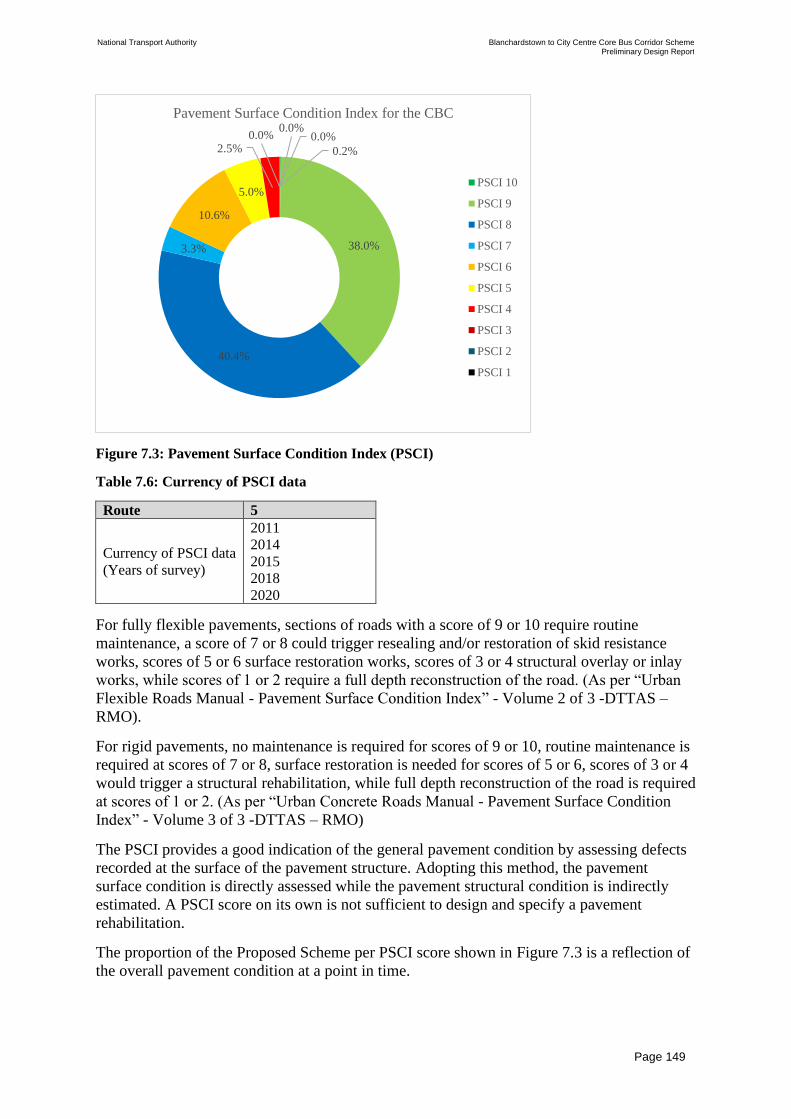
National Transport Authority Blanchardstown to City Centre Core Bus Corridor Scheme Preliminary Design Report
| Issue | 7 May 2022
\\GLOBAL\EUROPE\DUBLIN\JOBS\268000\268401-00\4. INTERNAL\4-04 REPORTS\4-04-03 INFRASTRUCTURE\PRELIMINARY DESIGN REPORT\CBC 5\ISSUE MAY 2022\BCIDC-ARP-PMG_PD-
0005_XX_00-RP-ZZ-0001_ISSUE.DOCX
Page 149
Figure 7.3: Pavement Surface Condition Index (PSCI)
Table 7.6: Currency of PSCI data
Route 5
Currency of PSCI data
(Years of survey)
2011
2014
2015
2018
2020
For fully flexible pavements, sections of roads with a score of 9 or 10 require routine
maintenance, a score of 7 or 8 could trigger resealing and/or restoration of skid resistance
works, scores of 5 or 6 surface restoration works, scores of 3 or 4 structural overlay or inlay
works, while scores of 1 or 2 require a full depth reconstruction of the road. (As per “Urban
Flexible Roads Manual - Pavement Surface Condition Index” - Volume 2 of 3 -DTTAS –
RMO).
For rigid pavements, no maintenance is required for scores of 9 or 10, routine maintenance is
required at scores of 7 or 8, surface restoration is needed for scores of 5 or 6, scores of 3 or 4
would trigger a structural rehabilitation, while full depth reconstruction of the road is required
at scores of 1 or 2. (As per “Urban Concrete Roads Manual - Pavement Surface Condition
Index” - Volume 3 of 3 -DTTAS – RMO)
The PSCI provides a good indication of the general pavement condition by assessing defects
recorded at the surface of the pavement structure. Adopting this method, the pavement
surface condition is directly assessed while the pavement structural condition is indirectly
estimated. A PSCI score on its own is not sufficient to design and specify a pavement
rehabilitation.
The proportion of the Proposed Scheme per PSCI score shown in Figure 7.3 is a reflection of
the overall pavement condition at a point in time.
0.2%
38.0%
40.4%
3.3%
10.6%
5.0%
2.5%0.0%
0.0%0.0%
Pavement Surface Condition Index for the CBC
PSCI 10
PSCI 9
PSCI 8
PSCI 7
PSCI 6
PSCI 5
PSCI 4
PSCI 3
PSCI 2
PSCI 1

National Transport Authority Blanchardstown to City Centre Core Bus Corridor Scheme Preliminary Design Report
| Issue | 7 May 2022
\\GLOBAL\EUROPE\DUBLIN\JOBS\268000\268401-00\4. INTERNAL\4-04 REPORTS\4-04-03 INFRASTRUCTURE\PRELIMINARY DESIGN REPORT\CBC 5\ISSUE MAY 2022\BCIDC-ARP-PMG_PD-
0005_XX_00-RP-ZZ-0001_ISSUE.DOCX
Page 150
The percentages are expected to remain constant over the following years, as long as the
Local Authorities’ pavement maintenance strategies remain unchanged. The geographical
distribution of sections with various PSCI will evolve between now and the commencement
of the Proposed Scheme. This is because pavement assets deteriorate over time and the Local
Authorities have already and are expected to continue maintenance of those roads in the
interim period.
The other pavement condition indicators are as noted in Figure 7.4.
Figure 7.4: Pavement Condition through five Pavement Indicators Pavement Surface
Condition:
Both the SCRIM and texture depth indicators reflect the skid resistance of the pavement
when a road user brakes or turns. On one hand, the SCRIM indicator measures the skid
resistance provided by the micro-texture of the pavement surface and is a proxy for skid

National Transport Authority Blanchardstown to City Centre Core Bus Corridor Scheme Preliminary Design Report
| Issue | 7 May 2022
\\GLOBAL\EUROPE\DUBLIN\JOBS\268000\268401-00\4. INTERNAL\4-04 REPORTS\4-04-03 INFRASTRUCTURE\PRELIMINARY DESIGN REPORT\CBC 5\ISSUE MAY 2022\BCIDC-ARP-PMG_PD-
0005_XX_00-RP-ZZ-0001_ISSUE.DOCX
Page 151
resistance at low speed and/or in dry weather conditions. On the other hand, the texture depth
indicator is a direct measurement of the macro-texture of the pavement surface and is a proxy
for skid resistance at higher speeds and/or in wet weather conditions.
30% of the Proposed Scheme is in a poor to very poor condition while more than 55% of the
Proposed Scheme is in a fair or worse SCRIM condition.
In terms of texture depth, at least 45% of the Proposed Scheme is in a fair or worse condition.
Poor skid resistance of the pavement surface may become an issue for vulnerable road users
such as pedestrians and cyclists, especially where motorised and non-motorised traffic
interact.
The rut depth indicator is showing that about 90% of the Proposed Scheme is in good or very
good condition. From a pavement surface perspective, this is positive as little to no
transversal surface irregularities are expected and little to no water is expected to be ponding
in the ruts.
Pavement Structural Condition:
The structural condition of the pavement can only be reported on and assessed from indirect
condition indicators taken from the surface of the pavement: rut depth, International
Roughness Index (IRI) and Longitudinal Profile Variance (LPV).
The rut depth being at approximately 90% in the good or very good categories, thus no
structural issue can be identified through this indicator. It does not however mean that there
are no structural issues.
Both the IRI and LPV indicators are a reflection of the ride quality of the road, in other
words, how smooth the road surface is. Those indicators are in most part influenced by
surface defects such as potholes, large cracks or networks of cracks, open joints, poor or
failing reinstatements, depression that can originate from the surface or the pavement
structure below. Features like gullies, manhole covers or other ironworks and if not filtered
out of the survey data, ramps, can also influence the IRI and LPV indicators.
Where high levels of profile variance are observed over long sections of road, it is likely for
structural failure to have occurred.
Less than 20% of the Proposed Scheme is displaying poor or very poor LPV condition while
less than 30% of the Proposed Scheme is displaying poor or very poor IRI condition.
Every effort should be made to address, at the source, all structural failures along the
Proposed Scheme in order to guarantee a high-quality ride for all bus passengers, cyclists and
other road users.
Subgrade Condition:
Whatever the network, no information about the subgrade is made available in terms of
bearing capacity (California Bearing Ratio – CBR).
The foundation for all widening and full depth reconstruction pavement structures is designed
on the assumption that the Design CBR is the minimum permitted in Clause 3.23 of DN-
PAV-03021 (Dec. 2010): 2.5%.

National Transport Authority Blanchardstown to City Centre Core Bus Corridor Scheme Preliminary Design Report
| Issue | 7 May 2022
\\GLOBAL\EUROPE\DUBLIN\JOBS\268000\268401-00\4. INTERNAL\4-04 REPORTS\4-04-03 INFRASTRUCTURE\PRELIMINARY DESIGN REPORT\CBC 5\ISSUE MAY 2022\BCIDC-ARP-PMG_PD-
0005_XX_00-RP-ZZ-0001_ISSUE.DOCX
Page 152
Additional condition data is expected to become available at Specimen Design stage in the
form of core logs taken as part of the GPR survey (Ground Penetrating Survey).
The delivery of the Proposed Scheme is expected to commence in 2022/2023. The condition
of all pavements is therefore expected to change, deteriorate in most cases and improve
where Local Authorities’ interventions occur.
7.1.2.3.3 Required Complementary Surveys
Additional condition data requirements, including surveys, will be required both at Specimen
Design and Detailed Design stages in order to develop and implement Pavement
Rehabilitation strategies. Those requirements shall be in line with AM-PAV-06050 (Mar.
2020).
7.1.3 Pavement Design
7.1.3.1 Pavement Materials
At Specimen Design stage, the selection of appropriate pavement materials will be made with
the following considerations:
• Which pavement structure is the most appropriate and compatible with the existing
pavement? (i.e. Fully flexible vs. Flexible Composite vs. Rigid pavement);
• Which materials are most appropriate from a noise, permeability, colour, texture, etc.
perspective?; and
• Which materials, from a lifecycle perspective, provide the best value in terms of
environmental impact, durability, maintainability, repairability, recyclability, cost, etc.?
Specific materials will be selected for specific loading areas.
Where pavement material is excavated, it is envisaged that the contractor will seek to reuse or
recycle it, where practicable, within the Proposed Scheme.
The choice of surfacing materials will be discussed with the Landscape Architect.
7.1.3.2 Pavement Strategy
7.1.3.2.1 New Pavement and Bus Interchange Strategy
A Bus Interchange is proposed at the Blanchardstown shopping centre (N3 junction 3). Such
location will be trafficked by a large volume of buses. Slow moving, stationary, vibrating and
manoeuvring buses are extremely damaging to both the pavement surface and the pavement
structure.
Fully flexible (bituminous mixtures) and flexible composite (bituminous mixtures on a
hydraulically bound base) pavement structure are unlikely to provide a durable and low
maintenance option for this location. It is therefore proposed for the pavement to be rigid
(concrete) at that location.
Rigid pavements do not rut, are highly resistant to scuffing and oil dropping, requiring
limited maintenance (e.g. joints).

National Transport Authority Blanchardstown to City Centre Core Bus Corridor Scheme Preliminary Design Report
| Issue | 7 May 2022
\\GLOBAL\EUROPE\DUBLIN\JOBS\268000\268401-00\4. INTERNAL\4-04 REPORTS\4-04-03 INFRASTRUCTURE\PRELIMINARY DESIGN REPORT\CBC 5\ISSUE MAY 2022\BCIDC-ARP-PMG_PD-
0005_XX_00-RP-ZZ-0001_ISSUE.DOCX
Page 153
A new section of carriageway is proposed on the east side of the N3/M50 interchange. This
new road is a bus lane linking the interchange roundabout to Navan Road eastbound.
Providing that the pavement structure of the existing link between the interchange roundabout
and the R147 is suitable for the forecasted bus traffic, it is anticipated that the pavement
structure of the new road will be of similar depth and make-up.
7.1.3.2.2 Pavement Rehabilitation Strategy
At Specimen Design stage, different pavement strategies will be developed for:
• Areas to be widened or fully reconstructed
• Areas to be rehabilitated (do minimum, intermediary strategies, fully reconstruct)
Additional testing requirements in line with AM-PAV-06050 will be specified to complete
the Pavement Design.
The risk of tar contaminated material presence in the existing pavement is expected to be
mitigated at Specimen Design stage with the delivery of the GPR survey through the testing
of the calibrating cores for tar.
In order to estimate the waste quantities and the carbon emissions from the Proposed Scheme
pavement works, the following assumptions were made:
• Where full depth reconstruction is anticipated (e.g. widening, traffic island relocation…),
a conservative fully flexible pavement design is assumed: 350mm of bituminous mixtures
on top of 150mm of subbase material and 400mm of capping material;
• Where the existing pavement is anticipated to only require rehabilitation, the assumed
materials and associated depths depend on the PSCI for the pavement design:
• Fully Flexible Carriageway;
• PSCI ≥ 7: no works;
• PSCI = 5 or 6: 50mm Bituminous Inlay;
• PSCI = 3 or 4: 200mm Bituminous Inlay;
• PSCI = 1 or 2: 350mm Bituminous Inlay + 150mm Subbase Inlay + 400mm Capping
Inlay;
• Rigid Carriageway;
• PSCI ≥ 5: no works; and
• PSCI ≤ 4: 200mm Concrete Inlay.
7.1.3.3 Opportunities for Innovation
Innovative materials and processes delivering enhanced environmental, social and financial
benefits are being promoted in the ongoing pavement design process.
7.1.3.4 Reuse and Recycling Considerations
Opportunities for reuse and recycling of secondary materials have and will continue to be
identified and quantified throughout the Specimen Design process.
Current opportunities include but are not limited to:

National Transport Authority Blanchardstown to City Centre Core Bus Corridor Scheme Preliminary Design Report
| Issue | 7 May 2022
\\GLOBAL\EUROPE\DUBLIN\JOBS\268000\268401-00\4. INTERNAL\4-04 REPORTS\4-04-03 INFRASTRUCTURE\PRELIMINARY DESIGN REPORT\CBC 5\ISSUE MAY 2022\BCIDC-ARP-PMG_PD-
0005_XX_00-RP-ZZ-0001_ISSUE.DOCX
Page 154
• Incorporation of minimum 20% of Reclaimed Asphalt into new base and binder layers of
the pavement;
• Excavated capping layer material to be reused as new capping material if compliant with
current standards; and
• Excavated subbase layer material to be reused as new subbase material if compliant with
current standards.
7.2 Kerbs, Footways and Paved Areas
7.2.1 Overview of Kerbs, Footways and Paved Areas
This section covers the preliminary design for the kerbs, footways and paved areas (KFPA)
assets:
• Kerbs;
• Footways (concrete, bituminous and paved); and
• Cycle tracks.
For the Proposed Scheme, two pavement networks are being considered, the primary and the
secondary networks. The primary network refers to the bus corridor under consideration
while the secondary network refers to the roads impacted by the re-routing of existing traffic
from the Proposed Scheme to the nearby road network.
The preliminary design of KFPA assets is based on the following standards:
• DN-PAV-03021 (Dec. 2010) – Pavement and Foundation Design;
• DN-PAV-03026 (Jan. 2005) – Footway Design;
• Construction Standards for Road and Street Works in Dublin City Council (May 2016) –
Revision 1;
• PE-SMG-02002 (Dec. 2010) – Traffic Assessment;
• CC-SPW-00600 (Mar. 2013) – Specification for Road Works Series 600 – Earthworks;
• CC-SPW-00700 (Jan. 2016) – Specification for Road Works Series 700 – Road
Pavements – General;
• CC-SPW-00800 (Mar. 2013) – Specification for Road Works Series 800 – Road
Pavements – Unbound and Cement Bound Mixtures;
• CC-SPW-00900 (Sep. 2017) – Specification for Road Works Series 900 – Road
Pavements – Bituminous Materials;
• CC-SPW-01000 (Mar. 2013) – Specification for Road Works Series 1000 – Road
Pavements – Concrete Materials;
• CC-SPW-01100 (Feb. 2012) – Specification for Road Works Series 1100 – Kerbs,
Footways and Paved Areas; and
• BS 7533 series of standards (1999 – 2021) – Pavement Constructed with Clay, Natural
Stone or Concrete Pavers;

National Transport Authority Blanchardstown to City Centre Core Bus Corridor Scheme Preliminary Design Report
| Issue | 7 May 2022
\\GLOBAL\EUROPE\DUBLIN\JOBS\268000\268401-00\4. INTERNAL\4-04 REPORTS\4-04-03 INFRASTRUCTURE\PRELIMINARY DESIGN REPORT\CBC 5\ISSUE MAY 2022\BCIDC-ARP-PMG_PD-
0005_XX_00-RP-ZZ-0001_ISSUE.DOCX
Page 155
This section identifies the proposed pavement strategy, setting out the design development
considerations for the pavement works in current and future design stages. It also outlines the
key elements for consideration for future testing requirements, and consideration for the
valorisation of reusable and recyclable materials in new pavement materials in the detailed
design stage.
This section should be read in conjunction with the Pavement Treatment Plans in Appendix
B.
The different KFPA assets are designed taking consideration of:
• Traffic loads;
• Changes in road geometry;
• Existing KFPA construction build-up;
• Existing KFPA condition;
• Landscape Architect’s requirements; and
• The impact of other assets such as drainage, utilities and structures.
7.2.2 Design Constraints
7.2.2.1 Traffic Loading Considerations
Depending on the expected traffic characteristics (volumes, pedestrian vs. vehicular) and the
proposed surface material, the Design Traffic may be categorised slightly differently as
illustrated in Figure 7.5.
For bituminous footways and cycle tracks, the Design Traffic will be calculated in
accordance with PE-SMG-02002 (Dec. 2010) and categorised as per DN-PAV-03026 (Jan.
2005), if the Design Traffic is below 50,000 standard axles over their lifetime (40 years).
For concrete footways, the Design Traffic will be calculated in accordance with PE-SMG-
02002 (Dec. 2010) for a 40-year design life.
And for paved footways, the Design Traffic will be calculated in accordance with PE-SMG-
02002 (Dec. 2010) and categorised as per BS 7533 series.

National Transport Authority Blanchardstown to City Centre Core Bus Corridor Scheme Preliminary Design Report
| Issue | 7 May 2022
\\GLOBAL\EUROPE\DUBLIN\JOBS\268000\268401-00\4. INTERNAL\4-04 REPORTS\4-04-03 INFRASTRUCTURE\PRELIMINARY DESIGN REPORT\CBC 5\ISSUE MAY 2022\BCIDC-ARP-PMG_PD-
0005_XX_00-RP-ZZ-0001_ISSUE.DOCX
Page 156
Figure 7.5: Traffic Design and Categorisation for KFPA
7.2.2.2 Geometry Considerations
At Specimen Design stage, the 3D geometry model will be further analysed to identify
footways and cycle tracks requiring full depth reconstruction and those that can be
maintained in place.
The current assumption for footpaths and cycle tracks is for full depth reconstruction.
7.2.2.3 Existing Pavement Condition Considerations
For the footways and cycle tracks that will be fully reconstructed, the design of the
foundation will be based on an assumed Design CBR of 2.5%, the minimum permitted value
as per Clause 3.23 of DN-PAV-03021 (Dec. 2010).
If some existing footways and cycle tracks are proposed to be maintained, their condition will
be assessed visually before proposing any potential rehabilitation works.
7.2.3 Pavement Design
7.2.3.1 Pavement Materials
At Specimen Design stage, the selection of appropriate pavement materials will be
undertaken with the following considerations:
• Which pavement structure is the most appropriate and compatible with the existing
pavement? (i.e. Fully flexible vs. Rigid pavement structure)

National Transport Authority Blanchardstown to City Centre Core Bus Corridor Scheme Preliminary Design Report
| Issue | 7 May 2022
\\GLOBAL\EUROPE\DUBLIN\JOBS\268000\268401-00\4. INTERNAL\4-04 REPORTS\4-04-03 INFRASTRUCTURE\PRELIMINARY DESIGN REPORT\CBC 5\ISSUE MAY 2022\BCIDC-ARP-PMG_PD-
0005_XX_00-RP-ZZ-0001_ISSUE.DOCX
Page 157
• Which materials are most appropriate from a noise, permeability, colour, texture, etc.
perspective?
• Which materials, from a lifecycle perspective, provide the best value in terms of
environmental impact, durability, maintainability, repairability, recyclability, cost, etc.?
Specific materials will be selected for specific loading areas.
The ambition in terms of pavement materials is to reuse or recycle all of the excavated
materials. The specification of materials and processes with a reduced environmental impact
will be prioritised.
The Landscape Architect’s design will be considered at Specimen Design stage to identify
the choice of surfacing materials which will in turn dictate the choice of materials used for
the underlying footway and cycle track structure.
For bituminous footways and cycle tracks, the bituminous layer(s) could make use of as
much recycled material as practicable. Low Energy Bound Mixtures (LEBM) will be
considered as an alternative to the conventional Asphalt Concrete (AC), Hot Rolled Asphalt
(HRA) and Stone Mastic Asphalt (SMA) mixtures.
As per Section 5.5 of the BCPDGB, in order to provide a visual differentiation between the
carriageway and cycle tracks and cycle lanes, it is proposed that all cycle tracks and cycle
lanes are to have red coloured epoxy resin type surfacing, or red coloured HRA, or similar in
accordance with the National Cycle Manual.
7.2.3.2 Pavement Structures
The appropriate pavement structures for footways and cycle tracks will be defined at
Specimen Design stage.
7.2.3.3 Opportunities for Innovation
Innovative materials and processes delivering enhanced environmental, social and financial
benefits are being promoted in the ongoing pavement design process.
7.2.3.4 Reuse and Recycling Considerations
Opportunities for reuse and recycling of secondary materials have and will continue to be
identified and quantified throughout the Specimen Design process.
Current opportunities include but are not limited to:
• Excavated capping layer material could be reused as new capping material if compliant
with current standards;
• Excavated subbase layer material could be reused as new subbase material if compliant
with current standards;
• Up to 50% of capping and subbase materials could be substituted with Reclaimed
Asphalt;
• Concrete base to paved areas could make use of Recycled Aggregate, Recycled Concrete
Aggregate and more sustainable hydraulic binders (e.g. CEM III/A);

National Transport Authority Blanchardstown to City Centre Core Bus Corridor Scheme Preliminary Design Report
| Issue | 7 May 2022
\\GLOBAL\EUROPE\DUBLIN\JOBS\268000\268401-00\4. INTERNAL\4-04 REPORTS\4-04-03 INFRASTRUCTURE\PRELIMINARY DESIGN REPORT\CBC 5\ISSUE MAY 2022\BCIDC-ARP-PMG_PD-
0005_XX_00-RP-ZZ-0001_ISSUE.DOCX
Page 158
• Concrete footways could also make use of more sustainable hydraulic binders;
• Jointing and bedding mortars used in the construction of paved areas could contain
recycled materials; and
• Aggregate for base/binder layer for cycle tracks could be 100% Reclaimed Asphalt (Low
Energy Bound Material – LEBM).

National Transport Authority Blanchardstown to City Centre Core Bus Corridor Scheme Preliminary Design Report
| Issue | 7 May 2022
\\GLOBAL\EUROPE\DUBLIN\JOBS\268000\268401-00\4. INTERNAL\4-04 REPORTS\4-04-03 INFRASTRUCTURE\PRELIMINARY DESIGN REPORT\CBC 5\ISSUE MAY 2022\BCIDC-ARP-PMG_PD-
0005_XX_00-RP-ZZ-0001_ISSUE.DOCX
Page 159
8 Structures
8.1 Overview of Structures Strategy
The Proposed Scheme impacts on a number of existing structures and also requires new
structures at various locations along the Proposed Scheme. The sections below summarises
where existing structures are impacted and where new structures are required.
A separate Preliminary Design Report for the structures has been prepared, following the
guidance set out in TII publication DN-STR-03001 (Technical Acceptance of Road
Structures on Motorways and Other National Roads). These are included in Appendix J of
this report.
8.2 Summary of Existing Structures
Table 8.1 below lists the existing structures along the Proposed Scheme and identifies those
that are being impacted. Refer to the Existing Structures Impact Assessment Report in
Appendix F for further details.
Table 8.1: Summary of Existing Structures
Structure
Ref.
Structure
Type
Name/
Description Jurisdiction Impact
5.01 Retaining
Wall
N3 Junction 3
Southbound off-
slip - retaining
wall at ESB
pylon.
FCC No impact
5.02 Bridge N3 - R121
Overbridge FCC No impact
5.03 Retaining
Wall
Retaining wall
between northern
edge of R121 and
Whitestown estate
FCC Structure
impacted
5.04 Embank-
ment
Embankment to
the N3 from the
L3020
Blanchardstown
FCC Structure
impacted
5.05
Embank-
ment &
Retaining
Wall
Embankment and
retaining wall
adjacent to the
L3020 at the Ebay
building
FCC Structure
impacted

National Transport Authority Blanchardstown to City Centre Core Bus Corridor Scheme Preliminary Design Report
| Issue | 7 May 2022
\\GLOBAL\EUROPE\DUBLIN\JOBS\268000\268401-00\4. INTERNAL\4-04 REPORTS\4-04-03 INFRASTRUCTURE\PRELIMINARY DESIGN REPORT\CBC 5\ISSUE MAY 2022\BCIDC-ARP-PMG_PD-
0005_XX_00-RP-ZZ-0001_ISSUE.DOCX
Page 160
Structure
Ref.
Structure
Type
Name/
Description Jurisdiction Impact
5.06 Pedestrian
Underpass
Pedestrian
underpass under
N3 and
westbound N3
offramp
FCC No impact
5.07 Culvert Tolka River
Culvert under N3 FCC
Structure
impacted
5.08 Cantilever
Gantry Navan Road N3 FCC
Structure
impacted
5.09 Portal
Gantry
Navan Road N3
Gantry SG-057 FCC
Structure
impacted
5.10 Culvert
Tolka River
Culvert under N3
(James Connolly
Bridge
FCC No impact
5.11 Bridge Mill Road Bridge FCC Structure
impacted
5.12 Portal
Gantry
Navan Road N3
Gantry SG-059 FCC
Structure
impacted
5.13 Retaining
Wall
Retaining wall at
N3 eastbound off-
slip (adjacent to
Connolly
Hospital)
FCC No impact
5.14 Bridge
Bridge over Tolka
River at Connolly
Hospital access
FCC No impact
5.15 Retaining
Wall
Retaining wall at
N3 eastbound off-
slip
FCC Structure
impacted
5.16 Bridge N3 Overbridge at
eastbound off-slip FCC
Structure
impacted

National Transport Authority Blanchardstown to City Centre Core Bus Corridor Scheme Preliminary Design Report
| Issue | 7 May 2022
\\GLOBAL\EUROPE\DUBLIN\JOBS\268000\268401-00\4. INTERNAL\4-04 REPORTS\4-04-03 INFRASTRUCTURE\PRELIMINARY DESIGN REPORT\CBC 5\ISSUE MAY 2022\BCIDC-ARP-PMG_PD-
0005_XX_00-RP-ZZ-0001_ISSUE.DOCX
Page 161
Structure
Ref.
Structure
Type
Name/
Description Jurisdiction Impact
5.17 Retaining
Wall
Retaining wall
between
northbound and
southbound
carriageway
FCC Structure
impacted
5.18 Bridge
N3 outbound -
M50 interchange -
Royal Canal
Bridge
FCC No impact
5.19 Bridge
N3 outbound -
M50 interchange -
M50 Bridge
FCC No impact
5.20 Bridge
N3 inbound -
M50 interchange -
M50 Bridge
FCC No impact
5.21 Bridge
N3 inbound -
M50 interchange -
Royal Canal
Bridge
FCC No impact
5.22 Bridge M50 interchange,
Bridge over N3 FCC No impact
5.23 Bridge M50 interchange
Bridge FCC
Structure
impacted
5.24 Portal
Gantry
Navan Road N3
Gantry SG-060 FCC No impact
5.25 Portal
Gantry
Navan Road N3
Gantry SG-061 FCC
Structure
impacted
5.26 Portal
Gantry
Navan Road R147
Gantry SG-062 FCC
Structure
impacted
5.27 Bridge Bridge- Ashtown
Train Station FCC No impact

National Transport Authority Blanchardstown to City Centre Core Bus Corridor Scheme Preliminary Design Report
| Issue | 7 May 2022
\\GLOBAL\EUROPE\DUBLIN\JOBS\268000\268401-00\4. INTERNAL\4-04 REPORTS\4-04-03 INFRASTRUCTURE\PRELIMINARY DESIGN REPORT\CBC 5\ISSUE MAY 2022\BCIDC-ARP-PMG_PD-
0005_XX_00-RP-ZZ-0001_ISSUE.DOCX
Page 162
Structure
Ref.
Structure
Type
Name/
Description Jurisdiction Impact
5.28 Portal
Gantry
Navan Road R147
Gantry SG-063 FCC
Structure
impacted
5.29 Bridge
R805 Old Cabra
Road - Railway
Bridge
Irish Rail No impact
5.30 Retaining
Wall
Retaining wall to
low courtyard, 42
Manor Street
Private No impact
5.31 Retaining
Wall
Retaining wall to
low courtyard,
32-37 Manor
Street
Private No impact
5.32 Retaining
Wall
Retaining wall to
low courtyard,
Blackhall Court
Private No impact
5.33 Retaining
Wall
Retaining wall to
low courtyard,
69-70 Queen
Street
Private No impact
5.34 Retaining
Wall
Retaining wall to
low courtyard,
72a Queen Street
Private No Impact
5.35 Retaining
Wall
Retaining wall to
Phoenix Industrial
Park / Gowan
Motors Retail
Group
Private No impact
5.36 Retaining
Wall
Retaining wall to
Ashtown Gate Private No impact
5.37 Retaining
Wall
Retaining wall
between 1-5
Herbert Road and
N3 westbound
carriageway
Private /
FCC No impact

National Transport Authority Blanchardstown to City Centre Core Bus Corridor Scheme Preliminary Design Report
| Issue | 7 May 2022
\\GLOBAL\EUROPE\DUBLIN\JOBS\268000\268401-00\4. INTERNAL\4-04 REPORTS\4-04-03 INFRASTRUCTURE\PRELIMINARY DESIGN REPORT\CBC 5\ISSUE MAY 2022\BCIDC-ARP-PMG_PD-
0005_XX_00-RP-ZZ-0001_ISSUE.DOCX
Page 163
8.3 Summary of Principal Structures
Principal Structures are defined as those that require technical approval following the
processes outlined in TII Publication DN-STR-03001.
8.3.1 Bridges and Bridge Sized Culverts
There are two existing bridge structures impacted by this Proposed Scheme. Both require
widening as a result of the proposed carriageway works;
Figure 8.1 indicates the structure locations.
Figure 8.1: Bridge & Bridge sized culvert Locations
8.3.2 Existing Tolka River Bridge (FG-N03-008.00) to be widened:
The existing bridge is located at the northern crossing of the Tolka River beneath the N3
(Alignment A, Ch 1110.00m). The structure comprises a corrugated steel arch culvert, which
has subsequently been widened using precast concrete girders. The proposed widening of the
N3 to accommodate the Proposed Scheme requires this bridge to be widened further at its
southern end. A similar approach is proposed, whereby the bridge will be widened by
approximately 2 m using TYE beams and a cast in-situ deck slab. The abutments will be
extended to suit.
Refer to the Preliminary Design Report - Tolka River Bridge in Appendix J for further
information.

National Transport Authority Blanchardstown to City Centre Core Bus Corridor Scheme Preliminary Design Report
| Issue | 7 May 2022
\\GLOBAL\EUROPE\DUBLIN\JOBS\268000\268401-00\4. INTERNAL\4-04 REPORTS\4-04-03 INFRASTRUCTURE\PRELIMINARY DESIGN REPORT\CBC 5\ISSUE MAY 2022\BCIDC-ARP-PMG_PD-
0005_XX_00-RP-ZZ-0001_ISSUE.DOCX
Page 164
8.3.3 Existing Mill Road Bridge (FG-N03-010.00) to be widened
Twin bridges carry the eastbound and westbound carriageways of the N3 over Mill Road at
this location (Alignment A, Ch 1605.00m). The bridge requires widening to accommodate
works associated with the Proposed Scheme.
The existing bridge will be widened along both its southern and northern sides as well as
closing up of the opening within the central median. It is proposed to extend the structure
using a cast in-situ arrangement, similar in form to the existing structure.
Refer to the Preliminary Design Report – Mill Road Bridge in Appendix J for further
information.
8.3.4 Retaining Walls
Retaining walls with a retained height greater than 1.5 m are classed as principal structures
and are summarised in Figure 8.2 and described within Table 8.2.
Figure 8.2: Retaining wall locations

National Transport Authority Blanchardstown to City Centre Core Bus Corridor Scheme Preliminary Design Report
| Issue | 7 May 2022
\\GLOBAL\EUROPE\DUBLIN\JOBS\268000\268401-00\4. INTERNAL\4-04 REPORTS\4-04-03 INFRASTRUCTURE\PRELIMINARY DESIGN REPORT\CBC 5\ISSUE MAY 2022\BCIDC-ARP-PMG_PD-
0005_XX_00-RP-ZZ-0001_ISSUE.DOCX
Page 165
Table 8.2: Summary of Principal Retaining Walls
Ref. Structure Type Chainage Start -
Chainage End (m)
Length
(m)
Max
Retained
Height
(m)
Comment
N3 Blanchardstown Junction to Snugborough Road
RW01 Spreadfoot
cantilever wall
Blanchardstown
Road South Ch
453.00 to
Alignment A – Ch
40.00
270 m 3.0 m Retains vegetated
berm adjacent
Blanchardstown
Road South.
Snugborough Road to N3 / M50 Junction
RW07-
A
Spreadfoot
cantilever wall
Alignment A Ch
1604.00m – 1653.00
100 m 1.5 m To service bus
stop on southern
side of N3.
Includes ramp and
stair access.
RW07-
B
Spreadfoot
cantilever wall
Alignment A Ch
1540.00-1609.00
250 m 3.0 m To service bus
stop on northern
side of N3.
Includes ramp and
stair access.
RW09 Spreadfoot
cantilever wall
Alignment A Ch
2219.00-Ch 2305.00
90 m 4.0 m Retains N3
embankment
adjacent Junction
6 Castleknock
health & leisure
village.
N3 / M50 Junction to Navan Road / Ashtown Road Junction
RW03 Soil nail wall Alignment A Ch
2926.00m-Ch
3027.00
100 m 4.0 m Retain cut slope
to accommodate
widening for bus
stop.
These walls range from 1.5 m in retained height up to approximately 4.0 m. Refer to the
Preliminary Design Report – Retaining Walls in Appendix J for further information
8.3.5 Sign Gantries
There are a number of existing gantries being impacted along the Proposed Scheme, as well
as two new gantries required. Refer to Figure 8.3 and Table 8.3 which identifies the various
gantries along the Proposed Scheme.
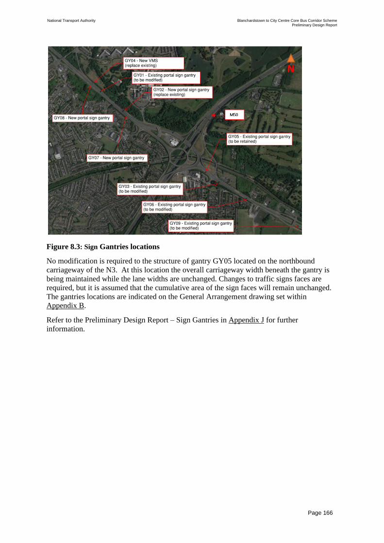
National Transport Authority Blanchardstown to City Centre Core Bus Corridor Scheme Preliminary Design Report
| Issue | 7 May 2022
\\GLOBAL\EUROPE\DUBLIN\JOBS\268000\268401-00\4. INTERNAL\4-04 REPORTS\4-04-03 INFRASTRUCTURE\PRELIMINARY DESIGN REPORT\CBC 5\ISSUE MAY 2022\BCIDC-ARP-PMG_PD-
0005_XX_00-RP-ZZ-0001_ISSUE.DOCX
Page 166
Figure 8.3: Sign Gantries locations
No modification is required to the structure of gantry GY05 located on the northbound
carriageway of the N3. At this location the overall carriageway width beneath the gantry is
being maintained while the lane widths are unchanged. Changes to traffic signs faces are
required, but it is assumed that the cumulative area of the sign faces will remain unchanged.
The gantries locations are indicated on the General Arrangement drawing set within
Appendix B.
Refer to the Preliminary Design Report – Sign Gantries in Appendix J for further
information.

National Transport Authority Blanchardstown to City Centre Core Bus Corridor Scheme Preliminary Design Report
| Issue | 7 May 2022
\\GLOBAL\EUROPE\DUBLIN\JOBS\268000\268401-00\4. INTERNAL\4-04 REPORTS\4-04-03 INFRASTRUCTURE\PRELIMINARY DESIGN REPORT\CBC 5\ISSUE MAY 2022\BCIDC-ARP-PMG_PD-
0005_XX_00-RP-ZZ-0001_ISSUE.DOCX
Page 167
Table 8.3: Summary of Sign Gantries
Ref. Gantry Type Existing / New Chainage (m) Carriageway &
Span Length
Snugborough Road to N3 / M50 Junction
GY01 Group 6 Sign
Gantry
Modify/Replace
existing
Alignment A Ch
1439.00
N3 Eastbound –
19.0 m
GY02 Group 6 Sign
Gantry
Replace existing Existing location
Alignment A Ch
1745.00
Proposed location
Alignment A Ch
1799.00
N3 Eastbound –
23.3 m
GY04 VMS Replace existing Alignment A Ch
1316.00
N3 Eastbound –
9.5 m
GY07 Group 6 Sign
Gantry
New Alignment A Ch
1765.00
N3 Westbound –
22.4 m
GY08 Group 6 Sign
Gantry
New Alignment A Ch
1311.00
N3 Westbound –
20.8 m
N3 / M50 Junction to Navan Road / Ashtown Road Junction
GY05 Group 6 Sign
Gantry
Existing – retain Alignment A Ch
2818.00
N3 Westbound –
21.6 m
GY03 Group 6 Sign
Gantry
Modify/Replace
existing
Alignment A Ch
2988.00
R147 Outbound –
22.6 m
GY06 Group 6 Sign
Gantry
Modify/Replace
existing
Alignment A Ch
3316.00
R147 Outbound –
18.1 m
GY09 Group 6 Sign
Gantry
Modify/Replace
existing
Alignment A Ch
3916.00
R147 Outbound –
20.0 m
8.4 Summary of Miscellaneous Structures
8.4.1 Retaining Walls (<1.5m)
Figure 8.4 and Figure 8.5 indicate the locations of proposed retaining walls less than 1.5m
high. Further details about each retaining wall are summarised within Table 8.4. In addition, a
number of residential properties, where boundary walls are being relocated, are likely to
incorporate retention of private gardens / frontages.

National Transport Authority Blanchardstown to City Centre Core Bus Corridor Scheme Preliminary Design Report
| Issue | 7 May 2022
\\GLOBAL\EUROPE\DUBLIN\JOBS\268000\268401-00\4. INTERNAL\4-04 REPORTS\4-04-03 INFRASTRUCTURE\PRELIMINARY DESIGN REPORT\CBC 5\ISSUE MAY 2022\BCIDC-ARP-PMG_PD-
0005_XX_00-RP-ZZ-0001_ISSUE.DOCX
Page 168
Figure 8.4: Retaining Walls RW10 to RW18 <1.5m - locations
Figure 8.5: Retaining Wall RW19 to RW21 <1.5m - locations

National Transport Authority Blanchardstown to City Centre Core Bus Corridor Scheme Preliminary Design Report
| Issue | 7 May 2022
\\GLOBAL\EUROPE\DUBLIN\JOBS\268000\268401-00\4. INTERNAL\4-04 REPORTS\4-04-03 INFRASTRUCTURE\PRELIMINARY DESIGN REPORT\CBC 5\ISSUE MAY 2022\BCIDC-ARP-PMG_PD-
0005_XX_00-RP-ZZ-0001_ISSUE.DOCX
Page 169
Table 8.4: Summary of Retaining Walls <1.5m
Ref.
Location Chainage Start/
Chainage End
Length (m) Max Retained
Height (m)
N3 Blanchardstown Junction to Snugborough Road
RW10 Blanchardstown
Road South
adjacent to
Whitestown
Grove
Blanchardstown
Road South
Ch 304.00-
Ch 543.00
241 0.3
RW11 West of Crowne
Plaza Junction
Alignment A
Ch 140.00- Ch
156.00
16 0.3
RW12-1 Westbound
Approach to
Crowne Plaza
Junction
Alignment A
Ch 229.00 – Ch
255.00
27
0.5
RW 12-2 Alignment A
Ch 269.00 –
Ch 293.00
24
0.6
RW 12-3 Alignment A
Ch 302.00 –
Ch 326.00
25
0.6
RW 12-4 Alignment A
Ch 339.00 –
Ch375.00
36 0.4
RW 13 L3020 adjacent to
Ben Dunne Gym,
Blanchardstown,
Dublin, Ireland
Alignment A
Ch 703.00-
Ch 741.00
36 0.9
Snugborough Road to N3 / M50 Junction
RW 14 N3 eastbound
verge connecting
to Mill Road
Northern
Pedestrian Ramp
Alignment A
Ch 1475.00-Ch
1545.00
66 0.7
RW 15 N3 eastbound
verge at location
of proposed
overhead sign
gantry
Alignment A Ch
1793.00 – Ch.
1801.00
8 0.5
RW 16 N3 adjacent to 3
Catherine’s Well,
Old River Road
Alignment A
Ch 1854.00-
Ch 1880.00
26 0.4
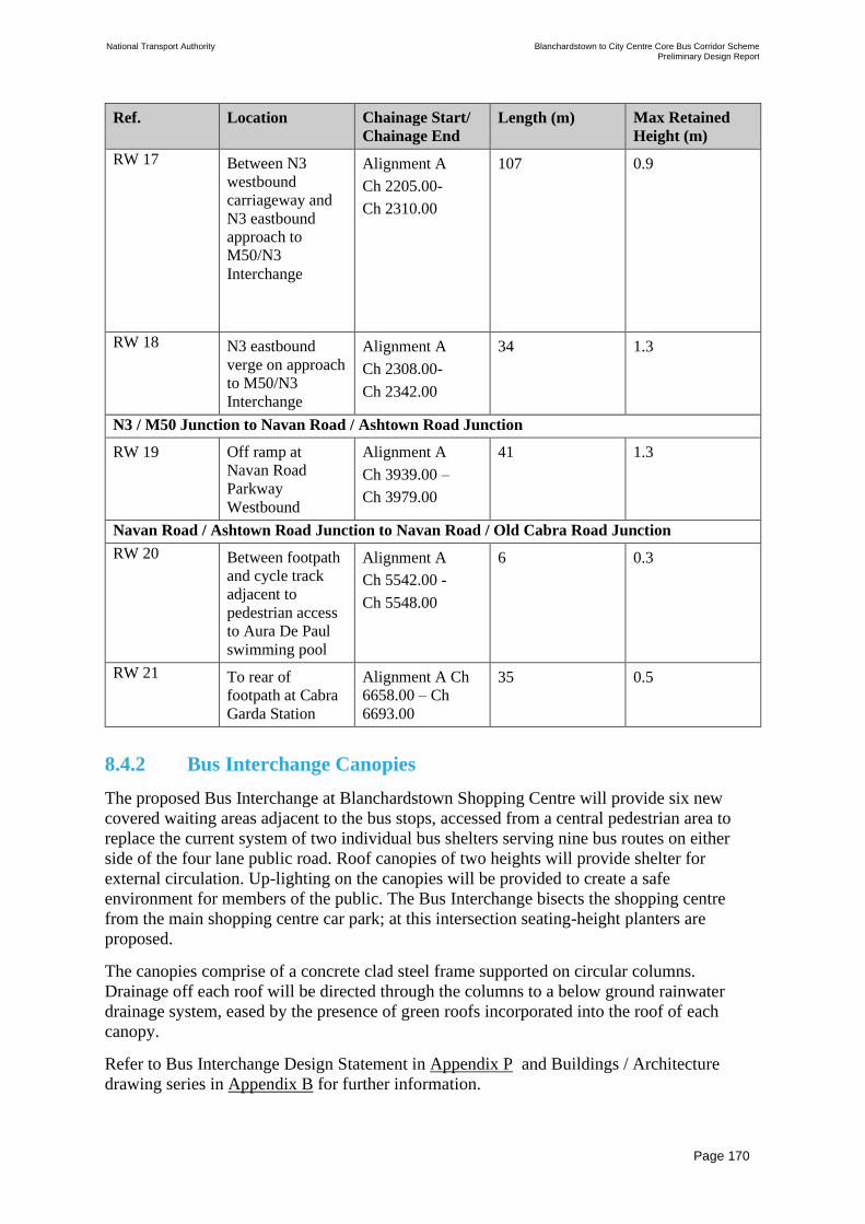
National Transport Authority Blanchardstown to City Centre Core Bus Corridor Scheme Preliminary Design Report
| Issue | 7 May 2022
\\GLOBAL\EUROPE\DUBLIN\JOBS\268000\268401-00\4. INTERNAL\4-04 REPORTS\4-04-03 INFRASTRUCTURE\PRELIMINARY DESIGN REPORT\CBC 5\ISSUE MAY 2022\BCIDC-ARP-PMG_PD-
0005_XX_00-RP-ZZ-0001_ISSUE.DOCX
Page 170
Ref.
Location Chainage Start/
Chainage End
Length (m) Max Retained
Height (m)
RW 17 Between N3
westbound
carriageway and
N3 eastbound
approach to
M50/N3
Interchange
Alignment A
Ch 2205.00-
Ch 2310.00
107 0.9
RW 18 N3 eastbound
verge on approach
to M50/N3
Interchange
Alignment A
Ch 2308.00-
Ch 2342.00
34 1.3
N3 / M50 Junction to Navan Road / Ashtown Road Junction
RW 19 Off ramp at
Navan Road
Parkway
Westbound
Alignment A
Ch 3939.00 –
Ch 3979.00
41 1.3
Navan Road / Ashtown Road Junction to Navan Road / Old Cabra Road Junction
RW 20 Between footpath
and cycle track
adjacent to
pedestrian access
to Aura De Paul
swimming pool
Alignment A
Ch 5542.00 -
Ch 5548.00
6 0.3
RW 21 To rear of
footpath at Cabra
Garda Station
Alignment A Ch
6658.00 – Ch
6693.00
35 0.5
8.4.2 Bus Interchange Canopies
The proposed Bus Interchange at Blanchardstown Shopping Centre will provide six new
covered waiting areas adjacent to the bus stops, accessed from a central pedestrian area to
replace the current system of two individual bus shelters serving nine bus routes on either
side of the four lane public road. Roof canopies of two heights will provide shelter for
external circulation. Up-lighting on the canopies will be provided to create a safe
environment for members of the public. The Bus Interchange bisects the shopping centre
from the main shopping centre car park; at this intersection seating-height planters are
proposed.
The canopies comprise of a concrete clad steel frame supported on circular columns.
Drainage off each roof will be directed through the columns to a below ground rainwater
drainage system, eased by the presence of green roofs incorporated into the roof of each
canopy.
Refer to Bus Interchange Design Statement in Appendix P and Buildings / Architecture
drawing series in Appendix B for further information.

National Transport Authority Blanchardstown to City Centre Core Bus Corridor Scheme Preliminary Design Report
| Issue | 7 May 2022
\\GLOBAL\EUROPE\DUBLIN\JOBS\268000\268401-00\4. INTERNAL\4-04 REPORTS\4-04-03 INFRASTRUCTURE\PRELIMINARY DESIGN REPORT\CBC 5\ISSUE MAY 2022\BCIDC-ARP-PMG_PD-
0005_XX_00-RP-ZZ-0001_ISSUE.DOCX
Page 171
8.4.3 Bus Interchange - Bus driver welfare facility
A bus driver welfare facility is to be located in proximity to the Blanchardstown Bus
Interchange. This facility is proposed adjacent to the proposed bus layover spaces on
Blanchardstown Road South, next to the retail park delivery access. This building will be a
single storey pitched roof structure with canteen, shower and bathroom facilities.
Refer to Buildings / Architecture drawing series in Appendix B for further information.
8.4.4 Noise Barriers
Existing noises barriers located on the N3 westbound carriageway adjacent to Old River
Road and Herbert Road are affected by the proposed works. These barriers will be relocated
to back of proposed verge to accommodate the Proposed Scheme, while their existing length,
height and coverage will be maintained to buildings they screen from the carriageway. Refer
to Fencing and Boundary Treatment drawing series in Appendix B for their current location.
8.4.5 Digipoles/Digipanels
As part of the Proposed Scheme, road widening is required at locations where digital
advertising panels are currently placed. The following panels or poles will be appropriately
relocated to the adjacent footpath as part of the works:
• Navan Road - Belvedere sports ground - Outbound footpath; and
• Navan Road - Cabra Garda Station – Inbound footpath.
Refer to General Arrangement drawing series in Appendix B for details of their proposed
locations.

National Transport Authority Blanchardstown to City Centre Core Bus Corridor Scheme Preliminary Design Report
| Issue | 7 May 2022
\\GLOBAL\EUROPE\DUBLIN\JOBS\268000\268401-00\4. INTERNAL\4-04 REPORTS\4-04-03 INFRASTRUCTURE\PRELIMINARY DESIGN REPORT\CBC 5\ISSUE MAY 2022\BCIDC-ARP-PMG_PD-
0005_XX_00-RP-ZZ-0001_ISSUE.DOCX
Page 172
9 Drainage, Hydrology and Flood Risk
9.1 Overview of Drainage Strategy
The drainage preliminary design was developed following consultation with the relevant
Local Authorities and Irish Water, where applicable. The strategy and design parameters to
be adopted throughout the Proposed Scheme is summarised in the Drainage Design Basis
Statement Doc. No BCIDX_ARP-PMG_PS-0000_XX_00-SD-ZZ-0002 included in
Appendix K. The design basis statement was developed taking account of the Greater Dublin
Regional Code of Practice (GDRCoP), Greater Dublin Strategic Drainage Study (GDSDS),
Planning requirements of Local Authorities within the Dublin region, Transport Infrastructure
Ireland (TII) requirements and international best practice, such as CIRIA The SuDS Manual
(C753).
The principal objectives of drainage design are as follows:
• To drain surface water from existing and proposed pavement areas throughout the
Proposed Scheme and maintain the existing standard of service;
• To maintain existing run-off rates from existing and newly paved surfaces using
Sustainable Urban Drainage Systems (SuDS); and
• To minimise the impact of the runoff from the carriageway on the surrounding
environment using SuDS and/or silt traps.
No drainage features like gullies or manholes will be located at, or any ponding will be
allowed to occur at, pedestrian cross-walk locations or at bus-stop locations. Where any such
drainage features currently exist at such locations, they will be relocated. Drainage of newly
paved areas includes SuDS measures to treat and attenuate any additional run-off. These
measures ensure that there is:
• No increase in existing run-off rates from newly paved areas; and
• Appropriate treatment to ensure run-off quality.
A hierarchical approach to the selection of SuDS measures has been adopted with ‘Source’
type measures e.g. tree pits implemented in preference to catchment type measures e.g.
attenuation tanks. Further details of the SuDS hierarchy are provided in the Drainage Design
Basis Statement in Appendix K.
9.2 Existing Watercourses and Culverts
All watercourse and crossing details in the vicinity of the Proposed Scheme have been
identified as shown in Table 9.1 below. A Stage 1 Flood Risk Assessment (FRA) has been
completed on the Preliminary Design and is summarised in Section 9.7. The Stage 1 FRA is
contained in Appendix N.
The location of existing watercourses and culverts has been identified using OS Mapping
(www.osi.ie) and EPA blue line network. The Proposed Scheme crosses the following
watercourses:

National Transport Authority Blanchardstown to City Centre Core Bus Corridor Scheme Preliminary Design Report
| Issue | 7 May 2022
\\GLOBAL\EUROPE\DUBLIN\JOBS\268000\268401-00\4. INTERNAL\4-04 REPORTS\4-04-03 INFRASTRUCTURE\PRELIMINARY DESIGN REPORT\CBC 5\ISSUE MAY 2022\BCIDC-ARP-PMG_PD-
0005_XX_00-RP-ZZ-0001_ISSUE.DOCX
Page 173
Table 9.1: Location of Existing Watercourses
Watercourse Chainage Crossing Detail
River Tolka A 1+115 Bridge
A 1+485 Bridge
Royal Canal A 2+500 Bridge
9.3 Existing Drainage Description
The Proposed Scheme extends from the N3/R121 intersection to Ellis Quay. Based on the
information received from Irish Water / TII / Fingal County Council (1992) / MMaRC, the
Proposed Scheme is serviced by surface water and combined drainage networks. The surface
water drainage system is managed by the Local Authority, whilst combined sewer systems
are managed by Irish Water. Flows are typically collected in standard gully grates and routed
via a gravity network to outfall points. There are no SuDS/attenuation measures on the
existing drainage networks to treat or attenuate run-off from the existing carriageway.
The existing drainage network along the scheme can be split into 21 catchment areas based
on topography and the existing pipe network supplied by Irish Water / TII / Fingal CC (1992)
/ MMaRC. The approximate catchment areas, existing sewer networks, outfalls and
watercourses are shown on the existing catchment drawings within the Proposed Surface
Water Drainage Works drawing series in Appendix B. The catchments are summarised in
Table 9.2.
Table 9.2: Summary of Existing Catchments
Existing
Catchment
Reference
Chainage Approx.
Drainage
Catchment
Area (km2)
Existing
Network
Type
Existing Outfalls
Catchment 1 A0+000 –
A0+160,
B0+000 –
B0+660,
E0+000 –
E0+355
0.0979 Surface
Water
(Storm)
Network outfalls to the River
Tolka
Catchment 2 A0+160 –
A0+600,
F0+000 –
F0+352
0.3456 Surface
Water
(Storm)
Network outfalls to the River
Tolka
Catchment 3 B0+660 –
B0+895,
C0+300 –
C0+450,
L0+095 –
L0+195,
A0+000 –
A0+050 (left)
0.0846 Surface
Water
(Storm)
Network outfalls to the River
Tolka
Catchment 4 C0+000 –
C+300
0.0109 Surface
Water
(Storm)
Network outfalls to the River
Tolka

National Transport Authority Blanchardstown to City Centre Core Bus Corridor Scheme Preliminary Design Report
| Issue | 7 May 2022
\\GLOBAL\EUROPE\DUBLIN\JOBS\268000\268401-00\4. INTERNAL\4-04 REPORTS\4-04-03 INFRASTRUCTURE\PRELIMINARY DESIGN REPORT\CBC 5\ISSUE MAY 2022\BCIDC-ARP-PMG_PD-
0005_XX_00-RP-ZZ-0001_ISSUE.DOCX
Page 174
Existing
Catchment
Reference
Chainage Approx.
Drainage
Catchment
Area (km2)
Existing
Network
Type
Existing Outfalls
Catchment 5 A0+600 –
A1+025,
A1+025 –
A1+100 (Right)
0.0477 Surface
Water
(Storm)
Network outfalls to the River
Tolka
Catchment 6 A1+025 –
A1+100 (Left),
A1+100 –
A1+325,
A1+325 –
A1+390 (Right)
0.0189 Surface
Water
(Storm)
Network outfalls to the River
Tolka
Catchment 7 A1+325 –
A1+390 (Left)
& A1+390 –
A1+580
0.0101 Surface
Water
(Storm)
Network outfalls to the River
Tolka
Catchment 8 A1+580 –
A2+400
0.0875 Surface
Water
(Storm)
Network outfalls to the River
Tolka
Catchment 9 A2+400 –
A2+550 (left)
0.1147 Surface
Water
(Storm)
Network outfalls to the River
Tolka
Catchment 10 A2+400 –
A2+550 (right)
0.0550 Surface
Water
(Storm)
Network outfalls to the River
Tolka
Catchment 11 A2+550 –
A3+125 &
Auburn Park
Roundabout
0.0712 Surface
Water
(Storm)
Network outfalls to the River
Tolka
Catchment 12 A3+125 –
A4+830
0.0864 Surface
Water
(Storm)
Network outfalls to the Royal
Canal
Catchment 13 A4+830 –
A4+920,
A4+920 –
A5+020 (Left)
0.0059 Surface
Water
(Storm)
Network outfalls to the Royal
Canal
Catchment 14 A4+920 –
A5+020 (Right),
A5+020 –
A5+070
0.0486 Surface
Water
(Storm)
Network outfalls to the Royal
Canal
Catchment 15 A5+070 -
A5+460,
A5+460 –
A5+550 (Right),
0.0288 Surface
Water
(Storm)
Network discharging to surface
water pipe that discharges to
the existing pond/lake in
Dublin Zoo. The outfall from
the lake finally discharges to a
combined sewer that flows to
the Main Lift Pump House and
partially discharges to the river
Liffey through overflow pipes
Catchment 16 A5+460 –
A5+550 (left),
0.1656 Surface
Water
Network discharging to surface
water pipe that discharges to
the existing pond/lake in

National Transport Authority Blanchardstown to City Centre Core Bus Corridor Scheme Preliminary Design Report
| Issue | 7 May 2022
\\GLOBAL\EUROPE\DUBLIN\JOBS\268000\268401-00\4. INTERNAL\4-04 REPORTS\4-04-03 INFRASTRUCTURE\PRELIMINARY DESIGN REPORT\CBC 5\ISSUE MAY 2022\BCIDC-ARP-PMG_PD-
0005_XX_00-RP-ZZ-0001_ISSUE.DOCX
Page 175
Existing
Catchment
Reference
Chainage Approx.
Drainage
Catchment
Area (km2)
Existing
Network
Type
Existing Outfalls
A5+550 -
A6+390
(Storm) &
Combined
Dublin Zoo. The outfall from
the lake finally discharges to a
combined sewer that flows to
the Main Lift Pump House and
partially discharges to the river
Liffey through overflow pipes
Catchment 17 A6+390 –
A6+745
0.0974 Surface
Water
(Storm)
Surface water network
discharges to a combined
which outfalls to Ringsend
Main Lift Pumphouse which
discharges to Ringsend
Treatment Works with
overflows to River Liffey
Catchment 18 A6+745 –
A7+400
0.0747 Surface
Water
(Storm) &
Combined
Network outfalls to Ringsend
Main Lift Pumphouse which
discharges to Ringsend
Treatment Works with
overflows to River Liffey
Catchment 19 A7+400 –
A9+100,
H0+014 –
H0+173
0.6913 Surface
Water
(Storm) &
Combined
Network outfalls to Ringsend
Main Lift Pumphouse which
discharges to Ringsend
Treatment Works
Catchment 20 K0+000 –
K0+070
0.0591 Surface
Water
(Storm) &
Combined
Network outfalls to the River
Liffey
Catchment 21 A9+100 –
A9+492,
G0+000 –
G0+496 &
J0+000 –
J0+147
0.1572 Combined Network outfalls to Ringsend
Main Lift Pumphouse which
discharges to Ringsend
Treatment Works with
overflows to River Liffey
9.4 Overview of Impacts of Proposed Works on
Drainage/Runoff
Whilst in some areas the Proposed Scheme increases the impermeable areas, additional
permeable areas are also provided by the softening of public realm along the route. The
drainage design aims to sustain flow levels within the existing pipe network after a rainfall
event by controlling discharge rates within each catchment. Flows are being controlled by the
implementation of SuDS techniques. One of the principal objectives of the road drainage
system is to minimise the impact of the run-off from the carriageway on the surrounding
environment via the positioning of: filter drains, swales, bio retention areas, tree pits, silt
traps and attenuation features if necessary. The welfare of pedestrians and cyclists is a high
priority in the consideration of the drainage system design.
The proposed surface water drainage works are shown on drawings BCIDC-ARP-DNG_RD-
0005_XX_00-DR-CD-0001 to DNG_RD-0005_XX_00-DR-CD-0040 in Appendix B.

National Transport Authority Blanchardstown to City Centre Core Bus Corridor Scheme Preliminary Design Report
| Issue | 7 May 2022
\\GLOBAL\EUROPE\DUBLIN\JOBS\268000\268401-00\4. INTERNAL\4-04 REPORTS\4-04-03 INFRASTRUCTURE\PRELIMINARY DESIGN REPORT\CBC 5\ISSUE MAY 2022\BCIDC-ARP-PMG_PD-
0005_XX_00-RP-ZZ-0001_ISSUE.DOCX
Page 176
Table 9.3 provides information on the proposed additional catchments (new paved areas) and
the proposed permeable areas (current paved areas to become grassed).
Each catchment area has been broken down into sub-catchments in order to define the change
in impermeable surface area as a result of the Proposed Scheme. Where there is a net increase
in impermeable surface area, a form of attenuation will be required prior to discharge. Where
there is no net change or net decrease, then no form of attenuation will be required prior to
discharge. A summary list of the sub-catchments, the associated chainage, and impermeable
surface area differential is given in the table below. The following table contains a column
entitled “Net change” which takes account of the change of use from impermeable to
permeable areas and vice versa.
Table 9.3: Summary of Increased Permeable and Impermeable Areas
Existing
Catchment
Reference
Chainage Road
Corridor
Area (m2)
Change of use
to
Impermeable
areas (m2)
Change of
use to
Permeable
areas (m2)
Net
Change
(m2)
Percentage
Change (%)
Catchment 1 A0+000 -
A0+160,
B0+000 –
B0+660,
E0+000 –
E0+355
30257 6928 521 6407 21.2
Catchment 2 A0+160 –
A0+600,
F0+000 –
F0+352
24763 6593 1252 5341 21.6
Catchment 3 B0+660 –
B0+895,
C0+300 –
C0+450,
L0+095 –
L0+195,
A0+000 –
A0+050
(left)
15475 6 0 6 0.0
Catchment 4 C0+000 –
C0+300
6250 388 202 186 3.0
Catchment 5 A0+600 –
A1+025,
A1+025 –
A1+100
(Right)
7165 2295 347 1948 27.2
Catchment 6 A1+025 –
A1+100
(Left),
A1+100 –
A1+325,
A1+325 –
A1+390
(Right)
16595 609 246 363 2.2
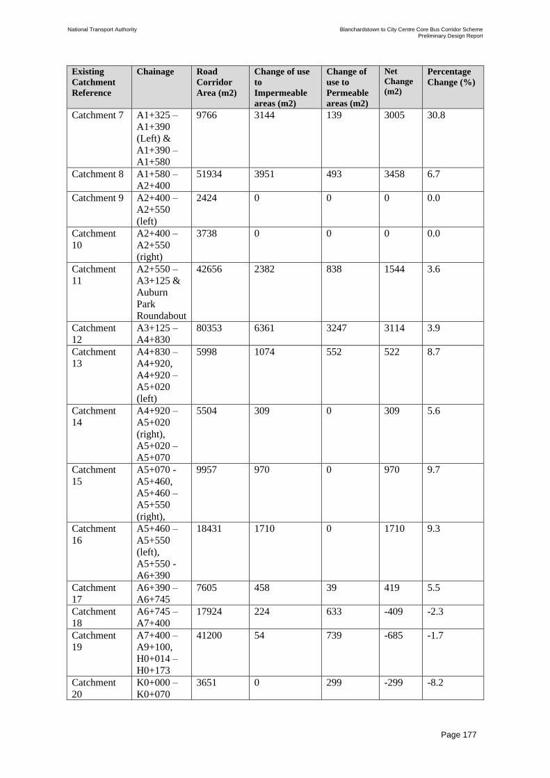
National Transport Authority Blanchardstown to City Centre Core Bus Corridor Scheme Preliminary Design Report
| Issue | 7 May 2022
\\GLOBAL\EUROPE\DUBLIN\JOBS\268000\268401-00\4. INTERNAL\4-04 REPORTS\4-04-03 INFRASTRUCTURE\PRELIMINARY DESIGN REPORT\CBC 5\ISSUE MAY 2022\BCIDC-ARP-PMG_PD-
0005_XX_00-RP-ZZ-0001_ISSUE.DOCX
Page 177
Existing
Catchment
Reference
Chainage Road
Corridor
Area (m2)
Change of use
to
Impermeable
areas (m2)
Change of
use to
Permeable
areas (m2)
Net
Change
(m2)
Percentage
Change (%)
Catchment 7 A1+325 –
A1+390
(Left) &
A1+390 –
A1+580
9766 3144 139 3005 30.8
Catchment 8 A1+580 –
A2+400
51934 3951 493 3458 6.7
Catchment 9 A2+400 –
A2+550
(left)
2424 0 0 0 0.0
Catchment
10
A2+400 –
A2+550
(right)
3738 0 0 0 0.0
Catchment
11
A2+550 –
A3+125 &
Auburn
Park
Roundabout
42656 2382 838 1544 3.6
Catchment
12
A3+125 –
A4+830
80353 6361 3247 3114 3.9
Catchment
13
A4+830 –
A4+920,
A4+920 –
A5+020
(left)
5998 1074 552 522 8.7
Catchment
14
A4+920 –
A5+020
(right),
A5+020 –
A5+070
5504 309 0 309 5.6
Catchment
15
A5+070 -
A5+460,
A5+460 –
A5+550
(right),
9957 970 0 970 9.7
Catchment
16
A5+460 –
A5+550
(left),
A5+550 -
A6+390
18431 1710 0 1710 9.3
Catchment
17
A6+390 –
A6+745
7605 458 39 419 5.5
Catchment
18
A6+745 –
A7+400
17924 224 633 -409 -2.3
Catchment
19
A7+400 –
A9+100,
H0+014 –
H0+173
41200 54 739 -685 -1.7
Catchment
20
K0+000 –
K0+070
3651 0 299 -299 -8.2

National Transport Authority Blanchardstown to City Centre Core Bus Corridor Scheme Preliminary Design Report
| Issue | 7 May 2022
\\GLOBAL\EUROPE\DUBLIN\JOBS\268000\268401-00\4. INTERNAL\4-04 REPORTS\4-04-03 INFRASTRUCTURE\PRELIMINARY DESIGN REPORT\CBC 5\ISSUE MAY 2022\BCIDC-ARP-PMG_PD-
0005_XX_00-RP-ZZ-0001_ISSUE.DOCX
Page 178
Existing
Catchment
Reference
Chainage Road
Corridor
Area (m2)
Change of use
to
Impermeable
areas (m2)
Change of
use to
Permeable
areas (m2)
Net
Change
(m2)
Percentage
Change (%)
Catchment
21
A9+100 –
A9+492,
G0+000 –
G0+496 &
J0+000 –
J0+147
18037 0 48 -48 -0.3
9.5 Preliminary Drainage Design
The existing drainage network is being maintained and used as the main discharge point for
the new drainage system. The design aims to replicate the existing situation. Where new
multiple gully connections discharging to a combined sewer are required, a new surface water
pipe will be provided where practicable and connected to the combined sewer as per Irish
Water requirements.
The following drainage systems were considered for the Proposed Scheme where new paved
areas are proposed:
• Sealed drainage (SD) comprises gullies and sealed pipes. They collect, convey and
discharge run-off. The gullies will be located within the kerbline mostly between the
cycle track and bus lane, and/or the footpath and the cycle track, depending on the
carriageway profile. Their location will also depend on the bicycle and/or bus wheel-
track in consideration of the cycling safety and ride-quality.
• Grass Surface Water Channels, Swales and bio-retention areas/rain gardens
(SW/RG) will be provided as road edge/footpath edge drainage collection systems. They
will provide treatment and will provide attenuation if required. A filter drain can be laid
under the bio-retention areas to keep them dry during low return period rainfall events.
• Filter Drains (FD) will be provided as road edge channels. These comprise a perforated
pipe with granular surround and are designed to convey, attenuate and treat run-off prior
to discharge.
• Tree pits will be provided in close proximity to the carriageway, where practicable.
These receive flows from the sealed pipe network and from footpaths, and are designed to
convey, attenuate and treat run-off prior to discharge.
• Green Roofs (GR) will be provided on the Bus Interchange roof canopy. These will
discharge to downpipes located on the columns and outfall to the surface water network.
The green roofs will provide a reduction in surface water runoff and also include visual
benefit and ecological value.
• Attenuation Tanks/oversize pipes (AT/OSP) Where there is insufficient attenuation
volume provided by the proposed SuDS drainage measures, hard attenuation measures
such as concrete attenuation tanks and/or oversize pipes will be provided to meet the
required attenuation volume.

National Transport Authority Blanchardstown to City Centre Core Bus Corridor Scheme Preliminary Design Report
| Issue | 7 May 2022
\\GLOBAL\EUROPE\DUBLIN\JOBS\268000\268401-00\4. INTERNAL\4-04 REPORTS\4-04-03 INFRASTRUCTURE\PRELIMINARY DESIGN REPORT\CBC 5\ISSUE MAY 2022\BCIDC-ARP-PMG_PD-
0005_XX_00-RP-ZZ-0001_ISSUE.DOCX
Page 179
9.5.1 Summary of Surface Water Drainage
The proposed drainage types for Blanchardstown to City Centre Scheme are listed on Table
9.4.
Table 9.4: Summary of Proposed Surface Water Infrastructure
Catchment Chainage Drainage Type
Asset Owner/Location: Fingal County Council
Catchment 1 A0+000 to 0+050 (left)
Bio retention areas/rain gardens with underground
storage & sealed pipe network
Catchment 2 A0+200 to 0+390 (both
sides)
Tree pits, filter drain, sealed pipe network &
oversized pipe
Catchment 2 A0+390 to 0+490 (both
sides) Tree pits, filter drain, sealed pipe network
Catchment 2 A0+490 to 0+600 (both
sides)
Tree pits, filter drain, sealed pipe network &
oversized pipe
Catchment 2 A0+575 to 0+600 (right) Bio retention areas/rain gardens with underground
storage
Catchment 4 C0+000 to C0+120 (left) Filter drain
Catchment 4 C0+225 to C0+300 (both
sides)
Bio retention areas/rain gardens
Catchment 5 A0+600 to 0+620 (right) Bio retention areas/rain gardens with underground
storage
Catchment 5 A0+600 (left) Bio retention areas/rain gardens
Catchment 5 A0+620 to 0+747 (right) Bio retention areas/rain gardens, oversized pipe
Catchment 5 A1+040 to 1+100 (right) Filter drain
Catchment 6 A1+080 to 1+325 (left) Bio retention areas/rain gardens, filter drain & sealed
pipe network
Catchment 6 A1+160 to 1+390 (right) Permeable paving
Catchment 7 A1+325 to 1+445 (left) Permeable paving, bio retention areas/rain gardens &
filter drain
Catchment 7 A1+390 to 1+485 (right) Permeable paving, bio retention areas/rain gardens &
filter drain
Catchment 7 A1+485 to 1+600 (right) Oversized pipe
Catchment 7 A1+520 to 1+630 (left) Permeable paving, bio retention areas/rain gardens,
filter drain & oversized pipe
Catchment 8 A1+600 to 1+720 (right) Permeable paving, bio retention areas/rain gardens &
filter drain
Catchment 8 A1+700 to 1+800 (left) Permeable paving
Catchment 8 A1+800 to 2+000 (left) Sealed pipe network
Catchment 8 A1+910 to 2+000 (right) Bio retention areas/rain gardens with underground
storage & sealed pipe network
Catchment 8 A2+020 to 2+100 (right) Bio retention areas/rain gardens with underground
storage
Catchment 8 M0+000 to 0+150 (both
sides)
Filter drain & sealed pipe network
Catchment 8 A2+100 to 2+300 (right) Filter drain
Catchment 8 A2+220 to 2+320 (left) Sealed pipe network & oversized pipe
Catchment 8 A2+320 to 2+400 (left) Sealed pipe network
Catchment
11
A2+590 to 2+670 (both) Bio retention areas/rain gardens & filter drain

National Transport Authority Blanchardstown to City Centre Core Bus Corridor Scheme Preliminary Design Report
| Issue | 7 May 2022
\\GLOBAL\EUROPE\DUBLIN\JOBS\268000\268401-00\4. INTERNAL\4-04 REPORTS\4-04-03 INFRASTRUCTURE\PRELIMINARY DESIGN REPORT\CBC 5\ISSUE MAY 2022\BCIDC-ARP-PMG_PD-
0005_XX_00-RP-ZZ-0001_ISSUE.DOCX
Page 180
Catchment Chainage Drainage Type
Catchment
11
A2+730 to 2+782 (Navan 1
-both sides)
Swale, filter drain & sealed pipe network
Catchment
11
A2+782 to 2+880 (Bus
lane -both sides)
Swale, filter drain & sealed pipe network
Catchment
11
Auburn Park roundabout
(Old Navan Road
Castleknock Manor (both
sides))
Bio retention areas/rain gardens & sealed pipe
network
Catchment
11
A2+880 to 3+050 (right) Filter drain
Catchment
12
A3+470 to 3+675 (right) Bio retention areas/rain gardens, filter drain &
oversized pipe
Catchment
12
A3+675 to 3+855 (right) Filter drain
Catchment
12
A3+855 to 4+070 (left) Filter drain
Catchment
12
A3+855 to 4+100 (right) Oversized pipe
Catchment
12
A4+100 to 4+210 (right) Sealed pipe network & oversized pipe
Catchment
12
A4+140 to 4+470 (left) Tree pits, sealed pipe network & oversized pipe
Catchment
12
A4+210 to 4+505 (right) Sealed pipe network & oversized pipe
Catchment
12
A4+470 to 4+660 (left) Tree pits, filter drains & sealed pipe network
Catchment
12
A4+660 to 4+830 (both) Tree pits, filter drain, bio retention areas/rain gardens
& sealed pipe network
Catchment 1 B0+000 to 0+115 (both) Permeable paving, tree pits, filter drain & sealed pipe
network
Catchment 1 B0+115 to 0+280 (both) Tree pits, filter drain, Bio retention areas/rain
gardens & oversized pipe
Catchment 1 B0+280 to 0+450 (both) Bio retention area/rain garden & oversized pipe
Catchment 1 B0+450 to 0+610 (both) Bio retention area/rain garden, tree pits, filter drain &
oversized pipe
Catchment 1 D0+000 to 0+100 (left) Bio retention areas/rain gardens, filter drain, sealed
pipe network & oversized pipe
Catchment 1 E0+000 to 0+080 (left) Bio retention areas/rain gardens & sealed pipe
network
Catchment 1 E0+030 to 0+080 (right) Bio retention areas/rain gardens & sealed pipe
network
Catchment 1 E0+080 to 0+230 (right) Permeable paving, Tree pits, filter drain
Catchment 1 E0+080 to 0+230 (left) Tree pits, filter drain
Catchment 1 E0+230 to 0+360 (left) Tree pits, filter drain & sealed pipe network
Catchment 2 F0+000 to 0+334 (both
sides)
Green roof, bio retention area/rain garden, tree pits,
filter drain, sealed pipe network & oversized pipes
Asset Owner/Location: Dublin City Council
Catchment
13
A4+830 to 4+870 (right) Bio retention areas/rain gardens, tree pits & filter
drain
Catchment
13
A4+830 to 4+850 (left) Bio retention areas/rain gardens, tree pits & filter
drains

National Transport Authority Blanchardstown to City Centre Core Bus Corridor Scheme Preliminary Design Report
| Issue | 7 May 2022
\\GLOBAL\EUROPE\DUBLIN\JOBS\268000\268401-00\4. INTERNAL\4-04 REPORTS\4-04-03 INFRASTRUCTURE\PRELIMINARY DESIGN REPORT\CBC 5\ISSUE MAY 2022\BCIDC-ARP-PMG_PD-
0005_XX_00-RP-ZZ-0001_ISSUE.DOCX
Page 181
Catchment Chainage Drainage Type
Catchment
13
A4+850 to 5+020 (left) Bio retention areas/rain gardens, tree pits, filter
drains & sealed pipe network
Catchment
13
A4+870 to 4+920 (right) Bio retention areas/rain gardens & tree pits
Catchment
14
A4+990 to 5+020 (right) Sealed pipe network
Catchment
14
A5+020 to 5+070 (right) Sealed pipe network
Catchment
14
A5+020 to 5+070 (left) Bio retention areas/rain gardens, filter drain & sealed
pipe network
Catchment
15
A5+070 to 5+450 (left) Bio retention areas/rain gardens, filter drain, sealed
pipe network & oversized pipe
Catchment
15
A5+070 to 5+230 (right) Sealed pipe network
Catchment
15
A5+450 to 5+550 (right) Sealed pipe network
Catchment
16
A5+550 to 5+700 (right) Sealed pipe network
Catchment
16
A5+450 to 5+620 (left) Sealed pipe network
Catchment
16
A5+620 to 5+760 (left) Tree pits & filter drain
Catchment
16
A5+760 to 5+890 (left) Tree pits & filter drain
Catchment
16
A5+920 to 6+135 (right) Tree pits & filter drain
Catchment
16
A6+260 to 6+374 (right) Oversized pipe
Catchment
17
A6+374 to 6+488 (right) Sealed pipe network
Catchment
17
A6+465 to 6+642 (left) Tree pits, filter drain & sealed pipe network
Catchment
17
A6+642 to 6+745 (left) Sealed pipe network
Catchment
18
A6+745 to 6+900 (both
sides)
Sealed pipe network
Catchment
18
A7+075 to 7+260 (right) Sealed pipe network & oversized pipe
Catchment
18
A7+280 to 7+400 (left) Bio retention area/rain garden
Asset Owner/Location: Irish Water/ Dublin County Council
Catchment
19
A7+400 to 7+560 (left) Bio retention area/rain garden
Catchment
19
A7+560 to 7+720 (left) Sealed pipe network
Catchment
19
A8+040 to 8+080 (left) Sealed pipe network
Catchment
19
A8+210 to 8+285 (both
sides)
Bio retention areas/rain gardens & sealed pipe
network
Catchment
19
A8+285 to 8+400 (both
sides)
Sealed pipe network

National Transport Authority Blanchardstown to City Centre Core Bus Corridor Scheme Preliminary Design Report
| Issue | 7 May 2022
\\GLOBAL\EUROPE\DUBLIN\JOBS\268000\268401-00\4. INTERNAL\4-04 REPORTS\4-04-03 INFRASTRUCTURE\PRELIMINARY DESIGN REPORT\CBC 5\ISSUE MAY 2022\BCIDC-ARP-PMG_PD-
0005_XX_00-RP-ZZ-0001_ISSUE.DOCX
Page 182
Catchment Chainage Drainage Type
Catchment
19
A8+400 to 8+685 (both
sides)
Bio retention areas/rain gardens & sealed pipe
network
Catchment
19
A8+685 to 8+730 (left) Sealed pipe network
Catchment
19
A8+685 to 8+730 (right) Bio retention areas/rain gardens & sealed pipe
network
Catchment
19
A8+730 to 9+000 (right) Tree pits, filter drain, bio retention areas/rain gardens
& sealed pipe network
Catchment
19
A9+000 to 9+100 (both
sides)
Sealed pipe network
Catchment
21
A9+140 to 9+290 (both
sides)
Sealed pipe network
Catchment
21
A9+290 to 9+360 (right) Sealed pipe network
Catchment
21
A9+380 to 9+440 (right) Sealed pipe network
Catchment
21
G0+000 to 0+060 (both
sides)
Sealed pipe network
Catchment
21
G0+390 to G0+495 (King
Street North - both sides)
Bio retention areas/rain gardens, sealed pipe network
Catchment
19
H0+030 to 0+150
(Brunswick Street North -
both sides)
Sealed pipe network
Catchment
20
George’s Lane (both sides) Bio retention areas/rain gardens
9.5.2 Summary of Attenuation Features, SuDS and Outfalls
Where practicable, and in new areas of public realm gained as part of the design, a
sustainable drainage system is considered in the form of rain gardens, bioretention areas,
filter drains, swales, tree pits, permeable paving etc. SuDS is also considered in existing
areas, where practicable.
The attenuation measures from the Proposed Scheme are summarised for each catchment.
Refer to Table 9.5. Chainage locations not shown in Table 9.5 below do not require
attenuation or SuDS.
Table 9.5: Summary of Proposed Attenuation Features, SuDS & Outfalls
Chainage Existing
Catchment
Reference
(Refer to
Table 9.2)
Approx.
Impermeable Surface
Area
Permitted
Discharge
(l/s)
Possible SuDS
solution/
attenuation
measure
Catchment
Outfall
Existing
(m2)
Change
(m2)
Asset owner/Location: Fingal County Council
A0+000 to
0+050 (left)
Catchment 1 406 454 5.7 RG with
underground
storage 11m3
Existing SW,
Ch A0+015
A0+200 to
0+390
(both sides)
Catchment 2 1890 1479 26.6 Tree Pits,
201m of
225mm FD,
Existing SW,
Ch A0+390

National Transport Authority Blanchardstown to City Centre Core Bus Corridor Scheme Preliminary Design Report
| Issue | 7 May 2022
\\GLOBAL\EUROPE\DUBLIN\JOBS\268000\268401-00\4. INTERNAL\4-04 REPORTS\4-04-03 INFRASTRUCTURE\PRELIMINARY DESIGN REPORT\CBC 5\ISSUE MAY 2022\BCIDC-ARP-PMG_PD-
0005_XX_00-RP-ZZ-0001_ISSUE.DOCX
Page 183
Chainage Existing
Catchment
Reference
(Refer to
Table 9.2)
Approx.
Impermeable Surface
Area
Permitted
Discharge
(l/s)
Possible SuDS
solution/
attenuation
measure
Catchment
Outfall
Existing
(m2)
Change
(m2)
31m of 225mm
SW
58m of 300mm
OSP
92m of 375mm
OSP
A0+390 to
0+490
(both sides)
Catchment 2 1724 607 24.1 Tree Pits, 85m
of 225mm FD,
175m of
225mm SW
Existing SW,
Ch A0+495
A0+490 to
0+600
(both sides)
Catchment 2 1108 802 15.6 Tree Pits,
124m of
225mm FD,
16m of 225mm
SW, 47m of
300mm OSP
Existing SW,
Ch A0+590
A0+575 to
0+600
(right)
Catchment 2 428 286 6 RG with
underground
storage 3.1m3
Existing SW,
Ch A0+590
A0+600 to
0+620
(right)
Catchment 5 719 117 10 RG with
underground
storage 4m3
Existing SW,
Ch A0+650
A0+620 to
0+747
(right)
Catchment 5 1226 1232 17.3 33m of 450mm
OSP
49m of 600mm
OSP
Existing SW,
Ch A0+735
A1+040 to
1+100
(right)
Catchment 5 402 228 5.6 50m of 225mm
FD
Existing SW,
Ch A1+090
A1+080 to
1+325 (left)
Catchment 6 2901 249 40.4 215m of
300mm FD
Existing SW,
Ch A1+880
A1+325 to
1+445 (left)
Catchment 7 826 105811
03
11.1 103m of
300mm FD
RG with
underground
storage 8m3
Existing SW,
Ch A1+445
A1+390 to
1+485
(right)
Catchment 7 1245 458 17.4 67m of 300mm
FD
Existing SW,
Ch A1+455
A1+485 to
1+600
(right)
Catchment 7 1379 391 18.3 94m of 300mm
OSP
Existing SW,
Ch A1+564
A1+520 to
1+630 (left)
Catchment 7 732 1050 9.6 44m of 375mm
FD
26m of 525mm
OSP
Existing SW,
Ch A1+615
A1+600 to
1+720
(right)
Catchment 8 1532 1375 21.6 92m of 375mm
FD
Existing SW,
Ch A1+720

National Transport Authority Blanchardstown to City Centre Core Bus Corridor Scheme Preliminary Design Report
| Issue | 7 May 2022
\\GLOBAL\EUROPE\DUBLIN\JOBS\268000\268401-00\4. INTERNAL\4-04 REPORTS\4-04-03 INFRASTRUCTURE\PRELIMINARY DESIGN REPORT\CBC 5\ISSUE MAY 2022\BCIDC-ARP-PMG_PD-
0005_XX_00-RP-ZZ-0001_ISSUE.DOCX
Page 184
Chainage Existing
Catchment
Reference
(Refer to
Table 9.2)
Approx.
Impermeable Surface
Area
Permitted
Discharge
(l/s)
Possible SuDS
solution/
attenuation
measure
Catchment
Outfall
Existing
(m2)
Change
(m2)
RG with
underground
storage 12m3
A1+800 to
2+000 (left)
Catchment 8 1280 242 17.8 131m of
225mm SW
Existing SW,
Ch A1+914
A1+910 to
2+000
(right)
Catchment 8 677 193 9.5 RG with
underground
storage 12.4m3
Existing SW,
Ch A1+940
M0+000 to
0+150
(both sides)
Catchment 8 1823 98 25.3 31m of 300mm
FD
35m of 375mm
FD
Existing SW,
Ch A1+990
A2+020 to
2+100
(right)
Catchment 8
2350
290
32.7
RG with
underground
storage 25.6m3
Existing SW,
Ch A2+080
A2+100 to
2+300
(right)
Catchment 8
2305
365
32.1
58m of 225mm
FD
38m of 375mm
FD
41m of 450mm
FD
Existing SW,
Ch A2+140
A2+220 to
2+320 (left)
Catchment 8
701
390
9.8
42m of 300mm
OSP
38m of 225mm
SW
Existing SW,
Ch A2+220
A2+320 to
2+400 (left)
Catchment 8
745
76
10.5
51m of 225mm
SW
Existing SW,
Ch A2+330
A2+590 to
2+670
Navan 1
(both)
Catchment 11 1032 486 14.4 52m of 225mm
FD
RG with
underground
storage 11m3
Existing SW,
Ch A2+670
A2+730 to
2+782
Navan 1
(both)
Catchment 11 482 252 6.8 45m of 225mm
FD, Swale
15m3
Existing SW,
Ch A2+740
A2+782 to
2+880 Bus
Lane (both)
Catchment 11 150 2.0 27m of 225mm
FD
Existing SW,
Ch A2+785
Catchment 11 421 2.0 12m of 225mm
FD
Existing SW,
Ch A2+865
Old Navan
Road
(right)
Catchment 11 124 114 2.0 RG 2m3
Existing SW,
Ch A2+900
Old Navan
Rod (left)
Catchment 11 125 125 2.0 RG 1m3 Existing SW,
Ch A2+900

National Transport Authority Blanchardstown to City Centre Core Bus Corridor Scheme Preliminary Design Report
| Issue | 7 May 2022
\\GLOBAL\EUROPE\DUBLIN\JOBS\268000\268401-00\4. INTERNAL\4-04 REPORTS\4-04-03 INFRASTRUCTURE\PRELIMINARY DESIGN REPORT\CBC 5\ISSUE MAY 2022\BCIDC-ARP-PMG_PD-
0005_XX_00-RP-ZZ-0001_ISSUE.DOCX
Page 185
Chainage Existing
Catchment
Reference
(Refer to
Table 9.2)
Approx.
Impermeable Surface
Area
Permitted
Discharge
(l/s)
Possible SuDS
solution/
attenuation
measure
Catchment
Outfall
Existing
(m2)
Change
(m2)
& Auburn
Ave (both)
Castle-
knock
Manor
(both)
Catchment 11 184 196 2.0 RG 4m3
Existing SW,
Ch A2+900
A2+880 to
3+050
(right)
Catchment 11 2179 148 30.3 124m of
300mm FD
Existing SW,
Ch A3+050
A3+470 to
3+675
(right)
Catchment 12 3471 585 48.3 Tree Pits, 65m
of 225mm FD
60m of 300mm
FD
73m of 300mm
OSP
Existing SW,
Ch A3+675
A3+675 to
3+855
(right)
Catchment 12 955 364 13.3 72m of 450mm
FD
Existing SW,
Ch A3+769
A3+855 to
4+100
(right)
Catchment 12 1279 769 17.9 75m of 450mm
OSP
32m of 525mm
OSP
Existing SW,
Ch A3+982
A3+855 to
4+070 (left)
Catchment 12 1874 243 26.1 100m of
225mm FD
27m of 450mm
FD
42m of 525mm
FD
Existing SW,
Ch A4+042
A4+100 to
4+210
(right)
Catchment 12 1961 359 27.3 71m of 225mm
SW
39m of 300mm
OSP
Existing SW,
Ch A4+100
A4+140 to
4+470 (left)
Catchment 12 2096 1158 29.4 Tree Pits, 32m
of 225mm SW
200m of
300mm OSP
Existing SW,
Ch A4+230
A4+210 to
4+505
(right)
Catchment 12 3425 136 47.648.2 128m of
225mm SW
86m of 300mm
OSP
Existing SW,
Ch A4+210
A4+470 to
4+660 (left)
Catchment 12 887 478 12.4 Tree Pits, 69m
of 225mm FD
63m of 300mm
FD
Existing SW,
Ch A4+522
A4+660 to
4+830
(both)
Catchment 12 3162 467 44.0 Tree Pits,
105m of
300mm FD
Existing SW,
Ch A4+650
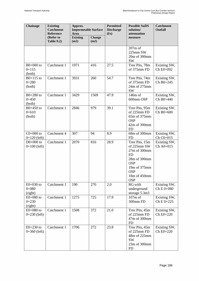
National Transport Authority Blanchardstown to City Centre Core Bus Corridor Scheme Preliminary Design Report
| Issue | 7 May 2022
\\GLOBAL\EUROPE\DUBLIN\JOBS\268000\268401-00\4. INTERNAL\4-04 REPORTS\4-04-03 INFRASTRUCTURE\PRELIMINARY DESIGN REPORT\CBC 5\ISSUE MAY 2022\BCIDC-ARP-PMG_PD-
0005_XX_00-RP-ZZ-0001_ISSUE.DOCX
Page 186
Chainage Existing
Catchment
Reference
(Refer to
Table 9.2)
Approx.
Impermeable Surface
Area
Permitted
Discharge
(l/s)
Possible SuDS
solution/
attenuation
measure
Catchment
Outfall
Existing
(m2)
Change
(m2)
207m of
225mm SW
20m of 300mm
SW
B0+000 to
0+115
(both)
Catchment 1 1971 416 27.5 Tree Pits, 78m
of 375mm FD
Existing SW,
Ch E0+092
B0+115 to
0+280
(both)
Catchment 1 3931 260 54.7 Tree Pits, 74m
of 375mm FD
24m of 275mm
SW
Existing SW,
Ch B0+245
B0+280 to
0+450
(both)
Catchment 1 3429 1569 47.9 146m of
600mm OSP
Existing SW,
Ch B0+440
B0+450 to
0+610
(both)
Catchment 1 2846 979 39.1 Tree Pits, 95m
of 225mm FD
65m of 375mm
OSP
42m of 300mm
FD
Existing SW,
Ch B0+600
C0+000 to
0+120 (left)
Catchment 4 307 94 8.9 68m of 300mm
FD
Existing SW,
Ch C0+015
D0+000 to
0+100 (left)
Catchment 1 2070 816 28.9 Tree Pits, 15m
of 225mm SW
27m of 300mm
FD
28m of 300mm
OSP
19m of 375mm
OSP
18m of 450mm
OSP
Existing SW,
Ch A0+015
E0+030 to
0+080
(right)
Catchment 1 190 270 2.0 RG with
underground
storage 5.3m3
Existing SW,
Ch E 0+080
E0+080 to
0+230
(right)
Catchment 1 1275 725 17.9 107m of
300mm FD
Existing SW,
Ch E 0+225
E0+080 to
0+230 (left)
Catchment 1 1508 372 21.0 Tree Pits, 45m
of 225mm FD
47m of 300mm
FD
Existing SW,
Ch E0+220
E0+230 to
0+360 (left)
Catchment 1 1706 272 23.8 Tree Pits, 45m
of 225mm FD
48m of 225mm
SW
23m of 300mm
FD
Existing SW,
Ch E0+220

National Transport Authority Blanchardstown to City Centre Core Bus Corridor Scheme Preliminary Design Report
| Issue | 7 May 2022
\\GLOBAL\EUROPE\DUBLIN\JOBS\268000\268401-00\4. INTERNAL\4-04 REPORTS\4-04-03 INFRASTRUCTURE\PRELIMINARY DESIGN REPORT\CBC 5\ISSUE MAY 2022\BCIDC-ARP-PMG_PD-
0005_XX_00-RP-ZZ-0001_ISSUE.DOCX
Page 187
Chainage Existing
Catchment
Reference
(Refer to
Table 9.2)
Approx.
Impermeable Surface
Area
Permitted
Discharge
(l/s)
Possible SuDS
solution/
attenuation
measure
Catchment
Outfall
Existing
(m2)
Change
(m2)
F0+000 to
0+334
(both)
Catchment 2 12800 2502 143.5 Tree Pits,
230m of
225mm FD
26m of 225mm
SW
89m of 300mm
FD
120m of
300mm OSP
121m of
375mm FD
430m of
375mm OSP
Existing SW,
Ch F0+320
Asset owner/Location: Dublin City Council
A4+830 to
4+850 (left)
Catchment 13 340 290 4.8 Tree Pits, RG
with
underground
storage 4.4m3
Existing SW,
Ch A4+850
A4+830 to
4+870
(right)
Catchment 13 728 140 10.2 Tree Pits, RG
with
underground
storage 3m3
Existing SW,
Ch A4+855
A4+850 to
5+020 (left)
Catchment 13 1820 170 25.4 Tree Pits, 39m
of 225mm FD
117m of
225mm SW
Existing SW,
Ch A4+860
A4+990 to
5+020
(right)
Catchment 14 365 75 5.1 33m of 225mm
FD
Existing SW,
Ch A5+020
A5+020 to
5+070
(right)
Catchment 14 517 73 7.2 46m of 225mm
SW
Existing SW,
Ch A5+020
A5+020 to
5+070 (left)
Catchment 14 371 84 5.2 Raingarden
with storage
area 1m3
Existing SW,
Ch A5+040
A5+070 to
5+230
(right)
Catchment 15 1445 272 20.1 139m of
225mm SW
New SW,
Ch5+210
A5+070 to
5+450 (left)
Catchment 15 3962 576 55 20m of 225mm
FD
21m of 225mm
SW
90m of 300mm
OSP
240m of
450mm OSP
Existing SW,
Ch A5+460

National Transport Authority Blanchardstown to City Centre Core Bus Corridor Scheme Preliminary Design Report
| Issue | 7 May 2022
\\GLOBAL\EUROPE\DUBLIN\JOBS\268000\268401-00\4. INTERNAL\4-04 REPORTS\4-04-03 INFRASTRUCTURE\PRELIMINARY DESIGN REPORT\CBC 5\ISSUE MAY 2022\BCIDC-ARP-PMG_PD-
0005_XX_00-RP-ZZ-0001_ISSUE.DOCX
Page 188
Chainage Existing
Catchment
Reference
(Refer to
Table 9.2)
Approx.
Impermeable Surface
Area
Permitted
Discharge
(l/s)
Possible SuDS
solution/
attenuation
measure
Catchment
Outfall
Existing
(m2)
Change
(m2)
A5+450 to
5+550
(right)
Catchment 15 804 126 11.2 78m of 225mm
SW
Existing SW,
Ch A5+540
A5+450 to
5+620 (left)
Catchment 16 1541 359 20.9 154m of
225mm SW
Existing SW,
Ch A5+615
A5+550 to
5+700
(right)
Catchment 16 1385 185 19.3 141m of
225mm SW
Existing SW,
Ch A5+700
A5+620 to
5+760 (left)
Catchment 16 1957 313 27.2 Tree Pits,
112m of
300mm FD
Existing SW,
Ch A5+760
A5+760 to
5+890 (left)
Catchment 16 1544 356 21.5 Tree Pits, 96m
of 300mm FD
Existing SW,
Ch A5+860
A5+920 to
6+135
(right)
Catchment 16 2897 534 40.3 Tree Pits, 62m
of 225mm FD
127m of
300mm FD
Existing SW,
Ch A6+135
A6+260 to
6+374
(right)
Catchment 16 2079 121 28.9 88m of 300mm
SW
Existing SW,
Ch A6+260
A6+374 to
6+488
(right)
Catchment 17 1084 63 15.1 52m of 225mm
SW
Existing SW,
Ch A6+488
A6+465 to
6+642 (left)
Catchment 17 1330 260 18.5 Tree Pits,
128m of
225mm FD
5m of 300mm
SW
Existing SW,
Ch A6+575
A6+642 to
6+745 (left)
Catchment 17 1968 108 27.4 50m of 225mm
SW
Existing SW,
Ch A6+562
A6+745 to
6+900 (left)
Catchment 18 1278 112 17.8 121m of
225mm SW
Existing SW,
Ch A6+900
A7+075 to
7+260
(right)
Catchment 18 2196 224 30.6 96m of 225mm
SW
64m of 300mm
OSP
Existing SW,
Ch A7+270
9.6 Drainage at New Bridge Structures
The Proposed Scheme is inclusive of a new bus stop for Connolly Hospital on the N3. The
walkway access structures are surrounded by thick vegetation and are located on an
embankment down to Mill Road. It is therefore not practicable to provide SuDS features to
attenuate for these additional impermeable areas. Over the edge drainage is therefore being
proposed for these structures.

National Transport Authority Blanchardstown to City Centre Core Bus Corridor Scheme Preliminary Design Report
| Issue | 7 May 2022
\\GLOBAL\EUROPE\DUBLIN\JOBS\268000\268401-00\4. INTERNAL\4-04 REPORTS\4-04-03 INFRASTRUCTURE\PRELIMINARY DESIGN REPORT\CBC 5\ISSUE MAY 2022\BCIDC-ARP-PMG_PD-
0005_XX_00-RP-ZZ-0001_ISSUE.DOCX
Page 189
9.7 Flood Risk
A Flood Risk Assessment (FRA) has been prepared as part of the planning application for the
Proposed Scheme.
The Stage 1 FRA is a high-level study of the scheme to identify flood risks to the Proposed
Scheme and any potential flooding issues arising due to the scheme. The FRA informs the
planning process and identifies whether a further Stage 2 FRA is required.
The FRA includes the following:
• Confirmation of the sources of flooding which may affect the site;
• A qualitative assessment of the risk of flooding to the site and to adjacent sites as a result
of construction of the proposed development;
• Review of the availability and adequacy of existing information;
• Identification of possible measures which could mitigate the flood risk to acceptable
levels; and
• Areas for further investigation (Stage 2 FRA) if required.
Section 9.7.1 summarises the Stage 1 FRA which is included in Appendix N.
9.7.1 Flood Risk Assessment
The FRA has been carried out as part of the Planning Application for the Proposed Scheme.
There are a number of historic flood events at different locations along or near to the
Proposed Scheme. The Proposed Scheme is largely on existing carriageways and results in
minimal additional paved areas.
Therefore, the Proposed Scheme does not increase the risk of these events reoccurring
compared to the current scenario.
The route lies in an area at low risk of flooding from surrounding rivers, such as the Rivers
Tolka and Liffey.
The nearest distance of the Proposed Scheme to the coastal boundary, located at Ellis Quay,
measures approximately 1km, and is elevated above sea level. There is therefore no risk of
coastal flooding to the Proposed Scheme in the present, or future climate change scenario.
The OPW Preliminary Flood Risk Assessments Groundwater Flooding Report concludes that
groundwater flooding is largely confined to the West Coast of Ireland due to the
hydrogeology of the area. The proposed works do not involve any deep excavations,
significant changes in levels or basement construction. As the Proposed Scheme is on
existing roads with no known flooding specifically due to groundwater, it is not expected that
this risk will increase to the site or surrounding areas due to the construction of the Proposed
Scheme. The risk of groundwater flooding to the site is therefore considered low.

National Transport Authority Blanchardstown to City Centre Core Bus Corridor Scheme Preliminary Design Report
| Issue | 7 May 2022
\\GLOBAL\EUROPE\DUBLIN\JOBS\268000\268401-00\4. INTERNAL\4-04 REPORTS\4-04-03 INFRASTRUCTURE\PRELIMINARY DESIGN REPORT\CBC 5\ISSUE MAY 2022\BCIDC-ARP-PMG_PD-
0005_XX_00-RP-ZZ-0001_ISSUE.DOCX
Page 190
The risk of pluvial flooding along the majority of the proposed route is high, however this
risk exists in the current scenario and will be reduced as a result of the Proposed Scheme.
All new surface water pipelines provided as part of the Proposed Scheme will be designed so
that no flooding will occur for a return period up to 30 years. This is an improvement when
compared to some of the existing historical drainage infrastructure to be replaced and will
reduce the risk of pluvial flooding. Also, as part of the Proposed Scheme, new drainage
infrastructure is being provided which includes new Sustainable (Urban) Drainage Systems
(SuDS) such as rain gardens, swales and bio retention tree pits. These SuDS features provide
some surface water storage and thus reduce the risk of pluvial flooding.
As the proposed route from Blanchardstown to City Centre lies within Flood Zone C, a
‘Justification Test’ is not required and it is necessary only to identify mitigation measures for
any residual risks, which has been undertaken as part of this flood risk assessment. From the
assessment no residual risks have been identified.

National Transport Authority Blanchardstown to City Centre Core Bus Corridor Scheme Preliminary Design Report
| Issue | 7 May 2022
\\GLOBAL\EUROPE\DUBLIN\JOBS\268000\268401-00\4. INTERNAL\4-04 REPORTS\4-04-03 INFRASTRUCTURE\PRELIMINARY DESIGN REPORT\CBC 5\ISSUE MAY 2022\BCIDC-ARP-PMG_PD-
0005_XX_00-RP-ZZ-0001_ISSUE.DOCX
Page 191
10 Services and Utilities
10.1 Overview of Utilities Strategy and Survey
Utility records from all providers were sought at an early stage of the scheme design. These
records combined with topographic survey records, walk over inspections and desktop
analysis of the Proposed Scheme identified areas of risk to existing assets. Where risk was
initially identified to high value assets, such as high voltage ESB cables, high pressure gas
mains and trunk water mains, a review was undertaken to ascertain if the risk could be
mitigated by amending the highways design whilst still meeting the objectives of the scheme.
Some areas of conflict were designed out at this stage; however, some remain and will be
accommodated within the overall scheme design.
10.1.1 Record Information
Available utility records for the route of the Proposed Scheme were submitted by service
providers and reviewed. These records have assisted with informing the scheme design.
Utility records were received from the following service providers:
• Irish Water
• Gas Networks Ireland (GNI)
• Electricity Supply Bord (ESB)
• Eir
• Virgin Media
• BT
• Vodafone
• Enet
• Fingal County Council
• Dublin City Council
10.1.2 Phase 1 Utility Survey
A targeted utility survey to British Standards Institution (BSI) PAS 128A, Specification for
underground utility detection, verification and location including Ground Penetrating Radar
(GPR), was commissioned by the NTA to investigate areas where there is risk identified to
existing high value assets such as high voltage ESB cables, high pressure gas mains and trunk
water mains due to the proposed carriageway alignment. Some areas where there is a high
concentration of utility diversions proposed were also surveyed to ensure that adequate
spacing is available for relocation of assets. The results of the utility survey have been
reviewed to confirm the adequacy of design provisions made with respect to diversion
proposals. Additionally, a more extensive utility survey will be completed to inform the
detailed design phase of the scheme.

National Transport Authority Blanchardstown to City Centre Core Bus Corridor Scheme Preliminary Design Report
| Issue | 7 May 2022
\\GLOBAL\EUROPE\DUBLIN\JOBS\268000\268401-00\4. INTERNAL\4-04 REPORTS\4-04-03 INFRASTRUCTURE\PRELIMINARY DESIGN REPORT\CBC 5\ISSUE MAY 2022\BCIDC-ARP-PMG_PD-
0005_XX_00-RP-ZZ-0001_ISSUE.DOCX
Page 192
10.1.3 Consultation with Utility Service Providers
Consultation with all relevant utility service providers was undertaken to evaluate the impact
of the Proposed Scheme on existing utilities.
Based on records and topographical survey that was available, utility diversions and areas
where protection measures might be required were identified. These potential impacts were
documented on a set of consultation drawings and a technical note was prepared for each
utility company.
Consultation meetings were held with ESB, Gas Networks Ireland, Irish Water and Eir. The
Proposed Scheme proposals were also outlined to them and scenarios where utility
infrastructure might be impacted by the Proposed Scheme were discussed.
10.2 Overview of Service Diversions
The construction of the Proposed Scheme will result in conflicts with several existing utility
assets.
These conflicts have been identified, and preliminary consultation has been undertaken with
the relevant service providers so that the conflict can be resolved by relocating or diverting
the services, where necessary, and protecting in-situ where appropriate.
The principal statutory and other service providers affected are:
• ESB;
• Irish Water (Water & Public Sewer);
• GNI; and
• Telecommunication Services – Eir, Virgin Media, eNet & BT.
In addition to the above, it will be necessary to relocate and upgrade some of the existing
public lighting and traffic signalling network and equipment along the extents of the scheme.
The services conflicts and the associated diversions will need to be considered in the design
and construction of the scheme. The design considerations have been taken into account as
much as possible at this stage, but it is likely that design modifications will be required at
detailed design stage when further site investigations have taken place. In addition to
chambers identified as Eir assets on the topographical survey that are identified as requiring
modification, there are other chambers that might contain telecommunications asset that are
impacted by the Proposed Scheme. Further investigation is required to confirm at the
construction design stage.
During construction, it may be necessary to maintain supply to certain services. This will
require the retention and protection of existing utility supplies until such time as permanent
diversions can be commissioned, or alternatively the construction of temporary diversions to
facilitate completion of the works, including the permanent diversion of services. The
sequence of works must also take into account the need to liaise with service providers and,
subject to their availability to carry out diversions, staging of the works may be necessary.

National Transport Authority Blanchardstown to City Centre Core Bus Corridor Scheme Preliminary Design Report
| Issue | 7 May 2022
\\GLOBAL\EUROPE\DUBLIN\JOBS\268000\268401-00\4. INTERNAL\4-04 REPORTS\4-04-03 INFRASTRUCTURE\PRELIMINARY DESIGN REPORT\CBC 5\ISSUE MAY 2022\BCIDC-ARP-PMG_PD-
0005_XX_00-RP-ZZ-0001_ISSUE.DOCX
Page 193
The service diversions required for the Proposed Scheme are discussed in the following
paragraphs and are summarised in Tables 10.1 to 10.5.
The locations of all known services from records provided from the service providers are
shown on Combined Existing Utilities Records Drawings in Appendix B.
10.3 Summary of Recommended Diversions
10.3.1 Gas Networks Ireland
No impacts to high pressure gas mains have been identified. There are five locations where
GNI medium pressure gas mains will require a diversion. There are six locations where GNI
low pressure gas mains will require a diversion. Table 10.1 outlines potential diversions of
Gas Networks Ireland services and are illustrated on drawing series BCIDC-ARP-UTL_UG-
0005__XX_00-DR-CU-0001 to 0040 in Appendix B.
Table 10.1: GNI Asset Diversions Reference No. Utility
Provider
Chainage Asset/ Apparatus
Impacted
Description of Works
R05-UG-MP-
001
GNI F0+040 –
F0+210
RHS
Medium pressure gas
main
Proposed diversion
length of 177m for GNI
utility.
R05-UG-MP-
002
GNI A0+210 –
A0+230
RHS
Medium pressure gas
main
Proposed diversion
length of 20m for GNI
utility.
R05-UG-MP-
003
GNI A0+550 –
A0+570
RHS
Medium pressure gas
main on L3020
Proposed diversion
length of 30m for GNI
utility.
R05-UG-LP-004 GNI A2+075 –
A2+120
RHS
Low pressure gas main
along the N3.
Proposed diversion
length of 45m for GNI
utility.
R05-UG-LP-005 GNI A2+240 –
A2+250
LHS
Low pressure gas mains Proposed diversion
around retaining wall to
be constructed.
R05-UG-LP-006 GNI A4+560 –
A4+610
LHS
Low pressure gas main
along Navan Road.
Proposed diversion
length of 51m for GNI
utility.
R05-UG-MP-
007
GNI A4+560 –
A4+610
LHS
Medium pressure gas
main on Navan Rd.
Proposed diversion
length of 46m for GNI
utility.
R05-UG-LP-008 GNI A4+800 –
A4+855
LHS
Low pressure gas main
on Navan Rd.
Proposed diversion
length of 35m for GNI
utility.
R05-UG-LP-009 GNI A5+625 –
A5+850
LHS
Low pressure gas main
along Navan Road.
Proposed diversion
length of 227m for GNI
utility.
R05-UG-MP-
010
GNI A5+970 –
A6+250
RHS
Medium pressure gas
main along Navan
Road.
Proposed diversion
length of 158m for GNI
utility.
R05-UG-LP-011 GNI A6+490 –
A6+580
LHS
Low pressure gas main
along Navan Road.
Proposed diversion
length of 94m for GNI
utility.

National Transport Authority Blanchardstown to City Centre Core Bus Corridor Scheme Preliminary Design Report
| Issue | 7 May 2022
\\GLOBAL\EUROPE\DUBLIN\JOBS\268000\268401-00\4. INTERNAL\4-04 REPORTS\4-04-03 INFRASTRUCTURE\PRELIMINARY DESIGN REPORT\CBC 5\ISSUE MAY 2022\BCIDC-ARP-PMG_PD-
0005_XX_00-RP-ZZ-0001_ISSUE.DOCX
Page 194
10.3.2 ESB
No impacts to high voltage cables have been identified. There are seventeen sections of
medium voltage underground cabling which will require diversions along the route. There are
five sections of low voltage underground cabling which will require diversions along the
route. Table 10.2 outlines several potential diversions for ESB services and are illustrated on
drawing series BCIDC-ARP-UTL_UE-0005_XX_00-DR-CU-0001 to 0040 in Appendix B.
Table 10.2: ESB Asset Diversions
Reference No. Utility
Provider
Chainage Asset/ Apparatus
Impacted
Description of Works
R0-UE-MV-001 ESB E0+075 –
F0+210
LHS
Medium voltage
ducting
Proposed diversion
length of 4 x 490m for
ESB utility.
R05-UE-MV-
002
ESB B0+020 –
E0+130
RHS
Medium voltage
ducting
Proposed diversion
length of 110m for ESB
utility.
R05-UE-MV-
003
ESB F0+045 –
F0+085
RHS
Medium voltage
ducting
Proposed diversion
length of 39m for ESB
utility.
R05-UE-MV-
004
ESB D0+000 –
D0+100
LHS
Medium voltage
ducting
Proposed diversion
length of 3 x 136m for
ESB utility.
R05-UE-MV-
005
ESB A0+200 –
A0+230
LHS
Medium voltage
ducting
Proposed diversion
length of 67m for ESB
utility.
R05-UE-MV-
006
ESB A0+550 –
A0+580
RHS
Medium voltage
ducting
Proposed diversion
length of 80m for ESB
utility.
R05-UE-MV-
007
ESB A1+460 –
A1+605
LHS
Medium voltage
ducting along the N3.
Proposed diversion
length of 146m for ESB
utility.
R05-UE-MV-
008
ESB A1+620 –
A1+725
RHS
Medium voltage
ducting along the N3.
Proposed diversion
length of 2 x 50m for
ESB utility.
R05-UE-MV-
009
ESB A1+900 –
A1+945
RHS
Medium voltage
ducting along the N3.
Proposed diversion
length of 52m for ESB
utility.
R05-UE-MV-
010
ESB A2+020 –
A2+110
RHS
Medium voltage
ducting along the N3.
Proposed diversion
length of 93m for ESB
utility.
R05-UE-MV-
011
ESB A2+210 –
A2+310
LHS
Medium voltage
ducting along the N3.
Proposed diversion
length of 100m for ESB
utility.
R05-UE-MV-
012
ESB A2+950 –
A3+000
LHS
Medium voltage
ducting along Navan
Road.
Proposed diversion
length of 2 x 51m for
ESB utility.
R05-UE-MV-
013
ESB A4+190 –
A4+750
LHS
Medium voltage
ducting along Navan
Road.
Proposed diversion
length of 540m for ESB
utility.
R05-UE-MV-
014
ESB A4+750 –
A4+870
LHS
Medium voltage
ducting along Navan
Road.
Proposed diversion
length of 145m for ESB
utility.

National Transport Authority Blanchardstown to City Centre Core Bus Corridor Scheme Preliminary Design Report
| Issue | 7 May 2022
\\GLOBAL\EUROPE\DUBLIN\JOBS\268000\268401-00\4. INTERNAL\4-04 REPORTS\4-04-03 INFRASTRUCTURE\PRELIMINARY DESIGN REPORT\CBC 5\ISSUE MAY 2022\BCIDC-ARP-PMG_PD-
0005_XX_00-RP-ZZ-0001_ISSUE.DOCX
Page 195
Reference No. Utility
Provider
Chainage Asset/ Apparatus
Impacted
Description of Works
R05-UE-LV-015 ESB A4+730 –
A4+860
LHS
Low voltage ducting
along Navan Road.
Proposed diversion
length of 120m for ESB
utility.
R05-UE-LV–
016
ESB A5+630 –
A5+900
LHS
Low voltage cable
along Navan Road.
Proposed diversion
length of 260m for ESB
utility.
R05-UE-MV-
017
ESB A5+660 –
A5+900
LHS
Medium voltage
ducting along Navan
Road.
Proposed diversion
length of 243m for ESB
utility.
R05-UE-LV–
018
ESB A6+435 –
A6+630
LHS
Low voltage cable
along Navan Road.
Proposed diversion
length of 165m for ESB
utility.
R05-UE-MV-
019
ESB A6+480 –
A6+565
LHS
Medium voltage
ducting along Navan
Road.
Proposed diversion
length of 87m for ESB
utility.
R05-UE-LV–
020
ESB A8+270 –
A8+320
LHS
Low voltage ducting
along Prussia Street.
Proposed diversion
length of 52m for ESB
utility.
R05-UE-
MV/LV-021
ESB A8+680 –
A8+720
LHS
Medium and low
voltage ducting along
Manor Street.
Proposed diversion
length of 2 x 40m for
ESB utility.
R05-UE-LV-022 ESB H0+015 –
H0+045
LHS
Low voltage cable
crossing George’s Lane
junction.
Proposed diversion
length of 33m for ESB
utility.
10.3.3 Irish Water – Watermains
There are eighteen sections of watermains which will require diversions along the route.
Table 10.3 outlines several potential diversions for watermain services and are illustrated on
drawing series BCIDC-ARP-UTL_UW-0005_XX_00-DR-CU-0001 to 0040 in Appendix B.
Table 10.3: Irish Water – Watermain Asset Diversions
Reference No. Utility
Provider
Chainage Asset/Apparatus
Impacted
Description of Works
R05-UW-001 Irish Water F0+045 –
F0+210
RHS
300mm dia. D.I
watermain
Proposed diversion
length of 170m for
watermain utility.
R05-UW-002 Irish Water A0+200 –
A0+230
LHS
Watermain Proposed diversion
length of 65m for
watermain utility.
R05-UW-003 Irish Water A0+550 –
A0+570
RHS
300mm dia. D.I
watermain
Proposed diversion
length of 35m for
watermain utility.
R05-UW-004 Irish Water A1+590 –
A1+700
RHS
Watermain located
along the N3.
Proposed diversion
length of 124m for
watermain utility.
R05-UW-005 Irish Water A1+900 –
A1+950
RHS
Watermain located
along the N3.
Proposed diversion
length of 48m for
watermain utility.

National Transport Authority Blanchardstown to City Centre Core Bus Corridor Scheme Preliminary Design Report
| Issue | 7 May 2022
\\GLOBAL\EUROPE\DUBLIN\JOBS\268000\268401-00\4. INTERNAL\4-04 REPORTS\4-04-03 INFRASTRUCTURE\PRELIMINARY DESIGN REPORT\CBC 5\ISSUE MAY 2022\BCIDC-ARP-PMG_PD-
0005_XX_00-RP-ZZ-0001_ISSUE.DOCX
Page 196
Reference No. Utility
Provider
Chainage Asset/Apparatus
Impacted
Description of Works
R05-UW-006 Irish Water A3+940 –
A3+965
RHS
Watermain located
along the Navan Road.
Proposed diversion
length of 34m for
watermain utility.
R05-UW-007 Irish Water A4+500 –
A4+580
LHS
Watermain located
along the Navan Road.
Proposed diversion
length of 83m for
watermain utility.
R05-UW-008 Irish Water A4+550 –
A4+560
RHS
Watermain located
along the southern side
of Navan Road.
Proposed diversion
length of 22m for
watermain utility.
R05-UW-009 Irish Water A4+790 –
A4+850
LHS
Watermain located
along the Navan Road.
Proposed diversion
length of 58m for
watermain utility.
R05-UW-010 Irish Water A4+875 –
A4+940
RHS
Watermain located
along the Navan Road.
Proposed diversion
length of 75m for
watermain utility.
R05-UW-011 Irish Water A5+460 –
A5+475
LHS
Watermain located
along the Navan Road.
Proposed diversion
length of 17m for
watermain utility.
R05-UW-012 Irish Water A5+460 –
A5+475
LHS
Watermain located
along the Navan Road.
Proposed diversion
length of 17m for
watermain utility.
R05-UW-013 Irish Water A5+720 –
A5+880
LHS
Watermain located
along the Navan Road.
Proposed diversion
length of 168m for
watermain utility.
R05-UW-014 Irish Water A5+965 –
A5+980
LHS
Watermain located
along the Navan Road.
Proposed diversion
length of 16m for
watermain utility.
R05-UW-015 Irish Water A5+970 –
A6+250
RHS
Watermain located
along the Navan Road.
Proposed diversion
length of 267m for
watermain utility.
R05-UW-016 Irish Water A6+260 –
A6+275
LHS
Watermain located
along the Navan Road.
Proposed diversion
length of 15m for
watermain utility.
R05-UW-017 Irish Water A7+030 –
A7+040
LHS
Watermain located
along the Navan Road
Proposed diversion
length of 14m for
watermain utility.
R05-UW-018 Irish Water n/a Watermain located
along the North Circular
Road.
Proposed diversion
length of 14m for
watermain utility.
10.3.4 Irish Water – Foul Sewers
There is one foul sewer main which will require diversion along the route. There are two foul
sewer main manhole cover adjustments which will also be required along the route. Table
10.4 outlines potential diversions for foul sewer services and are illustrated on drawing series
BCIDC-ARP-UTL_UD-0005_XX_00-DR-CU-0001 to 0040 in Appendix B.

National Transport Authority Blanchardstown to City Centre Core Bus Corridor Scheme Preliminary Design Report
| Issue | 7 May 2022
\\GLOBAL\EUROPE\DUBLIN\JOBS\268000\268401-00\4. INTERNAL\4-04 REPORTS\4-04-03 INFRASTRUCTURE\PRELIMINARY DESIGN REPORT\CBC 5\ISSUE MAY 2022\BCIDC-ARP-PMG_PD-
0005_XX_00-RP-ZZ-0001_ISSUE.DOCX
Page 197
Table 10.4: Irish Water-Foul Sewer Asset Diversions
Reference No. Utility
Provider
Chainage Asset/ Apparatus
Impacted
Description of Works
R05-UD-001 Irish Water A1+580
LHS
375mm foul sewer
crossing N3.
Proposed diversion length
of 6m for foul sewer to
avoid clash with proposed
new ramp structure.
R05-UD-002 Irish Water A5+410
RHS
Foul sewer located
along the Navan Road.
Proposed manhole cover
adjustment to avoid clash
with new kerbline.
R05-UD-003 Irish Water A7+850
RHS
Foul sewer located
along the Old Cabra
Road.
Proposed manhole cover
adjustment to avoid clash
with new kerbline.
10.3.5 Telecommunications
There are fifty-seven locations along the route where conflicts with telecommunications
infrastructure occur, and diversions or relocations will be required. In addition to chambers
identified as Eir assets on the topographical survey that are identified as requiring
modification, there are other chambers that might contain telecommunications asset that are
impacted by the Proposed Scheme. Further investigation is required to confirm at the
construction design stage.
Table 10.5 outlines several potential diversions for telecommunication services and are
illustrated on drawing series BCIDC-ARP-UTL_UL-0005_XX_00-DR-CU-0001 in
Appendix B.
Table 10.5: Telecoms Asset Diversions
Reference No. Utility
Provider
Chainage Asset/ Apparatus
Impacted
Description of Works
R05-UT-001 EIR C0+360
RHS
Eir chamber located
along Old Navan Road
Proposed chamber
relocation for telecom
utility.
R05-UT-002 EIR B0+320
LHS
Eir chamber located
along Blanchardstown
Road South.
Proposed chamber
relocation for telecom
utility.
R05-UT-003 EIR B0+340
LHS
Eir chamber located
along Blanchardstown
Road South.
Proposed chamber
relocation for telecom
utility.
R05-UT-004 EIR B0+580 –
B0+655
RHS
Eir ducting located
along Blanchardstown
Road South.
Proposed diversion
length of 129m for
telecom utility.
R05-UT-005 EIR B0+560
LHS
Eir chamber on
Blanchardstown Road
South
Proposed chamber
relocation for telecom
utility.
R05-UT-006 EIR B0+650
RHS
Eir chamber on
Blanchardstown Road
South.
Proposed chamber
relocation for telecom
utility.
R05-UT-007 EIR B0+610
RHS
Eir chamber. Proposed chamber
relocation for telecom
utility.

National Transport Authority Blanchardstown to City Centre Core Bus Corridor Scheme Preliminary Design Report
| Issue | 7 May 2022
\\GLOBAL\EUROPE\DUBLIN\JOBS\268000\268401-00\4. INTERNAL\4-04 REPORTS\4-04-03 INFRASTRUCTURE\PRELIMINARY DESIGN REPORT\CBC 5\ISSUE MAY 2022\BCIDC-ARP-PMG_PD-
0005_XX_00-RP-ZZ-0001_ISSUE.DOCX
Page 198
Reference No. Utility
Provider
Chainage Asset/ Apparatus
Impacted
Description of Works
R05-UT-008 EIR B0+610
RHS
Eir chamber Proposed chamber
relocation for telecom
utility.
R05-UT-009 EIR B0+100
LHS
Eir chamber Proposed chamber
relocation for telecom
utility.
R05-UT-010 EIR E0+105
LHS
Eir chamber Proposed chamber
relocation for telecom
utility.
R05-UT-011 EIR E0+170
LHS
Eir chamber Proposed chamber
relocation for telecom
utility.
R05-UT-012 EIR B0+070
LHS
Eir chamber Proposed chamber
relocation for telecom
utility.
R05-UT-013 EIR F0+040 –
F0+150
RHS
Eir ducting north of
Blanchardstown Centre
Proposed diversion
length of 116m for
telecom utility.
R05-UT-014 EIR F0+020 –
F0+210
LHS
Eir ducting north of
Blanchardstown Centre.
Proposed diversion
length of 191m for
telecom utility.
R05-UT-015 EIR F0+185
LHS
Telecoms kiosk Proposed kiosk
relocation for telecom
utility.
R05-UT-016 EIR F0+225 –
F0+255
RHS
Eir ducting north of
Blanchardstown Centre
Proposed diversion
length of 31m for
telecom utility.
R05-UT-017 EIR A0+210 –
A0+565
RHS
Eir ducting east of
Blanchardstown Centre
Proposed diversion
length of 255m for
telecom utility.
R05-UT-018 EIR A0+380
RHS
Eir chamber Proposed chamber
relocation for telecom
utility.
R05-UT-019 EIR A0+400
RHS
Eir chamber Proposed chamber
relocation for telecom
utility.
R05-UT-020 EIR A0+450
RHS
Eir chamber Proposed chamber
relocation for telecom
utility.
R05-UT-021 EIR A0+475
RHS
Eir chamber Proposed chamber
relocation for telecom
utility.
R05-UT-022 Virgin
Media
A0+400 –
A0+570
RHS
Virgin Media ducting
east of Blanchardstown
Centre
Proposed diversion
length of 185m for
telecom utility.
R05-UT-023 EIR A0+480 –
A0+570
RHS
Eir ducting east of
Blanchardstown Centre
Proposed diversion
length of 86m (x2) for
telecom utility.
R05-UT-024 EIR A0+540
RHS
Eir chamber Proposed chamber
relocation for telecom
utility.

National Transport Authority Blanchardstown to City Centre Core Bus Corridor Scheme Preliminary Design Report
| Issue | 7 May 2022
\\GLOBAL\EUROPE\DUBLIN\JOBS\268000\268401-00\4. INTERNAL\4-04 REPORTS\4-04-03 INFRASTRUCTURE\PRELIMINARY DESIGN REPORT\CBC 5\ISSUE MAY 2022\BCIDC-ARP-PMG_PD-
0005_XX_00-RP-ZZ-0001_ISSUE.DOCX
Page 199
Reference No. Utility
Provider
Chainage Asset/ Apparatus
Impacted
Description of Works
R05-UT-025 ENET A0+620 –
A0+655
LHS
ENet ducting north of
Blanchardstown Centre.
Proposed diversion
length of 40m for
telecom utility.
R05-UT-026 EIR A1+970
LHS
Eir chamber Proposed chamber
relocation for telecom
utility.
R05-UT-027 EIR A3+575
RHS
Eir chamber on Navan
Road
Proposed chamber
relocation for telecom
utility.
R05-UT-028 EIR A3+580
RHS
Eir chamber on Navan
Road
Proposed chamber
relocation for telecom
utility.
R05-UT-029 EIR A4+620 –
A4+670
LHS
Eir ducting along
Navan Road.
Proposed diversion
length of 53m for
telecom utility.
R05-UT-030 EIR A4+655
LHS
Eir chamber on Navan
Road
Proposed chamber
relocation for telecom
utility.
R05-UT-031 EIR A4+920
RHS
Eir chamber on Navan
Road
Proposed chamber
relocation for telecom
utility.
R05-UT-032 EIR A4+910 –
A4+955
RHS
Eir ducting along
Navan Road.
Proposed diversion
length of 53m for
telecom utility.
R05-UT-033 EIR A4+905 –
A5+070
RHS
Eir ducting along
Navan Road.
Proposed diversion
length of 170m for
telecom utility.
R05-UT-034 EIR A4+925
RHS
Eir chamber on Navan
Road
Proposed chamber
relocation for telecom
utility.
R05-UT-035 EIR A4+975
RHS
Eir chamber on Navan
Road
Proposed chamber
relocation for telecom
utility.
R05-UT-036 EIR A5+055
LHS
Eir chamber on Navan
Road
Proposed chamber
relocation for telecom
utility.
R05-UT-037 EIR A5+160 –
A5+220
RHS
Eir ducting along
Navan Road.
Proposed diversion
length of 60m for
telecom utility.
R05-UT-038 EIR A5+465
LHS
Eir chamber on Navan
Road.
Proposed chamber
relocation for telecom
utility.
R05-UT-039 EIR A5+465 –
A5+865
LHS
Eir ducting along
Navan Road.
Proposed diversion
length of 396m for
telecom utility.
R05-UT-040 EIR A5+565
LHS
Eir chamber on Navan
Road
Proposed chamber
relocation for telecom
utility.
R05-UT-041 EIR A5+720 –
A5+890
LHS
Eir ducting along
Navan Road.
Proposed diversion
length of 180m for
telecom utility.

National Transport Authority Blanchardstown to City Centre Core Bus Corridor Scheme Preliminary Design Report
| Issue | 7 May 2022
\\GLOBAL\EUROPE\DUBLIN\JOBS\268000\268401-00\4. INTERNAL\4-04 REPORTS\4-04-03 INFRASTRUCTURE\PRELIMINARY DESIGN REPORT\CBC 5\ISSUE MAY 2022\BCIDC-ARP-PMG_PD-
0005_XX_00-RP-ZZ-0001_ISSUE.DOCX
Page 200
Reference No. Utility
Provider
Chainage Asset/ Apparatus
Impacted
Description of Works
R05-UT-042 EIR A5+920
RHS
Eir chamber on Navan
Road.
Proposed chamber
relocation for telecom
utility.
R05-UT-043 EIR A5+920
LHS
Eir chamber on Navan
Road.
Proposed chamber
relocation for telecom
utility.
R05-UT-044 EIR A5+915 –
A6+675
RHS
Eir ducting along
Navan Road.
Proposed diversion
length of 1000m for
telecom utility.
R05-UT-045 EIR A6+530 –
A6+570
LHS
Eir ducting along
Navan Road.
Proposed diversion
length of 55m for three
telecom utilities.
R05-UT-046 EIR A6+950
RHS
Eir chamber on Navan
Road.
Proposed chamber
relocation for telecom
utility.
R05-UT-047 Virgin
Media
A7+140 –
A7+170
RHS
Virgin Media ducting
along Navan Road.
Proposed diversion
length of 36m for
telecom utility.
R05-UT-048 EIR A7+130 –
A7+210
RHS
Eir ducting along
Navan Road.
Proposed diversion
length of 84m for
telecom utility.
R05-UT-049 EIR A7+430
LHS
Eir chamber on Navan
Road.
Proposed chamber
relocation for telecom
utility.
R05-UT-050 EIR A8+300
LHS
Eir chamber on Prussia
Street.
Proposed chamber
relocation for telecom
utility.
R05-UT-051 EIR A8+310
LHS
Eir chamber on Prussia
Street
Proposed chamber
relocation for telecom
utility.
R05-UT-052 EIR A8+300 –
A8+320
LHS
Eir ducting along
Prussia Street.
Proposed diversion
length of 22m for
telecom utility.
R05-UT-053 EIR A8+310
LHS
Eir chamber on Prussia
Street.
Proposed chamber
relocation for telecom
utility.
R05-UT-054 Virgin
Media
A8+680 –
A8705 LHS
Virgin Media ducting
along Prussia Street.
Proposed diversion
length of 25m for
telecom utility.
R05-UT-055 EIR A8+850
RHS
Eir chamber on Manor
Street.
Proposed chamber
relocation for telecom
utility.
R05-UT-056 EIR H0+040
LHS
Eir chamber on
Brunswick Street.
Proposed chamber
relocation for telecom
utility.
R05-UT-057 EIR N/A Eir chamber located on
Dalymount Road.
Proposed chamber
relocation for telecom
utility.

National Transport Authority Blanchardstown to City Centre Core Bus Corridor Scheme Preliminary Design Report
| Issue | 7 May 2022
\\GLOBAL\EUROPE\DUBLIN\JOBS\268000\268401-00\4. INTERNAL\4-04 REPORTS\4-04-03 INFRASTRUCTURE\PRELIMINARY DESIGN REPORT\CBC 5\ISSUE MAY 2022\BCIDC-ARP-PMG_PD-
0005_XX_00-RP-ZZ-0001_ISSUE.DOCX
Page 201
11 Waste Quantities
11.1 Introduction
The majority of the waste arisings from the construction of the Proposed Scheme will
accumulate from excavation related activities and demolition works due to proposed public
domain street works. A waste calculator was developed for the Proposed Scheme to quantify
and classify the likely material types in accordance with TII GE-ENV-01101 and the
European Waste Catalogue waste codes.
Excavation waste will arise from the following activities:
• Excavation of existing pavements and carriageways;
• Removal of existing structures including bridges and overhead gantries;
• Construction and reconstitution of cycle tracks, footpaths, road widening and
urban realm improvements;
• Alteration of roundabouts to signalised junctions; and
• Utility diversions and / or protections.
Waste material resulting from these activities will include concrete (waste code 17 01 01),
bitumen/ asphalt (waste code 17 06 02), and soil and stones (waste code 17 05 04). The waste
quantities associated with the excavation of soil and stones have been further broken down
into the likely TII material specification to establish an understanding of the volume of
materials that could potentially be reused/recycled.
Demolition waste will arise from the following activities:
• Removal of street furniture including bus shelters, bins, gates, fences, railings and walls;
• Removal of roadside infrastructure including traffic signals, road signs, safety barriers,
street lighting poles and ESB/EIR poles; and
• Removal of trees.
Waste materials resulting from these activities will include masonry brick/blocks (waste code
17 01 02), metal (waste code 17 04 07), plastic (waste code 17 02 03), wood (waste code 17
02 01) and glass (waste code 17 02 02).
In developing the waste estimate quantities, a number of assumptions were required to
undertake the assessment which are outlined in Section 11.2.
11.2 Waste Calculation Assumptions
The following tables provide an overview of the various material weights and densities that
have been applied to calculate the overall material waste estimate quantities for the Proposed
Scheme.

National Transport Authority Blanchardstown to City Centre Core Bus Corridor Scheme Preliminary Design Report
| Issue | 7 May 2022
\\GLOBAL\EUROPE\DUBLIN\JOBS\268000\268401-00\4. INTERNAL\4-04 REPORTS\4-04-03 INFRASTRUCTURE\PRELIMINARY DESIGN REPORT\CBC 5\ISSUE MAY 2022\BCIDC-ARP-PMG_PD-
0005_XX_00-RP-ZZ-0001_ISSUE.DOCX
Page 202
Table 11.1: Street Furniture Unit Weights
Item Material Assumed
nominal weight
Notes
Timber
arising
from trees
Timber/
Wood
100 kg per tree Average value per tree across
the scheme length.
Vegetation
(eg hedges,
shrubs,
leaves and
branches)
Organic N/A Organic material from hedges,
shrubs, leaves and branches
have not been quantified.
Walls Masonry/
Bricks
1.5m height
0.3m width
Nominal assumed dimensions
for purposes of assessment
Gates Metal 100 kg/unit Nominal assumed average
weight per gate over scheme
Metal
railings
Metal 15 kg/m Nominal assumed average
weight per railing over scheme
Fencing Metal 40 kg/m Nominal assumed average
weight per railing over scheme
Traffic
Signals
Metal 68 kg per 4m
pole
15kg per traffic
signal head
Assumed 2
heads per pole
Source: Siemens Helios General
Handbook Issue 18.
Nominal assumed average
scenario per signal over scheme
length
Traffic
Signs
Metal 20kg per 3m
pole
0.75 m sign
height
0.01 m sign
thickness
Nominal assumed average
scenario per traffic sign over
scheme length
Lighting
poles
Metal 100 kg per 8m
pole
Nominal assumed average
scenario over scheme length
ESB/EIR
poles
Timber/wood 250 kg per 9m
pole
Nominal assumed average
scenario over scheme length
Bus stops Plastic 365 kg per bus
stop
JCDecaux and NTA (2017)
Reliance Bus Shelter
information
Metal 2400 kg per bus
stop
JCDecaux and NTA (2017)
Reliance Bus Shelter
information
Glass 54 kg per bus
stop
JCDecaux and NTA (2017)
Reliance Bus Shelter
information
Litter bins Metal 60 kg per bin Omos specification.
Nominal assumed average
scenario over scheme length
Safety
barrier
Metal 20 kg/m Nominal assumed average
scenario over scheme length
Cabinets Metal 85 kg ESB (2008). National Code of
Practice for Customer Interface
4th Edition. Available online:
https://www.esbnetworks.ie/doc

National Transport Authority Blanchardstown to City Centre Core Bus Corridor Scheme Preliminary Design Report
| Issue | 7 May 2022
\\GLOBAL\EUROPE\DUBLIN\JOBS\268000\268401-00\4. INTERNAL\4-04 REPORTS\4-04-03 INFRASTRUCTURE\PRELIMINARY DESIGN REPORT\CBC 5\ISSUE MAY 2022\BCIDC-ARP-PMG_PD-
0005_XX_00-RP-ZZ-0001_ISSUE.DOCX
Page 203
Item Material Assumed
nominal weight
Notes
s/default-
source/publications/national-
code-of-practice.pdf (Accessed
on 6 May 2021)
Benches Metal 32kg Lost Art (2016). Benches:
Product information operation
and maintenance instructions.
Available online:
https://www.lostart.co.uk/pdf/los
t-art-limited-product-
information.pdf (Accessed on 6
May 2021)
Wood 8kg
Cameras Metal 35 kg 2b Security Systems (2021)
PTZ-7000 Long range IP PTZ
camera. Available online:
https://www.2bsecurity.com/pro
duct/long-range-ptz-camera/
(Accessed on 6 May 2021)
Overhead
Gantry
(steel)
Metal 27.9 kg per m
width of road
TII (nb). CC- SCD- 01804-02.
Available
online:https://www.tiipublicatio
ns.ie/library/CC-SCD-01804-
02.pdf (Accessed on 6 May
2021)
TII (nb). CC- SCD- 0180-02.
Available
online:https://www.tiipublicatio
ns.ie/library/CC-SCD-01805-
02.pdf (Accessed on 6 May
2021) Cast Iron
Bollard
Metal 50 kg Furnitubes (2013) Cast Iron
Bollards: Product Brochure.
Available online:
https://www.furnitubes.com/upl
oads/assets/brochures-
2013/furnitubes-e-008-01-13-
cast-iron-bollard-brochure.pdf
(Accessed on 6 May 2021)
Non
Assigned
Bollard
Metal 40kg Furnitubes (2013) Cast Iron
Bollards: Product Brochure.
Available online:
https://www.furnitubes.com/upl
oads/assets/brochures-
2013/furnitubes-e-008-01-13-
cast-iron-bollard-brochure.pdf
(Accessed on 6 May 2021)

National Transport Authority Blanchardstown to City Centre Core Bus Corridor Scheme Preliminary Design Report
| Issue | 7 May 2022
\\GLOBAL\EUROPE\DUBLIN\JOBS\268000\268401-00\4. INTERNAL\4-04 REPORTS\4-04-03 INFRASTRUCTURE\PRELIMINARY DESIGN REPORT\CBC 5\ISSUE MAY 2022\BCIDC-ARP-PMG_PD-
0005_XX_00-RP-ZZ-0001_ISSUE.DOCX
Page 204
Item Material Assumed
nominal weight
Notes
Stainless
Steel
Bollard
Metal 30kg Furnitubes (2013) Cast Iron
Bollards: Product Brochure.
Available online:
https://www.furnitubes.com/upl
oads/assets/brochures-
2013/furnitubes-e-008-01-13-
cast-iron-bollard-brochure.pdf
(Accessed on 6 May 2021)
Vehicle
Restraint
Bollard
Metal 130 kg Furnitubes (2013) Cast Iron
Bollards: Product Brochure.
Available online:
https://www.furnitubes.com/upl
oads/assets/brochures-
2013/furnitubes-e-008-01-13-
cast-iron-bollard-brochure.pdf
(Accessed on 6 May 2021)
Bike
Railings/
handrails
Metal 16 kg Dublin City Council (2016)
Construction Standards for
Road and Street Works in
Dublin City Council
Gully
grates
Metal 40 kg Pam Saint- Gobain (2016).
Ductile Iron Access Covers and
Gratings: Product selection and
specification guide. Available
online: https://www.saint-
gobain-
pam.co.uk/sites/pamline_uk/file
s/access_covers_and_gratings_p
roduct_guide_0.pdf (Accessed
on 6 May 2021)
Greater Dublin Region (2012)
Greater Dublin Regional Code
of Practice for Drainage works.
Available online:
(https://www.sdcc.ie/en/downlo
ad-it/guidelines/greater-dublin-
regional-code-of-practice-for-
drainage.pdf (Accessed on 6
May 2021)
Chamber
covers and
frame
Metal 50kg Pam Saint- Gobain (2016).
Ductile Iron Access Covers and
Gratings: Product selection and
specification guide. Available
online: https://www.saint-
gobain-
pam.co.uk/sites/pamline_uk/file
s/access_covers_and_gratings_p
roduct_guide_0.pdf (Accessed
on 6 May 2021)
Greater Dublin Region (2012)
Greater Dublin Regional Code
of Practice for Drainage works.
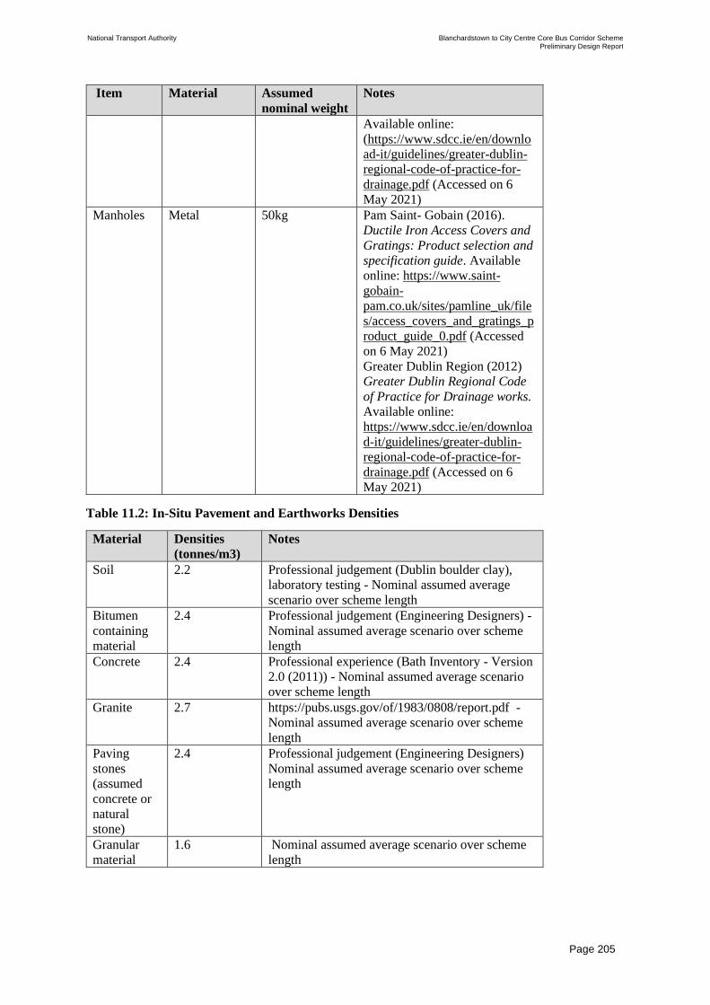
National Transport Authority Blanchardstown to City Centre Core Bus Corridor Scheme Preliminary Design Report
| Issue | 7 May 2022
\\GLOBAL\EUROPE\DUBLIN\JOBS\268000\268401-00\4. INTERNAL\4-04 REPORTS\4-04-03 INFRASTRUCTURE\PRELIMINARY DESIGN REPORT\CBC 5\ISSUE MAY 2022\BCIDC-ARP-PMG_PD-
0005_XX_00-RP-ZZ-0001_ISSUE.DOCX
Page 205
Item Material Assumed
nominal weight
Notes
Available online:
(https://www.sdcc.ie/en/downlo
ad-it/guidelines/greater-dublin-
regional-code-of-practice-for-
drainage.pdf (Accessed on 6
May 2021)
Manholes Metal 50kg Pam Saint- Gobain (2016).
Ductile Iron Access Covers and
Gratings: Product selection and
specification guide. Available
online: https://www.saint-
gobain-
pam.co.uk/sites/pamline_uk/file
s/access_covers_and_gratings_p
roduct_guide_0.pdf (Accessed
on 6 May 2021)
Greater Dublin Region (2012)
Greater Dublin Regional Code
of Practice for Drainage works.
Available online:
https://www.sdcc.ie/en/downloa
d-it/guidelines/greater-dublin-
regional-code-of-practice-for-
drainage.pdf (Accessed on 6
May 2021)
Table 11.2: In-Situ Pavement and Earthworks Densities
Material Densities
(tonnes/m3)
Notes
Soil 2.2 Professional judgement (Dublin boulder clay),
laboratory testing - Nominal assumed average
scenario over scheme length
Bitumen
containing
material
2.4 Professional judgement (Engineering Designers) -
Nominal assumed average scenario over scheme
length
Concrete 2.4 Professional experience (Bath Inventory - Version
2.0 (2011)) - Nominal assumed average scenario
over scheme length
Granite 2.7 https://pubs.usgs.gov/of/1983/0808/report.pdf -
Nominal assumed average scenario over scheme
length
Paving
stones
(assumed
concrete or
natural
stone)
2.4 Professional judgement (Engineering Designers)
Nominal assumed average scenario over scheme
length
Granular
material
1.6 Nominal assumed average scenario over scheme
length

National Transport Authority Blanchardstown to City Centre Core Bus Corridor Scheme Preliminary Design Report
| Issue | 7 May 2022
\\GLOBAL\EUROPE\DUBLIN\JOBS\268000\268401-00\4. INTERNAL\4-04 REPORTS\4-04-03 INFRASTRUCTURE\PRELIMINARY DESIGN REPORT\CBC 5\ISSUE MAY 2022\BCIDC-ARP-PMG_PD-
0005_XX_00-RP-ZZ-0001_ISSUE.DOCX
Page 206
Table 11.3: Utilities Material Excavation Assumptions
Asset type Assumed
nominal
average
trench
width
(m)
Assumed
material spec.
(TII)
Assumed
nominal
average
trench
depth under
pavement
layer (m)
Notes
Drainage
Pipe Bedding
Excavation
Assessment
(assumed at
1.2m cover
i.e obvert at
0.35m under
capping layer
of road)
0.9 Class 2/4/U1
Cohesive
subgrade
material
1.25 Irish Water (2020)
Water
Infrastructure
Standard Details:
Connections and
Developer Services.
Available online:
https://www.water.i
e/connections/Wate
r-Standard-
Details.pdf
(Accessed on 6
May 2021)
Foul Sewer
Pipe Bedding
Excavation
Assessment
(assumed at
1.2m cover
i.e obvert at
0.35m under
capping layer
of road)
0.9 Class 2/4/U1
Cohesive
subgrade
material
1.25 Irish Water (2020)
Water
Infrastructure
Standard Details:
Connections and
Developer Services.
Available online:
https://www.water.i
e/connections/Wate
r-Standard-
Details.pdf
(Accessed on 6
May 2021)
Potable
water Pipe
Bedding
Excavation
Assessment
(assumed at
1.2m cover
i.e obvert at
0.35m under
capping layer
of road)
0.9 Class 2/4/U1
Cohesive
subgrade
material
1.25 Irish Water (2020)
Water
Infrastructure
Standard Details:
Connections and
Developer Services.
Available online:
https://www.water.i
e/connections/Wate
r-Standard-
Details.pdf
(Accessed on 6
May 2021)
Road
Pavement
Excavation
(extra over
in addition to
road
widening
0.9 Bitumen
(surface+binder
and base)
0.35 Irish Water (2020)
Water
Infrastructure
Standard Details:
Connections and
Developer Services.
Available online:
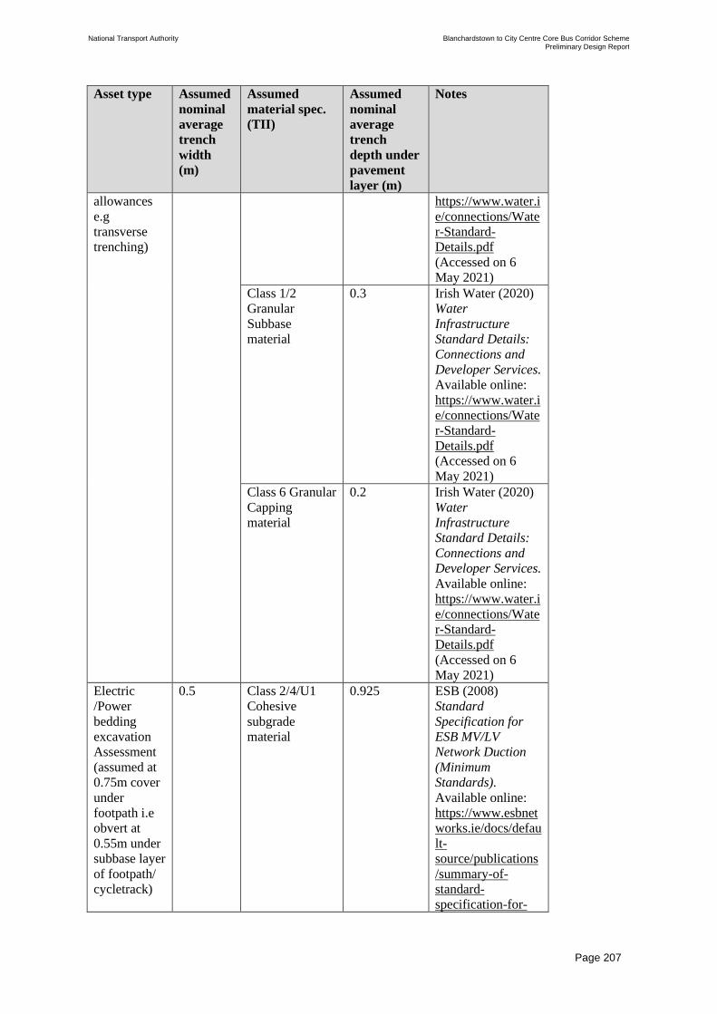
National Transport Authority Blanchardstown to City Centre Core Bus Corridor Scheme Preliminary Design Report
| Issue | 7 May 2022
\\GLOBAL\EUROPE\DUBLIN\JOBS\268000\268401-00\4. INTERNAL\4-04 REPORTS\4-04-03 INFRASTRUCTURE\PRELIMINARY DESIGN REPORT\CBC 5\ISSUE MAY 2022\BCIDC-ARP-PMG_PD-
0005_XX_00-RP-ZZ-0001_ISSUE.DOCX
Page 207
Asset type Assumed
nominal
average
trench
width
(m)
Assumed
material spec.
(TII)
Assumed
nominal
average
trench
depth under
pavement
layer (m)
Notes
allowances
e.g
transverse
trenching)
https://www.water.i
e/connections/Wate
r-Standard-
Details.pdf
(Accessed on 6
May 2021)
Class 1/2
Granular
Subbase
material
0.3 Irish Water (2020)
Water
Infrastructure
Standard Details:
Connections and
Developer Services.
Available online:
https://www.water.i
e/connections/Wate
r-Standard-
Details.pdf
(Accessed on 6
May 2021)
Class 6 Granular
Capping
material
0.2 Irish Water (2020)
Water
Infrastructure
Standard Details:
Connections and
Developer Services.
Available online:
https://www.water.i
e/connections/Wate
r-Standard-
Details.pdf
(Accessed on 6
May 2021)
Electric
/Power
bedding
excavation
Assessment
(assumed at
0.75m cover
under
footpath i.e
obvert at
0.55m under
subbase layer
of footpath/
cycletrack)
0.5 Class 2/4/U1
Cohesive
subgrade
material
0.925 ESB (2008)
Standard
Specification for
ESB MV/LV
Network Duction
(Minimum
Standards).
Available online:
https://www.esbnet
works.ie/docs/defau
lt-
source/publications
/summary-of-
standard-
specification-for-

National Transport Authority Blanchardstown to City Centre Core Bus Corridor Scheme Preliminary Design Report
| Issue | 7 May 2022
\\GLOBAL\EUROPE\DUBLIN\JOBS\268000\268401-00\4. INTERNAL\4-04 REPORTS\4-04-03 INFRASTRUCTURE\PRELIMINARY DESIGN REPORT\CBC 5\ISSUE MAY 2022\BCIDC-ARP-PMG_PD-
0005_XX_00-RP-ZZ-0001_ISSUE.DOCX
Page 208
Asset type Assumed
nominal
average
trench
width
(m)
Assumed
material spec.
(TII)
Assumed
nominal
average
trench
depth under
pavement
layer (m)
Notes
esb-networks-
mvlv-
ducting.pdf?sfvrsn=
f34b33f0_4
(Accessed on 6
May 2021)
Comms
bedding
Excavation
Assessment
(assumed at
0.75m cover
under
footpath i.e
obvert at
0.55m
subbase layer
of footpath)
0.5 Class 2/4/U1
Cohesive
subgrade
material
0.925 ESB (2008)
Standard
Specification for
ESB MV/LV
Network Duction
(Minimum
Standards).
Available online:
https://www.esbnet
works.ie/docs/defau
lt-
source/publications
/summary-of-
standard-
specification-for-
esb-networks-
mvlv-
ducting.pdf?sfvrsn=
f34b33f0_4
(Accessed on 6
May 2021)
Street
Lighting/
Comms
/Traffic
Excavation
Assessment
(assumed at
0.6m cover
under
footpath i.e
obvert at
0.4m
subbase layer
of footpath)
0.5 Class 2/4/U1
Cohesive
subgrade
material
0.56 South Dublin
County Council
(2016) Public
Lighting
Specification.
Available online:
https://www.sdcc.ie
/en/services/transpo
rt/public-
lighting/sdcc-
public-lighting-
specification.pdf
(Accessed on 6
May 2021)
Gas
Excavation
Assessment
(assumed at
0.6m cover
i.e obvert at
0.45 Class 2/4/U1
Cohesive
subgrade
material
0.7 Gas Network
Ireland (2018)
Guidelines for
Designers and
Builders- Industrial
and Commercial

National Transport Authority Blanchardstown to City Centre Core Bus Corridor Scheme Preliminary Design Report
| Issue | 7 May 2022
\\GLOBAL\EUROPE\DUBLIN\JOBS\268000\268401-00\4. INTERNAL\4-04 REPORTS\4-04-03 INFRASTRUCTURE\PRELIMINARY DESIGN REPORT\CBC 5\ISSUE MAY 2022\BCIDC-ARP-PMG_PD-
0005_XX_00-RP-ZZ-0001_ISSUE.DOCX
Page 209
Asset type Assumed
nominal
average
trench
width
(m)
Assumed
material spec.
(TII)
Assumed
nominal
average
trench
depth under
pavement
layer (m)
Notes
0.4m under
subbase layer
of footpath)
(Non-domestic)
Sites. Available
online:
https://www.gasnet
works.ie/Guidelines
-for-Designers-
and-Builders-
Industrial-and-
Commercial-
Sites.pdf (Accessed
6 May 2021)
Table 11.4: Footpath and Verge Widening Excavation Assumptions
Layer Assumed
Layer
thickness
(m)
Assumed material spec. (TII)
Footpath surface
treatment due to all
works (remove and
replace)
0.1 Concrete
Footpath sub-layer
excavation due to Full
Depth Construction
(FDC) widening
(material under footpath)
0.1 Granular material- Class 1/2 Granular
Subbase material
0.75 Soil and stones- Class 2/4/U1 Cohesive
subgrade material
Verge and sub-layer
excavation due to FDC
widening (material under
verge)
0.3 Soil and stones- Class 5 Topsoil
material
0.55 Soil and stones- Class 4/U1 Cohesive
subgrade material
Verge and sub-layer
excavation due to
footpath widening
(material under verge)
0.3 Soil and stones- Class 5 Topsoil
material
0 Soil and stones- Class 4/U1 Cohesive
subgrade material
Road surface treatment
due to road markings and
utilities trench
reinstatement (mill & re-
sheet)
0.05 Bitumen containing material - Bitumen
(surface)
Road sub-layer
excavation due to FDC
(material under road)
0.3 Bitumen containing material - Bitumen
(binder and base)
0.3 Class 1/2 Granular Subbase material
0.2 Granular material - Class 6 Granular
Capping material
0 Soil and stones- Class 2/4/U1 Cohesive
subgrade material
https://www.gasnetworks.ie/Guidelines-for-Designers-and-Builders-Industrial-and-Commercial-Sites.pdf
https://www.gasnetworks.ie/Guidelines-for-Designers-and-Builders-Industrial-and-Commercial-Sites.pdf
https://www.gasnetworks.ie/Guidelines-for-Designers-and-Builders-Industrial-and-Commercial-Sites.pdf
https://www.gasnetworks.ie/Guidelines-for-Designers-and-Builders-Industrial-and-Commercial-Sites.pdf
https://www.gasnetworks.ie/Guidelines-for-Designers-and-Builders-Industrial-and-Commercial-Sites.pdf

National Transport Authority Blanchardstown to City Centre Core Bus Corridor Scheme Preliminary Design Report
| Issue | 7 May 2022
\\GLOBAL\EUROPE\DUBLIN\JOBS\268000\268401-00\4. INTERNAL\4-04 REPORTS\4-04-03 INFRASTRUCTURE\PRELIMINARY DESIGN REPORT\CBC 5\ISSUE MAY 2022\BCIDC-ARP-PMG_PD-
0005_XX_00-RP-ZZ-0001_ISSUE.DOCX
Page 210
11.3 Waste Estimate Summary
The majority of the waste arisings from the construction of the Proposed Scheme
accumulates from excavation related activities and demolition works due to proposed public
domain street works. The waste produced as a result of the Proposed Scheme has been
summarised below along with an outline of how this waste will be managed.
In line with current practice in Ireland, surplus materials and wastes from the Proposed
Scheme will be managed as follows:
• Where feasible, naturally occurring excavated material will be reused within construction
in the Proposed Scheme in accordance with Article 2 of the Waste Directive Regulations,
Waste Framework Directive and Section 3 of the Waste Management Act 1996, as
amended;
• Where possible, excavation material will be used as engineering and landscaping material
within the Proposed Scheme where practicable and on other projects requiring the types
of materials generated. Reuse of topsoil and excavated material within the Proposed
Scheme is proposed where possible. The material will also be subject to testing to ensure
it is suitable for its proposed end use;
• Article 28 (End-of-Waste) (EPA 2020) criteria may be met by the excavation material,
should such facilities become available by the time of commencement of construction of
the Proposed Scheme, ensuring that the material will meet the acceptance criteria set out
in Article 28 of the Waste Directive Regulations;
• All excavation wastes requiring removal from site for recycling or recovery will be
delivered to facilities which are authorised under the Waste Management Act 1996 (i.e.
which hold a Certificate of Registration, Waste Facility Permit or EPA Licence).
Examples of recycling / recovery activities for excavation material may include:
o Processing of stone to produce construction aggregate;
o Backfilling of quarries; and
o Raising land for site improvement or development.
• There is no crushing and screening of material planned for the Proposed Scheme;
• All wastes removed from site will be delivered to recovery or disposal facilities holding a
Certificate of Registration, Waste Facility Permit or EPA Waste Licence; and
• All wastes removed from site will be transported by the holder of the appropriate waste
collection permit, granted in accordance with S.I. No. 820/2007 - Waste Management
(Collection Permit) Regulations 2007.
It will be the responsibility of the appointed contractor to secure agreements for acceptance of
surplus excavation materials from the Proposed Scheme in authorised and regulated facilities,
in accordance with the Waste Management Act 1996 and associated regulations.
11.3.1 Demolition
Table 11.5 shows the estimated quantity and type of waste that will be generated by
demolition activities in connection with the Proposed Scheme along with how much of this
material could potentially be reused or recovered.

National Transport Authority Blanchardstown to City Centre Core Bus Corridor Scheme Preliminary Design Report
| Issue | 7 May 2022
\\GLOBAL\EUROPE\DUBLIN\JOBS\268000\268401-00\4. INTERNAL\4-04 REPORTS\4-04-03 INFRASTRUCTURE\PRELIMINARY DESIGN REPORT\CBC 5\ISSUE MAY 2022\BCIDC-ARP-PMG_PD-
0005_XX_00-RP-ZZ-0001_ISSUE.DOCX
Page 211
Table 11.5: Estimated Demolition Waste Types and Quantities
Waste Type Approximate Waste and
Material Quantity
(tonnes)
Potential Recoverable/
Reusable Material
Recoverable/ Reusable
Quantities (tonnes)
Concrete,
bricks, tiles
and similar
1,900 100% 1,900
Metals 620 100% 620
Segregated
wood, glass
and plastic
80 100% 80
Total 2,600 2,600
Potentially 100% of material generated from the demolition phase of the Proposed Scheme
could be considered for reuse for construction within the Proposed Scheme or in other
construction projects in accordance with Article 27 of the Waste Directive Regulations. It
will be the responsibility of the appointed contractor to review feasibility of reuse of
materials and ensure that the necessary testing is undertaken to demonstrate compliance with
Article 27, as appropriate.
Where feasible, street and roadside infrastructure such as bus stops, lighting poles, traffic
signals, and signs will be reused within the Proposed Scheme and will not become a waste.
The appointed contractor will be responsible for ensuring compliance with all relevant
legislation.
Materials will require on-site segregation by waste classification and if not suitable for onsite
or offsite reuse, will be delivered to an authorised recycling or recovery facility. Where street
furniture is a waste, it may be necessary to separate elements at source such as lightbulbs
from luminaires and metals from other components and deliver these separately to suitable
authorised recycling or recovery facilities.
Where metal railings and gates are removed, typically these have inherent value due to their
metal content. These will be source-segregated and delivered for metal recycling to an
authorised waste facility. Some example facilities which are currently authorised to accept
metal and electronic waste include:
• Irish Lamp Recycling Co. Ltd, Woodstock Industrial Estate, Kilkenny Road, Athy,
Co. Kildare; and
• Hammond Lane Metal Company, Pigeon House Road, Dublin 4, Dublin
The least preferable option is disposal to an authorised facility which will only take place
when all viable opportunities for reuse and recycling have been investigated by the appointed
contractor for feasibility and ruled out.
Prior to commencing construction, the appointed contractor will undertake vegetation
clearance and street furniture removal. Limited demolition will be undertaken as part of the
construction works for the Proposed Scheme.

National Transport Authority Blanchardstown to City Centre Core Bus Corridor Scheme Preliminary Design Report
| Issue | 7 May 2022
\\GLOBAL\EUROPE\DUBLIN\JOBS\268000\268401-00\4. INTERNAL\4-04 REPORTS\4-04-03 INFRASTRUCTURE\PRELIMINARY DESIGN REPORT\CBC 5\ISSUE MAY 2022\BCIDC-ARP-PMG_PD-
0005_XX_00-RP-ZZ-0001_ISSUE.DOCX
Page 212
11.3.2 Excavation
Table 11.6 shows the estimated quantity and type of waste that will be generated by the
excavation activities of the Proposed Scheme.
Table 11.6: Summary of Excavation Material Type and Quantities
Waste Type Approximate Waste and Material
quantity (tonnes)
Bituminous mixtures 56,000
Concrete, bricks, tiles and similar 11,000
Class 1/2 Granular Subbase material from footway and
road
26,000
Class 6 Granular Capping material from road widening 11,000
Class 2/4/U1 Cohesive subgrade material (made
ground material under footpath/road
44,000
Class 4/U1 Cohesive subgrade fill material (made
ground material under verge)
8,000
Class 5 topsoil material (surface material from verge) 9,000
Total 165,000
It is estimated that a total of 165,000 Tonnes of material will be excavated as part of the
construction works. Due to the nature of the works in an urban environment there are limited
opportunities to achieve a cut/fill balance of materials that could be more readily
accommodated on a greenfield project where earthworks embankments/ bunds are more
common.
Where material is excavated, it is envisaged that the contractor will seek to reuse or recycle it,
where practicable, within the Proposed Scheme through implementation of the measures set
out below for each waste type identified within Table 11.6. To further establish an
understanding of how soil and stone waste materials could potentially be reused/recovered,
they have been further broken down into the likely TII material specification and class.
Excavated materials such as capping, subbase, bituminous and concrete materials could be
reused or recycled in line with TII specifications:
• capping, subbase, bituminous and concrete materials could be reused or recycled in fill
and capping materials (e.g. 6A, 6B, 6C, 6F, 6G, 6H ,6I, 6M, 6N) providing they comply
with the Specification for Road Works Series 600 – Earthworks (CC-SPW-00600);
• subbase, bituminous and concrete materials could be reused or recycled in subbase or
base materials (e.g. Granular Material Type A to Clause 803) providing they comply
with the Specification for Road Works Series 800 – Unbound and Cement Bound
Mixtures (CC-SPW-00800); and
• subbase and bituminous materials could be recycled in base or binder materials (e.g.
Asphalt Concrete base and binder products to Clause 3 or Low Energy Bound Mixtures
to Clause 8.1) providing they comply with Road Pavements – Bituminous Materials
(CC-SPW-00900).

National Transport Authority Blanchardstown to City Centre Core Bus Corridor Scheme Preliminary Design Report
| Issue | 7 May 2022
\\GLOBAL\EUROPE\DUBLIN\JOBS\268000\268401-00\4. INTERNAL\4-04 REPORTS\4-04-03 INFRASTRUCTURE\PRELIMINARY DESIGN REPORT\CBC 5\ISSUE MAY 2022\BCIDC-ARP-PMG_PD-
0005_XX_00-RP-ZZ-0001_ISSUE.DOCX
Page 213
It is assumed that some of the granular subbase and capping materials will contain excessive
cohesive material due to the excavation process and therefore unsuitable for direct reuse. This
excess material could be sent to a suitable recovery facility and reused as Class 2 general fill
or Class 4 landscape fill material, depending on excavation methods employed by the
contractor and existing ground conditions.
Excavated cohesive subgrade material is likely to be unacceptable for direct reuse for
pavement construction, however, this material can be tested for quality and contamination
and could potentially be reused as Class 2 general fill or Class 4 landscape fill under the
provisions of Article 27. Material which meets the necessary acceptance criteria may be
delivered to an authorised soil recovery facility. Material which requires recycling will be
sent to an authorised waste facility and may be used in accordance with Article 28 of the
European Communities (Waste Directive) Regulations 2011 - S.I. 126 of 2011 as amended.
Article 28 sets the criteria which must be complied with and the EPA must use to determine,
when a waste reaches “end of waste” status and becomes a material. Large quantities of this
type of material are unlikely to be reused on site due to the nature of the works in an urban
environment with limited embankments / earthworks bunds being constructed. Therefore,
excavated cohesive subgrade material may be recovered and used on future projects in the
industry.
Topsoil material could be reused in new landscaped areas. It is assumed that some of this
material will be contaminated with unsuitable material during the excavation process and
therefore will be sent to a suitable recovery facility and reused as Class 2 general fill or Class
4 landscape fill, along with the excavated cohesive subgrade material.
Future design stages will undertake additional site investigations to inform the detailed
pavement design and associated excavation quantity assessment.
11.3.3 Municipal Waste
It is anticipated that there will be approximately 250, up to 300 at peak, construction staff
employed over the Construction Phase of the Proposed Scheme. Small volumes of general
municipal wastes will be generated by construction staff during the Construction Phase (e.g.,
from offices and welfare facilities). Segregation facilities will be provided on the construction
site to ensure that recovery and recycling of such wastes is maximised.
11.3.4 Operational Phase
Operational waste may arise as a result of carriageway maintenance which will be undertaken
at regular intervals, or as necessary. This will primarily consist of bitumen containing
material due to maintenance of carriageway pavement. Only waste generated from the areas
where road widening and narrowing, undertaken as part of the Proposed Scheme, have taken
place will be considered in this assessment, as routine maintenance, and associated waste
generated, would be carried out on the existing road irrespective of the Proposed Scheme. It
is important to note that maintenance operations will be undertaken by the relevant Local
Authority.
It is envisaged that bitumen containing material will be reused within new carriageway
construction as far as practicable and in accordance with all applicable legislation. Bitumen
containing materials which are not incorporated into the Proposed Scheme are likely to be
reused where feasible off-site as a by-product in accordance with Article 27, of the Waste

National Transport Authority Blanchardstown to City Centre Core Bus Corridor Scheme Preliminary Design Report
| Issue | 7 May 2022
\\GLOBAL\EUROPE\DUBLIN\JOBS\268000\268401-00\4. INTERNAL\4-04 REPORTS\4-04-03 INFRASTRUCTURE\PRELIMINARY DESIGN REPORT\CBC 5\ISSUE MAY 2022\BCIDC-ARP-PMG_PD-
0005_XX_00-RP-ZZ-0001_ISSUE.DOCX
Page 214
Framework Directive. Bitumen containing materials may be recycled in accordance with the
provisions of an Article 28 (End of Waste) decision by the EPA (EPA 2020).
The quantity of bitumen containing material generated, over the assumed lifetime of the
Proposed Scheme (60 years), will decrease by approximately 4,550 tonnes. Therefore, there
will be a decrease in maintenance needs during operation of the Proposed Scheme, in
comparison to required maintenance of the existing carriageway. This is due to an overall
narrowing of the carriageway.

National Transport Authority Blanchardstown to City Centre Core Bus Corridor Scheme Preliminary Design Report
| Issue | 7 May 2022
\\GLOBAL\EUROPE\DUBLIN\JOBS\268000\268401-00\4. INTERNAL\4-04 REPORTS\4-04-03 INFRASTRUCTURE\PRELIMINARY DESIGN REPORT\CBC 5\ISSUE MAY 2022\BCIDC-ARP-PMG_PD-
0005_XX_00-RP-ZZ-0001_ISSUE.DOCX
Page 215
12 Traffic Signs, Lighting and Communications
12.1 Introduction
The existing signage and road markings along the extents of the Proposed Scheme will be
modified to clearly communicate information, regulatory and safety messages to the
corridor’s users. In addition, the existing lighting and communication equipment along the
Proposed Scheme has been reviewed and proposals developed to upgrade where necessary.
12.2 Traffic Signage Strategy
A preliminary traffic signage design has been undertaken to identify the requirements of the
Proposed Scheme. A combination of Information, Regulatory and Warning signs have been
assessed taking consideration of key destinations/centres; intersections/decision points; built
and natural environment. In line with DMURS, the signage proposals have been kept to the
minimum requirements of the Traffic Signs Manual (TSM) to avoid sign congestion within
the Proposed Scheme corridor.
A review of the existing regulatory and warning signs in the vicinity of the Proposed Scheme
was carried out to identify unnecessary repetitive and redundant signage to be removed. This
includes rationalising signage structures by better utilising individual sign poles and
clustering signage together on a single pole.
On review, the following design changes proposed between the intersection of Cabra
Road/Navan Road and Ellis Quay will alter the traffic patterns in this area:
• New left turn from North Circular Road to Cabra Road;
• New right turn from Cabra Road to North Circular Road;
• Southbound bus gate from Aughrim Street to Manor Street;
• Northbound & Southbound bus gate at the intersection of Manor Street, Prussia Street and
Aughrim Street;
• Southbound bus gate at the intersection of Navan Road/Old Cabra Road and Cabra Road
and a northbound bus gate on Old Cabra Road, at the railway overbridge, to the south of
Glenbeigh Road junction; and
• Northbound Bus Gate at Blackhall Place / King Street North junction, with a new right
turn for northbound general traffic at this junction.
Traffic management measures in the form of sections of one-way street and / or turn bans
have also been devised to minimise traffic impacts on roads adjacent to the proposed core bus
corridor due to any rerouting of traffic (which may occur due to the priority given on the bus
corridor scheme to pedestrians, cyclists and buses).
Turning bans and other traffic management measures will also be implemented on the route
to direct traffic away from either the Proposed Scheme corridor (to maximise bus journey
time reliability) or to limit use of side streets as a short-cut route by through traffic. Refer to
Section 4.16 for further information.
These changes are outlined within the Traffic Signs and Road Markings drawing series in
Appendix B, which outlines the associated signage requirements.

National Transport Authority Blanchardstown to City Centre Core Bus Corridor Scheme Preliminary Design Report
| Issue | 7 May 2022
\\GLOBAL\EUROPE\DUBLIN\JOBS\268000\268401-00\4. INTERNAL\4-04 REPORTS\4-04-03 INFRASTRUCTURE\PRELIMINARY DESIGN REPORT\CBC 5\ISSUE MAY 2022\BCIDC-ARP-PMG_PD-
0005_XX_00-RP-ZZ-0001_ISSUE.DOCX
Page 216
12.3 Traffic Signage and Road Markings
12.3.1 Traffic Signage General
A preliminary assessment was undertaken which involved an assessment of major road traffic
signage, including requirements for all information signs (TSM Chapter 2), regulatory signs
(TSM Chapter 5), warning signs (TSM Chapter 6), and road markings (TSM Chapter 7).
On review of the existing traffic signage, it is determined that the main changes to regulatory
signage will be the proposed introduction of turning bans from or to the Proposed Scheme as
indicated within the Traffic Signs and Road Markings drawing series in Appendix B.
Additional directional signs are proposed at the junction of North Circular Road and Cabra
Road to direct road users to the M50 via North Circular Road, reducing the vehicular traffic
within the Proposed Scheme.
In addition to the signs identified above, the existing signs within the Proposed Scheme are
being revised to accommodate the change in road cross-section communicating the
following:
• Information Signs to include geographical information signs, signs indicating facilities,
road layout signs, traffic calming signs and cycle network signs;
• Regulatory signage –e.g. parking regulation signs, bus lanes, pedestrian and cycle
facilities; and
• Warning signs – e.g. Stop and Yield Ahead.
As stated in TSM Chapter 1, in urban areas the obstruction caused by posts located in narrow
pedestrian footpaths will be minimised, ensuring that pedestrians are unimpeded by any such
signage infrastructure. Therefore, where practicable, signs are to be placed on single poles, or
larger signs will be cantilevered from a post at the back of the footpath using H-frames where
necessary. Passively safe posts will be introduced where practicable to eliminate the need for
vehicle restraint systems.
12.3.2 Gantry Signage
Gantries which are affected by the Proposed Scheme have been highlighted within section
8.3.5. It is proposed to provide two new overhead sign gantries on the N3 westbound (GY07
& GY08) with suitable lane designations and directional signage. Sign faces on existing,
relocated and modified gantries will be updated to indicate the new lane destinations and
directional signage installed as part of this scheme.
12.3.3 Road Markings
A preliminary design of road markings has been undertaken in accordance with TSM Chapter
7. Refer to the Traffic Signs and Road Markings drawing series contained within Appendix B
for details. This exercise includes the preliminary road marking design of the following
items:
• Bus lanes;

National Transport Authority Blanchardstown to City Centre Core Bus Corridor Scheme Preliminary Design Report
| Issue | 7 May 2022
\\GLOBAL\EUROPE\DUBLIN\JOBS\268000\268401-00\4. INTERNAL\4-04 REPORTS\4-04-03 INFRASTRUCTURE\PRELIMINARY DESIGN REPORT\CBC 5\ISSUE MAY 2022\BCIDC-ARP-PMG_PD-
0005_XX_00-RP-ZZ-0001_ISSUE.DOCX
Page 217
• Cycle tracks: The pavement will be marked according to best practice guidelines such as
DMURS and the National Cycle Manual with particular attention given to junctions.
Advance Stacking Locations (ASLs) have been designed, where practicable, to provide a
safer passage for cyclists at signal-controlled junctions for straight-ahead or right turn
movements; and
• Pedestrian crossings will be incorporated to connect the network of proposed and existing
footpaths. Wider pedestrian crossings will be provided in locations expected to
accommodate a high number of pedestrians.
12.4 Public Lighting
12.4.1 Existing Lighting
Light Emitting Diode (LED) lanterns will be the light source for any new or relocated public
lighting provided.
The lighting design involves works on functional, heritage and contemporary lighting
installations, on a broad spectrum of lighting infrastructure along the Proposed Scheme. This
will include, but not exclusively, luminaires supplied by underground and overhead cable
installations and those located on ESB Infrastructure.
In locations where road widening and/or additional space in the road margin is required, it is
proposed that the public lighting columns be replaced and relocated to the rear of the
footpath, and the existing lighting columns removed once the new facility is operational. This
will eliminate conflict with pedestrians.
Where significant alterations are proposed to the existing carriageways, the preliminary street
lighting design ensures that the current standard of public lighting is maintained or improved.
Refer to Street Lighting drawings in Appendix B for proposed location of all lighting
columns.
For existing columns that have specific aesthetic requirements, the intent for the replacement
of such columns will include:
• Replacing the existing heritage columns and brackets with identical replica columns and
brackets;
• Replacing existing luminaires with approved LED heritage luminaires; and
• Ensuring that the electrical installation is compliant with the latest version of the National
Rules for Electrical Installations, IS 10101.
12.4.2 New Lighting
All new public lighting will be designed and installed in accordance with the specific lighting
and electrical items set out the following National Standards and guides, including but not
limited to:
• Local Authority Guidance Specifications;
• EN 13201: 2014 Road Lighting (all sections);
• ET211:2003 ‘Code of Practice for Public Lighting Installations in Residential Areas’;
National Transport Authority Blanchardstown to City Centre Core Bus Corridor Scheme Preliminary Design Report
| Issue | 7 May 2022
\\GLOBAL\EUROPE\DUBLIN\JOBS\268000\268401-00\4. INTERNAL\4-04 REPORTS\4-04-03 INFRASTRUCTURE\PRELIMINARY DESIGN REPORT\CBC 5\ISSUE MAY 2022\BCIDC-ARP-PMG_PD-
0005_XX_00-RP-ZZ-0001_ISSUE.DOCX
Page 218
• BS 5489-1 ‘Code of practice for the design of road lighting’;
• TII Publications: Specification for Road Works, Series 1300 & 1400;
• TII Publications Standard Construction Details, Series 1300 & 1400;
• IS EN 40 – Lighting Columns; and
• Institution of Lighting Professionals “GN01 Guidance Notes for Reduction of Obtrusive
Light”.
All new lighting will aim to minimise the effects of obtrusive light at night and reduce visual
impact during daylight. Lighting schemes will comply with the ‘Guidance notes for the
Reduction of Light Pollution’ issued by the Institution of Lighting Professionals (ILP).
12.4.3 Lighting at Stops
The design will include for the provision of lighting in covered areas, open areas and
passenger waiting areas.
The location of the lighting columns will be dictated by the output from the fitting to adhere
to the required uniformity and illuminance required for the specific lighting class for the
associated road. The columns positioned at bus stops will ensure adequate clearances from
moving vehicles.
12.5 Traffic Signals
12.5.1 Above Ground Infrastructure
The Preliminary design shows the proposed locations of above ground infrastructure. This is
included in the Junction Systems Design drawings in Appendix B.
Above ground infrastructure will include:
Traffic Signal Poles
All traffic signal equipment has been designed in accordance with Chapter 9 of the
Department of Transport’s Traffic Signs Manual. The Traffic Signs Manual clearly defines
the requirements and positioning of traffic signal heads, detection equipment, and associated
traffic signal poles.
The Traffic signal modelling, including LinSig models, has been used to determine the signal
head configuration to achieve the required phasing and staging of the traffic signals. This
contributed to the determination of the design and positioning of the traffic signal heads.
Single height Traffic Signal poles typically 3m (as measured from the ground) have
predominantly been proposed to mount traffic signal heads, push button units, and other
equipment. Double height poles, (typically 6m) have been proposed at locations where
additional visibility of the signals is required by the motorist, e.g. high-speed approaches.
Cantilever Traffic Signal Poles
Cantilever poles will be installed on multi-lane approaches where there is a potential for a
high sided vehicle, including buses, to block the clear visibility of the primary traffic signal

National Transport Authority Blanchardstown to City Centre Core Bus Corridor Scheme Preliminary Design Report
| Issue | 7 May 2022
\\GLOBAL\EUROPE\DUBLIN\JOBS\268000\268401-00\4. INTERNAL\4-04 REPORTS\4-04-03 INFRASTRUCTURE\PRELIMINARY DESIGN REPORT\CBC 5\ISSUE MAY 2022\BCIDC-ARP-PMG_PD-
0005_XX_00-RP-ZZ-0001_ISSUE.DOCX
Page 219
of vehicles in the outer lanes. They will also be installed at locations where a median island is
not available to mount a second primary, required to control separate streams on a particular
arm of a junction.
Cantilever poles may also be used to provide a mounting structure for secondary signals,
where a median is not available and a position on opposing primary pole is outside the
required line of sight.
Roadside Cabinets
Most equipment locations will require a roadside cabinet to house and protect electronic,
electrical and communications equipment. Due to health and safety, design, space,
operational and maintenance constraints, it is often necessary to separate these cabinets in
accordance with their function. Typically, a junction will have cabinets for:
• Traffic Signal Control Cabinets;
• Fibre Breakout Cabinets; and
• Electricity supply Metering, Mini and Micro pillars.
Cabinets will be positioned to allow for ease of access by maintenance personnel and to
minimise their impact on the receiving environment. When accessing cabinets, maintenance
personnel will require a clear view of the associated equipment and of approaching vehicles,
pedestrians, and cyclists. Cabinets will be positioned at the back of footpaths, to minimise the
impact on the effective width of the footpath. They will be clustered together at a junction to
minimise the amount of cabling between cabinets and to allow maintenance personnel to
quickly shift operations from one cabinet to another.
In all cases the consideration of the siting of such roadside equipment will prioritise the
access for pedestrians and cyclists in the area and balance the aesthetics of the urban realm
with maintenance requirements.
12.5.2 Underground Infrastructure
The Proposed Scheme includes for a continuous underground ducting network to provide the
necessary communications for devices including traffic signals and CCTV. Where practicable
the Proposed Scheme shall utilise existing ducting and chambers to provide this continuity.
Below ground infrastructure will include:
Ducts
Each device, mounting structure, and cabinet will have associated underground infrastructure
including ducts for:
• Power Cables – installed equipment will require a power supply to function, this is
facilitated by a ducting connection between the electricity supply point and equipment
location. This connection is normally a single power supply duct.
• Communication Cables – to facilitate the provision of fibre optic cable along the
Proposed Scheme will require a telecommunication ducting network consisting of two
communication ducts, with chambers at 180m centres, along one side of the carriageway.
This longitudinal ducting will be continuous along the length of the Proposed Scheme,
with local duct spurs to connect to cabinets and devices.

National Transport Authority Blanchardstown to City Centre Core Bus Corridor Scheme Preliminary Design Report
| Issue | 7 May 2022
\\GLOBAL\EUROPE\DUBLIN\JOBS\268000\268401-00\4. INTERNAL\4-04 REPORTS\4-04-03 INFRASTRUCTURE\PRELIMINARY DESIGN REPORT\CBC 5\ISSUE MAY 2022\BCIDC-ARP-PMG_PD-
0005_XX_00-RP-ZZ-0001_ISSUE.DOCX
Page 220
• Device Cables – devices will require cabling between field equipment and control
equipment. For example, a ring of six ducts will be provided at each junction to allow for
cabling between the traffic signal controller and the traffic signal poles. It is necessary
when designing the ducting provision that sufficient spare capacity is provided to allow
for changes to the field equipment, deployment of additional equipment, or damage to the
ducting provision.
Chambers
Chambers will be required at the termination points of ducts, at regular intervals along ducts
(180m), at changes in direction, and at breakout points for devices.
The position of chambers will be designed to be away from carriageways, pedestrian and
cycle desire lines, and tactile paving. It is important when positioning chambers that they can
be accessed in a safe manner, without the need for extensive traffic and pedestrian
management.
Individual chambers will be designed and sized with consideration given to the number of
ducts and cables that will be routed through the chamber, and the need to provide
maintenance loops of cables within the chambers.
Unless prior agreement is in place, chambers will not be shared between users.
Foundations
All cabinets, poles and mounting structures will require a foundation or mounting frame to be
constructed to allow for their installation. It is envisaged that for traffic signal poles, 5m -8m
CCTV poles, cantilever signal poles and other lightweight mounting structures that retention
sockets will be installed to allow for the easy installation, maintenance and replacement of
structures.
For larger structures, such as high CCTV masts, bespoke mass concrete foundations will be
designed for incorporation into the works.
Cabinet mountings will be designed and constructed in accordance with the manufacturer’s
and local authorities’ standard details, including the incorporation of required vaults,
chambers, earthing rods and mats.
12.5.3 Traffic Signal Priority
Public transport priority will be provided through a number of passive and active means. The
means of passive priority are discussed elsewhere in this document and are based on the
design of the geometry, signing and road markings of the junctions. These include measures
such as bus gates and bus lanes. Active priority will be facilitated through the detection of the
public transport vehicle and communicating their presence to the Traffic Signal Controller for
the implementation of measures on site.
The Local Authorities utilise different controllers and adaptive Urban Traffic Control
systems. The systems can operate in several modes including adaptive, linked, vehicle
actuated, scheduled plans and fixed time modes. Dublin City Council use Sydney
Coordinated Adaptive Traffic System (SCATS) traffic signal controllers. Fingal County
Council use TR2500 type Controllers that feature Split Cycle Offset Optimisation Technique

National Transport Authority Blanchardstown to City Centre Core Bus Corridor Scheme Preliminary Design Report
| Issue | 7 May 2022
\\GLOBAL\EUROPE\DUBLIN\JOBS\268000\268401-00\4. INTERNAL\4-04 REPORTS\4-04-03 INFRASTRUCTURE\PRELIMINARY DESIGN REPORT\CBC 5\ISSUE MAY 2022\BCIDC-ARP-PMG_PD-
0005_XX_00-RP-ZZ-0001_ISSUE.DOCX
Page 221
(SCOOT) for adaptive control. The TR2500 type controllers also feature a Microprocessor
Optimise Vehicle Actuation (MOVA) mode of operation.
Detection will be based on the use of several different technologies, working in concert to
provide comprehensive detection solutions. The detection types will include:
• Embedded Inductive loop detectors – induction detectors will be cut into the road surface
at discrete positions around the junction to detect vehicles approaching, or departing
from, the junction. The position and number of detectors will be dependent on the lane
configuration and the type of traffic signal controller at the junctions. These embedded
induction detectors will require ducting, chambers, and carriageway loop pots, to route
the cables associated with the detector to the traffic signal controller.
• Specialised induction detectors – these can be utilised to detect cyclists on particular
approaches to junctions. These detectors use a concentrated induction pattern to detect the
passage of cyclists.
Above ground detection, including:
• Optical Detection – where it is impractical to install embedded inductive loop detectors
into the carriageway, optical detection may be installed. Using these devices, a virtual
detector is set up in the field of view that trigger alerts to the traffic signal controller.
Optical detectors are generally installed on existing traffic signal poles, or cantilever
traffic signal masts, to provide a clear view of the approach. Additional poles may need to
be installed to provide the optimum field of view for particular approaches.
• Microwave/Radar Detection – Radar detection is used for pedestrian crossings, pedestrian
wait areas, and cycle detection. Similar to the optical detection, virtual detection zones are
set up in the radar field of view that trigger alerts to the traffic signal controller. Radar
detectors are generally installed on existing traffic signal poles, or cantilever traffic signal
masts, to provide a clear view of the approach. Additional poles may need to be installed
to provide the optimum field of view for particular approaches.
• Push Button Units will be installed on traffic signal poles at pedestrian and cycle crossing
points to allow the user to manually alert the traffic signal controller of their presence.
Additional inputs from the Automatic Vehicle Location System (AVLS) and Dedicated Short
Range Communications (DSRC) devices can be provided to notify the Traffic Signal
Controller of the presence of particular vehicles.
The Traffic Signal Controllers will detect the presence of vehicles, including identification of
particular vehicles classes, and use this data to determine the timing to be applied to the
junction in the current and upcoming cycles, including the provision of priority to particular
traffic signal phases as programmed into the traffic signal plans.
12.6 Communications
Communications will be used to connect on-street devices with the appropriate traffic control
rooms. The communications will take the form of:
• Fibre Optic Cable network.
• All local authorities operate fibre optic cable networks. It is envisaged that each of these
networks will be extended along the length of the Proposed Scheme to provide high
bandwidth/low latency communication to Traffic Signal Controllers, CCTV Cameras, and

National Transport Authority Blanchardstown to City Centre Core Bus Corridor Scheme Preliminary Design Report
| Issue | 7 May 2022
\\GLOBAL\EUROPE\DUBLIN\JOBS\268000\268401-00\4. INTERNAL\4-04 REPORTS\4-04-03 INFRASTRUCTURE\PRELIMINARY DESIGN REPORT\CBC 5\ISSUE MAY 2022\BCIDC-ARP-PMG_PD-
0005_XX_00-RP-ZZ-0001_ISSUE.DOCX
Page 222
other apparatus deployed on the Proposed Scheme. Longitudinal ducting, provisionally
two communications ducts, is required along the length of the Proposed Scheme with
access chambers at 180m centres.
• Fibre breakout cabinets will be provided at each Traffic Signal Controller, or CCTV
camera.
• Microwave Wireless Point-to-Point Links - Where it is not practicable to install ducting
for fibre optic cable, or there is a need to provide a high bandwidth/low latency
communication to a remote site or cell, point-to-point microwave communications will be
provided to facilitate the communications link.
• Cellular Subscriber Networks (3G/4G/5G) - Cellular communications will be provided to
low bandwidth devices such as RTPI and Variable Messages Signs (VMS).
12.7 Traffic Monitoring
The preliminary design proposes a comprehensive CCTV camera deployment along the
length of the Proposed Scheme at key locations including junctions. These cameras will
enable the monitoring of traffic flows along the route and provide rapid identification of any
events that are causing, or are likely to cause, disruption to bus services on the route and to
road users in general.
High-definition cameras with a fibre-optic based communications network for the
transmission of video will be provided at each of the proposed CCTV locations. Additionally,
a mains power source will be required at each location where a camera is installed. The
cameras may be fixed position or pan, tilt and zoom (PTZ) depending on the most suitable
option for a given location as well as general operational preferences for fixed or PTZ.
Poles, between 5m - 8m, will be provided at each signalised junction, unless it is directly
adjacent to another observed junction, and as such all approaches are covered by that closed-
circuit television (CCTV). These CCTV poles will be erected using a retention socket as a
foundation.
Higher CCTV masts may be provided at locations where longer fields of view are required,
or where there is a need to mount wireless communications devices at positions to enable
clear line of sight between linked devices. These CCTV masts will require a bespoke mass
concrete foundation.
CCTV poles will be placed at positions, within the junction, to minimise the impact of solar
glare, and to maximise the field of view of the CCTV. In all cases the consideration of the
siting of such roadside equipment shall prioritize the health and safety for pedestrians and
cyclists, access for pedestrians and cyclists in the area and the aesthetics of the street urban
landscape.
12.8 Real-Time Passenger Information
RTPI will be provided at all of the proposed bus stops. This will comprise a “live” display
identifying the estimated arrival time of each bus at the stop.

National Transport Authority Blanchardstown to City Centre Core Bus Corridor Scheme Preliminary Design Report
| Issue | 7 May 2022
\\GLOBAL\EUROPE\DUBLIN\JOBS\268000\268401-00\4. INTERNAL\4-04 REPORTS\4-04-03 INFRASTRUCTURE\PRELIMINARY DESIGN REPORT\CBC 5\ISSUE MAY 2022\BCIDC-ARP-PMG_PD-
0005_XX_00-RP-ZZ-0001_ISSUE.DOCX
Page 223
12.8.1 RTPI Display Positioning and Mounting
The RTPI display, where present, is typically located adjacent to the shelter on the same side
as approaching buses so that people waiting at the stop can simultaneously view both the
display and the oncoming buses. Figure 12.1 illustrates this.
Figure 12.1: Typical layout for bus stop with RTPI display
The display is often placed around 4-5m from the shelter to maintain pedestrian access to the
shelter while also enabling a clear view of the display from within the shelter. However,
although this is considered the optimum position for a display, the precise location of it will
be dictated by other site-based factors such as pedestrian and cyclist access (both to/from the
stop and for those passing by) as well as requirements for other bus stop facilities such as
waste bins, cycle storage and signage. Other physical restrictions (e.g. narrow footway, other
street furniture, walls, and buildings) may also influence the exact location of the display at
each stop.
12.8.2 Power Supply for RTPI Display and Bus Shelter
The stand-alone design of the proposed RTPI display means that a physical link between the
display and the bus shelter is not required. However, the display will nonetheless require a
connection to a mains power supply. This can be shared with the supply to the bus shelter, as
shown in Figure 12.1 from a mains distribution cabinet or feeder pillar located at the bus stop,
where the mains service provider (DNO) will terminate its incoming connection. This cabinet
/pillar will provide mains power to both the RTPI display and the shelter.
The bus shelter will commonly include a mains power distribution unit for all of the
equipment in the shelter that requires mains power - usually lighting and/or advertising. Most
often this distribution unit is located under the seating, although it can vary according to the
shelter design.
The shelter installer will provide a connection from this unit to the cabinet/pillar containing
the mains power supply for the bus stop, as shown in Figure 12.1.

National Transport Authority Blanchardstown to City Centre Core Bus Corridor Scheme Preliminary Design Report
| Issue | 7 May 2022
\\GLOBAL\EUROPE\DUBLIN\JOBS\268000\268401-00\4. INTERNAL\4-04 REPORTS\4-04-03 INFRASTRUCTURE\PRELIMINARY DESIGN REPORT\CBC 5\ISSUE MAY 2022\BCIDC-ARP-PMG_PD-
0005_XX_00-RP-ZZ-0001_ISSUE.DOCX
Page 224
12.8.3 Data Communications for RTPI Display
The majority of RTPI systems currently in operation now use the mobile phone
(GPRS/3G/4G) network as the method of data communication between each display and the
central (“back office”) bus location/passenger information system. This comprises a small
mobile network comms device (including the SIM card) installed within the RTPI display
housing. It is assumed for the purpose of this design that such connectivity will be used for
provision of RTPI on the Proposed Scheme with the mains power for the display - as
described above – also providing power for this comms device. In this case no ducting will be
required for data comms at the bus stop and the only physical connection to the display (i.e.
ducting and cabling) will therefore be as described above for mains power.
12.9 Roadside Variable Message Signs
Three existing Variable Messaging Signs (VMS) will be retained as part of the Proposed
Scheme. An existing VMS sign is located at the end of the inbound merge lane to the N3
from Snugborough Road. A new VMS structure will be provided at this location but set back
from the original location to allow for widening of the slip road.
An existing VMS sign is located in the central reservation to the south of the intersection of
Navan Road and Hampton Green. Extension to the right turn pocket at the Cabra library
junction has resulted in this central reservation being shortened. This VMS sign will be
relocated to a section of the retained central reservation at Cabra Library.
An existing VMS is also located in the outbound verge of the R147 Navan Road
approximately 350m east of the Auburn Avenue junction. This VMS will remain in its
current location.
12.10 Safety and Security
The requirement for a pleasant, safe and secure environment for passengers waiting at Bus
Stops and undertaking their journeys is a key component of the proposed public transport
service. This is facilitated by the provision of:
• RTPI – Each stop will be provided with Real Time Passenger Information showing the
estimated time of arrival of subsequent buses; and
• Public Lighting – each stop will have public lighting designed to ensure the safe operation
of the stops in all lighting conditions and to enhance the sense of security at the stops.
12.11 Maintenance
All traffic signal, CCTV, and communications equipment will be designed and located to be
accessed and maintained frequently. All equipment will be accessible without disrupting
pedestrian, bicycle, or vehicle traffic and without the use of special equipment.
Apparatus will be designed and located to allow for easy access and the safe maintenance of
the Proposed Scheme into the future. This will include:
• Use of retention sockets, where applicable, for the erection of Traffic Signals, CCTV,
Above Ground Detection, and other equipment mounting poles to allow for the ease of
installation, maintenance and replacement;

National Transport Authority Blanchardstown to City Centre Core Bus Corridor Scheme Preliminary Design Report
| Issue | 7 May 2022
\\GLOBAL\EUROPE\DUBLIN\JOBS\268000\268401-00\4. INTERNAL\4-04 REPORTS\4-04-03 INFRASTRUCTURE\PRELIMINARY DESIGN REPORT\CBC 5\ISSUE MAY 2022\BCIDC-ARP-PMG_PD-
0005_XX_00-RP-ZZ-0001_ISSUE.DOCX
Page 225
• The use of lightweight equipment poles, where appropriate, such as cantilever signal
poles. Consideration will be given to the selection of products that allow for maintenance
activities to be undertaken from ground level, such as tilt down poles or poles with wind-
down mechanisms;
• Placement of poles and retention sockets within 7m of chambers to provide ease of
installation and replacement of cables;
• Locating chambers away from pedestrian desire lines, and areas of tactile paving. This is
to provide for a reduced impact of Traffic Management;
• On longitudinal duct runs, chambers to be placed at 180m centres, where practicable, to
allow for the ease of installation and replacement of cables;
• Safe areas to be provided for the access and parking of maintenance vehicles; and
• Locating controller, and other, cabinets in positions that allow for safe access and clear
visibility of the operation of the junction.
National Transport Authority Blanchardstown to City Centre Core Bus Corridor Scheme Preliminary Design Report
| Issue | 7 May 2022
\\GLOBAL\EUROPE\DUBLIN\JOBS\268000\268401-00\4. INTERNAL\4-04 REPORTS\4-04-03 INFRASTRUCTURE\PRELIMINARY DESIGN REPORT\CBC 5\ISSUE MAY 2022\BCIDC-ARP-PMG_PD-
0005_XX_00-RP-ZZ-0001_ISSUE.DOCX
Page 226
13 Land Use and Accommodation Works
13.1 Summary of Land Use
The land use along the Proposed Scheme comprises a mix of residential and commercial
properties. The various land uses are described in the sections below. The extent of the
impact due to the Proposed Scheme on a landowner’s holding is shown on the Compulsory
Purchase Order maps.
The following is a description of the land use along the Proposed Scheme divided into 5
sections.
N3 Blanchardstown Junction to Snugborough Road
The Proposed Scheme commences at Junction 3 (Blanchardstown / Mulhuddart) eastbound
off-slip from the N3. The Proposed Scheme continues through the Blanchardstown Shopping
Centre with a Bus Interchange being provided. The shopping centre is surrounded by the N3
to the north and east, leisure facilities to the south and housing estates to the north-west. The
Proposed Scheme progresses towards the Snugborough Road via L3020 which is bordered by
the N3 to the east and commercial and leisure units to the west.
Lands are required through this section to facilitate the scheme, including junction
reconfiguration, a new car park access from Blanchardstown Road South, provision of bus
layover spaces and Bus Interchange in the vicinity of the shopping centre, widening of
carriageway between the Crowne Plaza junction and the tie-in with the Snugborough junction
upgrade scheme, widening of a footpath adjacent to Millennium Park and the construction of
retaining walls (RW01, RW10, RW11, RW12 and RW13).
Temporary land take is required within this section to facilitate:
• Footpath works and new left turn filter lane along the Old Navan Road;
• The construction of retaining walls RW01, RW10, RW11 and RW12;
• The reconfiguration and regrading of Blanchardstown Shopping centre bus and car
parking;
• Regrading works in Blanchardstown shopping centre at the Blakestown Way
/Blanchardstown Road South junction and along Blanchardstown Road South;
• Widening of carriageway between Crowne Plaza junction and the junction adjacent to the
Liberty Insurance building (Ch A0+200 to Ch A0+600); and
• Construction of a new boundary wall at Millennium Park.
Snugborough Road to N3 / M50 Junction
The Proposed Scheme follows the N3 carriageway from Snugborough Road to the M50
motorway junction. To the north of the N3, the Proposed Scheme is bordered by Tolka
Valley Park and Waterville Park, along with an Annex 1 habitat and woodland. To the south
of the N3, the land use consists of rural grassland to the western side and extensive modern
suburban residential developments further east.

National Transport Authority Blanchardstown to City Centre Core Bus Corridor Scheme Preliminary Design Report
| Issue | 7 May 2022
\\GLOBAL\EUROPE\DUBLIN\JOBS\268000\268401-00\4. INTERNAL\4-04 REPORTS\4-04-03 INFRASTRUCTURE\PRELIMINARY DESIGN REPORT\CBC 5\ISSUE MAY 2022\BCIDC-ARP-PMG_PD-
0005_XX_00-RP-ZZ-0001_ISSUE.DOCX
Page 227
In addition to permanent land take, the existing grass median will be narrowed to facilitate
the Proposed Scheme. Elements of the Proposed Scheme for which permanent land take is
required includes the following:
• The widening of the BR01 Tolka River Bridge;
• The pedestrian ramps and associated bus stops encroaching into Millstead Estate to the
south of the N3 and woodlands to the north;
• Relocation of a variable messaging sign (GY04) and three (GY02, GY07 GY08)
overhead sign gantry locations on the N3;
• Outbound bus stop at Old River Road;
• Emergency Refuge layby and maintenance layby on the N3 outbound to the north of
Herbert Road;
• Widening of BR02 Mill Road Bridge; and
• Widening to junction approach from Connolly hospital overbridge over N3.
Temporary land take is required for the regrading of slopes, construction of retaining walls at
Junction 6 Castleknock (RW 09) and at 3 Catherine’s Well, and to facilitate the works listed
above which require permanent land take.
N3 / M50 Junction to Navan Road / Ashtown Road Junction
From the M50 Junction to Phoenix Park Avenue junction, this section is characterised by
dual carriageway infrastructure with a mix of residential developments, commercial and
sporting uses together with areas of undeveloped land to the north and south of the Proposed
Scheme.
The Royal Canal and a railway line also runs along the north of the Proposed Scheme.
From Phoenix Park Avenue junction to the Ashtown Road junction, there is a mix of
residential and commercial properties alongside the Proposed Scheme.
It is proposed that works will be contained within the R147 boundary with the exception of:
• Widening being provided for a new bus stop along the southern side at Navan Road
Parkway westbound off-slip ramp;
• Widening to provide the general Proposed Scheme cross-section at localised locations;
• Providing a two way cycle track in the southeast quadrant at the Auburn Avenue/Auburn
Park junction; and
• Provision of a signalised staggered junction at Phoenix Park Avenue / Ashtown Business
Centre junction
Temporary land take is required to facilitate the above works and the construction of a new
section of stone wall.
Navan Road / Ashtown Road Junction to Navan Road / Old Cabra Road Junction
This section of the Proposed Scheme progresses through an established residential area with
education, retail, employment and community uses along the Navan Road.

National Transport Authority Blanchardstown to City Centre Core Bus Corridor Scheme Preliminary Design Report
| Issue | 7 May 2022
\\GLOBAL\EUROPE\DUBLIN\JOBS\268000\268401-00\4. INTERNAL\4-04 REPORTS\4-04-03 INFRASTRUCTURE\PRELIMINARY DESIGN REPORT\CBC 5\ISSUE MAY 2022\BCIDC-ARP-PMG_PD-
0005_XX_00-RP-ZZ-0001_ISSUE.DOCX
Page 228
In this area, permanent land take is required from properties to accommodate widening
required for the Proposed Scheme, resulting in the need to relocate boundary walls and gates
at these properties. In this section temporary land take will be needed at these properties to
construct new boundaries walls. Temporary land take is also required from properties to
allow driveways and accesses to be regraded.
A list of these properties and the type of land take required is shown in Table 13.1.
Navan Road / Old Cabra Road Junction to Ellis Quay
The Proposed Scheme follows the R805 (Old Cabra Road, Prussia Street, Manor Street,
Stoneybatter and Blackhall Place) to where the scheme terminates at Ellis Quay. Cycle tracks
will be provided along Blackhall Street, George’s Lane and Queen Street.
Old Cabra Road is characterised as an established residential road with private dwellings and
garden fronting onto the road.
South of North Circular Road, the route consists of a cluster of modern residential and retail
developments, and transitions to the narrower, more traditional streetscape character.
Through Stoneybatter, there is a distinctive traditional mixed use urban neighbourhood
providing residential, commercial, retail, community and other uses.
The land use changes at the intersection of Blackhall Place/ Blackhall Street and Ellis Quay
to medium rise apartments and commercial premises.
The works within this section generally sit within the existing road boundary. Permanent land
take is required in the vicinity of the Park Shopping Centre on Prussia Street to facilitate the
scheme.
13.2 Summary of Compulsory Land Acquisition
From the commencement of the design of the Proposed Scheme, every effort has been made
to minimise compulsory land acquisition. However, there are a number of public and private
lands that are required to meet the objectives of the Proposed Scheme.
In total approximately 5.4 ha of land will be permanently acquired, to construct the Proposed
Scheme, of which approximately 4.9 ha of land FCC have an interest and approximately 0.05
ha of land which DCC have an interest. There will also be an additional 4.1 ha approximately
of temporary land acquired to allow for construction of boundary treatment and surface tie-in
works. This includes approximately 3.0 ha of land that FCC currently have an interest and
approximately 0.1 ha that DCC have an interest.
Reference should be made to the ‘Compulsory Purchase Order (CPO) Documents’ prepared
as part of the planning application for further details.
13.3 Summary of Impacted Properties
In order to determine what existing landowners/properties will be impacted by the scheme, a
desktop study has been carried out. This desktop study has highlighted any property within

National Transport Authority Blanchardstown to City Centre Core Bus Corridor Scheme Preliminary Design Report
| Issue | 7 May 2022
\\GLOBAL\EUROPE\DUBLIN\JOBS\268000\268401-00\4. INTERNAL\4-04 REPORTS\4-04-03 INFRASTRUCTURE\PRELIMINARY DESIGN REPORT\CBC 5\ISSUE MAY 2022\BCIDC-ARP-PMG_PD-
0005_XX_00-RP-ZZ-0001_ISSUE.DOCX
Page 229
5m of the Proposed Scheme, whether they will be impacted by the infrastructure works or
otherwise.
This list has then been reduced to landowners/properties being impacted by the scheme on the
basis of the preliminary design. These landowners/properties have received notification, via
mail, of the potential impact on their property. The properties being impacted are listed in
Table 13.1.
Table 13.1: List of Impacted Properties
Address Permanent
land take
Temporary
land take
Lands adjacent to Junction 3 eastbound off-slip (public) Y Y
Car Park on Old Navan Road adjacent to inbound N3 Slip
Road (public) Y
Lands at Whitestown Grove adjacent to Blanchardstown
Road South (public) Y Y
Lands at Blanchardstown Shopping Centre Y Y
Internal Roads at Blanchardstown Shopping Centre Y
Eir, Blanchardstown Centre, Dublin 15, D15 KP23 Y Y
Lands at Millennium Park (public) Y Y
Lands at commercial units, to the south side of the L3020,
Blanchardstown Y
Lands to northern side of L3020 (public) Y
Lands to the south of the N3 carriageway between
Snugborough Road junction and River Road junction
(public)
Y Y
Lands to rear of 3 Herbert Road (which forms part of N3
verge/embankment) Y
Lands to the north of the N3 carriageway between
Snugborough Road junction and River Road junction
(public)
Y Y
Pumping Station, Mill Road, Blanchardstown (public) Y Y
River Tolka in vicinity of N3 carriageway between
Snugborough Road junction and River Road junction
(public)
Y
Millstead Estate adjoining N3, Blanchardstown Y Y
Lands to north of N3 carriageway, at eastbound off-slip
adjacent to Connolly Hospital (public)
Land to the rear of 3 Catherine’s Well Y Y
Land at River Road, south of N3 carriageway (public) Y Y
Woodsend Apartments, River Road, Castleknock Y Y
Lands adjacent to Junction 6 Health and Leisure Village
(public) Y Y
Junction 6 Health and Leisure Village Y Y
Lands between N3 and Dunsink Lane (public) Y Y

National Transport Authority Blanchardstown to City Centre Core Bus Corridor Scheme Preliminary Design Report
| Issue | 7 May 2022
\\GLOBAL\EUROPE\DUBLIN\JOBS\268000\268401-00\4. INTERNAL\4-04 REPORTS\4-04-03 INFRASTRUCTURE\PRELIMINARY DESIGN REPORT\CBC 5\ISSUE MAY 2022\BCIDC-ARP-PMG_PD-
0005_XX_00-RP-ZZ-0001_ISSUE.DOCX
Page 230
Address Permanent
land take
Temporary
land take
Green plot adjacent to Auburn Green, Castleknock Y Y
Circle K, Ashtown Service Station, Navan Road, Dublin
15, D15 K3VW Y Y
Lands to the south of the R147 Navan Road, Phoenix Park
Racecourse Y Y
Lands to the north of the R147 Navan Road, adjacent to
railway line (opposite Phoenix Park racecourse) Y Y
Ashtown Business Centre, Pelletstown, Dublin 15 Y Y
Entrance to Phoenix Park Avenue Y Y
Land to south-west of Ashtown Roundabout, Navan Road Y Y
Woodlands, 397 Navan Road, Dublin 7, D07 C7Y0 Y
Saint Mary’s, 395 Navan Road, Dublin 7, D07 A5X5 Y
St. Anne’s, 393 Navan Road, Dublin 7, D07 T2P9 Y
391 Navan Road, Dublin 7, D07 P624 Y
Rosebank, 389 Navan Road, Dublin 7, D07 C2R8 Y
Alma, 387 Navan Road, Dublin 7, D07 A2F6 Y
Lyttle Holme, 385 Navan Road, Dublin 7, D07 W8W3 Y
Saint Anthony’s, 383 Navan Road, Dublin 7, D07 VNY3 Y
Belleville Estate (Common areas), Castleknock Y Y
Green areas at Navan Road / Kempton Avenue junction Y
Little Stars Creche & Montessori, 351A Navan Road,
Dublin 7, D07 HP80 Y
351 Navan Road, Dublin 7, D07 VE03 Y
349 Navan Road, Dublin 7, D07 R2C3 Y
347 Navan Road, Dublin 7, D07 F9F9 Y
345 Navan Road, Dublin 7, D07 V6V9 Y
343 Navan Road, Dublin 7, D07 VW11 Y
341 Navan Road, Dublin 7, D07 C6H3 Y
339 Navan Road, Dublin 7, D07 E0V8 Y
337 Navan Road, Dublin 7, D07 N6E5 Y
335 Navan Road, Dublin 7, D07 E2W0 Y
333 Navan Road, Dublin 7, D07 P2F4 Y
331 Navan Road, Dublin 7, D07 X6C7 Y
323 Navan Road, Dublin 7, D07 V2N9 Y Y
321 Navan Road, Dublin 7, D07 X6F5 Y Y
319 Navan Road, Dublin 7, D07 Y2X2 Y Y
317 Navan Road, Cabra, Dublin 7, D07 DC62 Y Y
315 Navan Road, Dublin 7, D07 E4H2 Y Y
313 Navan Road, Dublin 7, D07 K797 Y Y
311 Navan Road, Cabra, D07 W0X2 Y Y
309 Navan Road, Dublin 7, D07 E0F1 Y Y
307 Navan Road, Cabra, Dublin 7, D07 R5C8 Y Y
305 Navan Road, Cabra, Dublin 7, D07 R9Y7 Y Y
Landings at Saint Vincent’s Centre Y
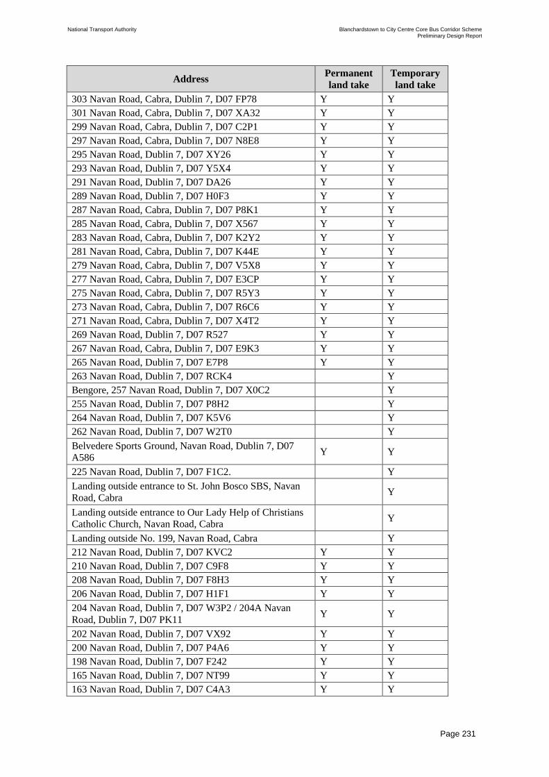
National Transport Authority Blanchardstown to City Centre Core Bus Corridor Scheme Preliminary Design Report
| Issue | 7 May 2022
\\GLOBAL\EUROPE\DUBLIN\JOBS\268000\268401-00\4. INTERNAL\4-04 REPORTS\4-04-03 INFRASTRUCTURE\PRELIMINARY DESIGN REPORT\CBC 5\ISSUE MAY 2022\BCIDC-ARP-PMG_PD-
0005_XX_00-RP-ZZ-0001_ISSUE.DOCX
Page 231
Address Permanent
land take
Temporary
land take
303 Navan Road, Cabra, Dublin 7, D07 FP78 Y Y
301 Navan Road, Cabra, Dublin 7, D07 XA32 Y Y
299 Navan Road, Cabra, Dublin 7, D07 C2P1 Y Y
297 Navan Road, Cabra, Dublin 7, D07 N8E8 Y Y
295 Navan Road, Dublin 7, D07 XY26 Y Y
293 Navan Road, Dublin 7, D07 Y5X4 Y Y
291 Navan Road, Dublin 7, D07 DA26 Y Y
289 Navan Road, Dublin 7, D07 H0F3 Y Y
287 Navan Road, Cabra, Dublin 7, D07 P8K1 Y Y
285 Navan Road, Cabra, Dublin 7, D07 X567 Y Y
283 Navan Road, Cabra, Dublin 7, D07 K2Y2 Y Y
281 Navan Road, Cabra, Dublin 7, D07 K44E Y Y
279 Navan Road, Cabra, Dublin 7, D07 V5X8 Y Y
277 Navan Road, Cabra, Dublin 7, D07 E3CP Y Y
275 Navan Road, Cabra, Dublin 7, D07 R5Y3 Y Y
273 Navan Road, Cabra, Dublin 7, D07 R6C6 Y Y
271 Navan Road, Cabra, Dublin 7, D07 X4T2 Y Y
269 Navan Road, Dublin 7, D07 R527 Y Y
267 Navan Road, Cabra, Dublin 7, D07 E9K3 Y Y
265 Navan Road, Dublin 7, D07 E7P8 Y Y
263 Navan Road, Dublin 7, D07 RCK4 Y
Bengore, 257 Navan Road, Dublin 7, D07 X0C2 Y
255 Navan Road, Dublin 7, D07 P8H2 Y
264 Navan Road, Dublin 7, D07 K5V6 Y
262 Navan Road, Dublin 7, D07 W2T0 Y
Belvedere Sports Ground, Navan Road, Dublin 7, D07
A586 Y Y
225 Navan Road, Dublin 7, D07 F1C2. Y
Landing outside entrance to St. John Bosco SBS, Navan
Road, Cabra Y
Landing outside entrance to Our Lady Help of Christians
Catholic Church, Navan Road, Cabra Y
Landing outside No. 199, Navan Road, Cabra Y
212 Navan Road, Dublin 7, D07 KVC2 Y Y
210 Navan Road, Dublin 7, D07 C9F8 Y Y
208 Navan Road, Dublin 7, D07 F8H3 Y Y
206 Navan Road, Dublin 7, D07 H1F1 Y Y
204 Navan Road, Dublin 7, D07 W3P2 / 204A Navan
Road, Dublin 7, D07 PK11 Y Y
202 Navan Road, Dublin 7, D07 VX92 Y Y
200 Navan Road, Dublin 7, D07 P4A6 Y Y
198 Navan Road, Dublin 7, D07 F242 Y Y
165 Navan Road, Dublin 7, D07 NT99 Y Y
163 Navan Road, Dublin 7, D07 C4A3 Y Y

National Transport Authority Blanchardstown to City Centre Core Bus Corridor Scheme Preliminary Design Report
| Issue | 7 May 2022
\\GLOBAL\EUROPE\DUBLIN\JOBS\268000\268401-00\4. INTERNAL\4-04 REPORTS\4-04-03 INFRASTRUCTURE\PRELIMINARY DESIGN REPORT\CBC 5\ISSUE MAY 2022\BCIDC-ARP-PMG_PD-
0005_XX_00-RP-ZZ-0001_ISSUE.DOCX
Page 232
Address Permanent
land take
Temporary
land take
161 Navan Road, Dublin 7, D07 N7X8 Y Y
159 Navan Road, Dublin 7, D07 X3T9 Y Y
Mount Eden, 157 Navan Road, Dublin 7, D07 K8X6 Y Y
The Haven, 155 Navan Road, Dublin 7, D07 FH93 Y Y
153 Navan Road, Dublin 7, D07 K2P8 Y Y
151 Navan Road, Dublin 7, D07 F5T6 & 151A Navan
Road, Dublin 7, D07 KW95 Y Y
149 Navan Road, Dublin 7, D07 F2X9 Y Y
147 Navan Road, Dublin 7, D07 CD68 Y Y
145 Navan Road, Dublin 7, D07 PR64 Y Y
143 Navan Road, Dublin 7, D07 P3CN Y Y
141 Navan Road, Dublin 7, D07 Y5R5 Y Y
139 Navan Road, Dublin 7, D07 DC03 Y Y
137 Navan Road, Dublin 7, D07 H9C9 Y Y
An Garda Síochána, Cabra Garda Station and adjoining
car park, Navan Road, Dublin 7, D07 XN61 Y Y
124 Navan Road, Dublin 7, D07 T6P1 Y
122 Navan Road, Dublin 7, D07 C2Y9 Y
St. Joseph’s School for Deaf Boys, Navan Road, Dublin 7,
D07 TH79 Y Y
Curam Care Home, Navan Road Y Y
Landing at Aras Slainte, Navan Road Y
116 Navan Road, Dublin 7, D07 TY8N Y
114 Navan Road, Dublin 7, D07 H2V0 Y
112 Navan Road, Dublin 7, D07 N4C1 Y
Prague, 110 Navan Road, Dublin 7, D07 A0W6 Y
72 Navan Road Y
Grass verge adjacent to Telephone exchange, Navan
Road, Dublin 7 Y Y
MLS Park Motors, Navan Road, Dublin 7, D07 H938 Y Y
Lands at Navan Road / Old Cabra Road junction (public) Y
Old Cabra Road Railway Bridge (public) Y
Landing at Lidl, Old Cabra Road Y
Footpath to Front of No. 46 Prussia Street Y
Footpath to Front of No. 45 Prussia Street Y
Footpath to Front of No. 44 Prussia Street Y
Footpath to Front of No. 43 Prussia Street Y
Park Shopping Centre Car Park and access Y Y
Landing at BA Steel Fabrications Limited Y
Luas tracks at Blackhall Street / Benburb Street (public) Y
Luas tracks at Queen Street / Benburb Street (public) Y
National Transport Authority Blanchardstown to City Centre Core Bus Corridor Scheme Preliminary Design Report
| Issue | 7 May 2022
\\GLOBAL\EUROPE\DUBLIN\JOBS\268000\268401-00\4. INTERNAL\4-04 REPORTS\4-04-03 INFRASTRUCTURE\PRELIMINARY DESIGN REPORT\CBC 5\ISSUE MAY 2022\BCIDC-ARP-PMG_PD-
0005_XX_00-RP-ZZ-0001_ISSUE.DOCX
Page 233
13.4 Demolition
13.4.1 General
It is envisaged that demolition works will be limited to the demolition of boundary walls
along the Proposed Scheme. Localised demolition of portions of BR01 Mill Road Bridge and
BR02 Tolka River Bridge are also proposed to allow widening of the structures to take place.
The demolition works shall be in accordance with the specific demolition items set out the
following National Standards and guides:
• I.S EN 1991-1-6:2005 – Actions on Structures: General Actions – Actions During
Execution (Including National Annex);
• BS 6187:2011 – Code of practice for full and partial demolition;
• BS 5228 – Code of practice for noise and vibration control on construction and open sites
– Part 1: Noise; and
• BS 5228 – Code of practice for noise and vibration control on construction and open sites
– Part 2: Vibration.
All reasonable precautions to prevent pollution of the site, works and the general environment
including streams and waterways shall be taken. All demolition waste shall be segregated
and, where practicable, sent for recycling. This shall be in accordance with guidelines as set
out by the National Construction and Demolition Waste Council (NCDWC).
A waste management plan following guidelines as set out by the NCDWC shall be produced
outlining the proposals with respect to waste recycling, segregation and details of landfill
proposals with target percentage of each element. The following legislation shall be noted:
• Protection of the Environment Act 2003.
• Waste Management (Amendment) Act 2001.
• Council Directive 1999/31/EC of 26 April 1999 on the landfill of waste.
• EU Council Decision on Waste Acceptance (2003/33/EC).
• WMA Amendment Act (#2) 2001.
• Protection of the Environment Act No. 27 2003.
• Best practice Guidelines on the preparation of Waste Management Plans for Construction
and Demolition Waste.
• Department of Environment, Heritage and Local Government (DEHLG) July 2006.
13.5 Summary of Accommodation Works and Boundary
Treatment
This section outlines the proposed design of the accommodation works along the Proposed
Scheme. All directly impacted landowners have been written to and follow-up telephone calls
offered to each directly impacted landowner. A number of meetings and telephone calls has
taken place with directly impacted landowners.

National Transport Authority Blanchardstown to City Centre Core Bus Corridor Scheme Preliminary Design Report
| Issue | 7 May 2022
\\GLOBAL\EUROPE\DUBLIN\JOBS\268000\268401-00\4. INTERNAL\4-04 REPORTS\4-04-03 INFRASTRUCTURE\PRELIMINARY DESIGN REPORT\CBC 5\ISSUE MAY 2022\BCIDC-ARP-PMG_PD-
0005_XX_00-RP-ZZ-0001_ISSUE.DOCX
Page 234
All requests made by the directly impacted landowners and the general public have been
evaluated and, where it was deemed appropriate, in the context of not impacting on the
objectives of the Proposed Scheme, have been included in the preliminary design.
The proposed accommodation works consist of relocated boundary walls and gates, and the
regrading of driveways and adjacent grassed areas, where deemed necessary. Where
driveways are proposed to be regraded a maximum gradient of 5% in accordance with
Recommendations for Site Development Works for Housing Areas, Dept of the Environment
and Local Government, 1998 has been adopted, where practicable.
Where boundary walls are being relocated and the existing access is less than 3.6 m in width,
the maximum width of new accesses will be 3.6 m, with the new driveway tying in with the
existing driveway at the temporary land acquisition boundary. The proposed maximum width
is consistent with Dublin City Council’s ‘Parking Cars in Front Gardens’ document.
In addition, there are two additional locations whereby it is proposed to provide widened
accesses of a maximum width of 5.0 m and 5.8 m i.e. 151 Navan Road (relocated) and a
shared access at 141/143 Navan Road respectively. It is also proposed to relocate the accesses
at both 72 Navan Road and 263 Navan Road to facilitate revised junction layouts.
Where cellars and private landings are affected by the Proposed Scheme pre-construction and
post construction surveys will be performed by the appointed contractor. It will be
determined during the detailed design stage if strengthening works are required to any
existing structures, impacted by the Proposed Scheme.
To maintain the character and setting of the Proposed Scheme, the approach to undertaking
the new boundary treatment works along the corridor is replacement on a ‘like for like’ basis
in terms of material selection and general aesthetics, unless otherwise noted on the drawings.
Final details of boundary walls, gates, driveways and grassed areas where affected, will be
agreed between the directly impacted landowners and the NTA.

National Transport Authority Blanchardstown to City Centre Core Bus Corridor Scheme Preliminary Design Report
| Issue | 7 May 2022
\\GLOBAL\EUROPE\DUBLIN\JOBS\268000\268401-00\4. INTERNAL\4-04 REPORTS\4-04-03 INFRASTRUCTURE\PRELIMINARY DESIGN REPORT\CBC 5\ISSUE MAY 2022\BCIDC-ARP-PMG_PD-
0005_XX_00-RP-ZZ-0001_ISSUE.DOCX
Page 235
14 Landscape and Urban Realm
14.1 Overview of Landscape and Urban Realm
Urban Realm refers to the everyday street spaces that are used by people to shop, socialise,
play, and use for activities such as walking, exercise or to commute to/from work. The Urban
Realm encompasses all streets, public spaces, junctions and other rights-of-way, whether in
residential, commercial or civic use. Well-designed urban realm contributes to the identity of
localities and enhances the everyday lives of local communities and those passing through. It
typically relates to the space between buildings to which the public has free access and may
include seating, trees, planting and other features that enhance the experience for all.
Successful urban realms or public open space tend to have certain characteristics including:
• being welcoming and appealing;
• having a distinct identity;
• being pleasant and safe; and
• are easy to move through.
Guidance
In addition to the overarching aims and objectives for the design of Landscape and Urban
Realm, the Fingal County Development Plan 2017 – 2023 and the Dublin City Development
Plan 2016 – 2022 include a range policies and objectives that have been considered in
developing landscape and urban realm proposals. The objectives and concepts contained in
the BusConnects Urban Realm Concept Designs have also been referenced as a basis for the
proposals.
Fingal Development Plan 2017 – 2023
The Fingal County Development Plan 2017 – 2023 is the county level planning framework
applicable to the northern end of the Proposed Scheme from Blanchardstown Town Centre to
the N3 Navan Road Ashtown Roundabout junction.
• Chapter 3 Placemaking includes Objective PM64 which seeks to protect, preserve and
ensure the effective management of trees and groups of trees.
• Chapter 7 Movement and Infrastructure, includes amongst others, Objective MT03 to
implement Smarter Travel A Sustainable Travel Future 20009 -2020; Objective MT13 to
promote walking and cycling as efficient, healthy, and environmentally-friendly modes of
transport by securing the development of a network of direct, comfortable, convenient
and safe cycle routes and footpaths, particularly in urban areas; Objective MT22 to
improve pedestrian and cycle connectivity to stations and other public transport
interchanges; and Objective MT33 Facilitate and promote the enhancement of bus
services through bus priority measures including bus lanes and bus gates.
• Chapter 8 Green Infrastructure includes Objectives GI01 to GI36. Objective GI07 to
ensure green infrastructure protection and provision promotes pedestrian access, cycling,
and public transport in preference to the car, as appropriate; Objective GI08 to integrate
the provision of green infrastructure with infrastructure provision and replacement,

National Transport Authority Blanchardstown to City Centre Core Bus Corridor Scheme Preliminary Design Report
| Issue | 7 May 2022
\\GLOBAL\EUROPE\DUBLIN\JOBS\268000\268401-00\4. INTERNAL\4-04 REPORTS\4-04-03 INFRASTRUCTURE\PRELIMINARY DESIGN REPORT\CBC 5\ISSUE MAY 2022\BCIDC-ARP-PMG_PD-
0005_XX_00-RP-ZZ-0001_ISSUE.DOCX
Page 236
including walking and cycling routes, as appropriate, while protecting biodiversity and
other landscape resources; and GI21 requires all new development to address the
protection and provision of green infrastructure for the five GI themes set out in the
Development Plan (Biodiversity, Parks, Open Space and Recreation, Sustainable Water
Management, Archaeological and Architectural Heritage, and Landscape) in a coherent
and integrated manner.
• Chapter 9 Natural Heritage includes Objective NH27 Protect existing woodlands, trees
and hedgerows which are of amenity or biodiversity value and/or contribute to landscape
character and ensure that proper provision is made for their protection and management.
• Sheet 13 Blanchardstown South identifies High Amenity Landscape along the River
Tolka Valley and tree preservation objectives for existing trees within the Tolka Valley.
Dublin City Development Plan 2016-2022
The Dublin City Development Plan 2016-2022 is the county level planning framework
applicable from the N3 Navan Road Ashtown Roundabout junction to the City Centre.
• Chapter 9 Sustainable Environmental Infrastructure includes Policy SI18 to use SuDS in
all new developments where appropriate, as set out in the Greater Dublin Regional Code
of Practice for Drainage Works.
• Chapter 10 Green Infrastructure includes Objective GIO24 to support the implementation
of the Dublin City Biodiversity Action Plan 2015-2020 and reflects the Strategic
Objectives of Ireland’s National Biodiversity Plan (Actions for Biodiversity 2011-2016)
• Chapter 10 Green Infrastructure also includes the Dublin City Tree Strategy 2016-2020
incorporating a set of policies for the long-term promotion and management of public
trees in Dublin and Objective GIO28 to identify opportunities for new tree planting.
14.2 Consultation with Local Authority
Consultation has taken place with FCC and DCC throughout the design process.
14.3 Landscape and Character Analysis
The landscape and urban realm proposals are derived from analysis of the existing urban
realm, including existing street and public space character, heritage features, boundaries, tree
planting and vegetation, and the range of contemporary and heritage materials in use that
inform the quality and character of different parts of the overall route.
The analysis identified the range of character areas along different parts of the route informed
by adjacent land uses fronting onto the route; the character and heritage of buildings
including any protected structures and private gardens or grounds; the nature and presentation
of any boundary walls, railings or hedgerows; existing street trees or vegetation and the
nature and quality of streetscape materials.
This analysis provided an understanding of the existing character areas along the route and
facilitated detailed and iterative consideration as to the integration of the Proposed Scheme.
This analysis informed design changes to the initial proposals so as to avoid adverse impacts
of existing streetscape character, and also identified opportunities for enhancement and
creation of new spaces along the route. Character analysis also informed the development of

National Transport Authority Blanchardstown to City Centre Core Bus Corridor Scheme Preliminary Design Report
| Issue | 7 May 2022
\\GLOBAL\EUROPE\DUBLIN\JOBS\268000\268401-00\4. INTERNAL\4-04 REPORTS\4-04-03 INFRASTRUCTURE\PRELIMINARY DESIGN REPORT\CBC 5\ISSUE MAY 2022\BCIDC-ARP-PMG_PD-
0005_XX_00-RP-ZZ-0001_ISSUE.DOCX
Page 237
mitigation proposals where public or private property would be directly impacted by the
Proposed Scheme.
14.4 Arboricultural Survey
14.4.1 Scope of Assessment
An Arboricultural Impact Assessment Report (AIAR), included in Appendix D, was prepared
based on a detailed tree survey along the proposed scheme corridor and following the
requirements of BS5837:2012 Trees in relation to design demolition and construction –
Recommendations.
The AIAR documents the nature, quality and condition of existing trees along and adjacent to
the route and identifies the likely direct and indirect impacts of the proposed development on
such trees. It then makes recommendations as to trees that should and/or will need to be
removed and identifies trees in relative proximity to the proposed works and construction
wayleaves that should be protected during construction, with suitable mitigation measures, as
appropriate. The identified trees to be removed, and the Arboricultural Method Statement sets
out how retained trees are to be successfully protected.
The AIAR includes the following:
• Description of the site/route and summary of the trees surveyed;
• Summary of any statutory or non-statutory designations affecting trees within the survey
area;
• A brief summary of trees to be removed;
• Outline guidance for the design team and any key considerations, or issues which need to
be addressed;
• Schedule and corresponding drawings of surveyed trees and key;
• Recommendations for tree works and incursions related to the proposed development;
and
• Tree Protection Plans.
14.5 Hardscape
Throughout the design process, a palette of materials has been developed to create a
consistent yet locally relevant design response appropriate to different locations along the
route. The proposed materials are based on the existing materials and treatments along
various parts of the route to match existing material treatments, while also identifying areas
of opportunity for enhancement through the use of higher quality materials. Material palettes
are described by reference to different typologies appropriate to different sections of the
route.
14.5.1 Material Typologies
The proposed material typologies employed in the preliminary design are described as:

National Transport Authority Blanchardstown to City Centre Core Bus Corridor Scheme Preliminary Design Report
| Issue | 7 May 2022
\\GLOBAL\EUROPE\DUBLIN\JOBS\268000\268401-00\4. INTERNAL\4-04 REPORTS\4-04-03 INFRASTRUCTURE\PRELIMINARY DESIGN REPORT\CBC 5\ISSUE MAY 2022\BCIDC-ARP-PMG_PD-
0005_XX_00-RP-ZZ-0001_ISSUE.DOCX
Page 238
• Poured in-situ concrete pavement - Used extensively on existing footpaths. Concrete
pavements can be laid with or without a kerb, can have neatly trowelled edges and
textured surface for a clean, durable, slip resistant surface;
• Asphalt footpath – Used locally on existing footpaths and will tie in with other sections of
public realm. Laid with a road kerb, can have a smooth finish or textured aggregate
surface, provides a strong flexible slip resistant surface;
• Precast concrete unit paving - Concrete paving slabs and bricks available in a wide
variety of sizes, colours and finishes to provide an enhanced public realm. Can be used
with matching concrete kerbs or with salvaged natural stone kerbs as appropriate;
• Natural stone paving - Employed for high quality urban realm areas, mostly in city centre
locations. This typology represents new or re-used natural stone paving and kerbs and is
used to create enhanced public spaces for major urban realm interventions;
• Stone or Concrete setts - Proposed for distinguishing features such as pedestrian crossing
points, raised tables and parking/set-down areas;
• Self-binding gravel - Proposed for pedestrian pathways that are off-road and leading
through informal landscaped areas; and
• No change - At some locations, the proposed scheme does not necessitate any alteration
to the alignment of the existing footpath or roadway. These include established and more
recently constructed sections of streetscape.
Detailing
The design considers re-use of existing high-quality and natural stone kerbs so as to maintain
streetscape character, reduce construction costs and maximise sustainability.
Pedestrian crossings at side streets will be raised where practicable and will be distinguished
using stone or concrete setts as appropriate to the locality.
In some locations, existing street trees have disturbed or damaged footpath surfaces. The
footpath around such trees will be replaced where appropriate with self-binding gravel so as
improve the vitality of the trees and ensure accessible pedestrian facilities.
Sustainable Drainage Systems (SuDS) will be incorporated within hardscape areas to locally
manage surface water run-off and reduce demand for piped surface water drainage
infrastructure.
Informal footpaths through landscaped areas that are set back from the main carriageway will
be formed using self-binding gravel as an alternative to asphalt or concrete.
Where private or commercial property boundaries are realigned, boundary walls and railings
will be reinstated to match the existing and may be extended to other properties along the
same street to enhance streetscape character.
Existing street furniture such as seating will be relocated within the revised streetscape and
new street furniture will be provided at locations where opportunity sites have been identified
to establish or enhance public spaces.

National Transport Authority Blanchardstown to City Centre Core Bus Corridor Scheme Preliminary Design Report
| Issue | 7 May 2022
\\GLOBAL\EUROPE\DUBLIN\JOBS\268000\268401-00\4. INTERNAL\4-04 REPORTS\4-04-03 INFRASTRUCTURE\PRELIMINARY DESIGN REPORT\CBC 5\ISSUE MAY 2022\BCIDC-ARP-PMG_PD-
0005_XX_00-RP-ZZ-0001_ISSUE.DOCX
Page 239
Hardscape works will be complemented by soft landscaping including trees, hedgerows,
native planting, ornamental planting, amenity grass areas and species rich grasslands as
appropriate. Soft landscaping will enhance the amenity value and visual character of streets
and spaces, mitigate the loss of existing trees, and enhance ecological value along the route.
14.6 Softscape
Softscape refers to existing trees including street trees and groups of trees or woodland areas,
new tree planting, hedgerows, ornamental planting and amenity grasslands. Softscape plays
an important role in ensuring that streets and public spaces are attractive and healthy spaces
for the local community, but also in providing better air quality, managing surface water run-
off and in maintaining and creating habitats.
14.6.1 Planting Strategy
The planting strategy has been developed in response to the objectives of the Proposed
Scheme and as set out in both the Fingal County Development Plan 2017 –2023 and the
Dublin City Development Plan 2016 – 2022. The planting strategy is also in response to
landscape and urban realm opportunities arising from the Proposed Scheme to integrate new
infrastructure within the existing local context and to enhance the visual and amenity value of
streets and spaces.
The overarching planting strategy is to retain established trees and vegetation wherever
possible for their arboricultural, amenity and biodiversity value.
The Arboricultural Survey described in Section 14.4 above identified trees and groups of
trees along the route and provided a detailed schedule of the characteristics, vitality and
quality of trees. The Arboricultural Impact Assessment Report (AIAR) was prepared by
overlaying the Proposed Scheme General Arrangement with the tree survey so as to identify
trees or groups of trees that might be impacted by the scheme. The AIAR includes
recommendations for the retention, removal or management of trees and identifies trees that
will be impacted by virtue of the Proposed Scheme. It also sets out tree protection measures
for trees adjacent to the Proposed Scheme that might otherwise risk damage during
construction.
The planting strategy includes replacement of street trees and groups of trees that may be
impacted by the Proposed Scheme, but also the introduction of new tree planting and street
trees within other spaces and along streets. Reinforcement of green infrastructure along the
route will improve the overall amenity, character and appeal of the route corridor and
localities along it, as well as enhancing biodiversity.
In addition to trees and street trees, other vegetation is also proposed along the route
including hedgerows, ornamental planting and amenity grassland, shrub and meadow grass
areas. These will be utilised to reinstate property boundaries altered by the Proposed Scheme.
Throughout the design process, collaboration between the Landscape and Urban Realm
designers and the Drainage Engineers has sought to adopt Sustainable Drainage Solutions
(SuDS) to manage storm water run-off. SuDS features have been considered along the route
and incorporated within suitable landscape areas in the form of rain gardens, bioretention
areas, filter drains, swales, tree pits and permeable paving.

National Transport Authority Blanchardstown to City Centre Core Bus Corridor Scheme Preliminary Design Report
| Issue | 7 May 2022
\\GLOBAL\EUROPE\DUBLIN\JOBS\268000\268401-00\4. INTERNAL\4-04 REPORTS\4-04-03 INFRASTRUCTURE\PRELIMINARY DESIGN REPORT\CBC 5\ISSUE MAY 2022\BCIDC-ARP-PMG_PD-
0005_XX_00-RP-ZZ-0001_ISSUE.DOCX
Page 240
Refer to Table 14.1 for Tree and Woodland/Tree Group Schedule for an overview of the net
increase in tree planting along the route that will result from the Proposed Scheme and Table
14.2 for Proposed Tree Planting Species, noting Benefit for Wildlife. Both tables can be
found towards the end of this chapter.
Refer to Table 14.3 Schedule of Proposed Planting Areas, Table 14.4 for Proposed Hedgerow
species, noting Benefit for Wildlife, Table 14.5 for Proposed Native Planting species, noting
Benefit for Wildlife and Table 14.6 for Proposed Ornamental Planting Species, noting
Benefit for Wildlife.
14.6.2 Typical Planting Typologies
A range of general planting typologies are incorporated into the Proposed Scheme as
appropriate to localities and character areas along the route. In some instances, planting is
focussed on reinstatement and repair of existing woodland or tree group areas that will be
impacted to facilitate construction of new footpaths, cycle tracks and road infrastructure. In
other cases, planting is focussed on enhancing the amenity, green infrastructure and
biodiversity along the route and in providing distinctive and attractive places for people to
gather and relax.
New Street Trees
A range of urban street tree species (Figure 14.1) have been incorporated into the overall
route design depending on location and whether trees are to be planted in grass verges or in
tree pits within paved urban environments as appropriate, and also to ensure diversity of
species and provide habitats for urban wildlife.
Typically, trees will be semi-mature and have a tree girth of 14/16 cm or 16/20 cm and where
appropriate, selected for having a clear stem height to facilitate visual permeability. The full
range are included in Table 14.1 and Table 14.2.

National Transport Authority Blanchardstown to City Centre Core Bus Corridor Scheme Preliminary Design Report
| Issue | 7 May 2022
\\GLOBAL\EUROPE\DUBLIN\JOBS\268000\268401-00\4. INTERNAL\4-04 REPORTS\4-04-03 INFRASTRUCTURE\PRELIMINARY DESIGN REPORT\CBC 5\ISSUE MAY 2022\BCIDC-ARP-PMG_PD-
0005_XX_00-RP-ZZ-0001_ISSUE.DOCX
Page 241
Figure 14.1: Street tree types
New Woodland Areas and Tree Groups
The Proposed Scheme includes a range of existing mature and immature woodlands areas.
Some of these will be impacted where the existing carriageway will be widened or cycling
infrastructure will be provided. It is proposed to reinstate construction working areas and also
to replant the edges of impacted woodland areas, so as to reinstate the streetscape or roadway
character. Additionally, there are areas of land within the corridor that are presently in grass
or scrub, and new woodlands areas will be established in these locations to offset the loss of
woodlands elsewhere and to provide more consistent presentation along carriageway edges.
Woodland tree planting will typically comprise bare-root native tree species including Alnus
glutinosa (Black Alder), Salix aurita, Salix cinerea oleifolia, Salix caprea, Salix petrandra
(Willow sp.), Betula pendula (Silver Birch), Pinus sylvestris (Scots Pine), Crataegus
monogyna (Hawthorn), Quercus petraea (Sessile Oak), Prunus spinosa (Blackthorn) and
Viburnum opulus (Guelder Rose).
Elsewhere along the Proposed Scheme, there are smaller areas of existing and proposed
woodlands and tree groups that will be retained, reinstated or established in order to provide
appropriate landscaping connectivity and design interventions at a range of different spaces,
including carriageway boundaries, new landscape spaces arising from junction
reconfiguration, reinforcement of established vegetation areas, and also establishing new
public realm and landscape opportunity areas. Tree species will be determined by location
and will comprise either native woodland trees as set out above, or selected street trees as set
out in Table 14.2. Additionally, understory planting, long grass and swathes of bulbs will be
provided to reinforce the character of landscaped areas along the scheme corridor.
A number of different landscaped central median areas exist along the scheme, including
those within high-capacity dual carriageway and smaller scale medians within suburban and
urban settings. Landscaping proposals respond to the different localities and may include

National Transport Authority Blanchardstown to City Centre Core Bus Corridor Scheme Preliminary Design Report
| Issue | 7 May 2022
\\GLOBAL\EUROPE\DUBLIN\JOBS\268000\268401-00\4. INTERNAL\4-04 REPORTS\4-04-03 INFRASTRUCTURE\PRELIMINARY DESIGN REPORT\CBC 5\ISSUE MAY 2022\BCIDC-ARP-PMG_PD-
0005_XX_00-RP-ZZ-0001_ISSUE.DOCX
Page 242
grass planting, hedgerows and trees as appropriate in medians within the larger scale
roadways, and grasses, ornamental planting, hedgerows and trees within the suburban and
urban medians.
Boundary Planting
The Proposed Scheme is bounded by a wide range of established private, commercial,
institutional and public land boundaries. While the design development has sought to avoid
impacts on such boundaries, the Proposed Scheme will nonetheless require both temporary
and permanent access to lands beyond the carriageway boundary.
Impacted property boundaries will be reinstated following construction. In some instances,
boundaries will be re-built along their original alignments. In other cases, boundaries will be
re-built on a new setback alignment. In general, property boundaries will be reinstated on a
‘like for like’ basis, including any walls, piers, fences, railings, gates, driveway finishes and
private landscaping.
Private grounds that are utilised in part for construction access will be reinstated following
completion of the works to match the existing landscaping of the property. Where private
grounds are reduced by virtue of permanent land take required for the scheme, the remaining
grounds will be reinstated to match the landscape and character of the existing grounds in
consultation with the property owner.
14.7 Proposed Landscape and Urban Realm Design
This section outlines the landscape and urban realm proposals along the Proposed Scheme.
The landscape design is presented on a series of 1:500 scale Landscaping General
Arrangement Drawings in Appendix B that include the combined hard and soft landscaping
proposals for the entire route. These drawings included the general arrangement of the
proposed layout and identify in particular:
• existing trees and woodland/tree group areas;
• tree and woodland/tree group felling;
• the location and extent of existing hard landscaping surfaces to be retained;
• the location and extent of new hard landscaping surfaces to be formed using different
materials;
• proposed trees and woodland/tree groups;
• Proposed grass verges, amenity areas and species rich grass land;
• Proposed ornamental planting, native planting and hedgerows; and,
• Sustainable Urban Drainage (SuDS) infrastructure.
Additionally, along the scheme corridor, a number of Urban Realm Opportunity Sites have
been identified where existing spaces can be enhanced or new spaces created. These are
included and further illustrated in the descriptions below as appropriate.
Codes of Practice and Recommendations
All tree planting works will be undertaken in accordance with the following British Standard
Codes of Practice:

National Transport Authority Blanchardstown to City Centre Core Bus Corridor Scheme Preliminary Design Report
| Issue | 7 May 2022
\\GLOBAL\EUROPE\DUBLIN\JOBS\268000\268401-00\4. INTERNAL\4-04 REPORTS\4-04-03 INFRASTRUCTURE\PRELIMINARY DESIGN REPORT\CBC 5\ISSUE MAY 2022\BCIDC-ARP-PMG_PD-
0005_XX_00-RP-ZZ-0001_ISSUE.DOCX
Page 243
• BS 3936-1:1992 Nursery stock specification for trees and shrubs
• BS 3998:2010 Tree work.
Recommendations:
• BS 4043:1989 Recommendations for Transplanting Root-Balled Trees
• BS 4428:1989 (Section 7)
• BS 8545:2014 Trees: from nursery to independence in the landscape – Recommendations.
Mitigation Measures
Mitigation measures are an inherent part of the multi-disciplinary design proposals and have
been considered iteratively throughout the design process. Mitigation measures are informed
by understanding existing conditions including the range of land uses, the nature and quality
of existing built and landscape features and dimensional constraints and other opportunities.
That information is used to identify the optimum integration of initial and evolving design
proposals for carriageways, streetscapes, infrastructure including pedestrian and cycle
facilities.
Mitigation includes minimising adverse impacts on private and public property and
landscapes through avoidance and reduction; identifying opportunities to create
improvements along streets and at other public spaces; and seeking opportunities to mitigate
unavoidable impacts of trees, landscapes and property through reinstatement and new
planting. Underlying landscape and public realm design and mitigation is the concept of
Placemaking that seeks to ensure that streets, public spaces and amenities are developed to
create attractive and safe places for people to use as destinations and for commuting.
Mitigation, as an integral part of the design process, includes:
• reinstatement of impacted built or other features on a ‘like for like’ basis so as to restore
established streetscape and spatial character;
• upgrading the condition and/or quality of built elements to restore or enhance overall
character and amenity;
• introduction of new and reconfigured public spaces and streetscapes to provide more
coherent, attractive and useable public realm;
• planting new street trees, woodland/tree groups and other landscaping to offset any
unavoidable impacts on existing landscape features along the Proposed Scheme; and
• enhancing the sustainability of public spaces through improving biodiversity and
introduction of Sustainable Drainage Systems (SuDS) wherever possible.
14.7.1 N3 Blanchardstown Junction to Snugborough Road
Existing Character: This is the start of the route and comprises the modern Blanchardstown
Shopping Centre set within the wider suburban residential context. This section of the route is
characterised by both the N3 and connected road network as well as the large-scale district
centre with extensive retail, community and leisure facilities and expansive surface parking
areas. The shopping centre attracts significant volumes of people by private car, public
transport, walking and cycling. It includes substantial tree and hedge planting around and
within surface parking areas and primary access routes, and the N3 road network also
comprises significant landscaped embankments. It is noted that the separate Snugborough

National Transport Authority Blanchardstown to City Centre Core Bus Corridor Scheme Preliminary Design Report
| Issue | 7 May 2022
\\GLOBAL\EUROPE\DUBLIN\JOBS\268000\268401-00\4. INTERNAL\4-04 REPORTS\4-04-03 INFRASTRUCTURE\PRELIMINARY DESIGN REPORT\CBC 5\ISSUE MAY 2022\BCIDC-ARP-PMG_PD-
0005_XX_00-RP-ZZ-0001_ISSUE.DOCX
Page 244
Junction Upgrade Scheme to the southeast of Blanchardstown Shopping Centre is presently
under construction and includes site clearance, removal of vegetation and enabling works
within that project area.
Design Proposals: The existing bus lane facility to the northeast of Blanchardstown
Shopping Centre and leading along Blanchardstown Road South will be upgraded together
with pedestrian and cycle facilities. The additional space required will necessitate removal of
sections of perimeter woodland planting at the shopping centre, however, new street trees
will be introduced to upgrade the amenity value of the street and the edges of the mixed
woodland group along the shopping centre boundary will be replanted so as to mitigate
impacts on existing landscape. A new dedicated bus lane will be provided from
Blanchardstown Road South into the shopping centre. The junction at Blanchardstown Road
South will be converted from a roundabout to a signalised junction, with new street trees
around the junction to enhance the presentation and amenity of the entrance to the western
shopping centre.
Within the shopping centre, the development of a new Bus Interchange (refer to Figure 14.2)
provides a Public Realm Opportunity Site between the primary shopping centre and the
northern retail outlets and with strong pedestrian connections to and from both. The Bus
Interchange will establish an accessible and attractive location with the overall shopping
centre that provides convenient access to and from public transport services within the
shopping centre.
The Bus Interchange is designed as a dedicated public transport island providing sheltered
passenger waiting areas centrally within a double-sided bus stop gyratory. The location and
layout optimise passenger access to the full range and frequency of bus services at the centre.
The central area is designed as a pedestrian plaza with high quality hard and soft landscaping
providing an attractive, comfortable and convenient facility for passengers within the
shopping centre. A distinctive curved canopy system will over sail the entire interchange to
provide cover for pedestrians and will also be illuminated from ground recessed uplighters in
the pavement to provide uniform illumination of the structure.
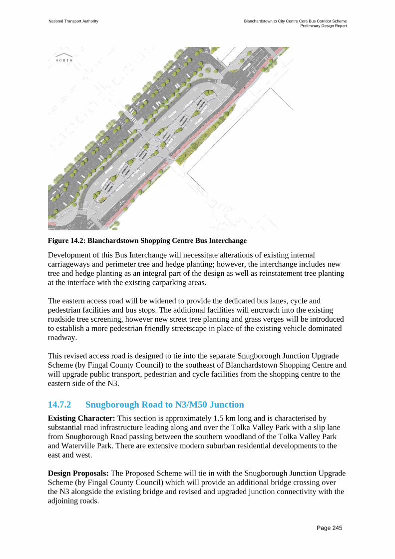
National Transport Authority Blanchardstown to City Centre Core Bus Corridor Scheme Preliminary Design Report
| Issue | 7 May 2022
\\GLOBAL\EUROPE\DUBLIN\JOBS\268000\268401-00\4. INTERNAL\4-04 REPORTS\4-04-03 INFRASTRUCTURE\PRELIMINARY DESIGN REPORT\CBC 5\ISSUE MAY 2022\BCIDC-ARP-PMG_PD-
0005_XX_00-RP-ZZ-0001_ISSUE.DOCX
Page 245
Figure 14.2: Blanchardstown Shopping Centre Bus Interchange
Development of this Bus Interchange will necessitate alterations of existing internal
carriageways and perimeter tree and hedge planting; however, the interchange includes new
tree and hedge planting as an integral part of the design as well as reinstatement tree planting
at the interface with the existing carparking areas.
The eastern access road will be widened to provide the dedicated bus lanes, cycle and
pedestrian facilities and bus stops. The additional facilities will encroach into the existing
roadside tree screening, however new street tree planting and grass verges will be introduced
to establish a more pedestrian friendly streetscape in place of the existing vehicle dominated
roadway.
This revised access road is designed to tie into the separate Snugborough Junction Upgrade
Scheme (by Fingal County Council) to the southeast of Blanchardstown Shopping Centre and
will upgrade public transport, pedestrian and cycle facilities from the shopping centre to the
eastern side of the N3.
14.7.2 Snugborough Road to N3/M50 Junction
Existing Character: This section is approximately 1.5 km long and is characterised by
substantial road infrastructure leading along and over the Tolka Valley Park with a slip lane
from Snugborough Road passing between the southern woodland of the Tolka Valley Park
and Waterville Park. There are extensive modern suburban residential developments to the
east and west.
Design Proposals: The Proposed Scheme will tie in with the Snugborough Junction Upgrade
Scheme (by Fingal County Council) which will provide an additional bridge crossing over
the N3 alongside the existing bridge and revised and upgraded junction connectivity with the
adjoining roads.

National Transport Authority Blanchardstown to City Centre Core Bus Corridor Scheme Preliminary Design Report
| Issue | 7 May 2022
\\GLOBAL\EUROPE\DUBLIN\JOBS\268000\268401-00\4. INTERNAL\4-04 REPORTS\4-04-03 INFRASTRUCTURE\PRELIMINARY DESIGN REPORT\CBC 5\ISSUE MAY 2022\BCIDC-ARP-PMG_PD-
0005_XX_00-RP-ZZ-0001_ISSUE.DOCX
Page 246
Beyond the Snugborough Junction, the Proposed Scheme will generally utilise the existing
N3 and associated road infrastructure with modifications to carriageway allocation to provide
dedicated bus lanes. New bus stops will be provided on the N3 at the Mill Road overbridge
and will require widening of the N3 to accommodate segregated bus stops on the N3. Ramps
and steps will be constructed from Mill Road to the elevated east and westbound
carriageways of the N3 to provide pedestrian connections to the new bus stops. Construction
will require clearance of tree screening from the N3 embankments on the northern and
southern side of the carriageway. Post construction, new trees will be planted to mitigate tree
removal and to integrate the new construction with the adjoining landscaped embankments
and provide an attractive and safe environment for pedestrian commuters.
Elsewhere, there will be localised areas of tree removal to accommodate new bus stop and
kerb line adjustments. Trees will be reinstated where practicable and new areas of tree
planting, grass verges and species rich grassland will be introduced where practicable to
enhance amenity and biodiversity characteristics along the N3.
14.7.3 N3/M50 Junction to Navan Road / Ashtown Road Junction
Existing Character: This section continues for approximately 2.2 km from the M50
interchange to the Ashtown roundabout. The majority of this section is characterised by dual
carriageway roadway infrastructure with median and roadside landscaping with a mix of
residential developments, commercial and sporting uses together with areas of undeveloped
land.
Approaching the Ashtown roundabout, the adjoining built context intensifies with apartment
buildings on the southern side of the road comprising strong boundary vegetation and
industrial, commercial and apartment buildings on the northern side with more sporadic tree
planting along the boundaries. Ashtown roundabout incorporates a copse of mature Monterey
Pine trees and the roundabout leads to the tree lined Ashtown Gate entrance to the Phoenix
Park.
Design Proposals: For much of this section, changes will consist of localised interventions
and reallocation of existing road space. A new dedicated citybound bus lane will be
constructed immediately east of the M50 interchange to provide bus priority to the Auburn
Avenue / Dunsink Lane. Intermediate lands between the Royal Canal, N3 and various slip
lanes will be planted with new mixed woodland planting.
A two-way shared surface cycle facility (Quite Street treatment) will be introduced along
Castleknock Manor, and the Auburn Avenue roundabout will be rationalised to provide
continuous pedestrian and cycle facilities with new tree planting, grass verges and species
rich grasslands introduced to enhance amenity and biodiversity.
New amenity grass planting is proposed in the modified R147 median. East and west of the
Parkway Station overbridge, sections of the existing median hedge will be removed and
replanted more centrally within the median together with new grass planting within the
median.
Continuous footpaths and cycle tracks will be provided from this junction eastwards along
the Navan Road and will include upgraded bus stops. These facilities will encroach onto

National Transport Authority Blanchardstown to City Centre Core Bus Corridor Scheme Preliminary Design Report
| Issue | 7 May 2022
\\GLOBAL\EUROPE\DUBLIN\JOBS\268000\268401-00\4. INTERNAL\4-04 REPORTS\4-04-03 INFRASTRUCTURE\PRELIMINARY DESIGN REPORT\CBC 5\ISSUE MAY 2022\BCIDC-ARP-PMG_PD-
0005_XX_00-RP-ZZ-0001_ISSUE.DOCX
Page 247
existing roadside woodland tree planting, however new tree planting will be provided where
practicable to reinstate the boundary screening. Approaching the Ashtown roundabout,
localised boundary realignments will be required including the removal of some boundary
and street trees. Following construction, new trees will be planted where practicable.
The Ashtown roundabout currently incorporates Monterey Pine trees and presents as a well-
known landmark when approaching or departing the city along the N3.
The roundabout will be reconfigured as a signalised junction (refer to Figure 14.3) and this
change presents an Urban Realm opportunity. The revised junction will greatly improve
pedestrian and cycle facilities at the junction and conversion from a roundabout will provides
substantial additional pedestrian space around the junction. This additional space will
incorporate high quality hard and soft landscaping that establishes a contemporary landscape
character at the junction that will become a new gateway landmark while also facilitating
local pedestrian and cyclist movements. Low level shrub planting will provide a buffer
between pedestrians and the junction and new trees, ornamental planting, species rich grass
areas and high-quality paving will provide an attractive public space. New trees will include
semi-mature Monterey Pine referencing the existing trees on the roundabout.
Figure 14.3: Ashtown Road Junction
14.7.4 Navan Road / Ashtown Road junction to Navan Road / Old
Cabra Road junction
Existing Character: This section of the route is approximately 2.5 km long and is both an
access route from the west into the city and a local road leading to established residential
settlements along both sides of the road. The road varies in character and includes the more
heavily wooded character towards the western end at The Paddock and Kempton Avenue.

National Transport Authority Blanchardstown to City Centre Core Bus Corridor Scheme Preliminary Design Report
| Issue | 7 May 2022
\\GLOBAL\EUROPE\DUBLIN\JOBS\268000\268401-00\4. INTERNAL\4-04 REPORTS\4-04-03 INFRASTRUCTURE\PRELIMINARY DESIGN REPORT\CBC 5\ISSUE MAY 2022\BCIDC-ARP-PMG_PD-
0005_XX_00-RP-ZZ-0001_ISSUE.DOCX
Page 248
The majority of the road comprises residential properties with front gardens fronting onto the
road with varying degrees of landscaping in private gardens as well as educational, sporting,
community and retail uses with frontages onto the road. Street trees are located in the narrow
grass verges and vary considerably in maturity as some have failed and been replanted over
time and others have not been replanted.
Design Proposals: The Proposed Scheme will require removal of existing verge planted
street trees and realignment of property boundaries. Modified boundaries will be reinstated to
match existing, and continuous footpaths and cycle tracks will be constructed along both
sides of the road to facilitate local and commuting pedestrians and cyclists. Junctions will
also be upgraded to provide proper pedestrian crossings. Pavements will be renewed
throughout, and high-quality paving and new soft landscaping will be provided at the Church
and Public Library. Where practicable, new street trees will be planted to reinstate some of
the tree planting and existing character of the road.
The Old Cabra Road junction will be rationalised (refer to Figure 14.4) and will provide an
Urban Realm opportunity. Some of the existing slip lanes will be removed to facilitate
reconfiguration of the junction to provide dedicated bus lanes and to substantially improve
pedestrian and cycle facilities throughout the junction. New hard and soft landscaping will be
introduced to enhance the presentation, amenity and biodiversity value of the junction and to
create a more pedestrian friendly and distinctive character. Some existing street trees will
need to be removed to facilitate the revised layout, however new tree planting will be
provided within the Navan Road median and within peripheral landscape areas that will
create an attractive pedestrian environment.
Figure 14.4: Old Cabra Road Junction
National Transport Authority Blanchardstown to City Centre Core Bus Corridor Scheme Preliminary Design Report
| Issue | 7 May 2022
\\GLOBAL\EUROPE\DUBLIN\JOBS\268000\268401-00\4. INTERNAL\4-04 REPORTS\4-04-03 INFRASTRUCTURE\PRELIMINARY DESIGN REPORT\CBC 5\ISSUE MAY 2022\BCIDC-ARP-PMG_PD-
0005_XX_00-RP-ZZ-0001_ISSUE.DOCX
Page 249
14.7.5 Navan Road / Old Cabra Road Junction to Ellis Quay
Existing Character: This last section is approximately 2.0 km long and is characterised as
an established residential road with private dwellings and gardens fronting onto the road with
varying amounts of private landscaping and occasional street trees along the public footpath.
The street then transitions to the more compact and urban local centre at Hanlon’s corner at
the junction with North Circular Road.
South of North Circular Road the route is characterised by a cluster of modern residential and
retail developments, but quickly transitions to the narrower, finer grained and more
traditional streetscape character of Prussia Street. At the junction of Prussia Street and
Aughrim Street, the street enters the distinctive traditional mixed use urban neighbourhood of
Stoneybatter with fined grained period terraced buildings providing residential, commercial,
retail, community and other uses. Stoneybatter has been well maintained and includes high-
quality public realm and landscape enhancements throughout.
Design Proposals: The Proposed Scheme will introduce traffic management measures that
will substantially reduce through traffic at Stoneybatter and provide opportunities to further
develop the public realm to create an even stronger pedestrian priority urban neighbourhood
character. Refer to Figure 14.5.
The carriageway width will be reduced in many locations and the footpaths widened to match
the existing urban realm works. New and upgraded bus stops will be installed and continuous
cycle tracks will be provided on both sides of the street. The junction at Aughrim Street will
be reduced to a single lane only and the existing public spaces either side of the junction will
be extended and further developed to increase the public amenity value of these spaces. The
existing mature trees will be retained, and the revised layout will facilitate planting of
additional new trees and other landscaping.

National Transport Authority Blanchardstown to City Centre Core Bus Corridor Scheme Preliminary Design Report
| Issue | 7 May 2022
\\GLOBAL\EUROPE\DUBLIN\JOBS\268000\268401-00\4. INTERNAL\4-04 REPORTS\4-04-03 INFRASTRUCTURE\PRELIMINARY DESIGN REPORT\CBC 5\ISSUE MAY 2022\BCIDC-ARP-PMG_PD-
0005_XX_00-RP-ZZ-0001_ISSUE.DOCX
Page 250
Figure 14.5: Stoneybatter Village
Along the main streetscape, the existing established urban realm will be extended to
incorporate wider footpaths and new cycle tracks.
After Brunswick Street North, Stoneybatter becomes particularly narrow. Brunswick Street
North will become one-way westbound for general traffic and will incorporate widened
footpaths and dedicated cycle tracks. The public realm along Brunswick Street North will be
upgraded to match Stoneybatter and to connect to that along George’s Lane which will be
further upgraded and will incorporate two-way cycle facilities and new tree planting. The
pedestrian route between Stoneybatter and the River Liffey will be upgraded in width,
amenity and quality, and will incorporate continuous high quality cycle facilities bringing
additional life and animation to these streets. Refer to Figure 14.6.

National Transport Authority Blanchardstown to City Centre Core Bus Corridor Scheme Preliminary Design Report
| Issue | 7 May 2022
\\GLOBAL\EUROPE\DUBLIN\JOBS\268000\268401-00\4. INTERNAL\4-04 REPORTS\4-04-03 INFRASTRUCTURE\PRELIMINARY DESIGN REPORT\CBC 5\ISSUE MAY 2022\BCIDC-ARP-PMG_PD-
0005_XX_00-RP-ZZ-0001_ISSUE.DOCX
Page 251
Figure 14.6: Brunswick Street North and George’s Lane
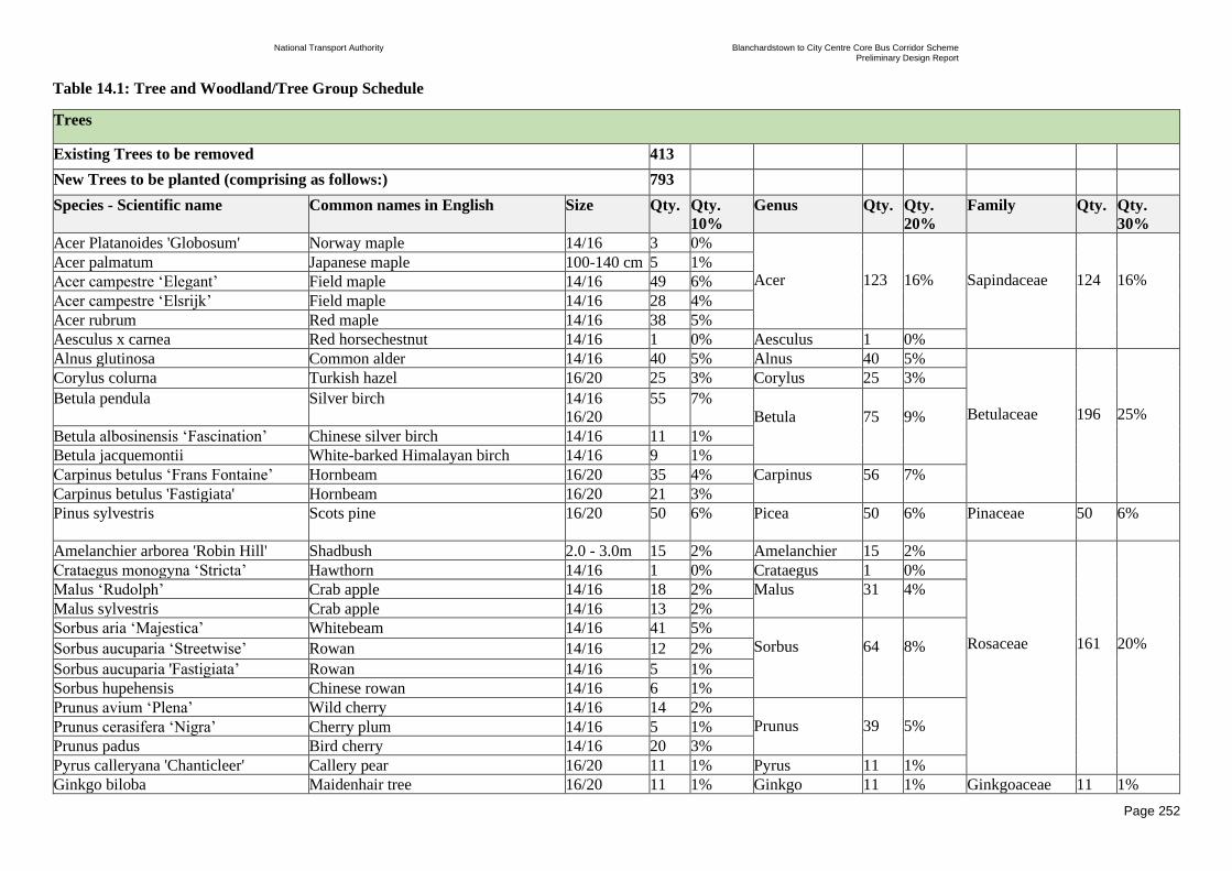
National Transport Authority Blanchardstown to City Centre Core Bus Corridor Scheme Preliminary Design Report
| Issue | 7 May 2022
\\GLOBAL\EUROPE\DUBLIN\JOBS\268000\268401-00\4. INTERNAL\4-04 REPORTS\4-04-03 INFRASTRUCTURE\PRELIMINARY DESIGN REPORT\CBC 5\ISSUE MAY 2022\BCIDC-ARP-PMG_PD-0005_XX_00-RP-ZZ-0001_ISSUE.DOCX
Page 252
Table 14.1: Tree and Woodland/Tree Group Schedule
Trees
Existing Trees to be removed 413
New Trees to be planted (comprising as follows:) 793
Species - Scientific name Common names in English Size Qty. Qty.
10%
Genus Qty. Qty.
20%
Family Qty. Qty.
30%
Acer Platanoides 'Globosum' Norway maple 14/16 3 0%
Acer
123
16%
Sapindaceae
124
16% Acer palmatum Japanese maple 100-140 cm 5 1%
Acer campestre ‘Elegant’ Field maple 14/16 49 6%
Acer campestre ‘Elsrijk’ Field maple 14/16 28 4%
Acer rubrum Red maple 14/16 38 5%
Aesculus x carnea Red horsechestnut 14/16 1 0% Aesculus 1 0%
Alnus glutinosa Common alder 14/16 40 5% Alnus 40 5%
Betulaceae
196
25%
Corylus colurna Turkish hazel 16/20 25 3% Corylus 25 3%
Betula pendula Silver birch 14/16
16/20
55 7%
Betula
75
9%
Betula albosinensis ‘Fascination’ Chinese silver birch 14/16 11 1%
Betula jacquemontii White-barked Himalayan birch 14/16 9 1%
Carpinus betulus ‘Frans Fontaine’ Hornbeam 16/20 35 4% Carpinus 56 7%
Carpinus betulus 'Fastigiata' Hornbeam 16/20 21 3%
Pinus sylvestris
Scots pine 16/20 50 6% Picea 50 6% Pinaceae 50 6%
Amelanchier arborea 'Robin Hill' Shadbush 2.0 - 3.0m 15 2% Amelanchier 15 2%
Rosaceae
161
20%
Crataegus monogyna ‘Stricta’ Hawthorn 14/16 1 0% Crataegus 1 0%
Malus ‘Rudolph’ Crab apple 14/16 18 2% Malus 31 4%
Malus sylvestris Crab apple 14/16 13 2%
Sorbus aria ‘Majestica’ Whitebeam 14/16 41 5%
Sorbus
64
8% Sorbus aucuparia ‘Streetwise’ Rowan 14/16 12 2%
Sorbus aucuparia 'Fastigiata’ Rowan 14/16 5 1%
Sorbus hupehensis Chinese rowan 14/16 6 1%
Prunus avium ‘Plena’ Wild cherry 14/16 14 2%
Prunus
39
5% Prunus cerasifera ‘Nigra’ Cherry plum 14/16 5 1%
Prunus padus Bird cherry 14/16 20 3%
Pyrus calleryana 'Chanticleer' Callery pear 16/20 11 1% Pyrus 11 1%
Ginkgo biloba Maidenhair tree 16/20 11 1% Ginkgo 11 1% Ginkgoaceae 11 1%

National Transport Authority Blanchardstown to City Centre Core Bus Corridor Scheme Preliminary Design Report
| Issue | 7 May 2022
\\GLOBAL\EUROPE\DUBLIN\JOBS\268000\268401-00\4. INTERNAL\4-04 REPORTS\4-04-03 INFRASTRUCTURE\PRELIMINARY DESIGN REPORT\CBC 5\ISSUE MAY 2022\BCIDC-ARP-PMG_PD-0005_XX_00-RP-ZZ-0001_ISSUE.DOCX
Page 253
Species – Scientific name Common names in English Size Qty. Qty.
10%
Genus Qty. Qty.
20%
Family Qty. Qty.
30%
Cercis Canadensis ‘Forest Pansy’ Redbud 14/16 16 2% Cercis 16 2%
Fabaceae
48
6% Gleditsia triacanthos 'Street Keeper' Honey locust 16/20 15 2% Gleditsia 32 4%
Gleditsia triacanthos ‘Skyline’ Honey locust 16/20 17 2%
Platanus x acerifolia London plane 16/20 8 1% Platanus 8 1% Platanaceae 8 1%
Quercus palustris ‘Fastigiata’ Pin oak 16/20 3 0% Quercus 24 3%
Fagaceae
40
5% Quercus robur ‘Fastigiata Koster’ Common oak 16/20 21 3%
Fagus Sylvatica European beech 14/16 16 2% Fagus 16 2%
Tilia cordata ‘Green Spire’ Small-leaved lime 16/20 42 5%
Tilia
104
13%
Malvaceae
104
13% Tilia cordata ‘Rancho’ Small-leaved lime 16/20 59 7%
Tilia x europaea ‘Euchlora’ Caucasian linden 16/20 3 0%
Ulmus 'New Horizon' Elm 16/20 38 5% Ulmus 51 6% Ulmaceae 51 6%
Ulmus hollandica ‘Dodoens’ Dutch elm 16/20 13 2%
Total 793 793 793
Woodland / Tree Groups
Existing Woodland Trees to be removed Total Area 0.93 ha.
New Woodland Trees to be planted Total Area 0.96 ha.

National Transport Authority Blanchardstown to City Centre Core Bus Corridor Scheme Preliminary Design Report
| Issue | 7 May 2022
\\GLOBAL\EUROPE\DUBLIN\JOBS\268000\268401-00\4. INTERNAL\4-04 REPORTS\4-04-03 INFRASTRUCTURE\PRELIMINARY DESIGN REPORT\CBC 5\ISSUE MAY
2022\BCIDC-ARP-PMG_PD-0005_XX_00-RP-ZZ-0001_ISSUE.DOCX
Page 254
Table 14.2 Proposed Tree Planting Species
Scientific
name
Common
name
Size Qty. Criteria for use Photo
Acer
Platanoide
'Globosum'
Norway maple
16/20 3 ‘Lollypop’ form of the
Norway Maple
Dense rounded crown and
intense yellow autumn
colour
Low maintenance
architectural tree
Feature accent element in
squares
Attractive to pollinating
insects
Tolerates air pollution and
resists drought
Acer
palmatum sp.
Japanese
maple
100-
140cm
5 A small deciduous tree
Attractive shape and
delicate looking foliage
Feature accent element

National Transport Authority Blanchardstown to City Centre Core Bus Corridor Scheme Preliminary Design Report
| Issue | 7 May 2022
\\GLOBAL\EUROPE\DUBLIN\JOBS\268000\268401-00\4. INTERNAL\4-04 REPORTS\4-04-03 INFRASTRUCTURE\PRELIMINARY DESIGN REPORT\CBC 5\ISSUE MAY
2022\BCIDC-ARP-PMG_PD-0005_XX_00-RP-ZZ-0001_ISSUE.DOCX
Page 255
Scientific
name
Common
name
Size Qty. Criteria for use Photo
Acer
campestre
‘Elegant’
Field maple
16/20 49 Compact and elegant
ascending structure of the
branches
Intense yellow and orange
autumn colour
A good avenue tree for use
on green belts, road
verges, streets, housing
estates and squares
Tolerates air pollution and
resists drought
Attractive to a number of
invertebrates and
pollinating insects. Fruits
are eaten by small
mammals.
Acer
campestre
‘Elsrijk’
Field maple
16/20 28 Upright oval to widely
conical shaped, dense
crown
Intense yellow and orange
autumn colour
Suitable for narrow streets
Tolerates air pollution and
resists drought
Attractive to pollinating
insects

National Transport Authority Blanchardstown to City Centre Core Bus Corridor Scheme Preliminary Design Report
| Issue | 7 May 2022
\\GLOBAL\EUROPE\DUBLIN\JOBS\268000\268401-00\4. INTERNAL\4-04 REPORTS\4-04-03 INFRASTRUCTURE\PRELIMINARY DESIGN REPORT\CBC 5\ISSUE MAY
2022\BCIDC-ARP-PMG_PD-0005_XX_00-RP-ZZ-0001_ISSUE.DOCX
Page 256
Scientific
name
Common
name
Size Qty. Criteria for use Photo
Acer rubrum
Red Maple
16/20 38 Medium-sized tree with a
spherical to conical crown,
dense and closed
Feature accent in urban
environment
Low maintenance
architectural tree
Bright red autumn colour
Acid soils will give the
best autumn colour
Tolerates air pollution and
resists drought
Attractive to pollinating
insects
Aesculus x
carnea
Red
horsechestnut
14/16 1 Large, deciduous tree with
a rounded crown
Feature accent in urban
environment
Low maintenance
architectural tree
Bright red autumn colour
The Red Horse Chestnut is
more disease-resistant than
the horse-chestnut
Alnus
glutinosa
Common
alder
Black alder
14/16 40 Irish native tree
Ideal tree for planting in
wet and mixed woodland
and forest ages
Tolerates most coastal
sites
A very good soil-
enhancing tree due to its
nitrogen-fixing
capabilities
Poor tolerance to hard
surfaces
Alder trees support over
80 different types of
insects. Attractive to a

National Transport Authority Blanchardstown to City Centre Core Bus Corridor Scheme Preliminary Design Report
| Issue | 7 May 2022
\\GLOBAL\EUROPE\DUBLIN\JOBS\268000\268401-00\4. INTERNAL\4-04 REPORTS\4-04-03 INFRASTRUCTURE\PRELIMINARY DESIGN REPORT\CBC 5\ISSUE MAY
2022\BCIDC-ARP-PMG_PD-0005_XX_00-RP-ZZ-0001_ISSUE.DOCX
Page 257
Scientific
name
Common
name
Size Qty. Criteria for use Photo
number of invertebrates
pollinating insects
Corylus
colurna
Turkish hazel
14/16 25 Extremely tolerant of
exposure and paved areas
which make it a perfect
candidate for urban
planting
Seasonal interest is
provided by elegant long
yellow catkins in spring,
clusters of edible nuts in
frilly cups and good
yellow autumn foliage
colour
Low maintenance
architectural tree
Generally disease free
Attractive to a number of
invertebrates and
pollinating insects. It
produces and drops nuts in
large beaked husks that are
popular with wildlife,
especially squirrels
Betula
pendula
Silver birch
14/16
16/20
55 Irish native tree
Intense yellow autumn
colour with striking white,
pink, or peeling brown
bark
Important tree for
reforestation projects and
soil protection
Birch trees support over
200 different types of
insects. Catkins are a good
food source for a variety
of birds

National Transport Authority Blanchardstown to City Centre Core Bus Corridor Scheme Preliminary Design Report
| Issue | 7 May 2022
\\GLOBAL\EUROPE\DUBLIN\JOBS\268000\268401-00\4. INTERNAL\4-04 REPORTS\4-04-03 INFRASTRUCTURE\PRELIMINARY DESIGN REPORT\CBC 5\ISSUE MAY
2022\BCIDC-ARP-PMG_PD-0005_XX_00-RP-ZZ-0001_ISSUE.DOCX
Page 258
Scientific
name
Common
name
Size Qty. Criteria for use Photo
Betula
albosinensis
‘Fascination’
Chinese silver
birch or
Chinese red-
barked birch
14/16
11 Low maintenance
architectural tree
Golden yellow autumn
colour with striking white
or peeling red, brown bark
Tolerant of a wide range
of conditions and soil
types
It’s an outstanding
addition to any landscape,
particularly good when
planted in groups
Betula
jacquemontii
White-barked
Himalayan
Birch
14/16
9 Ornamental tree
Golden yellow autumn
colour with striking snowy
white bark
It’s an outstanding
addition to any landscape,
particularly good when
planted in groups

National Transport Authority Blanchardstown to City Centre Core Bus Corridor Scheme Preliminary Design Report
| Issue | 7 May 2022
\\GLOBAL\EUROPE\DUBLIN\JOBS\268000\268401-00\4. INTERNAL\4-04 REPORTS\4-04-03 INFRASTRUCTURE\PRELIMINARY DESIGN REPORT\CBC 5\ISSUE MAY
2022\BCIDC-ARP-PMG_PD-0005_XX_00-RP-ZZ-0001_ISSUE.DOCX
Page 259
Scientific
name
Common
name
Size Qty. Criteria for use Photo
Carpinus
betulus
‘Frans
Fontaine’
Hornbeam
16/20 35 Uniquely upright and
dense foliage
‘Frans Fontaine’ is the
narrowest of all the
Carpinus
Ideal for narrow streets
and avenues
The autumnal colours are
a varied mixture of
yellows and oranges
The tough tree is suitable
for many locations
Attractive to a number of
invertebrates. Seeds eaten
by birds. Can provide a
dense nesting cover
Carpinus
betulus
'Fastigiata'
Hornbeam
16/20 21 Uniquely upright and
dense foliage
Ideal for narrow streets
and avenues
The autumnal colours are
a varied mixture of
yellows and oranges
The tough tree is suitable
for many locations

National Transport Authority Blanchardstown to City Centre Core Bus Corridor Scheme Preliminary Design Report
| Issue | 7 May 2022
\\GLOBAL\EUROPE\DUBLIN\JOBS\268000\268401-00\4. INTERNAL\4-04 REPORTS\4-04-03 INFRASTRUCTURE\PRELIMINARY DESIGN REPORT\CBC 5\ISSUE MAY
2022\BCIDC-ARP-PMG_PD-0005_XX_00-RP-ZZ-0001_ISSUE.DOCX
Page 260
Scientific
name
Common
name
Size Qty. Criteria for use Photo
Pinus
sylvestris
Scots pine
16/20 50 Irish native tree
Best suited in parks,
gardens, heath land,
woodlands and coastal
areas
Low maintenance
architectural tree
Creates habitats for native
Irish fauna, including
many bird species and
squirrels
Amelanchier
arborea
'Robin Hill'
Shadbush
2.0-
3.0m
15 Feature accent element on
urban squares and parks
Small ornamental tree
with decorative pink and
white flowers
Bright red and orange
autumn colour
Available as a multi-stem
and a standard tree
Attracts a wide assortment
of birds and wildlife

National Transport Authority Blanchardstown to City Centre Core Bus Corridor Scheme Preliminary Design Report
| Issue | 7 May 2022
\\GLOBAL\EUROPE\DUBLIN\JOBS\268000\268401-00\4. INTERNAL\4-04 REPORTS\4-04-03 INFRASTRUCTURE\PRELIMINARY DESIGN REPORT\CBC 5\ISSUE MAY
2022\BCIDC-ARP-PMG_PD-0005_XX_00-RP-ZZ-0001_ISSUE.DOCX
Page 261
Scientific
name
Common
name
Size Qty. Criteria for use Photo
Crataegus
monogyna
‘Stricta’
Hawthorn
14/16 1 Irish native tree
Because of its columnar
growth this tree is suitable
for narrow streets and
small gardens
White flowers in late
spring followed by
conspicuous red berries in
autumn
Tolerant of exposed
locations such as windy
and coastal sites
It provides food for more
than 150 different insect
species. Attractive to
pollinating insect
Malus
‘Rudolph’
Crab apple
14/16 18 A great choice for colour
and year-round interest
Small ornamental tree that
starts off by growing
vertically
Used as an avenue tree
because of the small fruit
Attractive to a number of
invertebrates and
pollinating insects. Many
species of birds and
mammals eat fruit and
disperse the seeds

National Transport Authority Blanchardstown to City Centre Core Bus Corridor Scheme Preliminary Design Report
| Issue | 7 May 2022
\\GLOBAL\EUROPE\DUBLIN\JOBS\268000\268401-00\4. INTERNAL\4-04 REPORTS\4-04-03 INFRASTRUCTURE\PRELIMINARY DESIGN REPORT\CBC 5\ISSUE MAY
2022\BCIDC-ARP-PMG_PD-0005_XX_00-RP-ZZ-0001_ISSUE.DOCX
Page 262
Scientific
name
Common
name
Size Qty. Criteria for use Photo
Malus
sylvestris
Crab apple
14/16
13
Irish native tree
Feature accent element on
urban squares and parks
Small to medium-sized
deciduous trees with
showy flowers in spring
and ornamental or edible
fruit in autumn
Attractive to a number of
invertebrates and
pollinating insects. Many
species of birds and
mammals eat fruit and
disperse the seeds
Sorbus aria
‘Majestica’
Whitebeam
14/16
41
Forms a compact, broad,
pyramidal crown
Stands up well to hard
surfaces 'Majestica' is a
good avenue and street
tree
Tolerant of atmospheric
pollution and dry
conditions
Attractive to a number of
invertebrates and
pollinating insects. Berries
provide a valuable food
source for birds

National Transport Authority Blanchardstown to City Centre Core Bus Corridor Scheme Preliminary Design Report
| Issue | 7 May 2022
\\GLOBAL\EUROPE\DUBLIN\JOBS\268000\268401-00\4. INTERNAL\4-04 REPORTS\4-04-03 INFRASTRUCTURE\PRELIMINARY DESIGN REPORT\CBC 5\ISSUE MAY
2022\BCIDC-ARP-PMG_PD-0005_XX_00-RP-ZZ-0001_ISSUE.DOCX
Page 263
Scientific
name
Common
name
Size Qty. Criteria for use Photo
Sorbus
aucuparia
‘Streetwise’
Rowan
14/16 12
Irish native tree
Ideal for tighter urban
locations with a very neat
upright habit
Tolerant of atmospheric
pollution and dry
conditions
Attractive to pollinating
insects. It produces an
important berry crop for
wildlife
Sorbus
aucuparia
'Fastigiata’
Rowan
14/16
5
Irish native tree
Grows in a narrow upright
fashion
Ideal for tighter urban
locations with a very neat
columnar habit
Tolerant of atmospheric
pollution and dry
conditions
Attractive to pollinating
insects. It produces an
important berry crop for
wildlife

National Transport Authority Blanchardstown to City Centre Core Bus Corridor Scheme Preliminary Design Report
| Issue | 7 May 2022
\\GLOBAL\EUROPE\DUBLIN\JOBS\268000\268401-00\4. INTERNAL\4-04 REPORTS\4-04-03 INFRASTRUCTURE\PRELIMINARY DESIGN REPORT\CBC 5\ISSUE MAY
2022\BCIDC-ARP-PMG_PD-0005_XX_00-RP-ZZ-0001_ISSUE.DOCX
Page 264
Scientific
name
Common
name
Size Qty. Criteria for use Photo
Sorbus
hupehensis
Chinese
rowan
14/16 6 Round headed shape
White or white tinged pink
fruits and glorious red
autumn colour
Feature accent element on
urban squares and parks
It is one of the faster
growing rowans
Prunus
avium
‘Plena’
Wild cherry
14/16
14 Irish native tree
Double flowered Wild
Cherry produces no fruit
Rounded and regularly
branched closed crown
Feature accent element on
urban squares, parks and
avenues
Attractive to a number of
invertebrates and
pollinating insects. Berries
provide a valuable food
source for birds
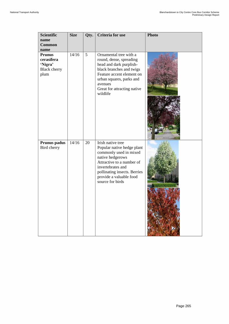
National Transport Authority Blanchardstown to City Centre Core Bus Corridor Scheme Preliminary Design Report
| Issue | 7 May 2022
\\GLOBAL\EUROPE\DUBLIN\JOBS\268000\268401-00\4. INTERNAL\4-04 REPORTS\4-04-03 INFRASTRUCTURE\PRELIMINARY DESIGN REPORT\CBC 5\ISSUE MAY
2022\BCIDC-ARP-PMG_PD-0005_XX_00-RP-ZZ-0001_ISSUE.DOCX
Page 265
Scientific
name
Common
name
Size Qty. Criteria for use Photo
Prunus
cerasifera
‘Nigra’
Black cherry
plum
14/16
5
Ornamental tree with a
round, dense, spreading
head and dark purplish-
black branches and twigs
Feature accent element on
urban squares, parks and
avenues
Great for attracting native
wildlife
Prunus padus
Bird cherry
14/16
20
Irish native tree
Popular native hedge plant
commonly used in mixed
native hedgerows
Attractive to a number of
invertebrates and
pollinating insects. Berries
provide a valuable food
source for birds

National Transport Authority Blanchardstown to City Centre Core Bus Corridor Scheme Preliminary Design Report
| Issue | 7 May 2022
\\GLOBAL\EUROPE\DUBLIN\JOBS\268000\268401-00\4. INTERNAL\4-04 REPORTS\4-04-03 INFRASTRUCTURE\PRELIMINARY DESIGN REPORT\CBC 5\ISSUE MAY
2022\BCIDC-ARP-PMG_PD-0005_XX_00-RP-ZZ-0001_ISSUE.DOCX
Page 266
Scientific
name
Common
name
Size Qty. Criteria for use Photo
Pyrus
calleryana
'Chanticleer'
Callery pear
16/20
11
Narrow conical to ovoid,
half-open crown
Perfect for avenue
planting due to its slender
form
Great for attracting native
wildlife
Ginkgo
biloba
Maidenhair
tree
16/20 11 The World's Oldest Tree
Species
Intense yellow autumn
colour
Feature accent element on
urban parks and avenues
Pests and diseases free
Resistant to air pollution

National Transport Authority Blanchardstown to City Centre Core Bus Corridor Scheme Preliminary Design Report
| Issue | 7 May 2022
\\GLOBAL\EUROPE\DUBLIN\JOBS\268000\268401-00\4. INTERNAL\4-04 REPORTS\4-04-03 INFRASTRUCTURE\PRELIMINARY DESIGN REPORT\CBC 5\ISSUE MAY
2022\BCIDC-ARP-PMG_PD-0005_XX_00-RP-ZZ-0001_ISSUE.DOCX
Page 267
Scientific
name
Common
name
Size Qty. Criteria for use Photo
Cercis
Canadensis
‘Forest
Pansy’
Redbud
14/16 16 Large deciduous shrub or
small, often multi-
stemmed or standard tree
with purple, heart-shaped
leaves which turn yellow
in autumn before falling
Grown mainly for striking
foliage effects
Feature accent element on
urban parks and squares
Attractive to pollinators
Gleditsia
triacanthos
'Street
keeper'
Honey locust
16/20 15 Suitable for urban streets
with ascending branches
and a narrowly pyramidal
growth habit
Vivid yellow autumn
colour
Feature accent element on
urban parks and avenues
Resistant to drought and
pollution

National Transport Authority Blanchardstown to City Centre Core Bus Corridor Scheme Preliminary Design Report
| Issue | 7 May 2022
\\GLOBAL\EUROPE\DUBLIN\JOBS\268000\268401-00\4. INTERNAL\4-04 REPORTS\4-04-03 INFRASTRUCTURE\PRELIMINARY DESIGN REPORT\CBC 5\ISSUE MAY
2022\BCIDC-ARP-PMG_PD-0005_XX_00-RP-ZZ-0001_ISSUE.DOCX
Page 268
Scientific
name
Common
name
Size Qty. Criteria for use Photo
Gleditsia
triacanthos
‘Skyline’
Honey locust
16/20 17 Suitable for urban streets
with ascending branches
and a narrowly pyramidal
growth habit
Vivid yellow autumn
colour
Feature accent element on
urban parks and avenues
Resistant to drought and
pollution
Platanus x
acerifolia
London plane
16/20 8 A large tree for a large
space
Coherence with existing
planting scheme
Tolerates air pollution and
resists drought and heavy
pruning
Great for attracting native
wildlife

National Transport Authority Blanchardstown to City Centre Core Bus Corridor Scheme Preliminary Design Report
| Issue | 7 May 2022
\\GLOBAL\EUROPE\DUBLIN\JOBS\268000\268401-00\4. INTERNAL\4-04 REPORTS\4-04-03 INFRASTRUCTURE\PRELIMINARY DESIGN REPORT\CBC 5\ISSUE MAY
2022\BCIDC-ARP-PMG_PD-0005_XX_00-RP-ZZ-0001_ISSUE.DOCX
Page 269
Scientific
name
Common
name
Size Qty. Criteria for use Photo
Quercus
palustris
‘Fastigiata’
Pin oak
16/20 3 Columnar, half-open
crown
Perfect for avenues and
narrow streets planting
due to its slender upright
habit
Low maintenance
architectural tree
Oak trees provide food
and shelter to over 450
species of insects.
Attractive to a range of
invertebrates and are
important for insect eating
birds. Acorns are eaten by
a variety of birds and
mammals
Quercus
robur
‘Fastigiata
Koster’
Common oak
3 -
3.5m
21
Irish native tree
Tall narrow pyramidal
version of the Common
Oak
-Ideal for growing along
an avenue or where space
is at a premium
Oak trees provide food
and shelter to over 450
species of insects.
Attractive to a range of
invertebrates and are
important for insect eating
birds. Acorns are eaten by
a variety of birds and
mammals

National Transport Authority Blanchardstown to City Centre Core Bus Corridor Scheme Preliminary Design Report
| Issue | 7 May 2022
\\GLOBAL\EUROPE\DUBLIN\JOBS\268000\268401-00\4. INTERNAL\4-04 REPORTS\4-04-03 INFRASTRUCTURE\PRELIMINARY DESIGN REPORT\CBC 5\ISSUE MAY
2022\BCIDC-ARP-PMG_PD-0005_XX_00-RP-ZZ-0001_ISSUE.DOCX
Page 270
Scientific
name
Common
name
Size Qty. Criteria for use Photo
Fagus
Sylvatica
European
Beech
12/14 16 Large, vigorous deciduous
tree with a broad,
spreading crown
Leaves stay on the tree
over the winter months,
giving a rustic brown look
Resists heavy pruning
Replacement tree to match
existing
Tilia cordata
‘Green Spire’
Small-leaved
lime
16/20 42 Pyramidal, later oval to
ovoid, half-open crown.
Coherence with existing
planting scheme.
Popular choice for urban
planting
Tolerates air pollution and
resists heavy pruning
Attractive to many
invertebrates and
pollinating insects
Tilia cordata
‘Rancho’
Small-leaved
lime
16/20
59
Narrow conical, later
narrow ovoid, half-open
crown
Coherence with existing
planting scheme
Popular choice for urban
planting
Tolerates air pollution and
resists heavy pruning
Attractive to many
invertebrates and
pollinating insects

National Transport Authority Blanchardstown to City Centre Core Bus Corridor Scheme Preliminary Design Report
| Issue | 7 May 2022
\\GLOBAL\EUROPE\DUBLIN\JOBS\268000\268401-00\4. INTERNAL\4-04 REPORTS\4-04-03 INFRASTRUCTURE\PRELIMINARY DESIGN REPORT\CBC 5\ISSUE MAY
2022\BCIDC-ARP-PMG_PD-0005_XX_00-RP-ZZ-0001_ISSUE.DOCX
Page 271
Scientific
name
Common
name
Size Qty. Criteria for use Photo
Tilia x
europaea
‘Euchlora’
Caucasian
linden
16/20 3 Coherence with existing
planting scheme
It is very versatile, being
suitable for urban settings,
avenues, verges and parks.
Tolerates air pollution and
resists heavy pruning
Attractive to many
invertebrates and
pollinating insects
Ulmus
'New Horizon'
Elm
16/20 38
Fast-growing tree with
dense pyramidal crown
High resistance to Dutch
elm disease (DED)
Tolerant of urban
conditions
Support over 80 different
types of insects. The early
flowers of elm are visited
by many insects and the
seeds are valued by red
squirrels
Ulmus
hollandica
‘Dodoens’
Dutch elm
16/20
13 Fast-growing tree with
dense broad spherical
crown
'Dodoens' is wind-resistant
and can be of excellent use
in both urban and rural
settings
High resistance to Dutch
elm disease (DED)
Tolerant of urban
conditions

National Transport Authority Blanchardstown to City Centre Core Bus Corridor Scheme Preliminary Design Report
| Issue | 7 May 2022
\\GLOBAL\EUROPE\DUBLIN\JOBS\268000\268401-00\4. INTERNAL\4-04 REPORTS\4-04-03 INFRASTRUCTURE\PRELIMINARY DESIGN REPORT\CBC 5\ISSUE MAY
2022\BCIDC-ARP-PMG_PD-0005_XX_00-RP-ZZ-0001_ISSUE.DOCX
Page 272
Table 14.3: Schedule of Proposed Planting Areas
Planting Type Length (m) / Area (m2)
Hedgerow 1,119 m
Native Planting 1,358 m2
Ornamental Planting 5,485 m2
Grass Verge and Amenity Areas 36,753 m2
Species Rich Grassland 6,373 m2
Table 14.4: Proposed Hedgerow species, noting Benefit for Wildlife
Latin name Common name Benefit
Buxus
sempervirens
Common Box Attractive to pollinators. Can provide a dense
nesting cover.
Ceanothus
species
Lilac Bush Provide nectar and pollen for butterflies, bees
and other pollinators in their dense flower
clusters in spring.
Cornus
sanguinea
Dogwood The flowers produce a scent that is attractive to
many species of invertebrates. The berries are
eaten by some species of birds.
Corylus
avellana
Hazel Reddish-brown nuts in a green husk are seen
on hazel in the late summer and autumn; but
these are generally eaten quickly by birds and
mammals.
Crataegus
monogyna
Hawthorn Provides a source of nectar and berries
providing food for birds including thrushes. If
allowed to grow dense it will provide good
nesting opportunities for birds.
Euonymus
europaeus
Spindle Spindle produces flowers that provide a good
source of food for bees and other insects. The
fruits attract aphids which in turn attract insect-
eating birds.
Ilex aquifolium Holly The berries are greatly enjoyed by birds and
mammals. Holly also plays a crucial part in the
life cycle of the beautiful butterfly the holly
blue, which lays eggs on holly leaves in spring
and is a frequent visitor to gardens in town.
Requires male and female plants to produce
berries.
Ligustrum
vulgare
Privet Wild privet is the preferred choice for wildlife
and may provide nesting sites for blackbirds
and other species. Left to grow a little less
tidily than many gardeners allow, the structure
will become more open and also offer nesting
opportunities for many more species. Good for
bees and butterflies.
Pyracantha
coccinea
Scarlett Firethorn Very valuable to birds as a source of food and
as a nesting site. Also, a good security plant
due to the thorns.

National Transport Authority Blanchardstown to City Centre Core Bus Corridor Scheme Preliminary Design Report
| Issue | 7 May 2022
\\GLOBAL\EUROPE\DUBLIN\JOBS\268000\268401-00\4. INTERNAL\4-04 REPORTS\4-04-03 INFRASTRUCTURE\PRELIMINARY DESIGN REPORT\CBC 5\ISSUE MAY
2022\BCIDC-ARP-PMG_PD-0005_XX_00-RP-ZZ-0001_ISSUE.DOCX
Page 273
Latin name Common name Benefit
Rosa species Roses Provides nectar for bees and butterflies. Hips
are valuable for small birds and mammals.
Salix
aegyptiaca
Musk Willow Winter-flowering shrub pollinated by bees and
other insects.
Sambucus
nigra
Common Elder Provides flowers for insects and berries for
birds.
Sarcococca
confusa
Sweet Box Flowering in winter, followed by black berries
eaten by birds.
Viburnum spp Viburnum Excellent for attracting hoverflies and are a
good source of nectar for bees. The shiny
berries provide a food source for birds and
mammals alike.
Table 14.5: Proposed Native Planting species, noting Benefit for Wildlife
Latin name Common name Benefit
Cornus
sanguinea
Dogwood The flowers produce a scent that is attractive to
many species of invertebrates. The berries are
eaten by some species of birds.
Corylus
avellana
Hazel Reddish-brown nuts in a green husk are seen
on hazel in the late summer and autumn; but
these are generally eaten quickly by birds and
mammals.
Crataegus
monogyna
Hawthorn Provides a source of nectar and berries
providing food for birds including thrushes. If
allowed to grow dense it will provide good
nesting opportunities for birds.
Euonymus
europaeus
Spindle Spindle produces flowers that provide a good
source of food for bees and other insects. The
fruits attract aphids which in turn attract insect-
eating birds.
Hypericum
androsaemum
Tutsan Flowers attract insects especially bees while
the berries are eaten by birds and small
mammals.
Ilex aquifolium Holly The berries are greatly enjoyed by birds and
mammals. Holly also plays a crucial part in the
life cycle of the beautiful butterfly the holly
blue, which lays eggs on holly leaves in spring
and is a frequent visitor to gardens in town.
Requires male and female plants to produce
berries.

National Transport Authority Blanchardstown to City Centre Core Bus Corridor Scheme Preliminary Design Report
| Issue | 7 May 2022
\\GLOBAL\EUROPE\DUBLIN\JOBS\268000\268401-00\4. INTERNAL\4-04 REPORTS\4-04-03 INFRASTRUCTURE\PRELIMINARY DESIGN REPORT\CBC 5\ISSUE MAY
2022\BCIDC-ARP-PMG_PD-0005_XX_00-RP-ZZ-0001_ISSUE.DOCX
Page 274
Latin name Common name Benefit
Ligustrum
vulgare
Privet Wild privet is the preferred choice for wildlife
and may provide nesting sites for blackbirds
and other species. Left to grow a little less
tidily than many gardeners allow, the structure
will become more open and also offer nesting
opportunities for many more species. Good for
bees and butterflies.
Rosa species Roses Provides nectar for bees and butterflies. Hips
are valuable for small birds and mammals.
Salix
aegyptiaca
Musk Willow Winter-flowering shrub pollinated by bees and
other insects.
Sambucus
nigra
Common Elder Provides flowers for insects and berries for
birds.
Thymus
species
Thyme The rose-purple flowers grow in long,
whorled, upright spikes and are very attractive
to bees, hoverflies and butterflies.
Viburnum spp Viburnum Excellent for attracting hoverflies and are a
good source of nectar for bees. The shiny
berries provide a food source for birds and
mammals alike.
Table 14.6: Proposed Ornamental Planting Species, noting Benefit for Wildlife
Latin name Common name Benefit
Abelia chinensis Bee Bush or
Chinese Abelia
Attractive to pollinators. Flowering in
October.
Ajuga reptans Bugle Bugle is excellent for ground cover under
shrubs since it prefers semi-shade, and is
attractive to a wide range of insects.
Anemone
nemorosa
Wood Anemone Provides a good early source of pollen and
nectar for bees and other insects.
Armeria maritima Thrift, Sea Pink Attractive to pollinators.
Aster novi-belgii Michaelmas
Daisy
Attractive to a range of bees, butterflies,
moths and birds.
Aubrieta deltoidea Purple Rock-
cress
Provides a good early food source for bees
and adds colour to edges of flower beds,
prefers full sunlight.
Bergenia
purpurascens
Elephant’s Ear
or Purple
Bergenia
Attractive to pollinators.
Campanula
glomerata
Clustered
Bellflower
Attractive to pollinators.
Clematis vitalba Clematis ‘Old
Man’s Beard’
Provides nectar for bee and butterflies.
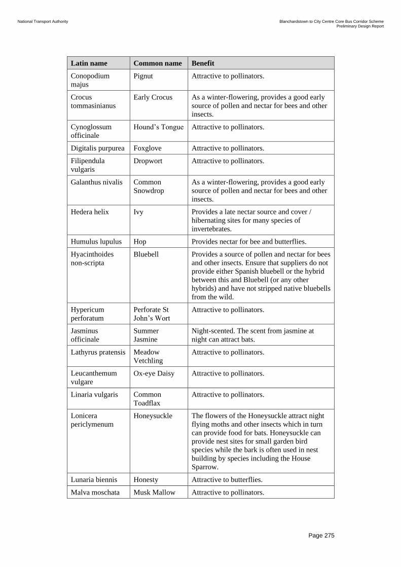
National Transport Authority Blanchardstown to City Centre Core Bus Corridor Scheme Preliminary Design Report
| Issue | 7 May 2022
\\GLOBAL\EUROPE\DUBLIN\JOBS\268000\268401-00\4. INTERNAL\4-04 REPORTS\4-04-03 INFRASTRUCTURE\PRELIMINARY DESIGN REPORT\CBC 5\ISSUE MAY
2022\BCIDC-ARP-PMG_PD-0005_XX_00-RP-ZZ-0001_ISSUE.DOCX
Page 275
Latin name Common name Benefit
Conopodium
majus
Pignut Attractive to pollinators.
Crocus
tommasinianus
Early Crocus As a winter-flowering, provides a good early
source of pollen and nectar for bees and other
insects.
Cynoglossum
officinale
Hound’s Tongue Attractive to pollinators.
Digitalis purpurea Foxglove Attractive to pollinators.
Filipendula
vulgaris
Dropwort Attractive to pollinators.
Galanthus nivalis Common
Snowdrop
As a winter-flowering, provides a good early
source of pollen and nectar for bees and other
insects.
Hedera helix Ivy Provides a late nectar source and cover /
hibernating sites for many species of
invertebrates.
Humulus lupulus Hop Provides nectar for bee and butterflies.
Hyacinthoides
non-scripta
Bluebell Provides a source of pollen and nectar for bees
and other insects. Ensure that suppliers do not
provide either Spanish bluebell or the hybrid
between this and Bluebell (or any other
hybrids) and have not stripped native bluebells
from the wild.
Hypericum
perforatum
Perforate St
John’s Wort
Attractive to pollinators.
Jasminus
officinale
Summer
Jasmine
Night-scented. The scent from jasmine at
night can attract bats.
Lathyrus pratensis Meadow
Vetchling
Attractive to pollinators.
Leucanthemum
vulgare
Ox-eye Daisy Attractive to pollinators.
Linaria vulgaris Common
Toadflax
Attractive to pollinators.
Lonicera
periclymenum
Honeysuckle The flowers of the Honeysuckle attract night
flying moths and other insects which in turn
can provide food for bats. Honeysuckle can
provide nest sites for small garden bird
species while the bark is often used in nest
building by species including the House
Sparrow.
Lunaria biennis Honesty Attractive to butterflies.
Malva moschata Musk Mallow Attractive to pollinators.

National Transport Authority Blanchardstown to City Centre Core Bus Corridor Scheme Preliminary Design Report
| Issue | 7 May 2022
\\GLOBAL\EUROPE\DUBLIN\JOBS\268000\268401-00\4. INTERNAL\4-04 REPORTS\4-04-03 INFRASTRUCTURE\PRELIMINARY DESIGN REPORT\CBC 5\ISSUE MAY
2022\BCIDC-ARP-PMG_PD-0005_XX_00-RP-ZZ-0001_ISSUE.DOCX
Page 276
Latin name Common name Benefit
Matthiola
longipetala
Night-scented
Stock
Night-scented. emits a pleasant scent in the
evening and through the night attracting night-
flying pollinators and insects and therefore
bats.
Mahonia species Mahonia Flowering occurs in autumn, winter and early
spring benefiting winter-active pollinators
(like bumblebees or some hoverflies). Flowers
produce abundant nectar. Berries are eaten by
birds.
Monarda didyma Bergamot Provides a good source of pollen and nectar.
Nicotiana Tobacco Plant Attractive to night pollinators like moths
(beneficial for bats).
Oenothera biennis Evening
Primrose
Particularly attractive to night flying insects
(therefore can attract bats).
Persicaria bistorta Common Bistort Attractive to pollinators.
Rudbeckia hirta Black-eyed
Susan
Attractive to pollinators. Flowering in
October.
Silene vulgaris Bladder
Campion
Attractive to pollinators.
Thalictrum
flavum
Meadow Rue Attractive to pollinators.
Viola riviniana Dog Violet Flowers from April to June and is attractive to
bees and other insects.

National Transport Authority Blanchardstown to City Centre Core Bus Corridor Scheme Preliminary Design Report
| Issue | 7 May 2022
\\GLOBAL\EUROPE\DUBLIN\JOBS\268000\268401-00\4. INTERNAL\4-04 REPORTS\4-04-03 INFRASTRUCTURE\PRELIMINARY DESIGN REPORT\CBC 5\ISSUE MAY
2022\BCIDC-ARP-PMG_PD-0005_XX_00-RP-ZZ-0001_ISSUE.DOCX
Page 277
15 How are we achieving the Objectives
This section sets out the manner in which the Proposed Scheme described herein
will achieve the following Objectives as set out:
• Enhance the capacity and potential of the public transport system by
improving bus speeds, reliability and punctuality through the provision of bus
lanes and other measures to provide priority to bus movement over general
traffic movements;
• Enhance the potential for cycling by providing safe infrastructure for cycling,
segregated from general traffic wherever practicable;
• Support the delivery of an efficient, low carbon and climate resilient public
transport service, which supports the achievement of Ireland’s emission
reduction targets;
• Enable compact growth, regeneration opportunities and more effective use of
land in Dublin, for present and future generations, through the provision of
safe and efficient sustainable transport networks;
• Improve accessibility to jobs, education and other social and economic
opportunities through the provision of improved sustainable connectivity and
integration with other public transport services; and
• Ensure that the public realm is carefully considered in the design and
development of the transport infrastructure and seek to enhance key urban
focal points where appropriate and feasible.
Currently, bus priority is characterised by discontinuity. Bus priority is only
provided along certain sections and a number of pinch-points cause significant
delays which result in a negative impact on the performance of the bus service as
a whole. Within the extents of the Proposed Scheme route, bus lanes are currently
provided on only approximately 10% and 40% of route outbound and inbound
respectively.
Issues related to frequency, reliability and a complex network have persisted for
many years and will continue to do so without further intervention. As such, there
are a number of high frequency public bus services along the routes to be
improved by the Proposed Scheme (including the 38 and 39 bus routes), as well as
multiple private and coach services. In addition to this there are multiple other bus
services which run along this corridor intermittently, providing interchange
opportunities with other bus services. Many of these services suffer from journey
time unreliability, particularly in peak times, due to the lack of bus priority
provision.
In addition to the level of service improvements the Proposed Scheme will
facilitate for existing bus services, the ongoing Dublin Area Bus Network
Redesign will see continued investment in bus services into the future, which will
also be afforded similar journey-time reliability and therefore improve their
attractiveness as an alternative to private car usage.

National Transport Authority Blanchardstown to City Centre Core Bus Corridor Scheme Preliminary Design Report
| Issue | 7 May 2022
\\GLOBAL\EUROPE\DUBLIN\JOBS\268000\268401-00\4. INTERNAL\4-04 REPORTS\4-04-03 INFRASTRUCTURE\PRELIMINARY DESIGN REPORT\CBC 5\ISSUE MAY
2022\BCIDC-ARP-PMG_PD-0005_XX_00-RP-ZZ-0001_ISSUE.DOCX
Page 278
Without the interventions of the Proposed Scheme there would likely be an
exacerbation of the issues which informed the need for the Proposed Scheme
itself. The capacity and potential of the public transport system would remain
restricted by the existing deficient and inconsistent provision of bus lanes and the
resulting sub-standard levels of bus priority and journey-time reliability. Thus, the
unreliability of bus services would continue. As such the Proposed Scheme is
actively enhancing the capacity and potential of the public transport system, and
supports the delivery of an efficient, low carbon and climate resilient public
transport service, which supports the achievement of Ireland’s emission reduction
targets.
In terms of the need to improve facilities for cyclists along the route of the
Proposed Scheme, the design intent is that segregated facilities should be provided
where practicable to do so. Within the extents of the Proposed Scheme there are
mandatory cycle lanes provided on approximately 14% and 15% of the route
outbound and inbound respectively, while advisory cycle lanes are provided on
approximately 23% and 16% of the route outbound and inbound respectively. The
remaining extents have no dedicated cycle provision or cyclists must cycle within
the bus lanes provided.
The Proposed Scheme is implementing safe, segregated infrastructure (inclusive
of Quiet Street treatment) to 78% of the Proposed Scheme, and as such is greatly
enhancing the potential for cycling.
Within the extents of the Proposed Scheme there are a number of amenities,
villages and urban centres which experience high pedestrian usage including
along Prussia Street, Stoneybatter Village, Queen Street, Blackhall Street and
George’s Lane, among others. In order to improve accessibility to jobs, education
and other social and economic opportunities through the provision of an
integrated sustainable transport system, there needs to be a high-quality pedestrian
environment, including specifically along the route of the Proposed Scheme.
There are a number of uncontrolled crossings along the route of the Proposed
Scheme, particularly at side roads which are generally of poor standard, including
lack of provision for the mobility and visually impaired. There are multiple
incidences of ‘patch repairs’ along footpaths that in some instance has led to
undulating, uneven surfaces caused by settlement of patch repair material. This is
often a hazard to pedestrians, particularly the mobility impaired. A number of
submissions were also received as part of the non-statutory consultation in which
members of the public indicated specific locations where the existing provision is
unsafe for pedestrians – many of which are proposed to be addressed by the
Proposed Scheme.
Along with these interventions, the proposals include significant improvements to
the pedestrian environment, both along links and at both signalised and priority
junctions and crossings. As such the Proposed Scheme will improve accessibility
to jobs, education and other social and economic opportunities not only through
improvement to the public transport network and cycling infrastructure but
through improvements to the pedestrian environment.

National Transport Authority Blanchardstown to City Centre Core Bus Corridor Scheme Preliminary Design Report
| Issue | 7 May 2022
\\GLOBAL\EUROPE\DUBLIN\JOBS\268000\268401-00\4. INTERNAL\4-04 REPORTS\4-04-03 INFRASTRUCTURE\PRELIMINARY DESIGN REPORT\CBC 5\ISSUE MAY
2022\BCIDC-ARP-PMG_PD-0005_XX_00-RP-ZZ-0001_ISSUE.DOCX
Page 279
The Landscape and Urban Realm proposals for the Proposed Scheme are based on
an urban context and landscape character analysis of the route. The proposals
have been informed through discussions with the NTA, local authorities and
stakeholders. The proposals have been developed amongst the BusConnects
Infrastructure Team so that the preliminary landscape design is integrated into the
overall Proposed Scheme design.
The overall landscape and public realm design strategy for the Proposed Scheme
was developed to create attractive, consistent, functional and accessible places for
people alongside the core bus and cycle facilities. It aims to mitigate any adverse
effects that the proposals may have on the streets, spaces, local areas and
landscape through the use of appropriate design responses. In addition,
opportunities have been sought to enhance the public realm and landscape design
where practicable.
The Proposed Scheme encourages local journeys to be taken through active travel
modes by:
• The provision of safe and efficient sustainable transport networks;
• Improved infrastructure for walking and cycling;
• Improved public realm; and
• Improved connectivity to facilities which will be developed for the mobility
and visually impaired.
The Proposed Scheme as described enables compact growth, regeneration
opportunities and more effective use of land in Dublin, for present and future
generations.
It is therefore considered that the design of the Proposed Scheme wholly achieves
the objectives set out herein. In doing so, it fulfils the aim of the Proposed Scheme
in providing enhanced walking, cycling and bus infrastructure on a key access
corridor in the Dublin region, enabling the delivery of efficient, safe, and
integrated sustainable transport movement along this corridor.