Preliminary Multidisciplinary Design Studies on an Upgraded ...
19
American Institute of Aeronautics and Astronautics 1 Preliminary Multidisciplinary Design Studies on an Upgraded 100 Passenger SpaceLiner Derivative Tobias Schwanekamp 1 and Jochen Bütünley 2 German Aerospace Center (DLR), Space Launcher System Analysis (SART) of the Institute of Space Systems, 28359 Bremen, Germany Dr. Martin Sippel 3 German Aerospace Center (DLR), Space Launcher System Analysis (SART) of the Institute of Space Systems, 28359 Bremen, Germany The visionary ultrafast passenger transportation concept SpaceLiner has been proposed by the Space Launcher System Analysis Department of the German Aerospace Center DLR. Based on rocket propulsion the baseline configuration of the two stage RLV should be capable of carrying about 50 passengers along the ambitious westbound route from Australia to Europe within 90 minutes. Based on the most recent and mature SpaceLiner configuration and its mission data, an upgraded 100 passenger derivative is explored since an increase of efficiency is expected and potential promising alternative travel routes and the correspondent system requirements are investigated. Preliminary estimation engineering tools are utilized within the initial, iterative design process, in order to identify potential configurations. The configuration approach most consistent with the predefined system and mission requirements is presented. Nomenclature A = area α = angle of attack C D = drag coefficient C L = lift coefficient C M = pitching momentum coefficient CoG = center of gravity δ = flap deflection angle g, g 0 = gravity of earth (9.81 m/s 2 ) GLOW = gross lift off weight h = altitude, height L/D = glide ratio M = Mach number MECO = main engine cut off n z = normal acceleration ρ = density SLME = SpaceLiner main engine TW = wall temperature v = velocity x cp = x-position of center of pressure 1 Research Scientist, German Aerospace Center, Institute of Space Systems, Space Launcher System Analysis, Robert-Hooke-Str. 7, 28359 Bremen, Germany. 2 Diploma Student, German Aerospace Center, Institute of Space Systems, Space Launcher System Analysis, Robert-Hooke-Str. 7, 28359 Bremen, Germany. 3 Head of Department, German Aerospace Center, Institute of Space Systems, Space Launcher System Analysis, Robert-Hooke-Str. 7, 28359 Bremen, Germany.
-
Upload
khangminh22 -
Category
Documents
-
view
3 -
download
0
Transcript of Preliminary Multidisciplinary Design Studies on an Upgraded ...

American Institute of Aeronautics and Astronautics
1
Preliminary Multidisciplinary Design Studies on an Upgraded 100 Passenger SpaceLiner Derivative
Tobias Schwanekamp1 and Jochen Bütünley2 German Aerospace Center (DLR), Space Launcher System Analysis (SART) of the Institute of Space Systems,
28359 Bremen, Germany
Dr. Martin Sippel3 German Aerospace Center (DLR), Space Launcher System Analysis (SART) of the Institute of Space Systems,
28359 Bremen, Germany
The visionary ultrafast passenger transportation concept SpaceLiner has been proposed by the Space Launcher System Analysis Department of the German Aerospace Center DLR. Based on rocket propulsion the baseline configuration of the two stage RLV should be capable of carrying about 50 passengers along the ambitious westbound route from Australia to Europe within 90 minutes. Based on the most recent and mature SpaceLiner configuration and its mission data, an upgraded 100 passenger derivative is explored since an increase of efficiency is expected and potential promising alternative travel routes and the correspondent system requirements are investigated. Preliminary estimation engineering tools are utilized within the initial, iterative design process, in order to identify potential configurations. The configuration approach most consistent with the predefined system and mission requirements is presented.
Nomenclature A = area α = angle of attack CD = drag coefficient CL = lift coefficient CM = pitching momentum coefficient CoG = center of gravity δ = flap deflection angle g, g0 = gravity of earth (9.81 m/s2) GLOW = gross lift off weight h = altitude, height L/D = glide ratio M = Mach number MECO = main engine cut off nz = normal acceleration ρ = density SLME = SpaceLiner main engine TW = wall temperature v = velocity xcp = x-position of center of pressure
1 Research Scientist, German Aerospace Center, Institute of Space Systems, Space Launcher System Analysis, Robert-Hooke-Str. 7, 28359 Bremen, Germany. 2 Diploma Student, German Aerospace Center, Institute of Space Systems, Space Launcher System Analysis, Robert-Hooke-Str. 7, 28359 Bremen, Germany. 3 Head of Department, German Aerospace Center, Institute of Space Systems, Space Launcher System Analysis, Robert-Hooke-Str. 7, 28359 Bremen, Germany.

American Institute of Aeronautics and Astronautics
2
I. Introduction ITH the SpaceLiner the DLR has proposed a visionary concept for hypersonic passenger transport over extremely long distances1. Connecting large business centers located on different continents could offer a
considerable market potential for high speed passenger transport, especially because of the gap left in the civil supersonic passenger transport sector by the decommissioning of the Concorde. Of course the very high-speed travel option of the SpaceLiner seems most attractive for ultra-long haul distances, where the total travel time could be reduced by up to 80% when compared to today’s common long distance flights2. With the unique combination of business travel and space tourism, the SpaceLiner has the potential to enable sustainable low-cost transportation to orbit by drastically increasing the number of launches per year and thus decreasing the manufacturing and operating costs of the launcher systems.
To achieve this goal, several requirements must be met. One requirement is the complete reusability of both stages. Furthermore the concept must achieve a certain level of efficiency and profitability. Therefore it is advantageous to increase the passenger capacity, even if the maximum total range of the vehicle might be reduced due to the additional mass. To address this circumstance, an enlarged derivative of the recent baseline configuration SpaceLiner7 is designed and investigated by DLR SART, capable of handling 100 passengers. The idea of the concept itself should remain the same, thus a couple of basic characteristics shall be maintained. First, former studies have already proven, that the dimensions of a single staged configuration are impossibly large, even for shorter travel routes such as Europe to North America. Hence similar to the SpaceLiner7, the upgraded version also consists of two stages, a winged booster stage and the orbiter stage including the passenger cabin. Second, booster and orbiter should be powered by conventional LH2/LOX staged combustion engines in order to avoid excessively exotic technologies such as SCRAM. Additionally, from the moment of vertical take-off to separation, propellant cross feeding from booster to orbiter is foreseen to reduce the overall size. Then, after separation of the two stages the booster performs a controlled re-entry and will be transferred back to the launch site by the patented method called ‘in air capturing’, which has been investigated by DLR in simulations and been proven feasible3. When the maximum velocity is achieved the engines cut off and the orbiter glides along the remaining part of the trajectory. However, apart from these characteristics an increase of the passenger capacity by 50 demands profound modifications. The most recent 50 PAX configuration named SpaceLiner7-1 is shown in Figure 1, compared to a potential draft of an enlarged 100 PAX configuration.
Figure 1: Comparison of the recent SL7 reference configuration and a sample 100 PAX derivative
II. Reference Concept and Mission Specification Currently the SpaceLiner7-1 (SL7-1) is the most consistent and mature SpaceLiner version. Designed to transport 50 passengers from Australia to Europe in less than 90 minutes, the preliminary process of development is highly sophisticated, supported by FAST20XX and CHATT activities. Ref. 4 gives an overview of the SpaceLiner development process itself whereas ref. 2 describes the most recent SL7-1 configuration and mission updates in detail. Here, only a rough description of the 100 passenger version, dubbed SL7-100, is presented, focusing on the orbiter stage. Figure 2 presents a CAD model of the SL7-1 orbiter and of the full lift-off configuration including some systems such as LOX/LH2 tanks, passenger cabin, orbiter engines and deflected orbiter wingflaps. In case of emergency the passenger capsule will be separated and flown back to earth safely.
SL7-1 (50 PAX) (reference configuration)
potential 100 PAX derivative (concept study)
W

American Institute of Aeronautics and Astronautics
3
Figure 2: CAD model of the SL7-1 orbiter and the full lift-off configuration The design of the outer shape of the SL7-1 was mainly driven by aerodynamic optimizations considering several restrictions, such as aerothermal aspects and systems requirements4,5. For the case of an emergency, different flight abort scenarios were investigated and the respective results influenced the design, in particular the wingflap size6. A detailed analysis of the passive TPS was performed, utilizing materials used on the SpaceShuttle. Therefore, regions below 1850K can be passively protected against the external heat loads. Nevertheless the critical surface regions, such as the nose and leading edges, may easily exceed this temperature during the orbiter descent. Thus these sections are to be actively cooled by the evaporation of liquid water through a porous ceramic. This cooling concept has already proven its feasibility theoretically through high enthalpy wind tunnel tests7. The previous concept studies resulted in the vehicle mass distribution given by Table 1 and Figure 3.
Masses [Mg] Orbiter Booster Structure 56.3 84.1 Propulsion 10.0 36.0 TPS 29.9 23.8 Subsystems 13.9 21.1 Passengers + Capsule 37.5 - Total dry mass 147.6 165.1 Total propellant mass 215.0 1283.5 Residuals 15.0 6.3 GLOW 377.6 1454.9
Table 1: Total mass break down of the SL7-1 reference configuration
Figure 3: Empty mass break down of the orbiter stage
In terms of propulsion ref. 2 gives a detailed description of the SpaceLiner main engines, dubbed SLME in the following. Table 2 only lists the most important data.
Table 2: SLME main engine data
Booster Orbiter Mixture ratio [-] 5.5 6.0 6.5 5.5 6.0 6.5 Chamber pressure [MPa] 15.1 16.0 16.9 15.1 16.0 16.9 Mass flow per engine [kg/s] 481 517 555 481 518 555 Expansion ratio [-] 33 33 33 59 59 59 Specific impulse in vacuum [s] 439 437 435 451 449 448 Specific impulse at sea level [s] 387 389 390 357 363 367 Thrust in vacuum per engine [kN] 2061 2206 2356 2116 2268 2425 Thrust at sea level per engine[kN] 1817 1961 2111 1678 1830 1986
Booster LOX-tank
Booster LH2-tank
Orbiter LOX-tank
Orbiter LH2-tank
Passengercabin
SL7-1 lift-off configuration
SL7-1 orbiter
Upper sideof passengercapsule
Wingflaps
SpaceLiner mainengines (SLME)
38.1 %
6.8 %20.3 %
9.4 %
25.4 %StructurePropulsionTPSSubsystemsPassengers + Capsule

American Institute of Aeronautics and Astronautics
4
An upgraded upgraded SpaceLiner7 configuration capable to carry 100 passengers (SL7-100) requires several mission and vehicle modifications. The aim to increase the passenger capacity by 50 implies a lot of consequences to the mission and the vehicle. The size and thereby the mass of the passenger cabin has to be strongly increased. Apart from that, a manned capsule with the large dimensions such as the one of the SL7-1 has never been built before and so the feasibility of a doubled-size cabin is absolutely unknown. Due to this it is preferable to have two smaller capsules instead of a very large one. In this case the fuselage of the orbiter would have to be enlarged to provide enough space to contain the second passenger cabin. These changes definitely result in a highly increased orbiter dry mass. As it is preferable to have the same or at least a very similar booster stage than for the SL7-1 reference configuration in terms of cost effectiveness, the amount of extra propellant is strongly limited. This means that the maximum downrange of the SL7-1 reference mission (Australia-Europe) cannot be economically achieved with the 100 passenger version because the amount of additional propellant and therefore the total vehicle size and mass had to be drastically increased. The outcome of a first estimation was that an increase of the orbiter propellant mass by about 300t was required to achieve the required MECO velocity of 7km/s with the unchanged SL7-1 booster stage. If the propellant is only distributed to the booster instead of the orbiter the amount required would actually increase by about 600t. Together with the additional mass due to the unavoidable changes of the structure, tanks and systems, this is an absolutely unacceptable value. To be economically feasible, the travel routes for a 100 passenger version should concentrate on the connection of large business agglomerations e.g. in East-Asia, Near East, Europe, USA and also Australia. But, the best way to keep the dimensions of the configuration to reasonable values is to reduce the MECO velocity and with this the maximum downrange.
Figure 4: Classification of potential promising destinations and travel routes for the SpaceLiner
To identify reasonable travel distances one important fact must be taken into account. The total travel time of
any air connection is different from the net flight time due to commuting to the airport hub which offers the long-
California
Denver
Washington, D.C.
Paris
Dubai
Seoul
Sydney
Class Start Destination PAX Distance [km]* Flight time [h:min]**
1 Australia (Sydney) Europe (Paris) 50 16,800 22:40
2 Dubai (Dubai) USA (Denver) 100 12,500 14:30
2 USA (California) Australia (Sydney) 100 12,100 14:30
2 USA (Washington, D.C.) East-Asia (Seoul) 100 11,200 13:00
3 USA (California) East-Asia (Seoul) 100 9,100 12:20
3 East-Asia (Seoul) Europe (Paris) 100 9,000 10:40
3 Europe (Paris) USA (California) 100 8,900 11:30
4 Dubai (Dubai) Europe (Paris) 100 5,200 7:20
*air-line distance, **Ordinary time frame of today’s air connections

American Institute of Aeronautics and Astronautics
5
distance flight, check-in, security-check, waiting and transfer. Even if the main part of the SL7 flight trajectory is flown at a much higher altitude than for the air breathing vehicles, off-shore or remote, unpopulated areas should be preferred as launch sites due to the expected noise at lift-off. Decoupling of the launch and landing site will create additional logistical challenges, which are already assessed in ref. 8. With reference to former studies the expected total travel time for ultra-long distances is approximately 5 to 6 hours which corresponds to a reduction of 75% to 80% compared to a conventional airliner operation. On the other hand this means that the advantage of time saving is reduced as the travel distance decreases because the logistical circumstances remain the same. Considering this matter, potential promising travel routes between large business centers are identified and divided into different classes (Figure 4).
The aim of this classification is to simplify the preliminary design process because it can be assumed that a configuration will be able to manage all missions of one class if it is designed for the longest distance of the respective class. The westbound route from Australia to Europe (class 1) can only efficiently be made by the SL7-1 reference configuration with 50 passengers. First studies with the SL7-1 have shown that the required MECO velocity for the longest class 2 mission (Dubai-Denver) is in the range of 6500m/s, which also should be feasible for the 100PAX version. The required MECO velocity for class 3 missions is in the order of 6000m/s. For a class 4 mission it was proven that the SpaceLiner concept is not really worthwhile, because the expected time savings cannot compensate for the high operating costs. For this reason the classes 2 and 3 are chosen as the most appropriate missions for the SL7-100. As it was already mentioned in section I the main performance specifications are very similar to the specifications of the SL7-1. The general requirements are safety, efficiency and profitability. Most of the specifications follow from these demands. A conclusion of the detailed requirements considered within the present studies is given in the following:
• Reusability and reliability (life cycle of 150 flights) • Avoidance of excessively exotic technologies (e.g. SCRAM) • Operation of the systems below their technical limit • Maximum similarity to the SL7-1 configuration and maximum similarity between the class 2 and class 3
configurations (→ manufacturing costs) • Low total masses • Sufficient MECO velocities for the particular mission (C2: 6500m/s, C3: 6000m/s) • Capability to trim the vehicle along the full trajectory • Sufficient aerodynamic and aerothermodynamic performance within the full Mach regime, in particular for
the orbiter • Adequate trajectory development to reduce structural and thermal loads • Maximum dynamic pressure ≤ 60kPa (structural loads) • Maximum vertical acceleration nz ≤ 2.5g (structural & passenger loads)
Most of the requirements are interdependent, so usually it is not suitable to consider them separately. The design
methodology applied within the preliminary design phase is given in section III.
III. Design Methodology and Tools During the preliminary design phase the configuration is generally subject to a great many of changes. The
multidisciplinary character of aircraft and spacecraft design implies many interdependencies and contradictions between disciplines. Thus, instead of one single optimal configuration, adequate trade-offs have to be found. It is in the nature of preliminary design that the investigations cannot consider every detail and the present studies focus on the most important issues. The key disciplines and the interactions between their main requirements, which are considered within this iterative design loop, are given in Figure 5 and described below in a simplified manner:
• Aerodynamics & aerothermodynamics: The aero-/thermodynamic performance of the configuration is mainly affected by the outer shell and the center of gravity. The vehicle must be capable of trimming along the whole trajectory and have a sufficient glide ratio, in particular during the hypersonic descent flight. Furthermore the thermal loads should be reduced to a minimum.
• Shape parametrization: The vehicle shell has to provide enough space for the main subsystems, in particular for the tanks and the passenger cabin. It also has to achieve a maximum structural stability and aerodynamic performance. The structural mass is strongly influenced by the vehicle shape geometry.

American Institute of Aeronautics and Astronautics
6
• Thermal protection system (TPS): The TPS must protect the structure, the internal systems and the passengers against the external heat loads during the descent. The TPS strongly influences the total CoG and the MECO mass and therefore its weight must be minimized. This goal can be achieved by modifying the aerodynamic shape and the flight path.
• Descent trajectory: The descent trajectory is mainly influenced by the aerodynamic performance and also by the MECO mass. The maximum downrange has to be large enough to safely reach the specified destination. Therefore a certain MECO velocity is required.
• Ascent trajectory: During the ascent the orbiter has to be accelerated to the required MECO velocity to reach the specified range. The acceleration is affected by the total lift off mass and the thrust provided by the engines. This relation naturally has an influence on the propellant mass needed for the ascent.
• Tank design: The tanks have to contain a sufficient amount of propellant to reach the required MECO velocity. In the beginning of the ascent, the total mass and CoG of the configuration is mainly influenced by the propellant in the tanks. At MECO the tanks are almost empty and there is only a minor influence. Nevertheless the structural mass of the tanks should be as low as possible. The fuselage geometry is strongly affected by the dimensions of the tanks and vice-versa.
• Total mass: The total lift-off mass and finally the overall size of the configuration is mainly influenced by the propellant needed for the ascent. As reducing the dry mass of the configuration also allows for reducing the required propellant mass, it is the aim of the design process to minimize all influencing factors with respect to the dry mass, such as the TPS and the structural mass. Furthermore the CoG during the ascent has a considerable effect on the aerodynamic performance due to the trim requirements.
Figure 5: Key disciplines and their interactions during the preliminary design process
Even if the preliminary design approach is very simplified and only focuses on the most important aspects,
Figure 5 illustrates the complexity of the interdependencies which already have to be taken into account. Hence starting from a first concept idea, a couple of iterations might be necessary to attain a potentially consistent configuration. The accordant design methodology is shown in Figure 6. Dependent on the main performance specifications a first baseline concept is created. In order to limit the baseline concepts to a reasonable number, completely new designs are avoided within the preliminary investigations. Instead only formerly studied concepts with essential modifications are taken into account. The baseline concepts are then investigated with respect to the different key disciplines described in Figure 5. These first approaches will probably not fulfill the performance specifications and will require many adjustments. But within this first analysis loop the most promising configurations can be extracted and less suitable approaches can be canceled to simplify further investigations. The process runs iteratively until the most qualified configuration has been found. Under certain circumstances, further

American Institute of Aeronautics and Astronautics
7
modifications of this concept are essential, until it conforms to all of the previously defined performance specifications. If a final design approach is achieved, it could be used as a baseline for a higher level approach when indicated, considering the application of more accurate models and analysis tools.
Figure 6: Iterative character of the preliminary multidisciplinary design methodology
During this iterative process of development complex numerical analysis methods such as CFD or FEM are too
time consuming and thus unsuitable to assess the large variety of vehicle modifications. Instead, approximate engineering tools characterized by very short computation times and an acceptable accuracy are the most appropriate choice. Several adequate programs are available at DLR-SART and are described below. Due to the standardized input and output formats most of these programs can be used interconnectedly within the preliminary, iterative design loop. Due to computation times on the order of seconds to minutes, these programs are very efficient tools for multidisciplinary spacecraft predesign.
A. Aerodynamics & aerothermodynamics The continuously changing flight regime is a special challenge for the calculation of the SpaceLiner aerodynamic
characteristics. Figure 4 shows the Mach number and the altitude of a sample descent trajectory of the SL7-1 reference configuration.
Figure 7: Mach number and altitude for the SL7-1 reference descent trajectory
As the main part of the descent is flown within the hypersonic regime, aerothermal aspects become a critical
design factor. For hypersonic Mach numbers the surface inclination method HOTSOSE (HOT Second Order Shock Expansion method) was implemented at DLR to estimate the total aerodynamic coefficients as well as surface parameters and heat loads8,9. The local pressure distribution is evaluated from various surface inclination methods, depending on the geometry of the corresponding surface section.
For bodies, the modified Newtonian Theory is applied on windward sides close to the stagnation region. Behind these regions Shock-Expansion Theory based on hypersonic shock relations and Prandtl-Meyer expansion is utilized. The Shock-Expansion Theory is also implemented to account for sharp nosed bodies with attached shock systems and leeward side regions without flow separation. The stagnation zone of blunt leading edges is calculated
0
10
20
30
40
50
60
70
0 5 10 15 20 25
A [k
m]
M [-]
SL7-1 descent (Australia-Europe)
h [k
m]

American Institute of Aeronautics and Astronautics
8
via an extension of the Newtonian Theory, valid for swept cylinders in hypersonic flow. Integration of the pressure distribution over the complete surface provides the total aerodynamic parameters such as the lift coefficient CL, the drag coefficient CD, the glide ratio L/D and the pitching momentum coefficient CM. HOTSOSE provides the option of approximately considering the influence of viscous effects either for ideal gas assumption or in case of thermodynamic equilibrium flow. The corresponding parameters such as wall temperature, heat transfer and skin friction coefficients are calculated by established engineering methods. For flat plates, the methods used are the White-Christoph formulation10, the Van-Driest-13 and the reference enthalpy methods16. The formulation of Fay & Riddell is applied for the stagnation point14, and the formulation of Zoby, Moss and Sutton is used for blunt bodies15 in general. Fleming and Krauss16 gave an approximation for the heat flux along blunt leading edges whicht is also utilized within the HOTSOSE-Code.
Even if some fundamental aerodynamic aspects such as shock-boundary layer interactions or interference drag are neglected by HOTSOSE, this method is well proven for preliminary design and suitable for a variety of vehicle shapes in hypersonic flow conditions9. Because the implemented methods are only valid for hypersonic flow, HOTSOSE dramatically loses accuracy in the lower Mach range (M<5). Therefore two other tools are available at the SART department, the CAC and the PAN AIR code.
CAC (Calculation of Aerodynamic Coefficients) was developed by DLR-SART for approximately calculating the total aerodynamic coefficients such as CL, CD, CM and the x-position of the center of pressure xcp for subsonic, transonic and supersonic Mach numbers16. The validity range is limited to the region of linear dependency between CL and angle of attack, α. The upper and lower bounds of α for the linear CL region are determined by methods given in ref. 18. The methods for calculating the aerodynamics of the fuselage are based on the slender body theory and taken from DATCOM, which only allow for simple axisymmetric bodies with conical or ogival noses19. The wing aerodynamics are estimated by theoretical and empirical methods described in ref. 19 and ref. 20. Wing-body configurations are calculated by linear superposition of the single results. The coefficients within the transonic regime (M=0.8…1.2) are approximated by non-linear interpolation between the boundary values of the sub- and supersonic Mach range.
The PAN AIR (A502) Technology Code is a program designed by Boeing that calculates flow properties for arbitrary three-dimensional configurations. The program uses a higher-order panel method to solve the linearized potential flow boundary-value problem at subsonic and supersonic Mach numbers21. The aerodynamic solution provides surface flow properties, configuration forces and moments, sectional forces and moments and pressures. It also provides the option to calculate flow properties in the flow-field points and streamlines. The validity of the results is limited to cases with either subsonic or supersonic and fully attached flow within the framework of the linearized potential equation. The quality of the results decreases if viscous effects and separation, transonic effects and changing total pressure become more dominant in the flow.
To facilitate the work with the very complex input and output of the PAN AIR code, a processing program for PAN AIR named ProPan was implemented at DLR-SART. This processing tool also provides a graphic output of the surface mesh including the distribution of correspondent surface parameters. To approximately consider the influence of viscous drag, ProPan includes routines for calculating skin friction via flat plate methods.
B. Shape parametrization and meshing To calculate aerodynamic characteristics with HOTSOSE the vehicle surface geometry has to be represented by
a structured quadrilateral panel mesh. To apply the appropriate engineering methods dependent on the corresponding surface section geometry (blunt nose, leading edge, etc.), the mesh must be built up blockwise. Therefore the very fast and efficient program GGH (Grid Generator for Hotsose) was implemented at DLR-SART22. Creating a text-based inputfile with the important geometric parameters enables GGH to automatically generate surface grids for a large variety of configurations within time frames of just a few seconds.
The shape design for CAC simulations is very simple and already included in the CAC inputfile. Hence no additional tools are required.
The requirements of the PAN AIR code concerning the surface mesh are slightly different from HOTSOSE and quite more demanding. Even if the grid is also built up blockwise, it is mandatory to accurately create junctions at the intersections of geometry blocks in order to correctly define geometrical abutments. Therefore an improved version of GGH was implemented at DLR-SART, which is capable to generate surface grids accordant to the PAN AIR standard. It was found out that the computation time in PAN AIR increases exponentially with the number of surface panels whereas the quality of the results is almost not affected. Hence a low mesh resolution is chosen for most of the simulations. GGH also produces graphic output files of the configuration with several formats for different viewers. Even if this output is too rough to bear comparison with a complex CAD shape design, it is definitely appropriate enough to serve as a structural geometry input for the mass model.

American Institute of Aeronautics and Astronautics
9
C. Thermal protection system (TPS) Relating to an adequate pre-dimensioning of the TPS the optimization tool TOP2 (Thermal protection system
Optimization Program, version 2) was implemented at DLR-SART. TOP2 is capable of calculating and optimizing the TPS thickness along the vehicle surface. If the external heat load is provided as an input, TOP2 calculates the time rate of temperature change in a multi-layer insolation system. For this demand, a large material database is included, which can be extended by the user. To avoid long run-time, only one-dimensional heat flux is considered. If the user specifies the maximum temperature for the structure below the TPS material at a certain point, TOP2 is able to determine the optimized insolation thickness by iteration. With this information and the material density, it is possible to estimate the specific coating weight per unit area and hence the mass of the full TPS by integration along the spacecraft surface. This can then serve as a first level input for STSM.
D. Trajectory analysis The DLR-SART program TOSCA_TS (Trajectory Optimization and Simulation of Conventional and Advanced
space Transportation Systems, abbr. TOSCA) was implemented for the investigation of spacecraft ascent and descent trajectories. The User has to provide input data such as control parameters, aerodynamic characteristics of the vehicle (e.g. HOTSOSE-output), structural and propellant masses, thrust over time, angle of attack and several optional parameters. With this input TOSCA is able to calculate and optimize trajectories and the correspondent data by theoretical equations. The most important data which are used within these investigations are Mach number, altitude, velocity, dynamic pressure, heat flux, acceleration, longitude and latitude.
E. Propellant management Another tool developed by SART, named PMP (Propellant Management Program), basically allows for the
preliminary design of the complete propellant system, including tanks, feed-, fill- and drainlines, pressurization and insulation. The basic input data includes the propellant masses and types, tank geometry and materials, as well as trajectory- and time-dependent data such as propellant mass flow, engine mixture ratio and acceleration. With this input PMP is capable of calculating inter alia the wall thickness, the size and the mass of the tanks via thermodynamic and structural mechanic formulas. Within the preliminary design loop PMP is utilized to provide a more accurate mass input for STSM.
F. Mass model The evaluation of a very detailed and accurate mass model requires profound structural analyses as well as
advanced dimensioning of systems and subsystems, aspects usually not applicable during the preliminary design process. Therefore the approximation tool STSM (Space Transportation Systems Mass) was developed at SART for zero and first level investigation of single and multiple stage configurations.
It supports the early evaluation process and conveniently delivers data required at the pre-design phase, calculated via empirical correlations which reduce the amount of necessary input to a minimum. The most powerful capability of STSM is the calculation of center of gravity (CoG) movement along the trajectory history. This is performed for the complete vehicle as well as for each stage. Moreover the development of pitching inertia for further flight dynamical analysis is calculated. When entering first level analysis the results can be refined by including more elaborate information from additional tools. Hence the input-file is also designed to support a more accurate examination, if high quality data from additional tools are available.
IV. Preliminary Design The procedure shown in Figure 6 is conducted for four baseline concept ideas to identify the most promising
type of configuration for further investigations. Due to the requirement for similarity between the configurations for class 2 and class 3 only one approach for the orbiter is developed for class 2. The same orbiter stage can then be used for class 3 mission, which probably allows for decreasing the length of the booster stage while keeping all other dimensions in order to maintain a maximum similarity to the SL7-1. The general baseline ideas for the first iteration loop of the SL7-100 orbiter design are given below:
• V1: Blended wing body concept • V2: Wave rider concept • V3: SL7-1 based configuration with elongated fuselage • V4: SL7-1 based configuration with widened fuselage
American Institute of Aeronautics and Astronautics
10
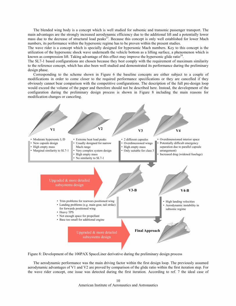
The blended wing body is a concept which is well studied for subsonic and transonic passenger transport. The main advantages are the strongly increased aerodynamic efficiency due to the additional lift and a potentially lower mass due to the decrease of structural load peaks23. Because this concept is only well established for lower Mach numbers, its performance within the hypersonic regime has to be proven within the present studies. The wave rider is a concept which is specially designed for hypersonic Mach numbers. Key to this concept is the utilization of the hypersonic shock wave underneath the vehicle bottom as a lifting surface, a phenomenon which is known as compression lift. Taking advantage of this effect may improve the hypersonic glide ratio24. The SL7-1 based configurations are chosen because they best comply with the requirement of maximum similarity to the reference concept, which has also been well studied and demonstrated its performance during the preliminary design phase. Corresponding to the scheme shown in Figure 6 the baseline concepts are either subject to a couple of modifications in order to come closer to the required performance specifications or they are cancelled if they obviously cannot bear comparison with the competitive configurations. The description of the full pre-design loop would exceed the volume of the paper and therefore should not be described here. Instead, the development of the configuration during the preliminary design process is shown in Figure 8 including the main reasons for modification changes or canceling.
Figure 8: Development of the 100PAX SpaceLiner derivative during the preliminary design process The aerodynamic performance was the main driving factor within the first design loop. The previously assumed aerodynamic advantages of V1 and V2 are proved by comparison of the glide ratio within the first iteration step. For the wave rider concept, one issue was detected during the first iteration. According to ref. 7 the ideal case of
V1 V2 V4V3
• Moderate hypersonic L/D• New capsule design• High empty mass• Marginal similarity to SL7-1
• Extreme heat load peaks• Usually designed for narrow
Mach range• Very complex system design • High empty mass• No similarity to SL7-1
• 2 different capsules• Overdimesioned wings• High empty mass• Only suitable for class 3
• Overdimensioned interior space• Potentially difficult emergency
separation due to parallel capsulearrangement)
• Increased drag (widened fuselage)
Final Approach
V3-B V4-B
• Trim problems for rearwars positioned wing• Landing problems (e.g. main gear, tail strike)
for forwards positioned wing• Heavy TPS• Not enough space for propellant• Base too small for additional engine
• High landing velocities• Aerodynamic instability in
subsonic regime
Upgraded & more detailedsubsystems design
Upgraded & more detailedsubsystems design

American Institute of Aeronautics and Astronautics
11
infinitesimal leading edge radii would imply also infinitely high heat flux densities, which cannot be handled either by passive or active TPS. Thus in reality a minimum required leading edge radius must be designed. First aerodynamic analyses have shown that the hypersonic glide ratio of the wave rider strongly depends on the sharpness of the leading edges. Figure 9 gives an exemplary comparison of L/D as a function of α for the ideal sharp edged configuration and a blunt configuration with an approximated leading edge radius in the same order of magnitude as the SL7-1. The glide ratio for the blunt configuration decreases by about 20%.
Figure 9: Glide ratio as a function of the angle of attack α for sharp and blunt edged wave rider (M=5 and M=20)
To avoid extreme peaks in the heat flux density only the blunt wave rider configuration is considered within the
further assessments of the aerodynamic performance. Figure 10 and Figure 11 compare the glide ratio of all configuration approaches. For the lower hypersonic regime almost all optima of L/D are within the range of 5.2 to 5.6, except for the widened fuselage has a lower maximum of approximately 4.5. At higher Mach numbers the differences in maximum L/D decrease and the glide ratios are within the range of 2.7 to 3.0. It has to be noted that the total range of the orbiter descent is strongly dependent on the glide ratio for higher Mach numbers, where V1 and V2 do not feature the expected performance. From the aerodynamic point of view, V3 is the most appropriate version.
Figure 10: Glide ratio for the different design approaches as a function of α (M=5, h=28.5km, turbulent)
Figure 11: Glide ratio for the different design approaches as a function of α (M=20, h=59.8km, turbulent)
However the multidisciplinary pre design also requires for consideration of the aspects shown in Figure 8. After
the first iteration loop it became obvious, that V1 and V2 are less suitable approaches than V3 and V4. For this reason these configurations were no longer considered within the preliminary design process. Because both, V3 and V4 are overdimensioned, the modifications during the second design loop mainly focus on mass reduction, but still keeping the other requirements in mind. The final approach is mainly based on the concept of the widened fuselage (V4).
0.0
1.0
2.0
3.0
4.0
5.0
6.0
7.0
8.0
0 5 10 15 20
L/D
[-]
α [°]
L/D sharp (M=5)L/D blunt (M=5)L/D sharp (M=20)L/D blunt (M=20)
-3.0-2.0-1.00.01.02.03.04.05.06.0
0 5 10 15 20
L/D
[-]
α [°]
M=5
L/D (V1)L/D (V2)L/D (V3)L/D (V4)
-1.5-1.0-0.50.00.51.01.52.02.53.03.5
0 5 10 15 20
L/D
[-]
α [°]
M=20
L/D (V1)L/D (V2)L/D (V3)L/D (V4)

American Institute of Aeronautics and Astronautics
12
V. Results The final result of the preliminary design is presented within this section. The masses and dimensions are given
in detail as well as aerodynamic and aerothermodynamic parameters. Furthermore the trajectories and the respective trajectory data are presented for the final approach.
Figure 12 shows the outer shape of the orbiter stage and the position of the passenger capsules and the multilobe tanks. To provide adequate thrust and avoid excessive stresses to the SLME an additional engine has to be planned.
Figure 12: Shape of the final SL7-100 approach (left) and position of passenger capsules and tanks (right)
A. Dimensions and masses The main dimensions of the final orbiter approach are given in Figure 13 a) and b). Figure 13 c) shows the
percentaged SL7-100 orbiter dry mass break down.
Figure 13: SL7-100 main orbiter dimensions (a,b) and dry mass break down (c)
Whereas the orbiter should be the same for both class 2 and class 3 missions to decrease the manufacturing costs, the length of the booster stage can be slightly decreased for class 3 missions like already mentioned in section IV. Figure 14 shows the main shape dimensions (a) and the dry mass break down for the two booster configurations.
Table 3 and Table 4 give the absolute values of the masses for class 2 and class 3. For the booster it has to be noted that the bold coordinates are global and the others are local. The class 2 booster stage is staggered by -21.24m in x-direction and -8.8m in z-direction compared to the orbiter stage. The class 3 booster stage is staggered by -12.49m in x-direction and -8.8m in z-direction. Therefore the orbiter coordinate system is taken as the reference for the global coordinate system.
Passengercapsules
LOX tank (multilobe)
LH2 tank (multilobe)
31.8 %
11.7 %5.6 %15.6 %
35.3 %
SL7-100 orbiter dry mass break down
Structure
Subsystems
Propulsion
Thermal Protection
Capsules + Passengers
69° 13.2m
34.0m
10.0m
5.5m
5.2m
1.5m
5.65m
5.2m
1.5m
77°
58.36m 3.19m
11.73ma) b)
c)

American Institute of Aeronautics and Astronautics
13
Figure 14: SL7-100 class 2 and class 3 booster stage dimensions (a) and dry mass break down (b)
Table 3: Total mass break down class 2 Table 4: Total mass break down class3
Orbiter mass [kg] xcog [m] zcog [m] Orbiter dry mass 212340 33.5 -1.01 Propellant mass 325000 Residuals 15020 Booster Class 2
mass [kg]
xcog [m]
zcog [m]
Booster dry mass 165060 32.68 (53.9) -9.01 (-0.22) Propellant mass 1283500 Residuals 6320 Total dry mass
377400
33.11
-4.52
Total lift off mass 2007240
Orbiter mass [kg] xcog [m] zcog [m] Orbiter dry mass 212340 33.5 -1.01 Propellant mass 325000 Residuals 15020 Booster Class 3
mass [kg]
xcog [m]
zcog [m]
Booster dry mass 143040 36.07 (48.56) -9.0 (-0.2) Propellant mass 1100000 Residuals 6320 Total dry mass
355380
34.12
-4.24
Total lift off mass 1801720
The total lift off configurations and the particular mass break down is given in Figure 15. By superposing both
booster stages it becomes obvious that the shape is very similar. Only the length of circular part is slightly decreased for the class 3 booster.
Figure 15: Total lift off configuration class 2 and class 3 (a) and total lift off mass break down (b)
27.1m
7.0m
80.5m
3.0m71.75m
60°
6.0m
8.7m
8.6m
Class 2
Class 3
51.0 %
12.8 %
21.8 %
14.4 %
Structure
Subsystems
Propulsion
Thermal Protection
49.6 %
13.6 %
25.0 %
11.8 %
Structure
Subsystems
Propulsion
Thermal Protection
mass break down class 2 mass break down class 3
a)
b)
8.3 %10.7 %
64.6 %
16.4 %
SL7-100 (K2) Total take off mass break down
Dry Mass Booster
Dry Mass Orbiter
Propellant Mass Booster
Propellant Mass Orbiter
8.0 %11.9 %
61.8 %
18.3 %
SL7-100 (K3) Total take off mass break down
Dry Mass Booster
Dry Mass Orbiter
Propellant Mass Booster
Propellant Mass Orbiter
a)
b)SL7-100 (C2) total take off mass break down SL7-100 (C2) total take off mass break down

American Institute of Aeronautics and Astronautics
14
B. Aerodynamics and aerothermodynamics The glide ratio is a key parameter for the performance of the SL7-100 orbiter. Furthermore the pitching
momentum coefficient has to be as close to zero as possible for the optimum glide ratio to decrease additional trim drag. Therefore Figure 16 and Figure 17 compare the L/D and cM of the SL7-100 and the SL7-1 reference for class 2 flight profile data for a Mach number of 5 and 20. It is obvious that the deficit in L/D of the SL7-100 gets less significant with increasing Mach number. The pitching momentum coefficient CM for the optimum L/D range is only very small and can be further reduced in the future by adequate moving of the CoG. The respective results for class 3 mission flight profile data are almost identical to these results and therefore are not presented here.
Figure 16: L/D and CM (class 2) as a function of α for SL7-1 and SL7-100 (M=5, h=29.7km, turbulent)
Figure 17: L/D and CM (class 2) as a function of α for SL7-1 and SL7-100 (M=20, h=57.7km, turbulent)
Another important aspect is the capability to trim the vehicle along the full trajectory. During the design process
it was found that the orbiter should be capable to be trimmed up to α=12° during its nominal descent. Due to structural restrictions a maximum wingflap deflection angle of ±45° should not be exceeded. Figure 18 shows the pitching momentum coefficient as a function of α for the maximum flap deflection angle. Trimming is possible at least up to 16° for lower Mach numbers.
Figure 18: CM as a function of α for maximum flap deflection angle δFlap = ±45° (M=5)
Figure 19: CM as a function of α for maximum flap deflection angle δFlap = ±45° (M=20)
Even in case of emergency flight abort scenario, the capability to trim is a dimensioning factor. This was already mentioned for the SL7-1 in ref. 6 and two scenarios were defined for the investigations: the total failure of the main engines at booster separation and the total engine failure at the highest point of the ascent trajectory. Because the final MECO-velocity cannot be reached anymore, a normal continuation of the flight is not possible. In this case the vehicle must be capable to fly back to earth safely. To investigate the trim capability in this case, a detailed analysis of the CoG has to be performed, because the tanks still contain a certain amount of propellant, which could be dumped depending on the optimum CoG position. These investigations are part of future studies.
-0.07
-0.06
-0.05
-0.04
-0.03
-0.02
-0.01
0
-1.0
0.0
1.0
2.0
3.0
4.0
5.0
6.0
0 5 10 15 20 25C
M[-]
L/D
[-]
α [°]
M=5
L/D SL7-1L/D SL7-100CM SL7-1CM SL7-100
-0.07-0.06-0.05-0.04-0.03-0.02-0.0100.01
-1.0-0.50.00.51.01.52.02.53.0
0 5 10 15 20 25
CM
[-]
L/D
[-]
α [°]
M=20
L/D SL7-1L/D SL7-100CM SL7-1CM SL7-100
-0.12-0.10-0.08-0.06-0.04-0.020.000.020.04
0 5 10 15 20 25
CM
[-]
α [-]
M=5
delta_flap=+45°delta_flap=-45°
-0.12-0.10-0.08-0.06-0.04-0.020.000.020.04
0 5 10 15 20 25
CM
[-]
α [-]
M=20
delta_flap=+45°delta_flap=-45°

American Institute of Aeronautics and Astronautics
15
Another very important issue is the capability to trim the vehicle during the landing process. To investigate this matter, the required angle of attack for landing has to be calculated. Therefore a load factor of n=1 is assumed for the landing, which means that the lift is equal to the total vehicle mass. With it the required CL can be approximated by the following formula.
ref2
2L Av
gmC⋅⋅
=ρ
The landing mass is approximately 217.5 tons (empty mass + residuals) and the reference area Aref = 461.0m2. Assuming sea level conditions, CL as a function of the landing speed is presented in Figure 20.
Figure 20: Required lift coefficient for the landing process as a function of the landing speed
There is a restriction on the maximum landing speed, in particular due to the characteristics of the tires. Ref. 25 gives a maximum tire speed of 400km/h; thus the landing speed is set to 360km/h (100m/s) within these investigations. This value is in very good agreement with the results of the trajectory analyses and results in a minimum required CL = 0.756. Figure 21 shows the CL as a function of α for zero flap deflection and for δFlap = 10° and the resulting minimum angles of attack, calculated by PANAIR. Figure 22 shows the accordant gradient of CM. Thus CM = 0 and CL = 0.756 can be reached between flap deflection angles of 0° and 10° and angles of attack between 9.36° and 13°, which are reasonable values. Nevertheless it has to be noted that longitudinal stability is not given in any case (positive gradient of CM). This issue may be solved either by a displacement of the CoG or the use of a stability control system, which might be a subject of future studies. However it has to be noted that these calculations were conducted by means of approximation tools, neglecting some fundamental aspects of fluid mechanics, such as vortex generation for delta wings.
Figure 21: CL as a function of α for zero flap deflection angle and δFlap = 10° (M=0.3, h=0m)
Figure 22: CM as a function of α for zero flap deflection angle and δFlap = 10° (M=0.3, h=0m)
0.0
0.5
1.0
1.5
2.0
2.5
3.0
3.5
50 75 100 125 150 175 200
CL
[-]
v [m/s]
CL = 0.756
0.0
0.2
0.4
0.6
0.8
1.0
1.2
1.4
0 5 10 15 20
CL
[-]
α [°]
delta_flap=10°delta_flap=0°
α = 9.36°
α = 13°
-0.08
-0.06
-0.04
-0.02
0.00
0.02
0.04
0.06
0.08
0 5 10 15 20
CM
[-]
α [°]
delta_flap=10°
delta_flap=0°

American Institute of Aeronautics and Astronautics
16
Also the aerothermodynamic properties of the orbiter were considered. Figure 23 shows the surface temperature of the orbiter at the trajectory point of the highest heat flux. The temperature distribution and also the maximum stagnation temperatures of SL7-1 and SL7-100 are very similar. Slight differences in the temperature of fuselage and wings are not considered as critical and caused by the applied engineering methods. Analogous to the SL7-1 the thermally highly stressed surface sections such as the stagnation point or the leading edges have to be actively cooled by transpiration of liquid water through a porous ceramic7. The amount of water needed to cool down these regions to moderate surface temperatures was estimated to 11.5 tons in the present studies, analogous to the SL7-1. The exact water mass will be calculated during future investigations but it is expected to remain in the same range.
Figure 23: Comparison of the surface temperature TW [K] of SL7-1 and SL7-100 (M=18, h=52km, α=10°)
C. Trajectory data and range The most recent optimization results for the full SL7-100 class 2 and class 3 trajectories are presented in the
following.
Figure 24: Altitude as a function of the flight time Figure 25: Mach number as a function of the flight time The most important factor of the design process is that the final configuration achieves the required range to
fulfill the class 2 and class 3 mission. Figure 24 presents the corresponding altitude as a function of the flight time whereas Figure 25 shows the gradient of the Mach number.
SL7-1 SL7-100
0
10
20
30
40
50
60
70
0 1000 2000 3000 4000 5000
Alti
tude
[km
]
flight time [s]
Class 3Class 2
0
5
10
15
20
25
0 1000 2000 3000 4000 5000
Mac
h nu
mbe
r [-]
flight time [s]
Class 2Class 3

American Institute of Aeronautics and Astronautics
17
According to the requirement to keep the dynamic pressure below 60kPa and the normal acceleration nz below 2.5g Figure 26 and Figure 27 show the gradients of both. It can be stated that these requirements are completely fulfilled.
Figure 26: Dyn. pressure as a function of the flight time Figure 27: nz as a function of the flight time
Figure 28 and Figure 29 show the full trajectory plotted in Mercator projection. The required downrange can easily be achieved, there is even a little reserve in the range, which allows for additional manoeuvers if required. The trajectory optimization, in particular the ascent, is not fully completed, so further improvements may be expected in the future.
Figure 28: Reference trajectory for class 2 missions Figure 29: Reference trajectory for class 3 missions
VI. Conclusion An iterative preliminary design process has been conducted to increase the maximum passenger number of the
SpaceLiner from 50 to 100. Many different disciplines, such as trajectory, mass and subsystems analysis as well as aerodynamics and aerothermodynamics, have been considered during the iteration loops. Fast engineering methods have been utilized in order to get quick results with an acceptable accuracy.
The final approach is capable of managing two different mission types, one with a flight distance of up to 12500km, dubbed mission class 2, and another one with a shorter distance of maximal 9100km, dubbed mission class 3. To reduce manufacturing costs, the orbiter stage is similar between both classes whereas the booster stage is only slightly shorter for class 3 missions. Analogous to the SL7-1 baseline configuration, the 100 PAX version should be fully reusable. Therefore the same engines, dubbed SLME, are used for both configurations. A total similarity between SL7-1 and SL7-100 cannot be maintained, thus a couple of changes had to be conducted, such as a third orbiter engine for the 100 PAX version. The vehicle comes with an adequate glide ratio along the full trajectory, with trimming available, even during landing. In future studies the trim capability in case of emergency flight abort, which depends on the filling level of the tanks, will be investigated. In subsonic regime, longitudinal
0
5
10
15
20
25
30
0 1000 2000 3000 4000 5000
dyn.
pre
ssur
e [k
Pa]
flight time [s]
Class 3Class 2
-0.2
0.0
0.2
0.4
0.6
0.8
1.0
1.2
0 1000 2000 3000 4000 5000
norm
al a
ccel
erat
ion
[g0]
flight time [s]
Class 3Class 2
Dubai
Denver
MECO:t=437sh=58kmv=6.5km/s
Map data 2012 Map link, Tele Atlas
San Francisco
Seoul
MECO:t=441sh=55kmv=6.0km/s
Map data 2012 Map link, Tele Atlas

American Institute of Aeronautics and Astronautics
18
stability was not proven, thus a displacement of CoG or artificial stability control is required. The thermal loads of the vehicle are not drastically increased compared to the loads of the reference configuration. This circumstance allows for reasonable passive and active TPS design. The exact coolant mass for the transpiration cooling using liquid water has to be estimated in the future. The maximum dynamic pressure does not exceed 30kPa during the whole flight, and is therefore half as high as the maximum allowed value. During the normal flight a vertical acceleration of nz = 2.5g is never reached, the maximum is approximately nz = 1g. Nevertheless it has to be checked whether the conditions stay within the allowed range in the case of flight abort scenarios. Finally the achieved result of the work can be used as an input for more detailed analyses in the future.
Acknowledgments Part of this work was performed within the ‘Future High-Altitude High-Speed Transport 20XX’ project
investigating high-speed transport. FAST20XX, coordinated by ESA-ESTEC, is supported by the EU within the 7th Framework Programme Theme7 Transport, Contract no.: ACP8-GA-2009-233816. Further information on FAST20XX can be found on http://www.esa.int/fast20xx.
Part of this work was performed within the ‘Cryogenic Hypersonic Advanced Tank Technologies’ project investigating tank technologies for high-speed transport. CHATT, coordinated by DLR-SART, is supported by the EU within the 7th Framework Programme Theme 7 Transport, Contract no.: ACP1-GA-2011-285117. Further information on CHATT can be found on http://www.chatt.aero
The authors gratefully acknowledge the contributions of Ms. Carola Bauer, Ms. Nicole Garbers, Mr. Alexander Kopp and Mr. David Gerson to the preliminary design of the SpaceLiner.
References 1 Sippel, M., Klevanski, J., Steelant, J.: “Comparative Study on Options for High-Speed Intercontinental Passenger Transports: Air-Breathing- vs. Rocket-Propelled”, IAC-05-D2.4.09, October 2005 2 Sippel, M., Schwanekamp, T., Bauer, C., Gerbers, N., van Foreest, A., Tengzelius, U., Lentsch, A.: “Technical Maturation of the SpaceLiner Concept”, AIAA-2012-5850, 18th AIAA/3AF International Space Planes and Hypersonic Systems and Technologies Conference, Tours, September 2012 3 Sippel, M., Klevanski, J., Kauffmann, J.: “Innovative Method for Return to the Launch Site of Reusable Winged Stages”, IAF-01-V.3.08, Toulouse, October 2001 4 Schwanekamp, T., Bauer, C., Kopp, A.: “The Development of the SpaceLiner Concept and its Latest Progress”, 4th CSA-IAA Conference on Advanced Space Technology, Shanghai, September 2011 5 Neeb, D., Schwanekamp, T., Gülhan, A..: “Preliminary Aerodynamic Shape Optimization of the SpaceLiner by Means of Engineering Methods”, AIAA 2011-2373, 17th AIAA International Space Planes and Hypersonic Systems and Technologies Conference, April 201 6 Dietlein, I., Schwanekamp, T., Kopp, A.: “Trim Requirements and Impact on Structural and Wing Design for the High Speed Passenger Transport Concept SpaceLiner”, 4th EUCASS, July 2011 7 Van Foreest, A. , Sippel, M., Gülhan, A., Esser, B., Ambrosius, B.A.C., Sudmeijer, K.: “Transpiration Cooling Using Liquid Water”, Journal of Thermophysics and Heat Transfer, Vol. 23, No. 4, October–December 2009 8 van Foreest, A., Sippel, M.: “The Logistical Challenges of the SpaceLiner Concept”, IAA 1st Symposium on Private Human Access to Space, Arcachon May 28-30 2008 9 Reisch, U., Anseaume, Y.: “Validation of the Approximate Calculation Procedure HOTSOSE for Aerodynamic and Thermal Loads in Hypersonic Flow with Existing Experimental and Numerical Results”, DLR-Forschungsbericht, 98-23, 1998 10 Streit, T., Martin, S., Eggers, T.: “Approximate Heat Transfer Methods for Hypersonic Flow in Comparison with Results Provided by Numerical Navier-Stokes Solution”, DLR-Forschungsbericht, 94-36, 1994 11 White, F. M., Christoph, G. H.: “A Simple Theory for the Two-Dimensional Compressible Turbulent Boundary Layer”, Journal of Basic Engineering, Vol. 91, 1972

American Institute of Aeronautics and Astronautics
19
12 Van Driest, E. R.: “Problem of Aerodynamic Heating”, Aeronautical Engineering Review, Vol. 15, No. 10, 1956. 13 Meador, W. E., Smart, M. K.: “Reference Enthalpy Method Developed from Solutions of the Boundary-Layer Equations”, AIAA Journal, Vol. 43, No. 1, 2005 14 Fay, J. A., Riddel, F. R.: “Theory of Stagnation Point Heat Transfer in Dissociated Air”, Journal of Aeronautical Sciences, Vol. 25, No. 2, 1958 15 Zoby, E. V., Moss, J. N., Sutton, K.: “Approximate Convective Heating Equations for Hypersonic Flows”, AIAA Paper 79-1078, 1979 16 Fleming, W. J., Krauss, W. E.: “Aerodynamic Heating from Turbulent Boundary Layers to Swept Surfaces”, 3rd International Heat Conference, 1966 17 Klevanski, J., Sippel, M.: “Beschreibung des Programms zur aerodynamischen Voranalyse CAC Version 2“, DLR-IB647-2003/04, Cologne, March 2003 18 Mchitaryan, A.M., “Aerodinamika“, Maschinenbau-Verlag, Moskau, 1970 19 N.N.: “USAF Stability and Control Datcom”, Capt. 4, 1960, revised 1972. 20 Schlichting, H., Truckenbrodt E.: “Aerodynamik des Flugzeuges“, Zweiter Band, Springer-Verlag Berlin/Heidelberg/New York 1969 21 Johnson, F.T.: “A General Panel Method for the Analysis and Design of Arbitrary Configurations in Incompressible Flows”, NASA Contractor Report 3079, Boeing Commercial Airplane Company, Seattle, Washington 1980 22 Schwanekamp, T.: “Beschreibung des Netzgenerators GGH“, DLR internal report, SART TN-008/2011, Bremen 2008 23 Potsdam, M.A., Page, M.A., Liebeck, R.H.: “Blended Wing Body Analysis and Design”, AIAA-97-2317, California, Long Beach 1997 24 Rodi, P.E.: “Engineering-Based Performance Comparisons Between Osculating Cone and Osculationg Flowfield Waveriders”, AIAA-2007-4344, Florida, Miami 2007 25 Roskam, J.: “Airplane Design – Part IV: Layout Design of Landing Gear and Systems”, The University of Kansas, Roskam Aviation and Engineering Cooperation, Lawrence 1989