Preliminary Design Report Project Title: Search and Destroy
14
EEL 4924 Electrical Engineering Design (Senior Design) Preliminary Design Report 19 April 2011 Project Title: Search and Destroy Team Member: Name: Robert Bethea Name: Felipe Freire Email: [email protected] Email: [email protected] Project Abstract Our project consists of building a robotic turret that will search for a designated target using image processing and automatically or manually “destroy” it. This design has two main parts: PC-side and Camera-side. The Camera-side will have the camera, a pointing mechanism (laser) on top of a rotating (left, right, up and down) device, and a microcontroller (MCU). The camera MCU will control camera input and rotating the device. The camera will get the image and send it through a serial port connected to the microprocessor. The PC side of the project will run the shape detection program and send the coordinates of the specified shape back to the camera side processor. The image processing software we will be using is all taken care of in MATLAB. We decided that because we were already familiar with the program, and it had an onboard image processing toolbox it would be the simplest tool to implement with our design. It also has a simple GUI creation tool.
-
Upload
khangminh22 -
Category
Documents
-
view
0 -
download
0
Transcript of Preliminary Design Report Project Title: Search and Destroy

EEL 4924 Electrical Engineering Design
(Senior Design)
Preliminary Design Report
19 April 2011
Project Title: Search and Destroy
Team Member:
Name: Robert Bethea Name: Felipe Freire
Email: [email protected] Email: [email protected] Project Abstract
Our project consists of building a robotic turret that will search for a designated target using image processing and automatically or manually “destroy” it. This design has two main parts: PC-side and Camera-side. The Camera-side will have the camera, a pointing mechanism (laser) on top of a rotating (left, right, up and down) device, and a microcontroller (MCU). The camera MCU will control camera input and rotating the device. The camera will get the image and send it through a serial port connected to the microprocessor. The PC side of the project will run the shape detection program and send the coordinates of the specified shape back to the camera side processor.
The image processing software we will be using is all taken care of in MATLAB. We
decided that because we were already familiar with the program, and it had an onboard image
processing toolbox it would be the simplest tool to implement with our design. It also has a simple
GUI creation tool.

Table of Contents
Project Features ............................................................................................................................3
Technical Concepts........................................................................................................................3
Hardware……………….………………………………………………………………...4
Software……………….………………………………………………………………....7
Distribution of Labor...................................................................................................................11
Project Timeline .........................................................................................................................11
Parts List………………………………………………………………………………………..12
Appendix A……………………………………………………………………………………..13
Appendix B……………………………………………………………………………………..13
List of Figures
1. Project Block Diagram ...........................................................................................................4 2. Microcontroller Pinout.............................................................................................................5
3.Camera......................................................................................................................................5
4.Camera Layout………………………………………………………………………………...6
5.Circuit Diagram……………………………………………………………………………..…6
6.BMP File……………………………………………………………………………………....8
7.Servo Timing Diagram………………………………………………………………………...9
8.Processed Image……………………………………………………………………………...10
9. Gantt Chart of Timeline...........................................................................................................11
10.Parts List…………………………………………………………………………………….12
11.PCB Layout…………………………………………………………………………………13
12-14.Project Images………………………………………………………………………..13-14

Primary Features/Objectives
In the Search and Destroy senior design project, there are four main
objectives that will be accomplished upon completion.
1. The turret and host computer will communicate serially.
2. The program will accept a “target” input from the user.
3. The camera will acquire the “target.”
4. The turret will eliminate the “target.”
We are going to communicate serially between the turret and computer. We will use a RS-232
breakout board to accomplish this portion of the project. This part was very simple to implement to the
microprocessor and PC. This option was chosen over wireless because we could not get a fast enough
data transfer rate to get the image from the camera to the PC.
The next feature of our project design is the turret will accept a “target” input
from a user. We made a simple GUI in MATLAB to accomplish the feat. The only action the user
has to take is press the button of which ever target they want to target. The image processing program
will take care of the rest of the steps.
The third feature we will implement to our design project is the turret will be
able to locate the target without user control. We accomplished this feat with writing
some image processing software in MATLAB. We decided to focus on targeting
shapes instead of more detailed images because neither of us had any image processing
experience.
The final feature of our design project is the elimination of the desired target. In
order for this to happen, the turret will need to be able to move both side-to-side and
up and down. For this portion of the project to be deemed successful, the laser must
hit the target in some way.
Technical Concepts
This section is divided into two parts: hardware and software design. The
hardware design describes the functions and the connections between the
components of the system. The software design section describes the rules and
protocols that handle wireless transmit/receive and turret operation. The host
software design section describes the PC GUI program that handles user commands
and video image processing.
Hardware design
Figure 1
The above figure shows the hardware flowchart. The MCU used is the Atmel
ATmega1284p and the camera used is the C3088 video camera with Omnivision
OV6620. All the components will be group into two parts: PC- side and camera-
side.
The MCU will control the turret and camera. The camera’s data is sent out
through its output pins to the GPIO’s ports of the MCU. The MCU gets the data the
sends it through the serial connection to transmit the data to the PC. Reading and
writing to the camera’s registers will be done through I2C.
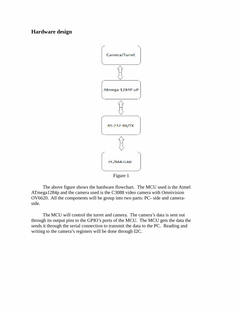
MCU
Figure 2
The Atmega1284p was chosen because of its large SRAM capacity (16KB)
which makes buffering of data easier. It’s a low power CMOS 8-bit microcontroller.
We decided not to use the internal clock of this processor because it simply was
not fast enough for data transfer. We went with a 20MHz external clock instead.
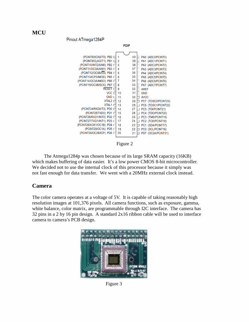
Camera
The color camera operates at a voltage of 5V. It is capable of taking reasonably high
resolution images at 101,376 pixels. All camera functions, such as exposure, gamma,
white balance, color matrix, are programmable through I2C interface. The camera has
32 pins in a 2 by 16 pin design. A standard 2x16 ribbon cable will be used to interface
camera to camera’s PCB design.
Figure 3

Figure 4
Power Supply
We will not use any external power supply. The 5V we need to operate the circuit
will all be supplied through the USB port of the PC. We decided to do this because of
its ease and simplicity.
Circuit Diagram
Figure 5
Figure 5 shows the circuit design we used to create the PCB. The PCB layout is
shown in the appendix section.
1 2
3 4
5 6
Programmer
Programmer
G N D
V C C
1 2
3 4
5 6
7 8
9 1 0
1 1 1 2
1 3 1 4
1 5 1 6
1 7 1 8
1 9 2 0
2 1 2 2
2 3 2 4
2 5 2 6
2 7 2 8
2 9 3 0
3 1 3 2
Camera
Camera
G N D
V C C
V C C
G N D
1
2
3
4
USB
USB
1
2
Clock
Clock
1 0 0 p F
C 1
Cap
1 0 0 p F
C 2
Cap
G N D
V C C
G N D
1
2
3
Servo1
Servo1
G N D
PB0 (XCK/T0)
1
PB1 (T1)
2
PB2 (AIN0/INT2)
3
PB3 (AIN1/OC0)
4
PB4 (SS)
5
PB5 (MOSI)
6
PB6 (MISO)
7
PB7 (SCK)
8
RESET
9
PD0 (RXD)
1 4
PD1 (TXD)
1 5
PD2 (INT0)
1 6
PD3 (INT1)
1 7
PD4 (OC1B)
1 8
PD5 (OC1A)
1 9
PD6 (ICP)
2 0
PD7 (OC2)
2 1
X T A L 2
1 2
X T A L 1
1 3
G N D
1 1
PC0 (SCL)
2 2
PC1 (SDA)
2 3
PC2 (TCK)
2 4
PC3 (TMS)
2 5
PC4 (TDO)
2 6
PC5 (TDI)
2 7
PC6 (TOSC1)
2 8
PC7 (TOSC2)
2 9
A R E F
3 2
A V C C
3 0
G N D
3 1
PA7 (ADC7)
3 3
PA6 (ADC6)
3 4
PA5 (ADC5)
3 5
PA4 (ADC4)
3 6
PA3 (ADC3)
3 7
PA2 (ADC2)
3 8
PA1 (ADC1)
3 9
PA0 (ADC0)
4 0
V C C
1 0
U 1
ATmega16-16PI
V C C
1
2
3
Servo2
Servo2
G N D
V C C
1
2
3
Reset
Reset
G N D
G N D
G N D
1 K
R 1
Res1
V C C
1 2 3
VCC/Ground
VCC/Ground
1 K
R 2
Res2
1 K
R 3
Res3
V C C
V C C
G N D

Software design
The software design of the project will have the embedded software of the PC side and camera side. The PC-side embedded software sends a command to the camera-side embedded system to request for data. This command activates the camera and initiates the broadcast of
image data via serial port. PC-side embedded system transmits video data to the PC host software to be processed after it receives it. PC host software process data images to find a specific target, then it send its position to turret to acquire the target. We used AVR studios and
MATLAB for our programming platforms.
Camera Software:
USART
One of the first things that were designed was the communications between the
Camera’s board and the PC. This was important to set up first because it was used to test and
troubleshoot by sending error messages to the computer. Port settings were designed to be: 8 data
bits, 1 stop, 0 parity, 115200 bps and flow control none. On the PC two text terminals were used:
Real Term and Hyper-terminal. Everything could have been done with Hyper-terminal, but for
reasons that I could not understand I was not able to open BMP files after getting them from the
camera. That’s why I used Real-Term, open source software. On the Camera’s board, a generic
code from AVR USART library for GCC was used. The algorithm was modified to fit the
requirements for this project. The two main functions of the header file USART.H are: sending
(no buffer) and receiving (buffer with interrupt).
I2C Comm
The cam module, CMOS C3088, uses I2C (Inter-Integrated Circuit) protocol for
communication. This protocol uses one pin for the clock and the other for data and a Master-
Slave design. The most difficult part of this project was to figure out a way to write to and read
from the cam’s registers, which was a requirement to control cam’s functionalities. The problem
was that the Atmega1284p does not implement I2C protocol. Two solutions were thought out:
I2C hardware converter or some kind of software that would emulate the I2C protocol.
Second solution was selected because it was easier to implement as the Atmega1284p uses a
synchronous TWI (Two Wire Interface) protocol which with some modifications can emulate
I2C protocol. The write and read functions are implemented on I2C_CAM.H header file.
BMP
The BMP.H header file was created to send images to the PC. BMP (Bitmap image)
file format was select for its simplicity to implement. After sending the headers of the BMP file,
the data (pixel) are sent. This allows sending an image to the PC as it is read from the cam
which does not require a buffer to store the data on the chip.
BMP file structure:

BMP File (figure 6)
To get an image from the cam, the timing diagram from the cam’s datasheet was
followed. The clock frequency of the cam (PCLK) runs to about 18MHz and the Atmega1284p
to 20MHz using external crystal oscillator. This was not a big problem using delays to make
sure both hardware works to the same frequencies.
There are two ways to read an image from the cam: horizontally and vertically.
Vertical Mode was chosen for it allowed a higher frequency to be used. The only problem with
vertical mode is that to get an image we need to read as many frames as to vertical lines.
Servos
Two servos were used to control the horizontal and vertical movement of the camera.
The main function of the two servos was: tracking and pointing a given object. The position of
the servos is control by the width of the periodic pulse as shown on fig 7. The specific values
were found by testing and the use of the oscilloscope. All the pins and set up timings can be
found on the header file SERVOS.H

Servo Timing Diagram (figure 7)
Main
In the Main function (source file) is where all the magic takes place. Here is where the
serial communication (USART.H) and the TWI (I2C_CAM.H) protocol are initiated and most of
the hardware (chip’s pins) configuration set up. The program sends a welcome message to the
PC and then it goes to an infinite while loop waiting for user’s command input. The source file
has a function call read-line which reads user’s input coming from the serial port chosen. Then
the input is compared to the commands hardcoded on the chip. If the input is correct or wrong, it
will output an acknowledgment based on the input.
Image processing Software
All the image processing was done in MATLAB. The image processing toolbox was
used frequently to process the image. The purpose of the image processing in our project was to
identify and locate the coordinates of the user specified target. The targets we are trying to
identify are three different shapes (circle, square, rectangle).

Identifying the Shapes
To identify a shape, the quality of their roundness was used. The following equation was
used to find a ratio of how round the object is.
( )
The above equation works by giving each object in the image a ratio. The closer the object’s ratio
is to 1, the rounder the object is. For our project’s images, circles tended to have ratios greater
than .65. Squares had ratios that ranged between .45 and .6, and rectangles had ratios between .3
and .44
Locating the Shapes
To locate the shape, a GUI was created within MATLAB. Buttons were made with the
name of each shape as the text on the button. . If an object was found to have a “roundness” ratio
within the parameters of the button the user selects, the program will get the central point of that
shape and send those coordinates to the MCU.
Figure 8
Figure 8 shows the program after it has been told to find the circle in the captured image.

Distribution of Labor Felipe Freire:
-Hardware design
-Camera Software design
-Object Acquisition/Targeting
-Serial Communication
Robert Bethea:
-Hardware design
-Image processing Software design
-Serial Communication
-PCB design
Gantt chart: This is an estimated timeline of the project’s completion.
Figure 9

Parts List Part Price
Camera Module $50.00
Pan and Tilt Servo Kit $29.00
Atmega 1284p $8.13
RS-232 $0
20 MHz ext. clock $1.50
Resistors/Capacitors $0
Packaging $5.00
Total: $102.63
Figure 10

Appendix A: PCB layout
Figure 11
Appendix B: Project Images
Figure 12
1
2
1
2
1
22 1
2 1
1
2
4321
3231
3029
2827
2625
2423
2221
2019
1817
1615
1413
1211
109
87
65
43
21
1 2
3 4
5 6
1
2
3
4
5
6
7
8
9
10
11
12
13
14
15
16
17
18
19
20
40
39
38
37
36
35
34
33
32
31
30
29
28
27
26
25
24
23
22
21
123
1 2 3
1
2
3
123

Figure 13
Figure 14