Toxicosis of Snake, Scorpion, Honeybee, Spider, and Wasp ...
Upload
khangminh22Category
view
0download
0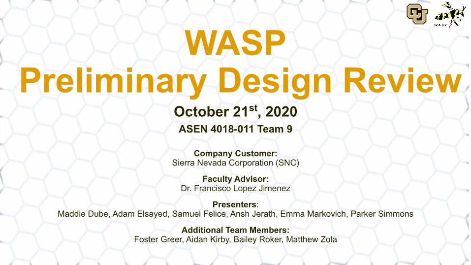
WASP Preliminary Design Review
October 21st, 2020ASEN 4018-011 Team 9
Company Customer:Sierra Nevada Corporation (SNC)
Faculty Advisor:Dr. Francisco Lopez Jimenez
Presenters:Maddie Dube, Adam Elsayed, Samuel Felice, Ansh Jerath, Emma Markovich, Parker Simmons
Additional Team Members:Foster Greer, Aidan Kirby, Bailey Roker, Matthew Zola
Future Work Back-upBudgetAccuracyElectronicsStructures Overview Conclusions
Presentation Outline
1. Project Overview - Parker Simmons, Ansh Jerath
2. Feasibility: Structures - Adam Elsayed, Parker Simmons
3. Feasibility: Electronics and Software - Maddie Dube
4. Feasibility: Accuracy - Samuel Felice, Emma Markovich
5. Feasibility: Budget - Emma Markovich
6. Feasibility Conclusions - Ansh Jerath
7. Future Work - Adam Elsayed, Emma Markovich
2

Project Overview
3
Future Work Back-upBudgetAccuracyElectronicsStructures Overview Conclusions
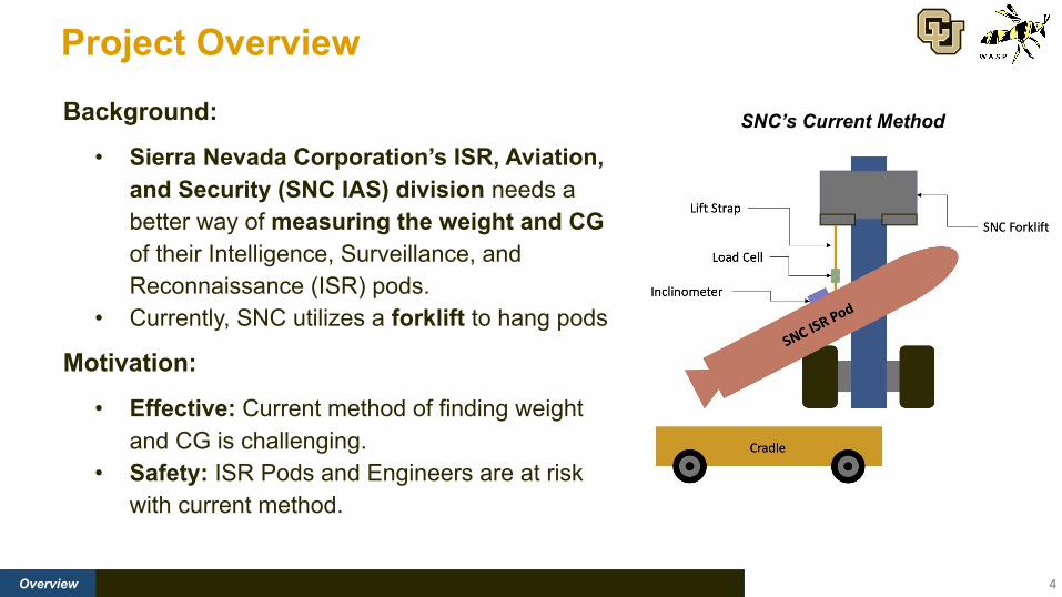
Project Overview
4
Background:
• Sierra Nevada Corporation’s ISR, Aviation, and Security (SNC IAS) division needs a better way of measuring the weight and CG of their Intelligence, Surveillance, and Reconnaissance (ISR) pods.
• Currently, SNC utilizes a forklift to hang pods
Motivation:
• Effective: Current method of finding weight and CG is challenging.
• Safety: ISR Pods and Engineers are at risk with current method.
SNC’s Current Method
Future Work Back-upBudgetAccuracyElectronicsStructures Overview Conclusions
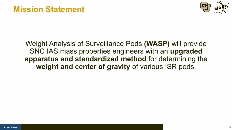
Mission Statement
5
Weight Analysis of Surveillance Pods (WASP) will provide SNC IAS mass properties engineers with an upgraded
apparatus and standardized method for determining the weight and center of gravity of various ISR pods.

Future Work Back-upBudgetAccuracyElectronicsStructures Overview Conclusions 6
Concept of Operations

Future Work Back-upBudgetAccuracyElectronicsStructures Overview Conclusions 7
Baseline Design
Current Structural Weight:
1179.22 lbs
[2]
Future Work Back-upBudgetAccuracyElectronicsStructures Overview Conclusions 8
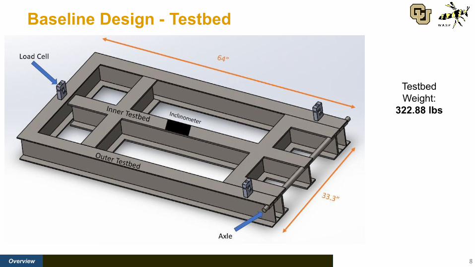
Baseline Design - Testbed
Testbed Weight:
322.88 lbs

Future Work Back-upBudgetAccuracyElectronicsStructures Overview Conclusions
Functional Block Diagram
9
Future Work Back-upBudgetAccuracyElectronicsStructures Overview Conclusions
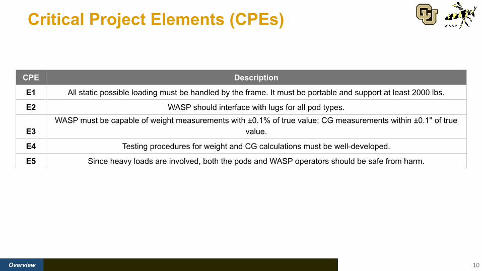
Critical Project Elements (CPEs)
10
CPE Description
E1 All static possible loading must be handled by the frame. It must be portable and support at least 2000 lbs.
E2 WASP should interface with lugs for all pod types.
E3WASP must be capable of weight measurements with ±0.1% of true value; CG measurements within ±0.1'' of true
value.
E4 Testing procedures for weight and CG calculations must be well-developed.
E5 Since heavy loads are involved, both the pods and WASP operators should be safe from harm.

Design Feasibility
11
Overview FOS ACC/W ACC/CG COST
Feasibility Tracking
COMPAT
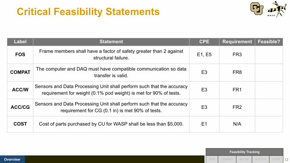
Critical Feasibility Statements
12
Label Statement CPE Requirement Feasible?
FOS Frame members shall have a factor of safety greater than 2 against structural failure.
E1, E5 FR3
COMPAT The computer and DAQ must have compatible communication so data transfer is valid.
E3 FR8
ACC/W Sensors and Data Processing Unit shall perform such that the accuracy requirement for weight (0.1% pod weight) is met for 90% of tests.
E3 FR1
ACC/CG Sensors and Data Processing Unit shall perform such that the accuracy requirement for CG (0.1 in) is met 90% of tests.
E3 FR2
COST Cost of parts purchased by CU for WASP shall be less than $5,000. E1 N/A

Structures
13
Future Work Back-upBudgetAccuracyElectronicsStructures Overview Conclusions FOS ACC/W ACC/CG COST
Feasibility Tracking
COMPAT
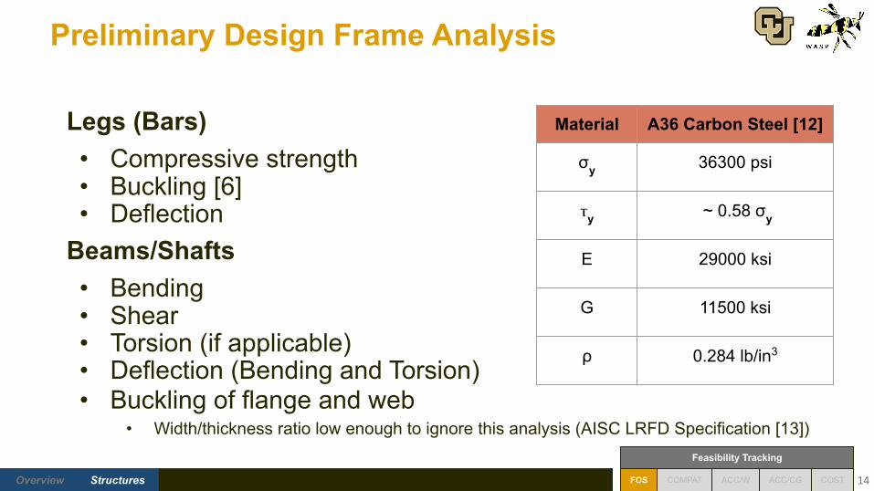
Preliminary Design Frame Analysis
14
Legs (Bars)• Compressive strength• Buckling [6]• Deflection
Beams/Shafts• Bending• Shear• Torsion (if applicable)• Deflection (Bending and Torsion)• Buckling of flange and web
• Width/thickness ratio low enough to ignore this analysis (AISC LRFD Specification [13])
Material A36 Carbon Steel [12]
σy 36300 psi
ⲧy ~ 0.58 σy
E 29000 ksi
G 11500 ksi
ρ 0.284 lb/in3
Future Work Back-upBudgetAccuracyElectronicsStructures Overview Conclusions FOS ACC/W ACC/CG COST
Feasibility Tracking
COMPAT
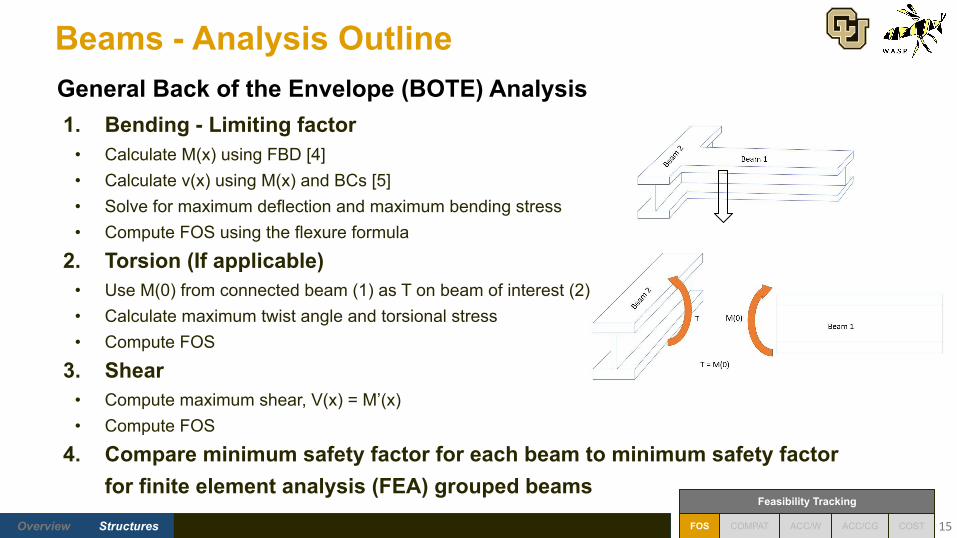
Beams - Analysis Outline
1. Bending - Limiting factor• Calculate M(x) using FBD [4]• Calculate v(x) using M(x) and BCs [5]• Solve for maximum deflection and maximum bending stress• Compute FOS using the flexure formula
2. Torsion (If applicable)• Use M(0) from connected beam (1) as T on beam of interest (2)• Calculate maximum twist angle and torsional stress• Compute FOS
3. Shear• Compute maximum shear, V(x) = M’(x)• Compute FOS
4. Compare minimum safety factor for each beam to minimum safety factor for finite element analysis (FEA) grouped beams
15
General Back of the Envelope (BOTE) Analysis
Future Work Back-upBudgetAccuracyElectronicsStructures Overview Conclusions FOS ACC/W ACC/CG COST
Feasibility Tracking
COMPAT
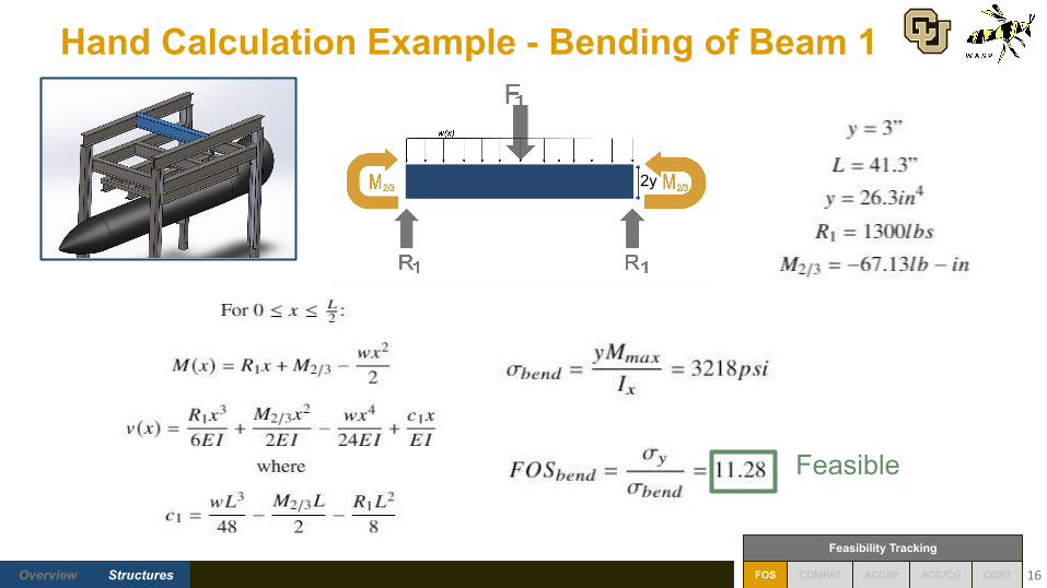
Hand Calculation Example - Bending of Beam 1
16
2y
Feasible
Future Work Back-upBudgetAccuracyElectronicsStructures Overview Conclusions FOS ACC/W ACC/CG COST
Feasibility Tracking
COMPAT
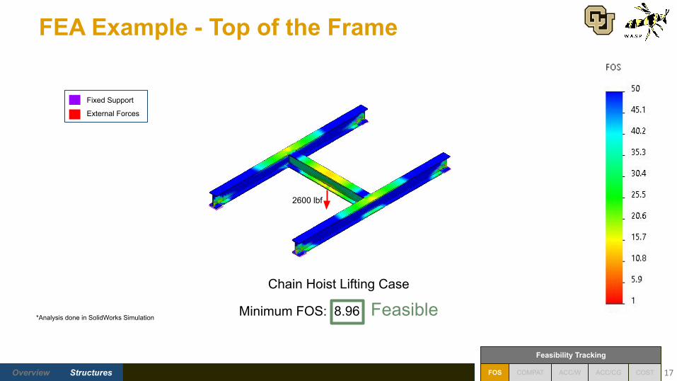
FEA Example - Top of the Frame
17
Chain Hoist Lifting Case
Minimum FOS: 8.96 Feasible
Fixed Support
External Forces
2600 lbf
*Analysis done in SolidWorks Simulation

Future Work Back-upBudgetAccuracyElectronicsStructures Overview Conclusions FOS ACC/W ACC/CG COST
Feasibility Tracking
COMPAT
FEA Example - Top of the Frame
18
Fixed Support
External Forces
Displacement
Maximum: 0.0134 in
2600 lbf 2600 lbf
Stress
Maximum: 4,047 psi
*FOS Distribution in structures feasibility portion of PDR

Future Work Back-upBudgetAccuracyElectronicsStructures Overview Conclusions FOS ACC/W ACC/CG COST
Feasibility Tracking
COMPAT
PartBOTE Max Deflection
(in)*
FEA Max Deflection
(in)
BOTE Max Stress (psi)
FEA Max Stress (psi)
BOTE Min FOS
FEA Min FOS Feasible?
(FOS > 2)
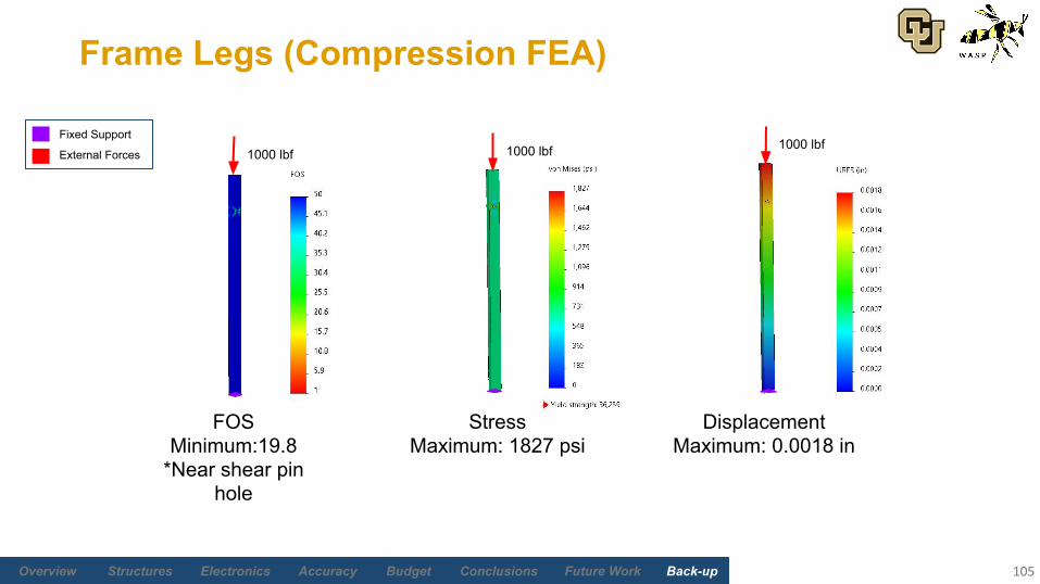
Frame Legs 0.0017 0.0018 804 1827 43.20 19.8 Yes
Top of Frame 0.0064 0.0134 3218 4047 11.28 8.96 Yes
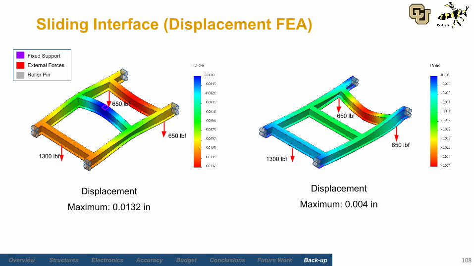
Sliding Interface 0.0047 0.0132 3215 4314 11.29 8.41 Yes
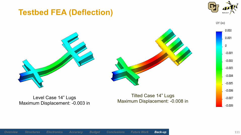
Testbed 0.0184 0.0080 2413.56 5011.2 15.04 7.24 Yes
Structural Analysis Results
19
* Maximum deflections are lower than current manufacturing tolerances (1/24”)

Electronics and Software
20
Future Work Back-upBudgetAccuracyElectronicsStructures Overview Conclusions FOS ACC/W ACC/CG COST
Feasibility Tracking
COMPAT
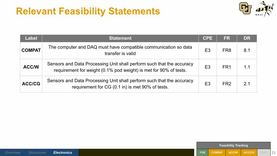
Relevant Feasibility Statements
21
Label Statement CPE FR DR
COMPAT The computer and DAQ must have compatible communication so data transfer is valid
E3 FR8 8.1
ACC/W Sensors and Data Processing Unit shall perform such that the accuracy requirement for weight (0.1% pod weight) is met for 90% of tests.
E3 FR1 1.1
ACC/CG Sensors and Data Processing Unit shall perform such that the accuracy requirement for CG (0.1 in) is met 90% of tests.
E3 FR2 2.1
Future Work Back-upBudgetAccuracyElectronicsStructures Overview Conclusions FOS ACC/W ACC/CG COST
Feasibility Tracking
COMPAT
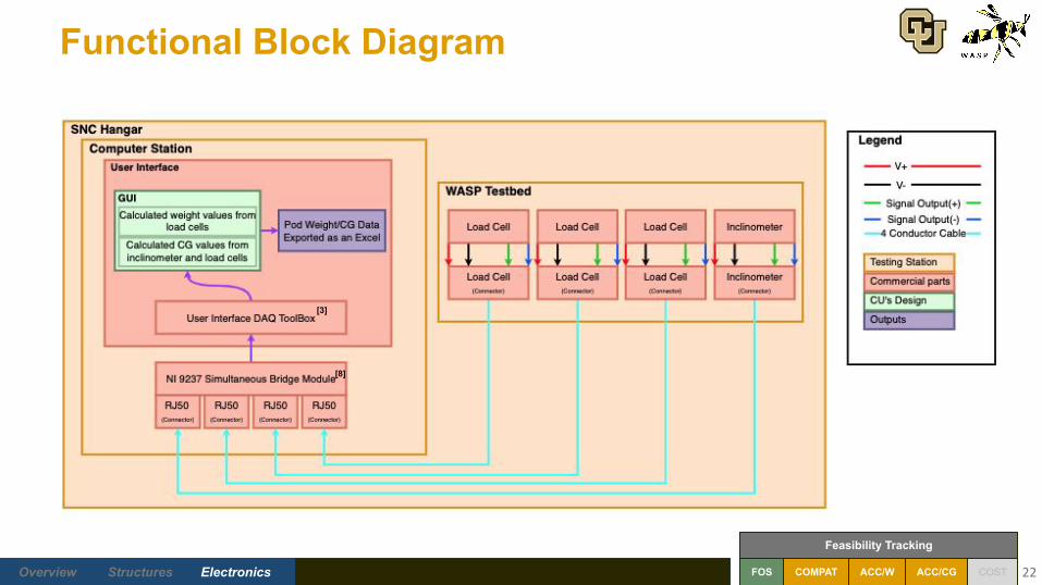
Functional Block Diagram
22
[8]
[3]
Future Work Back-upBudgetAccuracyElectronicsStructures Overview Conclusions FOS ACC/W ACC/CG COST
Feasibility Tracking
COMPAT 23
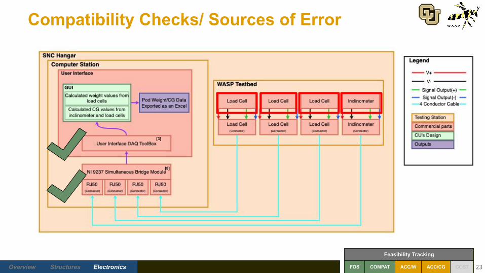
Compatibility Checks/ Sources of Error
[8]
[3]
Future Work Back-upBudgetAccuracyElectronicsStructures Overview Conclusions FOS ACC/W ACC/CG COST
Feasibility Tracking
COMPAT
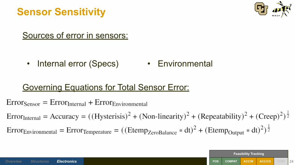
Sensor Sensitivity
24
Sources of error in sensors:
• Internal error (Specs)
Governing Equations for Total Sensor Error:
• Environmental
Future Work Back-upBudgetAccuracyElectronicsStructures Overview Conclusions FOS ACC/W ACC/CG COST
Feasibility Tracking
COMPAT
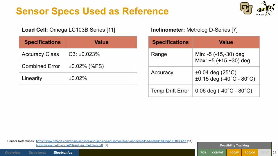
Sensor Specs Used as Reference
25
Specifications Value
Accuracy Class C3: ±0.023%
Combined Error ±0.02% (%FS)
Linearity ±0.02%
Specifications Value
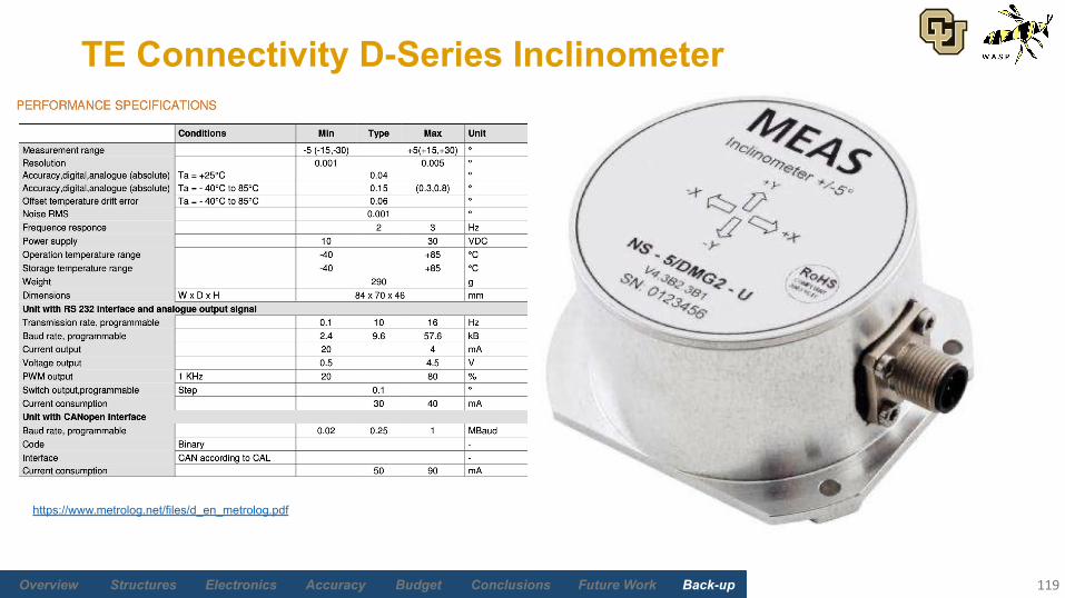
Range Min: -5 (-15,-30) degMax: +5 (+15,+30) deg
Accuracy ±0.04 deg (25°C)±0.15 deg (-40°C - 80°C)
Temp Drift Error 0.06 deg (-40°C - 80°C)
Sensor References: https://www.omega.com/en-us/sensors-and-sensing-equipment/load-and-force/load-cells/lc103b/p/LC103B-1K [11] https://www.metrolog.net/files/d_en_metrolog.pdf [7]
Load Cell: Omega LC103B Series [11] Inclinometer: Metrolog D-Series [7]

Weight and CG Accuracy
26
Future Work Back-upBudgetAccuracyElectronicsStructures Overview Conclusions FOS ACC/W ACC/CG COST
Feasibility Tracking
COMPAT 27
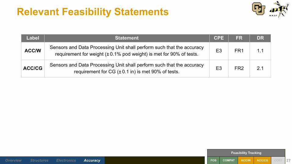
Label Statement CPE FR DR
ACC/W Sensors and Data Processing Unit shall perform such that the accuracy requirement for weight (± 0.1% pod weight) is met for 90% of tests.
E3 FR1 1.1
ACC/CG Sensors and Data Processing Unit shall perform such that the accuracy requirement for CG (± 0.1 in) is met 90% of tests.
E3 FR2 2.1
Relevant Feasibility Statements
Future Work Back-upBudgetAccuracyElectronicsStructures Overview Conclusions FOS ACC/W ACC/CG COST
Feasibility Tracking
COMPAT 28
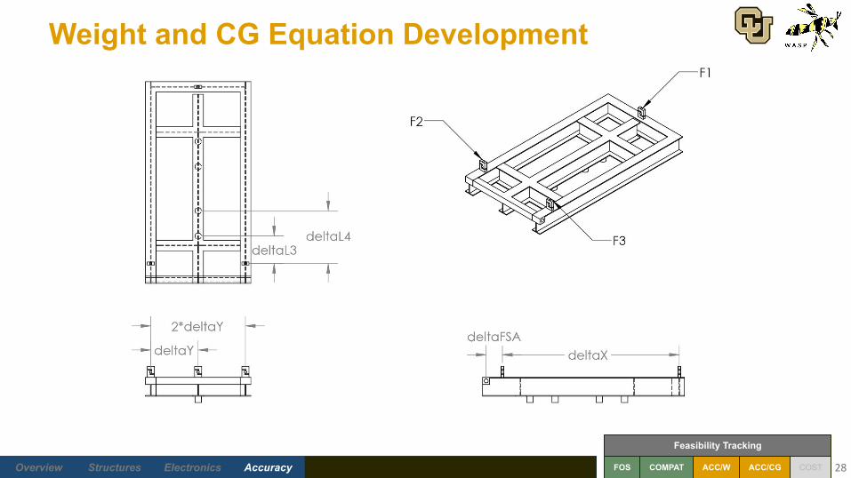
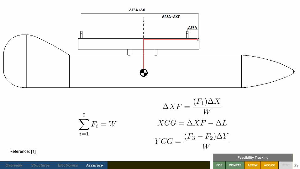
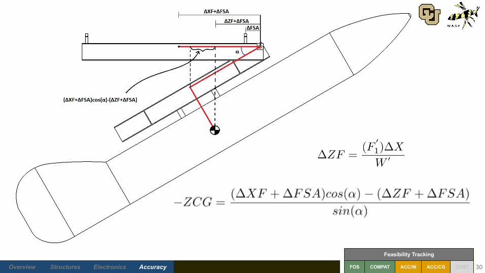
Weight and CG Equation Development
Future Work Back-upBudgetAccuracyElectronicsStructures Overview Conclusions FOS ACC/W ACC/CG COST
Feasibility Tracking
COMPAT 29
Reference: [1]
Future Work Back-upBudgetAccuracyElectronicsStructures Overview Conclusions FOS ACC/W ACC/CG COST
Feasibility Tracking
COMPAT 30
Future Work Back-upBudgetAccuracyElectronicsStructures Overview Conclusions FOS ACC/W ACC/CG COST
Feasibility Tracking
COMPAT
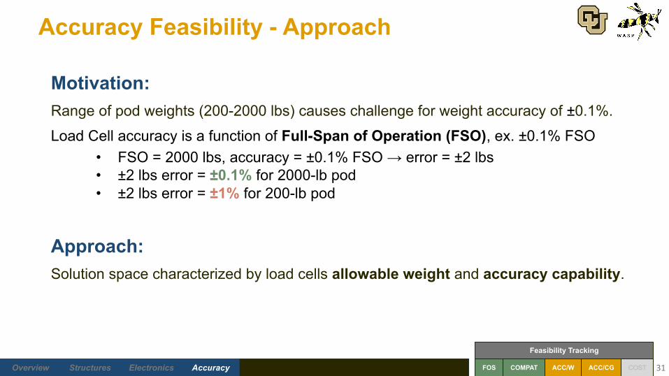
Accuracy Feasibility - Approach
31
Motivation:Range of pod weights (200-2000 lbs) causes challenge for weight accuracy of ±0.1%.
Load Cell accuracy is a function of Full-Span of Operation (FSO), ex. ±0.1% FSO• FSO = 2000 lbs, accuracy = ±0.1% FSO → error = ±2 lbs• ±2 lbs error = ±0.1% for 2000-lb pod• ±2 lbs error = ±1% for 200-lb pod
Approach:Solution space characterized by load cells allowable weight and accuracy capability.

Future Work Back-upBudgetAccuracyElectronicsStructures Overview Conclusions FOS ACC/W ACC/CG COST
Feasibility Tracking
COMPAT
Allowable Weight on Load Cells
32
“Allowable” Criteria:Expected maximum force on single load cell with specified factor of safety is less than
full-span for load cell. (Not referencing manufacturer’s specs for safe overload capacity.)
Pod Weight Range Allowable
Recommended Sensor Full-Span
FOS = 1.0 FOS = 1.5 FOS = 2.0
500 lbs 200-650 lbs 200-350 lbs N/A
1000 lbs 200-1700 lbs 200-1000 lbs 200-650 lbs
2000 lbs 200-2000 lbs 200-2000 lbs 200-1700 lbs

Future Work Back-upBudgetAccuracyElectronicsStructures Overview Conclusions FOS ACC/W ACC/CG COST
Feasibility Tracking
COMPAT
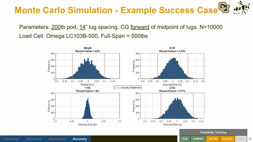
Defining Accuracy Solution Space - Monte Carlo
33
Error Sources - Weight:• Load cells - internal and environmental• DAQ - analog to digital conversion
Error Sources - CG:• Load cells - internal and environmental• Inclinometer - internal• DAQ - analog to digital conversion• Lengths of testbed - manufacturing tolerances
Extreme Case Considerations:• Pod weight - min = 200lbs, max = 2000lbs• Lug spacing - 14” or 30”• X CG forward or aft of midpoint between lugs
Error Source Error Value
Load Cell ± 0.021% FSO
Inclinometer ± 0.04 deg
DAQ ± 1 bin
Lengths ± 1/24th inch

Future Work Back-upBudgetAccuracyElectronicsStructures Overview Conclusions FOS ACC/W ACC/CG COST
Feasibility Tracking
COMPAT
Monte Carlo Simulation - Example Failure Case
34
Parameters: 200lb pod, 14” lug spacing, CG forward of midpoint of lugs, N=10000Load Cell: Omega LC103B-2K, Full-Span = 2000lbs
Future Work Back-upBudgetAccuracyElectronicsStructures Overview Conclusions FOS ACC/W ACC/CG COST
Feasibility Tracking
COMPAT
Monte Carlo Simulation - Example Success Case
35
Parameters: 200lb pod, 14” lug spacing, CG forward of midpoint of lugs, N=10000Load Cell: Omega LC103B-500, Full-Span = 500lbs
Future Work Back-upBudgetAccuracyElectronicsStructures Overview Conclusions FOS ACC/W ACC/CG COST
Feasibility Tracking
COMPAT
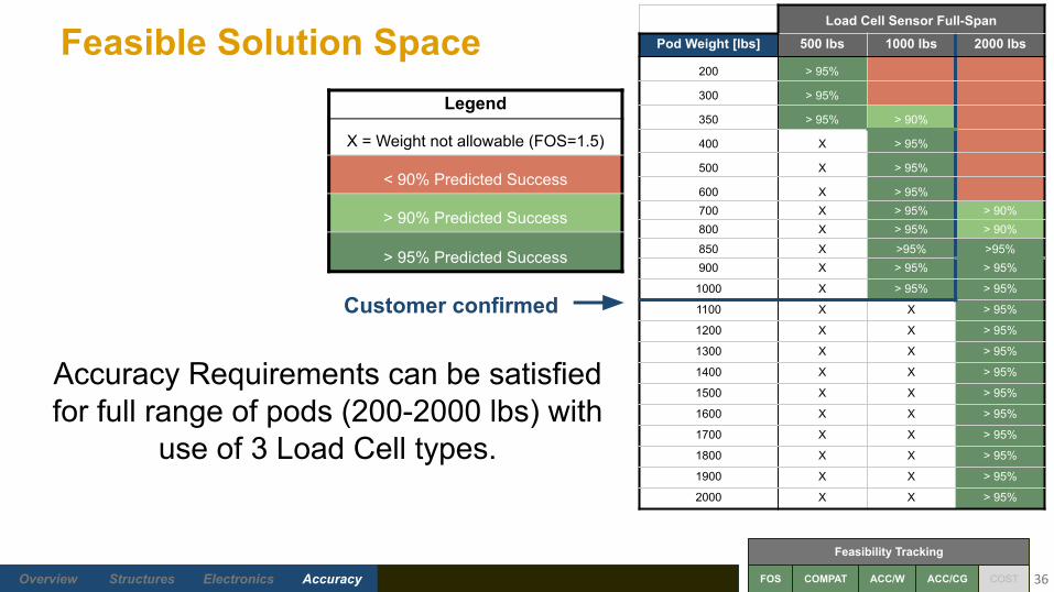
Feasible Solution Space
36
Accuracy Requirements can be satisfied for full range of pods (200-2000 lbs) with
use of 3 Load Cell types.
Legend
X = Weight not allowable (FOS=1.5)
< 90% Predicted Success
> 90% Predicted Success
> 95% Predicted Success
Load Cell Sensor Full-Span
Pod Weight [lbs] 500 lbs 1000 lbs 2000 lbs
200 > 95%
300 > 95%
350 > 95% > 90%
400 X > 95%
500 X > 95%
600 X > 95%700 X > 95% > 90%800 X > 95% > 90%
850 X >95% >95%900 X > 95% > 95%
1000 X > 95% > 95%
1100 X X > 95%
1200 X X > 95%
1300 X X > 95%
1400 X X > 95%
1500 X X > 95%
1600 X X > 95%
1700 X X > 95%
1800 X X > 95%
1900 X X > 95%
2000 X X > 95%
Customer confirmed
3 Load Cell types satisfy Accuracy Requirements for full range of pods

Financial Feasibility
37
Future Work Back-upBudgetAccuracyElectronicsStructures Overview Conclusions FOS ACC/W ACC/CG COST
Feasibility Tracking
COMPAT
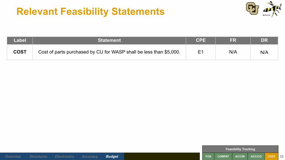
Relevant Feasibility Statements
38
COST Cost of parts purchased by CU for WASP shall be less than $5,000. E1 N/A N/A
Label Statement CPE FR DR

Future Work Back-upBudgetAccuracyElectronicsStructures Overview Conclusions FOS ACC/W ACC/CG COST
Feasibility Tracking
COMPAT
Finances
39
Structural Components Est. CostRaw Materials $2500
Hardware $500Chain Hoist $400
Contingency/Manufacturing (22%) $750
Total $4150
Electrical Components Est. CostLoad Cells (2 sets) $1200
Inclinometer $400Cables $100
DAQ system $2000*Contingency (30%) $500
Total $2200
Subsystem-Level Budgets Subsystem Est. CostStructural Components $4150Electrical Components $2200
Total $6350
Overall Budget
*DAQ for development provided by CU, SNC will need to purchase for ongoing use
Takeaway: WASP Project Budget is only $5000. We will need support from SNC to purchase the sensors
to make this project monetarily feasible.
Subsystem Est. CostStructural Components $4150Electrical Components $2200
Sensors ($1600)
Total $4750
Overall Budget - SNC Provides Sensors

Feasibility Conclusions
40

Future Work Back-upBudgetAccuracyElectronicsStructures Overview Conclusions FOS ACC/W ACC/CG COST
Feasibility Tracking
COMPAT
Conclusions
41
Label Statement CPE Requirement Feasible?
FOS Frame members shall have a factor of safety greater than 2 against failure in compression, shear, bending, torsion, and buckling.
E1, E5 FR3 YES
COMPAT The computer and DAQ must have compatible communication so data transfer is valid
E3 FR8 YES
ACC/W Sensors and Data Processing Unit shall perform such that the accuracy requirement for weight (0.1% pod weight) is met for 90% of tests.
E3 FR1 YES*
ACC/CG Sensors and Data Processing Unit shall perform such that the accuracy requirement for CG (0.1 in) is met 90% of tests.
E3 FR2 YES
COST Cost of parts purchased by CU for WASP shall be less than $5,000 E1 N/A YES**
* Customer expressed satisfaction with 0.1% accuracy in load cells
** Budget is still close to $5000 with SNC help

Future Work
42
Future Work Back-upBudgetAccuracyElectronicsStructures Overview Conclusions FOS ACC/W ACC/CG COST
Feasibility Tracking
COMPAT
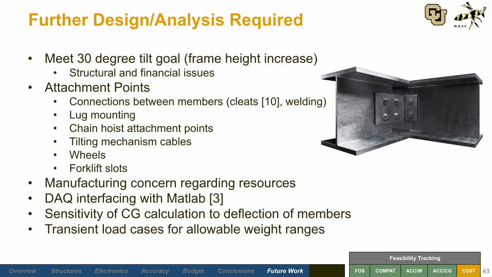
Further Design/Analysis Required
43
• Meet 30 degree tilt goal (frame height increase)• Structural and financial issues
• Attachment Points• Connections between members (cleats [10], welding)• Lug mounting• Chain hoist attachment points• Tilting mechanism cables• Wheels• Forklift slots
• Manufacturing concern regarding resources• DAQ interfacing with Matlab [3]• Sensitivity of CG calculation to deflection of members• Transient load cases for allowable weight ranges
Future Work Back-upBudgetAccuracyElectronicsStructures Overview Conclusions FOS ACC/W ACC/CG COST
Feasibility Tracking
COMPAT
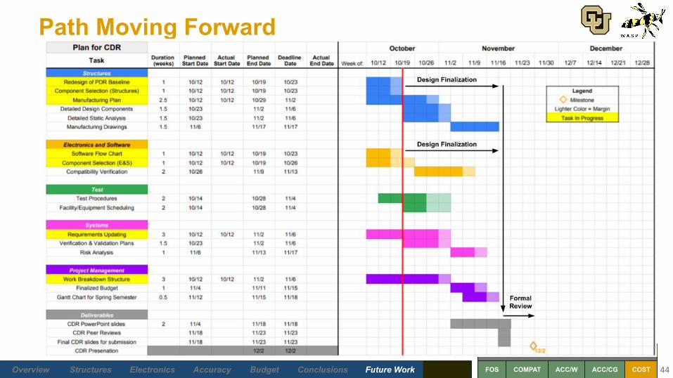
Path Moving Forward
44

Future Work Back-upBudgetAccuracyElectronicsStructures Overview Conclusions FOS ACC/W ACC/CG COST
Feasibility Tracking
COMPAT
Acknowledgements
45
SNC Team: Becky Vander Hoeven, Gary Hutton, Stephen McLaughlin, Jon Matula, AJ Olson
Advisory Board Members:Professor Bobby Hodgkinson, Dr. Jelliffe Jackson, Dr. Francisco Lopez Jimenez,
Professor Matt Rhode, Professor Trudy Schwartz
PDR Reviewers:Lara Buri, Dr. Francisco Lopez Jimenez, Team VORTEX, Addison Woodard
Thank you to everyone who supported the WASP Team!

Questions?
46
Future Work Back-upBudgetAccuracyElectronicsStructures Overview Conclusions
References
47
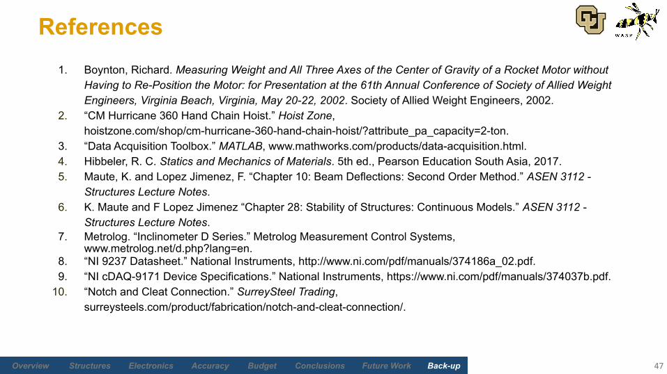
1. Boynton, Richard. Measuring Weight and All Three Axes of the Center of Gravity of a Rocket Motor without Having to Re-Position the Motor: for Presentation at the 61th Annual Conference of Society of Allied Weight Engineers, Virginia Beach, Virginia, May 20-22, 2002. Society of Allied Weight Engineers, 2002.
2. “CM Hurricane 360 Hand Chain Hoist.” Hoist Zone, hoistzone.com/shop/cm-hurricane-360-hand-chain-hoist/?attribute_pa_capacity=2-ton.
3. “Data Acquisition Toolbox.” MATLAB, www.mathworks.com/products/data-acquisition.html. 4. Hibbeler, R. C. Statics and Mechanics of Materials. 5th ed., Pearson Education South Asia, 2017. 5. Maute, K. and Lopez Jimenez, F. “Chapter 10: Beam Deflections: Second Order Method.” ASEN 3112 -
Structures Lecture Notes. 6. K. Maute and F Lopez Jimenez “Chapter 28: Stability of Structures: Continuous Models.” ASEN 3112 -
Structures Lecture Notes.7. Metrolog. “Inclinometer D Series.” Metrolog Measurement Control Systems,
www.metrolog.net/d.php?lang=en.8. “NI 9237 Datasheet.” National Instruments, http://www.ni.com/pdf/manuals/374186a_02.pdf.9. “NI cDAQ-9171 Device Specifications.” National Instruments, https://www.ni.com/pdf/manuals/374037b.pdf.
10. “Notch and Cleat Connection.” SurreySteel Trading, surreysteels.com/product/fabrication/notch-and-cleat-connection/.
Future Work Back-upBudgetAccuracyElectronicsStructures Overview Conclusions
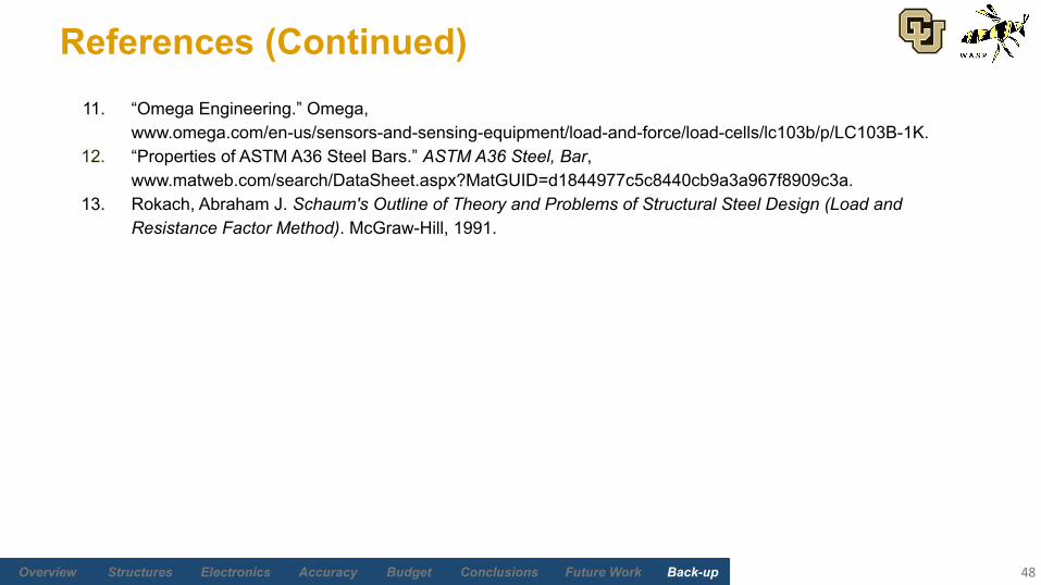
References (Continued)11. “Omega Engineering.” Omega,
www.omega.com/en-us/sensors-and-sensing-equipment/load-and-force/load-cells/lc103b/p/LC103B-1K.12. “Properties of ASTM A36 Steel Bars.” ASTM A36 Steel, Bar,
www.matweb.com/search/DataSheet.aspx?MatGUID=d1844977c5c8440cb9a3a967f8909c3a. 13. Rokach, Abraham J. Schaum's Outline of Theory and Problems of Structural Steel Design (Load and
Resistance Factor Method). McGraw-Hill, 1991.
48

Supporting Materials
49
Future Work Back-upBudgetAccuracyElectronicsStructures Overview Conclusions
Supporting Materials Quick Links
Administrative
Systems
Structures
Electronics and Software
Weight and CG Accuracy
Budget50

Future Work Back-upBudgetAccuracyElectronicsStructures Overview Conclusions
Administrative
51
Return to Supporting Material Quick Links
Future Work Back-upBudgetAccuracyElectronicsStructures Overview Conclusions
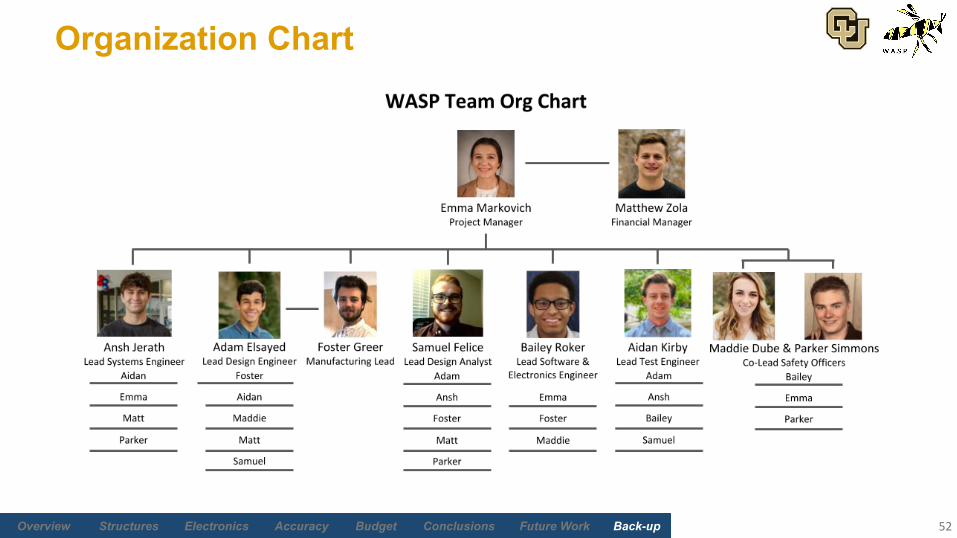
Organization Chart
52

Future Work Back-upBudgetAccuracyElectronicsStructures Overview Conclusions
Acronym List
53
Acronym Definition
ACC Accuracy
BC Boundary Conditions
BOTE Back of the Envelope (Hand-derived)
CAD Computer-Aided Design
CG Center of Gravity
COMPAT Compatibility
CONOPS Concept of Operations
COTS Consumer Off-The-Shelf
Acronym Definition
CPE Critical Project Elements
DAQ Data Acquisition System
DR Design Requirement
FEA Finite Element Analysis
FOS Factor of Safety
FSO Full Span of Operation
FR Functional Requirement
GUI Graphical User Interface

Future Work Back-upBudgetAccuracyElectronicsStructures Overview Conclusions
Acronym List
54
Acronym Definition
IAS ISR, Aviation & Security
ISR Intelligence, Surveillance, & Reconnaissance
NIST National Institute of Standards and Technology
PDR Product Design Review
SNC Sierra Nevada Corporation
UI User Interface
VBA Visual Basic for Applications
WASP Weight Analysis of Surveillance Pods

Future Work Back-upBudgetAccuracyElectronicsStructures Overview Conclusions
Key Term Definitions
55
Term Definition
Frame The physical truss structure of WASP
ISR Pod/Pod The physical object being measured by WASP, given by SNC.
Measurement Set One recorded value for each sensor (load and inclination) in the flat and tilted configurations.
Test The execution of a full procedure which starts after set-up and concludes when weight and CG values are output.
Tool Equivalent to WASP.
User Procedure Instructions document that describes transportation, maneuvering, and testing process for test engineers.
WASP All elements of the final product/deliverable.
Future Work Back-upBudgetAccuracyElectronicsStructures Overview Conclusions
Systems
56
Return to Supporting Material Quick Links

Future Work Back-upBudgetAccuracyElectronicsStructures Overview Conclusions
What constitutes a “measurement repetition”?
57
The process for one “measurement repetition” is…1. Calibrate the sensors in zero-load condition2. Mount the pod to lugs3. Lift and lock into flat configuration4. Record measurements from sensors at flat configuration5. Tilt and lock into tilted configuration6. Record measurements sensors at tilted configuration7. Untilt and lock into flat configuration8. Lower the pod to cradle9. Demount pod
If it is determined through experimental testing that the mounting error is small enough to be considered negligible (smaller than expected electronics system error), the measurement repetition will be altered to exclude mounting and demounting.

Future Work Back-upBudgetAccuracyElectronicsStructures Overview Conclusions
Requirements
58
FR DR1 DR2 Requirement Motivation Validation
1 WASP shall measure the weight of the ISR pod. Customer specified functional requirement.
Demonstration - WASP outputs weight value when a full test is performed.
1.1 WASP shall measure the weight of the pod within a tolerance of ± 0.1% of the total pod weight.
Customer specified accuracy requirement.
Testing - Perform several tests and confirm that reported weight meets the accuracy requirement for at least twotests on a test article of known weight.
1.1.1 Sensors shall be of high enough resolution ( ≤ 0.2 lbs) to meet weight tolerance requirement for lightest pod.
Derived accuracy requirement.
Inspection/Demonstration - Inspection of sensor specifications and demonstrationof sensor output resolution.
1.1.2 Sensor shall be precise enough (repeatability ≤ 0.11 lb) to meet the weight accuracy requirements.
Derived accuracy requirement.
Inspection/Testing - Inspection of sensor specifications. Repeatability test: load device, record multiple measurements, statistically evaluate variance.
1.1.3 Sensor calibration shall be National Institute of Standards and Technology (NIST) traceable such that measured values are accurate to within ± 0.1% of the pod’s true total weight.
Customer specified accuracy requirement.
Inspection/Testing - Inspection of sensor specifications, NIST-traceable certified,and testing to verify measurement accuracy.
1.1.4 Sensors shall be removable from the frame to minimize harmful vibrations due to transporting the device.
Derived design requirement.
Demonstration - Show that sensors can be disconnected and reconnected.
1.2 Sensors will be recalibrated per sensor supplier-recommended method prior to each measurement set to minimize errors due to drift, bias, hysteresis, etc.
Derived accuracy requirement.
Inspection - Operational guidelines and user manual will require sensor recalibrationprior to each measurement set.
Future Work Back-upBudgetAccuracyElectronicsStructures Overview Conclusions
Requirements
59
FR DR1 DR2 Requirement Motivation Validation
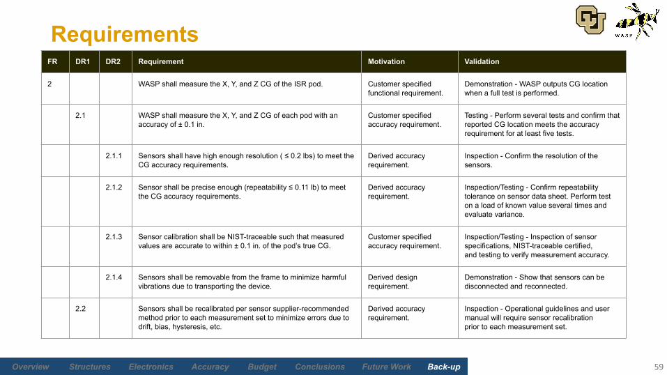
2 WASP shall measure the X, Y, and Z CG of the ISR pod. Customer specified functional requirement.
Demonstration - WASP outputs CG location when a full test is performed.
2.1 WASP shall measure the X, Y, and Z CG of each pod with an accuracy of ± 0.1 in.
Customer specified accuracy requirement.
Testing - Perform several tests and confirm that reported CG location meets the accuracy requirement for at least five tests.
2.1.1 Sensors shall have high enough resolution ( ≤ 0.2 lbs) to meet the CG accuracy requirements.
Derived accuracy requirement.
Inspection - Confirm the resolution of the sensors.
2.1.2 Sensor shall be precise enough (repeatability ≤ 0.11 lb) to meet the CG accuracy requirements.
Derived accuracy requirement.
Inspection/Testing - Confirm repeatability tolerance on sensor data sheet. Perform test on a load of known value several times and evaluate variance.
2.1.3 Sensor calibration shall be NIST-traceable such that measured values are accurate to within ± 0.1 in. of the pod’s true CG.
Customer specified accuracy requirement.
Inspection/Testing - Inspection of sensor specifications, NIST-traceable certified,and testing to verify measurement accuracy.
2.1.4 Sensors shall be removable from the frame to minimize harmful vibrations due to transporting the device.
Derived design requirement.
Demonstration - Show that sensors can be disconnected and reconnected.
2.2 Sensors shall be recalibrated per sensor supplier-recommended method prior to each measurement set to minimize errors due to drift, bias, hysteresis, etc.
Derived accuracy requirement.
Inspection - Operational guidelines and user manual will require sensor recalibrationprior to each measurement set.
Future Work Back-upBudgetAccuracyElectronicsStructures Overview Conclusions
Requirements
60
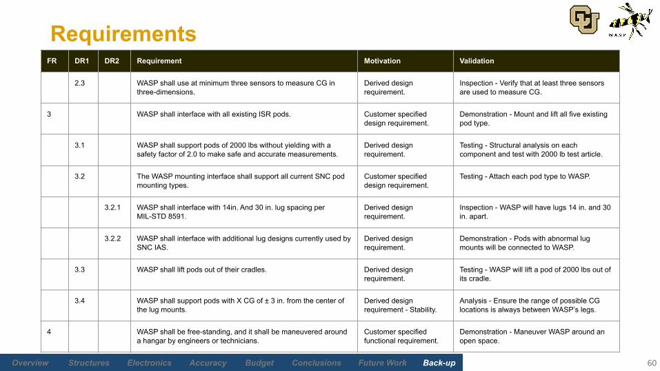
FR DR1 DR2 Requirement Motivation Validation
2.3 WASP shall use at minimum three sensors to measure CG in three-dimensions.
Derived design requirement.
Inspection - Verify that at least three sensors are used to measure CG.
3 WASP shall interface with all existing ISR pods. Customer specified design requirement.
Demonstration - Mount and lift all five existing pod type.
3.1 WASP shall support pods of 2000 lbs without yielding with a safety factor of 2.0 to make safe and accurate measurements.
Derived design requirement.
Testing - Structural analysis on each component and test with 2000 lb test article.
3.2 The WASP mounting interface shall support all current SNC pod mounting types.
Customer specified design requirement.
Testing - Attach each pod type to WASP.
3.2.1 WASP shall interface with 14in. And 30 in. lug spacing per MIL-STD 8591.
Derived design requirement.
Inspection - WASP will have lugs 14 in. and 30 in. apart.
3.2.2 WASP shall interface with additional lug designs currently used by SNC IAS.
Derived design requirement.
Demonstration - Pods with abnormal lug mounts will be connected to WASP.
3.3 WASP shall lift pods out of their cradles. Derived design requirement.
Testing - WASP will lift a pod of 2000 lbs out of its cradle.
3.4 WASP shall support pods with X CG of ± 3 in. from the center of the lug mounts.
Derived design requirement - Stability.
Analysis - Ensure the range of possible CG locations is always between WASP’s legs.
4 WASP shall be free-standing, and it shall be maneuvered around a hangar by engineers or technicians.
Customer specified functional requirement.
Demonstration - Maneuver WASP around an open space.
Future Work Back-upBudgetAccuracyElectronicsStructures Overview Conclusions
Requirements
61
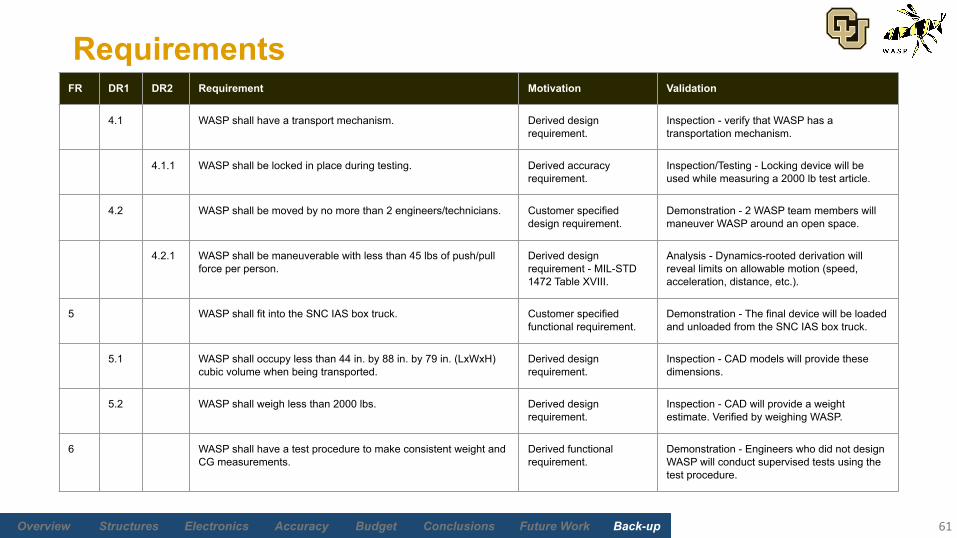
FR DR1 DR2 Requirement Motivation Validation
4.1 WASP shall have a transport mechanism. Derived design requirement.
Inspection - verify that WASP has a transportation mechanism.
4.1.1 WASP shall be locked in place during testing. Derived accuracy requirement.
Inspection/Testing - Locking device will be used while measuring a 2000 lb test article.
4.2 WASP shall be moved by no more than 2 engineers/technicians. Customer specified design requirement.
Demonstration - 2 WASP team members will maneuver WASP around an open space.
4.2.1 WASP shall be maneuverable with less than 45 lbs of push/pull force per person.
Derived design requirement - MIL-STD 1472 Table XVIII.
Analysis - Dynamics-rooted derivation will reveal limits on allowable motion (speed, acceleration, distance, etc.).
5 WASP shall fit into the SNC IAS box truck. Customer specified functional requirement.
Demonstration - The final device will be loaded and unloaded from the SNC IAS box truck.
5.1 WASP shall occupy less than 44 in. by 88 in. by 79 in. (LxWxH) cubic volume when being transported.
Derived design requirement.
Inspection - CAD models will provide these dimensions.
5.2 WASP shall weigh less than 2000 lbs. Derived design requirement.
Inspection - CAD will provide a weight estimate. Verified by weighing WASP.
6 WASP shall have a test procedure to make consistent weight and CG measurements.
Derived functional requirement.
Demonstration - Engineers who did not design WASP will conduct supervised tests using the test procedure.
Future Work Back-upBudgetAccuracyElectronicsStructures Overview Conclusions
Requirements
62
FR DR1 DR2 Requirement Motivation Validation
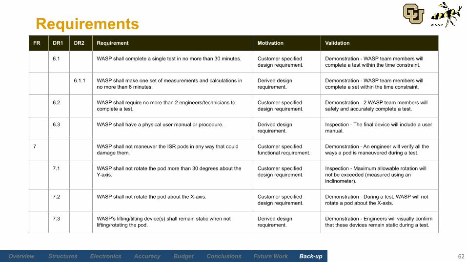
6.1 WASP shall complete a single test in no more than 30 minutes. Customer specified design requirement.
Demonstration - WASP team members will complete a test within the time constraint.
6.1.1 WASP shall make one set of measurements and calculations in no more than 6 minutes.
Derived design requirement.
Demonstration - WASP team members will complete a set within the time constraint.
6.2 WASP shall require no more than 2 engineers/technicians to complete a test.
Customer specified design requirement.
Demonstration - 2 WASP team members will safely and accurately complete a test.
6.3 WASP shall have a physical user manual or procedure. Derived design requirement.
Inspection - The final device will include a user manual.
7 WASP shall not maneuver the ISR pods in any way that could damage them.
Customer specified functional requirement.
Demonstration - An engineer will verify all the ways a pod is maneuvered during a test.
7.1 WASP shall not rotate the pod more than 30 degrees about the Y-axis.
Customer specified design requirement.
Inspection - Maximum allowable rotation will not be exceeded (measured using an inclinometer).
7.2 WASP shall not rotate the pod about the X-axis. Customer specified design requirement.
Demonstration - During a test, WASP will not rotate a pod about the X-axis.
7.3 WASP’s lifting/tilting device(s) shall remain static when not lifting/rotating the pod.
Derived design requirement.
Demonstration - Engineers will visually confirm that these devices remain static during a test.
Future Work Back-upBudgetAccuracyElectronicsStructures Overview Conclusions
Requirements
63
FR DR1 DR2 Requirement Motivation Validation
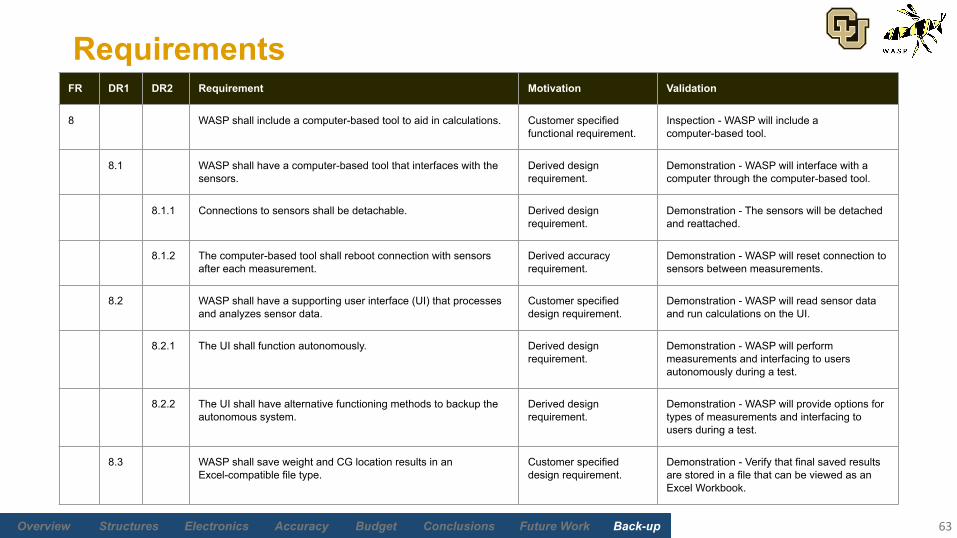
8 WASP shall include a computer-based tool to aid in calculations. Customer specified functional requirement.
Inspection - WASP will include a computer-based tool.
8.1 WASP shall have a computer-based tool that interfaces with the sensors.
Derived design requirement.
Demonstration - WASP will interface with a computer through the computer-based tool.
8.1.1 Connections to sensors shall be detachable. Derived design requirement.
Demonstration - The sensors will be detached and reattached.
8.1.2 The computer-based tool shall reboot connection with sensors after each measurement.
Derived accuracy requirement.
Demonstration - WASP will reset connection to sensors between measurements.
8.2 WASP shall have a supporting user interface (UI) that processes and analyzes sensor data.
Customer specified design requirement.
Demonstration - WASP will read sensor data and run calculations on the UI.
8.2.1 The UI shall function autonomously. Derived design requirement.
Demonstration - WASP will perform measurements and interfacing to users autonomously during a test.
8.2.2 The UI shall have alternative functioning methods to backup the autonomous system.
Derived design requirement.
Demonstration - WASP will provide options for types of measurements and interfacing to users during a test.
8.3 WASP shall save weight and CG location results in an Excel-compatible file type.
Customer specified design requirement.
Demonstration - Verify that final saved results are stored in a file that can be viewed as an Excel Workbook.

Future Work Back-upBudgetAccuracyElectronicsStructures Overview Conclusions
Structures
64
Return to Supporting Material Quick Links
Future Work Back-upBudgetAccuracyElectronicsStructures Overview Conclusions
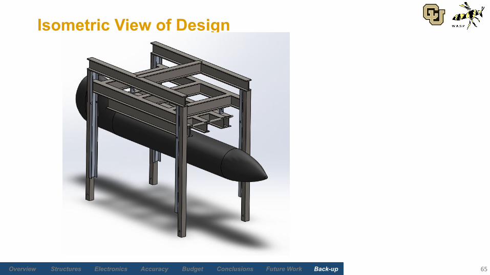
Isometric View of Design
65
Future Work Back-upBudgetAccuracyElectronicsStructures Overview Conclusions
Lugs
Generic Lug
66
Future Work Back-upBudgetAccuracyElectronicsStructures Overview Conclusions
Lugs
67
14” Lugs for the 1000 lb weight class (MIL-STD 8591)

Future Work Back-upBudgetAccuracyElectronicsStructures Overview Conclusions
Lugs
30” Lugs for the 2000 lb weight class (MIL-STD 8591)
68
Future Work Back-upBudgetAccuracyElectronicsStructures Overview Conclusions
Current Chain Hoist Being Considered
• Hurricane 360 Hand Chain Hoist
• 2 ton capacity• 10’ - 30’ lifting• $391 - $534 depending on lift
distance• Can rotate pull chain so it
doesn’t interfere with the structure
69

Future Work Back-upBudgetAccuracyElectronicsStructures Overview Conclusions
• Common Assumptions (Beams/Shafts, Bars, Axle)• Isotropic material with constant cross section• Torsional twisting is the same throughout the cross section
• e.g. the entire “I” of the I-beam twists the same amount at any given distance along the length of the beam
• Every force other than beam weight is modeled as a point load• Elastic behavior• L is the beam/bar length
Frame Analysis - Hand Derivations
70
Future Work Back-upBudgetAccuracyElectronicsStructures Overview Conclusions
Bar Analysis (Legs)
71
• Isotropic• Constant cross section• Euler Column (buckling)
• Limitation: Assumes solid beam cross section
• Compression• Min. compressive strength at center of shear pin hole
Future Work Back-upBudgetAccuracyElectronicsStructures Overview Conclusions
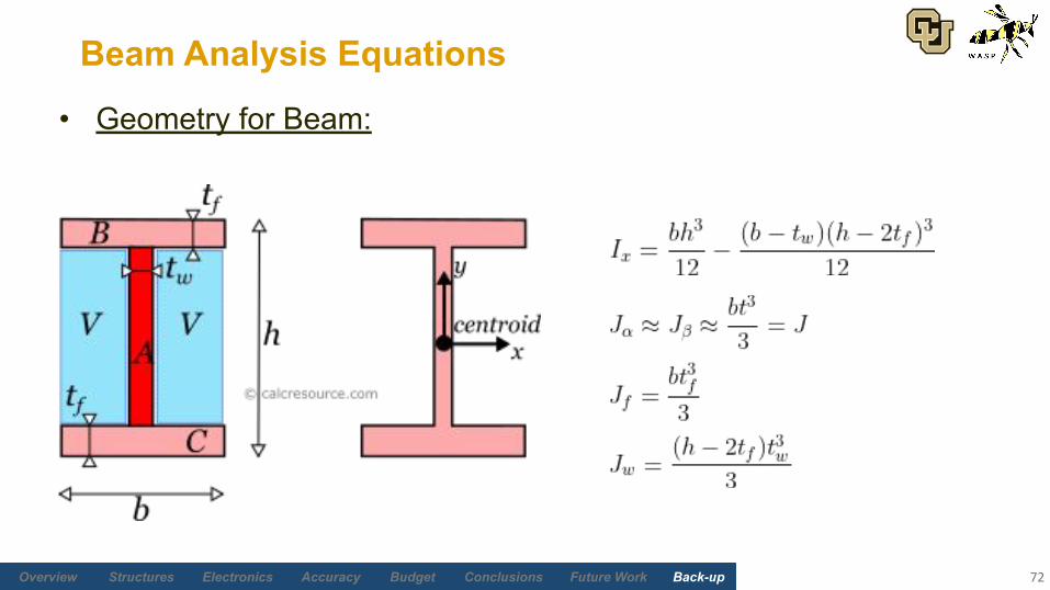
Beam Analysis Equations
72
• Geometry for Beam:
Future Work Back-upBudgetAccuracyElectronicsStructures Overview Conclusions
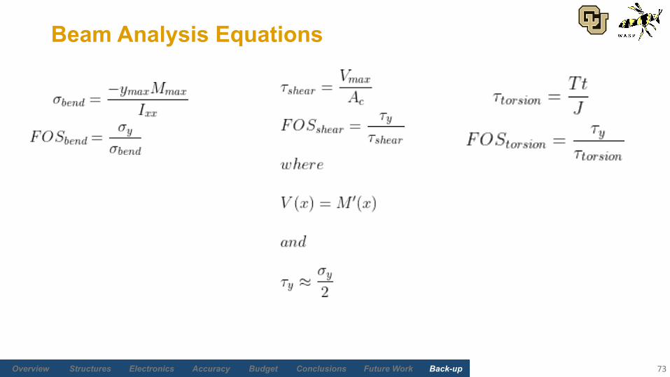
Beam Analysis Equations
73

Future Work Back-upBudgetAccuracyElectronicsStructures Overview Conclusions
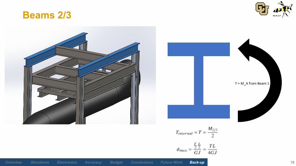
• Fixed-fixed assumption is bad for beams connected to other beams (i.e. beam 1 and beam 2)
• If fixed, the connection between beam 1 and 2 must be level (v’(0) = 0)
• This suggests that a large moment must act on the end of beam 1. Because it is connected to beam 2, an equal and opposite torque must act on beam 2. This leads to a nonzero twist angle: cannot assume fixed.
Reasoning for Iterative Process for Beam Modeling
74
Future Work Back-upBudgetAccuracyElectronicsStructures Overview Conclusions
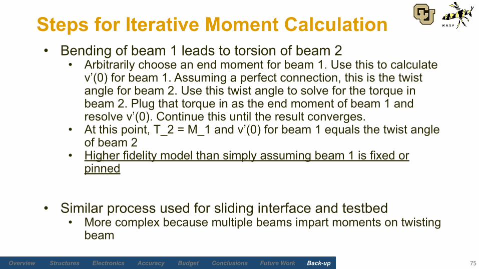
• Bending of beam 1 leads to torsion of beam 2• Arbitrarily choose an end moment for beam 1. Use this to calculate
v’(0) for beam 1. Assuming a perfect connection, this is the twist angle for beam 2. Use this twist angle to solve for the torque in beam 2. Plug that torque in as the end moment of beam 1 and resolve v’(0). Continue this until the result converges.
• At this point, T_2 = M_1 and v’(0) for beam 1 equals the twist angle of beam 2
• Higher fidelity model than simply assuming beam 1 is fixed or pinned
• Similar process used for sliding interface and testbed• More complex because multiple beams impart moments on twisting
beam
Steps for Iterative Moment Calculation
75
Future Work Back-upBudgetAccuracyElectronicsStructures Overview Conclusions
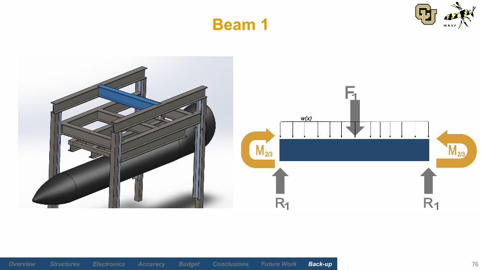
Beam 1
76

Future Work Back-upBudgetAccuracyElectronicsStructures Overview Conclusions
• Neither fixed nor pinned• Symmetric
Beam 1
77
Future Work Back-upBudgetAccuracyElectronicsStructures Overview Conclusions
Beams 2/3
78
Future Work Back-upBudgetAccuracyElectronicsStructures Overview Conclusions
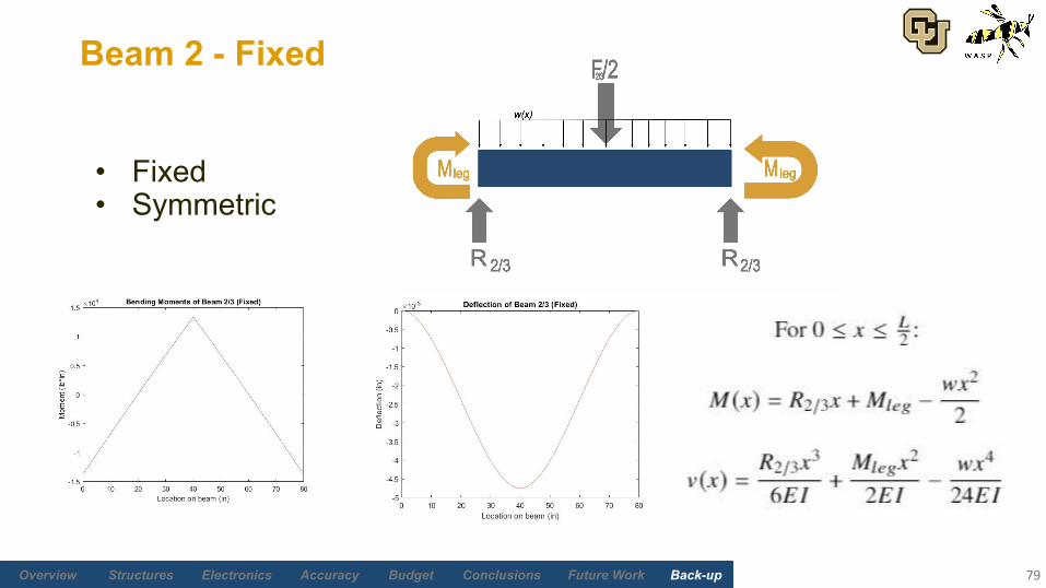
• Fixed• Symmetric
Beam 2 - Fixed
79
Future Work Back-upBudgetAccuracyElectronicsStructures Overview Conclusions
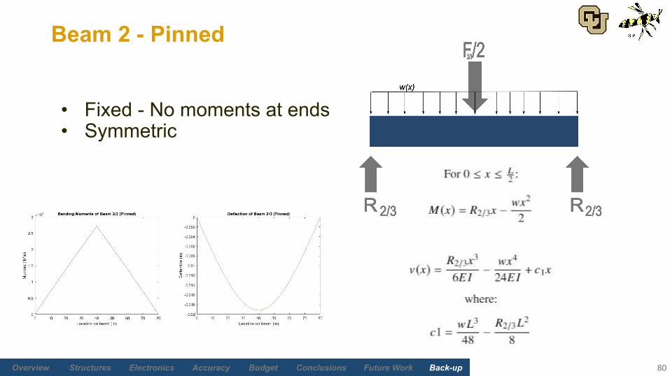
• Fixed - No moments at ends• Symmetric
Beam 2 - Pinned
80
Future Work Back-upBudgetAccuracyElectronicsStructures Overview Conclusions
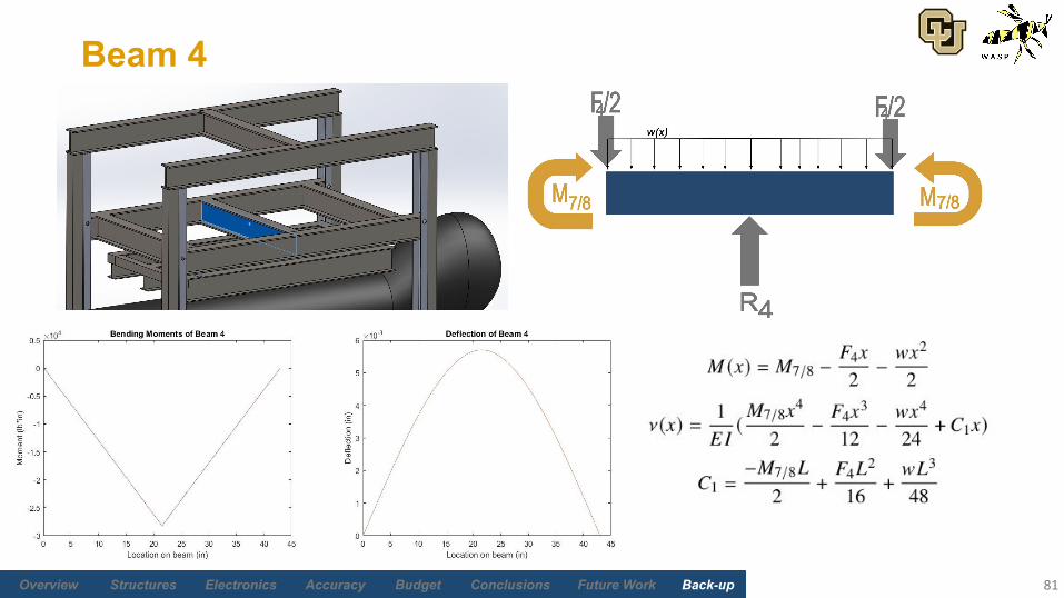
Beam 4
81
Future Work Back-upBudgetAccuracyElectronicsStructures Overview Conclusions
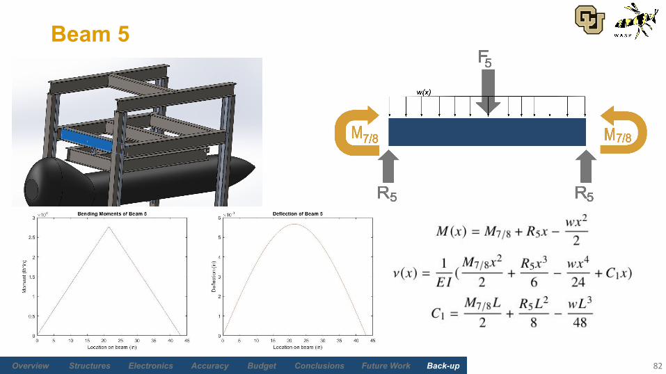
Beam 5
82
Future Work Back-upBudgetAccuracyElectronicsStructures Overview Conclusions
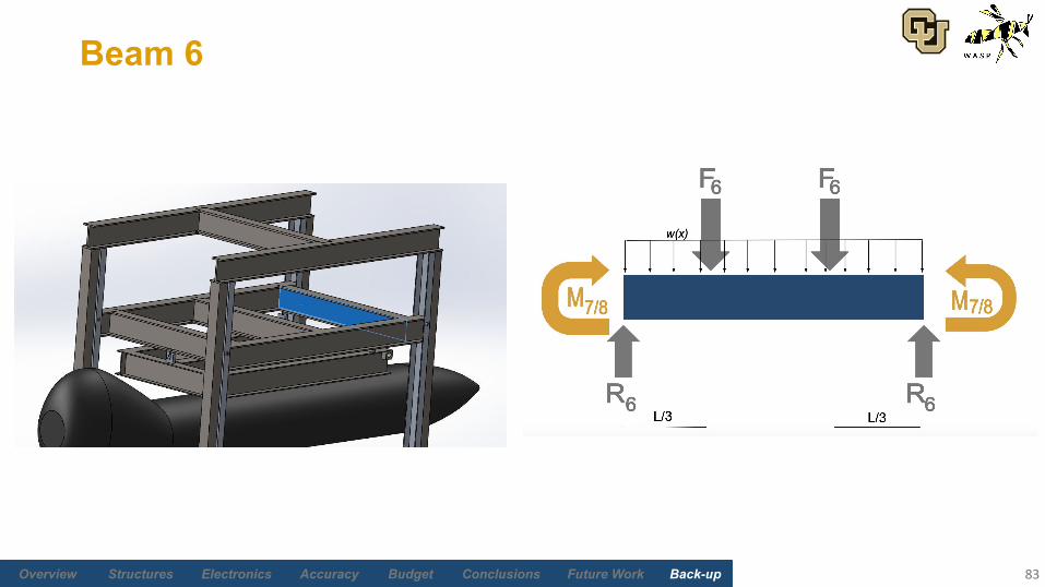
Beam 6
83
Future Work Back-upBudgetAccuracyElectronicsStructures Overview Conclusions
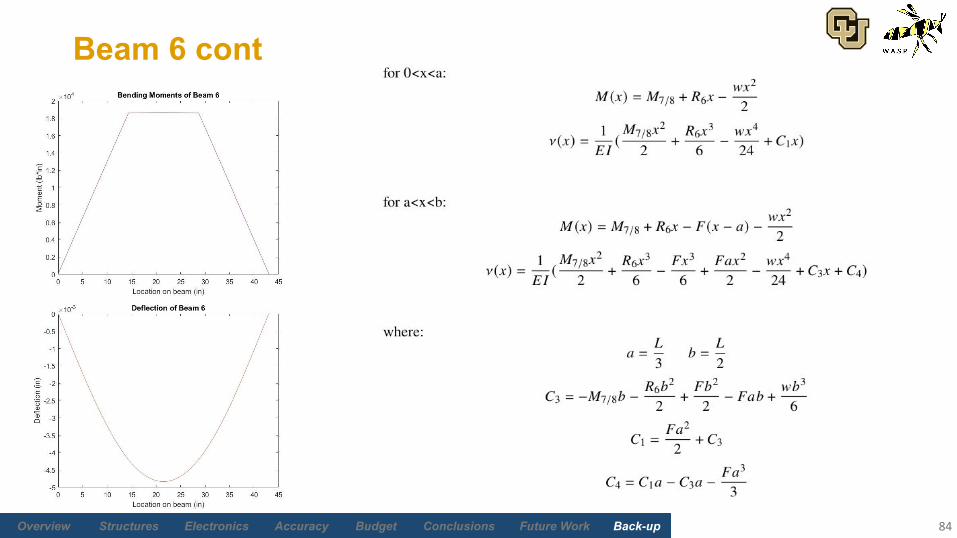
Beam 6 cont
84

Future Work Back-upBudgetAccuracyElectronicsStructures Overview Conclusions
Beams 7 / 8
85
Future Work Back-upBudgetAccuracyElectronicsStructures Overview Conclusions
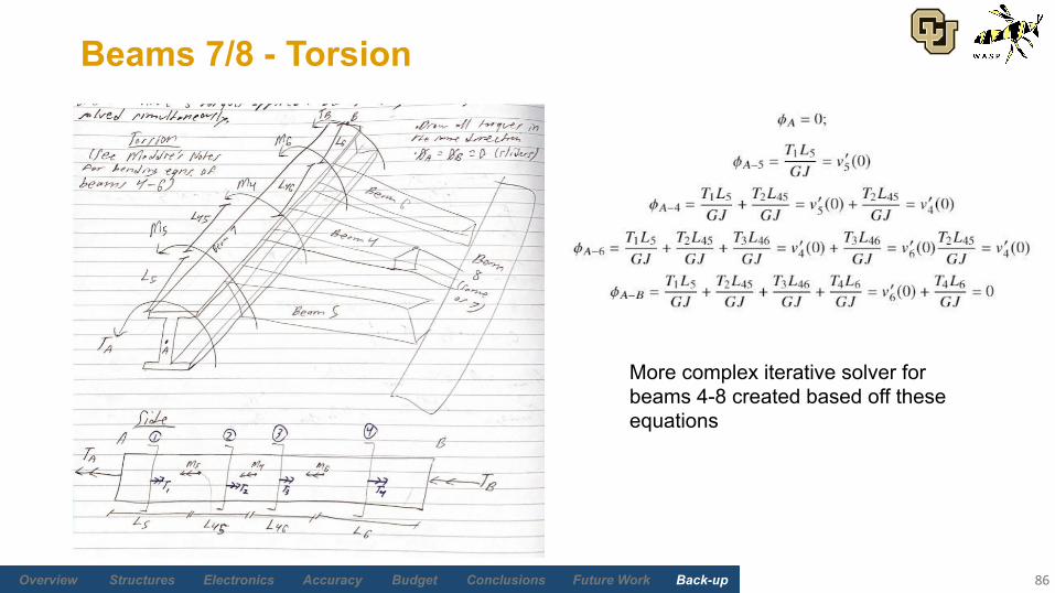
Beams 7/8 - Torsion
86
More complex iterative solver for beams 4-8 created based off these equations
Future Work Back-upBudgetAccuracyElectronicsStructures Overview Conclusions
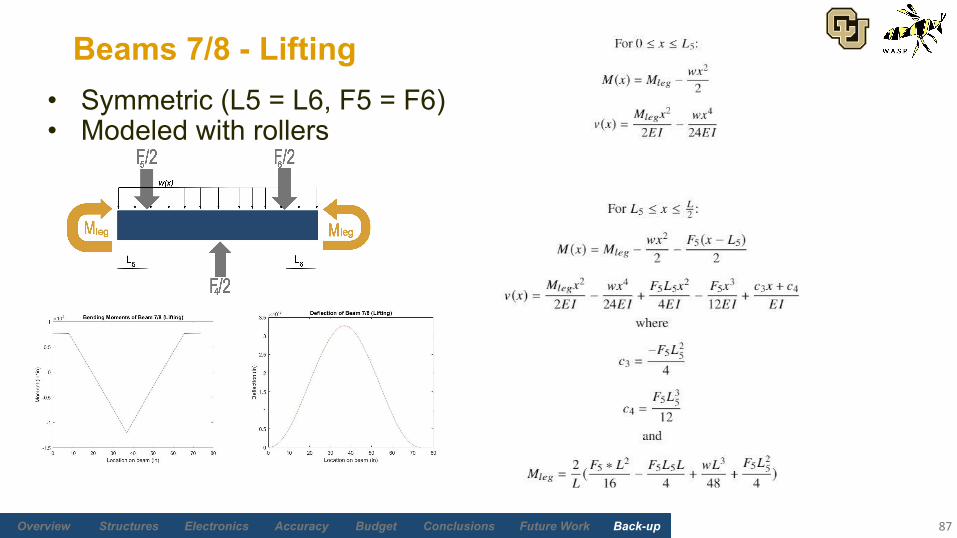
Beams 7/8 - Lifting
87
• Symmetric (L5 = L6, F5 = F6)• Modeled with rollers
Future Work Back-upBudgetAccuracyElectronicsStructures Overview Conclusions
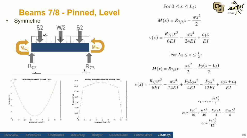
Beams 7/8 - Pinned, Level
88
• Symmetric
Future Work Back-upBudgetAccuracyElectronicsStructures Overview Conclusions
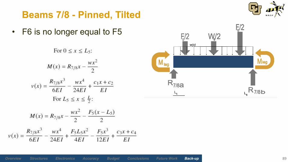
Beams 7/8 - Pinned, Tilted
89
• F6 is no longer equal to F5
Future Work Back-upBudgetAccuracyElectronicsStructures Overview Conclusions
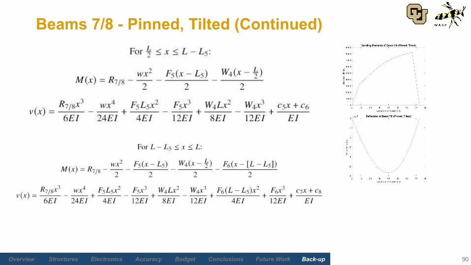
Beams 7/8 - Pinned, Tilted (Continued)
90
Future Work Back-upBudgetAccuracyElectronicsStructures Overview Conclusions
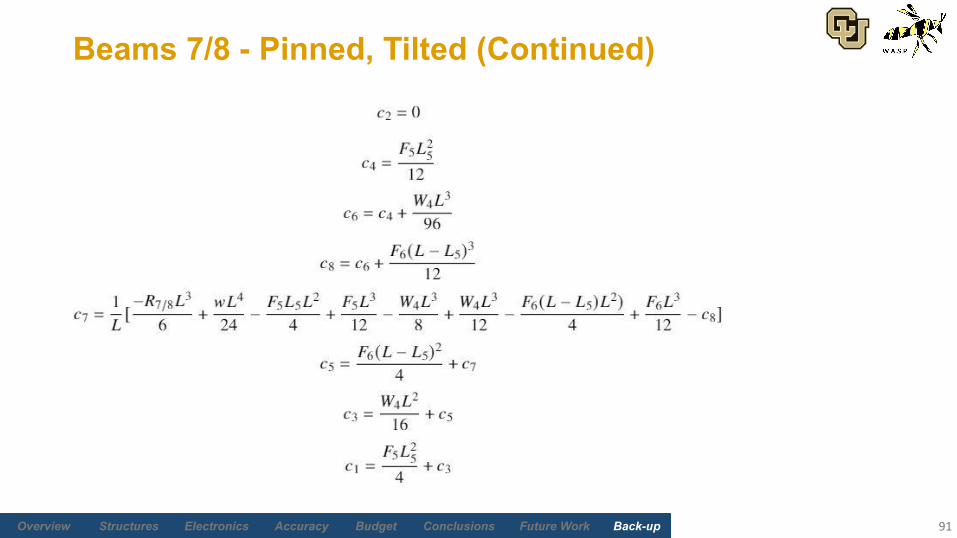
Beams 7/8 - Pinned, Tilted (Continued)
91
Future Work Back-upBudgetAccuracyElectronicsStructures Overview Conclusions
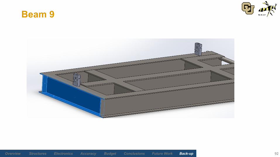
Beam 9
92
Future Work Back-upBudgetAccuracyElectronicsStructures Overview Conclusions
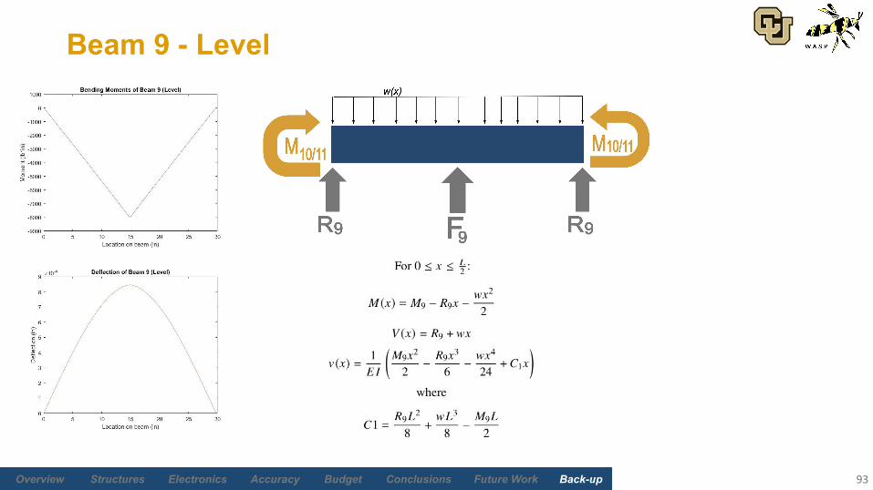
Beam 9 - Level
93
Future Work Back-upBudgetAccuracyElectronicsStructures Overview Conclusions
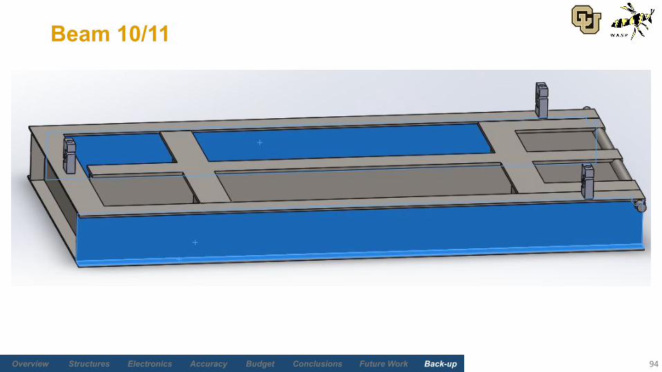
Beam 10/11
94
Future Work Back-upBudgetAccuracyElectronicsStructures Overview Conclusions
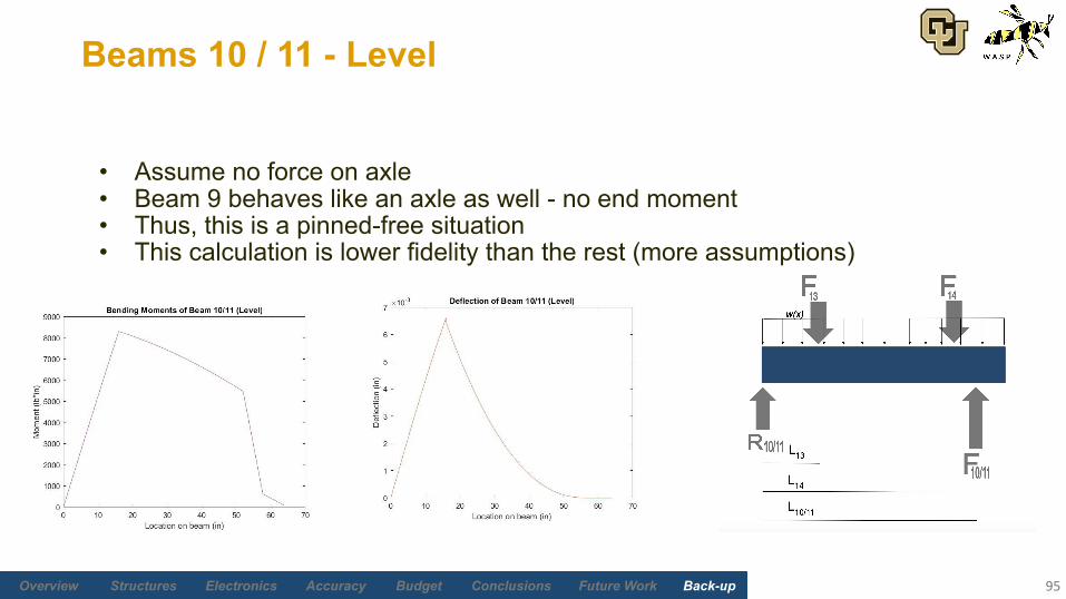
• Assume no force on axle• Beam 9 behaves like an axle as well - no end moment• Thus, this is a pinned-free situation• This calculation is lower fidelity than the rest (more assumptions)
Beams 10 / 11 - Level
95
Future Work Back-upBudgetAccuracyElectronicsStructures Overview Conclusions
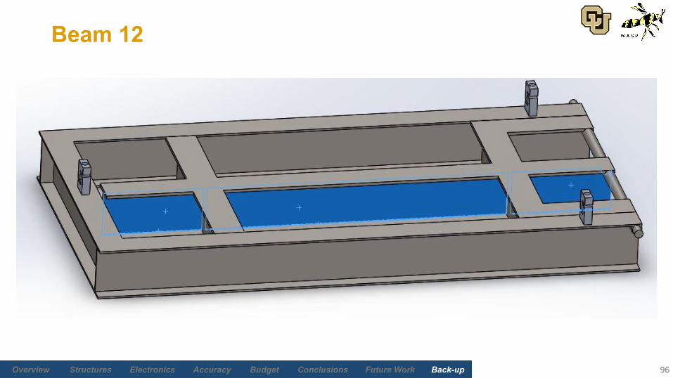
Beam 12
96
Future Work Back-upBudgetAccuracyElectronicsStructures Overview Conclusions
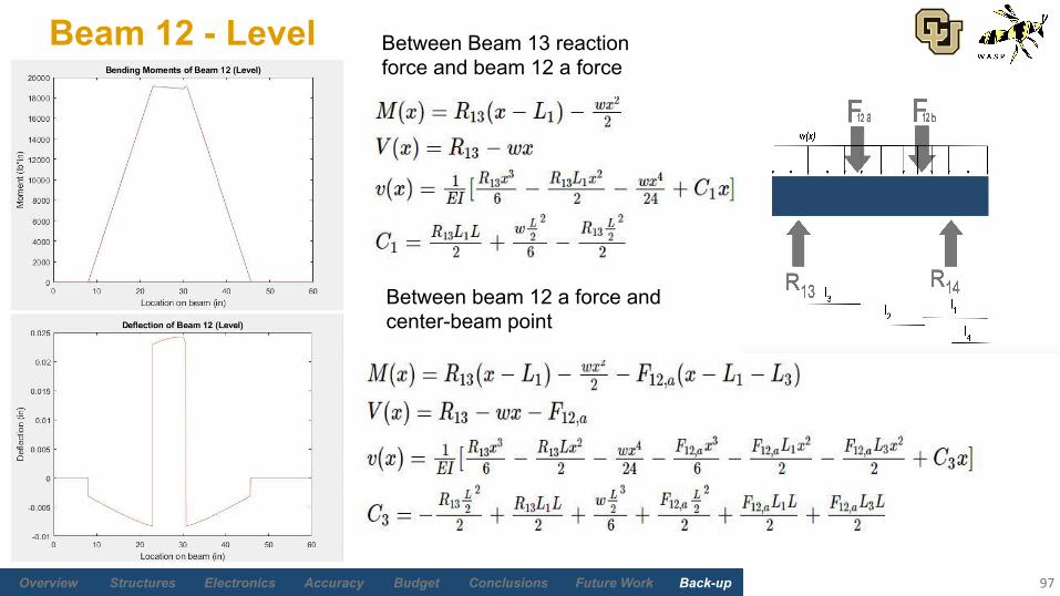
Beam 12 - Level
97
Between Beam 13 reaction force and beam 12 a force
Between beam 12 a force and center-beam point
Future Work Back-upBudgetAccuracyElectronicsStructures Overview Conclusions
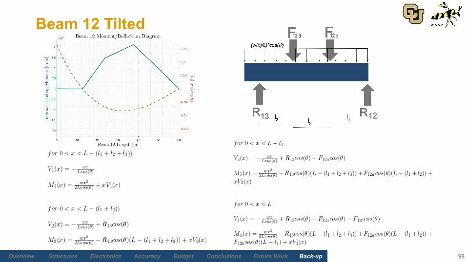
Beam 12 Tilted
98
Future Work Back-upBudgetAccuracyElectronicsStructures Overview Conclusions
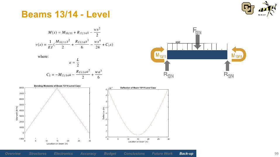
Beams 13/14 - Level
99

Future Work Back-upBudgetAccuracyElectronicsStructures Overview Conclusions
Beams 13/14 - Level Alternative Model
100
● Analyze from connection to beam 10/11 to connection to beam 12
*A value for M12 cannot be found yet as beam 12 has not been incorporated into an iterative bending-torsion solver.
Future Work Back-upBudgetAccuracyElectronicsStructures Overview Conclusions
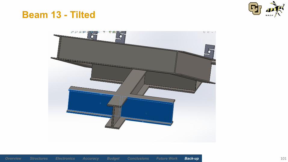
Beam 13 - Tilted
101
Future Work Back-upBudgetAccuracyElectronicsStructures Overview Conclusions
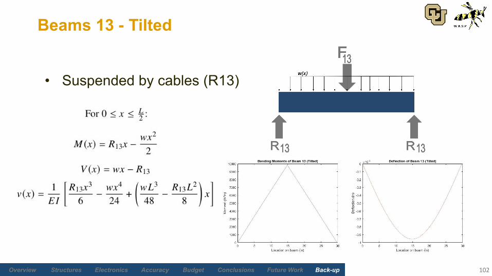
Beams 13 - Tilted
102
• Suspended by cables (R13)
Future Work Back-upBudgetAccuracyElectronicsStructures Overview Conclusions
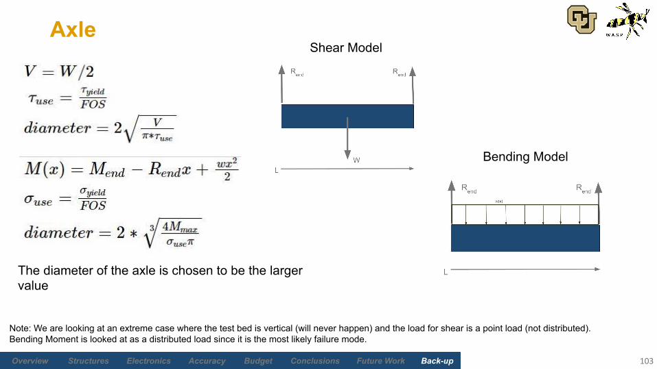
Axle
103
Note: We are looking at an extreme case where the test bed is vertical (will never happen) and the load for shear is a point load (not distributed). Bending Moment is looked at as a distributed load since it is the most likely failure mode.
The diameter of the axle is chosen to be the larger value
Shear Model
Bending Model

Future Work Back-upBudgetAccuracyElectronicsStructures Overview Conclusions
Frame Legs (Buckling FEA)
104
Fixed Support
External Forces
Frame Leg Buckling AnalysisBeam FOS: 26.3
1000 lbf
Future Work Back-upBudgetAccuracyElectronicsStructures Overview Conclusions
Frame Legs (Compression FEA)
105
Fixed Support
External Forces
FOSMinimum:19.8
*Near shear pin hole
1000 lbf 1000 lbf
StressMaximum: 1827 psi
1000 lbf
DisplacementMaximum: 0.0018 in

Future Work Back-upBudgetAccuracyElectronicsStructures Overview Conclusions
Sliding Interface (Stress FEA)
106
Stress
Maximum: 4,314 psi
Fixed Support
External Forces
Roller Pin
650 lbf
650 lbf
650 lbf
650 lbf
1300 lbf1300 lbf
Stress
Maximum: 2,015 psi

Future Work Back-upBudgetAccuracyElectronicsStructures Overview Conclusions
Sliding Interface (FOS FEA)
107
Chain Hoist Lifting Case
Minimum FOS: 8.41
Pinned Case
Minimum FOS: 18.00
Fixed Support
External Forces
Roller Pin
650 lbf
650 lbf 650 lbf
650 lbf
1300 lbf1300 lbf
Future Work Back-upBudgetAccuracyElectronicsStructures Overview Conclusions
Sliding Interface (Displacement FEA)
108
Displacement
Maximum: 0.0132 in
Fixed Support
External Forces
Roller Pin
650 lbf
650 lbf
650 lbf
650 lbf
1300 lbf1300 lbf
Displacement
Maximum: 0.004 in

Future Work Back-upBudgetAccuracyElectronicsStructures Overview Conclusions
Testbed FEA (FOS)
109
Fixed Support
External Forces
Level Case
Minimum FOS: 7.69
650 lbf
650 lbf
650 lbf
650 lbf
Future Work Back-upBudgetAccuracyElectronicsStructures Overview Conclusions
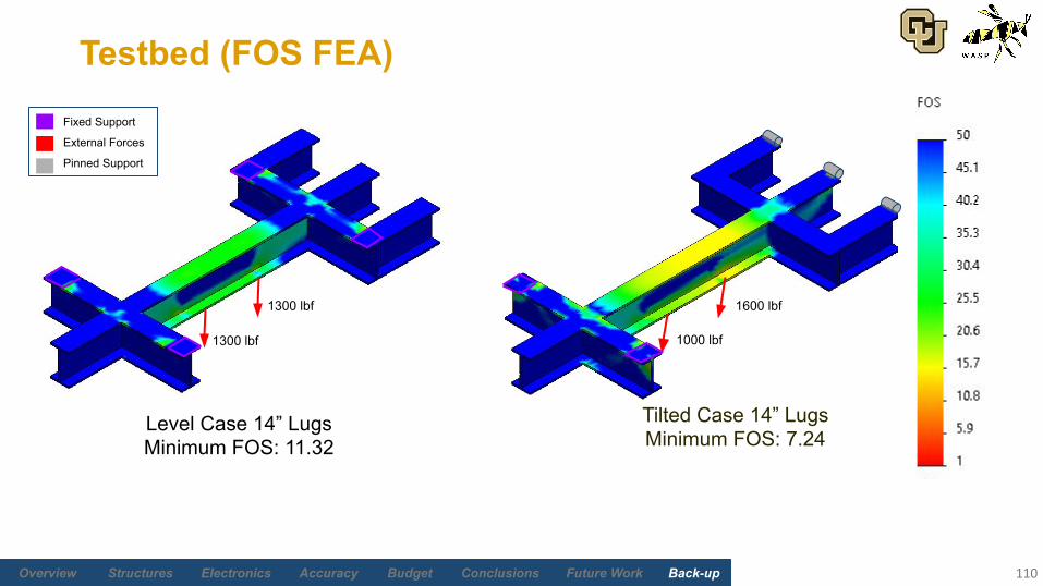
Testbed (FOS FEA)
110
Level Case 14” LugsMinimum FOS: 11.32
Tilted Case 14” LugsMinimum FOS: 7.24
Fixed Support
External Forces
Pinned Support
1300 lbf
1300 lbf
1000 lbf
1600 lbf
Future Work Back-upBudgetAccuracyElectronicsStructures Overview Conclusions
Testbed FEA (Deflection)
111
Level Case 14” LugsMaximum Displacement: -0.003 in
Tilted Case 14” LugsMaximum Displacement: -0.008 in
Future Work Back-upBudgetAccuracyElectronicsStructures Overview Conclusions
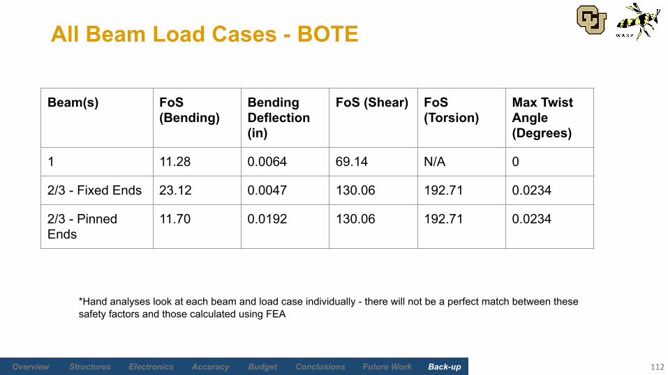
All Beam Load Cases - BOTE
112
Beam(s) FoS (Bending)
Bending Deflection (in)
FoS (Shear) FoS (Torsion)
Max Twist Angle (Degrees)
1 11.28 0.0064 69.14 N/A 0
2/3 - Fixed Ends 23.12 0.0047 130.06 192.71 0.0234
2/3 - Pinned Ends
11.70 0.0192 130.06 192.71 0.0234
*Hand analyses look at each beam and load case individually - there will not be a perfect match between these safety factors and those calculated using FEA
Future Work Back-upBudgetAccuracyElectronicsStructures Overview Conclusions
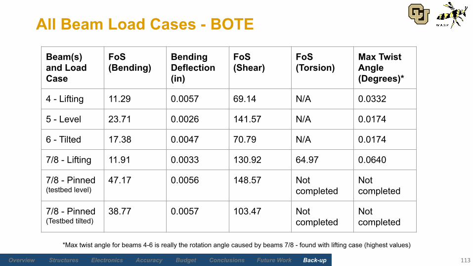
All Beam Load Cases - BOTE
113
Beam(s) and Load Case
FoS (Bending)
Bending Deflection (in)
FoS (Shear)
FoS (Torsion)
Max Twist Angle (Degrees)*
4 - Lifting 11.29 0.0057 69.14 N/A 0.0332
5 - Level 23.71 0.0026 141.57 N/A 0.0174
6 - Tilted 17.38 0.0047 70.79 N/A 0.0174
7/8 - Lifting 11.91 0.0033 130.92 64.97 0.0640
7/8 - Pinned (testbed level)
47.17 0.0056 148.57 Not completed
Not completed
7/8 - Pinned (Testbed tilted)
38.77 0.0057 103.47 Not completed
Not completed
*Max twist angle for beams 4-6 is really the rotation angle caused by beams 7/8 - found with lifting case (highest values)
Future Work Back-upBudgetAccuracyElectronicsStructures Overview Conclusions
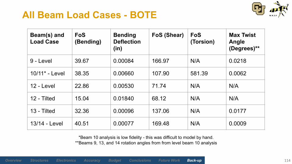
All Beam Load Cases - BOTE
114
Beam(s) and Load Case
FoS (Bending)
Bending Deflection (in)
FoS (Shear) FoS (Torsion)
Max Twist Angle (Degrees)**
9 - Level 39.67 0.00084 166.97 N/A 0.0218
10/11* - Level 38.35 0.00660 107.90 581.39 0.0062
12 - Level 22.86 0.00530 71.74 N/A N/A
12 - Tilted 15.04 0.01840 68.12 N/A N/A
13 - Tilted 32.36 0.00096 137.06 N/A 0.0177
13/14 - Level 40.51 0.00077 169.48 N/A 0.0009
*Beam 10 analysis is low fidelity - this was difficult to model by hand.**Beams 9, 13, and 14 rotation angles from from level beam 10 analysis

Future Work Back-upBudgetAccuracyElectronicsStructures Overview Conclusions
I-Beam Compactness Analysis (Buckling)
115
*Schaum’s Outline of Structural Steel Design - Rokach, 1991, Based upon American Institute of Steel Construction (AISC) Load and Resistance Factor Design (LRFD) Specification
Rule of thumb: If λ ≤ λp, “local buckling need not be considered”
Future Work Back-upBudgetAccuracyElectronicsStructures Overview Conclusions
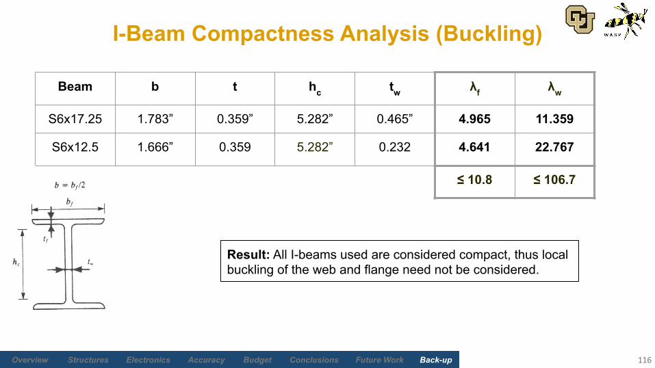
I-Beam Compactness Analysis (Buckling)
116
Beam b t hc tw λf λw
S6x17.25 1.783” 0.359” 5.282” 0.465” 4.965 11.359
S6x12.5 1.666” 0.359 5.282” 0.232 4.641 22.767
≤ 10.8 ≤ 106.7
Result: All I-beams used are considered compact, thus local buckling of the web and flange need not be considered.

Future Work Back-upBudgetAccuracyElectronicsStructures Overview Conclusions
Electronics and Software
117
Return to Supporting Material Quick Links

Future Work Back-upBudgetAccuracyElectronicsStructures Overview Conclusions
LC103B S-Beam Load Cell Specs
118
https://www.omega.com/en-us/sensors-and-sensing-equipment/load-and-force/load-cells/p/LC103B
Future Work Back-upBudgetAccuracyElectronicsStructures Overview Conclusions
TE Connectivity D-Series Inclinometer
119
https://www.metrolog.net/files/d_en_metrolog.pdf
Future Work Back-upBudgetAccuracyElectronicsStructures Overview Conclusions
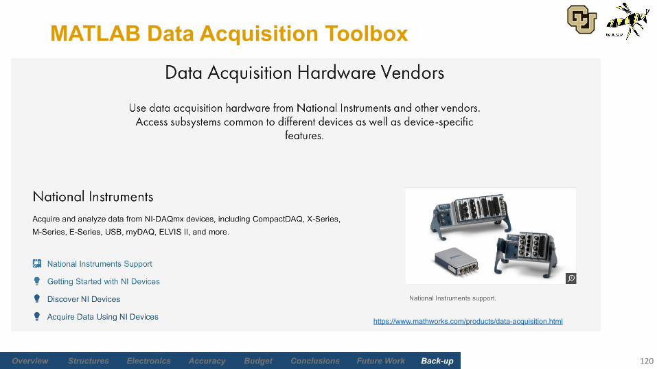
MATLAB Data Acquisition Toolbox
120
https://www.mathworks.com/products/data-acquisition.html
Future Work Back-upBudgetAccuracyElectronicsStructures Overview Conclusions
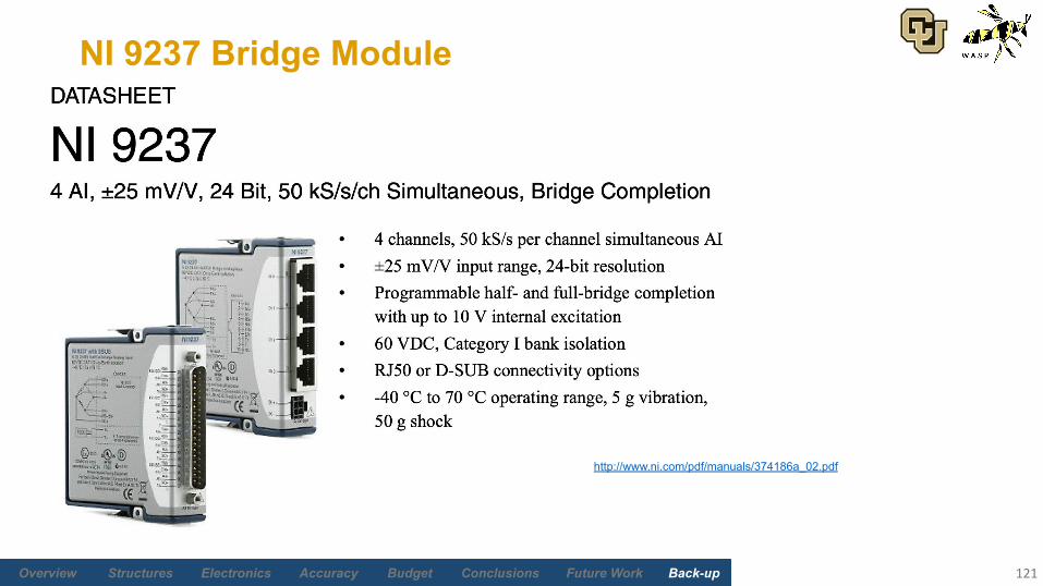
NI 9237 Bridge Module
121
http://www.ni.com/pdf/manuals/374186a_02.pdf

Future Work Back-upBudgetAccuracyElectronicsStructures Overview Conclusions
NI cDAQ-9171 Compact DAQ
122
https://www.ni.com/pdf/manuals/374037b.pdf
Future Work Back-upBudgetAccuracyElectronicsStructures Overview Conclusions
Weight and CG Accuracy
123
Return to Supporting Material Quick Links
Future Work Back-upBudgetAccuracyElectronicsStructures Overview Conclusions
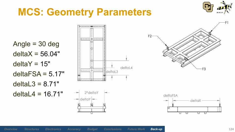
MCS: Geometry Parameters
124
Angle = 30 degdeltaX = 56.04"deltaY = 15"deltaFSA = 5.17"deltaL3 = 8.71"deltaL4 = 16.71"
Future Work Back-upBudgetAccuracyElectronicsStructures Overview Conclusions
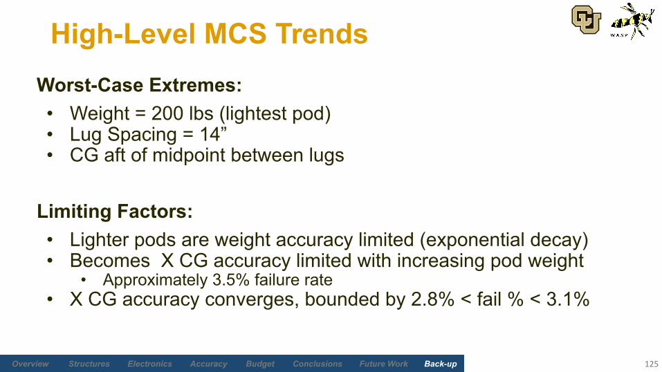
High-Level MCS Trends
125
Worst-Case Extremes:• Weight = 200 lbs (lightest pod)• Lug Spacing = 14”• CG aft of midpoint between lugs
Limiting Factors:• Lighter pods are weight accuracy limited (exponential decay)• Becomes X CG accuracy limited with increasing pod weight
• Approximately 3.5% failure rate• X CG accuracy converges, bounded by 2.8% < fail % < 3.1%
Future Work Back-upBudgetAccuracyElectronicsStructures Overview Conclusions
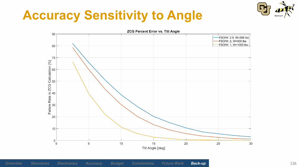
Accuracy Sensitivity to Angle
126
Future Work Back-upBudgetAccuracyElectronicsStructures Overview Conclusions
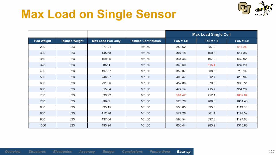
Max Load on Single Sensor
127
Max Load Single CellPod Weight Testbed Weight Max Load Pod Only Testbed Contribution FoS = 1.0 FoS = 1.5 FoS = 2.0
200 323 97.121 161.50 258.62 387.9 517.24
300 323 145.68 161.50 307.18 460.8 614.36
350 323 169.96 161.50 331.46 497.2 662.92
375 323 182.1 161.50 343.60 515.4 687.20
400 323 197.57 161.50 359.07 538.6 718.14
500 323 246.97 161.50 408.47 612.7 816.94
600 323 291.36 161.50 452.86 679.3 905.72
650 323 315.64 161.50 477.14 715.7 954.28
700 323 339.92 161.50 501.42 752.1 1002.84
750 323 364.2 161.50 525.70 788.6 1051.40
800 323 395.15 161.50 556.65 835.0 1113.30
850 323 412.76 161.50 574.26 861.4 1148.52
900 323 437.04 161.50 598.54 897.8 1197.08
1000 323 493.94 161.50 655.44 983.2 1310.88
Future Work Back-upBudgetAccuracyElectronicsStructures Overview Conclusions
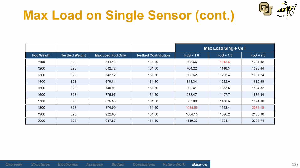
Max Load on Single Sensor (cont.)
128
1100 323 534.16 161.50 695.66 1043.5 1391.32
1200 323 602.72 161.50 764.22 1146.3 1528.44
1300 323 642.12 161.50 803.62 1205.4 1607.24
1400 323 679.84 161.50 841.34 1262.0 1682.68
1500 323 740.91 161.50 902.41 1353.6 1804.82
1600 323 776.97 161.50 938.47 1407.7 1876.94
1700 323 825.53 161.50 987.03 1480.5 1974.06
1800 323 874.09 161.50 1035.59 1553.4 2071.18
1900 323 922.65 161.50 1084.15 1626.2 2168.30
2000 323 987.87 161.50 1149.37 1724.1 2298.74
Max Load Single CellPod Weight Testbed Weight Max Load Pod Only Testbed Contribution FoS = 1.0 FoS = 1.5 FoS = 2.0

Future Work Back-upBudgetAccuracyElectronicsStructures Overview Conclusions
Max Failure Percentage
129
Maximum % Failure in Weight or CGPod Weight FSO = 500 lbs FSO = 1000 lbs FSO = 2000 lbs
200 4.93 33.33 61.90
300 3.08 13.99 45.89
325 3.28 11.33 42.35
350 3.46 8.59 39.30
375 2.87 6.25 34.79
400 2.73 5.06 32.82
425 3.21 3.58 29.59
500 2.97 3.15 22.17
600 3.10 3.18 13.94
650 2.94 3.46 10.76
700 X 3.07 8.58
750 X 2.87 6.72
800 X 3.36 5.25
850 X 2.89 3.45
900 X 2.95 3.18
1000 X 3.03 3.21
Future Work Back-upBudgetAccuracyElectronicsStructures Overview Conclusions
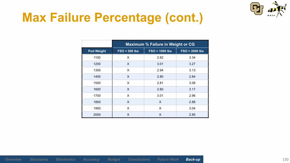
Max Failure Percentage (cont.)
130
1100 X 2.82 3.34
1200 X 3.01 3.27
1300 X 2.94 3.13
1400 X 2.80 2.84
1500 X 2.81 3.08
1600 X 2.80 3.17
1700 X 3.01 2.96
1800 X X 2.88
1900 X X 3.04
2000 X X 2.85
Maximum % Failure in Weight or CGPod Weight FSO = 500 lbs FSO = 1000 lbs FSO = 2000 lbs

Future Work Back-upBudgetAccuracyElectronicsStructures Overview Conclusions
Budget
131
Return to Supporting Material Quick Links
Future Work Back-upBudgetAccuracyElectronicsStructures Overview Conclusions
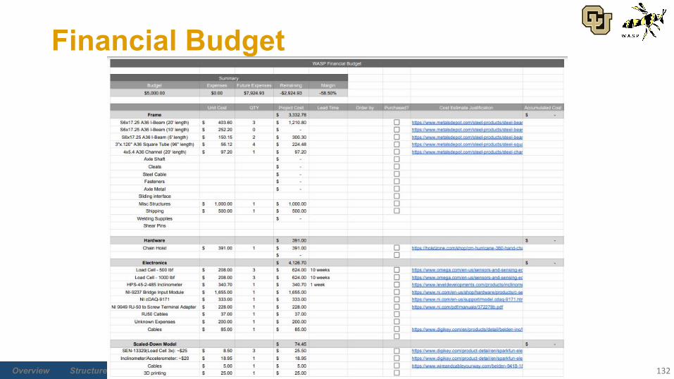
Financial Budget
132
Copyright © 2022 FDOKUMEN