UAS CHALLENGE 2015 PRELIMINARY DESIGN REVIEW Table of Contents
31
UAS CHALLENGE 2015 PRELIMINARY DESIGN REVIEW i
Transcript of UAS CHALLENGE 2015 PRELIMINARY DESIGN REVIEW Table of Contents

UAS CHALLENGE 2015 PRELIMINARY DESIGN REVIEW
i

Table of Contents
1 INTRODUCTION ................................................................................................................................ 1
1.1 MISSION OBJECTIVES................................................................................................................. 1
2 PROJECT MANAGEMENT .................................................................................................................. 1
2.1 TEAM ORGANISATION ............................................................................................................... 1
2.2 RESOURCE MANAGEMENT ........................................................................................................ 1
2.3 PROJECT PLAN ........................................................................................................................... 1
2.4 DESIGN COVERGENCE ............................................................................................................... 1
2.4.1 STAGE 1 CONVERGENCE..................................................................................................... 2
2.4.2 STAGE 2 CONVERGENCE .................................................................................................... 2
3 DESIGN CONCEPT ............................................................................................................................. 2
4 STRUCTURAL ANALYSIS .................................................................................................................... 3
4.1 LOAD PATHS .............................................................................................................................. 3
4.2 COMPOSITE TUBE STRESS ......................................................................................................... 4
5 PERFORMANCE & PROPULSION ....................................................................................................... 5
5.1 POWER REQUIREMENTS ........................................................................................................... 5
5.2 PERFORMANCE CACULATIONS .................................................................................................. 5
6 SYSTEM REQUIREMENTS, FUNCTIONAL DESCRIPTION, SCHEMATICS AND PAYLOAD DELIVERY .... 6
6.1 SYSTEM REQUIREMENTS ........................................................................................................... 6
6.2 LIST OF SYSTEM COMPONENTS ................................................................................................. 6
6.3 DESCRIPTION OF SYSTEM OPERATION AND SCHEMATICS ........................................................ 6
6.3.1 FLIGHT CONTROL ................................................................................................................ 6
6.3.2 NAVIGATION AND AUTONOMOUS FLIGHT ........................................................................ 7
6.3.3 IMAGING/RECOGNITION SYSTEM ...................................................................................... 7
6.3.4 SENSORS ............................................................................................................................. 7
6.4 MECHANISM OF PAYLOAD DELIVERY ........................................................................................ 7
6.4.1 THE HINGE-CLAMP METHOD.............................................................................................. 7
6.4.2 THE ELECTRO-MAGNET METHOD ...................................................................................... 7
6.4.3 THE HINGE-PIN METHOD ................................................................................................... 8
6.5 IDEAL CofG LOCATIONS ............................................................................................................. 8
7 PRELIMINARY SAFETY CASE .............................................................................................................. 9
7.1 OVERVIEW ................................................................................................................................. 9
7.2 RISK IDENTIFICATION AND MANAGEMENT............................................................................... 9
7.2.1 HAZARDOUS COMPONENTS ............................................................................................... 9
ii

7.2.2 FLIGHT CONTROLLER SAFETY MECHANISM ..................................................................... 10
7.2.3 SAFETY MEASURES FOR FLIGHT TESTING ......................................................................... 10
7.3 DESCRIPTION OF FUNCTIONALITY FOR FLIGHT TERMINATION CASES ................................... 10
7.3.1 GPS LOSS ........................................................................................................................... 10
7.3.2 GROUND STATION COMMUNICATION LOSS .................................................................... 10
7.3.3 GEOFENCE BREACH .......................................................................................................... 11
7.3.4 MAXIMUM PRESSURE ALTITUDE BREACH ....................................................................... 11
8 MANUFACTURING, TESTING AND COST ESTIMATION OF OVERALL SYSTEM ................................ 11
8.1 MANUFACTURING ................................................................................................................... 11
8.2 TESTING ................................................................................................................................... 12
8.2.1 SYSTEM TESTING .............................................................................................................. 13
8.2.2 STRUCTURAL TESTING ...................................................................................................... 13
9. BUSINESS CASE ................................................................................................................................ 14
REFERENCES ............................................................................................................................................. 15
APENDIX A – PROJECT MANAGEMENT (PROJECT PLAN) ...................................................................... 16
APENDIX B – DESIGN CONCEPT.............................................................................................................. 17
APENDIX C – PERFORMANCE CACULATIONS .........................................................................................20
APENDIX D – SYSTEM SCHEMATICS ........................................................................................................23
APENDIX E – CofG CALCULATIONS ......................................................................................................... 25
APENDIX F – OVERALL COST ESTIMATION OF UAV................................................................................ 26
APENDIX G – OVERALL COST ESTIMATION OF TEST RIG ........................................................................ 27
iii

Table of Figures
Figure 1 – Design Concept (Deployed Configuration) ............................................................................. 2 Figure 2 - Design Concept (Folding Configuration) ................................................................................. 3 Figure 3 - Load Paths On Hexacopter...................................................................................................... 4 Figure 4 – Hinge Clamp Method ............................................................................................................. 7 Figure 5 – Electro Magnet Method ......................................................................................................... 7 Figure 6 - Hinge Pin Method ................................................................................................................... 8 Figure 7 – Hexacopter (View from Top) .................................................................................................. 8 Figure 8 – Hexacopter (View From Side)................................................................................................. 8 Figure 9 – Exploded Layout of Hexacopter ........................................................................................... 12 Figure 10 – Example Test Rig ................................................................................................................ 13 Figure 11 – General Isometric View of Concept ................................................................................... 18 Figure 12 - Exploded view of general concept ...................................................................................... 18 Figure 13 - Top view of concept ............................................................................................................ 19 Figure 14 - Side view of general concept .............................................................................................. 19 Figure 15 – Typical Mission Profile Layout ............................................................................................ 20 Figure 16 – System Schematics ..............................................................................................................23 Figure 17 – Schematics of Propulsion System with Auto-Pilot ............................................................. 24
iv

1 INTRODUCTION This Preliminary Design Review (PDR) document presents the requirements, preliminary design solution, overall layout, feasibility of operation, costs and predicted mass for the IMechE Unmanned Aircraft System (UAS) Challenge. It also includes a project management section in which the team responsibilities and roles are identified. Additionally included are safety considerations and mitigations for certification and qualification phases.
1.1 MISSION OBJECTIVES The UAS challenge competition has been set to replicate a humanitarian aid mission set under extreme conditions involving areas affected by abnormal changes in temperature, earthquakes, flooding and potentially conflict zones. The task involves the design, construction, development and demonstration of a UAS with a Maximum Take-off Mass (MTOM) limit of 7kg. The UAS shall perform a series of tasks such as take-off, climb to an altitude between 100-400ft, cruise, follow a predefined route, deliver two payloads (Bag of flour at 1kg each) in two independent instances and return to launch preferably autonomously.
2 PROJECT MANAGEMENT To achieve the project objectives, effective management styles were adopted. This section describes the project plan and how it is being implemented. The design convergence methods used to narrow down the aircraft type are also included in this section.
2.1 TEAM ORGANISATION As with any large project, one must discretize the task into smaller, manageable elements with clear objectives. The project has been split into smaller tasks with clear objectives; to enable group members to know exactly what actions are required for an effective contribution. Throughout the project, weekly meetings with supervisors were undertaken to discuss any updates, complications and actions required. A detailed task tracker is employed to monitor progress and identify what each member in the group was working towards.
2.2 RESOURCE MANAGEMENT To accomplish the project objectives while making effective use of human resources, the project team of 12 is divided into two groups (Structural Team and Systems Team). The structural team handles tasks relating to the design, quality control, compliance, manufacture, test and certification of the UAS. The systems team handles tasks relating to performance and propulsion, stability, control systems, flight and navigation, imaging system, mission control and payload deployment system. For effective management, team leaders have been appointed to report back to the project manager regarding difficulties or progress updates. Using this style of leadership allows for accountability and effective communication within the group; it allows project management to focus on the management aspects of the project rather than delve into technicalities.
2.3 PROJECT PLAN A Gantt chart for the project plan can be found in Appendix A. It provides the project plan from the initiation till competition day with detailed milestones and stages of work.
2.4 DESIGN COVERGENCE To hone in on a workable design solution with application to the project, various concepts were compared using a design convergence approach.
1

2.4.1 STAGE 1 CONVERGENCE Application of the design solutions were analysed using a weighting system under criteria such as manoeuvrability, structural integrity, stability during flight and payload accuracy to name a few. A workable concept was congregated after a two-stage design convergence; stage one convergence was to determine the type of aircraft to be used and the concepts assessed were:
Osprey / Multi-Rotor / Helicopter / Fixed Wing The results from the stage-one convergence demonstrated that the multi-rotor would be the best option to meet the product design specification.
2.4.2 STAGE 2 CONVERGENCE Stage-two design convergence was to determine which multi-rotor system would best meet the UAS requirements. Criteria used in stage-two included redundancy (motor failure), manufacturing complexity, power consumption, noise, payload capacity, structural integrity and costs to name a few. The concepts considered during the stage-two design convergence were:
Quad-Copter / Hexacopter / Octacopter / 3 arm – 6 rotors Upon comparison between the multi rotors under the above criteria, the Hexacopter was found to be the best concept that would meet the set criteria.
3 DESIGN CONCEPT Based on the initial research carried out by the team a Hexacopter concept was chosen to meet the competition requirements as described in the design convergence section above (2.4).
The initial UAV design concept has been shown below in Figure 1. The Hexacopter’s main body is made up of three levels of composite laminates (cost dependant), the middle and bottom levels have been allocated to hold most of the electronic components. The top level has been designed to hold the battery for CofG / stability considerations and for the GPS to increase displacement and isolate from interference and vibration. The Payload system will be joined to the bottom level as shown below.
Figure 1 – Design Concept (Deployed Configuration)
Fixed arm
Retracting arm
Retracting arm
Payload box
2

The Hexacopter has been designed to be collapsible by allowing 4 of the arms and landing gear to rotate about pivots. This allows the structure to fold into linear and compact configuration allowing for easy transportation and storage as shown on Figure 2.
Figure 2 - Design Concept (Folding Configuration)
Further drawings of the initial design are shown in APENDIX B.
4 STRUCTURAL ANALYSIS This section looks at the initial material sizing and guidance geometry of the UAV. Constant involvement in the design stage has allowed for the design of a material efficient structure, making use of materials strengths based on their ideal uses. For example, commercially available metallic-fastening brackets for tubular arms have been eliminated by the use of machined plastics being used in compression. The need for threading has been eliminated as a sandwich type configuration has been designed, hence using the compression properties of plastics to one’s advantage. Using M4 hex head screws throughout the main structure along with locking thread Nuts (Nylock) will allow for a strengthened and stiff structure with achievable tolerances for the project budget.
4.1 LOAD PATHS The load paths in this Hexacopter are designed to make use of composite materials and lightweight plastics. The use of a tubular carbon fibre composite with a multi-directional 3k 2/2 twill weave (OD=25mm, ID=23mm as initial sizing) will allow the UAV to maintain a light structure weight and provide the stiffness required for this application. The use of carbon fibre will also mean the structure is suitable for a heavier payload with the addition to more batteries and potentially a double layer of motors.
The use of Nylon as spacer material and support clamps allow for the UAV to be foldable and be incredibly strong as it is being used in compression. The Carbon tube support clamps will be held to the main frame with 10mm machined Nylon blocks, which are more cost efficient than buying readily available metallic equivalents. The 4 moving carbon fibre arms of the UAV shall be able to move with the use of a pivot mechanism and held firmly during operation using a “sprung ball quick release” pin or equivalent. The same removed pins shall now enable the structure to be locked into it’s stowed position without losing parts during transport or having complex mechanisms to maintain.
3

The plate material used for the body shall potentially be made of multi-directional carbon fibre composite (2mm as an initial sizing with density per square metre to be justified). The carbon composite plates shall contain lightening and access holes for inspection, cable routing and locking positions. Purchasing the carbon fibre in rigid form may be too costly; hence the in-house manufacture using roll material and epoxy resin using a wet lay process may be adopted.
Figure 3 - Load Paths On Hexacopter
Figure 3 shows the initial sizing process for the carbon composite tubes using isotropic idealisations at this initial sizing stage. Plate stressing of the carbon composite will take similar calculations based on geometry, cut-outs, stress concentrations and combined loading effects. Composite plate stressing will be achievable based on the design maturity at a later stage of the program when cable routing, cut-outs and component mounting is confirmed.
The force at the tip of each arm can be decided based upon the acceleration the UAV it designed to achieve. As the designed acceleration is not yet available, and for the sizing of potential impacts, a 6g factor ( ) has been applied.
4.2 COMPOSITE TUBE STRESS The composite tube stress is calculated by using the bending moment at the last fixed position and treated as a cantilever hollow tubular beam with a load (lift) at the free end.
Observing the peak stress for the composite tube with this initial sizing, 59.83 Mpa is very small compared to the strength of multi-directional carbon fibre. Comparing this to a weaker 2024 Aluminium Alloy drawn tube with wall thickness between 0.018-0.5 inch,
(MMPDS-05). If aluminium can be used in this instance then one can confidently accept that a multi-directional carbon reinforced tube can be used. Additional justifications and choice of material shall be considered based on cost, load optimisation and lead times as the maturity of the design progresses.
4
Fψ =MTOM6arms
×ψg× sf
Fψ=1 =7kg6arms
×1g×1.33=15.22N
Fψ=6 =7kg6arms
×6g×1.33= 91.33N
σ Tube_Tension =MyI=FArm × d2 ×
D2
π64(D4 − d 4 )
=91.33N ×0.285m× 0.025m
2π64(0.0254 − 0.0234 )
σ Tube_Compression = −σ Tube_Tension = −59.83Mpa
= 59,830,328.88 N m2 = 59.83Mpa

5
The reason for a low stress value is due to the outer dimensions of the tube used for initial sizing, the distance between moment centre and outer wall is 12.5mm (D/2). The carbon tube shall need further analysis to determine its suitability in this instance based on the anisotropic characteristics of the composite material. Additionally local buckling shall also need to be considered and effects of stress concentrations around the machined Nylon fixing brackets at the root.
5 PERFORMANCE & PROPULSION This section investigates the possible inrunner and outrunner electric motors, propellers, and power sources that are capable of producing the thrust required to firstly lift the Hexacopter, and secondly to attain the velocity required to complete the challenge on time before the batteries are exhausted.
5.1 POWER REQUIREMENTS Steps Taken:
1. To calculate Hexacopter’s performance the MTOW weight is vital, initially 7kg was usedbased on 2kg payload, 1.5kg power source, 1.2kg propeller, motors and attachment, theframe and all other electronics components adding to 2kg plus another 5% for possibleunexpected weight addition.
2. Identified Hover thrust – Using MTOW of 7kg it was identified that for the Hexacopter tohover it would require each of the six motors to produced 1.167kg of thrust to hover in 1g.
3. Identified thrust for manoeuvrability – Using an equation provided by leading multicopterdevelopers such as DJI, thrust required for improved manoeuvrability was calculated:
MTOW ∗ 2 ∗ 1.2Number of motors
= 2.8kg of thrust/motor 4. Identified performance criteria to complete the mission in 2minutes – The mission consists
of a range of 2km with a target time of 2 minutes. The velocity the Hexacopter requires to travel at is 16.67m/s (32knots) taking into account 12.8m/s (25 knots) gust and 10.2m/s (20 knots) wind the Hexacopter would require to travel at relative speed of 29.47m/s (57 knots).
5. Propeller, Motor, Electronic Speed Controller (ESC) and Battery selection-‐ It was identifiedthat a low rpm/V brushless electric motor was required using a large propeller with high pitch angle to enable provisions for sufficient lift and thrust. The propeller cannot be overly large as it will sacrifice velocity of the craft, increase noise, and require more power draw from the batteries. The selection of these important components required the use of a source known as xcalc.com containing theoretical calculations, which identified 20 combination of producing the thrust, velocity and battery life required that could last greater than 2 minutes. Performing these calculations helped to narrow down the countless combinations of propeller, motor, ECS and batteries that would achieve the specification required. Specification of these components can be found in Appendix C.
6. As it can be seen from Appendix C, the Turnigy G32M 770kv motor has a maximum rating of 1000Watts. The 1000W is based on a zero load condition where a propeller is not attached to the motor. These conditions however change when a propeller is added to the motors, thereby reducing the motors output to 791.9W. The motor itself also has an efficiency factor of 0.882 that is specified by the manufacturer and further reduces the motors capability to 698.2W.
5.2 PERFORMANCE CACULATIONS The flight profile for the Hexacopter has been considered using the flight path specified in Appendix C. The performance calculations have been based on using the Turnigy G32 - 770 motor, APC - E
Propellers, 60A ESC and 16000mAh 5S1P lipo batteries (taking into account a 10% error). Results of the flight profile, velocities, time taken, distance covered and battery status are presented in Appendix C.

6 SYSTEM REQUIREMENTS, FUNCTIONAL DESCRIPTION, SCHEMATICS AND PAYLOAD DELIVERY
The UAS control system shall be designed to meet certain design specifications. The UAS primary function is to deliver a payload to a specified location, it also has a secondary function that is to recognise an alphanumeric code. An image recognition system is to be designed and appropriate code written to implement recognition. This section also specifics initial ideas for the payload delivery system and mechanism. These are the hinge-clamps system, the electro-magnet method and the hinge-pin method.
6.1 SYSTEM REQUIREMENTS For the UAV to carry out its primary and secondary functions the control system must meet the design criteria. The UAV’s control system is made up of smaller sub-systems with specialised tasks; to achieve this, the systems are designed and integrated to meet the systems requirement.
• Flight Control System shall be capable of autonomous flight.• Flight Control System shall have the capacity to switch between manual and automatic flight
modes.• Navigation System shall have the capacity to be programmed on the day of the flight and
also mid-flight in case errors are made.• Imaging System shall have the capacity of recognising alphanumeric code and activating the
payload delivery system autonomously.
6.2 LIST OF SYSTEM COMPONENTS 1) Autopilot Control System2) Radio Controller (Antenna, Transmitter and Receiver)3) G.P.S module with Compass4) Motors5) Propellers6) Batteries7) Electronic Speed Controllers (ESC)8) Optical flow sensor (Camera or visual processing sensor/ Used for terrain avoidance system)9) Wireless telemetry kit (2.4GHz/433MHz) range of 1.5km from ground station & Potentially
5GHz Dual Band Wifi.(Assumption: 240VAC Power supply / generator available on competition day)
10) On Screen Display (OSD)11) Power regulator12) First Person View (FPV) Camera and Video Link
Some of the devices are optional and are only present to improve quality of flight and increase mission accuracy of the project. This list does not include cables and connectors.
6.3 DESCRIPTION OF SYSTEM OPERATION AND SCHEMATICS The System operation is broken down into:
Flight control (Altitude and Attitude Control), Navigation and Autonomous Flight Recognition System Sensors Payload Delivery
The schematics of these systems integrated can be found in Appendix D
6.3.1 FLIGHT CONTROL The UAV shall have two forms of control; these are manual (via Radio Controller) and Automatic control with the use of an autopilot system. The manoeuvres for flight control (Attitude and Altitude control) are: Thrust, Pitch, Yaw, Roll, Hover, Vertical Climb and Loiter
6

The above mentioned manoeuvres can be controlled manually with the use of a radio controller to either fly to specific locations or perform different manoeuvres, or can be completed automatically with the autopilot control system.
6.3.2 NAVIGATION AND AUTONOMOUS FLIGHT The desired method for control of the UAV is autonomous flight control, to accomplish this an external GPS and compass kit is included in the control system. The autopilot board has an internal GPS and compass unit for determining orientation and direction for the aircraft but does not support autonomous flight as the magnetometer sensor field interferes with the operation. The external GPS and compass unit provides a solution to the problem and can be used for a more robust fully autonomous flight.
6.3.3 IMAGING/RECOGNITION SYSTEM The UAV shall have an imaging/recognition system that would be used to recognise an alphanumeric code at the specified GPS location. The Imaging/Recognition system is used to increase the accuracy of the mission as it would be used to find the exact location to drop the payload at the GPS coordinates.
6.3.4 SENSORS The Pixhawk Autopilot control board has on-board sensors such as: Gyroscope used for stabilizing the UAV Accelerometer used for measuring speed Magnetometer used for orientating the UAV Barometer used for measuring the pressure to calculate the altitude Optical flow sensors to measure altitude and to hold the UAV accurately in one position
6.4 MECHANISM OF PAYLOAD DELIVERY As part of the UAS design challenge, a payload delivery system and mechanism must be incorporated. The purpose of this section is to present the various methods of releasing the payloads. These are the hinge-clamp system (6.4.1), electromagnet method (6.4.2) and the hinge-pin method (6.4.3).
6.4.1 THE HINGE-CLAMP METHOD The disadvantage of this method is that the hinge-clamp and servo motor can be tedious to implement. In this concept the bags of flour are to be put in pre-designed cases which have small holes in which the clamp teeth shall integrate. The system would be coupled to a set of 4 clamps actuated by 2 servo motors. The advantage of the system would be no variation of the C.G in the XY (Horizontal) plane. In addition, the structure is robust in case of turbulences, vibrations or sudden movements. The disadvantage of this method is that the hinge-clamp and servo motor can be complex to implement and have severe weight implications.
Figure 4 – Hinge Clamp Method
6.4.2 THE ELECTRO-MAGNET METHOD In this second concept, the pre-designed cases include bar members placed at precise locations. The topmost case would have a metallic rod at its bottom face. The second case would have 2 metal rods located at the corners of its top face. The metal rods would interact with 3 electro-magnets placed at specific locations on the airframe. The advantage is that the C.G will not vary in the XY (Horizontal) plane.
Figure 5 – Electro Magnet Method
7

The main disadvantages of this method are first of all, once the electro-magnet are on, the magnetic field may interfere with the overall electronics on board. Secondly, the electro-magnet will drain the power greatly, additional rods and coils will add more weight to the UAV and this design may not be robust in turbulence and vibration scenarios.
6.4.3 THE HINGE-PIN METHOD This last concept relies upon a set of pins coupled to hinges to release the payload. In this scenario, the loads are placed beside each other and released once the UAV arrives at the respective drop-off point. The advantage of this system is that it is a relatively simple system to operate. The disadvantage to this method is the addition of rigid structure to contain all the complex mechanisms. An improvement to this solution is to simply incorporate a pin-actuator design on which the payloads sit, all contained within an open box structure.
Figure 6 - Hinge Pin Method
6.5 IDEAL CofG LOCATIONS Ideally, the CofG should be at the centre point of the multi-copter, at 0 on the x and y-axis (Horizontal). As this may not be feasible depending on the size and weight of the systems and batteries, the CG can be off centre by up to 1-2cm. However considering the large moment arm from centre to propeller, the difference ratio of 5-10cm with a 1kg offset will have a miniscule (200-300g) thrust adjustment. Assuming the centre of the arms is the datum; CG is at 4.33cm with both payload, 2.24cm with one and -0.87cm without payload (See Appendix E). Ideally it should be closer to 0 on the z-axis but this may not be possible due to the batteries and payload compensation.
Figure 7 – Hexacopter (View from Top)
Figure 8 – Hexacopter (View From Side)
8
7 PRELIMINARY SAFETY CASE All aspects of safety have been covered during the initial conceptual design of the UAV. This has included cases such as malfunctioning and falling out the sky, while using ratings by looking at likelihood of the event and the severity.
7.1 OVERVIEW The UAV can cause property and individual damage and harm if misused, therefore precautions have to be put in place. Some main safety requirements that must to be adhered to are extracted from the UK Air Navigation Order 2009 and stated below. The statements that have been referenced are from articles 138, 166, 167 and CAA CAP 722, and CAP 393 from (Civil Aviation Authority, 2012;Corbett, 2014).
The requirements that must be met are; 1 The UAS should not operate above 400 feet (122 m) 2 The UAS should always be kept in Visual Line of Sight (VLOS) to allow for manual control at any
point during flight. 3 Operate 150m away from congested areas 4 Should not operate within 50m of any person, vehicle or structure. Except during takeoff and landing at which point the pilot is allowed to be in 30 meters from the craft.
7.2 RISK IDENTIFICATION AND MANAGEMENT Risk Likelihood Severity Risk Level Action Required Bird Strikes causing craft to fall out the sky.
Extremely Remote
Catastrophic Medium Risk Cannot be managed.
One motor failure Probable Hazardous Low Risk Design aicraft that can cope with a motor failure. Design a system that can be programmable to land the craft safely if such a case were to occur.
Take-off and Landing failure, causing blades to hit the ground and break.
Likely Hazardous Medium Risk Stand at a far enough distance, use a testing rig or use out-riggers during the testing phase.
Incorrect assembly of UAS components
Probable Hazardous Low Risk Use a checklist to check main connections prior to every flight.
Radio frequency interference
Probable Minor Low Risk Cannot be managed, however UAS autopilot system shall have a 30 second time frame to return home if communication response is not achieved.
Propeller Injuries Extremely Improbable
Catastrophic Medium Risk Operate away from congested areas, 50m away from all personals and structures.
Battery detachment Improbable Catastrophic Medium Risk Use a secure fixing which holds the batteries on all manoeuvres including crash cases.
Batterycombustion Extremely Remote
Catastrophic High Risk Highest combustion risk is during recharging therefore charge batteries in charging bags to contain any possible explosions or leak of gaseous vapours.
7.2.1 HAZARDOUS COMPONENTS High speed propellers – Detachment of propellers in flight can cause serious injuries to people and animals. Carbon fibre reinforced blades cause a higher risk compared to blades made from plastics
9

due to their strength and stiffness. However due to flying the UAV away from any objects, structures and 50m away from personnel the risk can be mitigated. The use of carbon blades can therefore be considered.
Batteries – The consequences of the following steps will result in explosion and destruction of the batteries; short wiring, overheating or possible defects during manufacture. Batteries must be securely fastened to the craft to ensure the CofG does not change during flight therefore also affecting stability and performance. The batteries should also be secured properly to prevent them from falling out during manoeuvres. Batteries will be made bright in colour to identify them in a crash and shall be mounted using Velcro Straps for easy removal in situations such as crashes or charging operations.
7.2.2 FLIGHT CONTROLLER SAFETY MECHANISM The Pixhawk flight controller selected has a number of safety mechanisms. It includes a motor arming safety feature when manually controlling the copter. Safety features such as Return To Launch (RTL), FailSafe and GeoFence are also built into this controller. In the event of a signal loss to the UAS, it can be programmed to return to the launch location using RTL while FailSafe will ensure its safety. Stabilize or Stabilize plus modes can be triggered to land the Hexacopter safely in case of a motor failure.
7.2.3 SAFETY MEASURES FOR FLIGHT TESTING Ensuring no personnel are near propellers when they are powered, special when performing
PID tests. Terminating the flight before battery’s safety capacity is reached. After landing, ensure battery power to the components has been stopped either by removing
cables or using a switch before handling the UAV. Prior testing, ensuring the home location shown in the mission planner software is correct. Using a staggered flight test approach, increasing speed and height with each test. Use of checklists for mechanical and electrical components, systems and assembly before
every flight test to ensure they are connected correctly and working.
7.3 DESCRIPTION OF FUNCTIONALITY FOR FLIGHT TERMINATION CASES The core safety functionality of the Pixhawk software “APM:Plane” is for RTL, if the UAV loses contact with the ground station or during manual control. If more advanced options are required then Pixhawk has an on-board Advanced Failsafe system (AFS). The autopilot can be setup for failsafe conditions so that the multi-copter can loiter for a short period of time before RTL automatically lands or terminates flight (APM Plane, 2014).
7.3.1 GPS LOSS The AFS system monitors the strength of the GPS receivers throughout the flight. If both GPS, on-board and external lose position lock for over 3 seconds then the Pixhawk AFS is initiated (APM Plane, 2014). This involves the system looking at the data input into the “AFS_WP_GPS_LOSS” parameter which instructs the multi-copter on its next action, ranging from loiter for a period of time or reducing motor RPM to land the craft. If the GPS regains positioning then the multi-copter will continue its mission from where it left off.
7.3.2 GROUND STATION COMMUNICATION LOSS The AFS system constantly monitors the strength of the data-link between the multi-copter and the ground station using “HEARTBEAT MAVlink” (APM Plane, 2014) messages that are transmitted by the ground station. If for a period of 10 seconds or greater the multi-copter does not receive a
10

HEARTBEAT (similar to handshake ping in IT systems) message then it enters AFS state. During AFS state, the system looks for the “AFS_WP_COMMS” parameter, a waypoint number to which the UAV should navigate to when communication loss has occurred (APM Plane, 2014). If this is a non-zero value the UAV will change its target waypoint given by the “AFS_WP_COMMS”, otherwise it shall RTL.
If the craft loses GPS positioning and connection with the ground station then this is considered ‘dual loss’ and the craft will carry out pre-programmed commands. However the user can override Pixhawk and enable manual mode and take control regardless of loss of GPS or connection between ground-station. If all connections are lost, including manual control then the multi-copter will terminate flight after a specified time in milliseconds, in this case for 30,000 milliseconds (30 seconds).
7.3.3 GEOFENCE BREACH Geofence allows the user to set boundaries of where the multi-copter can operate in terms of distance and height. If the multi-copter goes outside the set boundaries it will switch to guided mode and fly back to a pre-defined location (APM Plane, 2014).
7.3.4 MAXIMUM PRESSURE ALTITUDE BREACH When the airspace is being shared by multiple UAVs, the flight altitude will be measured by a common reference pressure, typically the QNH, a Q-code. The AFS system can be used to set a pressure altitude limit, a value in millibars into the “AFS_AMSL_PRESSURE” parameter, which the craft will not exceed. Similarly the pressure altitude limit can be set in the “AFS_AMSL_LIMIT” (APM Plane, 2014) parameter in metres. If both parameters are set and are exceeded then the AFS will initiate a pre-programmed termination process.
The AFS system will also monitor the barometer, and if it shows to be malfunctioning for 5 seconds then the AFS system will look at the “AFS_AMSL_ERR_GPS” (APM Plane, 2014) parameter. The multi-copter will enter flight termination immediately if it is set at the default value of -1. If not, it will continue flight and use the value as a margin to add to the GPS height. This allows the flight to continue if the GPS altitude plus the “AFS_AMSL_ERR_GPS” value (in meters) is below the “AFS_AMSL_LIMIT” value. This margin value is to account for the inaccuracies of GPS altitudes and according to APM, a value of 200 is reasonable for safety to ensure “AFS_AMSL_LIMIT” pressure altitude is not breached (APM Plane, 2014).
8 MANUFACTURING, TESTING AND COST ESTIMATION OF OVERALL SYSTEM
This section includes consideration for manufacture and assembly of the various components, sub-systems and systems forming the UAV itself. Also considered is a ball-socket or 3-axis gimbol testing rig for safe testing of the UAV (3-axis gimbol shown in Figure 10). Finally cost estimations are also considered in this section for overall off-the-shelf components and systems.
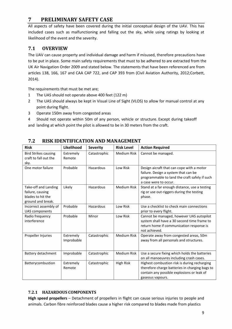
8.1 MANUFACTURING To accomplish the design requirements for the competition, the manufacturing process is focused on two aspects of multi-copter; minimum weight with optimum performance. The structure architecture of the multi-copter is simply based on sandwiched carbon fibre layers that integrate all the other parts of the multi-copter. The following image shows the preliminary layout of the design with propulsion system.
11
Bottom Carbon Fibre Plate
Nylon Clamp
Mid Carbon Fibre Plate
Top Carbon Fibre Plate
Arm – Carbon Fibre Tube
Machined Nylon 6 rod for pivot
Figure 9 – Exploded Layout of Hexacopter
Considering the budget and design specification, carbon fibre is suitable for manufacturing the plates of the multi-copter. Since the University has the facility of a composites lab and CNC machining; A wet lay-up process using resin can be used to manufacture the composite sheets and the Nylon 6 rod and 10mm plate brackets can be machined to obtain the proposed designs. Carbon tubes for arms and joining fasteners shall be directly supplied from the university suppliers.
The budget allocation of the project is £1000 and considering the materials and components needed for the project, the table in APPENDIX F shows the estimated breakdown of the expenses of this project.
Batteries are considered as consumables in this product as with Nitro fuels for engine type propulsion systems hence are not considered as part of the £1000 Commercial Off The Shelf components (COTS). Also in compliance with IMechE Competition Rules Issue 2 (IMechE, July 2014).
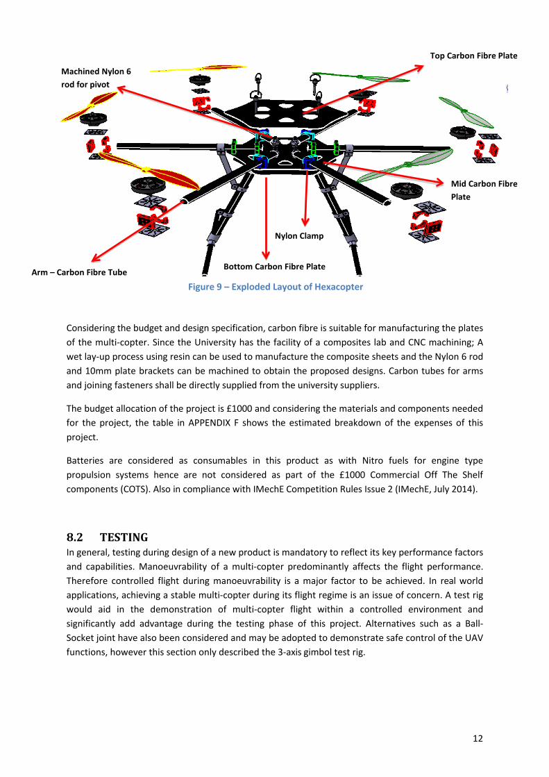
8.2 TESTING In general, testing during design of a new product is mandatory to reflect its key performance factors and capabilities. Manoeuvrability of a multi-copter predominantly affects the flight performance. Therefore controlled flight during manoeuvrability is a major factor to be achieved. In real world applications, achieving a stable multi-copter during its flight regime is an issue of concern. A test rig would aid in the demonstration of multi-copter flight within a controlled environment and significantly add advantage during the testing phase of this project. Alternatives such as a Ball-Socket joint have also been considered and may be adopted to demonstrate safe control of the UAV functions, however this section only described the 3-axis gimbol test rig.
12

Mid square frame (1.152m x 1.152m)
Model mount frame (1m x 1m)
Bearing housing
Outer square frame (1.252m x 1.252m)
Gimbal test rig stand
8.2.1 SYSTEM TESTING To solely rely on systems to operate as efficiently as possible is not good practice, hence testing the operation of individual system components and post integration would validate the testing processes. The gimbal test rig would be a beneficial tool for the verification of sub-system tests in controlled conditions. As part of the competition requirement, the chosen Hexacopter design is required to be able to carry two payloads (1kg each bags of flour) and deploy each payload independently. This independent deployment of payloads at any given time could cause instability post deployment and hence would affect the weight distribution on the UAS. The stability of the multi-rotor after imbalance can be verified during testing within the gimbal design shown below.
Figure 10 – Example Test Rig
As seen from figure 10 above, the gimbal frame has 3 frames allowing for movement in all directions except for total body lift (vertical).
8.2.2 STRUCTURAL TESTING In addition to stability checks on the test rig, other tests such as static material tests, impact/crash tests and modal analysis due to vibrations shall be carried out using Finite Element Analysis (FEA).
Although the design specification does not require building a test rig, it was noted that fabricating a gimbal test rig would be worthwhile as manoeuvrability and stability of a Hexacopter is complex. Therefore a safe testing method would have to be implemented to avoid damage on such a costly design. However the cost incurred for the fabrication of the test rig would be raised through sponsorship and is being discussed.
Details of the potential components for this particular test rig are shown in Appendix G.
13

9. BUSINESS CASE
The primary and potential functions of the UAS make it suitable to be applied in the emergency services sector. The systems on board the Unmanned Aerial Vehicle (UAV) represent the large-scale scheme that can be deployed in search and rescue missions. Systems such as the payload delivery can be used to deliver food, water and medications to victims of disaster in inaccessible areas prior to rescue. Instead of deployable payloads, the UAV can carry specialised equipment such as a defibrillators or oxygen tanks for first response units. The Imaging/Recognition system on the UAV is programmed to recognise alphanumeric codes to improve its mission accuracy. A specialised system can be incorporated to recognise human images, vehicles or buildings. An infra-red sensor can also be integrated into the system for night time operation or in a cold environments to detect body heat.
As was presented earlier, some of the UAV’s primary selling factors are its portability and collapsible nature allowing effortless storage and transport; requiring single person operation and having a reasonable payload carrying capacity. As previously mentioned, one of the possible real world scenarios a UAS can be deployed for, is areas where natural disaster has struck. While a fixed wing aircraft has a longer range and can carry a weightier payload, a multi-copter has the benefit of flying low through complex terrain such as foliage and damaged buildings. Flying low can enable the craft to deliver sensitive payloads safely that are prone to damage from high altitude drops. Furthermore the added capability of flying at low forward speeds and hovering enables accurate delivery in a secure manner and is currently being investigated for its use in logistics.
Advances in technology are ever improving; the ability to take high quality videos with low cost cameras enable amateur filmmakers to take impressive panoramic and scenic videos with very little additional costs. Using off-the-shelf autopilot systems such as DJI’s NAZA, ArduPilot and Pixhawk the learning curve for controlling a multi-copter is made feasible for the inexperienced enthusiast. Professional aerial photography has been commercializing in the past few years and allows capturing images of hard to reach locations and unique perspectives. Surveillance and inspection of buildings, bridges, power plants, off-shore oil platforms, wind farms and volcanic sites which otherwise would require specialised equipment, can now be conducted much more efficiently at a reduced cost. The ability to modify the simple design of this multi-rotor into an amphibious vehicle is possible due to its unique structure and element type design. Modifications of propulsion, control and electrical systems without pressurisation of the entire vehicle make it feasible for underwater inspection of tunnels, bridge columns, shipping docks and archaeology.
14

REFERENCES APM Plane. (2014). Advanced Failsafe Configuration. Retrieved November 31, 2014 from http://plane.ardupilot.com/wiki/advanced-failsafe-configuration/
APM Plane. (2014). Complete Parameter List. Retrieved December 02, 2014 from http://plane.ardupilot.com/wiki/arduplane-parameters/
IMECHE July 2014. Compertition Rules Issue 2 - University UAS Challenge 2015.
15
[4] APM Plane, 2014. Advanced Failsafe Configuration. [Online] Available at: http://plane.ardupilot.com/wiki/advancedD_failsafeD_configuration/ [Accessed 31 November 2014].
Civil Aviation Authority, (2012). Unmanned Aircraft System Operations in UK Airspace – Guidance. 5th ed. [PDF] Available at: http://www.caa.co.uk/docs/33/CAP722.pdf [Accessed 27 Nov. 2014].
Corbett, G. (2014). UK UAS Operations. 1st ed. [pdf] UK CAA Safety and Airspace Regulation Group. Available at: http://jarusD rpas.org/pdf/2_Workshop_140319/2014_Presentation_01_CorbettDGerry_CAA_UK.pdf [Accessed 15 Nov. 2014].
Weibel, R. and Hansman, R. (2005). SAFETY CONSIDERATIONS FOR OPERATION OF UNMANNED AERIAL VEHICLES IN THE NATIONAL AIRSPACE SYSTEM. 1st ed. [pdf] Cambridge,: MIT International Center for Air Transportation Department of Aeronautics & Astronautics Massachusetts Institute of Technology. Available at: http://dspace.mit.edu/bitstream/handle/1721.1/34912/Weibel%20D%20ICAT%20Report%20D %20UAV%20Safety.pdf [Accessed 17 Nov. 2014].
Rogershobbycenter.com, (2014). A Guide to Understanding LiPo Batteries -‐ Roger's Hobby Center -‐ Radio Control (R/C or RC) Cars, Boats, Airplanes, Puzzles, Plastic Models, & Trains W Saginaw, MI. [online] Available at: http://www.rogershobbycenter.com/lipoguide/ [Accessed 25 Nov. 2014].
Copter.ardupilot.com, (n.d.). Safety MultiCopter | ArduCopter. [online] Available at: http://copter.ardupilot.com/wiki/safetyD_multicopter/ [Accessed 9 Nov. 2014].

APENDIX A– PROJECT MANAGEMENT (PROJECT PLAN)
16

APENDIX B– DESIGN CONCEPT
Figure 11 – General Isometric View of Concept
Figure 12 - Exploded view of general concept
17

Figure 13 - Top view of concept
Figure 14 - Side view of general concept
18

19

APENDIX C– PERFORMANCE CACULATIONS
Figure 15 – Typical Mission Profile Layout
Location Velocity (m/s)
Time (s) Battery Status (%) 16000mAh
Distance Covered (m)
[Runway] 0 0 100 0 [Runway]-[30.5m
Altitude] 6.77 3.85 98.7 26.2
[30.5m Altitude]-[1] 15.932 16 92.5** (282-26)=255.8 At [1] half loiter
performed 8 0.875 90.2 7
[1]-[2] 15.932 50.78 66.5 (842-7-26)=809 [30.5m Altitude]-[descend to 1m]
6.77 3.85 65.3 26.2
Hover N/A 5 64.5 N/A From 1m to 30.5m 6.77 3.85 63.3 26.2
[30.5m]-[3] 15.932 24.6 51.8 (418-26.2)=391.8 At [3] half loiter
performed 8 0.875 51.5 7
[3]-[Target] 15.932 18.9 42.7 (334-7-26)=301 [30m Altitude]-[descend
to 1m] 6.77 3.85 41.3 26.2
Hover N/A 5 40.5 N/A From 1m to 30.5m 6.77 3.85 39.1 26.2 [30.5m]-[Runway] 15.932 6.13 36.2 (124-26.2)=97.8
Hover N/A 5 35 N/A Total N/A 152.41 (2.54 minutes) N/A 2000
20

Sample Calculation
Max velocity calculation
Total Thrust = Max thrust per motor*number of motors*9.81
Total thrust = 2.8kg*6*9.81m/s2 = 164.8N
Total thrust produced at 49degree tilt angle = Total thrust*Cos(ϴ)
Total thrust produced at 49degree tilt angle = 164.8Cos(49) = 108N
Max velocity (m/s) =
Max velocity (m/s) = = 26.22m/s
Taking into account 10.288m/s wind condition Velocity = 15.932m/s
Google maps was used to measure the distance from runway to point [1] = 255.8m
From this time(s) taken is calculated = T=distance/velocity = 16s
Calculating battery percentage remaining
Battery charge state at runway = 16000mAh (16Ah)
Current (I) = 44.77A*number of motors = 44.77A*6 = 268.62A
Time (s) = 16s = 0.267minutes
Battery Capacity (Ah) = = 1.193Ah
Battery capacity remaining = 16Ah-1.193Ah = 14.8Ah
**Battery percentage % =
21

Spreadsheet showing a motor and its propellers relative performance
22

APENDIX D– SYSTEM SCHEMATICS
Figure 16 – System Schematics
IN
OUT
+5v
GND
TX
RX
BLK
GND
GND
+12v
+12v
VIN
VOUT
MinimOSD
Video Transmitter
BatteryFPV
Camera
APM Telemetry port
23

Figure 17 – Schematics of Propulsion System with Auto-Pilot
Battery 12345612345678
RC SB
ESC1
Motor 1
ESC2
ESC3
ESC4
ESC6
ESC5
Motor 2
Motor 3
Motor 4
Motor 5
Motor 6
Pixhawk
SD card
Front
24

APENDIX E– CofG CALCULATIONS
Mass of battery, payload and systems
Additional compensating thrust
Assuming one motor is doing all the work, it requires 180g of additional thrust to compensate for CG that is off-centre by 2cm. As thrust/power ratio is not linear, increasing thrust will reduce motor efficiency.
With 2kg of payload, CG is at 4.33cm, 2.24cm with 1kg and -0.87cm with no payload.
25

APENDIX F– OVERALL COST ESTIMATION OF UAV
* Considered as consumables as with any fuel type system.
COMPONENTS Type Quantity Estimated Cost (£) SYSTEM
Autopilot Control System PIXHAWK control board 1 84
Wireless telemetry kit TBD - Part of Telemetry Kit 1 82.45 (Antenna, Transmitter and
Receiver)
G.P.S module with compass 3DR uBlox GPS with Compass Kit 1 37
Optical flow sensor
TBD 1 65 FPV Camera and Video Link
(camera or visual processing sensor)
On Screen Display (OSD) MinimOSD Rev. 1.1 1 14
PROPULSION SYSTEM
Motor EMP—N5045/70 800kv 6 246
Propellers APC-E 11’x7’ 6 18
ESC Turnigy Plush 6 108
Batteries Gens ace 16000mAh 5S 1P 1.6kg 1 100*
STRUCTURE Carbon fibre Carbon Fibre 2/2 Twill 3k 240g
1.25m Wide 3 90
Carbon tube 25mm(23mm) Woven Finish Carbon Fibre Tube - 1m Length
3 78.75
Carbon tube 16mm(14mm) Woven Finish Carbon Fibre Tube - 1m Length
1 16.75
Resin EL2 Epoxy Laminating Resin 500g FAST
500 (g) 10
Clamps Nylon 6 Black Sheet 250 x 250 x 25mm
1 22.4
Joints Nylon 6 Black Rod 25mm dia x 500mm
1 3.3
Other expenses for screws, bolts, etc.
10
TOTAL £ 885.65
26

APENDIX G – OVERALL COST ESTIMATION OF TEST RIG
The material and cost required for the proposed gimbal test rig design is shown in the table below and is not part of the £1000 COTS requirement:
The suppliers that would provide us with above mentioned components are yet to be finalised. Hence, list of suppliers are not provided. The estimated costs for the components are obtained from the following suppliers:
• Unmanned Tech UK
• Hobby king UK
• Easy Composites UK
• Direct Plastics Limited UK
A table in Appendix F presents the overall estimated cost for the UAV.
Item Description Dimension Qty Est. Cost (£) 5m Aluminium square
tube [1] 1in x 1in x 0.064in 4 50
Nylon 6 natural sheet [2] 50mm x 250mm x 30mm
2 55
Easyfix 2 way connector [1]
Type 1 12 18
Budget Rubber Sealed Single Row Cam Roller [3]
15mm x 40mm x11mm
8 100
27