OUTLINE DESIGN REPORT
201
MINISTRY OF ROADS AND HIGHWAYS (MRH) GHANA HIGHWAY AUTHORITY (GHA) REPUBLIC OF GHANA REHABILITATION OF NATIONAL TRUNK ROAD NO. 8 (PHASE 2) IN THE REPUBLIC OF GHANA OUTLINE DESIGN REPORT JANUARY 2015 JAPAN INTERNATIONAL COOPERATION AGENCY (JICA) CENTRAL CONSULTANT INC. EIGHT JAPAN ENGINEERING CONSULTANTS CO. LTD. EI CR(5) 15-002
-
Upload
khangminh22 -
Category
Documents
-
view
1 -
download
0
Transcript of OUTLINE DESIGN REPORT

MINISTRY OF ROADS AND HIGHWAYS (MRH) GHANA HIGHWAY AUTHORITY (GHA) REPUBLIC OF GHANA
REHABILITATION OF
NATIONAL TRUNK ROAD NO. 8 (PHASE 2)
IN THE REPUBLIC OF GHANA
OUTLINE DESIGN REPORT
JANUARY 2015
JAPAN INTERNATIONAL COOPERATION AGENCY (JICA)
CENTRAL CONSULTANT INC.
EIGHT JAPAN ENGINEERING CONSULTANTS CO. LTD. EI
CR(5)
15-002

EI EI

PREFACE
Japan International Cooperation Agency (JICA) decided to conduct the preparatory survey
on Rehabilitation of National Trunk Road No. 8 (Phase 2) and entrusted the survey to the consortium
consist of Central Consultant Inc. and Eight Japan Engineering Consultants Co. Ltd.
The survey team held a series of discussions with officials concerned of the Government of
the Republic of Ghana, and conducted field investigations. As a result of further studies in Japan, the
present report was finalised,
I hope that this report will contribute to the promotion of the project and to the enhancement
of friendly relation between our two countries.
Finally, I wish to express my sincere appreciation to the officials concerned of the
Government of the Republic of Ghana for their close cooperation extended to the survey team.
January 2015
Akira NAKAMURA
Director General
Infrastructure and Peacebuilding Department
Japan International Cooperation Agency

Project Location Map
Bridge for the Design
Road Section for the Design

Perspective View of Four Lane Improvement Section in Assin Fosu
Perspective View of Two Lane Rehabilitation Section

SUMMARY

Rehabilitation of National Trunk Road No. 8 (Phase 2) Outline Design Report Summary
S - 1
SUMMARY
1. Outline of the Country
The Republic of Ghana (Ghana) lies in a tropical region in the western part of the African continent
between 4º and 11º from the equator and its climate is classified as tropical savannah.
The total population of the nation is 25 million, and the total land area is 238,537 km2. Ghana has
reduced the poverty headcount ratio at USD 2.00 a day and USD 1.25 a day by about 26 points and 23
points, respectively, however, the poverty headcount ratio at USD 2.00 a day was still as high as
51.8% in 2006.
The per capita gross domestic product (GDP) in 2012 was USD 1,645 (World Bank), of which
primary industry accounted for 23.0%, secondary industry for 28.6% and tertiary industry for 48.4%.
Ghana’s economy depends on primary products such as agricultural and mining products, and the
three major export commodities are gold, cacao and timber. These products tend to be influenced by
international market prices and the climate. However, the agriculture and mining sectors have received
major foreign direct investment.
Agriculture is the most important economic sector: more than half of the population engages in
agriculture, and agricultural products account for 27% of GDP and 34% of exports by value. The
production volume of agricultural products in total excluding cocoyam has increased by 5.1% per
annum and is currently 28 million tonnes. By product, annual production of rice accounts for 8.6% by
volume, followed by maize and plantain. Cacao is a traditional export commodity of Ghana, with the
world’s sixth largest share at 5.4%, and accounting for 27% of total exports by value of Ghana in 2010.
Furthermore, production of oil palm has increased thanks to large-scale plantations and individual
farms, however, oil palm is mainly consumed within Ghana and neighbouring countries. Even though
the export values of cash crops vary year by year, exports of bananas, vegetables and cashew nuts
have continuously increased.
The total length of the trunk road network is 14,588 km, consists of 2,106 km of asphalt concrete
paved roads (14.4%), 38 km of cement concrete paved roads (0.3%), 5,005 km of bitumen surface
roads (34.3%), and the remaining roads are unpaved. Infrastructure development in Ghana, mainly
road development, has focused on the so-called ‘golden triangle’ in the southern part of the country,
connecting Accra, Tema Port and Kumashi Takoradi Port, which have large concentrations of
population, mineral resources and agricultural production.
2. Background, Circumstances and Outline of the Grant Aid Project
The N8 was improved to an asphalt concrete road between 1990 and 1994 with financial assistance
from Japan. However, the road surface has rapidly deteriorated mainly due to the much faster increase
in traffic and deterioration with age than was expected at the design stage. As a result, it became
impossible for the Ghana Highway Authority (GHA) to maintain the road by routine and periodic
maintenance alone. The Government of Ghana (GoG) requested grant aid from the Government of

Rehabilitation of National Trunk Road No. 8 (Phase 2) Outline Design Report Summary
S - 2
Japan (GoJ) in order to improve and rehabilitate 176 km of road sections, including the reconstruction
of two bridges, in 2006. Within this requested road section, improvement works of the section between
Assin Praso and Bekwai (about 60 km), where the road surface had deteriorated seriously, were
commenced in 2009 under the grant aid programme of the GoJ under the Rehabilitation of National
Trunk Road No. 8 (Phase 1 Project) and were completed in December 2013.
The contents of the request for this Project from the GoG were rehabilitation of the N8 between
Assin Praso and Yamoransa (about 100 km), which was excluded in the Phase 1 Project, and two other
sections. The Preparatory Survey Team (Study Team) surveyed the road surface damage, and
examined past records of rehabilitation as well as the need for rehabilitating the road section as
requested by the GoG. As a result, the Study Team selected the section between Assin Praso and Assin
Fosu (31.2 km) for the outline design in consideration of severe damage to the road surface,
insufficient traffic capacity which causes chronic traffic congestion in the centre of Assin Fosu
township, and continuation from the Phase 1 Project, and the GHA agreed with this selection.
Also, the centre of Assin Fosu township suffers constant traffic congestion and is the worst
bottleneck on the N8 mainly due to many minibuses and taxis waiting for passengers on the
carriageway. Based on the further request of the GHA for dualisation of a part of the section in the
centre of Assin Fosu township, the Study Team has decided to dualise 1.2 km of this section, based on
traffic demand forecasts and the social benefits generated by dualisation. The Study Team also
clarified the deterioration of the existing railway underpass bridge and its insufficient traffic capacity,
and decided to reconstruct the railway underpass as a box culvert.
Furthermore, road closures occasionally occur north of Assin Andoe (about 20 km south of Assin
Fosu) when the Okyi River overflows the four continuous box culverts installed at the N8, causing a
bottle neck during the rainy season. The Study Team also selected these four-continuous box culverts
for the outline design to be replaced by a bridge.
3. Outline of the Results of the Study and Summary of the Project
JICA dispatched the Study Team to Ghana between 5th October and 20th November, 2014 and 1st
and 22nd December to carry out survey works in Ghana to prepare the rehabilitation plan for the
above-mentioned road section. The Study Team had discussions with relevant agencies of the GoG,
conducted site surveys, carried out engineering studies and examined the suitability of the Project for
the Grant Aid Scheme. Then, the Study Team selected a section for the outline design, and confirmed
the necessity and importance of road rehabilitation of the section selected for the outline design.
JICA also dispatched the Study Team to Ghana between 26th February and 25th March, 2014 for
verification of the draft design drawings and the traffic safety audit by the GHA, as well as to help the
GHA hold a public forum.
The Study Team then examined the justification for rehabilitating 31.2 km of the road section
between Assin Fosu and Assin Praso (including dualisation in the centre of Assin Fosu township and
reconstruction of the railway underpass bridge), and reconstruction of the Okyi River bridge, at the
stage of works in Japan. Based on the results of the site investigations and analyses of natural

Rehabilitation of National Trunk Road No. 8 (Phase 2) Outline Design Report Summary
S - 3
condition surveys, the Study Team studied the scale of road rehabilitation and reconstruction of the
Okyi River bridge (including approach roads), prepared the outline design drawings, estimated
construction works quantities, prepared the implementation programme, and estimated the preliminary
project costs.
The Study Team compiled the results of the works in Ghana and in Japan as the Draft Outline
Design (DOD) Report. Then, JICA dispatched a mission to explain the contents of the DOD Report to
Ghana between 20th and 29th November, 2014, and obtained basic agreement from the relevant
authorities in Ghana on the contents of the DOD Report.
The outline design based on the results of the Study is summarised in Table S-1.
Table S-1 Summary of the Outline Design
Item Type/Specification
Rehabilitation of road between Assin Fosu and Assin Praso
Section to be rehabilitated
Assin Fosu Police Barrier – Assin Praso community: 31.2 km 2-lane section: 30.0 km Dualised section: 1.2 km (centre of Assin Fosu township)
Cross sectional elements
2-lane section: Total road width 12.3 m Carriageway 3.65 m 2, shoulder 2.50 m 2
Dualised section: Total road width 22.5 m Carriageway 3.25 m 4, shoulder 2.00 m 2, sidewalk 2.00 m 2, median 1.50 m
Pavement Asphalt concrete pavement
Drainage facilities Box culvert, RC pipes (cross drainage and vertical drainage at cross roads), U-shape ditch and side ditch
Railway underpass bridge
Reconstructed by a RC box culvert
Ancillary works New Jersey type centre median (dualised section), bus stops, steps, street lightings, pedestrian overpass bridge, toll plaza, traffic safety devices, etc.
Reconstruction of four-continuous box culverts on the Okyi River by a bridge
Location of bridge Okyi River north of Assin Andoe community on the N8
Bridge length 25 m
Cross-sectional elements
Bridge section Carriageway 3.65 m 2, shoulder 0.60 m 2 Total 8.5 m (road section) Sidewalk 1.50 m 2
Approach road section Carriageway 3.65 m 2, shoulder 2.50 m 2 Total 12.3 m
Superstructure type 2-span Continuous T-Girder Rigid-frame RC Slab Bridge
Substructure type Reverse T-style abutments (two) Elliptical type pier (one) Direct foundation
Pavement on bridge surface
Asphalt concrete pavement
Ancillary works Drainage facility, street lightings, steps, traffic safety facility
Source: Study Team
4. Implementation Programme and Preliminary Cost Estimation
The planned implementation period necessary for the Project is 9 months for the detailed design and
36 months for the construction works.
The project will be implemented in accordance with Japan’s Grant Aid scheme and the costs will be

Rehabilitation of National Trunk Road No. 8 (Phase 2) Outline Design Report Summary
S - 4
determined before concluding the Exchange Note for the project.
5. Project Evaluation
(1) Quantitative Effects
Table S-2 shows the quantitative effects that are considered to be generated by implementation of
the Project.
Table S-2 Quantitative Effects of the Project
Index Base Year
(2013)
Target Value (2021) [3 years after completion
of the Project]
1. Average daily traffic volume (veh./day) Assin Fosu 12,473 14,361 Assin Praso 2,749 4,546
2. Travel speed for the project section (between Assin Fosu and Assin Praso)
30’15” 22’30”
Source: Study Team
(2) Qualitative Effects
The qualitative effects that are considered to be generated by implementation of the Project are as
follows:
1) Rehabilitation of the national trunk road will help strengthen and stabilise the transport capacity
of logistics connecting the coastal area of Ghana, and central and northern areas as well as
neighbouring landlocked countries.
2) Road closures due to inundation of the road during the rainy season will be eliminated, and
access to markets and public services by residents of local communities will be secured.
3) Dualisation of the road and railway overpass bridge at the centre of Assin Fosu township will
solve chronic traffic congestion and improve traffic safety by sidewalks and intersections.
4) Even though Ghana has reduced the poverty headcount ratio since 1991, the ratio based on USD
2.00/day was still as high as 51.8% in 2006. One of the qualitative effects of rehabilitating the N8
is expected to be alleviation of the poverty ratio, especially of local residents living along the N8.

Project Location Map
Bridge for the Design
Road Section for the Design

Perspective View of Four Lane Improvement Section in Assin Fosu
Perspective View of Two Lane Rehabilitation Section

Rehabilitation of National Trunk Road No. 8 (Phase 2) Outline Design Report
Table of Contents
i
Table of Contents
PREFACE
SUMMARY
PROJECT LOCATION MAP
PERSPECTIVE VIEWS
LIST OF FIGURES AND TABLES
LIST OF ABBREVIATIONS
CHAPTER 1 BACKGROUND OF THE PROJECT .............................................................. 1 1-1 Background, Circumstances and Outlines of the Grant Aid Project ..................................................... 1
1-1-1 Background and Circumstance of the Grant Aid Project .......................................................... 1 1-1-2 Outline of the Project ................................................................................................................ 1
1-2 Present Condition of the Project Sites and Surrounding Areas ............................................................. 3 1-2-1 Present Condition of Existing Facilities .................................................................................... 3 1-2-2 Present Condition of Related Infrastructures ............................................................................ 5 1-2-3 Natural Conditions .................................................................................................................... 5
1-2-3-1 Natural Conditions ............................................................................................................. 5 1-2-3-2 Results of Natural Condition Surveys ................................................................................ 6
1-3 Environmental and Social Considerations ............................................................................................ 7 1-3-1 Results of Environmental and Social Consideration Survey ..................................................... 7
1-3-1-1 Outline of Project Components which Affect the Environment and Social Conditions ..... 7 1-3-1-2 Baseline Information of Natural and Social Environment ................................................. 7 1-3-1-3 Policy, Legal and Institutional Framework for Environmental and Social Considerations 14 1-3-1-4 Relevant Development Project .......................................................................................... 15 1-3-1-5 Comparison of Alternatives Considered ............................................................................ 16 1-3-1-6 Scoping of the Project Impacts .......................................................................................... 17 1-3-1-7 TOR of EIA Study ............................................................................................................. 19 1-3-1-8 Results of Environmental and Social Impact Analysis ...................................................... 19 1-3-1-9 Environmental Impact Assessment .................................................................................... 19 1-3-1-10 Mitigation Measures and Their Costs .............................................................................. 23 1-3-1-11 Environmental Management Plan and Monitoring Programme ....................................... 23 1-3-1-12 Stakeholder Meeting ........................................................................................................ 25
1-3-2 Land Acquisition and Involuntary Resettlement ....................................................................... 26 1-3-2-1 Necessity of Land Acquisition and Involuntary Resettlement ........................................... 26 1-3-2-2 Legal Framework ............................................................................................................... 27 1-3-2-3 Scale and Area for Land Acquisition and Involuntary Resettlements ................................ 29 1-3-2-4 Concrete Measures for Compensation and Assistance ....................................................... 30 1-3-2-5 Grievance Mechanism ....................................................................................................... 31 1-3-2-6 Institutional Responsibility ................................................................................................ 32 1-3-2-7 Implementation Schedule ................................................................................................... 32 1-3-2-8 Estimated Cost and Finance ............................................................................................... 33 1-3-2-9 Monitoring Programme ...................................................................................................... 33 1-3-2-10 Public Consultation .......................................................................................................... 34 1-3-2-11 Environmental Checklist .................................................................................................. 35
1-4 Results of Future Traffic Projection ...................................................................................................... 39 1-4-1 Future Traffic Volume Projection .............................................................................................. 39 1-4-2 Travel Speed and Travel Time on the N8 .................................................................................. 39
CHAPTER 2 CONTENTS OF THE PROJECT ..................................................................... 42 2-1 Basic Concepts of the Project ............................................................................................................... 42 2-2 Outline Design of the Japanese Assistance ........................................................................................... 42

Rehabilitation of National Trunk Road No. 8 (Phase 2) Outline Design Report
Table of Contents
ii
2-2-1 Design Policy ............................................................................................................................ 42 2-2-1-1 Basic Policy ....................................................................................................................... 42 2-2-1-2 Policy for the Natural Conditions ...................................................................................... 43 2-2-1-3 Policy for the Socio-Economic Conditions ........................................................................ 44 2-2-1-4 Policy for the Construction and Procurement Conditions .................................................. 45 2-2-1-5 Policy for the Local Contractor .......................................................................................... 45 2-2-1-6 Policy for the Operation and Maintenance ......................................................................... 45 2-2-1-7 Policy for Determining the Scale and Contents of the Facility for the Assistance ............. 46
2-2-1-7-1 Scale and Contents of the Facility .............................................................................. 46 2-2-1-7-2 Road and Ancillary Works .......................................................................................... 46 2-2-1-7-3 Drainage Structures .................................................................................................... 53 2-2-1-7-4 Bridges ........................................................................................................................ 54
2-2-1-8 Policy for the Construction Method and Implementation Programme .............................. 55 2-2-2 Basic Plan .................................................................................................................................. 56
2-2-2-1 Outline of the Plan ............................................................................................................. 56 2-2-2-2 Rehabilitation of Road between Assin Fosu and Assin Praoso .......................................... 58
2-2-2-2-1 Road and Ancillary Works .......................................................................................... 58 2-2-2-2-2 Drainage Facilities ...................................................................................................... 71 2-2-2-2-3 Design of Box Culvert for the Railway Underpass .................................................... 73
2-2-2-3 Reconstruction of Okyi River Bridge (Assin Andoe) ........................................................ 74 2-2-3 Outline Design Drawings .......................................................................................................... 82 2-2-4 Implementation Plan ................................................................................................................. 83
2-2-4-1 Construction Policy/Procurement Policy ........................................................................... 83 2-2-4-2 Important Considerations for Construction and Procurement ............................................ 83 2-2-4-3 Classification of Construction/Procurement and Installation ............................................. 85 2-2-4-4 Construction Supervision Plan and Procurement Management Plan ................................. 86 2-2-4-5 Quality Control Plan .......................................................................................................... 88 2-2-4-6 Procurement Plan for Materials and Construction Equipment ........................................... 90 2-2-4-7 Soft Component Plan ......................................................................................................... 93 2-2-4-8 Implementation Programme ............................................................................................... 93
2-3 Obligations of Recipient Country ......................................................................................................... 90 2-3-1 General Matters related to the Grant Aid Project of the GoJ ..................................................... 90 2-3-2 Matters Unique to the Project.................................................................................................... 90
2-4 Project Operation Plan .......................................................................................................................... 90 2-5 Project Cost Estimation ........................................................................................................................ 91
2-5-1 Initial Cost Estimation ............................................................................................................... 91 2-5-1-1 Costs Borne by the GoJ ..................................................................................................... 91 2-5-1-2 Costs Borne by the GoG .................................................................................................... 91 2-5-1-3 Conditions of Cost Estimation ........................................................................................... 91
2-5-2 Operation and Maintenance Costs ............................................................................................. 92
CHAPTER 3 PROJECT EVALUATION ................................................................................. 93 3-1 Preconditions ........................................................................................................................................ 93 3-2 Necessary Inputs by Recipient Country ................................................................................................ 93 3-3 Important Assumptions ......................................................................................................................... 94 3-4 Project Evaluation ................................................................................................................................. 94
3-4-1 Relevance .................................................................................................................................. 94 3-4-2 Effectiveness ............................................................................................................................. 95
APPENDICES Appendix 1 Member List of the Study Team .............................................................................................. 1 Appendix 2 Study Schedule ........................................................................................................................ 2 Appendix 3 List of Parties Concerned in the Recipient Country ................................................................ 5 Appendix 4 Minutes of Discussions for Presentation of Inception Report ................................................. 7 Appendix 5 Minutes of Discussions for Presentation of Draft Outline Design Report ............................... 1 Appendix 6 Technical Notes and Response for the Design Review Comments ......................................... 16
Appendix 6-1 Technical Note for Discussions of Road and Bridge: November 2013 ........................ 16

Rehabilitation of National Trunk Road No. 8 (Phase 2) Outline Design Report
Table of Contents
iii
Appendix 6-2 Technical Note for Discussions of Railway Underpass Bridge: November 2013 ........ 20 Appendix 6-3 Response for the Design Review Comments ............................................................... 24
Appendix-7 Results of Natural Condition Surveys ..................................................................................... 32 Appendix 7-1 Results of Meteorological Condition Surveys ............................................................. 32 Appendix 7-2 Scope of Topographical Surveys .................................................................................. 35 Appendix 7-3 Results of Geotechnical Investigations ........................................................................ 36
Appendix 8 RAP Related to the Construction of New Market Prepared by ANMA .................................. 38 Appendix 9 Sample Monitoring Form ........................................................................................................ 41 Appendix 10 Results of Future Traffic Projection ...................................................................................... 44 Appendix 11 Results of Visual Inspection of Pavement ............................................................................. 51 Appendix 12 Results of FWD Test Results ................................................................................................. 56 Appendix 13 Results of Confirmation of Existing Pavement Structure ...................................................... 58

Rehabilitation of National Trunk Road No. 8 (Phase 2) Outline Design Report
List of Tables and Figures
iv
List of Tables
Table 1 Outline of the Project Related to Environmental and Social Conditions ........................................ 8 Table 2 Rivers in the Project Area ............................................................................................................... 11 Table 3 Agricultural Production Assin North Municipal ............................................................................ 12 Table 4 List of Medical Facilities in Assin North Municipal ...................................................................... 13 Table 5 Organisations related to Environmental and Social Considerations, Land Acquisition and
Involuntary Resettlement ............................................................................................................. 15 Table 6 Results of Scoping of Environment Items ...................................................................................... 18 Table 7 TOR of Environmental and Social Considerations Survey ............................................................ 19 Table 8 Results of Environmental and Social Impact Analysis ................................................................... 20 Table 9 Environmental Impact Assessment (Road Rehabilitation: 31.2 km) .............................................. 21 Table 10 Environmental Impact Assessment (Reconstruction of Okyi River Bridge) ................................ 22 Table 11 Proposed Mitigation Measures for the Project ............................................................................. 23 Table 12 Estimated Costs for the Measures ................................................................................................ 24 Table 13 Objectives and Contents of Environmental Management Plan .................................................... 24 Table 14 Environmental Monitoring Items ................................................................................................. 26 Table 15 Outline of Stakeholder Meeting ................................................................................................... 26 Table 16 Legal Framework for Land Acquisition and Involuntary Resettlement ....................................... 28 Table 17 Comparison of between Laws and Regulations in Ghana and JICA Environmental
and Social Consideration Guidelines concerning Resettlement Policy ...................................... 28 Table 18 Scale of Involuntary Resettlement and Other Compensations ..................................................... 30 Table 19 Entitlement Matrix ....................................................................................................................... 31 Table 20 Implementation Schedule ............................................................................................................. 33 Table 21 Estimated Resettlement and Other Compensation Budget ........................................................... 34 Table 22 Monitoring Responsibilities ......................................................................................................... 34 Table 23 Consultation with Chiefs and Assemblymen along the Project Road ........................................... 35 Table 24 Environmental Checklist .............................................................................................................. 35 Table 25 Results of Future Traffic Volume Projection at each Traffic Survey Point ................................... 41 Table 26 Comparison of Road Formulation and Cross-sectional Element at the Centre of Assin Fosu
Township .................................................................................................................................... 47 Table 27 Road Sections for Raising Road Level (Purpose to reduce influences of water) ......................... 49 Table 28 Sections Necessary to Change Road Level to Improve the Vertical Sight Distance..................... 50 Table 29 Existing Pavement Structure Index Value and Value Required in the Future ............................... 51 Table 30 Pavement Rehabilitation Methods for Structural Measures ......................................................... 51 Table 31 Comparison of Pavement Rehabilitation Methods ....................................................................... 52 Table 32 Summary of Basic Design Specifications .................................................................................... 57 Table 33 Geometric Design Standard of Trunk National Roads ................................................................. 58 Table 34 Type of Change of Vertical Alignment by Section ....................................................................... 60 Table 35 Results of Test Pit Investigation of Existing Pavement Structure ................................................ 61 Table 36 Elastic Modulus of Existing Pavement ......................................................................................... 61 Table 37 Average Dairy Traffic Volume by Vehicle Type for the Section for the Outline Design .............. 62 Table 38 Traffic Volume by Vehicle Classification of GHA for the Design ................................................ 62 Table 39 Load Equivalency Factor .............................................................................................................. 63 Table 40 Pavement Design ESAL ............................................................................................................... 63 Table 41 Structural Number Necessary for Pavement ................................................................................ 64 Table 42 Minimum Pavement Thicknesses ................................................................................................. 64 Table 43 Coefficients of Planned Pavement Layers .................................................................................... 64 Table 44 Coefficients of Existing Pavement Layers ................................................................................... 65 Table 45 Planned Pavement Thicknesses of Recycled Base Course Section .............................................. 65 Table 46 Planned Pavement Thicknesses of Sections to Raise the Level of the Road ................................ 65 Table 47 List of Planned Intersections in the Project Area .......................................................................... 66 Table 48 Locations of Street Lighting ......................................................................................................... 71 Table 49 Probable Design Return Period of Precipitation ........................................................................... 71

Rehabilitation of National Trunk Road No. 8 (Phase 2) Outline Design Report
List of Tables and Figures
v
Table 50 Installation Plan for Box Culvert .................................................................................................. 72 Table 51 Installation Plan for Pipe Culverts ................................................................................................ 72 Table 52 Results of Hydraulic Analysis of Upstream (Cross-section A) and Downstream
(Cross-section B) Sides .............................................................................................................. 76 Table 53 Water Discharge Capacity at Bridge Site ..................................................................................... 76 Table 54 Span Length of Okyi River Bridge ............................................................................................... 77 Table 55 Comparison of Alternative Superstructure Types ......................................................................... 78 Table 56 Comparison of Substructure Types ............................................................................................... 79 Table 57 Average Daily Traffic Volume by Vehicle Type at Assin Andoe .................................................. 80 Table 58 Pavement Design ESAL of Approach Roads of Okyi River Bridge ............................................. 80 Table 59 Structural Numbers for the Pavement for Approach Roads of Okyi River Bridge ....................... 81 Table 60 Planned Pavement Thickness for the Approach Roads of the Bridge ........................................... 81 Table 61 Outline of Project to Reconstruct the Okyi River Bridge ............................................................. 82 Table 62 Outline Drawings ......................................................................................................................... 83 Table 63 List of Quality Control Items ....................................................................................................... 89 Table 64 Possible Origin of Supply of Major Construction Materials ........................................................ 92 Table 65 Possible Origin of Supply of Major Construction Equipment ...................................................... 93 Table 66 Project Implementation Schedule (Draft) ..................................................................................... 95 Table 67 Costs Borne by the GoG ............................................................................................................... 91 Table 68 Major Maintenance Items and Costs ............................................................................................ 92 Table 69 Quantitative Effects of the Project ................................................................................................ 96

Rehabilitation of National Trunk Road No. 8 (Phase 2) Outline Design Report
List of Tables and Figures
vi
List of Figures
Figure 1 Sections for the Outline Design .................................................................................................... 2 Figure 2 Present Situation of Assin Fosu Township .................................................................................... 4 Figure 3 Location of National Park and Forest Reserve ............................................................................. 8 Figure 4 Geographical Characteristic .......................................................................................................... 9 Figure 5 Geological Characteristic .............................................................................................................. 9 Figure 6 Population in Assin North Municipal ........................................................................................... 12 Figure 7 Distribution Ratio of Ethnicity in Assin North Municipal ............................................................ 12 Figure 8 Location of New Market Developed by ANMA ........................................................................... 16 Figure 9 Comparison of Alternatives for Dualised four-lane Section in the Centre of Assin Fosu
Township ...................................................................................................................................... 17 Figure 10 Organisational Structure ............................................................................................................. 32 Figure 11 Present Daily Traffic Volume on N8 ........................................................................................... 40 Figure 12 Dualised Section at the Centre of Assin Fosu Township ............................................................ 46 Figure 13 Comparison of Cross-sectional Element at the Centre of Assin Fosu Township ........................ 48 Figure 14 Dimensions of Hollow Section of the Box Culvert for Railway Underpass ............................... 54 Figure 15 Typical Cross Section (Two-lane Section) .................................................................................. 58 Figure 16 Typical Cross Section (Four-lane Section) ................................................................................. 59 Figure 17 Location of Test Pit for Existing Pavement Structure and Deflection of Pavement ................... 61 Figure 18 Regional Roads Connecting to the N8 in the Section for the Outline Design ............................ 65 Figure 19 Planned Roundabout at the Start of the Dualised Section (KM 0+700) ..................................... 67 Figure 20 Planned Roundabout at the End of the Dualised Section (KM 1+900)....................................... 67 Figure 21 Specification of Standard Type 3-leg Intersection ...................................................................... 68 Figure 22 Arrangement of Bus Bays ........................................................................................................... 69 Figure 23 Locations of Communities where a Bus Stop Will Be Constructed............................................ 69 Figure 24 Overhead Type Guide Signs with Gate Type Support ................................................................ 70 Figure 25 Cross-section of the Box Culvert for the Railway Underpass .................................................... 73 Figure 26 Relation between the Box Culvert for Railway Underpass and Cross Section of N8 ................. 74 Figure 27 Stage Construction of Box Culvert for the Railway Underpass in Assin Fosu ........................... 75 Figure 28 Typical Cross Section of Okyi River Bridge .............................................................................. 75 Figure 29 Channel Gradient and High-water Level .................................................................................... 76 Figure 30 Process to Determine the Span Length of the Bridge ................................................................. 77 Figure 31 Result of Geotechnical Investigation beside the Existing 4-continuous Box Culvert ................. 79 Figure 32 General Plan of Okyi River Bridge ............................................................................................. 82
List of Photos
Photos 1 Land Use along the Road Section for the Outline Design ............................................................ 10

Rehabilitation of National Trunk Road No. 8 (Phase 2) Outline Design Report
List of Abbreviations
vii
List of Abbreviations
Abbreviation Full Name
AASHTO American Association of State Highway and Transportation Officials AC Asphalt concrete ADT Average Daily Traffic ADF African Development Fund AfDB African Development Bank AIDS Acquired Immune Deficiency Syndrome ANMA Assin North Municipal Assembly A/P Authorisation to Pay ARAP Abbreviated Resettlement Action Plan BADEA Arab Bank for Economic Development in Africa B/A Banking Arrangements BS British Standard CBR California Bearing Ratio CO2 Carbon dioxide ECOWAS Economic Community of West African States EIA Environmental Impact Assessment EMU Environmental Management Unit, GHA E/N Exchange Note EPA Environmental Protection Agency ESAL Equivalent Single Axle Load EU European Union FWD Falling Weight Defectometer GHA Ghana Highway Authority GHACEM Ghana Cement GHS Ghana Cedi GoG Government of Ghana GRDA Ghana Railway Development Authority HIV Human Immunodeficiency Virus IRI International Roughness Index IDA International Development Association JICA Japan International Cooperation Agency LED Light-emitting diodes LI1652 Environmental Assessment Regulations LI1652, 1999 MCC Millennium Challenge Corporation MRH Ministry of Roads and Highways N8 National Road No. 8 NGO Non-Governmental Organizations NO2 Nitrogen dioxide O/D Origin and Destination OPEC Organization of the Petroleum Exporting Countries PAPs Project Affected Persons PC Prestressed Concrete PM10 Particulates P/Q Prequalification RAP Resettlement Action Plan RC Reinforced Concrete ROW Right of Way RPF Resettlement Policy Framework SF Saudi Fund for Development SO2 Sulfur dioxide TOR Terms of Reference USD United States Dollar WB World Bank

CHAPTER 1
BACKGROUND OF THE PROJECT

Rehabilitation of National Trunk Road No. 8 (Phase 2) Outline Design Report Chapter 1 Background of the Project
- 1 -
Chapter 1 Background of the Project
1-1 Background, Circumstances and Outline of the Grant Aid Project
1-1-1 Background and Circumstances of the Grant Aid Project
Infrastructure development in Ghana, mainly road development, has focused on the so-called
golden triangle in the southern part of the country, connecting the Accra economic region
consisting of the capital Accra and Tema Port, the Kumashi economic region in the inland area,
and the western economic region centred on Takoradi Port, where there are high concentrations
of population, mineral resources and agricultural production. The target road of the Preparatory
Survey on Rehabilitation of National Trunk Road No. 8 (Phase 2) (Study), National Road No. 8
(N8), is located in the centre of this golden triangle, and connects a part of these economic
regions and functions as an important economic corridor for transporting major export
commodities such as timber, cacao, gold, manganese and bauxite to Takoradi Port as well as
transporting major import commodities to Kumashi from Tema Port. In addition, due to political
instability in Cote d’Ivoire in 2002, much transit cargo related to landlocked countries such as
Burkina Faso, Mali and Niger shifted from Abidjan Port to Takoradi and Tema Ports, and so the
N8 became part of international transport routes and its role as an international logistics corridor
has increased.
The N8 was improved to an asphalt concrete road between 1990 and 1994 with financial
assistance from Japan. However, the road surface has rapidly deteriorated mainly due to the
much faster increase in traffic and deterioration with age than was expected at the design stage.
As a result, it became impossible for the Ghana Highway Authority (GHA) to maintain the road
by routine and periodic maintenance alone.
Therefore, the Government of Ghana (GoG) requested grant aid from the Government of
Japan (GoJ) in order to improve and rehabilitate 176 km of road sections, including the
reconstruction of two bridges, in 2006. Within this requested road section, improvement works
of the section between Assin Praso and Bekwai (about 60 km), where the road surface had
deteriorated seriously, was commenced in 2009 under the grant aid programme of the GoJ and
was completed in December 2013.
In the present Study, the Study Team of Japan International Cooperation Agency (JICA)
investigated the condition of the remaining road sections, selected appropriate road section(s)
for the project after identifying the priority, carried out an appropriate outline design for the
grant aid scheme, prepared the project implementation plan, and estimated the preliminary
costs.
1-1-2 Outline of the Project
(1) Rehabilitation of Road Section

Rehabilitation of National Trunk Road No. 8 (Phase 2) Outline Design Report Chapter 1 Background of the Project
- 2 -
The Study Team surveyed the road surface damage, and examined past records of
rehabilitation as well as the necessity of rehabilitating the road section as requested by the GoG.
As a result, the Study Team selected the section between Assin Proso and Assin Fosu (31.2 km)
in consideration of severe damage to the road surface, insufficient traffic capacity which causes
chronic traffic congestion in the centre of Assin Fosu township, and continuation from the
previous Project of Rehabilitation of National Trunk Road No. 8 (Phase 1). The Study Team
then proposed this selection to the GHA, and both parties agreed to proceed with the Study.
The centre of Assin Fosu township suffers constant traffic congestion, not only on market
days (Tuesday and Friday) but also on other days, and is a bottleneck on the N8. Therefore, the
Study Team has decided to dualise 1.2
km of the section in the centre of the
township, after consultation with the
GHA. Furthermore, the Study Team
clarified the deterioration of the existing
railway underpass bridge and its
insufficient traffic capacity, and decided
to reconstruct the railway underpass as a
box culvert. Figure 1 shows the road
section for the outline design, and the
outline of the rehabilitation project is
shown below.
Rehabilitation of 31.2 km of road
section between Assin Fosu and
Assin Praso by asphalt concrete
(AC) pavement.
Dualisation to a 4-lane carriageway
of a 1.2 km section in the centre of
Assin Fosu township
Reconstruction of the railway
underpass bridge by a reinforced
concrete (RC) box culvert
Construction of a pedestrian
overpass bridge at adjacent to the
new market in Assin Fosu
Reconstruction and rehabilitation of drainage structures between Assin Fosu and Assin
Praso
Installation of a toll plaza for north-bound traffic at the south of Assin Praso township
(2) Reconstruction of Bridge
Road closures occasionally occur north of Assin Andoe (about 20 km south of Assin Fosu)
Bridge for the design
Road section for the design
Source: Study Team
Figure 1 Sections for the Outline Design

Rehabilitation of National Trunk Road No. 8 (Phase 2) Outline Design Report Chapter 1 Background of the Project
- 3 -
when the Okyi River overflows the four continuous box culverts installed on the N8, causing a
bottle neck during the rainy season. The Study Team also selected these four continuous box
culverts for the outline design to be replaced by a bridge. The bridge to be constructed is as
follows:
Position of bridge: At the same position as the existing box culverts
Bridge length: 25 m
Superstructure type: 2-span continuous T-girder rigid-frame RC slab bridge
Substructure type: reverse T-style abutments and an elliptical type pier
Foundation type: Direct foundation
Length of approach roads: 494 m
1-2 Present Condition of the Project Sites and Surrounding Areas
1-2-1 Present Condition of Existing Facilities
The present condition of the N8, which is the target road of the Project is as described below.
(1) Section between Assin Praso and the North of Assin Fosu Township (27.0 km)
This road section, which is a continuation of the Phase 1 section from Assin Praso, was
mostly constructed in a hilly terrain, the same as the section from Adanse Asokwa toward the
south in the Phase 1 section, and there are many curved sections and sags (transition point from
a downgrade to an upgrade of the road). There are several sections with damaged pavement, and
many of these sections are sags where surface water cannot be drained.
The present average daily traffic (ADT) volume at Assin Praso in this section is 2,739
veh./day, and it is expected to increase to 6,785 veh./day in 2038, 20 years after completion of
the Project.
According to the results of the axle road survey conducted in this section, many semi-trailers
carrying cargoes with close to the allowable axle load, mainly carrying raw lumber, were
observed, since commercial logging is active on both sides of this section.
(2) Section between Assin Fosu Old Township Area and Railway Underpass Bridge (3.1 km)
Assin Fosu township, which is the centre of Assin North Municipal, has rapidly expanded
from the old township area towards the railway side, and the main market was constructed on
the east side of the Assin Fosu railway station. As a result, the largest commercial area along the
N8 was formed, as shown in Figure 2. The market has become too crowded and many vendors
are doing business regularly along the N8, which cause traffic congestion in the centre of Assin
Fosu township. In order to solve this problem, the Assin North Municipal Assembly has
constructed a new market and a lorry park for minibuses and trucks to the north of the new
market. However, traffic congestion in the centre of Assin Fosu remains, mainly due to many
taxis waiting for passengers and minibuses entering/exiting the lorry terminal, thus obstructing
the main traffic flow.

Rehabilitation of National Trunk Road No. 8 (Phase 2) Outline Design Report Chapter 1 Background of the Project
- 4 -
The present ADT at this section is
10,654 veh./day on the railway underpass
bridge, and the future traffic volume is
projected as 26,947 veh./day, exceeding
the traffic capacity of the two-lane
carriageway. In addition, even though the
maximum speed limit in urbanised area
and township area is set at 50 km/h, the
actual average speed of vehicles in the
centre of Assin Fosu township is much
slower at 22 km/h, according to the result
of a travel speed survey conducted by the
Study Team. Thus, it was confirmed that
the centre of Assin Fosu township is the
worst bottleneck on the N8.
(3) Railway Underpass Bridge at Assin Fosu
The existing railway underpass bridge
is 6.5 m wide and 14.2 m long, and it was not reconstructed during reconstruction of the N8
with a Japanese Yen Loan. Therefore, the bridge structure has deteriorated. At the time of the
Study, the Central Line of Ghana Railway under the bridge had ceased operation as of 2009.
The Ministry of Transport (MoT) and Ghana Railway Development Authority (GRDA) plan to
reconstruct the Central Line using standard gauge (1,435 mm), and so it is necessary to satisfy
the construction standard required by the GRDA when reconstructing this underpass bridge.
In addition to the traffic volume counting survey on this bridge, the Study Team also counted
the number of pedestrians and bicycles crossing the bridge. The results showed that 11,624
persons/day and 721 bicycles/day cross this bridge, which has no sidewalk and hence a very
high risk of traffic accidents.
(4) Section between Railway Underpass Bridge and Police Barrier (1.2 km)
At about 500 m south of the Assin Fosu railway underpass bridge, there is a section where
pavement deterioration is the worst between Assin Praso and Yamoransa. This section is a sag
from a downgrade of the vertical alignment both from the railway underpass bridge and the
police barrier, and almost all AC structures have disappeared and the base course is exposed
across the whole width of the carriageway, due to inundation during the rainy season.
(5) Four-continuous Box Culvert at Assin Andoe
The four-continuous box culvert located to the north of Assin Andoe community, about 20
km south of Assin Fosu township, was constructed at a new location across the Okyi River
during reconstruction of the N8 with a Japanese Yen Loan. After the 2-span bridge on the old
alignment was replaced by this four-lane box culvert, overflows at this box culvert sometimes
occurred during the rainy season, causing road closure of the N8, even though the N8 is
Source: Study Team
Figure 2 Present Situation of Assin Fosu Township

Rehabilitation of National Trunk Road No. 8 (Phase 2) Outline Design Report Chapter 1 Background of the Project
- 5 -
expected to function as an all-weather road. The main cause of overflow is considered to be
floating matter, such as branches, blocking the flow area of the box culvert.
1-2-2 Present Condition of Related Infrastructures
As this project involves rehabilitation of the existing road and bridges, there are many
townships and communities located along the existing road. Therefore, the existing paved road
can serve as a transport route for equipment and materials for the road rehabilitation works.
Also, there are electricity cables, water supply pipes and optical fibre cables laid underground,
as well as communication towers for cell phones installed at several locations. Furthermore,
there are filling pumps at some locations, which will be required to refill to vehicles and
construction equipment with petrol and diesel oil to be used for construction works.
Note that some of these electricity cables, water supply pipes and optical fibre cables should
be relocated before commencing road rehabilitation works.
1-2-3 Natural Conditions
1-2-3-1 Natural Conditions
(1) Terrain Condition
The project site is located in a hilly area slightly inland from the coast line with an altitude of
about 100–200 m above sea level. The retain is hilly with gentle gradients.
The main river in this area is the Pra River, which is located at the northern end of the project
road section, while to the south is a catchment area of small and medium-scale rivers which
flow into the Gulf of Guinea.
(2) Geological Condition
The base formation along the N8 consists of the Eburnean Plutonic Suite and Birimian
Protoliths. The main formation of rocks consists of undifferentiated biotite granite between
Assin Fosu and Assin Break, sericite schist and quartz-sericite schist containing garnet and
staurolite. The surface layer consists of sandy conglomerate and clay conglomerate.
(3) Soil Condition
According to the soil classification by the Food and Agriculture Organization (FAO) of the
United Nations, a ferric lixisos layer is widespread in the project area and this type of soil is
suitable as a construction material. However, increasing weathering of a podsol layer tends to
cause high acidity after eluviation of the base. In addition, the drainage capacity is limited in
some areas with a concentration of clay layers in forest areas.
(4) Meteorological Condition
Ghana lies in a tropical area in the western part of the African continent between 4º and 11º
from the equator and its climate is classified as tropical savannah according to the Köppen
climate classification. However, there are rainy and dry seasons with relatively high
precipitation in the south-western coastal area. Generally, the rainy season runs from March to
October (major rainy season between May and June, and minor rainy season between
September and October), while the dry season runs from November to February.

Rehabilitation of National Trunk Road No. 8 (Phase 2) Outline Design Report Chapter 1 Background of the Project
- 6 -
The Project area is located in an area with relatively heavy precipitation, which is a hilly area
slightly away from the coast where the weather conditions are different from the arid region in
the north and coastal area. The prevailing wind direction in this area is mainly from the coast to
the inland with high humidity
1-2-3-2 Results of Natural Condition Surveys
In order to grasp the natural conditions along the project road, the Study Team conducted the
following natural condition surveys.
(1) Meteorological Condition Survey
In order to grasp the meteorological condition in the project area, which is necessary for the
planning, design, construction and maintenance of the project road and bridge, the Study Team
gathered meteorological data in the project area. The Ghana Meteorological Agency (GMA)
collects and analyses meteorological data from all over the country, and the Study Team
collected and analysed data of the Assin Fosu and Twifo Praso meteorological observatories.
The detailed results of the meteorological condition survey are attached in Appendix 7-1.
The monthly average temperature at the Assin Fosu meteorological observatory between
2003 and 2012 was lowest in January (21.9ºC) and the maximum temperature was highest in
February (33.1ºC). As a whole, the differences in temperature between each month are limited
and steady.
The average yearly precipitation at Assin Fosu varied between 1,446.7 mm in 2005 and
2,093.3 mm in 2007. The average yearly precipitation at Twifo Praso varied between 1,231.5
mm in 2007 and 1,774.4 mm in 2007. The rainy season in the project area starts in March and
ends in July, and starts again in September and ends in November; rainfall is very limited in
January, and no rainfall was recorded in some years..
Daily precipitation exceeded 80.0 mm on 12 days at Assin Fosu and 7 days at Twifo Praso in
the last 10 years and the highest daily precipitation of 151.2 mm was recorded in June 2012 at
Twifo Praso.
(2) Earthquake
Even though there is no frequent earthquake in Ghana, there are records of earthquake
although most were small and medium in scale in the past. Stronger earthquakes were recorded
in 1862, 1906 and 1939 in the coastal area of Accra. The epicentre of the earthquake on 22nd
June, 1939 was estimated to be 0°13' west latitude and 5°18' north of the equator, with the
magnitude of 6.5. Hence, it is necessary to consider seismic effects when designing structures in
Ghana.
(3) Topographical Survey
The Study Team conducted topographical surveys to grasp the topography of areas along the
project road necessary for preparing design and construction plans for the road and bridges. The
contents of the topographical survey are as follows and the area of the topographical survey is
shown in Appendix 7-2.

Rehabilitation of National Trunk Road No. 8 (Phase 2) Outline Design Report Chapter 1 Background of the Project
- 7 -
Land survey for road: 32,000 m x 50 m=1,600,000 m2
Land survey for Assin Fosu railway underpass bridge: 100 m x 50 m=5,000 m2
Okyi River bridge: Land survey 1,000 m x 100 m=100,000m2
River profile survey: 1,000 m
(4) Geotechnical Investigations
The Study Team conducted geotechnical investigations to obtain geological data necessary
for planning, designing and construction planning of structures for reconstruction of the Assin
Fosu railway underpass bridge and Okyi River bridge. The geotechnical investigation consists
of boring works (one borehole each for Assin Fosu railway bridge and Okyi River bridge),
investigation of materials at borrow pits for embankment materials and at a possible quarry site
for aggregate, the laboratory tests of collected samples. The locations of boring works and
results of geotechnical investigations are attached in Appendix 7-3.
(5) Hydrological Survey
The Study Team conducted a site investigation to grasp the characteristics of the river
channel and interviewed local residents about the highest level of water during floods near the
location where the bridge across the Okyi River is planned to be reconstructed.
1-3 Environmental and Social Considerations
1-3-1 Results of Environmental and Social Consideration Survey
The Study Team conducted the environmental and social consideration survey of projects for
the outline design. The results are summarised below.
1-3-1-1 Outline of Project Components which Affect the Environment and Social Conditions
The Project consists of two major components, road rehabilitation and reconstruction of a
bridge, which will affect the environment and social conditions. The outline of the Project is
summarised in Table 1.
1-3-1-2 Baseline Information of Natural and Social Environment
(1) Natural Environment
a) Meteorology
The Project Area is located in Assin North Municipal and in Assin South District. Both are in
the Central Region of Ghana and meteorologically are categorised as tropical rainforest with
annual rainfall of between 1,500 to 2,000 mm or more and a temperature of approximately 30°C
throughout the year.
Average relative humidity is high, ranging from 80% to 90%. The Municipal receives
relatively cool and moist South-West monsoon winds that blow from the Atlantic for most of
the period between December and February. However, the dry Hamattan or North-East trade
winds blow from the North, although these winds are greatly dissipated by the long passage
over forest areas. The rainfall pattern is bimodal, with two peaks with an average monthly
precipitation of 200–330 mm in June and October coinciding with the major farming season.

Rehabilitation of National Trunk Road No. 8 (Phase 2) Outline Design Report Chapter 1 Background of the Project
- 8 -
Table 1 Outline of the Project Related to Environmental and Social Conditions Contents Road Rehabilitation Bridge Reconstruction
Project component
Rehabilitation of existing road Reconstruction of existing railway underpass bridge
Reconstruction of existing box culverts to a bridge
Location N8 between Assin Fosu and Assin Praso (Assin North Municipal)
Railway underpass bridge at Assin Fosu township (Assin North Municipal)
Okyi River north of Assin Andoe village (Assin North District)
Length Total length 31.2 km (including dualised four-lane section of about 1,200 m
10.00 m 25.00 m
Width Two-lanes section Carriageway width:
W = 3.65 m x 2 = 7.30 m Shoulder width:
W = 2.50 m x 2 = 5.00 m Four-lanes section
Carriageway width: W = 3.25 m x 4 = 13.00 m
Shoulder width: W = 2.00 m x 2 = 4.00 m
Sidewalk width: W = 2.00 m x 2 = 4.00 m
Four-lanes section Carriageway width:
W = 3.25 m x 4 = 13.00 m Shoulder width:
W = 2.00 m x 2 = 4.00 m Sidewalk width:
W = 2.00 m x 2 = 4.00 m
Two-lanes section Carriageway width:
W = 3.65 m x 2 = 7.30 m Shoulder width:
W = 0.60 m x 2 = 1.20 m Sidewalk width:
W = 1.50 m x 2 = 3.00 m
Structure type
Earth work (cutting and embankment) Pavement Road drainage facilities (culverts and
side ditches) Road ancillary works
Earth work (cutting and embankment)
Box culvert (railway underpass) Road ancillary works
2-span continuous T-girder rigid-frame RC slab bridge
Direct foundation Road ancillary works
Other matters Operation of construction vehicles during construction
Detour and traffic control during construction
Procurement of road construction materials
Operation of construction vehicles during construction
Detour and traffic control during construction
Procurement of road construction materials
Operation of construction vehicles during construction
Detour and traffic control during construction
Source: Study Team
b) Flora and Fauna
The site survey and reference collection did
not identify a significant natural environment
with valuable species of insects and wildlife
along the project area of the N8; small
settlements of people are scattered throughout the
area.
There are several forest reserves in the project
area, as shown in Figure 3. Assin South District
has Kakum National Park located 30 km south of
Assin Fosu and 13 km west of Assin Manso. The
park contains about 40 species of wild mammals
such as wild elephants and monkeys, 300 species
of birds and 400 species of butterflies. The forest
areas including Kakum National Park are also
home to endemic species of wet forest trees and
riparian forest trees such as African teak (Milica
spp.), Garea (Guarea spp.) and Sapele
(Entandrophragma spp.). Access to the park is
gained not from the N8 which runs along the east
side of the park, but from the R32 regional road
Source: Prepared by the Study Team based on data from the
Forestry Commission
Figure 3 Location of National Park and Forest Reserve

Rehabilitation of National Trunk Road No. 8 (Phase 2) Outline Design Report Chapter 1 Background of the Project
- 9 -
on the west side.
Regarding the flora in the project area, there are no protected areas such as national parks
according to the environment survey, but there are eight forest reserves controlled by the
Forestry Commission to encourage sustainable forestry with a balance between reforestation
and deforestation along the road in the project area. The areas are not for protecting wildlife;
instead, the Forestry Commission strictly manages the areas to control sustainable development
of the forestry industry of Ghana. Moreover, most of the forest reserves are located about 3 to 8
km from the road.
c) Geography
The project area is characterised by undulating topography and has an average altitude of
about 100–200 m above sea level. The terrain is hilly without great differences in height. A
geographical overview is illustrated in Figure 4.
d) Geology and Soil
In terms of geology, the project area is classified as Cape Coast granite mixture composed of
adamellite and granite belonging to the Pre Cambrian Platform. There are three major soil types
in the project area: Acrisol, Lixisol and Fluvisol. Acrisol and Lixisol are mostly found in the
tropical area especially in the Central Region and are suitable for agriculture since the soils
contain many nutrients. Fluvisol is normally found along rivers, and is suitable for cultivating
wet crops because the alluvial soil is often saturated and formed by deposition during flooding
of rivers and irrigation. Figure 5 shows the geographical characteristics.
Source: Study Team Source: Study Team
Figure 4 Geographical Characteristic Figure 5 Geological Characteristic
e) Land Use
Most of the land along the project area of the N8 in rural areas is used for agriculture, where
local farmers cultivate primarily palm, cacao and plantain. There are also commercial forests for
timber scattered in the areas far from the road. Most of the felled trees are loaded onto heavy
100 – 150m
150 – 200m
200 – 250m
50 – 100m
Assin Fosu
Assin Praso
Assin Manso
Acrisol
Lixisol
Fluvisol
Assin Fosu
Assin Praso
Assin Manso

Rehabilitation of National Trunk Road No. 8 (Phase 2) Outline Design Report Chapter 1 Background of the Project
- 10 -
trailers and transported to Kumasi for processing, and then the processed timbers are transported
to Takoradi Port along the N8 again for export.
In the urban and settlement areas, commercial activities such as markets are run from shops
in wooden huts, parasols and movable containers along the road. Especially in the centre of
Assin Fosu, the capital city of Assin North Municipal, there is a large market with many shops
along the road.
There is also a single-track railway running through the commercial area in the centre of
Assin Fosu. Since the base of the railway track is located approximately 5.0 m below the
existing road, a railway bridge spans the gap between the banks with a length of 5.0 m.
However, the bridge is only 4.0 m wide, which is insufficient for the current traffic volume.
Moreover, because the railway is not currently used, the railway track is covered with
unmaintained grass and litter. The Photos-1 show typical land use in the project area.
Shops in AssinFosu (within ROW) Agricultural Farm (Citrus)
Agricultural Farm (Cacao) Agricultural Farm (Oil Palm)
Photos taken by the Study Team, November 2013
Photos 1 Land Use along the Road Section for the Outline Design
f) Hydrology
One of the major rivers near the project area is the Pra River, which forms the Northern
border of the Central Region in Assin Praso. Between Assin Praso and Assin Fosu there are four
smaller rivers which cross the N8 in concrete box culverts or colgate pipes. Additionally, near
Assin Andoe, the larger Okyi River crosses the N8 in four continuous box culverts, but the

Rehabilitation of National Trunk Road No. 8 (Phase 2) Outline Design Report Chapter 1 Background of the Project
- 11 -
residents suffer chronic flooding after heavy rains. Table 2 shows an overview of the relevant
rivers for the project. Although the rivers provide water for daily life including drinking and
laundry for smaller communities near the rivers, the environmental survey found no significant
water pollution. As a new bridge was constructed on the Pra River in the first phase of the
project, no significant impact is expected since the river flows 300 m from the starting point of
the project area.
Since the centre of Assin Fosu is located at the bottom of gentle hilly terrain and many of the
drainage pipes are blocked by sand and mud and do not function well, floods often happen
during heavy rain.
Table 2 Rivers in the Project Area
Name Location(CSR:WGS84)
Remarks X Y
Pra E 1.36827 N 5.93143 600 m north of Assin Praso town North boarder of Central Region
Tuatam E 1.35726 N 5.90839 400 m south of Asempanaye
Dansame E 1.34202 N 5.89454 480 m south of Dansame
Kyeremoa E 1.33482 N 5.85741 720 m south of Assn Breku
Komkom E 1.30622 N 5.81477 1.0 km south of Assin Akonfode
Subin E 1.28928 N 5.78520 280 m south of Brofoyeduru
Bonto E 1.29128 N 5.74897 380 m north of Assin Nyankomase
Okyi E 1.18342 N 5.53435 470 m north of Assin Andoe
Source: Study Team
(2) Social Environment
a) Structure of the Community
The main component of the Project for rehabilitation of the N8 is located in the Assin North
Municipal. The Municipal has a population of 160,000 and its centre, Assin Fosu township, has
a population of 30,000, accounting for 40% of the total population in the Municipal. There are
about 36,000 households in the Assin North Municipal and 23,000 households in the Assin
South District, and the average number of family members is 4.3 and 4.4 in the Assin North
Municipal and Assin South District, respectively, which are slightly higher than 4.0 in the
Central Region.
Regarding ethnicity in these two districts, 83.8% belong to the Akan tribe including the
Ashante and Fante tribes according to the Population Census Report of 2010. Since the Assin
North Municipal is located adjacent to the border of the Central Region, the ratio of the Ewe
tribe is high in addition to the dominant tribe.
The Assin North Municipal Assembly is the administrative organisation which deploys direct
services most closely related to the residents such as social infrastructure, public welfare,
education and industry. When an administrative project or social activity project is conducted,
the opinions and approval from relevant chiefs must be sought in accordance with the customs
of the local chieftaincy system in the region.

Rehabilitation of National Trunk Road No. 8 (Phase 2) Outline Design Report Chapter 1 Background of the Project
- 12 -
b) Economic Activity
63.2% of the people in the communities along the N8 in the Project section are engaged in
agriculture, and palm oil fruits and cacao are the major products as cash crops. In addition,
maize, plantain, cassava, cocoyam and rice are cultivated as food crops. Most of the agricultural
products are consumed in the Central Region or nearby districts. Apart from these food and cash
crops, there is a large-scale orange farm located 10 km north of Assin Fosu township which
produces orange juice in a processing factory. A comparison of agricultural products by
regional level is shown in Table 4.1.
Table 3 Agricultural Production Assin North Municipal (Unit: Mt/ha)
Crop Assin North Municipal
Central RegionLevel
National Level
Maize 11,601 176,222 1,215,502
Plantain 8,597 86,475 24,999,900
Cassava 109,907 18,671,160 10,225,752
Cocoyam 4,002 129,321 1,801,657
Rice 79 4,586 253,897
Source: ANMA MTDP 2012
Economic activities other than agriculture consist of 2.4% production business, 9.6% service
industry and 24.8% other small-scale commerce. Forestry is another significant industry that
supports Assin North Municipal, with many productive forest reserves near the Project road
producing lumber trees such as odum, mahogany and wawa. Most of the cut trees are extracted
from the forest and loaded onto heavy trailers to be carried by the N8 to other regions for
processing and export. However, with the stagnation of forestry, there is concern about
devastation of the forest environment due to the increase in unauthorised contractors illegally
cutting the trees.
There are a total of five markets, both small and large, located in rural and urban
30,384
7,9665,007
4,343
4,050
3,806
3,409
3,230
2,9893,028 2,408 Assin Fosu
Assin Bereku
Assin Akonfudi
Assin Akropong
Assin Nyankumasi
Assin Praso
Assin Dansame
Assin Awisem
Assin Kushea
Assin Dompim
Assin Wurakese
83.8
4.8
6.0
1.80.4
1.90.9
0.20.2 Akan
Ga-dangme
Ewe
Guan
Guma
Mole-Dagbon
Grusi
Mande
Other tribes
Source: ANMA MTDP 2012 Figure 6 Population in Assin North Municipal
Source: ANMA MTDP 2012 Figure 7 Distribution Ratio of Ethnicity in
Assin North Municipal
(Total Population:70,620)
(Township & community) (Ethnic group)

Rehabilitation of National Trunk Road No. 8 (Phase 2) Outline Design Report Chapter 1 Background of the Project
- 13 -
communities along the N8 and people sell food crops produced from farms along the N8 at the
markets. In particular, many people do business in the market of Assin Fosu, the largest market
in Assin North Municipal, selling not only agricultural crops but also daily goods. The bus and
lorry station is located next adjacent to the market.
In terms of consumption tendency of residents, 55.7% of income comes from food. This
shows that the residents tend not to spend money on items other than food compared with the
national average of 35 to 40% for rural areas in Ghana. On the other hand, the average monthly
income per capita of the Assin North Municipal is GHS 14.7. This shows that the living
standard in the region is low compared to the national income per capita of GHS 44.0. The
major reasons are considered to be insufficient infrastructure and lack of industry other than
agriculture.
c) Social infrastructure
The electricity supply in the Assin North Municipal is inadequate, so about 50% of residents
use wood or charcoal as an energy source. Conversely, the mobile phone network covers almost
all townships and villages along the N8, as optical fibre cables have been installed along the N8
connecting to the antenna of each communication company.
In terms of water for daily living, 44.2% is taken from wells, 39.4% from boreholes and
16.4% from rivers. The site survey confirmed that no wells or boreholes will be affected by the
rehabilitation of the N8.
There is one hospital, which is in Assin Fosu township, as well as three clinics and three
Community based Health Planning and Service Compounds (CHPS) in the Assin North
Municipal, as shown in Table 4. According to an interview survey of residents, more than 30%
of residents struggle to receive medical treatment due to long distances to a medical facility.
Table 4 List of Medical Facilities in Assin North Municipal
Settlement Type Remark
Assin Fosu Hospital Along N8
Assin Praso Health Centre Along N8
Assin Akropong CHPS
Assin Akonfode Clinic Along N8
Assin Kushea CHPS
Assin Awisem Clinic
Assin Breku CHPS Along N8
Source: ANMA MTDP 2012
There are a number of education facilities both public and private, in the Assin North
Municipal: 174 pre-schools, 161 primary schools, 108 junior high schools, and 4 senior high
schools. Also, there is a teacher training college and a national vocational and technical institute,
both in Assin Fosu. Of these education facilities: seven are located along the N8 in the Project
Area: one primary school in each of Assin Fosu, Assin Brofoyeduru, Assin Dansama, and Assin
Praso, one junior high school in Assin Fosu, one high school in Assin Akofonde, and one
teacher training college in Assin Breku. The Project is expected to have some effects on pupils
and students commuting to school.

Rehabilitation of National Trunk Road No. 8 (Phase 2) Outline Design Report Chapter 1 Background of the Project
- 14 -
The only method of refuse disposal in the Assin North Municipal is surface dumping. About
36% of residents use well-organised refuse disposal dumps, 51% use undeveloped refuse
disposal dumps, 11% use open pits and only about 2% burn their refuse. Nearly three quarters
of the residents have to walk between 10 m and 300 m to dispose of refuse, which causes
indiscriminate dumping. Many refuse disposal dumps are not well organised and pollutant
run-off from dump sites may cause water pollution and hence the risk of water related diseases
such as bilharzia and cholera. Only 22% of the entire Municipal population have toilet facilities
in their houses; the remaining 78% use public conveniences which are not properly maintained,
causing people to resort to open defecation.
d) Health situation
Specific health statistics for the Assin North Municipal are not available, but are available for
the Central Region. The statistics show the prevalence of HIV/AIDS for the region to be 1.9%,
which is slightly above the national average of 1.3%. Immunisation is high with coverage of
over 90% in the Central Region, which is higher than the national average. The ‘under-five’
mortality rate is 108 in the Central Region compared with a national average of 80, while the
infant mortality rate is 73 against a national average of 50.
1-3-1-3 Policy, Legal and Institutional Framework for Environmental and Social
Considerations
(1) Environmental Assessment Regulations and Procedures
Under the Environmental Assessment Regulations (EAR), LI1652, enacted in 1999, it is
mandatory for agencies involved in road and bridge construction projects (including major road
rehabilitation projects) to carry out an Environmental Impact Assessment (EIA) and submit the
EIA report to the Environmental Protection Agency (EPA). The EPA then issues an
Environmental Permit for a project that has been approved after investigation, and the project
can then proceed.
In addition, if the project requires land acquisition and involuntary resettlement, based on the
Resettlement Policy Framework (RPF) of the Ministry of Roads and Highways (MRH), which
is one of the policy frameworks of the MRH for resettlement of residents, the agency in charge
of the project will coordinate with the government agencies concerned such as the Land
Commission, prepare a Resettlement Action Plan (RAP), and secure the necessary budget for
compensation, payment, expropriation of land and structures, and monitoring.
(2) Institutional Framework
Institutional responsibilities in Ghana for environmental and social consideration issues, land
acquisition and involuntary resettlement are fragmented among a number of agencies, ministries
and organisations. The major institutions involved are shown in Table 5.

Rehabilitation of National Trunk Road No. 8 (Phase 2) Outline Design Report Chapter 1 Background of the Project
- 15 -
Table 5 Organisations related to Environmental and Social Considerations, Land Acquisition and Involuntary Resettlement
Name of Organisation Responsibility
Environment Protection Agency (EPA)
The EPA is the agency with sole responsibility for environmental management in Ghana. The EPA will be responsible for supervision of Environmental Management Plan (EMP) implementation specified in the Environmental Impact Statement (EIS), and will conduct external monitoring as the regulatory agency during the construction phase.
Ministry of Road and Highway (MRH)
The MRH will be responsible for supervising the GHA’s project implementation including environmental management throughout the project cycle, and for evaluating the project implementation. The evaluation of EMP shall be included in the completion audit.
Ghana Highway Authority (GHA)
The Environmental Management Unit (EMU) of the GHA will be the principal responsible agency of the implementation agency. The EMU will be responsible for the whole process of the EMP including legal environmental clearance, assurance of mitigation measures and monitoring. It will also be responsible for all monitoring activities throughout the project cycle including the operation phase and the completion audit.
Lands Commission (LC) Vested Lands Management Division (PVLMD)
The Public and Vested Lands Management Division (PVLMD) of the Lands Commission (LC), is responsible for guiding the subject area’s development through policy framework development and stakeholder coordination. The PVLMD will be mainly involved in the preparation stage for matters concerning area development and allocation of land as a mitigation measure.
Land Valuation Division (LVD)
The Land Valuation Division (LVD) of the LC, formerly known as the Land Valuation Board, will be responsible for valuing project affected properties such as land, buildings, and economic activities for evaluating compensation. The compensation valuation list from the LVD will be forwarded to the acquiring agency for payment processing.
Assin North Municipal Assembly Assin South District Assembly
Assembly will be the principal representatives of the project affected persons (PAPs) as well as development of area under the jurisdiction. As representatives of the project affected communities, assembly members of district or commune level officials will be involved in the whole process of the projects throughout the project cycle.
Source: Study Team
(3) Relevant Development Project
There a large number of
temporary shades and shops
operating along the planned
dualised four-lane road section in
the centre of Assin Fosu township,
and the Project may cause
negative social impacts on these.
On the other hand, the Assin
North Municipal Assembly
(ANMA) has launched a
development project to construct a
new market to replace the existing
small market near the railway
underpass bridge, and plans to
relocate all temporary shades,
shops, and kiosks that have
obtained a temporary operation permit from the ANMA, into the new market, in order to ease
the traffic congestion and confusion caused by these temporary structures.
This project comprises the construction of a new market area next to the existing lorry park
Lorry park
New Market
Existing Market
鉄道
N8
Source: Study Team
Figure 8 Location of New Market Developed by ANMA

Rehabilitation of National Trunk Road No. 8 (Phase 2) Outline Design Report Chapter 1 Background of the Project
- 16 -
and a resettlement programme to relocate all of the temporary structures to the new market.
However, most of the people are still not willing to change their business environment even
though the resettlement requirement has been approved by the relevant organisation of the
commercial union in Assin Fosu through the stakeholder meeting organised by ANMA.
Details of the RAP related to the construction of a new market are described in a later stage
of this report: Figure 8 shows the location of the new market and other circumstances.
1-3-1-5 Comparison of Alternatives Considered
The following alternatives were taken into consideration for the validity of the proposed
rehabilitation component for the Project including the “zero option”.
(1) Zero Option
The zero option means to maintain the status quo, which would be no rehabilitation of the
road and no reconstruction of the railway underpass bridge at Assin Fosu. The existing
deteriorated road from Assin Fosu to Assin Praso would be maintained without major
rehabilitation work. This would result in congestion of vehicular traffic and possible accidents,
especially during the rainy season, with no improvement of poor air quality caused by traffic
congestion, especially in the centre of Assin Fosu township.
Regarding the existing four-continuous box culverts at Assin Andoe, no action for these
would lead to the threat of chronic flooding, which would affect not only the residents in the
region, but also logistics companies that use the N8 for transportation. For these reasons, The
zero option would have a significant negative impact on the social environment and a lesser
negative impact on the natural environment.
(2) Consideration of Alternatives
Under the design policy for the outline design, the horizontal alignment of the existing N8 is
basically followed, except the planned dualised four-lane section in the centre of Assin Fosu
township. Hence, the discussion focuses on this dualised four-lane section between two
roundabouts, for which there are two alternatives to be considered as shown in Figure 9. As a
result of comparing these two alternatives in terms of reducing traffic congestion, risk of traffic
accidents, and negative social impact on business in the centre of the township, Alternative 1 is
selected and approved by the GHA.

Rehabilitation of National Trunk Road No. 8 (Phase 2) Outline Design Report Chapter 1 Background of the Project
- 17 -
Alternative 1
Description / Evaluation • The length of the four-lane section is about 1.2 km
from the intersection near the hospital and Assin North Municipal Assembly to the intersection connecting with a community road in the south.
• Roundabouts are planned to be installed at both ends of the dualised four-lane section.
• One house and 13 commercial buildings need to be resettled.
• One electrical transformer located near the south end of the section needs to be relocated.
Result: Highly desirableAlternative 2
Description / Evaluation • The length of the four-lane section is about 1.1 km
from the intersection near the hospital and Assin North Municipal Assembly to the point north of intersection of Alternative 1.
• Roundabouts are planned to be installed at the intersection near the hospital and the one connecting to a regional road adjacent to the existing old market.
• The distance between the two roundabouts is about 0.7 km, which might cause traffic congestion.
• One house and 10 commercial buildings need to be resettled.
• The south roundabout might become another bottleneck due to concentration of commercial activities around it.
Result: Fair
Source: Study Team
Figure 9 Comparison of Alternatives for Dualised four-lane Section in the Centre of Assin Fosu Township
1-3-1-6 Scoping of the Project Impacts
According to the “JICA Guidelines for Environmental and Social Considerations, 2010”
(hereinafter referred to as “JICA Environmental Guideline”) and the policy for preparation of
EIAs in Ghana, project impacts were selected and scoped, as shown in Table 6. The scoping of
impacts was carried out based on a screening format provided by the GHA.

Rehabilitation of National Trunk Road No. 8 (Phase 2) Outline Design Report Chapter 1 Background of the Project
- 18 -
Table 6 Results of Scoping of Environment Items
Category Items Evaluation
Reasons P, C O
Pollution 1 Air pollution B- C-/B+ C: Exhaust emissions from construction equipment are expected. O: Dust will be reduced, but air pollution will be increased by traffic increase.
2 Water pollution B- B- C: Water pollution caused by construction equipment is expected. O: Road dust could affect the quality of nearby water.
3 Soil pollution B- D C: Leaking oil from construction equipment is expected to cause soil pollution. O: No substance which could cause serious soil pollution is identified.
4 Waste disposal B- D C: Leftover soil for filling and debris from existing structures could cause a negative impact from waste disposal. O: No material having a serious negative impact is expected.
5 Noise and vibration B- D C: Noise of construction equipment could cause a negative impact. O: No negative factor is identified for noise and vibration nuisance.
6 Ground subsidence D D No factor associated with negative impact is identified.
7 Odour D D No factor of odour associated with a negative impact is identified.
8 Bottom sediment D D No factor associated with a negative impact is identified.
Natural Environment
1 Protected area D D No protected area such as a forest reserve or park is identified.
2 Ecosystem D D No valuable ecosystem is found.
3 Hydrology D D No significant hydrological feature around the Project site is identified.
4 Geography and geology D D No significant feature around the Project site is identified.
Social Environment
1 Involuntary resettlement B- D C: Small-scale involuntary resettlement at the dualised four-lane section is expected.
2 Local economy, such as employment, livelihood, etc.
D B+ P: No significant impact on the local economy is expected. O: The forestry industry is expected to be boosted.
3 Land use and utilisation of local resources
D D No significant impact on local resources is expected since the Project involves rehabilitation of the existing road.
4 Social institutions such as social infrastructure and local decision-making institutions
D D No significant factor involved with local institutions is expected since the Project involves rehabilitation of the existing road.
5 Existing social infrastructure and services
B- C- C: Traffic congestion could impair access to social services. O: Traffic increase in Assin Fosu township could cause problems with accessibility.
6 Cultural heritage D D No significant cultural heritage is found around the Project site.
7 Landscape D D No significant landscape feature is found around the Project site.
8 Indigenous or ethnic people D D No indigenous and ethnic people are found around the Project site.
9 Misdistribution of benefits and damages
D D No implied factor for misdistribution of benefits is expected due to the rehabilitation project.
10 Working conditions C- D C: Appropriate working conditions for construction workers must be considered.
11 Water usage D D No significant impact on wells or rivers is expected during the construction and operational phases.
12 Poverty group C- B+ P: It is possible to have poverty group along the Project section. O: Improved access to social services and markets is expected due to smooth traffic environment after the Project.
13 Sanitary condition D D No factor is identified associated with declining sanitary condition of settlements around the Project site.
14 Gender D D No significant factor caused by the rehabilitation project is expected.
15 Children’s rights D D No significant factor caused by the rehabilitation project is expected.
16 Infectious diseases such as HIV/AIDS
B- D C: The influx of construction workers may spread infectious diseases.
Other 1 Accidents B- B- C: Traffic control during construction must be considered. O: Traffic accidents may increase after the rehabilitation due to the traffic increase.
2 Global warming D D No global warming factor is identified.
Notes- P: Planning stage, C: Construction stage, O: Operation stage, A+/-: Significant positive/negative impact is expected. B+/-: Positive/negative impact is expected to some extent. C+/-: Extent of positive/negative impact is unknown. (A further examination is needed, and the impact could be clarified as the study progresses) D: No impact is expected.
Source: Study Team

Rehabilitation of National Trunk Road No. 8 (Phase 2) Outline Design Report Chapter 1 Background of the Project
- 19 -
1-3-1-7 TOR of EIA Study
The Terms of Reference (TOR) for the environmental and social considerations survey
associated with the scoping of the environmental impact are summarised in Table 7.
Table 7 TOR of Environmental and Social Considerations Survey
Item Survey Item Methodology of Survey
Air pollution 1. Environmental regulations of Ghana 2. Air pollution study 3. Future traffic projection 4. Locational survey of residence, school and medical
facilities around the Project site 5. Impact during construction
1. Existing reference study 2. Existing reference study 3. Expectations based on future traffic demand
forecast 4. On-site study, questionnaire 5. Details of construction works
Water pollution 1. River water quality 2. Current usage of river water
1. Existing reference study 2. On-site study, questionnaire
Soil pollution 1. Protection from oil leak during construction 1. Details of construction works Waste disposal 1. Current systems of waste disposal 1. Details of construction works Noise and vibration 1. Environmental regulations of Ghana
2. Distance from construction site to residences, schools and hospitals
3. Impact during construction
1. Existing reference study 2. On-site study, questionnaire 3. Details of construction works
Land acquisition and involuntary resettlement
1. Scope of land acquisition and involuntary resettlement
2. ARAP
1. On-site and aerial photo study 2. Existing reference study and questionnaire survey
of relevant organisations 2. Similar project as a reference 2. Finalisation of preliminary ARAP with discussion
with GHA Local economy, such as employment, livelihood, etc.
1. Socio-economic activity of the residents of related settlements
1. Existing reference study and questionnaire
Existing social infrastructure and services
1. Locational survey of residence, school and medical facilities around the Project site
1. On-site study, existing reference study and questionnaire
Working condition 1. Mitigation measures for labour safety 1. Finding similar references
Poverty group 1. Poverty group around the Project site 2. Impact on poverty group
1. On-site study, questionnaire 2. Expectations based on future traffic demand forecast
Infectious diseases such as HIV/AIDS
1. Prevalence of HIV/AID in the district 2. Relevant organisations
1. Existing reference study and questionnaire survey of relevant organisations
2. Questionnaire survey of relevant organisations Accidents 1. Level of increase in traffic accidents in operational
phase 1. Expectations based on future traffic demand forecast
Source: Study Team
1-3-1-8 Results of Environmental and Social Impact Analysis
Based on the results of scoping described above, the environmental and social impact
analysis of the Project is summarised in Table 8.
1-3-1-9 Environmental Impact Assessment
Based on the environmental and social impact analysis described above, environmental
impact assessments of each component of the projects are summarised in Tables 9 and 10.

Rehabilitation of National Trunk Road No. 8 (Phase 2) Outline Design Report Chapter 1 Background of the Project
- 20 -
Table 8 Results of Environmental and Social Impact Analysis Category Item Evaluation Results
Pollution Air pollution Currently, conspicuous exhaust emissions and dust from vehicular traffic especially in Assin Fosu township have been witnessed due to the chronic traffic congestion, although the traffic is controlled under the speed limit of 80 km/h in rural areas and 50 km/h in built-up areas. Under the current conditions, there will be temporary air pollution caused by traffic exhaust and dust in built-up areas where the population and buildings are concentrated. After the construction, although the impact of air pollution from the increase in traffic is expected to increase in the built-up and rural areas, mitigation of current air pollution caused by traffic exhaust and dust is also expected, since the traffic flow will be smoother after rehabilitation of the N8. For the construction works, plants for construction materials will need to be built, including a concrete and asphalt plant. The locations of the plants must be considered carefully in view of the air pollution they will generate.
Water pollution
There are four small rivers in the Project area which the N8 crosses. Since construction equipment during the construction will not significantly pollute the water of these rivers, the negative impact on the water environment along the Project road is very limited. Regarding drainage in Assin Fosu township, drainage water is polluted due to eutrophication caused by urbanisation and loss of drainage capacity due to clogging of sediment. Replacing the drainage facilities during road construction is expected to improve the water quality by suppressing sand sedimentation in the drainage system. At the temporary construction yard, an appropriate management system for maintenance and system for deciding to establish facilities will be required, since the construction plant and workers’ toilets could cause water pollution.
Soil pollution
Although there are palm oil trees and cacao farms adjacent to the N8 in rural areas, the possibility of soil pollution by machinery oil is extremely limited since the construction scale and equipment are small. At the temporary construction yard, there is a serious concern of soil pollution such as by diesel oil from the asphalt plant and construction equipment in the parking lot, which may require treatment depending on the status.
Waste disposal
When applying the pavement recycling method using existing pavement material for recycling the sub-base for part of the Project road, the amount of waste to be disposed of produced during the construction can be greatly reduced compared to the ordinary pavement reconstruction method. It is also necessary to choose an appropriate location for waste disposal of demolished asphalt pavement and existing concrete structures to prevent negative impacts on the environment.
Noise and vibration
There is a concern about the negative impact of noise and vibration along the N8 in the Project area, including during the construction stage, since there are 11 townships and villages with residential houses. The stabiliser, which will be used for pavement recycling for the Project, could cause nuisance noise and vibration for residential districts. However, since one construction section will be less than 1.5 km long and the period of reconstruction work will take one week at most, the negative impact of noise and vibration will be limited and mitigation measures will be taken. The location of the temporary construction yard, which will produce the negative impacts of noise and vibration on the surrounding area from operating plant and generators, must be carefully considered.
Natural Environment
Hydrology There are four small rivers crossing by the N8 in the Project area. Three existing box culverts are planned to be replaced and the other will be reconstructed by a bridge. The hydrological impact on the environment is very limited, since the design concept for the facilities will use their existing function and will not involve significant renovation.
Social Environment
Involuntary resettlement
In terms of houses and buildings to be resettled by the Project, there are three residential house, one religious facility and 13 businesses in the dualised four-lane section at the centre of Assin Fosu township. In addition, 427 simple temporary shops along the road in the centre of the township have been identified. However, these temporary shops will be resettled for the new market construction project conducted by Assin North District Municipal and all resettlements will be completed by the middle of October 2014. Other than those temporary shops in Assin Fosu, 40 temporary shops along the Project road need to be relocated.
Local economy, such as employment, livelihood, etc.
Agriculture is a primary socio-economic activity of the residents near to the Project site. The amount of agricultural crops tends to be small due to the scale of each agricultural activity and most of the crops are distributed to neighbouring towns for their main revenue. After completion of the Project, many economic activities in the Assin North Municipal are expected to be activated due to the increase in logistics opportunities for trading agricultural crops. Furthermore, expansion of logistics will stimulate the service industry as well as agricultural industry.
Existing social infrastructure and services
At present, the N8 at the centre of Assin Fosu township is used as a school route by primary and junior high schools pupils in the township. These pupils must go to school amid heavy traffic with the risk of accidents due to inappropriate safety devices such as lack of sidewalks, pedestrian crossing, etc. The provision of sidewalks and pedestrian crossings, and the installation of pavement markings and traffic signs under the Project will make the school route safer. On the other hand, access to the entrance of the hospital in Assin Fosu, the only hospital in Assin North Municipal, will be restricted, even though the flow of through traffic will be improved.
Working conditions
The rights of labour unions in Ghana tend to be appropriately ensured throughout the nation. During the N8 Rehabilitation Project (Phase 1), which is a similar type of project, transportation to the working site, establishment of lodging and the legal minimum wage were appropriately ensured. The same level of working conditions is expected to be ensured for workers in the present Project. However, improvement of working conditions depending on the season and local customs must still be considered.
Water usage More than 80% of drinking water for the residents in the Assin North Municipal along the N8 relies on wells and boreholes, and river water is used mainly for living only. Regarding water usage along the Project road, there is no well for drinking water. Therefore, the negative impact of water usage by the Project in the Assin North Municipal is very limited. Regarding the management of water intake for irrigation from rivers near the construction site, mitigation measures to prevent dust being scattered from the construction site are required.
Poverty group
No community mired in poverty or socially vulnerable groups have been found in the Project area.
Infectious diseases such as HIV/AIDS
In the Central Region, the prevalence of AIDS is 4.7%, the highest in the nation according to the survey data for 2011 of the AIDS Commission. It is important to consider the rise in the prevalence of infectious diseases such as HIV/AIDS caused by the influx of construction workers related to the Project.
Other Accidents According to statistical data, more than 40% of fatal accidents in the nation involve pedestrians (National Road Safety Commission). Although the main cause of accidents is speeding by vehicles, lack of safety devices is another significant reason. For the Project, since single-lane traffic control will be planned during the construction period, proper traffic control management will be necessary at the start and end sections of the construction site. During operation, road safety in the centre of Assin Fosu township is expected to be improved by various road safety devices such as sidewalks, construction of a pedestrian overpass bridge and installation of guard fences on the median divider, installation of a pedestrian crossing on humps, traffic signs, etc., even though the traffic volume will increase in the future.
Source: Study Team

Rehabilitation of National Trunk Road No. 8 (Phase 2) Outline Design Report Chapter 1 Background of the Project
- 21 -
Table 9 Environmental Impact Assessment (Road Rehabilitation: 31.2 km)
Category Environment Item Scoping
EvaluationImpact
Assessment Reasons for Evaluation P, C O P, C O
Pollution 1 Air pollution B- C-/B+ B- C-/B+ C: Dust and exhaust emissions from construction equipment is expected to cause air pollution in rural areas. O: Dust raising is expected to decrease in rural areas, whereas exhaust emissions are expected to increase in built-up areas due to traffic.
2 Water pollution B- B- C- C-/B+ C: Possibility of water pollution is limited due to the few rivers crossing the Project road. O: Water pollution caused by dust from the road is limited due to rehabilitation of the road surface.
3 Soil pollution B- D B- D C: Chemical substances from temporary construction plants could affect the soil quality around the site.
4 Waste disposal B- D B- D C: The waste disposal of debris and leftover construction materials must be carefully managed.
5 Noise and vibration B- D C- C+ C: Negative impacts are limited due to the few residential areas along the Project road. O: Nuisance noise and vibration are expected after the rehabilitation.
6 Ground subsidence D D D D -7 Odour D D D D -8 Bottom sediment D D D D -
Natural Environment
1 Protected area D D D D -2 Ecosystem D D D D - 3 Hydrology C- D C- D C: Construction work at the small rivers could have a negative, but
very limited, impact on the hydrological environment. 4 Geography and geology D D D D -
Social Environment
1 Involuntary resettlement B- D B- D C: Fewer than 20 buildings require resettlement. Some of the agricultural fields along the Project road will be affected by the construction work.
2 Local economy, such as employment, livelihood, etc.
D B+ D B+ O: Expansion of business activities as well as trading of agricultural crops is expected, especially in the centre of Assin Fosu township.
3 Land use and utilisation of local resources
D D B- D C: Roadside trees affected by the construction work along the Project road are a significant resource of the Municipal. Establishment of a borrow pit for construction materials will change the existing land use.
4 Social institutions such as social infrastructure and local decision-making institutions
D D D D -
5 Existing social infrastructure and services
B- C- C- C- C: Limited access to social services due to traffic congestion caused by single-lane traffic control is expected during construction. O: Limited access to social infrastructure and services caused by traffic congestion is expected in the centre of Assin Fosu township.
6 Cultural heritage D D D D -7 Landscape D D D D -8 Indigenous or ethnic
people D D D D -
9 Misdistribution of benefits and damages
D D D D -
10 Working conditions C- D C- D C: The working environment for construction workers must be considered.
11 Water usage D D C- D C: The intake of water for construction must be managed.12 Poverty group C- B+ D D No poverty group is identified along the Project road. 13 Sanitary condition D D D D -14 Gender D D D D -15 Children’s rights D D D D -16 Infectious diseases such as
HIV/AIDS B- D B- D C: The spread of infectious diseases caused by the influx of
construction workers must be controlled. Other 1 Accidents B- B- B- B+ C: Traffic accidents are expected to increase due to single lane
control during construction. O: Road safety in Assin Fosu township is expected to improve with the installation of traffic safety devices in the Project.
2 Global warming D D D D -
Notes: P: Planning stage, C: Construction stage, O: Operation stage, Z: Zero option A+/-: Significant positive/negative impact is expected. B+/-: Some positive/negative impact is expected.
C+/-: Extent of positive/negative impact is unknown. (Further examination is needed, and the impact could be clarified as the study progresses.), D: No impact is expected.
Source: Study Team

Rehabilitation of National Trunk Road No. 8 (Phase 2) Outline Design Report Chapter 1 Background of the Project
- 22 -
Table 10 Environmental Impact Assessment (Reconstruction of Okyi River Bridge)
Category Environment Item Scoping
EvaluationImpact
Assessment Reasons for Evaluation P, C O P, C O
Pollution 1 Air pollution B- C-/B+ C-
D Possible negative impacts are negligible because of the small scale of the construction site.
2 Water pollution B- B- B- D C: Pollution of river water by spilled oil from construction machinery is a concern. O: No factors leading to water pollution are expected.
3 Soil pollution B- D C- D C: Leakage of oil from construction equipment is expected, but is very limited.
4 Waste disposal B- D B- D C: Management of debris from existing concrete structures is critical.5 Noise and vibration B- D B- C+ C: Noise and vibration could negatively affect adjacent residences.
O: Rehabilitation of the road is expected to reduce noise and vibration.
6 Ground subsidence D D D D - 7 Odour D D D D - 8 Bottom sediment D D D D -
Natural Environment
1 Protected area D D D D - 2 Ecosystem D D D D No significant ecosystem is found due to housing settled area 3 Hydrology C- D C- D C: Impact on the river channel route is a concern during the
construction work. 4 Geography and geology D D D D -
Social Environment
1 Involuntary resettlement B- D D D No involuntary resettlement is found for this construction work. 2 Local economy, such as
employment, livelihood, etc.
D B+ D B+ O: Expansion of business as well as trading of agricultural crops is expected, especially in the centre of Assin Andoe and Assin Manso.
3 Land use and utilisation of local resources
D D D D -
4 Social institutions such as social infrastructure and local decision-making institutions
D D D D -
5 Existing social infrastructure and services
B- C- C- B+ C: Limited access to social services due to traffic congestion caused by single lane traffic control during construction is expected. O: No significant negative impact is expected.
6 Cultural heritage D D D D - 7 Landscape D D D D - 8 Indigenous or ethnic
people D D D D -
9 Misdistribution of benefits and damages
D D D D -
10 Working conditions C- D C- D C: The working environment for construction workers must be considered.
11 Water usage D D C- D C: The intake of water for construction must be managed. 12 Poverty group C- B+ D D No poverty group is identified around the construction site. 13 Sanitary condition D D D D - 14 Gender D D D D - 15 Children’s rights D D D D - 16 Infectious diseases such as
HIV/AIDS B- D C- D C: The spread of infectious diseases caused by the influx of
construction workers must be controlled. Other 1 Accidents B- B- B- B+ C: Traffic accidents are expected to increase due to single lane
control during construction. O: Traffic accidents in Assin Andoe village are expected to be reduced with the installation of traffic safety devices in the Project.
2 Global warming D D D D -
Notes: P: Planning stage, C: Construction stage, O: Operation stage, Z: Zero option
A+/-: Significant positive/negative impact is expected. B+/-: Some positive/negative impact is expected.
C+/-: Extent of positive/negative impact is unknown. (Further examination is needed, and the impact could be clarified as the
study progresses.), D: No impact is expected.
Source: Study Team

Rehabilitation of National Trunk Road No. 8 (Phase 2) Outline Design Report Chapter 1 Background of the Project
- 23 -
1-3-1-10 Mitigation Measures and Their Costs
Proposed mitigation measures for the significant negative impacts of the project evaluated in
the previous section and brief estimated costs for the measures are summarised in Tables 11 and
12, respectively.
Table 11 Proposed Mitigation Measures for the Project Category Environment Item Mitigation Measures
Pollution Air pollution • Regular watering of exposed surfaces to prevent dust dispersion during the construction work is required.
• Comprehensive management of equipment maintenance is required to prevent undesirable gas emissions from poorly maintained equipment.
• Well managed construction supervision is critical to prevent dust dispersion during the construction work.
Water pollution and soil pollution
• A control and management policy for the storage of construction materials, fuel, sewage and other chemical substances is required to prevent unexpected leakage.
• Appropriate disposal and discharge points for disposing of waste and drainage from the area related to the construction work should be established.
• Proper sanitary facilities and an appropriate sanitary management system for construction workers must be established.
Waste disposal • Providing disposal areas for protecting the natural and social environment in the relevant regions is the key to reducing the problems of waste disposal.
Noise and vibration • An appropriate construction schedule is required to avoid the nuisance of noise and vibration, particularly at night.
• Maintenance management of construction equipment is required. Natural Environment
Hydrology • A well-organised construction scheme related to rivers must be considered before carrying out the construction.
Social Environment
Involuntary resettlement
• A system for monitoring RAP is required to ensure appropriate resettlement.• A grievance programme should be applied for the management of the RAP.
Land use and utilisation of local resources
• Affected roadside trees must be properly replanted to restore regional resources.
• The location and areal plan for borrow pits and quarry sites must be approved by the GHA as well as the excavation and restoration plan.
Existing social infrastructure and services
• The management plan for single lane traffic control must be approved by the GHA and local police to avoid traffic confusion.
• The accessibility of existing paths between roads and houses should be ensured by providing temporary access routes at affected points.
• Utility lines such as electric cables, optical fibre cables, and water pipes should be relocated by the organisations concerned prior to commencement of the construction work.
Working conditions • The proper establishment of a work camp should be supervised. • Programmes for monitoring the working conditions should be applied to
ensure appropriate working conditions. • Safety management for construction workers is essential to prevent
unexpected fatal accidents during the construction.Water usage • The management plan for water intake for the construction work should be
authorised by relevant organisations including the Municipal Assembly.Infectious diseases such as HIV/AIDS
• An HIV/AIDS awareness campaign for construction workers should be established.
Other Accidents • The management plan for single lane traffic control must be approved by the GHA and local police to avoid causing more traffic accidents.
Source: Study Team
1-3-1-11 Environmental Management Plan and Monitoring Programme
An EMP for the Project is prepared in accordance with the EAR, LI165. This plan comprises
the various measures that will be implemented to mitigate the environmental and social impacts
rated as ‘medium’ and ‘high’ from the construction and operational phases of the project in
order to reduce the potential impacts to reasonably practical levels.

Rehabilitation of National Trunk Road No. 8 (Phase 2) Outline Design Report Chapter 1 Background of the Project
- 24 -
Table 12 Estimated Costs for the Measures Phase Item Amount
(USD) Remark
Planning Phase Coordination with stakeholder 15,000 •Assembly men and chiefs for overall project
•GCE, telecommunication companies and CWSA for relocation of utility lines and water supply pipes
• Relevant commissions for relevant issuesCompensation for involuntary resettlement
See followingsection
•Referring to ARAP
Construction Phase
Monitoring supervision 30,000 • Every monthTraining of contractor’s staff 10,000 Training of GHA officers 70,000HIV/AIDS awareness campaign 20,000Provision of sanitary facilities 20,000Replanting of trees - • Estimated as compensation in the ARAP
Operational Phase
Monitoring 20,000 • Annual base
Source: Study Team
Table 13 shows the main objectives of the EMP, policy for the management items, including
the monitoring programme, and the contents, and Table 14 shows the concrete contents.
Table 13 Objectives and Contents of Environmental Management Plan (1)
Objectives
・Appropriate implementation of mitigation measures and monitoring in EIA report ・Clarifying the basic policy of management contents in the environmental management plan as well as complying environmental guidelines in
the operational and construction phase ・Clarifying the organization responsible for conducting the environmental management ・Specifying mitigation measures for the negative impacts on the natural and social environment ・Compiling the report including the monitoring plan and environmental management ・Ensuring the implementation of environmental management activities ・Ensuring a sound construction environment that the and needs of stakeholders including regional residents are satisfied
Management Contents Basic Policy
1. Potential sources of Occupational Health Hazards
・Fire and drowning hazards Collection of adequate information about organisation and equipment for avoiding fire and drowning accidents
・Materials handling, usage and storage
Establishment of guideline for handling construction materials and facilities expected to involve work hazard
・Waste and Sanitation at Temporary Construction Yard
Sharing information of methods of disposing of waste that could cause environmental pollution, to ensure a clean work environment and select construction materials that avoid environmental pollution
・Operation of construction equipment
Sharing knowledge on the appropriate operation of construction equipment to avoid noise nuisance
・Traffic and Public Safety Development of traffic safety plan that prioritises regional safety
・Personal Protective Gear Provision of protective safety gear to avoid injury accidents during construction work
・Incidence of Diseases Creating a system to gather and share information on avoiding infectious diseases such as HIV/AIDS which are expected to spread due to the influx of construction workers
2. Environmental Action Plan
・Waste management Mandatory use of protective gears for workers, implementation of appropriate waste disposal
・Noise nuisance Measurement of noise level, devices for reducing noise, appropriate measures for mitigating noise nuisance
・Water quality Prevention of dispersion of water-polluting substances such as oil, fuel, and other solid waste
3. Work environment Action Plan for health and safety
・Fire and drowning hazards Mandatory training on the use of fire extinguisher, creation of operation manual for generators, designation of off-limit areas at river construction site
・Materials handling, usage and storage
Thorough guidelines on the handling of construction materials
・Waste and sanitation at temporary construction yard
Provision of appropriate waste disposal sites and waste bins, implementation of appropriate waste disposal, providing toilet
・Operation of construction equipment
Encouraging the use of guidelines on the operation of various plant and construction equipment

Rehabilitation of National Trunk Road No. 8 (Phase 2) Outline Design Report Chapter 1 Background of the Project
- 25 -
Table 13 Objectives and Contents of Environmental Management Plan (2)
Management Contents Basic Policy
・Traffic and public safety Provision of information on traffic controls to relevant organisations or persons such as assembly men and chiefs, installation of traffic control signboards, sharing and communicating information on control methods and training to persons in charge
・Personal protective gear Compliance with occupational safety and health standards, encouraging risk awareness thoroughness of safety equipment guidelines
・Incidence of diseases Implementation of training programme related to infectious diseases
4. Emergency Preparedness and Response/ Contingency Plan
・Emergency response coordinator Appointment of a person responsible for emergency incidents, creating an emergency incident manual
・Communication Obligation to carry wireless communication devices such as cellular phones by responsible persons
・Emergency contact information Prior coordination with relevant agencies and preparation of an emergency contact network including the fire department, police and medical facilities.
・Internal/external emergency reporting
Cooperation with the corresponding officer of the GHA responsible for emergency incidents
5. Emergency Response Procedures
・Personnel Injury Training for security awareness, provision of first aid in case of injury, contact details in case of emergency
・Fire Designation of off-limit areas, request for assistance from medical, police and fire departments, firefighting training for accident prevention
・Chemical Spillage Sharing information about methods of handling dangerous chemical substances with the police and fire departments, thoroughness of spillage prevention manual, transfer of authority to corresponding responsible persons for emergency incidents when leakage occurs
・Evacuation Designation of evacuation area, guidance by responsible persons for emergency incidents, contact with the GHA and local administrative officer in case of serious situation
・Internal/external emergency reporting
Improvement programme for organisation, equipment, education and training, alarms, if the response was insufficient, validation of security systems, creation of accident investigation report
・Safety Training Clarification of organisation, sharing information on Environmental Management Plan, development of monitoring result report, recognition of regulations and relevant laws of Ghana, conducting disaster prevention training
6. Administration, Monitoring and Implementation of Health, Safety and Environment Action Plan
・EMP Administration Organisation of environmental management committee responsible for supervising environmental management progress, responding to emergency incidents by the GHA, appointment of project manager for actions on Environmental Management Plan, periodical study and check-up of environment report on a weekly basis by health and safety environment officers
7. Employee Training
・Training Setting safety goals, clarifying the roles of responsible organisations, clarifying the authority of supervision, awareness of sanitary environment, handling of construction equipment and personal protective gear, sharing information on first-aid equipment, installation of safety boards and safety fences, prevention of dust dispersal, traffic safety, knowledge of HIV/AIDS
・Safety Booklet Creation of environment manual for construction workers describing problems related to the environment, safety and health of the work environment
8. Monitoring Programme Implementation of review with stakeholders and checking of current conditions of air, noise and water quality, checking of personal protective gear, sanitary conditions of the working environment, checking of implementation of safety measures such as installation of safety fences, review of the environment report on a weekly or monthly basis, study of accident prevention measures, checking of working system and number of workers, checking of maintenance condition of automobiles, construction equipment and other relevant facilities
Source: Study Team
1-3-1-12 Stakeholder Meeting
The Study Team assisted the GHA to hold the stakeholder meeting (public forum) based on
the components of the proposed project. At the meeting, stakeholders gave many opinions and
proposals, including appreciation for the Project, and the GHA and the Study Team answered
questions. In addition, the Study Team explained that the opinions and proposals expressed at
the meeting would be referred to the design of the Project. The contents of the meeting and
summary of opinions are summarised in Table 15.

Rehabilitation of National Trunk Road No. 8 (Phase 2) Outline Design Report Chapter 1 Background of the Project
- 26 -
Table 14 Environmental Monitoring Items Environment
Item Monitoring item Location Frequency
Implementing Institution
Planning Phase Resettlement Progress of RAP Area of RAP Monthly GHA Construction Phase Air quality SO2, NO2, PM10 Construction site Biannual Contractor
Water quality pH, SS, coliform bacteria, oil
Construction site (Okyi River)
Biannual Contractor
Noise Noise level
Settlements where impact is expected
Biannual Contractor
Report of using noise reduction devices
Construction site Monthly Contractor
Waste Waste disposal record Construction site Monthly Contractor HIV/AIDS Infected numbers Construction site Biannual Contractor Accident Accident record Construction site Monthly Contractor Operation Phase Air quality SO2, NO2, PM10 Construction site Annual GHA
Noise Noise level Settlements where impact ise expected
Biannual GHA
Accident Accident record Construction site Monthly GHA
Source: Study Team
Table 15 Outline of Stakeholder Meeting
Title of Meeting Stakeholder meeting for the Rehabilitation of N8 Project
Sponsor, etc. Sponsor: GHA, Co-sponsor: ANMA, Assistant: JICA Study Team
Date and time 20th March, 2014 (Thursday), 10:00 – 12:00
Venue Assembly Hall, Assin North Municipal
Participants Sponsor side: GHA officials, Representative of ANMA, JICA Study Team Participants: Representatives from related communities (chiefs, etc.), representative of Central Region
Government, representative of electric company, representatives of communication companies, representative of police, residents of related communities (voluntary)
Total number of participants: about 300
Contents of discussions
Explanation of outline of the rehabilitation project Explanation of outline of the environmental and social impacts Discussion on the contents of the rehabilitation project
Summary of Opinions
Extension of the section of the road to be dualised to four lanes from the northern entry (St. Andrews) into the town to the police barrier near the Assin Fosu College of Education
Provision of appropriate pedestrian bridges in town Provision of traffic signals in front of Assin Fosu District Hospital Provision of concrete barriers over the length of the proposed dual carriageway Provision of bus bays in the towns along the proposed Project Road Moving the proposed roundabout at Dompem junction in Assin Fosu to the Masarachi area Ensuring that the relocation of utilities in the towns, especially Assin Fosu township, does not cause undue inconvenience
to the population Inclusion of the development of the old market in Assin Fosu township as a taxi rank to reduce traffic congestion in the
town Ensuring that flooding in the Besease area in Assin Fosu township is resolved Further congestion is expected near the railway underpass in Assin Fosu township
Source: Study Team
1-3-2 Land Acquisition and Involuntary Resettlement
1-3-2-1 Necessity of Land Acquisition and Involuntary Resettlement
The main component of the Project is rehabilitation of the target section of N8 (Assin Fosu –
Assin Praso: 31.2 km) without major modification of horizontal/vertical assignment and road

Rehabilitation of National Trunk Road No. 8 (Phase 2) Outline Design Report Chapter 1 Background of the Project
- 27 -
width. Since very limited number of houses are located adjacent to the existing Right-of-Way
(ROW), no major resettlement of local residents is expected. Even though, 1.2 km of section
(including weaving sections) is planned to be dualised as four lane road in the centre of
urbanised area of Assin Fosu township, limited number of local residents and commercial
buildings should be relocated. Since this planned section is located in the commercial land use
area, permanent and temporary commercial facilities are expected to be relocated. However, the
ANMA has a plan to relocate all temporary operating vendors to the newly constructed market
under their own project, and all temporary operating vendors will be relocated according to the
RAP prepared by the ANMA.
Regarding to land acquisition, existing roads usually have an established ROW of 90 m (45 m
from centreline of the road). Since no change of horizontal alignment of road is planned, except
at planned dualised section in Assin Fosu, no land acquisition is required on the Project road
section,. In addition, since all dualised section in Assin Fosu is planned within the existing
ROW, no land acquisition is required.
As many agricultural lands are located along the Project roads, particularly in rural areas,
there are several agricultural products, such as palm oil trees and cacao trees, as well as road
side trees, which are either personal or local properties. In order to carry out smooth
implementation of construction works, those trees should be copped and compensation for these
properties, even within the ROW, will be necessary.
Furthermore, it will be necessary to rent sufficient land for the temporary construction yard
for a certain period of time, and compensation will be necessary for renting this kind of land.
1-3-2-2 Legal Framework
Since the Project requires land acquisition and resettlement, the GHA will prepare the RAP,
based on the RPF which was enacted by the Ministry of Transport (MoT) under the Transport
Sector Development Programme in 2006 with the financial assistance of the World Bank (WB),
and has been applied to projects by other government agencies, including the MRH, in
accordance with the following legal framework. Table 16 shows the legal framework for land
acquisition and involuntary resettlement in Ghana.
Table 17 compares the laws and regulations in Ghana and JICA environment and social
consideration guidelines concerning the resettlement policy.

Rehabilitation of National Trunk Road No. 8 (Phase 2) Outline Design Report Chapter 1 Background of the Project
- 28 -
Table 16 Legal Framework for Land Acquisition and Involuntary Resettlement Name Description Remarks
Constitution of the Republic of Ghana, 1992
Fundamental human rights and freedoms Act for protection from compulsory acquisition
Act 20
Administration of Lands Act, 1962 Management and administration of stool lands for the rights of ownership
Act 123
The State Lands Act, 1962 Mandatory requirement of acquiring land for development of public infrastructure
Act 125
The State Lands Regulation, 1962 Procedure of land acquisition Lands (Statutory Way-Leaves) Act, 1963 Execution of compulsory acquisition of land by the
President
Office of the Administration of Stool Lands Act, 1994
Ensuring establishment of administrative office to be managed for stool land
Environmental Assessment Regulations Defining regulations relevant to environmental matters
LI1652
The 2006 Resettlement Policy Framework (RPF)
Stating basic policy about land acquisition and involuntary resettlement
MoT
Source: Study Team
Table 17 Comparison of between Laws and Regulations in Ghana and JICA Environmental and Social Consideration Guidelines concerning Resettlement Policy (1)
No. JICA Environmental and Social
Considerations Guidelines Resettlement policy of
Ghana Differences
Implementation policy for the project
1 Involuntary resettlement and loss of means of livelihood are to be avoided when feasible by exploring all viable alternatives. (JICA GL)
Land acquisition, involuntary resettlement and resettlement assistance are defined in the 2006 Resettlement Policy Framework (RPF).
The resettlement policy of the JICA guideline is adopted in the RPF.
Policies for land acquisition, involuntary resettlement and other resettlement assistance are adopted in the RPF in accordance with the JICA guide line.
2 When population displacement is unavoidable, effective measures to minimise impact and to compensate for losses should be taken. (JICA GL)
3 People who must be resettled involuntarily and people whose means of livelihood will be hindered or lost must be sufficiently compensated and supported, so that they can improve or at least restore their standard of living, income opportunities and production levels to pre-project levels. (JICA GL)
4 Compensation must be based on the full replacement cost wherever possible. (JICA GL)
Evaluation of the loss is carried out by the Land Valuation Board and compensation shall consider economic well-being, as well as social and cultural value.
Compensation is not defined clearly as market value or replacement value in the RPF.
Compensation will be paid for the replacement value in accordance with the JICA guideline.
5 Compensation and other kinds of assistance must be provided prior to displacement. (JICA GL)
Prompt payment is defined in the RPF.
Payment of “Prior to displacement” is not clearly defined.
Payment of compensation will be completed prior to displacement in accordance with the JICA guideline.
6 For projects that entail large-scale involuntary resettlement, resettlement action plans must be prepared and made available to the public. (JICA GL)
Public consultation is required to be held to carry out the RAP developed by the relevant authority.
Notification and explanation of resettlement is adopted in the RAP in accordance with the JICA guideline.
An abbreviated resettlement action plan is required to be developed in accordance with the JICA guideline.
7 In preparing a resettlement action plan, consultations must be held with the affected people and their communities based on sufficient information made available to them in advance. (JICA GL)
8 When consultations are held, explanations must be given in a form, manner, and language that are understandable to the affected people. (JICA GL)
9 Appropriate participation of affected people must be promoted in the planning, implementation, and monitoring of resettlement action plans. (JICA GL)

Rehabilitation of National Trunk Road No. 8 (Phase 2) Outline Design Report Chapter 1 Background of the Project
- 29 -
Table 17 Comparison of between Laws and Regulations in Ghana and JICA Environmental and Social Consideration Guidelines concerning Resettlement Policy (2)
No. JICA Environmental and Social
Considerations Guidelines Resettlement policy of
Ghana Differences
Implementation policy for the project
10 Appropriate and accessible grievance mechanisms must be established for the affected people and their communities. (JICA GL)
Although a grievance mechanism is followed by the grievance redress committee in the GHA, there is no formal document to be defined.
A grievance mechanism is established in accordance with the JICA guideline in the customary way.
A grievance mechanism will be provided in accordance with the JICA guideline. To ensure that grievance redress is properly implemented, the activity will be comprehensively monitored.
11 Affected people are to be identified and recorded as early as possible in order to establish their eligibility through an initial baseline survey (including population census that serves as an eligibility cut-off date, asset inventory, and socioeconomic survey), preferably at the project identification stage, to prevent a subsequent influx of encroachers of others who wish to take advantage of such benefits. (WB OP4.12 Para.6)
According to the RFP social survey is required for the RAP, and cut-off date is set at the end of the study.
The RAP is developed based on a social survey in accordance with the JICA guideline and it defines the cut-off date as the start date of the social survey
A social survey will be developed to provide base information for the RAP and the cut-off date will be defined as the end of the survey.
12 Eligibility for benefits includes, the PAPs who have formal legal rights to land (including customary and traditional land rights recognised under law), the PAPs who do not have formal legal rights to land at the time of the census but who have a claim to such land or assets and the PAPs who have no recognisable legal right to the land they are occupying. (WB OP4.12 Para.15)
No compensation for squatters is defined.
Since the JICA guideline defines that the PAPs are eligible to receive compensation regardless of having formal or non-formal legal right to land, there is a difference between the two policies.
Squatters are eligible to receive supplementary assistance, but not compensation for land.
13 Preference should be given to land-based resettlement strategies for displaced persons whose livelihoods are land-based. (WB OP4.12 Para.11)
Land based resettlement is not defined in the relevant policy
Apart from monetary base compensation, the PAPs can choose the alternatives of land-based resettlement.
The type of compensation will follow the PAPs request through public consultation.
14 Provide support for the transition period (between displacement and livelihood restoration). (WB OP4.12 Para.6)
15 Particular attention must be paid to the needs of the vulnerable groups among those displaced, especially those below the poverty line, landless, elderly, women and children, ethnic minorities etc. (WB OP4.12 Para.8)
There is no formal definition of support for vulnerable groups.
There is a difference in support for vulnerable groups between the two policies.
Assistance including soft and hard programmes for vulnerable groups will be provided in accordance with the JICA guideline.
16 For projects that entail land acquisition or involuntary resettlement of fewer than 200 people, abbreviated resettlement plan is to be prepared. (WB OP4.12 Para.25)
An abbreviated resettlement action plan is required in the customary way in accordance with WB policy.
No difference is found between the two policies.
An abbreviated resettlement action plan will be developed since the project has fewer than 200 PAPs in accordance with the JICA guideline.
Source: Study Team
1-3-2-3 Scale and Area for Land Acquisition and Involuntary Resettlements
Based on the site observation and interviews carried out by the Study Team, number of
permanent structures necessary to be relocated were identified in the centre of Assin Fosu
township and Assin Praso. Number of those permanent structures to be relocated, with
dualisation a part of the Project road in the centre of Assin Fosu town ship, are one residential
house and 13 commercial buildings in Assin Fosu and one commercial building in Assin Praso,
15 in total. For identifying necessity of resettlement, 18.0 m (9.0 m each from the centre line)
for two-lane road section, and 28.0 m (14.0 m each from the centre line) fir dualised section, are
considered as influenced areas. Then, sections with slopes and drainage facilities are confirmed
from the design drawings, and affected buildings were identified.
Since all construction/rehabilitation works can be performed within the existing ROW, any
land acquisition will not be required. Even though the widening of the ROW will be required at

Rehabilitation of National Trunk Road No. 8 (Phase 2) Outline Design Report Chapter 1 Background of the Project
- 30 -
the planned widening section in Assin Fosu due to shifting the centre line of the road, this
widening of ROW can be performed by only changing the land use, and actual land acquisition
is not necessary.
It will be necessary to compensate for relocation of stalls using temporary structures/shades
within the ROW. As every stall operate business in Assin Fosu will be relocated by the RAP of
the ANMA (this RAP is attached in Annex 3) by another project, 40 cases of stalls operated by
temporary structures, other than in the Assin Fosu township, are identified as necessary to be
relocated.
A temporary construction yard of about 50,000 m2 of area, will be necessary to be rented for
the construction works, estimated in reference to the similar project, the Project for the
Rehabilitation of N8, Phase 1. In addition, compensation for chopping agricultural products and
roadside trees are also estimated. Table 18 shows the outline of resettlement of structures, other
compensations, etc.
Table 18 Scale of Involuntary Resettlement and Other Compensations
Type Item Details Quantity Location Note
Involuntary resettlement
Relocation of non-temporary structure
Residential house: Commercial building and
religious facility: Commercial building:
3
141
Assin Fosu - ditto - Assin Praso
Non-temporary structure 14 owners
Relocation of temporary structure
Kiosk, shade, container shop 40 Whole section Wooden and container shops
Compensation for vegetation and crops
Roadside trees 666 Whole section
Oil palm trees 74
Plantain 64
Cacao 41
Cassava 10
Renting land Temporary construction yard 50,000 m2
Source: Study Team
1-3-2-4 Concrete Measures for Compensation and Assistance
Land-taking typically entails compensation for land, houses, businesses and other structures
on that land, as well as other assistance in order to mitigate the adverse consequences that affect
people and communities when they give up property for the public good. Also, production of
agricultural land within the ROW is considered as renouncing the right of properties during a
certain period, and assistance to mitigate the negative impact is provided. The form of
resettlement agreeable to the PAPs for both the permanent properties and temporary structures
affected by the Project Road is restoration with monetary compensation, and no assistance for
relocation is considered. In areas where utility lines such as water supply pipes, underground
electricity lines and optical-fibre cables will be affected by the construction, the GHA will liaise
with the utility companies for the relocation of service lines and the restoration of services.
The provisional cut-off date for being eligible for compensation and/or resettlement
assistance was 13th March 2014, which is the last day during which the socio-economic survey
was completed. The provisional cut-off date was explained and agreed with the Assin North

Rehabilitation of National Trunk Road No. 8 (Phase 2) Outline Design Report Chapter 1 Background of the Project
- 31 -
Municipal Assemblies as well as community and opinion leaders.
Project-affected persons also include:
Those who have formal legal rights to land (including customary and traditional rights
recognised under the laws of the country)
Those who do not have formal legal rights to land at the time the census begins but have a
claim to such land or assets and become recognised during the survey
Those who have no recognisable legal rights or claim to the land they are occupying
Table 19 Entitlement Matrix Type of Loss Eligibility Criteria Compensation Responsible
Organization 1. Loss of structure Temporary business structures (wooden kiosk, containers)*
Various interest and rights –freeholder, leaseholder
Payment based on capital market value of asset
ANMA
Permanent structures (residential house and shops)
Landlord/leaser Payment based on capital market value of asset
GHA
2. Loss of income Loss of business income Business owner/operator Payment as supplementary
assistance basedGHA
Loss of business rent House owner/tenants Average net monthly profit GHA Loss of residential rent Landlord/leaser Monthly rent passing GHA Loss of advance rent for tenants
Business employees/attendants Owner of building during the reinstatement period
Equivalent of rent advance to be refunded Monthly wages earned
GHA
Loss of agricultural crops Landlord/leaser Payment based on capital market value of asset
GHA
Source: Study Team
*All of the temporary structures are to be replaced before the construction regarding to the reconstruction project of Assin Fosu
Market conducted ANMA
1-3-2-5 Grievance Mechanism
All PAPs will be offered the compensation approved by the Land Valuation Board (LVB). If
the property owner or PAP is not satisfied with the offer, he/she has the option of petitioning the
Grievances and Redress Committee set up by the GHA or employing a private valuer of his/her
choice to reassess the property and submit same to the LVB for consideration and final
determination of the value of the property. The figure of PAPs re-determined by the LVB is
then communicated to the GHA for payment to the beneficiaries. The Committee is composed
of the Director of Survey and Design, the Principal Valuer, the Manager of Environmental
Management Unit and the Principal Legal Officer of the GHA, and an EPA officer as well as a
representative from the relevant Municipal/District Assembly. In situations where the
beneficiary is still not satisfied with the amount of compensation payable to him/her, the PAP
can seek redress from the Magistrate Court at the Municipal/District Assembly to the High
Court as is common practice in Ghana. The litigation commences from the Magistrate Courts,
and if the applicant is still not satisfied with the decision, he/she can appeal to the highest court,
which is the Supreme Court.
However, it is preferred that grievances first be settled amicably whenever possible. That is,
the PAP is allowed to engage his own valuer at the cost of the project to determine the

Rehabilitation of National Trunk Road No. 8 (Phase 2) Outline Design Report Chapter 1 Background of the Project
- 32 -
compensation due. The valuer and the LVB will then together to negotiate a settlement.
1-3-2-6 Institutional Responsibility
The MRH is ultimately responsible for ensuring the smooth implementation of the road
project. The GHA as the implementing agency has the ultimate responsibility for implementing
this ARAP. The GHA, through its Road Safety and Environment Division and the Valuation
Section under the Planning Division, will be directly responsible for ensuring that every PAP
entitled to supplemental assistance and/or compensation is adequately paid and on time. The
various governmental agencies also have roles to play in ensuring the effective implementation
of the programme. At the same time, the GHA will work in collaboration with local officials to
implement the clearance programme. The GHA will inform the Municipal Assembly of the date
to begin clearance of the construction corridor. A public forum will be convened to further
explain the programme to the affected people. The district assemblies will also assist in
identification of the rightful owners of properties and farms and in paying the PAPs. The
organisational structure for ensuring fair and timely compensation to PAPs is shown in Figure
10.
Source: Study Team
Figure 10 Organisational Structure
1-3-2-7 Implementation Schedule
Table 20 indicates the proposed implementation schedule of the resettlement and land
acquisition related to the rehabilitation of the N8.

Rehabilitation of National Trunk Road No. 8 (Phase 2) Outline Design Report Chapter 1 Background of the Project
- 33 -
Table 20 Implementation Schedule
Major Activities Month
1 2 3 4 5 6 7 8 9 10 11 12
Disclosure of ARAP and re-disclosure of RPF
Effectiveness of Credit
Formation Project Implementation Committee
Education and awareness creation about ARAP procedures and compensation payment
Payment of compensation for both permanent & temporary properties as well as tenants
Complaint redress measures
Monitoring and Evaluation
Completion Report Writing
Source: Study Team
1-3-2-8 Estimated Cost and Finance
Table 21 shows the estimated resettlement and other compensation budget. The GHA, as the
agency in the GoG, is mainly responsible for coordinating the securing of budget for
compensation for resettlement by the Project.
1-3-2-9 Monitoring Programme
The implementation of the ARAP, prepared by the GHA, activities shall be monitored
regularly to ensure that the activities have proceeded in accordance with the provisions of the
ARAP. The GHA has established two monitoring mechanisms in the implementation of this
ARAP: internal monitoring and external (independent) monitoring.
Internal monitoring will be carried out by the MRH, LVB, EPA and the Municipal/District
Assemblies to ensure that the GHA’s Project Management Unit follows the schedule and abides
by the principles of this ARAP. The purpose of this internal monitoring is to maintain the
responsibilities of the resettlement implementation institution, i.e. the GHA. The services of an
external (independent) monitoring organisation will be procured to regularly conduct
independent monitoring and evaluation of the activities of this ARAP. The purpose of
independent monitoring is to provide an evaluation and to review the overall implementation
from a broader, long-term point of view. A draft monitoring form is attached in Appendix 3.

Rehabilitation of National Trunk Road No. 8 (Phase 2) Outline Design Report Chapter 1 Background of the Project
- 34 -
Table 21 Estimated Resettlement and Other Compensation Budget (Unit: GHS)
Item Quantity Unit Price Price Remarks
Non-Temporary Structure Residential House 1 62,000 62,000 Fence wall / compound Commercial building 13 25,000 325,000 Concrete building Commercial building 1 15,000 15,000 Wooden structure Mosque 1 40,000 40,000
Sub total 566,000 Temporary Structure Kiosk 28 1,356 37,968Shade 7 696 4,872 Container 5 2,568 12,840 Shop
Sub total 55,680 Vegetation and Crops Roadside Trees 666 5.00 3,330 Palm Trees 74 8.00 592 Plantain 64 0.50 32 Cocoa 41 1.60 66 Cassava 10 0.51 5
Sub total 4,025 Other Expense Consultation with PAPs 6 1,000.00 6,000 Monitoring 6 3,000.00 18,000 Completion Report 1 4,000.00 4,000 Contingency 1 60,000.00 60,000
Subtotal 88,000
Total 713,705
Source: Study Team with unit price from Land Valuation Board
Table 22 Monitoring Responsibilities
Organisation Roles
GHA (Environmental Management Unit) Lead the internal monitoring on a daily and periodic basis. Policy Planning and M & E Directorates of MRH
Lead agency and coordinating institution for both internal and external monitoring of the implementation of this ARAP. Periodic monitoring of implementation of the Plan and its impact.
LVB Regular monitoring to ensure that the approved assessed compensation is paid
EPA Periodic monitoring of the implementation of the Plan and its impact Assin North Municipal Assembly Assin South District
Periodic monitoring on the impacts of implementing the Plan
External Consultant(s) or NGOs Periodic monitoring, evaluation and auditing of implementation of ARAP
Source: Study Team
1-3-2-10 Public Consultation
Prior to the stakeholder meeting, the Study Team held public consultations with individual
PAPs and opinion leaders in the communities. During these consultations, the impacts of the
project and proposed mitigation measures were explained to them and they individually gave
their assurance that they would cooperate to ensure smooth implementation of the project.
A summary of the consultations and the concerns raised by the opinion leaders in the project
zone of influence is given in Table 23.

Rehabilitation of National Trunk Road No. 8 (Phase 2) Outline Design Report Chapter 1 Background of the Project
- 35 -
Table 23 Consultation with Chiefs and Assemblymen along the Project Road
Location Contact Person Role Concerns Raised / Information Received
Fosu Nana Krontihene Traditional Ruler
The Betinsin river was dredged recently due to flooding during the rainy season. The upstream flow is used as drinking water but the downstream has become polluted with rubbish and garbage.
Smaller vehicles cannot ply the road due to floods during the rainy season.
The drains near the river are blocked with sand and wooden structures have been built on them, making desilting impossible. Drains should be constructed in such a way that people cannot build wooden structures on them.
The major drainage system is blocked. It should therefore be tackled first so that the hawkers and vendors by the road can relocate to allow the project to proceed unhindered.
If, as a result of relocation of the market, any compensation or money is to be paid, it should not be paid to individuals but to the Municipal Assembly.
Brofoyedru Nana Agyapong II Traditional Ruler
Rehabilitation of the road will be good because several accidents occur on it. Libation must be poured before construction starts.
Endwa Nana Konagye Ampaw II
Traditional Ruler
There are too many accidents on this stretch of the road and so we hope that speed ramps will be constructed around here. We also need a bus stop.
Akonfudi Hon. Alex Ayma Assembly man
We are happy about the project and hope it begins soon as the Nketego river crosses the road in this town.
Breku Hon. F. K. Asare Bediako
Assembly man
We are also glad about the project. There are two rivers passing through this town, the Brupan and the Kutupan.
Source: Study Team
1-3-2-11 Environmental Checklist
Table 24 summarises the environmental checklist covering the items necessary for the
environmental and social conditions survey based on the request letter from the GoG and details
examined in the later stage.
Table 24 Environmental Checklist (1)
Cat
egor
y
Environmental Item
Main Check Items Yes: Y
No: N
Confirmation of Environmental Considerations (Reasons, Mitigation Measures)
1 P
erm
its
and
Exp
lana
tion
(1) EIA and Environmental Permits
(a) Have EIA reports already been prepared in the official process?
(b) Have EIA reports been approved by the authorities of the host country's government?
(c) Have EIA reports been unconditionally approved? If conditions are imposed on the approval of EIA reports, are the conditions satisfied?
(d) In addition to the above approvals, have other required environmental permits been obtained from the appropriate regulatory authorities of the host country's government?
(a) N(b) N(c) N(d) N
(a) The EIA report is under preparation. The Study Team submitted the draft EIA report to GHA (November 2014).
(b) The GHA will submit the EIA report to the EPA after completion of the report.
(c) No particular condition will be required for approval of the EIA.
(d) No other authority will be involved in the approval of the EIA.
(2) Explanation to the Local Stakeholders
(a) Have the contents of the project and the potential impacts been adequately explained to the local stakeholders based on appropriate procedures, including information disclosure? Has the understanding of local stakeholders been obtained?
(b) Have the comment from stakeholders (such as local residents) been reflected in the project design?
(a) Y(b) Y
(a) Stakeholder meeting was held during the EIA study (20th March, 2014).
(b) The EIA study was completed and the opinions of stakeholders in the stakeholder meeting were reflected in the report.
(3) Examination of Alternatives
(a) Have alternative plans for the project been examined with social and environmental considerations?
(a) Y (a) Three alternative analyses including the zero option from technical, economic and environmental and social considerations have been conducted in the EIA study.

Rehabilitation of National Trunk Road No. 8 (Phase 2) Outline Design Report Chapter 1 Background of the Project
- 36 -
Table 24 Environmental Checklist (2)
Cat
egor
y
Environmental Item
Main Check Items Yes: Y
No: N
Confirmation of Environmental Considerations (Reasons, Mitigation Measures)
2 P
ollu
tion
Con
trol
(1) Air Quality (a) Is there a possibility that air pollutants emitted from project-related sources, such as vehicles traffic will affect ambient air quality? Does ambient air quality comply with the country's air quality standards? Will any mitigating measures be taken?
(b) Where industrial areas already exist near the route, is there a possibility that the project will make air pollution worse?
(a) N(b) N
(a) Although dust dispersal from construction equipment during construction activities is expected, it will be mitigated through appropriate mitigation measures.
(b) No significant air pollution is expected during the operational phase.
(2) Water Quality
(a) Is there a possibility that soil runoff from bare land resulting from earthmoving activities, such as cutting and filling will cause water quality degradation in downstream water areas?
(b) Is there a possibility that surface runoff from roads will contaminate water sources, such as groundwater?
(c) Do effluents from various facilities, such as parking areas/service areas comply with the country's effluent standards and ambient water quality standards? Is there a possibility that the effluents will cause areas not to comply with the country's ambient water quality standards?
(a) N(b) N
(a) There is no large volume of cut-and-fill in the construction activities. Although there will be some partial and small volume of cut-and-fill, no significant impact on the current land form resulting in outflow of soil is expected. No outflow of soil is expected during the operational phase.
(b) Since the designed alignment basically follows the existing one, no negative impact on water resources such as wells is expected.
(3) Wastes (a) Are wastes generated from the project facilities, such as parking areas/service areas, properly treated and disposed of in accordance with the country's regulations?
(a) Y (a) An appropriate waste disposal system will be implemented using the same waste disposal site as the previous relevant road rehabilitation project.
(4) Noise and Vibration
(a) Do noise and vibrations from vehicles and train traffic comply with the country's standards?
(a) Y (a)Mitigation measures will be implemented in line with the environmental regulation of Ghana for noise and vibration.
3 N
atur
al E
nvir
onm
ent
(1) Protected Areas
(a) Is the project site located in protected areas designated by the country's laws or international treaties and conventions? Is there a possibility that the project will affect the protected areas?
(a) N (a) No negative impact on protected areas is expected since there is no protected area adjacent to the project site designated by the GoG.
(2) Ecosystem (a) Does the project site encompass primaeval forests, tropical rain forests, ecologically valuable habitats (e.g., coral reefs, mangroves, or tidal flats)?
(b) Does the project site encompass the protected habitats of endangered species designated by the country's laws or international treaties and conventions?
(c) If significant ecological impacts are anticipated, are adequate protection measures taken to reduce the impacts on the ecosystem?
(d) Are adequate protection measures taken to prevent impacts, such as disruption of migration routes, habitat fragmentation, and traffic accidents of wildlife and livestock?
(e) Is there a possibility that installation of roads will cause impacts, such as destruction of forests, poaching, desertification, reduction of wetland areas, and disturbance of ecosystems due to the introduction of exotic (nonnative invasive) species and pests? Are adequate measures for preventing such impacts considered?
(f) In case the project site is located in an undeveloped area, is there a possibility that the new development will result in extensive loss of natural environments?
(a) N(b) N(c) – (d) –(e) N(f) N
(a) No primaeval forests, tropical rain forests, or ecological valuable habitats exist around the project site as the designed road follows the existing road alignment.
(b) No protected habitats of endangered species have been confirmed.
(c) No significant negative impact on the ecosystem is expected.
(d) No significant negative impact on habitat fragmentation and migrating wild life or livestock is expected since the project involves rehabilitation of the existing road.
(e) There will be no destruction of forests, poaching, desertification, or reduction of wetland areas since no such relevant elements subject to negative impact were confirmed.
(f) The project will not be implemented in an undeveloped area.
(3) Hydrology (a) Is there a possibility that alteration of topographic features and installation of structures, such as tunnels will adversely affect surface water and groundwater flows?
(a) N (a) Although construction of a bridge pier in the river will affect river water flow, significant negative impact on the existing water flow as well as high water line is not expected since the project includes widening the river section at the point where the road crosses. Additionally no negative impact on ground water at
the site is expected since the construction activities will not include pumping up of ground water.

Rehabilitation of National Trunk Road No. 8 (Phase 2) Outline Design Report Chapter 1 Background of the Project
- 37 -
Table 24 Environmental Checklist (3)
Cat
egor
y
Environmental Item
Main Check Items Yes: Y
No: N
Confirmation of Environmental Considerations (Reasons, Mitigation Measures)
3 N
atur
al E
nvir
onm
ent
(4) Topography and Geology
(a) Is there any soft ground on the route that may cause slope failures or landslides? Are adequate measures considered to prevent slope failures or landslides, where needed?
(b) Is there a possibility that civil works, such as cutting and filling will cause slope failures or landslides? Are adequate measures considered to prevent slope failures or landslides?
(c) Is there a possibility that soil runoff will result from cut-and-fill areas, waste soil disposal sites, and borrow sites? Are adequate measures taken to prevent soil runoff?
(a) N(b) N(c) N
(a) Since the designed alignment follows the existing road, no slope failures and landslides are expected.
(b) No large volume of cut-and-fill is planned for the construction activities.
(c) No significant modification of land form by construction activities is expected.
Installation of road side drainage is designed to avoid soil outflow related to the rehabilitated road.
4 S
ocia
l Env
iron
men
t
(1) Resettlement
(a) Is involuntary resettlement caused by project implementation? If involuntary resettlement is caused, are efforts made to minimise the impacts caused by the resettlement?
(b) Is adequate explanation on compensation and resettlement assistance given to affected people prior to resettlement?
(c) Is the resettlement plan, including compensation with full replacement costs, restoration of livelihoods and living standards developed based on socioeconomic studies on resettlement?
(d) Are the compensations going to be paid prior to the resettlement?
(e) Are the compensation policies prepared in a document? (f) Does the resettlement plan pay particular attention to
vulnerable groups or people, including women, children, the elderly, people below the poverty line, ethnic minorities, and indigenous peoples?
(g) Are agreements with the affected people obtained prior to resettlement?
(h) Is the organisational framework established to properly implement resettlement? Are the capacity and budget secured to implement the plan?
(i) Are any plans developed to monitor the impacts of resettlement?
(j) Is the grievance redress mechanism established?
(a) Y(b) Y(c) Y(d) Y(e) Y(f) Y(g) Y(h) Y(i) Y(j) Y
(a) – (j) Although involuntary resettlement is expected, the draft ARAP was prepared and submitted to the GHA (November 2014) in accordance with the JICA’s environment and social consideration guideline.
(2) Living and Livelihood
(a)Where roads are newly installed, is there a possibility that the project will affect the existing means of transportation and the associated workers? Is there a possibility that the project will cause significant impacts, such as extensive alteration of existing land uses, changes in sources of livelihood, or unemployment? Are adequate measures considered for preventing these impacts?
(b) Is there a possibility that the project will adversely affect the living conditions of the inhabitants other than the target population? Are adequate measures considered to reduce the impacts, if necessary?
(c) Is there a possibility that diseases, including infectious diseases, such as HIV will be brought due to the influx of workers associated with the project? Are adequate considerations given to public health, if necessary?
(d) Is there a possibility that the project will adversely affect road traffic in the surrounding areas (e.g., increase of traffic congestion and traffic accidents)?
(e) Is there a possibility that roads will impede the movement of inhabitants?
(f) Is there a possibility that structures associated with roads (such as bridges) will cause a sun shading and radio interference?
(a) Y(b) Y(c) N(d) N(e) Y(f) N
(a) Since there is a possibility of traffic congestion during construction of the temporary bridge and single-lane road, traffic control signboards will be used to avoid traffic congestion during the construction activities.
(b) No significant negative impact on the regional residents after the rehabilitation of the road is expected.
(c) Mitigation measures in the form of training will be implemented to prevent the expected spread of infectious disease due to the influx of construction workers.
(d) Although traffic congestion is expected at the diversion point, the counter measures described in “(a)” will be implemented and the volume of traffic accidents is expected to decrease after the project due to smooth traffic flow.
(e) Since the project involves rehabilitation of the existing road, no impediment to residents movement is expected.
(f) No sun shading or radio interference is expected since the project will not include the construction of any high object such as bridges associated with these impacts.
(3) Heritage (a) Is there a possibility that the project will damage the local archaeological, historical, cultural, and religious heritage? Are adequate measures considered to protect these sites in accordance with the country's laws?
(a) N (a)No local archaeological, historical, cultural or religious heritage affected by the project has been confirmed through the EIA study.

Rehabilitation of National Trunk Road No. 8 (Phase 2) Outline Design Report Chapter 1 Background of the Project
- 38 -
Table 24 Environmental Checklist (4)
Cat
egor
y
Environmental Item
Main Check Items Yes: Y
No: N
Confirmation of Environmental Considerations (Reasons, Mitigation Measures)
4 S
ocia
l Env
iron
men
t
(4) Landscape (a) Is there a possibility that the project will adversely affect the local landscape? Are necessary measures taken?
(a) Y (a) Replantation of street trees to restore the road landscape is planned when these trees need to be cut.
(5) Ethnic Minorities and Indigenous Peoples
(a) Are considerations given to reduce impacts on the culture and lifestyle of ethnic minorities and indigenous peoples?
(b) Are all of the rights of ethnic minorities and indigenous peoples in relation to land and resources to be respected?
(a) – (b) -
(a) and (b) No ethnic minorities and indigenous people have been found through the EIA study.
(6) Working Conditions
(a) Is the project proponent violating any laws and ordinances associated with the working conditions of the country which the project proponent should observe in the project?
(b) Are tangible safety considerations in place for individuals involved in the project, such as the installation of safety equipment which prevents industrial accidents, and management of hazardous materials?
(c) Are intangible measures being planned and implemented for individuals involved in the project, such as the establishment of a safety and health programme, and safety training (including traffic safety and public health) for workers etc.?
(d) Are appropriate measures being taken to ensure that security guards involved in the project do not threaten the safety of other individuals involved, or local residents?
(a) Y(b) Y(c) Y(d) Y
(a) Supervision of construction contractors concerning labour laws will be implemented.
(b) Supervision of construction contractors concerning appropriate safety measures will be implemented.
(c) A safety management plan will be developed with supervision of construction contractors.
(d) Safety measure for regional residents and project officers as well as the natural environment will be implemented with supervision of construction contractors.
5 O
ther
s
(1) Impacts during Construction
(a) Are adequate measures considered to reduce impacts during construction (e.g., noise, vibrations, turbid water, dust, exhaust gases, and wastes)?
(b) If construction activities adversely affect the natural environment (ecosystem), are adequate measures considered to reduce impacts?
(c) If construction activities adversely affect the social environment, are adequate measures considered to reduce impacts?
(a) Y(b) N(c) N
(a) Supervision of construction contractors regarding all kinds of pollution will be implemented.
(b) No adverse impacts on the natural environment are expected.
(c) No significant negative impact on the social environment during the construction activities is expected.
(2) Monitoring (a) Will the proponent develop and implement a monitoring programme for the environmental items that are considered to have potential impacts?
(b) What are the items, methods and frequencies of the monitoring programme?
(c) Will the proponent establish an adequate monitoring framework (organisation, personnel, equipment, and adequate budget to sustain the monitoring framework)?
(d) Are any regulatory requirements pertaining to the monitoring report system identified, such as the format and frequency of reports from the proponent to the regulatory authorities?
(a) Y(b) Y(c) Y(d) Y
(a) Monitoring of the conditions of air, water, noise, vibration, waste disposal and accidents will be conducted based on the ARAP.
(b) The monitoring programme will be carried out based on the EMP.
(c) Monitoring will be conducted based on EIA and ARAP covering the monitoring framework.
(d) A monitoring report will be compiled regarding the EMP in the EIA report.

Rehabilitation of National Trunk Road No. 8 (Phase 2) Outline Design Report Chapter 1 Background of the Project
- 39 -
Table 24 Environmental Checklist (5)
Cat
egor
y
Environmental Item
Main Check Items Yes: Y
No: N
Confirmation of Environmental Considerations (Reasons, Mitigation Measures)
6 N
ote
Reference to Checklist of Other Sectors
(a) Where necessary, pertinent items described in the Forestry Projects checklist should also be checked (e.g., projects including large areas of deforestation).
(b) Where necessary, pertinent items described in the Power Transmission and Distribution Lines checklist should also be checked (e.g., projects including installation of power transmission lines and/or electric distribution facilities).
(a) – (b) -
(a) – (b) No items related to forestry project were found through the EIA study.
Notes on Using Environmental Checklist
(a) If necessary, the impacts on transboundary or global issues should be confirmed, if necessary (e.g., the project includes factors that may cause problems, such as transboundary waste treatment, acid rain, destruction of the ozone layer, or global warming).
(a) - (a) No significant negative impact on transboundary or global issues is expected.
Note: 1) Regarding the term “Country's Standards” mentioned in the above table, in the event that environmental standards in the country where the project is located diverge significantly from international standards, appropriate environmental considerations are required to be made. In cases where local environmental regulations are yet to be established in some areas, considerations should be made based on comparisons with appropriate standards of other countries (including Japan's experience).
2) The environmental checklist provides general environmental items to be checked. It may be necessary to add or delete items taking into account the characteristics of the project and the particular circumstances of the country and locality in which it is located.
Source: Study Team
1-4 Results of Future Traffic Projection
The details of future traffic projections are attached in Appendix 10.
1-4-1 Future Traffic Volume Projection
The Study Team carried out directional traffic volume counting at two intersections,
cross-sectional traffic volume counting at seven locations, and roadside origin-destination (O/D)
interview surveys at two locations, and then estimated future traffic demand for 2021 and 2038,
3 years and 20 years after completion of the Project. Figure 11 shows the present daily traffic
volume on the N8 (including pedestrian/bicycle traffic on the Assin Fosu railway underpass
bridge), and Table 25 shows the projected traffic on the N8 in 2021 and 2038.
The present traffic volume counting survey revealed that vehicular traffic in both directions
on the Assin Fosu railway underpass is particularly high at 12,473 veh./day, while the number
of pedestrians and bicycles is also high at 12,912 people. This volume of traffic, together with
many taxis waiting for passengers on the carriageway and many pedestrians, is one of the major
causes of traffic congestion in the centre of Assin Fosu township almost every day even at
present.
Furthermore, it is estimated that the traffic volume on the Assin Fosu railway bridge will
reach 22,001 veh./day in 2038, exceeding the capacity of the two-lane road.
1-4-2 Travel Speed and Travel Time on the N8
According to the result of the travel speed survey conducted by the Study Team, the average
travel speed between the north of Assin Fosu township and Assin Praso was about 77.1 km/h,
15 km/h slower than the travel speed between Assin Praso and Bekwai, where the N8 was
rehabilitated under the Phase I Project.

Rehabilitation of National Trunk Road No. 8 (Phase 2) Outline Design Report Chapter 1 Background of the Project
- 40 -
Source: Study Team
Figure 11 Present Daily Traffic Volume on N8
In addition, the average travel speed in the centre of Assin Fosu township was as slow as 22
km/h, due to traffic congestion in every day.
After completion of the Project, the travel speed between the north of Assin Fosu township
and Assin Praso is expected to be about 90 km/h, the same level as the Phase I Project section,
ande about 40 km/h (10 km/h less than the maximum speed limit in a township) in the centre of
Assin Fosu township, due to the effects of roundabouts and crossing pedestrians. Based on these
assumed travel speeds for each section of the Project road, the average travel time between
Assin Praso and the Assin Fosu police barrier is expected to be shortened from 30’15” at
present to 22’30” after completion of the rehabilitation of the N8 under the Project.
6,1446,329
3,4623,037
1,9161,868
3,023 3,132
1,4361,436
Assin Praso
Assin Fosu Railway Underpass
Assin Andoe
Yamoransa
Adanse Asokwa
5,979
6,035 3,372
3,810
2,919 3,034
1,908
2,062
To Bekwai
To Obuasi
To Cape Coast To Saltpond
Pedestrian/Bicycle
6,716
Pedestrian/Bicycle
6,196
Unit: ADT (Veh./day)

Rehabilitation of National Trunk Road No. 8 (Phase 2) Outline Design Report Chapter 1 Background of the Project
- 41 -
Table 25 Results of Future Traffic Volume Projection at each Traffic Survey Point
1) Results of Future Traffic Projection at Yamoransa Intersection
Vehicle Type Present Traffic Volume
(2013) Future Traffic Volume
(2021) Future Traffic Volume
(2038) North Bound South Bound North Bound South Bound North Bound South Bound
Passenger car/ Taxi 1,990 1,687 3,148 2,618 4,250 3,533 Minibus 1,049 975 1,420 1,319 1,918 1,786 Bus 34 29 62 95 84 127 Truck 163 186 338 318 439 426 Semi-trailer 156 95 361 359 361 359
Sub-total 3,392 2,972 5,329 4,709 7,052 6,231 Total of both directions 6,364 10,038 13,283
2) Results of Future Traffic Projection at Assin Andoe Community
Vehicle Type Present Traffic Volume
(2013) Future Traffic Volume
(2021) Future Traffic Volume
(2038) North Bound South Bound North Bound South Bound North Bound South Bound
Passenger car/ Taxi 1,308 1,230 2,231 1,833 3,009 2,475 Minibus 244 296 298 415 406 564 Bus 43 48 61 91 88 121 Truck 135 129 224 169 285 231 Semi-trailer 139 123 273 249 357 329
Sub-total 1,869 1,826 3,087 2,757 4,145 3,720 Total of both directions 3,695 5,844 7,865
3) Results of Future Traffic Projection on Assin Fosu Railway Underpass
Vehicle Type Present Traffic Volume
(2013) Future Traffic Volume
(2021) Future Traffic Volume
(2038) North Bound South Bound North Bound South Bound North Bound South Bound
Passenger car/ Taxi 5,368 5,286 7,268 7,155 9,447 9,141 Minibus 351 581 422 697 642 1,065 Bus 44 43 48 75 79 112 Truck 244 252 287 302 414 436 Semi-trailer 137 167 243 215 353 312
Sub-total 6,144 6,329 8,268 8,444 10,935 11,066 Total of both directions 12,473 16,712 22,001
4) Results of Future Traffic Projection at Assin Praso Township
Vehicle Type Present Traffic Volume
(2013) Future Traffic Volume
(2021) Future Traffic Volume
(2038) North Bound South Bound North Bound South Bound North Bound South Bound
Passenger car/ Taxi 893 888 1,077 1,308 1,453 1,766 Minibus 193 170 260 255 353 311 Bus 44 54 56 134 69 108 Truck 128 124 186 176 238 178 Semi-trailer 116 139 224 237 312 313
Sub-total 1,374 1,375 1,803 2,110 2,425 2,676 Total of both directions 2,749 3,913 5,101
5) Results of Future Traffic Projection at Asanse Asokwa Intersection
Vehicle Type Present Traffic Volume
(2013) Future Traffic Volume
(2021) Future Traffic Volume
(2038) North Bound South Bound North Bound South Bound North Bound South Bound
Passenger car/ Taxi 1,545 1,532 1,865 2,258 2,514 3,047 Minibus 912 955 1,232 1,438 1,670 1,749 Bus 58 29 74 72 92 118 Truck 231 207 337 295 431 298 Semi-trailer 161 126 312 215 434 284
Sub-total 2,907 2,849 3,820 4,278 5,141 5,496 Total of both directions 5,756 8,098 10,637
Source: Study Team

CHAPTER 2
CONTENTS OF THE PROJECT

Rehabilitation of National Trunk Road No. 8 (Phase 2) Outline Design Report Chapter 2 Contents of the Project
- 42 -
Chapter 2 Contents of the Project
2-1 Basic Concept of the Project The components of the Project are rehabilitation of the road section of the N8 between Assin
Fosu and Assin Praso, and reconstruction of the four-continuous box culverts installed at the
Okyi River north of Assin Andoe community to a bridge.
The rehabilitation of the road section between Assin Fosu and Assin Praso consists of the
following:
1) Rehabilitation of 31.2 km of the road section between Assin Fosu and Assin Praso with AC
pavement
2) Dualisation of 1.2 km of the section in the centre of Assin Fosu township
3) Reconstruction of the existing railway underpass bridge
4) Reconstruction and rehabilitation of the drainage facilities between Assin Fosu and Assin
Praso
5) Installation of a toll plaza for north-bound traffic to the south of Assin Praso community
Also, the four-continuous box culverts installed at the Okyi River are planned to be
reconstructed by a RC bridge with the length of 25 m; rehabilitation of the approach roads to the
existing alignment is also included in the Project.
The Project will restore the function of the N8 as a trunk national highway, by rehabilitating
road sections where the pavement has been seriously damaged and hinders driving of vehicles,
and will ease the traffic congestion in the centre of Assin Fosu township by dualisation.
2-2 Outline Design of the Japanese Assistance
2-2-1 Design Policy
2-2-1-1 Basic Policy
The N8, which is the road for the Study, not only contributes to economic development in
Ghana, but also functions as an important logistics route for transporting goods to nearby
landlocked countries. The N8 was improved as an asphalt concrete (AC) road in 1993 with a
Yen Loan from Japan. However, the pavement of the N8 has deteriorated and is damaged, and
can no longer function as a national trunk road with merely routine maintenance. In addition,
several sections are often submerged after heavy rainfall in the rainy season, while some
sections do not have sufficient carriageway width. Furthermore, there is chronic traffic
congestion at the centre of Assin Fosu township, due to the concentration of both internal traffic
and through traffic as a result of increasing traffic demand in recent years. These situations
adversely affect not only the socio-economic conditions in the region, but also the road safety
and smooth traffic flow on the national trunk road.
In view of these situations, the Study Team set up the basic policy for the outline design as
follows:

Rehabilitation of National Trunk Road No. 8 (Phase 2) Outline Design Report Chapter 2 Contents of the Project
- 43 -
To prepare a plan to restore the original function of the existing road in compliance with the
design standard of Ghana as far as possible.
To prepare a plan within the existing right-of-way (ROW).
To prepare a plan to minimise social effects, such as resettlement of residences and land
acquisition.
To prepare a plan to use the existing pavement and structure as far as possible to improve
the function of the road, while aiming to reduce the cost and impacts on the environment
and lives of those living along the road.
To prepare a plan for the road structure and traffic safety devices, which will contribute to
smooth traffic flow and road safety.
To prepare a plan that considers the traffic characteristics of public transportation (bus and
taxi) and pedestrians.
To prepare a plan to secure the long-term durability of the road.
To prepare a plan for the roadway to minimise the influence on through traffic caused by
other traffic (right- and left-turning vehicles, parking and stopping commercial and
passenger vehicles, broken-down vehicles) in the centre of Assin Fosu township.
2-2-1-2 Policy for the Natural Conditions
(1) Topographical Conditions
The average altitude of Assin Fosu township is about 140 m, and the altitude about 5 km
north of the township, the highest point within the road section for the Project, is 180 m. The
terrain then descends to Assin Praso township, where the altitude is about 95 m. The N8 in the
Study Area passes through mainly rolling terrain with ups and downs of 10 to 20 m for the
whole section. Therefore, the Study Team has considered these terrain conditions when
preparing the rehabilitation plan.
(2) Geological Conditions
The bedrock along the N8 is granitite and schist, while the surface soil is mainly sandy gravel
and clay with gravel. According to the Soil Classification developed by the United Nations
(UN) Food and Agriculture Organization (FAO), Ferric Lixisos is widespread in the Study Area
and this type of soil is suitable for road construction. Also, areas with many clay layers suffer
insufficient drainage, such as in forest areas. In addition, a rock layer was confirmed at 14.2 m
below ground level close to the railway underpass in Assin Fosu township. Therefore, the Study
Team has thoroughly considered these geological conditions when preparing the rehabilitation
plan.
(3) Meteorological Conditions
The monthly average temperature at the Assin Fosu meteorological observatory for the last
10 years is lowest in January (21.9ºC) and the maximum temperature is highest in February
(33.1ºC). In general, the temperature is stable without significant variations. The average yearly

Rehabilitation of National Trunk Road No. 8 (Phase 2) Outline Design Report Chapter 2 Contents of the Project
- 44 -
precipitation at Assin Fosu meteorological observatory for the last 10 years is 1,610.4 mm. The
rainy season starts in March and ends in August, and starts again in September and ends in
November. Even though Ghana is not considered to be located in a region with frequent
earthquakes, there are some effects of large-scale earthquakes (about magnitude 6.5) near the
coastal Accra Region. Therefore, it is necessary to consider the effects of earthquake when
designing structures in Ghana.
(4) Hydrological Conditions
Some medium- and small-scale rivers cross the N8, including the Okyi River north of Assin
Andoe township, and the road is often submerged when these rivers flood during the rainy
season. The Study Team has conducted hydrological and hydraulic analyses of the rivers to
determine the vertical alignment and the length of the bridge across the Okyi River at Assin
Andoe to replace the existing four continuous box culverts, and sizes of box culverts for other
rivers.
2-2-1-3 Policy for the Socio-Economic Conditions
(1) Economic Activities in Ghana and Neighbouring Landlocked Countries
The traffic volume on the N8 has been increasing year by year resulting from the economic
growth in Ghana and nearby landlocked countries, and the traffic demand is also expected to
increase in future. Particularly, it is necessary to pay attention to heavy commercial vehicles,
such as trucks and semi-trailers, which may cause damage to the pavement. Ghana ratified the
“Decision C/DEC.7/91 Relating to the Road Traffic Regulations based on the 11.5 tons Axle
Load to Protect Road Infrastructure and Road Transportation Vehicles” of the Economic
Community of West African States (ECOWAS), and the maximum permissible axle load is set
at 13.5 tonnes per axle. Even though the GHA has been implementing strict axle load control by
installing weigh bridges at major national roads, there are still many overloaded vehicles. Also,
there are many parking/waiting taxis and passenger cars on the shoulder at the centre of Assin
Fosu township and some broken-down heavy commercial vehicles on the carriageway. The
Study Team has thoroughly considered this traffic environment and prepared plans to secure
smooth traffic flow and road safety.
(2) Socio-economic Activities of Communities along the N8
There are 13 communities along the N8 in the Study Area. In addition, there are some
communities located some distance from the existing N8, where the alignment of the N8 was
changed to bypass these communities during the improvement of the N8 in 1993. In order to
improve convenience and stimulate the socio-economic activities of these communities, the
Study Team has prepared plans to construct bus-bays at or near these communities to enable
them to use buses and minibuses as a mode of transport.
(3) Minimising Negative Social Impacts along the N8
The Study Team has prepared a plan to minimise the involuntary resettlement of residences

Rehabilitation of National Trunk Road No. 8 (Phase 2) Outline Design Report Chapter 2 Contents of the Project
- 45 -
and land acquisition. It should be noted that the ANMA already has the RAP to relocate all
vendors doing business in temporary stalls to the newly constructed market along the N8 in the
centre of Assin Fosu township under another project. Also, the GoG has agreed to relocate
permanent structures and residences, other than temporary stalls, affected by the road
rehabilitation works prior to the commencement of the Project.
2-2-1-4 Policy for the Construction and Procurement Conditions
Many foreign contractors have been working on road construction works financed by various
development partners in Ghana. General-purpose construction equipment and construction
materials are available in Ghana, but other types of equipment and materials should be procured
by each project.
Construction of the Project will be executed by a Japanese contractor under the Grant Aid
Scheme of Japan. In this case, it is better to effectively use local resources (labour, material and
construction equipment) as far as possible, and to procure unavailable equipment and materials
from either Japan or a third country.
2-2-1-5 Policy for the Local Contractor
For sub-contracting a local contractor, its experience of construction works and resources
(staff and labour, and construction equipment) must be considered. In order to complete the
Project successfully, it is necessary to train and transfer technologies to the sub-contractor
during construction works. However, for those works items that are critical for the work
schedule and quality of works, the contractor should carefully decide whether to sub-contract
with a local contractor, or with a contractor from Japan or a third country.
2-2-1-6 Policy for the Operation and Maintenance
The Central Region Highway Directory of the GHA is in charge of the operation and
maintenance (O&M) of the section of the N8 in the Study. Periodical maintenance, including
heavy maintenance of pavement such as reconstruction and sealing at certain sections (contract
with private company), routine maintenance, including light maintenance of pavement such as
patching of potholes (contract with private company) and ROW cleaning such as cutting grass
and cleaning side ditches (contract with workers), have been carried out. There is no major
problem for the system of O&M of the road so far. On the other hand, it is necessary to secure
sufficient budget for the O&M of the road network in the Central Region in the future, to cope
with the increasing traffic demand and heavy commercial vehicles. Therefore, the Study Team
has prepared rehabilitation plans to reduce the long-term O&M cost of the Project road section,
in order to secure and allocate adequate budget for the road network under the jurisdiction of the
Central Region Highway Directory.

Rehabilitation of National Trunk Road No. 8 (Phase 2) Outline Design Report Chapter 2 Contents of the Project
- 46 -
2-2-1-7 Policy for Determining the Scale and Contents of the Facility for the Assistance
2-2-1-7-1 Scale and Contents of the Facility
Based on the request from the GoG for the technical contents of the Project, the Study Team
has studied the scale and contents of the road rehabilitation works in terms of applicability of
the Japanese Grant Aid scheme, and carried out the outline design within the scope that is
judged as appropriate.
2-2-1-7-2 Road and Ancillary Works
(1) Dualisation to Four-lanes at the Centre of Assin Fosu Township
a) Selection of a section to be dualised to four-lanes
The present vehicular traffic volume at the centre of Assin Fosu township is about 12,500
veh./day, which is a very high volume on the N8. A particular characteristic is a very high
volume of taxis, mainly moving within the township. Also, there are many obstacles for traffic
passing through the centre of the township, including mini-buses entering and exiting from the
lorry terminal, many parking/stopping vehicles (mainly taxis) waiting for passengers adjacent to
the newly constructed market, and many vehicles making right-turns, left-turns, and U-turns.
Furthermore, the pedestrian volume at the railway underpass is also high at about 12,000
persons/day due to the lorry terminal and big market in the centre of the township. According to
traffic projections, the traffic volume at the centre of the township will increase to about 22,000
veh./day.
Source: Study Team
Figure 12 Dualised Section at the Centre of Assin Fosu Township
Accordingly, the Study Team has drawn up plans to dualise a part of the N8 to four-lanes at
the centre of Assin Fosu township. After consultation with the GHA, it was decided to dualise a

Rehabilitation of National Trunk Road No. 8 (Phase 2) Outline Design Report Chapter 2 Contents of the Project
- 47 -
1.2-km section between KM0+700 and KM1:900 as shown in Figure 12, with roundabouts to be
constructed at both ends of dualised four-lane section to consider for accommodating U-turn
traffic.
b) Cross-sectional element of the four-lanes section
For the proposed four-lane section in the centre of the township, the road formulation and
cross-sectional element were compared, considering the roadside condition and traffic volume
projections, as shown in Table 26 and Figure 13. Table 26 Comparison of Road Formulation and Cross-sectional Element at the Centre of Assin
Fosu Township Items Studied Alternative 1 Alternative 2 Alternative 3
Outline
To widen the existing road to a four-lane dual carriageway
To widen the existing road by providing a transition lane
To widen the existing road by providing a service road
To provide a median to restrict turning left and secure smoother traffic flow
To provide a median to restrict turning left and secure smoother traffic flow
To provide a service road to separate the main traffic flow from the traffic for roadside service
To provide roundabouts to allow U-turns and to secure access to roadside facilities
To provide an exclusive U-turn lane and to secure access to roadside facilities
To provide roundabouts to allow U-turns and to secure access to roadside facilities
No. of lanes Four-lanes Partial four-lanes
(Two-lanes + transition lane)Four-lanes (Two-lanes + service road)
Total road width 22.5 m 23.9 m 26.3 m
Increase of width (Effects for roadside)
Smallest of the 3 alternatives
A
1.4 m wider than Alt. 1
B
3.8 m wider than Alt. 1
C
Smooth traffic flow on N8 and separation of through traffic from traffic for roadside facilities
Carriageway width necessary for through traffic and access traffic to roadside facilities are secured
A
Queuing traffic on a transition lane may affect the through traffic flow
B
Through traffic and traffic access to roadside facilities (service road) are physically separated
A
Emergency case (broken-down heavy vehicles occupying carriageway, etc.)
There will be no major problem to use one side of the carriageway for traffic of both directions in case of emergency, as the road width on one side is 8.5 m
A
It will be possible to use one side of the carriageway for traffic of both directions in case of emergency, as there is a section with a road width of 6.15 m
C
There will be no major problem to use one side of the carriageway for traffic of both directions in case of emergency, as the road width on one side is 11.3 m
A
Overall evaluation After comparing alternative plans and consultation with the GHA, Alternative 1 was selected as the desirable road formulation and cross-sectional element
Source: Study Team
(2) Horizontal Alignment of the Road
As mentioned in the basic policy for the design, the Study Team mainly follows the existing
horizontal alignment of the N8: 1) to ensure the rehabilitation plan is within the existing ROW,
2) to minimise negative social impacts such as resettlement of residents along the N8 and land
acquisition, and 3) to maximize utilisation of the existing pavement and road structures.

Rehabilitation of National Trunk Road No. 8 (Phase 2) Outline Design Report Chapter 2 Contents of the Project
- 48 -
Alternative 1: Dual carriageway four-lane road Total road width 22.5 m
Alternative 2: Dual carriageway 2 lane road Total road width 23.9 m
Alternative 3: Provision of service road Total road width 26.3 m
Source: Study Team
Figure 13 Comparison of Cross-sectional Element at the Centre of Assin Fosu Township
If the road is widened to four-lanes from the centre of the existing road in the case of the
proposed dualised four-lane section in the centre of Assin Fosu township, it will be necessary to
demolish many permanent structures, such as several shops in front of the new market, and
several shops and houses near the railway underpass bridge market, which are the main base of
commercial activities. Also, it is necessary to consider the construction method and process of
reconstructing the railway underpass bridge. In order to minimise resettlement of shops and
houses, and consider the reconstruction method of the railway underpass bridge, the Study
Team has planned to shift the centre line of the dualised section to eastern side with the
maximum shifting range of about 5.4 m.
(3) Vertical Alignment of the Road
a) Raising the level of the road to reduce the influence of water
According to the results of a road damage survey, pavement damage was found at many
Width of median at opening section 4.0 m (width necessary for U-turn) Width of transition lane 3.0 m
Service road
Reduce shoulder width from 2.5m to 2.0m
Reduce shoulder width from 2.5m to 2.0m

Rehabilitation of National Trunk Road No. 8 (Phase 2) Outline Design Report Chapter 2 Contents of the Project
- 49 -
sections at sags of the vertical alignment. The main causes are considered to be insufficient
capacity to drain water, which infiltrates from the road surface into the pavement, or inadequate
drainage facilities, etc. In addition, it is also considered that once the pavement is damaged
(mainly alligator cracks), water infiltrates through those cracks and further damages the
pavement, especially at sag sections where drainage water concentrates. Especially, the most
serious pavement damage is found at the sag section near the starting point of the project road in
Assin Fosu where the asphalt concrete wearing course has already disappeared. Other than sag
sections, there are some sections where the pavement is seriously damaged by water due to the
local topography.
Therefore, the Study Team plans to raise the level of the road surface from the existing level
in order to reduce deterioration of pavement at: 1) sag sections of the vertical alignment where
pavement damage is serious, and 2) sections other than sag sections where pavement damage is
serious.
As the height to which the level of the road surface must be raised depends on the
surrounding topography and vertical alignment of the road before and after a sag section, the
Study Team considered raising the level by 60 cm to 100 cm. Also, the design speed of 100
km/h is applied at the planned sag sections for improvement of the vertical alignment in order to
secure driving comfort and safety. Table 27 shows the sections for raising the road level and
their length.
Table 27 Road Sections for Raising Road Level (Purpose to reduce influences of water)
Location of Section (KM) Length of Section (m)
0+180 – 0+240 220
1+890 – 2+850 960
6+050 – 6+750 700
9+400 – 9+700 300
10+950 – 11+300 350
13+800 – 14+900 1,100
23+800 – 23+600 300
27+450 – 27+850 400
28+600 – 29+100 500
Source: Study Team
b) Changing the level of the approach sections of crest with a present vertical alignment design
speed of 60 km/h
According to the results of the topographical survey of the road section for the Project, the
Study Team found some sections with a slightly steep gradient where the vertical alignment was
equivalent to the design speed of 60 km/h, and not conforming the standard vertical alignment
design speed of 80 km/h. At these sections equivalent to 60 km/h, the risk of traffic accidents is
higher due to insufficient vertical sight distance, based on the observed actual traffic conditions
and running speed of vehicles. Therefore, the Study Team plans to improve the vertical
alignment of those sections to conform to the design speed of 80 km/h, in order to secure the

Rehabilitation of National Trunk Road No. 8 (Phase 2) Outline Design Report Chapter 2 Contents of the Project
- 50 -
safety of running vehicles.
The Study Team identified 12 crest sections and 2 sag sections, other than those sections
where the road level should be raised to minimise the effects of water, where the vertical
curvature radius and length do not conform with the design standard of 80 km/h. Table 28
summarises the sections where the road level of approach sections needs to be raised at crest
sections, and road level of sag sections.
Table 28 Sections Necessary to Change Road Level to Improve the Vertical Sight Distance
KM Formation Vertical Curve
Radius (m) Vertical Curve
Length (m) Improvement
1+700 Crest 2,800 200 Raise the road level of approach sections
3+870 Sag 1,500 70 Raise the road level 5+200 Crest 2,800 230 Raise the road level of
approach sections 12+700 Crest 2,800 200 - ditto - 13+400 Crest 1,400 140 - ditto - 18+150 Crest 2,500 190 - ditto - 18+600 Crest 1,800 150 - ditto - 19+700 Crest 2,100 180 - ditto - 21+000 Crest 2,300 230 - ditto - 22+850 Crest 2,900 190 - ditto - 25+800 Sag 1,700 190 Raise the road level 26+200 Crest 1,500 150 Raise the road level of
approach sections 26+950 Crest 2,300 170 - ditto - 29+550 Crest 2,300 190 - ditto -
Note: Standard values for the design speed of 80 km/h:
1. Crest section: Minimum vertical curvature radius R=3,000 m, Minimum vertical curvature length L=70 m
2. Sag section: Minimum vertical curvature radius R=2,000 m, Minimum vertical curvature length L=70 m
Source: Study Team
(4) Construction Method to Rehabilitate Pavement
a) Necessity of improving the pavement structure
In compliance with the visual inspection method to check road surface damage adopted by
the GHA, the Study Team conducted a visual inspection of the pavement for the whole section
of the road for the outline design and evaluated the road surface condition (The result of the
visual inspection is attached in Appendix 11). As a result, damages were confirmed to be
scattered and severe for the whole section. On the other hand, as shown in Table 29, the present
pavement structure coefficient is calculated as 1.99, which is 2.07 less than the value of 4.06
required to accommodate the future traffic volume.
This result indicates that preliminary or emergency measures (e.g. thin overlay) to restore
smoothness and skid resistance capability for the wearing course are insufficient. Therefore, it is
necessary to strengthen the bearing capacity of the pavement and improve smooth driving, by
applying structural measures to protect the pavement from repeated loading by future traffic
volume.

Rehabilitation of National Trunk Road No. 8 (Phase 2) Outline Design Report Chapter 2 Contents of the Project
- 51 -
Table 29 Existing Pavement Structure Index Value and Value Required in the Future
Item Pavement Structure coefficient
(1) Present pavement structure index 1.99
(2) Pavement structure index required for future traffic volume
4.06
(2) - (1) Shortfall 2.07
Notes: 1. This analysis was conducted for a section near Assin Fosu.
2. Calculation method: According to AASHTO and Pavement Design Manual of Ghana.
3. Elasticity coefficient of pavement and sub-grade are based on the results of FWD investigation.
4. Pavement thickness is based on the observation of test pits.
5. Strength of existing wearing course for the overlay method was calculated by considering
the remaining lifespan of the wearing course.
Source: Study Team
As shown in Table 30, three structural measures to rehabilitate the pavement in the section for the
Study are considered: 1) Overlay method, 2) Pavement recycling method on road, and 3) Pavement
reconstruction method.
Table 30 Pavement Rehabilitation Methods for Structural Measures
Pavement Rehabilitation Method
Outline of Method
Overlay method After repairing damages on the existing wearing course, newly lay asphalt mix on the existing wearing course.
Pavement recycling method
After crushing the existing asphalt surface layer, mix and stir it with the existing base course material and additives such as cement or bitumen, construct the recycled base course, then newly lay AC mixture on the recycled base course.
Pavement reconstruction method (reconstruction of parts of pavement)
After demolishing and removing the existing asphalt surface layer, construct an additional base course, and newly lay AC mixture on the base course.
Source: Study Team
b) Comparison of Pavement Rehabilitation Methods (Selection of Basic Rehabilitation Method)
The Study Team compared the above three pavement rehabilitation methods in terms of cost
performance, workability, traffic control during construction, environment, impacts on roadside
residents, demolition damages on wearing course, and applicability for sections where the road
level must be raised. Table 31 shows the results of the comparison.
As a result of the comparison, the “Pavement recycling method”, which is more favourable
than the other methods, is selected as the basic pavement rehabilitation method for the section
of the Project. In addition, the “Pavement reconstruction method”, which can adjust the height
of raising the road level by adding embankment and base course materials, is also selected for
the section where the road level must be raised.
(5) Intersections
Intersections with other cross roads are basically planned to be at-grade intersections.
However, for the intersections at both ends of the dualised four-lane section at the centre of
Assin Fosu township, roundabouts are planned in consideration of the many U-turning taxis and
mini-buses according to the results of a site survey and traffic volume counting survey, as well
as in view of the power supply with frequent blackouts.

Rehabilitation of National Trunk Road No. 8 (Phase 2) Outline Design Report Chapter 2 Contents of the Project
- 52 -
Table 31 Comparison of Pavement Rehabilitation Methods
Item Overlay Method Pavement Recycling MethodPavement Reconstruction
Method
Cost performance
The AC layer tends to be thickest (e.g. 17 cm near Assin Fosu)
This method has cost advantage compared with the pavement reconstruction method
C
It requires cost of recycling base course, however, the AC layer becomes thin (e.g. 13 cm near Assin Fosu)
This method has cost advantage compared with pavement reconstruction method
A
It requires demolishing existing AC layer and base course, and construct new base course
Thickness of AC layer is between two methods (e.g. 15 cm near Assin Fosu)
B
Workability
The condition and extent of damages differ by location, so maintenance works for the existing pavement will be complicated
C
Curing time for the cement mixture to construct the recycling sub-base is necessary (about one week), which can be reduced by adding bitumen
B
After demolishing and removing the existing AC layer, an additional base course must be constructed to secure the required strength of pavement
C
Traffic control during
construction
One-side traffic control is necessary
B
One-side traffic control is necessary
B
One-side traffic control is necessary
B
Environment
It is not necessary to dispose of a part of the existing AC mixture
B
It is not necessary to dispose of the existing AC mixture
A
It is necessary to dispose and transport all existing AC mixture (generating CO2)
C
Elimination of damages of AC
layer
Impossible to eliminate causes of pavement damages
B
Possible to eliminate causes of pavement damages
A
Possible to eliminate causes of pavement damages
A
Applicability for a section where road
level must be raised
Not applicable
C
Applicable only up-to a certain level of raising height by adding materials for base course
B
Applicable because it is possible to easily adjust the raising height by embankment material and base course materials
A
Technology transfer
This method is widely used in Ghana
B
There is no experience of recycling base course method on AC paved road in Ghana, and expectation is high for introducing new technology
A
This method is widely used in Ghana
B
Overall evaluation
The “Pavement recycling method” is selected as the basic pavement rehabilitation method, since it has more advantages compared with the other methods.
The “Pavement reconstruction method” is selected as the basic pavement rehabilitation method only for the section where the road level must be raised, since it is easy to adjust the height raised by embankment material and base course materials.
Note: A: Favourable, B: Medium, C: Unfavourable
Source: Study Team
(6) Median Divider
The Study Team plans to install a concrete barrier as a median divider for the whole dualised
four-lane section in order to ensure orderly traffic flow by physically preventing left-turn and
U-turn manoeuvres by vehicles in the section. Also, guard fences are planned to be installed on
top of the concrete barrier to prevent traffic accidents caused by random crossing by
pedestrians.

Rehabilitation of National Trunk Road No. 8 (Phase 2) Outline Design Report Chapter 2 Contents of the Project
- 53 -
(7) Toll-plaza
In order to collect tolls for the Pra Bridge newly constructed by the Phase 1 Project, instead
of collecting tolls by a toll collector on the road, even after completion of the new bridge, the
Study Team plans to install a toll-plaza at the south of Assin Praso township. However, after
discussion with the GHA, this toll-plaza facility will only collect tolls from north-bound traffic.
The pavement of the toll-plaza is planned to be inter-block pavement, which is widely used for
other toll-plazas in Ghana and which can be maintained by the GHA (GHA Standard).
(8) Bust Stop
The Study Team plans to install at least one bus stop in each township along the section for
the Project. Bus bays with cement concrete (CC) pavement for each direction are planned to be
installed at each bus stop.
(9) Street Lighting
For rehabilitation of the section for the Project, it is necessary to demolish the existing street
lights installed in Assin Fosu township. Instead, the Study Team plans to install new street lights
along 3.8 km of section in the township..
(10) Guardrail
The Study Team plans to install guardrails on the top of the side slope of the embankment
with a height of at least 3 m, and to install guardrails at sections where necessary for safety.
(11) Overhead Information Sign Board with Gate Type Support
The Study Team plans to install overhead type guidance signs near the railway underpass
bridge at Assin Fosu and a toll plaza at Assin Praso. These signs will indicate that the road
section is rehabilitated with Grant Aid of Japan.
2-2-1-7-3 Drainage Structures
(1) Box Culverts for Drainage
Box culverts are installed at locations where small rivers and streams cross the road sections
for the Project. There is no major deterioration or damage to these box culverts. The Study
Team calculated the maximum discharge volume of each river and stream, measured the inner
size of the culverts to calculate the flow capacities, then compared the water discharge volume
and flow capacity of each culvert. As a result, the culverts which have enough capacity to
discharge the maximum volume will be reused in the Project, while the culverts with
insufficient capacity will be replaced with ones having sufficient flow capacity.
(2) Pipes for Drainage
Since existing corrugated pipes have seriously deteriorated and are damaged, all of them will
be replaced. Concrete pipe culverts are planned to be used in order to prevent deterioration and
damage. All existing pipe culverts with a diameter of 600 mm will be replaced by pipe culverts
with a diameter of 900 mm for ease of maintenance (cleaning).

Rehabilitation of National Trunk Road No. 8 (Phase 2) Outline Design Report Chapter 2 Contents of the Project
- 54 -
(3) Side Ditches
At present, side ditches with concrete lining (about width 120 cm, height 50 cm, cross section
for water flow A = 0.43 m2) are installed at road sections in every township. Since this type of
side ditch is the open type with a wide width, residents in townships must place wooden or
concrete plates to enable them to cross these side ditches, which is inconvenient them. The
GHA requested that concrete side ditches capable of being covered should be installed in the
rehabilitation project. Therefore, the Study Team plans to install concrete side ditches (cross
section for water flow of about A = 0.50 m2) with concrete covers at every township along the
section for the Project.
2-2-1-7-4 Bridges
(1) Reconstruction of Railway Underpass Bridge
Bridge at Assin Fosu
According to the Ghana Railway
Development Authority (GRDA), the
central line of Ghana Railway is planned to
be rehabilitated by a single track, but
double track space is required for the
underpass. The Study Team and the GHA
agreed with the GRDA to reconstruct the
underpass bridge by using a box culvert
structure, which will be relatively easy to
expand in future. Also, based on
discussions with the GRDA about the
construction gauge of the railway line, the
Study Team has planned a box culvert with
a hollow section (height from the surface of a rail to the ceiling is 6.0 m and width of the inner
section is 5.0 m) to secure the construction gauge requirement by the GRDA, as shown in
Figure 14.
(2) Reconstruction of Okyi River Bridge at Assin Andoe
Four continuous box culverts are installed at the location where the Okyi River crosses the
N8 to the north of Assin Andoe community, and river water sometimes overflows onto the road
surface during the rainy season according to interviews with local residents. The causes of this
overflow are considered to be complex, such as increasing volume of rainfall in recent years,
stacking obstacles on culverts such as branches flowing from upstream, blocking of the river
flow, and bending of the river channel downstream.
Furthermore, even though these continuous culverts were constructed according to the design
standard in the early 1990s, the discharge cross section is insufficient under the existing design
Source: Study Team
Figure 14 Dimensions of Hollow Section of the Box Culvert for Railway Underpass

Rehabilitation of National Trunk Road No. 8 (Phase 2) Outline Design Report Chapter 2 Contents of the Project
- 55 -
standard (15-year return period of frequency of occurrence). Hence, the insufficient discharge
capacity of these continuous culverts is one of the causes of overflow on the road surface (the
present allowable discharge volume of 80% of water depth is calculated as 283.38 m3/s, which
is insufficient for the flood discharge volume of 290.10 m3/s calculated for a 15-year return
period).
In view of the above situation, rehabilitation of these four continuous box culverts is judged
as necessary, and reconstruction by a bridge is planned in order to improve the discharge
capacity at the point where it crosses the river to eliminate the effects of flowing obstacles such
as branches.
2-2-1-8 Policy for the Construction Method and Implementation Programme
(1) Construction Method
As the N8 is the trunk national highway, it is necessary to carry out the road rehabilitation
works while allowing traffic to move during construction. Since it is very difficult to provide a
detour for the whole section of the Project because of land use along the road, the Study Team
plans to control only one lane for the construction works and to allow traffic to use the other
lane. However, for those locations where existing box culverts or pipes for drainage are planned
to be replaced or newly constructed, the Study Team is considering providing detours for the
passage of traffic in both directions in order to allow effective construction works.
For reconstruction of the railway underpass bridge at Assin Fosu, it is planned to demolish
the existing 2-lane bridge and construct a four-lane-width box culvert. The Study Team has
designed the construction plan so as not to stop the traffic during the construction period. For
reconstruction of this bridge, it is difficult to rent land for a temporary construction yard along
the road, however, it is possible to use a part of the existing ROW as a temporary construction
yard, since this section will be widened to four-lanes.
Reconstruction of four continuous box culverts to a bridge at Assin Andoe (Okyi River
Bridge) is planned at the same position as the existing box culverts, considering the existing
horizontal alignment of road, topography of surrounding area and land use along the N8, and it
is planned to provide a detour just beside the existing box culverts so as not to stop the traffic
during the construction period.
(2) Implementation Programme
There are two rainy seasons: the main rainy season between May and June, and the minor
rainy season between September and October, however, rain is also expected before and after
these rainy seasons. Therefore, it is necessary to prepare the implementation programme not
only considering the construction schedule concentrated in the dry season, but also to consider
an efficient work schedule during the rainy seasons.
Furthermore, resettlement of permanent structures, land acquisition and relocation of utilities
(electricity lines, water supply pipes, optical fibre cable, etc.) should be carried out by the GoG

Rehabilitation of National Trunk Road No. 8 (Phase 2) Outline Design Report Chapter 2 Contents of the Project
- 56 -
before execution of the construction works commences. Hence, the Study Team has prepared
the implementation programme in consideration of the necessary duration of these arrangements
by the GoG.
2-2-2 Basic Plan
2-2-2-1 Outline of the Plan
(1) Summary of Basic Design Specifications
Table 32 summarises the basic design specifications determined based on discussions with
the GHA. The areas to be covered by the outline design are the rehabilitation of the N8 between
Assin Fosu and Assin Praso (L=31.2 km) and reconstruction of four continuous box culverts to
a bridge (within the total length of road rehabilitation L = 515 m, the length to reconstruct a
bridge is L = 25.0 m) across the Okyi River on the N8 in Assin Andoe, located about 20 km
south of Assin Fosu.
(2) Design Standard
The following design guidelines and specification are used for the design of road and
pavement. In addition, the standards and guidelines of Japan and of the American Association
of State Highway and Transportation Officials (AASHTO) are also referred to where necessary.
Ghana Road Design Guide, 2009
Ghana Pavement Design Manual, 1998
Ghana Overlay Design Method – Design, 1998
Standard Details, Road Signs and Markings for Urban and Trunk Roads, Ghana,1991
Maximum Rainfall Intensity – Duration Frequencies in Ghana, 1974
Standard Specification for Road and Bridges, Ghana 2007
On the other hand, the Study Team compared the bending moments by live load HB of
BS5400 and live load B of the Specification of Highway Bridges (SHB) in Japan (Japan Road
Association) for each span from 20 m to 100 m, and confirmed that the bending moments by
live load B of the SHB mostly exceed that of BS5400. In addition, reconstruction of bridges in
the Project will be executed under the Grant Aid Scheme of Japan. Considering these facts, the
Study Team consulted with the GHA, and the GHA agreed to adopt the SHB as a design
standard for reconstruction of the railway underpass bridge at Assin Fosu and the bridge across
the Okyi River at Assin Andoe.

Rehabilitation of National Trunk Road No. 8 (Phase 2) Outline Design Report Chapter 2 Contents of the Project
- 57 -
Table 32 Summary of Basic Design Specifications Item Concepts Note
Geo
met
ric
Des
ign
Sta
ndar
d of
Roa
d
Design Speed
100 km/h (80 km/h) In order to rehabilitate the project road to an appropriate level
by Japanese Grant Aid, the design speed of 100 km/h is applied at sections where a change of horizontal or vertical alignment is required (e.g. dualised section and sections where it is necessary to raise the road level at sag).
The design speed of 80 km/h is applied at sections with restrictions, such as in township areas and rolling terrain.
The existing road was constructed with the design speed of 80 km/h (partially 60 km/h). The vertical alignment of sections with the design speed of 60 km/h are planned to be improved to comply with the design speed of at least 80 km/h, based on the discussion with the GHA.
Horizontal Alignment
The existing horizontal alignment will be followed in principle. The horizontal alignment of the dualised four-lane section is
separately considered.
Vertical Alignment
The existing vertical alignment will be followed in principle. The vertical alignment of sections where the road level will be
raised is separately considered.
Number of Lane A two-lane road in principle.Four-lane dual carriageway at the centre of Assin Fosu township
Road Width
Ordinary road section (two-lanes) Carriageway width: W = 3.65 m x 2 = 7.30 m Shoulder width: W = 2.50 m x 2 = 5.00 m
Ordinary road section(four-lanes) Carriageway width: W = 3.25 m x 4 = 13.00 m Shoulder width: W = 2.00 m x 2 = 4.00 m Sidewalk width: W = 2.00 m x 2 = 4.00 m
Bridge section (two-lanes) Carriageway width: W = 3.65 m x 2 = 7.30 m Shoulder width: W = 0.60 m x 2 = 1.20 m Sidewalk width: W = 1.50 m x 2 = 3.00 m
To secure carriageway and shoulder width of 17.00 m (3.65 x 2 + 0.6 x 2) according to the design standard of Ghana.
Cross Slope Carriageway: I = 2.5% Shoulder: I = 2.5%
Pav
emen
t
Pavement Structure
Asphalt concrete pavement
Design Period 20 years Reliability 90% Elasticity
Coefficient Elasticity coefficient of existing pavement and sub-grade are calculated based on the result of the Falling Weight Deflectometer (FWD) test
Embankment Slope 1:1.5 or 1:2.0 depending on surrounding conditions Cutting Slope 1:1.0 or 1:2.5 depending on surrounding conditions
Dra
inag
e
Box Culvert Utilise existing culverts in principle, unless reconstruction for those with insufficient cross section
If length is insufficient, construct extension parts
Corrugated Pipe All corrugated pipes will be replaced by concrete pipe culverts Due to serious deterioration
and damages Concrete Pipe
Culvert Concrete pipe culverts with 600 mm diameter will be replaced by concrete pipe culverts of 900 mm diameter
Cross section to consider maintenance works
Side Ditches All side ditches will be reconstructed by road rehabilitation works Ditches can be covered in
townships Estimated Water
Discharge Volume
Probable rainfall intensity of box culverts is set as 15 years (80% of water depth) and sensitivity analysis is made for 25 years probable rainfall intensity
Anc
illa
ry
Wor
ks Bus Bay Construct at least one bus bay at each township
Toll-plaza Construct one toll-plaza for north-bound traffic
Ancillary Works Install guardrails, traffic signs, information boards, pavement markings, pedestrian crossings, and humps (traffic calming measure) as required
Bri
dge
Design Live Load
Based on the “Type B live load” of the Specification of Highway Bridges in Japan
Seismic Load Design horizontal seismic coefficient of kh = 0.08 or more Temperature
Variation +8°C to +51°C
Estimated Flood Probable return period of 50 years Construction Gauge of
Railway Underpass Vertical clearance from the top of the rail: H = 6.0 m Horizontal clearance: W = 5.0 m
According to the result of discussion with the GRDA
ROW 90 m (45 m for each side) According to the result of
discussion with the GRDA
Source: Study Team

Rehabilitation of National Trunk Road No. 8 (Phase 2) Outline Design Report Chapter 2 Contents of the Project
- 58 -
(3) Geometric Design Standard
Since the N8 is classified as a Trunk National Road, its geometric design standard should
comply with the values shown in Table 33.
Table 33 Geometric Design Standard of Trunk National Roads
Item Value
Design speed (km/h) 100 80 60
Minimum curve radius (m) Desirable value 700 420 220
Absolute minimum 370 230 130
Curve radius to avoid transition curve (m) 910 580 330
Minimum curve length (m) IA 7 170 140 100
IA = 2 600 500 350
Minimum transition curve length (m) 56 44 33
Curve radius to avoid superelevation (m) 5,000 3,500 2,000
Vertical gradient (%) 3 4 5
Limited length to utilise the absolute minimum value of vertical gradient (m)
4% (700 m) 5% (600 m) 6% (500 m)
5% (500 m) 6% (500 m) 7% (400 m)
6% (400 m) 7% (400 m) 8% (300 m)
K value Crest 64 30 14
Sag 28 18 10
Superelevation (%) e = (0.7)^xV^2 / 127R = 0.003858 xV^2 / R
Source: Study Team
2-2-2-2 Rehabilitation of Road between Assin Fosu and Assin Praoso
2-2-2-2-1 Road and Ancillary Works
(1) Typical Cross Section
Figures 15 and 16 illustrate typical cross sections of the two-lane section and four-lane
section, respectively.
Source: Study Team
Figure 15 Typical Cross Section (Two-lane Section)

Rehabilitation of National Trunk Road No. 8 (Phase 2) Outline Design Report Chapter 2 Contents of the Project
- 59 -
Source: Study Team
Figure 16 Typical Cross Section (Four-lane Section)
(2) Vertical Alignment Plan
The vertical alignments are planned based on the following policy:
To raise the road level at sag sections to reduce the influence of water
To raise the road level at approach sections of crests to improve the vertical alignment based
on the design speed equivalent to 60 km/h
Sufficient thickness of wearing course and binding course of pavement to enable application
of the pavement recycling method
Sufficient overburden of cross drainages and the box culvert of the railway underpass at
Assin Fosu
Table 34 shows sections where the vertical alignment will be changed, by type of
improvement.
(3) Pavement Design
a) Sections for Analysing Pavement Structure
Based on the condition of the existing pavement (AC), sub-grade condition, traffic condition,
Design Equivalent Single Axle Load (ESAL), and necessary structural number for the pavement,
the Study Team considered to rehabilitate the pavement appropriately and rationally, by
determining appropriate pavement components for each section.
First, the deflections obtained by the FWD test of pavement to be rehabilitated for the whole
section of the road for the Project are statistically analysed (cumulative remainder method), and
analysis units to determine pavement components are identified. The results of the FWD test
and the test pit excavation to confirm the existing pavement structure are attached in
Appendices 12 and 13, respectively.

Rehabilitation of National Trunk Road No. 8 (Phase 2) Outline Design Report Chapter 2 Contents of the Project
- 60 -
Table 34 Type of Change of Vertical Alignment by Section
SectionDivision
Change of Vertical Alignment
Sub-section (KM) Section Length (m)
A
Type 2 0+000 – 0+180 180 Type 1 0+180 – 0+400 220 Type 2 0+400 – 0+730 330
Type 2 (four-lane section) 0+730 – 1+890 1,160 Type 1 1+890 – 2+850 960 Type 3 2+850 – 3+750 900
B
Type 2 3+750 – 4+000 250 Type 3 4+000 – 4+900 900 Type 2 4+900 – 5+700 800 Type 3 5+700 – 6+050 350 Type 1 6+050 – 6+750 700
C
Type 3 6+750 – 9+400 2,650 Type 1 9+400 – 9+700 300 Type 3 9+700 – 10+950 1,250 Type 1 10+950 – 11+300 350 Type 3 11+300 – 12+250 950 Type 2 12+250 – 13+800 1,550
D Type 1 13+800 – 14+900 1,100 Type 3 14+900 – 17+700 2,800
E
Type 2 17+700 – 18+950 1,250 Type 3 18+950 – 19+350 400 Type 2 19+350 – 20+250 900 Type 3 20+250 – 20+600 350 Type 2 20+600 – 21+650 1,050 Type 3 21+650 – 22+300 650
F
Type 3 22+300 – 22+500 200 Type 2 22+500 – 23+300 800 Type 1 23+300 – 23+600 300 Type 3 23+600 – 24+400 800 Type 1 24+400 – 24+900 500 Type 3 24+900 – 25+700 800 Type 2 25+700 – 27+450 1,750 Type 1 27+450 – 27+850 400 Type 2 27+850 – 28+600 750 Type 1 28+600 – 29+100 500 Type 2 29+100 – 29+950 850 Type 3 29+950 – 31+201 1,251
Notes: 1) Section division (A to F) indicates the section for which the road structure was analysed.
2) Type 1 – To raise the road level at sag sections to reduce the influence of water,
Type 2 – To raise the road level at approach sections of crests to improve the vertical alignment based on the
design speed equivalent to 60 km/h,
Type 3 – Pavement recycling method section
Source: Study Team
Based on discussions with the GHA, the road section for the Project is divided into six
sections (Sections A to F), as shown in Figure 17 and Table 35. In this case, as the elastic
modulus of each layer of the existing pavement (asphalt layer, base and sub-base) and subgrade
are calculated by the programme owned by the GHA from the FWD test data (Table 36),
maintenance of pavement after completion of the rehabilitation work is expected to be
rationalised.

Rehabilitation of National Trunk Road No. 8 (Phase 2) Outline Design Report Chapter 2 Contents of the Project
- 61 -
Table 35 Results of Test Pit Investigation of Existing Pavement Structure
Test Pit No. Surface Course (m) Base Course (m) Sub-base Course (m)
AC Crushed Stone Natural Gravel
1 0.05 0.15 0.10 2 0.05 0.25 0.20 3 0.05 0.20 0.15 4 0.07 0.15 0.15 5 0.06 0.16 0.12 6 0.05 0.15 0.15 7 0.07 0.15 0.15 8 0.07 0.20 0.20 9 0.07 0.20 - 10 0.07 0.20 0.20
Source: Study Team
Note: PIT in the figure indicates the location of a test pit for the pavement structure
Source: Study Team
Figure 17 Location of Test Pit for Existing Pavement Structure and Deflection of Pavement
Table 36 Elastic Modulus of Existing Pavement
Section Section
Length (m) Elastic Modulus (psi)
Surface Course Base Course Sub-base Course Sub-grade
A 3,900 217,065 74,385 37,265 19,575
B 2,500 615,380 43,355 21,750 32,770
C 7,500 459,795 57,565 28,710 29,870
D 4,300 630,170 49,735 24,940 22,620
E 4,100 319,580 47,125 23,490 17,545
F 8,900 350,175 48,865 24,360 24,360
Source: Prepared by Study Team based on the data provided by the GHA
b) Traffic condition
Table 37 shows the present (2013) and the future (2038) daily traffic volume at Assin Fosu
and Assin Praso based on the results of future traffic demand forecasts. Even though the total
traffic volume is much higher in Assin Fosu, there is not much difference in the traffic volume
of large-size vehicles, which affects the pavement design, at both locations. Hence, the traffic
volume of Assin Fosu is used as a representative value for the pavement design.
PIT 1 PIT 2 PIT 3 PIT 4
PIT 5 PIT 6 PIT 7 PIT 8 PIT 9 PIT10
A B
C D
E F

Rehabilitation of National Trunk Road No. 8 (Phase 2) Outline Design Report Chapter 2 Contents of the Project
- 62 -
Table 37 Average Dairy Traffic Volume by Vehicle Type for the Section for the Outline Design (unit: veh./day)
Vehicle Type
Study Section: Assin Fosu Study Section: Assin Praso
Present Traffic Volume
Future Traffic Volume
Present Traffic Volume
Future Traffic Volume
2013 2038 2013 2038
A Passenger Car/ Taxi 10,654 19,686 1,781 3,219
B Mini-bus 932 926 363 664
C Bus 87 191 98 177
D Truck 496 533 252 416
E Semi-trailer 304 665 255 625
Total 12,473 22,001 2,749 5,101
Other than large-size vehicles (A, B)
11,586 20,612 2,144
3,883
Large size vehicles (C,D, E) 887 1,389 605 1,218
Note: Traffic volume in the table is the daily traffic volume at a certain section in both directions.
Source: Study Team
Table 38 shows the present and future (20 years after completion of the project) traffic
volume by vehicle classification adopted by the GHA. It should be noted that the future traffic
demand forecast was carried out for groups of vehicle classifications with the same Passenger
Car Unit (PCU) values based on the results of classified traffic counts in the Study. However,
the traffic volume of the vehicle classifications of the GHA, as shown in Table 38, is necessary
for the pavement design.
Table 38 Traffic Volume by Vehicle Classification of GHA for the Design (unit: veh./day)
Vehicle Classification of GHA Present Future
2013 2038
1 Cars/Taxis 8,736 16,163
2 Pick-up/Vans/4WD 1,918 3544
3 Small bus 804 804
4 Medium bus/ Mummy wagons 128 128
5 Large bus 87 191
6 Light truck 336 361
7 Medium truck 112 112
8 Heavy truck 47 47
9 Semi-trailer (Light) 40 81
10 Semi-trailer (Heavy) 40 85
11 Semi-trailer (Heavy) 39 80
12 Semi-trailer (Extra large) 185 405
Total 12,472 22,001
Note: Traffic volume in the table is the daily traffic volume at certain section in both directions.
Source: Study Team
c) ESAL for Pavement Design
The Load Equivalency Factor (LEF: 80 kN Axle Load Equivalency Factor) used to determine
the ESAL for the pavement design is appropriately set based on the “Ghana Pavement Design
Manual, 1998 (GPDM)” and the results of an axle load survey carried out by the Study Team, as
shown in Table 39. The Study Team compared the average value of the LEF on trunk roads in
the Central and Ashanti regions based on the GPDM, and adjusted the value of the actual axle
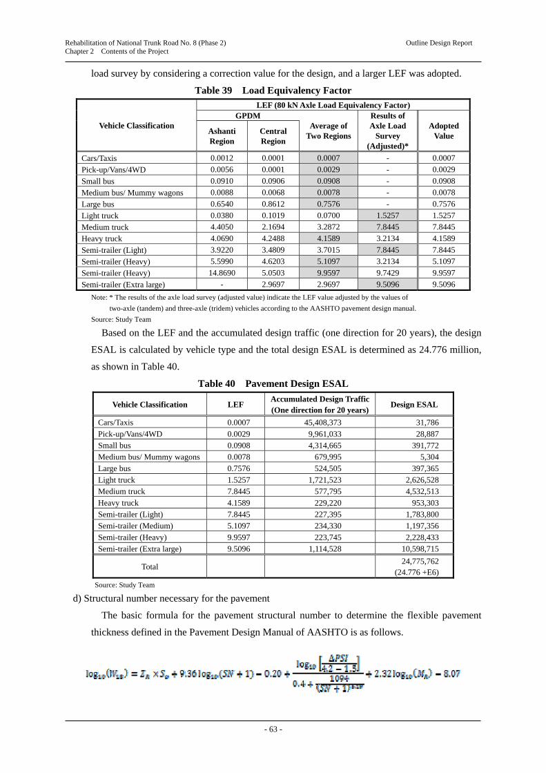
Rehabilitation of National Trunk Road No. 8 (Phase 2) Outline Design Report Chapter 2 Contents of the Project
- 63 -
load survey by considering a correction value for the design, and a larger LEF was adopted.
Table 39 Load Equivalency Factor
Vehicle Classification
LEF (80 kN Axle Load Equivalency Factor) GPDM
Average of Two Regions
Results of Axle Load
Survey (Adjusted)*
Adopted Value
Ashanti Region
Central Region
Cars/Taxis 0.0012 0.0001 0.0007 - 0.0007
Pick-up/Vans/4WD 0.0056 0.0001 0.0029 - 0.0029
Small bus 0.0910 0.0906 0.0908 - 0.0908
Medium bus/ Mummy wagons 0.0088 0.0068 0.0078 - 0.0078
Large bus 0.6540 0.8612 0.7576 - 0.7576
Light truck 0.0380 0.1019 0.0700 1.5257 1.5257
Medium truck 4.4050 2.1694 3.2872 7.8445 7.8445
Heavy truck 4.0690 4.2488 4.1589 3.2134 4.1589
Semi-trailer (Light) 3.9220 3.4809 3.7015 7.8445 7.8445
Semi-trailer (Heavy) 5.5990 4.6203 5.1097 3.2134 5.1097
Semi-trailer (Heavy) 14.8690 5.0503 9.9597 9.7429 9.9597
Semi-trailer (Extra large) - 2.9697 2.9697 9.5096 9.5096
Note: * The results of the axle load survey (adjusted value) indicate the LEF value adjusted by the values of
two-axle (tandem) and three-axle (tridem) vehicles according to the AASHTO pavement design manual.
Source: Study Team
Based on the LEF and the accumulated design traffic (one direction for 20 years), the design
ESAL is calculated by vehicle type and the total design ESAL is determined as 24.776 million,
as shown in Table 40.
Table 40 Pavement Design ESAL
Vehicle Classification LEF Accumulated Design Traffic (One direction for 20 years)
Design ESAL
Cars/Taxis 0.0007 45,408,373 31,786
Pick-up/Vans/4WD 0.0029 9,961,033 28,887
Small bus 0.0908 4,314,665 391,772
Medium bus/ Mummy wagons 0.0078 679,995 5,304
Large bus 0.7576 524,505 397,365
Light truck 1.5257 1,721,523 2,626,528
Medium truck 7.8445 577,795 4,532,513
Heavy truck 4.1589 229,220 953,303
Semi-trailer (Light) 7.8445 227,395 1,783,800
Semi-trailer (Medium) 5.1097 234,330 1,197,356
Semi-trailer (Heavy) 9.9597 223,745 2,228,433
Semi-trailer (Extra large) 9.5096 1,114,528 10,598,715
Total
24,775,762 (24.776 +E6)
Source: Study Team
d) Structural number necessary for the pavement
The basic formula for the pavement structural number to determine the flexible pavement
thickness defined in the Pavement Design Manual of AASHTO is as follows.

Rehabilitation of National Trunk Road No. 8 (Phase 2) Outline Design Report Chapter 2 Contents of the Project
- 64 -
where: W18: Number of 18kip single axle load applications (Design ESAL) ZR: Standard normal deviation corresponding to selected reliability (R = reliability) SO: Overall standard deviation MR: Roadbed soil resilient modulus (psi) ∆PSI: Design serviceability loss between the default design serviceability index (P0) and
the ultimate design serviceability index (PT) SN: Structural number
Table 41 Structural Number Necessary for Pavement
Item Section A Section B Section C Section D Section E Section F
W18 (million ESAL) 24.776 R (%) 90
ZR -1.282 SO 0.45
MR (psi) 19,575 32,770 29,870 22,620 17,545 24,360 PO 4.2 PT 2.5 ∆PSI 1.7
SN 4.06 3.36 3.48 3.86 4.24 3.76
Source: Study Team
e) Pavement thickness
The minimum pavement thicknesses estimated from the above calculations are shown in
Table 42.
Table 42 Minimum Pavement Thicknesses
Design ESAL AC Course Aggregate Base Course
50,001 – 150,000 50 (2.0) 150 (6.0)
150,000 – 1,000,000 50 (2.0) 150 (6.0)
1,000,000 – 2,000,000 50 (2.0) 200 (8.0)
2,000,000 – 5,000,000 76 (3.0) 200 (8.0)
5,000,000 – 9,000,000 102 (4.0) 200 (8.0)
Source: GPDM
The coefficients of the planned pavement layers are calculated as shown in Table 43.
Table 43 Coefficients of Planned Pavement Layers
Wearing Course (Dense-grade AC)
Binding Course (Coarse-grade AC)
Base Course (Crushed Stone)
Base Course (Recycled Base)
Sub-base Course(Crusher-run)
0.44 0.34 0.14 0.22 0.08
Source: Study Team
In addition, the coefficients of the existing pavement layers are shown in Table 44.
Based on these results, the pavement thicknesses of the planned recycled base course section
are calculated as shown in Table 45. The pavement thicknesses of sections to raise the level of
the road are calculated as shown in Table 46.

Rehabilitation of National Trunk Road No. 8 (Phase 2) Outline Design Report Chapter 2 Contents of the Project
- 65 -
Table 44 Coefficients of Existing Pavement Layers
Section Coefficient of Pavement Layer
Wearing and Binding Course (AC)
Base Course (Crushed Stone)
Sub-base Course (Natural Gravel)
A 0.31 0.14 0.14 B 0.44 0.14 0.14 C 0.44 0.14 0.14 D 0.44 0.14 0.14 E 0.37 0.14 0.14 F 0.39 0.14 0.14
Source: Study Team (based on the results of FWD test)
Table 45 Planned Pavement Thicknesses of Recycled Base Course Section
Item A B C D E F
Wearing course (cm) Dense-grade AC 5 5 5 5 5 5 Binding course (cm) Coarse-grade AC 8 5 5 5 5 5
Recycled base course (cm) Cement or bitumen stabilised
20 20 20 20 22 20
Sub-base course cm Crusher run (existing) 10 25 19 16 15 27
Pavement thickness (cm) 43 55 49 46 47 57
Required pavement structural number SN 4.06 3.36 3.48 3.86 4.24 3.76 Design pavement structural number SN 4.22 4.92 5.20 4.15 4.28 4.76
Judgement (Structural number) OK OK OK OK OK OK
Source: Study Team
Table 46 Planned Pavement Thicknesses of Sections to Raise the Level of the Road
Section A B C D E F
Wearing course (cm) Dense-grade AC 5 5 5 5 5 5 Binding course (cm) Coarse-grade AC 10 5 5 5 10 5 Base course (cm) Crushed stone 20 20 20 20 20 20 Sub-base course (cm) Crusher run 30 30 30 40 30 40
Pavement thickness (cm) 43 60 60 70 65 70
Required pavement structural number SN 4.06 3.36 3.48 3.86 4.24 3.76 Design pavement structural number SN 4.25 3.58 3.58 3.90 4.25 3.74
Judgement (Structural number) OK OK OK OK OK OK
Source: Study Team
(4) Design of Intersection
a) Intersections to be considered
There are three regional roads
connecting to the N8: R81 at Assin Fosu,
R83 at Assin Nyankomase and R83 at
Assin Brofovedure. Other than regional
roads, 37 feeder roads and community
roads connect to the N8, as shown in
Figure 18 and Table 47.
Based on the present condition, every
regional, feeder and community road
connecting to the N8 is planned to be a
3-leg intersection, except for three feeder
roads which will connect to the planned Source: Study Team
Figure 18 Regional Roads Connecting to the N8 in the Section for the Outline Design

Rehabilitation of National Trunk Road No. 8 (Phase 2) Outline Design Report Chapter 2 Contents of the Project
- 66 -
roundabouts in the centre of Assin Fosu township.
Table 47 List of Planned Intersections in the Project Area
Location (KM) Shape of Intersection Note Location (KM) Shape of Intersection Note
0+728 Roundabout (4-legs) 14+824 3-leg intersection
0+943 3-leg intersection 15+102 3-leg intersection
1+068 3-leg intersection 16+563 3-leg intersection
1+233 3-leg intersection R81 16+603 3-leg intersection
1-405 3-leg intersection 17+095 3-leg intersection
1+554 3-leg intersection 17+648 3-leg intersection
1+762 3-leg intersection 17+658 3-leg intersection
1+774 3-leg intersection 18+297 3-leg intersection
1+876 Roundabout (4 legs) 22+247 3-leg intersection
1+900 3-leg intersection 23+672 3-leg intersection
2+152 3-leg intersection 24+394 3-leg intersection
2+719 3-leg intersection 26+953 3-leg intersection
2+777 3-leg intersection 27+919 3-leg intersection
3+326 3-leg intersection 29+190 3-leg intersection
6+556 3-leg intersection 29+450 3-leg intersection
8+555 3-leg intersection 30+834 3-leg intersection
8+671 3-leg intersection R83 30+882 3-leg intersection
10+960 3-leg intersection 31+009 3-leg intersection
11+628 3-leg intersection R83 31+032 3-leg intersection
12+880 3-leg intersection
Source: Study Team
b) Roundabout
1) Reason for constructing roundabouts
The Study Team planned a roundabout at each end of the dualised four-lane section in the
centre of Assin Fosu township, based on the strong recommendation of the GHA. This
recommendation is not only to allow U-turns by vehicles, particularly taxis and mini-buses, but
also because: 1) roundabouts are far safer than signalised intersections; in particular, the
frequency and severity of accidents at roundabouts are far lower based on traffic observations,
and 2) signalised intersections might not function all the time due to power outages, causing
inconvenience especially to motorists.
2) Specifications of the roundabout
The major specifications for the roundabout design are as follows:
To provide two-lanes for the circulating lanes.
To provide 100 m of storage length for the approach lanes, and 50 m of transition length
(tapered length) to increase the lane, at the transition between four-lanes and two-lanes.
To provide 50 m of parallel section for the exit lanes, and 100 m of transition length to
decrease a lane (the rate of transition to decrease a lane is 1/30).
To provide two-lanes with a length of 70 m for the exit of a roundabout to the cross road,
and 50 m of transition length.
The design vehicles for a roundabout are a semi-trailer for the traffic from/to a main road, a
truck for the traffic from a main road to a cross road, and a truck for U-turn traffic.

Rehabilitation of National Trunk Road No. 8 (Phase 2) Outline Design Report Chapter 2 Contents of the Project
- 67 -
Figures 19 and 20 show drawings of the roundabouts planned to be installed at both ends of
the dualised section.
Source: Study Team
Figure 19 Planned Roundabout at the Start of the Dualised Section (KM 0+700)
Source: Study Team
Figure 20 Planned Roundabout at the End of the Dualised Section (KM 1+900)

Rehabilitation of National Trunk Road No. 8 (Phase 2) Outline Design Report Chapter 2 Contents of the Project
- 68 -
c) Other intersections
The specifications for intersections other than roundabouts mentioned above are 3-leg
intersections; 10 m from the edge of the N8 carriageway is planned to be paved by the same
pavement structure, as shown in Figure 21.
(5) Retaining Wall
In order to minimise the effect on permanent structures along the road, the Study Team plans
to install small gravity type retaining walls near permanent structures.
(6) Bus Stop
The Study Team plans to construct a bus stop at each community along the N8. The
specifications of the bus stops are as follows:
According to the design standard of the GHA, the bus bays are cement concrete pavement.
The structure of the pavement is 20 cm of concrete slab and 15 cm of base course (well
graded crushed stone).
The bus bays will be constructed in a staggered arrangement, as shown in Figure 22 with a
mounted-up type (hump) pedestrian crossing installed between two bus bays.
The locations of communities where a bus stop will be constructed are shown in Figure 23.
(7) Steps
In order to secure access from houses and commercial facilities to the Project road, the Study
Team plans to install steps where required.
(8) Toll-plaza facility
The Study Team plans to install a toll-plaza at the south of Assin Praso township, which will
collect tolls only from vehicles travelling north. According the results of future traffic
projections, the ADT in 2038 at this location is 2,325 veh./day, consisting of 69 buses/day, 238
trucks/day, and 312 semi-trailers/day.
Source: Study Team
Figure 21 Specification of Standard Type 3-leg Intersection

Rehabilitation of National Trunk Road No. 8 (Phase 2) Outline Design Report Chapter 2 Contents of the Project
- 69 -
These traffic volumes of large-size vehicles are used for the design of the pavement; the
pavement structure of the inter-locking block pavement is calculated as follows:
Inter-locking block: Standard type (8 cm thickness)
Sand 2 cm
Base course (cement stabilised): 20 cm
Sub-base course: 40 cm
This inter-locking block pavement is used only on the northbound carriageway.
(9) Median
For the dualised four-lane section at the centre of Assin Fosu township, the Study Team plans
to install a “New Jersey Style Median Barrier”, which is widely used in Ghana, in order to
minimise the width of the median in the urban area. In addition, the Study Team plans to install
guard fence on the median in order to prevent disorderly crossing of the road by pedestrians.
(10) Guardrails
Guardrails are required where there is a high embankment of more than 3 m and at other
necessary sections. Guardrails are located at the outside shoulders of 2.5 m.
(11) Pedestrian Crossing on Hump
The speed of vehicles travelling through populated areas is likely to be one of the most
important safety issues; one of the main problems will be conflict between vehicles and
pedestrians, so driving speed of vehicles should be reduced. This should be done by using speed
humps and/or a raised carriageway with pedestrian crossings. Humps should be used on roads
with a speed limit of 50 km/h or less through towns or village areas with many pedestrians on
the roads. The humps should be constructed as trapezoidal humps (4.0 m in width and 75 mm in
Source: Study Team
Figure 23 Locations of Communities where a Bus Stop Will Be Constructed
Source: Study Team
Figure 22 Arrangement of Bus Bays

Rehabilitation of National Trunk Road No. 8 (Phase 2) Outline Design Report Chapter 2 Contents of the Project
- 70 -
height) at pedestrian crossings.
(12) Road Signs and Pavement Markings
The following road signs will be placed in appropriate locations:
Danger Warning signs such as Hump Ridge, Pedestrian Crossing, and Crossing Road
Regulatory signs such as Maximum Speed Limit
Mandatory signs such as Give Way (major road ahead)
Guidance signs such as destination directions
Appropriate pavement markings are provided to control traffic movement, and to warn and
guide motorists and pedestrians. Generally, a broken guiding line is provided as a centreline
where the sight distance is adequate. Where the sight distance is inadequate, a continuous full
marked centreline is provided. Edge line markings are also provided on both sides of the road.
In addition, overhead type guide signs with gate type support, as shown in Figure 24, will be
installed near the railway underpass bridge at Assin Fosu and a toll plaza at Assin Praso.
(13) Delineator
The Study Team plans to install delineators at curve sections where visual guidance for
drivers is necessary at night, by putting reflective material or painting reflective paint either on
guide posts or guard rails.
(14) Street Lighting
The Study Team plans to install street lightings at sections shown in Table 48. The lighting
system consists of a pole with light-emitting diodes (LED) as the light source, which has a long
operating life.
Source: Study Team
Figure 24 Overhead Type Guide Signs with Gate Type Support

Rehabilitation of National Trunk Road No. 8 (Phase 2) Outline Design Report Chapter 2 Contents of the Project
- 71 -
Table 48 Locations of Street Lighting
Sections with Continuous Lighting
Sections where street lightings are installed at present 3,850 m
a) Dualised four-lane section (install at the centre) KM 0+750 – KM 1+830
b) two-lane section (install at one side) KM 0+0 – KM 0+680 KM 1+930 – KM 3+850
Sections with Spot Lighting
Roundabout (2 locations) Near KM 0+680 – KM 0+780
Near KM 1+830 – KM 1+930
Toll-plaza (1 location) Near KM 30+100
Okyi River Bridge 2 sets (solar type street light)
Source: Study Team
(15) Pedestrian Overpass Bridge
As a median with a guard fence to prevent random crossing will installed on the dualised
four-lane section in the centre of Assin Fosu township, it is necessary to provide ways for
pedestrians to cross the Project road. Therefore, the Study Team plans to construct one
pedestrian overpass bridge in front of New Assin Fosu market, to secure the safety of
pedestrians when crossing the road. In addition, two at-grade pedestrian crossings are also
planned at about 300 m on each side of the pedestrian overpass bridge to avoid splitting the
community of Assin Fosu township. The outline of the pedestrian overpass bridge is as follows:
Location of overpass bridge: KM 1+270
Structure: Steel pedestrian overpass bridge
Width: On the pedestrian bridge: 2.10 m, Steps with a slope: 2.10 m, Steps: 1.50 m
Clearance under the girder: 5.95 m (construction gauge of GHA 5.50 m + clearance)
2-2-2-2-2 Drainage Facilities
(1) Drainage Plan
The Study Team used the probable design return period of precipitation shown in Table 49
when preparing the drainage plan, according to the Ghana Road Design Guide, 2009.
Table 49 Probable Design Return Period of Precipitation
Drainage Facility Probable Design Return
Period of Precipitation Note
Road drainage, side ditches, etc. 5 years
Box culvert, pipe culvert 15 years Conducted sensitivity analysis for return period of 25 years
Source: Ghana Road Design Guide, 2009
The Study Team measured the catchment area of each river used for the flow calculation from
1:50,000 scale topographical maps. Then, the inlet time was calculated based on the catchment area
by the following equation:
where:
tc: Inlet time (minutes) L: Flow length (km)

Rehabilitation of National Trunk Road No. 8 (Phase 2) Outline Design Report Chapter 2 Contents of the Project
- 72 -
A: Catchment area (km2) Se: Gradient of flow channel (m/km)
(2) Box Culverts for Drainage
Table 50 shows the installation plan for box culverts for drainage. The inner cross-section of the
box culverts that change in cross-sectional shape is calculated by comparing the maximum discharge
volume Q15y (15-year rainfall intensity) and the allowable quantity of flow Q80% (80% of depth),
and sensitivity analysis by comparing the maximum discharge volume Q25y (25-year rainfall
intensity) and the allowable quantity of flow Q100% (100% of depth).
Table 50 Installation Plan for Box Culvert
Location (KM) Cross-Section (Inner Section) Note
0 + 196 1 - 2.0m × 2.0m Extension of existing box culvert
2 + 478 1 - 3.0m × 2.0m New installation (Change from a pipe culvert)
6 + 546 1 - 2.0m × 2.0m New installation (Change from a pipe culvert)
8 + 93 1 - 3.0m × 2.5m New installation (Change cross-sectional shape)
11 + 127 1 - 2.0m × 2.0m New installation (Change from a pipe culvert)
12 + 255 1 - 4.0m × 4.0m Extension of existing box culvert
16 + 198 2 - 3.5m × 3.5m New installation (Change cross-sectional shape)
22 + 463 2 - 3.0m × 3.0m Extension of existing box culvert
26 + 527 1 - 2.5m × 2.5m Extension of existing box culvert
28 + 861 1 - 2.5m × 2.5m New installation (Change cross-sectional shape)
Note: The culverts that are changed from pipe culverts are based on the request of the GHA.
Source: Study Team
(3) Pipe Culverts for Drainage
Table 51 shows the installation plan for concrete pipe culverts for drainage.
Table 51 Installation Plan for Pipe Culverts
Location (KM)
Cross Section (mm)
Location (KM)
Cross Section (mm)
Location (KM)
Cross Section (mm)
1 + 147 1-φ1000 9 + 550 1-φ1000 20 + 300 1-φ1000
1 + 310 1-φ1000 10 + 176 1-φ 900 20 + 400 1-φ1000
1 + 372 1-φ1000 10 + 419 1-φ 900 20 + 750 1-φ1000
1 + 889 1-φ1000 11 + 830 1-φ1000 21 + 389 1-φ1000
2 + 165 1-φ1200 13 +0 20 1-φ1000 22 + 563 2-φ1200
2 + 619 1-φ1000 13 +089 1-φ1000 23 +011 1-φ1000
2 + 975 1-φ1000 13 + 595 1-φ1000 23 + 486 2-φ1200
3 + 745 1-φ1000 14 +063 1-φ1200 23 + 950 1-φ 900
4 + 293 1-φ1000 14 + 409 1-φ1000 24 + 752 1-φ1500
4 + 562 1-φ 900 14 + 725 1-φ1000 25 + 872 1-φ1000
4 + 902 1-φ 900 15 + 305 1-φ 900 27 + 165 1-φ1200
5 + 665 1-φ1000 17 +002 2-φ1000 27 + 541 1-φ1000
6 + 223 1-φ1000 17 + 869 1-φ1200 27 + 666 1-φ1000
7 + 709 1-φ1000 18 + 412 1-φ 900 30 +035 1-φ1000
8 + 830 1-φ1000 19 + 253 1-φ1500 31 +190 1-φ1000
Source: Study Team
(4) Roadside Ditches
Roadside ditches with dimensions of 0.7 m × 0.7 m will be installed by the cast-in-place
method at suitable locations in a community.

Rehabilitation of National Trunk Road No. 8 (Phase 2) Outline Design Report Chapter 2 Contents of the Project
- 73 -
There are no side ditches along the existing road outside of communities at present.
However, the Study Team plans to install U-shape precast ditches at locations where water
drainage at the toe of slopes is necessary, such as at sag sections, to raise the road level.
Side ditches will be installed at locations where surface damage was identified by the road
damages survey (including the sections mentioned above where the road level will be
raised).
Side ditches will be installed at locations where deflection of road structures was
particularly large according to the results of the FWD survey.
L-shape side ditches will be installed for the mount-up curb on the dualised four-lane
section, and L-shape ditches and side ditches at the toe of slopes will be connected at
intervals of about 30 m by vertical ditches.
In order to prevent pooling of rain water beside the concrete barrier of the median at
locations with cant on the dualised four-lane section, drain holes will be installed at intervals
of about 20 m to 30 m.
2-2-2-2-3 Design of Box Culvert for the Railway Underpass
(1) Study of Cross-section of the Box Culvert
As shown in Figure 5, the inner cross-section of the box culvert for the railway underpass
bridge was determined according to the construction gauge required by the GRDA.
Furthermore, considering the live
load of a locomotive on the railway
track and the live load of vehicles
on the top slab, the cross-section of
the box culvert is determined as
shown in Figure 25. The
assumptions are that PC sleepers are
used and ballast of crushed stone is
laid on the bottom slab of the box
culvert.
(2) Position to Construct the Box Culvert
Based on the discussion with
the GRDA, the horizontal position of the expected centre line of the box culvert is planned to be
the same as that of the existing railway track. Also, the vertical alignment of the top of the rail
of the expected track in the box culvert is planned to be flush with the top of the rail of the
existing railway track.
(3) Geological Condition under the Box Culvert
According to the results of the geotechnical investigation, the geological condition of the soil
under the box culvert is a relatively hard layer, hence the box culvert is planned to be direct
Source: Study Team
Figure 25 Cross-section of the Box Culvert for the Railway Underpass

Rehabilitation of National Trunk Road No. 8 (Phase 2) Outline Design Report Chapter 2 Contents of the Project
- 74 -
foundation.
(4) Earth covering of the box culvert
The thickness of earth covering of the box culvert will directly affect the vertical alignment
of the road in the rehabilitation section. The Study Team discussed this with the Bridge Division
of the GHA, and the thickness of earth covering is planned so as to secure the thickness of the
base course, in order to avoid effects on the vertical alignment of the road rehabilitation section,
as shown in Figure 26.
Source: Study Team
Figure 26 Relation between the Box Culvert for Railway Underpass and Cross Section of N8
(5) Stage Construction Plan
Based on the results of site observation, there is no appropriate road that can be used as a
detour around the existing railway underpass bridge in Assin Fosu. In a case to reconstruct
two-lane bridge, it is necessary to allow traffic to flow, such as by providing a temporary bridge.
However, the rehabilitation of the N8 in the centre of Assin Fosu township is planned to widen
the road to four-lanes, including reconstruction of the railway underpass bridge. Therefore, the
Study Team has planned the stage construction method by utilising the existing railway
underpass bridge, without a temporary bridge, as shown in Figure 27.
2-2-2-3 Reconstruction of Okyi River Bridge (Assin Andoe)
(1) Typical Cross-Section
Typical cross-sections of the bridge and approach roads are planned as shown in Figure 28.
(2) Horizontal Alignment
As described in the Basic Policy, it is desirable to reconstruct the bridge at the same position
as the existing four continuous box culverts, considering the horizontal alignment of approach
roads on both sides of the existing box culverts.
(3) Hydraulic Condition
The design flood discharge was estimated as 342.64 m3/s based on the following conditions:
Catchment area: 367.11 km2
Probable return period of precipitation: 50 years (bridge)
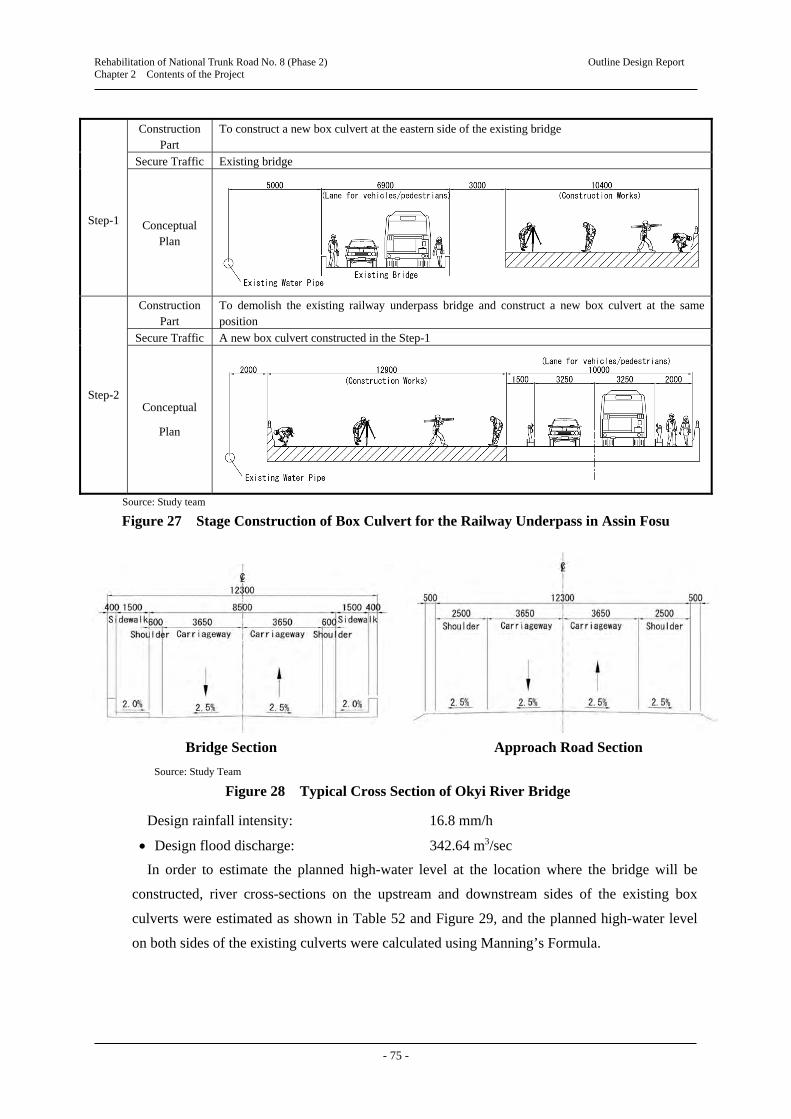
Rehabilitation of National Trunk Road No. 8 (Phase 2) Outline Design Report Chapter 2 Contents of the Project
- 75 -
Step-1
Construction Part
To construct a new box culvert at the eastern side of the existing bridge
Secure Traffic Existing bridge
Conceptual Plan
Step-2
Construction Part
To demolish the existing railway underpass bridge and construct a new box culvert at the same position
Secure Traffic A new box culvert constructed in the Step-1
Conceptual
Plan
Source: Study team
Figure 27 Stage Construction of Box Culvert for the Railway Underpass in Assin Fosu
Design rainfall intensity: 16.8 mm/h
Design flood discharge: 342.64 m3/sec
In order to estimate the planned high-water level at the location where the bridge will be
constructed, river cross-sections on the upstream and downstream sides of the existing box
culverts were estimated as shown in Table 52 and Figure 29, and the planned high-water level
on both sides of the existing culverts were calculated using Manning’s Formula.
Bridge Section Approach Road Section
Source: Study Team
Figure 28 Typical Cross Section of Okyi River Bridge

Rehabilitation of National Trunk Road No. 8 (Phase 2) Outline Design Report Chapter 2 Contents of the Project
- 76 -
Table 52 Results of Hydraulic Analysis of Upstream (Cross-section A) and Downstream (Cross-section B) Sides
Item Cross-section (1) Cross-section (2)
Cross-section A m2 124.7 132.1
Water depth H m2 4.75 5.05
Hydraulic mean depth R m2 2.97 3.08
Multiplier n 0.035 0.035
Channel gradient i % 0.22 0.19
Current velocity v m/s 2.77 2.63
Flow rate Q m3/s 345 348
Note: The river cross-sections (1) and (2) are estimated as a river-bed width of 12 m with gradient of 1:3, and a
river-bed width of 11 m with gradient of 1:3, respectively.
Source: Study Team
H=5.05m H=4.75m
HWL 94.850
Section A
HWL 94.650
Bridge
I=0.22% I=0.71%I=0.19%
HWL 94.736
H= 95.810 ▼ ▼ ▼
High Water Level
Average Height ofRiver Bed
Existing River Bed
H=4.94m
Section B
m Source: Study team
Figure 29 Channel Gradient and High-water Level
As a result, the high-water level at the bridge site is determined as H = 94.736 m, based on
the estimated high-water level on the upstream side as H = 94.850 m and on the downstream
side as H = 94.850 m.
Estimated high-water level at the planned bridge site: HWL = 94.736 m
Then, the water discharge capacity at the bridge site is calculated as 391 m3/s, which exceeds
the design flood discharge of 343 m3/s, as shown in Table 53.
Table 53 Water Discharge Capacity at Bridge Site
Item Bridge Location Note
Cross-section A m2 78.6 Excluding bridge cross-section
Water depth H m2 4.94
Hydraulic mean depth R m2 2.97
Multiplier n 0.035
Channel gradient i % 0.71
Current velocity v m/s 4.98
Flow rate Q m3/s 391 > 343 OK
Source: Study Team
(4) Method to Determine the Span Length
Figure 30 shows the process of determining the span length.

Rehabilitation of National Trunk Road No. 8 (Phase 2) Outline Design Report Chapter 2 Contents of the Project
- 77 -
Source: Study Team
Figure 30 Process to Determine the Span Length of the Bridge
As a result of this process, the span length of the Okyi River Bridge is determined as shown
in Table 54.
Table 54 Span Length of Okyi River Bridge
Item Okyi River Bridge
Classification of road National Road
Important river No
Design flood discharge Q (m3/sec) 343
Q 2000 m3/s No
Problem for river management No
Q 500 m3/s No
River width 30 m or more No
Standard span length L 12.5 m
Determined span length 12.5 m
Source: Study Team
At this stage, a single span prestressed concrete (PC) bridge could be considered as an
alternative to eliminate obstruction of the river cross section by suspended objects. However,
this PC bridge requires an erection girder and the construction cost is estimated to be 35%
higher than a 2-span RC bridge, thus a single span PC bridge is judged to be inappropriate for
this bridge.
Start
Expressway?
Q 2,000 m3/s? Q 2,000 m3/s?
Important river?
Problem for river management?
Q 500 m3/s?
River width 30 m?
L 12.5m L 15m L 20m L 20m + 0.005Q
No No
No
Yes Yes
No
Yes
Yes No
Yes
No
No
Yes
Yes
L: Span length (m) Q: Design flood discharge (m3/sec)

Rehabilitation of National Trunk Road No. 8 (Phase 2) Outline Design Report Chapter 2 Contents of the Project
- 78 -
(5) Selection of Bridge Type
a) Selection of superstructure type
According to the determined span length of the bridge (L = 12.5 m), three alternative types of
bridge and their suitability for the construction conditions in Ghana are compared, as shown in
Table 55.
Table 55 Comparison of Alternative Superstructure Types
Alternative Evaluation Judgement
Alternative 1
2-Continuous Box
Culvert
Selected as an alternative because it is the same type as the existing structure. It exceeds the general applicable maximum span (10 m). The scale of structure becomes very large as a box culvert. Hence, it is necessary
to consider the effects of variations of temperature and drying shrinkage, which are not considered in the ordinary design.
River diversion works are complicated, since concrete for the sole plate of a box culvert is placed on the riverbed.
Not
applicable
Alternative 2
2-span Continuous
Portal Rigid-frame RC
Slab Bridge
Selected as an alternative to omit void pipes, which is an issue for construction, of a hollow slab type bridge.
In order to supplement the reduced applicable span length due to omission of void pipes, a pier and superstructure are combined to allow a span length of 12.5 m.
The structure could be excessively affected by variations of temperature and drying shrinkage, since it is a rigid-frame structure.
In order to minimise the effects of variations of temperature and drying shrinkage, the substructure becomes excessively large.
Not
applicable
Alternative 3
2-span Continuous
T-Girder Rigid-frame
RC Slab Bridge
Selected as an alternative to omit void pipes, which is an issue for construction of a hollow slab type bridge.
In order to supplement the reduced applicable span length due to omission of void pipes, a pier and superstructure are combined to allow a span length of 12.5 m.
In order to solve the structural problems of Alternative 2, effects of variations of temperature and drying shrinkage are eliminated by installing movable shoes on abutments.
As the space between substructures can be used as a river diversion watercourse, river diversion work is easy.
Applicable
Source: Study Team
As a result of comparison, Alternative 3, a 2-span continuous T-girder rigid-frame RC slab
bridge, is selected as a suitable type of bridge, which has the structural capability for expansion
and contraction of the superstructure with variations of temperature and drying shrinkage, and
better workability in the river.
b) Selection of substructure type
A suitable type of substructure can be determined from the relation between the height of
each substructure, as shown in Table 56.
As for the abutments, their height is about 7.5 m, hence the reverse T-style abutment, which
is a commonly used abutment type, is selected.
As for the pier, either a column (1) or rigid-frame (2) pier, which is rectangular in section, is
not desirable because the pier is constructed in the river. Also, a pile bent type pier (3) is not
desirable because of the necessity of measures against scouring. Hence, the elliptical type
pier (4) is selected, even though the height of the pier is slightly shorter than the applicable
range.

Rehabilitation of National Trunk Road No. 8 (Phase 2) Outline Design Report Chapter 2 Contents of the Project
- 79 -
Table 56 Comparison of Substructure Types
Substructure type Applicable height (m)
Characteristics 10 20 30
Abu
tmen
t
Gravity type With shallow support ground, the gravity
type is suitable for direct foundations.
Reverse T-style Used in many bridges. Suitable for direct
foundations and pile foundations.
Buttressed type Suitable for tall abutments.
Rigid frame type Suitable for tall abutments and
construction of a road behind an abutment
Box type Suitable for tall abutments with soft
bearing layer in order to reduce vertical load
Pie
r
Column type Economical for a relatively high pier.
It may obstruct water discharge during a flood.
Rigid-frame type It is applicable for a relatively tall
and wide bridge. It may obstruct water discharge during a flood.
Pile bent type
Most economical type of pier, but it is not applicable for a bridge with a large horizontal force. Also, it is necessary to consider measures against scouring in the river.
Elliptical type It is applicable for a high pier with
large external force for a bridge. Source: Study Team
c) Foundation type
According to the result of the geotechnical investigation just beside the existing 4-continuous
box culverts, as shown in Figure 31, the bearing layer (rock layer) was found at the riverbed of
the existing Okyi River. Hence, the direct foundation, which is the most economical type, is
selected.
Source: Study Team
Figure 31 Result of Geotechnical Investigation beside the Existing 4-continuous Box Culvert
d) Pavement on the bridge deck
Hot-mixed AC pavement with a thickness of 8 cm is planned to be applied on the bridge

Rehabilitation of National Trunk Road No. 8 (Phase 2) Outline Design Report Chapter 2 Contents of the Project
- 80 -
deck.
(6) Planning of Approach Roads of the Bridge
a) Vertical alignment plan
The Study Team has determined the vertical alignment of the approach roads of the planned
bridge (bridge length 25 m, abutment positions KM 1+585 and 1+835) in order to minimise the
effects for houses along the road. A clearance of 1.0 m under the bridge girders above the
design high-water level (H = 94.736 m) is secured.
b) Pavement design
Table 57 shows the present and future traffic volumes on the N8 at Assin Andoe village
based on the results of future traffic demand forecasts.
Table 57 Average Daily Traffic Volume by Vehicle Type at Assin Andoe (unit: veh./day)
Vehicle Classification of GHA Present Future
2013 2038
1 Cars/Taxi 1,338 2,900
2 Pick-up/Vans/4WD 1,200 2,599
3 Small bus 490 880
4 Medium bus/ Mummy wagons 50 85
5 Large bus 91 208
6 Light truck 134 262
7 Medium truck 91 179
8 Heavy truck 39 73
9 Semi-trailer (Light) 3 3
10 Semi-trailer (Medium) 40 90
11 Semi-trailer (Heavy) 42 94
12 Semi-trailer (Extra large) 219 492
Total 3,737 7,865
Note: Traffic volume in the table is daily traffic volume at certain section for both directions.
Source: Study Team
The design ESAL is calculated by vehicle type and the total design ESAL is determined as
shown in Table 58.
Table 58 Pavement Design ESAL of Approach Roads of Okyi River Bridge
Vehicle Classification LEF Cumulative Design Traffic (One direction for 20 years)
Design ESAL
Cars/Taxi 0.0007 8,002,625 5,602
Pick-up/Vans/4WD 0.0029 7,184,843 20,836
Small bus 0.0908 2,595,150 235,640
Medium bus/ Mummy wagons 0.0078 249,113 1,943
Large bus 0.7576 562,465 426,123
Light truck 1.5257 749,528 1,143,555
Medium truck 7.8445 513,008 4,024,291
Heavy truck 4.1589 207,138 861,466
Semi-trailer (Light) 7.8445 10,950 85,897
Semi-trailer (Heavy) 5.1097 243,638 1,244,917
Semi-trailer (Heavy) 9.9597 255,683 2,546,526
Semi-trailer (Extra large) 9.5096 1,341,375 12,755,940
Total 23,352,736
(23.352+E6)
Source: Study Team

Rehabilitation of National Trunk Road No. 8 (Phase 2) Outline Design Report Chapter 2 Contents of the Project
- 81 -
The required structural numbers for the pavement based on the design ESAL are as shown in
Table 59.
Table 59 Structural Numbers for the Pavement for Approach Roads of Okyi River Bridge
Item Connection with existing road –
Road level raised by 30 cm* Road level raised by 30 cm – Connection with the bridge**
W18 (million ESAL) 23.353 R (%) 90
ZR -1.282 SO 0.45
MR (psi) 30,450 16,500 PO 4.2 PT 2.5 ∆PSI 1.7
SN 3.42 4.29
Note: * The elastic modulus of the section between the connection with the existing road and road level raised by
30 cm is based on the result of the FWD survey.
** The elastic modulus of the section between the road level raised by 30 cm and the connection with the bridge is
based on the result of laboratory tests of materials from a possible borrow pit.
Source: Study Team
The minimum pavement thickness of the approach roads of the bridge is estimated from the
above calculation results as shown in Table 60.
Table 60 Planned Pavement Thickness for the Approach Roads of the Bridge
Section Connection with existing road – Road level raised by 30 cm
Road level raised by 30 cm – Connection with the bridge
Wearing course (cm) Dense-grade AC 5 5 Binding course (cm) Coarse-grade AC 10 10 Base course (cm) Crushed stone 20 20 Sub-base course (cm) Crusher run 0 35 Existing base course Crusher run 32 -
Pavement thickness (cm) 67 70
Required pavement structural number SN 3.42 4.29 Design pavement structural number SN 4.32 4.41
Judgment (Structural number) OK OK
Note: The existing pavement (5 cm) of the section to be improved will be totally demolished.
Source: Study Team
(7) Basic Plan for Okyi River Bridge
Based on the above results of the study, the project to reconstruct the Okyi River Bridge is
summarised in Table 61, and the general plan of the bridge is shown in Figure 32.

Rehabilitation of National Trunk Road No. 8 (Phase 2) Outline Design Report Chapter 2 Contents of the Project
- 82 -
Table 61 Outline of Project to Reconstruct the Okyi River Bridge
Item Detail Contents or Quantity
Scope of the Project (1) Reconstruction of Okyi River Bridge (2) Rehabilitation of approach roads and abutment protection
Alignment Horizontal R = 630 m
Vertical Vertical gradient on the bridge = 1.5% - 1.74%
Structural Details
New bridge
Bridge length: L = 25.0 m Bridge width: W = 12.3 m Skew angle: θ = 0° Bridge surface area: A = 307.5 m2 Superstructure type: 2-spans Continuous T-Girder Rigid-frame RC Slab Bridge Superstructure erection method: Erection beam method Abutment: Two reverse T-style abutments, Height = 7.5 m Pier: One elliptical type pier, Height = 7.5 m Foundation: Direct foundation Pavement on bridge surface: A = 212.5 m2, Hot mixed AC pavement (t = 8.0 cm)
Approach roads
Total road width: W = 9.7 m Length: A1 abutment side = 178.5 m, A2 abutment side = 315.5 m Pavement of carriageway: Hot mixed AC pavement (t = 15 cm) Pavement of shoulder: Hot mixed AC pavement (t = 10 cm)
Approach cushion
Total width: W = 8.6 m Length: L = 5.0 m
Embankment protection
Position: Slope around the abutments Measure: Stacking gabions
Source: Study Team
Source: Study Team
Figure 32 General Plan of Okyi River Bridge
2-2-3 Outline Design Drawings
Based on the plan described above, the Study Team conducted the outline design. The outline
design drawings are listed in Table 62 and are attached in the Drawings.

Rehabilitation of National Trunk Road No. 8 (Phase 2) Outline Design Report Chapter 2 Contents of the Project
- 83 -
Table 62 Outline Drawings
Assin Fosu – Assin Praso (L = 31.2 km) Reconstruction of Okyi River Bridge
1 Location plan 1 Location plan
2 Horizontal and vertical alignment plans 2 Horizontal and vertical alignment plans
3 Typical cross-section 3 Typical cross-section
4 Intersection plans 4 General plan of bridge
5 General plan of toll-plaza 5 General plan of approach road
6 General plan of railway underpass 6 General plan of drainage facilities
7 General plan of box culverts 7 General plan of retaining wall
8 General plan of retaining wall 8 General plan of road safety devices
9 General plan of road safety devices 9 General plan of steps
10 General plan of steps 10 Detour plan (Reference)
11 General plan of bus stop
12 General plan of approach roads
13 General plan of street lightings
14 General plan of other ancillary works
15 General plan of pedestrian overpass bridge
Source: Study Team
2-2-4 Implementation Plan
2-2-4-1 Construction Policy/Procurement Policy
As the Project will be executed under the Grant Aid scheme of Japan, the construction policy
includes the following:
A realistic and reliable construction plan will be created by employing appropriate
construction methods in consideration of the geological, precipitation and inundation
conditions.
In order to help revitalise the regional economy, create job opportunities, and promote
technology transfer, it is desirable to maximise the utilisation of local engineers and
labourers, and local materials and construction equipment for the execution of the Project.
The GoG needs to complete the land acquisition of the ROW and resettlement prior to the
execution of the Project, as the responsibility of the recipient country. The GoG also needs
to secure land (for temporary buildings, detours, borrow pits, compensation for land and
agricultural products, and exploitation right of quarry site) after the commencement of the
construction work.
The GoG needs to arrange exemption from import taxes, domestic taxes, value added taxes,
etc. related to the execution of the Project, including for the procurement and import of
materials and construction equipment related to the construction works.
A network for close communication between the GHA, consultant and contractor must be
set up to enable the Project to proceed smoothly.
2-2-4-2 Important Considerations for Construction and Procurement
The important points to consider for the execution of the Project are shown below.

Rehabilitation of National Trunk Road No. 8 (Phase 2) Outline Design Report Chapter 2 Contents of the Project
- 84 -
(1) Safety during the Construction Period
The construction works should be carried out while minimising the effects on traffic. When
construction occupying one side of the existing road is unavoidable, the contractor should
assign traffic controllers and install appropriate signboards for the work, road signs and
traffic safety devices to prevent traffic accidents. The contractor should also secure a
passageway for pedestrians, and clearly demarcate the construction area to prevent outsiders
from entering it.
The contractor should assign traffic controllers at exits from temporary buildings and
borrow pits to an ordinary road.
The construction plan must take into consideration sudden inundation during the rainy
season, as it may be necessary to suspend the construction work.
The security situation in Ghana is relatively stable, but theft is rife. Therefore, the contractor
should assign guards at temporary buildings and construction equipment storage depots.
The contractor should encourage an attitude of safety among operators of construction
vehicles and equipment, and clearly instruct drivers to obey the speed limit for construction
vehicles.
(2) Environmental Protection during Construction
In order to suppress dust generation by construction vehicles and equipment, the contractor
should sprinkle water. It is also necessary to minimise the generation of dust by restricting
the speed of construction vehicles.
The contractor should avoid carrying out construction works in the early morning and at
night to minimise the impact on residents of noise and vibration caused by construction
equipment.
The contractor should conduct final disposal of concrete, waste oil, used tyres, and sludge
and sewage from construction yards.
The consultant should indicate items requiring compliance with environmental protection in
the construction specifications, and supervise the contractor to ensure compliance with those
items during the construction period.
(3) Compliance with the Labour Laws in Ghana
The contractor must comply with the present labour laws in Ghana, respect appropriate
working conditions and employment customs, avoid disputes with workers, and secure the
safety of workers.
(4) Construction Method of Recycled Cement and Asphalt Stabilised Base Course on the Road
This construction method is attracting most attention for technology transfer in the Project.
The method involves crushing the existing asphalt pavement, mixing it with the base course
together with cement and bitumen, and rolling-compacting them to form the base course. Since
this method requires precise quality control, construction equipment (stabiliser) should be
procured from outside Ghana, and an experienced operator from Japan or another country

Rehabilitation of National Trunk Road No. 8 (Phase 2) Outline Design Report Chapter 2 Contents of the Project
- 85 -
should operate the equipment. Also, the contractor should train Ghanaian operators, and should
consider organising observation tours for GHA engineers, local contractors, students studying
civil engineering, etc., since this method is new in Ghana.
2-2-4-3 Classification of Construction/Procurement and Installation
For the execution of the Project, the allocation of undertakings of the GoJ and GoG is as
shown below.
(1) Undertakings of the GoJ
1) Construction of the road rehabilitation works of the N8 between Assin Fosu and Assin Praso
with a length of about 32 km, as the Project for the cooperation programme, shown in the
“Basic Plan”
2) Reconstruction of the bridge at Assin Andoe (Okyi River Bridge)
3) Construction and demolition of temporary yard (site office, plant, etc.)
4) Assuring the safety of ordinary traffic and pedestrians during construction
5) Measures to prevent environmental pollution during the construction period
6) Procurement, import and transportation of construction materials and equipment indicated in
the “Construction materials and equipment procurement plan”, re-exportation of imported
construction equipment and temporary materials
7) Carrying out the detailed design, preparation of bidding and contract documents, assistance
for the tender process, and supervision of construction, indicated in the “Construction
supervision plan”, including monitoring of the environmental management plan
(2) Undertakings of the GoG
1) Acquisition and clearance of necessary lots of land (ROW, temporary site office, borrow pits)
and provision thereof to the Project without compensation, smooth resettlement of residents
and relocation of houses, shops and utilities (underground pipes and overhead lines) affected
by the Project
2) Issuance of identification cards to person related to the Project and stickers on vehicles used
for the construction.
3) Provision of a site for disposing of soil and construction debris near the Project road without
compensation
4) Ensuring exemption from customs duties, internal taxes and other fiscal levies imposed by
the GoG
5) Provision of logistical assistance for entering, staying and leaving Ghana for persons (from
Japan and other countries) related to the Project
6) Implementation of Banking Arrangements (B/A) (opening of an account, and preparation of
the Authorisation to Pay (A/P)), and bearing of commissions paid to the bank for banking
services (advisory commission of A/P and payment commission)

Rehabilitation of National Trunk Road No. 8 (Phase 2) Outline Design Report Chapter 2 Contents of the Project
- 86 -
2-2-4-4 Construction Supervision Plan and Procurement Management Plan
(1) Construction Supervision Plan
As the Project is to be executed with the Grant Aid scheme of Japan, the basic policy of the
construction supervision works should consider the following:
As the quality of construction works will affect the life and durability of completed
facilities, quality management is the most important issue, necessitating construction
supervision
Following quality management, controls on progress, safety, and payment are also important
issues.
In order to complete the Project within the contract period, the Contractor and the
Consultant should hold weekly meetings, and discuss problems and their solutions. Both
parties will also inspect the construction site.
The person in charge of the Client (GHA), the Contractor and the Consultant should hold a
monthly meeting at the site office, and discuss problems and their solutions. If there is a
problem that cannot be solved by the level of person in charge, the Contractor and the
Consultant will promptly hold a meeting with higher-level officials of the GHA, and request
the GHA to solve the problem.
As several works will be executed at several locations, the Consultant will assign
construction supervisors at each work location at a suitable timing. In addition, the
Consultant should employ local engineers as assistants, and will make efforts to transfer
technologies related to construction supervision such as controls on quality, progress, and
safety.
The Consultant should manage documentation, such as instructions to the Contractor,
records of minutes of every meeting, and reports to the Client. Every report to the Client and
the Contractor should be made in writing.
(2) Construction Supervision Works by Consultant
The major work items included in the contract with the consultant are described below.
a) Stage of preparation of tender documents
The Consultant will carry out the detailed design of each facility based on the Final Report of
the Preparatory Survey. Then, the Consultant will prepare the tender documents, and obtain
approval for the following deliverables:
Design report
Design drawings
Tender documents
b) Stage of tendering for construction
After the signing of the Exchange Note (E/N), the GHA (Client) will make a contract with
the Consultant for the construction supervision, and the Consultant will assist the GHA with the
tender procedure for construction works. At this time, the Client will be represented by the

Rehabilitation of National Trunk Road No. 8 (Phase 2) Outline Design Report Chapter 2 Contents of the Project
- 87 -
GHA. The GHA will select a construction company from Japan (Contractor) through a
competitive tender with a public announcement, with the assistance of the Consultant. The
representative selected by the GoG, who will attend the competitive tender and then the contract
signing for the construction works, should have authorisation for all matters related to the
contract for the construction. The Consultant will assist the GHA with the following works:
Public announcement of tender
Evaluation of prequalification (P/Q)
Opening of tenders and evaluation of tenders
Negotiation for the contract
c) Stage of construction supervision
Through the contract with the Contractor selected by the tender with the GHA, which is the
representative of the GoG, the Consultant will issue the order to start the work to the Contractor,
and will then commence the construction supervision works. In the construction supervision
works, the Consultant will directly report on the progress of construction works each month to
the GHA, the Embassy of Japan in Ghana and the JICA Ghana Office, and send a monthly
report to relevant authorities, if required. The Consultant will supervise construction and
suggest and propose improvement measures regarding management matters, such as work
progress, quality control, safety measures, and payment, and engineering matters related to
construction works.
Furthermore, the Consultant will conduct inspections for defects one year after completion of
the construction supervision works. The consulting service will terminate with this inspection.
(3) Staff Assignment Plan
Staffs necessary for the detailed design stage, tendering for construction works stage, and the
construction supervision stage, and their respective responsibilities are shown below.
a) Detailed design stage
1) Chief Consultant: Responsible for managing technical and administrative matters, and
responding to the Client regarding the detailed design.
2) Highway Engineer: In charge of the final calculation of the alignment of the whole section of
the Project road, determination of typical cross-section, study of slope works, preparation of
design drawings and quantity calculation.
3) Pavement Engineer: In charge of pavement design of the whole section of the Project road,
preparation of design drawings and quantity calculations.
4) Road Structure Engineer: In charge of design of road drainage structures for the whole
section of the Project road, preparation of design drawings and quantity calculation.
5) Bridge Engineer: In charge of design of the railway underpass box culvert at Assin Fosu, and
superstructure and substructure of the Okyi River Bridge, structural calculation, preparation
of design drawings and quantity calculation.
6) Construction Planning and Cost Estimation Engineer: In charge of preparation of

Rehabilitation of National Trunk Road No. 8 (Phase 2) Outline Design Report Chapter 2 Contents of the Project
- 88 -
construction plan, and estimation of the project cost based on the quantities in the detailed
design and unit construction cost.
7) Tender Document Specialist: In charge of preparing the tender documents.
b) Stage of tendering for construction
The Consultant will assist the GHA by finalising the P/Q document and tender documents,
conducting the P/Q evaluation, and evaluating the tender for the construction works.
1) Chief Consultant: Responsible for supervising consulting services for assisting the tendering
process.
2) Highway Engineer: In charge of approval of the tender documents and assisting the
evaluation of tenders.
c) Stage of construction supervision
1) Chief Consultant: Responsible for supervising consulting services for the construction
supervision (including supervising road earth works, drainage works and road ancillary
works).
2) Resident Engineer: Leader of the construction supervision at the site, and reporting and
coordinating the monthly progress of construction works to the related authorities of the
GoG.
3) Pavement Engineer: In charge of supervising pavement works.
4) Bridge Engineer: In charge of supervising earth works and concrete works of the railway
underpass culvert at Assin Fosu and the Okyi River Bridge.
2-2-4-5 Quality Control Plan
Based on the technical specifications and the construction supervision plan, the Consultant should
carry out several types of quality control and work progress control. The major work types are earth
works, pavement works and construction of structures. Therefore, the Consultant should carry out the
quality control for selection of materials and quality control at the construction sites, as listed in Table
63.

Rehabilitation of National Trunk Road No. 8 (Phase 2) Outline Design Report Chapter 2 Contents of the Project
- 89 -
Table 63 List of Quality Control Items (1)
Type Item Class Control Item Contents of Test/Control Inspection Timing/Frequency
Str
uctu
re
Concrete
Material
Cement Quality certificate Before construction and when
changing material Table of composition
Admixture for concrete Conformity with standard - ditto -
Water Content of toxic substance - ditto -
Fine aggregate
Specific gravity in oven-dry state
- ditto -
Coefficient of water absorption
Sieve analysis
Decantation test (75μm sieve)
Clay lump
Stability
Alkali aggregate reaction
Coarse aggregate
Specific gravity in oven-dry state
- ditto -
Coefficient of water absorption
Sieve analysis
Abrasion loss
Decantation test (75μm sieve)
Clay lump
Stability
Alkali aggregate reaction
Mixture, Construction
Ready-mixed concrete
Slump
Each construction Air content
Temperature of ready-mixed concrete
Chloride content
Compressive strength (7 days, 28 days)
Appropriate timing
Reinforcing bar
Material Reinforcing bar Quality guarantee of material Before construction and when
changing material Tension and bending tests
Ear
th w
ork
Embankment and backfill
Material
Embankment section and backfill
CBR
- ditto - Compaction
Sieve analysis
Sub-grade and backfill
CBR
- ditto -
Compaction
Sieve analysis
Plasticity index
Decantation test (75μm sieve)
Construction
Embankment section and backfill
Compaction
Appropriate timing Moisture content
Finishing height
Sub-grade and backfill
Compaction
- ditto - Moisture content
Finishing height
Proof rolling At completion
Source: Study Team

Rehabilitation of National Trunk Road No. 8 (Phase 2) Outline Design Report Chapter 2 Contents of the Project
- 90 -
Table 63 List of Quality Control Items (2)
Type Item Class Control Item Contents of Test/Control Inspection Timing/Frequency
Pav
emen
t
Base course
Material
Sub-base course
Modified CBR
Before construction and when
changing material
Compaction
Sieve analysis
Plasticity index
Abrasion loss
Base course
Modified CBR
- ditto -
Compaction
Sieve analysis
Plasticity index
Liquid limit
Abrasion loss
Construction
Sub-base course
Compaction Appropriate timing
Moisture content
Proof rolling At completion
Base course
Compaction Appropriate timing
Moisture content
Proof rolling At completion
AC pavement
Material
Asphalt Quality certificate Before construction and when
changing material Table of composition
Coarse aggregate
Sieve analysis
- ditto -
Specific gravity
Water absorption
Abrasion loss
Stability
Content of light stone pieces
Content of long and aggregate shape
stones
Fine aggregate
Sieve analysis
- ditto -
Specific gravity
Water absorption
Plasticity index
Stability
Mixture AC Mixture
(Hot mixture)
Stability
- ditto -
Flow value
Porosity
Intensity
Immersion stability
Plant AC Mixture
Particle size (2.36mm sieve)
Each construction Particle size (75μm sieve)
Content of asphalt
Temperature
Construction AC Mixture
Compaction
- ditto - Temperature
Visual inspection
Source: Study Team
2-2-4-6 Procurement Plan for Materials and Construction Equipment
In the case of procurement in Ghana, materials and construction equipment will be procured
from major cities such as Tema, Accra and Kumasi. In the case of procurement from Japan or a
third country, Tema Port should be the gateway port, since there is no regular container liner
route to Takoradi Port at present. Then, materials and construction equipment unloaded at Tema

Rehabilitation of National Trunk Road No. 8 (Phase 2) Outline Design Report Chapter 2 Contents of the Project
- 91 -
Port will be transported by road to the temporary yard. In view of the distance of 223 km from
Tema Port to the candidate temporary yard at Assin Fosu, it may take a total of about two
months for marine transportation, customs clearance and road transportation, for materials and
construction equipment procured from Japan.
(1) Materials
Aggregate (for concrete and base course), soil from borrow pits (for embankments and
sub-base course), timber and cement can be procured in Ghana, while all other materials should
be imported. Therefore, the procurement policy for materials is as follows:
If imported materials are constantly supplied to the local market and their qualities satisfy
the requirements, those materials should be procured in Ghana.
If it is impossible to procure materials in Ghana, those materials will be procured from
either Japan or a third country. In this case, the supplier should be reliable and able to
deliver the required quality and quantity within the limited period.
a) Soil from borrow pits (for embankment and sub-base course)
It is necessary to open borrow pits along the Project road, from which soil material for
embankments and sub-base course will be procured. Even though there is a borrow pit currently
in use near Assin Praso, the Study Team identified several candidate locations of borrow pits at
the minimum interval of about 10 km along the Project road, so the average transport distance
of soil materials is considered to be 5 km.
b) Aggregate (for concrete and material for base course)
There is one quarry site located about 25 km north of Assin Praso, which was used in the
Phase I Project. The owner of this quarry site has agreed to supply crushed stone as required.
Since the quality of material from this quarry site is much better than that from other quarry
sites, the Study Team intends to use aggregate from this site.
c) Straight asphalt
There are oil refinery plants in the industrial area near Tema Port which can produce straight
asphalt. Therefore, straight asphalt will be procured from some major oil companies who can
supply it.
d) Asphalt emulsion
There is an existing asphalt emulsion plant located between Assin Praso and Kumasi, and
asphalt emulsion was supplied from this plant to the construction of the Phase I Project. In
addition, this plant continuously produces and supplies asphalt emulsion to the local market.
Except for straight asphalt, other chemical substances used for the asphalt emulsion are
imported from Europe, etc. and are of sufficient quality. However, this plant has no experience
of producing nonionic asphalt emulsion, which is normally used for soil stabilisation for base
course in Japan, hence due consideration is necessary when selecting the type of asphalt
emulsion used for soil stabilisation in the Project.

Rehabilitation of National Trunk Road No. 8 (Phase 2) Outline Design Report Chapter 2 Contents of the Project
- 92 -
e) Cement
Ghana Cement (GHACEM) is the major cement company in Ghana and has cement factories
in Tema and Takoradi that produce and sell cement. The cement produced by GHACEM is of
sufficient quality and was used for the construction of a PC bridge in the Phase I Project. Even
though there are other imported cement products with good quality in the local market, it is
practical to use the cement produced by GHACEM, which can provide a stable supply.
f) Steel materials (reinforcing bar, steel shapes)
There is a distributor in Ghana which procures steel materials from the South African factory
of Arcelor Mittal, the world’s largest producer of steel, and so reinforcing bar and steel shapes
can be procured. However, there are slight differences in specifications compared with the
Japanese specifications, hence due consideration is necessary when selecting steel materials.
g) Wood (plywood for concrete formwork)
The Study Team confirmed the production of wood in Ghana. Sawn wood can be used for
temporary works, but surface-treated plywood used for concrete formwork is mostly imported
by project contractors. Therefore, the Study Team intends to procure all plywood for concrete
formwork from Japan.
Table 64 Possible Origin of Supply of Major Construction Materials
Type of Material
Origin of Supply
Reason to Procure from Japan Ghana Japan
Third Country
Soil from borrow pit X - -
Aggregate X - -
Straight asphalt X - -
Asphalt emulsion X - -
Cement X - -
Chemical additives for concrete
X X -
Even though chemical additives are available in Ghana, high-efficiency additives are scarce. Therefore, it is necessary to design the mix in advance and select appropriate chemical additives.
Reinforcing bar and steel shapes
X X X If steel shapes match the requirements of the plan, it is necessary to procure steel shapes from Japan.
Guardrails X - X It is possible to procure materials that comply with international standards from South Africa.
Rubber shoes - X - Impossible to procure in Ghana.
Expansion joints - X - - ditto -
Steel member for erection - X - Difficult to procure in Ghana, as there is little experience of constructing PC bridges.
Plywood for concrete formwork
- X x All plywood for concrete formwork to be imported into Ghana.
Diesel oil X - -
Petrol X - -
Street lighting - X - Impossible to procure in Ghana.
Large traffic sign boards - X - Impossible to produce in Ghana, including supporting poles.
Steel members for pedestrian overpass bridge
- X - The Study Team could not confirm a fabricator.
Source: Study Team
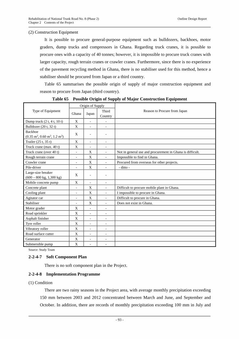
Rehabilitation of National Trunk Road No. 8 (Phase 2) Outline Design Report Chapter 2 Contents of the Project
- 93 -
(2) Construction Equipment
It is possible to procure general-purpose equipment such as bulldozers, backhoes, motor
graders, dump trucks and compressors in Ghana. Regarding truck cranes, it is possible to
procure ones with a capacity of 40 tonnes; however, it is impossible to procure truck cranes with
larger capacity, rough terrain cranes or crawler cranes. Furthermore, since there is no experience
of the pavement recycling method in Ghana, there is no stabiliser used for this method, hence a
stabiliser should be procured from Japan or a third country.
Table 65 summarises the possible origin of supply of major construction equipment and
reason to procure from Japan (third country).
Table 65 Possible Origin of Supply of Major Construction Equipment
Type of Equipment
Origin of Supply
Reason to Procure from Japan Ghana Japan
Third Country
Dump truck (2 t, 4 t, 10 t) X - -
Bulldozer (20 t, 32 t) X - -
Backhoe (0.35 m3, 0.60 m3, 1.2 m3)
X - -
Trailer (25 t, 35 t) X - -
Truck crane (max. 40 t) X - -
Truck crane (over 40 t) - X - Not in general use and procurement in Ghana is difficult.
Rough terrain crane - X - Impossible to find in Ghana.
Crawler crane - X - Procured from overseas for other projects.
Pile-driver - X - - ditto -
Large-size breaker (600 – 800 kg, 1,300 kg)
X - -
Mobile concrete pump X - -
Concrete plant - X - Difficult to procure mobile plant in Ghana.
Cooling plant - X - I impossible to procure in Ghana.
Agitator car - X - Difficult to procure in Ghana.
Stabiliser - X - Does not exist in Ghana.
Motor grader X - -
Road sprinkler X - -
Asphalt finisher X - -
Tyre roller X - -
Vibratory roller X - -
Road surface cutter X - -
Generator X - -
Submersible pump X - -
Source: Study Team
2-2-4-7 Soft Component Plan
There is no soft component plan in the Project.
2-2-4-8 Implementation Programme
(1) Condition
There are two rainy seasons in the Project area, with average monthly precipitation exceeding
150 mm between 2003 and 2012 concentrated between March and June, and September and
October. In addition, there are records of monthly precipitation exceeding 100 mm in July and

Rehabilitation of National Trunk Road No. 8 (Phase 2) Outline Design Report Chapter 2 Contents of the Project
- 94 -
November. As high rainfall is expected for 8 months, the Study Team prepared a plan to
improve the work efficiency during the rainy season, rather than concentrating works only in the
dry season.
(2) Coefficient of Suspension of Works
In preparing the work plan, a coefficient of suspension of works of 1.35 is applied, based on
the “Manual of Cost Estimation in the Preparatory Survey, Supplementary Volume (Civil
Engineering Field” (Provisional Version), (March 2009).
(3) Summary of Construction
a) Rehabilitation of 31.2 km of road between Assin Fosu and Assin Praso (two-lane road at present)
Dualisation to four-lanes road in the centre of Assin Fosu township
Reconstruction of the railway underpass bridge at Assin Fosu
Construction of a pedestrian overpass bridge at Assin Fosu
Rehabilitation of drainage facilities
Construction of a toll-plaza at Assin Praso township
Construction of bus bays (bust stop)
Other ancillary works
b) Reconstruction of Okyi River Bridge at Assin Andoe
(4) Construction Period
Considering the preparatory works (land acquisition, construction of a temporary yard, and
procurement of construction equipment and plans), the construction period is set at about three
years, as shown in Table 66.

Rehabilitation of N
ational Trunk R
oad No. 8 (P
hase 2) Outline D
esign Report
Chapter 2 C
ontents of the Project
- 95 -
Table 66 Project Implementation Schedule (Draft)
Det
aile
d D
esig
n Item 1 2 3 4 5 6 7 8 9 10 11 12
Work in Ghana
Work in Japan
Tender process
Con
stru
ctio
n W
orks
Work Item 2 4 6 8 10 12 14 16 18 20 22 24 26 28 30 32 34 36
Preparatory works/ Procurement of materials and construction equipment
Reconstruction of bridges
Reconstruction of drainage facilities
Earth works
Pavement works
Ancillary works
Cleaning-up
Source: Study Team

Preparatory Survey on Rehabilitation of National Trunk Road No. 8 (Phase 2) Draft Outline Design Report Chapter 3 Obligations of Recipient Country
- 90 -
2-3 Obligations of Recipient Country The GoG should arrange the following matters for the execution of the Project.
2-3-1 General Matters related to the Grant Aid Project of the GoJ
Providing data and information necessary for the implementation of the Project
Securing land necessary for the implementation of the Project (ROW, construction site,
temporary yard, and material and equipment storage site)
Clearing the ground of each construction site prior to execution of the construction work
Opening an account with a bank in Japan under the name of the GoG and issuing the
authority to pay (A/P)
Unloading cargoes promptly at Tema Port, which is the unloading point in Ghana and taking
measures to exempt them from taxes and customs duties
Exempting Japanese companies and individuals concerned with the Project from customs
duties, local taxes and other taxed imposed in Ghana in relation to the outputs and services
supplied under the contract attested
Based on the contract approved or in relation to the services provided, permitting persons
concerned with the Project to enter and stay in Ghana in order to implement relevant work
Granting permits and other authorities, where necessary, in relation to the implementation of
the Project
Maintaining, managing and preserving the facilities to be built under the project properly
and effectively
Bearing all expenses other than those financed by Japan’s grant aid scheme within the scope
of the Project
2-3-2 Matters Unique to the Project
The GoG should complete the following matters prior to the start of construction works:
Removing facilities and resettling residences affected by the construction work
Securing additional land necessary for the Project other than the land for the existing ROW
Relocation of electric poles and cables, optical fibre cables, water supply pipes and street
lightings affected by the construction works
Providing and clearing land for the temporary yard
Providing soil dumping areas and waste disposal sites
Assigning traffic policemen during the construction period (centre of Assin Fosu township)
Also, the GoG should carry out the following matters during the construction work:
Observing the entire construction site during the construction period
Supervision by officers of the GoG during the construction period
2-4 Project Operation Plan The GoG will be responsible for operation and maintenance (O&M) of the Project. The
O&M after completion of the Project is classified as: routine maintenance carried out every year,

Preparatory Survey on Rehabilitation of National Trunk Road No. 8 (Phase 2) Draft Outline Design Report Chapter 3 Obligations of Recipient Country
- 91 -
and periodic maintenance carried out once every few years. The following O&M will be
required for the Project.
(1) Routine Inspection and Maintenance
Cleaning and weed control within the ROW
Removal of sand and dirt, and cleaning of side ditches and culverts
Maintenance of road ancillary works, such as repainting of pavement markings, and
repairing traffic signs, guardrails, etc.
Removal of sand and dirt around the bearing shoes of the Okyi River Bridge
(2) Periodic Maintenance
Repair of pot-holes in the pavement by patching works approximately every 5 years
Pavement overlay works approximately every 10 years
Repainting of steel railings and replacement of the expansion joint of the Okyi River Bridge
2-5 Project Cost Estimation
2-5-1 Initial Cost Estimation
2-5-1-1 Costs Borne by the GoJ
The project will be implemented in accordance with Japan’s Grant Aid scheme and the costs
will be determined before concluding the Exchange Note for the project.
2-5-1-2 Costs Borne by the GoG
Table 67 Costs Borne by the GoG
Division by Project Cost Item Amount to be Borne
(USD) Converted to JPY
(JPY thousand)
(1) Cost for environmental considerations (including resettlement of residences, land acquisition, and compensation for agricultural loss)
528,085 528,085
(2) Cost for relocation of electrical pole and cables 799,686 799,686
(3) Cost for relocation of water supply pipes 1,060,405 1,060,405
(4) Cost for relocation of optical fibre cables 824,881 824,881
(5) Cost for relocation of street lightings 210,876 210,876
(6) Cost for cleaning of land for the temporary yard 14,723 14,723
Total 3,438,656 3,438,656
Source: Study Team
2-5-1-3 Conditions of Cost Estimation
Cost estimation timing: March 2014
USD exchange rate: USD1.0 = JPY 104.18 (three-month average from February 2014)
GHS exchange rate: GHS = JPY 45.65 (three-month average from February 2014)
Construction period: 36 months
Others: The Project will be implemented according to the Guideline for Grant
Aid Cooperation issued by the GoJ. The above estimated project cost
will be revised by the GoJ prior to the E/N.

Preparatory Survey on Rehabilitation of National Trunk Road No. 8 (Phase 2) Draft Outline Design Report Chapter 3 Obligations of Recipient Country
- 92 -
2-5-2 Operation and Maintenance Costs
Annual maintenance works of road: about USD 11,000 (about JPY 1,144 thousand)
Annual maintenance works of bridges: about USD 400 (about JPY 42 thousand)
Cost of rehabilitating pavement by patching works every 5 years: about USD 9,000.- (about
JPY 936 thousand)
Cost of rehabilitating pavement by overlay works every 10 years: about USD 110,000.-
(about JPY 11,440 thousand)
The converted average annual O&M cost will be about USD 24,200 (about JPY 2,521
thousand)
Since, this cost is about 0.9% of the annual allocation of the road maintenance budget for
the GHA Central Region Office of USD 2.7 million (about JPY 279 million), it is
considered that adequate O&M of the Project road is possible.
Table 68 Major Maintenance Items and Costs
Category Frequency Parts to be Inspected
Contents of Work
Estimated Cost
Notes USD
JPY thousand
(equivalent)
Maintenance within ROW
Twice a year ROW Cleaning, weed
control
8,000 832
Maintenance of side ditches and culverts
Twice a year
Side ditches and culverts
Removal of sand and dirt
Maintenance of road ancillary works
Once a year Road
markings, etc.
Repainting, repair
3,000 312
Maintenance of bridge
Twice a year Bearing shoes
Removal of sand and dirt
400 42
Total of annual necessary O&M costs 11,400 1,188 Maintenance and repair of pavement
Once every 5 years
Pavement surface
Repair of pot holes, etc.
9,000 936
Maintenance and repair of pavements
Once every 10 years
Pavement surface
Overlay 70,000 7,280 Expected to be
5% of total area of pavement
Pavement surface of shoulder
Rehabilitation 40,000 4,160
Annual average equivalent of O&M costs 24,200 2,521
Note: Exchange rate USD1.0 = JPY104.18
Source: Study Team

CHAPTER 3
PROJECT EVALUATION

Preparatory Survey on Rehabilitation of National Trunk Road No. 8 (Phase 2) Outline Design Report Chapter 3 Project Evaluation
- 93 -
Chapter 3 Project Evaluation
3-1 Preconditions Preconditions necessary for the execution of the Project are as follows:
1) Prior to signing the exchange note, the GoG should allocate budget necessary for land
acquisition, compensation for resettlement, relocation and demolition of structures and
utilities, renting and clearance of land for the temporary construction yard, and securing of
borrow pits, which should be completed before commencement of the construction works.
2) The GoG should complete land acquisition, compensation for resettlement, relocation and
demolition of structures and utilities, renting and clearance of land for the temporary
construction yard, and securing of borrow pits before commencement of the construction
works.
3) Resettlement of vendors doing business along the N8 in the centre of Assin Fosu township
should be implemented according to the Resettlement Action Plan prepared by the ANMA.
4) The GHA should submit the EIA Report to the EPA in order to obtain the environmental
permit (valid for 18 months), and A-RAP to the LVB, EPA and related local
municipal/district assembly, who will participate in the resettlement process.
5) In order to implement the relocation and demolition of electric cables, water supply pipes,
optical fibre cables and street lightings smoothly, the GHA should conclude contracts with
related agencies and companies, and the relocation and demolition works of these utilities
should be completed before commencement of the construction works.
6) The GHA should obtain permits for usage of borrow pits and quarry site(s) necessary for
the construction works, before commencement of the works.
7) According to the present regulation in Ghana, the Interim Waiver for tax exemption is no
longer effective. Hence, the contractor is required to apply for tax exemption to the Ghana
Revenue Authority, and the application will be deliberated in the congress and the cabinet.
8) In order to ensure traffic safety during construction, the contractor should prepare
appropriate traffic control measures, while the GHA should organise a traffic safety
campaign for road users and local residents.
3-2 Necessary Inputs by Recipient Country In order to develop and sustain the effects of the Project, the GoG should provide the
following necessary inputs:
1) In order to secure smooth implementation of the Project, the GoG should secure the
necessary budget described in [2-5-1 Costs Borne by the GoG] in this report, before
commencement of the construction works.
2) Within items mentioned in 1), it is required to secure without fail the land for the
construction yard, etc. before commencement of the construction works.
3) In order to carry out processes related to the environmental and social considerations

Preparatory Survey on Rehabilitation of National Trunk Road No. 8 (Phase 2) Outline Design Report Chapter 3 Project Evaluation
- 94 -
smoothly and appropriately, the GHA will set up a team of environmental and social
specialists in the GHA headquarters.
4) The GHA should assign two engineers to be stationed at the site office, in order to
appropriately adjust the construction works to local conditions, to ensure smooth
implementation of the Project, by explaining and responding to local residents, and to
transfer technologies to them.
5) The GHA should assign a person in the GHA HDQ, who will be in charge of
administration works (taxes, compensation for land acquisition, etc.) in order to ensure
smooth implementation of the Project.
6) In order to ensure adequate maintenance of the project road after completion, the GHA
should secure necessary staff and annual budget for maintenance works, which are
described in [2-4 Major Maintenance Items and Costs] in this report.
3-3 Important Assumptions The following are important assumptions for developing and sustaining the effects of the
Project:
1) The GHA shall strictly control overloaded vehicles running on the trunk road, to maintain the
road condition of the N8.
2) In order to avoid traffic congestion occurring again in the centre of Assin Fosu township after
completion of the Project, the related authorities, particularly the ANMA, shall take necessary
actions against illegal parking and illegal vendors along the N8.
3) In order to secure traffic safety after completion of the Project, a traffic safety campaign for
road users and local residents shall be carried out.
4) Overhead information signs will be installed at the entrance of the centre of Assin Fosu
township and at the toll plaza in Assin Praso. After installation of these signs, controls against
over-height cargo vehicles shall be strictly enforced for the sake of traffic safety.
3-4 Project Evaluation
3-4-1 Relevance
Implementation of the Project under the Japanese Grant scheme is judged as relevant from
the following points of view:
(1) Beneficiaries of the Project
The Central Region, Ashanti Region and Western Regions are directly influenced by the N8.
The total population of these three regions is about 4.7 million (2010), accounting for about
18% of the total population of the nation. Indirectly, the entire population of 24.22 million of
Ghana and people in neighbouring landlocked countries (Burkina Faso, Niger and Mali) will
benefit from the Project.
(2) Necessity of the Project
As pavement deterioration and damage have worsened over the section of about 30 km
between Assin Praso and Assin Fosu on the N8, it has become difficult to maintain the road

Preparatory Survey on Rehabilitation of National Trunk Road No. 8 (Phase 2) Outline Design Report Chapter 3 Project Evaluation
- 95 -
condition by annual routine maintenance works, and some sections in particular are inundated
during the rainy season, obstructing traffic. Furthermore, the present ADT at Assin Fosu
township is high at 12,473 veh./day on the whole stretch of the N8, and many taxis, waiting
passengers, and pedestrians cause chronic traffic congestion.
According to traffic projections for 2038, the traffic volume on the railway underpass bridge
at Assin Fosu will reach 22,000 veh./day, exceeding the maximum traffic capacity of the 2-lane
road. Also, since the traffic load will exceed the proof stress of the pavement, the speed of
deterioration and damage to the pavement will accelerate. Under these circumstances, it is
desirable to implement the Project at an early stage.
(3) Conformity with the Medium-Term and Long-Term Development Plans and Higher Plan in Ghana
In the transport sector of the Transport Sector Development Programme and the Ghana
Shared Growth Development Agenda 2010–2013, major targets are the formulation of a
transport network to contribute to sustainable growth and socio-economic development, and the
establishment of transport hub in West African countries. Thus, the preservation and
development of transport infrastructure are positioned as important development themes. Based
on these national development plans, the MRH, under the Road Sector Development
Programme 2010–2013, placed priority on the N8 as an important policy.
(4) Conformity with the Cooperation Policy and Principles of Japan
Under the country assistance policy for Ghana, “Infrastructure (electricity and roads) is
selected as one of the priority areas, and Japan assists Ghana in infrastructure development in
areas such as transportation, especially roads, utilising Japanese technological capability to the
maximum extent. Rehabilitation and reconstruction of facilities, such as roads and bridges, are
directly related to achieving the relevant priorities.”
(5) Operation and Maintenance after Completion of the Project
Since the Ghanaian side will be able to operate and maintain the facilities after completion of
the Project with their own resources, manpower and technology, advanced technology and
considerable budget will not be needed.
3-4-2 Effectiveness
(1) Quantitative Effects
Table 69 shows the quantitative effects that are considered to be generated by implementation
of the Project.
(2) Qualitative Effects
The qualitative effects that are considered to be generated by implementation of the Project
are as follows:
1) Rehabilitation of the national trunk road will help strengthen and stabilise the transport
capacity of logistics connecting the coastal area of Ghana, and central and northern areas
as well as neighbouring landlocked countries.

Preparatory Survey on Rehabilitation of National Trunk Road No. 8 (Phase 2) Outline Design Report Chapter 3 Project Evaluation
- 96 -
Table 69 Quantitative Effects of the Project
Index Base Year
(2013)
Target Value (2021) [3 years after completion
of the Project]
1. Average daily traffic volume (veh./day) Assin Fosu 12,473 14,361 Assin Praso 2,749 4,546
2. Travel speed for the project section (between Assin Fosu and Assin Praso)
30’15” 22’30”
Source: Study Team
2) Road closures due to inundation of the road during the rainy season will be eliminated, and
access to markets and public services by residents of local communities will be secured.
3) Dualisation of the road and railway overpass bridge at the centre of Assin Fosu township
will solve chronic traffic congestion and improve traffic safety by sidewalks and
intersections.
4) Even though Ghana has reduced the poverty headcount ratio since 1991, the ratio based on
USD 2.00/day was still as high as 51.8% in 2006. One of the qualitative effects of
rehabilitating the N8 is expected to be alleviation of the poverty ratio, especially of local
residents living along the N8.

APPENDICES

Rehabilitation of National Trunk Road No. 8 (Phase 2) Outline Design Report Appendices
A-1
Appendices
Appendix 1 Member List of the Study Team
Table A1 Member List of the Study Team
Responsibility Name Organisation
Team Leader Hiroshi SUMIYOSHISenior Resident Representative, Japan International Cooperation Agency, Ghana Office
Team Leader/Study Coordination Jitsuya ISHIGURO Advisor, Infrastructure and Peacebuilding Department, Japan International Cooperation Agency
Chief Consultant/Road Planning Hikaru NISHIMURA Central Consultant Inc.
Deputy Chief Consultant/Highway and Pavement Design
Shigeru ANDO Central Consultant Inc.
Road Damages Survey Shinya TOYOSAKI Central Consultant Inc.
Bridge and Structure Design Shinichi UEDA Central Consultant Inc.
Environmental and Social Considerations
Tomomi FUJITA Central Consultant Inc.
Natural Condition Survey Noboru SHIMIZU Eight-Japan Engineering Consultants Inc. Construction and Procurement Planning/Cost Estimation
Jiro NISHITANAKA Central Consultant Inc.
Source: Study Team

Rehabilitation of National Trunk Road No. 8 (Phase 2) Outline Design Report Appendices
A-2
Appendix 2 Study Schedule
(1) Study Schedule of the First Site Survey in Ghana
Table A2 Study Schedule of the First Site Survey in Ghana (1st Phase) No. M D Day Itinerary Lodging Study Contents
1 10 5 Sa Ando and Shimizu left Tokyo On the plane 2 6 Su Ando, Shimizu arrived Accra Accra Preparation of site survey 3 7 Mo Toyosaki left Tokyo -ditto- Courtesy call to MRH and GHA by Sumiyoshi and Ando 4 8 Tu Toyosaki arrived Accra
Nishitanaka left Tokyo -ditto- Preparation of site survey
5 9 We Nishimura started work in Accra Nishitanaka arrived Accra
-ditto- Data collection and preparation of natural condition surveys
6 10 Th Accra <–> Project site on N8 -ditto- Courtesy call of EOJ, Site survey 7 11 Fr -ditto- Data collection 8 12 Sa Ueda left Tokyo -ditto- Data compilation 9 13 Su Ueda arrived Accra -ditto- -ditto-
10 14 Mo Accra -> Cape Coast Accra, Cape Coast Data collection, Site survey 11 15 Tu -ditto- -ditto- 12 16 We -ditto- Discussion with JICA HDQ (Sumiyoshi, Nishimura, Ando)13 17 Th Accra -> Cape Coast Cape Coast Site survey 14 18 Fr N8 -> Accra (Sumiyoshi) Accra, Cape Coast -ditto- 15 19 Sa Cape Coast -> Accra (1 member) -ditto- -ditto- 16 20 Su Cape Coast -> Accra (4 members) -ditto- -ditto-
17 21 Mo -ditto- Data collection, site survey
18 22 Tu Cape Coast -> Accra (1 member) -ditto- Sub-contract of topographical survey (1) and geotechnical survey, Commencement of FWD test
19 23 We Fujita left Tokyo -ditto- Explanation and discussion of ICR, Site survey
20 24 Th Fujita arrived Accra -ditto- Data collection, Site survey
21 25 Fr -ditto- Discussion and signing of M/D, Site survey
22 26 Sa Accra -> Cape Coast Shimizu left Accra
-ditto- Sub-contract of traffic survey, Supervision of natural condition survey, Site survey
23 27 Su -ditto- Supervision of natural condition survey, Site survey
24 28 Mo Shimizu returned to Tokyo -ditto- -ditto-
25 29 Tu -ditto- -ditto-
26 30 We -ditto- -ditto-
27 31 Th -ditto- -ditto-
28 11 1 Fr -ditto- Sub-contract of topographical survey (2) and EIA survey
29 2 Sa -ditto- Supervision of sub-contracted surveys, Site survey
30 3 Su Accra -> Kumasi (Nishimura, Fujita) Toyosaki left Accra
Accra, Cape Coast, Kumasi
-ditto-
31 4 Mo Kumasi -> Cape Coast (Nishimura, Fujita) Accra, Cape Coast Data collection at GHA Ashanti Regional Office, Site survey32 5 Tu Cape Coast -> Accra
Toyosaki returned to Tokyo -ditto- Data collection at GHA Central Regional Office, Site survey
33 6 We Fujita left Accra Accra -> Cape Coast (Nishitanaka)
-ditto- Data collection
34 7 Th Nishimura left Accra -ditto- -ditto- 35 8 Fr Ando and Ueda left Accra
Fujita returned to Tokyo Cape Coast -ditto-
36 9 Sa Cape Coast -> Accra (Nishitanaka) Accra 37 10 Su Ando and Ueda returned to Tokyo -ditto- Data compilation
38- 45
11-18
Mo- Mo
-ditto- Data collection and compilation
46 19 Tu Nishitanaka left Accra 47 20 We On the plane 48 21 Th Nishitanaka returned to Tokyo
Source: Study Team

Rehabilitation of National Trunk Road No. 8 (Phase 2) Outline Design Report Appendices
A-3
Table A3 Study Schedule of the First Site Survey in Ghana (2nd Phase) No. M D Day Itinerary Lodging Study Contents
1 12 1 Su Ando left Tokyo On the plane 2 2 Mo Ando and Shimizu arrived Accra Accra Data collection, Supervision of laboratory tests
3- 7
3- 7
Tu- Sa
-ditto- -ditto-
8 8 Su Accra -> Cape Coast Cape Coast Site survey, Investigation of borrow pits and quarry site 9- 14
9- 14
Mo- Sa
-ditto- -ditto-
15 15 Su Cape Coast -> Accra Accra Site survey 16- 18
16- 18
Mo- We
-ditto- Data compilation
19 19 Th Ando left Accra -ditto- -ditto- 20 20 Fr Shimizu left Accta On the plane 21 21 Sa Ando returned to Tokyo On the plane 22 22 Su Shimizu returned to Tokyo
Source: Study Team
(2) Study Schedule of the Second Site Survey in Ghana
Table A4 Study Schedule of the Second Site Survey in Ghana No. M D Day Itinerary Lodging Study Contents
1 12 1 We Nishimura left Japan On the plane 2 27 Th Nishimura arrived Accra Accra Preparation of site survey 3 28 Fr -ditto- Explanation of draft outline design drawings to GHA,
Courtesy call to JICA Ghana Office 4 3 1 Sa -ditto- Data compilation
5 2 Su -ditto- -ditto-
6 3 Mo Fujita left Japan -ditto- Courtesy call to EOJ
7 4 Tu Fujita arrived Accra Ando left Tokyo
-ditto- Data collection
8 5 We Ando arrived Accra Nishimura left Accra
-ditto- -ditto-
9 6 Th -ditto- -ditto-
10 7 Fr Nishimura returned to Tokyo -ditto- -ditto-
11 8 Sa Accra -> Cape Coast Cape Coast Site survey 12 9 Su -ditto- -ditto- 13 10 Mo -ditto- -ditto- 14 11 Tu Cape Coast -> Accra (Ando) Accra, Cape Coast -ditto- 15 12 We -ditto- Site survey, Data collection 16 13 Th Ando left Accra Cape Coast Site survey 17 14 Fr -ditto- -ditto-
18 15 Sa Ando returned to Tokyo -ditto- -ditto-
19- 22
16- 19
Su- We
-ditto- -ditto-
23 20 Th -ditto- Assist public forum conducted by GHA
24- 26
21- 23
Fr- Su
-ditto- Site survey
27 24 Mo Cape Coast -> Accra Accra 28 25 Tu Fujita left Accra On the plane 29 26 We On the plane 30 27 Th Fujita returned to Tokyo
Source: Study Team

Rehabilitation of National Trunk Road No. 8 (Phase 2) Outline Design Report Appendices
A-4
(3) Study Schedule of the Third Site Survey in Ghana
Table A5 Study Schedule of the Third Site Survey in Ghana No. M D Day Itinerary Lodging Study Contents
1 11 20 Th Nishimura and Ando left Tokyo On the plane 2 21 Fr Nishimura and Ando arrived Accra Accra Preparation of site survey 3 22 Sa Accra -> Assin Fosu Accra, Assin Fosu Site survey 4 23 Su Ishiguro left Tokyo
Assin Fosu -> Accra Accra Site survey
5 24 Mo Ishiguro arrived Accra -ditto- Discussion in JICA Ghana Office
6 25 Tu -ditto- Explanation and Discussion of DOD to GHA
7 26 We -ditto- Courtesy call to MRH and MOF
8 27 Th -ditto- Discussion of M/D
9 28 Fr Ishiguro and Ando left Accra -ditto- Signing of M/D, Courtesy call to EOJ
10 29 Sa Ishiburo and Ando returned to Tokyo Nishimura continued to another study in Accra
-ditto- Data compilation
Source: Study Team

Rehabilitation of National Trunk Road No. 8 (Phase 2) Outline Design Report Appendices
A-5
Appendix 3 List of Parties Concerned in the Recipient Country
Table A6 List of Parties Concerned in the Recipient Country (1)
Ministry of Roads & Highway (MRH) Mr. Daniel D. Darku Chief Director Mr. G. J. Brocke Director, P & P (Policy and Planning) Mr. Francis O. M. Digber Director, M & E Mr. F. N. K. Ashong Director, RSIM (Research, Statistics and Information Management) Mr. Cletus Kugbila Director of Procurement Mr. Francis Nudze Deputy Director of Procurement Mr. Francis Ahlidza Deputy Director of M & E Ms. Josephine Menu Legal Officer Mr. Gense K. Addison Principal Engineer of Planning Ms. Equa Eqqah Senior Engineer of Planning Mr. Kwasi Ayyemcm Boakye Engineer Ghana Highway Authority (GHA) Mr. Michael A. Abbey Chief Executive Mr. Joe Fred Peseo AG. DY. Chief Executive (Development) Mr. Francis Hammond AG. DY. Chief Executive (Administration) Mr. Addo Sitsofe David Director of Planning Mr. Sitsofe David Addo Director of Planning Mr. Owusu Sekyere Antwi Director of Bridge(前職) Michael Okine Director of Bridges Mr. Bonne Acquah Director of Material Mr. Maame Osei Akuanoch Director of Maintenance Mr. Ebenefer A Mills Director of Design and Survey Mr. David Hammono Director of Contracts Mr. Mallam Issah Ishak Director of Quantity Surveying Mr. T. K. Oppong Baah Network Planning Manager(前職) Mr. Oduro Amoakohene Engineer of Planning Mr. Kingsley Osae-Boateng Maintenance Manager Mr. Gordon A. Amartey Highway Design Manager (S/Sector) Ms. Rita Ohene Sarfoh Chief Engineer Ms. Hildo Annan Assistant Manager Mrs. Faustina Oppong Yeboah Senior Engineer Mr. Bernard Owusu Senior Engineer Mr. Abraham Steele Dadzie Assistant Engineer Mr. Ruth Mensah Senior Technical Engineer Mr. Paul Y. A. P. Duah Highway design Manager (N/Sector) Mrs. Mercy Payne Axle Load Control Manager Ms. Olivia Oppong Senior Engineer of Design and Survey GHA Central Region Office Mr. Michael Okine Director(前職) Mr. John Arthur-Amissah Regional Maintenance Manager, Central Region GHA Ashanti Region Office Mr. Joseph Atsu Direcot Mr. Eric Odosu Engineer Ministry of Finance and Economic Planning (MFEP) Mr. David Quist Head of Japan Desk Mr. Kwadwo Awua-Peasah Director, ERM-Bilateral Ministry of Transport (MoT) Mr. Sisi Ocran Director of Policy and Planning Ghana Railway Development Authority (GRDA) Mr. A. A. Sadique Ag. Chief Executive Ministry of Tourism (MoTr) Mr. Reaben Kwadzofio Tourism Office

Rehabilitation of National Trunk Road No. 8 (Phase 2) Outline Design Report Appendices
A-6
Table A6 List of Parties Concerned in the Recipient Country (2)
Regional Coordinating Council, Central Region Mr. Frank Oberg-Dapaah Chief Regional Economic Planning Officer Regional Coordinating Council, Ashanti Region Mr. Joseph Donkor Regional Economic Planning Officer Assin North Municipality Assembly Mrs. Dorcas Hutchful Aldoo Co-ordinating Director Mr. Charles C. Lartey Deputy Director Assin South District Assembly Mr. Richard Blevi Co-ordinating Director
Source: Study Team

Rehabilitation of National Trunk Road No. 8 (Phase 2) Outline Design Report Appendices
A-7
Appendix 4 Minutes of Discussions for Presentation of Inception Report

Rehabilitation of National Trunk Road No. 8 (Phase 2) Outline Design Report Appendices
A-8

Rehabilitation of National Trunk Road No. 8 (Phase 2) Outline Design Report Appendices
A-9
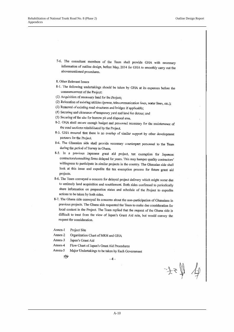
Rehabilitation of National Trunk Road No. 8 (Phase 2) Outline Design Report Appendices
A-10

Rehabilitation of National Trunk Road No. 8 (Phase 2) Outline Design Report Appendices
A-11

Rehabilitation of National Trunk Road No. 8 (Phase 2) Outline Design Report Appendices
A-12

Rehabilitation of National Trunk Road No. 8 (Phase 2) Outline Design Report Appendices
A-13

Rehabilitation of National Trunk Road No. 8 (Phase 2) Outline Design Report Appendices
A-14

Rehabilitation of National Trunk Road No. 8 (Phase 2) Outline Design Report Appendices
A-15

Rehabilitation of National Trunk Road No. 8 (Phase 2) Outline Design Report Appendices
A-16

Rehabilitation of National Trunk Road No. 8 (Phase 2) Outline Design Report Appendices
A-17

Rehabilitation of National Trunk Road No. 8 (Phase 2) Outline Design Report Appendices
A-1
Appendix 5 Minutes of Discussions for Presentation of Draft Outline Design Report

Rehabilitation of National Trunk Road No. 8 (Phase 2) Outline Design Report Appendices
A-2

Rehabilitation of National Trunk Road No. 8 (Phase 2) Outline Design Report Appendices
A-3

Rehabilitation of National Trunk Road No. 8 (Phase 2) Outline Design Report Appendices
A-4

Rehabilitation of National Trunk Road No. 8 (Phase 2) Outline Design Report Appendices
A-5

Rehabilitation of National Trunk Road No. 8 (Phase 2) Outline Design Report Appendices
A-6
This Page is closed due to the confidentiality.

Rehabilitation of National Trunk Road No. 8 (Phase 2) Outline Design Report Appendices
A-7

Rehabilitation of National Trunk Road No. 8 (Phase 2) Outline Design Report Appendices
A-8

Rehabilitation of National Trunk Road No. 8 (Phase 2) Outline Design Report Appendices
A-9

Rehabilitation of National Trunk Road No. 8 (Phase 2) Outline Design Report Appendices
A-10

Rehabilitation of National Trunk Road No. 8 (Phase 2) Outline Design Report Appendices
A-11

Rehabilitation of National Trunk Road No. 8 (Phase 2) Outline Design Report Appendices
A-12

Rehabilitation of National Trunk Road No. 8 (Phase 2) Outline Design Report Appendices
A-13

Rehabilitation of National Trunk Road No. 8 (Phase 2) Outline Design Report Appendices
A-14

Rehabilitation of N
ational Trunk R
oad No. 8 (P
hase 2) Outline D
esign Report
Appendices
A-15

Rehabilitation of National Trunk Road No. 8 (Phase 2) Outline Design Report Appendices
A-16
Appendix 6 Technical Notes and Response for the Design Review Comments
Appendix 6-1 Technical Note for Discussions of Road and Bridge: November 2013

Rehabilitation of National Trunk Road No. 8 (Phase 2) Outline Design Report Appendices
A-17

Rehabilitation of National Trunk Road No. 8 (Phase 2) Outline Design Report Appendices
A-18

Rehabilitation of National Trunk Road No. 8 (Phase 2) Outline Design Report Appendices
A-19

Rehabilitation of National Trunk Road No. 8 (Phase 2) Outline Design Report Appendices
A-20
Appendix 6-2 Technical Note for Discussions of Railway Underpass Bridge:
November 2013

Rehabilitation of National Trunk Road No. 8 (Phase 2) Outline Design Report Appendices
A-21

Rehabilitation of National Trunk Road No. 8 (Phase 2) Outline Design Report Appendices
A-22

Rehabilitation of National Trunk Road No. 8 (Phase 2) Outline Design Report Appendices
A-23

Rehabilitation of National Trunk Road No. 8 (Phase 2) Outline Design Report Appendices
A-24
Appendix 6-3 Response for the Design Review Comments

Rehabilitation of National Trunk Road No. 8 (Phase 2) Outline Design Report Appendices
A-25

Rehabilitation of N
ational Trunk R
oad No. 8 (P
hase 2) Outline D
esign Report
Appendices
A-26
Response for the Design Review and Road Safety Audit by the Study Team
Design Review
Comment by the GHA Response by the Study Team A. General 1. Chainage format should in thousands and not hundreds We will follow the instruction 2. The cover page should mention the project length and specific location of project (Assin Fosu – Assin
Praso N8 Km 67.01 to Km 98.21) We will follow the instruction
3. A legend explain all abbreviations used should be provided We will follow the instruction B. Geometric Design
I. Plan 1. The consultant should provide alternative alignment which by-passes Assin Fosu town as agreed with management at one of the pre-commencement meetings.
The Study covers only rehabilitation of existing N8, not bypass. There was no such agreement.
2. The consultant should provide comparative amalyses of the alternative alignment based on factors such as cost, environmental/social impact and safety as was done for the Asutsuare Junction – Asikuma Junction road project.
The Study cover only rehabilitation of existing N8, not like Eastern Corridor F/S
3. We note that radii below the desirable minimum have been used at chainages 2+500, 14+750, 17+250, 29+650 and 30+350. Please explain why radii above the desirable minimum cannot be used at these sections.
We follow the existing horizontal alignment and adopted design speed of 80 km/h on rolling terrain, as agreed between GHA and us on 8th November, 2013.
4. North arrow and labelled grid lines should be shown on plan. We will follow the instruction 5. Junction destination names should be shown on plan. We will follow the instruction 6. Plan scale should be 1:2500. A3 size: 1/5000, A1 size: 1:2500 II. Profile 1. Vertical alignment details falling below the minimum requirement for a design speed of 100 kph are shown
in table 1 attached. All affected section should be revised accordingly. The Study Team and the GHA agreed on 6th November “A design speed of 100 km/h should be used, however, 80 km/h can be used for the rolling terrains. Hence, a design speed of 80 km/h was used for those terrain sections.
2. Vertical curve between chainages 24+400 – 24+950 should be raised to an average height of 0.6 m to minimize the effect of capillary action.
We will follow the instruction
3. The Consultant should check the possibility of reducing the levels of the finished profile between chainages 1+100 – 1+350 in Assin Fosu town. The high fill will deface the adjoining properties and consequently reduce their commercial/economic value.
We will follow the instruction

Rehabilitation of N
ational Trunk R
oad No. 8 (P
hase 2) Outline D
esign Report
Appendices
A-27
III. Typical Cross Sections
1. Typical cross section of areas with guardrails should be provided We will follow the instruction
2. Side slopes should be 1:3 for embankment less than 1 m, 1:2 (with guardrails) for embankment ranging 1 m – 3 m and 1:1.5 (with guardrails) for embankment greater than 3 m.
In order to minimize effects for houses along the road and stabilized slope point of view, we adopted 1:2.0 (slope of existing road is 1:1.5)
3. All embankment should be protected with stone pitching (in towns) and grassing (out of town) We have planned to grassing outside of towns and either stone pitching or installation of retaining wall to avoid effects for permanent structures in towns.
4. Shoulder width in Assin Fosu should be 2.5 m, GHA and the Study Team agreed to have the minimum value of 2.0 m in Assin Fosu to minimize the effects for the roadside permanent structures.
5. A shoulder width of 2.5 m should be provided on the right hand side of typical cross section (6). We will follow the instruction IV. Intersection
1. All exit lanes at the Assin Fosu roundabouts should be two lanes for about 70 m before tapering over a length of about 50 m into a single lane.
We will follow the instruction
2. Specific details should be provided for major intersection at chainages 0+723, 1+300, 8+670, 11+628, 17+650 and 29+200.
We will follow the instruction
3. All access roads should be properly adjoined to the main road (pave and lined). The length of the access road to be improved as part of this project should be determined by site condition but not less than10 m.
We will follow the instruction
4: Two roundabouts at Assin Fosu The proposed locations of the two roundabouts were analyzed. The following are the merits and demerits: Merit: 1) Better organized traffic flow as compared to the existing situation,
2) Reduction in traffic congestion. Demerits: 1) Provision for pedestrian crossing is inadequate, 2) Conflict at intersection of lorry station/market due to direct access. i. Functionality of these roundabouts is dependent on peripheral roads which are in poor condition and none was selected for improvement under this project, ii. Circulatory lane width of 3.25 m is inadequate and should be increased 4 m to cater for trucks. iii. The length of 300 m between the roundabouts could create grid lock due to high traffic volume. It is
therefore inadequate.
We will follow the instruction
Recommendations The roundabout should be relocated from the proposed position of km 1+235 and 1+5554 to km 0+700 and 1+900
respectively. The dual carriageway should extend about 100 m beyond the roundabouts and tapered over a length of 50
We have changed location of roundabouts as your recommendations.

Rehabilitation of N
ational Trunk R
oad No. 8 (P
hase 2) Outline D
esign Report
Appendices
A-28
m into a single lane. This will ensure a better organized traffic flow and reduce congestion. Consider a grade separated pedestrian crossing. An underpass could be less expensive than overpass. Since there are frequent inundation
during rainy season in Assin Fosu, pedestrian under pass is not desirable. We have carry out a pedestrian bridge in front of the market. JICA has big concern about separation of communities by 4 lane divided road (1.2 km) and recommend us to provide some at-grade pedestrian crossings from social impact point of view
To reduce conflict at Station/Market access points and others, provide access point on minor peripheral roads. It is out of scope of the Study Peripheral Road: Key peripheral roads should be identified for improvement under this project. E.g. the link between the
two proposed roundabout and the Twifo-Praso road. We will identify important peripheral road, but preparation of improvement plan is out of scope of the Study.
Circulatory lane widths of roundabout should be increased to 4 m to cater for truck swept paths. We will follow the instruction V. BUS BAY
Bus bays should be located in the centre of the towns where they will be properly utilized and also staggered so that vehicles leaving the bay will not face each other as shown below.
We will follow the instruction
The length of the parallel section of the bus bays should be based on parking studies by not fixed. We will study more in detailed design, if it is necessary.
Separators should be provided for all bus bays with the parallel width consequently increased to a minimum of 5.5 n as shown below (GHA Road Design Guide 1991)
To refer other projects and consider the speed limit of towns (50 km/h), we designed as 3.5 m of bus bay without separator, according to the Road Design Guide.
A distance of 500 m between two consecutive bus bays is recommended in Assin Fosu township. However, the exact positions should be determined by the parking studies.
We will study more in detailed design, if it is necessary.
C. DRAINAGE
We will study more in detailed design, if it is necessary.
I. Hydrological and Hydraulic analysis
Topographical maps with catchment are demarcations should be provided. As the river bed gradient and river cross section at upper and lower stream are almost similar, we calculated water discharge capacity using Manning Formula.
Inlet control method should be used to calculate the capacity of the existing pipe and box culverts. We will follow the instruction Inventory of existing culverts should be provided. We have prepared the inventory results
in the Draft Report

Rehabilitation of N
ational Trunk R
oad No. 8 (P
hase 2) Outline D
esign Report
Appendices
A-29
Culvert schedule should include existing ones. (It is not clear whether they are being maintained or demolished). Table 2 provides a schedule of recommended culvert sizes and additional culvert locations.
We will follow the instruction
Side ditch type sizes should be specified. We will include in the detailed design Side drains should be provided for all towns. Table 3 provides a schedule of recommended start and end
chainages of side drains as well as new provision in the towns. We will follow the instruction
II. Drainage Structure
Drawing no. 32: Provide bending schedule for the U type side ditch. We will include in the detailed design
Pipe culvert on drawing no. 33: The drawing should explain whether the surround concrete for the pipe culvert is half way or total surround.
We will follow the instruction
Drawing no. 40: The bending schedule for the Guard fence should be provided. We will follow the instruction Headwalls, apron and wing walls:
The height of the headwalls should be determined for each culvert at specific locations and it should not be a fixed height as indicated on drawing nos 35 – 38. Provide nominal reinforcement for apron, wind walls headwalls.
We will include in the detailed design. Nominal reinforcement will be prepared in this stage.
III. Access Pipe Culverts
Drawing no. 39 All access culverts should be provided with a headwall. The minimum length of access culverts should be 8000 mm. Provide bending schedule for the reinforcement for the access pipe culvert.
We will follow the instruction Bending schedule for the reinforcement will be provided in this stage
D. Structure I. Assin Fosu Railway Underpass
i. General plan and cross section provided for the culvert was not readable. We have changed colour of drawing to be readable.
ii. Provide a typical cross section showing the dimensions for the width of the carriageway, footpath and concrete parapet on the culvet.
We will follow the instruction
iii. Provide dimensions of the support (corbel) for the approach slab (see cross section B-B on drawing no. 31)
We will follow the instruction
iv. Identify the material placed at the bottom slab to support the railway sleepers (see cross section B-B on drawing no. 31)
We will follow the instruction
v. What material are the sleepers for supporting the railway track made of? We consider PC sleeper vi. We recommend that railway underpass should be designed according to the latest version of BS5400 and
BD37/01 (and not Load T – Japanese standards), else the Consultant should show the relationship between the Japanese Standards – Load T and that of BS5400 and BD37/01.
Please refer the end of this paper.
vii. It is our understanding that the detail structural design for the box culvert is yet to be submitted to us. We will include in the detailed design viii. The strength of concrete to be used for all box culverts should be a least 30 N/mm2 and the strength of
reinforced steel shold be at least 460 N/mm2 or its equivalent. We will follow the instruction
II. Box Culvert
Detailed design for the box culvert on chainages 80+93, 161+98 and 288+61 should be submitted for our review.
We will provide then soon

Rehabilitation of N
ational Trunk R
oad No. 8 (P
hase 2) Outline D
esign Report
Appendices
A-30
III. Proposed Bridge over River Lkye at Assin Andoe
i. Computation for hydrological and hydraulic analysis use in determining the maximum flow depth of 3,50 m as well as the hydraulic capacity of the bridge should be submitted.
We will include hydrological computation in the Draft Report.
ii. The Consultant should provide the geotechnical investigation report use in determining the location of the spread footing.
We will include geotechnical conditions in the Draft Report.
iii. Approach slab should be shown on the general arrangement drawing We will follow the instruction We recommend that railway underpass should be designed according to the latest version of BS5400 and
BD37/01 (and not Load B – Japanese standards), else the Consultant should show the relationship between the Japanese Standards – Load T and that of BS5400 and BD37/01.
Please refer the end of this paper.
A comparison of the design bending moment caused by a live load indicates that the bending moment ratio by live load defined in the Specification for Highway
Bridges in Japan (Japan Road Association) exceeds that defined in BS5400 for each span length of up to 100 m
0
0.2
0.4
0.6
0.8
1
1.2
20 30 40 50 60 70 80 90 100
Japan
BS
AASHTO
Bending momento ratio agaist B live load of Japanese specification
Span Length (m)

Rehabilitation of N
ational Trunk R
oad No. 8 (P
hase 2) Outline D
esign Report
Appendices
A-31
Road Safety Audit
Comment by the GHA Response by the Study Team Vertical Curves
Recommendations The major control for safe operation on crest curve is the provision of sufficient sight distances for the
design speed. Minimum stopping sight distances should be provided for all the vertical curves. Consideration should therefore be given to the provision of minimum lengths of crest curves slated for the project roadway.
Sag vertical curves should be designed according to comfort criteria. Profiles with successive short vertical curves, particularly between Chainages 18+000 and 19+00,
should be avoided.
We will follow the instruction base on the design speed in accordance with topographical conditions (rolling terrain).
Lay By Recommendations Consideration should be given to the rearrangement of all lay by that are sited in the opposite direction.
Staggering of the lay bys in the “Left-Right” orientation and separated by a buffer of at least 50 meters has the highest safety benefit.
All lay bys should be located beyond intersections to enhance visibility splays of approaching drivers on minor roads
Lay bys should be located beyond pedestrian crossings to avoid stopped vehicles masking pedestrian As much as possible lay bys should be located in straight sections. Parking studies should be undertaking in all communities to determine the dimensions of lay bys
required to handle the present and future traffic.
We will follow the instruction
Roundabouts Recommendations For safety purpose, the number of lanes on the exit of the secondary roads should be the same as the
number of lanes on the circulatory road. Consideration should be given to the provision of an auxiliary lane (at least 100m - inclusive of the parallel and taper lengths) along the exit lane to accommodate two vehicles. A transition section with two lanes has higher safety benefit in addition to the pavement markings. Traffic Congestion is also reduced with the application of this arrangement.
We will follow the instruction
Uncontrolled Parking on Roadway at Assin Fosu
Recommendations With the dualization of a section of the roadway in the Central Business District and lack of parking
facilities for the proposed scheme, it is most likely that more commercial vehicles will park on the outer lanes of the dual carriageway after the project implementation. Although regulatory traffic signs can be employed, the violation of such traffic offences in recent years and the general driver attitude will warrant the need to provide dedicated parking facilities to accommodate the high parking demand in the vicinity. Consideration should therefore be giving to a comprehensive parking study to generate parking facilities acceptable for use by all drivers in the community and beyond.
Assin North Municipal Assembly is undertaking to construct a new lorry station after relocation of the local markets along the national highway in the central area of Assin Fosu. This can be considerably contributed to systematic traffic parking and flows at Assin Fosu.
Uncontrolled Pedestrian crossing at
Recommendations Consideration should be given to the provision of additional metallic fencing on the New Jersey Barrier
(similar to the one provided on the N1) to prevent pedestrian from climbing the concrete median.
We will follow the instruction

Rehabilitation of N
ational Trunk R
oad No. 8 (P
hase 2) Outline D
esign Report
Appendices
A-32
Assin Fosu Provision of street lighting should be considered to increase driver perception of pedestrians and other road users. This arrangement will enhance driver and pedestrian response time to appropriate evasion situation.
Climbing Lane
Recommendations The provision of climbing lane (roadway between Chainage 15+140 and 15+900) may be particularly
beneficial.
Existing vertical gradient is 3.0% and its length is 768 m. According to the design criteria for design speed 80 km/h (rolling terrain), this section is not required for any climbing lane.

Rehabilitation of National Trunk Road No. 8 (Phase 2) Outline Design Report Appendices
A-33
Appendix-7 Results of Natural Condition Surveys
Appendix 7-1 Results of Meteorological Condition Surveys
(1) Temperature
The monthly average temperature at the Assin Fosu meteorological observatory of the Ghana
Meteorological Agency (GMA) between 2003 and 2012 was lowest in January (21.9ºC) and the
maximum temperature was highest in February (33.1ºC). As a whole, the differences in
temperature between each month are limited and steady.
Source: GMA
Figure A1 Maximum and Minimum Temperature (Average of 2003 – 2012)
(2) Precipitation
a) Monthly precipitation
Monthly precipitation at the Assin Fosu and Twifo Praso meteorological observatories of the
GMA between 2003 and 2013 are shown in Tables A7 and A8.
Table A7 Monthly Precipitation at Assin Fosu Meteorological Observatory (Unit: mm)
Assin Fosu
Month
1 2 3 4 5 6 7 8 9 10 11 12 Total
2003 52.0 86.7 145.5 237.7 276.3 133.0 70.3 69.8 54.3 372.8 162.4 59.1 1,719.9
2004 44.1 98.7 185.6 132.2 111.9 80.6 170.2 113.5 390.1 188.7 61.2 57.9 1,634.7
2005 1.8 82.7 211.3 218.0 99.2 261.3 16.1 30.3 78.6 271.7 95.8 79.9 1,446.7
2006 58.7 83.5 139.8 277.5 271.7 210.8 73.6 54.8 201.3 339.7 69.4 37.3 1,818.1
2007 62.4 54.0 147.1 238.0 267.6 337.5 191.3 60.8 173.1 405.5 116.6 39.4 2,093.3
2008 0.0 69.8 151.4 81.6 n.a. n.a. 82.6 107.6 169.5 94.7 40.4 106.5 n.a.
2009 0.0 171.0 121.6 112.5 146.9 452.8 144.4 43.2 43.9 106.4 109.2 5.4 1,457.3
2010 61.0 81.6 275.7 191.1 181.3 292.9 67.1 132.9 213.3 192.3 129.2 17.4 1,835.8
2011 33.1 164.2 136.3 140.3 126.6 174.0 121.3 77.3 243.9 190.8 86.6 15.5 1,509.9
2012 4.3 33.6 55.8 134.4 226.2 326.6 215.9 26.9 126.2 218.2 155.6 90.6 1,614.3
Average 31.7 92.6 157.0 176.3 197.5 252.2 115.3 71.7 169.4 238.1 102.6 50.9 1,610.4
Source: GMA
0.0
10.0
20.0
30.0
40.0
1 2 3 4 5 6 7 8 9 10 11 12
Maximum
Minimum
Month
Mean Temperature (ºC)

Rehabilitation of National Trunk Road No. 8 (Phase 2) Outline Design Report Appendices
A-34
Table A8 Monthly Precipitation at Twifo Praso Meteorological Observatory (Unit: mm)
Twifo Praso
Month
1 2 3 4 5 6 7 8 9 10 11 12 Total
2003 51.4 53.2 66.4 198.7 222.5 227.6 97.7 70.0 90.3 89.7 110.9 10.4 1,288.8
2004 91.4 53.2 135.0 n.a. 138.5 122.0 137.9 81.4 292.1 177.7 82.2 89.3 n.a.
2005 11.1 70.1 228.8 218.4 192.9 154.7 65.0 28.5 75.8 317.5 125.0 46.6 1,534.4
2006 56.8 71.0 137.8 103.0 190.0 214.8 62.4 58.2 177.3 175.6 60.2 14.1 1,321.2
2007 0.0 45.1 170.2 157.3 218.4 287.0 174.9 63.0 186.7 251.9 177.4 42.5 1,774.4
2008 15.1 65.4 178.0 115.7 419.7 265.1 259.3 109.1 95.5 89.4 50.0 98.3 1,760.6
2009 1.6 96.2 83.7 115.7 152.3 232.9 114.6 32.1 43.7 117.3 167.6 73.8 1,231.5
2010 55.9 135.1 123.4 143.1 160.3 131.2 51.6 197.2 139.0 149.6 142.1 100.8 1,529.3
2011 48.3 114.2 132.5 187.3 189.8 226.6 66.1 60.7 200.1 165.3 69.2 18.1 1,478.2
2012 4.7 75.3 131.3 45.3 176.8 353.2 155.7 21.0 103.2 191.1 89.9 98.5 1,446.0
Average 33.6 77.9 138.7 142.7 206.1 221.5 118.5 72.1 140.4 172.5 107.5 59.2 1,476.5
Source: GMA
The average yearly precipitation at Assin Fosu varied between 1,446.7 mm in 2005 and
2,093.3 mm in 2007. The average yearly precipitation at Twifo Praso varied between 1,231.5
mm in 2007 and 1,774.4 mm in 2007.
As shown in Figure A2, the rainy season in the project area starts in March and ends in July,
and starts again in September and ends in November; rainfall is very limited in January, and no
rainfall was recorded in some years.
Note: Data of 2008 is not used because data for two months are missing.
Source: GMA
Figure A2 Monthly Fluctuation of Precipitation between 2007 and 2012 at Assin Fosu
b) Maximum daily precipitation
Tables A9 and A10 show the maximum daily precipitation between 2003 and 2012 at the
Assin Fosu and Twifo Praso meteorological observatories. The maximum daily precipitation
exceeded 80.0 mm on 12 days at Assin Fosu and 7 days at Twifo Praso in the last 10 years and
the highest daily precipitation of 151.2 mm was recorded in June 2012 at Twifo Praso.
0.0
50.0
100.0
150.0
200.0
250.0
300.0
350.0
400.0
450.0
500.0
1 2 3 4 5 6 7 8 9 10 11 12
2007
2009
2010
2011
2012
Ave.
Precipitation (mm)
Month

Rehabilitation of National Trunk Road No. 8 (Phase 2) Outline Design Report Appendices
A-35
Table A9 Maximum Daily Precipitation for Last 10 Years (Assin Fosu) (Unit: mm)
Assin Fosu
Month
1 2 3 4 5 6 7 8 9 10 11 12
2003 37.4 35.3 31.8 85.6 55.0 42.4 34.3 25.3 17.2 99.0 32.2 19.5
2004 26.2 30.1 34.4 67.7 55.5 37.8 111.5 59.5 48.7 59.8 32.4 28.9
2005 1.8 30.2 59.5 50.1 36.3 98.2 9.8 12.7 40.8 81.6 20.6 62.0
2006 50.4 30.4 26.2 45.6 48.4 62.5 26.3 28.4 49.8 87.8 24.8 37.3
2007 54.6 44.9 67.4 80.7 126.1 48.6 80.6 21.6 46.9 92.5 28.1 38.0
2008 0.0 33.1 37.2 36.6 n.a. n.a. 33.4 39.8 37.8 32.7 20.0 24.7
2009 0.0 35.3 57.3 32.8 66.9 96.4 25.8 10.3 20.9 23.2 42.6 3.6
2010 20.7 29.7 59.2 58.2 42.4 55.7 29.3 50.6 49.1 42.2 39.5 7.0
2011 17.5 54.4 54.8 36.0 32.5 56.0 50.0 30.2 88.5 73.0 17.4 15.5
2012 4.3 13.8 21.6 48.2 67.4 68.7 55.5 13.4 39.0 37.2 44.9 29.6
Source: GMA
Table A10 Maximum Daily Precipitation for Last 10 Years (Twifo Praso) (Unit: mm)
Twifo Praso
Month
1 2 3 4 5 6 7 8 9 10 11 12
2003 34.6 15.9 21.4 42.0 35.1 82.3 56.7 40.6 36.8 41.0 24.2 6.4
2004 81.7 37.3 37.4 n.a. 30.2 47.3 53.7 19.8 56.4 33.0 14.9 39.5
2005 11.0 28.1 90.2 36.5 54.8 38.6 50.2 11.3 31.3 49.9 20.5 27.0
2006 24.0 31.2 37.2 25.7 45.3 49.5 22.1 18.7 41.2 38.6 21.1 13.9
2007 0.0 22.1 52.1 37.3 32.3 75.5 69.1 14.7 39.0 25.0 42.6 16.9
2008 15.1 26.3 56.7 49.2 97.3 50.3 116.2 40.4 14.5 19.9 21.0 40.5
2009 1.6 66.0 22.9 49.2 95.1 68.8 29.9 6.9 10.9 25.1 36.5 36.3
2010 27.6 39.3 28.8 43.2 46.3 43.5 21.0 71.1 50.2 31.1 34.7 34.4
2011 19.6 70.8 24.3 70.4 81.9 60.0 29.6 20.9 56.0 32.7 34.1 10.1
2012 4.7 47.7 31.2 15.9 30.1 151.2 41.3 9.7 21.0 42.9 38.3 47.2
Source: GMA
(3) Wind Direction and Velocity
According to the data of the GMA, the prevailing winds are from the west during the rainy
season at Assin Fosu, and tend to come from the north during the dry season. The maximum wind
speed between 2003 and 2010 was 6 knots (about 3.1 m/s).

Rehabilitation of National Trunk Road No. 8 (Phase 2) Outline Design Report Appendices
A-36
Appendix 7-2 Scope of Topographical Surveys The Study Team conducted topographical surveys along the N8 and a possible detour at
Assin Fosu (scale of 1/1000), and detailed topographical surveys around the existing railway
underpass bridge at Assin Fosu and the four-continuous box culverts across the Okyi River near
Assin Andoe (scale of 1/200) as shown in Table A11 and Figure A3.
Table A11 Scope of Topographical Surveys
Specifications and Scale Quantity (m2)
Lot 1
Topographical survey: Scale 1/1000
Along the N8: L = 11,600 m, W = 50 m 580,000
Possible detour at Assin Fosu: L = 1,400 m, W = 30 m 42,000
Detailed topographical survey: Scale 1/200
Railway underpass bridge at Assin Fosu: L = 100 m, W = 100 m 10,000
Four-continuous box culverts across the Okyi River: L = 1,000 m, W = 100 m
100,000
Lot 2 Topographical survey: Scale 1/1000
Along the N8: L = 22,000 m, W = 50 m 1,100,000
Source: Study Team
Source: Study Team
Figure A3 Area of Topographical Surveys
● Assin Fosu
● Assin Praso
to Assin Manso
to Assin Fosu
● Assin Andoe
Railway underpass bridge→← Okyi River
↓ Possible detour
Lot
2 N
8 L
= 2
2,00
0 m
Lo
t1 N
8 L
11,
600
m
Lot
1 N
8 L
=11
,600
m

Rehabilitation of National Trunk Road No. 8 (Phase 2) Outline Design Report Appendices
A-37
Appendix 7-3 Results of Geotechnical Investigations
The Study Team conducted geotechnical investigations by mechanical borings adjacent to the
existing railway underpass bridge at Assin Fosu and the existing four-continuous box culverts
on the Okyi River in Assin Andoe; the results are shown in Tables A12 and A13, respectively.
Also, Table A14 shows the detailed positions (coordinates) of the boreholes for the geotechnical
investigations.
Table A12 Results of Geotechnical Investigation adjacent to the Existing Railway Underpass
Bridge at Assin Fosu
Note: Digging length of rock layer from -14.5 m was 2.7 m
Source: Study Team
Moist medium dense brown clayey gravelly、 Medium to coarse grained SAND with occasional cobbles
Dry medium dense mottle (reddish brown, yellowish, whitish, greyish) clayey SAND with pockets of gravels
Moist medium dense mottle (yellowish, reddish brown, whitish) coarse grained highly weathered GRANITE
Moist dense mottle (yellowish, whitish, blackish, greyish) coarse grained slightly decomposed and highly weathered
Moist medium dense mottle (greyish, whitish, blackish, yellowish) coarse grained slightly decomposed and highly weathered GRANITE
Moist medium dense mottle (greyish, whitish, blackish, yellowish) coarse highly weathered GRANITE

Rehabilitation of National Trunk Road No. 8 (Phase 2) Outline Design Report Appendices
A-38
Table A13 Results of Geotechnical Investigation adjacent to the Existing Four-continuous Box
Culverts across the Okyi River
Note: Digging length of rock layer from -4.9 m was 3.3 m
Source: Study Team
Table A14 Positions of Boreholes and Digging Length
Borehole Position and Coordinates Digging Length
No. 1 Railway underpass bridge at Assin Fosu (N 005 °41.703’, W 001°16.477’) 17.2 m
No. 2 Four-continuous box culverts across the Okyi River (N 005°32.188’, W 001°11.026’) 8.2 m
Source: Study Team
Moist medium dense greyish reddish brown medium to coarse grained sandy GRAVEL with occasional cobbles
Moist medium dense brownish grey sandy clayey GRAVEL with traces of quartzites
Moist medium dense yellowish brown gravelly CLAY
Moist firm to stiff reddish brown yellowish gravelly CLAY with traces of mica
Moist medium dense mottle (whitish, blackish, greyish) coarse grained highly weathered GRANITE

Rehabilitation of National Trunk Road No. 8 (Phase 2) Outline Design Report Appendices
A-39
Appendix 8 RAP Related to the Construction of New Market Prepared by ANMA

Rehabilitation of National Trunk Road No. 8 (Phase 2) Outline Design Report Appendices
A-40

Rehabilitation of National Trunk Road No. 8 (Phase 2) Outline Design Report Appendices
A-41

Rehabilitation of National Trunk Road No. 8 (Phase 2) Outline Design Report Appendices
A-42
Appendix 9 Sample Monitoring Form
(1) Planning Phase
Preparation of Resettlement Sites (where necessary)
No. Explanation of the site
(e.g. Area, no. of
resettlement HH, etc.)
Status
(Completed (date) /
not complete)
Details
(e.g. Site selection, identification of candidate sites,
discussion with PAPs, development of site, etc.)
Expected Date
of Completion
1
2
Public Consultation
No. Date Place Contents of the consultation / main comments and answers
Resettlement Activities Planned
Total Unit
Progress in Quantity Progress in % Expected Date of
Completion
Responsible Organisation
During the
Quarter
Till the Last
Quarter
Up to the
Quarter
Till the Last
Quarter
Up to the
Quarter Preparation of RAP Employment of Consultants
Man-month
Implementation of Census Survey
(including Socioeconomic Survey)
-
Approval of RAP - Finalisation of PAPs List
No. of PAPs
Progress of Compensation Payment
No. of HHs
Lot 1 No. of HHs Lot 2 No. of HHs Lot 3 No. of HHs Lot 4 No. of HHs Progress of Land Acquisition (All Lots)
ha
Lot 1 ha Lot 2 ha Lot 3 ha Lot 4 ha Progress of Asset Replacement (All Lots)
No. of HHs
Lot 1 No. of HHs Lot 2 No. of HHs Lot 3 No. of HHs Lot 4 No. of HHs Progress of Relocation of People (All Lots)
No. of HHs
Lot 1 No. of HHs Lot 2 No. of HHs Lot 3 No. of HHs Lot 4 No. of HHs

Rehabilitation of National Trunk Road No. 8 (Phase 2) Outline Design Report Appendices
A-43
(2) During Construction
The latest results of the below monitoring items shall be submitted to the lenders as part of Quarterly
Progress Report throughout the construction phase.
Construction Phase
1. Response/Actions to Comments and Guidance from Government Authorities and the Public
Monitoring Item Monitoring Results during Report Period
Number and contents of formal
comments made by the public
Number and contents of responses
from Government agencies
2. Pollution
- Air Quality (Ambient Air Quality)
Item Unit Measured Value
(Mean)
Measured Value (Max)
Country’s Standards
Standards for
Contract
Referred International
Standards
Measurement Point
Frequency
SO2 μg/m3 (24h) 20 Biannual
NO2 μg/m3 (1h) 200 Biannual
PM10 μg/m3 (24h) 50 Biannual
- Water Quality
Item Unit Measured
Value (Mean)
Measured Value (Max)
Country’s Standards
Standards for
Contract
Referred International
Standards
Measurement Point
Frequency
pH -
6-9
Biannual
SS mg/l
50
Biannual
Coliform
bacteria
MPN
/100ml
400
Biannual
Oil mg/l
10
Biannual
- Noise
Item Unit Measured
Value (Mean)
Measured Value (Max)
Country’s Standards
Standards for
Contract
Referred International
Standards
Measurement Point
Frequency
Noise Level
Leq. dB A 55 (day) Biannual
Monitoring Item Monitoring Results during Report Period Measures to be Taken Frequency
Inventry record of using anti-vibration
device
Details of survey results, such as findings Monthly
- Waste
Monitoring Item Monitoring Results during Report Period Measures to be Taken Frequency
Invenry record of waste disposal
(volume, methodology ) Details of survey results, such as findings Monthly

Rehabilitation of National Trunk Road No. 8 (Phase 2) Outline Design Report Appendices
A-44
3. Social Environment
- HIV/AIDS and other STDs Monitoring Item Monitoring Results during Report Period Measures to be Taken Frequency
HIV/AIDS and other STDs Incidences per 1000 inhabitants Biannual
4. Other
- Traffic Accidents Monitoring Item Monitoring Results during Report Period Measures to be Taken Frequency
Inventory record of traffic accident Details of survey results, such as findings Monthly
(3) During Operation
The latest results of the below monitoring items shall be submitted to the lenders on biannual basis for
the first two years of operation.
Operation Phase
1. Response/Actions to Comments and Guidance from Government Authorities and the Public
Monitoring Item Monitoring Results during Report Period Frequency
Number and contents of formal comments
made by the public
Upon receipt of comments/complaints Number and contents of responses from
Government agencies
2. Pollution
- Air Quality (Ambient Air Quality)
Item Unit Measured Value
(Mean)
Measured Value (Max)
Country’s Standards
Standards for
Contract
Referred International
Standards
Measurement Point
Frequency
SO2 mg/m3 20 Annual
NO2 mg/m3 200 Annual
PM10 mg/m3 50 Annual
- Noise
Item Unit Measured Value
(Mean)
Measured Value (Max)
Country’s Standards
Standards for
Contract
Referred International
Standards
Measurement Point
Frequency
Noise
Level Leq. dB (A) 55 (day) Biannual
3. Other
- Traffic Accidents Monitoring Item Monitoring Results during Report Period Measures to be Taken Frequency
Inventory record of traffic accident Details of survey results, such as findings Monthly

Rehabilitation of National Trunk Road No. 8 (Phase 2) Outline Design Report Appendices
A-45
Appendix 10 Results of Future Traffic Projection
(1) Results of Future Traffic Demand Projection
a) Results of sectional and intersection traffic volume counting surveys
The Study Team conducted directional traffic flow counting at two intersections and the
manual classified counting (MCC) of traffic at seven locations (24 hours counting only on the
Assin Fosu railway underpass bridge), and the roadside O/D interview survey at two locations,
in order to identify the present and future bottlenecks on the N8.
Source: Study Team
Figure A4 Present Daily Traffic Volume on the N8
The traffic volume obtained from each counting station was converted into the average daily
traffic (ADT) considering the day/night ratio of traffic obtained from the MCC station on the
6,1446,329
3,4623,037
1,9161,868
3,023 3,132
1,4361,436
Assin Praso
Assin Fosu Railway Underpass
Assin Andoe
Yamoransa
Adanse Asokwa
5,979
6,035 3,372
3,810
2,919 3,034
1,908
2,062
To Bekwai
To Obuasi
To Cape Coast To Saltpond
Pedestrian/Bicycle
6,716
Pedestrian/Bicycle
6,196
Unit: ADT (Veh./day)

Rehabilitation of National Trunk Road No. 8 (Phase 2) Outline Design Report Appendices
A-46
Assin Fosu railway underpass bridge, a daily fluctuation rate and a monthly fluctuation rate
obtained from the toll collection result by the GHA at the Pra River bridge at Assin Praso. The
present traffic volume on the N8 is shown in Figure A4.
It should be noted from the results of the traffic volume counting survey that the vehicular
traffic for both directions on the Assin Fosu railway underpass bridge was 11,184 veh./day,
while the number of pedestrians and bicycles was also high at 12,912. This present traffic
situation is considered to be one of the main causes of the chronic traffic congestion at the
centre of the Assin Fosu township.
Furthermore, Figure A5 illustrates the vehicle composition of the present traffic on the
railway underpass bridge and the very high ratio of taxis (62.5%), which are mainly internal
traffic in the Assin Fosu township; those taxis greatly influence the traffic congestion.
Source: Study Team
Figure A5 Vehicle Composition of Traffic on the Assin Fosu Railway Underpass Bridge
Figure A6 illustrates the hourly fluctuation of traffic on the railway underpass bridge in Assin
Fosu. There are particular peak hours of pedestrians and bicycle traffic between 14:00 and 16:00
with 1,350 people and bicycles per hour, when students go back from school, and those
pedestrians (mainly students) cross the railway underpass bridge with a high risk of conflicts
with vehicular traffic as there is no sidewalk.
b) Results of roadside O/D interview survey
For the MCC survey, the Study Team conducted the roadside O/D interview survey at
Yamoransa intersection and Adanse Asokwa intersection, both on the N8, on the same day, in
order to grasp the situation of medium and long-haul traffic on the N8. As a result, the major
trips on the N8 are between Cape Coast and Assin North, and Kumasi and Assin North, and the
trip generation/attraction volume in Assin North, particularly Assin Fosu township, is
predominant on the N8, as shown by the desired lines of trips of the present traffic in Figure A7.
4.7% 16.4%
62.5%
7.2%
1.9%4.4% 2.7%
Motorcycle
Passengercar
Taxi
Minibus
Bus
Truck
Semi‐trailer

Rehabilitation of National Trunk Road No. 8 (Phase 2) Outline Design Report Appendices
A-47
Source: Study Team
Figure A6 Hourly Fluctuation of Traffic on the Railway Underpass Bridge in Assin Fosu
Source: Study Team
Figure A7 Present Desired Lines of Trips on the N8
c) Results of future traffic demand forecast
In the Study, the future traffic demand was forecasted by passenger vehicles and freight
0
200
400
600
800
1,000
1,200
1,400
6 7 8 9 10 11 12 13 14 15 16 17 18 19 20 21 22 23 0 1 2 3 4 5
Vehicular Traffic Pedestrian/Bicycle

Rehabilitation of National Trunk Road No. 8 (Phase 2) Outline Design Report Appendices
A-48
vehicles, based on the results of the roadside O/D interview survey. In this case, the target year
of the forecast was set as 2038, 20 years after completion of the Project, and the same method of
the recent “Preparatory Survey on Eastern Corridor Development Project” was used, i.e.,
expansion of generated traffic volume, by using the future population growth rate (1.83 times)
estimated by the Ghana Statistical Service (GSA) for passenger traffic, and the GDP growth rate
(1.723 times) determined by the IMF for freight traffic. Then, based on the projected O/D
matrix in 2038, the future traffic volumes on the N8 for 2021 (3 years after completion of the
Project) and 2038 were assigned on the network. Since taxi traffic in the centre of Assin Fosu
township is considered to be already saturated even at present, the internal traffic in Assin Fosu
in 2038 is assumed to be the same as at present.
Source: Study Team
Figure A8 Results of Future Traffic Assignment on the N8 in 2038
Figure A8 illustrates the results of the future traffic assignment in 2038, while Table A15
shows the future traffic demand on the N8 in 2021 and 2038.
10,93511,066
7,0526,231
4,1453,720
5,496 5,141
2,4252,676
Assin Praso
Assin Fosu Railway Underpass
Assin Andoe
Yamoransa
Adanse Asokwa
To Bekwai
To Obuasi
To Cape Coast To Saltpond
Unit: ADT (Veh./day)

Rehabilitation of National Trunk Road No. 8 (Phase 2) Outline Design Report Appendices
A-49
Table A15 Results of Future Traffic Volume Projection at each Traffic Survey Point
1) Results of Future Traffic Projection at Yamoransa Intersection
Vehicle Type Present Traffic Volume
(2013) Future Traffic Volume
(2021) Future Traffic Volume
(2038) North Bound South Bound North Bound South Bound North Bound South Bound
Passenger car/ Taxi 1,990 1,687 3,148 2,618 4,250 3,533 Minibus 1,049 975 1,420 1,319 1,918 1,786 Bus 34 29 62 95 84 127 Truck 163 186 338 318 439 426 Semi-trailer 156 95 361 359 361 359
Sub-total 3,392 2,972 5,329 4,709 7,052 6,231 Total of both directions 6,364 10,038 13,283
2) Results of Future Traffic Projection at Assin Andoe Community
Vehicle Type Present Traffic Volume
(2013) Future Traffic Volume
(2021) Future Traffic Volume
(2038) North Bound South Bound North Bound South Bound North Bound South Bound
Passenger car/ Taxi 1,308 1,230 2,231 1,833 3,009 2,475 Minibus 244 296 298 415 406 564 Bus 43 48 61 91 88 121 Truck 135 129 224 169 285 231 Semi-trailer 139 123 273 249 357 329
Sub-total 1,869 1,826 3,087 2,757 4,145 3,720 Total of both directions 3,695 5,844 7,865
3) Results of Future Traffic Projection on Assin Fosu Railway Underpass
Vehicle Type Present Traffic Volume
(2013) Future Traffic Volume
(2021) Future Traffic Volume
(2038) North Bound South Bound North Bound South Bound North Bound South Bound
Passenger car/ Taxi 5,368 5,286 7,268 7,155 9,447 9,141 Minibus 351 581 422 697 642 1,065 Bus 44 43 48 75 79 112 Truck 244 252 287 302 414 436 Semi-trailer 137 167 243 215 353 312
Sub-total 6,144 6,329 8,268 8,444 10,935 11,066 Total of both directions 12,473 16,712 22,001
4) Results of Future Traffic Projection at Assin Praso Township
Vehicle Type Present Traffic Volume
(2013) Future Traffic Volume
(2021) Future Traffic Volume
(2038) North Bound South Bound North Bound South Bound North Bound South Bound
Passenger car/ Taxi 893 888 1,077 1,308 1,453 1,766 Minibus 193 170 260 255 353 311 Bus 44 54 56 134 69 108 Truck 128 124 186 176 238 178 Semi-trailer 116 139 224 237 312 313
Sub-total 1,374 1,375 1,803 2,110 2,425 2,676 Total of both directions 2,749 3,913 5,101
5) Results of Future Traffic Projection at Asanse Asokwa Intersection
Vehicle Type Present Traffic Volume
(2013) Future Traffic Volume
(2021) Future Traffic Volume
(2038) North Bound South Bound North Bound South Bound North Bound South Bound
Passenger car/ Taxi 1,545 1,532 1,865 2,258 2,514 3,047 Minibus 912 955 1,232 1,438 1,670 1,749 Bus 58 29 74 72 92 118 Truck 231 207 337 295 431 298 Semi-trailer 161 126 312 215 434 284
Sub-total 2,907 2,849 3,820 4,278 5,141 5,496 Total of both directions 5,756 8,098 10,637
Source: Study Team
It is clear from these figures and tables that the future traffic volume on the Assin Fosu

Rehabilitation of National Trunk Road No. 8 (Phase 2) Outline Design Report Appendices
A-50
railway underpass bridge will be 22,001 veh./day, exceeding the traffic capacity of the 2-lane
road. As a result, it is concluded that dualisation will be required in the central area of Assin
Fosu township.
(2) Travel Speed
a) Results of travel speed survey
The Study Team conducted the travel speed survey between Yamoransa and Bekwai by
section. Table A16 shows the results of the survey. Even though the average travel speed on
sections rehabilitated under the Phase 1 Project is 92.2 km/h, the travel speeds of other sections
without rehabilitation, i.e. between Assin Praso and the north of Assin Fosu township, and
Assin Fosu police barrier and Yamoransa are about 77 km/h. In addition, the average travel
speed between the north of Assin Fosu township and the railway underpass bridge was 22 km/h,
even though the maximum speed on this section is 50 km/h, showing evidence of traffic
congestion in this section.
Table A16 Results of Travel Speed Survey
Location Distance (km)
Average Travel Time
Average Travel Speed (km/h)
Bekwai
| 67 43’37” 92.2
Assin Praso
| 27 22’55” 77.1
North of Assin Fosu Township
| 2.2 5’30” 22.0
Assin Fosu Railway Underpass Bridge
| 1 1’50” 33.2
Assin Fosu Police Barrier
| 65.6 50’51” 77.4
Yamoransa
Source: Study Team
b) Estimation of travel speed and travel time after completion of the Project
After completion of the rehabilitation of the N8 under the Project, the travel speed of the
ordinary 2-lane road section between Assin Praso and the north of Assin Fosu township is
assumed to increase to 90 km/h, which is the same level of travel speed as the road section
rehabilitated under the Phase 1 Project. On the other hand, since many crossing pedestrians are
expected on the planned dualised section in the centre of Assin Fosu township, the travel speed
on this section is assumed to be 40 km/h, less than the maximum speed limit in urban areas. As
rehabilitation of the worst damaged section south of the railway underpass bridge is planned, the
travel speed on the remaining section up to the Assin Fosu police barrier is assumed to be the
maximum speed limit in urban areas of 50 km/h.
Based on these assumed travel speeds for each section of the Project road, the average travel
time between Assin Praso and the Assin Fosu police barrier is expected to be shortened from
30’15” at present to 22’30” after completion of the rehabilitation of the N8 under the Project, as
shown in Table A17.

Rehabilitation of National Trunk Road No. 8 (Phase 2) Outline Design Report Appendices
A-51
Table A17 Results of Estimated Travel Speed and Travel Time
Location Distance (km)
Assumed Travel Speed (km/h)
Estimated Travel Time
Assin Praso
| 27 90.0 18’00”
North of Assin Fosu Township
| 2.2 40.0 3’18”
Assin Fosu Railway Underpass Bridge
| 1 50.0 1’12”
Assin Fosu Police Barrier
Source: Study Team

Rehabilitation of National Trunk Road No. 8 (Phase 2) Outline Design Report Appendices
A-52
Appendix 11 Results of Visual Inspection of Pavement
In order to supplement the results of the road surface inspection carried out by the GHA, the
Study Team conducted a detailed visual inspection of the pavement on the N8 between Assin
Praso and Yamoransa, with cooperation from the Material Division of the GHA. For the visual
inspection, the Study Team referred to the method of the visual inspection carried out by the
GHA, and evaluated damages on the road. Since the section for evaluating the road surface
condition by the GHA is large (evaluation of 10 to 20 km of road section as a unit), the Study
Team modified the method to evaluate the road surface at intervals of 100 m and estimated the
degree of damage. In this survey, a Study Team member visually inspected the road surface by
walking (Assin Praso to Assin Fosu) and from a slow-moving vehicle (Assin Fosu to
Yomaransa), accompanied by an engineer from the Material Division of the GHA.
Regarding the inspection method, the Study Team referred to the “GHA Road Maintenance
Operation Manual – Road Condition Survey Revised Manual (October 2003)” prepared under
the GHA GTZ Road Maintenance Project. The degree of damage of the road surface (“degree of
damage” and “scale of damage”) was recorded by type of damage, and a score was calculated
by combining both factors. The criteria for evaluating the degree of damage on the road surface
are shown in Table A18.
Table A18 Criteria for Evaluating Degree of Damage Type of Damage Degree of Damage Scale of Damage
Alligator crack Light: Width of crack is less than 6 mm Medium: Width of crack is less than 12 mm Severe: Width of crack is 12 mm or more
Per length 1–15%:
Limited part 16–30%:
Continuous part More than 30%:
Most parts
Difference in level
Light: Difference in level is less than 20 mm Medium: Difference in level is 20–50 mm Severe: Difference in level is more than 50 mm
Rutting
Light: Depth is less than 10 mm Medium: Depth is 10–25 mm Severe: Depth is more than 25 mm
Bituminous flashing and bleeding
Light: Aggregates at the main part of the carriageway are not covered by bituminous emulsion Medium: Aggregates on the wide part are not covered by bituminous emulsion Severe: Aggregates are not covered at all by bituminous emulsion
Detached aggregate Light: Some aggregates have detached Medium: Many aggregates have detached and the surface condition is rough Severe: Most aggregates have detached and the surface condition is very rough
Transverse cracking
Light: Width of crack is less than 6 mm Medium: Width of crack is less than 12 mm Severe: Width of crack is 12 mm or more
Longitudinal cracking
Light: Width of crack is less than 6 mm Medium: Width of crack is less than 12 mm Severe: Width of crack is 12 mm or more
Damages on pavement edge
Light: Less than 200 mm Medium: 300–500 mm Severe: 500 mm or more
Lowering of pavement edge
Light: Difference of level 25–50 mm Medium: Difference of level 50–100 mm Severe: Difference of level 100 mm or more
Pothole Score 1: Area less than 10 m2/km Score 2: Area 10–30 m2/km Score 3: Area 31–50 m2/km Score 4: Area 50 m2/km or more
Source: Study Team

Rehabilitation of National Trunk Road No. 8 (Phase 2) Outline Design Report Appendices
A-53
Based on the criteria mentioned above, the degree of damage was calculated by the following
matrix using the damage condition recorded by the visual inspection:
Table A19 Weighting Matrix to Calculate Degree of Damage
Scale of damage
Degree of damage
Limited Parts 1–15% of length
Continuous Parts 16–30% of length
Most Parts More than 30% of
length
Light degree 1 2 3
Medium degree 4 5 6
Severe degree 7 8 9
Source: Material Division, GHA
According to this matrix, the Study Team weighted each type of damage and calculated the weight
of each type of damage for each section for the investigation.
Table A20 Weight of Each Type and Scale of Damage by Visual Inspection
Type of Damage Degree of Damage
Scale of Damage
Limited PartsContinuous
Parts Most Parts
Alligator crack Light 5 6 7
Medium 7 8 9
Severe 9 11 11
Difference in level Light 5 7 8
Medium 8 9 10
Severe 10 12 12
Rutting
Light 3 4 5
Medium 5 6 7
Severe 7 8 9
Bituminous flashing and bleeding
Light 0 1 1
Medium 1 2 2
Severe 2 3 3
Detached aggregate Light 1 2 3
Medium 3 4 5
Severe 5 6 6
Transverse cracking
Light 1 2 3
Medium 3 4 5
Severe 5 6 6
Longitudinal cracking
Light 2 3 4
Medium 4 5 6
Severe 6 7 7
Damages on pavement edge
Light 4 5 6
Medium 6 7 8
Severe 8 9 9
Lowering pavement edge
Light 4 5 6
Medium 6 7 8
Severe 8 9 9
Pothole Level 1 6
Level 2 9
Level 3 11
Level 4 14
Source: Material Division, GHA
On the other hand, IRI values obtained by an IRI measurement vehicle are classified into
scores as shown in Table A21, and the total evaluation score of each section for the evaluation

Rehabilitation of National Trunk Road No. 8 (Phase 2) Outline Design Report Appendices
A-54
was calculated by using the following equation. For the Study, no IRI measurement was
conducted, and instead, the latest IRI measurement result, conducted by the GHA in 2013, was
used.
Table A21 Calculation of Damage Score based on IRI Value
IRI Value Score
4–6 5
6–7 8
7 or more 12
Source: Material Division, GHA
The equation used to calculate the total evaluation score for each evaluation section is as
follows:
Total evaluation score = 100 – (Σ [Score of damages by visual inspection] +
Score based on IRI Value)
The results of the detailed visual inspection of the road surface are shown in Figure A9; the
Study Team confirmed that damages to the road surface for the section selected for the Project
have worsened. Particularly, the damages on the road section south of Assin Fosu township (67
km from Yamoransa) are the worst on the N8. At this location, the asphalt concrete layer has
totally disappeared and this section has become the most critical point, as vehicle travel speed
has fallen below 10 km/h.
Based on the results of visual inspection, damage has worsened in many sections adjacent to
sags. The main causes of damage are insufficient drainage, and once the pavement has
deteriorated, water penetrates through generated cracks and damage worsens further at sags
where drainage water is concentrated.
Based on the results of the visual inspection, the damage condition, particularly at sags where
damage is severe, is summarised in Table A22. Alligator cracks have been generated and
worsened in many cases. Even though the alligator cracks have been maintained by patching,
due to the poor quality of materials, bituminous flashing, difference in level with corrugation
shape, and rutting have also be generated.

A-55-
Rehabilitation of N
ational Trunk R
oad No. 8 (P
hase 2) Outline D
esign Report
Appendices
0 1 2 3 4 5 6 7 8 9 10 11 12 13 14 15 16 17 18 19 20 21 22 23 24 25 26 27 28 29 30 31 32 33 34
0 100 200 300 400 500 600 700 800 900 0 100 200 300 400 500 600 700 800 900 0 100 200 300 400 500 600 700 800 900 0 100 200 300 400 500 600 700 800 900 0 100 200 300 400 500 600 700 800 900 0 100 200 300 400 500 600 700 800 900 0 100 200 300 400 500 600 700 800 900 0 100 200 300 400 500 600 700 800 900 0 100 200 300 400 500 600 700 800 900 0 100 200 300 400 500 600 700 800 900 0 100 200 300 400 500 600 700 800 900 0 100 200 300 400 500 600 700 800 900 0 100 200 300 400 500 600 700 800 900 0 100 200 300 400 500 600 700 800 900 0 100 200 300 400 500 600 700 800 900 0 100 200 300 400 500 600 700 800 900 0 100 200 300 400 500 600 700 800 900 0 100 200 300 400 500 600 700 800 900 0 100 200 300 400 500 600 700 800 900 0 100 200 300 400 500 600 700 800 900 0 100 200 300 400 500 600 700 800 900 0 100 200 300 400 500 600 700 800 900 0 100 200 300 400 500 600 700 800 900 0 100 200 300 400 500 600 700 800 900 0 100 200 300 400 500 600 700 800 900 0 100 200 300 400 500 600 700 800 900 0 100 200 300 400 500 600 700 800 900 0 100 200 300 400 500 600 700 800 900 0 100 200 300 400 500 600 700 800 900 0 100 200 300 400 500 600 700 800 900 0 100 200 300 400 500 600 700 800 900 0 100 200 300 400 500 600 700 800 900 0 100 200 300 400 500 600 700 800 900 0 100 200 300 400 500 600 700 800 900 0 100 200 300 400 500 600 700 800 900
85 84 89 86 89 92 92 91 91 86 95 91 91 91 91 92 91 91 91 100 100 77 74 100 92 89 79 79 92 100 77 77 92 89 92 89 100 83 89 81 92 81 80 85 80 91 100 77 77 89 91 80 89 83 91 92 92 92 89 84 84 92 89 89 89 80 100 92 89 91 78 79 89 91 89 100 77 89 89 89 91 89 100 91 100 91 78 92 100 100 100 89 89 89 89 89 92 89 89 89 100 89 91 89 92 89 79 89 100 91 91 84 100 89 92 100 90 91 100 92 100 68 71 91 80 100 89 81 92 92 83 86 78 94 100 81 100 83 86 77 89 88 74 94 74 74 89 88 89 85 88 88 77 89 89 92 100 62 83 78 86 100 79 91 65 83 79 89 62 89 77 89 92 94 88 85 85 91 87 87 87 91 91 91 92 87 87 79 87 87 87 87 87 69 68 88 100 87 88 85 85 85 91 100 81 100 44 91 77 89 92 100 92 91 91 94 94 100 100 91 91 89 91 100 91 91 92 74 80 92 89 77 66 87 54 73 92 77 88 91 91 100 95 95 92 84 74 92 100 100 78 78 91 100 91 92 91 94 92 77 92 100 90 92 93 92 100 92 92 89 89 91 89 100 91 89 83 85 92 92 87 81 91 86 89 85 74 83 89 88 92 100 77 78 83 100 82 82 92 92 89 81 91 100 89 89 91 92 92 92 65 74 92 89 83 57 75 86 100 100 100 100 68 92 77 68 66 62 76 100 100 91 100 100 91 65 77 89 74 89 84 67 65 92 80 100 83 100
91 86 86 92 91 83 82 80 91 84 87 100 89 89 89 89 89 81 89 100 100 74 74 83 91 89 91 92 100 91 91 100 100 92 89 92 100 81 89 91 82 77 74 74 94 94 100 100 92 81 89 89 89 92 100 100 94 100 91 87 87 89 89 81 89 81 81 100 92 89 77 80 92 89 89 100 100 92 100 89 77 89 77 89 89 89 86 71 72 65 100 92 89 77 89 91 92 89 89 89 89 89 77 89 77 89 74 89 86 100 81 81 81 100 92 94 77 100 92 100 100 91 100 100 89 91 100 100 77 83 83 95 95 100 71 100 100 80 92 77 91 67 100 100 91 100 68 85 77 77 88 100 91 92 79 91 73 60 83 84 87 94 91 68 65 89 81 72 92 92 77 89 74 100 77 79 93 94 91 91 94 77 77 89 100 89 87 100 85 85 94 91 100 88 76 92 100 92 100 100 100 74 89 100 77 91 74 65 89 77 77 74 92 91 92 100 91 92 92 80 100 68 77 78 78 77 77 62 62 92 100 65 86 86 69 69 77 79 100 100 91 74 84 87 84 92 89 92 100 100 92 100 92 92 94 100 91 89 83 100 92 92 83 100 100 92 100 92 86 89 89 100 88 89 100 100 65 85 74 89 95 78 89 53 77 89 91 51 79 74 94 92 94 62 100 92 75 59 77 72 77 88 100 81 77 92 78 92 89 77 68 74 92 100 100 75 81 86 77 71 100 51 68 56 56 63 69 69 59 86 71 81 63 100 92 68 77 100 89 94 95 75 74 92 80 89 83 90
35 36 37 38 39 40 41 42 43 44 45 46 47 48 49 50 51 52 53 54 55 56 57 58 59 60 61 62 63 64 65 66 67 68 69
0 100 200 300 400 500 600 700 800 900 0 100 200 300 400 500 600 700 800 900 0 100 200 300 400 500 600 700 800 900 0 100 200 300 400 500 600 700 800 900 0 100 200 300 400 500 600 700 800 900 0 100 200 300 400 500 600 700 800 900 0 100 200 300 400 500 600 700 800 900 0 100 200 300 400 500 600 700 800 900 0 100 200 300 400 500 600 700 800 900 0 100 200 300 400 500 600 700 800 900 0 100 200 300 400 500 600 700 800 900 0 100 200 300 400 500 600 700 800 900 0 100 200 300 400 500 600 700 800 900 0 100 200 300 400 500 600 700 800 900 0 100 200 300 400 500 600 700 800 900 0 100 200 300 400 500 600 700 800 900 0 100 200 300 400 500 600 700 800 900 0 100 200 300 400 500 600 700 800 900 0 100 200 300 400 500 600 700 800 900 0 100 200 300 400 500 600 700 800 900 0 100 200 300 400 500 600 700 800 900 0 100 200 300 400 500 600 700 800 900 0 100 200 300 400 500 600 700 800 900 0 100 200 300 400 500 600 700 800 900 0 100 200 300 400 500 600 700 800 900 0 100 200 300 400 500 600 700 800 900 0 100 200 300 400 500 600 700 800 900 0 100 200 300 400 500 600 700 800 900 0 100 200 300 400 500 600 700 800 900 0 100 200 300 400 500 600 700 800 900 0 100 200 300 400 500 600 700 800 900 0 100 200 300 400 500 600 700 800 900 0 100 200 300 400 500 600 700 800 900 0 100 200 300 400 500 600 700 800 900 0 100 200 300 400 500 600 700 800 900
92 66 89 74 92 91 100 83 100 77 72 88 74 89 89 91 70 100 100 92 92 89 100 92 56 92 100 91 94 74 92 92 90 100 91 89 75 80 86 92 89 94 100 100 89 100 92 100 91 91 89 92 100 89 100 100 83 83 89 100 65 65 74 94 100 100 83 72 89 89 89 70 74 91 92 100 92 83 100 74 89 92 100 80 100 91 89 91 92 92 100 89 89 100 100 92 100 92 89 100 93 100 92 100 91 91 100 100 100 94 98 92 92 100 100 91 100 89 92 92 92 92 100 100 92 96 92 100 92 79 92 100 100 100 80 100 92 100 92 74 45 92 89 81 100 100 89 80 92 74 100 74 100 92 89 92 82 94 91 89 89 82 89 100 91 77 92 89 80 77 92 89 89 100 68 94 92 89 89 100 92 76 89 92 89 100 88 74 68 100 100 100 89 91 100 100 89 89 89 89 92 90 91 91 100 89 86 89 77 89 89 94 92 100 100 100 100 92 94 83 94 83 88 100 100 89 89 89 100 94 86 94 94 100 88 89 89 79 89 91 92 92 92 92 91 92 100 91 100 77 81 89 89 89 94 92 89 100 86 92 89 73 100 89 100 100 85 94 90 92 75 100 100 93 85 100 94 100 92 100 85 100 100 100 81 89 92 100 91 89 100 100 96 92 91 92 92 88 81 88 84 100 92 92 100 100 100 100 92 100 100 100 100 92 91 100 98 89 100 84 43 80 100 100 94 100 100 92 88 65 80 89 89 92 100 92 80 74 78 73 92 92 89 89 94 89 89 89 91 83
86 66 89 80 92 75 77 99 81 65 66 84 89 89 92 82 89 100 92 93 86 83 91 92 60 100 92 92 89 81 91 100 89 82 92 81 100 100 86 92 80 83 89 89 89 100 92 89 83 92 92 92 83 89 89 89 89 89 89 89 68 68 83 92 80 100 83 61 89 80 69 75 65 100 100 91 94 66 100 89 91 89 92 89 91 91 89 100 100 100 100 92 100 100 100 91 91 100 89 91 89 92 89 100 89 89 91 89 83 91 74 92 92 74 92 91 89 94 100 100 91 80 91 86 91 94 92 65 83 92 65 100 100 89 83 100 89 91 89 89 76 92 100 100 94 68 68 89 92 83 89 89 74 100 89 68 89 89 89 89 92 94 100 83 89 92 100 100 80 77 100 100 89 94 77 91 100 100 78 77 100 79 89 89 89 89 100 74 68 100 100 100 89 91 100 100 89 89 89 90 74 89 77 89 100 89 94 89 62 89 83 94 100 81 89 89 89 83 89 89 94 89 88 83 91 89 100 92 100 94 94 89 82 89 100 100 100 100 92 89 91 91 83 100 94 100 82 89 100 83 83 100 80 89 80 92 91 100 94 82 82 100 83 100 85 92 85 85 90 65 91 81 92 92 78 100 86 93 81 86 85 100 86 83 89 100 100 100 82 100 100 100 93 100 89 100 93 80 88 95 81 92 100 92 92 91 100 89 95 89 92 100 100 91 89 83 85 82 71 81 43 91 89 93 91 93 91 89 83 65 89 89 80 89 91 91 91 56 65 71 83 77 74 62 89 83 89 83 83 89
70 71 72 73 74 75 76 77 78 79 80 81 82 83 84 85 86 87 88 89 90 91 92 93 94 95 96 97
0 100 200 300 400 500 600 700 800 900 0 100 200 300 400 500 600 700 800 900 0 100 200 300 400 500 600 700 800 900 0 100 200 300 400 500 600 700 800 900 0 100 200 300 400 500 600 700 800 900 0 100 200 300 400 500 600 700 800 900 0 100 200 300 400 500 600 700 800 900 0 100 200 300 400 500 600 700 800 900 0 100 200 300 400 500 600 700 800 900 0 100 200 300 400 500 600 700 800 900 0 100 200 300 400 500 600 700 800 900 0 100 200 300 400 500 600 700 800 900 0 100 200 300 400 500 600 700 800 900 0 100 200 300 400 500 600 700 800 900 0 100 200 300 400 500 600 700 800 900 0 100 200 300 400 500 600 700 800 900 0 100 200 300 400 500 600 700 800 900 0 100 200 300 400 500 600 700 800 900 0 100 200 300 400 500 600 700 800 900 0 100 200 300 400 500 600 700 800 900 0 100 200 300 400 500 600 700 800 900 0 100 200 300 400 500 600 700 800 900 0 100 200 300 400 500 600 700 800 900 0 100 200 300 400 500 600 700 800 900 0 100 200 300 400 500 600 700 800 900 0 100 200 300 400 500 600 700 800 900 0 100 200 300 400 500 600 700 800 900 0 100 200 300 400 500 600 700 800 900
91 92 87 95 91 92 88 88 92 93 74 79 94 65 92 92 83 85 93 100 92 88 92 94 81 92 87 95 75 74 66 92 89 92 80 91 92 100 100 96 91 91 92 93 92 91 93 92 92 91 91 100 91 92 77 86 71 94 79 92 100 98 100 94 92 91 100 97 91 91 77 69 91 60 65 94 85 83 91 75 98 81 93 92 92 95 96 92 100 92 63 71 83 69 91 93 92 79 77 91 93 95 100 94 92 92 83 89 80 95 80 88 91 92 100 100 100 89 91 89 89 82 83 82 100 100 83 81 91 89 83 96 77 80 77 85 100 96 88 91 90 92 96 100 100 100 92 92 100 92 95 60 100 92 97 95 84 91 83 80 81 89 86 95 100 88 100 95 100 95 88 77 86 90 100 89 89 89 92 89 89 65 68 89 100 92 92 77 51 89 91 89 88 80 79 91 87 92 100 95 100 78 72 75 89 91 91 91 100 92 92 89 70 89 89 89 78 96 96 87 92 91 94 94 95 89 83 89 86 92 91 75 86 96 98 93 92 92 100 79 93 95 89 82 83 78 80 87 88 94 95 91 88 81 84 69 92 80 91 92 95 100 100 91 91 89 89 90 89 100 84 93 87 88 100 100 85 86 83 100
89 82 86 71 82 82 89 74 91 91 91 79 76 72 83 83 71 79 89 91 86 86 77 67 62 91 86 74 84 65 55 65 89 91 65 92 86 93 90 81 62 79 92 88 88 70 92 84 87 91 91 92 85 93 77 83 56 93 70 73 97 92 63 79 86 91 91 88 85 70 89 66 67 66 65 77 91 81 58 81 91 92 91 91 75 88 82 89 85 87 77 77 87 73 85 91 77 65 80 77 93 86 77 83 91 44 66 68 83 91 89 91 76 82 87 85 92 92 89 89 75 82 82 81 81 83 83 81 84 82 57 76 81 84 64 83 86 87 87 88 95 92 87 87 78 85 78 100 72 87 90 80 89 87 97 84 84 76 81 77 81 89 81 84 89 87 87 86 100 86 76 77 72 79 89 77 89 88 91 80 77 71 83 75 75 92 89 89 74 89 89 89 94 68 77 91 83 86 86 94 83 68 63 75 57 89 89 74 81 87 89 75 77 75 70 89 71 86 83 83 89 91 91 75 83 89 75 91 79 84 91 75 85 91 94 91 82 89 100 71 83 86 89 68 89 74 80 59 86 84 83 85 77 87 82 89 57 84 81 94 85 87 91 86 86 58 83 82 83 83 86 95 86 92 89 84 79 78 78 85
Reference Total evaluation score 40 – 50 50 – 60 60 – 70 70 – 80
0 km Yamoransa
98 km Assin Praso
End point of design
66 km 800 Start point of design
10 km 20 km 30 km
60 km 50 km 40 km
70 km 80 km 90 km
Assin Fosu
Partial
Source: Study Team
Figure A9 Results of Detailed Visual Inspection for Road Damages

Rehabilitation of National Trunk Road No. 8 (Phase 2) Outline Design Report Appendices
A-56
Table A22 Damage Condition on Section between Assin Fosu and Assin Praso Km Post
Total Evaluation Score
Damage Condition
3+000 43
Even though this location is vertically a gentle sag, there is not much difference in level with the surrounding ground level, and the side and cross drainages are improper, thus drain water from the surrounding area runs over the road surface. The surface course has totally disappeared and the base course is bumpy, so vehicles have to reduce speed.
2+100 56 This location is a gentle sag in an urbanised area. Even though this section was maintained by patching, due to the poor quality of materials, bituminous flashing, alligator cracks and potholes have occurred.
2+500 62 There is a gradient of 5% for about 800 m, ending in a sag. There are alligator cracks. Even though patching maintenance was done, due to the poor quality of materials, bituminous flashing and a difference in level with a corrugated shape have occurred.
5+6050 67 This section is a gentle sag on an approach to an urbanised area. Even though patching maintenance was done, due to the poor quality of materials, bituminous flashing, alligator cracks and rutting have occurred.
6+265 55
This section is a sag with a gentle vertical alignment, and there is an exit from a filling pump. Alligator cracks have worsened. Even though patching maintenance was done, due to the poor quality of materials, bituminous flashing, a difference in level with a corrugated shape and rutting have occurred. Also, there are large potholes of 22 m in size.
9+550 63 This section is a sag section with a vertical downgrade of about 5% from both sides. Even though patching maintenance was done, due to the poor quality of materials, bituminous flashing, alligator cracks and potholes of 22 m in size have occurred.
10+600 66
This section is a gentle sag at the edge of a hill where there is a beverage factory. Alligator cracks have worsened. Even though patching maintenance was done, due to the poor quality of materials, bituminous flashing, a difference in level with a corrugated shape, medium rutting and potholes have occurred.
11+130 58
Both sides of this point are a downgrade of about 5% to a sag. Alligator cracks have worsened. Even though patching maintenance was done, due to the poor quality of materials, bituminous flashing, a difference in level with a corrugated shape, and medium rutting have occurred.
12+340 63 This point is at a sag on the 4x4 box culvert installed on a small river. There is a difference in level of about 5 cm between the box culvert and earth work sections, and alligator cracks have occurred adjacent to those level gaps.
13+200 65 This point is at a gentle sag where two RC pipes of 1 m diameter are installed. Alligator cracks have occurred on the top of the RC pipes. Even though patching maintenance was done, a difference in level with a corrugated shape has occurred.
14+146 44
This point is a sag at a stream in hilly terrain. Even though patching maintenance was done, due to the poor quality of materials, bituminous flashing, alligator cracks, a difference in level with a corrugated shape, and rutting have occurred. Also, there are large potholes of 22 m and 1.51.5 m in size.
18+385 60
This point is a sag at a stream in hilly terrain. Alligator cracks have worsened. Even though patching maintenance was done, a difference in level with a corrugated shape, and plastic flow to form a bump at the end of the pavement, were observed.
21+400 65
This point is a sag from a steep downgrade of about 5.5% from the start point side. Even though patching maintenance was done, due to the poor quality of materials, a difference in level with a corrugated shape, potholes, and plastic flow to form a bump at the end of the pavement were observed.
23+450 57
This point is a sag with a gentle vertical alignment. Large alligator cracks with a length of 300 m have worsened. There is a large difference in level caused by complete damage of the surface layer over 52 m at the centre of the carriageway. In addition, there are many potholes and driving comfort has drastically decreased.
24+650 71 This point is a sag from a steep downgrade of about 5.0% from the start point side. Alligator cracks have worsened, and several small potholes have formed.
25+850 75 This point is a sag from a steep downgrade of more than 5.0% from the start point side. Alligator cracks have worsened, and several small potholes have occurred.
27+650 68 This point is a sag from a steep downgrade of about 5.5% from the end point side. Alligator cracks have worsened, and there is a relatively large difference in level with 33 m on the carriageway caused by complete damage of the surface layer.
28+850 57 This point is a sag on gentle terrain in the south of Assin Praso community. The patched surface layer was detached and a hollow section of about 30 m in length, together with worsened alligator cracks and several pot hotels, has formed.
Source: Study Team

Rehabilitation of National Trunk Road No. 8 (Phase 2) Outline Design Report Appendices
A-57
Appendix 12 Results of FWD Test Results
In the Study, the Study Team borrowed FWD measurement equipment from the Material
Division of the GHA, and measured the deflection by non-destructive inspection for the whole
section requested for the Study. Deflection was measured by the FWD Test for each 200 m
section for the whole stretch, and conducted for the other direction, and the deflection was
analysed for each 100 m pitch.
FWD Measurement Equipment and Actual Measurement
Source: Study Team
Figure A10 Method of FWD Test
Based on the FWD measurement test, the average deflection between Assin Fosu and Assin
Praso was 503 μm, while it was 434 μm between Assin Fosu and Yamoransa. Since the standard
value of allowable deflection in Japan is based on the loading of 49 kN (40 kN in Ghana), and a
simple comparison cannot be done, the bearing capacity of the pavement is considered to be
insufficient on average, referring to the Japanese standard.
Also, there are nine locations between Assin Praso and Assin Fosu where the deflection value
is particularly high. Within these nine locations, five of them are located at sags or where box
culverts are installed, where water easily accumulates and the deflection value tends to become
bigger. Table A23 Road Alignment at Locations where Deflection Values are Large
(Between Assin Praso and Assin Fosu) Location where Deflection Value is Very Large
(800 μm or more) 1 2 3 4 5 6 7 8 9
1) At sag section ✔ ✔ ✔ ✔ 2) At locations with a culvert ✔ ✔ ✔ ✔ ✔ 3) Other than the above (locations where influence of water is expected due to surrounding terrain)
✔ ✔ ✔ ✔
Source: Results of FWD Test carried out by the Study Team
200m 100m
200m
200m 200m

Rehabilitation of National Trunk Road No. 8 (Phase 2) Outline Design Report Appendices
A-58
Source: Results of FWD Test carried out by the Study Team
Figure A11 Results of the FWD Test (Deflection Value)
Note: According to the standard value of allowable deflection in Japan, the deflection for the daily design traffic volume of pavement
of 1,000–3,000 veh./day is 400 μm.
Source: Results of FWD Test by the Study Team
Figure A12 Present Situation of Deflection Value between Assin Praso and Assin Fosu
Average value: 503μm
1 2
3
4 5 6
7
89
Assin Fosu Assin Praso
0
200
400
600
800
1000
1200
1400
1
14
27
40
53
66
79
92
105
118
131
144
157
170
183
196
209
222
235
248
261
274
287
300
313
326
339
352
365
378
391
404
417
430
443
456
469
482
495
508
521
534
547
560
573
586
599
612
625
638
651
664
677
690
703
716
729
742
755
768
781
794
807
820
833
846
859
872
885
898
911
924
937
950
963
976
989
たわみ量(μ
m)
Average deflection value: 434μm Average deflection value: 503μm
Assin Fosu Assin Praso Yamoransa
Def
lect
ion
valu
e (μ
m)

Rehabilitation of National Trunk Road No. 8 (Phase 2) Outline Design Report Appendices
A-59
Appendix 13 Results of Confirmation of Existing Pavement Structure
The Study Team conducted test pit excavations to confirm the existing pavement structure of the
Project Road. Table A24 shows the existing pavement structure, while Tables A25 and A26 show the
results of material tests for the base and sub-base, and subgrade, respectively.
Table A24 Present Structure of Pavement
No. Distance from Assin Fosu
Railway Bridge (km) Surface Layer
(Asphalt Concrete) Base Course
(Crushed Stone) Sub-Base Course (Crusher Run)
km m m m
1 -1.05 0.05 0.15 0.10
2 5.60 0.05 0.25 0.20
3 10.80 0.05 0.20 0.15
4 11.30 0.07 0.15 0.15
5 14.70 0.06 0.16 0.12
6 17.00 0.05 0.15 0.15
7 20.90 0.07 0.15 0.15
8 23.30 0.07 0.20 0.20
9 24.80 0.07 0.20 -
10 26.20 0.07 0.20 0.20
Source: Study Team
Table A25 Results of Material Tests for Base and Subbase Courses
Source: Study Team
Table A26 Results of Material Tests for Subgrade
Source: Study Team