Service Manual Outline
546
90-806934 1194 iv Service Manual Outline SECTION 1 - Important Information A - General Information B - Maintenance C - Troubleshooting SECTION 2 - Removal and Installation A - MCM (Stern Drive) Models B - MIE (Inboard) Models SECTION 3 - Engine A - All Models SECTION 4 - Electrical Systems A - Starting System B - Glow Plug System C - Charging System D - Instrumentation E - Wiring Diagrams SECTION 5 - Fuel System A - Fuel Delivery Pump and Fuel Filter B - Injection Pump C - Fuel Injectors SECTION 6 - Cooling System A - Seawater Cooled Section B - Closed Cooled Section SECTION 7 - Intake and Exhaust System A - Intercooler B - Intake / Exhaust System C - Turbocharger SECTION 8 - Drive Systems A - Hurth Down Angle Transmission B - Hurth V-Drive Transmission C - Propeller Shaft Models SECTION 9 - Power Steering A - Pump and Related Components
-
Upload
khangminh22 -
Category
Documents
-
view
0 -
download
0
Transcript of Service Manual Outline

90-806934 1194iv
Service Manual OutlineSECTION 1 - Important Information
A - General Information
B - Maintenance
C - Troubleshooting
SECTION 2 - Removal and Installation
A - MCM (Stern Drive) Models
B - MIE (Inboard) Models
SECTION 3 - Engine
A - All Models
SECTION 4 - Electrical Systems
A - Starting System
B - Glow Plug System
C - Charging System
D - Instrumentation
E - Wiring Diagrams
SECTION 5 - Fuel System
A - Fuel Delivery Pump and Fuel Filter
B - Injection Pump
C - Fuel Injectors
SECTION 6 - Cooling System
A - Seawater Cooled Section
B - Closed Cooled Section
SECTION 7 - Intake and Exhaust System
A - Intercooler
B - Intake / Exhaust System
C - Turbocharger
SECTION 8 - Drive Systems
A - Hurth Down Angle Transmission
B - Hurth V-Drive Transmission
C - Propeller Shaft Models
SECTION 9 - Power Steering
A - Pump and Related Components

90-806934 1194 i
NoticeThroughout this publication, “Dangers,” “Warnings”and “Cautions” are used to alert the mechanic to spe-cial instructions concerning a particular service or op-eration that may be hazardous if performed incorrect-ly or carelessly. Observe them carefully!
These “Safety Alerts” alone cannot eliminate the haz-ards that they signal. Strict compliance to these spe-cial instructions when performing the service, plus“common sense” operation, are major accident pre-vention measures.
! DANGER
DANGER - Immediate hazards which will result insevere personal injury or death.
! WARNING
WARNING - Hazards or unsafe practices whichcould result in severe personal injury or death.
! CAUTIONCAUTION - Hazards or unsafe practices whichcould result in minor personal injury or productor property damage.
Notice to Users of ThisManualThis service manual has been written and publishedby the service department of Mercury Marine to aidour dealers, mechanics and company service per-sonnel when servicing the products described here-in.
It is assumed that these personnel are familiar withthe servicing procedures of these products, of like orsimilar products manufactured and marketed by Mer-cury Marine, and that they have been trained in therecommended servicing procedures for these prod-ucts which include the use of mechanic’s commonhand tools and the special Mercury Marine or recom-mended tools from other suppliers.
We could not possibly know of and advise the servicetrade of all conceivable procedures by which a ser-vice might be performed and of the possible hazardsand/or results of each method. We have not under-taken any such wide evaluation. Therefore, anyonewho uses a service procedure and/or tool, which isnot recommended by the manufacturer, firstmust completely satisfy himself that neither his northe product’s safety will be endangered by the ser-vice procedure selected.
All information, illustrations and specifications con-tained in this manual are based on the latest productinformation available at time of publication.
It should be kept in mind, while working on the prod-uct, that the electrical system is capable of violentand damaging short circuits or severe electri-cal shocks. When performing any work where electri-cal terminals could possibly be grounded or touchedby the mechanic, the battery cables should be dis-connected at the battery.
Any time the intake or exhaust openings are exposedduring service they should be covered to protectagainst accidental entrance of foreign material whichcould enter the cylinders and cause extensive inter-nal damage when the engine is started.
It is important to note that, during any mainte-nance procedure, replacement fasteners must havethe same measurements and strength as those re-moved, whether metric or customary. Numbers onthe heads of the metric bolts and on surfaces of met-ric nuts indicate their strength. Customary bolts useradial lines for this purpose, while most custom-ary nuts do not have strength markings. Mismatchedor incorrect fasteners can result in damage or mal-function, or possible personal injury. Therefore, fas-teners removed should be saved for re-use in thesame locations whenever possible. Where the fas-teners are not satisfactory for re-use, care should betaken to select a replacement that meets thesame specifications as the original.
90-806934 1194ii
Engine MechanicalComponentsMany of the engine mechanical components are de-signed for marine applications. Unlike automotiveengines, marine engines are subjected to extendedperiods of heavy load and wide-open-throttle opera-tion and, therefore, require heavy-duty components.Special marine engine parts have design and man-ufacturing specifications which are required to pro-vide long life and dependable performance. Marineengine parts also must be able to resist the corrosiveaction of salt or brackish water that will rust or corrodestandard automotive parts within a short period oftime.
Failure to use recommended Quicksilver service re-placement parts can result in poor engine perform-ance and/or durability, rapid corrosion of parts sub-jected to salt water and possibly complete failure ofthe engine.
Use of parts other than recommended service re-placement parts, will void the warranty on those partswhich are damaged as a result of the use of otherthan recommended replacement parts.
Replacement Parts! WARNING
Electrical and fuel system components on Mer-Cruiser Engines and Stern Drives are designedand manufactured to comply with U.S. CoastGuard Rules and Regulations to minimize risksof fire or explosion.
Use of replacement electrical or fuel system com-ponents, which do not comply to these rules andregulations, could result in a fire or explosionhazard and should be avoided.
When servicing the electrical and fuel systems,it is extremely important that all components areproperly installed and tightened. If not, any elec-trical component opening would permit sparks toignite fuel vapors from fuel system leaks, if theyexisted.

90-806934 1194 iii
In-Line Diesel Models Covered in This Manual
MCM (Stern Drive) MODEL SERIAL NUMBER
D3.0L/150 D0725150 and Above
D3.6L/180 D0850125 and Above
D4.2L/220 D0554730 and Above
MIE (Inboard) MODEL SERIAL NUMBER
D3.0L/150 D0725150 and Above
D3.6L/180 D0850125 and Above
D4.2L/220 D0554730 and Above
NOTICERefer to appropriate “Stern Drive Service Manual”
for Transom Assembly and Stern Drive Unit Repair.

1
A
IMPORTANT INFORMATION
GENERAL INFORMATION
Note: Refer to the following Service Bulletins regarding this section.
SB 97-13 Service/Repair of Electrical Test Equipment
SB 96-13 Official Recall Notification Federal Boat Safety Act Commander 3000 Remote Control
SB 96-5 Troubleshooting Shift Problems
SB 95-2 Oildyne Trim Pump Adaptor Connectors
SB 91-14 Replacement Trim Pump for the Prestolite Style Pump
72000

1A-0 – GENERAL INFORMATION 90-806934 1194
Table of ContentsPage
Introduction 1A-1. . . . . . . . . . . . . . . . . . . . . . . . . . . . . . . . . . How to Use This Manual 1A-1. . . . . . . . . . . . . . . . . . . . . . .
Page Numbering 1A-1. . . . . . . . . . . . . . . . . . . . . . . . . . How to Read Parts Manual 1A-2. . . . . . . . . . . . . . . . . . . . Directional References 1A-3. . . . . . . . . . . . . . . . . . . . . . . . Engine Rotation 1A-3. . . . . . . . . . . . . . . . . . . . . . . . . . . . . . Engine Serial Number and Identification Locations 1A-3Propeller Information 1A-4. . . . . . . . . . . . . . . . . . . . . . . . . . Water Testing New Engines 1A-4. . . . . . . . . . . . . . . . . . . . Boat and Engine Performance 1A-5. . . . . . . . . . . . . . . . . .
Boat Bottom 1A-6. . . . . . . . . . . . . . . . . . . . . . . . . . . . . . Marine Fouling 1A-6. . . . . . . . . . . . . . . . . . . . . . . . . . . . Weight Distribution 1A-6. . . . . . . . . . . . . . . . . . . . . . . . . Water in Boat 1A-6. . . . . . . . . . . . . . . . . . . . . . . . . . . . . Elevation and Climate 1A-6. . . . . . . . . . . . . . . . . . . . . . Recommended Operation/Duty Cycle 1A-7. . . . . . . .
Pre-Lubricating Turbocharger 1A-7. . . . . . . . . . . . . . . . . .
NOTICE
For information and procedures on troubleshoot-ing, refer to SECTION 1C.
NOTICERefer to appropriate Stern Drive Service Manualfor transom assembly and stern drive unit repair.
1A – GENERAL INFORMATION

GENERAL INFORMATION – 1A-190-806934 1194
IntroductionThis comprehensive overhaul and repair manual isdesigned as a service guide for the models previouslylisted. It provides specific information, including pro-cedures for disassembly, inspection, assembly andadjustment to enable dealers and service mechanicsto repair and tune these engines.
Before attempting repairs, it is suggested that the pro-cedure first be read through to gain knowledge of themethods and tools used and the cautions and warn-ings required for safety.
How to Use This ManualThis manual is divided into sections which representmajor components and systems.
Some sections are further divided into parts whichmore fully describe the component.
Page NumberingTwo number groups appear at the bottom of eachpage. Following is an example and description.
72426
90-806934 1-794
1A-2 – GENERAL INFORMATION 90-806934 1194
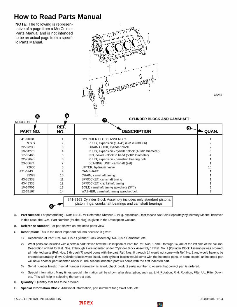
How to Read Parts Manual
PART NO.REF.NO. DESCRIPTION QUAN.
841-81631 1 CYLINDER BLOCK ASSEMBLY 1 N.S.S. 2 PLUG, expansion (1-1/4″) (GM #3738306) 222-87238 3 DRAIN COCK, cylinder block 219-34270 4 PLUG, expansion - cylinder block (1-5/8″ Diameter) 817-35465 5 PIN, dowel - block to head (5/16″ Diameter) 422-72640 6 PLUG, expansion - camshaft bearing hole 123-85674 7 BEARING UNIT, camshaft (set) 1 72638 8 LIFTER, hydraulic valve 16
431-5943 9 CAMSHAFT 1 35378 10 CHAIN, camshaft timing 143-35338 11 SPROCKET, camshaft timing 143-48338 12 SPROCKET, crankshaft timing 110-34505 13 BOLT, camshaft timing sprockets (3/4″) 3
12-39167 14 WASHER, camshaft timing sprocket bolt 3
841-8163 Cylinder Block Assembly includes only standard pistons,piston rings, crankshaft bearings and camshaft bearings.
CYLINDER BLOCK AND CAMSHAFTM0033-D8
bc
d
a
e
73287
NOTE: The following is represen-tative of a page from a MerCruiserParts Manual and is not intendedto be an actual page from a specif-ic Parts Manual.
A. Part Number: For part ordering - Note N.S.S. for Reference Number 2, Plug, expansion - that means Not Sold Separately by Mercury Marine; however,
in this case, the G.M. Part Number (for the plug) is given in the Description Column.
B. Reference Number: For part shown on exploded parts view.
C. Description: This is the most important column because it gives:
1) Description of Part: Ref. No. 1 is a Cylinder Block Assembly, No. 9 is a Camshaft, etc.
2) What parts are included with a certain part: Notice how the Description of Part, for Ref. Nos. 1 and 8 through 14, are at the left side of the column.Description of Part for Ref. Nos. 2 through 7 are indented under “Cylinder Block Assembly.” If Ref. No. 1 (Cylinder Block Assembly) was ordered,all indented parts (Ref. Nos. 2 through 7) would come with the part. Ref. Nos. 8 through 14 would not come with Ref. No. 1 and would have to beordered separately. If two Cylinder Blocks were listed, both cylinder blocks would come with the indented parts. In some cases, an indented partwill have another part indented under it. The second indented part will come with the first indented part.
3) Serial number break: If serial number information is listed, check product serial number to ensure that correct part is ordered.
4) Special information: Many times special information will be shown after description, such as: L.H. Rotation, R.H. Rotation, Filter Up, Filter Down,etc. This will help in selecting the correct part.
D. Quantity: Quantity that has to be ordered.
E. Special Information Block: Additional information, part numbers for gasket sets, etc.

GENERAL INFORMATION – 1A-390-806934 1194
Directional ReferencesFront of boat is bow; rear is stern. Starboard side isright side; port side is left side. In this maintenancemanual, all directional references are given as theyappear when viewing boat from stern looking towardbow.
72000
STARBOARD(RIGHT)
PORT(LEFT)
FORE or BOW(FRONT)
AFT or STERN(REAR)
Engine RotationEngine rotation is determined by observing flywheelrotation from the rear (stern end) of the engine lookingforward (toward water pump end). Propeller rotationis not necessarily the same as engine rotation. Whenordering replacement engine, short blocks or partsfor engine, be certain to check engine rotation. Do notrely on propeller rotation in determining engine rota-tion.
73330
a - Standard Left-Hand Rotation
Engine Serial Number and Identification LocationsEngine model and serial numbers are located on two plates attached on the engine where shown. Emission Certifi-cation Decals are placed where shown.
MIE (Inboard) Engine Shown [MCM (Stern Drive) Similar]
BSO: M12 11 3 93_ _
D3.6L/180 TURBO AC
71675
73565
71688
THIS ENGINE CONFORMS TO INT’LBODENSEE SHIPPING
COMISSION STDS CERT NO.
M12 11 3 93 _ _ bc
d
a
ab
c
a - Riveted Serial Number Plate, and Emission Certification Decal If Applicable (Port Side of Engine Block, Near Top of Electrical Box)b - Self-Adhesive Serial Number Plate (Applied to Top of Intercooler Duct)c - Self-Adhesive Emission Certification Decal, If Applicable (Applied to Top of Intercooler Duct)d - VM Serial Number (Stamped in Block)

1A-4 – GENERAL INFORMATION 90-806934 1194
Propeller InformationRefer to the “Propeller” section in appropriate Mer-Cruiser Stern Drive Service Manual, or order publica-tion P/N 90-86144-92, “Everything you need to knowabout propellers.”
Changing diameter, pitch or coupling of a propellerwill affect engine RPM and boat performance . Theblade configuration also will affect performance. Twolike propellers, same pitch and diameter, from two dif-ferent manufacturers also will perform differently.
It is the responsibility of the boat manufacturer and/orselling dealer to equip the boat with the correct pro-peller to allow the engine to operate within its speci-fied RPM range at wide-open-throttle (W.O.T.).
Because of the many variables of boat design and op-eration, only testing will determine the best propellerfor the particular application.
To test for correct propeller, operate boat (with anaverage load onboard) at W.O.T. and check RPM withan accurate tachometer. Engine RPM should be neartop of the specified range so that, under heavy load,engine speed will not fall below specifications.
If engine exceeds the specified RPM, an increase inpitch and/or diameter is required.
If engine is below rated RPM, a decrease in pitch and/or diameter is required.
Normally, a change of approximately 100 to 150 RPMwill be achieved for each single pitch change of a pro-peller.
! CAUTIONIf a propeller is installed that does not allow en-gine RPM to reach the specified full-throttle RPMrange, the engine will “labor” and will not pro-duce full power. Operation under this conditionwill cause excessive fuel consumption and en-gine overheating. On the other hand, installationof a propeller, that allows engine to run above thespecified RPM limit, will cause excessive wear oninternal engine parts which will lead to prematureengine failure.
Water Testing New EnginesUse care during the first 20 hours of operation on newMerCruiser engines or possible engine failure mayoccur. If a new engine has to be water-tested at fullthrottle before the break-in period is complete, followthis procedure ONLY AFTER the engine INITIALBREAK-IN PROCEDURE has been completed.
1. Start engine and run at idle RPM until normal op-erating temperature is reached.
2. Run boat up on plane.
3. Advance engine RPM (in 200 RPM increments)until engine reaches its maximum rated RPM.
IMPORTANT: Do not run at maximum RPM formore than 2 minutes.

GENERAL INFORMATION – 1A-590-806934 1194
Boat and EnginePerformance
Boat BottomFor maximum speed, a boat bottom should be as flatas possible in a fore-aft direction (longitudinally) forapproximately the last 5 ft. (1.5 m).
72002
a - Critical Bottom Area
For best speed and minimum spray, the corner be-tween the bottom and the transom should be sharp.
72003
a - Flatb - Sharp Corner
The bottom is referred to as having a “hook” if it is con-cave in the fore-and-aft direction. A hook causesmore lift on the bottom near the transom and forcesthe bow to drop. This increases wetted surface andreduces boat speed. A hook, however, aids in planing
and reduces any porpoising (rhythmical bouncing)tendency. A slight hook is often built in by the man-ufacturer. A hook also can be caused by incorrecttrailering or storing the boat with support directly un-der the transom.
72004
a - Hook
A “rocker” is the reverse of a hook. The bottom is con-vex or bulged in the fore-and-aft direction. It cancause the boat to porpoise.
72005
a - Rocker
Any hook, rocker or surface roughness on the bottom,particularly in the all-important center-aft portion willhave a negative effect on speed, often several milesper hour on a fast boat.

1A-6 – GENERAL INFORMATION 90-806934 1194
Marine FoulingFouling is an unwanted build-up (usually animal-veg-etable-derived) occurring on the boat’s bottom anddrive unit. Fouling adds up to drag, which reducesboat performance. In fresh water, fouling results fromdirt, vegetable matter, algae or slime, chemicals, min-erals and other pollutants. In salt water, barnacles,moss and other marine growth often produce dramat-ic build-up of material quickly. Therefore, it is impor-tant to keep the hull as clean as possible in all waterconditions to maximize boat performance.
Special hull treatments, such as anti-fouling paint, willreduce the rate of bottom fouling. However, due to thefact that drive units (outboard or stern drive) are madeprimarily of aluminum, be sure to select an anti-foul-ing paint having a copper-free, organo-tin base. TheBIS (Tri Butyl Tin) Adipate (TBTA) base paint will notset up a galvanic corrosion “cell” as it is completelycompatible with aluminum and avoids any electroly-sis problems connected with many other paints.Applied according to instructions, it also is very effec-tive.
Weight DistributionWeight distribution is extremely important; it affects aboat’s running angle or attitude. For best top speed,all movable weight - cargo and passengers - shouldbe as far aft as possible to allow the bow to come upto a more efficient angle (3 to 5 degrees). On the neg-ative side of this approach is the problem that, asweight is moved aft, some boats will begin an unac-ceptable porpoise.
Secondly, as weight is moved aft, getting on plane be-comes more difficult.
Finally, the ride in choppy water becomes more un-comfortable as the weight goes aft. With these factorsin mind, each boater should seek out what weight lo-cations best suit his/her needs.
Weight and passenger loading placed well forward in-creases the “wetted area” of the boat bottom and, insome cases, virtually destroys the good performanceand handling characteristics of the boat. Operation inthis configuration can produce an extremely wet ride,from wind-blown spray, and could even be unsafe incertain weather conditions or where bow steeringmay occur.
Weight distribution is not confined strictly to fore andaft locations, but also applies to lateral weight distri-bution. Uneven weight concentration to port or star-board of the longitudinal centerline can produce a se-vere listing attitude that can adversely affect theboat’s performance, handling ability and riding com-fort. In extreme rough water conditions, the safety ofthe boat and passengers may be in jeopardy.
Water in BoatWhen a boat loses performance, check bilge for wa-ter. Water can add considerable weight to the boat,thereby decreasing the performance and handling.
Make certain that all drain passages are open forcomplete draining.
Elevation and ClimateElevation has a very noticeable effect on thewide-open- throttle power of an engine. Since air(containing oxygen) gets thinner as elevation in-creases, the engine begins to starve for air. Humidity,barometric pressure and temperature do have a no-ticeable effect on the density of air. Heat and humiditythin the air. This phenomenon can become particular-ly annoying when an engine is propped out on a cooldry day in spring and later, on a hot, sultry day in Au-gust, doesn’t have its old zip.
Although some performance can be regained bydropping to a lower pitch propeller, the basic problemstill exists. The propeller is too large in diameter forthe reduced power output. The experienced marinedealer or a Quicksilver Propeller Repair Station candetermine how much diameter to remove from a low-er-pitch propeller for specific high-elevation loca-tions. In some cases, a gear-ratio change to the driveunit to more reduction is possible and very beneficial.It is a known fact that weather conditions exert a pro-found effect on power output of internal combustionengines. Therefore, established horsepower ratingsrefer to the power that the engine will produce at itsrated RPM under a specific combination of weatherconditions.

GENERAL INFORMATION – 1A-790-806934 1194
Recommended Operation/Duty CycleIt is the operator’s responsibility to operate within thefollowing recommended operational capability, orduty cycle, as applicable to engine and installation:
• Pleasure Duty -
1.) Operated at rated power and ratedspeed for short periods of time.
• Light Duty -
1.) Operated such that full rated power atmaximum rated RPM is limited to 10% of operatingtime and continuous cruising RPM is limited to90% of Wide-Open-Throttle RPM (when proppedwithin specified RPM range).
2.) Annual operating time is not to exceed500 hours.
NOTE: Pleasure duty rating applies to highperformance-type boats, or boats with planing hullswhere acceleration and top speed are of primaryimportance. This rating is reserved forprivately-owned yachts, or recreational power boatsin non-revenue applications.
Light duty rating applies to planing boats where theuse of full rated power at maximum rated RPM islimited (as stated above). Examples of Light Dutyapplications include, but are not limited to: search andrescue craft, fast patrol boats, fire boats, dive boats,and limited season fishing boats such as sport-fishcharter boats. Application to common commercialcrafts having full-displacement or semi-displacementhulls exceeds the recommended operationalcapability, or duty cycle.
IMPORTANT: Damage caused by improperapplication or failure to operate within theoperational capability, or duty cycle, will not becovered by the MerCruiser Diesel LimitedWarranty.
Pre-LubricatingTurbochargerIMPORTANT: After a lengthy lay-up (severalmonths or more), it is necessary to pre-lubricatethe turbocharger and engine. To do this, movethe “STOP” switch toggle lever DOWN and holdin this position while you turn the key switch to“START” position. Doing this TOGETHER turnsthe engine without starting it. DO NOT engagestarter for more than 15 seconds; allow at leastone minute cool down time before re-engagingstarter for another 15 seconds. Watch that starterdoes not overheat.

1
B
IMPORTANT INFORMATION
MAINTENANCE
Note:Refer to the following Service Bulletin regarding this section.
SB 91-7 New Engine Break-In Procedure for Diesel Engines

1B-0 – MAINTENANCE 90-806934 1194
Table of ContentsPage
Maintenance Schedule 1B-1. . . . . . . . . . . . . . . . . . . . . . . . Scheduled Maintenance To Be Performed ByOwner/Operator 1B-1. . . . . . . . . . . . . . . . . . . . . . . .
Maintenance Schedule (Continued) 1B-2. . . . . . . . . . . . . Scheduled Maintenance To Be Performed ByDealer 1B-2. . . . . . . . . . . . . . . . . . . . . . . . . . . . . . . .
Specifications 1B-3. . . . . . . . . . . . . . . . . . . . . . . . . . . . . . . . Engine 1B-3. . . . . . . . . . . . . . . . . . . . . . . . . . . . . . . . . . . Fluid Capacities 1B-4. . . . . . . . . . . . . . . . . . . . . . . . . . . Required Coolant 1B-4. . . . . . . . . . . . . . . . . . . . . . . . . .
Engine Initial Break-In Procedure 1B-5. . . . . . . . . . . . . . . Engine 20-Hour Break-In Period 1B-5. . . . . . . . . . . . . . . . After Break-in Period 1B-5. . . . . . . . . . . . . . . . . . . . . . . . . . 20-50 Hour Check-up 1B-6. . . . . . . . . . . . . . . . . . . . . . . . . Fluid Specifications 1B-7. . . . . . . . . . . . . . . . . . . . . . . . . . .
Diesel Fuel 1B-7. . . . . . . . . . . . . . . . . . . . . . . . . . . . . . . Diesel Fuel In Cold Weather 1B-7. . . . . . . . . . . . . .
Power Steering Fluid 1B-7. . . . . . . . . . . . . . . . . . . . . . . Transmission Fluid 1B-7. . . . . . . . . . . . . . . . . . . . . . . . . Crankcase Oil 1B-8. . . . . . . . . . . . . . . . . . . . . . . . . . . . .
Recommended Oils for D3.0L/150 and D3.6L/180 1B-8. . . . . . . . . . . . . . . . . . . . . . . . . Recommended Oils for D4.2L/220 1B-8. . . . . . . .
Coolant for Closed Cooling System 1B-9. . . . . . . . . . Maintaining Crankcase Oil Level 1B-9. . . . . . . . . . . . . . . .
Overfilled Engine Crankcase 1B-9. . . . . . . . . . . . . . . . Checking Engine Oil Level/Filling 1B-9. . . . . . . . . . . .
Changing Crankcase Oil and Oil Filter 1B-10. . . . . . . . . . Maintaining Power Steering Pump Fluid Level 1B-11. . .
With Engine Cold 1B-11. . . . . . . . . . . . . . . . . . . . . . . . . Filling and Bleeding Power Steering System 1B-12. . . . . Maintaining Transmission Fluid Level 1B-12. . . . . . . . . . . Maintaining Power Trim Pump Oil Level 1B-13. . . . . . . . Maintaining Drive Unit Oil (Gear Lube Monitor) 1B-13. . Maintaining Closed Cooled Section Coolant Level 1B-14Changing (Draining) Closed Cooled Section Coolant 1B-14. . . . . . . . . . . . . . . . . . . . . . . . . . . . . Filling Closed Cooled Section 1B-15. . . . . . . . . . . . . . . . . Flushing Seawater Cooling System 1B-16. . . . . . . . . . . .
MCM Stern Drive 1B-16. . . . . . . . . . . . . . . . . . . . . . . . . MIE Inboard 1B-17. . . . . . . . . . . . . . . . . . . . . . . . . . . . .
Inspect Water Pickups 1B-18. . . . . . . . . . . . . . . . . . . . . . . Stern Drive Gear Housing 1B-18. . . . . . . . . . . . . . . . . . Inboard Thu-Hull Pickup 1B-18. . . . . . . . . . . . . . . . . . .
Check/Clean Seawater Strainer 1B-18. . . . . . . . . . . . . . .
PageFuel Filter 1B-19. . . . . . . . . . . . . . . . . . . . . . . . . . . . . . . . . .
Precautions 1B-19. . . . . . . . . . . . . . . . . . . . . . . . . . . . . . Draining 1B-19. . . . . . . . . . . . . . . . . . . . . . . . . . . . . . . . . Filling 1B-20. . . . . . . . . . . . . . . . . . . . . . . . . . . . . . . . . . . Replacing 1B-20. . . . . . . . . . . . . . . . . . . . . . . . . . . . . . .
Clean/Replace Air Filter 1B-21. . . . . . . . . . . . . . . . . . . . . . Inspect Drive Belts 1B-21. . . . . . . . . . . . . . . . . . . . . . . . . . . Replace Drive Belts 1B-22. . . . . . . . . . . . . . . . . . . . . . . . . .
Engine Water Circulating Pump Belt 1B-22. . . . . . . . . Alternator Belt 1B-22. . . . . . . . . . . . . . . . . . . . . . . . . . . . Power Steering Pump Belt 1B-23. . . . . . . . . . . . . . . . .
D3.0L/150 and D3.6L/150 Models 1B-23. . . . . . . . D4.2L/220 Models 1B-24. . . . . . . . . . . . . . . . . . . . .
Vacuum Pump Belt 1B-25. . . . . . . . . . . . . . . . . . . . . . . D3.0L/150 and D3.6L/150 Models 1B-25. . . . . . . . D4.2L/220 Models 1B-26. . . . . . . . . . . . . . . . . . . . .
Inspect/Replace Cooling System Sacrificial Anodes 1B-27. . . . . . . . . . . . . . . . . . . . . . . . . . . . . . . . . . . .
Coolant Tank / Heat Exchanger Anode 1B-27. . . . . . . Inspection 1B-27. . . . . . . . . . . . . . . . . . . . . . . . . . . . Replacement 1B-27. . . . . . . . . . . . . . . . . . . . . . . . . .
Intercooler Anode 1B-28. . . . . . . . . . . . . . . . . . . . . . . . . Inspection 1B-28. . . . . . . . . . . . . . . . . . . . . . . . . . . . Replacement 1B-28. . . . . . . . . . . . . . . . . . . . . . . . . .
Corrosion and Corrosion Protection 1B-28. . . . . . . . . . . . Check Battery 1B-29. . . . . . . . . . . . . . . . . . . . . . . . . . . . . . . Lubrication 1B-29. . . . . . . . . . . . . . . . . . . . . . . . . . . . . . . . .
Throttle Cable 1B-29. . . . . . . . . . . . . . . . . . . . . . . . . . . . Shift Cable 1B-29. . . . . . . . . . . . . . . . . . . . . . . . . . . . . . . Engine Coupler/U-Joint Shaft Splines 1B-30. . . . . . . .
Freezing Temperature and Cold Weather Operation 1B-30. . . . . . . . . . . . . . . . . . . . . . . . . . . . . . . . . . Saltwater Operation 1B-31. . . . . . . . . . . . . . . . . . . . . . . . . . Cold Weather or Extended Storage 1B-31. . . . . . . . . . . .
Precautions 1B-31. . . . . . . . . . . . . . . . . . . . . . . . . . . . . . Layup 1B-32. . . . . . . . . . . . . . . . . . . . . . . . . . . . . . . . . . .
Draining Instructions 1B-33. . . . . . . . . . . . . . . . . . . Battery Winter Storage 1B-36. . . . . . . . . . . . . . . . .
Recommissioning 1B-37. . . . . . . . . . . . . . . . . . . . . . . . . . .
NOTICE
For information and procedures on troubleshoot-ing, refer to SECTION 1C.
1B – MAINTENANCE

MAINTENANCE – 1B-190-806934 1194
Maintenance Schedule
! WARNINGAlways disconnect battery cables from batteryBEFORE working around electrical system com-ponents to prevent injury to yourself or damageto electrical system should a wire be accidentallyshorted.
NOTE: Refer to appropriate Stern Drive ServiceManual for information and procedures on stern drivemaintenance items listed.
SCHEDULED MAINTENANCE TO BE PERFORMED BY OWNER/OPERATOR
REQUIRED SERVICE INTERVAL
Check engine oil level.
Check drive unit gear lube monitor
Check transmission fluid level.
Check closed coolant level.Before Operation
Check water pickups for marine growth or debris.
Drain fuel filter.
Check / Clean seawater strainer. Before Operation / Clean As Required
Inspect drive unit alloy anodes for erosion (Replacewhen over 50% eroded).
Weekly or As Required
Flush seawater section of cooling system. Saltwater Use: After Each Use
Check power trim pump oil level.
Check power steering fluid level.Every 50 Hours of Use
Clean air filter element. Every 50 Hours of Operation, or as ConditionsRequire
Inspect condition and check tension of drive belts. Every 50 Hours of Operation or 60 Days - WhicheverOccurs First
Lubricate propeller shaft.
Saltwater Use: Every 50 Hours of Operation or 60Days, Whichever Occurs First Freshwater Use: Every 100 Hours of Operation or120 Days, Whichever Occurs First
Replace fuel filter. Every 100 Hours of Operation or Once A Year,Whichever Occurs First
Replace air filter element. Every 200 Hours of Operation, or Once a Year,Whichever Occurs First
Check sacrificial anode (in heat exchanger) - Replace when over 50% eroded.
Check sacrificial anode (in intercooler) - Replacewhen over 50% eroded). Once a Year
Spray power package exterior surfaces with Quicksil-ver Corrosion Guard.
Clean and paint power package exterior surfaces. As Necessary
Check battery fluid level. Refer to Battery Manufacturer Specifications

1B-2 – MAINTENANCE 90-806934 1194
Maintenance Schedule (Continued)SCHEDULED MAINTENANCE TO BE PERFORMED BY DEALER
REQUIRED SERVICE INTERVAL
20-50 Hour Checkup (See NOTE 1.). After First 20 Hours, But Not Later Than 50 Hours, of Op-eration
Retorque cylinder heads After First 100 Hours of Operation or First OperatingSeason, Whichever Occurs First
Change engine oil and filter.
After 20-Hour Break-In Period, Then, for Pleasure-craft Use: Every 100 Hours of Use or 120 Days,Whichever Occurs First ; and for Light Duty Use:Every 50 Hours of Use or 60 Days, Whichever Oc-curs First (See NOTE 2.)
Lubricate engine coupling and universal joint shaftsplines.
Every 50 Hours of Operation or 60 Days, WhicheverOccurs First
Check engine alignment and mounting hardware.
Change transmission fluidEvery 100 Hours of Operation
Change Stern Drive Unit oil including gear lube moni-tor oil.
Every 100 Hours of Operation or 120 Days, Whichev-er Occurs First
Retorque gimbal ring clamping U-bolt to 50 - 55 lb. ft.(67 - 74 N·m). Every 100 Hours of Operation or Once a Year,Clean, inspect and test the closed cooling systempressure cap.
Every 100 Hours of Operation or Once a Year,Whichever Occurs First
Replace coolant (using only Quicksilver PremixedMarine Engine Coolant). Every 200 Hours of Operation or Once a Year,
Clean heat exchangers. Whichever Occurs First
Lubricate universal joint cross bearings
Check and adjust idle RPM. Once a Year
Clean intercooler core.
Replace drive belts.Every 500 Hours of Operation
Inspect cooling system hoses and clamps.
Inspect engine exhaust system externally for dam-age, deterioration and restrictions. Check clamps fortightness.
Inspect and lubricate shift/throttle cables and linkage . Saltwater use: Every 50 hours of operation or 60
Check electrical system for loose or damaged wiring. days, Whichever Occurs First.Freshwater use: Every 100 hours of operation or
Lubricate transom gimbal bearingFreshwater use: Every 100 hours of operation or120 days, Whichever Occurs First.
Lubricate and inspect steering system for loose, dam-aged or missing parts.
Ground Wire Circuit continuity - Check componentsfor loose connections, broken or frayed wires.
Disassemble and inspect seawater pump.Whenever Insufficient Seawater Flow is Suspected (IfOperating Temperature Exceeds Normal Range) orAt Least Once yearly
Clean fuel tank. Every 1000 Hours of Operation
NOTE 1: For a list of 20-50 Hour Checkup maintenance items to be performed, see “IMPORTANT INFORMATION, SECTION 1A” of this manual.
NOTE 2: For an explanation of Pleasure Craft and Light Duty usage refer to SECTION 1A -“Recommended Operation/Duty Cycle”.

MAINTENANCE – 1B-390-806934 1194
SpecificationsEngine
SPECIFICATIONITEM
D3.0L/150 D3.6L/180 D4.2L/220
Crankshaft Horse- MCM (Stern Drive) 150 ( 112 ) 180 ( 134 ) 220 ( 164 )Crankshaft Horse-power (Kilowatts) 1 MIE (Inboard) 2 150 ( 112 ) 180 ( 134 ) 220 ( 164 )
Propeller Shaft MCM (Stern Drive) 140 ( 104 ) 170 ( 127 ) 200 (149 )Horsepower (Kilowatts) 1 MIE (Inboard) 2 150 ( 112 ) 180 ( 134 ) 210 (156 )
Engine Type In-Line 5 Cylinder Diesel
In-Line 6 CylinderDiesel
Displacement 183 cu. in. ( 3.0 L ) 219 cu. in. ( 3.6 L ) 254 cu. in. ( 4.2L )
Firing Order 1-2-4-5-3 1-5-3-6-2-4
Bore 3.622 in. ( 92mm ) 3.700 in. ( 94 mm )
Stroke 3.543 in. ( 90mm ) 3.937 in.( 100 mm )
Compression Ratio 22 : 1 21.5 : 1
Valve Clearance ( Intake / Exhaust ) .012 in. ( 0.30 mm )
Maximum Pressure Difference Between Cyl. 72 PSI ( 500 kPa )
Maximum Governed WOT RPM 4300 ± 50 4200 ± 50
Maximum WOT RPM 3800 3600
Idle RPM in Forward Gear 700
750 RPM 22-36 PSI [ 1.5 - 2.5 bar ( 152-248 kPa ) ]Oil Pressure:
3600 RPM 50-58 PSI [ 3.5 - 4 bar ( 345-400 kPa ) ]
Oil Temperature 212° - 230° F ( 100° - 110° C )
Thermostats:Water: 1 at temperature: 160° F ( 70° C )
(2 for Water) 1 at temperature: 180° F ( 82° C )(1 for Oil) ° °(1 for Oil) Oil: 195° F ( 90° C )
Coolant Temperature 176° - 185° F ( 80° - 85° C )
Electrical System 12-volt Negative ( – ) Ground
Alternator Rating 949W, 14.6v, 65A
Recommended Battery Rating ( Minimum ) 12v, 750cca, 950mca, 180Ah
Starter ( Bosch ) 12v, 2.7 kW
1 Power rated in accordance with NMMA Procedure - ISO 3046 (Technically Identical to ICOMIA 28-83).
2 Engine rated with Hurth 8 degree Down-Angle transmission. Power output with other transmissions will vary.

1B-4 – MAINTENANCE 90-806934 1194
Fluid Capacities
NOTICE
All capacities are approximate fluid measures in U.S. Quarts (Litres).
SPECIFICATION - MIE ( INBOARD )ITEM ITEM
D3.0L/150 D3.6L/180 D4.2L/220
Total Oil-filling Capacity 1 9-1/2 ( 9 ) 10-1/2 ( 10 ) 12-3/4 ( 12 )
from oil pan 7-1/2 ( 7 ) 8-1/2 ( 8 ) 10-3/4 ( 10 )
Oil Drainage from oil filter 1 ( 1 )
from oil cooler 1 ( 1 )
Transmission - Hurth - 630A 8° Down Angle 1 4-1/4 ( 4 )
Transmission - Hurth - 630V-Drive 1 5 ( 4-3/4 )
Drive Unit Oil Capacity, with GearBravo One Round Monitor
Square Monitor3-1/4 ( 3 )2-1/4 ( 2 )Drive Unit Oil Capacity, with Gear
Lube MonitorBravo Two Round Monitor
Square Monitor3-3/4 ( 3-1/2 )
3-1/4 ( 3 )
Closed Cooling Circuit 11-1/2 ( 11 ) 12-3/4 ( 12 ) 13-3/4 ( 13 )
1 Always use dipstick to determine exact quantity of oil or fluid required.
2 Seawater cooling system capacity information is for cold weather or extended storage use only.
Required Coolant: Quicksilver Premixed Marine Engine CoolantIMPORTANT: This contains special low silicate ethylene glycol, special additives, and purified water. Useof other coolant may cause fouling of the heat exchangers, and overheating of the engine.
MAINTENANCE – 1B-590-806934 1194
Engine Initial Break-InProcedureIt is especially important that the following procedurebe used on new and rebuilt diesel engines. Thisbreak-in procedure allows the proper seating of thepistons and rings, which greatly reduces the likeli-hood of problems.
IMPORTANT: It is recommended that the boat notbe accelerated hard until this procedure has beencompleted.
IMPORTANT: Never operate the starter motor longerthan 15 seconds at a time, to avoid overheating thestarter motor. If engine does not start, wait 1 minute toallow the starter motor to cool; then, repeat startingprocedure.
Initial Break-In Procedure is as follows:
1. Refer to owner’s manual and start engine. Allowengine to idle until engine has reached normal op-erating temperature.
2. Run engine in gear for 3 minutes at each of the fol-lowing RPMs: 1200 RPM, 2400 RPM and 3000RPM.
3. Run engine in gear for 3 minutes at each of the fol-lowing RPMs: 1500 RPM, 2800 RPM and 3400RPM.
4. Run engine in gear for 3 minutes at each of the fol-lowing RPMs: 1800 RPM, 3000 RPM and Maxi-mum Rated Wide-Open-Throttle RPM.
Engine 20-Hour Break-InPeriodIMPORTANT: The first 20 hours of operation is theengine break-in period. Correct break-in is essen-tial to obtain minimum oil consumption and maxi-mum engine performance. During this break-inperiod, the following rules must be observed:
The first 20 hours of operation is the engine (new orrebuilt) break-in period. During this period, it is ex-tremely important that the engine is operated as out-lined in the following.
1. DO NOT operate engine below 1500 RPM for ex-tended periods of time during the first 10 hours.During this period, shift into gear as soon as pos-sible after starting engine and advance throttle sothat RPM is above 1500 (provided that conditionspermit safe operation at this speed).
2. DO NOT operate at any one constant speed forextended periods of time.
3. DO NOT exceed 75% of full throttle during the first10 hours except during the Engine Initial Break-InProcedure. During the next 10 hours, occasionaloperation at full throttle (5 minutes at a time maxi-mum) is permissible.
4. AVOID full throttle accelerations from stopped po-sition.
5. DO NOT operate at full throttle until engine reach-es normal operating temperature.
6. OBSERVE INSTRUMENTATION carefully. If anabnormal reading occurs, stop engine immedi-ately and determine cause.
7. FREQUENTLY CHECK crankcase oil level andadd oil if necessary. It is normal for oil consump-tion to be somewhat high during the break-in peri-od.
8. AT END OF THE 20-HOUR BREAK-IN PERIOD,drain oil from crankcase and replace oil and filter.Fill crankcase with correct grade and viscosity oil.
After Break-in PeriodTo help extend the life of your MerCruiser powerpackage, the following recommendations should beconsidered;
• Use a propeller that allows the engine to operateat or near the top of the maximum RPM range (See“Specifications” section) when at full throttle witha normal boat load.
• Operation at 3/4 throttle setting or lower is recom-mended. Refrain from prolonged operation atmaximum (full throttle) RPM.

1B-6 – MAINTENANCE 90-806934 1194
20 Hour CheckupAfter 20 hours of operation, but no later than 50 hours, an Authorized MerCruiser Dealer should be contacted forthe following services, checks, and adjustments. (Note: Some items may not apply to your specific powerpackage.)
The product owner is responsible for any charges. A copy of the dealer service work order must be kept by theproduct owner.Service, check or adjust as indicated.
BEFORE RUNNING (ENGINE COLD) - CHECK OR ADJUST
Not
Applicable Completed
Torque turbocharger fasteners [31 lb. ft. (42 N·m)] and exhaust manifold fasteners [24 lb. ft. (32 N·m)] (V-8 Diesel models only)Tighten cooling and exhaust system hose clampsThrottle, shift and steering system fasteners tight and/or properly securedDrive mounting fasteners are tightCheck that both front engine mount locknuts are tightened securely. Then, check to ensure that tab washers are bent down over adjusting nuts.Check that rear engine mounts are torqued to 35-40 lb. ft. (47-54 N⋅m). (stern drive models only)Drain fuel filter and check for waterCheck condition and tension of all drive beltsCheck closed cooling system coolant level *Retorque gimbal ring clamping bolt to 50 - 55 lb. ft. (67 - 74 N·m) (stern drive models only)Power steering system fluid (stern drive models only)*Drive unit lubricant level (stern drive models only)*Transmission fluid level (inboard models only)*Power trim pump oil level (stern drive models only)*
ON-WATER TESTING (ENGINE RUNNING/OPERATING TEMPERATURE) - CHECK OR ADJUSTAdjust idle RPM in forward gear♦All gauges and indicator lamps proper readings♦Fuel, oil, water, coolant and exhaust leaksRemote control operation--forward, neutral and reverseSteering operation throughout rangePower trim operation (stern drive models only)Maximum RPM in forward gear -- change propeller if necessary♦
AFTER-WATER TESTING - SERVICEChange crankcase oil and filter
♦ - Refer to “Specifications - Engine” Chart in this manual.
* - Use only factory approved coolant and fluids.

MAINTENANCE – 1B-790-806934 1194
Fluid Specifications
Diesel Fuel
! WARNINGFIRE HAZARD: Fuel leakage from any part of thefuel system can be a fire hazard which can causeserious bodily injury or death. Careful periodic in-spection of entire fuel system is mandatory, par-ticularly after storage. All fuel components in-cluding fuel tanks, whether plastic, metal orfiberglass, fuel lines, primers, fittings, and fuel fil-ters should be inspected for leakage, softening,hardening, swelling or corrosion. Any sign ofleakage or deterioration requires replacementbefore further engine operation.
! WARNINGUnder no circumstances should gasoline, gaso-hol and/or alcohol be mixed with diesel fuel forany reason. This mixture of gasoline, gasoholand/or alcohol with diesel fuel is highly flam-mable and produces a significant risk to the user.
IMPORTANT: Use of improper or water-contami-nated diesel fuel will damage your engine seri-ously. Use of improper fuel is considered misuseof engine, and damage caused thereby will not becovered by warranty.
Grade 2-D diesel fuel is required, meeting ASTMStandards D975 (or fuel rated Diesel DIN 51601), andhaving a minimum cetane rating of 45.
The cetane number is a measure of the ignition quali-ty of diesel fuel. Increasing the cetane number will notimprove overall engine performance, but it may benecessary to raise the cetane rating for low tempera-ture or high altitude use.
NOTE: If your engine suddenly becomes noisy aftera fuel fill, you possibly received substandard fuel witha low cetane rating.
Sulphur content of the above fuel is rated at 0.50% byweight, maximum (ASTM). Limits may vary in coun-tries outside of the United States.
On intermittent use engines, high sulphur content die-sel fuel will greatly increase:
• Corrosion of metal parts.
• Deterioration of elastomer and plastic parts.
• Corrosion and extensive damage, and excessivewear of internal engine parts, particularly bear-ings.
• Starting and operating difficulties.
DIESEL FUEL IN COLD WEATHER
Unaltered diesel fuels thicken and “gel” in cold tem-peratures, unless treated. Virtually all diesel fuels are“climatized” to allow their use in the particular regionfor that time of the year. If it becomes necessary to fur-ther treat diesel fuel, it is the owner/operator’s re-sponsibility to add a commercial “standard brand”“anti-gel” diesel fuel additive, following that product’sdirections.
Power Steering FluidUse Quicksilver Power Trim and Steering Fluid, or au-tomatic transmission fluid (ATF), Dexron, Dexron II.
Transmission FluidUse automatic transmission fluid (ATF) Dexron II.
1B-8 – MAINTENANCE 90-806934 1194
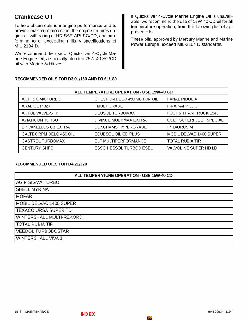
Crankcase OilTo help obtain optimum engine performance and toprovide maximum protection, the engine requires en-gine oil with rating of HD-SAE-API-SG/CD, and con-forming to or exceeding military specifications ofMIL-2104 D.
We recommend the use of Quicksilver 4-Cycle Ma-rine Engine Oil, a specially blended 25W-40 SG/CDoil with Marine Additives.
If Quicksilver 4-Cycle Marine Engine Oil is unavail-able, we recommend the use of 15W-40 CD oil for alltemperature operation, from the following list of ap-proved oils.
These oils, approved by Mercury Marine and MarinePower Europe, exceed MlL-2104 D standards.
RECOMMENDED OILS FOR D3.0L/150 AND D3.6L/180
ALL TEMPERATURE OPERATION - USE 15W-40 CD
AGIP SIGMA TURBO CHEVRON DELO 450 MOTOR OIL FANAL INDOL X
ARAL OL P 327 MULTIGRADE FINA KAPP LDO
AUTOL VALVE-SHP DEUSOL TURBOMAX FUCHS TITAN TRUCK 1540
AVIATICON TURBO DIVINOL MULTIMAX EXTRA GULF SUPERFLEET SPECIAL
BP VANELLUS C3 EXTRA DUKCHAMS HYPERGRADE IP TAURUS M
CALTEX RPM DELO 450 OIL ECUBSOL OIL CD PLUS MOBIL DELVAC 1400 SUPER
CASTROL TURBOMAX ELF MULTIPERFORMANCE TOTAL RUBIA TIR
CENTURY SHPD ESSO HESSOL TURBODIESEL VALVOLINE SUPER HD LD
RECOMMENDED OILS FOR D4.2L/220
ALL TEMPERATURE OPERATION - USE 15W-40 CD
AGIP SIGMA TURBO
SHELL MYRINA
MOPAR
MOBIL DELVAC 1400 SUPER
TEXACO URSA SUPER TD
WINTERSHALL MULTI-REKORD
TOTAL RUBIA TIR
VEEDOL TURBOBOSTAR
WINTERSHALL VIVA 1

MAINTENANCE – 1B-990-806934 1194
Coolant for Closed Cooling System
! CAUTIONAlcohol or Methanol base antifreeze or plain wa-ter, are not recommended for use in fresh watersection of cooling system at any time.
We require that the coolant section of closed coolingsystem be filled with Quicksilver Premixed MarineEngine Coolant.
IMPORTANT: Quicksilver Premixed Marine En-gine Coolant contains special low silicate ethy-lene glycol, special additives, and purified water.Use of other coolant may cause fouling of theheat exchangers, and overheating of the engine.
Maintaining Crankcase OilLevel
Overfilled Engine CrankcaseOverfilled crankcases (oil level being too high ) cancause a fluctuation or drop in oil pressure on Mer-Cruiser engines. The over-full condition results in theengine crankshaft splashing and agitating the oil,causing it to foam (become aerated). The aerated oilcauses a loss of engine performance and an increasein crankcase backpressure. An extreme overfillcondition could result in backpressure sufficient tocause large amounts of oil to be pulled over into theintake.
Care must be taken when checking engine oil level.Oil level must be maintained between the MINIMUMmark and the MAXIMUM mark on the dipstick. To en-sure that you are not getting a “false reading,” makesure the following steps are done before checking theoil level.
• Boat “at rest” in the water, or
• If boat is on a trailer, raise or lower bow until theboat is setting at the approximate angle that itwould be if setting “at rest” in the water.
• Allow sufficient time for oil to drain into the crank-case if engine has just been run or oil has just beenadded.
Checking Engine Oil Level/FillingIMPORTANT: ENGINE CRANKCASE OIL MUSTBE CHECKED AT INTERVALS SPECIFIED IN“MAINTENANCE SCHEDULE” CHART. It is nor-mal for an engine to use a certain amount of oil inthe process of lubrication and cooling of the en-gine. The amount of oil consumption is greatlydependent upon engine speed, with consump-tion being highest at wide-open-throttle and de-creasing substantially as engine speed is re-duced.
Check engine oil daily before first start-up.
If it becomes necessary to check oil level during oper-ation, stop the engine and allow 5 minutes for oil todrain into pan.
! CAUTIONAvoid possible injury, or damage to oil dipstickand internal engine components. Do not removecrankcase oil dipstick when engine is running.Stop the engine completely before removing orinserting dipstick.
1. Remove dipstick. Wipe clean and reinstall intodipstick tube.
a
a - Dipstick

1B-10 – MAINTENANCE 90-806934 1194
2. Remove dipstick and observe oil level. Oil mustbe between MIN and MAX marks on dipstick. Ifnecessary, add oil as follows.
71380
71382
a
b
c
a - Dipstickb - Minimum Oil Level Markc - Maximum Oil Level Mark
3. Remove oil filler cap. Add specified oil to bring lev-el up to, but not over, “MAX” mark on dipstick. Re-install oil filler cap.
73322
a
a - Oil Filler Cap
Changing Crankcase Oil andOil FilterIMPORTANT: Change oil when engine is warmfrom operation. Warm oil flows more freely, carry-ing away more impurities. Use only recom-mended motor oil (see SPECIFICATIONS).
1. Start engine and allow it to warm up to normal op-erating temperature.
2. Stop engine and allow some time for oil to draininto oil pan (approximately 5 minutes).
3. Loosen hose clamp and disconnect crankcasevent oil return hose from oil return tube.
4. Install crankcase oil pump (Quicksilver Part Num-ber - 90265A2) onto threaded fitting of oil returntube.
73325
70571
a
b
c
d
e
cd
a - Hose Clampb - Vent Oil Hosec - Oil Return Tubed - Threaded Fittinge - Crankcase Oil Pump Drain Assembly
5. Pump oil out of crankcase into drain pan. Whencrankcase is empty, remove pump and reinstallcrankcase oil return hose to oil return tube. Tight-en hose clamp securely.
MAINTENANCE – 1B-1190-806934 1194
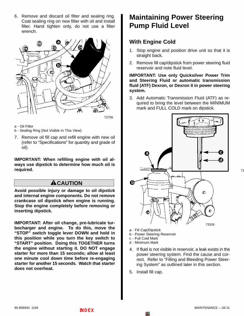
6. Remove and discard oil filter and sealing ring.Coat sealing ring on new filter with oil and installfilter. Hand tighten only, do not use a filterwrench.
72706
a
b
a - Oil Filterb - Sealing Ring (Not Visible In This View)
7. Remove oil fill cap and refill engine with new oil(refer to “Specifications” for quantity and grade ofoil).
IMPORTANT: When refilling engine with oil al-ways use dipstick to determine how much oil isrequired.
! CAUTIONAvoid possible injury or damage to oil dipstickand internal engine components. Do not removecrankcase oil dipstick when engine is running.Stop the engine completely before removing orinserting dipstick.
IMPORTANT: After oil change, pre-lubricate tur-bocharger and engine. To do this, move the“STOP” switch toggle lever DOWN and hold inthis position while you turn the key switch to“START” position. Doing this TOGETHER turnsthe engine without starting it. DO NOT engagestarter for more than 15 seconds; allow at leastone minute cool down time before re-engagingstarter for another 15 seconds. Watch that starterdoes not overheat.
Maintaining Power SteeringPump Fluid Level
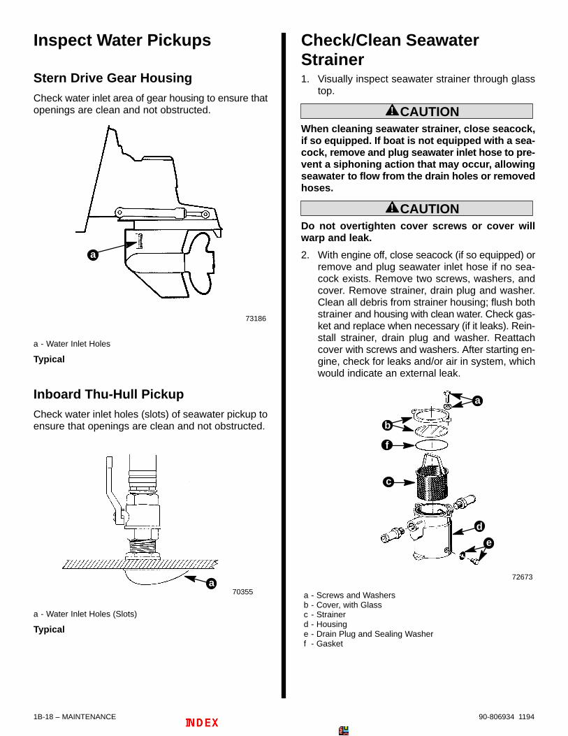
With Engine Cold1. Stop engine and position drive unit so that it is
straight back.
2. Remove fill cap/dipstick from power steering fluidreservoir and note fluid level.
IMPORTANT: Use only Quicksilver Power Trimand Steering Fluid or automatic transmissionfluid (ATF) Dexron, or Dexron II in power steeringsystem.
3. Add Automatic Transmission Fluid (ATF) as re-quired to bring the level between the MINIMUMmark and FULL COLD mark on dipstick.
73326
b
71
a
d
c
a - Fill Cap/Dipstickb - Power Steering Reservoirc - Full Cold Markd - Minimum Mark
4. If fluid is not visible in reservoir, a leak exists in thepower steering system. Find the cause and cor-rect. Refer to “Filling and Bleeding Power Steer-ing System” as outlined later in this section.
5. Install fill cap.

1B-12 – MAINTENANCE 90-806934 1194
Filling and Bleeding PowerSteering SystemIMPORTANT: Power steering system must befilled exactly as explained in the following to besure that all air is bled from the system. All airmust be removed, or fluid in pump may foam dur-ing operation and be discharged from pump res-ervoir. Foamy fluid also may cause power steer-ing system to become spongy, which may resultin poor boat control.
1. With engine stopped, position drive unit so that itis straight back. Remove fill cap/dipstick frompower steering pump. Add Quicksilver PowerTrim and Steering Fluid or automatic transmis-sion fluid (ATF), Dexron, or Dexron II, as required,to bring level up to FULL COLD mark on dipstick.
IMPORTANT: Use only Quicksilver Power Trimand Steering Fluid or automatic transmissionfluid (ATF), Dexron, or Dexron II in power steeringsystem.
2. With engine NOT running, turn the steeringwheel, at a moderate rate, back-and-forth to endof travel in each direction pausing each time atend of travel for a few seconds to allow any air tobubble from pump reservoir. Do this a minimumof 5 complete cycles, then recheck fluid level andadd fluid, if necessary.
3. Install reservoir fill cap.
! CAUTIONDO NOT operate engine without water beingsupplied to seawater pickup pump, or pump im-peller may be damaged and subsequent over-heating damage to engine may result.
4. Position boat in the water and/or see that water issupplied to seawater pickup holes. Start engineand run AT IDLE. During this time, turn steeringwheel back and forth to end of travel in each direc-tion several times.
5. Position drive unit so that it is straight back andstop engine. Remove fill cap from pump reservoir.Allow any foam in pump reservoir to disperse,then check fluid level. DO NOT OVERFILL. Rein-stall fill cap securely.
IMPORTANT: Drive unit must be positionedstraight back to accurately check fluid level.
6. If fluid is still foamy (in Step 5), repeat Steps 4 and5 until fluid does not foam and level remains con-stant.
Maintaining TransmissionFluid LevelIMPORTANT: To accurately check fluid level, en-gine MUST BE run at 1500 RPM for 2 minutes im-mediately prior to checking level.
1. Start engine and run at 1500 RPM for 2 minutesto fill all circuits, lines, and cooler.
71383
a
b
a - Maximum Fluid Levelb - Minimum Fluid Level
Typical Hurth Transmission Shown
IMPORTANT: Be sure to push dipstick all the waydown into dipstick tube when checking fluid lev-el.
2. Stop engine and quickly check level before fluiddrains back into transmission. Add fluid if neces-sary.
3. If fluid level is extremely low, check transmissioncase, cooler, and hoses for leaks.
IMPORTANT: Use automatic transmission fluid(ATF) Dexron II.

MAINTENANCE – 1B-1390-806934 1194
Maintaining Power TrimPump Oil Level1. Place drive unit in full down/in position.
IMPORTANT: Trim pump reservoir fill cap has asmall vent hole in it. Occasionally check to en-sure vent is not restricted.
2. Unscrew fill cap.
73182
a - Fill Capb - Fill Cap Vent Hole
b
a
NOTE: New trim pumps have a shipping “caplug” inthe reservoir fill neck. Check to ensure that this ca-plug is NOT present in filler neck. DISCARD caplugif present.
73183
a - Caplug
a
3. Observe oil level. Level must be up to, but notover, bottom of fill neck. Add Quicksilver PowerTrim and Steering Fluid if required (or SAE10W-30 motor oil if Quicksilver Power Trim andSteering Fluid is unavailable) to bring level to bot-tom of filler neck. Replace fill cap, and tightenwhen finished with checks.
73184a - Fill Neckb - Fill Cap
a
b
Maintaining Drive Unit Oil(Gear Lube Monitor)Check gear lube monitor oil level; keep oil level at ornear FILL line. Check for water at bottom of monitor,and/or if oil appears a milky-tan. Both conditions indi-cate a water leak somewhere in the drive unit.
IMPORTANT: If more than 2 oz. (57 grams) ofQuicksilver High Performance Gear Lube are re-quired to fill drive unit, a seal may be leaking.Damage to unit may occur due to lack of lubrica-tion.
73185
Square Monitor BottleRound Monitor Bottle

1B-14 – MAINTENANCE 90-806934 1194
Maintaining Closed CooledSection Coolant Level1. Check coolant level in coolant recovery bottle.Coolant level should be between the ADD and FULLmarks on coolant recovery reservoir with the engineat normal operating temperature. Add specified cool-ant as required.
72520
a - Coolant Recovery Reservoir
a
NOTE: Coolant recovery system is considered to befunctioning properly when coolant level in heat ex-changer/coolant tank remains at bottom edge of itsfiller neck.
! WARNINGAllow engine to cool down before removing pres-sure cap. Sudden loss of pressure could causehot coolant to boil and discharge violently. Afterengine has cooled, turn cap 1/4 turn to allow anypressure to escape slowly, then push down andturn cap all the way off.
2. Periodically, to ensure that coolant recovery sys-tem is functioning properly, you should allow engineto cool and then slowly and carefully remove coolanttank cap. Coolant level must be to the bottom edge ofthe tank filler neck. If coolant is low, add coolant asnecessary to bring up to proper level. Refer to “Speci-fications” for proper coolant.
IMPORTANT: When installing pressure cap, besure to tighten it until it contacts stop on fillerneck.
Changing (Draining) ClosedCooled Section Coolant
! WARNINGAllow engine to cool before removing pressurecap. Sudden loss of pressure could cause hotcoolant to boil and discharge violently. After en-gine has cooled, turn cap 1/4 turn to allow anypressure to escape slowly, then push down andturn cap all the way off.
IMPORTANT: A wire should be inserted into drainholes to ensure that foreign material is not ob-structing the drain holes.
IMPORTANT: Engine must be as level as possibleto ensure complete draining of cooling system.
IMPORTANT: Closed cooled section must be keptfilled year round with recommended coolant. Ifengine will be exposed to freezing temperatures,make sure closed cooled section is filled with anethylene glycol antifreeze and water solutionproperly mixed to protect engine to lowest tem-perature to which it will be exposed.
IMPORTANT: Do not use Propylene Glycol Anti-freeze in the closed cooled section of the engine.
NOTE: Drain coolant into a suitable container. Dis-pose of old coolant properly.

MAINTENANCE – 1B-1590-806934 1194
1. Allow engine to cool down. Slowly and carefullyremove pressure cap from coolant tank.
2. Drain coolant from intake/exhaust manifold byopening the petcock.
3. Drain coolant from the engine block by openingthe petcock.
4. After coolant has drained completely, securelyclose petcocks.
5. Remove coolant recovery bottle from mountingbracket and pour out coolant.
6. If required, clean system as outlined in “CleaningSystem.”
7. Fill system with required coolant, as outlined in“Filling Closed Cooled Section.”
Changing (Draining) Closed Cooled Section
71364 72706
71381
a
b
c
d
a - Pressure Capb - Drain Petcock on Intake/Exhaust Manifoldc - Drain Petcock on Engine Blockd - Coolant Recovery Bottle
Typical
NOTICE
For instructions on Draining Seawater Section refer to “Cold Weather or Extended Storage” in this SEC-TION 1B.

1B-16 – MAINTENANCE 90-806934 1194
Filling Closed CoolingSection1. Remove pressure cap from heat exchanger and
fill section with Quicksilver Premixed Marine En-gine Coolant through heat exchanger fill neck.Continue filling until coolant level is 1 in. (25 mm)below filler neck.
! CAUTIONAvoid seawater pickup pump impeller damage andsubsequent overheating damage to stern drive unit.DO NOT operate engine without water being suppliedto seawater pickup pump.
2. With pressure cap off, start engine and run at fastidle (1500-1800 RPM). Add coolant solution toheat exchanger, as required, to maintain coolantlevel 1 in. (25 mm) below filler neck.
3. After engine has reached normal operating tem-perature (thermostats are fully open), and coolantlevel remains constant, fill heat exchanger to bot-tom of filler neck.
4. Observe engine temperature gauge to make surethat engine operating temperature is normal. Ifgauge indicates excessive temperature, stop en-gine immediately and examine for cause.
5. Install pressure cap on heat exchanger.
6. Remove cap from coolant recovery reservoir andfill to a level between the ADD and FULL markswith coolant solution. Reinstall cap.
7. With engine still running, check hose connec-tions, fittings and gaskets for leaks. Repeat Step 4.
Flushing Seawater CoolingSystemIf engine is operated in salty, polluted, or mineral-lad-en water, flush cooling system (preferably after eachuse) to reduce corrosion and prevent the accumula-tion of deposits in the system. Thoroughly flush cool-ing system prior to storage.
! WARNINGWhen flushing, be certain the area around propel-ler is clear, and no one is standing nearby. Toavoid possible injury, remove propeller.
MCM Stern DriveNOTE: If flushing seawater cooling system with boatin water, raise drive unit to TRAILER position, installflushing attachment and lower drive unit to full down/in position.
1. Install Quicksilver flushing attachment (or equiva-lent) over water intake openings in gear housing.
72012
Typical
2. Attach a garden hose between the flushing at-tachment and a water tap.
3. Lower drive unit to full IN position.
! CAUTIONDo not run engine above 1500 RPM when flush-ing. Suction created by seawater pickup pumpmay collapse flushing hose, causing engine tooverheat.
! CAUTIONWatch temperature gauge on dash to ensure thatengine does not overheat.
4. Partially open water tap (approximately 1/2 maxi-mum capacity). DO NOT use full water pressure.
5. Place remote control in neutral, idle speed posi-tion, and start engine.
6. Operate engine at idle speed in neutral for 10 min-utes, then stop engine.
7. Shut off water tap.
8. Raise drive unit to TRAILER (full-UP) position, ifboat is in the water.
9. Remove garden hose and flushing attachment.

MAINTENANCE – 1B-1790-806934 1194
MIE Inboard
! CAUTIONIf boat is in the water, seacock (water inlet valve),if so equipped, must be closed until engine is tobe re-started, to prevent water from flowing intothe boat and/or back into the cooling system. Ifboat is not fitted with a seacock, water inlet hosemust be disconnected and plugged (to preventwater from flowing into the boat and/or back intothe cooling system). As a precautionary mea-sure, attach a tag to the ignition switch or steeringwheel of the boat with the warning: Open seacockor reconnect water inlet hose before starting en-gine.
IMPORTANT: If a seacock is to be installed for thepurpose of draining or flushing the seawater sys-tem, the valve used must have an internalcross-sectional area equal to or greater than wa-ter inlet hose to prevent restricting water flowduring normal operation. A 1-1/2 in. (38 mm), orlarger, brass ball valve or gate valve is recom-mended.
1. Shut off seacock or plug seawater inlet hose toprevent seawater from entering boat, if boat is inthe water.
2. Remove inlet hose from seawater pump.
73522
b
a
a - Seawater Pumpb - Inlet Hose
D3.6L/180 Shown (All Similar)
3. Using an adaptor, connect a garden hose from awater tap to seawater pump inlet.
4. Partially open water tap (approximately 1/2 maxi-mum). Do not use full water pressure.
5. Place the remote control lever in neutral positionand start engine.
! WARNINGWhen flushing, be certain the area around propel-ler is clear, and no one is standing nearby. Toavoid possible injury, remove propeller.
! CAUTIONDo not run engine above 1500 RPM when flush-ing. Suction created by seawater pickup pumpmay collapse flushing hose, causing engine tooverheat.
! CAUTIONWatch temperature gauge on dash to ensure thatengine does not overheat.
6. Operate engine at idle speed in neutral for 10 min-utes, or until discharge water is clear. Stop en-gine.
7. Shut off water tap. Remove garden hose andadaptor from pump inlet and reconnect water inlethose. Be sure to tighten hose clamp securely.
! CAUTIONIf boat is in the water, seacock (water inlet valve),if so equipped, must remain closed until engineis to be re-started, to prevent water from flowingback into cooling system and/or boat. If boat isnot fitted with a seacock, water inlet hose must bedisconnected and plugged (to prevent water fromflowing back into cooling system and/or boat). Asa precautionary measure, attach a tag to the igni-tion switch or steering wheel of the boat with thewarning: Open seacock or reconnect water inlethose before starting engine.
1B-18 – MAINTENANCE 90-806934 1194
Inspect Water Pickups
Stern Drive Gear HousingCheck water inlet area of gear housing to ensure thatopenings are clean and not obstructed.
73186
a
a - Water Inlet Holes
Typical
Inboard Thu-Hull PickupCheck water inlet holes (slots) of seawater pickup toensure that openings are clean and not obstructed.
70355a
a - Water Inlet Holes (Slots)
Typical
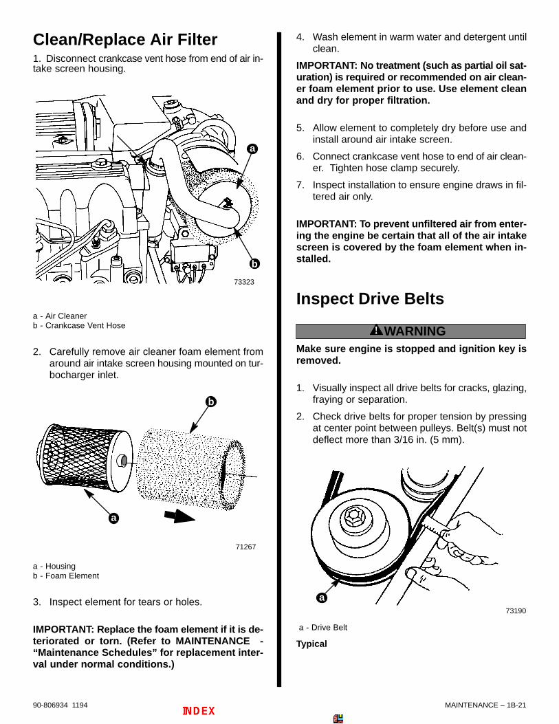
Check/Clean SeawaterStrainer1. Visually inspect seawater strainer through glass
top.
! CAUTIONWhen cleaning seawater strainer, close seacock,if so equipped. If boat is not equipped with a sea-cock, remove and plug seawater inlet hose to pre-vent a siphoning action that may occur, allowingseawater to flow from the drain holes or removedhoses.
! CAUTIONDo not overtighten cover screws or cover willwarp and leak.
2. With engine off, close seacock (if so equipped) orremove and plug seawater inlet hose if no sea-cock exists. Remove two screws, washers, andcover. Remove strainer, drain plug and washer.Clean all debris from strainer housing; flush bothstrainer and housing with clean water. Check gas-ket and replace when necessary (if it leaks). Rein-stall strainer, drain plug and washer. Reattachcover with screws and washers. After starting en-gine, check for leaks and/or air in system, whichwould indicate an external leak.
72673
a - Screws and Washersb - Cover, with Glassc - Strainerd - Housinge - Drain Plug and Sealing Washerf - Gasket
d
f
a
b
c
e

MAINTENANCE – 1B-1990-806934 1194
Fuel Filter
Precautions
! WARNINGAlways disconnect battery cables from batteryBEFORE working on fuel system to prevent fire.This eliminates the engine wiring as a potentialsource of ignition.
! WARNINGBe careful when draining, filling or replacing wa-ter separating fuel filter; diesel fuel is flammable.Be sure that the ignition key is OFF. DO NOTsmoke or allow sources of open flame in the areawhile changing fuel system components. Wipeup any spilled fuel immediately. DO NOT allowfuel to come into contact with any hot surfacewhich may cause it to ignite.
! WARNINGDispose of fuel-soaked rags, paper, etc., in an ap-propriate air tight, fire retardant container.Fuel-soaked items may spontaneously ignite andresult in a fire hazard which could cause seriousbodily injury or death.
! WARNINGMake sure no fuel leaks exist before closing en-gine hatch.
! CAUTIONAbsolute cleanliness is required for work on thefuel injection system, since the injection pumpand fuel injectors have very close tolerances.Even minute particles of dirt or small amounts ofwater can impair the function of the fuel injectionsystem.
Draining
NOTICE
Refer to “Precautions,” in this Fuel Filtersection , BEFORE proceeding.
NOTE: To ensure complete draining, in warm weath-er, open the drain cock before starting daily opera-tions. In cold weather, when there is a possibility thatthe condensed water will freeze, drain the filter shortlyafter the end of daily operations.
1. The filter can be drained of water and small dirtparticles by pressing up on the water bleed valve.
71370
a
b
a - Fuel Filterb - Water Bleed Valve
2. Drain until fuel is clear in appearance.
3. Release bleed valve.
4. Fill fuel filter as outlined later in this section.

1B-20 – MAINTENANCE 90-806934 1194
Filling
NOTICE
Refer to “Precautions,” in this Fuel Filtersection , BEFORE proceeding.
NOTE: Follow this procedure after installing new filteror if fuel has been drained from filter checking forwater.1. Loosen bleed screw on fuel filter bracket.
71370
a b
a - Bleed Screwb - Fuel Filter Bracket
2. Move lever on pump up and down repeatedly, untilan air free stream of fuel flows from bleed screw.
73332
b
a
a - Hand Pump / Primer Lever (On Fuel Pump)b - Bleed Screw
3. Securely tighten bleed screw.
Replacing
NOTICE
Refer to “Precautions,” in this Fuel Filtersection , BEFORE proceeding.
1. Turn water bleed valve counterclockwise (whenviewed from bottom of filter element) and removefrom old filter. Note position of o-ring.
2. Install o-ring and valve on new filter. Tighten se-curely.
3. Coat sealing ring on new filter with clean motor oil.Thread filter onto bracket and tighten securely byhand. Do not use a filter wrench.
71370
a
b
c
d
e
a - Fuel Filter Bracketb - O-Ringc - Fuel Filterd - O-Ringe - Water Bleed Valve
4. Fill fuel filter as outlined previously.
5. Start and run engine. Check filter connections forfuel leaks. If leaks exist, recheck filter installationand correct as needed.
MAINTENANCE – 1B-2190-806934 1194
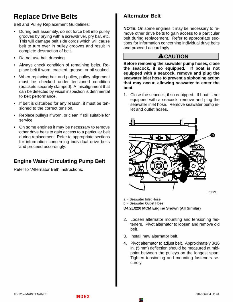
Clean/Replace Air Filter1. Disconnect crankcase vent hose from end of air in-take screen housing.
73323
a
b
a - Air Cleanerb - Crankcase Vent Hose
2. Carefully remove air cleaner foam element fromaround air intake screen housing mounted on tur-bocharger inlet.
71267
a
b
a - Housingb - Foam Element
3. Inspect element for tears or holes.
IMPORTANT: Replace the foam element if it is de-teriorated or torn. (Refer to MAINTENANCE -“Maintenance Schedules” for replacement inter-val under normal conditions.)
4. Wash element in warm water and detergent untilclean.
IMPORTANT: No treatment (such as partial oil sat-uration) is required or recommended on air clean-er foam element prior to use. Use element cleanand dry for proper filtration.
5. Allow element to completely dry before use andinstall around air intake screen.
6. Connect crankcase vent hose to end of air clean-er. Tighten hose clamp securely.
7. Inspect installation to ensure engine draws in fil-tered air only.
IMPORTANT: To prevent unfiltered air from enter-ing the engine be certain that all of the air intakescreen is covered by the foam element when in-stalled.
Inspect Drive Belts
! WARNINGMake sure engine is stopped and ignition key isremoved.
1. Visually inspect all drive belts for cracks, glazing,fraying or separation.
2. Check drive belts for proper tension by pressingat center point between pulleys. Belt(s) must notdeflect more than 3/16 in. (5 mm).
73190
a - Drive Belt
a
Typical
1B-22 – MAINTENANCE 90-806934 1194
Replace Drive BeltsBelt and Pulley Replacement Guidelines:
• During belt assembly, do not force belt into pulleygrooves by prying with a screwdriver, pry bar, etc.This will damage belt side cords which will causebelt to turn over in pulley grooves and result incomplete destruction of belt.
• Do not use belt dressing.
• Always check condition of remaining belts. Re-place belt if worn, cracked, grease- or oil-soaked.
• When replacing belt and pulley, pulley alignmentmust be checked under tensioned condition(brackets securely clamped). A misalignment thatcan be detected by visual inspection is detrimentalto belt performance.
• If belt is disturbed for any reason, it must be ten-sioned to the correct tension.
• Replace pulleys if worn, or clean if still suitable forservice.
• On some engines it may be necessary to removeother drive belts to gain access to a particular beltduring replacement. Refer to appropriate sectionsfor information concerning individual drive beltsand proceed accordingly.
Engine Water Circulating Pump BeltRefer to “Alternator Belt” instructions.
Alternator Belt
NOTE: On some engines it may be necessary to re-move other drive belts to gain access to a particularbelt during replacement. Refer to appropriate sec-tions for information concerning individual drive beltsand proceed accordingly.
! CAUTIONBefore removing the seawater pump hoses, closethe seacock, if so equipped. If boat is notequipped with a seacock, remove and plug theseawater inlet hose to prevent a siphoning actionthat may occur, allowing seawater to enter theboat.
1. Close the seacock, if so equipped. If boat is notequipped with a seacock, remove and plug theseawater inlet hose. Remove seawater pump in-let and outlet hoses.
a
73521
b
a - Seawater Inlet Hoseb - Seawater Outlet Hose
D4.2L/220 MCM Engine Shown (All Similar)
2. Loosen alternator mounting and tensioning fas-teners. Pivot alternator to loosen and remove oldbelt.
3. Install new alternator belt.
4. Pivot alternator to adjust belt. Approximately 3/16in. (5 mm) deflection should be measured at mid-point between the pulleys on the longest span.Tighten tensioning and mounting fasteners se-curely.

MAINTENANCE – 1B-2390-806934 1194
5. Install seawater pump inlet and outlet hoses.Tighten hose clamps securely.
73521
73324
c
a
b
a - Mounting Fastenerb - Tensioning Fastenerc - 3/16 in. (5 mm) Approximate Deflection
D4.2L/220 MCM Engine Shown (All Similar)
Power Steering Pump Belt
D3.0L/150 AND D3.6L/150 MODELS
1. Loosen mounting and tensioning fasteners onpower steering pump.
2. Turn tensioning bolt with pinion, to pivot pumpand loosen belt.
3. Remove old power steering belt and install newbelt.
4. Turn tensioning bolt with pinion to adjust tension.Approximately 3/16 in. (5 mm) deflection shouldbe measured at midpoint between the pulleys onthe longest span.
5. Tighten mounting and tensioning fasteners se-curely.
71443
73320
a
c
c
b
d
a - Mounting Fastenerb - Tensioning Fastener with Pinionc - Power Steering Pumpd - 3/16 in. (5 mm) Approximate Deflection

1B-24 – MAINTENANCE 90-806934 1194
D4.2L/220 MODELS
NOTE: On some engines it may be necessary to re-move other drive belts to gain access to a particularbelt during replacement. Refer to appropriate sec-tions for information concerning individual drive beltsand proceed accordingly.
1. Loosen the two mounting screws and the tension-ing screw on power steering pump.
2. Pivot the power steering pump to loosen belt.
70113b
a
c
a
a - Mounting Screws (One Hidden In This View)b - Tensioning Screwc - Power Steering Pump
! CAUTIONBefore removing the seawater pump, close theseacock, if so equipped. If boat is not equippedwith a seacock, remove and plug the seawater in-let hose to prevent a siphoning action that mayoccur, allowing seawater to enter the boat.
3. Remove or loosen the seawater pump fastenerssufficiently to allow drive belts to fit betweencrankshaft balancer. (Refer to SECTION 6A,Seawater Pump Removal.)
23161
a
a - Seawater Pump Fasteners
Typical
4. Remove old power steering belt and install newbelt.
5. Pivot the power steering pump to adjust belt.Approximately 3/16 in. (5 mm) deflection shouldbe measured at midpoint between the pulleys onthe longest span.
6. Tighten mounting screws and tensioning screwsecurely.
70113b
a
c
a
d
73521
a - Mounting Screws (One Hidden In This View)b - Tensioning Screwc - 3/16 in. (5 mm) Approximate Deflection
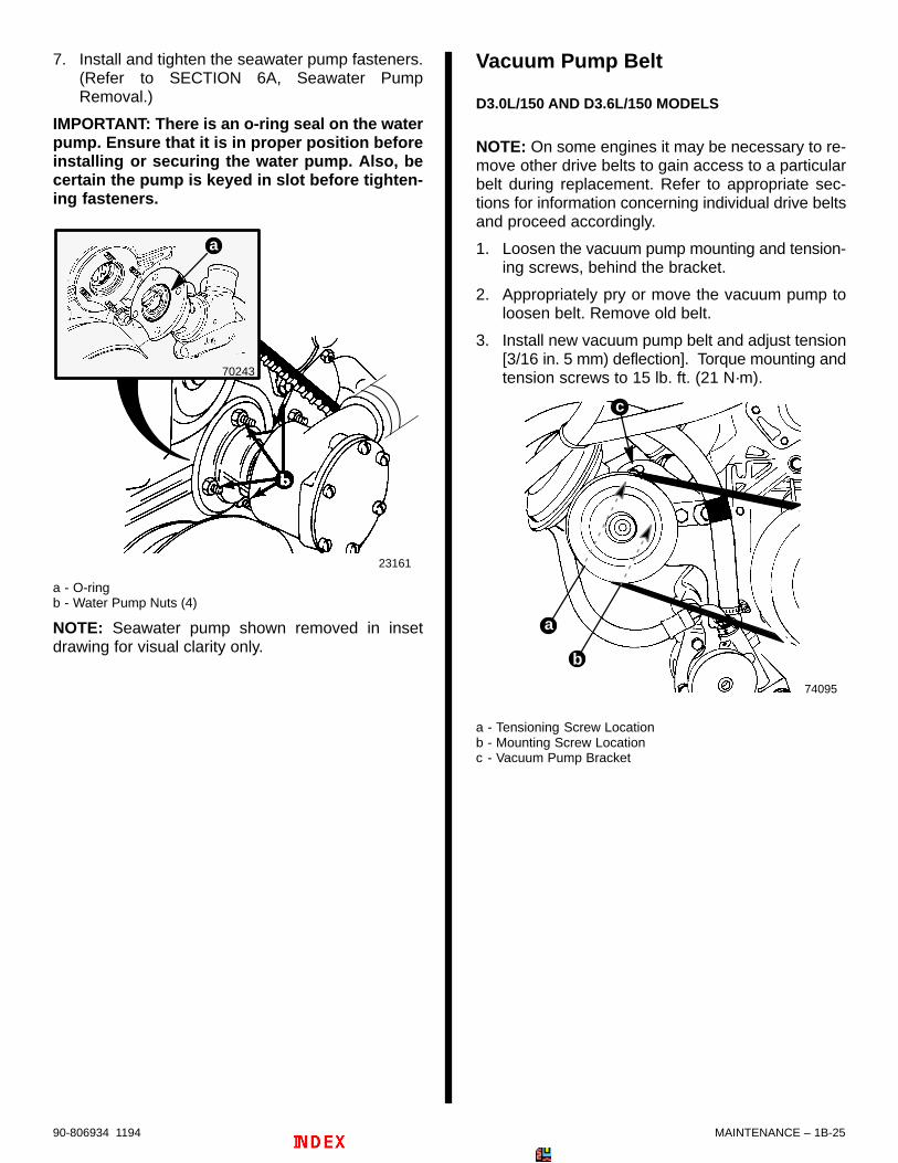
MAINTENANCE – 1B-2590-806934 1194
7. Install and tighten the seawater pump fasteners.(Refer to SECTION 6A, Seawater PumpRemoval.)
IMPORTANT: There is an o-ring seal on the waterpump. Ensure that it is in proper position beforeinstalling or securing the water pump. Also, becertain the pump is keyed in slot before tighten-ing fasteners.
23161
70243
a
a - O-ringb - Water Pump Nuts (4)
NOTE: Seawater pump shown removed in insetdrawing for visual clarity only.
Vacuum Pump Belt
D3.0L/150 AND D3.6L/150 MODELS
NOTE: On some engines it may be necessary to re-move other drive belts to gain access to a particularbelt during replacement. Refer to appropriate sec-tions for information concerning individual drive beltsand proceed accordingly.
1. Loosen the vacuum pump mounting and tension-ing screws, behind the bracket.
2. Appropriately pry or move the vacuum pump toloosen belt. Remove old belt.
3. Install new vacuum pump belt and adjust tension[3/16 in. 5 mm) deflection]. Torque mounting andtension screws to 15 lb. ft. (21 N·m).
74095
a
b
c
a - Tensioning Screw Locationb - Mounting Screw Locationc - Vacuum Pump Bracket

1B-26 – MAINTENANCE 90-806934 1194
D4.2L/220 MODELS
NOTE: On some engines it may be necessary to re-move other drive belts to gain access to a particularbelt during replacement. Refer to appropriate sec-tions for information concerning individual drive beltsand proceed accordingly.
1. Remove or loosen seawater pump fastenerssufficiently to allow vacuum pump belt to fitbetween crankshaft balancer and water pumphousing. (Refer to SECTION 6A, SeawaterPump Removal.)
23161
a
2. Loosen the vacuum pump mounting and tension-ing screws, behind the bracket.
ba
c
74085
a - Mounting Screw Locationb - Tensioning Screw Locationc - Vacuum Pump Bracket
3. Appropriately pry or move the vacuum pump toloosen belt. Remove old belt.
4. Install new vacuum pump belt and adjust tension[3/16 in. (5 mm) deflection]. Torque mounting andtensioning screws to 15 lb. ft. (21 N·m).
ba
74085
a - Tensioning Screw Locationb - Mounting Screw Location
5. Install seawater pump and tighten nuts securely.
IMPORTANT: There is an o-ring seal on the waterpump. Ensure that it is in proper position beforeinstalling or securing the water pump. Also, becertain the pump is keyed in slot before tighten-ing fasteners.
23161
70243
a
a - O-ringb - Water Pump Nuts (4)
NOTE: Seawater pump shown removed in insetdrawing for visual clarity only.

MAINTENANCE – 1B-2790-806934 1194
Inspect/Replace CoolingSystem Sacrificial Anodes
Coolant Tank / Heat ExchangerAnode
INSPECTION
The sacrificial anode is located on the starboard ,aft-side of the heat exchanger.
1. With the engine cold, remove anode plug and in-spect sacrificial anode for deterioration.
2. Replace anode assembly when deteriorated50%.
73326b
a
71368
c
de
a - Heat Exchangerb - Anode Plug and Sacrificial Anodec - 3/4 in. (19 mm) - Length When Newd - 5/8 in. (16 mm) - Diameter When Newe - Copper Sealing Washer
REPLACEMENT
NOTE: Sacrificial anodes are available as an assem-bly. Replace both the plug and anode, if so desired.
1. Refer to “Inspection”, as previously outlined andremove anode plug. Then:
a. Unscrew anode from anode plug by holdingplug hex head and turning anode.
b. Clean interior threads of anode plug.
c. Apply Loctite #242 to threads of new sacrifi-cial anode and install into anode plug. Tightensecurely.
d. Install new copper sealing washer.
e. Install anode plug, with washer and sacrificialanode, into heat exchanger. Tighten securely.
71367
ca
b
a - Anode Plugb - Sacrificial Anodec - Copper Sealing Washer
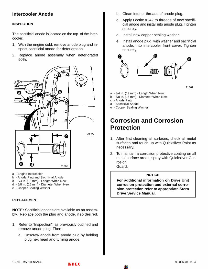
1B-28 – MAINTENANCE 90-806934 1194
Intercooler Anode
INSPECTION
The sacrificial anode is located on the top of the inter-cooler.
1. With the engine cold, remove anode plug and in-spect sacrificial anode for deterioration.
2. Replace anode assembly when deteriorated50%.
a b
71368
c
de
73327
a - Engine Intercoolerb - Anode Plug and Sacrificial Anodec - 3/4 in. (19 mm) - Length When Newd - 5/8 in. (16 mm) - Diameter When Newe - Copper Sealing Washer
REPLACEMENT
NOTE: Sacrificial anodes are available as an assem-bly. Replace both the plug and anode, if so desired.
1. Refer to “Inspection”, as previously outlined andremove anode plug. Then:
a. Unscrew anode from anode plug by holdingplug hex head and turning anode.
b. Clean interior threads of anode plug.
c. Apply Loctite #242 to threads of new sacrifi-cial anode and install into anode plug. Tightensecurely.
d. Install new copper sealing washer.
e. Install anode plug, with washer and sacrificialanode, into intercooler front cover. Tightensecurely.
71367
ca
b
a - 3/4 in. (19 mm) - Length When Newb - 5/8 in. (16 mm) - Diameter When Newc - Anode Plugd - Sacrificial Anodee - Copper Sealing Washer
Corrosion and CorrosionProtection
1. After first cleaning all surfaces, check all metalsurfaces and touch up with Quicksilver Paint asnecessary.
2. To maintain a corrosion protective coating on allmetal surface areas, spray with Quicksilver Cor-rosionGuard.
NOTICE
For additional information on Drive Unitcorrosion protection and external corro-sion protection refer to appropriate SternDrive Service Manual.

MAINTENANCE – 1B-2990-806934 1194
Check Battery
1. Check battery connections to ensure they areclean and tight.
2. Keep exterior surfaces of battery wiped clean witha water/baking soda solution.
3. Ensure battery is securely fastened in place.
4. Refer to battery manufacturer’s recommenda-tions for fluid levels and charging.
Lubrication
Throttle CableLubricate pivot points and guide contact surfaces withSAE 30W motor oil.
71261a
b
a - Pivot Pointsb - Guide Contact Surfaces
Single Cable Shown (Dual Similar)
Shift CableLubricate pivot points and guide contact surfaces withSAE 30W motor oil.
22245
ab
b
a
a
a
a - Pivot Pointsb - Guide Contact Surface
MCM Model (Typical) Shift Cable
73587
a
b
a - Pivot Pointsb - Guide Contact Surface
MIE Model (Typical) Shift Cable and TransmissionLinkage

1B-30 – MAINTENANCE 90-806934 1194
Engine Coupler/U-Joint Shaft Splines
NOTE: Refer to MerCruiser Stern Drive Service Man-ual for stern drive unit removal and installation.
70559
a
a - Quicksilver Engine Coupler Spline Grease
72531
a - Quicksilver Engine Coupler Spline Grease
a
a
a
Freezing Temperature andCold Weather OperationIMPORTANT: If boat is operated during periods offreezing temperature, precautions must be takento prevent freezing damage to power package.Refer to the following and to “Cold Weather or Ex-tended Storage” for related information anddraining instructions.
In order to operate the engine in temperatures of 32°F (0° C) or lower, observe the following precautionsand instructions:
! CAUTIONSeawater (raw water) section of cooling systemMUST BE COMPLETELY drained for winter stor-age or immediately after cold weather use, if thepossibility of freezing temperatures exist. Failureto comply may result in trapped water causingfreeze and/or corrosion damage to engine.
1. At the end of each daily operation, COMPLETELYdrain seawater section of the cooling system andthe seawater strainer to protect against damageby freezing. Refer to Section 6A, and the precau-tionary statement above.
! CAUTIONIf boat is in the water, seacock (water inlet valve),if so equipped, must remain closed until engineis to be re-started to prevent water from flowingback into seawater cooling system. If boat is notfitted with a seacock, water inlet hose must be leftdisconnected and plugged to prevent water fromflowing into cooling system and/or boat. As a pre-cautionary measure, attach a tag to the ignitionswitch or steering wheel with the warning that thevalve must be opened or the water inlet hose re-connected prior to starting the engine.
2. At the end of each daily operation, drain waterfrom water separator, if equipped. Fill fuel tank atend of daily operation to prevent condensation.
3. Closed cooling section of engine must be filledwith Quicksilver Premixed Marine Engine Cool-ant, a mixture of antifreeze/water solution suffi-cient to prevent freezing to the coldest tempera-ture of the user area.
4. Be sure to use proper cold weather lubrication oil,and be sure the crankcase contains a sufficientamount.
5. Make certain that the battery is of sufficient sizeand is fully charged. Check that all other electricalequipment is in optimum condition.
6. At temperatures of –4° F (–20° C) and below, itis recommended that you use the crankcasemounted coolant heater to improve cold starting.
7. If operating in arctic temperatures of –20° F (–29°C) or lower, consult your dealer for informationabout special cold weather equipment and pre-cautions.

MAINTENANCE – 1B-3190-806934 1194
Saltwater OperationSeawater section must be flushed after each use. Re-fer to “Flushing Seawater Cooling System.”
Cold Weather or ExtendedStorage
Precautions
! CAUTIONSeawater section of cooling system MUST BECOMPLETELY drained for winter storage, or im-mediately after cold weather use, if the possibilityof freezing temperatures exists. Failure to com-ply may result in trapped water causing freezeand/or corrosion damage to engine.
! CAUTIONIf boat is in the water, seacock (water inlet valve),if so equipped, must remain closed until engineis to be re-started, to prevent water from flowingback into cooling system and/or boat. If boat isnot fitted with a seacock, water inlet hose must re-main disconnected and plugged (to prevent wa-ter from flowing back into cooling system and/orboat). As a precautionary measure, attach a tag tothe ignition switch or steering wheel of the boatwith the warning: Open seacock or reconnect wa-ter inlet hose before starting engine.
IMPORTANT: Observe the following informationto ensure complete draining of cooling system.
• Engine must be as level as possible.
• A wire should be repeatedly inserted into alldrain holes to ensure there are no obstruc-tions in passages. Remove petcock, if neces-sary, to insert wire completely into drain hole.
IMPORTANT: To prevent threads in cylinderblocks from rusting out during storage, reinstallplugs using Quicksilver Perfect Seal on threads.Never leave drain plugs out during storage.
NOTE: If possible, place a container under drains andhoses to prevent water from draining into boat.
! CAUTIONClosed cooling section of engine must be keptfilled with specified coolant to protect engine tolowest temperature to which it will be exposed.DO NOT USE PROPYLENE GLYCOL antifreeze inclosed cooling section. Seawater section, how-ever, must be drained completely.
! CAUTIONA discharged battery can be damaged by freez-ing.
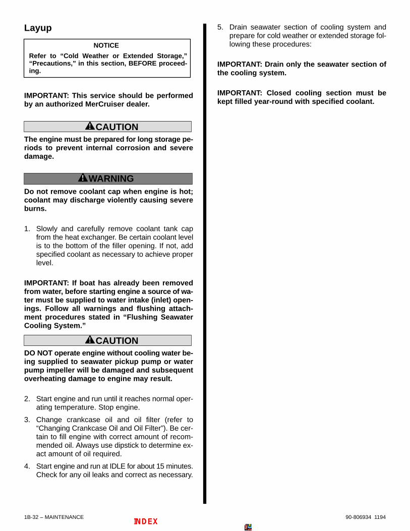
1B-32 – MAINTENANCE 90-806934 1194
Layup
NOTICE
Refer to “Cold Weather or Extended Storage,”“Precautions,” in this section, BEFORE proceed-ing.
IMPORTANT: This service should be performedby an authorized MerCruiser dealer.
! CAUTIONThe engine must be prepared for long storage pe-riods to prevent internal corrosion and severedamage.
! WARNINGDo not remove coolant cap when engine is hot;coolant may discharge violently causing severeburns.
1. Slowly and carefully remove coolant tank capfrom the heat exchanger. Be certain coolant levelis to the bottom of the filler opening. If not, addspecified coolant as necessary to achieve properlevel.
IMPORTANT: If boat has already been removedfrom water, before starting engine a source of wa-ter must be supplied to water intake (inlet) open-ings. Follow all warnings and flushing attach-ment procedures stated in “Flushing SeawaterCooling System.”
! CAUTIONDO NOT operate engine without cooling water be-ing supplied to seawater pickup pump or waterpump impeller will be damaged and subsequentoverheating damage to engine may result.
2. Start engine and run until it reaches normal oper-ating temperature. Stop engine.
3. Change crankcase oil and oil filter (refer to“Changing Crankcase Oil and Oil Filter”). Be cer-tain to fill engine with correct amount of recom-mended oil. Always use dipstick to determine ex-act amount of oil required.
4. Start engine and run at IDLE for about 15 minutes.Check for any oil leaks and correct as necessary.
5. Drain seawater section of cooling system andprepare for cold weather or extended storage fol-lowing these procedures:
IMPORTANT: Drain only the seawater section ofthe cooling system.
IMPORTANT: Closed cooling section must bekept filled year-round with specified coolant.

MAINTENANCE – 1B-3390-806934 1194
DRAINING INSTRUCTIONS
! CAUTIONIf boat is to remain in the water, seacock, if soequipped, must be closed until engine is to be re-started to prevent water from flowing back intoseawater cooling system. If boat is not fitted witha seacock, water inlet hose must be discon-nected and plugged to prevent water from flow-ing into cooling system and/or boat. As a precau-tionary measure, attach a tag to the ignitionswitch or steering wheel with the warning that thevalve must be opened or the water inlet hose re-connected prior to starting the engine.
IMPORTANT: Observe the following informationto ensure complete draining of seawater coolingsystem.
• Engine must be as level as possible.
• A wire should be repeatedly inserted into alldrain holes to ensure there are no obstruc-tions in passages.
1. Close seacock, if so equipped, or disconnect andplug seawater inlet hose, if boat is to remain in thewater.
2. Do not open either of these two petcocks. Theyare in the closed cooling section.
71364
72706
73522
73335
a
b
a - Exhaust Manifold Petcock (Do NOT Open.)b - Engine Block Petcock (Do NOT Open.)
Typical

1B-34 – MAINTENANCE 90-806934 1194
3. Remove the end covers from BOTH port and star-board ends on upper and lower sections of heatexchanger tank. Drain tank completely. Sponge-out or soak-up any water that remains in the bot-tom part of each section, until all water passagetubes are completely free of standing water.
! CAUTIONAvoid damage to heat exchanger and subsequentpossible engine damage. Remove all water fromheat exchanger sections. Failure to do so couldcause corrosion or freeze damage to heat ex-changer water passage tubes.
73322
73326
a
b
b
a
a - Upper Section End Cover(s)b - Lower Section End Cover(s)
NOTE: In the following it may be necessary to loweror bend the hoses to allow water to drain completely.
4. Follow appropriate instructions “a” or “b”:
a. On MCM (Stern Drive) Engines: Disconnectseawater outlet hose at aft end of powersteering fluid cooler. Lower hose and draincompletely.
72470
b
a
a - Power Steering Fluid Coolerb - Seawater Hose
b. On MIE (Inboard) Engines: Disconnectseawater outlet hose at aft end oftransmission fluid cooler. Lower hose anddrain completely.
73335
ab
a - Transmission Fluid Coolerb - Seawater Hose

MAINTENANCE – 1B-3590-806934 1194
5. Remove the drain plug from the aft end cover ofthe intercooler.
70071
b
a
a - Drain Plugb - Intercooler
6. Remove seawater pump outlet hose from top ofseawater pump and drain.
73322
a
a - Seawater Pump Outlet Hose
7. Repeatedly clean out drain holes using a stiffpiece of wire. Do this until entire system isdrained.
! CAUTIONAvoid water entering boat. Do not unplug seawa-ter inlet hose unless a seacock is present and itis closed.
8. Remove hose(s) at seawater strainer and drainhose(s) completely. Empty seawater strainer.(Refer to MAINTENANCE SECTION - CleaningQuicksilver Seawater Strainer.) Reconnecthose(s) and tighten hose clamps securely.
9. After seawater section of cooling system hasbeen drained completely, coat threads of inter-cooler drain plug with Perfect Seal and reinstall.Tighten securely. Reconnect hoses. Tighten hoseclamps securely. Install all four end covers on theheat exchanger tank (Renew end cover gasketsif worn or deteriorated.). Torque the end coverson the upper heat exchanger section to 16 lb. ft.(22 N·m). Torque the end covers on the lowerheat exchanger section to 96 lb. in. (11 N·m).
10. If not already accomplished, close seacock, if soequipped, or disconnect and plug seawater inlethose, if boat is to remain in the water. Disconnecthoses at seawater strainer (if so equipped) anddrain hoses completely. Empty and clean seawa-ter strainer (refer to “Check/Clean SeawaterStrainer”). Reconnect hoses and tighten hoseclamps securely.
72691
a - Seawater Strainerb - Hosesc - Hose Clamps
ba
c c
b
11. After seawater section of cooling system hasdrained completely, coat threads of drain plugspreviously removed with Quicksilver PerfectSeal, and reinstall. Tighten securely. Install allhoses previously removed and tighten hoseclamps securely.
IMPORTANT: MerCruiser recommends that pro-pylene glycol antifreeze (nontoxic and biode-gradable, which makes it friendly to lakes and riv-ers) be used in seawater section of the coolingsystem for cold weather or extended storage.Make sure that the propylene glycol antifreezecontains a rust inhibitor and is recommended foruse in marine engines. Be certain to follow thepropylene glycol manufacturer’s recommenda-tions.
12. Fill a container with approximately 6 U.S. quarts(5.6 L) of antifreeze and tap water mixed to man-ufacturer’s recommendation to protect engine tothe lowest temperature to which it will be exposedduring cold weather or extended storage.

1B-36 – MAINTENANCE 90-806934 1194
13. Disconnect hose from seawater inlet side of sea-water pump. Using an adaptor, temporarily con-nect an appropriate length piece of hose to sea-water pump and place the other end of the hoseinto container of coolant.
73521
a
a - Seawater Pump Inlet Hose
MCM (Stern Drive) Engine Shown (All Similar)
! CAUTIONIt is good practice to ventilate the engine com-partment prior to servicing any engine compo-nents to remove any fuel vapors which may causedifficulty breathing or be an irritant.
14. Start engine and run, AT IDLE SPEED, until anti-freeze mixture has been pumped into engine sea-water cooling system. Stop engine.
15. Clean engine and coat with Quicksilver CorrosionGuard or equivalent corrosion inhibiting oil.
16. Lubricate all items outlined in ”Lubrication.”
17. Remove and store battery in a cool, dry place. Donot store on a concrete surface, or on the ground.Place on a dry, wood board or a thick plastic base(Refer to battery manufacturer’s instructions.)
18. Perform all checks, inspections, lubrication andfluid changes outlined in “Maintenance Schedule”under “At Least Once Yearly.”
19. Remove seawater pump impeller for storage asfollows:
a. Remove seawater pump cover mountingscrews, and remove cover and gasket.
b. Ease impeller off pump shaft with two screw-drivers.
c. Reinstall cover for storage.
NOTE: Pump shown removed for visual clarity only.
ab
c de
e
71366
a - Seawater Pump Housingb - Cover Screwsc - Coverd - Gaskete - Impeller
D3.0L/150 Seawater Pump Shown (All Similar)
IMPORTANT: Place a CAUTION TAG at instrumentpanel and in engine compartment stating that“Seawater Pump is Out - DO NOT Operate En-gine.”
! CAUTIONStern drive unit should be stored in full “down”position. Universal Joint bellows may develop a“set” if unit is stored in raised position and mayfail when unit is returned to service.
20. Place stern drive unit in the full “down” position.

MAINTENANCE – 1B-3790-806934 1194
BATTERY WINTER STORAGE
Follow battery manufacturer’s instructions for stor-age. If not available, use the following instructions:
1. Be certain all electrical components are off, andignition key is in OFF position.
2. To avoid possible electrical system damage,FIRST remove the NEGATIVE (–) battery cable,and NEXT remove the POSITIVE (+) batterycable. Remove the battery.
3. Remove dirt and grease from top surface of bat-tery.
4. Follow battery manufacturer’s recommendationsand add distilled water, if needed.
5. Grease cable ends and bolts.
6. Store battery in a cool, dry place. Do not store ona concrete surface, or on the ground. Place on adry wood board or a thick plastic base.
! CAUTIONA discharged battery can be damaged by freez-ing.
7. Every 30 to 45 days, check water level and re-charge battery according to manufacturer’s spec-ifications. Do not fast charge.
If you cannot perform the above service, contact yourauthorized MerCruiser dealer or local automotivegarage.
Recommissioning
NOTICERefer to “Cold Weather or Extended Storage,”“Precautions,” in this section, BEFORE pro-ceeding.
1. Reinstall seawater pump components as follows:
a. Place impeller in pump housing, turningclockwise while simultaneously pushing firm-ly inward onto pump shaft.
NOTE: Use new gasket. Install in correct position -wide surface on side of cam.
b. Install pump cover with new gasket in notedposition.
c. Install the seawater pump cover mountingscrews. Tighten securely.
NOTE: Pump shown removed for visual clarity only.
71366
b
a
acd
e
a - Impellerb - Seawater Pump Housingc - Gasket (Wide Surface on Cam Side)d - Covere - Cover Screws
D3.0L/150 Seawater Pump Shown (All Similar)
2. Check that all cooling system hoses are in goodcondition and connected properly, hose clampsare tight, and all petcocks and drain plugs are in-stalled and tight.
3. Inspect all drive belts.
4. Perform all lubrication and maintenance specifiedfor completion “At Least Once Yearly” in “Mainte-nance Schedule,” except items which were per-formed at time of engine layup.
5. Fill fuel tank(s) with fresh diesel fuel. Old fuelshould not be used. Check fuel lines and connec-tions for leaks and general condition.

1B-38 – MAINTENANCE 90-806934 1194
6. Replace fuel filter as outlined previously in thissection.
7. For drive unit, refer to appropriate Stern DriveService Manual.
! CAUTIONWhen installing battery, be sure to connect POSI-TIVE (+) battery cable to POSITIVE (+) battery ter-minal FIRST, and NEGATIVE (–) battery cable toNEGATIVE (–) battery terminal LAST. If batterycables are reversed, or connection order is re-versed, electrical system damage will result.
8. Install fully-charged battery. Clean battery cableclamps and terminals and reconnect cables (seeCAUTION listed above). Secure each cableclamp when connecting. Coat terminals with abattery terminal anti-corrosion spray to help re-tard corrosion.
9. Perform all checks on OPERATION CHART inthe STARTING PROCEDURE column.
IMPORTANT: After a lengthy lay-up (severalmonths), it is necessary to pre-lubricate theturbocharger. To do this, move the “STOP”switch toggle lever DOWN and hold in thisposition while you turn the key switch to “START”position. Doing this TOGETHER turns the enginewithout starting it. DO NOT engage starter formore than 15 seconds; allow at least one minutecool down time before re-engaging starter foranother 15 seconds. Watch that starter does notoverheat.
! CAUTIONDO NOT operate engine without water flowingthru seawater pickup pump, as pump impellermay be damaged and subsequent overheatingdamage to engine or transmission may result.
10. Start engine and closely observe instrumentationto make sure that all systems are functioning cor-rectly.
11. Carefully inspect engine for fuel, oil, fluid, waterand exhaust leaks.
12. Check steering system, shift and throttle controlfor proper operation.

1
C
IMPORTANT INFORMATION
TROUBLESHOOTINGNote: Refer to the following Service Bulletin regarding this section:
SB 96-9 MerCruiser Scan Tool
1C-0 – TROUBLESHOOTING 90-806934 1194
Table of Contents
NOTICE
Refer to “Precautions” BEFORE proceedingwith Troubleshooting.
PagePrecautions 1C-1. . . . . . . . . . . . . . . . . . . . . . . . . . . . . . . . . . Poor Boat Performance and/or Poor Maneuverability 1C-2. . . . . . . . . . . . . . . . . . . . . . . . . . . . . . Improper Full Throttle Engine RPM 1C-3. . . . . . . . . . . . . .
RPM Too High 1C-3. . . . . . . . . . . . . . . . . . . . . . . . . . . . RPM Too Low 1C-3. . . . . . . . . . . . . . . . . . . . . . . . . . . . .
Engine Cranks Over but Will Not Start or Starts Hard 1C-4. . . . . . . . . . . . . . . . . . . . . . . . . . . . . . .
Important Information 1C-4. . . . . . . . . . . . . . . . . . . . . . Electrical 1C-4. . . . . . . . . . . . . . . . . . . . . . . . . . . . . . . . . Fuel System 1C-4. . . . . . . . . . . . . . . . . . . . . . . . . . . . . . Miscellaneous 1C-5. . . . . . . . . . . . . . . . . . . . . . . . . . . . .
Engine Will Not Crank Over or Starter Inoperative 1C-5. Glow Plugs Inoperative 1C-6. . . . . . . . . . . . . . . . . . . . . . . . Charging System Inoperative 1C-7. . . . . . . . . . . . . . . . . . . Noisy Alternator 1C-7. . . . . . . . . . . . . . . . . . . . . . . . . . . . . . Engine Runs Poorly at Idle 1C-8. . . . . . . . . . . . . . . . . . . . . Engine Runs Poorly At High Rpm 1C-9. . . . . . . . . . . . . . . Poor Fuel Economy 1C-10. . . . . . . . . . . . . . . . . . . . . . . . . . Engine Smoking (Black) 1C-11. . . . . . . . . . . . . . . . . . . . . .
PageEngine Smoking (Blue) 1C-12. . . . . . . . . . . . . . . . . . . . . . . Engine Smoking (White) 1C-12. . . . . . . . . . . . . . . . . . . . . . Exhaust Gas Temperature (High) 1C-13. . . . . . . . . . . . . . Exhaust Gas Temperature (Low) 1C-13. . . . . . . . . . . . . . . Fuel Injection Nozzle 1C-13. . . . . . . . . . . . . . . . . . . . . . . . . Turbocharger 1C-14. . . . . . . . . . . . . . . . . . . . . . . . . . . . . . . Engine Noise 1C-15. . . . . . . . . . . . . . . . . . . . . . . . . . . . . . .
Valve Cover Area 1C-15. . . . . . . . . . . . . . . . . . . . . . . . . Cylinder Area 1C-15. . . . . . . . . . . . . . . . . . . . . . . . . . . . Camshaft Area 1C-16. . . . . . . . . . . . . . . . . . . . . . . . . . . Crankshaft Area 1C-17. . . . . . . . . . . . . . . . . . . . . . . . . . Miscellaneous 1C-17. . . . . . . . . . . . . . . . . . . . . . . . . . . .
Oil Pressure 1C-18. . . . . . . . . . . . . . . . . . . . . . . . . . . . . . . . Low Oil Pressure 1C-19. . . . . . . . . . . . . . . . . . . . . . . . . High Oil Pressure 1C-19. . . . . . . . . . . . . . . . . . . . . . . . . Excessive Oil Consumption 1C-20. . . . . . . . . . . . . . . .
Water in Engine 1C-21. . . . . . . . . . . . . . . . . . . . . . . . . . . . . Important Information 1C-21. . . . . . . . . . . . . . . . . . .
Water In Crankcase Oil 1C-21. . . . . . . . . . . . . . . . . . . . Water On Top Pistons 1C-22. . . . . . . . . . . . . . . . . . . . .
Engine Overheats (Cooling System) 1C-22. . . . . . . . . . . . Engine Overheats (Mechanical) 1C-24. . . . . . . . . . . . . . . Power Steering 1C-25. . . . . . . . . . . . . . . . . . . . . . . . . . . . . .
Poor, Erratic, or No Assist 1C-25. . . . . . . . . . . . . . . . . . Noisy Pump 1C-26. . . . . . . . . . . . . . . . . . . . . . . . . . . . . . Fluid Leaks 1C-26. . . . . . . . . . . . . . . . . . . . . . . . . . . . . .
Insufficient Water Flow From Belt Driven Seawater Pump 1C-27. . . . . . . . . . . . . . . . . . . . . . . . . . . . Hurth Hydraulic Transmission 1C-28. . . . . . . . . . . . . . . . .
1C – TROUBLESHOOTING

TROUBLESHOOTING – 1C-190-806934 1194
Precautions! WARNING
Always disconnect battery cables from batteryBEFORE working on fuel system to prevent fire orexplosion.
! WARNINGAlways disconnect battery cables from batterybefore working around electrical system compo-nents to prevent injury to yourself or damage toelectrical system.
! WARNINGBe careful when changing fuel system compo-nents; diesel fuel is flammable. Be sure that igni-tion key is OFF. DO NOT smoke or allow sourcesof spark or flame in the area while changing fuelsystem components. Wipe up any spilled fuel im-mediately. DO NOT allow fuel to come into con-tact with any hot surface which may cause it to ig-nite.
! WARNINGAvoid diesel fuel fire. Improper installation ofbrass fittings or plugs into fuel filter base cancrack casting and/or cause a fuel leak. Followspecific procedure, given in Section 4 of thismanual, for all fuel line connections.
Fuel Supply Connections
! WARNINGAvoid diesel fuel fire or explosion. Improper in-stallation of brass fittings or plugs into fuel filterbase can crack casting and/or cause a fuel leak.
• Apply #592 Loctite Pipe Sealant with Teflon tothreads of brass fitting or plug. DO NOT USETEFLON TAPE.
• Thread brass fitting or plug into fuel filter base un-til finger tight.
• Tighten fitting or plug an additional 1-3/4 to 2-1/4turns using a wrench. DO NOT OVER-TIGHTEN.
• Install fuel line. To prevent over-tightening, holdbrass fitting with suitable wrench and tighten fuelline connectors securely.
• Check for fuel leaks.
! WARNINGFIRE HAZARD: Fuel leakage from any part of thefuel system can be a fire hazard which can causeserious bodily injury or death. Careful periodic in-spection of entire fuel system is mandatory, par-
ticularly after storage. All fuel components in-cluding fuel tanks, whether plastic, metal orfiberglass, fuel lines, primers, fittings, and fuel fil-ters should be inspected for leakage, softening,hardening, swelling or corrosion. Any sign ofleakage or deterioration requires replacementbefore further engine operation.
! WARNINGDispose of fuel-soaked rags, paper, etc., in an ap-propriate air tight, fire retardant container.Fuel-soaked items may spontaneously ignite andresult in a fire hazard which could cause seriousbodily injury or death.
! WARNINGMake sure no fuel leaks exist before closing en-gine hatch.
! CAUTIONDO NOT operate engine without water being suppliedto seawater pickup pump on engine, or pump impellermay be damaged and subsequent overheating dam-age to engine may result. Engine may be operated withboat out of water, if instructions for running enginewith boat out of water, below, are followed.
! WARNINGWhen running engine with boat out of water, becertain that area in vicinity of propeller is clearand that no person is standing nearby. As a pre-cautionary measure, it is recommended that thepropeller be removed.
! CAUTIONDO NOT run engine above 1500 RPM, as suctioncreated by seawater pickup pump may collapse watersupply hose and cause engine to overheat.
! WARNINGBe sure that engine compartment is well venti-lated and that no diesel fuel vapors are present toprevent the possibility of a FIRE or EXPLOSION.
! WARNINGDO NOT leave helm unattended while performingidle speed adjustment.
! WARNINGSafety glasses should be worn while working onfuel injection system. The fuel injection pump willgenerate pressures in excess of 2000 PSI (13790kPa). Use caution when removing injectors, injec-tor lines, or bleeding air from injection system.

1C-2 – TROUBLESHOOTING 90-806934 1194
Poor Boat Performance and/or Poor ManeuverabilitySymptom Cause
1. Bow too low 1. A. Improper drive unit trim angle
B. Improper weight distribution
C. Boat is underpowered
D. Permanent or power hook in boat bottom
E. False bottom full of water
F. Improperly adjusted trim tabs (after planes)
2. Bow too high 2. A. Improper drive unit trim angle
B. Propeller pitch too great
C. Dirty boat bottom (marine growth)
D. Poor running engine
E. Improper weight distribution
F. Rocker in boat bottom
G. False bottom full of water
H. Improperly adjusted trim tabs (after planes)
3. Propeller ventilating 3. A. Drive unit installed too high on transom
B. Dirty or rough boat bottom
C. Damaged propeller; pitch too small; diameter too small
D. Keel located too close to propeller or too deepin the water
E. Water pickup or accessories located too closeto propeller
F. Hook in boat bottom
G. Propeller plugged up with weeds

TROUBLESHOOTING – 1C-390-806934 1194
Improper Full Throttle Engine RPM
RPM Too High
Cause Special Information
1. Propeller 1. Damaged; pitch too low; diameter too small; propeller hub slipping
2. Boat 2. A. Water pickup or accessories mounted too close to propeller (ventilation)
B. Keel located too close to propeller and/or too deep in the water (ventilation)
C. Drive installed too high on transom
D. Wrong gear ratio
3. Operation 3. Unit trimmed out too far
4. Engine coupler slipping
RPM Too Low
Cause Special Information1. Propeller 1. Damaged; pitch too great; diameter too great
2. Boat 2. A. Dirty or damaged bottomB. Permanent or power hook in bottomC. False bottom full of waterD. Drive installed too low
3. Operation 3. Unit trimmed in too far
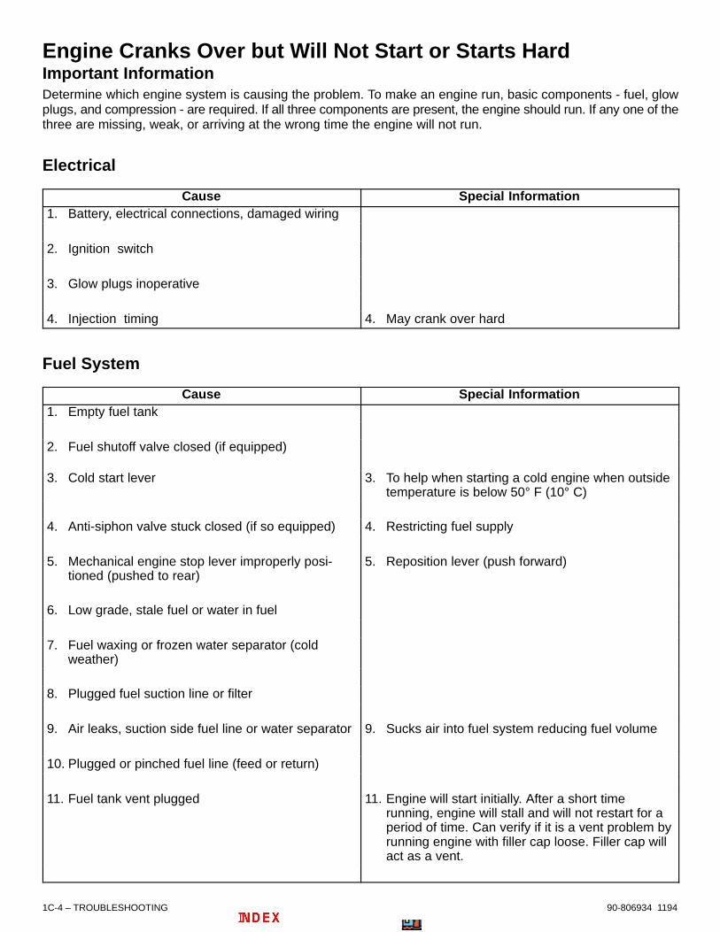
1C-4 – TROUBLESHOOTING 90-806934 1194
Engine Cranks Over but Will Not Start or Starts HardImportant InformationDetermine which engine system is causing the problem. To make an engine run, basic components - fuel, glowplugs, and compression - are required. If all three components are present, the engine should run. If any one of thethree are missing, weak, or arriving at the wrong time the engine will not run.
Electrical
Cause Special Information1. Battery, electrical connections, damaged wiring
2. Ignition switch
3. Glow plugs inoperative
4. Injection timing 4. May crank over hard
Fuel System
Cause Special Information1. Empty fuel tank
2. Fuel shutoff valve closed (if equipped)
3. Cold start lever 3. To help when starting a cold engine when outsidetemperature is below 50° F (10° C)
4. Anti-siphon valve stuck closed (if so equipped) 4. Restricting fuel supply
5. Mechanical engine stop lever improperly posi-tioned (pushed to rear)
5. Reposition lever (push forward)
6. Low grade, stale fuel or water in fuel
7. Fuel waxing or frozen water separator (cold weather)
8. Plugged fuel suction line or filter
9. Air leaks, suction side fuel line or water separator 9. Sucks air into fuel system reducing fuel volume
10. Plugged or pinched fuel line (feed or return)
11. Fuel tank vent plugged 11. Engine will start initially. After a short timerunning, engine will stall and will not restart for aperiod of time. Can verify if it is a vent problem byrunning engine with filler cap loose. Filler cap willact as a vent.

TROUBLESHOOTING – 1C-590-806934 1194
Fuel System (continued)
Cause Special Information12. Injection pump solenoid valve
13. Fuel supply pump 13. Low pump pressure
Miscellaneous
Cause Special Information
1. Low grade or stale fuel
2. Water in fuel
3. Incorrect starting procedure 3. Refer to Owners Manual
4. Internal mechanical damage (bent rods, etc.)
5. Low compression 5. Worn valves, rings, cylinder, or head gasket
6. Valve timing incorrect 6. Timing gears improperly installed or cam slippedin drive gear
7. Restricted or plugged exhaust
Engine Will Not Crank Over or Starter InoperativeCause Special Information
1. Remote control lever not in neutral position
2. Battery charge low; damaged wiring; loose electri-cal connections
3. Circuit breaker tripped
4. Blown fuse
5. Ignition switch
6. Slave solenoid
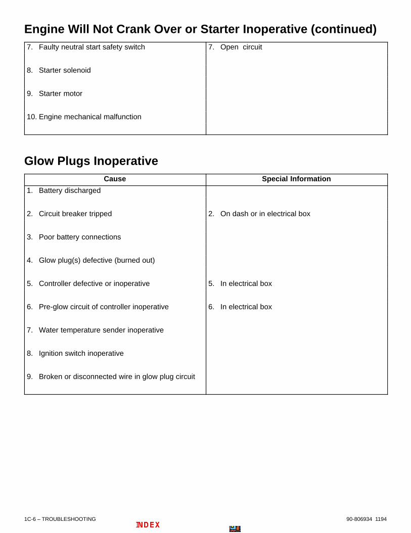
1C-6 – TROUBLESHOOTING 90-806934 1194
Engine Will Not Crank Over or Starter Inoperative (continued)7. Faulty neutral start safety switch 7. Open circuit
8. Starter solenoid
9. Starter motor
10. Engine mechanical malfunction
Glow Plugs InoperativeCause Special Information
1. Battery discharged
2. Circuit breaker tripped 2. On dash or in electrical box
3. Poor battery connections
4. Glow plug(s) defective (burned out)
5. Controller defective or inoperative 5. In electrical box
6. Pre-glow circuit of controller inoperative 6. In electrical box
7. Water temperature sender inoperative
8. Ignition switch inoperative
9. Broken or disconnected wire in glow plug circuit

TROUBLESHOOTING – 1C-790-806934 1194
Charging System InoperativeCause Special Information
1. Loose or broken drive belt
2. Engine RPM too low on initial start 2. Rev engine to 1500 RPM
3. Loose or corroded electrical connections
4. Faulty battery gauge 4. Best way to test is to replace gauge
5. Battery will not accept charge 5. Low electrolyte or failed battery
6. Faulty alternator or regulator
7. Refer to “Charging System” SECTION for com-plete diagnostic procedures
Noisy AlternatorCause Special Information
1. Loose mounting bolts
2. Drive belt 2. Worn, frayed, loose
3. Loose drive pulley
4. Worn or dirty bearings
5. Faulty diode trio or stator
6. Faulty armature 6. Rubbing, broken wire

1C-8 – TROUBLESHOOTING 90-806934 1194
Engine Runs Poorly at IdleCause Special Information
1. Clogged air cleaner
2. Improper idle fuel mixture adjustment
3. Plugged fuel suction line or filter
4. Air leaks: suction side fuel line, water separatingfuel filter or loose intake manifold
5. Water in fuel 5. Refer to Sections 1A and 5A
6. Low grade or stale fuel
7. Fuel waxing or frozen water separating fuel filter(cold weather)
8. Valve timing 8. Cam slipped in drive gear
9. Restricted or plugged exhaust
10. Injectors not functioning properly 10. Refer to Section 5C
11. Injection pump timing incorrect
12. Low compression 12. Also check for defective (blown) head gasket
13. Water leaking into cylinders 13. Defective head gasket, exhaust manifold, crackedhead or valve seat
14. Loose or broken engine mounts

TROUBLESHOOTING – 1C-990-806934 1194
Engine Runs Poorly At High RpmCause Special Information
1. Also refer to “Poor Boat Performance” 1. See “Table of Contents”
2. Crankcase overfilled with oil 2. Check oil level with boat at rest in the water
3. Anti-siphon valve (if equipped) 3. Restricting fuel supply
4. Plugged fuel tank vent
5. Low fuel supply
6. Clogged fuel filter
7. Low grade of fuel or water in the fuel
8. Obstructed fuel lines
9. Injectors not functioning properly 9. Refer to Section 5C
10. Engine overheating 10. Refer to “Engine Overheats” (See “Table of Contents”)
11. Low compression 11. Worn valves, rings, cylinders, etc.
12. Restricted or plugged exhaust
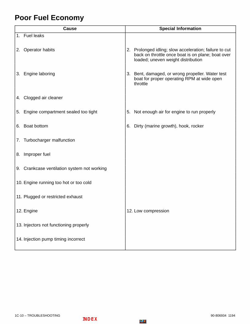
1C-10 – TROUBLESHOOTING 90-806934 1194
Poor Fuel EconomyCause Special Information
1. Fuel leaks
2. Operator habits 2. Prolonged idling; slow acceleration; failure to cut back on throttle once boat is on plane; boat overloaded; uneven weight distribution
3. Engine laboring 3. Bent, damaged, or wrong propeller. Water test boat for proper operating RPM at wide open throttle
4. Clogged air cleaner
5. Engine compartment sealed too tight 5. Not enough air for engine to run properly
6. Boat bottom 6. Dirty (marine growth), hook, rocker
7. Turbocharger malfunction
8. Improper fuel
9. Crankcase ventilation system not working
10. Engine running too hot or too cold
11. Plugged or restricted exhaust
12. Engine 12. Low compression
13. Injectors not functioning properly
14. Injection pump timing incorrect

TROUBLESHOOTING – 1C-1190-806934 1194
Engine Smoking (Black)Cause Special Information
1. Overload
2. Clogged air cleaner
3. Excessive fuel delivery 3. Refer to Section 5A
4. Faulty injector(s) 4. Refer to Section 5C
5. Restricted or plugged exhaust
6. Insufficient coolant temperature
7. Excessive idle time (slobber)
8. Inoperative glow plug system 8. Refer to Section 4B
9. Leaking head gaskets
10. Worn piston rings

1C-12 – TROUBLESHOOTING 90-806934 1194
Engine Smoking (Blue)Cause Special Information
1. Insufficient load 1. Check propeller
2. Low fresh water temperature (faulty thermostat) 2. Check temperature of oil and water
3. Worn piston rings 3. Check compression
4. Sticking piston rings 4. Check compression
5. Oil leakage from compressor side of turbocharger 5. Check turbocharger
6. Crankcase overfilled - incorrect dipstick reading
7. Leaking head gaskets
Engine Smoking (White)Cause Special Information
1. Injection pump timing incorrect 1. Refer to Section 5B
2. Faulty injector(s) 2. Refer to Section 5C
3. Low compression
4. Plugged fuel suction line or filter
5. Air leaks, suction side fuel line or water separat-ing fuel filter
6. Questionable fuel quality
7. Restricted fuel return/excessive return line pres-sure
8. Leaking head gaskets

TROUBLESHOOTING – 1C-1390-806934 1194
Exhaust Gas Temperature (High)Cause Special Information
1. Excessive load
2. Injection pump timing incorrect 2. Refer to Section 5B
3. Wrong assembly - timing device - pressure regu-lating valve
Exhaust Gas Temperature (Low)Cause Special Information
1. Injection pump timing incorrect 1. Refer to Section 5B
2. Excessive idling time/light loads
3. Heater system air locked
Fuel Injection NozzleCause Special Information
1. Nozzle turning blue 1. Faulty installation or tightening; insufficientcooling
2. Nozzle opening pressure too high 2. Incorrect shim adjustment; nozzle valve dirty orsticky; seized nozzle
3. Nozzle opening pressure too low 3. Shim/spacer wear; nozzle valve spring weak orbroken; nozzle seat worn
4. Nozzle valve seat leakage 4. Nozzle leaks because of excessive carbon de-posits or sticking nozzle valve; defective nozzle
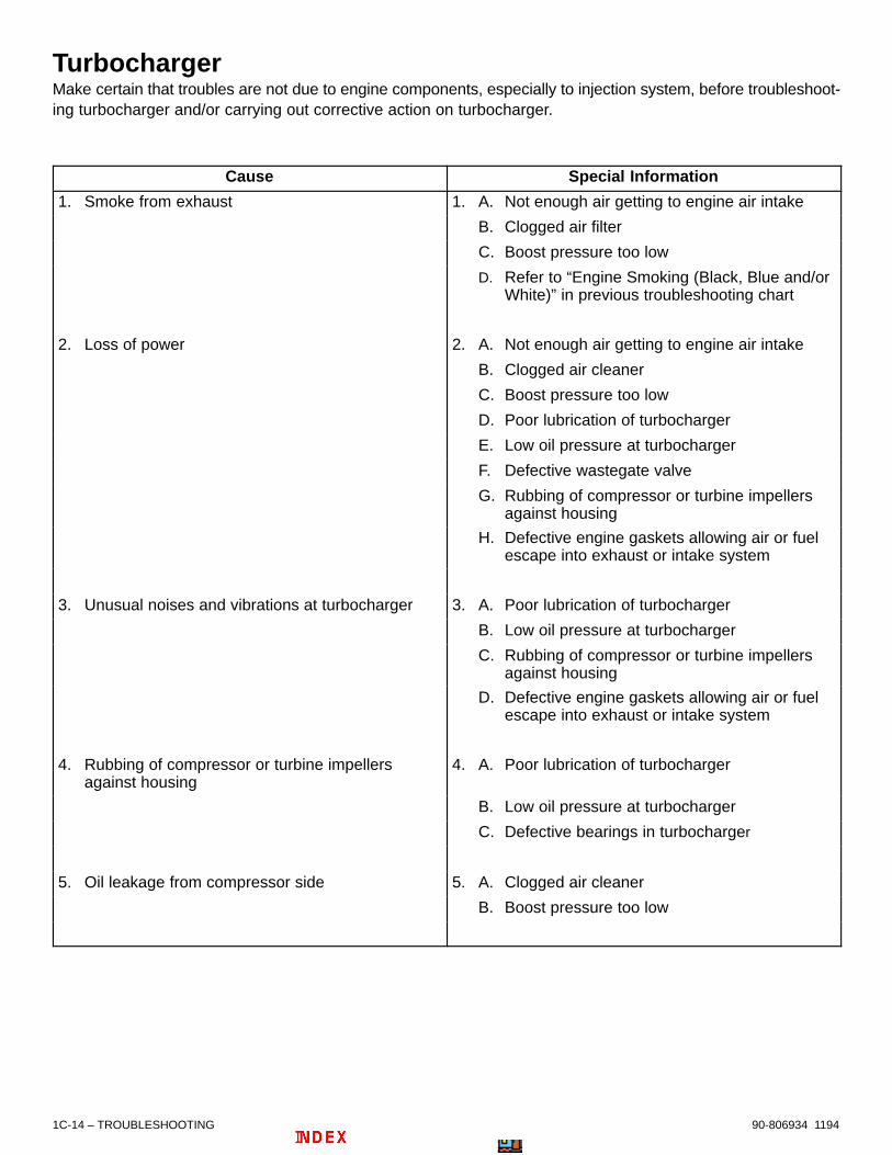
1C-14 – TROUBLESHOOTING 90-806934 1194
TurbochargerMake certain that troubles are not due to engine components, especially to injection system, before troubleshoot-ing turbocharger and/or carrying out corrective action on turbocharger.
Cause Special Information
1. Smoke from exhaust 1. A. Not enough air getting to engine air intake
B. Clogged air filter
C. Boost pressure too low
D. Refer to “Engine Smoking (Black, Blue and/or White)” in previous troubleshooting chart
2. Loss of power 2. A. Not enough air getting to engine air intake
B. Clogged air cleaner
C. Boost pressure too low
D. Poor lubrication of turbocharger
E. Low oil pressure at turbocharger
F. Defective wastegate valve
G. Rubbing of compressor or turbine impellersagainst housing
H. Defective engine gaskets allowing air or fuel escape into exhaust or intake system
3. Unusual noises and vibrations at turbocharger 3. A. Poor lubrication of turbocharger
B. Low oil pressure at turbocharger
C. Rubbing of compressor or turbine impellers against housing
D. Defective engine gaskets allowing air or fuel escape into exhaust or intake system
4. Rubbing of compressor or turbine impellers against housing
4. A. Poor lubrication of turbocharger
B. Low oil pressure at turbocharger
C. Defective bearings in turbocharger
5. Oil leakage from compressor side 5. A. Clogged air cleaner
B. Boost pressure too low

TROUBLESHOOTING – 1C-1590-806934 1194
Engine NoiseIMPORTANT INFORMATION
No definite rule or test will positively determine sourceof engine noise; therefore, use the following informa-tion only as a general guide to engine noise diagno-sis.
1. Use a timing light to determine if noise is timedwith engine speed or one-half engine speed.Noises timed with engine speed are related tocrankshaft, rods, pistons, piston pins, and fly-wheel. Noises timed to one-half engine speed arevalve train related.
2. The use of a stethoscope can aid in locating anoise source; however, because noise will travelto other metal parts not involved in the problem,caution must be exercised.
3. If you believe noise is confined to one particularcylinder, ground spark plug leads, one at a time.If noise lessens noticeably or disappears, it is iso-lated to that particular cylinder.
4. Try to isolate the noise to location in engine: frontto back, top to bottom. This can help determinewhich components are at fault.
5. Sometimes noises can be caused by movingparts coming in contact with other components.Examples are: flywheel or coupler; exhaust flap-pers rattling against exhaust pipe; crankshaftstriking (pan, pan baffle, or dipstick tube); rockerarm striking valve cover; and loose flywheel cov-er. In many cases if this is found to be the problem,a complete engine teardown is not necessary.
6. When noise is isolated to a certain area and com-ponent, removal and inspection will be required.Refer to proper sections of service manual for in-formation required for service.
7. If noise cannot be distinguished between engineand drive unit, remove drive from boat. Run a wa-ter supply directly to engine. Run engine withoutthe drive to determine if noise is still there.
Valve Cover Area
Location Possible Cause
1. Valve cover area, timed to one-half enginespeed, noise could be confined to one cylinderor may be found in any multitude of cylinders
1. A. Rocker arm striking valve cover
B. Rocker arm out of adjustment
C. Worn rocker arm
D. Bent push rod
E. Worn camshaft
F. Sticking valve
Cylinder Area
Location Possible Causes
1. Cylinder area, may be confined to one cylinder or found in more than one cylinder, timed toengine speed
1. A. Sticking valve
B. Carbon build-up
C. Connecting rod installed wrong
D. Bent connecting rod
E. Piston
F. Piston rings
G. Piston pin
H. Cylinder worn

1C-16 – TROUBLESHOOTING 90-806934 1194
Cylinder Area (continued)
Location Possible Causes
2. Engine knocking 2. A. Faulty injector (white smoke)
B. Worn delivery valve
C. Wrong injection timing
D. Incorrect valve clearance
E. Loose pre-combustion chamber
F. Tight piston pin
Camshaft Area
Location Possible Causes
1. Camshaft area, front of engine, timed to enginespeed
1. A. Camshaft timing gear
B. Injection pump
C. Fuel pump
D. Valve lifter - camshaft wear
E. Cam bearings
2. Camshaft area, center of engine, timed to engine speed
2. A. Fuel pump
B. Valve lifter - camshaft wear
C. Cam bearings
3. Camshaft area, rear of engine, timed to enginespeed
3. A. Valve lifter - camshaft wear
B. Cam bearings
4. Camshaft area, throughout engine, timed toengine speed
4. A. Loss of oil pressure
B. Valve lifter - camshaft wear
C. Cam bearings

TROUBLESHOOTING – 1C-1790-806934 1194
Crankshaft Area
Location Possible Causes
1. Crankshaft area, front of engine, timed to enginespeed
1. A. Crankshaft timing gear
B. Oil Pump
C. Rod bearing
D. Main bearing
2. Crankshaft area, center of engine, timed to engine speed
2. A. Crankshaft striking pan or pan baffle
B. Rod bearing
C. Main bearing
3. Crankshaft area, rear of engine, timed to enginespeed
3. A. Loose flywheel cover
B. Loose coupler or drive plate
C. Loose flywheel
D. Rod bearing
E. Main bearing
4. Crankshaft area, throughout engine, timed toengine speed
4. A. Loss of oil pressure
B. Rod bearings
C. Main bearings
Miscellaneous
1. Hissing 1. A. Vacuum leak
B. Leaking exhaust (manifolds or pipes)
C. Loose cylinder heads
D. Blown head gasket
2. Whistle 2. A. Vacuum leak
B. Dry or tight bearing in an accessory
3. Squeaks or squeals 3. A. Drive belt slipping
B. Dry or tight bearing in an accessory
C. Parts rubbing together
4. Rattling in exhaust pipe area 4. A. Exhaust shutters

1C-18 – TROUBLESHOOTING 90-806934 1194
Oil PressureItem Special Information
1. Measuring oil pressure 1. Use a good automotive oil pressure test gauge. Do not rely on the oil pressure gauge in the boat.
2. Check engine oil level with boat at rest in thewater
2. Oil level should be between the ADD and FULL marks
3. Oil level in crankcase above FULL mark 3. May cause loss of engine RPM, oil pressure gauge fluctuation, drop in oil pressure, and hydraulic valve lifter noise at high RPM
4. Oil level in crankcase below ADD mark 4. Low oil pressure; oil pressure gauge fluctuation; internal engine noise and/or damage
5. Change in oil pressure 5. This may be a normal condition. Oil pressure mayread high in the cooler times of the day, and whenengine is not up to operating temperature. As the air temperature warms up and engine is running at normal opening temperature, it is normal for oil pressure to drop.
6. Low engine oil pressure at idle 6. With modern engines and engine oils, low oil pressure readings at idle do not necessarily meanthere is a problem. If valve lifters do not “clatter” (at idle), there is a sufficient volume of oil to lubricate all internal moving parts properly. The reason for the drop in oil pressure is that engine heat causes an expansion of the internal tolerances in the engine and, also, the oil will thin out somewhat from heat.
7. Low engine oil pressure at idle after running at ahigh RPM
7. Refer to No. 5 and 6, preceding
8. Boats with dual engines 8. It is not uncommon to see different oil pressure readings between the two engines, as long as both engines fall within specifications. Differencesin oil pressure can be attributed to differences in engine tolerances, gauges, wiring, senders, etc.
9. Boats with dual stations 9. Refer to No. 8. preceding

TROUBLESHOOTING – 1C-1990-806934 1194
Low Oil Pressure
Cause Special Information
1. Low oil level in crankcase
2. Defective oil pressure gauge and/or sender 2. Verify with an automotive test gauge.
3. Thin or diluted oil 3. Oil broken down; contains water or fuel; wrong viscosity; engine running too hot or too cold; excessive idling in cold water (condensation)
4. Oil pump 4. Relief valve stuck open; pickup tube restricted; worn parts in oil pump; air leak on suction side of oil pump or pickup oil tube
5. Oil leak can be internal or external 5. Oil passage plugs leaking, cracked or porous cylinder block
6. Excessive bearing clearance 6. Cam bearings, main bearings, rod bearings
High Oil PressureIMPORTANT: Oil pressure slightly higher than normal does not always indicate a problem. Oil viscosity,and weather conditions could cause high oil pressure.
Cause Special Information
1. Oil too thick 1. Wrong viscosity, oil full of sludge or tar
2. Defective oil pressure gauge and/or sender 2. Verify with an automotive test gauge
3. Clogged or restricted oil passage
4. Oil pump relief valve stuck closed

1C-20 – TROUBLESHOOTING 90-806934 1194
Excessive Oil Consumption
Cause Special Information
1. Normal consumption 1. One quart of oil consumed in 5-15 hours of operation at wide-open-throttle (especially in a new or rebuilt engine) is normal
2. Oil leaks 2. Clean bilge, run engine with clean white paper on bilge floor, locate oil leak(s)
3. Oil too thin 3. Oil diluted or wrong viscosity
4. Oil level too high
5. Drain holes in cylinder head plugged 5. Oil will flood valve guides
6. Defective valve stem seals (if so equipped)
7. Worn valve stems or valve guides
8. Defective oil cooler (if so equipped) 8. Crack in cooler tubes
9. Defective piston rings 9. Glazed, scuffed, worn, stuck, improperly installed;ring grooves worn; improper break-in; wrong end gap
10. Defective cylinders 10. Out of round, scored, tapered, glazed; excessive piston to cylinder clearance; cracked piston
11. Excessive bearing clearance

TROUBLESHOOTING – 1C-2190-806934 1194
Water in Engine
IMPORTANT INFORMATION
IMPORTANT: First determine location of water inengine. This information can be of great helpwhen trying to determine where the water camefrom and how it got into the engine. The threemost common problems are “water on top of pis-tons, water in crankcase oil, water in crankcaseoil and on top of pistons.”
The first step, after locating water, is to remove all thewater from the engine by removing all spark plugsand pumping cylinders out by cranking engine over.Next change oil and filter. Now, start engine and seeif problem can be duplicated. If problem can be dupli-cated, there more than likely is a mechanical prob-lem. If the problem cannot be duplicated, the problemis either an operator error or a problem that exists onlyunder certain environmental conditions.
If water is contained to cylinder(s) only, it is usually en-tering through the intake system, exhaust system, orhead gasket.
If the water is contained to crankcase only, it is usuallycaused by a cracked or porous block, a flooded bilge,or condensation.
If the water is located in both the cylinder(s) and thecrankcase, it is usually caused by water in the cylin-ders getting past the rings and valves, or completesubmersion.
Checking for rust in the intake manifold or exhaustmanifolds is a good idea. Rust in these areas will giveclues if the water entered these areas.
Water In Crankcase Oil
Cause Special Information
1. Water in boat bilge 1. Boat has been submerged or bilge water was high enough to run in through dipstick tube
2. Water seeping past piston rings or valves 2. Refer to “Water in Engine” (“Water On Top of Pistons”)
3. Engine running cold 3. Defective thermostat, missing thermostat; pro-longed idling in cold water
4. Intake manifold leaking near a water passage
5. Cracked or porous casting 5. Check cylinder head, cylinder block, and intake manifold

1C-22 – TROUBLESHOOTING 90-806934 1194
Water On Top Pistons
Cause Special Information
1. Rain water running onto air cleaner 1. Hatch cover
2. Backwash through the exhaust system
3. Improper engine or exhaust hose installation 3. Refer to exhaust specifications
4. Cracked exhaust manifold
5. Improper manifold to elbow gasket installation
6. Loose cylinder head bolts
7. Blown cylinder head gasket 7. Check for warped cylinder head or cylinder block
8. Cracked valve seat
9. Porous or cracked casting 9. Check cylinder heads, cylinder block, and intakemanifold
Engine Overheats (Cooling System)Cause Special Information
IMPORTANT: The first step is to verify if the en-gine is actually overheating or the temperaturegauge or sender is faulty
1. Seacock (seawater shutoff valve) partially or fully closed (if so equipped)
2. Low coolant level
3. Antifreeze not mixed properly 3. Use Quicksilver Premixed Marine EngineCoolant. DO NOT mix water with QuicksilverPremixed Marine Engine Coolant.
4. Loose or broken drive belt
5. Clogged or improperly installed sea strainer

TROUBLESHOOTING – 1C-2390-806934 1194
Engine Overheats (Cooling System) (continued)Cause Special Information
6. Loose hose connections between seawaterpickup and seawater pump inlet
6. Pump will suck air. Pump may fail to prime or will force air bubbles into cooling system.
7. Seawater inlet hose kinked or collapsed 7. Inlet hose must be wire reinforced to prevent col-lapsing, and positioned to prevent kinks or restric-tions.
8. Seawater pickup clogged
9. Obstruction on boat bottom causing water turbulence
9. Obstruction will be in front of seawater pickup, causing air bubbles to be forced into coolingsystem
10. Defective thermostat(s)
11. Exhaust elbow water outlet holes plugged
12. Insufficient seawater pump operation 12. Worn pump impeller
13. Obstruction in cooling system such as castingflash, sand, rust, salt, etc.
13. Refer to water flow diagram for engine type beingserviced
14. Engine water circulating pump defective
18. Heat exchanger cores plugged
15. Also refer to “Engine Overheats (Mechanical)”

1C-24 – TROUBLESHOOTING 90-806934 1194
Engine Overheats (Mechanical)Cause Special Information
1. Engine RPM below specifications at wide-open-throttle (engine laboring)
1. Damaged or wrong propeller; growth on boatbottom; false bottom full of water
2. Incorrect injection pump timing 2. Injection pump timing too far advanced orretarded
3. Seawater pump impeller slipping
4. Exhaust restriction
5. Valve timing off 5. Jumped timing chain, or gears improperlyinstalled
6. Insufficient lubrication to moving parts of engine 6. Defective oil pump, plugged oil passage, low oillevel

TROUBLESHOOTING – 1C-2590-806934 1194
Power Steering
Poor, Erratic, or No Assist
Cause Special Information
1. Drive belt 1. Worn, broken or out of adjustment
2. Low fluid level
3. Air in system 3. Air leak in lines, pump, or air from installation. Refer to Section 9A for bleeding procedure.
4. Leaking hoses 4. Refer to Section 9A for bleeding procedure.
5. Steering cables and/or steering helm 5. Cable or helm partially frozen from corrosion or rust; cable over-lubricated; improper cable installation
6. Binding in stern drive unit 6. Refer to appropriate Stern Drive Service Manual
7. Restriction in hydraulic hoses 7. Causes a loss of pressure
8. Control valve not positioned properly, not balanced properly, or the mounting nut is loose
9. Mounting bracket adjusting screw loose or mounting tube is loose
10. Faulty pump 10. Flow control valve may be sticking
11.Worn piston ring or scored housing bore in cylinder
11. Causes loss of pressure
12. Leaking valve body or loose fitting spool

1C-26 – TROUBLESHOOTING 90-806934 1194
Noisy Pump
Cause Special Information
1 Drive belt 1. Check belt tension
2. Low fluid level
3. Air in fluid 3. Air leak in lines, pump, or air form installation
4. Faulty Pump 4. Use stethoscope to listen for noise in pump
5. Restricted fluid passages 5. Kinks or debris in hoses or debris in passages
6. Stop nut adjusted improperly 6. Refer to appropriate Stern Drive Service Manual
7. Steering cables installed that do not meet BIA standards
7. Refer to appropriate Stern Drive Service Manual
Fluid Leaks
Cause Special Information
1. Loose hose connections 1. Refer to Section 10A for bleeding instructions
2. Damaged hose
3. Oil leaking from top of pump 3. System overfilled; fluid contains water; fluid contains air
4. Cylinder piston rod seal
5. Faulty seals in valve
6 Faulty seals in o-rings in pump
7. Cracked or porous metal parts
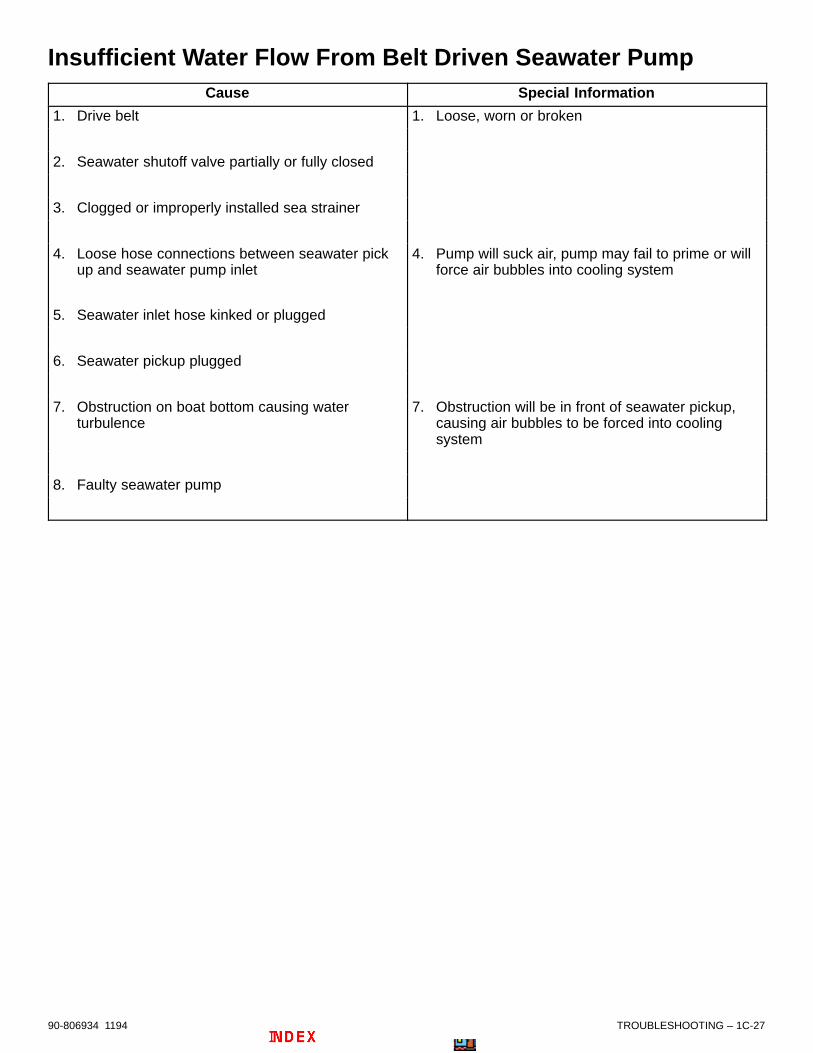
TROUBLESHOOTING – 1C-2790-806934 1194
Insufficient Water Flow From Belt Driven Seawater PumpCause Special Information
1. Drive belt 1. Loose, worn or broken
2. Seawater shutoff valve partially or fully closed
3. Clogged or improperly installed sea strainer
4. Loose hose connections between seawater pickup and seawater pump inlet
4. Pump will suck air, pump may fail to prime or will force air bubbles into cooling system
5. Seawater inlet hose kinked or plugged
6. Seawater pickup plugged
7. Obstruction on boat bottom causing water turbulence
7. Obstruction will be in front of seawater pickup, causing air bubbles to be forced into cooling system
8. Faulty seawater pump

1C-28 – TROUBLESHOOTING 90-806934 1194
Hurth Hydraulic TransmissionTrouble Possible Cause Remedy
1. Transmission gearscannot be shifted
1. A. Shifting lever loose 1. A. Tighten clamping screw on shifting lever
B. Remote control does not permit lever travel required for testing
B. Lift remote control off, if gears can be shifted by hand, correctremote control
C. Remote control faulty C. Repair remote control
D. No shifting pressure available D. Refer to 7
2. Gears are shiftedsluggishly
2. Lever travel of remote control istoo short; lever shift just short ofminimum traveling distance
2. Lift remote control off, if gears canbe shifted by hand, correct remotecontrol
3. Clutch is slipping;propeller speed too lowas compared to enginespeed
3. A. Incorrect fluid used 3. A. Drain and refill with correct fluid, flush transmission while engine runs in neutral position,drain fluid, refill transmission
B. Fluid contains water B. Refer to 9
C. Shifting pressure too low C. Refer to 6
D. Wear on clutch discs D. Disassemble transmission replace clutch discs
E. Piston rings in clutch are damaged
E. Disassemble transmission replace clutch
4. Transmission is blocked 4. A. Medium piston ring in input shaft in control block is faulty
4. A. Remove control block, replace piston ring, replace control block if worn
5. Output shaft turns inneutral position
5. A. Rotary slide valve in control block is worn
5. A. Replace control block
B. Faulty needle bearing on input shaft
B. Disassemble transmission andinput shaft, replace bearing
C. Dished discs due to overheating of slipping clutch
C. Refer to 3

TROUBLESHOOTING – 1C-2990-806934 1194
Hurth Hydraulic Transmission (continued)Trouble Possible Cause Remedy
6. Shifting pressure too low 6. A. Fluid filter dirty 6. A. Replace fluid filter
B. Fluid level in transmission is too low
B. Fill with fluid; check for fluid loss in transmission,cooler andpipelines lines for leaks also refer to steps 10 to 13
C. Fluid pump is worn out C. Replace control block together with fluid pump
D. Piston rings in input shaft in control block are faulty
D. Remove control block and replace piston rings. also replace control block
E. Piston rings in clutch are faulty E. Disassemble transmission, replace clutch
7. No shifting pressure 7. A. Direction of engine rotation does not agree with arrow on transmission
7. A. Replace with L.H. rotation engine
B. No fluid in transmission B. Refill with fluid
C. Fluid filter is dirty C. Replace fluid filter
D. Fluid level in transmission is too low
D. Fill with fluid; check for fluid loss in transmission,cooler andpipelines lines for leaks also refer to steps 10 to 13
E. Fluid pump is worn out E. Replace control block together with fluid pump
F. Fitting key in input shaft for fluid pump drive is broken
F. Remove control block. Replace fitting key and any other faulty parts
G. Shifting pressure relief valve spring is broken
G. Replace control block
8. Excessive fluidtemperature
8. A. Excessive fluid in transmission 8. A. Remove excessive fluid with commercial fluid pump
B. Fluid cooler is dirty on water side
B. Remove coolant lines andclean fluid cooler on water side
C. Worn fluid pump in control block
C. Replace control block and fluidpump
D. Faulty piston rings in input shaft in control block
D. Remove control block, replace piston rings in input shaft. Check control block and replace if damaged from faulty piston rings
E. Clutch is slipping E. Refer to 3
F. Clutch does not open completely due to worn clutch discs
F. Dismount transmission, replace inner disc all faulty parts
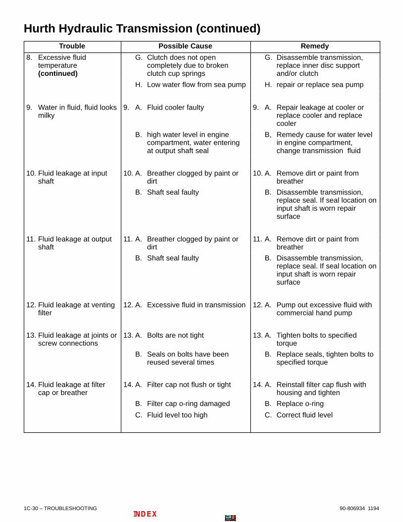
1C-30 – TROUBLESHOOTING 90-806934 1194
Hurth Hydraulic Transmission (continued)Trouble Possible Cause Remedy
8. Excessive fluidtemperature(continued)
G. Clutch does not open completely due to broken clutch cup springs
G. Disassemble transmission, replace inner disc support and/or clutch
H. Low water flow from sea pump H. repair or replace sea pump
9. Water in fluid, fluid looksmilky
9. A. Fluid cooler faulty 9. A. Repair leakage at cooler or replace cooler and replace cooler
B. high water level in engine compartment, water entering at output shaft seal
B, Remedy cause for water level in engine compartment, change transmission fluid
10. Fluid leakage at inputshaft
10. A. Breather clogged by paint or dirt
10. A. Remove dirt or paint from breather
B. Shaft seal faulty B. Disassemble transmission,replace seal. If seal location oninput shaft is worn repair surface
11. Fluid leakage at outputshaft
11. A. Breather clogged by paint or dirt
11. A. Remove dirt or paint from breather
B. Shaft seal faulty B. Disassemble transmission,replace seal. If seal location oninput shaft is worn repair surface
12. Fluid leakage at ventingfilter
12. A. Excessive fluid in transmission 12. A. Pump out excessive fluid with commercial hand pump
13. Fluid leakage at joints orscrew connections
13. A. Bolts are not tight 13. A. Tighten bolts to specified torque
B. Seals on bolts have been reused several times
B. Replace seals, tighten bolts to specified torque
14. Fluid leakage at filtercap or breather
14. A. Filter cap not flush or tight 14. A. Reinstall filter cap flush with housing and tighten
B. Filter cap o-ring damaged B. Replace o-ring
C. Fluid level too high C. Correct fluid level

TROUBLESHOOTING – 1C-3190-806934 1194
Hurth Hydraulic Transmission (continued)Trouble Possible Cause Remedy
15. Transmission noisechanges, becomeslouder
15. A. Fluid level too low so that pump sucks in air
15. A. Top off fluid to fill mark
B. Damage starting on flexible coupling due to wear or fatigue, possible due to misalignment between engine and transmission
B. Replace flexible coupling. Check alignment between engine and transmission
C. Beginning damage of bearings in transmission; torsional vibrations, running without fluid, overload, wrong alignment of transmission, excessive motor output
C. Disassemble transmission, replace bearings concerned and other faulty parts
D. Beginning damage of gearings; torsional vibrations, running without, fluid, overload
D. Disassemble transmission, remove faulty parts
E. Fluid baffle on transmission has come loose
E. Disassemble transmission,attach baffle plate
F. Fluid suction pipe in transmission has come loose
F. Disassemble transmission, fix fluid suction pipe
16. Chattering transmissionnoise mainly at lowspeed
16. A. The engine or propeller generate torsional vibrations, which produce a chattering noise in the transmission
16. A. Mount a flexible coupling with another stiffness factor between engine and transmission; a coupling with ahigher stiffness factor might besufficient
B. Misaligned cardan shafts on input or output shafts
B. Mount and align cardan shaft strictly according to instructions issued by cardan shaft manufacturer

2
A
73935
REMOVAL AND INSTALLATION
MCM (STERNDRIVE) MODELNote:Refer to the following Service Bulletins regarding this section.
SB 98-12 Gimbal Housing Oil Reservoir Bulkhead Fitting-Material Change
SB 97-10 Alternate Gear Ratio Sterndrive Units for High Altitude
SB 97-7 Bravo Drives and Transoms
SB 96-1 Bravo Transom Assemblies for the 1996-1/2 Model Year
SB 95-21 Bearing Cup Installation in the Bravo One Bearing Carrier
SB 95-10 MerCruiser MCM D7.3L/270 Diesel Sterndrive Replacement
SB 91-26 Bravo One Clutch
SB 91-21 Drive Unit Gear Ratio Identification
SB 91-19 Anode Material Change
SB 91-4 815471A3 Bravo Shift Cable Replacement Kit

2A-0 - MCM (STERN DRIVE) MODEL 90-806934 1194
Table of ContentsPage
Torque Specifications 2A-1. . . . . . . . . . . . . . . . . . . . . . . . . Tools/Lubricants/Adhesives 2A-1. . . . . . . . . . . . . . . . . . . . Removal 2A-2. . . . . . . . . . . . . . . . . . . . . . . . . . . . . . . . . . . .
Engine Removal 2A-2. . . . . . . . . . . . . . . . . . . . . . . . . . . Installation 2A-3. . . . . . . . . . . . . . . . . . . . . . . . . . . . . . . . . . .
Engine Preparation 2A-3. . . . . . . . . . . . . . . . . . . . . . . . Engine Alignment 2A-5. . . . . . . . . . . . . . . . . . . . . . . . . . Engine Connections 2A-6. . . . . . . . . . . . . . . . . . . . . . . .
Shift Cable Installation and Adjustment 2A-9. . . . . . . . . . Throttle Cable Installation and Adjustment 2A-13. . . . . . Engine Idle Speed Adjustment 2A-14. . . . . . . . . . . . . . . . .
NOTICEFor information and procedures on trouble-shooting, refer to SECTION 1C.
2A - MCM (STERN DRIVE) MODEL

MCM (STERN DRIVE) MODEL - 2A-190-806934 1194
Torque SpecificationsIMPORTANT: Listed below are the torque specifications for those fasteners which have a specific torquevalue. Tighten all other fasteners (not listed) securely.
DESCRIPTION Lb. In. Lb. Ft. N·m
Drive Unit Shift Cable or Power Shift Output Cable End GuideAttaching Nut
Tighten Nut Until It Bottoms Out Against FlatWasher; then, Back Nut Off 1 Turn
Remote Control Throttle Cable End Guide Attaching Nut Tighten Nut Until It Bottoms Out Against FlatWasher; then, Back Nut Off 1 Turn
Remote Control Throttle and Shift Cable Barrel Attaching Nut Securely
Rear Engine Mounts 35-40 47-54
Power Steering Fluid Hose Fittings (at Control Valve) 20-25 27-34
Stern Drive Unit Fasteners 50 68
Transom Assembly Fasteners 20-25 27-34
Seawater Pickup (Inlet) Fitting (on gimbal housing) 45 5
Drive Unit Gear Lube Monitor - 90 Degree Barb Fitting 70-90 8-10
Steering Cable Pivot Bolts 25 (34)
Steering Cable Coupler Nut 35 (47)
Bravo One / Two Propeller Nut 55 MINIMUM 75
Tools/Lubricants/AdhesivesDESCRIPTION PART NUMBER
Quicksilver 2-4-C Marine Lubricant 92-825407A12
Quicksilver Special Lubricant 101 92-13872A1
Quicksilver Liquid Neoprene 92-25711--2
Quicksilver Perfect Seal 92-34227--1
Quicksilver Engine Alignment Tool [or old tool (91-57797A3) which hasbeen modified per OEM Service Bulletin 92-4]
91-805475A1
Quicksilver Engine Coupler Spline Grease 91-816391A4
Engine Lifting Eye Tool 91-814412
# 592 - Loctite Pipe Sealant with Teflon Obtain Locally

2A-2 - MCM (STERN DRIVE) MODEL 90-806934 1194
Removal
IMPORTANT: Stern drive unit must be removedprior to engine removal. Refer to Stern Drive Ser-vice Manual.
Engine Removal1. Disconnect battery cables from battery.
2. Disconnect gear lube monitor bottle wires on tran-som mounted bottles. Remove engine mountedgear lube monitor bottle and disconnect wires.Set the bottle aside, in the upright position.
3. Disconnect extension harness connector plugsfrom engine harness connector ends.
! CAUTIONIt is good practice to ventilate the engine com-partment prior to servicing any engine compo-nents to remove any fuel vapors which may causedifficulty breathing or be an irritant.
! WARNINGBe careful when changing fuel system compo-nents; diesel fuel is flammable. Be sure that theignition key is OFF. DO NOT smoke or allowsources of open flame in the area while changingfuel system components. Wipe up any spilled fuelimmediately. DO NOT allow fuel to come into con-tact with any hot surface which may cause it to ig-nite.
! WARNINGDispose of fuel-soaked rags, paper, etc., in an ap-propriate air tight, fire retardant container.Fuel-soaked items may spontaneously ignite andresult in a fire hazard which could cause seriousbodily injury or death.
! WARNINGFIRE HAZARD: Fuel leakage from any part of thefuel system can be a fire hazard which can causeserious bodily injury or death.
4. Loosen hose clamps, then disconnect and suit-ably plug fuel lines to prevent fuel in tank fromleaking into bilge.
5. Disconnect throttle cable from injection pumplinkage on engine and retain locknuts and hard-ware.
6. Disconnect bullet connectors of trim sender wires(coming from transom assembly) from engineharness.
NOTE: After wires are disconnected be sure to loos-en them from clamps or sta-straps retaining them toengine or hoses.
7. Disconnect MerCathode wires from MerCathodecontroller mounted on engine.
8. If not already accomplished, close seacock, if soequipped, or disconnect and plug seawater inlethose, if boat is to remain in the water.
! CAUTIONBefore removing seawater inlet hose, close sea-cock, if so equipped. If boat is not equipped witha seacock, remove and plug seawater inlet hoseto prevent a siphoning action that may occur, al-lowing seawater to flow from the drain holes or re-moved hoses.
9. Disconnect seawater inlet hose from water inletfitting on engine.
10. Disconnect exhaust elbow hose from exhaustpipe.
11. On Engines WITH Power Shift: Disconnectvacuum hose from power shift cylinder to vacuumpump fitting.
12. Remove both shift cables from shift plate. Retainlocknuts and hardware.
13. Disconnect any grounding wires and accessoriesthat are connected to engine.
14. Disconnect (and suitably plug) fluid hoses frompower steering control valve on transom.

MCM (STERN DRIVE) MODEL - 2A-390-806934 1194
! CAUTIONDO NOT allow lifting sling to hook or compressengine components or damage will occur.
15. Support engine with suitable sling, through liftingeyes on engine and remove front and rear enginemounting bolts. Retain hardware.
73935
73322
a
71706
a
b
a - Engine Lifting Eyesb - Suitable Sling
Typical
16. Carefully remove engine. DO NOT hit powersteering control valve.
Installation
Engine Preparation1. Follow instructions “a” or “b”:
a. On Engines Where Engine Mounts WERENOT Disturbed: Proceed to Step 2.
b. On Engines Where Engine Mounts WEREDisturbed: Ensure front mount adjustingnuts are positioned midway on studs so thatadequate up and down adjustment exists forengine alignment.
2. Lubricate coupler splines with 2-4-C MarineLubricant.
73330
a
a - Coupler Splines
Typical
3. Attach a suitable sling to lifting eyes on engineand adjust so that engine is level when sus-pended. Refer to previous “Removal” section forlocation of engine lifting eyes.
4. Lift engine into position (in boat), using an over-head hoist.
5. Align rear engine mounts with inner transom platemounts and set onto front engine mounts and in-ner transom plate mounts, while simultaneouslyaligning exhaust elbow with exhaust tube. (Donot relieve hoist tension.)

2A-4 - MCM (STERN DRIVE) MODEL 90-806934 1194
IMPORTANT: Engine attaching hardware must beinstalled in sequence shown.
6. Install both rear engine mounting bolts and hard-ware as shown. Torque to 35-40 lb. ft. (47-54N·m).
22032
e
f
ga
b
c
d
a - Rear Engine Mountb - Inner Transom Plate Mountc - Boltd - Washere - Spacerf - Fiber Washerg - Double-Wound Lockwasher
7. Relieve hoist tension and disconnect sling fromengine lifting eyes.
NOTE: Install appropriate Engine Lifting Eye Toolshown in following steps to help equalize load onhoist during alignment procedure.
! CAUTIONAvoid injury or damage to product. Engine LiftingEye Tool must be used for alignment proceduresonly and is NOT to be used for installing the en-gine in the boat.
8. Remove rocker cover nut (and O-ring seal) near-est pulley end of engine and install Engine LiftingEye Tool 91-814412 as shown. Tighten securely,but do not overtighten. Attach chain and hookfrom suitable hoist.
71730
a
b
73328
a - Rocker Cover Nut (and O-ring Seal - Not Visible Here)b - Engine Lifting Eye Tool

MCM (STERN DRIVE) MODEL - 2A-590-806934 1194
Engine Alignment1. Align engine as follows:
! CAUTIONDO NOT use an alignment tool from another man-ufacturer. Alignment tools other than QuicksilverAlignment Tool, may cause improper alignmentand damage to gimbal bearing and/or engine cou-pler.
! CAUTIONTo avoid damage to gimbal bearing, engine cou-pler, or alignment tool:
• DO NOT attempt to force alignment tool!
• DO NOT raise or lower engine with alignmenttool inserted (or partially inserted) in gimbalbearing or engine coupler.
a. Attempt to insert the solid end of the align-ment tool thru the gimbal bearing and into theengine coupler splines.
b. If the tool does not fit, remove it and carefullyraise or lower the front end of the engine, asnecessary, and attempt to insert the align-ment tool.
c. Repeat step “c” until the alignment tool installseasily (SLIDES FREELY WITH TWO FIN-GERS) all the way into and out of engine cou-pler splines. Do not check by turning.
b
22029
c
d
73794
a
a - Alignment Tool (use only recommended alignment tool)b - Insert this end of Alignment Tool thru Gimbal Housing
Assemblyc - Gimbal Bearingd - Engine Coupler
Typical
2. Front engine mounts must rest on boat stringer.Adjust front engine mounts until they touchstringer.
3. Relieve hoist tension entirely and fasten frontmount assembly to boat stringer using appropri-ate hardware (lag bolts or thru-bolts, etc.).
4. Recheck alignment with alignment tool. Tool mustenter coupler splines freely. If not, readjust frontmounts.
5. When alignment is correct, tighten locknuts andjam nuts securely. Bend tabs (if so equipped)down on adjusting nuts.
23161
b
c
d
e
f
g
a
a - Lock Nutb - Bracketc - Mount Adjustment Nut – turn left to lower, right to raised - Lag Screws (or Bolts)e - Clampf - Nuts – Loosen to Move Bracket Side-to-Sideg - Clamp Spread-Screw
D3.0L/150. D3.6L/180, and D4.2L/220
6. Remove alignment tool if not already removed.
7. Remove Engine Lifting Eye Tool. Install rockercover nut with new o-ring seal. Torque rocker nutto 84 lb. in. (10 N·m).

2A-6 - MCM (STERN DRIVE) MODEL 90-806934 1194
Engine Connections1. Connect power steering hoses to control valve.
IMPORTANT: Make hydraulic connections asquickly as possible to prevent oil leakage.
IMPORTANT: Be careful not to cross-thread orovertighten hose fittings.
74045
a
b
a - Rear Fitting (Pressure Hose) b - Front Fitting (Return Hose)
2. Tighten exhaust tube hose clamps securely.
3. Connect continuity circuit wire from engine totransom assembly. Tighten screw securely.
IMPORTANT: Do not attach any accessoryground (–) wires to transom plate ground point.
73567
a
b
c
a - Flywheel Housing Screwb - Continuity Circuit Wirec - Inner Transom Plate Grounding Screw
4. Connect any grounding wires and accessoriesthat were connected to engine.
5. Connect seawater inlet hose to engine water inletfitting. Tighten hose clamp securely.
7352150226
c
b
a
a - Water Inlet Fittingb - Seawater Inlet Hose c - Hose Clamp
6. Connect coolant recovery hose to bayonet fittingon heat exchanger and secure with tubing clamp.
70548
b
a
a - Plastic Tubingb - Tubing Clamp

MCM (STERN DRIVE) MODEL - 2A-790-806934 1194
7. Connect MerCathode wires to MerCathode con-troller mounted on engine. Apply a thin coat ofLiquid Neoprene to ALL electrical connections.
71709
a
a - Controller Assembly Location
22232b c da
a - Orange Wire - From Electrode on Transom Assemblyb - Red/Purple Wire - Connect (Other End) to Positive (+)
Battery Terminalc - Black Wire - From Engine Harnessd - Brown Wire - From Electrode on Transom Assembly
8. Connect the trim position sender wires bullet con-nectors (coming from transom assembly) to en-gine harness.
24841
BLK/WHT
BLU/BLK BLK
BLK
a b
a - From Engine Harnessb - From Gimbal Housing
9. Follow gear lube monitor bottle connectioninstructions “a” or “b”. In “a” and “b” the TAN/BLUE wire connects to BLACK/GREEN wire.BLACK wire connects to BLACK wire. Check thatbullet connectors are together tightly.
a. On transom mounted bottles: Connectdrive unit gear lube monitor bottle wires tocorresponding engine harness wires.
b. On engine mounted bottles: Mount thebottle in the engine bracket. Connect driveunit gear lube monitor bottle wires to corre-sponding engine harness wires.
50027
a
74235
b
c
c
a - Transom Mounted, Round Gear Lube Monitor Bottle b - Engine Mounted, Square Gear Lube Monitor Bottlec - Bullet Connectors
10. Connect instrument extension harness ends toengine harness ends – connector collars must befully engaged and secure.
71890
ba
c
a - Extension Harnesses (From Instruments)b - Engine Harness and Connector Endsc - Connector Collar(s)

2A-8 - MCM (STERN DRIVE) MODEL 90-806934 1194
! WARNINGBe careful when working on fuel system compo-nents; diesel fuel is flammable. Be sure that theignition key is OFF. DO NOT smoke or allowsources of open flame in the area while changingfuel system components. Wipe up any spilled fuelimmediately. DO NOT allow fuel to come into con-tact with any hot surface which may cause it to ig-nite.
! WARNINGDispose of fuel-soaked rags, paper, etc., in anappropriate air tight, fire retardant container.Fuel-soaked items may spontaneously ignite andresult in a fire hazard which could cause seriousbodily injury or death.
! WARNINGFIRE HAZARD: Fuel leakage from any part of thefuel system can be a fire hazard which can causeserious bodily injury or death.
11. Connect fuel lines as follows:
a. Connect flexible fuel line to inlet fitting on fuelpump and secure with hose clamps.
71710
b
cd
a
a - Fuel Lineb - Hose Clampc - Inlet Fittingd - Fuel Pump
b. Connect fuel return line to injection pump re-turn fitting and secure with hose clamps.
23284
bc a
a - Fuel Lineb - Hose Clampc - Return Fitting
12. On Engines with Power Shift: Attach vacuumhose from power shift cylinder to vacuum pumpfitting. Tighten hose clamp securely.
13. After all wires are connected be sure to securethem with clamps or Sta-Straps which may havebeen retaining them to engine or hoses prior toremoval.
14. Connect both shift cables to shift plate usingretained locknuts and hardware. Refer to “ShiftCable Installation and Adjustment” sectionoutlined later and follow instructions.
15. Connect throttle cable using retained hardware.Refer to “Throttle Cable Installation and Ad-justment” section outlined later and followinstructions.
16. Connect battery cables to engine:
a. Make sure that grounding stud and starter so-lenoid terminal are free of paint and any othermaterial that could cause a poor electricalconnection.
b. After battery cables are connected, apply athin coat of Liquid Neoprene to the terminals.
c. Be sure to slide rubber boot over the positive(+) terminal after Liquid Neoprene dries.
17. Connect battery cables to battery by FIRST con-necting positive (+) battery cable (usually red) topositive (+) battery terminal. Tighten clamp se-curely. Then, connect negative (–) battery cable(usually black) to negative (–) battery terminal.Tighten clamp securely.
NOTE: Spray terminals with a battery connectionsealant to help retard corrosion.

MCM (STERN DRIVE) MODEL - 2A-990-806934 1194
Shift Cable Installation and Adjustment
NOTE: Shift Cable Adjustment Tool (91-12427) al-lows the shift cables to be installed and adjusted,with or without the stern drive attached.
IMPORTANT: When installing shift cables, besure that cables are routed in such a way as toavoid sharp bends and/or contact with movingparts. DO NOT fasten any items to shift cables.
IMPORTANT: The direction of propeller rotation(RH or LH) for this drive unit is determined by thefollowing method.
1. Determine desired propeller rotation.
a. RIGHT HAND PROPELLER ROTATION -Control cable will have to be installed in re-mote control so that cable end will move in di-rection “A,” when shift handle is placed in theforward position.
b. LEFT HAND PROPELLER ROTATION - Con-trol cable will have to be installed in remotecontrol so that cable end will move in direction“B,” when shift handle is placed in the forwardposition.
23242
2. Install shift cable into remote control (refer toappropriate remote control instructions).
3. Loosen stud and move it to dimension as shown.Retighten stud.
23345
b
a
a - Studb - 3 in. (76mm) - Center of Pivot Bolt to Center of Stud
4. Install drive unit shift cable.
23345
b
c
a
a - Washers (2)b - Lock Nut - Tighten Until Contact, Then Back Off 1/2 Turnc - Cotter Pin - Insert from Top and Spread Both Ends
5. Place adjustment tool over drive unit shift cable,as shown. Hold tool in place, using a piece of tapeover the barrel retainer.
23242
NOTE: Shift Cable Adjustment Tool (91-12427) al-lows the shift cables to be installed and adjusted, withor without the stern drive attached on engines WITH-OUT Power Shift. On engines WITH Power Shift finaladjustment must be accomplished with the drive unitinstalled, and when the engine can be operated.

2A-10 - MCM (STERN DRIVE) MODEL 90-806934 1194
6. Locate center of remote control shift cable play(backlash), or center of Power Shift output controlcable play (on engines with Power Shift).
a. Remote control must be in NEUTRAL posi-tion.
b. Push in on shift cable end with enough pres-sure to remove play, and mark position “a” ontube.
c. Pull out on shift cable end with enough pres-sure to remove play, and mark position “a” ontube.
d. Measure distance between marks “a” and “b”and mark position “c” half-way betweenmarks “a” and “b.”
22024
c
b c
a
IMPORTANT: Be sure to keep center mark “c”aligned with remote control shift cable end guideedge when making the following adjustment.
7. Adjust remote control shift cable or Power Shiftoutput cable as follows:
a. Temporarily install shift cable end guide intoshift lever, and insert anchor pin.
b. Adjust shift cable barrel so that hole in barrelcenters with vertical centerline of stud. En-sure that backlash center mark is alignedwith edge of control cable end guide.
! CAUTIONDO NOT attempt to install or remove remote con-trol cable or Power Shift output cable barrel fromstud, without first removing end guide anchor pinfrom shift lever, and removing cable. Attemptingto bend cable to install or remove barrel, willplace undue stress on cable end guide and shiftlever, and damage to both could occur.
23242
b
cd
e
a
a - Control/Output Cable End Guideb - Anchor Pinc - Backlash Centerd - Remote Control Shift Cable Barrele - Stud
c. Remove remote control or output cable endguide from shift lever, by removing anchorpin.
8. Install remote control shift cable or Power Shiftoutput shift cable.
23242
b
c
d
a
a - Lock Nut - Tighten Until Bottomed Outb - Washers - Both Sides of Barrelc - Anchor Pind - Cotter Pin (Not Visible) - Spread Both Ends
9. Remove adjustment tool.
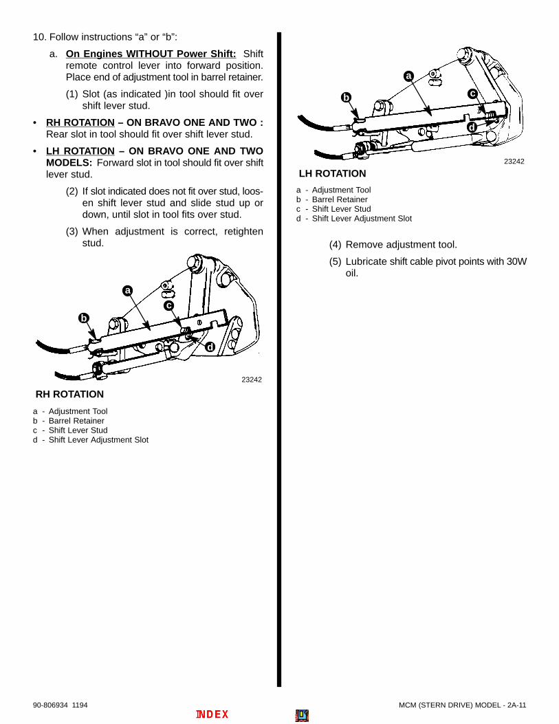
MCM (STERN DRIVE) MODEL - 2A-1190-806934 1194
10. Follow instructions “a” or “b”:
a. On Engines WITHOUT Power Shift: Shiftremote control lever into forward position.Place end of adjustment tool in barrel retainer.
(1) Slot (as indicated )in tool should fit overshift lever stud.
• RH ROTATION – ON BRAVO ONE AND TWO :Rear slot in tool should fit over shift lever stud.
• LH ROTATION – ON BRAVO ONE AND TWOMODELS: Forward slot in tool should fit over shiftlever stud.
(2) If slot indicated does not fit over stud, loos-en shift lever stud and slide stud up ordown, until slot in tool fits over stud.
(3) When adjustment is correct, retightenstud.
23242
b
d
a
RH ROTATION
c
a - Adjustment Toolb - Barrel Retainerc - Shift Lever Studd - Shift Lever Adjustment Slot
23242
b
d
a
c
LH ROTATION
a - Adjustment Toolb - Barrel Retainerc - Shift Lever Studd - Shift Lever Adjustment Slot
(4) Remove adjustment tool.
(5) Lubricate shift cable pivot points with 30Woil.

2A-12 - MCM (STERN DRIVE) MODEL 90-806934 1194
b. On Engines Equipped WITH Power Shift: Final adjustment of Power Shift Assemblyoutput cable at the shift plate cannot be ac-complished unless vacuum is applied to thePower Shift cylinder. In which case, the en-gine must be running or vacuum must becreated through another source (such as anelectric vacuum pump).
In any case, the following precautions apply:
! WARNINGIf the engine is to be operated with boat out of wa-ter, the propeller must be removed to avoid injury.
! CAUTIONFailure to comply with the following instructionswill result in improper unit shift cable adjustmentand possible damage to stern drive shift mecha-nism.
• Remove throttle cable(s) from injection pumpbefore checking and adjusting shift cablewhen using combination shift/throttle remotecontrol(s).
• Engine must be running and Power Shift oper-ating when cable adjustment procedure re-quires moving remote control handle to fullforward or full reverse positions.
NOTE: If your remote control has separate shift andthrottle levers, it is NOT necessary to disconnectthrottle cable(s) from injection pump.
(1) Disconnect throttle cable(s) from injectionpump if using combination shift/throttleremote control(s).
(2) Start engine. Allow engine to reach oper-ating temperature.
(3) Shift remote control lever into full forwardposition.
(4) If slot does not fit over stud, loosen shiftlever stud and slide stud up or down, untilslot in tool fits over stud.
(5) Place end of adjustment tool in barrel re-tainer. Slot in tool (as indicated) should fitover shift lever stud.
• RH ROTATION – ON BRAVO ONE AND TWOMODELS: Rear slot in tool should fit over shiftlever stud.
• LH ROTATION – ON BRAVO ONE AND TWOMODELS: Forward slot in tool should fit over shiftlever stud.
(6) When adjustment is correct, retightenstud.
23242
b
d
a
RH ROTATION
c
23242
b
d
a
c
LH ROTATION
a - Adjustment Toolb - Barrel Retainerc - Shift Lever Studd - Shift Lever Adjustment Slot
(7) Remove adjustment tool.
(8) Shift remote control lever into neutralposition. Stop engine.
(9) Lubricate shift cable pivot points with 30Woil.
(10) Connect throttle cable(s) to injectionpump if using combination shift/throttleremote control(s) (Refer to “ThrottleCable Installation and Adjustment” aspreviously outlined.)

MCM (STERN DRIVE) MODEL - 2A-1390-806934 1194
Throttle Cable Installationand Adjustment
IMPORTANT: When installing throttle cables, besure that cables are routed in such a way as toavoid sharp bends and/or avoid contact withmoving parts. DO NOT fasten any items tothrottle cables.
1. Place remote control lever(s) in neutral/idleposition.
2. Lightly push on throttle cable end guide and turnbarrel to align anchor points with studs. Installcable and secure with hardware as shown.
3. Tighten locknuts until they bottom and back off 1turn.
71261
b
c a
c
a - Throttle Cable End Guideb - Cable Barrelc - Washers and Locknuts
4. Place remote control lever in full forwardwide-open-throttle (W.O.T.) position.
! CAUTIONThe injector pump lever WOT-stop-screw ad-justs the engine speed governor, and is factoryset and sealed. DO NOT readjust this setting.Readjusting the governed speed, and operatingabove the specified RPM will cause extensiveengine damage, and/or failure. Removal of theseal, and/or readjustment of the WOT-stop-screw is considered misuse of engine andresulting damages will not be covered by thelimited warranty.
5. Check to ensure injector pump lever is contact-ing “W.O.T. Stop Screw,” DO NOT attempt toadjust screw (screw is sealed). Check to ensurethat remote control and cable are providingproper output.
23728
b
c
d
e
a
a
a - W.O.T. Stop Screw (DO NOT ADJUST - Read “Caution”above)
b - Leverc - Seald - Remote Control Throttle Cable Levere - Contact Point - Lever/W.O.T. Stop Screw
6. Place remote control lever in neutral/idle positionand, if necessary, readjust throttle cable barrel.
7. Recheck that (when operated) injection pumplever contacts “W.O.T. Stop Screw” as shownabove, and idle screw as shown below.
23728
b
cda
a - Idle Screwb - Leverc - Stopd - Jam Nut

2A-14 - MCM (STERN DRIVE) MODEL 90-806934 1194
Engine Idle SpeedAdjustment
! WARNINGDO NOT leave helm unattended while performingidle speed check. Boat MUST BE moving forward(not tied to the dock) when checking idle speed.
Idle speed must not be lower than 750 RPM, ingear. If necessary, proceed with the followingreadjustment.
1. Adjusting screw (a) is on the backside of the fuelinjector pump, and is secured by a jam-nut. Usinga 10mm crow foot wrench with extension, loosenjam-nut (b), while holding screw from turning.
2. Using an accurate tachometer, adjust idle speed,as follows:
a. TO LOWER IDLE SPEED - Turn screw (a)counterclockwise (left) until idle RPM isreached. Check that injector pump lever (c) istouching lever stop (d).
b. TO INCREASE IDLE SPEED - Turn screw(a) clockwise (right) until idle RPM isreached. Check that adjusting screw (a) istouching lever stop (d).
c. Tighten jam-nut while preventing screw (a)from turning.
b
c
23728
d
a
a - Idle Adjustment Screwb - Locknutc - Injector Leverd - Idle Stop
! CAUTIONThe injector pump lever WOT-stop-screw ad-justs the engine speed governor, and is factoryset and sealed. DO NOT readjust this setting.Readjusting the governed RPM will cause exten-sive engine damage, and/or failure. Removal ofthe seal, and/or readjustment of theWOT-stop-screw is considered misuse of engineand resulting damages will not be covered by thelimited warranty.

2
B
73322
REMOVAL AND INSTALLATION
MIE (INBOARD) MODELS

2B-0 - MIE (INBOARD) MODELS 90-806934 594
Table of ContentsPage
Torque Specifications 2B-1. . . . . . . . . . . . . . . . . . . . . . . . . . Tools/Lubricants/Adhesives 2B-1. . . . . . . . . . . . . . . . . . . . . Removal 2B-2. . . . . . . . . . . . . . . . . . . . . . . . . . . . . . . . . . . . .
Engine Removal 2B-2. . . . . . . . . . . . . . . . . . . . . . . . . . . Installation 2B-3. . . . . . . . . . . . . . . . . . . . . . . . . . . . . . . . . . .
Engine Installation and Initial Alignment 2B-3. . . . . . . Engine Final Alignment 2B-5. . . . . . . . . . . . . . . . . . . . . . Engine Connections 2B-8. . . . . . . . . . . . . . . . . . . . . . . . Shift Cable Installation and Adjustment - Hurth Transmissions 2B-11. . . . . . . . . . . . . . . . . . . . . . Throttle Cable Installation and Adjustment 2B-15. . . .
NOTICEFor information and procedures on trouble-shooting, refer to SECTION 1C.
2B - MIE (INBOARD) MODELS
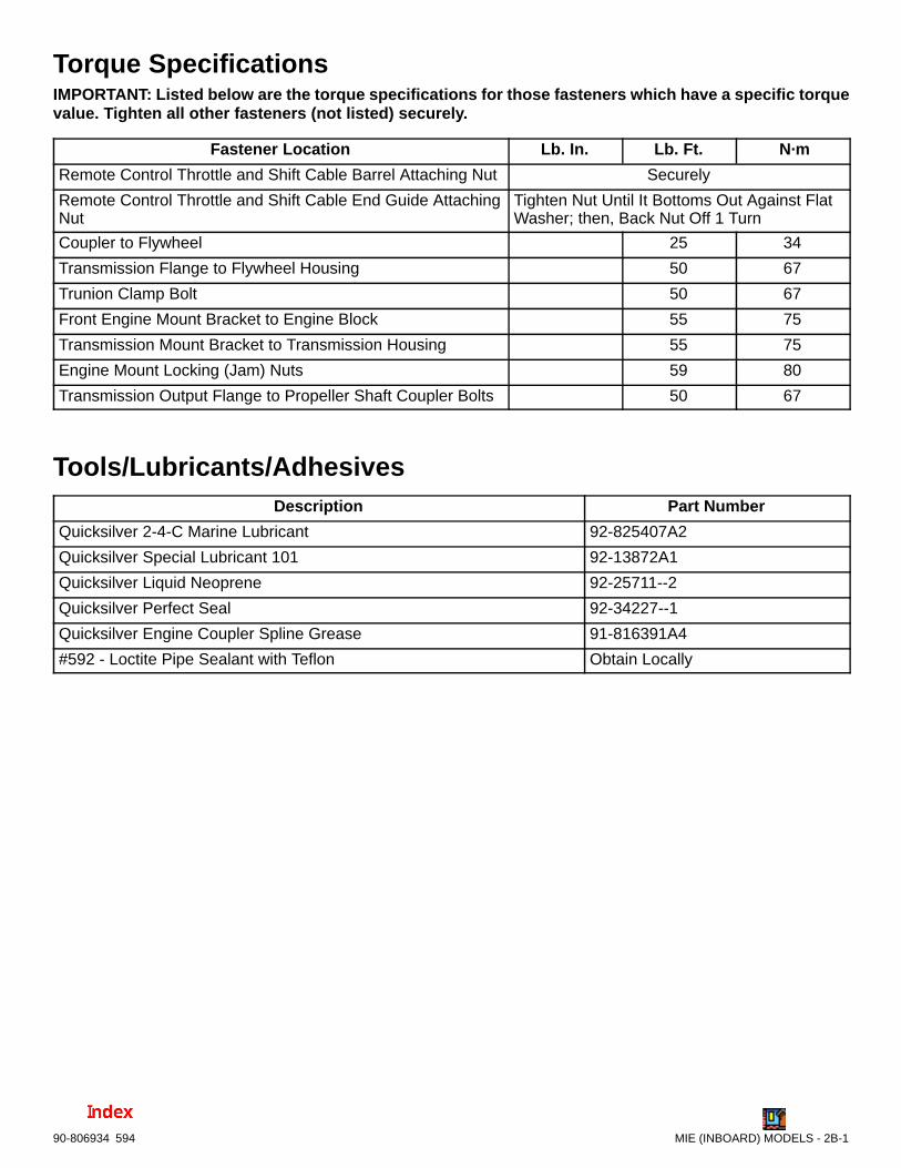
MIE (INBOARD) MODELS - 2B-190-806934 594
Torque SpecificationsIMPORTANT: Listed below are the torque specifications for those fasteners which have a specific torquevalue. Tighten all other fasteners (not listed) securely.
Fastener Location Lb. In. Lb. Ft. N·m
Remote Control Throttle and Shift Cable Barrel Attaching Nut Securely
Remote Control Throttle and Shift Cable End Guide AttachingNut
Tighten Nut Until It Bottoms Out Against FlatWasher; then, Back Nut Off 1 Turn
Coupler to Flywheel 25 34
Transmission Flange to Flywheel Housing 50 67
Trunion Clamp Bolt 50 67
Front Engine Mount Bracket to Engine Block 55 75
Transmission Mount Bracket to Transmission Housing 55 75
Engine Mount Locking (Jam) Nuts 59 80
Transmission Output Flange to Propeller Shaft Coupler Bolts 50 67
Tools/Lubricants/AdhesivesDescription Part Number
Quicksilver 2-4-C Marine Lubricant 92-825407A2
Quicksilver Special Lubricant 101 92-13872A1
Quicksilver Liquid Neoprene 92-25711--2
Quicksilver Perfect Seal 92-34227--1
Quicksilver Engine Coupler Spline Grease 91-816391A4
#592 - Loctite Pipe Sealant with Teflon Obtain Locally

2B-2 - MIE (INBOARD) MODELS 90-806934 594
Removal
Engine Removal
! CAUTIONIt is good practice to ventilate the engine com-partment prior to servicing any engine compo-nents to remove any fuel vapors which may causedifficulty breathing or be an irritant.
1. Disconnect battery cables from battery.
2. Disconnect negative battery cable from engineblock. Disconnect positive battery cable fromstarter solenoid.
3. Remove instrument extension harness connectorends from engine harness ends.
! WARNINGBe careful when changing fuel system compo-nents; diesel fuel is flammable. Be sure that theignition key is OFF. DO NOT smoke or allowsources of open flame in the area while changingfuel system components. Wipe up any spilled fuelimmediately. DO NOT allow fuel to come into con-tact with any hot surface which may cause it to ig-nite.
! WARNINGDispose of fuel-soaked rags, paper, etc., in anappropriate air tight, fire retardant container.Fuel-soaked items may spontaneously ignite andresult in a fire hazard which could cause seriousbodily injury or death.
! WARNINGFIRE HAZARD: Fuel leakage from any part of thefuel system can be a fire hazard which can causeserious bodily injury or death.
4. Loosen hose clamp, then disconnect and suitablyplug fuel inlet and fuel return lines to prevent fuelin tank from leaking into bilge.
5. Disconnect throttle cable from injection pump andbracket anchor studs. Retain locknuts and hard-ware.
6. Disconnect shift cable(s) from transmission.
! CAUTIONBefore removing seawater strainer hose, closeseacock, if so equipped. If boat is not equippedwith a seacock, remove and plug seawater inlethose to prevent a siphoning action that may oc-cur, allowing seawater to flow from drain holes orremoved hoses.
7. Close seacock, if so equipped, or disconnect andplug seawater inlet hose, if boat is to remain in thewater.
71362
a b
c
a - Seawater Strainerb - Seawater Inlet Hosec - Suitable Plug (If Not Equipped With Seacock)
Typical
8. Disconnect seawater inlet hose from the seawa-ter pump fitting.
9. Disconnect exhaust system hose.
10. Disconnect any grounding wires and accessoriesthat are connected to engine.
11. Disconnect coolant recovery bottle plastic hosefrom heat exchanger.
12. Disconnect propeller shaft coupler from transmis-sion output flange. On models with V-Drive trans-missions: Remove propeller shaft coupler.
NOTE: It may be necessary to remove the propellershaft prior to engine removal on engines with V-Drivetransmissions.

MIE (INBOARD) MODELS - 2B-390-806934 594
! CAUTIONDO NOT allow lifting sling to hook or compressengine components or damage to them willoccur.
13. Support engine with suitable sling, through liftingeyes on engine and remove front and rear enginemounting bolts. Retain hardware.
71706
c
a
b
c
73322
a - Forward Lifting Eyeb - Rear Lifting Eyec - Sling
Typical
14. Remove front and rear engine mounting bolts.Retain hardware.
23161
a
a
a - Mounting Bolt Locations
Port Front Mount Shown (All Similar)
15. Carefully remove engine with transmission.
Installation
Engine Installation and InitialAlignment1. Follow instructions “a” or “b”:
a. Engine mount(s) or adjustment WAS NOTDISTURBED during engine service: Pro-ceed to following Step 2.
b. Engine mount(s) or adjustment WAS DIS-TURBED during engine service:
IMPORTANT: Engine mounts must be adjusted,as explained in the following, to center mount ad-justment and establish a uniform height on allmounts.
Ensure that:
(1) All mounts are in the center of theirup-and-down adjustment.
(2) Mounting hole, which is a slot, if so de-signed, is forward.

2B-4 - MIE (INBOARD) MODELS 90-806934 594
(3) Large diameter of mount trunnion ex-tended no more than 3/4 in. (19 mm), asshown.
(4) Each mount base is downward. Tightenclamping screws and nuts slightly to pre-vent moving in or out. Mounts must befree to pivot when installing engine.
Typical Front Mount Shown
23161
b
a
Typical Rear Mount Shown
27035
a
b
a - Trunnion Clamping Bolts and Nutsb - Mount Trunnion MAXIMUM Extension - 3/4 in. (20 mm)
2. Attach a suitable sling to lifting eyes on engineand adjust so that engine is level when sus-
pended. Refer to “Removal” section for loca-tion of lifting eyes.
! CAUTIONDO NOT allow lifting sling to hook or compressengine components or damage will occur.
3. Lift engine into boat and position on engine bedso that transmission output flange and propellershaft coupler are visibly aligned (no gap can beseen between coupling faces when butted to-gether). Adjust engine bed height, if necessary,to obtain proper alignment. DO NOT use mountadjustments to adjust engine position at this time.
IMPORTANT: Engine bed must position engine sothat a minimum of 1/4 in. (6mm) up-and-downmount adjustment exists on all four mounts afterperforming initial alignment. This is necessary toallow for final engine alignment.
50609b
c
a
a - Propeller Shaftb - Propeller Shaft Couplerc - Transmission Output Flange
Typical Transmission Shown
4. Check all four mounts to ensure that they are stillpositioned properly, then fasten mounts to enginebed with appropriate bolts or lag screws and hard-ware. Tighten lag bolts/screws securely.
5. Disconnect and remove sling. Proceed to “EngineFinal Alignment” section following.
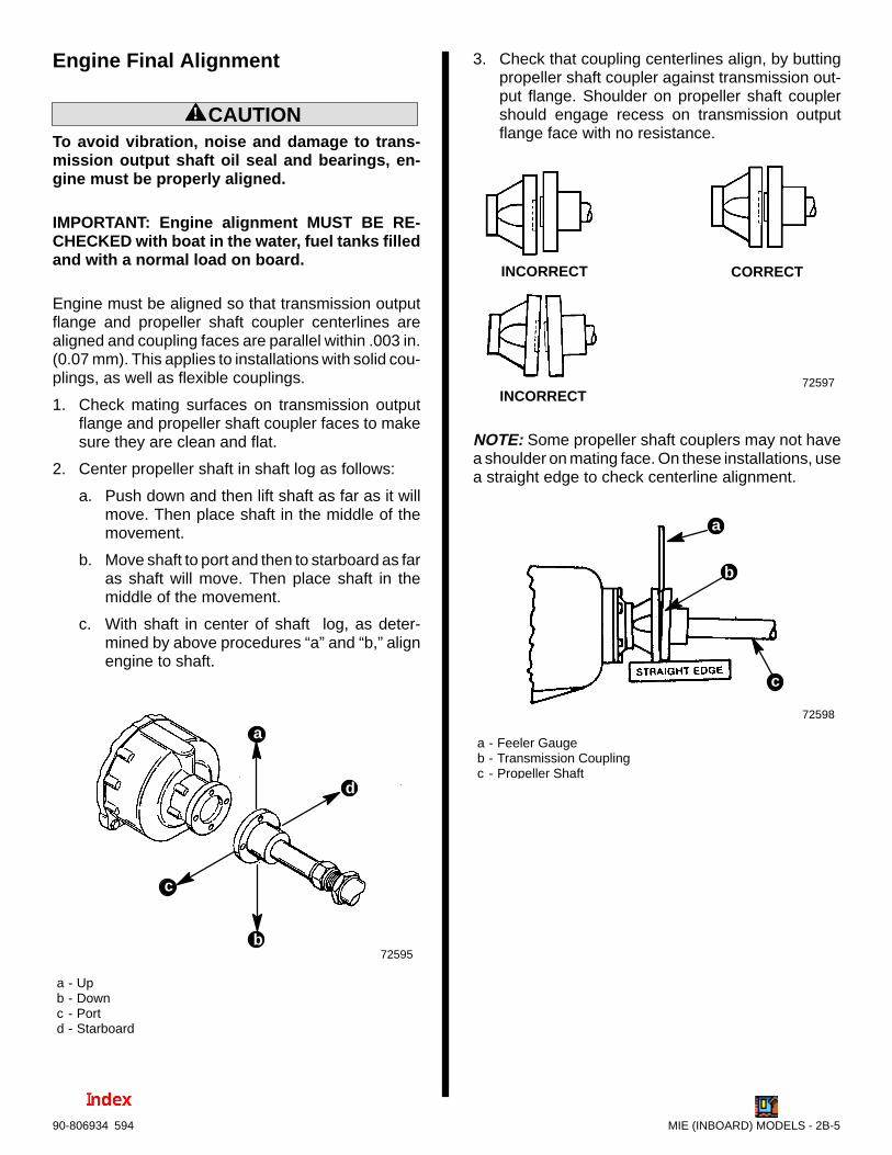
MIE (INBOARD) MODELS - 2B-590-806934 594
Engine Final Alignment
! CAUTIONTo avoid vibration, noise and damage to trans-mission output shaft oil seal and bearings, en-gine must be properly aligned.
IMPORTANT: Engine alignment MUST BE RE-CHECKED with boat in the water, fuel tanks filledand with a normal load on board.
Engine must be aligned so that transmission outputflange and propeller shaft coupler centerlines arealigned and coupling faces are parallel within .003 in.(0.07 mm). This applies to installations with solid cou-plings, as well as flexible couplings.
1. Check mating surfaces on transmission outputflange and propeller shaft coupler faces to makesure they are clean and flat.
2. Center propeller shaft in shaft log as follows:
a. Push down and then lift shaft as far as it willmove. Then place shaft in the middle of themovement.
b. Move shaft to port and then to starboard as faras shaft will move. Then place shaft in themiddle of the movement.
c. With shaft in center of shaft log, as deter-mined by above procedures “a” and “b,” alignengine to shaft.
72595
a - Upb - Downc - Portd - Starboard
b
c
d
a
3. Check that coupling centerlines align, by buttingpropeller shaft coupler against transmission out-put flange. Shoulder on propeller shaft couplershould engage recess on transmission outputflange face with no resistance.
72597
INCORRECT CORRECT
INCORRECT
NOTE: Some propeller shaft couplers may not havea shoulder on mating face. On these installations, usea straight edge to check centerline alignment.
72598
a - Feeler Gaugeb - Transmission Couplingc - Propeller Shaft
b
c
a

2B-6 - MIE (INBOARD) MODELS 90-806934 594
4. Check for angular misalignment, by hand holdingcoupling faces tightly together and checking for agap between coupling faces with a .003 in.(0.07mm) feeler gauge at 90° intervals.
Borg-Warner 5000 (All Down Angle TransmissionSimilar)
a
c
d
50688
b
Hurth V-Drive
50608
ca
b
d
a - Propeller Shaft Couplerb - Feeler Gaugec - Transmission Output Flanged - Check Point Intervals
5. If coupling centerlines are not aligned or if cou-pling faces are more than .003 in. (0.07 mm) outof parallel, adjust engine mounts as follows:
a. TO ADJUST ENGINE UP OR DOWN: Loos-en locking nut on mounts requiring adjust-ment and turn both front mount or rear mountadjusting nuts equally.
IMPORTANT: Both front mount (or rear mount)adjusting nuts must be turned equally to keep en-gine level from side to side.
23161
b
a
a - Locking (Jam) Nut(s)b - Adjusting Nut(s)
Front Mount Shown (All Similar)

MIE (INBOARD) MODELS - 2B-790-806934 594
b. TO MOVE ENGINE TO THE LEFT ORRIGHT: Loosen clamping screw and nut on allfour mount brackets; move engine to the leftor right as necessary to obtain proper align-ment. Torque clamping screws and nuts to 50lb. ft. (68 N·m).
NOTE: A small amount of side-to-side adjustmentcan also be obtained from the slots on the enginemount pad (front pads only). Loosen lag screws(which fasten mounts to engine bed) and moveengine, as required. Tighten lag screws securely.
IMPORTANT: Large diameter of mount trunnionMUST NOT extend over 3/4 in. (20mm) frommount brackets on any of the mounts.
Front Mounts
50687
ba
Rear Mounts
50687
b
a
a - Clamping Bolts and Nutsb - Mount Trunnion Maximum Extension - 3/4 in. (20mm)
c. After engine has been properly aligned, se-cure mounts to stringers using appropriatehardware.
6. Connect propeller shaft coupler to transmissionoutput flange following instructions “a” or “b”:
IMPORTANT: All coupler bolts must be SAEGrade 8 (Metric Grade 10.9) or better, with a shoul-der (grip length) sufficient to pass through themating face plane of couplers.
a. All Couplings Without Propeller Shaft SetScrews: Secure coupling together with bolts,lockwashers and nuts. Torque to 50 lb.ft. (68N·m).
50687
b
a
d
c
a - Propeller Shaft Couplerb - Bolts (4)c - Lockwashers and Nuts (4)d - Transmission Output Flange
Hurth 8 ° Down Angle Transmission Shown (AllSimilar)

2B-8 - MIE (INBOARD) MODELS 90-806934 594
b. Couplings with Propeller Shaft SetScrews:
(1) If propeller shaft coupler has set screws,remove set screws and mark (dimple) lo-cations using a transfer punch.
50609
ba
a - Set Screw Locationb - Transfer Punch
Hurth V-Drive Shown (All Similar)
(2) Remove propeller shaft coupler and drillshallow dimples at locations marked withpunch.
(3) Reinstall propeller shaft coupler andtorque bolts to 50 lb.ft. (68 N·m). Install setscrews and tighten securely. Safety wireset screws to ensure they do not back out.
50608
b
c
d
e
a
a - Propeller Shaft Couplerb - Bolts (4), with Lockwashers and Nuts (4)c - Set Screwsd - Safety Wiree - Transmission Output Flange
Hurth V-Drive Shown (All Similar)
Engine Connections
! CAUTIONIt is good practice to ventilate the engine com-partment prior to servicing any engine compo-nents to remove any fuel vapors which may causedifficulty breathing or be an irritant.
IMPORTANT: When routing all wire harnessesand hoses, be sure they are routed and securedto avoid coming in contact with hot spots on en-gine and avoid contact with moving parts.
1. Connect instrument extension harness ends toengine harness ends– connector collars must befully engaged and secure.
71890
ba
c
a - Extension Harnesses (From Instruments)b - Engine Harness and Connector Endsc - Connector Collar(s)
2. Connect any ground wires or accessories thatwere disconnected from engine.

MIE (INBOARD) MODELS - 2B-990-806934 594
! WARNINGBe careful when working on fuel system compo-nents; diesel fuel is flammable. Be sure that theignition key is OFF. DO NOT smoke or allowsources of open flame in the area while changingfuel system components. Wipe up any spilled fuelimmediately. DO NOT allow fuel to come into con-tact with any hot surface which may cause it toignite.
! WARNINGDispose of fuel-soaked rags, paper, etc., in anappropriate air tight, fire retardant container.Fuel-soaked items may spontaneously ignite andresult in a fire hazard which could cause seriousbodily injury or death.
! WARNINGFIRE HAZARD: Fuel leakage from any part of thefuel system can be a fire hazard which can causeserious bodily injury or death.
3. Connect fuel lines as follows:
a. Connect flexible fuel line to inlet fitting on fuelpump and secure with hose clamps.
71710
b
cd
a
a - Fuel Lineb - Hose Clampc - Inlet Fittingd - Fuel Pump
b. Connect fuel return line to injection pump re-turn fitting and secure with hose clamps.
23284
bc a
a - Fuel Lineb - Hose Clampc - Return Fitting
c. Check for leaks. Repair as needed.
4. After all wires are connected be sure to securethem with clamps or Sta-Straps which may havebeen retaining them to engine or hoses prior to re-moval.
5. Connect both shift cables to shift plate usingretained locknuts and hardware. Refer to “ShiftCable Installation and Adjustment” sectionoutlined later and follow instructions.
6. Connect throttle cable using retained hardware.Refer to “Throttle Cable Installation and Ad-justment” section outlined later and followinstructions.
7. Connect exhaust elbow, riser or water lift muffler,if so equipped, to exhaust system hose using atleast two hose clamps at each connection. Tight-en hose clamps securely.

2B-10 - MIE (INBOARD) MODELS 90-806934 594
8. Connect seawater inlet hose to seawater pumpfitting. Tighten hose clamp securely.
73331
71362b
a
a - Seawater Pump Fittingb - Seawater Inlet Hose
9. If removed previously, connect seawater inlethose to seawater strainer and tighten hoseclamps securely.
71362
ab c
a - Seawater Inlet Hoseb - Seawater Strainerc - Hose Clamps (2)
10. Connect coolant recovery bottle plastic hose toheat exchanger and secure with tubing clamp.
70548
b
a
a - Plastic Tubingb - Tubing Clamp
11. Connect battery cables to engine:
a. Make sure that grounding stud and starter so-lenoid terminal are free of paint and any othermaterial that could cause a poor electricalconnection.
b. After battery cables are connected, apply athin coat of Liquid Neoprene to the terminals.
c. Be sure to slide rubber boot over the positive(+) terminal after Liquid Neoprene dries.
12. Connect battery cables to battery by FIRST con-necting positive (+) battery cable (usually red) topositive (+) battery terminal. Tighten clamp se-curely. Then, connect negative (–) battery cable(usually black) to negative (–) battery terminal.Tighten clamp securely.
NOTE: Spray terminals with a battery connectionsealant to help retard corrosion.

MIE (INBOARD) MODELS - 2B-1190-806934 594
Shift Cable Installation andAdjustment - Hurth Transmissions
NOTE: On models with other than Quicksilver shiftcables refer to shift cable manufacturer’s instruc-tions.
IMPORTANT: When installing shift cables, besure that cables are routed in such a way as toavoid sharp bends and/or contact with movingparts. DO NOT fasten any items to shift cables.
NOTE: Shift cable must be hooked up to remote con-trol before starting installation and adjustment proce-dures.
IMPORTANT: These Hurth transmissions are fullreversing transmissions. Direction of output/pro-peller rotation is determined by hookup of shiftcable at remote control.
Shift cable must be hooked up to remote controlbefore starting installation and adjustment proce-dures.
For Left Hand Propeller Rotation – shift cablehookup at remote control must result in shift cableend guide moving in direction “B”, when remotecontrol handle is placed in forward position.
For Right Hand Propeller Rotation – shift cablehookup at remote control must result in shift cableend guide moving in direction “A”, when remotecontrol handle is placed in forward position.
23242
! WARNINGAvoid serious injury or property damage causedby improper shifting. Anchor stud for shift cablemust be installed in the correct hole.
1. Be certain anchor stud is installed in the lower,front hole as shown in the illustration following.
c
b
a
b
a
c
73588
71020
a - Cable Bracketb - Shift Cable Anchor Stud Location (For Quicksilver Shift Cables)
Shift Cable Bracket - Anchor Stud PositionShown for 630A and 630V Transmission
IMPORTANT: Check that shift lever is positionedapproximately 10 ° aft of vertical when in the neu-tral detent position and that the distance (“c”)between studs in the following is set at 7-1/8 in.(318mm). If necessary, loosen clamping bolt andposition lever so that dimension “c” is as shownwhen in the neutral detent position and retightenbolt.
a
c
d
b
73587
a - Shift Leverb - Lever, in Neutral Detent, Must Be Approximately 10° Aft
of Verticalc - Dimension Between Studs - 7-1/8 in. (318mm)d - Clamping Bolt
Typical Hurth Transmission Shown
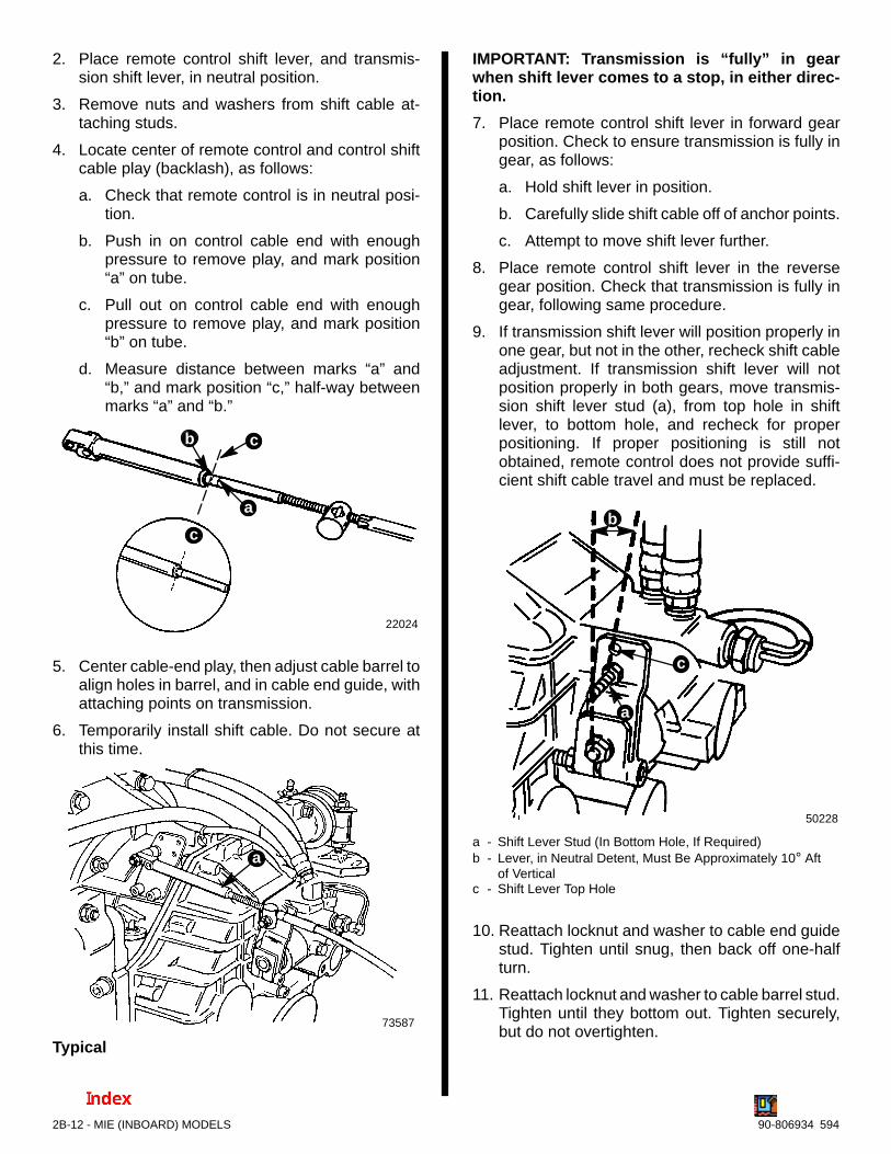
2B-12 - MIE (INBOARD) MODELS 90-806934 594
2. Place remote control shift lever, and transmis-sion shift lever, in neutral position.
3. Remove nuts and washers from shift cable at-taching studs.
4. Locate center of remote control and control shiftcable play (backlash), as follows:
a. Check that remote control is in neutral posi-tion.
b. Push in on control cable end with enoughpressure to remove play, and mark position“a” on tube.
c. Pull out on control cable end with enoughpressure to remove play, and mark position“b” on tube.
d. Measure distance between marks “a” and“b,” and mark position “c,” half-way betweenmarks “a” and “b.”
22024
c
b c
a
5. Center cable-end play, then adjust cable barrel toalign holes in barrel, and in cable end guide, withattaching points on transmission.
6. Temporarily install shift cable. Do not secure atthis time.
a
73587
Typical
IMPORTANT: Transmission is “fully” in gearwhen shift lever comes to a stop, in either direc-tion.
7. Place remote control shift lever in forward gearposition. Check to ensure transmission is fully ingear, as follows:
a. Hold shift lever in position.
b. Carefully slide shift cable off of anchor points.
c. Attempt to move shift lever further.
8. Place remote control shift lever in the reversegear position. Check that transmission is fully ingear, following same procedure.
9. If transmission shift lever will position properly inone gear, but not in the other, recheck shift cableadjustment. If transmission shift lever will notposition properly in both gears, move transmis-sion shift lever stud (a), from top hole in shiftlever, to bottom hole, and recheck for properpositioning. If proper positioning is still notobtained, remote control does not provide suffi-cient shift cable travel and must be replaced.
c
a
b
50228
a - Shift Lever Stud (In Bottom Hole, If Required)b - Lever, in Neutral Detent, Must Be Approximately 10° Aft
of Verticalc - Shift Lever Top Hole
10. Reattach locknut and washer to cable end guidestud. Tighten until snug, then back off one-halfturn.
11. Reattach locknut and washer to cable barrel stud.Tighten until they bottom out. Tighten securely,but do not overtighten.

MIE (INBOARD) MODELS - 2B-1390-806934 594
NOTE: To change cable approach direction onsingle or dual station installations, only the spacers/bushings have to be switched to the opposite stud(the studs are identical).
SINGLE CABLE - FORWARD ENTRY
73589
71210
CABLEBARRELSTUD
CABLEEND GUIDESTUD
f
b
cd
e
a
b
e
a - Cable End Guideb - Locknut and Washer (Tighten Until Bottomed, Then Back
Off One Full Turn)c - Spacer (Fits over Bushings)d - Bushingse - Cable Barrel Locationf - Spacers (Fit over Stud)
Typical
SINGLE CABLE - REAR ENTRY
73587
50229
CABLEBARRELSTUD
CABLEEND GUIDESTUD
f
b
c
d
e
a
b
a - Cable End Guideb - Locknut and Washer (Tighten Until Bottomed, Then Back
Off One Full Turn)c - Spacer (Fits over Bushings)d - Bushingse - Cable Barrel Locationf - Spacers (Fit over Stud)
e
Typical

2B-14 - MIE (INBOARD) MODELS 90-806934 594
DUAL CABLE - FORWARD ENTRY
73590
71211
CABLEBARRELSTUD
CABLEEND GUIDESTUD
b
d
a
b
c
e
e
a - Cable End Guidesb - Locknut and Washer (Tighten Until Bottomed, Then Back
Off One Full Turn)c - Spacer (Fits over Stud)d - Bushingse - Cable Barrel Locations
Typical
DUAL CABLE - REAR ENTRY
73591
50073
CABLEBARRELSTUD
CABLEEND GUIDESTUD
b
c
d
a
b
e
e
a - Cable End Guidesb - Locknut and Washer (Tighten Until Bottomed, Then Back
Off One Full Turn)c - Spacer (Fits over Stud)d - Bushingse - Cable Barrel Locations
Typical

MIE (INBOARD) MODELS - 2B-1590-806934 594
Throttle Cable Installation andAdjustment
NOTE: On models equipped with other than Quick-silver Throttle Cables, attach and adjust throttlecables referring to cable manufacturer’s instructions.
IMPORTANT: When installing throttle cables, besure that cables are routed in such a way as toavoid sharp bends and/or contact with movingparts. DO NOT fasten any items to throttle cables.
On Models Equipped with Quicksilver ThrottleCables, connect and adjust throttle cable(s) as out-lined following:
1. Place remote control lever(s) in neutral/idle posi-tion.
2. Lightly push on throttle cable end guide and turnbarrel to align ends with attachment points (Thiswill place a slight preload on cable to avoid slackin cable when moving remote control lever.) In-stall cable and secure with hardware as shown.
a
c
f
b
e
d
b f
f
71261
af
e
f
73348
a - Throttle Cable End Guideb - Locknut and Washerc - Spacer (Fit Over Bushing)d - Bushinge - Cable Barrel Positionf - Spacer (Fit Over Stud)g - Anchor Stud(s)
Single Cable Installation
73348
b
b
ae
d
c
f
f
a - Throttle Cable End Guideb - Locknut and Washerc - Spacer (Fit Over Stud)d - Bushinge - Cable Barrel Positionf - Anchor Stud
Dual Cable Installations
3. Place remote control lever in full forwardwide-open-throttle (W.O.T.) position.
! CAUTIONThe injector pump lever WOT-stop-screw ad-justs the engine speed governor, and is factoryset and sealed. DO NOT readjust this setting.Readjusting the governed speed, and operatingabove the specified RPM will cause extensiveengine damage, and/or failure. Removal of theseal, and/or readjustment of the WOT-stop-screw is considered misuse of engine and re-sulting damages will not be covered by the lim-ited warranty.

2B-16 - MIE (INBOARD) MODELS 90-806934 594
4. Check to ensure injector pump lever is contact-ing “W.O.T. Stop Screw,” DO NOT attempt toadjust screw (screw is sealed). Check to ensurethat remote control and cable are providingproper output.
23728
b
c
d
e
a
a
a - W.O.T. Stop Screw (DO NOT ADJUST - Read “Caution”preceding)
b - Leverc - Seald - Remote Control Throttle Cable Levere - Contact Point - Lever/W.O.T. Stop Screw
5. Place remote control lever in neutral/idle posi-tion and, if necessary, readjust throttle cablebarrel.
6. Recheck that (when operated) injection pumplever contacts “W.O.T. Stop Screw” as shownabove, and idle screw as shown below.
23728
b
cda
a - Idle Screwb - Leverc - Stopd - Jam Nut

7C
6A
5A
4A
3
A
2A
1AENGINE
ALL MODELS - ENGINE
Note: Refer to the following Service Bulletin regarding this section.
SB 96-10 Piston Ring End Gap

ENGINE - ALL MODELS - 3A-–190-806934 1194
Table of ContentsPage
Torque Specifications 3A-1. . . . . . . . . . . . . . . . . . . . . . . . . MerCruiser Diesel Service Tools 3A-2. . . . . . . . . . . . . . . . Kent-Moore Special Tools 3A-2. . . . . . . . . . . . . . . . . . . . . . Lubricants/Sealants 3A-2. . . . . . . . . . . . . . . . . . . . . . . . . . .
Engine Specifications 3A-3. . . . . . . . . . . . . . . . . . . . . . Piston Rings 3A-4. . . . . . . . . . . . . . . . . . . . . . . . . . . Liner I.D. 3A-4. . . . . . . . . . . . . . . . . . . . . . . . . . . . . . Head Gaskets 3A-4. . . . . . . . . . . . . . . . . . . . . . . . . . Cylinder Head 3A-4. . . . . . . . . . . . . . . . . . . . . . . . . . Camshaft 3A-4. . . . . . . . . . . . . . . . . . . . . . . . . . . . . . Valve Specifications 3A-4. . . . . . . . . . . . . . . . . . . . . Valve Seat Specifications 3A-5. . . . . . . . . . . . . . . . Valve Adjustment 3A-5. . . . . . . . . . . . . . . . . . . . . . . Valve Guide Specifications 3A-5. . . . . . . . . . . . . . . Valve Spring Specifications 3A-5. . . . . . . . . . . . . . . Rocker Arm Specifications 3A-5. . . . . . . . . . . . . . . Crankshaft 3A-5. . . . . . . . . . . . . . . . . . . . . . . . . . . . . Connecting Rods 3A-6. . . . . . . . . . . . . . . . . . . . . . . Pistons 3A-6. . . . . . . . . . . . . . . . . . . . . . . . . . . . . . . . Connecting Rod Bushings / Piston Pins 3A-6. . . . Flywheel 3A-6. . . . . . . . . . . . . . . . . . . . . . . . . . . . . . . Oil Pump 3A-6. . . . . . . . . . . . . . . . . . . . . . . . . . . . . .
Firing Order 3A-7. . . . . . . . . . . . . . . . . . . . . . . . . . . . . . . . . D3.6L/180 and D4.2L/220 3A-7. . . . . . . . . . . . . . . D3.0L/150 3A-7. . . . . . . . . . . . . . . . . . . . . . . . . . . . .
General Information 3A-8. . . . . . . . . . . . . . . . . . . . . . . . . . . Engine Identification 3A-8. . . . . . . . . . . . . . . . . . . . . . . Cylinder Head Identification 3A-9. . . . . . . . . . . . . . . . .
Code Stamping 3A-9. . . . . . . . . . . . . . . . . . . . . . . . . Glow Plug Arrangement 3A-9. . . . . . . . . . . . . . . . .
Engine Rotation 3A-10. . . . . . . . . . . . . . . . . . . . . . . . . . Description 3A-10. . . . . . . . . . . . . . . . . . . . . . . . . . . . . .
Engine Block 3A-10. . . . . . . . . . . . . . . . . . . . . . . . . . Crankshaft 3A-10. . . . . . . . . . . . . . . . . . . . . . . . . . . . Piston Rings And Connecting Rods 3A-10. . . . . . Valve Train 3A-10. . . . . . . . . . . . . . . . . . . . . . . . . . . . Camshaft And Gears 3A-10. . . . . . . . . . . . . . . . . . . Cylinder Heads 3A-10. . . . . . . . . . . . . . . . . . . . . . . . Engine Lubrication System – All Models 3A-11. . . Engine Lubrication Flow Chart 3A-11. . . . . . . . . . .
Bearing Failures 3A-12. . . . . . . . . . . . . . . . . . . . . . . . . . . . . Scratched By Dirt 3A-12. . . . . . . . . . . . . . . . . . . . . . Lack Of Oil 3A-12. . . . . . . . . . . . . . . . . . . . . . . . . . . . Improper Seating 3A-12. . . . . . . . . . . . . . . . . . . . . . Radius Ride 3A-12. . . . . . . . . . . . . . . . . . . . . . . . . . . Fatigue Failure 3A-12. . . . . . . . . . . . . . . . . . . . . . . . Tapered Journal 3A-12. . . . . . . . . . . . . . . . . . . . . . .
Compression Testing 3A-12. . . . . . . . . . . . . . . . . . . . . . . . . Engine Mounts 3A-13. . . . . . . . . . . . . . . . . . . . . . . . . . . . . .
Front Mount Positions 3A-13. . . . . . . . . . . . . . . . . . . . . MIE (Inboard) Transmission Mounts 3A-13. . . . . . . . .
Flywheel Related Components 3A-14. . . . . . . . . . . . . . . . MIE (Inboard) Drive Plate, Adaptor and Flywheel Housing 3A-14. . . . . . . . . . . . . . . . . . . . MCM (Stern Drive) Engine Coupler and Flywheel Housing 3A-14. . . . . . . . . . . . . . . . . . . .
Rocker Covers 3A-15. . . . . . . . . . . . . . . . . . . . . . . . . . . . . . Removal 3A-15. . . . . . . . . . . . . . . . . . . . . . . . . . . . . . . . Installation 3A-15. . . . . . . . . . . . . . . . . . . . . . . . . . . . . . .
Water Manifold 3A-16. . . . . . . . . . . . . . . . . . . . . . . . . . . . . . Removal 3A-16. . . . . . . . . . . . . . . . . . . . . . . . . . . . . . . . Installation 3A-16. . . . . . . . . . . . . . . . . . . . . . . . . . . . . . .
Cylinder Heads 3A-17. . . . . . . . . . . . . . . . . . . . . . . . . . . . . . Removal 3A-17. . . . . . . . . . . . . . . . . . . . . . . . . . . . . . . . Identification 3A-17. . . . . . . . . . . . . . . . . . . . . . . . . . . . . Disassembly 3A-18. . . . . . . . . . . . . . . . . . . . . . . . . . . . . Cleaning 3A-18. . . . . . . . . . . . . . . . . . . . . . . . . . . . . . . . Inspection 3A-18. . . . . . . . . . . . . . . . . . . . . . . . . . . . . . .
PageRepair 3A-19. . . . . . . . . . . . . . . . . . . . . . . . . . . . . . . . . .
Valve Seat Replacement 3A-19. . . . . . . . . . . . . . . . Exhaust Valve Seat Specifications 3A-19. . . . . . . . Intake Valve Seat Specifications 3A-20. . . . . . . . . Measuring Valve Guide Wear 3A-20. . . . . . . . . . . . Valve Guide Replacement 3A-21. . . . . . . . . . . . . . . Valve Seat Reconditioning 3A-21. . . . . . . . . . . . . . Valve Refacing 3A-21. . . . . . . . . . . . . . . . . . . . . . . . Valve Specifications 3A-21. . . . . . . . . . . . . . . . . . . . Valve Spring Specifications 3A-22. . . . . . . . . . . . . .
Assembly 3A-22. . . . . . . . . . . . . . . . . . . . . . . . . . . . . . . . . . Cylinder Head Studs 3A-22. . . . . . . . . . . . . . . . . . . Determining Head Gasket Thickness 3A-23. . . . . Head Gasket Identification 3A-24. . . . . . . . . . . . . .
Installation 3A-24. . . . . . . . . . . . . . . . . . . . . . . . . . . . . . . Torque Sequence Diagrams 3A-26. . . . . . . . . . . . .
Rocker Arm 3A-29. . . . . . . . . . . . . . . . . . . . . . . . . . . . . . . . . Repair 3A-29. . . . . . . . . . . . . . . . . . . . . . . . . . . . . . . . . . Assembly 3A-29. . . . . . . . . . . . . . . . . . . . . . . . . . . . . . . .
Adjusting Valve Clearance 3A-30. . . . . . . . . . . . . . . . . . . . Timing Gear Cover 3A-31. . . . . . . . . . . . . . . . . . . . . . . . . .
Removal 3A-31. . . . . . . . . . . . . . . . . . . . . . . . . . . . . . . . Inspection 3A-32. . . . . . . . . . . . . . . . . . . . . . . . . . . . . . . Installation 3A-32. . . . . . . . . . . . . . . . . . . . . . . . . . . . . . .
Oil Pump 3A-33. . . . . . . . . . . . . . . . . . . . . . . . . . . . . . . . . . . Removal 3A-33. . . . . . . . . . . . . . . . . . . . . . . . . . . . . . . . Inspection 3A-34. . . . . . . . . . . . . . . . . . . . . . . . . . . . . . . Installation 3A-34. . . . . . . . . . . . . . . . . . . . . . . . . . . . . . .
Oil Pressure Relief Valve 3A-35. . . . . . . . . . . . . . . . . . . . . Removal 3A-35. . . . . . . . . . . . . . . . . . . . . . . . . . . . . . . . Installation 3A-35. . . . . . . . . . . . . . . . . . . . . . . . . . . . . . .
Oil Pick-Up Tube Assembly 3A-36. . . . . . . . . . . . . . . . . . . Removal 3A-36. . . . . . . . . . . . . . . . . . . . . . . . . . . . . . . . Inspection 3A-36. . . . . . . . . . . . . . . . . . . . . . . . . . . . . . . Installation 3A-36. . . . . . . . . . . . . . . . . . . . . . . . . . . . . . .
Oil Thermostat 3A-37. . . . . . . . . . . . . . . . . . . . . . . . . . . . . . Removal 3A-37. . . . . . . . . . . . . . . . . . . . . . . . . . . . . . . . Testing 3A-38. . . . . . . . . . . . . . . . . . . . . . . . . . . . . . . . . . Installation 3A-39. . . . . . . . . . . . . . . . . . . . . . . . . . . . . . .
Camshaft 3A-40. . . . . . . . . . . . . . . . . . . . . . . . . . . . . . . . . . . Measuring Lobe Lift 3A-40. . . . . . . . . . . . . . . . . . . . . . . Removal 3A-40. . . . . . . . . . . . . . . . . . . . . . . . . . . . . . . . Inspection 3A-41. . . . . . . . . . . . . . . . . . . . . . . . . . . . . . . Installation 3A-42. . . . . . . . . . . . . . . . . . . . . . . . . . . . . . .
Camshaft Bearings 3A-43. . . . . . . . . . . . . . . . . . . . . . . . . . Inspection 3A-43. . . . . . . . . . . . . . . . . . . . . . . . . . . . . . . Removal 3A-43. . . . . . . . . . . . . . . . . . . . . . . . . . . . . . . . Installation 3A-43. . . . . . . . . . . . . . . . . . . . . . . . . . . . . . .
Valve Lifters (Tappets) 3A-44. . . . . . . . . . . . . . . . . . . . . . . Removal 3A-44. . . . . . . . . . . . . . . . . . . . . . . . . . . . . . . . Cleaning and Inspection 3A-44. . . . . . . . . . . . . . . . . . .
Specifications Chart 3A-44. . . . . . . . . . . . . . . . . . . . Installation 3A-44. . . . . . . . . . . . . . . . . . . . . . . . . . . . . . .
Valve Push Rods 3A-45. . . . . . . . . . . . . . . . . . . . . . . . . . . . Removal 3A-45. . . . . . . . . . . . . . . . . . . . . . . . . . . . . . . . Cleaning and Inspection 3A-45. . . . . . . . . . . . . . . . . . . Installation 3A-45. . . . . . . . . . . . . . . . . . . . . . . . . . . . . . .
Connecting Rod/Piston Assembly 3A-45. . . . . . . . . . . . . . Measuring Rod Bearing Clearance 3A-45. . . . . . . . . . Removal 3A-46. . . . . . . . . . . . . . . . . . . . . . . . . . . . . . . . Disassembly 3A-46. . . . . . . . . . . . . . . . . . . . . . . . . . . . . Cleaning and Inspection 3A-47. . . . . . . . . . . . . . . . . . .
Connecting Rod And Pin 3A-47. . . . . . . . . . . . . . . . Pistons 3A-47. . . . . . . . . . . . . . . . . . . . . . . . . . . . . . . Checking Ring End Gap 3A-49. . . . . . . . . . . . . . . .
Assembly 3A-49. . . . . . . . . . . . . . . . . . . . . . . . . . . . . . . . Installation 3A-50. . . . . . . . . . . . . . . . . . . . . . . . . . . . . . .
3A - ENGINE - ALL MODELS 90-806934 1194

3A-0 - ENGINE - ALL MODELS 90-806934 1194
PageOil Seal (Rear Main) 3A-51. . . . . . . . . . . . . . . . . . . . . . . . .
Removal 3A-51. . . . . . . . . . . . . . . . . . . . . . . . . . . . . . . . Installation 3A-51. . . . . . . . . . . . . . . . . . . . . . . . . . . . . . .
Crankshaft/Main Bearings 3A-52. . . . . . . . . . . . . . . . . . . . Removal 3A-52. . . . . . . . . . . . . . . . . . . . . . . . . . . . . . . .
Rear Main Bearing and Carrier 3A-52. . . . . . . . . . Crankshaft 3A-54. . . . . . . . . . . . . . . . . . . . . . . . . . . . . . . Front Main Bearing 3A-55. . . . . . . . . . . . . . . . . . . . . . .
Timing Gear (Crankshaft) 3A-56. . . . . . . . . . . . . . . Inspection 3A-56. . . . . . . . . . . . . . . . . . . . . . . . . . . . . . .
Crankshaft 3A-56. . . . . . . . . . . . . . . . . . . . . . . . . . . . Main Bearings (Measurement) 3A-56. . . . . . . . . . .
Installation 3A-57. . . . . . . . . . . . . . . . . . . . . . . . . . . . . . .
PageFront Main Bearing 3A-57. . . . . . . . . . . . . . . . . . . . . Main Bearing Carriers And Bearings 3A-58. . . . . . Crankshaft 3A-58. . . . . . . . . . . . . . . . . . . . . . . . . . . . Rear Main Bearing 3A-59. . . . . . . . . . . . . . . . . . . . . Rear Main Bearing Carrier 3A-60. . . . . . . . . . . . . . Crankshaft End-play (Axial) Clearance 3A-62. . . .
Cylinder Liners 3A-62. . . . . . . . . . . . . . . . . . . . . . . . . . . . . . Removal 3A-62. . . . . . . . . . . . . . . . . . . . . . . . . . . . . . . . Identification 3A-63. . . . . . . . . . . . . . . . . . . . . . . . . . . . . Cleaning and Inspection 3A-63. . . . . . . . . . . . . . . . . . .
Cylinder Liners 3A-63. . . . . . . . . . . . . . . . . . . . . . . . Cylinder Liner (Block) Bores 3A-64. . . . . . . . . . . . .
Installation 3A-64. . . . . . . . . . . . . . . . . . . . . . . . . . . . . . .
3A - ENGINE - ALL MODELS90-806934 1194

ENGINE - ALL MODELS - 3A-190-806934 1194
Torque SpecificationsTORQUE
DESCRIPTIONLb. In. Lb. Ft. N·m
14mm Dia. Cylinder Head Bolts See NOTE 1
12mm Dia. Cylinder Head Bolts See NOTE 1
Rocker Arm Support 81 110
Connecting Rod 61 82
Flywheel 81 110
Crankshaft Pulley (Loctite 222) 114 155
Oil Drain Plug 59 80
Engine Mount 37 50
Oil Pump 20 27
Rear Main Bearing Housing 20 27
Flywheel Housing 37 50
Main Bearing Carrier 31 42
Rocker Cover 84 10
Oil Pan 96 11
Water Manifold 84 10
Oil Lines (Heat Exchanger to Engine) 18 24
Fuel Injection Pump 23 31
Fuel Injection Pump Gear 66 90
Balancer 37 50
Timing Gear Cover 96 11
Idler Gear 18 25
Main Bearing Carrier Locating Bolts (Banjo) 30 40
Oil Pick-up Tube 96 11
Rocker Arm Lock Nuts 13 18
Drive Plate [MIE (Inboard) Engines] 53 72
Adaptor Plate [MIE (Inboard) D3.0L/150 and D3.6L/180 Engines] 22 30
Coupler [MCM (Stern Drive) Engines] 22 30
Power Steering Pulley (on Crankshaft) 96 11
Alternator Mounts 37 50
Power Steering Pump Mounts 37 50
Camshaft Bolts 20 27
Water Pump 20 27
Water Pump Pulley 96 11
Other fasteners not listed, tighten securely.
NOTE 1: Along with the conventional application of torque, all diesel engines will require cylinder head torque with a suitablewrench using a Torque Angle Gauge (obtain locally). Refer to Cylinder Head, “Installation” section.

3A-2 - ENGINE - ALL MODELS 90-806934 1194
MerCruiser DieselService Tools
DESCRIPTION PART NUMBER
Cylinder Head Service Tool Kit(For Special Cylinder HeadScrews)
91-806563A1
Graduated Disc (Timing) 91-801333500
Cylinder Head Guide Pin 91-801333501
Cylinder Liner Puller 91-801333502
Crankshaft Gear Puller 91-801333503
Crankshaft Installer 91-801333504
Injection Pump Gear Puller1 91-801333505
Injection Pump Gear Puller2 91-818371
Injection Pump Gear Puller3 91-818372
Flywheel Holder 91-801333506
Crankshaft Pulley Puller 91-801763540
Front Main Bearing andCamshaft Bearing Puller
91-801333508
Liner Gauge Bar, Metric4 91-814612A1
Liner Gauge Bar, S.A.E.5 91-814812A1
Injection Pump Adaptor Tool,Metric4 91-801333510
Injection Pump Adaptor ToolS.A.E.5
91-816997A1
Crankshaft Tool (Rotating) 91-814827
Dial Indicator 91-58222A1
Heat Exchanger Core Puller6 91-801761156
Torque Angle Gauge (DegreeWheel Torquing)7
TA360
Piston Ring Expander 91-24697
Compression Tester Adaptor 91-813810
Compression Gauge7 MT33B
Flywheel Seal Installer 91-801111260
Note 2: For use on D3.0L/150 with VM S/N 70811 and up. Alsofor use on D3.6L/180 with VM 5/N 56945 and up.
Note 3: For use on D4.2L/220.
Note 4: For use with millimeter dial gauge.
Note 5: For use with S.A.E. dial gauge.
Note 6: For use on D3.0L/150 and D3.6L/180.
Note 7: SNAP-ON Tool Number
Kent-Moore Special ToolsCan Be Ordered From:
Kent-Moore Tools, Inc.29784 Little MackRoseville, MI 48066Phone:(313) 574-2332
DESCRIPTION PART NUMBER
Valve Spring Compressor J-8062
Piston Ring Compressor J-8307
Lubricants/SealantsDESCRIPTION PART NUMBER
Loctite Master Gasket 92-12564-1
Loctite 514 92-75505-1
Quicksilver Needle Bearing Assembly Lubricant
92-42649A1
Quicksilver 2-4-C Marine Lubricant
92-825407A12
Loctite - 8831 92-823089--1
Loctite 242 Obtain Locally
Loctite 222 Obtain Locally
Loctite 620 Obtain Locally
Molykote Obtain Locally

ENGINE - ALL MODELS - 3A-390-806934 1194
Engine Specifications
UNIT OF MEASUREMENTin. (mm)
MODEL D3.0L/150 D3.6L/180 D4.2L/220
Engine Type – In-Line Diesel 5 Cylinder 6 Cylinder 6 Cylinder
Firing Order 1-2-4-5-3 1-5-3-6-2-4 1-5-3-6-2-4
Crankshaft Horsepower (Kilowatts)1 150 (112) 180 (134) 220 (164)
Propeller Shaft Horsepower MCM (Stern Drive Models): 140 (104) 170 (127) 200 (149)Propeller Shaft Horsepower(Kilowatts)2 MIE (Inboard Models)3: 150 (112) 180 (134) 220 (164)
Maximum Torque @ RPM240 lbs. ft.(326 N·m)@ 2750
280 lbs. ft.(380 N·m)@ 2750
387 lbs. ft.(525 N·m)@ 2400
Displacement 183 cu. in.(3.0L)
219 cu. in.(3.6L)
254 cu. in.(4.2L)
Bore 3.622 in. (92mm) 3.700 in.(94mm)
Stroke 3.543 in. (90mm) 3.937 in.(100mm)
Compression Ratio 22:1 21.5:1
Compression Pressure 348-377 PSI (2400-2600 kPa) @ 300 RPM
Maximum Pressure Difference Between Cylinders 72 PSI (500 kPa)
Recommended Maximum RPM 3800 3600
Idle RPM in Forward Gear 700
Oil Pressure @ RPM[Oil Temperature 176 - 195 F (80 - 90 C)]
22-36 PSI [ 1.5 - 2.5 bar ( 152-248 kPa ) ],50-58 PSI [ 3.5 - 4 bar ( 345-400 kPa ) ]
Oil Thermostat (Opening Temperature) 195 F (90 C)
Valve Clearance - Intake/Exhaust .012 in. (0.30mm)
2 Continuous effective braked output – per DIN 6271, Part 1, Supplement I.
1 Power rated in accordance with NMMA Procedure – SAE J1228.
3 Engine rated with Hurth 8 degree Down-Angle transmission. Power output with other transmissions will vary.

Gro
ove
Wid
thE
nd
Gap
Rin
gT
hic
knes
sR
ing
to
Gro
ove
Cle
aran
ce
3A-4 - ENGINE - ALL MODELS 90-806934 1194
UNIT OF MEASUREMENTin. (mm)
NOTE: Unless listed otherwise, specifications are forall models.
PISTON RINGS
MODELS D3.0L/150 andD3.6L/180 D4.2L/220
1stCompression
Tapered
.0856 - .0868(2.175 - 2.205)
.1055 - .1066(2.68 - 2.71)
2ndCompression
.0811 - .0818(2.06 - 2.08)
.0811 - .0818(2.06 - 2.08)
Oil Control .1583 - .1591(4.02 - 4.04)
.1586 - .1594(4.03 - 4.05)
1stCompression
Tapered
.0816 - .0824(2.075 - 2.095)
.1013 - .1021(2.575 - 2.595)
2ndCompression
.0779 - .0783(1.978 - 1.990)
.0779 - .0783(1.978 - 1.990)
Oil Control .1566 - .1570(3.978 - 3.990)
.1564 - .1570(3.975 - 3.990)
1stCompression
.0157 - .0255(0.40 - 0.65)
.0157 - .0255(0.40 - 0.65)
2ndCompression
.0157 - .0255(0.40 - 0.65)
.0157 - .0255(0.40 - 0.65)
Oil Control .0098 - .0228(0.25 - 0.50)
.0118 - .0236(0.30 - 0.60)
1stCompression
.0024 - .0031(0.060 - 0.080)
.0033 - .0053(0.085 - 0.135)
2ndCompression
.0016 - .0044(0.040 - 0.112)
.0027 - .0401(0.070 - 1.020)
Oil Control .0016 - .0029(0.040 - 0.075)
.0016 - .0029(0.040 - 0.075)
LINER INNER DIAMETER
MODELS D3.0L/150 andD3.6L/180 D4.2L/220
ClassA
3.6220 - 3.6224(92.000 - 92.010)
3.7007 - 3.7011(94.000 - 94.010)
StandardClass
B3.6624 - 3.6228
(92.010 - 92.020)— — —
Max. Outof Round
.004 (0.100)
Max. Taper .004 (0.100)
HEAD GASKETS
Piston Protrusion Above Engine Block Gasket Size To
530-TA/636-TAD183/D219 D4.2L/220
Gasket Size ToBe Used
.019 - .022(0.48 - 0.57)
.017 - .020(0.43 - 0.52)
.056 (1.42)
.023 - .026(0.58 - 0.67)
.021 - .024(0.53 - 0.62)
.060 (1.52)
.027 - .030(0.68 - 0.77)
.025 - .028(0.63 - 0.72)
.064 (1.62)
If replacing only one head gasket, use same size asremoved.
All head gaskets must be the same size on the sameengine.
CYLINDER HEAD
Height 3.541 - 3.545(89.95 - 90.05)
Height of CylinderHead End Spacers
3.593 - 3.596(91.26 - 91.34)
Max. Resurface .008 (0.20)
CAMSHAFT
LobeExhaust .300
(7.64)LobeLift
Intake .283(7.20)
Journal Diameter 2.1060 - 2.1066(53.495 - 53.510)
BearingInside Diameter
2.1079 - 2.1098(53.540 - 53.590)
Run-out .0019(0.05)
VALVE SPECIFICATIONS
Exhaust Intake
Stem Diameter .3118 - .3125(7.922 - 7.940)
.3126 - .3133(7.942 - 7.960)
Face Width .096 - .119(2.45 - 3.02)
.107 - .135(2.73 - 3.44)
Margin (New) .070(1.78)
.075(1.90)
Margin (AfterGrinding)
.051 in. (1.30mm)
Face Angle(New)
45° (30’) 55° (30’)

Mai
n J
ou
rnal
Ou
tsid
eM
ain
Bea
rin
gC
lear
ance
Dia
met
er
Mai
n B
eari
ng
Insi
de
Dia
met
er
ENGINE - ALL MODELS - 3A-590-806934 1194
VALVE SEAT SPECIFICATIONS
Exhaust Intake
Seat Angle 45° 55°
Seat Width .055 - .059(1.40 - 1.50)
.047 - .051(1.20 - 1.30)
Seat O. D. 1.420 - 1.421(36.068 - 36.084)
1.656 - 1.657(42.070 - 42.086)
Seat Height .276 - .278(7.00 - 7.05)
.276 - .278(7.00 - 7.05)
Counterbore I.D.
1.416 - 1.417(35.964 - 35.988)
1.652 - 1.653(41.962 - 41.985)
Head SurfaceTo Seat
.118(3.00)
.128(3.25)
Valve Recession
.0311 - .0468(0.790 - 1.190)
.0314 - .0472(0.800 - 1.200)
VALVE ADJUSTMENT
Exhaust Intake
Clearance .012(0.30)
.012(0.30)
VALVE GUIDE SPECIFICATIONS
Exhaust Intake
Max. Wear .002 - .004(0.060 - 0.093)
.002 - .003(0.040 - 0.073)
Inside Diameter .315 - .316(8.000 - 8.015)
Height AboveSpring Counter-bore
.531 - .551(13.50 - 14.00)
VALVE SPRING SPECIFICATIONS
Height Pressure
Free Standing 1.70(43.20)
0
Valve Closed 1.46(37)
73 - 77 lb.(33 - 35 kg)
Valve Open 1.05(26.61)
194 - 208 lb.(88 - 95 kg)
ROCKER ARM SPECIFICATIONS
Journal Diameter .865 - .866(21.979 - 22.000)
Bushing I.D. .867 - .868(22.020 - 22.041)
Max. Clearance .008 (0.200)
CRANKSHAFT
Front 2.4801 - 2.4807(62.995 - 63.010)
Center 2.4805 - 2.4810(63.005 - 63.020)
Rear 2.7553 - 2.7559(69.985 - 70.000)
Front .0019 - .0045(0.050 - 0.115)
Center .0011 - .0028(0.030 - 0.073)
Rear .0015 - .0027(0.040 - 0.070)
Front 2.4827 - 2.4846(63.060 - 63.110)
Center 2.4822 - 2.4840(63.050 - 63.093)
Rear 2.7574 - 2.7580(70.040 - 70.055)
Max. MainBearing Wear
.008(0.200)
Connecting RodJournal Outside Diameter
2.1236 - 2.1242(53.940 - 53.955)
Connecting RodBearing Clearance
.0008 - .0029(0.020 - 0.074)
Connecting Rod BearingInside Diameter
2.1250 - 2.1265(53.975 - 54.014)
Max. Rod BearingWear
.008(0.200)
Crankshaft End Play(Axial Clearance)
.005 - .013(0.121 - 0.323)
Thrust WashersStandard
.091 - .093(2.311 - 2.362)
1st Oversized .095 - .097(2.411 - 2.462)
2nd Oversized .099 - .101(2.511 - 2.562)
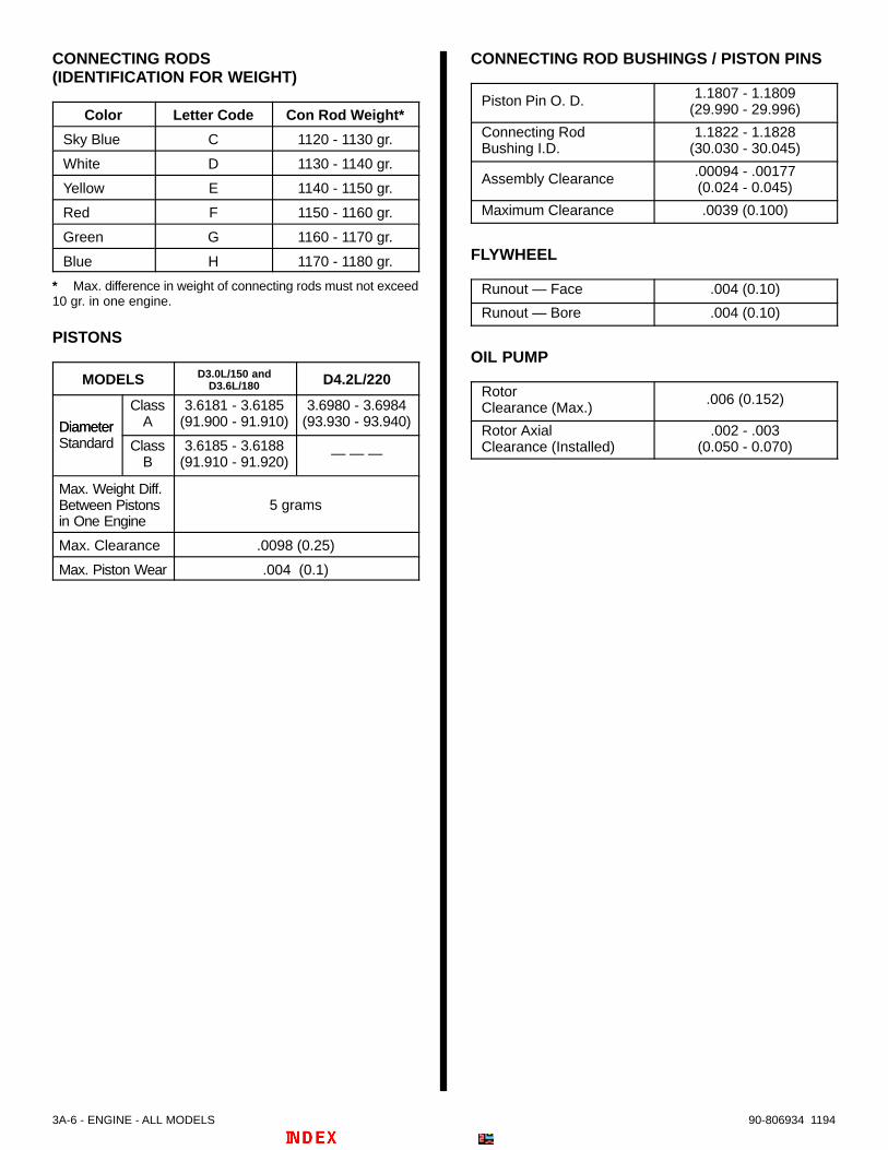
3A-6 - ENGINE - ALL MODELS 90-806934 1194
CONNECTING RODS(IDENTIFICATION FOR WEIGHT)
Color Letter Code Con Rod Weight*
Sky Blue C 1120 - 1130 gr.
White D 1130 - 1140 gr.
Yellow E 1140 - 1150 gr.
Red F 1150 - 1160 gr.
Green G 1160 - 1170 gr.
Blue H 1170 - 1180 gr.
* Max. difference in weight of connecting rods must not exceed10 gr. in one engine.
PISTONS
MODELS D3.0L/150 andD3.6L/180 D4.2L/220
Diameter
ClassA
3.6181 - 3.6185(91.900 - 91.910)
3.6980 - 3.6984(93.930 - 93.940)Diameter
Standard ClassB
3.6185 - 3.6188(91.910 - 91.920)
— — —
Max. Weight Diff.Between Pistonsin One Engine
5 grams
Max. Clearance .0098 (0.25)
Max. Piston Wear .004 (0.1)
CONNECTING ROD BUSHINGS / PISTON PINS
Piston Pin O. D. 1.1807 - 1.1809(29.990 - 29.996)
Connecting RodBushing I.D.
1.1822 - 1.1828(30.030 - 30.045)
Assembly Clearance .00094 - .00177(0.024 - 0.045)
Maximum Clearance .0039 (0.100)
FLYWHEEL
Runout — Face .004 (0.10)
Runout — Bore .004 (0.10)
OIL PUMP
RotorClearance (Max.)
.006 (0.152)
Rotor AxialClearance (Installed)
.002 - .003(0.050 - 0.070)

1-5-3-6-2-4D3.6L/180 and D4.2L/220
1-2-4-5-3D3.0L/150
FLYWHEEL
FLYWHEEL
50489
ENGINE - ALL MODELS - 3A-790-806934 1194
Firing Order

3A-8 - ENGINE - ALL MODELS 90-806934 1194
General Information
Some repairs, that are listed in this section, must becompleted with engine removed from boat. Engineremoval depends upon type of repair and boatdesign. Place engine on repair stand for majorrepairs.
NOTE: This section contains disassembly andassembly procedures of the engine block andcylinder heads only. Refer to other sections fordisassembly and assembly of various othercomponents.
IMPORTANT: Do not use any sealers or adhesivescontaining silicone. Silicone can cause blockagein the cooling/heat exchanger systems.
Engine IdentificationThe engine model and serial numbers are located ona plate attached to the coolant tank and stamped onthe engine block as shown.
71675 73321
THIS ENGINE CONFORMS TO INT’LBODENSEE SHIPPING
COMISSION STDS CERT NO.
M12 11 3 93 _ _
c71675
a
Mercruiser Serial Number
70427
VM Serial Numbera - MerCruiser Serial Number Platesb - VM Serial Number (Stamped in Block)c - Exhaust Gas Emissions Certificate Number (Example)

ENGINE - ALL MODELS - 3A-990-806934 1194
Cylinder Head Identification
CODE STAMPING
Heads are identified by a code stamped on flange asshown.
70270
a - Head Code Location
GLOW PLUG ARRANGEMENT
Early cylinder heads were designed with a radialglow plug arrangement in which the glow plug entersinto the center of the combustion chamber, and isseated at an angle in relation to the center line of thehead.
Later model D3.0L/150 engines beginning with SerialNumber 0D725152 and above, D3.6L/180 enginesbeginning with Serial Number 0D850268 and above,and D4.2L/220 engines with Serial Number0D554753 and above, are equipped with cylinderheads which have a tangential glow plugarrangement. This design differs from the radial stylein that the glow plug enters the combustion chamberat the side, that is, on a tangent to the combustionchamber, but is parallel to the center line of the head.
Cylinder heads with the tangential glow plugs alsohave steel inserts between the valve seats.
IMPORTANT: Because of the different glow plugarrangements there is also a corresponding dif-ference in the electrical connecting bridges andpre-chambers, be certain to obtain the correctparts when ordering.
Overhead View of Glow Plug Arrangements
73792
a
73792
b
a - Cylinder Head With Radial Glow Plug Arrangement (Glow Plug Enters Side of Head At An Angle)
b – Cylinder Head With Tangential Glow Plug Arrangement (Glow Plug Enters Perpendicular To Side of Head)

3A-10 - ENGINE - ALL MODELS 90-806934 1194
Engine RotationEngine rotation terminology, at times, has causedconfusion. To clarify, engine rotation is determined byobserving flywheel rotation from the rear (transmission orstern drive end) of the engine looking forward.
Propeller Rotation is not necessarily the same asEngine Rotation.
The 5 and 6 cylinder diesel engines, stern drive (MCM)and Inboard (MIE), covered in this manual are lefthand (CCW) rotation, as viewed from flywheel end.
Description
ENGINE BLOCK
The engine block is made of cast iron and is designedfor maximum strength. The crankshaft main bearingcarriers are completely enclosed in the block. Theblock has removable cylinder liners which are cooledby engine coolant. Rubber O-rings on the bottom ofthe liners are used to seal off the closed coolingsystem from the crankcase.
CRANKSHAFT
The crankshaft is supported in the block by insert typemain bearings, (seven in the six cylinder engine andsix in the five cylinder engine). Each bearing, exceptthe front main, is held by an aluminum carrier. Thefront main bearing is pressed into the block. Longbanjo bolts prevent the bearing carriers from turningin the block. Crankshaft end play is controlled bythrust washers in the rear main bearing carrier.
PISTON RINGS and CONNECTING RODS
The pistons have three rings, two compression andone oil control. The top compression ring is taperedand the second compression ring is stepped. Thebottom ring, oil control, has a spring inside to helppress it tight against the cylinder wall.
The pistons use full-floating piston pins retained withsnap rings.
The connecting rods and connecting rod caps havematching machined grooves for a perfect fit.Connecting rods are available in six different weightsto help in balancing the engine.
VALVE TRAIN
The valve train consists of lifters, push rods, rockerarms, rocker arm supports, valves and valve springs.The lifters and push rods are both solid and arelubricated by oil running off the rocker arms. Therocker arms have screws with lock nuts which areused to adjust valve clearance. Removable bushingsin the rocker arms are lubricated by oil which is pipedthru the rocker arm supports.
There is one heavy duty spring used for each valve.Valve spring retainers and two-piece keepers holdthe springs in place.
CAMSHAFT and GEARS
The camshaft is supported by bearings which arepressed in the engine block. It is gear driven atone-half crankshaft speed and has one lobe tooperate the fuel pump.
CYLINDER HEADS
The cylinder heads are made of aluminum withreplaceable valve seats, and valve guides. A watermanifold supplies each head with coolant.

ENGINE - ALL MODELS - 3A-1190-806934 1194
ENGINE LUBRICATION SYSTEM – ALLMODELS
The engine’s oil pump, which is gear driven off thecrankshaft, is recessed in the front of the engineblock. The pressure relief valve is recessed into theblock’s front oil pan flange. A thermostat/valveassembly in the system directs oil through acombined engine heat exchanger/coolant tank/oil
cooler when it reaches a preset temperature. Aftergoing through a replaceable filter, oil is piped to therocker arm supports and to the turbocharger. Internalpassages channel oil through banjo bolts to the mainbearing carriers. To help cool the pistons, the mainbearing carriers contain jets which spray oil on theunderside of the pistons. Another internal passagedirects oil to the camshaft bearings.
ENGINE LUBRICATION FLOW CHART
73721
1 - Oil Pan2 - Oil Pump3 - Pressure Relief Valve4 - Oil Thermostat5 - Oil Filter6 - Engine Oil Cooler (Lower Portion of Heat Exchanger/Coolant Tank)7 - Rocker Arms8 - Camshaft Bearings9 - Piston Oil Jets10- Crankshaft Main Bearing Carrier and Bearing11- Turbocharger
D4.2L/220 Shown (D3.0L/150 and D3.6L/180 Similar)

3A-12 - ENGINE - ALL MODELS 90-806934 1194
Bearing Failures
70436
ScratchesDirtImbeddedinto BearingMaterial
OverlayWiped Out
Bright (Polished)Sections
Overlay Gonefrom Entire Surface
Radius RideCraters or Pockets
SCRATCHEDBY DIRT
LACK OF OIL IMPROPERSEATING
RADIUSRIDE
FATIGUE FAILURETAPEREDJOURNAL
70436
Compression TestingPeriodically check engine compression pressure.Lowering of pressure causes loss of power, greaterfuel consumption, smoke at the exhaust, lowacceleration, unsteady slow idle, difficulty in startingand bearing seizure because of engine overheating.
1. Refer to Section 5C – “Fuel Injectors” andwhile observing precautions listed in Section5C, remove fuel injector from head to be tested.
2. Clean injector bore and install CompressionTester Adaptor Tool 91-813810.
3. Connect gauge to Adaptor Tool and set gauge tozero reading.
4. Check that battery is fully charged using asuitable device.
5. Operate starter (engine should be cranking atapproximately 300 RPM) and check compressiongauge reading. Compression should be 348-377PSI (2400-2600 kPa). Maximum pressuredifference between cylinders should not exceed72 PSI (500 kPa).
6. Readings lower than specified, or differencesbetween cylinders greater than specified,indicate engine problems exist (such as faultyrings, valves, cylinders and pistons). Refer toappropriate sections and repair as needed.
7. If readings are within specifications, refer toSection 5C – “Fuel Injectors” and install injectorsin heads from which removed previously. Bleedinjectors as instructed.

ENGINE - ALL MODELS - 3A-1390-806934 1194
Engine Mounts
Front Mount PositionsThe front motor mounts can be installed two ways asshown by the following photos. Be sure and mark themounts before removing them from engine block.Front Mount Standard Position
50533
Front Mount Alternate Position
50533
a - Mount Bracketb - Boltsc - Mount Pad
Reverse mount pad on front mounts by looseningclamp bolt and turning pad over.
23161
a - Mount Padb - Clamping Bolts
MIE (Inboard) Transmission Mounts
27035
Hydraulic Transmission Mount Components
Standard Mount Position
Alternate Mount Position
27035
a - Mount Bracketb - Bolts

3A-14 - ENGINE - ALL MODELS 90-806934 1194
Flywheel Related Components
MIE (Inboard) Drive Plate, Adaptor and Flywheel Housing
c
ba
73791
a - Drive Plate Housingb - Drive Platec - Adaptor Plate (D3.0L/150 and D3.6L/180 Engines Only)
MCM (Stern Drive) Engine Coupler And Flywheel HousingNOTE: Some engines are equipped with a solid (Single Stage) coupler, in place of the “Dual Stage” coupler foundon others.
b
a
73791
a - Flywheel Housingb - Engine Coupler - Solid (Single Stage) Coupler Shown, “Dual Stage” Coupler Similar

ENGINE - ALL MODELS - 3A-1590-806934 1194
Rocker Covers
Removal1. Remove retaining screw. Remove oil separator
and O-ring seal from rear rocker cover.
70665
b
74452
b
a
c
a - Retaining Screwb - Oil Separatorc - O-Ring Seal
2. Remove rocker cover nuts. Remove long coverplate on top of both rocker covers.
70271
a - Rocker Cover Nutsb - Cover Plate
3. Using a rubber hammer, tap against side of rockercovers to loosen. Remove both covers at thesame time.
4. Pull rocker covers apart. Discard the 4 old O-ringson the 2 connectors between the rocker covers.
5. Clean gaskets from rocker covers and cylinderheads. Do not drop anything into cylinder headopenings.
Installation1. Install 4 new O-rings on connectors before
pushing rocker covers together. Push coverstogether.
70428
b
a a
a - O-rings (4 - Renew)b - Connector (2)
2. Install rocker cover gaskets.
NOTE: A small amount of Loctite Master Gasket orQuicksilver Omnifit can be used to hold gaskets onrocker covers.
3. Install rocker covers on cylinder heads. Installlong cover plate on top of both rocker covers.
4. Install new O-rings on retaining nuts. Install nuts,torque to 84 lb. in. (10 N·m).
5. Place a new O-ring seal in groove on oil separatorand install separator on rear of valve cover. Tight-en retaining bolt securely.
74452
a - Cover Plateb - Retaining Nutc - O-Ringd - Oil Separatore - O-Ring Sealf - Retaining Screwg - Rocker Cover Gasket(s)5 and 6 Cylinder Rocker Cover Components

3A-16 - ENGINE - ALL MODELS 90-806934 1194
Water ManifoldRemoval1. Follow instructions “a,” “b” and “c”:
a. Loosen hose clamp at rear of water manifold.
b. Remove banjo bolt and vent hoses.
c. Remove retaining screws and washers.
70663
a - Hose Clampb - Banjo Bolt and Vent Hose(s) Mounting Locationc - Water Manifold Retaining Screws with WashersSix Cylinder Shown (Five Cylinder Similar)
2. Using a rubber hammer, tap against side ofmanifold to loosen.
3. Clean gaskets from flanges and cylinder heads.Do not drop anything into cylinder head openings.
4. Align manifold halves and torque screws to 84 lb.in. (10 N·m).
IMPORTANT: When replacing the gasket betweenmanifold halves, align flanges using a straightedge as shown.
70660
a - Gasketb - Straight Edge Devicec - Bolts (4, Two Are Hidden In This View)
Installation1. Use a new gasket and install end cover on man-
ifold pieces. Torque screws with washers to 84 lb.in. (10 N·m).
2. Place new gaskets in position on cylinder heads. Asmall amount of Loctite Master Gasket or QuicksilverOmnifit may be used to hold gaskets in position.
3. Install water manifold. Torque bolts with washersto 84 lb. in. (10 N⋅m) in a diagonal pattern fromcentermost to outer ends.
4. Install banjo bolt and banjo fittings using newsealing washers. Securely tighten the bolt whilesimultaneously positioning the fittings. Install ventlines if previously removed.
5. Tighten hose clamp on hose at rear of water man-ifold.
74453
b
a
cd
e
f
g h
i
a - Water Manifold (Two Pieces)b - Screws with Washersc - Vent Hose (To Turbocharger Fitting)d - Vent Hose (To Heat Exchanger Fitting)e - Banjo Boltf - Sealing Washersg - End Cover and Gasketh - Cylinder Head Gasketsi - Hose and Clamp (To Exhaust Manifold End Cover)Typical

ENGINE - ALL MODELS - 3A-1790-806934 1194
Cylinder Heads
RemovalIMPORTANT: To avoid distorting cylinder heads,remove only when engine is cold.
IMPORTANT: Retain fuel Injectors with theiroriginal heads to aid in diagnosis of problems.Faulty fuel injectors can actually melt thealuminum cylinder heads.
IMPORTANT: Before removing rocker armassemblies and cylinder heads, mark theirposition on the engine for reassembly. They mustbe reinstalled in their original locations.
1. Mark rocker arm assemblies and cylinder headsas to position (for reassembly).
2. Follow instructions “a,” “b” and “c”:
a. Remove rocker arm oil feed line banjo boltswith sealing washers and remove line fromcylinder heads and from rear of engine block.
b. Loosen all valve adjuster lock nuts and backout adjustment screws.
c. Remove rocker assembly retaining nuts andremove assemblies.
70662
a - Banjo Bolts With Sealing Washers (6 or 7 Depending onNumber of Cylinders)
b - Oil Feed Linec - Valve Adjuster Lock Nutsd - Valve Adjustment Screwse - Rocker Assembly Retaining Nuts (5 or 6 Depending on
Number of Cylinders)
3. Take note of shape and location of thick head boltwashers. Starting at one end of the engine,remove head bolts.
50528
4. Using a rubber hammer, tap on side of cylinderheads to loosen and remove.
IdentificationIf needed, refer to “Cylinder Head Identification” sec-tion, as previously outlined, for proper identification ofthe cylinder heads on the engine before proceedingwith work.

3A-18 - ENGINE - ALL MODELS 90-806934 1194
Disassembly1. Using valve spring compressor, carefully remove
keepers, retainers, and springs. Place valves innumbered rack according to their position in theengine.
70272
a - Typical Valve Spring Compressor
Cleaning1. Being careful not to damage aluminum heads,
clean carbon deposits and gasket material fromcombustion chambers and sealing surfaces.
2. Using wire wheel, remove carbon deposits fromvalves.
3. Wash head and components in cleaning solvent.Dry with compressed air.
4. Clean head bolt holes in engine block.
Inspection1. Prechamber for cracks or being loose in
counterbore.
2. Glow plug and injector seats for damage.
3. All gasket surfaces for deep grooves or pitting.
4. Valve seats for cracks, excessive wear, or beingloose in counterbore.
5. Valves for cracks, excessive wear, or bent stems.
6. Valve springs for discoloration due to excessiveheat.
7. Valve guides for cracks or chips. Valve guidebores for seizure marks, carbon deposits, orscoring. Valve guide height.
8. Rocker arm support journals for scoring.
9. Rocker arm bushings for excessive wear.
10. Valve spring keepers, retainers, and washer forwear, distortion, or cracks.
11. Any melting of aluminum by faulty fuel injectors.
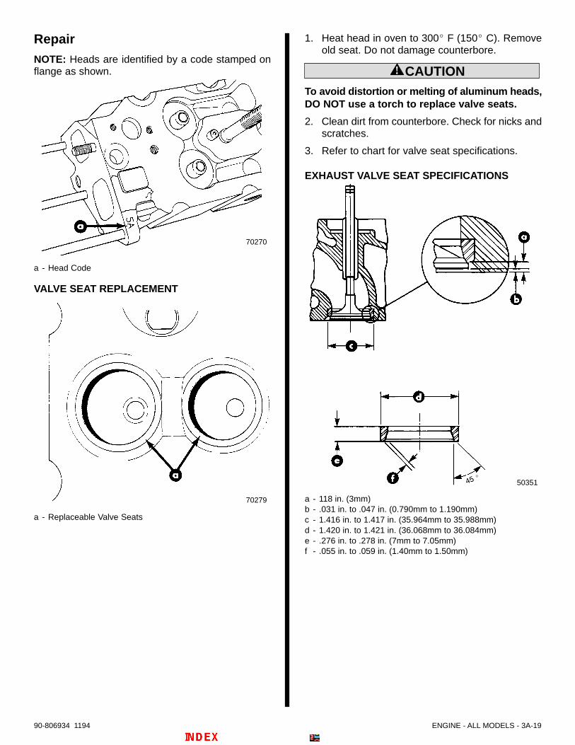
ENGINE - ALL MODELS - 3A-1990-806934 1194
RepairNOTE: Heads are identified by a code stamped onflange as shown.
70270
a - Head Code
VALVE SEAT REPLACEMENT
70279
a - Replaceable Valve Seats
1. Heat head in oven to 300 F (150 C). Removeold seat. Do not damage counterbore.
! CAUTIONTo avoid distortion or melting of aluminum heads,DO NOT use a torch to replace valve seats.
2. Clean dirt from counterbore. Check for nicks andscratches.
3. Refer to chart for valve seat specifications.
EXHAUST VALVE SEAT SPECIFICATIONS
50351
a - 118 in. (3mm)b - .031 in. to .047 in. (0.790mm to 1.190mm)c - 1.416 in. to 1.417 in. (35.964mm to 35.988mm)d - 1.420 in. to 1.421 in. (36.068mm to 36.084mm)e - .276 in. to .278 in. (7mm to 7.05mm)f - .055 in. to .059 in. (1.40mm to 1.50mm)
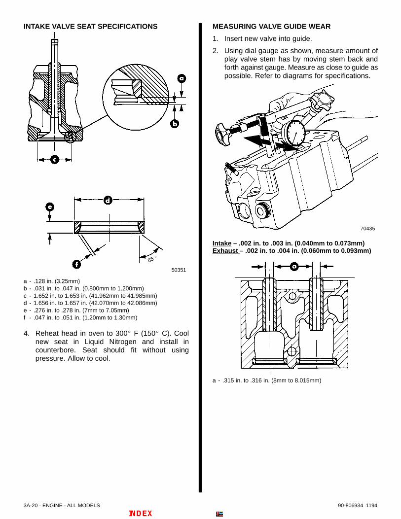
3A-20 - ENGINE - ALL MODELS 90-806934 1194
INTAKE VALVE SEAT SPECIFICATIONS
50351
a - .128 in. (3.25mm)b - .031 in. to .047 in. (0.800mm to 1.200mm)c - 1.652 in. to 1.653 in. (41.962mm to 41.985mm)d - 1.656 in. to 1.657 in. (42.070mm to 42.086mm)e - .276 in. to .278 in. (7mm to 7.05mm)f - .047 in. to .051 in. (1.20mm to 1.30mm)
4. Reheat head in oven to 300 F (150 C). Coolnew seat in Liquid Nitrogen and install incounterbore. Seat should fit without usingpressure. Allow to cool.
MEASURING VALVE GUIDE WEAR
1. Insert new valve into guide.
2. Using dial gauge as shown, measure amount ofplay valve stem has by moving stem back andforth against gauge. Measure as close to guide aspossible. Refer to diagrams for specifications.
70435
Intake – .002 in. to .003 in. (0.040mm to 0.073mm)Exhaust – .002 in. to .004 in. (0.060mm to 0.093mm)
a - .315 in. to .316 in. (8mm to 8.015mm)

ENGINE - ALL MODELS - 3A-2190-806934 1194
VALVE GUIDE REPLACEMENT
1. Heat head in oven to 185 F (85 C). Using a suit-able drift, drive out old guide from underside of head.
! CAUTIONTo avoid distortion or melting of aluminum heads,DO NOT use a torch to replace valve guides.
2. With head temperature at 185 F (85 C), pressnew guide in to obtain measurement as shown.
a - .531 in. to .551 in. (13.50mm to 14mm)b - Valve Spring Counterbore
VALVE SEAT RECONDITIONING
Valve seat reconditioning is very important, sinceseating of valves must be perfect for engine to delivermaximum power and performance.
Another important factor is valve head cooling. Goodcontact between each valve and its seat in head isimportant to insure that heat in valve head will beproperly dispersed.
Several different types of equipment are available forreconditioning valve seats. Equipment manufacturer’srecommendations should be followed carefully to attainproper results.
Regardless of type of equipment, however, it isessential that valve guide bores be free from carbonor dirt to insure proper centering of pilot in valveguide.
Machine valve seat angles to the following specifications.Intake - 55 ; Exhaust - 45.
VALVE REFACING
Pitted valves can be refaced to proper angle on a valvegrinder, thus insuring correct relation between cylinderhead seat and valve mating surface. Replace valves withexcessive wear on stems or valves which are warpedexcessively. When an excessively-warped valve head is
refaced, a knife edge will be ground on part or all of thevalve head, due to amount of metal that must beremoved to completely reface. Knife edges lead tobreakage or burning. After grinding, measure valves andreplace if out of specifications.
Various equipment is available for refacing valves.Manufacturer’s recommendations should be carefullyfollowed to attain proper results.
Refer to “Specifications and the following for valvespecifications.
VALVE SPECIFICATIONS
a - .312 in. to .313 in. (7.922mm to 7.940mm)b - .096 in. to .119 in. (2.45mm to 3.02mm)c - .070 in. (1.78mm)
a - .313 in. to .313 in. (7.942mm to 7.960mm)b - .107 in. to .135 in. (2.73mm to 3.44mm)c - .075 in. (1.90mm)
EXHAUST
INTAKE

3A-22 - ENGINE - ALL MODELS 90-806934 1194
VALVE SPRING SPECIFICATIONS
a - Height Measurement: 1.70 [1-45/64] in. (43.20mm)Free Standing
a - Height Measurement: 1.46 [1-15/32] in. (37mm)b - Applied Pressure: 73-77 lb. (33-35 kg)Closed Valve
a - Height Measurement: 1.05 [1-3/84] in. (26.61mm)b - Applied Pressure: 194-208 lb. (88-95 kg)Open Valve
3. Check for spring distortion as shown.
a - Measurement: Maximum .079 [5/64] in. (2mm)
Assembly
1. Lubricate valve guides and valve stems withS.A.E. 30W Oil.
2. Install each valve in the port from which it wasremoved or to which it was fitted.
NOTE: Valve stem seals are not used on intake orexhaust valves.
NOTE: Grease may be used to hold keepers in placewhile releasing compressor tool.
3. Install plate washer, valve spring, and retainer onvalve stem. Using valve spring compressor tool,carefully compress spring and insert keepers intovalve stem groove.
70275
a - Plate Washerb - Valve Springc - Retainerd - Keepers
4. Release compressor tool, making sure keepersseat properly in groove of valve stem.
CYLINDER HEAD STUDS
IMPORTANT: All long cylinder head studs are notthe same length. Some studs are longer than therest and are used for attaching accessories.These studs must be in the correct locationbefore exhaust manifold is installed.
70273
a - Long Cylinder Head Studs (Lengths Vary)
When replacing cylinder heads, remove studs andinstall in new head in same location.
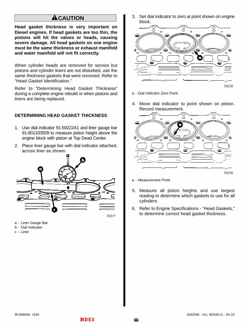
ENGINE - ALL MODELS - 3A-2390-806934 1194
! CAUTIONHead gasket thickness is very important onDiesel engines. If head gaskets are too thin, thepistons will hit the valves or heads, causingsevere damage. All head gaskets on one enginemust be the same thickness or exhaust manifoldand water manifold will not fit correctly.
When cylinder heads are removed for service butpistons and cylinder liners are not disturbed, use thesame thickness gaskets that were removed. Refer to“Head Gasket Identification.”
Refer to “Determining Head Gasket Thickness”during a complete engine rebuild or when pistons andliners are being replaced.
DETERMINING HEAD GASKET THICKNESS
1. Use dial indicator 91-59222A1 and liner gauge bar91-801333509 to measure piston height above theengine block with piston at Top Dead Center.
2. Place liner gauge bar with dial indicator attached,across liner as shown.
70277
a - Liner Gauge Barb - Dial Indicatorc - Liner
3. Set dial indicator to zero at point shown on engineblock.
70278
a - Dial Indicator Zero Point
4. Move dial indicator to point shown on piston.Record measurement.
70278
a - Measurement Point
5. Measure all piston heights and use largestreading to determine which gaskets to use for allcylinders.
6. Refer to Engine Specifications - “Head Gaskets,”to determine correct head gasket thickness.

3A-24 - ENGINE - ALL MODELS 90-806934 1194
HEAD GASKET IDENTIFICATION
NOTE: All engines use the same cylinder headgaskets in one of three thickness as previouslydetermined and shown following.
The 1.52 and 1.62 head gaskets differ from the 1.42gasket as follows.
The 1.52 gasket has two notches while the 1.62gasket has a smaller hole where indicated, whencompared to the 1.42 and 1.52 gasket.
70280
a - 1.42 Gasketb - 1.52 Gasket, with Two Notchesc - 1.62 Gasket, with Smaller Hole
Installation1. Before installing cylinder heads follow instruc-
tions “a” – “c”:
a. Clean out bolt holes in engine block. Be cer-tain no contaminants (dirt, old oil or coolant)remain in holes.
b. Clean block and heads, on gasket surfaces.
c. Oil cylinder bores with Quicksilver 4 cyclemotor oil.
2. Prepare hardware following instructions “a” – “d”:
IMPORTANT: Cylinder head bolts may beinstalled as many as three times, and then mustbe replaced with new bolts. Replace if any doubtexists.
a. Thoroughly clean all cylinder head bolts andwashers, including all formed spacer-washers (terminal bridges, three types) andcylinder head spacers (for ends of first andlast cylinder heads).
b. Using clean SAE 30W motor oil, lubricate thebolt threads and underside of bolt heads of all12mm cylinder head bolts.
c. Lubricate the threads and underside of boltheads on all 14mm cylinder head bolts withMolykote (obtain locally).
d. Place all parts on a clean surface or lint-freeshop cloth.
IMPORTANT: Head gaskets must be installedDRY – DO NOT use any sealer on gaskets.
IMPORTANT: Install head gaskets ONLY asshown with prechamber seal facing UP.
70280
a - Prechamber Seal (Facing UP)
! CAUTIONThe following steps must be carried out properlyto prevent misalignment of cylInder heads orhead gaskets which could result in failure of thecylinder head gaskets or cylinder heads causingsevere engine damage.
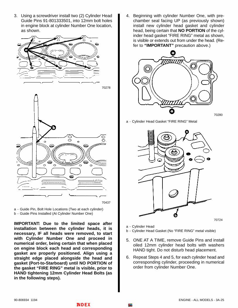
ENGINE - ALL MODELS - 3A-2590-806934 1194
3. Using a screwdriver install two (2) Cylinder HeadGuide Pins 91-801333501, into 12mm bolt holesin engine block at cylinder Number One location,as shown.
70278
70437
a - Guide Pin, Bolt Hole Locations (Two at each cylinder)b - Guide Pins Installed (At Cylinder Number One)
IMPORTANT: Due to the limited space afterinstallation between the cylinder heads, it isnecessary, IF all heads were removed, to startwith Cylinder Number One and proceed innumerical order, being certain that when placedon engine block each head and correspondinggasket are properly positioned. Align using astraight edge placed alongside the head andgasket (Port-to-Starboard) until NO PORTION ofthe gasket “FIRE RING” metal is visible, prior toHAND tightening 12mm Cylinder Head Bolts (asin the following steps).
4. Beginning with cylinder Number One, with pre-chamber seal facing UP (as previously shown)install new cylinder head gasket and cylinderhead, being certain that NO PORTION of the cyl-inder head gasket “FIRE RING” metal as shown,is visible or extends out from under the head. (Re-fer to “IMPORTANT” precaution above.)
70280
a - Cylinder Head Gasket “FIRE RING” Metal
70724
a - Cylinder Headb - Cylinder Head Gasket (No “FIRE RING” metal visible)
5. ONE AT A TIME, remove Guide Pins and installoiled 12mm cylinder head bolts with washersHAND tight. Do not disturb head placement.
6. Repeat Steps 4 and 5, for each cylinder head andcorresponding cylinder, proceeding in numericalorder from cylinder Number One.
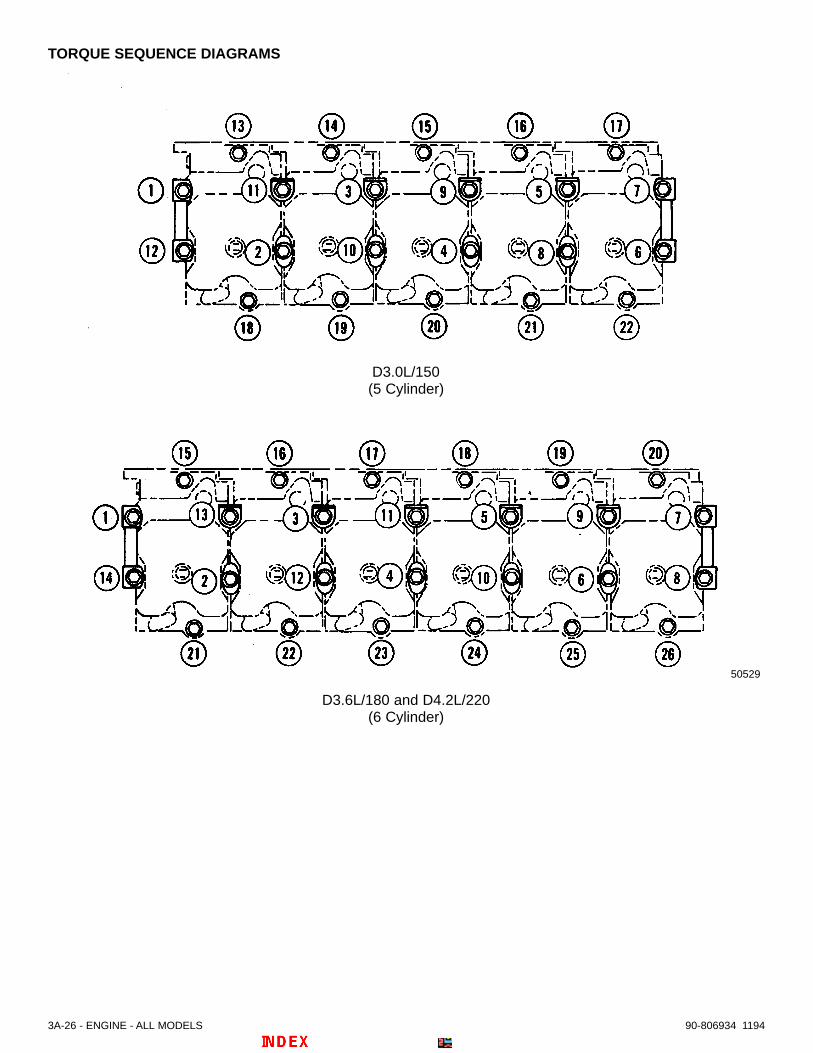
3A-26 - ENGINE - ALL MODELS 90-806934 1194
TORQUE SEQUENCE DIAGRAMS
50529
D3.0L/150(5 Cylinder)
D3.6L/180 and D4.2L/220(6 Cylinder)

ENGINE - ALL MODELS - 3A-2790-806934 1194
7. Install all lubricated 14mm cylinder head bolts, in-cluding the proper formed spacer-washers (ter-minal bridges, three types) and cylinder headspacers, for ends of first and last cylinder heads,as shown in the following. Lightly HAND tightenbolts in torque sequence. (Refer to Cylinder HeadTorque Sequence Diagrams.)
50528
a - Spacer(s). First and Last Cylinder Head Endsb - Formed Spacer-Washers (Terminal Bridges, Three Types)
8. Temporarily install exhaust manifold WITHOUTGASKETS and FINGER tighten each nut withlocking washer.
9. Slightly loosen 12mm and 14mm bolts as need-ed, to allow heads to ALIGN as you HAND tightenexhaust manifold nuts.
10. Hand tighten all 14mm and 12mm cylinder headbolts in torque sequence.
11. In torque sequence tighten 14mm cylinder headbolts to 22 lb. ft. (30 N⋅m). Refer to Torque Se-quence Diagrams. Repeat using the same speci-fication, to ensure the best preload, before pro-ceeding.
12. Following the same sequence tighten each14mm bolt through an angle of 70 Degrees usinga Torque Angle Gauge.
13. Tighten each 14mm bolt through ANOTHER 70Degrees following the same sequence.
14. In sequence tighten port and starboard 12mm cyl-inder head bolts to 22 lb. ft. (30 N⋅m).
15. In sequence tighten only the STARBOARD 12mmcylinder head bolts through an angle of 85 ± 5 De-grees using a Torque Angle Gauge.
16. In sequence tighten only the PORT 12mm cylin-der head bolts through an angle of 85 ± 5 Degreesusing a Torque Angle Gauge.
! CAUTIONAvoid component or engine failure. Cylinderheads require additional angular torque and con-ventional torque application after the first 20-30minute run-in and then, after the first 100 hours orfirst operating season whichever occurs first.
17. Remove exhaust manifold.
18. Insert push rods in position. Be certain they seatin lifters.
19. Make sure lubrication passages on rocker armsare clean and open. Install rocker arm assemblieson studs. Position push rod and adjusting screwtogether. Tighten retaining nuts to 81 lb. ft. (110N⋅m).
20. Install rocker arm oil feed line using 2 new sealingwashers at each banjo fitting and bolt.
21. Install manifold strip with new gaskets on cylinderheads. Torque bolts with washers to 84 lb. in. (10N⋅m) in a diagonal pattern from centermost toouter ends.
22. Complete engine assembly. Refer to appropriatesections of this manual.

3A-28 - ENGINE - ALL MODELS 90-806934 1194
23. AFTER COMPLETE ENGINE ASSEMBLY ANDINSTALLATION, follow these additional cylinderhead angular torque instructions:
a. Run engine at idle until water temperaturereaches 158° f. (70° c) and then run engine at2000 rpm for approximately 20-30 minutes atoperating temperatures. Let the engine cooldown completely (inoperative overnight, ifpossible)
b. Remove rocker arm covers. Refer to section,Rocker Covers – “Removal.” Retorque thecylinder head bolts, as follows:
(1) n torque sequence, and operating on onlyone bolt at a time, loosen each 14 mm(center) bolt and then retorque to 22 lb. ft.(30 N·m). Continue by tightening the boltthrough an angle of 65 Degrees and thenthrough ANOTHER 65 Degrees (130Degrees total).
(2) In sequence and without loosening, checktorque on port and starboard 12 mm (side)bolts to be 66 lb. ft. (90 N·m)
c. Check valve clearance with proper feelergauge and reset clearance if necessary be-fore valve covers are reinstalled. (Refer to ap-propriate section.)
d. Install rocker arm covers. Refer to section,Rocker Covers – “Installation.”
! CAUTIONAvoid component or engine failure. Cylinderheads require additional angular torque and con-ventional torque application after the first 100hours or first operating season, whichever oc-curs first.
24. AFTER 100 HOURS, OR THE FIRST OPERAT-ING SEASON, WHICHEVER OCCURS FIRST,follow instructions “a” – “e”:
a. Remove valve covers. Refer to section,Rocker Covers – “Removal.”
b. In torque sequence and without loosening,tighten the 14mm (center) cylinder head boltsthrough an angle of 15 Degrees.
c. In sequence and without loosening, torquethe 12mm (side) cylinder head bolts throughan angle of 15 Degrees.
d. Check valve clearance with proper feelergauge and reset clearance if necessary be-fore valve covers are reinstalled. (Refer to ap-propriate section.)
e. Install valve covers. Refer to section, RockerCovers – “Installation.”

ENGINE - ALL MODELS - 3A-2990-806934 1194
Rocker Arm
Repair1. Using a micrometer, measure outside diameter
(O. D.) of rocker arm support journals.
70274
a - O. D. Rocker Arm Support Journal Measurement - .865 in. to .866 in. (21.99mm to 22.00mm)
2. Replace rocker arm support if journals are badlygrooved or worn.
3. Using an inside micrometer, measure inside di-ameter (I.D.) of rocker arm bushing.
70274
a - I.D. Rocker Arm Bushing Measurement - .867 in. to .868 in. (22.02mm to 22.04mm)
4. Replace rocker arm bushing if difference be-tween bushing I.D. and journal O. D. is greaterthan .008 in. (0.2mm).
Assembly1. Install rocker arm adjustment screw and locknut.
Replace locknut if damaged or if edges arerounded off.
70274
a - Rocker Arm Adjustment Screwb - Locknutc - Rocker Arm
2. Lubricate rocker arm bushings and support jour-nals with S.A.E. 30W Oil.
70274
a - Rocker Arm Bushingsb - Rocker Arm Support Journals
3. Install rocker arms on support. Position as shown.
70218
a - Rocker Arms (Positioned Correctly)b - Rocker Arm Support
4. Install strap. Make sure strap is not spread openor valve cover will not fit.
70217
a - Strapb - Strap Installed On Rocker Arm Assembly

3A-30 - ENGINE - ALL MODELS 90-806934 1194
Adjusting Valve ClearanceIMPORTANT: Engine must be cold before settingvalve clearance.
IMPORTANT: Set valves only when the piston ofeach cylinder is at top dead center (TDC) of itscompression stroke.
NOTE: Glow plugs may be removed to release com-pression when turning crankshaft.
! WARNING
Be sure to keep hands, feet, and clothing awayfrom moving engine parts.
1. Follow instructions “a” or “b”:
a. On D3.0L/150 and D3.6L/180 Models: If soequipped, remove power steering belt anddrive pulley with flange. Remove 3 opposingbalancer (vibration damper) retaining boltsfrom crankshaft pulley. Do not removebalancer.
b. On D4.2L/220 Models: Remove 3 opposingretaining bolts from the balancer (vibrationdamper).
2. Using balancer bolts or suitable, attach crank-shaft tool 91-814827 to crankshaft pulley.
70485
a - Crankshaft Tool 91-814827
3. Remove oil fill cap from valve cover.
73322
a
a - Oil Fill Cap
4. Look through oil fill cap hole into valve cover,while using a suitable inspection light, and slowlyrotate engine CLOCKWISE watching the firstrocker arm and valve (front-most is Number 1 cyl-inder’s intake valve). After the valve has opened(rocker arm moved down) and then CLOSED(rocker arm up), continue to rotate engine clock-wise until crankshaft pulley notch aligns with markon timing gear cover as shown. Number 1 pistonis at Top Dead Center (TDC) on its compressionstroke at this point.
70281
a - Crankshaft Pulley Notchb - Timing Cover Mark
NOTE: On D4.2L/220 Engines crankshaft pulleynotch is on smaller power steering pulley edge, be-hind larger drive pulleys.
5. Using adaptor plate, attach graduated disc91-801333500 to crankshaft pulley, with zeropositioned as shown.
a
cb
a - Adaptor Plate, (Retains Graduated Disc to Balancer)b - Graduated Discc - Crankshaft Tool

ENGINE - ALL MODELS - 3A-3190-806934 1194
6. Using wire, make a pointer and attach it to a suit-able location on engine. Align pointer to zero (“0”)as shown.
70664
a - Wire Pointer
7. Remove rocker arm covers.
8. Loosen locknuts on both rocker arm adjustingscrews of number 1 cylinder.
9. Insert a .012 in. (0.30mm) feeler gauge betweenvalve stem and rocker arm. Using a screwdriver,turn adjusting screw to obtain a slight drag whilemoving feeler gauge.
70666
c
b
a
a - Rocker Armb - Valve Stemc - Feeler Gauge - .012 in. (0.30 mm)
10. While holding screwdriver to maintain clearance,tighten locknut to 13 lb. ft. (18 N⋅m).
11. Adjust second valve of number 1 cylinder usingthe same procedure.
12. Using crankshaft tool, turn crankshaft clockwise(6 cylinder – 120 degrees or 5 cylinder – 144degrees) to bring next cylinder in firing order up toT.D.C.
Firing Order
5 Cylinder 1-2-4-5-3
6 Cylinder 1-5-3-6-2-4
Valve Clearance
Intake .012 in. (0.30mm)
Exhaust .012 in. (0.30mm)
13. Adjust remaining valves as outlined.14. Refer to appropriate sections and reassemble
components as instructed.
Timing Gear Cover
Removal1. Follow instructions “a” or “b”:
a. On D3.0L/150 and D3.6L/180 Models: If soequipped, remove power steering belt. Re-move three allen-head bolts from vibrationdamper (balancer) and remove power steer-ing drive pulley with flange.
b. On D4.2L/220 Models: If so equipped, loos-en power steering pump belt.
2. Remove alternator belt(s), and upper alternatorbracket screw from timing gear cover.
! CAUTIONWhen removing seawater hoses or seawaterpump, close seacock, if so equipped. If boat is notequipped with a seacock, remove and plug sea-water inlet hose to prevent a siphoning actionthat may occur, allowing seawater to flow fromthe drain holes or removed hoses and enter boat.3. Refer to Seawater System section and remove
sea-water pump inlet hose and outlet hose.Remove seawater pump.
4. Follow instructions “a” or “b”:a. On D3.0L/150 and D3.6L/180 Models: Re-
move six, or the remaining three (if engine isequipped with power steering), allen-headbolts and remove crankshaft vibration damp-er.
b. On D4.2L/220 Models: Remove six allen-head bolts and remove crankshaft vibrationdamper.
5. Install flywheel holding tool 91-801333506.

3A-32 - ENGINE - ALL MODELS 90-806934 1194
6. Using a suitable socket remove the large crank-shaft pulley nut.
7. Using Puller 91-801333507, remove crankshaftpulley.
8. Follow instructions “a” or “b”:
a. On D3.0L/150 and D3.6L/180 Models:Remove lower cover to gain access to atiming gear cover screw. Remove screw. Notesize and position of fasteners for reassembly.
b. On D4.2L/220 Models: Proceed to Step 9.
70661
a - Lower Cover Location (Cover Removed)b - Timing Cover Screw
9. Remove fasteners, including one at alternatorbracket, and remove timing cover. Note size andposition of fasteners for reassembly.
InspectionIMPORTANT: Due to a production change,engines with VM Serial Numbers 57252 and uphave a different oil pump and timing cover. Theseparts cannot be interchanged with those onengines with VM Serial Numbers 57251 andbelow. Be certain to order the proper parts foryour engine should they require replacement.
1. Remove old gasket material from block andtiming cover. Be careful not to gouge or nickflanges.
2. Clean and check cover for wear or damage.
3. Check oil seal for wear or damage. Using a suit-able tool remove and replace oil seal if needed.
NOTE: Bore in timing cover for oil seal must be3.1496-3.1507 in. (80.000 – 80.030mm). If not,replace timing cover.
Installation1. Check to see that crankshaft O-ring seal between
timing gear and pulleys is still in place and inacceptable condition.
NOTE: While timing cover is removed renew O-ringif crankshaft and pulleys show signs of oil leakagefrom center.
2. Coat new timing gear cover gasket with LoctiteMaster Gasket. Install gasket and timing coverspecified for your engine block number. Torquescrews evenly, in a diagonal pattern, to 7 lb. ft. (10N⋅m).
IMPORTANT: On D3.0L/150 and D3.6L/180 en-gines do not forget to install and torque timingcover screw inside lower cover recess.
70661
a - Lower Cover Locationb - Timing Cover Screw [Torque to 7 lb. ft. (10 N⋅m)]
3. Follow instructions “a” or “b”:
a. On D3.0L/150 and D3.6L/180 Models:Install small lower cover with a new gasketand torque screws to 18 lb. ft. (24 N⋅m).
NOTE: Upper-left screw (10 o’clock position) is anallen-head screw. Do not substitute with a differentfastener.
b. On D4.2L/220 Models: Proceed to Step 4.

ENGINE - ALL MODELS - 3A-3390-806934 1194
4. Install crankshaft pulley. Be certain key remainsin proper position. With flywheel holder tool91-801333506 in place, torque large pulley nut to114 lb. ft. (155 N⋅m).
5. Follow instructions “a” or “b”:
a. On D3.0L/150 and D3.6L/180 Models:Install vibration damper, and if so equipped,install power steering pulley flange usingdamper bolts. Torque allen-head bolts to 37lb. ft. (50 N⋅m). If power steering pulley was re-moved from flange, torque bolts to 96 lb. in.(11 N⋅m).
b. On D4.2L/220 Models: Make certain powersteering pulley belt is in proper position andthen install vibration damper and torque boltsto 37 lb. ft. (50 N⋅m).
6. Remove flywheel holder tool.
7. Refer to SECTION 6B - “Seawater System”, andinstall seawater pump using a new O-ring seal.Tighten nuts with washers securely.
IMPORTANT: D4.2L/220 seawater pump is NOT in-terchangeable with seawater pumps on other die-sel engines. Use only the seawater pump desig-nated for your engine.
8. Install upper alternator bracket (brace) to timingcover. Torque fastener to 34-37 lb. ft. (45-50 N⋅m).
9. Refer to Maintenance Section – “Replace DriveBelts” and tension alternator belt, power steeringbelt, and vacuum pump belt, if so equipped.Torque alternator and power steering mountingand tensioning bolts to specifications.
10. Install seawater pump inlet hose and outlet hose.Tighten hose clamps securely.
11. Refer to Seawater System Section, and openseacock if so equipped, or remove plug fromseawater inlet hose and reconnect seawater inlethose to inlet of seawater strainer.
Oil Pump
IMPORTANT: Due to a change in production,engines with VM Serial Numbers 57252 and uphave a different oil pump and timing cover. Theseparts cannot be interchanged with those onengines with VM Serial Numbers 57251 andbelow. Be certain to order the proper parts foryour engine should they require replacement.
Removal1. Remove timing gear cover.
2. Remove screws securing oil pump.
NOTE: Oil pump bearing arrangement in this picturemay differ slightly from your model. Picture isrepresentative of all models.
70292
a - Screws (3)b - Oil Pump
3. Remove oil pump from bore in block.
70287
a - Oil Pump, Complete Unit
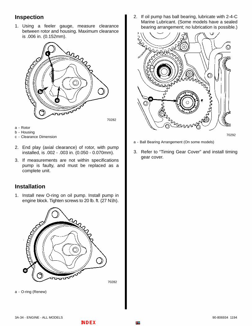
3A-34 - ENGINE - ALL MODELS 90-806934 1194
Inspection1. Using a feeler gauge, measure clearance
between rotor and housing. Maximum clearanceis .006 in. (0.152mm).
70282
a - Rotorb - Housingc - Clearance Dimension
2. End play (axial clearance) of rotor, with pumpinstalled, is .002 - .003 in. (0.050 - 0.070mm).
3. If measurements are not within specificationspump is faulty, and must be replaced as acomplete unit.
Installation1. Install new O-ring on oil pump. Install pump in
engine block. Tighten screws to 20 lb. ft. (27 N⋅m).
70282
a - O-ring (Renew)
2. If oil pump has ball bearing, lubricate with 2-4-CMarine Lubricant. (Some models have a sealedbearing arrangement; no lubrication is possible.)
70292
a - Ball Bearing Arrangement (On some models)
3. Refer to “Timing Gear Cover” and install timinggear cover.

ENGINE - ALL MODELS - 3A-3590-806934 1194
Oil Pressure Relief Valve
Removal
1. Remove oil pan. Clean gaskets from engine blockand pan flanges.
! WARNING
Wear safety glasses. There is high springpressure against cap. Use caution whenremoving or installing snap-ring.
2. Push in cap. Remove snap-ring.
70298
a - Capb - Snap-Ring
3. Remove cap, spring(s), and relief valve frombore.
70283
a - Capb - Spring (Inner – Present If Dual Spring Equipped)c - Spring (Referred To As Outer – If Dual Spring Equipped)d - Relief Valve
NOTE: Some oil pressure relief valves have only onespring.
4. If spring(s) is/are broken or valve is badly worn orsticking in bore, replace complete valveassembly.
NOTE: Bore may need to be heated before removalfrom engine block.
70285
a - Valve Assembly, Complete
Installation1. When replacing complete valve assembly, apply
Loctite 242 to threads and tighten securely inengine block.
2. Assemble valve, spring(s) (inner and outersprings, if dual spring equipped), and cap asshown.
70284
a - Capb - Spring (Inner – Present If Dual Spring Equipped)c - Spring (Referred To As Outer – If Dual Spring Equipped)d - Relief Valve
NOTE: Some oil pressure relief valves have only onespring.
3. Coat inside of bore with S.A.E. 30W engine oil.Install assembled valve and spring(s) into bore.Valve must slide freely.
4. Push cap into bore and install snap-ring.
5. Install oil pan.
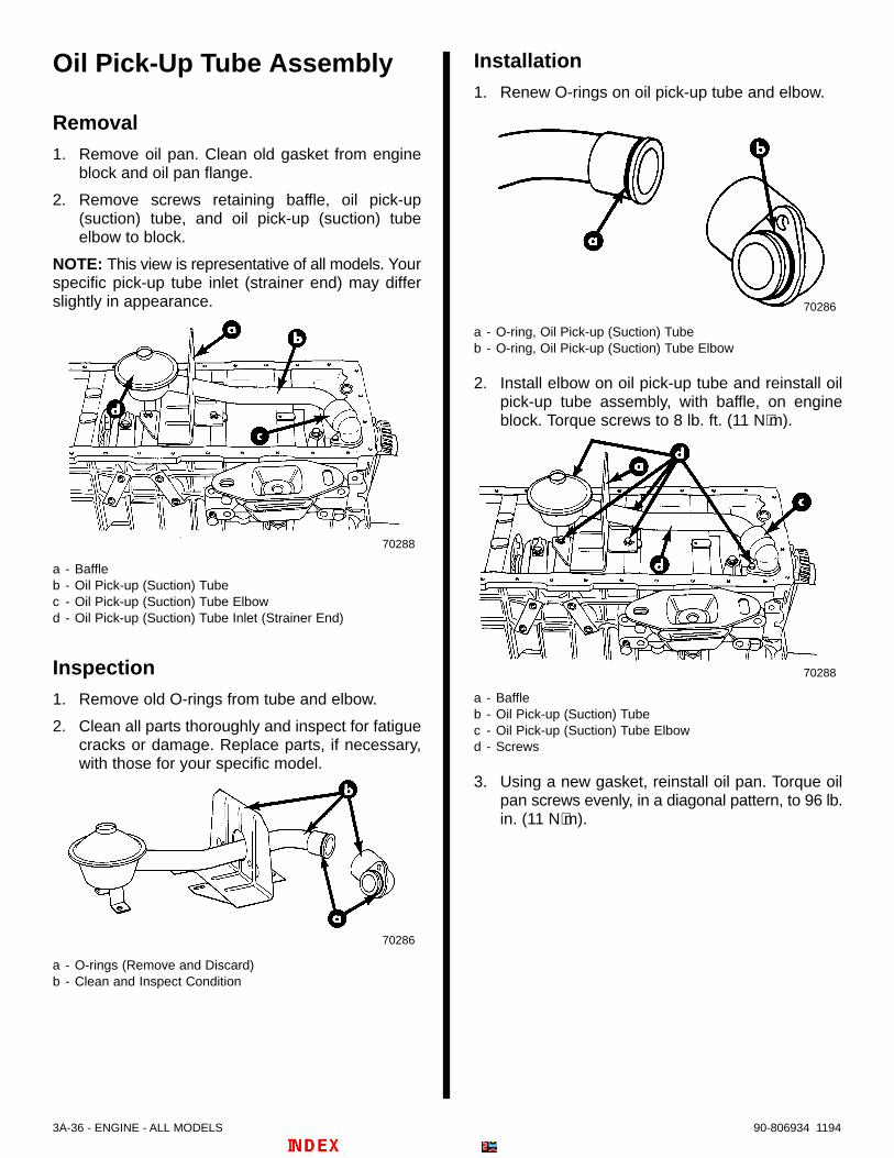
3A-36 - ENGINE - ALL MODELS 90-806934 1194
Oil Pick-Up Tube Assembly
Removal1. Remove oil pan. Clean old gasket from engine
block and oil pan flange.
2. Remove screws retaining baffle, oil pick-up(suction) tube, and oil pick-up (suction) tubeelbow to block.
NOTE: This view is representative of all models. Yourspecific pick-up tube inlet (strainer end) may differslightly in appearance.
70288
a - Baffleb - Oil Pick-up (Suction) Tubec - Oil Pick-up (Suction) Tube Elbowd - Oil Pick-up (Suction) Tube Inlet (Strainer End)
Inspection1. Remove old O-rings from tube and elbow.
2. Clean all parts thoroughly and inspect for fatiguecracks or damage. Replace parts, if necessary,with those for your specific model.
70286
a - O-rings (Remove and Discard)b - Clean and Inspect Condition
Installation1. Renew O-rings on oil pick-up tube and elbow.
70286
a - O-ring, Oil Pick-up (Suction) Tubeb - O-ring, Oil Pick-up (Suction) Tube Elbow
2. Install elbow on oil pick-up tube and reinstall oilpick-up tube assembly, with baffle, on engineblock. Torque screws to 8 lb. ft. (11 N⋅m).
70288
a - Baffleb - Oil Pick-up (Suction) Tubec - Oil Pick-up (Suction) Tube Elbowd - Screws
3. Using a new gasket, reinstall oil pan. Torque oilpan screws evenly, in a diagonal pattern, to 96 lb.in. (11 N⋅m).
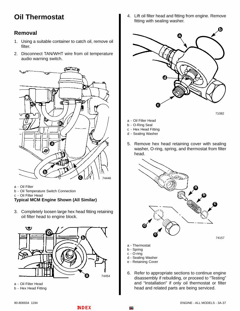
ENGINE - ALL MODELS - 3A-3790-806934 1194
Oil Thermostat
Removal1. Using a suitable container to catch oil, remove oil
filter.
2. Disconnect TAN/WHT wire from oil temperatureaudio warning switch.
74446cb
a
a - Oil Filterb - Oil Temperature Switch Connectionc - Oil Filter HeadTypical MCM Engine Shown (All Similar)
3. Completely loosen large hex head fitting retainingoil filter head to engine block.
74454
b
a
a - Oil Filter Headb - Hex Head Fitting
4. Lift oil filter head and fitting from engine. Removefitting with sealing washer.
71082
ba
d
c
a - Oil Filter Headb - O-Ring Sealc - Hex Head Fittingd - Sealing Washer
5. Remove hex head retaining cover with sealingwasher, O-ring, spring, and thermostat from filterhead.
74157
b
c
d
e
a
a - Thermostatb - Springc - O-ringd - Sealing Washere - Retaining Cover
6. Refer to appropriate sections to continue enginedisassembly if rebuilding, or proceed to “Testing”and “Installation” if only oil thermostat or filterhead and related parts are being serviced.

3A-38 - ENGINE - ALL MODELS 90-806934 1194
Testing
! WARNING
Always wear safety glasses when using com-pressed air.
1. Clean parts in solvent. Dry with compressed air.
2. Thermostat pin should be retracted as shownwhen cold. If not, thermostat is faulty and must bereplaced.
71085
a - Thermostatb - Thermostat Pin (Retracted)
! WARNING
The following test involves the use of electricityand intense heat. Failure to follow appropriateprocedures or warnings can cause burns orshock which can result in severe personal injuryor death. While performing the following test, ob-serve these general precautions:
Wear personal protective clothing such asrubber gloves, a non-flammable apron, andeye protection – preferably full face shield orsafety glasses.
Work area should include the use of rubberfloor mats. Use insulated tools.
The appropriate heat source should only beelectric. Heat source should be operated by aqualified person. Be sure to follow allinstructions of the manufacturer of the heatsource. The heat source should be checkedeach time it is used to be sure it is functioningproperly.
The thermometer used in the test should be ahigh-temperature thermometer with amaximum reading of at least 300° F (150° C).Under no circumstances should the operatorallow temperatures to exceed testspecifications.
Perform test only in a well ventilated area.
Use a suitable container to hold the water,such as metal. Avoid use of glass containersunless the operator first confirms forhim/herself that the glass container is anappropriate high-temperature vessel.
Because the components will reach hightemperatures do not handle materials orcomponents until COMPLETELY cooled.
3. Observe the preceding precautions and placethermostat in container of water. Water mustcover thermostat. Suspend a thermometer in thewater. Do not allow thermometer to touch thebottom of the pan.
4. Heat water and observe thermostat pin.

ENGINE - ALL MODELS - 3A-3990-806934 1194
5. Pin must begin to extend (push up) as shown,when water temperature reaches 195° F (90° C).At 212° F (100° C) pin should be extendedapproximately 3/16 - 5/16 in. (5-7mm) more thanwhen it was cold.
NOTE: Thermostat shown removed from test waterfor visual clarity. Do not handle until cool.
71084
a - Thermostat Pin (Extended)
6. If pin does not extend (push out), thermostat isfaulty and must be replaced.
INSTALLATION1. Coat threads of hex head retaining cover with
Loctite Pipe Sealant with Teflon.
2. Install thermostat, spring, new O-ring, and retain-ing cover with new sealing washer into oil filterhead. Be certain O-ring is properly seated ingroove of filter head.
74157
b
c
d
e
a
b - Thermostatc - Springd - O-ringe - Sealing Washerf - Hex Head Retaining Cover
3. If not already accomplished, remove old O-ringfrom groove on oil filter head (on underside offilter head when mounted). Clean groove and oilfilter head flange using a suitable solvent. Also,clean engine block flange.
4. Install a new O-ring in groove of filter head flange.Install large hex head fitting with new sealingwasher through filter head as shown.
71086
a - Oil Filter Head (With Thermostat Assembled)b - O-ring Groove [On Underside Of Filter Head When
Mounted (Not Visible In This View)]c - O-ringd - Hex Head Fittinge - Sealing Washer
5. Install oil filter head on engine block as shown. Becertain O-ring seal is positioned properly. Tightenhex head fitting with sealing washer securely.
74454
b
a
c
a - Oil Filter Headb - Fittingc - Sealing Washer

3A-40 - ENGINE - ALL MODELS 90-806934 1194
6. Coat sealing washer of new oil filter withQuicksilver 4-Cycle Marine Engine Oil or15W-40CD engine oil and install. Hand tighten,do not use a filter wrench. Attach TAN/WHT wireto oil temperature switch.
72706
b
a
a - Oil Filterb - Wiring
7. Remove oil fill cap and fill engine to proper levelwithnew, recommended engine oil.
IMPORTANT: Always use dipstick to determinehow much oil is required.
73322
a
a - Oil Fill Cap
8. Pre-lubricate engine and turbocharger. To do this,move the “STOP” switch toggle lever DOWN andhold in this position while you turn the key switchto “START” position. Doing this TOGETHERturns the engine without starting it. DO NOTengage starter for more than 15 seconds; allow atleast one minute cool down time beforere-engaging starter for another 15 seconds.Watch that starter does not overheat.
9. Start engine and closely observe instrumentationto make sure that all systems are functioningcorrectly. Check for leaks.
Camshaft
Measuring Lobe Lift1. Remove all rocker arm assemblies.
2. Secure dial indicator 91-58222A1 to head soindicator plunger rests inside push rod cup.
3. Turn crankshaft so camshaft lobe is at the bottomof its travel and zero dial indicator.
4. Turn crankshaft two complete revolutions whilereading dial indicator. Refer to specifications.
5. Measure all lobes of camshaft in the samemanner.
Camshaft replacement will be necessary if lobedimensions are less than .0019 in. (0.05mm) ofthe values indicated in the specification charts.
Removal1. Turn crankshaft until number one cylinder is at top
dead center (TDC) of its compression stroke.
2. Remove:a. Timing Gear Coverb. Fuel Injection Pumpc. Fuel Pumpd. Push Rods
3. Drain engine oil.
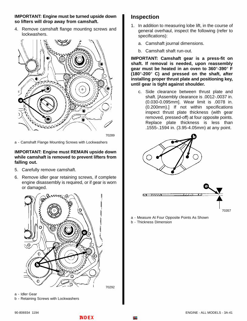
ENGINE - ALL MODELS - 3A-4190-806934 1194
IMPORTANT: Engine must be turned upside downso lifters will drop away from camshaft.
4. Remove camshaft flange mounting screws andlockwashers.
70289
a - Camshaft Flange Mounting Screws with Lockwashers
IMPORTANT: Engine must REMAIN upside downwhile camshaft is removed to prevent lifters fromfalling out.
5. Carefully remove camshaft.
6. Remove idler gear retaining screws, if completeengine disassembly is required, or if gear is wornor damaged.
70292
a - Idler Gearb - Retaining Screws with Lockwashers
Inspection1. In addition to measuring lobe lift, in the course of
general overhaul, inspect the following (refer tospecifications):
a. Camshaft journal dimensions.
b. Camshaft shaft run-out.
IMPORTANT: Camshaft gear is a press-fit onshaft. If removal is needed, upon reassemblygear must be heated in an oven to 360°-390° F(180°-200° C) and pressed on the shaft, afterinstalling proper thrust plate and positioning key,until gear is tight against shoulder.
c. Side clearance between thrust plate andshaft. [Assembly clearance is .0012-.0037 in.(0.030-0.095mm]. Wear limit is .0078 in.(0.200mm).] If not within specificationsinspect thrust plate thickness (with gearremoved, pressed-off) at four opposite points.Replace plate thickness is less than.1555-.1594 in. (3.95-4.05mm) at any point.
70357
a - Measure At Four Opposite Points As Shownb - Thickness Dimension

3A-42 - ENGINE - ALL MODELS 90-806934 1194
InstallationBEFORE installation of camshaft, consider thefollowing:
Inspect camshaft bearings. Replace as needed.(Refer to section.)
Inspect valve lifters (tappets) and push rods.Replace if needed. (Refer to section.)
IMPORTANT: Engine must remain upside downwhile camshaft is removed to prevent lifters fromfalling out.
1. Install idler gear, if previously removed, so marksalign with crankshaft gear as shown. Torquescrews to 18 lb. ft. (25 N⋅m).
! CAUTIONAvoid possible severe engine damage.Installation of a screw longer than 5/8 in. (16mm)will partially block oil gallery in engine blockcausing lack of lubrication. Be certain retainerscrew “c” as shown, is NOT longer than stated.
70293
a - Idler Gearb - Retaining Screws with Lockwashersc - Retaining Screw Must NOT Be Longer Than 5/8 in. (16mm)d - Marks Aligned Properly
2. Lubricate camshaft lobes with a mixture of 20%S.A.E. 30W engine oil and 80% Needle BearingLubricant 92-42649A1.
3. Lubricate camshaft bearings with S.A.E. 30Wengine oil.
4. Carefully insert camshaft.
5. Align camshaft gear marks with idler gear marksas shown. Torque screws to 20 lb. ft. (27 N⋅m).
70289
a - Camshaft Gearb - Idler Gearc - Marks Aligned Properlyd - Camshaft Flange Mounting Screws With Lockwashers
6. Turn engine upright.
7. Complete engine assembly.

ENGINE - ALL MODELS - 3A-4390-806934 1194
Camshaft Bearings
InspectionWith camshaft removed:
1. Visually inspect bearings. Renew if worn ordamaged.
2. Measure inner diameter of bearings. (Refer tospecifications.) Renew bearings if not withinspecifications.
RemovalNOTE: Camshaft bearings can only be removed andinstalled with crankshaft removed.
1. Using special tool 91-801333508 withappropriate hardware remove camshaft bearingsinto receiver end of tool (hidden in this view) asshown.
70438
a - Engine Blockb - Special Tool 91-801333508 (In Use)c - Camshaft Bearing Bore
Installation1. Clean camshaft bearing bores in cylinder block
with solvent and blow out with compressed air. Besure drilled oil passages are clean.
IMPORTANT: Oil feed holes in bearings MUSTalign with drilled oil passages in engine block orsevere engine damage will result.
2. Using Special Tool 91-801333508 withappropriate hardware, install new bearings.Lubricate outer surface of new camshaft bearingswith engine oil to ease installation.
70354
a - Engine Blockb - Special Tool (91-801333508)c - Camshaft Bearingd - Oil Feed Hole (MUST BE aligned with Drilled Passages in
Block)
3. Check position of oil hole in each bearing anddrilling in block, to ensure bearings are positionedcorrectly.
4. Recheck bearing inner dimensions to verifyproper installation.
5. Install camshaft. (Refer to previous section.)
6. Complete engine assembly. (Refer to appropriatesections.)

3A-44 - ENGINE - ALL MODELS 90-806934 1194
Valve Lifters (Tappets)! CAUTION
If the camshaft is replaced, the valve lifters(tappets) must also be replaced or seriouscomponent failure and engine damage couldresult.
RemovalWith the camshaft removed:
! CAUTIONIn case camshaft and lifters are reusable, liftersmust be installed on same camshaft lobes whereremoved.
1. Remove lifters, being certain to keep them inorder.
70429
a - Valve Lifter (Tappet)
Cleaning and InspectionThoroughly clean all parts in cleaning solvent andinspect them carefully. If any parts are damaged orworn, camshaft and lifters should be replaced. If outerlifter body wall is scuffed or worn, inspect cylinderblock lifter bore. If bottom of lifter is scuffed or worn(cupped) inspect camshaft lobe. If push rod seat isscuffed or worn, inspect push rod (refer to section).
70668
a - Lifter Diameter
SPECIFICATIONS CHART
Size Dimension (mm)
Lifter Diameter.5891 – .5899
(14.965 – 14.985)
.5909 – .5919Dia. of lifter bore
(15.010 – 15.035)
.0010 – .0027Assembly clearance
(0.025 – 0.070)
Wear limit .0039 (0.100)
Installation
IMPORTANT: Before installIng lifters, coat thebottom of lifter with engine oil. If new lifters andnew camshaft have been installed, an additivecontaining EP lube should be poured over liftersand camshaft lobes.
1. In order of removal, install lifters in engine blockbore.
2. Complete engine assembly.

ENGINE - ALL MODELS - 3A-4590-806934 1194
Valve Push RodsRemovalIMPORTANT: Place rocker arms, rocker armcomponents and push rods in a rack or holder forreinstallation in the same locations.
With valve covers and rocker arm assembliesremoved:
1. Lift push rod from seat in lifter cup.
Cleaning and Inspection1. Clean all parts with solvent and dry with
compressed air.
2. Inspect all contact surfaces for wear.
3. Check run-out or straightness of each push rod.
4. Replace all damaged or worn parts.
InstallationIMPORTANT: When installing lifters and rockerarms, coat rocker arm bearing surfaces, rockerarm and push rod ball and seat with engine oil.
1. Install push rods in order of removal. Be sure pushrods seat in lifter socket.
2. Install rocker arm assemblies. (Refer to section.)
3. Adjust valve clearance. (Refer to section.)
4. Install valve covers. (Refer to section.)
Connecting Rod/PistonAssemblyMeasuring Rod Bearing Clearance1. Remove oil pan and oil pick-up tube assembly.
NOTE: NOTE: This picture is representative of allmodels. Your specific pick-up tube inlet (strainer end)may differ slightly in appearance.
70288
a - Oil Pick-Up Tube Assembly
2. Turn crankshaft to gain access to connecting rodbolts.
3. One cylinder at a time, remove rod caps andinspect bearings. (Refer to “Bearing Failure”pictures at front of section.)
4. Measure crank pin with a micrometer forout-of-round, taper, or excessive wear. If notwithin specifications, replace or reconditioncrankshaft.
5. Measure new or used bearing clearances withPlastigage or its equivalent as follows:
a. Clean oil from crank pin.
b. Install bearing in connecting rod.
c. Place a piece of gauging plastic the full widthof crank pin (parallel to crankshaft).
d. Install rod cap with bearing and torque boltsto 61 lb. ft. (82 N⋅m).
IMPORTANT: Do not turn crankshaft while gaug-ing plastic is in place.
e. Remove rod cap and, using scale on gaugingplastic envelope, measure gauging plasticwidth at widest point.
6. If clearance exceeds specifications, on usedbearings, replace bearings and recheckclearance. With new bearings, if correctclearance is not possible, recheck crank pin(journal) dimensions. If new bearings andreplacement (or reconditioned crankshaft) will notyield proper measurement, it will be necessary toremove connecting rod/piston assembly (refer tofollowing section) to check dimension ofconnecting rod crank pin bore.
7. After obtaining the correct clearance, coat crankpin with S.A.E. 30W engine oil. Coat bearingsurface with oil and install rod cap. Torque to 61lb. ft. (82 N⋅m).

3A-46 - ENGINE - ALL MODELS 90-806934 1194
Removal1. Remove cylinder heads.
2. Remove oil pan and oil pick-up tube.
3. Use a reamer to remove the ridge or any depositsfrom upper end of cylinder bore.
4. Turn crankshaft to gain access to connecting rodbolts.
NOTE: Connecting rods are numbered as shown.Record the numbers and cylinder location forreassembly.
70297
a - Connecting Rod Number Placement
5. Remove connecting rod cap and rod bearings.
6. Push piston and connecting rod out of cylinder.(Mark or identify each to ensure placement inoriginal location during reassembly, if to bereused.)
7. Retain rod cap and bearings with connecting rod/piston assembly. Do not mix components.
Disassembly1. Clamp connecting rod in a soft jawed vise as
shown.
70290
2. Use Piston Ring Expander 91-24697 to remove 2top compression rings.
3. Using same tool, remove lower (oil control) ringand spring.
70291
a - Lower (Oil Control) Ringb - Spring
4. Remove snap rings retaining piston pin. Push pinout of connecting rod and piston.
70294
a - Snap Ring(s)b - Piston Pin

ENGINE - ALL MODELS - 3A-4790-806934 1194
Cleaning and Inspection
CONNECTING ROD and PIN:
1. Wash connecting rods in cleaning solvent and drywith compressed air.
2. Check for twisting of bent rods and inspect fornicks or cracks. Replace damaged connectingrods.
3. Measure connecting rod bushing I.D. and pistonpin O. D. Replace bushing if clearance isexcessive. (Refer to specification charts.)
a - Rod Bushing I.D.b - Piston Pin O. D.
4. Measure connecting rod crank pin bore with a dialbore gauge or inside micrometer for out-of-roundor excessive wear. Crank pin bore must be2.2662-2.2670 in. (57.563-57.582mm). Replaceconnecting rod if measurement exceedsallowable dimension by .0008 (0.02mm).
70397
a - Rod Crank Pin Bore
PISTONS:
! CAUTIONFor D3.0L/150 and D3.6L/180 engines, pistons areprovided in two standard sizes and correspond tothe tolerance classes: Class A or Class B. ForD4.2L/220 engines only Class A pistons (and liners)are provided. Failure to use only the piston Class (Aor B) designated for your engine and cylinder linerwill result in severe engine damage.
IMPORTANT: Determine which Class of piston isneeded by looking on top of piston (as shownfollowing) or by examining the underside of thecylinder liner (Refer to Cylinder Liner –“Identification”) for reference details.
70296
a - Letter “A” or “B” Location for Class A or B Designation
1. Clean varnish from piston skirts and pins with acleaning solvent. DO NOT WIRE BRUSH ANYPART OF PISTON. Clean ring grooves with agroove cleaner and make sure oil ring holes areclean.
70229
a - Ring Groovesb - Oil Ring Holes

3A-48 - ENGINE - ALL MODELS 90-806934 1194
2. Inspect piston for cracked ring lands, skirts or pinbosses, wavy worn ring lands, scuffed or damagedskirts or eroded areas at top of piston. Replacepistons which are damaged or show signs ofexcessive wear. (Refer to Step 6, following.)
3. Inspect grooves for nicks or burrs that mightcause rings to hang up.
4. Except on upper ring groove of pistons (refer toStep 6, following), insert edge of rings intorespective piston ring groove and roll ring entirelyaround the groove to make sure that ring is free.If binding occurs at any point, determine cause. Ifcaused by ring groove, remove by dressing witha fine cut file. Do not remove excess material.(Verify with feeler gauge and compare tospecifications.) If binding is thought to be adistorted ring, check with a new ring.
5. Measure piston O. D. about 1/2 in. (13mm) frombottom of skirt.
70229
a - O. D. Measurement Point - 1/2 in. (13mm)
6. Proper clearance of piston ring in its piston ringgroove is very important to provide proper ringaction and reduce wear.
Keep in mind that while the second “scraper” com-pression ring and the oil control ring are typical in na-ture, the upper (first) compression ring is “trapezoi-dal” (tapered) in design. That is, it has a 15 degreetaper on both upper and lower surfaces.
Correspondingly, the upper compression ring grooveis tapered 15 degrees on top and bottom.
Note also that the upper ring’s edge (parallel to cylin-der liner) is not a straight cut. It is rounded, or arced,in design.
IMPORTANT: Do not mistake these tapered or dif-ferent design characteristics for unusual wearpatterns.
70441
70440
a - Upper (First) Compression Ring – Trapezoidal (Tapered)b - Upper (First) Compression Ring Groove – (Tapered)c - Outer Edge of Upper Compression Ring – (Arced)
As always, when fitting serviceable or new rings,clearances between all ring and groove surfacesshould be measured. See “Specifications.”

ENGINE - ALL MODELS - 3A-4990-806934 1194
a - Tapered Compression Ringb - “Scraper” Compression Ringc - Oil Control Ringd - Ring Clearance
CHECKING RING END GAP
1. Select rings comparable in size to piston beingused.
2. Slip compression ring in cylinder bore, then pressring down into cylinder bore about 1/4 in. (6mm)(below ring travel). Be sure that ring is square withcylinder wall.
3. Measure gap between ends of ring with a feelergauge as shown.
70295
Checking Ring End Gap
4. If gap between ends of ring is belowspecifications, remove ring and try another for fit.
5. Fit each compression ring to cylinder in which it isgoing to be used.
Assembly1. Coat inside of connecting rod bushing, piston pin
bore, and piston pin with S.A.E. 30W engine oil.
2. Assemble piston to connecting rod with thecombustion chamber recess aligned with rodnumbers.
70296
a - Combustion Chamber Recessb - Rod Number(s)
3. Insert piston pin and install snap ring.
4. Clamp in vise as shown.
70290
NOTE: Always install rings with ring markings facingthe top of piston.
5. Install spring in lower piston groove.
6. Carefully install oil control ring.
7. Squeeze ring into groove to seat spring andcheck for binding.
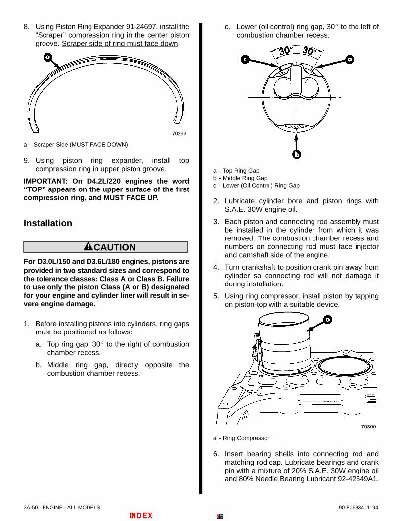
3A-50 - ENGINE - ALL MODELS 90-806934 1194
8. Using Piston Ring Expander 91-24697, install the“Scraper” compression ring in the center pistongroove. Scraper side of ring must face down.
70299
a - Scraper Side (MUST FACE DOWN)
9. Using piston ring expander, install topcompression ring in upper piston groove.
IMPORTANT: On D4.2L/220 engines the word“TOP” appears on the upper surface of the firstcompression ring, and MUST FACE UP.
Installation
! CAUTIONFor D3.0L/150 and D3.6L/180 engines, pistons areprovided in two standard sizes and correspond tothe tolerance classes: Class A or Class B. Failureto use only the piston Class (A or B) designatedfor your engine and cylinder liner will result in se-vere engine damage.
1. Before installing pistons into cylinders, ring gapsmust be positioned as follows:
a. Top ring gap, 30 to the right of combustionchamber recess.
b. Middle ring gap, directly opposite thecombustion chamber recess.
c. Lower (oil control) ring gap, 30 to the left ofcombustion chamber recess.
a - Top Ring Gapb - Middle Ring Gapc - Lower (Oil Control) Ring Gap
2. Lubricate cylinder bore and piston rings withS.A.E. 30W engine oil.
3. Each piston and connecting rod assembly mustbe installed in the cylinder from which it wasremoved. The combustion chamber recess andnumbers on connecting rod must face injectorand camshaft side of the engine.
4. Turn crankshaft to position crank pin away fromcylinder so connecting rod will not damage itduring installation.
5. Using ring compressor, install piston by tappingon piston-top with a suitable device.
70300
a - Ring Compressor
6. Insert bearing shells into connecting rod andmatching rod cap. Lubricate bearings and crankpin with a mixture of 20% S.A.E. 30W engine oiland 80% Needle Bearing Lubricant 92-42649A1.

ENGINE - ALL MODELS - 3A-5190-806934 1194
7. Align connecting rod with crank pin and tap onpiston top until rod bearing contacts crank pin. Donot scratch or nick crank pin.
8. Install rod cap, lubricate bolt threads with Quick-silver Needle Bearing Assembly Lubricant92-825265A1, and torque to 61 lb. ft. (82 N⋅m).
9. Check that corresponding numbers on rod capand connecting rod are the same and are on thesame (camshaft) side.
10. Check that connecting rod assembly and crankpin are not binding and that there is proper side-to-side movement.
11. Install remaining piston and connecting rodassemblies.
12. Measure for head gasket thickness as previouslyoutlined.
13. Refer to appropriate Sections and complete theengine assembly.
Oil Seal (Rear Main)The rear main oil seal rides on both the flywheel andthe crankshaft thrust plate.
Removal1. Remove:
a. Flywheel Housing Assembly (Rear Portion)b. On MCM: Coupler
On MIE: Drive Plate 1
c. Flywheeld. Thrust Plate
1 : It is not necessary to remove the adaptor plate(ring) on the D3.0/150 and D3.6L/180 MIE engines.
IMPORTANT: Do not damage main bearing carrieror thrust washers, in the following step.
2. CAREFULLY pry out old seal using a suitabledevice.
70301
a - Flywheel Housing (Engine Block Portion)b - Rear Main Bearing Carrierc - Oil Seal (Rear Main)d - Thrust Washers
Installation
IMPORTANT: Do not attempt to install rear mainseal using a hammer or mallet. Damage to theseal or rear main bearing carrier could result.
1. Install new seal in carrier using tool 91-801111260which will evenly PRESS the seal into position.Seal will stop (bottom-out) when seated.
2. Lubricate sealing surfaces (lips) of seal with cleanengine oil.

3A-52 - ENGINE - ALL MODELS 90-806934 1194
IMPORTANT: Whenever thrust plate is removedrenew O-ring.
3. Inspect thrust plate. Be certain there are noscratches, nicks, cracks, or seizure marks onplate. Renew plate if any are found. (Only minorgrooves or indentations can be removed.) Installnew O-ring into groove of thrust plate.
70304
a - Thrust Plateb - O-Ring
4. Install thrust plate with O-ring towards crankshaft.Tighten thrust plate retaining screw securely.
5. Reinstall flywheel. Lubricate threads of retainingbolts (6) with clean engine oil and install. Torquebolts to 81 lb. ft. (110 N⋅m).
6. Follow instructions “a” or “b”:
a. On MIE (Inboard) Models: Reinstall driveplate. Torque bolts to 30 lb. ft. (40 N⋅m).
b. On MCM (Stern Drive) Models: Reinstallcoupler. Torque bolts to 22 lb. ft. (30 N⋅m).
7. Reinstall flywheel housing assembly (rearportion). Torque bolts to 37 lb. ft. (50 N⋅m) exceptbolt on end of starter pocket (at two o’clockposition) torque to only 25 lb. ft. (34 N⋅m).
8. Complete assembly as required.
Crankshaft/Main Bearings
Removal1. Remove:
a. Pistonsb. Timing Gear Coverc. Camshaft and Liftersd. Oil Pump
2. Proceed with removal of the following.
REAR MAIN BEARING AND CARRIER
1. Remove flywheel housing assembly (rearportion).
2. Follow instructions “a” or “b”:
a. On MIE Models: Remove drive plate fromadaptor plate (D3.0L/150 and D3.6L/180only) and/or flywheel.
b. On MCM Models: Remove engine couplerfrom flywheel.
NOTE: Refer to “Flywheel Related Components”.

ENGINE - ALL MODELS - 3A-5390-806934 1194
3. Remove the six flywheel retaining bolts and theflywheel.
70361
a - Flywheel Retaining Bolts (6)b - Flywheel
4. Remove 9 bolts and 6 nuts (with respectivewashers) retaining flywheel housing. Removeflywheel housing.
70301
a - Bolts (9), With Washersb - Nuts (6), With Lockwashersc - Vacant Holes (Not used)
5. Mark position of rear main bearing carrier inrelation to block.
70302
a - Rear Main Bearing Carrierb - Engine Blockc - Reference Mark
6. Remove screw locking thrust plate to crankshaft.
70302
a - Locking Screwb - Thrust Plate

3A-54 - ENGINE - ALL MODELS 90-806934 1194
7. To assist in removing bearing carrier, temporarilyreinstall flywheel housing using only the nuts onthe carrier. By tapping evenly, around the housingas shown, the carrier and thrust plate will bepulled from the engine.
70303
a - Nuts (6)b - Flywheel Housingc - Tap Evenly, Around the Housingd - Hold Here
8. Remove nuts temporarily holding flywheelhousing to rear bearing carrier, and proceed tonext appropriate section.
Crankshaft1. Remove main bearing oil feed locating screws
(which hold main bearing carriers in block). Noteposition of oil sender in engine block.
70305
a - Engine Blockb - Main Bearing Oil Feed Locating Screwsc - Oil Sender (Note Position, For Proper Reinstallation)
2. Install Crankshaft Installer Tool 91-801333504over timing gear as shown, to protect front mainbearing.
70306
a - Tool 91-801333504b - Timing Gear
3. Turn engine vertical with front facing down.

ENGINE - ALL MODELS - 3A-5590-806934 1194
4. Using a hoist and suitable sling attached tocrankshaft, lift crank out of block.
Main Bearing Carriers and Bearings:
IMPORTANT: Before removing bearing carriersfrom crankshaft, number or mark them accordingto journal upon which they are fitted. Also markboth halves for correct reassembly. Do not mixparts.
1. After marking carriers, remove bolts to splitcarrier(s) and remove carrier(s) with bearingsfrom crankshaft journal(s).
70307
a - Bolts with Washersb - Bearing Carrierc - Main Bearings
Front Main BearingNOTE: If bearings are being inspected prior to re-placement, refer to “INSPECTION,” in this section,before removing front main bearing. If all bearings arebeing replaced proceed.
1. Assemble Bearing Puller 91-801333508 into frontmain bearing, as shown.
70308
a - Tool 91-801333508b - Front Main Bearing
2. Remove bearing.
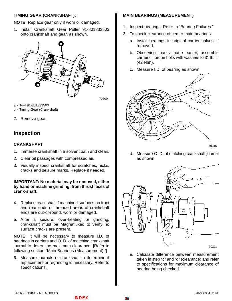
3A-56 - ENGINE - ALL MODELS 90-806934 1194
TIMING GEAR (CRANKSHAFT):
NOTE: Replace gear only if worn or damaged.
1. Install Crankshaft Gear Puller 91-801333503onto crankshaft and gear, as shown.
70309
a - Tool 91-801333503b - Timing Gear (Crankshaft)
2. Remove gear.
Inspection
CRANKSHAFT
1. Immerse crankshaft in a solvent bath and clean.
2. Clear oil passages with compressed air.
3. Visually inspect crankshaft for scratches, nicks,cracks and seizure marks. Replace if needed.
IMPORTANT: No material may be removed, eitherby hand or machine grinding, from thrust faces ofcrank-shaft.
4. Replace crankshaft if machined surfaces on frontand rear ends or threaded areas of crankshaftends are out-of-round, worn or damaged.
5. After a seizure, over-heating or grinding,crankshaft must be Magnafluxed to verify nosurface cracks are present.
NOTE: It will be necessary to measure I.D. ofbearings in carriers and O. D. of matching crankshaftjournal to determine maximum clearance. [Refer tofollowing section “Main Bearings (Measurement).”]
6. Measure journals of crankshaft to determine ifreplacement or regrinding is necessary. Refer tospecifications.
MAIN BEARINGS (MEASUREMENT)
1. Inspect bearings. Refer to “Bearing Failures.”
2. To check clearance of center main bearings:
a. Install bearings in original carrier halves, ifremoved.
b. Observing marks made earlier, assemblecarriers. Torque bolts with washers to 31 lb. ft.(42 N⋅m).
c. Measure I.D. of bearing as shown.
70310
d. Measure O. D. of matching crankshaft journalas shown.
70311
e. Calculate difference between measurementtaken in step “c” and “d” (clearance) and referto specifications for maximum clearance ofbearing being checked.
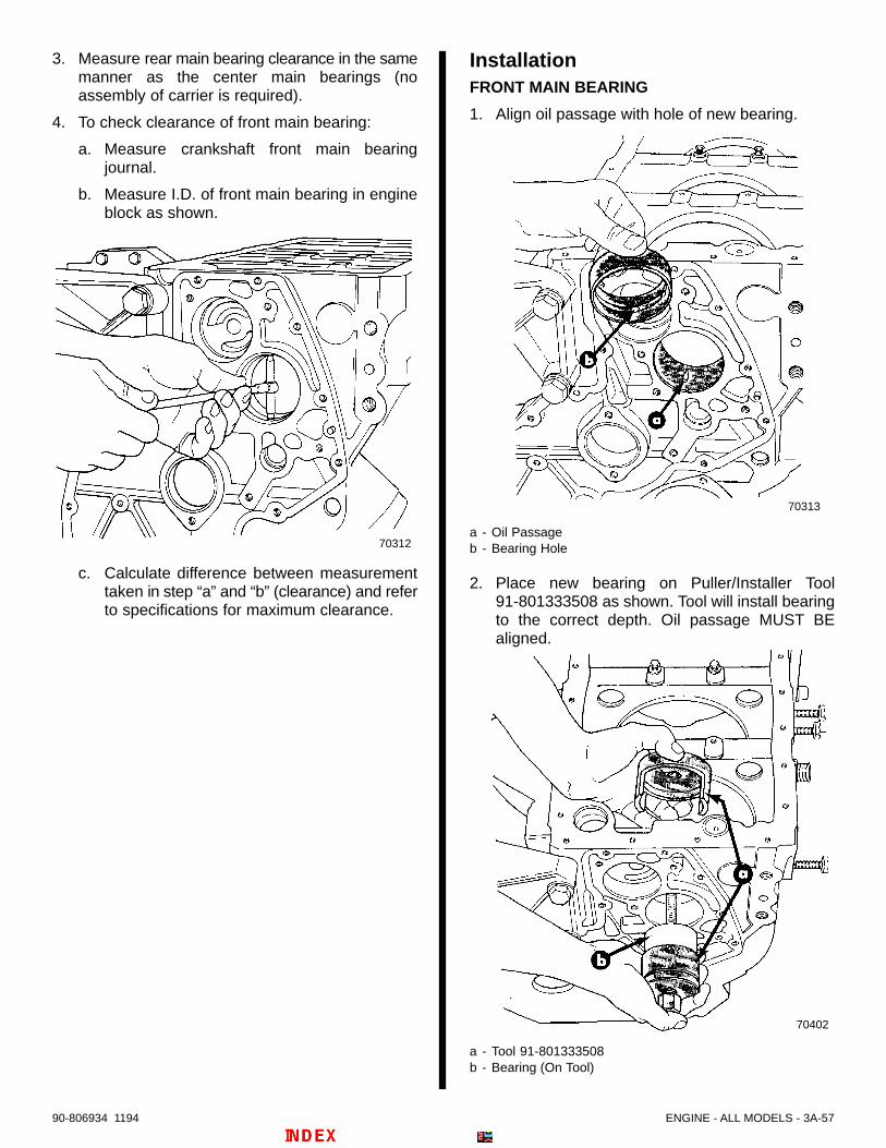
ENGINE - ALL MODELS - 3A-5790-806934 1194
3. Measure rear main bearing clearance in the samemanner as the center main bearings (noassembly of carrier is required).
4. To check clearance of front main bearing:
a. Measure crankshaft front main bearingjournal.
b. Measure I.D. of front main bearing in engineblock as shown.
70312
c. Calculate difference between measurementtaken in step “a” and “b” (clearance) and referto specifications for maximum clearance.
InstallationFRONT MAIN BEARING
1. Align oil passage with hole of new bearing.
70313
a - Oil Passageb - Bearing Hole
2. Place new bearing on Puller/Installer Tool91-801333508 as shown. Tool will install bearingto the correct depth. Oil passage MUST BEaligned.
70402
a - Tool 91-801333508b - Bearing (On Tool)

3A-58 - ENGINE - ALL MODELS 90-806934 1194
MAIN BEARING CARRIERS AND BEARINGS
1. Install new bearing shells into matching carrierhalves.
2. Lubricate bearings with clean engine oil.
70307
a - Main Bearing Shellsb - Main Bearing Carrier – Matching Halves
IMPORTANT: Piston oil jet MUST FACE FRONT(pulley end) OF ENGINE when installed.
3. Identify piston oil jet location on all main bearingcarriers.
70382
a - Piston Oil Jet Location
4. Be certain all carriers are positioned so thatpiston oil jet faces FRONT of engIne, asshown, when installing on journal. Installmatching carrier halves (marked earlier) oncrankshaft journals in their original locations.Lubricate bolts and washers with clean engine oil.Torque to 31 lb. ft. (42 N⋅m).
70404
FRONT
a - Piston Oil Jets (Face Front of Engine)
CRANKSHAFT
1. Install new timing gear with reference dots facingFRONT of engine. Install Crankshaft InstallationTool 91-801333504 on front gear as shown, toprotect front main bearing.
70404
a - Tool 91-801333504
2. Turn engine vertical, flywheel end facing up.
3. Carefully lower crankshaft, with main bearingsattached, into engine block.
4. Turn engine horizontal with bottom facing up.

ENGINE - ALL MODELS - 3A-5990-806934 1194
5. Follow instructions “a” or “b”:
a. On D3.0L/150 and D3.6L/180 Models: Turnall bearing carriers so “arrows” face up asshown, toward notches in oil pan flange andpiston oil jet faces FRONT of engine.
70405
a - Bearing Carriers With “Arrows” Facing Up (Toward Oil PanFlange)
b. On D4.2L/220 Models: Turn all bearing carri-ers so that “ROUND hole” through castingfaces up as shown, toward oil pan flange andpiston oil jet faces FRONT of engine.
70434
a - Bearing Carriers With “ROUND hole” Facing Up (TowardOil Pan Flange)
6. Install new sealing washers on all main bearing oilfeed locating screws and HAND THREAD CARE-
FULLY (to avoid damaging carrier threads) intobearing carriers. Where previously noted, installlocating screw for oil sending unit (after removingsending unit and adaptor nozzle from locatingscrew, to allow torquing). Torque all screws to 30lb. ft. (40 N⋅m).
70386
a - Main Bearing Oil Feed Locating Screw(s)b - Sealing Washer(s)
7. Reinstall adaptor nozzle and oil sending unit onproper locating screw. Tighten both securely.
REAR MAIN BEARING
IMPORTANT: Be certain to press bearing so as toprevent damage to notch arrangement in carrierwhere bearing tab aligns.
1. Using a suitable mandrel press bearing out ofcarrier.
2. When pressing new bearing into carrier, bearingtab and notch in carrier MUST BE aligned asshown.
70382
a - Bearing Tabb - Notch in Carrier

3A-60 - ENGINE - ALL MODELS 90-806934 1194
REAR MAIN BEARING CARRIER
1. Refer to Oil Seal (Rear Main) – “Installation” andinstall new seal in carrier. Lubricate lips of sealwith clean motor oil.
70406
a - Rear Main Oil Sealb - Rear Main Bearing Carrier
2. Install standard size thrust washers into flywheelside of carrier as shown. (Use Quicksilver NeedleBearing Lubricant to help keep washerspositioned.)
70407
a - Thrust Washers (Standard Size), Flywheel Side
3. Install standard size thrust washers into front(crankshaft) side of carrier. (Use QuicksilverNeedle Bearing Lubricant to help keep washerspositioned.)
70408
a - Thrust washers (Standard Size), Front (Crankshaft) Side
4. Install new O-ring into groove around carrier.(Coat with clean engine oil to assist duringinstallation.)
70408
a - O-ring

ENGINE - ALL MODELS - 3A-6190-806934 1194
5. Lubricate crankshaft journal and bearing withclean engine oil. Install rear main bearing carrierinto engine block, align marks previously made.Always be certain lubrication holes on block andcarrier align, especially when or if marks are notpresent.
70409
a - Rear Main Bearing Carrierb - Marks – Align
6. Install new O-ring into groove of thrust plate(crankshaft side).
70304
a - Thrust Plateb - O-ring
7. Install thrust plate with O-ring towards crankshaft.Tighten retaining screw securely.
8. Install new O-ring into groove of flywheel housingas shown.
70410
a - O-ring
9. Install flywheel housing. Torque bolts withwashers to 37 lb. ft. (50 N⋅m). Then, torque carriernuts with washers to 20 lb. ft. (27 N⋅m).
10. Lubricate threads of flywheel bolts with cleanengine oil and install flywheel. Torque bolts to 81lb. ft. (110 N⋅m).
3A-62 - ENGINE - ALL MODELS 90-806934 1194
CRANKSHAFT END-PLAY (AXIAL) CLEARANCE
1. Attach Dial Indicator 91-58222A1 to engine blockto check installed crankshaft end-play (axial)clearance. Reading can be taken off of counterweight as shown. Move crankshaft fore and aft inblock to obtain reading. Clearance should be.005-.013 in. (0.121-0.323mm).
70411
2. If clearance is incorrect, calculate the necessarythickness of thrust washers needed (from sizeslisted in parts manual). Install different thicknessthrust washers and recheck. Do this until properclearance is reached.
Cylinder Liners
Removal1. Remove components as needed, including
pistons, as previously outlined.
2. Remove plate from Cylinder Liner Puller91-801333502.
70412
a - Cylinder Liner Puller Tool 91-801333502b - Plate
IMPORTANT: Mark liners in a suitable fashion asto the cylinder number (to avoid mismatching topistons upon reassembly) and orientation inblock (reference to prechamber bore of head).
3. Install puller tool into cylinder and attach plate totool at bottom of liner. Remove liner(s) as shown.Note location of shim between liner andcrankcase bore relief. Also, note O-rings on linerlower part.
70413

ENGINE - ALL MODELS - 3A-6390-806934 1194
Identification
! CAUTIONFor D3.0L/150 and D3.6L/180 engines, cylinderliners are provided in two standard sizes and cor-respond to the tolerance classes: Class A orClass B. Failure to use only the Class (A or B) linerdesignated for your engine, with matching ClassA or B piston, will result in severe engine damage.
1. On D3.0L/150 and D3.6L/180 Engines: Asshown in the following, inspect underside of linerfor tolerance class identification reference mark(a small radial line). If NO MARK is present theliner is a standard size “Class A” liner. If MARKis present the liner is a standard size “Class B”liner. Refer to specifications – “Liner I.D.” for exactdimensions.
70439
70416
a - Cylinder Linerb - Tolerance Size “Class B” Reference Mark
2. On D4.2L/220 Engines: Only Class A tolerancesize liners and pistons are provided. No identifica-tion steps are needed. (There are no liner refer-ence marks. However, the piston does have theletter “A” on its crown.)
Cleaning and Inspection
CYLINDER LINERS
1. Clean liners, especially at areas as shown, andwhere O-rings fit.
70414
a - Areas for Special Cleanliness
2. Check liners for abnormal wear or cracks.Replace as needed with those parts for yourspecific model (refer to preceding“Identification”).
3. Measure liners for out-of-round or taper with a dialor bore gauge, taking readings at three differentvertical positions and at opposite sides of the linerbore. Refer to specifications.
4. When cylinder liner wear is within specificationslight honing of the liner bore is allowed. Replaceif liners are not within specifications. Refer topreceding section Cylinder Liners –“Identification.”

3A-64 - ENGINE - ALL MODELS 90-806934 1194
CYLINDER LINER (BLOCK) BORES
1. Thoroughly clean the engine block with suitablesolvent and blow dry with compressed air. Inspectfor cracks or flaws.
2. Check cylinder head mating surfaces of block andarea around cylinder liner bores for abnormalwear or damage.
3. Check block bores for damage and cleanliness,especially the flanges and counterbores forcylinder liners as shown.
70415
a - Areas for Special Cleanliness
4. If any checks or inspections reveal unacceptableconditions replace parts as needed with those foryour specific model.
InstallationCylinder liners on all engines are required to protrude(or rise above the surface of the block) .00004 - .0023in. (0.01 - 0.06mm). By using one of three shimsavailable (placed between the liner flange and theblock during installation of liner) it is possible to obtainthe correct protrusion.
1. Make seven cylindrical spacers as shown for usefollowing.
50490
4 in. (102mm)
5/8 in. (16mm)
2. To determine the correct shim thickness neededfor each liner follow instructions “a” – “e”:
! CAUTIONBe certain cylinder liners are fully seated in blockin the following instructions or incorrectmeasurements will occur causing engineperformance problems or severe engine damage.
a. Unless being replaced, install liners in samecylinder block bore as marked or noted upondisassembly WITHOUT shims or O-rings.
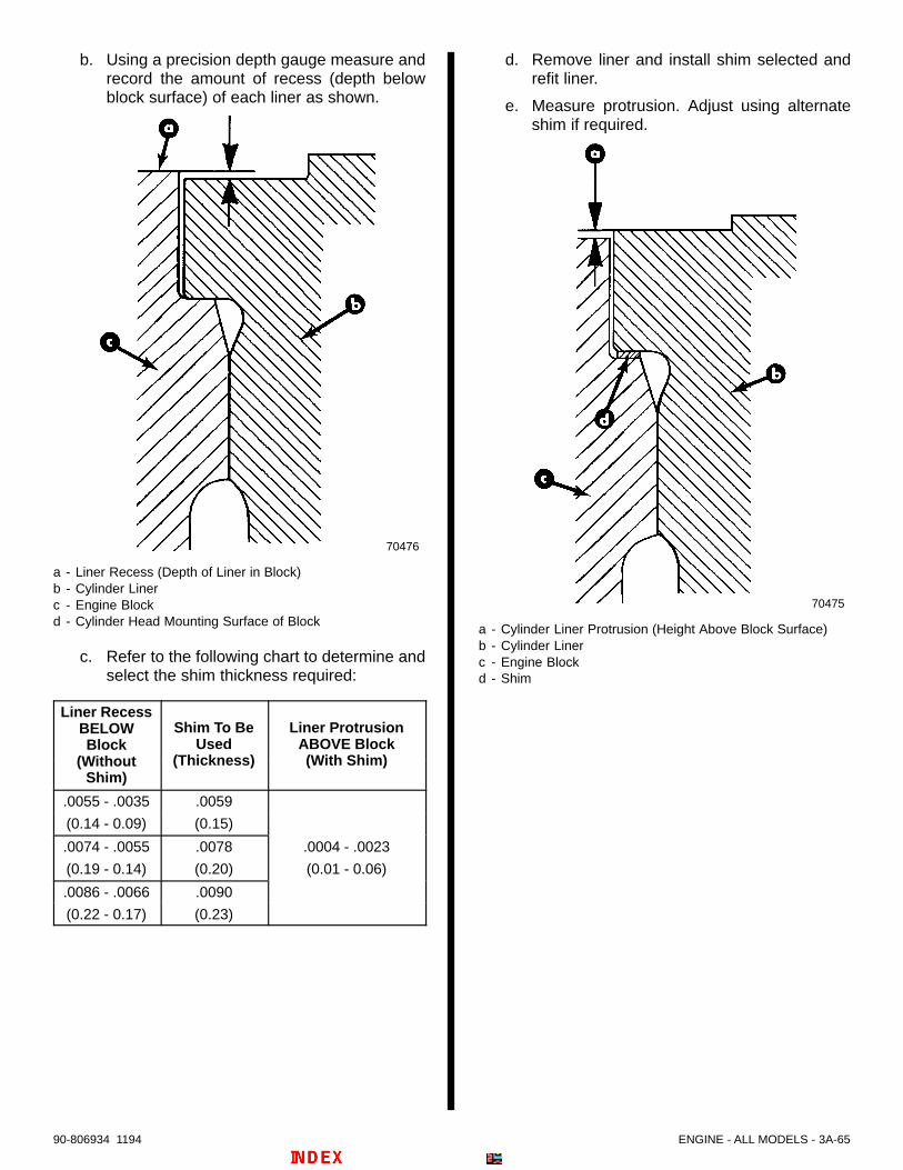
ENGINE - ALL MODELS - 3A-6590-806934 1194
b. Using a precision depth gauge measure andrecord the amount of recess (depth belowblock surface) of each liner as shown.
70476
a - Liner Recess (Depth of Liner in Block)b - Cylinder Linerc - Engine Blockd - Cylinder Head Mounting Surface of Block
c. Refer to the following chart to determine andselect the shim thickness required:
Liner RecessBELOWBlock
Shim To BeUsed
Liner ProtrusionABOVE Block
(WithoutShim)
(Thickness) (With Shim)
.0055 - .0035 .0059
(0.14 - 0.09) (0.15)
.0074 - .0055 .0078 .0004 - .0023
(0.19 - 0.14) (0.20) (0.01 - 0.06)
.0086 - .0066 .0090
(0.22 - 0.17) (0.23)
d. Remove liner and install shim selected andrefit liner.
e. Measure protrusion. Adjust using alternateshim if required.
70475
a - Cylinder Liner Protrusion (Height Above Block Surface)b - Cylinder Linerc - Engine Blockd - Shim

3A-66 - ENGINE - ALL MODELS 90-806934 1194
3. Tighten liners, with appropriate shims, to 22 lb. ft.(30 N⋅m) using cylindrical spacers (made in Step1) and formed spacer-washers as shown.
70417
a - Head Boltsb - Cylindrical Spacersc - Formed Spacer-Washers
4. Recheck-liners for proper amount of protrusionusing liner gauge bar 91-184812A1 (S.A.E.) or91-801333509 (Metric) and appropriate dialgauge as shown. If not as specified, adjustprotrusion as previously outlined until each lineris protruded .0004 - .0023 in. (0.01 - 0.06mm)above block.
71178
5. Remove liners in order, keeping appropriateshims matched to liners.
6. Install O-rings in grooves as shown.
71207
a - Shimb - Upper O-Ring Groovec - Brown or Red (Upper) O-Ringd - Black O-Ringse - Red O-Ring
D3.0L/150 and D3.6L/180 Engine Liners with OneUpper and Three Lower O-Rings
70416
a - Shimb - Black O-Ringsc - Red O-Ring
D3.0L/150 and D3.6L/180 and D4.2L/220 EngineLiners with Three Lower O-Rings Only (No UpperGroove or O-Ring)

ENGINE - ALL MODELS - 3A-6790-806934 1194
7. Lubricate LOWER centering collars in engineblock (those areas where lower liner O-rings sealagainst the bore) with Needle Bearing Lubricant92-42649A1 or clean engine oil as shown.
IMPORTANT: DO NOT lubricate upper bore areaeven on liners which have an upper brown or redO-ring.
NOTE: Liner shown fitted ONLY for visual clarity. DONOT install liners in this step.
50491
a - Lubricate This Area Of Engine BLOCK (Lower CenteringCollars)
8. Apply Loctite Master Gasket 92-12564--1 orLoctite 620 (obtain locally) to liner surfaces ASSHOWN.
IMPORTANT: DO NOT apply Loctite to shim, shimcontact surfaces, or upper O-ring (if soequipped).
70414
a - Apply Loctite To These Areas ONLY
9. Install liners in block, being careful not to damageO-rings or distort shim. Hold liners securely inposition with head bolts, cylindrical spacers(made previously) and head bolt formed,spacer-washers as shown. Torque bolts to 22 lb.ft. (30 N⋅m). Allow Loctite to dry. (Do not releaseliners for approximately 1-1/2 to 2 hours.)
70417
70418
a - Head Boltsb - Cylindrical Spacersc - Formed, Spacer-Washers
10. Once again, verify cylinder liner protrusion andmake corrections if required.
11. Continue engine assembly. Refer to appropriatesections.

5
A
A A
A
A
A
A
7
6
4
3
2
1ELECTRICAL SYSTEM
STARTING SYSTEM
Note: Refer to the following Service Bulletins regarding this section.
SB 97-12 Battery and Battery Cable Requirements for MerCruiser D-Tronic Diesels. . . . . . . . . .
SB 91-1 New Battery and Battery Cable Requirements for MerCruiserProducts. . . . . . . . . .

4A-0 – STARTING SYSTEM 90-806934 1194
Table Of ContentsPage
Starter Identification Number Location 4A-1. . . . . . . . . . . Starter Motor Specifications 4A-1. . . . . . . . . . . . . . . . . . . . Sealants – Lubricants 4A-1. . . . . . . . . . . . . . . . . . . . . . . . . General 4A-1. . . . . . . . . . . . . . . . . . . . . . . . . . . . . . . . . . . . . Replacement Parts 4A-1. . . . . . . . . . . . . . . . . . . . . . . . . . . Battery 4A-1. . . . . . . . . . . . . . . . . . . . . . . . . . . . . . . . . . . . . .
Battery Cables 4A-2. . . . . . . . . . . . . . . . . . . . . . . . . . . . Maintenance 4A-2. . . . . . . . . . . . . . . . . . . . . . . . . . . . . . Testing 4A-2. . . . . . . . . . . . . . . . . . . . . . . . . . . . . . . . . . . Storage 4A-3. . . . . . . . . . . . . . . . . . . . . . . . . . . . . . . . . .
Starting Circuit Description 4A-3. . . . . . . . . . . . . . . . . . . . Starting System Components 4A-4. . . . . . . . . . . . . . . . . . Starter – Exploded View 4A-5. . . . . . . . . . . . . . . . . . . . . . . Periodic Inspection 4A-6. . . . . . . . . . . . . . . . . . . . . . . . . . . Starter Motor Repair 4A-6. . . . . . . . . . . . . . . . . . . . . . . . . .
Starter Motor Removal 4A-6. . . . . . . . . . . . . . . . . . . . . Solenoid Switch 4A-6. . . . . . . . . . . . . . . . . . . . . . . . . .
Removal 4A-6. . . . . . . . . . . . . . . . . . . . . . . . . . . . . . Installation 4A-7. . . . . . . . . . . . . . . . . . . . . . . . . . . . .
Starter Motor Disassembly 4A-8. . . . . . . . . . . . . . . . . . Cleaning and Inspection 4A-9. . . . . . . . . . . . . . . . . . . . Armature Tests 4A-10. . . . . . . . . . . . . . . . . . . . . . . . . . .
Test For Shorts 4A-10. . . . . . . . . . . . . . . . . . . . . . . . Test For Ground 4A-10. . . . . . . . . . . . . . . . . . . . . . . Loose Electrical Connections 4A-10. . . . . . . . . . . . Turning The Commutator 4A-10. . . . . . . . . . . . . . .
Field Coil Tests 4A-10. . . . . . . . . . . . . . . . . . . . . . . . . . . Test For Open Circuit 4A-10. . . . . . . . . . . . . . . . . . Test For Ground 4A-11. . . . . . . . . . . . . . . . . . . . . . .
Starter Motor Reassembly 4A-11. . . . . . . . . . . . . . . . . . . . Starter Motor Installation 4A-15. . . . . . . . . . . . . . . . . . . . .
4A - STARTING SYSTEM

STARTING SYSTEM - 4A-190-806934 1194
Starter Identification NumberLocation
70809
a - I.D. Number on Starter
Starter Motor SpecificationsDESCRIPTION SPECIFICATION
I.D. Number 0 001 362 3--
Engine Rotation Left Hand (Counterclockwise)
No-Load Test 11.5 Volts125 Amps7000 RPM
CommutatorDiameter
New – 1.772 in. (45mm)Min. – 1.673 in. (42.5mm)
CommutatorOut-of-Round Max. – .001 in. (.03mm)
MinimumBrush Length .335 in. (8.5mm)
ArmatureClearance .004 to .016 in. (.1 to .4mm)
TorqueSpecifications Tighten all fasteners securely
Sealants – LubricantsQuicksilver Liquid Neoprene 92-25111
SAE 10W Oil Obtain Locally
GeneralThe starter motor is designed to operate under greatoverload and produce a high horsepower for its size.It can do this only for a short time, since considerableheat accumulates and can cause serious damage.For this reason, the cranking motor must never beused for more than 15 seconds at any one time.Cranking should not be repeated without a pause ofat least 2 minutes to permit the heat to escape.
Replacement Parts! WARNING
Electrical system components on this engine arenot external ignition protected. DO NOT STOREOR UTILIZE GASOLINE ON BOATS EQUIPPEDWITH THESE ENGINES, UNLESS PROVISIONSHAVE BEEN MADE TO EXCLUDE GASOLINEVAPORS FROM ENGINE COMPARTMENT (REF:33 CFR) Failure to comply could result in fire,explosion and/or severe personal injury.
BatteryIMPORTANT: Boating industry standards (BIA,ABYC, etc.) federal standards and Coast Guardregulations must be adhered to when installingor replacing battery or cables. Be sure batterycable installation meets the pull testrequirements and that positive battery terminalis properly insulated in accordance withregulations.
IMPORTANT: Engine electrical system isnegative (–) ground. It is recommended (requiredin some states) that battery be installed in anenclosed case. Refer to regulations for your area.
1. Select a battery that meets all of the followingspecifications:
a. 12-volt marine type.
b. Tapered post connectors or side terminalconnectors (Do not use a battery with wingnut connectors).
c. Battery capacity rating of at least:
Engine(cyl./type) CID (L) Minimum Required
Cranking Battery Size
5 In-Line 183 (3.0)
6 In-Line 219 (3.6) 750 cca, 950 mca
6 In-Line 254 (4.2) or 180 Ah

4A-2 – STARTING SYSTEM 90-806934 1194
Battery Cables1. Select proper size positive (+) and negative (–)
battery cables, using chart. Battery should belocated as close to engine as possible.
IMPORTANT: Terminals must be soldered tocable ends to ensure good electrical contact. Useelectrical grade (resin flux) solder only. Do notuse acid flux solder, as it may cause corrosionand a subsequent failure.
BatteryCable Length
MinimumCable Gauge
Up to 3-1/2 ft. (0.9m)3 - 3-3/4 ft. (0.9 - 1.1m)3-3/4 - 4-3/4 ft. (1.1 - 1.4m)4-3/4 - 6 ft. (1.4 - 1.8m)6 - 7-1/2 ft. (1.8 - 2.3m)7-1/2 - 9-1/2 ft. (2.3 - 2.9m)
9-1/2 - 12 ft. (2.9 - 3.7m)12 - 15 ft. (3.7 - 4.6m)15 - 19 ft. (4.6 - 5.8m)
2 (35mm2)1 (50mm2)0 (50mm2)
00 (70mm2)000 (95mm2)
0000 (120mm2) 00 (70mm2) 000 (95mm2)0000 (120mm2)
Both positive (+) and negative (–) cables
Two cables of specified gauge required for positive and tworequired for negative.
Maintenance
! WARNING
Hydrogen gases that escape from the batteryduring charging are explosive. Be sure thatbattery area is well ventilated and that bilgeblower is in operation when charging. Do notsmoke or allow sources of spark or open flame inarea when charging battery. Do not recharge aweak battery in the boat.
! WARNING
Battery electrolyte is a corrosive acid and shouldbe handled with extreme care. If electrolyte isspilled or splashed on any part of the body,immediately flush the exposed area with liberalamounts of water and obtain medical aid as soonas possible. Safety glasses and rubber glovesare recommended when handling batteries.
! WARNING
Always disconnect battery cables from batterybefore working around electrical systemcomponents to prevent injury to yourself ordamage to electrical system.
! CAUTIONTo prevent damage to the electrical system besure to adhere to the following:a. When installing battery, be sure to FIRST
connect the (+) positive battery cable to the(+) positive battery terminal, and THENconnect the (–) negative battery cable to the(–) negative battery terminal.
b. Never disconnect the battery cables while theengine is running.
c. Check battery condition periodically.d. Make sure that battery leads are kept clean
and tight.
! WARNING
Do not use jumper cables and a booster batteryto start engine. Damage to various electricalcomponents may occur. Do not recharge a weakbattery in the boat. Remove battery and rechargein a ventilated area away from fuel vapors,sparks or flames.
Testing
Place battery under heavy load (as during enginecranking or with a variable resistor tester) and testcell voltage while under load.
Certain conditions must be met before testing.
a. Battery temperature must be between 60° Fand 100° F (15° C – 38° C).
b. Electrolyte level must be correct in all cells.c. Battery must be at least half charged.d. No obvious defects.
1. Check voltage per manufacturer’s specifications.2. If readings are low, recharge and retest.3. If readings remain low, battery should be replaced.
! CAUTIONTest battery in well ventilated area as gasesgiven off by battery are hazardous.

STARTING SYSTEM - 4A-390-806934 1194
Storagea. Remove battery and clean exterior.b. Check fluid level and fill if low.c. Cover terminals and bolts with light coat of
grease.d. Set battery on wood or in carton, store in cool, dry
place.e. Check every 20 days for fluid level and slow
charge.IMPORTANT: A discharged battery can bedamaged by freezing.
Starting Circuit DescriptionThis is a general description of the positive (+12V)current flow thru the starting circuit.
The starter used on the diesel engine is a high torque12 volt motor capable of cranking high compressionengines. There are 3 circuit breakers used in thecircuit to prevent overload damage to wires and othercomponents. A neutral start switch is located in thecircuit to prevent starter operation in forward orreverse gears. Due to the diesel’s design, the engineis started and stopped by separate buttons locatedon the instrument panel. The ignition switch is usedto control the start button and instrumentation. Arelay is used in the start button circuit to allow higheramperage to the starter solenoid.

4A-4 – STARTING SYSTEM 90-806934 1194
Starting System Components
BSI
73846
Note 1
Note 1
Note 2
Note 3
(+)
(–)
BLK/YEL 123 4 5
67
12
4
3
56 RED/PUR
7 YEL/RED
8
10
Note 2
Note 4
Note 3
1 - Ignition (Start) Switch2 - 20 Ampere Fuse3 - Engine Stop Switch (See Note 4.)4 - Remote Control Neutral Safety Switch
[MCM (Stern Drive) Only]5 - Start Relay6 - Circuit Breaker(s)7 - Wire Junction8 - Starter Motor9 - Ground Stud10- Transmission Neutral Safety Switch [MIE (Inboard) Only]11- Injection Pump Solenoid -For Engine Stop (See Note 4.)
Note 1 : Wire routing on MIE (Inboard) engine and/orinstrument harness.
Note 2 : Wire routing on MCM (Stern Drive) engineand/or instrument harness.
Note 3 : Wires connected together with hex screwand nut, coated with liquid neoprene and protectedby a rubber sleeve.
Note 4 : Shown for clarification of complete start andstop circuits.

50185
a - Solenoidb - Drive Gear Housingc - Shift Leverd - Snap Ringe - Retainerf - Drive Gear
Assemblyg - Studsh - Bushing Platei - Field Frame
j - Armaturek - Brushl - Brush Holder Framem - End Framen - Shimso - C-Clipp - Rubber Sealq - Cap
STARTING SYSTEM - 4A-590-806934 1194
Starter – Exploded View

4A-6 – STARTING SYSTEM 90-806934 1194
Periodic InspectionStarter motor and solenoid are completely enclosedin the drive housing to prevent entrance of moistureand dirt. However, periodic inspection is required.
a. Inspect terminals for corrosion and looseconnections.
b. Inspect wiring for frayed and worn insulation.
c. Check mounting nuts for tightness.
Starter Motor Repair
Starter Motor Removal
! WARNING
Always disconnect battery cables from batterybefore working around electrical systemcomponents to prevent injury to yourself ordamage to electrical system.
1. Disconnect battery cables from battery.
2. Disconnect wires from solenoid.
3. Remove mounting nuts and lock washers.
4. Pull starter motor away from flywheel andremove.
70810
a - Battery Cableb - Red Wirec - Solenoid Wired - Mounting Nuts with Lockwashers
(2 Total, One Hidden In This View)
Solenoid Switch
REMOVAL
1. Remove starter motor as previously outlined.
2. Remove nut as shown, from field coil wire.
70811
a - Nut
3. Remove 3 screws retaining solenoid.
70812
a - Retaining Screws (3)

STARTING SYSTEM - 4A-790-806934 1194
4. Slide solenoid plunger off shift fork.
70813 70814
a - Solenoid Plungerb - Shift Fork
INSTALLATION
1. Slide solenoid plunger on shift fork while holdingdrive gear out as shown.
70833
a - Solenoid Plungerb - Shift Forkc - Drive Gear (Hold “Out”)
2. Install solenoid to starter with 3 screws. Tightensecurely.
70812
a - Solenoid Retaining Screws (3)
3. Place field coil wire on terminal and secure withhex nut.
70811
a - Field Coil Wireb - Hex Nut

4A-8 – STARTING SYSTEM 90-806934 1194
Starter Motor Disassembly1. Remove solenoid as outlined previously.
2. Remove cap screws and cap.
70814
a - Cap Screwsb - Cap
3. Remove rubber seal, C-clip, shims and hex nuts.
70815
a - Rubber Sealb - C-clipc - Shimsd - Hex Nuts
4. Remove end frame.
70816
a - End Frame
5. Remove field frame and brush holder from drivegear housing. Remove studs.
70817
a - Field Frame and Brush Holderb - Drive Gear Housingc - Studs

STARTING SYSTEM - 4A-990-806934 1194
6. Remove hex nut, wave washer and bolt. Then, liftarmature, drive gear assembly and shift leverfrom drive gear housing.
70819
a - Hex Nut and Wave Washerb - Bolt
7. Slide retainer off snap ring.
70820
a - Retainerb - Snap Ring
8. Pry snap ring out of groove and remove. Slideretainer, drive assembly and bushing plate fromarmature.
70821
a - Snap Ringb - Retainerc - Drive Assemblyd - Bushing Platee - Armature
Cleaning and InspectionWith starting motor completely disassembled,except for removal of field coils, component partsshould be cleaned and inspected. Defective partsshould be replaced or repaired.
1. Clean all starting motor parts but do not usedissolving solvents for cleaning over-runningclutch, armature and field coils. Such a solventwould dissolve grease packed in clutchmechanism and damage armature and field coilinsulation.
2. Test over-running clutch action. Pinion shouldturn freely in over-running direction and must notslip in cranking direction. Check pinion teeth.Check spring for tension and drive collar for wear.If drive assembly is defective replace starter.
3. Check that brush holders are not damaged orbent and will hold brushes against commutator.
4. Check brushes. Replace if pitted or worn.
5. Inspect armature commutator. If rough or out-of-round, turn down and undercut. Inspect points(where armature conductors join commutatorbars) for good, firm connection. Burnedcommutator bar usually is evidence of poorconnection.

4A-10 – STARTING SYSTEM 90-806934 1194
Armature Tests
TEST for SHORTS
Check armature for shorts by placing on growler andholding hack saw blade over armature core whilerotating armature. If saw blade vibrates, armature isshorted. After cleaning between commutator bars,recheck. If saw blade still vibrates, replace armature.
01441
TEST for GROUND
1. With continuity meter, place one lead on armaturecore or shaft and other lead on commutator.
2. If meter hand moves armature is grounded andmust be replaced.
01440
LOOSE ELECTRICAL CONNECTIONS
If open soldered connection of armature tocommutator leads is found during inspection, resolderwith rosin flux.
IMPORTANT: NEVER USE ACID FLUX ONELECTRICAL CONNECTIONS.
TURNING the COMMUTATOR
When inspection shows commutator roughness,clean as follows:
1. Turn down commutator in a lathe until thoroughlycleaned.
2. Recheck armature for shorts as outlined.
Field Coil Tests
TEST for OPEN CIRCUIT
1. With continuity meter, place one lead on eachend of field coils (insulated brush and field con-nector bar).
2. Continuity should exist. If meter does not move,field coils are open and starter must be replaced.
70822

STARTING SYSTEM - 4A-1190-806934 1194
TEST FOR GROUND
IMPORTANT: Be sure that positive brushes andleads do not contact field frame assembly duringtest, or false reading will result.
1. With continuity meter, place one lead on fieldconnector bar and other lead on ground (fieldframe).
2. NO continuity should exist. If meter moves, fieldcoils are grounded and starter must be replaced.
70823
Starter Motor Reassembly1. Brush Replacement.
a. Make 4 brush fixtures out of stiff wire (wirecoat hanger) as shown.
3/4 in.(19mm)
1 in.(25.4mm)
1 in.(25.4mm)
(Actual Size)
b. Cut off worn brush lead at field coil and brushholder frame.
70824
70825
a - Field Coilb - Brush Holder Framec - Brush Lead

4A-12 – STARTING SYSTEM 90-806934 1194
c. Install new brush leads to holes located inbrush holder frame, and fasten to field coilwith screws and hex nuts provided with newbrushes.
70826
d. Check to see that brush springs are in place.Push brushes into holders and hold in placeusing brush fixtures.
70827
a - Brush (Holding) Fixtures
2. Assemble components on armature as follows:
a. Lubricate drive end of shaft with SAE 10WOil. DO NOT over-lubricate. Install bushingplate, drive assembly, retainer and snap ringas shown.
70821
a - Bushing Plate (Bushing facing windings)b - Drive Assemblyc - Retainerd - Snap Ringe - Armature
b. Using a deep-well socket and brass hammer,tap snap ring over shoulder of shaft and intogroove as shown.
70820
a - Snap Ringb - Shoulder of Shaft

STARTING SYSTEM - 4A-1390-806934 1194
c. Install a universal puller plate on drive gearassembly. Place in arbor press as shown.
Compress snap-ring into groove using a pairof pliers while lightly pressing down on end ofshaft, until retainer covers snap-ring.
70828
3. Insert shift lever into drive gear housing asshown. Do not install bolt at this time.
70829
a - Shift Leverb - Drive Gear Housing
4. Lubricate bushing in drive gear housing with onedrop of SAE 10W oil. DO NOT over-lubricate.Install armature shaft into drive gear housing,engaging shift lever into drive gear assembly asshown.
70829
70830
a - Bushing (In Drive Gear Housing)b - Armaturec - Drive Gear Housingd - Shift Levere - Point(s) of Engagement
5. Insert bolt thru housing and shift lever. Fastenwith wave washer and hex nut. Tighten securely.
70831
a - Boltb - Wave Washerc - Hex Nut
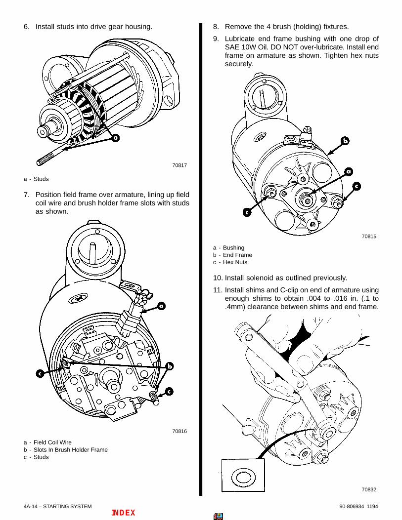
4A-14 – STARTING SYSTEM 90-806934 1194
6. Install studs into drive gear housing.
70817
a - Studs
7. Position field frame over armature, lining up fieldcoil wire and brush holder frame slots with studsas shown.
70816
a - Field Coil Wireb - Slots In Brush Holder Framec - Studs
8. Remove the 4 brush (holding) fixtures.
9. Lubricate end frame bushing with one drop ofSAE 10W Oil. DO NOT over-lubricate. Install endframe on armature as shown. Tighten hex nutssecurely.
70815
a - Bushingb - End Framec - Hex Nuts
10. Install solenoid as outlined previously.
11. Install shims and C-clip on end of armature usingenough shims to obtain .004 to .016 in. (.1 to.4mm) clearance between shims and end frame.
70832

STARTING SYSTEM - 4A-1590-806934 1194
12. Install rubber seal and cap. Tighten screwssecurely.
70814
a - Rubber Sealb - Capc - Screws
Starter Motor Installation1. Install starter motor to bell-housing with lock
washers and hex nuts. Tighten 50 lb. ft. (68 N⋅m).
2. Connect wires to solenoid as shown. Tightensecurely.
3. Coat terminals with Quicksilver Liquid Neoprene.
4. Connect battery cables to battery.
70810
a - Lock Washers and Hex Nuts (2, One Hidden In This View)b - Red Wirec - Solenoid Wire (Yellow/Red)d - Positive (+) Battery Cable

4
B73198
ELECTRICAL SYSTEMS
GLOW PLUG SYSTEM

4B-0 - GLOW PLUG SYSTEM 90-806934 1194
Table of ContentsPage
Identification 4B-1. . . . . . . . . . . . . . . . . . . . . . . . . . . . . . . . Specifications 4B-1. . . . . . . . . . . . . . . . . . . . . . . . . . . . . . .
General 4B-1. . . . . . . . . . . . . . . . . . . . . . . . . . . . . . . . . D3.0L/150 Engines 4B-1. . . . . . . . . . . . . . . . . . . D3.6L/180 and D4.2L/220 Engines 4B-2. . . . .
Torque Specifications 4B-2. . . . . . . . . . . . . . . . . . . . . . . . Tools/Lubricants/Adhesives 4B-2. . . . . . . . . . . . . . . . . . . Glow Plugs 4B-2. . . . . . . . . . . . . . . . . . . . . . . . . . . . . . . . .
Testing 4B-2. . . . . . . . . . . . . . . . . . . . . . . . . . . . . . . . . . Removal 4B-3. . . . . . . . . . . . . . . . . . . . . . . . . . . . . . . . Installation 4B-3. . . . . . . . . . . . . . . . . . . . . . . . . . . . . . .
Water Temperature Switch 4B-4. . . . . . . . . . . . . . . . . . . Testing 4B-4. . . . . . . . . . . . . . . . . . . . . . . . . . . . . . . . . . Removal 4B-4. . . . . . . . . . . . . . . . . . . . . . . . . . . . . . . . Installation 4B-4. . . . . . . . . . . . . . . . . . . . . . . . . . . . . . .
Pre-Glow Relay and Power Relay System 4B-5. . . . . . Glow Plug Circuit 4B-6. . . . . . . . . . . . . . . . . . . . . . . . . . . .
Description 4B-6. . . . . . . . . . . . . . . . . . . . . . . . . . . . . . Diagram 4B-6. . . . . . . . . . . . . . . . . . . . . . . . . . . . . . . . . Testing 4B-7. . . . . . . . . . . . . . . . . . . . . . . . . . . . . . . . . .
4B - GLOW PLUG SYSTEM
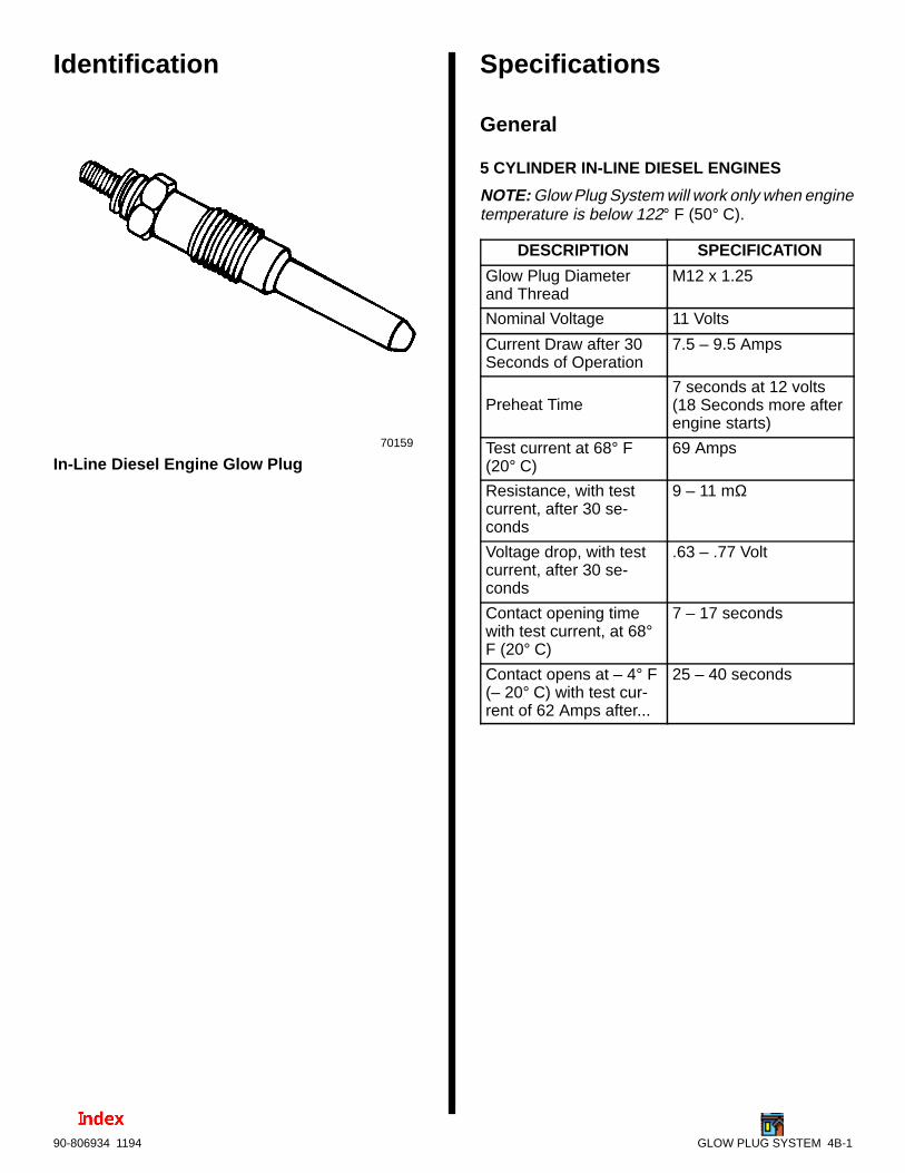
GLOW PLUG SYSTEM 4B-190-806934 1194
Identification
70159
In-Line Diesel Engine Glow Plug
Specifications
General
5 CYLINDER IN-LINE DIESEL ENGINES
NOTE: Glow Plug System will work only when enginetemperature is below 122° F (50° C).
DESCRIPTION SPECIFICATION
Glow Plug Diameterand Thread
M12 x 1.25
Nominal Voltage 11 Volts
Current Draw after 30 Seconds of Operation
7.5 – 9.5 Amps
Preheat Time7 seconds at 12 volts(18 Seconds more afterengine starts)
Test current at 68° F(20° C)
69 Amps
Resistance, with testcurrent, after 30 se-conds
9 – 11 mΩ
Voltage drop, with testcurrent, after 30 se-conds
.63 – .77 Volt
Contact opening timewith test current, at 68°F (20° C)
7 – 17 seconds
Contact opens at – 4° F(– 20° C) with test cur-rent of 62 Amps after...
25 – 40 seconds

4B-2 - GLOW PLUG SYSTEM 90-806934 1194
6 CYLINDER IN-LINE DIESEL ENGINES
DESCRIPTION SPECIFICATION
Glow Plug Diameterand Thread
M12 x 1.25
Nominal Voltage 11 Volts
Current Draw after 30 Seconds of Operation
7.5 – 9.5 Amps
Preheat Time7 Seconds at 12 volts
(18 Seconds more afterengine starts)
Test current at 68° F(20° C)
79 Amps
Voltage drop, with testcurrent, after 30 se-conds
.50 – .60 Volt
Contact opening timewith test current, at 68°F (20° C)
11 – 26 seconds
Contact opens at – 4° F(– 20° C) with test cur-rent of 62 Amps afterspecified time.
35 – 50 seconds
Torque SpecificationsDESCRIPTION Lb. Ft. N·m
Glow Plug 17 23
Tools/Lubricants/AdhesivesDESCRIPTION PART NUMBER
Volt/Ohm Meter 91-93572
Liquid Neoprene 92-25711--1
Quicksilver Perfect Seal 92-34227--1
Glow Plugs
Testing
! WARNING
Always disconnect battery cables from battery beforeworking around electrical system components to pre-vent injury to yourself or damage to the electrical sys-tem.
1. Disconnect battery cables from battery.
2. Remove hex nut and washer from glow plug ter-minal. Remove voltage supply wire when pres-ent.
3. Carefully bend connecting bridge away from glowplug terminal.
b
a
c
70191
a - Voltage Supply Wire (BLUE/WHITE Wire)b - Glow Plug Terminalc - Connecting Bridge
4. Connect ohmmeter between engine ground andglow plug terminal. Continuity should exist; if nocontinuity exists, glow plug is faulty.
5. If glow plug is removed, connect ohmmeter be-tween glow plug terminal (+) and glow plug exter-nal (–) threads. Continuity should exist; if no conti-nuity exists, glow plug is faulty. Refer to“Specifications” for values.
73198
a - Terminal (+)b - External Threads (–)
b
a

GLOW PLUG SYSTEM 4B-390-806934 1194
Removal
! WARNING
Always disconnect battery cables from battery beforeworking around electrical system components to pre-vent injury to yourself or damage to the electrical sys-tem.
1. Disconnect battery cables from battery.
2. Remove hex nut and washer from glow plug ter-minal. Remove voltage supply wire when pres-ent.
3. Carefully bend connecting bridge away from glowplug terminal.
70190
b
a
c
a - Voltage Supply Wire (BLUE/WHITE Wire)b - Glow Plug Terminalc - Connecting Bridge
IMPORTANT: Avoid contaminating cylinders.Clean any dirt away from around glow plug beforeremoval.
4. Clean any dirt away from around glow plug andremove glow plug.
Installation1. Clean seat area and install glow plug. Torque to
specifications.
2. Install electrical connections or connectors onglow plug terminals. (See note.)
NOTE: Be certain contact area of connecting bridgeis clean and free of corrosion or debris before instal-ling on glow plug terminals. See that wire terminalconnectors are clean and free of corrosion.
c
b
a
70191
a - Contact Areas That MUST BE Clean b - Voltage Supply Wire Ring Terminal Endc - Connecting Bridge
! CAUTIONAvoid shorting electrical circuits. Some voltagesupply wire ring terminal ends are large andcould contact the cylinder head which isgrounded (–). Be certain ring terminal is isolatedto the glow plug terminal.
3. Attach connecting bridge to glow plug terminalwith washer and hex nut. Be certain that theBLUE/WHITE voltage supply wire is present,where previously removed, and not contactingthe cylinder head.
4. Coat all terminal connections with QuicksilverLiquid Neoprene.
5. Connect battery cables to battery.

4B-4 - GLOW PLUG SYSTEM 90-806934 1194
Water Temperature Switch
Testing1. Before testing observe the following to obtain
proper results:
a. Engine must be cold, less than 122° F (50° C).
b. Fuse at instrument panel is not defective(blown).
c. Make sure wiring harness connector is at-tached to water temperature switch.
2. Turn ignition key to “ON” position.
3. Check for battery voltage at GREEN wire in har-ness connector. If voltage is present, switch is notdefective.
4. If voltage is not present, check for battery voltageat PURPLE wire in connector. If voltage is pres-ent, replace switch. If voltage is not present, PUR-PLE wire is open. Refer to SECTION 4E - “WiringDiagrams”.
70192
ab
c
74284
b
a
c
a - Wiring Harness Connectorb - Water Temperature Switchc - Last Cylinder Head (Closest to Flywheel)
Locations of Water Temperature Switch
Removal1. Refer to SECTION 6B and drain coolant from
closed cooling system into a suitable container.
2. Unplug the wiring harness connector.
3. Remove the sender and sealing washer.
74284
a
cb
a - Wiring Harness Connectorb - Water Temperature Switchc - Sealing Washer
Typical
Installation1. Coat threads of sender with Quicksilver Perfect
Seal.
2. Install sealing washer and thread sender into cyl-inder head. Tighten securely.
3. Plug in harness connector.
4. Refer to and fill closed cooling system with ap-proved coolant.
5. Run engine to operating temperature and checkfor leaks.
6. Follow instructions in SECTION 6B. Allow engineto cool and check coolant level as required.

GLOW PLUG SYSTEM 4B-590-806934 1194
Pre-Glow Relay and PowerRelay SystemRefer to “Glow Plug Circuit” information for diagramsand test procedures.
IMPORTANT: Check the following before testing:
• All wires in circuit are connected.
• Plug-in connectors are fully engaged.
• Battery is fully charged.
• All connections are tight and corrosionfree.
• Closed cooling system is cold, belowapproximately 122 ° F. (50° C).
• Circuit breakers on electrical box are notopen (tripped).
• Fuse at instrument panel is not defective(blown).

4B-6 - GLOW PLUG SYSTEM 90-806934 1194
Glow Plug Circuit
DescriptionThe glow plug circuit is controlled by the water tem-perature located in the closed cooling system.
When the coolant is cold, below approximately 122°F. (50° C), the switch is closed, allowing current toflow to the pre-glow relay and pre-heat light. The relayis timed to prevent the glow plugs from staying on toolong and overheating. When the coolant is hot, aboveapproximately 122° F. (50° C) the glow plugs are notneeded to start the engine.
Diagram
73876
b
cd
e
a
fg
h
i
J
1
2
3 4
5 6
78
910
11
11
2
10
9
56
7
8
1
k
l m
See Note.
a - Glow Plugb - Water Temperature Senderc - Preheat Indicator Lampd - Ignition Switche - Batteryf - Pre Glow Relayg - Start Relayh - Circuit Breaker (60 Amp)i - Circuit Breaker (60 Amp)j - Power Relayk - Slave Relayl - Power Relay Connectorm- Pre-Glow Relay Connector
D3.0L/150, D3.6L/180 and D4.2L/220 Engines
NOTE: Not present on 5 cylinder engines.
1 Represents a Numbered Test Point Location (Refer to “TESTING” outlined on following page.)

GLOW PLUG SYSTEM 4B-790-806934 1194
TestingNOTE: Location of Test Points are given on the pre-vious page.
STEP 1Using an ohmmeter (R x1 Scale), check for con-tinuity between : Test Point 1 and Ground Point2 to Ground
No Continuity:No Continuity:BLACK GroundWire is openWire is open.
Continuity
STEP 2Use a voltmeter for the following tests. Turnignition switch to the “ON” position. NOTE:Pre-glow relay will stay on for approximately7 seconds. Turn ignition switch to “OFF”position to reset relay. Check for battery volt-age at points 3-4-5-7-8-9-10-11 in relay con-nectors. Voltage at the Test Point 6 will beless than battery voltage.
No Voltage Present At TestPoint Number:
Problem
3 BLU/WHT wire is open betweenglow plugs and pre-glow relay.
4 BLU/WHT wire is open betweenglow plugs and power relay.
5 RED/PUR wire is open betweencircuit breaker and pre-glow relay.
Battery voltage present at all Test Points:Relays are good.
6GRN wire is open between watertemperature sender and pre-glowrelay.
7 PUR wire is open between igni-tion switch and pre-glow relay
8 Pre-glow relay is faulty.
9 BLU/WHT wire between relays isopen
10 RED/PUR wire is open betweenpower relay and circuit breaker.
11 Power relay is faulty.

ELECTRICAL SYSTEMS
CHARGING SYSTEM
4
C72078
4C-0 - CHARGING SYSTEM 90-806934 1194
Table of ContentsPage
Identification 4C-1. . . . . . . . . . . . . . . . . . . . . . . . . . . . . . . .
Mando 65 Amp AlternatorReplacement Parts Warning 4C-1. . . . . . . . . . . . . . . . . . . . Specifications 4C-1. . . . . . . . . . . . . . . . . . . . . . . . . . . . . . . . . Tools/Sealants 4C-1. . . . . . . . . . . . . . . . . . . . . . . . . . . . . . . . Torque Specifications 4C-2. . . . . . . . . . . . . . . . . . . . . . . . . . Description 4C-2. . . . . . . . . . . . . . . . . . . . . . . . . . . . . . . . . . . Precautions 4C-3. . . . . . . . . . . . . . . . . . . . . . . . . . . . . . . . . . System Components 4C-3. . . . . . . . . . . . . . . . . . . . . . . . . . Alternator Circuit 4C-4. . . . . . . . . . . . . . . . . . . . . . . . . . . . . . Battery Isolators 4C-5. . . . . . . . . . . . . . . . . . . . . . . . . . . . . . .
Dual Battery Charging Systems Using a Battery Isolator 4C-5. . . . . . . . . . . . . . . . . . . . .
Periodic Maintenance 4C-5. . . . . . . . . . . . . . . . . . . . . . . . . . Drive Belt Tension Adjustment 4C-6. . . . . . . . . . . . . . . . . .
Alternator 4C-6. . . . . . . . . . . . . . . . . . . . . . . . . . . . . . . . . Troubleshooting Tests (Alternator on Engine) 4C-6. . . . .
Circuitry Test 4C-6. . . . . . . . . . . . . . . . . . . . . . . . . . . . . . . Output Circuit 4C-6. . . . . . . . . . . . . . . . . . . . . . . . . . . Excitation Circuit 4C-7. . . . . . . . . . . . . . . . . . . . . . . . Sensing Circuit 4C-7. . . . . . . . . . . . . . . . . . . . . . . . . .
Current Output Test 4C-8. . . . . . . . . . . . . . . . . . . . . . . . . Voltage Output Test 4C-8. . . . . . . . . . . . . . . . . . . . . . . . .
Alternator Repair 4C-9. . . . . . . . . . . . . . . . . . . . . . . . . . . . . . Removal 4C-9. . . . . . . . . . . . . . . . . . . . . . . . . . . . . . . . . . Exploded View 4C-10. . . . . . . . . . . . . . . . . . . . . . . . . . . . Disassembly 4C-11. . . . . . . . . . . . . . . . . . . . . . . . . . . . . . Cleaning and Inspection 4C-14. . . . . . . . . . . . . . . . . . . . Component Testing 4C-14. . . . . . . . . . . . . . . . . . . . . . . .
Rotor 4C-14. . . . . . . . . . . . . . . . . . . . . . . . . . . . . . . . . Stator 4C-15. . . . . . . . . . . . . . . . . . . . . . . . . . . . . . . . . Rectifier and Diode Assembly 4C-16. . . . . . . . . . . . Condenser 4C-17. . . . . . . . . . . . . . . . . . . . . . . . . . . .
Reassembly 4C-17. . . . . . . . . . . . . . . . . . . . . . . . . . . . . . Installation 4C-20. . . . . . . . . . . . . . . . . . . . . . . . . . . . . . . . . .
Page
Prestolite 65 AmpReplacement Parts Warning 4C-21. . . . . . . . . . . . . . . . . . . Specifications 4C-21. . . . . . . . . . . . . . . . . . . . . . . . . . . . . . . . Tools/Sealants 4C-21. . . . . . . . . . . . . . . . . . . . . . . . . . . . . . . Torque Specifications 4C-21. . . . . . . . . . . . . . . . . . . . . . . . . Description 4C-21. . . . . . . . . . . . . . . . . . . . . . . . . . . . . . . . . . Precautions 4C-22. . . . . . . . . . . . . . . . . . . . . . . . . . . . . . . . . System Components 4C-22. . . . . . . . . . . . . . . . . . . . . . . . . Alternator Circuit 4C-23. . . . . . . . . . . . . . . . . . . . . . . . . . . . . Battery Isolators 4C-24. . . . . . . . . . . . . . . . . . . . . . . . . . . . . .
Dual Battery Charging Systems Using a Battery Isolator 4C-24. . . . . . . . . . . . . . . . . . . .
Periodic Maintenance 4C-24. . . . . . . . . . . . . . . . . . . . . . . . . Drive Belt Tension Adjustment 4C-25. . . . . . . . . . . . . . . . .
Alternator 4C-25. . . . . . . . . . . . . . . . . . . . . . . . . . . . . . . . Troubleshooting Tests (Alternator on Engine) 4C-25. . . .
Circuitry Test 4C-25. . . . . . . . . . . . . . . . . . . . . . . . . . . . . . Alternator Output Test 4C-25. . . . . . . . . . . . . . . . . . . Harness Voltage Test 4C-26. . . . . . . . . . . . . . . . . . . Open Diode-Trio Test 4C-26. . . . . . . . . . . . . . . . . . . current output test 4C-27. . . . . . . . . . . . . . . . . . . . . . Open Regulator test 4C-28. . . . . . . . . . . . . . . . . . . .
Alternator Repair 4C-28. . . . . . . . . . . . . . . . . . . . . . . . . . . . . Removal 4C-28. . . . . . . . . . . . . . . . . . . . . . . . . . . . . . . . . Exploded View 4C-29. . . . . . . . . . . . . . . . . . . . . . . . . . . . Disassembly 4C-30. . . . . . . . . . . . . . . . . . . . . . . . . . . . . . Cleaning and Inspection 4C-31. . . . . . . . . . . . . . . . . . . .
Front Bearing 4C-32. . . . . . . . . . . . . . . . . . . . . . . . . . . . . . . . Removal 4C-32. . . . . . . . . . . . . . . . . . . . . . . . . . . . . . . . . Installation 4C-32. . . . . . . . . . . . . . . . . . . . . . . . . . . . . . . .
Slip Rings/Rear Bearing 4C-32. . . . . . . . . . . . . . . . . . . . . . . Removal 4C-32. . . . . . . . . . . . . . . . . . . . . . . . . . . . . . . . . Installation 4C-33. . . . . . . . . . . . . . . . . . . . . . . . . . . . . . . .
Component Testing 4C-34. . . . . . . . . . . . . . . . . . . . . . . . . . . Rotor 4C-34. . . . . . . . . . . . . . . . . . . . . . . . . . . . . . . . . . . . Stator 4C-35. . . . . . . . . . . . . . . . . . . . . . . . . . . . . . . . . . . . Positive/Negative Rectifier and Diode-Trio Assembly 4C-35. . . . . . . . . . . . . . . . . .
Identification 4C-35. . . . . . . . . . . . . . . . . . . . . . . . . . . Negative (–) Rectifier 4C-35. . . . . . . . . . . . . . . . . . . Positive (+) Rectifier and Diode-Trio 4C-36. . . . . . .
Condenser 4C-37. . . . . . . . . . . . . . . . . . . . . . . . . . . . . . . Reassembly 4C-37. . . . . . . . . . . . . . . . . . . . . . . . . . . . . . . . . Installation 4C-39. . . . . . . . . . . . . . . . . . . . . . . . . . . . . . . . . .
NOTICE
For information and procedures on troubleshoot-ing, refer to SECTION 1C.
4C - CHARGING SYSTEM 90-806934 1194

CHARGING SYSTEM - 4C-190-806934 1194
Identification
72078
a - Excitation Wire - PURPLEb - Sensing Wire - RED/PURPLEc - Mando Part Number (Hidden in This View)
b
c
a
73078
a - Excitation Wire - PURPLEb - Sensing Wire - RED/PURPLEc - Prestolite Part Number
b
c
a
Mando 65 Amp Alternator
Prestolite 65 Amp Alternator
Mando 65 Amp Alternator
Replacement Parts Warning! WARNING
Electrical, ignition and fuel system componentson your MerCruiser are designed and manufac-tured to comply with U.S. Coast Guard Rules andRegulations to minimize risks of fire and explo-sion.
Use of replacement electrical, ignition or fuel sys-tem components, which do not comply with theserules and regulations, could result in a fire or ex-plosion hazard and should be avoided.
SpecificationsDESCRIPTION SPECIFICATION
Excitation Circuit 1.3-2.5 Volts
Current Output 65 Ampere
Voltage Output 13.9-14.7 Volts
Condenser Capacity .5 MFD
Minimum Brush Length 1/4 in. (6 mm)
Special Tools/SealantsDESCRIPTION PART NUMBER
Magneto Analyzer 91-76032
Bearing Removal andInstallation Kit
91-31229A5
Universal Puller Plate 91-37241
Multi-Meter/DVA Tester 91-99750
Quicksilver Liquid Neoprene
92-25711--1
Ammeter (0-70 Volts) Obtain Locally

4C-2 - CHARGING SYSTEM 90-806934 1194
Torque Specifications
DESCRIPTIONTORQUE
DESCRIPTIONLb. In. Lb. ft. N⋅m
End Frame Screws 55 5.6
Brush Setscrews 18 1.5
Regulator MountingScrews
43 4.5
Ground Terminal Nuts 25 2.5
Regulator Leads 25 2.5
Pulley Nut 33 58
Alternator Brace to Al-ternator
192 28
Alternator Brace to En-gine Block
30 41
Alternator to MountingBracket
35 48
Alternator MountingBracket to EngineBlock
30 41
V-Belt Tension 1/2 In. (13 mm) See Note 1.
Note 1. : Depress belt with thumb at midway pointbetween circulating pump pulley and alternator.
DescriptionThe alternator has a rotor, which is supported in twoend frames by ball bearings, and is driven by a pulleyat approximately twice engine speed. The rotor con-tains a field winding that is enclosed between twomultiple-finger pole pieces. The ends of the fieldwinding are connected to two brushes (mounted inthe rear end frame) which make continuous sliding (orslipping) contact with the slip rings. The current (flow-ing through the field winding) creates a magnetic fieldthat causes the adjacent fingers of the pole pieces tobecome alternate north and south magnetic poles.
A 3-phase stator is mounted directly over the rotorpole pieces and between two end frames. It consistsof three windings wound 120 degrees electrically out-of-phase on the inside of a laminated core. The wind-ings are all connected together on one end, while theother ends are connected to a full-wave rectifierbridge.
The rectifier bridge contains six diodes which are ar-ranged so that current flows from ground, through thestator and to the output terminal, but not in the oppo-site direction.
When current is supplied to the rotor field winding,and the rotor is turned, the movement of the magneticfields created induces an alternating current into thestator windings. The rectifier bridge then changes thisalternating current to direct current which appears atthe output terminal. A diode trio also is connected tothe stator windings to supply current to the regulatorand the rotor field during operation.
Voltage output of the alternator is controlled by regu-lating the current supplied to the rotor field. This is ac-complished by a transistorized voltage regulator thatsenses the voltage at the battery and regulates thefield current to maintain alternator voltage within pre-scribed limits for properly charging the battery. Cur-rent output of the alternator does not require regula-tion, as maximum current output is self-limited by thedesign of the alternator. As long as the voltage is reg-ulated within the prescribed limits, the alternator can-not produce excessive current. A cut-out relay in thevoltage regulator also is not required, as the rectifierdiodes (which allow current to flow in one directiononly) prevent the battery from discharging backthrough the stator.
Due to the lack of residual magnetism in the rotor polepieces, a small amount of current must be supplied tothe rotor field to initially start the alternator charging.This is accomplished by means of an excitation circuitin the regulator which is connected to the ignitionswitch. Once the alternator begins to produce output,field current is supplied solely by the diode trio, as ex-plained, preceding.
The alternator also is equipped with a fan (mountedon the rotor shaft) which induces air flow through thealternator to remove the heat created by the rectifiersand stator. A capacitor protects the rectifier systemfrom high voltages and suppresses radio noise.

CHARGING SYSTEM - 4C-390-806934 1194
PrecautionsThe following precautions MUST BE observed whenworking on the alternator system. Failure to observethese precautions may result in serious damage tothe alternator or alternator system.
1. DO NOT attempt to polarize the alternator.
2. DO NOT short across or ground any of the termi-nals on the alternator, except as specificallyinstructed in the “Troubleshooting Tests.”
3. NEVER disconnect the alternator output lead orbattery cables when the alternator is being drivenby the engine.
4. NEVER disconnect regulator lead from alternatorregulator terminal when the alternator is beingdriven by the engine.
5. ALWAYS remove negative (–) battery cable frombattery before working on alternator system.
6. When installing battery, BE SURE to connect thepositive (+) battery cable to the positive (+) bat-tery terminal and the negative (–) (grounded) bat-tery cable to negative (–) battery terminal.
7. If a charger or booster battery is to be used, BESURE to connect it in parallel with existing battery(positive to positive; negative to negative).
System ComponentsThe alternator system consists of the alternator, bat-tery, the ignition switch and the wiring which connectsthese components.
72933
IgnitionSwitch
BatteryMeter
HarnessPlug
CircuitBreaker
Alternator
StarterMotor
Battery
GroundStud

4C-4 - CHARGING SYSTEM 90-806934 1194
Alternator Circuits - Typical
74146
AUXILIARY BATTERY
MAIN BATTERY
STARTER
8 G
A. M
IN.

CHARGING SYSTEM - 4C-590-806934 1194
Battery Isolators
Dual Battery Charging SystemsUsing a Battery IsolatorBattery isolators allow the addition of an auxiliary (se-cond) battery to the MerCruiser electrical system.The auxiliary battery is primarily used as a powersource for various accessories installed on the boat.The battery isolator will allow the alternator to chargeboth the cranking and auxiliary batteries at the sametime while preventing accessories, connected to theauxiliary battery, from drawing power from the crank-ing battery.
Mercury Marine does not manufacture any batteryisolator systems. Battery isolators must be boughtfrom an outside manufacturer. Mercury Marine sug-gests following the manufacturer’s instructions care-fully.
IMPORTANT: Alternators used on MerCruiser en-gines ARE NOT equipped with an isolation diode.
! CAUTIONFollow battery isolator manufacturer’s instruc-tions for wire gauge. Battery isolator installationmust conform to BIA Low Voltage Wiring Stan-dard No. 125-79.
NOTE: MerCruiser engines equipped with a 3-wire,belt driven alternator, can use a battery isolator.
BLK = BLACKBLU = BLUEBRN = BROWNGRY = GRAYGRN = GREENORN = ORANGEPNK = PINK
PUR or PPL = PURPLERED = REDTAN = TAN
WHT = WHITEYEL = YELLOW
LIT or LT = LIGHTDRK = DARK
WIRING COLOR CODE ABBREVIATIONS
Periodic MaintenanceThe following maintenance check should be per-formed every 50 hours or 60 days (whichever comesfirst) in fresh water areas or every 25 hours or 30 daysin salt water areas.
! CAUTIONRemove all battery cables from battery (beforeconducting the following check) to prevent acci-dentally shorting out electrical system.
1. Inspect entire alternator system for corroded orloose connectors.
2. Check wiring for frayed or worn insulation.
3. Check alternator drive belt for excessive wear,cracks, fraying and glazed surfaces. Also, checkdrive belt tension and adjust, if necessary, as ex-plained under “Drive Belt Tension Adjustment.”
4. Check alternator mounting bolts for adequatetightness.
5. Inspect slip ring end frame flame arrestor screenfor debris and clean, if necessary, using com-pressed air or a cloth. Screen MUST BE clean, oralternator may overheat.
72078

4C-6 - CHARGING SYSTEM 90-806934 1194
Drive Belt TensionAdjustment
Alternator1. Install drive belt on pulleys and adjust tension as
follows:
a. Pivot alternator away from engine, as re-quired, until correct tension is obtained asshown. Belt should depress 1/2 in. (13 mm).
72669
a - Check Point
a
Typical
b. After obtaining correct tension, securely re-tighten alternator brace attaching bolts andalternator mounting bolts.
2. If a new drive belt has been installed, recheck belttension after running for five minutes.
Troubleshooting Tests(Alternator on Engine)Use the following tests in conjunction with the “Trou-bleshooting” in Section 1. Before proceeding with thetests, however, perform the following checks to elimi-nate possible problem areas. Also observe “Precau-tions,” preceding, to prevent damage to alternatorsystem.
1. If problem is an undercharged battery, check toensure that undercharged condition has not beencaused by excessive accessory current draw orby accessories which have accidentally been lefton. Also, check that undercharged condition hasnot been caused by running engine at too low aspeed for extended periods of time.
2. Check physical condition and state of charge ofbattery, as outlined in “Battery - Storage” in Sec-tion 4A. Battery MUST BE at least 75% (1.230specific gravity) of fully charged to obtain valid re-sults in the following tests. If not, charge batterybefore testing system.
3. Inspect entire alternator system wiring for de-fects. Check all connections for tightness andcleanliness, particularly battery cable clamps andbattery terminals.
4. Check alternator drive belt for excessive wear,cracks, fraying and glazed surfaces and replaceif necessary. Also, check drive belt tension andadjust if necessary, as outlined under “Drive BeltTension Adjustment.”
Circuitry TestPerform the following tests, using a 0-20 volt DC volt-meter, to check that all of the circuits between the al-ternator and the other components within the alterna-tor system are in good condition.
OUTPUT CIRCUIT
1. Connect positive (+) voltmeter lead to alternatoroutput terminal and negative (–) lead to a groundterminal on alternator.

CHARGING SYSTEM - 4C-790-806934 1194
2. Wiggle engine wiring harness while observingvoltmeter. Meter should indicate approximatebattery voltage and should not vary. If no readingis obtained, or if reading varies, check alternatoroutput circuit for loose or dirty connections ordamaged wiring.
72784
a - Output Wire - ORANGEb - Excitation Wire - PURPLEc - Sensing Wire - RED/PURPLEd - Voltmeter (0-20 Volts)e - Ground
b
c
d
a
e
EXCITATION CIRCUIT
1. Connect positive (+) voltmeter lead to tie strap/terminal on alternator and negative (–) lead to aground terminal on alternator (Test 1).
2. Turn ignition switch to “RUN” position and notevoltmeter reading. Reading should be 1.3 to 2.5volts.
3. If no reading is obtained, an opening exists in al-ternator excitation lead or in excitation circuit ofregulator. Unplug PURPLE lead from regulator.Connect positive voltmeter lead to purple leadand negative voltmeter leads to ground (Test 2).If voltmeter now indicates approximate batteryvoltage, voltage regulator is defective and mustbe replaced. If no voltage is indicated, check ex-citation circuit for loose or dirty connections ordamaged wiring.
4. If reading is between .75 and 1.1 volts, rotor fieldcircuit probably is shorted or grounded. Disas-semble alternator and test rotor as outlined under“Alternator Repair,” following.
5. If reading is between 6.0 and 7.0 volts, rotor fieldcircuit probably is open. Remove regulator and in-spect for worn brushes or dirty slip rings. Replacebrushes if less than 1/4 in. (6 mm) long. If brushesand slip rings are in good condition, disassembleand perform rotor test as outlined under “Compo-nent Testing - Rotor” following.
72785a - Excitation Wire - PURPLEb - Sensing Wire - RED/PURPLEc - Tie Strap/Terminald - Voltmeter (0-20 Volts)e - Ground
TEST 1 TEST 2
bc
a
e
d
SENSING CIRCUIT
1. Unplug red/purple lead from voltage regulator.
2. Connect positive (+) voltmeter lead to RED/PUR-PLE lead and negative (–) voltmeter lead toground terminal.
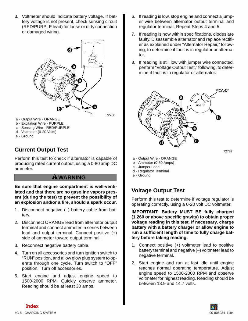
4C-8 - CHARGING SYSTEM 90-806934 1194
3. Voltmeter should indicate battery voltage. If bat-tery voltage is not present, check sensing circuit(RED/PURPLE lead) for loose or dirty connectionor damaged wiring.
72786a - Output Wire - ORANGEb - Excitation Wire - PURPLEc - Sensing Wire - RED/PURPLEd - Voltmeter (0-20 Volts)e - Ground
b c
d
a
e
Current Output TestPerform this test to check if alternator is capable ofproducing rated current output, using a 0-80 amp DCammeter.
! WARNING
Be sure that engine compartment is well-venti-lated and that there are no gasoline vapors pres-ent (during the test) to prevent the possibility ofan explosion and/or a fire, should a spark occur.
1. Disconnect negative (–) battery cable from bat-tery.
2. Disconnect ORANGE lead from alternator outputterminal and connect ammeter in series betweenlead and output terminal. Connect positive (+)side of ammeter toward output terminal.
3. Reconnect negative battery cable.
4. Turn on all accessories and turn ignition switch to“RUN” position, and allow glow plug system to op-erate through one cycle. Turn switch to “OFF”position. Turn off accessories.
5. Start engine and adjust engine speed to1500-2000 RPM. Quickly observe ammeter.Reading should be at least 30 amps.
6. If reading is low, stop engine and connect a jump-er wire between alternator output terminal andregulator terminal. Repeat Steps 4 and 5.
7. If reading is now within specifications, diodes arefaulty. Disassemble alternator and replace rectifi-er as explained under “Alternator Repair,” follow-ing, to determine if fault is in regulator or alterna-tor.
8. If reading is still low with jumper wire connected,perform “Voltage Output Test,” following, to deter-mine if fault is in regulator or alternator.
72787
a - Output Wire - ORANGEb - Ammeter (0-80 Amps)c - Jumper Leadd - Regulator Terminale - Ground
b
cd
a
e
Voltage Output TestPerform this test to determine if voltage regulator isoperating correctly, using a 0-20 volt DC voltmeter.
IMPORTANT: Battery MUST BE fully charged(1.260 or above specific gravity) to obtain propervoltage reading in this test. If necessary, chargebattery with a battery charger or allow engine torun a sufficient length of time to fully charge bat-tery before taking reading.
1. Connect positive (+) voltmeter lead to positivebattery terminal and negative (–) voltmeter lead tonegative terminal.
2. Start engine and run at fast idle until enginereaches normal operating temperature. Adjustengine speed to 1500-2000 RPM and observevoltmeter for highest reading. Reading should bebetween 13.9 and 14.7 volts.

CHARGING SYSTEM - 4C-990-806934 1194
3. If reading is high, check for a loose or dirty regula-tor ground lead connection. If connection is good(and sensing circuit checked out good in “Circuit-ry Test”), voltage regulator is faulty and must bereplaced. Be sure to disconnect battery cablesbefore attempting to remove regulator.
72788
a - Output Wire - ORANGEb - Excitation Wire - PURPLEc - Sensing Wire - RED/PURPLEd - Voltmeter (0-20 Volts)e - Ground
b
c
da
e
! WARNING
Be sure that engine compartment is well-venti-lated and that there are no gasoline vapors pres-ent (during the next steps) to prevent the possi-bility of an explosion and/or fire, should a sparkoccur.
! CAUTIONDO NOT allow tie jumper wire to contact alterna-tor end frame (in next step), as rectifier and diodeassembly may be damaged.
4. Remove four nuts holding excitation and sensingwires and Phillips screw. Remove regulator coverand install wires and nuts for testing. Connect ajumper wire from the ground stud to the brush ter-minal on the lower right- hand side of the brushassembly. Restart engine and gradually increaseengine speed to 1500 RPM while observing volt-meter. DO NOT allow voltage to exceed 16 volts.
5. If a voltmeter reading of 14.5 volts or above is nowobtained, voltage regulator is faulty and must bereplaced. If voltmeter reading is below 14.5 volts,inspect brushes and slip rings for wear, dirt ordamage. If brushes and slip rings are good, alter-nator is faulty internally. Disassemble alternatorand test components, as outlined under “Alterna-tor Repair,” following.
72971
a - Groundb - Brush/Regulator Assemblyc - Brush Terminald - Jumper Wire (Solder Connection to Ground)
b c
d
a
Alternator Repair
Removal1. Disconnect negative (–) battery cable from bat-
tery.
2. Disconnect wiring harness from alternator.
3. Loosen alternator support bracket screw.
4. Loosen alternator brace-to-alternator and alter-nator brace-to-engine attaching screws. Loosenalternator mounting bolt, then pivot alternator in-ward and remove alternator drive belt.
5. Remove alternator brace-to-alternator attachingbolt and washer.
6. Remove alternator mounting bolt, washers, andnut. Remove alternator.

4C-10 - CHARGING SYSTEM 90-806934 1194
72276
Exploded View
1 - Screw (3)2 - Nut (9)3 - Flat Washer (4)4 - Sensing Wire (RED/PURPLE)5 - Excitation Wire (PURPLE)6 - Cover7 - Tie Strap8 - Rubber Gasket9 - Condenser10- Insulator (3)11- Bolt (4)12- End Frame (Rear)13- Cap (2)14- Brush/Regulator Assembly
3
7
1012
16
26
29
27
28
213
9
2
2
5
413
6
810
2
132
1
1417
18
15
11
10
23
1920
2122
2425
3
15- Rectifier Assembly16- Flat Washer17- Screw18- Stator19- Rotor and Slip Rings20- Retaining Plate21- Front Bearing22- End Frame (Front)23- Screw (3)24- Fan Spacer25- Fan26- Pulley Spacer27- Pulley28- Lockwasher29- Nut
Mando 65 Amp Alternator

CHARGING SYSTEM - 4C-1190-806934 1194
DisassemblyIMPORTANT: The following instructions are forcomplete disassembly and overhaul of the alter-nator. In many cases, however, complete disas-sembly of alternator is not required and, in thosecases, it is necessary only to perform the opera-tions required to repair or replace the faulty part.
1. Mount alternator in a vise so that rear end frameis facing you.
2. Disconnect regulator leads from terminals on rearend frame. Remove four nuts, Phillips head screwand two regulator leads. Then pull regulator coveraway from rear end frame.
72963a - Regulator Leadsb - Nuts (4)c - Phillips Head Screwd - Regulator Cover
bcd
a
3. Remove stud cover insulator, two nuts and tiestrap from brush/regulator assembly.
4. Remove two brush/regulator attaching screwsand remove brush/regulator assembly.
72823
a - Screwsb - Brush/Regulator Assemblyc - Stud Cover Insulatord - Tie Strap
b
c
da
5. Scribe a mark on rear end frame, stator and frontend frame to ensure proper reassembly later.
6. Remove four screws which secure end framesand stator together.
IMPORTANT: DO NOT insert screwdriver bladesmore than 1/16 in. (1.5 mm) into openings (in nextstep), as stator windings may be damaged.
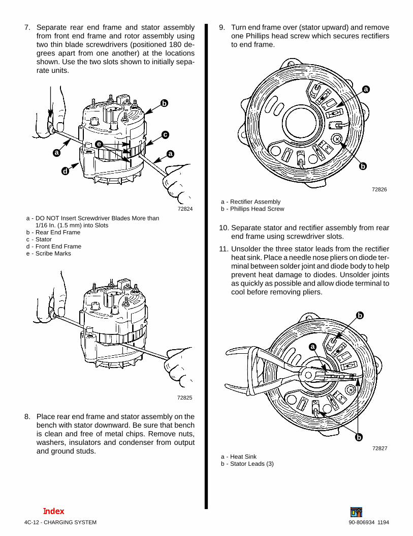
4C-12 - CHARGING SYSTEM 90-806934 1194
7. Separate rear end frame and stator assemblyfrom front end frame and rotor assembly usingtwo thin blade screwdrivers (positioned 180 de-grees apart from one another) at the locationsshown. Use the two slots shown to initially sepa-rate units.
72824
a - DO NOT Insert Screwdriver Blades More than 1/16 In. (1.5 mm) into Slots
b - Rear End Framec - Statord - Front End Framee - Scribe Marks
b
c
d
eaa
72825
8. Place rear end frame and stator assembly on thebench with stator downward. Be sure that benchis clean and free of metal chips. Remove nuts,washers, insulators and condenser from outputand ground studs.
9. Turn end frame over (stator upward) and removeone Phillips head screw which secures rectifiersto end frame.
72826
a - Rectifier Assemblyb - Phillips Head Screw
b
a
10. Separate stator and rectifier assembly from rearend frame using screwdriver slots.
11. Unsolder the three stator leads from the rectifierheat sink. Place a needle nose pliers on diode ter-minal between solder joint and diode body to helpprevent heat damage to diodes. Unsolder jointsas quickly as possible and allow diode terminal tocool before removing pliers.
72827
a - Heat Sinkb - Stator Leads (3)
a
b
b

CHARGING SYSTEM - 4C-1390-806934 1194
IMPORTANT: With alternator disassembled tothis point, stator, rectifier, diodes, and rotor maybe tested, as explained under “Component Test-ing,” following.
IMPORTANT: DO NOT clamp vise on rotor polepieces when removing pulley nut (in next step),as pole pieces may be distorted.
12. Remove pulley retaining nut by clamping pulley ina vise (using an oversize V-belt or protective jawsto protect pulley) and turning nut counterclock-wise with a 7/8 in. wrench. Remove lockwasherand slide pulley and fan from shaft. If pulley is diffi-cult to remove, it may be necessary to use a uni-versal puller.
72828a - 7/8 In. Wrenchb - Over-Sized V-Belt to Protect Pulley
b
a
13. Remove the three Phillips head screws and lock-washers which secure the front bearing retainingplate.
72829
a - Phillips Head Screws and Lockwashersb - Front Bearing Retaining Plate
b
a
14. Remove front bearing from front end frame usingan arbor press and a suitable size mandrel. (Dis-card bearing.)
72830
Removing Front Bearing from Front End Frame
15. If rotor slip rings or rear bearing requires replace-ment, entire rotor must be replaced. Parts cannotbe purchased separately.
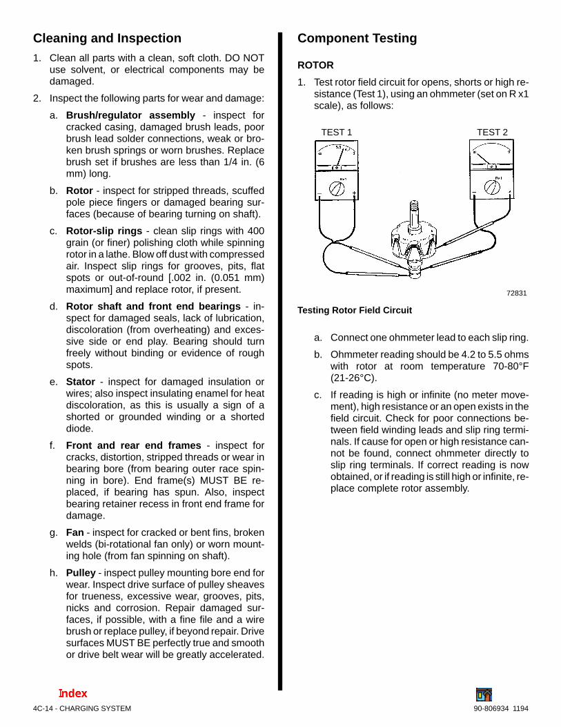
4C-14 - CHARGING SYSTEM 90-806934 1194
Cleaning and Inspection1. Clean all parts with a clean, soft cloth. DO NOT
use solvent, or electrical components may bedamaged.
2. Inspect the following parts for wear and damage:
a. Brush/regulator assembly - inspect forcracked casing, damaged brush leads, poorbrush lead solder connections, weak or bro-ken brush springs or worn brushes. Replacebrush set if brushes are less than 1/4 in. (6mm) long.
b. Rotor - inspect for stripped threads, scuffedpole piece fingers or damaged bearing sur-faces (because of bearing turning on shaft).
c. Rotor-slip rings - clean slip rings with 400grain (or finer) polishing cloth while spinningrotor in a lathe. Blow off dust with compressedair. Inspect slip rings for grooves, pits, flatspots or out-of-round [.002 in. (0.051 mm)maximum] and replace rotor, if present.
d. Rotor shaft and front end bearings - in-spect for damaged seals, lack of lubrication,discoloration (from overheating) and exces-sive side or end play. Bearing should turnfreely without binding or evidence of roughspots.
e. Stator - inspect for damaged insulation orwires; also inspect insulating enamel for heatdiscoloration, as this is usually a sign of ashorted or grounded winding or a shorteddiode.
f. Front and rear end frames - inspect forcracks, distortion, stripped threads or wear inbearing bore (from bearing outer race spin-ning in bore). End frame(s) MUST BE re-placed, if bearing has spun. Also, inspectbearing retainer recess in front end frame fordamage.
g. Fan - inspect for cracked or bent fins, brokenwelds (bi-rotational fan only) or worn mount-ing hole (from fan spinning on shaft).
h. Pulley - inspect pulley mounting bore end forwear. Inspect drive surface of pulley sheavesfor trueness, excessive wear, grooves, pits,nicks and corrosion. Repair damaged sur-faces, if possible, with a fine file and a wirebrush or replace pulley, if beyond repair. Drivesurfaces MUST BE perfectly true and smoothor drive belt wear will be greatly accelerated.
Component Testing
ROTOR
1. Test rotor field circuit for opens, shorts or high re-sistance (Test 1), using an ohmmeter (set on R x1scale), as follows:
72831
TEST 1 TEST 2
Testing Rotor Field Circuit
a. Connect one ohmmeter lead to each slip ring.
b. Ohmmeter reading should be 4.2 to 5.5 ohmswith rotor at room temperature 70-80°F(21-26°C).
c. If reading is high or infinite (no meter move-ment), high resistance or an open exists in thefield circuit. Check for poor connections be-tween field winding leads and slip ring termi-nals. If cause for open or high resistance can-not be found, connect ohmmeter directly toslip ring terminals. If correct reading is nowobtained, or if reading is still high or infinite, re-place complete rotor assembly.

CHARGING SYSTEM - 4C-1590-806934 1194
d. If reading is low, a short exists in the field cir-cuit. Inspect slip rings to be sure that they arenot bent and touching outer slip ring. Also, besure that excess solder is not shorting termi-nals to aft slip ring. If cause for short cannotbe found, unsolder field winding leads fromslip ring terminals and connect ohmmeter di-rectly to leads. If correct reading is now ob-tained, or if reading is still low, slip rings androtor field windings are shorted, and completerotor assembly must be replaced.
73112a - Field Winding Leadsb - Slip Ringsc - Rotor Shaftd - Pole Pieces
b
c
d
a
2. Test rotor field circuit for grounds (Test 2), usingan ohmmeter (set on R x1 scale) as follows:
a. Connect one lead of ohmmeter to either slipring and the other lead to rotor shaft or polepieces.
b. Meter should indicate no continuity (metershould not move).
c. If continuity does exist, complete rotor assem-bly must be replaced.
IMPORTANT: If alternator has output at lowspeeds, but no output at high speeds, rotor fieldwinding may be shorting or grounding out, due tocentrifugal force. Replace rotor if all other electri-cal components test good.
STATOR
IMPORTANT: Stator leads MUST BE discon-nected from rectifier for this test.
1. Test stator for grounds (Test 1), using an ohmme-ter (set on R x1 scale) as follows:
a. Connect one lead of ohmmeter to one of thestator leads and the other lead to stator frame.Be sure that lead makes good contact withframe.
b. Meter should indicate no continuity (metershould not move). If continuity does exist, sta-tor is grounded and must be replaced.
2. Test for opens in stator (Test 2), using an ohmme-ter (set on R x1 scale) as follows:
a. Connect ohmmeter between each pair of sta-tor windings (three different ways).
b. Continuity should be present in all three cases(meter should move). If it does not, one ormore of the windings are open and statormust be replaced.
72833
TEST 1 TEST 2 TEST 2 TEST 2
Testing Stator
3. A short in the stator is difficult to detect withoutspecial equipment, because of the low windingsresistance. If all other electrical components testout good, and alternator fails to produce ratedoutput, stator probably is shorted and should bereplaced. Also, examine stator for heat discolor-ation, as this usually is a sure sign of a short.
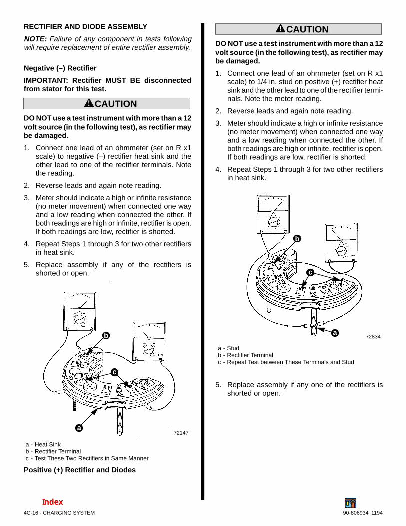
4C-16 - CHARGING SYSTEM 90-806934 1194
RECTIFIER AND DIODE ASSEMBLY
NOTE: Failure of any component in tests followingwill require replacement of entire rectifier assembly.
Negative (–) Rectifier
IMPORTANT: Rectifier MUST BE disconnectedfrom stator for this test.
! CAUTIONDO NOT use a test instrument with more than a 12volt source (in the following test), as rectifier maybe damaged.
1. Connect one lead of an ohmmeter (set on R x1scale) to negative (–) rectifier heat sink and theother lead to one of the rectifier terminals. Notethe reading.
2. Reverse leads and again note reading.
3. Meter should indicate a high or infinite resistance(no meter movement) when connected one wayand a low reading when connected the other. Ifboth readings are high or infinite, rectifier is open.If both readings are low, rectifier is shorted.
4. Repeat Steps 1 through 3 for two other rectifiersin heat sink.
5. Replace assembly if any of the rectifiers isshorted or open.
72147
a - Heat Sinkb - Rectifier Terminalc - Test These Two Rectifiers in Same Manner
b
a
c
Positive (+) Rectifier and Diodes
! CAUTIONDO NOT use a test instrument with more than a 12volt source (in the following test), as rectifier maybe damaged.
1. Connect one lead of an ohmmeter (set on R x1scale) to 1/4 in. stud on positive (+) rectifier heatsink and the other lead to one of the rectifier termi-nals. Note the meter reading.
2. Reverse leads and again note reading.
3. Meter should indicate a high or infinite resistance(no meter movement) when connected one wayand a low reading when connected the other. Ifboth readings are high or infinite, rectifier is open.If both readings are low, rectifier is shorted.
4. Repeat Steps 1 through 3 for two other rectifiersin heat sink.
72834
a - Studb - Rectifier Terminalc - Repeat Test between These Terminals and Stud
b
a
c
5. Replace assembly if any one of the rectifiers isshorted or open.
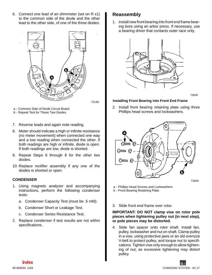
CHARGING SYSTEM - 4C-1790-806934 1194
6. Connect one lead of an ohmmeter (set on R x1)to the common side of the diode and the otherlead to the other side, of one of the three diodes.
72148
a - Common Side of Diode Circuit Boardb - Repeat Test for These Two Diodes
a
b
7. Reverse leads and again note reading.
8. Meter should indicate a high or infinite resistance(no meter movement) when connected one wayand a low reading when connected the other. Ifboth readings are high or infinite, diode is open.If both readings are low, diode is shorted.
9. Repeat Steps 6 through 8 for the other twodiodes.
10. Replace rectifier assembly if any one of thediodes is shorted or open.
CONDENSER
1. Using magneto analyzer and accompanyinginstructions, perform the following condensertests:
a. Condenser Capacity Test (must be .5 mfd).
b. Condenser Short or Leakage Test.
c. Condenser Series Resistance Test.
2. Replace condenser if test results are not withinspecifications.
Reassembly1. Install new front bearing into front end frame bear-
ing bore using an arbor press. If necessary, usea bearing driver that contacts outer race only.
72835
Installing Front Bearing into Front End Frame
2. Install front bearing retaining plate using threePhillips head screws and lockwashers.
72829
a - Phillips Head Screws and Lockwashersb - Front Bearing Retaining Plate
b
a
3. Slide front end frame over rotor.
IMPORTANT: DO NOT clamp vise on rotor polepieces when tightening pulley nut (in next step),or pole pieces may be distorted.
4. Slide fan spacer onto rotor shaft. Install fan,pulley, lockwasher and nut on shaft. Clamp pulleyin a vise, using protective jaws or an old oversizeV-belt to protect pulley, and torque nut to specifi-cations. Tighten vise only enough to allow tighten-ing of nut, as excessive tightening may distortpulley.

4C-18 - CHARGING SYSTEM 90-806934 1194
5. Assemble stator to rectifier by soldering the threeleads to the three rectifier terminals.
72826
a - Stator Lead Connections
a
NOTE: Be sure to connect leads to their original posi-tions.
6. Install assembled stator and rectifier assemblyinto rear end frame, aligning scribe marks oneach (scribed during disassembly), and installPhillips head screw and washer to retain.
IMPORTANT: The insulating washers MUST BEinstalled as shown or damage to the alternatorwill result.
7. Position stator down with rear end frame up andreinstall insulators, nuts and condenser.
a - Insulators (3)b - Nuts (5) - ONE REMOVEDc - Condenser
72561
c
a
b
b
8. Position rear end frame and stator assembly overfront end frame and rotor assembly and alignscribe marks on each (scribed during disassem-bly). Hand-press end frames together, then installfour screws. Tighten screws securely.
72561
a - Rear End Frameb - Statorc - Front End Framed - Scribe Markse - Insert Screws (4) (Two Hidden)
b
c
a e
d
9. Depress brushes flush with top of brush holderand insert a #54 drill bit or smaller (.050 in.) intohole in brush holder to hold brushes compressedduring reassembly.
72836a - Drill Bit
a
NOTE: Rubber gasket shown removed for clarity.

CHARGING SYSTEM - 4C-1990-806934 1194
10. Install brush/regulator assembly in rear endframe cavity and secure with two mountingscrews, as shown. Tighten screws securely. Re-move drill bit to release brushes against slip rings.
72837
a - Brush/Regulator Assemblyb - Mounting Screws
a
b
11. Install tie strap to rectifier stud and stud on brush/rectifier assembly. Tighten nuts securely.
72823
a - Studsb - Tie Strap
b
a
12. Install cover with one Phillips head screw and twonuts. Install two leads with nuts.
72963
a - Phillips Head Screwb - Nuts (4)c - Leads
b
c
a
13. Install insulator caps.
72078a - Insulator Caps
a

4C-20 - CHARGING SYSTEM 90-806934 1194
InstallationIMPORTANT: If the mounting bracket has been re-moved, refer to the diagram at the bottom of thispage. Be certain that the mounting spacer andproper length brace spacer are in position for theappropriate engines as indicated.
1. Install alternator in mounting bracket. DO NOTtighten fastener at this time.
2. Fasten alternator brace to alternator. DO NOTtighten screw at this time.
3. Position alternator drive belt on pulleys and adjusttension as explained under “Drive Belt TensionAdjustment.”
4. Torque fasteners to specifications. Securelytighten all other fasteners.
5. Reconnect wiring harness to alternator. Coat ter-minals with Quicksilver Liquid Neoprene.
6. Connect negative battery cable to battery.
72838a - Excitation Lead - PURPLEb - Sensing Lead - RED/PURPLEc - Ground Lead - BLACKd - Output Lead - ORANGEe - Charge Indicator Lamp (System Monitor Panel) - BROWNf - Alternator Driven Tachometer Lead - GRAY (Not Shown)
Used Only When Required
b
c
d
ae
74467
1 - Key2 - Alternator3 - Mounting Spacer(s)4 - Mounting Bracket5 - Mounting Stud, Lockwasher and Nut6 - Mounting Screw With Lockwasher7 - Alternator Mounting Bolt With Hardware8 - Alternator Brace9 - Alternator Brace Spacer10- Brace Bolt, Washers and Nut11- Tensioning Screw, Lockwasher and Flat Washers12- Pulley, Lockwasher and Nut13- Alternator V-Belt
2
Lubricant/Sealant Application PointsQuicksilver Liquid Neoprene - 92-25711A
Torque Specifications
a 192 lb. in. (28 N·m)b 30 lb. ft. (41 N·m)
c 35 lb. ft. (48 N·m)
b
A
54
76c
c
8
9
10
a 11
1
3
12
13
a

CHARGING SYSTEM - 4C-2190-806934 1194
Prestolite 65 Amp Alternator
Replacement Parts Warning
! WARNING
Electrical, ignition and fuel system componentson your MerCruiser are designed and manufac-tured to comply with U.S. Coast Guard Rules andRegulations to minimize risks of fire and explo-sion.
Use of replacement electrical, ignition or fuel sys-tem components, which do not comply with theserules and regulations, could result in a fire or ex-plosion hazard and should be avoided.
Specifications
Excitation Circuit
Current Output
Voltage Output
Condenser Capacity
Minimum Brush Length
1.5 to 3.0 Volts
60 Amp. Min.
13.8 to 14.8 Volts
.5 MFD
3/16 in. (5 mm)
Description Specification
Tools/Sealants
91-76032
91-37241
91-99750
92-25711--2
Obtain Locally
Magneto Analyzer
Universal Puller Plate
Multi-Meter/DVA Tester
Quicksilver Liquid Neoprene
Ammeter (0-50 Amps)
Part Number Description
Torque Specifications
Housing Screws 50-60(5.6-6.7)
Pulley Nut 35-50(48-68)
Front Bearing Screws 25-35(2.8-3.9)
Alternator to Mounting Bracket 35(48)
Adjustment Brace to Alternator 192(28)
Alternator Brace to Block 30(41)
Alternator Mounting Bracket 30(41)
Alternator Support Bracket Tighten Securely
V-Belt Tension (Note) Depress 3/16 In.(5 mm)
Fastener LocationLb. Ft.(N•m)
Lb. In.(N•m)
NOTE: Depress belt with thumb at midway pointbetween circulating pump pulley and alternator.
DescriptionThe alternator has a rotor, which is supported in twoend frames by ball bearings, and is driven by a pulleyat approximately twice engine speed. The rotor con-tains a field winding that is enclosed between twomultiple-finger pole pieces. The ends of the fieldwinding are connected to two brushes (mounted inthe rear end frame) which make continuous sliding (orslipping) contact with the slip rings. The current (flow-ing through the field winding) creates a magnetic fieldthat causes the adjacent fingers of the pole pieces tobecome alternate north and south magnetic poles.
A 3-phase stator is mounted directly over the rotorpole pieces and between two end frames. It consistsof three windings wound 120 degrees electrically out-of-phase on the inside of a laminated core. The wind-ings are all connected together on one end, while theother ends are connected to a full-wave rectifierbridge.
The rectifier bridge contains six rectifiers which arearranged so that current flows from ground, throughthe stator and to the output terminal, but not in the op-posite direction.
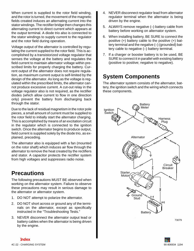
4C-22 - CHARGING SYSTEM 90-806934 1194
When current is supplied to the rotor field winding,and the rotor is turned, the movement of the magneticfields created induces an alternating current into thestator windings. The rectifier bridge then changes thisalternating current to direct current which appears atthe output terminal. A diode trio also is connected tothe stator windings to supply current to the regulatorand the rotor field during operation.
Voltage output of the alternator is controlled by regu-lating the current supplied to the rotor field. This is ac-complished by a transistorized voltage regulator thatsenses the voltage at the battery and regulates thefield current to maintain alternator voltage within pre-scribed limits for properly charging the battery. Cur-rent output of the alternator does not require regula-tion, as maximum current output is self-limited by thedesign of the alternator. As long as the voltage is reg-ulated within the prescribed limits, the alternator can-not produce excessive current. A cut-out relay in thevoltage regulator also is not required, as the rectifierdiodes (which allow current to flow in one directiononly) prevent the battery from discharging backthrough the stator.
Due to the lack of residual magnetism in the rotor polepieces, a small amount of current must be supplied tothe rotor field to initially start the alternator charging.This is accomplished by means of an excitation circuitin the regulator which is connected to the ignitionswitch. Once the alternator begins to produce output,field current is supplied solely by the diode trio, as ex-plained, preceding.
The alternator also is equipped with a fan (mountedon the rotor shaft) which induces air flow through thealternator to remove the heat created by the rectifiersand stator. A capacitor protects the rectifier systemfrom high voltages and suppresses radio noise.
PrecautionsThe following precautions MUST BE observed whenworking on the alternator system. Failure to observethese precautions may result in serious damage tothe alternator or alternator system.
1. DO NOT attempt to polarize the alternator.
2. DO NOT short across or ground any of the termi-nals on the alternator, except as specificallyinstructed in the “Troubleshooting Tests.”
3. NEVER disconnect the alternator output lead orbattery cables when the alternator is being drivenby the engine.
4. NEVER disconnect regulator lead from alternatorregulator terminal when the alternator is beingdriven by the engine.
5. ALWAYS remove negative (–) battery cable frombattery before working on alternator system.
6. When installing battery, BE SURE to connect thepositive (+) battery cable to the positive (+) bat-tery terminal and the negative (–) (grounded) bat-tery cable to negative (–) battery terminal.
7. If a charger or booster battery is to be used, BESURE to connect it in parallel with existing battery(positive to positive; negative to negative).
System ComponentsThe alternator system consists of the alternator, bat-tery, the ignition switch and the wiring which connectsthese components.
73079
IgnitionSwitch
BatteryMeter
HarnessPlug
Battery
Alternator
CircuitBreaker
StarterMotor
GroundStud

CHARGING SYSTEM - 4C-2390-806934 1194
Alternator Circuits -Typical
74147
AUXILIARY BATTERY
MAIN BATTERY
STARTER
8 G
A. M
IN.

4C-24 - CHARGING SYSTEM 90-806934 1194
Battery Isolators
Dual Battery Charging SystemsUsing a Battery IsolatorBattery isolators allow the addition of an auxiliary (se-cond) battery to the MerCruiser electrical system.The auxiliary battery is primarily used as a powersource for various accessories installed on the boat.The battery isolator will allow the alternator to chargeboth the cranking and auxiliary batteries at the sametime while preventing accessories, connected to theauxiliary battery, from drawing power from the crank-ing battery.
Mercury Marine does not manufacture any batteryisolator systems. Battery isolators must be boughtfrom an outside manufacturer. Mercury Marine sug-gests following the manufacturer’s instructions care-fully.
IMPORTANT: Alternators used on MerCruiser en-gines ARE NOT equipped with an isolation diode.
! CAUTIONFollow battery isolator manufacturer’s instruc-tions for wire gauge. Battery isolator installationmust conform to BIA Low Voltage Wiring Stan-dard No. 125-79.
NOTE: MerCruiser engines equipped with a 3-wire,belt driven alternator, can use a battery isolator.
BLK = BLACKBLU = BLUEBRN = BROWNGRY = GRAYGRN = GREENORN = ORANGEPNK = PINK
PUR or PPL = PURPLERED = REDTAN = TAN
WHT = WHITEYEL = YELLOW
LIT or LT = LIGHTDRK = DARK
WIRING COLOR CODE ABBREVIATIONS
Periodic MaintenanceThe following maintenance check should be per-formed every 50 hours or 60 days (whichever comesfirst) in fresh water areas or every 25 hours or 30 daysin salt water areas.
! CAUTIONRemove all battery cables from battery (beforeconducting the following check) to prevent acci-dentally shorting out electrical system.
1. Inspect entire alternator system for corroded orloose connectors.
2. Check wiring for frayed or worn insulation.
3. Check alternator drive belt for excessive wear,cracks, fraying and glazed surfaces. Also, checkdrive belt tension and adjust, if necessary, as ex-plained under “Drive Belt Tension Adjustment.”
4. Check alternator mounting bolts for adequatetightness.
5. Inspect slip ring end frame flame arrestor screenfor debris and clean, if necessary, using com-pressed air or a cloth. Screen MUST BE clean, oralternator may overheat.
73078

CHARGING SYSTEM - 4C-2590-806934 1194
Drive Belt TensionAdjustment
Alternator1. Install drive belt on pulleys and adjust tension as
follows:
a. Pivot alternator away from engine, as re-quired, until correct tension is obtained asshown. Belt should depress 1/2 in. (13 mm).
72669
a - Check Point
a
Typical
b. After obtaining correct tension, securely re-tighten alternator brace attaching bolts andalternator mounting bolts.
2. If a new drive belt has been installed, recheck belttension after running for five minutes.
Troubleshooting Tests(Alternator on Engine)Use the following tests in conjunction with the “Trou-bleshooting” in Section 1. Before proceeding with thetests, however, perform the following checks to elimi-nate possible problem areas. Also observe “Precau-tions,” preceding, to prevent damage to alternatorsystem.
1. If problem is an undercharged battery, check toensure that undercharged condition has not beencaused by excessive accessory current draw orby accessories which have accidentally been lefton. Also, check that undercharged condition hasnot been caused by running engine at too low aspeed for extended periods of time.
2. Check physical condition and state of charge ofbattery, as outlined in “Battery - Storage” in Sec-tion 4A. Battery MUST BE at least 75% (1.230specific gravity) of fully charged to obtain valid re-sults in the following tests. If not, charge batterybefore testing system.
3. Inspect entire alternator system wiring for de-fects. Check all connections for tightness andcleanliness, particularly battery cable clamps andbattery terminals.
4. Check alternator drive belt for excessive wear,cracks, fraying and glazed surfaces and replaceif necessary. Also, check drive belt tension andadjust if necessary, as outlined under “Drive BeltTension Adjustment.”
Circuitry TestPerform the following tests, using a 0-20 volt DC volt-meter, to check that all of the circuits between the al-ternator and the other components within the alterna-tor system are in good condition.
! WARNING
Be sure that engine compartment is well-venti-lated and that there are no gasoline vapors pres-ent (during the test) to prevent the possibility ofan explosion and/or a fire, should a spark occur.
ALTERNATOR OUTPUT TEST
1. Connect positive (+) voltmeter lead to alternatoroutput terminal (ORANGE wire) and negative (–)lead to a ground terminal on alternator. With en-gine running about 1500 RPM and all accessoriesturned on, voltage should be between 13.8-14.8.

4C-26 - CHARGING SYSTEM 90-806934 1194
2. If voltage output does not fall within specifica-tions, alternator should be tested for probablecause and disassembled for repair.
73081
a - Output Wire - ORANGEb - Excitation Wire - PURPLEc - Sensing Wire - RED/PURPLEd - Voltmeter (0-20 Volts)e - Ground
c
da
b
e
HARNESS VOLTAGE TEST
With ignition off, unplug RED/PURPLE wire andcheck for battery voltage at harness wire. No voltageat harness wire indicates wiring harness is “open” andshould be repaired or replaced.
73082
a - Excitation Wire - Purpleb - Sensing Wire - Red/Purplec - Voltmeter (0-20 Volts)d - Ground
c
d
a
b
OPEN DIODE-TRIO TEST
1. With ignition on and engine not running, check forbattery voltage at alternator output terminal (Test1) and 1.5 to 3.0 volts at regulator terminal (Test2).
73083
a - Regulator Terminalb - Output Terminalc - Groundd - Voltmeter (0-20 Volts)
c
d
a
b
2. Connect a jumper wire between regulator andoutput terminal. Start engine and run at idle. Ifcharging voltage (13.8-14.8 volts) is present atoutput terminal, the diode-trio is probably defec-tive and alternator should be removed for repair.
73084
a - Regulator Terminalb - Output Terminalc - Jumper Leadd - Grounde - Voltmeter (0-20 Volts)
c
d
a
be

CHARGING SYSTEM - 4C-2790-806934 1194
CURRENT OUTPUT TEST
Perform this test to check if alternator is capable ofproducing rated current output, using a 0-50 amp DCammeter.
! WARNING
Be sure that engine compartment is well-venti-lated and that there are no gasoline vapors pres-ent (during the test) to prevent the possibility ofan explosion and/or a fire, should a spark occur.
1. Disconnect negative (–) battery cable from bat-tery.
2. Disconnect ORANGE lead from alternator outputterminal and connect ammeter in series betweenlead and output terminal. Connect positive (+)side of ammeter toward output terminal.
3. Reconnect negative battery cable.
4. Turn on all accessories. Turn ignition switch to“RUN” position, and allow glow plug system to op-erate through one cycle. Turn switch to “OFF”position. Turn off accessories.
5. Start engine and adjust engine speed to1500-2000 RPM. Quickly observe ammeter.Reading should be at least 30 amps.
6. If reading is low, stop engine and connect a jump-er wire between alternator output terminal andregulator terminal. Repeat Steps 4 and 5.
7. If reading is now within specifications, diodes arefaulty. Disassemble alternator and replace recti-fier as explained under “Alternator Repair,”following, to determine if fault is in regulator oralternator.
8. If reading is still low with jumper wire connected,perform “Voltage Output Test,” following, to deter-mine if fault is in regulator or alternator.
73109
a - Output Wire - ORANGEb - Ammeter (0-80 Amps)c - Jumper Leadd - Regulator Terminale - Ground
b
c
d
a
e

4C-28 - CHARGING SYSTEM 90-806934 1194
OPEN REGULATOR TEST
IMPORTANT: This test requires removal of regu-lator.
! CAUTIONTo prevent electrical system damage and/orsparks, disconnect battery cables at battery.
1. Remove insulator cap from regulator terminal.
2. With ignition switch in the “RUN” position and en-gine not running, check for battery voltage at al-ternator output terminal (Test 1) and regulator ter-minal (Test 2).
73083
a - Regulator Terminalb - Output Terminalc - Groundd - Voltmeter (0-20 Volts)
c
d
a
b
3. Remove the four screws which secure the regula-tor to the alternator.
4. Connect a jumper wire between field terminal(green wire) and ground/ If 1.5 to 3.0 volts arepresent at regulator terminal, regulator is defec-tive. If voltage is not present at regulator terminal,there is an open field circuit (brushes slip rings,etc.). Remove alternator for repair.
a - Field Terminal (Green Wire)b - Regulator Terminalc - Groundd - Voltmeter (0-20 Volts)
73086
b
c
a
d
NOTE: Felt gasket is shown removed for visual clar-ity.
Alternator Repair! WARNING
Be sure that engine compartment is well-venti-lated and that there are no gasoline vapors pres-ent to prevent the possibility of an explosion and/or a fire, should a spark occur.
Removal
! CAUTIONTo prevent electrical system damage and/orsparks, disconnect battery cables at battery.
1. Disconnect battery cables from battery.
2. Disconnect wiring harness from alternator.
3. Loosen alternator support bracket screw.
4. Loosen alternator brace-to-alternator and alter-nator brace-to-engine attaching screws. Loosenalternator mounting bolt, then pivot alternator in-ward and remove alternator drive belt.
5. Remove alternator brace-to-alternator attachingbolt and washer.
6. Remove alternator mounting bolt, washers, andnut. Remove alternator.

CHARGING SYSTEM - 4C-2990-806934 1194
Exploded View
73106
1 - Regulator and Leads2 - Screws (4)3 - Insulator Cap4 - Nuts (6)5 - Washers (3)6 - Condenser7 - Insulating Washer8 - Nuts (2)9 - Insulating Washers (2)10- Felt Gasket11- Screws (2)12- Brush Assembly13- Screws (4)14- Rear End Frame15- Star Washers (2)16- Insulator17- Insulating Washers (2)
43
12
5
89
4
5
98
7
10
5
6
1112
15
13
22
24
14
16
17
18
19
23
2021
25
26
293031
3233
34
2728
BLACK
REDPURPLE
GREEN
BROWN
4
18- Nut19- Washer20- Insulating Washer21- Insulator22- Negative Rectifier23- Positive Rectifier/Diode-Trio24- Stator25- Rotor and Slip Rings26- Snap Ring27- Bearing28- Front End Frame29- Fan Bushing30- Woodruff Key31- Fan32- Pulley33- Lockwasher34- Nut
Prestolite 65 Amp Alternator

4C-30 - CHARGING SYSTEM 90-806934 1194
Disassembly
1. Using an oversized V-belt to protect the pulley,clamp alternator in vise as shown. Remove pulleynut and lockwasher.
72828
a - 7/8 In. Wrenchb - Oversized V-Belt to Protect Pulley
b
a
2. Remove pulley, fan, woodruff key and spacer.
73087
a - Nutb - Lockwasherc - Pulleyd - Woodruff Keye - Fanf - Spacerg - Alternator
b
c
d
a
ef
g
3. Disconnect regulator leads from terminals on rearend frame. Remove four regulator attachingscrews, then pull regulator away from rear endframe and disconnect field lead.
73088
a - Regulator Leads (2)b - Screws (4)c - Regulator
b
aa
c
4. Remove brush holder.
73090
a - Attaching Screwsb - Brush Holder
a
b
5. Note location of remaining insulating washersand nuts and remove.
6. Scribe a mark on rear end frame, stator and frontend frame to ensure proper reassembly later.
7. Remove the four screws which secure endframes and stator together.

CHARGING SYSTEM - 4C-3190-806934 1194
! CAUTIONDo not insert screwdriver blades deeper than 1/16in. (1.5 mm) to avoid damaging stator windings.
8. Using a suitable holding fixture, separate frontend frame and stator assembly from rear endframe using two thin blade screwdrivers (posi-tioned 180 degrees apart from each other) at thelocations shown.
73091
a - Front End Frameb - Statorc - Rear End Framed - Scribe Marks
b
a
c
d
9. While supporting front housing, use an arborpress to remove rotor from front end frame.
73092
a - Front Housingb - Rotor Shaftc - Bearing Driver
bc
a
Cleaning and Inspection1. Clean all parts with a clean, soft cloth. Do not use
solvent, or electrical components may be dam-aged.
2. Inspect the following:
a. Brush Set - Inspect for cracked porcelaincasing, damaged brush leads, poor brushsprings or worn brushes. Replace brush set ifbrushes are less than 3/16 in (5 mm) long.
b. Rotor - Inspect for stripped threads, scuffedpole piece fingers or damaged bearing sur-faces (because of bearing turning on shaft).
c. Rotor Slip Rings - Clean slip rings with 400grain (or finer) polishing cloth. Blow off dustwith compressed air. Inspect slip rings forgrooves, pits, flat spots or out-of-round [.002in. (.05 mm) maximum]. Replace if defective.
d. Rotor Shaft Bearings - Inspect for damagedseals, lack of lubrication, discoloration (fromoverheating) or excessive side or end play.Hold inner race of bearings while turning outerrace. Bearing should turn freely without bind-ing or evidence of rough spots.
e. Stator - Inspect for damaged insulation orwires; also inspect insulating enamel for heatdiscoloration, as this is usually a sign of ashorted or grounded winding or a shorteddiode.
f. Regulator - Inspect leads for damaged in-sulation.
g. Front and Rear Housings - Inspect forcracks, distortion, stripped threads or wear inbearing bore (from bearing outer race spin-ning in bore). Replace if defective.
h. Fan - Inspect for cracked or bent fins, brokenwelds or worn mounting hole (from fan spin-ning on shaft).
i. Pulley - Inspect pulley mounting bore and forwear. Inspect drive surface of pulley sheavesfor trueness, excessive wear, or corrosion.Repair damaged surfaces, if possible, with afine file and a wire brush, or replace pulley.Drive surfaces must be true and smooth, ordrive belt wear will be greatly accelerated.
j. Alternator - If alternator has output at lowspeeds, but no output at high speeds, rotorfield winding may be shorting or grounding outbecause of centrifugal force. Replace rotor, ifall other electrical components test good.

4C-32 - CHARGING SYSTEM 90-806934 1194
Front Bearing
Removal1. Remove snap ring.
2. Use an arbor press to remove bearing from hous-ing.
73093
a - Front Housingb - Bearing Driverc - Bearing
b
c
a
Installation1. Using an arbor press, press on outer race of new
bearing until fully seated in housing.
73094
2. Install snap ring to retain bearing.
Slip Rings/Rear Bearing
Removal1. Unsolder wires and carefully unwind them from
slip ring terminals.
IMPORTANT: Do not damage rotor wires when re-moving slip rings or bearing.
2. Install a universal puller plate between bearingand slip rings. Insert a 10 x 1 in. cap screw intoopening of slip ring assembly.
73095
a - Universal Plate Pullerb - Cap Screwc - Slip Rings
c
a
b
3. Using an arbor press, push against cap screw toremove slip rings.
4. Install a universal puller plate under bearing.
5. Using an arbor press, remove bearing.
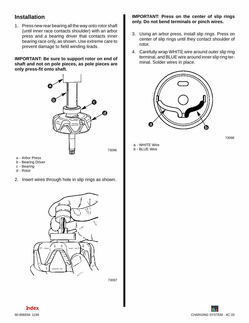
CHARGING SYSTEM - 4C-3390-806934 1194
Installation1. Press new rear bearing all the way onto rotor shaft
(until inner race contacts shoulder) with an arborpress and a bearing driver that contacts innerbearing race only, as shown. Use extreme care toprevent damage to field winding leads.
IMPORTANT: Be sure to support rotor on end ofshaft and not on pole pieces, as pole pieces areonly press-fit onto shaft.
73096
a - Arbor Pressb - Bearing Driverc - Bearingd - Rotor
b c
d
a
2. Insert wires through hole in slip rings as shown.
73097
IMPORTANT: Press on the center of slip ringsonly. Do not bend terminals or pinch wires.
3. Using an arbor press, install slip rings. Press oncenter of slip rings until they contact shoulder ofrotor.
4. Carefully wrap WHITE wire around outer slip ringterminal, and BLUE wire around inner slip ring ter-minal. Solder wires in place.
73098
a - WHITE Wireb - BLUE Wire
ab
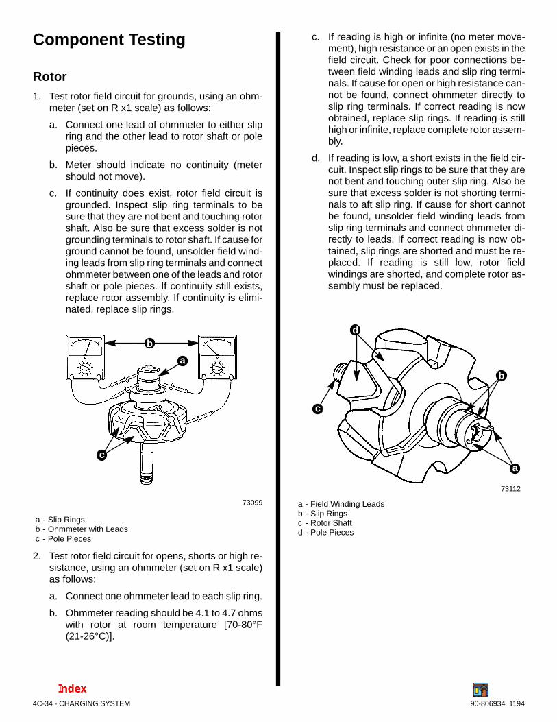
4C-34 - CHARGING SYSTEM 90-806934 1194
Component Testing
Rotor1. Test rotor field circuit for grounds, using an ohm-
meter (set on R x1 scale) as follows:
a. Connect one lead of ohmmeter to either slipring and the other lead to rotor shaft or polepieces.
b. Meter should indicate no continuity (metershould not move).
c. If continuity does exist, rotor field circuit isgrounded. Inspect slip ring terminals to besure that they are not bent and touching rotorshaft. Also be sure that excess solder is notgrounding terminals to rotor shaft. If cause forground cannot be found, unsolder field wind-ing leads from slip ring terminals and connectohmmeter between one of the leads and rotorshaft or pole pieces. If continuity still exists,replace rotor assembly. If continuity is elimi-nated, replace slip rings.
73099
a - Slip Ringsb - Ohmmeter with Leadsc - Pole Pieces
a
b
c
2. Test rotor field circuit for opens, shorts or high re-sistance, using an ohmmeter (set on R x1 scale)as follows:
a. Connect one ohmmeter lead to each slip ring.
b. Ohmmeter reading should be 4.1 to 4.7 ohmswith rotor at room temperature [70-80°F(21-26°C)].
c. If reading is high or infinite (no meter move-ment), high resistance or an open exists in thefield circuit. Check for poor connections be-tween field winding leads and slip ring termi-nals. If cause for open or high resistance can-not be found, connect ohmmeter directly toslip ring terminals. If correct reading is nowobtained, replace slip rings. If reading is stillhigh or infinite, replace complete rotor assem-bly.
d. If reading is low, a short exists in the field cir-cuit. Inspect slip rings to be sure that they arenot bent and touching outer slip ring. Also besure that excess solder is not shorting termi-nals to aft slip ring. If cause for short cannotbe found, unsolder field winding leads fromslip ring terminals and connect ohmmeter di-rectly to leads. If correct reading is now ob-tained, slip rings are shorted and must be re-placed. If reading is still low, rotor fieldwindings are shorted, and complete rotor as-sembly must be replaced.
b
c
d
a
a - Field Winding Leadsb - Slip Ringsc - Rotor Shaftd - Pole Pieces
73112
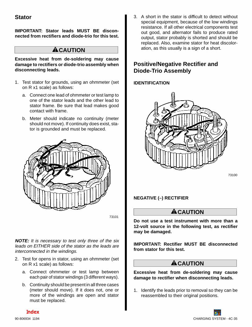
CHARGING SYSTEM - 4C-3590-806934 1194
Stator
IMPORTANT: Stator leads MUST BE discon-nected from rectifiers and diode-trio for this test.
! CAUTIONExcessive heat from de-soldering may causedamage to rectifiers or diode-trio assembly whendisconnecting leads.
1. Test stator for grounds, using an ohmmeter (seton R x1 scale) as follows:
a. Connect one lead of ohmmeter or test lamp toone of the stator leads and the other lead tostator frame. Be sure that lead makes goodcontact with frame.
b. Meter should indicate no continuity (metershould not move). If continuity does exist, sta-tor is grounded and must be replaced.
73101
NOTE: It is necessary to test only three of the sixleads on EITHER side of the stator as the leads areinterconnected in the windings.
2. Test for opens in stator, using an ohmmeter (seton R x1 scale) as follows:
a. Connect ohmmeter or test lamp betweeneach pair of stator windings (3 different ways).
b. Continuity should be present in all three cases(meter should move). If it does not, one ormore of the windings are open and statormust be replaced.
3. A short in the stator is difficult to detect withoutspecial equipment, because of the low windingsresistance. If all other electrical components testout good, and alternator fails to produce ratedoutput, stator probably is shorted and should bereplaced. Also, examine stator for heat discolor-ation, as this usually is a sign of a short.
Positive/Negative Rectifier andDiode-Trio Assembly
IDENTIFICATION
73100
NEGATIVE (–) RECTIFIER
! CAUTIONDo not use a test instrument with more than a12-volt source in the following test, as rectifiermay be damaged.
IMPORTANT: Rectifier MUST BE disconnectedfrom stator for this test.
! CAUTIONExcessive heat from de-soldering may causedamage to rectifier when disconnecting leads.
1. Identify the leads prior to removal so they can bereassembled to their original positions.

4C-36 - CHARGING SYSTEM 90-806934 1194
2. Using an ohmmeter (set on R x1 scale), check forcontinuity between rectifier terminal and heatsink. Reverse ohmmeter leads and recheck. Con-tinuity should be observed in one direction (polar-ity) only.
3. Check other two rectifiers in same manner.
4. Replace assembly if any of the rectifiers isshorted or open.
73102
POSITIVE (+) RECTIFIER AND DIODE-TRIO
! CAUTIONDo not use a test instrument with more than a12-volt source in the following test, as rectifiermay be damaged.
IMPORTANT: Rectifier MUST BE disconnectedfrom stator for this test.
! CAUTIONExcessive heat from de-soldering may causedamage to rectifier or diode-trio assembly whendisconnecting leads.
1. Identify the leads prior to removal so they can bereassembled to their original positions.
2. Using an ohmmeter (set on R x1 scale), check forcontinuity between rectifier terminal and heatsink. Reverse ohmmeter leads and recheck. Con-tinuity should be observed in one direction (polar-ity) only.
3. Check other two rectifiers in same manner.
4. Replace assembly if any of the rectifiers isshorted or open.
73103
5. Using an ohmmeter (set on R x1 scale), check forcontinuity between the common side of thediodes and one of the terminals on other side ofthe diode. Reverse ohmmeter leads and recheck.Continuity should be observed in one direction(polarity) only.
6. Check other two diodes in same manner.
7. Replace diode-trio if any of the diodes is shortedor open.
73104

CHARGING SYSTEM - 4C-3790-806934 1194
Condenser1. Using Magneto Analyzer (P/N 91-76032) and ac-
companying instructions, perform the followingcondenser tests:
a. Condenser Capacity Test (must be .5 mfd)
b. Condenser Short or Leakage Test
c. Condenser Series Resistance Test
2. Replace condenser if test results are not withinspecifications.
Reassembly1. Solder positive/negative rectifier and diode-trio
assembly to stator. Connect leads to original loca-tion as identified during disassembly.
73100
2. Install rotor to front end frame.
IMPORTANT: The insulators MUST BE installedas shown or damage to the alternator will result.
73085
a - Insulating Washersb - Insulatorsc - Negative Rectifierd - Positive Rectifier/Diode-Trio
c
da b
3. Position rear end frame and stator assembly withinsulators over front end frame and rotor assem-bly. Align scribe marks on each (scribed duringdisassembly). Hand press end frames together,then install four screws. Torque screws to 50-60lb. in. (5.6-6.7 N•m).
73105
a - Front End Frameb - Statorc - Rear End Framed - Scribe Marks
b
c
a
d
4. Install brush holder into rear end frame and slideforward to depress brushes against slip ring. In-sert two screws and tighten securely.
73090
a - Attaching Screwsb - Brush Holder
a
b

4C-38 - CHARGING SYSTEM 90-806934 1194
5. Attach field lead to brush assembly. Install regula-tor and felt gasket to rear end frame. Install fourscrews and tighten securely. Reconnect regulatorterminal leads to appropriate stud on rear endframe.
73107
a - Regulatorb - Felt Gasketc - Screws (4)d - Regulator Leads
b d
c a
d
6. Place condenser on ground terminal and lead onoutput terminal. Install insulator cap on regulatorterminal.
73088
a - Output Terminalb - Ground Terminalc - Condenser
ca b
7. Install spacer, woodruff key, fan, pulley, lock-washer and nut.
73087
a - Nutb - Lockwasherc - Pulleyd - Woodruff Keye - Fanf - Spacerg - Alternator
b
c
d
a
ef
g
8. Using an oversized belt to protect the pulley,clamp alternator in vise as shown. Tighten pulleynut to 35-50 lb. ft. (48-68 N•m).
73108
a - Oversized Beltb - Pulley
b
a
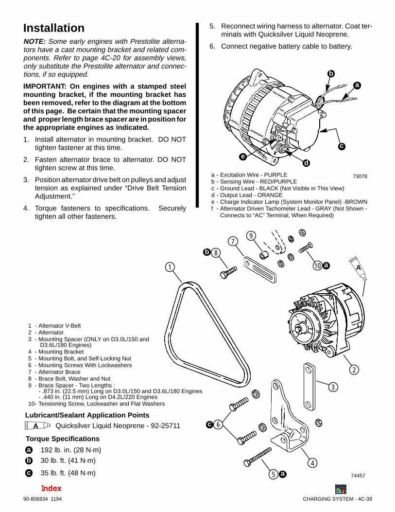
CHARGING SYSTEM - 4C-3990-806934 1194
InstallationNOTE: Some early engines with Prestolite alterna-tors have a cast mounting bracket and related com-ponents. Refer to page 4C-20 for assembly views,only substitute the Prestolite alternator and connec-tions, if so equipped.
IMPORTANT: On engines with a stamped steelmounting bracket, if the mounting bracket hasbeen removed, refer to the diagram at the bottomof this page. Be certain that the mounting spacerand proper length brace spacer are in position forthe appropriate engines as indicated.
1. Install alternator in mounting bracket. DO NOTtighten fastener at this time.
2. Fasten alternator brace to alternator. DO NOTtighten screw at this time.
3. Position alternator drive belt on pulleys and adjusttension as explained under “Drive Belt TensionAdjustment.”
4. Torque fasteners to specifications. Securelytighten all other fasteners.
5. Reconnect wiring harness to alternator. Coat ter-minals with Quicksilver Liquid Neoprene.
6. Connect negative battery cable to battery.
73078a - Excitation Wire - PURPLEb - Sensing Wire - RED/PURPLEc - Ground Lead - BLACK (Not Visible in This View)d - Output Lead - ORANGEe - Charge Indicator Lamp (System Monitor Panel) -BROWNf - Alternator Driven Tachometer Lead - GRAY (Not Shown -
Connects to “AC” Terminal, When Required)
b
a
d
c
e
74457
1 - Alternator V-Belt2 - Alternator3 - Mounting Spacer (ONLY on D3.0L/150 and
D3.6L/180 Engines)4 - Mounting Bracket5 - Mounting Bolt, and Self-Locking Nut6 - Mounting Screws With Lockwashers7 - Alternator Brace8 - Brace Bolt, Washer and Nut9 - Brace Spacer - Two Lengths :
- .873 in. (22.5 mm) Long on D3.0L/150 and D3.6L/180 Engines- .440 in. (11 mm) Long on D4.2L/220 Engines
10- Tensioning Screw, Lockwasher and Flat Washers
1
2
7
8
10
Lubricant/Sealant Application PointsQuicksilver Liquid Neoprene - 92-25711A
Torque Specifications
a 192 lb. in. (28 N·m)b 30 lb. ft. (41 N·m)
c 35 lb. ft. (48 N·m)
b
a A
3
4
5
6
9
a
c

4
D73288
ELECTRICAL SYSTEMS
INSTRUMENTATION

4D-0 - INSTRUMENTATION 90-806934 1194
Table of ContentsPage
Wiring Colors for MerCruiser Diesels 4D-1. . . . . . . . . . . . Wire Color Abbreviations 4D-1. . . . . . . . . . . . . . . . . . . . . . . Identification - Gauges 4D-2. . . . . . . . . . . . . . . . . . . . . . . . . General 4D-2. . . . . . . . . . . . . . . . . . . . . . . . . . . . . . . . . . . . . . Tachometer Special Information 4D-2. . . . . . . . . . . . . . . . . Gauge Special Information 4D-3. . . . . . . . . . . . . . . . . . . . .
Lighting Options 4D-3. . . . . . . . . . . . . . . . . . . . . . . . . . . . QSI Series 4D-3. . . . . . . . . . . . . . . . . . . . . . . . . . . . . .
Gauges 4D-3. . . . . . . . . . . . . . . . . . . . . . . . . . . . . . . . . . . . . . Oil Pressure and Water Temperature 4D-3. . . . . . . . . .
Testing 4D-3. . . . . . . . . . . . . . . . . . . . . . . . . . . . . . . . . Volt Meter Gauge 4D-4. . . . . . . . . . . . . . . . . . . . . . . . . . .
Testing 4D-4. . . . . . . . . . . . . . . . . . . . . . . . . . . . . . . . . Cruiselog (Engine Hour Meter) 4D-5. . . . . . . . . . . . . . .
Testing 4D-5. . . . . . . . . . . . . . . . . . . . . . . . . . . . . . . . . Tachometer 4D-5. . . . . . . . . . . . . . . . . . . . . . . . . . . . . . . .
Testing 4D-5. . . . . . . . . . . . . . . . . . . . . . . . . . . . . . . . . Gauge Replacement 4D-5. . . . . . . . . . . . . . . . . . . . . . . .
Senders 4D-6. . . . . . . . . . . . . . . . . . . . . . . . . . . . . . . . . . . . . . Oil Pressure 4D-6. . . . . . . . . . . . . . . . . . . . . . . . . . . . . . .
Removal 4D-6. . . . . . . . . . . . . . . . . . . . . . . . . . . . . . . Testing 4D-6. . . . . . . . . . . . . . . . . . . . . . . . . . . . . . . . .
Water Temperature - Primary Station 4D-7. . . . . . . . . . Removal 4D-7. . . . . . . . . . . . . . . . . . . . . . . . . . . . . . . Testing 4D-7. . . . . . . . . . . . . . . . . . . . . . . . . . . . . . . . . Installation 4D-8. . . . . . . . . . . . . . . . . . . . . . . . . . . . . .
Water Temperature - Second Station 4D-9. . . . . . . . . . Removal 4D-9. . . . . . . . . . . . . . . . . . . . . . . . . . . . . . . Testing 4D-9. . . . . . . . . . . . . . . . . . . . . . . . . . . . . . . . . Installation 4D-10. . . . . . . . . . . . . . . . . . . . . . . . . . . . .
Primary Station Switches 4D-10. . . . . . . . . . . . . . . . . . . . . . Ignition Key Switch 4D-10. . . . . . . . . . . . . . . . . . . . . . . .
Removal 4D-10. . . . . . . . . . . . . . . . . . . . . . . . . . . . . . Testing 4D-11. . . . . . . . . . . . . . . . . . . . . . . . . . . . . . . .
PageStop Switch 4D-11. . . . . . . . . . . . . . . . . . . . . . . . . . . . . . .
Removal 4D-11. . . . . . . . . . . . . . . . . . . . . . . . . . . . . . Testing 4D-11. . . . . . . . . . . . . . . . . . . . . . . . . . . . . . . . Installation 4D-12. . . . . . . . . . . . . . . . . . . . . . . . . . . . .
Audio Warning Test and Panel Light Switch 4D-12. . . Removal 4D-12. . . . . . . . . . . . . . . . . . . . . . . . . . . . . . Testing 4D-12. . . . . . . . . . . . . . . . . . . . . . . . . . . . . . . . Installation 4D-12. . . . . . . . . . . . . . . . . . . . . . . . . . . . .
Secondary Station Switches 4D-13. . . . . . . . . . . . . . . . . . . Start Switch 4D-13. . . . . . . . . . . . . . . . . . . . . . . . . . . . . .
Removal 4D-13. . . . . . . . . . . . . . . . . . . . . . . . . . . . . . Testing 4D-13. . . . . . . . . . . . . . . . . . . . . . . . . . . . . . . . Installation 4D-13. . . . . . . . . . . . . . . . . . . . . . . . . . . . .
Stop Switch 4D-14. . . . . . . . . . . . . . . . . . . . . . . . . . . . . . . Removal 4D-14. . . . . . . . . . . . . . . . . . . . . . . . . . . . . . Installation 4D-14. . . . . . . . . . . . . . . . . . . . . . . . . . . . .
Audio Warning System 4D-14. . . . . . . . . . . . . . . . . . . . . . . . Buzzer 4D-15. . . . . . . . . . . . . . . . . . . . . . . . . . . . . . . . . . .
Testing 4D-15. . . . . . . . . . . . . . . . . . . . . . . . . . . . . . . . Oil Pressure Switch 4D-15. . . . . . . . . . . . . . . . . . . . . . . .
Testing 4D-15. . . . . . . . . . . . . . . . . . . . . . . . . . . . . . . . Water Temperature Switch 4D-16. . . . . . . . . . . . . . . . . .
Removal 4D-16. . . . . . . . . . . . . . . . . . . . . . . . . . . . . . Testing 4D-16. . . . . . . . . . . . . . . . . . . . . . . . . . . . . . . . Installation 4D-17. . . . . . . . . . . . . . . . . . . . . . . . . . . . .
Transmission Fluid Temperature Switch 4D-18. . . . . . Removal 4D-18. . . . . . . . . . . . . . . . . . . . . . . . . . . . . . Testing 4D-18. . . . . . . . . . . . . . . . . . . . . . . . . . . . . . . . Installation 4D-19. . . . . . . . . . . . . . . . . . . . . . . . . . . . .
NOTICE
For information and procedures on troubleshoot-ing, refer to Section 1C.
4D - INSTRUMENTATION

INSTRUMENTATION - 4D-190-806934 1194
Wiring Colors for MerCruiser Diesels
Color CodeWhere Used
Color CodePrimary Usage Secondary Usage
Black All Grounds
Black/Yellow Engine Stop
Blue Instrument Lighting
Blue/Black Glow Plug Wait Switch
Blue/Tan Oil / Water Alarms
Blue/White Glow Plugs Glow Plug Wait Lamp
Brown Reference Electrode-MerCathode Alternator Charge Lamp
Brown/White Trim Sender to Trim Gauge
Gray Tachometer Signal
Green/White Trim -”Down” Switch Spare
Lt. Blue Oil Pressure Sender to Gauge
Lt. Blue/White Trim- ”Up” Switch
Orange Alternator DC Output Anode Electrode-MerCathode
Pink Fuel Gauge Sender to Gauge
Purple Ignition Switch (+12 V)
Purple/White Trim-”Trailer” Switch Water In Fuel Module and Instruments
Red Unprotected Wires from Battery
Red/Purple Protected (Fused) Wires from Battery Protected (+ 12V) to Trim Panel
Red/White Water In Fuel Sender (Probe)
Tan Water Temperature Sender to Gauge
Tan/Black Water Temperature Switch Transmission Fluid Temperature Switch
Tan/Blue OIl / Water Alarms
Tan/White Oil Pressure Switch Drive Oil Level Switch
White/Green Spare
Yellow Timing Advance Sender
Yellow/Black Transmission Neutral Safety Switch
Yellow/Red Starter Switch to Starter Solenoid toNeutral Start Switch
Wire Color AbbreviationsBLK Black PUR or PPL Purple
BLU Blue RED Red
BRN Brown TAN Tan
GRY Gray WHT White
GRN Green YEL Yellow
ORN Orange LIT or LT Light
PNK Pink DRK Dark
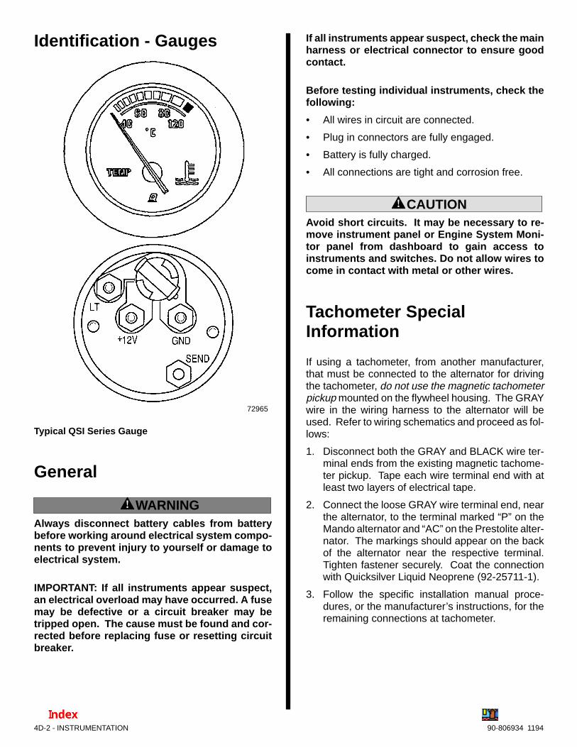
4D-2 - INSTRUMENTATION 90-806934 1194
Identification - Gauges
72965
Typical QSI Series Gauge
General
! WARNINGAlways disconnect battery cables from batterybefore working around electrical system compo-nents to prevent injury to yourself or damage toelectrical system.
IMPORTANT: If all instruments appear suspect,an electrical overload may have occurred. A fusemay be defective or a circuit breaker may betripped open. The cause must be found and cor-rected before replacing fuse or resetting circuitbreaker.
If all instruments appear suspect, check the mainharness or electrical connector to ensure goodcontact.
Before testing individual instruments, check thefollowing:
• All wires in circuit are connected.
• Plug in connectors are fully engaged.
• Battery is fully charged.
• All connections are tight and corrosion free.
! CAUTIONAvoid short circuits. It may be necessary to re-move instrument panel or Engine System Moni-tor panel from dashboard to gain access toinstruments and switches. Do not allow wires tocome in contact with metal or other wires.
Tachometer SpecialInformation
If using a tachometer, from another manufacturer,that must be connected to the alternator for drivingthe tachometer, do not use the magnetic tachometerpickup mounted on the flywheel housing. The GRAYwire in the wiring harness to the alternator will beused. Refer to wiring schematics and proceed as fol-lows:
1. Disconnect both the GRAY and BLACK wire ter-minal ends from the existing magnetic tachome-ter pickup. Tape each wire terminal end with atleast two layers of electrical tape.
2. Connect the loose GRAY wire terminal end, nearthe alternator, to the terminal marked “P” on theMando alternator and “AC” on the Prestolite alter-nator. The markings should appear on the backof the alternator near the respective terminal.Tighten fastener securely. Coat the connectionwith Quicksilver Liquid Neoprene (92-25711-1).
3. Follow the specific installation manual proce-dures, or the manufacturer’s instructions, for theremaining connections at tachometer.
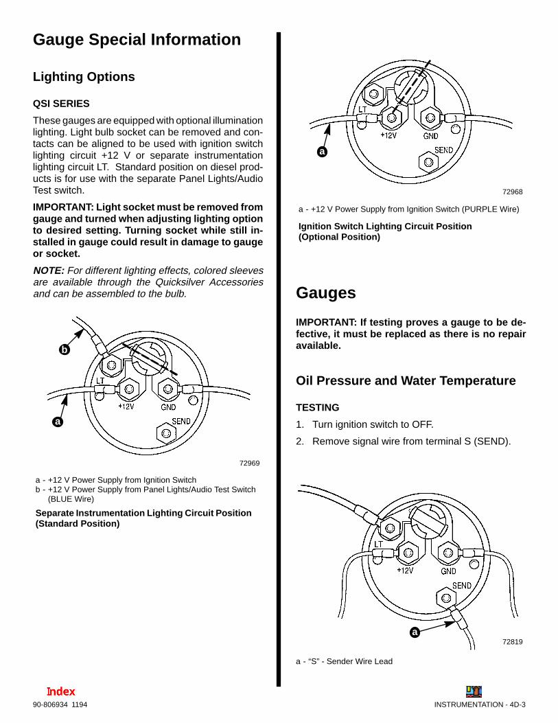
INSTRUMENTATION - 4D-390-806934 1194
Gauge Special Information
Lighting Options
QSI SERIES
These gauges are equipped with optional illuminationlighting. Light bulb socket can be removed and con-tacts can be aligned to be used with ignition switchlighting circuit +12 V or separate instrumentationlighting circuit LT. Standard position on diesel prod-ucts is for use with the separate Panel Lights/AudioTest switch.
IMPORTANT: Light socket must be removed fromgauge and turned when adjusting lighting optionto desired setting. Turning socket while still in-stalled in gauge could result in damage to gaugeor socket.
NOTE: For different lighting effects, colored sleevesare available through the Quicksilver Accessoriesand can be assembled to the bulb.
72969
a - +12 V Power Supply from Ignition Switchb - +12 V Power Supply from Panel Lights/Audio Test Switch
(BLUE Wire)
Separate Instrumentation Lighting Circuit Position(Standard Position)
b
a
72968
a - +12 V Power Supply from Ignition Switch (PURPLE Wire)
Ignition Switch Lighting Circuit Position(Optional Position)
a
Gauges
IMPORTANT: If testing proves a gauge to be de-fective, it must be replaced as there is no repairavailable.
Oil Pressure and Water Temperature
TESTING
1. Turn ignition switch to OFF.
2. Remove signal wire from terminal S (SEND).
72819a
a - “S” - Sender Wire Lead

4D-4 - INSTRUMENTATION 90-806934 1194
3. Turn ignition switch to RUN. Gauge being testedmust be at position A.
73288
aa
a - Needle at Position A
Typical
4. Turn ignition switch to OFF.
5. Connect jumper wire from terminal G (GND) toterminal S (SEND).
72748a
a - Jumper Wire
6. Turn ignition switch to RUN.
7. Indicator needle of gauge being tested must readat position B.
73289
aa
a - Needle at Position B
Typical
Volt Meter Gauge
TESTING
1. Remove cables from battery and fully charge bat-tery. Remove wires from back of gauge.
2. Connect negative (–) jumper lead from battery togauge terminal G (GND).
3. Connect positive (+) jumper lead from a 12 Voltpower source, or battery, to gauge terminal I or+12 V.
72750
a
b
a - Volt Meterb - 12 Volt Power Source
4. Check gauge reading; if not indicating batteryvoltage, as shown, replace gauge.
73290
a
a - Needle Indicating Battery Voltage
Typical

INSTRUMENTATION - 4D-590-806934 1194
Cruiselog (Engine Hour Meter)
TESTING
1. Remove cables from battery and fully charge bat-tery. Remove wires from back of gauge.
2. Connect positive (+) jumper lead from battery togauge terminal + (12 V).
3. Connect negative (–) jumper lead from battery togauge terminal GND (ground).
7281572750
4. Observe gauge run indicator on face of gauge. Ifindicator is turning, the gauge is operable. If notreplace gauge.
Tachometer
TESTING
1. If gauge is not accurate, be certain the switch onthe back of the tachometer is set properly. On In-Line Diesel engines using magnetic tachometerpickup for source, the setting is as follows:
Tachometer Switch Setting
Model Engine PulsesPer Revolution
SwitchPosition
D3.0L/150,D3.6L/180 and
D4.2L/220103 1
NOTE: Refer to “Tachometer Special Information” asdiscussed earlier, if using an alternator driventachometer.
2. If properly set and still inaccurate, connect a die-sel timing tool or suitable service tachometer toengine and compare readings.
3. Replace if not within specifications.
TachometerType Allowable Range
5000 RPM + 100 RPM
Gauge Replacement1. Disconnect battery cables from battery.
2. Remove wires from back of gauge.
3. Disconnect light socket wiring if separate.
4. Remove holding strap and remove gauge.
5. Position gauge assembly in appropriate mount-ing hole.
6. Install holding strap and nuts. Tighten nuts evenlyand securely.
IMPORTANT: Do not distort case or bracket byover-tightening.
7. Connect ground (BLACK) wire to ground termi-nal, if gauge is not mounted in metal panel.
8. Connect other wires to gauge as shown in SEC-TION 4E - “Wiring Diagrams”.
9. Install gauge light socket.
10. Coat all terminals with Quicksilver Liquid Neo-prene.
11. Reconnect battery cables to battery.

4D-6 - INSTRUMENTATION 90-806934 1194
Senders
Oil Pressure
REMOVAL
1. Remove LIGHT BLUE wire from sender.
2. Using a suitable wrench to hold the adaptor fitting(to prevent loosening of main bearing locatingscrew), unscrew the sender.
74281
d
c
a
b
a - LIGHT BLUE Wireb - Oil Pressure Senderc - Adaptor Fittingd - Main Bearing Locating Screw
TESTING
IMPORTANT: Use following test procedure forchecking accuracy of oil pressure sender only. Ifoil pressure gauge indicates zero oil pressure, re-fer to Section 1C - “Troubleshooting.”
1. Remove LIGHT BLUE wire from sender. Insulateto avoid possible short circuit.
2. Install a manual pressure gauge graduated in atleast 10 PSI (100 kPa or 1 bars) increments, usinga suitable “T”-fitting arrangement with the existingsender and adaptor or fitting.
3. Connect an ohmmeter between sender terminaland sender case.
NOTE: Sender shown removed for visual clarity only.
7293670686
74281
a
b
c
a - Oil Pressure Senderb - Adaptor Fittingc - Install Manual Pressure Gauge Here on a“T”-Fitting
4. Refer to chart. Check the resistance values of theappropriate sender at pressures as shown andverified on manual gauge with engine running.Replace sender if values are not correct.
SINGLE STATION SENDER - 805267
OIL PRESSUREPSI (kPa)
OHMS READING
0 (0) 240 15 Ω
60 (413.7) 103 15 Ω
DUAL STATION SENDER - 805268
Oil PressurePSI (kPa)
Ohms Reading
0 (0) 120 7 Ω
60 (413.7) 52 7 Ω
5. When replacing sender, coat threads with LoctitePipe Sealant with Teflon and install. Tighten se-curely.

INSTRUMENTATION - 4D-790-806934 1194
Water Temperature - Primary Station
REMOVAL
1. Drain coolant from closed cooling system into asuitable container, as outlined in SECTION 6B.
2. Remove harness wiring block from temperatureswitch located as shown.
70192
ab
c
Engines With Sender Mounted On Manifold End Cover
ba
c
74284
Engines With Sender Mounted On Cylinder Head
a - Harness Wiring Blockb - Water Temperature Senderc - Sealing Washer
3. Remove sender and sealing washer.
TESTING
IMPORTANT: Use the following test to determinethe accuracy of the Water Temperature Sendergauge circuit. If gauge indicates NO temperaturewhen running engine refer to the “TROUBLE-SHOOTING” section.
1. Connect an ohmmeter between sender terminal“G and switch hex (case) for “ground” (–) asshown.
70686
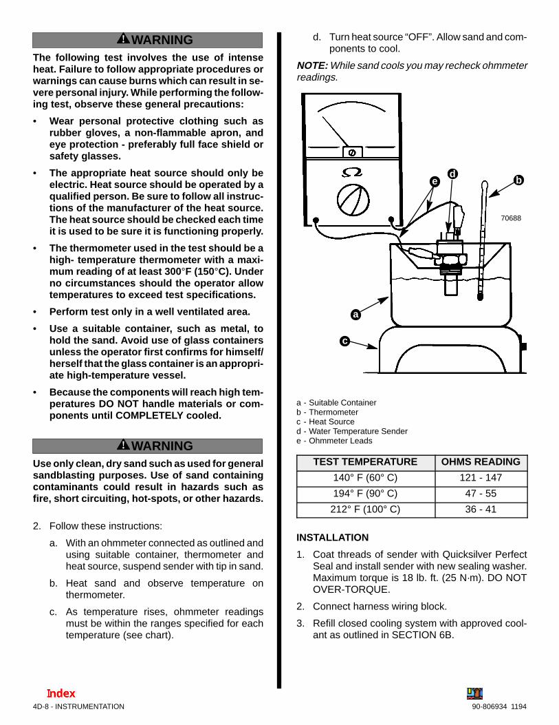
4D-8 - INSTRUMENTATION 90-806934 1194
! WARNINGThe following test involves the use of intenseheat. Failure to follow appropriate procedures orwarnings can cause burns which can result in se-vere personal injury. While performing the follow-ing test, observe these general precautions:
• Wear personal protective clothing such asrubber gloves, a non-flammable apron, andeye protection - preferably full face shield orsafety glasses.
• The appropriate heat source should only beelectric. Heat source should be operated by aqualified person. Be sure to follow all instruc-tions of the manufacturer of the heat source.The heat source should be checked each timeit is used to be sure it is functioning properly.
• The thermometer used in the test should be ahigh- temperature thermometer with a maxi-mum reading of at least 300 °F (150°C). Underno circumstances should the operator allowtemperatures to exceed test specifications.
• Perform test only in a well ventilated area.
• Use a suitable container, such as metal, tohold the sand. Avoid use of glass containersunless the operator first confirms for himself/herself that the glass container is an appropri-ate high-temperature vessel.
• Because the components will reach high tem-peratures DO NOT handle materials or com-ponents until COMPLETELY cooled.
! WARNINGUse only clean, dry sand such as used for generalsandblasting purposes. Use of sand containingcontaminants could result in hazards such asfire, short circuiting, hot-spots, or other hazards.
2. Follow these instructions:
a. With an ohmmeter connected as outlined andusing suitable container, thermometer andheat source, suspend sender with tip in sand.
b. Heat sand and observe temperature onthermometer.
c. As temperature rises, ohmmeter readingsmust be within the ranges specified for eachtemperature (see chart).
d. Turn heat source “OFF”. Allow sand and com-ponents to cool.
NOTE: While sand cools you may recheck ohmmeterreadings.
70688
b
c
a
ed
a - Suitable Containerb - Thermometerc - Heat Sourced - Water Temperature Sendere - Ohmmeter Leads
TEST TEMPERATURE OHMS READING
140° F (60° C) 121 - 147
194° F (90° C) 47 - 55
212° F (100° C) 36 - 41
INSTALLATION
1. Coat threads of sender with Quicksilver PerfectSeal and install sender with new sealing washer.Maximum torque is 18 lb. ft. (25 N·m). DO NOTOVER-TORQUE.
2. Connect harness wiring block.
3. Refill closed cooling system with approved cool-ant as outlined in SECTION 6B.
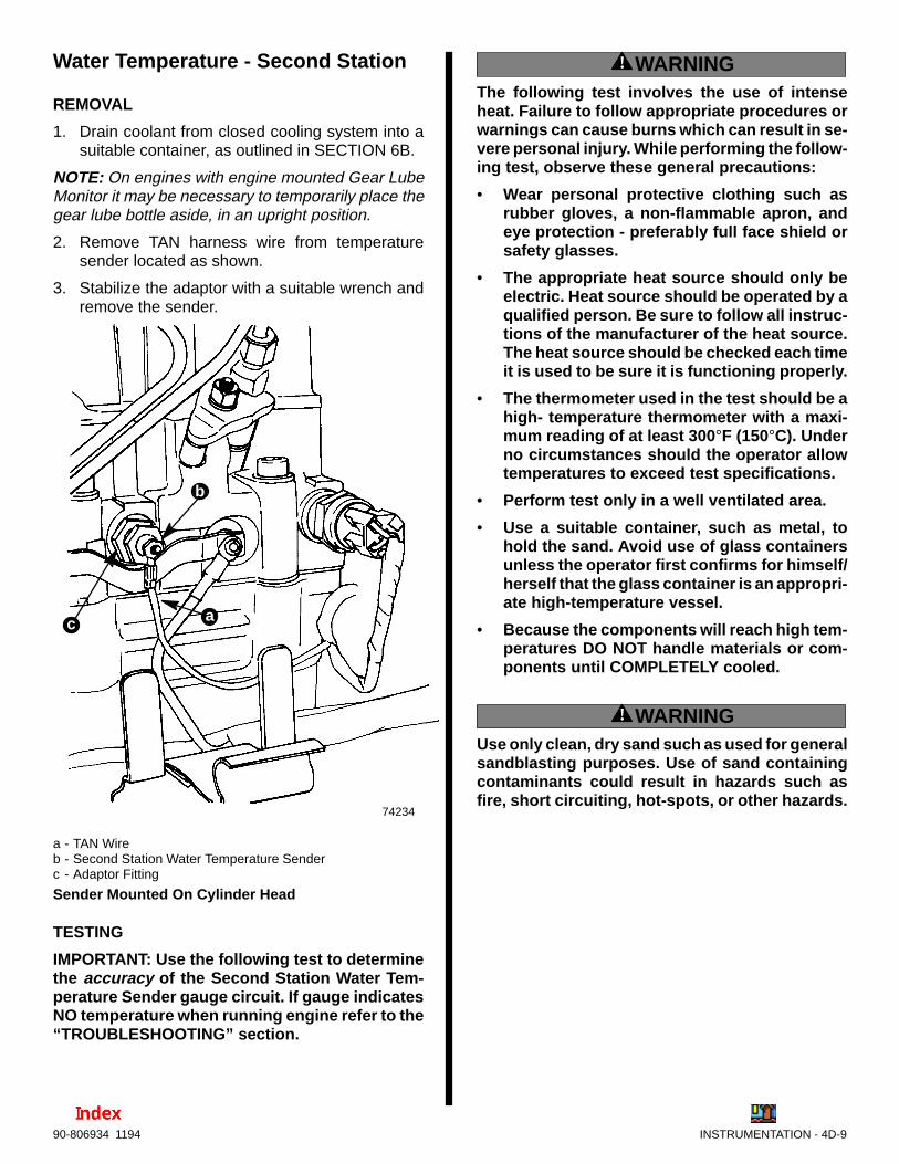
INSTRUMENTATION - 4D-990-806934 1194
Water Temperature - Second Station
REMOVAL
1. Drain coolant from closed cooling system into asuitable container, as outlined in SECTION 6B.
NOTE: On engines with engine mounted Gear LubeMonitor it may be necessary to temporarily place thegear lube bottle aside, in an upright position.
2. Remove TAN harness wire from temperaturesender located as shown.
3. Stabilize the adaptor with a suitable wrench andremove the sender.
74234
a
b
c
a - TAN Wireb - Second Station Water Temperature Senderc - Adaptor Fitting
Sender Mounted On Cylinder Head
TESTING
IMPORTANT: Use the following test to determinethe accuracy of the Second Station Water Tem-perature Sender gauge circuit. If gauge indicatesNO temperature when running engine refer to the“TROUBLESHOOTING” section.
! WARNINGThe following test involves the use of intenseheat. Failure to follow appropriate procedures orwarnings can cause burns which can result in se-vere personal injury. While performing the follow-ing test, observe these general precautions:
• Wear personal protective clothing such asrubber gloves, a non-flammable apron, andeye protection - preferably full face shield orsafety glasses.
• The appropriate heat source should only beelectric. Heat source should be operated by aqualified person. Be sure to follow all instruc-tions of the manufacturer of the heat source.The heat source should be checked each timeit is used to be sure it is functioning properly.
• The thermometer used in the test should be ahigh- temperature thermometer with a maxi-mum reading of at least 300 °F (150°C). Underno circumstances should the operator allowtemperatures to exceed test specifications.
• Perform test only in a well ventilated area.
• Use a suitable container, such as metal, tohold the sand. Avoid use of glass containersunless the operator first confirms for himself/herself that the glass container is an appropri-ate high-temperature vessel.
• Because the components will reach high tem-peratures DO NOT handle materials or com-ponents until COMPLETELY cooled.
! WARNINGUse only clean, dry sand such as used for generalsandblasting purposes. Use of sand containingcontaminants could result in hazards such asfire, short circuiting, hot-spots, or other hazards.

4D-10 - INSTRUMENTATION 90-806934 1194
1. Follow these instructions:
a. With an ohmmeter connected as shown fol-lowing and using a suitable container, ther-mometer and heat source, suspend senderwith tip in sand.
b. Heat sand and observe temperature on ther-mometer.
70688
+–
c. As the temperature rises ohmmeter readingsmust be within the ranges specified for eachtemperature. Refer to the chart below forspecifications.
SECOND STATION SENDER - 49734
Test Temperature Ohms Reading
100° F (38° C) 203 - 247 Ω160° F (71° C) 59 - 70 Ω220° F (71° C) 22 - 25 Ω
d. Turn heat source “OFF”. Allow sand and com-ponent to cool.
NOTE: While sand cools you may recheck ohmmeterreadings.
2. Replace sender if ohmmeter readings are otherthan as shown, for each temperature.
INSTALLATION
1. Apply Loctite Pipe Sealant with Teflon to threadsof sender and install. Tighten securely.
2. Refill closed cooling system with approved cool-ant as outlined in SECTION 6B.
Primary Station Switches
IMPORTANT: Disconnect battery cables from bat-tery before testing switches with wires still con-nected to switches.
IMPORTANT: The decal, or decals, on the side ofthe toggle switches, with the arrow and the word“UP”, refer to the position of the switch wheninstalled on the panel .
Ignition Key Switch
REMOVAL
1. Remove nut retaining switch to Engine SystemMonitor Panel.
73546a
c
b
a - Engine System Monitor Panelb - Ignition Key Switchc - Retainer
2. Remove wires from back of switch.

INSTRUMENTATION - 4D-1190-806934 1194
TESTING
1. Before testing key switch, check all fuses and/orcircuit breakers in electrical circuit which couldprevent operation of starter.
IMPORTANT: Disconnect battery cables from bat-tery before testing ignition key switch with wiresstill connected to switch.
2. Disconnect battery cables from battery, if pro-ceeding to test switch with wires still connected.With key switch in OFF position, there should beno continuity between switch terminals.
3. With key switch in RUN position, continuity will ex-ist between switch terminals “B” to “I”. Thereshould be no continuity between terminal “S” andany other terminals.
4. With key switch in START, continuity will exist be-tween terminals “B” to “I” and “B” to “S”.
5. Terminals are to make contact at angles shownand to stay in contact condition as switch is ro-tated toward START.
6. If ignition key switch tests bad, unscrew or un-solder wire connections and remove switch. Testswitch again, as in Steps 2-5, preceding. If switchtests good, wiring in harness is bad. There shouldbe no continuity between any switch harnesswires with key switch removed.
74103a - Keyb - Offc - Continuity B to I Terminalsd - Rune - Continuity, B to S Terminalsf - Start
Key View Back View
BSI
b
cdef
a
Stop SwitchThe “STOP” switch is a single-pole, momentarily“closed” switch, provided for stopping the engine.This is done by electrically shutting off the fuel deliv-ery system.
NOTE: The ignition key switch must be in the “RUN”position for the stop switch to function properly wheninstalled and connected.
REMOVAL
1. Remove hex nut retaining switch to Engine Sys-tem Monitor Panel.
73546a
cb
a - Engine System Monitor Panelb - Toggle “STOP” Switchc - Hex Nut Retainer
2. Remove wires from back of switch.
TESTING
1. With switch removed, or accessible, attach anohmmeter to terminal numbers 1 and 2 as indi-cated by the decal.
2. With switch lever toggled “DOWN” to its springloaded “ position continuity should exist betweenterminal numbers 1 and 2. If no continuity exists,replace switch.
ÉÉÉÉ
a
d
c
87-8
0567
6U
P 12
b
a - Stop Switchb - Toggle Lever Spring Loaded Position
(Direction of Movement DOWN When Installed)c - Terminal Number 2d - Terminal Number 1

4D-12 - INSTRUMENTATION 90-806934 1194
INSTALLATION
1. Using screws provided, install wires to appropri-ate switch terminals as shown in chart.
2. Make sure that all connections are secure. Sealterminals with Liquid Neoprene (92-25711--1).
3. Install switch in Engine System Monitor panel.Tighten hex nut securely to prevent switch fromturning in its mounting hole. DO NOT overtighten.
ÉÉÉÉÉÉÉÉÉÉÉÉÉÉÉÉÉÉÉÉÉÉÉÉÉÉ
73369
ÉÉÉÉ
a
d
ce
87-8
0567
6U
P 12
b
f
g
h
a - Stop Switchb - Toggle Lever Spring Loaded Position
(Direction of Movement DOWN When Installed)c - Terminal Number 2d - Terminal Number 1e - Jamb Nutf - Locking Washerg - Panelh - Hex Nut Retainer
Harness Wire(Color Code) Connect To: Terminal
Number
BLK/YELLOW(BLK/YEL)
2
PURPLE (PPL) 1
Audio Warning Test and Panel LightSwitchThe switch provided for the audio warning test andpanel (dash) lights is a three-position toggle switch.It must be wired and installed correctly to provideproper operation of the systems.
REMOVAL
1. Remove hex nut retaining switch to Engine Sys-tem Monitor Panel.
2. Remove wires from back of switch.
TESTING
1. With switch lever toggled “DOWN” to its springloaded AUDIO TEST position continuity shouldexist between terminal numbers 1 and 2 (asindicated by decals). If no continuity exists,replace switch.
2. With switch lever toggled “UP” to the panel light“ON” position, continuity should exist betweenterminal numbers 4 and 5 (as indicated by de-cals). If no continuity exists, replace switch.
b
a
73369
ÉÉÉ
87-805675
UP
12
3
d
c
UP
4
5
6 1
2
3
a - Audio Test/Panel Light Switchb - Spring-Loaded Audio Test Portion
(Direction of Movement DOWN When Installed)c - Terminal Number(s)d - Terminal(s)
INSTALLATION
1. Using screws provided, connect the listed colorcoded wires to numbered switch terminals asshown.
2. Make sure that all connections are secure. Sealterminals with Liquid Neoprene (92-25711).

INSTRUMENTATION - 4D-1390-806934 1194
3. Install switch in Engine System Monitor panel.Tighten hex nut securely to prevent switch fromturning in its mounting hole. DO NOT overtigh-ten.
b
a
b
71886
73369
ÉÉÉ
87-805675
UP
12
3
ed
fcU
P
4
5
6 1
2
3
a
ÉÉÉÉÉÉÉÉÉÉÉÉÉÉÉÉÉÉ
h
g
a - Audio Test/Panel Light Switchb - Spring-Loaded Audio Test Portion
(Direction of Movement DOWN When Installed)c - Terminal Number(s)d - Terminal(s)e - Jamb Nutf - Locking Washerg - Engine System Monitor Panelh - Hex Nut
Harness Wire(Color Code) Connect To: Terminal
Number
BLACK (BLK) 2
TAN/BLACK(TAN/BLK)
1
BLUE (BLU) 5
PURPLE (PPL) 4
Secondary Station Switches
Start SwitchThe “START” switch, provided for starting the engineat this second station, is a single-pole, momentarily“closed” switch.
REMOVAL
1. Remove hex nut retaining switch to Engine Sys-tem Monitor Panel.
2. Remove wires from back of switch.
TESTING
1. Toggle switch lever to its spring loaded STARTposition.
2. Continuity should exist between terminal num-bers 1 and 2 (as indicated by decals). If no conti-nuity exists, replace switch.
INSTALLATION
1. Using screws provided, connect the listed colorcoded wires to numbered switch terminals asshown in chart.
2. Make sure that all connections are secure. Sealterminals with Liquid Neoprene (92-25711).
3. Install jamb nut, and then locking washer, onswitch threaded portion. Secure to panel usinghex nut. Tighten securely, to prevent switch fromturning in hole. DO NOT overtighten.
74057
73369
ÉÉÉÉ d
ce
87-8
0567
6U
P 12
f
b a
b
ÉÉÉÉÉÉÉÉ
h
g
a - Start Switchb - Toggle Lever Spring Loaded Position
(Direction of Movement DOWN When Installed)c - Terminal Number(s)d - Terminal(s)e - Jamb Nutf - Locking Washer
Harness Wire(Color Code) Connect To: Terminal
Number
PURPLE (PPL) 1
YELLOW/RED(YEL/RED)
2

4D-14 - INSTRUMENTATION 90-806934 1194
Stop SwitchThe “STOP” switch, provided for stopping the engineat this second station, is a single-pole, momentarily“closed” switch.
REMOVAL
1. Remove hex nut retaining switch to Engine Sys-tem Monitor Panel.
2. Remove wires from back of switch.
INSTALLATION
1. Using screws provided, connect the listed colorcoded wires to numbered switch terminals asshown in chart.
2. Make sure that all connections are secure. Sealterminals with Liquid Neoprene (92-25711).
3. Install jamb nut, and then locking washer, onswitch threaded portion. Secure to panel usinghex nut. Tighten securely, to prevent switch fromturning in hole. DO NOT overtighten.
74057
73369
ÉÉÉ
a
ce
87-8
0567
6U
P 12
b
f
b
ÉÉÉÉÉÉÉÉÉÉÉÉÉÉÉÉÉÉ
h
g
d
a - S t o p S w i t c hb - T o g g l e L e v e r S p r i n g L o a d e d P o s i t i o n
( D i r e c t i o n o f M o v e m e n t D O W N W h e n I n s t a l l e d )c - T e r m i n a l N u m b e r ( s )d - T e r m i n a l ( s )e - J a m b N u tf - L o c k i n g W a s h e r
H a r n e s s W i r e( C o l o r C o d e )
C o n n e c tTo:
Terminal Numberand/or Connection
Location
PURPLE (PPL) 1
BLACK/YEL-LOW
(BLK/YEL) 2
Note 1.: Wire is sta-strapped to instrument harnessnear connector collar.
Audio Warning SystemThe Audio Warning System is divided into two sepa-rate circuits. Both circuits have an individual audiowarning buzzer that does NOT include any timedelay.
One circuit consists of the engine water temperatureswitch and related wiring. If this switch is activated(“closed”) during the operation of the engine, thealarm buzzer will sound and the Engine System Moni-tor panel light will be illuminated until the problem iscorrected or the electrical system is shut off (keyswitched “OFF”).
The other circuit consists of the engine oil pressureswitch, the transmission temperature switch [MIE (In-board) models] or the gear lube monitor bottle switch[MCM (Stern Drive) models) and related wiring.These switches are connected to the audio warningbuzzer through a control relay which is activatedwhen the glow plug control system has completed the“preheat cycle”. Likewise, the Engine System Moni-tor panel light is illuminated whenever the respectiveswitch is activated (“closed”) until the problem is cor-rected or the electrical system is shut off (keyswitched “OFF”)..
The function of an audio warning buzzer can betested by holding the toggle lever of the Audio Testswitch (on the Engine System Monitor panel) DOWNmomentarily, with the key switch in the “RUN” posi-tion. If the buzzer sounds the buzzer is operable.
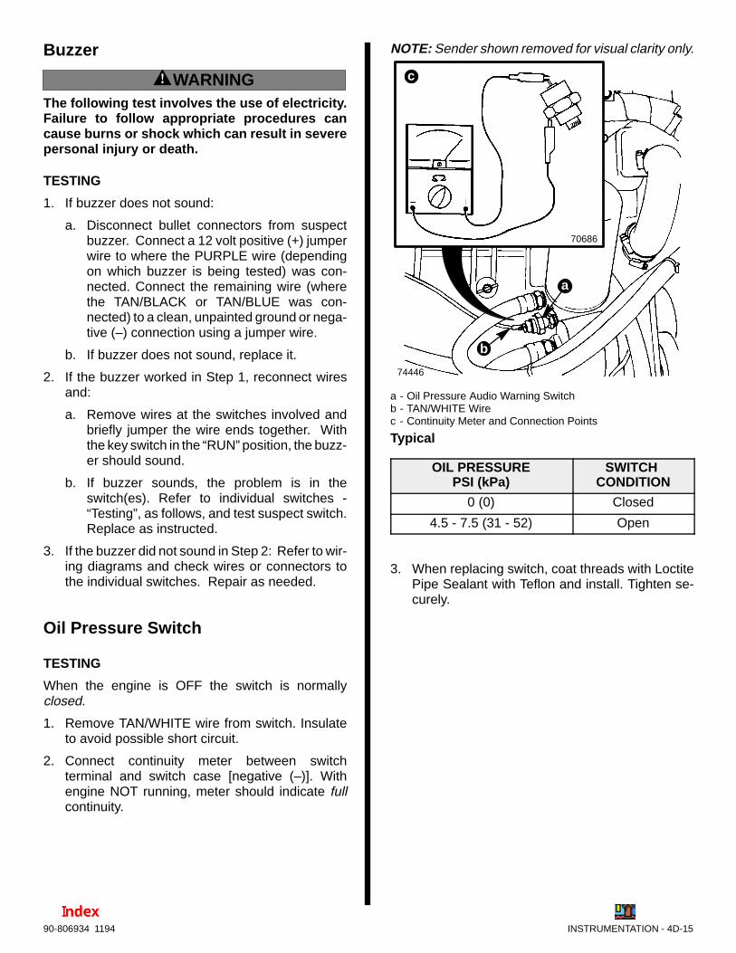
INSTRUMENTATION - 4D-1590-806934 1194
Buzzer
! WARNINGThe following test involves the use of electricity.Failure to follow appropriate procedures cancause burns or shock which can result in severepersonal injury or death.
TESTING
1. If buzzer does not sound:
a. Disconnect bullet connectors from suspectbuzzer. Connect a 12 volt positive (+) jumperwire to where the PURPLE wire (dependingon which buzzer is being tested) was con-nected. Connect the remaining wire (wherethe TAN/BLACK or TAN/BLUE was con-nected) to a clean, unpainted ground or nega-tive (–) connection using a jumper wire.
b. If buzzer does not sound, replace it.
2. If the buzzer worked in Step 1, reconnect wiresand:
a. Remove wires at the switches involved andbriefly jumper the wire ends together. Withthe key switch in the “RUN” position, the buzz-er should sound.
b. If buzzer sounds, the problem is in theswitch(es). Refer to individual switches -“Testing”, as follows, and test suspect switch.Replace as instructed.
3. If the buzzer did not sound in Step 2: Refer to wir-ing diagrams and check wires or connectors tothe individual switches. Repair as needed.
Oil Pressure Switch
TESTING
When the engine is OFF the switch is normallyclosed.
1. Remove TAN/WHITE wire from switch. Insulateto avoid possible short circuit.
2. Connect continuity meter between switchterminal and switch case [negative (–)]. Withengine NOT running, meter should indicate fullcontinuity.
NOTE: Sender shown removed for visual clarity only.
74446
70686
b
a
c
a - Oil Pressure Audio Warning Switchb - TAN/WHITE Wirec - Continuity Meter and Connection Points
Typical
OIL PRESSUREPSI (kPa)
SWITCH CONDITION
0 (0) Closed
4.5 - 7.5 (31 - 52) Open
3. When replacing switch, coat threads with LoctitePipe Sealant with Teflon and install. Tighten se-curely.

4D-16 - INSTRUMENTATION 90-806934 1194
Water Temperature Switch/SenderWhen engine is COLD audio warning circuit is nor-mally open.
REMOVAL
1. Drain coolant from closed cooling system into asuitable container, as outlined in SECTION 6B.
2. Remove harness wiring block from temperatureswitch/sender located as shown.
70192
ab
c
Engines With Switch/Sender Mounted On ManifoldEnd Cover
ba
c
74284
Engines With Switch/Sender Mounted On CylinderHead
a - Harness Wiring Blockb - Water Temperature Switch/Senderc - Sealing Washer
3. Remove switch/sender and sealing washer.
TESTING
1. With engine COLD, remove wiring block fromswitch/sender terminals. Note position on switch/sender for terminal referred to as “W”
70683
a
b
a - Water Temperature Switch/Senderb - Terminal “W” - Audio Warning Switch Circuit
2. Refer to the proceeding and connect a continuitymeter between switch terminal “W” and senderhex (case).
a. No continuity should exist.
b. If continuity exists, replace sender.
3. To test switch circuit for closing (sound buzzer),as if coolant temperature rises above operatingspecifications, follow instructions “a ”- “f”:
a. Refer to ”Removal” as previously outlined andremove the switch/sender.
b. Refer to top view of switch/sender in Step 1,and using suitable jumper leads connectbuzzer terminal “–” to switch terminal “W”.Then, using suitable jumpers and being care-ful to avoid short circuits, connect the nega-tive (–) of a 12 volt power source to sendercase and the positive (+) to the “+” on thebuzzer, as shown following.

INSTRUMENTATION - 4D-1790-806934 1194
! WARNINGThe following test involves the use of intenseheat. Failure to follow appropriate procedures orwarnings can cause burns which can result in se-vere personal injury. While performing the follow-ing test, observe these general precautions:
• Wear personal protective clothing such asrubber gloves, a non-flammable apron, andeye protection - preferably full face shield orsafety glasses.
• The appropriate heat source should only beelectric. Heat source should be operated by aqualified person. Be sure to follow all instruc-tions of the manufacturer of the heat source.The heat source should be checked each timeit is used to be sure it is functioning properly.
• The thermometer used in the test should be ahigh- temperature thermometer with a maxi-mum reading of at least 300 °F (150°C). Underno circumstances should the operator allowtemperatures to exceed test specifications.
• Perform test only in a well ventilated area.
• Use a suitable container, such as metal, tohold the sand. Avoid use of glass containersunless the operator first confirms for himself/herself that the glass container is an appropri-ate high-temperature vessel.
• Because the components will reach high tem-peratures DO NOT handle materials or com-ponents until COMPLETELY cooled.
! WARNINGUse only clean, dry sand such as used for generalsandblasting purposes. Use of sand containingcontaminants could result in hazards such asfire, short circuiting, hot-spots, or other hazards.
c. Using suitable container, thermometer andheat source, suspend switch with tip in sand.
d. Heat sand and observe temperature onthermometer.
e. Replace switch/sender if it does not close(sound buzzer) within the range of tempera-tures indicated in chart.
f. Turn heat source “OFF”. Allow sand and com-ponents to cool.
70758
b
c
d
a
71772
e
a - Suitable Containerb - Thermometerc - Heat Sourced - Water Temperature Switch/Sendere - 12 Volt Power Source and Jumper Leadsf - Audio Warning Buzzer With Jumper Lead
TEST TEMPERATURE SWITCH CONDITION
215 - 220° F (102 - 106° C) Closed
INSTALLATION
1. Coat threads of switch/sender with QuicksilverPerfect Seal and install with new sealing washer.Maximum torque is 18 lb. ft. (25 N·m). DO NOTOVER-TORQUE.
2. Connect harness wiring block.
3. Refill closed cooling system with approved cool-ant as outlined in SECTION 6B.

4D-18 - INSTRUMENTATION 90-806934 1194
Transmission Fluid TemperatureSwitchWhen transmission is COLD or at a temperature lessthan as shown (See “Test Temperature Chart”follow-ing.), the switch is open.
REMOVAL
1. Disconnect harness wires at switch.
2. Remove switch and sealing washer.
72770a - Transmission Fluid Temperature Switch with Sealing
Washerb - Harness Wires
b
a
Hurth Transmissions (630A and 630V)
TESTING
1. With transmission COLD, connect one lead of anohmmeter to one terminal of transmission switch.Connect the other lead of ohmmeter to other ter-minal.
NOTE: Shown removed for visual clarity only.
72771
a - Ohmmeter Leadsb - Transmission Fluid Temperature Switch
b
a
2. Switch should read no continuity. Replace switch,if continuity exists.

INSTRUMENTATION - 4D-1990-806934 1194
! WARNINGThe following test involves the use of intenseheat. Failure to follow appropriate procedures orwarnings can cause burns which can result in se-vere personal injury. While performing the follow-ing test, observe these general precautions:
• Wear personal protective clothing such asrubber gloves, a non-flammable apron, andeye protection - preferably full face shield orsafety glasses.
• The appropriate heat source should only beelectric. Heat source should be operated by aqualified person. Be sure to follow all instruc-tions of the manufacturer of the heat source.The heat source should be checked each timeit is used to be sure it is functioning properly.
• The thermometer used in the test should be ahigh- temperature thermometer with a maxi-mum reading of at least 300 °F (150°C). Underno circumstances should the operator allowtemperatures to exceed test specifications.
• Perform test only in a well ventilated area.
• Use a suitable container, such as metal, tohold the sand. Avoid use of glass containersunless the operator first confirms for himself/herself that the glass container is an appropri-ate high-temperature vessel.
• Because the components will reach high tem-peratures DO NOT handle materials or com-ponents until COMPLETELY cooled.
! WARNINGUse only clean, dry sand such as used for generalsandblasting purposes. Use of sand containingcontaminants could result in hazards such asfire, short circuiting, hot-spots, or other hazards.
3. Follow these instructions:
a. With an ohmmeter connected as outlined andusing suitable container, thermometer andheat source, suspend sender with tip in sand.
b. Heat sand and observe thermometer.
c. As temperature rises, switch will close andohmmeter will indicate continuity. Refer tochart below for specifications.
72772
a - Suitable Containerb - Thermometerc - Heat Sourced - Transmission Fluid Temperature Switche - Ohmmeter Leads
b
cd
a
e
TEST TEMPERATURE SWITCH CONDITION
258 - 282° F (126 - 138° C) Closed
218 - 242° F (103 - 117° C) Open
4. Turn heat source off. Allow sand to cool. Notethermometer reading to ensure switch opens atspecified temperature while cooling.
5. Replace switch if switch fails to either open orclose within the specified temperature.
INSTALLATION
1. Apply Quicksilver Perfect Seal to threads of trans-mission fluid temperature switch.
2. Install switch with sealing washer in transmissionand tighten securely.
3. Reconnect harness wires and coat with Quicksil-ver Liquid Neoprene.
4. Check transmission fluid level.

4
E
ELECTRICAL SYSTEMS
WIRING DIAGRAMS
Note:Refer to the following Service Bulletin regarding this section.
SB 96-2 Water In Fuel Module (WIF) Warning Light

4E -0 - WIRING DIAGRAMS 90-806934 1194
Table of ContentsPage
Wiring Colors for MerCruiser Diesel 4E -1. . . . . . . . . . . . . Wire Color Abbreviations 4E -1. . . . . . . . . . . . . . . . . . . . . . Engine Wiring Diagrams 4E -2. . . . . . . . . . . . . . . . . . . . . . .
MCM - D3.0L/150, D3.6L/180 and D4.2L/220 - Mando Alternator 4E -2. . . . . . . . . . . MCM - D3.0L/150, D3.6L/180 and D4.2L/220 - Prestolite Alternator 4E -3. . . . . . . . . MIE - D3.0L/150, D3.6L/180 and D4.2L/220 - Mando Alternator 4E -4. . . . . . . . . . . . . . . . . . . . . . . . MIE - D3.0L/150, D3.6L/180 and D4.2L/220 - Prestolite Alternator 4E -5. . . . . . . . . . . . . . . . . . . . . .
Quicksilver Instrumentation 4E -6. . . . . . . . . . . . . . . . . . . . MCM - D3.0L/150, D3.6L/150 and D4.2L/220 4E -6. . MIE - D3.0L/150, D3.6L/180 and D4.2L/220 4E -7. . . MCM - Second Station Instrumentation 4E -8. . . . . . . MIE - Second Station Instrumentation 4E -9. . . . . . . .
Wiring Harness ConnectionsMCM - (Standard) 4E -10. . . . . . . . . . . . . . . . . . . . . . . . MCM - (Optional) 4E -11. . . . . . . . . . . . . . . . . . . . . . . . MIE 4E -12. . . . . . . . . . . . . . . . . . . . . . . . . . . . . . . . . . . . .
NOTE: If using other than Quicksilver instrumenta-tion and harnesses, refer to manufacturers’ instruc-tions.
4E - WIRING DIAGRAMS

WIRING DIAGRAMS - 4E -190-806934 1194
Wiring Colors for MerCruiser DieselWhere Used
Color CodePrimary Usage Secondary Usage
Black All Grounds
Black/Yellow Engine Stop
Blue Instrument Lighting
Blue/Black Glow Plug Wait Switch
Blue/Tan Glow Plug Wait Lamp
Blue/White Glow Plugs
Brown Alternator Charge Lamp Reference Electrode-MerCathode
Brown/White Trim Sender to Trim Gauge
Gray Tachometer Signal
Green Glow Plug Temperature Sensor
Green/White Trim -“Down” Switch
Lt. Blue Oil Pressure Sender to Gauge
Lt. Blue/White Trim- “Up” Switch
Orange Alternator DC Output Anode Electrode-MerCathode
Pink Fuel Gauge Sender to Gauge
Purple Ignition Switch (+12 V)
Purple/White Trim-“Trailer” Switch
Red Unprotected Wires from Battery
Red/Purple Protected (Fused) Wires from Battery Protected (+ 12V) to Trim Panel
Tan Water Temperature Sender to Gauge
Tan/Black Water Temperature Switch Transmission Fluid Temperature Switch
Tan/Blue OIl / Water Alarms
Tan/White Oil Pressure Switch Drive Oil Level Switch
White/Green Spare
Yellow/Black Transmission Neutral Safety Switch
Yellow/Red Starter Switch to Starter Solenoid toNeutral Start Switch
Wire Color AbbreviationsBLK Black RED Red
BLU Blue TAN Tan
BRN Brown WHT White
GRY Gray YEL Yellow
GRN Green LIT or LT Light
ORN Orange DRK Dark
PNK Pink
PUR or PPL Purple

See NOTE 4. BLK = BLACKBLU = BLUEBRN = BROWNGRY = GRAYGRN = GREENORN = ORANGEPPL = PURPLERED = REDTAN = TANWHT = WHITEYEL = YELLOWLT = LIGHTDRK = DARK
BLK/YEL (1)
NOT USED
NOT USED
WHT/GRN (5)
BLU/TAN (2)
TAN/BLK (3)
BRN (4)
1 - MerCathode Controller Negative (–) Connection
2 - Trim Sender3 - Water Temperature Sender/Audio
Warning Switch4 - Starter5 - Oil Pressure Switch (Audio Warning)6 - Oil Pressure Sender7 - Tachometer Magnetic Pickup8 - Audio Warning Delay Relay9 - Power Relay10- Start Relay11- Pre-Glow Relay12- 60 Amp Circuit Breaker13- 60 Amp Circuit Breaker14- Gear Lube Monitor Bottle15- Engine Ground [Negative (–)]16- Fuel Injection Pump17- Glow Plugs 18- Fuel Solenoid19- Alternator - Mando20- Battery
NOT USEDYEL/RED (7)
LT BLU (8)
BLK (1)
GRY (2)
BRN/WHT (10)
TAN (3)
TAN/BLU (4)PPL (5)
RED/PPL (6)
NOT USED
1
23 4 5
67
12
4
3
56
7
8
10
See NOTE 1.
See NOTE 2.
See NOTE 3.
Electrical Box
74420
See NOTE 5.
NOTE 1 : Wires - Not Used On MCM EnginesNOTE 2 : Spare Wire - Not UsedNOTE 3 : Connect wires together with screw and hex nut; apply liquid neoprene to connec-tion and slide rubber sleeve over connection.NOTE 4 : Items not present on 5-Cylinder models.NOTE 5 : GRAY wire may be connected to alternator “P” terminal for tachometer signal. If con-nected in this manner, the GRAY and BLACK wire terminal ends at the Magnetic Pickup (Item 7)MUST be disconnected and protected with at least two layers of electrical tape.
AB
AB
4E -2 - WIRING DIAGRAMS 90-806934 1194
Engine Wiring Diagrams
MCM - D3.0L/150, D3.6L/180 and D4.2L/220 - Mando Alternator
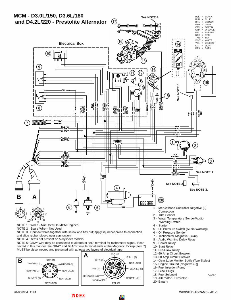
74297
BLK = BLACKBLU = BLUEBRN = BROWNGRY = GRAYGRN = GREENORN = ORANGEPPL = PURPLERED = REDTAN = TANWHT = WHITEYEL = YELLOWLT = LIGHTDRK = DARK
BLK/YEL (1)
NOT USED
NOT USED
WHT/GRN (5)
BLU/TAN (2)
TAN/BLK (3)
BRN (4)
1 - MerCathode Controller Negative (–) Connection
2 - Trim Sender3 - Water Temperature Sender/Audio
Warning Switch4 - Starter5 - Oil Pressure Switch (Audio Warning)6 - Oil Pressure Sender7 - Tachometer Magnetic Pickup8 - Audio Warning Delay Relay9 - Power Relay10- Start Relay11- Pre-Glow Relay12- 60 Amp Circuit Breaker13- 60 Amp Circuit Breaker14- Gear Lube Monitor Bottle (Two Styles)15- Engine Ground [Negative (–)]16- Fuel Injection Pump17- Glow Plugs 18- Fuel Solenoid19- Alternator - Prestolite20- Battery
NOT USEDYEL/RED (7)
LT BLU (8)
BLK (1)
GRY (2)
BRN/WHT (10)
TAN (3)
TAN/BLU (4)PPL (5)
RED/PPL (6)
NOT USED
1
23 4 5
67
12
4
3
56
7
8
10
See NOTE 1.
See NOTE 2.
See NOTE 3.
Electrical Box
BA
AB
See
NO
TE
5.
NOTE 1 : Wires - Not Used On MCM EnginesNOTE 2 : Spare Wire – Not UsedNOTE 3 : Connect wires together with screw and hex nut; apply liquid neoprene to connectionand slide rubber sleeve over connection.NOTE 4 : Items not present on 5-Cylinder models.NOTE 5: GRAY wire may be connected to alternator “AC” terminal for tachometer signal. If con-nected in this manner, the GRAY and BLACK wire terminal ends at the Magnetic Pickup (Item 7)MUST be disconnected and protected with at least two layers of electrical tape.
See NOTE 4.
WIRING DIAGRAMS - 4E -390-806934 1194
MCM - D3.0L/150, D3.6L/180 and D4.2L/220 - Prestolite Alternator
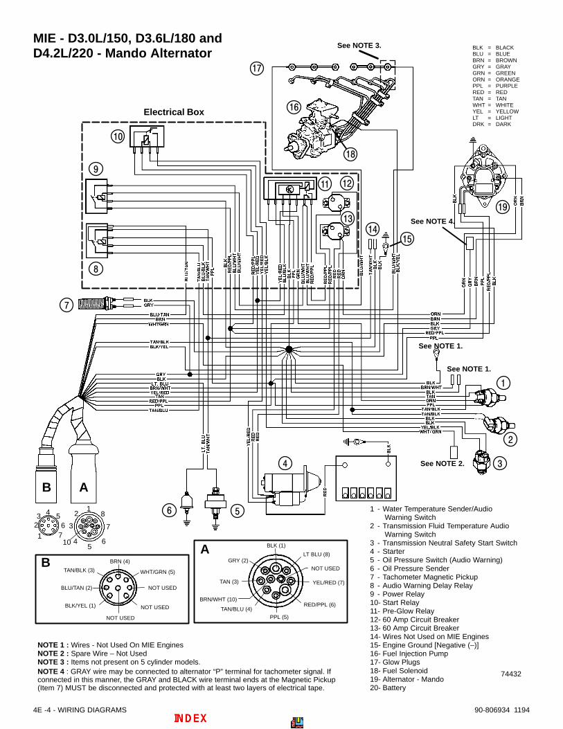
4E -4 - WIRING DIAGRAMS 90-806934 1194
MIE - D3.0L/150, D3.6L/180 andD4.2L/220 - Mando Alternator
74432
BLK = BLACKBLU = BLUEBRN = BROWNGRY = GRAYGRN = GREENORN = ORANGEPPL = PURPLERED = REDTAN = TANWHT = WHITEYEL = YELLOWLT = LIGHTDRK = DARK
BLK/YEL (1)
NOT USED
NOT USED
WHT/GRN (5)
BLU/TAN (2)
TAN/BLK (3)
BRN (4)
1 - Water Temperature Sender/Audio Warning Switch
2 - Transmission Fluid Temperature Audio Warning Switch
3 - Transmission Neutral Safety Start Switch4 - Starter5 - Oil Pressure Switch (Audio Warning)6 - Oil Pressure Sender7 - Tachometer Magnetic Pickup8 - Audio Warning Delay Relay9 - Power Relay10- Start Relay11- Pre-Glow Relay12- 60 Amp Circuit Breaker13- 60 Amp Circuit Breaker14- Wires Not Used on MIE Engines15- Engine Ground [Negative (–)]16- Fuel Injection Pump17- Glow Plugs 18- Fuel Solenoid19- Alternator - Mando20- Battery
NOTE 1 : Wires - Not Used On MIE EnginesNOTE 2 : Spare Wire – Not UsedNOTE 3 : Items not present on 5 cylinder models.
NOT USEDYEL/RED (7)
LT BLU (8)
BLK (1)
GRY (2)
BRN/WHT (10)
TAN (3)
TAN/BLU (4)PPL (5)
RED/PPL (6)
NOT USED
1
23 4 5
67
12
4
3
56
7
8
10
Electrical Box
See NOTE 1.
See NOTE 1.
See NOTE 2.
See NOTE 3.
NOTE 4 : GRAY wire may be connected to alternator “P” terminal for tachometer signal. Ifconnected in this manner, the GRAY and BLACK wire terminal ends at the Magnetic Pickup(Item 7) MUST be disconnected and protected with at least two layers of electrical tape.
See NOTE 4.
AB
AB

74327
BLK = BLACKBLU = BLUEBRN = BROWNGRY = GRAYGRN = GREENORN = ORANGEPPL = PURPLERED = REDTAN = TANWHT = WHITEYEL = YELLOWLT = LIGHTDRK = DARK
BLK/YEL (1)
NOT USED
NOT USED
WHT/GRN (5)
BLU/TAN (2)
TAN/BLK (3)
BRN (4)
1 - Water Temperature Sender/Audio Warning Switch
2 - Transmission Fluid Temperature Audio Warning Switch
3 - Transmission Neutral Safety Start Switch4 - Starter5 - Oil Pressure Switch (Audio Warning)6 - Oil Pressure Sender7 - Tachometer Magnetic Pickup8 - Audio Warning Delay Relay9 - Power Relay10- Start Relay11- Pre-Glow Relay12- 60 Amp Circuit Breaker13- 60 Amp Circuit Breaker14- Engine Ground [Negative (–)]15- Fuel Injection Pump16- Glow Plugs17- Fuel Solenoid18- Alternator – Prestolite19- Battery
NOTE 1 : Wires - Not Used On MIE EnginesNOTE 2 : Spare Wire – Not UsedNOTE 3 : Items Not Present On 5 Cylinder Engines
NOT USEDYEL/RED (7)
LT BLU (8)
BLK (1)
GRY (2)
BRN/WHT (10)
TAN (3)
TAN/BLU (4)PPL (5)
RED/PPL (6)
NOT USED
1
23 4 5
67
12
4
3
56
7
8
10
Electrical Box
See NOTE 1.
See NOTE 1.
See NOTE 2.
A
A
B
B
See
NO
TE
1.
NOTE 4 : GRAY wire may be connected to alternator “AC” terminal for tachometer signal. Ifconnected in this manner, the GRAY and BLACK wire terminal ends at the Magnetic Pickup(Item 7) MUST be disconnected and protected with at least two layers of electrical tape.
See
NO
TE
4.
See NOTE 3.
WIRING DIAGRAMS - 4E -590-806934 1194
MIE - D3.0L/150, D3.6L/180 and D4.2L/220 - Prestolite Alternator

A B
1 - Oil Pressure2 - Tachometer3 - Trim Gauge 4 - Coolant Temperature5 - Voltmeter6 - Cruise Log (Engine Hour Meter) (See NOTE 1.)7 - Engine System Monitor -
a.-PreHeat, b.-Alternator,c.-Oil Pressure, d.-Coolant Temp.
12
34
56
7
8
1 2
4
3
56
7
8
10
YEL/RED (7)
LT BLU (8)
BLK (1)
GRY (2)
BRN/WHT (10)
TAN (3)
TAN/BLU (4)
PPL (5)RED/PPL (6)
BLK/YEL (1)
BLK (8)
BLK (7)TAN/WHT (6)
WHT/GRN (5)
BLU/TAN (2)TAN/BLK (3)
BRN (4)
74066
NOTE 2: Connect wires together with screw and hex nut;apply Liquid Neoprene to connection and slide rubber sleeveover connection.
See NOTE 2.
8 - Light Switch and Audio Test9 - Stop Switch10- Keyswitch11- 20-Amp Fuse and Holder12- Audio Warning Buzzers13- Spare Wires - (Not Used) 14- Remote Control -
(Neutral Safety Circuit)
NOTE 1: May be wired to any PPL (that is key switched),and BLK.
BLK = BLACKBLU = BLUEBRN = BROWNGRY = GRAYGRN = GREENORN = ORANGEPPL = PURPLERED = REDTAN = TANWHT = WHITEYEL = YELLOWLT = LIGHTDRK = DARK
UP
BS
I
b
c
d
a
A B
4E -6 - WIRING DIAGRAMS 90-806934 1194
Quicksilver Instrumentation
MCM - D3.0L/150, D3.6L/150 and D4.2L/220

1 - Oil Pressure2 - Tachometer3 - Wires Not Used
(See NOTE 1.)4 - Coolant Temperature5 - Voltmeter6 - Cruise Log (Engine Hour Meter) (See NOTE 2.)7 - Engine System Monitor -
a.-PreHeat, b.-Alternator,c.-Oil Pressure, d.-Coolant Temp.
12
34
56
7
8
1 2
4
3
56
7
8
10
YEL/RED (7)
LT BLU (8)
BLK (1)
GRY (2)
BRN/WHT (10)
TAN (3)
TAN/BLU (4)
PPL (5)RED/PPL (6)
BLK/YEL (1)
BLK (8)
BLK (7)TAN/WHT (6)
WHT/GRN (5)
BLU/TAN (2)TAN/BLK (3)
BRN (4)
73603
8 - Light Switch and Audio Test9 - Stop Switch10- Keyswitch11- 20-Amp Fuse and Holder12- Audio Warning Buzzers13- Spare Wires - (Not Used)
NOTE 1 : Tape each wire separately with at least two layers of elec-trical tape.NOTE 2 : May be wired to any PPL (that is key switched), and BLK.
BLK = BLACKBLU = BLUEBRN = BROWNGRY = GRAYGRN = GREENORN = ORANGEPPL = PURPLE
RED = REDTAN = TANWHT = WHITEYEL = YELLOWLT = LIGHTDRK = DARK
UP
b
c
d
a
A B
A B
WIRING DIAGRAMS - 4E -790-806934 1194
MIE - D3.0L/150, D3.6L/180 andD4.2L/220

12
34
56
7
8
1 2
4
3
56
7
8
10
a b
With Remote Control Neutral Safety Switch Wired at Instrumentation
YEL/RED (7)
LT BLU (8)
BLK (1)
GRY (2)
BRN/WHT (10)
TAN (3)
TAN/BLU (4)
PPL (5)RED/PPL (6)
a
BLK/YEL (1)
BLK (8)
BLK (7)TAN/WHT (6)
WHT/GRN (5)
BLU/TAN (2)TAN/BLK (3)
BRN (4)
b
74065
See NOTE 2.
BLK = BLACKBLU = BLUEBRN = BROWNGRY = GRAYGRN = GREENORN = ORANGEPPL = PURPLE
RED = REDTAN = TANWHT = WHITEYEL = YELLOWLT = LIGHTDRK = DARK
UP
1 - Oil Pressure (See NOTE 4.)2 - Tachometer3 - Trim Gauge (See NOTE 4.)4 - Wire(s) Not Used
(See NOTE 1.) 5 - Voltmeter (See Note 3 and 4.)6 - Engine System Monitor7 - Light Switch and Audio Test
8 - Stop Switch9 - Start Switch10- 20-Amp Fuse and Holder11- Audio Warning Buzzers12- Spare Wires - (Not Used) 13- Remote Control -
(Neutral Safety Circuit)
NOTE 2: Connect wires together with screw and hex nut;apply Liquid Neoprene to connection and slide rubbersleeve over connection.
NOTE 1: Tape each wire separately with at least two layersof electrical tape.
See Note 1.
NOTE 3: May be wired to any PPL (that is key switched),and BLK.
NOTE 4: Items 1, 3, and 5 are not included in this SecondStation Kit. Order separately, if desired.
See Note 1.
4E -8 - WIRING DIAGRAMS 90-806934 1194
MCM - Second Station Instrumentation

WIRING DIAGRAMS - 4E -990-806934 1194
MIE - Second Station Instrumentation
74067
YEL/RED (7)
LT BLU (8)
BLK (1)
GRY (2)
BRN/WHT (10)
TAN (3)
TAN/BLU (4)
PPL (5)RED/PPL (6)
a
BLK/YEL (1)
BLK (8)
BLK (7)TAN/WHT (6)
WHT/GRN (5)
BLU/TAN (2)TAN/BLK (3)
BRN (4)
bBLK = BLACKBLU = BLUEBRN = BROWNGRY = GRAYGRN = GREENORN = ORANGEPPL = PURPLE
RED = REDTAN = TANWHT = WHITEYEL = YELLOWLT = LIGHTDRK = DARK
UP
12
34
56
7
8
1 2
4
3
56
7
8
10
a b
See Note 1.
See Note 1.
1 - Oil Pressure(See NOTE 4.)
2 - Tachometer3 - Wire(s) Not Used
(See NOTE 1.) 4 - Voltmeter
(See NOTE 4.)
5 - Engine System Monitor6 - Light Switch and Audio Test7 - Stop Switch8 - Start Switch9 - 20-Amp Fuse and Holder10- Audio Warning Buzzers11- Spare Wires - (Not Used)
NOTE 2: Connect wires together with screw and hex nut;apply Liquid Neoprene to connection and slide rubbersleeve over connection.
NOTE 1: Tape each wire separately with at least two layersof electrical tape.
NOTE 3: May be wired to any PPL (that is key switched),and BLK.
NOTE 4: Items 1 and 4 are not included in this Second Sta-tion Kit. Order separately, if desired.
See Note 1.

MCM - With Remote Control Neutral Safety Switches Wired at Instrumentation
a - “Y” Harnessb - “T” Harnessc - Extension Harnesses (Primary to Secondary Instrumentation)d - Extension Harnesses (To Engine)
Note: Connect these wires together with a screw andnut. Coat with Liquid Neoprene and slide rubber sleeveover connection.
See Note.
See Note.
Primary StationSecondary Station
d
ba
c
74069
4E -10 - WIRING DIAGRAMS 90-806934 1194
Wiring Harness ConnectionsMCM - Wiring Harness Connections (Standard)

MCM - With Remote Control Neutral Safety Switches Wired at Harnesses
a - “Y” Harnessb - “T” Harnessc - Extension Harnesses (Primary to Secondary Instrumentation)d - Extension Harnesses (To Engine)
Note: Connect these wires together with a screw andnut. Coat with Liquid Neoprene and slide rubber sleeveover connection.
d
b
See
No
te:
See
No
te:
a
c
Primary StationSecondary Station
74068
WIRING DIAGRAMS - 4E -1190-806934 1194
MCM - Wiring Harness Connections (Optional)

MIE - Harnesses
a - “Y” Harnessb - “T” Harnessc - Extension Harnesses (Primary to Secondary Instrumentation)d - Extension Harnesses (To Engine)
Note: Connect these wires together with a screw andnut. Coat with Liquid Neoprene and slide rubber sleeveover connection.
See Note.
See Note.
d
ba
c
Primary StationSecondary Station
74070
4E -12 - WIRING DIAGRAMS 90-806934 1194
MIE - Wiring Harness Connections
A A
A
A
A
A
7
6
4
3
2
1
5
A
74475
FUEL SYSTEMS
FUEL DELIVERY PUMPand FUEL FILTER
Note:Refer to the following Service Bulletins regarding this section.
SB 95-16 Low Sulfur Diesel Fuels
SB 95-9 Diesel Fuel Filters and Fuel Additives

5A-0 – FUEL DELIVERY PUMP AND FUEL FILTER 90-806934 1194
Table Of ContentsPage
Identification 5A-1. . . . . . . . . . . . . . . . . . . . . . . . . . . . . . . . Fuel Pump Specifications 5A-1. . . . . . . . . . . . . . . . . . . . . Torque Specifications 5A-1. . . . . . . . . . . . . . . . . . . . . . . . Tools / Lubricants / Sealants 5A-1. . . . . . . . . . . . . . . . . . General 5A-1. . . . . . . . . . . . . . . . . . . . . . . . . . . . . . . . . . . .
Fuel Pump and Filter Description 5A-1. . . . . . . . . . . Precautions 5A-1. . . . . . . . . . . . . . . . . . . . . . . . . . . . . . Fuel Lines 5A-2. . . . . . . . . . . . . . . . . . . . . . . . . . . . . . .
Exploded View - Fuel Pump and Fuel Filter 5A-3. . . . . Fuel Pump Removal 5A-4. . . . . . . . . . . . . . . . . . . . . . . . . Fuel Pump Repair 5A-5. . . . . . . . . . . . . . . . . . . . . . . . . . .
Disassembly 5A-5. . . . . . . . . . . . . . . . . . . . . . . . Assembly 5A-6. . . . . . . . . . . . . . . . . . . . . . . . . . .
Fuel Pump Installation 5A-8. . . . . . . . . . . . . . . . . . . . . . . Water Separating Fuel Filter Replacement 5A-9. . . . . . Water Bleed Valve Operation 5A-10. . . . . . . . . . . . . . . . . Purging Air from Fuel System - Priming Injection Pump 5A-11. . . . . . . . . . . . . . . . . . . . .
5A – FUEL DELIVERY PUMP AND FUEL FILTER

FUEL DELIVERY PUMP AND FUEL FILTER – 5A-190-806934 1194
Identification
70163
Fuel Pump SpecificationsSPECIFICATIONS
Measured at 2500 RPM, No Load
Fuel Flow per Minute 85 U. S. Qts. (80 L)at 2500 RPM
Pressure 2-5 PSI(13.8 - 34.5 kPa)
Torque SpecificationsDESCRIPTION Lb. Ft. N·m
Filter Header-to-Bracket 24 32
Pump-to-Block 18 24
Fuel Filter-to-HeaderHand Tighten
Only, Until Secure
All Fasteners Not OtherwiseListed
Tighten Securely
Tools / Lubricants / Sealants
DESCRIPTION PARTNUMBER
Quicksilver Perfect Seal 92-34227
Quicksilver Needle Bearing As-sembly Lubricant
92-825265A1
#592 Loctite Pipe Sealant with Teflon
Fuel Pressure Gauge [0-15 PSI(0-103.35 kPa)]
Obtain Locally
General
Fuel Pump and Filter DescriptionThe fuel delivery pump is of the diaphragm type andis mounted on the side of the engine block. It isoperated by the camshaft, and on all models isequipped with an external lever to assist in primingthe injection pump and purging air from fuel system.
The fuel filter is mounted next to the fuel pump. It isa water-separating filter and is equipped with a waterbleed valve at the bottom of the canister.
Precautions
! WARNING
ALWAYS disconnect battery cables from batteryBEFORE working on fuel system to prevent fire.This eliminates the engine wiring as a potentialsource of ignition.
! WARNING
Be careful when changing fuel systemcomponents; diesel fuel is flammable. Be surethat ignition key is OFF. DO NOT smoke or allowsources of open flame in the area while changingfuel system components. Wipe up any spilledfuel immediately. DO NOT allow fuel to come intocontact with any hot surface which may cause itto ignite.
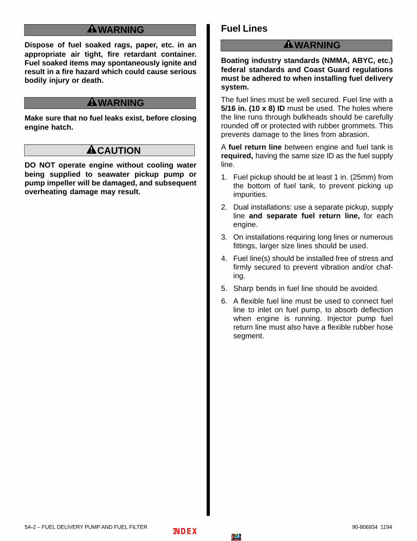
5A-2 – FUEL DELIVERY PUMP AND FUEL FILTER 90-806934 1194
! WARNING
Dispose of fuel soaked rags, paper, etc. in anappropriate air tight, fire retardant container.Fuel soaked items may spontaneously ignite andresult in a fire hazard which could cause seriousbodily injury or death.
! WARNING
Make sure that no fuel leaks exist, before closingengine hatch.
! CAUTIONDO NOT operate engine without cooling waterbeing supplied to seawater pickup pump orpump impeller will be damaged, and subsequentoverheating damage may result.
Fuel Lines
! WARNING
Boating industry standards (NMMA, ABYC, etc.)federal standards and Coast Guard regulationsmust be adhered to when installing fuel deliverysystem.
The fuel lines must be well secured. Fuel line with a5/16 in. (10 x 8) ID must be used. The holes wherethe line runs through bulkheads should be carefullyrounded off or protected with rubber grommets. Thisprevents damage to the lines from abrasion.
A fuel return line between engine and fuel tank isrequired, having the same size ID as the fuel supplyline.
1. Fuel pickup should be at least 1 in. (25mm) fromthe bottom of fuel tank, to prevent picking upimpurities.
2. Dual installations: use a separate pickup, supplyline and separate fuel return line, for eachengine.
3. On installations requiring long lines or numerousfittings, larger size lines should be used.
4. Fuel line(s) should be installed free of stress andfirmly secured to prevent vibration and/or chaf-ing.
5. Sharp bends in fuel line should be avoided.
6. A flexible fuel line must be used to connect fuelline to inlet on fuel pump, to absorb deflectionwhen engine is running. Injector pump fuelreturn line must also have a flexible rubber hosesegment.

FUEL DELIVERY PUMP AND FUEL FILTER – 5A-390-806934 1194
Exploded View - Fuel Pump and Fuel Filter
74475
A
a
b
c
1 - Bracket2 - Screw3 - Lockwasher4 - Nut5 - Fuel Filter6 - O-Ring7 - Drain Cap8 - Pipe, Pump-to-Filter Header9 - Banjo Bolt (3)10- Sealing Washer11- Filter Bracket12- Pipe, Filter Header-to-Injection Pump13- Banjo Bolt14- Sealing Washers15- Fuel Pump16- O-Ring 17- Stud (2)18- Lockwasher (2)19- Nut (2)
20- Fuel Inlet Fitting21- Fuel Pump Cover (Removed for visual clarity
of Items 19 - 20.)22- Diaphragm23- Diaphragm Spring
Lubricant/Sealant Application Points
A Clean Motor Oil
Torque Specificationsa 24 lb. ft. (32 N·m)b 18 lb. ft. (24 N·m)c Hand Tighten Only

5A-4 – FUEL DELIVERY PUMP AND FUEL FILTER 90-806934 1194
Fuel Pump Removal
! WARNING
ALWAYS disconnect battery cables from batteryBEFORE working on fuel system to prevent fireor explosion.
1. Disconnect battery cables from battery.
! WARNING
FIRE HAZARD: Fuel leakage from any part of thefuel system can be a fire hazard which can causeserious bodily injury or death.
! WARNING
Be careful when changing fuel systemcomponents; diesel fuel is flammable. Be surethat ignition key is OFF. DO NOT smoke or allowsources of open flame in the area while changingfuel system components. Wipe up any spilledfuel immediately. Dispose of rags appropriately.DO NOT allow fuel to come into contact with anyhot surface which may cause it to ignite.
2. Remove fuel supply hose. Plug hose to preventfuel from leaking into boat.
73332
a
a - Fuel Supply Hose
3. Remove banjo bolt at fuel filter. Discard sealingwashers.
73332
a
b
ab b
a - Banjo Boltb - Sealing Washers
4. Remove mounting nuts and remove pump.Discard O-ring.
73332
b
a
a
a - Mounting Nut With Lockwasher (2)b - O-Ring

FUEL DELIVERY PUMP AND FUEL FILTER – 5A-590-806934 1194
Fuel Pump RepairDISASSEMBLY
1. Remove banjo bolts and fuel lines. Discardsealing washers.
70162
a - Banjo Bolts, with Sealing Washersb - Fuel Lines
2. Take note of fuel line positions or mark cover toaid in reassembly. Remove 6 cover screws.
70169
a - Fuel Line Positionsb - Cover Screws, with Washersc - Mark Cover (if so desired)
3. Remove cover exposing pump diaphragms andone-way valves.
70194
a - Pump Diaphragmsb - One-Way Valves
4. Remove one-way valve carrier from cover.
70206
70164
a - One-Way Valve Carrierb - Cover

5A-6 – FUEL DELIVERY PUMP AND FUEL FILTER 90-806934 1194
5. Remove from cover and inspect O-ring andspacer for damage.
70168
70165
a - Coverb - O-ringc - Spacer
6. Press down and turn diaphragm 1/4 turn todisengage rod from pump arm.
70167
a - Diaphragmb - Rodc - Pump Arm
7. Remove spacer from between diaphragms.
70166
a - Spacerb - Diaphragms
8. Clean parts in solvent. Dry with compressed air.
ASSEMBLY
1. Install spacer between diaphragms.
70166
a - Spacerb - Diaphragms

FUEL DELIVERY PUMP AND FUEL FILTER – 5A-790-806934 1194
2. Place spring on rod and install in pump housing.Push in and turn diaphragm 1/4 turn to holdin place.
70167
a - Springb - Rod, Diaphragmc - Pump Housing
3. Install spacer and O-ring in cover, as shown.
70165
a - Spacerb - O-ringc - Cover
4. Install one-way valve carrier in cover, as shown.
70164
a - One-Way Valve Carrierb - Cover
5. Install cover on pump housing in position asnoted or marked during disassembly.
70163
a - Cover (Position Properly)b - Pump Housing
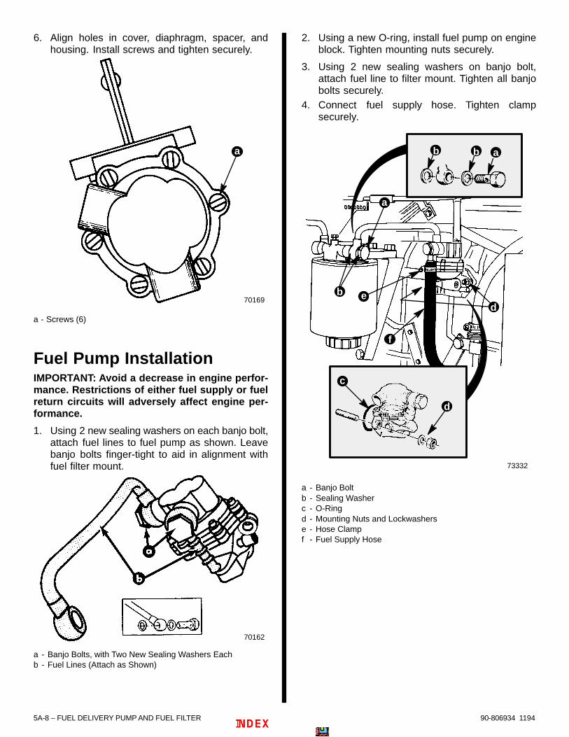
5A-8 – FUEL DELIVERY PUMP AND FUEL FILTER 90-806934 1194
6. Align holes in cover, diaphragm, spacer, andhousing. Install screws and tighten securely.
70169
a
a - Screws (6)
Fuel Pump InstallationIMPORTANT: Avoid a decrease in engine perfor-mance. Restrictions of either fuel supply or fuelreturn circuits will adversely affect engine per-formance.
1. Using 2 new sealing washers on each banjo bolt,attach fuel lines to fuel pump as shown. Leavebanjo bolts finger-tight to aid in alignment withfuel filter mount.
70162
a - Banjo Bolts, with Two New Sealing Washers Eachb - Fuel Lines (Attach as Shown)
2. Using a new O-ring, install fuel pump on engineblock. Tighten mounting nuts securely.
3. Using 2 new sealing washers on banjo bolt,attach fuel line to filter mount. Tighten all banjobolts securely.
4. Connect fuel supply hose. Tighten clampsecurely.
73332
a
b
ab b
e
f
d
c
d
a - Banjo Boltb - Sealing Washerc - O-Ringd - Mounting Nuts and Lockwasherse - Hose Clampf - Fuel Supply Hose

FUEL DELIVERY PUMP AND FUEL FILTER – 5A-990-806934 1194
Water Separating Fuel FilterReplacement
! WARNING
ALWAYS disconnect battery cables from batteryBEFORE working on fuel system to prevent fire.This eliminates the engine wiring as a potentialsource of ignition.
! WARNING
Be careful when changing water separating fuelfilter. Diesel fuel is flammable. Be sure ignitionkey is OFF. Do not allow fuel to come into contactwith any hot surface which may cause it to ignite.Do not allow sources of open flame in the area.
1. Disconnect battery cables from battery.
NOTE: Use a suitable container to catch excess fuel.
! WARNING
Wipe up any spilled fuel immediately anddispose of fuel soaked rags, paper, etc., in anappropriate air tight, fire retardant container.Fuel soaked items may spontaneously ignite andresult in a fire hazard which could cause seriousbodily injury or death.
2. Remove filter element from header mounting. Afilter wrench may be needed to loosen element.
70161
73332
a
a - Fuel Filter Element
IMPORTANT: Element cannot be cleaned andreused. It must be replaced.
3. Turn water bleed valve counterclockwise and re-move from old filter. Install it on new filter turningclockwise. Tighten securely. (Note position of O-ring seal.)
70160
a - Water Bleed Valveb - O-ring Seal
4. Coat sealing ring on new filter with clean motoroil. Thread filter clockwise onto bracket and tight-en securely by hand. Do not use a filter wrench.
71370
a
b
c
a - Water Separating Fuel Filterb - Sealing Ring (Lubricate)c - Fuel Filter Header
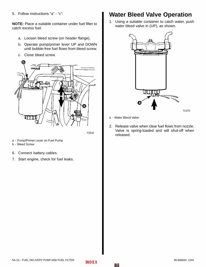
5A-10 – FUEL DELIVERY PUMP AND FUEL FILTER 90-806934 1194
5. Follow instructions “a” - “c”:
NOTE: Place a suitable container under fuel filter tocatch excess fuel.
a. Loosen bleed screw (on header flange).
b. Operate pump/primer lever UP and DOWNuntil bubble-free fuel flows from bleed screw.
c. Close bleed screw.
73332
a
b
a - Pump/Primer Lever on Fuel Pumpb - Bleed Screw
6. Connect battery cables.
7. Start engine, check for fuel leaks.
Water Bleed Valve Operation1. Using a suitable container to catch water, push
water bleed valve in (UP), as shown.
71370
a
a - Water Bleed Valve
2. Release valve when clear fuel flows from nozzle.Valve is spring-loaded and will shut-off whenreleased.
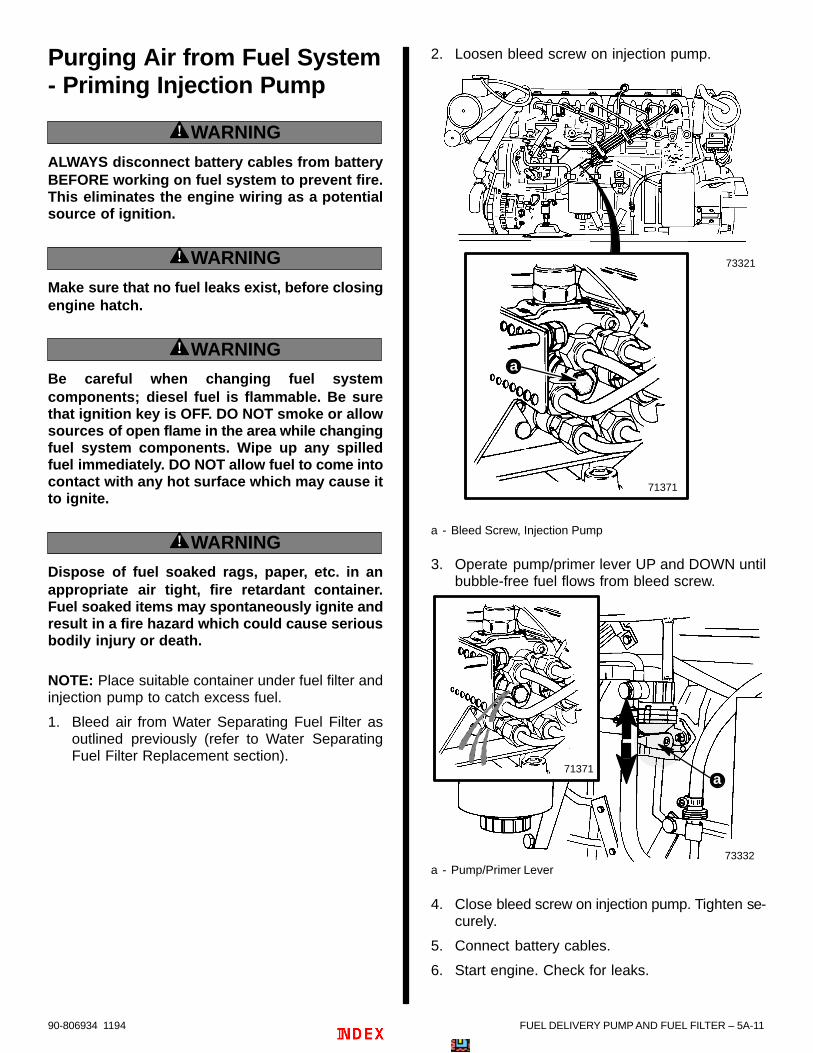
FUEL DELIVERY PUMP AND FUEL FILTER – 5A-1190-806934 1194
Purging Air from Fuel System- Priming Injection Pump
! WARNING
ALWAYS disconnect battery cables from batteryBEFORE working on fuel system to prevent fire.This eliminates the engine wiring as a potentialsource of ignition.
! WARNING
Make sure that no fuel leaks exist, before closingengine hatch.
! WARNING
Be careful when changing fuel systemcomponents; diesel fuel is flammable. Be surethat ignition key is OFF. DO NOT smoke or allowsources of open flame in the area while changingfuel system components. Wipe up any spilledfuel immediately. DO NOT allow fuel to come intocontact with any hot surface which may cause itto ignite.
! WARNING
Dispose of fuel soaked rags, paper, etc. in anappropriate air tight, fire retardant container.Fuel soaked items may spontaneously ignite andresult in a fire hazard which could cause seriousbodily injury or death.
NOTE: Place suitable container under fuel filter andinjection pump to catch excess fuel.
1. Bleed air from Water Separating Fuel Filter asoutlined previously (refer to Water SeparatingFuel Filter Replacement section).
2. Loosen bleed screw on injection pump.
73321
71371
a
a - Bleed Screw, Injection Pump
3. Operate pump/primer lever UP and DOWN untilbubble-free fuel flows from bleed screw.
73332
a71371
a - Pump/Primer Lever
4. Close bleed screw on injection pump. Tighten se-curely.
5. Connect battery cables.
6. Start engine. Check for leaks.

7A
6
A
B
4
A
3
A
2
A
1
A
550397
FUEL SYSTEM
INJECTION PUMP

90-806934 11945B-0 – INJECTION PUMP
Table Of ContentsPage
Identification 5B-1. . . . . . . . . . . . . . . . . . . . . . . . . . . . . . . . Pump Code and I.D. Number Location 5B-1. . . . . .
Pump Code and Identification Number 5B-1. . . . . . . . . Specifications 5B-1. . . . . . . . . . . . . . . . . . . . . . . . . . . . . . . Torque Specifications 5B-1. . . . . . . . . . . . . . . . . . . . . . . . Special Tools 5B-2. . . . . . . . . . . . . . . . . . . . . . . . . . . . . . . Lubricants / Sealants 5B-2. . . . . . . . . . . . . . . . . . . . . . . . Description 5B-2. . . . . . . . . . . . . . . . . . . . . . . . . . . . . . . . .
General 5B-2. . . . . . . . . . . . . . . . . . . . . . . . . . . . . . . . . Precautions 5B-3. . . . . . . . . . . . . . . . . . . . . . . . . . . . . . Fuel Requirements 5B-4. . . . . . . . . . . . . . . . . . . . . . . Diesel Fuel in Cold Weather 5B-4. . . . . . . . . . . . . . .
Fuel Injection Pump Repair and Service 5B-4. . . . . . . . Exploded Views - Injection Pump and Related Components 5B-5. . . . . . . . . . . . . . . . . . . . . . . . Fuel Injection Pump Removal 5B-6. . . . . . . . . . . . . . . . . Fuel Injection Pump Installation 5B-10. . . . . . . . . . . . . . .
Installation With Engine Assembled 5B-10. . . . . . . . . Installation During Engine Reassembly 5B-12. . . . . .
Fuel Injection Pump Timing 5B-14. . . . . . . . . . . . . . . . . . . Checking Timing 5B-14. . . . . . . . . . . . . . . . . . . . . . . . . Setting Timing 5B-14. . . . . . . . . . . . . . . . . . . . . . . . . . .
Starting Engine – After Fuel Injection Pump Installation and Timing 5B-18. . . . . . . . . . . . . . . . . . . . . .
5B – INJECTION PUMP

INJECTION PUMP – 5B-190-806934 1194
Identification
Pump Code and I.D. Number Location
50536
50397
a - Pump Code and I.D. Number Location
Pump Code andIdentification NumberEngine - MCM
and MIEPump Code and Identification
Number
D3.0L/150
Code: VE 5/11F 1900 L179Bosch Part Number: 0460 415007(Quicksilver Part Number:801763706)
D3.6L/180
Code: VE 6/11F 1900 L178Bosch Part Number: 0460 416035(Quicksilver Part Number:801763466)
D4.2L/220
Code: VE 6/11F 1800 L363Bosch Part Number: 0460 416064(Quicksilver Part Number:816550)
SpecificationsManufacturer Robert Bosch Corporation
Type of InjectionPump
Distributor Type VE-L withManifold-Pressure
Compensator
Ejection Pressure atFuel Injectors
2248.12 psi (15,500 kPa)
Delivery Begins 6° BTDC
Governor Type Centrifugal
Torque SpecificationsDESCRIPTION Lb. Ft. N·m
Pump Mounting Nuts 23 31
Pump Gear 66 90
Fuel Line Fittings (High Pressure)
13 18

90-806934 11945B-2 – INJECTION PUMP
Special ToolsQUICKSILVER
DESCRIPTION PART NUMBER
Graduated Disc 91-801333500
Crankshaft Tool 91-814827
Injection Pump GearPuller (Note 1.)
91-818371
Injection Pump GearPuller (Note 2.)
91-818372
Injection Pump AdaptorTool, Metric
91-801333510
Injection Pump AdaptorTool, S.A.E.
91-813658
Note 1 : For use on D3.0L/150 and D3.6L/180 engines.
Note 2 : For use on D4.2L/220 engines.
Lubricants / SealantsDESCRIPTION PART NUMBER
Quicksilver RTV Sealer 92-91601 1
Loctite 242 Obtain Locally
Description
GeneralMerCruiser Diesel Engines use Bosch, Type VE,Distributor Fuel Injection Pumps. The pump isengine driven off the camshaft gear. It is timed todeliver the correct amount of fuel to the fuel injectors.Injection pump pressure, at the fuel injectors,exceeds 2000 P.S.I. (13,790 kPa). Pressure valveson the outlets of the pump make sure that a certaininitial pressure is always in the lines leading to theinjectors. Because these engines are turbo-charged, the injection pump uses a manifoldpressure compensator to reduce the amount of fuelinjected during low turbo boost conditions. Thisreduces exhaust smoke at low engine RPM.
The timing-advance device advances timing up to 24crankshaft degrees. There is also a governor built intothe injection pump. The pump’s high speed screw ispreset and sealed at the Bosch factory. Do not attemptto adjust this screw. Diesel engines are stopped byshutting off the fuel supply. The injection pump isequipped with two means of fuel shut off, electrical andmechanical. The electrical shut off is a solenoid valveoperated by the stop button in the instrument panel.The mechanical shut off is a lever location on theinjection pump. A cold start lever is also located on theside of the pump. It is used to help start the enginewhen outside air temperature is below 50 F (10 C).

INJECTION PUMP – 5B-390-806934 1194
Precautions
! WARNING
Electrical system components on this engine arenot external ignition protected. DO NOT STOREOR UTILIZE GASOLINE ON BOATS EQUIPPEDWITH THESE ENGINES, UNLESS PROVISIONSHAVE BEEN MADE TO EXCLUDE GASOLINEVAPORS FROM ENGINE COMPARTMENT (ref: 33CFR). Failure to comply could result in fire,explosion and/or severe personal injury.
! WARNING
Always disconnect battery cables from batteryBEFORE working on fuel system to prevent fire.This eliminates the engine wiring as a potentialsource of ignition.
! CAUTIONIt is good practice to ventilate the enginecompartment prior to servicing any enginecomponents to remove any fuel vapors whichmay cause difficulty breathing or be an irritant.
! WARNING
FIRE HAZARD: Fuel leakage from any part of thefuel system can be a fire hazard which can causeserious bodily injury or death. Careful periodicinspection of entire fuel system is mandatory,particularly after storage. All fuel componentsincluding fuel tanks, whether plastic, metal orfiberglass, fuel lines, primers, fittings, and fuelfilters should be inspected for leakage,softening, hardening, swelling or corrosion. Anysign of leakage or deterioration requiresreplacement before further engine operation.
! WARNING
Be careful when changing fuel systemcomponents; diesel fuel is flammable. Be surethat ignition key is OFF. DO NOT smoke or allowsources of open flame in the area while changingfuel system components. Wipe up any spilledfuel immediately. Dispose of rags appropriately.DO NOT allow fuel to come into contact with anyhot surface which may cause it to ignite.
! WARNING
Dispose of fuel soaked rags, paper, etc. in anappropriate air tight, fire retardant container.Fuel soaked items may spontaneously ignite andresult in a fire hazard which could cause seriousbodily injury or death.

90-806934 11945B-4 – INJECTION PUMP
Fuel Requirements
! WARNING
Under should gasoline bemixed with diesel fuel for any reason. This mixtureof gasoline and diesel fuel is highly flammable andproduces a significant risk to the user.
IMPORTANT: Use of improper or watercontaminated diesel fuel can damage the engineseriously. Use of improper fuel is consideredmisuse of engine, and damage caused therebywill not be covered by warranty.
Grade 2-D diesel fuel is required, meeting ASTMStandards D975 (or fuel rated Diesel DIN 51601),and having a minimum cetane rating of 45.
The Cetane number is a measure of the ignitionquality of diesel fuel. Increasing the cetane numberwill not improve overall engine performance, but itmay be necessary to raise the cetane rating for lowtemperature, or high altitude use.
Sulphur content of the above fuel is rated at 0.50%by weight, maximum (ASTM). Limits may vary incountries outside of the United States.
On intermittent use engines, high sulphur contentdiesel fuel will greatly increase:
Corrosion of metal parts.
Deterioration of elastomer and plastic parts.
Corrosion and extensive damage, and excessivewear of internal engine parts, particularlybearings.
Starting and operating difficulties.
Diesel Fuel in Cold Weather
! WARNING
Under should gasoline bemixed with diesel fuel for any reason. This mixtureof gasoline and diesel fuel is highly flammable andproduces a significant risk to the user.
Unaltered diesel fuels thicken and “gel” in coldtemperatures, unless treated. Virtually all diesel fuelsare “climatized” to allow their use in the particularregion for that time of the year. If it becomesnecessary to further treat diesel fuel, it is theowner/operator’s responsibility to add a commercial“standard brand” “anti-gel” diesel fuel additive,following that product’s directions.
Fuel Injection Pump Repairand Service
The Robert Bosch Corporation has a network ofauthorized Bosch Service Dealers throughout theworld to service their products.
The pump and injectors must be sent to anauthorized Bosch Service Center.
When shipping an injection pump to a service centerfor adjustments or repairs, the fuel return line banjobolt must accompany the unit. The banjo boltincorporates a sized orifice (is calibrated) for properpressure which is matched to the pump. The pumpcannot be properly adjusted without the matchedorifice.
Contact the Bosch distributor nearest you for thelocation of an authorized Bosch Service Center.

INJECTION PUMP – 5B-590-806934 1194
Exploded Views - Injection Pump and Related Components
73911
2
3
4
5
6 7
8
910
1
11
12
1314
15
16
17
18
19
20
22
23
24
25
13
2629
32
27
28
30
31
A
a
b
21
1 - Injection Pump2 - Lever3 - Gasket4 - Traction Rod5 - Ball Pin6 - Washer and Nut for Ball Pin7 - Washer (2)8 - Screw (2)9 - Bearing Angle10- Fuel Shut-Off Solenoid and Nut11- Sealing Washer12- Lever13- Bushing (2)14- Lockwasher (1)15- Lockwasher (1)16- E-Ring17- Clamping Set (For Cable Controlled Cold Start)18- Support Angle19- Screw (2)20- Cable Barrel Anchor Stud with Hardware21- Cable End Guide Anchor Stud with Hardware22- Key23- Lockwasher and Nut (Gear-to-Pump Shaft)24- Stud (3)
25- Plain Washer, Lockwasher and Nut (3 of each)26- Boost Pressure Tube27- Banjo Bolt and Sealing Washers28- Clamp29- Screw, Lockwasher and Nut (1 of each)30- Support Bracket31- Screw and Lockwasher (1 of each)32- Connector
Lubricant/Sealant Application Points
A Quicksilver Perfect Seal - 92-34227
Torque Specifications
a 66 lb. ft. (90 N·m)b 23 lb. ft. (31 N·m)

90-806934 11945B-6 – INJECTION PUMP
Fuel Injection Pump Removal
! WARNING
Safety glasses should be worn while working onfuel injection system. The fuel injection pumpwill generate pressures in excess of 2000 psi(13790 kPa). Use caution when removinginjectors, injector lines, or bleeding air frominjection system.
1. Follow instructions “a” or “b”:
a. On MCM (Stern Drive) D3.0L/150 andD3.6L/180 Engines:
(1) Remove power steering belt.
(2) Remove power steering drive pulley.
(3) Remove three allen-head screws retain-ing the flange to which the power steeringpulley was mounted.
(4) Remove the flange.
d
cb
a
73777
a - Power Steering Pulleyb - Screws (4)c - Power Steering Pulley Flanged - Screws (3)
(5) Proceed to Step 2.
b. On MIE (Inboard) D3.0L/150 and D3.6L/180Engines and All D4.2L/220 Engines:
(1) Remove three of the six allen-headscrews retaining the crankshaft balancerto the drive pulley assembly.
(2) Proceed to Step 2.
2. Using balancer bolts or suitable, attach crankshafttool 91-814827 to crankshaft balancer.
70485
a - Crankshaft Tool 91-814827
3. Remove oil fill cap from valve cover.
73322
a
a - Oil Fill Cap

INJECTION PUMP – 5B-790-806934 1194
4. Look through oil fill cap hole into the valve cover,while using a suitable inspection light. Proceedas follows:
a. Slowly rotate engine CLOCKWISE (lookingfrom water pump end toward flywheel end)while watching the first rocker arm and valve(front-most is Number 1 cylinder’s intakevalve).
b. After the intake valve has OPENED (rockerarm moved down) and then CLOSED (rockerarm moved up), continue to rotate engineclockwise until crankshaft pulley notch alignswith mark on timing gear cover as shown.
c. Number 1 piston is at Top Dead Center (TDC)on its compression stroke at this point.
NOTE: On D4.2L/220 engines the crankshaft pulleynotch is on smaller power steering pulley edge, be-hind the larger drive pulleys.
70281
a - Crankshaft Pulley Notchb - Timing Cover Mark
Typical Engine Shown
5. Attach graduated disc adaptor and graduateddisc 91-801333500 to crankshaft balancer withzero positioned as shown.
NOTE: Seawater pump shown removed for visualclarity only.
74370
70485
a
bc
d
a- Adaptor Plate, (Retains Graduated Disc to Balancer)b – Graduated Disc-to-Adaptor Retaining Screws (3)c - Graduated Discd - Crankshaft Tool
Typical Engine Shown
6. Using wire, make a pointer and attach it to a suit-able location on engine. Align pointer to zero(“0”) as shown.
70664
a - Wire Pointer
Typical Engine Shown
7. Refer to SECTION 4C and remove alternatorbelt.

90-806934 11945B-8 – INJECTION PUMP
IMPORTANT: Banjo bolts, used to hold fuel inletand return lines to injection pump, are calibratedand MUST remain with pump in their originallocation.
8. Refer to the following and remove:
Fuel Return Line (Plug hose after removal.)
Injection Pump Inlet Line (Plug hose afterremoval.)
Throttle Cable and Bracket
Turbo Pressure Line
23284
71261
c
d
d
f
e
a - Fuel Return Lineb - Hose Clamp, Fuel Return Linec - Fuel Injection Pump Inlet Lined - Banjo Bolt With Sealing Washerse - Throttle Cable and Bracketf - Turbo Pressure Line and Fitting
! CAUTIONKeep injectors and injection pump fittings clean.Do not allow dirt to enter fittings when removinglines. Dirt will cause injectors or injection pumpto malfunction.
! CAUTIONDo not bend fuel injector lines. Bending maycause metal to flake off inside lines, causinginjectors or injection pump to malfunction.
9. Carefully loosen fittings and remove high pressurefuel lines from injection pump and fuel injectors.
70148
17MM
a - Injection Pump Fuel Line Fittingsb - Fuel Line Fittings At Injectorsc - Fuel Line(s)
NOTE: At this time return to Fuel Injection PumpTiming – “Setting Timing” if Steps 1-10 wereaccomplished for injection pump timing purposes.For continuing injection pump removal proceed tothe following Step 10.

INJECTION PUMP – 5B-990-806934 1194
10. Remove injection pump gear cover followinginstructions “a” or “b”:
a. On D3.0L/150 and D3.6L/180 Engines:Remove 4 hex nuts and cover.
70762
a - Hex Nuts (4) (One Hidden In This View)b - Cover
b. On D4.2L/220 Engines: Using a suitable de-vice remove threaded, round cover by turningCOUNTERCLOCKWISE.
70761
a - Cover
11. Remove injection pump gear nut and lockwasher.
12. With central bolt of tool backed out, installappropriate injection pump gear puller tool (referto Special Tools chart). Puller will hold gearagainst gear housing while pump is removed.
NOTE: Gear puller is bolted to injection pump gear,with the exception of the D4.2L/220 puller whichscrews into timing cover housing.
70765
a - Timing Coverb - Gear Puller Toolc - Central Bolt of Tool
D3.0L/150 and D3.6L/180 Puller Shown Installed
70770
a - Timing Coverb - Gear Puller Toolc - Central Bolt of Tool
D4.2L/220 Gear Puller Shown Installed
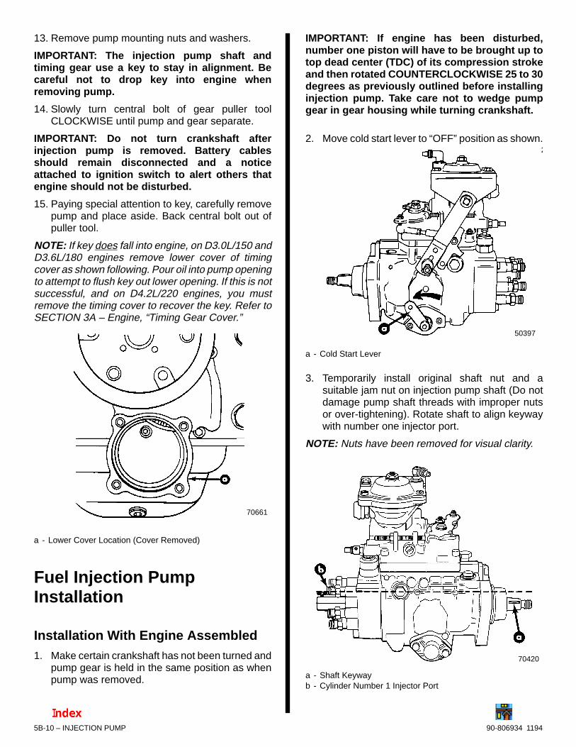
90-806934 11945B-10 – INJECTION PUMP
13. Remove pump mounting nuts and washers.
IMPORTANT: The injection pump shaft andtiming gear use a key to stay in alignment. Becareful not to drop key into engine whenremoving pump.
14. Slowly turn central bolt of gear puller toolCLOCKWISE until pump and gear separate.
IMPORTANT: Do not turn crankshaft afterinjection pump is removed. Battery cablesshould remain disconnected and a noticeattached to ignition switch to alert others thatengine should not be disturbed.
15. Paying special attention to key, carefully removepump and place aside. Back central bolt out ofpuller tool.
NOTE: If key does fall into engine, on D3.0L/150 andD3.6L/180 engines remove lower cover of timingcover as shown following. Pour oil into pump openingto attempt to flush key out lower opening. If this is notsuccessful, and on D4.2L/220 engines, you mustremove the timing cover to recover the key. Refer toSECTION 3A – Engine, “Timing Gear Cover.”
70661
a - Lower Cover Location (Cover Removed)
Fuel Injection PumpInstallation
Installation With Engine Assembled1. Make certain crankshaft has not been turned and
pump gear is held in the same position as whenpump was removed.
IMPORTANT: If engine has been disturbed,number one piston will have to be brought up totop dead center (TDC) of its compression strokeand then rotated COUNTERCLOCKWISE 25 to 30degrees as previously outlined before installinginjection pump. Take care not to wedge pumpgear in gear housing while turning crankshaft.
2. Move cold start lever to “OFF” position as shown.2
50397
a - Cold Start Lever
3. Temporarily install original shaft nut and asuitable jam nut on injection pump shaft (Do notdamage pump shaft threads with improper nutsor over-tightening). Rotate shaft to align keywaywith number one injector port.
NOTE: Nuts have been removed for visual clarity.
70420
a - Shaft Keywayb - Cylinder Number 1 Injector Port

INJECTION PUMP – 5B-1190-806934 1194
4. Remove any pump backlash by rotating shaftCOUNTERCLOCKWISE (facing unit) until resis-tance is felt.
Keyway will be at 11 o’clock position as shown.
70767
70421
b a
b a
a - Shaft – Rotate COUNTERCLOCKWISEb - Keyway at 11 O’clock
5. Being careful not to disturb shaft alignment,remove nuts temporarily installed to rotate shaft.
6. Install new gasket on pump mounting studs.Upper pump gear slot should be positionedapproximately as shown to be in alignment withkey when injection pump is installed.
70768
a - Gasketb - Pump Mounting Studs (3)c - Upper Pump Gear Slot
7. Using a heavy grease to hold in place, install in-jection pump key in pump shaft slot. Be certainkey is positioned properly.
IMPORTANT: Do not drop key into engine. If keyis dropped into engine, remove as described in“Fuel Injection Pump Removal” instructions aspreviously outlined.
8. Insert pump shaft into gear, being careful not todislodge key. Do not turn pump shaft from 11o’clock position. Rotate pump body in slottedholes to help align key with gear slot.
9. Install hex nuts with flat washers andlockwashers finger tight.
10. Remove gear puller tool. Make certain key is inposition.
11. Using new lockwasher, secure gear to shaft withhex nut. Torque to 66 lb. ft. (90 N·m).
12. Using new O-ring in groove, install andappropriately, depending on model, tighteninjection pump gear cover on timing cover.
13. Rotate pump to end of adjustment slot travel indirection shown.
70422
a - Direction to Rotate
14. Timing of the injection pump MUST BEaccomplished. Refer to “Fuel Injection PumpTiming” for instructions, following in this section.

90-806934 11945B-12 – INJECTION PUMP
Installation During Engine Reassembly
1. Install flywheel holder tool and install crankshaftpulley. Using Loctite 222 on threads, install pulleynut and torque to 114 lb. ft. (155 N·m). Removeflywheel holder.
! CAUTIONTo avoid severe engine damage the engine MUSTBE set on Number One Cylinder’s COMPRES-SION STROKE at Top Dead Center (TDC) beforeproceeding.
IMPORTANT: If crankshaft position wasdisturbed after assembly (rotated), it may benecessary to slowly rotate the crankshaft, in thedirection of rotation, numerous revolutions toalign the crankshaft gear, idler gear, andcamshaft gear alignment marks. Refer toSECTION 3A – Engine, “Camshaft – Installation,”and verify alignment to establish number oneTDC on compression stroke in the following.
2. Turn crankshaft until number 1 piston is at TopDead Center on its compression stroke and tim-ing marks are aligned.
3. Attach graduated disc adaptor and graduateddisc 91-801333500 to crankshaft balancer withzero positioned as shown.
74370
70485
a
bc
d
a - Adaptor Plate (Retains Graduated Disc to Balancer)b - Graduated Disc-to-Adaptor Retaining Screws (3)c - Graduated Discd - Crankshaft Tool
Typical Engine Shown
4. Using a suitable gauge wire, make a pointer andbeing careful not to damage mating surfacesattach to a suitable location on the block. Alignwire pointer to zero degrees (“0”) as shown.
70419
a - Wire Pointerb - Zero (“0”) Degree Mark
IMPORTANT: Cold start lever must be in the“OFF” position (forward, toward the shaft end ofthe pump) before timing the pump or proceeding.
5. Move cold start lever to “OFF” position as shown.
50397
a - Cold Start Lever

INJECTION PUMP – 5B-1390-806934 1194
6. Using a heavy grease to hold in place installinjection pump key in pump slot. Temporarilyinstall gear on injection pump shaft (Do notsecure gear at this time). Rotate shaft and gearto align keyway with number one injector port.
NOTE: Gear has been removed for visual clarity.
70420
a - Shaft Keywayb - Cylinder Number 1 Injector Portc - Key
7. Remove any pump backlash by rotating gearCOUNTERCLOCKWISE until resistance is felt.Upper keyway will be at approximately the 11o’clock position as shown.
70421
a - Rotate Counterclockwiseb - Upper Keyway at 11 O’clock
8. Remove gear.
9. Install injection pump using new gasket. Installhex nuts with flat washers and lockwashersfinger tight. Rotate pump to end of adjustmentslot travel in direction shown.
70422
70426
a - Gasketb - Hex Nuts With Flat Washers and Lockwashers (3 Total)c - Direction to Rotate

90-806934 11945B-14 – INJECTION PUMP
10. Be certain injection pump key is properlypositioned. Apply heavy grease to hold key in slotof pump.
IMPORTANT: Due to a change in productionEngines with VM Serial Number 56945 and uphave a different injection pump gear than earliernumber engines. Injection pump gears are notinterchangeable. Be certain to order the propergear for your engine should it requirereplacement.
IMPORTANT: Do not force gear on shaft.
11. Install gear on injection pump, using whicheverkey slot on gear that allows gear to be installedthe easiest.
12. Make certain key is still in position.
13. Using a new lockwasher, install gear on shaft withhex nut. Torque to 66 lb. ft. (90 N·m).
70424
a - Gearb - New Lockwasherc - Hex Nut
14. Timing of the injection pump MUST BEaccomplished. Refer to “Fuel Injection PumpTiming” for instructions, following in this section.
Fuel Injection Pump TimingChecking TimingOn completely assembled and/or installed engines,and for the purpose of “checking” fuel injection pumptiming refer to instructions previously outlined under– Fuel Injection Pump Removal, and accomplishSteps 1 through 9, in that section, dealing withinstallation of crankshaft tool, graduated disc,positioning of crankshaft and removal of parts to gainaccess to rear of fuel injection pump and vent screw.
Then proceed to following, Fuel Injection PumpTiming – “Setting Timing.”
Setting Timing
Having accomplished previously outlined Steps 1through 9 of “Fuel Injection Pump Removal,” or onpumps just installed, due to repair or service, or uponengine reassembly with pump just installed, followthese instructions.
1. Remove vent screw and sealing washer fromrear of injection pump.
NOTE: Pump shown removed for visual clarity.
23286
a - Injection Pumpb - Vent Screw with Sealing Washer
IMPORTANT: Cold start lever must still be in the“OFF” position (forward, toward shaft end ofpump) before proceeding.

INJECTION PUMP – 5B-1590-806934 1194
2. Be certain cold start lever is positioned as shown.
70426
3. Install adaptor tool and dial gauge as shown.Pre-load the dial indicator with at least 0.10 in.(2.54 mm).
NOTE: Internal bore of adaptor tool is of two differentsizes. Adaptor tool 91-813658 is designed to usewith SAE inch dial indicator. Adaptor tool91-801333510 is designed to use with millimeter dialindicator.
70430
a - Suitable Adaptor Toolb - Dial Gauge
4. Watch dial indicator needle and SLOWLY rotatethe crankshaft COUNTERCLOCKWISE (viewedfrom water pump end looking toward flywheel)toward 0 ° until dial indicator STOPS moving.
5. Set the dial indicator to Zero [ 0 in. 0.00 mm) ],as shown.
70431
a - Indicator at 0 Degrees
6. SLOWLY rotate crankshaft CLOCKWISE(viewed from water pump end looking towardflywheel) until 0 Degrees (engine Top DeadCenter) is indicated on graduated disc as shown(or until notch on crankshaft damper, or powersteering pulley, aligns with timing mark on gearhousing cover).
70432
NOTE: The dial indicator follows this rotationalmovement of crankshaft and STOPS when the Num-ber One piston is at T.D.C., when the crankshaft isnot turned further.

90-806934 11945B-16 – INJECTION PUMP
7. AT THIS MOMENT, the dial indicator should read0.34 in. (0.88 mm). If not, loosen the injectionpump mounting nuts and rotate the pump in ei-ther direction to obtain the correct specifications.
8. Tighten hex nuts securely.
! CAUTIONDial gauge indication MUST NOT be allowed tochange when mounting nuts are tightened.Failure to maintain setting will result in enginedamage.
70422
70433
a - Direction to Rotateb - Dial Gauge Indication MUST BE .034 in. (0.88mm)
9. Remove dial gauge and adaptor. Reinstall fuel in-jection pump vent screw using new sealingwasher. Tighten securely.
! CAUTIONKeep injectors and injection pump fittings clean.Do not allow dirt to enter fittings when installinglines. Dirt will cause injectors or injection pumpto malfunction.
! CAUTIONDo not bend fuel injector lines. Bending maycause metal to flake off inside lines, causinginjectors or injection pump to malfunction.
10. Follow instructions “a” or “b”:
a. During Engine Reassembly: Continueengine reassembly. Refer to followinginstructions “b” after all other necessaryengine reassembly steps are complete.
b. With Engine Assembled or After CheckingTiming:
(1) Install high pressure lines on injectionpump pressure valves and fuel injectors.Torque fittings to 13 lb. ft. (18 N·m).
IMPORTANT: Banjo bolts, used to hold fuel inletand return lines to injection pump, are calibratedand MUST remain with pump in their originallocation.
IMPORTANT: Use new sealing washers on fuelline banjo bolts to prevent leaks.
11. Refer to the following and install as indicated:
Fuel Return Line - Tighten hose clamp securely.
Injection Pump Inlet Line - Use new sealingwashers. Tighten banjo bolts securely.
Throttle Cable Bracket - Using the two originalallen head screws. Tighten screws securely.
Turbo Pressure Line - Tighten fitting securely.
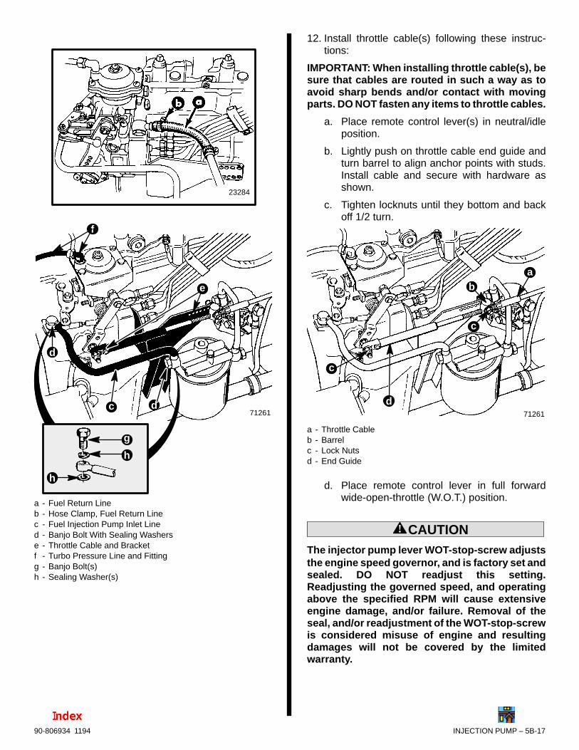
INJECTION PUMP – 5B-1790-806934 1194
23284
71261c
d
d
f
e
g
h
h
a - Fuel Return Lineb - Hose Clamp, Fuel Return Linec - Fuel Injection Pump Inlet Lined - Banjo Bolt With Sealing Washerse - Throttle Cable and Bracketf - Turbo Pressure Line and Fittingg - Banjo Bolt(s)h - Sealing Washer(s)
12. Install throttle cable(s) following these instruc-tions:
IMPORTANT: When installing throttle cable(s), besure that cables are routed in such a way as toavoid sharp bends and/or contact with movingparts. DO NOT fasten any items to throttle cables.
a. Place remote control lever(s) in neutral/idleposition.
b. Lightly push on throttle cable end guide andturn barrel to align anchor points with studs.Install cable and secure with hardware asshown.
c. Tighten locknuts until they bottom and backoff 1/2 turn.
71261
b
c
c
a
d
a - Throttle Cableb - Barrelc - Lock Nutsd - End Guide
d. Place remote control lever in full forwardwide-open-throttle (W.O.T.) position.
! CAUTIONThe injector pump lever WOT-stop-screw adjuststhe engine speed governor, and is factory set andsealed. DO NOT readjust this setting.Readjusting the governed speed, and operatingabove the specified RPM will cause extensiveengine damage, and/or failure. Removal of theseal, and/or readjustment of the WOT-stop-screwis considered misuse of engine and resultingdamages will not be covered by the limitedwarranty.
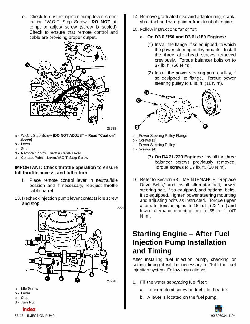
90-806934 11945B-18 – INJECTION PUMP
e. Check to ensure injector pump lever is con-tacting “W.O.T. Stop Screw.” DO NOT at-tempt to adjust screw (screw is sealed).Check to ensure that remote control andcable are providing proper output.
23728
a - W.O.T. Stop Screw (DO NOT ADJUST – Read “Caution”above)
b - Leverc - Seald - Remote Control Throttle Cable Levere - Contact Point – Lever/W.O.T. Stop Screw
IMPORTANT: Check throttle operation to ensurefull throttle access, and full return.
f. Place remote control lever in neutral/idleposition and if necessary, readjust throttlecable barrel.
13. Recheck injection pump lever contacts idle screwand stop.
22217
23728
a - Idle Screwb - Leverc - Stopd - Jam Nut
14. Remove graduated disc and adaptor ring, crank-shaft tool and wire pointer from front of engine.
15. Follow instructions “a” or “b”:
a. On D3.0l/150 and D3.6L/180 Engines:
(1) Install the flange, if so equipped, to whichthe power steering pulley mounts. Installthe three allen-head screws removedpreviously. Torque balancer bolts on to37 lb. ft. (50 N·m).
(2) Install the power steering pump pulley, ifso equipped, to flange. Torque powersteering pulley to 8 lb. ft. (11 N·m).
b
a
c
d
a - Power Steering Pulley Flangeb - Screws (3)c - Power Steering Pulleyd - Screws (4)
(3) On D4.2L/220 Engines: Install the threebalancer screws previously removed.Torque screws to 37 lb. ft. (50 N·m).
16. Refer to Section 5B – MAINTENANCE, “ReplaceDrive Belts,” and install alternator belt, powersteering belt, if so equipped, and optional belts,if so equipped. Tighten power steering mountingand adjusting bolts as instructed. Torque upperalternator tensioning nut to 16 lb. ft. (22 N·m) andlower alternator mounting bolt to 35 lb. ft. (47N·m).
Starting Engine – After FuelInjection Pump Installationand TimingAfter installing fuel injection pump, checking orsetting timing it will be necessary to “Fill” the fuelinjection system. Follow instructions:
1. Fill the water separating fuel filter:
a. Loosen bleed screw on fuel filter header.
b. A lever is located on the fuel pump.

INJECTION PUMP – 5B-1990-806934 1194
c. Move fuel pump lever UP and DOWNrepeatedly, until an air free stream of fuelflows from bleed screw.
73332
a
b
a - Pump/Primer Lever on Fuel Pumpb - Bleed Screw
d. Tighten bleed screw.
2. Fill fuel injection pump:
a. Loosen vent screw on back of fuel injectionpump.
b. A lever is located on the fuel pump.
c. Move fuel pump lever UP and DOWNrepeatedly, until an air free stream of fuelflows from vent screw.
73332
a71371
b
a - Pump/Primer Leverb - Vent Screw
d. Tighten vent screw.
! CAUTIONWhen installing battery, be sure to connectPOSITIVE (+) battery cable to POSITIVE (+)battery terminal FIRST, and NEGATIVE (–) batterycable to NEGATIVE (–) battery terminal LAST. Ifbattery cables are reversed, or connection orderis reversed, electrical system damage will result.
3. Install fully charged battery. Clean battery cableclamps and terminals and reconnect cables (seeCAUTION listed above). Secure each cableclamp when connecting.
! WARNING
Be certain area around propeller is clear to avoidpersonal injury.
! WARNING
Water must be supplied to seawater pickup pumpto avoid engine damage due to overheating.
! CAUTIONTo prevent damage to starter motor, do notoperate starter for more than 15 seconds at onetime. Allow at least 2 minutes for starter motor tocool before reusing.
! WARNING
Safety glasses should be worn while working onfuel injection system. The fuel injection pumpwill generate pressures in excess of 2000 psi(13790 kPa). Use caution when removinginjectors, injector lines, or bleeding air frominjection system.
! WARNING
Do not use your fingers to feel for fuel leaks atfittings. Fuel pressure is high enough topenetrate the skin.
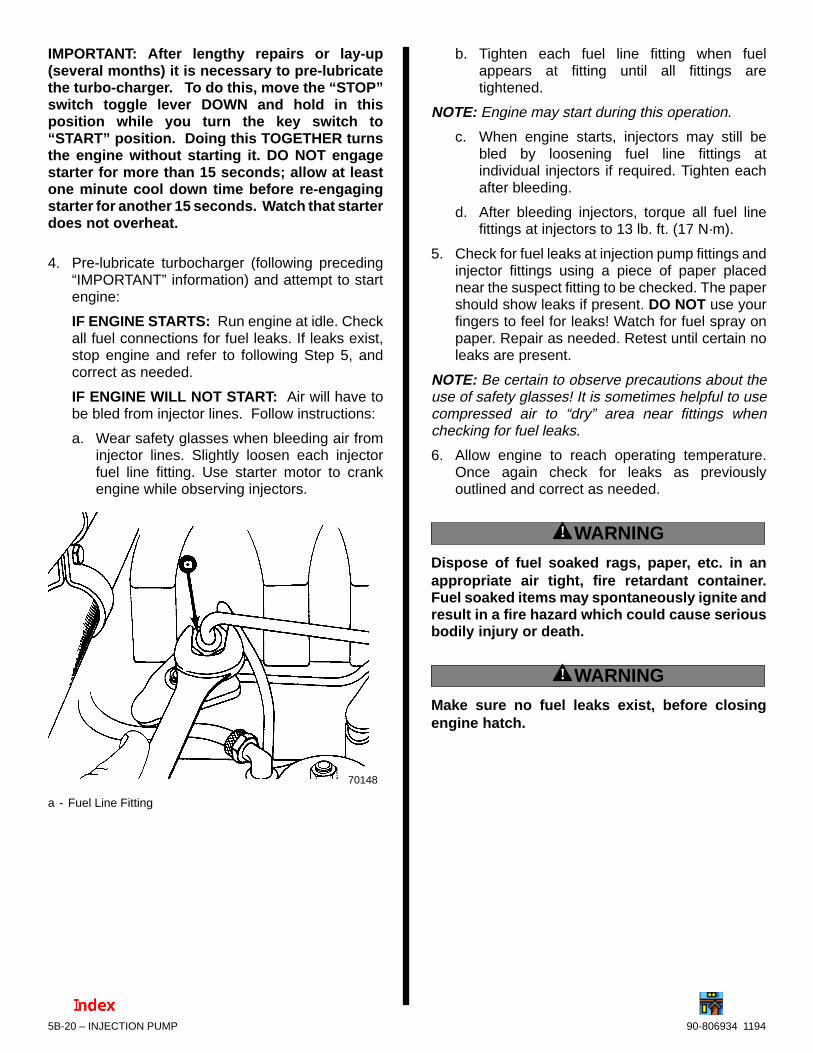
90-806934 11945B-20 – INJECTION PUMP
IMPORTANT: After lengthy repairs or lay-up(several months) it is necessary to pre-lubricatethe turbo-charger. To do this, move the “STOP”switch toggle lever DOWN and hold in thisposition while you turn the key switch to“START” position. Doing this TOGETHER turnsthe engine without starting it. DO NOT engagestarter for more than 15 seconds; allow at leastone minute cool down time before re-engagingstarter for another 15 seconds. Watch that starterdoes not overheat.
4. Pre-lubricate turbocharger (following preceding“IMPORTANT” information) and attempt to startengine:
IF ENGINE STARTS: Run engine at idle. Checkall fuel connections for fuel leaks. If leaks exist,stop engine and refer to following Step 5, andcorrect as needed.
IF ENGINE WILL NOT START: Air will have tobe bled from injector lines. Follow instructions:
a. Wear safety glasses when bleeding air frominjector lines. Slightly loosen each injectorfuel line fitting. Use starter motor to crankengine while observing injectors.
70148
a - Fuel Line Fitting
b. Tighten each fuel line fitting when fuelappears at fitting until all fittings aretightened.
NOTE: Engine may start during this operation.
c. When engine starts, injectors may still bebled by loosening fuel line fittings atindividual injectors if required. Tighten eachafter bleeding.
d. After bleeding injectors, torque all fuel linefittings at injectors to 13 lb. ft. (17 N·m).
5. Check for fuel leaks at injection pump fittings andinjector fittings using a piece of paper placednear the suspect fitting to be checked. The papershould show leaks if present. DO NOT use yourfingers to feel for leaks! Watch for fuel spray onpaper. Repair as needed. Retest until certain noleaks are present.
NOTE: Be certain to observe precautions about theuse of safety glasses! It is sometimes helpful to usecompressed air to “dry” area near fittings whenchecking for fuel leaks.
6. Allow engine to reach operating temperature.Once again check for leaks as previouslyoutlined and correct as needed.
! WARNING
Dispose of fuel soaked rags, paper, etc. in anappropriate air tight, fire retardant container.Fuel soaked items may spontaneously ignite andresult in a fire hazard which could cause seriousbodily injury or death.
! WARNING
Make sure no fuel leaks exist, before closingengine hatch.
7A
6
A
C
4
A
3
A
2
A
1
A
550442
FUEL SYSTEMS
FUEL INJECTORS

5C-0 – FUEL INJECTORS 90-806934 1194
Table Of ContentsPage
Index 5C-0. . . . . . . . . . . . . . . . . . . . . . . . . . . . . . . . . . . . . . . . Identification 5C-1. . . . . . . . . . . . . . . . . . . . . . . . . . . . . . . . . . Specifications 5C-1. . . . . . . . . . . . . . . . . . . . . . . . . . . . . . . . . Torque Specifications 5C-1. . . . . . . . . . . . . . . . . . . . . . . . . . Bosch Special Tools 5C-1. . . . . . . . . . . . . . . . . . . . . . . . . . . Description 5C-1. . . . . . . . . . . . . . . . . . . . . . . . . . . . . . . . . . . Fuel Injector (Cutaway View) 5C-1. . . . . . . . . . . . . . . . . . . Precautions 5C-2. . . . . . . . . . . . . . . . . . . . . . . . . . . . . . . . . . Fuel Injectors 5C-3. . . . . . . . . . . . . . . . . . . . . . . . . . . . . . . . .
Removal 5C-3. . . . . . . . . . . . . . . . . . . . . . . . . . . . . . . . . . Testing 5C-4. . . . . . . . . . . . . . . . . . . . . . . . . . . . . . . . . . . . Installation 5C-4. . . . . . . . . . . . . . . . . . . . . . . . . . . . . . . . . Bleeding Fuel Injectors 5C-6. . . . . . . . . . . . . . . . . . . . . .
Injector Test (Engine Misfiring) 5C-7. . . . . . . . . . . . . . . . . .
5C – FUEL INJECTORS
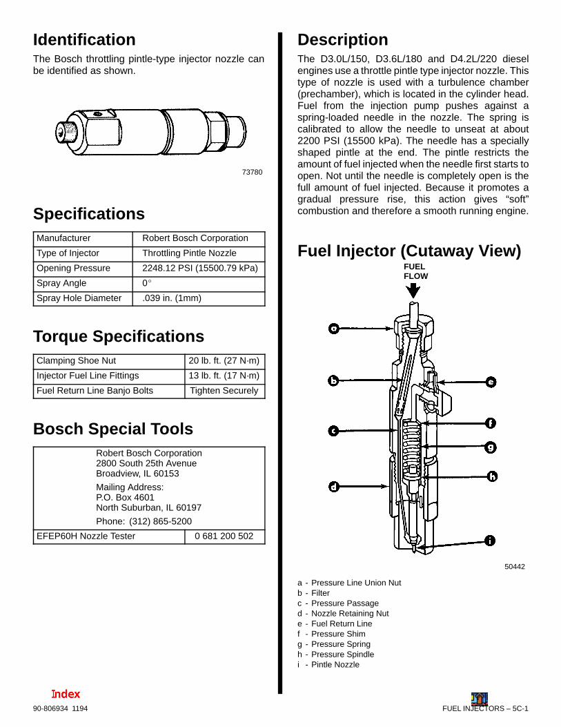
FUEL INJECTORS – 5C-190-806934 1194
IdentificationThe Bosch throttling pintle-type injector nozzle canbe identified as shown.
73780
SpecificationsManufacturer Robert Bosch Corporation
Type of Injector Throttling Pintle Nozzle
Opening Pressure 2248.12 PSI (15500.79 kPa)
Spray Angle 0
Spray Hole Diameter .039 in. (1mm)
Torque SpecificationsClamping Shoe Nut 20 lb. ft. (27 N·m)
Injector Fuel Line Fittings 13 lb. ft. (17 N·m)
Fuel Return Line Banjo Bolts Tighten Securely
Bosch Special ToolsRobert Bosch Corporation2800 South 25th AvenueBroadview, IL 60153
Mailing Address:P.O. Box 4601North Suburban, IL 60197
Phone: (312) 865-5200
EFEP60H Nozzle Tester 0 681 200 502
DescriptionThe D3.0L/150, D3.6L/180 and D4.2L/220 dieselengines use a throttle pintle type injector nozzle. Thistype of nozzle is used with a turbulence chamber(prechamber), which is located in the cylinder head.Fuel from the injection pump pushes against aspring-loaded needle in the nozzle. The spring iscalibrated to allow the needle to unseat at about2200 PSI (15500 kPa). The needle has a speciallyshaped pintle at the end. The pintle restricts theamount of fuel injected when the needle first starts toopen. Not until the needle is completely open is thefull amount of fuel injected. Because it promotes agradual pressure rise, this action gives “soft”combustion and therefore a smooth running engine.
Fuel Injector (Cutaway View)
50442
FUELFLOW
a - Pressure Line Union Nutb - Filterc - Pressure Passaged - Nozzle Retaining Nute - Fuel Return Linef - Pressure Shimg - Pressure Springh - Pressure Spindlei - Pintle Nozzle
5C-2 – FUEL INJECTORS 90-806934 1194
Precautions
! WARNING
Always disconnect battery cables from batteryBEFORE working on fuel system to prevent fireor explosion.
! WARNING
Be careful when changing fuel systemcomponents; diesel fuel is flammable. Be surethat ignition key is OFF. DO NOT smoke or allowsources of open flame in the area while changingfuel system components. Wipe up any spilledfuel immediately. DO NOT allow fuel to come intocontact with any hot surface which may cause itto ignite.
! WARNING
Dispose of fuel soaked rags, paper, etc. in anappropriate air tight, fire retardant container.Fuel soaked items may spontaneously ignite andresult in a fire hazard which could cause seriousbodily injury or death.
! WARNING
Make sure that no fuel leaks exist, before closingengine hatch.
! CAUTIONDO NOT operate engine without cooling waterbeing supplied to seawater pump, or impeller willbe damaged and subsequent overheating damageto engine may result.
! WARNING
Electrical system components on this engine arenot external ignition protected. DO NOT STORE ORUTILIZE GASOLINE ON BOATS EQUIPPED WITHTHESE ENGINES, UNLESS PROVISIONS HAVEBEEN MADE TO EXCLUDE GASOLINE VAPORSFROM ENGINE COMPARTMENT (ref: 33 CFR).Failure to comply could result in fire, explosionand/or severe personal injury.
! WARNING
FIRE HAZARD: Fuel leakage from any part of thefuel system can be a fire hazard which can causeserious bodily injury or death. Careful periodicinspection of entire fuel system is mandatory,particularly after storage. All fuel componentsincluding fuel tanks, whether plastic, metal orfiberglass, fuel lines, primers, fittings, and fuelfilters should be inspected for leakage, softening,hardening, swelling or corrosion. Any sign ofleakage or deterioration requires replacementbefore further engine operation.
! WARNING
Safety glasses should be worn while working onfuel injection system. The fuel injection pump willgenerate pressures in excess of 2000 P.S.I. (13790kPa). Use caution when removing injectors,injector lines, or bleeding air from injectionsystem.
IMPORTANT: Mercury Marine does notrecommend fuel injectors be disassembled forservice. If an injector tester is not available,substitute a new injector for any injectors thoughtto be faulty.
! CAUTIONDue to fuel injector design changes the 530 D-TA,636 D-TA, D183 and D219 Model fuel injector MUSTNOT be used in a D254, D3.0L/150, D3.6L/180 or aD4.2L/220 engine under any conditions. However,the new-style D254 or a D4.2L/220 fuel injectorCAN BE used in all engines as a replacement.(Refer to QUICKSILVER PARTS CATALOG.)
IMPORTANT: Always wash hands and use cleantools when working on fuel injection system.

FUEL INJECTORS – 5C-390-806934 1194
Fuel Injectors
Removal
! CAUTIONKeep injectors and injection pump fittings clean.Do not allow dirt to enter fittings when removingor installing lines. Dirt will cause injectors orinjection pump to malfunction.
! CAUTIONDo not bend fuel injector lines. Bending maycause metal to flake off inside lines, causinginjectors or injection pump to malfunction.
1. Wearing safety glasses, clean dirt from around fuelinjectors using clean rags and compressed air.
2. Remove valve covers.
3. Remove fuel return line banjo bolts. Discard sealing washers.
70142
a - Fuel Return Lineb - Banjo Boltsc - Sealing Washers (Two Per Banjo Bolt and Fitting)
4. Remove injector fuel lines by completely loosen-ing fuel line fittings. Remove clamps as required.
70180
a - Injector Fuel Linesb - Fuel Line Fittingsc - Clamps
5. Remove clamping shoe after removing hex nutand lockwasher. Remove spacer. Retain allcomponents.
70144
a - Clamping Shoeb - Spacerc - Hex Nutd - Lockwasher
! CAUTIONTo prevent injector nozzle from rusting, wethands with diesel fuel before handling injectors.
70147
a - Fuel Injector Nozzle
6. Remove fuel injector. Discard copper sealingwasher.
70147
a - Fuel Injectorb - Copper Sealing Washer
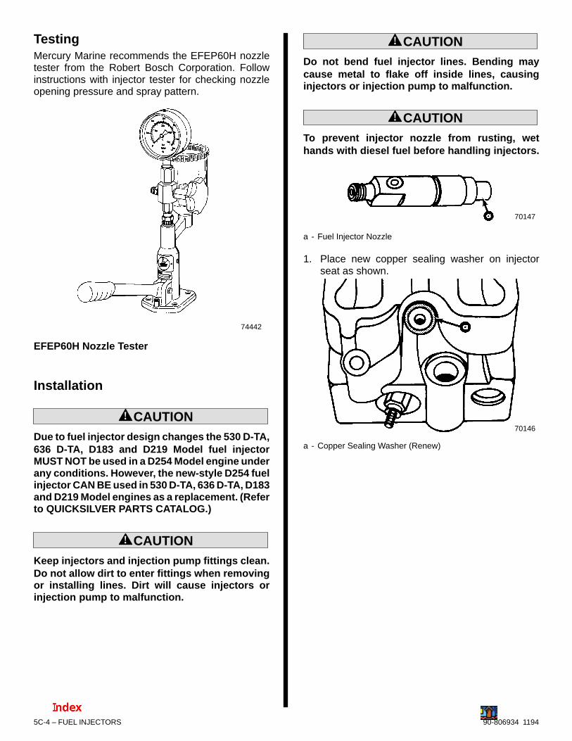
5C-4 – FUEL INJECTORS 90-806934 1194
TestingMercury Marine recommends the EFEP60H nozzletester from the Robert Bosch Corporation. Followinstructions with injector tester for checking nozzleopening pressure and spray pattern.
74442
EFEP60H Nozzle Tester
Installation
! CAUTIONDue to fuel injector design changes the 530 D-TA,636 D-TA, D183 and D219 Model fuel injectorMUST NOT be used in a D254 Model engine underany conditions. However, the new-style D254 fuelinjector CAN BE used in 530 D-TA, 636 D-TA, D183and D219 Model engines as a replacement. (Referto QUICKSILVER PARTS CATALOG.)
! CAUTIONKeep injectors and injection pump fittings clean.Do not allow dirt to enter fittings when removingor installing lines. Dirt will cause injectors orinjection pump to malfunction.
! CAUTIONDo not bend fuel injector lines. Bending maycause metal to flake off inside lines, causinginjectors or injection pump to malfunction.
! CAUTIONTo prevent injector nozzle from rusting, wethands with diesel fuel before handling injectors.
70147
a - Fuel Injector Nozzle
1. Place new copper sealing washer on injectorseat as shown.
70146
a - Copper Sealing Washer (Renew)

FUEL INJECTORS – 5C-590-806934 1194
2. Install injector with fuel return hole facing rockerarms.
70145
a - Fuel Return Hole
3. Place spacer as shown.
70143
a - Spacer
4. Install clamping shoe around flat sides of fuelinjector as shown. Install lockwasher and hexnut. Tighten to 20 lb. ft. (27 N·m).
70144
a - Clamping Shoeb - Lockwasherc - Hex Nut
5. Install injector fuel lines. Tighten fuel line fittingsto 13 lb. ft. (17 N·m). Install and tighten clamps asrequired.
70180
a - Injector Fuel Linesb - Fuel Line Fittingsc - Clamps

5C-6 – FUEL INJECTORS 90-806934 1194
6. Using 2 new sealing washers for each banjo bolt,install fuel-return line. Tighten banjo boltssecurely.
70142
a - Fuel Return Lineb - Banjo Boltsc - Sealing Washers (Two Per Banjo Bolt and Fitting)
7. Install valve covers. (Refer to SECTION 3A - En-gine.) Torque fasteners to 7 lb. ft. (10 N·m).
Bleeding Fuel Injectors
! CAUTIONTo prevent damage to starter motor, do not usefor more than 15 seconds at one time. Allow atleast 2 minutes for starter motor to cool beforereusing.
! WARNING
Wipe up any spilled fuel immediately anddispose of fuel soaked rags, paper, etc., in anappropriate air tight, fire retardant container.Fuel soaked items may spontaneously ignite andresult in a fire hazard which could cause seriousbodily injury or death.
! WARNING
Safety glasses should be worn while working onfuel injection system. The fuel injection pumpwill generate pressures in excess of 2000 P.S.I.(13790 kPa). Use caution when removinginjectors, injector lines, or bleeding air frominjection system.
1. Start engine. If engine will not start, air will haveto be bled from injector lines, as outlined in thefollowing.
2. Wear safety glasses when bleeding air from in-jector lines. Slightly loosen each injector fuel linefitting. Use starter motor to crank engine, whileobserving injectors.
70148
17 MM
a - Fuel Line Fitting
3. Tighten each fuel line fitting when fuel appears atfitting until all fittings are tightened. (NOTE:Engine may start during this operation.)
4. When engine starts, injectors may still be bled byloosening fuel line fittings at individual injectors,if required. Tighten each after bleeding.
5. After bleeding injectors, torque all fuel line fittingsto 13 lb. ft. (17 N·m).
! WARNING
Do not use your fingers to feel for fuel leaks atfittings. Fuel pressure is high enough topenetrate the skin.
6. Allow engine to reach operating temperature.Check for fuel leaks at injection pump fittings andinjector fittings using a piece of paper placednear the suspect fitting to be checked. The papershould show leaks if present. DO NOT use yourfingers to feel for leaks! Watch for fuel spray onpaper. Repair as needed. Retest until certain noleaks are present.
NOTE: Be certain to observe precautions on thispage about the use of safety glasses! It is sometimeshelpful to use compressed air to dry area near fittingswhen checking for fuel leaks.
! WARNING
Make sure no fuel leaks exist, before closingengine hatch.
FUEL INJECTORS – 5C-790-806934 1194
Injector Test (Engine Misfiring)
! WARNING
Safety glasses should be worn while working onfuel injection system. The fuel injection pumpwill generate pressures in excess of 2000 P.S.I.(13790 kPa). Use caution when removinginjectors, injector lines, or bleeding air frominjection system.
1. Follow instructions “a” - “d”:
a. Wear safety glasses when testing injectors.
b. With engine running at idle, carefully loosenfuel line fitting at injectors, one cylinder at atime.
(1) If idle RPM changes, injector is operating.
(2) If idle RPM does not change, injector maybe faulty.
c. Stop engine and replace injector.
d. Check all injectors one at a time.
2. If engine continues to misfire, check for mechani-cal problems (faulty injection pump, burnedvalves, etc.).

7A A
5
A
4
A
3
A
2
A
1
A
6
COOLING SYSTEM
SEAWATER SYSTEM
Note:Refer to the following Service Bulletin regarding this section.
SB 97-2 MerCruiser MCM/MIE Inline Diesel Heat Exchanger End Cover Torque
90-806934 11946A-0 – SEAWATER SYSTEM
Table Of ContentsPage
Torque Specifications 6A-1. . . . . . . . . . . . . . . . . . . . . . . . Specifications 6A-1. . . . . . . . . . . . . . . . . . . . . . . . . . . . . . . .
Seawater Pump 6A-1. . . . . . . . . . . . . . . . . . . . . . . . . . . D3.0L/150 and D3.6L/180 Engines 6A-1. . . . . . . . D4.2L/220 Engines 6A-1. . . . . . . . . . . . . . . . . . . . .
Lubricants/Sealants 6A-1. . . . . . . . . . . . . . . . . . . . . . . . . . . Cooling System Cleaners 6A-1. . . . . . . . . . . . . . . . . . . . . . Seawater Pickup Connection 6A-1. . . . . . . . . . . . . . . . . . . Seacock 6A-2. . . . . . . . . . . . . . . . . . . . . . . . . . . . . . . . . . . . Sea Strainer 6A-2. . . . . . . . . . . . . . . . . . . . . . . . . . . . . . . . . Exploded Views and Diagrams 6A-3. . . . . . . . . . . . . . . . .
D3.0L/150 and D3.6L/180 Seawater Pump 6A-3. . . . D4.2L/220 Seawater Pump 6A-4. . . . . . . . . . . . . . . . . Water Flow Diagram 6A-5. . . . . . . . . . . . . . . . . . . . . . .
Seawater Pump 6A-6. . . . . . . . . . . . . . . . . . . . . . . . . . . . . . Removal 6A-6. . . . . . . . . . . . . . . . . . . . . . . . . . . . . . . . . Repair 6A-6. . . . . . . . . . . . . . . . . . . . . . . . . . . . . . . . . . .
Disassembly 6A-6. . . . . . . . . . . . . . . . . . . . . . . . . . . Cleaning And Inspection 6A-9. . . . . . . . . . . . . . . . . Assembly 6A-10. . . . . . . . . . . . . . . . . . . . . . . . . . . . .
Installation 6A-14. . . . . . . . . . . . . . . . . . . . . . . . . . . . . . . Sea Strainer 6A-15. . . . . . . . . . . . . . . . . . . . . . . . . . . . . . . .
Exploded View 6A-15. . . . . . . . . . . . . . . . . . . . . . . . . . . Removal 6A-16. . . . . . . . . . . . . . . . . . . . . . . . . . . . . . . . Installation 6A-17. . . . . . . . . . . . . . . . . . . . . . . . . . . . . . .
Oil / Power Steering / Transmission Fluid Coolers 6A-17Location of Coolers 6A-18. . . . . . . . . . . . . . . . . . . . . . . Inspection 6A-18. . . . . . . . . . . . . . . . . . . . . . . . . . . . . . . Cleaning 6A-19. . . . . . . . . . . . . . . . . . . . . . . . . . . . . . . . Removal 6A-19. . . . . . . . . . . . . . . . . . . . . . . . . . . . . . . .
Power Steering 6A-19. . . . . . . . . . . . . . . . . . . . . . . . Engine Oil Cooler 6A-20. . . . . . . . . . . . . . . . . . . . . . Transmission Fluid Cooler 6A-21. . . . . . . . . . . . . .
Installation 6A-21. . . . . . . . . . . . . . . . . . . . . . . . . . . . . . . Power Steering 6A-21. . . . . . . . . . . . . . . . . . . . . . . . Engine Oil Cooler 6A-22. . . . . . . . . . . . . . . . . . . . . . Transmission Fluid Cooler 6A-23. . . . . . . . . . . . . .
NOTICE
For instructions on Cleaning Seawater Strainer,Flushing Seawater Cooling System or DrainingSeawater Section refer to SECTION 1B - “Main-tenance.”
6A – SEAWATER SYSTEM

SEAWATER SYSTEM – 6A-190-806934 1194
Torque SpecificationsTighten All Fasteners Securely
Specifications
Seawater Pump
D3.0L/150 AND D3.6L/180 ENGINES
Seawater Pump Delivery Rates
Engine R.P.M. U.S. Gal. (L)
1000 7.3 (27.7)
2000 14.5 (55)
3000 21.1 (80)
4000 24 (91)
D4.2L/220 ENGINES
Seawater Pump Delivery Rates
Engine R.P.M. U.S. Gal. (L)
1000 10 (37.8)
2000 19 (71)
3000 26 (98)
3600 30 (113.5)
Lubricants/Sealants
DESCRIPTION PARTNUMBER
Quicksilver 2-4-C Marine Lubricant 92-90018A12
Special Lubricant 101 92-13872A12
Shell Alvania No. 2 Obtain Locally
Quicksilver Perfect Seal 92-34227--1
Loctite Master Gasket 92-12564--1
Loctite Pipe Sealant (With Teflon) Obtain Locally
Cooling System Cleaners
DESCRIPTION PARTNUMBER
Quicksilver Cooling System Cleaner 91-814825
Fleetguard Restore CC2610
Seawater Pickup ConnectionSeawater Pickup and Hose: Water pickup must belarge enough to permit sufficient water flow to engineseawater pickup pump for adequate engine cooling.
SEAWATER PICKUP FLOW REQUIREMENT
MODEL FLOW RATE(Minimum)
D3.0L/150 and D3.6L/180 30 U.S. Gal. per min.(114 L per min.)
D4.2L/220 40 U.S. Gal. per min. (150 L per min.)
IMPORTANT: DO NOT install water pickupdirectly in line with propeller, as pickup maycreate turbulence and allow air to flow into the“propeller slipstream.” This will cause propellerventilation and will adversely affect boatperformance.
Pickup also must supply a positive head whileunderway. Water pickup should be located as closeto seawater pickup pump inlet as possible and in anarea where an uninterrupted, solid stream of waterwill flow past when boat is underway.
Connect water pickup to seawater inlet hose withdimensions as shown in the following.
SEAWATER PICKUP HOSE SIZE REQUIREMENT
MODEL DIAMETER(Minimum)
D3.0L/150 and D3.6L/180 1-1/4 in. (32mm)
D4.2L/2200 1-1/2 in. (38mm)
Use only ID wire reinforced hose of adequate wallthickness to prevent it from collapsing from pumpsuction. Be sure to secure hose connections withhose clamps.

90-806934 11946A-2 – SEAWATER SYSTEM
SeacockIf a seacock is being used, it must be installedbetween water pickup and seawater pickup pump (orsea strainer), to allow operator to shut off theseawater in case of a leak or when boat is not in use.This will also allow the operator to flush or drain theengine, or clean the sea strainer while boat is in thewater. Install seacock in an area where it will beeasily accessible and support adequately to preventhose fatigue.
To prevent restricting water flow seacock used musthave an internal cross-sectional area (equal to orgreater than hose) as shown in the following.
SEACOCK SIZE REQUIREMENT
MODEL DIAMETER(Minimum)
D3.0L/150 and D3.6L/180 1-1/4 in. (32mm)
D4.2L/220 1-1/2 in. (38mm)
70355
a
b
c
a - Wire Reinforced Hoseb - Seacockc - Seawater Pickup
Quicksilver MIE (Inboard) D4.2L/220 Compo-nents Shown - All Similar
Sea StrainerThe strainer, if so equipped, must be of sufficient sizeto ensure that an adequate supply of water will bemaintained for cooling engine. A minimum flow rateis required as shown in the following.
SEA STRAINER FLOW REQUIREMENT
MODEL FLOW RATE(Minimum)
D3.0L/150 and D3.6L/180 30 U.S. Gal. per min.(114 L per min.)
D4.2L/220 40 U.S. Gal. per min.(150 L per min.)

SEAWATER SYSTEM – 6A-390-806934 1194
Exploded Views and Diagrams
D3.0L/150 and D3.6L/180 Seawater Pump
73947
B
A
a
a
1 - Pump Housing2 - Screw3 - Housing Pin4 - Ball Bearing5 - Spacer6 - Snap Ring7 - Shaft8 - Thrust Washer (Align Notch with Housing Pin)9 - Oil Seal10- Spreader11- O-Ring12- Cam (Apply Sealer Indicated to Back-Side)13- Impeller14- Gasket15- Cover16- Screw17- O-Ring18- Nut with Washer (4 - Washers not shown)
Lubricant/Sealant Application Points
A Shell Alvania No. 2 (See NOTE.)B Loctite Master Gasket
NOTE: In cases where high-speed or heavy duty willnot be encountered, it is permissible to use Quicksil-ver 2-4-C Marine Lubricant or Special Lubricant101.)
Torque Specifications
a Tighten Securely
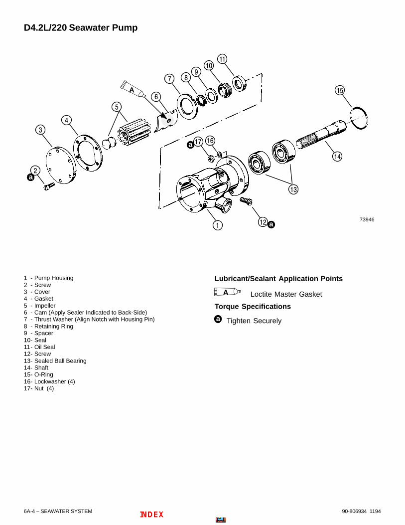
90-806934 11946A-4 – SEAWATER SYSTEM
D4.2L/220 Seawater Pump
73946
a
a
a
A
1 - Pump Housing2 - Screw3 - Cover4 - Gasket5 - Impeller6 - Cam (Apply Sealer Indicated to Back-Side)7 - Thrust Washer (Align Notch with Housing Pin)8 - Retaining Ring9 - Spacer10- Seal11- Oil Seal12- Screw13- Sealed Ball Bearing14- Shaft15- O-Ring16- Lockwasher (4)17- Nut (4)
Lubricant/Sealant Application Points
A Loctite Master Gasket
Torque Specifications
a Tighten Securely
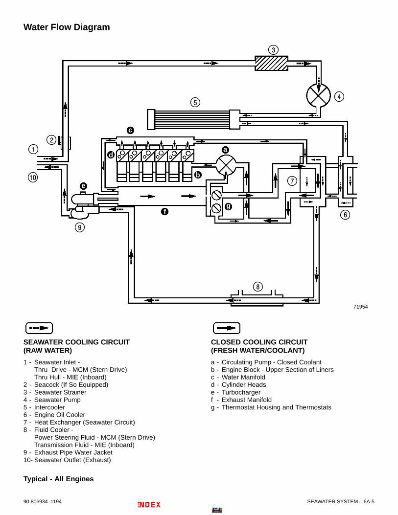
SEAWATER SYSTEM – 6A-590-806934 1194
Water Flow Diagram
b
c
d
e
fg
a
71954
SEAWATER COOLING CIRCUIT(RAW WATER)
1 - Seawater Inlet -Thru Drive - MCM (Stern Drive)Thru Hull - MIE (Inboard)
2 - Seacock (If So Equipped)3 - Seawater Strainer4 - Seawater Pump5 - Intercooler6 - Engine Oil Cooler7 - Heat Exchanger (Seawater Circuit)8 - Fluid Cooler -
Power Steering Fluid - MCM (Stern Drive)Transmission Fluid - MIE (Inboard)
9 - Exhaust Pipe Water Jacket10- Seawater Outlet (Exhaust)
Typical - All Engines
CLOSED COOLING CIRCUIT(FRESH WATER/COOLANT)
a - Circulating Pump - Closed Coolantb - Engine Block - Upper Section of Linersc - Water Manifoldd - Cylinder Headse - Turbochargerf - Exhaust Manifoldg - Thermostat Housing and Thermostats

90-806934 11946A-6 – SEAWATER SYSTEM
Seawater PumpRemoval
! CAUTIONIf boat is in water while working on seawaterpump, when removing seawater inlet hose, closeseacock, if so equipped. If boat is not equippedwith a seacock, remove and plug seawater inlethose to prevent a siphoning action that mayoccur, allowing seawater to enter boat.
1. Remove and plug seawater pump inlet hose.Loosen 6 cover screws to drain water into asuitable container. Remove outlet hose.
73320
c
da
b
a - Seawater Pumpb - Inlet Hosec - Cover Screws (6)d - Outlet Hose
Typical Seawater Pump and Connections
2. Remove 4 hex nuts with lockwashers. Removepump.
70423
a - Location of Hex Nuts (Shown Already Removed)b - Pump
Repair
DISASSEMBLY
1. Clamp pump in vise as shown. Remove 6 coverscrews.
70625
a - Cover Screws
2. Remove gasket from cover and pump housing.
3. Using 2 screwdrivers, carefully remove impelleras shown.
70626

SEAWATER SYSTEM – 6A-790-806934 1194
4. Follow instructions “a” or “b”:
a. On D3.0L/150 and D3.6L/180 pumps: Re-move internal snap ring from pump body.
70628
a - Snap Ring
b. On D4.2L/220 pumps: Follow instructions(1) and (2).
(1) Remove external retaining ring frompump shaft.
70694
a - Retaining Ring, External
(2) Remove spacer (washer) from shaft.
70695
a - Spacer (Washer)
5. Using a soft hammer, tap shaft and bearingassembly out of pump housing.
70638
a - Shaft and Bearing Assemblyb - Pump Housing
Typical

90-806934 11946A-8 – SEAWATER SYSTEM
6. Follow instructions “a” or “b”:
IMPORTANT: Take note of factory markings onbearings (if visible), or suitably mark eachbearing, to ensure installation in original positionif reused.
a. On D3.0L/150 and D3.6L/180 pumps: Us-ing an arbor press and suitable hardware, re-move one bearing at a time from pump shaftto avoid damaging spacer. Press off towardsplines of shaft and on inner race of bearingsonly.
70635
a - Bearing(s)b - Spacerc - Pump Shaft
b. On D4.2L/220 pumps: Using an arbor pressand suitable hardware, remove one bearingat a time from pump shaft (spacer is ma-chined as part of shaft). Press one bearing offtoward splines of shaft and the other oppo-site. Press on inner race of bearings only.
70696
a - Bearing(s)b - Spacer (Is machined as part of shaft)c - Pump Shaft
7. Remove screw from between inlet and outlet toallow cam removal.
70632
70638
a - Screw and Locationb - Cam
Typical Pump and Cam Shown
8. Remove thrust washer from its position onlocating pin in pump housing.
70631
a - Thrust Washer
Typical Pump and Thrust Washer Shown

SEAWATER SYSTEM – 6A-990-806934 1194
9. Follow instructions “a” or “b”:
a. On D3.0L/150 and D3.6L/180 pumps: Us-ing a suitable tool, remove two seals, one O-ring, and one flat washer from pump housing.Notice positioning.
70637
a - Seal, Rearb - O-ringc - Flat Rubber Washerd - Seal, Front
b. On D4.2L/220 pumps: Follow instructions(1) and (2):
(1) Being careful not to gouge or nick pumphousing, remove rear seal by inserting ascrewdriver through holes in pump hous-ing and carefully pry (push).
70697
a - Screwdriverb - Seal, Rearc - Pump Housing (Do Not gouge or nick)
(2) Using a suitable tool, press front seal as-sembly out front of pump housing fromrear.
NOTE: Although different in appearance the frontseal will press out like a normal seal.
a - Seal, Front (Assembly)b - Pump Housingc - Seal, Rear
CLEANING and INSPECTION
! WARNING
Always wear safety glasses when usingcompressed air.
1. Clean metal parts in solvent and blow dry withcompressed air.
IMPORTANT: On those models with open (notsealed) Ball Bearings, do not spin bearings athigh speed when drying with compressed air, asbearings may be scored and damaged.
2. After cleaning, apply a coat of light engine oil toshaft and bearings to prevent rusting.
3. Clean all gasket material and sealer from sealingsurfaces.
4. Inspect bearing housing. Examine surfaces(where bearings contact housing) for evidence ofbearing outer racers turning in housing.
5. Inspect bearings for worn or defective condition.Examine “sealed” bearings for evidence of lossof factory grease, or evidence of internalcontamination by engine oil.
6. Inspect seals from bearing housing.
7. Inspect pump shaft for grooves in surface whereseals contact shaft. Inspect drive key on shaft.Also, inspect surface, where bearings contactshaft for evidence of inner races turning on shaft.
8. Inspect impeller splines and shaft splines.
9. Inspect pump body.
10. Inspect cam for scratches or gouging.
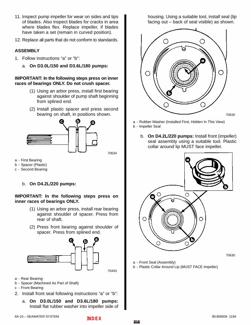
90-806934 11946A-10 – SEAWATER SYSTEM
11. Inspect pump impeller for wear on sides and tipsof blades. Also inspect blades for cracks in areawhere blades flex. Replace impeller, if bladeshave taken a set (remain in curved position).
12. Replace all parts that do not conform to standards.
ASSEMBLY
1. Follow instructions “a” or “b”:
a. On D3.0L/150 and D3.6L/180 pumps:
IMPORTANT: In the following steps press on innerraces of bearings ONLY. Do not crush spacer.
(1) Using an arbor press, install first bearingagainst shoulder of pump shaft beginningfrom splined end.
(2) Install plastic spacer and press secondbearing on shaft, in positions shown.
70634
abc
a - First Bearingb - Spacer (Plastic)c - Second Bearing
b. On D4.2L/220 pumps:
IMPORTANT: In the following steps press oninner races of bearings ONLY.
(1) Using an arbor press, install rear bearingagainst shoulder of spacer. Press fromrear of shaft.
(2) Press front bearing against shoulder ofspacer. Press from splined end.
70443
c ab
a - Rear Bearingb - Spacer (Machined As Part of Shaft)c - Front Bearing
2. Install front seal following instructions “a” or “b”:
a. On D3.0L/150 and D3.6L/180 pumps:Install flat rubber washer into impeller side of
housing. Using a suitable tool, install seal (lipfacing out – back of seal visible) as shown.
70630
a - Rubber Washer (Installed First, Hidden In This View)b - Impeller Seal
b. On D4.2L/220 pumps: Install front (impeller)seal assembly using a suitable tool. Plasticcollar around lip MUST face impeller.
70630
a - Front Seal (Assembly)b - Plastic Collar Around Lip (MUST FACE Impeller)

SEAWATER SYSTEM – 6A-1190-806934 1194
3. Install rear seal following instructions “a” or “b”:
a. On D3.0L/150 and D3.6L/180 pumps:Install O-ring into bearing side of housing.Using a suitable tool, install seal (lip facingout – back of seal visible) as shown.
70629
a - O-ringb - Seal
b. On D4.2L/220 pumps: Using a suitable tool,install seal (lip facing out – back of sealvisible) as shown.
70444
4. Install thrust washer into pump housing. Alignwasher notch with pin in housing.
70630
a - Thrust Washerb - Washer Notchc - Housing Pin
Typical Pump and Thrust Washer
5. Coat backside of cam with Loctite Master Gasketand install cam in housing as shown. Tightenscrew securely. Remove excess Loctite andallow to dry before continuing assembly.
70633
a - Camb - Screw (Hidden in This View)
Typical Pump and Cam Shown

90-806934 11946A-12 – SEAWATER SYSTEM
6. Follow instructions “a” or “b”:
a. On D3.0L/150 and D3.6L/180 pumps:
IMPORTANT: It is recommended that ShellAlvania No. 2 grease be used when packing sealsand bearings in the following steps. If notavailable, it is permissible to use Quicksilver2-4-C Marine Lubricant or Special Lubricant 101.However, 2-4-C or 101 are not recommendedwhere continuous high-speed, heavy-dutyoperation will be encountered.
(1) Pack bearings with recommendedgrease.
(2) Coat lips of seals in pump housing withrecommended grease.
b. On D4.2L/220 pumps: Bearings are sealedwith lubricant from the factory. Coat lips ofseals in pump housing with recommendedgrease.
7. Install shaft and bearing assembly into housingas shown. Tap lightly with soft hammer if neededto seat assembly.
70638
Typical Pump and Shaft With Bearings Shown
8. Follow instructions “a” or “b”:
a. On D3.0L/150 and D3.6L/180 pumps:Install internal snap ring into pump bodygroove.
70628
a - Snap Ring
b. On D4.2L/220 pumps: Install spacer(washer) on shaft next to front seal assembly.Install external retaining ring into groove ofshaft.
70694
a - Front Seal Assemblyb - Spacer (Washer)c - Retaining Ring, External

SEAWATER SYSTEM – 6A-1390-806934 1194
9. Hold pump housing in soft-jaw vise. Installimpeller into housing by turning clockwise whilesimultaneously pushing inward as shown.
70624
Typical Pump and Impeller Shown
10. Push rubber button seal into end of impeller.
70627
a - Rubber Button Sealb - Impeller
11. Install gasket and cover. Tighten screws evenlyin a diagonal pattern. Tighten securely.
70625
a - Coverb - Gasket (Wide Surface On Cam Side)c - Screws (6)
Typical Pump and Cover Shown
90-806934 11946A-14 – SEAWATER SYSTEM
Installation1. Install O-ring on pump housing shoulder.
70628
a - O-ring
Typical Pump Shown
2. Turn pump shaft in direction shown to align driveslot with camshaft.
70628
70442
b
a
a - Drive Slotb - Camshaft
Typical Pump and Camshaft End Shown
3. Install pump on timing gear cover studs. Tightenhex nuts with washers securely.
70423
23161
a - Studsb - Hex Nuts With Washers
Typical Pump Installation Shown
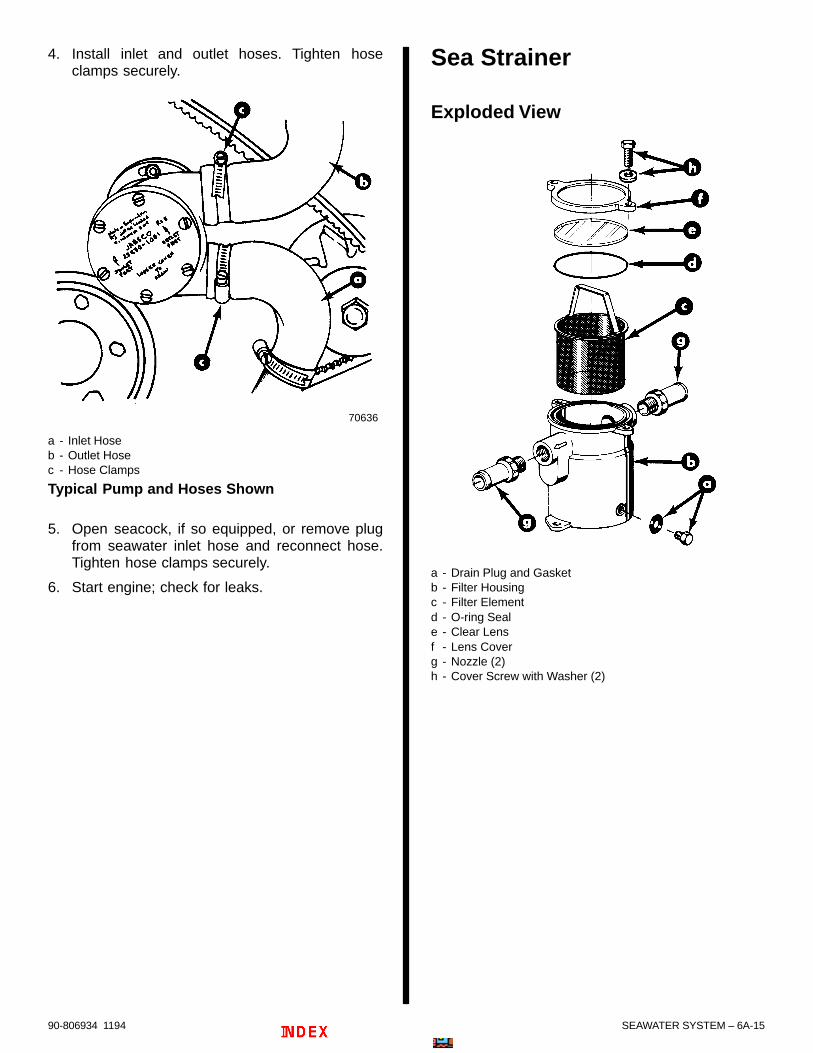
SEAWATER SYSTEM – 6A-1590-806934 1194
4. Install inlet and outlet hoses. Tighten hoseclamps securely.
70636
a - Inlet Hoseb - Outlet Hosec - Hose Clamps
Typical Pump and Hoses Shown
5. Open seacock, if so equipped, or remove plugfrom seawater inlet hose and reconnect hose.Tighten hose clamps securely.
6. Start engine; check for leaks.
Sea Strainer
Exploded View
a - Drain Plug and Gasketb - Filter Housingc - Filter Elementd - O-ring Seale - Clear Lensf - Lens Coverg - Nozzle (2)h - Cover Screw with Washer (2)
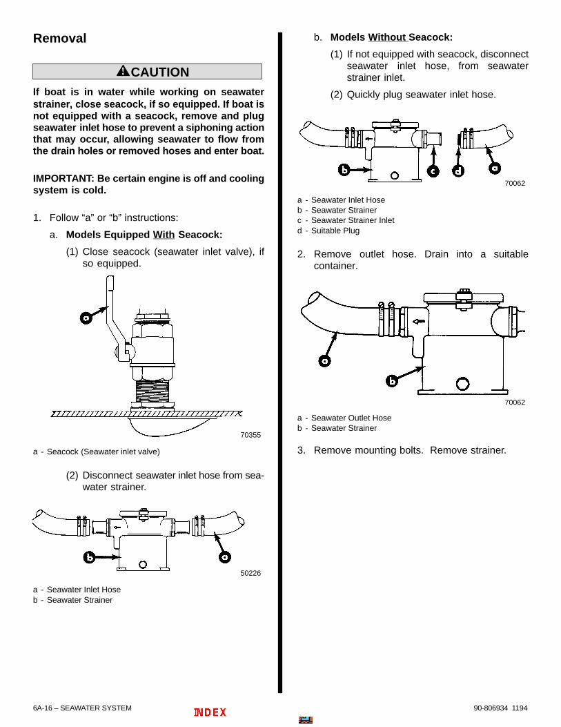
90-806934 11946A-16 – SEAWATER SYSTEM
Removal
! CAUTIONIf boat is in water while working on seawaterstrainer, close seacock, if so equipped. If boat isnot equipped with a seacock, remove and plugseawater inlet hose to prevent a siphoning actionthat may occur, allowing seawater to flow fromthe drain holes or removed hoses and enter boat.
IMPORTANT: Be certain engine is off and coolingsystem is cold.
1. Follow “a” or “b” instructions:
a. Models Equipped With Seacock:
(1) Close seacock (seawater inlet valve), ifso equipped.
70355
a - Seacock (Seawater inlet valve)
(2) Disconnect seawater inlet hose from sea-water strainer.
50226
a - Seawater Inlet Hoseb - Seawater Strainer
b. Models Without Seacock:
(1) If not equipped with seacock, disconnectseawater inlet hose, from seawaterstrainer inlet.
(2) Quickly plug seawater inlet hose.
70062
a - Seawater Inlet Hoseb - Seawater Strainerc - Seawater Strainer Inletd - Suitable Plug
2. Remove outlet hose. Drain into a suitablecontainer.
70062
a - Seawater Outlet Hoseb - Seawater Strainer
3. Remove mounting bolts. Remove strainer.

SEAWATER SYSTEM – 6A-1790-806934 1194
InstallationIMPORTANT: Mount seawater strainer in avibration-free location. Never mount it on theengine or transmission. Hoses must not bekinked or allowed to come in contact with hot ormoving engine or transmission parts.
1. Mount seawater strainer. Note the following:
Arrow must point towards seawater pump.
Tighten mounting bolts securely.
50226
a - Seawater Strainerb - Arrowc - Mounting Bolt Hole Location (Bolts Not Shown)
2. Install inlet and outlet hoses. Use 2 hose clampson each hose connection. Tighten clampssecurely.
50226
a - Seawater Inlet Hoseb - Seawater Strainerc - Double Hose Clamps
3. Check drain plug and lens cover bolts. Tightensecurely. Do not overtighten cover bolts or covermay warp and leak water into boat.
50226
a - Drain Plugb - Lens Cover Bolts – (2, One Hidden In This View)
Oil/Power Steering/Transmission Fluid CoolersCooling efficiency of an engine and components isgreatly dependent upon heat transfer through thetubes within the coolers (heat exchanger orexchangers, if equipped with more than one). Duringengine operation, contaminants within the seawater(such as salt, silt, lime, etc.) collect on the inside ofthe tubes, thus reducing heat transfer and greatlydecreasing cooler (heat exchanger) efficiency.
It is therefore, recommended that the seawatercoolers be cleaned every 200 hours of operation orat least once a year, or whenever decreased coolingefficiency is suspected.
Additionally, inspect cooler hoses and clamps:
For Saltwater Use: Every 50 hours of operationor 60 days, at least once yearly.
For Freshwater Use: Every 100 hours ofoperation or 120 days, at least once yearly.
IMPORTANT: If the possibility of freezing exists,seawater section, and associated heat exchang-ers, MUST BE drained to prevent freeze damageto cooling system and engine. Seawater sectionalso should be drained if boat is to be stored foran extended period of time, to prevent corrosiondamage.

90-806934 11946A-18 – SEAWATER SYSTEM
! CAUTIONSeawater cooling system MUST BE completelydrained for storage, or trapped water may causefreeze and/or corrosion damage to engine and/orcomponents.
! CAUTIONIf boat is in the water, seacock (if so equipped)MUST BE left closed until engine is to berestarted, to prevent water from flowing back intothe cooling system and to prevent contaminatedwater from entering the system. If boat is notfitted with a seacock, water inlet hose MUST BEleft disconnected and plugged to prevent waterfrom flowing into cooling system and/or boat. Asa precautionary measure, attach a tag to theignition switch or steering wheel with theWARNING that the seacock MUST BE opened orthe water inlet hose reconnected prior to startingthe engine.
IMPORTANT: A wire should be repeatedlyinserted into drain holes to ensure that foreignmaterial is not obstructing the drain holes.
IMPORTANT: To prevent threads from rusting outduring storage, reinstall plugs using Perfect Sealon threads. NEVER leave drain plugs out aftercleaning or during storage.
Location of CoolersRefer to the following for location of oil, powersteering and transmission fluid coolers.
72470
a
b
a - Power Steering Coolerb - Engine Oil Cooler
MCM (Stern Drive) Models (All Similar)
73522
ab
a - Transmission Fluid Coolerb - Engine Oil Cooler
MIE (Inboard) D4.2L/220 Shown (All Similar)
Inspection1. Refer to Section 1B – Maintenance, “Cold
Weather or Extended Storage, DrainingInstructions” (and precautions in this section)and drain the seawater system.
2. Remove hose clamp or end cover from INLETend (refer to Seawater Flow Diagrams) of the ap-propriate cooler(s).
3. Inspect passages:
a. If passages appear blocked or restricted withcontaminants, cleaning is required. Refer tothe following section - “Cleaning”..
b. If blockage or restriction is not present, refithose or end cover. Torque end cover to spec-ification or securely tighten hose clamp.
SEAWATER SYSTEM – 6A-1990-806934 1194
Cleaning
1. Refer to Section 1B – Maintenance, “ColdWeather or Extended Storage, DrainingInstructions” (and precautions in this section)and drain the seawater system, if not alreadyaccomplished.
2. Remove hoses from both ends of cooler to becleaned.
3. Temporarily attach a suitable hose to inlet end ofcooler and place end of hose in a suitablecontainer to catch water in the following.
4. Attach a suitable adaptor to the outlet end ofcooler to which a tap water hose may beconnected.
5. Open tap water faucet and “backflush” cooleruntil discharge water is clean.
6. Remove temporary hose and adaptor andinspect cooler passages:
If passages are clear, reconnect seawaterhoses and tighten hose clamps securely.
IMPORTANT: MerCruiser does not recommendthe immersion of oil/power steering/ transmis-sion fluid coolers in cleaning solutions. If back-flushing of the problem cooler does not satisfac-torily clear the passages replacement of thecooler is recommended.
If passages are still obstructed, followinstructions “a” - “c”:
a. Clean tubes in heat exchanger and coolersby running a suitable wire brush of the propersize thru each tube.
71724
a
a - Wire Brush, Sized to Fit Passages
b. Rinse out heat exchanger and cooler tubeswith tap water from a hose to remove loos-ened particles.
c. Replace unit if it cannot be satisfactorilycleaned. Refer to the following section.
Removal
POWER STEERING
1. Refer to Section 1B – Maintenance, “ColdWeather or Extended Storage, DrainingInstructions” (and precautions in this section)and drain the seawater system, if not alreadyaccomplished.
2. Follow instructions “a” – “e”:
NOTE: Obtain two clean, suitable devices and plughoses in following instructions to avoid loss of powersteering fluid.
a. Mark fore and aft fluid hoses to aid inreassembly.
b. Using a suitable container to catch excessfluid, disconnect power steering fluid hosesas shown. Plug hoses quickly.
c. Disconnect attached seawater hoses.
NOTE: On later engines a shift bracket fastener mustbe removed to allow removal of cooler.
d. If fitted as shown, remove shift bracketfastener and stud extension.
e. Remove cooler with J-clamp.
74447
72470
db
b
c
e d
a
a - Power Steering Coolerb - Power Steering Fluid Hosesc - Shift Bracket Fastener and Stud Extensiond - Seawater Hosese - J-Clamp
Typical Power Steering Cooler Installation (All Similar)
90-806934 11946A-20 – SEAWATER SYSTEM
ENGINE OIL COOLER
1. Refer to SECTION 1B – Maintenance, “ColdWeather or Extended Storage, DrainingInstructions” (and precautions in this section)and drain the seawater system, if not alreadyaccomplished.
2. Refer to SECTION 6B – “Draining ClosedCooling Section” instructions (and precautions inthis section) and drain system, if not alreadyaccomplished.
3. Follow instructions “a” – “g”:
NOTE: Obtain clean, suitable devices and plughoses in following instructions to avoid loss of engineoil.
a. Mark port and starboard oil hoses to aid inreassembly.
b. Disconnect engine oil filter head-to-oil coolerline fittings (near each end of oil cooler) onheat exchanger. Quickly plug hoses.
72470
abc
74446
bc
a - Engine Oil Cooler (Combined With Heat Exchanger)b - Starboard Oil Hose Line and Fittingc - Port Oil Hose Line and Fitting (Fitting Not Visible)
c. Disconnect seawater and closed coolinghoses as required to allow removal of heatexchanger, as shown following.
d. Disconnect turbocharger coolant vent hoseon upper-port side of expansion tank.
e. Remove the two large screw clamps retainingthe heat exchanger to the port and starboardbrackets.
f. Remove combination heat exchanger andengine oil cooler.
g. If cooler is to be replaced, it will be necessaryto replace the complete heat exchangerassembly.
74484
a
a
a
aa
b
b
a - Remove End Of Hoses Where Indicated For Ease Of Disassembly and Reassembly
b - Clamps
Engine Oil Cooler/Heat Exchanger and RelatedComponents

SEAWATER SYSTEM – 6A-2190-806934 1194
TRANSMISSION FLUID COOLER
1. Refer to Section 1B – Maintenance, “ColdWeather or Extended Storage, DrainingInstructions” (and precautions in this section)and drain the seawater system, if not alreadyaccomplished.
2. Follow instructions “a” – “f”:
NOTE: Obtain clean, suitable devices and plughoses in following instructions to avoid loss oftransmission fluid.
a. Disconnect seawater hoses fromtransmission fluid cooler.
b. Mark fore and aft transmission fluid hoses toaid in reassembly.
c. Disconnect transmission fluid hoses fromcooler.
d. Remove fasteners from clamps retainingcooler to manifold.
e. Remove transmission fluid cooler.
f. If cooler is to be replaced, note position of 90°elbow connectors and remove to retain.
f
a
b b
c
e
f
d d
a - Transmission Fluid Coolerb - Seawater Hosesc - Transmission Fluid Hosesd - Retaining Clampse - Fastenersf - 90° Elbow Connectors
Typical Transmission Fluid Cooler
Installation
POWER STEERING
1. Follow instructions “a” – “c”:
a. Install cooler with J-clamp into connectingseawater hoses. Position fittings as shownand tighten seawater hose clamps.
b. If fitted as shown, install shift bracket studextension and fastener. Torque both to 24 lb.ft. (32 N·m).
c. Remove plugs from fluid hoses and connectto fittings as marked on disassembly. Tightenfluid hose clamps securely.
74447
db
b
c
e da
a - Cooler, Power Steeringb - Hose, Seawater-to-Coolerc - Hose Clamp, Seawaterd - Cooler Fittingse - Hose, Power Steering Fluidf - Hose Clamp, Fluid
Typical Power Steering Cooler
2. Refer to Section 1B, Maintenance – “CheckPower Steering Fluid” and refill power steeringreservoir.
3. Open seacock if so equipped, or unplugseawater inlet hose and reconnect. Tighten hoseclamps securely.
4. Run-test engine briefly (to fill cooler); check forleaks. Stop engine.
5. Refer to Section 1B, Maintenance – “CheckingPower Steering Fluid” and refill power steeringreservoir.

90-806934 11946A-22 – SEAWATER SYSTEM
ENGINE OIL COOLER
1. Follow instructions “a” – “e”:
NOTE: Prior to installing the heat exchanger, put asmall amount of petroleum jelly on the brackets andhose ends to ease installation.
a. Install the combination heat exchanger andengine oil cooler.
b. Make all necessary seawater and closedcooling hose connections. Tighten hoseclamps securely.
c. To minimize oil loss, quickly install engine oilfilter head-to-oil cooler lines, as marked upondisassembly, to fittings (near each end of oilcooler, on heat exchanger).
d. Reconnect coolant recovery bottle hose.
e. Install the two large screw clamps retainingthe heat exchanger to the port and starboardbrackets.
f. Reconnect turbocharger coolant vent hose .Tighten hose clamp securely.
2. Refer to SECTION 6B – “Filling Closed CoolingSection” instructions and fill the system.
3. Open seacock if so equipped, or unplugseawater inlet hose and reconnect. Tighten hoseclamps securely.
4. Pre-lube the turbocharger. Start the engine. Runbriefly (to fill cooler) and check for leaks. Stop en-gine.
IMPORTANT: Use only specified engine oil.
5. Check engine oil level. Fill to proper level withspecified oil.
d
ab
74487
74484
Ab
b
a
74446
b
c
b
c
e
f
a - Heat Exchanger/Oil Coolerb - Clampsc - Starboard Oil Hose Line and Fittingd - Port Oil Hose Line and Fittinge - Turbocharger Coolant Vent Hose Connectionf - Coolant Recovery Bottle Hose
A - Petroleum Jelly Obtain Locally
Engine Oil Cooler/Heat Exchanger and Related

SEAWATER SYSTEM – 6A-2390-806934 1194
TRANSMISSION FLUID COOLER
1. Follow instructions “a” – “c” :
a. If cooler is being replaced, coat threads of90° elbow connectors retained previouslywith Loctite Pipe Sealant (with Teflon) andinstall on cooler in positions noted ondisassembly.
b
a
a - Transmission Fluid Coolerb - 90° Elbow Connectors
Typical Transmission Fluid Cooler Shown
b. Install transmission fluid cooler on manifold.Secure with clamps and fasteners. Torque to18 lb. ft. (25 N⋅m).
c. Connect transmission fluid hoses to cooler,where noted upon disassembly, as shown.Tighten hoses securely.
d. If cooler is to be replaced, note position of 90°elbow connectors and remove to retain.
f
a
b b
c
e
f
d d
a - Transmission Fluid Coolerb - Seawater Hosesc - Transmission Fluid Hosesd - Retaining Clampse - Fastenersf - 90° Elbow Connectors
D4.2L/220 Transmission Fluid Cooler InstallationShown (All Similar)
2. Open seacock if so equipped, or unplugseawater inlet hose and reconnect. Tighten hoseclamps securely.
3. Start engine. Run briefly (to fill cooler) and checkfor leaks. Stop engine.
IMPORTANT: Use only ATF (AutomaticTransmission Fluid), such as Dexron II-D.
4. Check transmission fluid level. Fluid should bebetween “MIN” and “MAX” marks on dipstick. Filltransmission to proper level.

6
B
73793
COOLING SYSTEMS
CLOSED COOLING SYSTEM

6B-0 - CLOSED COOLING SYSTEM 90-806934 1194
Table of ContentsPage
Torque Specifications 6B-1. . . . . . . . . . . . . . . . . . . . . . . . . . Specifications 6B-1. . . . . . . . . . . . . . . . . . . . . . . . . . . . . . . . .
Capacity 6B-1. . . . . . . . . . . . . . . . . . . . . . . . . . . . . . . . . . Thermostats 6B-1. . . . . . . . . . . . . . . . . . . . . . . . . . . . . . . Pressure Cap 6B-1. . . . . . . . . . . . . . . . . . . . . . . . . . . . . . Coolant 6B-1. . . . . . . . . . . . . . . . . . . . . . . . . . . . . . . . . . .
Lubricants / Sealants 6B-2. . . . . . . . . . . . . . . . . . . . . . . . . . Cooling System Cleaners 6B-2. . . . . . . . . . . . . . . . . . . . . . Special Tools 6B-2. . . . . . . . . . . . . . . . . . . . . . . . . . . . . . . . . Exploded Views and Diagrams 6B-3. . . . . . . . . . . . . . . . . .
Water Flow Diagram 6B-3. . . . . . . . . . . . . . . . . . . . . . . . Heat Exchanger / Coolant Tank, Water Manifold, and Related Components 6B-4. . . . . . . . . . . . . . . . . . . Engine Water Circulating Pumps 6B-5. . . . . . . . . . . . .
D3.0L/150 and D3.6L/180 Engines 6B-5. . . . . . . . D4.2L/220 Engines 6B-5. . . . . . . . . . . . . . . . . . . . . .
Sea Strainer 6B-5. . . . . . . . . . . . . . . . . . . . . . . . . . . . . . . Thru-Hull Pickup and Seacock 6B-5. . . . . . . . . . . . . . .
Description 6B-6. . . . . . . . . . . . . . . . . . . . . . . . . . . . . . . . . . . Maintaining Coolant Level 6B-6. . . . . . . . . . . . . . . . . . . . . . Changing (Replacing) Coolant 6B-7. . . . . . . . . . . . . . . . . .
Coolant Requirement 6B-7. . . . . . . . . . . . . . . . . . . . . . . Change Interval 6B-7. . . . . . . . . . . . . . . . . . . . . . . . . . . .
Draining Closed Cooling Section 6B-8. . . . . . . . . . . . . . . . Closed Cooling Section Draining Diagram 6B-8. . . . .
Cleaning Closed Cooling Section 6B-9. . . . . . . . . . . . . . . . Heat Exchangers and Coolers 6B-9. . . . . . . . . . . . . . .
Filling Closed Cooling Section 6B-10. . . . . . . . . . . . . . . . . Testing The System 6B-10. . . . . . . . . . . . . . . . . . . . . . . . . .
Testing Coolant for Alkalinity 6B-10. . . . . . . . . . . . . . . . Pressure Testing System 6B-10. . . . . . . . . . . . . . . . . . . Testing for Cylinder Head Gasket Leak 6B-11. . . . . . . Testing Pressure Cap 6B-12. . . . . . . . . . . . . . . . . . . . . .
Thermostats 6B-13. . . . . . . . . . . . . . . . . . . . . . . . . . . . . . . . . Removal 6B-13. . . . . . . . . . . . . . . . . . . . . . . . . . . . . . . . . Testing 6B-13. . . . . . . . . . . . . . . . . . . . . . . . . . . . . . . . . . . Installation 6B-14. . . . . . . . . . . . . . . . . . . . . . . . . . . . . . . .
Heat Exchanger 6B-14. . . . . . . . . . . . . . . . . . . . . . . . . . . . . . Testing 6B-14. . . . . . . . . . . . . . . . . . . . . . . . . . . . . . . . . . .
For Internal Leak: 6B-14. . . . . . . . . . . . . . . . . . . . . . . For Blockage: 6B-14. . . . . . . . . . . . . . . . . . . . . . . . . .
PageRepair 6B-14. . . . . . . . . . . . . . . . . . . . . . . . . . . . . . . . . . . Removal 6B-15. . . . . . . . . . . . . . . . . . . . . . . . . . . . . . . . . Cleaning and Inspection 6B-15. . . . . . . . . . . . . . . . . . . . Installation 6B-16. . . . . . . . . . . . . . . . . . . . . . . . . . . . . . . .
Water Circulating Pump 6B-17. . . . . . . . . . . . . . . . . . . . . . . Removal 6B-17. . . . . . . . . . . . . . . . . . . . . . . . . . . . . . . . . Cleaning and Inspection 6B-17. . . . . . . . . . . . . . . . . . . . Installation 6B-17. . . . . . . . . . . . . . . . . . . . . . . . . . . . . . . .
Water Manifold 6B-18. . . . . . . . . . . . . . . . . . . . . . . . . . . . . . . Removal 6B-18. . . . . . . . . . . . . . . . . . . . . . . . . . . . . . . . . Cleaning and Inspection 6B-18. . . . . . . . . . . . . . . . . . . . Installation 6B-18. . . . . . . . . . . . . . . . . . . . . . . . . . . . . . . .
Corrosion Protection 6B-19. . . . . . . . . . . . . . . . . . . . . . . . . . Auxiliary Hot Water Heater Connections 6B-20. . . . . . . . .
NOTICE
For instructions on Cleaning Seawater Strainer,Flushing Seawater Cooling System or DrainingSeawater Section refer to SECTION 1B - “Main-tenance.”
NOTICE
For information on other heat exchangerscooled by seawater refer to SECTION 6A - Sea-water System, “Oil/Power Steering/Transmis-sion Fluid Coolers.”
NOTICE
For information on Oil Filter Head and Oil Ther-mostat refer to SECTION 3A - Engine, “Oil Ther-mostat.”
6B – CLOSED COOLING SYSTEM
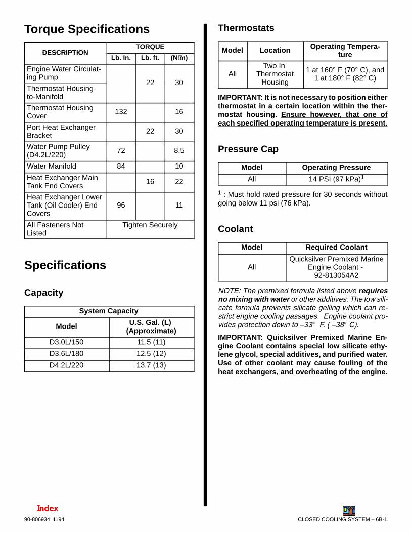
CLOSED COOLING SYSTEM – 6B-190-806934 1194
Torque Specifications
DESCRIPTIONTORQUE
DESCRIPTIONLb. In. Lb. ft. (N⋅m)
Engine Water Circulat-ing Pump
22 30Thermostat Housing-to-Manifold
22 30
Thermostat HousingCover
132 16
Port Heat ExchangerBracket
22 30
Water Pump Pulley(D4.2L/220)
72 8.5
Water Manifold 84 10
Heat Exchanger MainTank End Covers
16 22
Heat Exchanger LowerTank (Oil Cooler) EndCovers
96 11
All Fasteners NotListed
Tighten Securely
Specifications
Capacity
System Capacity
Model U.S. Gal. (L) (Approximate)
D3.0L/150 11.5 (11)
D3.6L/180 12.5 (12)
D4.2L/220 13.7 (13)
Thermostats
Model Location Operating Tempera-ture
AllTwo In
ThermostatHousing
1 at 160° F (70° C), and1 at 180° F (82° C)
IMPORTANT: It is not necessary to position eitherthermostat in a certain location within the ther-mostat housing. Ensure however, that one ofeach specified operating temperature is present.
Pressure Cap
Model Operating Pressure
All 14 PSI (97 kPa)1
1 : Must hold rated pressure for 30 seconds withoutgoing below 11 psi (76 kPa).
Coolant
Model Required Coolant
AllQuicksilver Premixed Marine
Engine Coolant - 92-813054A2
NOTE: The premixed formula listed above requiresno mixing with water or other additives. The low sili-cate formula prevents silicate gelling which can re-strict engine cooling passages. Engine coolant pro-vides protection down to –33° F. ( –38° C).
IMPORTANT: Quicksilver Premixed Marine En-gine Coolant contains special low silicate ethy-lene glycol, special additives, and purified water.Use of other coolant may cause fouling of theheat exchangers, and overheating of the engine.
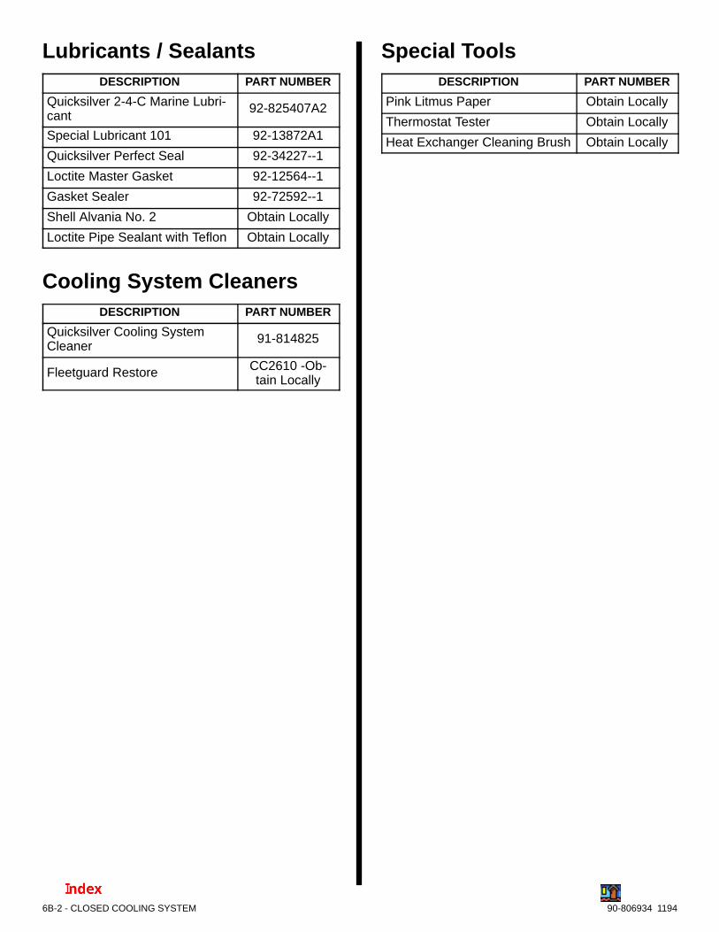
6B-2 - CLOSED COOLING SYSTEM 90-806934 1194
Lubricants / SealantsDESCRIPTION PART NUMBER
Quicksilver 2-4-C Marine Lubri-cant
92-825407A2
Special Lubricant 101 92-13872A1
Quicksilver Perfect Seal 92-34227--1
Loctite Master Gasket 92-12564--1
Gasket Sealer 92-72592--1
Shell Alvania No. 2 Obtain Locally
Loctite Pipe Sealant with Teflon Obtain Locally
Cooling System CleanersDESCRIPTION PART NUMBER
Quicksilver Cooling SystemCleaner
91-814825
Fleetguard Restore CC2610 -Ob-tain Locally
Special ToolsDESCRIPTION PART NUMBER
Pink Litmus Paper Obtain Locally
Thermostat Tester Obtain Locally
Heat Exchanger Cleaning Brush Obtain Locally
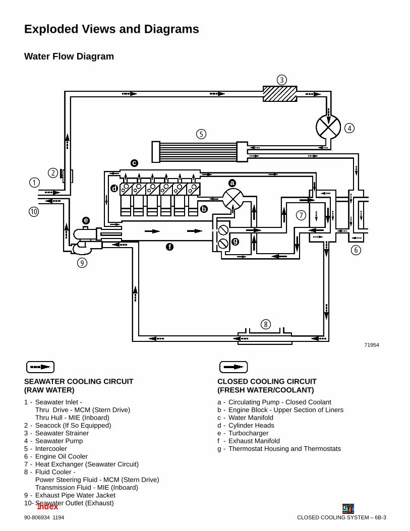
CLOSED COOLING SYSTEM – 6B-390-806934 1194
Exploded Views and Diagrams
Water Flow Diagram
12
3
45
6
7
9
b
c
d
e
fg
a
71954
8
10
SEAWATER COOLING CIRCUIT(RAW WATER)
1 - Seawater Inlet -Thru Drive - MCM (Stern Drive)Thru Hull - MIE (Inboard)
2 - Seacock (If So Equipped)3 - Seawater Strainer4 - Seawater Pump5 - Intercooler6 - Engine Oil Cooler7 - Heat Exchanger (Seawater Circuit)8 - Fluid Cooler -
Power Steering Fluid - MCM (Stern Drive)Transmission Fluid - MIE (Inboard)
9 - Exhaust Pipe Water Jacket10- Seawater Outlet (Exhaust)
CLOSED COOLING CIRCUIT(FRESH WATER/COOLANT)
a - Circulating Pump - Closed Coolantb - Engine Block - Upper Section of Linersc - Water Manifoldd - Cylinder Headse - Turbochargerf - Exhaust Manifoldg - Thermostat Housing and Thermostats
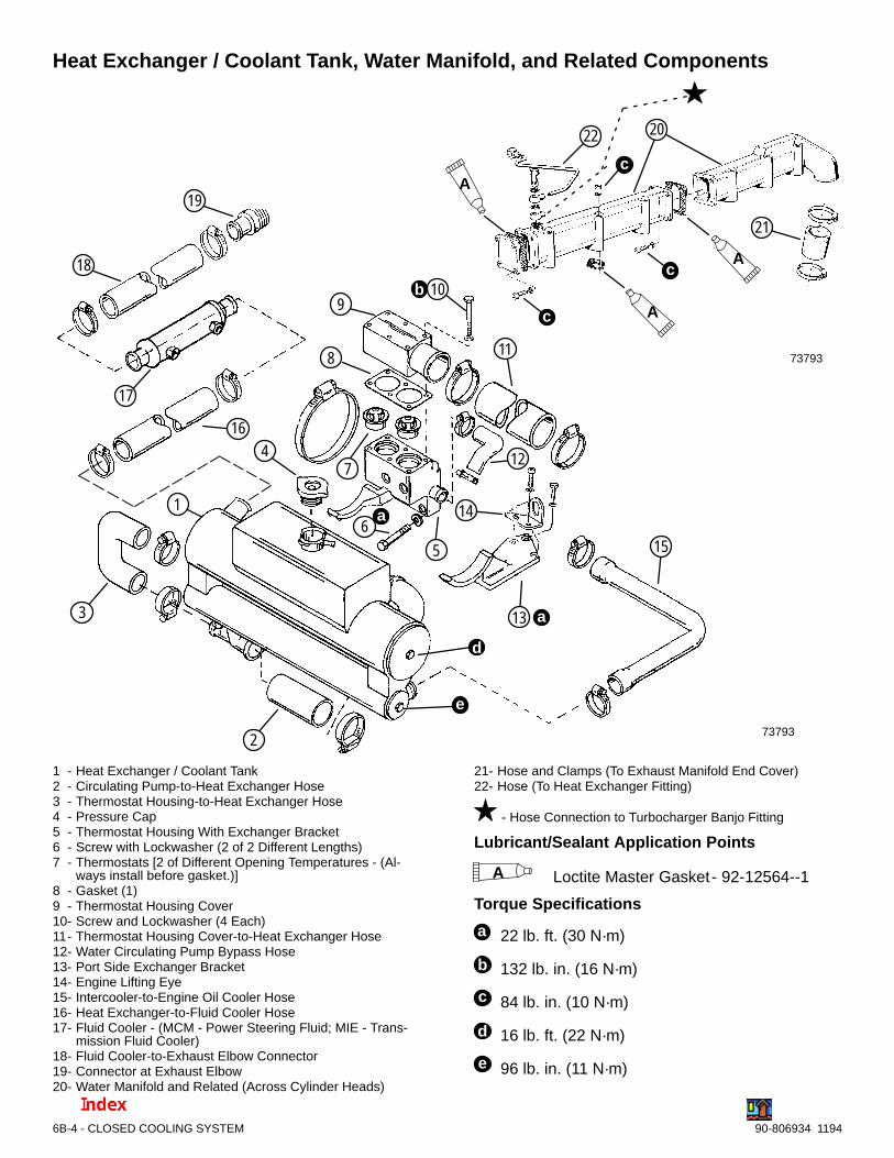
6B-4 - CLOSED COOLING SYSTEM 90-806934 1194
Heat Exchanger / Coolant Tank, Water Manifold, and Related Components
73793
1
2
3
4
5
7
8
910
11
12
13
14
15
16
17
19
Ab
c
a
a
6
18
20
21
22
c
c
A
A
73793
d
e
1 - Heat Exchanger / Coolant Tank2 - Circulating Pump-to-Heat Exchanger Hose3 - Thermostat Housing-to-Heat Exchanger Hose4 - Pressure Cap5 - Thermostat Housing With Exchanger Bracket6 - Screw with Lockwasher (2 of 2 Different Lengths)7 - Thermostats [2 of Different Opening Temperatures - (Al-
ways install before gasket.)]8 - Gasket (1)9 - Thermostat Housing Cover10- Screw and Lockwasher (4 Each)11- Thermostat Housing Cover-to-Heat Exchanger Hose12- Water Circulating Pump Bypass Hose13- Port Side Exchanger Bracket14- Engine Lifting Eye15- Intercooler-to-Engine Oil Cooler Hose16- Heat Exchanger-to-Fluid Cooler Hose17- Fluid Cooler - (MCM - Power Steering Fluid; MIE - Trans-
mission Fluid Cooler)18- Fluid Cooler-to-Exhaust Elbow Connector19- Connector at Exhaust Elbow20- Water Manifold and Related (Across Cylinder Heads)
21- Hose and Clamps (To Exhaust Manifold End Cover)22- Hose (To Heat Exchanger Fitting)
- Hose Connection to Turbocharger Banjo Fitting
Lubricant/Sealant Application Points
A Loctite Master Gasket- 92-12564--1
Torque Specifications
a 22 lb. ft. (30 N·m)
b 132 lb. in. (16 N·m)
c 84 lb. in. (10 N·m)
d 16 lb. ft. (22 N·m)
e 96 lb. in. (11 N·m)

CLOSED COOLING SYSTEM – 6B-590-806934 1194
Engine Water Circulating Pumps
D3.0L/150 AND D3.6L/180 ENGINES
73944
1 2 3
4 a
1 - Water Circulating Pump (With Pulley)2 - Gasket3 - Stud(s)4 - Hex Nuts with Washers
Torque Specifications
a 22 lb. ft. (30 N·m)
D4.2L/220 ENGINES
73948
1
2
3
4 a
1 - Water Circulating Pump2 - Pulley3 - Gasket4 - Screws With Washers
Torque Specifications
a 22 lb. ft. (30 N·m)
Sea Strainer
72673
12
3
4
5
6
7
1 - Screws and Washers2 - Cover 3 - Glass4 - Gasket5 - Strainer6 - Housing7 - Drain Plug and Sealing Washer
Quicksilver Seawater Strainer Shown
Thru-Hull Pickup and Seacock
70355
1
2
3 4
1 - Hose Connector [1-1/2 In. (38 mm) I.D.] to Seawater Strainer Inlet
2 - Seacock [1-1/2 In. (38 mm)] Brass Ball or Gate Valve 3 - Seawater Pickup4 - Direction of Seawater Flow
Quicksilver Components Shown - MIE (Inboard)
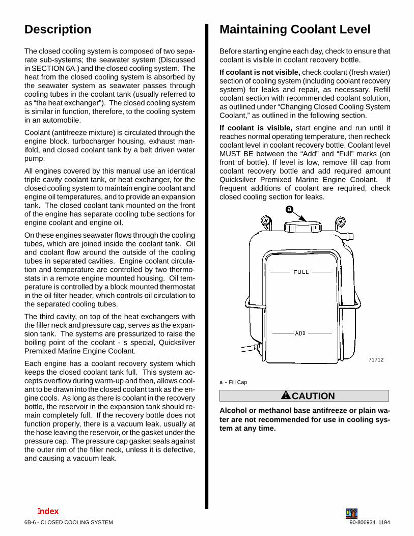
6B-6 - CLOSED COOLING SYSTEM 90-806934 1194
Description
The closed cooling system is composed of two sepa-rate sub-systems; the seawater system (Discussedin SECTION 6A.) and the closed cooling system. Theheat from the closed cooling system is absorbed bythe seawater system as seawater passes throughcooling tubes in the coolant tank (usually referred toas “the heat exchanger”). The closed cooling systemis similar in function, therefore, to the cooling systemin an automobile.
Coolant (antifreeze mixture) is circulated through theengine block. turbocharger housing, exhaust man-ifold, and closed coolant tank by a belt driven waterpump.
All engines covered by this manual use an identicaltriple cavity coolant tank, or heat exchanger, for theclosed cooling system to maintain engine coolant andengine oil temperatures, and to provide an expansiontank. The closed coolant tank mounted on the frontof the engine has separate cooling tube sections forengine coolant and engine oil.
On these engines seawater flows through the coolingtubes, which are joined inside the coolant tank. Oiland coolant flow around the outside of the coolingtubes in separated cavities. Engine coolant circula-tion and temperature are controlled by two thermo-stats in a remote engine mounted housing. Oil tem-perature is controlled by a block mounted thermostatin the oil filter header, which controls oil circulation tothe separated cooling tubes.
The third cavity, on top of the heat exchangers withthe filler neck and pressure cap, serves as the expan-sion tank. The systems are pressurized to raise theboiling point of the coolant - s special, QuicksilverPremixed Marine Engine Coolant.
Each engine has a coolant recovery system whichkeeps the closed coolant tank full. This system ac-cepts overflow during warm-up and then, allows cool-ant to be drawn into the closed coolant tank as the en-gine cools. As long as there is coolant in the recoverybottle, the reservoir in the expansion tank should re-main completely full. If the recovery bottle does notfunction properly, there is a vacuum leak, usually atthe hose leaving the reservoir, or the gasket under thepressure cap. The pressure cap gasket seals againstthe outer rim of the filler neck, unless it is defective,and causing a vacuum leak.
Maintaining Coolant Level
Before starting engine each day, check to ensure thatcoolant is visible in coolant recovery bottle.
If coolant is not visible, check coolant (fresh water)section of cooling system (including coolant recoverysystem) for leaks and repair, as necessary. Refillcoolant section with recommended coolant solution,as outlined under “Changing Closed Cooling SystemCoolant,” as outlined in the following section.
If coolant is visible, start engine and run until itreaches normal operating temperature, then recheckcoolant level in coolant recovery bottle. Coolant levelMUST BE between the “Add” and “Full” marks (onfront of bottle). If level is low, remove fill cap fromcoolant recovery bottle and add required amountQuicksilver Premixed Marine Engine Coolant. Iffrequent additions of coolant are required, checkclosed cooling section for leaks.
71712
a
a - Fill Cap
! CAUTIONAlcohol or methanol base antifreeze or plain wa-ter are not recommended for use in cooling sys-tem at any time.
CLOSED COOLING SYSTEM – 6B-790-806934 1194
! WARNING
DO NOT remove coolant pressure cap when theengine is hot - coolant may discharge violently,causing severe burns.
! CAUTIONIf the coolant should get extremely low and theengine very hot, let the engine cool for approxi-mately 15 minutes before adding coolant; then,with the engine running, add coolant slowly. Ad-ding cold coolant to a hot engine may crack thecylinder head or crankcase. Never use wateralone.
Occasionally, check to ensure that coolant recoverysystem is functioning properly by removing pressurecap from heat exchanger and checking level. Afterengine has cooled down, turn pressure cap1/4-turn to allow any pressure to escape slowly,then push down and turn cap all-the-way off.Coolant level should be up to bottom of heatexchanger filler neck. If low, inspect entire closedcooling coolant (fresh water) section (especiallycoolant recovery system) for leaks and repair, asnecessary.
IMPORTANT: When reinstalling pressure cap, besure to tighten it until its contact stops on fillerneck.
Changing (Replacing)Coolant
Coolant Requirement
! CAUTIONAlcohol or methanol base antifreeze or plain wa-ter are not recommended for use in cooling sys-tem at any time.
IMPORTANT: Quicksilver Premixed Marine En-gine Coolant contains special low silicate ethy-lene glycol, special additives, and purified water.Use of other coolant may cause fouling of theheat exchangers, and overheating of the engine.
It is required that the coolant section of the ClosedCooling Section be filled with Quicksilver PremixedMarine Engine Coolant . this premixed formula re-quires no mixing with water or other additives; low sili-cate formula prevents silicate gelling which can re-strict engine cooling passages. Quicksilver enginecoolant provides protection down to –33°F (–38°C).
DO NOT MIX the new antifreeze/coolant mixture withthe old solution or it will cause particles to form in thecoolant. These small particles can settle in the heatexchangers and restrict coolant flow. Drain and flushthe old coolant from the closed cooling system as re-quired.
Change IntervalThe old coolant should be drained from the closedcooling system every 200 hours of use or once yearly,whichever occurs first. Refer to “Cleaning ClosedCooling System”, whenever decreased cooling effi-ciency is experienced.

6B-8 - CLOSED COOLING SYSTEM 90-806934 1194
Draining Closed CoolingSection
! WARNING
Allow engine to cool before removing pressurecap. Sudden loss of pressure could cause hotcoolant to boil and discharge violently. After en-gine has cooled, turn cap 1/4 turn to allow anypressure to escape slowly, then push down andturn cap all the way off.
IMPORTANT: A wire should be repeatedly in-serted into drain holes to ensure that foreign ma-terial is not obstructing the drain holes.
IMPORTANT: Engine must be as level as possibleto ensure complete draining of cooling system.
IMPORTANT: Closed cooled section must be keptfilled year round with recommended coolant. Ifengine will be exposed to freezing temperatures,make sure closed cooled section is filled with anethylene glycol antifreeze and water solution
properly mixed to protect engine to lowest tem-perature to which it will be exposed.
IMPORTANT: Do not use Propylene Glycol Anti-freeze in the closed cooled section of the engine.
1. Allow engine to cool down. Remove pressure capfrom coolant tank.
2. Drain coolant from intake/exhaust manifold byopening the petcock.
3. Drain coolant from the engine block by openingthe petcock.
4. After coolant has drained completely, securelyclose petcocks.
5. Remove coolant recovery bottle from mountingbracket and pour out coolant.
6. If required, clean system as outlined in “CleaningSystem.”
7. Fill system as outlined in “Filling Closed CooledSection.”
Closed Cooling Section Draining Diagram
71364 72706
71381
a
b
c
d
a - Pressure Capb - Drain Petcock on Intake/Exhaust Manifoldc - Drain Petcock on Engine Blockd - Coolant Recovery Bottle
Typical
NOTICE
For instructions on Draining Seawater Sectionrefer to SECTION 1B - “Maintenance.”

CLOSED COOLING SYSTEM – 6B-990-806934 1194
Cleaning Closed CoolingSectionCooling System Cleaners1. Drain coolant from engine as previously outlined.
NOTE: Properly dispose of old coolant.
2. Add one liter of Quicksilver Cooling SystemCleaner 92-814825 or add Fleetgaurd RestoreCC2610 to cooling system following the manufac-turer’s instructions.
3. Fill the cooling system with tap water to within 1/2to 3/4 in. (13 - 19 mm) of bottom of filler neck.
NOTE: During system cleaning leave auxiliary heat-er, if so equipped, connected to engine. Otherwise,the engine will contaminated when the heater is re-connected.
4. Operate the engine in open water at wide openthrottle at normal operating temperature for thirtyminutes minimum to circulate cleaner.
5. Stop engine and after cool down, drain cleanerfrom cooling system.
NOTE: Properly dispose of contaminated cleaner.
6. Flush closed cooling system as follows:
a. Remove thermostat housing cover and ther-mostats. Temporarily install cover.
b. Remove large hex plug from exhaust man-ifold rear cover. On engines equipped withauxiliary hot water heater, remove heaterhose from fitting (in place of hex plug). Then,install an adaptor to this opening, suitable forconnecting a tap water hose.
70192
Hex Plug Drain (Similar With Hot Water Connection)
c. Attach tap water hose to adaptor.
d. Follow instructions “(1)” or “(2)”:
(1) On engines with Auxiliary Hot WaterHeaters: Proceed to “e”.
(2) On engines without Auxiliary Hot Wa-ter Heaters: Open cylinder block drainpetcocks.
e. Run tap water through system until dischargewater is clean.
NOTE: Catch expelled water (from either the opencylinder block petcocks, or the loose end of the auxil-iary hot water hose previously disconnected) in a suit-able container and dispose of properly.
f. Shut off tap water.
g. Remove tap water hose and adaptor. Installlarge hex plug, with new sealing washer, onintercooler, or reconnect heater hose. Closecylinder block petcocks if previously opened.
h. Install thermostats. Position thermostats inhousing and then, position a new thermostathousing gasket on housing. Torque housingcover screws to 132 lb. in. (16 N·m).
7. Refer to “Filling Closed Cooling Section” and refillwith Quicksilver Premixed Marine EngineCoolant.
NOTICE
For instructions on Flushing Seawater Sectionrefer to SECTION 1B - “Maintenance.”
Heat Exchanger and Cooler Cleaning1. Clean tubes in heat exchanger and coolers by running
a suitable wire brush thru each tube.
71724
a
a - Wire Brush, Sized to Fit Passages
2. Rinse out heat exchanger and cooler tubes with tapwater from a hose to remove loosened particles.
3. Replace unit if it cannot be satisfactorily cleaned.

6B-10 - CLOSED COOLING SYSTEM 90-806934 1194
Filling Closed CoolingSection1. Remove pressure cap from heat exchanger and
fill section with Quicksilver Premixed MarineEngine Coolant through heat exchanger fillneck. Continue filling until coolant level is 1 in. (25mm) below filler neck.
! CAUTIONAvoid seawater pickup pump impeller damageand subsequent overheating damage to sterndrive unit. DO NOT operate engine without waterbeing supplied to seawater pickup pump.
2. With pressure cap off, start engine and run at fastidle (1500-1800 RPM). Add recommended cool-ant solution to heat exchanger, as required, tomaintain coolant level 1 in. (25 mm) below fillerneck.
3. After engine has reached normal operating tem-perature (thermostats are fully open), and coolantlevel remains constant, fill heat exchanger to bot-tom of filler neck.
4. Observe engine temperature gauge to make surethat engine operating temperature is normal. Ifgauge indicates excessive temperature, stop en-gine immediately and examine for cause.
5. Install pressure cap on heat exchanger.
6. Remove cap from coolant recovery reservoir andfill to FULL mark with recommended coolant solu-tion. Reinstall cap.
7. With engine still running, check hose connec-tions, fittings and gaskets for leaks. RepeatStep 4.
Testing The System
Testing Coolant for Alkalinity
! WARNING
Allow engine to cool before removing pressurecap as sudden loss of pressure could cause hotcoolant to boil and discharge violently. After en-gine has cooled, turn cap 1/4 turn to allow anypressure to escape slowly, then push down andturn cap all the way off.
Coolant in closed cooling (fresh water) section shouldbe changed every two years and should be checkedfor alkalinity at least once between change intervals.To check coolant for alkalinity, proceed as follows:
1. Obtain pink litmus paper from a local supplier(drug store, pet shop, etc.).
2. Remove pressure cap from heat exchanger andinsert one end of litmus paper into coolant.
3. If pink litmus paper turns blue, coolant is alka-line and need not be replaced.
4. If pink litmus paper remains pink, coolant is notalkaline and MUST BE REPLACED, as explainedunder “Changing Coolant.”
Pressure Testing System
! WARNING
Allow engine to cool before removing pressurecap. Sudden loss of pressure could cause hotcoolant to boil and discharge violently. After en-gine has cooled, turn cap 1/4 turn to allow anypressure to escape slowly, then push down andturn cap all the way off.
If coolant section of closed cooled section is sus-pected of leaking or not holding sufficient pressure,and no visible signs of leakage can be found, performthe following test:
1. Remove pressure cap from heat exchanger orreservoir.
2. Clean, inspect and pressure test pressure cap, asoutlined under “Testing Pressure Cap,” to elimi-nate the possibility that cap is not maintainingproper pressure in system and is causing coolantto boil over.
3. Clean inside of filler neck to remove any depositsor debris. Examine lower inside sealing surfacefor nicks or other damage. Surface must be per-fectly smooth to achieve a good seal between itand rubber seal on cap. Also check locking camson sides of filler neck to be sure that they are notbent or damaged. If locking cams are bent ordamaged, pressure cap will not hold the properpressure.
4. Adjust coolant level in fresh water section to 1 in.(25 mm) below filler neck.

CLOSED COOLING SYSTEM – 6B-1190-806934 1194
5. Attach an automotive-type cooling system pres-sure tester to filler neck and pressurize closedcooled section to amount specified in followingchart, based on pressure cap rating for your en-gine.
Pressure Cap RatingAmount of PressureApplied to Closed
Cooled Section
14 PSI (97 kPa) 20 PSI (137 kPa)
6. Observe gauge reading for approximately twominutes; pressure should not drop during thistime. If pressure drops, proceed with the followingsteps until leakage is found.
7. While maintaining specified pressure on closedcooled section, visually inspect external portion ofcooling system (hoses, gaskets, drain plugs, coreplugs, circulating pump seal, etc.) for leakage.Also listen closely for bubbling or hissing, as theyusually are a sure indication of a leak.
8. Refer to “Testing Heat Exchanger” in this sectionand test as outlined.
9. If no leakage could be found in above steps, en-gine is leaking internally, and it probably is due toone or more of the following: (1) loose cylinderhead bolts or damaged gasket, (2) loose turbo-charger bolts or damaged gasket, (3) loose ex-haust elbow or damaged gasket, (4) cracked orporous cylinder head or block, or (5) cracked orporous exhaust manifold. Proceed as follows untillocation of internal leak is found.
a. Start engine. Pressurize system to previouslyspecified amount and observe pressuregauge on tester. If needle in gauge vibrates,compression or combustion is leaking intoclosed cooled section from a leak in the com-bustion chamber. Stop engine.
b. Remove glow plugs (one at a time) from cylin-ders and examine for presence of coolant. Aglow plug that is perfectly clean or milky ap-pearing is a sure indication of a leak.
c. Drain oil from engine and examine for pres-ence of coolant. Oil usually will be milky ifcoolant is present. If coolant is present, re-move engine from boat and remove the oilpan. With engine in the upright position, pres-surize closed cooled section to previouslyspecified amount and examine internal sur-faces of engine to locate leak.
d. If no leakage can be found in above steps, en-tire engine must be disassembled and in-spected for leakage.
Testing for Cylinder Head GasketLeakA leaking head gasket will cause combustion gas tobe forced into the cooling system. The mixture ofcoolant and tiny air bubbles is a poor heat conductorand will overheat an engine quickly. Compressiontests or cooling system pressure check normally willnot detect the leak because the test pressure is farbelow the combustion pressures which cause theleak. An effective test is as follows:
IMPORTANT: Run boat in lake for this test. It isbest to run the engine at or above cruising speedduring this test. Usually a failed head gasket willnot cause the engine to overheat below cruisingspeed.
1. Install a clear plastic hose between the reservoirand coolant recovery bottle. Use a 2-3 ft. (61-91cm) long hose for this test.
2. Route this hose so a “U” is formed.
3. Put enough coolant into hose to fill the center 4 or5 inches (10-13 cm) of the “U.”
4. Observe the “U” while the engine is running.
a. During Idle and Warm-Up: Some coolantand/or air will leave the reservoir.
b. During Cruising Speed (2800 - 3200 RPM):Coolant and/or air leaving the reservoirshould stop after approximately five minutesrunning at a given RPM. A leaking head gas-ket will produce air bubbling through the “U,”going to the coolant recovery bottle. The fre-quency and size of the bubbles will depend onthe size of the leak.
c. At Higher Speeds (3200 - 3800 onD3.0L/150 and D3.6L/180 Engines or 3200- 3600 on D4.2L/220 Engines): Normal op-eration is the same as described in “b” above.A failed head gasket will cause the bubbles tocome faster and may be accompanied by vio-lent, intermittent bursts of coolant.
It is important not to confuse normal warm-up expan-sion with a failed head gasket. Normal warm-up pro-duces an intermittent flow of coolant which will stopwithin approximately five minutes at a given RPM. Ahead gasket leak will not stop because the one thingthat marks a failed head gasket is the continued pas-sage of air. This may be accompanied by violent, in-termittent bursts of coolant leaving the reservoir. Ifcoolant continues to flow (not in violent, intermittentbursts) from the reservoir at cruising speed, some-thing other than the head gasket is causing the en-gine to overheat.

6B-12 - CLOSED COOLING SYSTEM 90-806934 1194
Testing Pressure CapPressure cap is designed to maintain a pressure ofapproximately its rated capacity (refer to “Specifica-tions”) in closed cooled section once engine has at-tained operating temperature. Cap should becleaned, inspected and pressure-tested at regulartune-up intervals or whenever cap is suspected ofmaintaining improper pressure as follows:
! WARNING
Allow engine to cool before removing pressurecap. Sudden loss of pressure could cause hotcoolant to boil and discharge violently. After en-gine has cooled, turn cap 1/4 turn to allow anypressure to escape slowly, then push down andturn cap all the way off.
1. Carefully remove pressure cap from reservoir orheat exchanger.
2. Wash cap with clean water to remove any depos-its or debris from sealing surfaces.
3. Inspect gasket (if used) and rubber seal on cap fortears, cuts, cracks or other signs of deterioration.Replace gasket, if damaged, or entire cap if rub-ber seal is damaged.
72714
b
ca
a - Rubber Seal (Cap MUST BE Replaced if Damaged)b - Gasket (Look for Cracks under Gasket)c - Locking Tabs (1 Hidden)
4. Check that locking tabs on cap are not bent ordamaged.
5. Using a cooling system pressure tester (similar toone shown), test cap to be sure that it releases atproper pressure and does not leak. (Refer to in-structions which accompany tester for correct testprocedure.) Cap must relieve pressure at 14 PSI(97 kPa), and must hold rated pressure for 30 se-conds without going below 11 PSI (76 kPa). Re-place cap if it fails to fall within these lim-its.
72716
Typical Pressure Cap Tester
IMPORTANT: Before reinstalling cap in next step,examine lower inside sealing surface in fillerneck to ensure that it is perfectly smooth and freeof debris. Also, inspect cam lock flanges on sidesof filler neck to be sure that they are not bent.
72715
a
b
a - Inspect for Damageb - Cam Lock Flange
6. Reinstall cap on heat exchanger.

CLOSED COOLING SYSTEM – 6B-1390-806934 1194
Thermostats
Removal1. Refer to “Draining Closed Cooling Section” as
previously outlined, and drain coolant.
2. Remove closed cooling system hose betweenthermostat housing and heat exchanger.
3. Remove thermostat housing cover fasteners.
NOTE: Components shown removed for visual clarityonly. It is not necessary to remove the housing itself.
73973
bc
a
a - Hose and Clampsb - Thermostat Housing Coverc - Fasteners (6)
4. Remove housing cover.
5. Remove old gasket.
6. Remove thermostats.
73973
b
a
bc
a - Thermostat Housing Coverb - Thermostat(s)c - Gasket
IMPORTANT: Do not allow old gasket material ordebris inside, which might foul cooling systempassages.
Testing1. Clean thermostats in soap and water to remove
any deposits or debris.
2. Inspect thermostats for corrosion or other visibledamage.
3. If thermostats are suspected of producing insuffi-cient engine temperature, check thermostats forleakage by holding them up to lighted back-ground. Light leakage around the thermostatvalve indicates that thermostat is not closing com-pletely and should be replaced. (A small amountof leakage at one or two points around the valveperimeter is acceptable.)
72717
a
a - Check for Light Leakage Around Perimeter of Valve
4. Following the manufacturers recommendationsfor usage, check opening and closing tempera-ture. The thermostat opens when it drops off ofthread using a tester. Thermostat must open atspecified temperature stamped on thermostat.
72675
b
c
a
a - Thermometerb - Nylon Stringc - Thermostat
Typical Thermostat Tester In Use

6B-14 - CLOSED COOLING SYSTEM 90-806934 1194
IMPORTANT: Refer to specifications and notethat the two thermostats have different openingtemperatures.
5. Continue to heat water until a temperature 25°F(14°C) above opening temperature is obtained.Thermostat valve must be completely OPEN atthis temperature.
6. Unplug tester and allow water to cool to a temper-ature 10°F (5°C) below specified opening tem-perature. The thermostat must be completelyCLOSED at this temperature.
7. Always replace a thermostat that fails to meet allof the preceding tests with one of the same tem-perature specification.
Installation
1. Installation is the reverse of procedures for re-moval. Refer to the preceding instructions “Re-moval.” Also, observe the following:
• Remove all old gasket material from mating sur-faces.
• ALWAYS use a new thermostat housing gasket.
• Apply Quicksilver Perfect Seal to the new gasket.
• Torque the six housing screws evenly, in a diago-nal pattern, to 132 lb. in. (16 N·m).
• Tighten hose clamps securely.
2. Refer to “Filling Closed Cooling Section” instruc-tions and fill system with Quicksilver PremixedMarine Engine Coolant.
3. Run test engine - observe temperature gaugeand check for leaks.
Heat Exchanger
Testing
FOR INTERNAL LEAK:
An internal leak will cause coolant to go into the sea-water circuit when pressure is put on the closed cool-ing circuit.
1. Remove top seawater (inlet) hose from the ex-changer. Do not drain the exchanger.
2. Pressurize the closed cooling circuit to 20 PSI(137 kPa) with a radiator tester.
3. If seawater begins to flow from the nipple there isa leak.
FOR BLOCKAGE:
IMPORTANT: Seawater flows THROUGH thetubes in the exchanger. Closed cooling coolantflows AROUND the tubes.
1. Remove end caps and inspect for any blockagein the seawater circuit (weeds, etc.).
2. Remove closed cooling circuit hoses and inspectthe tubes just inside the nipples. Because thecomplete heat exchanger cannot be inspected,the heat exchanger should be replaced if block-age is suspected.
RepairIMPORTANT: Braze with BCUP 2 rod or silver sol-der. Care must be taken not to melt other jointsduring repair.
1. Internal leaks can be repaired by brazing shut theends of the leaking tube. This is only a temporaryfix because usually another tube will start leakingafter a short period of time and this also causesa reduction in cooling capacity. Do not close morethan three tubes.
2. Nipples and drains that have been broken off theheat exchanger can be reattached by brazing.

CLOSED COOLING SYSTEM – 6B-1590-806934 1194
Removal1. Refer to SECTION 1B – Maintenance, “Cold
Weather or Extended Storage, DrainingInstructions” (and precautions in this section) anddrain the seawater system, if not alreadyaccomplished.
2. Refer to previously outlined “Draining ClosedCooling Section” instructions (and precautions inthis section) and drain system, if not alreadyaccomplished.
3. Follow instructions “a” – “f”:
NOTE: Obtain clean, suitable devices and plug hosesin following instructions to avoid loss of engine oil.
a. Mark port and starboard oil hoses to aid inreassembly.
b. Disconnect engine oil filter head-to-oil coolerline fittings (near each end of oil cooler) onheat exchanger. Quickly plug hoses.
72470
bc
74446
bc
a
a - Heat Exchanger (Combined With Engine Oil Cooler)b - Starboard Oil Hose Line and Fittingc - Port Oil Hose Line and Fitting (Fitting Not Visible)
c. Disconnect seawater and closed coolinghoses as required to allow removal of heat ex-changer, as shown following.
d. Remove the two large screw clamps retainingthe heat exchanger to the port and starboardbrackets.
e. Disconnect turbocharger coolant vent hoseon upper-port side of expansion tank.
f. Remove combination heat exchanger andengine oil cooler.
74484
a
a
a
aa
b
b
a - Remove End Of Hoses Where Indicated For Ease Of Disassembly and Reassembly
b - Clamps
Engine Oil Cooler/Heat Exchanger and RelatedComponents
4. If either the closed cooling section or oil coolerportion of the heat exchanger are defective, it willbe necessary to replace the complete assembly.
Cleaning and Inspection
! CAUTIONAlways wear safety glasses when using com-pressed air.
1. Clean water passages in heat exchanger by in-serting a suitable sized wire brush on a properlength rod into each passage. Use compressedair to blow loose particles out of water passages.
2. Provided the passages for seawater are accept-ably clean and free of debris, clean the exterior ofthe with soap and water, scrubbing gently with abrush as required.
NOTE: Use compressed air to blow loose particlesfrom between passages.
3. Visually inspect all exterior surfaces and waterpassages for cracks or damage. Repair or re-place as required.

6B-16 - CLOSED COOLING SYSTEM 90-806934 1194
Installation1. Follow instructions “a” – “e”:
NOTE: Prior to installing the heat exchanger, put asmall amount of petroleum jelly on the brackets andhose ends to ease installation.
a. Install the combination heat exchanger andengine oil cooler.
b. Make all necessary seawater and closedcooling hose connections. Tighten hoseclamps securely.
c. To minimize oil loss, quickly install engine oilfilter head-to-oil cooler lines, as marked upondisassembly, to fittings (near each end of oilcooler, on heat exchanger).
d. Install the two large screw clamps retainingthe heat exchanger to the port and starboardbrackets.
e. Reconnect turbocharger coolant vent hose .Tighten hose clamp securely.
2. Refer to SECTION 6B – “Filling Closed CoolingSection” instructions and fill the system withQuicksilver Premixed Marine Engine Coolant.
3. Open seacock if so equipped, or unplug seawaterinlet hose and reconnect. Tighten hose clampssecurely.
4. Pre-lube the turbocharger and engine. Start theengine and while observing the temperaturegauge, run briefly to operating temperature.Check for leaks, and then stop the engine.
IMPORTANT: Use only specified engine oil.
5. Check engine oil level. Fill to proper level withspecified oil.
d
ab
74487
74484
Ab
b
a
74446
b
c
b
c
e
a - Heat Exchanger/Oil Coolerb - Clampsc - Starboard Oil Hose Line and Fittingd - Port Oil Hose Line and Fittinge - Turbocharger Vent Hose Connection
A - Petroleum Jelly Obtain Locally
Heat Exchanger/Engine Oil Cooler and Related

CLOSED COOLING SYSTEM – 6B-1790-806934 1194
Water Circulating PumpIMPORTANT: Water circulating pump onD4.2L/220 engines is a larger volume pump anddoes NOT interchange with circulating pumps onother diesel engines.
Removal1. Refer to instructions in Changing (Replace) Cool-
ant - “Draining Coolant” and drain coolant fromclosed cooling system.
2. Remove alternator drive belt.
3. If equipped with removable water circulatingpump pulley, remove fasteners and removepulley,
NOTE: Some water circulating pump pulleys are NOTremovable and can be identified by the absence offasteners on the face of the pulley.
4. Loosen hose clamps and disconnect hoses atwater pump.
5. Remove fasteners (and washers) retaining pumpand remove pump.
Cleaning and Inspection1. Remove all traces of old gasket material from
pump body.
2. Inspect water pump for blockage, cracks, sandholes, corrosion or other damage. Inspect pumpimpeller for cracks and erosion. Replace com-plete pump, if any damage exists.
3. Check impeller shaft and bearings for excessiveside play. If play can be felt, replace completepump.
4. Inspect pump pulley for bends, cracks, corrosion,or other physical damage. Inspect pulley for rota-tional trueness. Replace pulley, if removable, orcomplete pump on those with permanent pulley,if damaged or untrue.
Installation1. Remove all traces of old gasket material from en-
gine block (Do not allow debris inside, whichmight foul cooling system passages.)
2. Coat both sides of new gasket with gasket sealer92-72592-1 and position on engine block. Checkthat hose clamps are still on hoses and insert wa-ter pump fittings into hoses, while installing pumpusing fasteners with washers removed during dis-assembly. Torque evenly, in a diagonal pattern, to22 lb. ft. (30 N m). Tighten hose clamps securely.
3. Install pulley on pump as shown if pulley was re-moved previously. Torque fasteners to 72 lb. in.(8.5 N·m).
73948
a - Pulley Fastener (With Washer) - (4)b - Water Circulating Pump Pulley (Removable)c - Water Circulating Pump Fasteners
D4.2L/220 Pump Shown (D3.0L/150 andD3.6L/180 Similar)
4. Position drive belt(s) and tension followinginstructions in SECTION 1B - “Replace DriveBelts.”
NOTE: On all models, check belt tension by depress-ing upper strand of belt at center point between pul-leys. Belt must not deflect more than 3/16 in. (5mm).

6B-18 - CLOSED COOLING SYSTEM 90-806934 1194
Water Manifold
Removal1. Refer to instructions in Changing (Replace) Cool-
ant - “Draining Coolant” and drain coolant fromclosed cooling system.
2. Remove banjo bolt and sealing washers fromfront manifold strip. Disconnect coolant venthoses.
3. Disconnect coolant hose from exhaust manifoldrear cover-to-rear manifold strip elbow.
4. Remove fasteners and washers retaining watermanifold assembly to cylinder heads.
70883
ba
70883
c
a - Water Manifold Assemblyb - Fasteners with Washersc - Coolant Vent Hoses
5. Remove water manifold assembly.
6. Disassemble water manifold components asneeded for repair.
Cleaning and InspectionIMPORTANT: Do not allow old gasket material ordebris inside of engine, which might foul coolingsystem passages.
1. Remove all traces of old gasket material.
2. Inspect for blockage, cracks, sand holes, corro-sion or other damage. Inspect for cracks and ero-sion. Replace complete manifold and/or sectionof manifold , if any damage exists.
Installation1. Be certain mating surfaces of water manifold
sections are clean and free of all old gasketmaterial. Machined surfaces must not have nicksor gouges, or coolant leaks may result.
2. Assemble water manifold as follows:
a. Replace cover gasket on front section. Installcover. Tighten screws to 84 lb. in. (10 N·m).
b. When replacing the gasket between manifoldhalves, align flanges using a straight edge asshown. Tighten screws to 84 lb. in. (10 N·m).
70660
a
b c
d h
e fc
g
cf
a - Front Coverb - Front Cover Gasketc - Front Manifold Stripd - Screw With Washer (4)e - Gasketf - Rear Manifold Stripg - Straight Edge Deviceh - Screw With Washer (4)

CLOSED COOLING SYSTEM – 6B-1990-806934 1194
3. Install new gaskets on cylinder head/manifoldstuds.
4. Slide water manifold assembly on studs. Installlockwashers and nuts. Torque nuts evenly in adiagonal pattern to 24 lb. ft. (32 N·m).
5. Install coolant vent hoses using new sealingwasher with the banjo bolts. Install in ordershown. Tighten bolt securely.
6. Install hose clamp on hose from rear exhaustmanifold cover-to-rear manifold strip elbow.Tighten securely.
73793
70883
c
e
b
a
d
a - Manifold Strip Assemblyb - Coolant Hose with Clampsc - Fastenersd - Gasket, Cylinder Head-to-Manifold Stripse - Coolant Vent Tube and Banjo Fittings
Corrosion ProtectionThere are anodes as part of the heat exchanger andintercooler system, which serve as sacrificial anodes.
Replace when eroded more than 50%; check at leastonce yearly. Refer to SECTION 1B - Maintenance, formore information.
a
b
73326
71367
73327
71368
a - Length When New - 3/4 in. (19mm)b - Diameter When New - 5/8 in. (15mm)
NOTE: Anode and plug are available as a unit if so de-sired.

6B-20 - CLOSED COOLING SYSTEM 90-806934 1194
Auxiliary Hot Water Heater Connections
b
cd
a 72037
72038
71898
ef
g
h
i
J
k
a - Plug, Rear Cover (Allen-Head or Hex-Head) b - Sealing Washer, (Existing)c - Hose Coupler Fitting (From Kit)d - Sealing Washer (From Kit)e - Plug, On Closed Coolant Tank/Heat Exchanger or Outlet
Fitting (Existing)
f - Sealing Washer, (Existing)g - Hose Coupler Fitting (From Kit)h - Sealing Washer (From Kit)i - Supply Hosej - Heaterk - Return Hose
Quicksilver Auxiliary Hot Water Heater Adaptor Kit (805984A1)
7
A
6A
5A
4A
3A
A
AINTAKE AND EXHAUSTSYSTEM
INTERCOOLER

90-806934 11947A-0 – INTERCOOLER
Table Of ContentsPage
Table Of Contents 7A-0. . . . . . . . . . . . . . . . . . . . . . . . . . . . . Torque Specifications 7A-1. . . . . . . . . . . . . . . . . . . . . . . . . . Sealants 7A-1. . . . . . . . . . . . . . . . . . . . . . . . . . . . . . . . . . . . . Description 7A-1. . . . . . . . . . . . . . . . . . . . . . . . . . . . . . . . . . . Exploded Views 7A-2. . . . . . . . . . . . . . . . . . . . . . . . . . . . . . .
D3.0L/150 and D3.6L/180 Intercooler 7A-2. . . . . . . . . D4.2L/220 Intercooler 7A-3. . . . . . . . . . . . . . . . . . . . . . .
Intercooler 7A-4. . . . . . . . . . . . . . . . . . . . . . . . . . . . . . . . . . . . Removal 7A-4. . . . . . . . . . . . . . . . . . . . . . . . . . . . . . . . . . Disassembly 7A-6. . . . . . . . . . . . . . . . . . . . . . . . . . . . . . . Cleaning and Inspection 7A-8. . . . . . . . . . . . . . . . . . . . . Assembly 7A-8. . . . . . . . . . . . . . . . . . . . . . . . . . . . . . . . . Installation 7A-10. . . . . . . . . . . . . . . . . . . . . . . . . . . . . . . .
7A – INTERCOOLER

INTERCOOLER – 7A-190-806934 1194
Torque SpecificationsDESCRIPTION Lb. In. Lb. Ft. N·m
Intake Duct 84 10
Intercooler End Covers 30 40
Intercooler Housing 24 32
Anode Plug 120 13
Water TemperatureSender
120 13
Turbocharger PressureFitting
Tighten Securely
SealantsLoctite 514 92-75505-1
Quicksilver Perfect Seal 92-34227--1
DescriptionSeawater is pumped through a radiator insert (heatexchanger core) in the intercooler while the engineis running.
There is an anode in the front cover and a seawaterdrain plug in the rear cover of all intercoolers.
All diesel engines covered in this manual use an in-tercooler (sometimes referred to as an “aftercooler”or “air cooler”) to cool the intake air before it entersthe cylinders. On D3.0L/150 and D3.6L/180 enginesthe intercooler housing has a separate intake ductretained with screws on the outer side. On theD4.2L/220 engines the intercooler is a one-piece-casting with a smaller intake duct screwed on therear-most end. On all engines the intake duct con-nects to the turbocharger by a section of hose withclamps.

90-806934 11947A-2 – INTERCOOLER
Exploded Views
D3.0L/150 and D3.6L/180 Intercooler
a - Radiator Insert (Heat Exchanger Core)b - Intercooler Housingc - Intake Ductd - Front Covere - Rear Coverf - O-ring (3 On Some Engines, 4 On Others Equipped With Plate)g - Plate (On Some Engines)h - Anodei - Anode Plug With Sealing Washerj - Drain Plug With Sealing Washerk - Gasket [5 or 6, (Not Shown Here)]
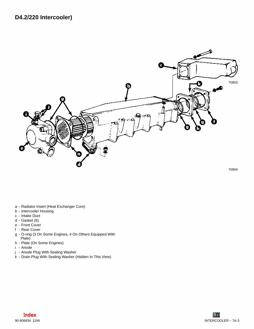
INTERCOOLER – 7A-390-806934 1194
D4.2/220 Intercooler)
70903
70904
a - Radiator Insert (Heat Exchanger Core)b - Intercooler Housingc - Intake Ductd - Gasket (6)e - Front Coverf - Rear Coverg - O-ring (3 On Some Engines, 4 On Others Equipped With
Plate)h - Plate (On Some Engines)i - Anodej - Anode Plug With Sealing Washerk - Drain Plug With Sealing Washer (Hidden In This View)

90-806934 11947A-4 – INTERCOOLER
Intercooler
Removal1. Refer to SECTION 6A and drain seawater from
seawater cooling section into a suitable con-tainer.
2. Remove drain plug and sealing washer from rearcover of intercooler.
70911
70912
a - Intercoolerb - Rear Coverc - Drain Plug With Sealing Washer
D3.0L/150 and D3.6L/180 Engines
70071
a - Drain Plug With Sealing Washer, Intercooler
D4.2L/220 Engines
3. Remove boost pressure tube banjo bolt withsealing washers from intercooler and removetube.
70913
a - Banjo Bolt With Sealing Washersb - Boost Pressure Tube
D4.2L/220 Boost Pressure Tube Shown(D3.0L/150 and D3.6L/180 Similar)
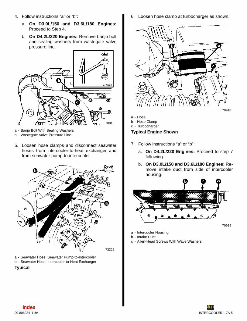
INTERCOOLER – 7A-590-806934 1194
4. Follow instructions “a” or “b”:
a. On D3.0L/150 and D3.6L/180 Engines:Proceed to Step 4.
b. On D4.2L/220 Engines: Remove banjo boltand sealing washers from wastegate valvepressure line.
70916
73940
a - Banjo Bolt With Sealing Washersb - Wastegate Valve Pressure Line
5. Loosen hose clamps and disconnect seawaterhoses from intercooler-to-heat exchanger andfrom seawater pump-to-intercooler.
73322
a
b
a - Seawater Hose, Seawater Pump-to-Intercoolerb - Seawater Hose, Intercooler-to-Heat Exchanger
Typical
6. Loosen hose clamp at turbocharger as shown.
70918
a - Hoseb - Hose Clampc - Turbocharger
Typical Engine Shown
7. Follow instructions “a” or “b”:
a. On D4.2L/220 Engines: Proceed to step 7following.
b. On D3.0L/150 and D3.6L/180 Engines: Re-move intake duct from side of intercoolerhousing.
70919
a - Intercooler Housingb - Intake Ductc - Allen-Head Screws With Wave Washers
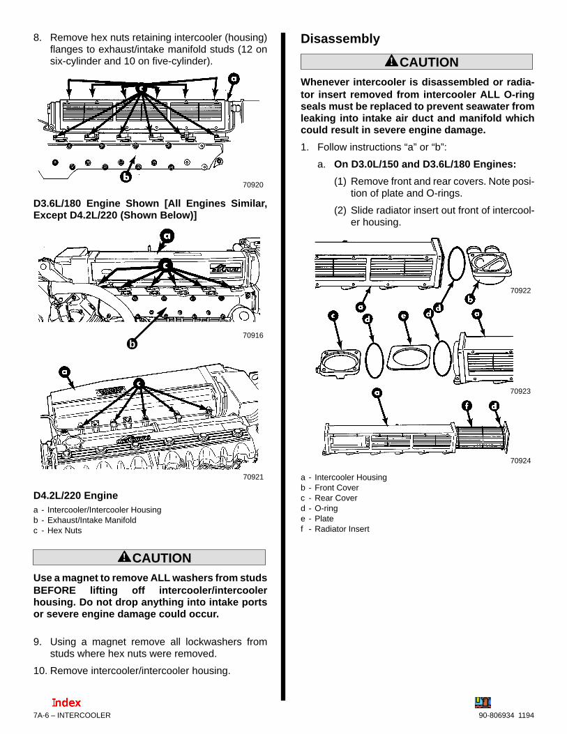
90-806934 11947A-6 – INTERCOOLER
8. Remove hex nuts retaining intercooler (housing)flanges to exhaust/intake manifold studs (12 onsix-cylinder and 10 on five-cylinder).
70920
D3.6L/180 Engine Shown [All Engines Similar,Except D4.2L/220 (Shown Below)]
70916
70921
b
D4.2L/220 Enginea - Intercooler/Intercooler Housingb - Exhaust/Intake Manifoldc - Hex Nuts
! CAUTIONUse a magnet to remove ALL washers from studsBEFORE lifting off intercooler/intercoolerhousing. Do not drop anything into intake portsor severe engine damage could occur.
9. Using a magnet remove all lockwashers fromstuds where hex nuts were removed.
10. Remove intercooler/intercooler housing.
Disassembly
! CAUTIONWhenever intercooler is disassembled or radia-tor insert removed from intercooler ALL O-ringseals must be replaced to prevent seawater fromleaking into intake air duct and manifold whichcould result in severe engine damage.
1. Follow instructions “a” or “b”:
a. On D3.0L/150 and D3.6L/180 Engines:
(1) Remove front and rear covers. Note posi-tion of plate and O-rings.
(2) Slide radiator insert out front of intercool-er housing.
70923
70924
70922
a - Intercooler Housingb - Front Coverc - Rear Coverd - O-ringe - Platef - Radiator Insert

INTERCOOLER – 7A-790-806934 1194
b. On D4.2L/220 Engines:
(1) Remove intake duct from rear of inter-cooler.
70931
a - Intercooler Housingb - Intake Duct
IMPORTANT: Some early D4.2L/220 engineintercoolers may have a plate between theintercooler housing and rear cover. Theseintercoolers use two O-rings here, one on eachside of the plate. On those without the plate onlyone O-ring is used between the rear cover andintercooler.
(2) Remove rear cover. Note position of O-ring, and if so equipped, plate and se-cond O-ring position.
70906
a - Intercooler Housingb - Rear Coverc - O-ring (Two – If So Equipped)d - Plate (If So Equipped)
(3) Remove front cover and O-ring.
70907
a - Intercooler Housingb - Front Coverc - O-ring
(4) Slide radiator insert out front of intercool-er housing. Note position of O-ring.
70905
a - Radiator Insertb - O-ring

90-806934 11947A-8 – INTERCOOLER
Cleaning and Inspection1. Clean old gasket material and sealant from
flanges. Do not nick or gouge the surfaces whichwould cause intake or water leaks.
2. Use a 11/64 in. (4.4mm) diameter by 24 in.(610mm) long rod to clean out radiator inserttubes, or take to a radiator shop for cleaning.
3. Inspect each part for cracks or other damagewhich would render it unserviceable.
4. Refer to SECTION 1B – Maintenance, “Inspect/Replace Cooling System Sacrificial Anodes,”and check anodes.
5. Clean and paint exterior surfaces as required toprevent corrosion.
AssemblyIMPORTANT: Do not roll or twist O-ring(s) wheninstalling around radiator insert in the following.
1. Install O-ring on radiator insert against frontflange.
70925
a - Radiator Insert (Front Flange)b - O-ring
Typical Radiator Insert Shown
2. Install radiator insert into housing. Align insertpassages as shown.
70926
D3.0L/150 and D3.6L/180 Intercooler
70933
D4.2L/220 Intercoolera - Intercooler Housing (Front)b - Radiator Insertc - Alignment Reference Mark

INTERCOOLER – 7A-990-806934 1194
3. Place O-ring into groove of front cover. Fasten tohousing using 4 allen-head screws and wavewashers. Torque to 30 lb. ft. (40 N·m).
70908
70926
a - Front Coverb - O-ringc - Allen-Head Screws and Wave Washers
D4.2L/220 Intercooler Shown (All Similar)
IMPORTANT: Do not roll or twist O-ring(s) wheninstalling around radiator insert in the following.
4. Install O-ring on rear of intercooler housing.
70927
a - O-ringb - Rear of Intercooler Housing
Typical
5. Following instructions “a” or “b”:
a. On intercoolers WITHOUT plate andsecond O-ring: Proceed to step 6.
b. On intercoolers WITH plate and secondO-ring:
(1) Install plate on rear of intercooler.
(2) Install second O-ring around radiator in-sert and against plate.
70928
a - Plateb - O-ring (Second One Required)
Typical
6. Using 4 allen-head screws and wave washers,install rear cover with drain plug positioned asshown. Torque to 30 lb. ft. (40 N·m).
70912
a - Rear Coverb - Drain Plugc - Allen-Head Screws and Wave Washers
Typical

90-806934 11947A-10 – INTERCOOLER
7. Follow instructions “a” or “b”:
a. On D3.0L/150 and D3.6L/180 Engines:Proceed to the following “Installation” instruc-tions.
b. On D4.2L/220 Engines: Apply Loctite 514sealer on intake duct-to-intercooler housingmating surface. Using 4 allen-head screwsand wave washers, install intake duct on rearof intercooler as shown. Torque to 30 lb. ft.(40 N·m).
70929
a - Intercooler Housingb - Intake Ductc - Allen-Head Screws and Wave Washers
D4.2L/220 Intercooler and Intake Duct Shown
Installation1. Being careful not to drop anything into intake
ports, clean old gasket material from manifold.
2. Install new intake port gaskets.
70881
c
a - Manifoldb - Intake Portsc - Intake Port Gaskets
Typical
3. Install intercooler housing. Install hex nuts (10 onfive cylinder, and 12 on six cylinder) with lock-washers and torque to 24 lb. ft. (32 N·m).
70920
D3.6L/180 Manifold and Intercooler Shown [AllEngines Similar, Except D4.2L/220 (Shown Be-low)]
70916
70921
b
a - Intercooler/Intercooler Housingb - Exhaust/Intake Manifoldc - Hex Nuts and Lockwashers
D4.2L/220 Engine and Intercooler Shown
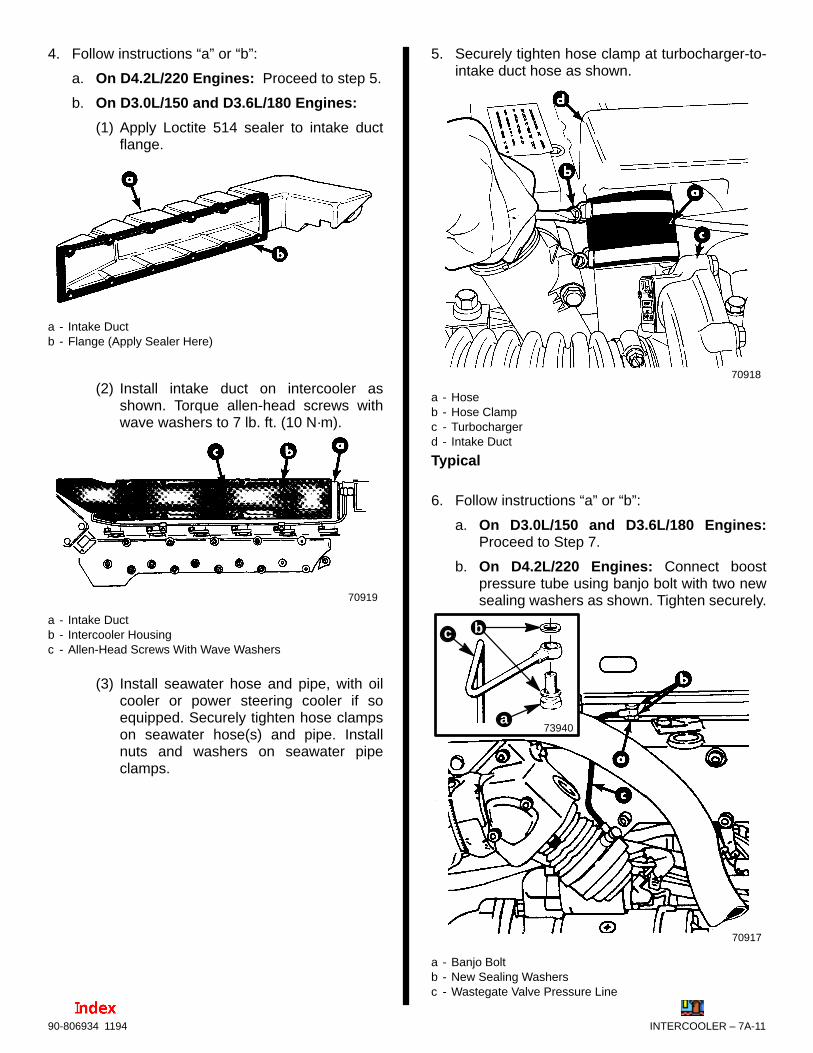
INTERCOOLER – 7A-1190-806934 1194
4. Follow instructions “a” or “b”:
a. On D4.2L/220 Engines: Proceed to step 5.
b. On D3.0L/150 and D3.6L/180 Engines:
(1) Apply Loctite 514 sealer to intake ductflange.
a - Intake Ductb - Flange (Apply Sealer Here)
(2) Install intake duct on intercooler asshown. Torque allen-head screws withwave washers to 7 lb. ft. (10 N·m).
70919
a - Intake Ductb - Intercooler Housingc - Allen-Head Screws With Wave Washers
(3) Install seawater hose and pipe, with oilcooler or power steering cooler if soequipped. Securely tighten hose clampson seawater hose(s) and pipe. Installnuts and washers on seawater pipeclamps.
5. Securely tighten hose clamp at turbocharger-to-intake duct hose as shown.
70918
a - Hoseb - Hose Clampc - Turbochargerd - Intake Duct
Typical
6. Follow instructions “a” or “b”:
a. On D3.0L/150 and D3.6L/180 Engines:Proceed to Step 7.
b. On D4.2L/220 Engines: Connect boostpressure tube using banjo bolt with two newsealing washers as shown. Tighten securely.
73940
b
a
c
70917
a - Banjo Boltb - New Sealing Washersc - Wastegate Valve Pressure Line

90-806934 11947A-12 – INTERCOOLER
7. Install seawater hoses from seawater pump-to-intercooler and from intercooler-to-heat ex-changer. Securely tighten all hose clamps..
73322
a
b
a - Seawater Hose, Seawater Pump-to-Intercoolerb - Seawater Hose, Intercooler-to-Heat Exchanger
Typical
8. Securely tighten seawater drain cocks if soequipped, and install all seawater system drainplugs removed previously (coat threads of drainplugs with Quicksilver Perfect Seal or use newsealing washers on drain plugs so equipped).Tighten each securely.
! CAUTIONDO NOT operate an engine without water flowingthrough seawater pickup pump, as pump impel-ler may be damaged and subsequent overheat-ing damage to engine, transmission or sterndrive unit may result.
! CAUTIONWatch temperature gauge on dash to ensure thatengine does not overheat.
9. Upon first running engine, after repair or serviceof intake system and/or intercooler, observe tem-perature gauge for normal engine operating tem-peratures, and be certain to check for leaks. Stopengine IMMEDIATELY in the event of leakage oroverheating, and repair as needed.

7
B
28085
INTAKE AND EXHAUST SYSTEM
INTAKE / EXHAUST SYSTEM

7B-0 – INTAKE/EXHAUST SYSTEM 90-806934 1194
Table Of ContentsPage
Torque Specifications 7B-1. . . . . . . . . . . . . . . . . . . . . . . . . . Description 7B-1. . . . . . . . . . . . . . . . . . . . . . . . . . . . . . . . . . . Exploded Views 7B-1. . . . . . . . . . . . . . . . . . . . . . . . . . . . . . .
D3.0L/150 and D3.6L/180 Intake/Exhaust Manifold 7B-1. . . . . . . . . . . . . . . . . . . . . . . . . . . . . . . . . . D4.2L/220 Intake/Exhaust Manifold 7B-2. . . . . . . . . . . MCM (Stern Drive) Exhaust Systems 7B-3. . . . . . . . . MIE (Inboard) Exhaust Systems 7B-4. . . . . . . . . . . . . .
Representative View of Complete Exhaust System – Inboard 7B-5. . . . . . . . . . . . . . . . . . . . . . . . . . . . . Exhaust System - Stern Drive 7B-6. . . . . . . . . . . . . . . . . . . Exhaust System - Inboard 7B-6. . . . . . . . . . . . . . . . . . . . . . Exhaust Pipe - Stern Drive 7B-8. . . . . . . . . . . . . . . . . . . . .
Removal 7B-8. . . . . . . . . . . . . . . . . . . . . . . . . . . . . . . . . . Installation 7B-8. . . . . . . . . . . . . . . . . . . . . . . . . . . . . . . . .
Exhaust Manifold 7B-9. . . . . . . . . . . . . . . . . . . . . . . . . . . . . . Removal 7B-9. . . . . . . . . . . . . . . . . . . . . . . . . . . . . . . . . . Cleaning and Inspection 7B-9. . . . . . . . . . . . . . . . . . . . . Installation 7B-10. . . . . . . . . . . . . . . . . . . . . . . . . . . . . . . .
7B – INTAKE/EXHAUST SYSTEM

Exploded View
1 - Exhaust Manifold2 - Stud(s)3 - Welch Plug4 - Gasket(s)5 - Drain Cock6 - Screw7 - Cover8 - Water Temperature Switch/Sender
See NOTE.
NOTE: Later engines have the water temperature switch/sender mounted on the last cylinder head (closest tothe flywheel). A hex-head plug replaces the switch/sender.
4
78
1
22
2
3
4
444
5
6
D3.0L/150 and D3.6L/180 Intake/Exhaust Manifold
INTAKE/EXHAUST SYSTEM – 7B-190-806934 1194
Torque SpecificationsDESCRIPTION Lb. In. Lb. Ft. N·m
Exhaust Manifold Nuts 24 32
Rear Cover Bolts 30 40
Water TemperatureSwitch/Sender
120 13
Exhaust Pipe Bolts(MCM)
20-25 27-34
Exhaust Elbow ClampNut Tighten SecurelyHose Clamps
g y
DescriptionAll diesel engines covered in this manual use anexhaust manifold which incorporates air passagesfor both intake and exhaust in a single unit. Freshwater from the closed cooling system is pumped bythe engine water pump through the combined intakeand exhaust manifold when the engine is running.
When reference is made to the exhaust manifold,keep in mind that it includes the intake air passages(or manifold).
Additionally, on D4.2L/220 engines the exhaustmanifold includes a flange for mounting a turbo boostwastegate and valve assembly.

7B-2 – INTAKE/EXHAUST SYSTEM 90-806934 1194
D4.2L/220 Intake/Exhaust Manifold
See NOTE.
7
8
12
2
2
3
4
5
6
4
28085
1 - Exhaust Manifold, With Wastegate Flange2 - Stud(s)3 - Welch Plug4 - Gasket(s)5 - Drain Cock6 - Screw7 - Cover8 - Water Temperature Sender With Sealing Washer
NOTE: Later engines have the water temperature switch/sender mounted on the last cylinder head (closest tothe flywheel). A hex-head plug replaces the switch/sender.

INTAKE/EXHAUST SYSTEM – 7B-390-806934 1194
MCM (Stern Drive) Exhaust Systems
1
23
5
7
8
910
4
6
6
a
b
71704
b
11
10 a
12
73942 73942
1 - Exhaust Elbow2 - Connector3 - Plug4 - Clamp5 - Gasket6 - Hose Clamps (4 Total)7 - Exhaust Hose8 - Water Shutter Assembly - Not Present On Riser Equipped
Engines With Unique, Round-Inlet Exhaust Pipe9 - Oval Exhaust Pipe (A Round Exhaust Pipe is used on
Riser Equipped Engines to match Riser outlet.)10- Screw and Lockwasher (4)11- D4.2L/220 Exhaust Riser Assembly (D3.0L/150 and
D3.6L/180 are similar.)12- Round Exhaust Pipe for Exhaust Riser Equipped
D4.2L/220 Engines (No Water Shutter Assembly)
Torque Specifications
a - 23 lb. ft. (30 N·m)
b - Tighten Securely

7B-4 – INTAKE/EXHAUST SYSTEM 90-806934 1194
MIE (Inboard) Exhaust Systems
1
2
3
4
5
7
8
6
6
71704
b
9
A
7394270902
1 - Exhaust Elbow2 - Connector3 - Plug4 - Clamp5 - Gasket6 - Hose Clamps (4 Total In This Example))7 - Short Exhaust Hose (If So Equipped)8 - Exhaust Pipe Oval-to-Round Adaptor (If So Equipped)9 - D4.2L/220 Exhaust Riser Assembly (D3.0L/150 and
D3.6L/180 are similar.)
Typical
Lubricant/Sealant Application Points
A Loctite Pipe Sealant With Teflon
Torque Specifications
Tighten all fasteners securely.

a - Exhaust Elbow With Gasket and Clampb - Hosec - Outlet With Water Shutter and Flapperd - Water Lift Mufflere - Oval-to-Round Adaptor (On Some Engines)
Typical
70902
INTAKE/EXHAUST SYSTEM – 7B-590-806934 1194
Representative View of Complete Exhaust System – Inboard(Use diagrams for parts identification only.)
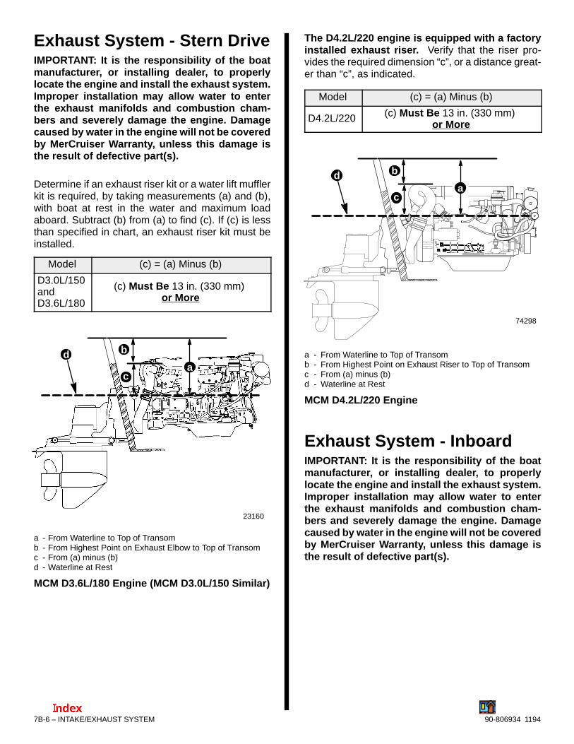
7B-6 – INTAKE/EXHAUST SYSTEM 90-806934 1194
Exhaust System - Stern DriveIMPORTANT: It is the responsibility of the boatmanufacturer, or installing dealer, to properlylocate the engine and install the exhaust system.Improper installation may allow water to enterthe exhaust manifolds and combustion cham-bers and severely damage the engine. Damagecaused by water in the engine will not be coveredby MerCruiser Warranty, unless this damage isthe result of defective part(s).
Determine if an exhaust riser kit or a water lift mufflerkit is required, by taking measurements (a) and (b),with boat at rest in the water and maximum loadaboard. Subtract (b) from (a) to find (c). If (c) is lessthan specified in chart, an exhaust riser kit must beinstalled.
Model (c) = (a) Minus (b)
D3.0L/150andD3.6L/180
(c) Must Be 13 in. (330 mm) or More
bda
c
23160
a - From Waterline to Top of Transomb - From Highest Point on Exhaust Elbow to Top of Transomc - From (a) minus (b)d - Waterline at Rest
MCM D3.6L/180 Engine (MCM D3.0L/150 Similar)
The D4.2L/220 engine is equipped with a factoryinstalled exhaust riser. Verify that the riser pro-vides the required dimension “c”, or a distance great-er than “c”, as indicated.
Model (c) = (a) Minus (b)
D4.2L/220 (c) Must Be 13 in. (330 mm) or More
bda
74298
c
a - From Waterline to Top of Transomb - From Highest Point on Exhaust Riser to Top of Transomc - From (a) minus (b)d - Waterline at Rest
MCM D4.2L/220 Engine
Exhaust System - InboardIMPORTANT: It is the responsibility of the boatmanufacturer, or installing dealer, to properlylocate the engine and install the exhaust system.Improper installation may allow water to enterthe exhaust manifolds and combustion cham-bers and severely damage the engine. Damagecaused by water in the engine will not be coveredby MerCruiser Warranty, unless this damage isthe result of defective part(s).
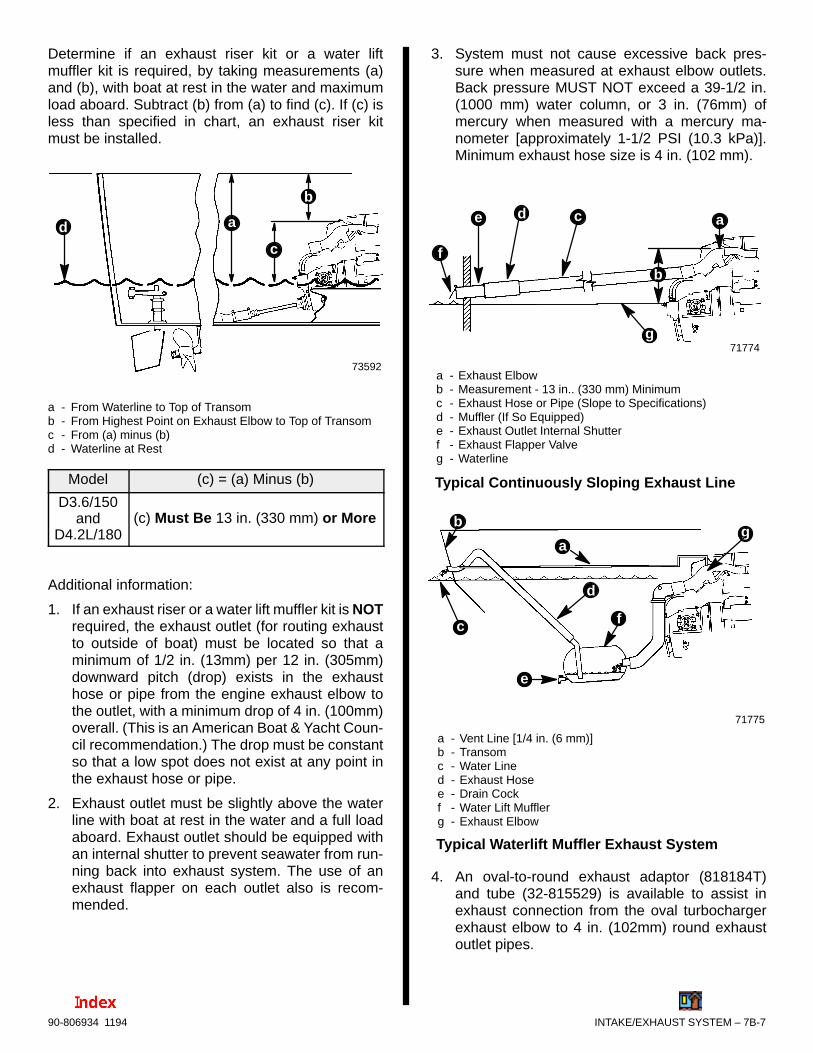
INTAKE/EXHAUST SYSTEM – 7B-790-806934 1194
Determine if an exhaust riser kit or a water liftmuffler kit is required, by taking measurements (a)and (b), with boat at rest in the water and maximumload aboard. Subtract (b) from (a) to find (c). If (c) isless than specified in chart, an exhaust riser kitmust be installed.
73592
b
cd a
c
a - From Waterline to Top of Transomb - From Highest Point on Exhaust Elbow to Top of Transomc - From (a) minus (b)d - Waterline at Rest
Model (c) = (a) Minus (b)
D3.6/150and
D4.2L/180(c) Must Be 13 in. (330 mm) or More
Additional information:
1. If an exhaust riser or a water lift muffler kit is NOTrequired, the exhaust outlet (for routing exhaustto outside of boat) must be located so that aminimum of 1/2 in. (13mm) per 12 in. (305mm)downward pitch (drop) exists in the exhausthose or pipe from the engine exhaust elbow tothe outlet, with a minimum drop of 4 in. (100mm)overall. (This is an American Boat & Yacht Coun-cil recommendation.) The drop must be constantso that a low spot does not exist at any point inthe exhaust hose or pipe.
2. Exhaust outlet must be slightly above the waterline with boat at rest in the water and a full loadaboard. Exhaust outlet should be equipped withan internal shutter to prevent seawater from run-ning back into exhaust system. The use of anexhaust flapper on each outlet also is recom-mended.
3. System must not cause excessive back pres-sure when measured at exhaust elbow outlets.Back pressure MUST NOT exceed a 39-1/2 in.(1000 mm) water column, or 3 in. (76mm) ofmercury when measured with a mercury ma-nometer [approximately 1-1/2 PSI (10.3 kPa)].Minimum exhaust hose size is 4 in. (102 mm).
71774
a - Exhaust Elbowb - Measurement - 13 in.. (330 mm) Minimumc - Exhaust Hose or Pipe (Slope to Specifications)d - Muffler (If So Equipped)e - Exhaust Outlet Internal Shutterf - Exhaust Flapper Valveg - Waterline
f
a
Typical Continuously Sloping Exhaust Line
de
g
c
b
71775
a - Vent Line [1/4 in. (6 mm)]b - Transomc - Water Lined - Exhaust Hosee - Drain Cockf - Water Lift Mufflerg - Exhaust Elbow
Typical Waterlift Muffler Exhaust System
a
b
c
g
d
e
f
4. An oval-to-round exhaust adaptor (818184T)and tube (32-815529) is available to assist inexhaust connection from the oval turbochargerexhaust elbow to 4 in. (102mm) round exhaustoutlet pipes.
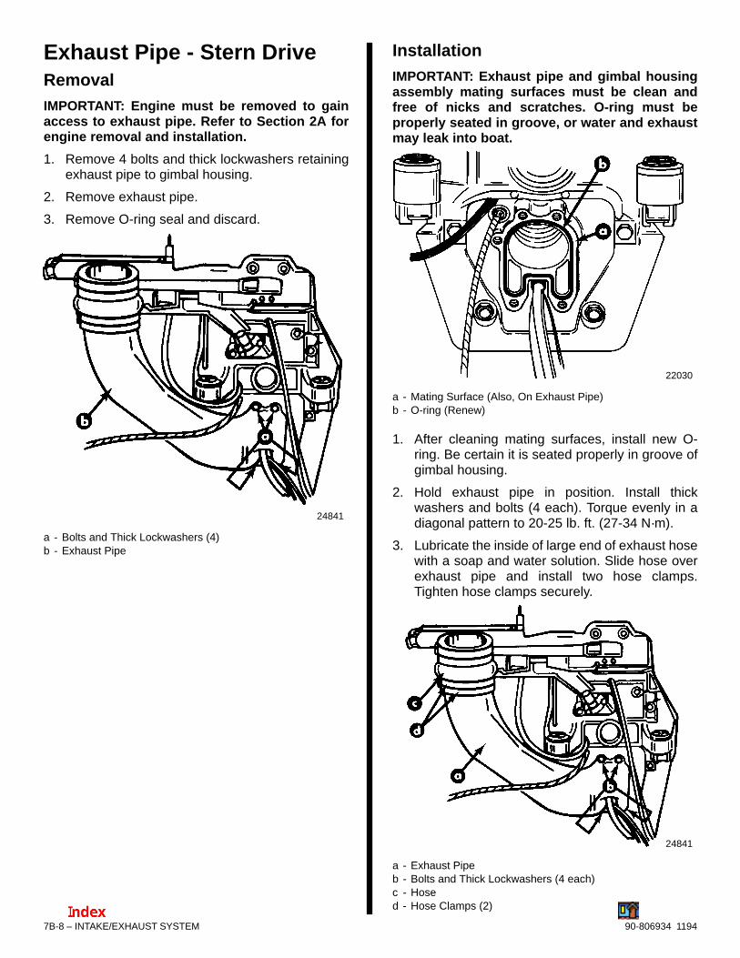
7B-8 – INTAKE/EXHAUST SYSTEM 90-806934 1194
Exhaust Pipe - Stern DriveRemovalIMPORTANT: Engine must be removed to gainaccess to exhaust pipe. Refer to Section 2A forengine removal and installation.
1. Remove 4 bolts and thick lockwashers retainingexhaust pipe to gimbal housing.
2. Remove exhaust pipe.
3. Remove O-ring seal and discard.
24841
a - Bolts and Thick Lockwashers (4)b - Exhaust Pipe
InstallationIMPORTANT: Exhaust pipe and gimbal housingassembly mating surfaces must be clean andfree of nicks and scratches. O-ring must beproperly seated in groove, or water and exhaustmay leak into boat.
22030
a - Mating Surface (Also, On Exhaust Pipe)b - O-ring (Renew)
1. After cleaning mating surfaces, install new O-ring. Be certain it is seated properly in groove ofgimbal housing.
2. Hold exhaust pipe in position. Install thickwashers and bolts (4 each). Torque evenly in adiagonal pattern to 20-25 lb. ft. (27-34 N·m).
3. Lubricate the inside of large end of exhaust hosewith a soap and water solution. Slide hose overexhaust pipe and install two hose clamps.Tighten hose clamps securely.
24841
a - Exhaust Pipeb - Bolts and Thick Lockwashers (4 each)c - Hosed - Hose Clamps (2)

INTAKE/EXHAUST SYSTEM – 7B-990-806934 1194
Exhaust ManifoldRemoval1. Remove heat exchanger assembly as outlined in
Section 6B.
2. Remove intercooler housing as outlined inSection 7A.
3. Remove wastegate and valve as outlined inSection 7C, if so equipped.
4. Remove turbocharger as outlined in Section 7C.
5. Disconnect wiring block from water temperaturesender, if located on rear cover.
NOTE: Later engines have a hex head plug in placeof the temperature switch/sender.
6. Loosen hose clamp on rear cover-to-rearmanifold strip elbow hose.
70882
70881
a - Exhaust Manifoldb - Rear Coverc - Hose Clampd - Hose, Rear Cover-to-Rear Manifold Stripe - Water Temperature Switch/Sender (Hex Head Plug On
Later Engines)
Typical
7. Remove nuts and lockwashers (6 cylinder has24, and 5 cylinder has 20).
70881
a - Nuts and Lockwashers
Typical
Cleaning and Inspection1. Clean gasket material from all surfaces and wash
parts in solvent.
2. Inspect all parts carefully. Machined surfacesmust be clean and free of all marks and deepscratches, or water and exhaust leaks mayresult.
3. Check water passages for foreign material.Passages must be clean for efficient cooling.
4. If more thorough inspection is desired, pipe plugsmay be removed from exhaust manifold andexhaust elbow.
IMPORTANT: If plugs are removed, coat threadswith Perfect Seal before reinstalling.
5. Check for cracks.
6. To test manifold body for leaks, block off plates,plugs, or short hoses with plugged ends must beused. One block off plate must have a threadedhole for attaching compressed air hose. Use newgaskets when installing block off plate(s). Apply40 PSI (276 kPa) of air pressure and submergemanifold in water. Air bubbles will indicate a leak.

7B-10 – INTAKE/EXHAUST SYSTEM 90-806934 1194
Installation1. Be certain mating surfaces of cylinder heads are
clean and free of all old gasket material.Machined surfaces must not have nicks orgouges, or water and exhaust leaks may result.
2. Install new gaskets on cylinder head/manifoldstuds.
70883
a - Cylinder Head/Manifold Studsb - Gaskets
Typical
3. Slide exhaust manifold on studs. Installlockwashers and nuts. Torque nuts evenly in adiagonal pattern to 24 lb. ft. (32 N·m).
4. Install hose clamp on rear cover-to-rear manifoldstrip elbow hose. Tighten securely.
5. Connect wiring block to water temperatureswitch/sender, if located on rear cover.
NOTE: Later engines have a hex head plug in placeof the temperature switch/sender.
70882
70881
a - Exhaust Manifoldb - Rear Coverc - Hose Clampd - Hose, Rear Cover-to-Rear Manifold Stripe - Water Temperature Switch/Sender (Hex Head Plug On
Later Engines)f - Nuts and Lockwashers
Typical
6. Install turbocharger as outlined in SECTION 7C.
7. Install wastegate and valve as outlined in SEC-TION 7C, if so equipped.
8. Install intercooler housing as outlined in SEC-TION 7A.
9. Install heat exchanger assembly as outlined inSECTION 6B.
10. Fill closed cooling system according toinstructions in SECTION 6B, “Filling ClosedCooling System.”
11. Start engine. Check for leaks.
7
C
INTAKE/EXHAUST SYSTEM
TURBOCHARGER

7C-0 – TURBOCHARGER 90-806934 1194
Table Of ContentsPage
Identification 7C-1. . . . . . . . . . . . . . . . . . . . . . . . . . . . . . . . . . Torque Specifications 7C-1. . . . . . . . . . . . . . . . . . . . . . . . . . Sealants 7C-1. . . . . . . . . . . . . . . . . . . . . . . . . . . . . . . . . . . . . Turbocharger Specifications 7C-1. . . . . . . . . . . . . . . . . . . . Description 7C-2. . . . . . . . . . . . . . . . . . . . . . . . . . . . . . . . . . .
Turbocharger 7C-2. . . . . . . . . . . . . . . . . . . . . . . . . . . . . . Wastegate 7C-2. . . . . . . . . . . . . . . . . . . . . . . . . . . . . . . . .
Exploded Views 7C-3. . . . . . . . . . . . . . . . . . . . . . . . . . . . . . . Turbocharger And Related Components 7C-3. . . . . . . Boost Pressure Control (Wastegate) Components 7C-4. . . . . . . . . . . . . . . . . . . . . . . . . . . . . .
Turbocharger 7C-5. . . . . . . . . . . . . . . . . . . . . . . . . . . . . . . . . Testing Turbocharger Boost Pressure 7C-5. . . . . . . . . Checking Turbine Bearings (Assembled) 7C-5. . . . . . Removal 7C-6. . . . . . . . . . . . . . . . . . . . . . . . . . . . . . . . . .
Removing Exhaust Elbow 7C-6. . . . . . . . . . . . . . . . Removing Turbocharger Unit 7C-7. . . . . . . . . . . . . .
Disassembly 7C-8. . . . . . . . . . . . . . . . . . . . . . . . . . . . . . . Cleaning 7C-9. . . . . . . . . . . . . . . . . . . . . . . . . . . . . . . . . . Inspection 7C-9. . . . . . . . . . . . . . . . . . . . . . . . . . . . . . . . .
Axial (End) Play – Measuring 7C-9. . . . . . . . . . . . . Radial (Side) Play – Measuring 7C-10. . . . . . . . . . .
Assembly 7C-10. . . . . . . . . . . . . . . . . . . . . . . . . . . . . . . . Installation 7C-11. . . . . . . . . . . . . . . . . . . . . . . . . . . . . . . .
Boost Pressure Control (D254 Engines) 7C-16. . . . . . . . . Exhaust Pipe 7C-16. . . . . . . . . . . . . . . . . . . . . . . . . . . . .
Inspection 7C-16. . . . . . . . . . . . . . . . . . . . . . . . . . . . . Removal 7C-17. . . . . . . . . . . . . . . . . . . . . . . . . . . . . . Installation 7C-17. . . . . . . . . . . . . . . . . . . . . . . . . . . . .
Valve 7C-18. . . . . . . . . . . . . . . . . . . . . . . . . . . . . . . . . . . . Removal 7C-18. . . . . . . . . . . . . . . . . . . . . . . . . . . . . . Installation 7C-18. . . . . . . . . . . . . . . . . . . . . . . . . . . . .
Wastegate 7C-19. . . . . . . . . . . . . . . . . . . . . . . . . . . . . . . . Removal 7C-19. . . . . . . . . . . . . . . . . . . . . . . . . . . . . . Installation 7C-19. . . . . . . . . . . . . . . . . . . . . . . . . . . . .
7C – TURBOCHARGER
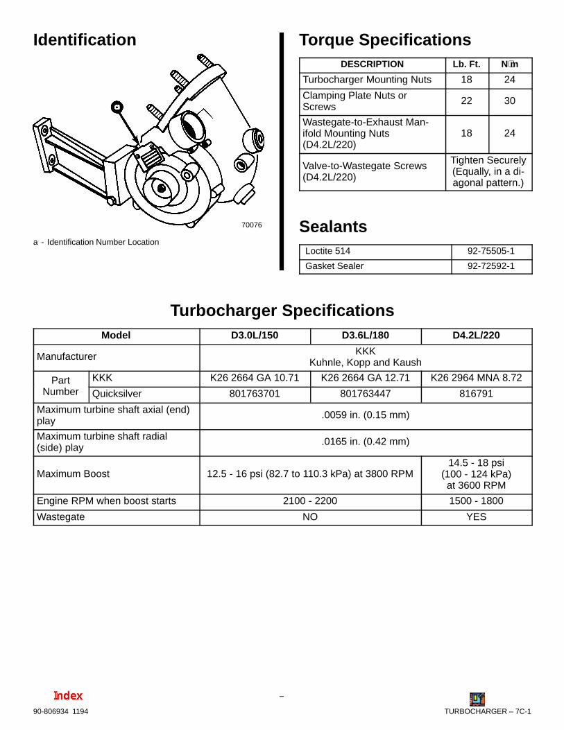
TURBOCHARGER – 7C-190-806934 1194
Identification
70076
a - Identification Number Location
Torque SpecificationsDESCRIPTION Lb. Ft. N⋅m
Turbocharger Mounting Nuts 18 24
Clamping Plate Nuts orScrews
22 30
Wastegate-to-Exhaust Man-ifold Mounting Nuts(D4.2L/220)
18 24
Valve-to-Wastegate Screws(D4.2L/220)
Tighten Securely(Equally, in a di-agonal pattern.)
SealantsLoctite 514 92-75505-1
Gasket Sealer 92-72592-1
Turbocharger SpecificationsModel D3.0L/150 D3.6L/180 D4.2L/220
Manufacturer KKKKuhnle, Kopp and Kaush
Part KKK K26 2664 GA 10.71 K26 2664 GA 12.71 K26 2964 MNA 8.72Number Quicksilver 801763701 801763447 816791
Maximum turbine shaft axial (end)play
.0059 in. (0.15 mm)
Maximum turbine shaft radial(side) play
.0165 in. (0.42 mm)
Maximum Boost 12.5 - 16 psi (82.7 to 110.3 kPa) at 3800 RPM14.5 - 18 psi
(100 - 124 kPa)at 3600 RPM
Engine RPM when boost starts 2100 - 2200 1500 - 1800
Wastegate NO YES

7C-2 – TURBOCHARGER 90-806934 1194
Description
TurbochargerAll diesel engines covered in this manual areequipped with a turbocharger to boost intakepressure resulting in increased horsepower. In onecasing on the turbocharger housing exhaust gasesare used to spin the turbine up to 100,000 RPM. Thecompressor, which is installed on the same shaft butin a separate casing, draws in filtered air,compresses it, and delivers it to the engine throughan intake duct and intercooler.
The turbo bearings are lubricated by engine oil.
Coolant from the engine’s closed cooling systemcools the turbocharger housing, while the exhaustelbow is cooled by seawater flowing through it fromthe seawater system.
On D3.0L/150 and D3.6L/180 Engines: Turbopressure, or boost, is limited by engine RPM.
On D4.2L/220 Engines: Turbo pressure is limited bya boost pressure control valve (commonly called a“wastegate”) is mounted on the combinedexhaust/intake manifold.
WastegateWhen used in combination with the turbocharger (onthe D4.2L/220 engines only) a higher torque outputeven at low engine speeds is obtained and allows theengine a wider operating speed range.
The function of the wastegate is to limit the boostpressure generated by the turbocharger within acontrolled tolerance band.
When factory set boost pressure is exceeded, thevalve opens and bypasses a part of the exhaust gasflow around the turbine. The resulting reducedmass-flow produces a lower power output. Thecompressor output is reduced in proportion and theboost pressure falls to the predetermined level. Thiscontrol process is repeated for each change inengine load.
This allows the use of a smaller turbocharger turbinewhich provides better acceleration and torque, asboost comes on more rapidly and turbo lag isreduced.
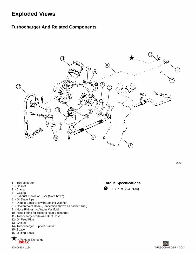
TURBOCHARGER – 7C-390-806934 1194
Exploded Views
Turbocharger And Related Components
73941
34
5
6
7
8
11
12
15 213
14
79 9
a1
10
16
1 - Turbocharger2 - Gasket3 - Clamp4 - Gasket5 - Exhaust Elbow, or Riser (Not Shown)6 - Oil Drain Pipe7 - Double Banjo Bolt with Sealing Washer8 - Coolant Vent Hose (Connection shown as dashed line.)9 - Hose Fittings, At Water Manifold10- Hose Fitting for Hose to Heat Exchanger11- Turbocharger-to-Intake Duct Hose12- Oil Feed Pipe13- Gasket14- Turbocharger Support Bracket15- Spacer16- O-Ring Seals
- To Heat Exchanger
Torque Specificationsa 18 lb. ft. (24 N·m)

7C-4 – TURBOCHARGER 90-806934 1194
Boost Pressure Control (Wastegate) Components
Typical MCM (Stern Drive) D4.2L/220 Components Shown - [MIE (Inboard) Similar]
73940
1
2
3
4
6
7
8
9
4
105
a
1 - Wastegate2 - Wastegate-to-Exhaust Manifold Gasket3 - Wastegate Exhaust Pipe, MCM Shown (MIE Similar)4 - Gasket (2)5 - Hex Nut and Lockwasher (4)6 - Heat Shield Blanket (For Exhaust Pipe)7 - Boost Pressure Valve8 - Boost Pressure Line9 - Banjo Bolt and Sealing Washers (at Exhaust Manifold)10- Banjo Bolt and Sealing Washers (at Valve))
Torque Specificationsa 18 lb. ft. (24 N·m)

TURBOCHARGER – 7C-590-806934 1194
IMPORTANT: Before suspecting the turbochargerfor engine running problems, the fuel injectionsystem and engine mechanicals (valves, cam-shaft, etc.) must be in good working order.
TurbochargerTesting Turbocharger Boost Pressure
! CAUTIONSafety glasses, gloves and protective clothingshould be worn while testing turbocharger boostpressure, to protect against pressurized air beingreleased by a leak or rupture of a hose which couldcause injury.
The following should be observed prior to testing:
Engine should be at normal operatingtemperature.
Engine air cleaner should be clean (or replacedif not clean).
1. Remove plug (screw with sealing washer) fromintercooler housing as shown.
70904
73334
a
b
a - Plug (Screw with Sealing Washer)b - Intercooler Housing
Typical
2. Install a 0-25 psi (0-172.4 kPa) pressure gaugeinto intercooler where plug was removed in Step 1.
3. Start engine and watch pressure gauge.
On D3.0L/150 and D3.6L/180 Engines:Maximum boost should be between 12.5 - 16 psi(82.7 - 110.3 kPa) at 3800 RPM.
On D4.2L/220 Engines: Maximum boost shouldbe between 14.5 - 18 psi (100 - 124 kPa) at 3600RPM.
Readings LOWER than specified above indicatepossible turbocharger problem(s), or boost pressurecontrol system problems (D4.2L/220 engines only),IF no engine problem exists, such as incorrect valveclearance or a blockage in the exhaust system (referto appropriate Sections in this manual, including“Troubleshooting”). NO boost pressure wouldindicate a faulty turbocharger requiring replacement.
Checking Turbine Bearings(Assembled)1. Refer to the following section Turbocharger -
“Removal” and remove exhaust elbow as out-lined for your engine.
2. Rotate the turbine impeller by hand to see that itturns smoothly. If not, turbine bearings or impel-ler problems exist.
3. Using a feeler gauge as shown, check clearancebetween turbine blades and housing at two loca-tions opposite one another. The difference in thetwo readings is the radial play. Maximum radialplay is .0165 in. (0.42mm).
70984
Checking Turbine Blade Clearance
4. Check if turbine blades are rubbing on housing.Replace turbocharger if so.

7C-6 – TURBOCHARGER 90-806934 1194
Removal
! WARNING
Always disconnect battery cables from batterybefore working around electrIcal system compo-nents to prevent injury to yourself or damage toelectrical system.
REMOVING EXHAUST ELBOW
1. Disconnect battery cables from battery termi-nals.
2. Loosen hose clamp and disconnect seawaterhose at turbocharger exhaust elbow or riser.Drain seawater into a suitable container.
50665
a - Hose Clampb - Seawater Hose
Typical
3. Loosen exhaust elbow hose clamps as shown.
74298
c
b
a
a - Hose Clampsb - Exhaust Elbow or Riserc - Exhaust Hose
MCM D4.2L/220 With Riser Shown (All Similar)
4. Follow instructions “a” or “b”:
a. On D3.0L/150 and D3.6L/180 Engines:Proceed to Step 5.
b. On D4.2L/220 Engines:
(1) Loosen spring retaining heat-shield blan-ket around wastegate exhaust pipe.
(2) Remove fasteners and lockwashers re-taining wastegate exhaust pipe to ex-haust elbow.
70986
a - Spring (Blanket Retainer)b - Blanket, Heat-Shieldc - Hex Nuts With Lockwashersd - Wastegate Exhaust Pipe
Typical
5. Suitably mark exhaust elbow, or riser, andturbocharger housing for alignment during reas-sembly.

TURBOCHARGER – 7C-790-806934 1194
6. Loosen exhaust elbow, or riser, clamp. Removeelbow gasket and clamp.
70987
a
c
b
73941
c
73632
a - Clampb - Exhaust Elbowc - Exhaust Gasket (Not Shown)
Typical Exhaust Elbow Shown (Similar With Riser)
REMOVING TURBOCHARGER UNIT
1. Refer to SECTION 6B - Closed Cooling System,“Draining Coolant” and drain closed cooling sys-tem.
2. Remove lifting eye bracket as shown to gain ac-cess to turbocharger mounting nuts.
70988
a - Bracket, Lifting Eyeb - Screws
Typical Shown
3. Remove oil feed pipe and banjo bolt from coolantvent pipe at turbocharger as shown. Loosen airfilter and turbocharger-to-intake duct hoseclamps.
70989
a - Turbocharger-to-Intake Duct Hose Clampb - Oil Feed Pipec - Banjo Bolt (With Sealing Washers), Coolant Vent Lined - Air Filter Hose Clamp
Typical Shown (All Similar)
4. Remove oil drain pipe on bottom of turbochargeras shown.
70990
a - Oil Drain Pipeb - Hex Nuts With Lockwashers

7C-8 – TURBOCHARGER 90-806934 1194
5. To gain access to turbocharger mounting nuts,follow instructions “a” or “b”:
a. On D3.0L/150 and D3.6L/180 Engines:Remove intake duct from side of intercoolerhousing. (Refer to SECTION 7A - Intercooler,for instructions on removal.)
b. On D254 Engines: Remove intake duct fromrear of intercooler housing. (Refer to SEC-TION 7A - Intercooler, for instructions on re-moval.)
IMPORTANT: In the event that turbochargermounting nuts are corroded, or otherwise resistloosening in the following, it may become neces-sary to completely remove the intercooler hous-ing to gain a more suitable access to mountingnuts. Refer to SECTION 7A - Intercooler, forinstructions on removal and installation of the in-tercooler housing.
6. Remove four mounting nuts retaining turbochar-ger to exhaust manifold.
70991
a - Mounting Nuts (4 Total, Two Hidden In This View)
Typical Shown (All Similar)
7. Remove the two support bracket mountingscrews as shown, and MerCathode controllerbracket if so equipped (not shown in the follow-ing). Remove turbocharger unit.
70992
c
a - Support Bracketb - Screw (2) With Washerc - MerCathode Controller Bracket Location
Disassembly1. Make matching marks on the exhaust housing
and bearing housing to aid alignment in reas-sembly.
2. Remove 6 hex nuts or hex screws and the 3clamping plates shown.
70993
a - Matching Marksb - Hex Nuts or Hex Screws (6 Total - 2 Hidden In This View)c - Clamping Plates (3 Total - One Hidden In This View)d - Exhaust Housinge - Bearing Housing
Typical Turbocharger Shown

TURBOCHARGER – 7C-990-806934 1194
NOTE: If the exhaust housing cannot easily beremoved by hand, tap on it carefully all around usinga plastic hammer and carefully remove it in thefollowing.
IMPORTANT: Be careful not to damage the turbineimpeller when removing exhaust housing.
3. Remove exhaust housing as shown.
70994
a - Exhaust Housingb - Bearing Housingc - Turbine Impeller
Typical Turbocharger Shown
4. Inspect turbine blades. If blades are rubbingagainst housing, the bearings are worn. Replaceturbocharger.
70994
a - Turbineb - Inspect (Edges of Blades)
CleaningIMPORTANT: Never use a caustic cleaning solu-tion, as it may attack aluminum. Also, never usea wire brush which could damage impeller ormating surfaces.
1. BEFORE cleaning inspect the disassembledparts for burning, abrasion, carbon deposits, gasand oil leakage.
! CAUTIONAlways wear safety glasses when usingcompressed air to protect from hose rupturing orflying debris.
! WARNING
When using compressed air to dry components,DO NOT spin turbine, or allow turbine to spin,since no oil is being provided to the bearings andcould result in damage to the bearings.
2. Thoroughly clean all the parts with clean dieselfuel, using a soft brush. Dry with compressed air.
InspectionIMPORTANT: If turbine shaft bearing axial orradial play is excessive, replace turbocharger.
AXIAL (END) PLAY – MEASURING
1. With turbocharger held in vise, attach dial indica-tor as shown following.
2. Move turbine shaft in direction shown. Maximumaxial play (end play) is .0059 in. (0.15mm).
70995
Measuring Axial (End) Play

7C-10 – TURBOCHARGER 90-806934 1194
RADIAL (SIDE) PLAY – MEASURING
1. With turbocharger held in vise, attach dial indica-tor as shown in following.
2. Move turbine shaft in direction shown. Maximumradial (side) play is .0165 in. (0.42mm).
70996
Measuring Radial (Side) Play
AssemblyIMPORTANT: When installing a new turbochar-ger, it may be necessary to turn intake, bearing,and/or exhaust housings to allow mountingbracket to be bolted to engine.
1. While aligning matching marks, assemble ex-haust housing and bearing housing together.Install clamping plates and finger tighten hexnuts or screws. Do not tighten securely at thistime.
70993
a - Matching Marksb - Exhaust Housingc - Bearing Housingd - Clamping Plates (3 Total - One Hidden In This View)e - Hex Nuts or Hex Screws (6 Total - Two Hidden In This
View)
Typical Turbocharger Shown
2. Follow instructions “a” or “b”:
a. On D3.0L/150 and D3.6L/180 Engines:
(1) Being certain surfaces are clean of oldgasket material or debris, install a newgasket on bearing housing oil drain/spacer flange.
(2) Assemble spacer with bracket attachedas shown. Tighten hex nuts finger tight atthis time.
70997
a - Gasketb - Spacerc - Support Bracketd - Hex Nut

TURBOCHARGER – 7C-1190-806934 1194
b. On D4.2L/220 Engines:
(1) Being certain surfaces are clean, install anew O-ring in groove of drain/spacerflange where it meets bearing housing ofturbocharger.
(2) Assemble spacer with bracket attachedas shown. Tighten hex nuts finger tight atthis time.
70998
a - O-ring (Hidden In Assembled View)b - Spacer (Oil Drain)c - Support Bracketd - Hex Nut
3. Position exhaust housing and bearing housing(with intake housing) as shown.
70999
a - Exhaust Housingb - Bearing Housing (With Intake Housing)
InstallationIMPORTANT: When installing turbocharger, itmay be necessary to turn intake and exhausthousings to line up with intake air duct and ex-haust manifolds on engine.
1. Using a new gasket, install turbocharger on ex-haust manifold as shown. Tighten nuts to 18 lb.ft. (24 N·m).
70991
a - Gasket, Exhaust Manifold-to-Turbochargerb - Nut (4 Total - Two Hidden In This View)
Typical Turbocharger Shown
2. Install support bracket screws with washers asshown (and MerCathode controller with bracketif so equipped - not shown following). Tightenscrews securely.
70992
a - Screws With Washersb - Support Bracket
Typical
3. Tighten the six hex nuts or hex screws (on D4.2L)on clamping plates of exhaust housing-to-bear-ing housing to 22 lb. ft. (30 N·m). (Refer to Step1 in “Assembly” section, for location.)
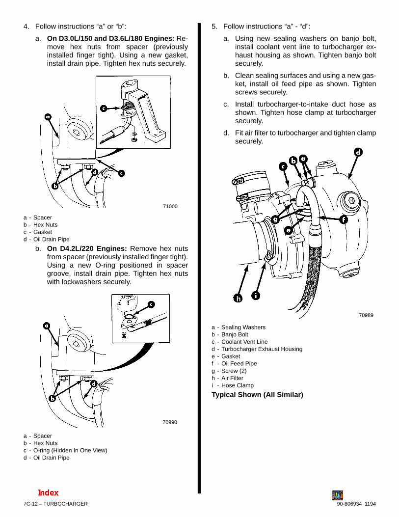
7C-12 – TURBOCHARGER 90-806934 1194
4. Follow instructions “a” or “b”:
a. On D3.0L/150 and D3.6L/180 Engines: Re-move hex nuts from spacer (previouslyinstalled finger tight). Using a new gasket,install drain pipe. Tighten hex nuts securely.
71000
a - Spacerb - Hex Nutsc - Gasketd - Oil Drain Pipe
b. On D4.2L/220 Engines: Remove hex nutsfrom spacer (previously installed finger tight).Using a new O-ring positioned in spacergroove, install drain pipe. Tighten hex nutswith lockwashers securely.
70990
a - Spacerb - Hex Nutsc - O-ring (Hidden In One View)d - Oil Drain Pipe
5. Follow instructions “a” - “d”:
a. Using new sealing washers on banjo bolt,install coolant vent line to turbocharger ex-haust housing as shown. Tighten banjo boltsecurely.
b. Clean sealing surfaces and using a new gas-ket, install oil feed pipe as shown. Tightenscrews securely.
c. Install turbocharger-to-intake duct hose asshown. Tighten hose clamp at turbochargersecurely.
d. Fit air filter to turbocharger and tighten clampsecurely.
70989
h
a - Sealing Washersb - Banjo Boltc - Coolant Vent Lined - Turbocharger Exhaust Housinge - Gasketf - Oil Feed Pipeg - Screw (2)h - Air Filteri - Hose Clamp
Typical Shown (All Similar)

TURBOCHARGER – 7C-1390-806934 1194
IMPORTANT: If it became necessary to removethe entire intercooler housing from the intake/ex-haust manifold during disassembly (to gain bet-ter access to turbocharger mounting nuts) referto Section 7A - Intake Manifold/Intercooler, at thistime for proper installation.
6. If previously only the intake duct of intercoolerwas removed, follow instructions “a” or “b”:
a. On D3.0L/150 and D3.6L/180 Engines:
(1) Clean sealing flanges of intercoolerhousing and intake duct. Do not nick orgouge the surfaces.
(2) Apply Loctite 514 sealer to intake ductflange as shown.
a - Intake Ductb - Flange (Apply Sealer Here)
(3) Install intake duct on intercooler asshown. Torque allen-head screws withwave washers to 7 lb. ft. (10 N·m).
70919
a - Intake Ductb - Intercooler Housingc - Screws With Wave Washers
D3.6L/180 Shown (D3.0L/150 Similar)
b. On D4.2L/220 Engines:
(1) Clean sealing flanges of intercoolerhousing and intake duct. Do not nick orgouge the surfaces.
(2) Apply Loctite 514 sealer to intake ductflange on intercooler as shown.
70931
a - Intercooler Housingb - Intake Ductc - Flange (Apply Sealer Here)
(3) Install intake duct on intercooler asshown. Torque four allen-head screwswith wave washers to 7 lb. ft. (10 N·m).
NOTE: Intercooler shown removed for visual clarityonly.
70929
a - Intake Ductb - Intercooler Housingc - Screw With Wave Washer

7C-14 – TURBOCHARGER 90-806934 1194
7. Install lifting eye bracket as shown. Tightenscrews securely.
70988
a - Bracket, Lifting Eyeb - Screws With Washers
Typical Shown
8. As shown, tighten turbocharger-to-intake ducthose clamp securely.
70918
a - Hoseb - Hose Clampc - Turbochargerd - Intake Duct
9. Follow instructions “a” or “b”:
a. On D3.0L/150 and D3.6L/180 Engines:
(1) Using a new gasket, install exhaust el-bow, or exhaust riser if so equipped, asshown. Align with exhaust pipe. Tightenelbow or riser clamp securely.
(2) Install seawater hose to exhaust elbow,or exhaust riser fitting, if so equipped.Tighten hose clamps securely.
(3) Position exhaust hose on elbow, or riser.Tighten hose clamps securely.
74298g
e
50665
7394173632
a
b
c
b
c
d
d
h
f
a - Gasketb - Exhaust Elbowc - Exhaust Elbow, or Riser, Clampd - Seawater Hose and Clamp (At Exhaust Elbow or Riser)e - Exhaust Riserf - Exhaust Hoseg - Exhaust Hose Clamp (4)h - Exhaust Pipe
Typical Installations Shown

TURBOCHARGER – 7C-1590-806934 1194
b. On D4.2L/220 Engines:
(1) Install exhaust elbow, or riser, using newgaskets on exhaust elbow and wastegateexhaust pipe flange as shown, Alignstuds on elbow, or riser, with holes in was-tegate exhaust pipe. Simultaneously,align with exhaust pipe. Tighten exhaustelbow clamp securely.
(2) Install hex nuts and washers, or screwsand washers, on wastegate exhaustpipe. Tighten fasteners securely andwrap with heat shield blanket. Fastenspring to retain blanket.
71001
70986
a - Gasket, Exhaust Elbowb - Gasket, Wastegate Exhaust Pipe-to-Elbow, or Riserc - Exhaust Elbowd - Wastegate Exhaust Pipee - Clamp, Exhaust Elbowf - Hex Nutg - Blanket, Heat Shieldh - Spring
Early MCM D4.2L/220 Shown (Similar With Riser,or On MIE Models)
(3) Install seawater hose from fluid cooler-to-exhaust elbow, or riser if so equipped.Tighten hose clamp securely.
(4) Position exhaust hose as shown. Tightenhose clamps securely.
71003
71704
e
c
a
b
c
d
e
e
f
g
a - Exhaust Riserb - Exhaust Elbowc - Seawater Hose (Fluid Cooler-to-Exhaust Elbow)d - Seawater Hose (Fluid Cooler-to-Exhaust Riser)e - Clamp, Seawater Hosef - Exhaust Hoseg - Clamp(s), Exhaust Hose
Early MCM D4.2L/220 Shown, With Inset of RiserConnection (All Connections Similar On MIEModels)

7C-16 – TURBOCHARGER 90-806934 1194
10. Fill closed cooling system at this time accordingto instructions in Section 6B - Closed CoolingSystem, “Filling Closed Cooling System.”
11. Connect battery cables to battery by FIRSTinstalling positive (+) battery cable end onpositive (+) battery terminal. Tighten clampsecurely. THEN install negative (–) battery cableend on negative (–) battery terminal. Tightenclamp securely.
12. Pre-lubricate turbocharger by turning ignitionswitch to the ON position and depressing bothSTART and STOP buttons TOGETHER, turningthe engine over without starting it. DO NOT en-gage starter for more than 15 seconds at onetime. Allow at least one minute for starter to coolbefore reusing. Crank engine intermittently untiloil pressure registers on oil gauge.
13. Start engine and check for leaks.
14. Test turbocharger boost pressure as previouslyoutlined.
Boost Pressure Control(D254 Engines)
! WARNING
Always disconnect battery cables from batterybefore working around electrical system compo-nents to prevent injury to yourself or damage toelectrical system.
Exhaust Pipe
INSPECTION
1. Loosen spring retaining heat shield blanketaround wastegate exhaust pipe as shown.
71002
a - Retaining Springb - Blanket, Heat Shieldc - Wastegate Exhaust Piped - Gasket
Typical MCM Assembly Shown (MIE Similar)
2. Visually examine pipe and convolutions for signsof cracking or leakage. Also, examine gaskets forsigns of leakage. Repair as needed. (Refer to“Removal” if required.)
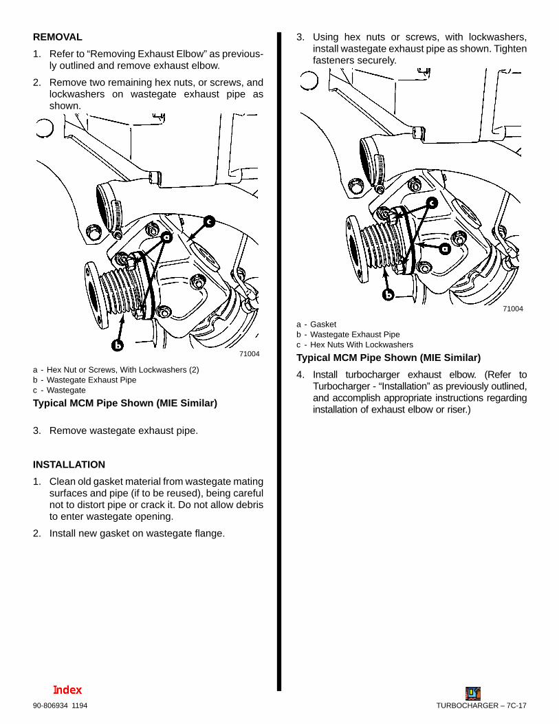
TURBOCHARGER – 7C-1790-806934 1194
REMOVAL
1. Refer to “Removing Exhaust Elbow” as previous-ly outlined and remove exhaust elbow.
2. Remove two remaining hex nuts, or screws, andlockwashers on wastegate exhaust pipe asshown.
71004
a - Hex Nut or Screws, With Lockwashers (2)b - Wastegate Exhaust Pipec - Wastegate
Typical MCM Pipe Shown (MIE Similar)
3. Remove wastegate exhaust pipe.
INSTALLATION
1. Clean old gasket material from wastegate matingsurfaces and pipe (if to be reused), being carefulnot to distort pipe or crack it. Do not allow debristo enter wastegate opening.
2. Install new gasket on wastegate flange.
3. Using hex nuts or screws, with lockwashers,install wastegate exhaust pipe as shown. Tightenfasteners securely.
71004
a - Gasketb - Wastegate Exhaust Pipec - Hex Nuts With Lockwashers
Typical MCM Pipe Shown (MIE Similar)
4. Install turbocharger exhaust elbow. (Refer toTurbocharger - “Installation” as previously outlined,and accomplish appropriate instructions regardinginstallation of exhaust elbow or riser.)

7C-18 – TURBOCHARGER 90-806934 1194
Valve
REMOVAL
1. Follow instructions “a” - “c”:
a. Remove banjo bolt with sealing washers (2)from pressure line on bottom of intercoolerhousing as shown.
b. Remove banjo bolt with sealing washers (2)from pressure line on valve as shown.
c. Remove pressure line.
70917
a - Banjo Boltsb - Sealing Washers (2 Each)c - Pressure Lined - Intercooler Housinge - Wastegatef - Valve
Typical
2. Remove allen-head screws and washers retain-ing valve to wastegate. Remove valve.
70983
a - Allen-Head Screws With Washers (3 Total - Two Hidden InThis View)
b - Valvec - Wastegate
Typical
INSTALLATION
1. Position pressure line fitting on valve toward frontof engine and install on wastegate using allen-head screws and washers. In equal amounts,tighten screws securely.
2. Install pressure line on valve using banjo bolt withnew sealing washers. Finger tighten.
3. Install banjo bolt with new sealing washers onpressure line at exhaust manifold. Finger tighten.
4. Tighten both banjo bolts securely. Do not over-tighten.
5. Pre-lubricate turbocharger and engine. To dothis, move the “STOP” switch toggle lever DOWNand hold in this position while you turn the keyswitch to “START” position. Doing this TOGETH-ER turns the engine without starting it. DO NOTengage starter for more than 15 seconds; allowat least one minute cool down time before re-en-gaging starter for another 15 seconds. Watchthat starter does not overheat.
6. Start engine and check for leaks.
7. Test turbocharger boost pressure as previouslyoutlined.

TURBOCHARGER – 7C-1990-806934 1194
Wastegate
REMOVAL
1. Remove the following, as previously outlined:
Exhaust elbow
Wastegate exhaust pipe
Wastegate valve
2. Remove the four fasteners with lockwashers re-taining wastegate to exhaust manifold as shown.
71005
a - Hex Nuts, or Screws, With Lockwashers (4)b - Wastegatec - Exhaust Manifold
Typical
INSTALLATION
1. Clean all traces of old gasket material from ex-haust manifold flange where shown.
71006
2. Clean old gasket material from wastegate andusing a new gasket install wastegate on exhaustmanifold as shown. Tighten the four fastenerswith lockwashers securely.
71005
c
a - Wastegateb - Gasketc - Hex Nuts, or Screws, With Lockwashers (4 Total)
Typical
7C-20 – TURBOCHARGER 90-806934 1194
3. Following instructions previously outlined, install:
Wastegate valve
Wastegate exhaust pipe
Exhaust elbow or riser
4. Pre-lubricate turbocharger and engine. To dothis, move the “STOP” switch toggle leverDOWN and hold in this position while you turnthe key switch to “START” position. Doing thisTOGETHER turns the engine without starting it.DO NOT engage starter for more than 15 sec-onds; allow at least one minute cool down timebefore re-engaging starter for another 15 sec-onds. Watch that starter does not overheat.
5. Start engine and check for leaks.
6. Test turbocharger boost pressure as previouslyoutlined.

8A
25280
DRIVE SYSTEMS
HURTH DOWN ANGLE TRANSMISSION
Note:Refer to the following Service Bulletins regarding this section.
SB 99-5 Proper Oil Fill Level On Velvet Drive Transmissions
SB 98-15 Shift Cable Measurements For Transmissions
SB 96-16 Hurth V-Drive Output Flange Torque
SB 96-11 Hurth Transmissions
SB 95-24 Hurth Marine Gear Distributors
SB 95-23 Velvet Drvie Distributors

8A-0 - HURTH DOWN ANGLE TRANSMISSION 90-806934 1194
Table of ContentsPage
Identification 8A-1. . . . . . . . . . . . . . . . . . . . . . . . . . . . . . . . Torque Specifications 8A-1. . . . . . . . . . . . . . . . . . . . . . . . Tools/Lubricants/Sealants 8A-1. . . . . . . . . . . . . . . . . . . . . Specifications 8A-2. . . . . . . . . . . . . . . . . . . . . . . . . . . . . . .
Transmission Fluid Specification 8A-2. . . . . . . . . . . . Capacity 8A-2. . . . . . . . . . . . . . . . . . . . . . . . . . . . . . . . Operating Specifications 8A-2. . . . . . . . . . . . . . . . . . . Transmission Ratios 8A-2. . . . . . . . . . . . . . . . . . . . . .
General 8A-2. . . . . . . . . . . . . . . . . . . . . . . . . . . . . . . . . . . . Shift Cable Installation and Adjustment 8A-3. . . . . . . . . Checking TransmissionFluid Level 8A-6. . . . . . . . . . . . . . . . . . . . . . . . . . . . . . . . . Draining Transmission 8A-7. . . . . . . . . . . . . . . . . . . . . . . Filling Transmission 8A-8. . . . . . . . . . . . . . . . . . . . . . . . . . Transmission Removal 8A-9. . . . . . . . . . . . . . . . . . . . . . . Transmission Installation 8A-9. . . . . . . . . . . . . . . . . . . . . Transmission Repair 8A-10. . . . . . . . . . . . . . . . . . . . . . . . .
Disassembly 8A-10. . . . . . . . . . . . . . . . . . . . . . . . . . . . . Transmission Fluid Cooler 8A-10. . . . . . . . . . . . Oil Filter and Dipstick 8A-10. . . . . . . . . . . . . . . . . Mounts 8A-12. . . . . . . . . . . . . . . . . . . . . . . . . . . . . Control Block 8A-13. . . . . . . . . . . . . . . . . . . . . . . . Housing 8A-14. . . . . . . . . . . . . . . . . . . . . . . . . . . . Bearing, Gear and Seal Inspection 8A-15. . . . . Seals 8A-16. . . . . . . . . . . . . . . . . . . . . . . . . . . . . . Tapered Roller Bearing Cups 8A-17. . . . . . . . . . Tapered Roller Bearings 8A-18. . . . . . . . . . . . . . Reversing Clutch, Gears and Tapered RollerBearings 8A-19. . . . . . . . . . . . . . . . . . . . . . . . . . . . Clutch Discs 8A-21. . . . . . . . . . . . . . . . . . . . . . . .
PageReassembly 8A-23. . . . . . . . . . . . . . . . . . . . . . . . . . . . .
Clutch Discs 8A-23. . . . . . . . . . . . . . . . . . . . . . . . Needle Bearings 8A-26. . . . . . . . . . . . . . . . . . . . . Gear Assembly 8A-26. . . . . . . . . . . . . . . . . . . . . . Tapered Roller Bearing 8A-27. . . . . . . . . . . . . . . Intermediate Shaft 8A-28. . . . . . . . . . . . . . . . . . . Output Shaft 8A-28. . . . . . . . . . . . . . . . . . . . . . . . Preassembly of Output Half of Housing 8A-29. Preassembly of Input Half of Housing 8A-32. . .
Final Assembly 8A-39. . . . . . . . . . . . . . . . . . . . . . . . . . . Input Shaft Seal 8A-39. . . . . . . . . . . . . . . . . . . . . Control Block 8A-40. . . . . . . . . . . . . . . . . . . . . . . . Fluid Filter 8A-40. . . . . . . . . . . . . . . . . . . . . . . . . . Dipstick 8A-41. . . . . . . . . . . . . . . . . . . . . . . . . . . . Output Flange 8A-41. . . . . . . . . . . . . . . . . . . . . . . Transmission Fluid Cooler 8A-41. . . . . . . . . . . . Filling with Transmission Fluid 8A-42. . . . . . . . .
Functional Test 8A-43. . . . . . . . . . . . . . . . . . . . . . . . . . . . . .
8A - HURTH DOWN ANGLE TRANSMISSION

HURTH DOWN ANGLE TRANSMISSION - 8A-190-806934 1194
IdentificationThe transmission identification plate is located on thetop rear of the transmission.
72957
a - Transmission Identification Plate(Stating: Gear Ratio, Serial Number and Model)
a
71038
HSW 630A – 1,6
Getr.-Nr.
iA = 1,56 iB = 1,58
MADE IN WEST-GERMANY
Typical Identification Plate
Torque SpecificationsTORQUE
DESCRIPTIONLb. Ft. N⋅m
TransmissionHousing HalvesBolts and Nuts
36 49
Control Block toHousing Bolts
18 25
Output Flange toOutput Shaft
63 85
Mounts 50 68
Transmission toFlywheel Housing
50 68
Tools/Lubricants/SealantsDESCRIPTION PART NUMBER
Tapered Roller BearingInner Race Puller
91-813950
Tapered Roller BearingOuter Race Puller
91-813951
Pressure Plate RemovalTool Reversing Clutch
91-813952
Tapered Roller BearingInner Race Puller Plate
91-813953
Mandrel-Input Shaft Seal 91-912955
Mandrel-Output Shaft Seal 91-813956
Preload Tool Input Shaft 91-813957
Preload Tool IntermediateShaft
91-813958
Quicksilver Loctite 8831 92-823089-1
Quicksilver Engine CouplerSpline Grease
91-816391A4
Quicksilver LiquidNeoprene
92-27511-1
Pressure Gauge (M10x1Thread)
Loctite 515 (Split-LIne)Sealer Obtain Locally
Thermometer (3/8 In.Thread 0-270° F) (–18-132° F)

8A-2 - HURTH DOWN ANGLE TRANSMISSION 90-806934 1194
Specifications
Transmission Fluid Specification
DESCRIPTION SPECIFICATION
Obtain Locally ATF Dexron ll-D
Capacity
MODEL U.S. QTS. (LITRES)
630A 8° Down Angle 4.25 (4.0)
Operating Specifications
DESCRIPTION SPECIFICATION
Shifting Pressure 312-377 (2151-2599 kPa)
OperatingTemperature
130° 200° F (54° - 93° C)
Transmission Ratios
TransmissionModel 630A
NominalTransmission
Ratio1.5 2.0 2.5
TransmissionRatio ShiftingPosition ”A”
(Forward Gear)
1.56 2.04 2.52
TransmissionRatio ShiftingPosition ”B”
(Reverse Gear)
1.58 2.10 2.53
GeneralThe Hurth transmission is a “full power reversing”transmission, allowing a standard (LH rotation) en-gine to be used for both rotations. Propeller rotationis determined by shift cable attachment at the remotecontrol.
IMPORTANT: Transmission propeller rotation isdetermined by the shift cable installation in theremote control.
• RIGHT-HAND PROPELLER ROTATION - Controlcable will have to be installed in remote control so thatcable end will move in direction (A) when shift handle isplaced in the forward position.
• LEFT-HAND PROPELLER ROTATION - Control cablewill have to be installed in remote control so that cableend will move in direction (B) when shift handle isplaced in the forward position.
23242
A
B
72709
Shifting Leverin Position
PropellerRotation Propeller
A Opposite to EngineRotation
Right-Hand(RH)
B Same as EngineRotation
Left-Hand (LH)
72710
“A” Is Forward Gear for RH Rotation Propeller “B” Is Forward Gear for LH Rotation Propeller

HURTH DOWN ANGLE TRANSMISSION - 8A-390-806934 1194
Shift Cable Installation andAdjustmentThese Hurth transmissions are full reversing trans-missions. Direction of output/propeller rotation isdetermined by hookup of shift cable at remotecontrol.
Shift cable must be hooked up to remote controlbefore starting installation and adjustment proce-dures.
For Right Hand Propeller Rotation – shift cablehookup at remote control must result in shift cableend guide moving in direction “A”, when remotecontrol handle is placed in forward position.
For Left Hand Propeller Rotation – shift cablehookup at remote control must result in shift cableend guide moving in direction “B”, when remotecontrol handle is placed in forward position.
23242
! WARNINGAvoid serious injury or property damage causedby improper shifting. Anchor stud for shift cablemust be installed in the correct hole.
1. Be certain anchor stud is installed in the lower,front hole as shown in the illustration following.
c
b
a
b
a
c
7358871020
a - Cable Bracketb - Shift Cable Anchor Stud Location (For Quicksilver
Shift Cables)
Shift Cable Bracket - Anchor Stud PositionShown for 630A
IMPORTANT: Check that shift lever is positionedapproximately 10° aft of vertical when in the neu-tral detent position and that the distance (“c”)between studs in the following is set at 7-1/8 in.(318mm). If necessary, loosen clamping bolt andposition lever so that dimension “c” is as shownwhen in the neutral detent position and retightenbolt.
a
c
d
b
73587
a - Shift Leverb - Lever, in Neutral Detent, Must Be Approximately 10° Aft
of Verticalc - Dimension Between Studs - 7-1/8 in. (318mm)d - Clamping Bolt
Typical Hurth Transmission Shown
1. Place remote control shift lever, and transmis-sion shift lever, in neutral position.
2. Remove nuts and washers from shift cable at-taching studs.

8A-4 - HURTH DOWN ANGLE TRANSMISSION 90-806934 1194
3. Locate center of remote control and control shiftcable play (backlash), as follows:
a. Check that remote control is in neutral posi-tion.
b. Push in on control cable end with enoughpressure to remove play, and mark position“a” on tube.
c. Pull out on control cable end with enoughpressure to remove play, and mark position“b” on tube.
d. Measure distance between marks “a” and“b,” and mark position “c,” half-way betweenmarks “a” and “b.”
22024
c
b c
a
4. Center cable-end play, then adjust cable barrel toalign holes in barrel, and in cable end guide, withattaching points on transmission.
5. Temporarily install shift cable. Do not secure atthis time.
a
73587
Typical
IMPORTANT: Transmission is “fully” in gearwhen shift lever comes to a stop, in either direc-tion.
6. Place remote control shift lever in forward gearposition. Check to ensure transmission is fully ingear, as follows:
a. Hold shift lever in position.
b. Carefully slide shift cable off of anchor points.
c. Attempt to move shift lever further.
7. Place remote control shift lever in the reversegear position. Check that transmission is fully ingear, following same procedure.
8. If transmission shift lever will position properly inone gear, but not in the other, recheck shift cableadjustment. If transmission shift lever will notposition properly in both gears, move transmis-sion shift lever stud (a), from top hole in shiftlever, to bottom hole, and recheck for properpositioning. If proper positioning is still notobtained, remote control does not provide suffi-cient shift cable travel and must be replaced.
c
a
b
50228
a - Shift Lever Stud (In Bottom Hole, If Required)b - Lever, in Neutral Detent, Must Be Approximately 10° Aft
of Verticalc - Shift Lever Top Hole
9. Reattach locknut and washer to cable end guidestud. Tighten until snug, then back off one-halfturn.
10. Reattach locknut and washer to cable barrel stud.Tighten until they bottom out. Tighten securely,but do not overtighten.

HURTH DOWN ANGLE TRANSMISSION - 8A-590-806934 1194
NOTE: To change cable approach direction on singleor dual station installations, only the spacers/bush-ings have to be switched to the opposite stud (thestuds are identical).
73589
71210
b
c
c
a
b
d
d
e
f
g
a - Cable End Guideb - Spacer (As Required)c - Elastic Stop Nut and Washerd - Cable Barrel (Position Only Indicated In Lower Drawing)e - Bushing(s)f - Cable Barrel Studg - Cable End Guide Stud
Single Cable - Forward Entry
73587
e
71972
ba
e
f
gc
d
bc
a - Cable End Guideb - Spacer (As Required)c - Elastic Stop Nut and Washerd - Cable Barrel (Position Only Indicated In Lower Drawing)e - Bushing(s)f - Cable Barrel Studg - Cable End Guide Stud
Single Cable - Rear Entry

8A-6 - HURTH DOWN ANGLE TRANSMISSION 90-806934 1194
73590
71211
CABLEBARRELSTUD
CABLEEND GUIDESTUD
b
a
b
c
e
d
e
g
f
a - Cable End Guidesb - Locknut and Washer (Tighten Until Bottomed, Then Back Off
One Full Turn)c - Spacer (Fits over Stud)d - Bushingse - Cable Barrels[Position(s) Only Indicated In Lower Drawing]f - Cable Barrel Studg - Cable End Guide Stud
Dual Cable - Forward Entry
73591
e
50073
b
d
a
c
f
g
e
a - Cable End Guide(s)b - Spacerc - Elastic Stop Nut and Washerd - Bushing(s)e - Cable Barrel(s) [Position(s) Only Indicated In Lower
Drawing]f - Cable Barrel Studg - Cable End Guide Stud
Dual Cable - Rear Entry

HURTH DOWN ANGLE TRANSMISSION - 8A-790-806934 1194
Checking TransmissionFluid LevelIMPORTANT: Use only specified transmissionfluid (see “Specifications”).
Check transmission fluid before starting engine eachday, as follows:
1. Remove dipstick. Check fluid level as indicatedon dipstick. Fluid level may be somewhat over fullmark, as some of the fluid from transmission fluidcooler and hoses may have drained back intotransmission. If low, add transmission fluid tobring level up to full mark on dipstick.
27661
Typical Hurth Transmission Shown
IMPORTANT: To accurately check fluid level, en-gine must be run at 1500 RPM for two minutes im-mediately prior to checking level.
2. Start engine and run at 1500 RPM for two minutesto fill all hydraulic circuits.
IMPORTANT: Be sure to push dipstick all the waydown into dipstick tube when checking fluid lev-el.
3. Stop engine and quickly check fluid level. Addautomatic transmission fluid, if necessary, tobring level up to full mark on dipstick. (Refer to“Filling Transmission,” following.)
4. Reinstall dipstick.
5. If transmission fluid level was extremely low,carefully check transmission, fluid cooler andhoses for leaks.
Draining Transmission1. Clean the exterior of transmission before disas-
sembly.
2. Remove oil filter from housing by turning (coun-terclockwise) and pulling at the same time.
27666
3. Push hose of suction pump through suction pipeand down to the bottom of the housing. Pump fluidfrom housing.
71043

8A-8 - HURTH DOWN ANGLE TRANSMISSION 90-806934 1194
Filling TransmissionIMPORTANT: Use only Automatic TransmissionFluid (ATF) as recommended in “Specifications.”
1. Fill transmission to proper level, through oil filtercavity. (Refer to “Capacity.”)
2. Install filter as follows:
a. Coat O-ring on filter cover with transmissionfluid.
27662
b
a
a - Filter Coverb - O-Ring
! CAUTIONTransmission fluid filter and cover must be prop-erly seated to avoid fluid foaming and/or loss offluid, thus resulting in decreased efficiency and/or damage to transmission.
b. Push down until cover is fully seated (top ofcover flush with housing), then turn T-handleclockwise until tight.
27666
3. Start engine and run for two minutes to fill systemwith fluid.
4. Stop engine and check fluid level. Fluid should bebetween min. and max. lines on dipstick.
27661

HURTH DOWN ANGLE TRANSMISSION - 8A-990-806934 1194
Transmission Removal1. Disconnect wires from neutral safety switch and
audio warning temperature switch.
2. Disconnect fluid cooler hoses. Appropriately la-bel hose “Port” and “Starboard”.
50686
b
a
a - Neutral Safety Switchb - Audio Warning Temperature Switchc - Fluid Cooler Hoses
c c
3. Remove bolts and locknuts and remove transmis-sion.
72720
a - Bolts (2), One on Each Sideb - Locknuts (4), Two on Each Side
b
a
Transmission Installation1. Coat splines on input shaft with Quicksilver En-
gine Coupler Spline Grease.
a
a - Input Shaft
71044
2. Install transmission on flywheel housing and se-cure with hardware shown. Torque fasteners to50 lb. ft. (68 N·m).
72720
a - Bolts (2), One on Each Sideb - Locknuts (4), Two on Each Side
b
a

8A-10 - HURTH DOWN ANGLE TRANSMISSION 90-806934 1194
3. Reconnect fluid cooler hoses. Securely tightenhose fittings.
4. Connect wires to neutral safety switch and toaudio warning temperature switch. Coat connec-tions on neutral safety switch with QuicksilverLiquid Neoprene.
50686
b
a
a - Neutral Safety Switchb - Audio Warning Temperature Switchc - Fluid Cooler Hoses
c c
Transmission Repair
DisassemblyIMPORTANT: Ensure work area is clean beforedisassembly is started. Be sure to use lint freecloths when cleaning and/or handling parts.
TRANSMISSION FLUID COOLER
See section 6A, “Sea Water System”.
OIL FILTER AND DIPSTICK
1. Remove oil filter from housing by turning T-handlecounterclockwise and pulling at the same time.
27666
2. Remove cover and filter element from transmis-sion.
27662

HURTH DOWN ANGLE TRANSMISSION - 8A-1190-806934 1194
3. Remove filter element from cover and inspectO-rings for wear. Replace if necessary.
50975
a
a - O-Rings
4. Push hose of suction pump through suction pipeand down to the bottom of the housing. Pump fluidfrom housing.
71043
5. Remove dipstick by turning counterclockwise andpulling at the same time.
27661
6. Inspect seal for wear and replace if necessary.
27659
a
a - Seal

8A-12 - HURTH DOWN ANGLE TRANSMISSION 90-806934 1194
BREATHER VALVE
1. Remove breather valve. Clean with suitablecleaner, allow to dry and coat with oil.
71048
a
a - Breather Valve
MOUNTS
1. Remove mounts from transmission housing. In-spect mounts for damage and replace if neces-sary.
a
a - Transmission Mountb - Retaining Screws (4 Total on Each Mount - One Hidden in
This View)
72711
b
OUTPUT FLANGE
1. Remove bolt, washer and O-ring.
71050
71049
b
c
a
ba
a - Boltb - Washerc - O-Ring

HURTH DOWN ANGLE TRANSMISSION - 8A-1390-806934 1194
2. Reinstall bolt and remove flange using appropri-ate puller.
71052
71051b
c
b
a
a - Boltb - Flangec - Puller
CONTROL BLOCK
1. Remove hex head bolts.
27661
a
a - Hex Head Bolts (6)
2. Remove control block and gasket from housing.
27666

8A-14 - HURTH DOWN ANGLE TRANSMISSION 90-806934 1194
! CAUTIONBe careful not to allow dirt to enter control blockfrom front side.
3. Cover openings in control block with a protectivecloth.
27665
a
a - Openings
HOUSING
1. Remove hex head bolts from input side of hous-ing.
71044
a
a - Bolts (12)
2. Remove input side of housing. Be sure to locateand save locator pins.
71053
a
a
a - Locator Pins
3. Remove input shaft assembly.
71054

HURTH DOWN ANGLE TRANSMISSION - 8A-1590-806934 1194
4. Remove intermediate shaft assembly.
71055
5. Remove baffle plate as follows:
a. Bend tabs up away from screws.
b. Remove screws, then remove baffle plate.
71057
71056
b
a
a
a
a
b
c
a - Tabb - Screwsc - Baffle Plate
6. Remove output shaft assembly.
71058
BEARING, GEAR AND SEAL INSPECTION
1. Inspect all tapered roller bearings, the pistonrings on the input shaft and all gears for wear. Ifdamage has been found on the gearing of the in-termediate or output shaft, it is ALWAYS neces-sary to replace the complete shaft.
When gears on the input shaft have to be re-placed, the tapered roller bearings and needlebearings MUST BE replaced as well.
2. Turn gears of input shaft to check correct opera-tion of the reversing clutch. If it is hard to turn thegears, the clutch is probably damaged.

8A-16 - HURTH DOWN ANGLE TRANSMISSION 90-806934 1194
SEALS
1. Remove suction pipe seal as follows:
27666
a
a - Seal
a. Bend tabs up away from screws.
71059
a
a - Tabs
b. Remove screws and hold-down plate.
c. Remove suction pipe by pulling downward outof seal.
71060
b
a
a - Screwsb - Hold-Down Plate
d. Remove seal from top side.
27660
a
a - Seal

HURTH DOWN ANGLE TRANSMISSION - 8A-1790-806934 1194
2. Remove input shaft seal using appropriate man-drel.
27670
a
a - Seal
3. Remove output shaft seals using appropriatemandrel.
71061
a
a - Seal
TAPERED ROLLER BEARING CUPS
IMPORTANT: Do not remove tapered roller bear-ing cups unless replacing tapered roller bear-ings. Bearing and cup must be replaced as a set.
IMPORTANT: Do not mix up shims under cups onthe input housing side. Shims are required for ad-justing the bearing preload.
1. Pull tapered roller bearing cups from housing us-ing special puller as follows:
a. Position appropriate puller guide (large diam-eter or small diameter) over cup as shown.
27681
72712
a
a - Small Diameter Puller Guideb - Large Diameter Puller Guide
b

8A-18 - HURTH DOWN ANGLE TRANSMISSION 90-806934 1194
b. Pull bearing cup from housing using tool asshown.
27681
c. Input Housing Side: Remove and retainshims. DO NOT MIX UP.
27682
TAPERED ROLLER BEARINGS
! CAUTIONGears should never be removed from intermedi-ate shaft or output shaft, as this will affect propergear alignment.
1. Remove tapered roller bearings from intermedi-ate shaft and output shaft by using a universalpuller plate and pressing bearings off.
71046
71045

HURTH DOWN ANGLE TRANSMISSION - 8A-1990-806934 1194
REVERSING CLUTCH, GEARS AND TAPEREDROLLER BEARINGS
1. Remove tapered roller bearing from splined endof input shaft using special tool as follows:
a. Place tool over tapered roller bearing. Ensurejaws of tool will be pulling on bottom edge ofrollers and NOT on the cage.
27671
b
a
a - Jawsb - Bottom Edge of Rollers
b. Tighten jaws onto bearing by turning onknurled part of tool. Tighten assembly.
27671
c. Pull tapered roller bearing from shaft usingtool as shown.
27672
b
a
a - Hold Tool Stationaryb - Turn Top Nut

8A-20 - HURTH DOWN ANGLE TRANSMISSION 90-806934 1194
2. Remove butting ring from splined end of inputshaft by installing special tool as shown and lightlytapping upward on tool.
27673
b
a
a - Special Toolb - Butting Ring
3. Remove butting ring and gear assembly.
27675
b
a
a - Butting Ringb - Gear Assembly
4. Remove needle bearings.
27680
5. Remove piston rings from shaft.
27679

HURTH DOWN ANGLE TRANSMISSION - 8A-2190-806934 1194
6. Remove tapered roller bearing, butting ring andgear from piston end of shaft using special tool asshown. Press all components off at the sametime. Then remove needle bearings.
27673
CLUTCH DISCS
NOTE: Discs on both sides of clutch are removed inthe same manner.
IMPORTANT: Reference marks are placed on theclutch housing and end disc to aid in locating thesnap ring opening.
27675
a
a - Reference Marks
1. Position snap ring compression tool on clutch as-sembly so that compression screws are centeredover slots in clutch housing.
2. Remove end disc and snap ring as follows:
a. Tighten all compression screws until a slightresistance is felt.
b. Tighten compression screws evenly (approxi-mately 1/2 turn at a time).
c. Tap up lightly on bottom edge of compressiontool until snap ring pops up and out of groovein clutch housing.
27674
b
c
a
a - Snap Ring Compression Toolb - Compression Screws (6)c - Slots
27675

8A-22 - HURTH DOWN ANGLE TRANSMISSION 90-806934 1194
NOTE: For ease of reassembly, end disc and snapring should not be removed from tool unless their con-dition is questionable.
27676
a
a - End Disc (Snap Ring Compressed)
d. If necessary, remove end disc and snap ringfrom tool.
27676
ba
a - End Discb - Snap Ring
IMPORTANT: Thrust discs have a wave pattern.These discs must be reinstalled in a specific pat-tern when reassembled. Make note of notches inthrust disc tabs, and how they are arranged.
50248
27679
bca
a - Thrust Discs (5 per Side) (See Note)b - Inner Discs (4 per Side) (See Note)c - Notches
630A Clutch Arrangement Shown

HURTH DOWN ANGLE TRANSMISSION - 8A-2390-806934 1194
3. Remove discs.
27680
4. Inspect thrust discs and inner discs for wear. Re-place if there is any questionable wear.
5. Remove and inspect disc on opposite side ofclutch in same manner.
Reassembly
CLUTCH DISCS
IMPORTANT: Thrust discs have a wave pattern.These discs must be reinstalled in a specific man-ner as explained following.
50248
1. Arrange thrust discs and inner discs as shown.Ensure notches on thrust disc tabs are aligned asshown.
27679
bca
a - Thrust Discs (5 per Side) (See Note)b - Inner Discs (4 per Side) (See Note)c - Notches
630A Clutch Arrangement Shown

8A-24 - HURTH DOWN ANGLE TRANSMISSION 90-806934 1194
2. Install discs in clutch housing.
27680
3. Align snap ring opening with reference marks onend disc and clutch housing.
27678b
a
b
a - Snap Ring Openingb - Reference Marks
4. If end disc and snap ring were removed from tool,reinstall as follows:
a. Loosen all compression screws on tool.
27677
a
a - Compression Screws
b. Place snap ring into groove in end disc andcompress by hand so that compression dogswill hold in on snap ring.
27677
b
c
a
a - End Discb - Snap Ringc - Compression Dogs

HURTH DOWN ANGLE TRANSMISSION - 8A-2590-806934 1194
c. Tighten compression screws evenly to com-pletely compress snap ring into end disc.
27677
b
a
a - End Discb - Compression Screws
d. Carefully lower end disc and special tool ontoclutch housing and align compression dogswith slots in housing.
27675
b
a
a - Slotsb - Compression Dogs
5. Tap lightly around top of tool until end disc bot-toms. Loosen compression screws and removetool.
27675
27678

8A-26 - HURTH DOWN ANGLE TRANSMISSION 90-806934 1194
6. Double check that snap ring has been properlyseated by prying up lightly on end disc.
27679
7. Reinstall discs on opposite side of clutch in samemanner.
NEEDLE BEARINGS
1. Reinstall needle bearings.
27680
GEAR ASSEMBLY
1. Reinstall gear assembly. Twist gear assemblyfrom side to side to allow splines to engage withinner discs. Ensure all inner discs are engagedwith splines by observing through slots in clutchhousing.
27673
2. Reinstall butting ring.
27672

HURTH DOWN ANGLE TRANSMISSION - 8A-2790-806934 1194
TAPERED ROLLER BEARING
! WARNINGDo not touch bearing once it has been heated. Se-vere burns could result. Use special protectivegloves to handle bearing.
1. Heat inner race of tapered roller bearing using atorch lamp and press bearing onto shaft. Whenbearing has cooled (DO NOT cool with water),carefully tap bearing down to ensure properseating against butting ring, using a soft (copper)punch. Tap on inner race only.
27674
b
a
a - Tapered Roller Bearingb - Butting Ring
2. Install components on opposite side of clutch as-sembly in same manner.
! CAUTIONUse care in reinstalling piston rings on inputshaft. Piston rings are brittle and may snap ifspread too far open.
3. Reinstall piston rings on input shaft. Ensure endsof rings are coupled as shown. Then positionrings so that ends are staggered so no two arealigned.
27679

8A-28 - HURTH DOWN ANGLE TRANSMISSION 90-806934 1194
INTERMEDIATE SHAFT
! WARNINGDo not touch bearing once it has been heated. Se-vere burns could result. Use special protectivegloves to handle bearing.
1. Heat inner race of tapered roller bearing using atorch lamp and press bearing onto shaft. Whenbearing has cooled (DO NOT cool with water),carefully tap bearing to ensure proper seatingagainst gear, using a soft (copper) punch. Tap oninner race only.
71045
2. Install tapered roller bearing on opposite end ofshaft in the same manner.
OUTPUT SHAFT
! WARNINGDo not touch bearing once it has been heated. Se-vere burns could result. Use special protectivegloves to handle bearing.
1. Heat inner race of tapered roller bearing using atorch lamp and press bearing onto shaft. Whenbearing has cooled (DO NOT cool with water),drive bearing down against gear using a soft (cop-per) punch. Tap on inner race only.
710462. Install tapered roller bearing on opposite end of
shaft in the same manner.
NOTE: Tap bearing on splined end of shaft until it isseated against shoulder on shaft.

HURTH DOWN ANGLE TRANSMISSION - 8A-2990-806934 1194
PREASSEMBLY OF OUTPUT HALF OF HOUSING
IMPORTANT: If tapered roller bearing cups wereremoved, ensure output shaft seal IS NOT inplace, as it will be necessary to heat housing priorto installing bearing cups.
IMPORTANT: The tapered roller bearing cup onthe input shaft (control block end) is properly po-sitioned by bottoming out on the face of the con-trol block assembly. It will be necessary to tempo-rarily install control block to install this taperedroller bearing cup.
1. Temporarily install control block on outer housing.Tighten bolts securely.
27682
27666
b
a
a
a - Input Shaft Bearing Cupb - Control Block Face
! WARNINGUse care in handling housing once it has beenheated. Severe burns could result. Use specialprotective gloves to handle housing.
2. Heat bearing bores of housing using a torch lampand install bearing cups using a suitable mandrel.
27681
b
a
a - Bearing Cupsb - Torch Lamp
3. Allow housing to cool (DO NOT cool with water)and then tap bearing cup with suitable mandrel toensure it is properly seated.
4. Remove control block assembly.

8A-30 - HURTH DOWN ANGLE TRANSMISSION 90-806934 1194
Output Shaft Seal
1. If bearing were not replaced and no shimmingis required, push new seal onto special mandrel.Ensure seal will be positioned with lip of seal fac-ing inward. Drive seal uniformly into bore of hous-ing to the point that it is countersunk .040 in. (1mm) with reference to housing surface.
71061
a
a - Seal
Suction Pipe
1. Reinstall suction pipe seal in bottom of oil filterbore. Coat seal with ATF (automatic transmissionfluid).
27660
a
a - Seal
2. Reinstall suction pipe. Place one drop of Quicksil-ver Loctite 8831 or Type A on screw threads.Then secure suction pipe down with retainerplate. Tighten screws securely.
3. Bend tabs down over screws.
71060
Shafts and Baffle Plate
1. Coat tapered roller bearings with ATF.
2. Install output shaft.
71058

HURTH DOWN ANGLE TRANSMISSION - 8A-3190-806934 1194
3. Install baffle plate. Apply one drop of QuicksilverLoctite 8831 or Type A to screws. Tighten screwssecurely and bend tabs down over screws.
71057
b
c
ab
a
a - Tabsb - Screwsc - Baffle Plate
4. Install intermediate shaft.
71055
5. Install input shaft. Ensure all gears mesh asshown.
71054
71062

8A-32 - HURTH DOWN ANGLE TRANSMISSION 90-806934 1194
PREASSEMBLY OF INPUT HALF OF HOUSING
1. Install breather valve (DO NOT overtighten).
71048
Bearing Preload Adjustment
IMPORTANT: If new tapered roller bearings havebeen installed, the preload must be readjusted. Ifbearings were not replaced, proceed to the finalreassembly section.
NOTE: The required preload of bearings of the indi-vidual shafts is obtained by using shims beneath thetapered roller bearing cups in the input half of thehousing.
NOTE: Shims which have been removed during dis-assembly may be reused.
2. Subtract approximately .008 in. (0.2 mm) of shimsfrom each bearing cup bore. Remove and setaside, but do not mix up.
! WARNINGUse care in handling housing once it has beenheated. Severe burns could result. Use specialprotective gloves to handle housing.
3. Heat each tapered roller bearing cup bore with atorch lamp. Insert shims (less those removed)and bearing cups into appropriate bearing bores.When housing has cooled (DO NOT cool with wa-ter), tap bearing cups with a suitable mandrel toensure that cups are fully seated.
71063
27681
b
a
a - Bearing Cupsb - Torch Lamp

HURTH DOWN ANGLE TRANSMISSION - 8A-3390-806934 1194
4. Install input half of housing onto output half. En-sure locator pins are in place. Install bolts andlockwashers and torque to 36 lb. ft. (49 N·m).
71064
Input Shaft Preload
1. Measure bearing clearance as follows:
a. Install special tool as shown. Tightenhold-down bolts securely.
27863
b
a
a - Special Toolb - Hold-Down Bolts
b. Mount dial indicator on input shaft. Turn inputshaft several times to seat bearing.
27685
c. Zero the dial indicator.
27685

8A-34 - HURTH DOWN ANGLE TRANSMISSION 90-806934 1194
IMPORTANT: The following step should be donevery carefully to obtain the actual bearing clear-ance. Avoid bumping the input shaft and turnvery slowly on the special tool knob. (Shaft willonly be moving a very small amount.)
d. Slowly turn the special tool knob clockwise topush the shaft upward. (Perform the abovesequence several times to ensure an accu-rate reading.)
27682
e. Make note of reading. The bearing clearancemeasured PLUS the preload required is equalto the amount of shim thickness to be ADD-ED.
27685
Example:
Bearing Clearance Measured .009 in.
+ Bearing Preload Required .004 in.
= Shims to Be Added .013 in.

HURTH DOWN ANGLE TRANSMISSION - 8A-3590-806934 1194
Intermediate Shaft Preload
1. Measure bearing clearance as follows:
a. Remove hex plug from housing.
71065
b. Screw special bolt with nut into intermediateshaft and tighten snugly. Turn nut up until ittouches bolt head.
c. Mount dial indicator on bolt head. Turn outputshaft several times to ensure bearing isseated.
71066
a
a - Special Bolt with Nut
d. Zero dial indicator.
27685
IMPORTANT: The following step should be donevery carefully, to obtain the actual bearing clear-ance. Turn nut very slowly as shaft will only bemoving a small amount.
e. Hold bolt with one wrench and slowly turndown nut to pull shaft upward. (Perform theabove sequence several times to ensure ac-curate reading.)
72869
b
a
a - Bolt - Hold Stationaryb - Nut - Turn to Move Shaft

8A-36 - HURTH DOWN ANGLE TRANSMISSION 90-806934 1194
f. Make note of the reading. The bearing clear-ance measured PLUS the preload required isequal to the amount of shim thickness to beADDED.
27686
Example:
Bearing Clearance Measured .007 in.
+ Bearing Preload Required .004 in.
= Shims to Be Added .011 in.
g. Remove dial indicator, special bolt and nut,and reinstall hex plug. Tighten securely.
Output Shaft Preload
1. Measure the bearing clearance as follows:
a. Install flange washer and bolt. Tighten snugly.
b. Mount dial indicator on bolt head. Turn outputshaft several times to ensure bearing isseated.
71069
a
a - Flange Washer and Bolt
c. Zero dial indicator.
27685

HURTH DOWN ANGLE TRANSMISSION - 8A-3790-806934 1194
IMPORTANT: The following step should be donevery carefully to obtain the actual bearing clear-ance. Pry up gently and evenly to lift shaft. Shaftwill only move a small amount.
d. Pry up on washer to lift output shaft.
71068
e. Make note of the reading. The bearing clear-ance measured PLUS the preload required isequal to the amount of shim thickness to beADDED.
27686
Example:
Bearing Clearance Measured .010 in.
+ Bearing Preload Required .004 in.
= Shims to Be Added .014 in.
f. Remove dial indicator. Remove bolt andflange washer.
2. When thickness of shims to be ADDED has beendetermined, the input half of housing must againbe removed. Remove bolts and lockwashers,then lift off input half of housing.
71044
a
a - Bolts
3. Remove tapered roller bearing cups from housingusing special puller as follows:
a. Position appropriate puller guide (large orsmall diameter) over cup as shown.
27681
a
a - Small Diameter Puller Guide

8A-38 - HURTH DOWN ANGLE TRANSMISSION 90-806934 1194
b. Pull bearing cup from housing as shown.
27681
4. Add the necessary amount of shims as deter-mined previously to the appropriate bearingbores.
27682
! WARNINGUse care in handling housing once it has beenheated. Severe burns could result. Use specialprotective gloves to handle housing.
5. Heat each tapered roller bearing cup bore with atorch lamp. Install bearing cups into appropriatebore and tap into place using a suitable mandrel.When housing has cooled (DO NOT cool with wa-ter), tap bearing cups to ensure they are fullyseated.
71063
a
27681
b
a - Torch Lampb - Bearing Cups

HURTH DOWN ANGLE TRANSMISSION - 8A-3990-806934 1194
Final Assembly
INPUT SHAFT SEAL
1. Push new seal onto special mandrel. Ensure sealwill be positioned with lip of seal facing inward.
Drive seal uniformly into bore of housing to thepoint that it is countersunk .040 in. (1 mm) with ref-erence to housing surface.
27670
2. Coat lips of seals on input and output shafts withATF.
3. Apply a thin layer of Loctite 515 Sealer to ma-chined surfaces on housing halves. Reinstall in-put half of housing. Ensure locator pins are prop-erly positioned.
71053
ba
a - Locator Pinsb - Machined Surface
4. Install bolts and lockwashers and torque to 36 lb.ft. (49 N·m).
71064
5. Double check to ensure that there is no shaftclearance on all three shafts. Refer back to pre-vious steps if necessary, and use dial indicator.
6. Remove intermediate shaft hex plug. Apply adrop of Quicksilver Loctite type A or 8831 tothreads and reinstall in housing. Tighten securely.
71065

8A-40 - HURTH DOWN ANGLE TRANSMISSION 90-806934 1194
CONTROL BLOCK
1. Ensure piston rings are in place and the key is inkeyway. Align key on shaft with keyway in controlblock.
2. Install new gasket between control block andhousing.
27666
b
a
a - Keyb - Piston Rings
3. Carefully push control block onto input shaft.
4. Coat each hex socket head bolt with a drop ofQuicksilver Loctite type A or 8831. Secure controlblock to housing with bolts and lockwashers.Torque to 18 lb. ft. (25 N·m).
27661
a
a - Hex Socket Head Bolts (6)
FLUID FILTER
1. Coat new O-rings with ATF.
50975
a
a - O-Rings
2. Reassemble filter assembly as shown. DO NOTtighten and compress upper O-ring.
72805
a - O-Ring
a
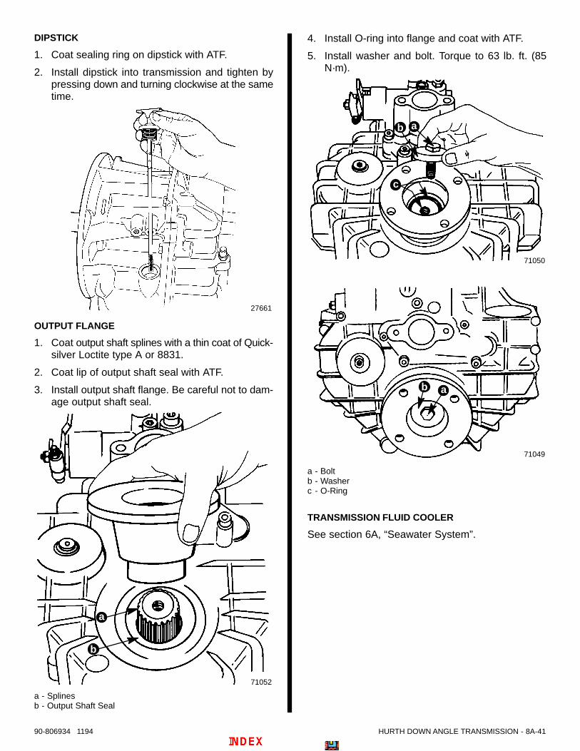
HURTH DOWN ANGLE TRANSMISSION - 8A-4190-806934 1194
DIPSTICK
1. Coat sealing ring on dipstick with ATF.
2. Install dipstick into transmission and tighten bypressing down and turning clockwise at the sametime.
27661
OUTPUT FLANGE
1. Coat output shaft splines with a thin coat of Quick-silver Loctite type A or 8831.
2. Coat lip of output shaft seal with ATF.
3. Install output shaft flange. Be careful not to dam-age output shaft seal.
71052
b
a
a - Splinesb - Output Shaft Seal
4. Install O-ring into flange and coat with ATF.
5. Install washer and bolt. Torque to 63 lb. ft. (85N·m).
71050
71049
b a
b
c
a
a - Boltb - Washerc - O-Ring
TRANSMISSION FLUID COOLER
See section 6A, “Seawater System”.

8A-42 - HURTH DOWN ANGLE TRANSMISSION 90-806934 1194
FILLING WITH TRANSMISSION FLUID
IMPORTANT: Use only ATF (Automatic Transmis-sion Fluid), such as Dexron II-D.
1. Fill transmission to proper level, through fluid filtercavity. (Refer to “Transmission Fluid Capacity”.)
2. Install filter as follows:
a. Align flat spot on filter with flat surface insideof housing.
b. Tighten filter by pushing down and turningclockwise at the same time.
27662
b
a
a - Filter Coverb - O-Ring
27666
a
a - Flat Spot
27666
3. Check fluid level. Fluid should be between min.and max. marks on dipstick.
27661

HURTH DOWN ANGLE TRANSMISSION - 8A-4390-806934 1194
Functional Test1. Connect a pressure gauge and thermometer to
fluid pump at locations shown.
50686
a - Pressure Gauge (M10x1 Thread) - Remove Plugb - Thermometer (3/8 In. Thread) - Remove Temperature
Sender
b
a
2. Perform functional tests as shown in chart follow-ing. Refer to “Operating Specifications” for cor-rect readings.
Tests to Be Carried Out:
1. Leakages
2. Noise emission
3. Direction of rotation, LH/RH
4. Fluid temperature
5. Shifting pressure
Engine Speed RPM Shift Lever Position Duration Minutes Tests
800-1000 Neutral 5 1 2
600-800 (Idle) A-B Position Repeatedly 1 2 3
1500-2500 B Position * 1 2 4
600-800 (Idle) A-B Position Repeatedly 1 2 3
Idling Max Speed A Position 1 2 5**
600-800 From A-B Position 1 2
Idling Max Speed B Position 1 2 5**
* Until fluid temperature of 167-176° F(75-80° C) has been reached**At different speeds

8
B
72959
DRIVE SYSTEMS
HURTH V-DRIVE TRANSMISSION
8B-0 - HURTH V-DRIVE TRANSMISSION 90-806934 1194
Table of ContentsPage
Identification 8B-1. . . . . . . . . . . . . . . . . . . . . . . . . . . . . . . . . . Torque Specifications 8B-1. . . . . . . . . . . . . . . . . . . . . . . . . . Specifications 8B-1. . . . . . . . . . . . . . . . . . . . . . . . . . . . . . . . . Tools/Lubricants/Sealants 8B-2. . . . . . . . . . . . . . . . . . . . . . Capacity 8B-2. . . . . . . . . . . . . . . . . . . . . . . . . . . . . . . . . . . . . General 8B-2. . . . . . . . . . . . . . . . . . . . . . . . . . . . . . . . . . . . . .
Shift Cable Installation and Adjustment 8B-3. . . . . . . . Checking Transmission Fluid Level 8B-7. . . . . . . . . . . . . . Draining Transmission 8B-7. . . . . . . . . . . . . . . . . . . . . . . . . Filling Transmission 8B-8. . . . . . . . . . . . . . . . . . . . . . . . . . . Transmission Removal 8B-9. . . . . . . . . . . . . . . . . . . . . . . . . Transmission Installation 8B-9. . . . . . . . . . . . . . . . . . . . . . . Transmission Repair 8B-10. . . . . . . . . . . . . . . . . . . . . . . . . .
Disassembly 8B-10. . . . . . . . . . . . . . . . . . . . . . . . . . . . . . Transmission Fluid Cooler 8B-10. . . . . . . . . . . . . . . Oil Filter and Dipstick 8B-10. . . . . . . . . . . . . . . . . . . Breather Valve 8B-11. . . . . . . . . . . . . . . . . . . . . . . . . Mounts 8B-11. . . . . . . . . . . . . . . . . . . . . . . . . . . . . . . . Output Flange 8B-12. . . . . . . . . . . . . . . . . . . . . . . . . . Control Block 8B-13. . . . . . . . . . . . . . . . . . . . . . . . . . Housing 8B-13. . . . . . . . . . . . . . . . . . . . . . . . . . . . . . . Bearing, Gear and Seal Inspection 8B-15. . . . . . . . Seals 8B-15. . . . . . . . . . . . . . . . . . . . . . . . . . . . . . . . . Tapered Roller Bearing Cups 8B-17. . . . . . . . . . . . . Tapered Roller Bearings 8B-18. . . . . . . . . . . . . . . . . Reversing Clutch, Gears and Tapered Roller Bearings 8B-18. . . . . . . . . . . . . . . . . . . . . . . . Clutch Discs 8B-20. . . . . . . . . . . . . . . . . . . . . . . . . . .
PageReassembly 8B-23. . . . . . . . . . . . . . . . . . . . . . . . . . . . . .
Clutch Discs 8B-23. . . . . . . . . . . . . . . . . . . . . . . . . . . Needle Bearings 8B-25. . . . . . . . . . . . . . . . . . . . . . . Gear Assembly 8B-26. . . . . . . . . . . . . . . . . . . . . . . . . Tapered Roller Bearing 8B-26. . . . . . . . . . . . . . . . . . Intermediate Shaft 8B-27. . . . . . . . . . . . . . . . . . . . . . Reversing Shaft 8B-27. . . . . . . . . . . . . . . . . . . . . . . . Preassembly of Output Half of Housing 8B-28. . . . Preassembly of Input Half of Housing 8B-31. . . . . Bearing Preload Adjustment 8B-31. . . . . . . . . . . . . Reversing Shaft Preload 8B-35. . . . . . . . . . . . . . . . . Output Shaft Preload 8B-35. . . . . . . . . . . . . . . . . . . .
Final Assembly 8B-38. . . . . . . . . . . . . . . . . . . . . . . . . . . . Input Shaft Seal 8B-38. . . . . . . . . . . . . . . . . . . . . . . . Control Block 8B-39. . . . . . . . . . . . . . . . . . . . . . . . . . Fluid Filter 8B-39. . . . . . . . . . . . . . . . . . . . . . . . . . . . . Dipstick 8B-40. . . . . . . . . . . . . . . . . . . . . . . . . . . . . . . Output Flange 8B-40. . . . . . . . . . . . . . . . . . . . . . . . . . Transmission Fluid Cooler 8B-40. . . . . . . . . . . . . . . Filling with Transmission Fluid 8B-41. . . . . . . . . . . .
Functional Test 8B-42. . . . . . . . . . . . . . . . . . . . . . . . . . . . . . .
8B - HURTH V-DRIVE TRANSMISSION 90-806934 1194

a
71039
HSW 630V – 1,5
Getr.-Nr.
iA = 1,56 iB = 1,58
MADE IN WEST-GERMANY
Late Style Identification Plate
A B
72959
HURTH V-DRIVE TRANSMISSION - 8B-190-806934 1194
IdentificationThe transmission identification plate is located on thetop rear of the transmission.
a - Transmission Identification Plate (Stating: Serial Number and Gear Ratio)
Torque Specifications
DESCRIPTIONTORQUE
DESCRIPTIONLb. Ft. N⋅m
TransmissionHousing HalvesBolts and Nuts
36 49
Control Block toHousing Bolts
18 25
Output Flange toOutput Shaft
63 85
Mounts 50 68
Transmission toFlywheel Housing
50 68
SpecificationsDESCRIPTION SPECIFICATION
Shifting Pressure 312-377 (2151-2599 kPa)
Operating Temperature 130° 200° F (54° - 93° C)

8B-2 - HURTH V-DRIVE TRANSMISSION 90-806934 1194
Tools/Lubricants/SealantsDESCRIPTION PART NUMBER
Tapered Roller BearingInner Race Puller
91-813950
Tapered Roller BearingOuter Race Puller
91-813951
Pressure Plate RemovalTool Reversing Clutch
91-813952
Tapered Roller BearingInner Race Puller Plate
91-813953
Mandrel-Input Shaft Seal 91-912955
Mandrel-Output Shaft Seal 91-813956
Preload Tool Input Shaft 91-813957
Preload Tool IntermediateShaft
91-813958
Quicksilver Loctite 8831 92-823089-1
Quicksilver Engine CouplerSpline Grease
91-816391A4
Quicksilver LiquidNeoprene
92-25711-2
Pressure Gauge (M10x1Thread)
Ob i L llLoctite 515 (Split-LIne)Sealer Obtain Locally
Thermometer (3/8 In.Thread 0-270° F) (–18-132° F)
Capacity
MODEL U.S. QTS.(LITRES)
630V V-Drive 5 (4.7)
NOTE: Always use dipstick to determine exact quan-tity of fluid required.
GeneralThe Hurth transmission is a “full power reversing”transmission, allowing a standard (LH rotation) en-gine to be used for both rotations. Propeller rotationis determined by shift cable attachment at the remotecontrol.
IMPORTANT: Transmission propeller rotation isdetermined by the shift cable installation in theremote control.
• RIGHT-HAND PROPELLER ROTATION - Con-trol cable will have to be installed in remote controlso that cable end will move in direction “A” whenshift handle is placed in the forward position.
• LEFT-HAND PROPELLER ROTATION - Controlcable will have to be installed in remote control sothat cable end will move in direction “B” when shifthandle is placed in the forward position.
23242

HURTH V-DRIVE TRANSMISSION - 8B-390-806934 1194
Shift Cable Installation andAdjustmentThese Hurth transmissions are full reversing trans-missions. Direction of output/propeller rotation isdetermined by hookup of shift cable at remotecontrol.
Shift cable must be hooked up to remote controlbefore starting installation and adjustment proce-dures.
For Right Hand Propeller Rotation – shift cablehookup at remote control must result in shift cableend guide moving in direction “A”, when remotecontrol handle is placed in forward position.
For Left Hand Propeller Rotation – shift cablehookup at remote control must result in shift cableend guide moving in direction “B”, when remotecontrol handle is placed in forward position.
23242
! WARNINGAvoid serious injury or property damage causedby improper shifting. Anchor stud for shift cablemust be installed in the correct hole.
1. Be certain anchor stud is installed in the lower,front hole as shown in the illustration following.
c
b
a
b
a
c
7358871020
a - Cable Bracketb - Shift Cable Anchor Stud Location (For Quicksilver Shift Cables)
Shift Cable Bracket - Anchor Stud PositionShown for 630V Transmission
IMPORTANT: Check that shift lever is positionedapproximately 10 ° aft of vertical when in the neu-tral detent position and that the distance (“c”)between studs in the following is set at 7-1/8 in.(318mm). If necessary, loosen clamping bolt andposition lever so that dimension “c” is as shownwhen in the neutral detent position and retightenbolt.
a
c
d
b
73587
a - Shift Leverb - Lever, in Neutral Detent, Must Be Approximately 10° Aft
of Verticalc - Dimension Between Studs - 7-1/8 in. (318mm)d - Clamping Bolt
Typical Hurth Transmission Shown
1. Place remote control shift lever, and transmis-sion shift lever, in neutral position.
2. Remove nuts and washers from shift cable at-taching studs.

8B-4 - HURTH V-DRIVE TRANSMISSION 90-806934 1194
3. Locate center of remote control and control shiftcable play (backlash), as follows:
a. Check that remote control is in neutral posi-tion.
b. Push in on control cable end with enoughpressure to remove play, and mark position“a” on tube.
c. Pull out on control cable end with enoughpressure to remove play, and mark position“b” on tube.
d. Measure distance between marks “a” and“b,” and mark position “c,” half-way betweenmarks “a” and “b.”
22024
c
b c
a
4. Center cable-end play, then adjust cable barrel toalign holes in barrel, and in cable end guide, withattaching points on transmission.
5. Temporarily install shift cable. Do not secure atthis time.
a
73587
Typical
IMPORTANT: Transmission is “fully” in gearwhen shift lever comes to a stop, in either direc-tion.
6. Place remote control shift lever in forward gearposition. Check to ensure transmission is fully ingear, as follows:
a. Hold shift lever in position.
b. Carefully slide shift cable off of anchor points.
c. Attempt to move shift lever further.
7. Place remote control shift lever in the reversegear position. Check that transmission is fully ingear, following same procedure.
8. If transmission shift lever will position properly inone gear, but not in the other, recheck shift cableadjustment. If transmission shift lever will notposition properly in both gears, move transmis-sion shift lever stud (a), from top hole in shiftlever, to bottom hole, and recheck for properpositioning. If proper positioning is still notobtained, remote control does not provide suffi-cient shift cable travel and must be replaced.
c
a
b
50228
a - Shift Lever Stud (In Bottom Hole, If Required)b - Lever, in Neutral Detent, Must Be Approximately 10° Aft
of Verticalc - Shift Lever Top Hole
9. Reattach locknut and washer to cable end guidestud. Tighten until snug, then back off one-halfturn.
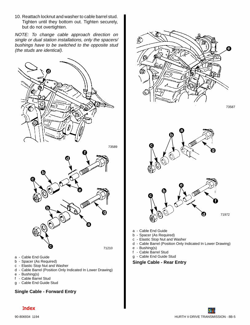
HURTH V-DRIVE TRANSMISSION - 8B-590-806934 1194
10. Reattach locknut and washer to cable barrel stud.Tighten until they bottom out. Tighten securely,but do not overtighten.
NOTE: To change cable approach direction onsingle or dual station installations, only the spacers/bushings have to be switched to the opposite stud(the studs are identical).
73589
71210
b
c
c
a
b
d
d
e
f
g
a - Cable End Guideb - Spacer (As Required)c - Elastic Stop Nut and Washerd - Cable Barrel (Position Only Indicated In Lower Drawing)e - Bushing(s)f - Cable Barrel Studg - Cable End Guide Stud
Single Cable - Forward Entry
73587
e
71972
ba
e
f
gc
d
bc
a - Cable End Guideb - Spacer (As Required)c - Elastic Stop Nut and Washerd - Cable Barrel (Position Only Indicated In Lower Drawing)e - Bushing(s)f - Cable Barrel Studg - Cable End Guide Stud
Single Cable - Rear Entry

8B-6 - HURTH V-DRIVE TRANSMISSION 90-806934 1194
73590
71211
CABLEBARRELSTUD
CABLEEND GUIDESTUD
b
a
b
c
e
d
e
g
f
a - Cable End Guidesb - Locknut and Washer (Tighten Until Bottomed, Then BackOff
One Full Turn)c - Spacer (Fits over Stud)d - Bushingse - Cable Barrels[Position(s) Only Indicated In Lower Drawing]f - Cable Barrel Studg - Cable End Guide Stud
Dual Cable - Forward Entry
73591
e
50073
b
d
a
c
f
g
e
a - Cable End Guide(s)b - Spacerc - Elastic Stop Nut and Washerd - Bushing(s)e - Cable Barrel(s) [Position(s) Only Indicated In Lower
Drawing]f - Cable Barrel Studg - Cable End Guide Stud
Dual Cable - Rear Entry

HURTH V-DRIVE TRANSMISSION - 8B-790-806934 1194
Checking TransmissionFluid LevelIMPORTANT: Use only specified transmissionfluid (see “Lubricants/Sealants”).
Check transmission fluid before starting engine eachday, as follows:
1. Remove dipstick. Check fluid level as indicatedon dipstick. Fluid level may be somewhat over fullmark, as some of the fluid from transmission fluidcooler and hoses may have drained back intotransmission. If low, add transmission fluid tobring level up to full mark on dipstick.
27661
Typical Hurth Transmission Shown
IMPORTANT: To accurately check fluid level, en-gine must be run at 1500 RPM for two minutes im-mediately prior to checking level.
2. Start engine and run at 1500 RPM for two minutesto fill all hydraulic circuits.
IMPORTANT: Be sure to push dipstick all the waydown into dipstick tube when checking fluid lev-el.
3. Stop engine and quickly check fluid level. Addautomatic transmission fluid, if necessary, tobring level up to full mark on dipstick. (Refer to“Filling Transmission,” following.)
4. Reinstall dipstick.
5. If transmission fluid level was extremely low,carefully check transmission, fluid cooler andhoses for leaks.
Draining Transmission1. Clean the exterior of transmission before disas-
sembly.
2. Remove oil filter from housing by turning (coun-terclockwise) and pulling at the same time.
27666
3. Remove drain plug from transmission and allowfluid to drain. Reinstall drain plug and tighten se-curely.
73013
a - Drain Plug
a

8B-8 - HURTH V-DRIVE TRANSMISSION 90-806934 1194
Filling TransmissionIMPORTANT: Use only Automatic TransmissionFluid (ATF) as recommended in “Tool/Lubricants/Sealants.”
1. Fill transmission to proper level, through oil filtercavity. (Refer to “Capacity.”)
2. Install filter as follows:
a. Coat O-ring on filter cover with transmissionfluid.
27662
b
a
a - Filter Coverb - O-Ring
! CAUTIONTransmission fluid filter and cover must be prop-erly seated to avoid fluid foaming and/or loss offluid, thus resulting in decreased efficiency and/or damage to transmission.
b. Push down until cover is fully seated (top ofcover flush with housing), then, Turn T-handleclockwise until tight.
27666
3. Start engine and run for two minutes to fill systemwith fluid.
4. Stop engine and check fluid level. Fluid should bebetween min. and max. lines on dipstick.
27661
Typical Hurth Transmission Shown

HURTH V-DRIVE TRANSMISSION - 8B-990-806934 1194
Transmission Removal1. Disconnect wires from neutral safety switch and
audio warning temperature switch.
2. Disconnect fluid cooler hoses. Appropriately la-bel hose “Port” and “Starboard”.
50686
a - Pressure Gauge (M10x1 Thread) - Remove Plugb - Thermometer (3/8 In. Thread) - Remove Temperature
Senderc - Fluid Cooler Hoses
b
a
c c
3. Remove bolts and locknuts and remove transmis-sion.
72720
b
a
a - Bolts (2), One On Each Sideb - Locknuts (4), Two On Each Side
Transmission Installation1. Coat splines on input shaft with Quicksilver En-
gine Coupler Spline Grease.
71044
a
a - Input Shaft
2. Install transmission on flywheel housing and se-cure with hardware shown. Torque fasteners to50 lb. ft. (68 N•m).
72720
b
a
a - Bolts (2), One On Each Sideb - Locknuts (4), Two On Each Side

8B-10 - HURTH V-DRIVE TRANSMISSION 90-806934 1194
3. Connect wires to neutral safety switch and to au-dio warning temperature switch. Coat connec-tions on neutral safety switch with Quicksilver Liq-uid Neoprene.
50686
b
a
a - Neutral Safety Switchb - Audio Warning Temperature Switchc - Fluid Cooler Hoses
c c
Transmission Repair
DisassemblyIMPORTANT: Ensure work area is clean beforedisassembly is started. Be sure to use lint freecloths when cleaning and/or handling parts.
TRANSMISSION FLUID COOLER
See section 6A, “Sea Water System”.
OIL FILTER AND DIPSTICK
1. Remove oil filter from housing by turning (coun-terclockwise) and pulling at the same time.
27666
2. Remove cover and filter element from transmis-sion.
27662
3. Remove filter element from cover and inspectO-rings for wear. Replace if necessary.
50975
a
a - O-Rings
4. Remove drain plug from transmission and allowfluid to drain. Reinstall drain plug and tighten se-curely.
73013
a - Drain Plug
a

HURTH V-DRIVE TRANSMISSION - 8B-1190-806934 1194
5. Remove dipstick by turning (counterclockwise)and pulling at the same time.
27661
6. Inspect seal for wear and replace if necessary.
27659
a
a - Seal
BREATHER VALVE
1. Remove breather valve. Clean with suitablecleaner, allow to dry and coat with oil.
71048
a
a - Breather Valve
MOUNTS
1. Remove mounts from transmission housing. In-spect mounts for damage and replace if neces-sary.
72711
a
b
a - Transmission Mountb - Retaining Screws (4 Total on Each Mount - One Hidden In
This View)

8B-12 - HURTH V-DRIVE TRANSMISSION 90-806934 1194
OUTPUT FLANGE
1. Remove four bolts as shown and loosen but DONOT remove four remaining bolts. Install flangepuller plate on output flange and secure with boltsand nuts.
73015
73014
b
c
a
b
d
a - Bolts - Removeb - Bolts - Loosen (DO NOT Remove)c - Flange Puller Plated - Bolts and Nuts
2. Turn four remaining bolts out until they just con-tact flange puller plate. Then continue to turn boltsout evenly (to push on puller plate) to removeflange.
73017
73016
c
a
b
a - Hex Wrenchb - Flangec - Flange Puller Plate

HURTH V-DRIVE TRANSMISSION - 8B-1390-806934 1194
CONTROL BLOCK
1. Remove hex head bolts.
27661
a
a - Hex Socket Head Bolts (6)
2. Remove control block and gasket from housing.
27666
! CAUTIONBe careful not to allow dirt to enter control blockfrom front side.
3. Cover openings in control block with a protectivecloth.
27665
a
a - Openings
HOUSING
1. Remove hex head bolts from input side of hous-ing.
73018
a
a - Hex Bolts (16)

8B-14 - HURTH V-DRIVE TRANSMISSION 90-806934 1194
2. Remove input side of housing. Be sure to locateand save locator pins.
73019
a - Locator Pins
a
3. Remove input shaft assembly.
73020
4. Remove intermediate shaft assembly.
73021
5. Remove reversing shaft assembly.
73022

HURTH V-DRIVE TRANSMISSION - 8B-1590-806934 1194
6. Remove output shaft assembly.
73023
BEARING, GEAR AND SEAL INSPECTION
1. Inspect all tapered roller bearings, the pistonrings on the input shaft and all gears for wear. Ifdamage has been found on the gearing of the in-termediate or output shaft, it is ALWAYS neces-sary to replace the complete shaft.
When gears on the input shaft have to be re-placed, the tapered roller bearings and needlebearings MUST BE replaced as well.
2. Turn gears of input shaft to check correct opera-tion of the reversing clutch. If it is hard to turn thegears, the clutch is probably damaged.
SEALS
1. Remove suction pipe seal as follows:
27666
a
a - Seal
a. Bend tabs up away from screws.
73024
a
a - Tabs

8B-16 - HURTH V-DRIVE TRANSMISSION 90-806934 1194
b. Remove screws and hold down plate.
c. Remove suction pipe by pulling downward outof seal.
73025
a - Screwsb - Hold Down Plate
b
a
d. Remove seal from top side.
27660
a
a - Seal
2. Remove input shaft seal using appropriate man-drel.
27670
a
a - Seal
3. Remove output shaft seals using appropriatemandrel.
73026
a - Seals
73027
a
a
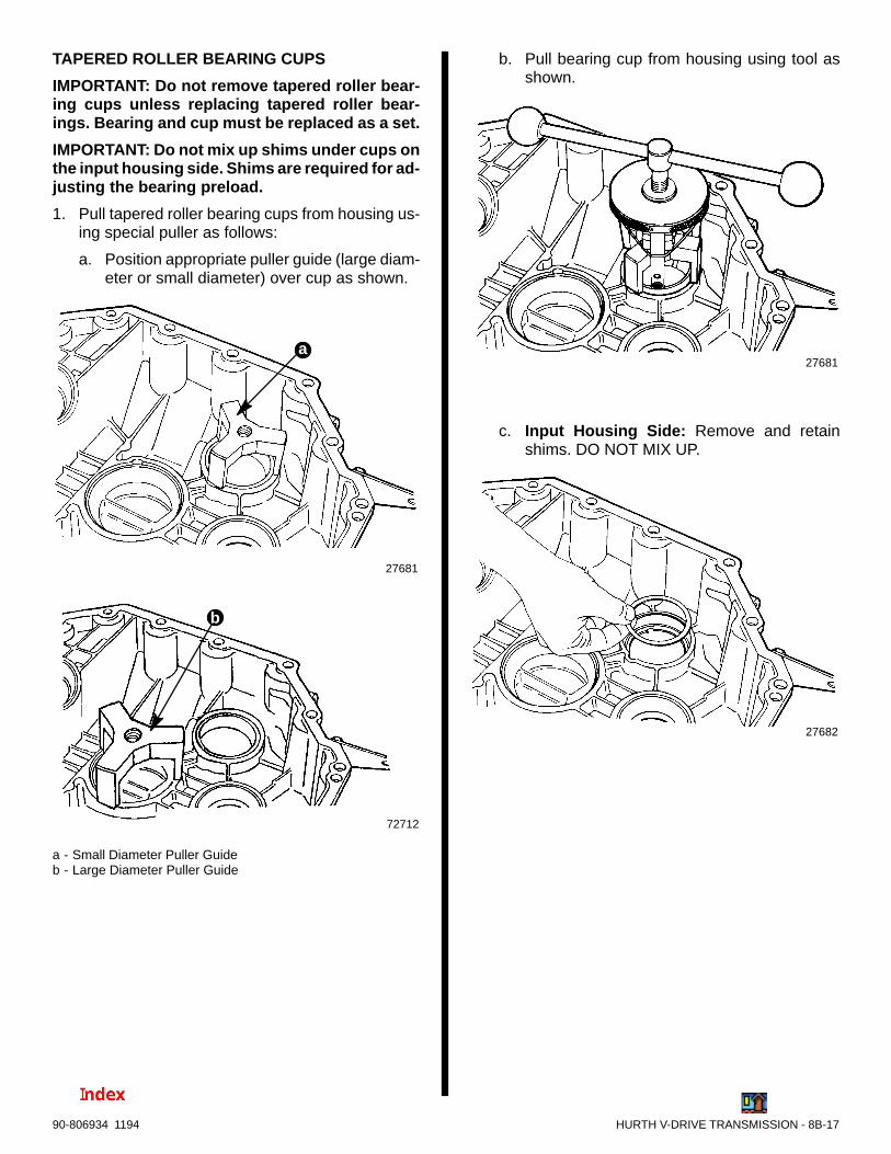
HURTH V-DRIVE TRANSMISSION - 8B-1790-806934 1194
TAPERED ROLLER BEARING CUPS
IMPORTANT: Do not remove tapered roller bear-ing cups unless replacing tapered roller bear-ings. Bearing and cup must be replaced as a set.
IMPORTANT: Do not mix up shims under cups onthe input housing side. Shims are required for ad-justing the bearing preload.
1. Pull tapered roller bearing cups from housing us-ing special puller as follows:
a. Position appropriate puller guide (large diam-eter or small diameter) over cup as shown.
27681
72712
a
b
a - Small Diameter Puller Guideb - Large Diameter Puller Guide
b. Pull bearing cup from housing using tool asshown.
27681
c. Input Housing Side: Remove and retainshims. DO NOT MIX UP.
27682
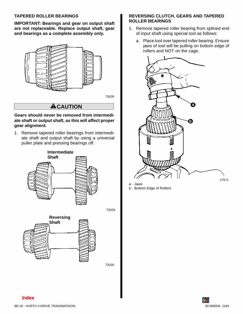
8B-18 - HURTH V-DRIVE TRANSMISSION 90-806934 1194
TAPERED ROLLER BEARINGS
IMPORTANT: Bearings and gear on output shaftare not replaceable. Replace output shaft, gearand bearings as a complete assembly only.
73028
! CAUTIONGears should never be removed from intermedi-ate shaft or output shaft, as this will affect propergear alignment.
1. Remove tapered roller bearings from intermedi-ate shaft and output shaft by using a universalpuller plate and pressing bearings off.
73030
73029
IntermediateShaft
ReversingShaft
REVERSING CLUTCH, GEARS AND TAPEREDROLLER BEARINGS
1. Remove tapered roller bearing from splined endof input shaft using special tool as follows:
a. Place tool over tapered roller bearing. Ensurejaws of tool will be pulling on bottom edge ofrollers and NOT on the cage.
27671
b
a
a - Jawsb - Bottom Edge of Rollers
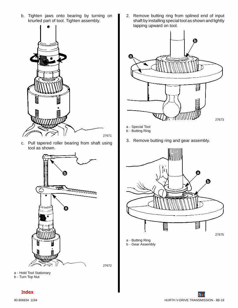
HURTH V-DRIVE TRANSMISSION - 8B-1990-806934 1194
b. Tighten jaws onto bearing by turning onknurled part of tool. Tighten assembly.
27671
c. Pull tapered roller bearing from shaft usingtool as shown.
27672
b
a
a - Hold Tool Stationaryb - Turn Top Nut
2. Remove butting ring from splined end of inputshaft by installing special tool as shown and lightlytapping upward on tool.
27673
a
b
a - Special Toolb - Butting Ring
3. Remove butting ring and gear assembly.
27675
b
a
a - Butting Ringb - Gear Assembly

8B-20 - HURTH V-DRIVE TRANSMISSION 90-806934 1194
4. Remove needle bearings.
27680
5. Remove piston rings from shaft.
27679
6. Remove tapered roller bearing, butting ring andgear from piston end of shaft using special tool asshown. Press all components off at the sametime. Then, remove needle bearings.
27673
CLUTCH DISCS
NOTE: Discs on both sides of clutch are removed inthe same manner.
IMPORTANT: Reference marks are placed on theclutch housing and end disc to aid in locating thesnap ring opening.
27675
a
a - Reference Marks

HURTH V-DRIVE TRANSMISSION - 8B-2190-806934 1194
1. Position snap ring compression tool on clutch as-sembly so that compression screws are centeredover slots in clutch housing.
2. Remove end disc and snap ring as follows:
a. Tighten all compression screws until a slightresistance is felt.
b. Tighten compression screws evenly (approxi-mately 1/2 turn at a time).
c. Tap up lightly on bottom edge of compressiontool until snap ring pops up and out of groovein clutch housing.
27674
b
c
a
a - Snap Ring Compression Toolb - Compression Screws (6)c - Slots
27675
NOTE: For ease of reassembly, end disc and snapring should not be removed from tool unless their con-dition is questionable.
27676
a
a - End Disc (Snap Ring Compressed)
d. If necessary, remove end disc and snap ringfrom tool.
27676
ba
a - End Discb - Snap Ring
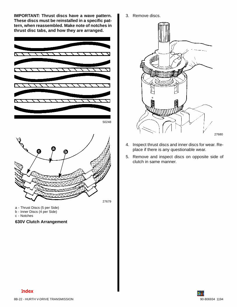
8B-22 - HURTH V-DRIVE TRANSMISSION 90-806934 1194
IMPORTANT: Thrust discs have a wave pattern.These discs must be reinstalled in a specific pat-tern, when reassembled. Make note of notches inthrust disc tabs, and how they are arranged.
50248
27679
bca
630V Clutch Arrangement
a - Thrust Discs (5 per Side)b - Inner Discs (4 per Side)c - Notches
3. Remove discs.
27680
4. Inspect thrust discs and inner discs for wear. Re-place if there is any questionable wear.
5. Remove and inspect discs on opposite side ofclutch in same manner.

HURTH V-DRIVE TRANSMISSION - 8B-2390-806934 1194
Reassembly
CLUTCH DISCS
IMPORTANT: Thrust discs have a wave pattern.These discs must be reinstalled in a specific man-ner as explained following.
50248
1. Arrange thrust discs and inner discs as shown.Ensure notches on thrust disc tabs are aligned asshown.
27679
bca
a - Thrust Discs (5 per Side) b - Inner Discs (4 per Side) c - Notches
630V Clutch Arrangement
2. Install discs in clutch housing.
27680
3. Align snap ring opening with reference marks onend disc and clutch housing.
27678b
a
b
a - Snap Ring Openingb - Reference Marks
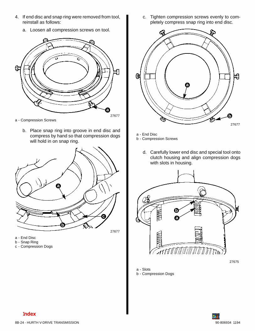
8B-24 - HURTH V-DRIVE TRANSMISSION 90-806934 1194
4. If end disc and snap ring were removed from tool,reinstall as follows:
a. Loosen all compression screws on tool.
27677
a
a - Compression Screws
b. Place snap ring into groove in end disc andcompress by hand so that compression dogswill hold in on snap ring.
27677
b
c
a
a - End Discb - Snap Ringc - Compression Dogs
c. Tighten compression screws evenly to com-pletely compress snap ring into end disc.
27677
b
a
a - End Discb - Compression Screws
d. Carefully lower end disc and special tool ontoclutch housing and align compression dogswith slots in housing.
27675
b
a
a - Slotsb - Compression Dogs

HURTH V-DRIVE TRANSMISSION - 8B-2590-806934 1194
5. Tap lightly around top of tool until end disc bot-toms. Loosen compression screws and removetool.
27675
27678
6. Double check that snap ring has been properlyseated by prying up lightly on end disc.
27679
7. Reinstall discs on opposite side of clutch in samemanner.
NEEDLE BEARINGS
1. Reinstall needle bearings.
27680

8B-26 - HURTH V-DRIVE TRANSMISSION 90-806934 1194
GEAR ASSEMBLY
1. Reinstall gear assembly. Twist gear assemblyfrom side to side to allow splines to engage withinner discs. Ensure all inner discs are engagedwith splines by observing through slots in clutchhousing.
27673
2. Reinstall butting ring.
27672
TAPERED ROLLER BEARING
! WARNINGDo not touch bearing once it has been heated. Severeburns could result. Use special protective gloves tohandle bearing.
1. Heat inner race of tapered roller bearing using atorch lamp and press bearing onto shaft. Whenbearing has cooled down (DO NOT cool with wa-ter), tap bearing carefully down to ensure properseating against butting ring, using a soft (copper)punch. Tap on inner race only.
27674
b
a
a - Tapered Roller Bearingb - Butting Ring
2. Install components on opposite side of clutch as-sembly in same manner.

HURTH V-DRIVE TRANSMISSION - 8B-2790-806934 1194
! CAUTIONUse care in reinstalling piston rings on inputshaft. Piston rings are brittle and may snap ifspread too far open.
3. Reinstall piston rings on input shaft. Ensure endsof rings are coupled as shown. Then positionrings so that ends are staggered so no two arealigned.
27679
INTERMEDIATE SHAFT
! WARNINGDo not touch bearing once it has been heated. Severeburns could result. Use special protective gloves tohandle bearing.
1. Heat inner race of tapered roller bearing using atorch lamp and press bearing onto shaft. Whenbearing has cooled down (DO NOT cool with wa-ter), tap bearing carefully down to ensure properseating against gear, using a soft (copper) punch.Tap on inner race only.
73029
2. Install tapered roller bearing on opposite end ofshaft in the same manner.
REVERSING SHAFT
! WARNINGDo not touch bearing once it has been heated. Severeburns could result. Use special protective gloves tohandle bearing.
1. Heat inner race of tapered roller bearing using atorch lamp and press bearing onto shaft. Whenbearing has cooled (DO NOT cool with water),drive bearing down against gear using a soft (cop-per) punch. Tap on inner race only .
73030
2. Install tapered roller bearing on opposite end ofshaft in the same manner.
NOTE: Bearing on splined end of shaft is tapped untilseated against shoulder on shaft.

8B-28 - HURTH V-DRIVE TRANSMISSION 90-806934 1194
PREASSEMBLY OF OUTPUT HALF OFHOUSING
IMPORTANT: If tapered roller bearing cups wereremoved, ensure output shaft seal IS NOT inplace, as it will be necessary to heat housing priorto installing bearing cups.
IMPORTANT: The tapered roller bearing cup onthe input shaft (control block end) is properly po-sitioned by bottoming out on the face of the con-trol block assembly. It will be necessary to tempo-rarily install control block to install this taperedroller bearing cup.
1. Temporarily install control block on outer housing.Tighten bolts securely.
27682
27666
b
a
a
a - Input Shaft Bearing Cupb - Control Block Face
! WARNINGUse care in handling housing, once it is heated withtorch lamp. Severe burns could result. Use specialprotective gloves when handling housing.
2. Heat bearing bores of housing using a torch lampand install bearing cups using a suitable mandrel.
27681
b
a
a - Bearing Cupsb - Torch Lamp
3. Allow housing to cool (DO NOT cool with water)and then tap bearing cup with suitable mandrel toensure it is properly seated.
4. Remove control block assembly.

HURTH V-DRIVE TRANSMISSION - 8B-2990-806934 1194
Output Shaft Seal
1. If bearing were not replaced and no shimmingis required, push new seal onto special mandrel.Ensure seal will be positioned with lip of seal fac-ing inward. Drive seal uniformly into bore of hous-ing to the point that it is countersunk .040 in. (1mm) with reference to housing surface.
73027
a
a - Seal
Suction Pipe
1. Reinstall suction pipe seal in bottom of oil filterbore. Coat seal with ATF.
27660
a
a - Seal
2. Reinstall suction pipe. Place one drop of Loctite8831 or Type A on screw threads. Then securesuction pipe down with retainer plate. Tightenscrews securely.
3. Bend tabs down over screws.
73025

8B-30 - HURTH V-DRIVE TRANSMISSION 90-806934 1194
Shafts
1. Coat tapered roller bearings with ATF.
2. Install output shaft.
73023
3. Install reversing shaft.
73022
4. Install intermediate shaft.
73021
5. Install input shaft. Ensure all gears mesh asshown.
73020
73031

HURTH V-DRIVE TRANSMISSION - 8B-3190-806934 1194
PREASSEMBLY OF INPUT HALF OF HOUSING
1. Install breather valve (do not over-tighten).
71048
a
a - Breather Valve
BEARING PRELOAD ADJUSTMENT
IMPORTANT: If new tapered roller bearings havebeen installed, the preload must be readjusted. Ifbearings were not replaced, proceed to the “FinalAssembly.”
NOTE: The required preload of bearings of the indi-vidual shafts is obtained by using shims beneath thetapered roller bearing cups in the input half of thehousing.
NOTE: Shims which have been removed during dis-assembly may be reused.
1. Subtract approximately .008 in. (.2 mm) of shimsfrom each bearing cup bore. Remove and setaside, but do not mix up.
! WARNINGUse care in handling housing once it has been heatedwith a torch lamp. Severe burns could result. Use spe-cial protective gloves when handling housing.
2. Heat each tapered roller bearing cup bore with atorch lamp. Insert shims (less those removed)and bearing cups into appropriate bearing bores.When housing has cooled (DO NOT cool with wa-ter), tap bearing cups with a suitable mandrel toensure that cups are fully seated.
27681
a
a - Torch Lamp
73032
a - Bearing Cups
a

8B-32 - HURTH V-DRIVE TRANSMISSION 90-806934 1194
3. Install input half of housing onto output half. En-sure locator pins are in place. Install bolts andlockwashers and torque to 36 lb. ft. (49 N·m).
73033
a - Bolts and Lockwashers
Input Shaft Preload
1. Measure bearing clearance as follows:
a. Install special tool as shown. Tighten holddown bolts securely.
27863
b
a
a - Special Toolb - Hold Down Bolts
b. Mount dial indicator on input shaft. Turn inputshaft several times to seat bearing.
27685
c. Zero the dial indicator.
27685
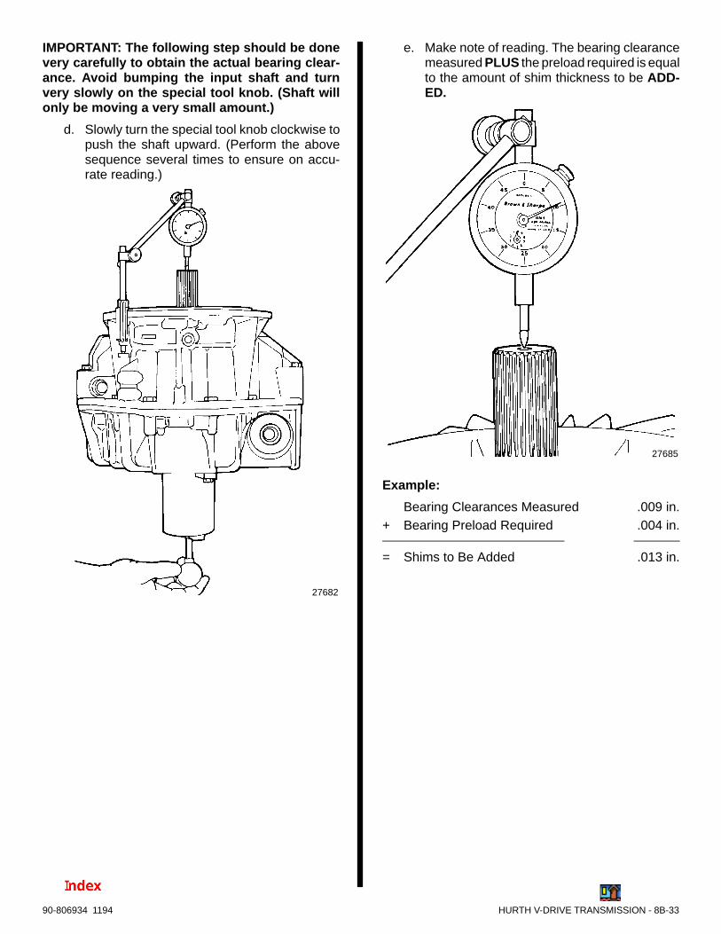
HURTH V-DRIVE TRANSMISSION - 8B-3390-806934 1194
IMPORTANT: The following step should be donevery carefully to obtain the actual bearing clear-ance. Avoid bumping the input shaft and turnvery slowly on the special tool knob. (Shaft willonly be moving a very small amount.)
d. Slowly turn the special tool knob clockwise topush the shaft upward. (Perform the abovesequence several times to ensure on accu-rate reading.)
27682
e. Make note of reading. The bearing clearancemeasured PLUS the preload required is equalto the amount of shim thickness to be ADD-ED.
27685
Example:
Bearing Clearances Measured .009 in.+ Bearing Preload Required .004 in.
= Shims to Be Added .013 in.
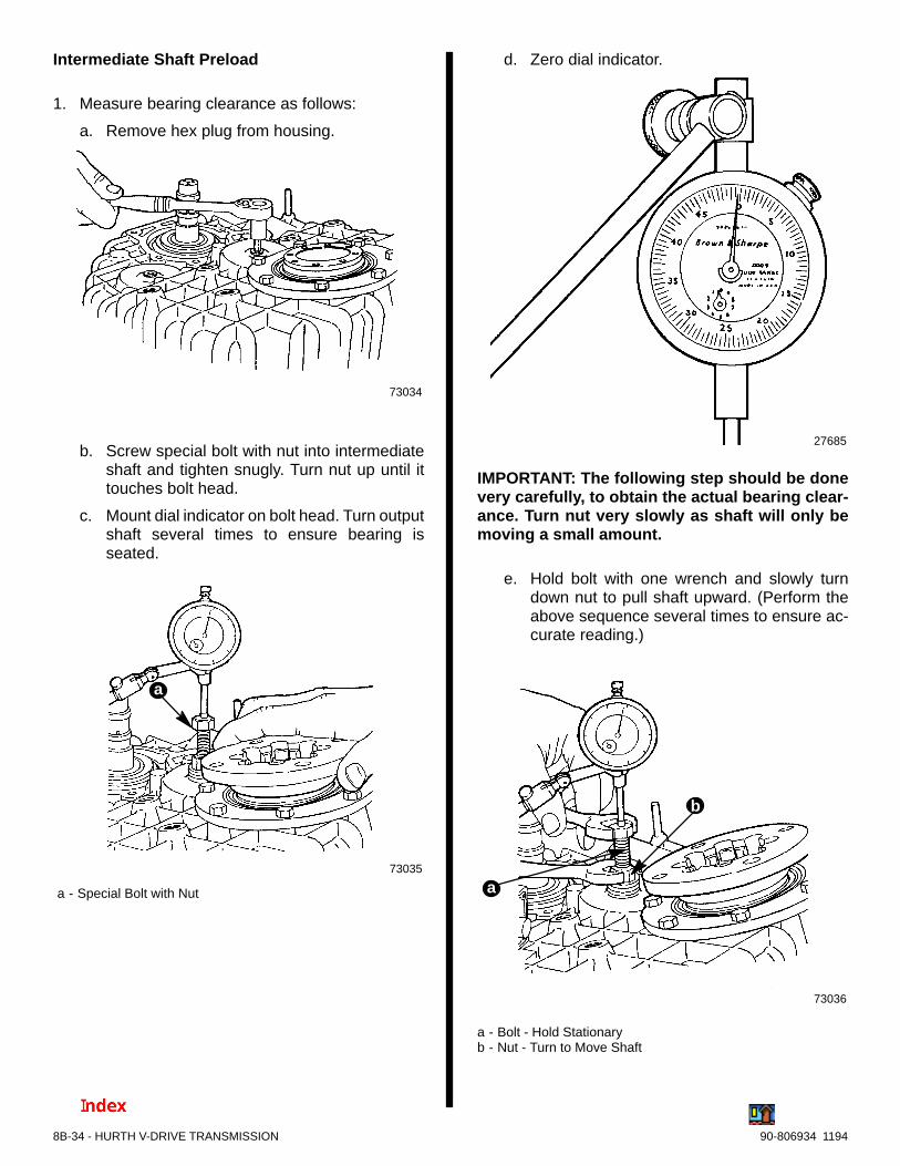
8B-34 - HURTH V-DRIVE TRANSMISSION 90-806934 1194
Intermediate Shaft Preload
1. Measure bearing clearance as follows:
a. Remove hex plug from housing.
73034
b. Screw special bolt with nut into intermediateshaft and tighten snugly. Turn nut up until ittouches bolt head.
c. Mount dial indicator on bolt head. Turn outputshaft several times to ensure bearing isseated.
73035
a
a - Special Bolt with Nut
d. Zero dial indicator.
27685
IMPORTANT: The following step should be donevery carefully, to obtain the actual bearing clear-ance. Turn nut very slowly as shaft will only bemoving a small amount.
e. Hold bolt with one wrench and slowly turndown nut to pull shaft upward. (Perform theabove sequence several times to ensure ac-curate reading.)
73036
b
a
a - Bolt - Hold Stationaryb - Nut - Turn to Move Shaft

HURTH V-DRIVE TRANSMISSION - 8B-3590-806934 1194
f. Make note of the reading. The bearing clear-ance measured PLUS the preload required isequal to the amount of shim thickness to beADDED.
27686
Example:
Bearing Clearance Measured .007 in.+ Bearing Preload Required .004 in.
= Shims to Be Added .011 in.
g. Remove dial indicator, special bolt and nut,and reinstall hex plug. Tighten securely.
REVERSING SHAFT PRELOAD
The reversing shaft preload is adjusted exactly thesame as the intermediate shaft. Refer to that proce-dure for adjusting reversing shaft.
73037
a - Reversing Shaft Locationb - Intermediate Shaft Location
ba
OUTPUT SHAFT PRELOAD
1. Measure the bearing clearance as follows:
a. Install flange with bolts and washers. Tightensnugly.
b. Mount dial indicator on flange. Turn outputshaft several times to ensure bearing isseated.
73038
a
a - Flange
c. Zero dial indicator.
27685

8B-36 - HURTH V-DRIVE TRANSMISSION 90-806934 1194
IMPORTANT: The following step should be donevery carefully to obtain the actual bearing clear-ance. Pry up gently and evenly to lift shaft. Shaftwill only move a small amount.
d. Pry up on flange to lift output shaft.
73039
e. Make note of the reading. The bearing clear-ance measured PLUS the preload required isequal to the amount of shim thickness to beADDED.
27686
Example:
Bearing Clearance Measured .010 in.+ Bearing Preload Required .004 in.
= Shims to Be Added .014 in.
2. When thickness of shims to be ADDED has beendetermined, the input half of housing must againbe removed. Remove bolts and lockwashers,then lift off input half of housing.
73018
a - Hex Bolts (16)
a
3. Remove tapered roller bearing cups from housingusing special puller as follows:
a. Position appropriate puller guide (large orsmall diameter) over cup as shown.
27681
a
a - Small Diameter Puller Guide
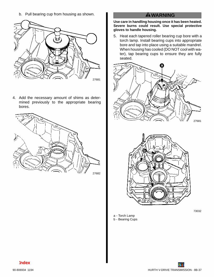
HURTH V-DRIVE TRANSMISSION - 8B-3790-806934 1194
b. Pull bearing cup from housing as shown.
27681
4. Add the necessary amount of shims as deter-mined previously to the appropriate bearingbores.
27682
! WARNINGUse care in handling housing once it has been heated.Severe burns could result. Use special protectivegloves to handle housing.
5. Heat each tapered roller bearing cup bore with atorch lamp. Install bearing cups into appropriatebore and tap into place using a suitable mandrel.When housing has cooled (DO NOT cool with wa-ter), tap bearing cups to ensure they are fullyseated.
73032
a
27681
b
a - Torch Lampb - Bearing Cups

8B-38 - HURTH V-DRIVE TRANSMISSION 90-806934 1194
Final Assembly
INPUT SHAFT SEAL
1. Push new seal onto special mandrel. Ensure sealwill be positioned with lip of seal facing inward.
Drive seal uniformly into bore of housing to thepoint that it is countersunk .040 in. (1 mm) with ref-erence to housing surface.
27670
IMPORTANT: Transmissions with 2.0 or 2.5 GearRatios - The input shaft seal should not be in-stalled until after the input shaft is installed andhousing halves have been joined. (The inputshaft must be tilted in order to install the othershafts and this could damage the seal.)
73040
a - Input Shaftb - Seal
b
a
2. Coat lips of seals on input and output shafts withATF.
3. Apply a thin layer of Loctite 515 Sealer to ma-chined surfaces on housing halves. Reinstall in-put half of housing. Ensure locator pins are prop-erly positioned.
73019
ba
a - Locator Pinsb - Machined Surface
4. Install bolts and lockwashers and torque to 36 lb.ft. (49 N·m).
73033

HURTH V-DRIVE TRANSMISSION - 8B-3990-806934 1194
5. Double check to ensure that there is no shaftclearance on all three shafts. Refer back to pre-vious steps if necessary, and use dial indicator.
6. Remove intermediate shaft hex plug. Apply adrop of Quicksilver Loctite 8831 or Type A tothreads and reinstall in housing. Tighten securely.
73041
CONTROL BLOCK
1. Ensure piston rings are in place and the key is inkeyway. Align key on shaft with keyway in controlblock.
2. Install new gasket between control block andhousing.
27666
b
a
a - Keyb - Piston Rings
3. Carefully push control block onto input shaft.
4. Coat each hex socket head bolt with a drop ofQuicksilver Loctite 8831 or Type A. Secure con-trol block to housing with bolts and lockwashers.Torque to 18 lb. ft. (25 N·m).
27661
a
a - Hex Socket Head Bolts (6)
FLUID FILTER
1. Coat new O-rings with ATF.
50975
a
a - O-Rings

8B-40 - HURTH V-DRIVE TRANSMISSION 90-806934 1194
2. Reassemble filter assembly as shown. DO NOTtighten and compress upper O-ring.
72805
a - O-Ring
a
DIPSTICK
1. Coat sealing ring on dipstick with ATF.
2. Install dipstick into transmission and tighten bypressing down and turning clockwise at the sametime.
73042
OUTPUT FLANGE
1. Install locator pins into output shaft.
73017
a - Locator Pins (4)
a
a
2. Install flange on output shaft. Apply Loctite 8831or Type A to threads of bolts and torque to 14 lb.ft. (18 N·m).
73013
b
a
a - Flangeb - Bolts (8)
TRANSMISSION FLUID COOLER
See section 6A, “Sea Water System”.

HURTH V-DRIVE TRANSMISSION - 8B-4190-806934 1194
FILLING WITH TRANSMISSION FLUID
IMPORTANT: Use only ATF (Automatic Transmis-sion Fluid), such as Dexron II-D.
1. Fill transmission to proper level, through fluid filtercavity. (Refer to “Capacity.”)
2. Install filter as follows:
a. Bring flat spot on filter into agreement with flatsurface inside of housing.
b. Tighten filter by pushing down and turningclockwise at the same time.
27662
b
a
a - Filter Coverb - O-Ring
27666
a
a - Flat Spot
27666
3. Check fluid level. Fluid should be between min.and max. marks on dipstick.
27661

8B-42 - HURTH V-DRIVE TRANSMISSION 90-806934 1194
Functional Test1. Connect a pressure gauge and thermometer to fluid pump at locations shown.
50686
a - Pressure Gauge (M10x1 Thread) - Remove Plugb - Thermometer (3/8 In. Thread) - Remove Temperature
Sender
b
a
2. Perform functional tests as shown in chart following. Refer to “Specifications” for correct readings.
Tests to Be Carried Out:1. Leakages
2. Noise emission
3. Direction of rotation, LH/RH
4. Fluid temperature
5. Shifting pressure
Engine Speed RPM Shift Lever Position Duration Minutes Tests
800-1000 Neutral 5 1 2
600-800 (Idle) A-B Position Repeatedly 1 2 3
1500-2500 B Position * 1 2 4
600-800 (Idle) A-B Position Repeatedly 1 2 3
Idling Max Speed A Position 1 2 5**
600-800 From A-B Position 1 2
Idling Max Speed B Position 1 2 5**
* Until fluid temperature of 167-176° F(75-80° C) has been reached
**At different speeds

8
C
DRIVE SYSTEMS
PROPELLER SHAFT MODELS

8C-0 - PROPELLER SHAFT MODELS 90-806934 1194
Table of ContentsPage
Torque Specifications 8C-1. . . . . . . . . . . . . . . . . . . . . Tools/Lubricants/Sealants 8C-1. . . . . . . . . . . . . . . . . Propeller Shaft (MIE Model) 8C-1. . . . . . . . . . . . . . .
Checks Made with Boat In Water 8C-1. . . . . . . . Checks Made with Boat Out of Water and Shaft Installed 8C-2. . . . . . . . . . . . . . . . . . . . Checks Made with Propeller Shaft Removed from Boat 8C-3. . . . . . . . . . . . . . . . . . . . Strut 8C-3. . . . . . . . . . . . . . . . . . . . . . . . . . . . . . . . .
8C – PROPELLER SHAFT MODELS
PROPELLER SHAFT MODELS – 8C-190-806934 1194
Torque Specifications
DESCRIPTIONTORQUE
DESCRIPTIONLb. Ft. N⋅m
Propeller Shaft Coupling to Coupling Housing(MIE Model)
50 68
Coupling Set Screws (If so equipped) Securely (See NOTE. )
NOTE: Safety wire set screws if so equipped
Tools/Lubricants/SealantsDESCRIPTION PART NUMBER
Quicksilver 2-4-C Marine Lubricant 92-86154A1
Quicksilver Engine Coupler Spline Grease 92-8166391A4
Quicksilver Loctite 8831 92-823089--1
Loctite 290 Obtain Locally
Propeller Shaft (MIE Model)
The following information can be used as a guide for determining vibration problems on boats pow-ered by inboard engines (MIE Engines). For installation, alignment and repairs to shafts,struts,shaftlogs and rudders, refer to boat manufacturer’s service manual. If boat is equipped with V-Drive or aremote mounted V-Drive refer to boat manufacturer’s service manual. For MIE engine installation andalignment, refer to SECTION 2, of this handbook.
NOTICE
Checks Made with Boat In Water1. Disconnect propeller shaft coupling from trans-
mission coupling.
2. Check fit of coupling to propeller shaft followinginstructions “a” or “b”:
a. Straight Bore Type:
(1) Loosen set screws.
(2) Try to move coupling by hand. The bore ofthe coupling should be a semi press fit toshaft.
(3) Check shaft for wear. If worn replacementof shaft may be necessary. If shaft is notworn try another coupling.
b. Tapered Bore Type
(1) Check nut on shaft for tightness.
(2) If nut was loose, remove coupling andcheck for damage to taper on shaft or incoupling.
(3) Replace worn parts.
(4) Always make sure key is not sticking outof coupling.
(5) Install coupling on shaft without the key.
(6) Mark the shaft (behind the coupling);then, remove the coupling.
(7) Now install the key and coupling. Makesure coupling still lines up with the mark.This ensures that the key is not oversizeand holding the tapers apart.

8C-2 - PROPELLER SHAFT MODELS 90-806934 1194
3. Check output coupling flange of transmission.
Checking Coupling Outside Diameter - RotateOne Complete Turn
Checking Coupling Face - Rotate One CompleteTurn
Typical Drive System Shown
4. If there is movement in Step 3, replace outputcoupling.
5. Replace damaged parts and realign engine asoutlined.
6. Torque propeller shaft coupling and transmissioncoupling (output flange) to 50 lb. ft. (68 N·m).
7. Tighten set screws securely. Safety wire set-screws, if so equipped.
Checks Made with Boat Out of Waterand Shaft InstalledPossible causes for vibration may be propeller shaft,propeller to shaft fit or propeller. All three can bechecked by using the rudder, a strong metal straightedge and a C-clamp.
1. Check installation of propeller to shaft.
a. Remove propeller.
b. Check for chipped or cracked keyway in pro-peller on shaft without key.
c. Install propeller on shaft without key.
d. Mark the shaft (behind the propeller), then re-move propeller.
e. Install the key and propeller. Make sure pro-peller still lines up with mark. This ensuresthat key is not oversize and holding the tapersapart. Retighten propeller nut.
f. Be sure key is not sticking out of propeller.
2. Check for propeller shaft being bent behind thestrut.
ab
a - Metal Straight Edge (Held to Rudder with C-Clamp) - Position Corner of Straight Edge at Center of Shaft. Rotate Shaft One Complete Turn. If Shaft “Wobbles,” Replace Shaft.
b - Rudder
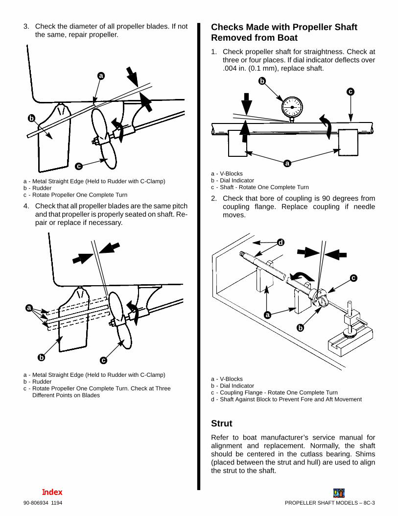
PROPELLER SHAFT MODELS – 8C-390-806934 1194
3. Check the diameter of all propeller blades. If notthe same, repair propeller.
a
b
c
a - Metal Straight Edge (Held to Rudder with C-Clamp)b - Rudderc - Rotate Propeller One Complete Turn
4. Check that all propeller blades are the same pitchand that propeller is properly seated on shaft. Re-pair or replace if necessary.
a
b c
a - Metal Straight Edge (Held to Rudder with C-Clamp)b - Rudderc - Rotate Propeller One Complete Turn. Check at Three
Different Points on Blades
Checks Made with Propeller ShaftRemoved from Boat1. Check propeller shaft for straightness. Check at
three or four places. If dial indicator deflects over.004 in. (0.1 mm), replace shaft.
a
bc
a - V-Blocksb - Dial Indicatorc - Shaft - Rotate One Complete Turn
2. Check that bore of coupling is 90 degrees fromcoupling flange. Replace coupling if needlemoves.
a
b
c
d
a - V-Blocksb - Dial Indicatorc - Coupling Flange - Rotate One Complete Turnd - Shaft Against Block to Prevent Fore and Aft Movement
StrutRefer to boat manufacturer’s service manual foralignment and replacement. Normally, the shaftshould be centered in the cutlass bearing. Shims(placed between the strut and hull) are used to alignthe strut to the shaft.

9
A71034
POWER STEERING SYSTEM
PUMPS AND RELATED COMPONENTS
Note:Refer to the following Service Bulletins regarding this section.
SB 96-8 Brass Power Steering Hose Coupling
SB 95-8 MerCruiser Steering Recommendations

9A-0 - PUMPS AND RELATED COMPONENTS 90-806934 1194
Table of ContentsPage
Torque Specifications 9A-1. . . . . . . . . . . . . . . . . . . . . . . . . Lubricants / Sealants 9A-1. . . . . . . . . . . . . . . . . . . . . . . . . . Description 9A-1. . . . . . . . . . . . . . . . . . . . . . . . . . . . . . . . . . Exploded Views 9A-2. . . . . . . . . . . . . . . . . . . . . . . . . . . . . .
Power Steering Pumps 9A-2. . . . . . . . . . . . . . . . . . . . . D3.0L/150 and D3.6L/180 Engines 9A-2. . . . . . . . D4.2L/220 Engines 9A-3. . . . . . . . . . . . . . . . . . . . . .
Related Components 9A-4. . . . . . . . . . . . . . . . . . . . . . . All Engines 9A-4. . . . . . . . . . . . . . . . . . . . . . . . . . . .
Power Steering Pump 9A-5. . . . . . . . . . . . . . . . . . . . . . . . . Removal 9A-5. . . . . . . . . . . . . . . . . . . . . . . . . . . . . . . . . Installation 9A-6. . . . . . . . . . . . . . . . . . . . . . . . . . . . . . . .
Maintaining Power Steering Pump Fluid Level 9A-8. . . . Filling and Bleeding Power Steering System 9A-8. . . . . .
NOTICE
For more information on power steeringsystem and components refer to ServiceManual Number 11 - Bravo Stern DriveUnit, “Steering Systems”.
9A – PUMPS AND RELATED COMPONENTS
PUMPS AND RELATED COMPONENTS - 9A-190-806934 1194
Torque SpecificationsTORQUE
DESCRIPTIONLb. Ft. N⋅m
Front bracket
Rear Brace24 32
Mounting Nut andScrew
15 21
All Fasteners NotListed
Tighten Securely
Lubricants / SealantsDESCRIPTION PART NUMBER
Quicksilver Power Trim andSteering Fluid
92-90100
Automatic Transmission Fluid -Dexron, Dexron II, Dexron II -D
Obtain Locally
IMPORTANT: Power Steering Pumps are consid-ered non-repairable units and are intended to beremoved and replaced by new units.
Description
The power steering system utilizes an engine-drivenhydraulic pump that supplies fluid flow and pressureby means of hoses to a control valve that, in turn, con-trols fluid flow and pressure to-and-from a boostercylinder. A reservoir mounted on the side of the en-gine supplies fluid to the pump
IMPORTANT: Power Steering Pump is a non-re-pairable unit and is intended to be removed andreplaced by a new unit.

9A-2 - PUMPS AND RELATED COMPONENTS 90-806934 1194
Exploded Views
Power Steering Pumps
D3.0L/150 AND D3.6L/180 ENGINES
71034
b
a
a
bb
1 - Pump2 - Pulley3 - Tensioning Bolt4 - Pinion For Tensioning Nut5 - Tensioning Nut6 - O-Ring7 - Adaptor8 - Fluid Pressure Hose9 - Fluid Reservoir Hose10- Hose Clamp11- Front Bracket12- Rear Brace13- Bracket14- Mounting Bolt15- Mounting Nut16- Spacer17- Tightening Brace
Torque Specifications
a 24 lb. ft. (32 N·m)
b 15 lb. ft. (21 N·m)
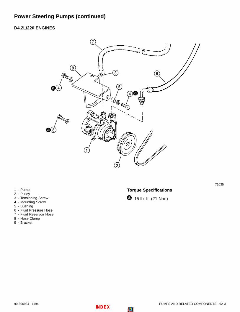
PUMPS AND RELATED COMPONENTS - 9A-390-806934 1194
Power Steering Pumps (continued)
D4.2L/220 ENGINES
71035
a
aa
1 - Pump2 - Pulley3 - Tensioning Screw4 - Mounting Screw5 - Bushing6 - Fluid Pressure Hose7 - Fluid Reservoir Hose8 - Hose Clamp9 - Bracket
Torque Specifications
a 15 lb. ft. (21 N·m)

9A-4 - PUMPS AND RELATED COMPONENTS 90-806934 1194
Related Components
ALL ENGINES
71034
a
a
A
1 - Fluid Reservoir Tank2 - Hose Clamp (2)3 - Clamping Screw4 - Support5 - Supply Hose6 - Pressure Hose7 - Return Hose (From Transom)8 - Return Hose (From Cooler)9 - Power Steering Fluid Cooler
Lubricant/Sealant Application Points
A Quicksilver Power Trim and Steering . . Fluid - 92-90100, or Automatic Transmission Fluid - Dexron, Dexron II, Dexron II -D- Obtain Locally
Torque Specifications
a 20 - 25 lb. ft. (27 - 34 N·m)

PUMPS AND RELATED COMPONENTS - 9A-590-806934 1194
Power Steering Pump
Removal
! CAUTIONDisconnect Battery cables at battery to preventengine rotation and injury while working onpump.
1. Remove vacuum pump belt (see SECTION 1B“Maintenance.”)
2. Remove and retain bolts or screws, lockwashers,hardware and nuts as shown.
26441
b
a
a - Mounting Bolt and Nutb - Tensioning Bolt with Pinion and Nut
D3.0L/150, D3.6L/180
70113
ba
a
a - Mounting Screws (2-One Hidden In This View with a Bush-ing)
b - Tension Screw
D4.2L/220
3. Lower pump down to gain access to hose con-nections. Remove hoses and adaptor as shown.Using clean, suitable plugs, quickly plug hoses tolimit loss of fluid.
NOTE: If possible lift pump above power steering res-ervoir and then remove hoses to minimize fluid loss.
26441
b
a
a - Hosesb - Adaptor
D3.0L/150, D3.6L/180
4. Drain power steering fluid from pump into a suit-able container. DO NOT reuse fluid.
5. Following instructions “a” or “b”.
a. On D4.2L/220 Pumps: Proceed to Step 5.
b. On D3.0L/150, D3.6L/180 Pumps:
(1) Remove and retain front bracket andscrews.
(2) Remove and retain rear brace andscrews.
74482
b
ca
a - Front Bracketb - Rear Bracec - Screws (5 Total - 2 Hidden in This View)

9A-6 - PUMPS AND RELATED COMPONENTS 90-806934 1194
6. Using a suitable puller remove pulley from pumpshaft. Retain pulley for installation on new pump.
71035D4.2L/220 (All Similar)
7. Drain fluid from power steering reservoir into asuitable container. DO NOT reuse fluid. Disposeof fluid properly.
Installation1. Using a suitable screw, pull (install) pulley onto
shaft until pulley face is flush as shown with shaftend (screw head will bottom out).
74481
2. Follow instructions “a” or “b”:
a. D4.2L/220 Pumps: Proceed to Step 3.
b. D3.0L/150, D3.6L/180 Pumps:
(1) Install new O-ring onto adaptor and installadaptor into new pump. Tighten securely.
(2) Install front bracket and rear brace asshown. Torque screws to 24 lb. ft. (32N·m).
74483
a - O-Ringb - Adaptorc - Front Bracketd - Rear Bracee - Screws (5 Total - 3 Front, 2 Rear)
3. Install reservoir hose and pressure hose to pumpas shown. Do not tighten presently.
26441
ca
d
b
a - Reservoir Hoseb - Hose Clampc - Pressure Hosed - Fitting
D3.0L/150, D3.6L/180 (D4.2L/220 similar)

PUMPS AND RELATED COMPONENTS - 9A-790-806934 1194
4. Place hoses appropriately between oil filter andpump mounting bracket, lift pump into place andattach with fasteners and hardware retained pre-viously, as shown.
26441
a
b
c
d
a - Mounting Nutb - Mounting Boltc - Tensioning Nutd - Tensioning Bolt with Pinion
D3.0L/150, D3.6L/180
70113
a
b
c
a
a - Mounting Screws with Washers (2-One Hidden, Shown inInset with Bushing)
b - Tensioning Screw with Washerc - Bushing
(D4.2L/220 similar)
5. Tighten reservoir hose clamp securely. Tightenpressure hose fitting securely. DO NOT overtigh-ten.
6. Position drive belt in pulley groove and tensionbelt following instructions “a” or “b”:
a. On D3.0L/150, D3.6L 180 Pumps: Turn ten-sioning bolt with pinion to adjust belt. Torquemounting nut and tensioning nut 15 lb. ft. (21N·m).
b. On D4.2L/220 Pumps: Move or pry powersteering pump to tension belt. Torque mount-ing screws and tensioning screw to 15 lb. ft.(21 N·m).
NOTE: On All Models: Check belt tension by de-pressing upper strand of belt at center point betweenpulleys. Belt must not deflect more than 3/16 in.(5mm).
23724
a
a - Belt Center Point Between Pulleys, - Deflection of 3/16 in.(5mm) or Less
NOTE: On D4.2L/220 models, power steering drivepulley is behind crankshaft front pulley.
7. If not already accomplished, drain fluid from pow-er steering reservoir into a suitable container. Donot reuse old fluid. Dispose of properly.
8. Fill power steering reservoir with new fluid. Referto “Power Steering Fluid” Chart at front of section.
9. Connect battery cables at battery by FIRSTinstalling Positive (+) battery cable to Positive (+)battery terminal and tighten clamp. THEN, installNEgative (–) battery cable to NEgative (–) batteryterminal and tighten clamp.
10. Bleed air from power steering system followinginstruction in “Filling and Air Bleeding PowerSteering System.”
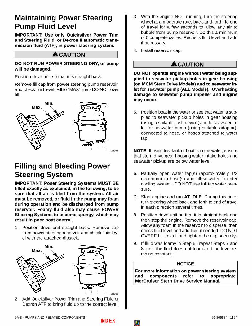
9A-8 - PUMPS AND RELATED COMPONENTS 90-806934 1194
Maintaining Power SteeringPump Fluid LevelIMPORTANT: Use only Quicksilver Power Trimand Steering Fluid, or Dexron II automatic trans-mission fluid (ATF), in power steering system.
! CAUTIONDO NOT RUN POWER STEERING DRY, or pumpwill be damaged.
Position drive unit so that it is straight back.
Remove fill cap from power steering pump reservoir,and check fluid level. Fill to “MAX” line - DO NOT overfill.
23162
Max.Min.
Filling and Bleeding PowerSteering SystemIMPORTANT: Poser Steering Systems MUST BEfilled exactly as explained, in the following, to besure that all air is bled from the system. All airmust be removed, or fluid in the pump may foamduring operation and be discharged from pumpreservoir. Foamy fluid also may cause POWERSteering Systems to become spongy, which mayresult in poor boat control.
1. Position drive unit straight back. Remove capfrom power steering reservoir and check fluid lev-el with the attached dipstick.
23162
Max.Min.
2. Add Quicksilver Power Trim and Steering Fluid orDexron ATF to bring fluid up to the correct level.
3. With the engine NOT running, turn the steeringwheel at a moderate rate, back-and-forth, to endof travel for a few seconds to allow any air tobubble from pump reservoir. Do this a minimumof 5 complete cycles. Recheck fluid level and addif necessary.
4. Install reservoir cap.
! CAUTIONDO NOT operate engine without water being sup-plied to seawater pickup holes in gear housing(on MCM Stern Drive Models) and to seawater in-let for seawater pump (ALL Models). Overheatingdamage to seawater pump impeller and enginemay occur.
5. Position boat in the water or see that water is sup-plied to seawater pickup holes in gear housing(using a suitable flush device( and to seawater in-let for seawater pump (using suitable adaptor),connected to hose, or hoses attached to watertap..
NOTE: If using test tank or boat is in the water, ensurethat stern drive gear housing water intake holes andseawater pickup are below water level.
6. Partially open water tap(s) (approximately 1/2maximum) to hose(s) and allow water to entercooling system. DO NOT use full tap water pres-sure.
7. Start engine and run AT IDLE. During this time,turn steering wheel back-and-forth to end of travelin each direction several times.
8. Position drive unit so that it is straight back andthen stop the engine. Remove the reservoir cap.Allow any foam in the reservoir to disperse, thencheck fluid level and add fluid if needed. DO NOTOVERFILL. Install and tighten the cap securely.
9. If fluid was foamy in Step 6., repeat Steps 7 and8, until the fluid does not foam and the level re-mains constant.
NOTICE
For more information on power steering systemand components refer to appropriateMerCruiser Stern Drive Service Manual.

9A
71034
POWER STEERING SYSTEM
PUMPS AND RELATED COMPONENTS

10A-0 - PUMPS AND RELATED COMPONENTS 90-806934 1194
Table of ContentsPage
Torque Specifications 10A-1. . . . . . . . . . . . . . . . . . . . . . . . . Lubricants / Sealants 10A-1. . . . . . . . . . . . . . . . . . . . . . . . . Description 10A-1. . . . . . . . . . . . . . . . . . . . . . . . . . . . . . . . . . Exploded Views 10A-2. . . . . . . . . . . . . . . . . . . . . . . . . . . . . .
Power Steering Pumps 10A-2. . . . . . . . . . . . . . . . . . . . . D3.0L/150 and D3.6L/180 Engines 10A-2. . . . . . . D4.2L/220 Engines 10A-3. . . . . . . . . . . . . . . . . . . . .
Related Components 10A-4. . . . . . . . . . . . . . . . . . . . . . All Engines 10A-4. . . . . . . . . . . . . . . . . . . . . . . . . . . .
Power Steering Pump 10A-5. . . . . . . . . . . . . . . . . . . . . . . . . Removal 10A-5. . . . . . . . . . . . . . . . . . . . . . . . . . . . . . . . . Installation 10A-6. . . . . . . . . . . . . . . . . . . . . . . . . . . . . . . .
Maintaining Power Steering Pump Fluid Level 10A-8. . . Filling and Bleeding Power Steering System 10A-8. . . . .
NOTICE
For more information on power steeringsystem and components refer to ServiceManual Number 11 - Bravo Stern DriveUnit, “Steering Systems”.
10A - PUMPS AND RELATED COMPONENTS

PUMPS AND RELATED COMPONENTS - 10A-190-806934 1194
Torque Specifications
DESCRIPTIONTORQUE
DESCRIPTIONLb. Ft. N⋅m
Front bracket24 32
Rear Brace24 32
Mounting Nut andScrew
15 21
All Fasteners NotListed
Tighten Securely
Lubricants / SealantsDESCRIPTION PART NUMBER
Quicksilver PowerTrim and SteeringFluid
92-90100
Automatic Trans-mission Fluid - Dex-ron, Dexron II, Dex-ron II -D
Obtain Locally
IMPORTANT: Power Steering Pumps are consid-ered non-repairable units and are intended to beremoved and replaced by new units.
DescriptionThe power steering system utilizes an engine-drivenhydraulic pump that supplies fluid flow and pressureby means of hoses to a control valve that, in turn, con-trols fluid flow and pressure to-and-from a boostercylinder. A reservoir mounted on the side of the en-gine supplies fluid to the pump
IMPORTANT: Power Steering Pump is a non-re-pairable unit and is intended to be removed andreplaced by a new unit.

10A-2 - PUMPS AND RELATED COMPONENTS 90-806934 1194
Exploded Views
Power Steering Pumps
D3.0L/150 AND D3.6L/180 ENGINES
71034
2
3
4 5
6
7
8
11
12
13
14
1
9
10
14
15
15
14
16
1617
b
a
a
bb
1 - Pump2 - Pulley3 - Tensioning Bolt4 - Pinion For Tensioning Nut5 - Tensioning Nut6 - O-Ring7 - Adaptor8 - Fluid Pressure Hose9 - Fluid Reservoir Hose10- Hose Clamp11- Front Bracket12- Rear Brace13- Bracket14- Mounting Bolt15- Mounting Nut16- Spacer17- Tightening Brace
Torque Specifications
a 24 lb. ft. (32 N·m)
b 15 lb. ft. (21 N·m)

PUMPS AND RELATED COMPONENTS - 10A-390-806934 1194
Power Steering Pumps (continued)
D4.2L/220 ENGINES
71035
1
2
3
4 5
6
7
89
4
a
aa
1 - Pump2 - Pulley3 - Tensioning Screw4 - Mounting Screw5 - Bushing6 - Fluid Pressure Hose7 - Fluid Reservoir Hose8 - Hose Clamp9 - Bracket
Torque Specifications
a 15 lb. ft. (21 N·m)
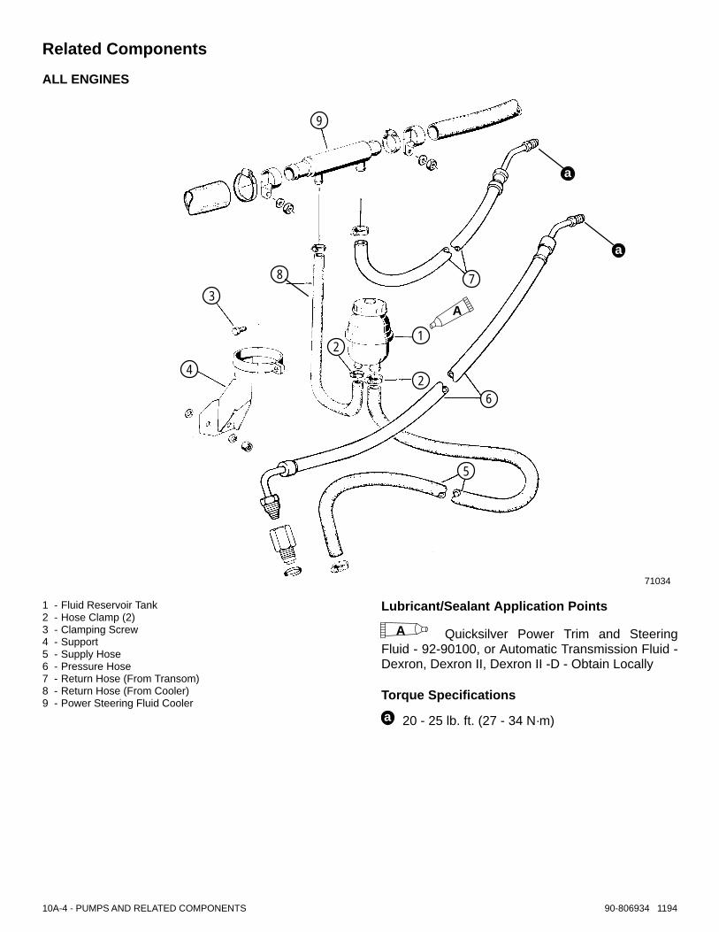
10A-4 - PUMPS AND RELATED COMPONENTS 90-806934 1194
Related Components
ALL ENGINES
71034
4
5
6
78
9
1
2
2
3
a
a
A
1 - Fluid Reservoir Tank2 - Hose Clamp (2)3 - Clamping Screw4 - Support5 - Supply Hose6 - Pressure Hose7 - Return Hose (From Transom)8 - Return Hose (From Cooler)9 - Power Steering Fluid Cooler
Lubricant/Sealant Application Points
A Quicksilver Power Trim and SteeringFluid - 92-90100, or Automatic Transmission Fluid -Dexron, Dexron II, Dexron II -D - Obtain Locally
Torque Specifications
a 20 - 25 lb. ft. (27 - 34 N·m)

PUMPS AND RELATED COMPONENTS - 10A-590-806934 1194
Power Steering Pump
Removal
! CAUTIONDisconnect Battery cables at battery to preventengine rotation and injury while working onpump.
1. Remove vacuum pump belt (see Section 1B“Maintenance.”)
2. Remove and retain bolts or screws, lockwashers,hardware and nuts as shown.
26441
b
a
a - Mounting Bolt and Nutb - Tensioning Bolt with Pinion and Nut
D3.0L/150, D3.6L/180
70113
a
b
a - Mounting Screws (2-One Hidden In This View with a Bush-ing)
b - Tension Screw
D4.2L/220
3. Lower pump down to gain access to hose con-nections. Remove hoses and adaptor as shown.Using clean, suitable plugs, quickly plug hoses tolimit loss of fluid.
NOTE: If possible lift pump above power steering res-ervoir and then remove hoses to minimize fluid loss.
26441
b
a
a - Hoses

10A-6 - PUMPS AND RELATED COMPONENTS 90-806934 1194
b - Adaptor
D3.0L/150, D3.6L/180
4. Drain power steering fluid from pump into a suit-able container. DO NOT reuse fluid.
5. Following instructions “a” or “b”.
a. On D4.2L/220 Pumps: Proceed to Step 5.
b. On D3.0L/150, D3.6L/180 Pumps:
1. Remove and retain front bracket andscrews.
2. Remove and retain rear brace andscrews.
74482
b
ca
a - Front Bracketb - Rear Bracec - Screws (5 Total - 2 Hidden in This View)
6. Using a suitable puller remove pulley from pumpshaft. Retain pulley for installation on new pump.
71035D4.2L/220 (All Similar)
7. Drain fluid from power steering reservoir into asuitable container. DO NOT reuse fluid. Disposeof fluid properly.
Installation1. Using a suitable screw, pull (install) pulley onto
shaft until pulley face is flush as shown with shaftend (screw head will bottom out).
74481
2. Follow instructions “a” or “b”:
a. D4.2L/220 Pumps: Proceed to Step 3.
b. D3.0L/150, D3.6L/180 Pumps:
1. Install new O-ring onto adaptor and installadaptor into new pump. Tighten securely.
2. Install front bracket and rear brace asshown. Torque screws to 24 lb. ft. (32N·m).
74483
a - O-Ringb - Adaptorc - Front Bracketd - Rear Bracee - Screws (5 Total - 3 Front, 2 Rear)

PUMPS AND RELATED COMPONENTS - 10A-790-806934 1194
3. Install reservoir hose and pressure hose to pumpas shown. Do not tighten presently.
26441
ca
d
b
a - Reservoir Hoseb - Hose Clampc - Pressure Hosed - Fitting
D3.0L/150, D3.6L/180 (D4.2L/220 similar)
4. Place hoses appropriately between oil filter andpump mounting bracket, lift pump into place andattach with fasteners and hardware retained pre-viously, as shown.
26441
a
b
c
d
a - Mounting Nutb - Mounting Boltc - Tensioning Nutd - Tensioning Bolt with Pinion
D3.0L/150, D3.6L/180
70113
a
b
a - Mounting Screws with Washers (2-One Hidden, Shown inInset with Bushing)
b - Tensioning Screw with Washerc - Bushing
(D4.2L/220 similar)
5. Tighten reservoir hose clamp securely. Tightenpressure hose fitting securely (DO NOT overtigh-ten).
6. Position drive belt in pulley groove and tensionbelt following instructions “a” or “b”:
a. On D3.0L/150, D3.6L 180 Pumps: Turn ten-sioning bolt with pinion to adjust belt. Torquemounting nut and tensioning nut 15 lb. ft. (21N·m).
b. On D4.2L/220 Pumps: Move or pry powersteering pump to tension belt. Torque mount-ing screws and tensioning screw to 15 lb. ft.(21 N·m).

10A-8 - PUMPS AND RELATED COMPONENTS 90-806934 1194
NOTE: On All Models: Check belt tension by de-pressing upper strand of belt at center point betweenpulleys. Belt must not deflect more than 3/16 in.(5mm).
23724
a
a - Belt Center Point Between Pulleys, [Deflection of 3/16 in.(5mm) or Less]
NOTE: On D4.2L/220 models, power steering drivepulley is behind crankshaft front pulley.
7. If not already accomplished, drain fluid from pow-er steering reservoir into a suitable container. Donot reuse old fluid. Dispose of properly.
8. Fill power steering reservoir with new fluid. Referto “Power Steering Fluid” Chart at front of section.
9. Connect battery cables at battery by FIRSTinstalling Positive (+) battery cable to Positive (+)battery terminal and tighten clamp. THEN, installNEgative (–) battery cable to NEgative (–) batteryterminal and tighten clamp.
10. Bleed air from power steering system followinginstruction in “Filling and Air Bleeding PowerSteering System.”
Maintaining Power SteeringPump Fluid LevelIMPORTANT: Use only Quicksilver Power Trimand Steering Fluid, or Dexron II automatic trans-mission fluid (ATF), in power steering system.
! CAUTIONDO NOT RUN POWER STEERING DRY, or pumpwill be damaged.
Position drive unit so that it is straight back.
Remove fill cap from power steering pump reservoir,and check fluid level. Fill to “MAX” line - DO NOT overfill.
23162
Max.Min.
Filling and Bleeding PowerSteering SystemIMPORTANT: Poser Steering Systems MUST BEfilled exactly as explained, in the following, to besure that all air is bled from the system. All airmust be removed, or fluid in the pump may foamduring operation and be discharged from pumpreservoir. Foamy fluid also may cause POWERSteering Systems to become spongy, which mayresult in poor boat control.
1. Position drive unit straight back. Remove capfrom power steering reservoir and check fluid lev-el with the attached dipstick.
23162
Max.Min.
2. Add Quicksilver Power Trim and Steering Fluid orDexron ATF to bring fluid up to the correct level.

PUMPS AND RELATED COMPONENTS - 10A-990-806934 1194
3. With the engine NOT running, turn the steeringwheel at a moderate rate, back-and-forth, to endof travel for a few seconds to allow any air tobubble from pump reservoir. Do this a minimumof 5 complete cycles. Recheck fluid level and addif necessary.
4. Install reservoir cap.
! CAUTIONDO NOT operate engine without water being sup-plied to seawater pickup holes in gear housing(on MCM Stern Drive Models) and to seawater in-let for seawater pump (ALL Models). Overheatingdamage to seawater pump impeller and enginemay occur.
5. Position boat in the water or see that water is sup-plied to seawater pickup holes in gear housing(using a suitable flush device( and to seawater in-let for seawater pump (using suitable adaptor),connected to hose, or hoses attached to watertap..
NOTE: If using test tank or boat is in the water, ensurethat stern drive gear housing water intake holes andseawater pickup are below water level.
6. Partially open water tap(s) (approximately 1/2maximum) to hose(s) and allow water to entercooling system. DO NOT use full tap water pres-sure.
7. Start engine and run AT IDLE . During this time,turn steering wheel back-and-forth to end of travelin each direction several times.
8. Position drive unit so that it is straight back andthen stop the engine. Remove the reservoir cap.Allow any foam in the reservoir to disperse, thencheck fluid level and add fluid if needed. DO NOTOVERFILL. Install and tighten the cap securely.
9. If fluid was foamy in Step 6., repeat Steps 7 and8, until the fluid does not foam and the level re-mains constant.
NOTICE
For more information on power steering systemand components refer to appropriateMerCruiser Stern Drive Service Manual.