Outline of Knowledge Database - Outline of Knowledge Website
Upload
khangminh22Category
view
3download
0
Mechanically Fastened Joint Outline
• Joint Overview• Overview of Metal Joint for Comparison• Single Fastener Joint• Joint with Single Strip of Fasteners• Multiple Row of Fasteners• Fastener Loading• Questions and Discussion
RBB Mechanically Fastened Composite Joints 3

Types of Joining Methods
• Mechanically Fastened Jointso Cylindrical Rods: bolt, rivet, pin, or stableo Primary load bearingo The load transfer through the fastener is localized
• Adhesively Bonded Jointso Structural Adhesiveso Primary load bearing
• Welded Joints• Friction Joints
RBB Mechanically Fastened Composite Joints 4

Joining Methods
Joint Type Advantages Disadvantages
Mechanically Fastened
Straightforward DesignInspectableRepairableNo Thickness RestrictionsCan be disassembled
Many PartsStress Concentrations/WeakFatigue, fretting ProneProne to corrosionMust be sealed
Adhesive Bonding
Few Parts, Full Load TransferRepairable, Fatigue ResistantSealing, Stiff ConnectionLight‐Weight, Smooth Contour, corrosion resistantNo Stress Concentrations
Difficult to Inspect, Surface PrepEnvironmental effects, designRequired Skill, Thickness limitedResidual StressesNo DisassemblyShear Loading Only
WeldingPermanent, InspectableLoad Transfer, Continuous
Permanent, Microstructural changeResidual Stresses, Trade Skill
Friction Simple Friction Dependent
RBB Mechanically Fastened Composite Joints 5

Joint Design Considerations
• Joint GeometryoHole diameter, plate width/fastener spacing, plate thickness
• Clamping AreaoCAUTION: Through the Thickness compliance/weakness
• Ply Fiber Orientation and Ply Stacking Sequence• Hole Stress Concentration• Moisture and Temperature Conditions• Applied Stress
RBB Mechanically Fastened Composite Joints 6

Simple Joint Analysis:Homogeneous and Isotropic
• No Stress Concentrationso Static Loading: Factor of Safety of 3o Fatigue Loading: Factor of Safety of 4.5
• Multiple Rows of Fastenerso Each row takes equal proportion of the applied load
• Failure Stress Analysiso Individual Failure ModesoGood design promotes preferred failure condition
• Assume Each Fastener in a Row Shares Equal Load
RBB Mechanically Fastened Composite Joints 7
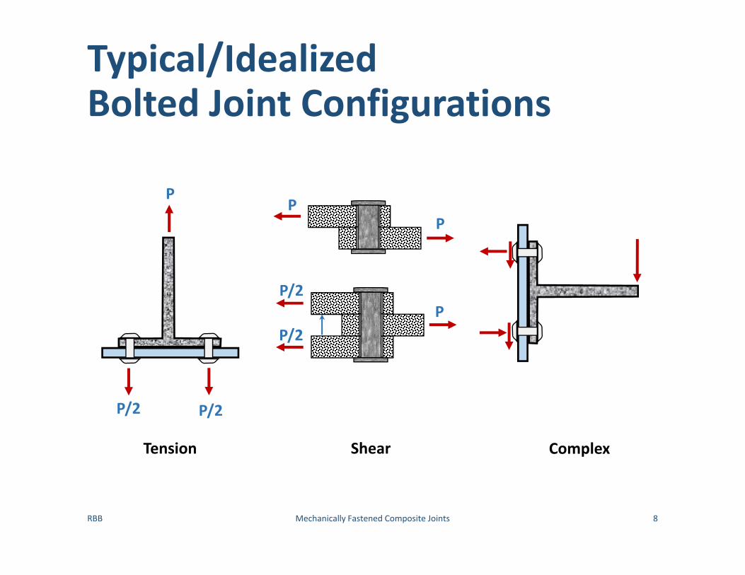
Typical/Idealized Bolted Joint Configurations
RBB Mechanically Fastened Composite Joints 8
PP
P/2
P/2P
P/2 P/2
P
Tension Shear Complex

Nomenclature for Basic Shear Joint Geometryd – Hole Diameter
w‐ Plate Width
p‐ Fastener Spacing
e‐ Edge Distance
t0 and t1 – Plate Thickness
P‐ LoadFastener
RBB Mechanically Fastened Composite Joints 9

Basic Shear Joint Geometry
d
e
W or pt1t0
PP
t1t0
P
P
P
P/2
P/2
P
P
PP
P
P/2
P/2
P
P/2
P/2
RBB Mechanically Fastened Composite Joints 10
P/2
P/2
P
Single Lap Configuration Double Lap Configuration

Net Tension Failure
RBB Mechanically Fastened Composite Joints 11
,nt
all all tensionP k t w d
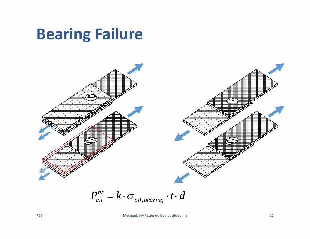
Bearing Failure
RBB Mechanically Fastened Composite Joints 12
,br
all all bearingP k t d

Shear Out Failure
RBB Mechanically Fastened Composite Joints 13
2soall allP t e

Combined Net Tension and Shear Out Failure
RBB Mechanically Fastened Composite Joints 14
/ 1, 2
nt soall all tension allP k t w d t e
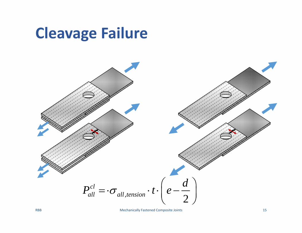
Cleavage Failure
RBB Mechanically Fastened Composite Joints 15
, 2cl
all all tensiondP t e

Fastener Failures
Fastener Shear Failure
Fastener Pull Through Failure
Fastener Bending Failure
RBB Mechanically Fastened Composite Joints 16
fsall allP A n

Composite Joint Analysis Neither Perfectly Elastic or Plastic
RBB Mechanically Fastened Composite Joints 17
• Single Bolt Joint• Composite Response Between
o Window Glasso Ductile Metal
• ONLY Fiber Glass comes close to idealo massive delamination
prior to failure• Failure in composite
o Gross section Failureo Not net section failure
Form of Curveif analysis based on Simple Bearing Stress and Net‐Section Stress Allowables

Inhomogeneity of Composite Failure Dominates Behavior
RBB Mechanically Fastened Composite Joints 18
Composite Failure Modes• Tension
o Fiber/matrix bond broken locally
o Delaminationo Splitting of resin between
fiberso No Fiber Damageo Relieves Stress Concentration
• Compressiono All tensile modeso Micro‐buckling

Comparison of Metal and Composite Bolted Joints
RBB Mechanically Fastened Composite Joints 19
Simple Comparison between the weights of equivalent metal and composite structures• Superiority of composites over metals typically
based on unnotched specimens• Sometimes deduced from monolayer properties
For a Common load per unit width, P
anda a c c c ac a
P PP t t t t
The weight ratio is given by c c c c a c a
a a a a c a c c
w tw t E

Implications to Structural Design
RBB Mechanically Fastened Composite Joints 20
c c c c a c a
a a a a c a c c
w tw t E
Composite Structures are preferred• Aluminum stress a is Low• Strain in composite c is kept High
Aluminum Structures are preferred• Aluminum stress a is High

Illustrations of Trade‐Offs on a Lay‐Up Suitable for Wing Skins
RBB Mechanically Fastened Composite Joints 21
50 ksi

Illustrations of Trade‐Offs on a Quasi‐Isotropic Lay‐Up
RBB Mechanically Fastened Composite Joints 22
Recommended Fiber Patterns for Bolted or Riveted Joints
RBB Mechanically Fastened Composite Joints 23
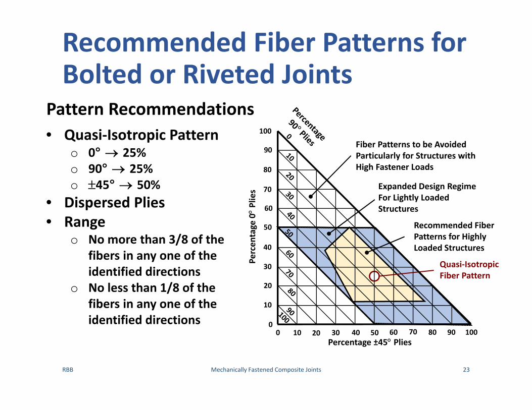
Pattern Recommendations• Quasi‐Isotropic Pattern
o 0° 25%o 90° 25%o 45° 50%
• Dispersed Plies• Range
o No more than 3/8 of the fibers in any one of the identified directions
o No less than 1/8 of the fibers in any one of the identified directions
Percen
tage 0Plies
Percentage ±45 Plies
Fiber Patterns to be AvoidedParticularly for Structures withHigh Fastener Loads
Expanded Design RegimeFor Lightly LoadedStructures
Recommended FiberPatterns for HighlyLoaded Structures
Quasi‐IsotropicFiber Pattern
0 10 20 30 40 50 60 70 80 90 1000
10
20
30
40
50
60
70
80
90
100

Elastic‐Isotropic Stress Concentrations for Single Holes
RBB Mechanically Fastened Composite Joints 24
A Wealth of Data Exists• Single Fastener• Single Lap/Shear• Double Lap/Shear
An additional variable is clamping torque
Theories Developed to Explain Data• Performance/Design of
more complex structural joints checked against data
• THIS IS A LOGICAL PLACE TO START THE DEVELOPMENT

Elastic‐Isotropic, Single HoleNet‐Section Tension Stress Concentration
RBB Mechanically Fastened Composite Joints 25
Stress Concentration Based on • Experimental data• Analytical results
max
1312 1
3 1 for 12 2
1 for 1
te
te
ww dk
wdd
w ee w
ew
Pkt w d
d/w
k te

Elastic‐Isotropic, Single HoleAverage Bearing Stress Concentration
RBB Mechanically Fastened Composite Joints 26
k be
d/w
Stress Concentration Based on • Experimental data• Analytical results
max
1
2 3 1121 1
3 1 for 12 2
1 for 1
tebe
kk P wt d d
w wd d
w ee w
ew

Elastic‐Isotropic, Single HoleAverage Bearing Stress Concentration
RBB Mechanically Fastened Composite Joints 27
Stress Concentration• Well behaved for small d/w
k be
d/w
2 3 1121 1bek w w
d d
• d/w01bek
• d/w0, accounting for e3
41bek ed

Elastic‐Isotropic Stress Field Around a Bolt Hole
RBB Mechanically Fastened Composite Joints 28
• Bearing Stress Peaks 27% higher than average
• Peak Hoop Tensile Stresso Equal to average Bearing Stress
• Distance to Edge Not Accounted for
• Potential Failure Siteso Bearingo Back Side of Fastenero Tension on Side of Hole
• With Shorter Edge Distanceo Cleavage Failure Possible
For Nominal Net Fit Fastener

Impact of Stress Concentration on Strip Strength
RBB Mechanically Fastened Composite Joints 29
Solving kte and kbe(kte ) for Joint Strength P
max
max32 12
1 1
32 1max 2
1 1
1
net avgte
d d dw w w
d d dw w w
P w d t w d tk
t w
Pt w
Max Load at d/w=0.4, bolt pitch p=2.5inmax max0.21P w t
0.21
(Advanced Composites are NOT this brittle)
Elastic‐Isotropic Material

Net‐Section Strength of a Strip Containing UNLOADED Hole
RBB Mechanically Fastened Composite Joints 30
kte for UNLOADED Hole3
2 1tedkw
Net Section Strength of Hole 3
max
1 1
2 1
d dw w
dte w
Pt w k

Differences Between Isolated Hole and Wide Seam of Holes
RBB Mechanically Fastened Composite Joints 31
Differences Small for d/w0
Differences Substantial as d/w1

Isolated versus Seam of Hole Comparison, Unloaded Hole
RBB Mechanically Fastened Composite Joints 32
Suggested Form of Seam kte2.413 2
1 1 1ted dkp p
kte for UNLOADED Hole3
2 1tedkw
Difference Between the TwoSignificant, (d/w≤0.5)

Isolated versus Seam of Hole Comparison, Loaded Hole
RBB Mechanically Fastened Composite Joints 33
Suggested Form of Seam kte
2.412 1312 1
te
pdp dk
pd pd
kte for LOADED Single Hole
1312 1
te
ww dk
wdd
max
1te
bekk P w
t d d
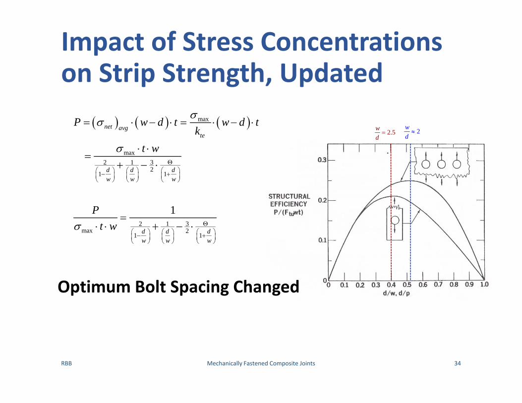
Impact of Stress Concentrations on Strip Strength, Updated
RBB Mechanically Fastened Composite Joints 34
max
max32 12
1 1
32 1max 2
1 1
1
net avgte
d d dw w w
d d dw w w
P w d t w d tk
t w
Pt w
2.5wd 2w
d
Optimum Bolt Spacing Changed

Open Hole Composite Laminate Stress Concentration Factor
RBB Mechanically Fastened Composite Joints 35
Characteristics of Composite Laminates• No local yielding • High Interlaminar stresses induced at hole boundaries• Above conditions result in greater and varying stress
concentration effect
Ultimate Stress in a Composite Structure
Composite Stress Concentration
tc appult
tc
k Pw d t
k

Open Hole Stress Concentration for Orthotropic Laminate
RBB Mechanically Fastened Composite Joints 36
1 121
2 12
1
2
12
21
1 2
longitudinal Young's Modulustransverse Young's Moduluslin-plane shear modulusmajor in-plane Poisson's Ratio
tcE EkE G
EEG
Net Tension Stress Concentration Factor DependentOn Ply Angles

Composite Laminate ktc Vary with Ply Geometry
RBB Mechanically Fastened Composite Joints 37
• ktc=7.5 for 100% 0° plies
• ktc=1.8 for 100% 45° plies
• ktc=3 for 50% 45 ° pliesIsotropic Value

Stress Concentrations in Composite Materials Bolted Joint
RBB Mechanically Fastened Composite Joints 38
• Composite Laminateso Do not behave as
brittle as Fiber and Matrix would suggest
o Bolted joints are stronger
o Joint structural efficiency a result of stress concentration relief

Proposed Relationship Between kte and ktc, Loaded Holes
RBB Mechanically Fastened Composite Joints 39
Experimentally Determined Relationship 1 1tc tek C k
Assumptions• Joint geometry will cause NET‐TENSION failure• Fiber pattern will cause NET‐TENSION failureExperimental Measurement of ktc
/tc tuk F t w d P

Composite Joint Efficiency versus d/w, Single Hole in Narrow Strip
RBB Mechanically Fastened Composite Joints 40
H
I
J
K
1
tu tc
dP w
F t w k
Fully‐PlasticBehavior
Perfectly ElasticBehavior
Elastic‐Isotropic Material
e/w1
Curves CA 1.0B 0.8C 0.6D 0.4E 0.2F 0.1G 0
H Fbr=FtuI Fbr=2 FtuJ Fbr=3 FtuK Fbr=4 Ftu

Composite Joint Efficiency versus d/w, Single Hole in Narrow Strip
RBB Mechanically Fastened Composite Joints 41
H
I
J
K Fully‐PlasticBehavior
Perfectly ElasticBehavior
e/w1
Curves CA 1.0B 0.8C 0.6D 0.4E 0.2F 0.1G 0
H Fbr=FtuI Fbr=2 FtuJ Fbr=3 FtuK Fbr=4 Ftu
Eventually Bolt Spacing Becomes Large,• No‐longer Net Tension• Bearing Failure Dominate
To use this figure all that is needed is the Experimental Determination of• Laminate Strength, Ftu• Bearing Strength, Fbr• Correlation Factor, C

Proposed Relationship Between kte and ktc, Un‐Loaded Holes
RBB Mechanically Fastened Composite Joints 42
Elastic‐Isotropic Composite
1 1tc tek C k

Experimental Program Conducted to find C
RBB Mechanically Fastened Composite Joints 43
Percen
tage 0Plies
Percentage ±45 Plies
Fiber Patterns to be AvoidedParticularly for Structures withHigh Fastener Loads
Expanded Design RegimeFor Lightly LoadedStructures
Recommended FiberPatterns for HighlyLoaded Structures
Quasi‐IsotropicFiber Pattern
0 10 20 30 40 50 60 70 80 90 1000
10
20
30
40
50
60
70
80
90
100All Tests Conducted within Recommended Region

Quasi‐Isotropic Gr/Ep:Thornel 300/Narmco 5280
RBB Mechanically Fastened Composite Joints 44
Net TensionFailure
BearingFailure
C=0.25
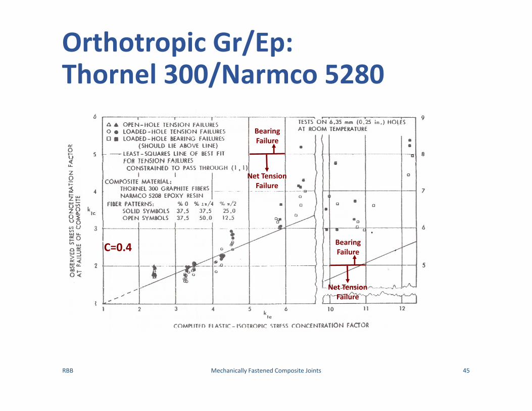
Orthotropic Gr/Ep:Thornel 300/Narmco 5280
RBB Mechanically Fastened Composite Joints 45
Net TensionFailure
BearingFailure
Net TensionFailure
BearingFailure
C=0.4

Quasi‐Isotropic Gr/Ep:Morganite II/Narmco 1004
RBB Mechanically Fastened Composite Joints 46
C=0.25

Orthotropic Gr/Ep:Morganite II/Narmco 1004
RBB Mechanically Fastened Composite Joints 47
C=0.46

C as a Function of 0° Plies
RBB Mechanically Fastened Composite Joints 48
1 1tc tek C k

Quasi‐Isotropic Values of C versus Fastener Diameter
RBB Mechanically Fastened Composite Joints 49
1 1tc tek C k
1
non-dimensional diameter1
dC eddin

Stress Concentration Around a Hole Complex
RBB Mechanically Fastened Composite Joints 50
• Peak stresses actually occur at 45° to the holeo ktc=2 for common laminate configurations
• Individual ply stresses will vary with orientation
• Complex Three Dimensional state of stress
• Interlaminar stresses result in delaminationo tends to reduce ktc through local softening
• Compressive Loading Even More Complex

Shear‐Out Failures
RBB Mechanically Fastened Composite Joints 51
In Metal Structures
• % of 45 plies significantly large • optimal 50% 45 plies
2app
ult
Pe t
Relationship Holds in Composites as long as
Variations in ply percentages will cause changes inShear Out strength

Failure Mode Results for Short Edge Distance, e/d=2
RBB Mechanically Fastened Composite Joints 52

Failure Mode Results for Large Edge Distances, e/d>8
RBB Mechanically Fastened Composite Joints 53

Multiple Rows of Fasteners requires Non‐Linear FEA
RBB Mechanically Fastened Composite Joints 54

First Estimate of Joint Strength for Multiple Rows of Fasteners
RBB Mechanically Fastened Composite Joints 55
• Divide Panel into Strips of Equal Widtho Strip Width = Fastener Pitch po Strip Load Po m =number of Strips/Fastenerso Total Load Pt
• Each Fastener in the Strip will take a Portion of the load P
Total Number of FastenersT
fastenerPP
TPPm
Assuming Linear Interaction between Bearing & By‐Pass Loads
RBB Mechanically Fastened Composite Joints 56
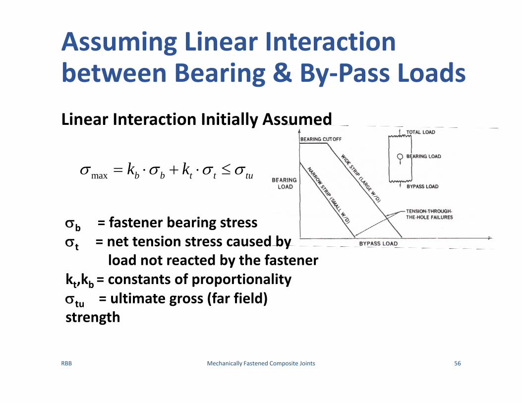
Linear Interaction Initially Assumed
max b b t t tuk k
b = fastener bearing stresst = net tension stress caused by
load not reacted by the fastenerkt,kb = constants of proportionalitytu = ultimate gross (far field) strength

Interaction between Bearing and Bypass In Multi‐Row Joints
RBB Mechanically Fastened Composite Joints 57
max b b t t tuk k
Alleviation Factors and Stress Concentrations Factors
max
3
1 1 1 11
2 3 1121 1 1
1 1
2 1
b be
tebe
t te
te
wk C k dwd
kk
P w w wt d d d d
k C k
dkw
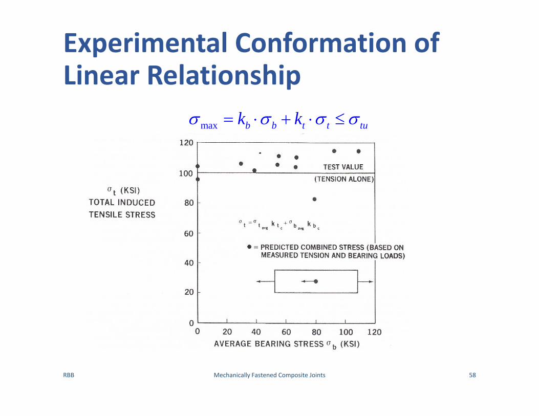
Experimental Conformation of Linear Relationship
RBB Mechanically Fastened Composite Joints 58
max b b t t tuk k

Interaction between Bearing and Bypass In Multi‐Row Joints
RBB Mechanically Fastened Composite Joints 59
max b b t t tuk k
Even if w/d too large to exhibit tensile failure under pure bearing load it will still do so for bypass load
tub
b
Fk
tut
t
Fk
b tu t t brF k F Most Efficient Joint: One bolt subject to a pure Bearing load (no Bypass) with minimum Bearing Load
Maximum Joint Strength: Proportioning the joint to cause tension (rather than bearing) failures at all bolt holes
Interactions for Compressive Loading Has Different Form``
RBB Mechanically Fastened Composite Joints 60
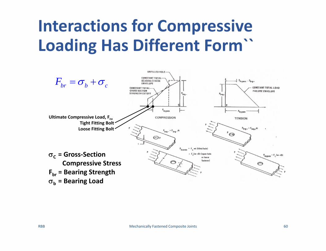
br b cF
C = Gross‐Section Compressive Stress
Fbr = Bearing Strengthb = Bearing Load
Ultimate Compressive Load, FcuTight Fitting BoltLoose Fitting Bolt

Multi‐Rows of Fasteners Show Small Improvement Over Single Row
RBB Mechanically Fastened Composite Joints 61

Impact of 0 Plies on Stress
RBB Mechanically Fastened Composite Joints 62
12.5% 0 Plies
25% 0 Plies
37.5% 0 Plies
50% 0 Plies
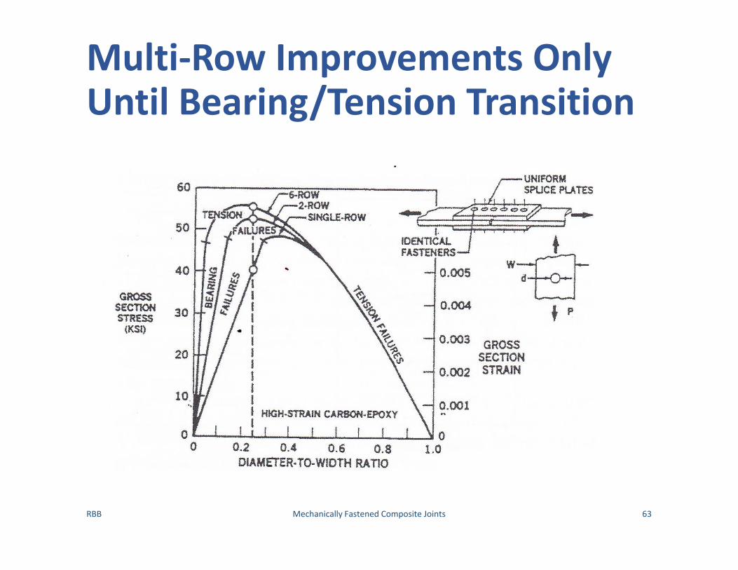
Multi‐Row Improvements Only Until Bearing/Tension Transition
RBB Mechanically Fastened Composite Joints 63

Comparison Between Narrow Strip and Wide Panel
RBB Mechanically Fastened Composite Joints 64

Joint Configurations Have Effect on Bolt Loading
RBB Mechanically Fastened Composite Joints 65

Preliminary Estimation Fastener Load Sharing, Basic Parameters
RBB Mechanically Fastened Composite Joints 66
Plate Stiffness
pA EK
L
Fastener Bending Stiffness
2 2
0
1
Fastener Effective Compliance
8=
22
Fastener Modulus of Elasticity
d Fastener Diameter
f
av av
av f
iav
f
KC
C
t tA B H
t E d d
t tt
E

Parameter Summary
RBB Mechanically Fastened Composite Joints 67
Case InnerPlate
OuterPlate Fastener A B H
1 St St St 0.13 2.12 1.0
2 Al Al Al 0.13 2.12 1.0
3 Al Al St 0.13 2.12 1.87
4 Al St St 0.13 2.12 1.43
5 Al St Al 0.13 2.12 0.84
6 Al Al Ti 0.133 2.06 1.242
7 Al Ti Ti 0.1325 2.06 1.1125
8 CFRP (QI) Ti Ti 0.1325 2.06 1.1125
9 GFRP (QI) Al Al 0.13 2.12 1.0

RBB Mechanically Fastened Composite Joints 68
Number of Rows
Inner‐to‐OuterPlate Stiffness Ratio
Fastener Row Load Shear ExpressionRLF‐Relative Load Fraction
3 Kinner=Kouter RFLR1=RFLR3=‐0.0167(Kt/Kp)2+0.0803(Kt/Kp)+0.3362
RFLR2=0.0333(Kt/Kp)2+0.1607(Kt/Kp)+0.3275

RBB Mechanically Fastened Composite Joints 69
Number of Rows
Inner‐to‐OuterPlate Stiffness Ratio
Fastener Row Load Shear ExpressionRLF‐Relative Load Fraction
4 Kinner=Kouter RFLR1=RFLR4=‐0.0556(Kt/Kp)2+0.1678(Kt/Kp)+0.258
RFLR2=RFLR3=0.0556(Kt/Kp)2‐0.1678(Kt/Kp)+0.2471
RBB Mechanically Fastened Composite Joints 70
Number of Rows
Inner‐to‐OuterPlate Stiffness Ratio
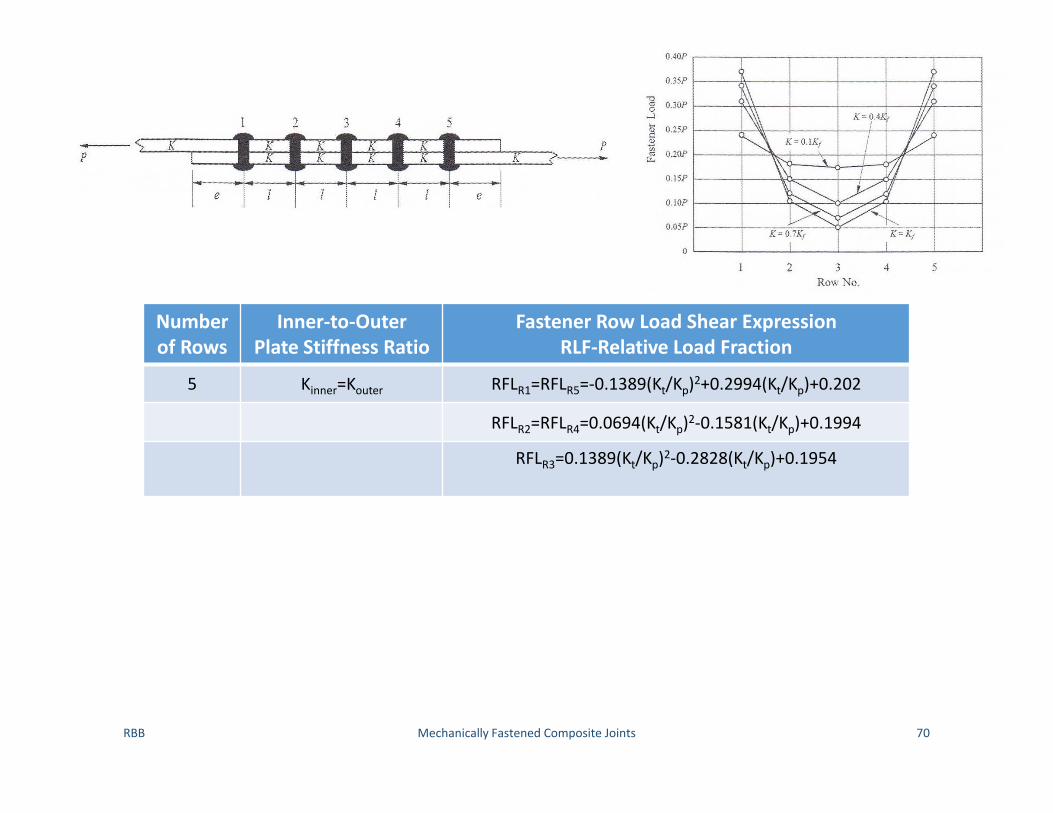
Fastener Row Load Shear ExpressionRLF‐Relative Load Fraction
5 Kinner=Kouter RFLR1=RFLR5=‐0.1389(Kt/Kp)2+0.2994(Kt/Kp)+0.202
RFLR2=RFLR4=0.0694(Kt/Kp)2‐0.1581(Kt/Kp)+0.1994
RFLR3=0.1389(Kt/Kp)2‐0.2828(Kt/Kp)+0.1954

RBB Mechanically Fastened Composite Joints 71
Number of Rows
Inner‐to‐OuterPlate Stiffness Ratio
Fastener Row Load Shear ExpressionRLF‐Relative Load Fraction
3 Kinner=1.5 Kouter RFLR1=‐0.0278(Kt/Kp)2+0.0194(Kt/Kp)+0.3128
RFLR2=0.0138(Kt/Kp)2‐0.1064(Kt/Kp)+0.3205
RFLR3=0.0139(Kt/Kp)2‐0.0869(Kt/Kp)+0.3776

RBB Mechanically Fastened Composite Joints 72
Number of Rows
Inner‐to‐OuterPlate Stiffness Ratio
Fastener Row Load Shear ExpressionRLF‐Relative Load Fraction
5 Kinner=1.5 Kouter RFLR1=‐0.125(Kt/Kp)2+0.2692(Kt/Kp)+0.1551
RFLR2=0.0417(Kt/Kp)2‐0.1142(Kt/Kp)+0.1618
RFLR3=0.1167(Kt/Kp)2‐0.2677(Kt/Kp)+0.2008
RFLR4=0.0972(Kt/Kp)2‐0.1953(Kt/Kp)+0.2383
RFLR5=0.1306(Kt/Kp)2‐0.3079(Kt/Kp)+0.2441

RBB Mechanically Fastened Composite Joints 73
Number of Rows
Inner‐to‐OuterPlate Stiffness Ratio
Fastener Row Load Shear ExpressionRLF‐Relative Load Fraction
2 Kinner=Kouter RFLR1=0.0333(Kt/Kp)+0.5267
Kinner=2/3 Kouter RFLR2=‐0.0333(Kt/Kp)+0.4733
RBB Mechanically Fastened Composite Joints 74
Number of Rows
Inner‐to‐OuterPlate Stiffness Ratio
Fastener Row Load Shear ExpressionRLF‐Relative Load Fraction
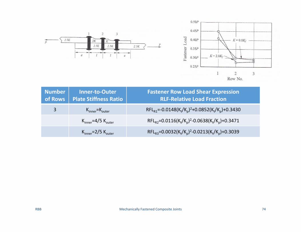
3 Kinner=Kouter RFLR1=‐0.0148(Kt/Kp)2+0.0852(Kt/Kp)+0.3430
Kinner=4/5 Kouter RFLR2=0.0116(Kt/Kp)2‐0.0638(Kt/Kp)+0.3471
Kinner=2/5 Kouter RFLR3=0.0032(Kt/Kp)2‐0.0213(Kt/Kp)+0.3039
RBB Mechanically Fastened Composite Joints 75
Number of Rows
Inner‐to‐OuterPlate Stiffness Ratio
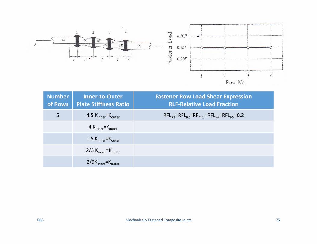
Fastener Row Load Shear ExpressionRLF‐Relative Load Fraction
5 4.5 Kinner=Kouter RFLR1=RFLR2=RFLR3=RFLR4=RFLR5=0.2
4 Kinner=Kouter
1.5 Kinner=Kouter
2/3 Kinner=Kouter
2/9Kinner=Kouter

Bolt Stager Patter Parameters
RBB Mechanically Fastened Composite Joints 76
Fastener Diameter
(in)
lspSingle Row Spacing
sspFastener Stager Spacing
pspStager Distance e
5/32 1.0 0.39 0.63 0.34
3/16 1.18 0.47 0.75 0.41
1/4 1.56 0.63 1.0 0.53
5/16 1.8 0.78 1.19 0.66
3/8 2.35 0.94 1.5 0.78
2 2
2 2
2
2
sp sp sp
sp sp sp
l p s
l p sD D D

Stager Distance for a Single Row of Fasteners
RBB Mechanically Fastened Composite Joints 77

Two Rows of Staggered Fasteners
RBB Mechanically Fastened Composite Joints 78
Net Tension
2
Bearing
2
Shear Out
2 2
NTsp sp
BR
SOsp
P Pt p D t l D
Ft D
Fe s

Three Rows of Staggered Fasteners
RBB Mechanically Fastened Composite Joints 79
Net Tension
2
Bearing
3
Shear Out
2 2 3
NTsp
BR
SOsp
Pt p D
Ft D
Fe s

Questions and Discussion
RBB Mechanically Fastened Composite Joints 80
Copyright © 2022 FDOKUMEN