
OUTLINE DESIGN DESIGN SPECIFICATIONS FOR PHASE-IV ...
145
OUTLINE D DELHI MET Metro B Barakham DESIGN SPECIFICATIONS FOR PHASE-IV (REVISION-2) (JULY 2021) TRO RAIL CORPORATION LTD. Bhawan, Fire Brigade Lane, mba Road, New Delhi – 110 001 S
-
Upload
khangminh22 -
Category
Documents
-
view
3 -
download
0
Transcript of OUTLINE DESIGN DESIGN SPECIFICATIONS FOR PHASE-IV ...
OUTLINE DESIGN
DELHI METRO RAIL CORPORATION LTD.Metro Bhawan, Fire Brigade Lane,
Barakhamba Road, New Delhi
DESIGN SPECIFICATIONS FOR
PHASE-IV
(REVISION-2)
(JULY 2021)
DELHI METRO RAIL CORPORATION LTD. Metro Bhawan, Fire Brigade Lane,
Barakhamba Road, New Delhi – 110 001
SPECIFICATIONS

Outline Design Specifications (July 2021)
Table of Contents
S.No. Description Page No.
1 Introduction 1
2 Outline Design Specifications for Viaduct 3
3 Outline Design Specifications for Double Decker Structure 31
4 Outline Design Specifications for Elevated Stations 39
5 Outline Design Specifications for Cut & Cover Section 56
6 Outline Design Specifications for Bored Tunnel 99
7 Outline Design Criteria for Geotechnical Works 122
8 List of Design Codes and Standards 130

Outline Design Specifications (July 2021)
1
INTRODUCTION
With the introduction of Phase IV the total length of Delhi Metro will exceed 450 Kms. Proposed route of Phase IV construction are listed below :-
S No. Description of Corridor
1 R.K. Ashram to Janakpuri (West)
2 Mukundpur to Maujpur
3 Aerocity to Tughlakabad
4 Inderlok to Indraorastha
5 Lajpat Nagar – Saket G Block
6 Rithala – Bawana - Narela
The Outline Design Specification comprises of Viaduct, Elevated Station, Double Decker, Cut & Cover and Bored tunnels for Phase-IV.
The broad parameters covered in this specification are listed below:
General
1) Material Parameters (Concrete, Reinforcement steel, Structural Steel, Prestressing bars, etc.)
2) Design Parameters
3) Loading Consideration (Dead Load, Super imposed Dead Load, Footpath Live Load, Railway Vehicular Load, Temperature Loads, etc.)
4) Load Combinations
5) Allowable stresses
6) Design Methodology
7) List of Design Codes to be followed
Elevated Structures (Viaduct, Elevated stations & Double Decker)
8) Design Specification for Prestressed Structure
9) Design Specifications for Steel/Composite structure

Outline Design Specifications (July 2021)
2
Underground Structures (Cut & Cover and Bored Tunnels)
10) Tunnel Profile
11) Cross Passage
12) Drainage arrangement in Tunnels
13) Settlement and Building Protection
14) Design Specifications for Temporary Works
Outline Design Specifications (July 2021)
3
OUTLINE DESIGN SPECIFICATIONS FOR
VIADUCT

Outline Design Specifications (July 2021)
4
1 INTRODUCTION
This ODS pertains to Viaduct Portion of the Delhi Metro Phase-IV project.
1.1 SCOPE OF PROJECT
The Viaduct for Delhi Metro Project comprises of simply supported Precast Pre-tensioned twin U-girder (each U-girder supporting one track only)/Post tensioned Segmental Box Girder with RCC sub-structure and bored cast in situ pile /open foundation. The standard gauge of 1435 mm shall be followed. The Centre to Centre distance between two tracks shall be as per approved SOD of DMRC. However, PSC I-Girder / Balanced Cantilever / Steel Composite Girders have been proposed at sharp curves / special spans /crossover/ turnout / railway crossing / highway crossing.
1.1.1 Scope of Design Basis Report (DBR)
This ODS covers design basis with design parameters and assumptions to be adopted in design of foundations & substructures and superstructure of the Viaduct/Bridge based on Model DBR issued by RDSO.
The ODS shall be read in conjunction with the Outline Construction Specifications where appropriate.
1.1.2 Site Particular
The project corridor is located in state of Delhi.
Maximum Temperature 47.8oC (as per Annexure-F of IRC 6)
Minimum Temperature -0.4oC (as per Annexure-F of IRC 6)
Rainfall season July-August
Average Rainfall 800-1000mm
Seismic Zone IV
1.1.3 Units
The main units used for design shall be: [m], [mm], [t], [KN/m2], [MPa], [°C], [rad].
1.1.4 Codes
All relevant codes as listed in DBR shall be of latest revision including all amendments & corrections.
2 TRACK GEOMETRY, TRACK STRUCTURE AND ROLLING STOCK’
Track Geometry, Track Structure & Rolling Stock should be as per the approved SOD of DMRC. Summary of Important parameters are given below:
Gauge : Standard Gauge 1435 mm. Track C/C distance: as per SoD Rolling stock width: 3200mm. Maximum Gradient: as per SoD Track: Ballast less

Outline Design Specifications (July 2021)
5
3 ROADWAY AND RAILWAY CLEARANCES
The viaduct runs along and crosses several existing roadways and existing railways. The following sections outline the general clearance requirements for these crossings.
3.1 CLEARANCES FOR ROAD TRAFFIC
Clearance for road traffic shall be as per clause 104.4.2 of IRC: 5 i.e. 5.50m at 0.250m (0.225m (width of the crash barrier) + 0.025m (clearance between crash barrier and pier shaft)) from pier shaft outer line i.e. at face of crash barrier. In all cases 5.5m clearance shall be kept from road level to soffit level of Metro structure.
Clearance for Railway Traffic should as per Schedule of Dimensions of Indian Railways & for metro crossings as per SOD of DMRC. General Arrangement Drawing of railway crossing shall be approved by the relevant Railway Authority.
3.2 CLEARANCES FOR ROLLING STOCK OF DMRC
Clearances for Rolling Stock should be as per the approved Schedule of Dimensions of DMRC.
4 DESIGN LIFE & SERVICEABILITY
The life of main structural systems should be 100 years (as per clause-15.1.3 & 16.1.3 of IRS-CBC & 3.6.5 of IRS steel Bridge code).
5 MATERIALS PARAMETERS
5.1 CONCRETE
I. Young's Modulus & Modular ratio
A. Young's Modulus
Clause-5.2.2.1 of IRS-CBC shall be followed.
Grade of Concrete (N/mm2)
Modulus of Elasticity (kN/mm2)
M10 18.0 M15 22.0 M20 25.0 M25 26.0 M30 28.0 M35 29.5 M40 31.0 M45 32.5 M50 34.0 M55 35.0 M60 36.0
B. Modular Ratio:
Modular Ratio including long term effects such as creep shall be taken as per clause 5.2.6 of IRS-CBC i.e. m1=280/fck for tensile reinforcement & m2 =420/fck for compression reinforcement.

Outline Design Specifications (July 2021)
6
II. Grade of Concrete & Cover
Minimum grade of concrete should be as per clause-5.4.4 of IRS-CBC. For exposure condition referred in Clause-5.4.1 of IRS-CBC. The cover should be as per clause 15.9.2 of IRS-CBC.
In case of foundation, cover shall be taken as 75mm for all conditions of exposure.
III. Cement
As per Clause 4.1 of IRS-CBC.
The minimum cementitious material content shall be as per clause-5.4.5 & Table-4 (c) of IRS-CBC.
The maximum water-cement ratio shall be as per clause 5.4.3 & Table-4(a) of IRS-CBC. The total chloride content by weight of cement shall be as per Clause 5.4.6 of IRS-CBC.
IV. Density
Density of concrete shall be 25 kN/m3 for PSC and RCC, 25 kN/m3 for Plain cement concrete and 26 kN/ m3 for Wet concrete.
V. Poisson's Ratio
Poisson's ratio for all grades of concrete shall be 0.15.
VI. Thermal Expansion Coefficient
Coefficient of thermal expansion (a) has been considered as 11.7 x10⁻⁶ oC in accordance with Clause-2.6.2 of IRS-Bridge Rules.
VII. Time-Dependent Characteristics of Materials
i) Long-term losses should be calculated in accordance with Clause-16.8.2 of IRS-CBC.
ii) The design shall be done according to construction sequence to be adopted in site.
5.2 PRESTRESSING STEEL FOR TENDONS
Prestressing steel shall be as per clause 4.6 of IRS-CBC. Characteristic strength of prestressing tendons shall be as per clause 16.2.4.3 of IRS-CBC.
i) Prestressing Units (as per Table-2, Class-II of IS 14268)
All Prestressing steel units shall be of 0.6” strands type (Nominal diameter =15.2mm, Area=140 mm2).
ii) Breaking Strength & Breaking Stress (as per Table-1, Class-II of IS 14268)
Breaking strength of strand = 260.7 kN
0.2% Proof Load = 234.6 kN
0.1% proof Load (85% of UTS) = 221.6 kN
Minimum breaking stress = 1860 MPa
Outline Design Specifications (July 2021)
7
iii) Density: =78.5 kN/m3
5.2.1 Young's Modulus
Young's modulus of Prestressing steel shall be taken as 195.0GPa as per § 4.6.2.1 of IRS -CBC for the Strands confirming to IS: 14268.
5.2.2 Prestressing
Jacking Force shall be as per Clause- 16.8.1 of IRS-CBC.
Other Parameters:
Sheathing: Corrugated HDPE Duct shall be used as per clause-7.2.6.4.2 of IRS-CBC.
Diameter of Sheathing 107mm ID for 19K15 , 86mm ID for 12K15 and 69mm for 7K15 as
per clause 6.2.1 of Technical specifications. Wobble / Curvature shall be 0.0020 /m & 0.170 as per clause Table 26A of IRS-CBC.
Clear Cover shall be provided from outer diameter of duct. Minimum center to center spacing between ducts shall be taken w.r.t outer diameter of duct.
Maximum Slip at anchorage = 6mm (to be decided based on pre-stressing anchorage system adopted).
5.3 REINFORCEMENT STEEL (REBARS)
High strength deformed (HYSD) reinforcement bars of Fe-500D grade, conforming to IS 1786 and Clause 4.5 & 7.1.5 of IRS-CBC shall be used.
I. Young’s Modulus: E= 200,000 Mpa
II. Yield Stress: fy = 500 MPa.
III. Density: 78.5 kN/m3
5.4 STRUCTURAL STEEL (FOR COMPOSITE BRIDGES & OTHER STRUCTURES IF ANY)
I. Introduction
Structural steel shall be used for special composite bridges and for miscellaneous use such as railing, supporting utilities, coverings etc.
ll. Structural Steel for Miscellaneous Use
The design of miscellaneous structure shall be done as per IS: 800 and related provisions.
Hollow steel sections for structural use shall be as per IS: 4923.
Steel tubes for structural purpose shall be as per IS: 1161.
Steel for General Structural Purposes (Grade E250, E350 – B0) shall be as per IS: 2062.
III. Structural Steel for Composite Bridges
A. General
Structural steel conforming to IS: 2062 shall be adopted.

Outline Design Specifications (July 2021)
8
Fabrication shall be done as per provisions of IRS B1 (Fabrication Code).
Design of steel structures shall be done as per IRS steel Bridge Code.
IRC Code: 22 shall be referred for steel-RCC composite construction.
Welding shall be done following IRS Steel Bridge Code, IRS welded Bridge code or relevant IS codes for welding.
Grade# Tensile Strength
(Mpa) Yield Stress (Mpa)
t<20 t=20-40 t>40 E250 B0 410 250 240 230 E350 B0 490 350 330 320
*t-thickness
B. Young's Modulus shall be taken as 21,100kg/mm2 as per Clause-A-1.3 of IRS-Steel Bridge Code.
C. Density: 7850 kg/m3 as per clause 505.2.2.1 of IRC: 24.
D. Poisson’s Ratio: 0.30 as per clause 505.2.2.1 of IRC: 24.
E. Thermal Expansion Coefficient: 12x10-6 as per clause 505.2.2.1 of IRC: 24.
Note: In case design of any component/member is done using foreign code, material shall confirm to the specifications of the relevant foreign code.
5.5 DESIGN GROUND WATER TABLE
The Ground water table (Base value) shall be considered as maximum (in terms of RL) of Ground water table data published by (a) Central Ground water board (CGWB), (b) Ground water table reported in Geotechnical report provided by DMRC in tender documents, (c) Ground water table reported in Geotechnical report provided by Design & Build contractor.
The design Ground water table shall be taken as 4.0m higher than the Base value for evaluation of effects for design purposes.
5.6 LIQUEFACTION
Liquefaction shall be considered as per IS 1893-Part-1. The design Ground water table shall be used for liquefaction potential calculation. The Moment Magnitude Mw to be taken in design shall be 7.0. The factor of safety shall be more than 1.0 to ascertain that the strata is not liquefiable.
5.7 SOIL PARAMETERS
The borehole, which provide lesser vertical & Horizontal capacity of pile or lesser SBC in case of open/Well foundation, shall be referred in design among 1 & 2 as referred below. For Pile foundation, in case one bore hole provide lesser Horizontal capacity and other provide lesser vertical capacity then lesser values of horizontal & vertical capacity obtained from two boreholes shall be referred.
1) As per soil investigation report in the tender document.
2) As per soil investigation done by contractor.

Outline Design Specifications (July 2021)
9
The soil investigation report of Bore hole done by contractor shall be compared by soil investigation report of the nearest Bore hole given in the tender document.
6 LOADS TO BE CONSIDERED FOR DESIGN
Following are the various loads to be taken into consideration for analysis and design of structures as prescribed in IRS-Bridge Rules up to latest up-to-date correction slip.
6.1 DEAD LOAD
Dead load shall be based on the actual cross section area and unit weights of materials and shall include the weight of the materials that are structural components of viaduct and permanent in nature.
6.1.1 SUPER IMPOSED DEAD LOAD (SIDL)
Superimposed dead loads include all the weights of materials on the structure that are not structural elements but are permanent. It includes weight of track form plinth/rails/ fasteners/ cables/parapet/ hand-rail OHE mast/ cable trough/ Signaling equipment etc. and will be considered in the design as per following assumptions.
S.No. Element Unfactored
Load
1 Parapet/Railing * 2 Plinth 3.40 t/m 3 Rail+Pads (All 4) 0.30 t/m 4 Cables 0.07 t/m 5 Cable trays# 0.01 t/m 6 Deck drainage concrete (Avg. thk. 62.5mm) 0.24 t/m 7 Miscll. (OHE Mast, Signalling , etc.) 0.40 t/m 8 Solar Panel (wherever applicable) 30kg/sqm 9 Noise Barrier (wherever applicable) 0.2 t/m 10 PTM Pipe Line 0.06t/m
*Parapet/Railing weight shall be calculated as per actual. The load due to parapet/railing shall be considered as fixed type and load factor applicable for dead load shall be consider for this component. All other SIDL shall be considered as variable.
# in case cable through cell is used; its weight will be 0.74 t/m
## In case of cross-over, actual track weight including plinths shall be considered for design.
6.2 SHRINKAGE & CREEP
Shrinkage and Creep effects will be calculated as per Clause 5.2.3 & 5.2.4 of IRS CBC.
6.3 PRE-STRESS FORCE (PR)
The pre-stressing force calculation will be as per Clause-16.8 of IRS-CBC. The loss of pre-stress due to friction will be calculated as per Clause-16.8.3 of IRS-CBC.
For calculation of long-term effects, the relative humidity to be considered as per Annexure A.7 of IRC 112 shall be (70(max) +47(min))/2 = 58.5%

Outline Design Specifications (July 2021)
10
Provision of emergency cables and future cables in prestressing shall be made as per clause 16.9.9 & 16.9.10 of IRS:CBC.
6.4 LIVE LOAD (LL)
6.4.1 Railway Vehicular Load
Each component of the structure shall be designed / checked for all possible combinations of these loads and forces. They shall resist the effect of the worst combination:
All axle loads = 17 tons
Maximum number of successive cars=6
Where,
L = 22.100m (Length of a car)
a = 2.250m (overhang)
b = 2.500m (Wheel base in a bogie)
c = 12.600m (Distance between Axle-2 and Axle-3 in the car)
Moving load analysis shall be carried out in order to estimate the maximum longitudinal force, max shear and max BM. The simply supported structures shall be designed for Medium Metro Loading Envelopes as tabulated in Annexure-l of Model DBR of RDSO.
In case of Twin U-Girder, each U-Girder will support only one track.
These superstructures and sub-structures will be checked for one track loaded condition as well as both tracks loaded condition (Single Span as well as Both Spans loaded condition).
However, for any other configuration (Axle load, and Axle spacing) of Modern Rolling stock including maintenance, machinery, crane etc., shall be within the loading envelope of present live load configuration.
6.4.2 Dynamic Augmentation
CDA will be considered as specified in clause 2.4.1.1 of IRS Bridge Rule. No reduction for double track loading will be considered.
6.4.3 Footpath Live Load
Footpath live load shall be taken as 490 kg/sqm. as per clause 2.3.2 of IRS Bridge Rules. As footpath live load is to be considered with carriageway live load without impact, this design

Outline Design Specifications (July 2021)
11
will not be critical for any design except the parapet. The parapet will be designed for this loading.
6.4.4 Longitudinal Force
Braking load is taken as 18% of the unfactored Axle load.
Traction load is taken as 20% of the unfactored Axle load.
Since both the tracks are supported by a single girder, hence tractive force of one track and braking force of another track will be taken in the same direction to produce worst condition of loading.
As per Clause-2.8.5 of IRS-Bridge Rules, in transverse / longitudinal seismic condition, only 50% of gross tractive effort/braking force will be considered.
Dispersion, of longitudinal forces is not allowed as per Clause-2.8.3.4 of IRS Bridge Rules except during checking of Rail stress.
6.4.5 Centrifugal Forces Due to Curvature of Superstructure
The horizontal centrifugal force due to moving load in curved superstructure is to be considered as per § 2.5 of IRS: BR.
C = 𝑾 𝒗𝟐
𝟏𝟐𝟕 𝐑
Where W is Live load reaction & C is Centrifugal force (unit of C & W shall be same), v is maximum design speed in km/h and R is radius of curvature in m. This force is assumed to act at a height of 1.830 m above rail top level on safer side.
Design Speed of Live load of 95 km/h will be considered for computation of centrifugal force for curvature up to 450m radius. For sharper curves, speed restrictions as per SOD shall be followed.
6.4.6 Racking Force
The horizontal transverse loading due to racking specified in IRS-Bridge Rules Clause-2.9 is applicable to design of lateral bracing.
6.5 TEMPERATURE EFFECTS
6.5.1 A) Overall Temperature (OT)
The loads shall be considered as per Clause-2.6 of IRS-Bridge Rules and Clause-215 of IRC: 6. Temperature variation of + 35°C will be considered details of which are given below
Maximum Temperature considered as per Annex. F of IRC 6: +47.8°C
Minimum Temperature considered as per Annex. F of IRC 6: -0.4°C
Temperature variation as per clause 215.2 of IRC 6 will be =(47.8-(-0.4)/2+10=+34.1°C say 35OC.

Outline Design Specifications (July 2021)
12
B) Differential Temperature (DT)
The provision given in § 215.4 of IRC 6, shall be considered to compute effect of differential temperature gradient in absence of any provisions in IRS code. The differential gradient of temperature along depth of superstructure has been reproduced below for ready reference. Short term modulus of elasticity as per Table given under clause 5.1 of DBR shall be used to calculate the effects.
Note: For purpose of these calculations no reduction shall be made for presence of track plinths.
Temperature Difference for Concrete Bridge Decks
Temperature Difference across Steel and Composite Sections
Note: For purpose of these calculations no reduction shall be made for presence of track plinths.
T1
h1 h1 h4
h2 h2
Positive Temperature Difference Negative Temperature Differenceh1 =0.6hh2 =0.4m
H(m) T1ocH(m) T1oc 0.2 4.40.2 180.3 20.5
Positive Temperature Difference h1 = 0.3h < 0.15m h2 = 0.3h > 0.1m < 0.25m h3 = 0.3h <0.15m
Negative Temperature Difference h1 = h4 = 0.2h < 0.25m h2 = h3 = 0.25h < 0.25m

Outline Design Specifications (July 2021)
13
6.5.2 Resistance to Movement of Elastomeric Bearings (BS)
Elastomeric bearing will resist movement/deformation of superstructure other than applied load i.e. due to variation of temperature/creep strain/shrinkage strain etc. The bearing resistance shall be calculated as per Clause-211.5.1.3 of IRC: 6.
The bearing resistance will produce lateral force on the substructure and foundation. The bearing resistance shall be calculated as (VL L - VR R), where VL and VR are the shear rating of the left and right elastomeric bearings respectively and L and R are the deck movement at elastomeric bearing location. The above force will be zero when both side spans & supporting bearings are identical, in such case 10% of VL L shall be considered for design of substructure and foundation.
6.5.3 Rail Structure Interaction (LWR Forces)
Guidelines vide BS Report No. 119 “RDSO Guidelines for carrying out Rail-Structure Interaction studies on Metro System (version-2)” shall be followed.
A rail structure interaction [RSI] analysis is required because the continuously welded running rails are continuous· over the deck expansion joints. The interaction occurs because the rails are directly connected to the decks by fastening system.
1. Rail structure interaction studies shall be done as per provisions of “RDSO Guidelines for carrying out Rail-Structure Interaction studies on Metro System (version-2)”. The following shall be adhered to:
a) Track resistance in loaded and unloaded conditions shall be obtained from cl. 3.2.6 Track Stiffness of “RDSO Guidelines for carrying out Rail-Structure Interaction studies on Metro System (version-2)”. As per the clause, the recommended values for track stiffness for ballasted tracks are 60kN/m and 20kN/m for loaded and unloaded track respectively and recommended values of track stiffness for ballast less tracks are 60kN/m and 40kN/m for loaded and unloaded tracks respectively. The elastic limit is 2 mm for ballasted tracks and 0.5 mm for ballast less tracks. No change in track stiffness is permitted on account of actual track behavior.
b) The temperature variations, to be used for analysis, shall be taken as per provisions of cl. 3.2.8 Temperature Variations of “RDSO Guidelines for carrying out Rail-Structure Interaction studies on Metro System (version-2)”. The following shall be used for analysis:
-The temperature of the bridge does not deviate from the reference temperature by more than + 35 0C
-The temperature of the rail does not deviate by more than + 500C.
-The difference in temperature between deck and track does not exceed + 200C.
-The reference temperature is the temperature of the deck and the rail when the rail is fixed.
c) Maximum additional stresses in rail in tension as well as compression on account of rail-structure interaction shall be within the permissible limits as prescribed in cl. 3.3.1 Additional Stresses in Rails of “RDSO Guidelines for carrying out Rail-Structure

Outline Design Specifications (July 2021)
14
Interaction studies on Metro System (version-2)”. The limit prescribed in the document shall be used as it is and no benefit on account of lesser axle load of actual rolling stock shall be permitted.
d) The provisions of cl. 3.3.2 Displacements of Bridge Elements of “RDSO Guidelines for carrying out Rail-Structure Interaction studies on Metro System (version-2)” shall be adhered to.
e) Checks must be performed for break in rail continuity due to unusual conditions such as fractures or for maintenance purposes. The provisions of cl. 4.8 “Rail Gap Analysis of RDSO Guidelines for carrying out Rail-Structure Interaction studies on Metro System (version-2)” shall be followed.
f) Minimum (unfactored) LWR force of 1.6t/m of span length shall be considered for design irrespective of number of tracks.
2. Software and general methodology to be used for carrying out Rail Structure interaction analysis must be validated before adopting the same. A well-established document such as UIC 774-3R may be used for validation.
3. Representative stretches must be chosen for carrying out Rail-Structure interaction which shall include special spans. The same shall be got approved from the engineer.
4. LWR forces shall be considered in appropriate load combinations as specified in cl. 7.0 Load Combinations (Ground IIIb) of the DBR.
6.6 WIND LOAD (WL)
The wind load shall be calculated as per § 2.11 of IRS: BR and IS: 875 (Part 3).
As per § 5.3 of IS: 875 (Part 3)
Design Wind Speed, Vz = Vb.k1.k2.k3.k4
Where
Vb = Basic wind speed = 50 m/s for Delhi Zone (as per National Building code).
K1 = 1.08 for class IV type structure (§ table 1 of IS: 875 (Part 3)). k2 = 1.07 for category 2 (§ table 2 of IS: 875 (Part 3)) for 20m Height. k2 = 1.12 for category 2 (§ table 2 of IS: 875 (Part 3)) for 30m Height k3 = 1.0 (§ 6.3.3.1 of IS: 875 (Part 3)). K4=1.0 (for non-cyclonic zone as per clause 6.3.4)
However, a bridge shall not be considered to be carrying any live load when the wind pressure at deck level exceeds 150kg/m2 as per clause 2.11.2 of IRS Bridge rule, however as it is a long viaduct therefore there is fair possibility that once wind pressure exceeds 150kg/m2 train may be standing static over viaduct due to close of operation therefore in case of wind pressure above 150kg/m2, train will be considered as static load i.e. no longitudinal loads or impact loads.
Wind load on train in transverse direction will be calculated based on exposed surface & intensity as per above given values& reference. These are computed for length of train as

Outline Design Specifications (July 2021)
15
seen in elevation normal to longitudinal axis. The transverse load will be applied to train at center of projected area of the vehicle.
As per clause 209.3.4 of IRC: 6 the longitudinal wind load on Superstructure will be considered as 25% of Transverse load for Beam/Box/U/Plate girder bridges. In case of Truss Bridges longitudinal load on Superstructure will be considered as 50%.
As per clause 209.3.6 of IRC: 6 the longitudinal wind load on Live Load will be considered as 25% of Transverse Wind load considered on Live load.
In case of Pier & Pier cap full load will be considered.
The longitudinal load will be acted simultaneously with transverse load.
Effect of vertical wind load shall be considered in accordance with clause 209.3.5 of IRC: 6.
6.7 SEISMIC FORCE (EQ)
The purpose of this section is to summarize the methodology and the assumptions that shall be used for the seismic analysis.
6.7.1 Seismic Design
Seismic design philosophy as stated in IRS Seismic Code has been considered. The peak ground acceleration denoted as zone factor is taken as 0.24 since Delhi is situated in zone IV of seismic map of India.
6.7.2 Definition of Seismic Input
Spectral Acceleration (Sa/g vs T) as prescribed in IRS Seismic code, shall be used for seismic load computation.
6.7.3 Horizontal Seismic Coefficient
The horizontal seismic design coefficient shall be calculated as per following expression
Ah = (Z/2) * (I/R) * (Sa/g) Where,
Ah = horizontal seismic coefficient to be considered in design Z = peak ground acceleration or zone factor = 0.24 I = importance factor = 1.5 R = response modification factor as per Table 3 Sa/g = normalized pseudo spectral acceleration for corresponding to relevant
damping of load resisting elements (pier/columns) depending upon the fundamental period of vibration T
Damping factor = 5% for reinforced concrete piers.

Outline Design Specifications (July 2021)
16
6.7.4 Response Reduction Factor
Response Reduction Factor “R” as per IRS Seismic code Table -3 shall be as given below
S.No. Elements Response Reduction Factor “R”
1 RCC Pier with ductile detailing 3.0
2 PSC Pier/Pier cap/Portal beam 2.0
3 Portal Pier with ductile detailing
(Beam integral with pier)
3.0-In Longitudinal direction
4.0-In transverse direction
4 Bearing/Superstructure 2.0
5 Stopper 1.0
6 Foundations 2.0
Note: In addition to the response reduction factor given above, reinforcement detailing of Piers/Portal Piers shall conform to ductility/capacity design requirements as per Annexure-B of IRS Seismic Code.
6.7.5 Vertical Seismic Coefficient
The seismic zone factor & time period (of Vertical motion) for calculating vertical seismic coefficient shall be considered as per clause 7.3.2 & 9.4.2 of IRS seismic code. The Zone factor for calculating the vertical seismic coefficient will be 2/3*Zone factor i.e. 2/3*0.24=0.16. For Pier & foundations, while calculating vertical seismic coefficient R=1 shall be considered.
6.7.6 Computation of Fundamental period of vibration
The fundamental time period shall be calculated by any rational method of analysis. Each pier is considered as a single degree of freedom oscillator with mass placed at the Centre of Gravity (COG) of the deck.
The time period can also be calculated based on expression given in Clause 8.1 of IRS Seismic Code, which is as follows:
a) Mass
Permanent masses (Self Weights, SIDL) of:
(a) Full span longitudinally, which can be resisted by reaction blocks or POT/Spherical bearings during earthquake, at one side of the pier or half of spans on either side of pier in case seismic is resisted by bearings (For longitudinal seismic)
(b) Half of spans on either side of pier (For transverse seismic)

Outline Design Specifications (July 2021)
17
Mass of the pier cap
The earth quake acceleration will be considered on full mass and not buoyant mass.
It may be noted that while calculating lateral seismic forces, 50% live load is included in the seismic weight for transverse direction i.e. Minimum live load among 4 cases i.e. OSOT (one span one track), OSBT (One span both tracks), BSOT (Both span one track) & BSBT (Both span both tracks) will be considered, whereas no live load is included for seismic weight in longitudinal direction.
As per clause 2.8.5 of IRS: Bridge Rule, in transverse/ longitudinal seismic condition, only 50% of gross tractive effort / braking force/centrifugal force/racking force shall be considered.
b) Stiffness
Stiffness shall be calculated with the concrete instantaneous modulus of elasticity, for all structural elements.
Pier stiffness considering fixed base and free at deck location K = 3EIeff/L3
Ieff=0.75Ig, as per clause 5.2.1 of IRC: SP: 114-2018. In the calculation of fundamental time period, effective moment of inertia is considered.
Flexibility of foundation soil system may be considered while calculating time period i.e. foundation and soil spring may be modelled while calculating time period.
The static stiffness of soil spring shall be calculated as per Table-3 of Annexure-C of IS 2911 Part-1 (Section 2). While calculating the static soil stiffness, soil shall be considered as dry granular soil (for time period calculation) with uniform N values of 25 throughout the depth or actual soil stiffness for all cases, whichever is critical. In liquefaction zone no soil spring shall be considered.
Only for calculating the time period, dynamic stiffness (Kdynamic) shall be used and it shall be taken as 3.5 times the static stiffness (Kstatic) i.e Kdynamic= 3.5*Kstatic.
For calculating effect of seismic forces i.e. Axial load, BM, SF, Torsions etc. for design of members, the static value of soil springs as per clause 12.4.2 of the DBR shall be used.
Time period of more than 4s shall not be allowed in any case; section needs to be resized when it exceeds 4s.
6.7.7 Direction Combinations
The seismic forces shall be assumed to come from any horizontal direction. For this purpose, two separate analyses shall be performed for design seismic forces acting along two orthogonal horizontal directions. The design seismic force resultant (that is axial force, bending moment, shear force and torsion) at any cross section of abridge component resulting from the analysis in the two orthogonal horizontal directions shall be combined according to the expressions given below.
a) ± ELx ± 0.3 ELy b) ± 0.3 ELx ± ELy
Where ELX = Force resultant due to full seismic force along X direction, and ELY = Force resultant due to full seismic force along Y direction
When vertical seismic forces are also considered, the design seismic force resultants at any cross-section of a bridge component shall be combined as below:

Outline Design Specifications (July 2021)
18
a) ± ELx ± 0.3 ELy ± 0.3 ELz b) ± 0.3 ELx ± ELy ± 0.3 ELz c) ± 0.3 ELx ± 0.3 ELy ± ELz
Where ELX and ELY are as defined above and ELZ is the force resultant due to full seismic force along vertical direction. As an alternative to the procedure given above, the forces due to the combined effect of two or three components can be obtained on the basic square root of sum of square (SRSS) √(ELx
2+ ELY2) or √(ELx
2+ ELY2+ ELZ
2)
6.8 ERECTION TEMPORARY LOADS (ETL)
Erection forces and effects shall be considered as per Clause-2.13 of IRS-Bridge Rules.
The weight of all permanent and temporary materials together with all other forces and effects which can operate on any part of structure during erection shall be considered in design. The loads arising from most onerous conditions of the construction methods adopted is awaited from the Contractor.
Special care shall be taken that no damage is caused by the construction contractor to the permanent structure. In case of any hole etc., drilled in permanent structural element, the same will be made good by using non-shrink, expansive, high strength grout and its strength shall be better than the structural element and will have to be demonstrated.
6.9 DERAILMENT LOADS (DR)
For vertical considerations, check shall be made in accordance with the IRS-Bridge Rules, Appendix-XXV with standard gauge in place of Broad gauge. For ULS and stability check, loading shall proportional as per maximum axle load.. This derailment load corresponds to an ULS load for SLS combinations (Group-V of IRS-CBC) a 1/1.75 coefficient will be applied to the derailment load. The Sacramento criteria need to be considered for U-Girder.
6.10 FORCES ON PARAPET
The parapets shall be designed to resist lateral horizontal force & a vertical force of 1.50 kN/m applied simultaneously at the top of the parapet as per Clause 2.10 of IRS Bridge Rules.
6.11 DIFFERENTIAL SETTLEMENT (DS)
Differential Settlement between two adjacent viaduct piers shall be as follows.
i) 12mm for Long Term Settlement;
ii) 6 mm for Short Term Settlement
The allowable settlement for pile group is 25mm (as per IS 2911-part 4); hence differential settlement between two foundations is considered as half of 25 mm i.e. 12 mm as long-term settlement. The short-term settlement of 6mm is considered to cater for bearing replacement condition.
Differential settlement shall be considered only in the design of continuous structures, if any.

Outline Design Specifications (July 2021)
19
6.12 BUOYANCY LOADS
The design of the foundation shall be done considering design ground water table as referred in clause 5.5 of the DBR.
In case of river bridges, stability check and calculation of base pressure, full buoyancy shall be considered on submerged portion of substructure and foundation up to HFL or LWL as the case may be, irrespective of the type of soil on which the foundation will rest.
Hydro dynamic forces will be considered as per clause 6 of IRS Seismic code.
6.13 WATER CURRENT FORCES
Water current force in submerged portion of substructures and foundations shall be calculated as per Clause 5.9 of IRS Bridge Substructure & Foundation Code
6.14 VEHICLE COLLISION LOAD (VCL)
The vehicle collision load on piers: as per Clause-222 of IRC: 6. Rules specifying the loads for design of superstructure and sub-structure of bridges and for assessment of the strength of existing bridges should be done as per IRS: Bridge Rules. All structure near railway track shall be checked for accidental impact from derailed trains as per clause 2.16.4 of IRS Bridge Rules as per Addendum & Corrigendum Slip No. 48 dated 22.06.2017.
6.15 GRADIENT EFFECT
The bearing shall be sandwiched between two true horizontal surfaces. Steel Wedge shall be provided to cater longitudinal slope of superstructure.
6.16 BUFFER LOAD
Provision of Buffers is contemplated at the end of temporary terminal stations during stage opening of the Corridors, at Pocket track ends and at the terminal stations of the corridors (at the end of turn back/stabling lines). Such buffers will be of friction type. These buffers will be designed to have stopping performance based on mass of fully loaded train and its declaration to avoid damage to the train or buffer. Viaduct elements need to be designed for such Buffer load. The exact Buffer loads need to be interfaced and ascertained during the detailed design.
6.17 VIBRATION EFFECT
Effect of vibration due to movement of train on Viaduct structure will be taken into consideration. This will be checked in dynamic analysis.

Outline Design Specifications (July 2021)
20
7 LOAD COMBINATIONS
7.1 Methodology: Provisions of IRS-CBC shall be followed. The partial load factors and load combinations shall be as per Clause-11 and Table-12 of IRS-CBC as modified and shown below:
Load Abbreviations Dead load DL Super imposed dead load SIDL Prestressing PS Live Load LL Live load on footpath LFP Longitudinal force ( Traction & Braking) LF Centrifugal force CF Over all temperature OT Differential Temperature DT Long welded rail force LWR Racking Forces RF Wind forces WL Earthquake EQ Differential settlement DS Derailment DR Erection load ER

Outline Design Specifications (July 2021)
21
Limit state Loads Symbol G I
G II (EQ) G II (WL) G III (a) G III (b)
G V G IIa (EQ)
G II b (EQ)
G IIa (WL)
G II b (WL)
Temperature LWR
SLS
Com
bina
tions
Dead Loads DL 1.00 1.00 1.00 1.00 1.00 1.00 1.00 1.00 Prestressing PS 1.00 1.00 1.00 1.00 1.00 1.00 1.00 1.00 Super Imposed Loads (fixed)
SIDL-1 1.00 1.00 1.00 1.00 1.00 1.00 1.00 1.00
Super Imposed Loads (variable)
SIDL-2 1.20 1.20 1.20 1.20 1.20 1.20 1.20 1.20
Earthquake EQ
1.00 1.00
Overall T OT 1.00 1.00
LWR 1.00 Differential DT
DT
0.80 0.80
Differential settlement
DS 1.00
Live load LL 1.10
0.50
1.00 1.00 0.50 Live load on footpath
LWP 1.00 0.50 1.00 1.00 0.50/ 1.00 (#)
Derailment Loads
DR
1.00(**)
Wind Load
1.00 1.00
ULS
Com
bina
tions
Dead Loads DL 1.25 1.25 1.25 1.25 1.25 1.25 1.25 1.25
Prestressing PS 1.15/0.87 (*) 1.40 1.40 1.15/0.87
(*) 1.15/0.87 (*)
1.15/0.87
(*) 1.15/0.87 (*)
1.15/0.87 (*)
Super Imposed Loads (fixed)
SIDL-1 1.25 1.25 1.25 1.25 1.25 1.25 1.25 1.25
Super Imposed Loads (variable)
SIDL-2 2.00 2.00 2.00 2.00 2.00 2.00 2.00 2.00
Earthquake EQ
1.60 1.25
Overall T OT 1.50 1.50
LWR 1.50 Differential DT
DT
1.15 1.15
Differential settlement DS
Live load LL 1.75 0.50 1.40 1.40 0.70 Live load on footpath
LWP 1.50 0.50 1.25 1.25 0.6125
Derailment Loads DR 1.00
Wind Load 1.60 1.25
In each of SLS and ULS cases, 5 basic load combination groups shall be considered, according to the IRS- CBC.
(*) 1.15/0.87: In accordance with IRS CBC article 11.3.3., when the Prestressing PR increases the section capacity vs. shear then PR is multiplied by 0.87. When the Prestressing PR decreases the section capacity vs. shear then PR is multiplied by 1.15.
(**) Refer clause 6.9.
# 0.50 for two or more tracks and 1.0 for single track.
Notes:
1) ULS-Ultimate Limit state2) SLS-Serviceability Limit state3) Wind load and earth quake loads shall not be assumed to be acting simultaneously.4) Live load shall also include dynamic effect, force due
longitudinal forces, braking forces and forces on parapet.5) Crack width check shall be done in SLS case for 6) Load combination for Vehicle collision shall be as per IRC 6 but design of members under
vehicle collision load combination shall be carried out as per IRS CBC.7) Load combination 1.0*DL + 1.0*SIDL8) Load combination 1.5*DL
7.2 The Superstructure/bearing, sloaded condition as well both track loaded condition, for single span and both spans loaded conditions, as the case may be.
7.3 Design of viaduct shall be done in accordance with the construction mconstruction sequence to be adopted during execution.
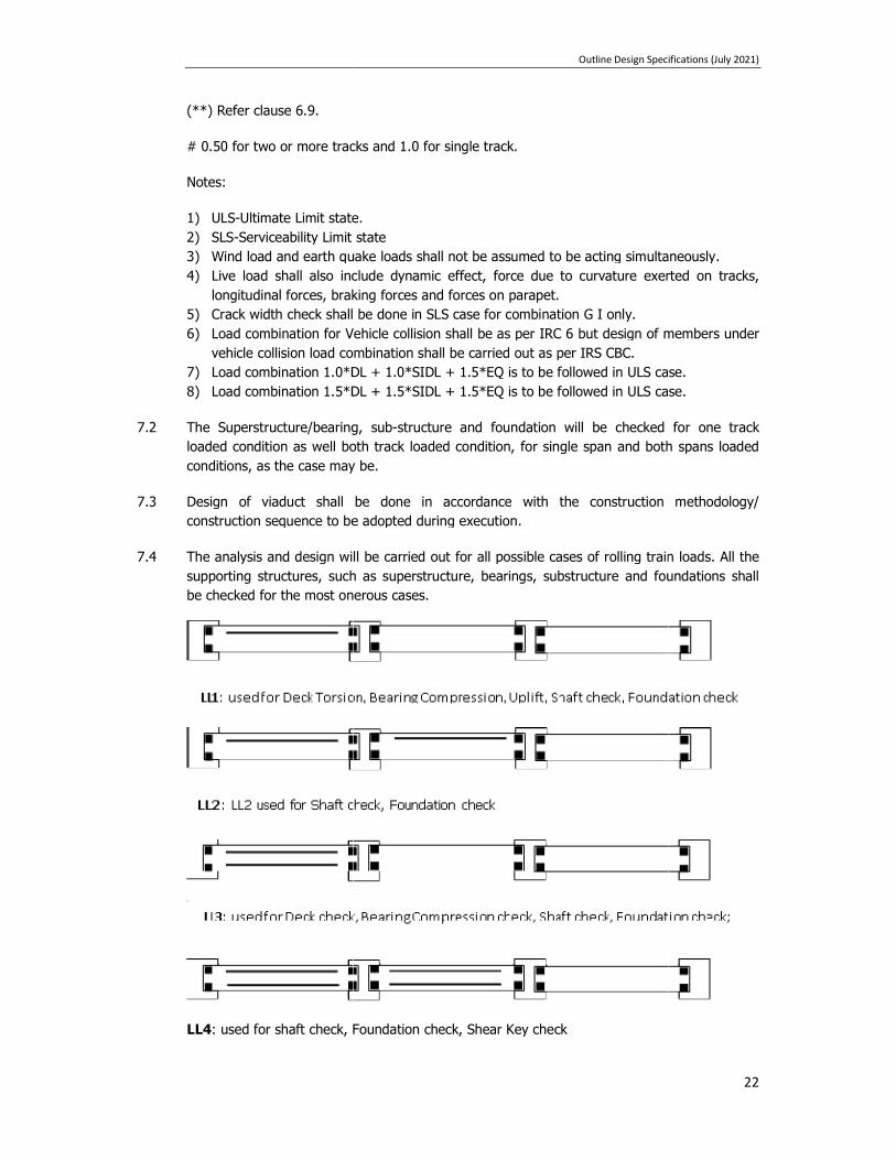
7.4 The analysis and design will be carried out for all possible cases of rolling train loads. All the supporting structures, such as superstructure, bearings, substructure and foundations sbe checked for the most onerous cases.
LL4: used for shaft check, Foundation check, Shear Key check
Outline Design Specifications (July 20
0.50 for two or more tracks and 1.0 for single track.
Ultimate Limit state. Serviceability Limit state
Wind load and earth quake loads shall not be assumed to be acting simultaneously.Live load shall also include dynamic effect, force due to curvature exerted on tracks, longitudinal forces, braking forces and forces on parapet. Crack width check shall be done in SLS case for combination G I only. Load combination for Vehicle collision shall be as per IRC 6 but design of members under vehicle collision load combination shall be carried out as per IRS CBC. Load combination 1.0*DL + 1.0*SIDL + 1.5*EQ is to be followed in ULS case.Load combination 1.5*DL + 1.5*SIDL + 1.5*EQ is to be followed in ULS case
The Superstructure/bearing, sub-structure and foundation will be checked for one track loaded condition as well both track loaded condition, for single span and both spans loaded conditions, as the case may be.
Design of viaduct shall be done in accordance with the construction mconstruction sequence to be adopted during execution.
The analysis and design will be carried out for all possible cases of rolling train loads. All the supporting structures, such as superstructure, bearings, substructure and foundations sbe checked for the most onerous cases.
used for shaft check, Foundation check, Shear Key check
Outline Design Specifications (July 2021)
22
Wind load and earth quake loads shall not be assumed to be acting simultaneously. to curvature exerted on tracks,
Load combination for Vehicle collision shall be as per IRC 6 but design of members under
+ 1.5*EQ is to be followed in ULS case. is to be followed in ULS case.
structure and foundation will be checked for one track loaded condition as well both track loaded condition, for single span and both spans loaded
Design of viaduct shall be done in accordance with the construction methodology/
The analysis and design will be carried out for all possible cases of rolling train loads. All the supporting structures, such as superstructure, bearings, substructure and foundations shall

Outline Design Specifications (July 2021)
23
8 DESIGN CHECK FOR CONCRETE STRUCTURE
8.1 ALLOWABLE STRESSES FOR CONCRETE AT SERVICEABILITY LIMIT STATE (SLS)
The stresses at transfer and construction stage during service for prestressed cast in situ and segmental construction shall be as per Clause-16.4.2.2 (Concrete Compressive stress Limitations), Clause-16.4.2.3 (Steel stress Limitations), Clause-16.4.2.4 (Cracking), Clause-17.3.3 (Other types of Connections) and Clause-17.4 (Composite Concrete Constructions) of IRS-CBC.
Clause-10.2 (Serviceability Limit States) of IRS-CBC shall be used for RCC construction (Beams, Columns and Slabs).
Summary of Permissible Stresses
Precast or Cast-In-Situ Post-Tensioned Structures
No Load Combination
Allowable compressive
strength Reference
Allowable tensile stress*
Reference
At transfer and/or construction stage 1 DL +*DS +
App.PR 0.5 fci but <0.4
fck CI 16.4.2.2(b)
of IRS CBC 1 MPa* CI 16.4.2.4(b)
of IRS CBC
2 Group 1+50% EL
0.5 fci but <0.4 fck
(CI 16.4.2.2(b) of IRS CBC
1 MPa* CI 16.4.2.4(b) of IRS CBC
During Service
3 SLS G I 0.4 fck (CI 16.4.2.2(a) of IRS CBC
No tension anywhere
cI 16.4.2.4(b) of IRS CBC
4 SLS G II 0.4 fck (CI 16.4.2.2(a) of IRS CBC
No tension anywhere
cI 16.4.2.4(b) of IRS CBC
5 SLS G III 0.4 fck (CI 16.4.2.2(a) of IRS CBC No tension anywhere
* In case of Segmental structures no tension is permitted under any stage or any SLS Load combination as clause 17.3.3 of IRS-CBC. ** In case of Uniform compressive stress distribution in PSC structures, permissible stress shall not be more than 0.3fck.
II RCC Structures
Permissible stress in Concrete (triangular compressive stress distribution) - 0.50fck Permissible stress in Concrete (Uniform compressive stress distribution) - 0.38fck
Permissible stress in Steel - 0.75fy
8.2 ULS CHECK FOR PRESTRESSED CAST-IN SITU CONCRETE/COMPOSITE CONSTRUCTION
Clause-16.4.3 (Ultimate Limit State: Flexure) to Clause 16.4.6 (Longitudinal Shear) of IRS-CBC shall be applicable for cast-in situ Prestressed construction whereas for composite construction Clause-17.4 (Composite Concrete Construction) shall be used.

Outline Design Specifications (July 2021)
24
8.3 ULS CHECK FOR RCC STRUCTURE
Section Capacity check for RC beams (ULS) for the superstructure should be conforming to Clause-15.4 of IRS-CBC. The design of RCC slabs shall conform to Clause 15.5 of IRS-CBC. The design of column should conform to Clause-15.6 of IRS-CBC.
9 DESIGN CHECK FOR STEEL/COMPOSITE STRUCTURE
The design of steel structure shall be done by IRS Steel Bridge Code/IRS-Welded Bridge. In case of steel structure, IRS-steel bridge code shall be followed and Load combination G1 shall be used. While Designing for composite action IRC :22 shall be referred with load combinations as given in table under clause 7.1.
10 DURABILITY & CRACK WIDTH
10.1 DURABILITY
Provision of Clause-5.4 of IRS-CBC shall be followed. The exposure condition of present corridor is Moderate and in case of Nallah crossing the exposure condition may be treated as “Severe”.
10.2 CRACK WIDTH CHECK
For SLS Combination, Group - I, crack width in reinforced concrete members shall be calculated as per Clause-15.9.8.2.1 of IRS-CBC.
The allowable crack width should be as per Clause 10.2.1 (a) (CS-1-12/2014) based on the exposure condition defined in Clause 5.4.1 of IRS-CBC and table-10 of IRS-CBC.
For crack control in columns, clause15.6.7 of IRS-CBC will be modified to the extent that actual axial load will be considered to act simultaneously.

Outline Design Specifications (July 2021)
25
CLEAR COVER AND CMIN FOR CRACK WIDTH CALCULATION
10.3 DEFLECTION
Clause No. 10.4.1, 11.3.4 and 13.3 of IRS: CBC shall be kept in view while calculating vertical deflection at mid span. Permissible values of deformation shall be in accordance with provision of UIC-776-3R.
11 FATIGUE
11.1 GENERAL
Fatigue phenomenon shall be analyzed for those structural elements that are subjected to repetition of significant stress variation (under traffic load). Thus generally the fatigue shall be regarded only for deck structural part supporting the tracks.

Outline Design Specifications (July 2021)
26
11.2 PRESTRESSED CONCRETE STRUCTURE
The fatigue shall be checked as per Clause-13.4 IRS-CBC. However, fatigue check for prestressed concrete structures does not need to be performed as long as the whole section (from top to bottom fiber) remains under compression under SLS load combination 1.
11.3 REINFORCED CONCRETE STRUCTURE
The fatigue shall be checked as per Clause-13.4 of IRS-CBC.
Fatigue check for reinforced concrete structures does not need to be performed unless it is a main structure member (i.e. the deck) supporting the traffic that consists of reinforced concrete. The permissible stress range in unwelded reinforcement as per clause 13.4.1 of IRS CBC shall be 155Mpa (under Live load) up to 16mm diameter & 120Mpa for bars exceeding 16mm diameter.
11.4 STEEL/STEEL COMPOSITE STRUCTURES
Clause-3.6 of IRS-Steel Bridge (up to latest correction slip) / Clause-13.2 of IRS-Welded Bridge code shall govern. If values are required to be used, the train closest to the actual train formation proposed to be run on the DMRC shall be used. Otherwise, detailed counting of cycles shall be done.
12 DESIGN METHODOLOGY
12.1 SUPERSTRUCTURE SYSTEM OF VIADUCT
The Superstructure of the viaduct comprises of simply supported Twin U-Girder.
However sharp curvature/ crossovers / turnouts/ railways crossings / highway crossings, PSC I -Girder/ Balanced Cantilever/Steel Composite girders/Steel Truss may be used. The minimum dimensions shall be considered as per Clause 16.9.6 of IRS-CBC.
Design of superstructure should be done in accordance with construction methodology/ construction sequence to be adopted during execution by DMRC.
Drainage
The drainage of deck shall be designed to cater the maximum envisaged rainfall intensity and suitable longitudinal and transverse slope should be provided. Moreover the provisions of Clauses-10.4.1.1 & 15.2.2 of IRS-CBC shall be followed.
Solid Pier
The drain pipe of double wall HDPE corrugated pipes with water collection box at top, shall be located within solid pier to avoid unpleasant aesthetics.
Deck
The top of soffit slab will be profiled so as to collect the run-off water at multiple points by providing a cross slope of 2.5%. Drainage pipes will be provided to collect the run-off.

Outline Design Specifications (July 2021)
27
12.2 BEARING SYSTEM AND ITS DESIGN METHODOLOGY
a) Bearing System
Considering the span configuration and safety aspects of the structural system (in normal and seismic condition), it is proposed to adopt elastomeric bearings placed underneath the Twin U-Girder for transfer of vertical forces and in-plane forces. The elastomeric bearings shall not be designed for seismic forces and seismic forces will be transferred to substructure via shear key/seismic restrainer. Elastomeric bearings/pads place vertically shall be used in between the Seismic stopper/seismic restrainer and the superstructure to mitigate the dynamic effects..
POT -PTFE bearing shall be designed as per IRC: 83 Part-III & Spherical bearing shall be designed as per IRC: 83 part-IV.
The elastomeric bearing shall be designed in accordance with EN 1337 part 1 and part 3 wherever required.
b) Replaceability of Bearings
While finalizing the proposed bearing system, it shall be kept in mind that accessibility and replacement of each part of bearing are of paramount importance as the design life of bearings is shorter than that of the structure. Keeping in view the above cited criteria, all the bearings and pier caps will be detailed for replacement of bearings in the future. The girders/end diaphragms shall be designed to facilitate the operations of jacks during maintenance as per clause 15.9.11.3 of IRS-CBC.
Special Low Height jacks shall be employed to replace bearings, if minimum vertical clearance is less than 400 mm as stipulated in Clause-15.9.11.4 of IRS-CBC.
c) Uplift
If required a holding-down device connecting the deck and the pier head shall be placed in order to prevent the deck from overturning. The holding-down device may be integrated in the pot-bearing system or be a separate system constituted of bars embedded in pier cap and viaduct with appropriate details, permitting translation/rotation. Other systems can also be foreseen.
Due to the lack of appropriate guidelines in Indian codes, the design criteria for holding down device (upward force limit requiring holding down device, design formulas) will be taken from the latest international practice.
12.3 SUBSTRUCTURE SYSTEM
a) Pier Cap
For designing the pier cap as corbel the provisions of Clause-17.2.3 of IRS-CBC should be followed. In case of shear span to effective depth ratio being more than 0.6, pier cap will be designed as flexural member.
Height of pedestal should be in between 150mm and 500mm as per clause 710.10.2 of IRC: 78.

Outline Design Specifications (July 2021)
28
The Pier cap shape shall be suitable at transition pier supporting different types of superstructure instead of providing raised/column pedestal over pier cap.
b) Piers
The effective length of a cantilever pier for the purpose of slenderness ratio calculation will be taken as per Table-18 of IRS-CBC. Ductile detailing is mandatory. In this project most of the columns are isolated columns with elastomeric bearing supporting the superstructure. In either direction the effective length will be taken as 2.3L0 (case 7).
Here L0 represent height of column from top of footing slab/Pile cap to top of pier cap. Effective length of portal column in longitudinal direction will be taken similar to singe column i.e. 2.3L0 and for transverse direction it should be taken as 1.5 L0 (case 6).
The design of pier shall be done as per clause 15.6 of IRS CBC.
Prestressed Cantilever Pier
In case of vertically prestressed piers, minimum longitudinal reinforcement shall be provided as RCC column as per clause 15.9.4.1 of IRS CBC.
Shear reinforcement & ductile detailing shall be done as that of RCC column.
In all SLS combinations, column shall remain in compression.
Clause 16.6.1 of IRS CBC shall be applicable in case of prestressed piers/columns.
12.4 FOUNDATION SYSTEM
Foundation shall be designed as per IRS Bridge Substructure & Foundation Code, IRS Concrete Bridge Code, IRC-78, Manual on the design and construction of well foundation; IS-2911 should be followed for design of foundations.
12.4.1 Pile Foundation
Foundation analysis and design will be based on IRS Code for Substructure & IRC-78. The forces applied by the pier are transferred to the bottom of the pile cap for this purpose. Reactions in pile are calculated using Rivet theory. The various specific assumptions made for the pile and pile cap design are as follows:
a) Bored-cast-in-situ multiple pile groups will be adopted.
b) Minimum 1.0m diameter (unless specified otherwise in tender drawing) bored cast-in-situ vertical piles in soil/rock have been contemplated for the foundation of piers. Minimum number of pile in each pile cap shall not be less than 4.
c) Open foundation have been contemplated for the pier location with rocky strata at shallow depth.
d) For piles and pile caps, load combinations shall be considered as per IRS-CBC, Table-12. The various specific assumptions made for the pile and pile cap design including pile load testing shall be as per IS: 2911, IRC-78 and IRS-Bridge Sub-structure and Foundation Code.
e) For pile carrying capacity, all SLS Load combinations as per IRS-CBC will be considered.
f) Increase in vertical load capacity of pile shall be done as per Table-1 of IS 1893-Part-1.

Outline Design Specifications (July 2021)
29
g) The lateral load capacity of pile shall be evaluated either by using empirical formulae given in IS: 2911 (Part-1/ section-2) or by soil structure interaction analysis using Winkler’s spring model by limiting the lateral deflection as 1% of Pile diameter as per Cl. 709.3.5.2 of IRC: 78.
h) Initial load tests (not on working pile) will be conducted as per IS: 2911 - Part IV. Initial test is proposed to be conducted for a load of 2.5 times as per the safe load based on static formula.
i) The working load on pile for vertical and horizontal loads shall be verified through routine load tests during construction.
j) In case of multiple pile system, spacing between the piles shall not be less than 3 times the diameter of pile in soil and 2.5 times the diameter when founded on rock.
k) In general the top of pile cap shall be kept about min 500mm below the existing ground level and weight of the earth cover will be applied on top of pile cap when unfavorable. The earth cover on pile cap for any favorable effect (stability, soil horizontal capacity.) will be neglected.
l) The following limiting values shall not be exceeded for computation of safe load:
o Result of sub-structure investigation will be used for adopting the value of angle of internal friction “φ” and cohesion of soil “c” as per clause 5.7 of the DBR .
o Angle of wall friction δ shall be taken as equal to φ deg. o Co-efficient of earth pressure “K‟ shall be taken as 1.0. o Maximum overburden pressure at bottom of pile for calculation of shaft resistance
and bearing resistance shall be limited to 15 times the diameter of the pile. The maximum depth shall be considered from existing ground level.
o For calculating the pile capacities, the design ground water table as per clause 5.5 of the DBR shall be considered.
o Bulk density corresponding to 100% saturation shall be calculated and used for working out submerged density of soil.
o In case of liquefiable strata, only submerged weight of soil shall be considered as overburden for vertical pile capacity calculation.
m) While finalizing length of pile, Clause 705.4.1 of IRC: 78 shall also be followed.
n) Live load surcharge needs to be considered for pile group which is outside median and where live load is moving over pile cap. Normal Pile groups below median or where there is no live load over pile cap need not to be design for live load surcharge.
o) In case of foundations near railway crossing effect of railway live load surcharge shall be considered if applicable
Structural Design
a) Pile design shall be done according to § 15.6 of IRS CBC. However, for crack control in
piles, § 15.6.7 of IRS CBC it will be clarified that actual axial load will be considered to act simultaneously.
b) Where there is a risk of liquefaction, the lateral soil resistance of the liquefied layer will be taken as zero.
Outline Design Specifications (July 2021)
30
c) Pile cap shall be designed based on § 15.8.3.1 of IRS –CBC 1997. No support from soil below pile cap shall be considered.
d) The thickness of the pile cap shall be kept minimum 1.5 times diameter of the piles for multiple-pile group as per IRC 78.
e) The structural design of the pile cap shall be carried out as per §10.2.2 & §15.4 and §15.8.3 of IRS CBC. Crack width shall be checked for load combination 1 as per §15.9.8.2 IRS CBC.
f) Minimum reinforcement in pile caps at top shall be at least 0.12% in each direction in case of compression and in case of tension, it shall not be less than 0.2%.
12.4.2 Soil Structure Analysis
When designing element forces or estimating displacements the soil stiffness and other parameters shall be assessed based on clause 5.7 of the DBR considering the design ground water table as per clause 5.5 of the DBR.
12.4.3 Well Foundation & Open foundation
Well Foundation & Open foundation shall be designed as per IRS Bridge Substructure & Foundation Code/ IRC: 78.
13 CODAL PREFERENCE
The IRS Codes shall be followed in principle. Although main clauses have been mentioned in the DBR, the other relevant clauses as available in the IRS codes shall also be followed, whenever applicable. If provisions are not available in IRS, the order of preference shall be as follows, unless specified otherwise:
For railway loading related issues:
i. UIC Codes
ii. Euro Codes
iii. Any other code, which covers railway loading.
For other Design/ detailing related issues:
i. IS
ii. IRC iii. EURO iv. AASHTO v. Any international code with approval of DMRC.

Outline Design Specifications (July 2021)
31
OUTLINE DESIGN SPECIFICATIONS FOR
DOUBLE DECKER STRUCTURE

Outline Design Specifications (July 2021)
32
1 INTRODUCTION
This Outline Design Specification (ODS) pertains to Double Decker Viaduct Portion of the Delhi Metro Phase-IV project.
1.1 SCOPE OF PROJECT
The Viaduct for Delhi Metro Project comprises of simply supported Precast Pre-tensioned twin U-girder (each U-girder supporting one track only)/Post tensioned Segmental Box Girder with RCC sub-structure and bored cast in situ pile /open foundation. The standard gauge of 1435 mm shall be followed. The Centre to Centre distance between two tracks shall be as per approved SOD of DMRC. However, PSC I-Girder / Balanced Cantilever / Steel Composite Girders have been proposed at sharp curves / special spans /crossover/ turnout / railway crossing / highway crossing etc.
PWD has planned to construct an elevated 4/6 lane corridor in the same alignment as the metro. It has since been decided that the PWD elevated corridor and the Metro Viaduct will share a common set of foundations and substructure in order to eliminate the crowded set of piers and foundation. It has also been decided that the construction of the elevated corridor will be carried out by the Metro with cost sharing by PWD.
The metro viaduct runs on the top level and the PWD flyover at the lower level in a double-decker arrangement with both viaducts being supported on common single piers.
The general arrangement for flyovers as proposed in this project consists of standard spans of 24 to 27m in most of the length of the flyover. The span arrangement has been decided matching with the spans of the metro viaduct. All the spans are simply supported for the metro and flyover structure. Only deck continuity is to be provided for the flyover structure for a minimum length of 120 to 130m to ensure the smooth ride and less noise in general and specifically in the station zone. The minimum thickness of deck for flyover structure shall be 200mm. Provision of expansion joints shall be made with local thickening of the slab.
The superstructure of flyover consists of divided 4-lane/ 6-Lane carriageway with a central median to suit the requirement of the pier size required for the metro viaduct support.
The typical cross section of the double-decker viaduct is shown in the figure below:-

Outline Design Specifications (July 2021)
33
1.1.1 Scope of Design Basis Report (DBR)
This report highlights the general arrangement of the flyover and the combined substructure, design parameters and methodology to be adopted for detailed design of these structures.
1.1.2 Site Particular
Refer Outline Design Specifications for Viaduct.
1.1.3 Units
Refer Outline Design Specifications for Viaduct.
1.1.4 Codes
Refer Outline Design Specifications for Viaduct.
2 TRACK GEOMETRY, TRACK STRUCTURE AND ROLLING STOCK’
Refer Outline Design Specifications for Viaduct.

Outline Design Specifications (July 2021)
34
3 ROADWAY AND RAILWAY CLEARANCES
Refer Outline Design Specifications for Viaduct.
3.1 CLEARANCES FOR ROAD TRAFFIC
Refer Outline Design Specifications for Viaduct.
3.2 CLEARANCES FOR ROLLING STOCK OF DMRC
Refer Outline Design Specifications for Viaduct.
3.3 GENERAL FUNCTIONAL REQUIREMENTS
Flyover superstructure consists of deck supporting 4 Lane/ 6 Lane traffic having divided carriageway with median at center. Some of the salient geometrical features are described below:
Vertical clearance : minimum 5.5m above the road level below for flyover and 5.5m above flyover top below metro viaduct
Central median Crash barrier : RCC crash barrier for each carriageway Cross slope : cross slope of 2.5% at each carriageway Expansion joints : single / modular strip seal joints Wearing coat : 65mm thick (40mm thick bituminous concrete
and 25mm thick mastic asphalt)
3.4 CHOICE OF STRUCTURAL SYSTEM
The choice of structural system is done on the basis of following aspects:
Functionally Effective – The completed structures should have two separate carriageways of 2 LANE/3LANE TRAFFIC for each direction, divided by a median.
Ease of construction – pre-cast pre-tensioned / post-tensioned girders has been proposed for the flyover superstructure. The substructure is single rectangular/circular pier. The structural system is chosen to make use of the site conditions favoring pre-cast construction to save time.
Maintenance – As the structures fall on a busy road, it is desirable to opt for spherical bearings, thus reducing the maintenance and replacement of bearings to the maximum possible extent.
Economy – Structural system and span arrangement are chosen so as to limit the requirement of heavy equipment. Moreover, the system chosen are in line with the metro viaduct superstructure.
4 DESIGN LIFE & SERVICEABILITY
The life of main structural systems should be 100 years (as per clause-15.1.3 & 16.1.3 of IRS-CBC, clause 3.6.5 of IRS steel Bridge code and clause 5.8.1 of IRC-112).

Outline Design Specifications (July 2021)
35
The exposure condition shall be consider as below:
1. For members supporting metro viaduct only, exposure condition shall be as per IRS CBC.
2. For members supporting highway loads only and, exposure condition shall be as per IRC.
3. For members supporting both metro viaduct & highway loads, exposure condition shall be as mentioned (1) & (2) above.
4. For separate flyover structure, exposure condition shall be as per IRC.
5 MATERIALS PARAMETERS
Material Parameters for Metro viaduct is to be referred from Outline Design Specifications for Viaduct. While checking of structures as per IRC Codes, the material properties shall be taken as per IRC Codes.
6 LOADS TO BE CONSIDERED FOR DESIGN
Following are the various loads to be taken into consideration for analysis and design of structures.
6.1 LOADS FOR METRO VIADUCT
Refer Outline Design Specification’s Viaduct Part.
6.2 LOADS FOR FLYOVER STRUCTURE
The design loading for the flyover in general have been considered in accordance with IRC: 6 (Loads and Stresses) so as to sustain the most critical combinations of various loads and forces, given in Annex 3 of IRC: 6 & other relevant IRC codes.
A. Dead Load (DL)
The dead load includes self-weight of the members estimated on the basis of unit weight of the material.
B. Super Imposed Dead Load (SIDL)
Wearing Course The wearing coat over the superstructure is 65 mm thick and load considered in the analysis and design is estimated with a unit weight 22 kN/m3
Weight of wearing coat = 2.00 KN/m2 (unfactored)
Crash Barrier New Jersey type crash barriers as per tender drawing. The crash barriers are designed for loads in accordance with as per Table 4 of IRC: 6.
C. Live Load
Live load is applied on the structure as per live load combinations mentioned in Table 2 of IRC: 6.
Considering the carriageway to be a restricted 4-Lane/ 6-Lane divided carriageway,

Outline Design Specifications (July 2021)
36
following live loads on the bridge are considered with impact factor as per IRC: 6 and governing of all these is considered in the design.
For the deck width of 9 m and above, minimum of 3 lanes shall be considered in design on each deck.
Class A and Class 70 R Vehicle
Two/Three traffic lanes in each direction operates on the four/six lane carriageway. Reduction as specified in clause 205 of IRC: 6 for multi-lane loading shall be followed.
Minimum clear distance between the edges of passing vehicles shall be taken as specified in IRC:6 for Class A vehicles and Class 70R vehicles.
Combination of Live Load Vehicles for different lanes of carriageway shall be as per Cl. 204.3 of IRC: 6.
The design for special vehicle in this project is not warranted as at grade level, 2 lane road is available in each direction all along the length of this corridor and hence not considered for the analysis.
Braking/Traction Force
Braking effect resulting from the application of brakes to vehicles on any carriageway or tractive effort caused through acceleration of vehicles in adjacent carriageway is considered to produce the worst effect on bridge structure.
As per clause 211.2 of IRC :6, for every two lanes of any carriageway braking force shall be equal to twenty percent of the first train load on single lane plus ten percent of the load of the succeeding trains or part thereof in that lane.
Traction loads in the adjacent span are taken as same as braking loads. Braking and traction loads act 1.2 m above roadway along a line parallel to it.
Effect of live load impact is not considered for the calculation of braking and traction loads.
Centrifugal force
The bridge situated on curve will be subjected to centrifugal action of moving vehicles which is determined as per section 212 of IRC: 6.
6.3 TEMPERATURE EFFECTS
Refer Outline Design Specifications for Viaduct.
6.4 WIND LOAD (WL)
The wind load analysis of integrated structure shall be carried out separately as below and worst shall be considered for design.
1. Outline design specification’s Viaduct Part.
2. IRC 6.
6.5 SEISMIC FORCE (EQ)
The seismic analysis of integrated structure shall be carried out separately as below and worst shall be considered for design.

Outline Design Specifications (July 2021)
37
3. Outline design specification’s Viaduct Part.
4. IRC SP 114.
6.6 ERECTION TEMPORARY LOADS (ETL)
Refer Outline Design Specifications for Viaduct.
6.7 DERAILMENT LOADS (DR)
Refer Outline Design Specifications for Viaduct.
6.8 FORCES ON PARAPET
Refer Outline Design Specifications for Viaduct.
6.9 DIFFERENTIAL SETTLEMENT (DS)
Refer Outline Design Specifications for Viaduct.
6.10 BUOYANCY LOADS
Refer Outline Design Specifications for Viaduct.
6.11 WATER CURRENT FORCES
Refer Outline Design Specifications for Viaduct.
6.12 VEHICLE COLLISION LOAD (VCL)
The vehicle collision load on piers: as per Clause-222 of IRC: 6. Rules specifying the loads for design of superstructure and sub-structure of bridges and for assessment of the strength of existing bridges should be done as per IRS: Bridge Rules. All structure near railway track shall be checked for accidental impact from derailed trains as per clause 2.16.4 of IRS Bridge Rules as per Addendum & Corrigendum Slip No. 48 dated 22.06.2017.
6.13 GRADIENT EFFECT
Refer Outline Design Specifications for Viaduct.
6.14 BUFFER LOAD
Refer Outline Design Specifications for Viaduct.
6.15 VIBRATION EFFECT
Refer Outline Design Specifications for Viaduct.
7 LOAD COMBINATIONS
1. Load combination for members supporting metro viaduct only, Outline Design Specification’s Viaduct Part shall be followed.

Outline Design Specifications (July 2021)
38
2. Load combination for members supporting highway loads only, load combination as per Annexure B of IRC 6 shall be used.
3. Load combination for members supporting both metro viaduct & highway loads, load combination shall be considered both as mentioned (1) & (2) above. While checking with ODF for viaduct, all loads with load factor as per ODS for viaduct shall be considered except road vehicle which should be as per IRC-6 with load factor as per IRC-6. Similarly, while checking with IRC-6, all loads with load factor as per IRC-6 shall be considered except for metro loading ODS for Viaduct shall be followed.
8 DESIGN METHODOLOGY
Flyover superstructure/pier cap shall be designed as per applicable IRC code whereas the Metro Viaduct will be designed as per Outline Design Specifications for Viaduct. The common substructure and foundations for the combined Metro and elevated corridor will be designed both as per Outline Design Specifications for Viaduct and IRC codes and worst of the two designs shall be adopted.
In case of a separate flyover structure, the design shall be done in accordance with the applicable IRC codes.
The design basis report shall be read in conjunction with the Outline Construction Specifications and Outline Design Specifications for Viaduct, where appropriate.
9 CODAL PREFERENCE
1. For members supporting metro viaduct only, codal preference shall be as per Outline Design Specifications for Viaduct.
2. For members supporting highway loads only, codal preference shall be as per relevant IRC codes.
3. For members supporting both metro viaduct & highway loads, codal preference shall be as per both as mentioned (1) & (2) above.
Outline Design Specifications (July 2021)
39
OUTLINE DESIGN SPECIFICATIONS
FOR
ELEVATED STATIONS

Outline Design Specifications (July 2021)
40
1. INTRODUCTION
1.1 BRIEF DESCRIPTION OF THE PROJECT
This Outline Design Specification (ODS) is applicable for elevated metro stations of Delhi Metro Rail Project of DMRC-Phase-IV.
1.2 SCOPE OF PROJECT
The object of this ODS is to establish a common procedure for the design of "Elevated Metro Stations of DMRC phase-IV". This is meant to serve as a guide to the designer but compliance with the rules there-in does not relieve them in any way of their responsibility for the stability and soundness of the structure designed. The design of Elevated Metro Stations requires an extensive and thorough knowledge and entrusted to only to specially qualified engineers with adequate practical experience in structure designs.
Outline Design Specifications for viaduct shall be followed for following structures/elements of station:
For single pier and portal pier stations.
Structural elements which support metro live loads.
This design basis report is applicable for following structures/structural elements:
Structural elements of station which do not support metro live loads.
Ancillary and entry exit structures separated from main station by an expansion joint.
The DL, SIDL & LL considered in design of station has been specified in 2.7.1 to 2.7.3 of this document.
Prestressed concrete structures shall be designed as per IS: 1343. RCC Structures shall be designed by IS: 456. Steel structure design shall be designed by IS: 800. Seismic design shall generally be governed by IS: 1893-Part 1.
The design basis report shall be read in conjunction with the Outline Construction Specifications where appropriate.

Outline Design Specifications (July 2021)
41
1.3 SITE PARTICULAR
The project corridor is located in state of Delhi & NCR
Maximum Temperature : 47.8˚C (as per Annexure-F of IRC 6)
Minimum Temperature : -0.4˚C (as per Annexure-F of IRC 6)
Rainfall season : July-August
Average Rainfall : 800-1000mm
Seismic Zone : IV
1.4 UNITS
The main units used for design will be: [m], [mm], [t], [kN], [kN/m2], [MPa], [⁰C], [rad].
1.5 CODES
All relevant codes as listed in DBR shall be of latest revision including all amendments & corrections.
2. DESIGN SPECIFICATION
2.1 MATERIALS
2.1.1 Cement
For plain and reinforced concrete structures cement shall be used as per clause 5.1 of IS: 456. For PSC structures Cl. 5.1 of IS: 1343 shall be used.
2.1.2 Concrete
As per Cl. 6, 7, 8, 9 and 10 of IS: 456 in case of Plain and Reinforced Concrete structures and Clause 6, 7, 8,9 and 10 of IS: 1343 for Pre-stressed concrete structures.
Short term modulus of elasticity (Ec) shall be taken as per Cl. 6.2.3.1 of IS: 456 for Plain and Reinforced Concrete structures and IS: 1343 for Pre-stressed concrete structures. The modular ratio for concrete grades shall be taken as per Annex B of IS: 456.
2.1.3 Prestressing steel for tendons
As per Cl. 5.6.1 of IS: 1343.

Outline Design Specifications (July 2021)
42
2.1.3.1 Young’s Modulus
As per Cl. 5.6 of IS: 1343.
2.1.3.2 Prestressing Units
As per Cl. 13 of IS: 1343.
2.1.3.3 Maximum initial Prestress
As per Cl. 19.5.1 of IS: 1343.
2.1.3.4 Sheathing
As per Cl. 12.2 of IS: 1343.
2.1.4 Density
25 kN/m3 for Reinforced concrete & Prestressed concrete
25 kN/m3 for Plain concrete
26 kN/m3 for wet concrete
For density of strands and all other materials, the densities shall be considered as per IS Codes.
2.1.5 Structural Steel
Structural steel used shall confirm to following:
a) Hollow steel sections as per IS: 4923
b) Steel for general Structural Purpose as per IS: 2062
c) Steel tubes for structural purpose as per IS: 1161
NOTE:
I. Grade of steel to be used shall be indicated, shall not be less than minimum grade as applicable, based on whether structure is taking moving loads or not and relevant code as indicated in (II) and (III) below.
II. Design of steel structure will be governed by IS 800. In case of composite (steel-concrete) structure it will be governed by IS: 11384 & IS: 3935.
III. Fabrication shall be done in accordance with IS: 800.
Tensile Strength / Yield Strength

Outline Design Specifications (July 2021)
43
Structural steel conforming to IS: 2062 shall be adopted.
Welding shall be done as relevant IS codes for welding.
Where, t = thickness of steel members
Young's Modulus shall be taken as 20,000kg/mm2 as per Clause 2.2.4 of IS: 800
Density: 7850 kg/m3 as per clause 2.2.4 of IS: 800
Poisson’s Ratio: 0.30 as per clause 2.2.4 of IS: 800
Thermal Expansion Coefficient: 12x10-6 as per clause 2.2.4 of IS: 800
2.1.6 Reinforcement Steel (Rebars)
For Reinforcement, refer ODS for Viaduct.
2.1.6.1 Reinforcement Detailing
All reinforcement shall be detailed in accordance with Cl. 12 & 26 of IS: 456 & SP: 34 for plain and reinforced concrete structures and as per Cl. 12.3 & 19.6.3 of IS: 1343 for PSC structures.
The ductile detailing of seismic resisting RC elements shall comply with ductile requirements of IS: 13920.
2.2 DURABILITY
Durability of concrete shall be as per Cl. 8 of IS: 456 for Plain & RCC, as per Cl. 8 of IS: 1343 for PSC elements and as per IS: 800 for steel structures.
For foundation & pier design, the exposure condition is Moderate. And in case of Nallah crossing (upto 50m on either side of the edge of Nallah) , the exposure condition may be treated as “Severe”.
2.2.1 Concrete Grades
The minimum grade of concrete shall be as per IS: 456 for Plain and RCC structures and IS: 1343 for PSC structures.
Grade# Tensile Strength (Mpa)
Yield Stress (Mpa)
t<20 t=20-40 t>40
E250 B0 410 250 240 230 E350 B0 490 350 330 320

Outline Design Specifications (July 2021)
44
2.2.2 Cover to Reinforcement
As per Cl. 26.4 of IS: 456 for Plain and RCC structures and Cl. 12.3.2 of IS: 1343 for PSC structures. Cover to Prestressing steel shall be in accordance with Cl. 12.1.6 of IS: 1343. For the Pile foundations, cover shall be taken as 75mm for all exposure conditions.
2.2.3 Fire Resistance Period
All the structural elements shall be designed for minimum period of fire resistant of 2 hour. The minimum element thickness for fire resistance shall be as per Cl. 21of IS: 456 for concrete structures and as per IS: 800 for steel structures.
2.2.4 Crack width Check
All structural concrete elements shall be designed to prevent excessive cracking due to flexure, early age thermal and shrinkage. Flexural crack width shall be checked in accordance with Cl. 35.3.2 and 43 of IS: 456 for Plain and RCC structures and Cl. 20.3.2 & 24.2 of IS: 1343 for PSC structures.

Outline Design Specifications (July 2021)
45
CLEAR COVER AND CMIN FOR CRACK WIDTH CALCULATION
2.3 CLEARANCES
Wherever the station locations are proposed on road or off-road, clearances for road traffic shall be minimum 5.5m beyond the outer face of pier i.e. in all cases 5.5 m clearance shall be kept from road level to soffit level of any structures.
2.4 DESIGN GROUND WATER TABLE
The Ground water table (Base value) shall be considered as maximum (in terms of RL) of Ground water table data published by (a) Central Ground water board (CGWB), (b) Ground water table reported in Geotechnical report provided by DMRC in tender documents, (c) Ground water table reported in Geotechnical report provided by Design & Build contractor.

Outline Design Specifications (July 2021)
46
The design Ground water table shall be taken as 4.0m higher than the Base value for evaluation of effects for design purposes.
2.5 LIQUEFACTION
Liquefaction shall be considered as per IS 1893-Part-1. The design Ground water table shall be used for liquefaction potential calculation. The Moment Magnitude Mw to be taken in design shall be 7.0. The factor of safety shall be more than 1.0 to ascertain that the strata are not liquefiable.
2.6 SOIL PARAMETERS
The borehole, which provide lesser vertical & Horizontal capacity of pile or lesser SBC in case of open/Well foundation, shall be referred in design among 1 & 2 as referred below. For Pile foundation, in case one bore hole provide lesser Horizontal capacity and other provide lesser vertical capacity then lesser values of horizontal & vertical capacity obtained from two boreholes shall be referred.
1) As per soil investigation report in the tender document.
2) As per soil investigation done by contractor.
The soil investigation report of Bore hole done by contractor shall be compared by soil investigation report of the nearest Bore hole given in the tender document.
2.7 DESIGN LOAD
2.7.1 Dead Load (DL)
Dead load shall be based on the actual cross sectional area and unit weights of materials and shall include the weight of structural members of the station building.
2.7.2 Super Imposed Dead Load For Non Track Area (SIDL)
FIXED SIDL (SIDL)
For platform slabs, the following loads in SIDL will be taken
Floor finishes is assumed to be a 3.6 kN/m2 uniform load as per architectural requirement.
Suspension load is assumed to be 2.0 kN/m2 uniform load (Suspension load will be considered as the load of false ceiling and services. This load will be considered where ever is applicable.
Light partition wall load is assumed to be 1.0 kN/m2 uniform load.
Outline Design Specifications (July 2021)
47
For concourse area, the following loads in SIDL will be considered.
Floor finishes is assumed to be a 3.6 kN/m2 uniform load as per architectural requirement.
Load due to additional fill in the toilets (brick bat) shall be considered as per architectural drawing.
Suspension load is assumed to be 2.0 kN/m2 uniform load (Suspension load will be considered as the load of false ceiling and services. This load will be considered where ever is applicable.
Loads due to escalator / lift will be considered as per manufacturer’s detail.
Light partition wall load should be taken as minimum 1.0 kN/m2 at concourse.
Loads due to Platform screen door (PSD) shall be considered as per actual. Loads due to solar panel shall be considered as 30 kg/m2.
SIDL for Technical Room shall be as follows: i) UPS Room* : 25** kN/m2 ii) ASS room* : 15** kN/m2 iii) Other Technical Room* : 10** kN/m2
Minimum dead load of PEB roof shall be considered as 120Kg/m2. However actual to be taken as per architecture.
*This should be verified with actual load and its location.
** Values are minimum load to be considered in design. Actual loads will be calculated on the basis of equipment & machinery which have to be installed at detail design stage. The concentrated load of 40kN for ASS/UPS room and 20kN for other technical room shall also be considered in design.
Note:
a) The walls loading will be taken based on actual location shown in architectural drawings. External wall load/glazing load will be taken as per details provided in architectural drawings. It is proposed to take 230 mm thick brick wall with 20 mm thick plaster on either side. However, the same shall not be taken less than 2.4 kN/m2.
Above loads intensities are minimum loads to be considered in design, Actual load may be higher as per detailed architectural drawings.

Outline Design Specifications (July 2021)
48
2.7.3 Live loads (LL)
2.7.4 Earthquake Loads (EQ)
Earthquake design shall follow the seismic requirement of IS: 1893 (Part1)
Horizontal Seismic Coefficient- The horizontal seismic design coefficient shall be calculated as per following expression
Ah = (Z/2) * (I/R) * (Sa/g)
Where,
Ah = horizontal seismic coefficient to be considered in design
Z = peak ground acceleration or zone factor = 0.24
I = importance factor = 1.5
R = response modification factor = 5
Sa/g = normalized pseudo spectral acceleration for corresponding to relevant damping of load resisting elements (pier/columns) depending upon the fundamental period of vibration T
Damping factor = 5% for RCC structures
Damping factor = 5% for Steel structures
2.7.4.1 Drift Limitations
The storey drift in the building shall satisfy the drift limitation specified in IS: 1893.
2.7.4.2 Seismic detailing
i) For RCC structures as per IS: 13920
Location Distributed load
(kN/m2) Concentrated load (kN)
Public/Staff Room
Any floor including Concourse, Platform, Staircase, Office Accomodation, Shop, Foot Over Bridge
5 4.5

Outline Design Specifications (July 2021)
49
ii) For other structures as per IS: 4326
2.7.5 Wind Loads (WL)
Wind Loads (longitudinal & transverse) shall be calculated as stated in IS 875: Part 3.
Wind loads will be calculated in accordance with IS 875: Part 3.
Design wind speed Vz (m/s) = Vb*K1*K2*K3*K4
Vb (basic wind speed in m/s) = 50 m / sec (As per NBC)
K1 (risk coefficient) = 1.08 (for 100 years mean probable design
life), Table 1
K2 = as per table2 based on terrain
category and structure height
K3 (Topography factor) = 1.0, as per Cl.6.3.3.1
K4 = 1.0 for Non cyclonic zone as per Cl.6.3.4
Based on the above, Design wind pressure at height z, (Pz) = 0.6 x Vz x Vz Cl. 7.2
Design wind pressure, Pd = Pz * Kd * Ka * Kc
Kd = wind directionality factor = 0.9 for buildings
Ka = area averaging factor = 0.8 Table 4 (for contributory area > 100 m2)
Kc = combination factor = 0.9
2.7.6 Construction and Erection Loads (ER)
The weight of all temporary and permanent materials together with all other forces and effects which can operate on any part of structure during erection shall be taken into account. Allowances shall be made in the permanent design for any locked in stresses caused in any member during erection.
2.7.7 Temperature Load (TL)
As per Cl. 19.5 of IS: 456. Temperature gradient shall be considered as per CL. 215 of IRC-6, if applicable.

Outline Design Specifications (July 2021)
50
2.7.8 Shrinkage
Shrinkage strain shall be evaluated as Cl. 6.2.4 of IS: 456 for plain and RCC structures and Cl. 6.2.4 of IS: 1343 for prestressed concrete structures.
2.7.9 Creep
Creep strain shall be evaluated as Cl. 6.2.5 of IS: 456 for plain and RCC structures and Cl. 6.2.5 of IS: 1343 for prestressed concrete structures.
2.7.9.1 Earth Pressure (EP) & Water pressure (WP)
In the design of structures or part of structures below ground level, such as retaining walls and underground pump room/ water tanks etc. the pressure exerted by soil or water or both shall be duly accounted for. When a portion or whole of the soil is below the free water surface, the lateral earth pressure shall be evaluated for weight of soil diminished by buoyancy and the full hydrostatic pressure. (As per IS: 875-part 5).
All foundation slabs / footings subjected to water pressure shall be designed to resist a uniformly distributed uplift equal to the full hydrostatic pressure. Checking of overturning of foundation under submerged condition shall be done considering buoyant weight of foundation.
If any of the structure supporting metro loading is subjected to earth pressure, the loads and effects shall be calculated in accordance with Cl. 5.7 of IRS substructure code. In case of Double decker structure in stations, relevant clause of IRC 6.
2.7.10 Surcharge Load (SL)
In the design of structures or the parts of the structures below ground level, such as retaining walls & underground pump room/ water tank etc. the pressure exerted by surcharge from stationary or moving load, shall be duly accounted for. For the area approachable by road traffic, the minimum live load surcharge shall be taken as 24 kN/m^2
2.7.11 Prestressing force (PS)
The prestressing force should be as per IS: 1343.
2.7.12 Settlement (DS)
Maximum and differential settlement shall not exceed, as provided in Table 1 of IS: 1904. The allowable settlement for pile group is 25mm (as per IS 2911-part 4).

Outline Design Specifications (July 2021)
51
2.7.13 Other Forces and Effects
As per Cl. 19.6 of IS: 456.
2.8 LOAD COMBINATIONS
Load Abbreviations Dead load DL Super imposed dead load (Fixed) SIDL Prestressing PS Live Load LL Temperature Load TL Wind Load WL Earthquake Load EQ Differential settlement DS Earth Pressure EP Water Pressure WP Surcharge Load SL Erection load ER

Outline Design Specifications (July 2021)
52
a) For PSC elements, the load combinations shall be as per table 7 of IS: 1343. b) For steel structures, the load combinations shall be as per IS: 800. c) For RCC structures / elements, shall be as per Table 18 of IS: 456 and IS: 1893-1 as
follows:
2.9 Deflection Criteria
The deflection limitations as per Cl. 23.2 of IS: 456 for Plain and RCC Structures and Cl. 20.3.1 if IS: 1343 for PSC structures shall be followed.
2.9.1 Lateral Sway
The lateral sway at the top of the building due to wind loads should not exceeds H/500, where ‘H’ is the height of the building.
2.10 FOUNDATION SYSTEM
2.10.1 Type of foundation:
Considering the nature of ground, type of proposed structure, expected loads on foundation, the following type of foundations are considered practical:
a. Spread or pad footing b. Raft Foundation c. Pile foundation
No matter the type of foundation to be adopted, the following performance criteria shall be satisfied:

Outline Design Specifications (July 2021)
53
1. Foundation must not fail in shear 2. Foundation must not settle by more than the settlements permitted as per table-1 of
IS: 1904. The allowable settlement for pile group is 25mm (as per IS 2911-part 4);
2.10.2 Design of Pile Foundation
IS: 2911 shall be followed for design of pile, load capacity etc. Theoretical estimation of settlement for deep foundation shall be done in accordance with IS: 8009-Part-2.
The forces applied by the pier are transferred to the bottom of the pile cap for this purpose. Reactions in pile are calculated using Rivet theory. The various specific assumptions made for the pile and pile cap design are as follows:
a. Bored-cast-in-situ multiple pile groups will be adopted.
b. The various specific assumptions made for the pile and pile cap design including pile load testing shall be as per IS: 2911.
c. Increase in vertical load capacity of pile shall be done as per Table-1 of IS 1893-Part-1.
d. The lateral load capacity of pile shall be evaluated either by using empirical formulae given in IS: 2911 (Part-1/ section-2) or by soil structure interaction analysis using Winkler’s spring model by limiting the lateral deflection as 1% of Pile diameter.
e. Initial load tests (not on working pile) will be conducted as per IS: 2911 - Part IV. Initial test is proposed to be conducted for a load of 2.5 times as per the safe vertical load based on static formula.
f. The working load on pile for vertical and horizontal loads shall be verified through routine load tests during construction.
g. In case of pile in scourable/ liquefiable bed, scour/liquefiable depth shall be isolated by providing sleeves around the pile during load lest (or any other suitable method with prior approvable of DMRC). Necessary correction for existing water table shall also be made.
h. In case of multiple pile system, spacing between the piles shall not be less than 3 times the diameter of pile in soil and 2.5 times the diameter when founded on rock.
i. The following limiting values shall not be exceeded for computation of safe load:

Outline Design Specifications (July 2021)
54
o Result of sub-structure investigation will be used for adopting the value of
angle of internal friction “φ” and cohesion of soil “c” as per 2.6. of this DBR.
o Angle of wall friction δ shall be taken as equal to φ deg.
o Co-efficient of earth pressure “K‟ shall be taken as 1.0.
o Maximum overburden pressure at bottom of pile for calculation of shaft
resistance and bearing resistance shall be limited to 15 times the diameter of
the pile. The maximum depth shall be considered from existing ground level.
o For calculating the pile capacities, the design ground water table shall be
considered as per Cl. 2.4 of this DBR.
o Bulk density corresponding to 100% saturation shall be calculated and used
for working out submerged density of soil.
o In case of liquefiable strata, only submerged weight of soil shall be
considered as overburden for vertical pile capacity calculation.
j. While finalizing length of pile, Clause 705.4.1 of IRC: 78 shall also be followed.
k. In general the top of pile cap shall be kept about min 500mm below the existing ground level and weight of the earth cover will be applied on top of pile cap when unfavourable. The earth cover on pile cap for any favourable effect (stability, soil horizontal capacity.) will be neglected.
l. Live load surcharge needs to be considered for pile group which is outside median and where live load is moving over pile cap. Normal Pile groups below median or where there is no live load over pile cap need not to be design for live load surcharge.
m. In case of foundations near railway crossing effect of railway live load surcharge shall be considered if applicable
n. Minimum reinforcement in pile caps at top shall be at least 0.12% in each direction in case of compression and in case of tension, it shall not be less than 0.2%.
2.10.3 Open foundation
Open foundation shall be designed as per IS: 456, IS: 1904, IS: 6403. Calculation of settlements shall be done as per IS: 8009-Part-1.
2.11 Design of water retaining structures
The underground tank in a station shall be designed as a water retaining structure based on IS: 3370. Various types of loadings shall be considered in the design of the underground tank. The side walls shall be subjected to earth pressure. The water table

Outline Design Specifications (July 2021)
55
being high in the area, horizontal pressure due to it shall also be considered. Stability of water tank shall be checked against buoyancy and foundation raft shall be designed for the worst of buoyant force and soil pressure. The tank shall also be designed for surcharge loading if any. Water proofing treatment shall be done on the external surface as well as in the internal surface.
2.12 MASONRY WALLS
All Masonry walls shall be treated as non-structural infill panels and shall be treated as one way / two way slab panels spanning between adjoining beams and columns to check structural safety. Masonry walls shall be designed as un-reinforced masonry as per IS: 1905 and IS: 4326. Shear connector reinforcement between walls & upper beams and walls & sides of columns shall be provided for external walls, while the internal partition walls shall be connected with roof slabs/beams using dry packing mortar between top of walls and soffit of slab / beam.
3. CODAL PREFERENCE
The design shall be carried out as per provision of these design specifications. Reference shall be made to the following codes for any additional information:
Order of preferences of codes shall be as follows:
i. IS
ii. IRS
iii. IRC iv. BS or Euro Codes v. AASHTO
vi. Any international code with approval of DMRC.

Outline Design Specifications (July 2021)
56
OUTLINE DESIGN SPECIFICATIONS FOR
CUT & COVER SECTION

Outline Design Specifications (July 2021)
57
1 INTRODUCTION
This ODS pertains to Cut and Cover Portion of the Delhi Metro Phase-IV project.
2 SCOPE OF DBR
This ODS defines the structural design assumptions for Underground Station / Cut & Cover
portion, as described above. The aim is to collect in a unique document for all the design input
and procedures to be employed for the calculation and design of underground structures. The
report gives the basis for calculations including the applicable codes and standards, the material
properties, the design method, the loading to be taken into account and the considered load
combinations. The present document will be used as reference for the future calculation notes
and structural drawings. It should be adopted in conjunction with the Geotechnical Interpretative
Report specific for each Underground structure.
3 CUT & COVER STRUCTURES
3.1 Introduction
This section summarizes the Civil, Structural and Geotechnical design philosophy and other
related parameters for underground stations, station entrances, vent shafts, subways and cut &
cover tunnel. For geotechnical design parameters, reference shall be made to Geotechnical
Interpretative Report and for geotechnical investigations related works refer “Outline Design
Criteria for Geotechnical Works"
3.2 General Principles
1. Cut-and-cover structures include UG station, station entrances/exits, vent shafts, subway, utility
duct, OTE DUCT, Cut & Cover Box tunnels, Cut & Construct Open U Ramp structures linking
with Elevated Ramps and the structures other than bored tunnels that are required to be
constructed below ground surface.
2. The cut-and-cover structure is proposed to be a rigid box section with permanent walls as
external wall support system and beam-slab & column forming the internal structural framing.
The roof slab shall support the soil and vehicular LL surcharge while the passenger and plant
loads are carried by the concourse slab. The track and platform loads shall be supported by the
base slab. The permanent walls shall resist the lateral earth and hydrostatic pressures in
addition to the LL and building surcharge (horizontal loads) from nearby road and buildings.

Outline Design Specifications (July 2021)
58
3. The completed stations, station entrances, vent shafts shall comply with Contract water-
tightness criteria.
4. Where temporary walls are intended as part of the Permanent Works, the Contractor shall
justify the feasibility and suitability of such to the Employers Representative. The durability
criteria shall also be satisfied to ensure 100 years design life.
5. The Contractor shall take into account the following in the design of cut-and cover structures.
a. Method of construction, including temporary works and construction sequence.
b. Ground/structure interaction, including the effects of temporary works.
c. Ground pressure, shear force and bending moment distribution during construction
and in the long-term.
d. Short- and long-term ground and groundwater response.
e. Other static loads changes such as; excavation, surcharge, traffic loadings and the like.
f. Long-term water table level changes
g. Dynamic (such as seismic or vibratory plant) loads and displacements.
6. For the purposes of assessing ground and groundwater pressures during service stage, the cut-
and cover structures shall be considered to be effectively impermeable rigid box structures
subject to “at rest” (Ko) earth pressure and “active” (Ka) earth pressure as the case may be.
7. The Contractor shall design to minimize the effects (such as movement, distortion of the
ground and the like) on all Existing Building Structure (EBS) that may be affected by the Works.
Where necessary the Contractor shall provide additional support for these EBS. Building
damage assessment reports along the zone of construction shall be prepared and the type of
strengthening required may be decided based on category of building.
3.3 Design Principles
1. The design of all cut-and-cover structures shall take into account, but not be limited to the
following:
a. The variation in ground conditions along the alignment.
b. The variation in engineering properties of soil or rock within the influence of the
proposed works.
c. All dewatering and groundwater cut-off systems required to maintain dry and stable
conditions within all excavations required for these Works.
d. Any ground treatment before, during or after construction of the Works (e.g.
groundwater recharge) which is required to stabilise the ground and EBS in order to

Outline Design Specifications (July 2021)
59
minimise adjacent ground and EBS movement and distortion.
e. Methods by which the completed structure shall be secured against flotation. Any
temporary dewatering system shall not be turned off till the structure is safe against
leakage or flotation when the ground water returns to the design levels.
f. Differential groundwater pressures due to inside and outside water table
g. Methods of waterproofing the completed structure.
h. Drawdown of the groundwater levels outside the UG station and cut and cover tunnel
walls shall be limited to not more than 2 metres from the existing average
groundwater level in the zone of construction. Recharging pits shall be provided in
case there is a danger of reduction in water table outside area of construction. This is
necessary to prevent settlement of ground outside area of construction. In general,
groundwater levels interior to construction excavations shall not be depressed more
than 1.0m below final base slab level.
i. The magnitude of ground and EBS movements and distortions, and changes in loading
conditions on these EBS that might be expected as a result of the works and how
these will be mitigated so as to comply with any imposed constraints or so as to
minimise disturbance to these EBS.
j. Any difficulties that the Contractor’s intended plant/machinery/methods might meet
with in respect of access, clearances, working space and obstruction to excavation.
k. Maintenance of traffic flows along roads including access to adjoining properties and
roads.
l. Noise levels produced during construction.
m. Control of heave, swell, piping and instability of the excavations.
n. The effects of vibration and vibration induced movements – e.g. earthquake.
2. The following methods of construction shall be used either individually or in combination
depending upon the particular requirements of the location, size and type of structure.
a. Diaphragm Walls - Particular attention shall be paid to the D wall and panel alignment,
the stability of excavation, the design mix and condition of the slurry, placement of the
reinforcement cage, methods for forming and locating box-outs, waterproofing of the
vertical panel joints, placement of concrete, and the overall integrity and water-
tightness of the formed wall.
b. Secant Piles/Sheet Piles/Soldier Piles and Horizontal Planks – Particular attention shall

Outline Design Specifications (July 2021)
60
be paid to the construction/installation of the piles and ground support systems to
ensure their integrity and water-tightness and to provide adequate support to the
ground during excavation.
3. Diaphragm walling is the preferred support method for the TBM Shafts, UG station, construction
close to sensitive existing structures, Cut & Cover Box tunnel excavations at large to medium
depths close to existing structures, cross over structures, etc
4. Soldier Pile wall/ Bored Pile wall methods of support may be used for the other medium
excavations such Cut & Cover tunnel, entrances/exits, utilities and services. In case of high
underground water table, soldier pile system with horizontal planks is not allowed.
5. Sheet Pile wall methods of support may be used for the other shallow excavations such as open
U Ramp, shafts utilities and services.
3.4 Excavation Support
3.4.1 General
a. The Contractor shall prepare and submit a detailed Design Report including
calculations, schedules and drawings for each proposed excavation support wall
construction, prior to the commencement of any such works. This Design Report shall
take into account but not be limited to the following:
i) Earth pressure. ii) Hydrostatic pressure. iii) Deck load iv) Surcharge loads. v) Seismic and/or vibratory loads vi) Support types and arrangement. vii) Temperature loads viii) Any other incidental/accidental load. ix) Construction/deconstruction sequence. x) Calculated ground and adjacent EBS movements and distortions. xi) Calculated fluctuations in groundwater levels both within and outside of the
excavation and support walls. xii) Calculated changes in EBS loading conditions. xiii) For Deep Excavation in rocky strata, Rock bolt and Shotcrete to be used.
3.4.2 Method Statement
a. The Contractor shall prepare a Method Statement giving the full details of materials,
plant and operations involved in the construction of excavation support walls. This
Method Statement shall be incorporated into the Design Report submission for the
Employers Representatives notice and shall include but not be limited to the following
details:
i) Formation of the joints between panels and installation of water stops. ii) Method of producing the workable concrete.

Outline Design Specifications (July 2021)
61
iii) Methods of handling within the excavations and disposing of groundwater outside of the excavations.
iv) Sequence of excavation and concreting of panels. v) Methods of instrumenting, monitoring and reporting of the performance of all
adjacent EBS that may be affected by the works. vi) Type and construction of permanent lining wall. vii) Emergency procedures to be implemented in the event that monitoring indicates
tolerances associated with the excavation support wall may be exceeded.
3.5 Design Life and Serviceability
3.5.1 General
The design life of a structure or component is that period for which the structural item is
required to fulfil its intended function when maintained in accordance with agreed procedures to
meet a required level of performance. The definition of a design life for a structure or component
does not necessarily mean that the structure will no longer be fit for its intended purpose at the
end of that period. Neither will it be expected to necessarily continue to be serviceable for that
length of time without adequate maintenance to mitigate the demands of degradation.
3.5.2 Civil Engineering Structures
1. The design life of all civil engineering structures shall be a minimum of 100 years unless
otherwise specified or agreed upon.
2. Adequate measures shall be taken to ensure a minimum of 100 years serviceability of civil
structures by producing durable concrete structures. For achieving this suitable property
enhancers / blending materials conforming to relevant BIS codes (or more stringent
International Standards/Codes wherever required) may be used as deemed appropriate and
subject to Notice of No Objection from the Engineer.
3. The design life of the above ground building structures including ancillary buildings, utility
support, structures and vent shafts etc. shall also be 50 years.
4. The design life of non-structural elements shall be 50 years.
5. Durability approach and assessment report (DAAR) to ensure service life of structures shall be
submitted and to be got approved before start of work on site.
3.5.3 Road pavement
The design life of all pavements shall conform to the requirement of relevant codes of IRC and
MORTH.
3.5.4 Serviceability of Civil and Building Works
1. Paint systems for steelwork, wherever permitted by the Engineer, shall ensure a minimum life
of 5 years before full maintenance painting is required.

Outline Design Specifications (July 2021)
62
2. The corrosion protection of non-structural steel items shall be appropriate to the accessibility of
the item for inspection and maintenance.
3.6 Units
The main units used for design will be: [t], [m], [mm], [kN], [KN/m2], [MPa], [oC], [rad]
3.7 Material Parameters
3.7.1 Cement
Cement shall be as defined in Outline Construction Specifications for Phase-IV Civil Works.
3.7.2 Concrete
Concrete shall be as defined in Outline Construction Specifications for Phase-IV Civil Works. The characteristic strengths (fck) and the corresponding mechanical characteristics necessary
for design as per requirements for 100 years of design life of structures are indicated in Table
here below: -
A Characteristics of main construction Materials (structural elements in contact with non-aggressive soil of Delhi)
S. No. Structural Components
Minimum Grade of concrete (cube)
1 Inner slabs, beams &
columns M35
2 Outer slabs M35
3 Outer cast-in-situ walls
against form work M35
4 Diaphragm walls M35
5 Tension Pile, barrettes,
compression piles M35
6 Platform slab, UPE duct, OTE duct, vent shafts etc
M35

Outline Design Specifications (July 2021)
63
B Characteristics of main construction Materials (structural elements in contact with Drain Water, chemically aggressive environment and soils)
S. No. Structural
Components
Minimum Grade of concrete (cube)
1 Outer slabs M45
2 Outer cast-in-situ walls
against form work M45
3 Diaphragm walls M45
4 Tension Pile M45
3.7.3 Cover Requirements for 100 years durability of structures
A For Underground structural elements in contact with non-aggressive soil of Delhi
S. No. Structural Components Nominal Cover/clear
cover to any reinf. (mm)
1 Inner slabs, beams & columns 50
2 Outer slabs at roof 50
3 Outer Base slabs 75
4 Outer cast-in-situ walls against form work 50
5 Diaphragm walls 75
6 Tension Pile, barrettes, compression piles 80
7 Platform slabs, internal RCC walls, vent shaft walls, staircase slabs, UPE and OTE ducts
35
B For Underground structural elements in contact with Drain water, aggressive soil and environment
S. No. Structural Components Nominal Cover/clear cover to outermost
reinf. (mm)
1 Outer slabs 65
2 Outer cast-in-situ walls against form work 65
3 Diaphragm walls 90
4 Tension Pile, barrettes, compression piles 95

Outline Design Specifications (July 2021)
64
3.7.4 Density
25 kN/m3 for reinforced concrete (IS:875 Part-1 Table-1 item 22 value rationalized)
23 kN/m3 for plain concrete (IS:875 Part-1 Table-1 item 20)
Actual density to be validated as per actual mix design
3.7.5 Poisson’s Ratio
Poisson’s ratio for all concrete: 0.15
3.7.6 Thermal Expansion Coefficient
As per cl. 6.2.6 of IS: 456
3.7.7 Young’s Modulus
Instantaneous modulus (E) is taken as per clause 6.2.3.1 of IS 456:2000
E =5000 (fck) ^0.5
Where, fck is the Characteristic Compressive Strength of 150mm Cube at 28 days.
3.7.8 Modular Ratio
Modular ratio for all concrete grades shall be taken as per Annex B of IS:456. Modular ratio, for cracked section m = Es/Eeff
Where, Es = Steel Modulus Eeff = Eff. Modulus of Concrete (Eeff = Ec / (1+))
3.7.9 Reinforcement
High strength deformed (HYSD) reinforcement bars of Fe-500D grade, conforming to IS 1786 and Clause 4.5 & 7.1.5 of IRS-CBC shall be used.
I. Young’s Modulus: E= 200,000 Mpa
II. Yield Stress: fy = 500 MPa.
III. Density: 78.5 kN/m3
3.7.10 Structural Steel: General
(1) Design of Structural steelwork shall comply with IS: 800.
(2) Two types of structural steel to be used and shall comply with the following standards:
a) IS: 4923 "Hollow steel sections for structural use with Yst 310".
b) Steel for General Structural Purposes (Grade Designation E250, E350 - B0) shall be
as per IS: 2062
(3) Hollow steel sections shall be square (SHS) or rectangular (RHS). Other traditional

Outline Design Specifications (July 2021)
65
rolled sections like plates, angles, channels, joists can also be used where required.
(4) The connections within the steel structure shall be designed as direct welded members
with or without gusset plates. The minimum thickness of metal for SHS/RHS sections
for main chord members as well as bracings shall be 4 millimetres as applicable for
steel tubes in cl. 6.3 of IS: 806.
(5) IS:800-2007 shall be followed and limit state method of design shall be adopted for
steel structures.
Material Properties shall be as follows:
Grade# Tensile Strength
(Mpa) Yield Stress (Mpa)
t<20 t=20-40 t>40 E250 B0 410 250 240 230 E350 B0 490 350 330 320
3.8 Durability Criteria
In carrying out structural designs it shall be ensured that both the serviceability and ultimate
limit states have been checked in accordance with the applicable Standards and Codes.
To achieve durability, the design shall take into account the prevailing ground and groundwater
conditions and those predicted to occur at the site within the design life of the Works.
Water permeability in concrete shall not be more than 10 millimetres (at the concrete age of 28
days) according to DIN 1048 and RCPT value (ability to resist chloride ion penetration) shall not
exceed 1000 coulombs at the concrete age of 28 days according to ASTM C-1202.
For all other durability requirements refer Outline Construction Specifications for Phase-IV Civil
Works, Delhi Metro.
3.8.1 Fire Resistance Period
All structures shall be designed for fire protection as specified by the applicable standards and
codes. Materials specified for the Works shall be non-combustible and non emit toxic fumes
when subject to heat or fire, except where permitted under the Contract. In all cases where
there is significant fire risk, materials shall be self-extinguishing, low flammability, low smoke
and low toxicity. All the main elements of the station structures (Roof Slab, Concourse Slab,
Base Slab, Outer Wall, Columns & any load bearing RCC Walls, ASS -TSS room RCC walls) and
including firemen staircase & Public fire escape underground structures shall be designed for a
minimum fire resistance period of 4 hours. All other element like Platform slab, vent shafts,
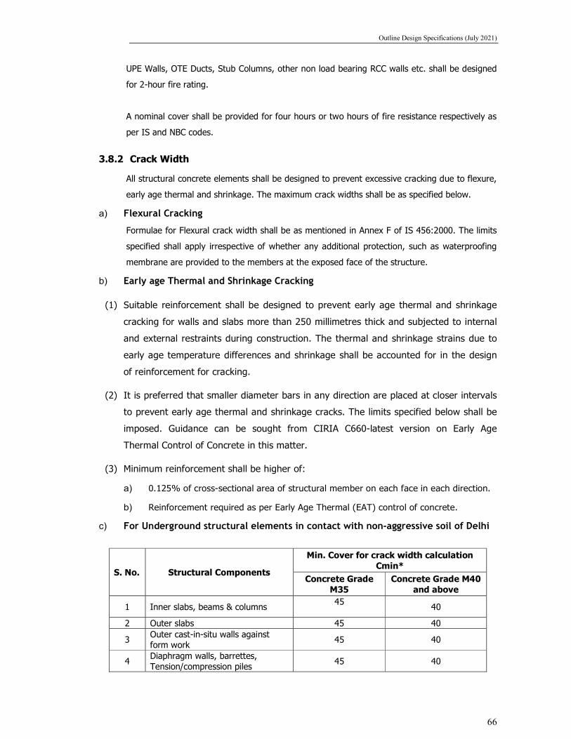
Outline Design Specifications (July 2021)
66
UPE Walls, OTE Ducts, Stub Columns, other non load bearing RCC walls etc. shall be designed
for 2-hour fire rating.
A nominal cover shall be provided for four hours or two hours of fire resistance respectively as
per IS and NBC codes.
3.8.2 Crack Width
All structural concrete elements shall be designed to prevent excessive cracking due to flexure,
early age thermal and shrinkage. The maximum crack widths shall be as specified below.
a) Flexural Cracking
Formulae for Flexural crack width shall be as mentioned in Annex F of IS 456:2000. The limits
specified shall apply irrespective of whether any additional protection, such as waterproofing
membrane are provided to the members at the exposed face of the structure.
b) Early age Thermal and Shrinkage Cracking
(1) Suitable reinforcement shall be designed to prevent early age thermal and shrinkage
cracking for walls and slabs more than 250 millimetres thick and subjected to internal
and external restraints during construction. The thermal and shrinkage strains due to
early age temperature differences and shrinkage shall be accounted for in the design
of reinforcement for cracking.
(2) It is preferred that smaller diameter bars in any direction are placed at closer intervals
to prevent early age thermal and shrinkage cracks. The limits specified below shall be
imposed. Guidance can be sought from CIRIA C660-latest version on Early Age
Thermal Control of Concrete in this matter.
(3) Minimum reinforcement shall be higher of:
a) 0.125% of cross-sectional area of structural member on each face in each direction.
b) Reinforcement required as per Early Age Thermal (EAT) control of concrete.
c) For Underground structural elements in contact with non-aggressive soil of Delhi
S. No. Structural Components
Min. Cover for crack width calculation Cmin*
Concrete Grade M35
Concrete Grade M40 and above
1 Inner slabs, beams & columns 45
40
2 Outer slabs 45 40
3 Outer cast-in-situ walls against form work
45 40
4 Diaphragm walls, barrettes, Tension/compression piles
45 40

Outline Design Specifications (July 2021)
67
d) For Underground structural elements in contact with Drain water, aggressive soils
or environment
S. No. Structural Components
Min. Cover for crack width Cmin*
Concrete Grade M35
Concrete Grade M40 and above
1 Outer slabs 45 40
2 Outer cast-in-situ walls against form work
45 40
3 Diaphragm walls, barrettes, Tension/compression piles
45 40
*The cover shall be considered as defined in sketches below.
However, as per durability requirements of 100 years for design life of underground structures and
minimum concrete cover, BS:8500-1-2006 has also to be followed for the exposure condition for the
different members as under:
Corrosion by carbonation criteria
S. No. Structural Components Exposure Class
1 All Structural members (outer/Inner) XC3
Corrosion by Carbonation criteria with hydraulic gradient more than 5 meter
S. No. Structural Components Exposure Class
1 All Outer structural members XC2 / AC-2/DC-2 (FND2)
The parameters such as Grade of Concrete, Concrete cover etc. shall be provided as per worst of both
as mentioned above.
Corrosion by chloride criteria for members in contact with aggressive soil/ Nallah etc.
Where soil is aggressive in addition to above criteria (given in A & B), following criteria shall also
be ensured:
S. No. Structural Components Exposure Class
1 All Outer structural members XD1

Outline Design Specifications (July 2021)
68
e) Permissible crack width
1. For Members in Contact with Soil: -
0.2mm for soil face
0.3 mm for inner face
2. For Members not in Contact with Soil: -
0.3 mm
3. For Water Tanks: -
0.2 mm

Outline Design Specifications (July 2021)
69
4 LOADS AND REQUIREMENTS
4.1 General
Unless specified otherwise the design of concrete and steel elements shall conform to IS 456 and
IS 800, respectively.
4.2 Nominal Loads
For the purpose of computing stresses and deformations, the following minimum load types and
consequential effects shall be taken into account as applicable.
Dead loads (including notional loads) DL
Superimposed Dead loads SIDL
Imposed (Live) loads LL
Railway loads RL
Fatigue FG
Dynamic DY
Derailment DR
Wind Loads WL
Temperature loads TE
Seismic Loads EQ
Construction/Erection ER
Shrinkage SH
Creep CP
Movement/ Distortion MD
Earth Pressure EP
Surcharge SR
Hydrostatic WP
Accidental AC
Redundancy R
4.3 Design Loads
Design shall include all of the following loads:
4.3.1 Dead Loads
Self-weight of the materials shall be calculated in accordance with IS 875:1987 Part 1.

Outline Design Specifications (July 2021)
70
4.3.2 Superimposed Dead Loads and Imposed (Live) Load
The minimum distributed and concentrated loads shall be in accordance with following Table, and
Contract specifications.
Superimposed Dead Loads (SIDL) & Imposed (Live) Loads
Description
Superimposed Dead Load Imposed Load
Finishes (kN/m2)
Partitions (kN/m2)
Ceiling& Services (kN/m2)
U.D.L. (kN/m2)
Concentrated Load
(Note2 & 3) (kN)
Station
Concourse Area 2.4(Note 5) 1.0(Note 6) 1.0(Note 6) 5.0(Note 1) 15.0
Platform Area 2.4(Note 5) 1.0(Note 6) - 5.0(Note 1) 15.0 Track (Note 10) Refer Section 3.3.3 Stairs and Landings
1.2(Note 4) - 1.0(Note 6) 5.0(Note 1) 15.0
General Plant Rooms, Pump Room
2.4(Note 5) - 1.0(Note 6) 7.5(Note 7) 22.5
General Office 2.4(Note 5) 1.0(Note 6) 1.0(Note 6) 2.5 7.5
Staff Rooms 2.4(Note 5) - 1.0(Note 6) 2.5 7.5
Toilets, changing Room
2.4(Note 5) 1.0(Note 6) 1.0(Note 6) 2.5 7.5
Store 2.4(Note 5) - 1.0(Note 6) 5.0 15.0
Water Tank, Fire Tank
2.4(Note 5) - - 20.0/ Water
Height+0.3 m -
Chiller Rooms 2.4(Note 5) - 1.0(Note 6) 10.0(Note 7) 15.0(Note 7)
Transformer Rooms, Sub stn
2.4(Note 5) - 1.0(Note 6) 10.0/15.0/20.0(
Note 7) 20.0(Note 7)
Switch Gear Plant Room
2.4(Note 5) - 1.0(Note 6) 7.5 (Note 7) 10.0
Roof Slab - - 1.0(Note 6) Soil Load+ 20(Note 9)
-
Notes:
1. Stairs and landings to be designed for the same load as the floors to which they give access with a minimum of 2.5 kN/m2 and a maximum of 10 kN/m2 and public area staircase with minimum 5 kN/m2.
2. Concentrated loads act on a square of 300 mm each side.
3. As specified or wall loads in accordance with layout in architectural plan, whichever is greater.
4. All loads are unfactored.
5. Minimum of 100 mm thick screed on top, unit weight of 24 kN/m3.

Outline Design Specifications (July 2021)
71
6. As specified above or the imposed load from services fixed to the underside of floor whichever is greater.
7. The design loads shall be actual plant/equipment loads or the ones specified above, whichever is maximum. For seismic design plate/machinery loading shall be considered as Super Imposed Dead Load.
8. Backfill / Earth Load Shall be calculated for the available soil depth for a unit weight of soil of 20 kN/m3.
9. Live Load surcharge shall be minimum as 20 kN/m2 at ground level (fill depth greater than 1.3m) or from actual load dispersion in case it gets higher than 20 kN/m2 for the areas under roads etc.
10. The loads due to Track :
a) Track work - UIC rails and other fittings and accessories.
b) Track bed - RCC blocks or concrete pour or precast slabs in RCC with inserts and fittings in case
of unballasted track (450 to 600 mm thick). Other loads -: as per Indian Railway Standards (IRS)
and Bureau of Indian Standards (BIS)
11. Construction Live Load (on c/c box tunnel & station box): 10 kPa on concourse and 20 kPa on
roof level with no finishes.
12. Allowance and loads from temporary deck (dead load+ live load) shall be as per actural
13. PSD (Platform Screen Door) loads shall be taken as per actual.
4.3.3 Railway Loads
A Vertical Train Live Load
The Train Live Load will have the following axle configuration
a b c b a
22100mm-one car
All axle loads = 17 tons
Maximum number of successive cars = 6
Configuration (alternative -1)
a = 2250 mm
b = 2500 mm
c = 12600 mm (2a+2b+c - 22100 mm)

Outline Design Specifications (July 2021)
72
Configuration (alternative - 2)
a = 2605 mm
b = 2290 mm
c = 12310 mm (2a+2b+c = 22100 mm)
Maximum number of axles shall be loaded on the station to arrive at maximum longitudinal force,
max shear and max BM.
* Details shown above are indicative only. Actual details of the Rolling stock and actual axle load
to be obtained from DMRC.
B Horizontal Train Live Load
Braking load is taken as 18% of the unfactored vertical loads. Traction load is taken as 20% of the unfactored vertical loads.
C Footpath Live Load
Footpath live load shall be adopted as 5.0 kN/m2.
D Derailment Loads
The Structural elements within 10m of the center line of track, which are at risk from collision by railway vehicles, shall be designed for the following collision loading. Collision loads shall be considered at ultimate limit state only:
i. For Station platform edges a nominal load of 1000kN acting horizontally and normal to the platform slab edge over a length of 2.2m, shall be considered.
ii. For all structural elements (columns in cross over structure) other than platform edges a nominal point load of 1250kN acting horizontally in any direction at the top of the element level, or 1.2m above the adjacent rail level, whichever is less, shall be considered. Where the soffit of the structural element occurs between 1.2m and 4.0m above adjacent rail level, the load shall be applied at soffit level.
E Vehicle Collision Load
The vehicle collision load due to highway loading on Retaining wall/ramp shall be considered as
per IRC-6 Clause no. 222.
5.3.4 Wind Load
Wind Loads (longitudinal & transverse) shall be calculated as stated in IS 875: Part 3-2015.
Wind loads will be calculated in accordance with IS 875: Part 3.
Design wind speed Vz (m/s) = Vb*K1*K2*K3*K4
Vb (basic wind speed in m/s) = 50 m / sec (As per NBC)

Outline Design Specifications (July 2021)
73
K1 (risk coefficient) = 1.08 (for 100 years mean probable design
life),
K2 = as per table2 based on terrain
category and structure height
K3 (Topography factor) = 1.0
K4 = 1.0 for Non-cyclonic zone
Based on the above, Design wind pressure at height z, (Pz) = 0.6 x Vz x Vz
Design wind pressure, Pd = Pz * Kd * Ka * Kc
Kd = wind directionality factor, = 0.9 for buildings
Ka = area averaging factor, = 0.8 Table 4 (for contributory area > 100 m2)
Kc = combination factor, = 0.9
4.3.5 Temperature
For underground structure temperature shall not be used.
For above ground structure:
The loads shall be considered as per Clause-2.6 of IRS-Bridge Rules and Clause-215 of IRC: 6.
Temperature variation of + 35°C will be considered details of which are given below
Maximum Temperature considered as per Annex. F of IRC 6: +47.8°C
Minimum Temperature considered as per Annex. F of IRC 6: -0.4°C
Temperature variation as per clause 215.2 of IRC 6 will be =(47.8-(-0.4)/2+10=+34.1°C say
35OC.
4.3.6 Seismic Loads
A General
Seismic effects shall be considered on all structures, including underground structures. Evaluation
of seismic loads shall conform to the IS 1893 or to other relevant seismic standards or references
where the Indian Standards are either not applicable or do not provide sufficient guidance.
Alternatively, the structural loads can be directly evaluated using a dynamic lateral force
(response-spectra) approach. The structure is required to be evaluated as an ‘important service
and community building’ for the purpose of ’functional use’ as stated in IS 1893.
The effects of load changes and deformation as a result of soil behaviour (e.g., liquefaction) shall
be allowed for in the assessment and design.
B Seismic design for above-ground structures
Earthquake design shall follow the seismic requirements of IS 1893 and the ductile detailing of
reinforced concrete structure shall comply with IS 13920 & IS 4326.

Outline Design Specifications (July 2021)
74
The design base shear shall be calculated based on recommendation given in IS: 1893. The total
design lateral force or design seismic base shear (VB) along any principal direction shall be
determined by the following expression:
VB = AhW
Where:
Ah : Design horizontal acceleration spectrum value, using the fundamental natural period Ta
calculated according to clause 7.6.1 of IS 1893-2016(Part 1) in the considered direction
of vibration, and;
W : Seismic weight of the building calculated according to clause 7.4 of IS1893-2016 Part 1.
The design horizontal seismic coefficient Ah for a structure shall be determined by the following
expression:
gR
SIZA ah
2
Where,
Z : Zone factor. The project site falls within Zone IV. Zone factor (Z) of 0.24 shall be taken
as per IS 1893-2016 (Part 1).
I : Importance factor shall be taken as 1.5.
R : Response reduction factor shall be as per Table 9 of IS 1893,
Sa/g : Average response acceleration coefficient for rock or soil sites as given by Fig. 2 and
clause 6.4.2 of IS 1893 based on appropriate natural periods (Ta) and damping of the
structure.
Damping for the concrete structure shall be assumed as 5%. Based on type of foundations
provided for the structure and soil strata type, the appropriate spectral coefficient shall be
selected from Fig. 2 of IS 1893-2016 Part 1.
The vertical seismic coefficient will be taken as per clause 6.4.6 of IS 1893-2016 Part 1.
C Seismic design for underground structures
i) General Solutions for Retaining Walls
Wood (“Earthquake Induced Soil Pressures on Structures”) proposed elastic dynamic solutions for
above ground ring degrees of flexibility. Based in this work it has been shown that for very
flexible walls where the deflection exceeds approximately 0.5 % of the height of the wall the
solution of dynamic pressures tends towards those suggested by Mononobe and Okabe which
were based on the assumption that a full active wedge develops behind the wall. For buried
structures it is unlikely that such an active wedge will form and it is therefore recommended that

Outline Design Specifications (July 2021)
75
solutions based on rigid retaining walls as developed by Wood are used. The Bulletin of The New
Zealand National Society for Earthquake Engineering (Vol. 13, No. 3) recommends that for buried
structures with depths of fill less than or equal to the depth of the tunnel that the seismic load
increment be calculated based on the pressure distributions shown in Fig below. The dynamic
increment should be added to static earth pressure loads based on at-rest soil pressures in
addition to water pressures and other imposed loads using appropriate load combinations.
= Weight Density of Soil (kN/m3)
Co = Seismic Coefficient
Elastic Dynamic Earth Pressure Increment for Rigid Retaining Walls
ii) Application to Buried Structures
For seismic design of underground structures, the following method may be adopted, in
accordance with “Hashash, Y. M. A.; Hook, J. J.; Schmidt, B.; Yao, J.i-C. (2001)“Seismic Design
and Analysis of Underground Structures”, Tunnel & Underground Space Technology 16, pp. 247-
293”.
a) Load Combinations for ODE (Operating Design Earthquake):
PGA for ODE: 0.18 g
b) Load Combinations for MDE (Maximum Design Earthquake):
PGA for MDE: 0.36 g
Note:-
1. Moment Magnitude (Mw) of 7 and Source to site distance of 50-100 km shall be consider
calculating ratio of peak ground velocity to peak ground acceleration. Value for Magnitude (Mw)
of 7 must be calculated by Interpolation between 6.5 and 7.5 magnitude (Mw) from Hashash et.
al, 2001.
2. The shear wave velocity shall be co-related with N-Value in case of soil as per below correlation.
The shear wave velocity for rock shall be calculated based on modulus of elasticity and Poisson’s
ratio as per below empirical formula. These values of soil parameters shall be considered from
the approved GIR.

Outline Design Specifications (July 2021)
76
Shear Wave Velocity for Soil:
The following correlation shall be considered for calculation of shear wave velocity upto SPT
(corrected) of 40. The shear wave velocity shall be calculated based on weighted average value
of SPT ignoring top 3 m depth from GL.
Vs=79 x N0.434 m/s (for sand) [C Hanumantha Rao & G V Ramana, 2008]
Vs=86 x N0.42 m/s (for silty sand/sandy silt) [C Hanumantha Rao & G V Ramana, 2008]
Vs=94.4 x N0.379 m/s (for clayey soil) [B K Maheshwari et. al, 2016]
The above co-relation are considered from the detailed study and published as follows:
1. Hanumantharao, C.; Ramana, G. V. (2008) “Dynamic soil properties for microzonation of
Delhi, India” J. Earth Syst. Sci. 117, S2, pp. 719-730,
2. Kirar, B.; Maheshwari, B.K.; and Muley, P. (2016). “Correlation between Shear Wave Velocity
(Vs) and SPT resistance (N) for Roorkee region.” Int., J., of Geosynth., and Ground Eng., pp.
1-11
Shear Wave Velocity for Rock (Reference: Technical Manual for Design and Construction of
Road Tunnels — Civil Elements):
Effective shear modulus, Gm = Shear modulus, G (Assuming isotropic rock)
= E/2(1+ν)
Effective shear wave propagation velocity, Cse = (Gm/ρ)½
Where ρ= Mass density of ground, E = Elastic Modulus of rock and v = Poisson’s ratio
The design shear wave velocity shall be considered as weighted average values of different layers
of rocks.
4.3.7 Construction/Erection
The weight of all permanent and temporary materials together with all other forces and effects
which can operate on any part of structure during construction shall be taken into account.
Allowances shall be made in the permanent design for “locked-in” stresses caused in any member
during construction.
4.3.8 Shrinkage and Creep
Provisions shall be made for the effects of shrinkage and creep within concrete structures. This
includes interface shear transfer mechanisms as a result of differential creep and residual

Outline Design Specifications (July 2021)
77
shrinkage effects from staged casting of concrete elements. The shrinkage and creep strains shall
be included in calculation of long term deflection of all structural elements in accordance with
Annexure C of IS 456-2000 and the limits specified in clause 23.2 shall be applied.
The above ground structures shall be designed for shrinkage strain as below:
Shrinkage strain shall be evaluated as Cl. 6.2.4 of IS: 456 for plain and RCC structures and Cl.
6.2.4 of IS: 1343 for prestressed concrete structures.
Creep strain shall be evaluated as Cl. 6.2.5 of IS: 456 for plain and RCC structures and Cl. 6.2.5
of IS: 1343 for prestressed concrete structures.
4.3.9 Differential Settlement
Consideration of the forces resulting from differential settlement shall be made where the nature
of the chosen foundation system and the ground conditions indicate that such a condition may
arise but not more than:
10 mm Long Term Settlement 5 mm Short Term Settlement
4.3.10 Earth Pressure Underground vertical elements that are in direct contact with the ground shall be designed as
permanent retaining walls to resist the lateral earth pressure. The earth pressure coefficients
shall be calculated based on geotechnical investigations.
4.3.11 Surcharge
(a) Live Load: A vehicular live load surcharge of 24KPa (lateral & vertical) for on road stations
shall be adopted for the design of all underground structures under live load category. Actual
calculation shall be done for vertical live load surcharge on roof slab, in case of soil cover less
than 1.5m. For heavy plants and equipment such as ancillary building, the actual loading
shall be determined individually and considered in the design of station.
(b) Building Surcharge: For existing buildings and other existing structures occupying areas
around the excavation, detailed assessments based on building and foundation type, and
loading are to be carried out to determine the applied loads and other impacts of such
building loads on the proposed structures, for future buildings or planned infrastructure
around UG station, the appropriate authorities and Employers Representative shall be
consulted for details.
However, in general the minimum building load surcharge of 60 kN/m2 shall be adopted. In
case, the actual building load surcharge exceeds 60 kN/m2 the actual value is to be
considered.

Outline Design Specifications (July 2021)
78
4.3.12 Groundwater
Loads due to water pressure shall be calculated using a unit weight of 10 kN/m3.
The Ground water table (Base value) shall be considered as maximum (in terms of RL) of Ground
water table from
a) data published by Central Ground water board (CGWB),
(b) Ground water table reported in Geotechnical report provided by DMRC in tender documents,
(c) Ground water table reported in Geotechnical report provided by Design & Build contractor.
The design Ground water table shall be taken as 4.0m higher than the Base value for evaluation
of effects for design purposes during service stage.
The level of water table for Construction stage analysis shall be adopted as Highest Record Level
(HRL) at site.
Should liquefaction of soils be a potential risk then the design water table level for permanent
structures shall include layers affected by liquefaction if this is above the design groundwater
levels. The effects of temporary drawdown, seepage and base heave effects shall be considered
in design of the temporary works and catered for in the permanent works if there is a “locked-in‟
effect from carry-over forces. The extent of the temporary walls shall be sufficient to mitigate the
effects of such loads during construction. The effects of flotation loads shall be allowed for in the
design both in the temporary and permanent design stages. The proposed structures (primarily
the stations) may act as obstructions to groundwater movement.
4.3.13 Accidental
The design shall allow for a minimum impact loading of 50 kN acting at any position and at any
direction on temporary works or on partially completed permanent works.
4.3.14 Air Pressure From Trains entering and leaving stations
1.5 kPa at tunnel entrance and through platform
1.5 kPa in tunnel ventilation shafts and platforms
0.5 kPa elsewhere
4.3.15 One Strut Failure The temporary structures shall be checked for the effects of a ‘One-Strut failure’ condition. A
condition of Single Strut failing at any location when all strut and Wallers are installed, shall be
evaluated in Ultimate limit state condition with Load factor of 1.05

Outline Design Specifications (July 2021)
79
4.4 Loading Combinations
Each component of the structure shall be designed and checked for all possible combinations of
applied loads and forces. The load factors and load combinations for ultimate and serviceability
limit states are specified as annexure – A.
Same load factors stated above for design of permanent works should be considered for the
design of temporary works also.
Notes: - 1. Structural steel design load combinations and partial factors of safety for the design of
structural steelwork are to be in accordance with IS 800 - Code of Practice for the Structural
Use of Steel Work
2. Earthquake loads are reversible.
3. Creep, shrinkage, temperature and differential settlement are not considered in combination
with the lateral loads at ultimate limit state.
For those structural members which are load bearing during the construction stage and
subsequently form part of the Permanent Works, the Serviceability Limit State(SLS) checks shall
be carried out both for ”Construction” and “Service/Operation” stages.
4.5 Deflection Criteria
The deflection limitations imposed in IS 456 and IS 800 shall be followed for Concrete and
Structural Steel elements respectively.
4.5.1 Vertical Deflection Limits
The deflection of a structure or part thereof shall not adversely affect the appearance or
efficiency of the structure or finishes or partitions. The deflection shall be limited to the
following.
a) Retaining wall/ Diaphragm walls
The maximum allowed calculated displacement for diaphragm wall in urban environment will be
35 mm corresponding to 25 mm vertical displacement at ground.
According to CIRIA C517 (Temporary Propping of Deep Excavation – Guidance on design, 1999),
the comparative wall and ground movements of propped walls in deep uniform soils are as
shown in the figure below (after Burland et al., 1979).

Outline Design Specifications (July 2021)
80
Hence, if V2 = 25mm (permissible vertical displacement in adjacent buildings),
H2 = 30 - 40 mm
Anyway, a detailed analysis of the induced effects on buildings will have to be performed
depending on their vulnerability. Accordingly, displacement for Retaining/Diaphragm wall shall be
limited.
b) Concrete structures
The final deflection due to all loads including the effects of temperature, creep and shrinkage and
measured from the as-cast level of the, supports of floors, roofs and all other horizontal
members, should not exceed span/250.
The deflection including the effects of temperature, creep and shrinkage occurring after erection
of partitions and the application of finishes should not normally exceed span/350 or 20
millimetres whichever is less.
c) Steel structures
Designs shall comply with the limits defined in IS 800.
4.6 Flotation
1. Flotation shall be checked considering water table at ground level.
2. For protection against flotation the following shall apply.
a. A load factor of 0.9 shall be applied to the self-weight of the structure, including the
first stage only of the track concrete.
b. A load factor of 0.9 shall be applied to the weight of backfill material over the
structure.
c. A load factor of 0.5 shall be applied to the skin friction between the concrete surface
and the soil.
d. The overall factor of safety against flotation shall not be less than 1.05 and 1.10 for
any construction stage and after the completion of the Permanent Works respectively.
3. The Contractor shall check all proposed cut-and-cover structures (including ramps, cut and
cover tunnels, box structures, stations etc) for the possibility of flotation due to differential

Outline Design Specifications (July 2021)
81
water pressure and shall design each and every underground structure such that the factors
of safety against flotation are achieved for all load cases. An additional check, in ULS
condition for all possible load combinations, shall also be performed to ensure that the
structures satisfy the strength criteria (capacity check with load factor of 1.0 for all load
cases) during the flotation condition. Seismic forces shall not be considered in this case.
4. The Contractor shall ensure that his method and sequence of construction is such that an
adequate resistance to uplift is maintained at all times and shall put forward his proposal to
this effect.
5. Suitable measures such as those listed below to counteract flotation forces for the
Permanent Works shall be incorporated in the Contractor’s design. The measure(s) chosen
shall suit the particular conditions and the method of construction and may include:
a. Integration of D/wall with structure;
b. Toeing-in of the base slab into the surrounding ground;
c. increasing the dead weight of the structure by:
d. thickening of structural members;
e. providing an extra thickness of concrete beneath the base slab tied into the structural base slab;
f. extending the diaphragm walls;
g. providing counterweights in parts of the structure with high density material;
h. The provision of tension piles. For this purpose, the use of secant piled wall can be considered.
6. It will not normally be acceptable to modify the vertical alignment of the tunnels solely to
counteract flotation forces. The use of ground anchors as a permanent measure to
counteract flotation forces will not be permitted.
7. Where the base slab is toed-in to the surrounding ground a partial safety factor of 2.0 shall
be applied to the shear resistance of the ground above the toe and the adhesion factor shall
not apply. The value of the weight of ground above the toe shall be calculated as for the
backfill material.
8. The value of the weight of any additional thickness of concrete shall take account of the
increased volume of water displaced.

Outline Design Specifications (July 2021)
82
9. The Contractor shall ensure that his method and sequence of construction is such that an
adequate resistance to uplift is maintained at all times and shall put forward his proposal to
this effect.
10. Ko shall be consider as considered in wall design.
4.7 Civil Design Works
4.7.1 Excavation Base Stability
The Contractor’s design shall include adequate precautions against base heave, piping and failure
of his excavations during construction. The stability of the excavation bases shall be checked in
accordance with an acceptable method of analysis which shall allow for all reasonable loads
within and outside of the excavation.
The Contractor shall show in his calculations the contribution made to the base stability of the
excavation by his proposed method of construction and shall state the factor(s) of safety used in
the design. The factor(s) of safety shall relate to the method of construction and to the particular
location of the Works and shall be subject to the notice of the Employer’s Representative.
4.7.2 Excavation Toe Stability
Design checks shall be performed to ensure adequate toe stability of retaining structure during
construction. The toe stability shall be checked in accordance with an acceptable method of
analysis. which shall allow for all reasonable loads within and outside of the excavation.
The conventional approach based on active and passive pressures shall be preferred with a
minimum factor of safety shall be 1.3 under SLS condition considering partial safety factor of 1.0
on soil parameters.
4.7.3 Waterproofing
For Water proofing, reference shall be made to Outline Construction Specification, Delhi Metro
Phase-IV Civil Works.
4.7.4 Water Control in Excavations
1. During construction in water-bearing ground, seepage water shall be controlled by suitable
means and the design shall provide for the same. The Contractor shall obtain the Employer’s
Representative’s prior notice to the process he intends to adopt to control groundwater
inflow, and the treatment and disposal of any groundwater collected.
2. Soldier pile/contiguous piles shall not be permitted in case design ground water table is
higher than excavation level.

Outline Design Specifications (July 2021)
83
3. Retractable type or GFRP Rock anchor shall be used in case of anchor is used for temporary
retaining system.
4. The piezometric pressure outside of the excavations shall at all times remain within the
normal expected groundwater variation and permissible safe limits. The Contractor shall be
responsible for all local authority approvals required for his groundwater control methods.
5. Ground water table outside of excavation shall not be lowered more than 2.0 m from
existing GWL. Suitable water recharge shall be done to maintain the water table.
6. Notwithstanding the limits on groundwater leakage rates, the design shall aim to ensure that
no loss of ground or groundwater occurs through any part of the structure.
4.7.5 Underpinning of Existing Building Structures (EBS)
1. Where the construction of bored tunnels or other underground works necessitates the
removal of existing support or foundations to existing buildings, structures, utilities, services,
wells, pavements, road furniture and the like (collectively termed EBS) the Contractor shall
carry out investigations on the extent of the existing works, their design and loading
conditions.
2. The Contractor shall design and carry out such works as are necessary to maintain the
integrity of the EBS at all times including its design life. No work shall commence prior to the
notice of The Employer’s Representative being given. Cost of design and provision of any
support/strengthening of such structures will be deemed as included in the Contractor’s
Price.
4.7.6 Seepage Barriers
The Contractor shall provide seepage walls or barriers to all external underground walls that lie
within public areas, staffrooms and plant-rooms, except for Pump, Environmental Control System
and Tunnel Ventilation rooms, shafts and plenums. In the public area, the seepage barrier may
be provided by either a finished wall with air gap behind or by architectural finishes mounted on
framing attached to the external wall. In non-public areas a block or brickwork wall shall be
provided. In all cases the Contractor shall design the seepage gap with a seepage drainage
channel such that discolouration or water damage to the seepage walls cannot occur. Access
panels to inspect and maintain the drains shall be included. All such finishes, panels and fixings
and the like shall be non-corrodible and comply with the Contract design life requirements.

Outline Design Specifications (July 2021)
84
At platform level in the stations, the visual aspect of the platform walls must be aesthetically
pleasing, and exposed diaphragm walls must be provided with a surface which will give a uniform
finish without distinct changes in colour or alignment. All external trackside diaphragm walls must
be either rendered or shotcrete or provided with another finish which has Notice of No Objection
by the Engineer.
4.7.7 Connection Details
4.7.7.1 Corners
Particular attention shall be paid to corner joints of large structural members. External wall/slab
junctions shall be provided with crack control steel and transverse ties. Radius of bend of main
tension bars shall be increased to cater for the high bearing stresses within the bend.
4.7.7.2 Construction Joints
The design and detailing of construction joints shall be sufficient for the proposed works and the
construction joints shall be minimised to reduce the risk of leakage.
4.7.7.3 Slab to Wall Connections
For top-down construction in particular, attention shall be paid to the practicalities of the design
and detailing of the slab to wall connections and the means by which the integrity of the
construction joints at these connections will be assured. Suitable cover values for slabs shall be
adopted, as defined earlier, to arrive at the centre line of top and bottom bars in various slabs for
design purposes.
4.7.7.4 Connections between Bored, NATM and Cut-and-Cover Structures
The design of connection joint shall consider the possibility of differential movement during both
construction and in-service. The differential movement between the bored/NATM tunnel and cut-
and-cover structure shall be sufficiently small so as not to cause overstressing of this joint which
shall be designed to permit an appropriate degree of movement in all directions. Particular
attention shall be paid to the waterproofing detail, to ensure that the water-tightness of this joint
is not inferior to the standard joint between precast tunnel segments.
5. Temporary Works
5.1 General Principles
In general, Temporary Works shall be designed in accordance with the same design
standards/principles as the Permanent Works. However, Earthquake forces shall also be
considered for Temporary structures design. Existing water table shall be used for temporary
structure design. Soil properties shall be same as permanent works.

Outline Design Specifications (July 2021)
85
The design of Temporary Works shall take account of all the applied external forces and imposed
structural deformations and, where applicable, the effects of removal of load from the ground.
5.2 Design of Temporary Excavation Support
Excavations for cut-and-cover structures in soft ground shall be supported by diaphragm walls,
secant piles or similar which may be incorporated into the Permanent Works. Design of these
elements shall include full step-by-step analyses of the progressive change in the loading and
required temporary support conditions as the excavation proceeds and subsequently as these
temporary elements are integrated into the Permanent Works.
Braced excavations shall be analysed by finite element or similar methods in which the changes
in ground stresses are properly related to the deflections which occur in the structural elements,
by the use of appropriate stiffness and other parameters. Relevant empirical evidence from
similar excavations must be referred to in support of the conclusions of the analyses. Simplified
analytical models and methods shall be employed to calibrate and support finite element analyses
of the various permutations of structure geometry and loading.
Temporary works shall be designed as far as possible to be removed when no longer required
and shall not be left in the ground. Temporary works which are viewed as being impossible to
remove on completion of the Permanent Works shall be dismantled to a minimum depth of 2
metres below the finished ground surface and designed so that there will be no risk of ground
settlement or other deleterious effects as a consequence of decay and/or collapse of these
Temporary Works.
5.3 Ground Movements
The Temporary and Permanent Works designs shall limit ground movement and distortions
around the site and to avoid damage to adjacent EBS.
The Contractor shall carry out a risk assessment for all EBS within the influence of the Works in
accordance with the Contract. The analyses for the Temporary Works shall be properly related to
the conclusions of this risk assessment.
5.4 Construction Dewatering
Temporary dewatering of construction excavations will be required to provide an undisturbed,
stable and dry subgrade to permit construction and backfilling of the Permanent Works under dry
conditions.

Outline Design Specifications (July 2021)
86
In general, the groundwater within the excavations shall be maintained at a level the permits
achievement of the above and avoids heave, piping or base failure of the excavation.
Temporary dewatering methods and system operations, along with other required temporary
works, shall not lower the groundwater outside the walls supporting the excavations, nor result in
settlement, distortion or loss of ground at adjacent EBS.
The Contractor shall prepare and submit his design of his construction dewatering system to the
Employer’s Representative for his notice. The construction dewatering design shall include
determination of subsurface conditions and geotechnical design parameters, analyses to establish
feasible methods, and system definition in sufficient detail to demonstrate that the general
objectives can be achieved without adverse effect on adjacent EBS. The selected system shall
generally provide for continuous (24-hour-per-day) operation, adequate reserve equipment, and
standby power.
5.5 Ground Improvement
Ground-improvement may be required along certain alignment segments of the Metro Rail
Corridors to control ground and EBS movement and distortion that may be induced by excavation
and tunnelling and at tunnel break-in/break-out locations, in advance of bored tunnel excavation.
The Contractor shall prepare and submit his designs and method statements supported by
analysis for all ground improvement to the Employer’s Representative for his notice. These
designs shall define performance objectives for the ground improvement.
Instrumentation, monitoring and reporting details for verifying achievement of ground
improvement performance objectives in accordance with this Contract shall be included in the
ground improvement design submission.
The information and assumptions on which the ground improvement is based shall be shown on
the design drawings.
5.6 Instrumentation
1. The Contractor shall instrument, monitor and report on ground and EBS movement and
distortion, groundwater level, stress and displacement in the excavation and lateral support
system, structural movement during construction to check his predictions.

Outline Design Specifications (July 2021)
87
2. Monitoring shall be carried out on a case-by-case day-to-day or more frequent basis
depending upon the importance of the EBS and/or the risk of damage to that EBS. Special
attention shall be paid to the historical buildings and wells located along the alignment.
3. Monitoring shall begin prior to commencement of the Works to enable instrument base-line
values to be determined accurately and shall continue until all movements and distortions to
the ground and EBS, and changes to the groundwater table that might be attributed to the
Works, as shown by the monitoring, have effectively ceased for a period of three months.
4. The Contractor shall submit a complete comprehensive instrumentation, monitoring and
reporting scheme with his Design and prior to any construction which is designed to achieve
the following.
a) To establish typical background movement, distortion, groundwater fluctuation, and noise
and vibration limits for the ground, groundwater and EBS prior to commencement of the
Works.
b) Protection to all parties during and after the construction by providing early warning of any
excessive and undue movement and distortion of the adjacent ground and EBS.
c) To provide movement and deformation information for design verification of the
Temporary and Permanent Works.
d) To ensure that the maximum allowable tolerances associated with various
structures/elements within the zone of influence of the Works are not exceeded.
e) To confirm that groundwater drawdown outside of the excavations does not exceed the
expected fluctuation limits
5. Vibration recording devices shall be provided to monitor for vibrations which may cause
damage to the proposed constructions and EBS. These devices shall be installed at intervals
and locations to provide comprehensive coverage of the Works. Unless otherwise directed by
the Fire/Life Safety Committee, these devices shall record ground accelerations generated by
the Works to ensure that these accelerations do not exceed the values set by the relevant
Authorities or those determined by the Contractor for the stability and safety of the
Temporary and Permanent Works and adjacent EBS.
Limiting Construction-Induced Vibrations at adjacent EBS
In the design, the effects of construction-related vibrations shall be considered. Unless
otherwise accepted by the applicable government agencies and the Engineer
peak particle velocities at adjacent EBS shall not exceed the values in the Table below (as per
AASHTHO -1990 & DIN 4150 -3,1999):

Outline Design Specifications (July 2021)
88
Peak Particle Velocities in mm/sec (Max. Allowable) at Adjacent EBS
Most structures in “good” condition 25
Most structures in “poor” condition 5
Most structures in “fair” condition 12
Water-supply structures 5
Heritage structures/bridge structures 5
Above limits are maximum permissible, however this may have to restricted further if required
to avoid damage to the adjacent EBS or causing discomfort to the occupants. Along the
proposed alignment, other limitations may be imposed at adjacent EBS, such as hospitals,
school buildings, telephone-exchange structures, special water- supply structures and
Heritage structures etc.. In addition working hours for such equipments causing vibrations
may have to restricted, keeping the convenience and comfort of the occupants in mind.
5.7 Settlement and Building Protection
For settlement and Building Protection refer Chapter 12 of Bored Tunnel DBR.
6. Codal Preference
The Order Preferences of codes will be as follows: -
i. BIS
ii. BSI or Euro Code
iii. IRC
iv. IRS
v. AASHTO

Outline Design Specifications (July 2021)
89
7. Annexure-A (Load Combinations)
L/C No. Descriptions of Load Case
ULS STATIC
1001 1002 1003 1004 1005 1101 1102 1103 1104 1105
Submerged Soil -Design Water Level Case Saturated / Dry Case
( MAX H - MAX V)
( MAX H - MAX V)
without LL ( MAX H -
MIN V)
( MIN H - MAX
V)
( MIN H - MAX V) without
LL
( MAX H - MAX V)
( MAX H - MAX V) without
LL
( MAX H - MIN V)
( MIN H - MAX
V)
( MIN H - MAX V)
without LL
1 Self Weight 1.5 1.5 1.0 1.5 1.5 1.5 1.5 1.0 1.5 1.5
2 SIDL 1.5 1.5 1.0 1.5 1.5 1.5 1.5 1.0 1.5 1.5
3 Soil Back Fill 1.5 1.5 1.0 1.5 1.5 1.5 1.5 1.0 1.5 1.5
4 Live Load on concourse & platform 1.5 0 0 1.5 0 1.5 0 0 1.5 0
5 Train Live Load 1.5 0 0 1.5 0 1.5 0 0 1.5 0
6 Lateral Earth Pressure (WL @ Design Water Level*) K0 1.5 1.5 1.5 0 0 0 0 0 0 0
7 Lateral Earth Pressure (WL @ Design Water Level*) Ka 0 0 0 1.0 1.0 0 0 0 0 0
8 Lateral Earth Pressure Sat_ K0 (#) 0 0 0 0 0 1.5 1.5 1.5 0 0
9 Lateral Earth Pressure Dry_ Ka (#) 0 0 0 0 0 0 0 0 1.0 1.0
10 Vertical Surcharge Load 1.5 1.5 0 1.5 1.5 1.5 1.5 0 1.5 1.5
11 Lateral Surcharge load (Towards Right) 0 0 0 0 0 0 0 0 0 0
12 Lateral Surcharge load (Towards Left) 0 0 0 0 0 0 0 0 0 0
13 Lateral Surcharge load (Both Sides) 1.5 1.5 1.5 0 0 1.5 1.5 1.5 0 0
14 Water Pressure at Design Water Level* (Lateral) 1.5 1.5 1.5 1.0 1.0 0 0 0 0 0
15 Water Pressure at Design Water Level* (Vertical) (Uplift) 1.5 1.5 1.0 1.5 1.5 0 0 0 0 0
16 0.18 g Racking Point Force (Towards Right) 0 0 0 0 0 0 0 0 0 0
17 0.18 g Racking Point Force (Towards Left) 0 0 0 0 0 0 0 0 0 0
18 0.18 g Racking Distribution Force (Towards Right) 0 0 0 0 0 0 0 0 0 0
19 0.18 g Racking Distribution Force (Towards Left) 0 0 0 0 0 0 0 0 0 0
20 0.36 g Racking Point Force (Towards Right) 0 0 0 0 0 0 0 0 0 0
21 0.36 g Racking Point Force (Towards Left) 0 0 0 0 0 0 0 0 0 0
22 0.36 g Racking Distribution Force (Towards Right) 0 0 0 0 0 0 0 0 0 0
23 0.36 g Racking Distribution Force (Towards Left) 0 0 0 0 0 0 0 0 0 0
Note: * During Construction stage HRL shall be considered instead of Design water table for all load combinations. Lateral Earth pressure shall be calculated based on submerged density up to water table and saturated density above water table. # Lateral Earth Pressure Sat_ K0 shall be calculated with saturated soil density up to GL and Lateral Earth Pressure Dry_ Ka shall be calculated with dry soil density up to GL.

Outline Design Specifications (July 2021)
90
L/C No.
Descriptions of Load Case
ULS SEISMIC (RACKING) CORRESPONDING TO 0.18g
2001 2002 2003 2004 2005 2006 2007 2008 2009 2010 2011 2012 Without LL
Submerged Soil -Design Water Level Case ( MAX H - MAX V) ( MAX H - MIN V) ( MIN H - MAX V)
Point Raking Force Distributed Raking Force Point Raking Force Distributed Raking Force Point Raking Force Distributed Raking Force Surcharge/
Raking Towards
Right
Surcharge/ Raking
Towards Left
Surcharge/ Raking
Towards Right
Surcharge/ Raking
Towards Left
Surcharge/ Raking
Towards Right
Surcharge/ Raking
Towards Left
Surcharge/ Raking
Towards Right
Surcharge/ Raking
Towards Left
Surcharge/ Raking
Towards Right
Surcharge/ Raking
Towards Left
Surcharge/ Raking
Towards Right
Surcharge/ Raking
Towards Left
1 Self Weight 1.5 1.5 1.5 1.5 1.0 1.0 1.0 1.0 1.5 1.5 1.5 1.5 2 SIDL 1.5 1.5 1.5 1.5 1.0 1.0 1.0 1.0 1.5 1.5 1.5 1.5 3 Soil Back Fill 1.5 1.5 1.5 1.5 1.0 1.0 1.0 1.0 1.5 1.5 1.5 1.5 4 Live Load on concourse & platform 0 0 0 0 0 0 0 0 0 0 0 0 5 Train Live Load 0 0 0 0 0 0 0 0 0 0 0 0
6 Lateral Earth Pressure (WL @ Design Water Level*) K0
1.5 1.5 1.5 1.5 1.5 1.5 1.5 1.5 0 0 0 0
7 Lateral Earth Pressure (WL @ Design Water Level*) Ka
0 0 0 0 0 0 0 0 1.0 1.0 1.0 1.0
8 Lateral Earth Pressure Sat_ K0 (#) 0 0 0 0 0 0 0 0 0 0 0 0 9 Lateral Earth Pressure Dry_ Ka (#) 0 0 0 0 0 0 0 0 0 0 0 0
10 Vertical Surcharge Load 1.5 1.5 1.5 1.5 1.0 1.0 1.0 1.0 1.5 1.5 1.5 1.5 11 Lateral Surcharge load (Towards Right) 1.5 0 1.5 0 1.5 0.0 1.5 0.0 1.0 0 1.0 0 12 Lateral Surcharge load (Towards Left) 0 1.5 0 1.5 0 1.5 0 1.5 0 1.0 0 1.0 13 Lateral Surcharge load (Both Sides) 0 0 0 0 0 0 0 0 0 0 0 0
14 Water Pressure at Design Water Level* (Lateral)
1.5 1.5 1.5 1.5 1.5 1.5 1.5 1.5 1.0 1.0 1.0 1.0
15 Water Pressure at Design Water Level* (Vertical) (Uplift)
1.5 1.5 1.5 1.5 1.0 1.0 1.0 1.0 1.5 1.5 1.5 1.5
16 0.18 g Racking Point Force (Towards Right)
1.5 0 0 0 1.5 0 0 0 1.0 0 0 0
17 0.18 g Racking Point Force (Towards Left)
0 1.5 0 0 0 1.5 0 0 0 1.0 0 0
18 0.18 g Racking Distribution Force (Towards Right)
0 0 1.5 0 0 0 1.5 0 0 0 1.0 0
19 0.18 g Racking Distribution Force (Towards Left)
0 0 0 1.5 0 0 0 1.5 0 0 0 1.0
20 0.36 g Racking Point Force (Towards Right)
0 0 0 0 0 0 0 0 0 0 0 0
21 0.36 g Racking Point Force (Towards Left)
0 0 0 0 0 0 0 0 0 0 0 0
22 0.36 g Racking Distribution Force (Towards Right)
0 0 0 0 0 0 0 0 0 0 0 0
23 0.36 g Racking Distribution Force (Towards Left)
0 0 0 0 0 0 0 0 0 0 0 0

Outline Design Specifications (July 2021)
91
L/C No.
Descriptions of Load Case
ULS SEISMIC (RACKING) CORRESPONDING TO 0.18g
2025 2026 2027 2028 2029 2030 2031 2032 2033 2034 2035 2036 Without LL
Saturated / Dry Case ( MAX H - MAX V) ( MAX H - MIN V) ( MIN H - MAX V)
Point Raking Force Distributed Raking Force Point Raking Force Distributed Raking Force Point Raking Force Distributed Raking Force Surcharge/
Raking Towards
Right
Surcharge/ Raking
Towards Left
Surcharge/ Raking
Towards Right
Surcharge/ Raking
Towards Left
Surcharge/ Raking
Towards Right
Surcharge/ Raking
Towards Left
Surcharge/ Raking
Towards Right
Surcharge/ Raking
Towards Left
Surcharge/ Raking
Towards Right
Surcharge/ Raking
Towards Left
Surcharge/ Raking
Towards Right
Surcharge/ Raking
Towards Left
1 Self Weight 1.5 1.5 1.5 1.5 1.0 1.0 1.0 1.0 1.5 1.5 1.5 1.5 2 SIDL 1.5 1.5 1.5 1.5 1.0 1.0 1.0 1.0 1.5 1.5 1.5 1.5 3 Soil Back Fill 1.5 1.5 1.5 1.5 1.0 1.0 1.0 1.0 1.5 1.5 1.5 1.5 4 Live Load on concourse & platform 0 0 0 0 0 0 0 0 0 0 0 0 5 Train Live Load 0 0 0 0 0 0 0 0 0 0 0 0
6 Lateral Earth Pressure (WL @ Design Water Level*) K0
0 0 0 0 0 0 0 0 0 0 0 0
7 Lateral Earth Pressure (WL @ Design Water Level*) Ka
0 0 0 0 0 0 0 0 0 0 0 0
8 Lateral Earth Pressure Sat_ K0 (#) 1.5 1.5 1.5 1.5 1.5 1.5 1.5 1.5 0 0 0 0 9 Lateral Earth Pressure Dry_ Ka (#) 0 0 0 0 0 0 0 0 1.0 1.0 1.0 1.0
10 Vertical Surcharge Load 1.5 1.5 1.5 1.5 1.0 1.0 1.0 1.0 1.5 1.5 1.5 1.5 11 Lateral Surcharge load (Towards Right) 1.5 0 1.5 0 1.5 0.0 1.5 0.0 1.0 0 1.0 0 12 Lateral Surcharge load (Towards Left) 0 1.5 0 1.5 0 1.5 0 1.5 0 1.0 0 1.0 13 Lateral Surcharge load (Both Sides) 0 0 0 0 0 0 0 0 0 0 0 0
14 Water Pressure at Design Water Level* (Lateral)
0 0 0 0 0 0 0 0 0 0 0 0
15 Water Pressure at Design Water Level* (Vertical) (Uplift)
0 0 0 0 0 0 0 0 0 0 0 0
16 0.18 g Racking Point Force (Towards Right)
1.5 0 0 0 1.5 0 0 0 1.0 0 0 0
17 0.18 g Racking Point Force (Towards Left) 0 1.5 0 0 0 1.5 0 0 0 1.0 0 0
18 0.18 g Racking Distribution Force (Towards Right)
0 0 1.5 0 0 0 1.5 0 0 0 1.0 0
19 0.18 g Racking Distribution Force (Towards Left)
0 0 0 1.5 0 0 0 1.5 0 0 0 1.0
20 0.36 g Racking Point Force (Towards Right)
0 0 0 0 0 0 0 0 0 0 0 0
21 0.36 g Racking Point Force (Towards Left) 0 0 0 0 0 0 0 0 0 0 0 0
22 0.36 g Racking Distribution Force (Towards Right)
0 0 0 0 0 0 0 0 0 0 0 0
23 0.36 g Racking Distribution Force (Towards Left)
0 0 0 0 0 0 0 0 0 0 0 0

Outline Design Specifications (July 2021)
92
L/C No.
Descriptions of Load Case
ULS SEISMIC (RACKING) CORRESPONDING TO 0.36g
2101 2102 2103 2104 2105 2106 2107 2108 2109 2110 2111 2112 Without LL
Submerged Soil -Design Water Level Case ( MAX H - MAX V) ( MAX H - MIN V) ( MIN H - MAX V)
Point Raking Force Distributed Raking Force Point Raking Force Distributed Raking Force Point Raking Force Distributed Raking Force Surcharge/
Raking Towards
Right
Surcharge/ Raking
Towards Left
Surcharge/ Raking
Towards Right
Surcharge/ Raking
Towards Left
Surcharge/ Raking
Towards Right
Surcharge/ Raking
Towards Left
Surcharge/ Raking
Towards Right
Surcharge/ Raking
Towards Left
Surcharge/ Raking
Towards Right
Surcharge/ Raking
Towards Left
Surcharge/ Raking
Towards Right
Surcharge/ Raking
Towards Left
1 Self Weight 1.0 1.0 1.0 1.0 1.0 1.0 1.0 1.0 1.0 1.0 1.0 1.0 2 SIDL 1.0 1.0 1.0 1.0 1.0 1.0 1.0 1.0 1.0 1.0 1.0 1.0 3 Soil Back Fill 1.0 1.0 1.0 1.0 1.0 1.0 1.0 1.0 1.0 1.0 1.0 1.0 4 Live Load on concourse & platform 0 0 0 0 0 0 0 0 0 0 0 0 5 Train Live Load 0 0 0 0 0 0 0 0 0 0 0 0
6 Lateral Earth Pressure (WL @ Design Water Level*) K0
1.0 1.0 1.0 1.0 1.0 1.0 1.0 1.0 0 0 0 0
7 Lateral Earth Pressure (WL @ Design Water Level*) Ka
0 0 0 0 0 0 0 0 1.0 1.0 1.0 1.0
8 Lateral Earth Pressure Sat_ K0 (#) 0 0 0 0 0 0 0 0 0 0 0 0 9 Lateral Earth Pressure Dry_ Ka (#) 0 0 0 0 0 0 0 0 0 0 0 0
10 Vertical Surcharge Load 1.0 1.0 1.0 1.0 1.0 1.0 1.0 1.0 1.0 1.0 1.0 1.0 11 Lateral Surcharge load (Towards Right) 1.0 0 1.0 0 1.0 0.0 1.0 0.0 1.0 0 1.0 0 12 Lateral Surcharge load (Towards Left) 0 1.0 0 1.0 0 1.0 0 1.0 0 1.0 0 1.0 13 Lateral Surcharge load (Both Sides) 0 0 0 0 0 0 0 0 0 0 0 0 14 Water Pressure at Design Water Level* (Lateral) 1.0 1.0 1.0 1.0 1.0 1.0 1.0 1.0 1.0 1.0 1.0 1.0
15 Water Pressure at Design Water Level* (Vertical) (Uplift)
1.0 1.0 1.0 1.0 1.0 1.0 1.0 1.0 1.0 1.0 1.0 1.0
16 0.18 g Racking Point Force (Towards Right) 0 0 0 0 0 0 0 0 0 0 0 0 17 0.18 g Racking Point Force (Towards Left) 0 0 0 0 0 0 0 0 0 0 0 0
18 0.18 g Racking Distribution Force (Towards Right)
0 0 0 0 0 0 0 0 0 0 0 0
19 0.18 g Racking Distribution Force (Towards Left)
0 0 0 0 0 0 0 0 0 0 0 0
20 0.36 g Racking Point Force (Towards Right) 1.0 0 0 0 1.0 0 0 0 1.0 0 0 0 21 0.36 g Racking Point Force (Towards Left) 0 1.0 0 0 0 1.0 0 0 0 1.0 0 0
22 0.36 g Racking Distribution Force (Towards Right)
0 0 1.0 0 0 0 1.0 0 0 0 1.0 0
23 0.36 g Racking Distribution Force (Towards Left)
0 0 0 1.0 0 0 0 1.0 0 0 0 1.0

Outline Design Specifications (July 2021)
93
L/C No.
Descriptions of Load Case
ULS SEISMIC (RACKING) CORRESPONDING TO 0.36g
2125 2126 2127 2128 2129 2130 2131 2132 2133 2134 2135 2136 Without LL
Saturated / Dry Case ( MAX H - MAX V) ( MAX H - MIN V) ( MIN H - MAX V)
Point Raking Force Distributed Raking Force Point Raking Force Distributed Raking Force Point Raking Force Distributed Raking Force Surcharge/
Raking Towards
Right
Surcharge/ Raking
Towards Left
Surcharge/ Raking
Towards Right
Surcharge/ Raking
Towards Left
Surcharge/ Raking
Towards Right
Surcharge/ Raking
Towards Left
Surcharge/ Raking
Towards Right
Surcharge/ Raking
Towards Left
Surcharge/ Raking
Towards Right
Surcharge/ Raking
Towards Left
Surcharge/ Raking
Towards Right
Surcharge/ Raking
Towards Left
1 Self Weight 1.0 1.0 1.0 1.0 1.0 1.0 1.0 1.0 1.0 1.0 1.0 1.0 2 SIDL 1.0 1.0 1.0 1.0 1.0 1.0 1.0 1.0 1.0 1.0 1.0 1.0 3 Soil Back Fill 1.0 1.0 1.0 1.0 1.0 1.0 1.0 1.0 1.0 1.0 1.0 1.0 4 Live Load on concourse & platform 0 0 0 0 0 0 0 0 0 0 0 0 5 Train Live Load 0 0 0 0 0 0 0 0 0 0 0 0
6 Lateral Earth Pressure (WL @ Design Water Level*) K0
0 0 0 0 0 0 0 0 0 0 0 0
7 Lateral Earth Pressure (WL @ Design Water Level*) Ka
0 0 0 0 0 0 0 0 0 0 0 0
8 Lateral Earth Pressure Sat_ K0 (#) 1.0 1.0 1.0 1.0 1.0 1.0 1.0 1.0 0 0 0 0 9 Lateral Earth Pressure Dry_ Ka (#) 0 0 0 0 0 0 0 0 1.0 1.0 1.0 1.0
10 Vertical Surcharge Load 1.0 1.0 1.0 1.0 1.0 1.0 1.0 1.0 1.0 1.0 1.0 1.0 11 Lateral Surcharge load (Towards Right) 1.0 0 1.0 0 1.0 0.0 1.0 0.0 1.0 0 1.0 0 12 Lateral Surcharge load (Towards Left) 0 1.0 0 1.0 0 1.0 0 1.0 0 1.0 0 1.0 13 Lateral Surcharge load (Both Sides) 0 0 0 0 0 0 0 0 0 0 0 0 14 Water Pressure at Design Water Level* (Lateral) 0 0 0 0 0 0 0 0 0 0 0 0
15 Water Pressure at Design Water Level* (Vertical) (Uplift)
0 0 0 0 0 0 0 0 0 0 0 0
16 0.18 g Racking Point Force (Towards Right) 0 0 0 0 0 0 0 0 0 0 0 0 17 0.18 g Racking Point Force (Towards Left) 0 0 0 0 0 0 0 0 0 0 0 0 18 0.18 g Racking Distribution Force (Towards Right) 0 0 0 0 0 0 0 0 0 0 0 0 19 0.18 g Racking Distribution Force (Towards Left) 0 0 0 0 0 0 0 0 0 0 0 0 20 0.36 g Racking Point Force (Towards Right) 1.0 0 0 0 1.0 0 0 0 1.0 0 0 0 21 0.36 g Racking Point Force (Towards Left) 0 1.0 0 0 0 1.0 0 0 0 1.0 0 0 22 0.36 g Racking Distribution Force (Towards Right) 0 0 1.0 0 0 0 1.0 0 0 0 1.0 0 23 0.36 g Racking Distribution Force (Towards Left) 0 0 0 1.0 0 0 0 1.0 0 0 0 1.0

Outline Design Specifications (July 2021)
94
L/C No.
Descriptions of Load Case
ULS SEISMIC (RACKING) CORRESPONDING TO 0.18g
2201 2202 2203 2204 2205 2206 2207 2208 2209 2210 2211 2212 With LL
Submerged Soil -Design Water Level Case ( MAX H - MAX V) ( MAX H - MIN V) ( MIN H - MAX V)
Point Raking Force Distributed Raking Force Point Raking Force Distributed Raking Force Point Raking Force Distributed Raking Force Surcharge/
Raking Towards
Right
Surcharge/ Raking
Towards Left
Surcharge/ Raking
Towards Right
Surcharge/ Raking
Towards Left
Surcharge/ Raking
Towards Right
Surcharge/ Raking
Towards Left
Surcharge/ Raking
Towards Right
Surcharge/ Raking
Towards Left
Surcharge/ Raking
Towards Right
Surcharge/ Raking
Towards Left
Surcharge/ Raking
Towards Right
Surcharge/ Raking
Towards Left
1 Self Weight 1.2 1.2 1.2 1.2 1.0 1.0 1.0 1.0 1.2 1.2 1.2 1.2 2 SIDL 1.2 1.2 1.2 1.2 1.0 1.0 1.0 1.0 1.2 1.2 1.2 1.2 3 Soil Back Fill 1.2 1.2 1.2 1.2 1.0 1.0 1.0 1.0 1.2 1.2 1.2 1.2 4 Live Load on concourse & platform 0.6 0.6 0.6 0.6 0.5 0.5 0.5 0.5 0.6 0.6 0.6 0.6 5 Train Live Load 0.6 0.6 0.6 0.6 0.5 0.5 0.5 0.5 0.6 0.6 0.6 0.6
6 Lateral Earth Pressure (WL @ Design Water Level*) K0
1.2 1.2 1.2 1.2 1.2 1.2 1.2 1.2 0 0 0 0
7 Lateral Earth Pressure (WL @ Design Water Level*) Ka
0 0 0 0 0 0 0 0 1.0 1.0 1.0 1.0
8 Lateral Earth Pressure Sat_ K0 (#) 0 0 0 0 0 0 0 0 0 0 0 0 9 Lateral Earth Pressure Dry_ Ka (#) 0 0 0 0 0 0 0 0 0 0 0 0
10 Vertical Surcharge Load 1.2 1.2 1.2 1.2 1.0 1.0 1.0 1.0 1.2 1.2 1.2 1.2 11 Lateral Surcharge load (Towards Right) 1.2 0 1.2 0 1.2 0.0 1.2 0.0 1.0 0 1.0 0 12 Lateral Surcharge load (Towards Left) 0 1.2 0 1.2 0 1.2 0 1.2 0 1.0 0 1.0 13 Lateral Surcharge load (Both Sides) 0 0 0 0 0 0 0 0 0 0 0 0
14 Water Pressure at Design Water Level* (Lateral)
1.2 1.2 1.2 1.2 1.2 1.2 1.2 1.2 1.0 1.0 1.0 1.0
15 Water Pressure at Design Water Level* (Vertical) (Uplift)
1.2 1.2 1.2 1.2 1.0 1.0 1.0 1.0 1.2 1.2 1.2 1.2
16 0.18 g Racking Point Force (Towards Right)
1.2 0 0 0 1.2 0 0 0 1.0 0 0 0
17 0.18 g Racking Point Force (Towards Left) 0 1.2 0 0 0 1.2 0 0 0 1.0 0 0
18 0.18 g Racking Distribution Force (Towards Right)
0 0 1.2 0 0 0 1.2 0 0 0 1.0 0
19 0.18 g Racking Distribution Force (Towards Left)
0 0 0 1.2 0 0 0 1.2 0 0 0 1.0
20 0.36 g Racking Point Force (Towards Right)
0 0 0 0 0 0 0 0 0 0 0 0
21 0.36 g Racking Point Force (Towards Left) 0 0 0 0 0 0 0 0 0 0 0 0
22 0.36 g Racking Distribution Force (Towards Right)
0 0 0 0 0 0 0 0 0 0 0 0
23 0.36 g Racking Distribution Force (Towards Left)
0 0 0 0 0 0 0 0 0 0 0 0

Outline Design Specifications (July 2021)
95
L/C No.
Descriptions of Load Case
ULS SEISMIC (RACKING) CORRESPONDING TO 0.18g
2225 2226 2227 2228 2229 2230 2231 2232 2233 2234 2235 2236 With LL
Saturated / Dry Case ( MAX H - MAX V) ( MAX H - MIN V) ( MIN H - MAX V)
Point Raking Force Distributed Raking Force Point Raking Force Distributed Raking Force Point Raking Force Distributed Raking Force Surcharge/
Raking Towards
Right
Surcharge/ Raking
Towards Left
Surcharge/ Raking
Towards Right
Surcharge/ Raking
Towards Left
Surcharge/ Raking
Towards Right
Surcharge/ Raking
Towards Left
Surcharge/ Raking
Towards Right
Surcharge/ Raking
Towards Left
Surcharge/ Raking
Towards Right
Surcharge/ Raking
Towards Left
Surcharge/ Raking
Towards Right
Surcharge/ Raking
Towards Left
1 Self Weight 1.2 1.2 1.2 1.2 1.0 1.0 1.0 1.0 1.2 1.2 1.2 1.2 2 SIDL 1.2 1.2 1.2 1.2 1.0 1.0 1.0 1.0 1.2 1.2 1.2 1.2 3 Soil Back Fill 1.2 1.2 1.2 1.2 1.0 1.0 1.0 1.0 1.2 1.2 1.2 1.2 4 Live Load on concourse & platform 0.6 0.6 0.6 0.6 0.5 0.5 0.5 0.5 0.6 0.6 0.6 0.6 5 Train Live Load 0.6 0.6 0.6 0.6 0.5 0.5 0.5 0.5 0.6 0.6 0.6 0.6
6 Lateral Earth Pressure (WL @ Design Water Level*) K0
0 0 0 0 0 0 0 0 0 0 0 0
7 Lateral Earth Pressure (WL @ Design Water Level*) Ka
0 0 0 0 0 0 0 0 0 0 0 0
8 Lateral Earth Pressure Sat_ K0 (#) 1.2 1.2 1.2 1.2 1.2 1.2 1.2 1.2 0 0 0 0 9 Lateral Earth Pressure Dry_ Ka (#) 0 0 0 0 0 0 0 0 1.0 1.0 1.0 1.0
10 Vertical Surcharge Load 1.2 1.2 1.2 1.2 1.0 1.0 1.0 1.0 1.2 1.2 1.2 1.2 11 Lateral Surcharge load (Towards Right) 1.2 0 1.2 0 1.2 0.0 1.2 0.0 1.0 0 1.0 0 12 Lateral Surcharge load (Towards Left) 0 1.2 0 1.2 0 1.2 0 1.2 0 1.0 0 1.0 13 Lateral Surcharge load (Both Sides) 0 0 0 0 0 0 0 0 0 0 0 0 14 Water Pressure at Design Water Level* (Lateral) 0 0 0 0 0 0 0 0 0 0 0 0
15 Water Pressure at Design Water Level* (Vertical) (Uplift)
0 0 0 0 0 0 0 0 0 0 0 0
16 0.18 g Racking Point Force (Towards Right) 1.2 0 0 0 1.2 0 0 0 1.0 0 0 0 17 0.18 g Racking Point Force (Towards Left) 0 1.2 0 0 0 1.2 0 0 0 1.0 0 0 18 0.18 g Racking Distribution Force (Towards Right) 0 0 1.2 0 0 0 1.2 0 0 0 1.0 0 19 0.18 g Racking Distribution Force (Towards Left) 0 0 0 1.2 0 0 0 1.2 0 0 0 1.0 20 0.36 g Racking Point Force (Towards Right) 0 0 0 0 0 0 0 0 0 0 0 0 21 0.36 g Racking Point Force (Towards Left) 0 0 0 0 0 0 0 0 0 0 0 0 22 0.36 g Racking Distribution Force (Towards Right) 0 0 0 0 0 0 0 0 0 0 0 0 23 0.36 g Racking Distribution Force (Towards Left) 0 0 0 0 0 0 0 0 0 0 0 0

Outline Design Specifications (July 2021)
96
L/C No.
Descriptions of Load Case
ULS SEISMIC (RACKING) CORRESPONDING TO 0.36g
2301 2302 2303 2304 2305 2306 2307 2308 2309 2310 2311 2312 With LL
Submerged Soil -Design Water Level Case ( MAX H - MAX V) ( MAX H - MIN V) ( MIN H - MAX V)
Point Raking Force Distributed Raking Force Point Raking Force Distributed Raking Force Point Raking Force Distributed Raking Force Surcharge/
Raking Towards
Right
Surcharge/ Raking
Towards Left
Surcharge/ Raking
Towards Right
Surcharge/ Raking
Towards Left
Surcharge/ Raking
Towards Right
Surcharge/ Raking
Towards Left
Surcharge/ Raking
Towards Right
Surcharge/ Raking
Towards Left
Surcharge/ Raking
Towards Right
Surcharge/ Raking
Towards Left
Surcharge/ Raking
Towards Right
Surcharge/ Raking
Towards Left
1 Self Weight 1.0 1.0 1.0 1.0 1.0 1.0 1.0 1.0 1.0 1.0 1.0 1.0 2 SIDL 1.0 1.0 1.0 1.0 1.0 1.0 1.0 1.0 1.0 1.0 1.0 1.0 3 Soil Back Fill 1.0 1.0 1.0 1.0 1.0 1.0 1.0 1.0 1.0 1.0 1.0 1.0 4 Live Load on concourse & platform 0.5 0.5 0.5 0.5 0.5 0.5 0.5 0.5 0.5 0.5 0.5 0.5 5 Train Live Load 0.5 0.5 0.5 0.5 0.5 0.5 0.5 0.5 0.5 0.5 0.5 0.5
6 Lateral Earth Pressure (WL @ Design Water Level*) K0
1.0 1.0 1.0 1.0 1.0 1.0 1.0 1.0 0 0 0 0
7 Lateral Earth Pressure (WL @ Design Water Level*) Ka
0 0 0 0 0 0 0 0 1.0 1.0 1.0 1.0
8 Lateral Earth Pressure Sat_ K0 (#) 0 0 0 0 0 0 0 0 0 0 0 0 9 Lateral Earth Pressure Dry_ Ka (#) 0 0 0 0 0 0 0 0 0 0 0 0
10 Vertical Surcharge Load 1.0 1.0 1.0 1.0 1.0 1.0 1.0 1.0 1.0 1.0 1.0 1.0 11 Lateral Surcharge load (Towards Right) 1.0 0 1.0 0 1.0 0.0 1.0 0.0 1.0 0 1.0 0 12 Lateral Surcharge load (Towards Left) 0 1.0 0 1.0 0 1.0 0 1.0 0 1.0 0 1.0 13 Lateral Surcharge load (Both Sides) 0 0 0 0 0 0 0 0 0 0 0 0
14 Water Pressure at Design Water Level* (Lateral)
1.0 1.0 1.0 1.0 1.0 1.0 1.0 1.0 1.0 1.0 1.0 1.0
15 Water Pressure at Design Water Level* (Vertical) (Uplift)
1.0 1.0 1.0 1.0 1.0 1.0 1.0 1.0 1.0 1.0 1.0 1.0
16 0.18 g Racking Point Force (Towards Right)
0 0 0 0 0 0 0 0 0 0 0 0
17 0.18 g Racking Point Force (Towards Left)
0 0 0 0 0 0 0 0 0 0 0 0
18 0.18 g Racking Distribution Force (Towards Right)
0 0 0 0 0 0 0 0 0 0 0 0
19 0.18 g Racking Distribution Force (Towards Left)
0 0 0 0 0 0 0 0 0 0 0 0
20 0.36 g Racking Point Force (Towards Right)
1.0 0 0 0 1.0 0 0 0 1.0 0 0 0
21 0.36 g Racking Point Force (Towards Left)
0 1.0 0 0 0 1.0 0 0 0 1.0 0 0
22 0.36 g Racking Distribution Force (Towards Right)
0 0 1.0 0 0 0 1.0 0 0 0 1.0 0
23 0.36 g Racking Distribution Force (Towards Left)
0 0 0 1.0 0 0 0 1.0 0 0 0 1.0

Outline Design Specifications (July 2021)
97
L/C No.
Descriptions of Load Case
ULS SEISMIC (RACKING) CORRESPONDING TO 0.36g
2325 2326 2327 2328 2329 2330 2331 2332 2333 2334 2335 2336 With LL
Saturated / Dry Case ( MAX H - MAX V) ( MAX H - MIN V) ( MIN H - MAX V)
Point Raking Force Distributed Raking Force Point Raking Force Distributed Raking Force Point Raking Force Distributed Raking Force Surcharge/
Raking Towards
Right
Surcharge/ Raking
Towards Left
Surcharge/ Raking
Towards Right
Surcharge/ Raking
Towards Left
Surcharge/ Raking
Towards Right
Surcharge/ Raking
Towards Left
Surcharge/ Raking
Towards Right
Surcharge/ Raking
Towards Left
Surcharge/ Raking
Towards Right
Surcharge/ Raking
Towards Left
Surcharge/ Raking
Towards Right
Surcharge/ Raking
Towards Left
1 Self Weight 1.0 1.0 1.0 1.0 1.0 1.0 1.0 1.0 1.0 1.0 1.0 1.0 2 SIDL 1.0 1.0 1.0 1.0 1.0 1.0 1.0 1.0 1.0 1.0 1.0 1.0 3 Soil Back Fill 1.0 1.0 1.0 1.0 1.0 1.0 1.0 1.0 1.0 1.0 1.0 1.0 4 Live Load on concourse & platform 0.5 0.5 0.5 0.5 0.5 0.5 0.5 0.5 0.5 0.5 0.5 0.5 5 Train Live Load 0.5 0.5 0.5 0.5 0.5 0.5 0.5 0.5 0.5 0.5 0.5 0.5
6 Lateral Earth Pressure (WL @ Design Water Level*) K0
0 0 0 0 0 0 0 0 0 0 0 0
7 Lateral Earth Pressure (WL @ Design Water Level*) Ka
0 0 0 0 0 0 0 0 0 0 0 0
8 Lateral Earth Pressure Sat_ K0 (#) 1.0 1.0 1.0 1.0 1.0 1.0 1.0 1.0 0 0 0 0 9 Lateral Earth Pressure Dry_ Ka (#) 0 0 0 0 0 0 0 0 1.0 1.0 1.0 1.0
10 Vertical Surcharge Load 1.0 1.0 1.0 1.0 1.0 1.0 1.0 1.0 1.0 1.0 1.0 1.0 11 Lateral Surcharge load (Towards Right) 1.0 0 1.0 0 1.0 0.0 1.0 0.0 1.0 0 1.0 0 12 Lateral Surcharge load (Towards Left) 0 1.0 0 1.0 0 1.0 0 1.0 0 1.0 0 1.0 13 Lateral Surcharge load (Both Sides) 0 0 0 0 0 0 0 0 0 0 0 0
14 Water Pressure at Design Water Level* (Lateral)
0 0 0 0 0 0 0 0 0 0 0 0
15 Water Pressure at Design Water Level* (Vertical) (Uplift)
0 0 0 0 0 0 0 0 0 0 0 0
16 0.18 g Racking Point Force (Towards Right) 0 0 0 0 0 0 0 0 0 0 0 0 17 0.18 g Racking Point Force (Towards Left) 0 0 0 0 0 0 0 0 0 0 0 0
18 0.18 g Racking Distribution Force (Towards Right)
0 0 0 0 0 0 0 0 0 0 0 0
19 0.18 g Racking Distribution Force (Towards Left)
0 0 0 0 0 0 0 0 0 0 0 0
20 0.36 g Racking Point Force (Towards Right) 1.0 0 0 0 1.0 0 0 0 1.0 0 0 0 21 0.36 g Racking Point Force (Towards Left) 0 1.0 0 0 0 1.0 0 0 0 1.0 0 0
22 0.36 g Racking Distribution Force (Towards Right)
0 0 1.0 0 0 0 1.0 0 0 0 1.0 0
23 0.36 g Racking Distribution Force (Towards Left)
0 0 0 1.0 0 0 0 1.0 0 0 0 1.0

Outline Design Specifications (July 2021)
98
L/C No.
Descriptions of Load Case
SLS 3001 3002 3003 3004 3005 3101 3102 3103 3104 3105
Submerged Soil -Design Water Level Case Saturated / Dry Case ( MAX
H - MAX
V)
( MAX H - MAX V)
without LL ( MAX H -
MIN V)
( MIN H - MAX
V)
( MIN H - MAX V)
without LL
( MAX H - MAX
V)
( MAX H - MAX V)
without LL ( MAX H -
MIN V)
( MIN H - MAX
V)
( MIN H - MAX V)
without LL
1 Self Weight 1 1 1 1 1 1 1 1 1 1 2 SIDL 1 1 1 1 1 1 1 1 1 1 3 Soil Back Fill 1 1 1 1 1 1 1 1 1 1 4 Live Load on concourse & platform 1 0 0 1 0 1 0 0 1 0 5 Train Live Load 1 0 0 1 0 1 0 0 1 0 6 Lateral Earth Pressure (WL @ Design Water Level*) K0 1 1 1 0 0 0 0 0 0 0 7 Lateral Earth Pressure (WL @ Design Water Level*) Ka 0 0 0 1 1 0 0 0 0 0 8 Lateral Earth Pressure Sat_ K0 (#) 0 0 0 0 0 1 1 1 0 0 9 Lateral Earth Pressure Dry_ Ka (#) 0 0 0 0 0 0 0 0 1 1
10 Vertical Surcharge Load 1 1 0 1 1 1 1 0 1 1 11 Lateral Surcharge load (Towards Right) 0 0 0 0 0 0 0 0 0 0 12 Lateral Surcharge load (Towards Left) 0 0 0 0 0 0 0 0 0 0 13 Lateral Surcharge load (Both Sides) 1 1 1 0 0 1 1 1 0 0 14 Water Pressure at Design Water Level* (Lateral) 1 1 1 1 1 0 0 0 0 0 15 Water Pressure at Design Water Level* (Vertical) (Uplift) 1 1 1 1 1 0 0 0 0 0 16 0.18 g Racking Point Force (Towards Right) 0 0 0 0 0 0 0 0 0 0 17 0.18 g Racking Point Force (Towards Left) 0 0 0 0 0 0 0 0 0 0 18 0.18 g Racking Distribution Force (Towards Right) 0 0 0 0 0 0 0 0 0 0 19 0.18 g Racking Distribution Force (Towards Left) 0 0 0 0 0 0 0 0 0 0 20 0.36 g Racking Point Force (Towards Right) 0 0 0 0 0 0 0 0 0 0 21 0.36 g Racking Point Force (Towards Left) 0 0 0 0 0 0 0 0 0 0 22 0.36 g Racking Distribution Force (Towards Right) 0 0 0 0 0 0 0 0 0 0 23 0.36 g Racking Distribution Force (Towards Left) 0 0 0 0 0 0 0 0 0 0

Outline Design Specifications (July 2021)
99
OUTLINE DESIGN SPECIFICATIONS FOR
BORED TUNNEL

Outline Design Specifications (July 2021)
100
1 INTRODUCTION
This ODS pertains to Bored Tunnel Portion of the Delhi Metro Phase-IV project.
2 SCOPE OF DBR
This Outline Design Specification (ODS) hereto provides minimum standards that are to govern
the design. This ODS shall be read in conjunction with the Outline Construction Specifications
where appropriate.
The design of the permanent and temporary supporting works shall comply with code of practice
and standards at the time of submission of Tender Documents, Regulations made and
requirements issued by the DMRC and by related utility authorities shall be followed and
specified
3 MATERIALS
3.1 Cement
(1) Ordinary Portland cement (OPC) of 53 grade conforming to IS: 12269 shall be used.
(2) Portland pozzolana cement (PPC) conforming to IS:1489 may also be used.
(3) Sulphate- resistant Portland cement conforming to IS:12330 for structural elements
exposed to soil may also e used.
(4) For foundation and substructure, the Engineer may direct the OPC substitution by
Blast Furnace Slag Cement confirming to IS:455.
3.2 Concrete
(1) The Density of concrete adopted shall be as below:
a. 25 kN/m3 for prestressed concrete
b. 25 kN/m3 for reinforced concrete
c. 25 kN/m3 for plain concrete
d. 26 kN/m3 for wet concrete
(2) Short term modulus of elasticity ‘Ec, & Modular Ratio 'm' shall be as per clause no.
6.2.3.1 & B-1.3 (d) of IS: 456 respectively.
(3) Minimum grade of concrete shall be M35.
(4) Thermal Expansion Coefficient: 1.17 x 10⁻⁵ / °C (Cl.2.6.2 IRS Bridge Rules).
(5) Poisson's Ratio: 0.15 for all concretes.
(6) Minimum cement content 400 kg/m3 and Maximum Water -Cement ratio 0.4 shall be

Outline Design Specifications (July 2021)
101
considered.
(7) Strength of concrete is the specified characteristic compressive strength of 150 mm
cube at 28 days.
(8) Minimum concrete cover as per IS: 456.
3.3 Reinforcement
High strength deformed (HYSD) reinforcement bars of Fe-500D grade, conforming to IS 1786 and Clause 4.5 & 7.1.5 of IRS-CBC shall be used.
1. Young’s Modulus: E= 200,000 Mpa
2. Yield Stress: fy = 500 MPa.
3. Density: 78.5 kN/m3
3.4 Structural Steel: General
(1) Design of Structural steelwork shall comply with IS: 800.
(2) Two types of structural steel to be used and shall comply with the following
standards:
a) Steel for General Structural Purposes (Grade Designation E250, E350 – B0) shall be as
per IS: 2062
b) IS: 4923 "Hollow steel sections for structural use with Yst 310"
(3) Hollow steel sections shall be square (SHS) or rectangular (RHS). Other traditional
rolled sections like plates, angles, channels, joists can also be used where required.
(4) The connection with concrete shall be effected by internally threaded bolt sleeves
(hot dipped galvanized @ 300 grams per square metres) manufactured from
IS:2062. The sleeve shall receive hexagon-head bolt M20 Class 8.8 as per IS:1364
(Part 1) with galvanized spring washer.
(5) The connections within the steel structure shall be designed as direct welded
members with or without gusset plates. The minimum thickness of metal for
SHS/RHS sections for main chord members as well as bracings shall be 4 millimetres
as applicable for steel tubes in cl. 6.3 of IS: 806.
3.4.1 Material Properties
Material Properties shall be as follows:
Grade# Tensile Strength
(Mpa) Yield Stress (Mpa)
t<20 t=20-40 t>40 E250 B0 410 250 240 230 E350 B0 490 350 330 320

Outline Design Specifications (July 2021)
102
4 TUNNEL PROFILE, CONSTRUCTION METHODS
Unless otherwise advised by the Engineer the bored tunnel alignment shall follow the alignment
shown on the Tender Drawings. The bored tunnels comprise twin single-track tunnels. The
spacing between the tunnels shall be based on the soil strata and determined by numerical
analysis. The minimum internal diameter for bored tunnel shall meet all services and SOD
(Schedule of Dimensions) requirements. Bored tunnels in rock and soil will be excavated mainly
using tunnel boring machines, other methods if required based on geological and hydrological
condition to be decided. Initial tunnel support will generally include precast concrete segments,
shotcrete/wire mesh, rock bolts, lattice girders, steel sets, or forepoles wherever necessary.
The design of the segmental lining shall be as per the following –
1 Austrian Society for Rock Mechanics: Geotechnical Underground Structures Design
(Tunneling in Rock)
2 International Tunnel Association: Guidelines for the Design of Tunnels
3 Hashash, Y.M.A., Hook, J.J., Schmidt, B., Yao, J.J. (2001). Seismic Design and Analysis
of Underground Structures, Tunneling and Underground Space Technology. 16, pp.
247-293.
4 Muir Wood, A.M. (1975): The Circular Tunnel in Elastic Ground (Closed form solution)
5 D.J. Curtis et al (1976): Discussion Paper - Circular Tunnel in Elastic Ground.
The analysis Will be carried out by using Geo-technical FEM Software to verify the Hoop forces
and Moments. Validation of used software shall be provided.
5 DESIGN LIFE/ DESIGN SPECIFICATIONS / REQUIREMENTS / PRINCIPLES
5.1 Design Life
Main Structure resisting ground and groundwater loads 100 Years
Non-structural components 50 Years
5.2 Tunnel Design
(1) The design of the bored tunnel shall be fully compatible with the construction
methodology and shall be carried out using suitable software.
(2) The design shall also take into account all expected loads prescribed in item no.6.
(3) The design shall take into account all additional loads, stresses and strains imposed
by or on adjacent Existing Building Structures (EBS) and assumed distortions and
loads by or on the proposed bored tunnel.
(4) Where bored tunnels are adjacent to or beneath EBS, the design shall demonstrate

Outline Design Specifications (July 2021)
103
that these EBS shall not be subjected to unacceptable movement, distortion or loss
of support which endangers the stability of the EBS and that any resulting
movements and distortions will be within prescribed limits determined by the
authority for that EBS, the Employer's Representative, or the Owner.
(5) The Designer shall ensure that ground movements and distortions, and changes to
the loads and piezometric pressures which may affect adjacent EBS either at surface
or underground, are within the allowable tolerances for each of those EBS.
(6) The design shall consider and minimise the short- and long-term influence of the
bored tunnels on the groundwater regime, and similarly the influence of the
groundwater on the bored tunnels.
(7) During tunnelling, Designer to constantly review the ground conditions based on
envisaged and actual condition encountered, to allow excavation to be carried out in
the safest and most efficient manner. This review shall be fully integrated into the
construction risk control and should typically include:
a) Probing ahead of and around the bored tunnel face in ground conditions.
b) Interpretation of fresh data and correlation with previous information.
c) Prediction of ground conditions likely to be encountered.
d) Investigation on the surface for the presence of water wells/ bore wells for
domestic use in residential areas that intersect the alignment.
(8) Ground Information from all construction activities shall be collated and interpreted.
5.3 Tunnel Lining segment
(1) The design of the segments shall be adequate for all stresses induced during
stacking, lifting, transport, erection jacking and impact, including in-service stress &
impact.
(2) The design shall consider in-situ ground stresses and shall provide evidence and/or
measurements in support of the parameters adopted in the design as part of the
calculations. The ground load on the tunnel shall be based on the actual height of
overburden above the tunnel lining.
(3) The design of the bored tunnel linings shall take into account the proximity of the
bored tunnels one to another, the sequence and timing of construction and the
proximity of adjacent EBS.
(4) The design shall also consider the relative rates of loading / unloading due to TBM
jacking force in both the lateral and vertical directions, and the resultant induced

Outline Design Specifications (July 2021)
104
tunnel deformations whether temporary or permanent.
(5) The segment has to be designed for 4hr fire rating as per IS:456.
(6) The design method shall take into account the interaction between the lining and the
ground, the deflection of the lining and the redistribution of the loading dependent
upon the relative flexibility of the lining, the variability and compressibility of the
ground.
(7) The designer shall consider and conform to all durability aspects of the permanent
bored tunnel lining including permeability/transmissivity and electrical resistivity.
(8) The design shall take into account the proximity of the lining to the tunnel face at the
time of installation and the potential for additional ground loads as the face
advances.
(9) The design shall allow for the expected variation in ground conditions and the size,
proximity, timing and method of construction of adjacent excavations. The lining
flexibility shall make due allowance for likely deflection of the lining during
construction and operation.
(10) Where a permanent or secondary lining is to be installed inside a temporary or
primary lining, the ground loads used in permanent lining design shall consider all
loads as described in the Contract and any additional ground loads that may arise
from time-dependent ground strains.
(11) The stiffness of the permanent lining should be such that the deflections are within
permissible limits as per BS: 8110-part1 and IS:456.
(12) The thickness of segments shall suit the method of construction and shall not be so
large that part shoving of the shield becomes a general necessity.
(13) The thickness of the segments shall be consistent with the capacity of the circle
bolting arrangements to withstand the shear forces induced in linings built with
staggered joints and for the planned reinforcement and required concrete cover.
(14) Gasket detail shall be as per Technical Specifications.
(15) A groove for post-construction grouting/caulking as necessary shall be provided on
the intrados for each segment joint.
(16) The lengths of segments shall be chosen with regard to bending stresses during
handling, storage and erection and the long-term stresses due to ground loading and
the resultant deflections.
(17) The design of linings shall include tapered rings in order to negotiate the alignment

Outline Design Specifications (July 2021)
105
curvature and to correct for line and level during construction with the minimum use
of circumferential joint packers consistent with attaining the required degree of
water-tightness of the bored tunnels in accordance with the contract.
(18) The design for segment lining shall address aspects including the following, as
appropriate
a) Ring configurations,
b) Segment size and form,
c) Fixing details including for:
ring to ring fixings;
segment to segment fixings;
fixings for all equipment to be installed
handling, stacking and installation of segments;
holes, recesses and fixtures for other system
components.
d) tolerances in production and installation of segments shall be accounted in the
design.
e) Installation of Other components, such as:
grout hole valves;
gaskets;
bedding and packing materials.
f) Cavity grout, between lining and ground.
g) Instrumentation and monitoring to demonstrate performance of the installed
linings.
h) Short-term {during construction) intermediate (immediately after construction)
and long-term (full design life) loading conditions.
i) Stresses induced by grouting and ground pre-treatment, where applicable.

Outline Design Specifications (July 2021)
106
6 DESIGN LOADS AND LOADING CONDITIONS
6.1 Loads
The method of analysis shall consider in situ ground stresses and shall provide evidence
and/or measurements to the Engineer in support of the parameters adopted in the design.
Analysis shall be undertaken of the additional ground loadings imposed by adjacent structures
on the underground structures and due account taken of the additional stresses in the design
of the underground structures.
Where the tunnels are adjacent to buildings and other structures, analysis shall be provided to
ensure that no loss of support can occur which endangers the stability of the buildings and
structures and that settlement will be within specified limits.
All tunnel sections shall have permanent, durable, structural linings, generally consisting of
bolted steel segments, pre-cast concrete segments, or cast-in-situ, plain or reinforced
concrete.
Linings shall be designed to withstand all environmental loadings, distortions and other effects
without detriment. In general, bored tunnel linings shall be designed to fulfil the following
requirements and to resist the following loads:
a) Dead Load
b) Superimposed surface loads from traffic, existing structures over and adjacent to
the bored tunnel, and any specified future loads
c) Appropriate ground loads, water pressure, and seismic loads
d) Railway loads where appropriate
e) Long- and short-term ground yield or squeeze
f) Unequal grouting pressures.
g) Adjacent bored tunnelling or excavation
h) Long-or short-term loads induced by construction
i) Temperature and shrinkage
j) Handling loads, including impact, especially in the case of unreinforced segments
k) Jacking forces, where appropriate.

Outline Design Specifications (July 2021)
107
l) Accidental loading such as fire and derailment.
6.2 Loading Conditions
The design of the linings for the tunnels shall be fully compatible with the Contractor's
proposed method of construction. The principal method is expected to be shield driven tunnel
(TBM) with permanent precast concrete lining.
The design shall also take into account all loadings, the requirements of the overall schedule,
the need for further investigations as necessary, and contract limitations with regard to
ground movements and de-watering.
The tunnel alignment shall generally follow the alignment shown on the Tender Drawings.
All components of underground structures shall be proportioned to withstand the applied
loads and forces as follows:
a) Dead load comprises the self-weight of the basic structure and secondary elements
supported and the weight of earth cover. The depth of cover shall be the actual
depth or minimum one diameter of tunnel. The depth of cover shall be measured
from the ground surface to the tunnel crown.
b) Traffic surcharge shall be as per the loading of IRC/IRS as applicable.
c) Loads from existing or known future adjacent structures above or within the area of
influence, which will remain in place above the bored tunnels, or any specified
future loading. The applicable foundation load and its influence shall be computed
based on the type and use, and the foundation type which supports that structure.
d) Additional support, ground treatment or additional lining thickening shall be
provided unless it can be shown that adequate provision already exists. Any
structure surrounding tunnel should be supported by grouting and shotcreting
techniques, should not be supported from tunnel lining.
e) Where provision for a specific future structure is not made a minimum uniformly
distributed surcharge of 60 kilo-Pascal at the design finished ground level shall be
assumed.
f) Hydrostatic pressure, ignoring pore pressure relief arising from any seepage into
the tunnel. Both Water at ground level and minimum water/dry condition to be
considered for design.
g) Loads and load changes due to known construction activity ln the vicinity of the
bored tunnel, such as the excavation and the formation of underpasses,
basements, pile groups, bridges, diaphragm walls and cable ground anchors.

Outline Design Specifications (July 2021)
108
•
h) The grouting pressure will not exceed the hydrostatic pressure by more than 1 bar,
however the actual pressure will be decided by in-charge chief Engineer based on
the geological conditions.
i) Structural requirements for resisting buckling is to be checked since tunnel is being
designed as compression member.
j) Additional loads / stresses in adjacent rings due to openings at cross passages
locations to be considered.
6.3 Floatation
For floatation check, the water table is assumed to coincide with the ground level. Where
the bored tunnels are relatively shallow they shall be checked for the possibility of
flotation due to differential water pressure at representative typical locations. Uplift due to
displaced water to be considered in the design. The overall factor of safety against
flotation shall not be less than 1.1 for any of the condition.
6.4 Crack Width
All structural concrete elements shall be designed to prevent excessive cracking due to
flexure, early & long-term age thermal shrinkage. Flexural crack width shall be checked in
accordance with Appendix F of IS: 456. The limits specified in Cl. 35.3.2 of IS:456 has to
be followed.
6.5 Load Cases, Load Factors and Combinations
All analysis shall clearly show the designs achieve the design factors of safety.
6.5.1 Load Cases
The following load cases will be considered at each design section:
(i) Load case-1: Ground water table at the ground surface with uniform surcharge
of 60 KN/m2
(ii) Load case-2: Ground water table at the ground surface with no surcharge.
(iii) Load case-3: No ground water with uniform surcharge of 60 KN/m2
(iv) Load case-4: No ground water with no surcharge.
(v) Load case-5: Ground water table at extreme water level (flooding condition i.e.
water at ground level +1m) with no surcharge.

Outline Design Specifications (July 2021)
109
6.5.2 Load factors and Combinations
The design forces will be derived based on the following load factors.
Load Combinatio
n
Dead Load (DL)
Imposed Load (IL)
Ground and Water
Loads
Seismic Load (EQ)
Adverse Beneficial Adverse Beneficial AdverseBeneficial
1. DL + IL 1.5 - 1.5 - 1.5 - -
2. DL + EQ 1.5 0.9 - - 1.5 - 1.5
3. DL + IL + EQ 1.2 - 1.2 - 1.2 - 1.2
4.Collision/
Accidental
1.5
1.0
1.5
-
1.5
1.0
-
Notes :-
1. Load Combination 4 will be used in checking temporary works proposals and checking the structure during temporary construction stages. The imposed load is the construction-imposed load.
2. For checking structures at the extreme water levels, the reduced partial factors of safety for water loads are to be 1.1.
3. Structural steel design load combinations and partial factors of safety for the design of structural steelwork are to be in accordance with IS 800-code of practice for the structural use of steel work.
4. Earthquake loads are reversible.
5. 50 % imposed load is to be used in line with the building mass calculated for seismic loads in load case 2 & 3.
6. Creep, shrinkage, temperature and differential settlement are not considered in combination with the lateral loads at ultimate limit state. Creep and shrinkage effects will usually be minor for building type structures, no specific calculation will be necessary for ultimate limit state.
7. (**) For those structural members which are load bearing during the construction stage and subsequently form part of the permanent Works, the serviceability Limit State (SLS) checks shall be carried out both for “Construction” and “Service/optional” stages.
Load factors for SLS Cases
Load Combination Dead Load
Imposed Load
Ground & Water Loads
1. DL+IL 1.0 1.0 1.0
2. DL 1.0 - 1.0

Outline Design Specifications (July 2021)
110
7 GENERAL CONSTRUCTION METHODS
(1) Initial ground support for the bored tunnels is expected to comprise ground pre-
treatment (where necessary) and/or precast concrete segments.
(2) Methods for excavation, spoil removal, ground treatment, installation of initial
support and the permanent lining construction to be prepared.
(3) Excavation shall be carried out in a uniform and controlled manner, over-cutting
shall be kept to a minimum.
(4) Appropriate methods and necessary steps to be taken to control flows and
movement into, and to maintain the stability of the excavation.
(5) Instrumentation and monitoring arrangements for ground and existing building
structures (EBS) movement and distortion and changes to the groundwater table(s)
and the trigger (Alert, Action & Alarm) levels for each and every identified EBS to be
performed. Designer has to specify the required instrumentation and monitoring
arrangement to maintain the safety of the EBS.
7.1 Tunnel Lining – General
7.1.1 Tunnel Lining -Temporary Support
(1) Steel sets and lattice arch girders shall be rolled to suit the dimensional requirements
of the designed opening. The Contractor shall provide dimensional details of the steel
sets or lattice arches girders and lagging which include all calculations regarding
imposed loads before and after any ground pre-treatment.
(2) S-piles shall be steel rods or tubes of outside diameter not less than 32 millimetres.
(3) Pipe piles shall be steel tubes of outside diameter not less than 100 millimetres.
(4) Rock dowels shall be un-tensioned steel bars threaded at one end and provided with a
face plate, shim plates and a conical seated washer and nut, or split or deformed steel
tubes, or glass fibre reinforced resin rods.
(5) Rock bolts shall be tensioned bar manufactured out as one of the following types -
solid steel bar, slit or deformed steel tube, glass fibre reinforced resin rods.
(6) Alternative materials shall be subject to the notice of the Employer's Representative.
7.1.2 Tunnel Lining - Permanent Support
(1) The permanent bored tunnel support or lining shall generally comprise segmental
spheroidal graphite iron (SGI) or precast concrete (plain or reinforced) rings that are
held securely in place and the same will remain so for all known possible future

Outline Design Specifications (July 2021)
111
conditions.
(2) The internal diameter shall take account of the need to accommodate the Structure
Gauge, and the track bed arrangement to be provided by the Trackwork Contractor.
(3) The stiffness of the lining shall be sufficient to limit the maximum allowable
deflection to 25mm. The distortional loads adopted shall also take account of the
speed of reloading of the horizontal and vertical ground pressure and in the case of
the shallow tunnels, the ability of the ground above the tunnel to generate sufficient
passive resistance to maintain stability of the lining.
(4) Stresses induced by grouting shall also be considered in the design of Tunnel linning.
(5) Exceptions to these permanent linings may be at cross-passages (links between
tunnels), enlargements of the bored tunnel and at the junction between cut-and-
cover and bored tunnel sections. In such locations cast-in- place linings shall be
used, or alternative types of permanent lining may be proposed subject to the notice
of The Employer's Representative.
(6) The reinforcement for segmental concrete lining shall be detailed such that there is
no electrical continuity across the circle joints. To prevent the stray current effects
and to inhibit the corrosion, suitable property enhancers shall be added in to
concrete. Such concrete shall be tested in accordance with ASTM C 1202 and DIN
1048. SGI lining segments and all concrete reinforcement shall be bonded to mitigate
stray currents. The bonding shall be part of the corrosion control system designed
and installed by the Contractor to the notice of the Employer's Representative. The
corrosion control system shall be tested and proven to the satisfaction of the
Designer that the corrosion control system functions as designed in all locations.
(7) Blind holes and other fixings shall be necessary for the installation of internal
construction, brackets and equipment, Such holes or fixings shall be detailed such
that they have no adverse effect on the integrity, water tightness or design life of the
linings.
7.1.3 Gasket Grooves
Gasket grooves shall be provided around all joint faces of each segment and key in
accordance with the dimensions as approved by the engineer in charge. The design shall
incorporate sealing gaskets in the segmental design.
7.1.4 Grout holes
Grout holes shall be provided in segment as per design excluding the key, and shall be of
a nominal 50 mm diameter.

Outline Design Specifications (July 2021)
112
7.1.5 Waterproofing
During construction in water bearing ground, the seepage water shall be controlled by
suitable means and design should provide for the same. The Contractor shall obtain the
Engineer’s prior agreement to the process he intends to adopt. Pumping of large
quantities of water such that the piezometric pressure in the vicinity is within permissible
safe limits and contractor is required to get permission from related authority.
Groundwater leakage rates shall not exceed 0.1 litre/m2/day and 0.2 litres/m2/day for
segmental lining and in-situ lining respectively. For any 10m length of tunnel the water
ingress rate shall not exceed 0.2 litre/m2/day and 0.4 litres/m2/day for segmental lining
and in-situ lining respectively.
The design shall incorporate two sealing gaskets in the segment design. Materials for
sealing gaskets shall be one gasket of hydrophilic material and one gasket of elastomeric
type. Materials shall have acceptable fire performance for use on an underground railway.
Notwithstanding the above limits on groundwater leakage rates, the design shall aim to
ensure that no loss of ground occurs through any part of the structure.
7.1.6 Cavity grouting
General purpose cement grout with suitable admixture shall be mixed in accordance with
the proposed design mix and purpose of use. Grout shall be used within one hour of
mixing.
7.2 Underpinning of Existing Structures
Where the construction of tunnels or other underground works would necessitate removal
of existing support or foundations to existing structures the Contractor shall carry out
investigations of the extent of the existing works, their design and loading conditions. The
Contractor shall design and carry out such works as are necessary to maintain the
integrity of the structure at all times including its design life. No work shall commence
prior to the consent of the Engineer being given. Cost of design and provision of any
support/strengthening of such structures will be deemed as included in the Contractor’s
Price.
8 CROSS-PASSAGES
(1) Where tunnelling is carried out not using TBM (ie, by hand or face excavator) temporary
support using pipe piles, spiles, structural-steel sets, lattice-arch girders, base-plates, ties

Outline Design Specifications (July 2021)
113
and connections and lagging sprayed concrete (shotcrete) or cast-in-place concrete all of
which comply with the relevant standards may be used together with appropriate ground
pre-treatment as deemed necessary for the expected ground conditions.
(2) Passenger emergency evacuation design for cross-passages between running tunnels
which are constructed by either cut-and-cover or bored method shall generally be in
accordance with the requirements of NBC-2016-Vol.1-Part-4 clause K-4.1.5.
(3) The openings into the running tunnels shall have a width of 1.2 metres and a height of
2.1 metres. Throughout the cross-passage the minimum headroom of 2.1 metres shall be
maintained over a width of 1.2m.
(4) The cross-passage floor screed shall be laid to fall and drain into the running tunnel
drainage system. Floor level shall correspond with the level of the bored tunnel escape
route.
(5) A concrete bulkhead fitted with steel door and frame shall be constructed to isolate the
cross-passage from each running tunnel. This door shall be self- latching, have a fire
resistance of 2 hours minimum and shall be capable of withstanding the maximum
differential pressures on either side created by the passage of trains. The maximum force
to open the door shall be as per NFPA 130 2017 6.3.3.12.
(6) The cross-passage permanent lining shall comprise concrete lining designed generally in
accordance with the requirements of these documents with the following exception that
the maximum allowable deflection on radius shall be as per IS:456 clause 23.2(b).
(7) The junctions with the running bored tunnels shall be steel-framed and encased with
concrete. The junctions shall be designed to fully support the running tunnel linings at the
openings together with the ground and groundwater loads on the junction itself.
(8) The cross-passages and junctions shall comply with same water-tightness criteria as the
bored tunnels.
(9) Where openings for cross-passages and the like are to be formed in running tunnels with
segmental concrete or SGI linings, temporary internal supports to the running tunnel
lining shall be provided. These supports shall adequately restrain the ground and lining
such that on completion of the openings and removal of the temporary supports the total
deflection of the linings in either the opening, junction or running tunnel and water
ingress do not exceed the limits.
9 TUNNEL WALKWAYS
The Contractor shall be responsible for the design, provision and installation of a tunnel
emergency evacuation walkway throughout bored and cut and cover tunnels. The

Outline Design Specifications (July 2021)
114
location of the walkway shall be determined to provide a generally continuous walkway to
permit emergency evacuation at any point in the tunnel. For a tunnel linking a side
platform station to a central platform station the tunnel walkway can only provide
continuity at one end. At the other end a fixed stairway shall be provided to track level to
enable maintenance staff to cross the track to the platform end steps.
The walkway shall provide a durable non-slip surface set to a fall away from the track at
the same level to the platform. In general, the walkway shall be minimum 600 mm wide
and provide a 600 mm wide X 2000mm high walkway space clear of fixed equipment. The
width of walkway may be suitably reduced up to 550m where the same is infringed with
SOD due to sharp curve. The detail of walkway is specified in tender drawings.
The Contractor shall liaise with the Designated Contractor to determine the setting out
dimension from track centre line.
The design shall permit maintenance access to tunnel services mounted below the
walkway and allow for ducts and/or pipes to pass from below to above walkway level
without impinging on the 600mm clear width.
The walkway shall be designed for a uniformly distributed load of not less than 5.0kN/m2
and shall be securely fixed to resist the effects of passing trains and movement of
passengers and emergency services personnel. The design life shall not be less than 50
years.
Metal components such as bearers or handrails shall be provided with stray current
corrosion protection as required. Particular attention shall be paid to step voltage from
the Rolling Stock to earth for the protection of passengers
10 TUNNEL BORING MACHINES
The TBM shall be robust with adequate safety margins for the anticipated duty, designed
and manufactured to comply with all safety standards. The TBM procured must be capable
of efficient excavation and installation of support within the expected site and ground
conditions. This includes soil, rock, soil/rock mixture and existing EBS (notably wells) all
mainly below the groundwater table.
General design requirement of TBM.
a) TBM design shall ensure that the cutter-head can be retracted back from the unexcavated
ground to minimise the risk of the TBM jamming and to facilitate maintenance.
b) TBM design shall make adequate provision for the safety of the workmen and the
application of safe methods of tunnelling.
c) TBM shall be designed for and equipped with a supplemental ground stabilisation system.

Outline Design Specifications (July 2021)
115
This system shall comprise regularly spaced grout ports built into the shield for drilling
into and grouting the ground ahead of the tunnel face. The location and number of ports
shall be adequate for implementation of face stabilisation measures needed for access to
the face in all ground conditions. All ports shall be readily accessible and fitted with
valves.
d) TBM shall be designed to enable the void between the segment lining and the ground
(tunnel extrados) to be grouted continuously from the shield as the shield is propelled
forward by synchronised operation. TBM design shall allow control of the grouting
volume, pressure and pipes to be cleaned in the event of a blockage. Grout pipes shall be
integral within the thickness of the TBM tail-skin.
e) The TBM shall be designed to maintain a pressure on the excavated ground at all times.
This pressure shall at-least balance the in-place soil and hydraulic pressures making up
the total overburden pressure and shall be capable of varying the face pressure as the
overburden pressure changes. The design shall also take into account the soil type,
density, gradation, strength and abrasion.
f) The Contractor shall provide and maintain a complete list of the names of persons and
their duties, responsible for the operation of the machine, who have completed the
appropriate training to an accepted standard. A Certificate of Competence shall be
provided by the Contractor.
For TBM breakthrough in launching / retrieval shafts, soft eye should be used
with Fibre Reinforcement only.
11 DRAINAGE ARRANGEMENT IN RUNNING TUNNELS
(1) The Designer shall coordinate with the adjacent station plumbing design before finalising
the design for drainage arrangement and sump location.
(2) The reserve capacity of a groundwater seepage sump shall be calculated on the basis of
the area of bored tunnel lining applicable to the sump in accordance with the following
formula.
VR = A * v * t * F.O.S. * 10-3
Where,
VR = Volume of reserve, m3
A = Bored tunnel lining area, m2
v = Maximum leakage rate, l/m2/day

Outline Design Specifications (July 2021)
116
t = Maximum response time, (day)
F.O.S = Factor of Safety
(3) For running tunnel lows, point sumps the response time "t" shall be 24 hours and the
factor of safety shall be 1.5.
(4) The sump design shall include outlets for the longitudinal drain pipe and discharge mains,
pumps of suitable capacity and power connection. Sumps shall be fitted with steel covers
and provided with step irons or access ladder. Permanent discharge mains shall be
installed as well as embedment of conduits for permanent electric power cables to the
pumps.
(5) The linings of the sumps shall be designed for the appropriate ground and groundwater
loads.
12 SETTLEMENT AND BUILDING PROTECTION
12.1 General
The Contractor shall design both his temporary and permanent works to ensure that
ground movements at the ground are kept to an absolute minimum. The Contractor shall
use proven techniques. Good workmanship is essential to restrict ground loss.
The Contractor shall be responsible for the control of all ground movements and for any
resulting damage to buildings, bridges, tracks and roads. The Contractor's attention is
drawn to the General Conditions of Contract and Employer's Requirements relating to
repair of damage should any arise as a result of the Contractor’s construction activities.
The Contractor shall take due regard of the presence of utilities over and adjacent to the
Works. The Contractor shall carefully and regularly monitor the ground adjacent to open
cut excavations and along tunnel drives to determine the rate and magnitude of any
settlements.
Settlement shall be limited such that any individual structure or buildings shall not suffer
damage greater than "Slight" as defined in the Damage Classification Table 12.7.
Settlement to Important Structures, Bridges, and Heritage Buildings shall be limited to
“Negligible” as defined in the Damage Classification Table 12.7.
The general approach to settlement control and building protection shall involve the
procedures described below.
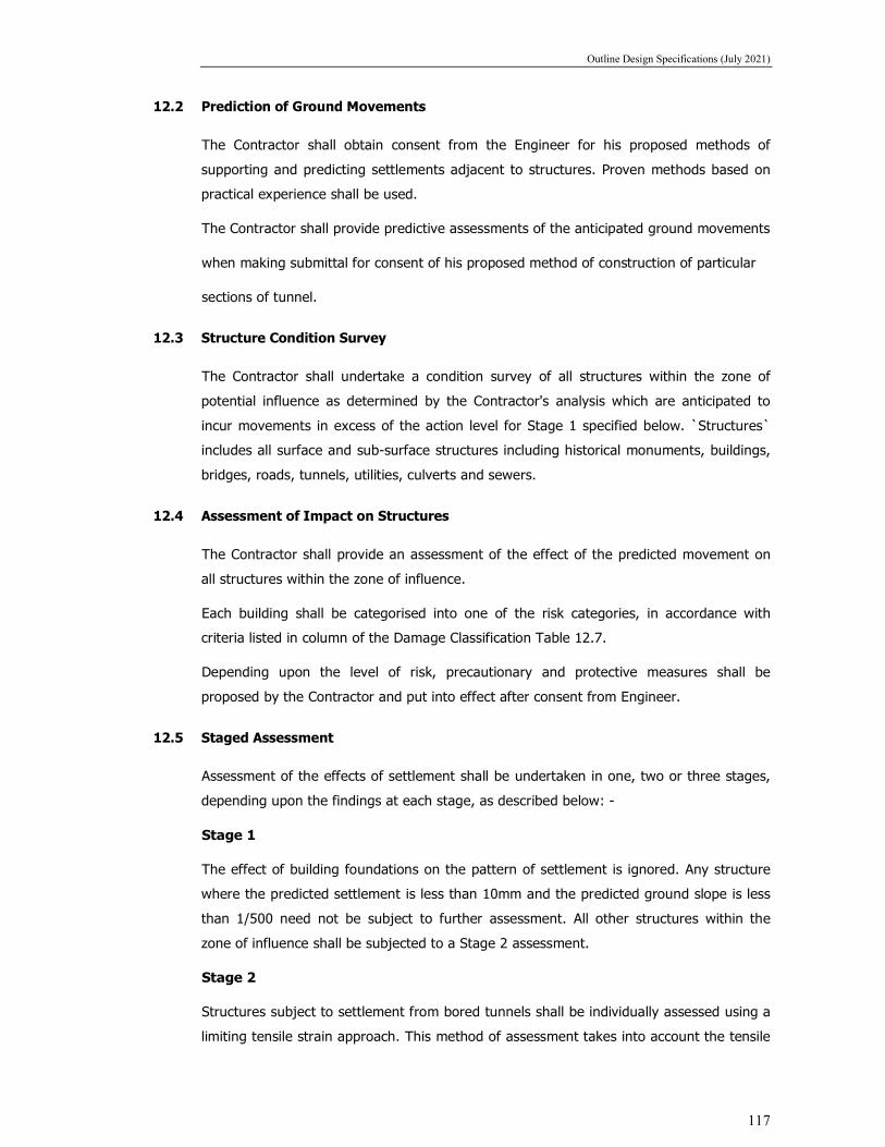
Outline Design Specifications (July 2021)
117
12.2 Prediction of Ground Movements
The Contractor shall obtain consent from the Engineer for his proposed methods of
supporting and predicting settlements adjacent to structures. Proven methods based on
practical experience shall be used.
The Contractor shall provide predictive assessments of the anticipated ground movements
when making submittal for consent of his proposed method of construction of particular
sections of tunnel.
12.3 Structure Condition Survey
The Contractor shall undertake a condition survey of all structures within the zone of
potential influence as determined by the Contractor's analysis which are anticipated to
incur movements in excess of the action level for Stage 1 specified below. `Structures`
includes all surface and sub-surface structures including historical monuments, buildings,
bridges, roads, tunnels, utilities, culverts and sewers.
12.4 Assessment of Impact on Structures
The Contractor shall provide an assessment of the effect of the predicted movement on
all structures within the zone of influence.
Each building shall be categorised into one of the risk categories, in accordance with
criteria listed in column of the Damage Classification Table 12.7.
Depending upon the level of risk, precautionary and protective measures shall be
proposed by the Contractor and put into effect after consent from Engineer.
12.5 Staged Assessment
Assessment of the effects of settlement shall be undertaken in one, two or three stages,
depending upon the findings at each stage, as described below: -
Stage 1
The effect of building foundations on the pattern of settlement is ignored. Any structure
where the predicted settlement is less than 10mm and the predicted ground slope is less
than 1/500 need not be subject to further assessment. All other structures within the
zone of influence shall be subjected to a Stage 2 assessment.
Stage 2
Structures subject to settlement from bored tunnels shall be individually assessed using a
limiting tensile strain approach. This method of assessment takes into account the tensile

Outline Design Specifications (July 2021)
118
strains in the ground and uses a simple idealised model of the building. Tried and tested
references from the literature may be utilised as an alternative.
In the case of cut and cover excavations, the assessment shall be based on the work of
Peck and Clough and O'Rourke using parameters derived from recent case histories or
any other tried and tested method.
Stage 3
All structures which are placed in Category 3 or above in the Damage Classification Table
12.7, during the second stage assessment, shall be subjected to a further settlement
assessment. A structural survey shall be undertaken by the Contractor to determine the
structural form and condition of a building, followed by an analysis of how individual
elements of the building would be affected by the predicted settlement. The method,
extent and detail of the analysis will be determined on a case-by-case basis and may
include, inter alia, an analysis of the soil/structure interaction, structural behaviour, and
the possible effects of differential stiffness of the foundations.
As a result of the Stage 3 analysis, the requirement for any protective works shall be
established and the details of any protective works including designs and method of
working determined. Details of such works shall be submitted to The Engineer for his
consent.
12.6 Monitoring
Instrumentation and monitoring arrangements for ground and existing building structures
(EBS) movement and distortion and changes to the groundwater table(s) and the trigger
(Alert, Action & Alarm) levels for each and every identified EBS to be performed. Designer
has to specify the required instrumentation and monitoring arrangement to maintain the
safety of the EBS.
The extent of monitoring of structures shall be carried out on a case-by-case day to day
or more frequent basis depending upon the assessment of risk of damage. Special
attention shall be paid to the historical buildings located along the alignment. Monitoring
shall begin prior to commencement of the Works to enable base-line values to be
determined accurately and shall continue until all settlements due to the underground
works, as shown by the monitoring, has effectively stopped for a period of three months.
The Contractor shall make monitoring results available for inspection by The Engineer at
the construction site offices.

Outline Design Specifications (July 2021)
119
12.7 BUILDING DAMAGE CLASSIFICATION
Notes:
(1) The table is based on the work of Burland et al (1977) and includes typical maximum
tensile strains for the various damage categories (column 5) used in the stage 2
settlement analysis.
(2) Crack width is only one aspect of damage and should not be used on its own as a
direct measure of it.

Outline Design Specifications (July 2021)
120
12.8 Limiting Construction-Induced Vibrations at Existing Adjacent Structures
In the design, the effects of construction-related vibrations shall be considered. Unless
otherwise accepted by the applicable government agencies and the Employer, peak particle
velocities at existing adjacent structures shall not exceed the values in the Table below:
Peak Particle Velocities in mm/sec (Maximum Allowable) at Existing Adjacent Structures
Most structures in “good” condition 25
Most structures in “fair” condition 12
Most structures in “poor” condition 5
Water-supply structures 5
Heritage structures/bridge structures 5
Above limits are maximum permissible, however this may have to restricted further if
required to avoid damage to the adjacent structure or causing discomfort to the occupants.
Along the proposed alignment, other limitations may be imposed at existing adjacent
structures, such as hospitals, school buildings, telephone-exchange structures, special water-
supply structures and Heritage structures.
Methods of reducing vibration, such as limiting explosive charge per delay or operating
piledriving equipment at lower energy levels, may be required. The use of expansive agents
or mechanical excavation methods shall be required in place of blasting at certain critical
locations. In addition, working hours for such equipment’s causing vibrations may have to
restricted, keeping the convenience and comfort of the occupants in mind.
13 CODAL PREFERENCE
Subject to the requirements of this specification and other Control documents, all design
work shall comply with the appropriate current standards issued by the Bureau of Indian
Standards (BIS), or if such a standard does not exist, then the appropriate current standard
issued by the British Standard Institute (BSI). If appropriate standard from BIS and BSI does
not exist, then subject to approval by engineer, an appropriate current standard from a
reputable institution may be used. The designer shall follow updated codes with latest
correction slips

Outline Design Specifications (July 2021)
121
(Note: the years of the codes mentioned below are notional, hence each time the designer
shall adopt latest code with the latest correction slip)
The Order Preferences of codes will be as follows: -
i. BIS
ii. BSI or Euro Code
iii. IRC
iv. IRS
v. AASHTO

Outline Design Specifications (July 2021)
122
OUTLINE DESIGN CRITERIA
FOR
GEOTECHNICAL WORKS
Outline Design Specifications (July 2021)
123
1.0 GENERAL, STANDARDS AND CODES 1.1 Purpose and Scope
The purpose of this section of these Design Criteria is to establish the minimum requirements
for geotechnical site investigations, studies, analyses, and preparation of geotechnical reports
and the design recommendations for earthworks, foundations, structures, and substructure
design, and the design for bored and cut and cover tunnels.
"Geotechnical works" shall mean foundations, earthworks, deep excavations, slopes,
embankments and earth retaining structures.
The Contractor shall be responsible for determining for his design purposes the Geology and
the Geotechnical parameters of the sub-surface strata along the route.
The Employer will make available to the Contractor, for information only, the Geotechnical
Investigation Report prepared by others. The accuracy or reliability of these reports supplied
by the Employer or Engineer in connection with the contract is not warranted. These shall be
supplemented as necessary by additional boreholes as required by the Contractor.
1.2 Design Considerations
In his design the Contractor shall take adequate measures to minimise the amount of local differential settlement of road surfaces around below ground level works.
The slopes of all permanent cuttings and excavations shall be so designed that they are
capable of supporting vegetation and shall be stabilised where necessary. In particular, soil
slopes shall be hydroseeded or turfed. Where necessary, soil slopes shall be pitched with
stones or brick on edge.
2.0 SITE INVESTIGATIONS AND LABORATORY INVESTIGATIONS
2.1 General Conditions
Subsurface Conditions
Regional engineering geology aspects for the area of the Rail alignments are generally documented by the Geological Survey of India.
Seismic Conditions
Detailed, seismic loading and ground-acceleration criteria are discussed under Structural, of
these Design Criteria. Consideration of design-level seismic forces in the design of temporary
structures is generally not required, except that such designs shall ensure public safety and
cause no loss or damage to adjacent projects or properties.
The effects of the design seismic event on the stability of slopes and on the potential for liquefaction of soils shall be taken into account in the design.
2.2 Investigation Requirements
Existing information shall be supplemented with project-specific site investigations (SI). The
intent and objectives of the SI shall be to collect all pertinent and reliable data and information
required to produce a safe and economic design and to meet tender and construction
requirements.
For the purpose of these Criteria, the term SI shall be considered to include, but not be limited

Outline Design Specifications (July 2021)
124
to, the following.
a. Compiling and reviewing pertinent existing geologic data.
b. Compiling and reviewing pertinent existing geotechnical data supplied and from adjacent projects.
c. Compiling and reviewing pertinent existing foundation, structure, substructure, and related data from adjacent projects.
d. Performing a detailed field reconnaissance.
e. Performing geophysical surveys.
f. Performing ground investigations that include, but are not limited to drilling, soil sampling,
rock coring, groundwater sampling, in-situ field installations and testing, trial pits,
geophysical surveys, slope protection strippings, and coreholes of retaining walls and
other existing manmade structures.
g. Performing laboratory testing of soil, rock, and groundwater samples collected from the
ground investigations (including chemical testing to identify potentially corrosive conditions).
h. As a minimum, the soils investigation programme shall consider the locations and lateral and vertical extent of: i. Major structures (viaducts, bridge and crossing structures, bored tunnels, cut-and-
cover tunnels, portal structures, retaining structures, stations, commercial developments, ancillary structures, etc.).
ii. Earthworks (soil and rock excavations, embankment fills, land reclamations, areas
requiring ground improvement, borrow pits and areas, disposal areas, etc.).
iii. Existing adjacent structures that may be influenced by proposed construction works
(i.e., structures – adjacent to, above, or below excavations or tunnels – that may be
affected by construction works such as dewatering or blasting; structures deemed to
have poor structural integrity; structures containing sensitive equipment or materials;
structures with historic/cultural significance, etc.).
iv. Significant engineering geology features that may influence the proposed construction works (i.e., principal faults, shear zones, persistent jointing; mass wasting, landslips).
Ground investigations, as part of a comprehensive soils investigation programme, shall be conducted according to IS1892 or BS 5930.
The depths of investigation borings shall be consistent with the nature and extent of the proposed construction works. Soil data shall be available at least up to 1.5B below the founding level/Termination Level of foundation. In case of open foundation B is the width of foundation and for Pile foundation B is the width of rectangle circumscribing the group of pile.
All aspects of the work shall be conducted under the direction of qualified geotechnical
personnel. Detailed plans, technical specifications, and standard forms, outlining the
proposed staffing and reporting formats, and indicating the types, locations, and proposed
depths of investigations relative to the proposed construction works shall be prepared and
submitted for review and acceptance prior to undertaking the work. Revisions to the SI
programme, if required, shall be submitted for review and acceptance.
All Consultant-produced ground-investigation data shall be prepared up to internationally
accepted standards using Association of Geotechnical and Geo-environmental Specialists

Outline Design Specifications (July 2021)
125
(AGS) format or equivalent and Geotechnical Integrator (GINT) software, latest versions. All
data shall be provided in both printed and electronic file formats.
2.3 Investigation Methods Geologic Studies
Geologic studies shall include, but not be limited to, a review of pertinent and existing literature, aerial photographs, and remote-sensing data; a detailed field reconnaissance of the
site; and preparation of project-specific maps and cross-sections.
Project-specific geologic maps shall be prepared at about 1:5,000 scale, and geologic cross-sections shall be prepared at about 1:5,000 scale, both horizontal and vertical. Suitable base
maps for geologic maps shall be utilised.
Geophysical Surveys
Geophysical surveys shall be accomplished where appropriate to provide additional site-specific information on depths and characteristics of overburden soils and bedrock.
Geophysical survey methods may be used to obtain subsurface information for planning other detailed SI studies, and for extending information between investigations. Exploratory Drill holes
Exploratory drilling in soil and rock, disturbed and undisturbed soil sampling, and rock coring
shall be performed according to procedures outlined in IS 1892 or BS 5930. Full-time
monitoring by qualified geotechnical personnel is required not only to direct the drilling,
sampling, and coring, but also to prepare field drill hole records.
Other Ground-Investigation Methods
Other ground-investigation methods commonly employed include, but are not limited to, the following:
a. Field testing: Standard Penetration, cone penetration, vane shear, pressuremeter,
permeability/water absorption, impression packer/discontinuity survey, acoustic borehole imaging, insitu density, N-Schmidt hammer, plate load testing.
b. Field instrumentation: piezometers, inclinometers.
c. Trial pits with/without block sampling.
d. Inspection pits.
e. Geocore probes.
f. Hand auger borings.
g. Coring through rock, retaining walls or other manmade features.
h. Slope protection stripping.
i. Pumping tests.
j. Groundwater sampling. For assessing the behavior of underground structure during earthquake event, the contractor
shall conduct cross hole seismic test/shear wave velocity test as per ASTM
D4428/D4428M.
Groundwater
Piezometers shall be installed during ground investigations to measure current and seasonal

Outline Design Specifications (July 2021)
126
fluctuations in groundwater levels. The SI programme shall incorporate the details of a
groundwater observation plan, including locations and details of piezometer installations and
frequency and duration of observations. . It should also include chemical analysis of ground
water. Full-scale groundwater pumping tests shall be conducted to develop design
parameters for construction dewatering schemes, where required. For additional Criteria
related to construction dewatering refer to Subsections 2.9.5.
LABORATORY TESTING METHODS
2.4 General Methods
The laboratory testing programme shall be developed considering not only the particular site
conditions and project requirements, but also the applicable design standards, codes,
regulations, and related publications as identified in Subsection 2.1.2. Prior to undertaking the
work, detailed plans/proposals for the laboratory testing programme shall be prepared and
submitted for acceptance along with technical specifications and standard forms, outlining the
proposed staffing and reporting formats and the types and numbers of tests proposed.
Revisions to the laboratory testing programme, if required, shall be submitted for review and acceptance.
All Consultants-produced laboratory test data shall be prepared using internationally accepted
standards e.g. AGS format, latest version. All data shall be provided in both printed and
electronic file formats. All testing shall be conducted by laboratories holding current
accreditation under International Standards Organisation/Bureau of Indian Standards.
2.5 Index/Classification Testing of Soil Samples
All index/classification test procedures for soils shall comply with the requirements of IS
2720/BS 1377. Tests shall include the determination of natural moisture content, specific
gravity, particle size distribution (with and without hydrometer), Atterberg limits, insitu bulk and
dry density, and dry density and moisture content relationships. 2.6 Strength Testing of Soil Samples
Strength-test procedures for soils shall include single- and multi-stage, consolidated-drained
and consolidated-undrained triaxial tests; unconsolidated undrained triaxial tests; laboratory
vane shear tests; and pocket shearmeter tests, all according to IS 2720 (Part 11). Unconfined
compressive strength testing for soils shall be according to IS 2720 (Part 10)/ASTM D2166,
and consolidated drained direct shear testing shall be according to IS 2720 (Part 13)/ASTM
D3080. 2.7 Consolidation Testing of Soil Samples
Consolidation test procedures for soils shall be based on one-dimensional, consolidation
methods according to ARE 2720 (Part 14) or Clause 3 of BS 1377: Part 5, with some minor modifications as accepted.
2.8 Permeability Testing of Soil Samples
Laboratory test procedures of soil permeability shall include constant-head permeability
methods for granular soils, generally according to IS 2720 (Part 17 or 36) or ASTM D2434,
and variable-head permeability methods for cohesive soils, generally according to Soil
Testing for Engineers by T. William Lambe. Permeability of insitu materials shall be measured

Outline Design Specifications (July 2021)
127
by constant-head or variable-head methods, using standpipe piezometers installed during the
ground-investigation programme. 2.9 Chemical Testing of Soil and Groundwater Samples
Chemical test procedures for soils and groundwater shall include, as appropriate:
determinations of resistivity, redox potential, pH, chloride ion content, sulphate ion content,
total sulphate content, total sulphide content, organic content, and carbonate content,
according to IS 2720 or BS 1377 or BS 812, or both, and identification of other potentially
corrosive conditions. 2.10 Testing of Rock Specimens
All rock testing shall be according to IS or ISRM suggested methods. Tests shall include the
determination of natural moisture content, porosity, density, adsorption, unconfined
compressive and tensile strength, strength of rock joints, mineralogy, and special tunnel
boring machine (TBM) boreability testing.
3.0 Geophysical Investigation
At several locations it would be difficult to carry boreholes along the alignment. Depending upon the site constraint and requirement, the contractor engaged must carry different methods of geophysical investigation to find the physical properties of strata underneath along the alignment. Any chances of encountering abrupt soil strata during construction stage must be avoided by carrying all the possible geophysical and geotechnical investigation.
Different type of geophysical methods for urban environment prior to construction:-
a) Resistivity Imaging
Electrical resistivity imaging survey determines sub-surface resistivity distribution by taking measurements on the ground. From these measurements, true resistivity of sub-surface can be estimated. The resistivity is related to various geological parameters like mineral and fluid content, porosity and degree of water saturation in rocks.
b) TDEM (time Domain Electro-Magnetic Method)
Electro Magnetic (EM) method is based on the physical effect of electromagnetic induction where an electrical current is induced in the ground and a secondary magnetic field is created. The secondary magnetic field is governed by the electrical resistivity of the ground and the resistivity contrast between various layers is the survey target of EM system (airborne or heliborne). The resistivity distribution is obtained by inverse modeling of the electromagnetic time decay or frequency response measured by the EM systems.
c) Seismic Refraction
Seismic refraction consists of recording the time taken for an artificially provoked surface vibration to propagate through the earth. By processing the data recorded at various sensors, absolute velocities, velocity contrasts and depths of the underlying layers are determined. These results provide information about the characteristics of the overburden and the bedrock.
d) Crosshole/Downhole/Uphole Surveys:
Crosshole geophysical testing is generally conducted in the near surface (upper hundred meters) for site specific engineering applications. The primary purpose of obtaining crosshole

Outline Design Specifications (July 2021)
128
data is to obtain the most detailed in-situ seismic wave velocity profile for site specific investigations and material characterization, Crosshole velocity data are valuable for assessing man-made materials, soil deposits or rock formations.
e) Seismic Reflection Method:
Deep seismic reflection surveying is the most advanced technique in geophysics with huge scale application for oil and gas exploration. Seismic energy is generated at the surface using either impulsive sources (dynamite) or continuous sources (vibroseis). The returned energy is recorded by a series of geophones installed along line at the surface. Reflection of the energy is caused by contrasts in acoustic impedance between the various strata. Data processing is a complex sequence of operations carried out usually on powerful computers using specialized software. The final product in a 2D or 3D dataset of seismic reflectors, which can then be correlated to specific geological interfaced through the use of borehole information. On a smaller scale, such as for civil engineering project site investigations, the methodology is identical, but the equipment and parameters are adjusted to provide a higher resolution at shallow depths.
f) Ground Penetrating Radar (GPR) Method:
Ground Penetrating radar, also known as GPR, Georadar, Subsurface Radar, Geoprobing Radar, is a totally non-destructive technique to produce a cross-section profile of subsurface without any drilling, trenching or ground disturbances. GPR profiles are used for evaluating the location and depth of buried objects and to investigate the presence and continuity of natural subsurface conditions and features.
The GPR operates by transmitting electromagnetic impulses into the ground through transmitter antenna. The transmitted energy is reflected from various buried objects or distinct contacts between different earth materials, across which there is a contrast in dielectric constant. The antenna then receives the reflected waves and displays them in real time on screen. Data is also saved in appropriate memory for later processing and interpretation.
GPR can detect objects of any material, metallic or non-metallic.
3.1 In addition to the soil investigation carried by geophysical and geotechnical methodology contractor needs to predict the geological condition ahead of cutter head by adopting below mentioned technique.
a) Tunnel Seismic Prediction (TSP): The Tunnel Seismic Prediction (TSP) approach allows a continuous prediction of geological uncertainties ahead and ground the tunnel face with a prediction range of 100-150 meters ahead of the face. By the majority, seismic exploration is based on seismic reflection by observing and evaluating elastic body wave. These waves are excited by artificial sources like detonation charge or the usage of an impact mass (hammer). The waves are being reflected at interfaces of different mechanical properties like density or elasticity. Thus, by detection of reflected elastic waves and their corresponding travel times it is possible to deduct information about the mechanical properties of the ground. In this way important engineering parameters like elastic modull can be derived. To perform reliable seismic measurements for tunnel construction, the Tunnel Seismic Prediction (TSP) system proves to be very efficient.
The major operational advantages include spatial investigation ahead of the face, detection of hazardous fault zones and cavities, exploration of water bearing formations and discovery of changes in rock mechanical properties.

Outline Design Specifications (July 2021)
129
b) Geo-Electrical Real-Time Ground Prediction while TBM Boring: The Bore Tunnelling Electrical Ahead Monitoring (BEAM) is a non-intrusive focused-electrical induced polarization ground prediction technique, permanently operating during TBM tunnelling. BEAM is based on advanced in-house developed processing evaluation and visualization software which shows the measuring data and distribution of percentage frequency effect (PFE) and resistivity (R) for geological classification and hydro geological characterization. The PFE characterizes the ability of the ground to store electrical energy. Thus it is reciprocally correlated to the effective porosity.

Outline Design Specifications (July 2021)
130
LIST OF DESIGN CODES AND STANDARDS

Outline Design Specifications (July 2021)
131
1. Indian Railway Standards (IRS) Codes and Manuals (With Latest Versions and all ammendments up to date of BIDDING)
IRS Bridge Rules
IRS Concrete bridge Code (Reprint 2014)
IRS Bridge substructures and foundation code.
IRS Steel bridge Code
IRS Indian Railway Bridge Manual
IRS Manual on the Design and Construction of Well and Pile Foundations
IRS Earthquake resistant design of Railway Bridges
IRS Welded Bridge COde
2. Indian Roads Congress Standards (IRC) (With Latest Versions and all ammendments up to date of BIDDING)
IRC 5: Standard Specifications and Code of Practice for Road Bridges.
Section I – General Features of Design
IRC 6: Standard Specification & Code of Practice for Road Bridges- Loads
and Stresses
IRC 11: Recommended Practice for the Design of Layout of Cycle Tracks
IRC 19: Standard Specifications and Code of Practice for Water Bound
Macadam
IRC 22: Standard Specifications and Code of Practice for Road Bridges,
Section VI – Composite Construction
IRC 24: Standard Specifications and Code of Practice for Road Bridges,
Section V – Steel Road Bridges
IRC 37: Guidelines for the Design of Flexible Pavement
IRC 45: Recommendations for Estimating the Resistance of Soil below the
maximum Scour Level in the Design of Well Foundations of Bridges
IRC 48: Tentative Specifications for Bituminous Surface Dressing Using Pre-
Coated Aggregates
IRC 78:
IRC: 83(I)
Standard Specifications and Code of Practice for Road Bridges,
Section VII Parts 1 and 2, Foundations and Substructure
Standard Specification & Code of Practice for Road Bridges, Part-l
Metallic Bearings
IRC:83(II) Standard Specification & Code of Practice for Road Bridges, Part-II
Elastomeric Bearings
IRC:83 (III) Standard Specification & Code of Practice for Road Bridges, Part-III
POT, POT-cum PTFE, Pin and Metallic Guide Bearings

Outline Design Specifications (July 2021)
132
IRC:83 (IV) Standard Specification & Code of Practice for Road Bridges, Part, IV
Spherical and Cylindrical Bearings
IRC 87: Guidelines for the Design and Erection of False Work for Road
Bridges
IRC 89: Guidelines for Design and Construction of River Training and Control
Works for Road Bridges
IRC:112 Code of Practice for Concrete Road Bridges
IRC:SP-11 1988 Handbook of Quality Control for Construction of Roads and
Runways
IRC-SP-64 Guidelines for Analysis and Design of Cast-in Place Voided slab
Superstructure
IRC-SP-65 Guidelines for Design and Construction of Segmental bridges
IRC-SP-66 Guidelines for Design and Construction of Continuous bridges
IRC-SP-69 Guidelines and Specifications for Expansion Joints
IRC-SP-71 Guidelines for Design and Construction of Pre-cast Pre-tensioned
Girders for bridges
IRC-SP-114 Guidelines for Seismic Design of Road Bridges
3. Bureau of Indian Standards Codes (With Latest Versions and all ammendments up to date of BIDDING)
SP 7: National Building Code
IS 73: Paving Bitumen
IS 150: Ready mixed paint brushing, finishing stoving for enamel colour as
required
IS 205: Non-ferrous metal Butt Hinges
IS 206: Tee and strap hinge
IS 207: Gate and shutter hooks and eyes
IS 208: Door handles
IS 210: Grey iron castings
IS 215: Road tar
IS 217: Cutback Bitumen
IS 269: 33 grade Ordinary Portland Cement.
IS 278: Galvanised steel barbed wire for fencing
IS 280: Mild Steel wire for general engineering Purposes
IS 281: Mild Steel sliding door bolts for use with Padlocks
IS 362: Parliament hinges
IS 363: Hasps and staples
IS 383: Coarse and fine aggregates from natural Sources for concrete

Outline Design Specifications (July 2021)
133
IS 432: Mild steel and medium tensile steel bars and hard- drawn steel wire
for concrete reinforcement
Part 1 Mild steel and medium tensile steel bars
Part 2 Hard-drawn steel wire
IS 453: Double-acting spring hinges
IS 455: Portland slag cement
IS 456: Code of practice for plain and reinforced concrete
IS 457: Code of practice for general construction of plain and
reinforced concrete for dams and other massive structures
IS 458: Precast concrete pipes (with and without reinforcement)
IS 459: Corrugated and semi-corrugated asbestos cement sheets
IS 460: Test sieves
IS 516: Method of test for strength of concrete
IS 650: Standard sand for testing cement
IS 733: Wrought aluminium and aluminium alloy bars, rods and
sections for general engineering purposes
IS 737: wrought aluminium and aluminium alloy sheet and strip
for general engineering purposes
IS 771: Glazed fire-clay sanitary appliances
Part 1 General requirements
Part 2 Specific requirements of Kitchen and laboratory sinks
Part 3/Sec. 1 Specific requirements of Urinals - Slab Urinals
Part 3/Sec. 2 Specific requirements of Urinals - Stall Urinals
IS 774: Flushing cistern for water closets and urinals
IS 775: Cast iron brackets and supports for wash basins and sinks
IS 777: Glazed earthenware wall tiles
IS 778: Copper Alloy gate, globe and check valves for water works Purposes
IS 779: Water meters
IS 780: Sluice valves for water works purposes (50 to 300 mm size)
IS 781: Cast copper alloy screw down bib taps and stop valves for water
service
IS 783: Code of practice for laying of concrete pipes
IS 800: Code of practice for general construction in steel
IS 814: Covered electrodes for manual metal arc welding of carbon and
carbon manganese steel
IS 875: Code of practice for design loads (other than earthquake) for
buildings and structures (All Parts)
IS 883: Code of practice for design of structural timber in building

Outline Design Specifications (July 2021)
134
IS 909: Under-ground fire hydrant, sluice valve type
IS 1003: Timber panelled and glazed shutters
Part 1 1991 Door shutters
Part 2 1994 Window and ventilator shutters
IS 1030: Carbon steel castings for general engineering purposes
IS 1038: Steel doors, windows and ventilators
IS 1077: Common burnt, clay building bricks
IS 1080: Design and construction of shallow foundation in soil (other than raft
ring and shell)
IS 1161: Steel tubes for structural purposes
IS 1195: Bitumen mastic for flooring
IS 1200 Methodology of measurement of Building and Civil Engineering
Works.
IS 1230: Cast iron rainwater pipes and fittings
IS 1237: Cement concrete flooring tiles
IS 1239: Mild steel tubes, tubular and other wrought steel fittings
Part 1 Mild steel tubes
Part 2 Mild steel tubular and other wrought steel pipe fittings
IS 1322: Bitumen felts for water proofing and damp-proofing
IS 1341: Steel butt hinges
IS 1343: Code of practice for Pre-Stressed Concrete
IS 1346: Code of practice Waterproofing of roofs with bitumen felts
IS: 1364 Hexagon Head Bolts, Screws & nuts of product grades A & B Part 1
(part 1 Hexagon, Head Bolts (size range M 16 to M64)
IS 1458: Railway bronze ingots and casting
IS 1489: Portland Pozzolana Cement
IS 1536: Centrifugally cast (spun) iron pressure pipes for water, gas and
sewage
IS 1537: Vertically cast-iron pressure pipes for water, gas and sewage
IS 1538: Cast iron fittings for pressure pipes for water, gas and sewage
IS 1566: Hard-drawn steel wire fabric for concrete reinforcement IS
IS 1592: Asbestos cement pressure pipes
IS 1703: Copper alloy float values (horizontal plunger type) for water supply
fittings
IS 1726: Cast iron manhole covers and frames
IS 1729: Sand cast iron spigot and socket soil waste and ventilating pipes,
fitting and accessories
IS 1732: Dimensions for round and square steel bars for structural and

Outline Design Specifications (July 2021)
135
general engineering purposes
IS 1785: Plain hard-drawn steel wire for prestressed concrete
Part 1 Cold-drawn stress – relieved wire
Part 2 As drawn wire
IS 1786: High strength deformed steel bars and wires for concrete
reinforcement
IS 1791: Batch type concrete mixers
IS 1795: Specifications for pillar taps for water supply purposes
IS 1834: Hot applied sealing compounds for joint in concrete
IS 1838: Pre-formed fillers for expansion joint in concrete pavements and
structures (non extruding and resilient type)
Part 1 Bitumen impregnated fibre
IS 1888: Method of load tests on soils
IS 1892: Code of practice for sub surface investigations for foundations
IS 1893 Criteria for earthquake resistant design of structures (Part 1 & Part 3)
Part 1 General Provisions and Buildings
IS 1904 Design and construction of foundations in soils General Requirements
IS: 1905 Code of practice for structural use of unreinforced masonry.
IS 1948: Aluminium doors, windows and ventilators
IS 1949: Aluminium windows for industrial buildings
IS 1977: Low Tensile Structural steel
IS 2004: Carbon steel forgings for general engineering purposes
IS 2062: Steel for general structural purposes
IS 2074: Ready mixed paint, air-drying, red oxide-zinc chrome, Priming
IS 2090: High tensile steel bars used in prestressed concrete
IS 2114: Code of practice for laying in-situ terrazzo floor finish
IS 2116: Sand for masonry mortars
IS 2119: Code of practice for construction of brick-cum-concrete composite
IS 2202: Wooden flush door shutters
IS 2326: Automatic flushing cisterns for urinals
IS 2386: Methods of test for aggregates for concrete
Part 1 Particle size and shape
Part 2 Estimation of deleterious materials and organic impurities
Part 3 Specific gravity, density, voids, absorption and bulking
Part 4 Mechanical properties
Part 5 Soundness
Part 6 Measuring mortar making properties of fine aggregates
Part 7 Alkali – aggregate reactivity

Outline Design Specifications (July 2021)
136
Part 8 Petrographic examination
IS 2430: Methods of sampling of aggregate for concrete
IS: 2502 Code of Practice for Bending and Fixing of Bars for Concrete
Reinforcement.
IS 2548: Plastic seats and covers for water closets
IS 2681: Non-ferrous metal sliding door bolts (aldrops) for use with padlocks
IS 2690: Burnt - clay for flat terracing Tiles
IS 2692: Ferrules for water services
IS 2720 Methods of Tests for Soils (all Parts)
IS 2751: Recommended practice for welding of mild steel plain and deformed
bars used for reinforced construction
IS 2906: Specification for sluice valves for water works purposes (350 to1200
mm size)
IS 2911: Code of practice for design and construction of pile foundations
Part 1 Concrete piles
Section 1 Driven cast –in-situ concrete piles
Section 2 Bored cast-in-situ concrete piles
Section 3 Driven precast concrete piles
Section 4 Bored precast concrete piles
Part 3 Under-reamed piles
Part 4 Load test on piles
IS 2950: Code of practice for design and construction of raft foundations.
IS 3067 Code of Practice for General Design Details and Preparatory Work for
Damp-Proofing and Water-Proofing of Buildings
IS 3370: Code of practice for concrete structures for the storage of liquids
IS 3564: Hydraulically regulated door closers
IS 3812: Fly ash for use as pozzolan and admixture
IS 3847: Mortice night latches
IS: 3935 Code of Practice for Composite Construction
IS 3955: Code of practice for design and construction of well foundations
IS 3989: Centrifugally cast (spun) iron spigot and socket soil, waste and
ventilating pipes, fittings and accessories
IS 4082: Recommendations on stacking and storage of construction materials
and components at site
IS 4138: Safety code for working in compressed air
IS 4326: Earthquake resistant design and construction of buildings – code of
practice
IS 4656: Form vibrators for concrete

Outline Design Specifications (July 2021)
137
IS 4736: Hot-dip zinc coatings on mild steel tubes
IS 4826: Hot-dipped galvanised coatings on round steel wires
IS 4925: Concrete batching and mixing plant
IS: 4923 Hollow steel sections for structural use -specification
IS 4926: Ready mixed concrete
IS 4968: Method for sub surface sounding for soils
IS 5525: Recommendations for detailing of reinforcement in reinforced
concrete works
IS 5529: Code of practice for in-situ permeability tests
IS 5640: Method of test for determining aggregate impact value of soft coarse
aggregate
IS 5816: Method of test for splitting tensile strength of concrete cylinders
IS 5889: Vibratory plate compactor
IS 5892: Concrete transit mixers and agitators
IS 6003: Specification for indented wire for prestressed concrete
IS 6006: Specification for uncoated stress relieved strands for prestressed
concrete
IS 6051: Code for designation of aluminium and its alloys
IS 6248: Specification for metal rolling shutters and rolling grills
IS 6403: Code of practice for determination of bearing capacity of shallow
foundations
IS 6603: Stainless steel bars and flats
IS 6760: Slotted countersunk head wood screws
IS 6911: Stainless steel plate, sheet and strip
IS 7181: Horizontally cast-iron double flanged pipes for water, gas and
sewage
IS 7196: Hold fast
IS 7205: Safety code for erection of structural steel work
IS 7231: Specifications for plastic flushing cisterns for water closets and
urinals
IS 7273: Method of testing fusion-welded joints in aluminium and aluminium
alloys
IS 7293: Safety code for working with construction machinery
IS 7320: Concrete slump test apparatus
IS 7534: Sliding locking bolts for use with padlocks
IS 7861: Code of practice for extreme weather concreting
Part 1 For Hot Weather concreting
Part 2 For Cold Weather concreting

Outline Design Specifications (July 2021)
138
IS 7969: Safety code for handling and storage of building Materials
IS 8009 Calculation of settlement of foundations
IS 8041: Rapid – hardening Portland cement
IS 8112: 43 grade ordinary Portland cement
IS 8142: Method of test for determining setting time of concrete by
penetration resistance
IS 8500: Structural steel-micro alloyed (medium and high strength qualities)
IS 9013: Method of making, curing and determining compressive strength of
accelerated cured concrete test specimens
IS 9103: Admixtures for concrete
IS 9284: Method of test for abrasion resistance of concrete
IS 9417: Recommendations for welding cold worked bars for reinforced
concrete construction
IS 9595: Recommendations for metal arc welding of carbon and carbon
manganese steels
IS 9762: Polyethylene floats (spherical) for float valves
IS 10262: Recommended guidelines for concrete mix design
IS 10379: Code of practice for field control of moisture and compaction of soils
for embankment and subgrade
IS 10500: Drinking water specification
IS: 11384 Code of practice for Composite Construction in Structural Steel and
Concrete
IS: 12070 Code of practice for Design and construction of shallow foundation
on Rocks
IS 12269: 53 grade ordinary Portland cement
IS 12894: Fly ash lime bricks
IS 13630: Ceramic tiles – methods of tests
IS 13920: Ductile detailing of reinforced concrete structures subjected to
seismic forces
IS 15388: Specifications for Silica Fume
IS: 14268 Uncoated Stress Relieved Low relaxation Seven-ply Strands for
Prestressed concrete
IS: 14593 Design and Construction of Bored Cast-in-Situ Piles Founded on
Rocks
IS: SP 36 Compendium of Indian Standards on Soil Engineering
(Laboratory Testing) – Part 1
IS: SP 36 Compendium of Indian Standards on Soil Engineering (Field Testing)
Indian Standard Hand Book on Steel Sections Part-I CRRI and IOC,

Outline Design Specifications (July 2021)
139
New Delhi Bituminous Road Construction Hand Book – Part 2
IS: SP 16 Design Aids for Reinforced Concrete to IS: 456
4. British Standards (With Latest Versions and all ammendments up to date of BIDDING)
BS 812 Testing Aggregates - Parts 117 to 119.
BS 1377 Methods of Test for Civil Engineering Purposes - Parts 1 thru 9.
BS 4395 Part 2 High strength friction grip bolts and associated nuts and washers for
Structural Engineering Higher Grade (Part 2)
BS 4447 The performance of pre-stressing anchorages for post-tensioned
construction
BS 4449 Specification for Carbon Steel Bars for the Reinforcement of Concrete
BS 4486 Hot rolled and hot rolled & processed high tensile alloy steel bars for
pre-tensioning of concrete
BS 4550 Methods of testing cement
BS 4592 Industrial Type Metal Flooring, walkways and stair treads
BS 4604 Part 2 The use of high strength friction grip bolts in structural steel work.
Higher grade (parallel shank) (Part 2)
BS 4870 Approval testing of welding procedures
BS 4871 Approval testing of welders working to approved welding Procedures
BS 4872 Approval testing of welders when welding procedure approval is not
required
BS 5075 Concrete admixtures
BS 5135 Process of arc welding of carbon and carbon manganese Steels
BS 5212 Part 2 Cold poured joint sealants for concrete pavements (Part 2)
BS 5328 Methods for specifying concrete, including ready mixed
Concrete
BS 5400 Steel, concrete and composite bridges
BS 5400 Part 4 Code of practice for design of concrete bridges (Part 4)
BS 5400 Part 6 Specification for materials and workmanship, steel
BS 5606 Accuracy in building (Part 6)
BS 5896 High tensile steel wire and stand for the pre-stressing of concrete.
BS 5930: Code of Practice for Site Investigations.
BS 5950 Part 2 Specification for materials, fabrication and erection: hot rolled
sections
BS 6031 Code of Practice for Earthworks.
BS 6105 Corrosion-resistant stainless-steel fasteners
BS 6164 Safety in tunnelling in the construction industry.
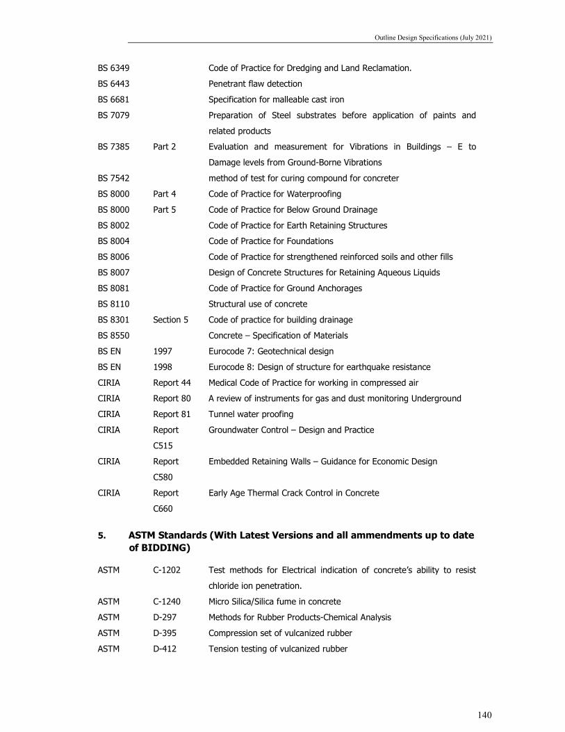
Outline Design Specifications (July 2021)
140
BS 6349 Code of Practice for Dredging and Land Reclamation.
BS 6443 Penetrant flaw detection
BS 6681 Specification for malleable cast iron
BS 7079 Preparation of Steel substrates before application of paints and
related products
BS 7385 Part 2 Evaluation and measurement for Vibrations in Buildings – E to
Damage levels from Ground-Borne Vibrations
BS 7542 method of test for curing compound for concreter
BS 8000 Part 4 Code of Practice for Waterproofing
BS 8000 Part 5 Code of Practice for Below Ground Drainage
BS 8002 Code of Practice for Earth Retaining Structures
BS 8004 Code of Practice for Foundations
BS 8006 Code of Practice for strengthened reinforced soils and other fills
BS 8007 Design of Concrete Structures for Retaining Aqueous Liquids
BS 8081 Code of Practice for Ground Anchorages
BS 8110 Structural use of concrete
BS 8301 Section 5 Code of practice for building drainage
BS 8550 Concrete – Specification of Materials
BS EN 1997 Eurocode 7: Geotechnical design
BS EN 1998 Eurocode 8: Design of structure for earthquake resistance
CIRIA Report 44 Medical Code of Practice for working in compressed air
CIRIA Report 80 A review of instruments for gas and dust monitoring Underground
CIRIA Report 81 Tunnel water proofing
CIRIA Report
C515
Groundwater Control – Design and Practice
CIRIA Report
C580
Embedded Retaining Walls – Guidance for Economic Design
CIRIA Report
C660
Early Age Thermal Crack Control in Concrete
5. ASTM Standards (With Latest Versions and all ammendments up to date of BIDDING)
ASTM C-1202 Test methods for Electrical indication of concrete’s ability to resist
chloride ion penetration.
ASTM C-1240 Micro Silica/Silica fume in concrete
ASTM D-297 Methods for Rubber Products-Chemical Analysis
ASTM D-395 Compression set of vulcanized rubber
ASTM D-412 Tension testing of vulcanized rubber

Outline Design Specifications (July 2021)
141
ASTM D-429 Adhesion of vulcanized rubber to metal
ASTM D-573 Accelerated aging of vulcanized rubber by the oven method
ASTM D-624 Tear resistance of vulcanized rubber
ASTM D-797 Young’s modulus in flexure of elastomer at normal and subnormal
temperature
ASTM D-1075 Effect of water on cohesion of compacted bituminous mixtures
ASTM D-1143 Test method for piles under static axial comp. test
ASTM D-1149 Accelerated ozone cracking of vulcanized rubber
ASTM D-1556 In-situ density by sand replacement
ASTM D-1559 Test for resistance to plastic flow of bituminous mixtures using
Marshall apparatus
ASTM D-2172 Extraction, quantitative, of bitumen from bituminous paving mixtures
ASTM D-2240 Indentation hardness of rubber and plastic by means of a Durometer
ASTM D-3689 Testing method of testing individual piles under static axial tensile
load
ASTM D-4945 Test method for high strain dynamic testing of piles
ASTM E-11 Specification for wire cloth sieve for testing purpose
ASTM: Section 4: Construction, Vol. 04.08: Soil and Rock I, and Volume 04.09: Soil and
Rock II,
6. AASHTO Standards (With Latest Versions and all ammendments up to date of BIDDING)
AASHTO M6-81 Fine aggregate for Portland cement concrete
AASHTO M31-82 Deformed and plain billet-steel bars for concrete reinforcement
AASHTO M42-81 Rail-steel deformed and plain bars for concrete reinforcement
AASHTO M54-81 Fabricated steel bar or rod mats for concrete reinforcement
AASHTO M 81-75 Cut-back asphalt (rapid-curing type)
AASHTO M 82-75 Cut-back asphalt (medium-curing type)
AASHTO M85-80 Portland cement
AASHTO M 140-80 Emulsified asphalt
AASHTO M 147-67 Materials for aggregate and soil–aggregate sub-base, base and
surface courses
AASHTO M148-82 Liquid membrane-forming compounds for curing concrete
AASHTO M154-79 Air-Entraining admixtures for concrete
AASHTO M173-60 Concrete joint-sealer, hot-poured elastic type
AASHTO M194-82 Chemical admixtures for concrete
AASHTO M213-81 Preformed expansion joint fillers for concrete paving and structural
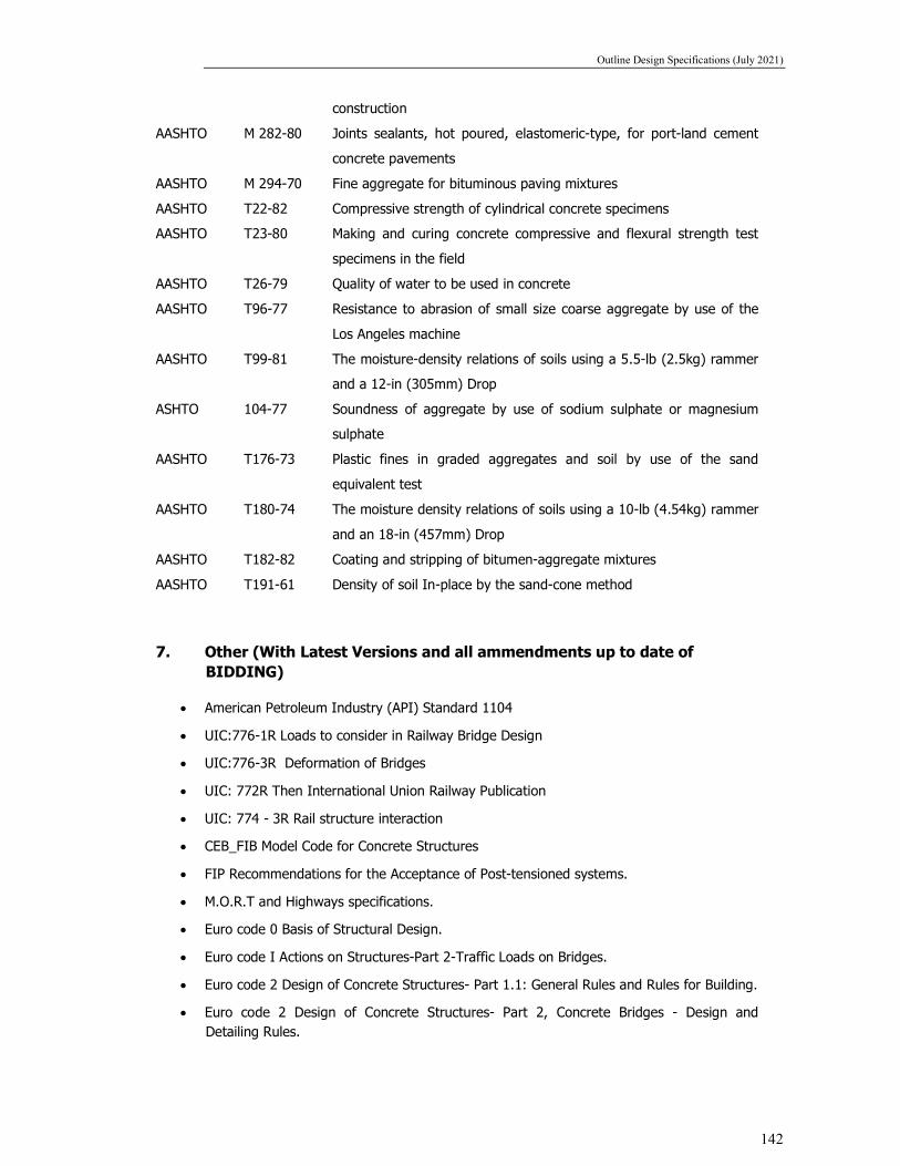
Outline Design Specifications (July 2021)
142
construction
AASHTO M 282-80 Joints sealants, hot poured, elastomeric-type, for port-land cement
concrete pavements
AASHTO M 294-70 Fine aggregate for bituminous paving mixtures
AASHTO T22-82 Compressive strength of cylindrical concrete specimens
AASHTO T23-80 Making and curing concrete compressive and flexural strength test
specimens in the field
AASHTO T26-79 Quality of water to be used in concrete
AASHTO T96-77 Resistance to abrasion of small size coarse aggregate by use of the
Los Angeles machine
AASHTO T99-81 The moisture-density relations of soils using a 5.5-lb (2.5kg) rammer
and a 12-in (305mm) Drop
ASHTO 104-77 Soundness of aggregate by use of sodium sulphate or magnesium
sulphate
AASHTO T176-73 Plastic fines in graded aggregates and soil by use of the sand
equivalent test
AASHTO T180-74 The moisture density relations of soils using a 10-lb (4.54kg) rammer
and an 18-in (457mm) Drop
AASHTO T182-82 Coating and stripping of bitumen-aggregate mixtures
AASHTO T191-61 Density of soil In-place by the sand-cone method
7. Other (With Latest Versions and all ammendments up to date of BIDDING)
American Petroleum Industry (API) Standard 1104
UIC:776-1R Loads to consider in Railway Bridge Design
UIC:776-3R Deformation of Bridges
UIC: 772R Then International Union Railway Publication
UIC: 774 - 3R Rail structure interaction
CEB_FIB Model Code for Concrete Structures
FIP Recommendations for the Acceptance of Post-tensioned systems.
M.O.R.T and Highways specifications.
Euro code 0 Basis of Structural Design.
Euro code I Actions on Structures-Part 2-Traffic Loads on Bridges.
Euro code 2 Design of Concrete Structures- Part 1.1: General Rules and Rules for Building.
Euro code 2 Design of Concrete Structures- Part 2, Concrete Bridges - Design and Detailing Rules.

Outline Design Specifications (July 2021)
143
ACI 358: IR-92 (American Concrete Institute) for assessment of dynamic impact for transit Guide ways.
ROSO Guidelines for carrying out RSI (Version 2.0 BS-111 version-3
SS 460 48 66: Swedish Standard Vibration and Shock Guidance Levels for Blast-induced
vibration
NS8141: Vibration and Shock in Structure, Guidance Limits for Blasting-Induced Vibrations
National Fire Protection Association, NFPA 130: Standard for Fixed Guideway Transit and
Passenger Rail Systems
International Society for Rock Mechanics (ISRM), Suggested Test Methods, (various dates)
British Tunnelling Society: Specification for Tunnelling
Austrian Society for Rock Mechanics: Geotechnical Ground Structures Design
International Tunnel Association: Guidelines for the Design and Analysis of Underground
Structure
ITA/AITES Accredited Material: Seismic Design and Analysis of Underground Structures
Muir Wood, A.M. (1975): The Circular Tunnel in Elastic Ground
D.J. Curtis et al (1976): Discussion Paper - Circular Tunnel in Elastic Ground
CG Lai et al (2000): Probabilistic Seismic Hazard Assessment and Stochastic Sire Response
Analysis at the Archaeological Site of Kancheepuram in Southern India. IUSS Press
American Society for Testing and Materials (ASTM), Section 4 : Construction, Volume
04.08 : Soil and Rock I, and Volume 04.09 : Soil and Rock II.
All codes listed above shall be of latest revision including all amendments & corrections.
8. DESIGN SOFTWARE
Any commercial or proprietary software can be used for analysis/design provided the same is validated with manual computations or other standard software in multiple scenarios.