Mobilizable Hydraulic Training Bench Design Report
52
1 Mobilizable Hydraulic Training Bench Design Report Prepared for Mr. Marc-Andre Isabelle, Farm Management and Technology Program, Mcgill University Presented to Professor Chandra Madramootoo BREE 495: Design 3 Birkhoff Li Jiansheng Huang Hiuto Ye, April 21st, 2020 Department of Bioresource Engineering Faculty of Agricultural and Environmental Science Macdonald Campus, McGill University
-
Upload
khangminh22 -
Category
Documents
-
view
0 -
download
0
Transcript of Mobilizable Hydraulic Training Bench Design Report
1
Mobilizable Hydraulic Training Bench Design Report
Prepared for Mr. Marc-Andre Isabelle,
Farm Management and Technology Program, Mcgill University
Presented to Professor Chandra Madramootoo
BREE 495: Design 3
Birkhoff Li
Jiansheng Huang
Hiuto Ye,
April 21st, 2020
Department of Bioresource Engineering
Faculty of Agricultural and Environmental Science
Macdonald Campus, McGill University
2
Content Acknowlegement ............................................................... 3
Nomenclature ................................................................. 3
Executive Summary ............................................................ 3
Introduction ................................................................. 5
Project Aims and Requirement ................................................ 5
The Background ............................................................. 7
Design objectives ........................................................... 13
Design Evolution ............................................................ 15
Design difficulties ....................................................... 15
Economic – The quality of hydraulic fluid under harsh working conditions: 16
Environmental – The disposal and leakage handling of the hydraulic fluid . 17
Social and Safety: The prevention on user injury related to irregulated hydra
ulic pressure ............................................................. 18
Preliminary Findings and Design Decisions ................................... 22
Preliminary Findings ...................................................... 22
Design Decisions .......................................................... 25
Design concept and example calculations ..................................... 27
Challenges ................................................................ 30
Final design and components choice .......................................... 31
Open loop sub-system ...................................................... 31
Close loop sub-system ..................................................... 34
Highlights of the selection components .................................... 36
Reservoir capacity verification ........................................... 36
The selection on suction and return line filter ........................... 39
Consideration on cylinder selection ....................................... 41
Motor selection: .......................................................... 42
Conclusions ................................................................. 44
Comparison ................................................................ 45
Evaluation Conclusion ..................................................... 47
Reference: .................................................................. 49
3
Acknowlegement
The project is under the supervision of Professor Viacheslav I. Adamc
huk and Professor Chandra Madramootoo. The machine is built for the FMT4 01
2 Machinery Maintenance course introduced by Mr. Marc-Andre Isabelle in the
Farm Management and Technology Program. Technical support: Mr. Scott Mankte
low at Macdonald Machine Shop and Mr. René Michaud from Cégep du Vieux Mont
réal.
Nomenclature
Abbriviation
MAC Macdonald Campus of McGill University
FMT Farm Management and Technology
CVM Cégep de Viexu-Montréal
Executive Summary
This report presents a design of a hydraulic training bench that will
fulfill the needs of demonstrating common characteristics This bench could
provide the student operation experience on different hydraulic components
that are available on the market. Functions and relationship between differ
ent hydraulic systems and its various components. The hydraulic training be
nch has the characteristic of reliable, modular, affordable and environment
friendly.
4
The design is mainly based on an integration platform that can be swi
tched between two common types of hydraulic system; open loop(center) syste
m and closed loop(center) system. This integration platform is powered by a
fixed gear pump and a displacement piston pump, the characteristics of the
hydraulic system is demonstrated by weight lifting through various directio
ns or electric power generation through hydraulic motors. Varies of logica
l valves (directional valve, servo valve, etc.) and different piping config
urations (two types of quick connect, varies socket and pipe length,) to ex
tend the possibility of training bench to simulate in various working condi
tions and hydraulic system configurations.
In order to fulfill the needs of quantifying the relationship and cha
racteristics of the testing bench, a meter system that is based on multiple
flow meters and pressure meters is deployed to all the major components in
the hydraulic system. Pressure release valves are integrated to major press
ure points to maximize the security of both client and equipment. Based on
the training bench’s realia nature, a separate pressure alarm system is de
signed to prevent intended human error, or unexpected pressure surge.
In this report, considerations and assumptions of the system are expl
ained, the choice of hydraulic fluid and filter are developed. Relative sta
ndards such as ISO 4406-1999 (ISO, 1999), and safety regulation are conclud
ed. This design could have potential alternation based on client’s feedbac
k and availability of the components. In generally, this design creates a u
5
nique solution for connecting Farm Management Technology students to real l
ife agriculture hydraulic workload.
Index Terms – Hydraulic training bench, agriculture machinery education
Introduction
Project Aims and Requirement
Hydraulic training bench is widely used in schools to provide certain
vocational training or theory demonstration on hydraulic machinery systems.
There are several models on the market but the institutions will customise
the bench based on their course curriculum and the student needs when they
order then bench from industry.
This design of a hydraulic training bench is asked by the FMT as the
re will be a course open in the 2021 winter semester named as FMT4 012 Mach
inery Maintenance. McGill’s Farm Management Technology (FMT) program is a
program that prepares students for the future management and operation in a
gricultural enterprise.(McGill University, 2019) The FMT students receive a
base theoretical introduction for agriculture industrial and skill trainin
g. Agricultural machines, most of which utilise hydraulic transmission syst
ems, are commonly seen. Those students need a straightforward illustration
to help understand the force, toques and power generation between etc. diff
erent hydraulic components systems.

6
Hence, Mr. Marc-Andre Isabelle, the lecturer of Farm Management and T
echnology Program finds a need of utilizing hydraulic training bench in his
teaching, enhancing the understanding of hydraulic system, also giving stud
ents a hands-on experience to explore the behavior and principle the charac
teristic, functions and behaviour of hydraulic systems and the various comp
onent in the hydraulic system (Personal communication, 2019)
The bench has to be installed with the open center and closed center
system with some required components: oil tank, pump, pressure relief valv
e, directional control valve, hydraulic cylinder, hydraulic motor and a ret
urn line oil filter. And it is desired to demonstrate the following relatio
nship between hydraulic characteristics: the relation between oil flow and
velocity of motion components, between the oil pressure and force & torque
generated by motion components; the pressure loss from resistance to flow i
n the system; the least resistance flow path; the constant flow rate low pr
essure open center systems; the constant high pressure variable flow rate c
losed center systems (or load sensing); cavitation in pumps from restrained
suction line from clog in line filter, strainer or low oil level.
However, the design should also consider that the FMT students have l
ittle background knowledge and the lack of operating experience, as a resul
t, it should be user friendly with well-organised components, visualising o
f the working principles and a proper safety measures to prevent injuries,
contamination and spills. What’s more, this bench will be placed in the ca
7
mpus machine shop which has limited space, so it is expected to be compacte
d on the provided table frame, mobilize and easy to store. (Marc-Andre, Per
sonal communication, 2019)
The Background
Hydraulic System
Hydraulic system is a machine system that its force is transformed fr
om its applied source (e.g.: A pump) to another point (e.g.: a hydraulic mo
tor or a hydraulic cylinder) by utilising the pressure of incompressible fl
uid in a sealed system. (Chapple, 2015)
There are a few advantages of this system: The potential performance
of the output in a thrust or torque is outstanding in hydraulic system and
compared to the same power output, the device using hydraulic transmission
system is smaller in size and lighter in weight; the flexibility of the arr
angement favors a few user because it is easy to design, manufacture and re
pair a hydraulic system, so does the installation of the hydraulic componen
t; the operation such as reverse operation, automatic control is easy to be
achieved and the adjustment is precise. However, we should also be aware of
the disadvantages: the resistance, which could raise the temperature, in th
e system is high, and the system is sensitive to temperature change because
it affects the fluid viscosity so that influence the performance of the sys
tem, the ideal working temperature of a hydraulic system is around 54℃, wh
8
at’s more, around 60% of the energy will be transferred to heat; somehow,
the component is expensive because of the precision standard in manufacturi
ng. (René Michaud, CVM, Oral communication, February 19, 2020)
Application in Agriculture Industry
Based on its nature of creating movement or repetition in an efficie
nt and cost-effective ways; hydraulic systems have been applied in the indu
stries where high load is needed such as the automobile industry, aerospace
industry, construction work and agriculture industry. Modern agriculture in
dustry depends a lot on machinery systems in cropping activities and livest
ock management where many big machines are applied.
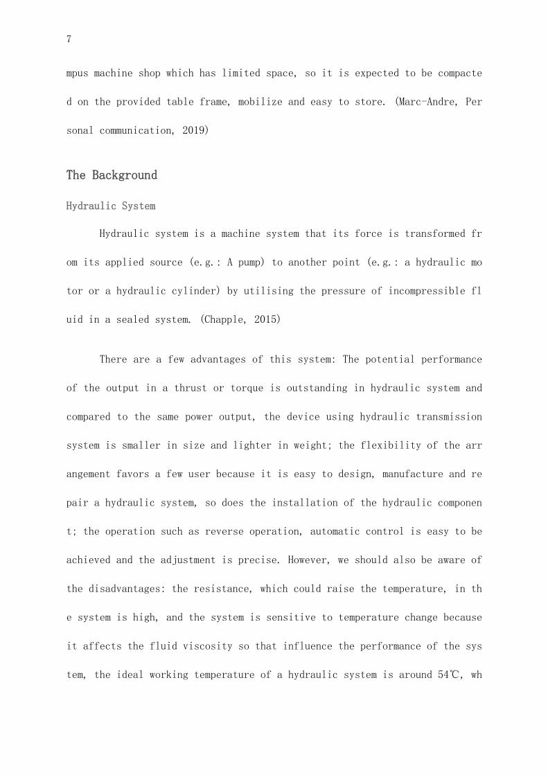
Different types of implements used for activities such as tillage equ
ipment, combined harvester, trailer and etc. Figure 1. is a moldboard plow
in Macdonald Farm introduced by BREE 412 Machinery System course lab. This
moldboard works for tillage and is used for the heavy clay on the farm in o
rder to make the land to be more productive. This implementation is connect
ed to a tractor which applies hydraulic control to lift up the arm and adju
st the angle of the blades. (Martin, Macdonald Farm technician, personal co
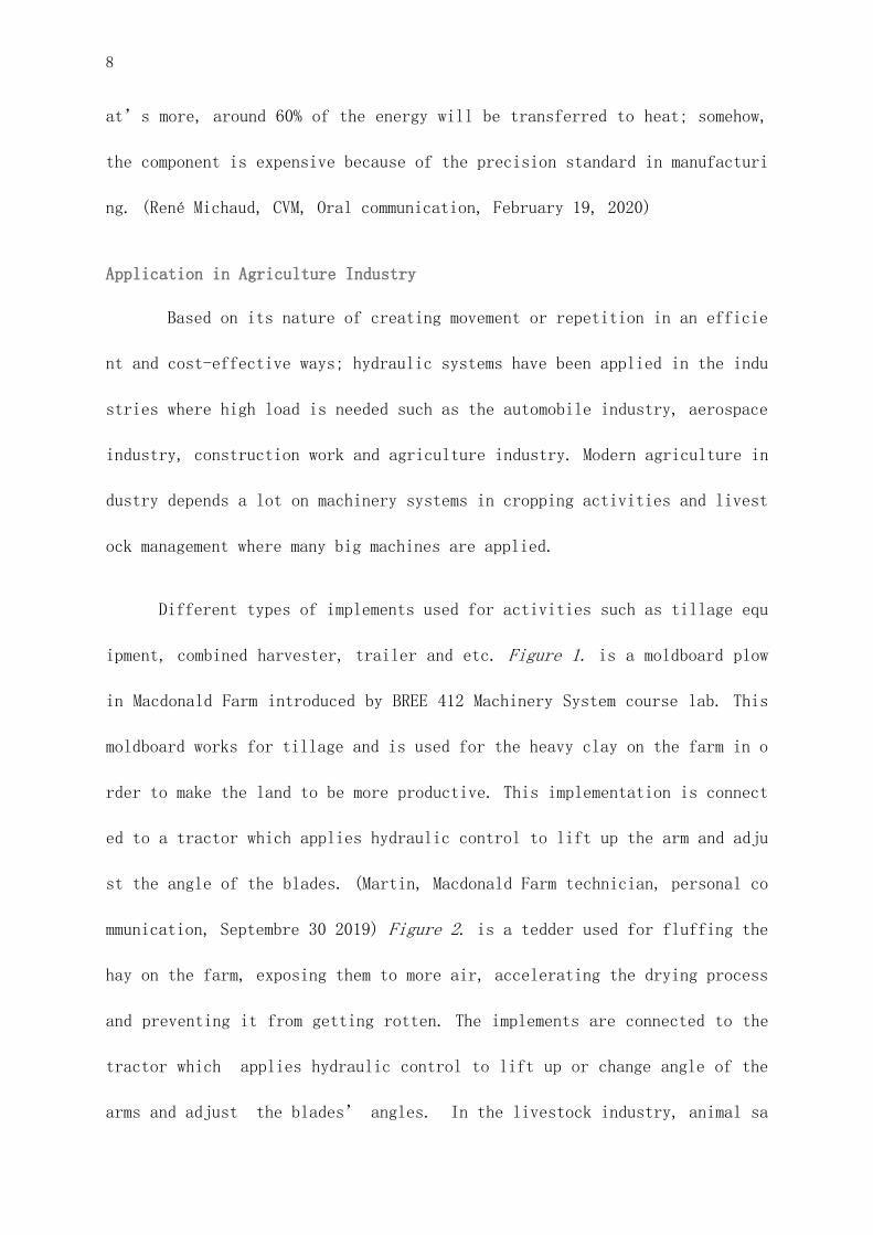
mmunication, Septembre 30 2019) Figure 2. is a tedder used for fluffing the
hay on the farm, exposing them to more air, accelerating the drying process
and preventing it from getting rotten. The implements are connected to the
tractor which applies hydraulic control to lift up or change angle of the
arms and adjust the blades’ angles. In the livestock industry, animal sa
9
lt mineral licking block press machine aslo utilises the hydraulic transmis
sion system to compress salt or sawdust of iron, aluminum and brass ,which
are usually from recycled materials, into high-density blocks - animial lik
ing salt. The mineral lick is a source of essential mineral supplement to t
he farm animals.
Fi
gure 1. Moldboard Plow. Figure 2. Tedder
Hydraulic Lab in Cégep de Vieux-Montréal
Cégep du Vieux-Montréal (CVM) provides students who will practice in
industry after cégep study a DEC (diplôme d'études collégiales) program. Th
is program is involved with general study for continued study and professio
nal skill training that satisfies the labor market. (Cégep du Vieux-Montréa
l, 2019) Among the college and university in Montréal, CVM has the most adv
anced in use hydraulic lab for students. (Marc-Andre Isabelle, personal com
munication, 2020)

10
In the lab, there are various models of hydraulic training benches manufact
ured by different companies in different years with different components co
mbinations. Mr. René Michaud showed us a recent model in the hydraulic lab
manufactured by Vicker’s (the figure on the left), in this model, two pump
s and a motor are aligned together to get a better output, the gauges are a
ttached aside on the bench to monitor the temperature and pressure, various
kind of hydraulic components are installed on the board. This board provide
s different models for the same kinds of components, for example, they have
3 models of directional valves grouped together to show the difference betw
een 2 way valves,3 way valves. It demonstrates the hydraulic cylinder power
by contracting it to a gas cylinder, and uses a marked plate to show the sp
eed of the motor. This bench could provide the student operating experience
on different hydraulic components that are available on the market, it focu
ses on hand-in experience more than on demonstration.
Pre-existing solution
After searching for models in the market, there are a few in use mode
ls including not only the one introduced in the CVM lab, but also benches w
ith just an open centre system or closed centre system. For example, the be
nch (Figure 2. and Figure 3) manugraturfe by Training System Australia Inc.
11
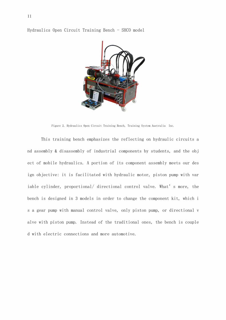
Hydraulics Open Circuit Training Bench - SHCO model
Figure 2. Hydraulics Open Circuit Training Bench, Training System Australia Inc.
This training bench emphasizes the reflecting on hydraulic circuits a
nd assembly & disassembly of industrial components by students, and the obj
ect of mobile hydraulics. A portion of its component assembly meets our des
ign objective: it is facilitated with hydraulic motor, piston pump with var
iable cylinder, proportional/ directional control valve. What’s more, the
bench is designed in 3 models in order to change the component kit, which i
s a gear pump with manual control valve, only piston pump, or directional v
alve with piston pump. Instead of the traditional ones, the bench is couple
d with electric connections and more automotive.
12
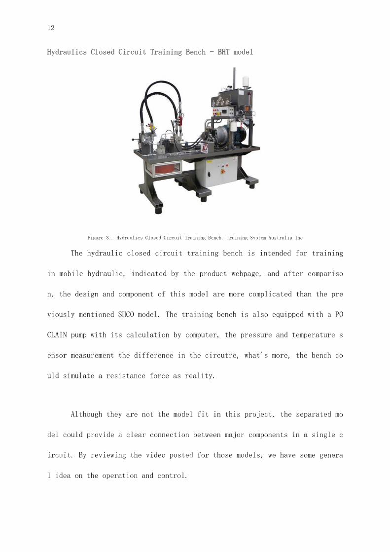
Hydraulics Closed Circuit Training Bench - BHT model
Figure 3.. Hydraulics Closed Circuit Training Bench, Training System Australia Inc
The hydraulic closed circuit training bench is intended for training
in mobile hydraulic, indicated by the product webpage, and after compariso
n, the design and component of this model are more complicated than the pre
viously mentioned SHCO model. The training bench is also equipped with a PO
CLAIN pump with its calculation by computer, the pressure and temperature s
ensor measurement the difference in the circutre, what's more, the bench co
uld simulate a resistance force as reality.
Although they are not the model fit in this project, the separated mo
del could provide a clear connection between major components in a single c
ircuit. By reviewing the video posted for those models, we have some genera
l idea on the operation and control.
13
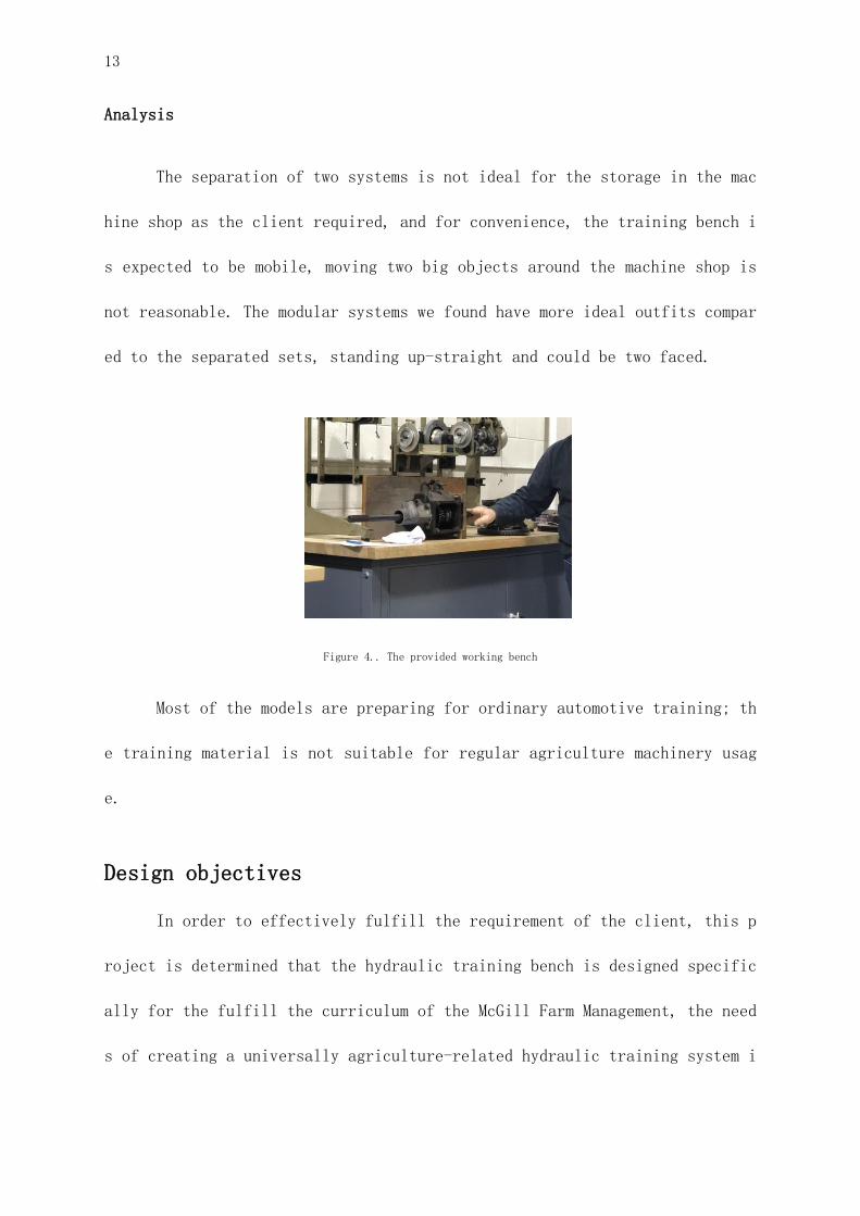
Analysis
The separation of two systems is not ideal for the storage in the mac
hine shop as the client required, and for convenience, the training bench i
s expected to be mobile, moving two big objects around the machine shop is
not reasonable. The modular systems we found have more ideal outfits compar
ed to the separated sets, standing up-straight and could be two faced.
Figure 4.. The provided working bench
Most of the models are preparing for ordinary automotive training; th
e training material is not suitable for regular agriculture machinery usag
e.
Design objectives
In order to effectively fulfill the requirement of the client, this p
roject is determined that the hydraulic training bench is designed specific
ally for the fulfill the curriculum of the McGill Farm Management, the need
s of creating a universally agriculture-related hydraulic training system i
14
s not prioritized. Based on the discussion with our client (Mr. Marc-Andre
Isabelle), mentors (Professor Adamchuk, Department of Bioresource Engineeri
ng) and technical feasibility with fabricate advisor (Mr. Scott Manktelow),
we were able to determine the following list of objectives and range them b
ased on priority from 5 (most important) to 1 (least important).
Based on a series of preliminary investigation, communications and em
pathizing, following objective has been proposed and agreed on:
· To design a hydraulic training bench that will incorporate both an op
en loop and closed loop system.
Prioritized level: 5
· To have the components modular, easily interchangeable, the pipe syst
em needs to be assembled easily.
Prioritized level: 4
· To incorporate the proper metering system to indicate pressure and fl
ow rate at various points of the system.
Prioritized level: 5
A need for a proper demonstration interface to link hydraulic machine
ry performance to real life agriculture tasks.
Prioritized level: 3
15
To incorporate the proper safety measures to prevent injuries, co
ntamination and spills.
Prioritized level: 4
· To utilize components that are common on farm equipment
Prioritized level: 1
After reviewing the previous design works in the Engineering Design 2
course, new design objectives are added on top of existing ones.
● utilizing the old pump
Prioritized level: 5
● Giving easy access for student to use the instrument
Prioritized level: 3
● Pressure readings is assigned as a key measurement to demonstrate the
work load of the hydraulic system
Prioritized level: 4
Design Evolution
Design difficulties
In order to form a robust design, the design difficulties of
the product need to be identified and targeted. In our case, the design d
ifficulties are raised through an engineering design approach that has be
en commonly used by material engineers, failure analysis (prevention). Th
e objective of the failure analysis is through the process of collecting
and analyzing data to determine corrective actions or liability.
16
Due to the limitation of projects, failure data collection is repla
ced by consulting our fabricate advisor (Mr. Manktelow) to gather the mos
t frequently happened failure scenario in hydraulic systems. The failure
scenario is then processed through backward chaining to clarify the desig
n flaws that cause the problem; then abstracting the design flaws to indi
vidual specific design problems. Based on these approaches, the design di
fficulties are categorized into four different sectors; economic, environ
mental, ergonomic and safety.
Economic – The quality of hydraulic fluid under harsh working c
onditions:
A lot of the common problems that caused hydraulic system failure c
an often stem from contamination of hydraulic fluid (The hydraulic wareh
ouse, 2018) The contamination can be caused through agglomeration and pre
cipitation of particulate contamination, oxidation or hydrolysis of the h
ydraulic fluids, reactions involving additives and free water. (Reference
4, Hydraulics & Pneumatics) Through consultation, the problem of oxidati
on, additives reaction and free water is a problem that can be majorly so
lved by the selection of adequate hydraulic solutions. So, the problem is
limited to prevent the agglomeration and precipitation of particulate con
tamination.
A major reason for agglomeration and precipitation is caused by air
borne particulate; the microparticle entering the system through air exch
17
ange from fluid level change in the reservoir. Especially in our design’
s designated working condition, a workshop with constant wood cutting, me
tal wielding. These activities release thousands of micro particles creat
ing a greater chance of airborne particulate. Finding the solution of pre
venting the micro-particles into the system or eliminating the effects on
micro-particles is critical for improving the hydraulic fluid quality und
er the harsh working environment condition.
Environmental – The disposal and leakage handling of the hydrau
lic fluid
Hydraulics leaks occur from failures at some point in the hyd
raulic system. A permanently sealed hydraulic system that never springs a
leak is unfortunately never to pass. Multiple generations of engineers tr
y to eliminate the hydraulic leaks in their design, still this problem is
still the biggest difficulty of the hydraulic design. (Mac hydraulics, 20
17) Based on our time, cost, and knowledge limit, it is impractical to ha
ve a permanent solution for the leakage, although attempts of using leak-
free fittings such as (ISO 16028 interchange coupler) is made to lower th
e chance of leakage. Since the usage of this hydraulic bench only happene
d once or twice per year, the cost of hydraulic leak is mainly environmen
tal rather than economic. Our focus turns to eliminating impacts on hydra
ulic leaks to the environment rather than design a permanent solution for
hydraulic leakage.
18
During our real life practise in component purchasing and building
the hydraulic bench we also found that leakage is deeply connected to the
use of connectors. Some old style connectors,i.e. NPT connectors do not h
ave specific design for leakage prevention, and usually require a budget
in purchasing additional sealing materials like NPT paste. However, some
recently designed connectors like O-ring connectors with swirl sealing ha
ve a better design of preventing leakage from both flow direction and sid
eways, in addition, no extra sealing materials are required. Based on our
new findings on sealing components and materials, the connection componen
ts of some of our key components (directional valve, hydraulic cylinder)
are designated to be the ones with O-ring design.
Social and Safety: The prevention on user injury related to irr
egulated hydraulic pressure
User injury in hydraulic systems are mainly caused by high-pr
essure hydraulic injection accidents, which is usually caused by a loose
connection or defective hose, results in a high-velocity stream of fluid
penetrating human skin; causing serious injury, gangrene or even death. I
n some extreme cases, a minor wound or unseen internal damage could lead
to amputation or death due to the toxicity of the hydraulic fluids. Moreo
ver, since the training bench is designed to be operated by FMT students,
human error or even intentional damage of the equipment needs to be consi
dered. The emphasizing idea has been implemented to the design, a brainst

19
orm of some common scenarios has been simulated. These questions all summ
arized to one single challenge, how to regulate hydraulic pressure in the
system under normal or even extreme conditions? In which configuration of
pressure-maintain components can insure that high-pressure hydraulic inje
ction injury will not happen?
In-Site studies
In February 2020 we also made several visits to CEGEP du Vieux Mont
real for having a close look on existing examples of hydraulic benches in
their Hydraulics Program, as well as advises and inspirations from the ex
perienced instructors there. In their hydraulic laboratory we saw an asto
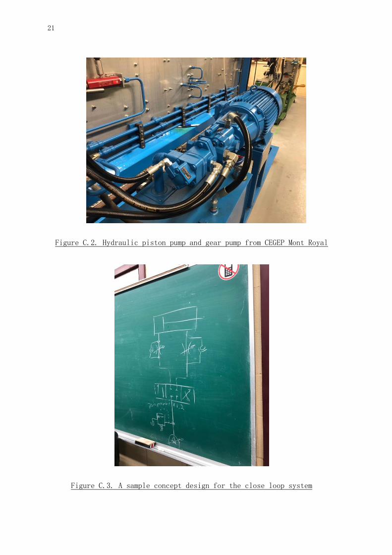
nishing design of integrating open loop and closed loop systems: the gear
pump and piston pump are connected in the same axis with the power sourc
e. This design greatly reduces the space taken for key components, and ke
eps its flexibility between the two systems by an easy shifting scheme. T
he hydraulic bench in CEGEP du Vieux Montreal also has an advanced contro
l system based on computer programs and a sophisticated set of electronic
sensors. Due to budget restrictions and concerns about taking apart our o
ld gear pump and reconnecting it, many of the advanced designs from CEGEP
hydraulic lab can not be applied to our design. Despite the non-applicabl
e ideas, we learnt many other useful informations from CEGEP, for exampl
e, the connection order of each of the hydraulic components, the orientat
ion of male quick connectors and the importance of tank cleaning, which i
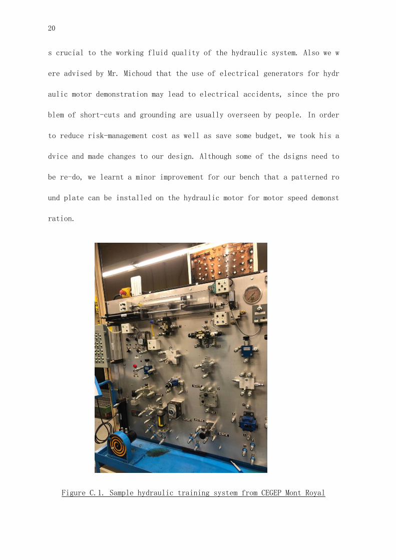
20
s crucial to the working fluid quality of the hydraulic system. Also we w
ere advised by Mr. Michoud that the use of electrical generators for hydr
aulic motor demonstration may lead to electrical accidents, since the pro
blem of short-cuts and grounding are usually overseen by people. In order
to reduce risk-management cost as well as save some budget, we took his a
dvice and made changes to our design. Although some of the dsigns need to
be re-do, we learnt a minor improvement for our bench that a patterned ro
und plate can be installed on the hydraulic motor for motor speed demonst
ration.
Figure C.1. Sample hydraulic training system from CEGEP Mont Royal
21
Figure C.2. Hydraulic piston pump and gear pump from CEGEP Mont Royal
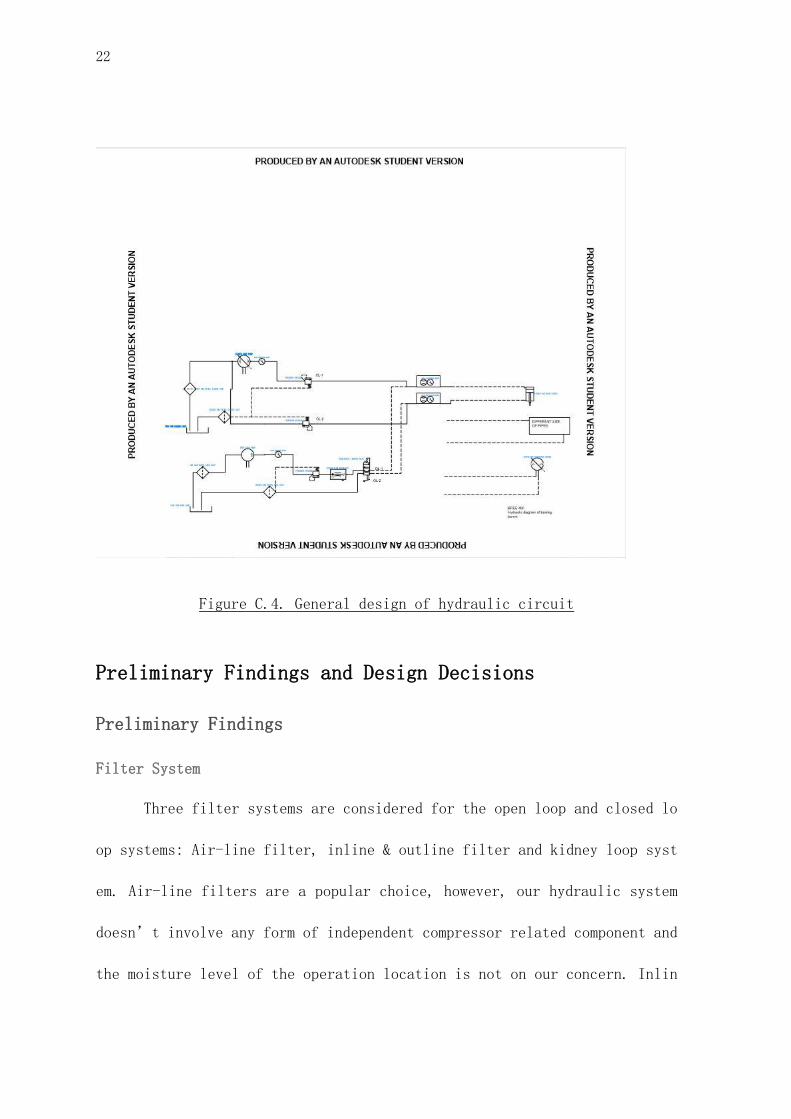
Figure C.3. A sample concept design for the close loop system
22
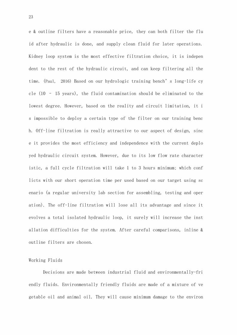
Figure C.4. General design of hydraulic circuit
Preliminary Findings and Design Decisions
Preliminary Findings
Filter System
Three filter systems are considered for the open loop and closed lo
op systems: Air-line filter, inline & outline filter and kidney loop syst
em. Air-line filters are a popular choice, however, our hydraulic system
doesn’t involve any form of independent compressor related component and
the moisture level of the operation location is not on our concern. Inlin
23
e & outline filters have a reasonable price, they can both filter the flu
id after hydraulic is done, and supply clean fluid for later operations.
Kidney loop system is the most effective filtration choice, it is indepen
dent to the rest of the hydraulic circuit, and can keep filtering all the
time. (Paul, 2016) Based on our hydrologic training bench’s long-life cy
cle (10 – 15 years), the fluid contamination should be eliminated to the
lowest degree. However, based on the reality and circuit limitation, it i
s impossible to deploy a certain type of the filter on our training benc
h. Off-line filtration is really attractive to our aspect of design, sinc
e it provides the most efficiency and independence with the current deplo
yed hydraulic circuit system. However, due to its low flow rate character
istic, a full cycle filtration will take 1 to 3 hours minimum; which conf
licts with our short operation time per used based on our target using sc
enario (a regular university lab section for assembling, testing and oper
ation). The off-line filtration will lose all its advantage and since it
evolves a total isolated hydraulic loop, it surely will increase the inst
allation difficulties for the system. After careful comparisons, inline &
outline filters are chosen.
Working Fluids
Decisions are made between industrial fluid and environmentally-fri
endly fluids. Environmentally friendly fluids are made of a mixture of ve
getable oil and animal oil. They will cause minimum damage to the environ
24
ment when they are spilled, and also have a very low toxicity. On the oth
er hand industrial fluid is toxic and needs extreme cautious treatment to
avoid permanent damage to soil. In the perspective of economic considerat
ion, use of environmentally friendly oil includes cost of throughout clea
ning of the hydraulic system, and additional costs are needed for purchas
ing components to accommodate working fluid of different specific weight.
The cost of industrial oil is reasonable. For safety and environment cons
ideration, if all the components are properly sealed, no harmful fluid wi
ll be leaked to the surroundings. Cost of designing a proper seal system
will not be greater than the cost of the application of environmentally-f
riendly oil. Overall speaking, industrial oil is still a suitable choice
as a working fluid.
Actuators
Possible actuators for demonstrations of hydraulic systems are disc
ussed. Torque produced by hydraulic forces can be demonstrated by a winch
system pulling up weights, or an electric generator producing certain pow
er. Careful consultancy was done with the help of technical advisors and
clients. For safety consideration, the output of the generator is adjusta
ble but the start-up torque produced by the hydraulic motor in the winch
system is uncontrollable. This will result in an excerpt of sudden force,
which is highly likely to damage the whole bench and even lead to terribl
e accidents. For demonstrating hydraulic pressure in the piston, a decisi
25
on is made between the plan of pressing on an industrial scale and pullin
g up a certain weight with a pulley system. The similar safety issue come
s up at the start up phase of the piston system, a sudden increase of pre
ssure will damage the structure of industrial scale, which will make the
scale a one-use component. In the end, the plan of using generators for h
ydraulic motors and using pulley systems for hydraulic systems is accepte
d.
Design Decisions
In the theoretical design of hydraulic bench in Design 2, we denied
the design of pulley system and mechanical press system due to safety con
sideration and the short product life of the components. Therefore, a lev
er system using hydraulic cylinders and a generator system driven by a hy
draulic motor are being considered.
After receiving the advice from Mr. Michaud in CVM, the electric ge
nerator design was also rejected due to safety considerations. Then Two n
ew options were brought forward: Hydraulic Dynamometer and Agricultural C
onveyor.
For Hydraulic Dynamometers, they are fancy options for demonstratin
g hydraulic torque, but the price issue and their large volume kept us fr
om picking it. Agricultural conveyors could be another affordable choice,
however, they are still too bulky and their demonstration of various torq
26
ue produced by hydraulic motors is not as good as expected. Therefore bot
h of the ideas were rejected.
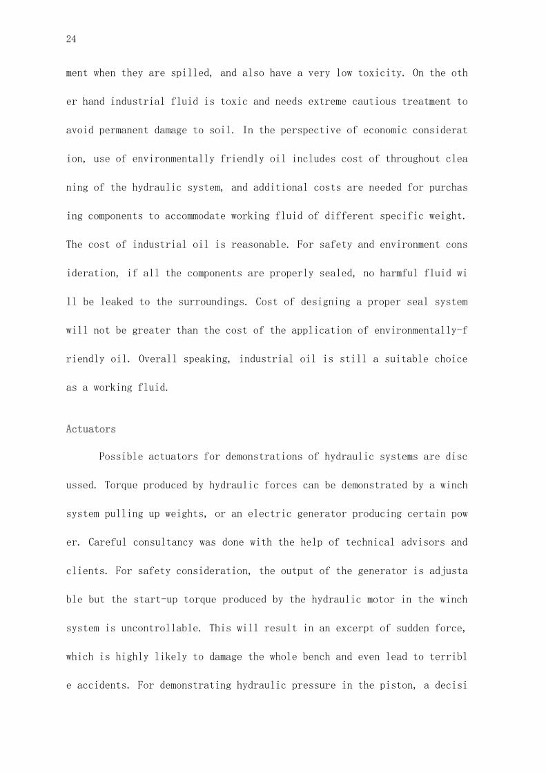
Later we were hit by the idea of a prony brake. This is a prelimina
ry kind of dynamometer that uses a friction block to clamp the rotating a
xis of a motor and measure its torque. Various weights can be added to on
e end of the brake’s arm, and as the brake got tightened, friction torqu
e produced by the brake will be balanced with the original torque of the
motor.(Encyclopedia Britannica, 2019) The primary advantage of prony brak
e is its simplicity, it can be easily built under the current condition o
f the workshop, and it can also be easily operated by two or three peopl
e. For safety considerations, as long as the output of the motor is contr
olled in a reasonable amount, the risk level of the prony brake is essent
ially lower than the electric generator. The summation of economy, easy a
ccess and safety made the prony brake a final choice for hydraulic torque
demonstration.
27
Figure A.1. An illustration of the pony break
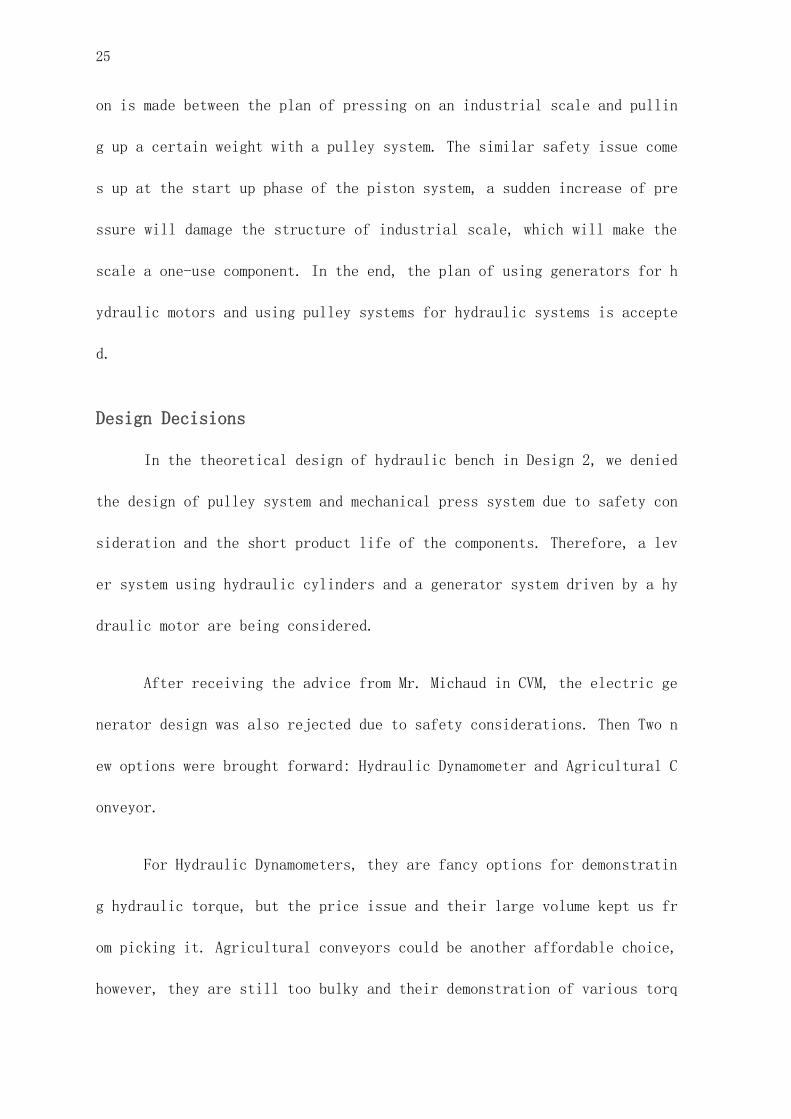
Design concept and example calculations
For our design concept, our working bench builds on a wheeled bench
with a metal plate installed on the back. The key components (piston pum
p, tank, prony brake, hydraulic motor) are installed on the center and lo
wer part of the bench as weight anchors, while the valve and gauge compon
ents are fixed on the metal wall at a suitable height (about 60 cm from t
he bench surface) for operation and demonstrations.
Figure A.2. A conception design for the training bench
28
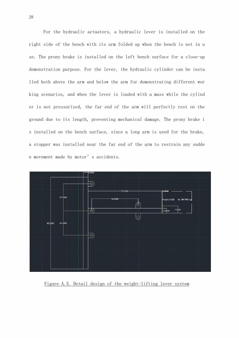
For the hydraulic actuators, a hydraulic lever is installed on the
right side of the bench with its arm folded up when the bench is not in u
se. The prony brake is installed on the left bench surface for a close-up
demonstration purpose. For the lever, the hydraulic cylinder can be insta
lled both above the arm and below the arm for demonstrating different wor
king scenarios, and when the lever is loaded with a mass while the cylind
er is not pressurized, the far end of the arm will perfectly rest on the
ground due to its length, preventing mechanical damage. The prony brake i
s installed on the bench surface, since a long arm is used for the brake,
a stopper was installed near the far end of the arm to restrain any sudde
n movement made by motor’s accidents.
Figure A.3. Detail design of the weight-lifting lever system
29
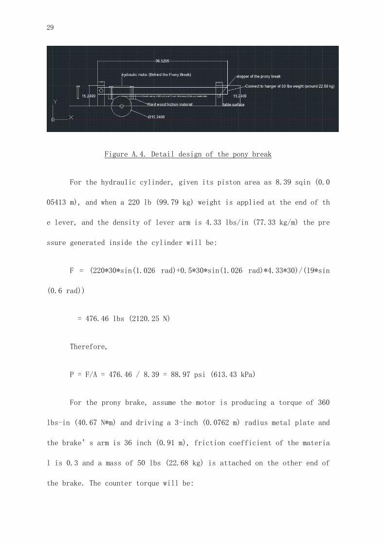
Figure A.4. Detail design of the pony break
For the hydraulic cylinder, given its piston area as 8.39 sqin (0.0
05413 m), and when a 220 lb (99.79 kg) weight is applied at the end of th
e lever, and the density of lever arm is 4.33 lbs/in (77.33 kg/m) the pre
ssure generated inside the cylinder will be:
F = (220*30*sin(1.026 rad)+0.5*30*sin(1.026 rad)*4.33*30)/(19*sin
(0.6 rad))
= 476.46 lbs (2120.25 N)
Therefore,
P = F/A = 476.46 / 8.39 = 88.97 psi (613.43 kPa)
For the prony brake, assume the motor is producing a torque of 360
lbs-in (40.67 N*m) and driving a 3-inch (0.0762 m) radius metal plate and
the brake’s arm is 36 inch (0.91 m), friction coefficient of the materia
l is 0.3 and a mass of 50 lbs (22.68 kg) is attached on the other end of
the brake. The counter torque will be:

30
Torque = 50 * (36/5) * 0.3 * 3 = 324 lbs-in (36.61 N*m)
This is a torque approximately counter balances the torque generate
d by the motor.
Challenges
There were some challenges waiting to be overcome during the design
progress. First, time management was the biggest challenge during the pro
ject, arranging meeting between the team, Mr.Isabelle and Mr. Manktelow w
as not easy, as they were both busy for their own work, the meeting time
had to be fit for the schedule for 5 persons, besides, most of the hard
work has to be done under the supervision of technician Mr. Manktelow in
the machine shop on campus, the following solidworks were expected to be
done during the time when both of the machine shop and Mr. Manktelow are
free. Second, language barrier is another major issue affected the progre
ss, during the communication with our supplier Pièces Hydrauliques Ménard
Inc (Les) and the Cégep du Vieux-Montréal, a certain level of French skil
l was needed, especially when communicated with the supplier, we could on
ly talk to the manager, Mario, as he is the only bilingual staff. The las
t challenge is the COVID-19 outbreak, school work had to be cancelled du
e to this, the installation and assembling were stopped, which is unpredi
ctable and uncontrollable.
31
Final design and components choice
The final design of the hydraulic training bench has been divid
ed into two major subsystems (open loop sub-system, close loop sub-system)
based on its teaching scenario. Since both subsystems will not run at the s
ame time, some components are sharing through both subsystems.
Based on our teaching target and implementing the idea of promp
ting hydraulic knowledge through hands on experience. The training bench di
stinguishes itself from market solutions through requiring the whole system
be self-assembled and troubleshooted by students themselves rather than man
ufacture. Base on that, all the fitting is being converted to the general p
urpose quick-action hydraulic couplers (ISO 5675:2008, DIN)
Open loop sub-system
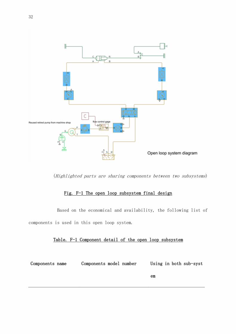
The open loop sub-system is in charge of demonstrating pressure
difference of the open loop hydraulic system under various different loads;
and different hydraulic cylinders’ performance under the same power sourc
e. To achieve that, an iconic open loop hydraulic system and a compacted le
ver-based weightlifting system is built to fulfil the demonstration require
ment. Also, in order to make it relevant to the daily agriculture machinery
operation, a mechanical failure scenario could be simulated through the emb
edded choke valve.
32
(Highlighted parts are sharing components between two subsystems)
Fig. F-1 The open loop subsystem final design
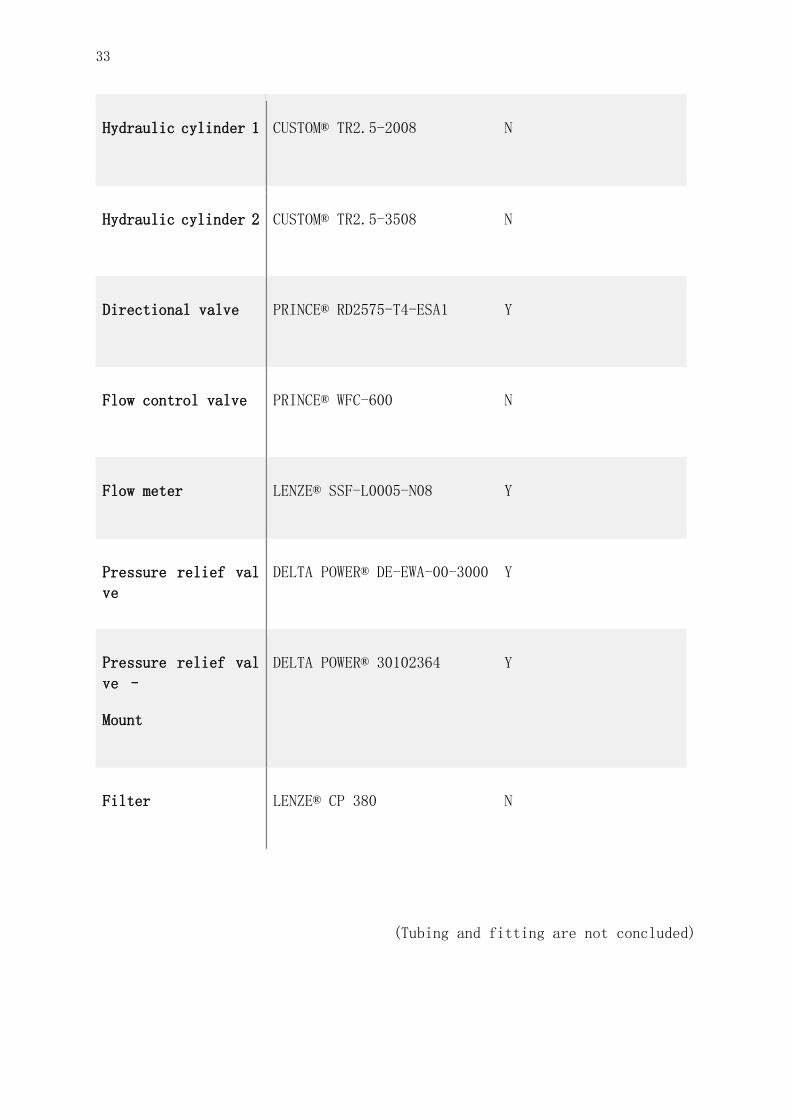
Based on the economical and availability, the following list of
components is used in this open loop system.
Table. F-1 Component detail of the open loop subsystem
Components name Components model number Using in both sub-syst
em
33
Hydraulic cylinder 1 CUSTOM® TR2.5-2008 N
Hydraulic cylinder 2 CUSTOM® TR2.5-3508 N
Directional valve PRINCE® RD2575-T4-ESA1 Y
Flow control valve PRINCE® WFC-600 N
Flow meter LENZE® SSF-L0005-N08 Y
Pressure relief val
ve
DELTA POWER® DE-EWA-00-3000 Y
Pressure relief val
ve –
Mount
DELTA POWER® 30102364 Y
Filter LENZE® CP 380 N
(Tubing and fitting are not concluded)
34
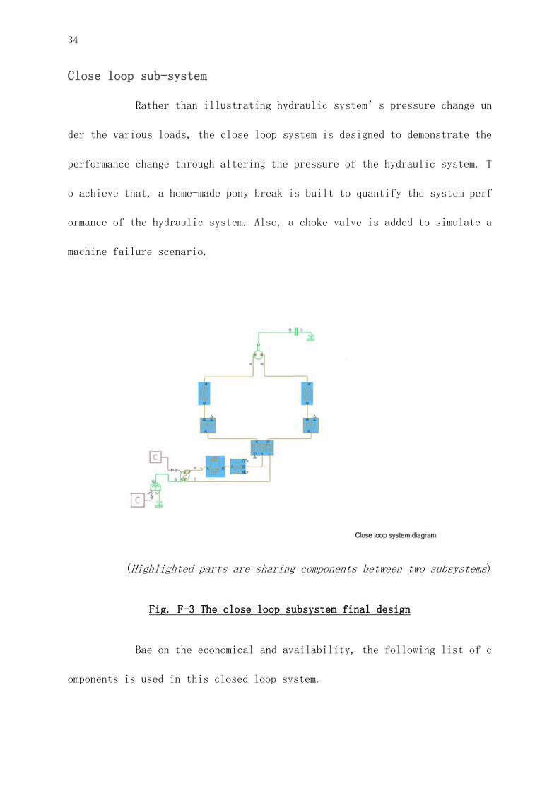
Close loop sub-system
Rather than illustrating hydraulic system’s pressure change un
der the various loads, the close loop system is designed to demonstrate the
performance change through altering the pressure of the hydraulic system. T
o achieve that, a home-made pony break is built to quantify the system perf
ormance of the hydraulic system. Also, a choke valve is added to simulate a
machine failure scenario.
(Highlighted parts are sharing components between two subsystems)
Fig. F-3 The close loop subsystem final design
Bae on the economical and availability, the following list of c
omponents is used in this closed loop system.
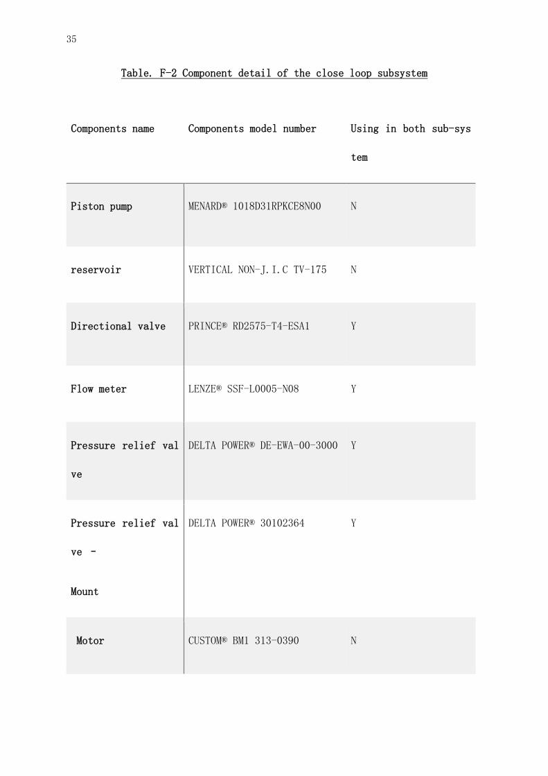
35
Table. F-2 Component detail of the close loop subsystem
Components name Components model number Using in both sub-sys
tem
Piston pump MENARD® 1018D31RPKCE8N00 N
reservoir VERTICAL NON-J.I.C TV-175 N
Directional valve PRINCE® RD2575-T4-ESA1 Y
Flow meter LENZE® SSF-L0005-N08 Y
Pressure relief val
ve
DELTA POWER® DE-EWA-00-3000 Y
Pressure relief val
ve –
Mount
DELTA POWER® 30102364 Y
Motor CUSTOM® BM1 313-0390 N
36
(Tubing and fitting are not concluded)
Highlights of the selection components
Open loop circuit is the most common circuit on the low to mid
end agriculture machinery. It generally has the nature of easy maintenance
and diagnostic. The circuit distinguishes itself by letting its return flow
directly to the reservoir rather than through the pump. (Islam, Raghuwanshi
and Singh, 2008) An adequate volume for the reservoir, pressure relief valv
e setting could protect the fluid from overheating. And a well selected suc
tion and return filter to keep the cleanness of the circulating hydraulic f
luid.
Reservoir capacity verification
For our hydraulic training bench, each sub-system has its own r
eservoir; due to the fact that the old pump that we recycled from the machi
ne shop already has a built in reservoir in it; and all the temptation of i
ntegrating this reservoir to the close loop system resulting unsatisfied re
sults.
Although it is safe to say that the pump's built-in reservoir s
hould meet the pumps operation requirement; however, based on the working c
ondition and the load of the system, the temperature of the hydraulic fluid

37
will drastically change. In order to build a reliable system, a verificatio
n of reservoir capacity is needed.
For the verification, a Simulink™ Simscape hydraulic system sim
ulation is set. The whole simulation, a fix-placement gear pump will be use
d as the major power source of the system. All the configuration of the sys
tem has been imported from our components’ catalog menu, the reservoir vol
ume will be simulated and compared with the reservoir from the recycled mac
hine shop pump. A maximum load of 452.23 kg was tested on the closed loop s
ystem, with all two cylinders run on tested. (TR2.5-3508 and TR2.5-2008)
38
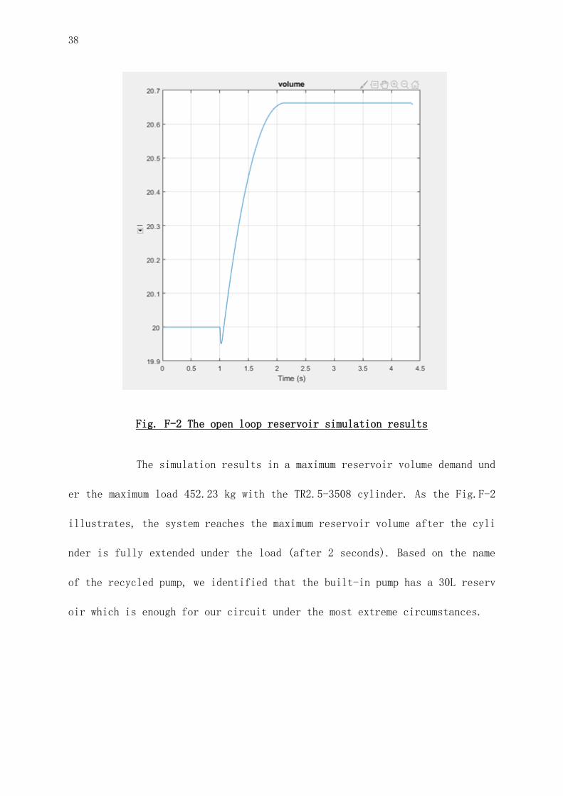
Fig. F-2 The open loop reservoir simulation results
The simulation results in a maximum reservoir volume demand und
er the maximum load 452.23 kg with the TR2.5-3508 cylinder. As the Fig.F-2
illustrates, the system reaches the maximum reservoir volume after the cyli
nder is fully extended under the load (after 2 seconds). Based on the name
of the recycled pump, we identified that the built-in pump has a 30L reserv
oir which is enough for our circuit under the most extreme circumstances.
39
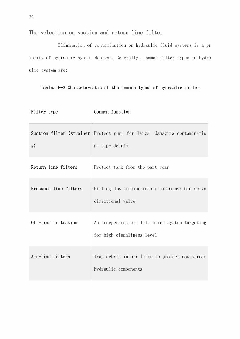
The selection on suction and return line filter
Elimination of contamination on hydraulic fluid systems is a pr
iority of hydraulic system designs. Generally, common filter types in hydra
ulic system are:
Table. F-2 Characteristic of the common types of hydraulic filter
Filter type Common function
Suction filter (strainer
s)
Protect pump for large, damaging contaminatio
n, pipe debris
Return-line filters Protect tank from the part wear
Pressure line filters Filling low contamination tolerance for servo
directional valve
Off-line filtration An independent oil filtration system targeting
for high cleanliness level
Air-line filters Trap debris in air lines to protect downstream
hydraulic components
40
Based on our analysis at the Premilitary finding section, press
ure line filter, off-line filter and air-line filter is not applicable for
our design. The filtration system of the open loop system will be consistin
g of one suction filter and one return line filter.
A spin-on type of filter has been chosen for both the suction f
ilter and the return line filter. Base on other common types of suction fil
ters require mount or other supported structure on the pump, and any modifi
cation on pump could result in extra work and potential safety hazard. Furt
hermore, since the spin-on type filter is the commonly used type of filter
in the tractor, using this specific type of tractor could bring real life h
ydraulic knowledge closed to the FMT students. Not only did the spin-on typ
e filter work well on the suction filter, it also can be used as a return-l
ine filter, based on its versatility and high degree of freedoms.
For the specific chrematistic of the spin-on filters, a proposa
l of using both identical filters for suction and return-line filter was pr
oposed on the preliminary design stage. However, based on detailed researc
h, the suction filter and the return-line filter are targeting different ki
nds of contamination in the hydraulic system. Suction filters are more comm
on on filtering contamination above 75 microns; whereas, the return-line fi
lter is more focused on contamination around 3 to 25 microns. (Hydraulics &
Pneumatics, 2008a) Using an inappropriate filter (using a finer filter for
our case) on the suction line could lead to increased pressure in the syste
41
m, causing hydraulic fluid overheating and creating high pressure points on
the system; potentially causing catastrophic failure, such as pipe burst.(H
ydraulics & Pneumatics, 2008b)
After considering the economic and part availability; CP380-101
8, a variant of LENZE® CP 380 with a target contamination size of 10 micron
is used for return-line filtration. Where as CP380-4018 were used for the s
uction filtration, targeting contamination above 40 microns.
Consideration on cylinder selection
There are a vast variety of hydraulic cylinders in the market,
types like: single acting cylinders, double acting cylinders, welded rod cy
linders and telescopic cylinders. Based on the nature of our design involve
d in constant assembly and disassembly, a welled rod cylinder is excluded f
or our consideration. Telescopic cylinders can be an interesting components
to add into the system; however, a telescopic cylinder involves in a sets o
f single acting and double acting cylinder with different diameter; which i
s hard for the student to quantified the difference on the hydraulic fluid
pressure when different diameter of cylinder is used in the system. (Desk,
2019) Hence, our final solution is between the single acting cylinders, dou
ble acting cylinders and tie-rod cylinders.
During our market research, tie-rod cylinder is widely used in
the industry and manufacturing application; this includes agriculture used.

42
The ease of maintenance, repair and assembling, and its fluid leakage preve
ntion feature based on its end caps design has made it our best candidate o
ver the single and multiple acting cylinder. After making a few estimation
and calculation to simulate the cylinder’s integration with our lever base
d weightlifting system, the detail of our chosen tie-rod cylinder is as fol
lowing:
Table. F-2 Detail of selected tie-rod cylinder
Cylinder model Maximum working pressur
e
Column loads at the max
imum working pressure
TR 2.5-2008 2500 PSI 3562 kg
TR 2.5-3508 2500 PSI 10910 kg
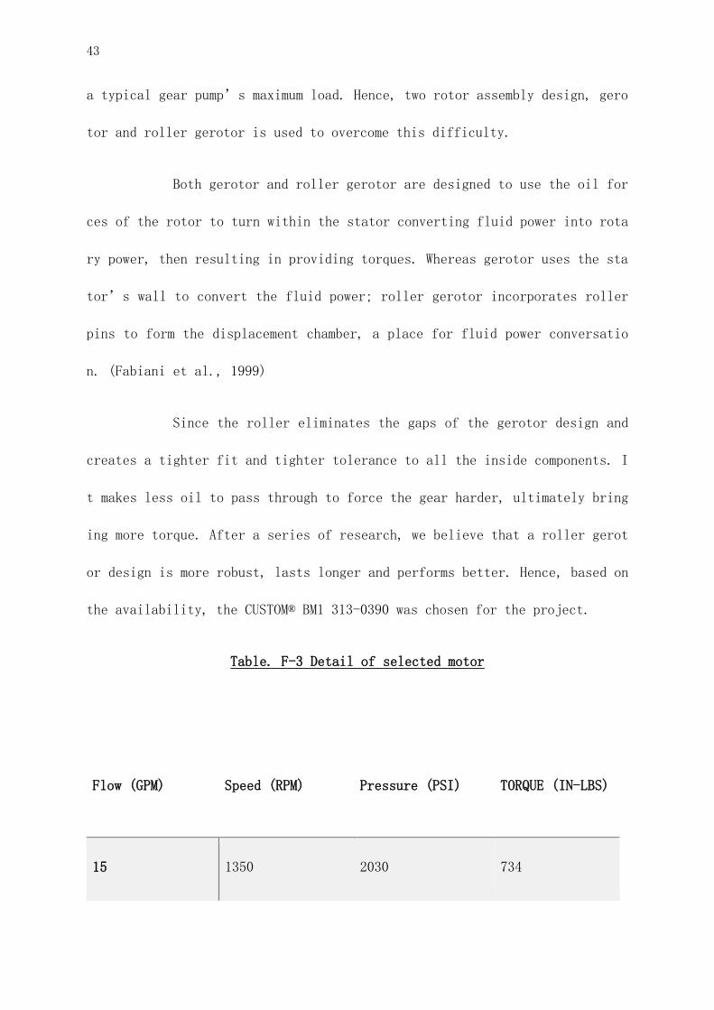
Motor selection:
For agriculture equipment, a motor is an essential component fo
r any application with rotary movement. The motor for the agriculture equip
ment tends to be having a characteristic of “low-speed, high torque”. In
this kind of usage scenario, a greater amount of torque is needed at the st
art up from the stationary position, making the required torque higher than
43
a typical gear pump’s maximum load. Hence, two rotor assembly design, gero
tor and roller gerotor is used to overcome this difficulty.
Both gerotor and roller gerotor are designed to use the oil for
ces of the rotor to turn within the stator converting fluid power into rota
ry power, then resulting in providing torques. Whereas gerotor uses the sta
tor’s wall to convert the fluid power; roller gerotor incorporates roller
pins to form the displacement chamber, a place for fluid power conversatio
n. (Fabiani et al., 1999)
Since the roller eliminates the gaps of the gerotor design and
creates a tighter fit and tighter tolerance to all the inside components. I
t makes less oil to pass through to force the gear harder, ultimately bring
ing more torque. After a series of research, we believe that a roller gerot
or design is more robust, lasts longer and performs better. Hence, based on
the availability, the CUSTOM® BM1 313-0390 was chosen for the project.
Table. F-3 Detail of selected motor
Flow (GPM) Speed (RPM) Pressure (PSI) TORQUE (IN-LBS)
15 1350 2030 734
44
Conclusions
Hydraulic working bench has been available on the market for a whil
e, with different designs and variations, it provides the user a demonst
ration or in hand exercise experience. The custom will choose components
or design models based on their own needs, and customisation also depends
on the budget. Most of the models applied in vocational training are very
intuitive as the targeted users are, as the students in CVM DEC program s
aid, prepared for industry workers who need to know more about device ope
rations than on theoretical research and calculation. The clients of our
product are Mr. Marc-Andre Isabelle and the students in FMT who register
course FMT4 012.
This project design prepares an hydraulic training bench integratin
g both closed loop system and open loop system, and demonstrates how hydr
aulics is used in agricultural machinery. Based on the knowledge and expe
rience gained by in-site investigation in CVM, market research online and
visiting local hydraulic company Pièces Hydrauliques Ménard Inc (Les) We
45
finally came up with the idea that fits the FMT’s need. Our design is ta
iloring a hydraulic training bench for FMT program that integrates both o
pen loop system and closed loop system into one bench, uses market availa
ble hydraulic components and focuses on agricultural related hydraulic de
monstrations. The bench is small in size, also mobile for better storing
in our faculty machine shop. After we considered and compared several com
binations of components based on the in-site visit in CVM, he consultatio
n with Mr. René Michaud, budget and reducing waste to the environment, an
d our working pressure, we only chose several easy-to-operate and commonl
y seen products that were enough to fulfill the need of the course, and d
ecided to reuse the old hydraulic pump in the shop.
To conclude, our hydraulic demonstration bench utilized a hydraulic
cylinder and hydraulic motor to demonstrate the work of hydraulic pressur
e by doing lifting and counter torque. These two demonstrations are stron
gly connected to real-life agricultural work as material lifting and work
of tractors. The accessibility and straight-forward interface is also tai
lored for first-year FMT students.
Comparison
1) Comparison between junior design project and senior design project:
Before Design 2 and Design 3, a fundamental Design 1 course had bee
n introduced to the junior Bioresource Students. The project in Des
46
ign 1 lasts shorter, more fundamental, and less flexible. It briefl
y introduces what an engineering project looks like. However, the
standard is higher in the current project runs through Design 2 and
Design 3. It involves communication outside the team, and less depe
ndent on the course instructor. Although the degree of freedom is h
igh, the theoretical knowledge base and project evaluation methods
are much stronger than the previous one.
2) Comparison between the audience of our design and the bench in CV
M: the students in CVM who are trained on these hydraulic devices a
re studying in mechanical engineering DEC program, after the traini
ng, most of them will work as techniciens in the related industry
in which various hydraulic machines apply. Due to this situation, t
hey will have more background knowledge on how hydraulic systems wo
rk with a series of theory courses, problem solving based on real i
ndustry situations, and in-hand experience on different models of c
omponents, motors, pumps that existed in the mechanical industry.
In contrast, FMT students focus more on farming knowledge and skill
s, agricultural machines that utilise hydraulic transmission are on
ly part of their course and career. The knowledge base on mechanica
l theory, mathematics and physics courses is weaker and the variety
of hydrauliced they will face is much less than that of the CVM stu
dents. The purpose of demonstrating the working principle in hydrau

47
lic systems weighs more than that of in-hand skill training. Instea
d of installing a complex hydraulic system with a big amount of hyd
raulic components, we have to focus more on how to visualise the w
ork done by the hydraulic system.
Evaluation Conclusion
Required by our client, the bench we design installed with both ope
n loop and closed loop. Before the cancel of school happened because of t
he COVID-19 outbreak started, the following design has been confirmed wit
h Mr. Marc-Andre Isabelle. The pump of open loop and the one of close loo
p will be attached to the oil tank and their own motor, later the power s
ystem will be connected to the component mounted on the steel board with
pipes that will coupling connectors on each side, the components that wil
l use coupling connector are directional valve, flow control valve, flow
meter, pressure gauge, pressure relief valve. The cylinder will attach at
the side of the bench.
There are a few tasks remained, 1) the parameter of the pump used f
or open loop remains unknown, as the pump is there for decades, the hand
book for it is lost, however this pump was in use for other work in the w
orkshop, Mr. Scott Manktelow didn’t allow us to disassemble it to find t
he plate until we finished all other parts. 2) The steel board has not be
en drilled and components not mounted, so we don’t know if the arrangeme
48
nt is user friendly for connection and operation (lining and height).3) t
he workshop of cutting pipe and mounting connector in company Pièces Hydr
auliques Ménard Inc (Les) had been cancelled 4) the method to demonstrat
ion of torque are still under discuss as we failed a few plan with Mr. Ma
rc-Andre Isabelle and we have to stop the work due to school being cancel
led 5) all of the existing data are based on computing with theoretical a
nd ideal conditions, no actual tests could be done as the built-up proces
s stopped for COVID-19 outbreak.
This project involves the process of applying scientific theory on solvin
g real life problems, a design not just based on school knowledge and team coop
eration, but also connected to communication with different roles in the societ
y.Mr. Michaud and the visit of CVM gave a huge impact on this project, showing t
he transition between our study and vocational training application, communicat
ing with suppliers, getting quotations, etc. are what we could not get from the
textbook. The unexpected situation of the COVID-19 outbreak stopped the project,
however, we wondered if we could continue on this built-up process when school l
ife becomes normal. Our team will keep in touch with our technician support and
client on this project, hopefully we could see the finalised product.

49
Reference:
ISO. (1999). ISO 4406:1999: Hydraulic fluid power – Fluids – Method for coding
the level of contamination by solid particles. Geneva, Switzerland:ISO
ISO. (2008). ISO 5675:2008: Agricultural tractors and machinery - General purpose
quick-action hydraulic couplers. Geneva, Switzerland:ISO
Chapple P. (2015). Principles of hydraulic systems design. New York, NY: Momentum
Press
McGill University. (2019). Farm Management and Technology – McGill University. Ag
riculture and environment sciences. Saint-Anne-de-Bellevue. Available at: https://
www.mcgill.ca/fmt/. Accessed 29 November 29, 2019.
Islam, A., Raghuwanshi, N. S., & Singh, R. (2008). Development and application of
hydraulic simulation model for irrigation canal network. Journal of irrigation and
drainage engineering, 134(1), 49-59.
Hydraulics & Pneumatics. (2008) Book2, Chapter 9: Filtration. ENDEAVOR Business me
dia: Nashville, TN. Available at: https://www.hydraulicspneumatics.com/technologie
s/other-technologies/article/21884322/book-2-chapter-9-filtration
Desk, W. (2019) 5 Types of Hydraulic Cylinder. Worldwide Hydraulic Professionals.
MARBOROX INFOMEDIA:India. Available at: https://whyps.com/5-Types-hydraulic-cylind
er
50
The hydraulic warehouse. (2018). The facts about Hydraulic Fluid and Hydraulic Sys
tem Failure. Seven Hills, Australia. Available at: https://www.thehydraulicwarehou
se.com.au/the-facts-about-hydraulic-fluid-and-hydraulic-system-failure/. Accessed
November 29, 2019.
MAC hydraulics. (2017). The dangers of hydraulic leaks. Brookhaven, PA. Available
at: https://mac-hyd.com/blog/dangers-hydraulic-leaks/. Accessed November 29, 2019.
Fabiani, M., Mancò, S., Nervegna, N., Rundo, M., Armenio, G., Pachetti, C., & Tric
hilo, R. (1999). Modelling and simulation of gerotor gearing in lubricating oil pu
mps (No. 1999-01-0626). SAE Technical Paper.
Marougy Thelma. 2012. Hydraulic fluids can help you go “green”. Hydraulics & Pne
umatics. London, England and Wales. Available at: https://www.hydraulicspneumatic
s.com/. Accessed 24 November 2019.
Heney Paul. 2016. What are kidney loop systems?. Sealing & Contamination Control T
ips. Cleveland OH. Available at: https://www.sealingandcontaminationtips.com/kidne
y-loop-systems/. Accessed 24 November 2019.
R.E. Cantley. "The Effect of Water in Lubricating Oil on Bearing Fatigue Life." AS
LE Transactions, American Society of Lubrication Engineers, Volume 20, No. 3, p. 2
44-248, 1977; from a presentation at the 31st Annual ASLE Meeting, Philadelphia, P
enn.
Dynamometer | measurement instrument. (2020). Encyclopedia Britannica. Retrieved 2
1 April 2020, from https://www.britannica.com/technology/dynamometer

51
Standard Belt Conveyors | Patz. (2020). Patzcorp.com. Retrieved 21 April 2020, fro
m https://patzcorp.com/products/agriculture-products/conveyors-and-feeders/belt-co
nveyors/standard-belt-conveyors/
Hydraulic dynamometer, water brake | POWERLINK. (2018). POWERLINK. Retrieved 21 Ap
ril 2020, from https://www.powerlinkpt.com/hydraulic-dynamometer-en/

52
Appendex: