FPGA based Speeded Up Robust Features
8
IEEE Copyright Notice This is an author version of the paper: Jan ˇ Sv´ ab, Tom´ aˇ s Krajn´ ık, Jan Faigl and Libor Pˇ reuˇ cil: FPGA-based Speeded Up Robust Features, In IEEE International Conference on Technologies for Practical Robot Applica- tions (TePRA), 2009. doi: 10.1109/TEPRA.2009.5339646. The full version of the article is available on IEEE Xplore or on request. Copyright 978-1-4244-4992-7/09/$25.00 c 2014 IEEE. Personal use of this material is permitted. However, permission to reprint/republish this material for advertising or promotional purposes or for creating new collective works for resale or redistribution to servers or lists, or to reuse any copyrighted component of this work in other works, must be obtained from the IEEE. I’m happy to grant permission to reprint these images, just send me a note telling me how you plan to use it. You should also request permission from the copyright holder, IEEE, at the [email protected] address listed above.
Transcript of FPGA based Speeded Up Robust Features

IEEE Copyright Notice
This is an author version of the paper:
Jan Svab, Tomas Krajnık, Jan Faigl and Libor Preucil:FPGA-based Speeded Up Robust Features,In IEEE International Conference on Technologies for Practical Robot Applica-tions (TePRA), 2009. doi: 10.1109/TEPRA.2009.5339646.
The full version of the article is available on IEEE Xplore or on request.
Copyright 978-1-4244-4992-7/09/$25.00 c©2014 IEEE. Personal use of thismaterial is permitted. However, permission to reprint/republish this materialfor advertising or promotional purposes or for creating new collective works forresale or redistribution to servers or lists, or to reuse any copyrighted componentof this work in other works, must be obtained from the IEEE. I’m happy to grantpermission to reprint these images, just send me a note telling me how you planto use it. You should also request permission from the copyright holder, IEEE,at the [email protected] address listed above.

FPGA BASED SPEEDED UP ROBUST FEATURES
Jan Svab, Tomas Krajnık, Jan Faigl, Libor Preucil
The Gerstner Laboratory for Intelligent Decision Making and ControlDepartment of Cybernetics, Faculty of Electrical Engineering
Czech Technical University in PragueKarlovo namesti 13,
121 35 Prague 2,Czech republic
Email: {svab,tkrajnik,xfaigl,preucil}@labe.felk.cvut.czPhone: +420 22435 5754
Fax: +420 22492 3677
ABSTRACTWe present an implementation of the Speeded Up Robust
Features (SURF) on a Field Programmable Gate Array(FPGA). The SURF algorithm extracts salient points fromimage and computes descriptors of their surroundings thatare invariant to scale, rotation and illumination changes.The interest point detection and feature descriptor extractionalgorithm is often used as the first stage in autonomous robotnavigation, object recognition and tracking etc. However,detection and extraction are computationally demanding andtherefore can’t be used in systems with limited computa-tional power. We took advantage of algorithm’s natural paral-lelism and implemented it’s most demanding parts in FPGAlogic. Several modifications of the original algorithm havebeen made to increase it’s suitability for FPGA implemen-tation. Experiments show, that the FPGA implementation iscomparable in terms of precision, speed and repeatability, butoutperforms the CPU and GPU implementation in terms ofpower consumption. Our implementation is intended to beused in embedded systems which are limited in computa-tional power or as the first stage preprocessing block, whichallows the computational resources to focus on higher levelalgorithms.
Index Terms— machine vision, visual navigation, SURF,FPGA
I. INTRODUCTIONMost of today’s mobile robots utilize computer vision
methods to gain information about their surrounding envi-ronment. Significant advantages of vision-based sensing areaffordable price of cameras, amount of provided data andeasy interpretation of these data by humans. The quantityof provided data can be also regarded as a drawback,because real-time processing of image data streams requirescomputationally strong hardware. However, this drawback
diminishes due to Moore’s law and therefore machine vi-sion methods have found applications in mobile robotics,where real-time processing is necessary. Vision-based objectrecognition [1], reactive navigation [2], three–dimensionalreconstruction [3], and efficient mapping and localizationmethods [4] [5] are used in mobile robotics [6] today.
Many of these methods rely on feature extraction algo-rithms [7] like Scale Invariant Feature Transformation [8],Gradient Location and Orientation Histogram [9] or LocalEnergy based Shape Histogram [10]. Although these algo-rithms are based on different principles and therefore per-form differently [9], their purpose is to provide descriptorsof significant image areas, which are immune to illuminationand camera position changes. Since detected feature de-scriptors contain information independent of viewpoint andillumination, they are especially suitable for image-matchingtasks. However, these algorithms are computationally de-manding and therefore represent a significant bottleneck inmany computer vision systems, forcing researchers to focuson improvement of their speed.
One of possible ways to increase speed of feature ex-traction is to exploit the fact, that image processing caneasily be parallelized. Implementations of feature extractionalgorithms utilizing GPUs [11] [12] have achieved perfor-mance over 30 FPS, which is considered as suitable for real-time applications. Although these implementations are basedon an affordable computational hardware, small roboticplatforms usually can not afford to carry entire PC system.As a consequence small robots have to use small intelligentcameras, e.g. CMUCam1, with on-board image processing.These intelligent cameras can rely on standard microcon-trollers, digital signal processors or specialized integratedcircuits [13]. A popular choice for embedded machine vision
1http://www.cmucam.org
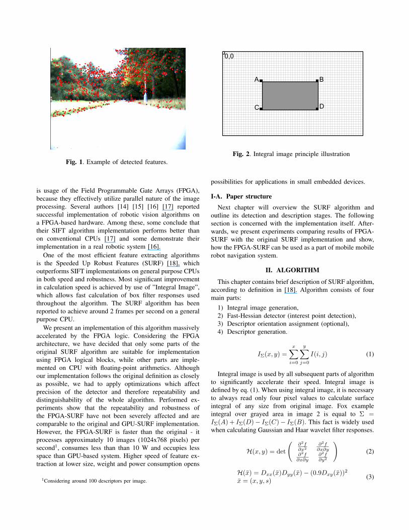
Fig. 1. Example of detected features.
is usage of the Field Programmable Gate Arrays (FPGA),because they effectively utilize parallel nature of the imageprocessing. Several authors [14] [15] [16] [17] reportedsuccessful implementation of robotic vision algorithms ona FPGA-based hardware. Among these, some conclude thattheir SIFT algorithm implementation performs better thanon conventional CPUs [17] and some demonstrate theirimplementation in a real robotic system [16].
One of the most efficient feature extracting algorithmsis the Speeded Up Robust Features (SURF) [18], whichoutperforms SIFT implementations on general purpose CPUsin both speed and robustness. Most significant improvementin calculation speed is achieved by use of ”Integral Image”,which allows fast calculation of box filter responses usedthroughout the algorithm. The SURF algorithm has beenreported to achieve around 2 frames per second on a generalpurpose CPU.
We present an implementation of this algorithm massivelyaccelerated by the FPGA logic. Considering the FPGAarchitecture, we have decided that only some parts of theoriginal SURF algorithm are suitable for implementationusing FPGA logical blocks, while other parts are imple-mented on CPU with floating-point arithmetics. Althoughour implementation follows the original definition as closelyas possible, we had to apply optimizations which affectprecision of the detector and therefore repeatability anddistinguishability of the whole algorithm. Performed ex-periments show that the repeatability and robustness ofthe FPGA-SURF have not been severely affected and arecomparable to the original and GPU-SURF implementation.However, the FPGA-SURF is faster than the original - itprocesses approximately 10 images (1024x768 pixels) persecond1, consumes less than than 10 W and occupies lessspace than GPU-based system. Higher speed of feature ex-traction at lower size, weight and power consumption opens
1Considering around 100 descriptors per image.
Fig. 2. Integral image principle illustration
possibilities for applications in small embedded devices.
I-A. Paper structure
Next chapter will overview the SURF algorithm andoutline its detection and description stages. The followingsection is concerned with the implementation itself. After-wards, we present experiments comparing results of FPGA-SURF with the original SURF implementation and show,how the FPGA-SURF can be used as a part of mobile mobilerobot navigation system.
II. ALGORITHM
This chapter contains brief description of SURF algorithm,according to definition in [18]. Algorithm consists of fourmain parts:
1) Integral image generation,2) Fast-Hessian detector (interest point detection),3) Descriptor orientation assignment (optional),4) Descriptor generation.
IΣ(x, y) =x∑
i=0
y∑j=0
I(i, j) (1)
Integral image is used by all subsequent parts of algorithmto significantly accelerate their speed. Integral image isdefined by eq. (1). When using integral image, it is necessaryto always read only four pixel values to calculate surfaceintegral of any size from original image. Fox exampleintegral over grayed area in image 2 is equal to Σ =IΣ(A) + IΣ(D)− IΣ(C)− IΣ(B). This fact is widely usedwhen calculating Gaussian and Haar wavelet filter responses.
H(x, y) = det
(∂2f∂x2
∂2f∂x∂y
∂2f∂x∂y
∂2f∂y2
)(2)
H(x) = Dxx(x)Dyy(x)− (0.9Dxy(x))2
x = (x, y, s) (3)

SURF uses determinants of Hessian matrices to locateimage’s significant points. Equation (2) shows original def-inition of this determinant for general two dimensionalfunction. Fast-Hessian detector modifies this equation intwo significant ways: 1) Second order partial derivatives arereplaced by convolutions of image with approximated Gaus-sian kernels second order derivatives. Approximation is doneby box filters with coefficients 1,−1, 2,−2 2. Coefficient0.9 in eq. (3) is used to compensate this approximation.2) Gaussian kernels are not parameterized only by positionin image, but also by their size. To achieve scale invariance,algorithm searches for significant points on multiple imagescale levels. Since scaling whole image is computationallyexpensive, SURF only scales Gaussian kernels (exactly boxfilters which approximate them). Scaling is represented bythird parameter s in eq. 3, this parameter creates the threedimensional space of determinant results, usually refered toas ”scale space”. Scale differs (and is quantized) accordingto octaves and intervals.
Table I. Scale quantization into octaves and intervals andassociated box filter sizes.
Octave 1 2Interval 1 2 3 . . . 1 2 . . .
Box filteredge size 9 15 21 . . . 15 27 . . .
s = size9
× 1.2 1.2 2 2.8 . . . 2 3.6 . . .
As we can see in table I box filter size increase doubles be-tween octaves, moreover image sampling step also doubles.When determinants in all preselected scales and intervalsare calculated they are filtered by positive threshold value.Afterwards a non-local maxima suppression is performedamong 26 closest neighbors in determinant scale space.Determinant local maxima marks position of interest point.However, this position has to be refined by interpolation tosub-pixel precision.
H(x) = H+∂H∂x
T
x +12xT ∂
2H∂x2
x (4)
x = −∂2H−1
∂x2
∂H∂x
(5)
Equation (4) shows second order Taylor polynomial ap-proximation of Hessian in scale space centered aroundexamined local maxima, where x = (x, y, s). Positioncorrection is obtained by seeking for zero value of this poly-nomial’s derivative. Resulting formula for position correctionis eq. (5), where x = (x, y, s). Local maxima is accepted asinterest point if none of absolute values of position correctionvector x elements is bigger than 0.5.
2Since area with coefficient −2 in Dxx and Dyy filters splits area withcoefficient 1 it is possible to save some memory read cycles by not splittingunderlying 1 area and by calculating with coefficient −3 instead of −2.
Rotation invariance is achieved by assigning each interestpoint a ”dominant direction”. If application doesn’t requiredescriptors to be rotation invariant we can simply skip stepsdescribed in this paragraph and assign orientation (0, 0).A circle of radius 6s is set around interest point. Insidea circle Haar wavelet responses in x and y direction arecalculated from 4s-sized filters with sampling step s. Theseresponses are weighted by Gaussian function with σ = 2.5scentered around interest point. Afterwards they are summedby a sliding sector window of π/3 with approximate stepπ/18. Longest vector obtained as this window sum is chosento be descriptor dominant direction.
The SURF descriptor is calculated from square interestpoint’s neighborhood with edge size 20s. This neighborhoodis rotated to match interest point dominant direction. Thissquare area is further divided into 16 equal sub-squareswith edge size 5s. Inside each of these sub-square areas25 Haar wavelet filter response pairs are calculated (filtersize 2s, sampling step s, one direction along interest pointdominant direction - dd, one perpendicular in positive sense- dp). Responses are weighted by Gaussian function withσ = 3.3s and summed within sub-square into four di-mensional vector v = [
∑dd,∑dp,∑|dd|,
∑|dp|]. These
vectors are chained (one for each of 16 sub-squares) to form64 dimensional SURF descriptor. Descriptor elements arefurther scaled so resulting descriptor is a unit vector.
Output of algorithm for one image gives us set of interestpoint locations in image’s scale space along with set of de-scriptors describing areas around interest points. To increasematching performance the sign of Laplacian (i.e. trace of theHessian matrix) is included into the algorithm output. Sinceinterest points are usually found on blob-type structuresthis sign distinguishes light blobs on dark background fromopposite.
III. IMPLEMENTATION
This chapter is dedicated to description of hardware designand software controlling functions. The algorithm to generatethe SURF descriptor is written according to specification oforiginal SURF with a few minor optimizations. As men-tioned before, for the purpose of the FPGA implementation,only the Fast-Hessian detector part of SURF has been chosenfor hardware-only implementation. Created hardware IP-blocks provide integral image, determinants for all inspectedscale levels and also marks local maxima in calculateddeterminant scale-space. Generation of the SURF descriptoris handled entirely by software. Descriptor generation byitself is still quite time demanding, that is why we havechosen XC5VFX70 FPGA which incorporates PowerPC-440CPU core with floating-point co-processor.
Hardware design of the Fast-Hessian detector introducestwo major limitations in comparison with other implemen-tations: 1) Determinant calculation is done in an integerarithmetics with limited precision. 2) Hardware block is de-

signed for specific number of octaves and scale intervals withlimited image size. Current image size limit is 1024× 1024pixels and IP-blocks are designed to calculate determinantsin 2 octaves and 4 intervals per octave.
III-A. FPGA SoC architecture
Fig. 3. FPGA SoC block schematic diagram
Fast-Hessian detector has been divided into two IP-blocks,see blocks in Figure 3: SSA IIG – Integral Image Gener-ator, SSA FHG – Fast-Hessian Generator. Both IP-blockshave MPLB (Master Processor Local Bus) interfaces withsimple DMA controllers, which allow them to manage datatransfers from and to system memory without any CPUinteraction. PLB2 bus is designated for these transfers andhas accordingly increased capacity. PixelBus is dedicatedsimple one-way bus which transfers integral image data intoFast-Hessian generator for determinant calculation. Figure 3also includes some design details, such as bus widths andclock frequencies, which are vital in order to achieve statedperformance.
III-B. Integral image generator
Fig. 4. Integral image generator calculation core rough blockdiagram
Integral image generator calculation core (fig. 4) is re-sponsible for generation of integral image from incoming8-bit grey scale image. It’s architecture is fairly simple. IP-block SSA IIG (in fig. 3) consists from this calculation core
and simple DMA controller to transfer data to and from thisblock.
III-C. Fast-Hessian generator
Fig. 5. Fast-Hessian calculation core block schematic dia-gram
Fast-Hessian calculation core carries out main function-ality of SSA FHG (in fig. 3) IP-block. This block gen-erates approximated determinants of Hessian matrices andsearches for local maxima among them. An overview ofFPGA’s dedicated blocks, bus widths and frequencies usageis summarized in Figure 5. Incoming integral image dataare stored in large FIFO inside MasterController block. Anaccess to integral image area of 52 × 52 pixels 3. is needto calculate response of the largest Gaussian filter. Data inthis area are accessed many times and in very unsequentialmanner, that’s why MasterController FIFO stores 56 integralimage lines and allows access to them through 4 independentbusses. This configuration delivers enough bandwidth forintegral image data used during determinant calculation. 18TripleMAC (Multiply-Accumulate) units are connected tothese busses to capture integral image data and calculateGaussian filter responses from them. A block HessianCalccalculates actual determinants from Gaussians. Determinantsare written into system memory using simple DMA con-troller in SSA FHG (in fig. 3) IP-block.
To achieve higher performance optimization determinantsare calculated not one by one but in ”determinant blocks”.Determinant block consists of all determinants calculatedfor 2 × 2 pixels image area. Since octave 2 has doubledsampling step and first 2 intervals in octave 2 have samefilter sizes as intervals 2 and 4 from octave 1 we have tocalculate only 18 determinants in each block (instead of 20).Integral image data are sent out through four output bussesin pre-optimized order. This order is stored in ”Controland addressing sequence memory”. This memory also holds
3According to original SURF specification octave 2, interval 4 usesGaussian filters with mask size 51×51 pixels. To calculate response of thisfilter using integral image we need to access one more row and column.

Fig. 6. MasterController rough block diagram
control signals for TripleMAC units which are sent out alongwith integral image data. Control and addressing sequencemust be optimized in order to achieve stated performance.To carry out this optimization a specialized script, whichgenerates this sequence, has been written. This sequence runsfor every 2× 2 pixels image block and delivers all integralimage data needed for calculation of one determinant block.
One TripleMAC block handles calculation of three Gaus-sian filter responses. Incoming data are scaled by one of1,−1, 3,−3 coefficients based on input control signals andadded to one of three filter responses. After each run ofMasterController’s sequence a signal indicating end of thissequence is being generated. This signal causes TripleMACblocks to load results into output buffers and to reset accu-mulators. On the output side all blocks are connected to onethree-state bus which is used to read results from them. Tosave FPGA’s resources TripleMAC performs three cycles ofaddition/subtraction instead of multiplication by coefficients3,−3. This fact has to be reflected in control and addressingsequence since TripleMACs don’t report MasterControllertheir busy state.
Fig. 7. HessianCalc rough block diagram
Block HessianCalc performs actual Hessian matrix deter-minant calculation. Gaussian filter responses, necessary for
this calculation, are read from TripleMAC over three-statebus after MasterController signalizes end of determinantblock sequence. Filter responses reading and determinantblock calculation are controlled by control sequence storedinside HessianCalc.
Fig. 8. LocMaxFinder rough block diagram
Block LocMaxFinder stores at least 3 determinant blocksand compares each determinant with its neighbors to searchfor local maxima. This block doesn’t have sufficient mem-ory resources to store all data needed to examine wholeneighborhood of each determinant. Thus it performs non-maxima suppression only throughout neighbors from twodeterminant blocks. Each determinant marked by this blockas local maxima has to be examined again by software.Determinants marked by this block are stored into FIFOin IP-block SSA FHG, which is readable through SPLBinterface and generates interrupts based on its occupancy.
Units MasterController, HessianCalc and LocMaxFinderare controlled by embedded sequences. In case of Master-Controller this sequence is quite large and needs to be storedin block RAM, other two use FPGA logic, since sequencesare short. Generation of control sequences for HessianCalcand LocMaxFinder is fairly simple – these only need toprocess incoming determinants in preset order. However,MasterController’s sequence has severe impact on system’sperformance and is not trivial to generate. To generate thissequence only very basic algorithm has been written andthus introduces approximately 11% increase in determinantblock processing time compared to optimal state4.
III-D. Control softwareThis part of software manages mainly data transfers to
and from IP-blocks and is represented by ”libSSA2” library.Processing is divided into tasks. Library provides functionsto create and process these tasks. Each task represents oneimage and has designated memory space to store image data,integral image data and determinants. SURF descriptors arebeing passed to superordinate application through callback.Task processing has four phases:
1) integral image generation,2) determinant generation,3) local maxima localization,
4Optimal state is regarded as state when MasterController integral imagereading busses do not have to carry idle cycles to wait for busy TripleMACunits

4) SURF descriptor generation.To optimize processing speed, all these phases may over-lap as well as processed task may overlap. First two arecarried out by hardware, library only sets data source anddestination addresses in IP-block DMA controllers and waitsfor interrupts. Third phase is only intermediate state whenimage is done processing in hardware but there are stillsome local maxima determinants unread from SSA FHGFIFO. Fourth phase is actually performing all that is leftfor ”software” part of our SURF implementation, i.e. interestpoint position interpolation and SURF descriptor generation.Since all hardware is wrapped up into two Xilinx PlatformStudio IP-blocks, its very simple to put more calculationaccelerators on one chip and library supports this option.
IV. RESULTS
Although we have tried to follow the original descriptionas closely as possible, some changes had to be made tooptimize algorithm for implementation in the FPGA logic.In current state of development this of course applies onlyto detection stage. There has been a great concern forthe possible degradation of the algorithm due to loss ofprecision in the detection phase. To evaluate impact onalgorithm efficiency, we have performed tests comparing therepeatability of SURF, GPU-SURF and FPGA-SURF. Thesetests used a dataset of 1500 images captured by a mobilerobot moving in a park environment.
IV-A. Measuring distinguishabilityBy distinguishability, we understand a chance of algorithm
to establish a valid correspondence. This is done by estab-lishing correspondencies solely by their descriptor Euclideandistance and checking these against geometric constraints ofmultiple view geometry [19].
For every feature fa in an image A, we compute descrip-tor’s Euclidean distance to each of feature descriptors inan image B. Two features from image B, which are mostsimilar to fa (i.e. they have minimal descriptor distance) areselected and therefore form two pairs with fa. If the mostsimilar feature pair has its descriptor distance lower than75% of the second most matching pair descriptor distance,we proclaim it a correspondence candidate. After we find allcorrespondence candidates for every feature in the image A,we perform a check based on the epipolar geometry [19].
The fundamental matrix is established by the eight-pointalgorithm [19] and RANSAC [20]. For every feature inimage A, we find an epipolar line in image B and computethe distance of the corresponding feature from that epipole.If this distance is greater than 3 pixels, the correspondencecandidate is discarded, otherwise it is considered valid. Theratio of valid correspondencies to the number of corre-spondence candidates is a measure of the SURF algorithmdistinguishability. The higher ratio means better algorithmperformance.
When evaluating algorithm performance, we compute thisratio for every two consecutive images of a particular dataset.The average ratio is then taken as algorithm’s distinguisha-bility measure.
We tested four versions of the way the initial correspon-dece candidates are established. Because consecutive datasetpictures are taken from a similar camera viewpoint andtherefore positions of the correspondent features are closeto each other, we can limit the correspondece search radiusto 200 pixels. Moreover, we might or might not considerthe Laplacian sign when establishing the correspondencecandidates.
Table II. Comparison of SURF, GPU-SURF and FPGA-SURF distinguishability.
Limited Laplac. Platformsearch used CPU GPU FPGA
Y Y 0.62 — 0.53Y N 0.61 0.54 0.53N Y 0.43 — 0.27N N 0.43 0.27 0.26
The table II compares the distinguishability for our,1500 image dataset. Similar results were obtained on a partof the dataset2 used by the authors of the original SURFalgorithm.
IV-B. Simple FPGA-SURF based navigation systemFinally, to demonstrate the usability of the proposed
implementation, we deployed a navigation system with animage preprocessing module based on FPGA-SURF. Thesystem composes of a P3AT robot with an Unibrain Fire-i601c camera with 1024x768 pixel resolution, TCM2 com-pass and HP 8710p laptop. This navigation system is firstguided through the environment by means of teleoperation.During this drive, the robot searches for SURF featuresin pictures from the onboard camera. As the robot moves,it tracks the features, estimates their distance and createsa three dimensional map of them. Using this map, thesystem can estimate its position using currently sensed andmapped features. Therefore, the robot is able to operate inthe environment. After the teleoperated drive is finished,the system can localize and navigate the robot through themapped environment simply by matching currently capturedand previously mapped. We have mapped part of the Czechtechnical university campus and let the robot traverse thelearned path. The system has proven to be able to faultlesslynavigate the learned path, which was approximately 500meters long.
V. CONCLUSIONWe have presented an implementation of the SURF al-
gorithm massively accelerated by the FPGA logic. Despite
2http://www.robots.ox.ac.uk/˜vgg/research/affine/
several simplifications imposed by the limitations of FPGAhardware, our implementation offers similar distinguisha-bility and robustness as the GPU-SURF implementation.The FPGA-SURF implementation achieves about 10 FPSat HD (1024x768 pixels) resolution, which is a necessityfor real-time operation. The total power consumption of thisdevice is less than 10 W, making it suitable for smallerrobotic platforms. In the future, we will extend the algorithmby feature matching as a first step towards an embeddeddevice realising visual localization and mapping. Moreover,we would like to port the algorithm to a Xilinx Spartan-6family of FPGA chips, reducing the costs of the final system.
ACKNOWLEDGMENTS
This work was supported by a research grantCTU0904313 of Czech Technical University in Prague,the Research programs funded by the Ministry of Educationof the Czech Republic No. MSM 6840770038, 2C06005and by the FP7-ICT project ”REPLICATOR” No. 216240.
VI. REFERENCES[1] Patricio Loncomilla and Javier Ruiz del Solar, “Im-
proving sift-based object recognition for robot appli-cations,” in Image Analysis and Processing - ICIAP2005, Italy, September 6-8, 2005, Proceedings. 2005,vol. 3617, pp. 1084–1092, Springer.
[2] C. Thorpe, M. Hebert, T. Kanade, and S. Shafer, “Vi-sion and navigation for the Carnegie-Mellon Navlab,”IEEE Transactions on Pattern Analysis and MachineIntelligence, vol. 10, no. 3, pp. 362 – 373, May 1988.
[3] E. Mouragnon, Maxime Lhuillier, M. Dhome,F. Dekeyser, and P. Sayd, “Real time localizationand 3d reconstruction,” in CVPR ’06: Proceedingsof the 2006 IEEE Computer Society Conference onComputer Vision and Pattern Recognition, Washington,DC, USA, 2006, pp. 363–370, IEEE Computer Society.
[4] Don Murray and James J. Little, “Using real-timestereo vision for mobile robot navigation,” AutonomousRobots, vol. 8, no. 2, pp. 161–171, 2000.
[5] Andrew J. Davison, Ian D. Reid, Nicholas D. Molton,and Olivier Stasse, “MonoSLAM: Real-time singlecamera SLAM,” IEEE Transactions on Pattern Analy-sis and Machine Intelligence, vol. 29, no. 6, pp. 1052–1067, JUN 2007.
[6] G. N. DeSouza and A. C. Kak, “Vision for mobilerobot navigation: A survey,” IEEE Trans. Pattern Anal.Mach. Intell., vol. 24, no. 2, pp. 237–267, 2002.
[7] J. Li and N. Allinson, “A comprehensive review ofcurrent local features for computer vision,” Neurocom-puting, vol. 71, no. 10-12, pp. 1771–1787, June 2008.
[8] S. Se, D. Lowe, and J. Little, “Vision-based mobilerobot localization and mapping using scale-invariantfeatures,” in Proceedings of the IEEE InternationalConference on Robotics and Automation (ICRA), Seoul,Korea, May 2001, pp. 2051–2058.
[9] Krystian Mikolajczyk and Cordelia Schmid, “A perfor-mance evaluation of local descriptors,” IEEE Transac-tions on Pattern Analysis & Machine Intelligence, vol.27, no. 10, pp. 1615–1630, 2005.
[10] A. Saquib Sarfraz and Olaf Hellwich, “Head poseestimation in face recognition across pose scenarios,”in VisApp 2008: Proceedings of the 3rd InternationalConference on Computer Vision Theory and Applica-tions, HJ Araujo, Ed., 2008, pp. 235–242.
[11] N. Cornelis and L. Van Gool, “Fast scale invari-ant feature detection and matching on programmablegraphics hardware,” in CVPR 2008 Workshop (June27th), Anchorage Alaska, June 2008.
[12] Changchang Wu, “SiftGPU: A GPU implementation ofscale invariant feature transform (SIFT),” online, 2007.
[13] Norbert O. Stoffler and Zoltan Schnepf, “An mpeg-processor-based robot vision system for real-time de-tection of moving objects by a moving observer,” inIn Proceedings of the 14th International Conference onPattern Recognition, 1998, pp. 477–481.
[14] J. Diaz, E. Ros, S. Mota, and R. Rodriguez-Gomez,“FPGA-based architecture for motion sequence extrac-tion,” International Journal of Electronics, vol. 94, no.5, pp. 435–450, May 2007.
[15] J Diaz, E Ros, F Pelayo, EM Ortigosa, and S Mota,“FPGA-based real-time optical-flow system,” IEEETransactions on Circuits and Systems for Video Tech-nology, vol. 16, no. 2, pp. 274–279, Feb 2006.
[16] Vanderlei Bonato, Eduardo Marques, and George A.Constantinides, “A Parallel Hardware Architecturefor Scale and Rotation Invariant Feature Detection,”IEEE Transactions on Circuits and Systems for VideoTechnology, vol. 18, no. 12, pp. 1703–1712, Dec 2008.
[17] M. Tornow, J. Kaszubiak, R. W. Kuhn, B. Michaelis,and T. Schindler, “Hardware approach for real timemachine stereo vision,” in WMSCI 2005: 9th WorldMulti-Conference on Systemics, Cybernetics and Infor-matics, Orlando, FL, Jul 10-13, 2005, Vol 5, 2005, pp.111–116.
[18] H. Bay, T. Tuytelaars, and L. Gool, “Surf: Speeded uprobust features,” in Proceedings of the ninth EuropeanConference on Computer Vision, 2006.
[19] R. I. Hartley and A. Zisserman, Multiple View Geom-etry in Computer Vision, Cambridge University Press,ISBN: 0521540518, second edition, 2004.
[20] Martin A. Fischler and Robert C. Bolles, “Randomsample consensus: a paradigm for model fitting,” Read-ings in computer vision: issues, problems, principles,and paradigms, pp. 726–740, 1987.