Families of asymptotic tensile crack tip stress fields in elastic-perfectly plastic single crystals
11
Int J Fract (2009) 155:143–153 DOI 10.1007/s10704-009-9336-5 ORIGINAL PAPER Families of asymptotic tensile crack tip stress fields in elastic-perfectly plastic single crystals Swapnil Patil · R. Narasimhan · Raja K. Mishra Received: 12 August 2008 / Accepted: 16 March 2009 / Published online: 3 April 2009 © Springer Science+Business Media B.V. 2009 Abstract In this work, two families of asymptotic near-tip stress fields are constructed in an elastic-ideally plastic FCC single crystal under mode I plane strain conditions. A crack is taken to lie on the (010) plane and its front is aligned along the [ 101] direction. Finite element analysis is first used to systematically exam- ine the stress distributions corresponding to different constraint levels. The general framework developed by Rice (Mech Mater 6:317–335, 1987) and Drugan (J Mech Phys Solids 49:2155–2176, 2001) is then adopted to generate low triaxiality solutions by intro- ducing an elastic sector near the crack tip. The two fami- lies of stress fields are parameterized by the normalized opening stress (τ A 22 /τ o ) prevailing in the plastic sector in front of the tip and by the coordinates of a point where elastic unloading commences in stress space. It is found that the angular stress variations obtained from the ana- lytical solutions show good agreement with finite ele- ment analysis. Keywords Asymptotic analysis · Elastic–plastic crack tip fields · FCC single crystals · Finite elements S. Patil · R. Narasimhan (B ) Department of Mechanical Engineering, Indian Institute of Science, Bangalore 560012, India e-mail: [email protected] R. K. Mishra General Motors Corporation, 30500 Mound Rd., Warren, MI 48090, USA 1 Introduction The study of crack tip fields in single crystals is impor- tant in order to understand the physics of fracture in these materials as well as in polycrystalline solids (for example, transgranular fracture). In this context, it must be noted that when the crack opening displacement is much less than the grain size, the crack tip fields are contained within a single grain. Further, some key structural components are being fabricated in single crystal form. For example, blades in high pressure tur- bines of jet engines are made of single crystals of Nickel -based superalloys. Therefore, to ensure the structural integrity of such components, it is necessary to under- stand and characterize the stress and deformation fields present near a crack tip in a single crystal. Rice (1987) proposed an asymptotic solution for the crack tip stress field in ductile single crystals under mode-I, plane strain conditions within small strain, ideal plasticity framework. His analysis considered the case of a crack on the (010) plane with the crack front along [10 ¯ 1] direction for FCC and BCC crystals. The motivation for considering these crack orientations is because they have been frequently observed to occur in experimental studies on fracture of ductile single crystals (see, Neumann 1974a, b; Garrett and Knott 1975). The solution of Rice (1987) consists of sectors of constant stress, with concentrated kink and slip shear deformation on the sector boundaries. In particular, it suggests that a kink shear band should form at 90 ◦ to the crack line, while slip shear bands should occur at 123
-
Upload
mumbaiunivercity -
Category
Documents
-
view
3 -
download
0
Transcript of Families of asymptotic tensile crack tip stress fields in elastic-perfectly plastic single crystals
Int J Fract (2009) 155:143–153DOI 10.1007/s10704-009-9336-5
ORIGINAL PAPER
Families of asymptotic tensile crack tip stress fieldsin elastic-perfectly plastic single crystals
Swapnil Patil · R. Narasimhan · Raja K. Mishra
Received: 12 August 2008 / Accepted: 16 March 2009 / Published online: 3 April 2009© Springer Science+Business Media B.V. 2009
Abstract In this work, two families of asymptoticnear-tip stress fields are constructed in an elastic-ideallyplastic FCC single crystal under mode I plane strainconditions. A crack is taken to lie on the (010) planeand its front is aligned along the [101] direction. Finiteelement analysis is first used to systematically exam-ine the stress distributions corresponding to differentconstraint levels. The general framework developed byRice (Mech Mater 6:317–335, 1987) and Drugan(J Mech Phys Solids 49:2155–2176, 2001) is thenadopted to generate low triaxiality solutions by intro-ducing an elastic sector near the crack tip. The two fami-lies of stress fields are parameterized by the normalizedopening stress (τ A
22/τo) prevailing in the plastic sectorin front of the tip and by the coordinates of a point whereelastic unloading commences in stress space. It is foundthat the angular stress variations obtained from the ana-lytical solutions show good agreement with finite ele-ment analysis.
Keywords Asymptotic analysis · Elastic–plasticcrack tip fields · FCC single crystals · Finite elements
S. Patil · R. Narasimhan (B)Department of Mechanical Engineering, Indian Institute ofScience, Bangalore 560012, Indiae-mail: [email protected]
R. K. MishraGeneral Motors Corporation, 30500 Mound Rd., Warren,MI 48090, USA
1 Introduction
The study of crack tip fields in single crystals is impor-tant in order to understand the physics of fracture inthese materials as well as in polycrystalline solids (forexample, transgranular fracture). In this context, it mustbe noted that when the crack opening displacementis much less than the grain size, the crack tip fieldsare contained within a single grain. Further, some keystructural components are being fabricated in singlecrystal form. For example, blades in high pressure tur-bines of jet engines are made of single crystals of Nickel-based superalloys. Therefore, to ensure the structuralintegrity of such components, it is necessary to under-stand and characterize the stress and deformation fieldspresent near a crack tip in a single crystal.
Rice (1987) proposed an asymptotic solution for thecrack tip stress field in ductile single crystals undermode-I, plane strain conditions within small strain, idealplasticity framework. His analysis considered the caseof a crack on the (010) plane with the crack frontalong [101] direction for FCC and BCC crystals. Themotivation for considering these crack orientations isbecause they have been frequently observed to occurin experimental studies on fracture of ductile singlecrystals (see, Neumann 1974a, b; Garrett and Knott1975). The solution of Rice (1987) consists of sectors ofconstant stress, with concentrated kink and slip sheardeformation on the sector boundaries. In particular, itsuggests that a kink shear band should form at 90◦ tothe crack line, while slip shear bands should occur at
123
144 S. Patil et al.
55◦ and 125◦ to the crack line for the case of the FCCsingle crystal having the orientation indicated above.
The finite element analysis of Rice et al. (1990)confirmed the above near-tip field. Subsequently,Saeedvafa and Rice (1989) extended these results byassuming power law hardening and proposed HRR-type asymptotic solutions for crack tip singular fields.A similar solution was also derived by Cuitino and Ortiz(1996) for FCC crystals obeying both diagonal and iso-tropic power law hardening. Zhang and Huang (1994)constructed a family of fully plastic near-tip solutionsfor elastic-perfectly plastic FCC crystals. Their solu-tions consist of three constant stress sectors with max-imum mean stress much less than that prevailing in thefour-sector field of Rice (1987).
In a series of investigations, Shield (1996), Croneand Shield (2001, 2003), Crone et al. (2004) and Croneand Drugan (2001) conducted experiments with pre-notched four-point bend fracture specimens of copperand copper-beryllium single crystals having the lat-tice orientation considered by Rice (1987). They usedMoire microscopy to examine the strain distributionand also studied the slipline traces on the surface ofthe specimen. Based on these investigations, they con-cluded that a kink-type sector boundary at θ = 90◦with respect to the notch line, which is predicted by theasymptotic sharp crack solution of Rice (1987) for elas-tic-ideally plastic FCC single crystals does not exist.Van der Giessen et al. (2001) performed discrete dis-location simulations with a sharp crack and arrived atthe same conclusion. However, the range of validity ofthese simulations is about 10–15 microns from the tip,whereas the window of observation in the experimentsof Shield (1996) and Crone and Shield (2001) is 350–750 microns. This prompted Drugan (2001) and Croneand Drugan (2001) to extend Rice’s analysis and deriveasymptotic solutions without kink type sector bound-aries by introducing a sub-yield near-tip sector. Theyshowed that the presence of such an elastic sector canlower the stress triaxiality ahead of the crack tip.
Although several asymptotic studies on crack tipfields in ductile single crystals have been undertakenin the literature as discussed above, some importantissues still need to be addressed analytically. Patil et al.(2008a) studied the effect of crack tip constraint onnear-tip stress and deformation fields in FCC singlecrystals under mode I, plane strain conditions. Theyneglected elastic anisotropy and generated a family offinite element solutions by employing a two parameter
(K –T based) modified boundary layer approach withincrystal plasticity framework. They showed that thenear-tip angular stress variation for the case of posi-tive T -stress is similar to the asymptotic solution ofRice (1987). However, imposition of negative T -stresscauses a significant drop in the stress levels around thecrack tip leading to loss of crack tip constraint or stresstriaxiality. In this connection, it must be mentioned thatRice (1987) noted that his asymptotic solution maynot apply under large scale yielding condition in lowconstraint single crystal fracture geometries whereinstresses around the crack tip may be much lower.
The presence of a sub-yield sector near the crack tipmay reduce the stress triaxiality as shown by Drugan(2001). However, the finite element analysis of Patilet al. (2008a), while confirming the existence of such asector, suggests a different type of trajectory in stressplane as the crack tip is traversed in contrast to thatassumed by Drugan (2001). Furthermore, recent exper-imental studies by Patil et al. (2008b, 2009) using sin-gle edge notched (tensile) and three point bend speci-mens, respectively, of aluminum single crystals havingthe orientation considered by Rice (1987) have shownthe existence of kink shear bands at θ = ±90◦ . Thesestudies employed in-situ Electron Back Scattered Dif-fraction (EBSD) observations to detect lattice rotationbands near the notch tip. In fact, for the single edgenotched (tensile) specimen which displays low cracktip constraint, Patil et al. (2008b) also noticed the occur-rence of an additional set of kink bands at θ = ±45◦to the notch line. This agreed well with 3D finite ele-ment computations using crystal plasticity by Patil et al.(2008b).
Thus, it is clear that the asymptotic solution near astationary crack tip needs further investigation espe-cially in the context of low stress triaxiality. This isbecause, although an elastic sector exists near the tip,the trajectory in stress plane as the crack tip is traversed,as well as the stress state on the crack flank are found tobe different by Patil et al. (2008a) from those assumedby Drugan (2001). Also, it is important to connect theseasymptotic stress fields with those prevailing near thecrack tip at different levels of T -stress (as discussed byPatil et al. 2008a).
The objectives of the present work are as follows.First, finite element analysis based on the modifiedboundary layer formulation will be used to examinethe near-tip stress fields corresponding to various tri-axiality levels ahead of the tip in an elastic-perfectly
123
Families of asymptotic tensile crack tip stress 145
plastic FCC single crystal. Secondly, guided by thesefields, two families of asymptotic solutions will be gen-erated by adopting the general framework developedby Rice (1987) and Drugan (2001). The results showthat asymptotic solutions displaying lower stress tri-axiality as compared to Rice’s solution can indeed beconstructed by introducing an elastic sector near thecrack tip. Further, the stress distribution correspondingto each member of these families, as well as the trajec-tory in stress plane as the crack tip is traversed agreewell with those computed from finite element analysisfor a certain value of T -stress. It must be noted that bothfamilies of analytical solutions proposed in this work,have a kink sector boundary at θ = 90◦, in confor-mity with the experimental observations of Patil et al.(2008b, 2009) for aluminum single crystal specimens.The possible reasons why this kink shear band was notdetected in the experiments of Crone and Shield (2001,2003), Crone et al. (2004) as well as in the discrete dis-location simulations of Van der Giessen et al. (2001)are discussed.
2 Asymptotic structure of stress field in currentlyplastic sectors at a stationary crack tip
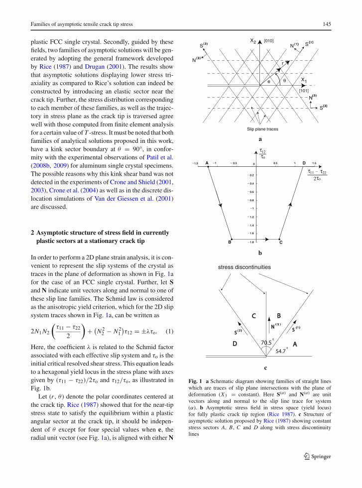
In order to perform a 2D plane strain analysis, it is con-venient to represent the slip systems of the crystal astraces in the plane of deformation as shown in Fig. 1afor the case of an FCC single crystal. Further, let Sand N indicate unit vectors along and normal to one ofthese slip line families. The Schmid law is consideredas the anisotropic yield criterion, which for the 2D slipsystem traces shown in Fig. 1a, can be written as
2N1 N2
(
τ11 − τ22
2
)
+ (
N 22 − N 2
1
)
τ12 = ±λτo. (1)
Here, the coefficient λ is related to the Schmid factorassociated with each effective slip system and τo is theinitial critical resolved shear stress. This equation leadsto a hexagonal yield locus in the stress plane with axesgiven by (τ11 − τ22)/2τo and τ12/τo, as illustrated inFig. 1b.
Let (r , θ ) denote the polar coordinates centered atthe crack tip. Rice (1987) showed that for the near-tipstress state to satisfy the equilibrium within a plasticangular sector at the crack tip, it should be indepen-dent of θ except for four special values when e, theradial unit vector (see Fig. 1a), is aligned with either N
θ
r
e
N S
X1
X2
[101]
[010]
Slip plane traces
( 1 )( 1 )( 2 )
N
S
( 2 )
( 3 )
N
S
( 3 )
1.8
1.6
1.4
1.2
1
0.8
0.6
0.4
0.2
01.5 1 0.5 0.5 1 1.5
_
_
_
_
_
_
_
_
_
___
τ τ11 22
2
_
το
ττ12ο
A
B C
D
SS
N
A
BC
D54.7
70.50
0
stress discontinuities
( 1 )( 2 )
( 3 )
a
b
c
Fig. 1 a Schematic diagram showing families of straight lineswhich are traces of slip plane intersections with the plane ofdeformation (X3 = constant). Here S(α) and N(α) are unitvectors along and normal to the slip line trace for system(α). b Asymptotic stress field in stress space (yield locus)for fully plastic crack tip region (Rice 1987). c Structure ofasymptotic solution proposed by Rice (1987) showing constantstress sectors A, B, C and D along with stress discontinuitylines
123
146 S. Patil et al.
or S. At these four special values of θ (which are 0◦,55◦, 90◦ and 125◦), the stress state and displacementchanges discontinuously.
Rice (1987) further showed that the continuity oftraction vector across the boundary line between twoadjoining plastic sectors requires that the stress statemust change from vertex to vertex on the yield locus(see Fig. 1b). In particular, he demonstrated that�
1
2(τ11 + τ22)
�= −�L� (2)
at each discontinuity. Here, � f � = f (θ+) − f (θ−)
and L is the arc length around the yield locus, havingthe units of stress and increasing in the anticlockwisesense.
Rice (1987) constructed a solution that exhibits highstress triaxiality ahead of the stationary crack tip. Thissolution exhibits yielding at all angles around the cracktip and consists of four constant stress sectors corre-sponding to vertices A, B, C and D on the yield locus(Fig. 1b), separated by stress and displacement discon-tinuities (see Fig. 1c). The vertices A and D in Fig. 1bcorrespond to sectors ahead of the crack tip and onthe crack flank, respectively, as indicated in Fig. 1c. Asalready mentioned, this solution suggests that slip shearbands should occur at 55◦ and 125◦, while a kink shearband should form at 90◦ to the crack line. As pointedout by Rice, the former is caused by sweeping of dis-locations generated at the crack tip along slip planes.By contrast, the latter is produced by dislocation loopsexpanding in a dipole mode from internal sources (seealso Frank and Stroh 1952).
3 Asymptotic structure of stress field in currentlyelastic sector at a stationary crack tip
The most general stress field in a near-tip elastic sectorthat satisfies equilibrium along with compatibility, asproposed by Drugan (2001), has the form:
τ11 − τ22
2τo= C2 sin 2θ + C4, (3a)
τ11 + τ22
2τo= C1 + 2C2θ, (3b)
τ12
2τo= −C2 cos 2θ + C3, (3c)
where, C1–C4 are undetermined constants.
4 Finite element analysis of crack tip fields
Finite element analysis is carried out to understand theeffect of various triaxiality levels ahead of the tip onthe nature of the near-tip stress field in an elastic-ide-ally plastic FCC single crystal. To this end, the crystalplasticity constitutive model (Asaro 1983) which hasbeen implemented in the general purpose finite elementcode FEAP (Zienkiewicz and Taylor 1989) through auser material subroutine is employed. The rate tangentformulation (Peirce et al. 1983) is applied for updatingstresses and plastic variables.
4.1 Computational Aspects
The details of finite element modeling using the mod-ified boundary layer formulation are similar to thosedescribed by Patil et al. (2008a) except that a sharpcrack is considered and the single crystal is assumedto be elastic-ideally plastic. The crystal orientation andthe set of active slip systems with respect to the crackline are chosen as depicted in Fig. 1a. The displacementcomponents based on the first and second terms of theelastic crack tip field (Williams 1957), which are gov-erned by the stress intensity factor K and T -stress, areprescribed as remote boundary conditions. Here elas-tic anisotropy is ignored. The plastic zone is well con-tained within the outer boundary of the domain. Resultspertaining to different T -stress levels at a fixed valueof K are obtained from the analysis.
4.2 Nature of near-tip stress state
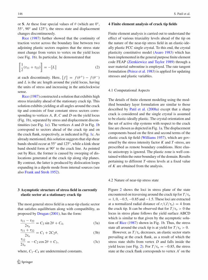
Figure 2 shows the loci in stress plane of the stateencountered on traversing around the crack tip for T/τo
= 1, 0, −0.5, −0.85 and −1.5. These loci are extractedat a normalized radial distance of r/(J/τo) = 4 fromthe crack tip. It can be observed that for T/τo > 0 thelocus in stress plane follows the yield surface ABCDwhich is similar to that given by the asymptotic solu-tion of Rice (1987) shown in Fig. 1b. Thus, the stressstate all around the crack tip is at yield for T/τo > 0.
However, as T/τo decreases, an elastic sector startsprevailing at the crack flank, as a result of which thestress state shifts from vertex D and falls inside theyield locus (see Fig. 2). For T/τo = −0.85, the stressstate at the crack flank corresponds to vertex A′ on the
123

Families of asymptotic tensile crack tip stress 147
Fig. 2 Trajectories plottedin stress plane of the stateencountered on traversingaround the crack tip atr/(J/τo) = 4 obtained fromfinite element analysis withdifferent T/τo values
1.5 1 0.5 0 0.5 1 1.5
1.8
1.6
1.4
1.2
1
0.8
0.6
0.4
0.2
0
11 22
12
(τ τ )/2τo
τ/τ
o
A
B C
D
D'
C'
A'
T/τo= 1.0T/τo= 0.0T/τo= 0.5T/τo= 0.85T/τo= 1.5
yield locus which is same as A. This implies that theelastic sector connects to a plastic sector correspondingto vertex A′ at the crack flank for T/τo ≤ −0.85. More-over, the point at which elastic unloading starts shiftsfrom vertex D and progressively approaches vertex Cand then vertex B as T/τo changes from a high positiveto a high negative value (see Fig. 2).The above pointcoincides with vertex C for T/τo = −0.85.
The coordinates (X, Y ) of the point D′ on segmentCD or point C ′ on segment BC of the yield locus shownin Fig. 1b where elastic unloading commences (depend-ing on whether T/τo > −0.85 or T/τo ≤ −0.85) aregiven by [(2 − p)
√6/4,−p
√3] and [(1 − 2p)
√6/4,
−√3], respectively. Here, the parameter p may fall
in the range from [0, 1]. Thus, corresponding to pointD and C on segment CD the values of p are 0 and1, respectively. Similarly, on segment BC, the vertexC and B are attained for p = 0 and 1. The value ofthe above parameter p corresponding to the point (D′or C ′) at which elastic unloading commences alongwith the normalized opening stress (τ A
22/τo) in frontof the crack tip at r/(J/τo) = 4 are summarized inTable 1 for various levels of T/τo. The combination of
parameter p, point D′ or C ′ and τ A22/τo presented in this
table will be used to construct the analytical solutionin the next section.
5 Construction of families of asymptotic solutionsfor stationary crack with sub-yield sector
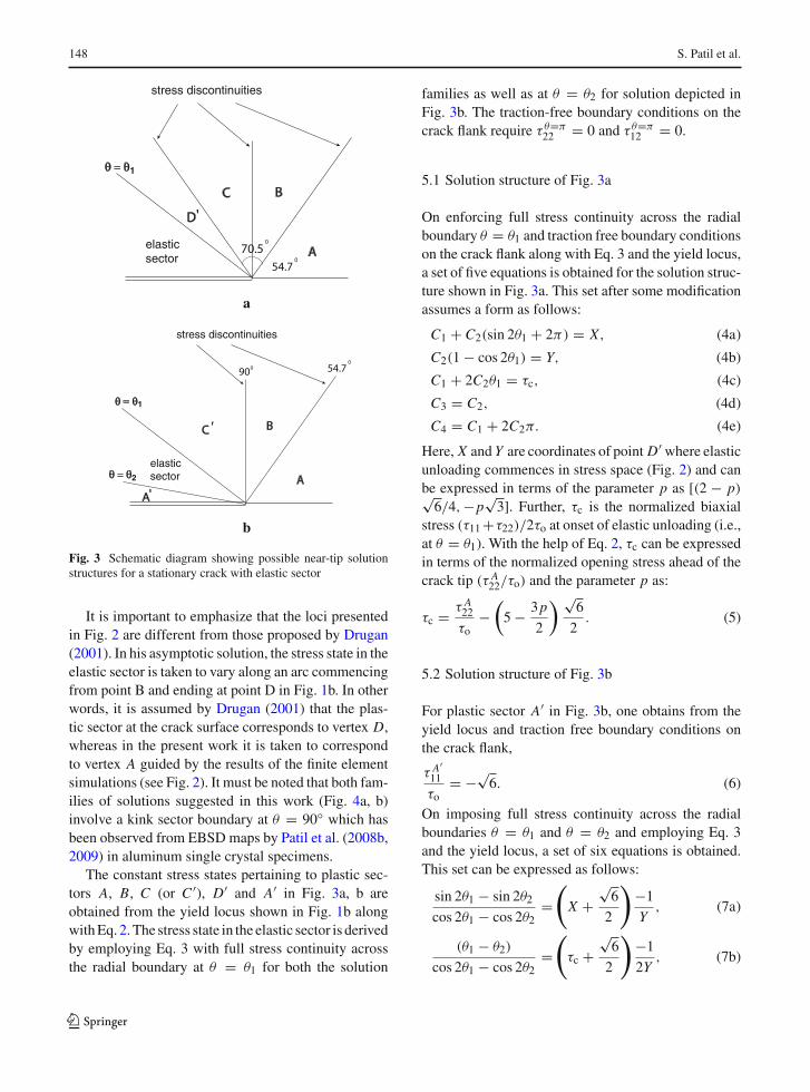
An attempt is made in this section to find solutionshaving the near-tip structure depicted in Fig. 3a or bguided by the observations from the numerical simula-tions carried out in Sect. 4. An elastic sector is incorpo-rated between sectors D′ and the crack flank as shownin Fig. 3a or between sectors C ′ and A′ as indicated inFig. 3b. Further, two families of solutions are gener-ated by commencing the elastic unloading at a variablepoint D′ in between C and D or at a variable point C ′ inbetween B and C in Fig. 2. It must be noted that, whenelastic unloading starts between vertex C and D, thesolution structure shown in Fig. 3a prevails, whereas,when unloading commences at a point between vertexB and C , the solution structure is given by that depictedin Fig. 3b.
Table 1 Parametersassociated with thesolutions obtained frommodified boundary layersimulations correspondingto different values of T/τoat normalized radialdistance r/(J/τo) = 4
T/τo Segment of commencementof elastic unloading
p τ A22/τo
0.0 CD 0.17 7.01−0.5 CD 0.5 6.57−0.85 BC 0 5.85−1.5 BC 0.65 4.46
123
148 S. Patil et al.
A
BC
D
54.7
70.50
0
stress discontinuities
elasticsector
θ = θ1
'
a
A
BC
54.70
stress discontinuities
elasticsector
θ = θ
θ = θ
900
1
2
A
'
'
b
Fig. 3 Schematic diagram showing possible near-tip solutionstructures for a stationary crack with elastic sector
It is important to emphasize that the loci presentedin Fig. 2 are different from those proposed by Drugan(2001). In his asymptotic solution, the stress state in theelastic sector is taken to vary along an arc commencingfrom point B and ending at point D in Fig. 1b. In otherwords, it is assumed by Drugan (2001) that the plas-tic sector at the crack surface corresponds to vertex D,whereas in the present work it is taken to correspondto vertex A guided by the results of the finite elementsimulations (see Fig. 2). It must be noted that both fam-ilies of solutions suggested in this work (Fig. 4a, b)involve a kink sector boundary at θ = 90◦ which hasbeen observed from EBSD maps by Patil et al. (2008b,2009) in aluminum single crystal specimens.
The constant stress states pertaining to plastic sec-tors A, B, C (or C ′), D′ and A′ in Fig. 3a, b areobtained from the yield locus shown in Fig. 1b alongwith Eq. 2. The stress state in the elastic sector is derivedby employing Eq. 3 with full stress continuity acrossthe radial boundary at θ = θ1 for both the solution
families as well as at θ = θ2 for solution depicted inFig. 3b. The traction-free boundary conditions on thecrack flank require τ θ=π
22 = 0 and τ θ=π12 = 0.
5.1 Solution structure of Fig. 3a
On enforcing full stress continuity across the radialboundary θ = θ1 and traction free boundary conditionson the crack flank along with Eq. 3 and the yield locus,a set of five equations is obtained for the solution struc-ture shown in Fig. 3a. This set after some modificationassumes a form as follows:
C1 + C2(sin 2θ1 + 2π) = X, (4a)
C2(1 − cos 2θ1) = Y, (4b)
C1 + 2C2θ1 = τc, (4c)
C3 = C2, (4d)
C4 = C1 + 2C2π. (4e)
Here, X and Y are coordinates of point D′ where elasticunloading commences in stress space (Fig. 2) and canbe expressed in terms of the parameter p as [(2 − p)√
6/4,−p√
3]. Further, τc is the normalized biaxialstress (τ11 +τ22)/2τo at onset of elastic unloading (i.e.,at θ = θ1). With the help of Eq. 2, τc can be expressedin terms of the normalized opening stress ahead of thecrack tip (τ A
22/τo) and the parameter p as:
τc = τ A22
τo−
(
5 − 3p
2
)√
6
2. (5)
5.2 Solution structure of Fig. 3b
For plastic sector A′ in Fig. 3b, one obtains from theyield locus and traction free boundary conditions onthe crack flank,
τ A′11
τo= −√
6. (6)
On imposing full stress continuity across the radialboundaries θ = θ1 and θ = θ2 and employing Eq. 3and the yield locus, a set of six equations is obtained.This set can be expressed as follows:
sin 2θ1 − sin 2θ2
cos 2θ1 − cos 2θ2=
(
X +√
6
2
)
−1
Y, (7a)
(θ1 − θ2)
cos 2θ1 − cos 2θ2=
(
τc +√
6
2
)
−1
2Y, (7b)
123

Families of asymptotic tensile crack tip stress 149
Fig. 4 Trajectories in stressspace corresponding to thetwo families of analyticalsolutions depicted in Fig. 3aand b
1.5 1 0.5 0 0.5 1 1.5
1.8
1.6
1.4
1.2
1
0.8
0.6
0.4
0.2
0
(τ11
τ22 ) / 2 τo
τ 12 /
τ o
A,
B C
DA'
D'
C'
A -- 7.35 B 0.17 7.01 C 0.5 6.57 D 0.0 5.85 E 0.65 4.46
Curve p τ /τ22 oA
Table 2 Various parameters associated with the two families of solutions, depicted in Fig. 3a and b
Point of unloading and p τ A22/τo θ1 θ2 C1 C2 C3 C4 τH/τo
solution structure
D′ (Fig. 3a) 0.17 7.01 157.3◦ N A 6.641 −0.991 −0.991 0.416 5.01D′ (Fig. 3a) 0.5 6.57 138.8◦ N A 6.196 −0.997 −0.997 −0.070 4.56C ′ (Fig. 3b) 0.0 5.85 136.7◦ 180.0◦ 10.328 −1.838 −1.838 −1.223 3.92C ′ (Fig. 3b) 0.65 4.46 142.2◦ 158.9◦ 18.266 −3.515 −2.600 −3.589 2.80
C2 = −Y
cos 2θ1 − cos 2θ2, (7c)
C1 = −√
6
2− 2C2θ2, (7d)
C3 = C2 cos 2θ2, (7e)
C4 = −√
6
2− C2 sin 2θ2. (7f)
Here, X and Y are coordinates of point C ′ whereelastic unloading commences in stress space (Fig. 2)and can be expressed in terms of the parameter p as[(1 − 2p)
√6/4,−√
3]. Further, the expression for τc,the normalized biaxial stress at θ = θ1, in terms ofτ A
22/τo and p is as follows:
τc = τ A22
τo−
(
7
2− p
)√
6
2. (8)
5.3 Solution procedure
The two families of solutions are generated by usingvarious combinations of τ A
22/τo and parameter p along
with the point of unloading (D′ or C ′) determined fromnumerical simulations (see Table 1) and solving Eq. 4or Eq. 7 for θ1, θ2 and C1 to C4. The stress field in plasticsectors D′, C , B and A (for first family) or C ′, B andA (for second family) are then progressively obtainedwith the help of Eq. 2 and noting that �L/τo�B−C =√
6/2 and �L/τo�A−B = 3√
6/4. The values of θ1, θ2,constants C1 to C4, as well as the normalized hydro-static stress prevailing ahead of the tip, τH/τo, are sum-marized in Table 2.
5.4 Comparison of analytical and numerical solutions
The stress trajectories for the two families of analyti-cal solutions having the general structure depicted inFig. 3a or b (with elastic unloading commencing atD′ or C ′) are plotted in stress space in Fig. 4. Here,curve A corresponds to the high triaxiality solution ofRice (1987) shown in Fig. 1c. It is evident on compar-ing Figs. 4 and 2 that the loci in stress space deter-
123
150 S. Patil et al.
mined from the two families of analytical solutionscorroborate well with those obtained from finite ele-ment analysis. Table 2 shows that for τ A
22/τo = 6.57 andp = 0.5 (solution structure of Fig. 3a), the elastic sectorextends from θ = 138.8◦ all the way to the crack flankrendering the stress state at the crack flank inside theyield locus as seen from curve C in Fig. 4. On the otherhand, for the case of τ A
22/τo = 4.46 and p = 0.65(solution structure of Fig. 3b), Table 2 shows that theelastic sector extends from θ1 = 142.2◦ to θ2 = 158.9◦with a plastic sector at the crack flank as noticed fromcurve E in Fig. 4.
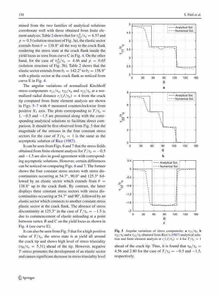
The angular variations of normalized Kirchhoffstress components τ11/τo, τ22/τo and τ12/τo at a nor-malized radial distance r/(J/τo) = 4 from the cracktip computed from finite element analysis are shownin Figs. 5–7 with θ measured counterclockwise frompositive X1 axis. The plots corresponding to T/τo =1,−0.5 and −1.5 are presented along with the corre-sponding analytical solutions to facilitate direct com-parison. It should be first observed from Fig. 5 that themagnitude of the stresses in the four constant stresssectors for the case of T/τo = 1 is the same as theasymptotic solution of Rice (1987).
It can be seen from Figs. 6 and 7 that the stress fieldsobtained from finite element analysis for T/τo = −0.5and −1.5 are also in good agreement with correspond-ing asymptotic solutions. However, certain differencescan be noticed on comparing Figs. 6 and 7. The formershows the four constant stress sectors with stress dis-continuities occurring at 54.7◦, 90.0◦ and 125.3◦ fol-lowed by an elastic sector which extends from θ =138.8◦ up to the crack flank. By contrast, the latterdisplays three constant stress sectors with stress dis-continuities occurring at 54.7◦ and 90◦, followed by anelastic sector which connects to another constant stressplastic sector at the crack flank. The absence of stressdiscontinuity at 125.3◦ in the case of T/τo = −1.5 isdue to commencement of elastic unloading at a pointbetween vertex B and C on the yield locus as shown inFig. 4 (see curve E).
It can also be seen from Fig. 5 that for a high positivevalue of T/τo, the stress state is at yield all aroundthe crack tip and shows high level of stress triaxiality(τH/τo = 5.31) ahead of the tip. However, negativeT -stress promotes the development of an elastic sectorand causes significant decrease in stress triaxiality level
0 30 60 90 120 150 1802
2.5
3
3.5
4
4.5
5
θ
τ 11/τ
o
Analytical Sol.Numerical Sol.
a
0 30 60 90 120 150 1800
2
4
6
8
θ
τ 22/τ
o
Analytical Sol.Numerical Sol.
b
0 30 60 90 120 150 180−2
−1.6
−1.2
−0.8
−0.4
0
0.4
θ
τ 12/τ
o
Analytical Sol.Numerical Sol.
c
Fig. 5 Angular variations of stress components: a τ11/τ0, bτ22/τ0 and c τ12/τ0 obtained from Rice’s (1987) analytical solu-tion and finite element analysis at r/(J/τo) = 4 for T/τo = 1
ahead of the crack tip. Thus, it is found that τH/τo =4.56 and 2.80 for the case of T/τo = −0.5 and −1.5,respectively.
123

Families of asymptotic tensile crack tip stress 151
0 30 60 90 120 150 180−1
0
1
2
3
4
5
θ
τ 11/τ
oAnalytical Sol.Numerical Sol.
a
0 30 60 90 120 150 180−1
0
1
2
3
4
5
6
7
θ
τ 22/τ
o
Analytical Sol.Numerical Sol.
b
0 30 60 90 120 150 180−2
−1.5
−1
−0.5
0
0.5
θ
τ 12/τ
o
Analytical Sol.Numerical Sol.
c
Fig. 6 Angular variations of stress components: a τ11/τ0,b τ22/τ0 and c τ12/τ0 obtained from analytical solution andfinite element analysis at r/(J/τo) = 4 for T/τo = −0.5(τ A
22/τ0 = 6.57)
0 30 60 90 120 150 1803
2
1
0
1
2
3
θ
τ 11/τ
o
Analytical Sol.Numerical Sol.
a
0 30 60 90 120 150 1801
0
1
2
3
4
5
6
θ
τ 22/τ
o
Analytical Sol.Numerical Sol.
b
0 30 60 90 120 150 180-2
-1.5
-1
-0.5
0
0.5
θ
τ 12/τ
o
Analytical Sol.Numerical Sol.
c
Fig. 7 Angular variations of stress components: a τ11/τ0,b τ22/τ0 and c τ12/τ0 obtained from analytical solution andfinite element analysis at r/(J/τo) = 4 for T/τo = −1.5(τ A
22/τ0 = 4.46)
123
152 S. Patil et al.
6 Discussion
As mentioned earlier, the solution structures presentedin Fig. 3a and b involve a kink sector boundary at θ =90◦ which, however, was not observed in the experi-ments of Crone and Shield (2001, 2003), Crone et al.(2004) and discrete dislocation simulation of Van derGiessen et al. (2001). Several reasons may be attributedfor this discrepancy (Kysar and Briant 2002; Flouriotet al. 2003). The above experimental studies employedpre-notched samples and used methods like Moiremicroscopy and optical metallography with the win-dow of observation taken to lie between 350 to 750microns from the tip so that better agreement will beobtained with asymptotic sharp crack solutions. How-ever, it should be noted that use of a notch instead ofsharp crack may cause faster decay in the magnitudeof plastic slip in the horizontal slip system. Thus, ifthe window of observation in pre-notched samples istoo far away from the tip, one may not be able to pickup the strain peak or observe horizontal slip traces. Onthe other hand, a more robust way of detecting kinkshear bands is by using EBSD as demonstrated byKysar and Briant (2002) and Flouriot et al. (2003).Indeed, the recent in-situ EBSD results of Patil et al.(2009) clearly show lattice rotation bands in aluminumsingle crystal specimens developing from the notch sur-face at θ = ±90◦ to the notch line. Further, as men-tioned by Rice (1987), the formation of kink shearbands requires adequate internal dislocation sources.High stacking fault energy (SFE) materials, like alumi-num, exhibit extensive double cross-slip which favorsthe rapid multiplication of Koehler dislocation sourcesand is known to generate dislocation dipoles (see, forexample, Fourie and Wilsdorf 1960). These, in turn,may enable triggering kink bands. This phenomenonhappens to a lesser extent in low SFE metals such ascopper which probably makes it more difficult to formkink shear bands as in the experiments of Crone andShield.
Van der Giessen et al. (2001) have shown that bytuning the density of dislocation sources, one may ormay not obtain kink bands in discrete dislocation simu-lations although this was for BCC single crystals. Fur-ther, a finite deformation formulation of the discretedislocation plasticity simulations may be necessary tocapture the lattice rotations that occur at kink shearbands (see also Kysar and Briant 2002). Also, it may notbe appropriate to compare the predictions of discrete
dislocation theory with classical continuum crystal plas-ticity formulation since the length scale of observationin the former is very small (within a few microns). Onemay need to perform multi-scale modeling to build acomplete picture of crack tip fields covering a widerange of length scales from the crack tip. While non-local plasticity models or discrete dislocation theorymay predict the fields correctly over distances of theorder of a few microns from the tip, classical contin-uum plasticity should prevail at a slightly larger lengthscale. Indeed, this has been observed by Xia and Hutch-inson (1996) for polycrystalline solids.
Rice and Nikolic (1985) noted that the ability of amaterial to form kink-shear bands may play an impor-tant role in determining whether its behavior is duc-tile or brittle. Thus, if there are sufficient dislocationsources in the near-tip region to create kink-shear bands,they could act as mechanisms to dissipate energy andshield the crack tip from external loading. This hasimportant technological implications especially forapplications such as those involving single crystals inhigh pressure turbine blades.
7 Concluding remarks
The nature of the crack tip stress field in elastic-perfectly plastic FCC single crystal has been exam-ined under mode I, plane strain conditions. The crystalorientation studied has the plane of crack as (010) andthe crack front along [101]. The near-tip stress fieldscorresponding to various triaxiality levels ahead of thetip have been obtained, first, by finite element analy-sis based on the modified boundary layer formulationby varying the level of T/τo. Further, guided by thesefields, two families of asymptotic solutions have beenconstructed by adopting the general framework devel-oped by Rice (1987) and Drugan (2001). The familiesof stress fields are parameterized by the normalizedopening stress ahead of the tip, τ A
22/τo, and a quan-tity p which characterizes the coordinates of the pointwhere elastic unloading commences in stress plane.
Both families have a kink sector boundary at θ =90◦ and an elastic sector in the near-tip field. The stressdistribution corresponding to each member of thesefamilies, as well as the trajectories in stress plane asthe crack tip is traversed, agree well with finite elementresults for a certain value of T -stress.
123
Families of asymptotic tensile crack tip stress 153
In closing, it must be mentioned that it is not clearhow the level of T/τo can be directly connected withthe near-tip stress triaxiality without resorting to a finiteelement analysis as performed in this work. This approachis similar to that adopted by Shih (1974) to connectthe remote elastic mode mixity to near-tip plastic mix-ity for mixed-mode loading under small scale yieldingcondition. However, if this could be accomplished in afully analytical framework, it would make the analyti-cal results predictive rather than descriptive.
Acknowledgements The authors would like to gratefullyacknowledge General Motors Research and Development Cen-ter, Warren, Michigan, USA, for financial support through spon-sored project GM/IISc/SID/PC20037.
References
Asaro RJ (1983) Crystal plasticity. J Appl Mech 50:921–934Crone WC, Drugan WJ (2001) Comparison of experiment and
theory for crack tip fields in ductile single crystals. In: Pro-ceedings of international congress of fracture, ICF10, Hono-lulu, USA, pp 1–6
Crone WC, Shield TW (2001) Experimental study of the defor-mation near a notch tip in copper and copperberyllium singlecrystals. J Mech Phys Solids 49:2819–2838
Crone WC, Shield TW (2003) An experimental study of theeffect of hardening on plastic deformation at notch tips inmetallic single crystals. J Mech Phys Solids 51:1623–1647
Crone WC, Shield TW, Creuziger A, Henneman B (2004) Orien-tation dependence of the plastic slip near notches in ductileFCC single crystals. J Mech Phys Solids 52:85–112
Cuitino AM, Ortiz M (1996) Three-dimensional crack-tip fieldsin four point bending copper single crystal specimens. JMech Phys Solids 44:863–904
Drugan WJ (2001) Asymptotic solutions for tensile crack tipfields without kink-type shear bands in elastic-ideally plas-tic single crystals. J Mech Phys Solids 49:2155–2176
Flouriot S, Forest S, Cailletaud G, Koster A, Remy L, BurgardtB, Gros V, Mosset S, Delautre J (2003) Strain localizationat the crack tip in single crystal CT specimens under monot-onous loading: 3D finite element analysis and applicationto nickel-based superalloys. Int J Fract 124:43–77
Fourie JT, Wilsdorf HGF (1960) Production of dislocation loopsby a combined climb and glide mechanism. J Appl Phys31:2219–2223
Frank FC, Stroh AN (1952) On the theory of kinking. Proc PhysSoc B 65:811–821
Garrett G, Knott J (1975) Crystallographic fatigue crack growthin aluminum alloys. Acta Metall 23:841–848
Kysar J, Briant C (2002) Crack tip deformation fields in ductilesingle crystals. Acta Mater 50(9):2367–2380
Neumann P (1974a) The geometry of slip processes at propagat-ing fatigue cracks-II. Acta Metall 22:1167–1178
Neumann P (1974b) New experiments concerning the slipprocesses at propagating fatigue cracks-I. Acta Metall22:1155–1165
Patil SD, Narasimhan R, Mishra RK (2008a) A numerical studyof crack tip constraint in ductile single crystals. J Mech PhysSolids 56:2265–2286
Patil SD, Narasimhan R, Biswas P, Mishra RK (2008b) A com-bined experimental and numerical study of crack tip fieldsin aluminium single crystal SEN(T) specimens. ASME JEng Mater Technol 130:1–11
Patil SD, Narasimhan R, Mishra RK (2009) Observation of kinkshear bands in an aluminum single crystal fracture specimen(submitted)
Peirce D, Asaro RJ, Needleman A (1983) Material rate depen-dence and localized deformation in crystalline solids. ActaMetall 31:1951–1976
Rice JR (1987) Tensile crack tip fields in elastic-ideally plasticcrystals. Mech Mater 6:317–335
Rice JR, Nikolic R (1985) Anti-plane shear cracks in ideallyplastic crystals. J Mech Phys Solids 33:595–622
Rice JR, Hawk D, Asaro RJ (1990) Crack tip fields in ductilesingle crystals. Int J Fract 42:301–321
Saeedvafa M, Rice JR (1989) Crach tip singular fields in ductilesingle crystals with Taylor power-law hardening. II: planestrain. J Mech Phys Solids 37:673–691
Shield TW (1996) Experimental study of the plastic strain fieldsnear a notch tip in a copper single crystal during loading.Acta Mater 44:1547–1561
Shih CF (1974)Small scale yielding analysis of mixed modeplain-strain crack problem. In: Fracture analysis, ASTMSTP 560, pp 187–210
Van der Giessen E, Deshpande VS, Cleveringa HHM, Needle-man A (2001) Discrete dislocation plasticity and crack tipfields in single crystals. J Mech Phys Solids 49:2133–2153
Williams ML (1957) On the stress distribution at the base of astationary crack. J Appl Mech 24:111–114
Xia ZC, Hutchinson JW (1996) Crack tip fields in strain gradientplasticity. J Mech Phys Solids 44:1621–1648
Zhang HW, Huang Y (1994) Asymptotic tensile crack-tip stressfields in elastic-perfectly plastic crystals. Int J Fract 67:133–142
Zienkiewicz OC, Taylor RL (1989) The finite element method.McGraw Hill Pulishing, New York
123