Tensile Properties of Fiber Reinforced Polymer Matrix ...
13
Designation: D7205/D7205M - 06 (Reapproved 2016) Standard Test Method for Tensile Properties of Fiber Reinforced Polymer Matrix Composite Bars 1 This standard is issued under the fixed designation D7205/D7205M; the number immediately following the designation indicates the year of original adoption or, in the case of revision, the year of last revision. A number in parentheses indicates the year of last reapproval. A superscript epsilon (´) indicates an editorial change since the last revision or reapproval. 1. Scope 1.1 This test method determines the quasi-static longitudinal tensile strength and elongation properties of fiber reinforced polymer matrix (FRP) composite bars commonly used as tensile elements in reinforced, prestressed, or post-tensioned concrete. NOTE 1—Additional procedures for determining tensile properties of polymer matrix composites may be found in test methods D3039/D3039M and D3916. 1.2 Linear elements used for reinforcing Portland cement concrete are referred to as bars, rebar, rods, or tendons, depending on the specific application. This test method is applicable to all such reinforcements within the limitations noted in the method. The test articles are referred to as bars in this test method. In general, bars have solid cross-sections and a regular pattern of surface undulations and/or a coating of bonded particles that promote mechanical interlock between the bar and concrete. The test method is also appropriate for use with linear segments cut from a grid. Specific details for preparing and testing of bars and grids are provided. In some cases, anchors may be necessary to prevent grip-induced damage to the ends of the bar or grid. Recommended details for the anchors are provided in Annex A1. 1.3 The strength values provided by this method are short- term static strengths that do not account for sustained static or fatigue loading. Additional material characterization may be required, especially for bars that are to be used under high levels of sustained or repeated loading. 1.4 The values stated in either SI units or inch-pound units are to be regarded separately as standard. The values stated in each system may not be exact equivalents; therefore, each system shall be used independently of the other. Combining values from the two systems may result in non-conformance with the standard. 1.4.1 Within the text, the inch-pound units are shown in brackets. 1.5 This standard does not purport to address all of the safety concerns, if any, associated with its use. It is the responsibility of the user of this standard to establish appro- priate safety and health practices and determine the applica- bility of regulatory limitations prior to use. 2. Referenced Documents 2.1 ASTM Standards: 2 A615/A615M Specification for Deformed and Plain Carbon- Steel Bars for Concrete Reinforcement D792 Test Methods for Density and Specific Gravity (Rela- tive Density) of Plastics by Displacement D883 Terminology Relating to Plastics D3039/D3039M Test Method for Tensile Properties of Poly- mer Matrix Composite Materials D3171 Test Methods for Constituent Content of Composite Materials D3878 Terminology for Composite Materials D3916 Test Method for Tensile Properties of Pultruded Glass-Fiber-Reinforced Plastic Rod D5229/D5229M Test Method for Moisture Absorption Prop- erties and Equilibrium Conditioning of Polymer Matrix Composite Materials E4 Practices for Force Verification of Testing Machines E6 Terminology Relating to Methods of Mechanical Testing E83 Practice for Verification and Classification of Exten- someter Systems E122 Practice for Calculating Sample Size to Estimate, With Specified Precision, the Average for a Characteristic of a Lot or Process E456 Terminology Relating to Quality and Statistics E1012 Practice for Verification of Testing Frame and Speci- men Alignment Under Tensile and Compressive Axial Force Application E1309 Guide for Identification of Fiber-Reinforced 1 This test method is under the jurisidiction of ASTM Committee D30 on Composite Materials and is the direct responsibility of Subcommittee D30.10 on Composites for Civil Structures. Current edition approved Nov. 1, 2016. Published November 2016. Originally approved in 2006. Last previous edition approved in 2011 as D7205/ D7205M–06(2011). DOI: 10.1520/D7205_D7205M-06R16. 2 For referenced ASTM standards, visit the ASTM website, www.astm.org, or contact ASTM Customer Service at [email protected]. For Annual Book of ASTM Standards volume information, refer to the standard’s Document Summary page on the ASTM website. Copyright © ASTM International, 100 Barr Harbor Drive, PO Box C700, West Conshohocken, PA 19428-2959. United States This international standard was developed in accordance with internationally recognized principles on standardization established in the Decision on Principles for the Development of International Standards, Guides and Recommendations issued by the World Trade Organization Technical Barriers to Trade (TBT) Committee. 1 Copyright by ASTM Int'l (all rights reserved); Sun Apr 30 13:10:34 EDT 2017 Downloaded/printed by Norwegian Univ Science And Tech (Norwegian Univ Science And Tech) pursuant to License Agreement. No further reproductions authorized.
-
Upload
khangminh22 -
Category
Documents
-
view
0 -
download
0
Transcript of Tensile Properties of Fiber Reinforced Polymer Matrix ...

Designation: D7205/D7205M − 06 (Reapproved 2016)
Standard Test Method forTensile Properties of Fiber Reinforced Polymer MatrixComposite Bars1
This standard is issued under the fixed designation D7205/D7205M; the number immediately following the designation indicates theyear of original adoption or, in the case of revision, the year of last revision. A number in parentheses indicates the year of lastreapproval. A superscript epsilon (´) indicates an editorial change since the last revision or reapproval.
1. Scope
1.1 This test method determines the quasi-static longitudinaltensile strength and elongation properties of fiber reinforcedpolymer matrix (FRP) composite bars commonly used astensile elements in reinforced, prestressed, or post-tensionedconcrete.
NOTE 1—Additional procedures for determining tensile properties ofpolymer matrix composites may be found in test methods D3039/D3039Mand D3916.
1.2 Linear elements used for reinforcing Portland cementconcrete are referred to as bars, rebar, rods, or tendons,depending on the specific application. This test method isapplicable to all such reinforcements within the limitationsnoted in the method. The test articles are referred to as bars inthis test method. In general, bars have solid cross-sections anda regular pattern of surface undulations and/or a coating ofbonded particles that promote mechanical interlock betweenthe bar and concrete. The test method is also appropriate foruse with linear segments cut from a grid. Specific details forpreparing and testing of bars and grids are provided. In somecases, anchors may be necessary to prevent grip-induceddamage to the ends of the bar or grid. Recommended details forthe anchors are provided in Annex A1.
1.3 The strength values provided by this method are short-term static strengths that do not account for sustained static orfatigue loading. Additional material characterization may berequired, especially for bars that are to be used under highlevels of sustained or repeated loading.
1.4 The values stated in either SI units or inch-pound unitsare to be regarded separately as standard. The values stated ineach system may not be exact equivalents; therefore, eachsystem shall be used independently of the other. Combiningvalues from the two systems may result in non-conformancewith the standard.
1.4.1 Within the text, the inch-pound units are shown inbrackets.
1.5 This standard does not purport to address all of thesafety concerns, if any, associated with its use. It is theresponsibility of the user of this standard to establish appro-priate safety and health practices and determine the applica-bility of regulatory limitations prior to use.
2. Referenced Documents
2.1 ASTM Standards:2
A615/A615M Specification for Deformed and Plain Carbon-Steel Bars for Concrete Reinforcement
D792 Test Methods for Density and Specific Gravity (Rela-tive Density) of Plastics by Displacement
D883 Terminology Relating to PlasticsD3039/D3039M Test Method for Tensile Properties of Poly-
mer Matrix Composite MaterialsD3171 Test Methods for Constituent Content of Composite
MaterialsD3878 Terminology for Composite MaterialsD3916 Test Method for Tensile Properties of Pultruded
Glass-Fiber-Reinforced Plastic RodD5229/D5229M Test Method for Moisture Absorption Prop-
erties and Equilibrium Conditioning of Polymer MatrixComposite Materials
E4 Practices for Force Verification of Testing MachinesE6 Terminology Relating to Methods of Mechanical TestingE83 Practice for Verification and Classification of Exten-
someter SystemsE122 Practice for Calculating Sample Size to Estimate, With
Specified Precision, the Average for a Characteristic of aLot or Process
E456 Terminology Relating to Quality and StatisticsE1012 Practice for Verification of Testing Frame and Speci-
men Alignment Under Tensile and Compressive AxialForce Application
E1309 Guide for Identification of Fiber-Reinforced
1 This test method is under the jurisidiction of ASTM Committee D30 onComposite Materials and is the direct responsibility of Subcommittee D30.10 onComposites for Civil Structures.
Current edition approved Nov. 1, 2016. Published November 2016. Originallyapproved in 2006. Last previous edition approved in 2011 as D7205/D7205M–06(2011). DOI: 10.1520/D7205_D7205M-06R16.
2 For referenced ASTM standards, visit the ASTM website, www.astm.org, orcontact ASTM Customer Service at [email protected]. For Annual Book of ASTMStandards volume information, refer to the standard’s Document Summary page onthe ASTM website.
Copyright © ASTM International, 100 Barr Harbor Drive, PO Box C700, West Conshohocken, PA 19428-2959. United States
This international standard was developed in accordance with internationally recognized principles on standardization established in the Decision on Principles for theDevelopment of International Standards, Guides and Recommendations issued by the World Trade Organization Technical Barriers to Trade (TBT) Committee.
1
Copyright by ASTM Int'l (all rights reserved); Sun Apr 30 13:10:34 EDT 2017Downloaded/printed byNorwegian Univ Science And Tech (Norwegian Univ Science And Tech) pursuant to License Agreement. No further reproductions authorized.

Polymer-Matrix Composite Materials in Databases (With-drawn 2015)3
E1434 Guide for Recording Mechanical Test Data of Fiber-Reinforced Composite Materials in Databases (Withdrawn2015)3
E1471 Guide for Identification of Fibers, Fillers, and CoreMaterials in Computerized Material Property Databases(Withdrawn 2015)3
3. Terminology
3.1 Terminology in D3878 defines terms relating to high-modulus fibers and their composites. Terminology in D883defines terms relating to plastics. Terminology in E6 definesterms relating to mechanical testing. Terminology in E456 andin Practice E122 define terms relating to statistics and theselection of sample sizes. In the event of a conflict betweenterms, Terminology in D3878 shall have precedence over theother terminology standards.
3.2 Definitions of Terms Specific to This Standard:3.2.1 anchor, n—a protective device placed on each end of
a bar, between the bar and the grips of the tensile testingmachine, to prevent grip-induced damage. Usually used onbars with irregular surfaces, as opposed to flat strips wherebonded tabs are more typical.
3.2.2 bar, n—a linear element, often with surface undula-tions or a coating of particles that promote mechanical inter-lock with concrete
3.2.3 grid, n—a two-dimensional (planar) or three-dimensional (spatial) rigid array of interconnected FRP barsthat form a contiguous lattice that can be used to reinforceconcrete. The lattice can be manufactured with integrallyconnected bars or constructed of mechanically connectedindividual bars. The grid bar elements have transverse dimen-sions typically greater than 3 mm [0.125 in.].
3.2.4 effective diameter, n—a geometric value representingthe diameter of a circle which has an enclosed area equal to thenominal cross-sectional area of a bar.
3.2.5 nominal cross-sectional area, n—a measure of cross-sectional area of a bar, determined over at least one represen-tative length, used to calculate stress.
3.2.6 nominal value, n—a value, existing in name only,assigned to a measurable property for the purpose of conve-nient designation. Tolerances may be applied to a nominalvalue to define an acceptable range for the property.
3.2.7 representative length, n—the minimum length of a barthat contains a repeating geometric pattern that, placed end-to-end, reproduces the geometric pattern of a continuous bar(usually used in reference to bars having surface undulationsfor enhancing interlock with concrete).
3.2.8 standard cross-sectional area, n—the cross-sectionalarea of a standard numbered steel concrete reinforcing bar asgiven in ASTM A615/A615M, Table 1.
3.2.9 surface undulation, n—variation in the area,orientation, or shape of cross-section of a bar along its length,intended to enhance mechanical interlock between a bar andconcrete, made by any of a number of processes such as, forexample, indentation, addition of extra materials, and twisting.
3.3 Symbols:
A = nominal cross-sectional area of a bar.CV = sample coefficient of variation, in percent.d = effective bar diameterEchord = chord modulus of elasticity in the test direction.Ftu = ultimate tensile strength.L = free length of specimen (length between anchors).La = anchor length.Lg = extensometer gage length.n = number of specimens.P = force carried by specimen.Pmax = maximum load carried by a test coupon before
failure.Sn–1 = sample standard deviation.xi = measured or derived property.x̄ = sample mean (average).δ = extensional displacement.ε = indicated normal strain from strain transducer.σ = normal stress.
4. Summary of Test Method
4.1 A fiber reinforced polymer (FRP) bar, preferably fittedwith anchors, is mounted in a mechanical testing machine andmonotonically loaded in tension to failure while recordingforce, longitudinal strain, and longitudinal displacement.
4.2 Anchors as described in Annex A1 are recommendedbut not required. Alternative methods for attaching the speci-mens to the testing machine are acceptable, but must allow forthe full strength of the bar to be developed and for the failureof the specimens to occur away from the attachments.
5. Significance and Use
5.1 This test method is designed to produce longitudinaltensile strength and elongation data. From a tension test, avariety of data are acquired that are needed for designpurposes. Material-related factors that influence the tensileresponse of bars and should therefore be reported include thefollowing: constituent materials, void content, volume percentreinforcement, methods of fabrication, and fiber reinforcementarchitecture. Similarly, test factors relevant to the measuredtensile response of bars include specimen preparation, speci-men conditioning, environment of testing, specimen alignmentand gripping, and speed of testing. Properties, in the testdirection, that may be obtained from this test method include:
5.1.1 Ultimate tensile strength,5.1.2 Ultimate tensile strain,5.1.3 Tensile chord modulus of elasticity, and5.1.4 Stress-strain curve.
6. Interferences
6.1 The results from the procedures presented are limited tothe material and test factors listed in Section 5.
3 The last approved version of this historical standard is referenced onwww.astm.org.
D7205/D7205M − 06 (2016)
2
Copyright by ASTM Int'l (all rights reserved); Sun Apr 30 13:10:34 EDT 2017Downloaded/printed byNorwegian Univ Science And Tech (Norwegian Univ Science And Tech) pursuant to License Agreement. No further reproductions authorized.
6.2 Gripping—The method of gripping has been known tocause premature tensile failures in bars. Anchors, if used,should be designed in such a way that the full tensile capacitycan be achieved without slip throughout the length of theanchor during the test.
6.3 System Alignment—Excessive bending may cause pre-mature failure, as well as a highly inaccurate modulus ofelasticity determination. Every effort should be made to elimi-nate bending from the test system. Bending may occur due tomisalignment of the bar within anchors or grips or associatedfixturing, or from the specimen itself if improperly installed inthe grips or if it is out-of-tolerance due to poor specimenpreparation. See ASTM E1012 for verification of specimenalignment under tensile loading.
6.4 Measurement of Cross-Sectional Area—The nominalcross-sectional area of the bar is measured by immersing aprescribed length of the specimen in water to determine itsbuoyant weight. Bar configurations that trap air during immer-sion (aside from minor porosity) cannot be assessed using thismethod. This method may not be appropriate for bars that havelarge variations in cross-sectional area along the length of thebar.
7. Apparatus
7.1 Micrometers—The micrometer(s) shall use a suitablesize diameter ball-interface on irregular surfaces and a flatanvil interface on machined edges or very-smooth tooledsurfaces. The accuracy of the instruments shall be suitable forreading to within 1 % of the intended measurement.
7.2 Testing Machine—The testing machine shall be in con-formance with Practice E4, and shall satisfy the followingrequirements:
7.2.1 Testing Machine Heads—The testing machine shallhave both an essentially stationary head and a movable head.
7.2.2 Drive Mechanism—The testing machine drive mecha-nism shall be capable of imparting to the movable head acontrolled displacement rate with respect to the stationaryhead. The displacement rate of the movable head shall becapable of being regulated as specified in 11.3.
7.2.3 Force Indicator—The testing machine force-sensingdevice shall be capable of indicating the total force beingcarried by the specimen. This device shall be essentially freefrom inertia-lag at the specified rate of testing and shallindicate the force with an accuracy over the load range(s) ofinterest of within 6 1 % of the indicated value, as specified byPractices E4. The force range(s) of interest may be fairly lowfor modulus evaluation, much higher for strength evaluation, orboth, as required.
NOTE 2—Obtaining precision force data over a large range of interest inthe same test, such as when both elastic modulus and ultimate force arebeing determined, place extreme requirements on the force transducer andits calibration. For some equipment a special calibration may be required.For some combinations of material and force transducer, simultaneousprecision measurement of both elastic modulus and ultimate strength maynot be possible, and measurement of modulus and strength may have to beperformed in separate tests using a different force transducer range foreach test.
7.2.4 Grips—If grips are used, each head of the testingmachine shall carry one grip for holding the specimen so thatthe loading direction is coincident with the longitudinal axis ofthe specimen. The grips shall apply sufficient lateral pressure toprevent slippage between the grip face and the specimen oranchor. It is highly desirable to use grips that are rotationallyself-aligning to minimize bending stresses in the specimen.The grips shall be aligned in accordance with ASTM E1012and shall not bias failure location in the bar.
7.3 Anchors—Use of a rigid pipe-shaped anchor as aninterface between the bar and the grips or loading head of thetesting machine is recommended to prevent stress concentra-tions and consequent downward biasing of measured strength.Details of recommended anchors are provided in Annex A1.
7.3.1 Attachment of anchors to loading heads shall be bythreaded connectors between the anchors and loading head orby grips. Details of this attachment are shown in Fig. A1.3.
7.4 Strain-Indicating Device—Longitudinal strain shall bemeasured by an appropriate strain transducer as long asattachment of this device does not cause damage to the bar (seeNote 3).
NOTE 3—For most bars the application of surface-bonded strain gagesis impractical due to surface undulations (for example, braided, twisted,and indented bars). Strain gages of a suitable gage length can be used ifthe surface of the bar can be smoothed with a polymer resin such as epoxyto provide a suitable bonding surface so that measurements are equivalentto those provided by an extensometer meeting the requirements of section7.4.1.
7.4.1 Extensometers—Extensometers shall satisfy, at aminimum, Practice E83, Class B-2 requirements for the strainrange of interest, and shall be calibrated over that strain rangein accordance with Practice E83. The extensometer shall beessentially free of inertia-lag at the specified speed of testing.The gage length of the extensometer, Lg, shall be not less thaneight times the effective bar diameter, nor less than onerepresentative length. The extensometer shall be centered onthe mid-length position of the bar, not less than eight effectivebar diameters from either anchor
7.4.1.1 Temperature compensation is recommended whennot testing at Standard Laboratory Atmosphere. Whenappropriate, use either (a) a traveler specimen (dummy speci-men) with identical bar material and extensometer(s) or (b) anextensometer calibrated for temperature changes.
7.5 Environmental Test Chamber—An environmental cham-ber is required for conditioning and test environments otherthan ambient laboratory conditions. These chambers shall becapable of maintaining the required relative temperature towithin 63°C [65°F] and the required relative humidity levelto within 65 %RH. In addition, the chambers may have to becapable of maintaining environmental conditions such as fluidexposure or relative humidity during the conditioning andtesting (see Sections 10 and 11.4).
8. Sampling and Test Specimens
8.1 Sampling—Test at least five specimens per test condi-tion unless valid results can be gained through the use of fewerspecimens, such as in the case of a designed experiment. For
D7205/D7205M − 06 (2016)
3
Copyright by ASTM Int'l (all rights reserved); Sun Apr 30 13:10:34 EDT 2017Downloaded/printed byNorwegian Univ Science And Tech (Norwegian Univ Science And Tech) pursuant to License Agreement. No further reproductions authorized.
statistically significant data, the procedures outlined in PracticeE122 should be consulted. The method of sampling shall bereported.
8.2 Geometry:8.2.1 Overall Specimen Length and Gage Length—The total
length of the specimen shall be the free length plus two timesthe anchor length, La. The free length between the anchors, L,shall be not less than 380 mm [15 in.] nor less than 40 times theeffective bar diameter. The length of the specimen in the gripsand anchors (if used) shall be sufficient for adequate anchor-age.
8.2.2 Labeling—The specimens shall be labeled so that theywill be distinct from each other and traceable back to the rawmaterial, and in a manner that will both be unaffected by thetest and not influence the test.
9. Calibration
9.1 The accuracy of all measuring equipment shall havecertified calibrations that are current at the time of use of theequipment.
10. Conditioning
10.1 Standard Conditioning Procedure—Condition per Pro-cedure C of Test Method D5229/D5229M; store at StandardLaboratory Atmosphere (2363° C [7365° F] and 50610 %RH) unless a different conditioning environment is specified aspart of the experiment.
NOTE 4—If tensile specimens are to undergo environmental condition-ing to equilibrium, and are of such type or geometry that the weightchange of the material cannot be properly measured by weighing thespecimen itself (such as a bar with anchors), then a traveler specimen ofthe same cross-section geometry and appropriate size (but withoutanchors) shall be used to determine when equilibrium has been reached forthe specimens being conditioned. The ends of tensile specimens andtraveler specimens shall be sealed with a water resistant sealant such as ahigh grade, room-temperature curing epoxy to avoid end effects duringconditioning.
11. Procedure
11.1 Parameters to be specified prior to test:11.1.1 The specimen sampling method, specimen type and
geometry, conditioning, and if required, traveler specimengeometry.
11.1.2 The tensile properties and data reporting formatdesired.
NOTE 5—Determine specific material property, accuracy, and datareporting requirements before test for proper selection of instrumentationand data-recording equipment. Estimate operating stress and strain levelsto aid in transducer selection, calibration of equipment, and determinationof equipment settings.
11.1.3 The environmental conditioning test parameters andsealant used for the ends of the specimens.
11.1.4 If performed, the sampling method, specimengeometry, and test methods used to determine density, voidfraction, and reinforcement volume.
11.2 General Instructions:11.2.1 Report any deviations from this test method, whether
intentional or inadvertent.
11.2.2 If specific gravity, density, reinforcement volume orvoid volume are to be reported, use ASTM D792 (specificgravity, density) and ASTM D3171 (reinforcement volume,void volume) for the determination of these properties andselect specimens from the same batch of bar as that used for thetensile and traveler specimens.
11.2.3 Condition the specimens (specify either before orafter attachment of anchors), as required. If test conditions areto be different from ambient laboratory conditions, it isrecommended that anchors be applied before conditioning.Condition the traveler coupons if they are to be used.
11.2.4 Following final specimen machining and anyconditioning, but before the tension testing, measure and reportthe free length of specimen.
11.2.5 Bar area and diameter—Either the nominal mea-sured cross-sectional area or the standard cross-sectional areaas given in ASTM A615/A615M is used to calculate stress andmodulus of elasticity. In either case, the nominal cross-sectional area must be measured and reported. If the nominalcross-sectional area differs from the standard cross-sectionalarea for the given bar size by more than 20 percent, standardcross-sectional area may not be used.
11.2.5.1 Nominal cross-sectional area—The nominal area iscalculated as the average of 5 representative specimens cutfrom the same bar stock as that used for the tensile test.Conditioning of the cross-sectional area specimens is the sameas that for the bars used for the tensile test. The volume of eachspecimen shall be measured indirectly by the difference inmass of the specimen in the dry and fully immersed states(refer to ASTM D792 for test methods). The volume of thespecimen is the mass of the specimen divided by the density asmeasured by ASTM D792. Nominal area is then found bydividing volume by the average length of the specimen. Theaverage length of a typical bar specimen (e.g., circular orpolygonal cross-section) is found by measuring the length ofthe outer edge of the specimen three times at the outer edge,rotating the specimen by 120 degrees for each measurement.Record the area in units mm2 [in.2]. Effective bar diameter, d,is found by equation (1):
d 5 2=~A/3.1416! (1)
NOTE 6—For a representative determination of area, specimens of atleast 100 mm [4 in.] or one representative length (whichever is greater)shall be used. The mass of a specimen may exceed the limit imposed byASTM D792 (50 grams) for large diameter bars, but the procedure maystill be used.
11.2.5.2 Standard cross-sectional area—The standardcross-sectional area is the conventionally accepted area of asteel bar with the same number designation as a FRP bar beingtested.
NOTE 7—Standard cross-sectional areas are taken as the cross-sectionalareas of steel reinforcing bars as given in ASTM A615/A615M. FRP barsare often manufactured as substitutions for steel reinforcing bars, and aretypically numbered using the same designations as steel bars, for example,a No. 4 bar has an effective diameter of 13 mm [0.5 in.] and a standardcross-sectional area of 129 mm2 [0.20 in.2]. For some applications it isconsidered appropriate to use the standard area for calculating stress andmodulus of elasticity in FRP bars as this is the practice for steel bars.
11.2.6 Apply extensometers or strain gages to the specimen.
D7205/D7205M − 06 (2016)
4
Copyright by ASTM Int'l (all rights reserved); Sun Apr 30 13:10:34 EDT 2017Downloaded/printed byNorwegian Univ Science And Tech (Norwegian Univ Science And Tech) pursuant to License Agreement. No further reproductions authorized.
11.3 Speed of Testing—The speed of testing shall be set toeffect a nearly constant strain rate in the gage section. Thestrain rate shall be selected so as to produce failure within 1 to10 minutes from the beginning of force application. If theultimate strain of the material cannot be reasonably estimated,conduct initial trials using standard speeds until the ultimatestrain of the material and the compliance of the system areknown, and the strain rate can be adjusted. The suggestedstandard strain rate is 0.01 min.-1. If strain control is notavailable on the testing machine, a nominal cross-head speedof 0.01 min.-1 times the specimen free length selected accord-ing to Section 8.2.1 shall be used.
11.4 Test Environment—Test at Standard Laboratory Atmo-sphere (2363° C [7365° F] and 50610 % RH) unless adifferent environment is specified as part of the experiment.Recommendations for testing at other than standard laboratoryconditions are given in Annex A2.
11.5 Specimen Insertion11.5.1 If grips are used, place the specimen in the grips of
the testing machine, taking care to align the longitudinal axis ofthe gripped specimen with the test direction. Tighten the grips,recording the pressure used on pressure controllable (hydraulicor pneumatic) grips.
11.5.2 If the anchor is attached to the loading head bythreading or clevis, attach the specimen to the loading headsand removed any excess slack from the test fixture.
11.6 Testing—Apply extension to the specimen at the speci-fied rate until failure occurs, while recording data.
11.7 Data Recording—Record force versus strain (or trans-ducer displacement) continuously, or at frequent regular inter-vals; for this test method, a sampling rate of 2 to 3 datarecordings per second, and a target minimum of 100 data pointsper test are recommended. If the specimen is to be failed,record the maximum force, the failure force, and the strain (ortransducer displacement) at, or as near as possible to, themoment of rupture.
NOTE 8—Other valuable data that can be useful in understanding testinganomalies and gripping or specimen slipping problems includes forceversus head displacement data and force versus time data.
11.8 Failure Modes—Record the mode and the location offailure of the specimen.
12. Validation
12.1 Values for ultimate properties shall not be calculatedfor any specimen that fails at some obvious flaw, unless such aflaw constitutes a variable being studied. Retests shall beperformed for any specimen on which values are not calcu-lated.
12.2 Re-examine the means of force introduction into thematerial if a significant fraction of failures in a samplepopulation occur within or just outside any anchor or grip.Factors considered should include the anchor-to-test framealignment, anchor material, anchor-to-specimen alignment,anchor filler and bonding agent, grip type, grip pressure, andgrip alignment.
13. Calculation
13.1 Tensile Stress/Tensile Strength—Calculate the ultimatetensile strength using Eq 2and report the results to threesignificant figures. If the tensile modulus is to be calculated,determine the tensile stress at each required data point using Eq3.
Ftu 5 Pmax/A (2)
σ i 5 Pi/A (3)
where:Ftu = Ultimate tensile strength, MPa [psi],Pmax = Maximum force prior to failure, N [lbf],σi = Tensile stress at i-th data point, MPa [psi]Pi = Force at i-th data point, N [lbf], andA = Cross-sectional area of the bar from 11.2.5, mm2
[in.2].
13.2 Tensile Strain/Ultimate Tensile Strain—If tensilemodulus or ultimate tensile strain is to be calculated, andmaterial response is being determined by an extensometer,determine the tensile strain from the indicated displacement ateach required data point using Eq 4 and report the results tothree significant figures.
ε i 5 δ i/Lg (4)
where:εi = tensile strain at i-th data point, mm/mm [in./in.]δi = extensometer displacement at i-th data point, mm [in.],
andLg = extensometer gage length, mm [in.].
13.3 Tensile Modulus of Elasticity:
13.3.1 Tensile Chord Modulus of Elasticity—Calculate thetensile chord modulus of elasticity from the stress-strain datausing Eq 5. If data are not available at the exact strain rangestart and end points (as often occurs with digital data), use theclosest available data point. The strain range is to be within thelower half of the stress-strain curve, with the start point beinga strain of 0.001 and the end point being a strain of 0.003. Formaterials that fail at a strain below 0.006, the start point shallbe 25 % of ultimate strain and the end point shall be 50 % ofultimate strain. Report the tensile chord modulus of elasticityto three significant figures.
Echord 5 ∆σ/∆ε (5)
where:Echord = chord modulus of elasticity, MPa [psi],∆σ = difference in applied tensile stress between the
starting and ending strain points, MPa [psi], and∆ε = difference in the average tensile strain between
starting and ending strain points at the lower andupper bound of the selected strain range.
13.4 Statistics—For each series of tests calculate the aver-age value, standard deviation, and coefficient of variation (inpercent) for each property determined:
x̄ 5 S (i51
n
xiD /n (6)
D7205/D7205M − 06 (2016)
5
Copyright by ASTM Int'l (all rights reserved); Sun Apr 30 13:10:34 EDT 2017Downloaded/printed byNorwegian Univ Science And Tech (Norwegian Univ Science And Tech) pursuant to License Agreement. No further reproductions authorized.
sn21 5ŒS (i51
n
xi2 2 nx̄2D /~n 2 1! (7)
CV 5 1 2 3 sn21/ x̄ (8)
Where:x̄ = sample mean (average),sn-1 = sample standard deviation,CV = sample coefficient of variation, in percent,n = number of tested specimens, andxI = measured or derived property.
14. Report
14.1 Report the following information, or references point-ing to other documentation containing this information, to themaximum extent applicable (reporting of items beyond thecontrol of a given testing laboratory, such as might occur withmaterial details or bar fabrication parameters, shall be theresponsibility of the requestor). The format for the reportingshall make use of Guides E1309, E1471, and E1434.
14.1.1 The revision level or date of issue of this test method.14.1.2 The date(s) and location(s) of the test.14.1.3 The name(s) of the test operator(s).14.1.4 Any variations to this test method, anomalies noticed
during testing or equipment problems occurring during testing.14.1.5 Identification of the material tested including (if
available) : material specification, material type, materialdesignation, manufacturer, manufacturer’s lot or batch number,source (if not from manufacturer), date of certification, expi-ration of certification, filament diameter, tow or yarn filamentcount and twist, sizing, form or weave, and matrix type.
14.1.6 If available, description of the fabrication steps usedto prepare the bar including fabrication start date, fabricationend date, process specification, cure cycle, consolidationmethod, and a description of the equipment used.
14.1.7 Description of fiber architecture and surface charac-teristics of the bar. Indicate the representative length of the bar,if appropriate.
14.1.8 If requested, report density, volume percentreinforcement, and void content test methods, specimen sam-pling method and geometries, test parameters, and test results.
14.1.9 Minimum, maximum, and average value of thenominal area of the bar and the average effective bar diameter.
14.1.10 Definition of cross-sectional area used in stresscalculations: nominal area or standard area.
14.1.11 Results of any nondestructive evaluation tests.14.1.12 Method of preparing the test specimen, including
specimen labeling scheme and method, specimen geometry,sampling method, and bar cutting method. Identification ofanchor material, geometry, bonding agent such as expansivecementitious material, and bonding agent preparation andcuring information.
14.1.13 Calibration dates and methods for all measurementand test equipment.
14.1.14 Type of test machine, grips, jaws, grip pressure, griplength and texture of grip faces, and data acquisition samplingrate and equipment type.
14.1.15 Results of system alignment evaluations, if anysuch evaluations were done.
14.1.16 Dimensions of each test specimen.14.1.17 Conditioning parameters (environments,
temperatures, relative humidities, durations) if other than thatspecified in the test method.
14.1.18 Relative humidity and temperature of the testinglaboratory.
14.1.19 Environment of the test machine environmentalchamber (if used).
14.1.20 Number of specimens tested.14.1.21 Speed of testing.14.1.22 Transducer placement on the specimen and trans-
ducer type for each transducer used.14.1.23 Type of area used for stress-strain curve calculation:
nominal area or standard area.14.1.24 Stress-strain curves and tabulated data of stress
versus strain for each specimen.14.1.25 Individual strengths and average value, standard
deviation, and coefficient of variation (in percent) for thepopulation. Note if the failure force was less than the maxi-mum force prior to failure.
14.1.26 Individual strains at failure and the average value,standard deviation, and coefficient of variation (in percent) forthe population.
14.1.27 If another definition of modulus of elasticity is usedin addition to chord modulus, describe the method used, theresulting correlation coefficient (if applicable), and the strainrange used for the evaluation.
14.1.28 Individual values of modulus of elasticity, and theaverage value, standard deviation, and coefficient of variation(in percent) for the population.
14.1.29 Failure mode and location of failure for eachspecimen.
15. Precision and Bias
15.1 Precision—The data required for the development of aprecision statement is not available for this test method.Precision, defined as the degree of mutual agreement betweenindividual measurements, cannot yet be estimated because ofan insufficient amount of data.
15.2 Bias—Bias cannot be determined for this test methodas no acceptable reference standard exists.
16. Keywords
16.1 tensile properties; tensile strength; tensile modulus ofelasticity; bars; composite materials; composite bars.
D7205/D7205M − 06 (2016)
6
Copyright by ASTM Int'l (all rights reserved); Sun Apr 30 13:10:34 EDT 2017Downloaded/printed byNorwegian Univ Science And Tech (Norwegian Univ Science And Tech) pursuant to License Agreement. No further reproductions authorized.

ANNEXES
(Mandatory Information)
A1. Recommended Anchor For Testing FRP Bars Under Tension
A1.1. Scope
A1.1.1 This annex describes the recommended anchor tofacilitate gripping of FRP bar specimens for various types oftests performed under tensile loading. It also specifies prepa-ration of the specimens. Other types of anchors may be usedprovided it is demonstrated that (a) failure of the bar occursoutside the anchors and (b) the anchors prevent excessive slipof the bar prior to tensile failure.
A1.2. Significance and Use
A1.2.1 This anchor is recommended for performing tests formonotonic tension, creep, relaxation, fatigue, and pullout bondstrength of FRP bars.
A1.2.2 This anchor is not recommended for testing FRPbars that require more than 400 000 N [90 000 pounds] of forceto fail the specimen.
NOTE A1.1—Experience with testing of larger-diameter FRP bars(greater than 25 mm [1.00 in.]) and that require force levels in excess of400 000N [90 000 pounds] to fail the bar is somewhat limited. The useris cautioned to verify that anchor tube wall thickness may need to beincreased and that all elements in the force train need to be verifed for thehigh force levels needed to fail these larger diameter specimens.
A1.3. Apparatus
A1.3.1 An example anchor is shown in Fig. A1.1. Thepoly-vinyl chloride (PVC) cap has a concentric through-hole ofthe appropriate diameter used to center FRP bars inside thesteel tube. The steel plug with a concentric through-hole maybe either threaded or welded to the steel tube. Recommendeddimensions of the steel tubes are given in Table A1.1. Tubelengths shorter than those recommended in Table A1.1 may beused if no excessive slip is observed and the specimen failswithin the gage length as required. For segments cut from FRPgrids, the same gripping fixture is suggested; however, at leastthree grid junctions are suggested to be included inembedment, as shown in Fig. A1.2. Recommended methods forattaching the anchor to the testing apparatus are shown in Fig.A1.3.
A1.3.2 Anchor surface preparation—Mechanicaltreatement, chemical treatment, or cleaning of the inner surfaceof the tube to promote adhesion of the tube with the castingresin or grout is acceptable, provided that it does not affect thetensile properties of the specimen in the free length portion andthat failure still occurs outside the anchors.
A1.3.3 Anchor filler materials—The tube may be filled witheither polymer resin or a 1:1 mixture by weight of resin andclean sand or an expansive cement grout. A filler materialcompatible with the resin of which the specimen is madeshould be used. The strength of the filler should be such that themaximum tensile force occurring during a test does not causeslip throughout the entire bonded length of the specimen.
NOTE A1.2—Upon curing, the resin or expansive cement grout exerts auniform pressure on the bar and allows a small degree of progressive,stable slip as tensile loading increases. A small amount of slippage at theloaded end of the anchor is believed to minimize stress concentrations inthe bar. Expansive cements and anchors selected to provide pressure of35-50 MPa at the inside of the anchor have been found to satisfactorilygrip carbon FRP bars when the embedment length to diameter ratio isapproximately 50. In comparison to carbon and glass FRP bars, aramidFRP bars are often more difficult to grip by the cementitious grout due tothe lower transverse modulus of these FRP’s. Use of a polymeric resin issuggested in such cases. The anchors must have sufficient strength to notdeform plastically during testing. Expansive cementitious materials thatdevelop suitable pressures and rigidities for use in bar anchors are soldcommercially for the demolition of concrete and stone masses. Theprimary ingredient of such cements is CaO. (One commercial product thathas been used successfully is known as Bristar 100 and is sold by OnodaCement, Japan.) The cure and expansion processes are time, temperature,and moisture sensitive, but generally proceed to useful levels in 48-72 hrin typical indoor laboratory conditions.
A1.4 Specimen preparation
A1.4.1 Cutting specimen—Specimens of the required lengthshould be cut from the bar stock supplied. To obtain specimensfrom grids, cutting the crossbars too close to the rod should beavoided. Leaving a 2 mm projection of the crossbars mayenhance gripping.
A1.4.2 Specimen length—The total length of the specimenshould be the free length plus two times the anchor length La.The free length between the anchors, L, should be not less than380 mm [15 in.] nor less than 40 times the effective bardiameter, d.
A1.5 Anchor casting procedure
A1.5.1 Assembly and preparation—The steel tubes and theFRP bar should be axially aligned before the grout or resin isapplied. Fig. A1.4 depicts a suitable fixure that may be used toachieve this alignment. In the fixture depicted, a steel plug isthreaded to the steel tube. The FRP bar goes through theconcentric hole of the steel plug and through the PVC cap andis thus held axially aligned inside the tube. Silicon caulking isapplied at the bottom of the plug so as to prevent any possibleleakage of resin or grout. Alternative alignment fixtures andsealing methods are acceptable.
A1.5.2 Casting—Whenever possible, the anchor should becast in a vertical position as shown in Fig. A1.4. The resin orgrout should be poured to the required level directly from abeaker with a narrow spout, or by means of a funnel with asuitable stem. Lightly tap the outside of the tube to remove anyentrapped air pocket inside, and then slide the PVC cap on therod down and tap onto the top of the tube immediately. If thespecimen needs anchors at both ends, at least 12 hrs shouldelapse before the first anchor is flipped to cast the other anchor.
A1.5.3 Curing—The curing schedule recommended by themanufacturer of the filler material should be allowed beforetesting to allow the resin or grout to set inside the tube.
D7205/D7205M − 06 (2016)
7
Copyright by ASTM Int'l (all rights reserved); Sun Apr 30 13:10:34 EDT 2017Downloaded/printed byNorwegian Univ Science And Tech (Norwegian Univ Science And Tech) pursuant to License Agreement. No further reproductions authorized.

A1.5.4 Handling—When not held vertically, the anchoredspecimen should be handled by holding both grips to avoidbending or twisting of the specimen.
FIG. A1.1 Example anchor details
D7205/D7205M − 06 (2016)
8
Copyright by ASTM Int'l (all rights reserved); Sun Apr 30 13:10:34 EDT 2017Downloaded/printed byNorwegian Univ Science And Tech (Norwegian Univ Science And Tech) pursuant to License Agreement. No further reproductions authorized.
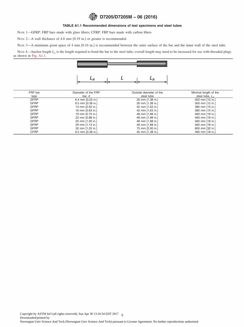
TABLE A1.1 Recommended dimensions of test specimens and steel tubes
NOTE 1—GFRP: FRP bars made with glass fibers; CFRP: FRP bars made with carbon fibers
NOTE 2—A wall thickness of 4.8 mm [0.19 in.] or greater is recommended.
NOTE 3—A minimum grout space of 4 mm [0.16 in.] is recommended between the outer surface of the bar and the inner wall of the steel tube.
NOTE 4—Anchor length La is the length required to bond the bar to the steel tube; overall length may need to be increased for use with threaded plugsas shown in Fig. A1.1.
FRP bartype
Diameter of the FRPbar, d
Outside diameter of thesteel tube
Minimal length of thesteel tube, La
GFRP 6.4 mm [0.25 in.] 35 mm [1.38 in.] 300 mm [12 in.]GFRP 9.5 mm [0.38 in.] 35 mm [1.38 in.] 300 mm [12 in.]GFRP 13 mm [0.50 in.] 42 mm [1.63 in.] 380 mm [15 in.]GFRP 16 mm [0.63 in.] 42 mm [1.63 in.] 380 mm [15 in.]GFRP 19 mm [0.75 in.] 48 mm [1.88 in.] 460 mm [18 in.]GFRP 22 mm [0.88 in.] 48 mm [1.88 in.] 460 mm [18 in.]GFRP 25 mm [1.00 in.] 48 mm [1.88 in.] 460 mm [18 in.]GFRP 29 mm [1.13 in.] 48 mm [1.88 in.] 460 mm [18 in.]GFRP 32 mm [1.25 in.] 75 mm [2.95 in.] 800 mm [32 in.]CFRP 9.5 mm [0.38 in.] 35 mm [1.38 in.] 460 mm [18 in.]
D7205/D7205M − 06 (2016)
9
Copyright by ASTM Int'l (all rights reserved); Sun Apr 30 13:10:34 EDT 2017Downloaded/printed byNorwegian Univ Science And Tech (Norwegian Univ Science And Tech) pursuant to License Agreement. No further reproductions authorized.

FIG. A1.2 Example of anchor details for test on grid specimens
D7205/D7205M − 06 (2016)
10
Copyright by ASTM Int'l (all rights reserved); Sun Apr 30 13:10:34 EDT 2017Downloaded/printed byNorwegian Univ Science And Tech (Norwegian Univ Science And Tech) pursuant to License Agreement. No further reproductions authorized.

FIG. A1.3 Example of attachment of anchor to grips or threaded collets
D7205/D7205M − 06 (2016)
11
Copyright by ASTM Int'l (all rights reserved); Sun Apr 30 13:10:34 EDT 2017Downloaded/printed byNorwegian Univ Science And Tech (Norwegian Univ Science And Tech) pursuant to License Agreement. No further reproductions authorized.

A2. Recommended Procedures for Testing Bars at Other than Standard Laboratory Conditions
A2.1. Scope
A2.1.1 This annex provides recommendations for testingbars in conditions that are other than standard laboratoryconditions. These conditions may include immersion in wateror other aqueous solution and/or elevated temperature ormoisture conditions.
A2.2. Conditioning
A2.2.1 Condition the specimen in the desired environment.Store the specimen in the conditioned environment until testtime, if the testing environment is different than the condition-ing environment.
A2.3 Test Environment
A2.3.1 Test under the specified exposure condition (e.g.,temperature, relative humidity, fluid exposure).
A2.3.2 Testing at Elevated Mositure Levels—Cases such aselevated temperature testing of a moist specimen may bebeyond the capabilities of common testing machine environ-mental chambers. In such cases, testing at elevated temperaturewith no fluid exposure control may be necessary, and moistureloss during mechanical testing may occur. This loss can beminimized by reducing exposure time in the test chamber;although care should be taken to ensure that the specimentemperature is at equilibrium. This loss may be further mini-mized by increasing the relative humidity in an uncontrolled
chamber by hanging wet, coarse fabric inside the chamber, andkeeping it moist with a drip bottle placed outside the chamber.In addition, fixtures may be preheated, temperature may beramped up quickly, and hold time at temperature may beminimized prior to testing. Environmentally conditioned trav-eler specimens, consisting of a bare bar with a length equal toone or more representative lengths with the cut ends protectedfrom moisture transmission with a high grade moisture resis-tant resin, may be used to measure moisture loss duringexposure to the test environment. Weigh a traveler specimenprior to testing and place it in the test chamber at the same timeas the specimen. Remove the traveler specimen immediatelyafter fracture and reweigh it to determine moisture loss. Recordmodifications to the test environment.
A2.3.3 Monitor test temperature by placing an appropriatethermocouple within 25 mm [1.0 inch] of the gage section ofthe specimen. Maintain temperature of the specimen and thetraveler bar if one is being used for thermal strain compensa-tion or moisture loss evaluation, within 63° C [65°F] of therequired condition. Taping thermocouple(s) to the test speci-men (and the traveler) is an effective measurement method.
A2.3.4 Required Dimensions of Environmental ExposureChamber—Common testing machine environmental chambersare unlikely to be of sufficient size to hold the entire specimenat the specified test conditions. Non-uniform thermal andmoisture profiles can be minimized by reducing exposure time
FIG. A1.4 Jig to align specimens and anchors
D7205/D7205M − 06 (2016)
12
Copyright by ASTM Int'l (all rights reserved); Sun Apr 30 13:10:34 EDT 2017Downloaded/printed byNorwegian Univ Science And Tech (Norwegian Univ Science And Tech) pursuant to License Agreement. No further reproductions authorized.

in the test chamber. Report the dimensions of the environmen-tal exposure chamber. Record the location of specimen failures
and report the location of these failures relative to the positionof the environmental chamber on the specimen.
ASTM International takes no position respecting the validity of any patent rights asserted in connection with any item mentionedin this standard. Users of this standard are expressly advised that determination of the validity of any such patent rights, and the riskof infringement of such rights, are entirely their own responsibility.
This standard is subject to revision at any time by the responsible technical committee and must be reviewed every five years andif not revised, either reapproved or withdrawn. Your comments are invited either for revision of this standard or for additional standardsand should be addressed to ASTM International Headquarters. Your comments will receive careful consideration at a meeting of theresponsible technical committee, which you may attend. If you feel that your comments have not received a fair hearing you shouldmake your views known to the ASTM Committee on Standards, at the address shown below.
This standard is copyrighted by ASTM International, 100 Barr Harbor Drive, PO Box C700, West Conshohocken, PA 19428-2959,United States. Individual reprints (single or multiple copies) of this standard may be obtained by contacting ASTM at the aboveaddress or at 610-832-9585 (phone), 610-832-9555 (fax), or [email protected] (e-mail); or through the ASTM website(www.astm.org). Permission rights to photocopy the standard may also be secured from the Copyright Clearance Center, 222Rosewood Drive, Danvers, MA 01923, Tel: (978) 646-2600; http://www.copyright.com/
D7205/D7205M − 06 (2016)
13
Copyright by ASTM Int'l (all rights reserved); Sun Apr 30 13:10:34 EDT 2017Downloaded/printed byNorwegian Univ Science And Tech (Norwegian Univ Science And Tech) pursuant to License Agreement. No further reproductions authorized.