Prediction Method of Tensile Properties and Fracture ...
7
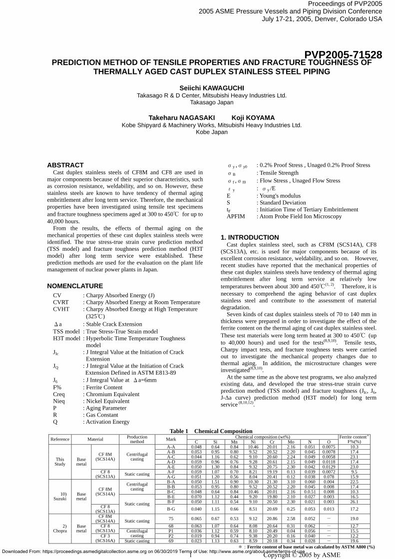
PREDICTION METHOD OF TENSILE PROPERTIES AND FRACTURE TOUGHNESS OF THERMALLY AGED CAST DUPLEX STAINLESS STEEL PIPING Seiichi KAWAGUCHI Takasago R & D Center, Mitsubishi Heavy Industries Ltd. Takasago Japan Takeharu NAGASAKI Koji KOYAMA Kobe Shipyard & Machinery Works, Mitsubishi Heavy Industries Ltd. Kobe Japan ABSTRACT Cast duplex stainless steels of CF8M and CF8 are used in major components because of their superior characteristics, such as corrosion resistance, weldability, and so on. However, these stainless steels are known to have tendency of thermal aging embrittlement after long term service. Therefore, the mechanical properties have been investigated using tensile test specimens and fracture toughness specimens aged at 300 to 450℃ for up to 40,000 hours. From the results, the effects of thermal aging on the mechanical properties of these cast duplex stainless steels were identified. The true stress-true strain curve prediction method (TSS model) and fracture toughness prediction method (H3T model) after long term service were established. These prediction methods are used for the evaluation on the plant life management of nuclear power plants in Japan. NOMENCLATURE CV : Charpy Absorbed Energy (J) CVRT : Charpy Absorbed Energy at Room Temperature CVHT : Charpy Absorbed Energy at High Temperature (325℃) Δa : Stable Crack Extension TSS model : True Stress-True Strain model H3T model : Hyperbolic Time Temperature Toughness model J Ic : J Integral Value at the Initiation of Crack Extension J Q : J Integral Value at the Initiation of Crack Extension Defined in ASTM E813-89 J 6 : J Integral Value at Δa=6mm F% : Ferrite Content Creq : Chromium Equivalent Nieq : Nickel Equivalent P : Aging Parameter R : Gas Constant Q : Activation Energy σ y ,σ y0 : 0.2% Proof Stress , Unaged 0.2% Proof Stress σ B : Tensile Strength σ f ,σ f0 : Flow Stress , Unaged Flow Stress ε y : σ y /E E : Young's modulus S : Standard Deviation t F : Initiation Time of Tertiary Embrittlement APFIM : Atom Probe Field Ion Microscopy 1. INTRODUCTION Cast duplex stainless steel, such as CF8M (SCS14A), CF8 (SCS13A), etc. is used for major components because of its excellent corrosion resistance, weldability, and so on. However, recent studies have reported that the mechanical properties of these cast duplex stainless steels have tendency of thermal aging embrittlement after long term service at relatively low temperatures between about 300 and 450℃ (1, 2) . Therefore, it is necessary to comprehend the aging behavior of cast duplex stainless steel and contribute to the assessment of material degradation. Seven kinds of cast duplex stainless steels of 70 to 140 mm in thickness were prepared in order to investigate the effect of the ferrite content on the thermal aging of cast duplex stainless steel. These test materials were long term heated at 300 to 450℃ (up to 40,000 hours) and used for the tests (8,9,10) . Tensile tests, Charpy impact tests, and fracture toughness tests were carried out to investigate the mechanical property changes due to thermal aging. In addition, the microstructure changes were investigated (8,9,10) . At the same time as the above test programs, we also analyzed existing data, and developed the true stress-true strain curve prediction method (TSS model) and fracture toughness (J Ic , J 6 , J-∆a curve) prediction method (H3T model) for long term service (8,10,12) . Table 1 Chemical Composition Chemical composition (wt%) Reference Material Production method Mark C Si Mn Ni Cr Mo N O Ferrite content * F%(%) A-A 0.048 0.64 0.84 10.46 20.01 2.16 0.051 0.0075 10.3 A-B 0.053 0.95 0.80 9.52 20.52 2.20 0.045 0.0078 17.4 A-C 0.044 1.16 0.62 9.10 20.60 2.24 0.049 0.0058 23.1 A-D 0.059 0.96 0.76 9.28 20.61 2.15 0.049 0.0118 17.4 CF 8M (SCS14A) Centrifugal casting A-E 0.050 1.30 0.84 9.32 20.75 2.30 0.042 0.0129 23.0 A-F 0.059 1.07 0.70 8.21 19.19 0.13 0.039 0.0072 9.5 This Study Base metal CF 8 (SCS13A) Static casting A-G 0.051 1.20 0.56 8.04 20.41 0.12 0.038 0.078 15.9 B-A 0.050 1.51 0.90 10.30 21.30 3.10 0.060 0.004 22.5 B-B 0.053 0.95 0.80 9.52 20.52 2.20 0.045 0.008 17.4 Centrifugal casting B-C 0.048 0.64 0.84 10.46 20.01 2.16 0.0.51 0.008 10.3 B-E 0.070 1.12 0.44 9.20 19.80 2.10 0.027 0.003 16.5 CF 8M (SCS14A) B-F 0.050 1.11 0.54 9.10 20.50 2.30 0.021 0.003 26.1 10) Suzuki Base metal CF 8 (SCS13A) Static casting B-G 0.040 1.15 0.66 8.51 20.69 0.25 0.053 0.013 17.2 CF 8M (SCS14A) 75 0.065 0.67 0.53 9.12 20.86 2.58 0.052 - 19.0 Static casting 68 0.063 1.07 0.64 8.08 20.64 0.31 0.062 - 12.7 CF 8 (SCS13A) P1 0.036 1.12 0.59 8.10 20.49 0.04 0.056 - 15.5 Centrifugal casting P2 0.019 0.94 0.74 9.38 20.20 0.16 0.040 - 12.2 2) Chopra Base metal CF 3 (SCS16A) Static casting 69 0.023 1.13 0.63 8.59 20.18 0.34 0.028 - 19.6 *:Ferrite content of base metal was calculated by ASTM A800 (%) Proceedings of PVP2005 2005 ASME Pressure Vessels and Piping Division Conference July 17-21, 2005, Denver, Colorado USA PVP2005-71528 1 Copyright © 2005 by ASME Downloaded From: https://proceedings.asmedigitalcollection.asme.org on 06/30/2019 Terms of Use: http://www.asme.org/about-asme/terms-of-use
-
Upload
khangminh22 -
Category
Documents
-
view
0 -
download
0
Transcript of Prediction Method of Tensile Properties and Fracture ...
Downloaded From: ht
Proceedings of ASME PVP-2005ASME Pressure Vessels & Piping Division Conference
July 17-21, 2005 Denver ColoradoPVP 2005-71528
PREDICTION METHOD OF TENSILE PROPERTIES AND FRACTURE TOUGHNESS OF
THERMALLY AGED CAST DUPLEX STAINLESS STEEL PIPING
Seiichi KAWAGUCHI Takasago R & D Center, Mitsubishi Heavy Industries Ltd.
Takasago Japan
Takeharu NAGASAKI Koji KOYAMA Kobe Shipyard & Machinery Works, Mitsubishi Heavy Industries Ltd.
Kobe Japan
Proceedings of PVP20052005 ASME Pressure Vessels and Piping Division Conference
July 17-21, 2005, Denver, Colorado USA
PVP2005-71528
ABSTRACT Cast duplex stainless steels of CF8M and CF8 are used in
major components because of their superior characteristics, such as corrosion resistance, weldability, and so on. However, these stainless steels are known to have tendency of thermal aging embrittlement after long term service. Therefore, the mechanical properties have been investigated using tensile test specimens and fracture toughness specimens aged at 300 to 450℃ for up to 40,000 hours.
From the results, the effects of thermal aging on the mechanical properties of these cast duplex stainless steels were identified. The true stress-true strain curve prediction method (TSS model) and fracture toughness prediction method (H3T model) after long term service were established. These prediction methods are used for the evaluation on the plant life management of nuclear power plants in Japan.
NOMENCLATURE CV : Charpy Absorbed Energy (J) CVRT : Charpy Absorbed Energy at Room Temperature CVHT : Charpy Absorbed Energy at High Temperature (325℃) Δa : Stable Crack Extension TSS model : True Stress-True Strain model H3T model : Hyperbolic Time Temperature Toughness model JIc : J Integral Value at the Initiation of Crack Extension JQ : J Integral Value at the Initiation of Crack Extension Defined in ASTM E813-89 J6 : J Integral Value at Δa=6mm F% : Ferrite Content Creq : Chromium Equivalent Nieq : Nickel Equivalent P : Aging Parameter R : Gas Constant Q : Activation Energy
1tps://proceedings.asmedigitalcollection.asme.org on 06/30/2019 Terms of Use: ht
σy ,σy0 : 0.2% Proof Stress , Unaged 0.2% Proof Stress σB : Tensile Strength σf ,σf0 : Flow Stress , Unaged Flow Stress εy : σy /E E : Young's modulus S : Standard Deviation tF : Initiation Time of Tertiary Embrittlement APFIM : Atom Probe Field Ion Microscopy
1. INTRODUCTION
Cast duplex stainless steel, such as CF8M (SCS14A), CF8 (SCS13A), etc. is used for major components because of its excellent corrosion resistance, weldability, and so on. However, recent studies have reported that the mechanical properties of these cast duplex stainless steels have tendency of thermal aging embrittlement after long term service at relatively low temperatures between about 300 and 450℃(1, 2). Therefore, it is necessary to comprehend the aging behavior of cast duplex stainless steel and contribute to the assessment of material degradation.
Seven kinds of cast duplex stainless steels of 70 to 140 mm in thickness were prepared in order to investigate the effect of the ferrite content on the thermal aging of cast duplex stainless steel. These test materials were long term heated at 300 to 450℃ (up to 40,000 hours) and used for the tests(8,9,10). Tensile tests, Charpy impact tests, and fracture toughness tests were carried out to investigate the mechanical property changes due to thermal aging. In addition, the microstructure changes were investigated(8,9,10).
At the same time as the above test programs, we also analyzed existing data, and developed the true stress-true strain curve prediction method (TSS model) and fracture toughness (JIc, J6, J-∆a curve) prediction method (H3T model) for long term service (8,10,12).
Table 1 Chemical Composition Chemical composition (wt%) Reference Material Production
method Mark C Si Mn Ni Cr Mo N O Ferrite content*
F%(%) A-A 0.048 0.64 0.84 10.46 20.01 2.16 0.051 0.0075 10.3 A-B 0.053 0.95 0.80 9.52 20.52 2.20 0.045 0.0078 17.4 A-C 0.044 1.16 0.62 9.10 20.60 2.24 0.049 0.0058 23.1 A-D 0.059 0.96 0.76 9.28 20.61 2.15 0.049 0.0118 17.4
CF 8M (SCS14A)
Centrifugal casting
A-E 0.050 1.30 0.84 9.32 20.75 2.30 0.042 0.0129 23.0 A-F 0.059 1.07 0.70 8.21 19.19 0.13 0.039 0.0072 9.5
This Study
Base metal
CF 8 (SCS13A) Static casting A-G 0.051 1.20 0.56 8.04 20.41 0.12 0.038 0.078 15.9
B-A 0.050 1.51 0.90 10.30 21.30 3.10 0.060 0.004 22.5 B-B 0.053 0.95 0.80 9.52 20.52 2.20 0.045 0.008 17.4 Centrifugal
casting B-C 0.048 0.64 0.84 10.46 20.01 2.16 0.0.51 0.008 10.3 B-E 0.070 1.12 0.44 9.20 19.80 2.10 0.027 0.003 16.5
CF 8M (SCS14A)
B-F 0.050 1.11 0.54 9.10 20.50 2.30 0.021 0.003 26.1
10) Suzuki
Base metal
CF 8 (SCS13A)
Static casting B-G 0.040 1.15 0.66 8.51 20.69 0.25 0.053 0.013 17.2
CF 8M (SCS14A) 75 0.065 0.67 0.53 9.12 20.86 2.58 0.052 - 19.0 Static casting
68 0.063 1.07 0.64 8.08 20.64 0.31 0.062 - 12.7 CF 8 (SCS13A) P1 0.036 1.12 0.59 8.10 20.49 0.04 0.056 - 15.5 Centrifugal
casting P2 0.019 0.94 0.74 9.38 20.20 0.16 0.040 - 12.2
2) Chopra
Base metal
CF 3 (SCS16A) Static casting 69 0.023 1.13 0.63 8.59 20.18 0.34 0.028 - 19.6
*:Ferrite content of base metal was calculated by ASTM A800 (%)
Copyright © 2005 by ASMEtp://www.asme.org/about-asme/terms-of-use

Downloaded F
2. TEST METHODS The chemical compositions of the base metals are shown in
Table 1(2,8,10). The base metals are mainly centrifugal cast pipes (thickness is approximately 70 mm) of CPF8M (hereinafter referred to as CF8M) (SCS14A) having ferrite contents of approximately 10 to 26% (calculated by ASTM A800), and the rest were CPF8 (hereinafter referred to as CF8) (SCS13A) or the equivalent not containing Mo. The plate thickness of the static casting is approximately 140 mm. The table 1 shows materials used in the other studies(2,10). For the calculation of the ferrite contents (F%) in the base metals, the following equation obtained from the drawing of ASTM A800 by multiple regression analysis was used.
( ) 2X641.134X80472.56834366.4%%F +−−= 43 X02316.30X90123.99 +− ·························· (1)
( ) 2.770.02N26Mn0.5C30Ni
4.99NbMo1.4Si1.5Cr
Creq/Nieq
+−×+×+×+=
−+×+×+=
=
Nieq
reqC
X
Where C, Si, Mn, Cr, Mo, Ni, Mo, Nb are in wt.% The test materials were heated at the aging temperatures of
300, 350, 400, and 450℃ for up to 40,000 hours, and the following tests were carried out. For the tensile tests, round bar tensile test specimens of 10 mm in diameter were used. The tests were carried out at room temperature and 325℃ in accordance with ASTM A370 and ASTM E8. For the impact tests, Charpy impact test specimens of 10mm thickness with 2mm V-notch were used. These tests were also carried out at room temperature and 325℃ in accordance with ASTM A370 and ASTM E23. For the fracture toughness tests, lTCT test specimens as described in ASTM E813-85 were used. The tests were carried out in accordance with ASTM E813-89.
In this study, JQ is expressed as JIc even if it is invalid. The fracture toughness values with a stable crack extention ∆a of 6 mm were obtained from the J-∆a curve, and expressed as J6. 3. AGING PARAMETER
The degree of embrittlement can be obtained using the Arrhenius extrapolation of test data at higher temperature. The aging time to reach a given degree of embrittlement at different temperatures can be determined from the following equation(6).
( ) ⎟⎠⎞
⎜⎝⎛
−+=T
1
2.673
1
R4343.0t
10LogP
Q························ (2)
where Q is the activation energy (100 kJ/mol), T is the aging temperature (K), t is the aging time (hours), R is the gas constant (0.008368 kJ/mol.K), and P is the aging parameter. 4. EXPERIMENTAL RESULTS 4.1 Tensile Properties
Fig. 1 shows examples of the changes of the 0.2% proof stress and tensile strength for the base metal aged at 300, 350, 400℃.
It is recognized that the tensile strength tends to increase with aging time, but the 0.2% proof stress does not seem to change. This tensile strength increasing tendency grows with increasing aging temperature. The reason why the proof stress is not affected by thermal aging is considered to be that tensile strain occurs mainly in the austenite phase up to the 0.2% proof stress. Namely, it is considered that hardening due to thermal aging occurs mainly in the ferrite phase, and the austenite phase is not changed by aging.
Using these data, as described below, the true stress-strain curve prediction model after long term aging was studied.
2rom: https://proceedings.asmedigitalcollection.asme.org on 06/30/2019 Terms of Use: http
Fig. 1 Effect of Aging on Tensile Properties
(No. A-A, CF8M, F%=10.3%) 4.2 Charpy Impact Test Properties
Fig. 2(8) shows the change in the Charpy absorbed energy (at 325℃) due to aging for the base metals aged at 300, 350, and 400℃ . The Charpy absorbed energy reduces more with increasing aging temperature. In addition, the higher the ferrite content is, the lower the toughness after aging becomes.
Fig. 2 Effect of Aging Time on Charpy Absorbed Energy
(No. A-A, CF8M, F%=10.3%)
The change in the toughness of all materials tends to saturate after heating at 400℃ for 20,000 to 40,000 hours. In this figure, the fitting curve by the toughness prediction model (H3T) mentioned below is also shown. 4.3 Fracture Toughness Properties
Fig. 3(8) shows the J-∆a curves of the base metal (A-A material) with aging at 400℃. The slope of the J-∆a curve
Fig. 3 J-∆a curve
(Aging Temp. : 400℃, No. A-A, F%=10.3%)
Aging Temp.
Fitting curve by H3T model
Copyright © 2005 by ASME://www.asme.org/about-asme/terms-of-use

Download
tends to reduce as aging progresses. The JIc change due to thermal aging shows a tendency similar to that of the Charpy absorbed energy, and tends to decrease more with increasing aging temperature.
The aging parameters arranged with respect to J6 (J integral valure at ∆a=6 mm) are shown in Fig. 4. Aging data for temperatures in the range of 300 to 450℃ are well correlated with the aging parameters P. 4.4 Transmission Electron Microscopy
Transmission electron microscopy (TEM) analysis was carried out.
Two basic features of the ferrite phase sub-structure were identified by the TEM analysis of thin foils in aged material. The first, is the so-called mottled image (α’ phase), typically with contrast variations and the second, the presence of a G-phase, homogeneously distributed in ferrite for the material aged at 450℃ for 3,000 and 10,000 hours(9).
The profiles of concentration of Fe and Cr in the ferrite phase have been investigated for CF8M by APFIM before and after aging. It was recognized that the amplification of Cr concentration of ferrite phase after the thermal aging was larger than that for unaged material and their ferrite phases are separated.
Fig. 4 J6 and Aging Parameter P (No. A-A, F%=10.3%)
Fig. 5(9) shows the illustration for the mechanism of thermal
aging embrittlement in duplex stainless steels. Before thermal aging, the Cr concentration of the ferrite phase is approximately 25%. However, the ferrite phase is separated into theα’ phase (Cr rich phase) with a Cr concentration of 70 to 80% and the α phase (Fe rich phase) with a small Cr concentration and a high Fe concentration by the thermal aging. Therefore, it is clear that thermal aging embrittlement is mainly caused by the phase separation (spinodal decomposition). 5. DEVELOPMENT OF PREDICTION MODELS 5.1 Prediction Method of True Stress-True Strain Curve
(TSS Model) Based on aging tests for predicting the stress- strain curve
after thermal aging, we have developed a prediction method
3
ed From: https://proceedings.asmedigitalcollection.asme.org on 06/30/2019 Terms of Use: htt
Fig. 5 Mechanism of Thermal Aging Embrittlement for Cast Duplex Stainless Steels
(TSS model: True Stress-True Strain model). For the development of this model, the results of the tension tests of the base metals aged at aging temperatures of 300, 350, and 400℃ for up to 40,000 hours in this study(8) were used.
The stress-strain data at 325℃ obtained by the aging tests were applied to the Ramberg-Osgood stress-strain equation shown below, and n and α were obtained.
n
yyy⎟⎟⎠
⎞⎜⎜⎝
⎛+=
σ
σα
σ
σ
ε
ε·······················································(3)
where σ is true stress (MPa) ; ε is true strain ; σy is 0.2% proof stress ; andεy is σy/E ; α is α, constant ; n is an exponent; E is Young’s modulus (174000MPa at 325℃.)
The relationship between each of the 0.2% proof stress (σy0) and flow stress (σf0) of unaged material and chemical composition (ferrite content, C, etc.) was obtained using multiple regression analysis. Analysis for σf0 is shown in Fig. 6.
Fig. 6 Comparison of Experimental Values and Prediction
Values for Unaged Flow Stress σf0
Copyright © 2005 by ASME
p://www.asme.org/about-asme/terms-of-use

Downloaded Fro
Next, in order to know a change in σy and σf after thermal aging, the ratios of σy/σyo and σf/σfo after thermal aging are obtained in relation to the aging parameters as shown for σf in Fig. 7. Based on the relationship of σf after thermal aging thus obtained, n and α after thermal aging can be obtained as shown in Fig. 8 (F%<23%). The prediction equations thus set are shown in Table 2. Using the prediction equations of n, α, σy, and σf, the true stress-true strain curve after thermal aging can be predicted from the chemical composition. The predicting procedure in the true stress-true strain curve prediction method after thermal aging is shown in Fig. 9.
Table 2 True Stress-Strain Prediction Equations (TSS model,Temp:325℃)
Prediction equation (unged) S eq.Unaged σyo
(MPa) 0.2% proof stress : σyo=6.653+5.385×F%+10.007×Mo+1535.385×C 9.450 (a)
Unaged σfo
(MPa)
Flow stress : σfo=105.472+6.96×F%+16.062×Mo+1535.398×CF% : Ferrite Content (%) calculated by ASTM A800 Mo, C : CMTR (wt%)
7.226 (b)
F% Prediction equation (afer aging) S note eq.
F%<23% Y=(1+1.071)/2-(1-1.071)/2× tanh((X-1.617)/0.916) 0.069 (c)
σy/σyo-P(t,T)
F%≧23% Y=(1+1.144)/2-(1-1.144/2× tanh((X-3.020) /1.462) 0.053
Y= σ /σy yoX=P(t,T) (d)
F%<23% Y =(1+1.161)/2-(1-1.161)/2× tanh((X -2.996)/0.929) 0.051 (e)
σf/σfo-P(t,T)
F%≧23% Y =(1+1.247)/2-(1-1.247/2× tanh((X-3.148)/0.919) 0.039
Y= σ /σf foX=P(t,T) (f)
F%<23% Y = X×(-0.005)+(6.763) 0.552 (g)n- σf (MPa) F%≧23% Y = X×(-0.011)+(9.734) 0.484
Y=n X=σf (h)
F%<23% Y = X×(-0.011)+(6.054) 0.577 (i)α- σf (MPa) F%≧23% Y = X×(-0.013)+(7.305) 0.347
Y=α X=σf (j)
note : P(t,T)=log(t)+0.4343・(Q/R)(1/673.2-1/T), T : K, t : hours, Q : 100kJ/mol, R : 0.008368kJ/mol・k
Fig. 7 Ratio of Flow Stress (σf /σf0) Versus P(t,T), F%<23%
4
m: https://proceedings.asmedigitalcollection.asme.org on 06/30/2019 Terms of Use: h
Fig. 8 n,α and flow stress σf
Experiment Data
・300,350,400℃×0~Max.40,000H・σy, σf, σ-εCurve
Selection n,α by fitting for Ramberg-Osgood eq.
True
stre
ssσ
True strain ε
n
yyy⎟⎟⎠
⎞⎜⎜⎝
⎛+=
σσα
σσ
εε
σyo, σfo and chemical comp.
f (F%,・・・)
σyoσfo
σy/ σy0, σf /σf0 and P(t, T)
Aging Parameter P(t, T)
σy /σyo,σf /σfo
σf
n, α
n, α and σf
Predicon equation of n, α, σy, σf in aged condition ; Table2
Data Input ; CMTR Chemi Comp. (C, Si, Mn, Ni, Cr, Mo, N)Aging Condition (T : K, t : hours)
F% by ASTM A800, P(t, T) Calculation
Unaged ; σyo (Ave.) eq. (a) , σfo (Ave.) eq. (b)
F%≧23%Yes
No
Aged σy (Ave, +2S, -2S)・・・eq. (c)Aged σf (Ave, +2S, -2S)・・・eq. (e)
n ・・・・・・・ eq. (g)α ・・・・・・・ eq. (i)
Aged σy (Ave, +2S, -2S)・・・eq. (d)Aged σf (Ave, +2S, -2S)・・・eq. (f)
n ・・・・・・・ eq. (h)α ・・・・・・・ eq. (j)
F%<23% F%≧23%
Predicted Ave. value : Ave. (σy, σf ) , Ave. (n, α)Predicted Upper value (+2S) : +2S (σy, σf ) , -2S (n, α)Predicted Lower value (-2S) : -2S (σy, σf ) , +2S (n, α)
Est
ablis
hmen
t of p
redi
ctio
n m
odel
Estim
atio
n of
pre
dict
ed tr
ue s
tress
-stra
in C
urue
Experiment Data・300,350,400℃×0~Max.40,000H・σy, σf, σ-εCurve
Selection n,α by fitting for Ramberg-Osgood eq.
True
stre
ssσ
True strain ε
n
yyy⎟⎟⎠
⎞⎜⎜⎝
⎛+=
σσα
σσ
εε
σyo, σfo and chemical comp.
f (F%,・・・)
σyoσfo
σy/ σy0, σf /σf0 and P(t, T)
Aging Parameter P(t, T)
σy /σyo,σf /σfo
σf
n, α
n, α and σf
Predicon equation of n, α, σy, σf in aged condition ; Table2
Data Input ; CMTR Chemi Comp. (C, Si, Mn, Ni, Cr, Mo, N)Aging Condition (T : K, t : hours)
F% by ASTM A800, P(t, T) Calculation
Unaged ; σyo (Ave.) eq. (a) , σfo (Ave.) eq. (b)
F%≧23%Yes
No
Aged σy (Ave, +2S, -2S)・・・eq. (c)Aged σf (Ave, +2S, -2S)・・・eq. (e)
n ・・・・・・・ eq. (g)α ・・・・・・・ eq. (i)
Aged σy (Ave, +2S, -2S)・・・eq. (d)Aged σf (Ave, +2S, -2S)・・・eq. (f)
n ・・・・・・・ eq. (h)α ・・・・・・・ eq. (j)
F%<23% F%≧23%
Predicted Ave. value : Ave. (σy, σf ) , Ave. (n, α)Predicted Upper value (+2S) : +2S (σy, σf ) , -2S (n, α)Predicted Lower value (-2S) : -2S (σy, σf ) , +2S (n, α)
Est
ablis
hmen
t of p
redi
ctio
n m
odel
Estim
atio
n of
pre
dict
ed tr
ue s
tress
-stra
in C
urue
Fig. 9 Estimation Process of Predicted True Stain-Stress
Curve (TSS model)
Copyright © 2005 by ASMEttp://www.asme.org/about-asme/terms-of-use

Downloaded
The experimental data and predicted true stress-true strain curve after thermal aging are shown in Fig. 10. The experimental data and predicted true stress the true strain curves are rather comparable with each other.
Fig. 10 Experimental Data and Predicted True Stress-True
Strain Curve by TSS Model 5.2 Prediction Method of Fracture Toughness
(H3T Model) The toughness degradation prediction model has been
developed on the basis of the H3T (Hyperbolic-Time- Temperature-Toughness) model. The H3T model expresses the relationship of the Charpy absorbed energy, JIc, and J6 to the aging time with the following hyperbolic function as shown in Fig. 11(8,10). Using the results(8) of this study and document data(2,10), the H3T model has been developed.
Ct
BAJJC IcV
++=6,, ·················································· (4)
where, t : Aging time, hours A : Fully aged toughness, kJ/m2
B : Constant relating to aging temperature C : Constant relating to aging time Now it is assumed that B = exp (D/T + Co) and D = Q/R,
where T is the aging temperature, Co is a constant, and R is the gas constant. When T is Ti, B is Bi, When T = Tj, B is Bj.
〕〔 )/1/1(exp/ jiji TTDBB −= ········································ (5) 〕〔 )/1/1)(/(exp/ jiji TTRQBB −= ································ (6)
The activation energy Q (kJ/mole) obtained from the temperature dependence of B is defined to be the embrittlement activation energy.
On the other hand, the initiation activation energy F is defined from the temperature dependence of the initiation time of tertiary embrittlement tF, as shown in Fig. 11 namely
〕〔 )/1/1)(/(exp/ jiFF TTRFttji
−= ································· (7) From equation (4), the relational expression B at temperatures Ti and Tj is as shown below.
jCF
t
jB
iCF
tiB
ji+
=+
···················································· (8)
From equation (8), tFj + Cj at Tj is determined using tFi + Ci at Ti as shown below.
( )iCF
tB
BjC
Ft
ii
j
j+=+ ·············································· (9)
Next, from equation (4), the equations of embrittlement prediction model at temperatures Ti and Tk is as shown below.
iCtiB
AiM+
+= ··························································· (10)
5
From: https://proceedings.asmedigitalcollection.asme.org on 06/30/2019 Terms of Use: ht
Fitting curve of H3T model
M = A +
M : CV, JIc, J6 A, B, C : Constant
Regression Analysis of relationbetween constant A, B, C andchemical composition
Chemical Composition
Ferrite content using ASTM A800
Establishment ofprediction equation(Table 3)
Calculation of constant A, B, C
Calculation of C1, C2, for J -△ a curve using JIc and J6 value
Toughness data・300, 350, 400℃ × 0 ~ 40,000h・CV, JIc, J6
Bt + C
Esta
blis
hmen
t of p
redi
ctio
n m
odel
Pred
ictio
n of
toug
hnes
s CV or JIc or J6 = A +B
t + c
△ a at JIc
=0.2+JIc
2σt
Fitting curve of H3T model
M = A +
M : CV, JIc, J6 A, B, C : Constant
Regression Analysis of relationbetween constant A, B, C andchemical composition
Chemical Composition
Ferrite content using ASTM A800
Establishment ofprediction equation(Table 3)
Calculation of constant A, B, C
Calculation of C1, C2, for J -△ a curve using JIc and J6 value
Toughness data・300, 350, 400℃ × 0 ~ 40,000h・CV, JIc, J6
Bt + CB
t + C
Esta
blis
hmen
t of p
redi
ctio
n m
odel
Pred
ictio
n of
toug
hnes
s CV or JIc or J6 = A +B
t + cB
t + c
△ a at JIc
=0.2+JIc
2σt
△ a at JIc
=0.2+JIc
2σt
JIc
2σt
Fig. 11 Flow Chart of The Toughness Prediction Model
(H3T Model)
kCtkB
AkM+
+= ························································· (11)
From these equations, the toughness Mk at any temperature Tk, can be calculated using a constant at Ti and Q and F as follows.
( )
( ) ( ) ( )⎥⎦⎤
⎢⎣⎡
⎥⎦⎤
⎢⎣⎡
⎥⎦⎤
⎢⎣⎡
−−−++
−
+=
iTkTR
FF
tiTkTR
QiC
Ftt
iTkTR
Qi
B
AkM
ii/1/1exp/1/1exp
/1/1exp
······················· (12) Fig. 11 shows the flow chart of the toughness prediction
model. First, the data for the aging temperature of 400℃ is fitted with the H3T model to obtain the constant A (the fully aged lowest toughness). With this constant A determined, the data for aging at 300 and 350℃ are fitted with the H3T model to obtain the constant B and C at the aging temperatures of 300 and 350℃ . By obtaining the relationship of the above constants A, B, and C to the chemical composition, the prediction expression can be obtained. Fig. 12 shows the relation of the constant A (after full aging) of JIc to the ferrite content.
Table 3(10) shows the H3T model for absorbed energy at room temperature and 325℃ , fracture toughness at 325℃ , the constant A of JIc and J6 (the fully aged lowest toughness) obtained in the same manner when the operating temperature is 325℃. Fig. 13 shows the applicable flow chart for the H3T model.
Copyright © 2005 by ASME
tp://www.asme.org/about-asme/terms-of-use

Downloaded F
Fig. 12 Fully Aged Toughness Constant A of 325℃ JIc versus F%
CMTR : Chemical composition
Ferrite content calculation (ASTM A800 diagram)
Selection of operation temp
Calculation of ; A, B 325, tF325, tF+ C 325 at 325℃ ・・・Table 3
CV or JIc or J6 = A + B325t + (tF + C)325 – tF325
Case Ⅱ
[ Operating Temp. Tk is not 325℃]
Q = 100kJ / mol F = 100kJ / mol
Calculation of toughness at Temp. Tk ・・・ eq. (12)
J6CV
Case Ⅰ
[ Operating Temp. Tk 325℃]≒
JIc
CMTR : Chemical composition
Ferrite content calculation (ASTM A800 diagram)
Selection of operation temp
Calculation of ; A, B 325, tF325, tF+ C 325 at 325℃ ・・・Table 3
CV or JIc or J6 = A + B325t + (tF + C)325 – tF325
B325t + (tF + C)325 – tF325
Case Ⅱ
[ Operating Temp. Tk is not 325℃]
Q = 100kJ / mol F = 100kJ / mol
Calculation of toughness at Temp. Tk ・・・ eq. (12)
J6CV
Case Ⅰ
[ Operating Temp. Tk 325℃]≒
JIc
Fig. 13 Estimation Process of Toughness Prediction Model
(H3T Model)
When the operating temperature is different from 325℃, the prediction model can be evaluated conservatively using the activation energy Q = 100 kJ/mole.
In evaluating the integrity of duplex stainless steels after thermal aging, fracture mechanics method may be used and, therefore, it is important to predict the J-∆a curve. When the JIC and J6 values at an optional aging condition are obtained, the J-∆a curve can be obtained by the following equation with the H3T model by giving the flow stress as shown in Fig. 11, and the integrity can be evaluated.
( ) 21
CaCJ ∆×= ······························································ (13) Fig. 14 shows predicted fracture toughness (J-∆a curves:
average and -2S lower bound curve) for No. A-A material after fully aging.
The lower bound (dotted line) by the H3T model was found to have a conservative prediction accuracy.
6
rom: https://proceedings.asmedigitalcollection.asme.org on 06/30/2019 Terms of Use
Table 3 Constants of Fully Aged Toughness Prediction Model when the Operating Temperature is 325℃ (H3T Model)
Predicted equation S
A Log10 (A of CV-RT)= 2.2818 -0.0472×F% 0.1411
B325Log10 B325= 6.0909
-0.2861×Mo 0.2621
tF325
Log10 tF325= 10.7270 -0.4720×Cr+0.2846×Ni-13.9003×N
0.1124
CV-RT (Charpy absorbed
energy(J) at RT
(tF+C)325Log10 (tF+C)325= 3.9369
-0.3784×Mo 0.1597
A Log10 (A of CV-HT)= 2.8357 -0.0592×F% 0.1638
B325
Log10 B325= 8.5909 +2.4273×Mn-0.4328×Ni
0.1606
tF325
Log10 tF325= 22.8968 -2.0122×Mn-0.8227×Cr-23.0802×C
0.0743
CV-HT (Charpy absorbed energy at 325℃)
(tF+ C)325Log10 (tF+C)325= 4.9882
-0.4121×Mo 0.1454
A Log10 (A of JIc-HT)= 3.2961 -0.0530×F% 0.2518
B325Log10 B325= 5.7869
+0.9256×Mn 0.1514
tF325Log10 tF325= 4.3047
-19.1095×N 0.2732
JIc-HT (JIc at 325℃,
kJ/m2)
(tF+ C)325Log10 (tF+C)325= 1.5354
+0.2062×Ni 0.1417
A Log10 (A of J6-HT)= 3.6699 -0.0490×F% 0.1490
B325Log10 B325= -1.7907
+0.4130×Cr 0.1783
tF325
Log10 tF325= 7.6362 -0.3670×Ni-16.108×N
0.0892
J6-HT (J6 at 325℃,
kJ/m2) J6:J value at Δa
6mm
(tF+ C)325
Log10 (tF+C)325= -2.9645 +0.3438×Cr-0.1648×Mo
0.0702
note) F% : Ferrite content(%) by ASTM A800 diagram. C, Si, Mn, Cr, Ni, Mo, N (wt%)
Fig. 14 Predicted J-Δa Curve for Fully Aged Toughness
(No. A-A, 400℃×40000H) 6. SUMMARY AND CONCLUSIONS
The mechanical tests were carried out for cast duplex stainless steels (CF8M, CF8) aged up to 40,000 hours. The results obtained can be summarized as follows. (1) The Charpy absorbed energy and fracture toughness are
lowered and tensile strength is increased with aging time. From the results of the electron microscopy and the APFIM analysis, the thermal aging embrittlement was verified to be caused by phase separation in the ferrite phase.
(2) Using the aging data up to 40,000 hours, the tensile properties (true stress-true strain curve) prediction method (TSS model) for long term aging was developed.
Copyright © 2005 by ASME
: http://www.asme.org/about-asme/terms-of-use

Downl
(3) In the same manner, the fracture toughness JIc, J6, J-∆a curve prediction method (H3T model) for long term aging was developed.
ACKNOWLEDGEMENTS
This work was supported by Japanese PWR Utilities. The authors are grateful to Japanese PWR Utilities.
REFERENCES 1. O.K. Chopra, et al., “Effects of Low-Temperature Aging
on the Mechanical Properties of Cast Stainless Steels”, Proceedings of the Winter Annual Meetings of ASME, Boston, MA., December 13-18, 1987.
2. O.K. Chopra, “Long-term embrittlement of cast duplex stainless steels in LWR Systems”, NUREG/CR-4744 Vol.6, No.1, ANL-91/22, R5, August, 1992.
3. O.K. Chopra, et al., “Evaluation of aging degradation of structural components”, in Proceedings of the Aging Research Information Conference, NUREG/CP-0122, Vol.2, 1992, pp396-386.
4. O.K. Chopra, et al., “Assessment of Thermal Embrittlement of Cast Stainless Steels”, NUREG/CR-6177 ANL-94/2, May, 1994.
5. O.K. Chopra, “Thermal Aging of Cast Stainless Steels in LWR Systems : Estimation of mechanical properties” ASME PVP 1992.
6. W.Gysel, et al., “Influence of long-time aging of CF8 and CF8M cast steel at temperatures between 300 and 500℃ on impact toughness and structual properties”, ASTM STP 756, 1982, pp165-198.
7. S.Kawaguchi, et al., “The phase decomposition by thermal aging in duplex stainless steels”, IIW DOC. IX-1747-94, September, 1994.
8. T.Tanaka, S.Kawaguchi, N.Sakamoto, K.Koyama “Thermal Aging of Cast Duplex Stainless Steels”, ASME/JSME PVP, 1995.
9. S.Kawaguchi, N.Sakamoto, G.Takano, F.Matsuda, L.Mraz “Microstructual Changes and Fracture Behavior of CF8M Duplex Stainless Steels after Long Term Aging”, Nuclear Engineering and Design 174, 1997, p273-285.
10. I.Suzuki, S.Kawaguchi, M.Koyama, H.Mimaki, M.Akiyama, T.Okubo, Y.Mishima, T.R.Mager “Long Term Thermal Aging of Cast Duplex Stainless Steels” The International Conference on Nuclear Engineering (ICONE-4), March, 1996.
11. A.Kirihigasi, S.Kawaguchi, S.Shimizu, Y.Fujioka, K.Sakai “NDT of Aged Duplex Stainless Steel using Mössbauer Spectroscopy” 14th International Conference on NDE in the Nuclear and Pressure Vessel Industries, Stockholm, Sep., 1996.
12. K.Hojo, I.Muroya, K.Koyama S.Kawaguchi, “Application of the Two-Criteria Approach to the Austenitic Cast Stainless Steel Pipe”, The 5th International Conference of Nuclear Engineering (ICONE-5), May, 1997.
7 Copyright © 2005 by ASME
oaded From: https://proceedings.asmedigitalcollection.asme.org on 06/30/2019 Terms of Use: http://www.asme.org/about-asme/terms-of-use