Evaluating Prediction Models of Creep and Drying Shrinkage ...
Upload
independentCategory
view
7download
0
JOURNAL of the AMERICAN CERAMIC SOCIETY
Volume 59, Number 3-4 March-April, 1976
High Temperature Tensile Creep of Magnesium Oxide Single Crystals
A. H. CLAUER* and B. A. WILCOX*J* Battelle Columbus Laboratories, Columbus, Ohio 43201
The creep behavior and the dislocation substructure developed during creep were investigated for <011> oriented MgO single crystals creep tested in tension. Creep deformation was studied over stress and temperature ranges of 29.0 to 86.2 MN/m2 and 1200 to 1500"C, and the minimum creep rate, 6, was found to obey the relation:
i .=Aa"exp- __ ("F) where g = applied tensile stress, k = the Boltzmann constant, T = absolute temperature, n = 3.8 to 4.5, and A = 11 x lo-' (MN/mT4 s-'. Dislocation substructures developed during creep were studied by transmission electron microscopy and etch pitting techniques. At 14OO0C, the dislocation density, p, at 0.10 tensile creep strain depended on applied stress as p uZ.l.
Numerous dislocation loops and long straight dislocations were present, but subboundaries were seldom observed. The results are discussed in terms of two possible operative creep mechanisms: (1) a recovery process based on annealing out of dislocation dipoles and loops, and (2) dislocation glide limited by atmospheres of charged defects surrounding dislocations.
I. Introduction
ONSIDERABLE research has been aimed at studying the high C temperature plastic properties of oxides, including several investigations on creep of MgO single crystals. 1-5 The present work deals with tension creep of MgO single crystals having a <011> axial orientation. Emphasis is placed on correlating mechanical behavior with dislocation substructures evolved during creep in an effort to more clearly understand creep mechanisms.
11. Experimental Procedures
m thick and having { 100) cleaved faces were obtained from a commercial vendor. t An analysis supplied by the manufacturer using the atomic absorption method gave the impurities (in ppm by the wt) as A1,03 300, Fez0,200, SiO, 100, Cr,O, 100, Na,O YO, MnO,30, NiO 30, CuO 20, and TiO, not detected.
Tensile creep specimens having a <011> axial orientation and the configuration shown in Fig. 1 were ultrasonically trepanned from the as-received slabs. Previous work by Day and Stokesss7 showed that this orientation deformed to large elongations during high temperature tensile straining. Also specimens could be de- formed under conditions where subgrain boundaries would or would not form. After machining, = 1.5 x m was removed from the specimen surfaces by chemical polishing in hot orthophos-
Single crystal MgO slabs (99.95% purity) =2.5 x
Top View
2.54 x10-* m 6.3 x We m
[oti]
Fig. 1. Tensile creep specimen configuration.
phoric acid at z 160°C. Prior to creep testing, all specimens were annealed Yz h at 2000°C in an Ar atmosphere in order to remove dislocations introduced during machining and to provide a standard precreep structure.
Creep tests were performed in a high temperature furnace in a dynamic vacuum of 3 X to 5 x torr. The temperature difference along a specimen was < 7°C and the temperature control cycle was < +0.5"C. In temperature change experiments the time to reach within 0.5"C of the desired temperature varied with the magnitude and direction of the temperature change. For a tempera- ture increase of 50°C the time was < 10 min.
The load was applied smoothly and quickly at a constant deflec- tion rate corresponding to an initial strain rate in the specimen of 7.3 X s-'. The stress was maintained constant to k I% with an Andrade-Chalmers contoured lever arm mounted within the vac- uum chamber. Strain over the 2 . 5 4 ~ lo-' m gage length was measured continuously by a recording linear variable differential transformer with sensitivity of 2.5 X rn. In the grips, wedge- shaped inserts machined from a W-4% Tho, alloy were in contact with the shoulders of the MgO crystals. No interaction occurred between the W alloy and the MgO during creep testing.
After creep, one half of a specimen was retained for etch pitting on (100) faces and the other half was sectioned with a diamond cutoff wheel into 5 x m thick slices for transmission electron microscopy (TEM). Prior to etch pitting, the specimens were chem- ically polished in hot orthophosphoric acid. They were then etch pitted by immersion in a solution of 6 parts NH,Cl, 1 part H,S04, and 1 part H,O for 30 s at room temperature. Specimens for TEM were prepared by chemically indenting both sides of the specimen with orthophosphoric acid at 140°C until the central web was 2 8 ~ lo-' m thick. Final thinning, until a small hole perforated the web area, was done by immersing in the same solution.
Received July 7, 1975; revised copy received October 31, 1975. Supported by the U.S. Army Research office. *Member, the American Ceramic Society. *Presently in the Division of Materials Research, National Science Foundation,
?Norton Research Corp. (Canada), Ltd., Chippewa, Ont., Canada. Washington, D.C.; on leave of absence from Battelle.
89

90 Journal of the American Ceramic Soc ie t yX lauer and Wilcox Vol. 59, No. %4
I O - ~
111. Results
I 1 I I I I ( B
( I ) Creep Behavior The creep curves showed the usual creep stages, primary, steady
state, and tertiary. A long steady state region was observed in only a few specimens. These were used for the temperature and stress change experiments and extended up to 0.30 to 0.40 creep strain before the experiment was discontinued. After loading, the creep rate decreased with increasing creep strain up to a strain range of 0.03 to 0.10, after which the creep rate slowly accelerated. The accelerating creep rate appeared to be due either to the beginning of a necked region within the gage length or to slowly opening cracks at the contact between the shoulder of the specimen and the grips. Where this behavior was observed, the minimum creep rate is reported. However this creep rate was probably close to the steady state rate as seen in Fig. 2(A), which includes creep rates of both types.
The temperature dependence of the creep rate is shown in Fig. 2 ( A ) , and calculated activation energy isQc=4. 1 eV. Table I shows that this value is within the range of values previously reported for creep of single crystal MgO. The data points in Fig. 2(A) were obtained from three crystals; one had a long steady state region and was temperature cycled (open circles). The stress dependence of the creep rate, 8, is plotted in Fig. 2(B) as a power law, 8 d’, where n = 3 . 8 to 4.5. Thus the results can be formulated as:
8=Acr”exp (..) -4.1
where A = 11 x ranges investigated.
(MN/m2)-4 s-’ over the stress and temperature
(2) Deformation Mode No sharp surface slip offsets were observed by optical micros-
copy, which may have been a result of thermal polishing of the surface during creep. However, the most active slip systems could be tentatively identified from the shape change of the specimen cross section and from Laue back-reflection patterns of the gage length. The dimensions parallel to the [loo] and [Oll] directions, i.e. normal to the specimen faces, were carefully measured along the gage length on 4 specimens before and after creep; 3 specimens were strained to 0.10 tensile creep strain at 1400°C and stresses of 37.2, 44.8, and 55.2 MN/m2. The 4th specimen was creep tested over a range of stress and temperature (stress and temperature cycled) to 0.40 total creep strain. Its dimensional changes are shown in Fig. 3(A). The specimens creep tested to 0.10 creep strain deformed relatively uniformly along the gage length and had no necks such as that shown in Fig. 3(A). It was found for the specimen in Fig. 3 that - 8 ~ 0 0 ~ ~ o l I , and &oil E O where 2.100 and 2.oii are the average normal strains measured parallel to [loo] and [ O i l ] , respec- tively, and is the tensile strain. Not only was $071 usually zero, but, as shown in Fig. 3(A), it was sometimes slightly greater than zero, i.e., the gage section increased in width.
The contributions of the different sets of previously reported slip systems in MgO to the observed dimensional changes were obtained by resolving the various shear strains into strains normal to the specimen faces, a_d & O i l , and thqtensile strain, Eoll.-The slip systems are { 1 lo} < 1 lo>, (001 } < 1 lo> , and { 1 11 1 < 1 10> and are designated sets 1, 2, and 3, respectively. These systems have
Temperature ,O C 10-5 1500 1400 1300 1200
I I i
I- t U =47.2 MN/mZ 0 Temperature chanye tests on one
c r ysta I
0 W Constont temperature tests on indiv idual c rys ta ls
I o - ~ I 1 I 1 I I ( A ‘ 0.56 058 0.60 0.62 0.64 0.66 0.68 (
I IT I O - ~ , ~ C
S t ress,MN/mZ 60 80 40
‘0
I
0 Crys ta l 2 A Crys to l 3 14OO0C
n = 3.8
n =40
t Log u
Fig. 2. Dependence of creep rate of <Oll>-oriented MgO single crystals on (A) temperature at 47.2 MN/m2 and (B) stress
at temperatures indicated.
Table I. Summary of Previous and Present Creep Results for Single Crystal MgO Temp. Creep activation Stress exponent,
Type of test range, “C energy, eV n Ref.
3-poin t bend 1450- 1700 3.5-7.0 4-7 2 3-point bend 130% 1630 5.8 3 3 Compression 1200 4.7 4
Compression 1350-1800 5-9 5-9 5
Hardness 1060- 1500 4.8 8 (“compression”)
Present work Tension 1200- 1500 4.1 3.8-4.5

Mar.-Apr. 1976 High Temperature Tensile Creep of Magnesium Oxide Single Crystals 91
Fino1 Width Initial Width
i na I Width
I
I I
I A
2
Fig. 3. (A) Dimensional changes of crystal strained to 0.40 tensile creep strain over ranges of 1200" to 1500°C and 33.1 to 47.6 MN/m2 in temperature- and stress-change experiments. (B) Laue back-reflection patterns along gage length of crystal represented in (A) . Letters correspond to locations on specimen
(in (A)) where patterns were taken.
been previously reported for high temperature tensile deformation of MgO crystals."!' The normal strain components, E , from these sets of slip systems, are:
where a, is the sum of the shear strains on the slip systems in set i which have a nonzero resolved shear stress on them. Because of the high strains and the presence of local lattice rotations in the crystals, these relations provide only a qualitative comparison of the depen- dence of normal strains on the operative slip systems.
Comparison of the experimentally measured normal strains with Eqs. (2a ) , (2h) , and (2c) indicates two possible ways to distribute most of the shear strai! among the 3 types of slip systems. First, if significant { 1 11 } < 1 10> slip is assumed to have occurre$, then, since B o i l r 0 and - ~ l o O ~ ~ o l l , very little {001}<110> or { 110) < l i O > slip took place. Nearly 41 the observed tensile strain must then be attributed to {111}<11_0> slip. Alternatively, if significant {110}<110> or {001}<110> slip is assumed, both must havctaken place in the ratio ( Y B / C Y I gl/z/z and very little {111)<110> slip could have occurred. The etch pitting results discussed in the next section are consistent with { 110) and (001) slip planes.
There was no asterism in the Laue patterns taken of specimens creep tested to 0.10 creep strain. The specimen deformed to a high strain did exhibit asterism in the Laue patterns (Fig. 3(B) ) , particularly in the vicinity of the neck. The primary rotation axis of the asterism in Fig. 3(B) is [OOI]. Also, the line of the neck in Fig. 3 ( A ) is parallel to [OOl]. Both of these_observatio_ns are con- sistent with slipon the orthogonal(llO)<llO> and (110)<110> slip systems in this region, as shown in Fig. 4. Thus in the necked
Fig. 4. Orientation of {i10}<110> and {001}-<110> slip planes relative to [Oll] tensile axis. Shaded {110}<110> planes appear to be predominant slip planes in necked region
of crystal in Fig. 3(A).

92 Journal of the American Ceramic Society-Clauer and Wilcox Vol. 59, No. %4
region, at least, {11O}<liO> slip is piominent. The asterism in Fig. 3(B) does have components other than that attributed to the [OOl] rotation axis. These components are due to other slip systems but were too complex to separate and identify.
(3) Creep-tnduced Substructure A series of specimens was creep tested at 1400°C to 0.10 strain to
examine how the structure was influenced by applied stress. The strain was uniform along the gage length, and the stress levels were 37.2, 44.8, 55.2, and 78.9 MN/m2. Structures of specimens tested at the 3 lowest stresses are shown in Fig. 5. At 37.2 MN/m2 the etch pits were uniformly distributed and gave a dislocation density of 8.4 x 10" m-'. At higher stresses, 44.8 and 55.2 MN/m2, the total etch pit density increased and there were diffuse bands containing a very high density of pits. These bands probably correspond to slip bands, especially at low creep strains. Figure 6 shows details of the etch-pit structure, using replica electron microscopy, and contrasts the relatively high density in a slip band (Fig. 6(C)) with the lower density in a region adjacent to a band (Fig. 6(B)) . The wavy nature of the bands suggests that considerable cross-slip took place during creep, but it is clear that the average trace of the slip bands lies at a large angle to the tensile axis and the possible slip planes should be examined on this basis according to Fig. 5. Gnly slip bands corres- ponding to one set of orthogonal { 1 lo}< 110> slip systems were observed, i.e., no crossing sets ofbands, which indicate the local operation of the oblique {101}<101> slip systems, were ever detected. Slip traces for {OIO} planes are also at 45" to the tensile axis and cannot be differentiated from the { 1 lo} slip traces. Slip traces for ( 1 1 I } slip planes would be horizontal and vertical and were not observed.
At the high stress levels, there were indications of the beginning of subboundary formation within the bands of high etch pit density. Well-defined rows of etch pits began to appear within these bands at 0.10 strain. However, these were usually a single row within a band and not a group of closely spaced parallel boundaries as found by Huether and Reppich5 after compression creep of [loo] oriented single crystals.
The etch-pit density increased with applied stress, and in Fig. 7 ( A ) the log-log plot of the dislocation density, p (which is taken to be twice the total etch pit density to convert etch pit density to dis- location line density), as a function of applied stress at 1400°C yields the relation p x (f2.'. This type of dependence of dislocation density on stress has been frequently observed for creep tested metals. A somewhat lower stress dependence of the dislocation density within subgrains, i.e. p m T ' . ~ , was obtained by Huether and Reppich5 for [loo] oriented MgO crystals creep tested in compres- sion. The 2 data points at 55.2 MN/mZ are from the same specimen and show that etch pit densities measured from optical micrographs are in good agreement with those obtained from replica electron
micrographs. The datapoint at 35.8MN/m2(p=5.2x 10" m ') i s from a specimen having a creep strain of only 0.036. The point is included in Fig. 7(A), since the specimen was entering the region o f minimum creep rate and should have been approaching a "steady state" structure comparable to the others. Dislocation densities measured by doubling the area density of intersections of disloca- tions with the surfaces of thin foils observed in transm micrographs are also included in Fig. 7(A). The dens in this way are higher than those measured by etch pitting. 'This discrepancy has often been observed, presumably because at high dislocation densities one etch pit may correspond to more than one dislocation; thus the etch pit density gives a lower apparent disloca- tion density. The line drawn in Fig. 7(A) ignores the 2 data points from TEM measurements.
The strain dependence of the substructure was studied by crcep- ing different crystals at 46.9 MN/m2 to strains of0.01 (initial plastic: strain), 0.02, 0.05, and 0.10 at 1400°C. Upon loading, individual dislocation bands containing a high density of etch pits formed along the gage length, and these widened into ad.jacent undei'ormcd regions with increasing creep strain until the gage length was f'illcd with a uniform distribution of etch pits at strains larger than 0.02. Figure 7(B) shows that the dislocation density increascs conlinii-. ously with increasing creep strain. The lar duced before 0.01 strain, probably by the appears that the dislocation density is approaching a constant valuc at strains slightly larger than 0.10. Thus, the dislocation densities determined at 0.10 strain (Fig. 7(A)) are not truc steady statc densities, but are slightly less than the actual steady stale valucs.
TEM of thin foils was also performed to examine the substructure in more detail. The foil plane was parallel to one of the I'our { 1 10) slip planes having equal, nonzero resolved shear stresses. I;oils were prepared from specimens creep tested to 0.10 strain at I4OOY' and various stresses. The general appearance of the suhstructutcs is shown in Figs. 8 and 9. No subboundaries were observed; o n l y an extensive, relatively uniform distribution of dislocations was pres ent. The bands of heavy dislocation density visible by etch pitting i r i
Fig. 6 were not obvious in the thin foils. They were searched for a1 great length, particularly in the specimen creep tested at the highcst stress where the scale of the substructure was sufficiently f'inc tha! there should have been a good possibility that heavy hands would cross the thinned regions of foils.
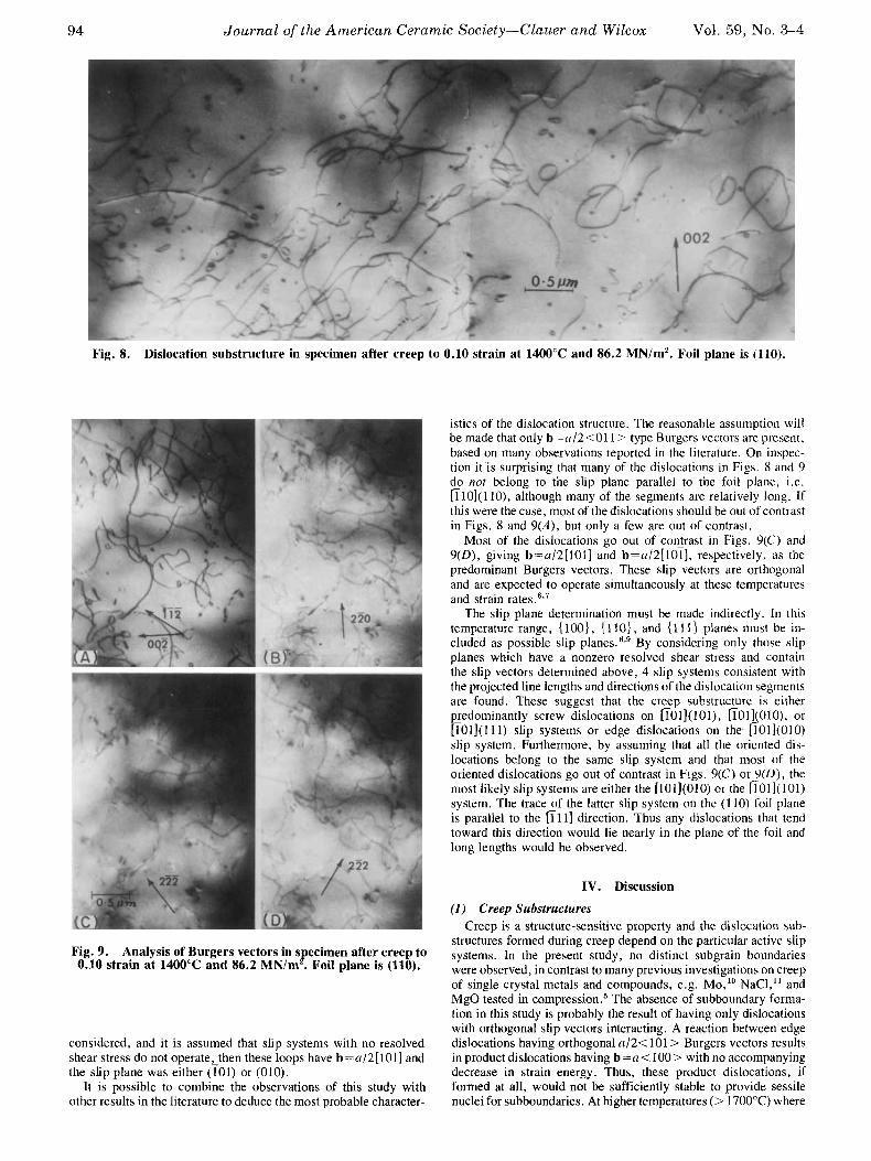
A prominent feature of the substructure is the large titirr~ber ol dislocation loops, and they are much numerous at thc highcsl stress. If a foil thickness of 5 X m umed, the loop dcrisities are 2.4X 10¹⁷ m-'3 and 2 . 6 ~ 10" m :' at 46.9 and 86.2 MN/m'? respectively. The loops have a variety of orientations and no general preferred orientation is discernible. The Burgers vector analysis sequence in Fig. 9 shows that most of thc loops disappear i n Fig. 9(C) where g = 2 22. If only <110> Burgers vectors arc
Fig. 5. Stress dependence of creep substructure after creep to 0.10 creep strain at 1400°C; (100) surfaces are shown. Bar=?() pm. (A) a = 3 7 . 2 MN/m2, p=8.4xlO" m-'; (B) (+=44,8 MN/m', p=9.2xlO" m-'; (C) a=55.2 MN/m2, p = 1 . 3 ~ 10l2 m -

Mar.-Apr. 1976 High Temperature Tensile Creep of Magnesium Oxide Single Crystals
/
Slope 2.1 1 0 Optical microscopy 0 Replica microscopy 0 Transmission electron
microscopy
lo1 ' L 1 I l o l l I 10 20 40 60 100 150
Stress , M N / m 2
Fig. 7. (A) Stress dependence and (B) strain dependence of dislocation density
determined at 1400°C.
Fig. 6. Etch-pit distribution and density within and without heavy bands of etch pits. (A) p (avg) = 1.3 x 10" m-2, bar=30 pm; (B) p=9.2x101' m-*, bar=5 pm; (C) p = 1.5 X 10'' m-', bar = 5 pm. Arrows indicate types of regions represented by replica electron micrographs.
c ---I
0 4 G c .- VI
al n
OEtch pit Transmission electron microscopy
1400 C 46.9 MN/m2
t " 0 0.02 0.04 0.06 0.00 0.10 0.12 0.14
Strain
93
94 Journal of the American Ceramic Society-Clauer and Wilcox Vol. 59, No. %4
Fig. 8. Dislocation substructure in specimen after creep to 0.10 strain at 1400°C and 86.2 MN/m2. Foil plane is (110).
istics of the dislocation structure. The reasonable assumption will be made that only b=u/2<01 I > type Burgers vectors are present, based on many observations reported in the literature. On inspec- tion i t is surprising that many of the dislocations in Figs. 8 and 9 do not belong to the slip plane parallel to the foil plane, i.e. [110](1 lo), although many of the segments are relatively long. If this were the case, most of the dislocations should be out of contrast in Figs. 8 and 9(A) , but only a few are out of contrast.
Most of the dislocations go out of contrast in Figs. 9(C) and 9(D), giving b=a/2[101] and b=a/2[101], respectively, as the predominant Burgers vectors. These slip vectors are orthogonal and are expected to operate simultaneously at these temperatures and strain rates.6s7
The slip plane determination must be made indirectly. In this temperature range, {loo}, { 1 lo}, and { 11 1 } planes must be in- cluded as possible slip planes."'" By considering only those slip planes which have a nonzero resolved shear stress and contain the slip vectors determined above, 4 slip systems consistent with the projected line lengths and directions of the dislocation segments are found. These suggest that the creep substructure is either pJedominantly screw dislocations on [101](101), [lOll(OlO), or [101](111) slip systems or edge dislocations on the [101](010) slip system. Furthermore, by assuming that all the oriented dis- locations belong to the same slip system and that most of the oriented dislocations go out of contrast in Figs. 9(C) or?(U), the most likely slip systems are either the [101](010) or the [101](101) system. The trace3f the latter slip system on the ( 1 10) foil plane is parallel to the [l 11) direction. Thus any dislocations that tend toward this direction would lie nearly in the plane of the foil and long lengths would be observed.
IV. Discussion
(1) Creep Substructures Creep is a structure-sensitive property and the dislocation sub-
structures formed during creep depend on the particular active slip systems. In the present study, no distinct subgrain boundaries were observed, in contrast to many previous investigations on creep of single crystal metals and compounds, e.g. Mo," NaCI," and MgO tested in compre~sion.~ The absence of subboundary forma- tion in this study is probably the result of having only dislocations with orthogonal slip vectors interacting. A reaction between edge dislocations having orthogonal a/2<101> Burgers vectors results in product dislocations having b=a<100> with no accompanying decrease in strain energy. Thus, these product dislocations, if formed at all, would not be sufficiently stable to provide sessile nuclei for subboundaries. At higher temperatures (> 1700°C) where
Fig. 9- Analysis of Burgers vectors in S after creep to B OS1O strain at 1400"c and 86-2 MN'm * plane is (110)*
considered, and it is assumed that slip systems with no resolved shear stress do not operate,then these loops have b=a/2[101] and the slip plane was either (101) or (010).
It is possible to combine the observations of this study with other results in the literature to deduce the most probable character-

Mar.-Apr. 1976 High Temperature Tensile Creep of Magnesium Oxide Single Crystals 95
the oblique systems operate simultaneously, subboundaries do form in tension teskGs7 In this case the obliqueu/2< 101 > Burgers vectors react to give a b=u/2(110) dislocation lying on a ( 1 12) slip plane with a decrease in energy. These dislocations then act as subboundary nuclei or form subboundaries themselves.
It was observed that creep at low stresses produced uniform etch pit structures in the MgO crystals, whereas at high stresses bands containing large etch pit densities formed. A possible expla- nation is that, at low stresses, where there are low dislocation and loop densities, these obstacles are widely distributed and the delay time at the obstacle, e.g. for dislocation climb, is relatively small compared to the time required to glide between obstacles. In this case the dislocations tend to move individually and uniformly through the specimen volume. At high stresses, corresponding to high dislocation and loop densities, the obstacle spacing is de- creased and the delay time may become of the same order as, or greater than, the time of flight. In this case, continued slip is favored on planes where groups of dislocations are moving together in the same direction, as shown by Li. l2 He predicted that under single slip conditions (which is similar to the present case), when only two orthogonal slip planes are active, dipoles become ineffective obsta- cles for groups of dislocations, and slip concentrated within closely spaced groups of slip planes (a slip band) would be favored com- pared to the glide of individual dislocations.
The presence of loops and irregular dipoles, as seen in Figs. 8 and 9, was a common feature in all thin foils from creep tested speci- mens. Neither the dipoles nor the loops display a preferred orienta- tion, because slip is occurring on at least 3 slipplanes, (101), (101), and (010); in addition, the dipoles from which the loops originate were probably formed by a collision process where two dislocations moving in parallel slip planes trap each other to form the dipole. ‘’,I4
The very nature of this mechanism creates dipoles of all orientations between edge and screw, which, upon breaking up into loops, results i n loops having a variety of orientations. Even if the dipoles were formed by a cross-slip mechanism or by a local accumulation of intersection jogs into a superjog, the resulting dipole may still be significantly curved away from the pure edge configuration before it is (2) Creep Mechanisms
High temperature creep of crystalline solids is usually diffusion controlled. In single crystals creep occurs by dislocation processes such as climb or glide, as opposed to polycrystals where creep may also occur by grain-boundary-dependent diffusional processes, such as the Nabarro-Herring or Coble mechanisms, or by grain boundary sliding. In a compound, diffusion-controlled dislocation climb requires that both species, e.g. Mg and 0 in MgO, diffuse to the core of climbing dislocations. Here, the diffusivity of the slower moving species should control the creep rate. In dislocation glide mechanisms, the glide velocity can be controlled by the diffusion of an atmosphere of charged impurity ions or vacancies which forms around dislocations. The atmospheres form because dislocations are charged, and the temperature dependence of the glide velocity includes not only that of the diffusion process but also that of the net charge on dislocations.
In a compound, such as MgO, the diffusivities of the atomic species depend on the native point defect structure as well as on the concentration and type of impurities present. There have been several studies of Mg diffusion in MgOl7-’’ and two investigations of 0 A comparison of the reported diffusion rates shows that 0 diffuses 10’ and lo3 times slower than Mg over the temperature range 1300 to 1500°C. However, in MgO the native defect structure and the effects of impurity ions are still poorly understood, as is best illustrated by the observation that it is still not clear whether the intrinsic diffusivity of Mg in MgO has ever been measured.”
Activation energies for creep of MgO single crystals fall in the range 3.5 to 7.0 eV (Table I). It is probable that creep at high temperatures is diffusion controlled. However, because of the un- certainty in interpreting diffusion results, it is not clear, at present, whether creep is controlled by Mg, 0, or impurity diffusion. Neither is it certain whether the diffusion process is extrinsic or intrinsic. In view of the high impurity content of the MgO used in
this study, it is unlikely that the creep activation energy is represen- tative of intrinsic diffusion.
The substructural studies suggest that creep may be governed either by ( 1 ) a recovery mechanism such as the annealing out of dislocation dipoles or loops, or (2) a glide mechanism, where glide may be limited by atmospheres of charged defects surrounding dislocations.
Chang” suggested a creep model based on the recovery of loops and dipoles. He predicted that the creep rate, 6, is proportional to stress, (T, as E ~ ( T ‘ ‘ where n = 4 and 5 for dissolution of loops and dipoles, respectively. This prediction is in general accord with experimentally determined stress exponents for MgO single crystal creep (Table I). Ifthis mechanism were operative, the creep activa- tion energy would be expected to correspond to that for 0 diffusion. Consistent with this is the observation by Narayan and Washburn“’ that the shrinkage of dislocation loops in MgO over the temperature range 1080 to 1427°C has an activation energy of 4.7 eV, which they attribute to intrinsic 0 bulk diffusion.
The possibility of a glide-controlled creep mechanism is suggested by the long, relatively straight dislocation segments ob- served in TEM. This observation indicates that during creep most of the dislocations are mobile, and that glide (controlled by drag of charged atmospheres), might be the rate-determining element. This drag mechanism originates from the idea that dislocations in crystals having some ionic character acquire a net charge, and this line charge is compensated by the formation of a cloud of’ oppositely charged defects. The basis for the formation of these atmospheres was treated in detail by Eshelby er ul., 24 and the diffusional drag problem for slowly moving dislocations was analyzed by Brown.25 If this mechanism were operative, the stress dependence of the creep rate should be = C ~ ( T “ , as shown by Weertman.26 Table I shows that the stress exponents from 3 to 7 have been observed for creep of MgO single crystals. The activation energy for creep would be expected to relate to the extrinsic diffusion of charged cation vacan- cies or impurity ions. The experimental creep activation energies, 3.5 to 7.0 eV (Table I), are somewhat too high for this. Rather, if this mechanism controls creep, it appears that a drag process con- trolled by intrinsic diffusion of charged impurity ions may be operative.
It is very possible that two or more mechanisms are contributing to creep, and there is no single dominant controlling process over the range of conditions investigated. As suggested by Bird ef ul., 87
all the substructural features will be in dynamic equilibrium during steady state creep. A model constructed by observing a significant feature of the substructure may adequately describe the creep be- havior, although it is not the dominant mechanism or even the rate-controlling one.
References C. 0. Hulse and 1. A. Pask, “Mechanical Properties of Magnesia Single Crystals in
R . L. Cummerow, “High-Temperature Steady-State Creep Rate in Single-Crystal
W. S. Rothwell and A. S . Neiman, “Creep in Vacuum of MgO Single Crystals and
D. R. C ~ O D W ~ . “The Effect of Plastic lnstabilitv on Creeo of M e 0 S i d e Crvstals
Compression,” J . Am. Ceram. Sac., 43 [7] 373-78 (1960).
MgO,” J . Appl. Phys., 34 [6] 172629 (1963).
the Electric Field Effect,” ibid., 36 (71 2309-16 (1965).
in Compressidn’”; M.S. Thesis, University of Califbrnia, Be;keley,-Califo;nia, f966. W. Huether and 9. Reppich, “Dislocation Structure During Creep ofMgO Single
Crystals,” Philos. Mug. , 28 121 363-71 (1973). R . 9. Day and R . J . Stokes, “Mechanical Behavior of Magnesium Oxide at High
Temperatures,” J . A m . Cerum. Soc., 47 [lo] 493-503 (1964). ’ R . B . Day and R . J . Stokes, “Effect of Crystal Orientation on the Mechanical Behavior of Magnesium Oxide at High Temperatures,” ibid., 49 [2] 72-80 (1966).
A. G. Atkins and D. Tabor. “Mutual Indentation Hardness of Single-Crystal Magnesium Oxide at High Temperatures,” ibtd.. 50 [4] 195-98 (1967).
C. 0. Hulse, S. M. Copley, and J . A. Pask, “Effect of Crystal Orientation on Plastic Deformation of Magnesium Oxide,” ibid., 46 [71 317-23 (1963).
A. H. Clauer. 9. A. Wilcox, and J . P. Hinh, “Dislocation SUbStruCtUre Induced by Creep in Molybdenum Single Crystals,” Actu Metull., IS 131 381-97 (1970).
1 L J . P. Poirier, “Hi h Temperature Creep of Single Crystalline Sodium Chloride: 11,” Philos. Mug. , 2673j 713-25 (1972).
l2 J. C. M. Li, “Interaction of Dislocation Dipoles,” Discuss. Furuduy Soc., 38,
l3 A. S. Tetelman, “Dislocation Dipole Formation in Deformed Crystals,’’ Acra
R. J . Stokes and K . H. Olsen, “Dislocation Interactions and Dipole Formation,”
J . Washburn; p. 301 in Electron Microscopy and Strength of Crystals. Edited by
13b46 (1964).
Metull., 10, 813-20 (1962).
Philos. Mag . , 8 [901 957-66 (1963).
Gareth and J . Washburn. John Wiley & Sons, Inc., New York, N.Y., 1963.

96 Journal of the American Ceramic Society-Sanders and Schaefer Vol. 59, No. 3-4 J. C. M. Li and P. R. Swann, “Reorientation and Termination of Dislocation
Dipoles,” Philos. Mug., 10 [lo61 617-31 (1964). I‘ B. J. Wuensch, W. C. Steele, and T. Vasilos, “Cation Self-Diffusion in Single-
Crystal MgO,” J. Chem. Phys., 58 [I21 5258-66 (1973). l8 R. Lindner and G. D. Parfttt, “Diffusion of Radioactive Magnesium in M a g
nesium Oxide Crystals,” ibid., 26 [l] 182-85 (1957). Is B. C. Harding, D. M. Price, and A. J. Mortlock, “Cation Self-Diffusion insingle
Crystal MgO,” Philos. Mag., 23 [I821 3 9 9 4 8 (1971). ’“Y. OishiandW. D. Kin ery, “OxygenDiffusioninPericlaseCrystals,”J. Chem.
Phys., 33 I31 905-906 (1968). *’ L. H. Rovner, “Diffusion of Oxygen in Magnesium Oxide”; Ph.D. Thesis, Cornell University, Ithaca, N.Y.; Llniv. Microfilms (Ann Arbor, Mich.), Order No. 66-7841, 154 pp.; Diss. Abstr.. E , 27 131 934-35 (1966).
Roger Chang; pp. 275-85 in The Physics and Chemistry of Ceramics. Edited by Cyrus Klingsberg. Gordon and Breach, Science Publishers, New York, 1963.
23 J. Narayan and J. Washburn, “Self-Climb of Dislocation Loops in Magnesium Oxide,” Philos. Mug., 26 [5] 117%90 (1972).
z4 J. D. Eshelby, C. W. A. Newey, P. L. Pratt, and A. B. Lidiard, “Charged Dislocations and the Strength of Ionic Crystals,” ibid., 3 [25] 75-89 (1958).
25 L. M. Brown, “Mobile Charged Dislocations in Ionic Crystals,” Phys. Srarus Solidi. 1 [61 585-99 (1961). *‘ J. Weertman, “Creep of Indium, Lead, and Some of Their Alloys with Various Metals,” Trans. AIME, 218 [4] 207-18 (1960). *‘ J. E. Bird, A. K. Mukherjee, and J. E. Dorn; p. 255 in Quantitative Relation Between Properties and Microstructure. Israel University Press, Jerusalem, Israel, 1969.
Reactive Vaporization of Soda-Lime-Silica Glass Melts DAVID M. SANDERS * and HELMUT A. SCHAEFER*,*
Inorganic Materials Division, Institute for Materials Research, National Bureau of Standards, Washington, D.C. 20234
Water-vapor-assisted transport of glass constituents from a soda-lime-silica melt was studied, using atomic spectroscopy for analysis of vapor condensates and microprobe analysis to de- termine diffusion profiles. The data presented indicate that the vaporization process is controlled by a surface membrane which has a composition different from the bulk composition. The
influence of this effect on glass homogeneity is discussed.
I. Introduction
APORIZATION from glass melts is of industrial interest due to V its influence on glass homogeneity and the surface structure of glass products. It is also important because of its effect on refractory corrosion and its contribution to glass-furnace stack emissions. Vaporization studies are of scientific interest because they permit, in principle, the determination of vapor pressure of various glass constituents and provide information about diffusion coefficients and reaction rate constants.
Historically, most vaporization studies of glass melts and, in particular, of soda-lime-silica glass have involved the measurement of mass loss of an unstirred glass sample during exposure to some gas. Only recently the Knudsen effusion method has been used to determine vapor pressures of unstirred soda-lime- silica glasses.6 Mass loss measurements as a function of time pro- vide information concerning the rate controlling steps in the vapori- zation process (surface reaction and/or diffusion control). For a soda-lime-silica glass, Howes et al. reported a linear mass loss between 1100 and 1300°C. At 14OO0C, a slight curvature appeared at shorter times; however, the mass loss still remained predomi- nately linear with time. On the other hand, studies by Oldfield and Wright5 showed a mass loss which varied with the square root of time with the presence of small amounts of B,03 in the glass.
One problem in the interpretation of previous data has been the lack of equilibrium vaporization conditions, since vaporization took place either under static conditions,’’2’5 under unspecified flow condition^,^ or under flow conditions which seem to indicate that the gas stream over the sample was unde~saturated,~ thus making the comparison of data almost impossible (see Table I).
To remedy this situation, vaporization is therefore studied here as a function of flow rate in order to establish equilibrium conditions, thereby providing vapor pressure data. To investigate the vaporiza- tion mechanism and to separate behavior caused by the vaporization process from that due to diffusion through depleted layers near the melt surface, we used a recent development in vapor pressure measurement of well-stirred, incongruently vaporizing viscous liquids. In addition, water vapor was added to nitrogen gas streams in both the stirred and unstirred melts, partly to assist in the vapori- zation process, as shown earlier by Dietzel and Merker,4 and partly because Hola et ~ 1 . ~ found strong influence of water vapor on diffusion coefficient and reaction rate constant in molten sodium disilicate glass. The resulting surfaces produced by the vaporization process were studied, using an electron microprobe to determine the composition profiles.
11. Transpiration Method
The transpiration method has been used with varying degrees of success for the determination of vapor pressures. This technique was critically evaluated by Alcock and Hooper,* and much of the
Presented at the 77th Annual Meeting, The American Ceramic Society, Washington, D.C., May 6, 1975 (Glass Division, No. 34-G-75). Received August 13, 1975; revised copy received October 16, 1975.
*Member, the American Ceramic Society. *Presently on leave from the Universitat Erlangen-Nuernberg, Martensstrasse 5 ,
Germany.
Table I. Vaporization Studies on Na20-Ca0-Si0, Glasses Specific mass loss, M (glcrn’) Temp. Flow rate Composition (wt%)
Re‘. SiO, Na,O CaO SOa B,O, (“C) Gas (ml/min) Time depend. H20 vapor depend. Remarks
Only Na20 volatile SO3 increases Na,O
N,(+H20) 1500t M F t t M t K- Mass loss in Pt tube # ceramic tube
VaDorization is dif-
1 73.35 15.94 9.90 1100-1400 Air 0 Mf“t 2 73.0 16.0 10.0 0.83 1300-1450 Air 0 Mt“ V P
loss 3 73.6 11.9 7 .8 0.2 1400 Air;CO,;H,O 0;Unspec. Highest mass loss 4 74.0 16.0 10.0 1400
5 70.5 16.3 5.7 0.5 1300-1500 Air 0 M ‘ 4 fusion-controlled
6 74.0 16.0 10.0 1050-1200 Vacuum Vapor pressure (2 x 1 0 - ~ torr) measurements
*Not stated, but V? law is approximately indicated. ?Doubling the flow rate resultedin same vaporization rate. (Indicates the conditions of region IV, see Fig. 1 .) $Measurements obtained at 2 times (factor 10 difference). Although a linear mass loss is not stated, the results seem to indicate this more than a square-root time dependence. $Obtained by replotting data, not stated explicitly.
Copyright © 2022 FDOKUMEN