CaLM -Cambodia | Laos | Myanmar 77 million untapped consumers
Upload
khangminh22Category
view
0download
0
�����������������
Citation: Amaechi, C.V.; Wang, F.; Ye,
J. Experimental Study on Motion
Characterisation of CALM Buoy
Hose System under Water Waves. J.
Mar. Sci. Eng. 2022, 10, 204. https://
doi.org/10.3390/jmse10020204
Academic Editor: Kostas
Belibassakis
Received: 14 November 2021
Accepted: 30 January 2022
Published: 2 February 2022
Publisher’s Note: MDPI stays neutral
with regard to jurisdictional claims in
published maps and institutional affil-
iations.
Copyright: © 2022 by the authors.
Licensee MDPI, Basel, Switzerland.
This article is an open access article
distributed under the terms and
conditions of the Creative Commons
Attribution (CC BY) license (https://
creativecommons.org/licenses/by/
4.0/).
Journal of
Marine Science and Engineering
Article
Experimental Study on Motion Characterisation of CALM BuoyHose System under Water WavesChiemela Victor Amaechi 1,2,* , Facheng Wang 3,* and Jianqiao Ye 1,*
1 Department of Engineering, Lancaster University, Lancaster LA1 4YR, UK2 Standards Organisation of Nigeria (SON), 52 Lome Crescent, Wuse Zone 7, Abuja 900287, Nigeria3 Department of Civil Engineering, Tsinghua University, Beijing 100084, China* Correspondence: [email protected] or [email protected] (C.V.A.);
[email protected] (F.W.); [email protected] (J.Y.)
Abstract: The application of marine bonded hoses has increased in recent times, due to the needfor more flexible conduits and flexible applications in the offshore industry. These marine struc-tures include Catenary Anchor Leg Moorings (CALM) buoys and ocean monitoring buoys. Theirattachments include floating hoses, submarine hoses and submarine cables. However, the structuralperformance challenges of a CALM buoy system from its hydrodynamics water waves and otherglobal loadings, have led to the need for this investigation. In this study, a detailed presentation on themotion characterisation of the CALM buoy hose system is presented. The CALM buoy is a structurewith six degrees of freedom (6DoF). A well-detailed experimental presentation on the CALM buoyhose model conducted in Lancaster University Wave Tank is presented using three novel techniques,which are: a digital image captured using Imetrum systems, using an Akaso 4K underwater camera,using wave gauges arranged in a unique pattern and using underwater Bluetooth sensors. The buoymodel was also found to respond uniquely for each motion investigated under water waves. Theresults showed that the higher the profile, the higher the response of the buoy. Thus, this studyconfirms the existence of flow patterns of the CALM buoy while floating on the water body.
Keywords: ocean waves; hydrodynamics; catenary anchor leg mooring (CALM) buoy; marine riser;marine hose; motion characterisation; CALM buoy model test; ocean engineering; offshore structure;floating offshore platform (FOS)
1. Introduction
The need for more energy resources from fossil fuels has led to the development ofnew floating offshore structures (FOS) for more explorations in different water depths [1–6].These structures are induced by water waves from shallow waters to intermediate watersand deep waters [7–13]. This has led to the increase in the trend for the need for lightermarine structures and more flexible ones that can be easier for fluid transportation, such asmarine risers [14–18]. Several innovations on FOS have been reported in ocean engineering,particularly Catenary Anchor Leg Moorings (CALM) buoys [19–26]. These buoys areattached with floating hoses, submarine hoses and reeling hoses. The stability of the buoywill also determine the lifespan of the marine buoys and mooring lines. However, thesemarine bonded hoses are challenged with different structural issues, despite being veryefficient in fluid delivery [27–33].
Thus, there is the need to investigate the motion characterisation of CALM buoysystems experimentally. Currently, the design guidelines for these marine hoses are basedon industry standards like API 17K, GMPHOM OCIMF 2009, DNVGL and ABS specifi-cations [34–39]. These hoses have some cons, ranging from a shorter service life, kinking,matrix cracking, damage from vessel motion, damage from hose response (snaking phe-nomenon and perturbations), damage from impact (line clashing), damage from discon-nection (accidental operation) and vibration to other structural challenges [40–44]. On the
J. Mar. Sci. Eng. 2022, 10, 204. https://doi.org/10.3390/jmse10020204 https://www.mdpi.com/journal/jmse

J. Mar. Sci. Eng. 2022, 10, 204 2 of 25
other hand, the buoys have motion responses that are relatively due to the wave loadsand hydrodynamic properties on the FOS [45–50]. In real-life applications of offloadingand loading operations in offshore oil terminal systems are made of single point moorings(SPM), which are made up of three main mooring configurations: Articulated Single PointMoorings (ASPM), Single Anchor Leg Moorings (SALM) and Catenary Anchor Leg Moor-ings (CALM) [51–55]. The SPM Buoy is a buoy that is securely anchored to the seabed bymultiple mooring lines/anchors/chains, allowing liquid petroleum product cargo to betransferred. A bearing system on the buoy allows a section of it to rotate around the mooredgeostatic portion. The vessel will freely weathervane all around the geostatic section of thebuoy while it is moored to this rotating part of the buoy with a mooring attachment. Thebuoy body, mooring and anchoring components, product transfer system and ancillaryelements make up the SPM system. Static legs connected to the seabed under the oceansecure the buoy body in place. The body is attached to the offloading/loading tanker by arevolving portion above the water level. The Main Bearing connects these two sections. Forthis same arrangement, the moored tanker will weathervane freely around the buoy to finda secure spot. The definition of the buoy is determined by the form of bearing used and theseparation of the rotating and geostatic components. The buoy’s size is determined by theamount of counter buoyancy needed to keep the anchor chains in place, and the anchorchains are determined by environmental factors and the size of the vessel.
Some experimental investigations have been conducted on the CALM buoy by varyingthe buoy skirts [56–60]. Edward & Dev [60] accessed the motion response of the CALMbuoy with some empirical estimation on the viscous damping. Cozijn et al. [61] conductedan experiment using a 1:20-scaled CALM buoy model and found drag coefficient valuesand damping data for pitch, roll and heave motions. These were also used to computethe coefficient of additional mass, which is 1.5 for CALM buoy hoses [61,62]. However,similar studies on buoy motion have been conducted using computational fluid dynamics(CFD) [63–65]. In principle, CFD models are developed using different discretisationmethods like interpolating element-free Galerkin (IEFG), the Boundary Element Method(BEM) and the Ciarlet–Raviart mixed finite element method (FEM) and finite volumemethods [66–68]. Figure 1 shows a CALM buoy maintained by Bluewater with two hawsersattached to the FPSO for loading/offloading operations.
Figure 1. CALM buoy with two hawsers attached to the FPSO for loading and offloading operations(reproduced, with permission, courtesy: Bluewater; Source: Bluewater, [69]).

J. Mar. Sci. Eng. 2022, 10, 204 3 of 25
In this article, an experimental investigation was conducted on the motion charac-terisation of a CALM buoy under water waves. Section 1 presents some introduction tothis buoy study. Section 2 presents the experimental model of the CALM buoy and thematerials and methods. Additionally, some assumptions on the buoy with a skirt andbuoy with the hose model were presented. Section 3 presents the results and discussion,while the concluding remarks on the CALM buoy study are given in Section 4. The CALMbuoy is a floating buoy designed to operate in six degrees of freedom (6DoFs). It is usuallyattached to a tanker via hawsers and a floating hose during loading operations.
2. Materials and Methods
The experimental modelling aspect is presented in this section on the materials utilisedin this experiment and the methodology. The materials included the buoy, submarine hoses,mooring lines and cameras, as discussed in the subsequent subsections.
2.1. Experimental Setup
For the experiment, the Lancaster University Wave Tank facility was used in all theexperimental investigations. The CALM buoy test model was first tested for buoyancy,and leakage; then, it was properly ballasted. It was then positioned 5.5 m from the wavemaker along the central axis of the wave tank. Figure 2 is the flow direction across theCALM buoy model’s hull. The buoy model was then moored using 4 steel chain mooringlines, and 4 wave gauges were attached to the buoy skirt, as in Figures 7–10. The steelchain mooring lines were later replaced with polyester lines, as they suitable. The anchorswere initially scree points on the floor of the wave tank. It was later replaced by usingsome marked “5 kg” weights as anchors for each of the 4 moorings. Video recordingswere also collected for each run using an underwater camera. It recorded the behavioursof the hoses (submarine and floating) and the CALM buoy for different frequencies. Theexperimental setup shows the Lancaster University wave tank in Figure 3. The first set ofthe experiment was carried out using a flat seabed for different frequencies. Wave gaugeswere attached to obtain the readings using a setup with LabView NXG 5.1. LabView wasinterfaced with a NI-DAQmx Device called National Instruments DSUB Model NI 9205.End fittings were connected at both ends of the two hoses connected to the buoy modelunderneath it (submarine hoses) and one hose on the side (floating hose). Mooring linesmade of 20-mm-diameter steel chains were used, and one end was anchored to the floorwhile the other end was to the skirt of the model for the CALM buoy. The methodology forthe experiment will be presented in Section 2.10.
Figure 2. Illustration of the flow direction across the CALM buoy model’s hull.

J. Mar. Sci. Eng. 2022, 10, 204 4 of 25
Figure 3. Test basin at the Lancaster University Wave Tank facility showing the location of the buoyand wave gauges used in the experiment.
2.2. Lancaster University’s Wave Tank
The experimental setup for the CALM buoy model is shown in Figure 3. The detailedsetup for other components are presented in Sections 2.3–2.10. The dimensions of thewave tank measure at 15 m lengthwise, 2.5 m in width and 1.7 m in depth. A schematicof the key features, dimensions, wave tank details, wave gauge layout, model supportingstructures and model mounting area on the wave tank is illustrated in Figure 4. The beachcontains a 2.5-m-lengthwise space, leaving a 12.5-m-lengthwise space available for use inthe experiments. Also, the depth was adjusted to 1.0 m. The waves are generated usingforce feedback control through seven (7) flappy-type paddles, designed by EdinburghDesigns, UK [70]. Each of the paddles has the capacity to produce sinusoidal waves witha frequency range of 1.5–0.5 Hz, while the amplitudes are as high as 100 mm. They arealso capable of creating data files from both irregular and regular waves, depending on theinput configuration. The wave tank facility has been used in validated studies [71–74].
Figure 4. Schematic of the key features, dimensions, wave tank details, wave gauge layout, modelsupporting structures and model mounting area of the Lancaster University Wave Tank.
J. Mar. Sci. Eng. 2022, 10, 204 5 of 25
2.3. The Buoy Model
The buoy model is developed by considering some model assumptions, including thatthe buoy is cylindrical, with a skirt attached to it and the skirt has a thin thickness fromsolid plates. The fabrication of the buoy model was obtained using the modelling rules.The parameters for the buoy applied in the design analysis are presented in Table 1. Themodel was scaled down, and the model test was constructed with two submarine hosesattached underneath the buoy and one floating hose on the side, as shown in Figure 5a,b.The results of the motion response of the CALM buoy carried out experimentally arepresented in Section 3, respectively. The fabrication of the buoy model was carried out inLancaster University Engineering Department’s Mechanical Workshop. The considerationsused included light metallic buoy materials, buoyancy, draft line, ballasting and scaled-modelling rules. To ballast the buoy, an opening was created at the top which was used tofill the ballast. The ballasting material used was a measured amount of sharp sand. Theparameters for the buoy used in the experimental study are presented in Table 1.
Table 1. Parameters of the model test buoy.
Parameters Model Test
Shape of buoy Cylindrical
Depth of Water (m) 0.90
Diameter of Skirt (m) 0.68
Draft size (m) 0.15
Mass of Buoy (kg) 0.25
Buoy’s Height (m) 0.20
Diameter of Buoy’s body (m) 0.50
Figure 5. Images of (a) the CALM buoy test model fabrication showing a skirt with the underneathhoses and (b) the buoy model with floating hoses and attached wave gauges on the buoy skirt.
2.4. Mooring Lines & Fittings
The CALM buoy system was moored with two sections of steel chain moorings. Themooring arrangement was made up of four (4) mooring lines modelled as catenary mooringlines. The moorings are set up on the buoy and fixed via fairings attached on its skirt, asseen in Figure 6. One end of the mooring line was attached to the skirt of the cylindricalbuoy, while the other end was anchored to the seabed. The schematic for the setup of the

J. Mar. Sci. Eng. 2022, 10, 204 6 of 25
model using chain moorings is presented in Figure 7. The mooring lines had the samestiffness and were 90◦ apart, as depicted in Figure 7.
Figure 6. Setting up the moorings on the buoy model, showing (a) the skirt with attached wavegauge fittings by mooring line fairleads, and (b) the polyester rope and the chain mooring lines usedon the moorings during the experiment.
Figure 7. Arrangement of moorings showing (a) a crown view of the buoy and (b) a side elevationview of the buoy.
2.5. Hoses and End Fittings
A floating hose was also attached on the side to investigate the behaviours of floatinghoses, such as snaking. The hose material used in the model was about 20 mm in diameter,with minimal flexible stiffness, to depict an offshore hose behaviour. Four end fittingswere also prepared for the hoses, as shown in the Figures 6 and 8a. As can be observed inthis study that the material chosen for the floating hoses reflects real-life applications [69].These fittings are to ensure that the investigation on the hose behaviour relative to thewater waves can be investigated in real time.
J. Mar. Sci. Eng. 2022, 10, 204 7 of 25
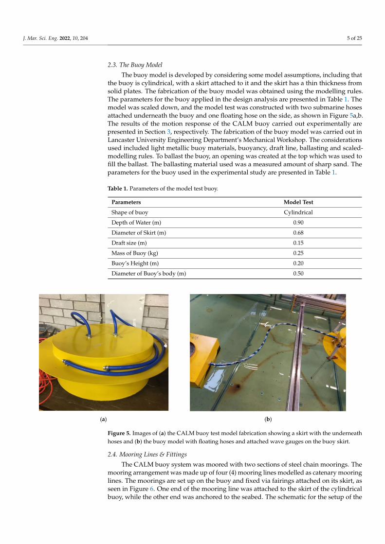
Figure 8. Experimental setup showing (a) floating hose attached on the buoy with the attached wavegauges on the buoy skirt and (b) the Imetrum system using DCI for data collection during the decaytest at Lancaster University Wave Tank.
2.6. Imetrum DIC (Digital Image Correlation) System
The experiment was conducted using three different novel techniques, which are: adigital image capturing using Imetrum systems, using wave gauges arranged in a uniquepattern and using underwater Bluetooth sensors. The Imetrum DIC system is shownin Figure 8b. The study was analysed with a digital image capturing (DIC) mechanismcalled the Imetrum system [75,76]. This system comprises two cameras and one noncontactsystem. It is designed for application in mechanical investigations fluid- and light waves-related. The Imetrum system can be used to capture both static and dynamic motions. Ithas been applied in capturing motion behaviour and structural investigations. Differentresearchers have applied the Imetrum system in obtaining results on deformation, strain,tension, compression and displacement, as well as for other material tests [77–79]. Theexperiment setup details are presented in Sections 2.1 and 2.2.
2.7. Wave Gauges and Readouts
The experiment was also conducted using some wave gauges that were calibratedwith crocodile clips with the right polarity and attached to the lead ends on the model test.The maximum signal input was 5 V for each of the 10 wave gauges (WG0, WG1, WG2, . . .WG9). This also aided the instrumentation as an interface to obtain the results. A networkwas developed in LabView [80,81] to enable the wave gauges to communicate with thereadout devices and the NI DAQ sets. The wave gauges are shown in Figure 8a, and theresults obtained are presented in Section 3.
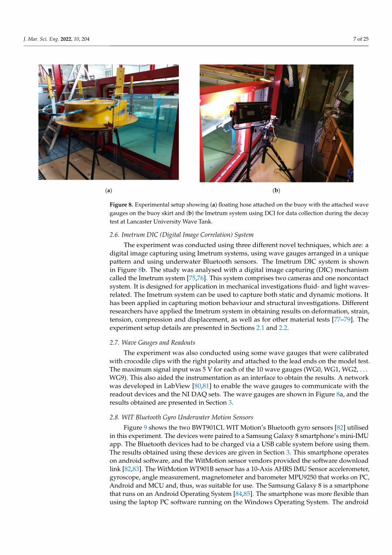
2.8. WIT Bluetooth Gyro Underwater Motion Sensors
Figure 9 shows the two BWT901CL WIT Motion’s Bluetooth gyro sensors [82] utilisedin this experiment. The devices were paired to a Samsung Galaxy 8 smartphone’s mini-IMUapp. The Bluetooth devices had to be charged via a USB cable system before using them.The results obtained using these devices are given in Section 3. This smartphone operateson android software, and the WitMotion sensor vendors provided the software downloadlink [82,83]. The WitMotion WT901B sensor has a 10-Axis AHRS IMU Sensor accelerometer,gyroscope, angle measurement, magnetometer and barometer MPU9250 that works on PC,Android and MCU and, thus, was suitable for use. The Samsung Galaxy 8 is a smartphonethat runs on an Android Operating System [84,85]. The smartphone was more flexible thanusing the laptop PC software running on the Windows Operating System. The android
J. Mar. Sci. Eng. 2022, 10, 204 8 of 25
application called mini-IMU was downloaded on the phone and on the laptop PC (personalcomputer) running on Microsoft Windows 10.
Figure 9. Experiment using 2 underwater Bluetooth WIT motion sensors paired on a Samsung Galaxy8 smartphone, showing (a) the PC for running the wave tank calibration software and (b) the interfaceof the Samsung Galaxy phone displaying the WIT motion’s mini-IMU app.
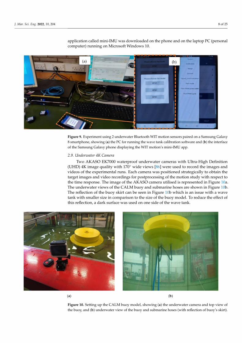
2.9. Underwater 4K Camera
Two AKASO EK7000 waterproof underwater cameras with Ultra-High Definition(UHD) 4K image quality with 170◦ wide views [86] were used to record the images andvideos of the experimental runs. Each camera was positioned strategically to obtain thetarget images and video recordings for postprocessing of the motion study with respect tothe time response. The image of the AKASO camera utilised is represented in Figure 10a.The underwater views of the CALM buoy and submarine hoses are shown in Figure 10b.The reflection of the buoy skirt can be seen in Figure 10b which is an issue with a wavetank with smaller size in comparison to the size of the buoy model. To reduce the effect ofthis reflection, a dark surface was used on one side of the wave tank.
Figure 10. Setting up the CALM buoy model, showing (a) the underwater camera and top view ofthe buoy, and (b) underwater view of the buoy and submarine hoses (with reflection of buoy’s skirt).

J. Mar. Sci. Eng. 2022, 10, 204 9 of 25
2.10. Methodology
The experimental setup was conducted as given in Section 2.1. The methodology forthe experiments was based on the phases. During this research, four different phases of theexperiment were conducted. The first phase was the buoy motion study, while the secondwas a hose response study. The third phase was a snaking hose study, while the fourth wasa reeling hose connection. The snaking hose study was investigated using the idealisationfrom the marine hose developments reviewed in earlier studies [28–31].
In the experimental model presented in Figures 3–6, the floating hose was attachedfrom a CALM buoy model to an FPSO model. It can be observed that the snaking phe-nomenon was evident, which was due to the water waves. Additionally, the floatinghose model was 20 mm in diameter and made of a flexible material to reflect the typicalmarine bonded hoses. It was attached to another FPSO model. Thus, this model wasapplied on the snaking hose study. The findings on the buoy motion study are detailedin Section 3. However, in the present paper, both the results of the hose snaking and thehose response studies are not included, but in another paper by the authors. The presentresults concentrated on the buoy motion, using the buoy attachments with hoses and themooring lines.
2.11. Engineering Application: Numerical Studies
The engineering application of the modelling was carried out numerically in previousstudies using the CALM buoy model in two configurations, namely the Lazy-S [87] andChinese lantern [88] configurations. Figure 11 shows the typical numerical modelling of aCALM buoy showing two different motion positions of the buoy model in Orcaflex 11.0f.It was developed using a finite element model (FEM) in Orcina’s Orcaflex as a model inthe Chinese lantern configuration to confirm the engineering application, as detailed inthe reference literature [89–92]. From these studies, the engineering application of themodel was numerically conducted to reflect its applicability and some validity. Anotherapplication was a sea trial testing using S-lay configuration published in Wang’s study [93].In the present study, further analysis experimental studies were conducted. The recordedresults were also postprocessed to confirm the consistency in the CALM buoy hose motionresponse, as presented in Section 3. The analysis of the results from this research are basedon the experimental output. However, details were still missing when considering thehydrodynamics theory for the boundary value problem.
Figure 11. Numerical model of submarine hoses attached to a floating buoy in Orcaflex 11.0f, showingtwo different motion response positions for the CALM buoy system, in (a) position 1 at time 1 and(b) position 2 at time 2, under the same environemental conditions.
2.12. Experimental Data Postprocessing
The experiment conducted in the wave tank was also videoed using two AKASOEK7000 underwater action cameras with 4K HD capabilities. They were positioned at twodifferent angles, one on the side while the other camera was underneath to obtain a video of

J. Mar. Sci. Eng. 2022, 10, 204 10 of 25
the buoy and hose motions. To adequately access the motion response, some postprocessingwas conducted on the recorded video output using Tracker version 6.0.2 [94–96]. From thecaptured responses and results in Figures 12 and 13, it can be observed that, for differentprofiles, the floating buoy had different responses captured per time.
Figure 12. Resulting plots from the experiment on the model using Tracker postprocessing software,showing the profile positions.
Figure 13. Analysis from the experiment using Tracker postprocessing software for profile A1.
3. Results and Discussion
The experimental results on the motion response of the CALM buoy with connectedsubmarine hoses and floating hose are presented in this section.

J. Mar. Sci. Eng. 2022, 10, 204 11 of 25
3.1. Results from Wave Gauges and Readout
The wave parameters run on the wave tank, and the experimental model is used toobtain the results on the influence of the wave angles, amplitude and frequency obtainedusing wave gauges, as shown in Figure 8. Figure 14 gives the waveform results obtained.
Figure 14. Results from the experiment showing the effect of (a) the wave angles, (b) frequency and(c) amplitude.

J. Mar. Sci. Eng. 2022, 10, 204 12 of 25
From the results obtained on the wave forms in Figure 14a, a variation in the waveangles had varying amplitudes in the wave forms. The effect of frequency from theexperiment as described was also conducted as presented in Figure 14b. Using the sameamplitude of 0.04 m, the highest frequency was 1.1 Hz, while the lowest was 0.8 Hz. Theeffect of the amplitude is seen in Figure 14c, as the higher the amplitude, the higher thewave form.
3.2. Results from Wave Tank’s Underwater Motion Sensors
The experiment was setup as described in Section 2.8 using the Bluetooth underwatersensors paired to a Samsung Galaxy 8 smartphone, as shown in Figure 9. However, thephone was more flexible to use. The phone was paired to the Bluetooth device BWT901CL,and then, the waves were run for the desired waves, as in Tables 2 and 3. The waveparameters run on the wave tank are presented in Table 2, as obtained using the wave tankinterface in Figures 3 and 9. The results obtained are presented in this section.
From Figure 15, three equations representing the profiles on: (a) the wave frequencyversus period, (b) surge response and (c) heave response were obtained as follows:
y = 0.3339x2 − 1.4905x + 2.1487, R2 = 0.9986 (1)
y = −0.0074x2 + 0.0333x − 0.0208, R2 = 0.998 (2)
y = 0.0618x2 − 0.137x + 0.077, R2 = 0.9413 (3)
However, further processing of the motion response against equations of motion wasuseful in obtaining the terms for the unknowns in each equation. Further hose motionresponse studies can be found in the literature [73,74].
In Table 2, it is noteworthy to add that these parameters were used based on thecalibrations on the Lancaster University Wave Tank at a wave frequency of 1 Hz. Thewave tank has the capacity for both tidal waves and ocean waves; however, the latter wasutilised in this experiment. Table 3 presents the results of the experiment using a singlewave direction, and the flow was calibrated for regular waves.
Table 2. Parameters for the hydrodynamic experiment on a wave tank.
Parameters Amplitude Angle Frequency Distance Max Runtime
Value 0.078 0.0 1.0 5.0 64.0
Unit m Degree (o) Hz m secs
Table 3. Results of the maximum amplitude during the experimental test.
Parameters for the Wave Max Displacement
Frequency, f (Hz) Period, T (s) Surge (m) Heave (m)
0.5 2.0 0.01506 0.04660
0.6 1.6 0.01301 0.02640
0.7 1.4 0.01150 0.00190
0.8 1.2 0.00825 0.00240
0.9 1.1 0.00633 0.00260
1.0 1.0 0.00465 0.00220

J. Mar. Sci. Eng. 2022, 10, 204 13 of 25
Figure 15. Result plots from the experiment on the model under the maximum displaced amplitudeshowing (a) the wave frequency versus period, (b) surge response and (c) heave response.

J. Mar. Sci. Eng. 2022, 10, 204 14 of 25
3.3. Results from DIC Using Imetrum System
The experiment was set up and also carried out as described in Section 2. The waveparameters run on the wave tank are presented in Table 2, as obtained using the wavetank interface in Figures 3 and 9. Table 3 presents the results of the experiment using asingle wave direction, and the flow was calibrated for regular waves. The results of theexperimental model were obtained with two methods: using the wave gauges via LabViewand, secondly, via the Imetrum system for the heave and surge of the CALM buoy system.The motions in the X and Z directions were studied, as defined in Figure 2. The Imetrumsystem was used to perform a motion study in the section based on a method called thedigital image capturing (DIC) methodology. The buoy had spots marked on it that werecaptured during the runup and used to obtain responses against positions per time. Thewave runup data in Table 3 were used to obtain the plots in Figures 16–21.
Figure 16. Surge motion for the decay test of the CALM buoy using the DIC with the Imetrum systemfor a 62-s run.
Figure 17. Heave motion for the decay test of the CALM buoy using the DIC with the Imetrumsystem for a 62-s run.
The decay tests conducted in this section show the motion response for differentmotion studies conducted under three different run times of 62 s and 80 s. As observed inFigures 16–21, the surge response along the five (5) different reference points are consistentbut show a different amplitude that is consistent, as the arrangement used was in a patternthat confirmed that the results worked well, as predicted, and a good agreement from thesurge can be applied in validating similar numerical models. The first set of runs was

J. Mar. Sci. Eng. 2022, 10, 204 15 of 25
undertaken in 62 s. As recorded in the surge motion in Figure 16, the surge was the highestin reference 4 at 2117 m at 5.7 s. As recorded in the heave motion in Figure 17, the heavewas also consistent for the five (5) reference points obtained and was also the highest inreference 4 at 1441 m at 5.3 s. As recorded in the roll motion in Figure 18, the heave was alsoconsistent for the five (5) reference points obtained and was also the highest in reference4 at 2.3 degrees at 5.4 s. The next set of runs were undertaken in 82 s. As recorded in thesurge motion in Figure 19, the heave was also consistent for the five (5) reference pointsobtained and was also the highest in reference 4 at 2193 m at 2.7 s. As recorded in theheave motion in Figure 20, the heave was also consistent for the five (5) reference pointsobtained and was also the highest in reference 1 at 1511 m at 2.2 s. Lastly, the heave motionin Figure 20 showed that the heave was consistent for the five (5) reference points obtainedand was also the highest in reference 2 at 1.5 degrees at 2.3 s. Additionally, this confirmedthe buoy response characteristics, as considered during the normal test run and the decaytests. The plots showed consistency with the lines of the best fit and the equations on theserelationships. On the roll motion given in Figure 21, the five (5) reference points obtainedshowed a closed correlation for their responses. It could be observed that the responseamplitude from the wave on the CALM buoy hoses was consistent. The motion video datafrom the experimental study was further postprocessed, as presented in Section 3.4.
Figure 18. Roll motion for the decay test of the CALM buoy using the DIC with the Imetrum systemfor a 62-s run.
Figure 19. Surge motion for the decay test of the CALM buoy using the DIC with the Imetrum systemfor a 80-s run.

J. Mar. Sci. Eng. 2022, 10, 204 16 of 25
Figure 20. Heave motion for the decay test of the CALM buoy using the DIC with the Imetrumsystem for an 80-s run.
Figure 21. Roll motion for the decay test of the CALM buoy using the DIC with the Imetrum systemfor an 80-s run.
3.4. Results from Tracker Postprocessing
The recorded video from this experimental study was postprocessed, as detailed inSection 2.12. The postprocessing on the recorded output was conducted via Tracker version6.0.2. From the captured responses and results in Figures 22 and 23, it can be observed that,for different profiles, the floating buoy has different responses captured per time. Tables 4and 5 present the result profiles for Profiles A and B, respectively. It shows that the Lunaaxis increases as the baseline axis, x, decreases. This shows a decay rate of the motionresponse, as in Section 3.3. It was observed that the profiles have different sinusoidal plotson the wave response. Figures 22 and 23 give the result plots from the experiment on thebuoy model under the maximum displaced amplitude. In the results in Figure 22, the waveresponse to the four selected profiles: A, A1, B and C are presented. It shows that eachprofile has a different motion response relative to the selected position of the profile basedon the coordinate positions. Additionally, the result of the postprocessing in Figure 22shows sinusoidal plots with the least trough seen as a drop within the range of 1.1 m–1.4 m,implying that the motion response is time-dependent for a free-floating buoy. From theplot in Figure 23, it can be noticed that the rotation per time for each frame increases forthe same angle when using 1.57◦. This confirms the motion behaviour of the buoy underwater waves.

J. Mar. Sci. Eng. 2022, 10, 204 17 of 25
Figure 22. Result plots from the experiment for profiles A, A1, B and C.
Figure 23. Plot from the experiment per frame increment for the same angle using 1.57◦.
Table 4. Data analysis from the experiment using Tracker postprocessing software for Profile A.
Horizontal, n Vertical, x Vertical, Luna
0 363.5 172.91 362.5 173.92 361.5 170.03 360.5 171.04 359.5 149.45 358.5 128.46 357.5 121.87 356.5 126.88 355.5 117.29 354.5 102.210 353.5 125.511 352.5 162.512 351.5 238.913 350.5 235.414 349.5 227.415 348.5 224.616 347.5 218.317 346.5 215.518 345.5 213.719 344.5 215.120 343.5 215.521 342.5 215.622 341.5 212.8

J. Mar. Sci. Eng. 2022, 10, 204 18 of 25
Table 5. Data Analysis from the experiment using Tracker postprocessing software for Profile B.
Horizontal, n Vertical, x Vertical, Luna
0 441.5 239.21 440.5 250.32 439.5 250.03 438.5 245.24 437.5 238.65 436.5 235.66 435.5 227.67 434.5 220.68 433.5 214.69 432.5 212.610 431.5 206.411 430.5 203.412 429.5 201.413 428.5 199.414 427.5 199.615 426.5 199.616 425.5 192.517 424.5 188.518 423.5 180.419 422.5 180.420 421.5 175.621 420.5 179.622 419.5 184.9
3.5. Discussion
The motion characteristics of a CALM buoy hull structure have been studied experi-mentally. Figure 13 gives the result plots from the experiment on the buoy model underthe maximum displaced amplitude, showing (a) the wave frequency versus period, (b)surge response and (c) heave response. Decay tests were also conducted in Section 3.3. Itshowed the motion response for different motions conducted under two different run timesof 62 s and 80 s. From the results presented in Figures 16–21, it could be observed thatthe motion behaviour of the CALM buoy hose system was recorded from the experiment.In the results in Figure 22, the wave response to the four selected profiles: A, A1, B andC are presented. It was observed that the profiles had different sinusoidal plots on thewave response. However, further study on the research is recommended to look at twoforms of motion analysis: vortex-induced motion, which is caused by resonance fromreciprocating shed vortexes, and wave-induced motion, which is caused by the dynamismof the wave characteristics. The wave–current interactions and wave-induced motion havebeen conducted experimentally. In this research, the motions caused by the hydrodynamicloads were studied at the wave tank facility of Lancaster University. Since the buoy had asmaller reciprocating amplitude than larger floating structures like semisubmersibles, it canbe assumed that it had a better vortex-induced motion (VIM) response. This could be due toa number of factors, including the geometric features of the buoy’s diameter, the geometricshape and the skirt positioning and mooring configurations. Under regular waves, thewave-produced motions showed a modest response, and the heave motion was found tobe inversely proportional to the draught size. It is crucial to note that the results obtainedfrom the Lancaster University Wave Tank facility were used for the experiment. The studyresults could be used for validation purposes in further studies. It can be observed in theresults in this section that the buoy motion changes the behaviours relative to the waterwaves on both the buoy and the hoses.
The motion video data from the experimental study was further postprocessed. Thismotion postprocessing shows that the responses are consistent on different profiles for thehydrodynamic phenomenon, particularly from the high surge response. For the resultsfrom Section 3.4, it could be observed that the surge and heave motions increased as

J. Mar. Sci. Eng. 2022, 10, 204 19 of 25
the time increased. Additionally, this confirmed the buoy response characteristics, asconsidered during the normal test run and the decay tests. The plots showed consistencywith the lines of best fit and the equations on these relationships. From the postprocessingresults using Tracker software, some tables were generated and used to create plots of theprofile response per time. This showed stable behaviour of the floating buoy under thetime investigated. This study can be further developed by using some comprehensiveformulations of the buoy for more understanding on the stability and dynamics behavioursof floating buoys.
4. Concluding Remarks
In this research, an experimental study on the motion characterisations of a CALMbuoy under water waves was investigated. Some background on the experimental modelfor the CALM buoy system was presented in Section 2. However, special attention wasgiven to the CALM buoy and the skirt. The results showed peculiar characteristics thatshould be considered in the design due to the drag and damping implications. The resultsof the experiment were presented on the motion characterisation study. Some discussionswere included on the engineering application of the system with numerical computationsin earlier studies. This study is relevant for enabling engineers to appropriately designCALM buoy systems using parametric information on hose behaviour, buoy motion, buoygeometry, oceanic data and other environmental conditions.
The model highlights included the following: firstly, an experimental framework waspresented on motion characterisation for the CALM buoy model. Secondly, there was awell-detailed experimental presentation on the CALM buoy hose model conducted at theLancaster University Wave Tank facility. Thirdly, three different novel techniques werepresented, which were: a digital image capturing using the Imetrum system using wavegauges arranged in a unique pattern, using AKASO underwater 4K UHD action cameraand using WitMotion underwater Bluetooth sensors. Fourthly, there was an experimentalstudy on the motion scenario from the motion response study on wave angles and waveamplitudes from the CALM buoy hoses. Lastly, a prediction of the CALM buoy’s motioncharacteristics was presented from the study from postprocessing using Tracker software.
The study presented response profiles based on the experimental predictions. From anoffshore mechanical point of view, the motion characterisation phenomenon was confirmedto exist as a result of the response from the water waves and other global loads on theCALM buoy. The study showed more dimensions of the CALM buoy in a water body andbuoy motion of the marine hose. The study also showed the wave forces acting on theCALM buoy model. This has been confirmed with previous studies by the authors usingthe diffraction and potential theories. Thus, this study will assist in both the manufacturingand installation of CALM buoys. The buoy model was also found to respond uniquelyto each motion investigated under water waves. The results showed that the higher theprofile, the higher the response of the buoy. Thus, this study confirmed the existenceof flow patterns on the CALM buoy while floating on the water body. Further study isrecommended with engineering application on marine hoses using the Orcaflex FEM,which could be experimentally validated. Other studies include the numerical fluid studyor vortex flow effect on the buoy using CFD.
Author Contributions: Conceptualisation, C.V.A. and J.Y.; methodology, C.V.A., F.W. and J.Y.; soft-ware, C.V.A. and J.Y.; validation, C.V.A., F.W. and J.Y.; formal analysis, C.V.A. and J.Y.; investigation,C.V.A., F.W. and J.Y.; resources, C.V.A.; data curation, C.V.A.; writing—original draft preparation,C.V.A.; writing—review and editing, C.V.A., F.W. and J.Y.; visualisation, C.V.A.; supervision, C.V.A.,F.W. and J.Y.; project administration, C.V.A. and J.Y. and funding acquisition, C.V.A. and J.Y. Allauthors have read and agreed to the published version of the manuscript.
Funding: The Department of Engineering, Lancaster University, UK and Engineering and PhysicalSciences Research Council (EPSRC)’s Doctoral Training Centre (DTC) are highly appreciated. Also,the funding of the Overseas Postgraduate Scholarship by the Niger Delta Development Commission(NDDC), Port Harcourt, Nigeria is also appreciated, as well as the support of the Standards Organisa-

J. Mar. Sci. Eng. 2022, 10, 204 20 of 25
tion of Nigeria (SON), F.C.T. Abuja, Nigeria. The research reported in this paper is part of Project51922064 supported by the National Natural Science Foundation of China (NSFC), China. The articleprocessing charges (APC) were funded by Author 1—C.V.A. with support from MDPI’s JMSE.
Institutional Review Board Statement: Not applicable.
Informed Consent Statement: Not applicable.
Data Availability Statement: The raw/processed data required to reproduce these findings cannotbe shared at this time, as the data also forms part of an ongoing study.
Acknowledgments: The authors acknowledge the technical support from the Lancaster UniversityEngineering Department staff. The authors acknowledge the technical support of Mark Salisbury,Andy Baker and Nick Renninson for support on the experiments done on the CALM buoy modelfabrications. The authors recognise the support from Simon Doyle of Lancaster University, UK fortechnical support during the experimental investigation of the model and the project contributionsof Stephen Quayle of Lancaster University, who contributed to the development of the model test.The authors also acknowledge Richard Leeuwenburgh of Bluewater for permission to use theirimages, including Figure 1. The authors also acknowledge the feedback given on this submission byProfessors George Aggidis of Lancaster University, UK and Long-Yuan Li of Plymouth University, UK.The authors are posthumously grateful to the late Jeevan Mahadev Rao of Lancaster University, whoassisted with the experimental investigation of this project but unfortunately passed away during theCOVID-19 pandemic after some health challenges. The authors also appreciate the editors of JMSEand the anonymous reviewers for their feedback on this submission, which have helped to improvethe quality of this manuscript.
Conflicts of Interest: The authors declare no conflict of interest. The funders had no role in the designof the study; in the collection, analyses or interpretation of the data; in the writing of the manuscriptor in the decision to publish the results.
Abbreviations
θ Angle to the Horizontal Axis3D Three-Dimensional6DoF Six Degrees of FreedomABS American Bureau of ShippingASPM Articulated Single Point MooringsBEM Boundary Element MethodCALM Catenary Anchor Leg MooringCB Cylindrical BuoyCCS Cartesian Coordinate SystemCFD Computational Fluid DynamicsCMS Conventional Mooring SystemsDIC Digital Image CorrelationDNVGL Det Norkse Veritas & Germanischer LloydF.C.T Federal Capital TerritoryFEM Finite Element ModelFOS Floating Offshore StructureFPSO Floating Production Storage and OffloadingFSO Floating Storage and Offloading
GMPHOMGuide to Manufacturing and Purchasing Hoses for OffshoreMoorings
ID Inner DiameterIEFG Interpolating Element Free GalerkinMSL Mean Sea LevelOCIMF Oil Companies International Marine ForumOD Outer DiameterRAO Response Amplitude Operator
J. Mar. Sci. Eng. 2022, 10, 204 21 of 25
SALM Single Anchor Leg MooringsSON Standards Organisation of NigeriaSPM Single-Point MooringUHD Ultra-High DefinitionU.K United KingdomVIM Vortex-Induced Motion
References1. Islam, A.S.M.S.; Jameel, M.; Jumaat, M.Z.; Shirazi, S.; Salman, F.A. Review of offshore energy in Malaysia and floating Spar
platform for sustainable exploration. Renew. Sustain. Energy Rev. 2012, 16, 6268–6284. [CrossRef]2. Sadeghi, K. An Overview of Design, Analysis, Construction and Installation of Offshore Petroleum Platforms Suitable for Cyprus
Oil/Gas Fields. GAU J. Soc. Appl. Sci. 2007, 2, 1–16. Available online: https://cemtelecoms.iqpc.co.uk/media/6514/786.pdf(accessed on 6 January 2022).
3. Amaechi, C.V.; Ye, J. A review of state-of-the-art and meta-science analysis on composite risers for deep seas. Ocean Eng. 2022.under review.
4. Odijie, A.C.; Wang, F.; Ye, J. A review of floating semisubmersible hull systems: Column stabilized unit. Ocean. Eng. 2017, 144,191–202. [CrossRef]
5. Yu, L.C.; King, L.S.; Hoon, A.T.C.; Yean, P.C.C. A Review Study of Oil and Gas Facilities for Fixed and Floating Offshore Platforms.Res. J. Appl. Sci. Eng. Technol. 2015, 10, 672–679. [CrossRef]
6. Hirdaris, S.E.; Bai, W.; Dessi, D.; Ergin, A.; Gu, X.; Hermundstad, O.A.; Huijsmans, R.; Iijima, K.; Nielsen, U.; Parunov, J.; et al.Loads for use in the design of ships and offshore structures. Ocean Eng. 2014, 78, 131–174. [CrossRef]
7. Sorensen, R.M. Basic Coastal Engineering, 3rd ed.; Springer: New York, NY, USA, 2006.8. Sorensen, R.M. Basic Wave Mechanics: For Coastal and Ocean Engineers; John Wiley and Sons: Hoboken, NJ, USA, 1993.9. Amaechi, C.V.; Wang, F.; Odijie, A.C.; Ye, J. Numerical investigation on mooring line configurations of a Paired Column
Semisubmersible for its global performance in deep water condition. Ocean. Eng. 2022. [CrossRef]10. Boccotti, P. Chapter 11 Analysis of The Wave Forces on Offshore Structures. In Wave Mechanics for Ocean Engineering, 1st ed.;
Elsevier Oceanography Series; Elsevier Science Publishers: London, UK, 2000; Volume 64, pp. 361–392. [CrossRef]11. Boccotti, P. Wave Mechanics and Wave Loads on Marine Structures, 1st ed.; Elsevier Science Publishers, Imprint of Butterworth-
Heinemann Inc.: Woburn, MA, USA, 2015. [CrossRef]12. Dean, R.G.; Dalrymple, R.A. Water Wave Mechanics for Engineers and Scientists; Advanced Series on Ocean Engineering; World
Scientific Publishers: Toh Tuck Link, Singapore, 1991; Volume 2. [CrossRef]13. McCormick, M.E. Ocean Engineering Mechanics: With Applications; Cambridge University Press: Cambridge, UK, 2010.14. Amaechi, C.V.; Gillett, N.; Odijie, A.C.; Hou, X.; Ye, J. Composite risers for deep waters using a numerical modelling approach.
Compos. Struct. 2019, 210, 486–499. [CrossRef]15. Amaechi, C.V.; Ye, J. Local tailored design of deep water composite risers subjected to burst, collapse and tension loads. Ocean.
Eng. 2022. [CrossRef]16. Amaechi, C.V.; Ye, J. A numerical modeling approach to composite risers for deep waters. In Proceedings of the International
Conference on Composite Structures (ICCS20) Proceedings, Paris, France, 4–7 September 2017; Società Editrice Esculapio: Bologna,Italy, 2017.
17. Amaechi, C.V.; Gillett, N.; Odijie, A.C.; Wang, F.; Hou, X.; Ye, J. Local and Global Design of Composite Risers on Truss SPARPlatform in Deep waters. In Proceedings of the 5th International Conference on Mechanics of Composites, Instituto Superior deTecnico, Lisbon, Portugal, 1–4 July 2019; Volume 20005, pp. 1–3.
18. Amaechi, C.V.; Gillet, N.; Ye, J. Tailoring the local design of deep water composite risers to minimise structural weight. J. Compos.Sci. 2022, 6. under review.
19. Sun, L.; Zhang, X.; Kang, Y.; Chai, S. Motion Response Analysis of FPSO’s CALM Buoy Offloading System. In Proceedings of theASME 2015 34th International Conference on Ocean, Offshore and Arctic Engineering, St. John’s, NL, Canada, 31 May–5 June2015; Volume 11, p. V011T12A008. [CrossRef]
20. Amaechi, C.V. Novel Design, Hydrodynamics and Mechanics of Marine Hoses in Oil/Gas Applications. Ph.D. Thesis, LancasterUniversity, Engineering Department, Lancaster, UK, 2022.
21. Kang, Y.; Sun, L.; Kang, Z.; Chai, S. Coupled Analysis of FPSO and CALM Buoy Offloading System in West Africa. In Proceedingsof the ASME 2014 33rd International Conference on Ocean, Offshore and Arctic Engineering, San Francisco, CA, USA, 8–13 June2014; Volume 8A, p. V08AT06A010. [CrossRef]
22. Qi, X.; Chen, Y.; Yuan, Q.; Xu, G.; Huang, K. CALM Buoy and Fluid Transfer System Study. In Proceedings of the 27th InternationalOffshore and Polar Engineering Conference, San Francisco, CA, USA, 25–30 June 2017; ISOPE: Lisbon, Portugal, 2017; pp. 128–932.Available online: https://onepetro.org/ISOPEIOPEC/proceedings-abstract/ISOPE17/All-ISOPE17/ISOPE-I-17-128/17225(accessed on 13 November 2021).
23. Wang, H.; Ma, G.; Sun, L.; Hu, K. Model test and coupled dynamic analysis of a deepwater FPSO with internal turret mooringsystem. Brodogradnja 2017, 68, 42–55. [CrossRef]

J. Mar. Sci. Eng. 2022, 10, 204 22 of 25
24. Gu, H.; Chen, H.-C.; Zhao, L. Coupled CFD-FEM simulation of hydrodynamic responses of a CALM buoy. Ocean. Syst. Eng. 2019,9, 21–42. [CrossRef]
25. Gu, H. Coupled Mooring Analysis of a CALM Buoy by a CFD Approach. Master’s Thesis, Texas A&M University, Texas, TX,USA, 2016.
26. Gu, H.; Chen, H.-C.; Zhao, L. Coupled Mooring Analysis of a CALM Buoy by a CFD Approach. In Proceedings of the 27thInternational Ocean and Polar Engineering Conference, San Francisco, CA, USA, 25–30 June 2017; Paper Number: ISOPE-I-17-223.Available online: https://www.researchgate.net/publication/320044188_Coupled_Mooring_Analysis_of_a_CALM_Buoy_by_a_CFD_Approach (accessed on 23 January 2022).
27. Amaechi, C.V.; Chesterton, C.; Butler, H.O.; Gu, Z.; Odijie, A.C.; Wang, F.; Hou, X.; Ye, J. Finite Element Model on the mechanicalbehaviour of Marine Bonded Composite Hose under internal pressure and external pressure. J. Mar. Sci. Eng. 2022, 10, 151.[CrossRef]
28. Amaechi, C.V.; Wang, F.; Ja’e, I.A.; Aboshio, A.; Odijie, A.C.; Ye, J. A literature review on the technologies of bonded hoses formarine applications. Ships Offshore Struct. 2022. [CrossRef]
29. Amaechi, C.V.; Chesterton, C.; Butler, H.O.; Wang, F.; Ye, J. An Overview on Bonded Marine Hoses for sustainable fluid transferand (un)loading operations via Floating Offshore Structures (FOS). J. Mar. Sci. Eng. 2021, 9, 1236. [CrossRef]
30. Amaechi, C.V.; Chesterton, C.; Butler, H.O.; Wang, F.; Ye, J. Review on the design and mechanics of bonded marine hoses forCatenary Anchor Leg Mooring (CALM) buoys. Ocean Eng. 2021, 242, 110062. [CrossRef]
31. Amaechi, C.V.; Wang, F.; Ye, J. Mathematical Modelling of Bonded Marine Hoses for Single Point Mooring (SPM) Systems, withCatenary Anchor Leg Mooring (CALM) Buoy Application—A Review. J. Mar. Sci. Eng. 2021, 9, 1179. [CrossRef]
32. Le Cunff, C.; Ryu, S.; Duggal, A.; Ricbourg, C.; Heurtier, J.M.; Heyl, C.; Liu, Y.; Beauclair, O. Derivation of CALM Buoy coupledmotion RAOs in Frequency Domain and Experimental Validation. In Proceedings of the Seventeenth International Offshore andPolar Engineering Conference, Lisbon, Portugal, 1–6 July 2007; Paper Number: ISOPE-I-07-402. ISOPE: Lisbon, Portugal, 2007;pp. 1–8. Available online: https://www.sofec.com/wp-content/uploads/white_papers/2007-ISOPE-Derivation-of-CALM-Buoy-Coupled-Motion-RAOs-in-Frequency-Domain.pdf (accessed on 23 January 2022).
33. Zhang, S.-F.; Chen, C.; Zhang, Q.-X.; Zhang, N.-M.; Zhang, F. Wave Loads Computation for Offshore Floating Hose Based onPartially Immersed Cylinder Model of Improved Morison Formula. Open Pet. Eng. J. 2015, 8, 130–137. [CrossRef]
34. ABS. Rules for Building and Classing—Single Point Moorings; American Bureau of Shipping: Houston, TX, USA, 2021; Availableonline: https://ww2.eagle.org/content/dam/eagle/rules-and-guides/current/offshore/8_rules-forbuildingandclassingsinglepointmoorings_2021/spm-rules-jan21.pdf (accessed on 13 November 2021).
35. API. API RP 2SK—Design and Analysis of Stationkeeping Systems for Floating Structures, 3rd ed.; American Petroleum Institute (API):Texas, TX, USA, 2005.
36. API. API 17K—Specification for Bonded Flexible Pipe. ISO 13628-10 (Identical), Petroleum and Natural Gas Industries—Design andOperation of Subsea Production Systems-Part 10: Specification for Bonded Flexible Pipe, 3rd ed.; American Petroleum Institute (API):Texas, TX, USA, 2017.
37. OCIMF. Guide to Manufacturing and Purchasing Hoses for Offshore Moorings (GMPHOM); Witherby Seamanship International Ltd.:Livingstone, UK, 2009.
38. DNVGL. DNVGL-RP-F205 Global Performance Analysis of Deepwater Floating Structures; Det Norske Veritas & Germanischer Lloyd:Oslo, Norway, 2017.
39. DNVGL. DNVGL-OS-E403. Offshore Laoding Buoys; Det Norske Veritas & Germanischer Lloyd: Oslo, Norway, 2016; Availableonline: https://rules.dnv.com/docs/pdf/DNV/os/2015-07/DNVGL-OS-E403.pdf (accessed on 13 November 2021).
40. Bridgestone, J. Study of Causes of Kinking in Floating Hoses at Petrobras/Tefran Terminal. Report No. 6YMT-0011; Bridgestone: Kurume,Japan, 1976.
41. Brown, M.; Elliott, L. A design tool for static underbuoy hose-systems. Appl. Ocean Res. 1987, 9, 171–180. [CrossRef]42. OCIMF. A Study into Crane Loads Associated with Hose Handling at Offshore Terminals, OCIMF Info Paper, Version 6; Oil Companies
International Marine Forum (OCIMF): London, UK, 2020; Available online: https://www.ocimf.org/media/58339/OC_INFOPAPER2961_CRANE_V6.pdf (accessed on 14 February 2021).
43. Liu, B.; Fu, D.; Zhang, Y.; Chen, X. Experimental and numerical study on the wave force calculation of a partially immersedhorizontal cylindrical float. Int. J. Nav. Arch. Ocean Eng. 2020, 12, 733–742. [CrossRef]
44. Roveri, F.E.; Volnei, L.S.S.; Cicilia, F.B. A Case Study on the Evaluation of Floating Hose Forces in a C.A.L.M. System. InProceedings of the Twelfth International Offshore and Polar Engineering Conference, Kitakyushu, Japan, 26–31 May 2002; ISOPE:Lisbon, Portugal, 2002; pp. 190–197. Available online: https://www.academia.edu/26568632/A_Case_Study_on_the_Evaluation_of_Floating_Hose_Forces_in_a_C.A.L.M._System (accessed on 21 January 2022).
45. Ryu, S.; Duggal, A.S.; Heyl, C.N.; Liu, Y. Prediction of Deepwater Oil Offloading Buoy Response and Experimental Validation.Int. J. Offshore Polar Eng. 2006, 16, 1–7. Available online: https://www.sofec.com/wp-content/uploads/white_papers/2006-ISOPE-Prediction-of-DW-Oil-Offloading-Buoy-Response.pdf (accessed on 21 January 2022).
46. Ricbourg, C.; Berhault, C.; Camhi, A.; Lecuyer, B.; Marcer, R. Numerical and Experimental Investigations on Deepwater CALMBuoys Hydrodynamics Loads. In Proceedings of the Offshore Technology Conference Proceeding, Houston, TX, USA, 1–4 May2006; OnePetro: Houston, TX, USA, 2006; pp. 1–8, OTC 18254-P. [CrossRef]

J. Mar. Sci. Eng. 2022, 10, 204 23 of 25
47. Quash, J.E.; Burgess, S. Improving underbuoy hose system design using relaxed storm design criteria. In Proceedings of theOffshore Technology Conference, Houston, TX, USA, 30 April–3 May 1979; OnePetro: Houston, TX, USA, 1979; pp. 1827–1836.[CrossRef]
48. Brady, I.; Williams, S.; Golby, P. A study of the Forces Acting on Hoses at a Monobuoy Due to Environmental Conditions. InProceedings of the Offshore Technology Conference Proceeding, Dallas, TX, USA, 6–8 May 1974; OnePetro: Houston, TX, USA,1974; pp. 1–10, OTC 2136.
49. Saito, H.; Mochizuki, T.; Fukai, T.; Okui, K. Actual measurement of external forces on marine hoses for SPM. In Proceedings ofthe Offshore Technology Conference, Houston, TX, USA, 6–8 May ; OnePetro: Houston, TX, USA, 1980; pp. 89–97, OTC 3803.[CrossRef]
50. Young, R.A.; Brogren, E.E.; Chakrabarti, S.K. Behavior of Loading Hose Models in Laboratory Waves and Currents. In Proceedingsof the Offshore Technology Conference, Houston, TX, USA, 6–8 May 1980; pp. 421–428, OTC-3842-MS. [CrossRef]
51. Amaechi, C.V.; Wang, F.; Ye, J. Investigation on Hydrodynamic Characteristics, Wave–Current Interaction and Sensitivity Analysisof Submarine Hoses Attached to a CALM Buoy. J. Mar. Sci. Eng. 2022, 10, 120. [CrossRef]
52. Duggal, A.; Ryu, S. The dynamics of deepwater offloading buoys. In WIT Transactions on The Built Environment; Paper FSI05026FU;WIT Press: Singapore, 2005; Available online: https://www.witpress.com/Secure/elibrary/papers/FSI05/FSI05026FU.pdf(accessed on 21 January 2022).
53. O’Donoghue, T.; Halliwell, A. Vertical bending moments and axial forces in a floating marine hose-string. Eng. Struct. 1990, 12,124–133. [CrossRef]
54. O’Donoghue, T.; Halliwell, A.R. Floating Hose-Strings Attached to a Calm Buoy. Available online: https://onepetro.org/OTCONF/proceedings-abstract/88OTC/All-88OTC/OTC-5717-MS/49540 (accessed on 21 January 2022). [CrossRef]
55. Ziccardi, J.J.; Robins, H.J. Selection of the hose systems for SPM tanker terminals. In Proceedings of the Offshore TechnologyConference (OTC), Houston, TX, USA, 21–23 April 1970. OTC-1152-MS. [CrossRef]
56. Amaechi, C.V.; Wang, F.; Ye, J. Understanding the fluid–structure interaction from wave diffraction forces on CALM buoys:Numerical and analytical solutions. Ships Offshore Struct. 2022. [CrossRef]
57. Amaechi, C.V.; Wang, F.; Ye, J. Numerical studies on CALM buoy motion responses and the effect of buoy geometry cum skirtdimensions with its hydrodynamic waves-current interactions. Ocean Eng. 2021, 244, 110378. [CrossRef]
58. Kang, Z.; Zhang, C.; Ni, W.; Xu, X. Research on Hydrodynamic Calculation Method of Deepwater CALM Buoy. In Proceedings ofthe 27th International Ocean and Polar Engineering Conference, San Francisco, CA, USA, 25–30 June 2017; pp. 217–224. Availableonline: https://onepetro.org/ISOPEIOPEC/proceedings-abstract/ISOPE17/All-ISOPE17/ISOPE-I-17-144/17298 (accessed on21 January 2022).
59. Edward, C.; Dev, A.K. Assessment of CALM Buoys Motion Response and Dominant OPB/IPB Inducing Parameters on FatigueFailure of Offshore Mooring Chains. In Practical Design of Ships and Other Floating Structures. PRADS 2019. Lecture Notes in CivilEngineering; Okada, T., Suzuki, K., Kawamura, Y., Eds.; Springer: Singapore, 2021; Volume 64. [CrossRef]
60. Wang, D.J.; Sun, S.P. An Analytical Solution of Wave Exciting Loads on CALM Buoy with Skirt. Appl. Mech. Mater. 2013, 477–478,254–258. [CrossRef]
61. Cozijn, J.L.; Bunnik, T.H.J. Coupled Mooring Analysis for a Deep water CALM Buoy. In Proceedings of the InternationalConference on Offshore Mechanics and Arctic Engineering (OMAE), Vancouver, BC, Canada, 20–25 June 2004; Volume 1,pp. 663–673. [CrossRef]
62. Cozijn, H.; Uittenbogaard, R.; Brake, E.T. Heave, Roll and Pitch Damping of a Deepwater CALM Buoy with a Skirt. In Proceedingsof the International Society of Offshore and Polar Engineering Conference, Seoul, Korea, 19–24 June 2005; pp. 388–395. Availableonline: https://www.researchgate.net/publication/267364857_Heave_Roll_and_Pitch_Damping_of_a_Deepwater_CALM_Buoy_with_a_Skirt (accessed on 22 December 2021).
63. Woodburn, P.; Gallagher, P.; Naciri, M.; Borleteau, J.-P. Coupled CFD Simulation of the Response of a Calm Buoy in Waves. InProceedings of the ASME 2005 24th International Conference on Offshore Mechanics and Arctic Engineering, Halkidiki, Greece,12–17 June 2005; Volume 3, pp. 793–803. [CrossRef]
64. Amaechi, C.V.; Wang, F.; Ye, J. An investigation on the vortex effect of a CALM buoy under water waves using ComputationalFluid Dynamics (CFD). Inventions 2022, 7, 23. [CrossRef]
65. Monroy, C.; Ducrozet, G.; Bonnefoy, F.; Babarit, A.; Gentaz, L.; Ferrant, P. RANS Simulations of a Calm Buoy in Regular andIrregular Seas using the SWENSE Method. Int. J. Offshore Polar Eng. 2011, 21, 264–271. Available online: https://hal.archives-ouvertes.fr/hal-01145146/document (accessed on 13 November 2021).
66. Abbaszadeh, M.; Dehghan, M.; Khodadadian, A.; Heitzinger, C. Analysis and application of the interpolating element freeGalerkin (IEFG) method to simulate the prevention of groundwater contamination with application in fluid flow. J. Comput. Appl.Math. 2019, 368, 112453. [CrossRef]
67. Mirsian, S.; Khodadadian, A.; Hedayati, M.; Manzour-Ol-Ajdad, A.; Kalantarinejad, R.; Heitzinger, C. A new method for selectivefunctionalization of silicon nanowire sensors and Bayesian inversion for its parameters. Biosens. Bioelectron. 2019, 142, 111527.[CrossRef]

J. Mar. Sci. Eng. 2022, 10, 204 24 of 25
68. Abbaszadeh, M.; Dehghan, M.; Khodadadian, A.; Noii, N.; Heitzinger, C.; Wick, T. A reduced-order variational multiscaleinterpolating element free Galerkin technique based on proper orthogonal decomposition for solving Navier–Stokes equationscoupled with a heat transfer equation: Nonstationary incompressible Boussinesq equations. J. Comput. Phys. 2020, 426, 109875.[CrossRef]
69. Bluewater. Bluewater Turret Buoy- Technical Description; Bluewater Energy Services: Amsterdam, The Netherlands, 2011; Avail-able online: https://www.bluewater.com/wp-content/uploads/2013/04/digitale-brochure-TurretBouy-Tech-description.pdf.(accessed on 13 November 2021).
70. EDesign. Edinburgh Designs Ltd., Edinburgh, UK. 2016. Available online: http://www4.edesign.co.uk/product/wave-generating-software/ (accessed on 26 September 2021).
71. Zhang, D.; George, A.; Wang, Y.; Gu, X.; Li, W.; Chen, Y. Wave tank experiments on the power capture of a multi-axis wave energyconverter. J. Mar. Sci. Technol. 2015, 20, 520–529. [CrossRef]
72. Zhang, D.; Aggidis, G.; Wang, Y.; McCabe, A.; Li, W. Experimental results from wave tank trials of a multi-axis wave energyconverter. Appl. Phys. Lett. 2013, 103, 103901. [CrossRef]
73. Doyle, S.; Aggidis, G.A. Experimental investigation and performance comparison of a 1 single OWC, array and M-OWC. Renew.Energy 2020, 168, 365–374. [CrossRef]
74. MARINET D2 27 Manual of Wave Instrumentation Survey of Laboratories. WP2: Marine Energy System Testing—Standardisationand Best Practice. MARINET (Marine Renewables Infrastrcuture Network for Emerging Energy Technologies). 2015. Availableonline: https://www.marinet2.eu/wp-content/uploads/2017/04/D2.27-Manual-of-Wave-Instrumentation-1.pdf (accessedon 13 November 2021).
75. Imetrum Digital Image Correlation in Video Gauge™. 2017. Available online: https://www.imetrum.com/documents/product-sheets/digital-image-correlation.pdf (accessed on 24 April 2021).
76. Imetrum. Video Gauge User Manual: Version 5.4.0.; Imetrum Limited: Bristol, UK, 2016; pp. 1–153.77. Milad, M.; Green, S.; Ye, J. Mechanical properties of reinforced composite materials under uniaxial and planar tension loading
regimes measured using a non-contact optical method. Compos. Struct. 2018, 202, 1145–1154. [CrossRef]78. Aboshio, A.; Green, S.; Ye, J. Experimental investigation of the mechanical properties of neoprene coated nylon woven reinforced
composites. Compos. Struct. 2014, 120, 386–393. [CrossRef]79. Odijie, A.C. Design of Paired Column Semisubmersible Hull. Ph.D. Thesis, Lancaster University, Lancaster, UK, 2016. [CrossRef]80. NI. LabView: Getting Started with LabView; National Instruments: Austin, TX, USA, 2003; Available online: https://www.ni.com/p
df/manuals/323427a.pdf (accessed on 6 January 2022).81. Klinger, T. Image Processing with LabVIEW and IMAQ Vision, 1st. ed.; National Instruments Virtual Instrumentation Series; Prentice
Hall Professional: Upper Saddle River, NJ, USA, 2003.82. WIT. WIT Motion User Manual. WIT Motion (Xingji Jia Yuan), Shenzhen City, Guangdong Province, China. 2019. Available
online: https://wiki.wit-motion.com/english (accessed on 26 September 2021).83. WIT. Wit Motion Bluetooth Sensor. WIT Motion (Xingji Jia Yuan), Shenzhen City, Guangdong Province, China. 2020. Available
online: http://www.wit-motion.com/english.php (accessed on 26 September 2021).84. Samsung. Samsung Galaxy S8|S8+ Smartphone User Manual; Samsung Electronics America Inc.: Ridgefield Park, NJ, USA,
2017; Available online: http://files.customersaas.com/files/Samsung_G950U_Galaxy_S8_User_Manual.pdf (accessed on 26September 2021).
85. Samsung. Samsung Galaxy S8- Support, Warranty Information, Solutions Tips; Samsung Electronics America Inc.: Ridgefield Park, NJ,USA, 2021; Available online: https://www.samsung.com/uk/support/model/SM-G950FZVABTU/ (accessed on 26 September2021).
86. AKASO. AKASO Action Camera EK7000 User Manual; Akaso Tech LLC: Frederick, MD, USA, 2020; Available online: https://www.akasotech.com/usermanual/detail?category=1&product=11&name=EK7000 (accessed on 26 September 2021).
87. Amaechi, C.V.; Wang, F.; Ye, J. Numerical Assessment on the Dynamic Behaviour of Submarine Hoses Attached to CALM BuoyConfigured as Lazy-S under Water Waves. J. Mar. Sci. Eng. 2021, 9, 1130. [CrossRef]
88. Amaechi, C.V.; Wang, F.; Hou, X.; Ye, J. Strength of submarine hoses in Chinese-lantern configuration from hydrodynamic loadson CALM buoy. Ocean Eng. 2018, 171, 429–442. [CrossRef]
89. Amaechi, C.V.; Ye, J.; Hou, X.; Wang, F.-C. Sensitivity Studies on Offshore Submarine Hoses on CALM Buoy with Comparisonsfor Chinese-Lantern and Lazy-S Configuration OMAE2019-96755. In Proceedings of the 38th International Conference on Ocean,Offshore and Arctic Engineering, Glasgow, Scotland, 9–14 June 2019; Available online: https://eprints.lancs.ac.uk/id/eprint/134404 (accessed on 24 April 2021).
90. Orcina. OrcaFlex Manual, Version 9.8; Orcina Ltd.: Ulverton, Cumbria, UK, 2014.91. Orcina. OrcaFlex Manual, Version 11.0f [Electronic Online Version of Manual and Documentation); Orcina Ltd.: Ulverton, Cumbria,
UK, 2022; Available online: https://www.orcina.com/SoftwareProducts/OrcaFlex/Documentation/index.php (accessed on 4January 2022).
92. Orcina. Orcaflex Documentation, Version 11.0f. 2021. Available online: https://www.orcina.com/webhelp/OrcaFlex/Default.htm (accessed on 24 April 2021).
93. Wang, F.; Chen, J.; Gao, S.; Tang, K.; Meng, X. Development and sea trial of real-time offshore pipeline installation monitoringsystem. Ocean Eng. 2017, 146, 468–476. [CrossRef]

J. Mar. Sci. Eng. 2022, 10, 204 25 of 25
94. Tracker Tracker Video Analysis and Modeling Tool- Tracker Home Page. 2016. Available online: https://physlets.org/tracker/(accessed on 4 January 2022).
95. Tracker Tracker Video Analysis and Modeling Tool- Tracker 6.0.2. 2016. Available online: http://www.opensourcephysics.org/items/detail.cfm?ID=7365 (accessed on 4 January 2022).
96. Brown, D.; Hanson, R.; Christian, W. Tracker Video Analysis and Modeling Tool. O.S.P- Open Source Physics. 2016. Availableonline: https://www.compadre.org/osp/items/detail.cfm?ID=7365 (accessed on 4 January 2022).
Copyright © 2022 FDOKUMEN