EXPERIMENTAL AND NUMERICAL STUDY ON THE EFFECT ...
11
Int. J. of Applied Mechanics and Engineering, 2020, vol.25, No.4, pp.203-213 DOI: 10.2478/ijame-2020-0059 Technical note EXPERIMENTAL AND NUMERICAL STUDY ON THE EFFECT OF CREEP BEHAVIOR ON EPOXY COMPOSITES REINFORCED WITH YTTRIUM OXIDE POWDER B.H. ABED Middle Technical University, Technical Engineering College-Baghdad Baghdad, IRAQ E-mail: [email protected] K.J. JADEE * Middle Technical University, Technical Engineering College-Baghdad Baghdad, IRAQ E-mail: [email protected]; [email protected] A.A. BATTAWI Middle Technical University, Technical Engineering College-Baghdad Baghdad, IRAQ E-mail: [email protected] The creep test is one of the important approaches to determining some mechanical properties of composite materials. This study was carried out to investigate the creep behaviour of an epoxy composite material that was reinforced with Y 2 O 3 powder at weight ratios of 2%, 7%, 12%, 17% and 22%. Each volume ratio was subjected to five loads over the range of 1N to5N at a constant temperature of 16 ± 2°C. In this work, creep behaviour, stress and elasticity modulus were studied through experimental and numerical analyses. Results showed that increasing the weight ratio of Y 2 O 3 powder enhanced creep characteristics. Key words: epoxy composite, yttrium oxide, creep, ANSYS/APDL, weight ratios. 1. Introduction Composites may be defined as any multicomponent material that presents a certain property of any of its constituents in accordance with the percentage of the constituent and wherein a combination of two or more components can provide improved properties to the end product. Epoxy-reinforced composites are important because they provide stiffness and high strength-to-weight ratios. The knowledge of creep behaviour is required to design parts for long- term use [1]. Creep behaviour is an important design property of polymers because it is responsible for important strength reductions and time-dependent changes in the dimensions of a product. These changes may affect the product's capability to resist design load. Polymers are susceptible to creep even at room temperature. Many researchers have studied this problem. Al-Hassani and Areef investigated the creep behaviour of an epoxy composite material that was reinforced with three * To whom correspondence should be addressed
-
Upload
khangminh22 -
Category
Documents
-
view
1 -
download
0
Transcript of EXPERIMENTAL AND NUMERICAL STUDY ON THE EFFECT ...

Int. J. of Applied Mechanics and Engineering, 2020, vol.25, No.4, pp.203-213 DOI: 10.2478/ijame-2020-0059
Technical note
EXPERIMENTAL AND NUMERICAL STUDY ON THE EFFECT OF CREEP BEHAVIOR ON EPOXY COMPOSITES REINFORCED WITH YTTRIUM
OXIDE POWDER
B.H. ABED Middle Technical University, Technical Engineering College-Baghdad
Baghdad, IRAQ E-mail: [email protected]
K.J. JADEE* Middle Technical University, Technical Engineering College-Baghdad
Baghdad, IRAQ E-mail: [email protected]; [email protected]
A.A. BATTAWI Middle Technical University, Technical Engineering College-Baghdad
Baghdad, IRAQ E-mail: [email protected]
The creep test is one of the important approaches to determining some mechanical properties of composite materials. This study was carried out to investigate the creep behaviour of an epoxy composite material that was reinforced with Y2O3 powder at weight ratios of 2%, 7%, 12%, 17% and 22%. Each volume ratio was subjected to five loads over the range of 1N to5N at a constant temperature of 16 ± 2°C. In this work, creep behaviour, stress and elasticity modulus were studied through experimental and numerical analyses. Results showed that increasing the weight ratio of Y2O3 powder enhanced creep characteristics.
Key words: epoxy composite, yttrium oxide, creep, ANSYS/APDL, weight ratios.
1. Introduction
Composites may be defined as any multicomponent material that presents a certain property of any of its constituents in accordance with the percentage of the constituent and wherein a combination of two or more components can provide improved properties to the end product. Epoxy-reinforced composites are important because they provide stiffness and high strength-to-weight ratios. The knowledge of creep behaviour is required to design parts for long-term use [1].
Creep behaviour is an important design property of polymers because it is responsible for important strength reductions and time-dependent changes in the dimensions of a product. These changes may affect the product's capability to resist design load. Polymers are susceptible to creep even at room temperature. Many researchers have studied this problem. Al-Hassani and Areef investigated the creep behaviour of an epoxy composite material that was reinforced with three
* To whom correspondence should be addressed

204 H.Abed, K.J.Jadee and A.A.Battawi
volume fractions of glass fibres at room temperature. Their results showed that creep behaviour increases when the volume fraction is increased [1].
Glaskova and Aniskevich estimated the creep behaviour of an epoxy/clay nanocomposite under the effect of moisture. They reported that the elastic modulus increases by 25% with the increase in filler content and decreases by 40% with the increase in moisture content[2]. Subramanian et al. studied the influence of fibre length on the creep performance of a fibre-reinforced polypropylene composite at different stress levels and room temperature. The creep strain of all tested materials increases with respect to time. Moreover, sensitivity changes in accordance with stress level [3]. Papanicolaou et al. compared the experimental and theoretical results for the creep behaviour of an epoxy material reinforced with fibreglass [4]. Bakonyi and Vas subjected nonreinforced polypropylene and fibreglass-reinforced polypropylene to creep and tensile tests at different loads for 10h is to determine the average ratios of failure force [5]. Lorandi et al. applied different stress and temperature conditions to evaluate the creep behaviour of a carbon/epoxy composite over test time [6]. Zhai et al. conducted a series of creep tests to predict the behaviour of E-glass-reinforced composites experimentally and constitutively [7].
Fu et al. studied the influence of loading rate on the creep response of an epoxy resin under indentation to establish the scope of deformation under constant loads [8].
2. Experimental work 2.1. Materials used
The epoxy resin used in this work was Nitofill EPLV (Jordan Industry). Its hardener was K-6. The
resin and hardener were mixed at the ratio of 1:2. Y2O3 powder with an average grain size of 30 µm was used as the reinforcement at 2%, 7%, 12%, 17% and 22% weight ratios.
2.2. Composite preparation
The epoxy composite was mixed with Y2O3 powder in accordance with the predefined weight ratios
by first using the hand lay-up technique and then by using a magnetic stirrer for 15 min. Then, the hardener was added at the amount specified by the suppliers. Subsequently, the mixture was placed in a vacuum chamber to remove bubbles and then carefully poured into a rubber mould with the required dimensions of the samples. The mixture was finally left for 72h to dry and then removed and cured for 5 days. Five specimens were prepared for each volume ratio.
2.3. Tensile test
The tensile test was carried out by using a Zwick/Roell Z100 universal testing machine to obtain the
mechanical properties that were required as the input in the finite element model (ANSYS) program. Specimen dimensions were selected in accordance with the ASTM D638 standard[9].
2.4. Creep test
The creep test was performed by using a WP600 creep testing machine as shown in Fig.1. The
specimens were moulded initially to meet the ASTM D2990 standard requirements [10] as indicated in Fig.2. Each volume ratio was subjected to loads ranging from1N to 5N at constant temperature (16 ± 2 °C).Strain as a function of time was recorded every 8s for 1h. Then, the load was removed, but the readings were continued to be taken for another hour because the rate of change in the first hour was high and additional points had to be collected to obtain a curve with increased accuracy. The creep specimens are shown in Fig.3. Figure 4 depicts the rubber mould used in this study.

Experimenta
Fi
Fig.3. Creep
3. Theoret
Maxmodel for modulus mu
whereσ is thconstant. T and −Q/RT
The
al and numeric
ig.1.Standard
p specimens w
tical analys
xwell and Kfinite elemeust be determ
Creep s
he applied strepresents th
T was taken to
Creep s
e applied stre
σ(t) =
cal study on th
d creep speci
with different
sis
Kelvin–Voighnt analysis
mined. The M
train = C1 σ
tress, t is thehe absolute teo be equal to
train = Ɛcreep
ess σ can be f
o e
t
he effect ...
imen.
t weight ratio
ht models we(FEA) [11].
Maxwell mod
C2 tC3 exp.(-Q
e time of the emperature.
o zero. Hence
p=C1 σ C2 tC3
found by usi
.
ere utilised to. Material codel was repre
Q/RT)
creep test, QIn this study
e, the general
.
ing the equat
Fig
Fig.4.Cre
o represent tonstants (C1esented by th
Q is the activy, the temperl creep equat
tion below
g.2.Creep tes
eepspecimen
the creep mo1, C2 and Che general cre
vation energyature was cotion took the
st device
ns rubber mo
odel in the fiC3), stress aeep equation
y and (R) is onstant for ale form of
205
ld.
nite elementand Young’sn as follows
(3.1)
Boltzmann'sl creep tests,
(3.2)
(3.3)
5
t s
)
s ,
)
)

206 H.Abed, K.J.Jadee and A.A.Battawi
where δ= o
1
σo : initial stress (1, 2, 3, 4, 5)Mpa. ε1: initial strain t: time in sec.
ƞ = έ
o, where έ = slope=
t
,which can be inferred from experimental readings.
Equation constants (C1, C2 and C3) must be calculated as input for the FEA model (ANSYS). Log strain was plotted versus log time for several loads as shown in Fig.5. The slope, which represents C3, was calculated. Figure 6 shows the relationship of stress versus strain (in log–log scale) that was needed to find C2 on the basis of the slope.
C1 was determined by inputting the value of C2 and C3 into the general creep Eq.(3.2). The creep constants for each weight ratio of composite materials are summarised in Tab.1.
Young’s modulus was calculated by applying the following equation
E(t) = t
t
= t
. (3.4)
Fig.5. Log strain versus log time for 2% additive at different loads.
Fig.6. Log strain versus log stress for 2% additive at different loads.
Table 1. Creep constants for each weight ratio used in FEM.
Y2O3 % C1 C2 C3
0% (Epoxy) 1.9035980453 0.5949980809 -0.9220200842
2% 1.6032895882 0.6232712681 -0.92201292
7% 1.402752392 0.5966758675 -0.92201292
12% 1.0021744219 0.6206395851 -0.92201292
17% 0.801802437 0.6036495364 -0.92201292
22% 0.7013568137 0.4274674809 -0.92201292
Experimental and numerical study on the effect ... 207
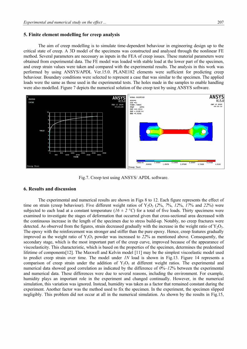
5. Finite element modelling for creep analysis The aim of creep modelling is to simulate time-dependent behaviour in engineering design up to the
critical state of creep. A 3D model of the specimens was constructed and analysed through the nonlinear FE method. Several parameters are necessary as inputs in the FEA of creep issues. These material parameters were obtained from experimental data. The FE model was loaded with stable load at the lower part of the specimen, and creep strain values were taken and compared with the experimental results. The analysis in this work was performed by using ANSYS/APDL Ver.15.0. PLANE182 elements were sufficient for predicting creep behaviour. Boundary conditions were selected to represent a case that was similar to the specimen. The applied loads were the same as those used in the experimental tests. The holes made in the samples to enable handling were also modelled. Figure 7 depicts the numerical solution of the creep test by using ANSYS software.
Fig.7. Creep test using ANSYS/ APDL software.
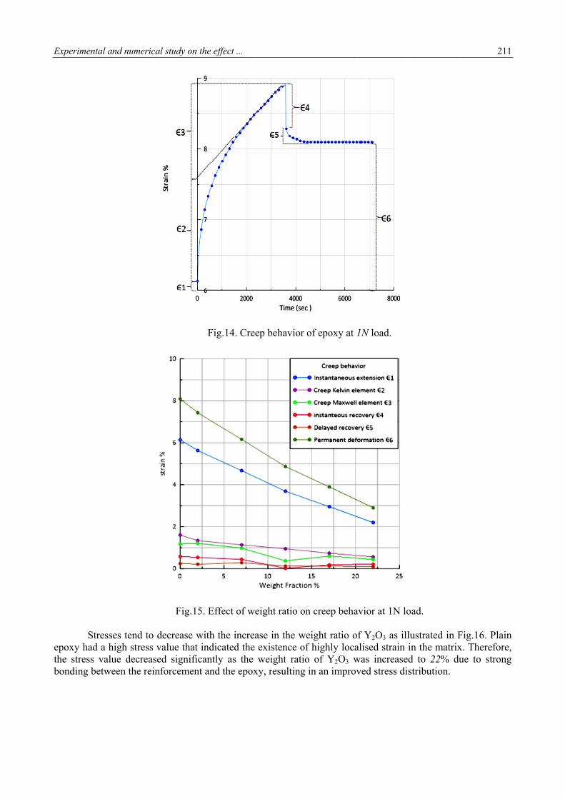
6. Results and discussion The experimental and numerical results are shown in Figs 8 to 12. Each figure represents the effect of time on strain (creep behaviour). Five different weight ratios of Y2O3 (2%, 7%, 12%, 17% and 22%) were subjected to each load at a constant temperature (16 ± 2 °C) for a total of five loads. Thirty specimens were examined to investigate the stages of deformation that occurred given that cross-sectional area decreased with the continuous increase in the length of the specimen due to stress build-up. Notably, no creep fractures were detected. As observed from the figures, strain decreased gradually with the increase in the weight ratio of Y2O3. The epoxy with the reinforcement was stronger and stiffer than the pure epoxy. Hence, creep features gradually improved as the weight ratio of Y2O3 powder was increased to 22% as mentioned above. Consequently, the secondary stage, which is the most important part of the creep curve, improved because of the appearance of viscoelasticity. This characteristic, which is based on the properties of the specimen, determines the predestined lifetime of components[12]. The Maxwell and Kelvin model [11] may be the simplest viscoelastic model used to predict creep strain over time. The model under 1N load is shown in Fig.13. Figure 14 represents a comparison of creep strain under the addition of Y2O3 at different weight ratios. The experimental and numerical data showed good correlation as indicated by the difference of 0%–12% between the experimental and numerical data. These differences were due to several reasons, including the environment. For example, humidity plays an important role in the experiment and changed continually. However, in the numerical simulation, this variation was ignored. Instead, humidity was taken as a factor that remained constant during the experiment. Another factor was the method used to fix the specimen. In the experiment, the specimen slipped negligibly. This problem did not occur at all in the numerical simulation. As shown by the results in Fig.15,

208
adding Y2OYoung’s mocapability o
Fig.8. A co
Fig.9. A com
O3 powder as odulus is indf this type of
omparison of A
mparison of A
a reinforcemdicative of higf reinforceme
ANSYS and e
ANSYS and e
ment to epoxygh stiffness.
ent to reduce
experimental
experimental
y increased YThis relationgap and void
study of strai
study of strai
Young’s modunship provided formation in
in versus time
in versus time
H.Abed,
ulus of the med clear and n the matrix
e for different
e for different
K.J.Jadee and
material graducertain indicduring moul
t weight ratios
t weight ratio
d A.A.Battawi
ually. A highcations of theding.
s at 1N load.
os at 2N load.
i
h e

Experimental and numerical study on the effect ... 209
Fig.10. A comparison of ANSYS and experimental study of strain versus time for different weight ratios at 3N load.
Fig.11. A comparison of ANSYS and experimental study of strain versus time for different weight ratios at 4N load.

210 H.Abed, K.J.Jadee and A.A.Battawi
Fig.12. A comparison of ANSYS and experimental study of strain versus time for different weight ratios at 5N load.
Fig.13. Modulus of elasticity for different weight ratios at 1N load.
Experimenta
Stre
epoxy had athe stress vbonding bet
al and numeric
esses tend toa high stressvalue decreastween the rei
cal study on th
Fig.15.
o decrease wi value that insed significainforcement
he effect ...
Fig.14. Cree
. Effect of we
ith the increandicated the antly as the and the epox
ep behavior
eight ratio on
ase in the weexistence ofweight ratio
xy, resulting
of epoxy at 1
n creep beha
eight ratio of highly locao of Y2O3 win an improv
1N load.
avior at 1N lo
f Y2O3 as illalised strain iwas increasedved stress dis
oad.
lustrated in Fin the matrixd to 22% dustribution.
211
Fig.16. Plainx. Therefore,ue to strong
n ,
g

212
7. Conclus
In treinforced wtemperature
1. Creindimat
2. Thecurv
3. Youincr
4. Strewith
5. Theincr
6. A c
Reference [1] AL-Hass
epoxy c
[2] GlaskovInterna
[3] Subramacreep b
sion
this study, twith Y2O3 pe. The conclueep charactericated that rterials. e addition ofve, thus prolung’s modulreased stiffneess distributih the increase weight ratioreasing the womparison re
es
sani E.S. and Acomposites. −
a T.K. and ational Confere
anian C., Al Mbehavior of po
Fig.16. Stre
the creep bepowder at fivusions could ristics could reinforcemen
f reinforcemlonging the tius increasedess. on was impr
se in the weigo of 22% proweight ratio bevealed good
Areef S.R. (2Engineering a
Aniskevich Aence on Comp
Mamari A.K.Holypropylene. −
ess versus tim
ehaviour, strve different wbe summarisbe enhanced
nt plays an
ent to the epime to break
d with the inc
roved by addght ratio of thovided the bebeyond this vd correlation
2010): The effand Technolo
A. (2009): Cposite Materia
H. and Senthi− Internationa
me for differe
ress and Youweight ratiosed as followd by increasiimportant r
poxy compokage. crease in the
ding reinforcehe reinforcemest creep provalue. n between the
fect of fiber orgy Journal, vo
Creep behavioals (ICCM-17
ilvelan S. (20al Journal of S
ent weight ra
ung’s modus were inves
ws: ing the weigrole in impro
osites extend
reinforceme
ement to the ment. perties. Supe
e experiment
rientation on ol.28, pp.1281
or of epoxy/c),Edinburgh, U
14): Effect ofStudents’. Res
H.Abed,
atio at 1N loa
ulus of epoxstigated unde
ght ratio of Yoving the m
ded the secon
ent ratio, thus
mixture. Str
erior propert
tal and nume
creep behavi1-1289.
clay nanocomUK.
f fiber length s Technol. Ma
K.J.Jadee and
ad.
xy compositeer five loads
Y2O3 powdermechanical p
ndary stage
s yielding m
ress noticeab
ties might be
erical results.
or and flexur
mposite. − Pr
on the short-anage, vol.2, p
d A.A.Battawi
es that weres at constant
r. This resultproperties of
of the creep
materials with
ly decreased
obtained by
ral strength in
roceedings of
-term flexuralpp.157-162.
i
e t
t f
p
h
d
y
n
f
l

Experimental and numerical study on the effect ... 213
[4] Papanicolaou G., Xepapadaki A. and Zarouchas D. (2009): Effect of water uptake on creep behaviour of glass–epoxy composites. − Plastics, Rubber and Composites, vol.38, pp.72-79.
[5] Bakonyi P. and Vas L.M. (2013): Analysis of the creep behavior of polypropylene and glass fiber reinforced polypropylene composites. − In Materials Science Forum, pp.302-307.
[6] Lorandi N.P., Cioffi M.O.H., Shigue C. and Ornaghi H.L. (2018): On the creep behavior of carbon/epoxy non-crimp fabric composites. − Materials Research, vol.21.
[7] Zhai Z., Jiang B. and Drummer D. (2018): Tensile creep behavior of quasi-unidirectional e-glass fabric reinforced polypropylene composite. − Polymers, vol.10, p.661.
[8] Fu K., Chang Y., Tang Y. and Zheng B. (2014): Effect of loading rate on the creep behaviour of epoxy resin insulators by nanoindentation. − Journal of Materials Science: Materials in Electronics, vol.25, pp.3552-3558.
[9] ASTM D638 (2010): Standard test method for tensile properties of plastics. − ASTM International, West Conshohocken. United States.
[10] ASTM D2990 (2004): Standard test methods for tensile, compressive, and flexural creep and creep-rupture of plastics. − ASTM International. West Conshohocken. United States.
[11] Dropik M.J., Johnson D.H. and Roth D.E. (2002): Developing an ANSYS creep model for polypropylene from experimental data. − In Proceedings of International ANSYS Conference.
[12] Bledzki A.K. and Faruk O. (2004): Creep and impact properties of wood fibre–polypropylene composites: influence of temperature and moisture content. − Composites Science and Technology, vol.64, pp.693-700.
Received: March 14, 2020
Revised: July 14, 2020