Experimental and numerical analysis of the effect of gear ...
8
M´ ecanique & Industries 7, 71–78 (2006) c AFM, EDP Sciences 2006 DOI: 10.1051/meca:2006021 M´ ecanique & Industries Experimental and numerical analysis of the effect of gear center distance variation and misalignment error on the dynamic behavior of narrow-faced spur gear drives Mohamed Ben Amar, Mohamed Maatar and Aref Maalej Laboratory of Electro-Mechanical System, LASEM, ´ Ecole Nationale d’Ing´ enieurs de Sfax, BP W 3038, Sfax, Tunisie Received 29 May 2002, Accepted 8 July 2005 Abstract – In this paper, we present an experimental and numerical analysis of the influence of gear center distance variation and misalignment amplitude on dynamic response of single stage spur gear transmis- sion systems. The experimental part is conducted on a specific test bench conceived and constructed at LASEM and composed essentially of a motor, a test gearbox and a receptor. It allows the measurement of the acceleration on the motor and receptor bearing shafts for different values of gear center distances and misalignment amplitudes. The numerical study is based on a 3D non-linear model with 36 degrees of free- dom including torsional, flexural and axial displacements of the gear-shaft-bearing system. The equations of motion and the contact problem are solved simultaneously using an original procedure by coupling a normal contact algorithm and a numerical Hilbert-Hughes-Taylor schema. Agreement between measure- ments and calculations is satisfactory and illustrates the influence of these mounting errors on the dynamic behavior of Narrow-Faced Spur Gear. Key words: Spur gear transmission / misalignement errors / gear centers distance variation / non-linear dynamic model / modal analysis / experimental and numerical dynamic responses 1 Introduction The dynamic behavior of gear transmission is gener- ally conditioned by the perturbations produced by the dif- ferent parts of the system (gear, motor, bearing, . . . ). The two kinds of geometrical errors, generally found in gear transmission systems, are manufacturing defaults (pitch errors, profile and distorsion errors, . . . ) and mount- ing errors (eccentricities, misalignment, gear center dis- tances, . . . ). It is well known that gear transmission design imposes a variation of the gear center distances because of permitted tolerance intervals. In fact, the functional gear center distance is different from the theoretical one. The variation of gear center distances modifies the length of the contact pattern on the base plane and generally causes a premature or backward contact. Consequently, the value of transverse contact ratio changes consider- ably. Misalignment has an important influence on the dy- namic load distribution of mating teeth and on the gear vibration. For important amplitude of misalignment, we can show a partial contact through the face width with a strong concentration on one edge of the flanks. As a result of this partial contact, a decrease of mesh stiffness is oc- curring and consequently the mesh resonance frequencies become lower. Experimental and numerical studies are proposed to analyze the influence of these mounting errors on the dynamic behavior of gear transmission systems. First, measurements of the dynamic response for different error amplitude and input rotational speed will be presented. Next, a series of numerical results, obtained at the same conditions, using a numerical tool developed by Maatar and Velex P. [1,2] will be compared to these measure- ments. 2 Non-linear dynamic model In this specific model, pinion and wheel are simulated as rigid cylinders connected by an elastic and dissipative link. Potential contact lines on the base plane are dis- cretized in independent elementary cells of normal stiff- ness (k i ). According to this discretization, mesh stiffness is time-dependent because of contact length evolutions and non-linear as contact length depends on actual tooth loading and geometrical deviations on mating surfaces. The contact deflection ∆ i (M i ) at the potential point of contact M i depends on the normal approach induced by Article published by EDP Sciences and available at http://www.edpsciences.org/meca or http://dx.doi.org/10.1051/meca:2006021
-
Upload
khangminh22 -
Category
Documents
-
view
4 -
download
0
Transcript of Experimental and numerical analysis of the effect of gear ...
Mecanique & Industries 7, 71–78 (2006)c© AFM, EDP Sciences 2006DOI: 10.1051/meca:2006021
Mecanique& Industries
Experimental and numerical analysis of the effect of gear centerdistance variation and misalignment error on the dynamicbehavior of narrow-faced spur gear drives
Mohamed Ben Amar, Mohamed Maatar and Aref Maalej
Laboratory of Electro-Mechanical System, LASEM, Ecole Nationale d’Ingenieurs de Sfax, BP W 3038, Sfax, Tunisie
Received 29 May 2002, Accepted 8 July 2005
Abstract – In this paper, we present an experimental and numerical analysis of the influence of gear centerdistance variation and misalignment amplitude on dynamic response of single stage spur gear transmis-sion systems. The experimental part is conducted on a specific test bench conceived and constructed atLASEM and composed essentially of a motor, a test gearbox and a receptor. It allows the measurement ofthe acceleration on the motor and receptor bearing shafts for different values of gear center distances andmisalignment amplitudes. The numerical study is based on a 3D non-linear model with 36 degrees of free-dom including torsional, flexural and axial displacements of the gear-shaft-bearing system. The equationsof motion and the contact problem are solved simultaneously using an original procedure by coupling anormal contact algorithm and a numerical Hilbert-Hughes-Taylor schema. Agreement between measure-ments and calculations is satisfactory and illustrates the influence of these mounting errors on the dynamicbehavior of Narrow-Faced Spur Gear.
Key words: Spur gear transmission / misalignement errors / gear centers distance variation / non-lineardynamic model / modal analysis / experimental and numerical dynamic responses
1 Introduction
The dynamic behavior of gear transmission is gener-ally conditioned by the perturbations produced by the dif-ferent parts of the system (gear, motor, bearing, . . . ). Thetwo kinds of geometrical errors, generally found in geartransmission systems, are manufacturing defaults (pitcherrors, profile and distorsion errors, . . . ) and mount-ing errors (eccentricities, misalignment, gear center dis-tances, . . . ). It is well known that gear transmission designimposes a variation of the gear center distances becauseof permitted tolerance intervals. In fact, the functionalgear center distance is different from the theoretical one.The variation of gear center distances modifies the lengthof the contact pattern on the base plane and generallycauses a premature or backward contact. Consequently,the value of transverse contact ratio changes consider-ably. Misalignment has an important influence on the dy-namic load distribution of mating teeth and on the gearvibration. For important amplitude of misalignment, wecan show a partial contact through the face width with astrong concentration on one edge of the flanks. As a resultof this partial contact, a decrease of mesh stiffness is oc-curring and consequently the mesh resonance frequenciesbecome lower.
Experimental and numerical studies are proposed toanalyze the influence of these mounting errors on thedynamic behavior of gear transmission systems. First,measurements of the dynamic response for different erroramplitude and input rotational speed will be presented.Next, a series of numerical results, obtained at the sameconditions, using a numerical tool developed by Maatarand Velex P. [1, 2] will be compared to these measure-ments.
2 Non-linear dynamic model
In this specific model, pinion and wheel are simulatedas rigid cylinders connected by an elastic and dissipativelink. Potential contact lines on the base plane are dis-cretized in independent elementary cells of normal stiff-ness (ki). According to this discretization, mesh stiffnessis time-dependent because of contact length evolutionsand non-linear as contact length depends on actual toothloading and geometrical deviations on mating surfaces.
The contact deflection ∆i(Mi) at the potential pointof contact Mi depends on the normal approach induced by
Article published by EDP Sciences and available at http://www.edpsciences.org/meca or http://dx.doi.org/10.1051/meca:2006021
72 M. Ben Amar et al.: Mecanique & Industries 7, 71–78 (2006)
the degrees of freedom δ(Mi) and the relative compositegeometrical deviation δe(Mi)
∆(Mi) = δ (Mi) + δ e(Mi) (1)
δ (Mi) = V (Mi)T q (2)δe(Mi) = e(M∗) − e(Mi) (3)
Withq: coordinate vector associated with the gear,V (Mi): structure vector depending on gear geometry,(ki): elementary mesh stiffness of the cell centered in Mi,e(M∗): composite deviation at M∗ – one point of contactin rigid body condition,e(Mi): composite deviation at Mi – potential point ofcontact in the deformed state.The instantaneous contact condition at the potentialpoint Mi is:
∆(Mi) > 0 (4)
The strain energy associated with the mesh can begiven by:
UG =12
∑i
ki H [∆(Mi)] ∆2(Mi)
=12qT
[∑i
ki H [∆(Mi)] V (Mi) V (Mi)T
]
× q − qT∑
i
ki H [∆(Mi)]
δe(Mi) V (Mi) +12
∑i
ki H [∆(Mi)]δe2(Mi) (5)
where H [∆(Mi)] is the unit Heaviside function defined by:H(∆) = 1 if ∆ > 0H(∆) = 0 if ∆ ≤ 0 (6)
Using Lagrange equations leads to:
ddt
(∂T Ro
G
∂qk
)−
(∂T Ro
G
∂qk
)= [M ] q − F1G
k = 1, 2, ..., 12 (7)
∂UG
∂qk= [KG (t, q)] q − F2G (q) (8)
The global equations of motion obtained after assem-bly of the gear, shafts and bearing matrices is:
[M ]
X
+ [C]X
+ [K(t, X)] X =
Fext + F1G + F2G (9)
where:
X: coordinate vector for the complete system.
The damping matrix is introduced in the equations ofmotion through modal damping factor. The mode shapes
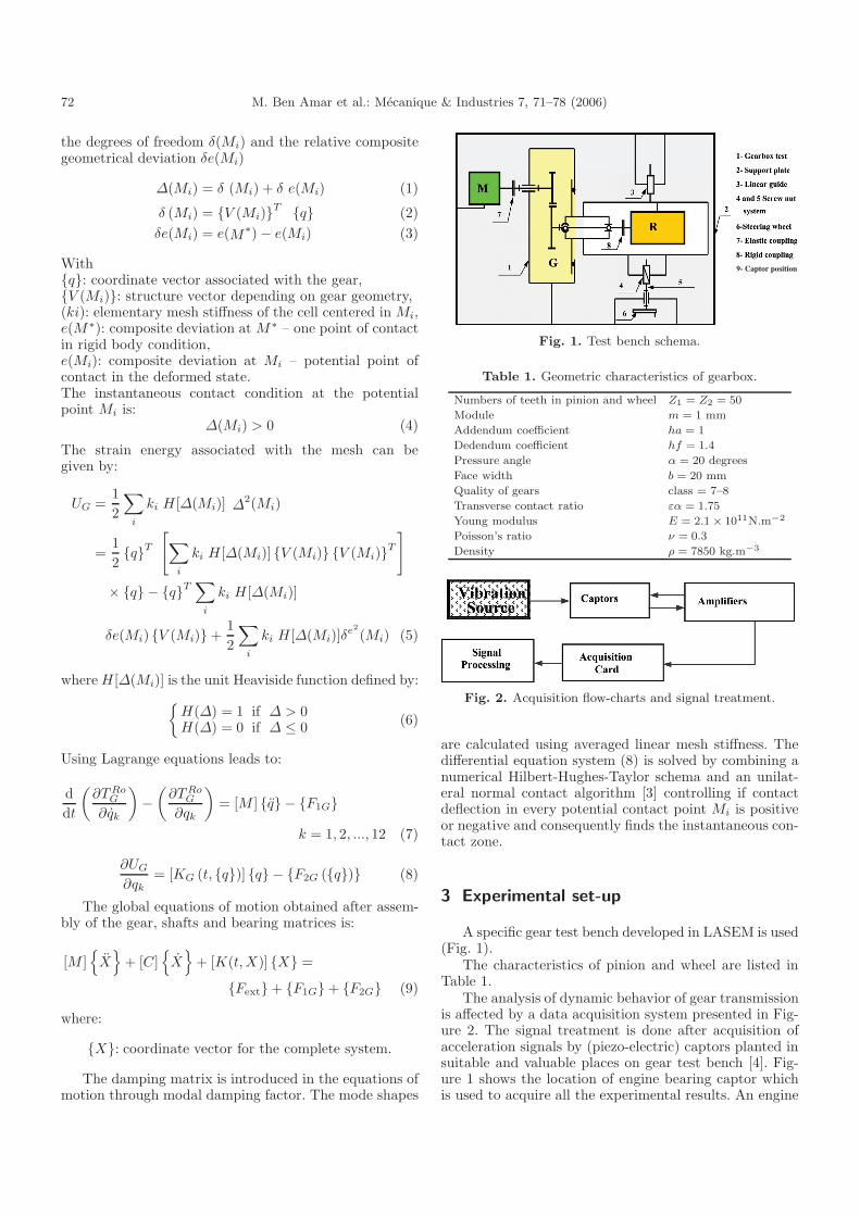
Fig. 1. Test bench schema.
Table 1. Geometric characteristics of gearbox.
Numbers of teeth in pinion and wheel Z1 = Z2 = 50
Module m = 1 mm
Addendum coefficient ha = 1
Dedendum coefficient hf = 1.4
Pressure angle α = 20 degrees
Face width b = 20 mm
Quality of gears class = 7–8
Transverse contact ratio εα = 1.75
Young modulus E = 2.1 × 10¹¹N.m−2
Poisson’s ratio ν = 0.3
Density ρ = 7850 kg.m−3
Fig. 2. Acquisition flow-charts and signal treatment.
are calculated using averaged linear mesh stiffness. Thedifferential equation system (8) is solved by combining anumerical Hilbert-Hughes-Taylor schema and an unilat-eral normal contact algorithm [3] controlling if contactdeflection in every potential contact point Mi is positiveor negative and consequently finds the instantaneous con-tact zone.
3 Experimental set-up
A specific gear test bench developed in LASEM is used(Fig. 1).
The characteristics of pinion and wheel are listed inTable 1.
The analysis of dynamic behavior of gear transmissionis affected by a data acquisition system presented in Fig-ure 2. The signal treatment is done after acquisition ofacceleration signals by (piezo-electric) captors planted insuitable and valuable places on gear test bench [4]. Fig-ure 1 shows the location of engine bearing captor whichis used to acquire all the experimental results. An engine
M. Ben Amar et al.: Mecanique & Industries 7, 71–78 (2006) 73
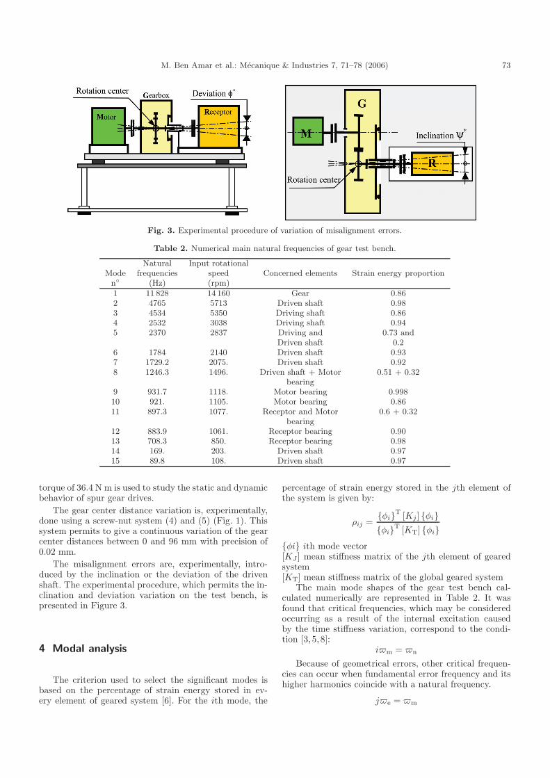
Fig. 3. Experimental procedure of variation of misalignment errors.
Table 2. Numerical main natural frequencies of gear test bench.
Natural Input rotationalMode frequencies speed Concerned elements Strain energy proportion
n (Hz) (rpm)1 11 828 14 160 Gear 0.862 4765 5713 Driven shaft 0.983 4534 5350 Driving shaft 0.864 2532 3038 Driving shaft 0.945 2370 2837 Driving and 0.73 and
Driven shaft 0.26 1784 2140 Driven shaft 0.937 1729.2 2075. Driven shaft 0.928 1246.3 1496. Driven shaft + Motor 0.51 + 0.32
bearing9 931.7 1118. Motor bearing 0.99810 921. 1105. Motor bearing 0.8611 897.3 1077. Receptor and Motor 0.6 + 0.32
bearing12 883.9 1061. Receptor bearing 0.9013 708.3 850. Receptor bearing 0.9814 169. 203. Driven shaft 0.9715 89.8 108. Driven shaft 0.97
torque of 36.4 N m is used to study the static and dynamicbehavior of spur gear drives.
The gear center distance variation is, experimentally,done using a screw-nut system (4) and (5) (Fig. 1). Thissystem permits to give a continuous variation of the gearcenter distances between 0 and 96 mm with precision of0.02 mm.
The misalignment errors are, experimentally, intro-duced by the inclination or the deviation of the drivenshaft. The experimental procedure, which permits the in-clination and deviation variation on the test bench, ispresented in Figure 3.
4 Modal analysis
The criterion used to select the significant modes isbased on the percentage of strain energy stored in ev-ery element of geared system [6]. For the ith mode, the
percentage of strain energy stored in the jth element ofthe system is given by:
ρij =φiT [Kj] φiφiT [KT] φi
φi ith mode vector[KJ ] mean stiffness matrix of the jth element of gearedsystem[KT] mean stiffness matrix of the global geared system
The main mode shapes of the gear test bench cal-culated numerically are represented in Table 2. It wasfound that critical frequencies, which may be consideredoccurring as a result of the internal excitation causedby the time stiffness variation, correspond to the condi-tion [3, 5, 8]:
im = n
Because of geometrical errors, other critical frequen-cies can occur when fundamental error frequency and itshigher harmonics coincide with a natural frequency.
je = m
74 M. Ben Amar et al.: Mecanique & Industries 7, 71–78 (2006)
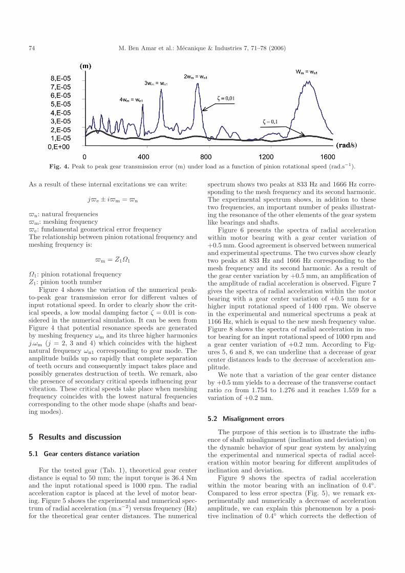
Fig. 4. Peak to peak gear transmission error (m) under load as a function of pinion rotational speed (rad.s−1).
As a result of these internal excitations we can write:
je ± im = n
n: natural frequenciesm: meshing frequencye: fundamental geometrical error frequencyThe relationship between pinion rotational frequency andmeshing frequency is:
m = Z1Ω1
Ω1: pinion rotational frequencyZ1: pinion tooth number
Figure 4 shows the variation of the numerical peak-to-peak gear transmission error for different values ofinput rotational speed. In order to clearly show the crit-ical speeds, a low modal damping factor ζ = 0.01 is con-sidered in the numerical simulation. It can be seen fromFigure 4 that potential resonance speeds are generatedby meshing frequency ωm and its three higher harmonicsj.ωm (j = 2, 3 and 4) which coincides with the highestnatural frequency ωn1 corresponding to gear mode. Theamplitude builds up so rapidly that complete separationof teeth occurs and consequently impact takes place andpossibly generates destruction of teeth. We remark, alsothe presence of secondary critical speeds influencing gearvibration. These critical speeds take place when meshingfrequency coincides with the lowest natural frequenciescorresponding to the other mode shape (shafts and bear-ing modes).
5 Results and discussion
5.1 Gear centers distance variation
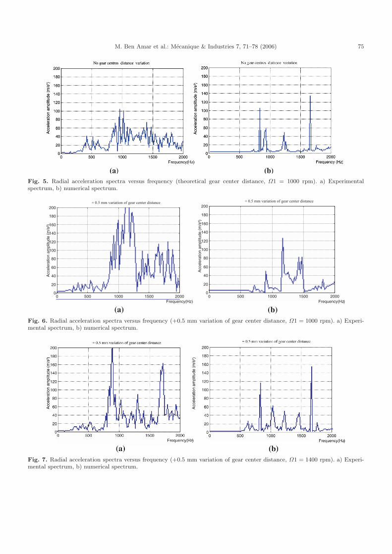
For the tested gear (Tab. 1), theoretical gear centerdistance is equal to 50 mm; the input torque is 36.4 Nmand the input rotational speed is 1000 rpm. The radialacceleration captor is placed at the level of motor bear-ing. Figure 5 shows the experimental and numerical spec-trum of radial acceleration (m.s−2) versus frequency (Hz)for the theoretical gear center distances. The numerical
spectrum shows two peaks at 833 Hz and 1666 Hz corre-sponding to the mesh frequency and its second harmonic.The experimental spectrum shows, in addition to thesetwo frequencies, an important number of peaks illustrat-ing the resonance of the other elements of the gear systemlike bearings and shafts.
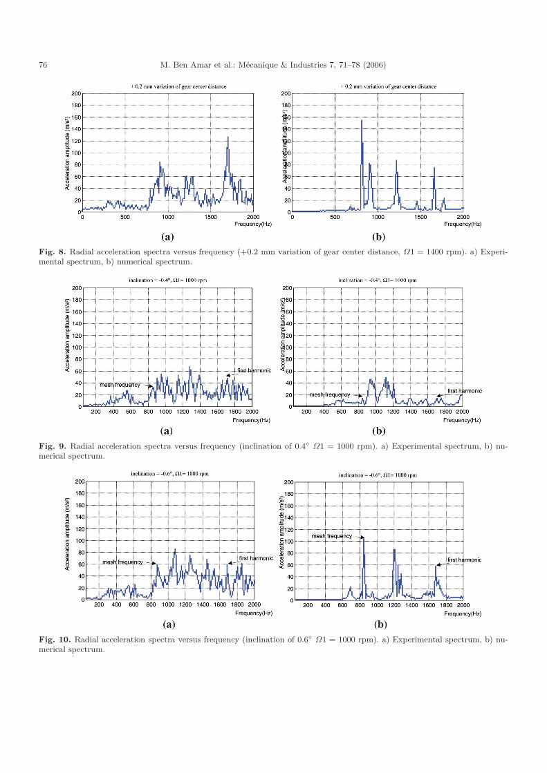
Figure 6 presents the spectra of radial accelerationwithin motor bearing with a gear center variation of+0.5 mm. Good agreement is observed between numericaland experimental spectrums. The two curves show clearlytwo peaks at 833 Hz and 1666 Hz corresponding to themesh frequency and its second harmonic. As a result ofthe gear center variation by +0.5 mm, an amplification ofthe amplitude of radial acceleration is observed. Figure 7gives the spectra of radial acceleration within the motorbearing with a gear center variation of +0.5 mm for ahigher input rotational speed of 1400 rpm. We observein the experimental and numerical spectrums a peak at1166 Hz, which is equal to the new mesh frequency value.Figure 8 shows the spectra of radial acceleration in mo-tor bearing for an input rotational speed of 1000 rpm anda gear center variation of +0.2 mm. According to Fig-ures 5, 6 and 8, we can underline that a decrease of gearcenter distances leads to the decrease of acceleration am-plitude.
We note that a variation of the gear center distanceby +0.5 mm yields to a decrease of the transverse contactratio εα from 1.754 to 1.276 and it reaches 1.559 for avariation of +0.2 mm.
5.2 Misalignment errors
The purpose of this section is to illustrate the influ-ence of shaft misalignment (inclination and deviation) onthe dynamic behavior of spur gear system by analyzingthe experimental and numerical specta of radial accel-eration within motor bearing for different amplitudes ofinclination and deviation.
Figure 9 shows the spectra of radial accelerationwithin the motor bearing with an inclination of 0.4.Compared to less error spectra (Fig. 5), we remark ex-perimentally and numerically a decrease of accelerationamplitude, we can explain this phenomenon by a posi-tive inclination of 0.4 which corrects the deflection of
M. Ben Amar et al.: Mecanique & Industries 7, 71–78 (2006) 75
Fig. 5. Radial acceleration spectra versus frequency (theoretical gear center distance, Ω1 = 1000 rpm). a) Experimentalspectrum, b) numerical spectrum.
Fig. 6. Radial acceleration spectra versus frequency (+0.5 mm variation of gear center distance, Ω1 = 1000 rpm). a) Experi-mental spectrum, b) numerical spectrum.
Fig. 7. Radial acceleration spectra versus frequency (+0.5 mm variation of gear center distance, Ω1 = 1400 rpm). a) Experi-mental spectrum, b) numerical spectrum.
76 M. Ben Amar et al.: Mecanique & Industries 7, 71–78 (2006)
Fig. 8. Radial acceleration spectra versus frequency (+0.2 mm variation of gear center distance, Ω1 = 1400 rpm). a) Experi-mental spectrum, b) numerical spectrum.
Fig. 9. Radial acceleration spectra versus frequency (inclination of 0.4 Ω1 = 1000 rpm). a) Experimental spectrum, b) nu-merical spectrum.
Fig. 10. Radial acceleration spectra versus frequency (inclination of 0.6 Ω1 = 1000 rpm). a) Experimental spectrum, b) nu-merical spectrum.
M. Ben Amar et al.: Mecanique & Industries 7, 71–78 (2006) 77
Fig. 11. Radial acceleration spectra versus frequency (deviation of 0.4 Ω1 = 1000 rpm). a) Experimental spectrum, b) nu-merical spectrum
Fig. 12. Radial acceleration spectra versus frequency (deviation of 0.6 Ω1 = 1000 rpm). a) Experimental spectrum, b) nu-merical spectrum.
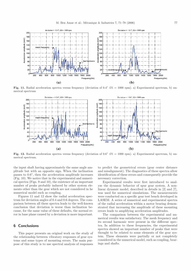
the input shaft having approximately the same angle am-plitude but with an opposite sign. When the inclinationpasses to 0.6, then the acceleration amplitude increases(Fig. 10). We notice that in the experimental and numeri-cal spectra (Figs. 9 and 10), the existence of an importantnumber of peaks probably induced by other system ele-ments other than the gear which are not considered in henumerical model such as coupling.
Figures 11 and 12 show the radial acceleration spec-trum for deviation angles of 0.4 and 0.6 degrees. The com-parison between all these spectra leads to the well-knownconclusion that deviation is worse than inclination be-cause, for the same value of these defaults, the normal er-ror in base plane caused by a deviation is more important.
6 Conclusions
This paper presents an original work on the study ofthe relationship between vibratory responses of gear sys-tems and some types of mounting errors. The main pur-pose of this study is to use spectral analysis of responses
to predict the geometrical errors (gear center distanceand misalignment). The diagnostics of these spectra allowidentification of these errors and consequently provide thenecessary correction.
Experimental results were first introduced to anal-yse the dynamic behavior of spur gear system. A non-linear dynamic model, described in details in [2] and [7],was used for numerical simulations. The measurementswere conducted on a specific gear test bench developed inLASEM. A series of numerical and experimental spectraof the radial acceleration within a motor bearing demon-strated that increasing the amplitude of these mountingerrors leads to amplifying acceleration amplitudes.
The comparison between the experimental and nu-merical results was satisfactory. The mesh frequency andits second harmonic were present in the different spec-tra. In addition to these frequencies, the experimentalspectra showed an important number of peaks that werethought to be related to some elements of the gear sys-tem. These elements were partially or not completelyconsidered in the numerical model, such as coupling, bear-ings and shafts.
78 M. Ben Amar et al.: Mecanique & Industries 7, 71–78 (2006)
Acknowledgements. The authors wish to thank M. PhilippeVelex of “Laboratoire de Mecanique des contacts de l’INSAde Lyon France” for his support of this research.
References
[1] M. Maatar, P. Velex, T. Nguyen, M. Octrue, J.L. Vasseur,Experimental and Numerical analysis of transmission er-rors in spur gear drives, J. Machine Vibration 4 (1995)8–13
[2] P. Velex, M. Maatar, A mathematical model for analysingthe influence of shape deviations and mounting errors ongear dynamic behaviour, J. Sound Vibration 5(191) 1996629–660
[3] P. Velex, D. Berthe, Meshing and EccentricityContributions to the Dynamic Tooth Loading, Proc.5th IFToMM Int. Conf. On Rotordynamics, Lyon 1990,219–224
[4] M. Ben Amar, Materiaux et endommagement des en-
grenages, DEA Ecole Centrale de Lyon, France, 1995[5] M. Maatar, P. Velex, Quasi-Static and Dynamic Analysis
of Narrow-Faced Helical Gears with Profile and LeadModifications, A.S.M.E. J. Mechanical Design 119 (1997)474–480
[6] P. Velex, A. Saada, Modal Analysis for the predictionof Dynamic Tooth loads in Geared Trains. Proc. 3rdJ.S.M.E, Int. Conf. On Motion and Power Transmission,Hiroshima 1991, 117–122
[7] M. Maatar, Contribution a l’analyse du comportementdynamique de reducteurs a engrenages simple etage ;influence des ecarts de forme et des defauts de mon-tage, These de doctorat : Institut National des SciencesAppliquees de Lyon, 1995
[8] M. Benton, A. Seireg, Simulation of Resonances andInstability Conditions in Pinion-Gear Systems, J.Mechanical Design; Trans. A.S.M.E., (1978) 100(1) 26–31
To access this journal online:www.edpsciences.org/meca