Experimental and Numerical Studies of Concrete-Filled ...
246
Experimental and Numerical Studies of Concrete-Filled Double Steel Tubular Columns by Mizan Ahmed Thesis submitted in fulfillment of the requirement for the Degree of Doctor of Philosophy Institute for Sustainable Industries and Liveable Cities, Victoria University Melbourne, Australia January 2020
-
Upload
khangminh22 -
Category
Documents
-
view
4 -
download
0
Transcript of Experimental and Numerical Studies of Concrete-Filled ...

Experimental and Numerical Studies of
Concrete-Filled Double Steel Tubular
Columns
by
Mizan Ahmed
Thesis submitted in fulfillment of the requirement for the Degree of
Doctor of Philosophy
Institute for Sustainable Industries and Liveable Cities, Victoria University
Melbourne, Australia
January 2020
M. Ahmed: Experimental and Numerical Studies of Concrete-Filled Double Steel Tubular Columns ii
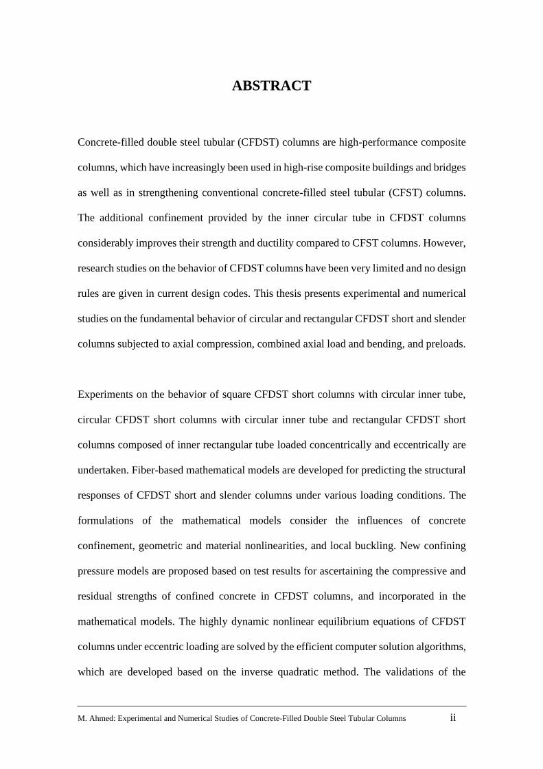
ABSTRACT
Concrete-filled double steel tubular (CFDST) columns are high-performance composite
columns, which have increasingly been used in high-rise composite buildings and bridges
as well as in strengthening conventional concrete-filled steel tubular (CFST) columns.
The additional confinement provided by the inner circular tube in CFDST columns
considerably improves their strength and ductility compared to CFST columns. However,
research studies on the behavior of CFDST columns have been very limited and no design
rules are given in current design codes. This thesis presents experimental and numerical
studies on the fundamental behavior of circular and rectangular CFDST short and slender
columns subjected to axial compression, combined axial load and bending, and preloads.
Experiments on the behavior of square CFDST short columns with circular inner tube,
circular CFDST short columns with circular inner tube and rectangular CFDST short
columns composed of inner rectangular tube loaded concentrically and eccentrically are
undertaken. Fiber-based mathematical models are developed for predicting the structural
responses of CFDST short and slender columns under various loading conditions. The
formulations of the mathematical models consider the influences of concrete
confinement, geometric and material nonlinearities, and local buckling. New confining
pressure models are proposed based on test results for ascertaining the compressive and
residual strengths of confined concrete in CFDST columns, and incorporated in the
mathematical models. The highly dynamic nonlinear equilibrium equations of CFDST
columns under eccentric loading are solved by the efficient computer solution algorithms,
which are developed based on the inverse quadratic method. The validations of the

M. Ahmed: Experimental and Numerical Studies of Concrete-Filled Double Steel Tubular Columns iii
numerical models are made by comparisons with experimental results. The influences of
various geometric and material parameters on the behavior of CFDST columns are
examined. The results obtained from experimental and numerical studies are used to
propose design equations.
This research makes significant contributions to the knowledge by adding new test results
on CFDST short columns to the database. The numerical models developed provide
researchers and structural designers with accurate and efficient computer simulation and
design tools, which lead to safer and more economical designs of composite structures.
The design equations proposed can be utilized to design CFDST short and slender
columns under various loading conditions.
M. Ahmed: Experimental and Numerical Studies of Concrete-Filled Double Steel Tubular Columns iv
DECLARATION
I, Mizan Ahmed, declare that the PhD thesis by publication entitled Experimental and
Numerical Studies of Concrete-Filled Double Steel Tubular Columns is no more than
100,000 words in length including quotes and exclusive of tables, figures, appendices,
bibliography, references, and footnotes. This thesis contains no material that has been
submitted previously, in whole or in part, for the award of any other academic degree or
diploma. Except where otherwise indicated, this thesis is my own work.
Signature: Date: 22-04-2020
Mizan Ahmed Digitally signed by Mizan Ahmed Date: 2020.04.22 20:19:03 +10'00'
M. Ahmed: Experimental and Numerical Studies of Concrete-Filled Double Steel Tubular Columns v
ACKNOWLEDGMENTS
First and foremost, all glory to the almighty for granting me this research opportunity
which has been a great privilege. I would like to then express my sincere gratitude to my
principal supervisor Associate Professor Qing Quan Liang of Victoria University,
Melbourne for his time, support and invaluable suggestions throughout my doctoral
study. I would also like to thank my associate supervisors Associate Professor
Muhammad N. S. Hadi of the University of Wollongong, NSW and Dr. Vipulkumar
Ishvarbhai Patel of La Trobe University, Bendigo for their discussions and suggestions.
The research project was supported by the Research Training Scheme and a College of
Engineering and Science scholarship at Victoria University, Melbourne, Australia. The
experimental work conducted as part of this research project was supported by the grants
provided by La Trobe University, Bendigo and Victoria University, Melbourne,
Australia. The financial support is gratefully acknowledged.
I would like to acknowledge the patience, support and constant care of my wife given
during the completion of this research degree. I am also grateful to my parents and
parents-in-law for their endless love, prayer, and support towards me. I really appreciate
their time to visit me in Australia and accompanying my wife and children during my
study. Heartfelt thanks to all of you. Last, but not least, I would like to dedicate this thesis
to my beloved children Muhammad Bin Ahmed and Fatimah Al Zahra Ahmed.

M. Ahmed: Experimental and Numerical Studies of Concrete-Filled Double Steel Tubular Columns vi
LIST OF PUBLICATIONS
Based on this research, the following papers have been either published or submitted for
publication in international journals and conference proceedings.
Journal Articles
1. Ahmed, M., Liang, Q. Q., Patel, V. I. and Hadi, M. N. S. (2018). Nonlinear analysis
of rectangular concrete-filled double steel tubular short columns incorporating local
buckling. Engineering Structures, 175: 13-26.
2. Ahmed, M., Liang, Q. Q., Patel, V. I. and Hadi, M. N. S. (2019). Numerical analysis
of axially loaded circular high strength concrete-filled double steel tubular short
columns. Thin-Walled Structures, 138: 105-116.
3. Ahmed, M., Liang, Q. Q., Patel, V. I. and Hadi, M. N. S. (2019). Local-global
interaction buckling of square high strength concrete-filled double steel tubular slender
beam-columns. Thin-Walled Structures, 143, 106244.
4. Ahmed, M., Liang, Q. Q., Patel, V. I. and Hadi, M. N. S. (2019). Experimental and
numerical studies of square concrete-filled double steel tubular short columns under
eccentric loading. Engineering Structures, 197, 109419.
5. Ahmed, M., Liang, Q. Q., Patel, V. I. and Hadi, M. N. S. (2019). Behavior of
eccentrically loaded double circular steel tubular short columns filled with concrete.
Engineering Structures, 201, 109790.
6. Ahmed, M., Liang, Q. Q., Patel, V. I. and Hadi, M. N. S. (2020). Experimental and
numerical investigations of eccentrically loaded rectangular concrete-filled double
steel tubular columns. Journal of Constructional Steel Research, 167, 105949.

M. Ahmed: Experimental and Numerical Studies of Concrete-Filled Double Steel Tubular Columns vii
7. Ahmed, M., Liang, Q. Q., Patel, V. I. and Hadi, M. N. S. (2020). Computational
simulation of eccentrically-loaded circular thin-walled concrete-filled double steel
tubular slender columns. Engineering Structures, 213, 110571.
8. Ahmed, M., Liang, Q. Q., Patel, V. I. and Hadi, M. N. S. (2020). Nonlinear analysis
of square concrete-filled double steel tubular slender columns incorporating preload
effects. Engineering Structures, 207, 110272.
9. Ahmed, M., Liang, Q. Q., Patel, V. I. and Hadi, M. N. S. (2020). Behavior of circular
concrete-filled double steel tubular slender beam-columns including preload effects.
Engineering Structures, (currently under review).
Refereed Conference Papers
1. Ahmed, M., Liang, Q. Q., Patel, V. I. and Hadi, M. N. S. (2018). Numerical
modelling of axially loaded circular concrete-filled double steel tubular short
columns, Part I: Formulation. Proceedings of the 13th International Conference on
Steel, Space and Composite Structures, Perth, Australia, 2018.
2. Ahmed, M., Liang, Q. Q., Patel, V. I. and Hadi, M. N. S. (2018). Numerical
modelling of axially loaded circular concrete-filled double steel tubular short
columns, Part II: Parametric study. Proceedings of the 13th International Conference
on Steel, Space and Composite Structures, Perth, Australia, 2018.
3. Ahmed, M., Liang, Q. Q., Patel, V. I. and Hadi, M. N. S. (2019). Nonlinear inelastic
analysis of high-strength square concrete-filled double steel tubular slender columns.
Proceedings of the 4th Australasian Conference on Computational Mechanics,
Tasmania, Australia, 2019.

M. Ahmed: Experimental and Numerical Studies of Concrete-Filled Double Steel Tubular Columns viii
PART A:
DETAILS OF INCLUDED PAPERS: THESIS BY PUBLICATION
Please list details of each Paper included in the thesis submission. Copies of published Papers
and submitted and/or final draft Paper manuscripts should also be included in the thesis
submission.
Item/ Chapter No.
Paper Title Publication Status (e.g.
published,
accepted for publication, to be revised and resubmitted, currently under review, unsubmitted but proposed to be submitted )
Publication Title and Details (e.g.
date published, impact factor
etc.)
3
Nonlinear analysis of rectangular
concrete-filled double steel
tubular short columns
incorporating local buckling.
Published Engineering Structures,
2018, 175, 13-26.
SCImago Journal Rank: Q1
Impact Factor: 3.084 (Year
of 2018) Experimental and numerical
studies of square concrete-filled
double steel tubular short columns
under eccentric loading.
Published Engineering Structures,
2019; 197: 109419.
SCImago Journal Rank: Q1
Impact Factor: 3.084 (Year
of 2018) Experimental and numerical
investigations of eccentrically-
loaded rectangular concrete-filled
double steel tubular columns.
Published
on April 2020
Journal of Constructional
Steel Research, SCImago
Journal Rank: Q1
Impact Factor: 2.650 (Year
of 2018)
4
Numerical analysis of axially
loaded circular high strength
concrete-filled double steel
tubular short columns.
Published Thin-Walled Structures,
2019, 138,105-116.
SCImago Journal Rank: Q1
Impact Factor: 3.488 (Year
of 2018)

M. Ahmed: Experimental and Numerical Studies of Concrete-Filled Double Steel Tubular Columns ix
Behavior of eccentrically loaded
double circular steel tubular short
columns filled with concrete.
Published Engineering Structures,
2019, 201, 109790.
SCImago Journal Rank: Q1
Impact Factor: 3.084 (Year
of 2018)
5
Local-global interaction buckling
of square high strength concrete-
filled double steel tubular slender
beam-columns.
Published Thin-Walled Structures,
2019, 143, 106244. SCImago
Journal Rank: Q1
Impact Factor: 3.488 (Year
of 2018)
6
Computational simulation of
eccentrically-loaded circular thin-
walled concrete-filled double steel
tubular slender columns.
Published
on 15th June
2020
Engineering Structures,
SCImago Journal Rank: Q1
Impact Factor: 3.084 (Year
of 2018)
7
Nonlinear analysis of square
concrete-filled double steel
tubular slender columns
incorporating preload effects.
Published
on 15th March
2020
Engineering Structures,
SCImago Journal Rank: Q1
Impact Factor: 3.084 (Year
of 2018)
Behavior of circular concrete-
filled double steel tubular slender
beam-columns including preload
effects
Under review Engineering Structures,
SCImago Journal Rank: Q1
Impact Factor: 3.084 (Year
of 2018)
Declaration by [candidate name]: Signature: Date:
Mizan Ahmed 22-04-2020
Mizan Ahmed Digitally signed by Mizan Ahmed Date: 2020.04.22 20:20:20 +10'00'

M. Ahmed: Experimental and Numerical Studies of Concrete-Filled Double Steel Tubular Columns x
CONTENTS
Page No.
Title…………………………………………………………………………………i
Abstract…………………………………………………………………………….ii
Declaration…………………………………………………………………………iv
Acknowledgements………………………………………………………………...v
List of Publications………………………………………………………………...vi
Details of Included Papers: Thesis by Publication………………………………viii
Contents…………………………………………….………………………………x
Chapter 1 Introduction…………………………………………………………….1
1.1 Background…………………………………………………………………....1
1.2 Research Significance…………………………………………………………5
1.3 Aims of This Research………………………………………………………...6
1.4 Thesis Layout………………………………………………………………….8
Chapter 2 Literature Review………………………………………………………12
2.1 Introduction……………………………………………………………………12
2.2 Local and Post Local Buckling of Steel Plates………...………………………13
2.3 Concrete-Filled Steel Tubular Columns…………….…………………………19
2.3.1 Experimental Studies…………….………………………………..…19
2.3.2 Numerical Studies…………….……………………………………...26
2.4 Double Skin CFST Columns…………….…………………………………….31
2.4.1 Experimental Studies…………….…………………………………..31
2.4.2 Numerical Studies…………….…………………………………..….35
2.5 Concrete-Filled Double Steel Tubular Columns…………….……..………….38
2.5.1 Experimental Studies……………………..………………………….38
2.5.2 Numerical Studies…………….…………………..………………….42
2.6 Composite Columns With Preload Effects…………….………………………45
2.6.1 Experimental studies…………….………………………….………..45

M. Ahmed: Experimental and Numerical Studies of Concrete-Filled Double Steel Tubular Columns xi
2.6.2 Numerical studies…………….………………………………….……47
2.7 Concluding Remarks…………….……………………………………………...49
Chapter 3 Rectangular CFDST Short Columns…………………………….…….51
3.1 Introduction…………….……………………………………………………....51
3.2 Declarations…………….……………………………………………………....53
3.3 Nonlinear analysis of rectangular concrete-filled double steel tubular short
columns incorporating local buckling…………….…………………………....59
3.4 Experimental and numerical studies of square concrete-filled double steel
tubular short columns under eccentric loading………….…………………....73
3.5 Experimental and numerical investigations of eccentrically-loaded rectangular
concrete-filled double steel tubular columns.…………….…………………….90
3.6 Concluding Remarks…………….…………………………………………….145
Chapter 4 Circular CFDST Short Columns…………………..…………………..146
4.1 Introduction…………….………………………………………..…………….....146
4.2 Declarations…………….………………………………………………….…….148
4.3 Numerical analysis of axially loaded circular high strength concrete-filled double
steel tubular short columns…………….…………………………………………152
4.4 Behavior of eccentrically loaded double circular steel tubular short columns filled
with concrete…………….………………………………………………………164
4.5 Concluding Remarks…………….………………………………………………180
Chapter 5 Local-Global Interaction Buckling of Square CFDST Slender
Columns…………….………………………………………………………...181
5.1 Introduction…………….………………………………………………………..181
5.2 Declarations…………….……………………………………………………….183
5.3 Local-global interaction buckling of square high strength concrete-filled double
steel tubular slender beam-columns…………….…………………………….…185
5.4 Concluding Remarks…………….……………………………………………...202

M. Ahmed: Experimental and Numerical Studies of Concrete-Filled Double Steel Tubular Columns xii
Chapter 6 Circular CFDST Slender Columns under Eccentric Loading………203
6.1 Introduction…………….…………………………………………….………….203
6.2 Declarations…………….…………………………………………………….….205
6.3 Computational simulation of eccentrically-loaded circular thin-walled concrete-
filled double steel tubular slender columns…………….……………………….207
6.4 Concluding Remarks…………….……………………………………………....260
Chapter 7 CFDST Slender Columns with Preload Effects…………….………..261
7.1 Introduction…………….……………………………………………………….261
7.2 Declarations…………….……………………………………………………….263
7.3 Nonlinear analysis of square concrete-filled double steel tubular slender columns
incorporating preload effects…………….…………………………...…………267
7.4 Behavior of circular concrete-filled double steel tubular slender beam-columns
including preload effects…………….…………………………………………..322
7.5 Concluding Remarks…………….……………………………………………...367
Chapter 8 Conclusions…………….………………………………………………368
8.1 Summary…………….………………………………………………………..368
8.2 Achievements…………….…………………………………………………...369
8.3 Further Research…………….……………………………………………......370
References…………….……………………………………………………………373

Chapter 1 Introduction
M. Ahmed: Experimental and Numerical Studies of Concrete-Filled Double Steel Tubular Columns 1
Chapter 1
INTRODUCTION
1.1 BACKGROUND
Steel-concrete composite columns have been extensively used in modern construction
industry owing to their high performance in terms of ductility, strength, energy absorption
capacity as well as good constructability in comparison with reinforced concrete columns.
In a concrete-filled steel tubular (CFST) column as depicted in Fig. 1, the filled concrete
prevents the steel tube from the inward local-buckling and works compositely with the
steel section. The steel tube acts as the permanent formwork for the concrete so that the
construction cost and time can be greatly minimized. The concrete-filled double steel
tubular (CFDST) column as shown in Fig. 2 is an innovative form of composite columns
where the steel tubes are placed concentrically and filled with concrete.
The choice of the cross-section and geometry of a CFDST column for a specific project
is dependent on the structural efficiency of the column, specific architecture or aesthetic
criteria, material availability or the cost and method of construction. As an example,
circular CFDST columns illustrated in Fig. 2 (a) have higher ductility and strength than
rectangular CFDST columns, therefore, they can be used to carry large axial loads.

Chapter 1 Introduction
M. Ahmed: Experimental and Numerical Studies of Concrete-Filled Double Steel Tubular Columns 2
However, rectangular CFDST columns (Fig. 2(b)) offer ease of connection to the steel
beams and can be used in the case where the large bending stiffness is essential.
(a) (b)
Fig. 1. Cross-sections of CFST columns: (a) circular; (b) rectangular.
Square CFDST columns composed of an internal circular tube as illustrated in Fig. 2 (c)
combine the benefits of both circular and square CFST columns. The presence of the
internal circular tube improves the strength, ductility and fire-resistance of CFDST
columns compared to CFST columns as well as double-skin concrete-filled tubular
(DCFST) columns illustrated in Fig. 3 (Pei 2005; Romero et al. 2015; Ekmekyapar and
Al-Eliwi 2017).
In addition to being used in new composite structures, a CFDST column can also be
constructed by strengthening an existing CFST column with an external steel tube that is
filled with concrete. Moreover, different strengths of materials can be used for the
external and internal tubes of CFDST columns to achieve economic designs. Due to their

Chapter 1 Introduction
M. Ahmed: Experimental and Numerical Studies of Concrete-Filled Double Steel Tubular Columns 3
availability, high-strength materials are increasingly used to construct such composite
columns. Nonetheless, high strength concrete is less ductile and therefore its effect on the
ductility of CFDST composite columns must be properly evaluated and understood.
Furthermore, rectangular CFDST columns with non-compact or slender sections are
susceptible to local buckling which significantly affects the column performance. The
steel tubular walls of a rectangular CFDST column under axial load combined with
bending resulting from the eccentric loading may be subjected to either uniform stresses
or stress gradients. The nonlinear analysis of local-global interaction buckling of slender
rectangular CFDST columns is complicated and a challenging problem in structural
engineering.
(a) (b) (c)
Fig. 2. Cross-sections of CFDST columns: (a) circular CFDST column; (b) rectangular
CFDST columns; and (c) square CFDST columns composed of an internal circular tube.
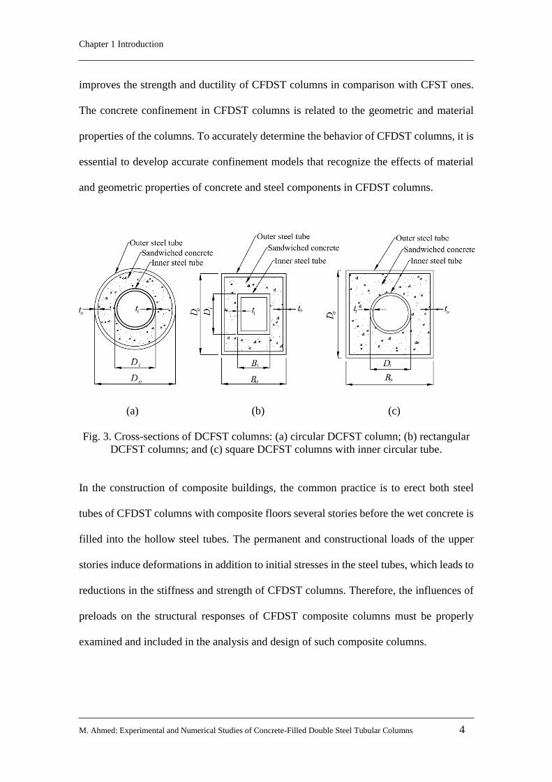
There is a difference between the confinement mechanism in CFDST and other steel-
concrete composite columns. The core-concrete of a circular CFDST column
incorporating an internal circular steel section is confined by both steel tubes, which
Chapter 1 Introduction
M. Ahmed: Experimental and Numerical Studies of Concrete-Filled Double Steel Tubular Columns 4
improves the strength and ductility of CFDST columns in comparison with CFST ones.
The concrete confinement in CFDST columns is related to the geometric and material
properties of the columns. To accurately determine the behavior of CFDST columns, it is
essential to develop accurate confinement models that recognize the effects of material
and geometric properties of concrete and steel components in CFDST columns.
(a) (b) (c)
Fig. 3. Cross-sections of DCFST columns: (a) circular DCFST column; (b) rectangular
DCFST columns; and (c) square DCFST columns with inner circular tube.
In the construction of composite buildings, the common practice is to erect both steel
tubes of CFDST columns with composite floors several stories before the wet concrete is
filled into the hollow steel tubes. The permanent and constructional loads of the upper
stories induce deformations in addition to initial stresses in the steel tubes, which leads to
reductions in the stiffness and strength of CFDST columns. Therefore, the influences of
preloads on the structural responses of CFDST composite columns must be properly
examined and included in the analysis and design of such composite columns.
Chapter 1 Introduction
M. Ahmed: Experimental and Numerical Studies of Concrete-Filled Double Steel Tubular Columns 5
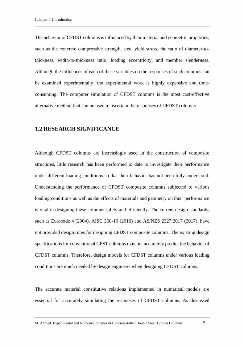
The behavior of CFDST columns is influenced by their material and geometric properties,
such as the concrete compressive strength, steel yield stress, the ratio of diameter-to-
thickness, width-to-thickness ratio, loading eccentricity, and member slenderness.
Although the influences of each of these variables on the responses of such columns can
be examined experimentally, the experimental work is highly expensive and time-
consuming. The computer simulation of CFDST columns is the most cost-effective
alternative method that can be used to ascertain the responses of CFDST columns.
1.2 RESEARCH SIGNIFICANCE
Although CFDST columns are increasingly used in the construction of composite
structures, little research has been performed to date to investigate their performance
under different loading conditions so that their behavior has not been fully understood.
Understanding the performance of CFDST composite columns subjected to various
loading conditions as well as the effects of materials and geometry on their performance
is vital in designing these columns safely and efficiently. The current design standards,
such as Eurocode 4 (2004), AISC 360-16 (2016) and AS/NZS 2327:2017 (2017), have
not provided design rules for designing CFDST composite columns. The existing design
specifications for conventional CFST columns may not accurately predict the behavior of
CFDST columns. Therefore, design models for CFDST columns under various loading
conditions are much needed by design engineers when designing CFDST columns.
The accurate material constitutive relations implemented in numerical models are
essential for accurately simulating the responses of CFDST columns. As discussed

Chapter 1 Introduction
M. Ahmed: Experimental and Numerical Studies of Concrete-Filled Double Steel Tubular Columns 6
earlier, CFDST columns have a different confinement mechanism from CFST columns.
Therefore, accurate confinement models need to be developed for the concrete in CFDST
columns to accurately predict the behavior of CFDST columns. The outer rectangular
steel tube of a CFDST column may undergo local buckling, which affects the column
performance significantly. However, no fiber-based numerical models have been
formulated for accurately quantifying the responses of CFDST rectangular composite
columns incorporating the effect of local-buckling.
This research makes significant contributions to the knowledge base of CFDST
composite columns by adding new test data on short CFDST columns and developing
computationally efficient numerical models for predicting the responses of CFDST
columns with different loading conditions including axial compression, axial load
combined with bending, and preloads. The proposed confinement models can accurately
ascertain the confinement of confined concrete in such columns and incorporated in
inelastic analysis procedures for CFDST columns. The fiber-based techniques developed
in this research provide researchers and structural designers with accurate and efficient
computer simulation and design tools, which lead to safer and more economical designs
of composite structures. The design models proposed in this research can be included in
design standards for the design of CFDST columns.
1.3 AIMS OF THIS RESEARCH
The main aim of this research is to examine the behavior of CFDST short columns
experimentally and develop mathematical models for the simulations of structural

Chapter 1 Introduction
M. Ahmed: Experimental and Numerical Studies of Concrete-Filled Double Steel Tubular Columns 7
performance of short and slender CFDST columns under various loading conditions
considering the influences of confinement, local buckling of thin-walled steel sections,
and geometric and material nonlinearities. The specific aims are as follows:
1. To perform a series of tests on the responses of circular and rectangular CFDST
short columns which are loaded axially and eccentrically.
2. To develop mathematical models for calculating the performance of short CFDST
rectangular columns with either circular or rectangular inner tube incorporating
local buckling.
3. To develop mathematical models for predicting the responses of short circular
CFDST columns loaded concentrically and eccentrically.
4. To develop a mathematical model for circular slender CFDST columns subjected
to eccentric loading.
5. To develop a mathematical model for simulating the interaction local-global
buckling behavior of eccentrically loaded slender rectangular CFDST columns
with inner circular tube.
6. To develop mathematical models for circular and rectangular CFDST slender
columns with preload effects.
7. To verify the mathematical models developed by experimental results.
8. To assess the sensitivities of the structural behavior of CFDST columns with
various design loads to key design parameters.
9. To propose design models for the design of CFDST columns subjected to various
design loads.

Chapter 1 Introduction
M. Ahmed: Experimental and Numerical Studies of Concrete-Filled Double Steel Tubular Columns 8
1.4 THESIS LAYOUT
This thesis comprises of 8 chapters. An extensive literature review on the investigations
of steel-concrete composite columns under different design loads is presented in Chapter
2. Firstly, research studies on the post-local buckling of plate elements in addition to
initial local-buckling are studied. Experimental studies as well as numerical
investigations on the behavior of concrete-filled steel composite columns under axial
loading and combined axial load with bending are then reviewed. Finally, a review on the
existing experimental and computational investigations of steel-concrete composite
columns with preload effects is carried out.
In Chapter 3, the performance of short CFDST columns made of square and rectangular
cross-sections is investigated that are loaded axially and eccentrically. Firstly, a
computational model is proposed for the response analysis of square CFDST stub
columns with an internal circular tube loaded concentrically, incorporating local
buckling, concrete confinement, and geometric and material nonlinearities. New
expressions are developed to quantify the lateral pressure and residual strength of the
filled concrete in CFDST columns based on the available experimental results. The effects
of crucial parameters on the responses of such columns that are loaded axially are
examined by employing the numerical models developed. A simple design model is
derived to estimate the column's ultimate axial capacity. Experiments are also undertaken
to investigate the behavior of square CFDST short columns having an inner circular tube
and double rectangular/square steel tubular short columns filled with concrete loaded
either axially or eccentrically. The test setup and the test results are discussed. An efficient

Chapter 1 Introduction
M. Ahmed: Experimental and Numerical Studies of Concrete-Filled Double Steel Tubular Columns 9
mathematical model incorporating local buckling is further proposed that can simulate
the strength envelopes and moment-curvature relationships of CFDST columns under
eccentric loading. Effective solution algorithms implemented the inverse quadratic
method are developed to solve the dynamic equilibrium function. The validation of the
computational models is performed by comparing computations with experimental
results. The influences of section geometry and material parameters on the structural
responses of CFDST columns are examined using the computational model developed.
The axial responses of circular CFDST stub columns having an internal circular tube are
investigated in Chapter 4. A mathematical model utilizing the fiber analysis method is
developed for the response analysis of short columns that are axially loaded. Upon the
interpretation of the existing test data, formulas for quantifying the lateral pressures on
concrete and the strength degradation of the confined concrete are suggested. The new
constitutive laws of concrete of CFDST columns are incorporated in the mathematical
model formulated and verified by experiments. Design models are proposed that ascertain
the ultimate loads of CFDST columns incorporating confinement and strain-hardening of
steel tubes. Furthermore, a series of tests are performed to investigate the behavior of
short circular CFDST columns that are loaded both axially and eccentrically. The test
results and discussions provide crucial information on the behavior of such columns
loaded eccentrically. A nonlinear mathematical model is also developed for simulating
the responses of CFDST columns under eccentrical loading. The influences of concrete
confinement, section geometry, material properties and loading ratio on the moment
capacity and interaction curves are investigated.
Chapter 1 Introduction
M. Ahmed: Experimental and Numerical Studies of Concrete-Filled Double Steel Tubular Columns 10
Chapter 5 presents a mathematical model for ascertaining the global buckling behavior
of slender square CFDST beam-columns where the internal tube is circular. The model
explicitly considers the interaction of local and global buckling, second-order effects,
concrete confinement as well as geometric and material nonlinearities. The solution
algorithms based on the inverse quadratic method are utilized to solve the highly dynamic
equilibrium equations during the loading history. The mathematical modeling approach
is verified against the independent test results and utilized to quantify the behavior of
slender CFDST columns loaded eccentrically. Design formulas are derived to estimate
the ultimate loads as well as strength curves of slender CFDST square columns.
In Chapter 6, a mathematical model is presented for the computational simulation of
eccentrically-loaded slender CFDST circular columns with a circular inner tube. The
model is formulated by using the concept of fiber analysis and considers the influences
of concrete confinement, second-order effects, and geometric and material nonlinearities.
The existing test results of high-strength slender CFDST columns are used to validate the
mathematical model developed. The model is further validated against the test results of
DCFST columns. Upon validation, the influences of material and geometric variables on
the performance of slender CFDST columns are evaluated. Design equations are derived
for the design of slender circular CFDST composite columns.
Fiber analysis models are developed in Chapter 7 for ascertaining the structural
performance of slender square CFDST columns with an internal circular tube and circular
CFDST columns with an inner circular tube loaded eccentrically with the preload effects.
The computational models explicitly take into consideration the effects of local buckling,

Chapter 1 Introduction
M. Ahmed: Experimental and Numerical Studies of Concrete-Filled Double Steel Tubular Columns 11
concrete confinement, second-order as well as geometric and material nonlinearities. The
nonlinear equilibrium equations are solved using the inverse quadratic method. The
validations of the mathematical models developed are undertaken. The influences of
preload and important design parameters including the section geometry, local buckling,
and concrete confinement on the behavior of CFDST columns are examined using the
computational models developed. The effects of preload on the load distributions in the
components of CFDST columns are also assessed. Finally, design models are suggested
for the design of slender square CFDST columns with preload effects.
Chapter 8 provides conclusions on the experimental and computational investigations
on the responses of rectangular, square and circular CFDST short and slender columns
subjected to various design loads. Significant achievements are highlighted. Further
research studies on this topic are recommended.

Chapter 2 Literature Review
M. Ahmed: Experimental and Numerical Studies of Concrete-Filled Double Steel Tubular Columns 12
Chapter 2
LITERATURE REVIEW
2.1 INTRODUCTION
Research investigations on the structural performance of concrete-filled composite
columns with various loading conditions have been an active area in the field of structural
engineering. Experimental and numerical investigations provide useful insight into the
performance of composite columns subjected to various loading conditions and the basis
for developing design guidelines. Several books on steel-concrete composite structures
have been published (Oehlers and Bradford 1999; Han 2007; Zhao et al. 2010a; Liang
2014; Patel et al. 2015a, 2018; Han et al. 2018). Although this thesis concerns with
investigations on the performance of CFDST columns, existing studies on the behavior
of CFST composite columns and double-skin CFST (DCFST) composite columns under
various loading conditions are also reviewed. Firstly, the current knowledge on the critical
local-buckling as well as post-local buckling of steel plates is discussed, followed by the
extensive review of the published experimental and computational works on the
responses of CFST and DCFST columns under axial loading as well as combined axial
load with bending. Finally, existing investigations on the structural responses of concrete-
filled composite columns where the steel tubes were preloaded are reviewed.

Chapter 2 Literature Review
M. Ahmed: Experimental and Numerical Studies of Concrete-Filled Double Steel Tubular Columns 13
2.2 LOCAL AND POST-LOCAL BUCKLING OF STEEL PLATES
There have been numerous studies performed on the behavior of the local and post-local
buckling of steel elements at both room and high temperatures (Bryan 1890, Lundquist
and Stowell 1939, Lundquist et al. 1943, Chilver 1953, Maas 1954, Gerard and Becker
1957, Timoshenko and Gere 1961, Bulson 1969, Usami and Fukumoto 1982, Usami
1982, Usami and Fukumoto 1984, Azhari and Bradford 1991, Wright 1993, Wright 1995,
Uy and Bradford 1995, Liang and Uy 1998, Liang and Uy 2000, Liang et al. 2004,
Knobloch and Fontana 2006, Liang et al. 2007, Heidarpour and Bradford 2007,
Heidarpour and Bradford 2008, Bedair 2009, Bedair 2010, Quiel and Garlock 2010,
Couto et al. 2014). The very first work on the local buckling of rectangular steel plates
was reported by Bryan (1890) who investigated the local-buckling behavior of
rectangular steel plates under in-plane uniform compressive loads. Lundquist and Stowell
(1939) performed instability analysis of plates that formed rectangular and channel
sections subjected to uniform compression. Lundquist et al. (1943) utilized the method of
moment distribution to study the instability of structures composed of flat steel plates in
compression.
The differential equations of the deflection for the general section made of steel plates
can be used for the instability analysis in which the lowest eigenvalue represents the
buckling load. However, such differential equations are difficult to be developed for
complex sections and therefore the Rayleigh-Ritz method developed by Ritz (1909) had
been widely employed to quantify the critical stress of local-buckling for steel plate
elements from 1950 to 1970 by a number of researchers, like Chilver (1953), Gerard and

Chapter 2 Literature Review
M. Ahmed: Experimental and Numerical Studies of Concrete-Filled Double Steel Tubular Columns 14
Becker (1957) and Bulson (1969). However, with the development of the digital computer
in the early 70s, using the matrix method including the finite element (FE) method became
popular amongst the researchers for the buckling analysis of steel plates without
difficulty. Some of the earlier researchers utilized the matrix method included
Przemieniecki (1963, 1968), Kapur and Hartz (1966), Wittrick and Curzon (1968), and
Williams and Wittrick (1969, 1972). Usami (1982) developed a theoretical method for
studying the elastic post-local buckling of rectangular steel elements under combined
compression and bending. Marguerre's compatibility equations (Marguerre 1938) with
the energy method were used to obtain the solution in the theoretical investigation.
Expressions for predicting the effective widths of plates in compression and bending were
suggested based on the theoretical study.
Bradford and Hancock (1984) investigated the post-local buckling strengths of
geometrically imperfect steel plate elements by means of utilizing the method of finite
strip. The proposed computational method provided an alternative approach to Winter’s
concept of effective widths for the post-local buckling of beams that were simply
supported. The interaction of local buckling and flexural-torsional buckling in beams with
thin steel flanges was studied. Bradford (1985a) further extended the method of finite
strip to the post-local buckling response analysis of rectangular box sections that were
under transverse gradient stress and longitudinal stress. Design charts of elastic local
buckling coefficients were provided, and expressions were proposed that estimated the
post-buckling strength of rectangular box sections considering residual stresses.

Chapter 2 Literature Review
M. Ahmed: Experimental and Numerical Studies of Concrete-Filled Double Steel Tubular Columns 15
The finite element (FE) model was formulated by Bradford (1985b) for studying the
distortional buckling of fabricated mono-symmetric steel I-beams under moment
gradients. The effects of the web slenderness of the I-beams on the buckling behavior
were studied. Design equations were formulated for the determination of the distortional
stress of steel I-beams under moment gradients. Bradford and Cuk (1988) further
extended the FE modeling technique to the simulation of the flexural-torsional buckling
of beam-columns made of non-prismatic tapered I-section. In computational modeling,
the beam-column was represented by one-dimensional element. The stability matrices in
addition to the stiffness matrices were derived for the flexural-torsional buckling analysis
of the beam-columns. Bradford and Wong (1991) employed the semi-analytical method
of finite strip to capture the local buckling responses of elastic composite box girders
subjected to negative bending. The local buckling coefficients of composite box girders
were derived, and the limits were given for classifying the compact and slender webs.
Wright (1995) described a method underlying the energy principles for investigating the
local instability of the steel sections restrained by concrete. The theories of orthotropic
plates and the flow of plasticity were used to derive the limits on the width-to-thickness (
/B t ) ratios of steel elements under axial compression and combined bending and shear.
The suggested /B t ratios for steel elements restrained by the concrete were larger than
those of the steel plates that were unrestrained by concrete. This showed the benefits of
utilizing the concrete to fill the steel hollow sections.
Uy and Bradford (1995, 1996) used the method of finite strip to investigate the local
buckling characteristics of elastic steel plate elements in steel-concrete composite

Chapter 2 Literature Review
M. Ahmed: Experimental and Numerical Studies of Concrete-Filled Double Steel Tubular Columns 16
columns at ambient temperature as well as elevated temperatures. The influences of high
temperatures on the properties of steel material namely the yield strength and Young’s
modulus were considered in the analysis method. The plate local-buckling of composite
columns was found to be influenced by the material properties of steel exposed to elevated
temperatures. Design equations were provided, which could be used to calculate the
slenderness limits and the local-buckling stress of steel elements exposed to high
temperatures.
The FE models were created by Liang and Uy (1998, 2000) by means of employing the
finite element analysis system Strand6 to quantify the post-local buckling strength in
addition to the critical local-buckling behavior of steel tubular walls in rectangular CFST
columns under uniform compression. The edges of steel tubular walls in a box column
filled with concrete were assumed to be clamped. The influences of initial geometric
imperfection, material yielding, residual stresses, and the /B t ratio of the steel boxes on
the behavior of local buckling of clamped steel plate elements were investigated. It was
reported that owing to residual stresses and geometric imperfections, the steel elements
could not attain their yield strengths. The formulas of effective widths were developed to
predict the post-local buckling strengths of steel elements loaded concentrically and
verified by available test results on short CFST columns.
Uy (2000, 2001) proposed a theoretical model underlying the method of finite strip for
ascertaining the local-buckling behavior of CFST columns. The in-plane stresses of the
steel elements were redistributed using the formulas of effective widths to consider the
post-local buckling of non-compact steel boxes. It was discovered that the small /B t
Chapter 2 Literature Review
M. Ahmed: Experimental and Numerical Studies of Concrete-Filled Double Steel Tubular Columns 17
ratio did not have a significant effect on the local buckling behavior of CFST columns.
However, the local-buckling effect became significant when the steel section had a large
/B t ratio.
The post-local buckling responses of steel elements in addition to their initial local-
buckling in double-skin steel-concrete composite panels subjected to either biaxial
compressive stresses or combined shear and biaxial compression load were investigated
by Liang et al. (2003, 2004) utilizing the FE software Strand7. The single steel plate field
between stud shear connectors was employed to simulate the local buckling in addition
to the post-local buckling of steel-concrete composite panels. The edges of the steel plate
field were identified to be hinged and its corners were restrained by stud shear connectors
which were simulated by the shear-slip model. The FE models created accounted for the
influences of the initial imperfection of the steel plate field, material nonlinearities and
headed stud shear connectors. Several expressions were derived that calculated the critical
stresses of local buckling of plates with various boundary conditions and the post-local
buckling strengths of steel plate fields.
Liang et al. (2007) undertook numerical investigations into the behavior of local and post-
local buckling of steel tubular walls in rectangular CFST columns loaded biaxially. The
steel tubular walls of CFST columns loaded biaxially were under stress gradients and
assumed to be clamped at their edges. The influences of geometric imperfection initially
presented, material yielding and residual stresses were considered in the nonlinear
analysis. It was found that there was no bifurcation point on the load-deflection
relationships which could be identified for steel plates because of geometric

Chapter 2 Literature Review
M. Ahmed: Experimental and Numerical Studies of Concrete-Filled Double Steel Tubular Columns 18
imperfections. In addition to this, the stiffness and ultimate strength of steel plate elements
were found to decrease by increasing the ratio of /B t . Moreover, the steel plate that had
a /B t ratio of 100 could attain only 61.4% of its ultimate load. A set of equations were
derived based on the FE results for computing the critical stress of local-buckling and the
strength of post-local buckling of steel tubular walls in rectangular CFST columns loaded
biaxially. These equations could be implemented in nonlinear analysis programs to
consider the influences of local and post-local buckling on the strength and ductility of
CFST rectangular columns where the cross-sections are non-compact or slender (Liang
2009a, 2009b).
A model based on a semi-analytical approach was developed by Heidarpour and Bradford
(2007) for the investigation of the local instability of steel flanges exposed to elevated
temperatures. Based on the sensitivity analyses, the plasticity and yield slenderness limits
on the steel plates were suggested. The critical temperature that caused the local buckling
of flange outstands with either clamped or pinned supports was determined. Heidarpour
and Bradford (2008) further examined the behavior of local buckling of steel webs and
flanges in I-beams under axial loading in combination with bending and shear at elevated
temperatures. The variation of the mechanical strains was considered in the computational
modeling along with the web depth. The theoretical analysis showed that the elastic
buckling coefficients and the web slenderness limits were affected by the thermal
gradient, shear strain and the depth of the compression zone.
An inelastic stability model was presented by Ragheb (2015) to examine the influences
of web-flange interaction on the local buckling of I-beams under bending. The numerical

Chapter 2 Literature Review
M. Ahmed: Experimental and Numerical Studies of Concrete-Filled Double Steel Tubular Columns 19
results demonstrated that while the local instability of the flange was markedly influenced
by both the ratio of depth-to-thickness of the web and the width-to-depth ratio of the
section, only the width-to-depth ratio of the section influenced the local buckling of the
web.
Yaghoubshahi et al. (2015) studied the post-local buckling of the flawed shear panel made
of aluminum alloy and mild steel using the FE analysis. The initial crack induced in the
panel was allowed to grow during the loading history and simulated using the Bonora
damage model. The ultimate loads of the very thin shear panels were found to be
influenced by the initial crack size. However, these effects became insignificant as the
slenderness of the panels was reduced. Furthermore, the ultimate loads of the panels were
affected by the boundary conditions.
The local instability of columns made of steel I-sections loaded concentrically exposed
to high temperatures was investigated theoretically by Ragheb (2016). The reductions in
the stiffness and the yield stress of steel under high temperatures were considered in the
modeling. However, the effects of residual stresses resulting from the manufacturing
process were ignored. It was found that the geometry of the web and flanges of the section
greatly influenced the buckling load of the plate elements, and the steel yield strength had
a negligible impact on the local buckling load.
2.3 CONCRETE-FILLED STEEL TUBULAR COLUMNS
2.3.1 Experimental Studies

Chapter 2 Literature Review
M. Ahmed: Experimental and Numerical Studies of Concrete-Filled Double Steel Tubular Columns 20
The structural responses of CFST columns have been extensively studied by investigators
since the early 1960s. Some of the earliest investigations into the behavior of CFST
columns were performed by Kloppel and Goder (1957), Furlong (1967), Knowles and
Park (1969, 1970), Bridge (1976) and Shakir-Khalil and Zeghiche (1989). The strength
of square and circular short CFST columns were experimentally investigated by Furlong
(1967). The effects of the /B t ratio of the steel section together with the confinement
provided by the steel tube were examined. Test results showed that the confinement
increased both the ductility and strength of the concrete in CFST columns with circular
cross-sections, but only the improvement on the concrete ductility could be observed in
square cross-sections. Knowles and Park (1969) studied the sensitivities of the concrete
confinement of CFST beam-columns to the ratio of the member slenderness ( /L r ) and
the ratio of the depth-to-thickness ( /D t ). The steel tubes of the tested columns had the
/D t ratios ranged from 15 to 59. The confinement considerably improved the ductility
as well as the strength of circular columns. However, increasing the /L r ratio reduced
the confinement on the filled concrete.
Bridge (1976) designed a test program to assess the structural behavior of slender pin-
ended CFST beam-columns made of square cross-sections that were loaded biaxially. All
tested columns were made of compact steel sections with /B t ratios ranged from 20.5 to
23.5. The influences of loading eccentricity, member slenderness, and the loading angle
on the structural responses of CFST columns were investigated. From the experiments, it
could be found that there was no local buckling took place on the faces of the columns
tested due to their small /B t ratios. The ultimate capacities of the CFST columns were
shown to reduce remarkably as either the slenderness of the columns or the loading

Chapter 2 Literature Review
M. Ahmed: Experimental and Numerical Studies of Concrete-Filled Double Steel Tubular Columns 21
eccentricity increased. However, the loading angle had an insignificant effect on the
ultimate loads of the columns.
Experiments on the behavior of slender rectangular CFST beam-columns loaded
eccentrically were undertaken by Shakir-Khalil and Zeghiche (1989). The column cross-
sections, which were fabricated by cold-formed steel tubes, were compact. The concrete
used to fill the hollow sections had the compressive strength up to 45 MPa. It was found
that all column specimens failed by the overall buckling without any sign of local-
buckling. The ultimate loads of CFST columns obtained from experiments were
compared against the FE results as well as the design ultimate strengths calculated by the
method specified in BS 5400 (1979). Shakir-Khalil and Mouli (1990) carried out further
tests to assess the sensitivities of the strength of slender CFST rectangular columns loaded
concentrically to the cross-sectional size, the member /L r ratio, steel yield strength as
well as concrete strength. The ratios of /D t were 24, 30 and 40. The local buckling of
steel sections did not occur owing to small /D t ratios.
Schneider (1998) conducted experiments on fourteen short CFST columns made of either
circular, rectangular or square cross-section where the /D t ratios varied up to 50. The
steel tubes that had the yield stress up to 430 MPa and the concrete with a strength of 30
MPa were utilized to construct these specimens. The effects of the geometry and the ratio
of /D t on the axial load-strain relationships of CFST columns were evaluated in the
experimental program. The strain hardening behavior of all circular columns was
observed. However, only rectangular and square cross-sections that had a /D t ratio less
than 20 exhibited the strain-hardening behavior.
Chapter 2 Literature Review
M. Ahmed: Experimental and Numerical Studies of Concrete-Filled Double Steel Tubular Columns 22
The influences of concrete infill on the responses of CFST rectangular short columns
loaded axially were investigated by Bridge and O'Shea (1998) by means of conducting
experiments on columns that had /B t ratios varied from 37 to 131. It was indicated that
using a large /B t ratio remarkably reduced the strengths of the columns. O'Shea and
Bridge (2000) further studied the performance of circular short CFST columns where the
/D t ratios varied from 60 to 220. High-strength concrete that had the strength up to 120
MPa was employed to construct these columns. Design models for calculating the
capacities of CFST columns with different loading conditions were given. The
comparison between the ultimate strengths obtained by the tests and computed by the
approach specified in Eurocode 4 (1994) was made. The comparison showed that the
design code conservatively predicted the ultimate capacities of CFST columns
constructed by normal strength concrete.
Uy (2000) reported the behavior of short square CFST columns loaded eccentrically
through an experimental program. The /B t ratios of the square columns formed by
welding four individual steel plates were 40, 50, 60, 80 and 100. These specimens had
the steel yield stress up to 750 MPa. It was confirmed that the failure patterns of these
columns were the outward local-buckling of the steel sections, concrete crushing and weld
fracture. The ultimate load of CFST columns tested was observed to decrease as the ratio
of /B t increased.
Experiments on twenty-four short CFST rectangular columns were performed by Han
(2002) to ascertain the influences of the ratio of /B t and the confinement factor on the
axial responses of CFST columns. The steel tubes of the columns, which had the /B t

Chapter 2 Literature Review
M. Ahmed: Experimental and Numerical Studies of Concrete-Filled Double Steel Tubular Columns 23
ratios varied from 24.5 to 47, were formed by mild steel sheets with the steel yield stress
varied from 194 MPa to 228 MPa. The average concrete cubic strength was measured as
59.3 MPa. It was evident that the CFST columns tested failed by local buckling, and
increasing the confinement factor resulted in an improvement in the axial performance of
CFST columns.
Mursi and Uy (2003, 2004) studied the structural performance of rectangular CFST
columns which were slender. Their studies indicated that the slender columns failed by
the global instability coupled with the tube local-buckling. The filled concrete
significantly increased the capacities of CFST columns when compared to their hollow
counterparts. However, increasing the eccentricity-to-width ( /e B ) ratio considerably
reduced the strength and stiffness performance of CFST columns.
An experimental program comprised of 114 specimens was undertaken by Sakino et al.
(2004) to evaluate the significance of high-strength materials on the performance of short
circular and rectangular CFST columns. The range of the steel yield stress was between
277 MPa to 853 MPa and the strength of the filled concrete varied from 25.4 to 85.1 MPa.
The experimental observations demonstrated that the confinement in circular cross-
sections was more obvious than their rectangular counterparts. Increasing either the steel
yield stress or concrete strength considerably led to an increase in the strength of the
composite columns. Design equations for CFST columns loaded axially were presented.
Fujimoto et al. (2004) undertook experimental investigations on the structural behavior
of eccentrically-loaded CFST short columns. The significance of the with-to-thickness

Chapter 2 Literature Review
M. Ahmed: Experimental and Numerical Studies of Concrete-Filled Double Steel Tubular Columns 24
ratios of the steel sections and high-strength materials of concrete and steel on the
performance of CFST columns was ascertained. The column specimens were constructed
by the concrete with strength up to 80 MPa and steel sections with the maximum yield
stress of 834 MPa. It was pointed out that the failure of square CFST columns was owing
to the local-buckling of thin-walled steel sections and the effect of concrete confinement
could be negligible. An analytical model was also presented that determined the moment-
curvature responses of CFST columns and its accuracy was validated by experimental
data.
Experimental work on fifteen short CFST circular columns loaded concentrically was
reported by Giakoumelis and Lam (2004) who assessed the influences of the ratio of /D t
, bond strength, and concrete confinement. Concrete compressive strength up to 100 MPa
was used to construct these columns. It was demonstrated that the bond strength had a
considerable influence on the performance of short CFST columns constructed by high-
strength concrete. From the comparisons of test and design strengths determined by using
Eurocode 4 (1994), ACI 318-02 (2002) and AS 3600 (1994), it was found that these codes
underestimated the capacities of composite columns and the best estimation was obtained
by Eurocode 4.
Lee et al. (2011) performed tests on eleven short CFST circular columns that were
eccentrically loaded. The test variables included the material strength, the ratio of /D t ,
and loading eccentricity ratio ( /e D ). The steel tubes had the /D t ratios varied from 40
to 100. The steel yield stress was in the range from 468 MPa to 517 MPa while the
concrete with different strengths of 31.5 MPa and 59 MPa were used to cast these

Chapter 2 Literature Review
M. Ahmed: Experimental and Numerical Studies of Concrete-Filled Double Steel Tubular Columns 25
specimens. The columns were subjected to two different /e D ratios of 0.167 and 0.5.
The test results indicated that for columns that had the /D t ratio greater than 40, there
was no significant improvement in their ultimate resistances due to the confinement
effect. Furthermore, CFST columns with lower strength concrete had better ductility. The
design strength envelopes of CFST columns developed based on the specifications given
in Eurocode 4 (1994), AISC 360-05 (2005), KBCS (2009) were compared against the test
results. It was found that AISC 360-05 and KBCS provided strength estimations with
reasonable accuracy compared to the test data while Eurocode 4 overestimated the
strength envelopes of CFST columns.
The experimental results of thirty-seven slender circular CFST columns loaded
eccentrically were described by Portolés et al. (2011). The significance of the /D t ratio,
concrete strength, /e D ratio and /L r ratio on the responses of CFST columns was
assessed. The tested columns had the diameters varied from 100 mm to 160.1 mm and
the strengths of concrete varied from 32.7 MPa to 107.33 MPa. It was found that the
longer the column, the better its ductility. Owing to the overall buckling, high-strength
concrete was shown to have an insignificant effect on the capacities of slender CFST
columns.
Uy et al. (2011) presented experimental results on the responses of concrete-filled
stainless steel tubular (CFSST) slender and short columns that were loaded either
concentrically or eccentrically. Austenitic stainless steel was utilized to construct these
columns that had the /D t ratios ranged up to 101.6. From the experimental results, it
could be found that the deflection performance of CFSST columns was affected by the

Chapter 2 Literature Review
M. Ahmed: Experimental and Numerical Studies of Concrete-Filled Double Steel Tubular Columns 26
distinguished strain-hardening of stainless steel. The CFSST columns had higher ductility
than CFST columns. The experimental ultimate loads of CFSST columns have been
compared with those computed by AS 3600 (2009), Eurocode 4 (2004), AISC 360-05
(2005) and DBJ/T 13-51 (2010). It was discovered that these design codes generally
provided conservative strength estimations because the strain-hardening of stainless steel
was not accounted for in the design codes.
Recently, the experimental performance of CFST rectangular columns constructed by
high-strength materials was discussed by Huang et al. (2019). The steel plates were cut
into desired shapes and welded to form CFST columns where the /B t ratios varied from
18 to 68. The steel yield stress and the concrete strength varied up to 750 MPa and 50
MPa, respectively. The local buckling of the rectangular steel boxes that had large /B t
ratios was observed. In addition, it was shown that increasing the /B t ratio markedly
reduced the capacity and stiffness of CFST columns.
2.3.2 Numerical Studies
Vrcelj and Uy (2002) theoretically investigated the overall buckling responses of CFST
rectangular columns which were slender. The influences of concrete strength, member
slenderness ratio and the yield stress of steel on the load-carrying capacities of slender
CFST columns were evaluated. An elastoplastic constitutive model was adopted for the
structural steel while the material laws of concrete considered the strain softening were
employed. The effective width formulas were adopted to quantify the post-local buckling
strengths of steel tubular walls subjected to uniform edge compression. However, the

Chapter 2 Literature Review
M. Ahmed: Experimental and Numerical Studies of Concrete-Filled Double Steel Tubular Columns 27
gradual post-local buckling of the steel boxes was not considered and the concrete
material laws adopted ignored the tensile strength and shear deformation of concrete.
The nonlinear structural responses of CFST columns were analyzed by employing the FE
program Abaqus by Hu et al. (2003). From the FE results, it was found that circular steel
sections provided good confinement to the filled concrete, particularly for columns that
had the /D t ratio smaller than 40. For square sections, the confinement effect on the
axial capacity of columns where the ratio of /B t was greater than 30 was negligible.
However, the confinement in square sections could be increased by using reinforcing ties
spaced closely. Equations were proposed for quantifying the lateral confining stresses on
the concrete infill in CFST columns of square and circular sections and square CFST
columns with reinforcing ties. However, Liang and Fragomeni (2009) found that the
model given by Hu et al. (2003) for the concrete in circular cross-sections overestimated
the performance of circular CFST columns constructed with high-strength materials,
particularly for columns where the ratio of /D t was less than 47.
Ellobody et al. (2006) simulated the inelastic responses of CFST columns using the FE
software Abaqus. The numerical model accounted for the strain-hardening behavior of
structural steel as well as the concrete confinement effect using the equations of confining
pressures given by Hu et al. (2003). The correlation between numerical and experimental
load-deflection curves was generally good. Parameter study showed that there was a
remarkable improvement in the column capacity when the concrete and steel grades were
increased. The acceptability of the design methods given by Eurocode 4 (2004), ACI 318-
02 (2002), AISC 360-05 (2005) and AS 3600 (1994) was examined. It was found that AS

Chapter 2 Literature Review
M. Ahmed: Experimental and Numerical Studies of Concrete-Filled Double Steel Tubular Columns 28
3600 and ACI 318-02 conservatively estimated the column strengths owing to the
negligence of the effect of concrete confinement.
A numerical model utilizing the concept of fiber elements was proposed by Liang et al.
(2006) that simulated the structural behavior of nonlinear CFST short columns of
rectangular and square cross-sections loaded concentrically. The influence of the post-
local buckling of thin-walled steel sections was incorporated in the mathematical model
by means of employing the effective width equations of Liang and Uy (2000). The
verified model was utilized to evaluate the significance of steel yield stress, concrete
strength and /B t ratio of the steel section on the ultimate resistance of CFST columns.
Liang (2009a, 2009b) developed a method of performance-based analysis underlying the
theory of fiber elements for the prediction of the performance of short rectangular CFST
columns loaded biaxially. The stress-strain constitutive laws of structural steels
recognizing confinement effects were given. Proposed were a coefficient of strength
degradation for compressive concrete in the post-yield regime and a coefficient of
strength reduction that was used to consider the effect of column size on the concrete
strength. The effect of local and post-local buckling of steel tubular walls was included
in the mathematical modeling method using the expressions given by Liang et al. (2007).
An efficient computer program was specially developed to model the gradual local and
post-local buckling of steel flanges and webs of CFST columns loaded biaxially. The in-
plane fiber stresses were gradually redistributed from the area heavily buckled to the edge
strips in the steel tube wall based on the concept of effective widths. Computational
procedures were designed that calculated the load-axial strain as well as axial load-

Chapter 2 Literature Review
M. Ahmed: Experimental and Numerical Studies of Concrete-Filled Double Steel Tubular Columns 29
moment-curvature responses of CFST columns including local buckling. The dynamic
equilibrium equations were solved by employing efficient solution algorithms that were
developed based on the secant method. The accuracy of the computational modeling
method was established by means of comparing computer solutions with the
experimentally measured responses of CFST columns.
The theoretical models of fiber approach for the response simulation of CFST circular
columns loaded axially and eccentrically were formulated by Liang and Fragomeni (2009,
2010). A confining pressure model, which was expressed in terms of the steel yield stress
and the /D t ratio, was proposed to ascertain the confinement effect on the concrete. An
iterative mathematical modeling procedure was designed to obtain the moment-curvature
relationships of CFST columns loaded eccentrically. The equilibrium condition was
maintained during loading history by adjusting the neutral axis depth. An efficient
solution algorithm implementing the secant method was developed to solve the nonlinear
equilibrium functions. The fiber modeling approach proposed was shown to accurately
capture the performance of CFST circular columns. Design models were proposed, which
estimated the section ultimate load and pure moment capacity of CFST columns and
verified against independent experimental results.
Liang (2011a, 2011b) developed a mathematical modeling scheme, which simulated the
overall buckling behavior of slender high-strength CFST circular columns that were
eccentrically loaded. The fiber-based mathematical model incorporated various important
features, including the geometric imperfection, concrete confinement, and material
nonlinearities. Computer modeling procedures for calculating the load-displacement and

Chapter 2 Literature Review
M. Ahmed: Experimental and Numerical Studies of Concrete-Filled Double Steel Tubular Columns 30
axial load-moment interaction relations of CFST columns were presented. The secant
method was implemented in the iterative computational procedures to calculate the true
neutral axis depth as well as the curvature in the simulation of nonlinear slender CFST
columns. The computational modeling method has been found to accurately predict the
responses of CFST circular columns.
A multiscale computational model was formulated by Liang et al. (2012) for ascertaining
the interaction behavior of local-global buckling of biaxially-loaded rectangular slender
CFST columns with pin-ended supports. The multiscale modeling technique accounted
for the local and post-local buckling of non-compact and slender steel sections that were
subjected to stress gradients. Computational solution algorithms underlying Müller’s
method were programmed to solve the highly dynamic, nonlinear equilibrium functions
generated in the iterative-incremental analysis of CFST columns. The validation of the
mathematical model was presented by Patel et al. (2015b) by comparing computations
against independent test data. The influences of material strengths and dimensions of the
tubes on the steel and concrete contribution ratios and ultimate strengths of CFST
columns under biaxial loads were assessed.
Patel et al. (2017a) employed a fiber method to predict the behavior of load-lateral
displacement and the axial load-moment of slender circular CFSST columns composed
of stainless steel tubes loaded eccentrically. The three-stage material constitutive laws
provided by Quach et al. (2008) and Abdella et al. (2011) were included in the fiber model
to model the behavior of stainless-steel. The effects of confinement, second-order, and
material nonlinearities were considered in the mathematical modeling method. Computer

Chapter 2 Literature Review
M. Ahmed: Experimental and Numerical Studies of Concrete-Filled Double Steel Tubular Columns 31
algorithms, which implemented Müller’s method, were programmed to solve the highly
dynamic equilibrium equations during the loading history. Patel et al. (2017b) further
developed the fiber method for quantifying the structural responses of CFSST slender
columns composed of rectangular cross-sections which were eccentrically loaded to
failure. The behavior of local and post-local buckling of thin-walled steel tubular walls
of CFSST columns was simulated by employing a set of expressions given by Liang et
al. (2007) for carbon steel tubes. Computational investigations on the significance of
various design variables on the ultimate loads, ultimate moments, deflection and
interaction strengths of CFST columns were undertaken.
The computer simulations of the nonlinear behavior of short concrete-filled aluminum
tubular (CFAT) circular columns concentrically loaded were presented by Patel et al.
(2020). A new lateral pressure model was derived based on the existing experimental data
to quantify the confinement effect on the concrete in CFAT columns. The validated model
was used to ascertain the influences of important variables on the structural performance
of CFAT columns.
2.4 DOUBLE-SKIN CFST COLUMNS
2.4.1 Experimental Studies
Wei et al. (1995) experimentally investigated the structural performance of DCFST short
columns that were concentrically loaded to failure. Polyester-based polymer concrete of
60 MPa was employed in this study. The tubes, which had the /D t ratio up to 169 and

Chapter 2 Literature Review
M. Ahmed: Experimental and Numerical Studies of Concrete-Filled Double Steel Tubular Columns 32
steel yield strength of 480 MPa, were utilized to construct these columns. The
experimental observations indicated that the lateral pressure provided by the tubes
increased the ductility and strength performance of the columns. It was evident that the
hollow inner tube buckled outwardly, and the concrete crushed in the region where the
local buckling took place.
The experimental behavior of eight square DCFST short columns with an inner circular
tube was described by Elchalakani et al. (2002). The width-to-thickness ratios of the
external tubes varied from 19 to 55 while the depth-to-thickness ratios of the internal
tubes ranged from 20 to 26. The compressive strength of concrete in these columns was
determined as 64 MPa. The experimental work demonstrated that the ductile failure was
observed in all the tested columns without fracture. Columns with a larger slenderness
ratio were less ductile but had a higher energy absorption capacity. The comparisons with
calculations using the codified method given in European design code indicated that the
design code generally overestimated the axial strength of DCFST columns so that the
codified method was unsafe for design purposes.
Tao et al. (2004b) performed experiments on circular DCFST columns to examine the
effects of several variables, which included the ratio of /D t , the hollow ratio, the loading
eccentricity, and the member slenderness ratio, on the nonlinear responses of DCFST
columns. The steel yield stress of the outer tubes ranged from 275 MPa to 294.5 MPa and
the inner tubes had the yield stress varied from 320.5 MPa to 396.1 MPa. It was reported
that the internal tube underwent local buckling, which was influenced by the tube depth-
to-thickness ratio. For the tube that had a small /D t ratio, there was no local buckling

Chapter 2 Literature Review
M. Ahmed: Experimental and Numerical Studies of Concrete-Filled Double Steel Tubular Columns 33
that could be detected. It was evident that the larger the /D t ratio, the lower the ductility
of the column. Furthermore, the ductility of DCFST columns was insignificantly
influenced by the hollow ratio of the column. However, the beam-columns with a large
loading eccentricity displaced good ductility. A theoretical model for quantifying the
responses of DCFST columns was proposed and validated by experimental data.
The experiments on the behavior of three rectangular DCFST stub columns, twenty-four
DCFST beam-columns, and three DCFST beams were conducted by Tao and Han (2006).
The loading eccentricity of the beam-columns varied from 0 to 60 mm. The length of all
beam specimens was 1400 mm. The specimens had the internal tube cross-section of
45×75 mm and the external tube cross-section of 100×150 mm. The concrete of high
strength was employed to construct these columns. For stub columns, the outward and
inward folding failures were observed. For beams, the compression flange of the outer
tube underwent local buckling, followed by a buckle at the compressed part of the web.
There were fractures spotted on the specimens before failure. The mode of failure of the
inner tubes was the unilateral local-buckling due to an inner void. A theoretical model
and simplified formulas were proposed for analyzing and designing short DCFST
columns.
Zhao et al. (2010b) described an experimental investigation into the responses of short
DCFST circular columns. The columns were initially tested under only static load, and
then the cyclic load at different stages and the constant axial load. The steel tubes had the
/D t ratios varied from 19 to 96 and the yield stress ranged from 395 MPa to 454 MPa.
The compressive strength of the filled concrete was estimated as 63.4 MPa. For columns

Chapter 2 Literature Review
M. Ahmed: Experimental and Numerical Studies of Concrete-Filled Double Steel Tubular Columns 34
with smaller slenderness ratios, there was no obvious crack whereas multiple cracks were
found on columns where slenderness ratio was large. It was found that the performance
of DCFST short columns was largely affected by the depth-to-thickness ratio of the steel
sections. The section slenderness ratio less than 82 did not have a significant effect on the
deformation responses of DCFST columns. However, for DCFST columns, which had a
section slenderness ratio higher than 110, their strength and stiffness were considerably
influenced by their section slenderness ratio.
The nonlinear responses of fifty-four DCFST columns with an outer stainless-steel tube
were investigated by Han et al. (2011) by means of conducting experiments. Different
cross-sections of DCFST columns including circular, square, round-ended rectangular
and elliptic sections were examined. The columns were subjected to either vertical
loading or inclined loading at 9 or tapered with the tapered angle varied from 0 to 1 .
High-strength concrete was employed to construct these columns. Due to the lack of
restraint at the column ends, the elephant foot buckling occurred. The columns failed by
the outward local-buckling of the outer tube as well as the outwardly local-buckling of
the internal tube. The behavior and strength of DCFST columns were found to be
remarkably influenced by the hollow ratio. The strength of DCFST columns decreased
with increasing the hollow ratio. The inclined and tapered angle had remarkable effects
on the ultimate loads of DCFST columns. A set of formulas for designing DCFST
columns were suggested and comparisons with experimental values were made.
Li et al. (2014) presented experimental results on eighteen DCFST columns that were
loaded by tensile forces to failure. The hollow ratio, the nominal steel ratio, and the

Chapter 2 Literature Review
M. Ahmed: Experimental and Numerical Studies of Concrete-Filled Double Steel Tubular Columns 35
loading eccentricity were treated as test variables. The compressive strength of concrete
cube was 60 MPa. The loading eccentricities varied from 35 mm to 140 mm were used.
The tested columns exhibited good ductility. No obvious local buckling was observed.
Several concrete cracks were found with a width of less than 0.1 mm after removing the
outer skin. It was discovered from the test observations that the ultimate tensile strength
of DCFST columns increased as the result of increasing the hollow ratio. However, this
had an insignificant effect on the column ultimate tensile strength under combined
actions. Simplified equations were provided for estimating the ultimate tensile resistance
of DCFST columns.
2.4.2 Numerical Studies
The responses of square and circular DCFST columns under concentric loads were
investigated using the FE software Abaqus by Huang et al. (2010). A five-stage stress-
strain curve and damage plastic model were adopted to describe the material behavior of
steel and concrete materials, respectively. The inner and outer tubes were modeled by the
shell elements with reduced integrations. The 8-node brick elements were employed to
discretize the concrete and endplates. However, the concrete in tension was not included
in the numerical analysis of DCFST columns. There were discrepancies between the test
and predicted load-strain and load-displacement responses. It was reported that increasing
the hollow ratio and concrete strength led to a decrease in the concrete confinement.
Hu and Su (2011) carried out the FE analysis on short DCFST circular columns that were
concentrically loaded by using the FE software Abaqus. Investigations of the lateral

Chapter 2 Literature Review
M. Ahmed: Experimental and Numerical Studies of Concrete-Filled Double Steel Tubular Columns 36
stresses on the sandwiched-concrete were performed. Based on the test and FE results,
confining pressure models for estimating the lateral stresses on the concrete sandwiched
by both outer and inner steel tubes were proposed as a function of the ratios of the depth-
to-thickness of the steel sections and steel yield stress. A strength degradation parameter
was given to quantify the concrete post-peak strength based on regression analyses.
The FE models of axially loaded DCFST columns were created by using Abaqus by
Hassanein et al. (2013b) and Hassanein and Kharoob (2014), respectively. The external
tube was made of either carbon steel or lean duplex stainless steel. The model given by
Liang and Fragomeni (2009) for the filled concrete in CFST circular columns was
employed to estimate the confining stresses on the concrete sandwiched by both tubes.
The validations of the FE models were undertaken by means of comparing computations
with independent test results reported by Tao et al. (2004a) and Uenaka et al. (2010). The
parameter studies showed that using higher strength material of either concrete or the
outer tube improved the resistance of the DCFST columns. However, the effect of either
the thickness ( /i ot t ) ratio or the yield stress of the internal tube on the strength of DCFST
columns was insignificant. Hassanein et al. (2015, 2018) undertook finite element
analyses on the behavior of square DCFST columns by means of utilizing Abaqus. The
significance of the member slenderness ratio in addition to material and geometric
variables on the structural responses of DCFST columns was ascertained. The FE results
demonstrated that the resistance of DCFST columns was reduced by increasing either the
member slenderness ratio or the hollow ratio.

Chapter 2 Literature Review
M. Ahmed: Experimental and Numerical Studies of Concrete-Filled Double Steel Tubular Columns 37
The responses of short DCFST columns to axial loads were investigated by Pagoulatou
et al. (2014) by using the FE models which were created by Abaqus. The lateral pressure
model of Hu and Su (2011) was employed to quantify the lateral compressive stresses on
the sandwiched-concrete of DCFST columns. From the comparative studies, it could be
observed that the FE models yielded conservative solutions to the experimentally
measured resistances of DCFST columns. The significance of the /D t ratio and material
strengths on the load-displacement relationships of DCFST columns was studied. The
applicability of the rules for CFST columns given by Eurocode 4 (2004) to the design of
DCFST circular columns was examined.
Liang (2017) developed a numerical model of fiber elements for quantifying the behavior
of short DCFST columns of circular cross-sections loaded concentrically. The
confinement exerted by both the inner and outer steel tubes on the concrete was
incorporated in the fiber model. The models for computing confining stresses on concrete
presented by Hu and Su (2011) were evaluated and the corrected model was identified
and implemented in the computer model. The strength degradation coefficient and
concrete strain were given that quantified the post-peak stress-strain curve for the
sandwiched concrete. The developed modeling method was found to accurately capture
the responses of DCFST short columns. Simple design formulas were derived for
designing short DCFST columns loaded axially. Liang (2018) extended the fiber-based
model to the determination of the load-deflection relationships of slender DCFST circular
columns, incorporated the strain hardening of structural steel, concrete confinement,
second-order effects, and geometric and material nonlinearities. Müller’s method has
been programed that solved the dynamic nonlinear equilibrium functions created in the

Chapter 2 Literature Review
M. Ahmed: Experimental and Numerical Studies of Concrete-Filled Double Steel Tubular Columns 38
incremental-iterative analysis of slender columns. Steel and concrete contribution factors
were defined and employed to assess the contributions of steel and concrete components
to the capacity of DCFST columns. The computer modeling procedures proposed not only
captured well the experimentally measured behavior of DCFST columns but also could
monitor the distributions of loads during the loading history. The effects of key geometric
and material variables on the column strength curves and load-displacement responses of
DCFST columns were investigated.
2.5 CONCRETE-FILLED DOUBLE STEEL TUBULAR COLUMNS
2.5.1 Experimental Studies
Pei (2005) performed experiments to ascertain the structural behavior of CFDST square
columns composed of an internal circular tube under eccentric loads. The cross-section
of the external tube of the specimens was 120×120 mm had the steel yield stress of 407.5
MPa. The diameters of the internal circular tube varied from 58.5 mm to 83 mm and the
steel yield stress ranged from 352.5 MPa to 680 MPa. The loading with eccentricity ratios
( / oe B ) varied from 0.17 and 0.25 was applied to the column ends. It was reported that
CFDST columns had higher capacities than DCFST columns. The strength of CFDST
columns was found to improve by using a larger cross-section of the internal tube.
However, the performance of CFDST columns in terms of ductility and strength was
reduced by increasing the eccentricity ratio.

Chapter 2 Literature Review
M. Ahmed: Experimental and Numerical Studies of Concrete-Filled Double Steel Tubular Columns 39
Experimental works on the strength of short CFDST circular columns consisted of an
internal circular tube loaded concentrically were undertaken by Peng et al. (2011). The
outer steel tube of the tested columns had the /o oD t ratios varied up to 65. These
specimens were constructed by high-strength concrete that had a maximum cube strength
of 102 MPa. Because of the utilization of the internal tube, the ductility and strength of
CFDST columns were shown to improve significantly. Moreover, increasing the steel
ratio and concrete grades significantly improved the resistances of CFDST columns.
However, the column ductility was reduced by employing high-strength concrete. Design
equations considering the confinement effects of both outer and inner tubes were given.
Qian et al. (2011) performed tests to ascertain the strength of square short CFDST
columns where the inner steel tube was circular. The outer square tubes had an identical
cross-section of 180×180 mm. The outer tubes had varying /o oB t ratios due to the
changes in their thickness. The diameter of internal circular tubes varied from 89 mm to
140 mm. The core-concrete had a different strength from that of the sandwiched concrete
in the inner tube. The filled concrete had the compressive strengths which were varied
from 87.5 MPa to 103 MPa. The yield stress of the external tubes with a thickness of 3.62
mm was 348 MPa while it was 338 MPa when the thickness was 5.4 mm. For the inner
tubes, the steel yield stress varied from 308 MPa to 345 MPa. It was found that all
columns tested failed by the local-buckling of the external steel tube together with the
crushing of the sandwiched concrete. The specimens could attain the longitudinal strains
up to 0.9-0.11, and residual strength up to 70% of their ultimate loads. The column
ultimate load increased with an increase in the steel ratios.

Chapter 2 Literature Review
M. Ahmed: Experimental and Numerical Studies of Concrete-Filled Double Steel Tubular Columns 40
The cyclic performance of short square CFDST columns composed of a circular internal
tube was assessed experimentally by Qian et al. (2014). The test specimens were designed
as the columns for the lower story of a high rise building by using a base footing. The
cross-section used for the outer tube was 300×300 mm with /o oB t ratios varied from 24.5
to 50.1 which were obtained by varying the tube thickness. The inner tube was circular
with a diameter of 219 mm. The concrete employed to fill these columns had the
compressive strength up to 80.9 MPa. The ratios of the axial force applied to the columns
ranged from 0.35 to 0.46. The failure of columns tested was due to the significant local-
buckling of the external square tube, the crushing of the sandwiched concrete, and the
slight local-buckling of the internal tube. From the lateral force-deformation curves, it
could be seen that the hysteresis loops were plump and stable. This indicated that CFDST
columns had a large energy dissipation capacity. Increasing the /i iD t ratio of the inner
tube or decreasing the /o oB t ratio of the external tube increased the flexural strength of
CFDST columns.
Romero et al. (2015) reported the test results of slender circular CFDST and DCFST
columns exposed to ambient and elevated temperatures. Different combinations of
concrete strength and the thickness of internal and external tubes were examined. Ultra-
high-strength (UHS) concrete with strength up to 150 MPa was employed in the
specimens. It was indicated that the maximum strength of columns that had thick outer
tube at room temperature increased due to the reduction in the effect of second order. The
improvement in the ultimate strength owing to the utilization of UHS concrete in the inner
tube was insignificant. However, the use of UHS concrete in the internal tube under fire
exposure improved the fire resistance and strength of the CFDST column compared to

Chapter 2 Literature Review
M. Ahmed: Experimental and Numerical Studies of Concrete-Filled Double Steel Tubular Columns 41
the one filled with normal strength concrete. The measurements were compared against
the calculations using the provisions in Eurocode 4 (2004). The comparison indicated that
Eurocode 4 significantly underestimated the axial resistance of CFDST columns.
The experiments on the structural responses of CFDST circular columns composed of a
circular inner tube were described by Wan and Zha (2016). The external tube of the short
columns had a diameter of 426 mm with varying thickness. The /i iD t ratio of the internal
tubes varied from 20 to 42. It was demonstrated that CFDST columns had good ductility.
The outer steel tube buckled outwardly while the inner tube failed by shear and concrete
crushing at places where the local buckling took place. The larger the steel ratio, the
higher the ductility and strength of the CFDST column. Furthermore, for the columns
with the same steel ratio, using high strength steel markedly improved the resistance of
the columns.
Ekmekyapar and Al-Eliwi (2017) conducted a series of experiments on short circular
CFDST columns composed of a circular section, which were loaded concentrically to
failure. To evaluate the applicability of CFDST columns in strengthening deformed CFST
columns, eight deformed CFST columns were also converted to CFDST columns by
placing an external tube which was filled with concrete. The test variables under
investigations included the /o oD t ratio of the outer tube, and the compressive strength of
concrete. The premature failure of the column ends was observed because the column
ends were not stiffened. It was shown that the performance of CFDST columns and the
retrofitted CFST columns was almost identical in terms of ductility, strength and failure

Chapter 2 Literature Review
M. Ahmed: Experimental and Numerical Studies of Concrete-Filled Double Steel Tubular Columns 42
modes. The composite actions between the internal tube and core concrete remarkably
improved the strength of CFDST columns when compared to CFST ones.
The performance of square CFDST columns consisted of a circular inner tube under axial
loading was examined by Wang et al. (2017). The outer square tube of these specimens
had a cross-section of 200×250 mm and a thickness of 2.01 mm. The internal tubes had
the /i iD t ratios varied from 29.2 to 70 with the steel yield stress ranged from 322 MPa
to 492 MPa. The concrete with cube strength of either 42.1 MPa or 69.8 MPa was
employed to fill the hollow tubes. From the experimental observations, it was discovered
that the failure modes of the CFDST columns included the local-buckling of the outer
steel tube walls, concrete crushing and shear failure for some columns. The stiffeners
welded to the inner face of the external tube buckled locally. The inner tube confined the
core concrete and no damage to the core concrete could be observed. The resistance of
CFDST columns was improved by increasing either the steel ratio of inner tubes or
concrete strength.
2.5.2 Numerical Studies
Qian et al. (2011) presented a FE model created using Abaqus for analyzing axially loaded
nonlinear short square CFDST columns consisted of an inner circular tube. The material
constitutive laws of concrete in CFST columns given by Han et al. (2001) were adopted
to model the behavior of concrete in CFDST columns. However, the local and post-local
buckling of the outer square tubes was not included in the model. The test results reported
by the authors were employed to establish the accuracy of the numerical modeling

Chapter 2 Literature Review
M. Ahmed: Experimental and Numerical Studies of Concrete-Filled Double Steel Tubular Columns 43
method. The experimentally measured strengths of CFDST columns were slightly
overestimated by the FE model.
The behavior of CFDST short columns composed of an outer circular stainless-steel tube
and an inner circular carbon-steel tube was examined numerically using the FE software
Abaqus by Chang et al. (2013) and Hassanein et al. (2013a). The double confinement on
the core-concrete was considered by adding the lateral stresses on the sandwiched-
concrete and core-concrete estimated by the confinement models of concrete in CFST
circular columns. The model formulated by Liang and Fragomeni (2009) for concrete in
CFST columns of circular sections was employed by Hassanein et al. (2013a) to quantify
the lateral stresses on the concrete in CFDST columns. The numerical results were
compared against experimental data reported by Chang et al. (2013). Parameter studies
conducted by Hassanein et al. (2013a) showed that increasing the thickness of either the
outer or internal steel tube improved the performance of CFDST columns. The column
capacity was improved by using high-strength materials of concrete and steel. Design
recommendations were suggested and compared against the design provisions given by
ACI 318-05 (2005).
Wan and Zha (2016) investigated the axial responses of CFDST columns in which both
the inner and outer tubes were circular using the FE program Abaqus. The FE model used
a bilinear elastic-plastic law for steel material. A confining pressure model incorporated
a confinement factor and a strength degradation parameter were developed based on the
test results for concrete in CFDST columns. However, there was a significant discrepancy

Chapter 2 Literature Review
M. Ahmed: Experimental and Numerical Studies of Concrete-Filled Double Steel Tubular Columns 44
between finite element results and measurements. This could be attributed to the
inaccuracy of the confinement model proposed by Wan and Zha (2016).
The FE models of concentrically loaded short CFDST columns fabricated by an external
square tube and an internal circular tube were created using the FE software Abaqus by
Wang et al. (2017). The strain hardening of steel material was considered for the inner
steel tube while the elastic-perfectly plastic relationship was utilized for the external
square tube of CFDST columns. The concrete model given by Tao et al. (2013) for
circular conventional CFST columns was employed to simulate the core-concrete
behavior. However, the effect of the local-buckling of the external square steel tubes was
not accounted for in the FE modeling of CFDST square columns. Consequently, the FE
modeling technique considerably overestimated the axial resistance of CFDST short
columns.
Zheng and Tao (2019) evaluated the ductility, strength, and stiffness of circular CFDST
columns composed of an inner circular tube by means of utilizing the FE software
Abaqus. The eight-node brick element (C3D8R) element was employed to discretize the
concrete whereas the steel tubes were meshed by the four-node shell element (S4R). The
strain hardening of steel material was incorporated in the FE models only for circular
CFDST columns using the material laws for steel proposed by Katwal et al. (2017). The
confinement for the confined concrete of circular CFDST columns was estimated. It was
indicated that a good correlation between experimental and numerical results was
obtained. Equations for estimating the stiffness, ultimate strain and ultimate load of
CFDST columns were given.

Chapter 2 Literature Review
M. Ahmed: Experimental and Numerical Studies of Concrete-Filled Double Steel Tubular Columns 45
2.6 COMPOSITE COLUMNS WITH PRELOAD EFFECTS
2.6.1 Experimental Studies
The influences of preloads on the performance of nonlinear circular CFST columns were
ascertained by Zhang et al. (1997) by conducting experiments. The circular section had a
diameter of 133 mm and a thickness of 4.5 mm. The steel yield strength and the concrete
cube strength were measured as 325 MPa and 42.2 MPa, respectively. The columns tested
had the lengths varied from 465 mm to 2730 mm. The columns were subjected to a wide
range of preload ratios which varied from 0.0 to 0.82. The /e D ratio of the loading was
either 0.38 or 0.45. It was observed that the small preload ratio had an insignificant
influence on the column strength. However, the preload with a ratio greater than 0.4 could
reduce the column ultimate load by more than 5%.
Han and Yao (2003) conducted tests on nineteen concentrically and eccentrically loaded
square CFST columns where the steel tubes were preloaded before the concrete was filled.
The slenderness ratio of the columns ranged up to 40 while the ratio of preload varied
from 0.0 to 0.7. The column specimens were constructed by mild steel tubes, which were
initially stressed by prestressing bars and filled with normal strength concrete. Their study
indicated that all specimens exhibited a ductile behavior. It was found that increasing the
preload ratio reduced the strength and axial stiffness of CFST columns. The maximum
strength reduction was about 20% of the capacity of the slender CFST column. However,
the preload with a ratio less than 0.3 caused an insignificant reduction in the column
capacity and its effect on short columns could be ignored.

Chapter 2 Literature Review
M. Ahmed: Experimental and Numerical Studies of Concrete-Filled Double Steel Tubular Columns 46
Experimental studies were conducted by Liew and Xiong (2009) to assess the
performance of eleven CFST circular columns of which eight columns were subjected to
preloads. The steel tubes of the tested columns had a diameter of 219 mm and a thickness
of 6.3 mm. Steel tubes were preloaded by prestressing strands anchored on two steel end
plates prior to filling concrete. The variables chosen for the study were the column relative
slenderness, concrete compressive strength and preload ratio. It was observed that short
columns failed by squashing while columns with intermediate and slender columns failed
by the overall buckling. The local bucking of a few columns was detected after their
ultimate strengths were attained. The preload was found to have an insignificant influence
on the behavior of short columns and could be neglected for a preload ratio of less than
0.2. However, the preload had a considerable influence on intermediate and slender
columns and could reduce the column ultimate strength by about 20%.
Huang et al. (2016) undertook experiments on preloaded circular CFST slender columns
where the steel sections had a dimension of 108×4 mm. The steel yield strength and
concrete cube strength were measured as 336 MPa and 54.9 MPa, respectively. The
slenderness of the column varied from 12 to 72. The preload on the steel tube was applied
using four bars welded to the end-plates prior to filling concrete. The ratio of the preload
ranged from 0.0 to 0.54. It was reported that the failure of the intermediate and long
columns was due to global buckling without significant plastic deformation whereas short
columns failed due to the local-buckling at the mid-height of the columns. It was found
that when the ratio of preload was 0.25, the reduction in the strength was only about 3%.
However, as the ratio of preload increased to 0.5, the reduction in the ultimate load of the
long column was calculated as 9.8%. It was confirmed that the influence of preload on

Chapter 2 Literature Review
M. Ahmed: Experimental and Numerical Studies of Concrete-Filled Double Steel Tubular Columns 47
the resistance of short columns was insignificant and could be negligible in the practical
design of short CFST columns.
The effects of long-term sustained load and preload on the behavior of circular concrete-
encased CFST columns were examined by Li et al. (2019). The steel tubes had the /D t
ratios varied from 32.5 to 44. All the tested columns had the same length of 600 mm. The
preload on the steel hollow tube was applied by tightening the steel tie rods until the
predetermined preload ratio was attained. The ratio of the preload on the steel hollow
column was designed to be 0.3 and 0.6. After 28 days of casting concrete, the columns
were under the long-term sustained load for 365 days before they were tested. The
longitudinal strains of CFST columns increased with time under preload in addition to
the long-term sustained load. However, within the first 40 days of the sustained load, the
columns reached 70% of the final strain, and the remaining strain increased slowly and
became stable after 100 days. It was discovered that the column ultimate load was reduced
by about 8.7% due to the combined actions of long-term sustained load and preload. The
columns with a smaller preload ratio had a larger creep coefficient. The ductility of the
columns increased with either increasing the loading age or decreasing the preload ratio.
2.6.2 Numerical Studies
Han and Yao (2003) presented a fiber model for studying the influences of preload on the
structural performance of CFST circular columns. The structural steel model suggested
by Han et al. (2001) and the concrete constitutive laws proposed by Han and Huo (2003)
were used in the fiber modeling technique. A strength indicator was defined for the

Chapter 2 Literature Review
M. Ahmed: Experimental and Numerical Studies of Concrete-Filled Double Steel Tubular Columns 48
strength estimation of CFST columns accounting for the influences of preload, member
slenderness ratio, and loading eccentricity.
The FE analysis model incorporating preload effects was developed for circular slender
CFST columns by Liew and Xiong (2009) using the FE software Abaqus. The concrete
and steel tube of CFST columns were meshed using solid element C3D8R and shell
element S4R, respectively. The FE analysis assumed the perfect bond between steel and
concrete elements of CFST columns. The accuracy of the FE results was validated against
the independent experimental data. Based on the design specifications in Eurocode 4
(2004), design models were proposed that could be used to design slender circular CFST
columns where the steel tubes were preloaded.
Li et al. (2012) conducted numerical investigations on the effects of preload on the
responses of square and circular DCFST columns by means of using the FE software
Abaqus. The damage plasticity relationships were used to simulate the concrete material.
It was confirmed that the preload remarkably decreased the strength of such composite
columns. Formulas were proposed for determining the strength indicator of DCFST
columns in which the steel tubes were preloaded.
Patel et al. (2013, 2014) developed fiber models, which could predict the structural
performance of slender circular and rectangular CFST columns that were preloaded. The
load-control approach was used to quantify the lateral displacement of the steel hollow
tube under preloads, which was incorporated in the simulation of nonlinear slender CFST
column as an additional imperfection. The mathematical models developed considered

Chapter 2 Literature Review
M. Ahmed: Experimental and Numerical Studies of Concrete-Filled Double Steel Tubular Columns 49
the interaction of local-global buckling, concrete confinement, second-order effects as
well as geometric and material nonlinearities. The established experimental results were
employed to verify the proposed fiber models. Parameters chosen for the study included
preload ratio, column slenderness, depth-to-thickness ratio of the steel section, loading
eccentricity, and material strength.
2.7 CONCLUDING REMARKS
An extensive literature review on the published works related to the present research
project has been presented in this chapter. These have included publications on the local
and post-local buckling of steel plates, experimental and numerical investigations on
various concrete-filled composite columns that were under axial compression, combined
bending and axial compression, and preloads. The following research gaps in the current
knowledge have been identified:
1. Fiber-based computational models for the load-strain response analysis of short
circular and rectangular CFDST columns have not been developed, considering
the influences of confinement and local buckling.
2. The local-global interaction buckling of slender square CFDST columns
composed of an inner circular tube has not been included in the fiber-based
computational modeling method.
3. No accurate confining model has been proposed that simulates the responses of
core concrete in circular CFDST columns based on the available test data.

Chapter 2 Literature Review
M. Ahmed: Experimental and Numerical Studies of Concrete-Filled Double Steel Tubular Columns 50
4. Experiments on the behavior of square, circular and rectangular CFDST stub
columns subjected to eccentric loading have rarely been reported.
5. Computational models underlying the fiber approach have not been developed,
which can simulate the axial load-moment and moment-curvature curves of short
CFDST columns with square, circular and rectangular sections loaded
eccentrically.
6. A computational model employing the fiber analysis technique for the analysis of
the overall buckling of slender CFDST columns of circular cross-sections has not
been formulated.
7. The influences of preload on the behavior of slender CFDST columns of circular
and square sections loaded eccentrically have not been investigated using the
computational model.
8. Existing design models for conventional CFST columns can not accurately predict
the performance of CFDST columns composed of circular and rectangular cross-
section under different loading conditions.

Chapter 3 Rectangular CFDST Short Columns
M. Ahmed: Experimental and Numerical Studies of Concrete-Filled Double Steel Tubular Columns
Chapter 3
RECTANGULAR CFDST SHORT COLUMNS
3.1 INTRODUCTION
The square or rectangular outer steel tube of a CFDST short column under the increasing
compressive load may undergo the progressive outward local-buckling, which leads to a
reduction in the performance of the column. This progressive local instability problem is
so complicated that it has not been taken into account in any fiber-based modeling
procedures for the inelastic response simulation of square CFDST columns.
This chapter presents computational and experimental studies on the performance of
axially and eccentrically loaded rectangular and square CFDST stub columns composed
of either a circular internal tube or a rectangular/square inner tube. New expressions are
proposed based on the existing test results to quantify the concrete post-peak
characteristics and incorporated in the numerical modeling method for simulating the
responses of CFDST rectangular columns having a circular inner tube. The local buckling
of the outer steel section and the confinement offered by the circular inner tube are
considered. The numerical simulation technique is validated by means of comparisons
with independent test results. Parameter study is performed and simple design equations
are suggested to quantify the axial resistance of CFDST short columns.
mizan
Typewritten Text
51

Chapter 3 Rectangular CFDST Short Columns
M. Ahmed: Experimental and Numerical Studies of Concrete-Filled Double Steel Tubular Columns
Experimental studies on eccentrically and concentrically loaded square CFDST short
columns composed of a circular internal tube and rectangular short CFDST columns with
a rectangular internal tube are described. Mathematical modeling techniques are also
developed to ascertain the strength envelopes and moment-curvature relationships of
CFDST stub columns incorporating the effects of local buckling. New computational
solution programs underlying the inverse quadratic method are designed to solve the
nonlinear equilibrium equations of short CFDST columns that are eccentrically loaded.
The experimental data are utilized to validate the accuracy of the computational modeling
methods proposed.
This chapter includes the following papers:
1. Ahmed, M., Liang, Q. Q., Patel, V. I. and Hadi, M. N. S. (2018). Nonlinear
analysis of rectangular concrete-filled double steel tubular short columns
incorporating local buckling. Engineering Structures, 175, 13-26.
2. Ahmed, M., Liang, Q. Q., Patel, V. I. and Hadi, M. N. S. (2019). Experimental
and numerical studies of square concrete-filled double steel tubular short columns
under eccentric loading. Engineering Structures, 197, 109419.
3. Ahmed, M., Liang, Q. Q., Patel, V. I. and Hadi, M. N. S. (2020). Experimental
and numerical investigations of eccentrically-loaded rectangular concrete-filled
double steel tubular columns. Journal of Constructional Steel Research, 167,
105949 (published on April 2020).
mizan
Typewritten Text
52

1. PUBLICATION DETAILS (to be completed by the candidate)
2. CANDIDATE DECLARATION
3. CO-AUTHOR(S) DECLARATION
OFFICE FOR RESEARCH TRAINING, QUALITY
AND INTEGRITY
DECLARATION OF CO-AUTHORSHIP AND CO-CONTRIBUTION: PAPERS INCORPORATED IN THESIS
This declaration is to be completed for each conjointly authored publication and placed at the beginning of the thesis chapter
in which the publication appears.
Title of Paper/Journal/Book:
Surname:
Institute:
First name:
Institute for Sustainable Industries and Liveable Cities Candidate’s Contribution (%):
Status:
I declare that the publication above meets the requirements to be included in the thesis as outlined
in the HDR Policy and related Procedures – policy.vu.edu.au.
Signature Date
In the case of the above publication, the following authors contributed to the work as follows:
The undersigned certify that:
1. They meet criteria for authorship in that they have participated in the conception, execution or interpretation of at least that part of the publication in their field of expertise;
2. They take public responsibility for their part of the publication, except for the responsible author who accepts overall responsibility for the publication;
Accepted and in press: Date:
Published:
Date:
Ahmed, M., Liang, Q. Q., Patel, V. I. and Hadi, M. N. S. (2018). Nonlinear analysis of rectangular concrete-filled double steel tubular short columns incorporating local buckling. Engineering Structures, 175: 13-26.
Ahmed Mizan
60
15-11-2018
✓
18-12-2019
Mizan Ahmed Digitally signed by Mizan Ahmed
Date: 2019.12.18 12:51:13 +11'00'
mizan
Typewritten Text
53

3. There are no other authors of the publication according to these criteria;
4. Potential conflicts of interest have been disclosed to a) granting bodies, b) the editor or publisher of journals or other publications, and c) the head of the responsible academic unit; and
5. The original data will be held for at least five years from the date indicated below and is stored at the following location(s):
Name(s) of Co-Author(s)
Contribution (%)
Nature of Contribution Signature Date
Mizan Ahmed 60 Methodology, Software, Validation, Formal analysis, Investigation, Data curation, Writing–Original draft, Visualization.
18-12-2019
Qing Quan Liang 20 Conceptualization, Methodology, Software, Validation, Writing–Review and Editing, Supervision, Project administration.
18-12-2019
Vipulkumar I. Patel 10 Validation, Writing–Review and Editing, Supervision.
18-12-2019
Muhammad N.S. Hadi 10 Validation, Writing–Review and Editing, Supervision.
18-12-2019
R:\CFDST Columns
Mizan Ahmed
Digitally signed by Mizan Ahmed Date: 2019.12.18 12:51:30 +11'00'
Qing Quan Liang
Digitally signed by Qing Quan Liang Date: 2019.12.18 13:10:15 +11'00'
Vipul Patel
Digitally signed by Vipul Patel Date: 2019.12.18 13:31:16 +11'00'
Muhammad Hadi
Digitally signed by Muhammad Hadi DN: cn=Muhammad Hadi, o=University of Wollongong, ou=School of CME, [email protected], c=AU Date: 2019.12.18 14:48:25 +11'00'
mizan
Typewritten Text
54

1. PUBLICATION DETAILS (to be completed by the candidate)
2. CANDIDATE DECLARATION
3. CO-AUTHOR(S) DECLARATION
OFFICE FOR RESEARCH TRAINING, QUALITY
AND INTEGRITY
DECLARATION OF CO-AUTHORSHIP AND CO-CONTRIBUTION: PAPERS INCORPORATED IN THESIS
This declaration is to be completed for each conjointly authored publication and placed at the beginning of the thesis chapter
in which the publication appears.
Title of Paper/Journal/Book:
Surname:
Institute:
First name:
Institute for Sustainable Industries and Liveable Cities Candidate’s Contribution (%):
Status:
I declare that the publication above meets the requirements to be included in the thesis as outlined
in the HDR Policy and related Procedures – policy.vu.edu.au.
Signature Date
In the case of the above publication, the following authors contributed to the work as follows:
The undersigned certify that:
1. They meet criteria for authorship in that they have participated in the conception, execution or interpretation of at least that part of the publication in their field of expertise;
2. They take public responsibility for their part of the publication, except for the responsible author who accepts overall responsibility for the publication;
Accepted and in press: Date:
Published:
Date:
Ahmed, M., Liang, Q. Q., Patel, V. I. and Hadi, M. N. S. (2019). Experimental and numerical studies of square concrete-filled double steel tubular short columns under eccentric loading. Engineering Structures, 197, 109419.
Ahmed Mizan
60
15-10-2019
✓
18-12-2019
Mizan Ahmed
Digitally signed by Mizan Ahmed Date: 2019.12.18 12:55:10 +11'00'
mizan
Typewritten Text
55

3. There are no other authors of the publication according to these criteria;
4. Potential conflicts of interest have been disclosed to a) granting bodies, b) the editor or publisher of journals or other publications, and c) the head of the responsible academic unit; and
5. The original data will be held for at least five years from the date indicated below and is stored at the following location(s):
Name(s) of Co-Author(s)
Contribution (%)
Nature of Contribution Signature Date
Mizan Ahmed 60 Methodology, Software, Validation, Formal analysis, Investigation, Data curation, Writing–Original draft, Visualization.
18-12-2019
Qing Quan Liang 20 Conceptualization, Methodology, Software, Validation, Writing–Review and Editing, Supervision, Project administration, Funding acquisition.
18-12-2019
Vipulkumar I. Patel 10 Validation, Writing–Review and Editing, Supervision, Funding acquisition.
18-12-2019
Muhammad N.S. Hadi 10 Validation, Investigation, Writing–Review and Editing, Supervision.
18-12-2019
R:\CFDST Columns
Mizan Ahmed
Digitally signed by Mizan Ahmed Date: 2019.12.18 12:55:22 +11'00'
Qing Quan Liang
Digitally signed by Qing Quan Liang Date: 2019.12.18 13:20:00 +11'00'
Vipul Patel
Digitally signed by Vipul Patel Date: 2019.12.18 13:39:35 +11'00'
Muhammad Hadi
Digitally signed by Muhammad Hadi DN: cn=Muhammad Hadi, o=University of Wollongong, ou=School of CME, [email protected], c=AU Date: 2019.12.18 14:52:33 +11'00'
mizan
Typewritten Text
56

1. PUBLICATION DETAILS (to be completed by the candidate)
2. CANDIDATE DECLARATION
3. CO-AUTHOR(S) DECLARATION
OFFICE FOR RESEARCH TRAINING, QUALITY
AND INTEGRITY
DECLARATION OF CO-AUTHORSHIP AND CO-CONTRIBUTION: PAPERS INCORPORATED IN THESIS
This declaration is to be completed for each conjointly authored publication and placed at the beginning of the thesis chapter
in which the publication appears.
Title of Paper/Journal/Book:
Surname:
Institute:
First name:
Institute for Sustainable Industries and Liveable Cities Candidate’s Contribution (%):
Status:
I declare that the publication above meets the requirements to be included in the thesis as outlined
in the HDR Policy and related Procedures – policy.vu.edu.au.
Signature Date
In the case of the above publication, the following authors contributed to the work as follows:
The undersigned certify that:
1. They meet criteria for authorship in that they have participated in the conception, execution or interpretation of at least that part of the publication in their field of expertise;
2. They take public responsibility for their part of the publication, except for the responsible author who accepts overall responsibility for the publication;
Accepted and in press: Date:
Published:
Date:
Ahmed, M., Liang, Q. Q., Patel, V. I. and Hadi, M. N. S. (2020). Experimental and numerical investigations of eccentrically loaded rectangular concrete-filled double steel tubular columns. Journal of Constructional Steel Research, (accepted).
Ahmed Mizan
60
16-01-2020
✓
16-01-2020
Mizan Ahmed Digitally signed by Mizan Ahmed Date: 2020.01.16 09:18:05 +11'00'
mizan
Typewritten Text
57

3. There are no other authors of the publication according to these criteria;
4. Potential conflicts of interest have been disclosed to a) granting bodies, b) the editor or publisher of journals or other publications, and c) the head of the responsible academic unit; and
5. The original data will be held for at least five years from the date indicated below and is stored at the following location(s):
Name(s) of Co-Author(s)
Contribution (%)
Nature of Contribution Signature Date
Mizan Ahmed 60 Methodology, Software, Validation, Formal analysis, Investigation, Data curation, Writing–Original draft, Visualization.
16-01-2020
Qing Quan Liang 20 Conceptualization, Methodology, Software, Validation, Writing–Review and Editing, Supervision, Project administration, Funding acquisition.
16-01-2020
Vipulkumar I. Patel 10 Validation, Writing–Review and Editing, Supervision, Funding acquisition.
16-01-2020
Muhammad N.S. Hadi 10 Validation, Investigation, Writing–Review and Editing, Supervision.
16-01-2020
R:\CFDST Columns
Mizan Ahmed
Digitally signed by Mizan Ahmed Date: 2020.01.16 09:18:22 +11'00'
Qing Quan Liang
Digitally signed by Qing Quan Liang Date: 2020.01.16 09:42:58 +11'00'
Vipul Patel
Digitally signed by Vipul Patel Date: 2020.01.16 09:48:39 +11'00'
Muhammad Hadi
Digitally signed by Muhammad Hadi DN: cn=Muhammad Hadi, o=University of Wollongong, ou=School of CME, [email protected], c=AU Date: 2020.01.16 13:52:12 +11'00'
mizan
Typewritten Text
58

Contents lists available at ScienceDirect
Engineering Structures
journal homepage: www.elsevier.com/locate/engstruct
Nonlinear analysis of rectangular concrete-filled double steel tubular shortcolumns incorporating local buckling
Mizan Ahmeda, Qing Quan Lianga,⁎, Vipulkumar Ishvarbhai Patelb, Muhammad N.S. Hadic
a College of Engineering and Science, Victoria University, PO Box 14428, Melbourne, VIC 8001, Australiab School of Engineering and Mathematical Sciences, La Trobe University, Bendigo, VIC 3552, Australiac School of Civil, Mining and Environmental Engineering, University of Wollongong, Wollongong, NSW 2522, Australia
A R T I C L E I N F O
Keywords:Concrete-filled double steel tubesNonlinear analysisLocal bucklingPost-local buckling
A B S T R A C T
Rectangular concrete-filled double steel tubular (CFDST) columns with inner circular steel tube possess higherstructural performance than conventional concrete-filled steel tubular (CFST) columns. However, the localbuckling of the outer steel tube of thin-walled rectangular CFDST columns has not been accounted for in theexisting fiber element models and design codes that may overestimate the column ultimate axial strengths. Thispaper describes a computationally efficient fiber-based modeling technique developed for determining the be-havior of concentrically-loaded rectangular CFDST short columns including the local buckling effects of theexternal steel tube and the confinement offered by the internal circular steel tube. The effective width concept isused to simulate the post-local buckling of the outer steel tube. Comparative studies are undertaken to verify thefiber-based model with the relevant test results. The computational model is then employed to investigate theaxial load–strain responses of rectangular CFDST short columns with various key design variables. A designequation is developed for computing the ultimate axial loads of short rectangular CFDST columns and comparedwith design methods given in several international design codes. It is shown that the fiber-based modelingtechnique and the proposed design model predict well the structural performance of short CFDST columns.
1. Introduction
The rectangular concrete-filled double steel tubular (CFDST)column is a high performance composite column, which is constructedby an outer rectangular steel tube and an inner circular steel tube filledwith concrete as depicted in Fig. 1. Experiments conducted by Knowlesand Park [1], Tomii et al. [2], Schneider [3] and Sakino et al. [4] in-dicated that the rectangular or square steel tube provided little con-finement to the filled concrete while the circular steel tube offered asignificant confinement to the concrete infill. The addition of a circularsteel tube to the rectangular concrete-filled steel tubular (CFST) columnremarkably improves the column structural performance. The circularsteel tube provides confinement to the core concrete, which increasesthe strength and ductility of the core concrete and thereby improves theultimate axial loads, stiffness, ductility, shear-resistance and fire-re-sistance of CFDST columns. The concrete within the inner circular steeltube not only prevents the local buckling of the inner steel tube but alsoincreases the overall buckling strength and fire-resistance of the innerhollow steel tube. Therefore, thin-walled rectangular CFDST columnsare utilized in high-rise composite steel-concrete buildings, industrial
buildings and bridges to support heavy loads. The CFDST columns arecharacterized by the outward local-buckling of the external rectangularsteel tube. However, the local buckling effects have not been in-corporated in the fiber-based analysis models for thin-walled CFDSTcolumns and in international design codes including Eurocode 4 [5],ACI 318-11 [6], AISC 360-16 [7] and AIJ [8]. A fiber element simula-tion technique considering the local buckling effects and concreteconfinement is much needed for accurately predicting the axial load-strain responses of rectangular CFDST columns with thin-walled sec-tions.
Computational and experimental investigations on the responses ofcircular short CFDST columns subjected to axial loading have beenundertaken by researchers, such as Peng et al. [9], Hassanein et al.[10], Wan and Zha [11], Xiong et al. [12], and Ekmekyapar and Al-Eliwi [13]. These studies showed that the core concrete was confined byboth the inner and outer circular steel tubes, which increased both theductility and capacity of circular CFDST columns. Ahmed et al. [14]proposed confinement models for the core concrete in short CFDSTcircular columns based on available test results while the confinementmodel presented by Hu et al. [15] was adopted to compute the
https://doi.org/10.1016/j.engstruct.2018.08.032Received 17 April 2018; Received in revised form 27 June 2018; Accepted 11 August 2018
⁎ Corresponding author.E-mail address: [email protected] (Q.Q. Liang).
Engineering Structures 175 (2018) 13–26
Available online 15 August 20180141-0296/ © 2018 Elsevier Ltd. All rights reserved.
T
mizan
Typewritten Text
59

maximum compressive strength of the concrete between the two tubes.The fiber technique implementing these confinement models wasshown to capture well the behavior of circular CFDST short columns.
Relatively limited investigations on the behavior of square CFDSTcolumns under static loading were conducted by researchers [16–20].Lu and Zhao [16] presented a numerical method for computing theload-deflection relationships of eccentrically-loaded square slenderCFDST columns with various width-to-thickness, loading eccentricityand column slenderness ratios. Pei [18] performed experimental in-vestigations on short and slender square CFDST columns subjected toaxial and eccentric loading and used the finite element software ANSYSto analyze square CFDST short columns. The effects of the inner circulartube with various thicknesses, diameters and steel yield stresses on theperformance of CFDST columns were examined. The 23 square shortCFDST columns under axial compressive loads were tested to failure byQian et al. [19]. The experimental results indicated that the localbuckling of the square steel tube occurred outwardly while the sand-wiched concrete near the buckled regions crushed. However, thesesquare CFDST columns still could withstand about 70% of the ultimateaxial loads and had the ultimate axial strains ranging from 0.09 to 0.11.The finite element software ABAQUS was utilized by Qian et al. [19] toanalyze short square CFDST columns including local buckling effects.Wang et al. [20] undertook tests on 12 square cold-formed thin-walledCFDST short columns with stiffeners under axial compression. It wasreported that the failure mode of all CFDST columns was the outwardlocal buckling of the external square steel tube. The outer steel tube atthe stiffeners buckled locally outward because the sandwiched concretecrushed and the stiffeners buckled. No local buckling of the inner cir-cular steel tube was observed so that the core concrete was effectivelyconfined by the internal tube, which improved the column ultimateload and ductility. The finite element software ABAQUS was employedby Wang et al. [20] to study the behavior of short CFDST columns.
It should be noted that at the early loading stage, the inner circularsteel tube does not provide confinement to the core concrete becausethe Poisson’s ratio of the concrete is less than that of the steel. When theaxial compressive stress in concrete is greater than its unconfinedcompressive strength, the sandwiched concrete crushes and separatesfrom the inner steel tube. Under this high axial compressive stress, thecore concrete expanses and eventually inserts a lateral pressure on the
inner steel tube so that the inner circular steel tube confines the coreconcrete. In the numerical analysis, the confinement effect is consideredin the stress-strain model for concrete in circular steel tubes when theaxial compressive stress in the concrete is greater than its unconfinedcompressive strength as discussed by Liang [21].
The dynamic and impact responses of CFDST columns and double-skin concrete-filled steel tubular (DCFST) columns have been studied inrecent years. Han et al. [22] developed a fiber element model for de-termining the cyclic behavior of square and circular DCFST beam-col-umns with inner circular tubes. Simple models were proposed thatcompute the moment-curvature and lateral load-deflection responses ofDCFST beam-columns under cyclic lateral loads. The seismic perfor-mance of high-strength square CFDST columns with various geometricparameters and axial force levels were experimentally investigated byQian et al. [23]. It was observed that the sandwiched and core concretecrushed and the outer square steel tube buckled locally outward. Wanget al. [24] employed ABAQUS software to quantify the effects of impactheight as well as geometric and material properties on the behavior ofcircular DCFST columns under lateral impact. They reported that thehollow ratio had a significant effect on the dynamic resistance of DCFSTcolumns, which should account for the dynamic increase factor whenthe confinement factor is greater than 1.03. The blast resistance ofsquare DCFST columns made of high performance steel-fiber reinforcedconcrete was studied experimentally and numerically by Zhang et al.[25]. The experimental results showed that square DCFST columnscould resist a large blast load without failure. Aghdamy et al. [26]utilized the finite element software LS-DYNA to investigate the effectsof load-related parameters on the behavior of circular DCFST columnsunder lateral impact. Large-scale tests and numerical analyses on theflexural behavior of square DCFST members under blast loads wereconducted by Ritchie et al. [27]. Their study indicated that increasingthe width of the inner steel tube increased the ultimate moment capa-city of DCFST columns and the width and thickness of the outer tubehad a significant effect on the ductility of DCFST columns.
The local buckling of the external steel tube is one of the mainfailure modes associated with rectangular CFDST short columns withinner circular steel tube. The local buckling of thin steel plates re-strained by concrete was studied previously by researchers [28–33].Liang and Uy [31] derived effective width models for calculating thepost-local buckling strength of steel plates in rectangular CFST columnsbased on finite element analyses. Liang et al. [32] utilized these effec-tive width models in the inelastic analysis of rectangular short CFSTcolumns. Liang et al. [33] also investigated the local and post-localbuckling strengths of steel tube walls of rectangular CFST columnsunder biaxial loads and developed expressions for determining initiallocal and post-local buckling strengths of clamped steel plates. Theexpressions were implemented in the fiber based models to includelocal buckling in the inelastic simulations of CFST columns subjected tobiaxial loads by Liang [34,35].
Although the local buckling of the external rectangular steel tube inCFDST columns could be considered in the finite element analysis usingcommercial programs, the nonlinear inelastic finite element analysis ofCFDST columns is highly time consuming and expensive. This paperpresents a computationally efficient fiber-based modeling technique forthe simulation of rectangular CFDST short columns including the effectsof the progressive local and post-local buckling of the outer rectangularsteel tube. The fiber-based analysis technique incorporates the con-finement to the core concrete offered by the inner circular steel tube.The model validation is performed by comparing the predicted ultimateaxial strength and load-strain relationships with the corresponding testresults. The developed computer program is then used to evaluate theinfluences of important variables on the ultimate load and behavior ofshort CFDST columns. A design formula is developed for rectangularshort CFDST columns considering the concrete confinement and localbuckling and verified by independent test results as well as designcodes.
Fig. 1. Cross-section of rectangular CFDST column with inner circular steeltube.
M. Ahmed et al. Engineering Structures 175 (2018) 13–26
14
mizan
Typewritten Text
60

2. Fiber element modeling
2.1. Efficiency of the fiber element technique
Although the commercial finite element software such as ABAQUSand ANSYS can be used to develop 3D models for the nonlinear analysisof CFDST columns, the 3D finite element models are tedious to be builtand expensive. As pointed out by Liang [36], many 3D elements mustbe used to divide the column along its length in the finite elementmodeling so that the model contains many degrees of freedom. Theinteractions between the concrete and steel tubes are simulated usingcontact elements. In addition to the development time of the 3D modelfor each CFDST column, its computational cost is very high compared tothe fiber element model that does not require the discretization of thecolumn along its length. The finite element model of Specimen I-CSCFT4 given in Table 1 was developed using ABAQUS and is shown inFig. 2. The time for creating the 3D finite element model was 13minwhile its computational time was 31min. The mesh of the fiber elementmodel is presented in Fig. 3. The user does not need to create the fiberelement model for each CFDST column but needs to input the data ofthe column. The data input time for Specimen I-CSCFT4 was 15 s whilethe computational time of the fiber element model was 10 s. The totaltime for creating and analyzing the finite element model was 2640 swhile the total time for creating and analyzing the fiber element model
was only 25 s. This demonstrates that the fiber element technique sig-nificantly saves the development and computational time of the com-posite column model compared to the finite element method. Theverification of the fiber element model is given in Section 3.
2.2. Section discretization and stress calculation
The numerical model is formulated based on the fiber elementmethod in this paper. In the fiber analysis, the cross-section of a CFDSTcolumn is discretized into small fibers which represent either the steelor concrete [34,37]. The stress of each fiber is computed using thematerial uniaxial stress-strain constitutive laws for steel or concrete andintegrated over the area of the entire cross-section to compute the stressresultants such as the axial load and moment. Fig. 3 shows the typicalfiber mesh of the column cross-section. In the computer program, theouter steel tube thickness is divided into layers as specified by the userand the steel tube wall is automatically discretized along the width onthe basis of the layer size [34]. The fiber discretization of the sand-wiched concrete is undertaken using a mesh generation algorithmproposed by Persson and Strang [38]. The algorithm was derived basedon simple mechanical analogy where the nodal locations are solved forequilibrium in 2-D truss structures using the linear force-displacementrelationship and reset the topology by the Delaunay algorithm [38]. Anon-uniform desire edge length function results in finer resolution for
Table 1Comparison of predicted and experimental ultimate axial loads of square CFDST short columns.
Specimen outer tube Inner tube Concrete Ultimate axial load Ref.
× ×B D to o o (mm) Doto
fsyo (MPa) ×D ti i (mm) Diti
fsyi (MPa) ′fco (MPa) ′fci (MPa) Pu,exp (kN) Pu num, (kN) Pu numPu
,,exp
I-CSCFT1 180×180×3.62 49.7 348 89×2.6 34.2 314 89.85 74.38 3643 3436 0.94 [19]I-CSCFT2 180×180×3.62 49.7 348 89×3.32 26.8 324 89.85 74.38 3583 3487 0.97I-CSCFT4 180×180×3.62 49.7 348 114×4.56 25.0 322 89.85 74.38 3820 3707 0.97I-CSCFT5 180×180×3.62 49.7 348 140×2.84 49.3 345 89.85 74.38 3940 3541 0.90I-CSCFT7 180×180×5.4 33.3 338 89×2.6 34.2 314 89.85 74.38 3865 3784 0.98I-CSCFT8 180×180×5.4 33.3 338 89×3.32 26.8 324 89.85 74.38 3947 3836 0.97I-CSCFT9 180×180×5.4 33.3 338 114×3.35 34.0 328 89.85 74.38 4045 3976 0.98I-CSCFT10 180×180×5.4 33.3 338 114×4.56 25.0 322 89.85 74.38 4121 4063 0.99I-CSCFT11 180×180×5.4 33.3 338 140×2.84 49.3 345 89.85 74.38 4251 3874 0.91I-CSCFT12 180×180×5.4 33.3 338 140×3.97 35.3 308 89.85 74.38 4258 4147 0.97II-CSCFT1 180×180×3.62 49.7 348 89×2.6 34.2 314 74.38 89.85 3355 3186 0.95II-CSCFT2 180×180×3.62 49.7 348 114×3.35 34.0 328 74.38 89.85 3686 3493 0.95II-CSCFT4 180×180×5.4 33.3 338 89×2.6 34.2 314 74.38 89.85 3814 3553 0.93II-CSCFT5 180×180×5.4 33.3 338 114×3.35 34.0 328 74.38 89.85 4043 3867 0.96II-CSCFT6 180×180×5.4 33.3 338 140×3.97 35.3 308 74.38 89.85 4428 4172 0.94II-CSCFT7 180×180×5.4 33.3 338 89×3.32 26.8 324 74.38 89.85 3855 3601 0.93III-CSCFT1 180×180×3.62 49.7 348 89×2.6 34.2 314 74.38 74.38 3198 3096 0.97III-CSCFT2 180×180×3.62 49.7 348 114×3.35 34.0 328 74.38 74.38 3415 3343 0.98III-CSCFT3 180×180×3.62 49.7 348 140×3.97 35.3 308 74.38 74.38 4120 3588 0.87III-CSCFT4 180×180×5.4 33.3 338 89×2.6 34.2 314 74.38 74.38 4021 3463 0.86III-CSCFT5 180×180×5.4 33.3 338 114×3.35 34.0 328 74.38 74.38 4165 3716 0.89III-CSCFT6 180×180×5.4 33.3 338 140×3.97 35.3 308 74.38 74.38 4436 3965 0.89III-CSCFT7 180×180×5.4 33.3 338 89×3.32 26.8 324 74.38 74.38 3900 3515 0.90SDS1-40a 200×200×2.01 99.5 230 136.5× 1.94 70.4 492.1 43.44 43.44 2450 2379 0.97 [20]SDS1-40b 200×200×2.01 99.5 230 136.5× 1.94 70.4 492.1 43.44 43.44 2383 2379 1.00SDS1-70a 200×200×2.01 99.5 230 136.5× 1.94 70.4 492.1 43.44 67.83 2997 2728 0.91SDS1-70b 200×200×2.01 99.5 230 136.5× 1.94 70.4 492.1 43.44 67.83 2806 2728 0.97SDS2-40a 200×200×2.01 99.5 230 114.6× 3.93 29.2 377.1 43.44 43.44 2366 2429 1.03SDS2-40b 200×200×2.01 99.5 230 114.6× 3.93 29.2 377.1 43.44 43.44 2463 2429 0.99SDS2-70a 200×200×2.01 99.5 230 114.6× 3.93 29.2 377.1 43.44 67.83 2765 2659 0.96SDS2-70b 200×200×2.01 99.5 230 114.6× 3.93 29.2 377.1 43.44 67.83 2884 2659 0.92SDS3-40a 200×200×2.01 99.5 230 140.1× 3.78 37.1 322.4 43.44 43.44 2505 2502 1.00SDS3-40b 200×200×2.01 99.5 230 140.1× 3.78 37.1 322.4 43.44 43.44 2479 2502 1.01SDS3-70a 200×200×2.01 99.5 230 140.1× 3.78 37.1 322.4 43.44 67.83 3144 2881 0.92SDS3-70b 200×200×2.01 99.5 230 140.1× 3.78 37.1 322.4 43.44 67.83 3100 2881 0.93G1-2 120×120×2.6 46.2 407.5 58.5× 1.4 41.8 352.5 29.92 29.92 980 946 0.97 [18]G1-3 120×120×2.6 46.2 407.5 74× 0.9 82.2 680 29.92 29.92 1040 1013 0.97G1-4 120×120×2.6 46.2 407.5 83× 0.9 92.2 597 29.92 29.92 1080 1019 0.94Mean 0.95Standard Deviation (SD) 0.04Coefficients of Variance (COV) 0.04
M. Ahmed et al. Engineering Structures 175 (2018) 13–26
15
mizan
Typewritten Text
61

the fibers close to the circle as shown in Fig. 3. The discretization of theinner circular tube and concrete core is similar to the conventionalCFST column [39].
2.3. Constitutive laws of steels
The stress-strain constitutive laws for structural steels employed inthe fiber model are shown in Fig. 4. The idealized stress-strain modelfor structural steels suggested by Liang [34] is adopted for strain up tothe onset of strain-hardening. Beyond this point, the expression givenby Mander [40] is used to model the strain hardening behavior. A re-duction in the yield stress due to the biaxial stresses on the steel tubes ofCFDST columns under compression is considered in the stress-strainmodel. The stress within the strain range of < ⩽ε ε ε0.9 sy s st is de-termined by the following equation derived by Liang [34]:
⎜ ⎟= ⎛⎝
−−
⎞⎠
σ fε εε ε
0.90.9s sy
s sy
st sy
145
(1)
in which σs represents the longitudinal steel stress and εs is the corre-sponding strain; fsy and εsy denote the yield strength and strain re-spectively; and εst stands for the strain at the onset of strain hardeningwhich is specified as 0.005 in the nonlinear analysis.
The stress within the strain range of < ⩽ε ε εst s su is calculated usingthe expressions developed by Mander [40] as follows:
⎜ ⎟= −⎛⎝
−−
⎞⎠
−σ f ε εε ε
f f( )s susu s
su st
n
su sy (2)
= ⎛
⎝⎜
−−
⎞
⎠⎟n E ε ε
f fstsu st
su sy (3)
where εsu is the ultimate strain taken as 0.2, Est is the modulus at theonset of strain hardening taken as E0.02 s, and fsu denotes the tensilestrength of steel.
2.4. Initial local buckling of the external steel tube
The rectangular CFDST column made of an outer non-compact orslender steel section is susceptible to local buckling. When the appliedaxial load attains the initial local buckling stress of the steel plate, theplate undergoes local buckling. Liang et al. [33] derived expressions forcomputing the initial local-buckling strength of clamped steel plates aspart of the CFST column based on the finite element analysis results.Local geometric imperfection and residual stresses of steel plates re-sulted from the induction of heating and welding during the productionwere considered in the formulation of these equations. The equationgiven by Liang et al. [33] is used to estimate the initial local bucklingstress of the outer steel tube wall subjected to uniform edge compres-sive stresses, and is written as
⎜ ⎟ ⎜ ⎟ ⎜ ⎟= + ⎛⎝
⎞⎠− × ⎛
⎝⎞⎠+ × ⎛
⎝⎞⎠
− −σf
bt
bt
bt
0.5507 0.005132 9.869 10 1.198 10cr
syo o o o
52
73
(4)
Fig. 2. Finite element model of CFDST column.
Fig. 3. Typical fiber mesh in CFDST column section with inner circular steeltube.
Fig. 4. Stress-strain curve for structural steel.
M. Ahmed et al. Engineering Structures 175 (2018) 13–26
16
mizan
Typewritten Text
62

where σcr and fsyo are the initial local buckling stress and yield strengthof the outer steel tube wall with imperfections respectively, and to is thethickness of the outer steel tube.
2.5. Post-local buckling of the outer steel tube
After the onset of initial local buckling, the progressive post-localbuckling behavior of steel plate under increasing applied load can bedescribed by the method of stress redistribution. The stresses are re-distributed to the unloaded edge strips from the central area of the steelplate which heavily buckles and carries lower stresses compared to theedge strips. The post-local buckling strength of the steel plate can becalculated using the effective width illustrated in Fig. 5. The followingeffective width formula derived by Liang et al. [33] for the steel tubewalls of CFST columns subjected to uniform compression is adopted inthe present study:
⎜ ⎟ ⎜ ⎟ ⎜ ⎟= + ⎛⎝
⎞⎠− × ⎛
⎝⎞⎠+ × ⎛
⎝⎞⎠
− −bb
bt
bt
bt
0.5554 0.02038 3.944 10 1.921 10e
o o o
42
63
(5)
where b and be are the clear width and the effective width of the steeltube wall, respectively. At the ultimate strength state, the maximumineffective width bne,max of the steel tube wall is computed by
= −b b bne e,max (6)
The ineffective width bne can be calculated by linear interpolationdepending on the stress level of the steel fiber using the following ex-pression [32]:
= ⎛
⎝⎜
−−
⎞
⎠⎟b σ σ
f σbne
s cr
syo crne,max
(7)
In the computation, the steel fiber stresses are firstly calculated bythe stress-strain laws and are checked against the criterial local buck-ling stress for possible local buckling. For steel tube walls having a b t/ oratio greater than 30, if >σ σs cr , the ineffective width of the steel plateis computed and the fiber stresses within this area are assigned to zerountil the maximum bne,max is attained.
2.6. Constitutive laws of concrete
Confinement models have been proposed for determining thecompressive strength of concrete in CFST columns [4,15,39,41–43]. Forrectangular CFDST columns with inner circular tube, it is assumed thatthe outer rectangular steel tube does not induce confinement to the coreconcrete as well as the sandwiched concrete and the internal circularsteel tube offers confinement to the core concrete. Therefore, the stress-strain model given by Liang [34] for concrete in rectangular CFSTcolumns can be applied to the sandwiched concrete while the stress-strain model provided by Liang and Fragomeni [39] for concrete incircular CFST columns can be used for the core concrete in the innersteel tube in CFDST columns. The idealized stress-strain laws of con-crete in a rectangular CFDST column presented in Fig. 6 are adopted inthe present model. The stress-strain model consists of two Parts: (1) theascending part and (2) the descending parabolic part. The stress-strainrelationships suggested by Liang [34] are used to simulate the as-cending branch while the descending branch is described by theequations proposed by Lim and Ozbakkaloglu [44]. The compressivestrength of confined concrete ( ′fcc) and its corresponding strain ( ′εcc) arecalculated by the equations provided by Lim and Ozbakkaloglu [44].However, the lateral confining pressure model proposed by Liang andFragomeni [39] is adopted to determine the lateral pressures on thecore concrete as it has been well established and verified by experi-mental data. Moreover, the post-peak behavior of the concrete ismodeled by the residual strength and the concrete degradation factor βcproposed in the present study based on experimental results on CFDSTcolumns.
The ascending branch of the stress-strain curve is defined by thefollowing formula presented by Mander et al. [45]:
=′ ′′ + −
⩽ ⩽ ′σf ε ε λ
ε ε λε ε
( / )( / ) 1
(0 )ccc c cc
c ccλ c cc (8)
in which σc stands for the longitudinal concrete stress, εc is the corre-sponding strain and λ is calculated as
=′
′ − ′λ
E εE ε f
c cc
c cc cc (9)
where Ec represents the Young’s modulus of concrete. The originalequation for Ec proposed by Lim and Ozbakkaloglu [44] is modified toconsider the effect of column size using the factor γc as
= ′E γ f4400 (MPa)c c c (10)
where ′fc is the compressive strength of the concrete cylinder, and thereduction factor γc is computed as −D1.85 c
0.135 suggested by Liang [34]and is limited to ⩽ ⩽γ0.85 1.0c . The parameter Dc is the diameter of thecircular concrete core and for rectangular sections, it is taken as thelarger of −B t( 2 )o o and −D t( 2 )o o .
Fig. 5. Effective width of the outer rectangular steel tube.
Fig. 6. Stress-strain curves for confined concrete in rectangular CFDST column.
M. Ahmed et al. Engineering Structures 175 (2018) 13–26
17
mizan
Typewritten Text
63

The descending parabolic branch of the stress-strain curve is de-termined by the following expression given by Lim and Ozbakkaloglu[44]
= ′ −′ −
⎡⎣
+ ⎤⎦
′ <− ′− ′
−( )σ f
f fε ε
1( )c cc
cc cr
ε εε ε
2 cc cc ccci cc (11)
where ′fcc and ′εcc represent the compressive strength and correspondingstrain of the confined concrete, respectively. Lim and Ozbakkaloglu[44] proposed expressions to calculate ′fcc and ′εcc based on extensive testresults. Their expressions are modified here to consider the effect ofcolumn size using the factor γc as follows:
⎜ ⎟′ = ′ + ′ ⎛
⎝ ′⎞
⎠= ′ −f γ f γ f
f
γ fa γ f5.2( ) where ( )cc c c c c
rp
c c
a
c c0.91 0.06
(12)
⎜ ⎟′ = ′ + ⎛
⎝ ′⎞
⎠ε ε
f
γ f0.045cc c
rp
c c
1.15
(13)
′ =′
εγ f( )
1000cc c
0.225
(14)
in which frp denotes the lateral pressure applied by the steel tube on theconcrete.
The lateral pressure frp on the sandwiched concrete between the twosteel tubes is zero so that its compressive strength is determined as′ = ′f γ fcc c c . For the core concrete in a CFDST column, the lateral con-
fining pressure is calculated using the confinement model developed byLiang and Fragomeni [39] for concrete in circular CFST columns, whichis expressed by
=⎧
⎨⎩
− ⩽
− < ⩽
−
( )fv v f
f
0.7( ) for 47
0.006241 0.0000357 for 47 150rpi
e st
D t syiDt
Dt syi
Dt
22i
i iii
ii
ii (15)
where Di and ti represent the diameter and thickness of the inner cir-cular tube, respectively; ve and vs are the Poisson’s ratios of the steeltube with and without concrete infill, respectively. In the fiber model,the Poisson’s ratio =v 0.5s is used and ve is provided by Tang et al. [46]as
= + ′− ⎛
⎝⎜
′ ⎞
⎠⎟ + ′⎛
⎝⎜
′ ⎞
⎠⎟−
⎛
⎝⎜
′ ⎞
⎠⎟v v
γ ff
vγ ff
γ ff
0.2312 0.3582 0.1524 4.843 9.169e ec c
syie
c c
syi
c c
syi
2
(16)
⎜ ⎟ ⎜ ⎟ ⎜ ⎟′ = × ⎛⎝
⎞⎠− × ⎛
⎝⎞⎠+ × ⎛
⎝⎞⎠+− − −v D
tDt
Dt
0.881 10 2.58 10 1.953 10 0.4011ei
i
i
i
i
i
63
42
2
(17)
In the stress-strain curve shown in Fig. 6, fcr is the residual concretestrength. The expression proposed by Lim and Ozbakkaloglu [44] isutilized to calculate the residual strength of the core concrete within theinner circular steel tube, which is written as
⎜ ⎟=
⎧
⎨
⎪⎪
⎩⎪⎪
′ ⩽
′ ⎛⎝
⎞⎠
⩽ ′
− ′ < ⩽
′f
f
f f f
γ f
for 40
1.6 and
0.15( ) for 40 150
cr
ccDt
ccf
γ f cr cc
c cDt
( )
ii
rp
c c
ii
0.24
0.32
(18)
The residual concrete strength of the sandwiched concrete can becalculated as = ′f β fcr c c , where βc is the concrete strength degradationfactor, which is related to the width-to-thickness ratio (B t/s o) of CFDSTcolumns, where Bs is taken as the larger of Bo and Do of the outer steeltube. Previous research on rectangular CFST columns with ⩽B t/ 24s o isfound to be less susceptible to local buckling and recommended βc valueas 1.0 [34]. Based on the previous study on rectangular CFST columns
[34] and by interpreting the test results of CFDST short columns asshown in Fig. 7, the factor βc for CFDST columns with >B t/ 24s o isproposed as
=⎧
⎨⎪
⎩⎪
− < ⩽
− + < ⩽
−
( ) ( )β
1 for 24 33
0.000062 0.011225 0.705288 for 33 100c
B t Bt
Bt
Bt
Bt
( / 24)15
2
s o so
so
so
so
(19)
In Eq. (11), εci is the strain corresponding to the inflection point thatdetermines the shape of the descending curve. For the sandwichedconcrete, εci is taken as 0.007. For the core concrete, the expressiondeveloped by Lim and Ozbakkaloglu [44] and modified using the factorγc is used to calculate εci as follows:
⎜ ⎟ ⎜ ⎟= ′ ⎛
⎝ ′⎞
⎠′ + ′ ⎛
⎝−
′⎞
⎠′− −ε ε
ff
γ f εff
γ f2.8 ( ) 10 1 ( )ci cccr
ccc c cc
cr
ccc c
0.12 0.47
(20)
2.7. Ductility index
The ductility index measures the ductility of a CFDST column and isdefined as
=PI εεsdu
y (21)
where εu denotes the axial strain when the axial load drops to 90% of itsultimate load in the post-peak regime or the ultimate strain in the casewhere column shows ascending stress-strain curve followed by reachingthe yielding point. The yield strain (εy) is taken as ε /0.750.75 , where ε0.75stands for the corresponding strain when axial load obtains 75% of itsultimate load.
3. Comparisons of computations with experimental results
The numerical model is validated by comparisons of the predictedultimate loads and load-strain responses of axially loaded rectangularCFDST short columns with corresponding test data provided by Qianet al. [19], Wang et al. [20] and Pei [18]. The test data of the specimensis given in Table 1. In the numerical analysis, the compressive strengthof concrete cylinder ′fc was taken as 85% of the concrete cube strengthas suggested by Oehlers and Bradford [47]. In the analysis of the Spe-cimens tested by Wang et al. [20], the local buckling of the outer tubewas considered by ignoring the effect of the stiffeners, but the areas ofthe stiffeners were included. Table 1 shows the computed ultimate axial
0
0.1
0.2
0.3
0.4
0.5
0.6
0 20 40 60 80 100 120
Eq. (19)
c
Bs/to
Fig. 7. Verification of the proposed expression for βc.
M. Ahmed et al. Engineering Structures 175 (2018) 13–26
18
mizan
Typewritten Text
64

strengths P( )u num, and experimentally measured strengths P( )u,exp ofCFDST columns. It appears that the fiber-based technique captures wellthe ultimate loads of axially loaded rectangular CFDST short columns.The mean of P P/u num u, ,exp is 0.95 with the corresponding standard de-viation of 0.04. However, the predicted ultimate axial loads of Speci-mens III-CSCFT3 to III-CSCFT7 are below or equal to 90% of the ex-perimental results. This is likely caused by the uncertainty of the actualstrength of concrete in these specimens. The model is further validatedby comparing the measured axial load-strain responses of square CFDSTshort columns with computer solutions in Figs. 8–10. Good agreementbetween the experimental and predicted responses is obtained. Thecomputed initial stiffness of the columns is in excellent agreement withthe measured one. Furthermore, the comparison shows that the pro-posed fiber-based model predicts the column residual strengths withreasonable accuracy.
4. Parametric study
The performance of rectangular CFDST columns with inner circulartube is influenced by both material and geometric properties of thecolumns. The numerical model proposed was used to examine the in-fluences of key design available on the performance of CFDST columns.The material and geometric properties of CFDST columns consideredare listed in Table 2. The corresponding tensile strengths of steel tubeswith the yield stresses of 250, 350, 450 and 520MPa were taken as 320,
430, 520 and 620MPa, respectively. The Young’s modulus of 200 GPawas used for all steel tubes.
4.1. Effects of inner circular tube
The influences of inner circular tube on the ultimate axial capacityand post-peak behavior of CFDST columns were investigated by thefiber-based model. The fiber element analyses of CFDST Column C2 andthe reference CFST Column C1 given in Table 2 were performed. Thetwo columns had the same cross-section and the same cross-sectionalsteel area. Fig. 11 illustrates that the ultimate load-carrying capacity ofthe Column C2 is increased by 10.43% due to the internal circular steeltube compared with that of Column C1. In addition, the circular in-ternal steel tube increases the residual strength of the Column C2 by32% in comparison with that of Column C1 without an inner steel tube.Moreover, the ductility index increases from 1.75 to 2.23 by strength-ening the CFST column (C1) with an inner circular tube. As depicted inFig. 11, the addition of an inner circular steel tube to the CFST columndoes not have a notable influence on the column initial stiffness.
The effects of diameter and thickness of the inner circular steel tubeon the behavior of CFDST short columns were investigated by the fibermodeling technique. Fiber analyses on Columns C2-C5 in Table 2 withdiameters ranging from 150 to 300mm were conducted. The computedaxial load-strain responses of the columns are presented in Fig. 12. It isseen that increasing the diameter of the inner steel tube considerably
(a) (b)
(c) (d)
0
500
1000
1500
2000
2500
3000
3500
4000
4500
Axia
l Lo
ad (k
N)
Strain
Test (I-CSCFT4)
Fiber element analysis
0
500
1000
1500
2000
2500
3000
3500
4000
4500
Axia
l Lo
ad (k
N)
Strain
Test (I-CSCFT8)
Fiber element analysis
0
500
1000
1500
2000
2500
3000
3500
4000
4500
Axia
l Lo
ad (k
N)
Strain
Test (I-CSCFT9)
Fiber element analysis
0
500
1000
1500
2000
2500
3000
3500
4000
4500
0 0.01 0.02 0.03 0.04 0.05 0.06 0.07 0 0.01 0.02 0.03 0.04 0.05 0.06 0.07
0 0.01 0.02 0.03 0.04 0.05 0.06 0.07 0 0.01 0.02 0.03 0.04 0.05 0.06 0.07
Axia
l Lo
ad (k
N)
Strain
Test (I-CSCFT10)
Fiber element analysis
Fig. 8. Comparison of predicted and experimental axial load-strain curves of CFDST short columns tested by Qian et al. [19].
M. Ahmed et al. Engineering Structures 175 (2018) 13–26
19
mizan
Typewritten Text
65

increases the ultimate axial loads of CFDST short columns. The columnultimate load is found to increase by 15.2% by increasing the diameterof the inner steel tube from 150mm to 300mm. It is noted that thelarger of the diameter of the inner steel tube, the larger of the cross-sectional steel area, concrete area confined by the circular steel tubeand thus the higher of the column ultimate axial strength. Columns C2and C6-C8 presented in Table 2 had thickness of the inner steel tubevaried from 6.0 to 15.0 mm. Fig. 13 demonstrates the effects of thethickness of the inner steel tube on the behavior of CFDST columns. Itappears that the column ultimate axial strength is markedly increasedby increasing the thickness of the inner steel tube. When the thicknessof the inner steel tube increases from 6.0 to 7.5, 10 and 15mm, theincrease in the column ultimate axial load is 6.0%, 9.8% and 16.5%,respectively. This is attributed to the increase in the steel area and theconfinement to the core concrete.
4.2. Effects of local buckling
Column C9 in Table 2 was analyzed to determine the influences oflocal buckling on the axial load-strain performance of short CFDSTcolumns. The D t/o o ratio of the column was 99.5, which was so largethat the local buckling of the external square steel tube under com-pression occurred. Fiber analyses on the column were undertaken bytaking into consideration the local buckling of the external steel tube
and ignoring its effect, respectively. Fig. 14 demonstrates that localbuckling reduces the column ultimate axial load. When local buckling isnot considered, the ultimate load of the CFDST short column is over-estimated by 7.9%. Fig. 14 shows that the residual strength of theCFDST short column is also overestimated by ignoring local bucklingeffects.
4.3. Effects of concrete strength
To investigate the influences of concrete strengths on the perfor-mance of CFDST short column, the Columns C10-C21 filled with con-crete with various compressive strengths in Table 2 were analyzed byusing the fiber modeling technique. The only variable considered wasthe concrete compressive strength. Three cases were considered: (1) thestrength of the sandwiched and core concrete was the same; (2) the coreconcrete strength was varied; and (3) the strength of the sandwichedconcrete was varied. For the first case, the concrete strength was in-creased from 35MPa to 50, 70 and 90MPa. The axial load capacity ofthe square CFDST columns increases with increasing the concretestrength as illustrated in Fig. 15. However, the ductility of the columnsdecreases with increasing the concrete strength. Changing the concretestrength from 35MPa to 90MPa results in a decrease in the ductilityindex from 4.5 to 2.85 as shown in Fig. 16. For the second case, theconcrete strength of the sandwiched concrete was 50MPa while the
(a) (b)
(c) (d)
0
500
1000
1500
2000
2500
3000
3500
4000
Axia
l Lo
ad (k
N)
Strain
Test (II-CSCFT4)
Fiber element analysis
0
500
1000
1500
2000
2500
3000
3500
4000
4500
0 0.01 0.02 0.03 0.04 0.05 0.06 0.07 0 0.01 0.02 0.03 0.04 0.05 0.06 0.07
Axia
l Lo
ad (k
N)
Strain
Test (II-CSCFT5)
Fiber element analysis
0
500
1000
1500
2000
2500
3000
3500
Axia
l Lo
ad (k
N)
Strain
Test (III-CSCFT1)
Fiber element analysis
0
500
1000
1500
2000
2500
3000
3500
4000
0 0.01 0.02 0.03 0.04 0.05 0.06 0.07 0 0.01 0.02 0.03 0.04 0.05 0.06 0.07
Axia
l Lo
ad (k
N)
Strain
Test (III-CSCFT2)
Fiber element analysis
Fig. 9. Comparison of predicted and experimental axial load-strain curves of CFDST columns tested by Qian et al. [19].
M. Ahmed et al. Engineering Structures 175 (2018) 13–26
20
mizan
Typewritten Text
66

strength of the core concrete was increased from 35MPa to 50, 70 and90MPa. The computed axial load-strain relationships of short columnsas a function of concrete strength are presented in Fig. 17. The columnultimate axial load is not significantly affected by the core concretestrength. For the third case, the strength of the core concrete was50MPa while the strength of the sandwiched concrete was increasedfrom 35MPa to 50, 70 and 90MPa. As shown in Fig. 18, the columnultimate strength is increased significantly by increasing the strength ofthe sandwiched concrete. The column made of concrete with 90MPahas a ductility index of 2.81 while it is 4.75 for the column with 35MPasandwiched concrete.
4.4. Effects of steel yield strength
The computational model was used to study the influences of theyield strength of the steel tubes on the performance of CFDST columns.Two groups of short columns were investigated for this purpose. In thefirst case, the yield strength ( fsyo) of the outer steel tubes of ColumnsC22-C25 in Table 2 was varied while the yield stress of the internal tubefsyi was fixed to 350MPa. In the second case, the yield strength of theinternal steel tubes of Columns C26-C29 in Table 2 was changed whilethe yield stress of the outer tubes was 350MPa. The predicted load-strain curves of these columns are presented in Figs. 19 and 20. It isobserved that the column ultimate axial strength is increased
considerably by increasing the yield stresses of either the outer or theinner steel tube. When the steel yield stress of the inner steel tube ischanged from 250MPa to 350, 450 and 520MPa, the column ultimateaxial load increases by 5.7%, 10.2% and 13.1%, respectively. On thecontrary, by increasing fsyo from 250MPa to 350, 450 and 520MPa, theultimate load of CFDST columns increases by 6.05%, 11.4% and 14.8%,respectively.
4.5. Effects of B D/o o ratio
The width-to-depth ratio (B D/o o) influences the performance ofCFDST columns. Columns C30-C33 in Table 2 had different B D/o o ratiosbut had an identical inner tube. When the B D/o o ratio is increased from0.5 to 0.75, 1.25 and 1.5, the column ultimate strength increases by25.5%, 49.8% and 56.8%, respectively. This is due to the fact that thearea of the sandwiched concrete is increased by increasing the B D/o oratio and the sandwiched concrete carries most of the load. The load-strain curves of Columns C30-C33 are presented in Fig. 21. It is de-monstrated that the lager the B D/o o ratio, the poor the ductility. Theresidual strength of Column C32 with B D/o o ratio of 1.25 is only about48.3% of the column ultimate strength.
(a) (b)
(c) (d)
0
500
1000
1500
2000
2500
3000
Axia
l Lo
ad (k
N)
Strain
Test (SDS2-40a)Test (SDS2-40b)Fiber element analysis
0
500
1000
1500
2000
2500
3000
3500
Axia
l Lo
ad (k
N)
Strain
Test (SDS2-70a)Test (SDS2-70b)Fiber element analysis
0
500
1000
1500
2000
2500
3000
Axia
l Lo
ad (k
N)
Strain
test (SDS3-40a)Test (SDS3-40b)Fiber element analysis
0
500
1000
1500
2000
2500
3000
3500
0 0.01 0.02 0.03 0.04 0.05 0 0.01 0.02 0.03 0.04 0.05
0 0.01 0.02 0.03 0.04 0.05 0 0.01 0.02 0.03 0.04 0.05
Axia
l Lo
ad (k
N)
Strain
Test (SDS3-70a)Test (SDS3-70b)Fiber element analysis
Fig. 10. Comparison of predicted and experimental axial load-strain curves of CFDST columns tested by Wang et al. [20].
M. Ahmed et al. Engineering Structures 175 (2018) 13–26
21
mizan
Typewritten Text
67

5. Proposed design model
In this study, a simple design formula was developed for computingthe ultimate axial strength of rectangular CFDST short columns as fol-lows:
= + + ′ + ′P f A γ f A γ f A γ f Au des syo soe si syi si sc co sc cc cc cc, (22)
where Asoe denotes the effective area of the external steel tube con-sidering local buckling effects; Asi, Asc and Acc represent the areas ofinternal steel tube, sandwiched concrete and core concrete,
respectively; ′fco is the compressive cylinder strength of the sandwichedconcrete; γsc and γcc represent the γc for the sandwiched concrete andcore concrete, respectively; γsi is the strength factor considering theeffects of geometric imperfection, strain-hardening and hoop-tension onthe inner tube and proposed by Liang and Fragomeni [39] as
⎜ ⎟= ⎛⎝
⎞⎠
⩽ ⩽−
γ Dt
γ1.458 (0.9 1.1)sii
isi
0.1
(23)
To validate the design model proposed, the ultimate strengths of the
Table 2Geometric and material properties of CFDST short columns used in the parameter study.
Column Outer tube Inner tube Concrete
× ×B D to o o (mm) D t/o o fsyo (MPa) ×D ti i (mm) D t/i i fsyi (MPa) ′fco (MPa) ′fci (MPa)
C1 450×450×12.8 35.2 350 – – – – 70C2 450×450×7.5 60 350 300×10 30 350 70 70C3 450×450×7.5 60 350 150×10 15 350 70 70C4 450×450×7.5 60 350 200×10 20 350 70 70C5 450×450×7.5 60 350 250×10 25 350 70 70C6 450×450×7.5 60 350 300×6.0 50 350 70 70C7 450×450×7.5 60 350 300×7.5 40 350 70 70C8 450×450×7.5 60 350 300×15 20 350 70 70C9 200×200×2.01 99.5 492 136.5×1.94 70.4 492 35 35C10 650×650×10 65 350 350×10 35 350 35 35C11 650×650×10 65 350 350×10 35 350 50 50C12 650×650×10 65 350 350×10 35 350 70 70C13 650×650×10 65 350 350×10 35 350 90 90C14 650×650×10 65 350 350×10 35 350 50 35C15 650×650×10 65 350 350×10 35 350 50 50C16 650×650×10 65 350 350×10 35 350 50 70C17 650×650×10 65 350 350×10 35 350 50 90C18 650×650×10 65 350 350×10 35 350 35 50C19 650×650×10 65 350 350×10 35 350 50 50C20 650×650×10 65 350 350×10 35 350 70 50C21 650×650×10 65 350 350×10 35 350 90 50C22 450×450×7.5 60 250 300×10 30 350 70 70C23 450×450×7.5 60 350 300×10 30 350 70 70C24 450×450×7.5 60 450 300×10 30 350 70 70C25 450×450×7.5 60 520 300×10 30 350 70 70C26 450×450×7.5 60 350 300×10 30 250 70 70C27 450×450×7.5 60 350 300×10 30 350 70 70C28 450×450×7.5 60 350 300×10 30 450 70 70C29 450×450×7.5 60 350 300×10 30 520 70 70C30 400×800×12 66.67 450 350×10 35 450 90 90C31 600×800×12 66.67 450 350×10 35 450 90 90C32 1000×800×12 66.67 450 350×10 35 450 90 90C33 1200×800×12 66.67 450 350×10 35 450 90 90
0
2500
5000
7500
10000
12500
15000
17500
20000
22500
0 0.01 0.02 0.03 0.04 0.05 0.06 0.07
Axia
l Lo
ad (k
N)
Strain
Square CFST column
Square CFDST column with innercircular steel tube
Fig. 11. Effects of the inner steel tube on the axial load-strain responses ofCFDST short column.
0
5000
10000
15000
20000
25000
0 0.01 0.02 0.03 0.04 0.05 0.06 0.07
Axia
l Lo
ad (k
N)
Strain
Di = 300 mm
Di = 150 mm Di = 200 mm Di = 250 mm
Fig. 12. Effects of the diameter of the inner steel tube on the axial load-strainresponses of CFDST short columns.
M. Ahmed et al. Engineering Structures 175 (2018) 13–26
22
mizan
Typewritten Text
68

tested columns presented in Table 1 were calculated using Eq. (22) andare compared with the experimental ultimate strengths in Table 3 andFig. 22. The design model can predict average 97% of the experimentalultimate loads of the short columns. The standard deviation and coef-ficient of variation of the P P/u des u, ,exp ratios are analyzed as 0.05.
The design model was used to investigate the effects of the diameterand thickness of the inner steel tube on the ultimate axial strengths ofCFDST short columns. For this purpose, the ultimate axial loads ofColumns C2-C8 where the inner steel tubes had various diameters andthicknesses as given in Table 2 were calculated using Eq. (22) and arecompared with those predicted by the fiber element modeling tech-nique in Table 4. It can be observed from Table 4 that increasing eitherthe diameter or the thickness of the inner steel tube markedly increasesthe ultimate axial strengths of CFDST short columns. Excellent agree-ment between the design calculations and numerical predictions isobtained. The mean P P/u des u num, , of these columns is calculated as 0.98with a coefficient variance of 0.02. The comparative studies demon-strate that the proposed simple design equation is capable of accuratelycomputing the ultimate axial load of CFDST short columns under axialcompression and can be used in the design of such composite columnsin practice.
6. Comparisons with design codes
The experimental ultimate strengths of rectangular CFDST columnspresented in Table 1 are further compared with the ultimate loadscomputed by the design methods provided in Eurocode 4 [5], ACI 318-11 [6], AISC 360-16 [7] and Japanese building code AIJ [8] given inTable 5. However, the current design codes do not cover the design ofCFDST columns. Table 3 summarizes the code predictions and experi-mental ultimate load-carrying capacities. It is shown that the ACI 318-11 [6] and AISC 360-16 [7] design codes underestimate the columnultimate strengths remarkably due to neglecting the confinement to thecore concrete provided by the inner circular tube. Eurocode 4 [5] andJapanese building code AIJ [8], which account for the confinementeffects on the core concrete, generally overestimate the ultimate load-carrying capacities of CFDST short columns because these codes do notconsider the local buckling effects of the outer square steel tube. Themean predicted-to-experimental ultimate strength by Eurocode 4 [5]and AIJ [8] was 1.06 and 1.01, respectively. The proposed design for-mula represented by Eq. (22) considers the local buckling of the outersteel tube and the confinement on the core concrete. It is seen that thedesign equation developed in the present study yields the best
0
5000
10000
15000
20000
25000
30000
0 0.01 0.02 0.03 0.04 0.05 0.06 0.07
Axia
l Lo
ad (k
N) ti = 15 mm
Strain
ti = 6.0 mm
ti = 7.5 mm
ti = 10 mm
Fig. 13. Effects of the thickness of the inner steel tube on the axial load-strainresponses of CFDST short columns.
0
500
1000
1500
2000
2500
3000
0 0.01 0.02 0.03 0.04
Axia
l Lo
ad (k
N)
Strain
Local buckling ignored
Local buckling considered
Fig. 14. Effects of local buckling of the outer steel tube on the axial load-strainresponses of CFDST short columns.
0
5000
10000
15000
20000
25000
30000
35000
40000
45000
50000
0 0.01 0.02 0.03 0.04 0.05 0.06 0.07
Axia
l Lo
ad (k
N)
Strain
fc’= 35 MPa
fc’= 90 MPa
fc’= 70 MPafc’= 50 MPa
Fig. 15. Effects of concrete compressive strength on the axial load-strain re-sponses of CFDST short columns.
0
0.5
1
1.5
2
2.5
3
3.5
4
4.5
5
0 25 50 75 100
PIsd
fc’ (MPa)
Fig. 16. Strain ductility indices of CFDST short columns with various concretestrengths.
M. Ahmed et al. Engineering Structures 175 (2018) 13–26
23
mizan
Typewritten Text
69

estimations of the ultimate loads of CFDST short columns.
7. Conclusions
This paper has presented a computationally efficient fiber-basedcomputational model proposed for the inelastic modeling of rectangularthin-walled CFDST short columns with inner circular steel tube sub-jected to axial loading. The effects of the progressive local and post-local buckling of the external rectangular steel tube as well as theconfinement on the core concrete within the internal circular steel tubehave been taken into consideration in the theoretical model. A strengthdegradation factor for determining the concrete post-peak behavior hasbeen proposed and incorporated in the material constitutive laws ofconcrete in CFDST columns. The comparisons of computer predictionswith experimental data have demonstrated that the fiber-based simu-lation technology can accurately determine the responses of rectangularCFDST short columns. A design equation has been formulated forcomputing the ultimate axial strengths of rectangular CFDST shortcolumns.
The conclusions drawn from the studies are:
(1) The inner circular steel tube remarkably increases the load-carryingcapacity, ductility and the residual strength of rectangular shortCFDST columns but does not affect the column initial stiffness
0
5000
10000
15000
20000
25000
30000
35000
0 0.01 0.02 0.03 0.04 0.05 0.06 0.07
Axia
l Lo
ad (k
N)
Strain
f’ci = 90 MPa
f’ci = 35 MPa
f’ci = 50 MPa
f’ci = 70 MPa
Fig. 17. Effects of core concrete compressive strength on the axial load-strainresponse of CFDST columns.
0
5000
10000
15000
20000
25000
30000
35000
40000
45000
50000
0 0.01 0.02 0.03 0.04 0.05 0.06 0.07
Axia
l Lo
ad (k
N)
Strain
f’co = 35 MPa
f’co = 50 MPa
f’co = 70 MPaf’co = 90 MPa
Fig. 18. Effects of sandwiched concrete compressive strength on the axial load-strain responses of CFDST columns.
0
5000
10000
15000
20000
25000
0 0.01 0.02 0.03 0.04 0.05 0.06 0.07
Axia
l Lo
ad (k
N)
Strain
fsyo = 250 MPa
fsyo = 350 MPa
fsyo = 450 MPa
fsyo = 520 MPa
Fig. 19. Effects of the yield strength of the outer steel tube on the axialload–strain responses of CFDST short columns.
0
5000
10000
15000
20000
25000
0 0.01 0.02 0.03 0.04 0.05 0.06 0.07
Axia
l Lo
ad (k
N)
Strain
fsyi = 250 MPa
fsyi = 520 MPa
fsyi = 450 MPa
fsyi = 350 MPa
Fig. 20. Effects of the yield strength of the inner steel tube on the axial load-strain responses of CFDST short columns.
0
10000
20000
30000
40000
50000
60000
70000
80000
90000
100000
0 0.01 0.02 0.03 0.04 0.05 0.06 0.07
Axia
l Lo
ad (k
N)
Strain
Bo/Do =0.5
Bo/Do =0.75
Bo/Do =1.25
Bo/Do =1.5
Fig. 21. Effects of the width-to-depth ratios on the axial load-strain responses ofCFDST short columns.
M. Ahmed et al. Engineering Structures 175 (2018) 13–26
24
mizan
Typewritten Text
70

notably. Increasing either the diameter or the thickness of the innercircular steel tube considerably increases the ultimate axialstrengths of CFDST columns.
(2) The local buckling of the external steel tube may reduce the axial
load capacity of CFDST short columns by about 7.9% and decreasethe column residual strengths.
(3) The ultimate axial loads of CFDST columns are increased sig-nificantly by using higher strength sandwiched concrete, but thecore concrete strength does not affect the column ultimate loadssignificantly.
(4) The ductility of CFDST short columns are decreased by using higherstrength concrete.
(5) The axial load capacity of CFDST short columns is shown to in-crease with an increase in the yield stress of either the external or
Table 3Comparison of ultimate strengths of rectangular CFDST short columns with the code predictions.
Specimen Pu,exp (kN) Pu EC, 4 (kN) Pu ACI, (kN) Pu AISC, (kN) Pu AIJ, (kN) Pu des, (kN) Pu ECPu
, 4,exp
Pu ACIPu
,,exp
Pu AISCPu
,,exp
Pu AIJPu
,,exp
Pu desPu
,,exp
I-CSCFT1 3643 3765 3263 3280 3703 3525 1.03 0.90 0.90 1.02 0.97I-CSCFT2 3583 3852 3319 3334 3775 3599 1.08 0.93 0.93 1.05 1.00I-CSCFT4 3820 4072 3440 3479 3937 3855 1.07 0.90 0.91 1.03 1.01I-CSCFT5 3940 3911 3310 3392 3777 3541 0.99 0.84 0.86 0.96 0.90I-CSCFT7 3865 4049 3556 3574 3980 3844 1.05 0.92 0.92 1.03 0.99I-CSCFT8 3947 4138 3612 3628 4052 3917 1.05 0.92 0.92 1.03 0.99I-CSCFT9 4045 4209 3635 3678 4087 4059 1.04 0.90 0.91 1.01 1.00I-CSCFT10 4121 4364 3733 3772 4213 4173 1.06 0.91 0.92 1.02 1.01I-CSCFT11 4251 4200 3603 3685 4054 3858 0.99 0.85 0.87 0.95 0.91I-CSCFT12 4258 4321 3674 3752 4146 4199 1.01 0.86 0.88 0.97 0.99II-CSCFT1 3355 3489 3025 3053 3423 3263 1.04 0.90 0.91 1.02 0.97II-CSCFT2 3686 3760 3203 3261 3647 3588 1.02 0.87 0.88 0.99 0.97II-CSCFT4 3814 3791 3334 3362 3718 3598 0.99 0.87 0.88 0.97 0.94II-CSCFT5 4043 4067 3512 3570 3942 3923 1.01 0.87 0.88 0.98 0.97II-CSCFT6 4428 4330 3680 3779 4153 4184 0.98 0.83 0.85 0.94 0.94II-CSCFT7 3855 3879 3388 3414 3788 3662 1.01 0.88 0.89 0.98 0.95III-CSCFT1 3198 3405 2953 2973 3338 3188 1.06 0.92 0.93 1.04 1.00III-CSCFT2 3415 3625 3084 3130 3507 3461 1.06 0.90 0.92 1.03 1.01III-CSCFT3 4120 3817 3191 3271 3646 3676 0.93 0.77 0.79 0.88 0.89III-CSCFT4 4021 3709 3262 3283 3633 3524 0.92 0.81 0.82 0.90 0.88III-CSCFT5 4165 3933 3393 3439 3802 3795 0.94 0.81 0.83 0.91 0.91III-CSCFT6 4436 4126 3500 3580 3941 4010 0.93 0.79 0.81 0.89 0.90III-CSCFT7 3900 3798 3318 3337 3705 3597 0.97 0.85 0.86 0.95 0.92SDS1-40a 2450 2738 2235 2281 2589 2379 1.12 0.91 0.93 1.06 0.94SDS1-40b 2383 2738 2235 2281 2589 2379 1.15 0.94 0.96 1.09 0.97SDS1-70a 2997 3064 2522 2597 2926 2728 1.02 0.84 0.87 0.98 0.88SDS1-70b 2806 3064 2522 2597 2926 2728 1.09 0.90 0.93 1.04 0.95SDS2-40a 2366 2875 2327 2351 2707 2429 1.22 0.98 0.99 1.14 1.08SDS2-40b 2463 2875 2327 2351 2707 2429 1.17 0.94 0.95 1.10 1.04SDS2-70a 2765 3084 2512 2555 2925 2659 1.12 0.91 0.92 1.06 1.03SDS2-70b 2884 3084 2512 2555 2925 2659 1.07 0.87 0.89 1.01 0.99SDS3-40a 2505 2889 2324 2370 2705 2502 1.15 0.93 0.95 1.08 1.04SDS3-40b 2479 2889 2324 2370 2705 2502 1.17 0.94 0.96 1.09 1.05SDS3-70a 3144 3212 2610 2685 3041 2881 1.02 0.83 0.85 0.97 0.96SDS3-70b 3100 3212 2610 2685 3041 2881 1.04 0.84 0.87 0.98 0.97G1-2 980 1031 915 917 997 944 1.05 0.93 0.94 1.02 0.96G1-3 1040 1124 969 976 1065 998 1.08 0.93 0.94 1.02 0.96G1-4 1080 1122 968 978 1063 997 1.04 0.90 0.91 0.98 0.92Mean 1.06 0.88 0.90 1.01 0.97Standard Deviation (SD) 0.09 0.06 0.06 0.07 0.05Coefficients of Variance (COV) 0.09 0.07 0.06 0.07 0.05
0
1000
2000
3000
4000
5000
6000
0 1000 2000 3000 4000 5000 6000
Des
ign
ultim
ate
stre
ngth
(kN
)
Test ultimate strength (kN)
-10%
+10%
Fig. 22. Verification of the design model.
Table 4Comparison of design ultimate strengths of CFDST columns with numericalpredictions.
Column Pu des, (kN) Pu num, (kN) Pu desPu num
,,
C2 19,376 19,461 1.00C3 16,393 16,894 0.97C4 17,368 17,621 0.99C5 18,367 18,462 0.99C6 16,835 17,726 0.95C7 18,462 18,787 0.98C8 20,897 20,650 1.01Mean 0.98Standard Deviation (SD) 0.02Coefficients of Variance (COV) 0.02
M. Ahmed et al. Engineering Structures 175 (2018) 13–26
25
mizan
Typewritten Text
71

the internal steel tube.(6) The B D/o o ratio of CFDST columns has a significant influence on the
load-carrying capacity of CFDST columns.(7) The methods given in Eurocode 4 [5] and AIJ [8] generally over-
estimate the ultimate axial loads of CFDST short column whereasthe design approaches provided in ACI 318-11 [6] and AISC 360-16[7] codes underestimate the ultimate strengths of CFDST shortcolumns.
(8) The proposed design formula provides more accurate results ofCFDST short columns than the design codes.
References
[1] Knowles RB, Park R. Strength of concrete filled steel columns. J Struct Division,ASCE 1969;95(12):2565–87.
[2] Tomii M, Yoshimura K, Morishita Y. Experimental studies on concrete-filled steeltubular stub columns under concentric loading. Procee Int Colloquium StabilityStruct Under Static Dyn Loads 1977:718–41.
[3] Schneider SP. Axially loaded concrete-filled steel tubes. J Struct Eng, ASCE1998;124(10):1125–38.
[4] Sakino K, Nakahara H, Morino S, Nishiyama I. Behavior of centrally loaded con-crete-filled steel-tube short columns. J Struct Eng, ASCE 2004;130(2):180–8.
[5] Eurocode 4. Design of composite steel and concrete structures-Part 1-1: generalrules and rules for buildings. London, UK: British Standards Institution. EN 1994-1-1; 2004.
[6] ACI. 318–11. Building code requirements for reinforced concrete. Detroit (MI)2011.
[7] AISC 360-16. Specification for structural steel buildings. American Institute of SteelConstruction, Chicago (IL); 2016.
[8] AIJ. Recommendations for design and construction of concrete filled steel tubularstructures. Japan: Architectural Institute of Japan; 1997.
[9] Peng YY, Tan KF, Yao Y. Mechanical properties of duplex steel tube high- strengthconcrete short columns under axial compression. J Wuhan University Technol2011;33(2):105–9. (in Chinese).
[10] Hassanein MF, Kharoob OF, Liang QQ. Behaviour of circular concrete-filled leanduplex stainless steel–carbon steel tubular short columns. Eng Struct2013;56:83–94.
[11] Wan CY, Zha XX. Nonlinear analysis and design of concrete-filled dual steel tubularcolumns under axial loading. Steel Compos Struct 2016;20(3):571–97.
[12] Xiong MX, Xiong DX, Liew JR. Axial performance of short concrete filled steel tubeswith high-and ultra-high-strength materials. Eng Struct 2017;136:494–510.
[13] Ekmekyapar T, Al-Eliwi BJ. Concrete filled double circular steel tube (CFDCST) stubcolumns. Eng Struct 2017;135:68–80.
[14] Ahmed M, Liang QQ, Patel VI, Hadi MNS. Numerical modeling of axially loadedcircular concrete-filled double steel tubular short columns, Part I: Formulation.Proceeding of the 13th international conference on steel, space and compositestructures. Perth, Australia; 2018.
[15] Hu HT, Huang CS, Wu MH, Wu YM. Nonlinear analysis of axially loaded concrete-filled tube columns with confinement effect. J Struct Eng, ASCE2003;129(10):1322–9.
[16] Lu TQ, Zhao GF. Numerical method for analysis of ultimate strength of concrete-filled square steel tubular columns under eccentric compression reinforced by innercircular steel tube. J Dalian University Technol 2001;41(5):612–5. (in Chinese).
[17] Wang ZH, Cheng R. Axial bearing capacity of composite-sectioned square concrete-filled steel tube. J Tsinghua University, Sci Technol 2005;45(12):1596–9. (inChinese).
[18] Pei WJ. Research on mechanical performance of multibarrel tube-confined concretecolumns. ME Thesis, Chang’an University, Xi’an, China; 2005 (in Chinese).
[19] Qian JR, Zhang Y, Ji XD, Cao WL. Test and analysis of axial compressive behavior ofshort composite-sectioned high strength concrete filled steel tubular columns. JBuild Struct 2011;32(12):162–9. (in Chinese).
[20] Wang Z-B, Tao Z, Yu Q. Axial compressive behaviour of concrete-filled double-tubestub columns with stiffeners. Thin-Walled Struct 2017;120:91–104.
[21] Liang QQ. Numerical simulation of high strength circular double-skin concrete-filled steel tubular slender columns. Eng Struct 2018;168:205–17.
[22] Han LH, Huang H, Zhao XL. Analytical behavior of concrete-filled double skin steeltubular (CFDST) beam-columns under cyclic loading. Thin-Walled Struct2009;47:668–80.
[23] Qian J, Li N, Ji X, Zhao Z. Experimental study on the seismic behavior of highstrength concrete filled double-tube columns. Earthquake Eng Eng Vibr2014;13(1):47–57.
[24] Wang R, Han LH, Zhao XL, Rasmussen KJR. Analytical behavior of concrete filleddouble steel tubular (CFDST) members under lateral impact. Thin-Walled Struct2016;101:129–40.
[25] Zhang FR, Wu CQ, Zhao XL, Heidarpour A, Li ZX. Experimental and numerical studyof blast resistance of square CFDST columns with steel-fibre reinforced concrete.Eng Struct 2017;149:50–63.
[26] Aghdamy A, Thambiratnam DP, Dhanasekar M, Saiedi S. Effects of load-relatedparameters on the response of concrete-filled double-skin steel tube columns sub-jected to lateral impact. J Constr Steel Res 2017;138:642–62.
[27] Ritchie C, Packer JA, Seica MV, Zhao XL. Flexural behavior of concrete-filledbouble-skin tubes subjected to blast loading. J Struct Eng, ASCE2018;144(7):04018076.
[28] Usami T. Effective width of locally buckled plates in compression and bending. JStruct Eng, ASCE 1993;119(5):1358–73.
[29] Uy B, Bradford MA. Local buckling of thin steel plates in composite construction:experimental and theoretical study. Procee Institution Civil Eng, Struct Build1995;110(4):426–40.
[30] Uy B. Strength of concrete filled steel box columns incorporating local buckling. JStruct Eng, ASCE 2000;126(3):341–52.
[31] Liang QQ, Uy B. Theoretical study on the post-local buckling of steel plates inconcrete-filled box columns. Comput Struct 2000;75(5):479–90.
[32] Liang QQ, Uy B, Liew JYR. Nonlinear analysis of concrete-filled thin-walled steelbox columns with local buckling effects. J Constr Steel Res 2006;62(6):581–91.
[33] Liang QQ, Uy B, Liew JYR. Local buckling of steel plates in concrete-filled thin-walled steel tubular beam–columns. J Constr Steel Res 2007;63(3):396–405.
[34] Liang QQ. Performance-based analysis of concrete-filled steel tubular beam–col-umns, Part I: theory and algorithms. J Constr Steel Res 2009;65(2):363–72.
[35] Liang QQ. Performance-based analysis of concrete-filled steel tubular beam–col-umns, Part II: verification and applications. J Constr Steel Res 2009;65(2):351–62.
[36] Liang QQ. Nonlinear analysis of circular double-skin concrete-filled steel tubularcolumns under axial compression. Eng Struct 2017;131:639–50.
[37] Patel VI, Liang QQ, Hadi MNS. Nonlinear analysis of concrete-filled steel tubularcolumns. Germany: Scholar’s Press; 2015.
[38] Persson P-O, Strang G. A simple mesh generator in MATLAB. SIAM Rev2004;46(2):329–45.
[39] Liang QQ, Fragomeni S. Nonlinear analysis of circular concrete-filled steel tubularshort columns under axial loading. J Constr Steel Res 2009;65(12):2186–96.
[40] Mander JB. Seismic design of bridge piers. Christchurch, New Zealand: Departmentof Civil Engineering, University of Canterbury; 1983. Ph.D. Thesis.
[41] Susantha K, Ge H, Usami T. Uniaxial stress–strain relationship of concrete confinedby various shaped steel tubes. Eng Struct 2001;23(10):1331–47.
[42] Lai Z, Varma AH. Effective stress-strain relationships for analysis of noncompactand slender filled composite (CFT) members. Eng Struct 2016;124:457–72.
[43] Katwal U, Tao Z, Hassan MK, Wang W-D. Simplified numerical modeling of axiallyloaded circular concrete-filled steel stub columns. J Struct Eng, ASCE2017;143(12):04017169.
[44] Lim JC, Ozbakkaloglu T. Stress–strain model for normal-and light-weight concretesunder uniaxial and triaxial compression. Constr Build Mater 2014;71:492–509.
[45] Mander JB, Priestley MJ, Park R. Theoretical stress-strain model for confinedconcrete. J Struct Eng, ASCE 1988;114(8):1804–26.
[46] Tang J, Hino S, Kuroda I, Ohta T. Modeling of stress-strain relationships for steeland concrete in concrete filled circular steel tubular columns. Steel Construct Eng,JSSC 1996;3(11):35–46.
[47] Oehlers DJ, Bradford MA. Elementary behavior of composite steel and concretestructural members. Oxford U.K.: Butterworth-Heinemann; 1999.
Table 5Strength prediction formulas for rectangular CFDST short columns by designcodes.
Design codes Design equations
Eurocode 4 [5] Circular CFST columns:
= + ⎛⎝
+ ⎞⎠
P η f f ηA A 1u sy c ctD
fsyfca s c
= + ⩽η λ η0.25(3 2 )( 1.0)a a
= − + >η λ λ η4.9 18.5 17 ( 0)c2
c
where the relative slenderness ratio is =λNpl RkNcr
,
Rectangular CFST columns:= + ′P A f A fu s sy c c
Rectangular CFDST columns with inner circular tube:
= + ′ + + ⎛⎝
+ ⎞⎠
P A f A f η f f ηA A 1u EC so syo sc c syi cc ctidi
fsyifci
, 4 a si cc
ACI 318-11 [6] = + + +P A f f f f0.85A A 0.85Au ACI syo sc syi cc, so sc si cc
AISC 360-16 [7]= ⎧⎨⎩
⩾<
P P P PP P P
[0.658 ] for 0.440.877 for 0.44u AISCo Po Pe e o
e e o,
( / )
= + + +P A f C A f A f C A fo so syo sc sc si syi cc cc2 2
=P EI( )eπKL eff
2
( )2
= + + +EI E I E I C E I C E I( )eff so so si si sc sc cc cc4 4
= + ⩽+( )C 0.6 2 0.9As
As Ac4
= ⎧⎨⎩
−−C 0.95 for circular cross section
0.85 for rectangular cross section2
AIJ [8] = + + + + + +P f η f f η fA (1 )A A (1 )Au AIJ sc syo cc syi, sc so cc si
= ⎧⎨⎩
−−η 0.27 for circular cross section
0 for rectangular cross section
M. Ahmed et al. Engineering Structures 175 (2018) 13–26
26
mizan
Typewritten Text
72

Contents lists available at ScienceDirect
Engineering Structures
journal homepage: www.elsevier.com/locate/engstruct
Experimental and numerical studies of square concrete-filled double steeltubular short columns under eccentric loading
Mizan Ahmeda, Qing Quan Lianga,⁎, Vipulkumar Ishvarbhai Patelb, Muhammad N.S. Hadic
a College of Engineering and Science, Victoria University, PO Box 14428, Melbourne, VIC 8001, Australiab School of Engineering and Mathematical Sciences, La Trobe University, Bendigo, VIC 3552, Australiac School of Civil, Mining and Environmental Engineering, University of Wollongong, Wollongong, NSW 2522, Australia
A R T I C L E I N F O
Keywords:Concrete-filled double steel tubesLocal and post-local bucklingNonlinear analysis
A B S T R A C T
Square concrete-filled double steel tubular (CFDST) beam-columns consisting of an internal circular steel tubehave increasingly been utilized in composite building structures because of their high structural performance.This paper describes experimental and numerical studies on the structural responses of square thin-walledCFDST columns loaded eccentrically. Tests on twenty short square CFDST columns were undertaken that in-cluded sixteen columns under eccentric loading and four columns under concentric loading. The parametersexamined in the experiments included the cross-sectional dimensions, the width-to-thickness ratios of outer andinternal tubes and loading eccentricity. The measured ultimate strengths, load-shortening responses, load-lateraldisplacement curves, stress-strain curves and observed failure modes are presented. A numerical model in-corporating the fiber analysis is developed that predicts the moment-curvature responses and axial load-momentstrength envelops of CFDST columns. The model explicitly accounts for the influences of the confinement exertedby the internal circular steel tube on the core concrete and the progressive post-local buckling of the externalsteel tube. Efficient computer algorithms implementing the inverse quadratic method is developed to produceconverged solutions to the nonlinear dynamic equilibrium equations generated in the analysis. Measurementsfrom the tests are employed to validate the proposed numerical model. It is shown that there is a good agreementbetween theory and experiment. The computer model is utilized to demonstrate the significance of variousparameters on the behavior of thin-walled short CFDST beam-columns.
1. Introduction
Square concrete-filled double steel tubular (CFDST) columns asdepicted in Fig. 1 are used in composite building structures due to theiraesthetic appearance and ease of connecting with steel beams in addi-tion to their high structural and fire performance. The external steeltube of a CFDST square column is fabricated by thin-walled section todecrease the usage of steel material for economical designs. However,this may cause the outward local buckling of the steel tube undercompression, which has a marked influence on the performance ofCFDST columns and should be considered in the nonlinear analysis anddesign. The internal circular steel tube effectively confines the core-concrete in a loaded CFDST column, which remarkably improves theconcrete compressive strength as well as ductility. The CFDST columnsin a building structure are likely subjected to eccentric loading or thecombination of bending and axial load, and are designed as beam-col-umns. Little research has been reported on the structural behavior of
thin-walled CFDST square columns that are subjected to eccentric loads.This paper presents experimental and numerical investigations on thebehavior of CFDST columns loaded eccentrically to failure.
Most of the investigations on CFDST columns reported previouslyhas focused on circular cross-section [1–12] and tests on short squareCFDST columns consisting of an inner circular steel tube have been verylimited [13–16]. Pei [13] performed tests to determine the structuralperformance of stub CFDST square columns under axial and eccentricloads. It was reported that the local buckling of the external steel tubein addition to concrete crushing caused the failure of short CFDSTsquare columns. Experiments on the structural behavior of squareCFDST short columns loaded either concentrically or eccentrically tofailure were undertaken by Qian et al. [14,15]. The failure of the col-umns was due to the bending as well as the outward local buckling ofthe outer steel tube. Since the internal circular tube confined the coreconcrete, the residual ductility and strength of CFDST columns weredramatically improved. Recently, Wang et al. [16] presented
https://doi.org/10.1016/j.engstruct.2019.109419Received 12 April 2019; Received in revised form 17 July 2019; Accepted 17 July 2019
⁎ Corresponding author.E-mail address: [email protected] (Q.Q. Liang).
Engineering Structures 197 (2019) 109419
0141-0296/ © 2019 Elsevier Ltd. All rights reserved.
T
mizan
Typewritten Text
73

experimental investigations on the characteristics of axially-loadedshort square CFDST columns incorporating stiffeners. It was reportedthat all CFDST columns failed by the outward local-buckling of theouter steel tube walls at the stiffeners coupled with stiffener buckling aswell as sandwiched concrete crushing.
Commercial finite element (FE) programs have been employed tomodel the structural behavior of square CFDST stub columns loadedconcentrically to failure by investigators. Pei [13] presented FE modelscreated by using the FE program ANSYS for ascertaining the load-axialstrain behavior of short CFDST square columns. The core-concrete wasmodeled by the stress-strain relations presented by Zhong [17] forconcrete confined by circular steel tubes while the sandwiched-concretewas simulated by the material constitutive laws given by Han [18] forconcrete in square CFST columns. However, the FE models by Pei [13]did not include the local buckling of the outer steel tube as well as thecomposite action between the concrete and steel components so thatthey overestimated the experimentally measured behavior of CFDSTcolumns. Qian et al. [14] utilized the FE software ABAQUS to model theresponses of a short square CFDST column loaded concentrically tofailure. The nonlinear analysis employed the constitutive model givenby Han [18] for sandwiched concrete and the relationship of stress andstrain given by Sun and Kenji [19] for core concrete. The FE modelpresented by Qian et al. [14], which considered the local buckling ofthe outer steel tube, was shown to predict well the behavior of theconcentrically loaded CFDST column. Wang et al. [16] utilizedABAQUS to investigate the interaction behavior of concrete and steeltube in axially loaded stub CFDST columns with outer square sections.The concrete model developed by Tao et al. [20] was adopted for bothsandwiched and core concrete. However, the local buckling of the ex-ternal tube was not included in the modeling.
The effects of local buckling on the structural performance of con-crete-filled steel tubular composite columns have been investigated by anumber of researchers [21–28]. A fiber-based modeling technique hasbeen proposed by Ky et al. [29] for the response predictions of axiallyloaded concrete-encased composite (CEC) short and slender columns.The modeling technique, which took into account the local buckling ofstructural steel, buckling of reinforcement bars, initial geometric im-perfection and concrete confinement, was shown to capture well thebehavior of CEC columns. Liu et al. [30] developed a numerical modelfor the inelastic analysis of nonlinear steel–concrete composite beams
curved in-plan. However, very limited experimental and numerical re-search works have been conducted on the performance of short CFDSTsquare beam-columns. Moreover, no fiber-based computational tech-nique has been proposed for the simulation of the moment-curvaturecurves and interaction strengths of such beam-columns. To fill thisknowledge gap, this paper presents experimental and numerical studieson the structural performance of CFDST square stub columns loadedeccentrically. A total of twenty short columns with different loadingeccentricities were tested to failure to examine their structural re-sponses. The experimental program and results obtained are described.A mathematical modeling method for the prediction of the moment-curvature curves and strength envelops of CFDST beam-columns isdeveloped and validated against test data. The computational model isthen utilized to assess the impacts of important design parameters onthe structural behavior of short CFDST square beam-columns.
2. Experimental program
2.1. Specimen preparation
Twenty short square CFDST columns fabricated by square outersteel tubes and circular inner steel tubes were tested to failure undereither eccentric or concentric loading. The specimens were divided intofour groups (G1, G2, G3 and G4). There were five specimens in eachgroup. For Groups G1 and G3, the specimens had an external squarecross-section of 125×125mm and an inner circular tube with a dia-meter of 76.1 mm. Specimens in Groups G2 and G4 had an outer squarecross-section of 150×150mm and an inner circular tube with a dia-meter of 88.9 mm. The thickness of the inner steel tubes was varied toinvestigate their effects on the structural performance. The columnspecimens were originally designed to be tested using the compressiontesting machine with a capacity of 2000 kN at Victoria University,Australia. The maximum size of the column specimens that could betested using this machine was 150× 150mm. For CFDST columns, thecross-section smaller than 125× 125mm was too small to place theinner tube and concrete. The specimens were fabricated by cold-formedsteel tubes, which were placed concentrically and welded with two steelbars. Two stiffeners were welded on each face of the ends of the steelsquare tube to prevent the premature failure of the column ends duringthe test. A schematic view of the cross-sectional dimensions of shortCFDST columns is presented in Fig. 2. Premix concrete was used toconstruct the columns. Two different batches of concrete mixes wereused. The hollow steel tubes were filled with concrete in layers and thecompaction of concrete was conducted by a vibrator. The test para-meters included loading application (concentric or eccentric loading),load eccentricity ratio (e B/ o) with Bo being the width of the outer steeltube, diameter-to-thickness ratios of the internal tube D t( / )i i and steelyield strength. The length of the CFDST columns was three times thewidth of the external tubes to prevent the overall column buckling. Thegeometric and material properties of all specimens are provided inTable 1.
2.2. Material properties
The material properties of steel tubes were obtained by conductingtensile coupon tests in accordance with AS 1391 [31]. The average steelyield strengths of steel specimens presented in Table 2 were calculatedfrom the test results of two coupon specimens for each tube. The yieldstrengths of the external steel tubes of 125×125×4.0mm and150× 150×5.0mm were measured as 360MPa and 378MPa, re-spectively. The yield strengths of the inner steel tubes varied from345MPa to 412MPa. The stress-strain curves for steel material ob-tained from tensile coupon tests are presented in Fig. 3.
The material properties of concrete were determined by under-taking compression tests on 100× 200mm concrete cylinders. Theconcrete compressive strength was averaged from the test results of 42
Fig. 1. Cross-section of square CFDST column with inner circular steel tube.
M. Ahmed, et al. Engineering Structures 197 (2019) 109419
2
mizan
Typewritten Text
74
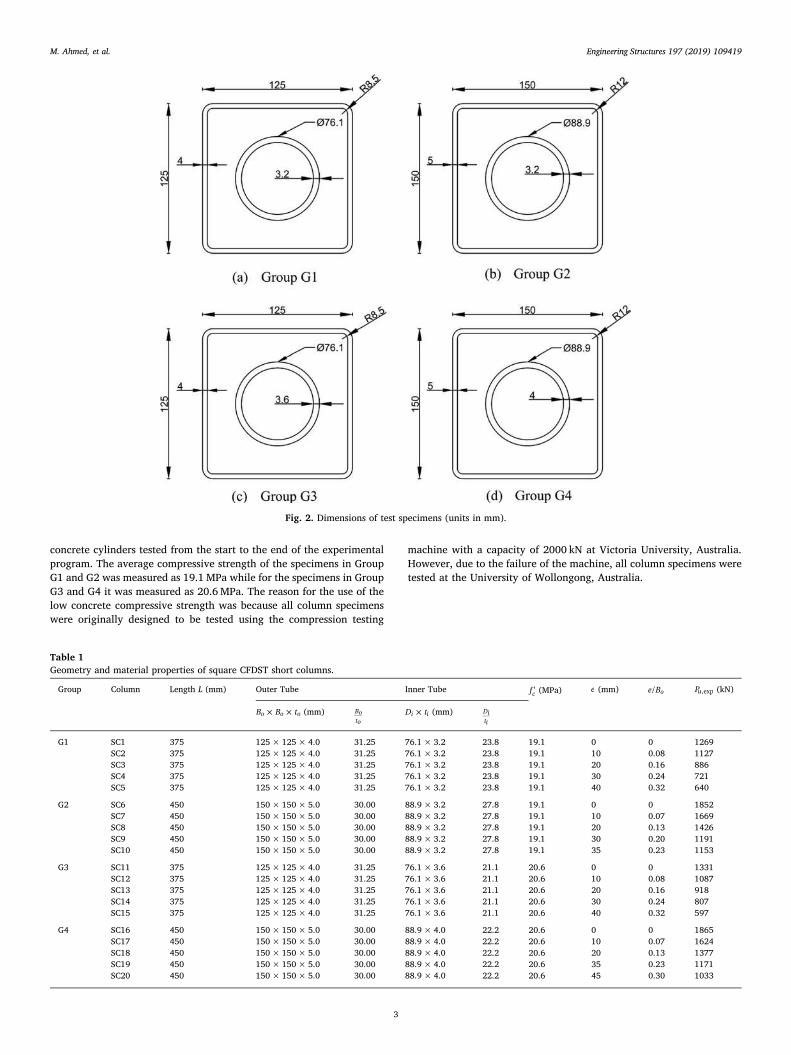
concrete cylinders tested from the start to the end of the experimentalprogram. The average compressive strength of the specimens in GroupG1 and G2 was measured as 19.1 MPa while for the specimens in GroupG3 and G4 it was measured as 20.6MPa. The reason for the use of thelow concrete compressive strength was because all column specimenswere originally designed to be tested using the compression testing
machine with a capacity of 2000 kN at Victoria University, Australia.However, due to the failure of the machine, all column specimens weretested at the University of Wollongong, Australia.
Fig. 2. Dimensions of test specimens (units in mm).
Table 1Geometry and material properties of square CFDST short columns.
Group Column Length L (mm) Outer Tube Inner Tube ′fc (MPa) e (mm) e B/ o Pu,exp (kN)
× ×B B to o o (mm) Boto
×D ti i (mm) Diti
G1 SC1 375 125×125×4.0 31.25 76.1× 3.2 23.8 19.1 0 0 1269SC2 375 125×125×4.0 31.25 76.1× 3.2 23.8 19.1 10 0.08 1127SC3 375 125×125×4.0 31.25 76.1× 3.2 23.8 19.1 20 0.16 886SC4 375 125×125×4.0 31.25 76.1× 3.2 23.8 19.1 30 0.24 721SC5 375 125×125×4.0 31.25 76.1× 3.2 23.8 19.1 40 0.32 640
G2 SC6 450 150×150×5.0 30.00 88.9× 3.2 27.8 19.1 0 0 1852SC7 450 150×150×5.0 30.00 88.9× 3.2 27.8 19.1 10 0.07 1669SC8 450 150×150×5.0 30.00 88.9× 3.2 27.8 19.1 20 0.13 1426SC9 450 150×150×5.0 30.00 88.9× 3.2 27.8 19.1 30 0.20 1191SC10 450 150×150×5.0 30.00 88.9× 3.2 27.8 19.1 35 0.23 1153
G3 SC11 375 125×125×4.0 31.25 76.1× 3.6 21.1 20.6 0 0 1331SC12 375 125×125×4.0 31.25 76.1× 3.6 21.1 20.6 10 0.08 1087SC13 375 125×125×4.0 31.25 76.1× 3.6 21.1 20.6 20 0.16 918SC14 375 125×125×4.0 31.25 76.1× 3.6 21.1 20.6 30 0.24 807SC15 375 125×125×4.0 31.25 76.1× 3.6 21.1 20.6 40 0.32 597
G4 SC16 450 150×150×5.0 30.00 88.9× 4.0 22.2 20.6 0 0 1865SC17 450 150×150×5.0 30.00 88.9× 4.0 22.2 20.6 10 0.07 1624SC18 450 150×150×5.0 30.00 88.9× 4.0 22.2 20.6 20 0.13 1377SC19 450 150×150×5.0 30.00 88.9× 4.0 22.2 20.6 35 0.23 1171SC20 450 150×150×5.0 30.00 88.9× 4.0 22.2 20.6 45 0.30 1033
M. Ahmed, et al. Engineering Structures 197 (2019) 109419
3
mizan
Typewritten Text
75

2.3. Test setup and instrumentation
The typical test setup of CFDST short columns is shown in Fig. 4. ForCFDST stub columns under concentric loading, the axial load was ap-plied to the concrete and steel simultaneously as illustrated in Fig. 4(a).The column ends were grinded using a concrete grinder prior to placingthe column on the compression testing machine to ensure flat andsmooth surface ends in order to obtain uniform load distribution. Forshort CFDST columns under eccentric loading, they were tested underpin-ended conditions by applying the compressive load on the loadingheads attached to the column ends as illustrated in Fig. 4(b). Theloading heads were designed by Hadi and Widiarsa [32] that consistedof a 50mm thick square steel cap called the adaptor plate and a 25mmthick bottom steel plate with a ball joint. The load generated by thecompression testing machine was transferred through the bottom plateand ball joint to the adaptor plate with designed eccentricities.
Two strain gauges were attached to the column mid-height (one ineach of the adjacent sides of the square column) to capture the axial andtransverse strains under concentric loading as illustrated in Fig. 4(a).For columns under eccentric loading, two strain gauges were attachedto the columns mid-height (one at each of the compression and tensionsides) to capture the axial strain only. The axial shortening of squareCFDST columns was averaged from the readings of the two linearvariable differential transducers (LVDTs) attached to the two oppositecorners of the machine. For columns under eccentric loading, one ad-ditional laser triangulation was utilized to capture the column mid-height deflection as shown in Fig. 4(b).
All CFDST columns were tested to failure using the Denison 5000 kNcompression testing machine at the structure laboratory in the School ofCivil, Mining and Environmental Engineering at the University ofWollongong, Australia. The specimen was initially preloaded to 100 kNusing the force-controlled mode to prevent any movement between thespecimen and loading head of the testing machine, and then unloaded
to 20 kN before starting recording the data. The column was loadedgradually with a displacement rate of 0.8 mm/min until the failureoccurred. The test process was stopped when the external steel tubeunderwent significant local buckling or the maximum axial shorteningreached to 30mm. The readings of the LVDTs, strain gauges, laser tri-angulation and applied load were recorded using a data logger.
3. Test results and discussions
3.1. Failure modes and behavior of columns under axial compression
The short CFDST square columns failed by the significant unilaterallocal buckling of the flanges and webs of the external square steel tubes.The failure patterns of the CFDST short columns with square sectionsloaded concentrically are shown in Fig. 5. The stiffeners effectivelyprevented the steel tube ends from the premature failure due to localbuckling during the test. Consequently, the outer steel tube generallybuckled at the position about one third measured from the column topor bottom end. The outer steel tube of Column SC1 split at the cornerswhere the adjacent tube walls buckled locally outward as shown inFig. 5. Fig. 6 presents the section view of Column SC1. It can be ob-served that the crushing of the sandwiched concrete took place at theregions where the local buckling of the external steel tube occurred. Asdemonstrated in Fig. 6, the core-concrete did not crush because of theconfinement offered by the internal circular steel tube.
The measured ultimate loads of CFDST columns loaded con-centrically to failure are given in Table 1 while their axial load-short-ening curves are depicted in Fig. 7. It would appear from Fig. 7 thatshort CFDST columns exhibit strain-hardening behavior and very goodductility because of the utilization of internal circular steel tubes. Thecolumns can sustain large axial deformation without a significantstrength degradation. The residual strengths of Columns SC1, SC6, SC11and SC16 were measured as 93%, 96%, 99% and 97% of their
Table 2. Material properties of steel tube obtained from tensile coupon tests.
Tube type No. Geometry of the tube (mm) Yield strength, fsy(MPa)
Ultimate strength, fsu(MPa)
Yield strain,εsy
Ultimate strain,εsu
Elastic modulus, Es(GPa)
Outer tube × ×B B to o o 1 125×125×4.0 360 461 0.0053 0.25 2032 150×150×5.0 378 464 0.0033 0.23 201
Inner tube ×D ti i 1 76.1×3.2 400 458 0.0015 0.188 2112 88.9×3.2 412 471 0.0013 0.202 2003 76.1×3.6 353 398 0.0026 0.170 2054 88.9×4.0 345 372 0.0042 0.193 200
Fig. 3. Measured stress-strain curves for steel tubes.
M. Ahmed, et al. Engineering Structures 197 (2019) 109419
4
mizan
Typewritten Text
76

corresponding ultimate axial strengths, respectively. For the identicalexternal steel tube, increasing the thickness (ti) of the internal steel tubeimproves the column ultimate load slightly. Columns SC1 and SC11,SC6 and SC16 had the same outer tube, however, the ultimate loads ofColumn SC11 and SC16 are higher than those of Columns SC1 and SC6due to the increased steel areas. The strain distributions in specimensloaded concentrically were measured during the tests and are given inFig. 8. Fig. 8(a) shows the relationships of the axial load and axialstrains as well as lateral strains. In Fig. 8(b), the relationships of thelateral strain (hoop strain) and axial strain are provided. It is seen thatboth the axial and lateral strains increased at a small rate at the initialstate of the loading. This is attributed to the effect of the Poisson’s ratio
of concrete, which was smaller than that of steel at the initial stage.However, after a certain load, the lateral strain increased significantlyas the load increased due to the rapid expansion of the concrete.
3.2. Failure modes and behavior of columns under eccentric loading
The failure of CFDST square beam-columns loaded eccentricallywere caused by the unilateral local buckling of the compression flangeand the two adjacent webs in the external steel tube, the crushing ofsandwiched concrete at places where local buckling occurred and thesignificant bending of the beam-columns as illustrated in Fig. 9. It isobserved from Fig. 10 that the sandwiched concrete was separated fromthe internal steel tube. Columns SC5 and SC15 were subjected to ec-centric loads with a large eccentricity ratio of 0.32. These two columnsfailed shortly due to the significant damage of the column bottom endwhere the load was applied as depicted in Fig. 11. The section view ofColumn SC14 is given in Fig. 12. It can be seen that the sandwichedconcrete crushed at the compression zone where the steel tube wallunderwent local buckling.
The load-axial shortening curves of CFDST square columns loadedeccentrically are presented in Fig. 13. It would appear that increasingthe loading eccentricity greatly decreases the axial stiffness and ulti-mate strengths of short columns. The measured column ultimatestrengths are tabulated in Table 1. For columns in Group 1, increasingthe loading eccentricity from 0mm to 10mm, 20mm, 30mm and40mm reduces its ultimate axial strength by 11.2%, 30.2%, 43.2% and49.6%, respectively. However, for the identical external steel tube, thereduction in the ultimate strength due to the eccentric loading wasgenerally higher for the columns with thicker inner tube. The columnsin Group G3 had a similar external tube as Group G1, however, thereduction in the ultimate axial strength was estimated as 18.3%, 31%,39.4% and 55.1% for increasing the loading eccentricity from 0mm to10mm, 20mm, 30mm and 40mm, respectively. The experimentallymeasured load-lateral deflection curves of CFDST columns are providedin Fig. 14. It is evident the initial bending stiffness of CFDST columnsdecreases as the loading eccentricity increases. Fig. 15 demonstrates theexperimental load-axial strain curves of CFDST columns subjected tovarious end eccentricities. It is observed from Fig. 15 that at the initialloading stage, the CFDST column was subjected to compression. How-ever, as the load increased, the axial strain in one of the steel tube wallsbecame negative, which implies that part of the column was undertension.
4. Numerical model based on fiber element formulation
4.1. The method of fiber analysis
The key aspect of designing square CFDST beam-columns is the
(a) Under concentric loading
(b) Under eccentric loading
Fig. 4. Test setup of square CFDST short columns.
Fig. 5. Failure modes of square CFDST short columns under axial compression.
M. Ahmed, et al. Engineering Structures 197 (2019) 109419
5
mizan
Typewritten Text
77

calculation of the cross-section strength under eccentric loading. Theaxial load-moment interaction diagrams (strength envelops) of com-posite columns are often used to evaluate the strengths of short andslender composite columns subjected to combined actions. A
mathematical model underlying the theory of fiber analysis has beenproposed for calculating the axial load-moment-curvature relationshipsand strength envelops of rectangular CFST beam-columns by Liang[33,34]. Fiber elements are used to mesh the column cross-section asshown in Fig. 16. A mesh generator developed by Persson and Strang[35] is employed to discretize the sandwiched concrete in the presentstudy. The formulation assumes that after deformation the plane sectionremains plane, which implies that a linear strain distribution throughthe depth of the cross-section is achieved as illustrated in Fig. 16. Thisassumption ensures the strain compatibility of steel and concrete fibersin the cross-section in the loading history. The stress of each fiber iscalculated from its corresponding strain by applying the uniaxial stress-strain laws of concrete and steel materials. The internal bending mo-ment (M) as well as the axial force (P) are determined by integrating thestresses over the cross-section.
4.2. Modeling of local and post-local buckling
The unilateral local buckling of the flanges and webs of a thin-walled CFST square column loaded eccentrically may take place, whichleads to a marked reduction in the column ultimate resistance [22,24].The longitudinal stresses on the steel flanges and webs of the CFSTcolumn loaded uniaxially are either non-uniform or uniform as dis-cussed by Liang et al. [24]. Liang et al. [24] developed formulas forascertaining the initial local buckling strengths of steel flanges and
Fig. 6. Section view of Specimen SC1.
0
400
800
1200
1600
2000
0 10 20 30
Axia
l Lo
ad P
(kN
)
SC1SC6SC11SC16
Axial shortening (mm)δ
Fig. 7. Measured axial load-shortening curves of square CFDST short columnsunder axial compression.
(a) (b)
0
500
1000
1500
2000
-0.015 -0.01 -0.005 0 0.005 0.01 0.015
Axia
l Lo
ad P
(kN
)
SC1SC6SC11SC16
Axial strain εLateral strain lε
-0.014
-0.012
-0.01
-0.008
-0.006
-0.004
-0.002
0
0 0.005 0.01 0.015
SC1SC6SC11SC16
Hoo
p st
rain
Axial strain ε
Fig. 8. Strain distributions in square CFDST short columns under axial compression.
M. Ahmed, et al. Engineering Structures 197 (2019) 109419
6
mizan
Typewritten Text
78

webs subjected to non-uniform compressive stresses in CFST rectan-gular columns. Their expressions are employed in the present mathe-matical model.
The gradual post-local buckling characteristics of the flanges andwebs of a CFDST column loaded eccentrically are modeled by theprinciple of stress redistributions as shown in Fig. 17. The effectivewidths of the thin-walled steel tube walls subjected to stress gradientsare calculated using the formulas developed by Liang et al. [24]. Theireffective width expressions can be used for steel plates with clear width-to-thickness ratios (b/t) ranging from 30 and 100. After the initial localbuckling took place, the plate ineffective width increased as the com-pressive load increased until the plate reached its strength of post-localbuckling. The computational scheme for modeling the gradual post-local buckling of a square CFST column loaded eccentrically proposedby Liang [33] is utilized in the present mathematical model.
4.3. Modeling of axial load-moment strength interaction diagrams
An incremental-iterative computational procedure has been devel-oped for quantifying the strength envelopes of short square CFDSTbeam-columns subjected to axial compression in addition to uniaxialbending. The ultimate axial load (Po) of the column without bendingmoment is initially calculated by using the load-axial strain responseanalysis technique that accounts for post-local buckling influences [33].For a given axial load (Pu), the curvature (ϕ) of the cross-section is in-crementally increased and the corresponding moment is calculated thatsatisfies the force equilibrium. The section ultimate bending resistanceis taken as the maximum moment on the predicted moment-curvaturecurve. By increasing the axial load from zero to the maximum value (Po)and calculating the corresponding ultimate bending resistance, a set ofultimate moments and axial loads can be determined, which are used to
(a) Group G1 (b) Group G2
(c) Group G3 (d) Group G4 Fig. 9. Failure modes of square CFDST short columns under eccentric loading.
(a) Specimen SC8 (b) Specimen SC14
Fig. 10. Separation of sandwiched concrete and inner steel tube in Specimens SC8 and SC14.
M. Ahmed, et al. Engineering Structures 197 (2019) 109419
7
mizan
Typewritten Text
79

plot the strength envelop of the CFDST column. The computer flowchart for calculating the strength envelop of a short CFDST column isshown in Fig. 18.
In the analysis, the neutral axis depth (dn) of the cross-section isadjusted iteratively until the force equilibrium condition is achieved.The inverse quadratic method [36] has been implemented in thecomputer algorithms to determine the neutral axis depth. In the com-putational method, three values are initialized to the neutral axis depth.The new neutral axis depth approaching the true value is calculated bymeans of executing the following equations:
= − ⎛⎝
⎞⎠
+ + +d d r ACn j n j p j, 3 , 1 , 1 (1)
= − + − + −
−
+ + + + + + +
+ +
Ar d d r r d d r r
r d d
( ) ( ) ( ) ( )
( )
p j n j n j p j p j n j n j p j p j
p j n j n j
,2
, 2 , 1 , , 1 , 1 , 2 , 1 , 2
, 2 , , 1 (2)
= − − −+ + + +C r r r r r r( )( )( )p j p j p j p j p j p j, 1 , , 2 , , 2 , 1 (3)
where = −r P Pp u and j is the iteration number. The initial three valuesof neural axis depths are taken as =d Dn,1 0, =d D /2n,2 0 and
= +d d d( )/2n n n,3 ,1 ,2 . The iterative computational process is stoppedwhen the convergence criterion of <r ε| |p k is achieved, where εk is takenas 10−4.
4.4. Material constitutive laws for steels
The external tube of a square CFDST column is subjected to biaxialstresses under compression. This results in the reduction of steel yieldstrength which is taken into account in the material laws for structural
steel as illustrated in Fig. 19, where fsy denotes the steel yield strength,εsy the yield strain, εst the strain at the onset of strain-hardening, fsu thetensile strength and εsu the ultimate strain of steel. The rounded part ofthe stress-strain curve between ε0.9 sy and εst is represented by the ex-pression proposed by Liang [33] while formulas suggested by Mander[37] are used to determine the stresses after the strain hardening oc-curs. The strain εst and the ultimate strain εsu are taken as 0.005 and 0.2,respectively.
4.5. Material constitutive laws for concrete
The internal and external tubes provide little confinement to thesandwiched concrete in a square CFDST column so that the sand-wiched-concrete is treated as unconfined concrete. However, the coreconcrete is confined by the internal circular steel tube in a squareCFDST column and this confinement is recognized in the materialstress-strain relations for core-concrete in the present study. The ma-terial constitutive models for sandwiched-concrete and core-concrete inrectangular CFDST columns have been validated against experimentaldata by Ahmed et al. [27]. The general stress-strain curves for bothconfined concrete and unconfined concrete are schematically illustratedin Fig. 20.
The ascending branch of the stress-strain curves are described by thefollowing expressions suggested by Mander et al. [38]
=′ ′′ + −
⩽ ⩽σf ε ε λ
ε ε λε ε
( / )( / ) 1
for 0ccc c cc
c ccλ c cc
'
(4)
=′
′ − ′λ
E εE ε f
c cc
c cc cc (5)
where σc and εc represent the longitudinal concrete compressive stressand corresponding strain, respectively; ′fcc and ′εcc the compressivestrength and corresponding strain of confined concrete, respectively; Ecthe concrete elastic modulus [12], which is taken as
= ′E γ f4400 (MPa)c c c (6)
where = −γ D1.85c c0.135 stands for the reduction factor given by Liang
[33], which considers the column size effect on the concrete compres-sive strength, and Dc is taken as −B t( 2 )o o .
The maximum compressive strength as well as its correspondingstrain of the core-concrete are calculated by
⎜ ⎟′ = ′ + ′ ⎛
⎝ ′⎞
⎠= ′ −f γ f γ f
f
γ fa γ f5.2 ( ) where ( )cc c c c c
rp
c c
a
c c0.91 0.06
(7)
⎜ ⎟′ = ′ + ⎛
⎝ ′⎞
⎠ε ε
f
γ f0.045cc c
rp
c c
1.15
(8)
(a) Specimen SC5 (b) Specimen SC15
Fig. 11. Failure modes of Specimens SC5 and SC15.
Fig. 12. Section view of Specimen SC14.
M. Ahmed, et al. Engineering Structures 197 (2019) 109419
8
mizan
Typewritten Text
80

′ =′
εγ f( )
1000cc c
0.225
(9)
where frp stands for the lateral pressure on the core-concrete, which iscomputed by the following equation suggested by Liang and Fragomeni[39]:
=⎧
⎨⎩
− ⩽
− < ⩽
−
( )fv v f
f
0.7( ) for 47
0.006241 0.0000357 for 47 150rp
e st
D t syiDt
Dt syi
Dt
22i
i iii
ii
ii (10)
in which ve and vs stand for the Poisson’s ratios of the steel tube withand without concrete infill. In the numerical analysis, =v 0.5s and the vesuggested by Tang et al. [40] are adopted.
The equation formulated by Lim and Ozbakkaloglu [41] is used todescribe the descending branch of the stress-strain responses of con-fined concrete as well as the unconfined one, and is expressed as
= ′ −′ −
⎡⎣
+ ⎤⎦
>− ′− ′
−( )σ f
f fε ε
1forc cc
cc cr
ε εε ε
2 c cc'
c ccci cc (11)
in which fcr denotes the residual strength of concrete and εci the strain atthe inflection point. The expressions suggested by Lim and Ozbakka-loglu [41] are used to determine fcr for the core concrete while fcr is
equal to ′β fc c for the sandwiched-concrete. By analyzing the availabletest data, Ahmed et al. [27] proposed βc as
=
⎧
⎨
⎪⎪
⎩⎪⎪
⩽ ⩽
− − < ⩽
− + < ⩽
( )( ) ( )
β
1 for 0 24
1 24 for 24 33
0.000062 0.011225 0.705288 for 33 100
c
Bt
Bt
Bt
Bt
Bt
Bt
115
2
oo
oo
oo
oo
oo
oo
(12)
The strain (εci) at the inflection point is specified as 0.007 for thesandwiched-concrete. The equation given by Lim and Ozbakkaloglu[41] is employed to calculate εci for the core-concrete, taking into ac-count the column size effect [27].
The stress-strain curves for concrete under tension is illustrated inFig. 20, where the tensile strength is equal to ′γ f0.6 c c and the ultimatetensile strain is taken as ten times the strain at cracking.
4.6. Curvature ductility index
The curvature ductility of a CFDST column in bending is expressedby the following curvature ductility indicator:
(a) Group G1 (b) Group G2
(c) Group G3 (d) Group G4
0
400
800
1200
1600
0 10 20 30 40
Axia
l Lo
ad P
(kN
)
SC1 SC2SC3 SC4SC5
e = 40
e = 30
e = 20
e = 10
e = 0
Axial shortening (mm)δ
0
400
800
1200
1600
2000
0 10 20 30 40
Axia
l Lo
ad P
(kN
)
SC6 SC7SC8 SC9SC10
e = 35 e = 30
e = 20 e = 10
e = 0
Axial shortening (mm)δ
0
400
800
1200
1600
2000
0 10 20 30 40
Axia
l Lo
ad P
(kN
)
SC11 SC12SC13 SC14SC15
e = 40
e = 30 e = 20 e = 10
e = 0
Axial shortening (mm)δ
0
400
800
1200
1600
2000
0 10 20 30 40
Axia
l Lo
ad P
(kN
)
SC16 SC17SC18 SC19SC20
e = 45
e = 35
e = 20
e = 10
e = 0
Axial shortening (mm)δ
Fig. 13. Effects of loading eccentricity on the axial load-shortening curves of square CFDST columns.
M. Ahmed, et al. Engineering Structures 197 (2019) 109419
9
mizan
Typewritten Text
81

=PIϕϕcdu
y (13)
where ϕu represents the curvature of the CFDST column when themoment reduces to 90% of its ultimate moment capacity in the post-peak range or the ultimate curvature where column shows ascendingmoment-curvature relationships. The yield curvature (ϕy) is taken asϕ /0.750.75 , where ϕ0.75 stands for the curvature when moment attains75% of the column ultimate moment capacity.
5. Experimental verification
The mathematical modeling technique developed is validated bycomparing the simulated strength envelops with experimentally mea-sured data in Fig. 21. The experimental ultimate moments were cal-culated as = ×M P eu u,exp ,exp , where Pu,exp denotes the ultimate axialload obtained from experiments provided in Table 1 and e stands for theloading eccentricity. In the moment-curvature analysis of each CFDSTcolumn, the ultimate concrete strain was taken as the concrete straincorresponding to the column ultimate axial load. It can be observedfrom Fig. 21 that the agreement between experimental results andnumerical predictions is generally good. The ultimate moments ofSpecimens SC2 and SC7 obtained from the experiments are slightlyhigher than the computed results. The cause for this is likely due to thefact that the actual concrete strengths in the tested specimens wereunknown and the average concrete strength was specified in the non-linear analyses. As shown in Fig. 21, the experimental ultimate bending
resistances of Specimens SC4, SC5 and SC15 are considerably lowerthan the predicted values. This is because Specimens SC4, SC5 andSC15 with large loading eccentricities failed prematurely by the da-mage of the column ends under the applied load as shown in Figs. 9 and11. For columns subjected to a large loading eccentricity, it is suggestedfor future tests that a cantilever should be rigidly connected to thecolumn ends to prevent the premature failure of the column ends. Thelimitation of the proposed numerical model is that it does not predictthe premature failure of the loading heads.
6. Parametric study
The computer simulation program developed was used to determinethe axial load-moment-curvature relationships and strength envelops ofsquare short CFDST columns with various width-to-thickness (B t/o o)ratios of the external tube, the diameter-to-thickness (D t/i i) ratio of theinternal tube, concrete strength ( ′fc ), steel yield strength ( fsy), axial loadratio (P P/u o) and local buckling effects. The details of the referenceCFDST column are as follows: =B 500 mmo , to =10mm, Di =250mm,ti =5mm, = =f fsyo syi 350MPa, =Es 200 GPa, ′ = ′ =f f 40 MPaco ci .
6.1. Effects of B t/o o ratio
The influences of the B t/o o ratio of the external square tube on thestructural behavior of CFDST columns were examined by using thecomputational technique. The thickness of the reference column wasvaried to give the B t/o o ratios of 30, 50, 75 and 100 while the other
(a) Group G1 (b) Group G2
(c) Group G3 (d) Group G4
0
500
1000
1500
0 10 20 30
Axia
l Lo
ad P
(kN
)
Mid-height deflection um (mm)
SC2SC3SC4SC5
0
500
1000
1500
2000
0 10 20 30
Axia
l Lo
ad P
(kN
)
Mid-height deflection um (mm)
SC7SC8SC9SC10
0
500
1000
1500
0 5 10 15 20 25
Axia
l Lo
ad P
(kN
)
Mid-height deflection um (mm)
SC12SC13SC14SC15
0
500
1000
1500
2000
0 10 20 30
Axia
l Lo
ad P
(kN
)
Mid-height deflection um (mm)
SC17SC18SC19SC20
Fig. 14. Measured axial load-lateral deflection curves of square CFDST short columns under eccentric loading.
M. Ahmed, et al. Engineering Structures 197 (2019) 109419
10
mizan
Typewritten Text
82

(a) Group G1 (b) Group G2
(c) Group G3 (d) Group G4
0
500
1000
1500
-0.01 -0.005 0 0.005 0.01
Axia
l Lo
ad P
(kN
)
SC2SC3SC4SC5
Axial strain ε
0
500
1000
1500
2000
-0.01 0 0.01 0.02
Axia
l Lo
ad P
(kN
)
SC7
SC8
SC9
SC10
Axial strain ε
0
500
1000
1500
-0.01 0 0.01 0.02
Axia
l Lo
ad P
(kN
)
SC12SC13SC14SC15
Axial strain ε
0
500
1000
1500
2000
-0.005 0 0.005 0.01
Axia
l Lo
ad P
(kN
)
SC17SC18SC19SC20
Axial strain ε
Fig. 15. Measured axial load-strain curves of square CFDST short columns under eccentric loading.
Fig. 16. Typical fiber discretization and strain distribution in the cross-sectionof square CFDST column.
Fig. 17. Effective widths of the external steel tube of square CFDST columnunder eccentric loading.
M. Ahmed, et al. Engineering Structures 197 (2019) 109419
11
mizan
Typewritten Text
83

parameters were unchanged. Fig. 22 presents the moment-curvatureresponses of the CFDST columns having various B t/o o ratios under aconstant axial load (Pu), which was taken as 60% of the pure ultimateaxial load of the column with the B t/o o ratio of 100. It is clearly shown
that increasing the B t/o o ratio remarkably reduces the column initialbending stiffness and ultimate moment capacity. This is due to the re-duction in the thickness and area of the steel tube and because of localbuckling. The reduction in the ultimate moment capacity was calcu-lated as 66.9% by changing the B t/o o ratio from 30 to 100. The curva-ture ductility of CFDST columns also decreases as the B t/o o ratio in-creases. When increasing the B t/o o ratio from 30 to 50, 75 and 100, thecurvature ductility index decreases from 4.62 to 3.75, 3.03 and 2.78,respectively. Furthermore, increasing the B t/o o ratio greatly reduces thepure ultimate axial load (Po) and pure ultimate moment (Mo) of theCFDST columns as can be seen from the strength envelops presented inFig. 23. However, the B t/o o ratio has the most prominent influence onthe pure ultimate bending resistance than on the pure ultimate axialload (Po). Changing the B t/o o ratio from 30 to 100 reduces the pureultimate axial load by 39.0% and the pure ultimate moment by 62.1%,respectively.
6.2. Effects of D t/i i ratio
The computer simulation program was employed to ascertain thesignificance of the D t/i i ratio on the responses of the CFDST columns.The D t/i i ratios of 20, 30, 40 and 50 were obtained by altering thethicknesstiof the internal tube only. Fig. 24 presents the influences oftheD t/i i ratio on the axial load-moment-curvature behavior of CFDSTcolumns under the axial load of =P 9388u kN. It would appear thattheD t/i i ratio has a minor influence on the initial bending stiffness ofCFDST columns. However, increasing the D t/i i ratio considerably re-duces the column ultimate bending resistance. The column ultimatemoment is reduced by 8.9%, 14.3% and 19.3%, respectively, bychanging the D t/i i ratio from 20 to 30, 40 and 50. Varying the D t/i i ratiofrom 20 to 50 decreases the curvature ductility index from 5.46 to 3.35.The strength envelops of CFDST columns as a function of D t/i i ratios are
Fig. 18. Computer flowchart for calculating axial load-moment interactioncurves.
Fig. 19. Stress-strain curve for structural steels.
Fig. 20. Stress-strain curves for confined and unconfined concrete.
M. Ahmed, et al. Engineering Structures 197 (2019) 109419
12
mizan
Typewritten Text
84

given in Fig. 25. It is seen that the D t/i i ratio has a moderate influenceon the column ultimate axial and bending resistances. When the D t/i iratio is increased from 20 to 50, the column pure ultimate axial andbending strengths are found to reduce by 11% and 8.5%, respectively.This is because increasing the D t/i i ratio reduces the confinement ex-erted on the core-concrete, which reduces the column ultimate re-sistances.
6.3. Effects of steel yield strength
The sensitivities of the moment-curvature and interaction behaviorof CFDST columns to the steel yield strength fsy were investigated byvarying fsy from 250MPa to 690MPa. The predicted moment-curvaturerelationships of CFDST columns subjected to the same axial load of=P 9388 kNu have been plotted in Fig. 26. It is discovered that the
(a) Group G1 (b) Group G2
(c) Group G3 (d) Group G4
0
500
1000
1500
0 10 20 30 40 50
Axia
l Lo
ad P
u(k
N)
Moment Mu (kNm)
SC1SC2SC3SC4SC5Numerical analysis
0
500
1000
1500
2000
0 20 40 60 80
Axia
l Lo
ad P
u(k
N)
Moment Mu (kNm)
SC6SC7SC8SC9SC10Numerical analysis
0
500
1000
1500
0 10 20 30 40 50
Axia
l Lo
ad P
u(k
N)
Moment Mu (kNm)
SC11SC12SC13SC14SC15Numeircal analysis
0
500
1000
1500
2000
0 20 40 60 80
Axia
l Lo
ad P
u(k
N)
Moment Mu (kNm)
SC16SC17SC18SC19SC20Numerical analysis
Fig. 21. Comparison of predicted strength envelops of square CFDST columns with test results.
0
500
1000
1500
2000
2500
3000
3500
4000
0 1 2 3 4 5
Mom
ent M
(kN
m)
BO / tO =100
BO / tO =75BO / tO =50BO / tO =30
5Curvature ( 10 )φ −×
Fig. 22. Effects of B t/o o ratio on the moment-curvature curves of square CFDSTcolumns.
0
5000
10000
15000
20000
25000
0 1000 2000 3000
Axia
l lo
ad P
u(k
N)
Moment Mu (kNm)
/ 30/ 50/ 75/ 100
o o
o o
o o
o o
B tB tB tB t
====
Fig. 23. Effects of B t/o o ratio on the strength envelops of square CFDST col-umns.
M. Ahmed, et al. Engineering Structures 197 (2019) 109419
13
mizan
Typewritten Text
85

initial bending stiffness and ultimate bending resistance of CFDST col-umns are markedly improved by using steel tube with higher yieldstrength. When altering the yield strength from 250MPa to 350MPa,480MPa and 690MPa, the column bending resistance increases by52.1%, 116.0%, and 220.1%, respectively. As shown in Fig. 26, the
column curvature ductility also improves as the yield strength in-creases. The calculated column curvature ductility indices with yieldstrengths of 250MPa, 350MPa and 480MPa are 2.69, 3.35 and 4.34,respectively. Fig. 27 gives the strength envelops of CFDST columns,which have been plotted by demonstrating the effect of steel yieldstrength. It is illustrated that the use of higher strength steel tube re-markably improves the ultimate bending and axial resistances of CFDSTcolumns. The numerical results show that changing the yield strengthfrom 250MPa to 690MPa leads to 70.5% improvement in the pureultimate axial load and 133.2% increase in the pure ultimate bendingresistance of the column.
6.4. Effects of concrete strength
Fiber analyses on CFDST short columns constructed by concretewith different compressive strengths were performed to ascertain theeffects of concrete strength on their moment-curvature and interactionstrength characteristics. The CFDST columns were made of concretewith strengths ranging from 40MPa to 100MPa. The simulated mo-ment-curvatures curves for the CFDST columns under a constant load of=P 9388u kN are provided in Fig. 28. The initial bending stiffness and
ultimate bending resistance of CFDST columns are shown to con-siderably improve by using higher strength concrete. As a result ofchanging the concrete strength from 40MPa to 100MPa, the column
Fig. 24. Effects of D t/i i ratio on the moment-curvature curves of square CFDSTcolumns.
Fig. 25. Effects of D t/i i ratio on the strength envelops of square CFDST columns.
Fig. 26. Effects of steel yield strength on the moment-curvature curves ofsquare CFDST columns.
Fig. 27. Effects of steel yield strength on the strength envelops of square CFDSTcolumns.
Fig. 28. Effects of concrete strength on the moment-curvature curves of squareCFDST columns.
M. Ahmed, et al. Engineering Structures 197 (2019) 109419
14
mizan
Typewritten Text
86

ultimate bending resistance increases by 102.3%. However, usinghigher strength concrete in CFDST columns decreases their curvatureductility. The column with 100MPa concrete has a curvature ductilityindex of 2.9 while the column with 40MPa concrete has a value of 3.35.Fig. 29 shows the complete axial load-bending resistance curves forCFDST columns with different concrete strengths. It is confirmed thatusing higher strength concrete improves both the ultimate bending andaxial strengths of CFDST columns. However, the effect of concretestrength on the column pure ultimate axial load is more prominent thanon its pure bending resistance. When the concrete strength is changedfrom 40MPa to 100MPa, the increase in the pure ultimate axial loadand pure ultimate bending resistance is 75.8% and 12.9%, respectively.
6.5. Effects of local buckling
The local buckling effects on the axial load-moment-curvature andinteraction responses of axial load and moment in the CFDST columnswere ascertained by means of using the computational model proposed.The nonlinear analyses on the reference column with a B t/o o ratio of100 were undertaken by ignoring and including local buckling, re-spectively. The local buckling effect on the moment-curvature behaviorof the CFDST column under the axial load of =P 7351 kNu is
demonstrated in Fig. 30. It is evident that the local buckling of the outersteel tube markedly reduces the column initial bending stiffness, ulti-mate bending resistance and curvature ductility. If the tube localbuckling was not included in the analysis, the column ultimate bendingresistance is overestimated by 23.6%. Fig. 31 illustrates the localbuckling influence on the complete strength envelops. It is confirmedthat the interaction strengths of the CFDST column are markedly re-duced by the outward local buckling. The column ultimate axial ca-pacity and pure bending resistance are overestimated by 7.4% and9.5%, respectively by ignoring the effect of local buckling.
6.6. Effects of axial load ratio
The significance of the axial load ratio (P P/u o) on the moment-cur-vature responses of CFDST beam-columns loaded eccentrically wasexamined by incorporating the axial load ratios from 0.2 to 0.8. Thepredicted moment-curvature responses have been plotted in Fig. 32. Itis demonstrated that the influence of the axial load on the moment-curvature responses is remarkable. Increasing the axial load ratio sig-nificantly decreases the column initial bending stiffness, ultimatebending resistance and curvature ductility. The column ultimate
Fig. 29. Effects of concrete strength on the strength envelops of square CFDSTcolumns.
Fig. 30. Effects of the local buckling of the outer steel tube on the moment-curvature curves of square CFDST columns.
Fig. 31. Effects of the local buckling of the outer steel tube on the normalizedstrength envelops of square CFDST columns.
Fig. 32. Effects of axial load ratio on the moment-curvature curves of squareCFDST columns.
M. Ahmed, et al. Engineering Structures 197 (2019) 109419
15
mizan
Typewritten Text
87

bending resistance is found to reduce by 7.7%, 32.4% and 65.1% byincreasing the P P/u o ratio from 0.2 to 0.4, 0.6 and 0.8, respectively. Forthe axial load ratios of 0.2, 0.4, 0.6 and 0.8, the curvature ductilityindices were estimated as 4.61, 4.35, 3.35 and 2.72, respectively. Thismeans that the column curvature ductility reduces by 6%, 27% and41%, respectively, as the P P/u o ratio increases from 0.2 to 0.4, 0.6 and0.8.
7. Conclusions
Experimental and numerical investigations on the structural per-formance of square CFDST stub columns loaded eccentrically have beenpresented in this paper. The experimental failure modes and behavior oftwenty square CFDST columns tested have been reported. A numericalmodel has been proposed for computing the axial load-moment-cur-vature relationships and interaction strengths of square CFDST stubcolumns incorporating local and post-local buckling. Efficient compu-tational algorithms implementing the inverse quadratic method havebeen developed to obtain converged solutions. Good agreement be-tween predictions and experimental data has been obtained. Thecomputer model developed has been employed to perform a parametricstudy on the responses of CFDST columns considering important geo-metric and material parameters.
The following concluding remarks are given:
1. Square CFDST short columns loaded concentrically failed by theoutward local buckling of the four walls of the external steel tubeand the crushing of the sandwiched concrete. The CFDST columnstested under eccentric loading failed by the outward local bucklingof the compression walls of the external steel tube, the crushing ofthe sandwiched-concrete and significant column bending. The coreconcrete in CFDST columns did not crush because the internal cir-cular tube effectively confined the core-concrete.
2. Test results indicate that increasing the loading eccentricity mark-edly reduces the column ultimate loads as well as initial bendingstiffness.
3. Numerical results demonstrate that the initial bending stiffness andultimate axial and bending resistances of CFDST columns are re-markably decreased by increasing the B t/o o ratio and the axial loadratio but are only slightly decreased by increasing the D t/i i ratio.
4. Using higher yield strength tubes and high strength concrete ap-preciably improves the column initial bending stiffness, ultimateaxial load and ultimate bending resistance, but the concrete strengthhas a more pronounced effect on the pure ultimate load than on thepure bending strength.
5. The unilateral local buckling of the outer steel tube considerablyreduces the ultimate axial and bending resistances of CFDST col-umns.
Square CFDST columns composed of an inner circular steel tubeoffer great benefits, such as high strength, high stiffness, high ductilityand ease of connecting with steel beams, and can be used in high-risecomposite buildings. To maximize their strengths and stiffness whilemaintaining good ductility, CFDST beam-columns should be designedwith small B t/o o ratios, high strength steel tubes, suitable D t/i i ratios sothat the inner tube effectively confines the concrete-core and highstrength concrete within the inner tube.
Acknowledgements
The financial support provided by Victoria University, Australia andLa Trobe University, Australia to conduct the experiments described inthis paper is gratefully acknowledged. The authors would like to thankthe technicians at both Victoria University and the University ofWollongong, Australia, particularly Mr. Ritchie McLean and Mr.Duncan Best at the University of Wollongong, Australia, for their
assistance and help during the experiments.
References
[1] Peng YY, Tan KF, Yao Y. Mechanical properties of duplex steel tube high- strengthconcrete short columns under axial compression. J Wuhan Univ Technol2011;33(2):105–9. (In Chinese).
[2] Liew JYR, Xiong DX. Ultra-high strength concrete filled composite columns formulti-storey building construction. Adv Struct Eng 2012;15(9):1487–503.
[3] Hassanein MF, Kharoob OF, Liang QQ. Behaviour of circular concrete-filled leanduplex stainless steel–carbon steel tubular short columns. Eng Struct2013;56:83–94.
[4] Romero ML, Espinós A, Portolés J, Hospitaler A, Ibañez C. Slender double-tubeultra-high strength concrete-filled tubular columns under ambient temperature andfire. Eng Struct 2015;99:536–45.
[5] Wan CY, Zha XX. Nonlinear analysis and design of concrete-filled dual steel tubularcolumns under axial loading. Steel Compo Struct 2016;20(3):571–97.
[6] Ekmekyapar T, Al-Eliwi BJ. Concrete filled double circular steel tube (CFDCST) stubcolumns. Eng Struct 2017;135:68–80.
[7] Ibañez C, Romero ML, Espinós A, Portolés JM, Albero V. Ultra-high strength con-crete on eccentrically loaded slender circular concrete-filled dual steel columns.Structures 2017;12:64–74.
[8] Romero ML, Ibañez C, Espinós A, Portolés J, Hospitaler A. Influence of ultra-highstrength concrete on circular concrete-filled dual steel columns. Structures2017;9:13–20.
[9] Xiong MX, Xiong DX, Liew JYR. Axial performance of short concrete filled steeltubes with high-and ultra-high-strength materials. Eng Struct 2017;136:494–510.
[10] Xiong MX, Xiong DX, Liew JYR. Behaviour of steel tubular members infilled withultra high strength concrete. J Constr Steel Res 2017;138:168–83.
[11] Zheng Y, He C, Zheng L. Experimental and numerical investigation of circulardouble-tube concrete-filled stainless steel tubular columns under cyclic loading.Thin-Walled Struct 2018;132:151–66.
[12] Ahmed M, Liang QQ, Patel VI, Hadi MN. Numerical analysis of axially loaded cir-cular high strength concrete-filled double steel tubular short columns. Thin-WalledStruct 2019;138:105–16.
[13] Pei WJ. Research on Mechanical Performance of Multibarrel Tube-ConfinedConcrete Columns. ME Thesis, Chang’an University, Xian, China, 2005 (in Chinese).
[14] Qian J, Zhang Y, Ji X, Cao W. Test and analysis of axial compressive behavior ofshort composite-sectioned high strength concrete filled steel tubular columns. JBuild Struct 2011;32(12):162–9. (in Chinese).
[15] Qian J, Zhang Y, Zhang W. Eccentric compressive behavior of high strength con-crete filled double-tube short columns. J Tsinghua Univ, Sci Technol2015;55(1):1–7. (in Chinese).
[16] Wang ZB, Tao Z, Yu Q. Axial compressive behaviour of concrete-filled double-tubestub columns with stiffeners. Thin-Walled Struct 2017;120:91–104.
[17] Zhong ST. Concrete Filled Steel Tubular Structures. Beijing: Tsinghua UniversityPress; 2003. (in Chinese).
[18] Han LH. Concrete Filled Steel Tubular Structures: Theory and Practice. SciencePress, Beijing, 1st Edition, 2000; Second Edition, 2007 (in Chinese).
[19] Sun YP, Kenji S. A comprehensive stress-strain model for high-strength concreteconfined by circular transverse reinforcement. Proce of the Sixth Inter Conf onSteel-Concrete Compo Struct, Los Angeles, USA, 2000; 1067-1074.
[20] Tao Z, Wang ZB, Yu Z. Finite element modelling of concrete-filled steel stub col-umns under axial compression. J Constr Steel Res 2013;89(10):121–31.
[21] Uy B. Local and post-local buckling of concrete filled steel welded box columns. JConstr Steel Res 1998;47(1–2):47–72.
[22] Liang QQ, Uy B. Theoretical study on the post-local buckling of steel plates inconcrete-filled box columns. Comput Struct 2000;75(5):479–90.
[23] Liang QQ, Uy B, Liew JR. Nonlinear analysis of concrete-filled thin-walled steel boxcolumns with local buckling effects. J Constr Steel Res 2006;62(6):581–91.
[24] Liang QQ, Uy B, Liew JYR. Local buckling of steel plates in concrete-filled thin-walled steel tubular beam–columns. J Constr Steel Res 2007;63(3):396–405.
[25] Huang Z, Li D, Uy B, Thai H-T, Hou C. Local and post-local buckling of fabricatedhigh-strength steel and composite columns. J Constr Steel Res 2019;154:235–49.
[26] Song Y, Li J, Chen YY. Local and post-local buckling of normal/high strength steelsections with concrete infill. Thin-Walled Struct 2019;138:155–69.
[27] Ahmed M, Liang QQ, Patel VI, Hadi MNS. Nonlinear analysis of rectangular con-crete-filled double steel tubular short columns incorporating local buckling. EngStruct 2018;175:13–26.
[28] Ahmed M, Liang QQ, Patel VI, Hadi MNS. Local-global interaction buckling ofsquare high strength concrete-filled double steel tubular slender beam-columns.Thin-Walled Struct 2019;143:106244.
[29] Ky VS, Tangaramvong S, Thepchatri T. Inealstic analysis for the post-collapse be-havior of concrete encased steel composite columns under axial compression. SteelCompo Struct 2015;19:1237–58.
[30] Liu X, Bradford MA, Erkmen RE. Non-linear inealstic analysis of steel-concretecomposite beams curved in-plan. Eng Struct 2013;57:484–92.
[31] AS 1391. Metallic Materials-Tensile Testing at Ambient Temperature. StandardsAustralia, Sydney, NSW, Australia, 2007.
[32] Hadi MNS, Widiarsa IBR. Axial and flexural performance of square RC columnswrapped with CFRP under eccentric loading. J Compos Constr ASCE2012;16(6):640–9.
[33] Liang QQ. Performance-based analysis of concrete-filled steel tubular beam–col-umns, part I: theory and algorithms. J Constr Steel Res 2009;65(2):363–72.
[34] Liang QQ. Performance-based analysis of concrete-filled steel tubular
M. Ahmed, et al. Engineering Structures 197 (2019) 109419
16
mizan
Typewritten Text
88

beam–columns, part II: verification and applications. J Constr Steel Res2009;65(2):351–62.
[35] Persson P-O, Strang G. A simple mesh generator in MATLAB. SIAM Rev2004;46(2):329–45.
[36] Epperson JF. An Introduction to Numerical Methods and Analysis. Wiley-Interscience; 2007.
[37] Mander JB. Seismic design of bridge piers. Ph.D. Thesis, Department of CivilEngineering. Christchurch, New Zealand: University of Canterbury; 1983.
[38] Mander JB, Priestley MJ, Park R. Theoretical stress-strain model for confined
concrete. J Struct Eng ASCE 1988;114(8):1804–26.[39] Liang QQ, Fragomeni S. Nonlinear analysis of circular concrete-filled steel tubular
short columns under axial loading. J Constr Steel Res 2009;65(12):2186–96.[40] Tang J, Hino S, Kuroda I, Ohta T. Modeling of stress-strain relationships for steel
and concrete in concrete filled circular steel tubular columns. Steel Constr Eng,JSSC 1996;3(11):35–46.
[41] Lim JC, Ozbakkaloglu T. Stress–strain model for normal-and light-weight concretesunder uniaxial and triaxial compression. Constr Build Mater 2014;71:492–509.
M. Ahmed, et al. Engineering Structures 197 (2019) 109419
17
mizan
Typewritten Text
89

Experimental and numerical investigations of eccentrically loaded rectangular concrete-filled double steel tubular columnsby M. Ahmed, Q.Q. Liang, V.I. Patel, and M.N.S. Hadi was published in the peer review journal, Journal of Constructional Steel Research, 167, 2020. The full-text of this article is subject to copyright restrictions, and cannot be included in the online version of the thesis. The published version is available from: https://doi.org/10.1016/j.jcsr.2020.105949

Chapter 3 Rectangular CFDST Short Columns
M. Ahmed: Experimental and Numerical Studies of Concrete-Filled Double Steel Tubular Columns
3.2 CONCLUDING REMARKS
Numerical and experimental studies on the behavior of square and rectangular CFDST
stub columns with either an inner circular tube or a rectangular/square inner tube have
been reported in this chapter. New constitutive relationship for modeling the concrete
post-peak behavior has been derived. The computer modeling method incorporating this
new relationship and local buckling has been found to predict well the experimental
behavior of CFDST rectangular columns having an internal circular tube. The design
formulas proposed have yielded accurate calculations of the capacities of CFDST stub
columns. The experimental results presented have provided new insight into the failure
modes, load-deformation characteristics and the capacities of rectangular and square
CFDST short columns. The numerical models incorporating local buckling and
confinement have been formulated to predict the moment-curvature relationships in
addition to the strength envelopes of short CFDST columns loaded eccentrically. New
computer solution algorithms, which have implemented the inverse quadratic method,
have been developed to solve the nonlinear dynamic equilibrium equations of
eccentrically loaded CFDST columns. It has been shown the computer modeling methods
developed can predict well the responses of CFDST composite columns and have been
used to conduct parametric studies.
mizan
Typewritten Text
145
Chapter 4 Circular CFDST Short Columns
M. Ahmed: Experimental and Numerical Studies of Concrete-Filled Double Steel Tubular Columns
Chapter 4
CIRCULAR CFDST SHORT COLUMNS
4.1 INTRODUCTION
This chapter presents numerical and experimental research studies on the behavior of
circular CFDST columns composed of a circular internal tube. A new confinement model
of the core-concrete of circular CFDST stub columns and a new strength degradation
coefficient for the post-peak concrete strength are proposed by interpreting the existing
test data and incorporated in the computational model developed for quantifying the axial
strain responses of CFDST circular columns to concentric loads. An extensive parameter
study is performed to examine the behavior of such composite columns under axial load.
A design formula is proposed for the calculation of the capacity of CFDST columns under
axial compression. Experimental programs on the behavior of short CFDST circular
columns loaded either concentrically or eccentrically are presented. The tests examine the
influences of loading application (axial and eccentric), diameter-to-thickness ratios of
steel sections as well as loading eccentricity on the structural performance of CFDST
circular columns. A mathematical model is also developed for simulating the moment and
curvature relationships as well as the strength envelopes of eccentrically loaded CFDST
circular short columns, incorporating the proposed confinement model and strength
degradation factor. The computer simulation model is employed to ascertain the effects
mizan
Typewritten Text
146

Chapter 4 Circular CFDST Short Columns
M. Ahmed: Experimental and Numerical Studies of Concrete-Filled Double Steel Tubular Columns
of design variables on the moment-curvature responses, strength interaction envelopes
and moment distributions in concrete and steel components of CFDST short columns.
This chapter includes the following papers:
1. Ahmed, M., Liang, Q. Q., Patel, V. I. and Hadi, M. N. (2019). Numerical analysis
of axially loaded circular high strength concrete-filled double steel tubular short
columns. Thin-Walled Structures, 138, 105-116.
2. Ahmed, M., Liang, Q. Q., Patel, V. I. and Hadi, M. N. S. (2019). Behavior of
eccentrically loaded double circular steel tubular short columns filled with
concrete. Engineering Structures, 201, 109790.
mizan
Typewritten Text
147

1. PUBLICATION DETAILS (to be completed by the candidate)
2. CANDIDATE DECLARATION
3. CO-AUTHOR(S) DECLARATION
OFFICE FOR RESEARCH TRAINING, QUALITY
AND INTEGRITY
DECLARATION OF CO-AUTHORSHIP AND CO-CONTRIBUTION: PAPERS INCORPORATED IN THESIS
This declaration is to be completed for each conjointly authored publication and placed at the beginning of the thesis chapter
in which the publication appears.
Title of Paper/Journal/Book:
Surname:
Institute:
First name:
Institute for Sustainable Industries and Liveable Cities Candidate’s Contribution (%):
Status:
I declare that the publication above meets the requirements to be included in the thesis as outlined
in the HDR Policy and related Procedures – policy.vu.edu.au.
Signature Date
In the case of the above publication, the following authors contributed to the work as follows:
The undersigned certify that:
1. They meet criteria for authorship in that they have participated in the conception, execution or interpretation of at least that part of the publication in their field of expertise;
2. They take public responsibility for their part of the publication, except for the responsible author who accepts overall responsibility for the publication;
Accepted and in press: Date:
Published:
Date:
Ahmed, M., Liang, Q. Q., Patel, V. I. and Hadi, M. N. S. (2019). Numerical analysis of axially loaded circular high strength concrete-filled double steel tubular short columns. Thin-Walled Structures, 138: 105-116.
Ahmed Mizan
60
01-05-2019
✓
18-12-2019
Mizan Ahmed Digitally signed by Mizan Ahmed
Date: 2019.12.18 12:52:06 +11'00'
mizan
Typewritten Text
148

3. There are no other authors of the publication according to these criteria;
4. Potential conflicts of interest have been disclosed to a) granting bodies, b) the editor or publisher of journals or other publications, and c) the head of the responsible academic unit; and
5. The original data will be held for at least five years from the date indicated below and is stored at the following location(s):
Name(s) of Co-Author(s)
Contribution (%)
Nature of Contribution Signature Date
Mizan Ahmed 60 Methodology, Software, Validation, Formal analysis, Investigation, Data curation, Writing–Original draft, Visualization.
18-12-2019
Qing Quan Liang 20 Conceptualization, Methodology, Software, Validation, Writing–Review and Editing, Supervision, Project administration.
18-12-2019
Vipulkumar I. Patel 10 Validation, Writing–Review and Editing, Supervision.
18-12-2019
Muhammad N.S. Hadi 10 Validation, Writing–Review and Editing, Supervision.
18-12-2019
R:\CFDST Columns
Mizan Ahmed
Digitally signed by Mizan Ahmed Date: 2019.12.18 12:52:18 +11'00'
Qing Quan Liang
Digitally signed by Qing Quan Liang Date: 2019.12.18 13:13:26 +11'00'
Vipul Patel
Digitally signed by Vipul Patel Date: 2019.12.18 13:32:19 +11'00'
Muhammad Hadi
Digitally signed by Muhammad Hadi DN: cn=Muhammad Hadi, o=University of Wollongong, ou=School of CME, [email protected], c=AU Date: 2019.12.18 14:49:06 +11'00'
mizan
Typewritten Text
149

1. PUBLICATION DETAILS (to be completed by the candidate)
2. CANDIDATE DECLARATION
3. CO-AUTHOR(S) DECLARATION
OFFICE FOR RESEARCH TRAINING, QUALITY
AND INTEGRITY
DECLARATION OF CO-AUTHORSHIP AND CO-CONTRIBUTION: PAPERS INCORPORATED IN THESIS
This declaration is to be completed for each conjointly authored publication and placed at the beginning of the thesis chapter
in which the publication appears.
Title of Paper/Journal/Book:
Surname:
Institute:
First name:
Institute for Sustainable Industries and Liveable Cities Candidate’s Contribution (%):
Status:
I declare that the publication above meets the requirements to be included in the thesis as outlined
in the HDR Policy and related Procedures – policy.vu.edu.au.
Signature Date
In the case of the above publication, the following authors contributed to the work as follows:
The undersigned certify that:
1. They meet criteria for authorship in that they have participated in the conception, execution or interpretation of at least that part of the publication in their field of expertise;
2. They take public responsibility for their part of the publication, except for the responsible author who accepts overall responsibility for the publication;
Accepted and in press: Date:
Published:
Date:
Ahmed, M., Liang, Q. Q., Patel, V. I. and Hadi, M. N. S. (2019). Behavior of eccentrically loaded double circular steel tubular short columns filled with concrete. Engineering Structures, 201, 109790.
Ahmed Mizan
60
15-12-2019
✓
18-12-2019
Mizan Ahmed Digitally signed by Mizan Ahmed
Date: 2019.12.18 12:56:10 +11'00'
mizan
Typewritten Text
150

3. There are no other authors of the publication according to these criteria;
4. Potential conflicts of interest have been disclosed to a) granting bodies, b) the editor or publisher of journals or other publications, and c) the head of the responsible academic unit; and
5. The original data will be held for at least five years from the date indicated below and is stored at the following location(s):
Name(s) of Co-Author(s)
Contribution (%)
Nature of Contribution Signature Date
Mizan Ahmed 60 Methodology, Software, Validation, Formal analysis, Investigation, Data curation, Writing–Original draft, Visualization.
18-12-2019
Qing Quan Liang 20 Conceptualization, Methodology, Software, Validation, Writing–Review and Editing, Supervision, Project administration, Funding acquisition.
18-12-2019
Vipulkumar I. Patel 10 Validation, Writing–Review and Editing, Supervision, Funding acquisition.
18-12-2019
Muhammad N.S. Hadi 10 Validation, Investigation, Writing–Review and Editing, Supervision.
18-12-2019
R:\CFDST Columns
Mizan Ahmed
Digitally signed by Mizan Ahmed Date: 2019.12.18 12:56:21 +11'00'
Qing Quan Liang
Digitally signed by Qing Quan Liang Date: 2019.12.18 13:21:11 +11'00'
Vipul Patel
Digitally signed by Vipul Patel Date: 2019.12.18 13:40:38 +11'00'
Muhammad Hadi
Digitally signed by Muhammad Hadi DN: cn=Muhammad Hadi, o=University of Wollongong, ou=School of CME, [email protected], c=AU Date: 2019.12.18 14:53:06 +11'00'
mizan
Typewritten Text
151
Contents lists available at ScienceDirect
Thin-Walled Structures
journal homepage: www.elsevier.com/locate/tws
Full length article
Numerical analysis of axially loaded circular high strength concrete-filleddouble steel tubular short columns
Mizan Ahmeda, Qing Quan Lianga,⁎, Vipulkumar Ishvarbhai Patelb, Muhammad N.S. Hadic
a College of Engineering and Science, Victoria University, PO Box 14428, Melbourne, VIC 8001, Australiab School of Engineering and Mathematical Sciences, La Trobe University, Bendigo, VIC 3552, Australiac School of Civil, Mining and Environmental Engineering, University of Wollongong, Wollongong, NSW 2522, Australia
A R T I C L E I N F O
Keywords:Concrete-filled double steel tubesComposite columnsHigh-strength concreteNumerical modeling
A B S T R A C T
Circular high-strength concrete-filled double steel tubular (CFDST) columns are high performance memberswhere the internal and external steel tubes offer significant confinement to the concrete infill. The confinementremarkably improves the concrete compressive strength and ductility. However, no fiber element models havebeen formulated for computing the responses of CFDST columns with circular steel tubes filled with high-strength concrete incorporating accurate confinement to the core and sandwiched concrete. In this paper, a newfiber-based numerical model is developed that computes the axial load-strain responses of circular high-strengthCFDST short columns under axial loading. Based on existing experimental results, a new confining pressuremodel is developed for the determination of the confining pressures on the core-concrete in CFDST columns withcircular sections. A new strength degradation parameter is also proposed that allows the concrete post-peakcharacteristics to be quantified. The fiber-based numerical model validated by experimental data is used toassess the responses of high-strength CFDST columns considering important parameters, which include the innersteel tube, external tube diameter-to-thickness ratio and concrete and steel strengths. A simple expression isderived for the estimation of the axial load-carrying capacities of circular short CFDST columns and comparisonswith several design codes are made. The proposed fiber-based analysis technique and design equation can ac-curately determine the responses of short circular high-strength CFDST columns.
1. Introduction
A circular concrete-filled double steel tubular (CFDST) column isfabricated by means of filling concrete into two concentrically-placedcircular hollow steel tubes as illustrated in Fig. 1. The CFDST columnshave higher ductility and strength performance than conventional cir-cular concrete-filled steel tubular (CFST) columns because the internalsteel tube offers additional confinement to the core-concrete. In addi-tion, CFDST columns could be constructed by high-strength concretethat allows further improvement in the column ultimate strengths, butits brittleness affects the ductility of the columns. Analytical and ex-perimental investigations on circular high-strength CFDST columnsconstructed by carbon steel tubes have been very limited. The con-finement induced by the inner and external steel tubes to the core-concrete in CFDST columns with circular sections has not been fullyunderstood and quantified. Furthermore, limited studies on CFDSTcolumns have not resulted in the development of appropriate designspecifications in international standards for circular CFDST columns.
Therefore, it is important to propose an accurate numerical model thatcan accurately quantify the confinement effects in circular CFDST col-umns to determine the behavior of CFDST columns and propose designrecommendation based on numerical solutions.
The performance of CFST columns made of circular and rectangularsections has been studied by means of conducting experiments [1–6].Portolés et al. [3] performed testes on slender circular CFST columnsexposed to eccentric loadings. It was observed from the tests that thehigh-strength concrete increased the strength of shorter columns undersmall load eccentricities. However, increasing the end eccentricity im-proved the column ductility. Their comparative studies showed that thestrengths of eccentrically-loaded slender CFST columns calculated bythe design approach given in Eurocode 4 [7] were conservative com-pared to test data. Similar conclusions were given by O'Shea and Bridge[4] for circular CFST short columns under combined actions. Xionget al. [6] studied the experimental behavior of short CFST circularcolumns constructed by means of using ultra-high-strength concrete(UHSC). They reported that UHSC CFST short columns attained their
https://doi.org/10.1016/j.tws.2019.02.001Received 21 September 2018; Received in revised form 16 January 2019; Accepted 1 February 2019
⁎ Corresponding author.E-mail address: [email protected] (Q.Q. Liang).
Thin-Walled Structures 138 (2019) 105–116
0263-8231/ © 2019 Elsevier Ltd. All rights reserved.
T
mizan
Typewritten Text
152
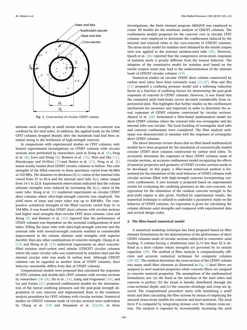
ultimate axial strengths at small strains before the core-concrete wasconfined by the steel tubes. In addition, the applied loads on the UHSCCFST columns dropped sharply after the maximum load had been at-tained owing to the brittleness of high-strength concrete.
In comparisons with experimental studies on CFST columns, onlylimited experimental investigations on CFDST columns with circularsections were performed by researchers, such as Xiong et al. [6], Penget al. [8], Liew and Xiong [9], Romero et al. [10], Wan and Zha [11],Ekmekyapar and Al-Eliwi [12]and Ibañez et al. [13]. Peng et al. [8]tested axially-loaded short CFDST circular columns to failure. The cubestrengths of the filled concrete in these specimens varied from 66MPato 102MPa. The diameter-to-thickness D t( / )o o ratios of the external tubevaried from 27 to 65.4 and the internal steel tube D t/i i ratios rangedfrom 14.1 to 22.8. Experimental observations indicated that the columnultimate strengths were reduced by increasing the D t/o o ratios of theouter tube. Xiong et al. [6] conducted experiments on circular CFDSTshort columns where ultra-high-strength concrete was employed. Theyield stress of inner and outer tubes was up to 428MPa. The com-pressive cylindrical strengths of the filled concrete varied from 51 to184MPa. It was found that CFDST short columns with circular sectionshad higher axial strengths than circular CFST short columns. Liew andXiong [9] and Romero et al. [10] reported that the performance ofCFDST columns was dependent on the sectional configurations of steeltubes. Filling the inner tube with ultra-high-strength concrete and theexternal tube with normal-strength concrete resulted in considerableimprovement in the column ultimate axial strengths with superiorductility than any other combinations of concrete strength. Chang et al.[14] and Zheng et al. [15] undertook experiments on short concrete-filled stainless steel-carbon steel tubular (CFSCST) circular columnswhere the outer circular tube was constructed by stainless steel and theinternal circular tube was made of carbon steel. Although CFSCSTcolumns can be regarded as another form of CFDST columns, theirbehavior sustainably differs from that of CFDST columns.
Computational models were proposed that calculated the responsesof CFST columns and double-skin CFST columns with circular sectionsby researchers [16–24]. Hu et al. [16], Liang and Fragomeni [18], andLai and Varma [21] proposed confinement models for the determina-tion of the lateral confining pressures and the post-peak strength de-gradation of core concrete and implemented them in the nonlinearanalysis procedures for CFST columns with circular sections. Numericalstudies on CFSCST columns made of circular sections were undertakenby Chang et al. [14] and Hassanein et al. [23,24]. In these
investigations, the finite element program ABAQUS was employed tocreate 3D models for the nonlinear analysis of CFSCST columns. Theconfinement models proposed for the concrete core in circular CFSTcolumns were employed to determine the confinement induced by theinternal and external tubes to the core-concrete in CFSCST columns.The stress-strain model for stainless steel obtained by the tensile coupontests was applied to the external stainless-steel tube [25]. However,Quach et al. [26] reported that the compressive stress-strain responsesof stainless steels is greatly different from the tension behavior. Theadoption of the constitutive model for stainless steel based on thetensile coupon testes may lead to the underestimation of the ultimateloads of CFSCST circular columns [19].
Numerical studies on circular CFDST short column constructed bycarbon steel tubes have been extremely scare [11,27]. Wan and Zha[11] proposed a confining pressure model and a softening reductionfactor as a function of confining factors for determining the post-peakresponses of concrete in CFDST columns. However, it was found thatthe computed axial load-strain curves deviated considerably from ex-perimental data. This highlights that further studies on the confinementmechanism are necessary and important in order to determine the ac-tual responses of CFDST columns constructed by circular sections.Ahmed et al. [28] formulated a fiber-based mathematical model forshort CFDST columns where the external tube was rectangular and theinternal tube was circular. The local buckling of rectangular steel tubeand concrete confinement were considered. The fiber analysis tech-nique was demonstrated to simulate well the responses of rectangularshort CFDST columns.
The above literature review shows that no fiber-based mathematicalmodels have been proposed for the simulation of concentrically-loadedcircular CFDST short columns constructed by carbon steel tubes. Toaccurately determine the responses of short CFDST columns made ofcircular sections, an accurate confinement model recognizing the effectsof material properties and geometry of CFDST circular sections needs tobe developed. In this paper, a fiber-based numerical method is for-mulated for the simulation of the axial behavior of CFDST columns withcircular sections filled with high-strength concrete incorporating con-crete confinement. A new formula is proposed based on experimentalresults for evaluating the confining pressures on the core-concrete. Anexpression for the estimation of the residual concrete strength in thepost-yield regime is also given. Verified by experimental results, thenumerical technique is utilized to undertake a parametric study on thebehavior of CFDST columns. An expression is given for calculating thecolumn ultimate axial strengths and compared with experimental dataand several design codes.
2. The fiber-based numerical model
A numerical modeling technique has been proposed based on fiberelement formulations for the determination of the performance of shortCFDST columns made of circular sections subjected to concentric axialloading. A column having a slenderness ratio (L/r) less than 22 is de-fined as a short column whose strengths are governed by its sectioncapacities [29]. The method of fiber analysis is computationally effi-cient and accurate numerical technique for composite columns[28–32]. The method discretizes the cross-section of the CFDST columninto many small fiber elements as illustrated in Fig. 2. Steel fibers areassigned to steel material properties while concrete fibers are assignedto concrete material properties. The assumptions of the mathematicalformulation are: (a) the bond at the interface of the steel tubes andconcrete is perfect; (b) the strain is lineally distributed through thecross-sectional depth; and (c) the concrete shrinkage and creep are ig-nored. The computational procedure starts with initializing a smallstrain and then calculating the fiber stresses by means of employing theuniaxial stress-strain models for concrete and steel materials. The axialforce P is computed by integrating stresses over the column cross-sec-tion. The analysis is repeated by incrementally increasing the axial
Fig. 1. Cross-section of circular CFDST column.
M. Ahmed et al. Thin-Walled Structures 138 (2019) 105–116
106
mizan
Typewritten Text
153

strain until the axial load drops to 50% of the column ultimate axialload or the specified ultimate concrete strain εcu is exceeded.
The ductility of a CFDST column in axial compression is expressedby the following indicator:
=PI εεsdu
y (1)
in which εu is the strain at the axial load that falls to 90% of the columnultimate strength in the post-peak range or the ultimate strain in thepost-yield ascending stress-strain branch. The yield strain εy is calcu-lated as ε /0.750.75 , where ε0.75 represents the strain under the axial loadthat achieves 75% of the column ultimate axial load in the ascendingbranch [22,33,34]
3. Material model for steel tubes
The internal and external steel tubes in a CFDST column with cir-cular section are under biaxial stresses resulting from the longitudinalcompression and either hoop compression or tension which lowers theyield stress of the steel tubes. To consider this effect, the yield stress isreduced by a factor of 0.9 in the constitutive model for structural steelsas shown in Fig. 3. The parabolic curve in the strain range of
< ≤ε ε ε0.9 sy s st applied to cold-formed steels is defined using the ex-pression proposed by Liang [30] as
⎜ ⎟= ⎛⎝
−−
⎞⎠
σ fε εε ε
0.90.9s sy
s sy
st sy
145
(2)
where σs denotes the axial steel stress; εs represents the axial steel strain;fsy stands for the steel yield strength; εsy is the yield strain; and εst is the
strain at the onset of strain-hardeningand is taken as 0.005 in the present study.The equations given by Mander [35] are utilized to calculate the
stress from the axial strain when the strain is in the range of< ≤ε ε εst s su, written as
⎜ ⎟⎜ ⎟= − ⎛⎝
−−
⎞⎠⎛⎝
− ⎞⎠
σ f ε εε ε
f fs susu s
su st
n
su sy(3)
= ⎛
⎝⎜
−−
⎞
⎠⎟n E ε ε
f fstsu st
su sy (4)
in which fsu denotes the steel tensile strength, =ε 0.2su is the ultimatestrain and Est represents the steel modulus at the onset of strain-hard-ening and a value of E0.02 s is used.
4. Material model for confined concrete
4.1. General stress-strain curve
The two-stage stress-strain model presented in Fig. 4 is employed tomodel the responses of confined concrete in CFDST columns with cir-cular sections under axial compression. In the first stage ≤ ≤ ′ε ε(0 )c cc ,the following formula by Mander et al. [36] is employed to calculatethe stress of the confined concrete from the axial strain:
=′ ′′ + −
σf ε ε λ
ε ε λ( / )
( / ) 1ccc c cc
c ccλ (5)
where σc is the axial stress in compression and εc denotes the corre-sponding strain; ′fcc and ′εcc represent the compressive strength andcorresponding strain of the confined concrete, respectively; and λcontrols the initial slope and the curvature of the ascending branch andgiven by
=′
′ − ′λ
ε Eε E f
cc c
cc c cc (6)
in which Ec represents the concrete modulus of elasticity. Lim andOzbakkaloglu [37] derived an expression for estimating Ec by analyzingmany experimental results on concrete cylinders. Their expression wasmodified by Ahmed et al. [28] to consider the effect of column size asfollows:
= ′E γ f4400 (MPa)c c c (7)
where γc stands for the reduction factor applied to the concrete strengthconsidering the influence of the column size, proposed by Liang [30] forCFST columns as
= ≤ ≤−γ D γ1.85 (0.85 1.0)c c c0.135 (8)
in which Dc denotes the concrete-core diameter of circular CFST andCFDST columns, and taken as −D t( 2 )o o for sandwiched concrete and
−D t( 2 )i i for core-concrete in circular CFDST columns.In the second stage > ′ε ε( )c cc , the descending stress-strain branch of
Fig. 2. Typical discretization of circular CFDST column section in the fiberelement analysis.
Fig. 3. General material stress-strain curve for structural steels.
Fig. 4. Stress-strain curves for confined concrete in circular CFDST columns.
M. Ahmed et al. Thin-Walled Structures 138 (2019) 105–116
107
mizan
Typewritten Text
154

confined-concrete is defined by the equation formulated by Lim andOzbakkaloglu [37] as
= ′ −′ −
⎡⎣
+ ⎤⎦
− ′− ′
−( )σ f
f f
1c cc
cc cr
ε εε ε
2c ccci cc (9)
where fcr represents the concrete residual strength and εci denotes theconcrete strain corresponding to the inflection point, which defines theshape of the stress-strain curve in the post-peak range as illustrated inFig. 4.
Parameters studies show that the ′f f/cr cc ratio is mainly influenced bythe D t/ ratio and ′fc . Based on the regression analyses, an expression isproposed for ′f f/cr cc as follows:
⎜ ⎟′= − ⎛
⎝⎞⎠− ′ ⎛
⎝≤
′≤ ⎞
⎠
ff
Dt
γ fff
1.2420 0.0029 0.0044 0 1.0cr
ccc c
cr
cc (10)
The accuracy of the proposed Eq. (10) for calculating the normal-ized residual strength of concrete ( ′f f/cr cc) is examined in Fig. 5 againstthe results obtained from the parametric study on 92 test data[1,2,6,8,9,11,12,38,39].
Lim and Ozbakkaloglu [37] provided a formula for determining thestrain (εci) at the inflection point based on extensive test results. Theirformula was modified by Ahmed et al. [28] by using
γc to incorporate the column size effect as follows:
⎜ ⎟ ⎜ ⎟= ′ ′ ⎛
⎝ ′⎞
⎠+ ′ ′ ⎛
⎝−
′⎞
⎠− −ε ε γ f
ff
ε γ fff
2.8 ( ) 10 ( ) 1ci cc c ccr
cccc c c
cr
cc
0.12 0.47
(11)
The concrete ultimate strain ε( )cu as illustrated in Fig. 4 is specifiedand used as the stopping criterion in the numerical analysis.
4.2. Compressive strength and strain of confined concrete
As illustrated in Fig. 4, when the axial compressive concrete stressexceeds the effective strength ′γ fc c of concrete in a CFDST column withcircular section, the concrete is said to be confined by the steel tubes.This implies that the confined-concrete compressive strength increasesfrom ′γ fc c to the maximum value ′fcc with increasing the axial load [22].The maximum strength ( ′fcc) and its corresponding strain ( ′εcc) of theconcrete confined are determined by the formulas provided by Manderet al. [36] incorporating the factor γc given by Liang and Fragomeni[18] as follows:
⎜ ⎟′ = ⎛
⎝+
′⎞
⎠′f
k f
γ fγ f1cc
rp
c cc c
1
(12)
′ = ′ +′
′ε ε
k f ε
γ fcc crp c
c c
2
(13)
in which frp represents the confining pressure on the concrete offered bythe tubes. In the present study, =k 4.11 and =k 20.52 provided by Ri-chart et al. [40] are used. The axial strain ′εc at ′fc depends on the ef-fective concrete strength in compression. The following equation givenby De Nicolo et al. [41] for computing the strain ′εc is adopted in thepresent study:
′ = + ′ − × −ε γ f0.00076 (0.626 4.33) 10c c c7
(14)
4.3. Confining pressure model for sandwiched concrete
Experimental results showed that the outer tube of a circular CFDSTcolumn was forced to buckle locally outward and the sandwichedconcrete crushed where the steel tube buckled [6,11,12]. The finiteelement analyses on circular CFST and CFDST columns conducted byChang et al. [21] indicated that the longitudinal compressive stress inthe core-concrete in the circular CFDST column was higher than that inthe corresponding concrete in the CFST column. However, the long-itudinal compressive stress in the sandwiched concrete in the CFDSTcolumn was similar to that in the corresponding concrete in the CFSTcolumn. This implies that in a CFDST short column under axial com-pression, the core-concrete is confined by both the outer and inner steeltubes but the sandwiched-concrete is confined mainly by the outer steeltube and the confinement provided by the inner steel tube on thesandwiched concrete is insignificant and can be ignored. In this study,the lateral pressure on the sandwiched concrete f( )rpo in CFDST columnsmade of circular sections is estimated by the following expressionsprovided by Hu et al. [16]:
=⎧
⎨⎪
⎩⎪
− ≤ ≤
− < ≤
( )( )
f
f
0.043646 0.000832 for 21.7 47
0.006241 0.0000357 for 47 150
rpo
syo
Dt
Dt
Dt
Dt
oo
oo
oo
oo (15)
4.4. Proposed confining pressure model for core concrete
The confining pressure model for the core concrete was developedby means of interpreting the experimental data of 34 circular shortCFDST columns given in Table 1 [6,8,9,11,12]. The maximum axialload on the axial load-strain curve with softening was used as the ul-timate axial strength of the CFDST column. For specimens withoutsoftening behavior, the axial load at the ultimate strain was assumed toreach its ultimate state. The compressive strength for the confined core-concrete was calculated by subtracting the capacities of the sandwichedconcrete and internal and external steel tubes. The lateral pressure( frpi,exp ) on the core concrete obtained from experiments was then de-termined using Eq. (16). By undertaking the regression analyses on theexperimental data given in Table 1, a new expression for quantifyingthe confining pressure exerted on the core-concrete in CFDST columnswith circular sections is proposed as
⎜ ⎟ ⎜ ⎟
⎜ ⎟ ⎜ ⎟
= + ⎛⎝
⎞⎠− ⎛
⎝⎞⎠
− ⎡⎣⎢
⎛⎝
⎞⎠− ⎛
⎝⎞⎠⎤⎦⎥
≥−
f Dt
Dt
Dt
Dt
ζ f
2.2897 0.0066 0.1918
0.0585 0.3801 ( 0)
rpio
o
i
i
o
o
i
irpi
1
(16)
in which Di and Do are the diameters of the internal and external steeltubes, respectively; ti and t0 are the thickness of the inner and outertubes, respectively; and ζ is the confinement factor which is expressedby
=+
′ + ′ζ
A f A fA γ f A γ f
so sy o si sy i
sc c sc cc c cc
, ,
(17)
R² = 0.98
0
0.2
0.4
0.6
0.8
1
1.2
0 0.2 0.4 0.6 0.8 1 1.2
Proposed equation (10)
f cr /
f’ cc
Fig. 5. Verification of the proposed expression for determining the residualconcrete strength.
M. Ahmed et al. Thin-Walled Structures 138 (2019) 105–116
108
mizan
Typewritten Text
155

in which Aso, Asi, Asc and Acc are the cross-sectional areas of the outertube, inner tube, sandwiched-concrete and core-concrete, respectively;′fcc and ′fsc are the strengths of the core concrete and sandwiched con-
crete in compression, respectively; fsyi and fsyo are the yield stresses of
the internal and external tubes, respectively. Fig. 6 shows that thelateral pressures calculated by the proposed Eq. (16) are in good cor-relation with test data.
5. Comparisons of computer solutions with test results
The accuracy of the fiber-based numerical model incorporating theproposed confining pressure model and material constitutive laws isestablished by means of comparing computations with correspondingmeasurements provided by Xiong et al. [6], Peng et al. [8], Liew andXiong [9], Wan and Zha [11] and Ekmekyapar and Al-Eliwi [12].Table 1 gives the material and geometric properties of 40 tested CFDSTshort columns. The unconfined concrete strengths were determined bythe compression tests on concrete cubes ′f( )cu , concrete cylinders of100× 200mm ′f( )c,100 or concrete cylinders of 150×300mm ′f( )c . Forconsistency, the unconfined concrete strengths were converted to ′fcusing the conversion of ′f /1.05ck,100 and ′f0.85 cu, respectively.
The predicted ultimate axial loads P( )u num, by the numerical modeland the experimental values P( )u,exp are given in Table 2. It is observedthat the fiber modeling technique accurately determines the capacitiesof short CFDST circular columns. The statistical study indicates that themean P P/u num u, ,exp ratio is 0.97 while both the coefficient of variationand standard deviation are 0.08. The simulated axial load-strain be-havior of high-strength CFDST columns are provided in Fig. 7. Themeasured axial load-strain performance of the tested columns was
Table 1Geometric and material properties of tested circular CFDST short columns.
Specimen Outer tube Inner tube Concrete Ref.
×D to o (mm) Doto
fsy o, (MPa) fsu o, (MPa) Es o, (GPa) ×D ti i (mm) Diti
fsy i, (MPa) fsu i, (MPa) Es i, (GPa) ′fc o, (MPa) ′fc i, (MPa)
C1-1 133×4.5 29.6 361 410 200 55.9×3.4 16.4 361 410 200 56.1 56.1 [8]C1-2 133×4.5 29.6 361 410 200 56×3.4 16.6 361 410 200 56.1 56.1C2-1 132.5×3.0 44.2 361 410 200 56×3.0 18.7 361 410 200 56.1 56.1C2-2 132.5×3.0 44.2 361 410 200 56×3.0 18.7 361 410 200 56.1 56.1C2-3 132.3×3.2 41.3 361 410 200 56.1×3.2 17.5 361 410 200 79.9 79.9C2-4 132×3.0 44.0 361 410 200 56.1×3.2 17.5 361 410 200 79.9 79.9C2-5 132.1×3.1 42.6 361 410 200 56×3.4 16.5 361 410 200 86.7 86.7C2-6 132×3.2 41.3 361 410 200 56.1×3.0 18.7 361 410 200 86.7 86.7C3-1 131.8×2.1 62.8 361 410 200 54.8×2.4 22.8 361 410 200 56.1 56.1C3-2 130.8×2.0 65.4 361 410 200 54.2×2.6 20.8 361 410 200 56.1 56.1C4-1 108×4.0 27.0 361 410 200 48×3.0 16.0 361 410 200 56.1 56.1C4-2 106.5×2.3 46.3 361 410 200 48×3.4 14.1 361 410 200 56.1 56.1C5-1 107.5×3.1 34.7 361 410 200 47.6×3.0 15.9 361 410 200 56.1 56.1C5-2 107.6×3.1 34.7 361 410 200 47.6×3.1 15.4 361 410 200 56.1 56.1S3-1-1 219×5.0 43.8 377 511 205 114×3.6 31.7 406 505 213 51 51 [9]S3-1-2 219×5.0 43.8 377 511 205 114×3.6 31.7 406 505 213 167 167S3-1-3 219×5.0 43.8 377 511 205 114×3.6 31.7 406 505 213 51 167S3-1-4 219×5.0 43.8 377 511 205 114×3.6 31.7 406 505 213 51 184S3-2-1 219×10 21.9 381 509 212 114×6.3 18.1 428 521 209 51 51S3-2-2 219×10 21.9 381 509 212 114×6.3 18.1 428 521 209 167 167S3-2-3 219×10 21.9 381 509 212 114×6.3 18.1 428 521 209 51 167S3-2-4 219×10 21.9 381 509 212 114×6.3 18.1 428 521 209 51 184A1-1 426×7.73 55.1 298 408 206 133×6.6 20.2 331.4 478 200 25.9 25.9 [11]A2-1 426×7.52 56.6 302 407 206 133×6.6 20.2 460 683 200 25.9 25.9A1-2 426×7.52 56.6 302 407 206 219×6.7 32.7 316.8 460 200 25.9 25.9A2-2 426×7.52 56.6 302 407 206 219×6.7 32.7 478 660 200 25.9 25.9A1-3 426×7.52 56.6 302 407 206 273×6.5 42.0 322 415 200 25.9 25.9A2-3 426×7.52 56.6 302 407 206 273×6.5 42.0 447 626 200 25.9 25.9CC1-SC1-OT1 139.7×3.3 42.3 290 350 200 88.9×4.25 20.9 375 450 200 29.1 29.1 [12]CC1-SC1-OT2 139.7×5.9 23.7 355 410 200 88.9×4.25 20.9 375 450 200 29.1 29.1CC1-SC2-OT1 139.7×3.3 42.3 290 350 200 88.9×4.25 20.9 375 450 200 64.9 29.1CC1-SC2-OT2 139.7×5.9 23.7 355 410 200 88.9×4.25 20.9 375 450 200 64.9 29.1CC2-SC1-OT1 139.7×3.3 42.3 290 350 200 88.9×4.25 20.9 375 450 200 29.1 64.9CC2-SC1-OT2 139.7×5.9 23.7 355 410 200 88.9×4.25 20.9 375 450 200 29.1 64.9CC2-SC2-OT1 139.7×3.3 42.3 290 350 200 88.9×4.25 20.9 375 450 200 64.9 64.9CC2-SC2-OT2 139.7×5.9 23.7 355 410 200 88.9×4.25 20.9 375 450 200 64.9 64.9DC-09 219.1×6.3 34.8 300 467 202 114×6.3 18.1 428 519 209 155 155 [6]DC-10 219.1×6.3 34.8 300 467 202 114×6.3 18.1 428 519 209 167 167DC-11 219.1×6.3 34.8 300 467 202 114×6.3 18.1 428 519 209 142 142DC-12 219.1×6.3 34.8 300 467 202 114×6.3 18.1 428 519 209 166 166
R² = 0.87
0
5
10
15
20
25
30
35
0 5 10 15 20 25 30 35
frpi,p
f rpi
Eq. 16
Fig. 6. Verification of the proposed expression for determining the lateralpressure on core concrete with the test results.
M. Ahmed et al. Thin-Walled Structures 138 (2019) 105–116
109
mizan
Typewritten Text
156

determined by the mathematical model with reasonable accuracy. Theexperimentally measured column initial axial stiffness slightly differsfrom the predicted one. The fiber-based modeling method also gives agood simulation of the post-yield responses of the CFDST columns. Thediscrepancy between the predictions and measurements is caused bythe uncertainty of the actual concrete strength and stiffness in the testedspecimens and the average concrete strength was used in the numericalanalyses.
6. Parametric study
The mathematical model proposed was utilized to examine thestructural behavior of short circular high-strength CFDST columns. Thedetails on the CFDST columns under investigations are provided inTable 3. Steel tubes having the yield stresses of 250 MPa, 300 MPa, 350MPa, 400 MPa and 450MPa were used in the numerical analyses andtheir corresponding tensile strengths were 320 MPa, 400 MPa, 420MPa, 500 MPa and 520MPa, respectively. In the parametric study, theultimate concrete strain εcu was taken as 0.04 which gives conservativeresults of columns with ascending stress-strain behavior in the post-yield range.
6.1. Influences of the internal steel tube
The effects of the internal tube on the strength as well as ductility ofthe CFDST column were examined by comparing its axial load-strainresponse with that of the conventional CFST column. For this purpose,analyses on Columns C1 and C2 presented in Group G1 in Table 3 wereundertaken by the mathematical model. Both columns had the sameouter tube diameter as well as the steel area and were made of high-strength concrete of 60MPa. Fig. 8 shows that the CFDST column has4.85% higher strength than the CFST column due to the inclusion of theinternal circular tube. The reason for the strength increase is that theinner steel tube provides additional confinement to the core-concrete,which increases the strength of the core-concrete thereby the columnultimate strength. The CFDST column also has a better ductility thanthe CFST column. However, the column initial stiffness is not affectedby the internal tube.
The influences of the internal tube diameter on the column behaviorwere evaluated by analyzing Columns C3–C6 in Group G1 in Table 3.Only the inner tube diameter (Di) was varied in this investigation. Fig. 9presents the calculated axial loads as a function of axial strains for theseCFDST columns. The ultimate axial loads of short circular CFDST col-umns are found to increase significantly as Di increases. By increasingthe diameter Di from 157.5 mm to 202.5 mm, 247.5 mm and 292.5 mm,the percentage increases in the column ultimate strengths are 3.4%,
Table 2Ultimate axial strengths of circular CFDST short columns.
Specimen Pu,exp (kN) Pu num, (kN) Pu EC, 4 (kN) Pu ACI, (kN) Pu AISC, (kN) Pu des, (kN) Pu numPu
,,exp
Pu ECPu
, 4,exp
Pu ACIPu
,,exp
Pu AISCPu
,,exp
Pu desPu
,,exp
C1-1 1942 1818 1847 1407 1455 1823 0.94 0.95 0.72 0.75 0.94C1-2 1911 1818 1846 1407 1455 1823 0.95 0.97 0.74 0.76 0.95C2-1 1683 1409 1546 1196 1249 1425 0.84 0.92 0.71 0.74 0.85C2-2 1592 1409 1546 1196 1249 1425 0.89 0.97 0.75 0.78 0.90C2-3 1831 1730 1852 1470 1544 1781 0.94 1.01 0.80 0.84 0.97C2-4 1875 1694 1811 1442 1516 1718 0.90 0.97 0.77 0.81 0.92C2-5 1870 1813 1916 1532 1612 1837 0.97 1.02 0.82 0.86 0.98C2-6 1925 1831 1908 1524 1605 1853 0.95 0.99 0.79 0.83 0.96C3-1 1434 1214 1327 1042 1097 1231 0.85 0.93 0.73 0.77 0.86C3-2 1425 1190 1303 1026 1080 1204 0.84 0.91 0.72 0.76 0.84C4-1 1432 1276 1042 979 1009 1281 0.89 0.73 0.68 0.70 0.89C4-2 1106 931 875 810 842 948 0.84 0.79 0.73 0.76 0.86C5-1 1256 1110 947 883 915 1121 0.88 0.75 0.70 0.73 0.89C5-2 1182 1110 953 888 920 1126 0.94 0.81 0.75 0.78 0.95S3-1-1 3626 4051 3460 3207 3351 3790 1.12 0.95 0.88 0.92 1.05S3-1-2 8529 7834 7295 6467 6938 8022 0.92 0.86 0.76 0.81 0.94S3-1-3 4968 4950 4499 4091 4323 5014 1.00 0.91 0.82 0.87 1.01S3-1-4 5239 5175 4652 4220 4465 5193 0.99 0.89 0.81 0.85 0.99S3-2-1 6300 6558 4891 4670 4783 5918 1.04 0.78 0.74 0.76 0.94S3-2-2 9817 8943 8252 7526 7930 9211 0.91 0.84 0.77 0.81 0.94S3-2-3 7022 6798 5828 5466 5660 6897 0.97 0.83 0.78 0.81 0.98S3-2-4 7160 6794 5966 5583 5788 7041 0.95 0.83 0.78 0.81 0.98A1-1 8142 8804 7260 6756 7043 7410 1.08 0.89 0.83 0.87 0.91A2-1 9830 9079 7563 7057 7341 7720 0.91 0.76 0.71 0.74 0.78A1-2 9830 9383 7725 7227 7506 7956 0.95 0.79 0.74 0.76 0.81A2-2 10,025 10,189 8446 7947 8216 8586 1.02 0.84 0.79 0.82 0.86A1-3 9740 9767 8037 7542 7818 8275 1.00 0.83 0.77 0.80 0.85A2-3 10,739 10,801 8717 8222 8488 8755 1.01 0.81 0.77 0.79 0.82CC1-SC1-OT1 1435.05 1460 1306 1247 1282 1429 1.02 0.91 0.87 0.89 1.00CC1-SC1-OT2 1977.94 2090 1658 1605 1635 1972 1.06 0.84 0.81 0.83 1.00CC1-SC2-OT1 1606.89 1673 1514 1412 1475 1661 1.04 0.94 0.88 0.92 1.03CC1-SC2-OT2 2044.44 2278 1908 1817 1871 2237 1.11 0.93 0.89 0.92 1.09CC2-SC1-OT1 1570.15 1627 1415 1328 1381 1563 1.04 0.90 0.85 0.88 1.00CC2-SC1-OT2 2153.11 2255 1849 1767 1815 2182 1.05 0.86 0.82 0.84 1.01CC2-SC2-OT1 1784.39 1839 1704 1574 1655 1877 1.03 0.96 0.88 0.93 1.05CC2-SC2-OT2 2274.77 2374 2099 1979 2051 2448 1.04 0.92 0.87 0.90 1.08DC-09 7640 7346 7038 6309 6727 7504 0.96 0.92 0.83 0.88 0.98DC-10 7209 7699 7414 6629 7078 7878 1.07 1.03 0.92 0.98 1.09DC-11 6882 6961 6631 5963 6346 7100 1.01 0.96 0.87 0.92 1.03DC-12 8375 7699 7383 6602 7049 7847 0.92 0.88 0.79 0.84 0.94Mean 0.97 0.89 0.79 0.83 0.95Standard Deviation (SD) 0.08 0.08 0.06 0.07 0.08Coefficients of Variance (COV) 0.08 0.09 0.08 0.08 0.08
M. Ahmed et al. Thin-Walled Structures 138 (2019) 105–116
110
mizan
Typewritten Text
157
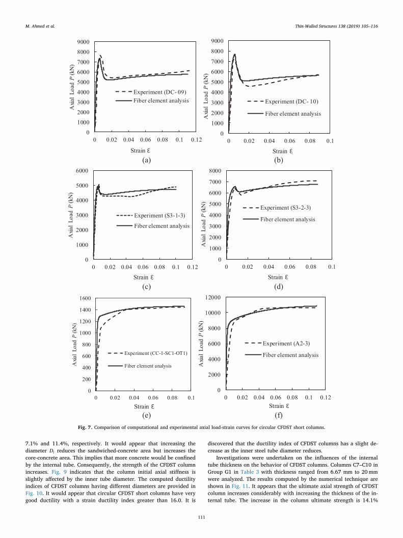
7.1% and 11.4%, respectively. It would appear that increasing thediameter Di reduces the sandwiched-concrete area but increases thecore-concrete area. This implies that more concrete would be confinedby the internal tube. Consequently, the strength of the CFDST columnincreases. Fig. 9 indicates that the column initial axial stiffness isslightly affected by the inner tube diameter. The computed ductilityindices of CFDST columns having different diameters are provided inFig. 10. It would appear that circular CFDST short columns have verygood ductility with a strain ductility index greater than 16.0. It is
discovered that the ductility index of CFDST columns has a slight de-crease as the inner steel tube diameter reduces.
Investigations were undertaken on the influences of the internaltube thickness on the behavior of CFDST columns. Columns C7–C10 inGroup G1 in Table 3 with thickness ranged from 6.67 mm to 20mmwere analyzed. The results computed by the numerical technique areshown in Fig. 11. It appears that the ultimate axial strength of CFDSTcolumn increases considerably with increasing the thickness of the in-ternal tube. The increase in the column ultimate strength is 14.1%
(a) (b)
(c) (d)
(e) (f)
0
1000
2000
3000
4000
5000
6000
7000
8000
9000
0 0.02 0.04 0.06 0.08 0.1 0.12
Axi
al
Lo
ad
P(k
N)
Experiment (DC- 09)
Fiber element analysis
0
1000
2000
3000
4000
5000
6000
7000
8000
9000
0 0.02 0.04 0.06 0.08 0.1
Axi
al
Lo
ad
P(k
N)
Experiment (DC- 10)
Fiber element analysis
0
1000
2000
3000
4000
5000
6000
0 0.02 0.04 0.06 0.08 0.1 0.12
Axi
al
Lo
ad
P(k
N)
Experiment (S3-1-3)
Fiber element analysis
0
1000
2000
3000
4000
5000
6000
7000
8000
0 0.02 0.04 0.06 0.08 0.1
Axi
al
Lo
ad
P(k
N)
Experiment (S3-2-3)
Fiber element analysis
0
200
400
600
800
1000
1200
1400
1600
0 0.02 0.04 0.06 0.08 0.1
Axi
al
Lo
ad
P(k
N)
Experiment (CC-1-SC1-OT1)
Fiber element analysis
0
2000
4000
6000
8000
10000
12000
0 0.02 0.04 0.06 0.08 0.1 0.12
Axi
al
Lo
ad
P(k
N)
Experiment (A2-3)
Fiber element analysis
Fig. 7. Comparison of computational and experimental axial load-strain curves for circular CFDST short columns.
M. Ahmed et al. Thin-Walled Structures 138 (2019) 105–116
111
mizan
Typewritten Text
158

when the thickness ti is increased from 6.67mm to 20mm. This can beexplained by the fact that increasing the inner tube thickness leads to anincrease in the steel area with yield stress of 450MPa but the samereduction in the core-concrete area with compressive strength of40MPa, which results in a considerable increase in the ultimate axialstrength of the column. As demonstrated in Fig. 12, reducing thethickness ti causes a slight decrease in the ductility because of the re-duction in the internal tube area. The numerical results presented inFig. 12 indicate that when the thickness ti is reduced from 20mm to 15mm, 10 mm and 6.67mm, the axial ductility index decreases from17.40 to 17.35, 17.31 to 17.20, respectively.
It has been demonstrated that circular CFDST columns possesshigher strength and ductility than circular CFST columns. High strength
inner steel tubes may be used to further increase the column capacity.The use of the inner steel tube instead of reinforcing bars certainlyspeeds up the construction process. Moreover, the existing conventionalCFST column can be strengthened by using an additional external steeltube filled with concrete and it becomes a CFDST column. However, toachieve economical and efficient designs, the cross-sections of CFDSTcolumns must be properly designed. The proposed computationalmodel can be used to analyze the cross-sectional capacities of CFDSTcolumns to determine the optimal designs of CFDST columns.
Table 3Geometric and material properties of circular CFDST short columns utilized in the parametric study.
Group Column Outer tube Inner tube Concrete Ultimate strength
Do (mm) to (mm) Doto
fsyo (MPa) Di (mm) ti (mm) Diti
fsyi (MPa) ′fc (MPa) Pu num, (kN) Pu des, (kN) Pu desPu num
,,
G1 C1 500 12.88 38.8 350 – – – – 60 18,973 18,387 0.97C2 500 10 50 350 280 5 56 350 60 19,751 19,849 1.00C3 450 10 45 350 157.5 8 19.68 350 60 14,831 14,696 0.99C4 450 10 45 350 202.5 8 25.31 350 60 15,330 15,249 0.99C5 450 10 45 350 247.5 8 30.93 350 60 15,889 15,868 1.00C6 450 10 45 350 292.5 8 36.56 350 60 16,520 16,534 1.00C7 600 10 60 450 200 6.67 30 450 40 21,648 20,403 0.94C8 600 10 60 450 200 10 20 450 40 22,343 21,168 0.95C9 600 10 60 450 200 15 13.33 450 40 23,520 22,396 0.95C10 600 10 60 450 200 20 10 450 40 24,694 23,559 0.95
G2 C11 280 8 35 350 140 5 28 350 60 7180 7127 0.99C12 320 8 40 350 140 5 28 350 60 8428 8417 1.00C13 360 8 45 350 140 5 28 350 60 9601 9607 1.00C14 400 8 50 350 140 5 28 350 60 10,968 11,000 1.00C15 450 9 50 350 200 8 25 350 70 15,806 15,844 1.00C16 450 10 45 350 200 8 25 350 70 16,568 16,523 1.00C17 450 11.25 40 350 200 8 25 350 70 17,840 17,683 0.99C18 450 12.86 35 350 200 8 25 350 70 19,123 18,966 0.99
G3 C19 480 12 40 350 200 8 25 350 55 18,311 17,655 0.96C20 480 12 40 350 200 8 25 350 75 20,817 20,537 0.99C21 480 12 40 350 200 8 25 350 95 23,653 23,420 0.99C22 480 12 40 350 200 8 25 350 115 26,449 26,302 0.99
G4 C23 720 12 60 250 280 8 35 250 60 31,692 30,722 0.97C24 720 12 60 300 280 8 35 300 60 33,175 31,866 0.96C25 720 12 60 350 280 8 35 350 60 34,072 33,229 0.98C26 720 12 60 400 280 8 35 400 60 35,949 34,729 0.97C27 720 12 60 450 280 8 35 450 60 37,836 36,319 0.96
Mean 0.98Standard Deviation (SD) 0.02Coefficients of Variance (COV) 0.02
Fig. 8. Effects of the inner steel tube on the axial load-strain curves. Fig. 9. Effects of the diameter of the inner steel tube on the axial load-straincurves of circular CFDST short columns.
M. Ahmed et al. Thin-Walled Structures 138 (2019) 105–116
112
mizan
Typewritten Text
159

6.2. Influences of D t/o o ratio
The behavior of CFDST columns is significantly dependent on theD t/o o ratios. Two scenarios were considered to examine the effects ofD t/o o ratios. The CFDST columns with D t/o o ratios of 35, 40, 45 and 50
given in Group G2 in Table 3 were examined in the first scenario bychanging the outer tube diameter Do only. Fig. 13 gives the computedload-strain relationships of these columns. It would appear that in-creasing the external steel tube diameter Do significantly increases thecolumn axial strength. By increasing Do from 280mm to 320 mm, 360mm and 400mm, the increases in the column axial strengths are 17.4%,33.7% and 52.8%, respectively. This is because increasing the diameterof the outer tube increases the areas of both steel tube and concrete sothat the column ultimate axial load increases. As depicted in Fig. 13, thecolumn initial stiffness increases considerably with an increase in theD t/o o ratio, however, it has an insignificant impact on the post-peakresponses of CFDST columns. The axial strain ductility indices are givenin Fig. 14. The ductility indices are found to vary with D t/o o ratios. Thecomputed axial ductility indexes are 16.3, 17.32, 18.73 and 19.63 forcolumns with D t/o o ratios of 35, 40, 45 and 50, respectively.
In the second scenario, only the external tube thickness to waschanged to determine the D t/o o ratios as 35, 40, 45 and 50 as shown inGroup G2 in Table 3. The axial load-strain curves predicted are given inFig. 15. It would appear that decreasing the thickness to significantlydecreases the column ultimate strength. The strength reductions arecomputed as 6.7%, 13.4% and 17.3%, respectively when the thicknessto is reduced from 12.86mm to 11.25 mm, 10 mm and 9mm, respec-tively. The reason for this is that deceasing the outer tube thicknessreduces the steel tube area and the confinement on the sandwiched andcore concrete so that the column axial loads decease significantly. It canbe seen from Fig. 15 that the D t/o o ratio influences the post-yield curves.
0
5
10
15
20
25
0 0.2 0.4 0.6 0.8
Di / Do
PIsd
Fig. 10. Effects of Di /Do ratio on the strain ductility index of circular CFDSTshort columns.
Fig. 11. Effects of the thickness of the inner steel tube on the axial load-straincurves of circular CFDST short columns.
0
5
10
15
20
25
0 0.2 0.4 0.6 0.8
Di / Do
PIsd
Fig. 12. Effects of D t/i i ratio on the strain ductility index of circular CFDSTshort columns.
Fig. 13. Effects of the diameter of the outer steel tube on the axial load-straincurves of circular CFDST short columns.
0
5
10
15
20
25
0 10 20 30 40 50 60
PIsd
Do / to
Fig. 14. Effects of Do/to ratio by varying diameter of the outer steel tube on thestrain ductility index of circular CFDST short columns.
M. Ahmed et al. Thin-Walled Structures 138 (2019) 105–116
113
mizan
Typewritten Text
160

Fig. 16 illustrates that increasing the D t/o o ratio improves the axialductility. For CFDST short columns with D t/o o ratio of 35, 40, 45 and50, the calculated strain ductility indexes are 16.05, 17.08, 18.44 and19.06, respectively.
6.3. Influences of concrete compressive strength
In Group G3 in Table 3, the concrete of different strengths was usedto construct CFDST columns. The compressive concrete strengths of55MPa, 75MPa, 95MPa and 115MPa were considered in the fiberanalysis. The predicted load-strain responses presented in Fig. 17 in-dicate that using higher strength concrete significantly improves theultimate strength of CFDST columns. When ′fc increases from 55MPa to75MPa, 95MPa and 115MPa, the increases in the column ultimatestrengths are 13.7%, 29.2% and 44.4%, respectively. This can be ex-plained by the fact that the ultimate axial load of short CFDST columnsis governed by its section and material properties such as the concretecompressive strength. However, it is noticed that CFDST columnsconstructed using high-strength concrete are less ductile due to itsbrittle behavior.
6.4. Influences of steel yield strength
The yield stress of steel tubes has influences on the behavior ofCFDST columns and its effect was studied by using the fiber-based
model. The Columns in Group G4 in Table 3 were considered for thisstudy. The calculated responses of these CFDST columns constructed bysteel tubes having various yield stresses are given Fig. 18. It is observedthat the ultimate strength of the CFDST column significantly increaseswhen the steel yield stress is increased. When the yield stress is in-creased from 250MPa to 300MPa, 350MPa, 400MPa and 450MPa,the column ultimate strength is found to increase by 4.7%, 7.5%, 13.4%and 19.4%, respectively. The reason for the column strength increase isthat the ultimate axial strength of a short CFDST column is governed byits section and material properties such as the steel yield strength. Thestrain ductility indices of CFDST columns are depicted in Fig. 19. It isshown that the ductility index of the column increases with an increasein its steel yield strength up to 350MPa and after that it decreases as itssteel yield strength increases.
7. Proposed design model
Currently, there are no design specifications available for the designof stub CFDST columns constructed by circular carbon steel tubes.Previously, Liang and Fragomeni [18] proposed a formula for thecomputation of the ultimate axial capacities of CFST columns withcircular cross-sections under axial loading considering confinementeffects. Liang [22] also derived design formulas for double-skin CFSTshort columns in axial compression. Hassanein et al. [23] recommendeda formula for the design of CFSCST columns where the outer tube wasmade of duplex stainless steel. Based on the proposed model for lateral
Fig. 15. Effects of the thickness of the outer steel tube on the axial load-straincurves of circular CFDST short columns.
0
5
10
15
20
25
0 10 20 30 40 50 60
PIsd
Do / to
Fig. 16. Effects of Do/to ratio by varying thickness of the outer steel tube on thestrain ductility index of circular CFDST short columns.
Fig. 17. Effects of concrete compressive strength on the axial load-strain curvesof circular CFDST short columns.
Fig. 18. Effects of steel yield strength on the axial load-strain curves of circularCFDST short columns.
M. Ahmed et al. Thin-Walled Structures 138 (2019) 105–116
114
mizan
Typewritten Text
161

pressures on core-concrete and the previously cited work [18,22], anew simple expression for the estimation of the ultimate strength ofshort circular CFDST columns is proposed as
= + + ′ + + ′ +P γ f A γ f A γ f f A γ f f A( 4.1 ) ( 4.1 )u design so syo so si syi si sc c rpo sc cc c rpi cc,
(18)
where γso and γsi are strength factors, accounting for the influences ofhoop-tension, strain hardening as well as imperfections on the outertube and inner tube, respectively and were developed by Liang andFragomeni [18] as
⎜ ⎟= ⎛⎝
⎞⎠
≤ ≤−
γ Dt
γ1.458 (0.9 1.1)soo
oso
0.1
(19)
⎜ ⎟= ⎛⎝
⎞⎠
≤ ≤−
γ Dt
γ1.458 (0.9 1.1)sii
isi
0.1
(20)
The proposed design equation is verified by comparing calculationswith test data of 40 CFDST columns in Table 2, where Pu des, , Pu,exp andPu num, are the ultimate axial loads calculated using Eq. (18), obtainedfrom experiments and determined by the fiber analysis, respectively. Itis observed that the mean Pu des, /Pu,exp ratio is 0.97 and the calculatedcoefficient of variance and standard deviation are 0.08. The strengthcomputations of circular CFDST columns by the design model are fur-ther validated by numerical predictions in Table 3. It is shown that thestrengths computed by the design model agree extremely well withcorresponding numerical predictions. The proposed design formula canpredict 98% of the numerical strengths with a coefficient of variance of0.02.
8. Comparisons with design codes
The applicability of the existing design specifications for short cir-cular CFST columns given in Eurocode 4 [7], ACI 318-11 [42] and AISC360-16 [43] to circular CFDST columns is examined herein. Table 4presents the specifications of the design codes to calculate the ultimateaxial strengths. Eurocode 4 accounts for the influence of concreteconfinement on the strength calculations of CFST circular columnswhereas ACI 318-11 and AISC 360-16 neglect this effect. Table 2summaries the comparisons between design calculations and measuredresults on 40 tested CFDST short columns. The calculated ultimatestrengths using ACI 318-11 and AISC 360-16 codes are very con-servative compared to test results. Although the design method speci-fied in Eurocode 4 yields better estimations of the load-carrying capa-cities of CFDST columns than ACI 318-11 and AISC 360-16, but it couldnot capture the actual improvement in the core concrete strength. The
mean calculated-to-measured ultimate axial strengths calculated bysuing Eurocode 4, ACI 318-11 and AISC 360-16 are 0.89, 0.79 and 0.83,respectively. On the contrary, the proposed design model generallyyields better strength predictions of short CFDST columns than designcodes. The current design equation given in Eurocode 4 [7] for CFSTcolumns is simpler than the proposed Eq. (18), but Eq. (18) yields moreaccurate results than the current design provision. Further studiesshould focus on developing a more simple revision to the current designprovision in Eurocode 4 for the design of CFDST columns.
9. Conclusions
This paper has described a fiber-based mathematical model for-mulated for the numerical simulations of short circular CFDST columnssubjected to axial loading. A new model for computing the confiningpressures on the core-concrete has been proposed based on existing testdata together with a new strength-degradation parameter for quanti-fying the post-peak responses of confined concrete. The accuracy of thedeveloped numerical analysis technique incorporating the new propo-sals of material constitutive laws has been examined by comparisonswith experimental results of CFDST columns. Details parametric studieshave been conducted considering various columns geometry and ma-terial properties. A new design formula has been derived and verifiedby test results. Furthermore, the applicability of the existing designrules recommended by Eurocode 4 [7], ACI 318-11 [42] and AISC 360-16 [43] for circular CFST columns to circular CFDST columns has beeninvestigated.
0
5
10
15
20
25
0 100 200 300 400 500
PIsd
fsy (MPa)
Fig. 19. Effects of steel yield strength on the strain ductility index of circularCFDST short columns.
Table 4Design formulas for circular CFDST short columns given in design codes.
Design codes Design equations
Eurocode 4 [7] Circular CFST columns:
⎜ ⎟= + ⎛⎝
+ ⎞⎠
P η f f η tD
f
fA A 1u outer syo sc c
o
o
syo
sc, a so sc
⎜ ⎟= + ⎛⎝
+ ⎞⎠
P η f f η tD
f
fA A 1u inner syi cc cc c
i
i
syi
cc, a si
= +P P PEC u outer u inner4 , ,
⎜ ⎟ ⎜ ⎟= ⎛⎝
+ ⎞⎠
⎛⎝
≤ ⎞⎠
−η λ η0.25 3 2 1.0a a
⎜ ⎟= − + ⎛⎝
> ⎞⎠
− −η λ λ η4.9 18.5 17 0c
2c
where the relative slenderness ratio is =−λ
Npl RkNcr
,
ACI 318-11[42] = + + +P f f f fA 0.85A A 0.85Au ACI syo sc syi cc, so sc si cc
AISC 360-16[43]
= ⎧⎨⎩
≥<
P P P PP P P
[0.658 ] for 0.440.877 for 0.44u AISCo Po Pe e o
e e o,
( / )
= + + +P A f C A f A f C A fo so syo sc sc si syi cc cc2 2
=P πKL
EI( )
( )e eff2
2
= + + +EI E I E I C E I C E I( )eff so so si si sc sc cc cc4 4
⎜ ⎟= + ⎛⎝ +
⎞⎠≤C A
A A0.6 2 0.9s
s c4
C2 = 0.95 for circular section
M. Ahmed et al. Thin-Walled Structures 138 (2019) 105–116
115
mizan
Typewritten Text
162

The conclusions are given as follows:
(1) The fiber-based mathematical model developed produces predic-tions which are in good correlations with experimental data ofcircular CFDST columns under axial compression.
(2) If both circular CFDST and CFST columns have the same externaltube diameter and the same steel area, the CFDST column hashigher strength and ductility than the CFST column.
(3) Increasing the inner steel-tube diameter remarkably improves theultimate strength of the CFDST column.
(4) Increasing the thickness of the inner tube considerably increases theultimate axial loads of CFDST columns made of normal strengthconcrete but its effect diminishes when high-strength concrete isused.
(5) The use of higher strength steel tubes and concrete results in higheraxial capacities, but it considerably affects the column axial ducti-lity.
(6) The design rules specified in Eurocode 4 [7], ACI 318-11 [42] andAISC 360-16 [43] for circular CFST columns give conservativecalculations of the ultimate axial strengths of short CFDST columnsmade of circular steel sections.
(7) The design formula proposed yields more accurate ultimatestrength predictions of CFDST columns than the design approachesprovided in existing design codes.
References
[1] K. Sakino, H. Nakahara, S. Morino, I. Nishiyama, Behavior of centrally loadedconcrete-filled steel-tube short columns, J. Struct. Eng. ASCE 130 (2) (2004)180–188.
[2] G. Giakoumelis, D. Lam, Axial capacity of circular concrete-filled tube columns, J.Constr. Steel Res. 60 (7) (2004) 1049–1068.
[3] J.M. Portolés, M.L. Romero, J.L. Bonet, F.C. Filippou, Experimental study of highstrength concrete-filled circular tubular columns under eccentric loading, J. Constr.Steel Res. 67 (4) (2011) 623–633.
[4] M.D. O'Shea, R.Q. Bridge, Design of circular thin-walled concrete filled steel tubes,J. Struct. Eng. ASCE 126 (11) (2000) 1295–1303.
[5] J.Y.R. Liew, M.X. Xiong, D.X. Xiong, Design of concrete filled tubular beam-columnswith high strength steel and concrete, Structures 8 (2016) 213–226.
[6] M.X. Xiong, D.X. Xiong, J.Y.R. Liew, Axial performance of short concrete filled steeltubes with high-and ultra-high-strength materials, Eng. Struct. 136 (2017)494–510.
[7] Eurocode 4, Design of Composite Steel and Concrete Structures-Part 1-1: GeneralRules and Rules for Buildings, European Committee for Standardization, CEN,Brussels, Belgium, 2004.
[8] Y.Y. Peng, K.F. Tan, Y. Yao, Mechanical properties of duplex steel tube high-strength concrete short columns under axial compression, J. Wuhan. Univ. Technol.33 (2) (2011) 105–109 (In Chinese).
[9] J.Y.R. Liew, D.X. Xiong, Ultra-high strength concrete filled composite columns formulti-storey building construction, Adv. Struct. Eng. 15 (9) (2012) 1487–1503.
[10] M.L. Romero, A. Espinós, J. Portolés, A. Hospitaler, C. Ibañez, Slender double-tubeultra-high strength concrete-filled tubular columns under ambient temperature andfire, Eng. Struct. 99 (2015) 536–545.
[11] C.Y. Wan, X.X. Zha, Nonlinear analysis and design of concrete-filled dual steeltubular columns under axial loading, Steel Compos. Struct. 20 (3) (2016) 571–597.
[12] T. Ekmekyapar, B.J. Al-Eliwi, Concrete filled double circular steel tube (CFDCST)stub columns, Eng. Struct. 135 (2017) 68–80.
[13] C. Ibañez, M.L. Romero, A. Espinos, J. Portolés, V. Albero, Ultra-high strengthconcrete on eccentrically loaded slender circular concrete-filled dual steel columns,Structures 12 (2017) 64–74.
[14] X. Chang, Z.L. Ru, W. Zhou, Y.B. Zhang, Study on concrete-filled stainless steel-carbon steel tubular (CFSCT) stub columns under compression, Thin-Walled Struct.63 (2013) 125–133.
[15] Y. Zheng, C. He, L. Zheng, Experimental and numerical investigation of circular
double-tube concrete-filled stainless steel tubular columns under cyclic loading,Thin-Walled Struct. 132 (2018) 151–166.
[16] H.T. Hu, C.S. Huang, M.H. Wu, Y.M. Wu, Nonlinear analysis of axially loadedconcrete-filled tube columns with confinement effect, J. Struct. Eng. ASCE 129 (10)(2003) 1322–1329.
[17] E. Ellobody, B. Young, D. Lam, Behaviour of normal and high strength concrete-filled compact steel tube circular stub columns, J. Constr. Steel Res. 62 (7) (2006)706–715.
[18] Q.Q. Liang, S. Fragomeni, Nonlinear analysis of circular concrete-filled steel tubularshort columns under axial loading, J. Constr. Steel Res. 65 (12) (2009) 2186–2196.
[19] V.I. Patel, Q.Q. Liang, M.N.S. Hadi, Nonlinear analysis of axially loaded circularconcrete-filled stainless steel tubular short columns, J. Constr. Steel Res. 101 (2014)9–18.
[20] F.C. Wang, L.H. Han, W. Li, Analytical behavior of CFDST stub columns with ex-ternal stainless steel tubes under axial compression, Thin-Walled Struct. 127 (2018)756–768.
[21] Z. Lai, A.H. Varma, Effective stress-strain relationships for analysis of noncompactand slender filled composite (CFT) members, Eng. Struct. 124 (2016) 457–472.
[22] Q.Q. Liang, Nonlinear analysis of circular double-skin concrete-filled steel tubularcolumns under axial compression, Eng. Struct. 131 (2017) 639–650.
[23] M.F. Hassanein, O.F. Kharoob, Q.Q. Liang, Behaviour of circular concrete-filled leanduplex stainless steel–carbon steel tubular short columns, Eng. Struct. 56 (2013)83–94.
[24] M.F. Hassanein, M. Elchalakani, V.I. Patel, Overall buckling behaviour of circularconcrete-filled dual steel tubular columns with stainless steel external tubes, Thin-Walled Struct. 115 (2017) 336–348.
[25] K.J. Rasmussen, Full-range stress-strain curves for stainless steel alloys, J. Constr.Steel Res. 59 (1) (2003) 47–61.
[26] W. Quach, J.G. Teng, K. Chung, Three-stage full-range stress-strain model forstainless steels, J. Struct. Eng. ASCE 134 (9) (2008) 1518–1527.
[27] D. Pons, A. Espinos, V. Albero, M.L. Romero, Numerical study on axially loadedultra-high strength concrete-filled dual steel columns, Steel Compos. Struct. 26 (6)(2018) 705–717.
[28] M. Ahmed, Q.Q. Liang, V.I. Patel, M.N.S. Hadi, Nonlinear analysis of rectangularconcrete-filled double steel tubular short columns incorporating local buckling,Eng. Struct. 175 (2018) 13–26.
[29] Q.Q. Liang, Analysis and Design of Steel and Composite Structures, CRC Press,Taylor and Francis Group, Boca Raton and London, 2014.
[30] Q.Q. Liang, Performance-based analysis of concrete-filled steel tubular beam-col-umns, Part I: theory and algorithms, J. Constr. Steel Res. 65 (2) (2009) 363–372.
[31] Q.Q. Liang, Performance-based analysis of concrete-filled steel tubular beam-col-umns, Part II: verification and applications, J. Const. Steel Res. 65 (2) (2009)351–362.
[32] V.I. Patel, Q.Q. Liang, M.N.S. Hadi, Concrete-Filled Stainless Steel TubularColumns, CRC Press, Taylor and Francis Group, Boca Raton and London, 2018.
[33] R. Park, Evaluation of ductility of structures and structural subassemblages fromlaboratory testing, Bull. N.Z. Soc. Earthq. Eng. 22 (3) (1989) 155–166.
[34] Z. Tao, L.H. Han, Z.L. Zhao, Behavior of concrete-filled double skin (CHS inner andCHS outer) steel tubular stub columns and beam-columns, J. Constr. Steel Res. 60(2004) 1129–1158.
[35] J.B. Mander, Seismic Design of Bridge Piers (Ph.D. Thesis), Depart. of Civil Eng.Uni. of Canterbury, Christchurch, New Zealand, 1983.
[36] J.B. Mander, M.J. Priestley, R. Park, Theoretical stress-strain model for confinedconcrete, J. Struct. Eng. ASCE 114 (1988), pp. 1804–1826.
[37] J.C. Lim, T. Ozbakkaloglu, Stress-strain model for normal- and light-weight con-cretes under uniaxial and triaxial compression, Constr. Build. Mater. 2014 (71)(2014) 492–509.
[38] S.P. Schneider, Axially loaded concrete-filled steel tubes, J. Struct. Eng. 124 (10)(1998) 1125–1138.
[39] L.H. Han, G.H. Yao GH, X.L. Zhao, Tests and calculations for hollow structural steel(HSS) stub columns filled with self-consolidating concrete (SCC), J. Constr. SteelRes. 61 (9) (2005) 1241–1269.
[40] F.E. Richart, A. Brandtzaeg, R.L. Brown, A Study of the Failure of Concrete UnderCombined Compressive Stresses, University of Illinois at Urbana Champaign,College of Eng. Eng. Exp. Station, 1928.
[41] B. De Nicolo, L. Pani, E. Pozzo, Strain of concrete at peak compressive stress for awide range of compressive strengths, Mater. Struct. 27 (4) (1994) 206–210.
[42] ACI 318-11, Building Code Requirements for Reinforced Concrete, AmericanConcrete Intitute, Detroit, MI, 2011.
[43] AISC 360-16, Specification for Structural Steel Buildings, American Institute of SteelConstruction, Chicago, IL, 2016.
M. Ahmed et al. Thin-Walled Structures 138 (2019) 105–116
116
mizan
Typewritten Text
163
Contents lists available at ScienceDirect
Engineering Structures
journal homepage: www.elsevier.com/locate/engstruct
Behavior of eccentrically loaded double circular steel tubular short columnsfilled with concrete
Mizan Ahmeda, Qing Quan Lianga,⁎, Vipulkumar Ishvarbhai Patelb, Muhammad N.S. Hadic
a College of Engineering and Science, Victoria University, PO Box 14428, Melbourne, VIC 8001, Australiab School of Engineering and Mathematical Sciences, La Trobe University, Bendigo, VIC 3552, Australiac School of Civil, Mining and Environmental Engineering, University of Wollongong, Wollongong, NSW 2522, Australia
A R T I C L E I N F O
Keywords:Concrete-filled double steel tubesBeam-columnsComposite columnsFiber element modelingNonlinear analysisShort columns
A B S T R A C T
Circular concrete-filled double steel tubular (CFDST) columns in high-rise building structures possess highductility and strength performance owing to the concrete confinement exerted by the external and internalcircular steel tubes. However, the behavior of circular CFDST short columns that are loaded eccentrically has notbeen investigated either experimentally or numerically. Particularly, numerical studies on the moment-curvatureresponses, strength envelopes, confinement effects and moment distributions in circular CFDST beam-columnshave not been reported. In this paper, experimental and computational investigations into the structural re-sponses of circular CFDST short columns loaded eccentrically are presented. Nineteen short circular CFDSTcolumns with various parameters under axial and eccentric loads were tested to failure to measure theirstructural responses. Test results are presented and discussed. A mathematical simulation model underlying themethod of fiber analysis is proposed that simulates the axial load-moment-curvature relationships as well as thestrength interaction curves of CFDST beam-columns composed of circular sections. The mathematical modelingtechnique explicitly takes into account the confinement of concrete on the responses of CFDST columns. Thecomputational procedure and solution method are given. The accuracy of the computer simulation model isevaluated by comparing computations against experimental data. The significance of material and geometricproperties, concrete confinement and axial load ratio on the responses of moment-curvature and strength en-velopes of CFDST columns and the moment distributions in concrete and steel components are investigated. Themathematical model proposed not only simulates well the experimentally observed responses of CFDST columnsbut also can monitor the moment distributions in the steel and concrete components of such composite columns.
1. Introduction
Circular concrete-filled double steel tubular (CFDST) columns asschematically depicted in Fig. 1 have increasingly been used in high-rise as well as super high-rise buildings to support heavy loads becauseof their high ductility and strength performance. The circular CFDSTcolumn may be formed by strengthening an existing concrete-filledsteel tubular (CFST) circular column with an outer circular steel tubethat is filled by either normal or high strength concrete. In a circularCFDST column loaded in compression, the inner steel tube effectivelyconfines the core-concrete while the external tube exerts confinementto both the sandwiched-concrete and the core concrete [1–3]. The ef-fective design of a CFDST column may be achieved by using the outerand inner tubes with different strengths and filling the tubes withconcrete of different strengths. In composite buildings, CFDST columns
are often subjected to eccentric loads. Therefore, understanding theirperformance under eccentric loading is vital for effective design pur-pose. The current design codes, which include Eurocode 4 [4] andANSI/AISC 360–16 [5], have not provided design rules for designingcircular CFDST beam-columns because experimental and computationalstudies on their behavior have been extremely rare. This paper ad-dresses this issue.
The experimental behavior of CFDST short columns composed ofcircular steel sections that were loaded axially has been reported by anumber of investigators [6–9]. Test results presented by Xiong et al. [6]showed that utilizing an internal circular tube increased the ultimateaxial loads of short circular CFDST columns significantly. However, theeffect of the internal tube was more pronounced on the CFDST columnsconstructed by normal strength concrete than those made of ultra-high-strength concrete. They also studied the effects of using concrete with
https://doi.org/10.1016/j.engstruct.2019.109790Received 9 July 2019; Received in revised form 10 October 2019; Accepted 10 October 2019
⁎ Corresponding author.E-mail address: [email protected] (Q.Q. Liang).
Engineering Structures 201 (2019) 109790
0141-0296/ © 2019 Elsevier Ltd. All rights reserved.
T
mizan
Typewritten Text
164

different strengths to fill the sandwiched space and the internal tube onthe structural behavior of CFDST columns. Peng et al. [7] reported thatthe ultimate loads of the tested circular CFDST columns decreased withincreasing the diameter-to-thickness ratio of the steel tubes. The CFDSTslender and short columns loaded in axial compression by Wan and Zha[8] failed in a ductile manner. It was reported that increasing the steelratio of the internal tube improved the ultimate strengths of CFDSTshort and slender columns markedly. Ekmekyapar and Al-Eliwi [9]investigated the possibility of repairing highly deformed CFST columnby placing an outer tube and filling the hollow section with concrete toform a CFDST column. It was observed that the repaired CFST columnsexhibited similar performance to that of the freshly fabricated CFDSTcolumns. However, the tested CFDST columns failed prematurely due tothe lack of sufficient end restraints. Moreover, Romero et al. [10]performed tests on circular CFDST slender columns at ambient andelevated temperatures. The parameters chosen for the study includedthe thickness of steel tubes as well as concrete strength. Ibañez et al.[11] investigated the influences of ultra-high-strength concrete on thestructural behavior of CFDST slender circular columns that were undereccentric compression. Chang et al. [2] and Zheng et al. [12] studiedthe strengths of concrete-filled stainless steel-carbon steel tubular(CFSCST) columns with an external stainless steel tube. However, asdiscussed by Patel et al. [13,14] owing to the difference of the materialbehaviors between carbon steel and stainless steel, the performance ofCFSCST columns is different from that of CFDST columns.
Computer modeling techniques have been employed to compute theperformance of nonlinear inelastic circular CFDST columns that wereloaded concentrically [1,3,8,15,16]. Chang et al. [2] and Hassaneinet al. [3] developed finite element (FE) models for analyzing nonlinearshort CFSST columns using the general-purpose FE program ABAQUS.The lateral pressure on the core-concrete was computed by simplyadding the lateral pressures induced by the outer stainless-steel tubeand by the inner carbon-steel tube. Zheng and Tao [15] developed FEmodels for circular and square CFDST columns and suggested designequations to estimate the ultimate strength, compressive stiffness andultimate strain of CFDST columns. The material laws of steel proposedby Katwal et al. [17] and the stress-strain curve for concrete given byTao et al. [18] were utilized to model the behavior of CFDST columns.The confinement exerted by the external tube on the strength en-hancement of the core-concrete was not considered, but confinementfactors for the sandwiched-concrete and core-concrete were used. It was
shown that the FE models predicted well the structural behavior.Ahmed et al. [1] developed a new confinement model based on theavailable experimental data for the core-concrete in circular CFDSTcolumns while the lateral pressures provided by the external steel tubeto the sandwiched-concrete were quantified using the model of Hu et al.[19]. The computational technique implementing the new confinementmodel predicted well the behavior of CFDST short circular columns thatwere axially loaded.
It would appear that no experimental and computational studies onthe responses of short CFDST columns composed of circular sectionsunder eccentric loading have been reported. In this paper, experimentaland computational investigations into the structural performance ofshort CFDST circular columns loaded eccentrically are presented for thefirst time. The paper is organized as follows. The test program is pre-sented first and the test results obtained are then described. The non-linear numerical analysis procedure for modeling the moment-curva-ture behavior and strength envelopes of CFDST columns is presented.This is followed by the experimental verification of the numericalprocedure. Parametric studies on the structural performance of CFDSTshort columns that are eccentrically loaded are conducted by means ofutilizing the computer model developed and the results obtained arediscussed.
2. Test program
2.1. General
A total of nineteen short CFDST columns composed of circular tubeswere tested to failure to investigate their structural performance. Theshort columns were loaded either axially or eccentrically during thetests. This is for the very first time, tests on eccentrically loaded circularshort CFDST columns had been carried out. The test parameters mainlyfocused on the application of loading (axial and eccentric), the dia-meter-to-thickness ratios of the inner and outer steel tubes and loadingeccentricity.
2.2. CFDST column specimens
The hollow circular tubes of CFDST column specimens were con-structed by cold-formed thin-walled steel tubes, which were cut into thedesign length from the long steel tubes supplied by the steel supplier.
(a) Plan view (b) Elevation view Fig. 1. Schematic view of circular CFDST column.
M. Ahmed, et al. Engineering Structures 201 (2019) 109790
2
mizan
Typewritten Text
165

The specimen length was three times the diameter of the external tubeto prevent the column from overall buckling. A typical circular CFDSTshort column specimen is depicted in Fig. 1, where Do and to are theouter diameter and thickness of the external tube; Di and ti the outerdiameter and thickness of the internal tube. The column specimenswere divided into four groups namely Groups G1, G2, G3 and G4. Thematerial properties as well as geometry of column specimens are givenin Table 1, where ′fc is the compressive strength of concrete cylinder, ethe loading eccentricity, and Pu,exp the experimental ultimate load. Eachgroup consisted of 5 column specimens in which two identical speci-mens were loaded concentrically to failure except Group G1. Thenominal cross-sectional dimensions of the outer steel tubes in GroupsG1 and G3 were 139.7× 5.0mm while those in Group G2 and G4 were165.1× 5.0mm. The nominal sizes of the inner tubes in Group G1, G2,G3 and G4 were 76.1×3.6mm, 88.9×4.0mm, 76.1× 3.2mm and88.9×3.2mm, respectively. The fabrication of CFDST column speci-mens was performed by placing the outer and inner hollow steel tubesconcentrically and the two tubes were welded with two steel bars tosecure their concentric position. Six stiffeners of 32×50mm with thesame thickness as the tube were welded to the ends of the circular outersteel tube around the circumference at °60 apart to avoid prematurelocal buckling at the column end during the test. Ready-mix concretewas utilized to fill the hollow steel tubes. Two different concrete mixeswere employed where the aggregate size was 12mm. The concrete waspoured into the tubes in layers and compacted by using a vibrator.
2.3. Material properties
Tensile coupon samples were cut from the steel tubes that wereemployed to fabricate the circular CFDST columns. Two coupon sam-ples were prepared from each tube and tested according to the re-quirements of AS 1391 [20]. The curves of stress and strain for thetensile coupon samples are presented in Fig. 2, where the cross-sec-tional dimensions of the tube were used to identify the individual curveassociated with a code designated by C1 or C2. The steel yield strengthsof coupon samples varied from 332 to 412MPa while their tensilestrengths ranged from 372 to 510MPa. The strains of the test couponsamples corresponding to the tensile strength ranged from 0.17 to 0.27with an average value of 0.21. The measured yield strengths, tensilestrengths and their corresponding strains with the calculated modulusof elasticity are listed in Table 2.
Concrete cylinders (100mm×200mm) were also casted and curedin the same environment as the circular CFDST column specimens.Compression tests on concrete cylinders were undertaken to determinetheir compressive concrete strengths at least after 28 days of thecasting. The concrete compressive strengths were averaged from 42-cylinder test results collected from the start and end of the experimentalwork. The average concrete compressive strength for CFDST columnspecimens in Groups G1 and G2 was 19.1 MPa while for Groups G3 andG4 it was 20.6 MPa. The reason for using the low strength concrete wasbecause all column specimens were originally designed to be testedusing the 2000 kN compression testing machine at Victoria University,Australia. However, due to the failure of the machine, all column spe-cimens were then tested at the University of Wollongong, Australia.
2.4. Test set up
All circular CFDST column specimens were loaded to failure usingthe Denison compression testing machine having 5000 kN capacity atthe structure laboratory in the School of Civil, Mining andEnvironmental Engineering at the University of Wollongong, Australia.The actual test configurations of column specimens under axial loadingand eccentric loading are illustrated in Fig. 3. As shown in Fig. 3(a), forcolumn specimens subjected to concentric loading, the compressionload was directly applied on the column specimens. The ends of axiallyloaded CFDST column specimens were grinded using a concrete grinderto ensure maximum uniform contact between the specimens and theloading heads of the machine. On the other hand, the specially designedloading heads were utilized to simulate the pined-end conditions of thecolumn specimen that was eccentrically loaded as illustrated inFig. 3(b). The loading heads, which were designed by Hadi and Wi-diarsa [21], had a round adaptor plate and a 25mm thick bottom steelplate with a ball joint. The loading heads were grooved with differentoffsets to obtain different loading eccentricities. Both ends of thecolumn specimen were plastered to the loading heads. The strain dis-tributions of circular CFDST columns were measured by strain gauges.Two strain gauges were mounted at the mid-height of the columnspecimen under axial compression where one strain gauge was used tocapture the axial strain and another strain gauge was used to record thetransverse strain of the columns. However, for the column specimensubjected to eccentric loading, both strain gauges were mounted at thecompression and tension sides of the column mid-height to record the
Table 1Geometric and material properties of circular CFDST short columns.
Group Column Length L (mm) Outer tube Inner tube ′fc (MPa) e(mm) e D/ o Pu,exp(kN)
×D to o (mm) Doto
×D ti i (mm) Diti
G1 CC1 420 139.7× 5.0 27.9 76.1×3.6 21.1 19.1 0 0 1605CC2 420 139.7× 5.0 27.9 76.1×3.6 21.1 19.1 10 0.07 1268CC3 420 139.7× 5.0 27.9 76.1×3.6 21.1 19.1 25 0.18 951CC4 420 139.7× 5.0 27.9 76.1×3.6 21.1 19.1 30 0.21 871
G2 CC5 495 165.1× 5.0 33.0 88.9×4.0 22.2 19.1 0 0 1721CC6 495 165.1× 5.0 33.0 88.9×4.0 22.2 19.1 0 0 1717CC7 495 165.1× 5.0 33.0 88.9×4.0 22.2 19.1 10 0.06 1327CC8 495 165.1× 5.0 33.0 88.9×4.0 22.2 19.1 20 0.12 1184CC9 495 165.1× 5.0 33.0 88.9×4.0 22.2 19.1 35 0.21 893
G3 CC10 420 139.7× 3.5 39.9 76.1×3.2 23.8 20.6 0 0 1491CC11 420 139.7× 3.5 39.9 76.1×3.2 23.8 20.6 0 0 1489CC12 420 139.7× 3.5 39.9 76.1×3.2 23.8 20.6 10 0.07 1023CC13 420 139.7× 3.5 39.9 76.1×3.2 23.8 20.6 20 0.14 918CC14 420 139.7× 3.5 39.9 76.1×3.2 23.8 20.6 30 0.21 765
G4 CC15 495 165.1× 3.5 47.2 88.9×3.2 27.8 20.6 0 0 1911CC16 495 165.1× 3.5 47.2 88.9×3.2 27.8 20.6 0 0 1915CC17 495 165.1× 3.5 47.2 88.9×3.2 27.8 20.6 10 0.06 1440CC18 495 165.1× 3.5 47.2 88.9×3.2 27.8 20.6 20 0.12 1231CC19 495 165.1× 3.5 47.2 88.9×3.2 27.8 20.6 35 0.21 961
M. Ahmed, et al. Engineering Structures 201 (2019) 109790
3
mizan
Typewritten Text
166
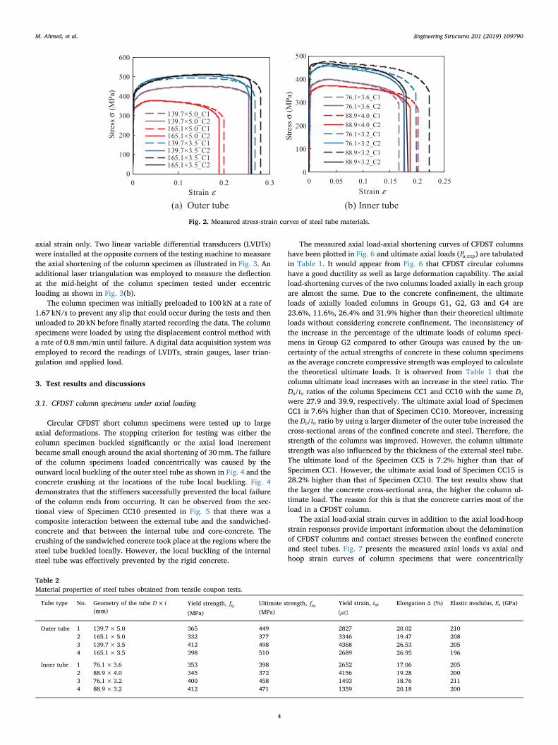
axial strain only. Two linear variable differential transducers (LVDTs)were installed at the opposite corners of the testing machine to measurethe axial shortening of the column specimen as illustrated in Fig. 3. Anadditional laser triangulation was employed to measure the deflectionat the mid-height of the column specimen tested under eccentricloading as shown in Fig. 3(b).
The column specimen was initially preloaded to 100 kN at a rate of1.67 kN/s to prevent any slip that could occur during the tests and thenunloaded to 20 kN before finally started recording the data. The columnspecimens were loaded by using the displacement control method witha rate of 0.8 mm/min until failure. A digital data acquisition system wasemployed to record the readings of LVDTs, strain gauges, laser trian-gulation and applied load.
3. Test results and discussions
3.1. CFDST column specimens under axial loading
Circular CFDST short column specimens were tested up to largeaxial deformations. The stopping criterion for testing was either thecolumn specimen buckled significantly or the axial load incrementbecame small enough around the axial shortening of 30mm. The failureof the column specimens loaded concentrically was caused by theoutward local buckling of the outer steel tube as shown in Fig. 4 and theconcrete crushing at the locations of the tube local buckling. Fig. 4demonstrates that the stiffeners successfully prevented the local failureof the column ends from occurring. It can be observed from the sec-tional view of Specimen CC10 presented in Fig. 5 that there was acomposite interaction between the external tube and the sandwiched-concrete and that between the internal tube and core-concrete. Thecrushing of the sandwiched concrete took place at the regions where thesteel tube buckled locally. However, the local buckling of the internalsteel tube was effectively prevented by the rigid concrete.
The measured axial load-axial shortening curves of CFDST columnshave been plotted in Fig. 6 and ultimate axial loads (Pu,exp) are tabulatedin Table 1. It would appear from Fig. 6 that CFDST circular columnshave a good ductility as well as large deformation capability. The axialload-shortening curves of the two columns loaded axially in each groupare almost the same. Due to the concrete confinement, the ultimateloads of axially loaded columns in Groups G1, G2, G3 and G4 are23.6%, 11.6%, 26.4% and 31.9% higher than their theoretical ultimateloads without considering concrete confinement. The inconsistency ofthe increase in the percentage of the ultimate loads of column speci-mens in Group G2 compared to other Groups was caused by the un-certainty of the actual strengths of concrete in these column specimensas the average concrete compressive strength was employed to calculatethe theoretical ultimate loads. It is observed from Table 1 that thecolumn ultimate load increases with an increase in the steel ratio. TheD t/o o ratios of the column Specimens CC1 and CC10 with the same Dowere 27.9 and 39.9, respectively. The ultimate axial load of SpecimenCC1 is 7.6% higher than that of Specimen CC10. Moreover, increasingthe D t/o o ratio by using a larger diameter of the outer tube increased thecross-sectional areas of the confined concrete and steel. Therefore, thestrength of the columns was improved. However, the column ultimatestrength was also influenced by the thickness of the external steel tube.The ultimate load of the Specimen CC5 is 7.2% higher than that ofSpecimen CC1. However, the ultimate axial load of Specimen CC15 is28.2% higher than that of Specimen CC10. The test results show thatthe larger the concrete cross-sectional area, the higher the column ul-timate load. The reason for this is that the concrete carries most of theload in a CFDST column.
The axial load-axial strain curves in addition to the axial load-hoopstrain responses provide important information about the delaminationof CFDST columns and contact stresses between the confined concreteand steel tubes. Fig. 7 presents the measured axial loads vs axial andhoop strain curves of column specimens that were concentrically
(a) Outer tube (b) Inner tube
0
100
200
300
400
500
600
0 0.1 0.2 0.3
139.7×5.0_C1139.7×5.0_C2165.1×5.0_C1165.1×5.0_C2139.7×3.5_C1139.7×3.5_C2165.1×3.5_C1165.1×3.5_C2
Strain ε
0
100
200
300
400
500
0 0.05 0.1 0.15 0.2 0.25
76.1×3.6_C176.1×3.6_C288.9×4.0_C188.9×4.0_C276.1×3.2_C176.1×3.2_C288.9×3.2_C188.9×3.2_C2
Strain ε
Stre
ss σ
(MPa
)
Stre
ss σ
(MPa
)
Fig. 2. Measured stress-strain curves of steel tube materials.
Table 2Material properties of steel tubes obtained from tensile coupon tests.
Tube type No. Geometry of the tube ×D t(mm)
Yield strength, fsy(MPa)
Ultimate strength, fsu(MPa)
Yield strain, εsyμε( )
Elongation Δ (%) Elastic modulus, Es (GPa)
Outer tube 1 139.7×5.0 365 449 2827 20.02 2102 165.1×5.0 332 377 3346 19.47 2083 139.7×3.5 412 498 4368 26.53 2054 165.1×3.5 398 510 2689 26.95 196
Inner tube 1 76.1× 3.6 353 398 2652 17.06 2052 88.9× 4.0 345 372 4156 19.28 2003 76.1× 3.2 400 458 1493 18.76 2114 88.9× 3.2 412 471 1359 20.18 200
M. Ahmed, et al. Engineering Structures 201 (2019) 109790
4
mizan
Typewritten Text
167

loaded. The axial and hoop strains of circular CFDST short columnsincreased linearly at the elastic stage without confinement because thesteel material had a larger Poisson’s ratio than the concrete. However,as the load increased, the sandwiched concrete expanded more thanthat of the outer tube. Therefore, the hoop strains of the column spe-cimens increased rapidly as shown in Fig. 7. The presence of the hoopstrain-induced lateral pressures on the concrete, which increased thecompressive strength of the concrete.
3.2. CFDST columns under eccentric loading
The failure of eccentrically loaded CFDST column specimens was
caused by the outward local buckling of the outer steel tubes in thecompression regions near the mid-height of the column specimens, theconcrete crushing at the locations of tube buckling, and the columnbending as shown in Fig. 8. For columns under a large loading eccen-tricity, the external steel tube near the column ends underwent sig-nificant buckling. The sandwiched concrete in some column specimenswas separated from the inner tubes as depicted in Fig. 9. The sectionview of Specimen CC13 is illustrated in Fig. 10. It is confirmed that thecore-concrete in the CFDST columns loaded eccentrically was confinedeffectively by the steel tubes and did not crush. The main differencebetween the fundamental behaviors of circular CFST columns andCFDST columns is that the CFDST column has higher strength andductility than the CFST column for the same outer tube diameter, steel
(a) Under axial compression
(b) Under eccentric compression Fig. 3. Test setup of circular CFDST columns.
Fig. 4. Failure modes of axially loaded circular CFDST short columns.
Fig. 5. Section view of Specimen CC10.
0
400
800
1200
1600
2000
2400
0 10 20 30 40
Axia
l Lo
ad P
(kN
)
CC1 CC5
CC6 CC10
CC11 CC15
CC16
Axial shortening (mm)δ
Fig. 6. Load-axial shortening curves of circular CFDST short columns underaxial compression.
M. Ahmed, et al. Engineering Structures 201 (2019) 109790
5
mizan
Typewritten Text
168

cross-sectional area and material strengths as reported by Ahmed et al.[1]. Circular CFST short columns under eccentric loading may fail bythe outward local buckling and crushing of the concrete in the com-pression zone. Circular CFDST columns under eccentric loading mayfail by the outward local buckling and crushing of the sandwichedconcrete in the compression zone, but the core concrete does not crushdue to the confinement provided by both steel tubes.
The experimentally measured axial load-shortening curves for thetested specimens have been plotted in Fig. 11. It is clearly illustratedthat increasing the loading eccentricity ratio (e D/ o) significantly re-duces the ultimate axial loads of the column specimens. The ultimateaxial loads of column specimens in Group G4 were reduced by 30%,43% and 59% by changing thee D/ o ratio from 0 to 0.06, 0.12 and 0.21,respectively. The measured responses of load-axial shortening and axial
load-lateral deflection of column specimens under eccentric compres-sion are given in Figs. 11 and 12, respectively, where umis the lateraldeflection at the column mid-height. It is observed that increasing thee D/ o ratio considerably reduces the axial stiffness of the beam-columns.However, all tested column specimens exhibited good ductility anddeformation capability. The measured load vs longitudinal strain dis-tributions for specimens loaded eccentrically are illustrated in Fig. 13.The negative strain represents tensile strain while the positive strainmeans compressive strain. The measured compressive strains werelarger than the tensile strains as can be seen from Fig. 13.
0
500
1000
1500
2000
-0.04 -0.02 0 0.02 0.04 0.06
Axia
l Lo
ad P
(kN
)
CC1CC5CC6CC10CC11CC15CC16
Axial strain εHoop strain hε
Fig. 7. Measured axial load-strain curves of axially loaded circular CFDST shortcolumns.
(a) Group G1 (b) Group G2
(c) Group G3 (d) Group G4 Fig. 8. Failure modes of eccentrically loaded circular CFDST short columns.
Fig. 9. Separation of sandwiched concrete and inner steel tube of SpecimenCC19.
M. Ahmed, et al. Engineering Structures 201 (2019) 109790
6
mizan
Typewritten Text
169

4. Nonlinear analysis
4.1. Basic concepts
A mathematical model underlying the theory of fiber analysis isdeveloped to simulate the nonlinear inelastic moment-curvature re-lationships and strength envelopes of eccentrically loaded circularCFDST columns. The fiber element method is an accurate and compu-tationally efficient numerical modeling method for the simulation ofnonlinear composite columns over the traditional finite elementmethod as pointed out by Liang [22] and Ahmed et al. [23]. The typicalfiber discretization of the concrete and steel components in the cross-
section of a circular CFDST is illustrated in Fig. 14, where dn is thedepth of the plastic neutral axis in the cross-section, yi the distance fromthe section centroid to the centroid of the ith fiber element, de i, thedistance from the neutral axis to the element centroid, ϕ the curvature,εt the compressive strain at the extreme fiber, and εe i, the strain of theith fiber element. The plane section is assumed to remain plane afterdeformation in the fiber analysis technique. This implies a linear dis-tribution of strains through the depth of the column cross-section asillustrated in Fig. 14. Under the axial loading combined with uniaxialbending, the fiber strain is computed from the curvature and the neutralaxis depth of the cross-section [14,24,25]. The stresses in steel andconcrete fibers are determined from the material uniaxial stress-strainrelationships of steel and concrete given in Section 5. The internal force(P) as well as moment (M) are calculated as stress resultants over theentire cross-section.
4.2. Computer simulation procedure
The moment vs curvature curves of circular CFDST columns loadedeccentrically are simulated by increasing the curvature incrementallyand computing the corresponding moment. The force equilibriumcondition must be maintained for each increment of the curvature byadjusting the neutral axis depth (dn) of the cross-section. The internalmoment (M) is determined by the integration of fiber stresses over theentire cross-section. The complete moment-curvature curve for a givenaxial load can be obtained by repeating the process of analysis.
The strength envelope, which represents the axial load (Pu) and ul-timate moment (Mu) interaction diagram, of a short circular CFDSTcolumn is used in designing columns subjected to eccentric loading. In
Fig. 10. Section view of Specimen CC13.
(a) Group G1 (b) Group G2
(c) Group G3 (d) Group G4
0
400
800
1200
1600
2000
0 10 20 30 40
Axi
al L
oad
P(k
N)
CC1 CC2
CC3 CC4
e = 10
e = 0
e = 30 e = 25
Axial shortening (mm)δ
0
400
800
1200
1600
2000
0 10 20 30 40
Axi
al L
oad
P(k
N)
CC5 CC7
CC8 CC9
e = 35 e = 20
e = 10
e = 0
Axial shortening (mm)δ
0
400
800
1200
1600
0 10 20 30 40
Axi
al L
oad
P(k
N)
CC10 CC12
CC13 CC14
e = 30
e = 20 e = 10
e = 0
Axial shortening (mm)δ
0
400
800
1200
1600
2000
2400
0 10 20 30 40
Axi
al L
oad
P(k
N)
CC15 CC17
CC18 CC19
e = 35
e = 20 e = 10
e = 0
Axial shortening (mm)δ
Fig. 11. Effects of load eccentricity on the axial load-shortening curves of circular CFDST columns.
M. Ahmed, et al. Engineering Structures 201 (2019) 109790
7
mizan
Typewritten Text
170

the simulation of the interaction curve, the ultimate axial load (Po) ofthe CFDST column loaded concentrically is firstly calculated by theaxial load-strain analysis procedure considering the concrete confine-ment. The axial load (Pu) is increased gradually from zero to the max-imum ultimate load (Po), and the corresponding ultimate moment (Mu)of the composite section is ascertained from the moment-curvaturerelationships. The equilibrium condition for each curvature incrementmust be maintained by ensuring the internal axial load (P) calculated isthe same as the applied axial load (Pu). To achieve this condition, theneutral axis depth (dn) of the column section is adjusted iteratively byefficient numerical algorithms. The inverse quadratic method has beenimplemented in the mathematical programming scheme to solve thehighly dynamic equilibrium functions [26]. The computer flowchart forcalculating the strength envelope of a short CFDST column is given inFig. 15, where εΔ is the axial strain increment, Pmax the maximum axialload that can be applied to the column, εcu the ultimate strain of con-crete in compression, ϕΔ the curvature increment, rp the residual forceexpressed as = −r P Pp u , and PΔ u the axial load increment.
4.3. Computational solution algorithms
Computational solution algorithms implementing the inversequadratic method have been developed by Ahmed et al. [26,27] forquantifying the neutral axis depth (dn) during the loading history ofCFDST columns. The inverse quadratic method requires three initialvalues of dn taken as =d Dn,1 0, =d D /2n,2 0 and = +d d d( )/2n n n,3 ,1 ,2 tobe initialized to start the computation process. The new true dn is thencalculated by the following equations:
= − ⎛⎝
⎞⎠
+ + +d d r ACn j n j p j, 3 , 1 , 1 (1)
= − + − + −
−
+ + + + + + +
+ +
Ar d d r r d d r r
r d d
( ) ( ) ( ) ( )
( )
p j n j n j p j p j n j n j p j p j
p j n j n j
,2
, 2 , 1 , , 1 , 1 , 2 , 1 , 2
, 2 , , 1 (2)
= − − −+ + + +C r r r r r r( )( )( )p j p j p j p j p j p j, 1 , , 2 , , 2 , 1 (3)
where the residual force = −r P Pp u and j is the iteration number. Thestopping criterion of the computational process is determined as
<r ε| |p k, in which εkis taken as 10−4.
4.4. Curvature ductility index
The curvature ductility indicator evaluates the ductility of a circularCFDST column eccentrically loaded and is defined as
=PIϕϕcdu
y (4)
in which ϕu denotes the ultimate curvature of the column when themoment falls to 90% of its ultimate moment capacity in the post-peakrange or the ultimate curvature where column shows ascending mo-ment-curvature relationships in the post-yield regime. The yieldcurvatureϕyis taken as the curvature corresponding to 75% of thecolumn ultimate moment capacity [24].
(a) Group G1 (b) Group G2
(c) Group G3 (d) Group G4
0
200
400
600
800
1000
1200
1400
0 10 20 30 40
Axi
al L
oad
P(k
N)
Lateral deflection um (mm)
CC2CC3CC4
0
200
400
600
800
1000
1200
1400
0 10 20 30 40
Axi
al L
oad
P(k
N)
Lateral deflection um (mm)
CC7CC8CC9
0
200
400
600
800
1000
1200
0 10 20 30 40
Axi
al L
oad
P(k
N)
Lateral deflection um (mm)
CC12CC13CC14
0
200
400
600
800
1000
1200
1400
1600
0 10 20 30 40
Axi
al L
oad
P(k
N)
Lateral deflection um (mm)
CC17CC18CC19
Fig. 12. Measured axial load-lateral deflection curves of eccentrically loaded circular CFDST columns.
M. Ahmed, et al. Engineering Structures 201 (2019) 109790
8
mizan
Typewritten Text
171

5. Material constitutive laws
5.1. Structural steels
The steel tubes in CFDST columns are subjected to biaxial stresseswhich reduce their yield strength in the longitudinal direction. Thestress and strain relationships of structural steel material are given inFig. 16, where σs and εs are the longitudinal stress and strain in steel,
respectively; εst and εsuare the strains at the onset of strain-hardeningand at the ultimate strain, and taken as 0.005 and 0.2, respectively.Liang [24] suggested that a reduction factor of 0.9 should be used toreduce the steel yield strength shown in Fig. 16 to consider the effects ofbiaxial stresses on the steel tube. The formulas to calculate the rounded-part in the stress-strain curve was also suggested by Liang [24] for cold-formed steed while the expression provided by Mander [28] is em-ployed to determine the stresses in the range of strain hardening.
5.2. Concrete
The current and existing test results [6–9] indicate that the effectiveconfinement provided by the circular steel tube significantly increasesthe ductility as well as the strength of CFDST columns composed ofcircular tubes. Moreover, the results obtained from finite elementanalyses presented by Chang et al. [2] confirmed that longitudinalstress in sandwiched concrete was similar to the concrete in circularCFST columns while the core-concrete in a circular CFDST columnloaded was subjected to a higher compressive longitudinal stress thanthe sandwiched-concrete. When the compressive load increases, thesandwiched-concrete and the core-concrete expand more than the steeltubes, the external steel tube confines the sandwiched-concrete. Thesandwiched-concrete under lateral compression exerts lateral pressureon the internal steel tube which therefore confines the core-concrete.Therefore, it can be assumed that the sandwiched-concrete is mainlyconfined by the external tube while the core-concrete is effectivelyconfined by both the external and internal tubes in a circular CFDSTcolumn [1–3]. Ahmed et al. [1] proposed constitutive laws of confinedconcrete in circular CFDST columns. The two-stage stress and strain
(a) Group G1 (b) Group G2
(c) Group G3 (d) Group G4
0
500
1000
1500
-0.02 0 0.02 0.04
Axi
al L
oad
P(k
N)
CC2
CC3
CC4
Axial strain ε
0
500
1000
1500
-0.02 0 0.02 0.04
Axi
al L
oad
P(k
N)
CC7
CC8
CC9
Axial strain ε
0
500
1000
1500
-0.02 0 0.02 0.04 0.06
Axi
al L
oad
P(k
N)
CC12
CC13
CC14
Axial strain ε
0
500
1000
1500
-0.02 0 0.02 0.04
Axi
al L
oad
P(k
N)
CC17
CC18
CC19
Axial strain ε
Fig. 13. Measured load-strain curves of eccentrically loaded circular CFDST short columns.
Fig. 14. Typical fiber discretization and strain distribution in the cross-sectionof circular CFDST column.
M. Ahmed, et al. Engineering Structures 201 (2019) 109790
9
mizan
Typewritten Text
172

curves for unconfined and confined concrete illustrated in Fig. 17 wasoriginally derived by Lim and Ozbakkaloglu [29]. A general stress-strain model is adopted for both sandwiched-concrete and core-con-crete, but different lateral confining pressure models are used to de-termine the confinement on the sandwiched-concrete and ore-concrete.The ascending branch of the curves is expressed by the equations pre-sented by Mander et al. [30] as
=′ ′′ + −
σf ε ε λ
ε ε λ( / )
( / ) 1ccc c cc
c ccλ (5)
=′
′ − ′λ
ε Eε E f
cc c
cc c cc (6)
in which σcand εc denote the longitudinal stress and the correspondingstrain; ′fcc and ′εcc represent the maximum strength of compressiveconcrete and its corresponding strain, respectively; Ec is the modulus ofelasticity of concrete, calculated as [23]
= ′E γ f4400 (MPa)c c c (7)
in which = −γ D1.85c c0.135 is the reduction factor applied to the concrete
compressive strength taking into account the column size effect, inwhich Dc stands for the concrete-core diameter and is −D t( 2 )i i for core-concrete and −D t( 2 )o o for sandwiched concrete.
The confinement is explicitly taken into account in the stress-strainmodel for confined concrete. As shown in Fig. 4, the confinement effectis included when the compressive stress in the concrete fibers is greaterthan ′γ fc c . The confinement increases the concrete compressive strengthfrom ′γ fc c to the maximum value of ′fcc. The maximum compressivestrength ( ′fcc) together with the corresponding strain ( ′εcc) are calculatedas
′ = ′ +f γ f f4.1cc c c rp (8)
′ = ′ +′
′ε ε
f ε
γ f
20.5cc c
rp c
c c (9)
where frp generally defines the lateral pressure on the confined con-crete. For the sandwiched concrete, the lateral pressure f( )rpo is calcu-lated by the equation proposed by Hu et al. [19] as
=⎧
⎨⎪
⎩⎪
− ⩽ ⩽
− < ⩽
( )( )
f
f
0.043646 0.000832 for 21.7 47
0.006241 0.0000357 for 47 150
rpo
syo
Dt
Dt
Dt
Dt
oo
oo
oo
oo (10)
Fig. 15. Computer flowchart for calculating axial load-moment interactioncurves.
Fig. 16. Typical stress-strain curve for structural steels.
Fig. 17. Typical stress-strain curves for confined and unconfined concrete.
M. Ahmed, et al. Engineering Structures 201 (2019) 109790
10
mizan
Typewritten Text
173

in which fsyo is the yield strength of the outer steel tube.Based on the test results, Ahmed et al. [1] proposed an equation for
estimating the lateral pressure on the core-concrete ( frpi) in CFDSTcolumns, expressed as
⎜ ⎟ ⎜ ⎟ ⎜ ⎟
⎜ ⎟
= + ⎛⎝
⎞⎠− ⎛
⎝⎞⎠− ⎡⎣⎢
⎛⎝
⎞⎠
− ⎛⎝
⎞⎠⎤⎦⎥
⩾−
f
Dt
Dt
Dt
Dt
ζ f
2.2897 0.0066 0.1918 0.0585
0.3801 ( 0)
rpi
o
o
i
i
o
o
i
irpi
1
(11)
in which the confinement factor ζ is defined as
=+
′ + ′ζ
A f A fA γ f A γ f
so sy o si sy i
sc c sc cc c cc
, ,
(12)
The strain ( ′εc) corresponding to the maximum strength ′fc of theunconfined compressive concrete shown in Fig. 17 is calculated usingthe expression given by De Nicolo et al. [31] as
′ = + ′ − × −ε γ f0.00076 (0.626 4.33) 10c c c7
(13)
Lim and Ozbakkaloglu [29] proposed an equation to express thedescending branch of stress-strain curves as
= ′ −′ −
⎡⎣
+ ⎤⎦
− ′− ′
−( )σ f
f f
1c cc
cc cr
ε εε ε
2c ccci cc (14)
where fcr is the residual strength of concrete, which was proposed byAhmed et al. [1] as
⎜ ⎟′= − ⎛
⎝⎞⎠− ′ ⎛
⎝⩽
′⩽ ⎞
⎠
ff
Dt
γ fff
1.2420 0.0029 0.0044 0 1.0cr
ccc c
cr
cc (15)
The original equation developed by Lim and Ozbakkaloglu [29] forcalculating the strain at the inflection point (εci) is modified to considerthe column size effects as
⎜ ⎟ ⎜ ⎟= ′ ′ ⎛
⎝ ′⎞
⎠+ ′ ′ ⎛
⎝−
′⎞
⎠− −ε ε γ f
ff
ε γ fff
2.8 ( ) 10 ( ) 1ci cc c ccr
cccc c c
cr
cc
0.12 0.47
(16)
The relationships of stress and strain of concrete in tension are il-lustrated in Fig. 17, where fct and εst are the tensile strength and cor-responding strain of concrete. The ultimate strength ( fct) of concrete intension is specified as ′γ f0.6 c c and the corresponding strain εtu is de-termined as ten times the cracking strain.
6. Experimental verification
The accuracy of the mathematical modeling technique proposed isassessed by means of comparing the predicted strength envelopes withexperimental results in Fig. 18. The experimental ultimate moment(Mu,exp) was determined as the product of the ultimate axial load (Pu,exp)and eccentricity (e). It can be observed from the comparisons that thecomputational results are generally in good agreement with measure-ments. However, the ultimate loads of CFDST columns under concentricloads are slightly underestimated by the numerical model and experi-mental ultimate moments of Columns CC7 and CC12 are slightly lowerthan the predicted values. The uncertainty in the actual concretestrengths in the tested specimens may cause these discrepancies as the
(a) Group G1 (b) Group G2
(c) Group G3 (d) Group G4
0
200
400
600
800
1000
1200
1400
1600
1800
0 10 20 30 40 50
Axi
al L
oad
P u(k
N)
Moment Mu (kNm)
CC1CC2CC3CC4Numerical analysis
0
200
400
600
800
1000
1200
1400
1600
1800
0 10 20 30 40 50 60
Axi
al L
oad
P u(k
N)
Moment Mu (kNm)
CC5CC6CC7CC8CC9Numerical analysis
0
200
400
600
800
1000
1200
1400
1600
0 10 20 30 40
Axi
al L
oad
P u(k
N)
Moment Mu (kNm)
CC10CC11CC12CC13CC14Numerical analysis
0
400
800
1200
1600
2000
0 20 40 60
Axi
al L
oad
P u(k
N)
Moment Mu (kNm)
CC15CC16CC17CC18CC19Numerical analysis
Fig. 18. Comparison of predicted strength envelopes of circular CFDST columns with test results.
M. Ahmed, et al. Engineering Structures 201 (2019) 109790
11
mizan
Typewritten Text
174

average compressive strengths of concrete were specified in the nu-merical analyses. The difference between the experimental and pre-dicted ultimate moments of Columns CC9, CC14 and CC19 is caused bythe failure of the column ends subjected to large loading eccentricitiesas shown in Fig. 8.
The computational model proposed has been further developed tosimulate the load-deflection responses of circular CFDST short andslender columns loaded eccentrically [26]. The accuracy of the com-putational model is validated by comparing the calculations with themeasured load-deflection curves of eccentrically loaded circular CFDSTshort and slender columns tested by the authors and Ibañez et al. [11].
The initial eccentricity of the tested short columns was taken as L/650in the numerical analyses. It would appear from Fig. 19 that reasonableagreement between test data and numerical results for short CFDSTcolumns is obtained. The difference between experiments and compu-tations is likely attributed to the uncertainty in the actual strengths ofconcrete in the tested columns. Moreover, as the concrete strength isvery low, the concrete model adopted might not accurately capture thebehavior of low strength concrete. However, the numerical modelpredicts well the complete load-deflection curves of slender CFDSTcolumns as depicted in Fig. 20. This approves that the mathematicalmodel proposed can accurately predict the structural behavior of
(a) Group G1 (b) Group G2
(c) Group G3 (d) Group G4
0
200
400
600
800
1000
1200
1400
0 10 20 30 40
Axi
al L
oad
P(k
N)
Mid-height deflection um (mm)
CC2-TestCC2-AnalysisCC3-TestCC3-AnalysisCC4-TestCC4-Analysis
0
200
400
600
800
1000
1200
1400
1600
0 10 20 30 40
Axi
al L
oad
P(k
N)
Mid-height deflection um (mm)
CC7-TestCC7-AnalysisCC8-TestCC8-AnalysisCC9-TestCC9-Analysis
0
200
400
600
800
1000
1200
0 10 20 30 40
Axi
al L
oad
P(k
N)
Mid-height deflection um (mm)
CC12-TestCC12-AnalysisCC13-TestCC13-AnalysisCC14-TestCC14-Analysis
0
200
400
600
800
1000
1200
1400
1600
0 10 20 30 40
Axi
al L
oad
P(k
N)
Mid-height deflection um (mm)
CC17-TestCC17-AnalysisCC18-TestCC18-AnalysisCC19-TestCC19-Analysis
Fig. 19. Comparison of tested and predicted axial load-mid-height deflection curves of circular CFDST columns.
0
400
800
1200
1600
0 20 40 60 80 100
Test (NR20)Fiber element analysisTest (NR21)Fiber element analysis
Mid-height deflection um (mm)
0
400
800
1200
1600
0 20 40 60 80 100
Test (NR23)Fiber element analysisTest (NR24)Fiber element analysis
Axi
al L
oad
P(k
N)
Axi
al L
oad
P(k
N)
Mid-height deflection um (mm)
Fig. 20. Comparison of predicted and experimental load-mid-height deflection curves of circular CFDST slender columns tested by Ibañez et al. [11].
M. Ahmed, et al. Engineering Structures 201 (2019) 109790
12
mizan
Typewritten Text
175

circular CFDST columns loaded eccentrically.
7. Parametric studies
The mathematical model, which was implemented in a computerprogram, was employed to examine the sensitivities of moment-cur-vature responses and strength envelopes of CFDST columns composedcircular sections to various important design parameters. The stress-strain model for concrete in circular CFDST columns has been verifiedby experimental results by the authors [1], and can be used to modelthe material behavior of both normal and high strength concrete inCFDST columns. For practical applications, the concrete strength used
in CFDST columns is usually above 40MPa. Therefore, the concretestrengths varying from 40MPa to 100MPa were used in the parametricstudies. The following data were used for the reference column:
=D 450 mmo , =t 10 mmo , Di =200mm, ti =6.67mm,= =f fsyo syi 350MPa, =Es 200 GPa, the concrete strength of the sand-
wiched-concrete and the core-concrete was taken as ′ = ′ =f f 70 MPaco ci ,and the load ratio was specified as Pu/Po=0.4.
7.1 D t/o o. ratioThe effects of the ratio of D t/o o on the structural behavior of CFDST
circular columns were examined by utilizing the computational modeldeveloped. The D t/o o ratio of CFDST columns was varied from 35 to 45,55 and 65 by altering the thickness of the external tube only. The
0
200
400
600
800
1000
1200
1400
1600
0 2 4 6 8 10
Mom
ent M
(kN
m)
5Curvature ( 10 )φ −×
/ 35/ 45/ 55/ 65
o o
o o
o o
o o
D tD tD tD t
====
Fig. 21. Moment-curvature curves of circular CFDST columns with variousD t/o o ratios.
0
5000
10000
15000
20000
25000
0 500 1000 1500 2000
Axia
l lo
ad P
u(k
N)
Moment Mu (kNm)
/ 35/ 45/ 55/ 65
o o
o o
o o
o o
D tD tD tD t
====
Fig. 22. Strength envelopes of circular CFDST columns with various D t/o o ra-tios.
0
200
400
600
800
1000
1200
1400
0 2 4 6 8 10
Mom
ent M
(kN
m)
5Curvature ( 10 )φ −×
/ 30/ 40/ 50/ 60
i i
i i
i i
i i
D tD tD tD t
====
Fig. 23. Moment-curvature curves of circular CFDST columns with various D t/i i
ratios.
0
5000
10000
15000
20000
0 500 1000 1500
Axia
l lo
ad P
u(k
N)
Moment Mu (kNm)
/ 30/ 40/ 50/ 60
i i
i i
i i
i i
D tD tD tD t
====
Fig. 24. Strength envelopes of circular CFDST columns with various D t/i i ratios.
0
200
400
600
800
1000
1200
1400
0 2 4 6 8 10 12
Mom
ent M
(kN
m)
5Curvature ( 10 )φ −×
/ 0.33/ 0.44/ 0.55/ 0.66
i o
i o
i o
i o
D DD DD DD D
====
Fig. 25. Moment-curvature curves of circular CFDST columns as a function ofD D/i o ratio.
0
5000
10000
15000
20000
25000
0 500 1000 1500
Axia
l lo
ad P
u(k
N)
Moment Mu (kNm)
/ 0.33/ 0.44/ 0.55/ 0.66
i o
i o
i o
i o
D DD DD DD D
====
Fig. 26. Strength envelopes of circular CFDST columns as a function ofD D/i o
ratio.
M. Ahmed, et al. Engineering Structures 201 (2019) 109790
13
mizan
Typewritten Text
176

moment-curvature curves and strength envelopes of CFDST columns arepresented in Figs. 21 and 22, respectively. Under the constant axial loadof 6591 kN, increasing ratio of D t/o o remarkably reduces both the initialbending stiffness and resistance of CFDST columns as demonstrated inFig. 21. This is caused by the decrease in the steel area of the outer tube.The ultimate moment capacity is decreased by 35.7% by increasing theratio D t/o o from 35 to 65. Moreover, Fig. 22 indicates that the ratio D t/o o
has a considerable influence on the pure ultimate axial and the purebending moment. Changing the D t/o o ratio from 35 to 45, 55 and 65causes an increase in the pure ultimate axial strength of the columns by13.7%, 19.6% and 22.5%, respectively, while the increases in the purebending resistance were calculated as 18.1%, 29.2% and 36.69%,
respectively.
7.2 D t/i i. ratioThe sensitivities of the structural responses of circular CFDST col-
umns to the ratio D t/i i were examined by altering the thickness of theinner tube only. The moment-curvature relations of CFDST columnsunder a constant axial load of 6591 kN are given in Fig. 23. It is ob-served that the ratio D t/i i has a minor effect on the moment-curvaturebehavior of the CFDST columns. The bending resistance of the CFDSTcolumns decreases by only 0.3% when the ratio D t/i i increases from 30to 60. The curvature ductility index of CFDST columns having the D t/i i
0
200
400
600
800
1000
1200
1400
1600
1800
0 2 4 6 8 10
Mom
ent M
(kN
m)
250 MPa
350 MPa
450 MPa
550 MPa
sy
sy
sy
sy
ffff
=
=
=
=
5Curvature ( 10 )φ −×
Fig. 27. Effects of steel yield strength on the moment-curvature curves of cir-cular CFDST columns.
0
5000
10000
15000
20000
25000
0 500 1000 1500 2000
Axia
l lo
ad P
u(k
N)
Moment Mu (kNm)
250 MPa
350 MPa
450 MPa
550 MPa
sy
sy
sy
sy
ffff
=
=
=
=
Fig. 28. Effects of steel yield strength on the strength envelopes of circularCFDST columns.
0
200
400
600
800
1000
1200
1400
0 2 4 6 8 10
Mom
ent M
(kN
m)
5Curvature ( 10 )φ −×
'
'
'
'
40 MPa
55 MPa
70 MPa
100 MPa
c
c
c
c
ffff
=
=
=
=
Fig. 29. Effects of concrete strength on the moment-curvature curves of circularCFDST columns.
0
5000
10000
15000
20000
25000
0 500 1000 1500
Axia
l lo
ad P
u(k
N)
Moment Mu (kNm)
'
'
'
'
40 MPa
55 MPa
70 MPa
100 MPa
c
c
c
c
ffff
=
=
=
=
Fig. 30. Effects of concrete strength on the strength envelopes of circularCFDST columns.
0
100
200
300
400
500
600
700
0 2 4 6 8 10 12
Mom
ent M
(kN
m)
Confinement ignored
Confinement considered
5Curvature ( 10 )φ −×
Fig. 31. Influences of concrete confinement on the moment-curvature curves ofcircular CFDST columns.
0
0.2
0.4
0.6
0.8
1
1.2
0 0.5 1 1.5 2
Confinement ignored
Confinement considered
Axia
l lo
ad P
u/ P
o
Moment Mu/ Mo
Fig. 32. Influences of concrete confinement on the normalized strength en-velopes of circular CFDST columns.
M. Ahmed, et al. Engineering Structures 201 (2019) 109790
14
mizan
Typewritten Text
177

ratio of 30 is 18.13 but it is 15.11 for the CFDST column having the D t/i iratio of 60. The strength curves generated by the computational modelare given in Fig. 24. It is apparent that the influence of the D t/i i ratio onthe strength envelopes is insignificant. The decreases in the pure ulti-mate axial and the bending strengths are only 2.3% and 5.2%, re-spectively when the ratio D t/i i is changed from 30 to 60.
7.3. D D/i o. ratioThe diameter of the inner tube was changed to investigate the sig-
nificance of the ratio D D/i o on the responses of CFDST columns. Themoment-curvature curves for the columns that were loaded by a con-stant axial load of 6591 kN are given in Fig. 25. It is evident that in-creasing the ratio D D/i o slightly increases the initial bending stiffnessbut improves the ultimate bending strength of CFDST columns con-siderably. When the ratio D D/i o is changed from 0.33 to 0.44, 0.55 and0.66, the column ultimate moment increases by 4.7%, 11.9% and21.6%, respectively. The curvature ductility index of CFDST columnsincreases from 20.1 to 23.3 by changing the ratio D D/i o from 0.33 to0.66. The computed strength envelopes of CFDST columns have beendrawn in Fig. 26. The change of the D D/i o ratio from 0.33 to 0.66 im-proves the pure ultimate axial load by 15% and the pure ultimatemoment of the CFDST column by 15.1%.
7.4. Steel yield strength
The steel yield stress of circular CFDST columns was varied from250MPa to 550MPa to ascertain its influences on their structuralperformance. The influences of steel yield stress on the moment-
curvature behavior of the CFDST columns subjected to the constantaxial load of 6591 kN are shown in Fig. 27. It would appear from Fig. 27that the initial bending stiffness of the columns is appreciably improvedby using the steel tubes with higher yield stress. Changing the steelyield stress from 250MPa to 650MPa causes a marked increase in theultimate moment by 70.8%. However, the column ductility index re-duces from 17.89 to 14.11 when the steel tubes with the yield stress of650MPa are used instead of those with the yield stress of 250MPa. Thesensitivity of the interaction behavior to the steel yield stress is de-monstrated in Fig. 28. The figure indicates that the higher the yieldstress of the steel tubes, the higher the pure ultimate axial and bendingstrengths of the column. However, the steel yield stress has the mostpronounced impact on the pure bending moment. The pure ultimateaxial and pure bending strengths increase by 38.7% and 90.4%, re-spectively when changing the steel yield stress from 250MPa to650MPa.
7.5. Concrete compressive strength
The sensitivities of the moment-curvature and strength interactionresponses of CFDST columns to the concrete compressive strengthsvaried from 40MPa to 100MPa were examined. The simulated mo-ment-curvature curves for the columns loaded by the constant axialload of 6591 kN are given in Fig. 29. The column’s initial bendingstiffness has a marked improvement due to the increase in the concretecompressive strength. Changing the concrete strength from 40MPa to100MPa increases the ultimate moment capacity of the column by37.5%, however, its ductility index decreases from 18.67 to 9.01.Fig. 30 shows that the concrete strength has a greater effect on the pureultimate axial load of the CFDST column than on its pure bendingmoment. As a result of increasing the concrete strength from 40MPa to100MPa, the pure ultimate axial load increases by 51.7% while thepure ultimate moment increases only 8.9%.
7.6. Concrete confinement
The concrete confinement is an important feature that has a re-markable effect on the responses of circular CFDST columns loadedeccentrically. The computer program developed was employed to as-certain this effect. The thickness to of the reference column was changedto produce a D t/o o ratio of 100 while Di was changed to =D D /3i o . Theother parameters of the reference column remained the same. Themoment-curvature and interaction strength curves of the CFDSTcolumn with and without considering the confinement effect are pro-vided in Figs. 31 and 32, respectively. It is discovered that ignoring theconfinement effect considerably underestimates the performance of theCFDST column. When the confinement is not considered in the nu-merical modeling, the column ultimate and residual moment capacity isunderestimated by 13.4% and 37% as indicated in Fig. 31. Moreover,the confinement has a considerable influence on the interaction curvesof CFDST columns as demonstrated in Fig. 32. If the confinement is notconsidered in the simulation, the pure ultimate axial load of the col-umns is underestimated by 7.4% while the pure bending moment isunderestimated by 1.1%.
7.7. Axial load ratio
The computer model was used to ascertain the influences of theapplied axial load ratio (Pu/Po) on the responses of CFDST columns. Themoment-curvature curves of the CFDST column with the Pu/Po ratiosvaried from 0.3 to 0.4, 0.5 and 0.6 are presented in Fig. 33. The initialbending stiffness and moment capacity are markedly decreased by in-creasing the load ratio. However, this effect is more significant for thePu/Po ratio larger than 0.5. If the axial load ratio is changed from 0.3 to0.4 and 0.5, the bending resistance of the CFDST column decreases byonly 2.5% and 8.7%, respectively. However, when the Pu/Po ratio
0
200
400
600
800
1000
1200
1400
0 2 4 6 8 10
Mom
ent M
(kN
m)
/ 0.3/ 0.4/ 0.5/ 0.6
u o
u o
u o
u o
P PP PP PP P
====
5Curvature ( 10 )φ −×
Fig. 33. Influences of axial load ratio on the moment-curvature curves of cir-cular CFDST column.
0
500
1000
1500
2000
2500
3000
3500
4000
0 2 4 6 8 10 12 14
Mom
ent M
(kN
m)
5Curvature ( 10 )φ −×
CFDST column
Inner steel tube
Outer steel tube
Sandwiched concrete
Core concrete
Fig. 34. Moment distributions in a circular CFDST beam-column.
M. Ahmed, et al. Engineering Structures 201 (2019) 109790
15
mizan
Typewritten Text
178

increases from 0.3 to 0.6, the ultimate moment reduces by 18.7%. Theductility performance of the CFDST column is insignificantly influencedby the Pu/Po ratio as indicated in Fig. 33.
7.8. Moment distributions in CFDST columns
The moment distributions in circular CFDST columns loaded ec-centrically have not been investigated. To provide information on themoment distributions, the circular CFDST beam-column that had thefollowing geometric and material properties was analyzed by thecomputational model: =D 800 mmo , =t 8 mmo , Di =400mm,ti =8mm, = =f fsyo syi 350MPa, =Es 200 GPa and ′ = ′ =f f 50 MPaco ci . Inthe moment-curvature analysis, the axial load of 22,289 kN was appliedto the beam-column. The predicted moment distributions in the ex-ternal steel tube, inner steel tube, sandwiched concrete and core-con-crete as a function of the curvature are schematically presented inFig. 34, where the moment-curvature curve for the CFDST column isalso shown. At the maximum moment, the moments carried by theexternal steel tube, the sandwiched concrete, the core-concrete and theinternal steel tube were calculated as 48.7%, 32.1%, 10.6% and 8.6%,respectively. The results indicate that the external steel tube andsandwiched-concrete withstand a large portion of the ultimate moment.The reason for this is that the sandwiched-concrete and external steeltube have larger cross-sectional areas and are located farer from thesection centroid than the internal steel tube and core concrete.
8. Conclusions
This paper has described experimental and computational in-vestigations into the behavior of CFDST short columns composed ofcircular tubes that are axially and eccentrically loaded. The experi-mental results have been employed to verify the computer modelingtechnique developed for quantifying the moment-curvature andstrength interaction behavior of circular CFDST columns incorporatingconcrete confinement effects. Parametric studies on the structural re-sponses of CFDST columns including various important features havebeen conducted.
Experiments conducted indicate that the local buckling of the in-ternal steel tube is effectively prevented by the rigid concrete and thecore-concrete in circular CFDST columns does not crush due to theconfinement provided by the steel tubes. The experimental data oncircular CFDST short columns under eccentric loading presented in thispaper for the first time can be used to validate other numerical models.The fiber-based computational method proposed is shown to be effi-cient and accurate, and can be employed to analyze and design ofCFDST beam-columns in practice. Numerical results presented on themoment-curvature responses, strength envelopes, concrete confinementeffect, and moment distributions in circular CFDST short columnsloaded eccentrically provide a better understanding of the fundamentalbehavior of CFDST columns. It has been demonstrated that the outersteel tube carries the largest portion of the moment followed by thesandwiched concrete while the core-concrete and inner steel tube makeless contributions to the moment capacity of the CFDST column.
Declaration of Competing Interest
Authors declare that there is no conflicts of interest.
Acknowledgements
The experimental work discussed in this paper was financiallysupported by both Victoria University and La Trobe University,Australia. The financial support is gratefully acknowledged. The au-thors thank the technicians at both Victoria University and theUniversity of Wollongong, Australia for their technical support,
particularly Mr. Ritchie McLean and Mr. Duncan Best in the structurelaboratory at the University of Wollongong, Australia for their helpfulassistance during the experiments.
References
[1] Ahmed M, Liang QQ, Patel VI, Hadi MNS. Numerical analysis of axially loadedcircular high strength concrete-filled double steel tubular short columns. Thin-Walled Struct 2019;138:105–16.
[2] Chang X, Ru ZL, Zhou W, Zhang YB. Study on concrete-filled stainless steel–carbonsteel tubular (CFSCT) stub columns under compression. Thin-Walled Struct2013;63:125–33.
[3] Hassanein MF, Kharoob OF, Liang QQ. Behaviour of circular concrete-filled leanduplex stainless steel–carbon steel tubular short columns. Eng Struct2013;56:83–94.
[4] Eurocode 4, Design of composite steel and concrete structures-Part 1-1: Generalrules and rules for buildings, European Committee for Standardization, CEN,Brussels, Belgium, 2004.
[5] ANSI/AISC 360-16, Specification for Structural Steel Buildings, American Instituteof Steel Construction, Chicago, IL, 2016.
[6] Xiong MX, Xiong DX, Liew JYR. Axial performance of short concrete filled steeltubes with high-and ultra-high-strength materials. Eng Struct 2017;136:494–510.
[7] Peng YY, Tan KF, Yao Y. Mechanical properties of duplex steel tube high- strengthconcrete short columns under axial compression. J Wuhan Univ Tech2011;33(2):105–9. (In Chinese).
[8] Wan CY, Zha XX. Nonlinear analysis and design of concrete-filled dual steel tubularcolumns under axial loading. Steel Comp Struct 2016;20(3):571–97.
[9] Ekmekyapar T, Al-Eliwi BJ. Concrete filled double circular steel tube (CFDCST) stubcolumns. Eng Struct 2017;135:68–80.
[10] Romero ML, Espinós A, Portolés J, Hospitaler A, Ibañez C. Slender double-tubeultra-high strength concrete-filled tubular columns under ambient temperature andfire. Eng Struct 2015;99:536–45.
[11] Ibañez C, Romero ML, Espinós A, Portolés JM, Albero V. Ultra-high strength con-crete on eccentrically loaded slender circular concrete-filled dual steel columns.Struct 2017;12:64–74.
[12] Zheng Y, He C, Zheng L. Experimental and numerical investigation of circulardouble-tube concrete-filled stainless steel tubular columns under cyclic loading.Thin-Walled Struct 2018;132:151–66.
[13] Patel VI, Liang QQ, Hadi MNS. Nonlinear analysis of axially loaded circular con-crete-filled stainless steel tubular short columns. J Constr Steel Res 2014;101:9–18.
[14] Patel VI, Liang QQ, Hadi MNS. Concrete-filled stainless steel tubular columns.Taylor and Francis, Boca Raton and London: CRC Press; 2018.
[15] Zheng Y, Tao Z. Compressive strength and stiffness of concrete-filled double-tubecolumns. Thin-Walled Struct 2019;134:174–88.
[16] Hassanein MF, Elchalakani M, Patel VI. Overall buckling behaviour of circularconcrete-filled dual steel tubular columns with stainless steel external tubes. Thin-Walled Struct 2017;115:336–48.
[17] Katwal U, Tao Z, Hassan MK, Wang WD. Simplified numerical modeling of axiallyloaded circular concrete-filled steel stub columns. J Struct Eng ASCE2017;143(12):04017169.
[18] Tao Z, Wang Z-B, Yu Q. Finite element modelling of concrete-filled steel stub col-umns under axial compression. J Constr Steel Res 2013;89:121–31.
[19] Hu HT, Huang CS, Wu MH, Wu YM. Nonlinear analysis of axially loaded concrete-filled tube columns with confinement effect. J Struct Eng 2003;129(10):1322–9.
[20] AS 1391-2007. Metallic materials - Tensile testing at ambient temperature,Standards Australia, Sydney, NSW, Australia, 2007.
[21] Hadi MNS, Widiarsa IBR. Axial and flexural performance of square RC columnswrapped with CFRP under eccentric loading. J Comp Constr 2012;16(6):640–9.
[22] Ahmed M, Liang QQ, Patel VI, Hadi MNS. Nonlinear analysis of rectangular con-crete-filled double steel tubular short columns incorporating local buckling. EngStruct 2018;175:13–26.
[23] Liang QQ. Nonlinear analysis of circular double-skin concrete-filled steel tubularcolumns under axial compression. Eng Struct 2017;131:639–50.
[24] Liang QQ. Performance-based analysis of concrete-filled steel tubular beam–col-umns, part I: theory and algorithms. J Constr Steel Res 2009;65(2):363–72.
[25] Patel VI, Liang QQ, Hadi MNS. Nonlinear analysis of concrete-filled steel tubularcolumns. Germany: Scholar’s Press; 2015.
[26] Ahmed M, Liang QQ, Patel VI, Hadi MNS. Local-global interaction buckling ofsquare high strength concrete-filled double steel tubular slender beam-columns.Thin-Walled Struct 2019;143:106244.
[27] Ahmed M, Liang QQ, Patel VI, Hadi MNS. Experimental and numerical studies ofsquare concrete-filled double steel tubular short columns under eccentric loading.Eng Struct 2019;143:109419.
[28] J. B. Mander, Seismic design of bridge piers, (Ph.D. Thesis), Christchurch, NewZealand, Dep. Civ. Eng., Uni. Cant., 1983.
[29] Lim JC, Ozbakkaloglu T. Stress–strain model for normal-and light-weight concretesunder uniaxial and triaxial compression. Const Build Mat 2014;71:492–509.
[30] Mander JB, Priestley MJ, Park R. Theoretical stress-strain model for confinedconcrete. J Struct Eng 1988;114(8):1804–26.
[31] De Nicolo B, Pani L, Pozzo E. Strain of concrete at peak compressive stress for awide range of compressive strengths. Mat Struct 1994;27(4):206–10.
M. Ahmed, et al. Engineering Structures 201 (2019) 109790
16
mizan
Typewritten Text
179
Chapter 4 Circular CFDST Short Columns
M. Ahmed: Experimental and Numerical Studies of Concrete-Filled Double Steel Tubular Columns
4.2 CONCLUDING REMARKS
In this chapter, a new confining pressure model and a strength degradation parameter
have been derived for the confined concrete of CFDST circular columns having an inner
circular tube. This concrete constitutive model has been incorporated in the computational
models, which have been developed for the determination of axial load-strain behavior,
strength envelopes and moment-curvature relationships of short CFDST columns of
circular section. Experimental results obtained from this research and existing test data
have been used to validate the mathematical models. It has been demonstrated that the
mathematical models developed can accurately capture the behavior of CFDST columns
and the proposed design formula can be used to design CFDST columns. Experimental
and numerical results presented provide important information on the structural
performance of CFDST short circular columns and can be employed to verify numerical
modeling techniques.
mizan
Typewritten Text
180
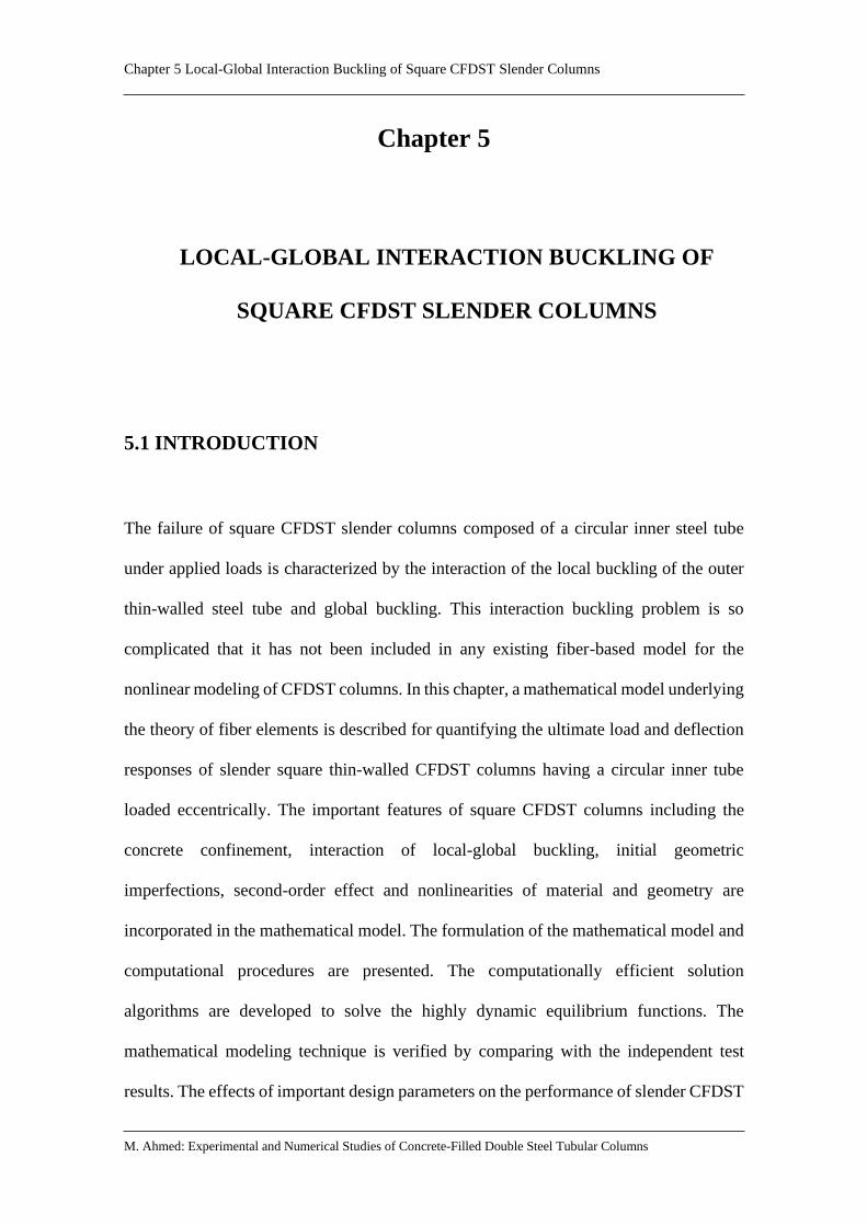
Chapter 5 Local-Global Interaction Buckling of Square CFDST Slender Columns
M. Ahmed: Experimental and Numerical Studies of Concrete-Filled Double Steel Tubular Columns
Chapter 5
LOCAL-GLOBAL INTERACTION BUCKLING OF
SQUARE CFDST SLENDER COLUMNS
5.1 INTRODUCTION
The failure of square CFDST slender columns composed of a circular inner steel tube
under applied loads is characterized by the interaction of the local buckling of the outer
thin-walled steel tube and global buckling. This interaction buckling problem is so
complicated that it has not been included in any existing fiber-based model for the
nonlinear modeling of CFDST columns. In this chapter, a mathematical model underlying
the theory of fiber elements is described for quantifying the ultimate load and deflection
responses of slender square thin-walled CFDST columns having a circular inner tube
loaded eccentrically. The important features of square CFDST columns including the
concrete confinement, interaction of local-global buckling, initial geometric
imperfections, second-order effect and nonlinearities of material and geometry are
incorporated in the mathematical model. The formulation of the mathematical model and
computational procedures are presented. The computationally efficient solution
algorithms are developed to solve the highly dynamic equilibrium functions. The
mathematical modeling technique is verified by comparing with the independent test
results. The effects of important design parameters on the performance of slender CFDST
mizan
Typewritten Text
181

Chapter 5 Local-Global Interaction Buckling of Square CFDST Slender Columns
M. Ahmed: Experimental and Numerical Studies of Concrete-Filled Double Steel Tubular Columns
columns are examined by means of utilizing the mathematical model developed. Design
formulas are proposed for designing slender CFDST columns loaded either concentrically
or eccentrically.
This chapter includes the following paper:
1. Ahmed, M., Liang, Q. Q., Patel, V. I. and Hadi, M. N. S. (2019). Local-global
interaction buckling of square high strength concrete-filled double steel tubular
slender beam-columns. Thin-Walled Structures, 143, 106244.
mizan
Typewritten Text
182

1. PUBLICATION DETAILS (to be completed by the candidate)
2. CANDIDATE DECLARATION
3. CO-AUTHOR(S) DECLARATION
OFFICE FOR RESEARCH TRAINING, QUALITY
AND INTEGRITY
DECLARATION OF CO-AUTHORSHIP AND CO-CONTRIBUTION: PAPERS INCORPORATED IN THESIS
This declaration is to be completed for each conjointly authored publication and placed at the beginning of the thesis chapter
in which the publication appears.
Title of Paper/Journal/Book:
Surname:
Institute:
First name:
Institute for Sustainable Industries and Liveable Cities Candidate’s Contribution (%):
Status:
I declare that the publication above meets the requirements to be included in the thesis as outlined
in the HDR Policy and related Procedures – policy.vu.edu.au.
Signature Date
In the case of the above publication, the following authors contributed to the work as follows:
The undersigned certify that:
1. They meet criteria for authorship in that they have participated in the conception, execution or interpretation of at least that part of the publication in their field of expertise;
2. They take public responsibility for their part of the publication, except for the responsible author who accepts overall responsibility for the publication;
Accepted and in press: Date:
Published:
Date:
Ahmed, M., Liang, Q. Q., Patel, V. I. and Hadi, M. N. S. (2019). Local-global interaction buckling of square high strength concrete-filled double steel tubular slender beam-columns. Thin-Walled Structures, 143, 106244.
Ahmed Mizan
60
01-10-2019
✓
18-12-2019
Mizan Ahmed
Digitally signed by Mizan Ahmed Date: 2019.12.18 12:52:45 +11'00'
mizan
Typewritten Text
183

3. There are no other authors of the publication according to these criteria;
4. Potential conflicts of interest have been disclosed to a) granting bodies, b) the editor or publisher of journals or other publications, and c) the head of the responsible academic unit; and
5. The original data will be held for at least five years from the date indicated below and is stored at the following location(s):
Name(s) of Co-Author(s)
Contribution (%)
Nature of Contribution Signature Date
Mizan Ahmed 60 Methodology, Software, Validation, Formal analysis, Investigation, Data curation, Writing–Original draft, Visualization.
18-12-2019
Qing Quan Liang 20 Conceptualization, Methodology, Software, Validation, Writing–Review and Editing, Supervision, Project administration.
18-12-2019
Vipulkumar I. Patel 10 Validation, Writing–Review and Editing, Supervision.
18-12-2019
Muhammad N.S. Hadi 10 Validation, Writing–Review and Editing, Supervision.
18-12-2019
R:\CFDST Columns
Mizan Ahmed
Digitally signed by Mizan Ahmed Date: 2019.12.18 12:52:59 +11'00'
Qing Quan Liang
Digitally signed by Qing Quan Liang Date: 2019.12.18 13:14:47 +11'00'
Vipul Patel
Digitally signed by Vipul Patel Date: 2019.12.18 13:34:24 +11'00'
Muhammad Hadi
Digitally signed by Muhammad Hadi DN: cn=Muhammad Hadi, o=University of Wollongong, ou=School of CME, [email protected], c=AU Date: 2019.12.18 14:49:41 +11'00'
mizan
Typewritten Text
184

Contents lists available at ScienceDirect
Thin-Walled Structures
journal homepage: www.elsevier.com/locate/tws
Full length article
Local-global interaction buckling of square high strength concrete-filleddouble steel tubular slender beam-columns
Mizan Ahmeda, Qing Quan Lianga,*, Vipulkumar Ishvarbhai Patelb, Muhammad N.S. Hadic
a College of Engineering and Science, Victoria University, PO Box 14428, Melbourne, VIC, 8001, Australiab School of Engineering and Mathematical Sciences, La Trobe University, Bendigo, VIC, 3552, Australiac School of Civil, Mining and Environmental Engineering, University of Wollongong, Wollongong, NSW, 2522, Australia
A R T I C L E I N F O
Keywords:Concrete-filled double steel tubesHigh-strengthSlender beam-columnsLocal-global interaction bucklingNonlinear analysis
A B S T R A C T
High-strength square concrete-filled double steel tubular (CFDST) slender beam-columns with a circular internalsteel tube subjected to eccentric loads may undergo interaction local-global buckling. No computational studieson the interaction local-global buckling of slender square CFDST beam-columns have been reported and theirbehavior has not been fully understood. This paper describes a mathematical model for the simulation of theinteraction local-global buckling behavior of square high-strength CFDST slender beam-columns under axialcompression in combination with uniaxial bending. The mathematical model is formulated by the fiber ap-proach, accounting for confinement provided by the internal circular steel tube, and geometric and materialnonlinearities. An incremental-iterative numerical procedure is designed to quantify the local-global interactionbuckling responses of slender CFDST columns. Efficient numerical solution algorithms implementing the inversequadratic method are developed for solving the nonlinear equilibrium dynamic functions of CFDST columns. Theformulation proposed is verified by existing experimental data on CFDST columns as well as double-skin con-crete-filled steel tubular (DCFST) slender columns. The developed computational model is employed to study thelocal-global interaction buckling behavior of CFDST columns made of high-strength materials with variousimportant parameters. Simplified design models are proposed for determining the ultimate axial strengths ofslender square CFDST columns under axial compression and the interaction curves of CFDST slender beam-columns loaded eccentrically. It is demonstrated that the computational and design models predict well theinteraction local-global buckling behavior and strength of slender square CFDST beam-columns.
1. Introduction
The applications of concrete-filled double steel tubular (CFDST)beam-columns made of high strength materials in tall buildings havebeen increased in recent years. The CFDST square columns as depictedin Fig. 1(a) combine the advantage properties of concrete and steelmaterials. In addition, CFDST columns offer improved ductility, stiff-ness, strength, and fire-resistance in comparison with square concrete-filled steel tubular (CFST) columns. The cross-sectional sizes of CFDSTcolumns can be reduced by means of using high-strength steel andconcrete and this greatly increases the space usage in compositebuildings. A column having a slenderness ratio (L/r) greater than 22 isdefined as a slender column in AS 3600-2009 [1]. Eccentrically loadedslender square CFDST thin-walled beam-columns may encounter theproblem of local-global interaction instability. The nonlinear analysisand design of slender square CFDST columns under combined actions
are complicated as the formulation must consider the material non-linearities, second-order effects as well as the interaction of local-globalbuckling. However, no attempt has been made to computationally in-vestigate the inelastic responses of slender square high-strength CFDSTcolumns loaded eccentrically, incorporating the interaction local-globalbuckling. To bridge this knowledge gap, a computationally-efficientmathematical model needs to be developed.
Experimental investigations on the strength and behavior of slenderCFST columns with rectangular and square sections made of high-strength materials were carried out by researchers in the past. Varmaet al. [2] conducted testes on slender high-strength CFST beam-columnswhich were subjected to constant axial load in combination withmonotonically increasing moment. The steel tubes were made of eitherhigh-strength or normal strength steel and had the width-to-thicknessratio (b/t) of either 32 or 48. These columns were fabricated by usinghigh-strength concrete of 110MPa. It was shown that slender CFST
https://doi.org/10.1016/j.tws.2019.106244Received 11 December 2018; Received in revised form 1 May 2019; Accepted 11 June 2019
* Corresponding author.E-mail address: [email protected] (Q.Q. Liang).
Thin-Walled Structures 143 (2019) 106244
0263-8231/ © 2019 Elsevier Ltd. All rights reserved.
T
mizan
Typewritten Text
185

square columns failed by the local-global interaction buckling withconcrete crushing. The axial load and b/t ratio had remarkable effectson the column curvature ductility. The responses of square slenderCFST columns loaded eccentrically to failure were studied experimen-tally by Mursi and Uy [3]. The steel tubes had the b/t ratios of 36, 46.4and 56.8 and were filled with 60MPa concrete. Mursi and Uy [4] un-dertook further tests on eccentrically-loaded square slender CFST col-umns constructed by steel tubes having a yield stress of 761MPa and20MPa concrete. It was reported that the failure mode associated withslender CFST square columns was the global column buckling coupledwith outward local buckling. The behavior of high-strength CFST rec-tangular columns that were loaded eccentrically to failure was experi-mentally studied by Liu [5]. Steel tubes having 550MPa yield stress andhigh-strength concrete of either 70.8MPa or 82.1 MPa were used toconstruct these columns. Liu [5] reported that the failure of CFSTslender columns was caused by the outward local buckling and concretecrushing coupled with overall column buckling. More recently, Du et al.[6,7] carried out an experimental research on eccentrically loadedslender CFST columns with rectangular sections, incorporating b/t ra-tios of high-strength steel tubes ranging from 21 to 42.6. The observedfailure modes of rectangular slender CFST columns with high-strengthsteel tubes were the column global buckling, local buckling, concretecrushing, and weld cracking.
The performance of double-skin CFST (DCFST) columns with hollowinner tube as depicted in Fig. 1(b) has been studied by Tao et al. [8,9],Zhao et al. [10,11] and Han et al. [12,13]. Square DCFST slender col-umns under combined actions and DCFST members under cyclicloading were tested to failure by Han et al. [12,13]. The parameterschosen for the study included the member slenderness, loading eccen-tricity, and the section hollow ratio. Han et al. [12] also developed atheoretical model for quantifying the structural behavior of squareDCFST slender columns loaded uniaxially. Moreover, a simplifiedmethod for calculating the design strengths of DCFST columns wasproposed. Xiong et al. [14] performed tests on square CFST and DCFSTslender columns incorporating an inner square steel tube. It was ob-served that the incorporation of an internal steel tube improved theultimate strength of CFST columns.
Only limited experiments on the responses of CFDST columnshaving square outer sections were performed by Pei [15], Qian et al.[16–18], Xiong et al. [14,19], and Wang et al. [20]. Pei [15] reportedthat short square CFDST columns failed by the outward local bucklingof the outer square steel tubes while slender square CFDST columnsfailed by the local-global interaction buckling. The concrete with cubecompressive strength up to 103MPa was used to construct CFDST shortcolumns by Qian et al. [17,18]. The inner circular steel tube was found
to provide an effective confinement to the concrete core, which resultedin improved ductility of the tested columns as well as their strengths.The residual strengths of the tested columns were found to be about75% of their ultimate axial strengths. Xiong et al. [14] tested one cir-cular and one rectangular CFDST slender column under eccentricloading. The aforementioned tests showed that for the same designparameters, the ultimate strength of CFDST slender columns was higherthan that of conventional CFST and DCFST slender columns.
The inelastic analysis procedures were utilized to simulate thestructural responses of slender CFST rectangular and square columns[21–24]. Shanmugam et al. [21] proposed a theoretical formulation forthe determination of the axial load-buckling performance of slenderCFST columns with either slender or non-compact sections where localbuckling occurs. A numerical model was described by Mursi and Uy[3,4] that predicted the strength of slender thin-walled CFST rectan-gular columns loaded eccentrically about one principal axis and in-cluding local buckling. However, the numerical model given by Mursiand Uy [3,4] employed the expressions for the effective widths of steelplates subjected to uniform stresses, which are not applicable to steelwebs in CFST columns with rectangular sections under non-uniformstresses induced by uniaxial bending. Moreover, their model did notconsider the progressive post-local buckling. Patel et al. [23] and Lianget al. [24] proposed fiber-based mathematical models for the predic-tions of local-global interaction buckling behavior of CFST rectangularcolumns which were designed to support axial compression as well asuniaxial or biaxial bending. The mathematical models were shown to becapable of simulating the gradual post-local buckling of steel tube wallsunder non-uniform stresses. Du et al. [6,7] and Xiong et al. [14] em-ployed the finite-element (FE) program ABAQUS to analyze rectangularCFST slender columns loaded eccentrically without the consideration oflocal buckling.
Computational research into the behavior of slender and shortCFDST columns with rectangular section has been very limited. The FEmodels were created by Pei [15] and Wang et al. [20] using the com-mercial FE software ABAQUS for analyzing nonlinear square CFDSTshort columns. The computer modeling technique using fiber approachproposed by Ahmed et al. [25] for short CFDST rectangular columnsmade of high-strength materials loaded concentrically incorporated theinfluences of confinement as well as the local buckling of the outer steeltube. Lü and Zhao [26] presented an analytical method for the simu-lation of nonlinear slender CFDST columns with square outer sections.The influences of the member slenderness, loading eccentricity as wellas the outer tube thickness on the load-deflection behavior were stu-died. However, the aforementioned numerical models have not con-sidered the influences of the interaction local-global buckling on theperformance of CFDST slender columns made of square sections.
This paper extends the mathematical model proposed by Ahmedet al. [25] to the simulation of slender square high-strength CFDSTbeam-columns loaded eccentrically, including the interaction local-global buckling. The confinement effect induced by steel tubes is con-sidered in the stress-strain relations of concrete. The theory and com-putational procedures for the calculations of the interaction local-globalbuckling responses of square CFDST columns under uniaxial bendingand axial compression are described. Efficient numerical solution al-gorithms are developed for obtaining solutions to the nonlinear equi-librium dynamic functions. The validation of the computational mod-eling method against experimental data and parametric studies areconducted and discussed. Design models are proposed for estimatingthe ultimate strengths of slender square CFDST columns under axialcompression and interaction curves of CFDST slender columns.
2. Formulation of the mathematical model
2.1. Inelastic analysis of cross-sections including local buckling
The mathematical model simulating the inelastic buckling of slender
Fig. 1. Cross-section of square concrete-filled steel tubular columns: (a) CFDSTcolumn; (b) DCFST column.
M. Ahmed, et al. Thin-Walled Structures 143 (2019) 106244
2
mizan
Typewritten Text
186

square CFDST columns is formulated by the method of fiber elements[27–30]. Fig. 2 illustrates the typical mesh of fibers and the distributionof strain in the cross-section of a square CFDST column. The meshgenerator developed by Persson and Strang [31] is used to discretize thesandwiched concrete while the discretization of the core concrete issimilar to that of circular CFDST columns [29,32]. It is assumed that theplane section remains plane after deformation. This results in a linearstrain distribution through the depth of the cross-section as depicted inFig. 2. The perfect bond between steel and concrete is assumed. Theseassumptions ensure that the strain compatibility in the cross-sectionthroughout the loading history is achieved [29,30]. The stresses of fi-bers are computed from fiber strains by the stress-strain relations ofconcrete and steel. Under combined actions, the fiber strain is calcu-lated using the function of curvature ϕ( ) and neutral axis depth (dn) asshown in Fig. 2 [27]. The internal axial force (P) and moment (M) arecalculated by integrating fiber stresses over the cross-section as stressresultants [27].
The steel tubular walls restrained by concrete in a rectangularCFDST column are susceptible to the outward local buckling. The ul-timate strength of CFDST columns is reduced considerably by localbuckling [27,28]. The outward local-buckling is included in the presentnumerical modeling of square CFDST columns to accurately predicttheir inelastic behavior. The external steel flange and webs of a squareCFDST column subjected to axial load in combination with bendingabout one principal axis are under either non-uniform or uniformstresses. Liang et al. [33] derived expressions that determine the initiallocal-buckling stresses of steel tube walls of CFST columns under non-uniform stresses. Experiments [15,17,18] indicated that the outer steeltube of a square CFDST column buckled locally outward, which is si-milar to that of a conventional CFST column. Therefore, the expressionsproposed by Liang et al. [33] are implemented directly in the presentmathematical modeling procedures for CFDST columns.
The progressive post-local buckling of steel tubes is modeled bygradually redistributing the in-plane stresses in the buckled walls. Forthis purpose, the effective width expressions of Liang et al. [33] areutilized. The effective widths be1 and be2 of the steel tube walls in asquare CFDST column subjected to axial compression in addition touniaxial bending are illustrated in Fig. 3, and are quantified by thefollowing equations formulated by Liang et al. [33]:
=
⎧
⎨
⎪⎪⎪
⎩
⎪⎪⎪
+ − ×
+ × >
+ + × − ×
=
−
−
− −
( ) ( )( )
( ) ( ) ( )
bb
α
α
0.2777 0.01019 1.972 10
9.605 10 ( 0. 0)
0.4186 0.002047 5.355 10 4.685 10 (
0. 0)
e
bt
bt
bt s
bt
bt
bt s
1
42
73
52
73
o o
o
o o o
(1)
= −bb
α bb
(2 )es
e2 1(2)
where b denotes the clear width of the external steel tube wall as pre-sented in Fig. 3, to represents the outer tube thickness, αs is the stress-gradient coefficient, which is taken =α σ σ/s 2 1, where σ2 and σ1 representthe minimum and maximum edge stressed on the plate, respectively.
The maximum ineffective width (bne,max ) of a steel plate corre-sponding to the ultimate axial load applied is determined as− −b b b( )e e1 2 . The ineffective width (bne) between zero and bne,max is
computed by means of the linear interpolation approach based on thesteel fiber stress level, which can be written as
= ⎛
⎝⎜
−−
⎞
⎠⎟b σ σ
f σbne
cr
syo crne
1,max
(3)
in which σcr stands for the stress at the onset of the initial local-bucklingof the outer steel tube wall, and fsyo represents the yield strength of theexternal steel tube.
The modeling scheme developed by Liang [27] for the progressivepost-local buckling characterized by thin steel plates is used in thepresent computational modeling approach to incorporate post-localbuckling into the global buckling simulation of CFST slender squarecolumns.
2.2. Incremental-iterative global buckling analysis
A mathematical model is formulated for simulating the interactionlocal-global buckling responses of slender CFDST columns of squaresections under uniaxial bending as well as axial compression. The for-mulation extends the numerical models proposed by Liang [34], Patelet al. [23] and Liang et al. [24] for conventional CFST slender columnsto the simulation of slender CFDST columns. It should be noted that inthe fiber analysis, the strain compatibility is used to control the de-formations of the adjacent fiber elements while the displacement shape
Fig. 2. Discretization and strain distribution of square CFDST column. Fig. 3. Effective width of the external steel tube of square CFDST column.
M. Ahmed, et al. Thin-Walled Structures 143 (2019) 106244
3
mizan
Typewritten Text
187

function is employed to control the overall deflection of the column.Unlike the finite element method, the computational model using themethod of fiber elements does not need to use contact elements tomodel the interface of steel tube and concrete. Fig. 4 illustrates theschematic view of the pin-ended CFDST slender column having equalloading eccentricity (e) and under single curvature bending. Thecolumn deflected shape is a part of a sinewave. The curvature at thecolumn mid-length (ϕm) is obtained from the buckling shape function[34] as
= ⎛⎝
⎞⎠
ϕ u πLm m
2
(4)
where um stands for the lateral deflection that occurs at the mid-lengthof the column, and L is the effective length of the pin-ended column.
The geometric imperfection (uo) initially presented in the columnand the second-order effect induced by the interaction of the axial loadand buckling displacement (um) are included in the formulation. Theexternal moment at the column mid-length is computed by
= + +M P e u u( )ext m o (5)
The default initial geometric imperfection (uo) at the column mid-height is taken as L/1000 in the mathematical model. The globalbuckling analysis of square CFDST slender columns is formulated bymeans of employing the displacement-control method. The computa-tional method incrementally increases the buckling displacement (um)at the mid-length of the column and calculates the internal axial force(P) and moment (M) considering local buckling effects [23,24]. Theinternal axial force satisfying the equilibrium condition of moment atthe column mid-height is treated as the axial load applied at the columnends. The complete axial load-buckling displacement curve for theslender CFDST column can be computed by iteratively executing thiscomputational process.
In the calculations by the numerical method, the equilibrium con-dition at the column mid-height is satisfied if the following residualmoment is sufficiently small:
= − + +r M P e u u( )p m o (6)
In mathematical form, the equilibrium condition is achieved if< = −r ε 10p k
4. The computer flowchart for the computation of theaxial load-buckling displacement curve of slender CFST columns madeof square sections is depicted in Fig. 5.
2.3. Solution algorithms implementing the inverse quadratic method
In the global buckling analysis of a slender column, the depth of theneutral axis of the section is iteratively adjusted to achieve the forceand moment equilibrium at the mid-length of the column. The residualmoment function (rp) is changing in the computational process and is ahighly nonlinear dynamic function, which is not derivative with respectto variables. Numerical solution algorithms implementing the secant
Fig. 4. Pin-ended CFDST slender beam-column.
Fig. 5. Computer flowchart for calculating the axial load-deflection curves ofsquare CFDST slender beam-columns.
M. Ahmed, et al. Thin-Walled Structures 143 (2019) 106244
4
mizan
Typewritten Text
188

approach and Müller's method have been programed by Liang [34],Patel et al. [23] and Liang et al. [24] for determining the neutral axis-depth. Although the secant and Müller's methods are effective numer-ical techniques for finding the roots of nonlinear functions, they are notused in the present study. Efficient numerical algorithms using the in-verse quadratic method are developed to solve the dynamic functions.The solution algorithms developed in the present study are completelydifferent from those presented by Liang [34], Patel et al. [23] and Lianget al. [24]. The inverse quadratic method requires three initial values tobe assigned to the neutral axis depths dn,1, dn,2 and dn,3 to facilitate thecomputation. The following equations are programed to adjust theneutral axis depth dn:
= − ⎛⎝
⎞⎠
+ + +d d r ACn j n j p j, 3 , 1 , 1 (7)
= − + −
+ − −
+ + + + +
+ + + +
A r d d r r d d
r r r d d
( ) ( ) ( )
( ) ( )
p j n j n j p j p j n j n j
p j p j p j n j n j
,2
, 2 , 1 , , 1 , 1 , 2
, 1 , 2 , 2 , , 1 (8)
= − − −+ + + +C r r r r r r( )( )( )p j p j p j p j p j p j, 1 , , 2 , , 2 , 1 (9)
where j is the iteration number. The iteration of searching for the trueneutral axis depth dn continues until the criterion of convergence
< = −r ε 10p k4 is satisfied. The prescribed value for the convergence
criterion is sufficiently small that the solutions obtained are adequatefor engineering purpose.
In the numerical analysis, the initial depths of the neutral axis aretaken as =d Dn,1 0, =d D /2n,2 0 and = +d d d( )/2n n n,3 ,1 ,2 . The inversequadratic method is found to be very fast and efficient to determine theneutral axis depth of CFDST columns considering local buckling.
3. Stress-strain relations of structural steels
The three-stage stress-strain relations of structural steels presentedin Fig. 6 consider the reduction of the steel yield strength as a result ofbiaxial stresses on the steel tube under compression. The rounded-partof the stress-strain curves is defined by the equation proposed by Liang[27]. The model for describing the strain-hardening behavior of struc-tural steels by Mander [35] is adopted in the present numerical model,and is different from that used by Liang [34], Patel et al. [23] and Lianget al. [24]. The model by Mander [35] is expressed as
⎜ ⎟= − ⎛⎝
−−
⎞⎠
− < ≤σ f ε εε ε
f f ε ε ε( ) fors susu s
su st
n
su sy st s su(10)
where σs and εs denote the longitudinal steel stress and correspondingstrain, respectively; fsy is the steel yield strength at the yield strain εsy; εstand εsu represent the hardening strain and ultimate strain taken as 0.005and 0.2, respectively. The strain-hardening exponent n is determined as
= ⎛
⎝⎜
−−
⎞
⎠⎟n E ε ε
f fstsu st
su sy (11)
in which Est is taken as E0.02 s, where Es represents the Young's modulusof steel.
4. Stress-strain relations of confined concrete
4.1. General stress-strain curve
The two-stage constitutive laws of confined and unconfined con-crete under compression are given in Fig. 7. The ascending part of thestress-strain curve is expressed by using the following expression ofMander et al. [36]:
=′ ′′ + −
σf ε ε λ
ε ε λ( / )
( / ) 1ccc c cc
c ccλ (12)
in which σc and εc denote the longitudinal concrete stress and corre-sponding strain, respectively; ′fcc and ′εcc are the ultimate compressivestrength and corresponding strain of confined concrete, respectively;the parameter λ is given as
=′
′ − ′λ
E εE ε f
c cc
c cc cc (13)
= ′E γ f4400 (MPa)c c c (14)
in which γc was proposed by Liang [27] as −D1.85 c0.135 to consider the
column size effects, and Dc is calculated as −B t( 2 )o o .The descending branch of the stress-strain curves given in Fig. 7
defines the post-peak responses of concrete. The equation presented byLim and Ozbakkaloglu [37] is used to describe the descending branch inthe present computational model and is completely different from thoseemployed by Liang [34], Patel et al. [23] and Liang et al. [24]. Theequation of Lim and Ozbakkaloglu [37] is written as
= ′ −′ −
⎡⎣
+ ⎤⎦
− ′− ′
−( )σ f
f f
1c cc
cc cr
ε εε ε
2c ccci cc (15)
in which fcr represents the concrete residual strength and εci stands forthe strain that defines the inflection point.
4.2. Compressive strength and strain of confined concrete
The lateral pressure exerted by the circular inner steel tube to thecore-concrete improves the ductility as well as the compressive strengthof concrete [32]. This effect is considered in the constitutive relation-ships by quantifying the lateral pressure on the concrete using theformula suggested by Lim and Ozbakkaloglu [37]. Ahmed et al. [25]Fig. 6. Stress-strain curve for structural steels.
Fig. 7. Stress-strain curves for confined and unconfined concrete.
M. Ahmed, et al. Thin-Walled Structures 143 (2019) 106244
5
mizan
Typewritten Text
189

modified the original expression to consider the column size effects γ( )cas follows:
⎜ ⎟′ = ′ ⎛
⎝ ′⎞
⎠+ ′f γ f
f
γ fγ f5.2( )cc c c
rp
c c
a
c c0.91
(16)
where = ′ −a γ f( )c c0.06, and frp stands for the lateral pressure on the core-
concrete.The compressive concrete strain ′εcc is calculated by
⎜ ⎟′ = ′ + ⎛
⎝ ′⎞
⎠ε ε
f
γ f0.045cc c
rp
c c
1.15
(17)
′ =′
εγ f( )
1000cc c
0.225
(18)
where ′εc is the strain corresponding to ′γ fc c .As discussed by Wang et al. [20], the confinement induced by the
external square steel tube to the sandwiched-concrete is so small thatthe lateral pressure ( frpo) on the sandwiched concrete is assumed to bezero as suggested by Ahmed et al. [25]. However, the core-concrete ispassively confined by the circular inner steel tube. The confining-pressure ( frpi) on the core-concrete is estimated using the expressions ofLiang and Fragomeni [38] based on the work of Hu et al. [39] and Tanget al. [40], which are written as
=⎧
⎨⎪
⎩⎪
− ≤
− < ≤
−( )( )
fv v f
f
0.7( ) for 47
0.006241 0.0000357 for 47 150rpi
e st
D t syiDt
Dt syi
Dt
22i
i iii
ii
ii (19)
in which ve and vs stand for the Poisson's ratios of the concrete-filledsteel tube and of the hollow tube, respectively, and are given by Tanget al. [40].
4.3. Residual concrete strength and inflection point
The accurate determination of the residual concrete strength ( fcr)and the concrete strain ε( )ci at the inflection point is vital to the accurateprediction of the post-peak behavior of square CFDST columns. Theresidual strength ( fcr) of the core-concrete is estimated by the expres-sions of Lim and Ozbakkaloglu [37], written as
=⎧
⎨⎪
⎩⎪
′ ≤
′ ⎡⎣⎢
⎤⎦⎥
≤ ′ − ′ < ≤′
f
f
f f f γ f
for 40
1. 6 and 0.15 ( ) for 40 150
cr
ccDt
ccf
γ f cr cc c cDt( )
ii
rpi
c c
ii
0.24
0.32
(20)
On the other hand, the residual concrete strength ( fcr) of the sand-wiched concrete is determined as = ′f β fcr c c where βc is the strengthdegradation parameter for the sandwiched concrete. Ahmed et al. [25]proposed βc based on the test results as
=
⎧
⎨
⎪⎪
⎩⎪⎪
≤ ≤
− − < ≤
− + < ≤
( )( ) ( )
β
1 for 0 24
1 24 for 24 33
0.000062 0.011225 0.705288 for 33 100
c
Bt
Bt
Bt
Bt
Bt
Bt
115
2
oo
oo
oo
oo
oo
oo
(21)
For the sandwiched concrete, a value of 0.07 is used for the strain atthe inflection point (εci) as suggested by Ahmed et al. [25]. The equa-tion proposed by Lim and Ozbakkaloglu [37] is utilized for the core-concrete, incorporating the column size effect by Ahmed et al. [25] as
⎜ ⎟ ⎜ ⎟= ′ ′ ⎛
⎝ ′⎞
⎠+ ′ ′ ⎛
⎝−
′⎞
⎠− −ε ε γ f
ff
ε γ fff
2.8 ( ) 10 ( ) 1ci cc c ccr
cccc c c
cr
cc
0.12 0.47
(22)
4.4. Tensile behavior of concrete
When subjected to eccentric loading, part of the concrete in a squareCFDST slender column is in tension. The tensile stress-strain relation-ship of concrete is given in Fig. 7. The stress under tension increaseslinearly up to the tensile strength at which the concrete cracks and thenlinearly decreases to zero. The tensile strength of concrete is prescribedas ′γ f0.6 c c in the numerical model and the ultimate tensile strain isequal to ten times the concrete cracking strain.
5. Comparisons of computational results with experimental data
In the absence of experimental data on CFDST slender columns withsquare sections under eccentric loading, test results on CFDST shortcolumns provided by Qian et al. [18] and on DCFST slender columnsgiven by Han et al. [12] are used to validate the developed numericalmodel. Qian et al. [18] carried out experiments on eccentrically loadedshort CFDST square columns with a length of 600mm. The dimensionsof the outer steel tubes were 180×180mm with the thickness of either3.62mm or 5.40mm. High strength concrete was used to constructthese columns. The specimens were tested with the loading eccentricityvaried from 18 to 54mm. The cylindrical concrete strength ′fc was es-timated by applying a reduction factor of 0.85 to the cube concretestrength as suggested by Oehlers and Bradford [41]. Table 1 gives thetest data of the specimens tested by Qian et al. [18]. The predictedultimate axial strengths using the mathematical model are found to beconsistent with the test results tabulated in Table 1, in which Pu num, andPu,exp are the numerical and experimental ultimate axial loads of thecolumns, respectively. The mean P P/u num u, ,exp ratio is 0.97. The pre-dicted axial load-lateral displacement responses of CFDST columns arecompared against experimental ones in Fig. 8 and Fig. 9. In general, thecomputed axial load-lateral deflection curves are correlated well withcorresponding test data. The small discrepancy between experimentaland computational solutions is observed. It is likely caused by fact thatthe actual stiffness and strength of concrete in the tested specimens areunknown.
Table 2 presents the material as well as geometric properties ofslender square double-skin concrete-filled steel tubes given by Hanet al. [12]. The initial geometric imperfection of the columns was takenas L/1000 in the analyses. The measured ultimate loads of DCFST col-umns as well as predictions are also provided in Table 2. There is a goodagreement between computed column strengths and measured valueswith a mean P P/u num u, ,exp ratio of 0.96. The axial load-buckling dis-placement curves of DCFST columns are given in Fig. 10. The experi-mentally measured curves are generally captured well by the mathe-matical modeling procedure developed. However, the measured post-yield curves differ slightly from the computational ones and the duc-tility of the test columns is slightly overestimated as the actual concretestrength and stiffness in tested columns are uncertain.
6. Local-global interaction buckling behavior
The mathematical model was implemented in a computer program,which was used to examine the influences of various factors on theinteraction local-global buckling of CFDST square columns. The para-meters investigated include the width-to-thickness ratio (B t/o o) of theexternal tube, the diameter-to-thickness ratio (D t/i i) of the internaltube, diameter-to-width ratio (D B/i o), column slenderness ratio (L r/ ),the loading eccentricity ratio e B( / )o , concrete strength ( ′fc ), and steelyield strength ( fsy). The material and geometric properties of the re-ference column used in the parametric studies were: =B 450 mmo , to=7.5mm, Di =150mm, ti =3.75mm, = =f fsyo syi 350MPa, =Es200 GPa, ′ = ′ =f f 70 MPaco ci , e B/ o = 0.3, L/r=50 and initial geometricimperfection= L/1000.
M. Ahmed, et al. Thin-Walled Structures 143 (2019) 106244
6
mizan
Typewritten Text
190

6.1. Influences of L/r ratio
Investigations on the influences of L/r ratio on the interaction local-global buckling responses of eccentrically loaded CFDST square col-umns were undertaken by means of altering the column length only.
The calculated axial load-buckling displacement curves for the columnsare plotted in Fig. 11. It would appear from Fig. 11 that the ultimatestrength and initial stiffness of the CFDST columns decrease sig-nificantly as a result of increasing the L/r ratio. Fig. 12 presents thecolumn strength curve which is a function of the member slenderness
Table 1Comparison of predicted and experimental ultimate axial loads of square CFDST beam-columns.
Specimen Outer Tube Inner Tube Concrete e(mm)
Ultimate load Ref.
× ×B B to o o(mm) Boto
fsyo(MPa) ×D ti i(mm) Diti
fsyi(MPa) ′fco(MPa) ′fci(MPa) Pu,exp (kN) Pu num, (kN) Pu numPu
,,exp
I-CFDT1-1 180×180×3.62 49.7 348 89×2.6 34.2 314 89.85 74.38 18 2690 2585 0.96 [18]I-CFDT3-1 180×180×3.62 49.7 348 114×3.35 34.0 328 89.85 74.38 18 2712 2746 1.01I-CFDT3-2 180×180×3.62 49.7 348 114×3.35 34.0 328 89.85 74.38 36 2177 2200 1.01I-CFDT3-3 180×180×3.62 49.7 348 114×3.35 34.0 328 89.85 74.38 54 1927 1801 0.93I-CFDT5-1 180×180×3.62 49.7 348 140×2.84 49.3 345 89.85 74.38 45 1933 1982 1.03I-CFDT7-1 180×180×5.40 33.3 338 89×2.6 34.2 314 89.85 74.38 18 3127 2879 0.92I-CFDT9-1 180×180×5.40 33.3 338 114×3.35 34.0 328 89.85 74.38 18 3186 3237 1.02I-CFDT9-2 180×180×5.40 33.3 338 114×3.35 34.0 328 89.85 74.38 36 2474 2388 0.97I-CFDT9-3 180×180×5.40 33.3 338 114×3.35 34.0 328 89.85 74.38 27 2897 2640 0.91I-CFDT11-1 180×180×5.40 33.3 338 140×2.84 49.3 345 89.85 74.38 27 2752 2605 0.95II-CFDT3-1 180×180×3.62 49.7 348 114×3.35 34.0 328 74.38 89.85 18 2624 2591 0.99II-CFDT3-2 180×180×3.62 49.7 348 114×3.35 34.0 328 74.38 89.85 36 2087 2112 1.01II-CFDT3-3 180×180×3.62 49.7 348 114×3.35 34.0 328 74.38 89.85 54 1797 1715 0.95III-CFDT3-1 180×180×3.62 49.7 348 114×3.35 34.0 328 74.38 74.38 18 2623 2495 0.95III-CFDT3-2 180×180×3.62 49.7 348 114×3.35 34.0 328 74.38 74.38 36 2123 2042 0.96III-CFDT3-3 180×180×3.62 49.7 348 114×3.35 34.0 328 74.38 74.38 54 1740 1670 0.96Mean 0.97Standard Deviation (SD) 0.04Coefficients of Variance (COV) 0.04
Fig. 8. Comparison of predicted and experimental axial load-deflection curves of square CFDST beam-columns tested by Qian et al. [18].
M. Ahmed, et al. Thin-Walled Structures 143 (2019) 106244
7
mizan
Typewritten Text
191

ratio. When the column is short, its ultimate strength is reduced by only5% by means of changing the L/r ratio from 0.0 to 22. However, theultimate load of the slender column represented as Pu in Fig. 12 in-corporating an L/r ratio of 140 is 30% of the ultimate strengthPoa, whichis the ultimate load of the eccentrically loaded column with the columnslenderness ratio approaching zero.
6.2. Influences of B t/o oratio
The sensitivities of the local-global interaction buckling strengths ofCFDST columns to the B t/o oratio were investigated by using the com-puter program. Changes were made only to the thickness of the externalsteel tube to produce the B t/o o ratios of 40, 60, 80 and 100, respectively.The column interaction responses of local-global buckling are providedin Fig. 13. The use of steel tube with a larger B t/o oratio causes a
Fig. 9. Comparison of predicted and experimental axial load-deflection curves of square CFDST beam-columns tested by Qian et al. [18].
Table 2Comparison of predicted and experimental ultimate axial loads of square DCFST slender beam-columns.
Specimen L (mm) Outer tube Inner tube Concrete e (mm) Ultimate load Ref.
× ×B B to o o(mm) Boto
fsyo (MPa) ×D ti i(mm) Diti
fsyi(MPa) ′fco(MPa) Pu,exp (kN) Pu num, (kN) Pu numPu
,,exp
scbc1-1 1070 120×120×3 40 275.9 58× 3 19.3 374.5 39.78 4 856 863 1.01 [12]scbc1-2 1070 120×120×3 40 275.9 58× 3 19.3 374.5 39.78 4 872 863 0.99scbc2-1 1070 120×120×3 40 275.9 58× 3 19.3 374.5 39.78 14 667 704 1.06scbc2-2 1070 120×120×3 40 275.9 58× 3 19.3 374.5 39.78 14 750 704 0.94scbc3-1 1070 120×120×3 40 275.9 58× 3 19.3 374.5 39.78 45 480 438 0.91scbc3-2 1070 120×120×3 40 275.9 58× 3 19.3 374.5 39.78 45 486 438 0.90scbc5-1 2136 120×120×3 40 275.9 58× 3 19.3 374.5 39.78 15.5 596 555 0.93scbc5-2 2136 120×120×3 40 275.9 58× 3 19.3 374.5 39.78 15.5 570 555 0.97scbc6-1 2136 120×120×3 40 275.9 58× 3 19.3 374.5 39.78 45 380 354 0.93scbc6-2 2136 120×120×3 40 275.9 58× 3 19.3 374.5 39.78 45 379 354 0.93Mean 0.96Standard Deviation (SD) 0.05Coefficients of Variance (COV) 0.05
M. Ahmed, et al. Thin-Walled Structures 143 (2019) 106244
8
mizan
Typewritten Text
192

remarkable reduction in the column ultimate load as well as its initialstiffness. The ultimate load of slender CFDST columns is reduced by15.98%, 26.08% and 46.28%, respectively when increasing theB t/o oratio from 40 to 60, 80 and 100. This is because increasing
theB t/o oratio induces a reduction in the cross-sectional area of the steeltubes that are susceptible to local buckling so that the column ultimateload decreases remarkably. The effect of B t/o oratio on the column-strength-curves are demonstrated in Fig. 14, where Poais the ultimate
Fig. 10. Comparison of predicted and experimental axial load-deflection curves of square DCFST slender beam-columns tested by Han et al. [12].
Fig. 11. Influences of L r/ ratio on the axial load-deflection curves of squareCFDST slender columns. Fig. 12. The column strength curve of square CFDST columns.
M. Ahmed, et al. Thin-Walled Structures 143 (2019) 106244
9
mizan
Typewritten Text
193
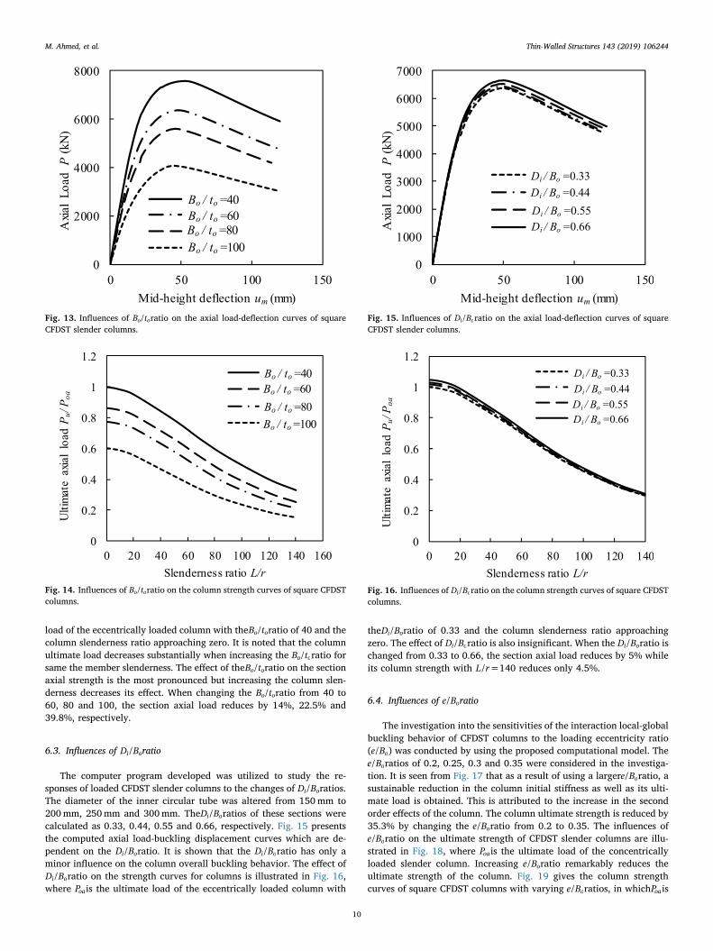
load of the eccentrically loaded column with theB t/o oratio of 40 and thecolumn slenderness ratio approaching zero. It is noted that the columnultimate load decreases substantially when increasing the B t/o oratio forsame the member slenderness. The effect of theB t/o oratio on the sectionaxial strength is the most pronounced but increasing the column slen-derness decreases its effect. When changing the B t/o oratio from 40 to60, 80 and 100, the section axial load reduces by 14%, 22.5% and39.8%, respectively.
6.3. Influences of D B/i oratio
The computer program developed was utilized to study the re-sponses of loaded CFDST slender columns to the changes of D B/i oratios.The diameter of the inner circular tube was altered from 150mm to200mm, 250mm and 300mm. TheD B/i oratios of these sections werecalculated as 0.33, 0.44, 0.55 and 0.66, respectively. Fig. 15 presentsthe computed axial load-buckling displacement curves which are de-pendent on the D B/i oratio. It is shown that the D B/i oratio has only aminor influence on the column overall buckling behavior. The effect ofD B/i oratio on the strength curves for columns is illustrated in Fig. 16,where Poais the ultimate load of the eccentrically loaded column with
theD B/i oratio of 0.33 and the column slenderness ratio approachingzero. The effect of D B/i oratio is also insignificant. When the D B/i oratio ischanged from 0.33 to 0.66, the section axial load reduces by 5% whileits column strength with L r/ =140 reduces only 4.5%.
6.4. Influences of e B/ oratio
The investigation into the sensitivities of the interaction local-globalbuckling behavior of CFDST columns to the loading eccentricity ratio(e B/ o) was conducted by using the proposed computational model. Thee B/ oratios of 0.2, 0.25, 0.3 and 0.35 were considered in the investiga-tion. It is seen from Fig. 17 that as a result of using a largere B/ oratio, asustainable reduction in the column initial stiffness as well as its ulti-mate load is obtained. This is attributed to the increase in the secondorder effects of the column. The column ultimate strength is reduced by35.3% by changing the e B/ oratio from 0.2 to 0.35. The influences ofe B/ oratio on the ultimate strength of CFDST slender columns are illu-strated in Fig. 18, where Poais the ultimate load of the concentricallyloaded slender column. Increasing e B/ oratio remarkably reduces theultimate strength of the column. Fig. 19 gives the column strengthcurves of square CFDST columns with varying e B/ oratios, in whichPoais
Fig. 13. Influences of B t/o oratio on the axial load-deflection curves of squareCFDST slender columns.
Fig. 14. Influences of B t/o oratio on the column strength curves of square CFDSTcolumns.
Fig. 15. Influences of D B/i oratio on the axial load-deflection curves of squareCFDST slender columns.
Fig. 16. Influences of D B/i oratio on the column strength curves of square CFDSTcolumns.
M. Ahmed, et al. Thin-Walled Structures 143 (2019) 106244
10
mizan
Typewritten Text
194

taken as the ultimate load of the eccentrically loaded column with thee B/ oratio of 0.2 and the column slenderness ratio approaching zero. It isevident that increasing thee B/ o ratio decreases the column ultimatestrength regardless of the member slenderness.
6.5. Influences of D t/i iratio
The influences of D t/i iratio on the behavior of slender CFDST col-umns were examined by varying the D t/i iratio from 20 to 50. The in-ternal tube thickness was varied while the other parameters were un-changed. The local-global interaction buckling behavior of the slendercolumns is illustrated in Fig. 20. It is discovered that the completecurves of axial load-buckling displacement for the slender CFDST col-umns are not sensitive to theD t/i iratio. The post-peak load-bucklingdisplacement curves cannot be distinguished for differentD t/i i ratios. Byincreasing D t/i iratio from 20 to 50, the column ultimate load decreasesby 1.25% only. The reason for this is that the global buckling of squareCFDST slender columns mainly depends on the B t/o oratio, memberslenderness and e B/ oratios. The column strength curves of squareCFDST beam-columns with varying D t/i iratios are given in Fig. 21, in
which Poais the ultimate load of the eccentrically loaded column withthe D t/i i ratio of 20 and the column slenderness ratio approaching zero.It is obvious from Fig. 21 that D t/i iratio has an insignificant effect on thecolumn strength curves.
6.6. Influences of local buckling
The influence of the outward local-buckling of the outer tubes withsquare sections on the global buckling of CFDST slender columns undereccentric loading was investigated. The B t/o o and e B/ oratios of thecolumn were taken as 100 and of 0.5, respectively. As demonstrated inFig. 22, the columns ultimate load is overestimated by 8.4% when theanalysis ignored local buckling. The sensitivities of the column strengthcurve to the local buckling of the square section are shown in Fig. 23, inwhich Poais the ultimate load of the eccentrically loaded column withthe column slenderness ratio approaching zero considering localbuckling. Local buckling has the most prominent influence on the sec-tion axial-load capacity. However, its effect on the column strengthdecreases when the column slenderness increases. For very slenderCFDST columns with a L r/ ratio greater than 200, the local buckling
Fig. 17. Influences of e B/ oratio on the axial load-deflection curves of squareCFDST slender columns.
Fig. 18. Influences of e B/ oratio on ultimate axial strengths of square CFDSTslender columns.
Fig. 19. Influences of e B/ oratio on the column strength curves of square CFDSTcolumns.
Fig. 20. Influences of D t/i iratio on the axial load-deflection curves of squareCFDST slender columns.
M. Ahmed, et al. Thin-Walled Structures 143 (2019) 106244
11
mizan
Typewritten Text
195

effect diminishes. This is because the ultimate strength of very slendercolumns is mainly governed by the global buckling and the strengthreduction due to the local buckling can be ignored.
6.7. Influences of concrete strength
The concrete in square CFDST slender columns carries most of thecompressive load. It is vital to understand the influences of high-strength concrete on the interaction local-global buckling responses ofslender CFDST columns for the economical design of such columns.Three different scenarios were considered as follows: (1) the sand-wiched-concrete and core-concrete had the same compressive strength;(2) the sandwiched-concrete strength was varied from 40MPa to70MPa while the core-concrete strength was not changed; and (3) thesandwiched-concrete strength was not changed while the core-concretestrength was varied from 40MPa to 70MPa. For the first case, the axialload-buckling displacement curves of CFDST columns with differentconcrete strengths are given in Fig. 24. The column ultimate load isincreased by 10.0%, 17.8% and 23.9%, respectively, by changing theconcrete strength from 40MPa to 50, 60 and 70MPa. The columnstrength curves which are dependent on the concrete strengths areprovided in Fig. 25, in which Poais the ultimate load of the eccentrically
Fig. 21. Influences of D t/i iratio on the column strength curves of square CFDSTcolumns.
Fig. 22. Influences of the local buckling of outer steel tube on the axial load-deflection curve of square CFDST slender column.
Fig. 23. Influences of the local buckling of outer steel tube on the columnstrength curves of square CFDST columns.
Fig. 24. Influences of concrete compressive strength on the axial load-deflec-tion curves of square CFDST slender columns.
Fig. 25. Influences of concrete compressive strength on the column strengthcurves of square CFDST columns.
M. Ahmed, et al. Thin-Walled Structures 143 (2019) 106244
12
mizan
Typewritten Text
196

loaded column with ′ =f 40 MPac and the column slenderness ratioapproaching zero. The use of higher strength concrete leads to a highercolumn ultimate load irrespective of its slenderness ratio. However, theconcrete strength effect decreases as the column slenderness increases.When changing the concrete strength from 40MPa to 70MPa, thesection axial capacity increases by 36% while its member axial strengthwith L r/ =140 increases by 13.5%. The influences of sandwiched-concrete strength on the load-deflection curves and column strengthcurves are illustrated in Fig. 26 and Fig. 27, respectively. In Fig. 27, Poaisthe ultimate load of the eccentrically loaded column with ′ =f 40 MPacoand the column slenderness ratio approaching zero. The effects of thecore-concrete strength on the structural behavior are presented inFig. 28 and Fig. 29, in which Poais the ultimate load of the eccentricallyloaded column with ′ =f 40 MPaci and the column slenderness ratioapproaching zero. It can be seen that the sandwiched-concrete strengthhas a remarkable effect on the global buckling behavior of squareslender CFDST columns but the influence of core-concrete strength isinsignificant.
6.8. Influences of steel yield strength
The studies on the inelastic buckling behavior of slender squareCFDST columns with various steel yield strengths were undertaken.Three cases were investigated. The first case was to change the yieldstress of both external and inner steel tubes from 350MPa to 450MPa,550MPa, and 650MPa. The interaction local-global buckling responsesof CFDST columns that are a function of the steel yield stress are givenin Fig. 30. The figure shows that the yield stress of both tubes does notaffect the column initial stiffness, but remarkably increases the columnaxial capacity. As shown in Fig. 30, when the steel yield stress of thetubes is changed from 350MPa to 650MPa, the percentage increase inthe column ultimate strength with a L/r ratio of 40 is 20.8%. The in-fluences of steel yield strength on the column strength curves are shownin Fig. 31, in which Poais the ultimate load of the eccentrically loadedcolumn with =f 350 MPasy and the column slenderness ratio ap-proaching zero. The effect of the steel yield stress of both tubes on thecolumn ultimate load decreases as the L/r ratio increases. The secondcase was to alter only the yield strength of the internal steel tube. Asdepicted in Figs. 32 and 33, the effect of internal steel tube yield stresson the load-buckling displacement responses and column strengthcurves is very minor and can be ignored. In Fig. 33, Poais the ultimateload of the eccentrically loaded column with =f 350 MPasyi and thecolumn slenderness ratio approaching zero. The third case was to varythe yield strength of the external steel tube only. It is seen from Figs. 34
Fig. 26. Influences of sandwiched concrete strength on the axial load-deflectioncurves of square CFDST slender columns.
Fig. 27. Influences of sandwiched concrete strength on the column strengthcurves of square CFDST columns.
Fig. 28. Influences of core concrete strength on the axial load-deflection curvesof square CFDST slender columns.
Fig. 29. Influences of core concrete strength on the column strength curves ofsquare CFDST columns.
M. Ahmed, et al. Thin-Walled Structures 143 (2019) 106244
13
mizan
Typewritten Text
197

Fig. 30. Influences of steel yield strength on the axial load-deflection curves ofsquare CFDST slender columns.
Fig. 31. Influences of steel yield strength on the column strength curves ofsquare CFDST columns.
Fig. 32. Influences of steel yield strength of the inner steel tube on the axialload-deflection curves of square CFDST slender columns.
Fig. 33. Influences of steel yield strength of the inner steel tube on the columnstrength curves of square CFDST columns.
Fig. 34. Influences of steel yield strength of the outer steel tube on the axialload-deflection curves of square CFDST slender columns.
Fig. 35. Influences of steel yield strength of the outer steel tube on the columnstrength curves of square CFDST columns.
M. Ahmed, et al. Thin-Walled Structures 143 (2019) 106244
14
mizan
Typewritten Text
198

and 35 that the global buckling responses and the column strengthcurves are affected predominantly by the yield strength of the externalsteel tube. In Fig. 35, Poais the ultimate load of the eccentrically loadedcolumn with =f 350 MPasyo and the column slenderness ratio ap-proaching zero. Thus, it is effective to use high strength external steeltube to improve the strength of CFDST columns with short and im-mediate lengths.
7. Proposed design models
7.1. CFDST slender columns under axial compression
The computational model developed in this study has been used toobtain the column strength curves for square CFDST columns underaxial compression with a wide range of parameters and initial geo-metric imperfection of L/1000. Based on the numerical results andEurocode 4 [42], a simple design model for calculating the ultimatestrength of square slender CFDST columns loaded concentrically isproposed herein as:
=P χPu des uo, (23)
where Puo is the column section ultimate strength under axial com-pression and calculated as
= + + ′ + ′P f A f A γ f A γ f Auo syo soe syi si co co co ci ci ci (24)
where Asoeis the effective area of the outer tube conserving localbuckling effects, Asi the cross-sectional area of inner tube, Aco the cross-sectional area of sandwiched concrete, Aci the cross-sectional area ofcore concrete, ′fco and ′fci the compressive strength of sandwiched-con-crete and core-concrete, respectively.
In Eq. (23), χ is the slenderness reduction factor. The original ex-pression for χ suggested by Eurocode 4 is modified herein as:
=+ −
≤χφ φ λ
1
‾1.0
2 2(25)
= + − +φ λ λ1.03 0.21(‾ 0.2) ‾2
2
(26)
The relative slenderness ratio λ is expressed as
=λ PPuo
cr (27)
in which Pcris the Euler buckling load of CFDST columns and computedby
=Pπ EI
L( )
creff
2
2 (28)
in which EI( )eff is the effective flexural stiffness of the composite cross-section, expressed as
= + + +EI E I E I E I E I( ) 0.6 0.6eff s so s so cm co c co s si s si cm ci c ci, , , , , , , , (29)
where Es is the Young's modulus of steel, Is the second moment of areaof the steel tube, Ecm the Young's modulus of concrete, Ic the secondmoment of area of concrete. The subscripts so, si, co and ci define theouter steel tube, inner steel tube, sandwiched concrete and core con-crete, respectively. The Young's modulus of concrete can be estimatedby
⎜ ⎟= ⎛⎝
′ + ⎞⎠
Ef
220008
10cmc
1/3
(30)
Fig. 36 presents the validation of the proposed design model. Thecolumn strength curve of the reference column given in Section 6 iscompared with the one calculated using the design model. It is shownthat the agreement between numerical predictions and design calcula-tions is good. Therefore, the proposed design model can be used in the
design of square CFDST slender columns loaded concentrically inpractice.
7.2. CFDST slender columns under eccentric loading
The numerical models developed by Liang et al. [24] and in thispaper were employed to generate the axial load-moment interactiondiagrams of square CFDST slender columns considering local buckling.Based on the numerical studies, the nominal interaction equations forCFDST slender columns with non-compact or slender sections undereccentric loading are proposed as
⎜ ⎟= ⎡⎣⎢
− ⎛⎝
⎞⎠
⎤⎦⎥
≥M M PP
P P1.04 1 for 0.2u ou
o
α
u o
m
(31)
⎜ ⎟= ⎡⎣⎢
− ⎛⎝
⎞⎠
⎤⎦⎥
<M M PP
P P1 110
for 0.2u ou
o
α
u o
n
(32)
where Pu is the axial load, Mu the corresponding ultimate bending re-sistance of the slender CFDST column, Po the ultimate pure axialstrength of the slender column without moment, Mo the column ulti-mate bending resistance without axial load, αm and αn the shape factorsof the interaction curves depending on the L/r ratio of CFDST columnsand are proposed as
⎟= − ⎛⎝
⎞⎠
≤ ≤ ⎞⎠
α Lr
α2.44 0.012 (1.0 2.0m m(33)
= ⎧⎨⎩
− ≤ ≤< ≤
αL r α
α2.668( / ) 2.496 for 1.0 1.51.5 for 1.5 2.0n
m
m (34)
The comparison of the interaction curves for CFDST columns withvarious design parameters given in the parametric study obtained bythe proposed equations and the numerical model is shown in Fig. 37. Itis seen that the agreement between the proposed design equations andnumerical results for a wide range of design parameters is good. Thedesign interaction curves are also compared with those computed bythe formulas given in AISC 360-16 [43]. The proposed design equationsyield better results than those specified in AISC 360-16 as can be seenfrom Fig. 37.
8. Conclusions
This paper has reported on the development of a mathematical
Fig. 36. Comparison of proposed design model with numerical analysis.
M. Ahmed, et al. Thin-Walled Structures 143 (2019) 106244
15
mizan
Typewritten Text
199

model incorporating the fiber approach for the simulation of the in-teraction local-global buckling responses of slender CFDST beam-col-umns with thin-walled square sections loaded eccentrically. Salientfeatures associated with slender CFST square columns have been takeninto consideration in the formulation of the mathematical model, in-cluding confinement, local-global interaction buckling, geometric im-perfection, and second-order as well as high-strength materials.Efficient computational solution algorithms implementing the inversequadratic method have been developed to obtain converged solutionsto the nonlinear dynamic functions generated in the incremental-iterative analysis process for slender CFDST columns. The computa-tional model has been verified by test data on CFDST and DCFST col-umns and employed to determine the local-global interaction bucklingbehavior of CFDST columns with various important parameters. Designmodels have been developed for calculating the ultimate strengths ofslender square CFDST columns subjected to axial compression and ec-centric loading.
The concluding remarks are provided as follows:
(1) Further tests on the behavior of slender square CFDST columnsshould be conducted to provide results that can be used to validatenumerical models.
(2) The initial stiffness and ultimate axial load of square CFDST col-umns are found to reduce significantly when increasing thecolumn slenderness ratio.
(3) The B t/o oratio has a remarkable effect on the strength and initial
stiffness of CFDST columns but its influence decreases with in-creasing the column slenderness.
(4) TheD B/i o ratio has a minor influence on the global buckling be-havior of CFDST columns.
(5) Increasing thee B/ oratio results in marked reductions in the columninitial stiffness and ultimate axial load.
(6) The buckling behavior of slender CFDST columns is almost notaffected by theD t/i i ratio.
(7) The outward local buckling of the outer steel tube considerablyreduces the ultimate load of CFDST square columns, but this effectdecreases when the column slenderness increases.
(8) Increasing the sandwiched-concrete strength substantially im-proves the column ultimate load. The influence of concretestrength, however, decreases with increasing the column slen-derness ratio. The core-concrete strength has an insignificant in-fluence on the column strength.
(9) The ultimate strength of CFDST columns is shown to increaseappreciably by using higher yield strength external steel tube.However, the column global buckling behavior is almost not af-fected by the yield stress of the inner steel Tube.
(10) The proposed design models derived based on the numerical re-sults predict well the ultimate strengths of square CFDST slendercolumns under axial compression and eccentric loading.
Fig. 37. Comparison of axial load-moment interaction curves for slender CFDST columns obtained by the proposed design equations and numerical model.
M. Ahmed, et al. Thin-Walled Structures 143 (2019) 106244
16
mizan
Typewritten Text
200

References
[1] AS 3600-2009, Australian Standard for Concrete Structures, Standards Australia,Sydney, NSW, Australia, 2009.
[2] A.H. Varma, J.M. Ricles, R. Sause, L.W. Lu, Experimental behavior of high strengthsquare concrete-filled steel tube beam-columns, J. Struc. Eng. ASCE 128 (3) (2002)309–318.
[3] M. Mursi, B. Uy, Strength of concrete filled steel box columns incorporating inter-action buckling, J. Struc. Eng. ASCE 129 (5) (2003) 626–639.
[4] M. Mursi, B. Uy, Strength of slender concrete filled high strength steel box columns,J. Constr. Steel Res. 60 (12) (2004) 1825–1848.
[5] D. Liu, Behaviour of high strength rectangular concrete-filled steel hollow sectioncolumns under eccentric loading, Thin-Walled Struct. 42 (12) (2004) 1631–1644.
[6] Y. Du, Z. Chen, Y.B. Wang, J.Y.R. Liew, Ultimate resistance behavior of rectangularconcrete-filled tubular beam-columns made of high-strength steel, J. Constr. SteelRes. 133 (2017) 418–433.
[7] Y. Du, Z. Chen, J.Y.R. Liew, M.X. Xiong, Rectangular concrete-filled steel tubularbeam-columns using high-strength steel: experiments and design, J. Constr. SteelRes. 131 (2017) 1–18.
[8] Z. Tao, L.H. Han, Behaviour of concrete-filled double skin rectangular steel tubularbeam–columns, J. Constr. Steel Res. 62 (7) (2006) 631–646.
[9] Z. Tao, L.H. Han, X.L. Zhao, Behaviour of concrete-filled double skin (CHS inner andCHS outer) steel tubular stub columns and beam-columns, J. Constr. Steel Res. 60(8) (2004) 1129–1158.
[10] X.L. Zhao, R. Grzebieta, M. Elchalakani, Tests of concrete-filled double skin CHScomposite stub columns, Steel Compos. Struct. 2 (2) (2002) 129–146.
[11] X.L. Zhao, L.W. Tong, X.Y. Wang, CFDST stub columns subjected to large de-formation axial loading, Eng. Struct. 32 (3) (2010) 692–703.
[12] L.H. Han, Z. Tao, H. Huang, X.L. Zhao, Concrete-filled double skin (SHS outer andCHS inner) steel tubular beam-columns, Thin-Walled Struct. 42 (9) (2004)1329–1355.
[13] L.H. Han, H. Huang, Z. Tao, X.L. Zhao, Concrete-filled double skin steel tubular(CFDST) beam–columns subjected to cyclic bending, Eng. Struct. 28 (12) (2006)1698–1714.
[14] M.X. Xiong, D.X. Xiong, J.Y.R. Liew, Behaviour of steel tubular members infilledwith ultra high strength concrete, J. Constr. Steel Res. 138 (2017) 168–183.
[15] W.J. Pei, Research on Mechanical Performance of Multibarrel Tube-ConfinedConcrete Columns, ME Thesis, Chang’an Univ., Xian, China, 2005 (in Chinese).
[16] J. Qian, N. Li, X. Ji, Z. Zhao, Experimental study on the seismic behavior of highstrength concrete filled double-tube columns, Earthq. Eng. Eng. Vib. 13 (1) (2014)47–57 (in Chinese).
[17] J. Qian, Y. Zhang, X. Ji, W. Cao, Test and analysis of axial compressive behavior ofshort composite-sectioned high strength concrete filled steel tubular columns, J.Build. Struct. 32 (12) (2011) 162–169 (in Chinese).
[18] J. Qian, Y. Zhang, W. Zhang, Eccentric compressive behavior of high strengthconcrete filled double-tube short columns, J. Tsinghua Univ. 55 (1) (2015) 1–7 (inChinese).
[19] M.X. Xiong, D.X. Xiong, J.Y.R. Liew, Axial performance of short concrete filled steeltubes with high-and ultra-high-strength materials, Eng. Struct. 136 (2017)494–510.
[20] Z.B. Wang, Z. Tao, Q. Yu, Axial compressive behaviour of concrete-filled double-tube stub columns with stiffeners, Thin-Walled Struct. 120 (2017) 91–104.
[21] N.E. Shanmugam, B. Lakshmi, B. Uy, An analytical model for thin-walled steel boxcolumns with concrete in-fill, Eng. Struct. 24 (6) (2002) 825–838.
[22] Z. Vrcelj, B. Uy, Strength of slender concrete-filled steel box columns incorporatinglocal buckling, J. Constr. Steel Res. 58 (2) (2002) 275–300.
[23] V.I. Patel, Q.Q. Liang, M.N.S. Hadi, High strength thin-walled rectangular concrete-filled steel tubular slender beam-columns, Part I: Modeling, J. Constr. Steel Res. 70(2012) 377–384.
[24] Q.Q. Liang, V.I. Patel, M.N.S. Hadi, Biaxially loaded high-strength concrete-filledsteel tubular slender beam-columns, Part I: multiscale simulation, J. Constr. SteelRes. 75 (2012) 64–71.
[25] M. Ahmed, Q.Q. Liang, V.I. Patel, M.N.S. Hadi, Nonlinear analysis of rectangularconcrete-filled double steel tubular short columns incorporating local buckling,Eng. Struct. 175 (2018) 13–26.
[26] T.Q. Lü, G.F. Zhao, Numerical method for analysis of ultimate strength of concrete-filled square steel Tubular columns under eccentric compression reinforced by innercircular steel tube, J. Dalian Univ. Technolgy 41 (5) (2001) 612–616 (in Chinese).
[27] Q.Q. Liang, Performance-based analysis of concrete-filled steel tubular beam–col-umns, Part I: theory and algorithms, J. Constr. Steel Res. 65 (2) (2009) 363–372.
[28] Q.Q. Liang, Performance-based analysis of concrete-filled steel tubular beam–col-umns, Part II: verification and applications, J. Constr. Steel Res. 65 (2) (2009)351–362.
[29] Q.Q. Liang, Analysis and Design of Steel and Composite Structures, CRC Press,Taylor and Francis Group, Boca Raton and London, 2014.
[30] V.I. Patel, Q.Q. Liang, M.N.S. Hadi, Concrete-filled Stainless Steel Tubular Columns,CRC Press, Taylor and Francis, Boca Raton and London, 2018.
[31] P.O. Persson, G. Strang, A simple mesh generator in MATLAB, SIAM Rev. 46 (2)(2004) 329–345.
[32] M. Ahmed, Q.Q. Liang, V.I. Patel, M.N.S. Hadi, Numerical analysis of axially loadedcircular high strength concrete-filled double steel tubular short columns, Thin-Walled Struct. 138 (2019) 105–116.
[33] Q.Q. Liang, B. Uy, J.Y.R. Liew, Local buckling of steel plates in concrete-filled thin-walled steel tubular beam–columns, J. Constr. Steel Res. 63 (3) (2007) 396–405.
[34] Q.Q. Liang, High strength circular concrete-filled steel tubular slender beam–col-umns, Part I: numerical analysis, J. Constr. Steel Res. 67 (2) (2011) 164–171.
[35] J.B. Mander, Seismic Design of Bridge Piers (Ph.D. Thesis), Depart. Of Civil Eng.Uni. of Canterbury, Christchurch, New Zealand, (1983).
[36] J.B. Mander, M.J. Priestley, R. Park, Theoretical stress-strain model for confinedconcrete, J. Struc. Eng. ASCE 114 (8) (1988) 1804–1826.
[37] J.C. Lim, T. Ozbakkaloglu, Stress–strain model for normal-and light-weight con-cretes under uniaxial and triaxial compression, Constr. Build. Mater. 71 (2014)492–509.
[38] Q.Q. Liang, S. Fragomeni, Nonlinear analysis of circular concrete-filled steel tubularshort columns under axial loading, J. Constr. Steel Res. 65 (12) (2009) 2186–2196.
[39] H.T. Hu, C.S. Huang, M.H. Wu, Y.M. Wu, Nonlinear analysis of axially loadedconcrete-filled tube columns with confinement effect, J. Struc. Eng. ASCE 129 (10)(2003) 1322–1329.
[40] J. Tang, S. Hino, I. Kuroda, T. Ohta, Modeling of stress-strain relationships for steeland concrete in concrete filled circular steel tubular columns, Steel Constr. Eng.JSSC 3 (11) (1996) 35–46.
[41] D.J. Oehlers, M.A. Bradford, Elementary Behaviour of Composite Steel andConcrete Structural Members, Butterworth-Heinemann, Oxford U.K., 1999.
[42] Eurocode 4, Design of Composite Steel and Concrete Structures-Part 1-1: GeneralRules and Rules for Buildings, European Committee for Standardization, CEN,Brussels, Belgium, 2004 EN 1994-1-1.
[43] AISC 360-16, Specification for Structural Steel Buildings, American Institute of SteelConstruction, Chicago (IL), 2016.
M. Ahmed, et al. Thin-Walled Structures 143 (2019) 106244
17
mizan
Typewritten Text
201
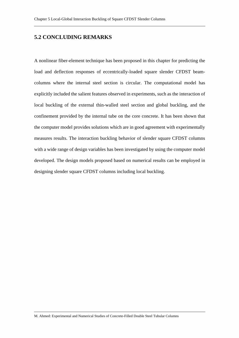
Chapter 5 Local-Global Interaction Buckling of Square CFDST Slender Columns
M. Ahmed: Experimental and Numerical Studies of Concrete-Filled Double Steel Tubular Columns
5.2 CONCLUDING REMARKS
A nonlinear fiber-element technique has been proposed in this chapter for predicting the
load and deflection responses of eccentrically-loaded square slender CFDST beam-
columns where the internal steel section is circular. The computational model has
explicitly included the salient features observed in experiments, such as the interaction of
local buckling of the external thin-walled steel section and global buckling, and the
confinement provided by the internal tube on the core concrete. It has been shown that
the computer model provides solutions which are in good agreement with experimentally
measures results. The interaction buckling behavior of slender square CFDST columns
with a wide range of design variables has been investigated by using the computer model
developed. The design models proposed based on numerical results can be employed in
designing slender square CFDST columns including local buckling.
mizan
Typewritten Text
202

Chapter 6 Circular CFDST Slender Columns under Eccentric Loading
M. Ahmed: Experimental and Numerical Studies of Concrete-Filled Double Steel Tubular Columns
Chapter 6
CIRCULAR CFDST SLENDER COLUMNS UNDER
ECCENTRIC LOADING
6.1 INTRODUCTION
This chapter deals with the computational simulation and design of pin-ended circular
CFDST slender columns composed of an inner circular steel tube subjected to eccentric
loading. The computational model of nonlinear fiber analysis is developed for the
simulation of load-deflection behavior and strength interaction diagrams of slender
circular CFDST columns, including the effects of concrete confinement, imperfections,
second-order, and geometric and material nonlinearities. Computer codes are written to
implement the inverse quadratic method for numerically solving the incremental-iterative
equilibrium functions of CFDST slender columns. The computational results are justified
against the independent test results of slender CFDST and DCFST columns loaded
eccentrically. The influences of important design parameters on the load distribution and
behavior of slender CFDST columns are examined using the computer program
developed. Design expressions are provided for the design of CFDST slender columns
and compared with numerical results and codified design methods.
mizan
Typewritten Text
203

Chapter 6 Circular CFDST Slender Columns under Eccentric Loading
M. Ahmed: Experimental and Numerical Studies of Concrete-Filled Double Steel Tubular Columns
This chapter includes the following paper:
1. Ahmed, M., Liang, Q. Q., Patel, V. I. and Hadi, M. N. S. (2020). Computational
simulation of eccentrically-loaded circular thin-walled concrete-filled double
steel tubular slender columns. Engineering Structures, 213, 110571.
mizan
Typewritten Text
204

1. PUBLICATION DETAILS (to be completed by the candidate)
2. CANDIDATE DECLARATION
3. CO-AUTHOR(S) DECLARATION
OFFICE FOR RESEARCH TRAINING, QUALITY
AND INTEGRITY
DECLARATION OF CO-AUTHORSHIP AND CO-CONTRIBUTION: PAPERS INCORPORATED IN THESIS
This declaration is to be completed for each conjointly authored publication and placed at the beginning of the thesis chapter
in which the publication appears.
Title of Paper/Journal/Book:
Surname:
Institute:
First name:
Institute for Sustainable Industries and Liveable Cities Candidate’s Contribution (%):
Status:
I declare that the publication above meets the requirements to be included in the thesis as outlined
in the HDR Policy and related Procedures – policy.vu.edu.au.
Signature Date
In the case of the above publication, the following authors contributed to the work as follows:
The undersigned certify that:
1. They meet criteria for authorship in that they have participated in the conception, execution or interpretation of at least that part of the publication in their field of expertise;
2. They take public responsibility for their part of the publication, except for the responsible author who accepts overall responsibility for the publication;
Accepted and in press: Date:
Published:
Date:
Ahmed, M., Liang, Q. Q., Patel, V. I. and Hadi, M. N. S. (2020). Computational simulation of eccentrically-loaded circular thin-walled concrete-filled double steel tubular slender columns. Engineering Structures, (currently under review).
Ahmed Mizan
60
06-01-2020
Mizan Ahmed Digitally signed by Mizan Ahmed
Date: 2020.01.06 14:04:00 +11'00'
mizan
Typewritten Text
205

3. There are no other authors of the publication according to these criteria;
4. Potential conflicts of interest have been disclosed to a) granting bodies, b) the editor or publisher of journals or other publications, and c) the head of the responsible academic unit; and
5. The original data will be held for at least five years from the date indicated below and is stored at the following location(s):
Name(s) of Co-Author(s)
Contribution (%)
Nature of Contribution Signature Date
Mizan Ahmed 60 Methodology, Software, Validation, Formal analysis, Investigation, Data curation, Writing–Original draft, Visualization.
06-01-2020
Qing Quan Liang 20 Conceptualization, Methodology, Software, Validation, Writing–Review and Editing, Supervision, Project administration.
06-01-2020
Vipulkumar I. Patel 10 Validation, Writing–Review and Editing, Supervision.
06-01-2020
Muhammad N.S. Hadi 10 Validation, Writing–Review and Editing, Supervision.
06-01-2020
R:\CFDST Columns
Mizan Ahmed
Digitally signed by Mizan Ahmed Date: 2020.01.06 14:04:13 +11'00'
Qing Quan Liang
Digitally signed by Qing Quan Liang Date: 2020.01.06 14:38:55 +11'00'
Vipul Patel
Digitally signed by Vipul Patel Date: 2020.01.06 15:06:52 +11'00'
Muhammad Hadi
Digitally signed byMuhammad Hadicn=Muhammad Hadi, o= University of Wollongong, l= Wollongong, st= NSW, c= AU, email= [email protected]: 2020.01.06 15:31:14 AEDT
mizan
Typewritten Text
206

Computational simulation of eccentrically loaded circular thin-walled concrete-filled double steel tubular slender columnsby M. Ahmed, Q.Q. Liang, V.I. Patel, and M.N.S. Hadi was published in the peer review journal, Engineering Structures, 213, 2020. The full-text of this article is subject to copyright restrictions, and cannot be included in the online version of the thesis. The published version is available from: https://doi.org/10.1016/j.engstruct.2020.110571

Chapter 6 Circular CFDST Slender Columns under Eccentric Loading
M. Ahmed: Experimental and Numerical Studies of Concrete-Filled Double Steel Tubular Columns
6.2 CONCLUDING REMARKS
The computer simulation and design of circular CFDST slender columns having an
internal circular steel tube under eccentric loading have been presented in this chapter.
The computational simulation technology developed has recognized the characteristics of
circular CFDST slender columns, such as the confining stresses provided by both the steel
tubes on the concrete, imperfections, second-order effects and inelastic material behavior.
The modeling technology developed has been found to accurately simulate the load-
deflection behavior, column strength curves, strength envelopes and load-distributions in
the steel tubes and concrete of CFDST slender columns. Computational results obtained
from the parametric studies have been used to develop design equations for designing
slender CFDST columns loaded either concentrically or eccentrically. It has been shown
that the proposed design equations generally provide more accurate strength predictions
of CFDST columns than the codified methods and can be used in practice.
mizan
Typewritten Text
260

Chapter 7 CFDST Slender Columns with Preload Effects
M. Ahmed: Experimental and Numerical Studies of Concrete-Filled Double Steel Tubular Columns
Chapter 7
CFDST SLENDER COLUMNS WITH PRELOAD
EFFECTS
7.1 INTRODUCTION
In the composite construction of high-rise buildings, the hollow steel tubes are designed
to support the permanent and construction loads of several upper floors before the
concrete is filled into the steel tubes to form CFDST columns. The preloads result in the
initial deformations and stresses in the hollow steel tubes and may reduce the performance
of slender CFDST columns. This chapter presents nonlinear computational modeling,
fundamental behavior and design of slender square and circular CFDST columns
composed of an internal circular tube incorporating preload effects. The local buckling of
the square outer steel section, the concrete confinement by the circular steel tube,
imperfections, second-order effects, and geometric and material nonlinearities are taken
into account in the computer model. The deformation caused by the preload is included
in the column analysis as an additional geometric imperfection. Robust and
computationally efficient algorithms are developed to obtain satisfactory solutions to the
highly dynamic, nonlinear equilibrium functions of slender CFDST columns having
preload effects. The computational results are verified with the experimental and FE
results of CFST and DCFST columns subjected to preloads. The significance of preloads
mizan
Typewritten Text
261

Chapter 7 CFDST Slender Columns with Preload Effects
M. Ahmed: Experimental and Numerical Studies of Concrete-Filled Double Steel Tubular Columns
and other important design variables on the behavior of slender CFDST columns is
ascertained using the mathematical models developed. Design models are proposed for
designing CFDST columns in which the steel tubes are under preloads.
This chapter includes the following papers:
1. Ahmed, M., Liang, Q. Q., Patel, V. I. and Hadi, M. N. S. (2020). Nonlinear analysis
of square concrete-filled double steel tubular slender columns incorporating preload
effects. Engineering Structures, 207, 110272 (published on 15th March 2020).
2. Ahmed, M., Liang, Q. Q., Patel, V. I. and Hadi, M. N. S. (2020). Behavior of circular
concrete-filled double steel tubular slender beam-columns including preload effects.
Engineering Structures (currently under review).
mizan
Typewritten Text
262

1. PUBLICATION DETAILS (to be completed by the candidate)
2. CANDIDATE DECLARATION
3. CO-AUTHOR(S) DECLARATION
OFFICE FOR RESEARCH TRAINING, QUALITY
AND INTEGRITY
DECLARATION OF CO-AUTHORSHIP AND CO-CONTRIBUTION: PAPERS INCORPORATED IN THESIS
This declaration is to be completed for each conjointly authored publication and placed at the beginning of the thesis chapter
in which the publication appears.
Title of Paper/Journal/Book:
Surname:
Institute:
First name:
Institute for Sustainable Industries and Liveable Cities Candidate’s Contribution (%):
Status:
I declare that the publication above meets the requirements to be included in the thesis as outlined
in the HDR Policy and related Procedures – policy.vu.edu.au.
Signature Date
In the case of the above publication, the following authors contributed to the work as follows:
The undersigned certify that:
1. They meet criteria for authorship in that they have participated in the conception, execution or interpretation of at least that part of the publication in their field of expertise;
2. They take public responsibility for their part of the publication, except for the responsible author who accepts overall responsibility for the publication;
Accepted and in press: Date:
Published:
Date:
Ahmed, M., Liang, Q. Q., Patel, V. I. and Hadi, M. N. S. (2020). Nonlinear analysis of square concrete-filled double steel tubular slender columns incorporating preload effects. Engineering Structures, (accepted).
Ahmed Mizan
60
21-01-2020
✓
22-01-2020
Mizan Ahmed
Digitally signed by Mizan Ahmed Date: 2020.01.22 11:34:55 +11'00'
mizan
Typewritten Text
263

3. There are no other authors of the publication according to these criteria;
4. Potential conflicts of interest have been disclosed to a) granting bodies, b) the editor or publisher of journals or other publications, and c) the head of the responsible academic unit; and
5. The original data will be held for at least five years from the date indicated below and is stored at the following location(s):
Name(s) of Co-Author(s)
Contribution (%)
Nature of Contribution Signature Date
Mizan Ahmed 60 Methodology, Software, Validation, Formal analysis, Investigation, Data curation, Writing–Original draft, Visualization.
22-01-2020
Qing Quan Liang 20 Conceptualization, Methodology, Software, Validation, Writing–Review and Editing, Supervision, Project administration.
22-01-2020
Vipulkumar I. Patel 10 Validation, Writing–Review and Editing, Supervision.
22-01-2020
Muhammad N.S. Hadi 10 Validation, Writing–Review and Editing, Supervision.
22-01-2020
R:\CFDST Columns
Mizan Ahmed
Digitally signed by Mizan Ahmed Date: 2020.01.22 11:35:10 +11'00'
Qing Quan Liang
Digitally signed by Qing Quan Liang Date: 2020.01.22 12:33:04 +11'00'
Vipul Patel
Digitally signed by Vipul Patel Date: 2020.01.22 12:37:49 +11'00'
Muhammad Hadi
Digitally signed by Muhammad Hadi DN: cn=Muhammad Hadi, o=University of Wollongong, ou=School of CME, [email protected], c=AU Date: 2020.01.22 13:07:27 +11'00'
mizan
Typewritten Text
264

1. PUBLICATION DETAILS (to be completed by the candidate)
2. CANDIDATE DECLARATION
3. CO-AUTHOR(S) DECLARATION
OFFICE FOR RESEARCH TRAINING, QUALITY
AND INTEGRITY
DECLARATION OF CO-AUTHORSHIP AND CO-CONTRIBUTION: PAPERS INCORPORATED IN THESIS
This declaration is to be completed for each conjointly authored publication and placed at the beginning of the thesis chapter
in which the publication appears.
Title of Paper/Journal/Book:
Surname:
Institute:
First name:
Institute for Sustainable Industries and Liveable Cities Candidate’s Contribution (%):
Status:
I declare that the publication above meets the requirements to be included in the thesis as outlined
in the HDR Policy and related Procedures – policy.vu.edu.au.
Signature Date
In the case of the above publication, the following authors contributed to the work as follows:
The undersigned certify that:
1. They meet criteria for authorship in that they have participated in the conception, execution or interpretation of at least that part of the publication in their field of expertise;
2. They take public responsibility for their part of the publication, except for the responsible author who accepts overall responsibility for the publication;
Accepted and in press: Date:
Published:
Date:
Ahmed, M., Liang, Q. Q., Patel, V. I. and Hadi, M. N. S. (2020). Behavior of circular concrete-filled double steel tubular slender beam-columns including preload effects. Marine Structures, (currently under review).
Ahmed Mizan
60
13-01-2020
Mizan Ahmed Digitally signed by Mizan Ahmed
Date: 2020.01.13 05:52:31 +11'00'
mizan
Typewritten Text
265

3. There are no other authors of the publication according to these criteria;
4. Potential conflicts of interest have been disclosed to a) granting bodies, b) the editor or publisher of journals or other publications, and c) the head of the responsible academic unit; and
5. The original data will be held for at least five years from the date indicated below and is stored at the following location(s):
Name(s) of Co-Author(s)
Contribution (%)
Nature of Contribution Signature Date
Mizan Ahmed 60 Methodology, Software, Validation, Formal analysis, Investigation, Data curation, Writing–Original draft, Visualization.
13-01-2020
Qing Quan Liang 20 Conceptualization, Methodology, Software, Validation, Writing–Review and Editing, Supervision, Project administration.
13-01-2020
Vipulkumar I. Patel 10 Validation, Writing–Review and Editing, Supervision.
13-01-2020
Muhammad N.S. Hadi 10 Validation, Writing–Review and Editing, Supervision.
13-01-2020
R:\CFDST Columns
Mizan Ahmed
Digitally signed by Mizan Ahmed Date: 2020.01.13 05:52:49 +11'00'
Qing Quan Liang
Digitally signed by Qing Quan Liang Date: 2020.01.13 12:35:48 +11'00'
Vipul Patel
Digitally signed by Vipul Patel Date: 2020.01.13 12:38:51 +11'00'
Muhammad Hadi
Digitally signed byMuhammad Hadicn=Muhammad Hadi, o= University of Wollongong, l= Wollongong, st= NSW, c= AU, email= [email protected]: 2020.01.13 13:26:0 AEDT
mizan
Typewritten Text
266

Nonlinear analysis of square concrete-filled double steel tubular slender columns incorporating preload effectsby M. Ahmed, Q.Q. Liang, V.I. Patel, and M.N.S. Hadi was published in the peer review journal, Engineering Structures, 207, 2020. The full-text of this article is subject to copyright restrictions, and cannot be included in the online version of the thesis. The published version is available from: https://doi.org/10.1016/j.engstruct.2020.110272 ,

322
Manuscript prepared for
Engineering Structures
January 2020
Behavior of circular concrete-filled double steel tubular slender
beam-columns including preload effects
Mizan Ahmeda, Qing Quan Lianga,*, Vipulkumar Ishvarbhai Patelb, Muhammad N. S. Hadic
a College of Engineering and Science, Victoria University, PO Box 14428, Melbourne,
VIC 8001, Australia b School of Engineering and Mathematical Sciences, La Trobe University, Bendigo, VIC
3552, Australia c School of Civil, Mining and Environmental Engineering, University of Wollongong,
Wollongong, NSW 2522, Australia
Corresponding author:
Dr Qing Quan Liang
College of Engineering and Science
Victoria University
PO Box 14428
Melbourne VIC 8001
Australia
E-mail: [email protected]
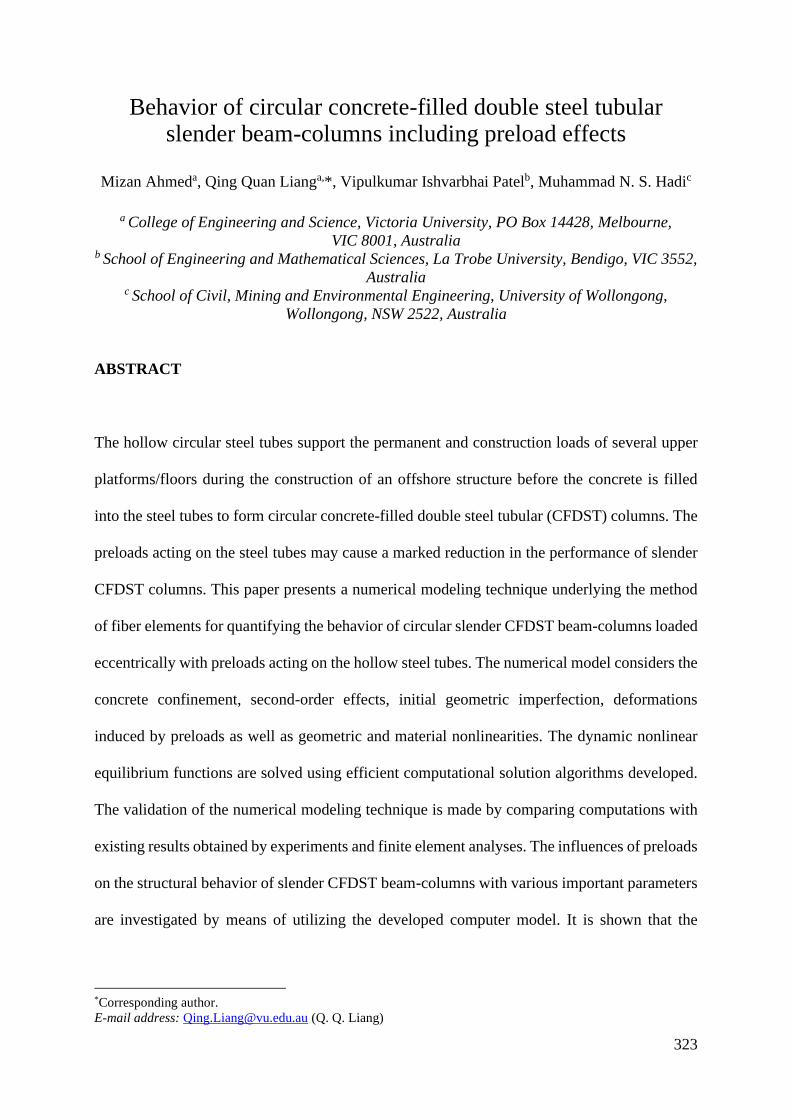
323
Behavior of circular concrete-filled double steel tubular slender beam-columns including preload effects
Mizan Ahmeda, Qing Quan Lianga,*, Vipulkumar Ishvarbhai Patelb, Muhammad N. S. Hadic
a College of Engineering and Science, Victoria University, PO Box 14428, Melbourne,
VIC 8001, Australia b School of Engineering and Mathematical Sciences, La Trobe University, Bendigo, VIC 3552,
Australia c School of Civil, Mining and Environmental Engineering, University of Wollongong,
Wollongong, NSW 2522, Australia
ABSTRACT
The hollow circular steel tubes support the permanent and construction loads of several upper
platforms/floors during the construction of an offshore structure before the concrete is filled
into the steel tubes to form circular concrete-filled double steel tubular (CFDST) columns. The
preloads acting on the steel tubes may cause a marked reduction in the performance of slender
CFDST columns. This paper presents a numerical modeling technique underlying the method
of fiber elements for quantifying the behavior of circular slender CFDST beam-columns loaded
eccentrically with preloads acting on the hollow steel tubes. The numerical model considers the
concrete confinement, second-order effects, initial geometric imperfection, deformations
induced by preloads as well as geometric and material nonlinearities. The dynamic nonlinear
equilibrium functions are solved using efficient computational solution algorithms developed.
The validation of the numerical modeling technique is made by comparing computations with
existing results obtained by experiments and finite element analyses. The influences of preloads
on the structural behavior of slender CFDST beam-columns with various important parameters
are investigated by means of utilizing the developed computer model. It is shown that the
*Corresponding author.
E-mail address: [email protected] (Q. Q. Liang)

324
numerical modeling method is an efficient computational simulation and design tool for slender
CFDST columns including preloads.
Keywords: Concrete-filled double steel tubes; nonlinear analysis; slender beam-columns;
preload effects.
1. Introduction
Circular concrete-filled double steel tubular (CFDST) columns as shown in Fig. 1(a) have high
ductility, stiffness, strength, and fire resistance because of the utilization of the internal circular
steel tube filled with concrete. The common practice in the construction of an offshore structure
or composite structure is to erect the hollow steel tubes that support several upper platforms or
floors prior to filling the concrete into the steel tubes. The preloads acting on the steel hollow
tubes may cause considerable reductions in the stiffness and strength of CFDST slender
columns and affect the load distribution in concrete and steel components in the columns.
Therefore, it is important to quantify the influences of preloads on the structural behavior of
CFDST columns to achieve safe and effective designs. However, the experimental and
computational studies of preload effects on the performance and load distribution in the
components of CFDST columns are extremely rare. The objective of this paper is to ascertain
the fundamental behavior of circular CFDST columns where the steel tubes are preloaded by
using an efficient computational model, which is developed based on the theory of the nonlinear
fiber analysis.
The structural performance of CFDST columns composed of circular sections without preload
effects has been investigated experimentally by Peng et al. [1], Xiong et al. [2], Ekmekyapar

325
and Al-Eliwi [3], Chang et al. [4], Romero et al. [5], Ibañez et al. [6], Xiong et al. [7], and
Ahmed et al. [8]. Ahmed et al. [8] undertook experiments to evaluate the significance of loading
eccentricity on the behavior of CFDST short beam-columns. The beam-columns were
constructed by cold-formed steel tubes that had yield stress up to 412 MPa and normal strength
concrete. The eccentricity ratio ( / oe D ) varied from 0.0 to 0.21. Like concrete-filled steel
tubular (CFST) columns depicted in Fig. 1(b), the ultimate load of CFDST columns was
discovered to be affected by the steel ratio and concrete area. However, the utilization of the
circular inner tube improved the ductility and strength of such composite columns under
eccentric loading. Romero et al. [9] and Ibañez et al. [6] examined the influences of different
combinations of steel thickness and concrete strength on the responses of slender CFDST
columns loaded either concentrically or eccentrically. The ultra-high-strength (UHS) concrete
up to 150 MPa was used in the construction of these column specimens. The UHS concrete was
found to have an insignificant effect on the strength of slender columns that were loaded
eccentrically as the failure of slender columns was mainly caused by the global buckling. Tao
et al. [10] undertook tests on double-skin CFST columns where the / oe D ratios of the columns
varied from 0.0 to 0.4. The columns failed in a ductile manner due to the composite action. A
theoretical model was presented for the response analysis of such composite columns and a
design model was also proposed by Tao et al. [10].
Tests on steel-concrete composite columns subjected to preloads have been very limited [11-
16]. Han and Yao [13] performed tests on square CFST columns where the steel tubes were
subjected to initial stresses that were applied by using the pre-stressing bars. The slenderness
of the column specimens varied from 10 to 40. It was observed that due to the initial stress
acting on the steel tube, the strength of CFST columns was reduced by up to 20%. The
significance of initial stresses on the behavior of CFST columns of circular sections with the

326
preload ratio (a ) ranged from 0.0 to 0.4 were ascertained experimentally by Liew and Xiong
[14]. Test results showed that the preload effect was insignificant when the a ratio was less
than 0.2. However, when thea ratio was greater than 0.6, the reduction in the column strength
was about 20%. Huang et al. [15] examined the sensitivities of the ultimate load of CFST
columns to preloads. It was found that the preload effect increased with increasing the member
slenderness and a significant preload remarkably reduced the strength of slender columns.
Numerical models have been developed and employed to numerically determine the structural
performance of CFST columns under preloads by Han and Yao [13], Liew and Xiong [14],
Xiong and Zha [17], Patel et al. [18], Patel et al. [19] and Huang et al. [15]. Patel et al. [18]
developed a mathematical model that considered the influences of concrete confinement,
second-order, and geometric and material nonlinearities. The significance of preloads on the
responses of double-skin DCFST columns as shown in Fig. 1(c) was studied by Li et al. [20]
using the finite element (FE) software Abaqus. The initial stresses on either outer steel tube or
both tubes were considered. Numerical models for circular CFDST columns without preloads
were previously developed by researchers [4, 8, 21-27]. Ahmed et al. [27] investigated the
significance of material properties in addition to geometry on the global buckling of CFDST
columns by means of using a mathematical modeling approach. From the load distribution of
CFDST columns, it was discovered that the sandwiched-concrete carried most of the load and
the load carried by the external tube was reduced remarkably by increasing the / oe D ratio.
No experimental and computational investigations on the behavior of slender CFDST circular
beam-columns having preloads acting on the hollow steel tubes have been reported. This paper
describes a numerical modeling approach for ascertaining the behavior of eccentrically loaded
CFDST slender beam-columns where the steel tubes are preloaded. The numerical model

327
explicitly considers the effects of concrete confinement, second-order, geometric and material
nonlinearities and deformations induced by preloads. The computational procedure and the
validation of the model are presented. The influences of preloads and important design
parameters on the structural behavior of slender CFDST circular beam-columns loaded
eccentrically are studied.
2. Nonlinear inelastic fiber element simulation
2.1. General
The numerical modeling technique utilizes the concept of fiber analysis to divide the cross-
section of a CFDST beam-column as shown in Fig. 2. The fiber analysis approach assumes that
no slippage in the longitudinal direction between the concrete infill and steel tubes occurs. The
strain in the cross-sectional depth is linearly distributed as shown in Fig. 2. The fiber strains are
determined from the curvature ( ) and plastic neutral axis depth (dn) of the cross-section under
axial compression in addition to uniaxial bending. The ratio of preload is defined as
/a pre usP P = , where preP denotes the preload acting on the hollow steel tubes and
usP the
ultimate axial load of the hollow steel tubes. The fiber stress is calculated from the fiber strain
using the material models of steel and concrete. The internal axial force (P) and moment (M)
are calculated by stress integration [28].
2.2. Constitutive model for steel material
The steel tubes of a CFDST beam-column composed of circular sections offer confinement to
the filled concrete. Both steel tubes of a CFDST beam-column are subjected to hoop tension

328
owing to the concrete expansion. This confinement effect decreases the steel yield stress in the
longitudinal direction, which is taken into account in the constitutive model for steel material
in CFDST columns using a reduction factor of 0.9. The elastic-plastic stress-strain curve with
strain hardening presented by Ahmed et al. [26] is adopted in the present model. The stress in
the strain range of stssy 0.9 and strain hardening is calculated using the expressions
suggested by Liang [28] and Mander [29]. The strain at the start of strain-hardening ( st ) is
assumed to be 0.005 while the ultimate strain ( su ) of 0.2 is used.
2.3. Constitutive model for concrete material
The stress-strain curves for confined and unconfined concrete are illustrated in Fig. 3. In a
circular CFDST column, the sandwiched-concrete is mainly confined by the external tube while
the core-concrete is confined by both the external and internal tubes [26]. The stress-strain curve
for confined compressive concrete consists of ascending and descending portions. The
ascending portion of the stress-strain curve is expressed as [30]:
' ''
'
( / ) for 0
( / ) 1
cc c ccc c cc
c cc
f
=
+ − (1)
in which c and c
are the concrete stress and corresponding strain, respectively. In Eq. (1),
is given by
''
'
ccccc
ccc
fE
E
−=
(2)

329
The concrete modulus of elasticity (cE ) is estimated by the expressions given by Lim and
Ozbakkaloglu [31] after considering the column size effect on the concrete compressive
strength using the reduction factor 0.1351.85c cD −= , which was originally proposed by Liang
[28] and ( )2cD D t= − .
The equations presented by Mander et al. [30] are used to compute the compressive strength (
'
ccf ) and the corresponding strain ( '
cc ) of confined concrete, expressed as
rpcccc fff 1.4'' += (3)
'
'
''5.20
cc
crp
cccf
f
+= (4)
The strain of unconfined concrete ( '
c ) in compression is estimated by the expressions
suggested by De Nicolo et al. [32]. The lateral pressure ( rpf ) improves the strength of concrete
in circular CFDST columns. The lateral pressure on the sandwiched-concrete is quantified using
the formulas derived by Hu et al. [33]. An equation for calculating the lateral pressure acting
on the core-concrete ( rpif ) was proposed by Ahmed et al. [26] as
12.2897 0.0066 0.1918 0.0585 0.3801 ( 0)o i o irpi rpi
o i o i
D D D Df f
t t t t −
= + − − −
(5)
where is the confinement factor given by
' '
so syo si syi
sc c sc cc c cc
A f A f
A f A f
+=
+ (6)

330
in which A is the cross-sectional area of the components of the CFDST column; the subscripts
so, si, sc and cc represent the outer steel tube, inner steel tube, sandwiched-concrete and core-
concrete, respectively; '
scf and '
ccf the compressive strengths of the sandwiched and core
concrete, respectively; and syof ,
syif the steel yield stresses of the outer and inner steel tubes,
respectively.
The descending portion of stress-strain curve is described by the formula given by Lim and
Ozbakkaloglu [31] as
'' '
2'
'
for
1
cc crc cc cc c
c cc
ci cc
f ff
−
−= −
−+
−
(7)
The residual concrete strength (crf ) proposed by Ahmed et al. [26] is determined by
)010(004400029024201 .f
f f .
t
D . .
f
f'
cc
cr'
cc'
cc
cr −
−= (8)
The strain at the inflection point ci in Eq. (7) defining the shape of the post-peak stress-strain
curve is computed after modifying the original expression suggested by Lim and Ozbakkaloglu
[31] as
( ) ( ) 47.0'
'
'12.0'
'
' 1108.2−−
−+
= cc
cc
crcccc
cc
crccci f
f
ff
f
f (9)

331
The concrete in tension displaces strain-softening as well as tension stiffening characteristics
after the concrete cracks. According to the constitutive law of concrete under tension presented
in Fig. 3, the concrete stress increases proportionately with the increase of axial strain until the
concrete cracks. The concrete tensile stress is then linearly reduced to zero. The ultimate
concrete tensile strain ( tu ) is taken as 10 times of the concrete cracking strain ( tc ). The ultimate
tensile strength ( ctf ) of concrete is specified as 0 6 '
. c c
f .
2.4. Column analysis
For the global analysis of the slender CFDST beam-column where the steel tubes are preloaded,
it is assumed that the beam-column is pin-ended under the same loading eccentricity (e) at both
ends and subjected to single curvature bending. The initial geometric imperfection ( ou ) and
second-order effects ( mu ) are included in the mathematical formulation. The lateral
displacement ( mou ) due to the preload on the steel tubes is considered as a geometric
imperfection and determined using a load-control analysis procedure [18, 19]. The
deformations of the beam- column are represented by a part-sine displacement function from
which the mid-height curvature of the column (m ) is determined as [34]:
2
m muL
=
(10)
The external moment occurring at the beam-column mid-height is

332
( )e o mo mM P e u u u= + + + (11)
A displacement-control method is employed in the global response analysis of CFDST slender
beam-columns incorporating preload effects. The column mid-height deflection (mu ) is
increased gradually under an eccentricity (e) and the corresponding internal axial force (P) and
moment (M) are determined [34]. The external moment (meM ) and internal moment (
miM ) at
the column mid-height must be equal to satisfy the equilibrium condition. To achieve this
condition, efficient solution algorithms that implement the inverse quadratic method have been
programmed to iteratively calculate the plastic neutral axis depth of the circular slender CFDST
column. The computational method is expressed by
, 3 , 1 , 1n j n j p j
Ad d r
C+ + +
= −
(12)
2
, , 2 , 1 , , 1 , 1 , 2 , 1 , 2 , 2 , , 1( ) ( ) ( ) ( ) ( )p j n j n j p j p j n j n j p j p j p j n j n jA r d d r r d d r r r d d+ + + + + + + + += − + − + − − (13)
, 1 , , 2 , , 2 , 1( )( )( )p j p j p j p j p j p jC r r r r r r+ + + += − − − (14)
in which j stands for the number of iteration and pr the residual moment, which is expressed as
( )p o mo m mir P e u u u M= + + + − (15)
A computer program has been developed to iteratively adjust the plastic neutral axis depth in
the nonlinear analysis. Three initial values are required to start the computational process of the
plastic neutral axis depth and are taken as 1 0nd D= , 2 0 / 2nd D= and ( ) 2/213 nnn ddd += . The
analysis of tracing the plastic neutral axis depth continues until the convergence criterion
333
p kr is met, where the convergence tolerance k is taken as 410−. The proposed incremental-
iterative computational procedure that computes the complete axial load-deflection curve for
the slender CFDST column including preload effects is given as:
(1) Input the material and geometric properties of the CFDST column.
(2) Mesh the cross-section of the column with fine fibers.
(3) Calculate the lateral displacement (mou ) of the hollow steel tubes under preload.
(4) Set o o mou u u= + .
(5) Initialize the lateral displacement as m mu u= .
(6) Determine the curvature (m ) at the column mid-height.
(7) Compute the true plastic neutral axis depth by the numerical solution program.
(8) Calculate the internal force P and moment M by stress integrations.
(9) Compute the residual moments (pr ).
(10) Repeat Steps (7)-(9) until 410pr − .
(11) Increase the lateral deflection by m m mu u u= + .
(12) Repeat Steps (6)-(12) until max0.5uP P (where
maxP is the maximum load on the axial
load-deflection curve) or the specified displacement limit is exceeded.
(13) Plot the axial load-lateral deflection curve.
3. Comparisons with test and finite element results
Since no experimental and numerical works have been undertaken on CFDST slender beam-
columns where the steel tubes are preloaded, the verification of the numerical modeling method
is made by comparisons of computations with the test and finite element results of CFST

334
columns having preloads on the steel tubes reported by Zha [11], Zhang et al. [12], Liew and
Xiong [14] and Huang et al. [15]. The details of the tested columns are given in Table 1, in
which the predicted ultimate axial load (,u numP ) and the experimentally measured ultimate load
(,expuP ) are also included. The comparison of the test and computational results indicates that
the numerical modeling method can predict reasonably well the ultimate strengths of CFST
columns with preloads. The mean value of ,exp, / unumu PP is 0.95 with a standard deviation of
0.08. The simulated and experimental load-deflection curves are presented in Fig. 4. Reasonable
agreement between numerical predictions and test results is obtained. The discrepancy between
the test and predicted stiffness of the tested Columns B122 and B124 are due to the slip occurred
during the experiment which was ignored in the mathematical modeling.
The computer model is further validated against the FE results on DCFST beam-columns with
preload effects provided by Li et al. [20]. The comparison of the FE analysis and numerical
results obtained from this study is given in Table 2, where , /p FE up wpk P P= is the strength index,
in which upP and
wpP are the ultimate axial strength of DCFST columns with and without
preload effects, respectively. Good accuracy is observed between the FE and numerical results.
4. Behavior of CFDST slender beam-columns with preload effects
The effects of preload and important parameters on the behavior of CFDST columns were
studied by employing the numerical modeling method developed. The details of the reference
column utilized for the parameter study are: 600 mmoD = , 10 mmot = , iD =200 mm,
it =10
mm, syo syif f= =350 MPa,
sE = 200 GPa, ' ' 60 MPaco cif f= = , / 50L r = , / 0.3oe D = and
0.6a = .

335
4.1. Effects of preload ratio
The ratio of preload (a ) was varied from 0.0 to 0.8 to examine the significance of preloads
on the deflection responses and load-distributions of CFDST columns. It can be observed from
Fig. 5 that the column ultimate load reduces by 3.0%, 6.2% and 8.7%, respectively when a
is increased from 0.0 to 0.3, 0.6 and 0.8. This can be explained by the fact that the preload
causes initial stresses and deformations in the steel tubes, which reduce the load-carrying
capacity of the columns. From the load-distributions of the components of CFDST columns
with various a ratios shown in Fig. 6, it is found that the
a ratio has a considerable impact
on the deflections of the components of CFDST columns. The load carried by the outer tube,
the inner tube and the core-concrete decreases by 13%, 16.4% and 15.6%, respectively when
the a ratio increases from 0.0 to 0.3, 0.6 and 0.8. However, the load carried by the
sandwiched-concrete reduces by only about 2.9%. Furthermore, regardless of the a ratio, the
sandwiched concrete carries most of the ultimate load as illustrated in Fig. 6. However,
increasing a ratio from 0.0 to 0.8, the contribution of the sandwiched concrete to the ultimate
load increases from 91.7% to 94.6%.
4.2. Effects of preload and / oe D ratios
The influences of preloads and / oe D ratio on the deflection and load-distributions of CFDST
columns were examined by altering the / oe D ratio from 0.1 to 0.4 as well as the a ratio from
0.0 to 0.6. Figure 7 demonstrates that increasing the / oe D ratio remarkably reduces the strength
and stiffness of CFDST columns. This is because increasing the / oe D ratio increases the

336
moment on the column, which decreases the column ultimate load. The reduction in the column
ultimate load was estimated as 24.8%, 42% and 53.4%, respectively by changing the / oe D
ratio from 0.1 to 0.2, 0.3 and 0.4. However, the displacement ductility of the columns improves
as the / oe D ratio increases. The effects of the / oe D ratio on the relationships between load
and deflection of the components of CFDST columns under preloads are given in Fig. 8. It is
demonstrated that changing the / oe D ratio from 0.1 to 0.2, 0.3 and 0.4 reduces the load carried
by the outer tube, inner tube, sandwiched-concrete and core-concrete at the ultimate strength
limit state by 68.3%, 72.9%, 30.4% and 73%, respectively. While increasing / oe D ratio from
0.1 to 0.4 reduces the load contribution rate of outer steel tube at the ultimate load from 19.7%
to 8.6%, the increase in the contribution rate of sandwiched concrete was calculated as 59.5%
to 79.1% at the same time as can be seen in Fig. 9. The influences of a and / oe D ratios on
the ultimate axial loads are presented in Fig. 10. When the / oe D ratio is greater than 1.0, the
influence of the a ratio on the column-strength curve can be ignored.
4.3. Effects of preload and /L r ratios
To examine the influences of preload and /L r ratios on the deflection curves and load-
distributions of CFDST columns, the /L r ratios of CFDST columns were varied from 22 to
90 while the a ratios were from 0.0 to 0.4 and 0.8. The load-deflection responses of columns
that have various /L r ratios and the a ratio of 0.6 are depicted in Fig. 11. It is noted that
increasing the /L r ratio leads to a remarkable reduction in the ultimate strength of CFDST
beam-columns, but increases their deflections and the displacement ductility. This reduction in
strength is due to the applied axial load which induces bending actions and lateral deflections
in the beam-column with initial geometric imperfections. The bending actions and lateral
337
deflections increase with an increase in the column slenderness, which results in a reduction in
the strength of the beam-column [36]. The column ultimate strength is reduced by 54.9% when
increasing the /L r ratio from 22 to 90. Figure 12 gives the load-deflection responses of
concrete and steel components in CFDST columns. As the /L r ratio increases, the resultant
tensile force in the external and internal steel tubes also increases. Altering the /L r ratio from
22 to 90 decreases the load carried by the outer tube, inner tube, sandwiched-concrete and core-
concrete by 50.2%, 76%, 35.4% and 81.5%, respectively. The influences of thea and /L r
ratios on the column-strength curves are illustrated in Fig. 13. It is seen that for CFDST columns
that have the /L r ratio less than 20, the effect of preloads can be neglected.
4.4. Effects of preloads and /i oD D ratios
The effects of the preload a and /i oD D ratios on the structural behavior of CFDST columns
were ascertained by changing the /i oD D ratios from 0.33 to 0.66 and the a ratios from 0.0
to 0.6. It should be noted that onlyiD was changed to give different /i oD D ratios. The load-
displacement curves shown in Fig. 14 illustrate that the ratio of /i oD D has a moderate influence
on the bending stiffness and ultimate strength of the columns. The column ultimate load
increases by 18.7% when the /i oD D ratio is changed from 0.33 to 0.66. The influence of the
/i oD D ratio on the column strength curves are provided in Fig. 15. It is shown that the ratio of
/i oD D has the most prominent influence on the section capacity as iD is a sectional
dimension. However, its effect decreases with an increase in the member slenderness as the
strength of more slenderness columns is governed by the member slenderness rather than the
section property. The effects of thea and /i oD D ratios on the ultimate loads are demonstrated
in Fig. 16. Increasing the a ratio reduces the column ultimate load regardless of the /i oD D
338
ratio. When the /i oD D ratio is 0.33, changing the a ratio from 0.0 to 0.8 causes 8.7%
reduction in the ultimate load.
4.5. Effects of preload and /o oD t ratios
The /o oD t ratios of CFDST columns subjected to preloads were ranged from 20 to 80 by
altering the thickness of the outer tube to examine their influences on the performance of
columns. The predicted load-deflection responses of CFDST columns having various /o oD t
ratios are given in Fig. 17. Significant reductions in the column ultimate load and flexural
stiffness are observed by increasing the ratio of /o oD t . The ultimate load of the CFDST
columns is reduced by 53.4% by changing the /o oD t ratio from 20 to 80. The strength curves
of CFDST columns as a function of /o oD t ratios are shown in Fig. 18. The figure demonstrates
that the /o oD t ratio has the most prominent effect on the section capacity and its influence
become less significant as the /L r ratio increases. In addition, increasing thea ratio further
reduces the column ultimate load as depicted in Fig. 19. When the /o oD t ratio is 80 and
changing thea ratio from 0.0 to 0.8, the column ultimate load decreases by 9.8%.
4.6. Effects of preload and /i iD t ratios
The influences of /i iD t ratios, which were ranged from 20 to 50 by altering the thickness of
the internal steel tube, on the structural responses of CFDST columns were studied by the
computer model. The results shown in Fig. 20 indicate that the ratio of /i iD t does not have a
significant impact on the load-deflection curves of the CFDST columns. Changing the /i iD t

339
ratio from 20 to 30, 40 and 50 leads to minor reductions in the ultimate load by 0.8%, 1.2% and
1.4%, respectively. This is because reducing the thickness of the inner tube decreases the steel
area and concrete confinement but slightly increases the area of core-concrete, which decreases
the column strength. The significance of the a and /i iD t ratios on the column axial strength
is demonstrated in Fig. 21. The column ultimate strength slightly decreases by increasing the
a ratio. The reductions in the column ultimate axial load with /i iD t ratios of 20, 30, 40 and
50 are about 8.8%, 8.1%, 7.8% and 7.6%, respectively if the a ratio increases from 0.0 to 0.8.
4.7. Effects of preload ratio and concrete strength
The sensitivities of the strengths of CFDST columns to the a ratio and concrete compressive
strength were examined by means of utilizing the computational model. The computed load-
deflection curves and column strength curves of CFDST columns with different concrete
strengths are depicted in Figs. 22 and 23, respectively. Figure 22 indicates that using higher
strength concrete leads to a marked improvement in the stiffness and ultimate strength of the
columns. This is because increasing the concrete strength increases both the concrete modulus
and sectional capacity of the column. It is expected that the ultimate load of the CFDST column
would have a 35.7% increase by altering the concrete strength from 40 MPa to 100 MPa.
However, the displacement ductility is shown to reduce as the concrete strength increases. The
column strength curves presented in Fig. 23 demonstrate that the section axial strength of
CFDST columns is improved by 44% due to the increase in the concrete strength from 40 MPa
to 100 MPa. The influences of a ratio and concrete strength on the column axial strength are
presented in Fig. 24. It is found that changing the a ratio from 0.0 to 0.8 results in 9.7%
reduction in the column axial load with concrete strength of 100 MPa.

340
4.8. Effects of preload ratio and steel yield strength
The a ratio and steel yield stress were varied to ascertain their effects on the performance of
CFDST columns. The load-deflection responses of the columns made of steel tubes that had
different yield strengths are shown in Fig. 25. It is noted that the steel yield stress does not have
an effect on the initial bending stiffness of the columns. However, the use of higher strength
steel tube remarkably improves the column ultimate load as the strength of the column depends
on the material strength. Changing the steel yield stress from 250 MPa to 550 MPa causes a
41.8% increase in the column ultimate strength. However, this effect decreases with increasing
the member slenderness as depicted in Fig. 26. The figure demonstrates that the section capacity
is increased up to 54% by using 550 MPa steel tube instead of 250 MPa one. The effects of
preload and steel yield stress on the ultimate axial load of CFDST columns are shown in Fig.
27. It indicates that increasing the a ratio decreases the column strength, but the reduction is
higher for the columns with higher steel yield stress.
4.9. Effects of preload ratio and concrete confinement
The influences of concrete confinement and preloads were investigated using the computer
program. The /L r and / oe D ratios of the reference column were taken as 40 and 0.1,
respectively. The effects of concrete confinement on the load-displacement curves and column
strength curves are presented in Figs. 28 and 29, respectively. Figure 28 indicates that the
ultimate axial strength of the CFDST column is underestimated by 7% if the concrete
confinement was not considered in the analysis. It would appear from Fig. 29 that ignoring the
influence of concrete confinement results in the underestimation of the section capacity of the

341
column by 8.3%. However, the confinement effect decreases as the member slenderness ratio
increases and can be ignored for the columns with /L r ratio greater than 60.
5. Conclusions
The influences of preloads on the structural behavior of CFDST slender columns composed of
circular sections loaded eccentrically have been investigated in this paper. A computational
method utilizing the fiber approach has been developed for this purpose that considers the
effects of concrete confinement, second-order, geometric and material nonlinearities, and
deflections caused by preloads. Efficient solution algorithms have been developed to solve the
nonlinear equilibrium functions during the entire loading history. The accuracy of the computer
modeling technique has been verified by comparing computations against existing experimental
results as well as FE results. The model has been employed to study the significance of preloads
and several design parameters on the behavior of slender CFDST circular columns loaded
eccentrically.
Numerical results obtained have shown that significant preloads have remarkable influences on
the ultimate loads and deflection responses of slender circular CFDST columns loaded
eccentrically. Increasing the / oe D , /L r or /o oD t ratio considerably reduces the ultimate load
of CFDST columns where the preloads are applied to the steel tubes. However, these effects
become less pronounced as the slenderness of the column increases. Furthermore, the /i iD t
ratio has a negligible impact on the performance of CFDST columns with the presence of
preloads. Ignoring concrete confinement considerably underestimates the performance of
CFDST columns where the steel tubes are preloaded at the construction stages.

342
References
[1] Peng YY, Tan KF, Yao Y. Mechanical properties of duplex steel tube high- strength
concrete short columns under axial compression. J. Wuhan Univ. Techn. 2011; 33 (2):
105-109 (In Chinese).
[2] Xiong MX, Xiong DX, Liew JYR. Axial performance of short concrete filled steel tubes
with high-and ultra-high-strength materials. Eng. Struct. 2017; 136: 494-510.
[3] Ekmekyapar T, Al-Eliwi BJ. Concrete filled double circular steel tube (CFDCST) stub
columns. Eng. Struct. 2017; 135: 68-80.
[4] Chang X, Ru ZL, Zhou W, Zhang YB. Study on concrete-filled stainless steel–carbon
steel tubular (CFSCT) stub columns under compression. Thin-Walled Struct. 2013; 63:
125-133.
[5] Romero ML, Ibañez C, Espinós A, Portolés J, Hospitaler A. Influence of ultra-high
strength concrete on circular concrete-filled dual steel columns. Struct. 2017; 9: 13-20.
[6] Ibañez C, Romero ML, Espinós A, Portolés JM, Albero V. Ultra-high strength concrete
on eccentrically loaded slender circular concrete-filled dual steel columns. Struct. 2017;
12: 64-74.
[7] Xiong MX, Xiong DX, Liew JYR. Behaviour of steel tubular members infilled with ultra
high strength concrete. J. Constr. Steel Res. 2017; 138: 168-183.
[8] Ahmed M, Liang QQ, Patel VI, Hadi MNS. Behavior of eccentrically loaded double
circular steel tubular short columns filled with concrete. Eng. Struct. 2019; 201:109790.
[9] Romero ML, Espinós A, Portolés J, Hospitaler A, Ibañez C. Slender double-tube ultra-
high strength concrete-filled tubular columns under ambient temperature and fire. Eng.
Struct. 2015; 99: 536-545.

343
[10] Tao Z, Han LH, Zhao XL. Behaviour of concrete-filled double skin (CHS inner and CHS
outer) steel tubular stub columns and beam-columns. J. Constr. Steel Res. 2004; 60 (8):
1129-1158.
[11] Zha XX. Investigation on the behavior of concrete filled steel tubular compression-
bending-torsion members under the initial stress. China, Harbin University; 1996. PhD
Thesis.
[12] Zhang XQ, Zhong ST, Yan SZ, Lin Wei Cao HL. Experimental study about the effect of
initial stress on bearing capacity of concrete-filled steel tubular members under eccentric
compression. J. Harbin Univ. Civil Eng. Arch. 1997; 30 (1): 50-56 (in Chinese).
[13] Han LH, Yao GH. Behaviour of concrete-filled hollow structural steel (HSS) columns
with pre-load on the steel tubes. J. Constr. Steel Res. 2003; 59 (12): 1455-1475.
[14] Liew JYR, Xiong DX. Effect of preload on the axial capacity of concrete-filled composite
columns. J. Constr. Steel Res. 2009; 65 (3): 709-722.
[15] Huang F, Yu X, Chen B, Li J. Study on preloading reduction of ultimate load of circular
concrete-filled steel tubular columns. Thin-Walled Struct. 2016; 98: 454-464.
[16] Li Y, Li G, Hou C, Zhang W-J. Long-term experimental behavior of concrete-encased
CFST with preload on the inner CFST. J. Constr. Steel Res. 2019; 155: 355-369.
[17] Xiong DX, Zha XX. A numerical investigation on the behaviour of concrete-filled steel
tubular columns under initial stresses. J. Constr. Steel Res. 2007; 63 (5): 599-611.
[18] Patel VI, Liang QQ, Hadi MNS. Numerical analysis of circular concrete-filled steel
tubular slender beam-columns with preload effects. Int. J. Struc. Stab. Dyn. 2013; 13 (03):
1250065.
[19] Patel VI, Liang QQ, Hadi MNS. Behavior of biaxially-loaded rectangular concrete-filled
steel tubular slender beam-columns with preload effects. Thin-Walled Struct. 2014; 79:
166-177.

344
[20] Li W, Han LH, Zhao XL. Axial strength of concrete-filled double skin steel tubular
(CFDST) columns with preload on steel tubes. Thin-Walled Struct. 2012; 56: 9-20.
[21] Hassanein MF, Kharoob OF, Liang QQ. Behaviour of circular concrete-filled lean duplex
stainless steel–carbon steel tubular short columns. Eng. Struct. 2013; 56: 83-94.
[22] Wan CY, Zha XX. Nonlinear analysis and design of concrete-filled dual steel tubular
columns under axial loading. Steel Compo. Struc. 2016; 20 (3): 571-597.
[23] Hassanein MF, Elchalakani M, Patel VI. Overall buckling behaviour of circular concrete-
filled dual steel tubular columns with stainless steel external tubes. Thin-Walled Struct.
2017; 115: 336-348.
[24] Pons D, Espinos A, Albero V, Romero ML. Numerical study on axially loaded ultra-high
strength concrete-filled dual steel columns. Steel Compo. Struc. 2018; 26 (6): 705-717.
[25] Zheng Y, Tao Z. Compressive strength and stiffness of concrete-filled double-tube
columns. Thin-Walled Struct. 2019; 134: 174-188.
[26] Ahmed M, Liang QQ, Patel VI, Hadi MNS. Numerical analysis of axially loaded circular
high strength concrete-filled double steel tubular short columns. Thin-Walled Struct.
2019; 138: 105-116.
[27] Ahmed M, Liang QQ, Patel VI, Hadi MNS. Nonlinear analysis of circular concrete-filled
double steel tubular slender columns under eccentric-loading. J. Constr. Steel Res. 2019
(under review).
[28] Liang QQ. Performance-based analysis of concrete-filled steel tubular beam–columns,
Part I: Theory and algorithms. J. Constr. Steel Res. 2009; 65 (2): 363-372.
[29] Mander JB. Seismic design of bridge piers. Christchurch, New Zealand, Department of
Civil Engineering, University of Canterbury; 1983. PhD Thesis.
[30] Mander JB, Priestley MJ, Park R. Theoretical stress-strain model for confined concrete.
J. Struc. Eng. 1988; 114 (8): 1804-1826.

345
[31] Lim JC, Ozbakkaloglu T. Stress–strain model for normal-and light-weight concretes
under uniaxial and triaxial compression. Const. Build. Mat. 2014; 71: 492-509.
[32] De Nicolo B, Pani L, Pozzo E. Strain of concrete at peak compressive stress for a wide
range of compressive strengths. Mat. Struc. 1994; 27 (4): 206-210.
[33] Hu HT, Huang CS, Wu MH, Wu YM. Nonlinear analysis of axially loaded concrete-filled
tube columns with confinement effect. J. Struc. Eng. 2003; 129 (10): 1322-1329.
[34] Liang QQ. High strength circular concrete-filled steel tubular slender beam–columns,
Part I: Numerical analysis. J. Constr. Steel Res. 2011; 67 (2): 164-171.
[35] Diniz SM, Frangopol DM. Strength and ductility simulation of high-strength concrete
columns. J. Struc. Eng. 1997; 123 (10): 1365-1374.
[36] Liang QQ. Analysis and Design of Steel and Composite Structures. CRC Press, Taylor
and Francis Group, Boca Raton and London, 2014.

346
Figures and tables
Table 1 Comparisons of predicted and experimental ultimate axial loads of circular CFST slender
columns with preload effects.
Column Length
L
(mm)
D t
(mm)
syf
(MPa)
'
cf
(MPa)
e
(mm) a
exp,uP
(kN)
numuP ,
(kN) exp,
,
u
numu
P
P
Ref.
ZI1-1 1862 133× 4.5 325 35.9 0 0 895 889 0.99
[11]
ZI1-2 1862 133× 4.5 325 35.9 0 0 872 889 1.02
ZI2 1862 133× 4.5 325 35.9 0 0.305 882 882 1.00
ZI3 1862 133× 4.5 325 35.9 0 0.436 715 853 1.19
ZL1-1 2793 133× 4.5 325 35.9 0 0 743 729 0.98
ZL1-2 2793 133× 4.5 325 35.9 0 0 682 729 1.07
ZL2 2793 133× 4.5 325 35.9 0 0.311 748 706 0.94
ZL3 2793 133× 4.5 325 35.9 0 0.498 800 682.9 0.85
A120 1670 133× 4.3 325 35.9 50 0 438 407 0.93
[12]
A122 1670 133× 4.3 325 35.9 50 0.22 430 398 0.92
A124 1670 133× 4.3 325 35.9 50 0.42 416 389 0.93
A126 1670 133× 4.3 325 35.9 50 0.58 412 370 0.90
B122 1670 133× 4.3 325 35.9 60 0.23 347 351 1.01
B124 1670 133× 4.3 325 35.9 50 0.42 335 344 1.03
A200 2730 133× 4.3 325 35.9 60 0 306 279 0.91
A202 2730 133× 4.3 325 35.9 60 0.22 293 267 0.95
A204 2730 133× 4.3 325 35.9 60 0.41 282 285 1.01
A206 2730 133× 4.3 325 35.9 60 0.59 268 253 0.94
CFT-S-40-30P 708 219× 6.3 300 37 0 0.252 3677 3152 0.86
[14]
CFT-S-100-0P 708 219× 6.3 300 108 0 0 5410 4799 0.89
CFT-S-100-30P 708 219× 6.3 300 107 0 0.252 4667 4761 1.02
CFT-I-40-30P 1728 219× 6.3 405 44 0 0.299 3648 3230 0.89
CFT-I-100-0P 1728 219× 6.3 405 99 0 0 4977 4805 0.97
CFT-I-100-30P 1728 219× 6.3 405 113 0 0.305 5278 5108 0.97
CFT-I-130-40P 1728 219× 6.3 405 139 0 0.38 5437 5848 1.08
CFT-L-40-30P 3078 219× 6.3 393 49 0 0.306 3610 2858 0.79
CFT-L-100-0P 3078 219× 6.3 393 100 0 0 4204 3680 0.88
CFT-L-100-30P 3078 219× 6.3 393 111 0 0.31 4580 3875 0.85
CFT-L-130-40P 3078 219× 6.3 393 125 0 0.399 4827 4303 0.89
I-0 1296 108× 4 336 46.7 0 0 792 786 0.99
[15] I-1 1296 108× 4 336 46.7 0 0.25 804 774 0.96
I-2 1296 108× 4 336 46.7 0 0.50 729 761 1.04
L-0 1944 108× 4 336 46.7 0 0 734 659 0.90
L-1 1944 108× 4 336 46.7 0 0.24 731 642 0.88
L-2 1944 108× 4 336 46.7 0 0.48 702 631 0.90
Mean 0.95
Standard Deviation (SD) 0.08
Coefficients of Variance (COV) 0.08
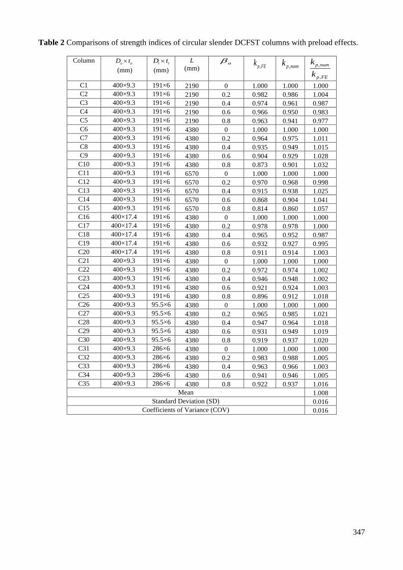
347
Table 2 Comparisons of strength indices of circular slender DCFST columns with preload effects.
Column o o
D t
(mm)
i iD t
(mm)
L
(mm) a
,p FEk ,p numk ,
,
p num
p FE
k
k
C1 400×9.3 191×6 2190 0 1.000 1.000 1.000
C2 400×9.3 191×6 2190 0.2 0.982 0.986 1.004
C3 400×9.3 191×6 2190 0.4 0.974 0.961 0.987
C4 400×9.3 191×6 2190 0.6 0.966 0.950 0.983
C5 400×9.3 191×6 2190 0.8 0.963 0.941 0.977
C6 400×9.3 191×6 4380 0 1.000 1.000 1.000
C7 400×9.3 191×6 4380 0.2 0.964 0.975 1.011
C8 400×9.3 191×6 4380 0.4 0.935 0.949 1.015
C9 400×9.3 191×6 4380 0.6 0.904 0.929 1.028
C10 400×9.3 191×6 4380 0.8 0.873 0.901 1.032
C11 400×9.3 191×6 6570 0 1.000 1.000 1.000
C12 400×9.3 191×6 6570 0.2 0.970 0.968 0.998
C13 400×9.3 191×6 6570 0.4 0.915 0.938 1.025
C14 400×9.3 191×6 6570 0.6 0.868 0.904 1.041
C15 400×9.3 191×6 6570 0.8 0.814 0.860 1.057
C16 400×17.4 191×6 4380 0 1.000 1.000 1.000
C17 400×17.4 191×6 4380 0.2 0.978 0.978 1.000
C18 400×17.4 191×6 4380 0.4 0.965 0.952 0.987
C19 400×17.4 191×6 4380 0.6 0.932 0.927 0.995
C20 400×17.4 191×6 4380 0.8 0.911 0.914 1.003
C21 400×9.3 191×6 4380 0 1.000 1.000 1.000
C22 400×9.3 191×6 4380 0.2 0.972 0.974 1.002
C23 400×9.3 191×6 4380 0.4 0.946 0.948 1.002
C24 400×9.3 191×6 4380 0.6 0.921 0.924 1.003
C25 400×9.3 191×6 4380 0.8 0.896 0.912 1.018
C26 400×9.3 95.5×6 4380 0 1.000 1.000 1.000
C27 400×9.3 95.5×6 4380 0.2 0.965 0.985 1.021
C28 400×9.3 95.5×6 4380 0.4 0.947 0.964 1.018
C29 400×9.3 95.5×6 4380 0.6 0.931 0.949 1.019
C30 400×9.3 95.5×6 4380 0.8 0.919 0.937 1.020
C31 400×9.3 286×6 4380 0 1.000 1.000 1.000
C32 400×9.3 286×6 4380 0.2 0.983 0.988 1.005
C33 400×9.3 286×6 4380 0.4 0.963 0.966 1.003
C34 400×9.3 286×6 4380 0.6 0.941 0.946 1.005
C35 400×9.3 286×6 4380 0.8 0.922 0.937 1.016
Mean 1.008
Standard Deviation (SD) 0.016
Coefficients of Variance (COV) 0.016

348
(a) (b) (c)
Fig. 1. Cross-section of circular concrete-filled steel tubular columns: (a) CFDST column, (b) CFST
column and (c) DCFST column.
Fig. 2. Typical discretization and strain distribution of circular CFDST beam-column.

349
Fig. 3. Typical stress-strain curves for confined and unconfined concrete.

350
(a) (b)
(c) (d)
(e) (f)
Fig. 4. Comparison of computational and experimental axial load-displacement curves for CFST
slender beam-columns with preload effects.
0
50
100
150
200
250
300
350
0 10 20 30 40
Test (A200)
Fiber element analysisAxi
al
Lo
ad
P(k
N)
Mid-height deflection um (mm)
0
100
200
300
0 10 20 30 40 50
Test (A204)
Fiber element analysis
Axi
al
Lo
ad
P(k
N)
Mid-height deflection um (mm)
0
100
200
300
400
0 10 20 30 40
Test (B122)
Fiber element analysisAxi
al
Lo
ad
P(k
N)
Mid-height deflection um (mm)
0
100
200
300
400
0 10 20 30 40
Test (B124)
Fiber element analysis
Axi
al
Lo
ad
P(k
N)
Mid-height deflection um (mm)
0
2000
4000
6000
0 10 20 30 40 50 60
Test (CFT-I-100-0P)
Fiber element analysisAxi
al
Lo
ad
P(k
N)
Mid-height deflection um (mm)
0
500
1000
1500
2000
2500
3000
3500
0 20 40 60 80 100
Test (CFT-L-40-30P)
Fiber element analysis
Axi
al
Lo
ad
P(k
N)
Mid-height deflection um (mm)

351
Fig. 5. Effects of preload ratio on the axial load-displacement curves of circular CFDST slender
columns.
0
1500
3000
4500
6000
7500
9000
0 50 100 150 200
Axi
al
Lo
ad
P
(kN
)
Mid-height deflection um (mm)
βa=0
βa=0.8
βa=0.6
βa=0.3

352
(a) 0a = (b) 0.3a =
(c) 0.6a = (d) 0.8a =
Fig. 6. Load-distributions in circular CFDST slender beam-columns with various preload ratios. (1-
CFDST column, 2- Outer steel tube, 3- Inner steel tube, 4- Sandwiched concrete and 5- Core
concrete)
-2000
0
2000
4000
6000
8000
10000
12000
0 50 100 150 200
Axi
al
Lo
ad
P
(kN
)
Mid-height deflection um (mm)
1 2 3
4 5
-2000
0
2000
4000
6000
8000
10000
0 50 100 150 200
Axi
al
Lo
ad
P
(kN
)
Mid-height deflection um (mm)
1 2 3
4 5
-2000
0
2000
4000
6000
8000
10000
0 50 100 150 200
Axi
al
Lo
ad
P
(kN
)
Mid-height deflection um (mm)
1 2 3
4 5
-2000
0
2000
4000
6000
8000
10000
0 50 100 150 200
Axi
al
Lo
ad
P
(kN
)
Mid-height deflection um (mm)
1 2 3
4 5

353
Fig. 7. Effects of / oe D ratio on the load-deflection curves of circular CFDST slender columns with
preloads on steel tubes.
0
3000
6000
9000
12000
15000
0 50 100 150 200 250
Axi
al
Lo
ad
P
(kN
)
Mid-height deflection um (mm)
e/Do = 0.1
e/Do = 0.4
e/Do = 0.3
e/Do = 0.2

354
(a) Outer steel tube (b) Inner steel tube
(c) Sandwiched concrete (d) Core concrete
Fig. 8. Influences of / oe D ratio on the load-deflection responses of components in circular CFDST
slender beam-columns.
-1000
0
1000
2000
3000
4000
0 50 100 150 200 250
Axi
al
Lo
ad
P
(kN
)
Mid-height deflection um (mm)
e/Do=0.4
e/Do=0.3
e/Do=0.2
e/Do=0.1
-1000
-500
0
500
1000
1500
2000
0 50 100 150 200 250 300Axi
al
Lo
ad
P
(kN
)
Mid-height deflection um (mm)
e/Do=0.4
e/Do=0.3
e/Do=0.2
e/Do=0.1
0
3000
6000
9000
0 50 100 150 200 250
Axi
al
Lo
ad
P
(kN
)
Mid-height deflection um (mm)
e/Do=0.4
e/Do=0.3
e/Do=0.2
e/Do=0.1
0
300
600
900
1200
0 50 100 150 200 250 300
Axi
al
Lo
ad
P
(kN
)
Mid-height deflection um (mm)
e/Do=0.1
e/Do=0.4
e/Do=0.3
e/Do=0.2

355
Fig. 9. Load contribution rate of the components in circular CFDST columns with various / oe D
ratios (1- Outer steel tube, 2- Inner steel tube, 3- Sandwiched concrete and 4- Core concrete).
Fig. 10. Effects of / oe D and preload ratios on the ultimate axial loads of circular CFDST slender
columns.
0
20
40
60
80
100
0 0.1 0.2 0.3 0.4 0.5
Lo
ad
Co
ntr
ibu
tio
n
(%)
Eccentricity ratio e/Do
1 2 3 4
0
4000
8000
12000
16000
20000
0 0.5 1 1.5 2
Eccentricity ratio e/Do
Ult
imate
axi
al
load
Pu
(kN
) βa=0
βa=0.8

356
Fig. 11. Effects of /L r ratio on the load-deflection curves of circular CFDST slender columns with
preloads on the steel tubes.
0
2000
4000
6000
8000
10000
12000
0 50 100 150 200 250 300 350 400
Axi
al
Lo
ad
P
(kN
)
Mid-height deflection um (mm)
L/r =22
L/r =90
L/r =70
L/r =50

357
(a) Outer steel tube (b) Inner steel tube
(c) Sandwiched concrete (d) Core concrete
Fig. 12. Influences of /L r ratio on the load-deflection responses of components in circular CFDST
slender beam-columns.
-1000
-500
0
500
1000
1500
2000
0 50 100 150 200 250 300 350 400Axi
al
Lo
ad
P
(kN
)
Mid-height deflection um (mm)
L/r =22
L/r =90
L/r =70
L/r =50
-1000
-500
0
500
1000
1500
0 50 100 150 200 250 300
Axi
al
Lo
ad
P
(kN
)
Mid-height deflection um (mm)
L/r =22
L/r =90
L/r =70
L/r =50
0
1000
2000
3000
4000
5000
6000
7000
8000
0 100 200 300 400 500
Axi
al
Lo
ad
P
(kN
)
Mid-height deflection um (mm)
L/r =22
L/r =90
L/r =70
L/r =50
0
200
400
600
800
1000
1200
0 50 100 150 200 250 300 350 400
Axi
al
Lo
ad
P
(kN
)
Mid-height deflection um (mm)
L/r =22
L/r =90
L/r =70
L/r =50

358
Fig. 13. Effects of /L r and preload ratios on the column strength curves of circular CFDST
columns.
Fig. 14. Effects of /i oD D ratio on the load-deflection curves of circular CFDST slender columns
with preloads on the steel tubes.
0
2000
4000
6000
8000
10000
12000
14000
0 20 40 60 80 100 120 140
Slenderness ratio L/r
Ult
imate
axi
al
load
Pu
(kN
)
βa=0.8
βa=0.4
βa=0
0
2000
4000
6000
8000
10000
0 50 100 150 200 250
Axi
al
Lo
ad
P
(kN
)
Mid-height deflection um (mm)
Di / Do =0.33
Di / Do =0.44
Di / Do =0.55
Di / Do =0.66

359
Fig. 15. Effects of /i oD D ratio on the strength curves of circular CFDST columns with preloads on
the steel tubes.
Fig. 16. Effects of /i oD D and preload ratios on the strength curves of circular CFDST slender
columns.
0
2000
4000
6000
8000
10000
12000
14000
0 20 40 60 80 100 120 140
Slenderness ratio L/r
Ult
imate
axi
al
load
Pu
(kN
)
Di / Do =0.66
Di / Do =0.55
Di / Do =0.44
Di / Do =0.33
0
2000
4000
6000
8000
10000
0 0.2 0.4 0.6 0.8
βa=0
βa=0.8
Di / Do
Ult
imate
axi
al
load
Pu
(kN
)

360
Fig. 17. Effects of /o oD t ratio on the load-deflection curves of circular CFDST slender columns
with preloads on the steel tubes.
Fig. 18. Effects of /o oD t ratio the strength curves of circular CFDST columns with preloads on the
steel tubes.
0
4000
8000
12000
16000
20000
0 50 100 150 200 250 300
Axi
al
Lo
ad
P
(kN
)
Mid-height deflection um (mm)
Do / to =20
Do / to =80
Do / to =60
Do / to =40
0
5000
10000
15000
20000
25000
0 20 40 60 80 100 120 140
Slenderness ratio L/r
Ult
imate
axi
al
load
Pu
(kN
)
Do / to =80
Do / to =60
Do / to =40
Do / to =20

361
Fig. 19. Effects of /o oD t and preload ratios on the strengths of circular CFDST slender columns.
Fig. 20. Effects of /i iD t ratio on the load-deflection curves of circular CFDST slender columns
with preloads on the steel tubes.
0
2000
4000
6000
8000
10000
12000
14000
16000
0 20 40 60 80 100
Ult
imate
axi
al
load
Pu
(kN
)
βa=0
βa=0.8
Do / to
0
2000
4000
6000
8000
0 50 100 150 200
Axi
al
Lo
ad
P
(kN
)
Mid-height deflection um (mm)
Di / ti =20
Di / ti =50
Di / ti =40
Di / ti =30

362
Fig. 21. Effects of /i iD t and preload ratios on the strengths of circular CFDST slender columns.
Fig. 22. Effects of concrete compressive strength on the load-deflection curves of circular CFDST
slender columns with preloads on the steel tubes.
0
2000
4000
6000
8000
10000
0 10 20 30 40 50 60
Ult
imate
axi
al
load
Pu
(kN
)
βa=0
βa=0.8
Di / ti
0
2000
4000
6000
8000
10000
0 50 100 150 200
Axi
al
Lo
ad
P
(kN
)
Mid-height deflection um (mm)
'
'
'
'
40 MPa
60 MPa
80 MPa
100 MPa
c
c
c
c
f
f
f
f
=
=
=
=

363
Fig. 23. Effects of concrete compressive strength on the strength curves of circular CFDST columns
with preloads on the steel tubes.
Fig. 24. Effects of concrete compressive strength and preloads on the strengths of circular CFDST
slender columns.
0
2000
4000
6000
8000
10000
12000
14000
16000
0 20 40 60 80 100 120 140
Slenderness ratio L/r
Ult
imate
axi
al
load
Pu
(kN
)
'
'
'
'
40 MPa
60 MPa
80 MPa
100 MPa
c
c
c
c
f
f
f
f
=
=
=
=
0
2000
4000
6000
8000
10000
12000
0 20 40 60 80 100 120 140
βa=0
βa=0.8
Ult
imate
axi
al
load
Pu
(kN
)
' (MPa)cf

364
Fig. 25. Effects of steel yield strength on the load-deflection curves of circular CFDST slender
columns with preloads on the steel tubes.
Fig. 26. Effects of steel yield strength on the strength curves of circular CFDST columns with
preloads on the steel tubes.
0
2000
4000
6000
8000
10000
0 50 100 150 200 250
Axi
al
Lo
ad
P
(kN
)
Mid-height deflection um (mm)
fsy =450 MPa
fsy =350 MPa
fsy =250 MPa
fsy =550 MPa
0
2000
4000
6000
8000
10000
12000
14000
16000
0 20 40 60 80 100 120 140
Slenderness ratio L/r
Ult
imate
axi
al
load
Pu
(kN
)
fsy =250 MPa
fsy =350 MPa
fsy =450 MPa
fsy =550 MPa

365
Fig. 27. Effects of steel yield strength and preloads on the strengths of circular CFDST slender
columns.
Fig. 28. Effects of concrete confinement on the load-deflection curves of circular CFDST slender
column with preloads on the steel tubes.
0
2000
4000
6000
8000
10000
12000
0 100 200 300 400 500 600
βa=0
βa=0.8
fsy (MPa)
Ult
imate
axi
al
load
Pu
(kN
)
0
2000
4000
6000
8000
10000
12000
14000
16000
0 20 40 60 80 100 120 140
Axi
al
Lo
ad
P
(kN
)
Mid-height deflection um (mm)
Confinement effect ignored
Confinement effect considered

366
Fig. 29. Effects of concrete confinement on the strength curves of circular CFDST columns with
preloads on the steel tubes.
0
4000
8000
12000
16000
20000
0 20 40 60 80 100 120 140
Slenderness ratio L/r
Confinement effect ignored
Confinement effect considered
Ult
imate
axi
al
load
Pu
(kN
)

Chapter 7 CFDST Slender Columns with Preload Effects
M. Ahmed: Experimental and Numerical Studies of Concrete-Filled Double Steel Tubular Columns
7.2 CONCLUDING REMARKS
This chapter has described the computer modeling, performance and structural design of
slender square and circular CFST columns composed of an internal circular steel tube
where the steel tubes are preloaded before concrete filling. The mathematical models have
considered the interaction of local and global buckling in square CFDST columns,
deformation induced by the preload, concrete confinement by the circular steel tube,
geometric imperfections, and material nonlinearities. The computer modeling techniques
developed have been demonstrated to accurately capture the experimentally measured
load-deflection responses, and to efficiently generate the column strength curves and load
distributions in concrete and steel components of slender CFDST columns having
preloads. Computational results obtained from the parametric studies have indicated that
significant preloads may remarkably reduce the performance of slender CFDST columns
and must be accounted for in the nonlinear modeling and design of such composite
columns. Design equations proposed have shown to yield good strength estimations of
concentrically loaded CFDST slender columns subjected to preloads on the steel tubes.
mizan
Typewritten Text
367

Chapter 8: Conclusions
M. Ahmed: Experimental and Numerical Studies of Concrete-Filled Double Steel Tubular Columns 368
Chapter 8
CONCLUSIONS
8.1 SUMMARY
This thesis has presented experimental and numerical investigations on the behavior of
rectangular and circular CFDST columns composed of either a rectangular inner steel
tube or a circular inner steel tube. Experimental programs on axially and eccentrically
loaded CFDST short columns have been conducted to investigate the influences of the
application of loading (axial or eccentric), cross-sections, geometric properties and
loading eccentricity on the failure patterns, ultimate strengths, strain distributions and
axial and lateral responses of CFDST columns. Computational models underlying the
theory of fiber elements have been developed for the response analysis of CFDST short
and slender columns under various loading conditions, incorporating the effects of
concrete confinement, local buckling of the rectangular outer tube, second-order,
geometric and material nonlinearities and preloads on the steel tubes. Based on the
existing test results, new lateral pressure models and strength degradation parameters for
the confined concrete have been derived and incorporated in the computational models.
New efficient computational algorithms underlying the inverse quadratic method have
also been developed to solve the dynamic nonlinear equilibrium functions of short and
slender CFDST columns loaded eccentrically. The computational modeling methods have

Chapter 8: Conclusions
M. Ahmed: Experimental and Numerical Studies of Concrete-Filled Double Steel Tubular Columns 369
been validated against the test data. The verified mathematical models have been utilized
to investigate the responses of short and slender CFDST columns. Design models have
been proposed for determining the ultimate strengths of CFDST short and slender
columns under various loading conditions.
8.2 ACHIEVEMENTS
This research project has made significant contributions to the field of CFDST columns.
The significant research achievements of this research work are summarized as follows:
1. The presented experimental results on circular, square and rectangular CFDST
short columns under concentric and eccentric loading provide useful insights into
the understanding of the structural behavior of such columns. The test data
obtained can be used by other researchers to validate their numerical models of
CFDST columns.
2. Proposed new confinement models and strength degradation factors for core
concrete in circular CFDST columns as well as for core concrete in square CFDST
columns with an inner circular tube. The confinement models proposed yield more
accurate results than existing models which were modified from those proposed
for conventional CFST columns.
3. Developed fiber-based numerical models for circular, square and rectangular
CFDST short columns under concentric and eccentric loading. The numerical
models developed incorporate the local buckling of the outer steel tube, concrete
confinement, and material nonlinearities. The fiber models developed are accurate
and cost-effective design tools for design engineers.

Chapter 8: Conclusions
M. Ahmed: Experimental and Numerical Studies of Concrete-Filled Double Steel Tubular Columns 370
4. Developed computational models for circular and square CFDST slender beam-
columns under axial load and bending considering the influences of confinement,
the interaction of local-global buckling and second-order. Efficient solution
algorithms were developed to solve nonlinear equilibrium functions. The accuracy
of the computational models was validated against the independent test results.
5. Developed mathematical models for eccentrically loaded square and circular
CFDST slender columns incorporating preload effects, the local buckling of the
outer steel tube and confinement provided by the steel tube.
6. Proposed a set of design models for the design of CFDST short and slender
columns. The design models for conventional CFST short columns originally
proposed by Liang and Fragomeni (2009) were modified for the design of CFDST
columns composed of circular and square cross-sections whereas design equations
given by Eurocode 4 (2004) were modified to propose the design models for
CFDST slender columns under axial loading. These design models can be used
by practicing design engineers in the design of CFDST columns.
8.3 FURTHER RESEARCH
This thesis focuses on experimental and numerical studies on the fundamental behavior
of CFDST short and slender columns under various loads, including axial compression,
eccentric loading and preloads. However, further tests are still required to fully
understand their behavior and numerical models should be developed for CFDST

Chapter 8: Conclusions
M. Ahmed: Experimental and Numerical Studies of Concrete-Filled Double Steel Tubular Columns 371
columns under other loading conditions. The following research studies on CFDST
columns are recommended:
1. Tests on eccentrically loaded slender circular and rectangular CFDST columns
are very limited. Therefore, further tests on slender CFDST columns that are
loaded eccentrically should be carried out to investigate their behavior.
2. Tests on slender CFDST columns having preloads are absent in the literature.
Hence, the experimental program should be carried out to examine the structural
performance of eccentrically loaded CFDST slender columns with preload
effects.
3. Tests on CFDST short and slender columns under dynamic loading (e.g. cyclic,
impact loading) have not been performed. However, CFDST columns may be
subjected to cyclic loading in the seismic active regions or subjected to impact
loading caused by the vehicle collision or terrorist attacks or by the flying debris
from the nearby explosions. Therefore, influences of dynamic loadings on the
responses of such columns should be experimentally investigated.
4. Fiber-based numerical models for eccentrically loaded CFDST slender columns
under cyclic or impact loading have not been developed. Therefore, further
research should be conducted to extend the developed numerical models to
CFDST columns under cyclic and impact loading considering the influences of
concrete confinement, geometric imperfection, and local buckling.
5. The numerical models developed in this research project are only applicable to
CFDST columns made of carbon steel. The behavior of stainless-steel is different
from that of carbon steel owing to the distinguished strain-hardening

Chapter 8: Conclusions
M. Ahmed: Experimental and Numerical Studies of Concrete-Filled Double Steel Tubular Columns 372
characteristics of stainless steel. Therefore, further research should be performed
on CFDST columns made of stainless steel.
6. The CFDST columns used in high-rise composite buildings are likely exposed to
fire. Therefore, further experimental and numerical studies on CFDST columns
at elevated temperatures should be conducted.

References
M. Ahmed: Experimental and Numerical Studies of Concrete-Filled Double Steel Tubular Columns 373
REFERENCES
Abdella, K., Tahannon, R. A., Mehri, A. I. and Alshaikh, F. A. (2011). "Inversion of
three-stage stress–strain relation for stainless steel in tension and compression."
Journal of Constructional Steel Research, 67(5), 826-832.
ACI 318-02. (2002). Building Code Requirements for Structural Concrete and
Commentary. Detroit, MI, USA: American Concrete Institute.
ACI 318-05. (2005). Building Code Requirements for Structural Concrete and
Commentary. Detroit, MI, USA: American Concrete Institute.
AISC 360-05. (2005). Specification for Structural Steel Buildings. Chicago, IL, USA:
American Institution of Steel Construction.
AISC 360-16. (2016). Specification for Structural Steel Buildings. Chicago, IL, USA:
American Institution of Steel Construction.
AS 3600. (1994). Australian Standard for Concrete Structures. Sydney, New South
Wales, Australia: Standards Australia..
AS 3600. (2009). Australian Standard for Concrete Structures. Sydney, New South
Wales, Australia: Standards Australia.
References
M. Ahmed: Experimental and Numerical Studies of Concrete-Filled Double Steel Tubular Columns 374
AS/NZS 2327:2017. (2017). Australian/New Zealand Standard for Composite
Structures- Composite Steel-Concrete Construction in Buildings. Sydney, New
South Wales, Australia: Standards Australia and Standards New Zealand.
Azhari, M. and Bradford, M. A. (1991). "Buckling modes using a complex finite strip
method." School of Civil Engineering, University of New South Wales, Sydney,
Australia, Reseach Report No. R291.
Bedair, O. (2009). "Analytical effective width equations for limit state design of thin
plates under non-homogeneous in-plane loading." Archive of Applied Mechanics,
79(12), 1173-1189.
Bedair, O. (2010). "Stability analysis of plates with partial restraints using unconstrained
optimization techniques." International Journal of Structural Stability and
Dynamics, 10(03), 571-587.
Bradford, M. A. (1985a). "Local and post-local buckling of fabricated box members."
Civil Engineering Transactions, Institution of Engineers Australia, 27 (4): 391-6.
Bradford, M. A. (1985b). "Distortional buckling of monosymmetric I-beams." Journal of
Constructional Steel Research, 5(2), 123-136.
Bradford, M. A. and Cuk, P. E. (1988). "Elastic buckling of tapered monosymmetric I-
beams." Journal of Structural Engineering, ASCE, 114(5), 977-996.

References
M. Ahmed: Experimental and Numerical Studies of Concrete-Filled Double Steel Tubular Columns 375
Bradford, M. A. and Hancock, G. J. (1984). "Elastic interaction of local and lateral
buckling in beams." Thin-Walled Structures, 2(1), 1-25.
Bradford, M. A. and Wong, T. (1991). "Local buckling of composite box girders under
negative bending". School of Civil Engineering, University of New South Wales,
Sydney, Australia, Reseach Report No. R292.
Bridge, R. Q. (1976). Concrete filled steel tubular columns. School of Civil Engineering,
The University of Sydney, Sydney, Australia. Research Report No. R283.
Bridge, R. Q. and O'Shea, M. D. (1998). "Behaviour of thin-walled steel box sections
with or without internal restraint." Journal of Constructional Steel Research,
47(1), 73-91.
Bryan, G. H. (1890). "On the stability of a plane plate under thrusts in its own plane, with
applications to the buckling of the sides of a ship." Proceedings of the London
Mathematical Society, 1(1), 54-67.
BS 5400 (1979). British Standard for Steel, Concrete and Composite Bridges: Part: 5
Code of Practice For Design of Composite Bridges. London, United Kingdom,
British Standards Institution.
Bulson, P. S. (1969). The Stability of Flat Plates. Netherland, Elsevier.

References
M. Ahmed: Experimental and Numerical Studies of Concrete-Filled Double Steel Tubular Columns 376
Chang, X., Ru, Z. L., Zhou, W. and Zhang, Y. B. (2013). "Study on concrete-filled
stainless steel–carbon steel tubular (CFSCT) stub columns under compression."
Thin-Walled Structures, 63, 125-133.
Chilver, A. (1953). "A generalised approach to the local instability of certain thin-walled
struts." The Aeronautical Quarterly, 4(3), 245-260.
Couto, C., Real, P. V., Lopes, N. and Zhao, B. (2014). "Effective width method to account
for the local buckling of steel thin plates at elevated temperatures." Thin-Walled
Structures, 84, 134-149.
DBJ/T 13-51. (2010). Technical Specification for Concrete-filled Steel Tubular
Structures. Fuzhou, China, The Department of Housing and Urban–Rural
Development of Fujian Province (in Chinese).
Ekmekyapar, T. and Al-Eliwi, B. J. (2017). "Concrete filled double circular steel tube
(CFDCST) stub columns." Engineering Structures, 135, 68-80.
Elchalakani, M., Zhao, X.-L. and Grzebieta, R. (2002). "Tests on concrete filled double-
skin (CHS outer and SHS inner) composite short columns under axial
compression." Thin-Walled Structures, 40(5), 415-441.

References
M. Ahmed: Experimental and Numerical Studies of Concrete-Filled Double Steel Tubular Columns 377
Ellobody, E., Young, B. and Lam, D. (2006). "Behaviour of normal and high strength
concrete-filled compact steel tube circular stub columns." Journal of
Constructional Steel Research, 62(7), 706-715.
Eurocode 4 (1994). Design of Composite Steel and Concrete Structures, Part 1.1 General
Rules and Rules for Buildings. European Committee for Standardization, CEN,
London, UK.
Eurocode 4 (2004). Design of Composite Steel and Concrete Structures, Part 1.1 General
Rules and Rules for Buildings. European Committee for Standardization, CEN,
Brussels, Belgium.
Fujimoto, T., Mukai, A., Nishiyama, I. and Sakino, K. (2004). "Behavior of eccentrically
loaded concrete-filled steel tubular columns." Journal of Structural Engineering,
ASCE, 130(2), 203-212.
Furlong, R. W. (1967). "Strength of steel-encased concrete beam columns." Journal of
the Structural Division, ASCE, 93(5), 113-124.
Gerard, G. and Becker, H. (1957). Handbook of Structural Stability: Failure of Plates
and Composite Elements, National Advisory Committee for Aeronautics.
Giakoumelis, G. and Lam, D. (2004). "Axial capacity of circular concrete-filled tube
columns." Journal of Constructional Steel Research, 60(7), 1049-1068.

References
M. Ahmed: Experimental and Numerical Studies of Concrete-Filled Double Steel Tubular Columns 378
Han, L. H. (2002). "Tests on stub columns of concrete-filled RHS sections." Journal of
Constructional Steel Research, 58(3), 353-372.
Han, L. H. (2007). Concrete Filled Steel Tube Structures-Theory and Application.
Beijing, China, Science Press.
Han, L.-H. and Huo, J.-S. (2003). "Concrete-filled hollow structural steel columns after
exposure to ISO-834 fire standard." Journal of Structural Engineering, ASCE,
129(1), 68-78.
Han, L.-H., Lam, D. and Nethercot, D. A. (2018). Design Guide for Concrete-filled
Double Skin Steel Tubular Structures. London, UK, CRC Press, Taylor and
Francis Group.
Han, L. H., Ren, Q. X. and Li, W. (2011). "Tests on stub stainless steel–concrete–carbon
steel double-skin tubular (DST) columns." Journal of Constructional Steel
Research, 67(3), 437-452.
Han, L.-H. and Yao, G.-H. (2003). "Behaviour of concrete-filled hollow structural steel
(HSS) columns with pre-load on the steel tubes." Journal of Constructional Steel
Research, 59(12), 1455-1475.

References
M. Ahmed: Experimental and Numerical Studies of Concrete-Filled Double Steel Tubular Columns 379
Han, L.-H., Zhao, X.-L. and Tao, Z. (2001). "Tests and mechanics model for concrete-
filled SHS stub columns, columns and beam-columns." Steel and Composite
Structures, 1(1), 51-74.
Hassanein, M., Elchalakani, M., Karrech, A., Patel, V. and Yang, B. (2018). "Behaviour
of concrete-filled double-skin short columns under compression through finite
element modelling: Shs outer and shs inner tubes." Structures, 14, 358-375.
Hassanein, M. F. and Kharoob, O. F. (2014). "Compressive strength of circular concrete-
filled double skin tubular short columns." Thin-Walled Structures, 77, 165-173.
Hassanein, M. F., Kharoob, O. F. and Gardner, L. (2015). "Behaviour and design of
square concrete-filled double skin tubular columns with inner circular tubes."
Engineering Structures, 100, 410-424.
Hassanein, M. F., Kharoob, O. F. and Liang, Q. Q. (2013a). "Behaviour of circular
concrete-filled lean duplex stainless steel–carbon steel tubular short columns."
Engineering Structures, 56, 83-94.
Hassanein, M. F., Kharoob, O. F. and Liang, Q. Q. (2013b). "Circular concrete-filled
double skin tubular short columns with external stainless steel tubes under axial
compression." Thin-Walled Structures, 73, 252-263.

References
M. Ahmed: Experimental and Numerical Studies of Concrete-Filled Double Steel Tubular Columns 380
Heidarpour, A. and Bradford, M. A. (2007). "Local buckling and slenderness limits for
flange outstands at elevated temperatures." Journal of Constructional Steel
Research, 63(5), 591-598.
Heidarpour, A. and Bradford, M. A. (2008). "Local buckling and slenderness limits for
steel webs under combined bending, compression and shear at elevated
temperatures." Thin-Walled Structures, 46(2), 128-146.
Hu, H.-T., Huang, C.-S., Wu, M.-H. and Wu, Y.-M. (2003). "Nonlinear analysis of axially
loaded concrete-filled tube columns with confinement effect." Journal of
Structural Engineering, ASCE, 129(10), 1322-1329.
Hu, H.-T. and Su, F.-C. (2011). "Nonlinear analysis of short concrete-filled double skin
tube columns subjected to axial compressive forces." Marine Structures, 24(4),
319-337.
Huang, H., Han, L. H., Tao, Z. and Zhao, X. L. (2010). "Analytical behaviour of concrete-
filled double skin steel tubular (CFDST) stub columns." Journal of Constructional
Steel Research, 66(4), 542-555.
Huang, Z., Li, D., Uy, B., Thai, H.-T. and Hou, C. (2019). "Local and post-local buckling
of fabricated high-strength steel and composite columns." Journal of
Constructional Steel Research, 154, 235-249.

References
M. Ahmed: Experimental and Numerical Studies of Concrete-Filled Double Steel Tubular Columns 381
Huang, F., Yu, X., Chen, B. and Li, J. (2016). "Study on preloading reduction of ultimate
load of circular concrete-filled steel tubular columns." Thin-Walled Structures,
98, 454-464.
Kapur, K. K. and Hartz, B. J. (1966). "Stability of plates using the finite element method."
Journal of the Engineering Mechanics Division, 92(2), 177-196.
Katwal, U., Tao, Z., Hassan Md, K. and Wang, W.-D. (2017). "Simplified Numerical
Modeling of Axially Loaded Circular Concrete-Filled Steel Stub Columns."
Journal of Structural Engineering, ASCE, 143(12), 04017169.
KBCS (2009). Korean Building Code- Structure. Seoul, Korea: Architectural Institute of
Korea.
Kloppel, V. and Goder, W. (1957). "An investigation of the load carrying capacity of
concrete-filled steel tubes and development of design formula." Der Stahlbau,
26(2), 44-50.
Knobloch, M. and Fontana, M. (2006). "Strain-based approach to local buckling of steel
sections subjected to fire." Journal of Constructional Steel Research, 62(1-2), 44-
67.
Knowles, R. B. and Park, R. (1969). "Strength of concrete filled steel columns." Journal
of the Structural Division, ASCE, 95(12), 2565-2587.

References
M. Ahmed: Experimental and Numerical Studies of Concrete-Filled Double Steel Tubular Columns 382
Knowles, R. B. and Park, R. (1970). "Axial load design for concrete filled steel tubes."
Journal of the Structural Division, ASCE, 96(10), 2125-2153.
Lee, S.-H., Uy, B., Kim, S.-H., Choi, Y.-H. and Choi, S.-M. (2011). "Behavior of high-
strength circular concrete-filled steel tubular (CFST) column under eccentric
loading." Journal of Constructional Steel Research, 67(1), 1-13.
Li, W., Han, L. H. and Chan, T. M. (2014). "Tensile behaviour of concrete-filled double-
skin steel tubular members." Journal of Constructional Steel Research, 99, 35-46.
Li, W., Han, L.-H. and Zhao, X.-L. (2012). "Axial strength of concrete-filled double skin
steel tubular (CFDST) columns with preload on steel tubes." Thin-Walled
Structures, 56, 9-20.
Li, Y., Li, G., Hou, C. and Zhang, W.-J. (2019). "Long-term experimental behavior of
concrete-encased CFST with preload on the inner CFST." Journal of
Constructional Steel Research, 155, 355-369.
Liang, Q. Q. (2009a). "Performance-based analysis of concrete-filled steel tubular beam–
columns, Part I: Theory and algorithms." Journal of Constructional Steel
Research, 65(2), 363-372.

References
M. Ahmed: Experimental and Numerical Studies of Concrete-Filled Double Steel Tubular Columns 383
Liang, Q. Q. (2009b). "Performance-based analysis of concrete-filled steel tubular beam–
columns, Part II: Verification and applications." Journal of Constructional Steel
Research, 65(2), 351-362.
Liang, Q. Q. (2011a). "High strength circular concrete-filled steel tubular slender beam–
columns, Part I: Numerical analysis." Journal of Constructional Steel Research,
67(2), 164-171.
Liang, Q. Q. (2011b). "High strength circular concrete-filled steel tubular slender beam–
columns, Part II: Fundamental behavior." Journal of Constructional Steel
Research, 67(2), 172-180.
Liang, Q. Q. (2014). Analysis and Design of Steel and Composite Structures. Boca Raton
FL, USA and London, UK, CRC Press, Taylor and Francis Group.
Liang, Q. Q. (2017). "Nonlinear analysis of circular double-skin concrete-filled steel
tubular columns under axial compression." Engineering Structures, 131, 639-650.
Liang, Q. Q. (2018). "Numerical simulation of high strength circular double-skin
concrete-filled steel tubular slender columns." Engineering Structures, 168, 205-
217.

References
M. Ahmed: Experimental and Numerical Studies of Concrete-Filled Double Steel Tubular Columns 384
Liang, Q. Q. and Fragomeni, S. (2009). "Nonlinear analysis of circular concrete-filled
steel tubular short columns under axial loading." Journal of Constructional Steel
Research, 65(12), 2186-2196.
Liang, Q. Q. and Fragomeni, S. (2010). "Nonlinear analysis of circular concrete-filled
steel tubular short columns under eccentric loading." Journal of Constructional
Steel Research, 66(2), 159-169.
Liang, Q. Q., Patel, V. I. and Hadi, M. N. S. (2012). "Biaxially loaded high-strength
concrete-filled steel tubular slender beam-columns, Part I: Multiscale simulation."
Journal of Constructional Steel Research, 75, 64-71.
Liang, Q. Q. and Uy, B. (1998). "Parametric study on the structural behaviour of steel
plates in concrete-filled fabricated thin-walled box columns." Advances in
Structural Engineering, 2(1), 57-71.
Liang, Q. Q. and Uy, B. (2000). "Theoretical study on the post-local buckling of steel
plates in concrete-filled box columns." Computers & Structures, 75(5), 479-490.
Liang, Q. Q., Uy, B. and Liew, J. R. (2006). "Nonlinear analysis of concrete-filled thin-
walled steel box columns with local buckling effects." Journal of Constructional
Steel Research, 62(6), 581-591.

References
M. Ahmed: Experimental and Numerical Studies of Concrete-Filled Double Steel Tubular Columns 385
Liang, Q. Q., Uy, B. and Liew, J. Y. R. (2007). "Local buckling of steel plates in concrete-
filled thin-walled steel tubular beam–columns." Journal of Constructional Steel
Research, 63(3), 396-405.
Liang, Q. Q., Uy, B., Wright, H. D. and Bradford, M. A. (2003). "Local and post-local
buckling of double skin composite panels." Structures and Buildings, Proceedings
of the Institution of Civil Engineers, 156(2), 111-119.
Liang, Q. Q., Uy, B., Wright, H. D. and Bradford, M. A. (2004). "Local buckling of steel
plates in double skin composite panels under biaxial compression and shear."
Journal of Structural Engineering, ASCE, 130(3), 443-451.
Liew, J. Y. R. and Xiong, D. X. (2009). "Effect of preload on the axial capacity of
concrete-filled composite columns." Journal of Constructional Steel Research,
65(3), 709-722.
Lundquist, E. and Stowell, E. (1939). "Local instability of columns with I, Z, channel and
rectangular tube sections." Langley Memorial Aeronautical Laboratory. Research
Report No. NACA TN, 722.
Lundquist, E. E., Stowell, E. Z. and Schuette, E. H. (1943). "Principles of moment
distribution applied to stability of structures composed of bars or plates." National
Advisory Committee for Aeronautics.

References
M. Ahmed: Experimental and Numerical Studies of Concrete-Filled Double Steel Tubular Columns 386
Maas, C. J. V. D. (1954). "Charts for the calculation of the critical compressive stress for
local instability of columns with hat sections." Journal of the Aeronautical
Sciences, 21(6), 399-403.
Marguerre K. (1938). Zur Theorie der gekrummten Platte grosser Formanderung, In
Proceedings of the fifth international congress for applied mechanics, pp. 93–101.
Mursi, M. and Uy, B. (2003). "Strength of concrete filled steel box columns incorporating
interaction buckling." Journal of Structural Engineering, ASCE, 129(5), 626-639.
Mursi, M. and Uy, B. (2004). "Strength of slender concrete filled high strength steel box
columns." Journal of Constructional Steel Research, 60(12), 1825-1848.
Oehlers, D. J. and Bradford, M. A. (1999). Elementary Behaviour of Composite Steel and
Concrete Structural Members. Oxford, London, UK, Butterworth-Heinemann.
O'Shea, M. D. and Bridge, R. Q. (2000). "Design of circular thin-walled concrete filled
steel tubes." Journal of Structural Engineering, ASCE, 126(11), 1295-1303.
Pagoulatou, M., Sheehan, T., Dai, X. and Lam, D. (2014). "Finite element analysis on the
capacity of circular concrete-filled double-skin steel tubular (CFDST) stub
columns." Engineering Structures, 72, 102-112.

References
M. Ahmed: Experimental and Numerical Studies of Concrete-Filled Double Steel Tubular Columns 387
Patel, V. I., Liang, Q. Q. and Hadi, M. N. S (2013). "Numerical analysis of circular
concrete-filled steel tubular slender beam-columns with preload effects."
International Journal of Structural Stability and Dynamics, 13(03), 1250065.
Patel, V. I., Liang, Q. Q. and Hadi, M. N. S (2014). "Behavior of biaxially-loaded
rectangular concrete-filled steel tubular slender beam-columns with preload
effects." Thin-Walled Structures, 79, 166-177.
Patel, V. I., Liang, Q. Q. and Hadi, M. N. S. (2015a). Nonlinear Analysis of Concrete-
filled Steel Tubular Columns, Germany, Scholar’s Press.
Patel, V. I., Liang, Q. Q. and Hadi, M. N. S. (2015b). "Biaxially loaded high-strength
concrete-filled steel tubular slender beam-columns, Part II: Parametric study."
Journal of Constructional Steel Research, 110, 200-207.
Patel, V. I., Liang, Q. Q. and Hadi, M. N. S. (2017a). "Nonlinear analysis of circular high
strength concrete-filled stainless steel tubular slender beam-columns."
Engineering Structures, 130, 1-13.
Patel, V. I., Liang, Q. Q. and Hadi, M. N. S. (2017b). "Nonlinear analysis of biaxially
loaded rectangular concrete-filled stainless steel tubular slender beam-columns."
Engineering Structures, 140, 120-133.

References
M. Ahmed: Experimental and Numerical Studies of Concrete-Filled Double Steel Tubular Columns 388
Patel, V. I., Liang, Q. Q. and Hadi, M. N. S. (2018). Concrete-filled Stainless Steel
Tubular Columns. Boca Raton FL, USA and London, UK, CRC Press, Taylor and
Francis Group.
Patel, V. I., Liang, Q. Q. and Hadi, M. N. S. (2020). "Numerical simulations of circular
high strength concrete-filled aluminum tubular short columns incorporating new
concrete confinement model." Thin-Walled Structures, 147, 106492.
Pei, W. J. (2005). Research on Mechanical Performance of Multibarrel Tube-confined
Concrete Columns. ME Thesis, Chang’an University, China (in Chinese).
Peng, Y. Y., Tan, K. F. and Yao, Y. (2011). "Mechanical properties of duplex steel tube
high- strength concrete short columns under axial compression." Journal of
Wuhan University of Technology, 33(2), 105-109 (In Chinese).
Portolés, J. M., Romero, M. L., Bonet, J. L. and Filippou, F. C. (2011). "Experimental
study of high strength concrete-filled circular tubular columns under eccentric
loading." Journal of Constructional Steel Research, 67(4), 623-633.
Przemieniecki, J. S. (1963). "Matrix structural analysis of substructures." AIAA Journal,
1(1), 138-147.
Przemieniecki, J. S. (1968). "Discrete-element methods for stability analysis of complex
structures." The Aeronautical Journal, 72(696), 1077-1086.

References
M. Ahmed: Experimental and Numerical Studies of Concrete-Filled Double Steel Tubular Columns 389
Qian, J., Li, N., Ji, X. and Zhao, Z. (2014). "Experimental study on the seismic behavior
of high strength concrete filled double-tube columns." Earthquake Engineering
and Engineering Vibration, 13(1), 47-57 (in Chinese).
Qian, J., Zhang, Y., Ji, X. and Cao, W. (2011). "Test and analysis of axial compressive
behavior of short composite-sectioned high strength concrete filled steel tubular
columns." Journal of Building Structures, 32(12), 162-169 (in Chinese).
Quach, W., Teng, J. G. and Chung, K. (2008). "Three-stage full-range stress-strain model
for stainless steels." Journal of Structural Engineering, ASCE, 134(9), 1518-1527.
Quiel, S. E. and Garlock, M. E. (2010). "Calculating the buckling strength of steel plates
exposed to fire." Thin-Walled Structures, 48(9), 684-695.
Ragheb, W. F. (2015). "Local buckling of welded steel I-beams considering flange–web
interaction." Thin-Walled Structures, 97, 241-249.
Ragheb, W. F. (2016). "Estimating the local buckling capacity of structural steel I-section
columns at elevated temperatures." Thin-Walled Structures, 107, 18-27.
Ritz, W. (1909). "Über eine neue Methode zur Lösung gewisser Variationsprobleme der
mathematischen Physik." Journal Für Die Reine und Angewandte Mathematik,
1909, 135, 1-61.

References
M. Ahmed: Experimental and Numerical Studies of Concrete-Filled Double Steel Tubular Columns 390
Romero, M. L., Espinós, A., Portolés, J., Hospitaler, A. and Ibañez, C. (2015). "Slender
double-tube ultra-high strength concrete-filled tubular columns under ambient
temperature and fire." Engineering Structures, 99, 536-545.
Sakino, K., Nakahara, H., Morino, S. and Nishiyama, I. (2004). "Behavior of centrally
loaded concrete-filled steel-tube short columns." Journal of Structural
Engineering, ASCE, 130(2), 180-188.
Schneider, S. P. (1998). "Axially loaded concrete-filled steel tubes." Journal of Structural
Engineering, ASCE, 124(10), 1125-1138.
Shakir-Khalil, H. and Mouli, M. (1990). "Further tests on concrete-filled rectangular
hollow-section columns." The Structural Engineer, 68, 405-13.
Shakir Khalil, H. and Zeghiche, J. (1989). "Experimental behaviour of concrete-filled
rolled rectangular hollow-section columns." The Structural Engineer, 67, 346-53.
Tao, Z. and Han, L.-H. (2006). "Behaviour of concrete-filled double skin rectangular steel
tubular beam–columns." Journal of Constructional Steel Research, 62(7), 631-
646.
Tao, Z., Han, L.-H. and Zhao, X.-L. (2004a). "Behaviour of concrete-filled double skin
(CHS inner and CHS outer) steel tubular stub columns and beam-columns."
Journal of Constructional Steel Research, 60(8), 1129-1158.

References
M. Ahmed: Experimental and Numerical Studies of Concrete-Filled Double Steel Tubular Columns 391
Tao, Z., Han, L. H. and Zhao, X. L. (2004b). "Behaviour of concrete-filled double skin
(CHS inner and CHS outer) steel tubular stub columns and beam-columns."
Journal of Constructional Steel Research, 60(8), 1129-1158.
Tao, Z., Wang, Z.-B. and Yu, Q. (2013). "Finite element modelling of concrete-filled
steel stub columns under axial compression." Journal of Constructional Steel
Research, 89, 121-131.
Timoshenko, S. P. and Gere, J. M. (1961). Theory of Elastic Stability. New York, USA,
McGraw-Hill.
Uenaka, K., Kitoh, H. and Sonoda, K. (2010). "Concrete filled double skin circular stub
columns under compression." Thin-Walled Structures, 48(1), 19-24.
Usami, T. (1982). "Post-buckling of plates in compression and bending." Journal of the
Structural Division, ASCE, 108(3), 591-609.
Usami, T. and Fukumoto, Y. (1982). "Local and overall buckling of welded box
columns." Journal of the Structural Division, ASCE, 108(3), 525-542.
Usami, T. and Fukumoto, Y. (1984). "Welded box compression members." Journal of
Structural Engineering, ASCE, 110(10), 2457-2470.

References
M. Ahmed: Experimental and Numerical Studies of Concrete-Filled Double Steel Tubular Columns 392
Uy, B. (2000). "Strength of concrete filled steel box columns incorporating local
buckling." Journal of Structural Engineering, ASCE, 126(3), 341-352.
Uy, B. (2001). "Strength of short concrete filled high strength steel box columns." Journal
of Constructional Steel Research, 57(2), 113-134.
Uy, B. and Bradford, M. A. (1995). "Local buckling of cold formed steel in composite
structural elements at elevated temperatures." Journal of Constructional Steel
Research, 34(1), 53-73.
Uy, B. and Bradford, M. A. (1996). "Elastic local buckling of steel plates in composite
steel-concrete members." Engineering Structures, 18(3), 193-200.
Uy, B., Tao, Z. and Han, L.-H. (2011). "Behaviour of short and slender concrete-filled
stainless steel tubular columns." Journal of Constructional Steel Research, 67(3),
360-378.
Vrcelj, Z. and Uy, B. (2002). "Strength of slender concrete-filled steel box columns
incorporating local buckling." Journal of Constructional Steel Research, 58(2),
275-300.
Wan, C. Y. and Zha, X. X. (2016). "Nonlinear analysis and design of concrete-filled dual
steel tubular columns under axial loading." Steel and Composite Structures, 20(3),
571-597.
References
M. Ahmed: Experimental and Numerical Studies of Concrete-Filled Double Steel Tubular Columns 393
Wang, Z. B., Tao, Z. and Yu, Q. (2017). "Axial compressive behaviour of concrete-filled
double-tube stub columns with stiffeners." Thin-Walled Structures, 120, 91-104.
Wei, S., Mau, S., Vipulanandan, C. and Mantrala, S. (1995). "Performance of new
sandwich tube under axial loading: experiment." Journal of Structural
Engineering, ASCE, 121(12), 1806-1814.
Williams, F. and Wittrick, W. (1969). "Computational procedures for a matrix analysis
of the stability and vibration of thin flat-walled structures in compression."
International Journal of Mechanical Sciences, 11(12), 979-998.
Williams, F. and Wittrick, W. (1972). "Numerical results for the initial buckling of some
stiffened panels in compression." The Aeronautical Quarterly, 23(1), 24-40.
Wittrick, W. (1968). "A unified approach to the initial buckling of stiffened panels in
compression." The Aeronautical Quarterly, 19(3), 265-283.
Wittrick, W. and Curzon, P. (1968). "Stability functions for the local buckling of thin flat-
walled structures with the walls in combined shear and compression." The
Aeronautical Quarterly, 19(4), 327-351.
Wright, H. D. (1993). "Buckling of plates in contact with a rigid medium." The Structural
Engineer, 71(12), 209-15.

References
M. Ahmed: Experimental and Numerical Studies of Concrete-Filled Double Steel Tubular Columns 394
Wright, H. D. (1995). "Local stability of filled and encased steel sections." Journal of
Structural Engineering, ASCE, 121(10), 1382-1388.
Yaghoubshahi, M., Alinia, M., Testa, G. and Bonora, N. (2015). "On the postbuckling of
flawed shear panels considering crack growth effect." Thin-Walled Structures, 97,
186-198.
Zhang, X. Q., Zhong, S. T., Yan, S. Z. and Lin Wei Cao, H. L. (1997). "Experimental
study about the effect of initial stress on bearing capacity of concrete-filled steel
tubular members under eccentric compression." Journal of Harbin University of
Civil Engineering and Architecture, 30(1), 50-56 (in Chinese).
Zhao, X.-L., Han, L.-H. and Lu, H. (2010a). Concrete-filled Tubular Members and
Connections. London, UK, CRC Press, Taylor and Francis Group.
Zhao, X.-L., Tong, L.-W. and Wang, X.-Y. (2010b). "CFDST stub columns subjected to
large deformation axial loading." Engineering Structures, 32(3), 692-703.
Zheng, Y. and Tao, Z. (2019). "Compressive strength and stiffness of concrete-filled
double-tube columns." Thin-Walled Structures, 134, 174-188.