Numerical implementation of temperature and creep in mass concrete
10
* Corresponding author. Finite Elements in Analysis and Design 37 (2001) 97}106 Numerical implementation of temperature and creep in mass concrete Yong Wu, Ronaldo Luna* Department of Civil Engineering, University of Missouri-Rolla, 1870 Miner Circle, Rolla, MO 65409, USA Abstract Mass concrete generates internal heat during the hydration period that occurs soon after casting. Added to these internal heat changes are the environmental conditions that the structure is subjected to during its design life. These thermal changes in the material a!ect the elastic and creep properties of the material, and in turn, the stress "elds within the structure. The numerical implementation of these factors is illustrated in a three-dimensional "nite element program that simulates the construction process of mass. The mathemat- ical formulation, the numerical implementation and other implementation details are presented herein. The temperature and stress variation of a concrete block was analyzed and results show that temperature plays an important role in concrete structures. ( 2001 Elsevier Science B.V. All rights reserved. Keywords: FEM; Mass concrete; Thermal stresses; Creep; Numerical method 1. Introduction The design and construction of mass concrete structures involves solving the problem of thermal stresses and temperature control. The material temperature changes due to two factors: (1) the internal hydration of concrete and (2) the environmental boundary conditions. Temperature not only in#uences the elastic modulus and creep properties of concrete, but it also produces thermal stresses. The temperature increase accelerates the initial elastic modulus of concrete. The creep rate is also increased with higher temperature and the creep strain is enlarged [1,2]. Therefore, the elastic modulus and creep variations at di!erent locations within the mass concrete structures are all a function of temperature and which in turn is a function of time. This requires extending the analysis into another dimension, time. This spatio-temporal problem requires the modi"cation of material properties with time, and if construction is being simulated, changes in gravity dead load 0168-874X/01/$ - see front matter ( 2001 Elsevier Science B.V. All rights reserved. PII: S 0 1 6 8 - 8 7 4 X ( 0 0 ) 0 0 0 2 2 - 6
-
Upload
independent -
Category
Documents
-
view
3 -
download
0
Transcript of Numerical implementation of temperature and creep in mass concrete
*Corresponding author.
Finite Elements in Analysis and Design 37 (2001) 97}106
Numerical implementation of temperature and creepin mass concrete
Yong Wu, Ronaldo Luna*
Department of Civil Engineering, University of Missouri-Rolla, 1870 Miner Circle, Rolla, MO 65409, USA
Abstract
Mass concrete generates internal heat during the hydration period that occurs soon after casting. Added tothese internal heat changes are the environmental conditions that the structure is subjected to during itsdesign life. These thermal changes in the material a!ect the elastic and creep properties of the material, and inturn, the stress "elds within the structure. The numerical implementation of these factors is illustrated ina three-dimensional "nite element program that simulates the construction process of mass. The mathemat-ical formulation, the numerical implementation and other implementation details are presented herein. Thetemperature and stress variation of a concrete block was analyzed and results show that temperature playsan important role in concrete structures. ( 2001 Elsevier Science B.V. All rights reserved.
Keywords: FEM; Mass concrete; Thermal stresses; Creep; Numerical method
1. Introduction
The design and construction of mass concrete structures involves solving the problem of thermalstresses and temperature control. The material temperature changes due to two factors: (1) theinternal hydration of concrete and (2) the environmental boundary conditions. Temperature notonly in#uences the elastic modulus and creep properties of concrete, but it also produces thermalstresses. The temperature increase accelerates the initial elastic modulus of concrete. The creep rateis also increased with higher temperature and the creep strain is enlarged [1,2]. Therefore, theelastic modulus and creep variations at di!erent locations within the mass concrete structures areall a function of temperature and which in turn is a function of time. This requires extending theanalysis into another dimension, time. This spatio-temporal problem requires the modi"cation ofmaterial properties with time, and if construction is being simulated, changes in gravity dead load
0168-874X/01/$ - see front matter ( 2001 Elsevier Science B.V. All rights reserved.PII: S 0 1 6 8 - 8 7 4 X ( 0 0 ) 0 0 0 2 2 - 6
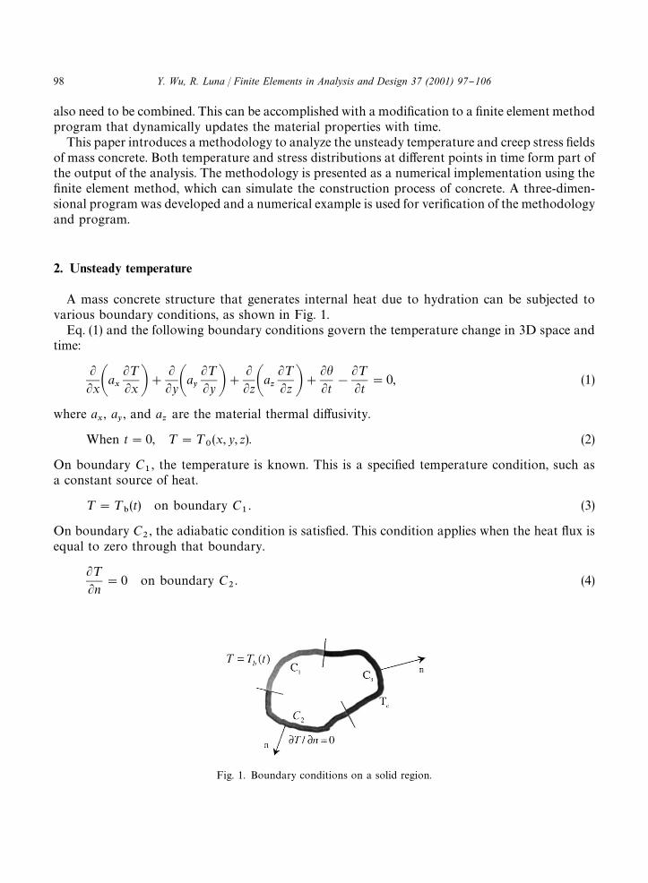
Fig. 1. Boundary conditions on a solid region.
also need to be combined. This can be accomplished with a modi"cation to a "nite element methodprogram that dynamically updates the material properties with time.
This paper introduces a methodology to analyze the unsteady temperature and creep stress "eldsof mass concrete. Both temperature and stress distributions at di!erent points in time form part ofthe output of the analysis. The methodology is presented as a numerical implementation using the"nite element method, which can simulate the construction process of concrete. A three-dimen-sional program was developed and a numerical example is used for veri"cation of the methodologyand program.
2. Unsteady temperature
A mass concrete structure that generates internal heat due to hydration can be subjected tovarious boundary conditions, as shown in Fig. 1.
Eq. (1) and the following boundary conditions govern the temperature change in 3D space andtime:
LLxAax
L¹Lx B#
LLyAay
L¹Ly B#
LLzAaz
L¹Lz B#
LhLt
!
L¹Lt
"0, (1)
where ax, a
y, and a
zare the material thermal di!usivity.
When t"0, ¹"¹0(x, y, z). (2)
On boundary C1, the temperature is known. This is a speci"ed temperature condition, such as
a constant source of heat.
¹"¹"(t) on boundary C
1. (3)
On boundary C2, the adiabatic condition is satis"ed. This condition applies when the heat #ux is
equal to zero through that boundary.
L¹Ln
"0 on boundary C2. (4)
98 Y. Wu, R. Luna / Finite Elements in Analysis and Design 37 (2001) 97}106

On boundary C3, convective-type condition is applied. This condition is when there are changes in
temperature along that boundary:
jx
L¹Lx
lx#j
y
L¹Ly
ly#j
z
L¹Lz
lz"!b(¹!¹
c), (5)
where ¹ is the transient temperature, h is the adiabatic temperature rise of concrete,¹0
is the initialtemperature, n is the outer normal of the boundary, j
x, j
y, j
zare the thermal conductivities for
each direction, b is the surface exothermic coe$cient, ¹cis the temperature of the bounding #uid,
and lx, ly, lz
are direction cosines of the external normal to the boundary.The above problem can be solved in 3D using the "nite element method, the equations for "nite
element method are listed as follows:
CH#
2*t
PDM¹Nt#CH!
2*t
PDM¹Nt~*t#MQN
t~*t#MQNt"0, (6)
where
Hij"+
e
heij"+
ePPP*RAax
LNi
LxLN
jLx
#ay
LNi
LyLN
jLy
#az
LNi
LzLN
jLz Bdxdydz,
Pij"+
e
peij"+
ePPP*R
NiN
jdxdydz,
Qij"+
e
qei"+
e A!PPP*R
LhLt
Nidxdy dz!PP
*C
bM ¹CN
ids#APP
*C
bM Ni[N
iN
j2] dsBG
¹i
¹jF HB.
Therefore, if the temperature at time t!*t is known, then the temperature at time tcan be calculated, since the initial temperature is known, the temperature at any time can becalculated.
3. Creep stress with temperature e4ects
In creep analysis, the most widely used models are the CEB-FIP Model [3]; the AmericanConcrete Institute (ACI) Model [4]; the Bazant and Panula's (BP) Model [5] and the Exponential
Y. Wu, R. Luna / Finite Elements in Analysis and Design 37 (2001) 97}106 99

Model [6]. The "rst three models have a common requirement for the numerical implementationusing FEM, that is, the entire stress history must be stored in a memory array. When a massconcrete structure is analyzed in 3D it demands signi"cant memory resources of the systemdepending on the detail used in discretizing into elements. If one adds on top of this a change in thematerial properties with time the task of keeping track of these changes becomes ine$cient. TheExponential Model can avoid storing the whole stress history and made the implementationfeasible and was selected for use in this methodology.
The Exponential Model of creep compliance can be expressed with the Dirichlet seriesas [6]
J(t, q)"N+k/1
1C
k(q)
[1!exp(yk(q)!y
k(t))], (7)
where J(t, q) is the creep function, q is the loading age in days, and Ck
and yk
are experimentalcoe$cients as functions of time (q or t).
For mass concrete structures the following speci"c form is often used [7]:
J(t, q)"1
E(q)#C(t, q),
C(t, q)"2+i/1
(Ai#B
iq~Gi)[1!exp(!S
i(t!q))]#D[exp(!S
3q)!exp(!S
3t)],
E(q)"E0(1!exp(!aqb)), (8)
where C(t, q) is the creep compliance, E(q) and E0
are transient and ultimate elastic moduli,respectively, and A
i,B
i, G
i,S
i, D, a, b are all experimental "tting parameters.
As mentioned before, the elastic modulus and creep properties of concrete are in#uencedby temperature. Du and Liu [8] introduced the term equivalent age (q
%), which represents
the hydration period for which the same degree of hydration is reached at a current temperatureas that one reached during the actual time (t) at a reference temperature. The concrete age, q,will be replaced with this equivalent age (q
%) in the above exponential model. This modi"ed
model includes the temperature e!ects on both the elastic modulus and the creep behavior ofconcrete.
In the numerical process for creep stress analysis, "rst the creep strain is calculated, then thecorresponding stress can be obtained. Du and Liu [8] derived the mathematical formulation forthe creep strain and stress in 3D, the "nal formula for the increment in strain (Eq. (9)) and stress (Eq.(10)) are presented below.
Let the time interval [t0, t] be subdivided into N steps, then the creep strain increment M*eC
nN at
a typical step [tn~1
, tn] (n"1,2,2, N) can be expressed as
M*eCnN"[Q]
3+r/1
[(1!exp(!Sru
Tn*q
n))Mu
rnN#M*p
nNuH
rnhHrn
]"[gn]#q
n[Q]M*p
nN, (9)
100 Y. Wu, R. Luna / Finite Elements in Analysis and Design 37 (2001) 97}106
where
[Q]"C1!k!k 0 0 0
1!k 0 0 0
1 0 0 0
2(1#k) 0 0
Sym. 2(1#k) 0
2(1#k)D, k is the Poisson's ratio,
MgnN"
3+r/1
(1!exp(!Sru
Tn*q
n))Mu
rnN,
qn"
3+r/1
uHrn
hHrn
,
Murn
N"Murn~1
Nexp(Sru
Tn~1*q
n~1)#[Q]M*p
n~1NuH
rn~1fHrn~1
exp(!Sr*q
n~1),
uHrn"u
r(q
%/~1@2),
hHrn"1!fH
rnexpA!S
r
n+i/1
uTi
*qiB,
fHrn"
1*q
nP
tn
tn~1
expASrPq
t0
uT
dt@B dq,
*qn"t
n!t
n~1.
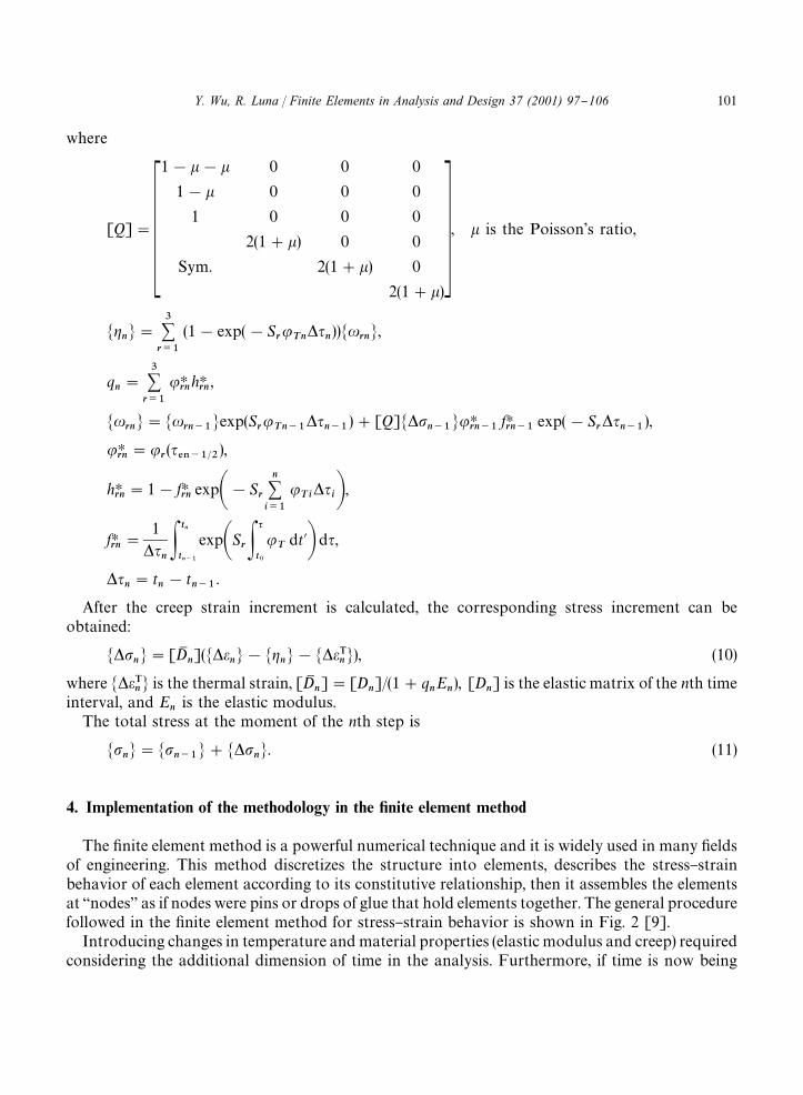
After the creep strain increment is calculated, the corresponding stress increment can beobtained:
M*pnN"[DM
n](M*e
nN!Mg
nN!M*eT
nN), (10)
where M*eTnN is the thermal strain, [DM
n]"[D
n]/(1#q
nE
n), [D
n] is the elastic matrix of the nth time
interval, and En
is the elastic modulus.The total stress at the moment of the nth step is
MpnN"Mp
n~1N#M*p
nN. (11)
4. Implementation of the methodology in the 5nite element method
The "nite element method is a powerful numerical technique and it is widely used in many "eldsof engineering. This method discretizes the structure into elements, describes the stress}strainbehavior of each element according to its constitutive relationship, then it assembles the elementsat `nodesa as if nodes were pins or drops of glue that hold elements together. The general procedurefollowed in the "nite element method for stress}strain behavior is shown in Fig. 2 [9].
Introducing changes in temperature and material properties (elastic modulus and creep) requiredconsidering the additional dimension of time in the analysis. Furthermore, if time is now being
Y. Wu, R. Luna / Finite Elements in Analysis and Design 37 (2001) 97}106 101
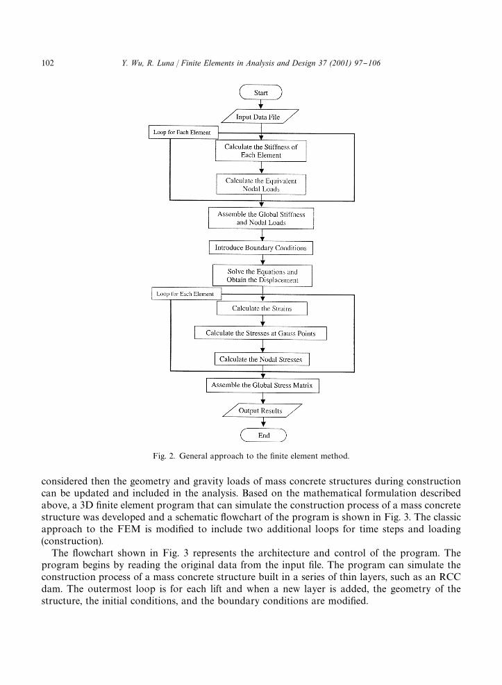
Fig. 2. General approach to the "nite element method.
considered then the geometry and gravity loads of mass concrete structures during constructioncan be updated and included in the analysis. Based on the mathematical formulation describedabove, a 3D "nite element program that can simulate the construction process of a mass concretestructure was developed and a schematic #owchart of the program is shown in Fig. 3. The classicapproach to the FEM is modi"ed to include two additional loops for time steps and loading(construction).
The #owchart shown in Fig. 3 represents the architecture and control of the program. Theprogram begins by reading the original data from the input "le. The program can simulate theconstruction process of a mass concrete structure built in a series of thin layers, such as an RCCdam. The outermost loop is for each lift and when a new layer is added, the geometry of thestructure, the initial conditions, and the boundary conditions are modi"ed.
102 Y. Wu, R. Luna / Finite Elements in Analysis and Design 37 (2001) 97}106
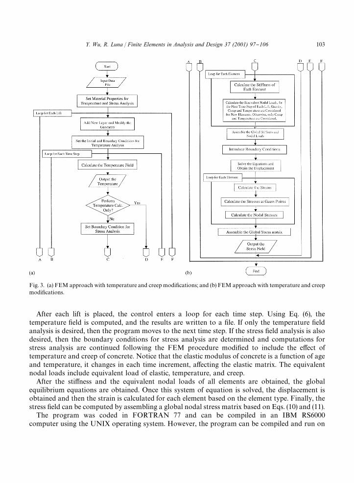
Fig. 3. (a) FEM approach with temperature and creep modi"cations; and (b) FEM approach with temperature and creepmodi"cations.
After each lift is placed, the control enters a loop for each time step. Using Eq. (6), thetemperature "eld is computed, and the results are written to a "le. If only the temperature "eldanalysis is desired, then the program moves to the next time step. If the stress "eld analysis is alsodesired, then the boundary conditions for stress analysis are determined and computations forstress analysis are continued following the FEM procedure modi"ed to include the e!ect oftemperature and creep of concrete. Notice that the elastic modulus of concrete is a function of ageand temperature, it changes in each time increment, a!ecting the elastic matrix. The equivalentnodal loads include equivalent load of elastic, temperature, and creep.
After the sti!ness and the equivalent nodal loads of all elements are obtained, the globalequilibrium equations are obtained. Once this system of equation is solved, the displacement isobtained and then the strain is calculated for each element based on the element type. Finally, thestress "eld can be computed by assembling a global nodal stress matrix based on Eqs. (10) and (11).
The program was coded in FORTRAN 77 and can be compiled in an IBM RS6000computer using the UNIX operating system. However, the program can be compiled and run on
Y. Wu, R. Luna / Finite Elements in Analysis and Design 37 (2001) 97}106 103

Fig. 4. Concrete block within mass concrete layer.
a Pentium-based personal computer. The main program calls 45 subroutines and the code is about6500 lines. As mentioned above, the creep compliance relationship was selected based on itscomputational e$ciency. However, the 3D nature of mass concrete analysis, the constructionsequence simulated, and the time e!ect of temperature and creep demand computer time toperform the calculations.
5. Numerical example
In order to demonstrate the methodology and the 3D "nite element program, the temperatureand stresses of a concrete block were analyzed.
Consider a 30]4]4 m concrete block supported on a rock base half-space, as shown in Fig. 4.The trivial mesh generating procedure included varying elemnt sizes until satisfactory convergencewas achieved at about 0.5 m cube elements. The upper surface of the block is exposed to the air, andthe ambient temperature was set to 103C. All the other sides of the block satisfy the adiabatic conditionor L¹/Ln"0. The unit weight of concrete was c"2400 kg/m3. The thermal material properties forconcrete were assumed to be as follows: thermal di!usivity, a"0.004 m2/h, thermal conductivity,j"2.16 cal/(mh3C), and surface exothermic coe$cient, b"20 cal/(m2h3C). Other values used fromprevious work are the Poisson's ratio k"1
6, linear thermal dilatation coe$cient, a"10~5/3C,
adiabatic temperature rise, h"30(1!e~0.3q)3C [8]. The elastic modulus and creep compliance modelsfor roller compacted concrete were based on reported values by Zhang [10], as follows:
E(q)"2.6]109(1!e~0.14q) in kg/m2,
C(t, q)"AA0#
A1q
#
A2
q2 B[1!e~K1 (t~q)]#AB0#
B1q
#
B2
q2 B][1!e~K2 (t~q)]#D(e~K3q!e~K3 t),
where A0"0.35494, A
1"3.7335, A
2"!2.5644, B
0"0.48368, B
1"!0.186, B
2"0.13786,
K1"0.35361, K
2"0.012486, K
3"0.032642, and D"0.83509.
The program can simulate the construction process of mass concrete structures and dynamicallyupdate the geometry of the FEM mesh when new lifts are added during construction. However, in
104 Y. Wu, R. Luna / Finite Elements in Analysis and Design 37 (2001) 97}106

Fig. 5. Temperature curve at the central point of block.
Fig. 6. Stress curve at the central point of block.
order to demonstrate the methodology and the 3D "nite element program, the temperature andstresses of a concrete block taken from one lift were analyzed. Fig. 5 shows the temperature at thecentral point of the concrete block. The temperature increases due to the heat produced byhydration, then reaches a maximum point at about 8 days after casting. Because of the heat transferbetween the concrete block and the outside air, the peak temperature is less than the initialtemperature plus the adiabatic hydration temperature rise. After 8 days, the block begins to cooldown. Only the upper surface is exposed to the air, which requires a long time for the block to reachthe boundary environmental temperature. After 300 days the central point of the concrete block isstill higher than the boundary environmental temperature. Fig. 6 shows the variation of stressalong the same point of the block considering only thermal stresses. At "rst, a compression stress
Y. Wu, R. Luna / Finite Elements in Analysis and Design 37 (2001) 97}106 105

develops inside the block, this is because the concrete tends to expand due to the temperatureincrease, while the boundary conditions restrict its expansion. The maximum compression stressalso occurs at about 8 days after the block is cast. Then the compression stress decreases which isexpected because the block begins to cool down. Finally, the compression stress changes to tensionstress and the tension stress becomes larger and larger because the block continues to cool down.This is why concrete often cracks under extreme cold weather conditions.
6. Conclusion
This paper introduced a numerical methodology to simulate the construction process of massconcrete that considers the temperature e!ects on the elastic modulus and creep behavior ofconcrete. The implementation of the methodology using the "nite element method and the#owchart of a 3D "nite element program were presented. A simple numerical example demon-strated the methodology and the capabilities of the proposed approach. This procedure could beused with other materials that are exposed to thermal changes and are sensitive to creep.
Acknowledgements
The authors would like to acknowledge the contributions to this paper from their colleagues inChina, Professor Guangting Liu, Dr. Guoxin Zhang. Additionally, the "rst author would like torecognize the Department of Civil and Environmental Engineering at Tulane University for the"nancial support during his graduate studies.
References
[1] Z.P. Bazant, Mathematical models for creep and shrinkage of concrete, in: Z.P. Bazant, F.H. Wittman (Eds.), Creepand Shrinkage in Concrete Structure, Wiley, New York, 1982.
[2] A.M. Neville, W.H. Dilger, J.J. Brooks, Creep of Plain and Structural Concrete, Longman, New York, 1983.[3] CEB-FIP, Model code for concrete structures, Comite Euro-International du Beton } Federation Internationale de
la Precontrainte, Paris, 1978, 348pp.[4] ACI Committee 209, Prediction of creep, shrinkage and temperature e!ects in concrete structures, Second Draft,
American Concrete Institute, Detroit, October, 1978, 98pp.[5] Z.P. Bazant, L. Panula, New model for practical prediction of creep and shrinkage, Publication SP-76, American
Concrete Institute, 1982.[6] Z.P. Bazant, S.T. Wu, Dirichlet series creep function for aging concrete, J. Eng. Mech. Div. ASCE 100 (EM3) (1974)
575}597.[7] B.F. Zhu, The elastic modulus, creep compliance and stress relaxation coe$cient of concrete, Hydraulic J. 9 (1985) 9.[8] C.J. Du, G.T. Liu, Numerical procedure for thermal creep stress in mass concrete structures, Comm. Numer.
Methods Eng. 10 (1994) 545}554.[9] R.D. Cook, Finite Element Modeling for Stress Analysis, Wiley, New York, 1995.
[10] M.L. Zhang, Study on structural treatment, stress and stability of roller compacted concrete gravity dam, MastersThesis, Department of Hydraulic and Hydropower Engineering, Tsinghua University, Beijing, China, 1995.
106 Y. Wu, R. Luna / Finite Elements in Analysis and Design 37 (2001) 97}106