Deformation and creep modeling in polycrystalline Ti–6Al alloys
This article appeared in a journal published by Elsevier. The attachedcopy is furnished to the author for internal non-commercial researchand education use, including for instruction at the authors institution
and sharing with colleagues.
Other uses, including reproduction and distribution, or selling orlicensing copies, or posting to personal, institutional or third party
websites are prohibited.
In most cases authors are permitted to post their version of thearticle (e.g. in Word or Tex form) to their personal website orinstitutional repository. Authors requiring further information
regarding Elsevier’s archiving and manuscript policies areencouraged to visit:
http://www.elsevier.com/copyright
Author's personal copy
Engineering Structures 31 (2009) 2203–2208
Contents lists available at ScienceDirect
Engineering Structures
journal homepage: www.elsevier.com/locate/engstruct
Effect of transient creep on the behaviour of reinforced concrete columns in fire
Arezki Sadaoui a, Amar Khennane b,∗a Faculté du Génie de la Construction, Université de Tizi-Ouzou, Algeriab University of New South Wales at the Australian Defence Force Academy, Canberra, Australia
a r t i c l e i n f o
Article history:Received 30 April 2008Received in revised form21 April 2009Accepted 21 April 2009Available online 15 May 2009
Keywords:Reinforced concrete columnsFire resistanceTransient creepAnalysis
a b s t r a c t
Concrete experiences transient creep when subjected to elevated temperatures, which is believed to bethe result of thermo-mechanical interactions within the cement paste microstructure. Transient creepoccurs in compression under first time heating. Although it is particularly relevant to the behaviourof columns, which most of the time are under a state of compression, its systematic effects on theirperformance and stability under fire have not been well elucidated. Indeed, current design of reinforcedconcrete columns is based at worst on tabulated data, which bear no resemblance to real fires, or at best,on codes of practice that consider transient creep through the deformation properties of concrete. Using apreviously developed finite element code, which is capable of considering transient creep either explicitlyas an additional strain rate component, or implicitly through the deformation properties of concrete, asystematic study of its effects on the behaviour of an unrestrained column is presented. It was foundthat transient creep gives rise to additional compressive stresses in the column magnifying any bendingmoments, and therefore precipitating its failure.
Crown Copyright© 2009 Published by Elsevier Ltd. All rights reserved.
1. Introduction
Columns form an integral part of the load path in reinforcedconcrete framed buildings. They constitute the main mean of loadtransfer to the foundations. A column failure is more detrimentalto a building than that of a beam, and more likely to result in aprogressive collapse [1]. This is particularly true in fire scenarios,where a column is more likely to be exposed to intensive heat onall its faces in a fire compartment, and more likely to fail first.Moreover, the forces and moments acting on a column within abuilding frame are time dependent. These time-variations havetheir origin in the change of the mechanical properties of thematerials, but also in the interaction with adjoining structuralelements. Rigbeth [2], citing Forsen [3], identified the followingfactors influencing the structural behaviour of a column:
• additional shear forces andmoments due to dilation of adjacenthorizontal members• additional axial forces due to restrained thermal elongation• restraintmoments and forcesmay be transferred from adjacentmembers as a result of stiff connections• significant second order moments may occur due to increasedhorizontal displacements.
∗ Corresponding author. Fax: +61 2 62688337.E-mail address: [email protected] (A. Khennane).
Additionally, the reinforcing bars in a column are placednear the surface. The load carrying ability of the reinforcementdecreases crescendo with the increase in temperature. As notedby Hertz [4], only the concrete will contribute to the load carryingability of the column. Or concrete has a unique property amongstructural materials, transient creep, which occurs in compressionunder first time heating. It is believed to be the result of thermo-mechanical interactions within the cement paste microstructure.Consequently, the mechanical response depends on both the loadand temperature histories. Such dependencemanifests itself in theabsence of transient creep if a concrete specimen has already beensubjected to a high temperature cycle prior to testing.According to Khoury [5], any structural analysis of heated
concrete that ignores this phenomenon will yield erroneousresults, particularly for columns exposed to fire. Consequently, thedesign of columns is of paramount importance to the structuralintegrity of the whole structure, and should be based on moredirect analytical approach that determines the structural fireresponse, which takes into account the fire load characteristics,the ventilation conditions, and, among all, the thermo-mechanicalproperties of the structural materials as well as the restraints.
2. Analytical procedure
The aim of this study is to investigate the effect of transientcreep on the structural response of reinforced concrete columnsunder severe thermo-mechanical loads using a finite element codedeveloped by the authors [6] which accounts for transient creep
0141-0296/$ – see front matter Crown Copyright© 2009 Published by Elsevier Ltd. All rights reserved.doi:10.1016/j.engstruct.2009.04.005
Author's personal copy
2204 A. Sadaoui, A. Khennane / Engineering Structures 31 (2009) 2203–2208
explicitly as an additional component of the total strain, or implic-itly through the use of the materials’ properties recommended bythe Eurocodes [7,8]. The later approach is also used by the codesSAFIR [9–11], VULCAN [12], and more recently by Zhang et al. [13].The present code uses a formulation based on a co-rotational
approach. It makes use of a tangential operator derived byintegrating the stress–strain rates of concrete and steel at elevatedtemperatures [6,14]. It includes geometrical nonlinear effectsresulting from large displacements, degradation of the elasticand inelastic material properties with temperature. The concretemodel also accounts for cracking and crushing, as well as transientcreep. The transient creep strain that develops under first timeheating of concrete and under a state of compression only [15] isaccounted for with a simple formula [16] as:
ε =kσfC20
εth (1)
where fC20 is the compressive strength at ambient temperature, εthis the free thermal strain rate and k, a coefficient varying between1.8 and 2.35.The code also includes a separate heat transfer analysis based
on an explicit forward finite difference scheme. The temperaturedistribution along an element is considered uniform, whichreduces the problem into a bi-dimensional one. The influence ofmoisture content in the concrete is implicitly considered in thefunction given for the specific heat.To concentrate solely on the structural response, and study
the effects of transient creep on column response, and avoid anyspurious errors that may arise from a simplified bi-dimensionalthermal analysis results, we have deliberately chosen to analysethe tests carried out at the Technical University of Braunschweig,Germany [17,18]. In these tests, which are fully described in [19],the temporal and spatial temperature variations were recordedwith thermocouples. This provides an accurate temperaturedistribution which does not need to be predicted with a parallelheat transfer analysis. Indeed, concrete is a highly heterogeneousporous material, which can be regarded as a network ofinterconnected and disconnected micro-pores and randomlydistributed micro-cracks. This makes it difficult to develop anexact microstructure model. Additionally, water is present underdifferent forms in the cement paste. Due to the large specificinternal area, a large proportion is in the adsorbed state. To predictaccurately the temperature distribution in a concrete element, aphysically realistic mathematical formulation for mass and heattransfer capable of describing the free water flow, adsorbed watermovement, and water vapour and air diffusion should be used,which is beyond the scope of this paper.
3. Geometrical and loading details of the column
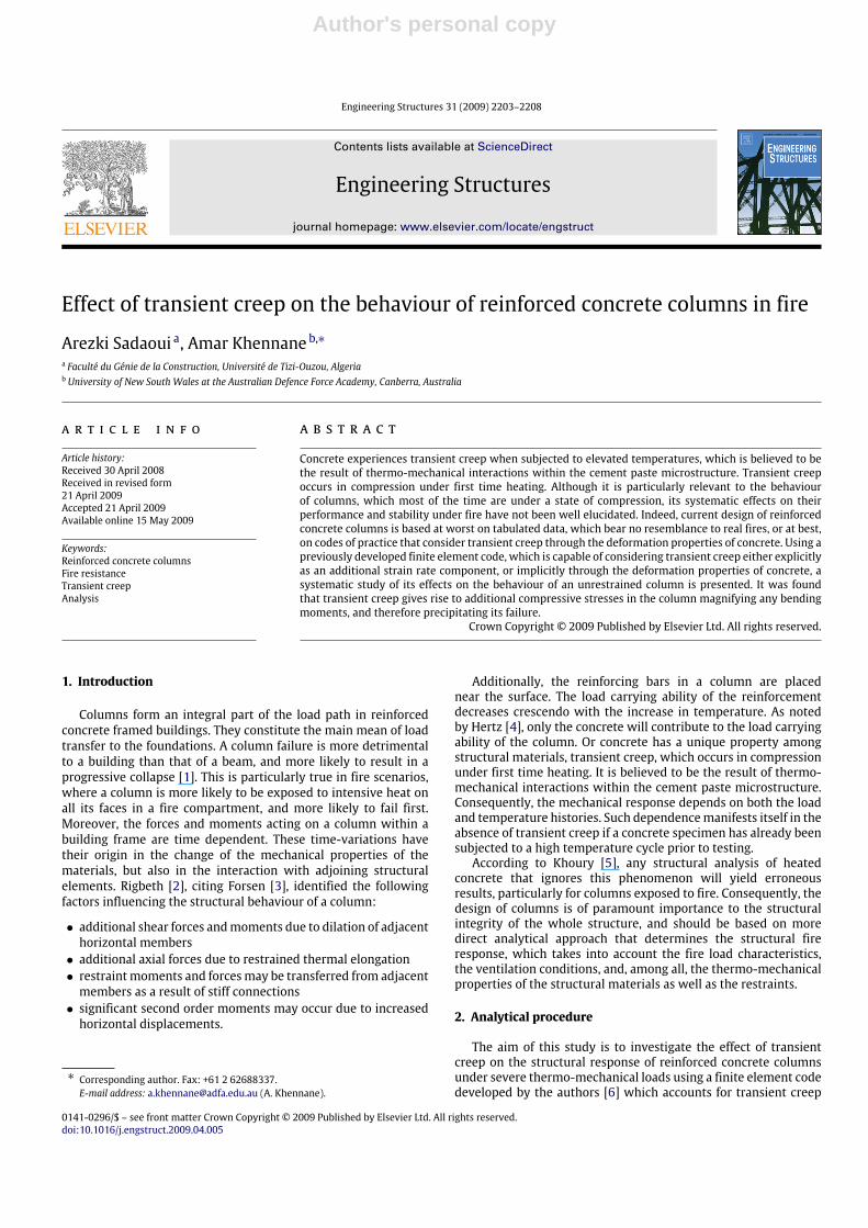
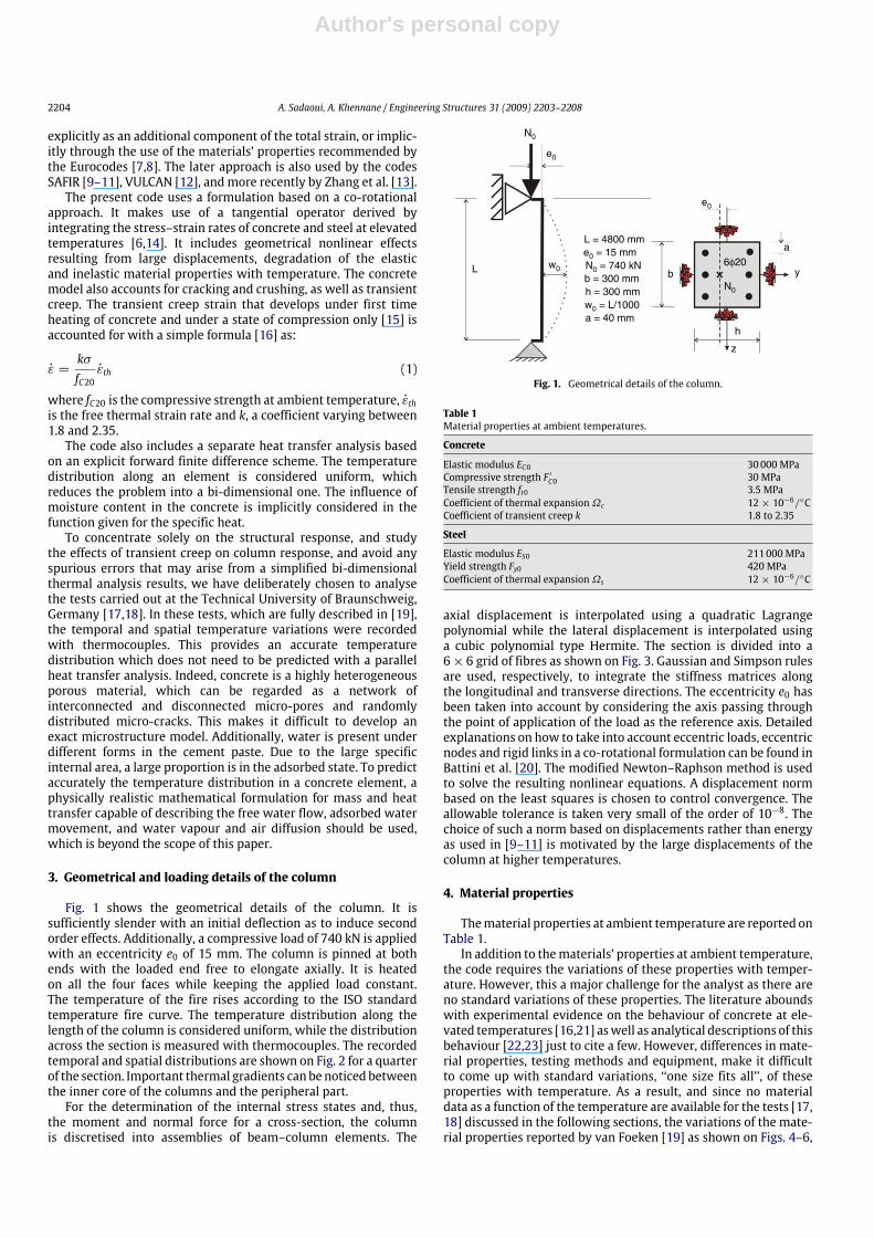
Fig. 1 shows the geometrical details of the column. It issufficiently slender with an initial deflection as to induce secondorder effects. Additionally, a compressive load of 740 kN is appliedwith an eccentricity e0 of 15 mm. The column is pinned at bothends with the loaded end free to elongate axially. It is heatedon all the four faces while keeping the applied load constant.The temperature of the fire rises according to the ISO standardtemperature fire curve. The temperature distribution along thelength of the column is considered uniform, while the distributionacross the section is measured with thermocouples. The recordedtemporal and spatial distributions are shown on Fig. 2 for a quarterof the section. Important thermal gradients can benoticed betweenthe inner core of the columns and the peripheral part.For the determination of the internal stress states and, thus,
the moment and normal force for a cross-section, the columnis discretised into assemblies of beam–column elements. The
L b
h
6φ20
z
a
y
a = 40 mm
L = 4800 mm
N0
N0
N0 = 740 kN
e0
e0
w0
w0 = L/1000
e0 = 15 mm
b = 300 mmh = 300 mm
Fig. 1. Geometrical details of the column.
Table 1Material properties at ambient temperatures.
Concrete
Elastic modulus EC0 30000 MPaCompressive strength F ′C0 30 MPaTensile strength ft0 3.5 MPaCoefficient of thermal expansionΩc 12× 10−6/CCoefficient of transient creep k 1.8 to 2.35
Steel
Elastic modulus ES0 211000 MPaYield strength Fy0 420 MPaCoefficient of thermal expansionΩs 12× 10−6/C
axial displacement is interpolated using a quadratic Lagrangepolynomial while the lateral displacement is interpolated usinga cubic polynomial type Hermite. The section is divided into a6× 6 grid of fibres as shown on Fig. 3. Gaussian and Simpson rulesare used, respectively, to integrate the stiffness matrices alongthe longitudinal and transverse directions. The eccentricity e0 hasbeen taken into account by considering the axis passing throughthe point of application of the load as the reference axis. Detailedexplanations on how to take into account eccentric loads, eccentricnodes and rigid links in a co-rotational formulation can be found inBattini et al. [20]. The modified Newton–Raphson method is usedto solve the resulting nonlinear equations. A displacement normbased on the least squares is chosen to control convergence. Theallowable tolerance is taken very small of the order of 10−8. Thechoice of such a norm based on displacements rather than energyas used in [9–11] is motivated by the large displacements of thecolumn at higher temperatures.
4. Material properties
Thematerial properties at ambient temperature are reported onTable 1.In addition to thematerials’ properties at ambient temperature,
the code requires the variations of these properties with temper-ature. However, this a major challenge for the analyst as there areno standard variations of these properties. The literature aboundswith experimental evidence on the behaviour of concrete at ele-vated temperatures [16,21] aswell as analytical descriptions of thisbehaviour [22,23] just to cite a few. However, differences in mate-rial properties, testing methods and equipment, make it difficultto come up with standard variations, ‘‘one size fits all’’, of theseproperties with temperature. As a result, and since no materialdata as a function of the temperature are available for the tests [17,18] discussed in the following sections, the variations of the mate-rial properties reported by van Foeken [19] as shown on Figs. 4–6,
Author's personal copy
A. Sadaoui, A. Khennane / Engineering Structures 31 (2009) 2203–2208 2205
00
100
200
300
400
500
600
700
800
900
1000
10 20 30 40Time (min)
Tem
pera
ture
°C
50 60 70 80
Point 1Point 2Point 3Point 4Point 5Point 6
75 mm 75 mm
75 mm
75 mm
1
1
2
2
3
4
46
5
Fig. 2. Temporal and spatial temperature distribution recorded with thermocouples.
Gauss points
y
j
z
i
Fig. 3. Cross section discretisation.
00 200 400 600
Temperature (°C)800 1000 1200
0.1
0.2
0.3
0.4
0.5
0.6
0.7
0.8
0.9
1
F’c(T)/F’c0Ec(T)/Ec0Ft(T)/Ft0
Fig. 4. Evolution of concrete properties with temperature.
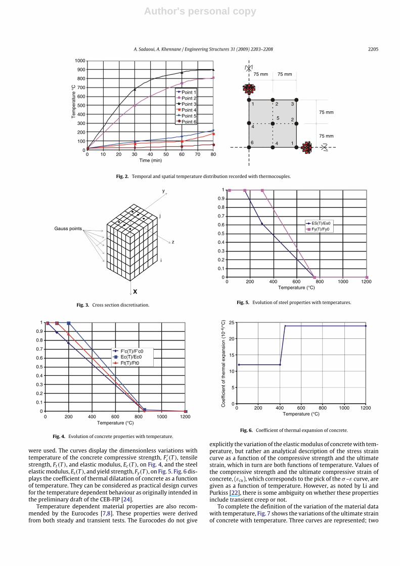
were used. The curves display the dimensionless variations withtemperature of the concrete compressive strength, F ′c(T ), tensilestrength, Ft(T ), and elastic modulus, Ec(T ), on Fig. 4, and the steelelasticmodulus, Es(T ), and yield strength, Fy(T ), on Fig. 5. Fig. 6 dis-plays the coefficient of thermal dilatation of concrete as a functionof temperature. They can be considered as practical design curvesfor the temperature dependent behaviour as originally intended inthe preliminary draft of the CEB-FIP [24].Temperature dependent material properties are also recom-
mended by the Eurocodes [7,8]. These properties were derivedfrom both steady and transient tests. The Eurocodes do not give
00
0.1
0.2
0.3
0.4
0.5
0.6
0.7
0.8
0.9
1
200 400 600Temperature (°C)
800 1000 1200
ES(T)/Es0Fy(T)/Fy0
Fig. 5. Evolution of steel properties with temperatures.
00 200 400 600
Temperature (°C)800 1000 1200
5
10
Coe
ffici
ent o
f the
rmal
exp
ansi
on (
10–6
/°C
)
15
20
25
Fig. 6. Coefficient of thermal expansion of concrete.
explicitly the variation of the elasticmodulus of concretewith tem-perature, but rather an analytical description of the stress straincurve as a function of the compressive strength and the ultimatestrain, which in turn are both functions of temperature. Values ofthe compressive strength and the ultimate compressive strain ofconcrete, (εcu), which corresponds to the pick of the σ–ε curve, aregiven as a function of temperature. However, as noted by Li andPurkiss [22], there is some ambiguity on whether these propertiesinclude transient creep or not.To complete the definition of the variation of the material data
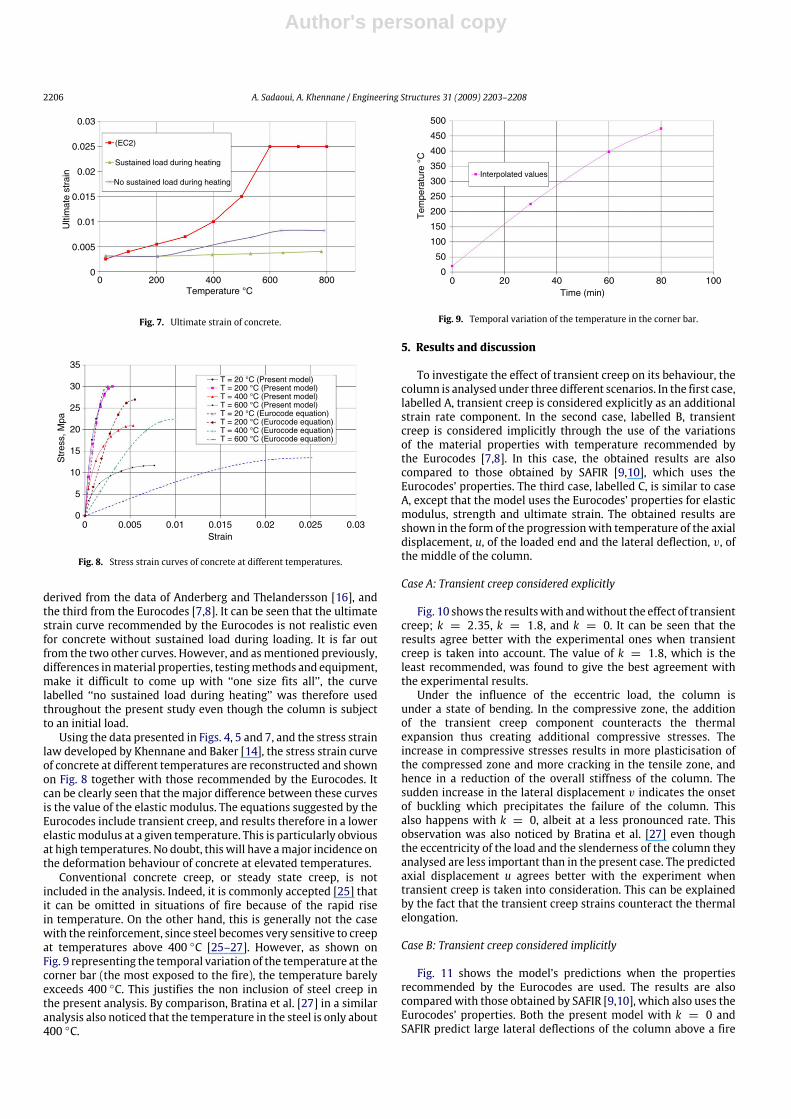
with temperature, Fig. 7 shows the variations of the ultimate strainof concrete with temperature. Three curves are represented; two
Author's personal copy
2206 A. Sadaoui, A. Khennane / Engineering Structures 31 (2009) 2203–2208
00
0.005
0.01
0.015
0.02
0.025
0.03
200 400Temperature °C
Ulti
mat
e st
rain
600 800
(EC2)
Sustained load during heating
No sustained load during heating
Fig. 7. Ultimate strain of concrete.
00
5
10
15
20
25
30
35
0.005 0.01 0.015Strain
Str
ess,
Mpa
0.02 0.025 0.03
T = 20 °C (Present model)T = 200 °C (Present model)T = 400 °C (Present model)T = 600 °C (Present model)T = 20 °C (Eurocode equation)T = 200 °C (Eurocode equation)T = 400 °C (Eurocode equation)T = 600 °C (Eurocode equation)
Fig. 8. Stress strain curves of concrete at different temperatures.
derived from the data of Anderberg and Thelandersson [16], andthe third from the Eurocodes [7,8]. It can be seen that the ultimatestrain curve recommended by the Eurocodes is not realistic evenfor concrete without sustained load during loading. It is far outfrom the two other curves. However, and asmentioned previously,differences inmaterial properties, testingmethods and equipment,make it difficult to come up with ‘‘one size fits all’’, the curvelabelled ‘‘no sustained load during heating’’ was therefore usedthroughout the present study even though the column is subjectto an initial load.Using the data presented in Figs. 4, 5 and 7, and the stress strain
law developed by Khennane and Baker [14], the stress strain curveof concrete at different temperatures are reconstructed and shownon Fig. 8 together with those recommended by the Eurocodes. Itcan be clearly seen that the major difference between these curvesis the value of the elastic modulus. The equations suggested by theEurocodes include transient creep, and results therefore in a lowerelasticmodulus at a given temperature. This is particularly obviousat high temperatures. No doubt, this will have amajor incidence onthe deformation behaviour of concrete at elevated temperatures.Conventional concrete creep, or steady state creep, is not
included in the analysis. Indeed, it is commonly accepted [25] thatit can be omitted in situations of fire because of the rapid risein temperature. On the other hand, this is generally not the casewith the reinforcement, since steel becomes very sensitive to creepat temperatures above 400 C [25–27]. However, as shown onFig. 9 representing the temporal variation of the temperature at thecorner bar (the most exposed to the fire), the temperature barelyexceeds 400 C. This justifies the non inclusion of steel creep inthe present analysis. By comparison, Bratina et al. [27] in a similaranalysis also noticed that the temperature in the steel is only about400 C.
00
50
100
150
200
250
300
350
400
450
500
20 40 60Time (min)
Tem
pera
ture
°C
80 100
Interpolated values
Fig. 9. Temporal variation of the temperature in the corner bar.
5. Results and discussion
To investigate the effect of transient creep on its behaviour, thecolumn is analysed under three different scenarios. In the first case,labelled A, transient creep is considered explicitly as an additionalstrain rate component. In the second case, labelled B, transientcreep is considered implicitly through the use of the variationsof the material properties with temperature recommended bythe Eurocodes [7,8]. In this case, the obtained results are alsocompared to those obtained by SAFIR [9,10], which uses theEurocodes’ properties. The third case, labelled C, is similar to caseA, except that the model uses the Eurocodes’ properties for elasticmodulus, strength and ultimate strain. The obtained results areshown in the form of the progressionwith temperature of the axialdisplacement, u, of the loaded end and the lateral deflection, v, ofthe middle of the column.
Case A: Transient creep considered explicitly
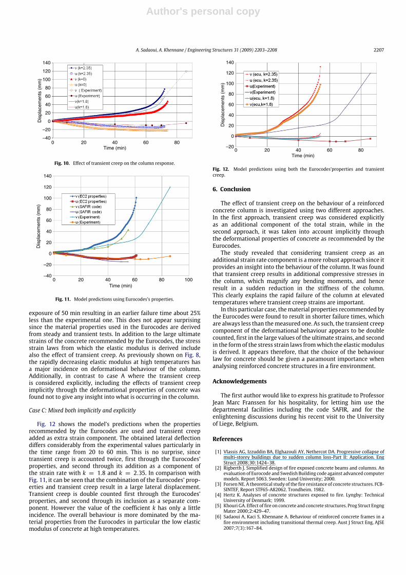
Fig. 10 shows the resultswith andwithout the effect of transientcreep; k = 2.35, k = 1.8, and k = 0. It can be seen that theresults agree better with the experimental ones when transientcreep is taken into account. The value of k = 1.8, which is theleast recommended, was found to give the best agreement withthe experimental results.Under the influence of the eccentric load, the column is
under a state of bending. In the compressive zone, the additionof the transient creep component counteracts the thermalexpansion thus creating additional compressive stresses. Theincrease in compressive stresses results in more plasticisation ofthe compressed zone and more cracking in the tensile zone, andhence in a reduction of the overall stiffness of the column. Thesudden increase in the lateral displacement v indicates the onsetof buckling which precipitates the failure of the column. Thisalso happens with k = 0, albeit at a less pronounced rate. Thisobservation was also noticed by Bratina et al. [27] even thoughthe eccentricity of the load and the slenderness of the column theyanalysed are less important than in the present case. The predictedaxial displacement u agrees better with the experiment whentransient creep is taken into consideration. This can be explainedby the fact that the transient creep strains counteract the thermalelongation.
Case B: Transient creep considered implicitly
Fig. 11 shows the model’s predictions when the propertiesrecommended by the Eurocodes are used. The results are alsocomparedwith those obtained by SAFIR [9,10], which also uses theEurocodes’ properties. Both the present model with k = 0 andSAFIR predict large lateral deflections of the column above a fire
Author's personal copy
A. Sadaoui, A. Khennane / Engineering Structures 31 (2009) 2203–2208 2207
0–40
–20
0
20
40
60
80
100
120
140
20 40Time (min)
Dis
plac
emen
ts (
mm
)
60 80
Fig. 10. Effect of transient creep on the column response.
0–40
–20
0
20
40
60
80
100
120
140
20 40Time (min)
Dis
plac
emen
ts (
mm
)
60 80 100
Fig. 11. Model predictions using Eurocodes’s properties.
exposure of 50 min resulting in an earlier failure time about 25%less than the experimental one. This does not appear surprisingsince the material properties used in the Eurocodes are derivedfrom steady and transient tests. In addition to the large ultimatestrains of the concrete recommended by the Eurocodes, the stressstrain laws from which the elastic modulus is derived includealso the effect of transient creep. As previously shown on Fig. 8,the rapidly decreasing elastic modulus at high temperatures hasa major incidence on deformational behaviour of the column.Additionally, in contrast to case A where the transient creepis considered explicitly, including the effects of transient creepimplicitly through the deformational properties of concrete wasfound not to give any insight into what is occurring in the column.
Case C: Mixed both implicitly and explicitly
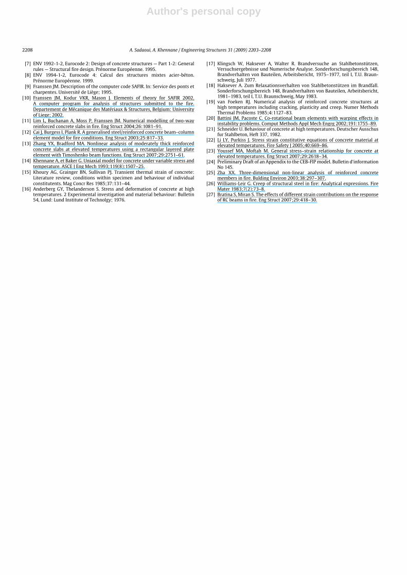
Fig. 12 shows the model’s predictions when the propertiesrecommended by the Eurocodes are used and transient creepadded as extra strain component. The obtained lateral deflectiondiffers considerably from the experimental values particularly inthe time range from 20 to 60 min. This is no surprise, sincetransient creep is accounted twice, first through the Eurocodes’properties, and second through its addition as a component ofthe strain rate with k = 1.8 and k = 2.35. In comparison withFig. 11, it can be seen that the combination of the Eurocodes’ prop-erties and transient creep result in a large lateral displacement.Transient creep is double counted first through the Eurocodes’properties, and second through its inclusion as a separate com-ponent. However the value of the coefficient k has only a littleincidence. The overall behaviour is more dominated by the ma-terial properties from the Eurocodes in particular the low elasticmodulus of concrete at high temperatures.
0–20
0
20
40
60
80
100
120
140
20 40Time (min)
Dis
plac
emen
ts (
mm
)
60 80
E
Fig. 12. Model predictions using both the Eurocodes’properties and transientcreep.
6. Conclusion
The effect of transient creep on the behaviour of a reinforcedconcrete column is investigated using two different approaches.In the first approach, transient creep was considered explicitlyas an additional component of the total strain, while in thesecond approach, it was taken into account implicitly throughthe deformational properties of concrete as recommended by theEurocodes.The study revealed that considering transient creep as an
additional strain rate component is amore robust approach since itprovides an insight into the behaviour of the column. It was foundthat transient creep results in additional compressive stresses inthe column, which magnify any bending moments, and henceresult in a sudden reduction in the stiffness of the column.This clearly explains the rapid failure of the column at elevatedtemperatures where transient creep strains are important.In this particular case, thematerial properties recommended by
the Eurocodes were found to result in shorter failure times, whichare always less than themeasured one. As such, the transient creepcomponent of the deformational behaviour appears to be doublecounted, first in the large values of the ultimate strains, and secondin the formof the stress strain laws fromwhich the elasticmodulusis derived. It appears therefore, that the choice of the behaviourlaw for concrete should be given a paramount importance whenanalysing reinforced concrete structures in a fire environment.
Acknowledgements
The first author would like to express his gratitude to ProfessorJean Marc Franssen for his hospitality, for letting him use thedepartmental facilities including the code SAFIR, and for theenlightening discussions during his recent visit to the Universityof Liege, Belgium.
References
[1] Vlassis AG, Izzuddin BA, Elghazouli AY, Nethercot DA. Progressive collapse ofmulti-storey buildings due to sudden column loss-Part II: Application. EngStruct 2008;30:1424–38.
[2] Rigberth J. Simplified design of fire exposed concrete beams and columns. Anevaluation of Eurocode and Swedish Building code against advanced computermodels. Report 5063. Sweden: Lund University; 2000.
[3] ForsenNE. A theoretical study of the fire resistance of concrete structures. FCB-SINTEF, Report STF65-A82062. Trondheim. 1982.
[4] Hertz K. Analyses of concrete structures exposed to fire. Lyngby: TechnicalUniversity of Denmark; 1999.
[5] Khouri GA. Effect of fire on concrete and concrete structures. Prog Struct EngngMater 2000;2:429–47.
[6] Sadaoui A, Kaci S, Khennane A. Behaviour of reinforced concrete frames in afire environment including transitional thermal creep. Aust J Struct Eng, AJSE2007;7(3):167–84.
Author's personal copy
2208 A. Sadaoui, A. Khennane / Engineering Structures 31 (2009) 2203–2208
[7] ENV 1992-1-2, Eurocode 2: Design of concrete structures — Part 1-2: Generalrules — Structural fire design. Prénorme Européenne. 1995.
[8] ENV 1994-1-2, Eurocode 4: Calcul des structures mixtes acier-béton.Prénorme Européenne. 1999.
[9] Franssen JM. Description of the computer code SAFIR. In: Service des ponts etcharpentes. Université de Liège; 1995.
[10] Franssen JM, Kodur VKR, Mason J. Elements of theory for SAFIR 2002,A computer program for analysis of structures submitted to the fire.Departement de Mécanique des Matériaux & Structures, Belgium: Universityof Liege; 2002.
[11] Lim L, Buchanan A, Moss P, Franssen JM. Numerical modelling of two-wayreinforced concrete slabs in fire. Eng Struct 2004;26:1081–91.
[12] Cai J, Burgess I, Plank R. A generalised steel/reinforced concrete beam–columnelement model for fire conditions. Eng Struct 2003;25:817–33.
[13] Zhang YX, Bradford MA. Nonlinear analysis of moderately thick reinforcedconcrete slabs at elevated temperatures using a rectangular layered plateelement with Timoshenko beam functions. Eng Struct 2007;29:2751–61.
[14] Khennane A, et Baker G. Uniaxial model for concrete under variable stress andtemperature. ASCE J Eng Mech 1993;119(8):1507–25.
[15] Khoury AG, Grainger BN, Sullivan PJ. Transient thermal strain of concrete:Literature review, conditions within specimen and behaviour of individualconstitutents. Mag Concr Res 1985;37:131–44.
[16] Anderberg GY, Thelanderson S. Stress and deformation of concrete at hightemperatures. 2 Experimental investigation and material behaviour: Bulletin54, Lund: Lund Institute of Technolgy; 1976.
[17] Klingsch W, Haksever A, Walter R. Brandversuche an Stahlbetonstützen,Versuchsergebnisse und Numerische Analyse. Sonderforschungsbereich 148,Brandverhalten von Bauteilen, Arbeitsbericht, 1975–1977, teil I, T.U. Braun-schweig, Juli 1977.
[18] Haksever A. Zum Relaxationsverhalten von Stahlbetonstützen im Brandfall.Sonderforschungsbereich 148, Brandverhalten von Bauteilen, Arbeitsbericht,1981–1983, teil I, T.U. Braunschweig, May 1983.
[19] van Foeken RJ. Numerical analysis of reinforced concrete structures athigh temperatures including cracking, plasticity and creep. Numer MethodsThermal Problems 1985;4:1127–83.
[20] Battini JM, Pacoste C. Co-rotational beam elements with warping effects ininstability problems. Comput Methods Appl Mech Engrg 2002;191:1755–89.
[21] Schneider U. Behaviour of concrete at high temperatures. Deutscher Ausschusfur Stahlbeton, Heft 337, 1982.
[22] Li LY, Purkiss J. Stress strain constitutive equations of concrete material atelevated temperatures. Fire Safety J 2005;40:669–86.
[23] Youssef MA, Moftah M. General stress–strain relationship for concrete atelevated temperatures. Eng Struct 2007;29:2618–34.
[24] Preliminary Draft of an Appendix to the CEB-FIP model. Bulletin d’informationNo 145.
[25] Zha XX. Three-dimensional non-linear analysis of reinforced concretemembers in fire. Bulding Environ 2003;38:297–307.
[26] Williams-Leir G. Creep of structural steel in fire: Analytical expressions. FireMater 1983;7(2):73–8.
[27] Bratina S, Miran S. The effects of different strain contributions on the responseof RC beams in fire. Eng Struct 2007;29:418–30.
Copyright © 2022 FDOKUMEN