CREEP-TESTING EQUIPMENT-DESIGN FEATURES AND ...
15
303 Paper 13 CREEP-TESTING EQUIPMENT-DESIGN FEATURES AND CONTROL By A. I. Smith*, D. Murray*, and M. F. Day* Those features of the design of creep-testing equipment which are of importance in the control and effective use of large test facilities are outlined in this paper. The requirements of different classes of test facility are dis- cussed against the background of the following factors: (1) basis of design and operations; (2) existing and well-established means of indicating and recording data; (3) recent developments in testing equipment and techniques, in particular those which will lead to an advance in the application of creep data. The requirements for different types of creep testing depend upon the types of materials a laboratory is required to handle in investigations, and on the ultimate purpose behind the investigations. The following factors are discussed in relation to various classes of creep testing: (1) the accuracy of load application; (2) measurement and control of temperature; (3) measurement and recording of strain data; (4) methods of data analysis; (5) laboratory environment and personnel ability. The ultimate measure of the effectiveness of a creep-testing facility is only demonstrated by its ability to provide data on the properties of materials which are of assistance to either a designer or to a manufacturer of materials. INTRODUCTION CREEP TESTS (i.e. sustained-load tests, usually at elevated temperature, in which time-dependent strain is measured) are undertaken usually with one or other of the following objects in view: (a) Research on mechanical properties, and on the physical or metallurgical processes in creep; (b) Alloy development or selection; (c) Design, i.e. provision of data from which design stresses may be derived; and (d) Acceptance or proving testing, i.e. determining whether or not a particular sample is within specified limits. Tests for purposes (c) and (d) should be conducted according to agreed procedures or specifications; this paper considers some of the special requirements for the testing equipment, and the difficulties in achieving ade- quate control of the test conditions. Similar considerations apply also, in some degree, in tests for purposes (a) and The M S . of this paper was received at the Institution on 18th March Materials Group, National Engineeriw Laboratory, East Kilbride. Proc Inrtn Mech Engrs 196566 1965. (b). The details of the test equipment, the test procedure, and the degree of control required, are dependent both on the information to be determined and the class of test material. The types of creep-testing generally recognized for specification purposes are : (a) creep-rupture testing, in which no extension meas- urements need be made during the test, and the main data required are the time to rupture the testpiece and the rupture ductility. (b) creep-strain testing, in which measurements of strain are made, usually at intervals, throughout the duration of the test. (c) creep stress-relaxation testing, in which the test- piece is maintained, not at constant load as in normal creep tests, but at constant length, and consequent reduction of load due to creep in the testpiece is measured. In the interests of brevity, the scope of this paper is confined almost entirely to creep and rupture testing of engineering metals in air at temperatures not exceeding looooc. Long-time, high-sensitivity creep-testing is, perhaps, more costly and makes more demands on the supervisory Vol180 Pt 3A at PENNSYLVANIA STATE UNIV on March 6, 2016 pcp.sagepub.com Downloaded from
-
Upload
khangminh22 -
Category
Documents
-
view
4 -
download
0
Transcript of CREEP-TESTING EQUIPMENT-DESIGN FEATURES AND ...

303
Paper 13
CREEP-TESTING EQUIPMENT-DESIGN FEATURES AND CONTROL
By A. I. Smith*, D. Murray*, and M. F. Day*
Those features of the design of creep-testing equipment which are of importance in the control and effective use of large test facilities are outlined in this paper. The requirements of different classes of test facility are dis- cussed against the background of the following factors: (1) basis of design and operations; (2) existing and well-established means of indicating and recording data; (3) recent developments in testing equipment and techniques, in particular those which will lead to an advance in the application of creep data.
The requirements for different types of creep testing depend upon the types of materials a laboratory is required to handle in investigations, and on the ultimate purpose behind the investigations.
The following factors are discussed in relation to various classes of creep testing: (1) the accuracy of load application; (2) measurement and control of temperature; (3) measurement and recording of strain data; (4) methods of data analysis; (5 ) laboratory environment and personnel ability.
The ultimate measure of the effectiveness of a creep-testing facility is only demonstrated by its ability to provide data on the properties of materials which are of assistance to either a designer or to a manufacturer of
materials.
INTRODUCTION CREEP TESTS (i.e. sustained-load tests, usually at elevated temperature, in which time-dependent strain is measured) are undertaken usually with one or other of the following objects in view:
(a) Research on mechanical properties, and on the physical or metallurgical processes in creep;
(b) Alloy development or selection; (c) Design, i.e. provision of data from which design
stresses may be derived; and (d) Acceptance or proving testing, i.e. determining
whether or not a particular sample is within specified limits.
Tests for purposes (c) and (d) should be conducted according to agreed procedures or specifications; this paper considers some of the special requirements for the testing equipment, and the difficulties in achieving ade- quate control of the test conditions. Similar considerations apply also, in some degree, in tests for purposes (a) and
The M S . of this paper was received at the Institution on 18th March
Materials Group, National Engineeriw Laboratory, East Kilbride. Proc Inrtn Mech Engrs 196566
1965.
(b). The details of the test equipment, the test procedure, and the degree of control required, are dependent both on the information to be determined and the class of test material.
The types of creep-testing generally recognized for specification purposes are :
(a) creep-rupture testing, in which no extension meas- urements need be made during the test, and the main data required are the time to rupture the testpiece and the rupture ductility.
(b) creep-strain testing, in which measurements of strain are made, usually at intervals, throughout the duration of the test.
(c) creep stress-relaxation testing, in which the test- piece is maintained, not at constant load as in normal creep tests, but at constant length, and consequent reduction of load due to creep in the testpiece is measured.
In the interests of brevity, the scope of this paper is confined almost entirely to creep and rupture testing of engineering metals in air at temperatures not exceeding looooc.
Long-time, high-sensitivity creep-testing is, perhaps, more costly and makes more demands on the supervisory
Vol180 Pt 3A
at PENNSYLVANIA STATE UNIV on March 6, 2016pcp.sagepub.comDownloaded from

304 A. I. SMITH, D. MURRAY AND M. F. DAY
staff than any other conventional mechanical test. Its difficulties should not be minimized, and are fully realized probably only by those who have themselves striven on the laboratory floor to reach the standards required. Most experienced personnel would echo similar sentiments to those of Gillett (I)* when, referring to the difficulties in achieving the standards required in tests up to about 1000°C, he asserted in 1939--'There is still difficulty in accurate establishment of the creep rates demanded by the turbine engineer.. . . It took us three years of struggling at Battelle to work out the technique. . . .'
Although only the actual test equipment is here con- sidered in detail, the installation of the test units in suit- able surroundings is also important. Special measures are required, e.g. for continuity of electrical power supply, stabilization of supply voltage, control of air temperature, and freedom from vibration and interference, if the best use is to be made of the test equipment. A number of de- tailed descriptions (2) (3) (4) are available of laboratories specifically designed for long-time high-temperature testing; Fig. 13.1 illustrates part of the installation of * References are given in Appendix 13.1.
creep-testing equipment at the National Engineering Laboratory.
CREEP-TEST SPECIFICATIONS The first national standard for long-time creep testing in Britain was produced particularly to cover testing of air- craft materials, and published in 1948 as British Standard A23 (5). In 1950 it was re-issued as one of a series of three specifications, B.S. 1686 (a), 1687 (7), and 1688 (8) covering, respectively, high-sensitivity creep testing, medium-sensitivity creep testing, and creep-rupture test- ing. However, as a result of the introduction, by the I S 0 (International Organization for Standardization) Tech- nical Committee 17-'Steel', of recommendations (drafted in 1958) for creep (9) (10) and rupture testing (11) of steel, B.S.I. Committee ISE/8--'Mechanical properties of steel at elevated temperatures' produced in 1959 a new series of British Standards, B.S. 3082, for the mechanical testing of steel at elevated temperatures; Parts 2 (12), 3 (13)~ and 4 (14) dealt with creep and rupture testing. These Standards were based largely on the corresponding I S 0 recommendations (which, in turn, had been considerably
Fig. 13.1. Tensize creeptesting installation at N.E.L. Proc Instn Mech Engrs 1965-66 Vol 180 Pt 3A
at PENNSYLVANIA STATE UNIV on March 6, 2016pcp.sagepub.comDownloaded from

305 CREEP-TESTING EQUIPMENT-DESIGN FEATURES AND CONTROL
influenced by Continental creep-testing practice), and introduced the technique-new to British practice-f interrupted-type testing in multi-specimen machines. Certain features of this type of testing are discussed later in this paper.
The co-existence of the B.S. 3082 series (restricted to steels) and the old ‘1600’ series (applicable to all metals) was, however, anomalous. In 1960 B.S.I. therefore appointed a new Sub-committee MEE/37/13-‘High- temperature testing of metals’-to prepare a single set of specifications for the creep and rupture testing of all metals. In preparing these standards, full use was made of existing standards but cognizance was taken of the fact that the former ‘1600’ had been, perhaps, idealistic rather than realistic in certain aspects, e.g. a temperature control of f l degC up to 600°C; as far as possible, the format, definitions, symbols and, where acceptable, the require- ments of the corresponding I SO recommendations were adopted. The first four parts of a new series, B.S. 3500 (15) (16) (17) (IS), were published in 1962, and these supersede the former ‘1600’ and 3082 series; three later parts have stated requirements for short-time production- acceptance creep and rupture tests (19), stress-relaxation tests (20), and notch-rupture tests (21), which were not included in the I S 0 recommendations.
During the preparation of the 3500 series of standards, difficulty was experienced by the drafting committee in specifying the requirements for strain measurement, and a panel was appointed to consider extensometers both at room and other temperatures; a standard was subse- quently issued for the calibration and grading of extenso- meters (22). Presumably, in due course, the various British Standards for creep testing will specify the use of extensometers of grades defined according to this new standard. It should be noted, however, that equipment for routine calibration at elevated temperature is not yet available, and current practice is to assume that calibration at room temperature is valid also at other temperatures.
It is interesting to compare the history of these British specifications with the development of the corresponding standards in America. As early as 1933 the Joint American Society for Testing and Materials-American Society Mech- anical Engineers Committee on ‘The effect of temperature on the properties of metals’ produced a tentative standard E22 (23) for creep testing. This was supplemented in 1950 by a tentative standard E85 (24) for rupture testing. In 1958 both were replaced by a single new standard E139- 58T (25) for both creep and rupture testing. With regard to strain measurement, the A.S.T.M. issued in 1950 a tentative standard for the verification and classification of extensometers ; the latest revision is designated E83-57T (26). It is worth noting, however, that the current A.S.T.M. creep standard does not invoke the extensometer standard in the clauses on strain measurement.
Two Continental standards are the DIN 50118 (27) creep-test standard issued in 1952 by the German Standards Commission (D.N.A.) and the Russian GOST 324840 (28) on creep-testing, issued in 1960 to supersede Proc Instn Mech Engrs 1965-66
a standard issued in 1946, by The Committee of Standards, Measures, and Measuring Instruments of the Council of Ministers of the USSR.
All of these specifications-British and foreign- represent compromises made in the light of the available, inadequate knowledge of certain aspects of high- temperature testing, and probably all of the drafting committees found themselves in the same position as the writers of a footnote which appears in several current A.S.T.M. standards-‘Certain features . . . represent the best possible compromise on controversial points in con- ducting the tests, in the light of existing factual informa- tion. There are also a number of features that are left indefinite. The Test Methods Panel . . urgently needs factual information enabling more definitive recommenda- tions to be made in future revisions.’ Some of the require- ments of current creep-test specifications, the difficulties experienced in attempting to implement them, and the associated extensometer and load-calibration requirements are the main themes of the remainder of this paper.
REPRODUCIBILITY IN CREEP PROPERTIES It was recognized quite early in modern investigations of creep that creep resistance might be highly sensitive to testing variables and therefore it was important to estab- lish the degree of reproducibility achieved by conventional equipment. About 1930, Tapsell at the N.P.L. undertook an inter-laboratory test programme with German labora- tories but poor agreement between the German and British results was revealed; it was suspected that this was probably owing to the fact that the heating medium in the German tests was liquid metal, but this does not appear to have been investigated further.
In the 1930’s the A.S.T.M. organized inter-laboratory tests (29), and eight American laboratories undertook 3000-h creep tests on a 0.35 per cent carbon steel under a stress of 7500 lb/in2 at 850°F. Certain significant differ- ences in results were obtained, e.g. the time to reach 0.3 per cent total strain (including elastic) varied from approximately 1540 to 2330 hours, and among the observations made were :
(a) two laboratories using entirely different equipment gave results in very good agreement;
(b) two laboratories using almost identical equipment gave significantly different results; and
(c) duplicate tests in the same laboratory using almost identical equipment gave significantly different results.
Various factors which might conceivably affect the results were investigated, including the possible effect of ‘mag- netic vibrations’ produced in furnaces wound inductively; no significant differences were revealed between tests in inductively and non-inductively wound furnaces, or from the use of magnetic or non-magnetic holders. Among the conclusions from this test programme were that ‘the creep rate and deformation characteristics are too sensitive an index of strength to permit exact duplication either in
VoI 180 P t 3A
at PENNSYLVANIA STATE UNIV on March 6, 2016pcp.sagepub.comDownloaded from
306 A. I. SMITH, D. MURRAY AND M. F. DAY
different laboratories or in duplicate tests in the same laboratory’, and ‘these apparent discrepancies may be due either to slight non-uniformities in the steel or to as yet unknown inconsistencies in the testing technique’.
In 1953 the United Steel Companies in Britain and the Timken Company in America (30) exchanged testpieces of a ferritic (5 per cent Cr) steel and an austenitic steel; particularly in the tests on the latter, significant differences were found, but these were thought to be associated with marked sensitivity of creep resistance of this material to time of prior heating and rate of loading. A number of other similar exercises have been undertaken from time to time, the results of which have not been published. One of the most recent is an international inter-laboratory test programme, initiated at the 1960 Dusseldorf con- ference, at which Significant differences were revealed between the test properties of similar steels tested in different countries. The collaborative test programme has confirmed that for the same sample of 24 per cent Cr-Mo steel, different laboratories report disturbingly different rupture times (31); in this programme, there was the added complication that several of the participating laboratories used interrupted-type testing in multi- specimen test machines, but a detailed analysis of the results is not yet available. In general, it is clear from these exercises that satisfactory reproducibility in creep testing between different laboratories is in doubt. In many inter-laboratory test programmes insufficient attention has been paid to initial uniformity of the test material, and there is uncertainty about the contribution of inhomogeneity in the test material to the differences in creep properties. It is not commonly realized how difficult it is to obtain a sizeable quantity of material of such high uniformity in creep properties that only one or two tests per laboratory would allow a valid inter-laboratory com- parison. On the other hand, increasing the number of tests per laboratory to a number which would allow a statistical comparison of results, increases the amount of test material required perhaps tenfold.
It is interesting to note that the A.S.T.M. recently established a ‘bank‘ of standard material (32), samples of which may be purchased with the object of checking the rupture lives under specified stress and temperature against a statistical distribution established by the Society and accepted by them as correct. The test conditions result, however, in rupture lives of only about 100 hours and the acceptable scatter is relatively high. Possibly test condi- tions giving rupture lives of at least a few hundred hours, which might be less sensitive to variations in loading pro- cedure, would result in less scatter in times to rupture.
In general, insu5cient factual information is available on the contribution of testing variables to scatter in results determined in individual laboratories , and between laboratories. Little has been published on the effects of major differences in testing techniques, e.g. interrupted- type testing as opposed to uninterrupted-testing. Murray and Hacon (33) have reported a few results of tests on 2) per cent Cr-Mo steel at 565°C which suggest that Proc Instn Mech Engrs 196566
interrupted-type testing does not affect rupture lives but reduces rupture elongation values.
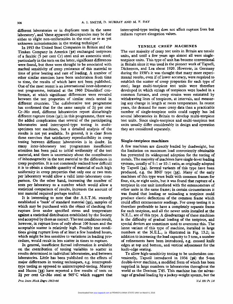
TENSILE CREEP MACHINES The vast majority of creep test units in Britain are tensile units, and until a few years ago almost all were single- testpiece units. This type of unit has become conventional in Britain since it was used in the pioneer work of Tapsell, Dickenson, and Lea about 1920. However, in Germany during the 1930’s it was thought that many more experi- mental results, even if of lower accuracy, were required to establish the scatter of creep properties for each type of steel; large multi-testpiece test units were therefore developed in which strings of testpieces were loaded in a common furnace, and creep strains were estimated by withdrawing lines of testpieces, at intervals, and measur- ing any change in length at room temperature. In recent years, the demand for more creep data than a practicable number of single-testpiece units could supply has led several laboratories in Britain to develop multi-testpiece test units. Since single-testpiece and multi-testpiece test units usually differ considerably in design and operation they are considered separately.
Single-testpiece machines A few machines are directly loaded by deadweight, but the limitation on maximum load conveniently obtainable has prevented its widespread adoption for the testing of metals. The majority of machines have single-lever loading systems, usually of 5: 1 or 10: 1 ratio, as originally adopted by Tapsell (34). Several variants of this type have been produced, e.g. the BNF type (35). Many of the early machines of this type were built with common frames for four, six, or eight units, but it was found that rupture of a testpiece in one unit interfered with the extensometers of other units in the same frame; in certain circumstances it was found that loading or unloading a testpiece could produce elastic deflections of the common frame which could affect extensometer readings. For creep testing it is therefore preferable to have a completely separate frame for each testpiece, and all the newer units installed at the N.E.L. are of this type. A disadvantage of these machines is the difficulty of gradual loading of the testpiece, and special devices are sometimes used to overcome this. The latest variant of this type of machine, installed in large numbers at the N.E.L., is illustrated in Fig. 13.2; in addition to increasing the load capacity to 3 tons, a number of refinements have been introduced, e.g. crossed knife edges at top and bottom, and vertical adjustment for the knife-edge seating.
To allow high-sensitivity testing to be undertaken con- veniently, Tapsell introduced in 1934 (36) the %on double-lever machine, a modified form of which has been supplied in large numbers to laboratories throughout the world as the Denison T45. This machine has the advan- tage of gradual loading by a jockey-weight system, but the
Vol 180 Pt 3A
at PENNSYLVANIA STATE UNIV on March 6, 2016pcp.sagepub.comDownloaded from

CREEP-TESTING EQUIPMENT-DESIGN FEATURES AND CONTROL 307
large magnification of movement by the double-lever system makes necessary repeated resetting of the head if the testpiece creeps a substantial amount, and hence the machine is not specially suitable for rupture testing of many materials. However, several laboratories have motorized the heads (37) to automatically maintain the loading-lever level. An undesirable feature of this machine is that, in the event of a power failure or furnace failure, thermal contraction of testpiece and adaptors results in serious overloading of the testpiece; unfortunately a few long-time tests have been lost by this eventuality. A number of devices have been developed to overcome this, including a toggle-type overload release (38).
T o allow the testing of small specimens in large num- bers, especially for production-acceptance purposes, a small single-lever machine was developed (39). A number of somewhat larger machines of the same general design have been produced, some with built-in electrical-control equipment, a feature which has been adopted in several models designed to be self-contained and compact.
Multi-testpiece machines The adoption of multi-testpiece testing machines in Britain has already been mentioned. Two common types in use are the ‘Unisteel’ (40) and a ‘long-furnace’ version
Fig. 13.2. N.E.L. 3-ton single-lever machine, showing hydraulic loading device Proc Instn Mech Engrs 196566 Vol180 Pt 3A
at PENNSYLVANIA STATE UNIV on March 6, 2016pcp.sagepub.comDownloaded from

308 A. I. SMITH, D. MURRAY AND M. F. DAY
of the N.P.L.-type 2-ton single-lever machine (3). The ‘Unisteel’ machine has four double-lever loading systems in a common frame, and a single furnace in which four sets each of three rupture testpieces or four single creep testpieces equipped with extensometers, can be accom- modated. In units in which the furnace does not have great thermal mass, withdrawal of a line of specimens may affect the temperature of other testpieces in the common furnace. This aspect has been virtually eliminated in the large units, Fig. 13.3, developed by Colvilles (41), in which a large stainless steel core assists thermal stability. In this design, lever-loading with deadweights has been adopted instead of spring-loading as used in many of the Continental units.
Factual information on the effects of interrupted-type testing on creep and rupture properties has not yet been fully reported. There are two aspects to be considered- the effects on creep and rupture of
(a) repeated thermal cycles; and (b) the possible effects of repeated shock-unloading.
Recent German (42) and Russian (43) work indicates that, in some types of multi-testpiece unit, shock- unloading may induce a compression wave which may cause plastic compressive strain. Both these aspects re- quire more extensive investigation.
Loading systems In routine creep testing a constant load is applied, either in single- or multi-testpiece machines, by one of the following methods :
(a) direct deadweight loading; (b) indirect deadweight loading, using either a single-
or multi-lever system; or (c) elastic loading, e.g. by tension or compression in
several types of rupture-tester.
In Britain, single- or double-lever systems are most common in both single- and multi-testpiece machines. Load calibration of all test units should be verified both initially and at suitable intervals, in accordance with B.S. 1610 (44). It is important to establish satisfactory axiality of loading both during calibration of the loading mechanism and in individual test assemblies. Double knife-edge systems are usually adopted at both upper and lower ends of the testpiece-adaptors assembly, and de- velopment of special loading systems, to achieve improved axiality of loading, has been reported (45). Since the complete assembly, including the adaptors between the testpiece and the loading rods, is involved, testing for axiality must be undertaken with a connector system which is the same as that for an actual testpiece. An acceptable technique is the use of a specially prepared testpiece instrumented with strain-measuring devices and loaded within its elastic range. A rectangular specimen fitted with resistance strain gauges is suitable if the quality of the gauges is the highest attainable with current tech- niques; this dummy testpiece can be used after a calibra- tion ring (or other device) has indicated no gross non- axiality affecting calibration of mean loads (46). Axiality in individual tests then largely depends on the quality of the threaded connections on the testpieces and the loading rods, which may be changed between tests. Close
Fig. 13.3. Multi-testpiece creeprupture testing equipment (41) Proc Instn Mech Engrs 1965-66 Vol 180 Pt 3A
at PENNSYLVANIA STATE UNIV on March 6, 2016pcp.sagepub.comDownloaded from

309 CREEP-TESTING EQUIPMENT-DESIGN FEATURES AND CONTROL
tolerances on the threads of testpieces, adaptors, and loading rods help to minimize the risk of non-axiality, and only in tests involving the use of double-sided extensometers can any further precautions be taken.
Creep-testing machines should be re-calibrated and checked for axiality at intervals preferably not greater than 2 years. Serious non-axiality of loading (47) could result in lower creep strength values than the true values, and might also affect rupture properties of brittle materials.
The test specifications stipulate smooth loading, but no loading rates are recommended. In tests involving strain measurements, the loading rate must be slow enough to allow strain readings to be noted, whereas in rupture tests faster loading rates are almost invariably used. How- ever, some materials (e.g. titanium and certain austenitic steels) are sensitive to changes associated with work- hardening effects during or after loading, and short-time creep properties may be noticeably affected if loading procedures are not standardized. Smooth application of load in machines designed for manual loading by adding weights to a scale-pen can be effected by use of screw or hydraulic-jacking systems to transfer the load gradually to the testpiece. Moving jockey-weight loading systems facilitate smooth and controlled rates of loading, at the expense of some additional complication and cost of equipment.
TEMPERATURE MEASUREMENT The B.S. 3500 series for creep and rupture testing stipu- lates the use of temperature measuring equipment with a sensitivity of 0.5 degC, and actual testpiece temperatures (throughout the gauge length) are required to be within f3 degC for temperatures up to 6OO0C, f4 degC be- tween 600" and 8OO"C, and f 6 degC between 800" and 1000°C. At temperatures up to approximately 550"- 600°C base-metal thermocouples, e.g. chromel-alumel, iron-constantan, are often used, but above this tempera- ture range precious metal thermocouples, usually platinum-platinum-rhodium, are required. However, deterioration at very long test times or at temperatures in excess of 800°C may occur even for platinum couples, due partly to diffusion of rhodium across the weld bead.
Accurate temperature measurement (48) requires ex- treme care. Thermocouples should be handled as little as possible to avoid cold-work effects. The diameter of the thermocouple wire should be as small as practicable in order to minimize thermal conduction from the hot- junction. Separate insulators for each lead, rather than twin-bore insulators, reduce the probability of twisting and false hot-junctions. Control of ambient temperature in the laboratory is advantageous, and all contacts and switches in the thermocouple circuits should be of low resistance and of materials which minimize spurious e.m.€'s.
Thermocouples must be firmly in contact with the surface of the testpiece, and the hot-junction must be effectively protected from radiation. The leads in the immediate vicinity of the hot-junction should be, as Proc Instn Mech Etlgrs 1965-66
nearly as possible, at the same temperature as the hot- junction. Tests have shown that negligible differences exist between temperatures at the surface and at the centre of specimens in suitable assemblies (49), but significant errors may occur, particularly in small test units, unless appropriate precautions are taken (33).
There is little published information on the stability of thermocouples over long times at high temperature, but considerable experience has been accumulated, over the years, at the N.P.L., N.E.L., and other laboratories (33). Errors due to instability are small for platinum-platinum- rhodium couples in air; typical calibration drifts at tem- peratures up to the 600"-700°C range, for test durations extending to 30000 hours, have been of the order of 1 or 2 degC.
Sample couples, made from each supply of wire, should be retained as standard reference couples in checking calibration by the comparison method (50). The standard couple should be calibrated by a recognized method (51) (52). In 'comparison' calibration, the thermal conditions should duplicate, as closely as possible, those in the creep test furnace, since differences in the depth of thermo- couple immersion may introduce significant errors.
A simple and reliable form of cold-junction consists of immersion of individual thermocouple leads (protected by glass sheaths) in a pure ice-water mixture. The use of electrically heated cold-junctions, common cold-junctions, and compensating cable may introduce significant errors, particularly with thermocouples of low e.m.f. output. The matching of compensating leads (52) to precious- metal thermocouples is difficult, especially if no laboratory ambient temperature control is employed.
Measurement of thermocouple e.m.f's should be made preferably with precision vernier potentiometers and galvanometers, a sensitivity of 1-2 microvolts being re- quired for precious-metal thermocouples. The absolute accuracy of temperature measurement is dependent on all the equipment used. If generalized temperature-e.m.f. tables produced by manufacturers are accepted as correct, individual couples may be in error by as much as f l degC (52). If all the possible sources of error pro- duced additive errors, it is clear that a substantial fraction of the seemingly wide control of f3 degC, required by B.S. 3500, may be accounted for by inaccuracies of tem- perature measurement, quite apart from actual variations caused by poor control.
A review of the techniques of temperature measurement has been made by Watson (53). It is difficult to envisage a technique more convenient than the use of thermo- couples for creep testing. Development of thermocouples combining the excellent stability of platinum couples with substantially higher e.m.f. outputs would greatly facilitate the adoption of automatic temperature- measuring equipment.
TEMPERATURE CONTROL Control of temperature, to a much closer degree than materials normally experience in service, is required if
VoZ 180 Pt 3A
at PENNSYLVANIA STATE UNIV on March 6, 2016pcp.sagepub.comDownloaded from

310 A. I. SMITH, D. MURRAY AND M. F. DAY
consistent and reliable creep and rupture data are to be obtained. There is evidence that considerable differences can arise from temperature fluctuations, or slight constant divergence from the nominal test temperature (54) (55) (56). Among instances reported are a tenfold change in creep rate with a temperature fluctuation of f10 degF and several per cent increase in creep rate for a tempera- ture increase of only 1 degF.
In early creep-testing equipment, temperature control was frequently achieved with either galvanometer con- trollers with thermocouples as the sensing element, or by magnification of the thermal expansion and contraction of a metallic tube on which the resistance element was wound (57). In recent years, a refined system depending on thermal expansion as the controlling element has been developed in which a swash plate alters the timing of a high-low voltage control (58).
A major advance in temperature control technique was made by Prosser (59), who developed an electronic con- troller using a platinum resistance thermometer in an a.c. bridge network and a proportional time base with a high-low voltage differential. Modifications of this tech- nique were later introduced by Roberts (6o), and by Gartside (61). This system has been continually developed with the a.c. bridge controlling fully proportional solid- state stepless power units utilizing reactors or silicon- controlled rectifiers. Manufacturers claim f 0-2 degC control for later instruments of this type, and although this nominal degree of control may be achieved over short times, it is doubtful if it can be maintained with con- ventional test equipment over thousands of hours. The control achieved in practice depends on the properties of all the components in the circuit, and this degree of con- trol would require extremely high stability of the sensing elements and other critical components in the circuit.
Thermostats using thermocouples as the sensing element in conjunction with galvanometers have been extensively used, particularly in America, but their sensitivity is normally considerably below that of the resistance thermometer types. However, later instruments, using a potentiometric circuit, have narrowed the difference in performance.
In the last ten years, increasing use has been made of multi-specimen testing machines, and the increased size of the furnace has made temperature control easier, owing to the larger thermal mass. Lessells and Barr (41) have reported extremely good temperature control in large test units incorporating a massive furnace.
Temperature control of creep test units is, however, usually extremely difficult if the B.S. 3500 requirements are to be fully met, particularly in tests of many thousand hours’ duration. The use of equipment of the highest quality, consistent attention to detail, and rigid main- tenance of standards of laboratory routine procedures, are essential if the high standards required are to be achieved. Some claims made in the past for temperature control were clearly unrealistic. Even when all reasonable precautions have been taken to maintain temperature Proc Instn Mech Engrs 1965-66
control, occasional excursions outside the specified limits may easily occur, and it is recognized in the B.S. 3500 series that these may not necessarily invalidate the test results. On the other hand, in certain materials, differences of temperature of the order of those permitted by B.S. 3500 may produce unacceptably large differences in creep properties, and even closer control may be required if meaningful results are to be obtained.
MEASUREMENT OF CREEP STRAIN IN UNINTERRUPTED CREEP TESTING
Creep strain measurement by direct viewing, through a hole in the furnace wall, of the displacement of markers attached to the testpiece, has been in use in America (62) for many years, but as it has not been extensively adopted in Britain, it will not be discussed in this paper.
Estimation of creep strain from measurements of the deflection of part of the loading system of the testing machine can provide approximate estimates of strain of limited value, but this procedure will also not be discussed in detail.
The measurement of strain in a testpiece at elevated temperature-even under elastic conditions-presents considerable difficulty, and a wide range of types of extensometer has been developed for this purpose. There are several requirements :
(a) to detect the extension occurring within the test material by the use of a suitable pick-up system;
(b) to transmit this movement to a point outside the test-furnace; and
(c) to translate this movement into a numerical value with an accuracy which is sufficient to meet the require- ments of the appropriate test specification.
The current British creep specifications call for accuracies of 2 per cent of the smallest total creep strain to be measured (B.S. 3500, Part 3) and 1 per cent of the specified strain for relaxation tests (B.S. 3500, Part 6). If it is assumed that the smallest total creep strain to be deter- mined in most creep laboratories is of the order of 0.1 per cent, then, in terms of the requirements of B.S. 3846 for Extensometer Calibration and Grading (an example of which is given in Table 13.1), the creep extensometer should be at least of Grade B; and if it is assumed that 0.15 per cent strain is the smallest total strain to be con- trolled in a stress-relaxation test, then the strain control extensometer for relaxation testing should be of Grade A. For higher values of total strain, the requirements for accuracy are less stringent, and for 1 per cent total strain the grade of extensometer can be as low as E.
Mounting of extensometers The methods of mounting extensometers on testpieces fall into two main classes:
(a) mounting directly on to part of the parallel portion of the testpiece; and
Vol180 Pt 3A
at PENNSYLVANIA STATE UNIV on March 6, 2016pcp.sagepub.comDownloaded from

311 CREEP-TESTING EQUIPMENT-DESIGN FEATURES AND CONTROL
Table 13.1. Example of grading of extensometer of I in gauge length
PrOPeaJr I Grade
Gauge length to be within f in . . . 1 0.0025
Smallest change of indicated or estimated exten-
Repeatability of extension reading in pin at:
sion reading pin (in x . 3
(1) Zerostrain . . . 6 (2) 0.001 st+n . . . . 7.2 (3) o*m straln . . . . 12 (4) 0.010 strain . . . (5) 0.020 strain . . . . i i l ;:
Accuracy of extension reading in pin at: (1) Zerostrain . . . . 10
(3) 0.005 strain . . . . 20 (2) 0.001 strain . . . . 12
0.005 1 0.010 0.010 I 0.010 0.010
120
240 28.8 72 144 288 48 120 240 480
720
12 14.4 24 36 72 180 360 60 120 300 600 1200
20 40 100 200 400 24 48 120 240 480 40 80 200 400 800
I I 1::
(b) mounting on the enlarged ends or heads of the test- piece.
Mounting of extensometers on the parallel length of creep testpieces, for elevated-temperature testing, is generally achieved by either :
(1) employing a set of pointed set-screws (34) or bear- ing edges engaged in light ‘pop’ or scratch marks in the surface of the testpiece, or
(2) mounting a pre-formed re-entrant head which fits over an annular ridge machined integral with a ‘circular’ testpiece (63) or a straight ridge on the side of a rectangular or sheet testpiece.
There are advantages and disadvantages in both methods, and a choice must be made on the basis of the class of testing to be undertaken, and possibly also on the basis of the type of material to be tested.
The method of mounting by set-screws engaging in pop marks in the surface of the parallel length is potentially capable of meeting the requirements of Grade A instru- ments, but it must be used with great care. The size of the marks must be limited, and the angle of the point of the set-screw should be slightly larger than that of the punch used to produce the pop marks, so that engagement occurs at the edges of the marks rather than at their centres. The rigidity of the set-screw in the head of the extensometer must be adequate. Because the pop marks must be small, there is a risk that the set-screws will be- come disengaged from the testpiece at testpiece strains of a few per cent. The usual criticism that the stress- concentration caused by marking the testpiece surface may initiate rupture at these points is less serious than may be supposed, except in the case of very brittle materials or badly made marks.
The method of mounting on ridges machined integral with the parallel length of the testpiece is widely used and, with suitable tensioning devices on the extensometer, Proc Znstn Mrch E g t s 1965-66
(4) 0*010 strain . . . . 30 60 120 300 (5) 0.020 strain . . . . 50 I 100 I 200 , 500
(22)
may retain positive attachment to the testpiece at large strains. In using this type of fixing, however, care must be taken not to load the extensometer limbs excessively in case errors are introduced by the bending strains. The special case of the use of projections for mounting exten- someters on sheet testpieces should be mentioned (63). The head of the extensometer may be mounted on an ‘ear’ on the edge of the sheet testpiece, by the same method as is used for mounting on annular ridges on round test- pieces, in which case particular attention must be paid to the lateral loads on the sheet as well as on the extenso- meter limbs. Alternatively, mounting may be effected by ‘pinching’ the relatively unstressed material of the ‘ears’, on the testpiece, by means of set-screws. Fig. 13.4 illu- strates a form of sheet testpiece used at the N.E.L. and Fig. 13.5 a testpiece-extensometer assembly; photo- elastic analysis of a model testpiece indicated that the stress-intensification, including the effects of clamping loads as well as longitudinal stress concentration, is un- likely to exceed 10 per cent, and this occurs only in a very small region close to the ears. In all the methods of attach- ment using ridges there is the problem of defining the gauge length of the test section; it is commonly taken as the distance between the centres of the ridges or ears, and this should be measured on every testpiece. It is question- able, however, if the definition of the gauge length is sufficiently precise to allow classification as a Grade A, or perhaps even Grade B, extensometer measurement.
If the extensometer is mounted on the head of the test- piece (63), it is accepted that there is an error arising from the use of the parallel length, or the equivalent elastic gauge length, or the distance between the mounting points, as the reference length for calculation of strain; this error may be minimized by choice of as long a parallel length as possible, and short transition sections to the heads of the testpiece. Small transition radii will introduce, however, some stress concentration at the ends of the parallel length. This extensometer mounting technique
Vo1180 P t 3A
600 1200
at PENNSYLVANIA STATE UNIV on March 6, 2016pcp.sagepub.comDownloaded from

312 A. I. SMITH, D. MURRAY AND M. F. DAY
Fig. 13.4. Form of creep testpiece for sheet
does not, therefore, completely overcome the objections raised against the use of pop marks for mounting extenso- meters directly on the parallel length. It is worth noting that there has been but little study of the initiation and spread of creep throughout the gauge length of a creep testpiece.
The main advantage of attaching the extensometer to the heads of the testpiece is that this system of mounting maintains positive location of the extensometer to the testpiece even at very high strains, and at very high tem- peratures at which other methods may be unsuitable. Thus, although this method is an acceptable technique in certain applications, it clearly should not be used for determinations of Young’s modulus values. Many laboratories have adopted it for general creep testing since it does not require marking of the parallel portion of the testpiece, for example by pop marks, which may in low- ductility materials initiate rupture cracks and possibly lead to ‘incorrect’ rupture ductility values.
‘Transmission of movement outside furnace The transmission of the movements (or displacements) detected at the surface of the testpiece to a position outside the furnace is usually achieved by use of rigid limbs made from heat-resisting material. Ideally, the limbs should be unstressed, free from constraint and frictional forces, and should be made of a material which is both resistant to deformation at elevated temperature and not subject to metallurgical transformations which may result in dimen- Prac Instn .Mech Engrs 196566
Fig. 13.5. Sheet testpiece extensometer assembly
sional changes during prolonged use at high temperature. After manufacture, the limbs should be thoroughly stress- relieved at temperatures well above the test-temperature range. Wherever possible, the layout of the limbs, with respect to the heating system, should be chosen so that the small changes in temperature which inevitably occur within the furnace produce equal effects on each limb; thus they should be disposed symmetrically about the furnace axis, but preferably circumferentially rather than radially. The, ‘rod-and-tube’ method of transmitting the relative movement of the extensometer heads is widely used (33) (63), but care must be taken in design and
Val 180 Pt 3A
at PENNSYLVANIA STATE UNIV on March 6, 2016pcp.sagepub.comDownloaded from

313 CREEP-TESTING EQUIPMENT-DESIGN FEATURES AND CONTROL
handling to minimize distortion and consequent friction in the assembly.
Optical extensometers Measurement of the relative movement of the limbs of extensometers is effected, at a convenient position outside the test furnace, by a variety of methods, including mech- anical and optical magnification systems and electrical transducers. For relatively large strains, devices such as dial gauges can be an effective and economic means of indicating extension, provided the gauge movement is relatively free from frictional effects. The recording of dial readings is limited either to direct observation by laboratory assistants, followed by clerical recording, or to lapse-time photography (64) followed by interpretation and clerical recording. These indicators are probably less subject to ‘operator error’ than simple micrometers, and have provided the basis of measurement in many labora- tories in which the minimum total strains to be measured are not much less than 1 per cent. Most other non- electrical extensometers use a combination of a mechanical and an optical lever to produce magnifications sufficient to measure strains in the 0.1 per cent range, or to control stress-relaxation tests in which the total strain is of the order of 0-15 per cent. The two most common systems employ either a rhomb* or a roller (63) as the mechanical lever, whose rotational movement is further magnified by an optical lever formed by a mirror mounted on the spindle of the rhomb or mirror, and a telescope and scale mounted at a suitable distance. The merits of both systems have long been discussed in high-temperature test laboratories, there being a preference, in most of the long-established laboratories, for rhombs.
Rhombs are difficult to make to the required degree of precision, and high-quality knife-edge seatings are also necessary. The theoretical (geometrical) calibration factor is invariably slightly different from the practical cali- bration factor (65), due to the reduction of the effective leverage by the radius required on the working edges of the rhombs. However, the stability of a rhomb in a pair of lightly constrained knife-edge seatings has made this system favoured in laboratories engaged on long-time, high-sensitivity testing in which long-term stability and reliability are essential; experience shows that an efficient design is one in which redundant contacts between the moving parts are avoided. A limitation of the rhomb-and- mirror extensometer is the comparatively short range of movement before non-linearity affects accuracy, but again in laboratories in which there is extensive long-time testing, a range of strain of 1 or 2 per cent between re- settings of the position of the adjustable rhomb seatings is not inconvenient. Rollers, used in high-temperature adaptations of the Lamb extensometer, have the practical advantage that round spindles are much easier to manu- facture to the necessary tolerances, but the effective dia- meter of a roller is often at least l per cent different from the measured value. * A hardened steel spindle having a working section of rhombus shape. Proc Instn Mech Engrs 196546
Well-designed extensometers avoid introduction of longitudinal loads in the limbs, but this is by no means always achieved. The roller system has the obvious advan- tage over the rhomb system that the transformation of longitudinal movement of the limbs into rotary motion is linear, and therefore when a suitably curved scale is used, the calibration of the instrument remains sensibly linear over the whole range of the scale. Disadvantages of the roller system are the less positive positioning of the rollers and the resulting greater liability of lost movement occurring, due to slip.
Time-lapse photography for recording data in silent hours has been used both with rhomb and with roller extensometers. However, whatever the system, the final recording of data and the presentation of creep curves require a substantial clerical effort involving simple arithmetical calculations.
Electrical extensometers Electrical transducers have been used to measure creep strains only to a limited extent, but there is an increasing interest in these devices. There are four types available, and with each the measuring circuit can be arranged to give direct readings, usually with an a.c. or d.c. amplifier to increase the output to an indicator; alternatively, a null-balance circuit may be adopted in which the more stable balancing elements of a bridge are used as the measuring devices.
The least sensitive of the transducers is the rectilinear displacement type, which is a single linear potentiometer. The best of these have sensitivities of about in and ranges of movement of a few inches; they are the electrical equivalent of the thousandth-inch dial gauge, being suitable only for the measurement of relatively large strains. A slightly more sensitive type uses ‘direct- reading’ linear differential transformers in matched pairs, one detecting the motion and the other being adjusted by a mechanical system, coupled to an indicator, to a position producing an equal and anti-phased signal; this is basically the system used in the Baldwin microformer extensometer system (66), and sensitivities of the order of in are attainable. Alternative ‘direct-reading’ use of the linear differential transformer (67) (68) (69) may provide sensitivity of the order of in, but unfortunately this system is often susceptible to long-time zero drift due to variations in amplifier gain.
Another use of the linear differential transformer is in a null-balance bridge circuit (70) (71), and this is now being used as the basis of several creep extensometers (Fig. 13.6). The ‘read-out’ system currently has a manually balanced bridge unit, which necessitates clerical work in recording the data. This system will be more attractive when automatic balancing and ‘read-out’ are available. The sensitivity may be of the order of in, but the overall accuracy for a 0.05 in range is about f 2 x in, i.e. suitable for a Grade A extensometer of gauge length of 2 in or more.
Vol180 P t 3A
at PENNSYLVANIA STATE UNIV on March 6, 2016pcp.sagepub.comDownloaded from

314 A. 1. SMITH, D. MURRAY AND M. F. DAY
Fig, 13.6. Linear differential transformer-type exrenso- meter for 3-ton creep machine
A differential capacitor transducer system has also been used for creep extensometers, either with manually or automatically null-balanced cascade voltage-divider transformers. Sensitivity is of the order of in, with an accuracy of about f 5 x in over a range of about 0-06 in, i.e. suitable for a Grade A extensometer with a gauge length of 5 in or greater (or a Grade B of 2+ in gauge length). The automatic balancing enables digital readings to be obtained.
A differential self-induaance transducer used in a null- balance cascade voltage-driver transformer circuit has a sensitivity of the order of 10- in, and a claimed accuracy of f5x in for a range of f0.025 in (i.e. suitable for Grade A extensometers of gauge lengths greater than 1 in), or f4 x in for a range of f0.1 in (i.e. suitable for Grade B extensometers of gauge lengths greater than 5 in). This bridge system may be either manually or automatically controlled to give a digitized output.
Electrical extensometers, when adequately tested for long-term stability, will become the basis for automatic strain-data handling in the future.
Auxiliary electrical devices have been used for strain Pros Inrtr Meck Engrs 1965-66
control in stress-relaxation testing, the most notable in British laboratories being the low-voltage trigger-arm attachment for rhomb-and-mirror extensometers, de- veloped by Herbert and Armstrong (72), and Draper’s (73) system using a photo-electric cell.
Calibration of extensometers Ideally, creep extensometers should be calibrated, in a suitable rig, at temperatures covering the range over which they are to be used. At present, this is not generally pos- sible owing to the absence of calibration rigs of appro- priate design for elevated-temperature use. An urgent requirement is the development of rigs for this purpose, preferably capable of undertaking even Grade A calibra- tion at typical test temperatures. At present equipment is available for calibration at room temperature (73) (74) (75) (76), using calibrated slip gauges, or accurate lead screws, or by interferometric measurements over short ranges (a few thousandths of an inch) by visual counting of fringes. Until suitable high-temperature calibration rigs become available, it is necessary to assume the validity, at elevated temperatures, of the results of calibration at room temperature according to B.S. 3846. The time re- quired for extensometer calibration is considerable, and will constitute a major commitment for all laboratories claiming to undertake testing to the standards laid down in B.S. 3500.
MEASUREMENT OF CREEP STRAIN IN INTERRUPTED CREEP TESTING
Following extensive use on the Continent, interrupted creep testing is now in common use in Britain also, and is covered by B.S. 3500, Part 4. This type of testing is adopted when it is not convenient to have extensometers attached to the testpieces throughout the tests, and strains are calculated from measurements made at room tem- perature during the interruptions, either between marks on the head of the testpiece or between machined faces on the testpiece ends. In the authors’ experience, the accuracy of measurement attainable with conventional equipment precludes satisfactory determination of strains below about 0.3 per cent, and with small testpieces and unfavourable test conditions the lower acceptable limit of measurement may be little better than 03 per cent. Even in only moderately oxidizing test conditions, defini- tion of the gauge marks may not remain sufficiently precise during long-time testing; again, attempts to employ gauge marks on locally plated platinum areas have been found, in unfavourable circumstances, to be little more successful than pop marks made on the test material.
FUTURE DEVELOPMENTS IN CREEP LABORATORY CONTROL
The staffing of large creep laboratories depends upon the class of testing, short-time investigations requiring sub- stantially more staff, both to set-up and dismantle test
Vol180 Pt 3A
at PENNSYLVANIA STATE UNIV on March 6, 2016pcp.sagepub.comDownloaded from

315 CREEP-TESTING EQUIPMENT-DESIGN FEATURES AND CONTROL
assemblies and to monitor test conditions. In most labora- tories, staff are on duty only during normal working hours, exceptions being the laboratories of a few material manufacturers whose production acceptance testing requires fuller-perhaps even 24-hour-coverage. Normal working hours result in a pattern of creep data in which strain readings are concentrated into about 8 hours in every 24 hours during the 5-day working week, followed by a gap of over 60 hours each weekend, unless special provision is made for readings during that period. Since monitoring of test conditions is at present usually associ- ated with the ‘daily’ readings, there may be an equally long gap in the surveillance of the test facility. Thus, precise temperature measurements by potentiometer may be taken only when strain readings are being re- corded, and since it is impracticable to continuously record the e.m.f. from more than a few thermocouples, there exists no permanent record to prove that the test temperature has remained within the specification limits.
In the next few years there will be increased use of temperature-monitoring equipment and automatic strain- data recording equipment, and advances in data-handling techniques will enable large laboratories to change their procedures radically. Automatic handling of strain meas- urements will present data in a form suitable for com- puters, and it will be necessary to determine the most economic means of processing creep data and the most appropriate forms of numerical analysis in large labora- tories. The first decision is selection of the most economic recording equipment. Strain data should be recorded automatically instead of being handled in numerical form by clerical techniques which at present require consider- able staff time. However, the cost of equipping each creep unit with individual sets of digitized strain-measuring equipment (even if performance, particularly accuracy and stability, were adequate) would be unjustified, since each set of creep data is not large enough to occupy the recording equipment full-time. On the other hand, if the data from all the machines in a laboratory were recorded by a single set of equipment, the problem of sorting the values into collections of data for individual tests must then be solved, This is complicated by variation in fre- quency of recording, dependent on duration of tests. However, the extra cost of sorting equipment would be small compared with the cost of individual sets of equip- ment on each machine; indeed, the sorting could probably be done on the computer used for the analysis of individual tests if the computer had a large enough storage capacity. Processing of creep data by computer to assess the effects of composition and other variables is an obvious develop- ment.
Where the main activity of a testing facility is batch- acceptance testing, the present forms of automatic strain measurement are suitable for indicating the times to specific strain values, but no laboratory yet appears to have achieved this degree of automation for routine tests.
The most useful extension of automation to creep test- ing would be continuous automatic monitoring of tem- R o c Inrtn Mech Engrs 1965-66
perature, with an alarm system to indicate when any temperature is approaching one of the specification limits, e.g. if specified limits are f3 deg C, an alarm could be arranged to indicate deviations greater than 2f. degC. Automatic recording might not be required since actual temperature values may never be used again if tempera- tures remain within specification. For those laboratories using base-metal thermocouples, which give an e.m.f. of the order of 50-100 pV/degC, there is already available a wide range of suitable equipment which was developed originally for use in nuclear power stations. However, for laboratories which cover a test temperature range which necessitates the use of platinum-platinum-rhodium thermocouples, there is at present no commercially avail- able equipment capable of operating at the required levels of accuracy and reliability. When further development work has resulted in the availability of suitable equipment, automatic monitoring of test temperatures and automatic strain recording in large creep laboratories should become a reality.
ACKNOWLEDGEMENTS This paper is published by permission of the Director of the National Engineering Laboratory, Ministry of Technology. It is Crown copyright, and is reproduced by permission of the Controller, H.M. Stationery Office.
APPENDIX 13.1 REFERENCES
(I) GILLETT, H. W. ‘Some things we don’t know about the creep of metals’, Trans. Amer. Inst. mitt. met. Engrs (1939), 135, Iron and Steel, p. 15.
(2) Central Creep Test Research Station, ‘New I.C.I. Develop- ment at Witton’, Merallurgia 1952 (Feb.), 62.
(3) Creep of Steel Laboratory, ‘Description of E.R.A. Leather- head Laboratory’, The Engineer 1961 (Aug. 4), 192.
(4) SMITH, A. I. ‘New high-temperature materials laboratory at N.E.L.: The Fairbairn Building’, N.E.L. Report (to be published 1965).
(5) B.S. A 23: 1948-‘Equipment and method for long-period, high-sensitivity, tensile creep testing’.
(6) B.S. 1686:1950--’B.S. equipment and method for long- period, high-sensitivity, tensile creep testing’.
(7) B.S. 1687:1950-‘B.S. equipment and method for long- period, medium-sensitivity, tensile creep testing’.
(8) B.S. 1688: 1950-‘B.S. equipment and method for the deter- mination of time to rupture under stress, with or without measurement of creep strain’.
(9) I S 0 Recommendation R2Ob‘Creep stress rupture testing of steel at elevated temperatures’ 1961 (June) (Inter- national Organization for Standardization).
(10) I S 0 Recommendation R203-‘Interrupted creep testing of steel at elevated temperatures: Load and temperature interrupted’ 1961 (June).
(11) I S 0 Recommendation R20P‘Non-interrupted creep testing of steel at elevated temperatures’ 1961 (June).
(12) B.S. 3082:1959, Part 2-‘Mechanical testing of steel at elevated temperatures : Stress rupture testing’.
(13) B.S. 3082:1959, Part S‘Mechanical testing of steel at elevated temperatures : Non-interrupted creep testing’.
(14) B.S. 3082:1959, Part +‘Mechanical testing of steel at elevated temperatures : Interrupted creep testing’.
(15) B.S. 3500:1962, Part 1-‘Methods for creep and rupture testing of metals: Uninterrupted tensile rupture testing’.
Vol 180 Pt 3A
at PENNSYLVANIA STATE UNIV on March 6, 2016pcp.sagepub.comDownloaded from

316 A. I. SMITH, D. MURRAY AND M. F. DAY
(16) B.S. 3500:1962, Part 2-‘Methods for creep and rupture testing of metals: Uninterrupted tensile rupture testing’.
(17) B.S. 3500: 1962, Part 3--‘B.S. methods for creep and rupture testing of metals’.
(18) B.S. 3500: 1962, Part P ‘ B . S . methods for creep and rupture testing of metals : Interrupted tensile creep testing’.
(19) B.S. 3500: 1962, Part 5-‘B.S. methods for creep and rupture testing of metals : Production acceptance tests’.
(20) B.S. 3500: 1963, Part 6 ‘ B . S . methods for creep and rupture testing of metals : Tensile stress relaxation testing’.
(21) B.S. 3500: 1964, Part 7-‘B.S. methods for creep and rupture testing of metals: Notch tensile rupture testing’.
(22) B.S. 3846: 1965-‘B.S. methods for calibration and grading of extensometers for testing of metals’.
(23) A.S.T.M. Designation E22-‘Tentative recommended prac- tice for conducting long-time, high-temperature tension tests of metallic materials’. (Tentative 1933-1941 ;
(24) A.S.T.M. Designation ESS-‘Tentative recommended prac- tice for conducting time-for-rupture tension tests for metallic materials’. (Tentative 1950-1958.)
(25) A.S.T.M. Designation El39-58T-‘Tentative recommended practice for conducting creep and time-for-rupture tension tests of materials’. (Issued 1958.)
(26) E83-57T--‘Tentative methods of verification and classi- fication of extensometers’, Amer. SOC. Test. Mater. 1957.
(27) DIN 50118-‘Testing of metallic materials. Creep test’. (Issued 1952.)
(28) GOST 3248-60-‘Metals: Creep test method’. (Issued in 1960 by The Committee of Standards, Measures, and Measuring Instruments of the Council of Ministers of the U.S.S.R.)
(29) ‘Report covering creep tests on 0.35 per cent carbon steel (K20) at 850°F under a stress of 7,500 lb/ina’, prepared by C. L. Clark. Proc. Amer. SOC. Test. Mater. 1938 38 (Pt. l), 130.
(30) ‘Comparative high-temperature properties of British and American steels’, W. E. Bardgett and C. L. Clark. Proc. Znstn mech. Engrs, Lond. 1953.
(31) MURRAY, J. D. Contribution to Discussion at International Conference on Creep, 1963. (Instn Mech. Engrs-to be published.)
‘Problems of calibration and standard- ization of creep-rupture test methods’, Proc. International Conference on Creep 1963. (Instn Mech. Engrs-to be published.)
‘Creep testing at United Steel Companies Ltd’, Metallurgia 1961 (Nov.) 64 (No. 385), 251.
(34) TAPSELL, H. J. Creep o j Metals 1931 (Oxford Univ. Press, London).
(35) MCKEOWN, J. The British Non-ferrous Metals Research Association, ‘Creep and fatigue testing equipment in the laboratories’, Metallurgia 1950 (Sept.), 189.
‘High-sensitivity creep- testing equipment at the National Physical Laboratory’, Engineering, Lond. 1934 137,212.
‘An apparatus for maintaining a constant load on high-sensitivity creep machines’, A.I.D. Report No. M3098 1958 (June).
(38) THORLEY, T. ‘A safety device for double-lever type creep testing machines’, N.G.T.E. Report M194 1955 (Sept.).
(39) HARRIS, G. T. ‘A small-scale creep-testing unit’, Metallurgia 1946 (July) 34, 129.
(40) ‘Unisteel multi-specimen creep testing machine’, Engineering, Lond. 1963 (Oct. 25), 526.
(41) LESSELLS, J. and BARR, R. R. ‘A new multiple-point creep rupture testing machine’, Iron & Steel 1964 (Om.), 491.
(4) KRISCH, A. ‘Compression at rupture of tensile testpieces’ (in German), Arch. f. d. Eisenhfittenw. 1960 8, 491.
(43) GEMINOV, V. N. ‘On testing specimens for rupture strength Proc Znstn Mech Engrs 1965-66
Standud 1941-1958.)
(32) WILLIAMS, W. LEE.
(33) MURRAY, J. D. and HACON, J.
(36) TAPSELL, H. J. and PROSSER, L. E.
(37) JOSLING, A. T. and TRANTER, F. J.
by the chain method’, Zav. Lab. 1962 (Nov.) 28 (ll), 1372.
(4) B.S. 1610:1958, Part 1-‘Methods of load verification, requirements for elastic proving devices, and verification of machines for tension and compression testing’.
(45) JONES, M. H. and BROWN, W. F. ‘An axial loading creep machine’, Bull. Am. SOC. Test. Mater. 1956 (Jan.), 53.
(46) SWINDELLS, B. and DEBNAM, R. C. ‘Methods of load verification of tension and compression testing machines’, Proc. Znstn mech. Engrs, Lond. 1962 176 (33), 911.
(47) MELLGREN, A. ‘Measuring accuracy in creep tests-I: InAuence of eccentricity of load’, Roy. Znst. Tech., Stockholm, Div. Strength of Materials Publ. 1958, No. 125, 19.
(48) B.S. 1041 : 1943-‘Code for temperature measurement’. (49) ‘Temperature distribution in a creep testpiece’, N.P.L.
Metallurgy Division. Report No. M2965 1963 (Jan.). (50) A.S.T.M. Designation E220-63T-‘Comparison calibration
of thermocouples’. (Issued 1963.) (51) HALL, J. A. and BARBER, C. R. ‘Calibration of temperature-
measuring instruments’, Notes on Applied Science 1964 No. 12 (H.M. Stationery Office, London).
(52) HALL, J. A. ‘Practical thermometry’, Znstn Physics Mono- graph 1953.
(53) WATSON, G. G. ‘A survey of techniques for measuring surface temperatures’, N.E.L. Report No. 153 1964(June).
(54) AVERY, H. S. ‘Cyclic temperature acceleration of strain in heat-resisting alloys’, Trans. Arne*. SOC. Metals 1942 30, 1130.
(55) ROBINSON, E. L. ‘Effect of temperature variation on the creep strength of steels’, Trans. Amer. SOC. mech. Engrs 1938 60,253.
(56) LOW, T. W., JEPSON, M. D. and RAIT, J. R. ‘The control of electric element furnaces to fine limits at high tem- peratures for research purposes’, 3. Iron St. Znst. 1951 (June) 168, 126.
(57) BAILEY, R. W. and ROBERTS, A. M. ‘Testing of materials for service in high-temperature steam plant’, Proc. Znsrn mech. Engrs, Lond. 1932 122, 209.
(58) ‘Sensitive temperature controller’, Engineering, Lond. 1951 (Aug. 17).
(59) PROSSER, L. E. ‘Alternating current bridge thermostat for creep testing’, Engineering, Lond. 1939 148, 95.
(60) ROBERTS, M. H. ‘Electronic controllers for laboratory furnaces’, Electron. Engng 1951 (Feb.).
(61) GARTSIDE, F. ‘Electronic controller for use with high- temperature creep-testing equipment’, Metallurgia 1950 (Sept.) 42,211.
(62) SMITH, G. V., MILLER, R. F. and BENZ, W. G. ‘Creep and creep-rupture testing’, Proc. Amer. SOC. Test. Mater. 1947 47,615.
(63) WHEATLEY, C. and BUCHAN, J. ‘The measurement of plastic strain in long-time creep tests at temperatures up to 1000”C, Metallurgia 1962 (Aug.) 66, 91.
(64) WALMSLEY, A. E. and TRANTER, F. J. ‘An extensometer with camera attachment for high-sensitivity creep tests’, A.I.D. Report No. Met128 1956 (July).
(65) BROWN, A. F. C. ‘Calibration of mirror extensometers by optical interference’, Engineering, Lond. 1958 186,180.
(66) GOSSICK, B. R. ‘Design of extensometer for creep studies’, Rev. scient. Znstrum. 1954 (Sept.) 25 (9), 907.
(67) SCHAEVITZ, H. ‘The linear differential transformer’, Proc. SOC. exper. Stress Analydis 1947 4 (ll), 79.
(68) HEATH, J. H. ‘An instrument for long-term creep measure- ments’,Jl R . nav. scient. Sew. 1954 (Mar.) 9 (2).
(69) LEEMAN, E. R. and GROBBELAR, C. ‘A lateral extensometer for the determination of Poisson’s ratio of rock‘, 31 scient. Znstrum. 1957 34,503.
‘Inductance bridge for sensitive displacement measurements over long periods’, Jl scient. Znsmun. 1959 (July) 36, 312.
Vol 180 Pt 3A
(70) MURRAY, D.
at PENNSYLVANIA STATE UNIV on March 6, 2016pcp.sagepub.comDownloaded from

CREEP-TESTING EQUIPMENT-DESIGN FEATURES AND CONTROL 317
(71) CLINTON, A. C. ‘Creep-Fresh work on a familiar prob- lem’, Airways International 1964 (May-June).
(72) HERBERT, D. C. and ARMSTRONG, D. J. ‘The development of a strain or displacement-activated electronic trigger for high-temperature stress-relaxation testing and other purposes’, Metallurgia 1952 45 (271), 267.
(73) DRAPER, J. H. M. ‘Stress-relaxation testing-Tests at constant strain and decreasing load’, Engineering, Lond. 1955 179,564.
(74) STANG, A. H. and SWEETMAN, L. R. ‘An extensometer
comparator,J. Res. natn. Bur. Stand. 1935 (Sept.) 15 (3), 199.
(75) TEMPLIN, R. L. ‘The calibration of extensometers’, Proc. Amer. SOC. Test. Muter. 1928 28 (Pt. 2), 714.
(76) ABER, W. C. and HOWELL, F. M. ‘A method of calibrating extensometers’, Bull. Am. SOC. Test. Muter. 1948, No. 155 (Dec.), p. 33.
(77) RICKWOOD, G. E. ‘An extensometer calibrator’, Mech. Engng Rep. natn. Res. Coun. Can. MH 102, 1963 (Aw.).
Proc Inrtn Mech Engrs 196566 Vol 180 Pt 3A
at PENNSYLVANIA STATE UNIV on March 6, 2016pcp.sagepub.comDownloaded from