
Ordering equipment
287
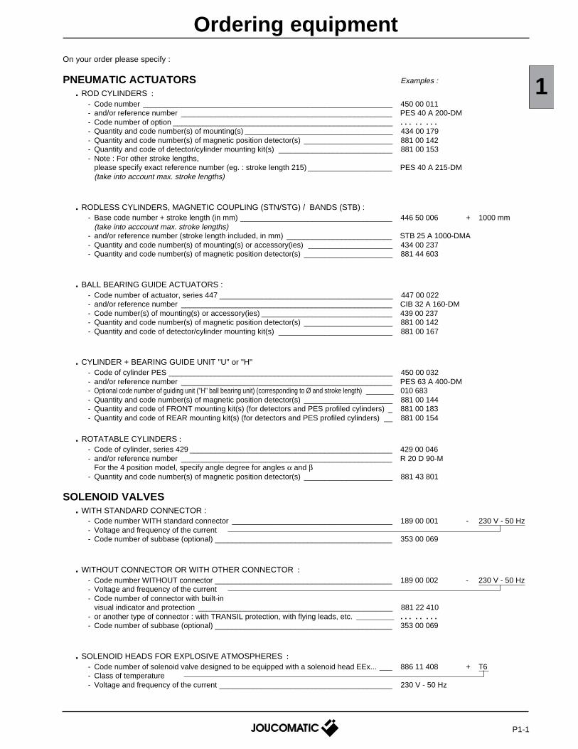
Ordering equipment On your order please specify : PNEUMATIC ACTUATORS Examples : . ROD CYLINDERS : - Code number ___________________________________________________________ 450 00 011 - and/or reference number __________________________________________________ PES 40 A 200-DM - Code number of option ____________________________________________________ . . . . . . . . - Quantity and code number(s) of mounting(s) ___________________________________ 434 00 179 - Quantity and code number(s) of magnetic position detector(s) _____________________ 881 00 142 - Quantity and code of detector/cylinder mounting kit(s) ___________________________ 881 00 153 - Note : For other stroke lengths, please specify exact reference number (eg. : stroke length 215) ____________________ PES 40 A 215-DM (take into account max. stroke lengths) . RODLESS CYLINDERS, MAGNETIC COUPLING (STN/STG) / BANDS (STB) : - Base code number + stroke length (in mm) ____________________________________ 446 50 006 + 1000 mm (take into acccount max. stroke lengths) - and/or reference number (stroke length included, in mm) _________________________ STB 25 A 1000-DMA - Quantity and code number(s) of mounting(s) or accessory(ies) ____________________ 434 00 237 - Quantity and code number(s) of magnetic position detector(s) _____________________ 881 44 603 . BALL BEARING GUIDE ACTUATORS : - Code number of actuator, series 447 _________________________________________ 447 00 022 - and/or reference number __________________________________________________ CIB 32 A 160-DM - Code number(s) of mounting(s) or accessory(ies) _______________________________ 439 00 237 - Quantity and code number(s) of magnetic position detector(s) _____________________ 881 00 142 - Quantity and code of detector/cylinder mounting kit(s) ___________________________ 881 00 167 . CYLINDER + BEARING GUIDE UNIT "U" or "H" - Code of cylinder PES _____________________________________________________ 450 00 032 - and/or reference number __________________________________________________ PES 63 A 400-DM - Optional code number of guiding unit ("H" ball bearing unit) (corresponding to Ø and stroke length) ________ 010 683 - Quantity and code number(s) of magnetic position detector(s) _____________________ 881 00 144 - Quantity and code of FRONT mounting kit(s) (for detectors and PES profiled cylinders) _ 881 00 183 - Quantity and code of REAR mounting kit(s) (for detectors and PES profiled cylinders) __ 881 00 154 . ROTATABLE CYLINDERS : - Code of cylinder, series 429 ________________________________________________ 429 00 046 - and/or reference number __________________________________________________ R 20 D 90-M For the 4 position model, specify angle degree for angles α and β - Quantity and code number(s) of magnetic position detector(s) _____________________ 881 43 801 SOLENOID VALVES . WITH STANDARD CONNECTOR : - Code number WITH standard connector ______________________________________ 189 00 001 - 230 V - 50 Hz - Voltage and frequency of the current - Code number of subbase (optional) __________________________________________ 353 00 069 . WITHOUT CONNECTOR OR WITH OTHER CONNECTOR : - Code number WITHOUT connector __________________________________________ 189 00 002 - 230 V - 50 Hz - Voltage and frequency of the current - Code number of connector with built-in visual indicator and protection ______________________________________________ 881 22 410 - or another type of connector : with TRANSIL protection, with flying leads, etc. __________ . . . . . . . . - Code number of subbase (optional) __________________________________________ 353 00 069 . SOLENOID HEADS FOR EXPLOSIVE ATMOSPHERES : - Code number of solenoid valve designed to be equipped with a solenoid head EEx... ___ 886 11 408 + T6 - Class of temperature - Voltage and frequency of the current _________________________________________ 230 V - 50 Hz 1 P1-1
-
Upload
khangminh22 -
Category
Documents
-
view
17 -
download
0
Transcript of Ordering equipment
Ordering equipmentOn your order please specify :
PNEUMATIC ACTUATORS Examples :
. ROD CYLINDERS :- Code number ___________________________________________________________ 450 00 011- and/or reference number __________________________________________________ PES 40 A 200-DM- Code number of option ____________________________________________________ . . . . . . . .- Quantity and code number(s) of mounting(s) ___________________________________ 434 00 179- Quantity and code number(s) of magnetic position detector(s) _____________________ 881 00 142- Quantity and code of detector/cylinder mounting kit(s) ___________________________ 881 00 153- Note : For other stroke lengths,
please specify exact reference number (eg. : stroke length 215) ____________________ PES 40 A 215-DM(take into account max. stroke lengths)
. RODLESS CYLINDERS, MAGNETIC COUPLING (STN/STG) / BANDS (STB) :- Base code number + stroke length (in mm) ____________________________________ 446 50 006 + 1000 mm
(take into acccount max. stroke lengths)- and/or reference number (stroke length included, in mm) _________________________ STB 25 A 1000-DMA- Quantity and code number(s) of mounting(s) or accessory(ies) ____________________ 434 00 237- Quantity and code number(s) of magnetic position detector(s) _____________________ 881 44 603
. BALL BEARING GUIDE ACTUATORS :- Code number of actuator, series 447 _________________________________________ 447 00 022- and/or reference number __________________________________________________ CIB 32 A 160-DM- Code number(s) of mounting(s) or accessory(ies) _______________________________ 439 00 237- Quantity and code number(s) of magnetic position detector(s) _____________________ 881 00 142- Quantity and code of detector/cylinder mounting kit(s) ___________________________ 881 00 167
. CYLINDER + BEARING GUIDE UNIT "U" or "H"- Code of cylinder PES _____________________________________________________ 450 00 032- and/or reference number __________________________________________________ PES 63 A 400-DM- Optional code number of guiding unit ("H" ball bearing unit) (corresponding to Ø and stroke length) ________ 010 683- Quantity and code number(s) of magnetic position detector(s) _____________________ 881 00 144- Quantity and code of FRONT mounting kit(s) (for detectors and PES profiled cylinders) _ 881 00 183- Quantity and code of REAR mounting kit(s) (for detectors and PES profiled cylinders) __ 881 00 154
. ROTATABLE CYLINDERS :- Code of cylinder, series 429 ________________________________________________ 429 00 046- and/or reference number __________________________________________________ R 20 D 90-M
For the 4 position model, specify angle degree for angles α and β- Quantity and code number(s) of magnetic position detector(s) _____________________ 881 43 801
SOLENOID VALVES. WITH STANDARD CONNECTOR :
- Code number WITH standard connector ______________________________________ 189 00 001 - 230 V - 50 Hz- Voltage and frequency of the current- Code number of subbase (optional) __________________________________________ 353 00 069
. WITHOUT CONNECTOR OR WITH OTHER CONNECTOR :- Code number WITHOUT connector __________________________________________ 189 00 002 - 230 V - 50 Hz- Voltage and frequency of the current- Code number of connector with built-in
visual indicator and protection ______________________________________________ 881 22 410- or another type of connector : with TRANSIL protection, with flying leads, etc. __________ . . . . . . . .- Code number of subbase (optional) __________________________________________ 353 00 069
. SOLENOID HEADS FOR EXPLOSIVE ATMOSPHERES :- Code number of solenoid valve designed to be equipped with a solenoid head EEx... ___ 886 11 408 + T6- Class of temperature- Voltage and frequency of the current _________________________________________ 230 V - 50 Hz
1
P1-1
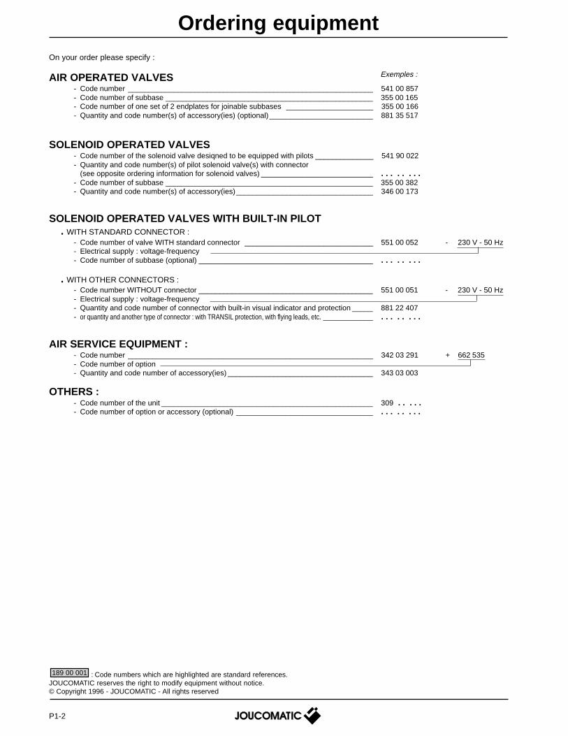
On your order please specify :
AIR OPERATED VALVES- Code number ___________________________________________________________ 541 00 857- Code number of subbase __________________________________________________ 355 00 165- Code number of one set of 2 endplates for joinable subbases _____________________ 355 00 166- Quantity and code number(s) of accessory(ies) (optional)_________________________ 881 35 517
SOLENOID OPERATED VALVES- Code number of the solenoid valve desiqned to be equipped with pilots ______________ 541 90 022- Quantity and code number(s) of pilot solenoid valve(s) with connector
(see opposite ordering information for solenoid valves) ___________________________ . . . . . . . .- Code number of subbase __________________________________________________ 355 00 382- Quantity and code number(s) of accessory(ies)_________________________________ 346 00 173
SOLENOID OPERATED VALVES WITH BUILT-IN PILOT. WITH STANDARD CONNECTOR :
- Code number of valve WITH standard connector _______________________________ 551 00 052 - 230 V - 50 Hz- Electrical supply : voltage-frequency- Code number of subbase (optional) __________________________________________ . . . . . . . .
. WITH OTHER CONNECTORS :- Code number WITHOUT connector __________________________________________ 551 00 051 - 230 V - 50 Hz- Electrical supply : voltage-frequency- Quantity and code number of connector with built-in visual indicator and protection _____ 881 22 407- or quantity and another type of connector : with TRANSIL protection, with flying leads, etc. ____________ . . . . . . . .
AIR SERVICE EQUIPMENT :- Code number ___________________________________________________________ 342 03 291 + 662 535- Code number of option- Quantity and code number of accessory(ies) ___________________________________ 343 03 003
OTHERS :- Code number of the unit ___________________________________________________ 309 . . . . .- Code number of option or accessory (optional) _________________________________ . . . . . . . .
Ordering equipment
: Code numbers which are highlighted are standard references.JOUCOMATIC reserves the right to modify equipment without notice.© Copyright 1996 - JOUCOMATIC - All rights reserved
189 00 001
Exemples :
P1-2
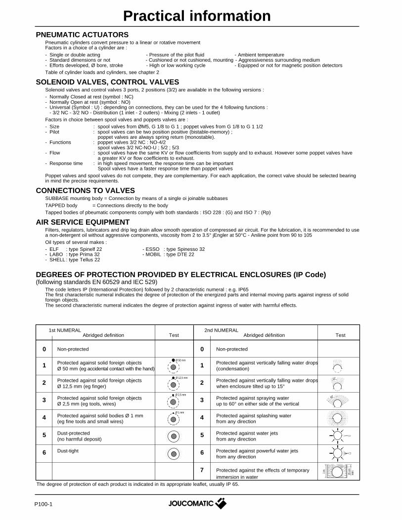
1st NUMERAL 2nd NUMERALAbridged definition Test Abridged définition Test
Non-protected Non-protected
Protected against solid foreign objects Protected against vertically falling water dropsØ 50 mm (eg accidental contact with the hand) (condensation)
Protected against solid foreign objects Protected against vertically falling water dropsØ 12,5 mm (eg finger) when enclosure tilted up to 15°
Protected against solid foreign objects Protected against spraying waterØ 2,5 mm (eg tools, wires) up to 60° on either side of the vertical
Protected against solid bodies Ø 1 mm Protected against splashing water(eg fine tools and small wires) from any direction
Dust-protected Protected against water jets(no harmful deposit) from any direction
Dust-tight Protected against powerful water jetsfrom any direction
Protected against the effects of temporaryimmersion in water
60˚
15 c
mm
ini
1 m
15˚Ø 12,5 mm
Ø 2,5 mm
Ø 1 mm
Ø 50 mm
1
2
3
4
5
6
7
0
1
2
3
4
5
6
0
The degree of protection of each product is indicated in its appropriate leaflet, usually IP 65.
PNEUMATIC ACTUATORSPneumatic cylinders convert pressure to a linear or rotative movementFactors in a choice of a cylinder are :- Single or double acting - Pressure of the pilot fluid - Ambient temperature- Standard dimensions or not - Cushioned or not cushioned, mounting - Aggressiveness surrounding medium- Efforts developed, Ø bore, stroke - High or low working cycle - Equipped or not for magnetic position detectorsTable of cylinder loads and cylinders, see chapter 2
SOLENOID VALVES, CONTROL VALVESSolenoid valves and control valves 3 ports, 2 positions (3/2) are available in the following versions :- Normally Closed at rest (symbol : NC)- Normally Open at rest (symbol : NO)- Universal (Symbol : U) : depending on connections, they can be used for the 4 following functions :
- 3/2 NC - 3/2 NO - Distribution (1 inlet - 2 outlers) - Mixing (2 inlets - 1 outlet)Factors in choice between spool valves and poppets valves are :- Size : spool valves from ØM5, G 1/8 to G 1 ; poppet valves from G 1/8 to G 1 1/2- Pilot : spool valves can be two position positive (bistable-memory) ;
poppet valves are always spring return (monostable).- Functions : poppet valves 3/2 NC : NO-4/2
spool valves 3/2 NC-NO-U ; 5/2 ; 5/3- Flow : spool valves have the same KV or flow coefficients from supply and to exhaust. However some poppet valves have
a greater KV or flow coefficients to exhaust.- Response time : in high speed movement, the response time can be important
Spool valves have a faster response time than poppet valvesPoppet valves and spool valves do not compete, they are complementary. For each application, the correct valve should be selected bearingin mind the precise requirements.
CONNECTIONS TO VALVESSUBBASE mounting body = Connection by means of a single oi joinable subbasesTAPPED body = Connections directly to the bodyTapped bodies of pbeumatic components comply with both standards : ISO 228 : (G) and ISO 7 : (Rp)
AIR SERVICE EQUIPMENTFilters, regulators, lubricators and drip leg drain allow smooth operation of compressed air circuit. For the lubrication, it is recommended to usea non-detergent oil without aggressive components, viscosity from 2 to 3.5° jEngler at 50°C - Aniline point from 90 to 105Oil types of several makes :- ELF : type Spinelf 22 - ESSO : type Spinesso 32- LABO : type Prima 32 - MOBIL : type DTE 22- SHELL : type Tellus 22
DEGREES OF PROTECTION PROVIDED BY ELECTRICAL ENCLOSURES (IP Code)(following standards EN 60529 and IEC 529)
The code letters IP (International Protection) followed by 2 characteristic numeral : e.g. IP65The first characteristic numeral indicates the degree of protection of the energized parts and internal moving parts against ingress of solidforeign objects.The second characteristic numeral indicates the degree of protection against ingress of water with harmful effects.
P100-1
Practical information
1EASY CONNECTIONS
The pilot valves series 190/192 and solenoid operated valves equipped with these pilots,are delivered with a connector size 30, rotatable x 90°, complying with standard ISO4400. Top cover removable so that one can chek that the coil is energized withoutunplugging the connector and hence without interrupting operation of the solenoidvalve.These valves can be equipped with cable outlets, 2 m long, or with built-in visual indicator(LED) and electrical protection, or with transil protection.
SAFETY EQUIPMENT FOR EXPLOSIVE ATMOSPHERESMost of our solenoid valves, spool and poppet valves can be equipped with EEx solenoid headscomplying with CENELEC European standards for use in explosive atmospheres :- Flameproof enclosures "d" (solenoid valves series 192)- Encapsulation "m" (solenoid valves series 189 and 192)- Instrinsically safe equipment "ia" (solenoid valves 195 and 302)
(See end of chapter 5)
PRESSURES. Maximum allowable pressure (MAP) : The maximum allowable pressure (MAP) in pipework is the maximum effective pressure
(in bar or in Pa) which can be applied to the pipework in the relevant installation (1 bar = 102 kPa)
. Inlet pressure : fluid pressure at the entrance to the pneumatic component
. Outlet pressure : fluid pressure at the exit from the pneumatic component
. Differential pressure ∆ P : difference in pressure between the inlet pressure and the outlet pressure.
FLOW COEFFICIENTS. KV (following standard NF E 29312) :
The flow rating of a valve is expressed as the KV - a French coefficient established experimentally for each valve. It corresponds tothe flow of water in litres per minute with a pressure differential ∆P of 1 bar with the orifice fully open.
. CV : The CV indicated in the tables is an equivalent KV flow coefficient but expressed in US gallons per minute with ∆P = 1 psi.CV and KV can be transfered as follows : KV = 14,3 CV and CV = 0,07 KV
. C and b (following standard ISO 6358) :Coefficients C (sonic conductance) and b (critical pressure ratio) following standard ISO 6358 allow flow calculation in sonic state(See spool valves 541 - 543 - chapters 4 and 5).
. Flow graphs : (see overleaf).
∆ P ≥ P inlet /2(Maximum allowable flow)
Q = 14 x KV x Pou
including correction for temperature and density
Q = 238,33 x KV x Pou x 1
CALCULATION OF FLOW (for air and gas). Defining flow at 6 bar :
Corresponding leaflets give for each product its mean flow in litres per minute at 6 bar in Normal Atmosphere Pressure (ANR) following standards ISO 8778 (with ∆∆∆∆∆ P = 1 bar)
. Calculation of flow :
∆ P < P inlet /2
Q = 28,16 x KV x ∆P x Pin
including correction for temperature and density
Q = 475 x KV x (∆P x Pin)
(Ta x d)
Pin = Absolute inlet pressure, in barPou = Absolute outlet pressure, in bar
(Ta x d)
Ta = Absolute temperature, in Celsius degreesd = Density compared with air
Q = Flow in l/min∆P = Differential pressure, in bar
P100-2
Practical information
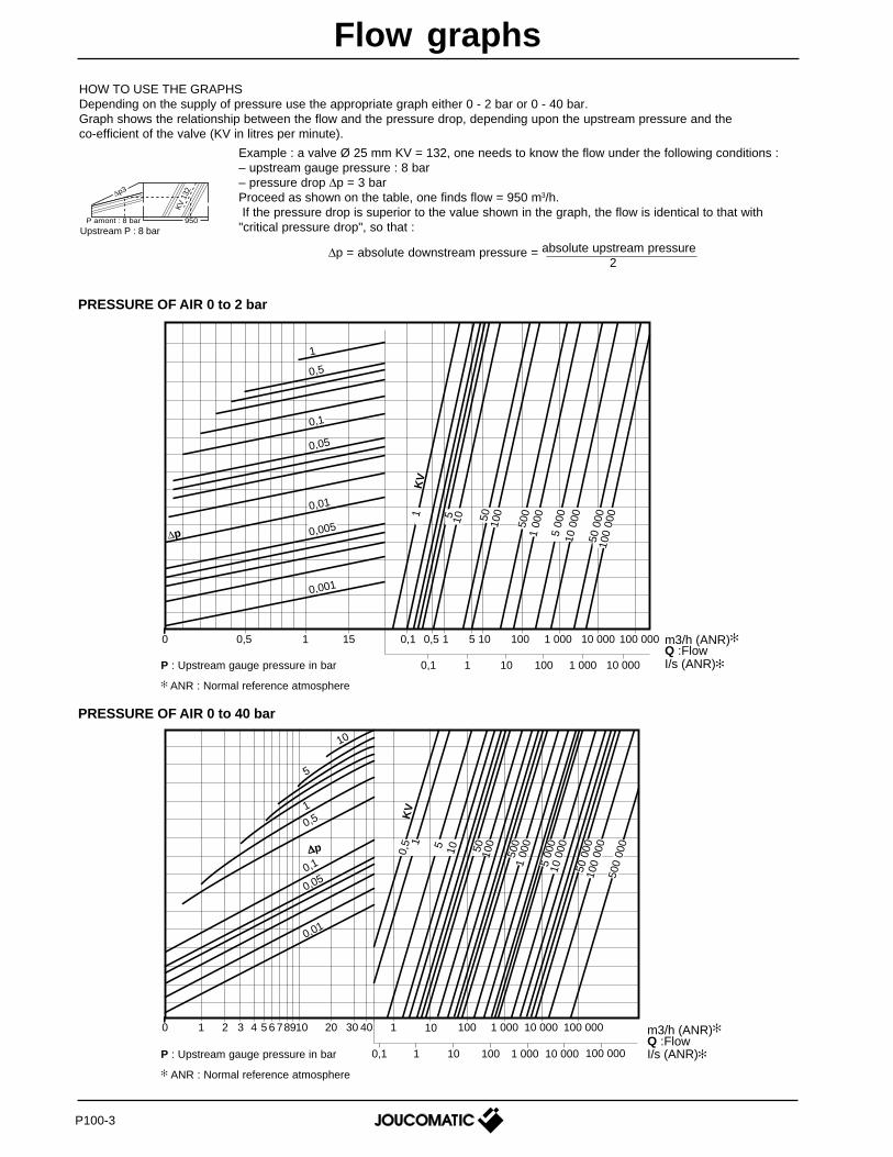
HOW TO USE THE GRAPHSDepending on the supply of pressure use the appropriate graph either 0 - 2 bar or 0 - 40 bar.Graph shows the relationship between the flow and the pressure drop, depending upon the upstream pressure and theco-efficient of the valve (KV in litres per minute).
Example : a valve Ø 25 mm KV = 132, one needs to know the flow under the following conditions :– upstream gauge pressure : 8 bar– pressure drop ∆p = 3 barProceed as shown on the table, one finds flow = 950 m3/h. If the pressure drop is superior to the value shown in the graph, the flow is identical to that with"critical pressure drop", so that :
1
1K
V
5 10 5010
0
500
1 00
0
5 00
010
000
50 0
0010
0 00
0
0,1
0,05
0,01
∆p 0,005
0,001
0,5
0 0,5 1 15 0,1 0,5
0,1 1 10 100 1 000
1 5 10 100 1 000 10 000
10 000
100 000Qm
P : Upstream gauge pressure in bar
ANR : Normal reference atmosphere
10,
5
105
10050
1 00
050
0
10 0
00
5 00
0
100
000
500
000
50 0
00
KV
∆p
0 1 2 3 4 65 78910 20 30 40 1 10
0,1 1 10 100 1 000 10 000
100 1 000 10 000 100 000
100 000
0,01
0,050,1
1
5
10
0,5
P : Upstream gauge pressure in bar
ANR : Normal reference atmosphere
∆p = absolute downstream pressure = absolute upstream pressure2
PRESSURE OF AIR 0 to 2 bar
PRESSURE OF AIR 0 to 40 bar
m3/h (ANR)Q :FlowI/s (ANR)
∆p3
P amont : 8 bar 950
KV 1
32
Upstream P : 8 bar
m3/h (ANR)Q :FlowI/s (ANR)
P100-3
Flow graphs
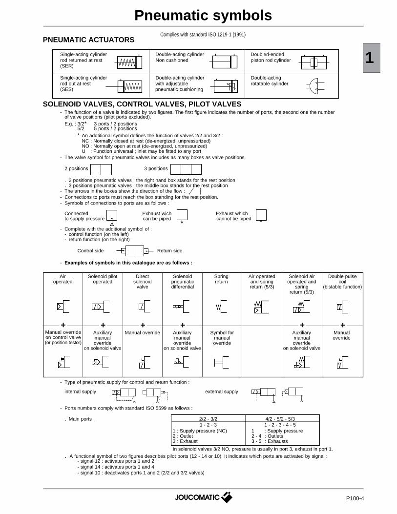
1PNEUMATIC ACTUATORS
Single-acting cylinder Double-acting cylinder Doubled-endedrod returned at rest Non cushioned piston rod cylinder(SER)
Single-acting cylinder Double-acting cylinder Double-actingrod out at rest with adjustable rotatable cylinder(SES) pneumatic cushioning
SOLENOID VALVES, CONTROL VALVES, PILOT VALVES- The function of a valve is indicated by two figures. The first figure indicates the number of ports, the second one the number
of valve positions (pilot ports excluded).E.g. : 3/2* 3 ports / 2 positions
5/2 5 ports / 2 positions* An addtitional symbol defines the function of valves 2/2 and 3/2 :
NC : Normally closed at rest (de-energized, unpressurized)NO : Normally open at rest (de-energized, unpressurized)U : Function universal ; inlet may be fitted to any port
- The valve symbol for pneumatic valves includes as many boxes as valve positions.
2 positions 3 positions
. 2 positions pneumatic valves : the right hand box stands for the rest position
. 3 positions pneumatic valves : the middle box stands for the rest position- The arrows in the boxes show the direction of the flow :- Connections to ports must reach the box standing for the rest position.- Symbols of connections to ports are as follows :
Connected Exhaust wich Exhaust whichto supply pressure can be piped cannot be piped
- Complete with the additional symbol of :- control function (on the left)- return function (on the right)
Control side Return side
- Examples of symbols in this catalogue are as follows :
- Type of pneumatic supply for control and return function :
internal supply external supply
- Ports numbers comply with standard ISO 5599 as follows :
. Main ports : 2/2 - 3/2 4/2 - 5/2 - 5/31 - 2 - 3 1 - 2 - 3 - 4 - 5
1 : Supply pressure (NC) 1 : Supply pressure2 : Outlet 2 - 4 : Outlets3 : Exhaust 3 - 5 : Exhausts
In solenoid valves 3/2 NO, pressure is usually in port 3, exhaust in port 1.
. A functional symbol of two figures describes pilot ports (12 - 14 or 10). It indicates which ports are activated by signal :- signal 12 : activates ports 1 and 2- signal 14 : activates ports 1 and 4- signal 10 : deactivates ports 1 and 2 (2/2 and 3/2 valves)
Airoperated
Solenoid pilotoperated
Directsolenoid
valve
Air operatedand springreturn (5/3)
Solenoid airoperated and
springreturn (5/3)
Double pulsecoil
(bistable function)
Auxiliarymanualoverride
on solenoid valve
Manual override Auxiliarymanualoverride
on solenoid valve
Symbol formanualoverride
Auxiliarymanualoverride
on solenoid valve
Manualoverride
+ + + + + +
Solenoidpneumaticdifferential
Springreturn
Pneumatic symbols
P100-4
Manual overrideon control valve(or position testor)
Complies with standard ISO 1219-1 (1991)
-
-
-
-
PNEUMATIC ACCESSORIES
PNEUMATIC LOGIC (following standard ISO 5784)
1 3
2
1 32 1
1 3&2
1 3
MANUAL AND MECHANICAL OPERATED SOLENOID VALVES
(1) With manual override on solenoid pilots.
3/2
4/2
5/2
5/3
FunctionAir operated
Symbols Control ReturnSolenoid operated
Symbols Control ReturnPorts/
Positions
-
-
air
air
air
air
air
air
air
-
-
-
-
spring
air
spring
spring
spring
differential
air
-
-
NC
NO
NC
NC
NO
W1
W2
W3
solenoid
solenoid
open positionto pressure (W2)
air operated
closed position (W1)air operated
open positonto exhaust (W3)
air operated
open positionto exhaust (W3)
solenoid operated
open positionto pressure (W2)solenoid operated
Examples of symbols in this catalogue are as follows
spring
spring
spring
spring
spring
spring
airdifferential
air
FunctionManual control
Symbols Control ReturnMechanical control
Symbols Control ReturnPorts/
Positions
roller
plunger
plunger
spring
spring
spring5/2 - 5/3
3/2NC
NO
-
pedal
manual
lever
spring
spring
spring
Filter Regulator Lubricator FRL unit(simplifieddiagram)
OR element(sum)
YES element(identity)
Programsequencermodule
Timer
One wayajustablerestrictor valve
Silencer Non-returnvalve
Adjustablepressureswitch
2 3
1P
1 3
0,4
ajustablerestrictor valvebi-directional
Quickexhaustvalve
Shuttle valve Indicator
11412
42
(X)(X)
1 3
AND element(product)
NOT element(negation)
Memoryrelay
Singlepulsegenerator
2
3 1
12
2
3 1
12 10
2
3 1
10
2
3
14 412
1
2
35
14 412
1
14 1214 2
35
4
1
14 1214 2
35
4
1
2
13
2
3 1
2
3
12
1
2
3
12
1
10
2
3
10
1
2
3
14 412
1
2
35
14 412
1
14 1214 2
35
4
1
2
35
14 412
1
14 1214 2
35
4
1
14 1214 2
35
4
1
24
35
14 12
1
24
35
14 12
1
24
35
14 12
1
24
35
14 12
1
24
35
14 12
1
24
35
14 12
1
2
3 1
24
351
2
13
2
3 1
2
35
4
1
2
13
AIR SERVICE EQUIPMENT
1 3
2
13
&
1 31
2
solenoid / airdifferential
closed position (W1)solenoidoperated
(1)
P100-5
Dire
ctop
erat
edP
ilot
oper
ated
solenoid / air
solenoid / air solenoid / air
solenoid / air
solenoid / air
solenoid / air
solenoid / air
solenoid / air
solenoid / air
solenoid / air solenoid / air
Pneumatic symbols
2
P200-R2
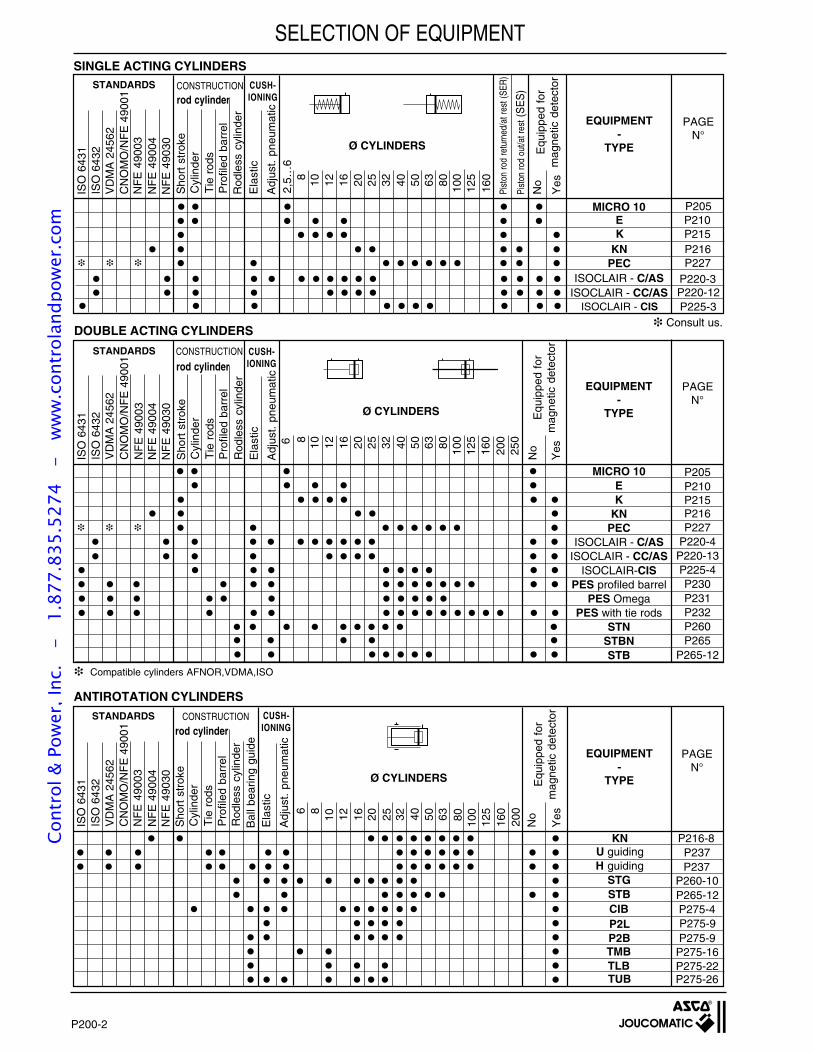
PNEUMATIC ACTUATORS(linear - rotatable cylinders and tables)
Summary
Products Type Series PageMicro-cylinders Ø 2,5-4 and 6 mm MICRO 10 435 P205Panel air cylinders Ø 6-10-16 mm E 429 P210Short-stroke air cylinders Ø 8 to 100 mm K 441 P215Short-stroke air cylinders Ø 20 - 25 mm - AFNOR NFE 49-004 KN 442 P216Air cylinders ISOCLAIR Ø 8 to 25 mm - ISO/CETOP/AFNOR C.AS 435 P220Air cylinders ISOCLAIR - COMPACT Ø 12 to 25 mm CC.AS 435 P220-11Air cylinders ISOCLAIR Ø 32 to 63 mm - ISO/CETOP CIS 438 P225Compact cylinders Ø32 to 100 mm compatible with VDMA/ISO PEC 449 P227Air cylinders with integrated pilot valves Ø 40 to 63 mm compatible with VDMA/ISO PEC 449 P228Eurostandard cylinders Ø 32 to 125 mm with profiled barrel-VDMA/ISO PES 450 P230Eurostandard Omega cylinders Ø 32 to 80 mm - VDMA/ISO PES 450 P231Eurostandard cylinders Ø 32 to 200 mm with tie rods - VDMA/ISO PES 450 P232"U" & "H" guiding units with slide or ball bearings/cylinders PES Ø 32 to 100 mm _ _ P237Rod lock for air cylinders PES Ø 40 to 100 mm _ _ P238Eurostandard cylinders special versions Ø 32 to 200 mm PES 450 P239Eurostandard cylinders Ø32 to 200 mm high temperature PES-HT 450 P239-8Anti-corrosive cylinders ISOCLAIR Ø 12 to 25 mm - ISO/CETOP CIX 435 P252Anti-corrosive cylinders Ø 32 to 80 mm - ISO/CETOP CIX 435 P258Rodless cylinders, magnetically induced Ø 6 to 40 mm STN/STG 445 P260Rodless cylinders Ø 16 to 63 mm STBN/STB 446 P265Actuators with plain or ball bearing guides Ø 6 to 100 mm CIB/P2L/P2B/TMB/TLB/TUB 447 P275Rotatable cylinders with 2,3 or 4 positions Ø 12 to 22 mm R/RS 429 P285Miniature detectors for air cylinders Ø 8 à 100 mm with dovetail grooves COMPACT 881 P293Miniature detectors "T" shaped for air cylinders KN-PEC Ø 20 to 100 mm 881 P294"UNI" miniature detectors for air cylinders Ø 8 to 200 mm UNI 881 P295Magneto-inductive detectors for air cylinders Ø 32 to 200 mm BIM 881 P297
3D/2D Cad library for CAD/CAM applications, cylinders P200-6
Cont
rol &
Pow
er, I
nc.
-
1.87
7.83
5.52
74
- w
ww
.con
trol
andp
ower
.com
Sho
rt s
trok
eC
ylin
der
Tie
rod
sP
rofil
ed b
arre
l
Equ
ippe
d fo
rm
agne
tic d
etec
tor
No
Yes
Adj
ust.
pneu
mat
ic
Ela
stic
Bal
l bea
ring
guid
eR
odle
ss c
ylin
der
rod cylinder
EQUIPMENT-
TYPE
PAGEN°
CUSH-IONING
CONSTRUCTIONSTANDARDS
ANTIROTATION CYLINDERS
Sho
rt s
trok
eC
ylin
der
Tie
rod
sP
rofil
ed b
arre
l
Ela
stic
Adj
ust.
pneu
mat
ic
Equ
ippe
d fo
rm
agne
tic d
etec
tor
No
Yes
Rod
less
cyl
inde
r
STANDARDS CUSH-IONING
CONSTRUCTION
rod cylinder
PAGEN°
EQUIPMENT-
TYPE
DOUBLE ACTING CYLINDERS
Sho
rt s
trok
eC
ylin
der
Tie
rod
sP
rofil
ed b
arre
l
Ela
stic
Adj
ust.
pneu
mat
ic
No
Yes
Rod
less
cyl
inde
r
Equ
ippe
d fo
rm
agne
tic d
etec
tor
Pist
on ro
d ou
t/at r
est (
SE
S)
Pist
on ro
d re
turn
ed/a
t res
t (SE
R)
STANDARDS CUSH-IONING
Ø CYLINDERS
CONSTRUCTIONrod cylinder
EQUIPMENT-
TYPE
PAGEN°
SINGLE ACTING CYLINDERS
P200-2
SELECTION OF EQUIPMENT
ISO
643
1IS
O 6
432
VD
MA
245
62C
NO
MO
/NF
E 4
9001
NF
E 4
9003
NF
E 4
9030
100
125
1608050403225201612108
ISO
643
1IS
O 6
432
NF
E 4
9030
NF
E 4
9003
CN
OM
O/N
FE
490
01
63
2,5…
6
100
1258 10 12 16 20 25 32 40 50 63 80 160
200
2506
ISOCLAIR - CISISOCLAIR - CC/AS
KE
ISOCLAIR - C/AS
P210P215
P225-3P220-12P220-3
MICRO 10 P205
ISO
643
1IS
O 6
432
CN
OM
O/N
FE
490
01
NF
E 4
9030
NF
E 4
9003
U guiding P237
160
125
1008063504032252016121086
KN P216-8
200
P237
CIB P275-4
STG P260-10P265-12STB
H guiding
P2B P275-9
TUB P275-26TLBTMB P275-16
P275-22
MICRO 10EK
KNPEC
ISOCLAIR - C/ASISOCLAIR - CC/AS
ISOCLAIR-CISPES profiled barrel
PES OmegaPES with tie rods
STNSTBNSTB
P205P210P215P216P227
P220-4P220-13P225-4P230P231P232P260P265
P265-12
P2L P275-9
KN P216 PEC P227
NF
E 4
9004
VD
MA
245
62
NF
E 4
9004
Compatible cylinders AFNOR,VDMA,ISO
VD
MA
245
62
NF
E 4
9004
Consult us.
Ø CYLINDERS
Ø CYLINDERS
Cont
rol &
Pow
er, I
nc.
-
1.87
7.83
5.52
74
- w
ww
.con
trol
andp
ower
.com
2
SELECTION OF EQUIPMENT
ROTATABLE CYLINDERS
No
Yes
P285-5P285-3
Adjustablepneumatic
CUSHIONING
12 16 2218 20
NUMBER OFPOSITIONS
Elastic2 3 490° 180°
ROTATIONANGLE
Ø CYLINDERS
EQUIPMENT-
TYPE
PAGEN°
Equippedfor
detector
RSR
P200-3
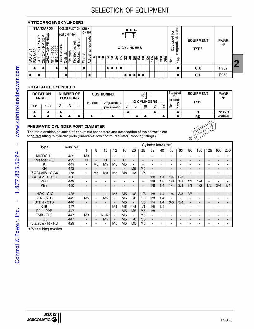
ANTICORROSIVE CYLINDERS
ISO
643
1IS
O 6
432
CE
TO
P -
RP
43
PC
ET
OP
- R
P 5
2 P
NF
E 4
9030
NF
E 4
9003
Sho
rt s
trok
eC
ylin
der
Tie
rod
sP
rofil
ed b
arre
l
Ela
stic
Adj
ust.
pneu
mat
ic
Ø CYLINDERS Equ
ippe
d fo
rm
agne
tic d
etec
tor
No
Yes
rod cylinder
PAGEN°
EQUIPMENT-
TYPEC
NO
MO
/NF
E 4
9001
100
1258 10 12 16 20 25 32 40 50 63 80 160
200
250
CIX
CIX
P258
P252
STANDARDS CUSH-IONING
CONSTRUCTION
6
Rod
less
cyl
inde
r
Type Serial No.Cylinder bore (mm)
6 8 10 12 16 20 25 32 40 50 63 80 100 125 160 200
With tubing nozzles
MICRO 10 435 M3 - - - - - - - - - - - - - - -threaded - E 429 - - - - - - - - - - - - -
K 441 - M5 M5 M5 M5 - - - - - - - - - - -KN 442 - - - - - M5 M5 - - - - - - - - -
ISOCLAIR - C.AS 435 - M5 M5 M5 M5 1/8 1/8 - - - - - - - - -ISOCLAIR - CIS 438 - - - - - - - 1/8 1/4 1/4 3/8 - - - - -
PEC 449 - - - - - - - 1/8 1/8 1/8 1/8 1/8 1/4 - - -PES 450 - - - - - - - 1/8 1/4 1/4 3/8 3/8 1/2 1/2 3/4 3/4
INOX - CIX 435 - - - M5 M5 1/8 1/8 1/8 1/4 1/4 3/8 3/8 - - - -STN - STG 445 M5 - M5 - M5 1/8 1/8 1/8 1/4 - - - - - - -STBN - STB 446 - - - - M5 - 1/8 1/4 1/4 3/8 3/8 - - - - -
CIB 447 - - - M5 M5 1/8 1/8 1/8 1/4 - - - - - - -P2L - P2B 447 - - - - M5 M5 M5 1/8 - - - - - - - -TMB - TLB 447 M3 - M3-M5 - M5 - M5 - - - - - - - - -
TUB 447 - - M5 - M5 1/8 1/8 - - - - - - - - -rotatable - R - RS 429 - - - M5 M5 M5 M5 - - - - - - - - -
PNEUMATIC CYLINDER PORT DIAMETERThe table enables selection of pneumatic connectors and accessories of the correct sizesfor direct fitting to cylinder ports (orientable flow control regulator, blocking fittings)
Cont
rol &
Pow
er, I
nc.
-
1.87
7.83
5.52
74
- w
ww
.con
trol
andp
ower
.com
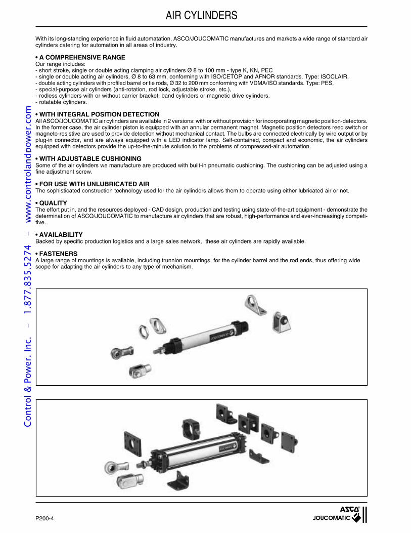
AIR CYLINDERS
With its long-standing experience in fluid automatation, ASCO/JOUCOMATIC manufactures and markets a wide range of standard aircylinders catering for automation in all areas of industry.
• A COMPREHENSIVE RANGEOur range includes:- short stroke, single or double acting clamping air cylinders Ø 8 to 100 mm - type K, KN, PEC- single or double acting air cylinders, Ø 8 to 63 mm, conforming with ISO/CETOP and AFNOR standards. Type: ISOCLAIR,- double acting cylinders with profiled barrel or tie rods, Ø 32 to 200 mm conforming with VDMA/ISO standards. Type: PES,- special-purpose air cylinders (anti-rotation, rod lock, adjustable stroke, etc.),- rodless cylinders with or without carrier bracket: band cylinders or magnetic drive cylinders,- rotatable cylinders.
• WITH INTEGRAL POSITION DETECTIONAll ASCO/JOUCOMATIC air cylinders are available in 2 versions: with or without provision for incorporating magnetic position-detectors.In the former case, the air cylinder piston is equipped with an annular permanent magnet. Magnetic position detectors reed switch ormagneto-resistive are used to provide detection without mechanical contact. The bulbs are connected electrically by wire output or byplug-in connector, and are always equipped with a LED indicator lamp. Self-contained, compact and economic, the air cylindersequipped with detectors provide the up-to-the-minute solution to the problems of compressed-air automation.
• WITH ADJUSTABLE CUSHIONINGSome of the air cylinders we manufacture are produced with built-in pneumatic cushioning. The cushioning can be adjusted using afine adjustment screw.
• FOR USE WITH UNLUBRICATED AIRThe sophisticated construction technology used for the air cylinders allows them to operate using either lubricated air or not.
• QUALITYThe effort put in, and the resources deployed - CAD design, production and testing using state-of-the-art equipment - demonstrate thedetermination of ASCO/JOUCOMATIC to manufacture air cylinders that are robust, high-performance and ever-increasingly competi-tive.
• AVAILABILITYBacked by specific production logistics and a large sales network, these air cylinders are rapidly available.
• FASTENERSA large range of mountings is available, including trunnion mountings, for the cylinder barrel and the rod ends, thus offering widescope for adapting the air cylinders to any type of mechanism.
P200-4
Cont
rol &
Pow
er, I
nc.
-
1.87
7.83
5.52
74
- w
ww
.con
trol
andp
ower
.com
5
10
5
10
15
20
5
10
15
20
25
5
10
15
20
25
435 00 460
435 00 461
435 00 462
435 00 463
435 00 464
435 00 465
435 00 466
435 00 467
435 00 468
435 00 469
435 00 470
435 00 500
435 00 501
435 00 502
435 00 503
435 00 504
0,65
0,65
1,5
1,5
1,5
1,5
3,0
2,9
2,9
2,9
3,0
1,2
1,2
2,9
2,9
2,9
2,9
5,3
5,3
5,3
5,3
5,3
1,5
1,9
3,4
4,4
5,2
6,1
10
12
15
18
21
10
12
15
18
21
min. max. min. max.
4
M3 Tappedtype
3,5
3,5
M3 Tappedtype 3,0
3,0 8
8
8
2,58
7
17
22 — —
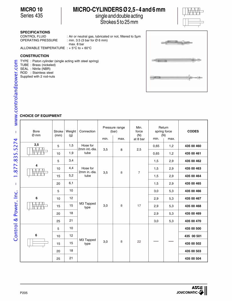
CHOICE OF EQUIPMENT
Hose for2mm int.-dia.
tube
Hose for2mm in.-dia.
tube
6
2,5
6
P205
Stroke(mm)
Weight(g)
ConnectionPressure range
(bar)Min.force(N)
at 8 bar
CODESReturn
spring force(N)
BoreØ mm
MICRO 10Series 435
SPECIFICATIONSCONTROL FLUID : Air or neutral gas, lubricated or not, filtered to 5µmOPERATING PRESSURE : min. 3.5 (3 bar for Ø 6 mm)
max. 8 barALLOWABLE TEMPERATURE : + 5°C to + 60°C
CONSTRUCTIONTYPE : Piston cylinder (single acting with steel spring)TUBE : Brass (nickeled)SEAL : Nitrile (NBR)ROD : Stainless steelSupplied with 2 rod-nuts
MICRO-CYLINDERS Ø 2,5 - 4 and 6 mmsingle and double acting
Strokes 5 to 25 mmCo
ntro
l & P
ower
, Inc
. -
1.
877.
835.
5274
-
ww
w.c
ontr
olan
dpow
er.c
om
2
Scale 1
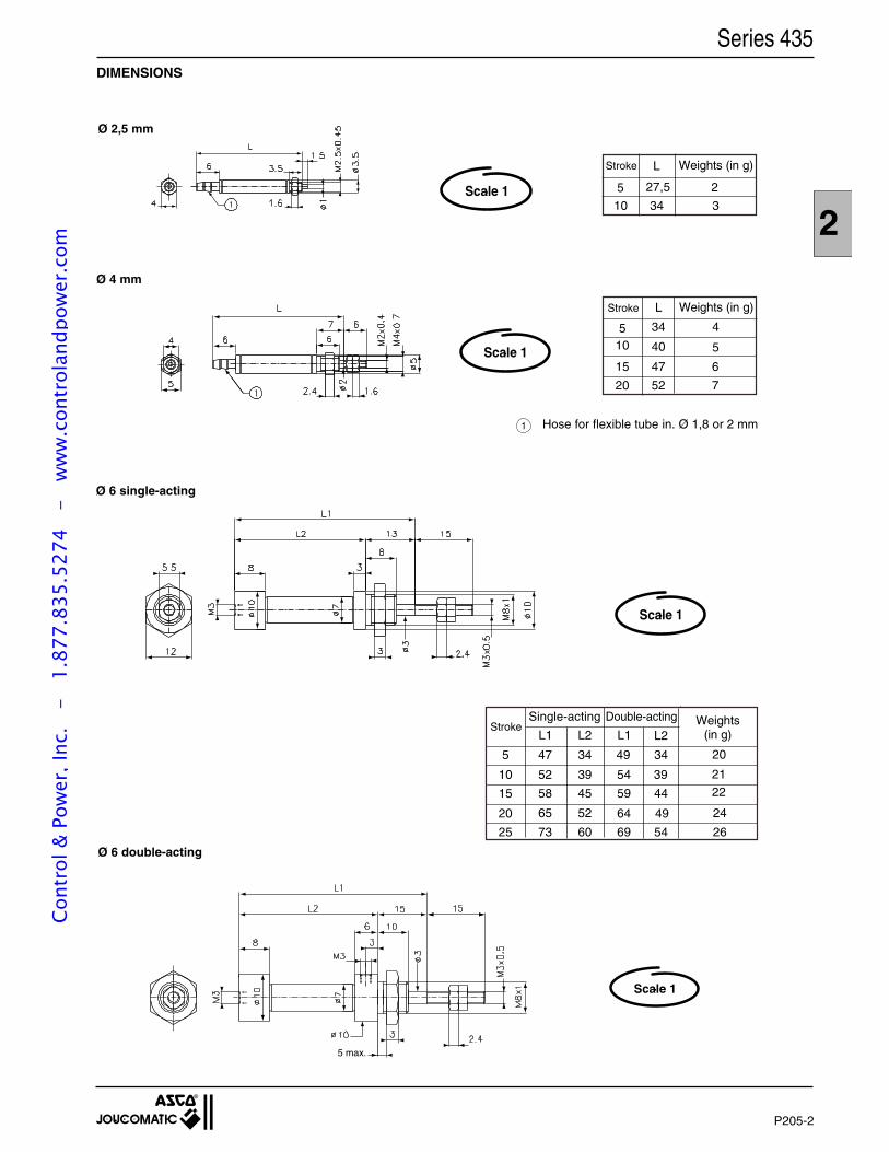
DIMENSIONS
Ø 4 mm
Ø 2,5 mm
Ø 6 single-acting
Ø 6 double-acting
47
34
Stroke L
5
4010
15
20 52
Weights (in g)
4
5
6
7
Double-acting
69
Single-acting
52 39 54 39
4964
StrokeL1 L2 L1 L2
5 47 34 49 34
10
15
20
25
58 45 59 44
65 52
73 60 54
Weights(in g)
20
2122
24
26
227,55
10 34
LStroke
3
Weights (in g)
Scale 1
Scale 1
Scale 1
Series 435
Hose for flexible tube in. Ø 1,8 or 2 mm
5 max.
1
P205-2
Cont
rol &
Pow
er, I
nc.
-
1.87
7.83
5.52
74
- w
ww
.con
trol
andp
ower
.com
J
EW
12
Ø KK
T D
AM
S
M B
A
Ø BE
Ø F
6
EW
J
AM
S
M B
A
6
Ø KK
T DØ BE
Ø F
PANEL CYLINDERS Ø 6 - 10 - 16 mmSingle and double acting - strokes 5 - 10 - 15 mm
Series 429Type: E
GENERALCompact cylinder with rear connection(s), including double acting cylinder.Its threaded body and nuts afford :- Easy adaptation on any support through its tapped or smooth hole- Adjustable body axis opposite the support.
SPECIFICATIONFLUID : Air or neutral gas, filtered, lubricated or notPRESSURE : 3 - 7 bar (single acting cylinder)
1,5 - 7 bar (double acting cylinder)TEMPÉRATURE : + 5°C to + 60°CBORE Ø : 6 - 10 - 16 mmSTROKES : 5 - 10 - 15 mm
CONSTRUCTION- Body nickeled brass- Nuts nickeled brass- Rod iron steel- Sealing nitrile (NBR)
CHOICE OF EQUIPMENT
DOUBLE ACTING CYLINDER
Bore Ø Strokes CODES REFERENCES Weights Con-(mm) (mm) (g) nection Ø
5 429 00 024 E 6 S 5 10 HoseØ 6 10 429 00 025 E 6 S 10 15 connection
15 429 00 026 E 6 S 15 18 2,7x4
5 429 00 027 E 10 S 5 30 HoseØ 10 10 429 00 028 E 10 S 10 37 connection
15 429 00 029 E 10 S 15 42 2,7x4
5 429 00 030 E 16 S 5 86 HoseØ 16 10 429 00 031 E 16 S 10 93 connection
15 429 00 032 E 16 S 15 100 2,7x4
Bore Ø Strokes CODES REFERENCES Weights Con-(mm) (mm) (g) nection Ø
5 429 00 033 E 6 D 5 34 HoseØ 6 10 429 00 034 E 6 D 10 42 connections
15 429 00 035 E 6 D 15 50 2,7x4
5 429 00 036 E 10 D 5 82 HoseØ 10 10 429 00 037 E 10 D 10 94 connections
15 429 00 038 E 10 D 15 106 2,7x4
5 429 00 039 E 16 D 5 126 HoseØ 16 10 429 00 040 E 16 D 10 138 connections
15 429 00 041 E 16 D 15 155 2,7x4
DIMENSIONSSINGLE ACTING CYLINDER DOUBLE ACTING CYLINDER
1 = Rod returned2 = Rod out
Strokes Strokes5 10 15 5 10 15
A B AM BE D EW F J KK M S T
Ø 6 38 45 52 13,5 20,5 27,5 7 M10x1 3 9 8,5 12 M3 8,5 2,4 5Ø 10 44 51 57 16 22,5 28,5 10 M15x1,5 4 13 12 19 M4 12 3,2 6Ø 16 53 58 63 22,5 27,5 32,5 12 M22x1,5 5 20 18,5 27 M5 14 5 7
Strokes Strokes5 10 15 5 10 15
A B AM BE D EW F J KK M S T
Ø 6 39 44 49 19 24 29 7 M15x1,5 4 13 12 19 M3 8,5 2,4 5Ø 10 47 52 57 18,5 23,5 28,5 10 M22x1,5 5 20 18,5 24 M4 12 3,2 6Ø 16 50 55 60 19,5 24,5 29,5 12 M26x1,5 6 24 23 32 M5 14 5 7
The return of the piston rod must be withoutload.
Double actingØ
cilynderrod
returned
Ø 6 1,3 1,7 1,3Ø 10 3,6 4,2 3,4Ø 16 8,8 10 9,2
EFFORTS DEVELOPED at 6 bar (in daN)
Single acting
rod out rod out
SINGLE ACTING CYLINDER (rod returned at rest)
P210
Hoseconnectionfor flexibletube Ø 2,7x4
Hoseconnectionsfor flexibletube Ø 2,7x4
Cont
rol &
Pow
er, I
nc.
-
1.87
7.83
5.52
74
- w
ww
.con
trol
andp
ower
.com
P215-GB-R7
SHORT STROKE CYLINDERSSINGLE AND DOUBLE ACTING
SERIES 441 - TYPE : K
Cont
rol &
Pow
er, I
nc.
-
1.87
7.83
5.52
74
- w
ww
.con
trol
andp
ower
.com
P215-2
All leaflets are available on: www.ascojoucomatic.com
Short stroke air cylinderAir cylinder diameter (Ø 8 to 100 mm)S : single acting, rod retracted when at restD : double actingLength of stroke (mm)Air cylinder designed to receive magnetic position detectors : add suffix M
ORDERING
When ordering, please specify :Air cylinder codeAir cylinder part number
* Magnetic position detectors should be ordered separately.
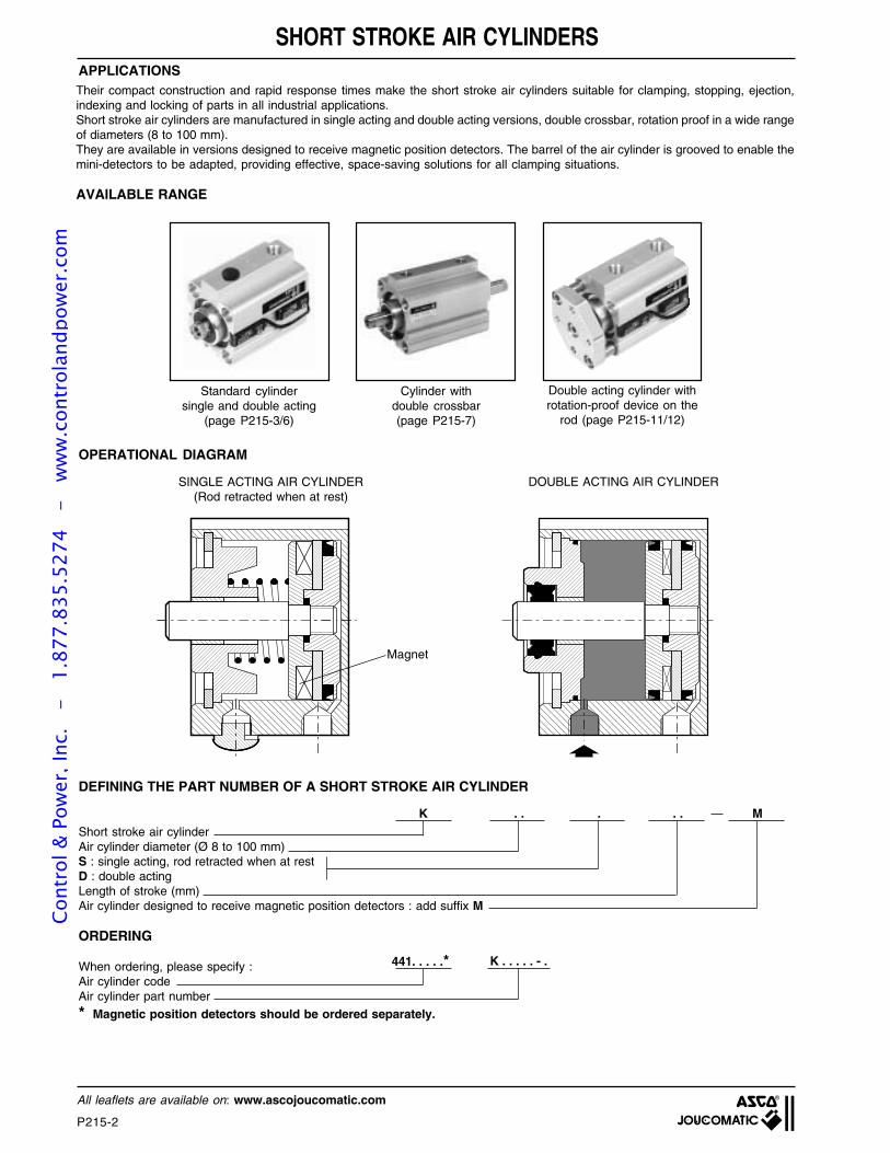
APPLICATIONS
Double acting cylinder withrotation-proof device on the
rod (page P215-11/12)
OPERATIONAL DIAGRAM
.. . . . M
DEFINING THE PART NUMBER OF A SHORT STROKE AIR CYLINDER
Magnet
441. . . . .*
K
K . . . . . - .
Their compact construction and rapid response times make the short stroke air cylinders suitable for clamping, stopping, ejection,indexing and locking of parts in all industrial applications.Short stroke air cylinders are manufactured in single acting and double acting versions, double crossbar, rotation proof in a wide rangeof diameters (8 to 100 mm).They are available in versions designed to receive magnetic position detectors. The barrel of the air cylinder is grooved to enable themini-detectors to be adapted, providing effective, space-saving solutions for all clamping situations.
AVAILABLE RANGE
Standard cylindersingle and double acting
(page P215-3/6)
Cylinder withdouble crossbar(page P215-7)
SINGLE ACTING AIR CYLINDER(Rod retracted when at rest)
DOUBLE ACTING AIR CYLINDER
SHORT STROKE AIR CYLINDERSCo
ntro
l & P
ower
, Inc
. -
1.
877.
835.
5274
-
ww
w.c
ontr
olan
dpow
er.c
om
2
P215-3
All leaflets are available on: www.ascojoucomatic.com
SPECIFICATIONSFLUID : Air or neutral gas, filtered, lubricated or notPRESSURE : 2 to 10 barTEMPERATURE : -10°C, +60°CCYLINDER BORE : 8 to 100 mmSTROKE : 4 - 5 - 10 - 25 mm
CONSTRUCTIONBody : light alloyPiston rod : stainless steel (Ø8 to 25 mm)Piston rod : hard chrome steel (Ø 32 to 100 mm)Piston rod : tappedInternal parts : acetal (POM) brass or light alloySealing : polyurethane (PUR)Self lubricating bearingFront, rear or side mounted: - with screws (not supplied)
- or flange (see mounting section)
SINGLE ACTING CYLINDER (rod returned at rest)
8
20
0,0250,0300,0300,0350,0350,0450,0800,0900,1200,1050,1200,1650,1750,2000,2750,2400,2600,3200,3500,4300,4950,6000,7150,8601,4502,600
10
Strokes(mm)
4104
104
104
10254
10255
10255
10251025102510252525
2,5 0,3
16 1,4
G 1/8
G 1/8
M5
M 5
M 5
M 5
12 5,6 0,7
10 1,216
2,22525
3,9 0,5
Øbore(mm)
3,6
4,8
6,3
8,5
11,512
4032
40
50
63
100
63
100
160
251400
G 1/8
G 1/8
G 1/8
G 1/8
80 G 1/4G 1/4
Magnetic detectors should be ordered separatelyIn order to prolong the product's service life, it is recommended to use external stoppers.Tolerance on stroke length ± 1 mm
OPTION• Other strokes on request• Version non equipped for use with detector (consult us)
CHOICE OF EQUIPMENT
K 8 S 4-MK 8 S 10-MK 10 S 4-MK 10 S 10-MK 12 S 4-MK 12 S 10-MK 16 S 4-MK 16 S 10-MK 16 S 25-MK 20 S 4-MK 20 S 10-MK 20 S 25-MK 25 S 5-MK 25 S 10-MK 25 S 25-MK 32 S 5-MK 32 S 10-MK 32 S 25-MK 40 S 10-MK 40 S 25-MK 50 S 10-MK 50 S 25-MK 63 S 10-MK 63 S 25-MK 80 S 25-MK 100 S 25-M
Forcedevelopedat 6 bar (daN)
Springreturn force
(daN) CODES
DETECTOR TYPESTO BE USED
ILS reedswitch type
—•
—•
—•
—••
—••
—••
—••••••••••
••••••••••••••••••••••••••
REFERENCESWeight
(Kg)Ø
Ports
CYLINDER EQUIPPEDFOR DETECTORS
magnetoresistantelectronic type
• Detector to be used
Series 441Type K
SHORT STROKE CYLINDERS Ø 8 to 100 mmSINGLE ACTING
equipped for magnetic position detectorsNS
441 00 001441 00 154441 00 002441 00 155441 00 003441 00 004441 00 005441 00 006441 00 156441 00 007441 00 008441 00 157441 00 009441 00 010441 00 158441 00 011441 00 012441 00 013441 00 014441 00 015441 00 016441 00 017441 00 018441 00 019441 00 020441 00 243
For installations using short stroke 32 to 100 mm bore,
it is recommended to select the new models of
the PEC type compatible with ISO 6431 (see page P227)
Cont
rol &
Pow
er, I
nc.
-
1.87
7.83
5.52
74
- w
ww
.con
trol
andp
ower
.com
P215-4
All leaflets are available on: www.ascojoucomatic.com
FLUID : Air or neutral gas, filtered, lubricated or notPRESSURE : 10 bar max.TEMPERATURE : -10°C, +60°CCYLINDER BORE : 8 to 100 mmSTROKE : See table below
SPECIFICATIONS
Body : light alloyPiston rod : stainless steel (Ø 8 to 25 mm)Piston rod : hard chrome steel (Ø 32 to 100 mm)Piston rod : tappedInternal parts : acetal (POM) brass or light alloySealing : polyurethane (PUR)Self lubricating bearingFront, rear or side mounted: - with screws (not supplied)
- or flange (see mounting section)
CONSTRUCTION
CHOICE OF EQUIPMENT
Magnetic detectors should be ordered separatelyTolerance on stroke length ± 1 mm
OPTION : • Other strokes on request• Version non equipped for use with detector (consult us)
Øbore(mm)
M5
M5
8
10
12
16
20
25
Weight(Kg)
G 1/8
G 1/8
M5
M5
2,7 2
4,2
6
10
16
3,4
5,4
8,1
13,5
27 22
0,0250,0300,0350,0400,0450,0300,0350,0400,0450,0500,0350,0450,0550,0650,0750,0850,0800,0900,1000,1100,1200,1300,1500,1050,1200,1350,1500,1650,1800,2100,2400,1750,2000,2250,2500,2750,3000,3500,400
5101520255
101520255
10152025305
1015202530405
101520253040505
10152025304050
K 8 D 5-MK 8 D 10-MK 8 D 15-MK 8 D 20-MK 8 D 25-MK 10 D 5-MK 10 D 10-MK 10 D 15-MK 10 D 20-MK 10 D 25-MK 12 D 5-MK 12 D 10-MK 12 D 15-MK 12 D 20-MK 12 D 25-MK 12 D 30-MK 16 D 5-MK 16 D 10-MK 16 D 15-MK 16 D 20-MK 16 D 25-MK 16 D 30-MK 16 D 40-MK 20 D 5-MK 20 D 10-MK 20 D 15-MK 20 D 20-MK 20 D 25-MK 20 D 30-MK 20 D 40-MK 20 D 50-MK 25 D 5-MK 25 D 10-MK 25 D 15-MK 25 D 20-MK 25 D 25-MK 25 D 30-MK 25 D 40-MK 25 D 50-M
—••••
—••••
—•••••
—••••••
—•••••••
—•••••••
•••••••••••••••••••••••••••••••••••••••
Strokes(mm)
Forcedeveloped at6 bar (daN)
Springreturn force6 bar (daN) CODES REFERENCES
ILS reedswitch type
magnetoresistantelectronic type
DETECTOR TYPESTO BE USED
CYLINDER EQUIPPEDFOR DETECTORS Ø
Ports
• Detector to be used
SHORT STROKE CYLINDERS Ø 8 to 100 mmDOUBLE ACTING
equipped for magnetic position detectors
Series 441Type K
NS
441 00 159441 00 021441 00 160441 00 161441 00 162441 00 163441 00 022441 00 164441 00 165441 00 166441 00 167441 00 023441 00 168441 00 169441 00 170441 00 171441 00 172441 00 024441 00 173441 00 174441 00 175441 00 176441 00 177441 00 178441 00 025441 00 179441 00 180441 00 026441 00 181441 00 182441 00 183441 00 184441 00 027441 00 185441 00 186441 00 028441 00 187441 00 188441 00 189
Cont
rol &
Pow
er, I
nc.
-
1.87
7.83
5.52
74
- w
ww
.con
trol
andp
ower
.com
2
P215-5
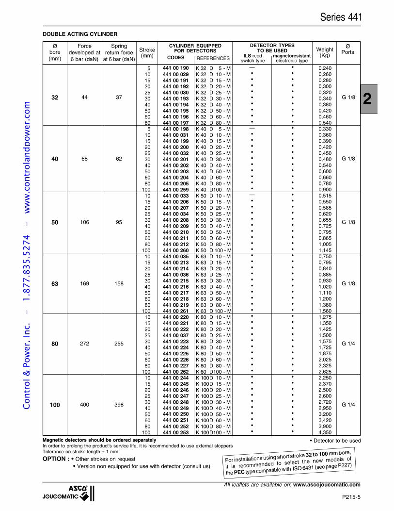
All leaflets are available on: www.ascojoucomatic.com
51015202530405060805
101520253040506080
100101520253040506080
100101520253040506080
100101520253040506080
100101520253040506080
100
ØPorts
Øbore(mm)
Weight(Kg)
Stroke(mm) CODES REFERENCES
32 44 37 G 1/8
100 400 398
80 272 255
63 169 158
50 106 95
40 68 62 G 1/8
G 1/8
G 1/8
G 1/4
G 1/4
K 32 D 5 - MK 32 D 10 - MK 32 D 15 - MK 32 D 20 - MK 32 D 25 - MK 32 D 30 - MK 32 D 40 - MK 32 D 50 - MK 32 D 60 - MK 32 D 80 - MK 40 D 5 - MK 40 D 10 - MK 40 D 15 - MK 40 D 20 - MK 40 D 25 - MK 40 D 30 - MK 40 D 40 - MK 40 D 50 - MK 40 D 60 - MK 40 D 80 - MK 40 D100 - MK 50 D 10 - MK 50 D 15 - MK 50 D 20 - MK 50 D 25 - MK 50 D 30 - MK 50 D 40 - MK 50 D 50 - MK 50 D 60 - MK 50 D 80 - MK 50 D 100 - MK 63 D 10 - MK 63 D 15 - MK 63 D 20 - MK 63 D 25 - MK 63 D 30 - MK 63 D 40 - MK 63 D 50 - MK 63 D 60 - MK 63 D 80 - MK 63 D 100 - MK 80 D 10 - MK 80 D 15 - MK 80 D 20 - MK 80 D 25 - MK 80 D 30 - MK 80 D 40 - MK 80 D 50 - MK 80 D 60 - MK 80 D 80 - MK 80 D100 - MK 100D 10 - MK 100D 15 - MK 100D 20 - MK 100D 25 - MK 100D 30 - MK 100D 40 - MK 100D 50 - MK 100D 60 - MK 100D 80 - MK 100D100 - M
DOUBLE ACTING CYLINDER
0,2400,2600,2800,3000,3200,3400,3800,4200,4600,5400,3300,3600,3900,4200,4500,4800,5400,6000,6600,7800,9000,5150,5500,5850,6200,6550,7250,7950,8651,0051,1450,7500,7950,8400,8850,9301,0201,1101,2001,3801,5601,2751,3501,4251,5001,5751,7251,8752,0252,3252,6252,2502,3702,5002,6002,7202,9503,2003,4203,9004,350
—•••••••••
—••••••••••
—•••••••••••••••••••••••••••••••••••••••
•••••••••••••••••••••••••••••••••••••••••••••••••••••••••••••
Forcedeveloped at6 bar (daN)
Springreturn force
at 6 bar (daN)ILS reed
switch typemagnetoresistant
electronic type
DETECTOR TYPESTO BE USED
CYLINDER EQUIPPEDFOR DETECTORS
• Detector to be used
Series 441
Magnetic detectors should be ordered separatelyIn order to prolong the product's service life, it is recommended to use external stoppersTolerance on stroke length ± 1 mm
OPTION : • Other strokes on request • Version non equipped for use with detector (consult us)
441 00 190441 00 029441 00 191441 00 192441 00 030441 00 193441 00 194441 00 195441 00 196441 00 197441 00 198441 00 031441 00 199441 00 200441 00 032441 00 201441 00 202441 00 203441 00 204441 00 205441 00 259441 00 033441 00 206441 00 207441 00 034441 00 208441 00 209441 00 210441 00 211441 00 212441 00 260441 00 035441 00 213441 00 214441 00 036441 00 215441 00 216441 00 217441 00 218441 00 219441 00 261441 00 220441 00 221441 00 222441 00 037441 00 223441 00 224441 00 225441 00 226441 00 227441 00 262441 00 244441 00 245441 00 246441 00 247441 00 248441 00 249441 00 250441 00 251441 00 252441 00 253
For installations using short stroke 32 to 100 mm bore,
it is recommended to select the new models of
the PEC type compatible with ISO 6431 (see page P227)
Cont
rol &
Pow
er, I
nc.
-
1.87
7.83
5.52
74
- w
ww
.con
trol
andp
ower
.com
P215-6
All leaflets are available on: www.ascojoucomatic.com
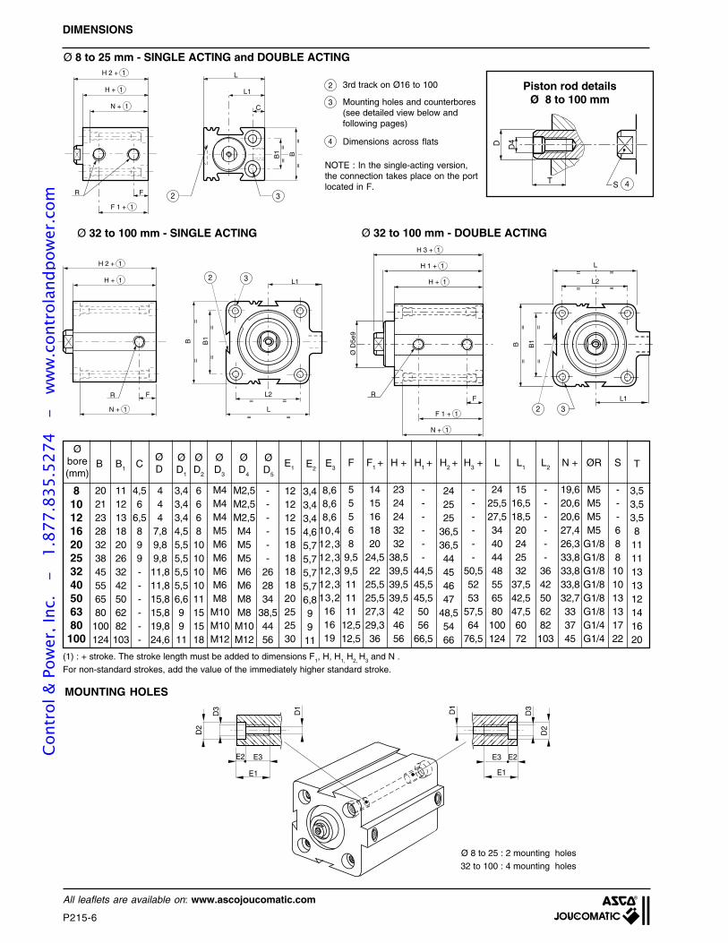
MOUNTING HOLES
Ø 8 to 25 : 2 mounting holes
32 to 100 : 4 mounting holes
E1E1
E2E2 E3E3
D1
D1
D2
D2
D3
D3
• •
•
•
= =
L1
H 1 + 1
H + 1
N + 1
F 1 + 1
L2
L
FR
Ø D
5e9
H 3 + 1
32
==
==
= =
B1B
L1
H 2 + 1
H + 1
N + 1
FR
L
L2
B1B
==
= =
===
=
2 3
Ø 32 to 100 mm - DOUBLE ACTINGØ 32 to 100 mm - SINGLE ACTING
Ø 8 to 25 mm - SINGLE ACTING and DOUBLE ACTING
4S
•
T
D D4
Embout de tige des vérins Ø 8 à 100mm
NOTE : In the single-acting version,the connection takes place on the portlocated in F.
Mounting holes and counterbores(see detailed view below andfollowing pages)
Dimensions across flats
BB1
C
L1
LH 2 + 1
H + 1
F
N + 1
R 2 3
=
=
=
=
F 1 + 1
DIMENSIONS
Piston rod detailsØ 8 to 100 mm
3rd track on Ø16 to 100
(1) : + stroke. The stroke length must be added to dimensions F1, H, H1, H2, H3 and N .
For non-standard strokes, add the value of the immediately higher standard stroke.
2
3
4
------
3642506282103
55568
9,59,5111111
12,512,5
1415161820
24,522
25,525,527,329,336
2324243232
38,539,539,539,5424656
------
44,545,545,55056
66,5
2425,527,534404448556580100124
1516,518,520242532
37,542,547,56072
19,620,620,627,426,333,833,833,832,7333745
M5M5M5M5
G1/8G1/8G1/8G1/8G1/8G1/8G1/4G1/4
---688101013131722
F H + H1 +
------
50,55253
57,564
76,5
H3 + L L1 L2 N + ØR S
------
262834
38,54456
66681010101011151518
3,53,53,581111131312141620
T
810121620253240506380
100
20212328323845556580100124
B B1
1112131820263242506282103
C
4,56
6,5899------
ØD
444
7,89,89,811,811,815,815,819,824,6
ØD1
3,43,43,44,55,55,55,55,56,69911
ØD2
ØD3
ØD4
ØD5
242525
36,536,544454647
48,55466
E3E1
121212151818181820252530
8,68,68,6
10,412,312,312,312,313,2161619
3,43,43,44,65,75,75,75,76,89911
E2
M2,5M2,5M2,5M4M5M5M6M6M8M8M10M12
M4M4M4M5M6M6M6M6M8M10M10M12
F1 + H2 +Ø
bore(mm)
Cont
rol &
Pow
er, I
nc.
-
1.87
7.83
5.52
74
- w
ww
.con
trol
andp
ower
.com
2
P215-7
All leaflets are available on: www.ascojoucomatic.com
(1) : +stroke. Dimensions F1, H, H4, K, G and N the stroke length must be added (2) : + twice stroke.For non-standard strokes, add the value of the immediately higher standard stroke.
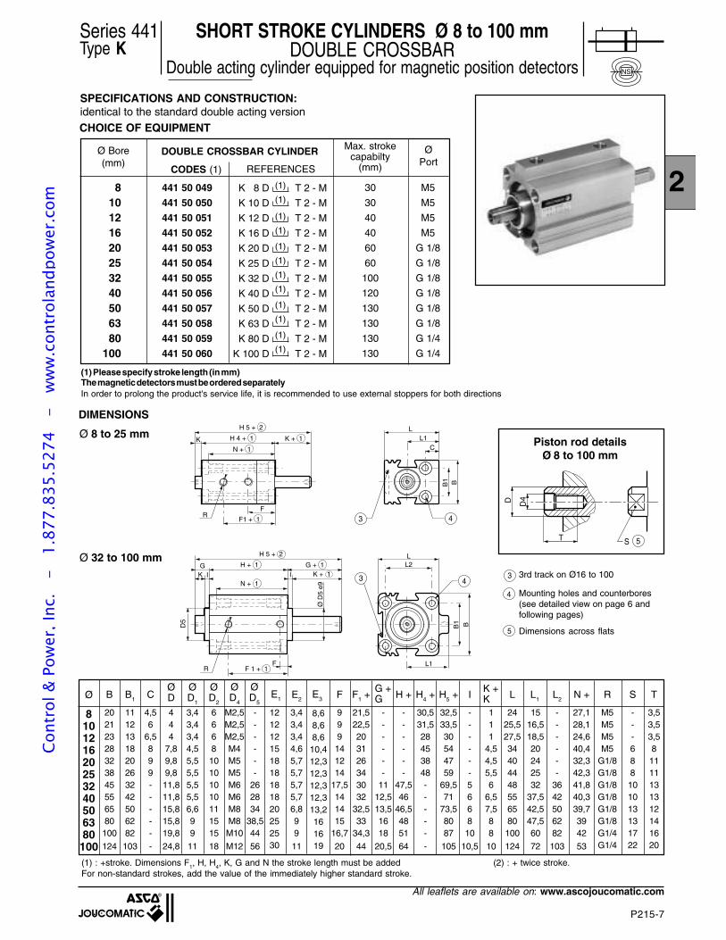
CODES (1)
441 50 049
441 50 050
441 50 051
441 50 052
441 50 053
441 50 054
441 50 055
441 50 056
441 50 057
441 50 058
441 50 059
441 50 060
Ø 8 to 25 mm
3rd track on Ø16 to 100
Mounting holes and counterbores(see detailed view on page 6 andfollowing pages)
DIMENSIONS
Ø 32 to 100 mm
810121620253240506380
100
B
Ø D
5 e9
B1
CL1
L1
LH 5 + 2
H 4 + 1 K + 1K
F
F1 + 1
N + 1
H 5 + 2
G H + 1
N + 1
F 1 + 1
R
BB1
L2L
FR
D5
3 4
43K I
G + 1K + 1I
(1) Please specify stroke length (in mm)The magnetic detectors must be ordered separatelyIn order to prolong the product's service life, it is recommended to use external stoppers for both directions
Dimensions across flats
REFERENCES
SHORT STROKE CYLINDERS Ø 8 to 100 mmDOUBLE CROSSBAR
Double acting cylinder equipped for magnetic position detectors
Series 441Type K
3
4
5
5S
•
T
D D4
Embout de tige des vérins Ø 8 à 100mm
Piston rod detailsØ 8 to 100 mm
810121620253240506380100
20212328323845556580100
124
1112131820263242506282
103
4,56
6,5899-----
-
444
7,89,89,811,811,815,815,819,8
24,8
3,43,43,44,55,55,55,55,56,699
11
666810101010111515
18
M2,5M2,5M2,5M4M5M5M6M6M8M8M10
M12
------
262834
38,544
56
---688101013131722
3,53,53,581111131312141620
Ø S TB B1 CØD
ØD1
ØD2
ØD5
ØD4
3,43,43,44,65,75,75,75,76,899
11
E2E1 E3
M5M5M5M5
G1/8G1/8G1/8G1/8G1/8G1/8G1/4G1/4
R
27,128,124,640,432,342,341,840,339,73942
53
N +
------
3642506282
103
L2
1516,518,520242532
37,542,547,560
72
L1
2425,527,534404448556580100
124
L
111
4,54,55,56
6,57,588
10
------566810
10,5
I
32,533,530544759
69,571
73,58087
105
H5 +
30,531,528453848-----
-
H4 +H +
------
47,546
46,54851
64
------
1112,513,51618
20,5
21,522,5203126343032
32,533
34,3
44
F1 +
999141214
17,5141415
16,7
20
F
121212151818181820252530
8,68,68,6
10,412,312,312,312,313,2161619
K +K
G +G
SPECIFICATIONS AND CONSTRUCTION:identical to the standard double acting version
M5
M5
M5
M5
G 1/8
G 1/8
G 1/8
G 1/8
G 1/8
G 1/8
G 1/4
G 1/4
K 8 D
K 10 D
K 12 D
K 16 D
K 20 D
K 25 D
K 32 D
K 40 D
K 50 D
K 63 D
K 80 D
K 100 D
T 2 - M
T 2 - M
T 2 - M
T 2 - M
T 2 - M
T 2 - M
T 2 - M
T 2 - M
T 2 - M
T 2 - M
T 2 - M
T 2 - M
(1)
(1)
(1)
(1)
(1)
(1)
(1)
(1)
(1)
(1)
(1)
(1)
DOUBLE CROSSBAR CYLINDERØ Bore(mm)
Max. strokecapabilty
(mm)
ØPort
30
30
40
40
60
60
100
120
130
130
130
130
CHOICE OF EQUIPMENT
NS
Cont
rol &
Pow
er, I
nc.
-
1.87
7.83
5.52
74
- w
ww
.con
trol
andp
ower
.com
P215-8
All leaflets are available on: www.ascojoucomatic.com
The tapped and sunten mounting holes provide great flexibility for mounting. The tappings simplify securing the cylinders, particularlywhen the stroke is long
• Rear mounting
• Front mounting
8 M4 M3 12 3,4 19,610 M4 M3 12 3,4 20,612 M4 M3 12 3,4 20,616 M5 M4 15 4,6 27,420 M6 M5 18 5,7 26,325 M6 M5 18 5,7 32,832 M6 M5 18 5,7 33,840 M6 M5 18 5,7 33,850 M8 M6 20 6,8 32,763 M10 M8 25 9 3380 M10 M8 25 9 37100 M12 M10 30 11 45
ØD3
ØD6
E1 E2 N +
(1) The length of stroke must be added to dimension N.For non-standard strokes, add the next higher standard one.
N + 1
Ø D6
N + 1
N + 1
Ø D6
Ø D6
N + 1
Ø D6
E1
E2
Ø D3
E1
E2
Ø D3
Øbore(mm)
Ø 8 to 25 : 2 mounting holes per faceØ 32 to 100 : 4 mounting holes per face
MOUNTING OPTIONSCo
ntro
l & P
ower
, Inc
. -
1.
877.
835.
5274
-
ww
w.c
ontr
olan
dpow
er.c
om
2
P215-9
All leaflets are available on: www.ascojoucomatic.com
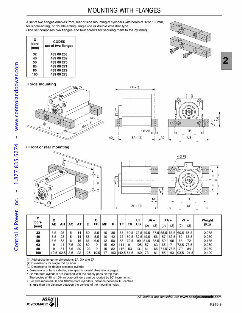
A set of two flanges enables front, rear or side mounting of cylinders with bores of 32 to 100mm,for single-acting, or double-acting, single rod or double crossbar type.(The set comprises two flanges and four screws for securing them to the cylinder).
MOUNTING WITH FLANGES
Øbore(mm)
CODESset of two flanges
32 439 00 26840 439 00 26950 439 00 27063 439 00 27180 439 00 272100 439 00 273
TR SA + 1
SA + 1A0 A0 US= =
XA + 1
TR
AH
= =4 Ø AB
AT
• Side mounting
TF
R
ZF + 1 UF= =
TF
R E
= =
==
==
MF
AT
4 Ø FB
• Front or rear mounting
(1) Add stroke length to dimensions SA, XA and ZF.(2) Dimensions for single rod cylinder(3) Dimensions for double crossbar cylinder• Dimensions of bare cylinder, see specific overall dimensions pages.• 32 mm bore cylinders are installed with the supply ports on top face.
The bodies of 40 to 100mm bore cylinders can be rotated by 90° increments.• For side-mounted 80 and 100mm bore cylinders, distance between TR centres
is less than the distance between the centres of the mounting holes.
Øbore(mm)
Weight(Kg)AH AO AT E MF R
ØAB
ØFB TF TR
UFUS
SA + XA + ZF +
32 5,5 25 5 14 50 5,5 10 36 63 50,5 72,5 49,5 57,5 55,5 63,5 60,5 68,5 0,06540 5,5 28 5 14 56 5,5 10 42 73 60,5 82,5 49,5 56 57 63,5 62 68,5 0,08050 6,6 33 6 16 66 6,6 12 50 88 72,5 99 51,5 58,5 59 66 65 72 0,13563 9 41 7,5 20 82 9 15 62 111 91 125 57 63 65 71 72,5 78,5 0,25080 9 51 7,5 20 102 9 15 82 116 53 131 61 66 71,5 76,5 79 84 0,260100 10,5 62,5 8,5 22 125 10,5 17 103 142,5 64,5 160 73 81 85 93 93,5 101,5 0,400
(2) (2) (2)(3) (3) (3)
Cont
rol &
Pow
er, I
nc.
-
1.87
7.83
5.52
74
- w
ww
.con
trol
andp
ower
.com
P215-10
All leaflets are available on: www.ascojoucomatic.com
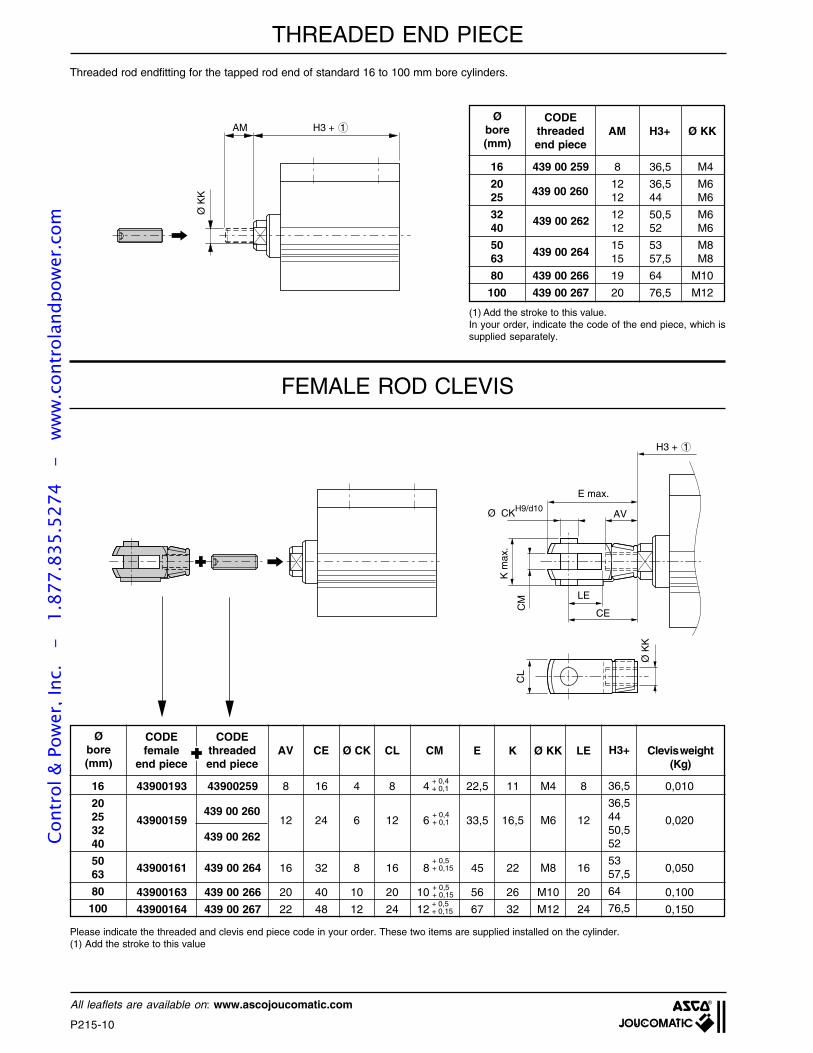
Threaded rod endfitting for the tapped rod end of standard 16 to 100 mm bore cylinders.
16 439 00 259 8 36,5 M4
20 12 36,5 M625 12 44 M6
32 12 50,5 M640 12 52 M6
50 15 53 M863 15 57,5 M8
80 439 00 266 19 64 M10
100 439 00 267 20 76,5 M12
CODEthreadedend piece
AM H3+ Ø KK
(1) Add the stroke to this value.In your order, indicate the code of the end piece, which issupplied separately.
FEMALE ROD CLEVIS
16
20253240
5063
80
100
CODEfemale
end piece
Please indicate the threaded and clevis end piece code in your order. These two items are supplied installed on the cylinder.(1) Add the stroke to this value
AVCODE
threadedend piece
CE Ø CK CL CM E
43900193 43900259 8 16 4 8 4 22,5 11 M4 8 0,010
43900159 12 24 6 12 6 33,5 16,5 M6 12 0,020
43900161 439 00 264 16 32 8 16 8 45 22 M8 16 0,050
43900163 439 00 266 20 40 10 20 10 56 26 M10 20 0,100
43900164 439 00 267 22 48 12 24 12 67 32 M12 24 0,150
+ 0,4+ 0,1
+ 0,4+ 0,1
439 00 260
439 00 262
H3 + 1AM
Ø K
K 439 00 260
439 00 262
439 00 264
K Ø KK LE H3+ Clevis weight(Kg)
36,5
36,54450,552
5357,5
64
76,5
+ 0,5+ 0,15
+ 0,5+ 0,15+ 0,5+ 0,15
Øbore(mm)
Øbore(mm)
E max.
Ø CKH9/d10AV
LE
CE
CM
K m
ax.
CL
Ø K
K
H3 + 1
THREADED END PIECECo
ntro
l & P
ower
, Inc
. -
1.
877.
835.
5274
-
ww
w.c
ontr
olan
dpow
er.c
om
2
P215-11
All leaflets are available on: www.ascojoucomatic.com
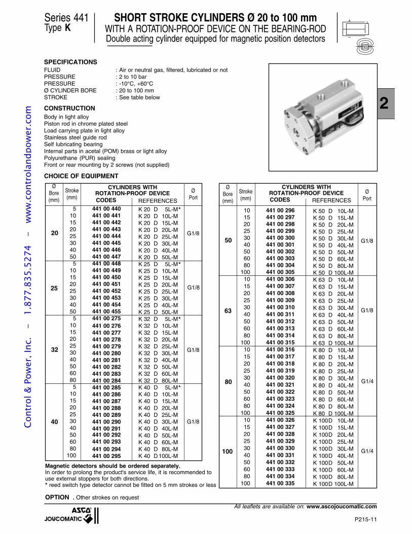
SPECIFICATIONSFLUID : Air or neutral gas, filtered, lubricated or notPRESSURE : 2 to 10 barPRESSURE : -10°C, +60°CØ CYLINDER BORE : 20 to 100 mmSTROKE : See table below
CONSTRUCTIONBody in light alloyPiston rod in chrome plated steelLoad carrying plate in light alloyStainless steel guide rodSelf lubricating bearingInternal parts in acetal (POM) brass or light alloyPolyurethane (PUR) sealingFront or rear mounting by 2 screws (not supplied)
CHOICE OF EQUIPMENT
ØBore(mm)
Stroke(mm)
ØPort
K 20 D 5L-M*K 20 D 10L-MK 20 D 15L-MK 20 D 20L-MK 20 D 25L-MK 20 D 30L-MK 20 D 40L-MK 20 D 50L-MK 25 D 5L-M*K 25 D 10L-MK 25 D 15L-MK 25 D 20L-MK 25 D 25L-MK 25 D 30L-MK 25 D 40L-MK 25 D 50L-MK 32 D 5L-M*K 32 D 10L-MK 32 D 15L-MK 32 D 20L-MK 32 D 25L-MK 32 D 30L-MK 32 D 40L-MK 32 D 50L-MK 32 D 60L-MK 32 D 80L-MK 40 D 5L-M*K 40 D 10L-MK 40 D 15L-MK 40 D 20L-MK 40 D 25L-MK 40 D 30L-MK 40 D 40L-MK 40 D 50L-MK 40 D 60L-MK 40 D 80L-MK 40 D100L-M
32
20
25
40 G1/8
G1/8
G1/8
G1/8
ØBore(mm)
Stroke(mm)
ØPort
G1/8
CYLINDERS WITHROTATION-PROOF DEVICECODES REFERENCES
100
50
G1/863
80
G1/4
G1/4
K 50 D 10L-MK 50 D 15L-MK 50 D 20L-MK 50 D 25L-MK 50 D 30L-MK 50 D 40L-MK 50 D 50L-MK 50 D 60L-MK 50 D 80L-MK 50 D 100L-MK 63 D 10L-MK 63 D 15L-MK 63 D 20L-MK 63 D 25L-MK 63 D 30L-MK 63 D 40L-MK 63 D 50L-MK 63 D 60L-MK 63 D 80L-MK 63 D 100L-MK 80 D 10L-MK 80 D 15L-MK 80 D 20L-MK 80 D 25L-MK 80 D 30L-MK 80 D 40L-MK 80 D 50L-MK 80 D 60L-MK 80 D 80L-MK 80 D 100L-MK 100D 10L-MK 100D 15L-MK 100D 20L-MK 100D 25L-MK 100D 30L-MK 100D 40L-MK 100D 50L-MK 100D 60L-MK 100D 80L-MK 100D 100L-M
510152025304050
510152025304050
5101520253040506080
5101520253040506080
100
101520253040506080
100101520253040506080
100101520253040506080
100101520253040506080
100
CYLINDERS WITHROTATION-PROOF DEVICECODES REFERENCES
Magnetic detectors should be ordered separately.In order to prolong the product's service life, it is recommended touse external stoppers for both directions.* reed switch type detector cannot be fitted on 5 mm strokes or less
OPTION . Other strokes on request
Series 441Type K
SHORT STROKE CYLINDERS Ø 20 to 100 mmWITH A ROTATION-PROOF DEVICE ON THE BEARING-RODDouble acting cylinder equipped for magnetic position detectors
NS
441 00 440441 00 441441 00 442441 00 443441 00 444441 00 445441 00 446441 00 447441 00 448441 00 449441 00 450441 00 451441 00 452441 00 453441 00 454441 00 455441 00 275441 00 276441 00 277441 00 278441 00 279441 00 280441 00 281441 00 282441 00 283441 00 284441 00 285441 00 286441 00 287441 00 288441 00 289441 00 290441 00 291441 00 292441 00 293441 00 294441 00 295
441 00 296441 00 297441 00 298441 00 299441 00 300441 00 301441 00 302441 00 303441 00 304441 00 305441 00 306441 00 307441 00 308441 00 309441 00 310441 00 311441 00 312441 00 313441 00 314441 00 315441 00 316441 00 317441 00 318441 00 319441 00 320441 00 321441 00 322441 00 323441 00 324441 00 325441 00 326441 00 327441 00 328441 00 329441 00 330441 00 331441 00 332441 00 333441 00 334441 00 335
Cont
rol &
Pow
er, I
nc.
-
1.87
7.83
5.52
74
- w
ww
.con
trol
andp
ower
.com
P215-12
All leaflets are available on: www.ascojoucomatic.com
Ø D
Ø C
Ø D
Ø C
J
F1
+ 1H +
1H3
+ 1
A
H4
+ 1
N +
1B
1B
2
B1
B2
G
M
N1
L Ø Q
G
L
L1
LØ Q
Ø Q
Ø K
==
==
P
T1P O
==
==
==
==
==
==
==
==
=
=
=
=
M
N1
N1
==
== ==
==
Ø K
Ø K
J
F1
+ 1
H +
1
H3
+ 1
A
H4
+ 1
N +
1
E1E1
E2E2 E3E3
D1
D1
D2D2
D3
D3
PO
T
O 44
2
2
2
Ø D6 Ø D6
15 (Ø20)16 (Ø25)
31 (Ø20) - 37 (Ø25)
21 (Ø20) - 25,6 (Ø25)
F=
=
F
Ø E
Ø R
Ø 20 - Ø 25 mm Ø 32 - Ø 100 mm
Ø 32 mm
See detail for holes and counterbores
MOUNTING HOLES Ø 40 - Ø 100 mm
Series 441
DIMENSIONS
2
(1) The stroke length must be added to dimensions F1, H, H3, H4 and N.For non-standard strokes, add the value of the immediately higher standard stroke.
1010101011151518
5,55,55,55,56,69911
M6M6M6M6M8M10M10M12
810101010111115
4,55,55,55,55,56,66,69
Ø(mm) A B1 B2
ØD3
ØD1
ØC
88101012121416
4,55,55,75,75,76,86,89
3,52,54,34,36,35,27,27
20253240506380100
ØD
ØD2
G1/8G1/8G1/8G1/8G1/8G1/8G1/4G1/4
M3M5M5M5M5M6M6M8
323845556580100124
20263242506282103
404448556580100124
26,332,833,833,832,7333745
ØD6
12,312,312,312,313,2161619
5,75,75,75,76,89911
242532
37,542,547,56072
--
566575
87,5110134
44,552
60,56265
69,578
92,5
36,544
50,55253
57,564
76,5
3238,539,539,539,5424656
2024,522
25,525,527,329,336
89,59,5111111
12,512,5
LG H4 +H3 +H +F1 + JE3E2
1818181820252530
E1
56888101010
--
3642506282103
ØK
ØQ
PON1N +MØE
F ØR
---
5,16,16,18,110,1
---
23,329,735,446
56,6
---
M5M6M6M8M10
Cont
rol &
Pow
er, I
nc.
-
1.87
7.83
5.52
74
- w
ww
.con
trol
andp
ower
.com
2
P215-13
All leaflets are available on: www.ascojoucomatic.com
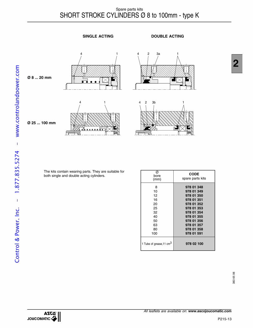
DOUBLE ACTING
4 1 4 2 3a 1
4 1 13b24
SINGLE ACTING
Ø 8 ... 20 mm
Ø 25 ... 100 mm
The kits contain wearing parts. They are suitable forboth single and double acting cylinders.
Spare parts kits
SHORT STROKE CYLINDERS Ø 8 to 100mm - type K
Øbore(mm)
CODEspare parts kits
8 978 01 34810 978 01 34912 978 01 35016 978 01 35120 978 01 35225 978 01 35332 978 01 35440 978 01 35550 978 01 35663 978 01 35780 978 01 358
100 978 01 59138
3 65
06
1 Tube of grease,11 cm3 978 02 100
Cont
rol &
Pow
er, I
nc.
-
1.87
7.83
5.52
74
- w
ww
.con
trol
andp
ower
.com
P216-GB-R3
SHORT STROKE CYLINDERS, Ø 20 - 25 mmSINGLE AND DOUBLE ACTING
CONFORMING WITH AFNOR NF E 49-004 STANDARDSSERIES 442 - TYPE : KN
2
Cont
rol &
Pow
er, I
nc.
-
1.87
7.83
5.52
74
- w
ww
.con
trol
andp
ower
.com
P216-2
All leaflets are available on: www.ascojoucomatic.com
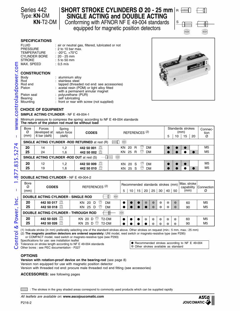
Series 442Type: KN-DM
KN-T2-DM
SHORT STROKE CYLINDERS Ø 20 - 25 mmSINGLE ACTING and DOUBLE ACTING
Conforming with AFNOR NF E 49-004 standardsequipped for magnetic position detectors
SPECIFICATIONSFLUID : air or neutral gas, filtered, lubricated or notPRESSURE : 2 to 10 bar max.TEMPERATURE : -20°C, +70°CCYLINDER BORE : 20 - 25 mmSTROKE : 5 to 50 mmMAX. SPEED : 0,5 m/s
R
S
NS NS
Minimum pressure to compress the spring: according to NF E 49-004 standardsThe return of the piston rod must be without load
DOUBLE ACTING CYLINDER - NF E 49-004-2
CHOICE OF EQUIPMENT
CONSTRUCTIONBody : aluminium alloyRod : stainless steelRod end tapped (threaded rod end: see accessories)Piston : acetal resin (POM) or light alloy fitted
with a permanent annular magnetPiston seal : polyurethane (PUR)Bearing : self lubricatingMounting : front or rear with screw (not supplied)
: The strokes in the grey shaded areas correspond to commonly used products which can be supplied rapidly
CODESBore
Ø(mm)
442 50 001 ....442 50 002 ....
2025
REFERENCES (2)
M5M5
DMDM(1)
(1)KN 20 R ...KN 25 R ...
(1)
(1)
Forcesdeveloped at6 bar (daN)
Springreturn force
(daN)
1424
1,21,6
442 50 009 ....442 50 010 ....
2025
M5M5
DMDM
(1)
(1)1219
1,21,6
SINGLE ACTING CYLINDER -ROD RETURNED at rest (R)
SINGLE ACTING CYLINDER -ROD OUT at rest (S)
NS
NS
Standards strokes(mm)
5 10 15 20
Connec-tionØ
(1)
(1)KN 20 S ...KN 25 S ...
SIMPLE ACTING CYLINDER - NF E 49-004-1
(1) Indicate stroke (in mm) preferably selecting one of the standard strokes above. Other strokes on request (min.: 5 mm, max.: 25 mm)(2) The magnetic position detectors are ordered separately: UNI model, reed switch or magneto-resistive type (see P295)
or COMPACT model, reed switch or magneto-resistive type (see P293)Specifications for use: see installation leafletTolerance on stroke length according to NF E 49-004 standardsOther bores : see PEC documentation - P227
OPTIONSVersion with rotation-proof device on the bearing-rod (see page 8)Version non equipped for use with magnetic position detectorVersion with threaded rod end: procure male threaded rod end fitting (see accessories)
ACCESSORIES: see following pages
KN 20 D ...KN 25 D ...
KN 20 D ...KN 25 D ...
CODESBore
Ø(mm)
442 50 017 ....442 50 018 ....
2025
REFERENCES (2)
DMDM(1)
(1)(1)
(1)M5M5
ConnectionØ5 10 15 20 25 30 40 50
Max. strokecapability
(mm)
Recommended standards strokes (mm)
6090
DOUBLE ACTING CYLINDER - SINGLE ROD
442 50 025 ....442 50 026 ....
2025
T2-DMT2-DM(1)
(1)(1)
(1)M5M5
6090
DOUBLE ACTING CYLINDER - THROUGH ROD
NS
NS
Recommended strokes according to NF E 49-004 Other strokes available as standardCo
ntro
l & P
ower
, Inc
. -
1.
877.
835.
5274
-
ww
w.c
ontr
olan
dpow
er.c
om
P216-3
2
All leaflets are available on: www.ascojoucomatic.com
DIMENSIONS AND WEIGHTSSINGLE AND DOUBLE ACTING CYLINDERS
Series 442
BG min.BG min.
TKTK
ØR
R
ØR
R ØD
2
ØD
2
ØR
T
ØR
T
ZJ + 1
WH
PL PL
Ø D1H11
P1
E1 max.
TG
TG
E2
max
.
Ø EE
3
4
SW 5
4
6
AF min.ØKF
ZM + 2
WH
WH + 1
ØDØMM
= =
= =
==
Tolerance on dimensions according to NF E 49-004 standards(7) Cylinder weight with 0 mm stroke.(8) Weight to be added per additional mm length.
MOUNTING
2
4
3
1 : + stroke
: 2 x stroke
: Ø 20 - 25 mm = 1 track per face
: Mounting holes and counterboreds
(see detailed view below and following pages)
: Dimensions accross flats
: Standard countersinking for centring at rear
5
6
SINGLEROD
CYLINDER
THROUGHROD
CYLINDER
tapped rod end
BoreØ
(mm) AF BG ØD ØD1 ØD2 EE E1 E2 ØKF ØMM PL P1 ØRR RT SW TG TK WH ZJ ZM (7) (8)
20 10 15 9,8 12 8 M5 36 44 M6x1 10 7,8 2,5 4,2 M5 8 22 4,7 6 43 49 0,082 0,002225 10 15 9,8 12 8 M5 40 48 M6x1 10 9,3 2,5 4,2 M5 8 26 4,7 6 45 50,5 0,125 0,0028
DIMENSIONS (mm) Weights (kg)
Cont
rol &
Pow
er, I
nc.
-
1.87
7.83
5.52
74
- w
ww
.con
trol
andp
ower
.com
P216-4
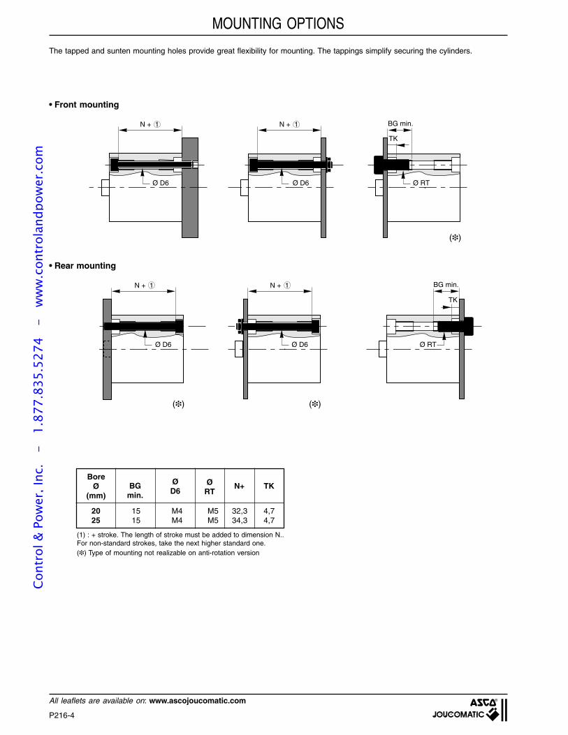
All leaflets are available on: www.ascojoucomatic.com
N + 1
Ø D6
N + 1
N + 1
Ø D6
Ø D6
N + 1
Ø D6
BG min.
TK
Ø RT
BG min.
TK
Ø RT
The tapped and sunten mounting holes provide great flexibility for mounting. The tappings simplify securing the cylinders.
• Rear mounting
• Front mounting
(1) : + stroke. The length of stroke must be added to dimension N..For non-standard strokes, take the next higher standard one.() Type of mounting not realizable on anti-rotation version
MOUNTING OPTIONS
20 15 M4 M5 32,3 4,725 15 M4 M5 34,3 4,7
BoreØ
(mm)BG
min.
ØD6
ØRT
N+ TK
()()
()
Cont
rol &
Pow
er, I
nc.
-
1.87
7.83
5.52
74
- w
ww
.con
trol
andp
ower
.com
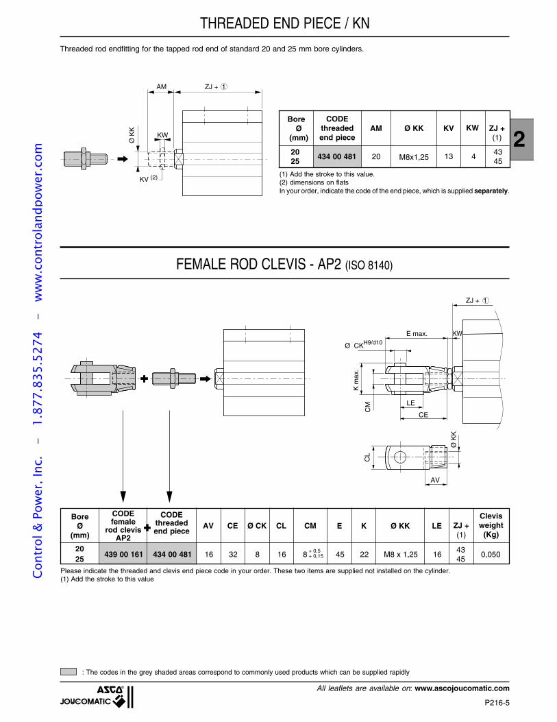
P216-5
2
All leaflets are available on: www.ascojoucomatic.com
E max.
Ø CKH9/d10
AV
LE
CE
CM
K m
ax.
CL
Ø K
K
ZJ + 1
KW
Threaded rod endfitting for the tapped rod end of standard 20 and 25 mm bore cylinders.
FEMALE ROD CLEVIS - AP2 (ISO 8140)
ZJ + 1AM
Ø K
KKW
KV (2) (1) Add the stroke to this value.(2) dimensions on flatsIn your order, indicate the code of the end piece, which is supplied separately.
THREADED END PIECE / KN
Please indicate the threaded and clevis end piece code in your order. These two items are supplied not installed on the cylinder.(1) Add the stroke to this value
: The codes in the grey shaded areas correspond to commonly used products which can be supplied rapidly
BoreØ
(mm)
CODEthreadedend piece
AM ZJ +(1)
434 00 481 20
Ø KK
M8x1,25
KV KW
13 420 4325 45
BoreØ
(mm)
CODEfemale
rod clevisAP2
CODEthreadedend piece
Clevisweight
(Kg)
2025
AV CE Ø CK CL CM E
+ 0,5+ 0,15
K Ø KK LE ZJ +(1)
4345
439 00 161 434 00 481 16 32 8 16 8 45 22 M8 x 1,25 16 0,050
Cont
rol &
Pow
er, I
nc.
-
1.87
7.83
5.52
74
- w
ww
.con
trol
andp
ower
.com
P216-6
All leaflets are available on: www.ascojoucomatic.com
ØCN H9
EN
h12
ØKK
AX
ZJ + 1
ER max.
CH
LF
KW
SPHERICAL BEARING ROD END - AP6 (ISO 8139)
Please indicate the threaded and spherical bearing end piece code in your order. These two items are supplied not installed on the cylinder.(1) Add the stroke to this value
NOTA: Alignment compensator rod end, see page P227-12
: The codes in the grey shaded areas correspond to commonly used products which can be supplied rapidly
2025
BoreØ
(mm)
CODEsphericalrod end
AP6
AX
CODEthreadedrod end CH CN EN ER LF Ø KK ZJ +
(1)
Sphericalbearingweight(Kg)
4345
439 00 187 434 00 481 16 36 8 12 12 13 M8 x 1,25 4° 0,050
ααααα
Cont
rol &
Pow
er, I
nc.
-
1.87
7.83
5.52
74
- w
ww
.con
trol
andp
ower
.com
P216-7
2
All leaflets are available on: www.ascojoucomatic.com
SPECIFICATIONS
CONSTRUCTION
CHOICE OF EQUIPMENT
SHORT STROKE CYLINDERS Ø 20 - 25 mmWITH A ROTATION-PROOF DEVICE ON THE BEARING-ROD
Conforming with AFNOR NF E 49-004-2 standardsDouble acting cylinder equipped for magnetic position detectors
Series 442Type: KN-L-DM
FLUID : air or neutral gas, filtered, lubricated or notPRESSURE : 10 bar max.TEMPERATURE : -20°C, +70°CCYLINDER BORE : 20 - 25 mmSTROKE : 5 to 100 mmMAX. SPEED : 0,5 m/s
Body : aluminium alloyRod : stainless steelLoad carrying plate : light alloyGuide rod : stainless steelPiston : acetal resin (POM) or light alloy fitted
with a permanent annular magnetPiston seal : polyurethane (PUR)Front and rear ends : aluminium alloyBearing : self lubricatingMounting : front or rear with screw (not supplied)
CODESBore
Ø(mm)
442 50 033 ....442 50 034 ....
2025
REFERENCES (2)
L - DM
L - DM(1)
(1)(1)
(1)KN 20 D ...KN 25 D ...
M5
M5
ConnectionØ
Max. strokecapability
(mm)
Recommended standards strokes(mm)
60
90
(1) Indicate stroke (in mm) preferably selecting one of the standard strokes above. Do not exceed maximum possible stroke(2) The magnetic position detectors are ordered separately: UNI model, reed switch or magneto-resistive type (see P295)
or COMPACT model, reed switch or magneto-resistive type (see P293)Specifications for use: see installation leafletTolerance on stroke length according to NF E 49-004 standards
NS
5 10 15 20 25 30 40 50
OPTION: Version non equipped for use with magnetic position detector
Recommended strokes according to NF E 49-004 Other strokes available as standard
: The strokes in the grey shaded areas correspond to commonly used products which can be supplied rapidly
MAXIMUM ADMISSIBLE LOAD «F» ON THE ROD END
Fd
G
WH A
d = the projection distance (in mm) corresponding to thedimension WH + A + the stroke length + the distance fromthe load centre of gravity (G) to the mating surface of thecylinder flange
Projection distance "d" (en mm)
F (N)
Ø25
Ø20
0 20 30 40 50 60 70 80 90 100 110 120 130 140 150
100
50
Cont
rol &
Pow
er, I
nc.
-
1.87
7.83
5.52
74
- w
ww
.con
trol
andp
ower
.com
P216-8
All leaflets are available on: www.ascojoucomatic.com
Series 442
CYLINDERS Ø 20 to 25 mm
4
3
1 : + stroke
: Ø 20 - 25 mm = 1 track per face
: Mounting holes and counterboreds (see detailed view below and previous pages)
: Standard countersinking for centring at rear
2
DIMENSIONS AND WEIGHTS
Tolerance on dimensions according to NF E 49-004 standards
BG min.
TK
ØR
R
ØD
2
ØR
T
Ø
RR
ØR
T
BG2 max.
MOUNTING
Ø RT
BG2 max.
Possibility rear mounting
Possibilities front mounting(see page P216-4)
Ø BG2max.
20 1025 10
(5) Cylinder weight with 0 mm stroke(6) Weight to be added per additional mm length
A ZJ + 1
WH
PL PL
ØD
E2
max
.
F
TGB
E1 max.
BTGF
2 ØR
2 ØE
2
3
Ø D1H11
P1
4
Ø EE
==
==
==
==
======
BoreØ
(mm) A B BG ØD ØD1ØD2 ØE ØEE E1 E2 F PL P1 ØR ØRR ØRT TG TK WH ZJ (5) (6)
20 8 30,5 15 5 12 8 4,1 M5 36 44 12 7,8 2,5 M4 4,2 M5 22 4,7 6 43 0,110 0,002525 8 36,5 15 5 12 8 5,1 M5 40 48 15,6 9,3 2,5 M5 4,2 M5 26 4,7 6 45 0,160 0,003
DIMENSIONS (mm) Weights (kg)
Cont
rol &
Pow
er, I
nc.
-
1.87
7.83
5.52
74
- w
ww
.con
trol
andp
ower
.com
P220-GB-R4
SINGLE OR DOUBLE ACTING CYLINDERS, Ø 8 to 25 mmCONFORMING WITH ISO 6432 - CETOP - AFNOR STANDARDS
ISOCLAIR - SERIES 435 - TYPES : C-AS , CC-AS
2
Cont
rol &
Pow
er, I
nc.
-
1.87
7.83
5.52
74
- w
ww
.con
trol
andp
ower
.com
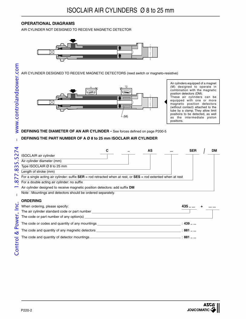
P220-2
When ordering, please specify: 435 .. ... + ... ...The air cylinder standard code or part number
The code or part number of any option(s)
The code or codes and quantity of any mountings : 439 .. ...
The code and quantity of any magnetic detectors : 881 .. ...
The code and quantity of detector mountings : 881 .. ...
ISOCLAIR AIR CYLINDERS Ø 8 to 25 mm
C .. AS ... SER DMISOCLAIR air cylinder
Air cylinder diameter (mm)
Type ISOCLAIR Ø 8 to 25 mm
Length of stroke (mm)
For a single acting air cylinder: suffix SER = rod retracted when at rest, or SES = rod extented when at rest
For a double acting air cylinder: no suffix
Air cylinder designed to receive magnetic position detectors: add suffix DM
Note : Mountings and detectors should be ordered separately.
AIR CYLINDER NOT DESIGNED TO RECEIVE MAGNETIC DETECTOR
DEFINING THE DIAMETER OF AN AIR CYLINDER - See forces defined on page P200-5
DEFINING THE PART NUMBER OF A Ø 8 to 25 mm ISOCLAIR AIR CYLINDER
ORDERING
OPERATIONAL DIAGRAMS
Air cylinders equipped of a magnet(M) designed to operate incombination with the magneticposition detectors (DM).These air cylinders can beequipped with one or moremagnetic position detectors(without contact) attached to thetube by a clamp. They allow limitpositions to be detected, as wellas the intermediate pistonpositions.
(M)
AIR CYLINDER DESIGNED TO RECEIVE MAGNETIC DETECTORS (reed switch or magneto-resistive)
Cont
rol &
Pow
er, I
nc.
-
1.87
7.83
5.52
74
- w
ww
.con
trol
andp
ower
.com
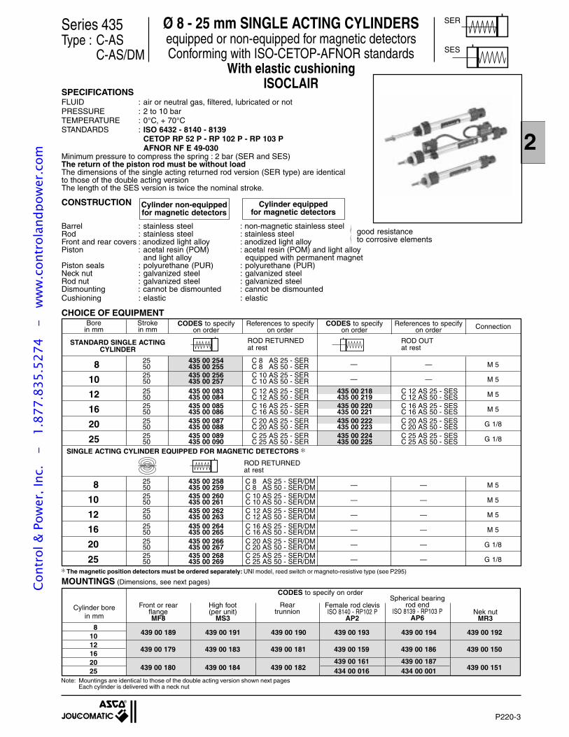
P220-3
2
Ø 8 - 25 mm SINGLE ACTING CYLINDERSequipped or non-equipped for magnetic detectorsConforming with ISO-CETOP-AFNOR standards
With elastic cushioningISOCLAIR
CHOICE OF EQUIPMENT
8
10
12
16
20
25
SINGLE ACTING CYLINDER EQUIPPED FOR MAGNETIC DETECTORS
ROD RETURNEDat rest
STANDARD SINGLE ACTINGCYLINDER
ROD RETURNEDat rest
ROD OUTat rest
8
10
12
16
20
25
M 5
M 5
M 5
M 5
G 1/8
G 1/8
—
—
—
—
25 435 00 258 C 8 AS 25 - SER/DM50 435 00 259 C 8 AS 50 - SER/DM25 435 00 260 C 10 AS 25 - SER/DM50 435 00 261 C 10 AS 50 - SER/DM25 435 00 262 C 12 AS 25 - SER/DM50 435 00 263 C 12 AS 50 - SER/DM25 435 00 264 C 16 AS 25 - SER/DM50 435 00 265 C 16 AS 50 - SER/DM25 435 00 266 C 20 AS 25 - SER/DM50 435 00 267 C 20 AS 50 - SER/DM25 435 00 268 C 25 AS 25 - SER/DM50 435 00 269 C 25 AS 50 - SER/DM
25 435 00 254 C 8 AS 25 - SER50 435 00 255 C 8 AS 50 - SER25 435 00 256 C 10 AS 25 - SER50 435 00 257 C 10 AS 50 - SER25 435 00 083 C 12 AS 25 - SER 435 00 218 C 12 AS 25 - SES50 435 00 084 C 12 AS 50 - SER 435 00 219 C 12 AS 50 - SES25 435 00 085 C 16 AS 25 - SER 435 00 220 C 16 AS 25 - SES50 435 00 086 C 16 AS 50 - SER 435 00 221 C 16 AS 50 - SES25 435 00 087 C 20 AS 25 - SER 435 00 222 C 20 AS 25 - SES50 435 00 088 C 20 AS 50 - SER 435 00 223 C 20 AS 50 - SES25 435 00 089 C 25 AS 25 - SER 435 00 224 C 25 AS 25 - SES50 435 00 090 C 25 AS 50 - SER 435 00 225 C 25 AS 50 - SES
CODES to specifyon order
References to specifyon order
CODES to specifyon order
References to specifyon order ConnectionStroke
in mmBore
in mm
439 00 189 439 00 191 439 00 190 439 00 193 439 00 194 439 00 192
439 00 179 439 00 183 439 00 181 439 00 159 439 00 186 439 00 150
439 00 180 439 00 184 439 00 182 439 00 151
81012162025
Reartrunnion
Female rod clevisISO 8140 - RP102 P
AP2
Front or rearflangeMF8
Spherical bearingrod end
ISO 8139 - RP103 PAP6
CODES to specify on order
Cylinder borein mm
High foot(per unit)
MS3
Note: Mountings are identical to those of the double acting version shown next pagesEach cylinder is delivered with a neck nut
The magnetic position detectors must be ordered separately: UNI model, reed switch or magneto-resistive type (see P295)
MOUNTINGS (Dimensions, see next pages)
— — M 5
— — M 5
— — M 5
— — M 5
— — G 1/8
— — G 1/8
439 00 161 439 00 187434 00 016 434 00 001
SER
SES
Nek nutMR3
Series 435Type : C-AS
C-AS/DM
SPECIFICATIONSFLUID : air or neutral gas, filtered, lubricated or notPRESSURE : 2 to 10 barTEMPERATURE : 0°C, + 70°CSTANDARDS : ISO 6432 - 8140 - 8139
CETOP RP 52 P - RP 102 P - RP 103 PAFNOR NF E 49-030
Minimum pressure to compress the spring : 2 bar (SER and SES)The return of the piston rod must be without loadThe dimensions of the single acting returned rod version (SER type) are identicalto those of the double acting versionThe length of the SES version is twice the nominal stroke.
good resistanceto corrosive elements
CONSTRUCTION
Barrel : stainless steel : non-magnetic stainless steelRod : stainless steel : stainless steelFront and rear covers : anodized light alloy : anodized light alloyPiston : acetal resin (POM) : acetal resin (POM) and light alloy
and light alloy equipped with permanent magnetPiston seals : polyurethane (PUR) : polyurethane (PUR)Neck nut : galvanized steel : galvanized steelRod nut : galvanized steel : galvanized steelDismounting : cannot be dismounted : cannot be dismountedCushioning : elastic : elastic
Cylinder non-equippedfor magnetic detectors
Cylinder equippedfor magnetic detectors
NS
Cont
rol &
Pow
er, I
nc.
-
1.87
7.83
5.52
74
- w
ww
.con
trol
andp
ower
.com
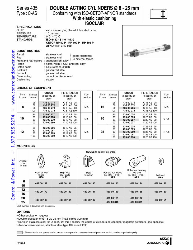
P220-4
Series 435Type : C-AS
DOUBLE ACTING CYLINDERS Ø 8 - 25 mmConforming with ISO-CETOP-AFNOR standards
With elastic cushioningISOCLAIR
SPECIFICATIONSFLUID : air or neutral gas, filtered, lubricated or notPRESSURE : 10 bar max.TEMPERATURE : 0°C, + 70°CSTANDARDS : ISO 6432 - 8140 - 8139
CETOP RP 52 P - RP 102 P - RP 103 PAFNOR NF E 49-030
439 00 189 439 00 191 439 00 190 439 00 193 439 00 194 439 00 192
439 00 179 439 00 183 439 00 181 439 00 159 439 00 186 439 00 150
439 00 180 439 00 184 439 00 182 439 00 151
81012162025
CODES to specify on order
439 00 187
434 00 001
439 00 161
434 00 016
Female rod clevisISO 8140 - RP102 P
AP2
High foot(per unit)
MS3
Reartrunnion
Front or rearflangeMF8
Spherical bearingrod end
ISO 8139 - RP103 PAP6
Cylinderbore
in mm
12 M 5
8 M 5
10 M 5
Borein mm
Strokesin mm
Con-nection
25 435 00 271 C 8 AS 2550 435 00 272 C 8 AS 5080 435 00 273 C 8 AS 80
100 435 00 274 C 8 AS 100
25 435 00 277 C 10 AS 2550 435 00 278 C 10 AS 5080 435 00 279 C 10 AS 80
100 435 00 280 C 10 AS 100
CODESto specify on
order
REFERENCESto specify on
order
25 435 00 066 C 12 AS 2550 435 00 067 C 12 AS 5080 435 00 283 C 12 AS 80
100 435 00 069 C 12 AS 100
25 G 1/8
16 M 5
20 G 1/8
Borein mm
Strokesin mm
Con-nection
25 435 00 070 C 16 AS 2550 435 00 071 C 16 AS 5080 435 00 285 C 16 AS 80
100 435 00 073 C 16 AS 100
25 435 00 074 C 20 AS 2550 435 00 075 C 20 AS 5080 435 00 287 C 20 AS 80
100 435 00 077 C 20 AS 100
25 435 00 078 C 25 AS 2550 435 00 079 C 25 AS 5080 435 00 289 C 25 AS 80
100 435 00 081 C 25 AS 100160 435 00 290 C 25 AS 160
CODESto specify on
order
REFERENCESto specify on
order
MOUNTINGS
CHOICE OF EQUIPMENT
CONSTRUCTIONBarrel : stainless stellRod : stainless stellFront and rear covers : anodized light alloyPiston : acetal resin (POM) and light alloyPiston seals : polyurethane (PUR)Neck nut : galvanized steelRod nut : galvanized steelDismounting : cannot be dismountedCushioning : elastic
Each cylinder is delivered with a neck nut.
OPTIONS• Other strokes on request• Double crossbar for Ø 16-20-25 mm (max. stroke 300 mm)• Barrel in stainless steel for Ø 16-20-25 mm : specify the codes of cylinders equipped for magnetic detectors (see opposite).• Anti-corrosive version, stainless steel type CIX (see P252)
Nek nutMR3
good resistanceto external forces
: The codes in the grey shaded areas correspond to commonly used products which can be supplied rapidly
Cont
rol &
Pow
er, I
nc.
-
1.87
7.83
5.52
74
- w
ww
.con
trol
andp
ower
.com
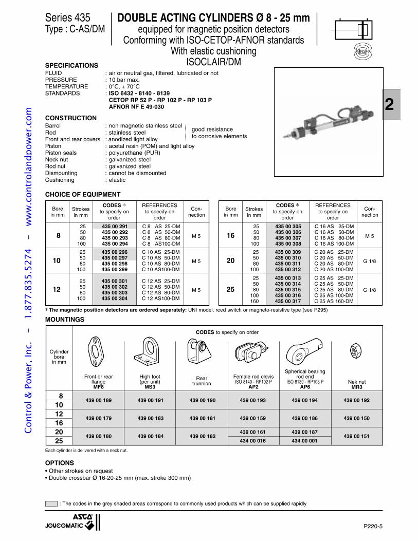
P220-5
2CONSTRUCTIONBarrel : non magnetic stainless steel
good resistanceRod : stainless steelto corrosive elementsFront and rear covers : anodized light alloy
Piston : acetal resin (POM) and light alloyPiston seals : polyurethane (PUR)Neck nut : galvanized steelRod nut : galvanized steelDismounting : cannot be dismountedCushioning : elastic
DOUBLE ACTING CYLINDERS Ø 8 - 25 mmequipped for magnetic position detectors
Conforming with ISO-CETOP-AFNOR standardsWith elastic cushioning
ISOCLAIR/DM
Series 435Type : C-AS/DM
SPECIFICATIONSFLUID : air or neutral gas, filtered, lubricated or notPRESSURE : 10 bar max.TEMPERATURE : 0°C, + 70°CSTANDARDS : ISO 6432 - 8140 - 8139
CETOP RP 52 P - RP 102 P - RP 103 PAFNOR NF E 49-030
12 M 5
8 M 5
10 M 5
Borein mm
Strokesin mm
Con-nection
25 435 00 291 C 8 AS 25-DM50 435 00 292 C 8 AS 50-DM80 435 00 293 C 8 AS 80-DM
100 435 00 294 C 8 AS100-DM
25 435 00 296 C 10 AS 25-DM50 435 00 297 C 10 AS 50-DM80 435 00 298 C 10 AS 80-DM
100 435 00 299 C 10 AS100-DM
CODES
to specify onorder
REFERENCESto specify on
order
25 435 00 301 C 12 AS 25-DM50 435 00 302 C 12 AS 50-DM80 435 00 303 C 12 AS 80-DM
100 435 00 304 C 12 AS100-DM
25 G 1/8
16 M 5
20 G 1/8
Borein mm
Strokesin mm
Con-nection
25 435 00 305 C 16 AS 25-DM50 435 00 306 C 16 AS 50-DM80 435 00 307 C 16 AS 80-DM
100 435 00 308 C 16 AS 100-DM
25 435 00 309 C 20 AS 25-DM50 435 00 310 C 20 AS 50-DM80 435 00 311 C 20 AS 80-DM
100 435 00 312 C 20 AS 100-DM
25 435 00 313 C 25 AS 25-DM50 435 00 314 C 25 AS 50-DM80 435 00 315 C 25 AS 80-DM
100 435 00 316 C 25 AS 100-DM160 435 00 317 C 25 AS 160-DM
CODES
to specify onorder
REFERENCESto specify on
order
CHOICE OF EQUIPMENT
The magnetic position detectors are ordered separately: UNI model, reed switch or magneto-resistive type (see P295)
439 00 189 439 00 191 439 00 190 439 00 193 439 00 194 439 00 192
439 00 179 439 00 183 439 00 181 439 00 159 439 00 186 439 00 150
439 00 180 439 00 184 439 00 182 439 00 151
81012162025
CODES to specify on order
439 00 187
434 00 001
439 00 161
434 00 016
Female rod clevisISO 8140 - RP102 P
AP2
High foot(per unit)
MS3
Reartrunnion
Front or rearflangeMF8
Spherical bearingrod end
ISO 8139 - RP103 PAP6
Cylinderbore
in mm
MOUNTINGS
Each cylinder is delivered with a neck nut.
OPTIONS• Other strokes on request• Double crossbar Ø 16-20-25 mm (max. stroke 300 mm)
Nek nutMR3
NS
: The codes in the grey shaded areas correspond to commonly used products which can be supplied rapidly
Cont
rol &
Pow
er, I
nc.
-
1.87
7.83
5.52
74
- w
ww
.con
trol
andp
ower
.com
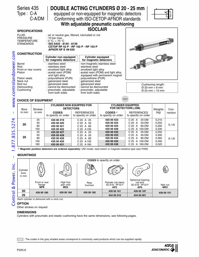
P220-6
CHOICE OF EQUIPMENT
435 00 419435 00 420435 00 421435 00 422435 00 427435 00 428435 00 429435 00 430435 00 431
C 20 A 25C 20 A 50C 20 A 80C 20 A 100C 25 A 25C 25 A 50C 25 A 80C 25 A 100C 25 A 160
255080
100255080
100160
435 00 423435 00 424435 00 425435 00 426435 00 432435 00 433435 00 434435 00 435435 00 436
C 20 A 25-DMC 20 A 50-DMC 20 A 80-DMC 20 A 100-DMC 25 A 25-DMC 25 A 50-DMC 25 A 80-DMC 25 A 100-DMC 25 A 160-DM
0,2100,2500,3000,3300,2500,3000,3600,4000,520
25
20 G 1/8
G 1/8
High foot(per unit)
MS3
Front or rearflangeMF8
Spherical bearingrod end
ISO 8139 - RP103 PAP6
Reartrunnion
439 00 184 439 00 161
434 00 016
439 00 187
434 00 001439 00 151439 00 182439 00 18020
25
CODES to specify on order
Magnetic position detectors are ordered separately: UNI model, reed switch or magneto-resistive type (see P295)
MOUNTINGS
Each cylinder is delivered with a neck nut.
DOUBLE ACTING CYLINDERS Ø 20 - 25 mmequipped or non-equipped for magnetic detectorsConforming with ISO-CETOP-AFNOR standards
With adjustable pneumatic cushioningISOCLAIR
OPTIONOther strokes on request
Female rod clevisISO 8140 - RP102 P
AP2
Series 435Type : C-A
C-A/DM
Cushioning length:Ø 20 mm = 8 mmØ 25 mm = 10 mm
CODES
to specify on orderREFERENCES
to specify on orderCODES
to specify on orderREFERENCES
to specify on order
CYLINDER EQUIPPEDFOR DETECTORS (-DM)
CYLINDER NON EQUIPPED FORDETECTORS
Cylinderbore
in mm
Nek nutMR3
SPECIFICATIONSFLUID : air or neutral gas, filtered, lubricated or notPRESSURE : 10 bar max.TEMPERATURE : 0 °C, + 70 °CSTANDARDS : ISO 6432 - 8140 - 8139
CETOP RP 52 P - RP 102 P - RP 103 PAFNOR NF E 49-030
CONSTRUCTIONCylinder non equipped Cylinder equippedfor magnetic detectors for magnetic detectors
Barrel : stainless steel : non-magnetic stainless steelRod : stainless steel : stainless steelFront or rear covers : anodized light alloy : anodized light alloyPiston : acetal resin (POM) : acetal resin (POM) and light alloy
and light alloy equipped with permanent magnetPiston seals : polyurethane (PUR) : polyurethane (PUR)Neck nut : galvanized steel : galvanized steelRod nut : galvanized steel : galvanized steelDismounting : cannot be dismounted : cannot be dismountedCushioning : pneumatic, adjustable : pneumatic, adjustable
from both sides from both sides
Strokes in mm
Weights(kg)
Con-nection
Borein mm
DIMENSIONSCylinders with pneumatic and elastic cushioning have the same dimensions, see following pages.
NS
: The codes in the grey shaded areas correspond to commonly used products which can be supplied rapidly
Cont
rol &
Pow
er, I
nc.
-
1.87
7.83
5.52
74
- w
ww
.con
trol
andp
ower
.com
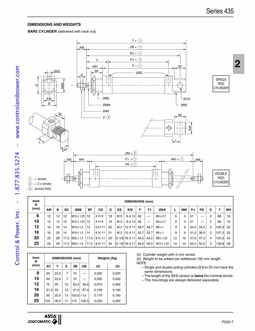
P220-7
2
AM B BC ØBE BF CD D EE EW F F1 ØKK L MM PJ PK S T WH
8 12 12 12 M12 x 1,25 12 4 H 9 18 M 5 8 d 13 46 — M4 x 0,7 6 4 31 — 2 86 16
10 12 12 12 M12 x 1,25 12 4 H 9 18 M 5 8 d 13 46 — M4 x 0,7 6 4 31 — 2 86 16
12 16 16 14 M16 x 1,5 14 6 H 11 20 M 5 12 d 11 48,7 48,7 M6 x 1 9 6 34,5 34,5 3 100,3 22
16 16 20 14 M16 x 1,5 14 6 H 11 21 M 5 12 d 11 55,7 52,7 M6 x 1 9 6 41,5 38,5 3 107,3 22
20 20 29 17,5 M22 x 1,5 17,5 8 H 11 29 G 1/8 16 d 11 64,2 64,2 M8 x 1,25 12 10 47,3 47,3 4 125,3 24
25 22 29 17,5 M22 x 1,5 17,5 8 H 11 30 G 1/8 16 d 11 69,5 69,5 M10 x 1,25 12 10 52,5 52,5 5 136,8 28
Series 435
DIMENSIONS (mm)boreØ
(mm)
8 64 23,5 7 74 — 0,030 0,020
10 64 23,5 7 74 — 0,030 0,040
12 75 29 10 84,5 93,4 0,070 0,090
16 81,5 29 10 91,5 97,4 0,100 0,100
20 95 32,5 13 103,5 113 0,170 0,160
25 104 36,5 17 115 126,5 0,200 0,200
Weights (Kg)DIMENSIONS (mm)boreØ
(mm) XC Y Z ZB ZM (4) (5)
BC
L
EW
WH
BF ØEES
Y
AM
BC
EW
B
BC
L
ØB
E
D
EW
ØBE
ØMM ØBE
ØCD
ØKK
WHAM WH + AM
ØEE
T + 1
XC + 1
PJ + 1
F + 1
Z 3
ZB + 1
F1
PK
ZM
+
+
+
1
1 1
2
SINGLEROD
CYLINDER
DOUBLEROD
CYLINDER
DIMENSIONS AND WEIGHTS
BARE CYLINDER (delivered with neck nut)
1 : + stroke
2 : + 2 x stroke
3 : across flats
(4) Cylinder weight with 0 mm stroke.(5) Weight to be added per additional 100 mm length.NOTE :
– Single and double acting cylinders Ø 8 to 25 mm have thesame dimensions.
– The length of the SES version is twice the nominal stroke.– The mountings are always delivered separately.
Cont
rol &
Pow
er, I
nc.
-
1.87
7.83
5.52
74
- w
ww
.con
trol
andp
ower
.com
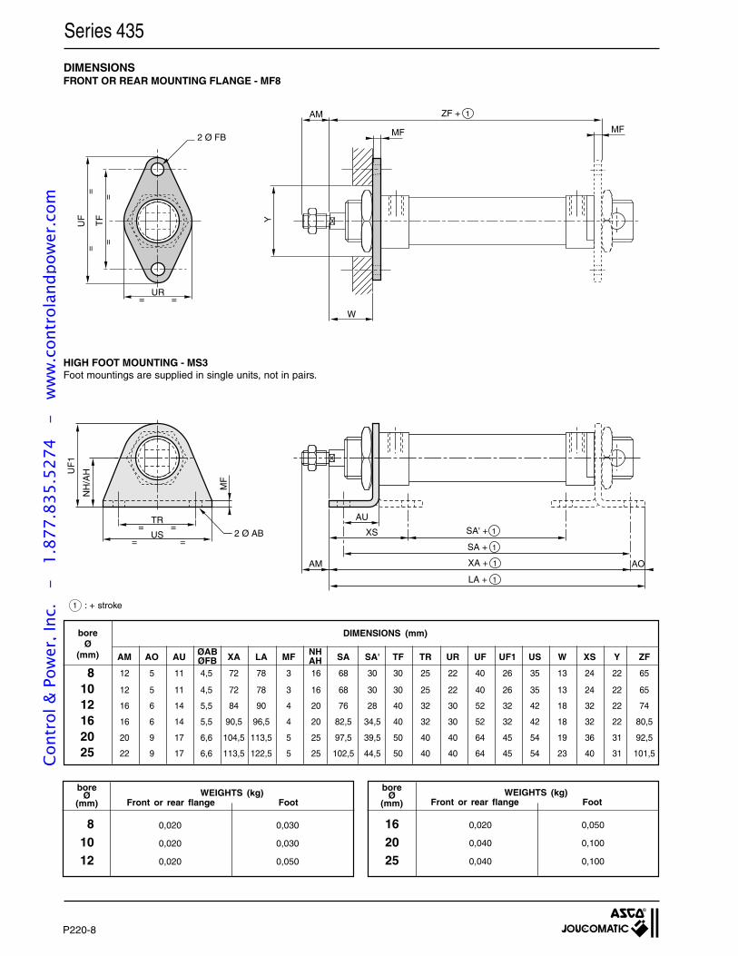
P220-8
HIGH FOOT MOUNTING - MS3Foot mountings are supplied in single units, not in pairs.
AM AO AU XA LA MF SA SA' TF TR UR UF UF1 US W XS Y ZF
12 5 11 4,5 72 78 3 16 68 30 30 25 22 40 26 35 13 24 22 65
12 5 11 4,5 72 78 3 16 68 30 30 25 22 40 26 35 13 24 22 65
16 6 14 5,5 84 90 4 20 76 28 40 32 30 52 32 42 18 32 22 74
16 6 14 5,5 90,5 96,5 4 20 82,5 34,5 40 32 30 52 32 42 18 32 22 80,5
20 9 17 6,6 104,5 113,5 5 25 97,5 39,5 50 40 40 64 45 54 19 36 31 92,5
22 9 17 6,6 113,5 122,5 5 25 102,5 44,5 50 40 40 64 45 54 23 40 31 101,5
DIMENSIONS (mm)
DIMENSIONSFRONT OR REAR MOUNTING FLANGE - MF8
UR= =
==
UF
TF
2 Ø FB
AM
MFMF
W
Y
==
ZF + 1
TR= =
US= =
UF
1
NH
/AH
MF
2 Ø AB
AU
XS
AM AO
SA' + 1
SA + 1
XA + 1
LA + 1
Series 435
1 : + stroke
81012
boreØ
(mm)
162025
boreØ
(mm)
0,020 0,050
0,040 0,100
0,040 0,100
0,020 0,030
0,020 0,030
0,020 0,050
WEIGHTS (kg)Front or rear flange Foot
WEIGHTS (kg)Front or rear flange Foot
boreØ
(mm)
81012162025
NHAH
ØABØFB
Cont
rol &
Pow
er, I
nc.
-
1.87
7.83
5.52
74
- w
ww
.con
trol
andp
ower
.com

P220-9
2
Series 435
DIMENSIONS
REAR TRUNNION MOUNTING
boreØ
(mm)
8 0,020
10 0,020
12 0,050
WEIGHTS (Kg)Rear trunnion
boreØ
(mm)
16 0,050
20 0,080
25 0,080
WEIGHTS (Kg)Rear trunnion
AM BH EA FA FB GA GC GG GL UA UB X α ω
boreØ
(mm)
DIMENSIONS (mm)
8 12 24 62,7 79 4,5 20 2,5 12,5 29 18 13 11,2 7° 160°
10 12 24 62,7 79 4,5 20 2,5 12,5 29 18 13 11,2 7° 160°
12 16 27 72,5 93 5,5 25 3 16 34 25 18 13,5 50° 180°
16 16 27 79 99,5 5,5 25 3 16 34 25 18 13,5 47° 180°
20 20 30 91 117 6,6 32 4 20 40 32 24 16 8° 168°
25 22 30 100 126 6,6 32 4 20 40 32 24 16 8° 168°
FAAM +
X
α
ω
UA
GA
GG
= =
UB 2ØFB
BH
= =
GC
GL
1
EA + 1
1 : + stroke
Cont
rol &
Pow
er, I
nc.
-
1.87
7.83
5.52
74
- w
ww
.con
trol
andp
ower
.com
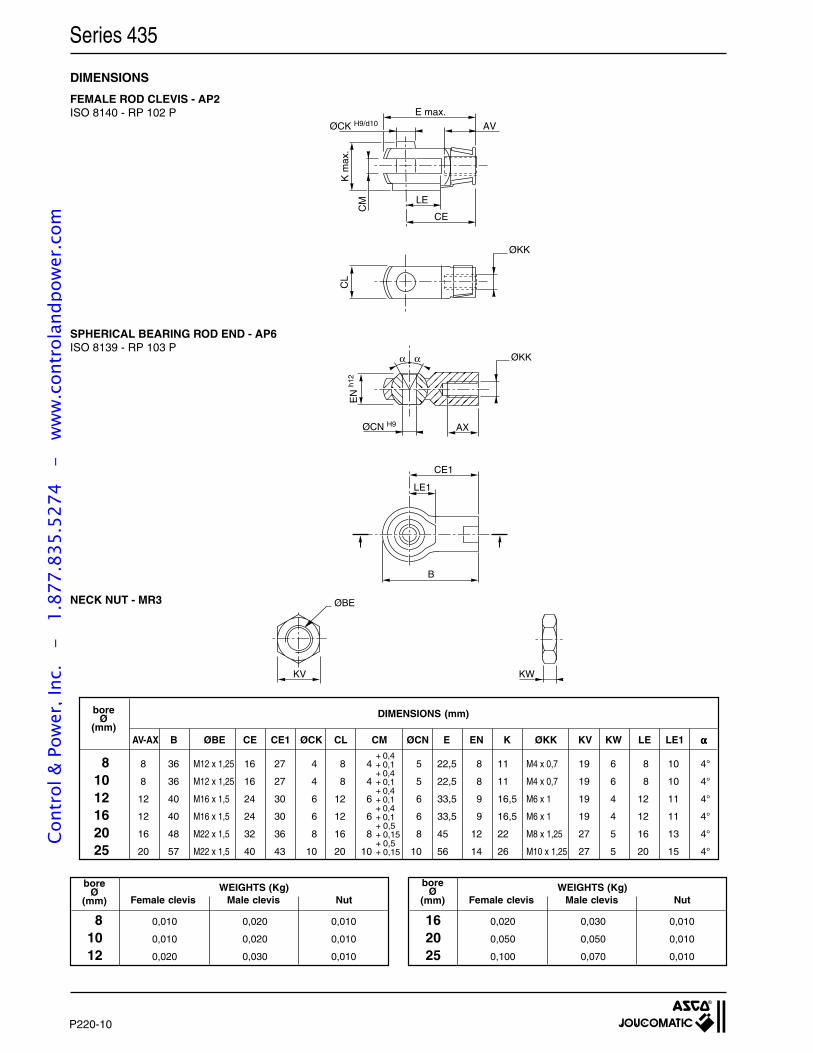
P220-10
WEIGHTS (Kg)Female clevis Male clevis Nut
8 0,010 0,020 0,010
10 0,010 0,020 0,010
12 0,020 0,030 0,010
WEIGHTS (Kg)Female clevis Male clevis Nut
16 0,020 0,030 0,010
20 0,050 0,050 0,010
25 0,100 0,070 0,010
DIMENSIONS (mm)boreØ
(mm)AV-AX B ØBE CE CE1 ØCK CL CM ØCN E EN K ØKK KV KW LE LE1 ααααα
8 8 36 M12 x 1,25 16 27 4 8 4 5 22,5 8 11 M4 x 0,7 19 6 8 10 4°
10 8 36 M12 x 1,25 16 27 4 8 4 5 22,5 8 11 M4 x 0,7 19 6 8 10 4°
12 12 40 M16 x 1,5 24 30 6 12 6 6 33,5 9 16,5 M6 x 1 19 4 12 11 4°
16 12 40 M16 x 1,5 24 30 6 12 6 6 33,5 9 16,5 M6 x 1 19 4 12 11 4°
20 16 48 M22 x 1,5 32 36 8 16 8 8 45 12 22 M8 x 1,25 27 5 16 13 4°
25 20 57 M22 x 1,5 40 43 10 20 10 10 56 14 26 M10 x 1,25 27 5 20 15 4°
+ 0,4+ 0,1+ 0,4+ 0,1+ 0,4+ 0,1+ 0,4+ 0,1+ 0,5+ 0,15+ 0,5+ 0,15
ØBE
KV KW
Series 435
FEMALE ROD CLEVIS - AP2ISO 8140 - RP 102 P
DIMENSIONS
boreØ
(mm)
boreØ
(mm)
SPHERICAL BEARING ROD END - AP6ISO 8139 - RP 103 P
ØCN H9
EN
h12
ØKK
AX
CE1
LE1
αα
B
NECK NUT - MR3
ØCK H9/d10
ØKK
E max.
K m
ax.
CM
AV
LE
CE
CL
Cont
rol &
Pow
er, I
nc.
-
1.87
7.83
5.52
74
- w
ww
.con
trol
andp
ower
.com

P225-GB-R2
SINGLE OR DOUBLE ACTING CYLINDERS, Ø 32 to 63 mmCONFORMING WITH ISO 6431 - CETOP STANDARDS
ISOCLAIR - SERIES 438 - TYPE : CIS
2
Cont
rol &
Pow
er, I
nc.
-
1.87
7.83
5.52
74
- w
ww
.con
trol
andp
ower
.com
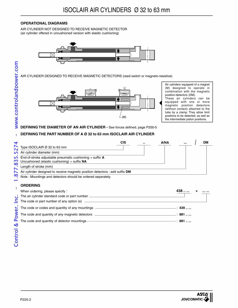
P225-2
When ordering, please specify :
The air cylinder standard code or part number
The code or part number of any option (s)
The code or codes and quantity of any mountings : 439 .. ...
The code and quantity of any magnetic detectors : 881 .. ...
The code and quantity of detector mountings : 881 .. ...
CIS .. ... DMType ISOCLAIR Ø 32 to 63 mm
Air cylinder diameter (mm)
End-of-stroke adjustable pneumatic cushioning = suffix AUncushioned (elastic cushioning) = suffix NA
Length of stroke (mm)
Air cylinder designed to receive magnetic position detectors : add suffix DM
Note : Mountings and detectors should be ordered separately.
ISOCLAIR AIR CYLINDERS Ø 32 to 63 mm
Air cylinders equipped of a magnet(M) designed to operate incombination with the magneticposition-detectors (DM).These air cylinders can beequipped with one or moremagnetic position detectors(without contact) attached to thetube by a clamp. They allow limitpositions to be detected, as well asthe intermediate piston positions.
AIR CYLINDER NOT DESIGNED TO RECEIVE MAGNETIC DETECTOR(air cylinder offered in uncushioned version with elastic cushioning)
DEFINING THE PART NUMBER OF A Ø 32 to 63 mm ISOCLAIR AIR CYLINDER
OPERATIONAL DIAGRAMS
A/NA
ORDERING
DEFINING THE DIAMETER OF AN AIR CYLINDER - See forces defined, page P200-5
438 .. ... + ... ...
(M)
AIR CYLINDER DESIGNED TO RECEIVE MAGNETIC DETECTORS (reed switch or magneto-resistive)
Cont
rol &
Pow
er, I
nc.
-
1.87
7.83
5.52
74
- w
ww
.con
trol
andp
ower
.com
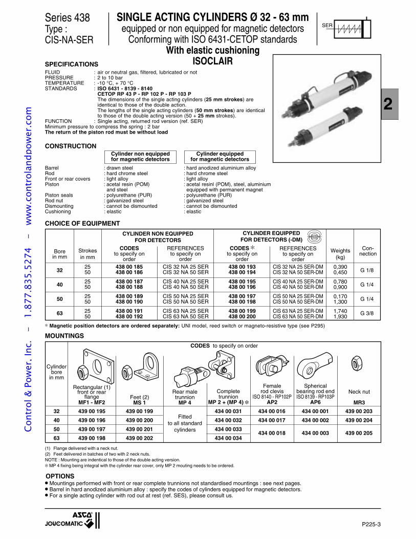
P225-3
2
Magnetic position detectors are ordered separately: UNI model, reed switch or magneto-resistive type (see P295)
MOUNTINGS
Series 438Type :CIS-NA-SER
SER
SPECIFICATIONSFLUID : air or neutral gas, filtered, lubricated or notPRESSURE : 2 to 10 barTEMPERATURE : -10 °C, + 70 °CSTANDARDS : ISO 6431 - 8139 - 8140
CETOP RP 43 P - RP 102 P - RP 103 PThe dimensions of the single acting cylinders (25 mm strokes) areidentical to those of the double action.The lengths of the single acting cylinders (50 mm strokes) are identicalto those of the double acting version (50 + 25 mm strokes).
FUNCTION : Single acting, returned rod version (ref. SER)Minimum pressure to compress the spring : 2 barThe return of the piston rod must be without load
CONSTRUCTION
Barrel : drawn steel : hard anodized aluminium alloyRod : hard chrome steel : hard chrome steelFront or rear covers : light alloy : light alloyPiston : acetal resin (POM) : acetal resinl (POM), steel, aluminium
and steel equipped with permanent magnetPiston seals : polyurethane (PUR) : polyurethane (PUR)Rod nut : galvanized steel : galvanized steelDismounting : cannot be dismounted : cannot be dismountedCushioning : elastic : elastic
Cylinder non equippedfor magnetic detectors
Cylinder equippedfor magnetic detectors
CHOICE OF EQUIPMENT
CYLINDER NON EQUIPPEDFOR DETECTORS
CYLINDER EQUIPPEDFOR DETECTORS (-DM)
CODESto specify on
order
REFERENCESto specify on
order
REFERENCESto specify on
order
CODES to specify on
order
32
40
50
63
438 00 193438 00 194
438 00 195438 00 196
438 00 197438 00 198
438 00 199438 00 200
2550
2550
2550
2550
438 00 185438 00 186
438 00 187438 00 188
438 00 189438 00 190
438 00 191438 00 192
CIS 32 NA 25 SERCIS 32 NA 50 SER
CIS 40 NA 25 SERCIS 40 NA 50 SER
CIS 50 NA 25 SERCIS 50 NA 50 SER
CIS 63 NA 25 SERCIS 63 NA 50 SER
CIS 32 NA 25 SER-DMCIS 32 NA 50 SER-DM
CIS 40 NA 25 SER-DMCIS 40 NA 50 SER-DM
CIS 50 NA 25 SER-DMCIS 50 NA 50 SER-DM
CIS 63 NA 25 SER-DMCIS 63 NA 50 SER-DM
Strokesin mm
Con-nectionWeights
(kg)
G 1/8
G 1/4
G 1/4
G 3/8
32
40
50
63
439 00 195
439 00 196
439 00 197
439 00 198
439 00 199
439 00 200
439 00 201
439 00 202
Fittedto all standard
cylinders
434 00 031
434 00 032
434 00 033
434 00 034
434 00 016
434 00 017
434 00 018
434 00 001
434 00 002
434 00 003
439 00 203
439 00 204
439 00 205
Cylinderbore
in mm
Completetrunnion
MP 2 + (MP 4)
CODES to specify on order
Femalerod clevis
ISO 8140 - RP102PAP2
SINGLE ACTING CYLINDERS Ø 32 - 63 mmequipped or non equipped for magnetic detectors
Conforming with ISO 6431-CETOP standardsWith elastic cushioning
ISOCLAIR
Borein mm
OPTIONS
0,3900,450
0,7800,900
0,1701,300
1,7401,930
Mountings performed with front or rear complete trunnions not standardised mountings : see next pages. Barrel in hard anodized aluminium alloy : specify the codes of cylinders equipped for magnetic detectors. For a single acting cylinder with rod out at rest (ref. SES), please consult us.
(1) Flange delivered with a neck nut.(2) Feet delivered in batches of two with 2 neck nuts.NOTE : Mounting are indentical to those of the double acting version. MP 4 fixing being integral with the cylinder rear cover, only MP 2 mouting needs to be ordered.
Sphericalbearing rod endISO 8139 - RP103P
AP6
Neck nut
MR3
NS
Rectangular (1)front or rear
flangeMF1 - MF2
Feet (2)MS 1
Rear maletrunnion
MP 4
Cont
rol &
Pow
er, I
nc.
-
1.87
7.83
5.52
74
- w
ww
.con
trol
andp
ower
.com
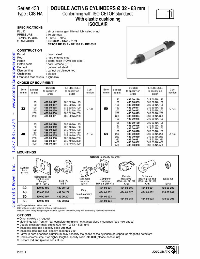
P225-4
Fitted
to all standard
cylinders
439 00 195 439 00 199 434 00 031 434 00 016 434 00 001 439 00 203
439 00 196 439 00 200 434 00 032 434 00 017 434 00 002 439 00 204
439 00 197 439 00 201 434 00 033
439 00 198 439 00 202 434 00 034434 00 018 434 00 003 439 00 205
Series 438Type : CIS-NA
SPECIFICATIONSFLUID : air or neutral gas, filtered, lubricated or notPRESSURE : 10 bar max.TEMPERATURE : - 10°C, + 70°CSTANDARDS : ISO 6431 - 8140 - 8139
CETOP RP 43 P - RP 102 P - RP103 P
CONSTRUCTIONBarrel : drawn steelRod : hard chrome steelPiston : acetal resin (POM) and steelPiston seals : polyurethane (PUR)Rod nut : galvanized steelDismounting : cannot be dismountedCushioning : elasticFront and rear covers : light alloy
CHOICE OF EQUIPMENT
Borein mm
Strokesin mm
Con-nection
CODESto specify on
order
REFERENCESto specify on
order
32 G 1/8
25 438 00 177 CIS 32 NA 2550 438 00 057 CIS 32 NA 50
100 438 00 058 CIS 32 NA 100160 438 00 059 CIS 32 NA 160200 438 00 060 CIS 32 NA 200250 438 00 061 CIS 32 NA 250
40 G 1/4
25 438 00 178 CIS 40 NA 2550 438 00 062 CIS 40 NA 50
100 438 00 063 CIS 40 NA 100160 438 00 064 CIS 40 NA 160200 438 00 065 CIS 40 NA 200250 438 00 066 CIS 40 NA 250320 438 00 067 CIS 40 NA 320400 438 00 068 CIS 40 NA 400
Borein mm
Strokesin mm
Con-nection
CODESto specify on
order
REFERENCESto specify on
order
50 G 1/4
63 G 3/8
25 438 00 179 CIS 50 NA 2550 438 00 069 CIS 50 NA 50
100 438 00 070 CIS 50 NA 100160 438 00 071 CIS 50 NA 160200 438 00 072 CIS 50 NA 200250 438 00 073 CIS 50 NA 250320 438 00 074 CIS 50 NA 320400 438 00 075 CIS 50 NA 400
25 438 00 180 CIS 63 NA 2550 438 00 076 CIS 63 NA 50
100 438 00 077 CIS 63 NA 100160 438 00 078 CIS 63 NA 160200 438 00 079 CIS 63 NA 200250 438 00 080 CIS 63 NA 250320 438 00 081 CIS 63 NA 320400 438 00 082 CIS 63 NA 400500 438 00 083 CIS 63 NA 500
MOUNTINGS
Cylinderbore
in mm
Completetrunnion
MP 2 + (MP 4)
CODES to specify on order
(1) Flange delivered with a neck nut(2) Feet delivered in batches of two with 2 neck nuts Note : MP 4 fixing being integral with the cylinder rear cover, only MP 2 mounting needs to be ordered
32405063
Femalerod clevis
ISO 8140 - RP102PAP2
Sphericalbearing rod endISO 8139 - RP103P
AP6
Other strokes on request Mountings with front or rear complete trunnions not standardised mountings (see next pages) Double crossbar (max. stroke 600 mm - Ø 63 = 595 mm) Stainless steel rod : specify code 995 002 Stainless steel rod nut : specify code 995 019 Barrel in hard anodized aluminium alloy : specify the codes of the cylinders equipped for magnetic detectors Rod in chrome steel : for higher lengths, specify code 995 003 (please consult us) Custom rod end (please consult us)
OPTIONS
Feet (2)MS 1
DOUBLE ACTING CYLINDERS Ø 32 - 63 mmConforming with ISO-CETOP standards
With elastic cushioningISOCLAIR
Rear maletrunnion
MP 4
Neck nut
MR3
Rectangular (1)front or rear
flangeMF 1 - MF 2
Cont
rol &
Pow
er, I
nc.
-
1.87
7.83
5.52
74
- w
ww
.con
trol
andp
ower
.com
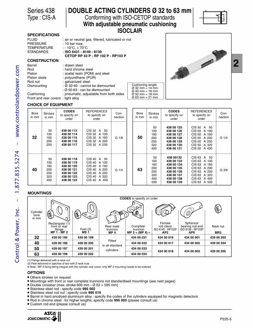
P225-5
2
Series 438Type : CIS-A
SPECIFICATIONSFLUID : air or neutral gas, filtered, lubricated or notPRESSURE : 10 bar max.TEMPERATURE : - 10°C, + 70°CSTANDARDS : ISO 6431 - 8140 - 8139
CETOP RP 43 P - RP 102 P - RP103 P
Borein mm
Strokesin mm
Con-nection
CODESto specify on
order
REFERENCESto specify on
order
32 G 1/8
40 G 1/4
Borein mm
Strokesin mm
Con-nection
CODESto specify on
order
REFERENCESto specify on
order
50 G 1/4
63 G 3/8
50 438 00 113 CIS 32 A 50100 438 00 114 CIS 32 A 100160 438 00 115 CIS 32 A 160200 438 00 116 CIS 32 A 200250 438 00 117 CIS 32 A 250
50 438 00 125 CIS 50 A 50100 438 00 126 CIS 50 A 100160 438 00 127 CIS 50 A 160200 438 00 128 CIS 50 A 200250 438 00 129 CIS 50 A 250320 438 00 130 CIS 50 A 320400 438 00 131 CIS 50 A 400
50 438 00132 CIS 63 A 50100 438 00 133 CIS 63 A 100160 438 00 134 CIS 63 A 160200 438 00 135 CIS 63 A 200250 438 00 136 CIS 63 A 250320 438 00 137 CIS 63 A 320400 438 00 138 CIS 63 A 400500 438 00 139 CIS 63 A 500
CHOICE OF EQUIPMENT
CONSTRUCTIONBarrel : drawn steelRod : hard chrome steelPiston : acetal resin (POM) and steelPiston seals : polyurethane (PUR)Rod nut : galvanized steelDismounting : Ø 32-40 : cannot be dismounted
: Ø 50-63 : can be dismountedCushioning : pneumatic, adjustable from both sidesFront and rear covers : light alloy
MOUNTINGS
Cylinderbore
in mm
439 00 195 439 00 199 434 00 031 434 00 016 434 00 001 439 00 203
439 00 196 439 00 200 434 00 032 434 00 017 434 00 002 439 00 204
439 00 197 439 00 201 434 00 033
439 00 198 439 00 202 434 00 034434 00 018 434 00 003 439 00 205
Fitted
to all standard
cylinders
CODES to specify on order
(1) Flange delivered with a neck nut(2) Feet delivered in batches of two with 2 neck nuts Note : MP 4 fixing being integral with the cylinder rear cover, only MP 2 mounting needs to be ordered
50 438 00 118 CIS 40 A 50100 438 00 119 CIS 40 A 100160 438 00 120 CIS 40 A 160200 438 00 121 CIS 40 A 200250 438 00 122 CIS 40 A 250320 438 00 123 CIS 40 A 320400 438 00 124 CIS 40 A 400
32405063
DOUBLE ACTING CYLINDERS Ø 32 to 63 mmConforming with ISO-CETOP standards
With adjustable pneumatic cushioningISOCLAIR
Cushioning lengthØ 32 mm = 14 mmØ 40 mm = 18 mmØ 50 mm = 18 mmØ 63 mm = 21 mm
Feet (2)MS 1
Rear maletrunnion
MP 4
Others strokes on request Mountings with front or rear complete trunnions not standardised mountings (see next pages) Double crossbar (max. stroke 600 mm - Ø 63 = 595 mm) Stainless steel rod : specify code 995 002 Stainless steel rod nut : specify code 995 019 Barrel in hard anodized aluminium alloy : specify the codes of the cylinders equipped for magnetic detectors Rod in chrome steel : for higher lengths, specify code 995 003 (please consult us) Custom rod end (please consult us)
OPTIONS
Rectangular (1)front or rear
flangeMF 1 - MF 2
Complete`trunnion
MP 2 + (MP 4)
Sphericalbearing rod endISO 8139 - RP103P
AP6
Femalerod clevis
ISO 8140 - RP102PAP2
Neck nut
MR3
Cont
rol &
Pow
er, I
nc.
-
1.87
7.83
5.52
74
- w
ww
.con
trol
andp
ower
.com
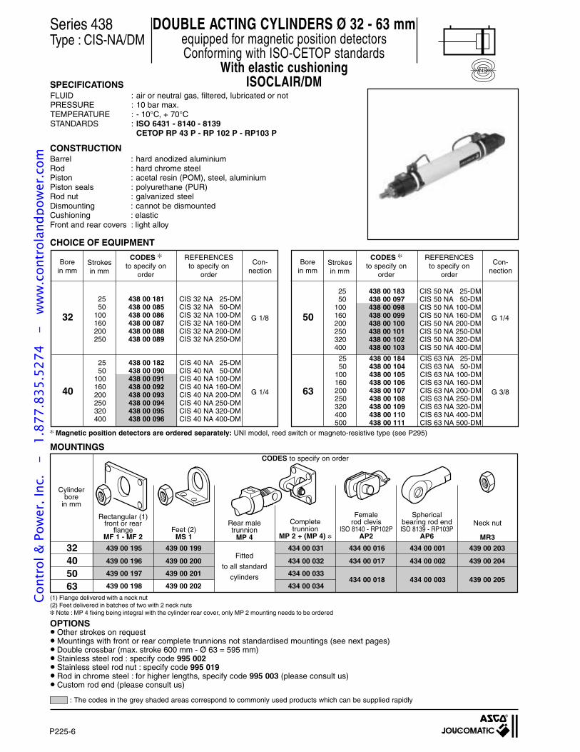
P225-6
Series 438Type : CIS-NA/DM
DOUBLE ACTING CYLINDERS Ø 32 - 63 mmequipped for magnetic position detectorsConforming with ISO-CETOP standards
With elastic cushioningISOCLAIR/DMSPECIFICATIONS
FLUID : air or neutral gas, filtered, lubricated or notPRESSURE : 10 bar max.TEMPERATURE : - 10°C, + 70°CSTANDARDS : ISO 6431 - 8140 - 8139
CETOP RP 43 P - RP 102 P - RP103 P
Borein mm
Strokesin mm
Con-nection
CODES
to specify onorder
REFERENCESto specify on
order
32 G 1/8
40 G 1/4
Borein mm
Strokesin mm
Con-nection
CODES
to specify onorder
REFERENCESto specify on
order
50 G 1/4
63 G 3/8
CHOICE OF EQUIPMENT
25 438 00 182 CIS 40 NA 25-DM50 438 00 090 CIS 40 NA 50-DM
100 438 00 091 CIS 40 NA 100-DM160 438 00 092 CIS 40 NA 160-DM200 438 00 093 CIS 40 NA 200-DM250 438 00 094 CIS 40 NA 250-DM320 438 00 095 CIS 40 NA 320-DM400 438 00 096 CIS 40 NA 400-DM
25 438 00 181 CIS 32 NA 25-DM50 438 00 085 CIS 32 NA 50-DM
100 438 00 086 CIS 32 NA 100-DM160 438 00 087 CIS 32 NA 160-DM200 438 00 088 CIS 32 NA 200-DM250 438 00 089 CIS 32 NA 250-DM
25 438 00 183 CIS 50 NA 25-DM50 438 00 097 CIS 50 NA 50-DM
100 438 00 098 CIS 50 NA 100-DM160 438 00 099 CIS 50 NA 160-DM200 438 00 100 CIS 50 NA 200-DM250 438 00 101 CIS 50 NA 250-DM320 438 00 102 CIS 50 NA 320-DM400 438 00 103 CIS 50 NA 400-DM
Magnetic position detectors are ordered separately: UNI model, reed switch or magneto-resistive type (see P295)
CONSTRUCTIONBarrel : hard anodized aluminiumRod : hard chrome steelPiston : acetal resin (POM), steel, aluminiumPiston seals : polyurethane (PUR)Rod nut : galvanized steelDismounting : cannot be dismountedCushioning : elasticFront and rear covers : light alloy
(1) Flange delivered with a neck nut(2) Feet delivered in batches of two with 2 neck nuts Note : MP 4 fixing being integral with the cylinder rear cover, only MP 2 mounting needs to be ordered
MOUNTINGS
Cylinderbore
in mm
439 00 195 439 00 199 434 00 031 434 00 016 434 00 001 439 00 203
439 00 196 439 00 200 434 00 032 434 00 017 434 00 002 439 00 204
439 00 197 439 00 201 434 00 033
439 00 198 439 00 202 434 00 034434 00 018 434 00 003 439 00 205
Fitted
to all standard
cylinders
32405063
Femalerod clevis
ISO 8140 - RP102PAP2
Sphericalbearing rod endISO 8139 - RP103P
AP6
25 438 00 184 CIS 63 NA 25-DM50 438 00 104 CIS 63 NA 50-DM
100 438 00 105 CIS 63 NA 100-DM160 438 00 106 CIS 63 NA 160-DM200 438 00 107 CIS 63 NA 200-DM250 438 00 108 CIS 63 NA 250-DM320 438 00 109 CIS 63 NA 320-DM400 438 00 110 CIS 63 NA 400-DM500 438 00 111 CIS 63 NA 500-DM
Feet (2)MS 1
Completetrunnion
MP 2 + (MP 4)
Rectangular (1)front or rear
flangeMF 1 - MF 2
CODES to specify on order
Rear maletrunnion
MP 4
Neck nut
MR3
NS
OPTIONS Other strokes on request Mountings with front or rear complete trunnions not standardised mountings (see next pages) Double crossbar (max. stroke 600 mm - Ø 63 = 595 mm) Stainless steel rod : specify code 995 002 Stainless steel rod nut : specify code 995 019 Rod in chrome steel : for higher lengths, specify code 995 003 (please consult us) Custom rod end (please consult us)
: The codes in the grey shaded areas correspond to commonly used products which can be supplied rapidly
Cont
rol &
Pow
er, I
nc.
-
1.87
7.83
5.52
74
- w
ww
.con
trol
andp
ower
.com
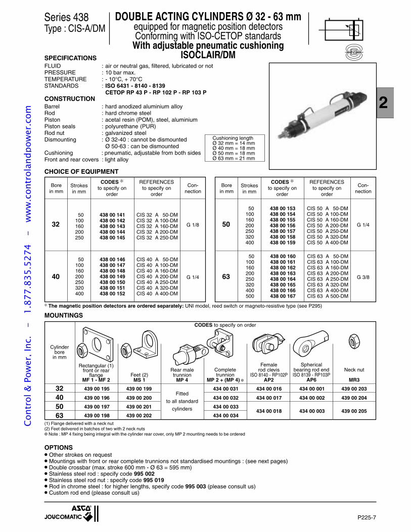
P225-7
2
Series 438Type : CIS-A/DM
SPECIFICATIONSFLUID : air or neutral gas, filtered, lubricated or notPRESSURE : 10 bar max.TEMPERATURE : - 10°C, + 70°CSTANDARDS : ISO 6431 - 8140 - 8139
CETOP RP 43 P - RP 102 P - RP 103 PCONSTRUCTIONBarrel : hard anodized aluminium alloyRod : hard chrome steelPiston : acetal resin (POM), steel, aluminiumPiston seals : polyurethane (PUR)Rod nut : galvanized steelDismounting : Ø 32-40 : cannot be dismounted
Ø 50-63 : can be dismountedCushioning : pneumatic, adjustable from both sidesFront and rear covers : light alloy
CHOICE OF EQUIPMENT
Borein mm
Strokesin mm
Con-nection
CODES
to specify onorder
REFERENCESto specify on
order
32 G 1/8
40 G 1/4
Borein mm
Strokesin mm
Con-nection
CODES
to specify onorder
REFERENCESto specify on
order
50 G 1/4
63 G 3/8
50 438 00 141 CIS 32 A 50-DM100 438 00 142 CIS 32 A 100-DM160 438 00 143 CIS 32 A 160-DM200 438 00 144 CIS 32 A 200-DM250 438 00 145 CIS 32 A 250-DM
50 438 00 146 CIS 40 A 50-DM100 438 00 147 CIS 40 A 100-DM160 438 00 148 CIS 40 A 160-DM200 438 00 149 CIS 40 A 200-DM250 438 00 150 CIS 40 A 250-DM320 438 00 151 CIS 40 A 320-DM400 438 00 152 CIS 40 A 400-DM
50 438 00 153 CIS 50 A 50-DM100 438 00 154 CIS 50 A 100-DM160 438 00 155 CIS 50 A 160-DM200 438 00 156 CIS 50 A 200-DM250 438 00 157 CIS 50 A 250-DM320 438 00 158 CIS 50 A 320-DM400 438 00 159 CIS 50 A 400-DM
50 438 00 160 CIS 63 A 50-DM100 438 00 161 CIS 63 A 100-DM160 438 00 162 CIS 63 A 160-DM200 438 00 163 CIS 63 A 200-DM250 438 00 164 CIS 63 A 250-DM320 438 00 165 CIS 63 A 320-DM400 438 00 166 CIS 63 A 400-DM500 438 00 167 CIS 63 A 500-DM
The magnetic position detectors are ordered separately: UNI model, reed switch or magneto-resistive type (see P295)
MOUNTINGS
Cylinderbore
in mm
Completetrunnion
MP 2 + (MP 4)
439 00 195 439 00 199 434 00 031 434 00 016 434 00 001 439 00 203
439 00 196 439 00 200 434 00 032 434 00 017 434 00 002 439 00 204
439 00 197 439 00 201 434 00 033
439 00 198 439 00 202 434 00 034434 00 018 434 00 003 439 00 205
Fitted
to all standard
cylinders
(1) Flange delivered with a neck nut(2) Feet delivered in batches of two with 2 neck nuts Note : MP 4 fixing being integral with the cylinder rear cover, only MP 2 mounting needs to be ordered
CODES to specify on order
32405063
DOUBLE ACTING CYLINDERS Ø 32 - 63 mmequipped for magnetic position detectorsConforming with ISO-CETOP standards
With adjustable pneumatic cushioningISOCLAIR/DM
Femalerod clevis
ISO 8140 - RP102PAP2
Sphericalbearing rod endISO 8139 - RP103P
AP6Feet (2)
MS 1
Rectangular (1)front or rear
flangeMF 1 - MF 2
OPTIONS Other strokes on request Mountings with front or rear complete trunnions not standardised mountings : (see next pages) Double crossbar (max. stroke 600 mm - Ø 63 = 595 mm) Stainless steel rod : specify code 995 002 Stainless steel rod nut : specify code 995 019 Rod in chrome steel : for higher lengths, specify code 995 003 (please consult us) Custom rod end (please consult us)
Cushioning lengthØ 32 mm = 14 mmØ 40 mm = 18 mmØ 50 mm = 18 mmØ 63 mm = 21 mm
Rear maletrunnion
MP 4
Neck nut
MR3
NS
Cont
rol &
Pow
er, I
nc.
-
1.87
7.83
5.52
74
- w
ww
.con
trol
andp
ower
.com
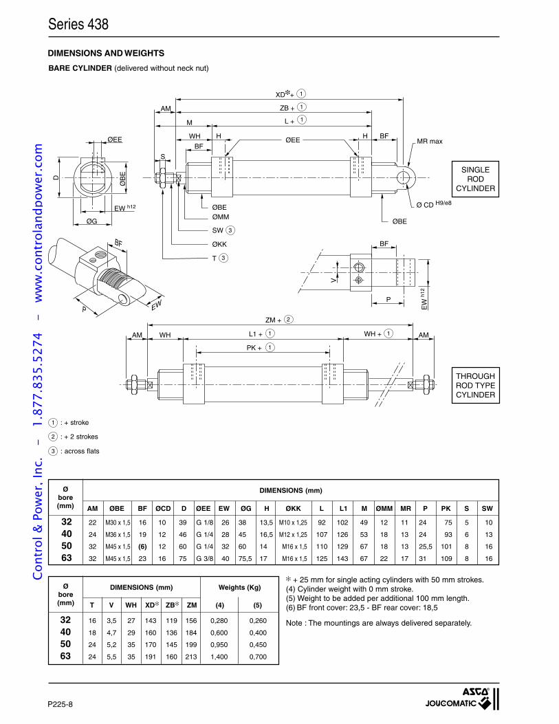
P225-8
Series 438
DIMENSIONS AND WEIGHTS
BARE CYLINDER (delivered without neck nut)
1 : + stroke
2 : + 2 strokes
3 : across flats
SINGLEROD
CYLINDER
THROUGHROD TYPECYLINDER
BF
P
EW
h12
V
WH
BFØEE
S
L + M
ZB +AM
XD+
BFHH
ØG
BF
P
ØB
E
D
EW
ØBE
SWØBE
MR max
ØKK
T
WH
PK +
ZM +
L1 + AM WH + AM
ØEE
EW h12
2
3
1
1
1
1 1
1
ØMM
3
Ø CD H9/e8
+ 25 mm for single acting cylinders with 50 mm strokes.(4) Cylinder weight with 0 mm stroke.(5) Weight to be added per additional 100 mm length.(6) BF front cover: 23,5 - BF rear cover: 18,5
Note : The mountings are always delivered separately.
DIMENSIONS (mm)Øbore(mm) AM ØBE BF ØCD D ØEE EW ØG H ØKK L L1 M ØMM MR P PK S SW
32 22 M30 x 1,5 16 10 39 G 1/8 26 38 13,5 M10 x 1,25 92 102 49 12 11 24 75 5 10
40 24 M36 x 1,5 19 12 46 G 1/4 28 45 16,5 M12 x 1,25 107 126 53 18 13 24 93 6 13
50 32 M45 x 1,5 (6) 12 60 G 1/4 32 60 14 M16 x 1,5 110 129 67 18 13 25,5 101 8 16
63 32 M45 x 1,5 23 16 75 G 3/8 40 75,5 17 M16 x 1,5 125 143 67 22 17 31 109 8 16
DIMENSIONS (mm)Øbore(mm) T V WH XD ZB ZM (4) (5)
32 16 3,5 27 143 119 156 0,280 0,260
40 18 4,7 29 160 136 184 0,600 0,400
50 24 5,2 35 170 145 199 0,950 0,450
63 24 5,5 35 191 160 213 1,400 0,700
Weights (Kg)
Cont
rol &
Pow
er, I
nc.
-
1.87
7.83
5.52
74
- w
ww
.con
trol
andp
ower
.com
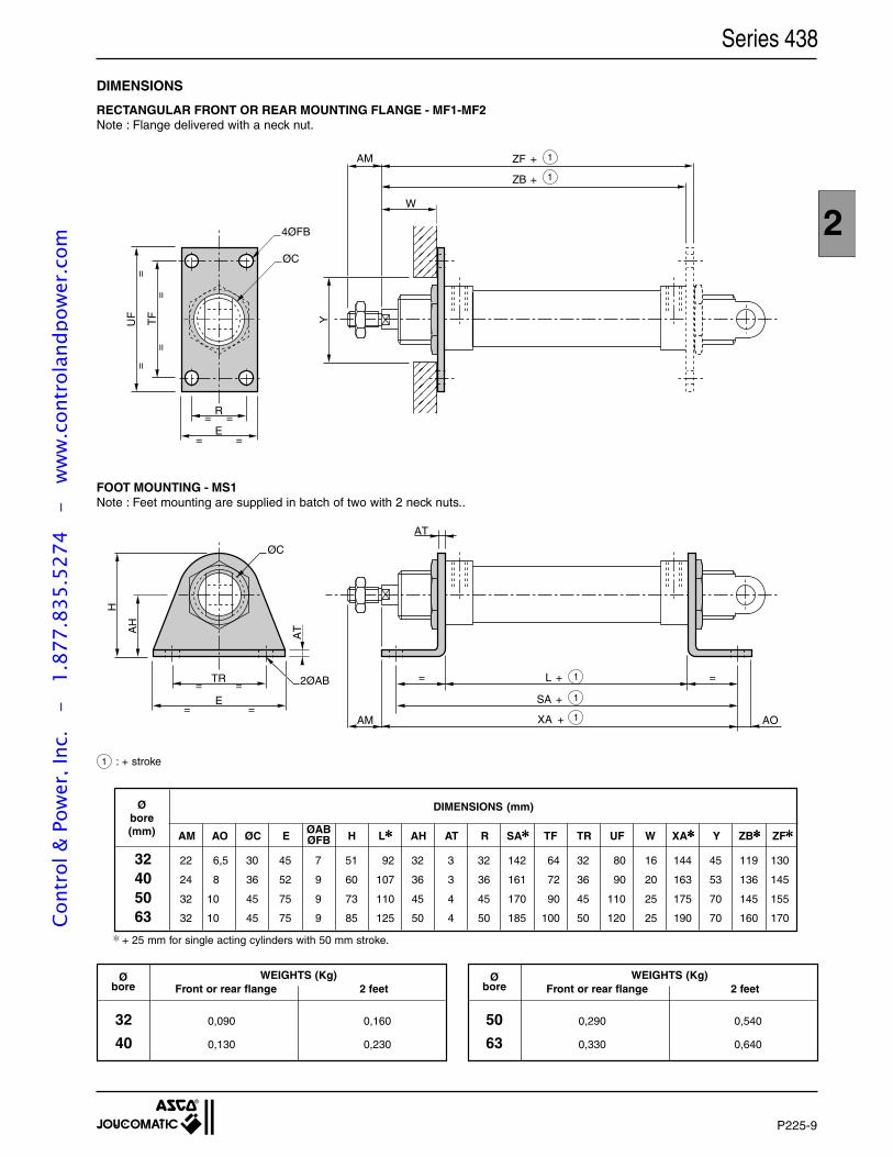
P225-9
2
Series 438
DIMENSIONS
RECTANGULAR FRONT OR REAR MOUNTING FLANGE - MF1-MF2Note : Flange delivered with a neck nut.
Øbore
WEIGHTS (Kg)Front or rear flange 2 feet
Øbore
WEIGHTS (Kg)Front or rear flange 2 feet
DIMENSIONS (mm)Øbore(mm)
32 22 6,5 30 45 7 51 92 32 3 32 142 64 32 80 16 144 45 119 130
40 24 8 36 52 9 60 107 36 3 36 161 72 36 90 20 163 53 136 145
50 32 10 45 75 9 73 110 45 4 45 170 90 45 110 25 175 70 145 155
63 32 10 45 75 9 85 125 50 4 50 185 100 50 120 25 190 70 160 170
AM AO ØC E H L AH AT R SA TF TR UF W XA Y ZB ZFØABØFB
32 0,090 0,160
40 0,130 0,230
50 0,290 0,540
63 0,330 0,640
W
ZB
ZFAM
+
+
E
UF
TF
R= =
=
=
=
=
= =
ØC
4ØFB
Y
1
1
FOOT MOUNTING - MS1Note : Feet mounting are supplied in batch of two with 2 neck nuts..
1 : + stroke
XA AOAM
L= =
+
+
SA +
H
AH
AT
E
TR
ØC
2ØAB= =
= =
AT
1
1
1
+ 25 mm for single acting cylinders with 50 mm stroke.
Cont
rol &
Pow
er, I
nc.
-
1.87
7.83
5.52
74
- w
ww
.con
trol
andp
ower
.com
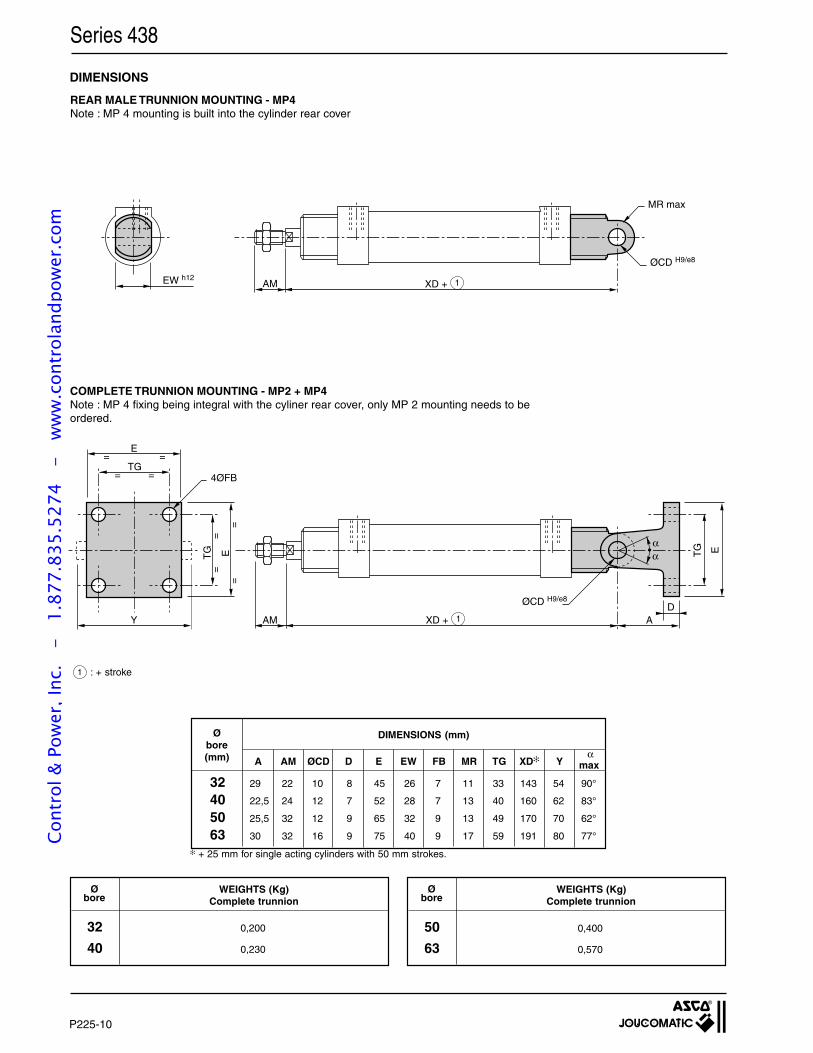
P225-10
Series 438
Øbore
32 0,200
40 0,230
WEIGHTS (Kg)Complete trunnion
Øbore
WEIGHTS (Kg)Complete trunnion
50 0,400
63 0,570
A AM ØCD D E EW FB MR TG XD Y
Øbore(mm)
DIMENSIONS (mm)
αmax
32 29 22 10 8 45 26 7 11 33 143 54 90°
40 22,5 24 12 7 52 28 7 13 40 160 62 83°
50 25,5 32 12 9 65 32 9 13 49 170 70 62°
63 30 32 16 9 75 40 9 17 59 191 80 77°
+ 25 mm for single acting cylinders with 50 mm strokes.
DIMENSIONS
REAR MALE TRUNNION MOUNTING - MP4Note : MP 4 mounting is built into the cylinder rear cover
COMPLETE TRUNNION MOUNTING - MP2 + MP4Note : MP 4 fixing being integral with the cyliner rear cover, only MP 2 mounting needs to beordered.
AM A
ETG
DØCD H9/e8
4ØFB
αα
TG
Y
E
= =
= =
TG E
=
=
=
=
•
XD + 1
1 : + stroke
EW h12XD + AM
ØCD H9/e8
MR max
1
Cont
rol &
Pow
er, I
nc.
-
1.87
7.83
5.52
74
- w
ww
.con
trol
andp
ower
.com
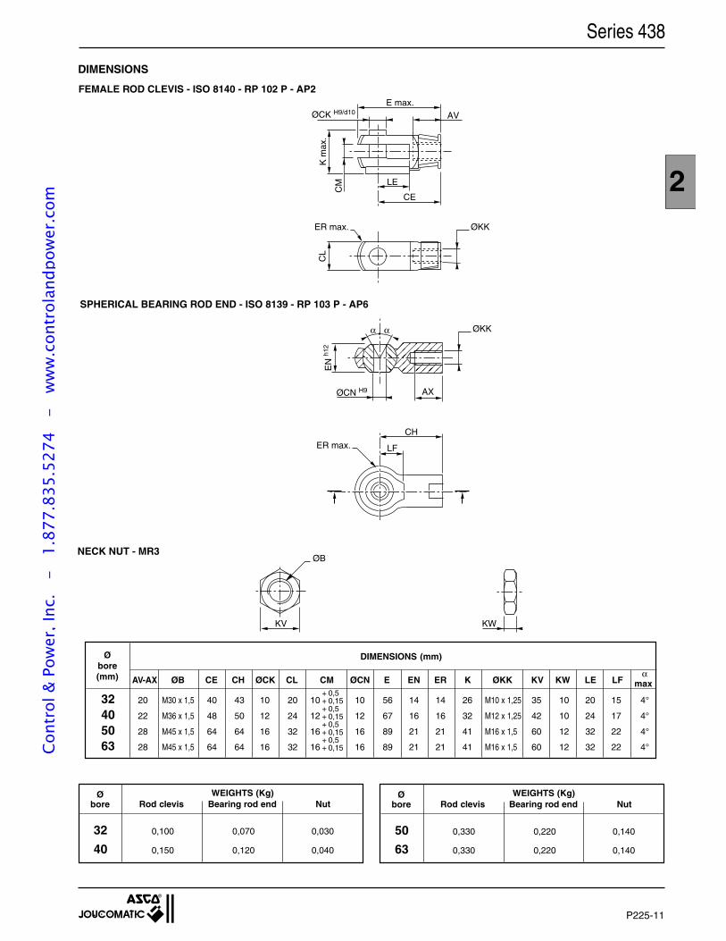
P225-11
2
Series 438
DIMENSIONS
FEMALE ROD CLEVIS - ISO 8140 - RP 102 P - AP2
Øbore
WEIGHTS (Kg)Rod clevis Bearing rod end Nut
32 0,100 0,070 0,030
40 0,150 0,120 0,040
DIMENSIONS (mm)Øbore(mm)
32 20 M30 x 1,5 40 43 10 20 10 10 56 14 14 26 M10 x 1,25 35 10 20 15 4°
40 22 M36 x 1,5 48 50 12 24 12 12 67 16 16 32 M12 x 1,25 42 10 24 17 4°
50 28 M45 x 1,5 64 64 16 32 16 16 89 21 21 41 M16 x 1,5 60 12 32 22 4°
63 28 M45 x 1,5 64 64 16 32 16 16 89 21 21 41 M16 x 1,5 60 12 32 22 4°
AV-AX ØB CE CH ØCK CL CM ØCN E EN ER K ØKK KV KW LE LFα
max+ 0,5+ 0,15+ 0,5+ 0,15+ 0,5+ 0,15+ 0,5+ 0,15
ØB
KV KW
Øbore
WEIGHTS (Kg)Rod clevis Bearing rod end Nut
50 0,330 0,220 0,140
63 0,330 0,220 0,140
SPHERICAL BEARING ROD END - ISO 8139 - RP 103 P - AP6
NECK NUT - MR3
ØCN H9
EN
h12
ER max.
ØKK
AX
CH
LF
αα
ØCK H9/d10
ER max. ØKK
E max.
K m
ax.
CM
AV
LE
CE
CL
Cont
rol &
Pow
er, I
nc.
-
1.87
7.83
5.52
74
- w
ww
.con
trol
andp
ower
.com
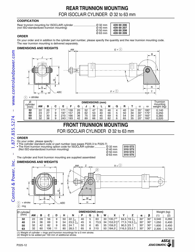
P225-12
Rear trunnion mounting for ISOCLAIR cylinder Ø 32 mm 439 00 206(not ISO-standardized trunnion mounting) Ø 40 mm 439 00 207
Ø 50 mm 439 00 208Ø 63 mm 439 00 209
On your order, please specify :• The cylinder standard code or part number (see pages P225-3 to P225-7)• The front trunnion mounting option code for ISOCLAIR cylinder Ø 32 mm 010 572 (Not ISO-standardized trunnion mounting) Ø 40 mm 010 573
Ø 50 mm 010 574Ø 63 mm 010 575
The cylinder and front trunnion mounting are supplied assembled
REAR TRUNNION MOUNTINGFOR ISOCLAIR CYLINDER Ø 32 to 63 mm
CODIFICATION
ORDEROn your order and in addition to the cylinder part number, please specify the quantity and the rear trunnion mounting code.The rear trunnion mounting is delivered separately.
32405063
Øcylinder
(mm)22 20 7 171 139 20 52 47 35 46 4 40 24 35° 180°24 27 9 197 157 28 62 53 40 56 5 50 30 30° 170°32 30 9 210 166 36 75 59 45 69 6 54 34 20° 165°32 38 9 243 193 42 89 66 50 82 6 65 35 20° 160°
0,1400,2500,3600,520
DIMENSIONS (mm)
22 28 56 9 50 22 40 5 63 30 135 64,5 19 30° 30°24 36 69 9 54 23,5 45 6 73,5 34 153,5 77,5 19,5 30° 30°32 42 82 9 65 24 50 6 85 35 159,5 90,5 23 30° 30°32 60 106 11 80 28,5 65 8 110 50 184,5 116,5 23,5 30° 30°
DIMENSIONS (mm)
+0,5 0+1 0+1 0
0 -0,5
0 -1
(1)
(1) Weight of cylinder + rings and trunnion mountings for a 0 mm stroke.(2) Weight to be added per 100 mm of additional stroke.
32405063
+0,50
0 -1
0 -0,5
(2)0,5401,0501,6002,300
0,2600,4000,4500,700
0-0,5
DIMENSIONS AND WEIGHTS
ORDER
Weight (kg)Ø cylinder(mm)
Trunnionmounting
weight (kg)
0-0,5
0-1
0-1
1 + stroke
EAM +
BJ
R
T
= =
4ØC
L
= =
Q
K
1
F + 1
ω
α
M
G
DIMENSIONS AND WEIGHTS
1 + stroke
2 ring
X + AM
= =C H
W
Z
β
α
B
1
2
NN
S
P
Y= =
Q
4ØD
FRONT TRUNNION MOUNTINGFOR ISOCLAIR CYLINDER Ø 32 to 63 mm
AM B C E F G J K L M Q R T α ω
AM B C D H N P Q S W X Y Z ααααα βββββ
Cont
rol &
Pow
er, I
nc.
-
1.87
7.83
5.52
74
- w
ww
.con
trol
andp
ower
.com
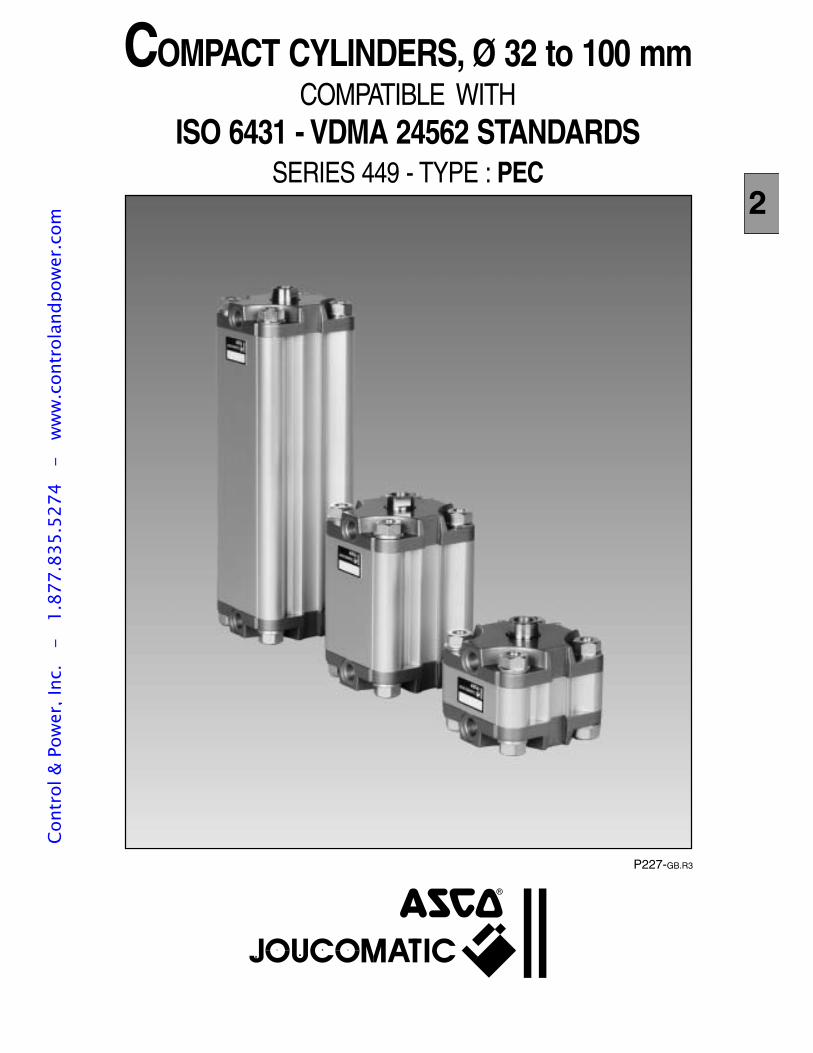
P227-GB.R3
COMPACT CYLINDERS, Ø 32 to 100 mmCOMPATIBLE WITH
ISO 6431 - VDMA 24562 STANDARDSSERIES 449 - TYPE : PEC
2
Cont
rol &
Pow
er, I
nc.
-
1.87
7.83
5.52
74
- w
ww
.con
trol
andp
ower
.com
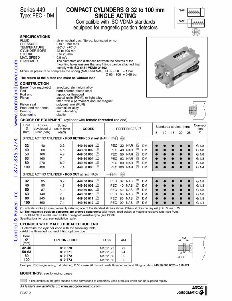
P227-2
All leaflets are available on: www.ascojoucomatic.com
CHOICE OF EQUIPMENT (cylinder with female threaded rod end)
Series 449Type: PEC - DM
COMPACT CYLINDERS Ø 32 to 100 mmSINGLE ACTING
Compatible with ISO-VDMA standardsequipped for magnetic position detectors
SPECIFICATIONSFLUID : air or neutral gas, filtered, lubricated or notPRESSURE : 2 to 10 bar max.TEMPERATURE : -20°C, +70°CCYLINDER BORE : 32 to 100 mmSTROKE : 5 to 25 mmMAX. SPEED : 0,5 m/sSTANDARD : The diameters and distances between the centres of the
mounting holes ensures that any fittings can be attached thatcomply with ISO 6431-VDMA 24562
Minimum pressure to compress the spring (NAR and NAS): Ø 32 - 50 = 1 barØ 63 - 100 = 0,65 bar
The return of the piston rod must be without load
CONSTRUCTION
(1) Indicate stroke (in mm) preferably selecting one of the standard strokes above. Others strokes on request (min. 5, max. 25)(2) The magnetic position detectors are ordered separately: UNI model, reed switch or magneto-resistive type (see P295)
or COMPACT model, reed switch or magneto-resistive type (see P293)Specifications for use: see installation leaflet
NAR
NAS
NS
CODESBore
Ø(mm)
449 50 001 ....449 50 002 ....449 50 003 ....449 50 004 ....449 50 005 ....449 50 006 ....
3240506380100
REFERENCES (2)
G 1/8G 1/8G 1/8G 1/8G 1/8G 1/4
DMDMDMDMDMDM
(1)
(1)PEC 32 NAR ...PEC 40 NAR ...PEC 50 NAR ...PEC 63 NAR ...PEC 80 NAR ...PEC 100 NAR ...
(1)
(1)
(1)
(1)
Connec-tionØ
(1)
(1)
(1)
(1)
(1)
(1)
Forcesdeveloped at6 bar (daN)
Springreturn force
(daN)
4060
100160270430
3,24,54,978,97,4
449 50 007 ....449 50 008 ....449 50 009 ....449 50 010 ....449 50 011 ....449 50 012 ....
3240506380100
G 1/8G 1/8G 1/8G 1/8G 1/8G 1/4
DMDMDMDMDMDM
(1)
(1)
(1)
(1)
(1)
(1)
(1)
(1)
(1)
(1)
(1)
(1)
355087
140245390
3,24,54,978,97,4
SINGLE ACTING CYLINDER - ROD RETURNED at rest (NAR)
SINGLE ACTING CYLINDER - ROD OUT at rest (NAS)
NS
NS
PEC 32 NAS ...PEC 40 NAS ...PEC 50 NAS ...PEC 63 NAS ...PEC 80 NAS ...PEC 100 NAS ...
Barrel (non magnetic) : anodized aluminium alloyRod : hard chrome plated steelRod end tapped or threadedPiston : acetal resin (POM), or light alloy
fitted with a permanent annular magnetPiston seal : polyurethane (PUR)Front and rear ends : aluminium alloyBearing : self lubricatingCushioning : elastic
Standards strokes (mm)
5 10 15 20 25
MOUNTINGS: see following pages
: The strokes in the grey shaded areas correspond to commonly used products which can be supplied rapidly
CYLINDER WITH MALE THREADED ROD END
BoreØ
(mm)OPTION - CODE
M10x1,25M12x1,25M16x1,50M16x1,50
Ø KK AM
32-4050-63
80100
010 870010 871010 872010 873
22243232
- Determine the cylinder code with the following table- Add the threaded rod end fitting option-code
Example: PEC single acting, rod returned, Ø 50 stroke 20 mm with male threaded rod end fitting - code = 449 50 003 0020 + 010 871
AM
Ø KK
Cont
rol &
Pow
er, I
nc.
-
1.87
7.83
5.52
74
- w
ww
.con
trol
andp
ower
.com
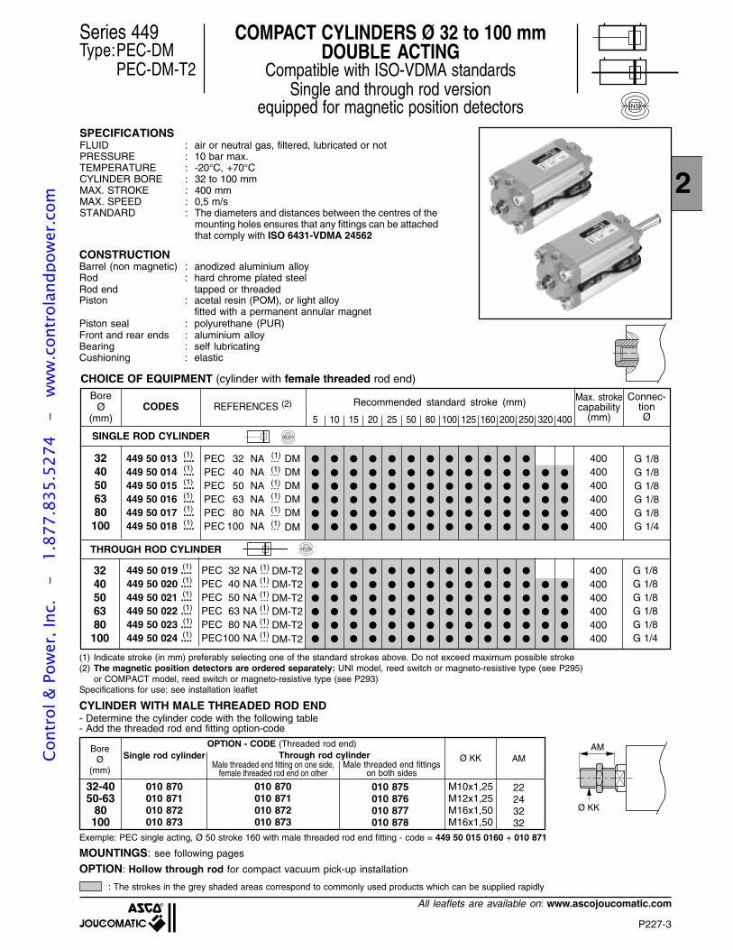
P227-3
2
All leaflets are available on: www.ascojoucomatic.com
CHOICE OF EQUIPMENT (cylinder with female threaded rod end)
Series 449Type:PEC-DM
PEC-DM-T2
COMPACT CYLINDERS Ø 32 to 100 mmDOUBLE ACTING
Compatible with ISO-VDMA standardsSingle and through rod version
equipped for magnetic position detectorsSPECIFICATIONSFLUID : air or neutral gas, filtered, lubricated or notPRESSURE : 10 bar max.TEMPERATURE : -20°C, +70°CCYLINDER BORE : 32 to 100 mmMAX. STROKE : 400 mmMAX. SPEED : 0,5 m/sSTANDARD : The diameters and distances between the centres of the
mounting holes ensures that any fittings can be attachedthat comply with ISO 6431-VDMA 24562
CONSTRUCTION
(1) Indicate stroke (in mm) preferably selecting one of the standard strokes above. Do not exceed maximum possible stroke(2) The magnetic position detectors are ordered separately: UNI model, reed switch or magneto-resistive type (see P295)
or COMPACT model, reed switch or magneto-resistive type (see P293)Specifications for use: see installation leaflet
Barrel (non magnetic) : anodized aluminium alloyRod : hard chrome plated steelRod end tapped or threadedPiston : acetal resin (POM), or light alloy
fitted with a permanent annular magnetPiston seal : polyurethane (PUR)Front and rear ends : aluminium alloyBearing : self lubricatingCushioning : elastic
NS
: The strokes in the grey shaded areas correspond to commonly used products which can be supplied rapidly
PEC 32 NA ...PEC 40 NA ...PEC 50 NA ...PEC 63 NA ...PEC 80 NA ...PEC100 NA ...
PEC 32 NA ...PEC 40 NA ...PEC 50 NA ...PEC 63 NA ...PEC 80 NA ...PEC 100 NA ...
CODESBore
Ø(mm)
449 50 013 ....449 50 014 ....449 50 015 ....449 50 016 ....449 50 017 ....449 50 018 ....
3240506380100
REFERENCES (2)
G 1/8G 1/8G 1/8G 1/8G 1/8G 1/4
DMDMDMDMDMDM
(1)
(1)
(1)
(1)
(1)
(1)
Connec-tionØ
(1)
(1)
(1)
(1)
(1)
(1)
5 10 15 20 25 50 80 100 125 160 200 250 320 400
Max. strokecapability
(mm)
Recommended standard stroke (mm)
400400400400400400
449 50 019 ....449 50 020 ....449 50 021 ....449 50 022 ....449 50 023 ....449 50 024 ....
3240506380100
G 1/8G 1/8G 1/8G 1/8G 1/8G 1/4
DM-T2DM-T2DM-T2DM-T2DM-T2DM-T2
(1)
(1)
(1)
(1)
(1)
(1)
(1)
(1)
(1)
(1)
(1)
(1)
400400400400400400
NS
THROUGH ROD CYLINDER
NSSINGLE ROD CYLINDER
MOUNTINGS: see following pages
CYLINDER WITH MALE THREADED ROD END
OPTION: Hollow through rod for compact vacuum pick-up installation
BoreØ
(mm)
Single rod cylinder Through rod cylinderMale threaded end fitting on one side,
female threaded rod end on other
OPTION - CODE (Threaded rod end)
M10x1,25M12x1,25M16x1,50M16x1,50
Ø KK AM
32-4050-63
80100
010 870010 871010 872010 873
010 870010 871010 872010 873
22243232
- Determine the cylinder code with the following table- Add the threaded rod end fitting option-code
Exemple: PEC single acting, Ø 50 stroke 160 with male threaded rod end fitting - code = 449 50 015 0160 + 010 871
AM
Ø KK
Male threaded end fittingson both sides
010 875010 876010 877010 878
Cont
rol &
Pow
er, I
nc.
-
1.87
7.83
5.52
74
- w
ww
.con
trol
andp
ower
.com
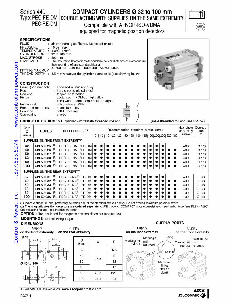
P227-4
All leaflets are available on: www.ascojoucomatic.com
A
BB
A
BB
A
BB
35.8
A
35.8
BB
4.5 mm
PEC 32 NA ...PEC 40 NA ...PEC 50 NA ...PEC 63 NA ...PEC 80 NA ...PEC100 NA ...
PEC 32 NA ...PEC 40 NA ...PEC 50 NA ...PEC 63 NA ...PEC 80 NA ...PEC100 NA ...
CHOICE OF EQUIPMENT (cylinder with female threaded rod end) (male threaded rod end: see P227-2)
Series 449Type: PEC-FE-DM
PEC-RE-DM
COMPACT CYLINDERS Ø 32 to 100 mmDOUBLE ACTING WITH SUPPLIES ON THE SAME EXTREMITY
Compatible with AFNOR-ISO-VDMAequipped for magnetic position detectors
CODESBore
Ø(mm)
449 50 025 ....449 50 026 ....449 50 027 ....449 50 028 ....449 50 029 ....449 50 030 ....
3240506380100
REFERENCES (2)
FE-DMFE-DMFE-DMFE-DMFE-DMFE-DM
Connec-tionØ
(1)
(1)
(1)
(1)
(1)
(1)
(1) Indicate stroke (in mm) preferably selecting one of the standard strokes above. Do not exceed maximum possible stroke(2) The magnetic position detectors are ordered separately: UNI model or COMPACT magneto-resistive or reed switch type (see P293 - P295)Specifications for use: see installation leaflet
NS
Max. strokecapability
(mm)
Recommended standard stroke (mm)
400400400400400400
449 50 031 ....449 50 032 ....449 50 033 ....449 50 034 ....449 50 035 ....449 50 036 ....
3240506380100
G 1/8G 1/8G 1/8G 1/8G 1/8G 1/8
RE-DMRE-DMRE-DMRE-DMRE-DMRE-DM
400400400400400400
SUPPLIES ON THE REAR EXTREMITY
SUPPLIES ON THE FRONT EXTREMITY
OPTION : Non equipped for magnetic position detectors (consult us)
DIMENSIONS
Ø 32
(1)
(1)
(1)
(1)
(1)
(1)
(1)
(1)
(1)
(1)
(1)
(1)
(1)
(1)
(1)
(1)
(1)
(1)
Ø 40 to 100
SPECIFICATIONSFLUID : air or neutral gas, filtered, lubricated or notPRESSURE : 10 bar max.TEMPERATURE : -20°C, +70°CCYLINDER BORE : 32 to 100 mmMAX. STROKE : 400 mmSTANDARD : The mounting holes diameter and the center distance of axes ensure
the mounting of any standard fitting:AFNOR NF E 49-003 - ISO 6431 - VDMA 24562
FITTING MAXIMUMTHREAD DEPTH : 4.5 mm whatever the cylinder diameter is (see drawing below)
CONSTRUCTIONBarrel (non magnetic) : anodized aluminium alloyRod : hard chrome plated steelRod end : tapped or threadedPiston : acetal resin (POM), or light alloy
fitted with a permanent annular magnetPiston seal : polyurethane (PUR)Front and rear ends : aluminium alloyBearinge : self lubricatingCushioning : elastic
SUPPLY PORTSSupply
on the rear extremitySupply
on the front extremity
Marking #4rod out
Marking #2rodreturned
Marking #4rod out
Marking #2rodreturned
Maximumfittingthreaddepth
FittingØ A BBore
32 6.5
40 9
50 12
63 17
80 28.3 22.5
100 31.3 28
25.8
Supplyon the rear extremity
Supplyon the front extremity
MOUNTINGS: see following pages
G 1/8G 1/8G 1/8G 1/8G 1/8G 1/8
5 10 15 20 25 50 80 100 125 160 200 250 320 400
Cont
rol &
Pow
er, I
nc.
-
1.87
7.83
5.52
74
- w
ww
.con
trol
andp
ower
.com
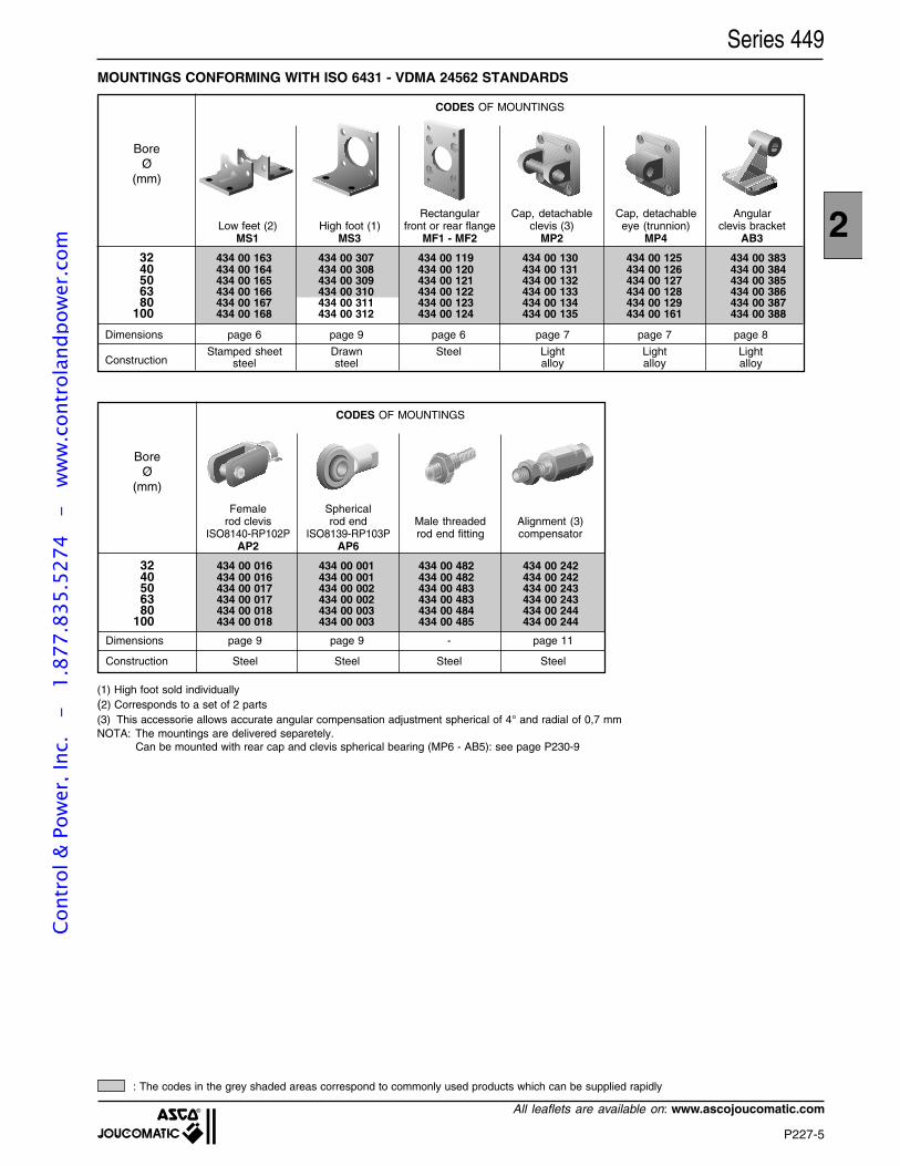
P227-5
2
All leaflets are available on: www.ascojoucomatic.com
CODES OF MOUNTINGS
32 434 00 163 434 00 307 434 00 119 434 00 130 434 00 125 434 00 38340 434 00 164 434 00 308 434 00 120 434 00 131 434 00 126 434 00 38450 434 00 165 434 00 309 434 00 121 434 00 132 434 00 127 434 00 38563 434 00 166 434 00 310 434 00 122 434 00 133 434 00 128 434 00 38680 434 00 167 434 00 311 434 00 123 434 00 134 434 00 129 434 00 387
100 434 00 168 434 00 312 434 00 124 434 00 135 434 00 161 434 00 388
Rectangular Cap, detachable Cap, detachable AngularLow feet (2) High foot (1) front or rear flange clevis (3) eye (trunnion) clevis bracket
MS1 MS3 MF1 - MF2 MP2 MP4 AB3
MOUNTINGS CONFORMING WITH ISO 6431 - VDMA 24562 STANDARDS
(1) High foot sold individually(2) Corresponds to a set of 2 parts(3) This accessorie allows accurate angular compensation adjustment spherical of 4° and radial of 0,7 mmNOTA: The mountings are delivered separetely.
Can be mounted with rear cap and clevis spherical bearing (MP6 - AB5): see page P230-9
: The codes in the grey shaded areas correspond to commonly used products which can be supplied rapidly
Series 449
BoreØ
(mm)
Dimensions page 6 page 9 page 6 page 7 page 7 page 8
Stamped sheet Drawn Steel Light Light Lightsteel steel alloy alloy alloyConstruction
CODES OF MOUNTINGS
32 434 00 016 434 00 001 434 00 482 434 00 24240 434 00 016 434 00 001 434 00 482 434 00 24250 434 00 017 434 00 002 434 00 483 434 00 24363 434 00 017 434 00 002 434 00 483 434 00 24380 434 00 018 434 00 003 434 00 484 434 00 244
100 434 00 018 434 00 003 434 00 485 434 00 244
Female Sphericalrod clevis rod end Male threaded Alignment (3)
ISO8140-RP102P ISO8139-RP103P rod end fitting compensatorAP2 AP6
BoreØ
(mm)
Dimensions page 9 page 9 - page 11
Construction Steel Steel Steel Steel
Cont
rol &
Pow
er, I
nc.
-
1.87
7.83
5.52
74
- w
ww
.con
trol
andp
ower
.com
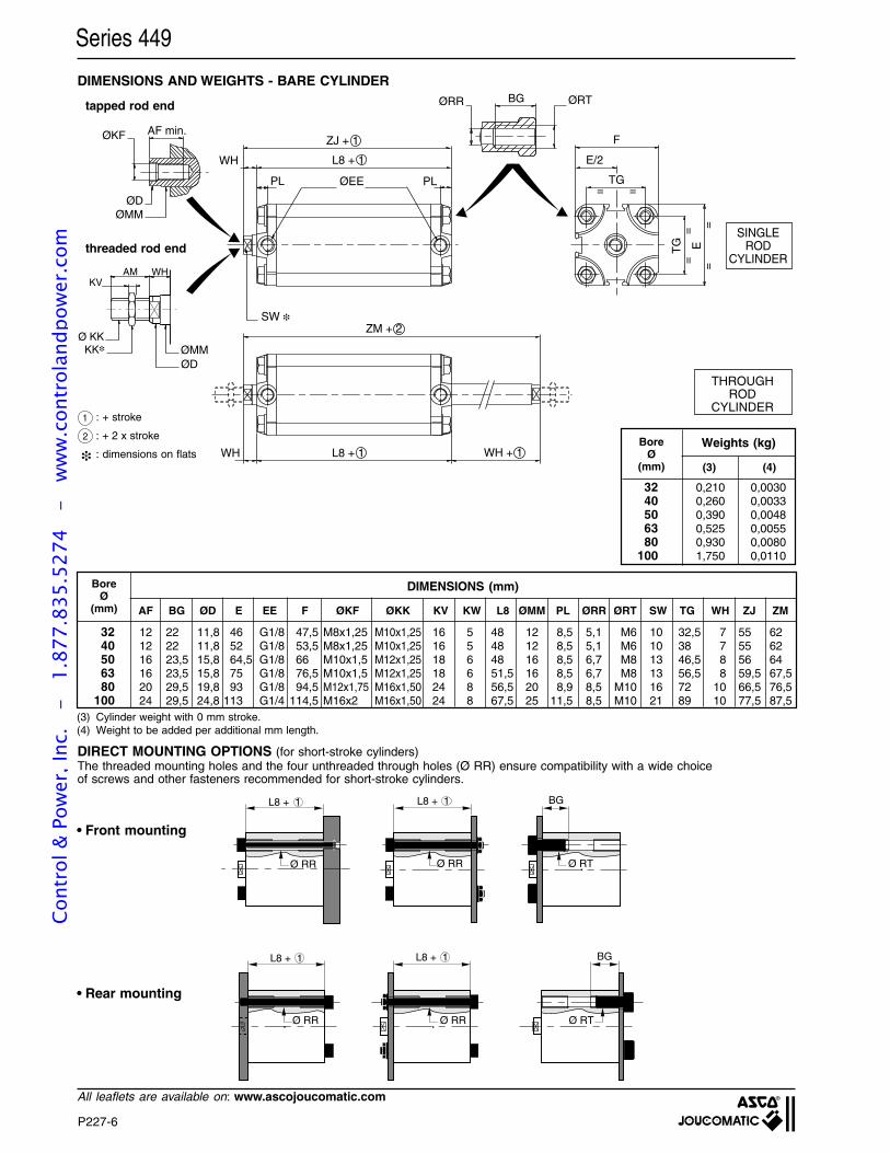
P227-6
All leaflets are available on: www.ascojoucomatic.com
BG ØRT
= =
F
TG
==
==
TG E
WH
AF min.
ØEEPL
L8 + 1
ZJ + 1
SW
ØKF
PL
E/2
ZM + 2
L8 + 1 WH + 1WH
ØDØMM
ØRR
AM
Ø KKØMMØD
KK
KVWH
(3) Cylinder weight with 0 mm stroke.(4) Weight to be added per additional mm length.
THROUGHROD
CYLINDER
DIMENSIONS AND WEIGHTS - BARE CYLINDER
SINGLEROD
CYLINDER
Series 449
1 : + stroke
: + 2 x stroke
: dimensions on flats
2
DIRECT MOUNTING OPTIONS (for short-stroke cylinders)The threaded mounting holes and the four unthreaded through holes (Ø RR) ensure compatibility with a wide choiceof screws and other fasteners recommended for short-stroke cylinders.
L8 + 1
Ø RR
L8 + 1
L8 + 1
Ø RR
Ø RR
L8 + 1
Ø RR
BG
Ø RT
BG
Ø RT
• Rear mounting
• Front mounting
threaded rod end
tapped rod end
Weights (kg)BoreØ
(mm)
32 0,210 0,003040 0,260 0,003350 0,390 0,004863 0,525 0,005580 0,930 0,0080
100 1,750 0,0110
(3) (4)
BoreØ
(mm) AF BG ØD E EE F ØKF ØKK KV KW L8 ØMM PL ØRR ØRT SW TG WH ZJ ZM
32 12 22 11,8 46 G1/8 47,5 M8x1,25 M10x1,25 16 5 48 12 8,5 5,1 M6 10 32,5 7 55 6240 12 22 11,8 52 G1/8 53,5 M8x1,25 M10x1,25 16 5 48 12 8,5 5,1 M6 10 38 7 55 6250 16 23,5 15,8 64,5 G1/8 66 M10x1,5 M12x1,25 18 6 48 16 8,5 6,7 M8 13 46,5 8 56 6463 16 23,5 15,8 75 G1/8 76,5 M10x1,5 M12x1,25 18 6 51,5 16 8,5 6,7 M8 13 56,5 8 59,5 67,580 20 29,5 19,8 93 G1/8 94,5 M12x1,75 M16x1,50 24 8 56,5 20 8,9 8,5 M10 16 72 10 66,5 76,5
100 24 29,5 24,8 113 G1/4 114,5 M16x2 M16x1,50 24 8 67,5 25 11,5 8,5 M10 21 89 10 77,5 87,5
DIMENSIONS (mm)
Cont
rol &
Pow
er, I
nc.
-
1.87
7.83
5.52
74
- w
ww
.con
trol
andp
ower
.com
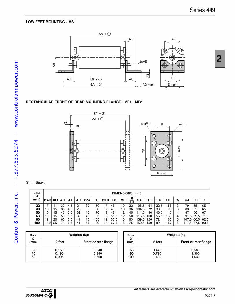
P227-7
2
All leaflets are available on: www.ascojoucomatic.com
Series 449
1 : + Stroke
LOW FEET MOUNTING - MS1
RECTANGULAR FRONT OR REAR MOUNTING FLANGE - MF1 - MF2
Weights (kg)BoreØ
(mm)
32 0,150 0,24040 0,190 0,24050 0,395 0,500
Weights (kg)BoreØ
(mm)
63 0,445 0,58080 0,790 1,390
100 1,400 1,630
2 feet Front or rear flange 2 feet Front or rear flange
RTR
BoreØ
(mm)
DIMENSIONS (mm)
ØAB AO AH AT AU Ød4 E ØFB L8 MF SA TF TG UF W XA ZJ ZF
32 7 11 32 4,5 24 30 50 7 48 10 32 96,5 64 32,5 86 3 79 55 6540 10 15 36 4,5 28 35 58 9 48 10 36 104,5 72 38 96 3 83 55 6550 10 15 45 5,5 32 40 70 9 48 12 45 111,5 90 46,5 115 4 87 56 6763 10 15 50 5,5 32 45 85 9 51,5 12 50 116,5 100 56,5 130 4 91,5 59,5 71,580 12 20 63 6,5 41 45 105 12 56,5 16 63 139,5 126 72 165 6 107,5 66,5 82,5
100 14,5 25 71 6,5 41 55 130 14 67,5 16 75 150,5 150 89 187 6 117,5 77,5 93,5
AH
TR= =E max.
=
TG=
=
=
AU L8 + 1
SA + 1
AU
AT
2øAB
AT
AO max.
XA + 1
= =MFØd4H11 R 4øFB
E max.
UF
max
.
TF
==
==
= =
ZJ + 1
ZF + 1
W
Cont
rol &
Pow
er, I
nc.
-
1.87
7.83
5.52
74
- w
ww
.con
trol
andp
ower
.com
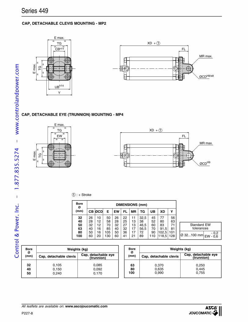
P227-8
All leaflets are available on: www.ascojoucomatic.com
Series 449
Ø 32...100 mm EW - 0,6
Standard EWtolerances
- 0,2
CAP, DETACHABLE CLEVIS MOUNTING - MP2
DIMENSIONS (mm)BoreØ
(mm) CB ØCD E EW FL MR TG UB XD Y
32 26 10 50 26 22 11 32,5 45 77 5640 28 12 58 28 25 13 38 52 80 6350 32 12 70 32 27 13 46,5 60 83 7163 40 16 85 40 32 17 56,5 70 91,5 8180 50 16 105 50 36 17 72 90 102,5 101
100 60 20 130 60 41 21 89 110 118,5 128
1 : + Stroke
Cap, detachable clevis
Weights (kg)BoreØ
(mm)
BoreØ
(mm)
Weights (kg)
Cap, detachable clevis
63 0,370 0,25080 0,635 0,445
100 0,990 0,755
32 0,105 0,08540 0,150 0,09250 0,240 0,170
CAP, DETACHABLE EYE (TRUNNION) MOUNTING - MP4
UBh14
CBH14
Y
E m
ax.
==
TG
==
=
==
=TG
E max.
XD + 1
FL
ØCDH9/e8
MR max.
l
XD + 1
FL
ØCDH9
MR max.
E max.
TG=
= =
=
==
TG
==E
max
.
EW= =
l
Cap, detachable eye(trunnion)
Cap, detachable eye(trunnion)Co
ntro
l & P
ower
, Inc
. -
1.
877.
835.
5274
-
ww
w.c
ontr
olan
dpow
er.c
om
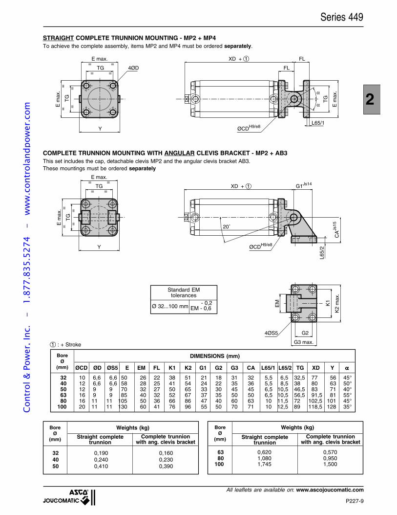
P227-9
2
All leaflets are available on: www.ascojoucomatic.com
Y
E m
ax.
==
TG
==
=
==
=TG
E max.
XD + 1 G1Js14
20˚
ØCDH9/e8
CA
Js15
K1
K2
max
.G2
G3 max.
4ØS5
EM
L65/
2
l
Series 449
Weights (kg)BoreØ
(mm)
BoreØ
(mm)
Weights (kg)
32 0,190 0,16040 0,240 0,23050 0,410 0,390
63 0,620 0,57080 1,080 0,950
100 1,745 1,500
DIMENSIONS (mm)BoreØ
(mm) ØCD ØD ØS5 E EM FL K1 K2 G1 G2 G3 CA L65/1 L65/2 TG XD Y ααααα
32 10 6,6 6,6 50 26 22 38 51 21 18 31 32 5,5 6,5 32,5 77 56 45°40 12 6,6 6,6 58 28 25 41 54 24 22 35 36 5,5 8,5 38 80 63 50°50 12 9 9 70 32 27 50 65 33 30 45 45 6,5 10,5 46,5 83 71 40°63 16 9 9 85 40 32 52 67 37 35 50 50 6,5 10,5 56,5 91,5 81 55°80 16 11 11 105 50 36 66 86 47 40 60 63 10 11,5 72 102,5 101 45°
100 20 11 11 130 60 41 76 96 55 50 70 71 10 12,5 89 118,5 128 35°
1 : + Stroke
STRAIGHT COMPLETE TRUNNION MOUNTING - MP2 + MP4To achieve the complete assembly, items MP2 and MP4 must be ordered separately.
COMPLETE TRUNNION MOUNTING WITH ANGULAR CLEVIS BRACKET - MP2 + AB3This set includes the cap, detachable clevis MP2 and the angular clevis bracket AB3.These mountings must be ordered separately
Ø 32...100 mm EM - 0,6
Standard EMtolerances
- 0,2
E max.
TG=
= =
== =
==T
G
E m
ax.
Y
4ØD
XD + 1 FL
FL
ØCDH9/e8
TG
E m
ax.α
α
L65/1
l
Complete trunnionwith ang. clevis bracket
Straight completetrunnion
Straight completetrunnion
Complete trunnionwith ang. clevis bracket
Cont
rol &
Pow
er, I
nc.
-
1.87
7.83
5.52
74
- w
ww
.con
trol
andp
ower
.com
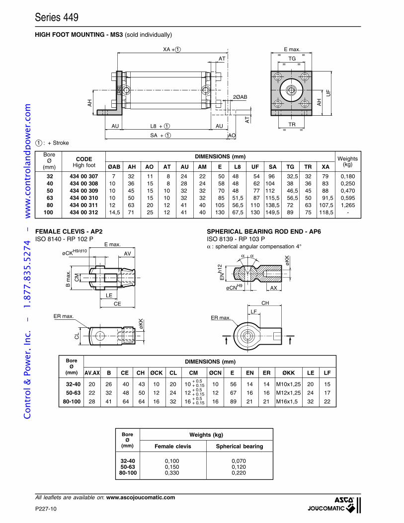
P227-10
All leaflets are available on: www.ascojoucomatic.com
Series 449HIGH FOOT MOUNTING - MS3 (sold individually)
1 : + Stroke
DIMENSIONS (mm)
ØAB AH AO AT AU AM E L8 UF SA TG TR XA
BoreØ
(mm)CODE
High foot
32 434 00 30740 434 00 30850 434 00 30963 434 00 31080 434 00 311
100 434 00 312
7 32 11 8 24 22 50 48 54 96 32,5 32 79 0,18010 36 15 8 28 24 58 48 62 104 38 36 83 0,25010 45 15 10 32 32 70 48 77 112 46,5 45 88 0,47010 50 15 10 32 32 85 51,5 87 115,5 56,5 50 91,5 0,59512 63 20 12 41 40 105 56,5 110 138,5 72 63 107,5 1,26514,5 71 25 12 41 40 130 67,5 130 149,5 89 75 118,5 -
Weights(kg)
øCNH9 AXø
KK
EN
h12
α α
CH
LFER max.
E max.
øCKH9/d10AV
LE
CE
CM
B m
ax.
CL
ER max.
øK
K
SPHERICAL BEARING ROD END - AP6ISO 8139 - RP 103 P
FEMALE CLEVIS - AP2ISO 8140 - RP 102 P
α : spherical angular compensation 4°
DIMENSIONS (mm)BoreØ
(mm) AV.AX B CE CH ØCK CL CM ØCN E EN ER ØKK LE LF
32-40 20 26 40 43 10 20 10 10 56 14 14 M10x1,25 20 15
50-63 22 32 48 50 12 24 12 12 67 16 16 M12x1,25 24 17
80-100 28 41 64 64 16 32 16 16 89 21 21 M16x1,5 32 22+ 0.5+ 0.15
+ 0.5+ 0.15
+ 0.5+ 0.15
TR= =
E max.=
TG=
=
=
XA + 1
AU L8 + 1
SA + 1
AU
AT
2ØAB
AT
AH
AO
AH
UFl
BoreØ
(mm) Spherical bearingFemale clevis
Weights (kg)
32-40 0,100 0,07050-63 0,150 0,12080-100 0,330 0,220
Cont
rol &
Pow
er, I
nc.
-
1.87
7.83
5.52
74
- w
ww
.con
trol
andp
ower
.com
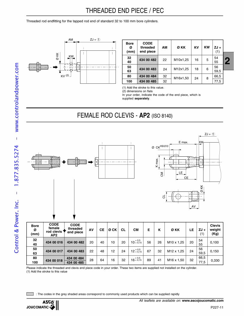
P227-11
2
All leaflets are available on: www.ascojoucomatic.com
ZJ + 1
E max.
Ø CKH9/d10
AV
LE
CE
CM
K m
ax.
CL
Ø K
K
KW
Threaded rod endfitting for the tapped rod end of standard 32 to 100 mm bore cylinders.
FEMALE ROD CLEVIS - AP2 (ISO 8140)
ZJ + 1AM
Ø K
KKW
KV (2)
(1) Add the stroke to this value.(2) dimensions on flatsIn your order, indicate the code of the end piece, which issupplied separately.
THREADED END PIECE / PEC
Please indicate the threaded and clevis end piece code in your order. These two items are supplied not installed on the cylinder.(1) Add the stroke to this value
: The codes in the grey shaded areas correspond to commonly used products which can be supplied rapidly
3240506380
100
BoreØ
(mm)
CODEfemale
rod clevisAP2
AVCODE
threadedend piece
CE Ø CK CL CM E K Ø KK LE ZJ +(1)
Clevisweight
(Kg)
54555659,566,577,5
+ 0,5+ 0,15
+ 0,5+ 0,15
434 00 016 434 00 482 20 40 10 20 10 56 26 M10 x 1,25 20 0,100
434 00 017 434 00 483 22 48 12 24 12 67 32 M12 x 1,25 24 0,150
28 64 16 32 16 89 41 M16 x 1,50 32434 00 018434 00 484434 00 485
+ 0,5+ 0,15 0,330
BoreØ
(mm)
CODEthreadedend piece
ZJ +(1)
434 00 482
434 00 483
Ø KK
M10x1,25
M12x1,25
M16x1,50
KV KW
16 5
18 6
24 8
AM
22
24
32 5440 55
50 5663 59,5
80 434 00 484 32 66,5
100 434 00 485 32 77,5
Cont
rol &
Pow
er, I
nc.
-
1.87
7.83
5.52
74
- w
ww
.con
trol
andp
ower
.com
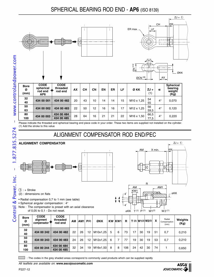
P227-12
All leaflets are available on: www.ascojoucomatic.com
ZJ + 1
ØCN H9
EN
h12
ØKK
AX
ER max.
CH
LF
KW
SPHERICAL BEARING ROD END - AP6 (ISO 8139)
Please indicate the threaded and spherical bearing end piece code in your order. These two items are supplied not installed on the cylinder.(1) Add the stroke to this value
: The codes in the grey shaded areas correspond to commonly used products which can be supplied rapidly
3240506380100
BoreØ
(mm)
CODEsphericalrod end
AP6
AX
CODEthreadedrod end CH CN EN ER LF Ø KK ZJ +
(1)
Sphericalbearingweight
(Kg)
434 00 001 434 00 482 20 43 10 14 14 15 M10 x 1,25 4° 0,070
434 00 002 434 00 483 22 50 12 16 16 17 M12 x 1,25 4° 0,120
28 64 16 21 21 22 M16 x 1,50 4°434 00 003434 00 484434 00 485
0,220
ααααα
54555659,566,577,5
AMKW1
AM1R
4˚
4˚
øKK
W2 ( 2 )W1(2)P ( 2 )T ( 2 )øKK
ZJ + 1
KWAM X min.
ALIGNMENT COMPENSATOR ROD END/PEC
• Radial compensation 0,7 to 1 mm (see table)• Spherical angular compensation : 4°Note : The compensator is preset with an axial clearance
of 0,05 to 0,1 - Do not reset.
ALIGNMENT COMPENSATOR
RadialCompensation
(mm)
3240506380
100
BoreØ
(mm)
CODEalignment
compensator AM
CODEthreadedrod end AM1 P(2) ØKK KW KW1 R T (2) Weights
(Kg)
434 00 242 434 00 482 22 26 12 M10x1,25 5 6 73 17 30 19 51 0,7
434 00 243 434 00 483 24 26 12 M12x1,25 6 7 77 19 30 19 53 0,7
32 34 19 M16x1,50 8 8 106 24 42 30 74 1434 00 244434 00 484434 00 485 0,650
W1(2) W2(2) X
0,210
0,210
1 : + Stroke(2) : dimensions on flats
Cont
rol &
Pow
er, I
nc.
-
1.87
7.83
5.52
74
- w
ww
.con
trol
andp
ower
.com
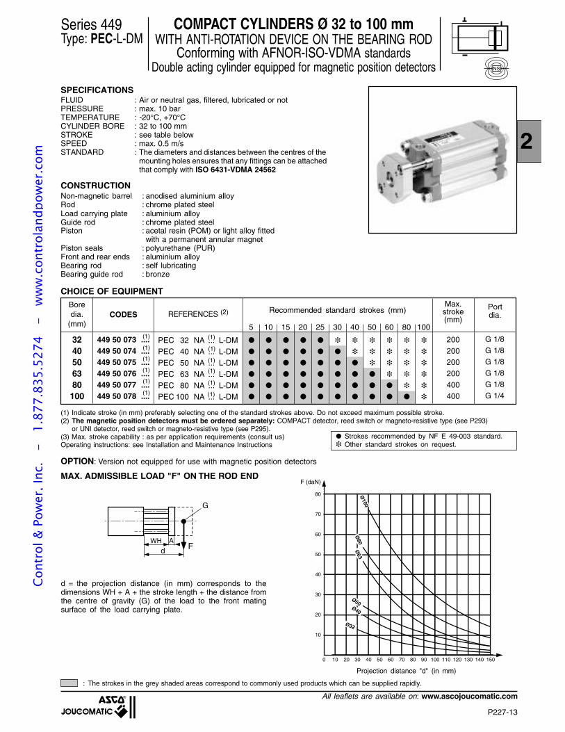
P227-13
2
All leaflets are available on: www.ascojoucomatic.com
COMPACT CYLINDERS Ø 32 to 100 mmWITH ANTI-ROTATION DEVICE ON THE BEARING ROD
Conforming with AFNOR-ISO-VDMA standardsDouble acting cylinder equipped for magnetic position detectors
SPECIFICATIONSFLUID : Air or neutral gas, filtered, lubricated or notPRESSURE : max. 10 barTEMPERATURE : -20°C, +70°CCYLINDER BORE : 32 to 100 mmSTROKE : see table belowSPEED : max. 0.5 m/sSTANDARD : The diameters and distances between the centres of the
mounting holes ensures that any fittings can be attachedthat comply with ISO 6431-VDMA 24562
CONSTRUCTIONNon-magnetic barrel : anodised aluminium alloyRod : chrome plated steelLoad carrying plate : aluminium alloyGuide rod : chrome plated steelPiston : acetal resin (POM) or light alloy fitted
with a permanent annular magnetPiston seals : polyurethane (PUR)Front and rear ends : aluminium alloyBearing rod : self lubricatingBearing guide rod : bronze
CHOICE OF EQUIPMENT
NS
(1) Indicate stroke (in mm) preferably selecting one of the standard strokes above. Do not exceed maximum possible stroke.(2) The magnetic position detectors must be ordered separately: COMPACT detector, reed switch or magneto-resistive type (see P293)
or UNI detector, reed switch or magneto-resistive type (see P295).(3) Max. stroke capability : as per application requirements (consult us)Operating instructions: see Installation and Maintenance Instructions
Series 449Type: PEC-L-DM
OPTION: Version not equipped for use with magnetic position detectors
: The strokes in the grey shaded areas correspond to commonly used products which can be supplied rapidly.
MAX. ADMISSIBLE LOAD "F" ON THE ROD END
Fd
G
WH A
d = the projection distance (in mm) corresponds to thedimensions WH + A + the stroke length + the distance fromthe centre of gravity (G) of the load to the front matingsurface of the load carrying plate.
Projection distance "d" (in mm)
10
100 20 30 40 50 60 70 80 90 100 110 120 130 140 150
20
30
40
50
60
70
80
F (daN)
Ø100
Ø80
Ø63
Ø50Ø40
Ø32
CODESBoredia.
(mm)
449 50 073 ....449 50 074 ....449 50 075 ....449 50 076 ....449 50 077 ....449 50 078 ....
3240506380100
REFERENCES (2)
(1)
(1)
(1)
(1)
(1)
(1)
G 1/8
G 1/8G 1/8
G 1/8G 1/8
G 1/4
Portdia.
Max.stroke(mm)
Recommended standard strokes (mm)
200
200
200200
400400
5 10 15 20 25 30 40 50 60 80 100
PEC 32 NA ...
PEC 40 NA ...PEC 50 NA ...
PEC 63 NA ...
PEC 80 NA ...PEC 100 NA ...
L-DM
L-DML-DM
L-DM
L-DML-DM
(1)
(1)
(1)
(1)
(1)
(1)
Strokes recommended by NF E 49-003 standard. Other standard strokes on request.
Cont
rol &
Pow
er, I
nc.
-
1.87
7.83
5.52
74
- w
ww
.con
trol
andp
ower
.com
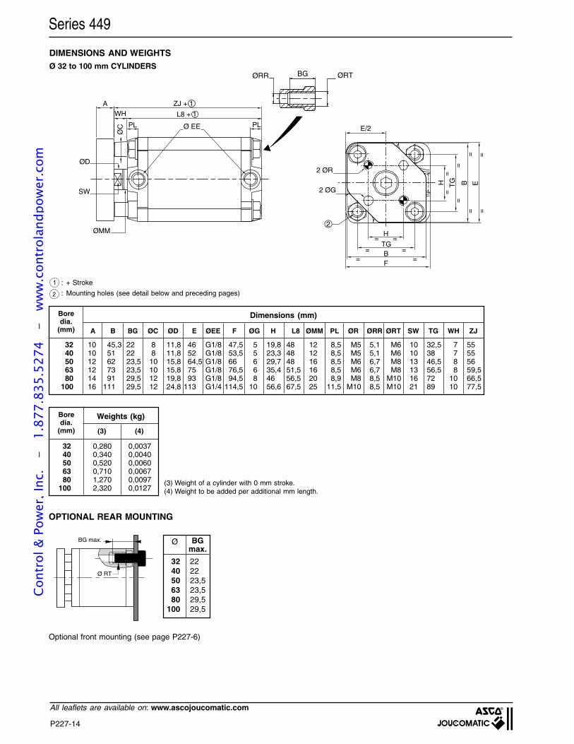
P227-14
All leaflets are available on: www.ascojoucomatic.com
Series 449
Ø 32 to 100 mm CYLINDERS
Boredia.
(mm) A B BG ØC ØD E ØEE F ØG H L8 ØMM PL ØR ØRR ØRT SW TG WH ZJ
32 10 45,3 22 8 11,8 46 G1/8 47,5 5 19,8 48 12 8,5 M5 5,1 M6 10 32,5 7 5540 10 51 22 8 11,8 52 G1/8 53,5 5 23,3 48 12 8,5 M5 5,1 M6 10 38 7 5550 12 62 23,5 10 15,8 64,5 G1/8 66 6 29,7 48 16 8,5 M6 6,7 M8 13 46,5 8 5663 12 73 23,5 10 15,8 75 G1/8 76,5 6 35,4 51,5 16 8,5 M6 6,7 M8 13 56,5 8 59,580 14 91 29,5 12 19,8 93 G1/8 94,5 8 46 56,5 20 8,9 M8 8,5 M10 16 72 10 66,5
100 16 111 29,5 12 24,8 113 G1/4 114,5 10 56,6 67,5 25 11,5 M10 8,5 M10 21 89 10 77,5
Dimensions (mm)
1 : + Stroke
: Mounting holes (see detail below and preceding pages)2
DIMENSIONS AND WEIGHTS
OPTIONAL REAR MOUNTING
Optional front mounting (see page P227-6)
Ø BGmax.
32 2240 2250 23,563 23,580 29,5
100 29,5
Boredia.
(mm)
Weights (kg)
(3) (4)
32 0,280 0,003740 0,340 0,004050 0,520 0,006063 0,710 0,006780 1,270 0,0097
100 2,320 0,0127(3) Weight of a cylinder with 0 mm stroke.(4) Weight to be added per additional mm length.
Ø RT
BG max.
A ZJ + 1WH
PL PLØ
C
E
H
TGBF
BTGH
2 ØR
2 ØG
2
Ø EE
==
==
= =
= =
==
====
L8 + 1
E/2
BGØRR ØRT
ØD
SW
ØMM
Cont
rol &
Pow
er, I
nc.
-
1.87
7.83
5.52
74
- w
ww
.con
trol
andp
ower
.com
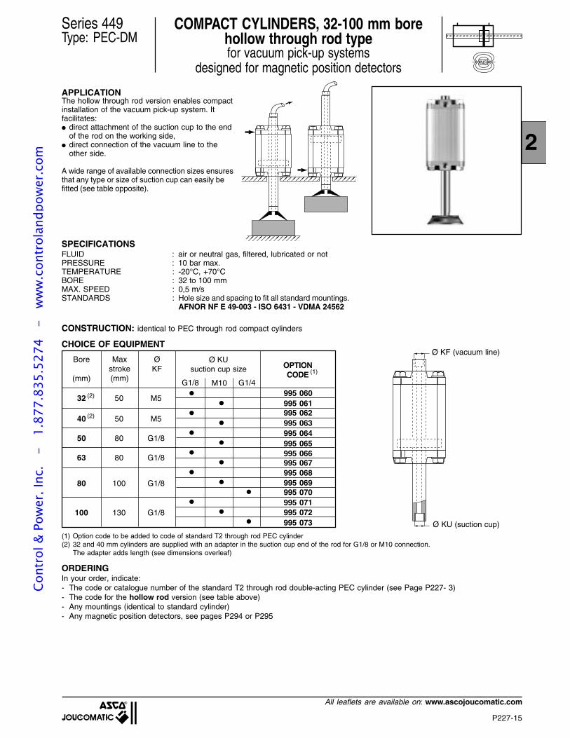
P227-15
2
All leaflets are available on: www.ascojoucomatic.com
Series 449Type: PEC-DM
COMPACT CYLINDERS, 32-100 mm borehollow through rod typefor vacuum pick-up systems
designed for magnetic position detectorsNS
APPLICATIONThe hollow through rod version enables compactinstallation of the vacuum pick-up system. Itfacilitates: direct attachment of the suction cup to the end
of the rod on the working side, direct connection of the vacuum line to the
other side.
A wide range of available connection sizes ensuresthat any type or size of suction cup can easily befitted (see table opposite).
SPECIFICATIONSFLUID : air or neutral gas, filtered, lubricated or notPRESSURE : 10 bar max.TEMPERATURE : -20°C, +70°CBORE : 32 to 100 mmMAX. SPEED : 0,5 m/sSTANDARDS : Hole size and spacing to fit all standard mountings.
AFNOR NF E 49-003 - ISO 6431 - VDMA 24562
CONSTRUCTION: identical to PEC through rod compact cylinders
CHOICE OF EQUIPMENT
Bore
(mm)
Maxstroke(mm)
ØKF
Ø KUsuction cup size
G1/8 M10 G1/4
OPTIONCODE
32 50 M5
40 50 M5
50 80 G1/8
63 80 G1/8
80 100 G1/8
100 130 G1/8
(2)
(2)
995 060995 061995 062995 063995 064995 065995 066995 067995 068995 069995 070995 071995 072995 073
(1)
(1) Option code to be added to code of standard T2 through rod PEC cylinder(2) 32 and 40 mm cylinders are supplied with an adapter in the suction cup end of the rod for G1/8 or M10 connection.
The adapter adds length (see dimensions overleaf)
ORDERINGIn your order, indicate:- The code or catalogue number of the standard T2 through rod double-acting PEC cylinder (see Page P227- 3)- The code for the hollow rod version (see table above)- Any mountings (identical to standard cylinder)- Any magnetic position detectors, see pages P294 or P295
Ø KF (vacuum line)
Ø KU (suction cup)
Cont
rol &
Pow
er, I
nc.
-
1.87
7.83
5.52
74
- w
ww
.con
trol
andp
ower
.com
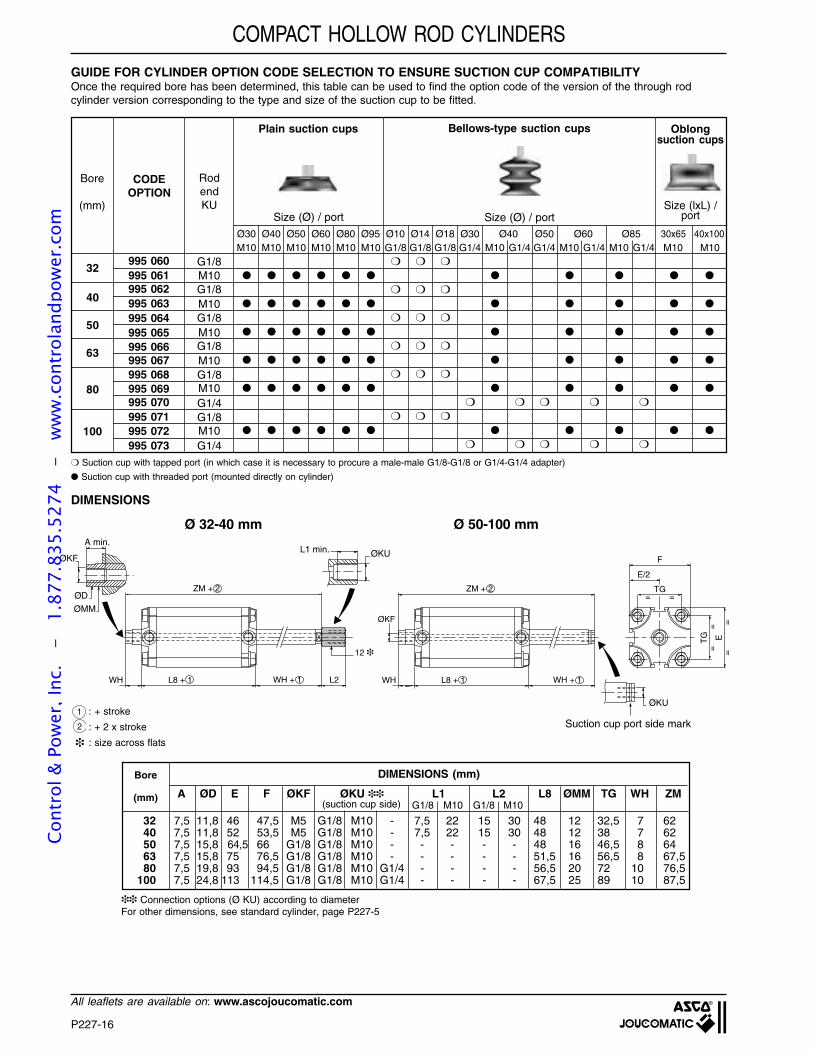
P227-16
All leaflets are available on: www.ascojoucomatic.com
COMPACT HOLLOW ROD CYLINDERS
GUIDE FOR CYLINDER OPTION CODE SELECTION TO ENSURE SUCTION CUP COMPATIBILITYOnce the required bore has been determined, this table can be used to find the option code of the version of the through rodcylinder version corresponding to the type and size of the suction cup to be fitted.
Bore
(mm)
RodendKU
Plain suction cups
G1/8M10G1/8
CODEOPTION
32
40
50
63
80
100
995 060995 061995 062995 063995 064995 065995 066995 067995 068995 069995 070995 071995 072995 073
M10G1/8M10G1/8M10G1/8M10G1/4G1/8M10G1/4
M10 M10 M10 M10 M10 M10 G1/8 G1/8 G1/8 G1/4 M10 G1/4 G1/4 M10 G1/4 M10 G1/4 M10 M10Ø30 Ø40 Ø50 Ø60 Ø80 Ø95 Ø10 Ø14 Ø18 Ø30 Ø40 Ø50 Ø60 Ø85 30x65 40x100
Bellows-type suction cups Oblongsuction cups
Size (Ø) / port Size (Ø) / portSize (lxL) /
port
Suction cup with tapped port (in which case it is necessary to procure a male-male G1/8-G1/8 or G1/4-G1/4 adapter)
Suction cup with threaded port (mounted directly on cylinder)
DIMENSIONS
ZM + 2
L8 + 1 WH + 1WH
A min.
ØD
ØMM
ØKUL1 min.
L2
ØKF
12
ØKU
ØKF
= =
F
TG
==
==
TG E
E/2
ZM + 2
L8 + 1 WH + 1WH
Bore
(mm)
DIMENSIONS (mm)
A ØD E F ØKF ØKU L1 L2 L8 ØMM TG WH ZM
32 7,5 11,8 46 47,5 M5 G1/8 M10 - 7,5 22 15 30 48 12 32,5 7 6240 7,5 11,8 52 53,5 M5 G1/8 M10 - 7,5 22 15 30 48 12 38 7 6250 7,5 15,8 64,5 66 G1/8 G1/8 M10 - - - - - 48 16 46,5 8 6463 7,5 15,8 75 76,5 G1/8 G1/8 M10 - - - - - 51,5 16 56,5 8 67,580 7,5 19,8 93 94,5 G1/8 G1/8 M10 G1/4 - - - - 56,5 20 72 10 76,5
100 7,5 24,8 113 114,5 G1/8 G1/8 M10 G1/4 - - - - 67,5 25 89 10 87,5
Ø 32-40 mm Ø 50-100 mm
G1/8 M10 G1/8 M10
Suction cup port side mark: + stroke
: + 2 x stroke
: size across flats
(suction cup side)
1
2
Connection options (Ø KU) according to diameterFor other dimensions, see standard cylinder, page P227-5
Cont
rol &
Pow
er, I
nc.
-
1.87
7.83
5.52
74
- w
ww
.con
trol
andp
ower
.com
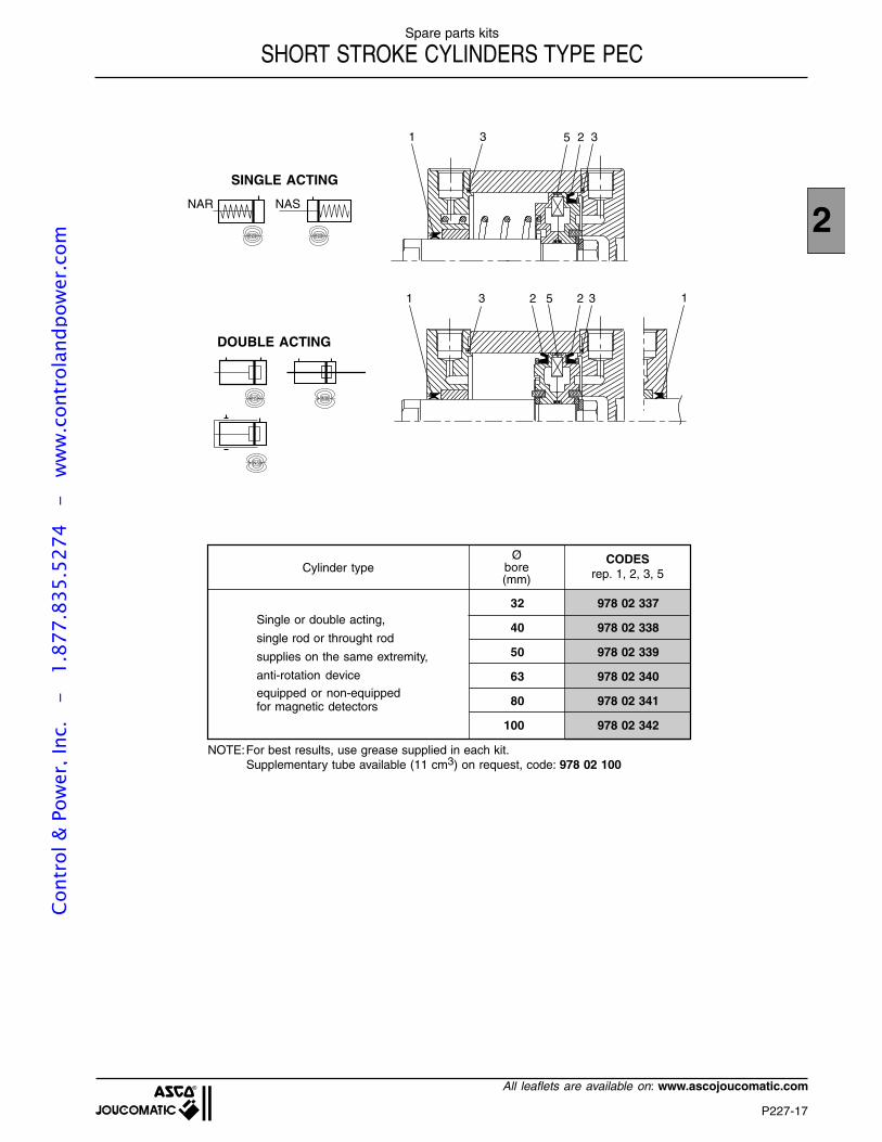
P227-17
2
All leaflets are available on: www.ascojoucomatic.com
Spare parts kits
SHORT STROKE CYLINDERS TYPE PEC
Cylinder typeØ
bore(mm)
CODESrep. 1, 2, 3, 5
32 978 02 337
40 978 02 338
50 978 02 339
63 978 02 340
80 978 02 341
100 978 02 342
SINGLE ACTING
DOUBLE ACTING
NS
NASNAR
NS
NOTE:For best results, use grease supplied in each kit.Supplementary tube available (11 cm3) on request, code: 978 02 100
221 3 3
21 3 3
15
5
Single or double acting,
single rod or throught rod
supplies on the same extremity,
anti-rotation device
equipped or non-equippedfor magnetic detectors
NS NS
NS
Cont
rol &
Pow
er, I
nc.
-
1.87
7.83
5.52
74
- w
ww
.con
trol
andp
ower
.com
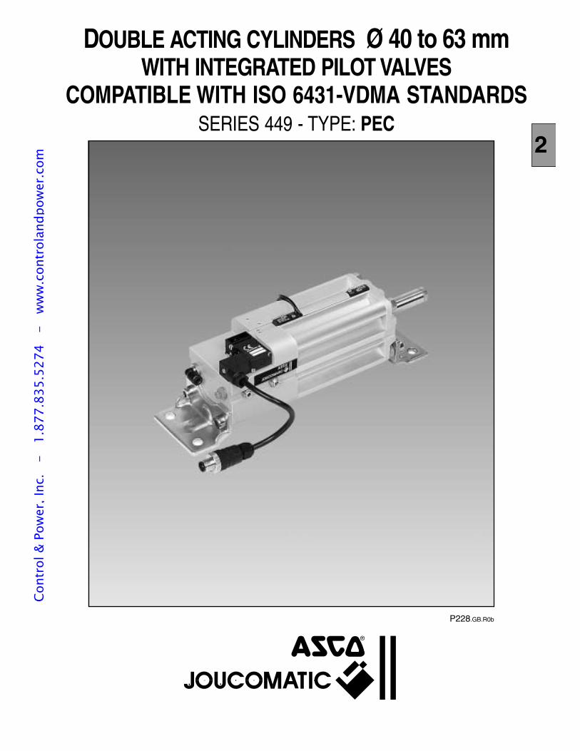
P228.GB.R0b
DOUBLE ACTING CYLINDERS Ø 40 to 63 mmWITH INTEGRATED PILOT VALVES
COMPATIBLE WITH ISO 6431-VDMA STANDARDSSERIES 449 - TYPE: PEC
2
Cont
rol &
Pow
er, I
nc.
-
1.87
7.83
5.52
74
- w
ww
.con
trol
andp
ower
.com
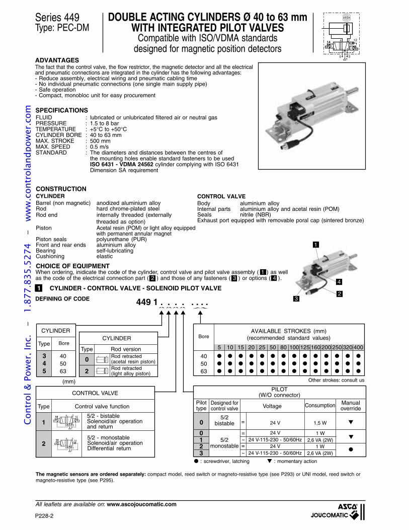
P228-2
All leaflets are available on: www.ascojoucomatic.com
1414 2
35
4
1
12
Series 449Type: PEC-DM
DOUBLE ACTING CYLINDERS Ø 40 to 63 mmWITH INTEGRATED PILOT VALVES
Compatible with ISO/VDMA standardsdesigned for magnetic position detectors
SPECIFICATIONSFLUID : lubricated or unlubricated filtered air or neutral gasPRESSURE : 1.5 to 8 barTEMPERATURE : +5°C to +50°CCYLINDER BORE : 40 to 63 mmMAX. STROKE : 500 mmMAX. SPEED : 0.5 m/sSTANDARD : The diameters and distances between the centres of
the mounting holes enable standard fasteners to be usedISO 6431 - VDMA 24562 cylinder complying with ISO 6431Dimension SA requirement
CONSTRUCTION
NS
1 CYLINDER - CONTROL VALVE - SOLENOID PILOT VALVE
CHOICE OF EQUIPMENT
5 10 15 20 25 50 80 100 125 160 200 250 320 400
AVAILABLE STROKES (mm)(recommended standard values)
449 1 . . . . . . . .
Type
3 404 505 63
Bore
CYLINDER
Other strokes: consult us(mm)
Type Control valve function
14 1214 2
35
4
1
14 1214 2
35
4
1
2
1
5/2 - monostableSolenoid/air operationDifferential return
5/2 - bistableSolenoid/air operationand return
CONTROL VALVE
Type
0
Rod version
CYLINDER
Rod retracted(acetal resin piston)
CYLINDERBarrel (non magnetic) anodized aluminium alloyRod hard chrome-plated steelRod end internally threaded (externally
threaded as option)Piston Acetal resin (POM) or light alloy equipped
with permanent annular magnetPiston seals polyurethane (PUR)Front and rear ends aluminium alloyBearing self-lubricatingCushioning elastic
: screwdriver, latching : momentary action
Bore
405063
1
4
23
ADVANTAGESThe fact that the control valve, the flow restrictor, the magnetic detector and all the electricaland pneumatic connections are integrated in the cylinder has the following advantages:- Reduce assembly, electrical wiring and pneumatic cabling time- No individual pneumatic connections (one single main supply pipe)- Safe operation- Compact, monobloc unit for easy procurement
CONTROL VALVEBody aluminium alloyInternal parts aluminium alloy and acetal resin (POM)Seals nitrile (NBR)Exhaust port equipped with removable poral cap (sintered bronze)
2 Rod retracted(light alloy piston)
The magnetic sensors are ordered separately: compact model, reed switch or magneto-resistive type (see P293) or UNI model, reed switch ormagneto-resistive type (see P295).
When ordering, inidicate the code of the cylinder, control valve and pilot valve assembly ( 1 ) as wellas the code of the electrical connection part ( 2 ) and those of any fasteners ( 3 ) or options ( 4 ).
0
0
Pilottype
PILOT(W/O connector)
VoltageManualoverride
24 V
=
=
~ 24 V-115-230 - 50/60Hz24 V
1
2 =
~ 24 V-115-230 - 50/60Hz24 V
3
Designed forcontrol valve
5/2bistable
5/2monostable
Consumption
1,5 W
1 W
1 W2,6 VA (2W)
2,6 VA (2W)
DEFINING OF CODE
Cont
rol &
Pow
er, I
nc.
-
1.87
7.83
5.52
74
- w
ww
.con
trol
andp
ower
.com
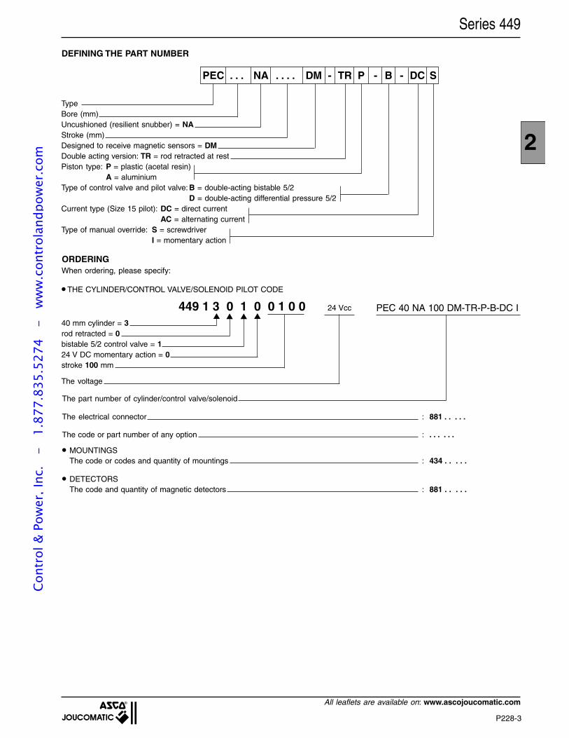
P228-3
2
All leaflets are available on: www.ascojoucomatic.com
The electrical connector : 881 . . . . .
The code or part number of any option : . . . . . .
MOUNTINGSThe code or codes and quantity of mountings : 434 . . . . .
DETECTORSThe code and quantity of magnetic detectors : 881 . . . . .
TypeBore (mm)Uncushioned (resilient snubber) = NAStroke (mm)Designed to receive magnetic sensors = DMDouble acting version: TR = rod retracted at restPiston type: P = plastic (acetal resin)
A = aluminiumType of control valve and pilot valve: B = double-acting bistable 5/2
D = double-acting differential pressure 5/2Current type (Size 15 pilot): DC = direct current
AC = alternating currentType of manual override: S = screwdriver
I = momentary action
Series 449
DEFINING THE PART NUMBER
PEC . . . NA . . . . DM - TR P - B - DC S
449 1 3 0 1 0 0 1 0 040 mm cylinder = 3rod retracted = 0bistable 5/2 control valve = 124 V DC momentary action = 0stroke 100 mm
ORDERING
When ordering, please specify:
THE CYLINDER/CONTROL VALVE/SOLENOID PILOT CODE
The voltage
The part number of cylinder/control valve/solenoid
24 Vcc PEC 40 NA 100 DM-TR-P-B-DC I
Cont
rol &
Pow
er, I
nc.
-
1.87
7.83
5.52
74
- w
ww
.con
trol
andp
ower
.com
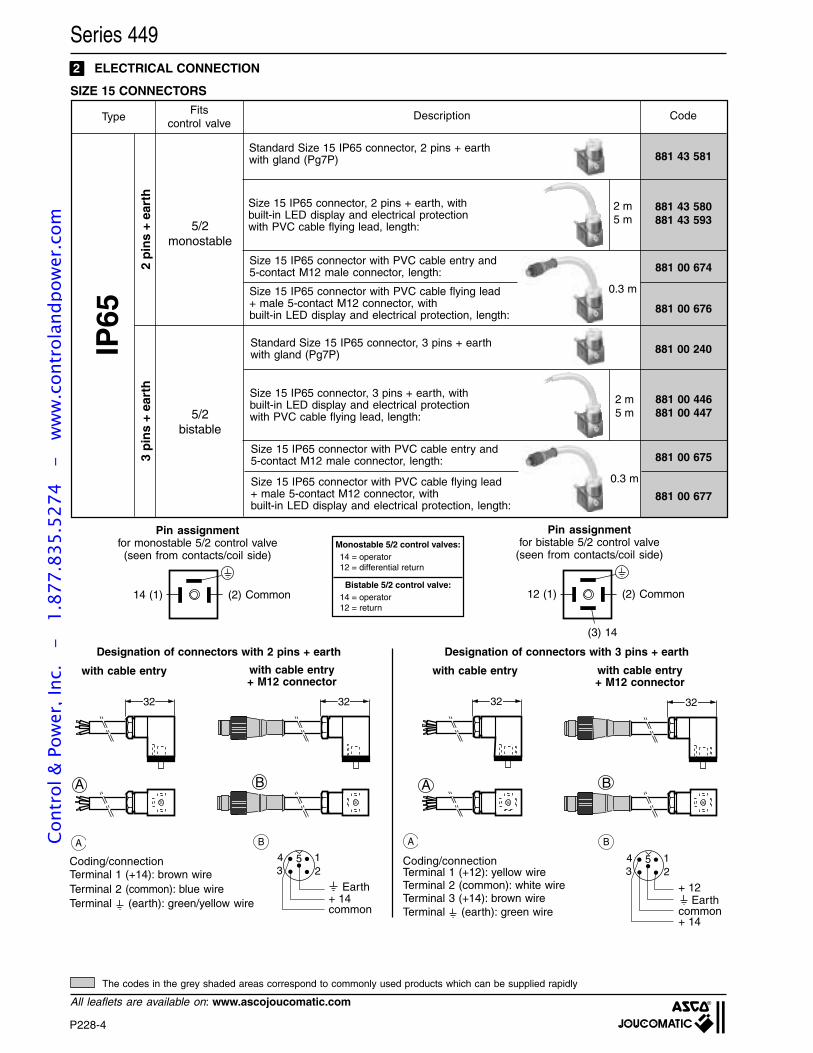
P228-4
All leaflets are available on: www.ascojoucomatic.com
A
32
B
32
Pin assignmentfor bistable 5/2 control valve
(seen from contacts/coil side)
(3) 14
32
A B
32
Coding/connectionTerminal 1 (+14): brown wireTerminal 2 (common): blue wireTerminal (earth): green/yellow wire
Coding/connectionTerminal 1 (+12): yellow wireTerminal 2 (common): white wireTerminal 3 (+14): brown wireTerminal (earth): green wire
with cable entry
(2) Common12 (1)
Pin assignmentfor monostable 5/2 control valve(seen from contacts/coil side)
(2) Common14 (1)
Monostable 5/2 control valves:14 = operator12 = differential return
Bistable 5/2 control valve:14 = operator12 = return
A
Designation of connectors with 2 pins + earth
with cable entry+ M12 connector
B A B
Designation of connectors with 3 pins + earth
with cable entry with cable entry+ M12 connector
2 ELECTRICAL CONNECTION
SIZE 15 CONNECTORS
5/2monostable
5/2bistable
IP65
2 m5 m
2 m5 m
3 p
ins
+ ea
rth
2 p
ins
+ ea
rth
0.3 m
Fitscontrol valve
Description CodeType
0.3 m
Standard Size 15 IP65 connector, 2 pins + earthwith gland (Pg7P) 881 43 581
Size 15 IP65 connector, 2 pins + earth, withbuilt-in LED display and electrical protectionwith PVC cable flying lead, length:
881 43 580881 43 593
Size 15 IP65 connector with PVC cable entry and5-contact M12 male connector, length: 881 00 674
Size 15 IP65 connector with PVC cable flying lead+ male 5-contact M12 connector, withbuilt-in LED display and electrical protection, length: 881 00 676
Standard Size 15 IP65 connector, 3 pins + earthwith gland (Pg7P)
Size 15 IP65 connector, 3 pins + earth, withbuilt-in LED display and electrical protectionwith PVC cable flying lead, length:
Size 15 IP65 connector with PVC cable entry and5-contact M12 male connector, length:
Size 15 IP65 connector with PVC cable flying lead+ male 5-contact M12 connector, withbuilt-in LED display and electrical protection, length:
881 00 240
881 00 446881 00 447
881 00 675
881 00 677
134
25
Earth
+ 14common
+ 12
134
25
Earth+ 14common
Series 449
The codes in the grey shaded areas correspond to commonly used products which can be supplied rapidly
Cont
rol &
Pow
er, I
nc.
-
1.87
7.83
5.52
74
- w
ww
.con
trol
andp
ower
.com
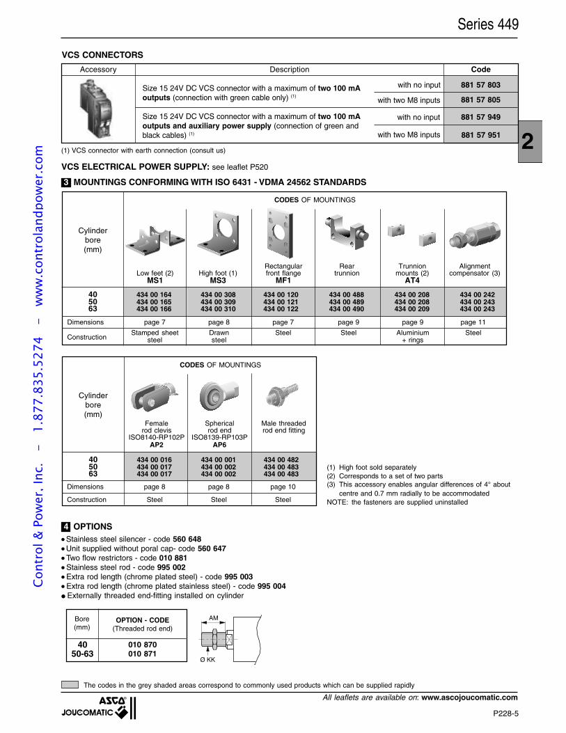
P228-5
2
All leaflets are available on: www.ascojoucomatic.com
VCS CONNECTORS
Accessory Description Code
Size 15 24V DC VCS connector with a maximum of two 100 mAoutputs (connection with green cable only) (1)
Size 15 24V DC VCS connector with a maximum of two 100 mAoutputs and auxiliary power supply (connection of green andblack cables) (1)
881 57 803
881 57 805
881 57 949
881 57 951
with no input
with two M8 inputs
with no input
with two M8 inputs
VCS ELECTRICAL POWER SUPPLY: see leaflet P520
Bore(mm)
OPTION - CODE(Threaded rod end)
4050-63
010 870010 871
AM
Ø KK
(1) VCS connector with earth connection (consult us)
Series 449
The codes in the grey shaded areas correspond to commonly used products which can be supplied rapidly
3 MOUNTINGS CONFORMING WITH ISO 6431 - VDMA 24562 STANDARDS
4 OPTIONS Stainless steel silencer - code 560 648 Unit supplied without poral cap- code 560 647 Two flow restrictors - code 010 881 Stainless steel rod - code 995 002 Extra rod length (chrome plated steel) - code 995 003 Extra rod length (chrome plated stainless steel) - code 995 004 Externally threaded end-fitting installed on cylinder
Dimensions page 7 page 8 page 7 page 9 page 9 page 11
Stamped sheet Drawn Steel Steel Aluminium Steelsteel steel + rings
CODES OF MOUNTINGS
40 434 00 164 434 00 308 434 00 120 434 00 488 434 00 208 434 00 24250 434 00 165 434 00 309 434 00 121 434 00 489 434 00 208 434 00 24363 434 00 166 434 00 310 434 00 122 434 00 490 434 00 209 434 00 243
Rectangular Rear Trunnion AlignmentLow feet (2) High foot (1) front flange trunnion mounts (2) compensator (3)
MS1 MS3 MF1 AT4
Cylinderbore(mm)
Construction
(1) High foot sold separately(2) Corresponds to a set of two parts(3) This accessory enables angular differences of 4° about
centre and 0.7 mm radially to be accommodatedNOTE: the fasteners are supplied uninstalled
CODES OF MOUNTINGS
40 434 00 016 434 00 001 434 00 48250 434 00 017 434 00 002 434 00 48363 434 00 017 434 00 002 434 00 483
Female Spherical Male threadedrod clevis rod end rod end fitting
ISO8140-RP102P ISO8139-RP103PAP2 AP6
Cylinderbore(mm)
Dimensions page 8 page 8 page 10
Construction Steel Steel Steel
Cont
rol &
Pow
er, I
nc.
-
1.87
7.83
5.52
74
- w
ww
.con
trol
andp
ower
.com
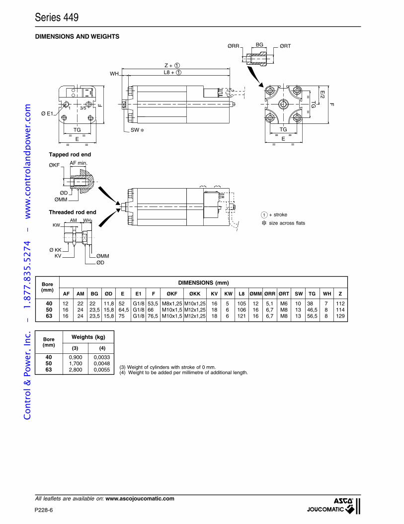
P228-6
All leaflets are available on: www.ascojoucomatic.com
BG ØRT
==
FTG
= =
= =TG
E
WH L8 + 1Z + 1
E/2
AF min.ØKF
ØDØMM
ØRR
AM
Ø KKØMMØD
KV
KWWH
1 3/5
SW
= =
= =TG
E
F
Ø E1
DIMENSIONS AND WEIGHTS
1 + stroke
size across flats
(3) Weight of cylinders with stroke of 0 mm.(4) Weight to be added per millimetre of additional length.
Threaded rod end
Tapped rod end
Series 449
Bore(mm)
AF AM BG ØD E E1 F ØKF ØKK KV KW L8 ØMM ØRR ØRT SW TG WH Z
40 12 22 22 11,8 52 G1/8 53,5 M8x1,25 M10x1,25 16 5 105 12 5,1 M6 10 38 7 11250 16 24 23,5 15,8 64,5 G1/8 66 M10x1,5 M12x1,25 18 6 106 16 6,7 M8 13 46,5 8 11463 16 24 23,5 15,8 75 G1/8 76,5 M10x1,5 M12x1,25 18 6 121 16 6,7 M8 13 56,5 8 129
DIMENSIONS (mm)
Weights (kg)Bore(mm)
40 0,900 0,003350 1,700 0,004863 2,800 0,0055
(3) (4)
Cont
rol &
Pow
er, I
nc.
-
1.87
7.83
5.52
74
- w
ww
.con
trol
andp
ower
.com
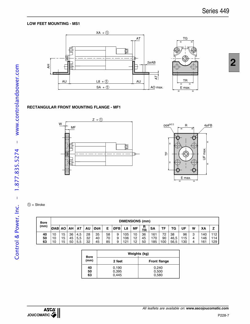
P228-7
2
All leaflets are available on: www.ascojoucomatic.com
AU AU
AH
L8 + 1
SA + 1
AT
2øAB
AT
AO max.
XA + 1
TR= =E max.
= =
TG= =
Series 449
LOW FEET MOUNTING - MS1
1: + Stroke
Weights (kg)Bore(mm)
40 0,190 0,24050 0,395 0,50063 0,445 0,580
2 feet Front flange
RECTANGULAR FRONT MOUNTING FLANGE - MF1
= =MFØd4H11 R 4øFB
E max.
UF
max
.
TF
==
==
= =
Z + 1W
Bore(mm)
DIMENSIONS (mm)
ØAB AO AH AT AU Ød4 E ØFB L8 MF SA TF TG UF W XA Z
40 10 15 36 4,5 28 35 58 9 105 10 36 161 72 38 96 3 140 11250 10 15 45 5,5 32 40 70 9 106 12 45 170 90 46,5 115 4 146 11463 10 15 50 5,5 32 45 85 9 121 12 50 185 100 56,5 130 4 161 129
RTR
Cont
rol &
Pow
er, I
nc.
-
1.87
7.83
5.52
74
- w
ww
.con
trol
andp
ower
.com
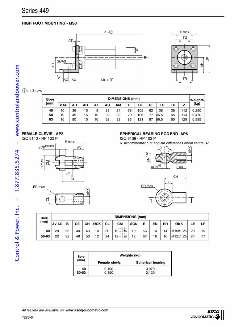
P228-8
All leaflets are available on: www.ascojoucomatic.com
Series 449
HIGH FOOT MOUNTING - MS3
1 : + Stroke
Bore(mm)
405063
10 36 15 8 28 24 58 105 62 38 36 112 0.25010 45 15 10 32 32 70 106 77 46.5 45 114 0.47010 50 15 10 32 32 85 121 87 56.5 50 129 0.595
TR= =
E max.=
TG=
=
=
Z + 1
AU L8 + 1
AH AH
UF
AOAT
AT
2ØAB
DIMENSIONS (mm)
ØAB AH AO AT AU AM E L8 UF TG TR ZWeights
(kg)
øCNH9 AX
øK
K
EN
h12
α α
CH
LFER max.
E max.
øCKH9/d10AV
LE
CE
CM
B m
ax.
CL
ER max.
øK
K
SPHERICAL BEARING ROD END - AP6ISO 8139 - RP 103 P
FEMALE CLEVIS - AP2ISO 8140 - RP 102 P
α: accommodation of angular differences about centre: 4°
DIMENSIONS (mm)Bore(mm)
AV.AX B CE CH ØCK CL CM ØCN E EN ER ØKK LE LF
40 20 26 40 43 10 20 10 10 56 14 14 M10x1.25 20 15
50-63 22 32 48 50 12 24 12 12 67 16 16 M12x1.25 24 17+ 0.5+ 0.15
+ 0.5+ 0.15
Bore(mm)
Spherical bearingFemale clevis
40 0,100 0,07050-63 0,150 0,120
Weights (kg)
Cont
rol &
Pow
er, I
nc.
-
1.87
7.83
5.52
74
- w
ww
.con
trol
andp
ower
.com
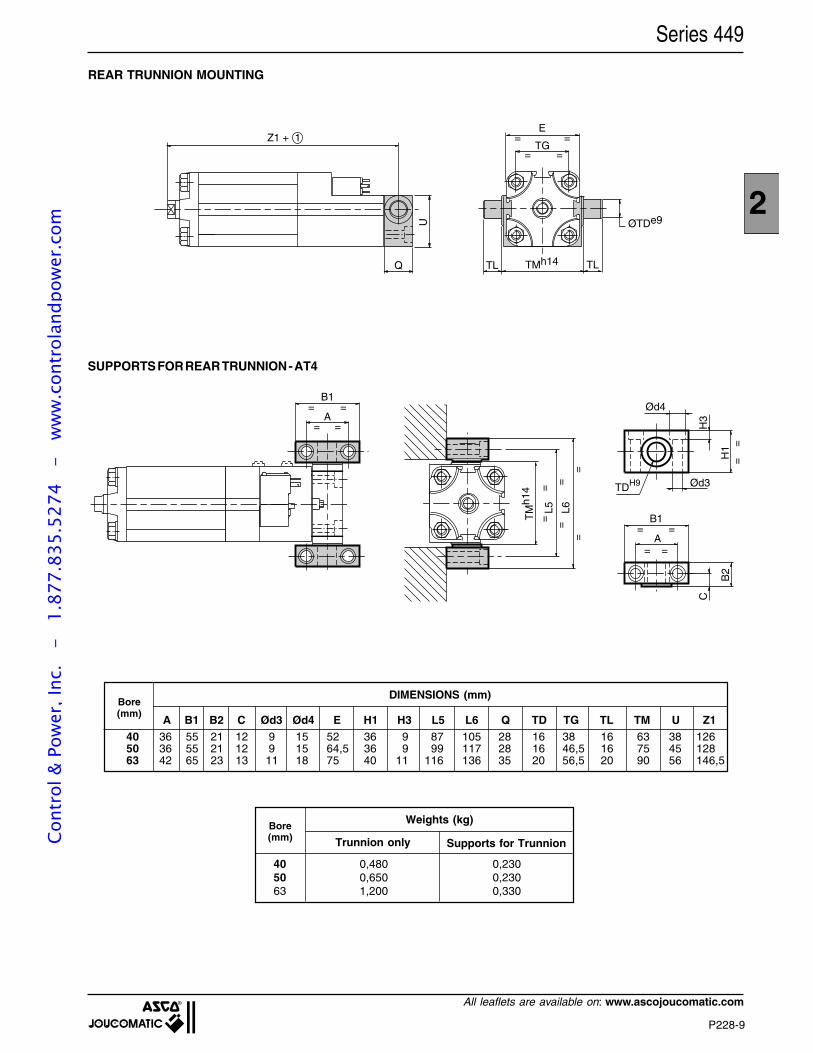
P228-9
2
All leaflets are available on: www.ascojoucomatic.com
Series 449
REAR TRUNNION MOUNTING
TG
E
= =
= =
ØTDe9
TMh14 TLTL
U
Q
Z1 + 1
SUPPORTS FOR REAR TRUNNION - AT4
Bore(mm)
Weights (kg)
40 0,480 0,23050 0,650 0,23063 1,200 0,330
Trunnion only
A B1 B2 C Ød3 Ød4 E H1 H3 L5 L6 Q TD TG TL TM U Z1
Bore(mm)
40 36 55 21 12 9 15 52 36 9 87 105 28 16 38 16 63 38 12650 36 55 21 12 9 15 64,5 36 9 99 117 28 16 46,5 16 75 45 12863 42 65 23 13 11 18 75 40 11 116 136 35 20 56,5 20 90 56 146,5
DIMENSIONS (mm)
TM
h14
L5 L6
= =
==
==
B1
= =A
= =
A==
B1
B2
H1
H3
Ød4
Ød3TDH9
C
==
= =
Supports for TrunnionCont
rol &
Pow
er, I
nc.
-
1.87
7.83
5.52
74
- w
ww
.con
trol
andp
ower
.com
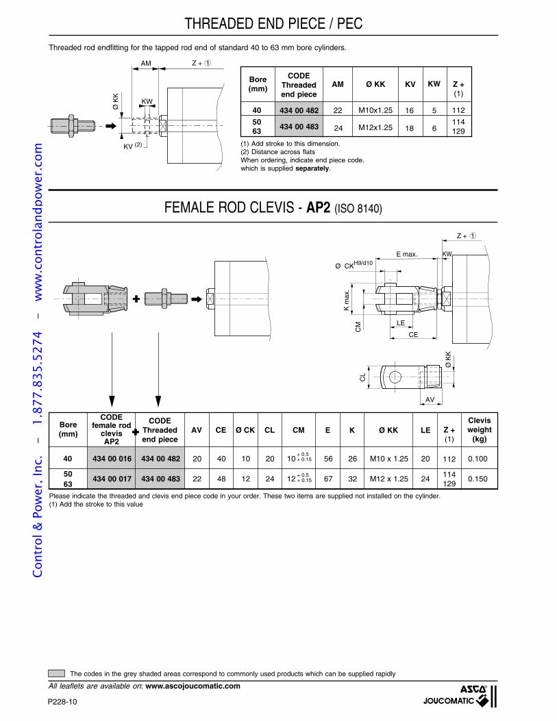
P228-10
All leaflets are available on: www.ascojoucomatic.com
Z + 1
E max.
Ø CKH9/d10
AV
LE
CE
CM
K m
ax.
CL
Ø K
K
KW
Threaded rod endfitting for the tapped rod end of standard 40 to 63 mm bore cylinders.
FEMALE ROD CLEVIS - AP2 (ISO 8140)
Z + 1AM
Ø K
K
KW
KV (2)
THREADED END PIECE / PEC
5063
Bore(mm)
CODEfemale rod
clevisAP2
AVCODE
Threadedend piece
CE Ø CK CL CM E K Ø KK LE Z +(1)
Clevisweight
(kg)
+ 0.5+ 0.15
+ 0.5+ 0.15
Please indicate the threaded and clevis end piece code in your order. These two items are supplied not installed on the cylinder.(1) Add the stroke to this value
434 00 016 434 00 482 20 40 10 20 10 56 26 M10 x 1.25 20 0.100
434 00 017 434 00 483 22 48 12 24 12 67 32 M12 x 1.25 24 0.150
Bore(mm)
(1) Add stroke to this dimension.(2) Distance across flatsWhen ordering, indicate end piece code.which is supplied separately.
CODEThreadedend piece
Z +(1)
434 00 482
434 00 483
Ø KK
M10x1.25
M12x1.25
KV KWAM
22
24
40 112
50 11463 129
16 5
18 6
40
114129
112
The codes in the grey shaded areas correspond to commonly used products which can be supplied rapidly
Cont
rol &
Pow
er, I
nc.
-
1.87
7.83
5.52
74
- w
ww
.con
trol
andp
ower
.com
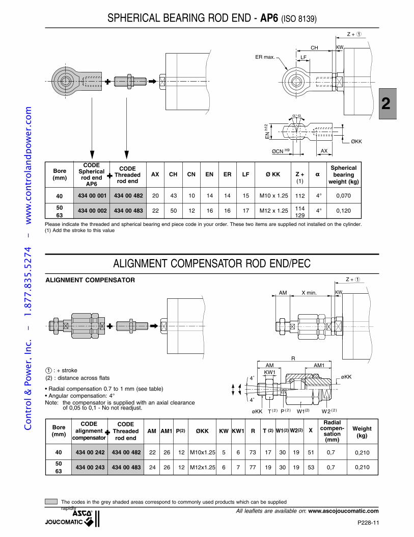
P228-11
2
All leaflets are available on: www.ascojoucomatic.com
AMKW1
AM1R
4˚
4˚
øKK
W2 ( 2 )W1(2)P ( 2 )T ( 2 )øKK
Z + 1
KWAM X min.
Z + 1
ØCN H9
EN
h12
ØKK
AX
ER max.
CH
LF
KW
SPHERICAL BEARING ROD END - AP6 (ISO 8139)
5063
Bore(mm)
CODESphericalrod end
AP6
AXCODE
Threadedrod end
CH CN EN ER LF Ø KK Z +(1)
Sphericalbearing
weight (kg)
434 00 001 434 00 482 20 43 10 14 14 15 M10 x 1.25 4° 0,070
434 00 002 434 00 483 22 50 12 16 16 17 M12 x 1.25 4° 0,120
ααααα
114129
The codes in the grey shaded areas correspond to commonly used products which can be suppliedrapidly
ALIGNMENT COMPENSATOR ROD END/PEC
• Radial compensation 0.7 to 1 mm (see table)• Angular compensation: 4°Note: the compensator is supplied with an axial clearance
of 0,05 to 0,1 - No not readjust.
ALIGNMENT COMPENSATOR
Radialcompen-
sation(mm)
5063
Bore(mm)
CODEalignment
compensatorAM AM1 P(2) ØKK KW KW1 R T (2) Weight
(kg)
434 00 242 434 00 482 22 26 12 M10x1.25 5 6 73 17 30 19 51 0,7
434 00 243 434 00 483 24 26 12 M12x1.25 6 7 77 19 30 19 53 0,7
W1(2) W2(2) X
0,210
0,210
1 : + stroke(2) : distance across flats
40 112
40
CODEThreadedrod end
Please indicate the threaded and spherical bearing end piece code in your order. These two items are supplied not installed on the cylinder.(1) Add the stroke to this value
Cont
rol &
Pow
er, I
nc.
-
1.87
7.83
5.52
74
- w
ww
.con
trol
andp
ower
.com
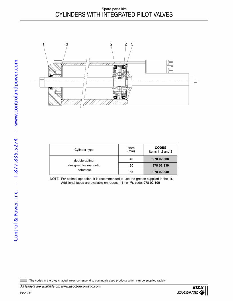
P228-12
All leaflets are available on: www.ascojoucomatic.com
Spare parts kits
CYLINDERS WITH INTEGRATED PILOT VALVES
Cylinder type Bore(mm)
CODESItems 1, 2 and 3
40 978 02 338
50 978 02 339
63 978 02 340
double-acting,
designed for magneticdetectors
NOTE: For optimal operation, it is recommended to use the grease supplied in the kit.Additional tubes are available on request (11 cm3), code: 978 02 100
221 3 3
The codes in the grey shaded areas correspond to commonly used products which can be supplied rapidly
Cont
rol &
Pow
er, I
nc.
-
1.87
7.83
5.52
74
- w
ww
.con
trol
andp
ower
.com

P228-13
2
All leaflets are available on: www.ascojoucomatic.com
YOUR NOTESCo
ntro
l & P
ower
, Inc
. -
1.
877.
835.
5274
-
ww
w.c
ontr
olan
dpow
er.c
om

P228-14
All leaflets are available on: www.ascojoucomatic.com
YOUR NOTESCo
ntro
l & P
ower
, Inc
. -
1.
877.
835.
5274
-
ww
w.c
ontr
olan
dpow
er.c
om
Local distributor - Distribué par - Ihr Ansprechpartner:
serves the world with a network of strategically-located facilitieswww.ascojoucomatic.com
EUROPE BELGIUM
ASCO/JOUCOMATIC BENELUXLusambostraat 53, Rue de Lusambo1190 BRUSSEL / BRUXELLESTel.(32) 2 / 333 02 50 - Fax (32) 2 / 333 02 51E-mail: [email protected]
CZECH REPUBLICASCO JOUCOMATIC S.R.O.Udolni 15 - CZ 140 00 - PRAHA 4Tel. (420) 2 / 61315 411 - Fax (420) 2 / 61315 444E-mail: [email protected]
FRANCEASCO JOUCOMATIC SA32, Av. Albert 1er - B.P. 312 - 92506 RUEIL CedexTel.(33) (0) 1 47 14 32 00 - Tx 634 228 - Fax (33) (0) 1 47 08 53 85www.ascojoucomatic.fr
GERMANYASCO JOUCOMATIC GmbH & Co.Otto-Hahn-Str. 5 - 75248 ÖLBRONN-DÜRRNTel.(49) 7237 9960 - Fax (49) 7237 9961E-mail: [email protected]
GREAT BRITAINASCO JOUCOMATIC Ltd.2 Pit Hey Place, West Pimbo - SKELMERSDALE - Lancashire WN8 9PGTel.(44) 1 / 695 71 36 00 - Fax (44) 1/ 695 71 36 33E-mail: [email protected]
HUNGARYASCO/JOUCOMATIC (ASCO Kft.)Bogancs u. 1 - 3 - 1151 BUDAPESTTel.(36) 1 / 306 41 00 - Fax (36) 1 / 306 09 80E-mail: [email protected]
ITALYASCO JOUCOMATIC SpAVia Zambeletti - ang. Via Ghisallo - 20021 BARANZATE di BOLLATE (MI)Tel.(39) 02 / 35 693 1 - Fax (39) 02 / 35 693 300E-mail: [email protected]
NETHERLANDSASCO/JOUCOMATIC (ASCO CONTROLS BV)Industrielaan 21 - 3925 BD - SCHERPENZEELTel.(31) 33 277 7911 - Fax (31) 33 277 7888E-mail: [email protected]
POLANDASCO JOUCOMATIC Sp. z o.o.Ul. Konstruktorska 11a02 673 WARSAWTel.(48) 22 / 54 85 280 - Fax (48) 22 / 54 85 288E-mail: [email protected]
PORTUGALASCO/JOUCOMATIC (FLUIDOCONTROL S.A.)Rua Eng° Ferreira Dias, 938 - AZ24100 - 246 PORTOTel.(351) 22 / 619 08 57 - Fax (351) 22 / 619 08 58E-mail: [email protected]
SPAINASCO/JOUCOMATIC (FLUIDOCONTROL S.A.)39700 CASTRO-URDIALES (Cantabria)Tel.(34) 942 87 61 00 - Fax (34) 942 86 33 23E-mail: [email protected]
SWEDENASCO/JOUCOMATIC (ASCO AB)Albanoliden 3-5 - 506 30 BORÅSTel.(46) 33 / 108 000 - Fax (46) 33 / 108 080E-mail: [email protected]
SWITZERLANDASCO/JOUCOMATIC Switzerland (ASCO CONTROLS AG)Schaftenholzweg 16 - 2557 STUDEN / BIEL-BIENNETel.(41) 32 / 374 45 10 - Fax (41) 32 / 374 45 11E-mail: [email protected]
TURKEYASCO/JOUCOMATIC TURKEYBayar Cd. Gülbahar Sk. - Perdemsaç Plaza N°17/9781090 KOZYATAGI - ISTANBULTel.(90) 216 / 464 07 70 - Fax (90) 216 / 464 07 71E-mail: [email protected]
AMERICAS BRAZIL
ASCO/JOUCOMATIC (ASCOVAL ind. e. com. Ltda.)Rod. Pres. Castelo Branco Km 20 - Jd. Sta. CeciliaCEP 06465-300 BARUERI - SAO PAULOTel.(55) 11 / 4195 5333 - Fax (55) 11 / 4195 3970E-mail: [email protected]
CANADAASCO/JOUCOMATIC (ASCOVALVE Inc)Airport Road - PO Box 160 - BRANTFORD, ONTARIO N3T 5M8Tel.(1) 519 / 758 2700 - Fax (1) 519 / 758 5540E-mail: [email protected]
MEXICOASCO/JOUCOMATIC (ASCOMATICA S.A. de C.V.)Bosques de Duraznos 65 - 1003 ABosques de las Lomas - 11700 MEXICO D.F.Tel.(52)5 / 596 77 41 - Fax (52)5 / 596 77 19E-mail: [email protected]
USAASCO (Valve, Inc)50 Hanover Road - FLORHAM PARK, NJ 07932Tel.(1) 973 / 966 2000 - Fax (1) 973 / 966 2628E-mail: [email protected]
4CV
.GB
-08/
02
383
93 7
5 -
1M51
002
AFRICA & MIDDLE EAST SOUTH AFRICA
ASCO/JOUCOMATIC (ASCOREG)P.O. Box 737 - 3 Commerce PlaceEastgate Ext. 12, Sandton - GAUTENGTel. (27) 11 / 444 22 13 - Fax (27) 11 / 444 22 21E-mail: [email protected]
UNITED ARAB EMIRATESASCO/JOUCOMATIC MIDEASTPO Box 17034 - Jebel Ali free zone - DUBAITel.(971) 4 / 883 44 94 - Fax (971) 4 / 883 44 95E-mail: [email protected]
ASIA & OCEANIA HONG KONG
ASCO/JOUCOMATIC (ASCO ASIA)Room 3904, Central Plaza, 18 Harbour Road - WANCHAITel.(852) 2343 8580 - Fax (852) 2790 1771E-mail: [email protected]
INDIAASCO/JOUCOMATIC (ASCO INDIA Ltd.)147 Karapakkam village - MADRAS 600 096Tel. (91) 44/496 0455 - Fax (91) 44/496 2270E-mail: [email protected]
JAPANASCO/JOUCOMATIC (ASCO JAPAN Co. Ltd.)1-20 Takahata-Cho Nishinomiya - HYOGO 663-8202Tel. (81) 798 65 6361 - Fax (81) 798 63 4443E-mail: [email protected]
KOREAASCO/JOUCOMATIC (ASCO ASIA)6 fl. Chunglim Bldg, 38-30 Samsung-dongKangnam-Ku - SEOUL 135 090Tel.(82) 2 / 515 2485 - Fax (82) 2 / 540 3250E-mail: [email protected]
ASCO/JOUCOMATIC REPRESENTATIVES (see web)Algeria - Argentina - Austria - Bolivia - Bulgaria - Cameroon - Chile - China - Colombia - Costa Rica - Croatia - Denmark - Ecuador - Egypt - Finland- Greece - Guadeloupe - Guatemala - Honduras - Iceland - Ireland - Israël - Ivory Coast - Luxemburg - Martinique - Morocco - Nicaragua - Norway - Pakistan- Panama - Peru - Porto Rico - Reunion Island and Madagascan Rep. - Romania - Russia - El Salvador - Saudi Arabia - Senegal - Slovakia - Slovenia - Tunisia- Ukraine - Uruguay - Venezuela - F.R. Yugoslavia (all other countries, contact E-mail : [email protected])
SINGAPOREASCO/JOUCOMATIC (ASCO ASIA)Blk 4008, Ang Mo Kio Ave.10 - 04-17/22, Techplace1SINGAPORE 569 625Tel.(65) 556 11 00 - Fax (65) 556 00 11E-mail: [email protected]
TAIWAN R.O.C.ASCO/JOUCOMATIC (ASCO ASIA)5th. fl, N°2 Jen Ai Road - Section 4 - TAIPEI 10650Tel.(886) 2 / 2325 9555 - Fax (886) 2 / 2702 6009E-mail: [email protected]
AUSTRALIAASCO/JOUCOMATIC (ASCOMATION Pty. Ltd.)Unit 12, Allambie Grove Business Park25 Frenchs Forest Road East - FRENCHS FOREST - N.S.W. 2086Tel.(61) 2 / 9451 7077 - Fax (61) 2 / 9451 9924 - E-mail: [email protected]
NEW ZEALANDASCO/JOUCOMATIC (ASCOMATION Pty. Ltd.)3 Vega place - Mairangi BayPO. Box 302 441 - North Harbour - AUCKLANDTel.(64) 9 / 478 0192 - Fax (64) 9 / 478 0193E-mail: [email protected]
Cont
rol &
Pow
er, I
nc.
-
1.87
7.83
5.52
74
- w
ww
.con
trol
andp
ower
.com
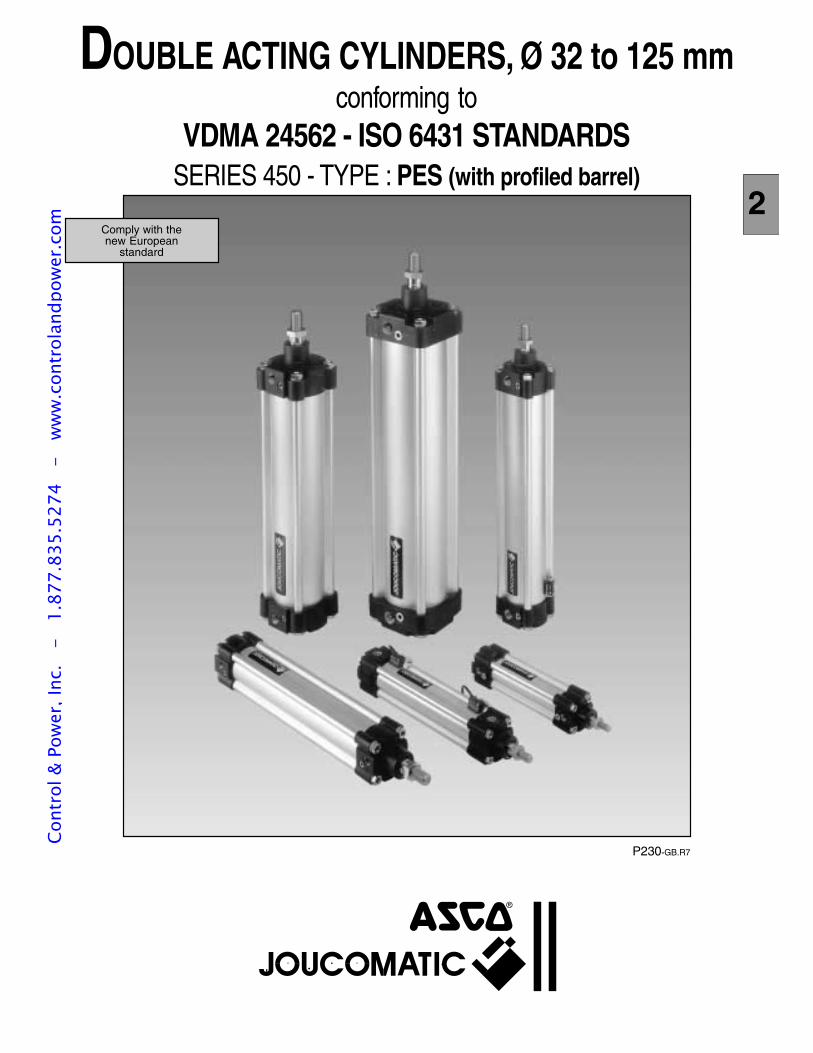
P230-GB.R7
Comply with thenew European
standard
DOUBLE ACTING CYLINDERS, Ø 32 to 125 mmconforming to
VDMA 24562 - ISO 6431 STANDARDSSERIES 450 - TYPE : PES (with profiled barrel)
2
Cont
rol &
Pow
er, I
nc.
-
1.87
7.83
5.52
74
- w
ww
.con
trol
andp
ower
.com
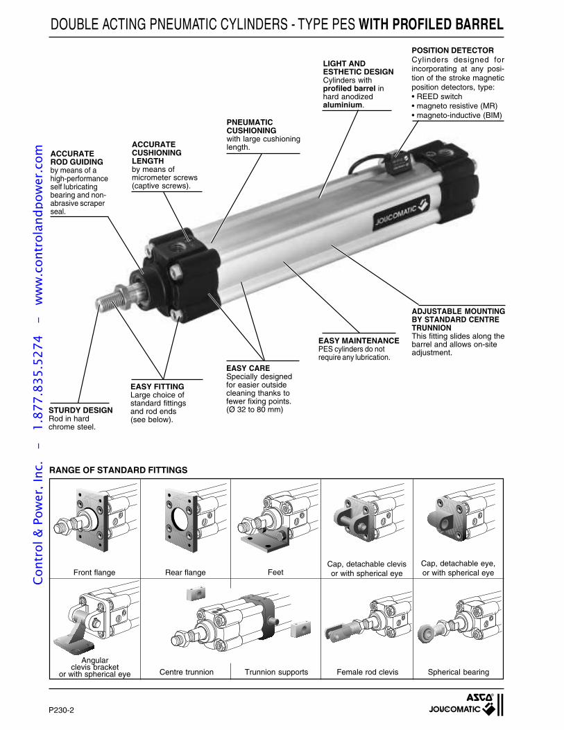
P230-2
Cap, detachable eye,or with spherical eye
Cap, detachable clevisor with spherical eyeFront flange
Centre trunnion
Rear flange
Trunnion supports Female rod clevis Spherical bearing
Feet
DOUBLE ACTING PNEUMATIC CYLINDERS - TYPE PES WITH PROFILED BARREL
ACCURATEROD GUIDINGby means of ahigh-performanceself lubricatingbearing and non-abrasive scraperseal.
ACCURATECUSHIONINGLENGTHby means ofmicrometer screws(captive screws).
PNEUMATICCUSHIONINGwith large cushioninglength.
LIGHT ANDESTHETIC DESIGNCylinders withprofiled barrel inhard anodizedaluminium.
ADJUSTABLE MOUNTINGBY STANDARD CENTRETRUNNIONThis fitting slides along thebarrel and allows on-siteadjustment.
EASY MAINTENANCEPES cylinders do notrequire any lubrication.
EASY CARESpecially designedfor easier outsidecleaning thanks tofewer fixing points.(Ø 32 to 80 mm)
EASY FITTINGLarge choice ofstandard fittingsand rod ends(see below).
STURDY DESIGNRod in hardchrome steel.
POSITION DETECTORCylinders designed forincorporating at any posi-tion of the stroke magneticposition detectors, type:• REED switch• magneto resistive (MR)• magneto-inductive (BIM)
RANGE OF STANDARD FITTINGS
Angularclevis bracket
or with spherical eye
Cont
rol &
Pow
er, I
nc.
-
1.87
7.83
5.52
74
- w
ww
.con
trol
andp
ower
.com
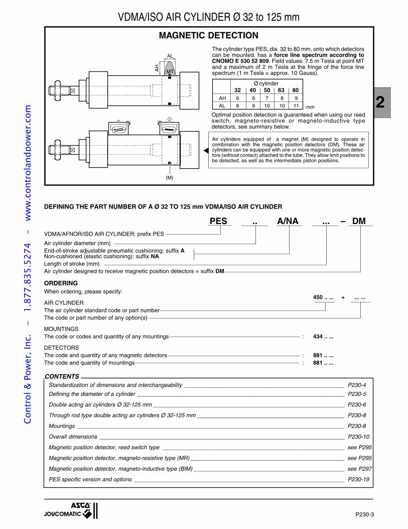
P230-3
2
VDMA/ISO AIR CYLINDER Ø 32 to 125 mm
MAGNETIC DETECTION
AL
AH
MT
(M)
The cylinder type PES, dia. 32 to 80 mm, onto which detectorscan be mounted, has a force line spectrum according toCNOMO E 530 52 809. Field values: 7.5 m Tesla at point MTand a maximum of 2 m Tesla at the fringe of the force linespectrum (1 m Tesla = approx. 10 Gauss).
32 40 50 63 80Ø cylinder
AH 6 6 7 8 9
AL 8 9 10 10 11 mm
Optimal position detection is guaranteed when using our reedswitch, magneto-resistive or magneto-inductive typedetectors, see summary below.
Air cylinders equipped of a magnet (M) designed to operate incombination with the magnetic position detectors (DM). These aircylinders can be equipped with one or more magnetic position detec-tors (without contact) attached to the tube. They allow limit positions tobe detected, as well as the intermediate piston positions.
CONTENTSStandardization of dimensions and interchangeability ___________________________________________________ P230-4
Defining the diameter of a cylinder __________________________________________________________________ P230-5
Double acting air cylinders Ø 32-125 mm _____________________________________________________________ P230-6
Through rod type double acting air cylinders Ø 32-125 mm _______________________________________________ P230-8
Mountings _____________________________________________________________________________________ P230-8
Overall dimensions ______________________________________________________________________________ P230-10
Magnetic position detector, reed switch type __________________________________________________________ see P295
Magnetic position detector, magneto-resistive type (MR) _________________________________________________ see P295
Magnetic position detector, magneto-inductive type (BIM) ________________________________________________ see P297
PES specific version and options ___________________________________________________________________ P230-19
DEFINING THE PART NUMBER OF A Ø 32 TO 125 mm VDMA/ISO AIR CYLINDER
PES .. A/NA ... – DMVDMA/AFNOR/ISO AIR CYLINDER: prefix PES
Air cylinder diameter (mm)End-of-stroke adjustable pneumatic cushioning: suffix ANon-cushioned (elastic cushioning): suffix NALength of stroke (mm)Air cylinder designed to receive magnetic position detectors = suffix DM
ORDERINGWhen ordering, please specify:
450 .. ... + ... ...AIR CYLINDERThe air cylinder standard code or part numberThe code or part number of any option(s)
MOUNTINGSThe code or codes and quantity of any mountings : 434 .. ...
DETECTORSThe code and quantity of any magnetic detectors : 881 .. ...The code and quantity of mountings : 881 .. ...
Cont
rol &
Pow
er, I
nc.
-
1.87
7.83
5.52
74
- w
ww
.con
trol
andp
ower
.com

P230-4
For full interchangeabilitywith ISO 6431,VDMA-AFNOR NFE 49003c y l i n d e r m u s t b ee q u i p p e d w i t h i t sm o u n t i n g s , a n dreciprocally.
(cylinder PES+mountingsinterchangeable with PIScylinder).
No interchangeability canbe achieved betweenCNOMO/NFE 49001c y l i n d e r ( b a r e o requipped) and AFNORNFE 49003 cylinder orISO 6431 cylinder, andreciprocally.
The international standards define a cylinder unit equippedwith its mountings without any specifications relative to thebare cylinder alone.
JOUCOMATIC cylinder, type PIS, complies with theinternational standards
The new standards define first all the external dimensionsof a barecylinder then the mountings which, when mounted,must comply with the above unit (ISO 6431 cylinder).
JOUCOMATIC cylinder, type PES with profiled barrel ortie rods, complies with the new standards
The French standards define first all the external dimen-sions of a bare cylinder then the mountings.
JOUCOMATIC cylinder, type PCN, complies with theFrench standards
INTERCHANGEABILITYwithin the standard between standards
ISO 6431 cylinders (year: 1983)
STANDARDS OF CYLINDERS Ø 32 to 320 mm
Interchangeability betweenmanufacturers is achievedby replacing both thecylinderand its mountings.
Ful l interchangeabi l i tybetween the manufacturersis achieved at every level:
• bare cylinder,• each mounting,• complete unit.
Ful l interchangeabi l i tybetween the manufacturersis possible at every level:
• bare cylinder,• each mounting,• complete unit.
A0XA+SA+
Ø AB
TRAHØ
VDMA 24562- CNOMO/AFNOR NFE 49003 cylinders (year: 1992)
CNOMO 06.07.02/AFNOR NFE 49001 cylinders (year: 1968)
Note : ISO 6432 and AFNOR NFE 49030 standards apply only to mini-cylinders Ø 8 to 25 mm.
STANDARDIZATION OF DIMENSIONS AND INTERCHANGEABILITY
Cont
rol &
Pow
er, I
nc.
-
1.87
7.83
5.52
74
- w
ww
.con
trol
andp
ower
.com
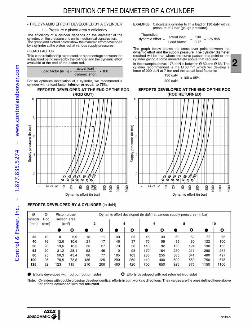
P230-5
2
10
8
6
4
2
1 2 3 5 10 20 50 100
175
200
500
1000
2000
5000
Efforts dynamiques (en daN)
10
8
6
4
2
1 2 3 5 10 20 50 100
200
500
1000
2000
5000
Efforts dynamiques (en daN)
Pre
ssio
n re
lativ
e (e
n ba
r)
Ø 32
Ø 40
Ø 50
Ø 63
Ø 80
Ø 10
0Ø
125
Ø 32
Ø 40
Ø 50
Ø 63
Ø 80
Ø 10
0Ø
125
DEFINITION OF THE DIAMETER OF A CYLINDER
EFFORTS DEVELOPED BY A CYLINDER (in daN)
Ø Ø Piston cross- Dynamic effort developed (in daN) at various supply pressures (in bar)Cylinder Rod section area(mm) (mm) (cm2) 2 4 6 8 10
32 12 8 6,9 13 11 30 25 46 39 62 52 77 6540 16 12,6 10,6 21 17 46 37 70 58 95 80 122 10050 20 19,6 16,5 33 27 70 58 110 92 150 124 190 15563 20 31,2 28,1 53 46 110 98 170 154 230 211 290 26480 25 50,3 45,4 88 77 185 163 285 255 385 341 480 427
100 25 78,5 73,5 135 125 290 260 440 400 600 550 750 675125 32 123 115 210 200 460 420 700 650 925 875 1150 1100
Efforts developed with rod out (bottom side) Efforts developed with rod returned (rod side)
Note: Cylinders with double crossbar develop identical efforts in both working directions. Their values are the ones defined here-abovefor efforts developed with rod returned.
• THE DYNAMIC EFFORT DEVELOPED BY A CYLINDER
F = Pressure x piston area x efficiencyThe efficiency of a cylinder depends on the diameter of thecylinder, on the pressure and on its mechanical construction.The graph and a chart below show the dynamic effort developedby a cylinder at the piston rod, at various supply pressures.
• LOAD FACTORThis is the relationship expressed as a percentage between theactual load being moved by the cylinder and the dynamic effortavailable at the end of the piston rod.
actual loadLoad factor (in %) = x 100
dynamic effort
For an optimum installation of a cylinder, we recommend acylinder with a load factor inferior or equal to 75%.
EXAMPLE: Calculate a cylinder to lift a load of 130 daN with apressure of 7 bar (gauge pressure).
Theoreticalactual load 130 dynamic effort = = = 175 daNLoad factor 0.75
The graph below shows the cross over point between thedynamic effort and the supply pressure. The cylinder diameterrequired will be that where the curve passes this point or thecylinder giving a force immediately above that required.In the example above: 175 daN is between Ø 50 and Ø 63. Thecylinder recommended is the Ø 63 mm which will develop aforce of 200 daN at 7 bar and the actual load factor is:
130 daNx 100 = 65%
200 daN
EFFORTS DEVELOPED AT THE END OF THE ROD(ROD OUT)
EFFORTS DEVELOPED AT THE END OF THE ROD(ROD RETURNED)
Sup
ply
pres
sure
(in
bar
)
Sup
ply
pres
sure
(in
bar
)
Dynamic effort (in bar) Dynamic effort (in bar)
Cont
rol &
Pow
er, I
nc.
-
1.87
7.83
5.52
74
- w
ww
.con
trol
andp
ower
.com
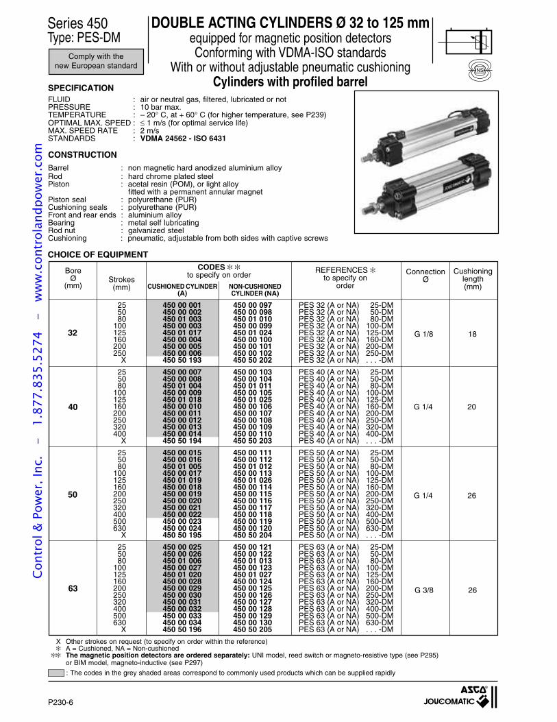
P230-6
SPECIFICATIONFLUID : air or neutral gas, filtered, lubricated or notPRESSURE : 10 bar max.TEMPERATURE : – 20° C, at + 60° C (for higher temperature, see P239)OPTIMAL MAX. SPEED : ≤ 1 m/s (for optimal service life)MAX. SPEED RATE : 2 m/sSTANDARDS : VDMA 24562 - ISO 6431
CONSTRUCTION
Barrel : non magnetic hard anodized aluminium alloyRod : hard chrome plated steelPiston : acetal resin (POM), or light alloy
fitted with a permanent annular magnetPiston seal : polyurethane (PUR)Cushioning seals : polyurethane (PUR)Front and rear ends : aluminium alloyBearing : metal self lubricatingRod nut : galvanized steelCushioning : pneumatic, adjustable from both sides with captive screws
Series 450Type: PES-DM
DOUBLE ACTING CYLINDERS Ø 32 to 125 mmequipped for magnetic position detectorsConforming with VDMA-ISO standards
With or without adjustable pneumatic cushioningCylinders with profiled barrel
Comply with thenew European standard
: The codes in the grey shaded areas correspond to commonly used products which can be supplied rapidly
NS
32
40
63 G 3/8 26
50 G 1/4 26
G 1/4 20
G 1/8 18
ConnectionØ
CODES to specify on order
CUSHIONED CYLINDER(A)
NON-CUSHIONEDCYLINDER (NA)
Cushioninglength(mm)
REFERENCES to specify on
order
BoreØ
(mm)
X Other strokes on request (to specify on order within the reference) A = Cushioned, NA = Non-cushioned
The magnetic position detectors are ordered separately: UNI model, reed switch or magneto-resistive type (see P295)or BIM model, magneto-inductive (see P297)
Strokes(mm)
25 450 00 001 450 00 097 PES 32 (A or NA) 25-DM50 450 00 002 450 00 098 PES 32 (A or NA) 50-DM80 450 01 003 450 01 010 PES 32 (A or NA) 80-DM
100 450 00 003 450 00 099 PES 32 (A or NA) 100-DM125 450 01 017 450 01 024 PES 32 (A or NA) 125-DM160 450 00 004 450 00 100 PES 32 (A or NA) 160-DM200 450 00 005 450 00 101 PES 32 (A or NA) 200-DM250 450 00 006 450 00 102 PES 32 (A or NA) 250-DM
X 450 50 193 450 50 202 PES 32 (A or NA) . . . -DM
25 450 00 007 450 00 103 PES 40 (A or NA) 25-DM50 450 00 008 450 00 104 PES 40 (A or NA) 50-DM80 450 01 004 450 01 011 PES 40 (A or NA) 80-DM
100 450 00 009 450 00 105 PES 40 (A or NA) 100-DM125 450 01 018 450 01 025 PES 40 (A or NA) 125-DM160 450 00 010 450 00 106 PES 40 (A or NA) 160-DM200 450 00 011 450 00 107 PES 40 (A or NA) 200-DM250 450 00 012 450 00 108 PES 40 (A or NA) 250-DM320 450 00 013 450 00 109 PES 40 (A or NA) 320-DM400 450 00 014 450 00 110 PES 40 (A or NA) 400-DM
X 450 50 194 450 50 203 PES 40 (A or NA) . . . -DM
25 450 00 015 450 00 111 PES 50 (A or NA) 25-DM50 450 00 016 450 00 112 PES 50 (A or NA) 50-DM80 450 01 005 450 01 012 PES 50 (A or NA) 80-DM
100 450 00 017 450 00 113 PES 50 (A or NA) 100-DM125 450 01 019 450 01 026 PES 50 (A or NA) 125-DM160 450 00 018 450 00 114 PES 50 (A or NA) 160-DM200 450 00 019 450 00 115 PES 50 (A or NA) 200-DM250 450 00 020 450 00 116 PES 50 (A or NA) 250-DM320 450 00 021 450 00 117 PES 50 (A or NA) 320-DM400 450 00 022 450 00 118 PES 50 (A or NA) 400-DM500 450 00 023 450 00 119 PES 50 (A or NA) 500-DM630 450 00 024 450 00 120 PES 50 (A or NA) 630-DM
X 450 50 195 450 50 204 PES 50 (A or NA) . . . -DM
25 450 00 025 450 00 121 PES 63 (A or NA) 25-DM50 450 00 026 450 00 122 PES 63 (A or NA) 50-DM80 450 01 006 450 01 013 PES 63 (A or NA) 80-DM
100 450 00 027 450 00 123 PES 63 (A or NA) 100-DM125 450 01 020 450 01 027 PES 63 (A or NA) 125-DM160 450 00 028 450 00 124 PES 63 (A or NA) 160-DM200 450 00 029 450 00 125 PES 63 (A or NA) 200-DM250 450 00 030 450 00 126 PES 63 (A or NA) 250-DM320 450 00 031 450 00 127 PES 63 (A or NA) 320-DM400 450 00 032 450 00 128 PES 63 (A or NA) 400-DM500 450 00 033 450 00 129 PES 63 (A or NA) 500-DM630 450 00 034 450 00 130 PES 63 (A or NA) 630-DM
X 450 50 196 450 50 205 PES 63 (A or NA) . . . -DM
CHOICE OF EQUIPMENT
Cont
rol &
Pow
er, I
nc.
-
1.87
7.83
5.52
74
- w
ww
.con
trol
andp
ower
.com
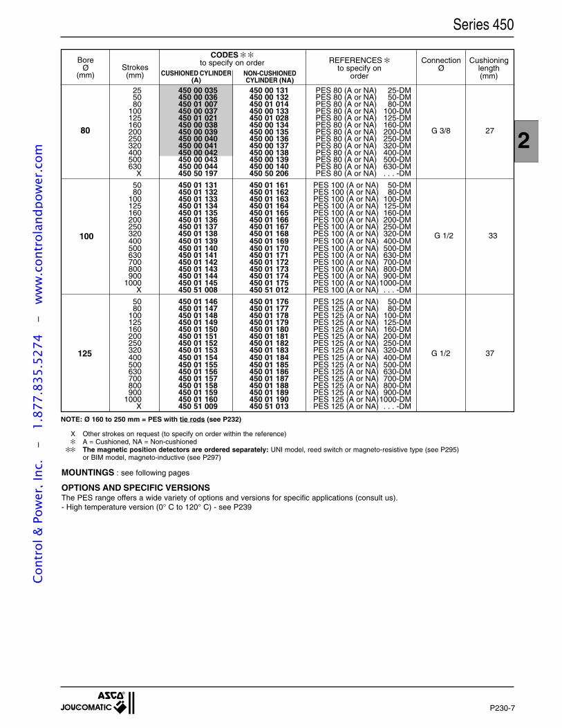
P230-7
2
Series 450
NOTE: Ø 160 to 250 mm = PES with tie rods (see P232)
X Other strokes on request (to specify on order within the reference) A = Cushioned, NA = Non-cushioned
The magnetic position detectors are ordered separately: UNI model, reed switch or magneto-resistive type (see P295)or BIM model, magneto-inductive (see P297)
25 450 00 035 450 00 131 PES 80 (A or NA) 25-DM50 450 00 036 450 00 132 PES 80 (A or NA) 50-DM80 450 01 007 450 01 014 PES 80 (A or NA) 80-DM
100 450 00 037 450 00 133 PES 80 (A or NA) 100-DM125 450 01 021 450 01 028 PES 80 (A or NA) 125-DM160 450 00 038 450 00 134 PES 80 (A or NA) 160-DM200 450 00 039 450 00 135 PES 80 (A or NA) 200-DM250 450 00 040 450 00 136 PES 80 (A or NA) 250-DM320 450 00 041 450 00 137 PES 80 (A or NA) 320-DM400 450 00 042 450 00 138 PES 80 (A or NA) 400-DM500 450 00 043 450 00 139 PES 80 (A or NA) 500-DM630 450 00 044 450 00 140 PES 80 (A or NA) 630-DM
X 450 50 197 450 50 206 PES 80 (A or NA) . . . -DM
50 450 01 131 450 01 161 PES 100 (A or NA) 50-DM80 450 01 132 450 01 162 PES 100 (A or NA) 80-DM
100 450 01 133 450 01 163 PES 100 (A or NA) 100-DM125 450 01 134 450 01 164 PES 100 (A or NA) 125-DM160 450 01 135 450 01 165 PES 100 (A or NA) 160-DM200 450 01 136 450 01 166 PES 100 (A or NA) 200-DM250 450 01 137 450 01 167 PES 100 (A or NA) 250-DM320 450 01 138 450 01 168 PES 100 (A or NA) 320-DM400 450 01 139 450 01 169 PES 100 (A or NA) 400-DM500 450 01 140 450 01 170 PES 100 (A or NA) 500-DM630 450 01 141 450 01 171 PES 100 (A or NA) 630-DM700 450 01 142 450 01 172 PES 100 (A or NA) 700-DM800 450 01 143 450 01 173 PES 100 (A or NA) 800-DM900 450 01 144 450 01 174 PES 100 (A or NA) 900-DM
1000 450 01 145 450 01 175 PES 100 (A or NA)1000-DMX 450 51 008 450 51 012 PES 100 (A or NA) . . . -DM
50 450 01 146 450 01 176 PES 125 (A or NA) 50-DM80 450 01 147 450 01 177 PES 125 (A or NA) 80-DM
100 450 01 148 450 01 178 PES 125 (A or NA) 100-DM125 450 01 149 450 01 179 PES 125 (A or NA) 125-DM160 450 01 150 450 01 180 PES 125 (A or NA) 160-DM200 450 01 151 450 01 181 PES 125 (A or NA) 200-DM250 450 01 152 450 01 182 PES 125 (A or NA) 250-DM320 450 01 153 450 01 183 PES 125 (A or NA) 320-DM400 450 01 154 450 01 184 PES 125 (A or NA) 400-DM500 450 01 155 450 01 185 PES 125 (A or NA) 500-DM630 450 01 156 450 01 186 PES 125 (A or NA) 630-DM700 450 01 157 450 01 187 PES 125 (A or NA) 700-DM800 450 01 158 450 01 188 PES 125 (A or NA) 800-DM900 450 01 159 450 01 189 PES 125 (A or NA) 900-DM
1000 450 01 160 450 01 190 PES 125 (A or NA)1000-DMX 450 51 009 450 51 013 PES 125 (A or NA) . . . -DM
G 1/2 33
G 1/2 37
100
125
80 G 3/8 27
ConnectionØ
Cushioninglength(mm)
REFERENCES to specify on
order
CODES to specify on order
CUSHIONED CYLINDER(A)
NON-CUSHIONEDCYLINDER (NA)
BoreØ
(mm)Strokes(mm)
MOUNTINGS : see following pages
OPTIONS AND SPECIFIC VERSIONSThe PES range offers a wide variety of options and versions for specific applications (consult us).- High temperature version (0° C to 120° C) - see P239
Cont
rol &
Pow
er, I
nc.
-
1.87
7.83
5.52
74
- w
ww
.con
trol
andp
ower
.com
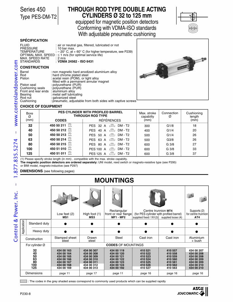
P230-8
Series 450Type PES-DM-T2
CHOICE OF EQUIPMENT
(1) Please specify stroke length (in mm) , compatible with the max. stroke capabilty.The magnetic position detectors are ordered separately: UNI model, reed switch or magneto-resistive type (see P295)or BIM model, magneto-inductive (see P297)
DIMENSIONS (see following pages)
THROUGH ROD TYPE DOUBLE ACTINGCYLINDERS Ø 32 to 125 mm
equipped for magnetic position detectorsConforming with VDMA-ISO standardsWith adjustable pneumatic cushioning
MOUNTINGS
SPÉCIFICATIONFLUID : air or neutral gas, filtered, lubricated or notPRESSURE : 10 bar max.TEMPERATURE : – 20° C, at + 60° C (for higher temperature, see P239)OPTIMAL MAX. SPEED : ≤ 1 m/s (for optimal service life)MAX. SPEED RATE : 2 m/sSTANDARDS : VDMA 24562 - ISO 6431
CONSTRUCTIONBarrel : non magnetic hard anodized aluminium alloyRod : hard chrome plated steelPiston : acetal resin (POM), or light alloy
fitted with a permanent annular magnetPiston seal : polyurethane (PUR)Cushioning seals : polyurethane (PUR)Front and rear ends : aluminium alloyBearing : metal self lubricatingRod nut : galvanized steelCushioning : pneumatic, adjustable from both sides with captive screws
NS
BoreØ
(mm)
3240506380
100125
CODES
PES CYLINDER WITH PROFILED BARRELTHROUGH ROD TYPE
450 50 211 ....450 50 212 ....450 50 213 ....450 50 214 ....450 50 215 ....450 51 010 ....450 51 011 ....
RÉFÉRENCES
300400500
500600600600
G1/8
G1/4G1/4G3/8
G 3/8G 3/8G 3/8
DM - T2DM - T2DM - T2
DM - T2DM - T2DM - T2
DM - T2
(1)
(1)PES 32 A
PES 40 A
PES 50 APES 63 APES 80 A
PES 100 APES 125 A
(1)
(1)
(1)
(1)
(1)
Max. strokecapabilty
(mm)
Cushioninglength(mm)
ConnectionØ
1820
262627
3337
(1)
(1)
(1)
(1)
(1)
(1)
(1)
App
licat
ion
For cylinder Ø CODES OF MOUNTINGS
Construction
Dimensions page 11 page 17 page 11 page 16 page 16 page 16
Heavy duty
Standard duty
Rectangular Centre trunnion MT4 Supports (2)Low feet (2) High foot (1) front or rear flange (for PES cylinder with profiled barrel) for centre trunnion
MS1 MS3 MF1 - MF2 AT4
Stamped sheet Drawn Steel Cast iron Cast iron Aluminiumsteel steel + bush
supplied fixed / XV(3) supplied loose (4)
32 434 00 163 434 00 307 434 00 119 410 521 410 557 434 00 20740 434 00 164 434 00 308 434 00 120 410 522 410 558 434 00 20850 434 00 165 434 00 309 434 00 121 410 523 410 559 434 00 20863 434 00 166 434 00 310 434 00 122 410 524 410 560 434 00 20980 434 00 167 434 00 311 434 00 123 410 525 410 561 434 00 209
100 434 00 168 434 00 312 434 00 124 410 526 410 562 434 00 210125 434 00 169 434 00 313 434 00 192 410 527 410 563 434 00 210
: The codes in the grey shaded areas correspond to commonly used products which can be supplied rapidly
Cont
rol &
Pow
er, I
nc.
-
1.87
7.83
5.52
74
- w
ww
.con
trol
andp
ower
.com
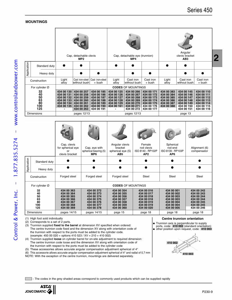
P230-9
2
Series 450
MOUNTINGS
For cylinder Ø CODES OF MOUNTINGS
Dimensions pages 12/13 pages 12/13 page 13
For cylinder Ø CODES OF MOUNTINGS
Dimensions pages 14/15 pages 14/15 page 15 page 18 page 18 page 18
Cap, clevis Angular clevis Female Sphericalfor spherical eye Cap, eye with bracket rod clevis rod end Alignment (6)
or spherical bearing (5) spherical eye (5) ISO 8140 - RP102P ISO 8139 - RP103P compensatorclevis bracket MP6 AB5 AP2 AP6
Forged steel Forged steel Forged steel Steel Steel Steel
32 434 00 363 434 00 372 434 00 354 434 00 016 434 00 001 434 00 24240 434 00 364 434 00 373 434 00 355 434 00 017 434 00 002 434 00 24350 434 00 365 434 00 374 434 00 356 434 00 018 434 00 003 434 00 24463 434 00 366 434 00 375 434 00 357 434 00 018 434 00 003 434 00 24480 434 00 367 434 00 376 434 00 358 434 00 019 434 00 004 434 00 245
100 434 00 368 434 00 377 434 00 359 434 00 019 434 00 004 434 00 245125 434 00 369 434 00 378 434 00 360 434 00 020 434 00 005 434 00 246
AngularCap, detachable clevis Cap, detachable eye (trunnion) clevis bracket
MP2 MP4 AB3
Light Cast iron+steel Cast iron+steel Light Cast iron Cast iron Light Cast iron Cast ironalloy without bush + bush alloy without bush + bush alloy without bush + bush
App
licat
ion
Construction
Construction
Heavy duty
Standard duty
App
licat
ion
Heavy duty
Standard duty
32 434 00 130 434 00 257 434 00 185 434 00 125 434 00 266 434 00 171 434 00 383 434 00 145 434 00 11040 434 00 131 434 00 258 434 00 186 434 00 126 434 00 267 434 00 172 434 00 384 434 00 146 434 00 11150 434 00 132 434 00 259 434 00 187 434 00 127 434 00 268 434 00 173 434 00 385 434 00 147 434 00 11263 434 00 133 434 00 260 434 00 188 434 00 128 434 00 269 434 00 174 434 00 386 434 00 148 434 00 11380 434 00 134 434 00 261 434 00 189 434 00 129 434 00 270 434 00 175 434 00 387 434 00 149 434 00 114
100 434 00 135 434 00 262 434 00 190 434 00 161 434 00 271 434 00 176 434 00 388 434 00 150 434 00 115125 - 434 00 263 434 00 191 - 434 00 272 434 00 177 - 434 00 151 434 00 116
(1) High foot sold individually(2) Corresponds to a set of 2 parts.(3) Trunnion supplied fixed to the barrel at dimension XV specified when ordered:
The centre trunnion code fixed and the dimension XV along with orientation code ofthe trunnion with respect to the ports must be added to the cylinder code.(example: 450 00 020 + options 410 523 / XV = 210 + 410 002)
(4) Trunnion supplied loose on cylinder barrel for on-site adjustment to required dimension:The centre trunnion code loose and the dimension XV along with orientation code ofthe trunnion with respect to the ports must be added to the cylinder code
(5) These accessories allows accurate angular compensation adjustment spherical of 4°(6) This accessorie allows accurate angular compensation adjustment spherical of 4° and radial of 0,7 mmNOTE: With the exception of the centre trunnion, mountings are delivered separetely.
410 003
410 002
Trunnion axis is perpendicular to supplyports, code: 410 002 (standard orientation)
other position upon request, code: 410 003
Centre trunnion orientation
: The codes in the grey shaded areas correspond to commonly used products which can be supplied rapidly
Cont
rol &
Pow
er, I
nc.
-
1.87
7.83
5.52
74
- w
ww
.con
trol
andp
ower
.com
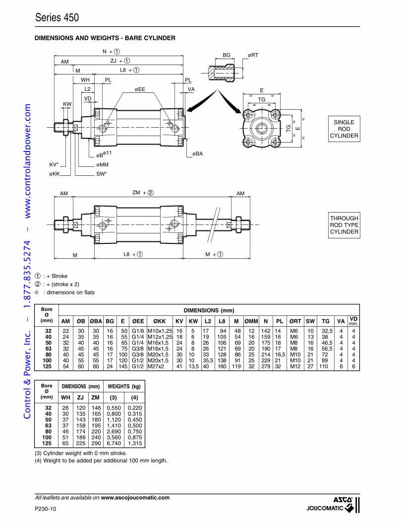
P230-10
All leaflets are available on: www.ascojoucomatic.com
DIMENSIONS AND WEIGHTS - BARE CYLINDER
1 : + Stroke
2 : + (stroke x 2)
: dimensions on flats
Series 450
ZM + 2AM AM
M L8 + 1 M + 1
øBA
VA
PL
øEE
PL
L2
VDKW
WH
M
AM
L8 + 1
ZJ + 1
N + 1
øBe11
øMMKV*
SW*øKK
=
=
=
=
==
==
E
TG
TG E
BG øRT
(3) Cylinder weight with 0 mm stroke.(4) Weight to be added per additional 100 mm length.
SINGLEROD
CYLINDER
THROUGHROD TYPECYLINDER
BoreØ
(mm)
DIMENSIONS (mm) WEIGHTS (kg)
WH ZJ ZM (3) (4)
32 26 120 146 0,550 0,22040 30 135 165 0,800 0,31550 37 143 180 1,120 0,45063 37 158 195 1,410 0,50080 46 174 220 2,690 0,750
100 51 189 240 3,560 0,875125 65 225 290 6,740 1,315
BoreØ
(mm)
DIMENSIONS (mm)
AM ØB ØBA BG E ØEE ØKK KV KW L2 L8 M ØMM N PL ØRT SW TG VA
32 22 30 30 16 50 G1/8 M10x1,25 16 5 17 94 48 12 142 14 M6 10 32,5 4 440 24 35 35 16 55 G1/4 M12x1,25 18 6 19 105 54 16 159 16 M6 13 38 4 450 32 40 40 16 65 G1/4 M16x1,5 24 8 26 106 69 20 175 18 M8 16 46,5 4 463 32 45 45 16 75 G3/8 M16x1,5 24 8 26 121 69 20 190 17 M8 16 56,5 4 480 40 45 45 17 100 G3/8 M20x1,5 30 10 33 128 86 25 214 16,5 M10 21 72 4 4
100 40 55 55 17 120 G1/2 M20x1,5 30 10 35,5 138 91 25 229 21 M10 21 89 4 4125 54 60 60 24 145 G1/2 M27x2 41 13,5 40 160 119 32 279 32 M12 27 110 6 6
VDmin.
Cont
rol &
Pow
er, I
nc.
-
1.87
7.83
5.52
74
- w
ww
.con
trol
andp
ower
.com
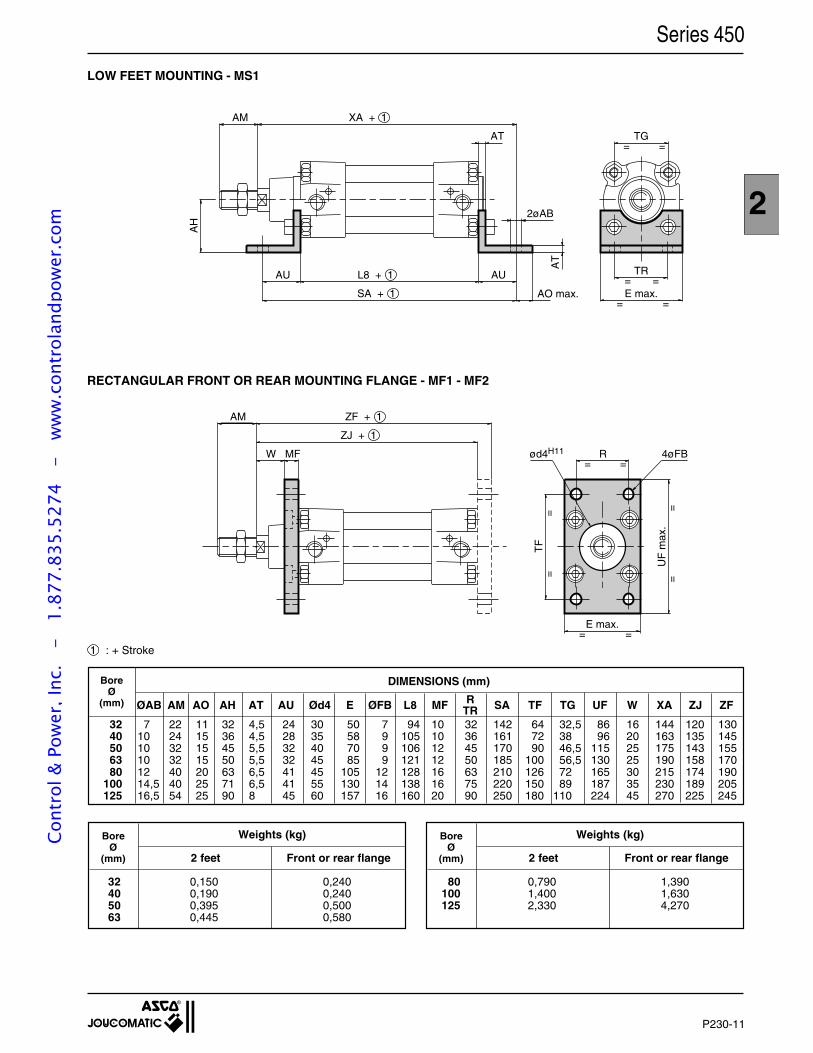
P230-11
2
RTR
Series 450
1 : + Stroke
Weights (kg)BoreØ
(mm) 2 feet Front or rear flange
Weights (kg)BoreØ
(mm) 2 feet Front or rear flange
80 0,790 1,390100 1,400 1,630125 2,330 4,270
BoreØ
(mm)
DIMENSIONS (mm)
ØAB AM AO AH AT AU Ød4 E ØFB L8 MF SA TF TG UF W XA ZJ ZF
32 7 22 11 32 4,5 24 30 50 7 94 10 32 142 64 32,5 86 16 144 120 13040 10 24 15 36 4,5 28 35 58 9 105 10 36 161 72 38 96 20 163 135 14550 10 32 15 45 5,5 32 40 70 9 106 12 45 170 90 46,5 115 25 175 143 15563 10 32 15 50 5,5 32 45 85 9 121 12 50 185 100 56,5 130 25 190 158 17080 12 40 20 63 6,5 41 45 105 12 128 16 63 210 126 72 165 30 215 174 190
100 14,5 40 25 71 6,5 41 55 130 14 138 16 75 220 150 89 187 35 230 189 205125 16,5 54 25 90 8 45 60 157 16 160 20 90 250 180 110 224 45 270 225 245
32 0,150 0,24040 0,190 0,24050 0,395 0,50063 0,445 0,580
AH
TR= =E max.
=
TG=
=
=
AM XA + 1
AU L8 + 1
SA + 1
AU
AT
2øAB
AT
AO max.
RECTANGULAR FRONT OR REAR MOUNTING FLANGE - MF1 - MF2
= =
ZJ + 1
ZF + 1AM
MFW ød4H11 R 4øFB
E max.
UF
max
.
TF
==
==
= =
LOW FEET MOUNTING - MS1
Cont
rol &
Pow
er, I
nc.
-
1.87
7.83
5.52
74
- w
ww
.con
trol
andp
ower
.com
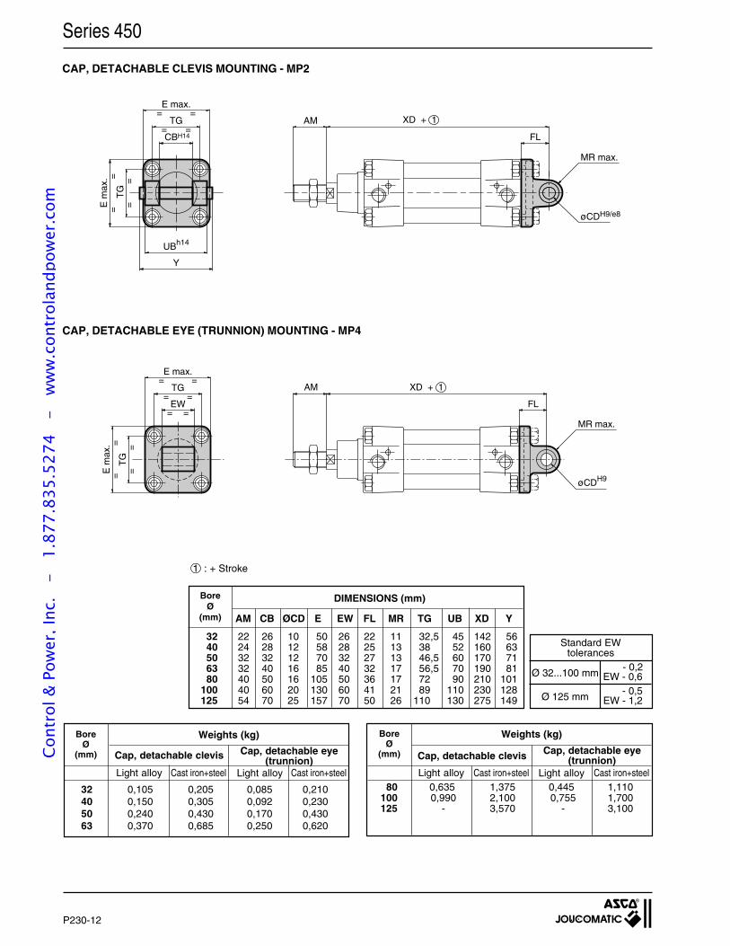
P230-12
Series 450
Ø 32...100 mm EW - 0,6
EW - 1,2- 0,5Ø 125 mm
Standard EWtolerances
- 0,2
Cap, detachable clevis
Weights (kg)BoreØ
(mm)
BoreØ
(mm)
Weights (kg)
Cap, detachable clevis
80 0,635 1,375 0,445 1,110100 0,990 2,100 0,755 1,700125 - 3,570 - 3,100
32 0,105 0,205 0,085 0,21040 0,150 0,305 0,092 0,23050 0,240 0,430 0,170 0,43063 0,370 0,685 0,250 0,620
Light alloy Light alloyCast iron+steel Cast iron+steel Light alloy Light alloyCast iron+steel Cast iron+steel
UBh14
CBH14
Y
E m
ax.
==
TG
==
=
==
=TG
E max.
AM XD + 1
FL
øCDH9/e8
MR max.
AM XD + 1
FL
øCDH9
MR max.
E max.
TG=
= =
=
==
TG
==E
max
.
EW= =
1 : + Stroke
DIMENSIONS (mm)
AM CB ØCD E EW FL MR TG UB XD Y
32 22 26 10 50 26 22 11 32,5 45 142 5640 24 28 12 58 28 25 13 38 52 160 6350 32 32 12 70 32 27 13 46,5 60 170 7163 32 40 16 85 40 32 17 56,5 70 190 8180 40 50 16 105 50 36 17 72 90 210 101
100 40 60 20 130 60 41 21 89 110 230 128125 54 70 25 157 70 50 26 110 130 275 149
BoreØ
(mm)
CAP, DETACHABLE CLEVIS MOUNTING - MP2
CAP, DETACHABLE EYE (TRUNNION) MOUNTING - MP4
Cap, detachable eye(trunnion)
Cap, detachable eye(trunnion)Co
ntro
l & P
ower
, Inc
. -
1.
877.
835.
5274
-
ww
w.c
ontr
olan
dpow
er.c
om
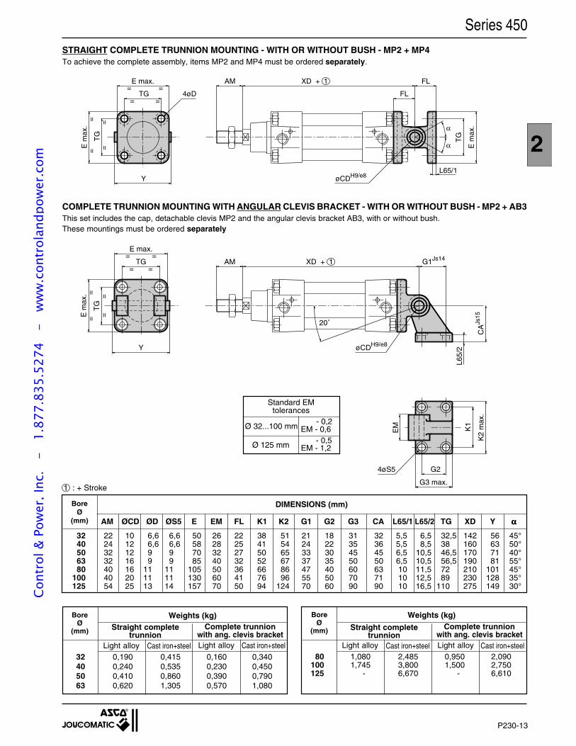
P230-13
2
Series 450
Weights (kg)BoreØ
(mm)
BoreØ
(mm)
Weights (kg)
Light alloy Cast iron+steel Light alloy Cast iron+steel Light alloy Light alloyCast iron+steel Cast iron+steel
E max.
TG=
= =
== =
==T
G
E m
ax.
Y
4øD
AM XD + 1 FL
FL
øCDH9/e8
TG
E m
ax.α
α
L65/1
Y
E m
ax.
==
TG
==
=
==
=TG
E max.
AM XD + 1 G1Js14
20˚
øCDH9/e8
CA
Js15
K1
K2
max
.
G2
G3 max.
4øS5
EM
L65/
2
STRAIGHT COMPLETE TRUNNION MOUNTING - WITH OR WITHOUT BUSH - MP2 + MP4To achieve the complete assembly, items MP2 and MP4 must be ordered separately.
COMPLETE TRUNNION MOUNTING WITH ANGULAR CLEVIS BRACKET - WITH OR WITHOUT BUSH - MP2 + AB3This set includes the cap, detachable clevis MP2 and the angular clevis bracket AB3, with or without bush.These mountings must be ordered separately
Complete trunnionwith ang. clevis bracket
Straight completetrunnion
Straight completetrunnion
Complete trunnionwith ang. clevis bracket
80 1,080 2,485 0,950 2,090100 1,745 3,800 1,500 2,750125 - 6,670 - 6,610
32 0,190 0,415 0,160 0,34040 0,240 0,535 0,230 0,45050 0,410 0,860 0,390 0,79063 0,620 1,305 0,570 1,080
DIMENSIONS (mm)BoreØ
(mm) AM ØCD ØD ØS5 E EM FL K1 K2 G1 G2 G3 CA L65/1 L65/2 TG XD Y ααααα
32 22 10 6,6 6,6 50 26 22 38 51 21 18 31 32 5,5 6,5 32,5 142 56 45°40 24 12 6,6 6,6 58 28 25 41 54 24 22 35 36 5,5 8,5 38 160 63 50°50 32 12 9 9 70 32 27 50 65 33 30 45 45 6,5 10,5 46,5 170 71 40°63 32 16 9 9 85 40 32 52 67 37 35 50 50 6,5 10,5 56,5 190 81 55°80 40 16 11 11 105 50 36 66 86 47 40 60 63 10 11,5 72 210 101 45°
100 40 20 11 11 130 60 41 76 96 55 50 70 71 10 12,5 89 230 128 35°125 54 25 13 14 157 70 50 94 124 70 60 90 90 10 16,5 110 275 149 30°
1 : + Stroke
Ø 32...100 mm EM - 0,6
EM - 1,2- 0,5Ø 125 mm
Standard EMtolerances
- 0,2
Cont
rol &
Pow
er, I
nc.
-
1.87
7.83
5.52
74
- w
ww
.con
trol
andp
ower
.com
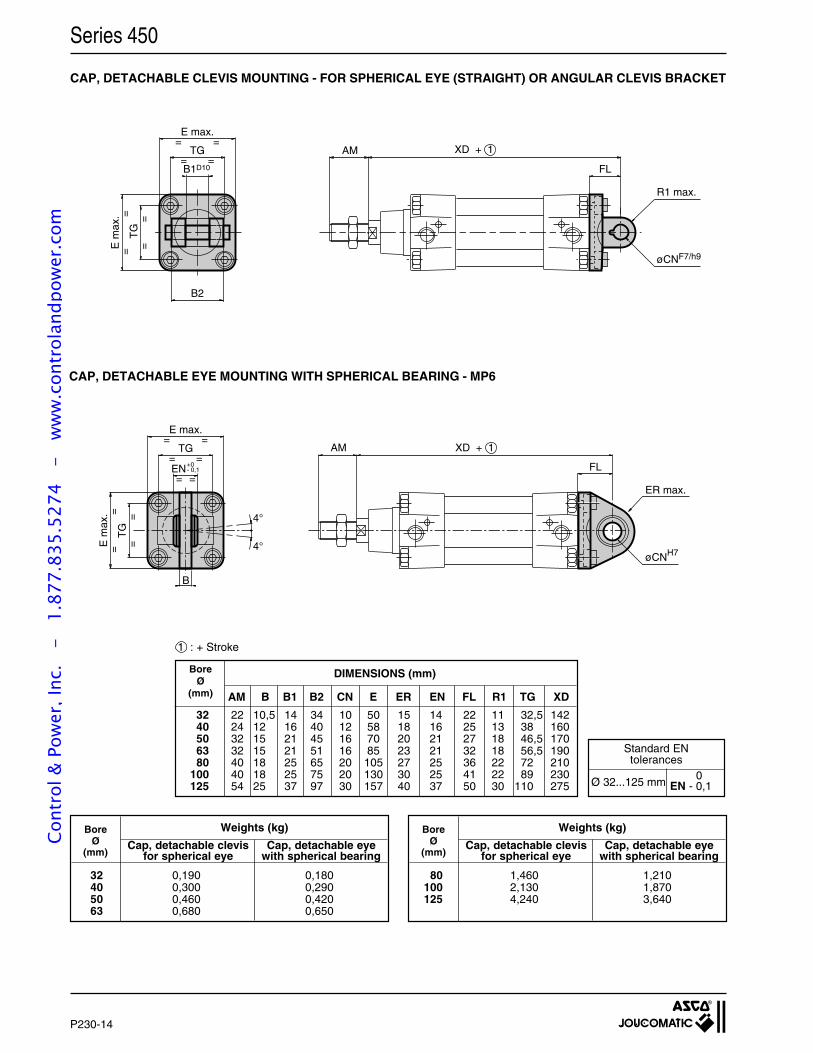
P230-14
CAP, DETACHABLE CLEVIS MOUNTING - FOR SPHERICAL EYE (STRAIGHT) OR ANGULAR CLEVIS BRACKET
CAP, DETACHABLE EYE MOUNTING WITH SPHERICAL BEARING - MP6
AM B B1 B2 CN E ER EN FL R1 TG XD
32 22 10,5 14 34 10 50 15 14 22 11 32,5 14240 24 12 16 40 12 58 18 16 25 13 38 16050 32 15 21 45 16 70 20 21 27 18 46,5 17063 32 15 21 51 16 85 23 21 32 18 56,5 19080 40 18 25 65 20 105 27 25 36 22 72 210
100 40 18 25 75 20 130 30 25 41 22 89 230125 54 25 37 97 30 157 40 37 50 30 110 275
DIMENSIONS (mm)
1 : + Stroke
Ø 32...125 mm EN - 0,1
Standard ENtolerances
0
B2
B1D10
E m
ax.
==
TG
==
=
==
=TG
E max.
AM XD + 1
FL
øCNF7/h9
R1 max.
AM XD + 1
FL
øCNH7
ER max.
E max.
TG
4°
4°
=
= =
=
==
TG
==E
max
.
EN= =
+0- 0,1
B
BoreØ
(mm)
Series 450
Weights (kg)BoreØ
(mm)
32 0,190 0,18040 0,300 0,29050 0,460 0,42063 0,680 0,650
Weights (kg)BoreØ
(mm)
80 1,460 1,210100 2,130 1,870125 4,240 3,640
Cap, detachable clevis Cap, detachable eyefor spherical eye with spherical bearing
Cap, detachable clevis Cap, detachable eyefor spherical eye with spherical bearing
Cont
rol &
Pow
er, I
nc.
-
1.87
7.83
5.52
74
- w
ww
.con
trol
andp
ower
.com
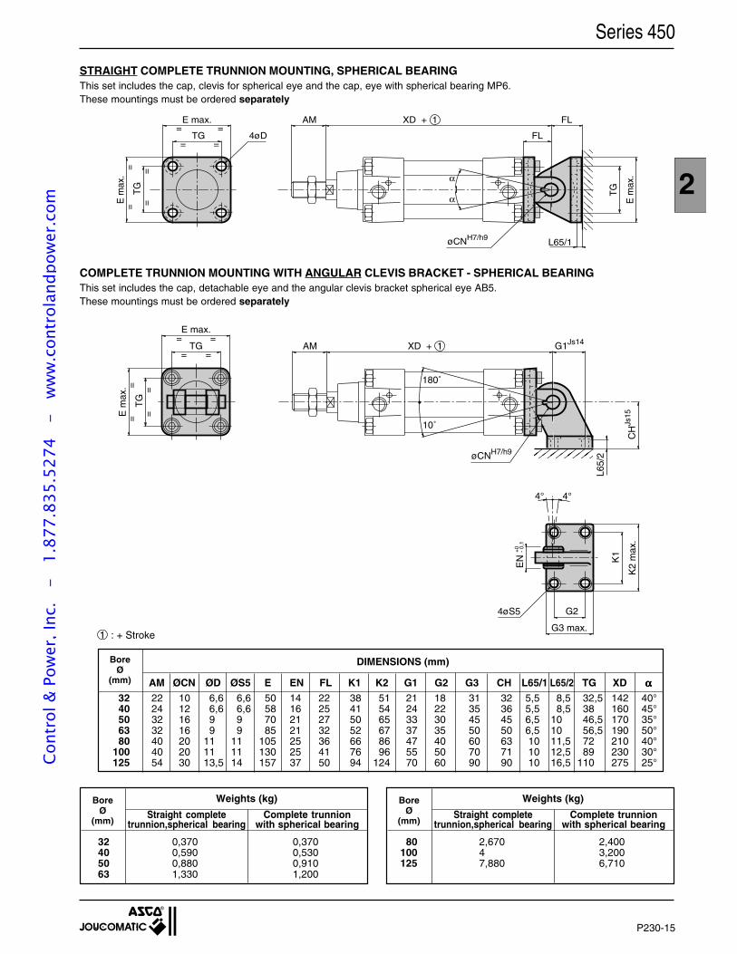
P230-15
2
Series 450
E max.
TG=
= =
== =
==T
G
E m
ax.
4øD
AM XD + 1 FL
FL
øCNH7/h9
TG
E m
ax.
L65/1
α
α
AM XD + 1 G1Js14
10˚
øCNH7/h9
CH
Js15
K1
K2
max
.
G2
G3 max.
4øS5
E m
ax.
==
TG
==
=
==
=TG
E max.
EN
4° 4°
180˚
+0 - 0,
1
L65/
2
STRAIGHT COMPLETE TRUNNION MOUNTING, SPHERICAL BEARINGThis set includes the cap, clevis for spherical eye and the cap, eye with spherical bearing MP6.These mountings must be ordered separately
COMPLETE TRUNNION MOUNTING WITH ANGULAR CLEVIS BRACKET - SPHERICAL BEARINGThis set includes the cap, detachable eye and the angular clevis bracket spherical eye AB5.These mountings must be ordered separately
1 : + Stroke
32 22 10 6,6 6,6 50 14 22 38 51 21 18 31 32 5,5 8,5 32,5 142 40°40 24 12 6,6 6,6 58 16 25 41 54 24 22 35 36 5,5 8,5 38 160 45°50 32 16 9 9 70 21 27 50 65 33 30 45 45 6,5 10 46,5 170 35°63 32 16 9 9 85 21 32 52 67 37 35 50 50 6,5 10 56,5 190 50°80 40 20 11 11 105 25 36 66 86 47 40 60 63 10 11,5 72 210 40°
100 40 20 11 11 130 25 41 76 96 55 50 70 71 10 12,5 89 230 30°125 54 30 13,5 14 157 37 50 94 124 70 60 90 90 10 16,5 110 275 25°
BoreØ
(mm)
DIMENSIONS (mm)
AM ØCN ØD ØS5 E EN FL K1 K2 G1 G2 G3 CH L65/1 L65/2 TG XD ααααα
Weights (kg)BoreØ
(mm)
32 0,370 0,37040 0,590 0,53050 0,880 0,91063 1,330 1,200
Weights (kg)BoreØ
(mm)
80 2,670 2,400100 4 3,200125 7,880 6,710
Straight complete Complete trunniontrunnion,spherical bearing with spherical bearing
Straight complete Complete trunniontrunnion,spherical bearing with spherical bearing
Cont
rol &
Pow
er, I
nc.
-
1.87
7.83
5.52
74
- w
ww
.con
trol
andp
ower
.com
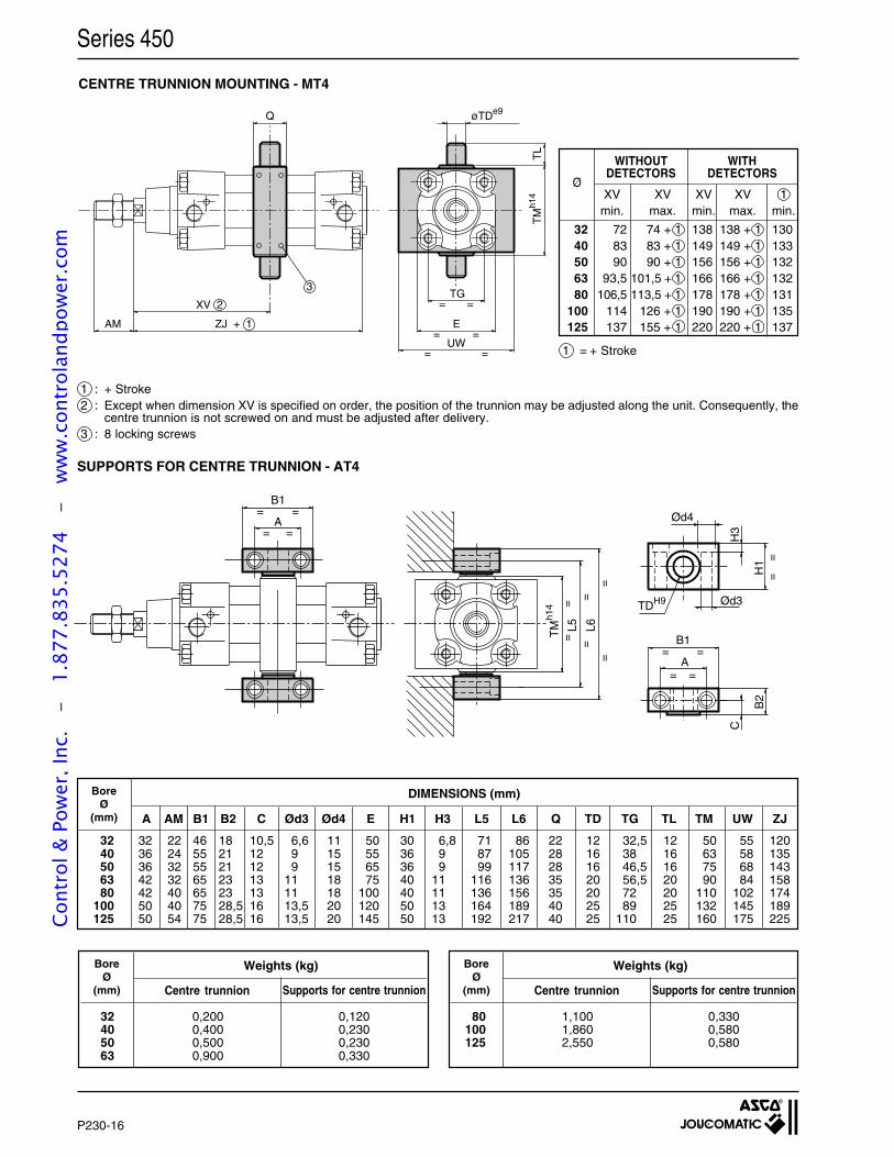
P230-16
Series 450
B1
= =A
TM
h14
L5 L6
A==
B1
B2
H1
H3
Ød4
Ød3TDH9
C
==
= =
==
==
= =
= =
CENTRE TRUNNION MOUNTING - MT4
DIMENSIONS (mm)BoreØ
(mm) A AM B1 B2 C Ød3 Ød4 E H1 H3 L5 L6 Q TD TG TL TM UW ZJ
32 32 22 46 18 10,5 6,6 11 50 30 6,8 71 86 22 12 32,5 12 50 55 12040 36 24 55 21 12 9 15 55 36 9 87 105 28 16 38 16 63 58 13550 36 32 55 21 12 9 15 65 36 9 99 117 28 16 46,5 16 75 68 14363 42 32 65 23 13 11 18 75 40 11 116 136 35 20 56,5 20 90 84 15880 42 40 65 23 13 11 18 100 40 11 136 156 35 20 72 20 110 102 174
100 50 40 75 28,5 16 13,5 20 120 50 13 164 189 40 25 89 25 132 145 189125 50 54 75 28,5 16 13,5 20 145 50 13 192 217 40 25 110 25 160 175 225
Weights (kg)BoreØ
(mm) Supports for centre trunnionCentre trunnion
32 0,200 0,12040 0,400 0,23050 0,500 0,23063 0,900 0,330
Weights (kg)BoreØ
(mm) Supports for centre trunnionCentre trunnion
80 1,100 0,330100 1,860 0,580125 2,550 0,580
Q
ZJ + 1
XV 2
AM
øTDe9
E
UW=
=
=
=
TM
h14
TL
==TG
3
1 : + Stroke 2 : Except when dimension XV is specified on order, the position of the trunnion may be adjusted along the unit. Consequently, the
centre trunnion is not screwed on and must be adjusted after delivery. 3 : 8 locking screws
SUPPORTS FOR CENTRE TRUNNION - AT4
32 72 74 + 1 138 138 + 1 13040 83 83 + 1 149 149 + 1 13350 90 90 + 1 156 156 + 1 13263 93,5 101,5 + 1 166 166 + 1 13280 106,5 113,5 + 1 178 178 + 1 131
100 114 126 + 1 190 190 + 1 135125 137 155 + 1 220 220 + 1 137
Ø
1 = + Stroke
XV XV XV XV 1min. max. min. max. min.
WITHDETECTORS
WITHOUTDETECTORS
Cont
rol &
Pow
er, I
nc.
-
1.87
7.83
5.52
74
- w
ww
.con
trol
andp
ower
.com
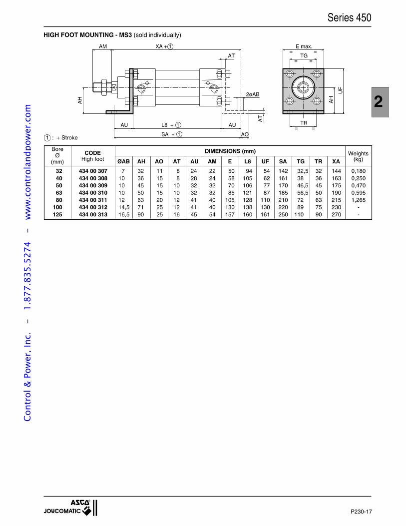
P230-17
2
HIGH FOOT MOUNTING - MS3 (sold individually)
1 : + Stroke
TR= =
E max.=
TG=
=
=
AM XA + 1
AU L8 + 1
SA + 1
AU
AT
2øAB
AT
AH
AO
AH
UF
Series 450
DIMENSIONS (mm)
ØAB AH AO AT AU AM E L8 UF SA TG TR XA
32 434 00 30740 434 00 30850 434 00 30963 434 00 31080 434 00 311
100 434 00 312125 434 00 313
BoreØ
(mm)
7 32 11 8 24 22 50 94 54 142 32,5 32 144 0,18010 36 15 8 28 24 58 105 62 161 38 36 163 0,25010 45 15 10 32 32 70 106 77 170 46,5 45 175 0,47010 50 15 10 32 32 85 121 87 185 56,5 50 190 0,59512 63 20 12 41 40 105 128 110 210 72 63 215 1,26514,5 71 25 12 41 40 130 138 130 220 89 75 230 -16,5 90 25 16 45 54 157 160 161 250 110 90 270 -
CODEHigh foot
Weights(kg)
Cont
rol &
Pow
er, I
nc.
-
1.87
7.83
5.52
74
- w
ww
.con
trol
andp
ower
.com
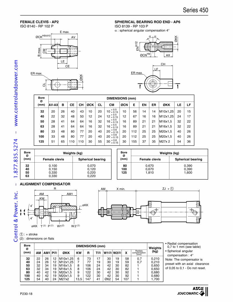
P230-18
Series 450
SPHERICAL BEARING ROD END - AP6ISO 8139 - RP 103 P
FEMALE CLEVIS - AP2ISO 8140 - RP 102 P
• Radial compensation0,7 to 1 mm (see table)
• Spherical angularcompensation : 4°
Note: The compensator ispreset with an axial clearanceof 0,05 to 0,1 - Do not reset.
Radialecompensation
(mm)
BoreØ
(mm) AM AM1 P(2) ØKK KW R T(2) W1(2) W2(2) X
32 22 26 12 M10x1,25 6 73 17 30 19 58 0,7 0,21040 24 26 12 M12x1,25 7 77 19 30 19 59 0,7 0,21050 32 34 19 M16x1,5 8 106 24 42 30 82 1 0,65063 32 34 19 M16x1,5 8 106 24 42 30 82 1 0,65080 40 42 19 M20x1,5 9 122 30 42 30 92 1 0,680
100 40 42 19 M20x1,5 9 122 30 42 30 92 1 0,680125 54 40 24 M27x2 13,5 147 41 Ø62 54 107 1 1,700
Weights(kg)
DIMENSIONS (mm)
1 : + stroke(2) : dimensions on flats
ZJ + 1AM X min.
AM
KW
AM1
R
4˚
4˚
øKK
W2 (2)W1(2)P (2 )T (2 )øKK
ALIGNMENT COMPENSATOR
α : spherical angular compensation 4°
Weights (kg)BoreØ
(mm) Spherical bearingFemale clevis
32 0,100 0,07040 0,150 0,12050 0,330 0,22063 0,330 0,220
Weights (kg)BoreØ
(mm) Spherical bearingFemale clevis
80 0,670 0,390100 0,670 0,390125 1,810 1,600
DIMENSIONS (mm)BoreØ
(mm) AV-AX B CE CH ØCK CL CM ØCN E EN ER ØKK LE LF
32 20 26 40 43 10 20 10 10 56 14 14 M10x1,25 20 15
40 22 32 48 50 12 24 12 12 67 16 16 M12x1,25 24 17
50 28 41 64 64 16 32 16 16 89 21 21 M16x1,5 32 22
63 28 41 64 64 16 32 16 16 89 21 21 M16x1,5 32 22
80 33 48 80 77 20 40 20 20 112 25 25 M20x1,5 40 26
100 33 48 80 77 20 40 20 20 112 25 25 M20x1,5 40 26
125 51 65 110 110 30 55 30 30 155 37 35 M27x 2 54 36+ 0.6+ 0.15
+ 0.6+ 0.15
+ 0.6+ 0.15
+ 0.5+ 0.15
+ 0.5+ 0.15
+ 0.5+ 0.15
+ 0.5+ 0.15
ØCNH9 AX
ØK
K
EN
h12
α α
CH
LFER max.
E max.
ØCKH9/d10AV
LE
CE
CM
B m
ax.
CL
ER max.
ØK
K
Cont
rol &
Pow
er, I
nc.
-
1.87
7.83
5.52
74
- w
ww
.con
trol
andp
ower
.com
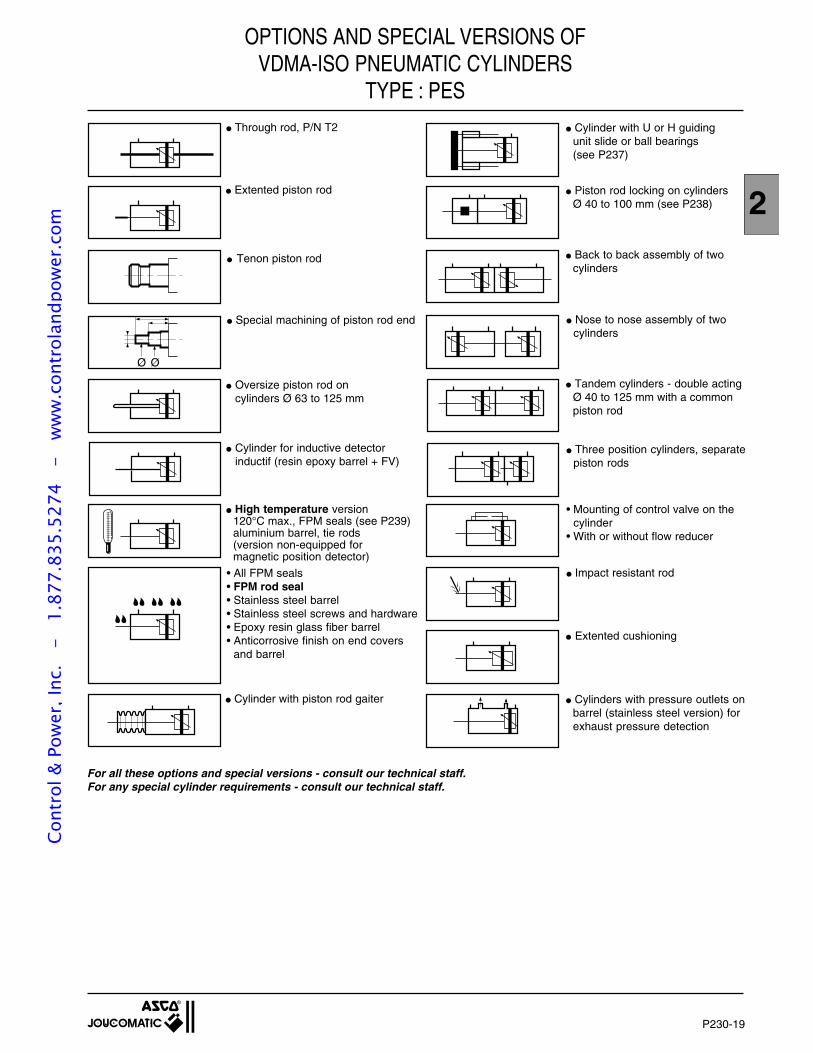
P230-19
2
OPTIONS AND SPECIAL VERSIONS OFVDMA-ISO PNEUMATIC CYLINDERS
TYPE : PES
For all these options and special versions - consult our technical staff.For any special cylinder requirements - consult our technical staff.
Cylinders with pressure outlets onbarrel (stainless steel version) forexhaust pressure detection
Cylinder with U or H guidingunit slide or ball bearings(see P237)
Piston rod locking on cylindersØ 40 to 100 mm (see P238)
Back to back assembly of twocylinders
Nose to nose assembly of twocylinders
Tandem cylinders - double actingØ 40 to 125 mm with a commonpiston rod
Three position cylinders, separatepiston rods
Impact resistant rod
Extented cushioning
• Mounting of control valve on thecylinder
• With or without flow reducer
Ø Ø
Through rod, P/N T2
High temperature version120°C max., FPM seals (see P239)aluminium barrel, tie rods(version non-equipped formagnetic position detector)
Extented piston rod
Tenon piston rod
Special machining of piston rod end
Oversize piston rod oncylinders Ø 63 to 125 mm
Cylinder with piston rod gaiter
• All FPM seals• FPM rod seal• Stainless steel barrel• Stainless steel screws and hardware• Epoxy resin glass fiber barrel• Anticorrosive finish on end covers
and barrel
Cylinder for inductive detectorinductif (resin epoxy barrel + FV)
Cont
rol &
Pow
er, I
nc.
-
1.87
7.83
5.52
74
- w
ww
.con
trol
andp
ower
.com
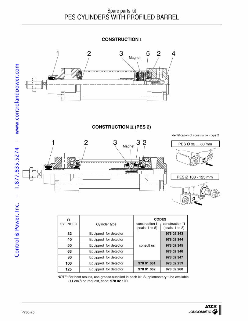
P230-20
Spare parts kitPES CYLINDERS WITH PROFILED BARREL
CONSTRUCTION I
Magnet
Magnet
CONSTRUCTION II (PES 2)
Equipped for detector 978 02 343
Equipped for detector 978 02 344
Equipped for detector consult us 978 02 345
Equipped for detector 978 02 346
Equipped for detector 978 02 347
Equipped for detector 978 01 661 978 02 259
Equipped for detector 978 01 662 978 02 260
CODESconstruction I(seals: 1 to 5)
construction II(seals: 1 to 3)
NOTE: For best results, use grease supplied in each kit. Supplementary tube available(11 cm3) on request, code: 978 02 100
32
40
50
63
80
100
125
ØCYLINDER Cylinder type
42321 5
1 2 3 3 2Identification of construction type 2
2
PES Ø 32 ... 80 mm
PES Ø 100 - 125 mm
2
Cont
rol &
Pow
er, I
nc.
-
1.87
7.83
5.52
74
- w
ww
.con
trol
andp
ower
.com
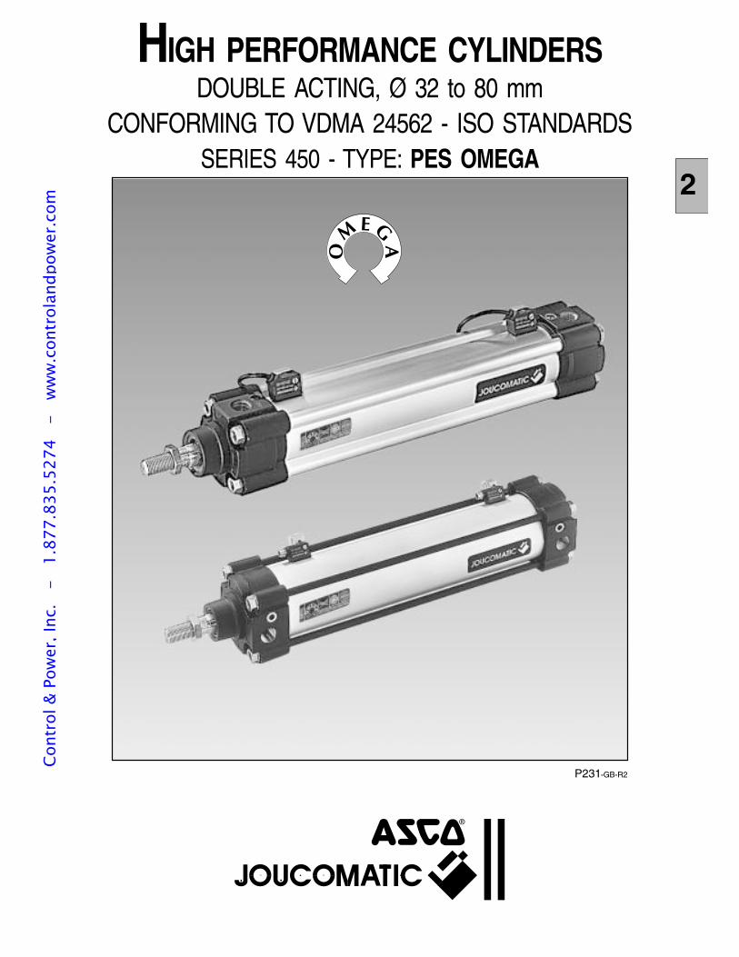
P231-GB-R2
2
HIGH PERFORMANCE CYLINDERSDOUBLE ACTING, Ø 32 to 80 mm
CONFORMING TO VDMA 24562 - ISO STANDARDSSERIES 450 - TYPE: PES OMEGA
Cont
rol &
Pow
er, I
nc.
-
1.87
7.83
5.52
74
- w
ww
.con
trol
andp
ower
.com
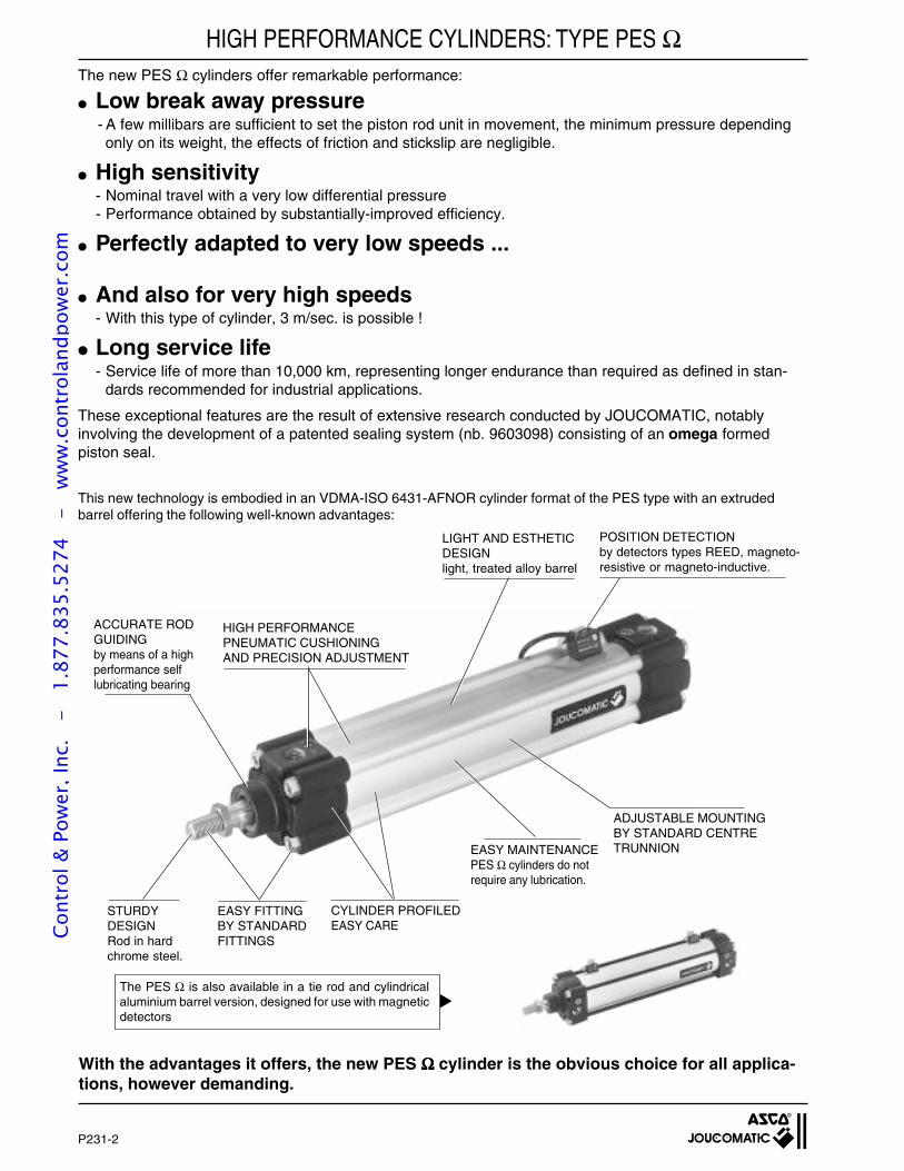
P231-2
HIGH PERFORMANCE CYLINDERS: TYPE PES ΩThe new PES Ω cylinders offer remarkable performance:
Low break away pressure- A few millibars are sufficient to set the piston rod unit in movement, the minimum pressure dependingonly on its weight, the effects of friction and stickslip are negligible.
High sensitivity- Nominal travel with a very low differential pressure- Performance obtained by substantially-improved efficiency.
Perfectly adapted to very low speeds ...
And also for very high speeds- With this type of cylinder, 3 m/sec. is possible !
Long service life- Service life of more than 10,000 km, representing longer endurance than required as defined in stan-
dards recommended for industrial applications.
These exceptional features are the result of extensive research conducted by JOUCOMATIC, notablyinvolving the development of a patented sealing system (nb. 9603098) consisting of an omega formedpiston seal.
With the advantages it offers, the new PES ΩΩΩΩΩ cylinder is the obvious choice for all applica-tions, however demanding.
POSITION DETECTIONby detectors types REED, magneto-resistive or magneto-inductive.
HIGH PERFORMANCEPNEUMATIC CUSHIONINGAND PRECISION ADJUSTMENT
ACCURATE RODGUIDINGby means of a highperformance selflubricating bearing
EASY MAINTENANCEPES Ω cylinders do notrequire any lubrication.
ADJUSTABLE MOUNTINGBY STANDARD CENTRETRUNNION
STURDYDESIGNRod in hardchrome steel.
EASY FITTINGBY STANDARDFITTINGS
CYLINDER PROFILEDEASY CARE
LIGHT AND ESTHETICDESIGNlight, treated alloy barrel
The PES Ω is also available in a tie rod and cylindricalaluminium barrel version, designed for use with magneticdetectors
This new technology is embodied in an VDMA-ISO 6431-AFNOR cylinder format of the PES type with an extrudedbarrel offering the following well-known advantages:
Cont
rol &
Pow
er, I
nc.
-
1.87
7.83
5.52
74
- w
ww
.con
trol
andp
ower
.com
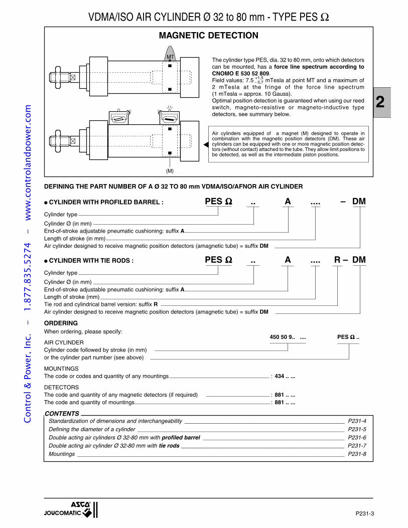
P231-3
2
ORDERINGWhen ordering, please specify:
450 50 9.. .... PES ΩΩΩΩΩ ..AIR CYLINDERCylinder code followed by stroke (in mm)or the cylinder part number (see above)
MOUNTINGSThe code or codes and quantity of any mountings : 434 .. ...
DETECTORSThe code and quantity of any magnetic detectors (if required) : 881 .. ...The code and quantity of mountings : 881 .. ...
MAGNETIC DETECTION
MT
(M)
Air cylinders equipped of a magnet (M) designed to operate incombination with the magnetic position detectors (DM). These aircylinders can be equipped with one or more magnetic position detec-tors (without contact) attached to the tube. They allow limit positions tobe detected, as well as the intermediate piston positions.
DEFINING THE PART NUMBER OF A Ø 32 TO 80 mm VDMA/ISO/AFNOR AIR CYLINDER
CYLINDER WITH PROFILED BARREL : PES ΩΩΩΩΩ .. A .... – DMCylinder type
Cylinder Ø (in mm)End-of-stroke adjustable pneumatic cushioning: suffix ALength of stroke (in mm)Air cylinder designed to receive magnetic position detectors (amagnetic tube) = suffix DM
CYLINDER WITH TIE RODS : PES ΩΩΩΩΩ .. A .... R – DMCylinder type
Cylinder Ø (in mm)End-of-stroke adjustable pneumatic cushioning: suffix ALength of stroke (mm)Tie rod and cylindrical barrel version: suffix RAir cylinder designed to receive magnetic position detectors (amagnetic tube) = suffix DM
CONTENTS
VDMA/ISO AIR CYLINDER Ø 32 to 80 mm - TYPE PES Ω
The cylinder type PES, dia. 32 to 80 mm, onto which detectorscan be mounted, has a force line spectrum according toCNOMO E 530 52 809.Field values: 7.5 mTesla at point MT and a maximum of2 mTesla at the fringe of the force line spectrum(1 mTesla = approx. 10 Gauss).Optimal position detection is guaranteed when using our reedswitch, magneto-resistive or magneto-inductive typedetectors, see summary below.
+1,5- 0,7
Standardization of dimensions and interchangeability ___________________________________________________ P231-4Defining the diameter of a cylinder __________________________________________________________________ P231-5Double acting air cylinders Ø 32-80 mm with profiled barrel _____________________________________________ P231-6Double acting air cylinder Ø 32-80 mm with tie rods ____________________________________________________ P231-7Mountings _____________________________________________________________________________________ P231-8
Cont
rol &
Pow
er, I
nc.
-
1.87
7.83
5.52
74
- w
ww
.con
trol
andp
ower
.com
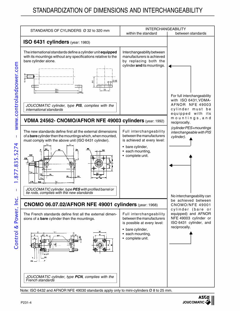
P231-4
For full interchangeabilitywith ISO 6431,VDMA-AFNOR NFE 49003c y l i n d e r m u s t b ee q u i p p e d w i t h i t sm o u n t i n g s , a n dreciprocally.
(cylinder PES+mountingsinterchangeable with PIScylinder).
No interchangeability canbe achieved betweenCNOMO/NFE 49001c y l i n d e r ( b a r e o requipped) and AFNORNFE 49003 cylinder orISO 6431 cylinder, andreciprocally.
The international standards define a cylinder unit equippedwith its mountings without any specifications relative to thebare cylinder alone.
JOUCOMATIC cylinder, type PIS, complies with theinternational standards
The new standards define first all the external dimensionsof a barecylinder then the mountings which, when mounted,must comply with the above unit (ISO 6431 cylinder).
JOUCOMATIC cylinder, type PES with profiled barrel ortie rods, complies with the new standards
The French standards define first all the external dimen-sions of a bare cylinder then the mountings.
JOUCOMATIC cylinder, type PCN, complies with theFrench standards
INTERCHANGEABILITYwithin the standard between standards
ISO 6431 cylinders (year: 1983)
STANDARDS OF CYLINDERS Ø 32 to 320 mm
Interchangeability betweenmanufacturers is achievedby replacing both thecylinderand its mountings.
Ful l interchangeabi l i tybetween the manufacturersis achieved at every level:
• bare cylinder,• each mounting,• complete unit.
Ful l interchangeabi l i tybetween the manufacturersis possible at every level:
• bare cylinder,• each mounting,• complete unit.
A0XA+SA+
Ø AB
TRAHØ
VDMA 24562- CNOMO/AFNOR NFE 49003 cylinders (year: 1992)
CNOMO 06.07.02/AFNOR NFE 49001 cylinders (year: 1968)
Note: ISO 6432 and AFNOR NFE 49030 standards apply only to mini-cylinders Ø 8 to 25 mm.
STANDARDIZATION OF DIMENSIONS AND INTERCHANGEABILITY
Cont
rol &
Pow
er, I
nc.
-
1.87
7.83
5.52
74
- w
ww
.con
trol
andp
ower
.com
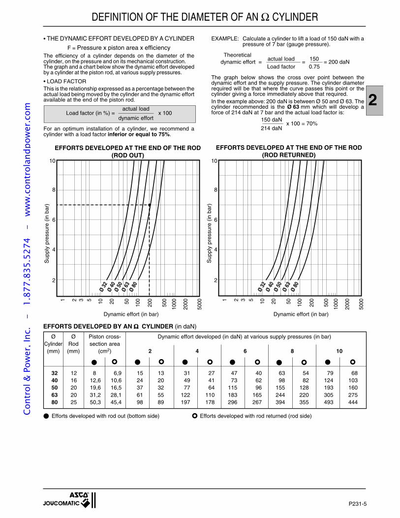
P231-5
2
Ø Ø Piston cross- Dynamic effort developed (in daN) at various supply pressures (in bar)Cylinder Rod section area(mm) (mm) (cm2) 2 4 6 8 10
32 12 8 6,9 15 13 31 27 47 40 63 54 79 6840 16 12,6 10,6 24 20 49 41 73 62 98 82 124 10350 20 19,6 16,5 37 32 77 64 115 96 155 128 193 16063 20 31,2 28,1 61 55 122 110 183 165 244 220 305 27580 25 50,3 45,4 98 89 197 178 296 267 394 355 493 444
• THE DYNAMIC EFFORT DEVELOPED BY A CYLINDER
F = Pressure x piston area x efficiencyThe efficiency of a cylinder depends on the diameter of thecylinder, on the pressure and on its mechanical construction.The graph and a chart below show the dynamic effort developedby a cylinder at the piston rod, at various supply pressures.
• LOAD FACTORThis is the relationship expressed as a percentage between theactual load being moved by the cylinder and the dynamic effortavailable at the end of the piston rod.
actual loadLoad factor (in %) = x 100
dynamic effort
For an optimum installation of a cylinder, we recommend acylinder with a load factor inferior or equal to 75%.
EXAMPLE: Calculate a cylinder to lift a load of 150 daN with apressure of 7 bar (gauge pressure).
Theoreticalactual load 150 dynamic effort = = = 200 daNLoad factor 0.75
The graph below shows the cross over point between thedynamic effort and the supply pressure. The cylinder diameterrequired will be that where the curve passes this point or thecylinder giving a force immediately above that required.In the example above: 200 daN is between Ø 50 and Ø 63. Thecylinder recommended is the Ø 63 mm which will develop aforce of 214 daN at 7 bar and the actual load factor is:
150 daNx 100 = 70%
214 daN
Efforts developed with rod out (bottom side) Efforts developed with rod returned (rod side)
EFFORTS DEVELOPED BY AN ΩΩΩΩΩ CYLINDER (in daN)
EFFORTS DEVELOPED AT THE END OF THE ROD(ROD OUT)
EFFORTS DEVELOPED AT THE END OF THE ROD(ROD RETURNED)
Sup
ply
pres
sure
(in
bar
)
10
8
6
4
2
1 2 3 5 10 20 50 100
200
500
1000
2000
5000
10
8
6
4
2
1 2 3 5 10 20 50 100
200
500
1000
2000
5000
Ø 32
Ø 40
Ø 50
Ø 63
Ø 80
Ø 32
Ø 40
Ø 50
Ø 63
Ø 80
Dynamic effort (in bar) Dynamic effort (in bar)
Sup
ply
pres
sure
(in
bar
)
DEFINITION OF THE DIAMETER OF AN Ω CYLINDERCo
ntro
l & P
ower
, Inc
. -
1.
877.
835.
5274
-
ww
w.c
ontr
olan
dpow
er.c
om
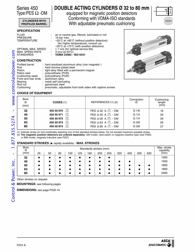
P231-6
CYLINDERS WITHPROFILED BARREL
Series 450Type:PES Ω -DM
DOUBLE ACTING CYLINDERS Ø 32 to 80 mmequipped for magnetic position detectorsConforming with VDMA-ISO standardsWith adjustable pneumatic cushioning
SPECIFICATIONFLUID : air or neutral gas, filtered, lubricated or notPRESSURE : 10 bar max.TEMPERATURE : –25°C at +80°C (without position detectors)
(for higher temperatures, consult us)–20°C at +70°C (with position detectors)
OPTIMAL MAX. SPEED : ≤ 1 m/s (for optimal service life)MAX. SPEED RATE : 3 m/s (at 20°C)STANDARDS : VDMA 24562 - ISO 6431
CONSTRUCTIONProfiled barrel : hard anodized aluminium alloy (non magnetic )Rod : hard chrome plated steelPiston : light alloy fitted with a permanent magnetPiston seal : polyurethane (PUR)Cushioning seals : polyurethane (PUR)Front and rear ends : aluminium alloyBearing : metal self lubricatingRod nut : galvanized steelCushioning : pneumatic, adjustable from both sides with captive screws
CHOICE OF EQUIPMENT
18202626
27
G 1/8G 1/4G 1/4
G 3/8G 3/8
3240506380
PES Ω 32 A ---- - DMPES Ω 40 A ---- - DM
PES Ω 50 A ---- - DMPES Ω 63 A ---- - DMPES Ω 80 A ---- - DM
(1)
(1)
(1)
(1)
(1)
(1)
(1)
(1)
(1)
(1)
Cushioninglength (mm)
REFERENCES (1) (2)
STANDARD STROKES (: rapidly available) - MAX. STROKES
Standards strokes (mm)
25 50 80 100 125 160 200 250 320 400 500 630
3240506380
Max. strokecapabilty
(mm)
1000150018001800
2000
MOUNTINGS: see following pages
DIMENSIONS: see page P230-10
Other strokes on request
NS
BoreØ
(mm)
BoreØ
(mm)
ConnectionØCODES (1)
(1) Indicate stroke (in mm) preferably selecting one of this standard strokes below. Do not exceed maximum possible stroke.(2) The magnetic position detectors are ordered separately: UNI model, reed switch or magneto-resistive type (see P295)
or BIM model, magneto-inductive (see P297)
450 50 970 ----450 50 971 ----450 50 972 ----450 50 973 ----450 50 974 ----
Cont
rol &
Pow
er, I
nc.
-
1.87
7.83
5.52
74
- w
ww
.con
trol
andp
ower
.com
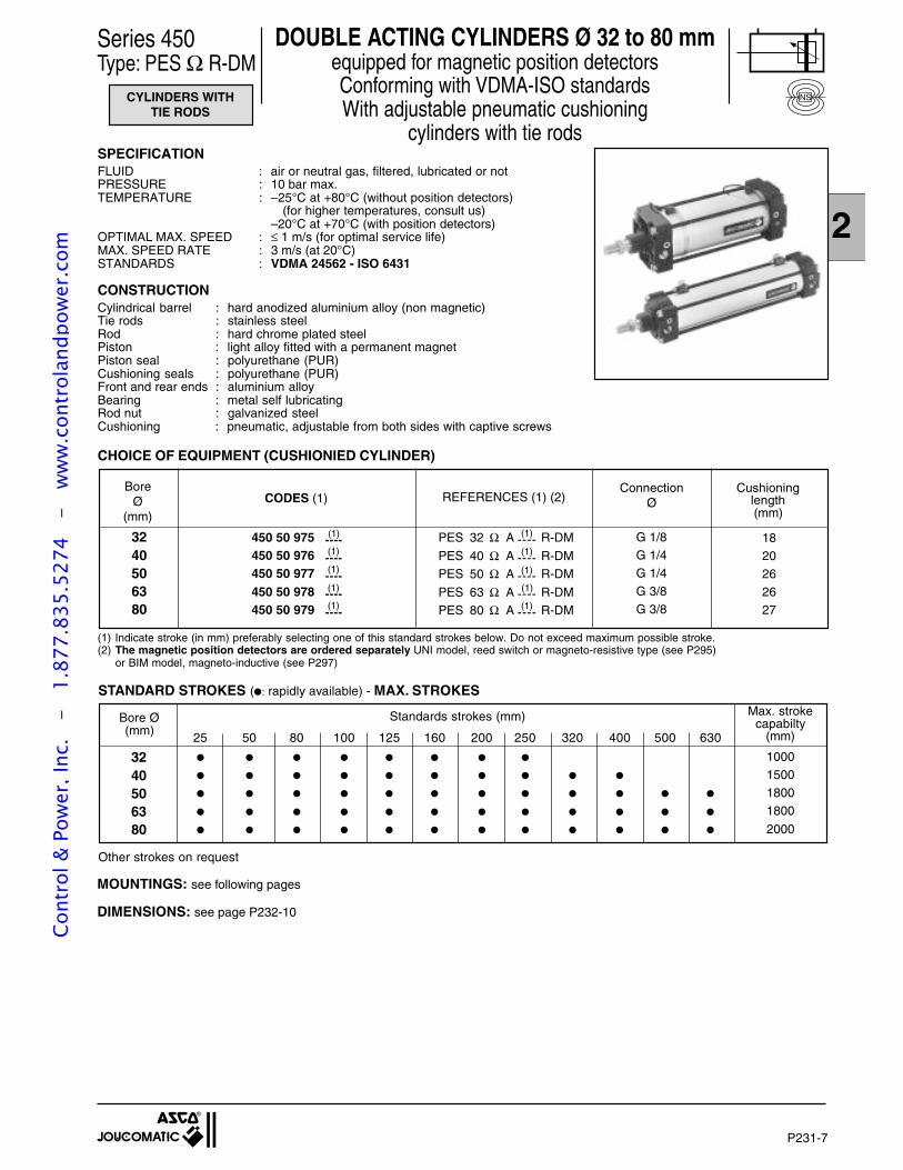
P231-7
2
DOUBLE ACTING CYLINDERS Ø 32 to 80 mmequipped for magnetic position detectorsConforming with VDMA-ISO standardsWith adjustable pneumatic cushioning
cylinders with tie rods
Series 450Type: PES Ω R-DM
CYLINDERS WITHTIE RODS
NS
SPECIFICATIONFLUID : air or neutral gas, filtered, lubricated or notPRESSURE : 10 bar max.TEMPERATURE : –25°C at +80°C (without position detectors)
(for higher temperatures, consult us)–20°C at +70°C (with position detectors)
OPTIMAL MAX. SPEED : ≤ 1 m/s (for optimal service life)MAX. SPEED RATE : 3 m/s (at 20°C)STANDARDS : VDMA 24562 - ISO 6431
CONSTRUCTIONCylindrical barrel : hard anodized aluminium alloy (non magnetic)Tie rods : stainless steelRod : hard chrome plated steelPiston : light alloy fitted with a permanent magnetPiston seal : polyurethane (PUR)Cushioning seals : polyurethane (PUR)Front and rear ends : aluminium alloyBearing : metal self lubricatingRod nut : galvanized steelCushioning : pneumatic, adjustable from both sides with captive screws
(1) Indicate stroke (in mm) preferably selecting one of this standard strokes below. Do not exceed maximum possible stroke.(2) The magnetic position detectors are ordered separately UNI model, reed switch or magneto-resistive type (see P295)
or BIM model, magneto-inductive (see P297)
1820262627
G 1/8G 1/4G 1/4G 3/8G 3/8
3240506380
450 50 975 ----450 50 976 ----450 50 977 ----450 50 978 ----450 50 979 ----
(1)
(1)
(1)
(1)
(1)
BoreØ
(mm)
ConnectionØREFERENCES (1) (2)CODES (1)
PES 32 Ω A ---- R-DM
PES 40 Ω A ---- R-DMPES 50 Ω A ---- R-DM
PES 63 Ω A ---- R-DMPES 80 Ω A ---- R-DM
(1)
(1)
(1)
(1)
(1)
CHOICE OF EQUIPMENT (CUSHIONIED CYLINDER)
STANDARD STROKES (: rapidly available) - MAX. STROKES
Standards strokes (mm)
25 50 80 100 125 160 200 250 320 400 500 630
3240506380
Max. strokecapabilty
(mm)
1000150018001800
2000
Bore Ø(mm)
Other strokes on request
Cushioninglength(mm)
MOUNTINGS: see following pages
DIMENSIONS: see page P232-10
Cont
rol &
Pow
er, I
nc.
-
1.87
7.83
5.52
74
- w
ww
.con
trol
andp
ower
.com
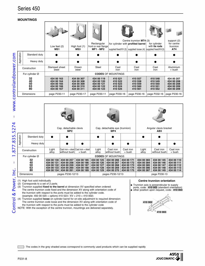
P231-8
Centre trunnion MT4 (3) support (2)Rectangular for centre
Low feet (2) High foot (1) front or rear flange trunnionMS1 MS3 MF1 - MF2 AT4
Stamped sheet Drawn Steel Cast Cast Cast Aluminiumsteel steel iron iron iron + bush
MOUNTINGS
Series 450
32 434 00 130 434 00 257 434 00 185 434 00 125 434 00 266 434 00 171 434 00 383 434 00 145 434 00 11040 434 00 131 434 00 258 434 00 186 434 00 126 434 00 267 434 00 172 434 00 384 434 00 146 434 00 11150 434 00 132 434 00 259 434 00 187 434 00 127 434 00 268 434 00 173 434 00 385 434 00 147 434 00 11263 434 00 133 434 00 260 434 00 188 434 00 128 434 00 269 434 00 174 434 00 386 434 00 148 434 00 11380 434 00 134 434 00 261 434 00 189 434 00 129 434 00 270 434 00 175 434 00 387 434 00 149 434 00 114
Appl
icat
ion
Standard duty
Heavy duty
Construction
Cap, detachable clevis Cap, detachable eye (trunnion) Angular clevis bracketMP2 MP4 AB3
Light Cast iron + steel Cast iron + steel Light Cast iron Cast iron Light Cast iron Cast ironalloy without bush + bush alloy without bush + bush alloy without bush + bush
For cylinder Ø CODES OF MOUNTINGS
Dimensions pages P230-12/13 pages P230-12/13 page P230-13
: The codes in the grey shaded areas correspond to commonly used products which can be supplied rapidly
App
licat
ion
For cylinder Ø CODES OF MOUNTINGS
Heavy duty
Construction
Standard duty
Dimensions page P230-11 page P230-17 page P230-11 page P230-16 page P230-16 page P232-16 page P230-16
32 434 00 163 434 00 307 434 00 119 410 521 410 557 410 548 434 00 20740 434 00 164 434 00 308 434 00 120 410 522 410 558 410 549 434 00 20850 434 00 165 434 00 309 434 00 121 410 523 410 559 410 550 434 00 20863 434 00 166 434 00 310 434 00 122 410 524 410 560 410 551 434 00 20980 434 00 167 434 00 311 434 00 123 410 525 410 561 410 552 434 00 209
for cylinder with profiled barrel for cylinderwith tie rods
supplied fixed/XV (3) supplied loose (4) supplied fixed/XV(3)
(1) High foot sold individually(2) Corresponds to a set of 2 parts.(3) Trunnion supplied fixed to the barrel at dimension XV specified when ordered:
The centre trunnion code fixed and the dimension XV along with orientation code ofthe trunnion with respect to the ports must be added to the cylinder code.(example: 450 00 020 + options 410 523 / XV = 210 + 410 002)
(4) Trunnion supplied loose on cylinder barrel for on-site adjustment to required dimension:The centre trunnion code loose and the dimension XV along with orientation code ofthe trunnion with respect to the ports must be added to the cylinder code
NOTE: With the exception of the centre trunnion, mountings are delivered separetely.
410 003
410 002
Trunnion axis is perpendicular to supplyports, code: 410 002 (standard orientation)
other position upon request, code: 410 003
Centre trunnion orientation
Cont
rol &
Pow
er, I
nc.
-
1.87
7.83
5.52
74
- w
ww
.con
trol
andp
ower
.com
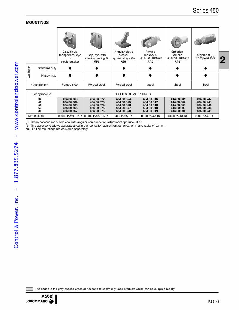
P231-9
2
Series 450
MOUNTINGS
32 434 00 363 434 00 372 434 00 354 434 00 016 434 00 001 434 00 24240 434 00 364 434 00 373 434 00 355 434 00 017 434 00 002 434 00 24350 434 00 365 434 00 374 434 00 356 434 00 018 434 00 003 434 00 24463 434 00 366 434 00 375 434 00 357 434 00 018 434 00 003 434 00 24480 434 00 367 434 00 376 434 00 358 434 00 019 434 00 004 434 00 245
Appl
icat
ion
Standard duty
Heavy duty
Construction
For cylinder Ø CODES OF MOUNTINGS
Dimensions pages P230-14/15 pages P230-14/15 page P230-15 page P230-18 page P230-18 page P230-18
Cap, clevis Angular clevis Female Sphericalfor spherical eye Cap, eye with bracket rod clevis rod end Alignment (6)
or spherical bearing (5) spherical eye (5) ISO 8140 - RP102P ISO 8139 - RP103P compensatorclevis bracket MP6 AB5 AP2 AP6
Forged steel Forged steel Forged steel Steel Steel Steel
: The codes in the grey shaded areas correspond to commonly used products which can be supplied rapidly
(5) These accessories allows accurate angular compensation adjustment spherical of 4°(6) This accessorie allows accurate angular compensation adjustment spherical of 4° and radial of 0,7 mmNOTE: The mountings are delivered separetely.
Cont
rol &
Pow
er, I
nc.
-
1.87
7.83
5.52
74
- w
ww
.con
trol
andp
ower
.com
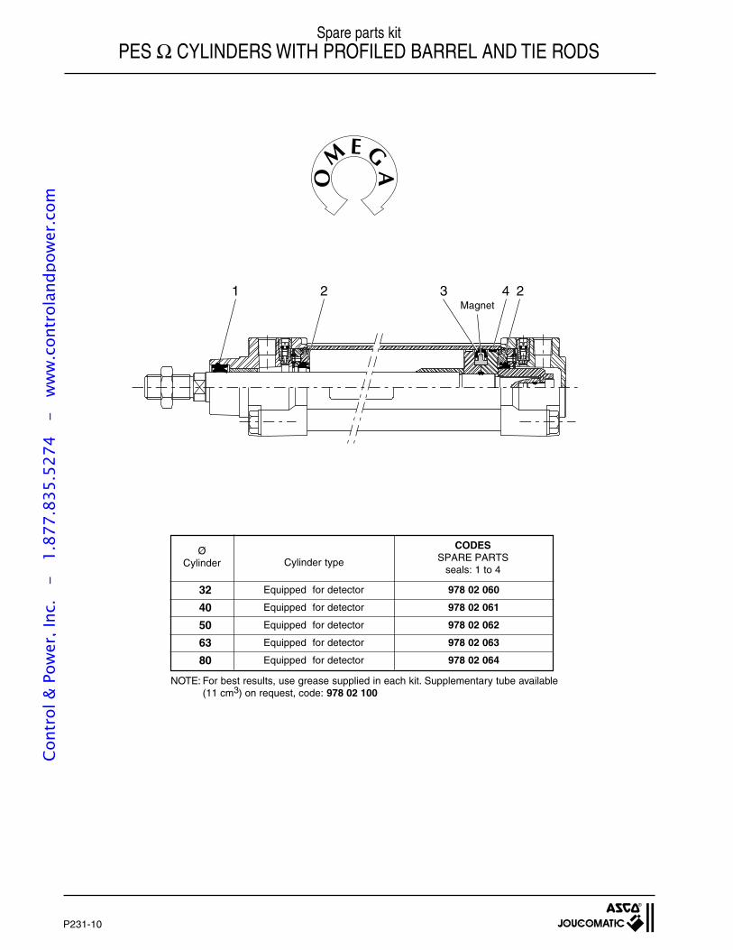
P231-10
1 2 3 4 2
32
40
50
63
80
Equipped for detector 978 02 060
Equipped for detector 978 02 061
Equipped for detector 978 02 062
Equipped for detector 978 02 063
Equipped for detector 978 02 064
Cylinder typeØ
Cylinder
CODESSPARE PARTS
seals: 1 to 4
Spare parts kitPES Ω CYLINDERS WITH PROFILED BARREL AND TIE RODS
Magnet
NOTE: For best results, use grease supplied in each kit. Supplementary tube available(11 cm3) on request, code: 978 02 100
Cont
rol &
Pow
er, I
nc.
-
1.87
7.83
5.52
74
- w
ww
.con
trol
andp
ower
.com
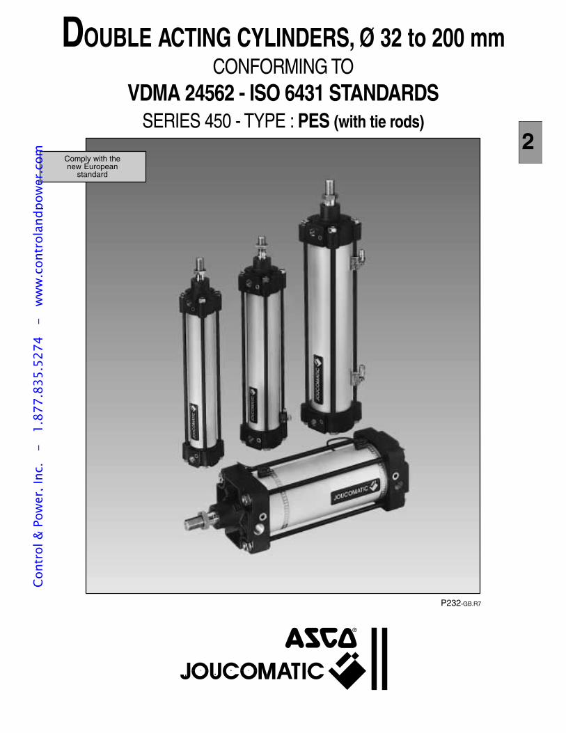
P232-GB.R7
Comply with thenew European
standard
DOUBLE ACTING CYLINDERS, Ø 32 to 200 mmCONFORMING TO
VDMA 24562 - ISO 6431 STANDARDSSERIES 450 - TYPE : PES (with tie rods)
2
Cont
rol &
Pow
er, I
nc.
-
1.87
7.83
5.52
74
- w
ww
.con
trol
andp
ower
.com
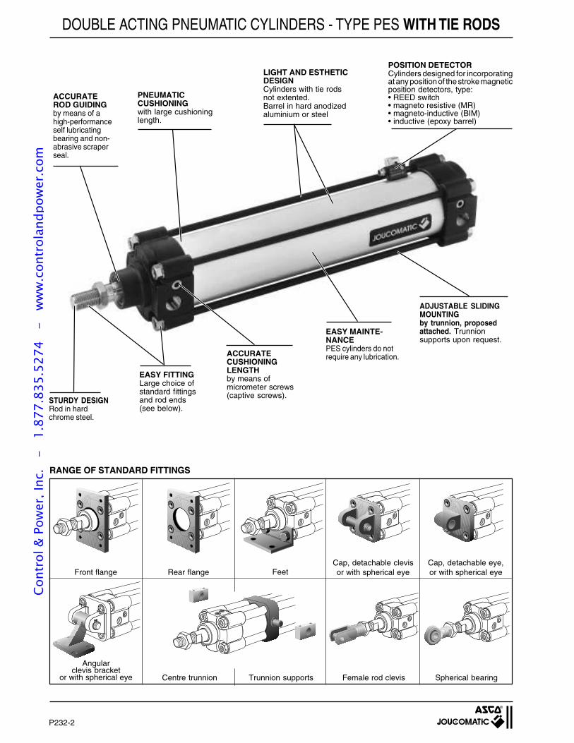
P232-2
Series 450
Centre trunnion Trunnion supports Female rod clevis Spherical bearing
DOUBLE ACTING PNEUMATIC CYLINDERS - TYPE PES WITH TIE RODS
ACCURATEROD GUIDINGby means of ahigh-performanceself lubricatingbearing and non-abrasive scraperseal.
ACCURATECUSHIONINGLENGTHby means ofmicrometer screws(captive screws).
PNEUMATICCUSHIONINGwith large cushioninglength.
LIGHT AND ESTHETICDESIGNCylinders with tie rodsnot extented.Barrel in hard anodizedaluminium or steel
EASY MAINTE-NANCEPES cylinders do notrequire any lubrication.
ADJUSTABLE SLIDINGMOUNTINGby trunnion, proposedattached. Trunnionsupports upon request.
STURDY DESIGNRod in hardchrome steel.
EASY FITTINGLarge choice ofstandard fittingsand rod ends(see below).
POSITION DETECTORCylinders designed for incorporatingat any position of the stroke magneticposition detectors, type:• REED switch• magneto resistive (MR)• magneto-inductive (BIM)• inductive (epoxy barrel)
Angularclevis bracket
or with spherical eye
Front flange Rear flange FeetCap, detachable clevisor with spherical eye
Cap, detachable eye,or with spherical eye
RANGE OF STANDARD FITTINGS
Cont
rol &
Pow
er, I
nc.
-
1.87
7.83
5.52
74
- w
ww
.con
trol
andp
ower
.com
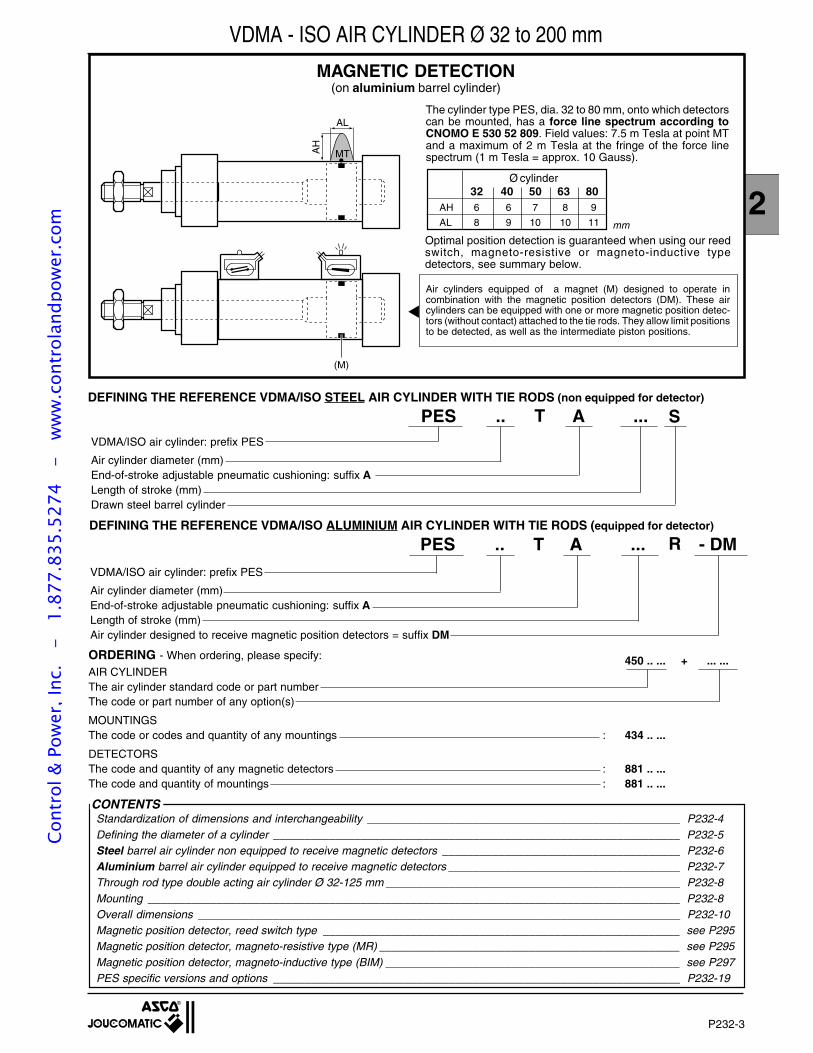
P232-3
2
Series 450
450 .. ... + ... ...AIR CYLINDERThe air cylinder standard code or part numberThe code or part number of any option(s)
MOUNTINGSThe code or codes and quantity of any mountings : 434 .. ...
DETECTORSThe code and quantity of any magnetic detectors : 881 .. ...The code and quantity of mountings : 881 .. ...
PES .. A ... - DMVDMA/ISO air cylinder: prefix PES
Air cylinder diameter (mm)End-of-stroke adjustable pneumatic cushioning: suffix ALength of stroke (mm)Air cylinder designed to receive magnetic position detectors = suffix DM
PES .. A ...VDMA/ISO air cylinder: prefix PES
Air cylinder diameter (mm)End-of-stroke adjustable pneumatic cushioning: suffix ALength of stroke (mm)Drawn steel barrel cylinder
VDMA - ISO AIR CYLINDER Ø 32 to 200 mm
AL
AH
MT
(M)
MAGNETIC DETECTION(on aluminium barrel cylinder)
The cylinder type PES, dia. 32 to 80 mm, onto which detectorscan be mounted, has a force line spectrum according toCNOMO E 530 52 809. Field values: 7.5 m Tesla at point MTand a maximum of 2 m Tesla at the fringe of the force linespectrum (1 m Tesla = approx. 10 Gauss).
32 40 50 63 80Ø cylinder
AH 6 6 7 8 9
AL 8 9 10 10 11 mm
Optimal position detection is guaranteed when using our reedswitch, magneto-resistive or magneto-inductive typedetectors, see summary below.
Air cylinders equipped of a magnet (M) designed to operate incombination with the magnetic position detectors (DM). These aircylinders can be equipped with one or more magnetic position detec-tors (without contact) attached to the tie rods. They allow limit positionsto be detected, as well as the intermediate piston positions.
CONTENTSStandardization of dimensions and interchangeability __________________________________________________ P232-4Defining the diameter of a cylinder _________________________________________________________________ P232-5Steel barrel air cylinder non equipped to receive magnetic detectors ______________________________________ P232-6Aluminium barrel air cylinder equipped to receive magnetic detectors _____________________________________ P232-7Through rod type double acting air cylinder Ø 32-125 mm _______________________________________________ P232-8Mounting _____________________________________________________________________________________ P232-8Overall dimensions _____________________________________________________________________________ P232-10Magnetic position detector, reed switch type _________________________________________________________ see P295Magnetic position detector, magneto-resistive type (MR) ________________________________________________ see P295Magnetic position detector, magneto-inductive type (BIM) _______________________________________________ see P297PES specific versions and options _________________________________________________________________ P232-19
RTDEFINING THE REFERENCE VDMA/ISO ALUMINIUM AIR CYLINDER WITH TIE RODS (equipped for detector)
STDEFINING THE REFERENCE VDMA/ISO STEEL AIR CYLINDER WITH TIE RODS (non equipped for detector)
ORDERING - When ordering, please specify:
Cont
rol &
Pow
er, I
nc.
-
1.87
7.83
5.52
74
- w
ww
.con
trol
andp
ower
.com
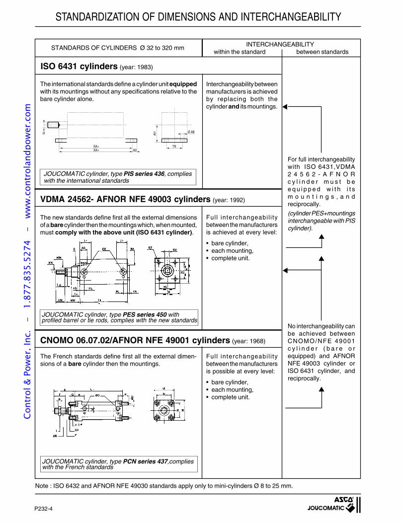
P232-4
Series 450
INTERCHANGEABILITYwithin the standard between standards
ISO 6431 cylinders (year: 1983)
For full interchangeabilitywith ISO 6431,VDMA2 4 5 6 2 - A F N O Rc y l i n d e r m u s t b ee q u i p p e d w i t h i t sm o u n t i n g s , a n dreciprocally.
(cylinder PES+mountingsinterchangeable with PIScylinder).
No interchangeability canbe achieved betweenCNOMO/NFE 49001c y l i n d e r ( b a r e o requipped) and AFNORNFE 49003 cylinder orISO 6431 cylinder, andreciprocally.
STANDARDS OF CYLINDERS Ø 32 to 320 mm
Interchangeability betweenmanufacturers is achievedby replacing both thecylinderand its mountings.
Ful l interchangeabi l i tybetween the manufacturersis achieved at every level:
• bare cylinder,• each mounting,• complete unit.
Ful l interchangeabi l i tybetween the manufacturersis possible at every level:
• bare cylinder,• each mounting,• complete unit.
CNOMO 06.07.02/AFNOR NFE 49001 cylinders (year: 1968)
Note : ISO 6432 and AFNOR NFE 49030 standards apply only to mini-cylinders Ø 8 to 25 mm.
VDMA 24562- AFNOR NFE 49003 cylinders (year: 1992)
The French standards define first all the external dimen-sions of a bare cylinder then the mountings.
The international standards define a cylinder unit equippedwith its mountings without any specifications relative to thebare cylinder alone.
JOUCOMATIC cylinder, type PIS series 436, complieswith the international standards
The new standards define first all the external dimensionsof a barecylinder then the mountings which, when mounted,must comply with the above unit (ISO 6431 cylinder).
JOUCOMATIC cylinder, type PCN series 437,complieswith the French standards
JOUCOMATIC cylinder, type PES series 450 withprofiled barrel or tie rods, complies with the new standards
STANDARDIZATION OF DIMENSIONS AND INTERCHANGEABILITY
A0XA+SA+
Ø AB
TR
AHØ
Cont
rol &
Pow
er, I
nc.
-
1.87
7.83
5.52
74
- w
ww
.con
trol
andp
ower
.com
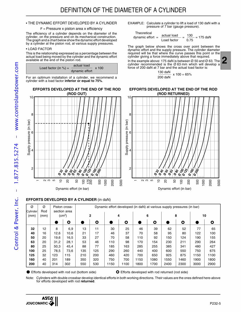
P232-5
2
Series 450
• THE DYNAMIC EFFORT DEVELOPED BY A CYLINDER
F = Pressure x piston area x efficiencyThe efficiency of a cylinder depends on the diameter of thecylinder, on the pressure and on its mechanical construction.The graph and a chart below show the dynamic effort developedby a cylinder at the piston rod, at various supply pressures.
• LOAD FACTORThis is the relationship expressed as a percentage between theactual load being moved by the cylinder and the dynamic effortavailable at the end of the piston rod.
actual loadLoad factor (in %) = x 100
dynamic effort
For an optimum installation of a cylinder, we recommend acylinder with a load factor inferior or equal to 75%.
EXAMPLE: Calculate a cylinder to lift a load of 130 daN with apressure of 7 bar (gauge pressure).
Theoreticalactual load 130 dynamic effort = = = 175 daNLoad factor 0.75
The graph below shows the cross over point between thedynamic effort and the supply pressure. The cylinder diameterrequired will be that where the curve passes this point or thecylinder giving a force immediately above that required.In the example above: 175 daN is between Ø 50 and Ø 63. Thecylinder recommended is the Ø 63 mm which will develop aforce of 200 daN at 7 bar and the actual load factor is:
130 daNx 100 = 65%
200 daN
Sup
ply
pres
sure
(in
bar
)
Sup
ply
pres
sure
(in
bar
)
10
8
6
4
2
1 2 3 5 10 20 50 100
175
200
500
1000
2000
5000
10
8
6
4
2
1 2 3 5 10 20 50 100
200
500
1000
2000
5000
Ø 32
Ø 40
Ø 50
Ø 63
Ø 80
Ø 10
0Ø
125
Ø 16
0Ø
200
Ø 32
Ø 40
Ø 50
Ø 63
Ø 80
Ø 10
0Ø
125
Ø 16
0Ø
200
EFFORTS DEVELOPED BY A CYLINDER (in daN)
Ø Ø Piston cross- Dynamic effort developed (in daN) at various supply pressures (in bar)Cylinder Rod section area(mm) (mm) (cm2) 2 4 6 8 10
32 12 8 6,9 13 11 30 25 46 39 62 52 77 6540 16 12,6 10,6 21 17 46 37 70 58 95 80 122 10050 20 19,6 16,5 33 27 70 58 110 92 150 124 190 15563 20 31,2 28,1 53 46 110 98 170 154 230 211 290 26480 25 50,3 45,4 88 77 185 163 285 255 385 341 480 427
100 25 78,5 73,6 135 125 290 260 440 400 600 550 750 675125 32 123 115 210 200 460 420 700 650 925 875 1150 1100160 40 201 189 350 320 750 700 1150 1080 1550 1460 1900 1800200 40 314 302 550 530 1150 1100 1800 1700 2400 2300 3000 2900
Efforts developed with rod out (bottom side) Efforts developed with rod returned (rod side)
Note: Cylinders with double crossbar develop identical efforts in both working directions. Their values are the ones defined here-abovefor efforts developed with rod returned.
EFFORTS DEVELOPED AT THE END OF THE ROD(ROD RETURNED)
Dynamic effort (in bar) Dynamic effort (in bar)
DEFINITION OF THE DIAMETER OF A CYLINDER
EFFORTS DEVELOPED AT THE END OF THE ROD(ROD OUT)
Cont
rol &
Pow
er, I
nc.
-
1.87
7.83
5.52
74
- w
ww
.con
trol
andp
ower
.com
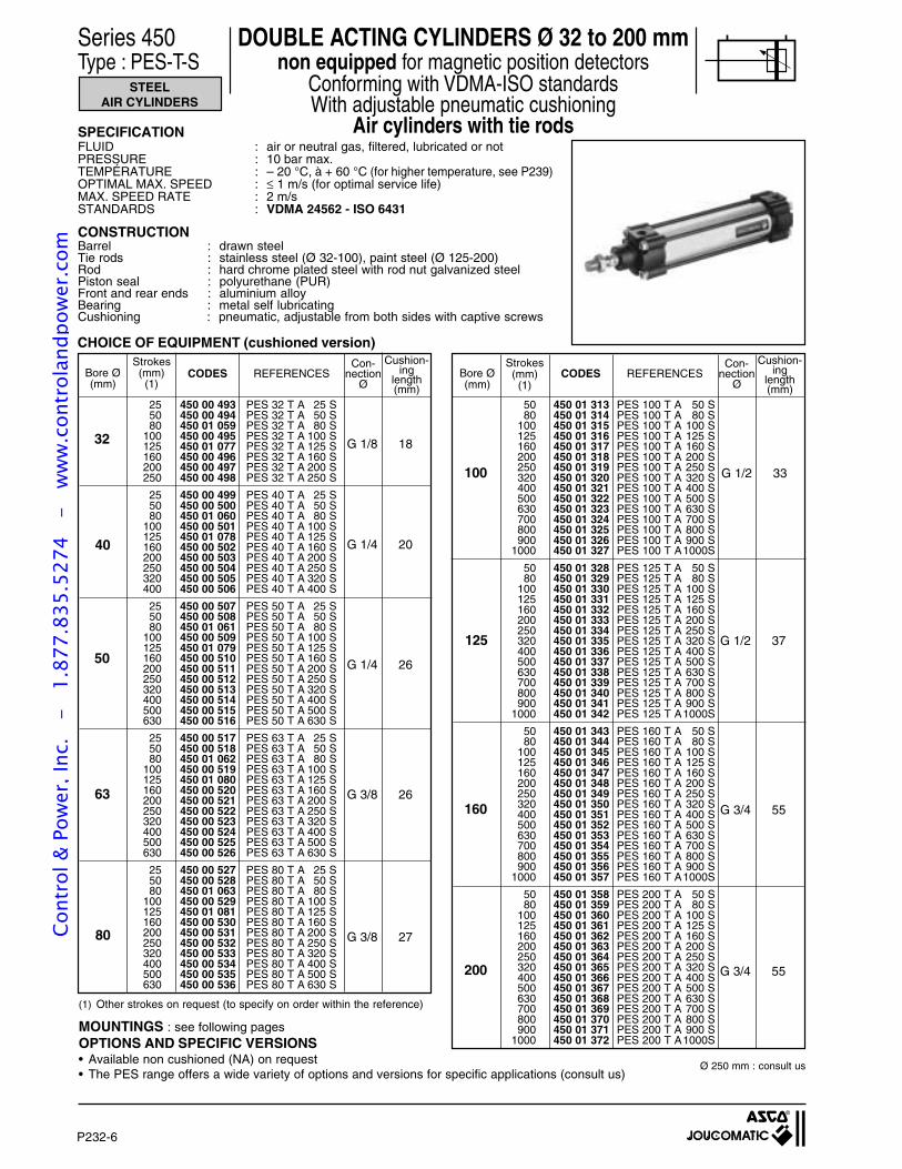
P232-6
Series 450
(1) Other strokes on request (to specify on order within the reference)
MOUNTINGS : see following pagesOPTIONS AND SPECIFIC VERSIONS• Available non cushioned (NA) on request• The PES range offers a wide variety of options and versions for specific applications (consult us)
Series 450 DOUBLE ACTING CYLINDERS Ø 32 to 200 mmType : PES-T-S non equipped for magnetic position detectors
Conforming with VDMA-ISO standardsWith adjustable pneumatic cushioning
Air cylinders with tie rods
STEELAIR CYLINDERS
32
40
50
63
80
G 1/8 18
G 3/8 26
G 1/4 26
G 1/4 20
G 3/8 27
100 G 1/2 33
160 G 3/4 55
125 G 1/2 37
G 3/4 55200
25 450 00 493 PES 32 T A 25 S50 450 00 494 PES 32 T A 50 S80 450 01 059 PES 32 T A 80 S
100 450 00 495 PES 32 T A 100 S125 450 01 077 PES 32 T A 125 S160 450 00 496 PES 32 T A 160 S200 450 00 497 PES 32 T A 200 S250 450 00 498 PES 32 T A 250 S
25 450 00 499 PES 40 T A 25 S50 450 00 500 PES 40 T A 50 S80 450 01 060 PES 40 T A 80 S
100 450 00 501 PES 40 T A 100 S125 450 01 078 PES 40 T A 125 S160 450 00 502 PES 40 T A 160 S200 450 00 503 PES 40 T A 200 S250 450 00 504 PES 40 T A 250 S320 450 00 505 PES 40 T A 320 S400 450 00 506 PES 40 T A 400 S
25 450 00 507 PES 50 T A 25 S50 450 00 508 PES 50 T A 50 S80 450 01 061 PES 50 T A 80 S
100 450 00 509 PES 50 T A 100 S125 450 01 079 PES 50 T A 125 S160 450 00 510 PES 50 T A 160 S200 450 00 511 PES 50 T A 200 S250 450 00 512 PES 50 T A 250 S320 450 00 513 PES 50 T A 320 S400 450 00 514 PES 50 T A 400 S500 450 00 515 PES 50 T A 500 S630 450 00 516 PES 50 T A 630 S
25 450 00 517 PES 63 T A 25 S50 450 00 518 PES 63 T A 50 S80 450 01 062 PES 63 T A 80 S
100 450 00 519 PES 63 T A 100 S125 450 01 080 PES 63 T A 125 S160 450 00 520 PES 63 T A 160 S200 450 00 521 PES 63 T A 200 S250 450 00 522 PES 63 T A 250 S320 450 00 523 PES 63 T A 320 S400 450 00 524 PES 63 T A 400 S500 450 00 525 PES 63 T A 500 S630 450 00 526 PES 63 T A 630 S
25 450 00 527 PES 80 T A 25 S50 450 00 528 PES 80 T A 50 S80 450 01 063 PES 80 T A 80 S
100 450 00 529 PES 80 T A 100 S125 450 01 081 PES 80 T A 125 S160 450 00 530 PES 80 T A 160 S200 450 00 531 PES 80 T A 200 S250 450 00 532 PES 80 T A 250 S320 450 00 533 PES 80 T A 320 S400 450 00 534 PES 80 T A 400 S500 450 00 535 PES 80 T A 500 S630 450 00 536 PES 80 T A 630 S
50 450 01 313 PES 100 T A 50 S80 450 01 314 PES 100 T A 80 S
100 450 01 315 PES 100 T A 100 S125 450 01 316 PES 100 T A 125 S160 450 01 317 PES 100 T A 160 S200 450 01 318 PES 100 T A 200 S250 450 01 319 PES 100 T A 250 S320 450 01 320 PES 100 T A 320 S400 450 01 321 PES 100 T A 400 S500 450 01 322 PES 100 T A 500 S630 450 01 323 PES 100 T A 630 S700 450 01 324 PES 100 T A 700 S800 450 01 325 PES 100 T A 800 S900 450 01 326 PES 100 T A 900 S
1000 450 01 327 PES 100 T A1000S
50 450 01 328 PES 125 T A 50 S80 450 01 329 PES 125 T A 80 S
100 450 01 330 PES 125 T A 100 S125 450 01 331 PES 125 T A 125 S160 450 01 332 PES 125 T A 160 S200 450 01 333 PES 125 T A 200 S250 450 01 334 PES 125 T A 250 S320 450 01 335 PES 125 T A 320 S400 450 01 336 PES 125 T A 400 S500 450 01 337 PES 125 T A 500 S630 450 01 338 PES 125 T A 630 S700 450 01 339 PES 125 T A 700 S800 450 01 340 PES 125 T A 800 S900 450 01 341 PES 125 T A 900 S
1000 450 01 342 PES 125 T A1000S
50 450 01 343 PES 160 T A 50 S80 450 01 344 PES 160 T A 80 S
100 450 01 345 PES 160 T A 100 S125 450 01 346 PES 160 T A 125 S160 450 01 347 PES 160 T A 160 S200 450 01 348 PES 160 T A 200 S250 450 01 349 PES 160 T A 250 S320 450 01 350 PES 160 T A 320 S400 450 01 351 PES 160 T A 400 S500 450 01 352 PES 160 T A 500 S630 450 01 353 PES 160 T A 630 S700 450 01 354 PES 160 T A 700 S800 450 01 355 PES 160 T A 800 S900 450 01 356 PES 160 T A 900 S
1000 450 01 357 PES 160 T A1000S
50 450 01 358 PES 200 T A 50 S80 450 01 359 PES 200 T A 80 S
100 450 01 360 PES 200 T A 100 S125 450 01 361 PES 200 T A 125 S160 450 01 362 PES 200 T A 160 S200 450 01 363 PES 200 T A 200 S250 450 01 364 PES 200 T A 250 S320 450 01 365 PES 200 T A 320 S400 450 01 366 PES 200 T A 400 S500 450 01 367 PES 200 T A 500 S630 450 01 368 PES 200 T A 630 S700 450 01 369 PES 200 T A 700 S800 450 01 370 PES 200 T A 800 S900 450 01 371 PES 200 T A 900 S
1000 450 01 372 PES 200 T A1000S
Con-nection
Ø
Strokes(mm)(1)
Bore Ø(mm)
CODES REFERENCESCushion-
inglength(mm)
Con-nection
Ø
Strokes(mm)(1)
CODES REFERENCESCushion-
inglength(mm)
Bore Ø(mm)
SPECIFICATIONFLUID : air or neutral gas, filtered, lubricated or notPRESSURE : 10 bar max.TEMPÉRATURE : – 20 °C, à + 60 °C (for higher temperature, see P239)OPTIMAL MAX. SPEED : ≤ 1 m/s (for optimal service life)MAX. SPEED RATE : 2 m/sSTANDARDS : VDMA 24562 - ISO 6431
CONSTRUCTIONBarrel : drawn steelTie rods : stainless steel (Ø 32-100), paint steel (Ø 125-200)Rod : hard chrome plated steel with rod nut galvanized steelPiston seal : polyurethane (PUR)Front and rear ends : aluminium alloyBearing : metal self lubricatingCushioning : pneumatic, adjustable from both sides with captive screws
Ø 250 mm : consult us
CHOICE OF EQUIPMENT (cushioned version)
Cont
rol &
Pow
er, I
nc.
-
1.87
7.83
5.52
74
- w
ww
.con
trol
andp
ower
.com
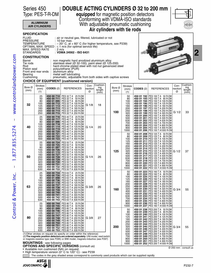
P232-7
2
Series 450
SPECIFICATIONFLUID : air or neutral gas, filtered, lubricated or notPRESSURE : 10 bar max.TEMPERATURE : – 20° C, at + 60° C (for higher temperature, see P239)OPTIMAL MAX. SPEED : ≤ 1 m/s (for optimal service life)MAX. SPEED RATE : 2 m/sSTANDARDS : VDMA 24562 - ISO 6431
CONSTRUCTIONBarrel : non magnetic hard anodized aluminium alloyTie rods : stainless steel (Ø 32-100), paint steel (Ø 125-200)Rod : hard chrome plated steel with rod nut galvanized steelPiston seal : polyurethane (PUR)Front and rear ends : aluminium alloyBearing : metal self lubricatingCushioning : pneumatic, adjustable from both sides with captive screws
ALUMINIUMAIR CYLINDERS
(1)Other strokes on request (to specify on order within the reference)(2)The magnetic position detectors are ordered separately: UNI model, reed switchor magneto-resistive type (see P295) or BIM model, magneto-inductive (see P297)
CHOICE OF EQUIPMENT (cushioned version)
NS
32
40
50
63
80
100
125
50 450 01 192 PES 100 T A 50 R-DM80 450 01 193 PES 100 T A 80 R-DM
100 450 01 194 PES 100 T A 100 R-DM125 450 01 195 PES 100 T A 125 R-DM160 450 01 196 PES 100 T A 160 R-DM200 450 01 197 PES 100 T A 200 R-DM250 450 01 198 PES 100 T A 250 R-DM320 450 01 199 PES 100 T A 320 R-DM400 450 01 200 PES 100 T A 400 R-DM500 450 01 201 PES 100 T A 500 R-DM630 450 01 202 PES 100 T A 630 R-DM700 450 01 203 PES 100 T A 700 R-DM800 450 01 204 PES 100 T A 800 R-DM900 450 01 205 PES 100 T A 900 R-DM
1000 450 01 206 PES 100 T A1000 R-DM50 450 01 208 PES 125 T A 50 R-DM80 450 01 209 PES 125 T A 80 R-DM
100 450 01 210 PES 125 T A 100 R-DM125 450 01 211 PES 125 T A 125 R-DM160 450 01 212 PES 125 T A 160 R-DM200 450 01 213 PES 125 T A 200 R-DM250 450 01 214 PES 125 T A 250 R-DM320 450 01 215 PES 125 T A 320 R-DM400 450 01 216 PES 125 T A 400 R-DM500 450 01 217 PES 125 T A 500 R-DM630 450 01 218 PES 125 T A 630 R-DM700 450 01 219 PES 125 T A 700 R-DM800 450 01 220 PES 125 T A 800 R-DM900 450 01 221 PES 125 T A 900 R-DM
1000 450 01 222 PES 125 T A1000 R-DM50 450 01 223 PES 160 T A 50 R-DM80 450 01 224 PES 160 T A 80 R-DM
100 450 01 225 PES 160 T A 100 R-DM125 450 01 226 PES 160 T A 125 R-DM160 450 01 227 PES 160 T A 160 R-DM200 450 01 228 PES 160 T A 200 R-DM250 450 01 229 PES 160 T A 250 R-DM320 450 01 230 PES 160 T A 320 R-DM400 450 01 231 PES 160 T A 400 R-DM500 450 01 232 PES 160 T A 500 R-DM630 450 01 233 PES 160 T A 630 R-DM700 450 01 234 PES 160 T A 700 R-DM800 450 01 235 PES 160 T A 800 R-DM900 450 01 236 PES 160 T A 900 R-DM
1000 450 01 237 PES 160 T A1000 R-DM50 450 01 238 PES 200 T A 50 R-DM80 450 01 239 PES 200 T A 80 R-DM
100 450 01 240 PES 200 T A 100 R-DM125 450 01 241 PES 200 T A 125 R-DM160 450 01 242 PES 200 T A 160 R-DM200 450 01 243 PES 200 T A 200 R-DM250 450 01 244 PES 200 T A 250 R-DM320 450 01 245 PES 200 T A 320 R-DM400 450 01 246 PES 200 T A 400 R-DM500 450 01 247 PES 200 T A 500 R-DM630 450 01 248 PES 200 T A 630 R-DM700 450 01 249 PES 200 T A 700 R-DM800 450 01 250 PES 200 T A 800 R-DM900 450 01 251 PES 200 T A 900 R-DM
1000 450 01 252 PES 200 T A1000 R-DM
160 G 3/4 55
G 3/4 55200
Con-nection
Ø
Strokes(mm)
(1)
Bore Ø(mm)
CODES (2) REFERENCESCushion-
inglength(mm)
Con-nection
Ø
Strokes(mm)
(1)
Bore Ø(mm)
CODES (2) REFERENCES
Cushion-ing
length(mm)
Ø 250 mm : consult us
G 1/2 37
G 1/2 33
G 1/8 18
G 3/8 26
G 1/4 26
G 1/4 20
G 3/8 27
25 450 00 710 PES 32 T A 25 R-DM50 450 00 711 PES 32 T A 50 R-DM80 450 01 095 PES 32 T A 80 R-DM
100 450 00 712 PES 32 T A 100 R-DM125 450 01 113 PES 32 T A 125 R-DM160 450 00 713 PES 32 T A 160 R-DM200 450 00 714 PES 32 T A 200 R-DM250 450 00 715 PES 32 T A 250 R-DM25 450 00 716 PES 40 T A 25 R-DM50 450 00 717 PES 40 T A 50 R-DM80 450 01 096 PES 40 T A 80 R-DM
100 450 00 718 PES 40 T A 100 R-DM125 450 01 114 PES 40 T A 125 R-DM160 450 00 719 PES 40 T A 160 R-DM200 450 00 720 PES 40 T A 200 R-DM250 450 00 721 PES 40 T A 250 R-DM320 450 00 722 PES 40 T A 320 R-DM400 450 00 723 PES 40 T A 400 R-DM25 450 00 724 PES 50 T A 25 R-DM50 450 00 725 PES 50 T A 50 R-DM80 450 01 097 PES 50 T A 80 R-DM
100 450 00 726 PES 50 T A 100 R-DM125 450 01 115 PES 50 T A 125 R-DM160 450 00 727 PES 50 T A 160 R-DM200 450 00 728 PES 50 T A 200 R-DM250 450 00 729 PES 50 T A 250 R-DM320 450 00 730 PES 50 T A 320 R-DM400 450 00 731 PES 50 T A 400 R-DM500 450 00 732 PES 50 T A 500 R-DM630 450 00 733 PES 50 T A 630 R-DM25 450 00 734 PES 63 T A 25 R-DM50 450 00 735 PES 63 T A 50 R-DM80 450 01 098 PES 63 T A 80 R-DM
100 450 00 736 PES 63 T A 100 R-DM125 450 01 116 PES 63 T A 125 R-DM160 450 00 737 PES 63 T A 160 R-DM200 450 00 738 PES 63 T A 200 R-DM250 450 00 739 PES 63 T A 250 R-DM320 450 00 740 PES 63 T A 320 R-DM400 450 00 741 PES 63 T A 400 R-DM500 450 00 742 PES 63 T A 500 R-DM630 450 00 743 PES 63 T A 630 R-DM25 450 00 744 PES 80 T A 25 R-DM50 450 00 745 PES 80 T A 50 R-DM80 450 01 099 PES 80 T A 80 R-DM
100 450 00 746 PES 80 T A 100 R-DM125 450 01 117 PES 80 T A 125 R-DM160 450 00 747 PES 80 T A 160 R-DM200 450 00 748 PES 80 T A 200 R-DM250 450 00 749 PES 80 T A 250 R-DM320 450 00 750 PES 80 T A 320 R-DM400 450 00 751 PES 80 T A 400 R-DM500 450 00 752 PES 80 T A 500 R-DM630 450 00 753 PES 80 T A 630 R-DM
: The codes in the grey shaded areas correspond to commonly used products which can be supplied rapidly
MOUNTINGS : see following pagesOPTIONS AND SPECIFIC VERSIONS (consult us)• Available non cushioned (NA) on request.• High temperature version (0° C to 120° C) - see P239
Series 450 DOUBLE ACTING CYLINDERS Ø 32 to 200 mmType: PES-T-R-DM equipped for magnetic position detectors
Conforming with VDMA-ISO standardsWith adjustable pneumatic cushioning
Air cylinders with tie rods
Cont
rol &
Pow
er, I
nc.
-
1.87
7.83
5.52
74
- w
ww
.con
trol
andp
ower
.com
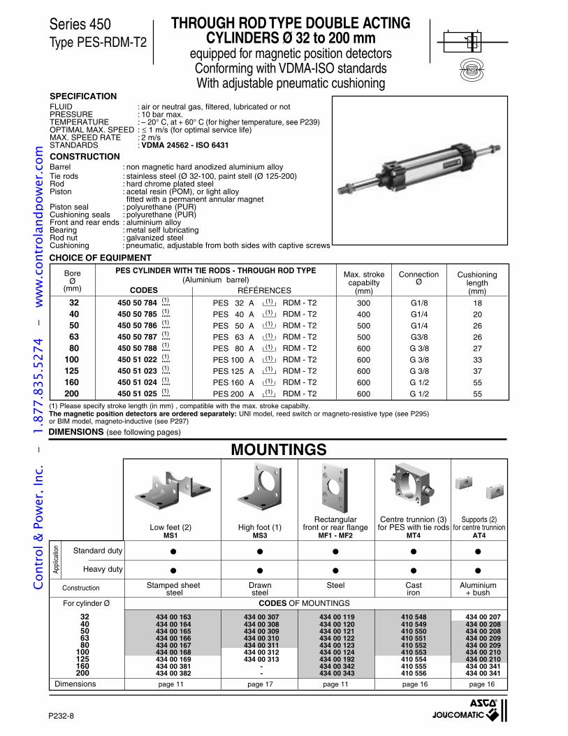
P232-8
Series 450
SPECIFICATIONFLUID : air or neutral gas, filtered, lubricated or notPRESSURE : 10 bar max.TEMPERATURE : – 20° C, at + 60° C (for higher temperature, see P239)OPTIMAL MAX. SPEED : ≤ 1 m/s (for optimal service life)MAX. SPEED RATE : 2 m/sSTANDARDS : VDMA 24562 - ISO 6431
CONSTRUCTIONBarrel : non magnetic hard anodized aluminium alloyTie rods : stainless steel (Ø 32-100, paint stell (Ø 125-200)Rod : hard chrome plated steelPiston : acetal resin (POM), or light alloy
fitted with a permanent annular magnetPiston seal : polyurethane (PUR)Cushioning seals : polyurethane (PUR)Front and rear ends : aluminium alloyBearing : metal self lubricatingRod nut : galvanized steelCushioning : pneumatic, adjustable from both sides with captive screws
MOUNTINGS
Appl
icat
ion
For cylinder Ø CODES OF MOUNTINGS
Standard duty
Heavy duty
Construction
Dimensions page 11 page 17 page 11 page 16 page 16
32 434 00 163 434 00 307 434 00 119 410 548 434 00 20740 434 00 164 434 00 308 434 00 120 410 549 434 00 20850 434 00 165 434 00 309 434 00 121 410 550 434 00 20863 434 00 166 434 00 310 434 00 122 410 551 434 00 20980 434 00 167 434 00 311 434 00 123 410 552 434 00 209
100 434 00 168 434 00 312 434 00 124 410 553 434 00 210125 434 00 169 434 00 313 434 00 192 410 554 434 00 210160 434 00 381 - 434 00 342 410 555 434 00 341200 434 00 382 - 434 00 343 410 556 434 00 341
Rectangular Centre trunnion (3) Supports (2)Low feet (2) High foot (1) front or rear flange for PES with tie rods for centre trunnion
MS1 MS3 MF1 - MF2 MT4 AT4
Stamped sheet Drawn Steel Cast Aluminium steel steel iron + bush
CODES
BoreØ
(mm)
PES CYLINDER WITH TIE RODS - THROUGH ROD TYPE(Aluminium barrel)
3240506380
100125160200
450 50 784 ....450 50 785 ....450 50 786 ....450 50 787 ....450 50 788 ....450 51 022 ....450 51 023 ....450 51 024 ....450 51 025 ....
(1)
(1)
(1)
(1)
(1)
(1)
(1)
(1)
(1)
RÉFÉRENCES
Cushioninglength(mm)
300400500
500600600600
600600
Max. strokecapabilty
(mm)
PES 32 APES 40 A
PES 50 APES 63 APES 80 A
PES 100 APES 125 APES 160 A
PES 200 A
RDM - T2RDM - T2
RDM - T2RDM - T2RDM - T2
RDM - T2RDM - T2RDM - T2
RDM - T2
(1)
(1)
(1)
(1)
(1)
(1)
(1)
(1)
(1)
ConnectionØ
G1/8G1/4
G1/4G3/8G 3/8
G 3/8G 3/8G 1/2
G 1/2
182026
26273337
5555
DIMENSIONS (see following pages)
(1) Please specify stroke length (in mm) , compatible with the max. stroke capabilty.The magnetic position detectors are ordered separately: UNI model, reed switch or magneto-resistive type (see P295)or BIM model, magneto-inductive (see P297)
CHOICE OF EQUIPMENT
Series 450Type PES-RDM-T2
THROUGH ROD TYPE DOUBLE ACTINGCYLINDERS Ø 32 to 200 mm
equipped for magnetic position detectorsConforming with VDMA-ISO standardsWith adjustable pneumatic cushioning
NS
Cont
rol &
Pow
er, I
nc.
-
1.87
7.83
5.52
74
- w
ww
.con
trol
andp
ower
.com
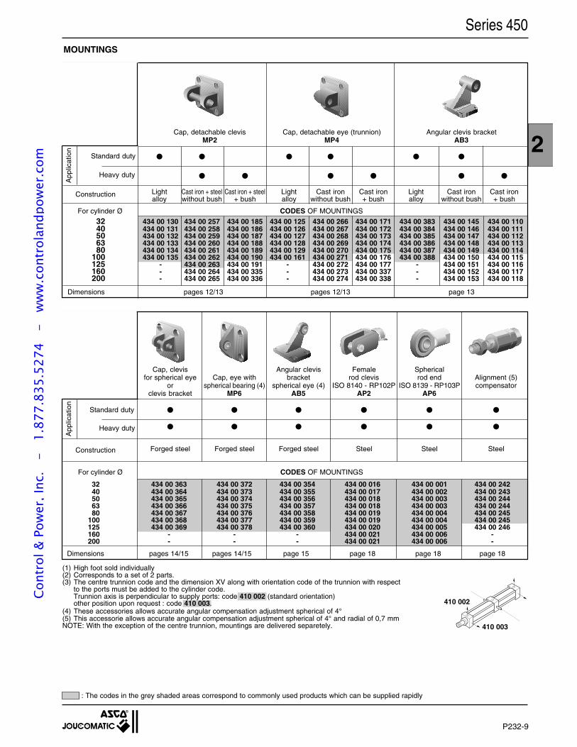
P232-9
2
Series 450MOUNTINGS
32 434 00 130 434 00 257 434 00 185 434 00 125 434 00 266 434 00 171 434 00 383 434 00 145 434 00 11040 434 00 131 434 00 258 434 00 186 434 00 126 434 00 267 434 00 172 434 00 384 434 00 146 434 00 11150 434 00 132 434 00 259 434 00 187 434 00 127 434 00 268 434 00 173 434 00 385 434 00 147 434 00 11263 434 00 133 434 00 260 434 00 188 434 00 128 434 00 269 434 00 174 434 00 386 434 00 148 434 00 11380 434 00 134 434 00 261 434 00 189 434 00 129 434 00 270 434 00 175 434 00 387 434 00 149 434 00 114
100 434 00 135 434 00 262 434 00 190 434 00 161 434 00 271 434 00 176 434 00 388 434 00 150 434 00 115125 - 434 00 263 434 00 191 - 434 00 272 434 00 177 - 434 00 151 434 00 116160 - 434 00 264 434 00 335 - 434 00 273 434 00 337 - 434 00 152 434 00 117200 - 434 00 265 434 00 336 - 434 00 274 434 00 338 - 434 00 153 434 00 118
App
licat
ion
Standard duty
Construction
Dimensions pages 12/13 pages 12/13 page 13
Cap, detachable clevis Cap, detachable eye (trunnion) Angular clevis bracketMP2 MP4 AB3
Light Cast iron + steel Cast iron + steel Light Cast iron Cast iron Light Cast iron Cast ironalloy without bush + bush alloy without bush + bush alloy without bush + bush
For cylinder Ø CODES OF MOUNTINGS
32 434 00 363 434 00 372 434 00 354 434 00 016 434 00 001 434 00 24240 434 00 364 434 00 373 434 00 355 434 00 017 434 00 002 434 00 24350 434 00 365 434 00 374 434 00 356 434 00 018 434 00 003 434 00 24463 434 00 366 434 00 375 434 00 357 434 00 018 434 00 003 434 00 24480 434 00 367 434 00 376 434 00 358 434 00 019 434 00 004 434 00 245
100 434 00 368 434 00 377 434 00 359 434 00 019 434 00 004 434 00 245125 434 00 369 434 00 378 434 00 360 434 00 020 434 00 005 434 00 246160 - - - 434 00 021 434 00 006 -200 - - - 434 00 021 434 00 006 -
App
licat
ion
Dimensions pages 14/15 pages 14/15 page 15 page 18 page 18 page 18
Construction
410 003
410 002
For cylinder Ø CODES OF MOUNTINGS
Cap, clevis Angular clevis Female Sphericalfor spherical eye Cap, eye with bracket rod clevis rod end Alignment (5)
or spherical bearing (4) spherical eye (4) ISO 8140 - RP102P ISO 8139 - RP103P compensatorclevis bracket MP6 AB5 AP2 AP6
Forged steel Forged steel Forged steel Steel Steel Steel
(1) High foot sold individually(2) Corresponds to a set of 2 parts.(3) The centre trunnion code and the dimension XV along with orientation code of the trunnion with respect
to the ports must be added to the cylinder code.Trunnion axis is perpendicular to supply ports: code 410 002 (standard orientation)other position upon request : code 410 003.
(4) These accessories allows accurate angular compensation adjustment spherical of 4°(5) This accessorie allows accurate angular compensation adjustment spherical of 4° and radial of 0,7 mmNOTE: With the exception of the centre trunnion, mountings are delivered separetely.
Heavy duty
Standard duty
Heavy duty
: The codes in the grey shaded areas correspond to commonly used products which can be supplied rapidly
Cont
rol &
Pow
er, I
nc.
-
1.87
7.83
5.52
74
- w
ww
.con
trol
andp
ower
.com
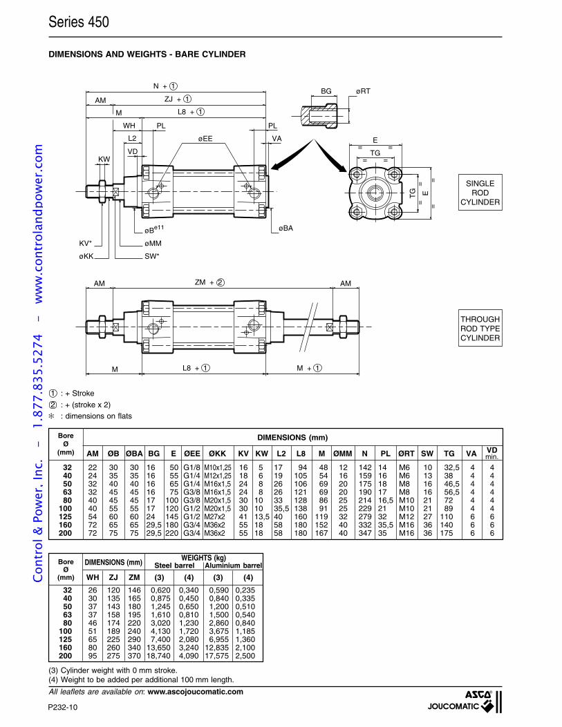
P232-10
Series 450
All leaflets are available on: www.ascojoucomatic.com
DIMENSIONS AND WEIGHTS - BARE CYLINDER
ZM + 2AM AM
M L8 + 1 M + 1
øBA
VA
PL
øEE
PL
L2
VDKW
WH
M
AM
L8 + 1
ZJ + 1
N + 1
øBe11
øMMKV*
SW*øKK
=
=
=
=
==
==
E
TG
TG E
BG øRT
(3) Cylinder weight with 0 mm stroke.(4) Weight to be added per additional 100 mm length.
THROUGHROD TYPECYLINDER
SINGLEROD
CYLINDER
1 : + Stroke
2 : + (stroke x 2)
: dimensions on flats
DIMENSIONS (mm)BoreØ
(mm) AM ØB ØBA BG E ØEE ØKK KV KW L2 L8 M ØMM N PL ØRT SW TG VA
32 22 30 30 16 50 G1/8 M10x1,25 16 5 17 94 48 12 142 14 M6 10 32,5 4 440 24 35 35 16 55 G1/4 M12x1,25 18 6 19 105 54 16 159 16 M6 13 38 4 450 32 40 40 16 65 G1/4 M16x1,5 24 8 26 106 69 20 175 18 M8 16 46,5 4 463 32 45 45 16 75 G3/8 M16x1,5 24 8 26 121 69 20 190 17 M8 16 56,5 4 480 40 45 45 17 100 G3/8 M20x1,5 30 10 33 128 86 25 214 16,5 M10 21 72 4 4
100 40 55 55 17 120 G1/2 M20x1,5 30 10 35,5 138 91 25 229 21 M10 21 89 4 4125 54 60 60 24 145 G1/2 M27x2 41 13,5 40 160 119 32 279 32 M12 27 110 6 6160 72 65 65 29,5 180 G3/4 M36x2 55 18 58 180 152 40 332 35,5 M16 36 140 6 6200 72 75 75 29,5 220 G3/4 M36x2 55 18 58 180 167 40 347 35 M16 36 175 6 6
32 26 120 146 0,620 0,340 0,590 0,23540 30 135 165 0,875 0,450 0,840 0,33550 37 143 180 1,245 0,650 1,200 0,51063 37 158 195 1,610 0,810 1,500 0,54080 46 174 220 3,020 1,230 2,860 0,840
100 51 189 240 4,130 1,720 3,675 1,185125 65 225 290 7,400 2,080 6,955 1,360160 80 260 340 13,650 3,240 12,835 2,100200 95 275 370 18,740 4,090 17,575 2,500
BoreØ
(mm)
DIMENSIONS (mm) WEIGHTS (kg)
WH ZJ ZM (3) (4) (3) (4)
Steel barrel Aluminium barrel
VDmin.
Cont
rol &
Pow
er, I
nc.
-
1.87
7.83
5.52
74
- w
ww
.con
trol
andp
ower
.com
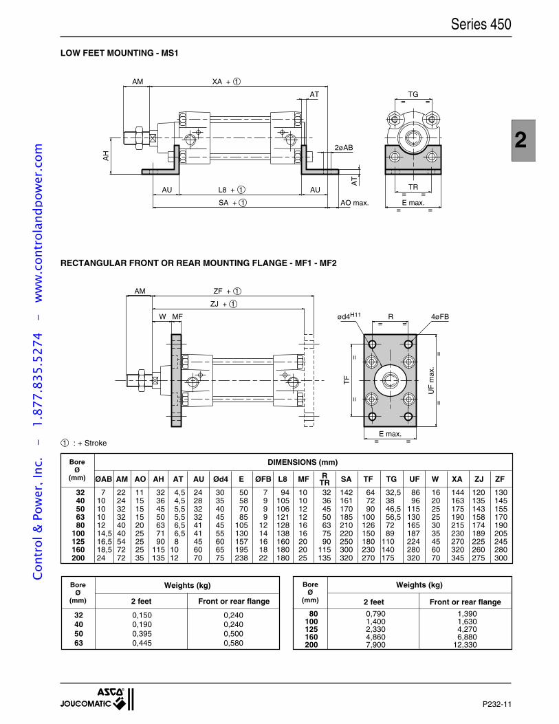
P232-11
2
Series 450
1 : + Stroke
32 7 22 11 32 4,5 24 30 50 7 94 10 32 142 64 32,5 86 16 144 120 13040 10 24 15 36 4,5 28 35 58 9 105 10 36 161 72 38 96 20 163 135 14550 10 32 15 45 5,5 32 40 70 9 106 12 45 170 90 46,5 115 25 175 143 15563 10 32 15 50 5,5 32 45 85 9 121 12 50 185 100 56,5 130 25 190 158 17080 12 40 20 63 6,5 41 45 105 12 128 16 63 210 126 72 165 30 215 174 190
100 14,5 40 25 71 6,5 41 55 130 14 138 16 75 220 150 89 187 35 230 189 205125 16,5 54 25 90 8 45 60 157 16 160 20 90 250 180 110 224 45 270 225 245160 18,5 72 25 115 10 60 65 195 18 180 20 115 300 230 140 280 60 320 260 280200 24 72 35 135 12 70 75 238 22 180 25 135 320 270 175 320 70 345 275 300
BoreØ
(mm) ØAB AM AO AH AT AU Ød4 E ØFB L8 MF SA TF TG UF W XA ZJ ZFRTR
DIMENSIONS (mm)
BoreØ
(mm)
Weights (kg) Weights (kg)BoreØ
(mm)
LOW FEET MOUNTING - MS1
AH
TR= =E max.
=
TG=
=
=
AM XA + 1
AU L8 + 1
SA + 1
AU
AT
2øAB
AT
AO max.
RECTANGULAR FRONT OR REAR MOUNTING FLANGE - MF1 - MF2
= =
ZJ + 1
ZF + 1AM
MFW ød4H11 R 4øFB
E max.U
F m
ax.
TF
==
==
= =
2 feet Front or rear flange 2 feet Front or rear flange
80 0,790 1,390100 1,400 1,630125 2,330 4,270160 4,860 6,880200 7,900 12,330
32 0,150 0,24040 0,190 0,24050 0,395 0,50063 0,445 0,580
Cont
rol &
Pow
er, I
nc.
-
1.87
7.83
5.52
74
- w
ww
.con
trol
andp
ower
.com
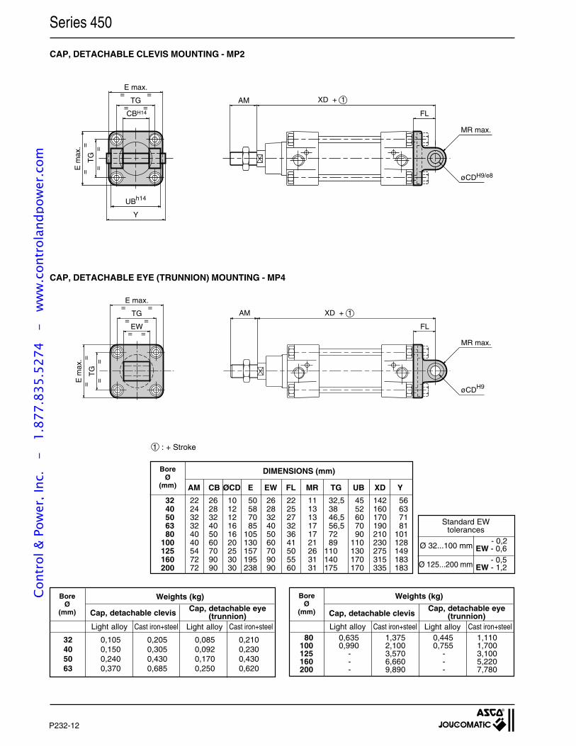
P232-12
Series 450
CAP, DETACHABLE CLEVIS MOUNTING - MP2
CAP, DETACHABLE EYE (TRUNNION) MOUNTING - MP4
BoreØ
(mm) AM CB ØCD E EW FL MR TG UB XD Y
32 22 26 10 50 26 22 11 32,5 45 142 5640 24 28 12 58 28 25 13 38 52 160 6350 32 32 12 70 32 27 13 46,5 60 170 7163 32 40 16 85 40 32 17 56,5 70 190 8180 40 50 16 105 50 36 17 72 90 210 101
100 40 60 20 130 60 41 21 89 110 230 128125 54 70 25 157 70 50 26 110 130 275 149160 72 90 30 195 90 55 31 140 170 315 183200 72 90 30 238 90 60 31 175 170 335 183
DIMENSIONS (mm)
Ø 32...100 mm EW - 0,6
EW - 1,2- 0,5
Ø 125...200 mm
Standard EWtolerances
- 0,2
Cap, detachable clevis
Weights (kg)BoreØ
(mm)
BoreØ
(mm)
Weights (kg)
Cap, detachable clevis
1 : + Stroke
UBh14
CBH14
Y
E m
ax.
==
TG
==
=
==
=TG
E max.
AM XD + 1
FL
øCDH9/e8
MR max.
AM XD + 1
FL
øCDH9
MR max.
E max.
TG=
= =
=
==
TG
==E
max
.
EW= =
80 0,635 1,375 0,445 1,110100 0,990 2,100 0,755 1,700125 - 3,570 - 3,100160 - 6,660 - 5,220200 - 9,890 - 7,780
32 0,105 0,205 0,085 0,21040 0,150 0,305 0,092 0,23050 0,240 0,430 0,170 0,43063 0,370 0,685 0,250 0,620
Light alloy Light alloyCast iron+steel Cast iron+steel Light alloy Light alloyCast iron+steel Cast iron+steel
Cap, detachable eye(trunnion)
Cap, detachable eye(trunnion)
Cont
rol &
Pow
er, I
nc.
-
1.87
7.83
5.52
74
- w
ww
.con
trol
andp
ower
.com
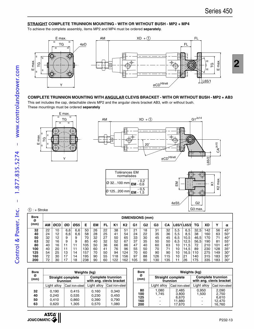
P232-13
2
Series 450
1 : + Stroke
Weights (kg)BoreØ
(mm)
BoreØ
(mm)
Weights (kg)Straight complete
trunnion
32 0,190 0,415 0,160 0,34040 0,240 0,535 0,230 0,45050 0,410 0,860 0,390 0,79063 0,620 1,305 0,570 1,080
80 1,080 2,485 0,950 2,090100 1,745 3,800 1,500 2,750125 - 6,670 - 6,610160 - 11,880 - 12,470200 - 17,670 - 16,760
Light alloy Cast iron+steel Light alloy Cast iron+steel Light alloy Light alloyCast iron+steel Cast iron+steel
STRAIGHT COMPLETE TRUNNION MOUNTING - WITH OR WITHOUT BUSH - MP2 + MP4To achieve the complete assembly, items MP2 and MP4 must be ordered separately.
32 22 10 6,6 6,6 50 26 22 38 51 21 18 31 32 5,5 6,5 32,5 142 56 45°40 24 12 6,6 6,6 58 28 25 41 54 24 22 35 36 5,5 8,5 38 160 63 50°50 32 12 9 9 70 32 27 50 65 33 30 45 45 6,5 10,5 46,5 170 71 40°63 32 16 9 9 85 40 32 52 67 37 35 50 50 6,5 12,5 56,5 190 81 55°80 40 16 11 11 105 50 36 66 86 47 40 60 63 10 11,5 72 210 101 45°
100 40 20 11 11 130 60 41 76 96 55 50 70 71 10 14,5 89 230 128 35°125 54 25 13 14 157 70 50 94 124 70 60 90 90 10 16,5 110 275 149 30°160 72 30 17 14 195 90 55 118 156 97 88 126 115 10 21 140 315 183 30°200 72 30 17 18 238 90 60 122 162 105 90 130 135 11 26 175 335 183 30°
BoreØ
(mm)
DIMENSIONS (mm)
AM ØCD ØD ØS5 E EM FL K1 K2 G1 G2 G3 CA L65/1 L65/2 TG XD Y ααααα
Complete trunnionwith ang. clevis bracket
Straight completetrunnion
Complete trunnionwith ang. clevis bracket
Ø 32...100 mm EM - 0,6
EM - 1,5- 0,5
Ø 125...200 mm
Tolérances EMnormalisées
- 0,2
Y
E m
ax.
==
TG
==
=
==
=TG
E max.
AM XD + 1 G1Js14
20˚
øCDH9/e8
CA
Js15
K1
K2
max
.
G2
G3 max.
4øS5
EM
L65/
2
COMPLETE TRUNNION MOUNTING WITH ANGULAR CLEVIS BRACKET - WITH OR WITHOUT BUSH - MP2 + AB3This set includes the cap, detachable clevis MP2 and the angular clevis bracket AB3, with or without bush.These mountings must be ordered separately
E max.
TG=
= =
=
= ===
TG
E m
ax.
Y
4øD
AM XD + 1 FL
FL
øCDH9/e8
TG
E m
ax.α
α
L65/1
Cont
rol &
Pow
er, I
nc.
-
1.87
7.83
5.52
74
- w
ww
.con
trol
andp
ower
.com
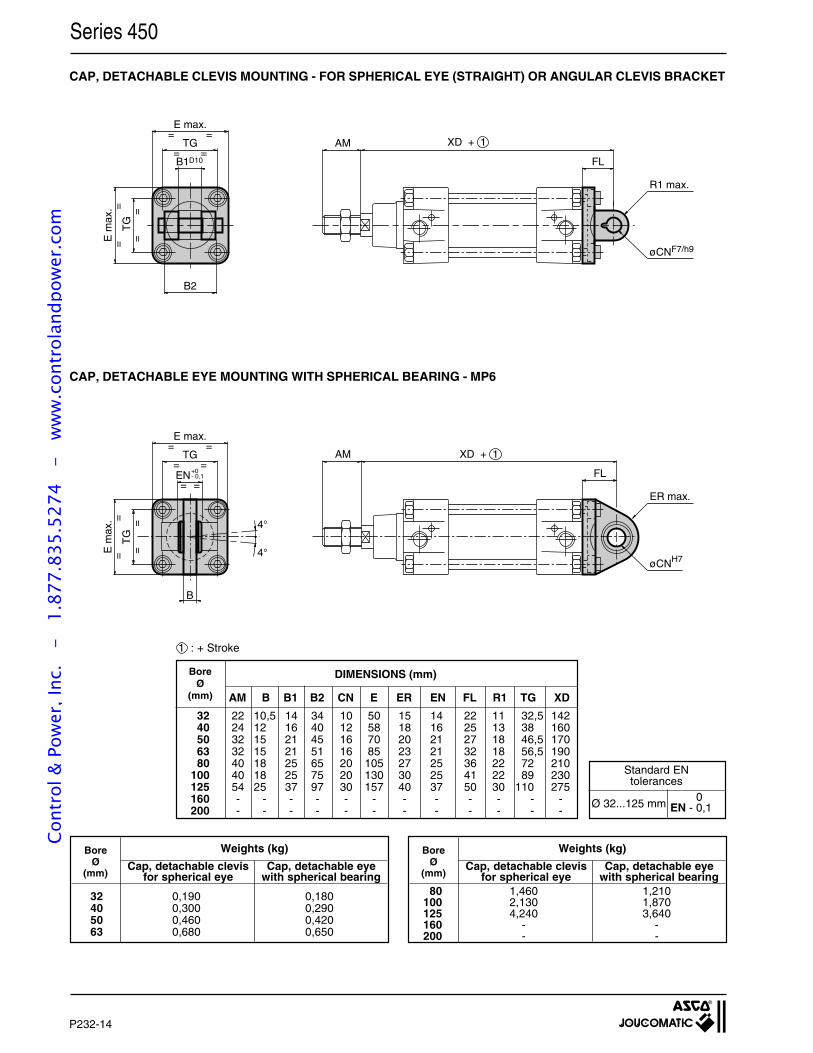
P232-14
Series 450
CAP, DETACHABLE EYE MOUNTING WITH SPHERICAL BEARING - MP6
CAP, DETACHABLE CLEVIS MOUNTING - FOR SPHERICAL EYE (STRAIGHT) OR ANGULAR CLEVIS BRACKET
BoreØ
(mm) AM B B1 B2 CN E ER EN FL R1 TG XD
32 22 10,5 14 34 10 50 15 14 22 11 32,5 14240 24 12 16 40 12 58 18 16 25 13 38 16050 32 15 21 45 16 70 20 21 27 18 46,5 17063 32 15 21 51 16 85 23 21 32 18 56,5 19080 40 18 25 65 20 105 27 25 36 22 72 210
100 40 18 25 75 20 130 30 25 41 22 89 230125 54 25 37 97 30 157 40 37 50 30 110 275160 - - - - - - - - - - - -200 - - - - - - - - - - - -
DIMENSIONS (mm)
1 : + Stroke
B2
B1D10
E m
ax.
==
TG
==
=
==
=TG
E max.
AM XD + 1
FL
øCNF7/h9
R1 max.
Ø 32...125 mm EN - 0,1
Standard ENtolerances
0
AM XD + 1
FL
øCNH7
ER max.
E max.
TG
4°
4°
=
= =
=
==
TG
==E
max
.
EN= =
+0- 0,1
B
Weights (kg)BoreØ
(mm)
32 0,190 0,18040 0,300 0,29050 0,460 0,42063 0,680 0,650
Weights (kg)BoreØ
(mm)
80 1,460 1,210100 2,130 1,870125 4,240 3,640160 - -200 - -
Cap, detachable clevis Cap, detachable eyefor spherical eye with spherical bearing
Cap, detachable clevis Cap, detachable eyefor spherical eye with spherical bearing
Cont
rol &
Pow
er, I
nc.
-
1.87
7.83
5.52
74
- w
ww
.con
trol
andp
ower
.com
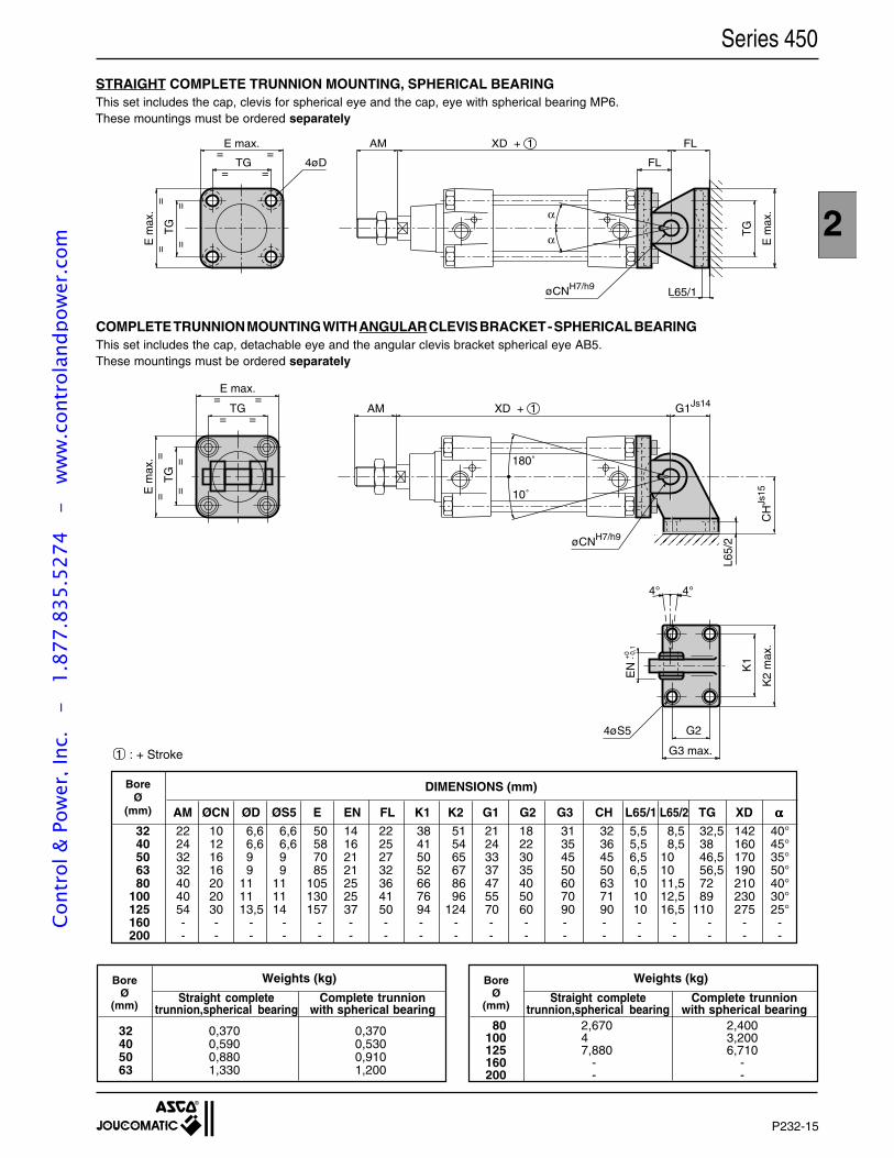
P232-15
2
Series 450
STRAIGHT COMPLETE TRUNNION MOUNTING, SPHERICAL BEARINGThis set includes the cap, clevis for spherical eye and the cap, eye with spherical bearing MP6.These mountings must be ordered separately
E max.
TG=
= =
== =
==T
G
E m
ax.
4øD
AM XD + 1 FL
FL
øCNH7/h9
TG
E m
ax.
L65/1
α
α
COMPLETE TRUNNION MOUNTING WITH ANGULAR CLEVIS BRACKET - SPHERICAL BEARINGThis set includes the cap, detachable eye and the angular clevis bracket spherical eye AB5.These mountings must be ordered separately
1 : + Stroke
32 22 10 6,6 6,6 50 14 22 38 51 21 18 31 32 5,5 8,5 32,5 142 40°40 24 12 6,6 6,6 58 16 25 41 54 24 22 35 36 5,5 8,5 38 160 45°50 32 16 9 9 70 21 27 50 65 33 30 45 45 6,5 10 46,5 170 35°63 32 16 9 9 85 21 32 52 67 37 35 50 50 6,5 10 56,5 190 50°80 40 20 11 11 105 25 36 66 86 47 40 60 63 10 11,5 72 210 40°
100 40 20 11 11 130 25 41 76 96 55 50 70 71 10 12,5 89 230 30°125 54 30 13,5 14 157 37 50 94 124 70 60 90 90 10 16,5 110 275 25°160 - - - - - - - - - - - - - - - - - -200 - - - - - - - - - - - - - - - - - -
BoreØ
(mm)
DIMENSIONS (mm)
AM ØCN ØD ØS5 E EN FL K1 K2 G1 G2 G3 CH L65/1 L65/2 TG XD ααααα
AM XD + 1 G1Js14
10˚
øCNH7/h9
CH
Js15
K1
K2
max
.
G2
G3 max.
4øS5
E m
ax.
==
TG
==
=
==
=TG
E max.
EN
4° 4°
180˚
+0 - 0,
1
L65/
2
Weights (kg)BoreØ
(mm)
32 0,370 0,37040 0,590 0,53050 0,880 0,91063 1,330 1,200
Weights (kg)BoreØ
(mm)
80 2,670 2,400100 4 3,200125 7,880 6,710160 - -200 - -
Straight complete Complete trunniontrunnion,spherical bearing with spherical bearing
Straight complete Complete trunniontrunnion,spherical bearing with spherical bearing
Cont
rol &
Pow
er, I
nc.
-
1.87
7.83
5.52
74
- w
ww
.con
trol
andp
ower
.com
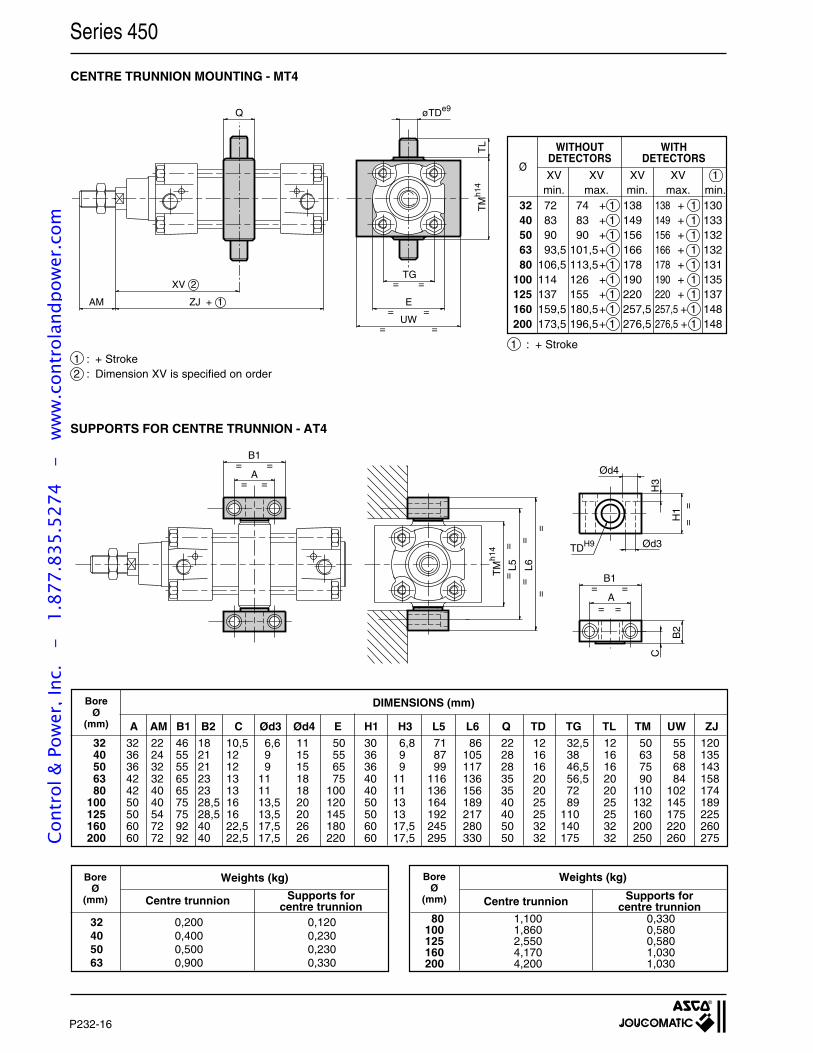
P232-16
Series 450
B1
= =A
TM
h14
L5 L6
A==
B1
B2
H1
H3
Ød4
Ød3TDH9
C
==
= =
==
==
= =
= =
A AM B1 B2 C Ød3 Ød4 E H1 H3 L5 L6 Q TD TG TL TM UW ZJ
BoreØ
(mm)
32 32 22 46 18 10,5 6,6 11 50 30 6,8 71 86 22 12 32,5 12 50 55 12040 36 24 55 21 12 9 15 55 36 9 87 105 28 16 38 16 63 58 13550 36 32 55 21 12 9 15 65 36 9 99 117 28 16 46,5 16 75 68 14363 42 32 65 23 13 11 18 75 40 11 116 136 35 20 56,5 20 90 84 15880 42 40 65 23 13 11 18 100 40 11 136 156 35 20 72 20 110 102 174
100 50 40 75 28,5 16 13,5 20 120 50 13 164 189 40 25 89 25 132 145 189125 50 54 75 28,5 16 13,5 20 145 50 13 192 217 40 25 110 25 160 175 225160 60 72 92 40 22,5 17,5 26 180 60 17,5 245 280 50 32 140 32 200 220 260200 60 72 92 40 22,5 17,5 26 220 60 17,5 295 330 50 32 175 32 250 260 275
DIMENSIONS (mm)
BoreØ
(mm)
Weights (kg)
32 0,200 0,12040 0,400 0,23050 0,500 0,23063 0,900 0,330
Centre trunnion
Weights (kg)BoreØ
(mm)
80 1,100 0,330100 1,860 0,580125 2,550 0,580160 4,170 1,030200 4,200 1,030
1 : + Stroke
CENTRE TRUNNION MOUNTING - MT4
SUPPORTS FOR CENTRE TRUNNION - AT4
1 : + Stroke 2 : Dimension XV is specified on order
Supports forcentre trunnion Centre trunnion Supports for
centre trunnion
Q
ZJ + 1
XV 2
AM
øTDe9
E
UW=
=
=
=
TM
h14
TL
==TG
32 72 74 + 1 138 138 + 1 13040 83 83 + 1 149 149 + 1 13350 90 90 + 1 156 156 + 1 13263 93,5 101,5+ 1 166 166 + 1 13280 106,5 113,5+ 1 178 178 + 1 131
100 114 126 + 1 190 190 + 1 135125 137 155 + 1 220 220 + 1 137160 159,5 180,5+ 1 257,5 257,5 + 1 148200 173,5 196,5+ 1 276,5 276,5 + 1 148
ØXV XV XV XV 1
min. max. min. max. min.
WITHOUTDETECTORS
WITHDETECTORS
Cont
rol &
Pow
er, I
nc.
-
1.87
7.83
5.52
74
- w
ww
.con
trol
andp
ower
.com
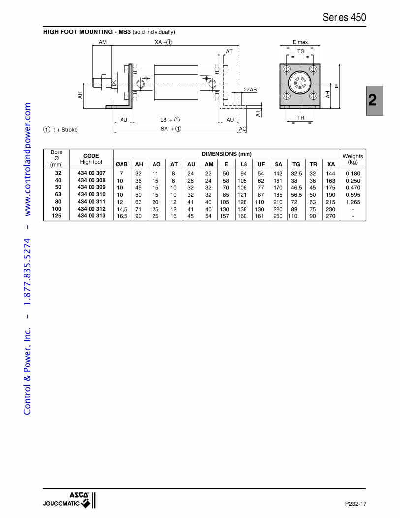
P232-17
2
Series 450HIGH FOOT MOUNTING - MS3 (sold individually)
TR= =
E max.=
TG=
=
=
AM XA + 1
AU L8 + 1
SA + 1
AU
AT
2øAB
AT
AH
AO
AH
UF
DIMENSIONS (mm)
ØAB AH AO AT AU AM E L8 UF SA TG TR XA
32 434 00 30740 434 00 30850 434 00 30963 434 00 31080 434 00 311
100 434 00 312125 434 00 313
BoreØ
(mm)
7 32 11 8 24 22 50 94 54 142 32,5 32 144 0,18010 36 15 8 28 24 58 105 62 161 38 36 163 0,25010 45 15 10 32 32 70 106 77 170 46,5 45 175 0,47010 50 15 10 32 32 85 121 87 185 56,5 50 190 0,59512 63 20 12 41 40 105 128 110 210 72 63 215 1,26514,5 71 25 12 41 40 130 138 130 220 89 75 230 -16,5 90 25 16 45 54 157 160 161 250 110 90 270 -
CODEHigh foot
Weights(kg)
1 : + Stroke
Cont
rol &
Pow
er, I
nc.
-
1.87
7.83
5.52
74
- w
ww
.con
trol
andp
ower
.com
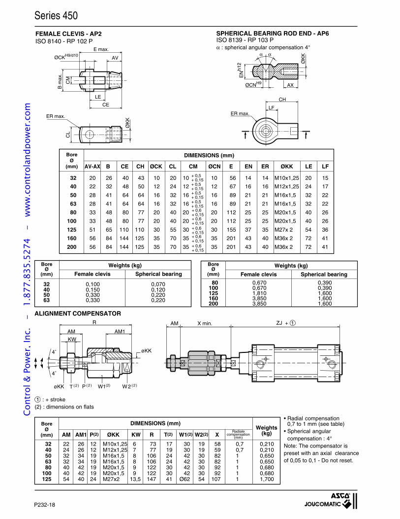
P232-18
Series 450
FEMALE CLEVIS - AP2ISO 8140 - RP 102 P
Radialecompensation
(mm)
BoreØ
(mm)
DIMENSIONS (mm)Weights
(kg)
1 : + stroke(2) : dimensions on flats
• Radial compensation0,7 to 1 mm (see table)
• Spherical angularcompensation : 4°
Note: The compensator ispreset with an axial clearanceof 0,05 to 0,1 - Do not reset.
AM AM1 P(2) ØKK KW R T(2) W1(2) W2(2) X
32 22 26 12 M10x1,25 6 73 17 30 19 58 0,7 0,21040 24 26 12 M12x1,25 7 77 19 30 19 59 0,7 0,21050 32 34 19 M16x1,5 8 106 24 42 30 82 1 0,65063 32 34 19 M16x1,5 8 106 24 42 30 82 1 0,65080 40 42 19 M20x1,5 9 122 30 42 30 92 1 0,680
100 40 42 19 M20x1,5 9 122 30 42 30 92 1 0,680125 54 40 24 M27x2 13,5 147 41 Ø62 54 107 1 1,700
ZJ + 1AM X min.
AM
KW
AM1
R
4˚
4˚
W2 ( 2 )W1(2)P ( 2 )T ( 2 )øKK
øKK
Female clevis Spherical bearing Female clevis Spherical bearing
80 0,670 0,390100 0,670 0,390125 1,810 1,600160 3,850 1,600200 3,850 1,600
32 0,100 0,07040 0,150 0,12050 0,330 0,22063 0,330 0,220
Weights (kg) Weights (kg)
+ 0,6+ 0,15
+ 0,6+ 0,15
+ 0,6+ 0,15
+ 0,5+ 0,15
+ 0,5+ 0,15
+ 0,5+ 0,15
+ 0,5+ 0,15
+ 0,6+ 0,15
+ 0,6+ 0,15
BoreØ
(mm)
BoreØ
(mm)
DIMENSIONS (mm)BoreØ
(mm) AV-AX B CE CH ØCK CL CM ØCN E EN ER ØKK LE LF
32 20 26 40 43 10 20 10 10 56 14 14 M10x1,25 20 15
40 22 32 48 50 12 24 12 12 67 16 16 M12x1,25 24 17
50 28 41 64 64 16 32 16 16 89 21 21 M16x1,5 32 22
63 28 41 64 64 16 32 16 16 89 21 21 M16x1,5 32 22
80 33 48 80 77 20 40 20 20 112 25 25 M20x1,5 40 26
100 33 48 80 77 20 40 20 20 112 25 25 M20x1,5 40 26
125 51 65 110 110 30 55 30 30 155 37 35 M27x 2 54 36
160 56 84 144 125 35 70 35 35 201 43 40 M36x 2 72 41
200 56 84 144 125 35 70 35 35 201 43 40 M36x 2 72 41
E max.
ØCKH9/d10AV
LE
CE
CM
B m
ax.
CL
ER max.
ØK
K
ØCNH9 AX
ØK
K
EN
h12
α α
CH
LFER max.
ALIGNMENT COMPENSATOR
SPHERICAL BEARING ROD END - AP6ISO 8139 - RP 103 Pα : spherical angular compensation 4°
Cont
rol &
Pow
er, I
nc.
-
1.87
7.83
5.52
74
- w
ww
.con
trol
andp
ower
.com
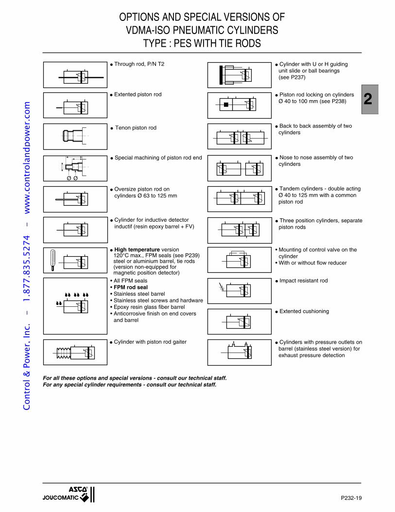
P232-19
2
Series 450OPTIONS AND SPECIAL VERSIONS OFVDMA-ISO PNEUMATIC CYLINDERS
TYPE : PES WITH TIE RODS
For all these options and special versions - consult our technical staff.For any special cylinder requirements - consult our technical staff.
Cylinders with pressure outlets onbarrel (stainless steel version) forexhaust pressure detection
Cylinder with U or H guidingunit slide or ball bearings(see P237)
Piston rod locking on cylindersØ 40 to 100 mm (see P238)
Back to back assembly of twocylinders
Nose to nose assembly of twocylinders
Tandem cylinders - double actingØ 40 to 125 mm with a commonpiston rod
Three position cylinders, separatepiston rods
Impact resistant rod
Extented cushioning
• Mounting of control valve on thecylinder
• With or without flow reducer
Ø Ø
Through rod, P/N T2
High temperature version120°C max., FPM seals (see P239)steel or aluminium barrel, tie rods(version non-equipped formagnetic position detector)
Extented piston rod
Tenon piston rod
Special machining of piston rod end
Oversize piston rod oncylinders Ø 63 to 125 mm
Cylinder with piston rod gaiter
• All FPM seals• FPM rod seal• Stainless steel barrel• Stainless steel screws and hardware• Epoxy resin glass fiber barrel• Anticorrosive finish on end covers
and barrel
Cylinder for inductive detectorinductif (resin epoxy barrel + FV)
Cont
rol &
Pow
er, I
nc.
-
1.87
7.83
5.52
74
- w
ww
.con
trol
andp
ower
.com
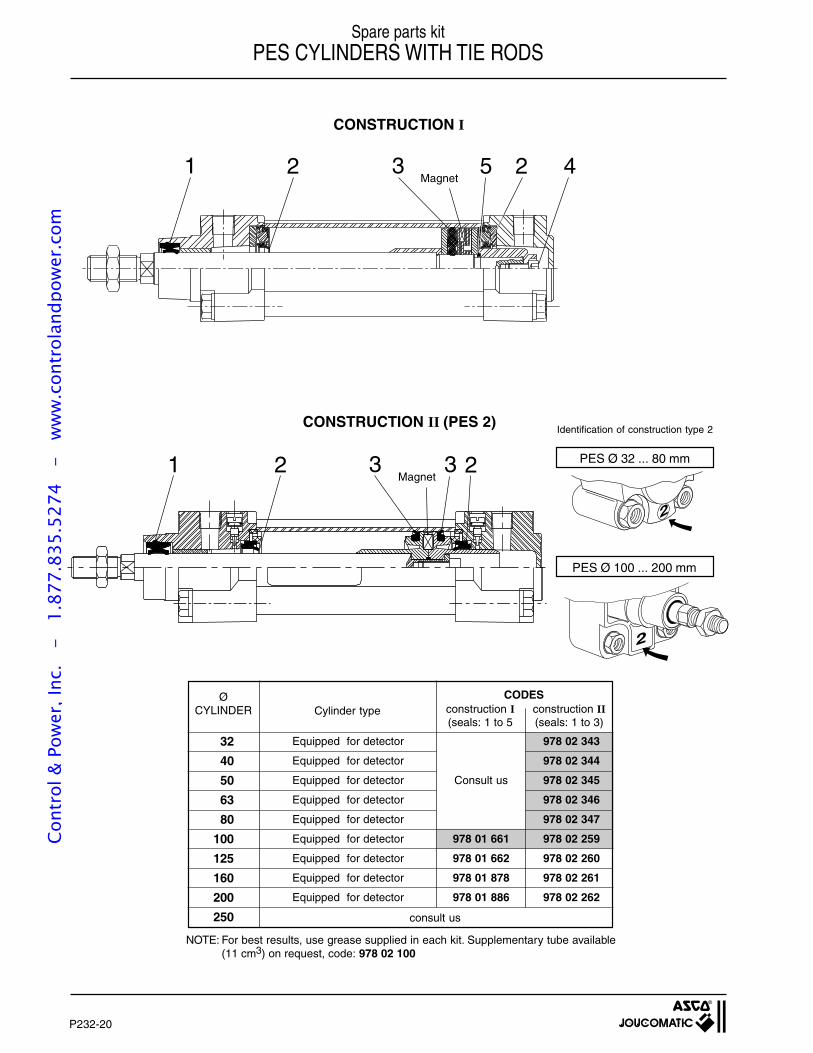
P232-20
Series 450 Spare parts kitPES CYLINDERS WITH TIE RODS
Magnet
Magnet
consult us
CODESconstruction I(seals: 1 to 5
construction II(seals: 1 to 3)
NOTE: For best results, use grease supplied in each kit. Supplementary tube available(11 cm3) on request, code: 978 02 100
Equipped for detector 978 02 343
Equipped for detector 978 02 344
Equipped for detector Consult us 978 02 345
Equipped for detector 978 02 346
Equipped for detector 978 02 347
Equipped for detector 978 01 661 978 02 259
Equipped for detector 978 01 662 978 02 260
Equipped for detector 978 01 878 978 02 261
Equipped for detector 978 01 886 978 02 262
32
40
50
63
80
100
125
160
200
250
ØCYLINDER Cylinder type
CONSTRUCTION I
1 2 3 3 2
42321 5
CONSTRUCTION II (PES 2)Identification of construction type 2
2
PES Ø 32 ... 80 mm
PES Ø 100 ... 200 mm
2
Cont
rol &
Pow
er, I
nc.
-
1.87
7.83
5.52
74
- w
ww
.con
trol
andp
ower
.com
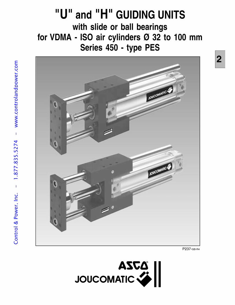
"U" and "H" GUIDING UNITSwith slide or ball bearings
for VDMA - ISO air cylinders Ø 32 to 100 mmSeries 450 - type PES
2
P237-GB-R4
Cont
rol &
Pow
er, I
nc.
-
1.87
7.83
5.52
74
- w
ww
.con
trol
andp
ower
.com
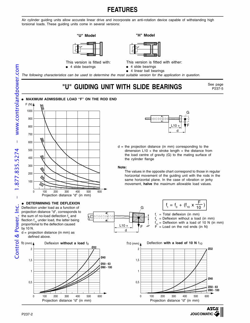
P237-2
FEATURESAir cylinder guiding units allow accurate linear drive and incorporate an anti-rotation device capable of withstanding hightorsional loads. These guiding units come in several versions:
MAXIMUM ADMISSIBLE LOAD “F” ON THE ROD END
"H" Model"U" Model
This version is fitted with: 4 slide bearings
This version is fitted with either: 4 slide bearings 4 linear ball bearings
"U" GUIDING UNIT WITH SLIDE BEARINGS See pageP237-5
The following characteristics can be used to determine the most suitable version for the application in question.
d = the projection distance (in mm) corresponding to thedimension L10 + the stroke length + the distance fromthe load centre of gravity (G) to the mating surface ofthe cylinder flange
Note:The values in the opposite chart correspond to those in regularhorizontal movement of the guiding unit with the rods in thesame horizontal plane. In the case of vibration or jerkymovement, halve the maximum allowable load values.
Projection distance “d” (in mm)
Ø32
Ø40
Ø50 - 63Ø80 - 100
0 100 200 300 400 500 6000
0,5
1
1,5
2
f0 (mm)
0 100 200 300 400 500 6000
0,5
1
1,5
2
f10 (mm)
Ø32
Ø40
Ø50 - 63Ø80 - 100
Projection distance “d” (in mm) Projection distance “d” (in mm)
ft = Total deflexion (in mm)f0 = Deflexion without a load (in mm)f10 = Deflexion with a load of 10 N (in mm)F = Load on the rod ends (in N)
Deflection under load as a function ofprojection distance "d", corresponds tothe sum of no-load deflection f
0 and
flection f10
under load, the latter beingproportional to the deflection causedby 10 N.d = projection distance (in mm) as
defined above.
DETERMINING THE DEFLEXION Fft = f
0 + (f
10 x )
10
Fd
L10 +
G
Ø32
Ø80Ø
100
0 100 200 300 400 500 600
100
300
500
700
900
200
400
600
800
1000
F (N)
Ø50
Ø40
Ø63
Deflection with a load of 10 N f10Deflexion without a load f0
Fd
L10 +
G
f t
Cont
rol &
Pow
er, I
nc.
-
1.87
7.83
5.52
74
- w
ww
.con
trol
andp
ower
.com
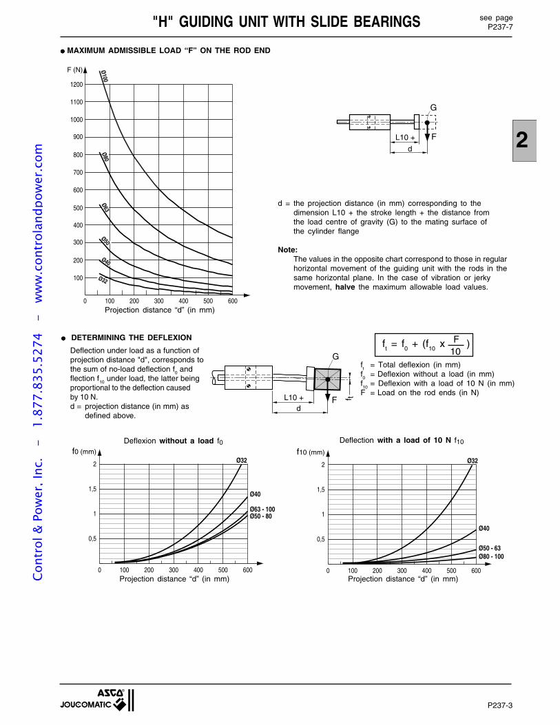
P237-3
2
"H" GUIDING UNIT WITH SLIDE BEARINGS see pageP237-7
Projection distance “d” (in mm)
MAXIMUM ADMISSIBLE LOAD “F” ON THE ROD END
0 100 200 300 400 500 600
100
200
300
400
500
600
700
800
900
1000
1100
1200
F (N) Ø100
Ø80Ø63
Ø50
Ø40
Ø32
10ft = f
0 + (f
10 x )F
Deflection with a load of 10 N f10Deflexion without a load f0
Projection distance “d” (in mm) Projection distance “d” (in mm)
Ø32
Ø40
Ø63 - 100Ø50 - 80
0 100 200 300 400 500 6000
0,5
1
1,5
2
f0 (mm)
0 100 200 300 400 500 6000
0,5
1
1,5
2
f10 (mm)Ø32
Ø40
Ø50 - 63Ø80 - 100
DETERMINING THE DEFLEXION
Fd
L10 +
G
Fd
L10 +
Gf t
d = the projection distance (in mm) corresponding to thedimension L10 + the stroke length + the distance fromthe load centre of gravity (G) to the mating surface ofthe cylinder flange
Note:The values in the opposite chart correspond to those in regularhorizontal movement of the guiding unit with the rods in thesame horizontal plane. In the case of vibration or jerkymovement, halve the maximum allowable load values.
ft
= Total deflexion (in mm)f0
= Deflexion without a load (in mm)f10
= Deflexion with a load of 10 N (in mm)F = Load on the rod ends (in N)
Deflection under load as a function ofprojection distance "d", corresponds tothe sum of no-load deflection f0 andflection f10 under load, the latter beingproportional to the deflection causedby 10 N.d = projection distance (in mm) as
defined above.
Cont
rol &
Pow
er, I
nc.
-
1.87
7.83
5.52
74
- w
ww
.con
trol
andp
ower
.com
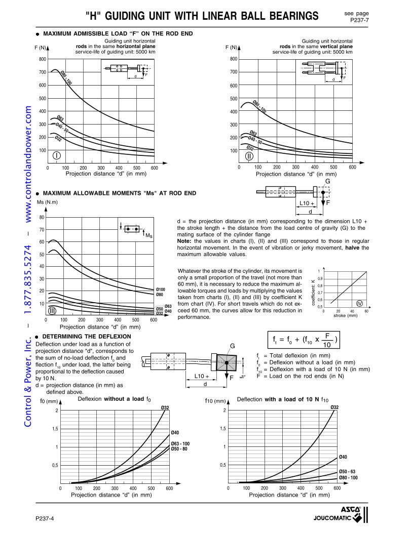
P237-4
"H" GUIDING UNIT WITH LINEAR BALL BEARINGS
Projection distance “d” (in mm) Projection distance “d” (in mm)
Projection distance “d” (in mm)
MAXIMUM ADMISSIBLE LOAD “F” ON THE ROD END
Ø32
Ø40
Ø63 - 100Ø50 - 80
0 100 200 300 400 500 6000
0,5
1
1,5
2
f0 (mm)
0 100 200 300 400 500 6000
0,5
1
1,5
2
f10 (mm)Ø32
Ø40
Ø50 - 63Ø80 - 100
10ft = f
0 + (f
10 x )F
MAXIMUM ALLOWABLE MOMENTS "Ms" AT ROD END
DETERMINING THE DEFLEXION
Deflexion without a load f0 Deflection with a load of 10 N f10
Projection distance “d” (in mm)
Projection distance “d” (in mm)
d = the projection distance (in mm) corresponding to the dimension L10 +the stroke length + the distance from the load centre of gravity (G) to themating surface of the cylinder flangeNote: the values in charts (I), (II) and (III) correspond to those in regularhorizontal movement. In the event of vibration or jerky movement, halve themaximum allowable values.
stroke (mm)0 100 200 300 400 500 600
0
10
20
30
40
50
60
70
80
Ms (N.m)
Ø32 Ø40Ø50
Ø80Ø100
Ø63
Ms
III
0 100 200 300 400 500 6000
100
200
300
400
500
600
700
800
F (N)
Ø32
Ø63
Ø80 - 100
Ø40 - 50
Fd
II
20 40 600,5
0,6
0,7
0,8
0,9
0
1
IV
see pageP237-7
Guiding unit horizontalrods in the same vertical plane
service-life of guiding unit: 5000 km
Fd
L10 +
G
0 100 200 300 400 500 600
100
300
500
700
200
400
600
800
F (N)
Ø32
Ø63Ø40 - 50
Ø80 - 100
Fd
I
Guiding unit horizontalrods in the same horizontal planeservice-life of guiding unit: 5000 km
ft
= Total deflexion (in mm)f0
= Deflexion without a load (in mm)f10
= Deflexion with a load of 10 N (in mm)F = Load on the rod ends (in N)
Whatever the stroke of the cylinder, its movement isonly a small proportion of the travel (not more than60 mm), it is necessary to reduce the maximum al-lowable torques and loads by multiplying the valuestaken from charts (I), (II) and (III) by coefficient Kfrom chart (IV). For short travels which do not ex-ceed 60 mm, the curves allow for this reduction inperformance.
coef
ficie
nt:
K
Deflection under load as a function ofprojection distance "d", corresponds tothe sum of no-load deflection f
0 and
flection f10
under load, the latter beingproportional to the deflection causedby 10 N.d = projection distance (in mm) as
defined above.
Fd
L10 +
G
f t
Cont
rol &
Pow
er, I
nc.
-
1.87
7.83
5.52
74
- w
ww
.con
trol
andp
ower
.com
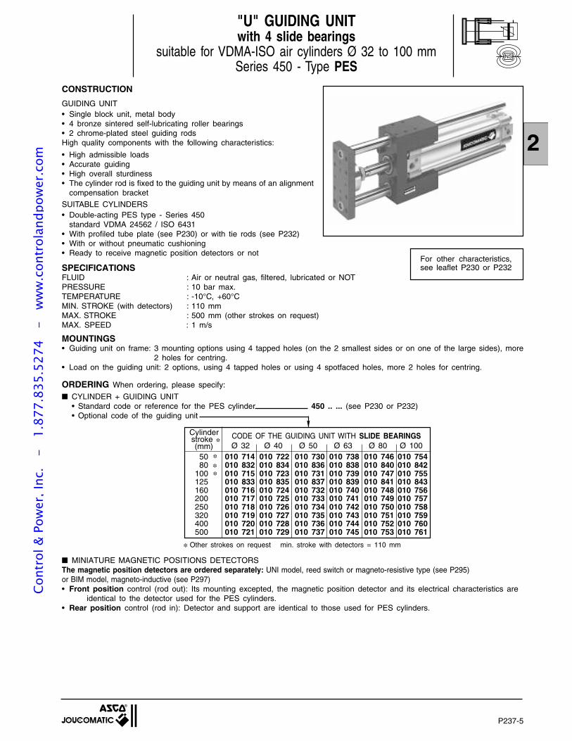
P237-5
2
"U" GUIDING UNITwith 4 slide bearings
suitable for VDMA-ISO air cylinders Ø 32 to 100 mmSeries 450 - Type PES
CONSTRUCTION
GUIDING UNIT• Single block unit, metal body• 4 bronze sintered self-lubricating roller bearings• 2 chrome-plated steel guiding rodsHigh quality components with the following characteristics:
• High admissible loads• Accurate guiding• High overall sturdiness• The cylinder rod is fixed to the guiding unit by means of an alignment
compensation bracket
SUITABLE CYLINDERS• Double-acting PES type - Series 450
standard VDMA 24562 / ISO 6431• With profiled tube plate (see P230) or with tie rods (see P232)• With or without pneumatic cushioning• Ready to receive magnetic position detectors or not
SPECIFICATIONSFLUID : Air or neutral gas, filtered, lubricated or NOTPRESSURE : 10 bar max.TEMPERATURE : -10°C, +60°CMIN. STROKE (with detectors) : 110 mmMAX. STROKE : 500 mm (other strokes on request)MAX. SPEED : 1 m/s
MOUNTINGS• Guiding unit on frame: 3 mounting options using 4 tapped holes (on the 2 smallest sides or on one of the large sides), more
2 holes for centring.• Load on the guiding unit: 2 options, using 4 tapped holes or using 4 spotfaced holes, more 2 holes for centring.
For other characteristics,see leaflet P230 or P232
ORDERING When ordering, please specify:
CYLINDER + GUIDING UNIT• Standard code or reference for the PES cylinder 450 .. ... (see P230 or P232)• Optional code of the guiding unit
MINIATURE MAGNETIC POSITIONS DETECTORSThe magnetic position detectors are ordered separately: UNI model, reed switch or magneto-resistive type (see P295)or BIM model, magneto-inductive (see P297)• Front position control (rod out): Its mounting excepted, the magnetic position detector and its electrical characteristics are
identical to the detector used for the PES cylinders.• Rear position control (rod in): Detector and support are identical to those used for PES cylinders.
Other strokes on request min. stroke with detectors = 110 mm
NS
50 010 714 010 722 010 730 010 738 010 746 010 75480 010 832 010 834 010 836 010 838 010 840 010 842
100 010 715 010 723 010 731 010 739 010 747 010 755125 010 833 010 835 010 837 010 839 010 841 010 843160 010 716 010 724 010 732 010 740 010 748 010 756200 010 717 010 725 010 733 010 741 010 749 010 757250 010 718 010 726 010 734 010 742 010 750 010 758320 010 719 010 727 010 735 010 743 010 751 010 759400 010 720 010 728 010 736 010 744 010 752 010 760500 010 721 010 729 010 737 010 745 010 753 010 761
Cylinder stroke
(mm)CODE OF THE GUIDING UNIT WITH SLIDE BEARINGSØ 32 Ø 40 Ø 50 Ø 63 Ø 80 Ø 100
Cont
rol &
Pow
er, I
nc.
-
1.87
7.83
5.52
74
- w
ww
.con
trol
andp
ower
.com
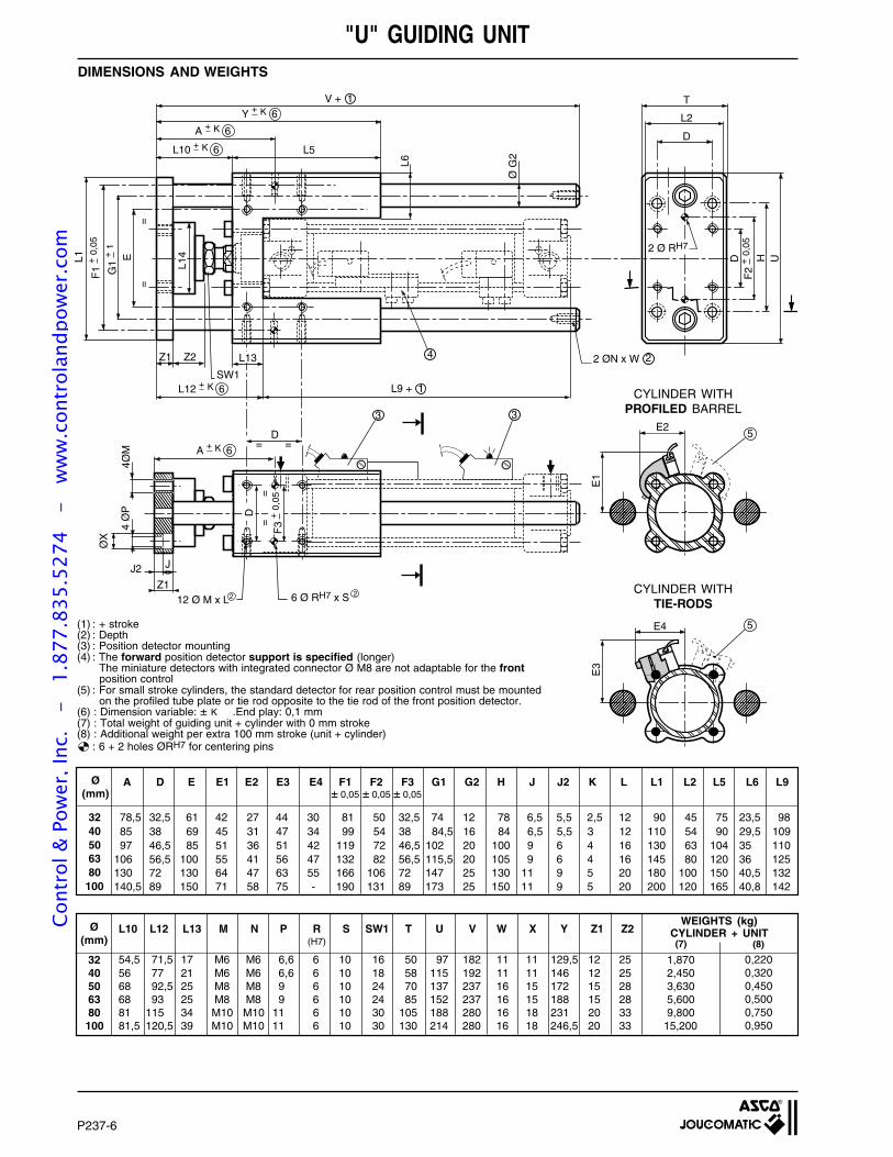
P237-6
D
4Ø
P
ØX
JJ2
V + 1
SW1
Z1
E D H U
Ø G
2
T
L2
D
L1
E3
E4
E1
E2
5
5
3
4 2 ØN x W 2
Z112 Ø M x L
= =
3
6 Ø RH7 x S 22
4ØM
2 Ø RH7
=
=
=
=
G1
+1
F1
+0,
05
F2
+0,
05
A + K 6
A + K 6
Y + K 6
L10 + K 6 L5
L6
Z2 L13
L12 + K 6 L9 + 1
L14
D
F3
+0,
05
DIMENSIONS AND WEIGHTS
"U" GUIDING UNIT
(1) : + stroke(2) : Depth(3) : Position detector mounting(4) : The forward position detector support is specified (longer)
The miniature detectors with integrated connector Ø M8 are not adaptable for the front position control
(5) : For small stroke cylinders, the standard detector for rear position control must be mounted on the profiled tube plate or tie rod opposite to the tie rod of the front position detector.
(6) : Dimension variable: ± K .End play: 0,1 mm(7) : Total weight of guiding unit + cylinder with 0 mm stroke(8) : Additional weight per extra 100 mm stroke (unit + cylinder)
: 6 + 2 holes ØRH7 for centering pins
CYLINDER WITHPROFILED BARREL
CYLINDER WITHTIE-RODS
3240506380
100
Ø(mm)
Ø(mm)
A D E E1 E2 E3 E4 F1 F2 F3 G1 G2 H J J2 K L L1 L2 L5 L6 L9± 0,05 ± 0,05 ± 0,05
L10 L12 L13 M N P R S SW1 T U V W X Y Z1 Z2(H7)
78,5 32,5 61 42 27 44 30 81 50 32,5 74 12 78 6,5 5,5 2,5 12 90 45 75 23,5 9885 38 69 45 31 47 34 99 54 38 84,5 16 84 6,5 5,5 3 12 110 54 90 29,5 10997 46,5 85 51 36 51 42 119 72 46,5 102 20 100 9 6 4 16 130 63 104 35 110
106 56,5 100 55 41 56 47 132 82 56,5 115,5 20 105 9 6 4 16 145 80 120 36 125130 72 130 64 47 63 55 166 106 72 147 25 130 11 9 5 20 180 100 150 40,5 132140,5 89 150 71 58 75 - 190 131 89 173 25 150 11 9 5 20 200 120 165 40,8 142
0,2200,3200,4500,5000,7500,950
1,8702,4503,6305,6009,800
15,200
(8)(7)
WEIGHTS (kg)CYLINDER + UNIT
54,5 71,5 17 M6 M6 6,6 6 10 16 50 97 182 11 11 129,5 12 2556 77 21 M6 M6 6,6 6 10 18 58 115 192 11 11 146 12 2568 92,5 25 M8 M8 9 6 10 24 70 137 237 16 15 172 15 2868 93 25 M8 M8 9 6 10 24 85 152 237 16 15 188 15 2881 115 34 M10 M10 11 6 10 30 105 188 280 16 18 231 20 3381,5 120,5 39 M10 M10 11 6 10 30 130 214 280 16 18 246,5 20 33
3240506380100
Cont
rol &
Pow
er, I
nc.
-
1.87
7.83
5.52
74
- w
ww
.con
trol
andp
ower
.com
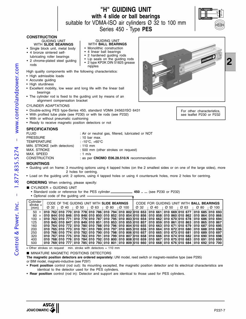
P237-7
2
"H" GUIDING UNITwith 4 slide or ball bearings
suitable for VDMA-ISO air cylinders Ø 32 to 100 mmSeries 450 - Type PES
CONSTRUCTIONGUIDING UNIT
WITH SLIDE BEARINGS• Single block unit, metal body• 4 bronze sintered self-
lubricating roller bearings• 2 chrome-plated steel guiding
rods
GUIDING UNITWITH BALL BEARINGS
• Monolithic construction• 4 linear ball bearings• 2 hardened guiding rods• Lip seals on the guiding rods• 2 type KP2K DIN 51825 grease
nipples
For other characteristics,see leaflet P230 or P232
Other strokes on request min. stroke with detectors = 110 mm
ORDERING When ordering, please specify:
CYLINDER + GUIDING UNIT• Standard code or reference for the PES cylinder 450 .. ... (see P230 or P232)• Optional code of the guiding unit
High quality components with the following characteristics:• High admissible loads• Accurate guiding• High sturdiness• Excellent mobility, low wear and long life with the linear ball
bearings• The cylinder rod is fixed to the guiding unit by means of an
alignment compensation bracket
CYLINDER ADAPTATIONS• Double-acting PES type-Series 450, standard VDMA 24562/ISO 6431• With profiled tube plate (see P230) or with tie rods (see P232)• With or without pneumatic cushioning• Ready to receive magnetic position detectors or not
SPECIFICATIONSFLUID : Air or neutral gas, filtered, lubricated or NOTPRESSURE : 10 bar max.TEMPERATURE : -10°C, +60°CMIN. STROKE (with detectors) : 110 mmMAX. STROKE : 500 mm (other strokes on request)MAX. SPEED : 1 m/sCONSTRUCTION : as per CNOMO E06.28.510.N recommendation
MOUNTINGS• Guiding unit on frame: 3 mounting options using 4 tapped holes (on the 2 smallest sides or on one of the large sides), more
2 holes for centring.• Load on the guiding unit: 2 options, using 4 tapped holes or using 4 countersunk holes, more 2 holes for centring.
NS
50 010 762 010 770 010 778 010 786 010 794 010 802 010 653 010 661 010 669 010 677 010 685 010 69380 010 844 010 846 010 848 010 850 010 852 010 854 010 856 010 858 010 860 010 862 010 864 010 866
100 010 763 010 771 010 779 010 787 010 795 010 803 010 654 010 662 010 670 010 678 010 686 010 694125 010 845 010 847 010 849 010 851 010 853 010 855 010 857 010 859 010 861 010 863 010 865 010 867160 010 764 010 772 010 780 010 788 010 796 010 804 010 655 010 663 010 671 010 679 010 687 010 695200 010 765 010 773 010 781 010 789 010 797 010 805 010 656 010 664 010 672 010 680 010 688 010 696250 010 766 010 774 010 782 010 790 010 798 010 806 010 657 010 665 010 673 010 681 010 689 010 697320 010 767 010 775 010 783 010 791 010 799 010 807 010 658 010 666 010 674 010 682 010 690 010 698400 010 768 010 776 010 784 010 792 010 800 010 808 010 659 010 667 010 675 010 683 010 691 010 699500 010 769 010 777 010 785 010 793 010 801 010 809 010 660 010 668 010 676 010 684 010 692 010 700
Cylinder stroke
(mm)CODE OF THE GUIDING UNIT WITH SLIDE BEARINGS CODE FOR GUIDING UNIT WITH BALL BEARINGSØ 32 Ø 40 Ø 50 Ø 63 Ø 80 Ø 100 Ø 32 Ø 40 Ø 50 Ø 63 Ø 80 Ø 100
MINIATURE MAGNETIC POSITIONS DETECTORSThe magnetic position detectors are ordered separately: UNI model, reed switch or magneto-resistive type (see P295)or BIM model, magneto-inductive (see P297)• Front position control (rod out): Its mounting excepted, the magnetic position detector and its electrical characteristics are
identical to the detector used for the PES cylinders.• Rear position control (rod in): Detector and support are identical to those used for PES cylinders.
Cont
rol &
Pow
er, I
nc.
-
1.87
7.83
5.52
74
- w
ww
.con
trol
andp
ower
.com
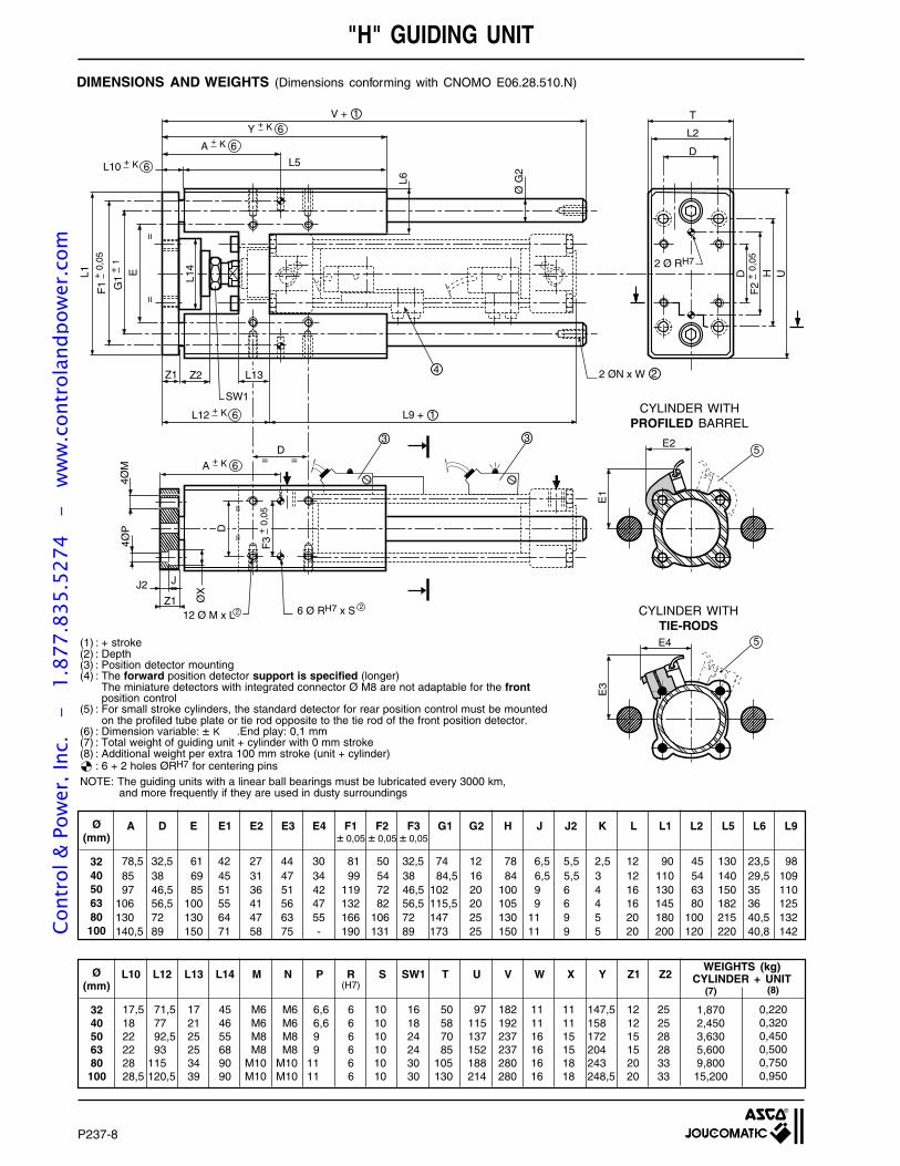
P237-8
D
4ØP
ØX
JJ2
V + 1
Z1 Z2
E D H U
Ø G
2
L6
T
L2
D
L1
3
4
SW1
2 ØN x W 2
Z112 Ø M x L
= =
3
6 Ø RH7 x S 22
D
4ØM
2 Ø RH7
=
=
=
=
G1
+1
F1
+0,
05
F2
+0,
05
F3
+0,
05
A + K 6
A + K 6
Y + K 6
L10 + K 6
E3
E4
E1
E2
5
5
L13
L5
L12 + K 6 L9 + 1
L14
"H" GUIDING UNIT
DIMENSIONS AND WEIGHTS (Dimensions conforming with CNOMO E06.28.510.N)
(1) : + stroke(2) : Depth(3) : Position detector mounting(4) : The forward position detector support is specified (longer)
The miniature detectors with integrated connector Ø M8 are not adaptable for the frontposition control
(5) : For small stroke cylinders, the standard detector for rear position control must be mountedon the profiled tube plate or tie rod opposite to the tie rod of the front position detector.
(6) : Dimension variable: ± K .End play: 0,1 mm(7) : Total weight of guiding unit + cylinder with 0 mm stroke(8) : Additional weight per extra 100 mm stroke (unit + cylinder)
: 6 + 2 holes ØRH7 for centering pinsNOTE: The guiding units with a linear ball bearings must be lubricated every 3000 km,
and more frequently if they are used in dusty surroundings
CYLINDER WITHPROFILED BARREL
CYLINDER WITHTIE-RODS
3240506380100
Ø(mm)
A D E E1 E2 E3 E4 F1 F2 F3 G1 G2 H J J2 K L L1 L2 L5 L6 L9± 0,05 ± 0,05 ± 0,05
78,5 32,5 61 42 27 44 30 81 50 32,5 74 12 78 6,5 5,5 2,5 12 90 45 130 23,5 9885 38 69 45 31 47 34 99 54 38 84,5 16 84 6,5 5,5 3 12 110 54 140 29,5 10997 46,5 85 51 36 51 42 119 72 46,5 102 20 100 9 6 4 16 130 63 150 35 110
106 56,5 100 55 41 56 47 132 82 56,5 115,5 20 105 9 6 4 16 145 80 182 36 125130 72 130 64 47 63 55 166 106 72 147 25 130 11 9 5 20 180 100 215 40,5 132140,5 89 150 71 58 75 - 190 131 89 173 25 150 11 9 5 20 200 120 220 40,8 142
Ø(mm)
L10 L12 L13 L14 M N P R S SW1 T U V W X Y Z1 Z2(H7)
0,2200,3200,4500,5000,7500,950
1,8702,4503,6305,6009,80015,200
(8)(7)
WEIGHTS (kg)CYLINDER + UNIT
17,5 71,5 17 45 M6 M6 6,6 6 10 16 50 97 182 11 11 147,5 12 2518 77 21 46 M6 M6 6,6 6 10 18 58 115 192 11 11 158 12 2522 92,5 25 55 M8 M8 9 6 10 24 70 137 237 16 15 172 15 2822 93 25 68 M8 M8 9 6 10 24 85 152 237 16 15 204 15 2828 115 34 90 M10 M10 11 6 10 30 105 188 280 16 18 243 20 3328,5 120,5 39 90 M10 M10 11 6 10 30 130 214 280 16 18 248,5 20 33
3240506380100
Cont
rol &
Pow
er, I
nc.
-
1.87
7.83
5.52
74
- w
ww
.con
trol
andp
ower
.com
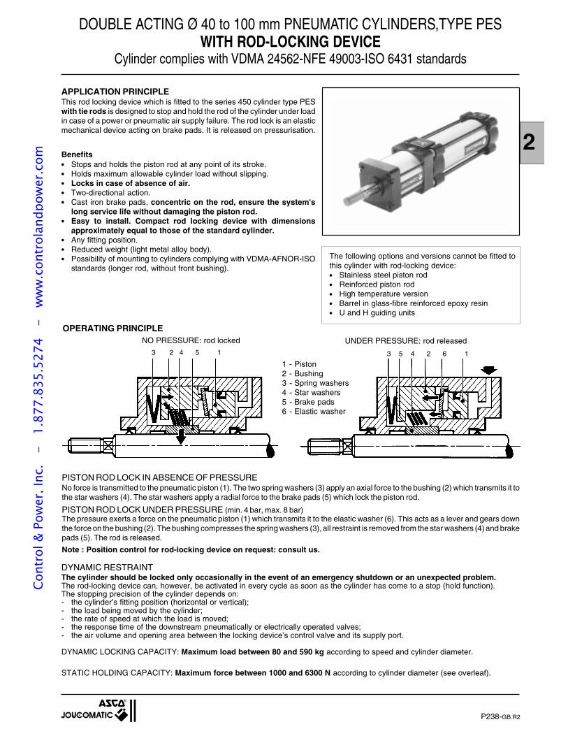
2
The following options and versions cannot be fitted tothis cylinder with rod-locking device: Stainless steel piston rod Reinforced piston rod High temperature version Barrel in glass-fibre reinforced epoxy resin U and H guiding units
DOUBLE ACTING Ø 40 to 100 mm PNEUMATIC CYLINDERS,TYPE PESWITH ROD-LOCKING DEVICE
Cylinder complies with VDMA 24562-NFE 49003-ISO 6431 standards
P238-GB.R2
APPLICATION PRINCIPLEThis rod locking device which is fitted to the series 450 cylinder type PESwith tie rods is designed to stop and hold the rod of the cylinder under loadin case of a power or pneumatic air supply failure. The rod lock is an elasticmechanical device acting on brake pads. It is released on pressurisation.
OPERATING PRINCIPLE
3 2 4 5 1 3 5 4 2 6 1
NO PRESSURE: rod locked UNDER PRESSURE: rod released
PISTON ROD LOCK IN ABSENCE OF PRESSURENo force is transmitted to the pneumatic piston (1). The two spring washers (3) apply an axial force to the bushing (2) which transmits it tothe star washers (4). The star washers apply a radial force to the brake pads (5) which lock the piston rod.
PISTON ROD LOCK UNDER PRESSURE (min. 4 bar, max. 8 bar)The pressure exerts a force on the pneumatic piston (1) which transmits it to the elastic washer (6). This acts as a lever and gears downthe force on the bushing (2). The bushing compresses the spring washers (3), all restraint is removed from the star washers (4) and brakepads (5). The rod is released.
Note : Position control for rod-locking device on request: consult us.
DYNAMIC RESTRAINTThe cylinder should be locked only occasionally in the event of an emergency shutdown or an unexpected problem.The rod-locking device can, however, be activated in every cycle as soon as the cylinder has come to a stop (hold function).The stopping precision of the cylinder depends on:- the cylinder’s fitting position (horizontal or vertical);- the load being moved by the cylinder;- the rate of speed at which the load is moved;- the response time of the downstream pneumatically or electrically operated valves;- the air volume and opening area between the locking device’s control valve and its supply port.
DYNAMIC LOCKING CAPACITY: Maximum load between 80 and 590 kg according to speed and cylinder diameter.
STATIC HOLDING CAPACITY: Maximum force between 1000 and 6300 N according to cylinder diameter (see overleaf).
1 - Piston2 - Bushing3 - Spring washers4 - Star washers5 - Brake pads6 - Elastic washer
Benefits Stops and holds the piston rod at any point of its stroke. Holds maximum allowable cylinder load without slipping. Locks in case of absence of air. Two-directional action. Cast iron brake pads, concentric on the rod, ensure the system's
long service life without damaging the piston rod. Easy to install. Compact rod locking device with dimensions
approximately equal to those of the standard cylinder. Any fitting position. Reduced weight (light metal alloy body). Possibility of mounting to cylinders complying with VDMA-AFNOR-ISO
standards (longer rod, without front bushing).
Cont
rol &
Pow
er, I
nc.
-
1.87
7.83
5.52
74
- w
ww
.con
trol
andp
ower
.com
P238-2
PES CYLINDER + ROD-LOCKING DEVICE
ORDERING INFORMATIONWhen ordering, please specify: The code for the unit consisting of the PES cylinder with tie rods + rod-locking device (see above). The length of stroke in mm (Max. 600 mm. Consult us for longer strokes). MOUNTINGS: The code(s) for the mounting(s) and quantity (see P232) - Consult us for the trunnion. DETECTORS: The codes for the requested magnetic position detectors are ordered separately: UNI model, reed switch
or magneto-resistive type (see P295) or BIM model, magneto-inductive (see P297)
MOUNTING AND OPERATING RECOMMENDATIONSPrecautions should be taken when installing a cylinder fitted with a rod-locking device. It is important to clearly define the type of layoutthat is required and the operating conditions of the cylinder.The cylinder should be locked only occasionally in the event of an emergency shutdown or an unexpected problem such as:- failure in electric supply;- failure in pneumatic supply;- drop in pressure.The rod locking device can, however, be activated in every cycle as soon as the cylinder has come to a stop (hold function).The cylinder may be fitted horizontally or vertically, with the rod either upward or downward. It may also be tilted, with the rod eitherupward or downward.A specific layout corresponds to each application. The specimen layouts on the opposite page show the principles to be observed andthe stops caused by interruption of the power supply or removal of the pressure by means of electropneumatic valves.In the case of a vertical movement of the load, the force on the piston which is generated by pressure - and which operates in the samedirection as the load - must not exceed the locking capacity of the device when it is combined to the force of the load (see table above).The rate of speed of the rod must be less than 500 mm/sec.After any emergency locking operation, make sure that the chambers of the cylinder are filled before the signal to unlock the device is given.The rod-locking device is fitted with 2 wiper seals made of PUR. It is recommended to grease the rod lightly at regular intervalswith a non-detergent class ISO VG 32 oil without aggressive additives (commonly used in pneumatic circuits). Do not let the rodcome into contact with any other oils or products which might damage the wiper seals made of PUR.It is recommended to check the correct operation of the rod-locking devices at regular intervals.
Note: Position control for rod-locking device on request : consult us
V(mm/s) Ø 40 Ø 50 Ø 63 Ø 80 Ø 100
500 80 130 200 320 500200 90 145 225 360 590
MAX. ALLOWABLE SPEED : 500 mm/sNUMBER OF CYCLES : 1.5 x 10 6 (at 20° C, at a balanced stop, in hold function, cycle = 1 Hz )
CHOICE OF EQUIPMENT
40 450 55 556 (1)
50 450 55 557 (1)
63 450 55 558 (1)
80 450 55 559 (1)
100 450 55 562 (1)
Ø
CODESCYLINDER (PES/tie rods) + ROD LOCK
(1) Please specify the cylinder stroke in mm
GENERAL SPECIFICATIONSASSEMBLY : Rod lock incorporated into cylinder, fitted in line, centered on the piston rod (cylinder without
front bushing).CYLINDER TYPE : Series 450 cylinder type PES with tie rods conforming to VDMA 24562-AFNOR NFE
49003- ISO 6431 standards, aluminium barrel, designed for Reed switches, magneto-resistant or magneto-inductive position detectors.
CYLINDER BORE DIAMETERS : Ø 40-50-63-80-100 mm.STANDARD CYLINDER STROKES : 50 to 600 mm (or more, to order).AMBIENT TEMPERATURE : - 20°C to + 70°CFITTING POSITION : Any, see assembly recommendations below.MOUNTINGS : All standard mountings for PES cylinders with tie rods (see P232).
Centre trunnion (consult us).
PNEUMATIC CHARACTERISTICSFLUID : Air or neutral gas, filtered, lubricated or dry.RELEASE PRESSURE : 4 bar (min.), 8 bar (max.)MAX. SYSTEM PRESSURE : 8 bar
MECHANICAL CHARACTERISTICSHOLDING FORCE (static) Ø 40 mm : 1000 N Ø 63 mm : 2500 N Ø 100 mm : 6300 N
Ø 50 mm : 1600 N Ø 80 mm : 4000 NRESTRAINING CAPACITY : Maximum load, in kg, that can be stopped dynamically over a distance of 50 mm in relation
to the rate of speed of the rod (the cylinder must be in a vertical fitting position).
Cont
rol &
Pow
er, I
nc.
-
1.87
7.83
5.52
74
- w
ww
.con
trol
andp
ower
.com
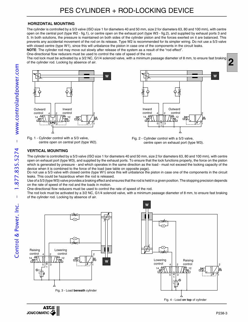
2
HORIZONTAL MOUNTINGThe cylinder is controlled by a 5/3 valve (ISO size 1 for diameters 40 and 50 mm, size 2 for diameters 63, 80 and 100 mm), with centreopen on the central port (type W2 - fig.1), or centre open on the exhaust port (type W3 - fig.2), and supplied by exhaust ports 3 and5. In both solutions, the pressure is maintained on both sides of the cylinder piston and the forces exerted on it are balanced. Thisprevents any accidental movement of the rod on its release. Type W2 is recommended for its simpler wiring. Do not use a 5/3 valvewith closed centre (type W1), since this will unbalance the piston in case one of the components in the circuit leaks.NOTE: The cylinder rod may move out slowly after release of the system as a result of the “rod effect”.One-directional flow reducers must be used to control the rate of speed of the rod.The rod lock must be activated by a 3/2 NC, G1/4 solenoid valve, with a minimum passage diameter of 8 mm, to ensure fast brakingof the cylinder rod. Locking by absence of air.
P238-3
Fig. 1 - Cylinder control with a 5/3 valve,centre open on central port (type W2).
Fig. 2 - Cylinder control with a 5/3 valve,centre open on exhaust port (type W3).
Raisingcontrol
Loweringcontrol
Raisingcontrol
2241214
13351
W
Fig. 3 - Load beneath cylinder
2241214
13351
W
Fig. 4 - Load on top of cylinder
Loweringcontrol
VERTICAL MOUNTINGThe cylinder is controlled by a 5/3 valve (ISO size 1 for diameters 40 and 50 mm, size 2 for diameters 63, 80 and 100 mm), with centreopen on exhaust port (type W3), and supplied by the exhaust ports. To ensure that the lock functions properly, the force on the pistonwhich is generated by pressure - and which operates in the same direction as the load - must not exceed the locking capacity of thedevice when it is combined to the force of the load (see table on opposite page).Do not use a 5/3 valve with closed centre (type W1) since this will unbalance the piston in case one of the components in the circuitleaks. This could be hazardous when the rod is released.Use of a 5/3 (type W3) valve provides a braking effect and ensures that the rod is held in a given position. The stopping precision dependson the rate of speed of the rod and the loads in motion.One-directional flow reducers must be used to control the rate of speed of the rod.The rod lock must be activated by a 3/2 NC, G1/4 solenoid valve, with a minimum passage diameter of 8 mm, to ensure fast brakingof the cylinder rod. Locking by absence of air.
Outwardcontrol
Inwardcontrol 224
1214
13351
W
Outwardcontrol
Inwardcontrol 224
1214
13351
W
PES CYLINDER + ROD-LOCKING DEVICECo
ntro
l & P
ower
, Inc
. -
1.
877.
835.
5274
-
ww
w.c
ontr
olan
dpow
er.c
om
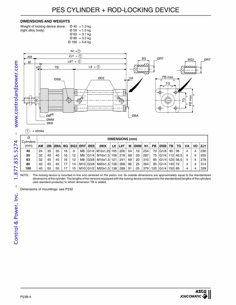
Weight of locking device alone : Ø 40 = 1.3 kg(light alloy body) Ø 50 = 1.5 kg
Ø 63 = 3.1 kgØ 80 = 3.5 kg
Ø 100 = 5.6 kg
DIMENSIONS AND WEIGHTS
1 : + stroke
NOTE : The locking device is mounted in line and centered on the piston rod. Its outside dimensions are approximately equal to the standardizeddimensions of the cylinder. The lengths of the versions equipped with the locking device correspond to the standardized lengths of the cylinders(see standard products) to which dimension TB is added.
Dimensions of mountings: see P232
PES CYLINDER + ROD-LOCKING DEVICE
P238-4
ØBA
VAØEE
L8 + 1
L8T + 1
ZJ1 + 1
ØBe9
ØMM
=
=
=
=
==
==
PB max.
TG
TG
PB
max
.
N1 + 1
AM
TBVD
ØKK
ØSB
MBG ØRT BG2 ØRT
ØCylinders
(mm)
DIMENSIONS (mm)
AM ØB ØBA BG BG2 ØRT ØEE ØKK L8 L8T M ØMM N1 PB ØSB TB TG VA VD ZJ1
40 24 35 35 16 9 M6 G1/4 M12x1,25 105 200 54 16 254 70 G1/8 95 38 4 4 23050 32 40 40 16 12 M8 G1/4 M16x1,5 106 218 69 20 287 75 G1/4 112 46,5 4 4 25563 32 45 45 16 12 M8 G3/8 M16x1,5 121 241 69 20 310 95 G1/4 120 56,5 4 4 27880 40 45 45 17 14 M10 G3/8 M20x1,5 128 268 86 25 354 95 G1/4 140 72 4 4 314100 40 55 55 17 15 M10 G1/2 M20x1,5 138 288 91 25 379 120 G1/4 150 89 4 4 339
Cont
rol &
Pow
er, I
nc.
-
1.87
7.83
5.52
74
- w
ww
.con
trol
andp
ower
.com
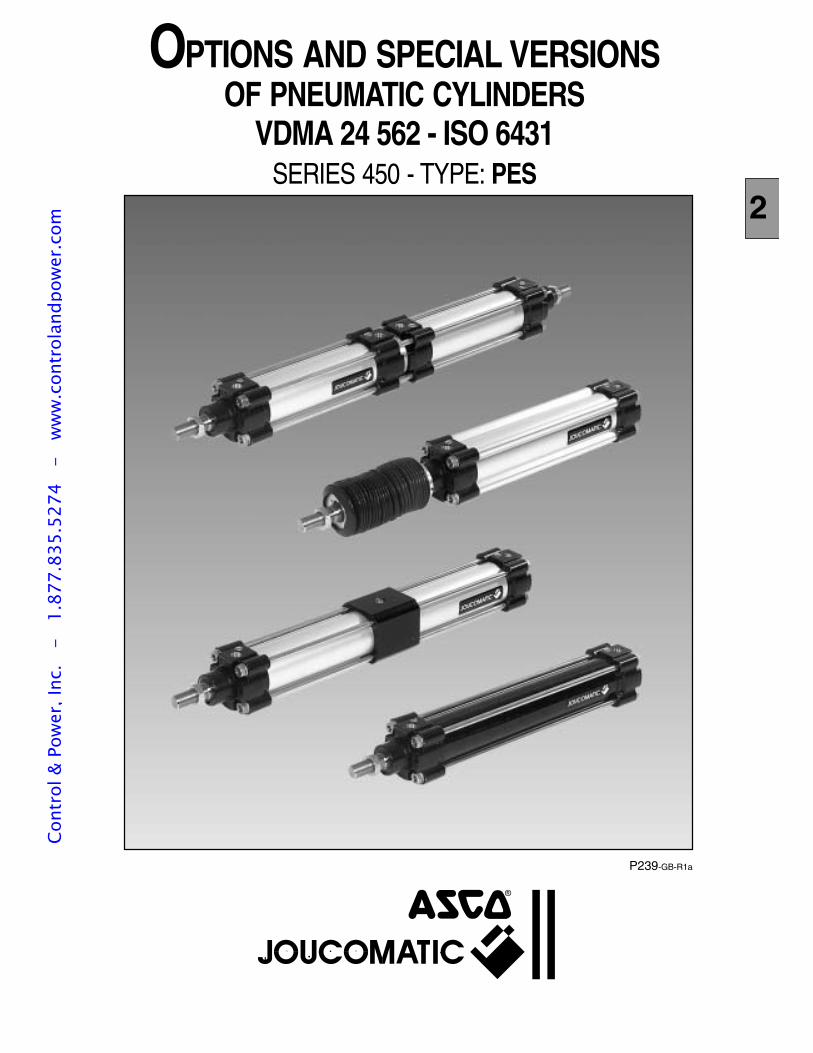
P239-GB-R1a
OPTIONS AND SPECIAL VERSIONSOF PNEUMATIC CYLINDERS
VDMA 24 562 - ISO 6431SERIES 450 - TYPE: PES
2
Cont
rol &
Pow
er, I
nc.
-
1.87
7.83
5.52
74
- w
ww
.con
trol
andp
ower
.com

P239-2
All leaflets are available on: www.ascojoucomatic.com
CONTENT OF PES RANGE
The PES range of pneumatic cylinders - Series 450 as perstandards VDMA 24 562 and ISO 6431, are suitable for allcompressed air automation applications. Standard range (for typical applications)
- PES 32 to 125 mm bore non tie-rod cylinders- PES 32 to 200 mm bore tie-rod cylinders
with steel or aluminium barrels- Cylinders with and without adjustable pneumatic cushioning,
designed or not designed to receive magnetic position detectorsof the reed switch, magneto-resistive or magneto-inductive types
The specialised versions and options shown in thisdocument can be used to to meet the requirements ofspecific applications in difficult environments.
Cont
rol &
Pow
er, I
nc.
-
1.87
7.83
5.52
74
- w
ww
.con
trol
andp
ower
.com
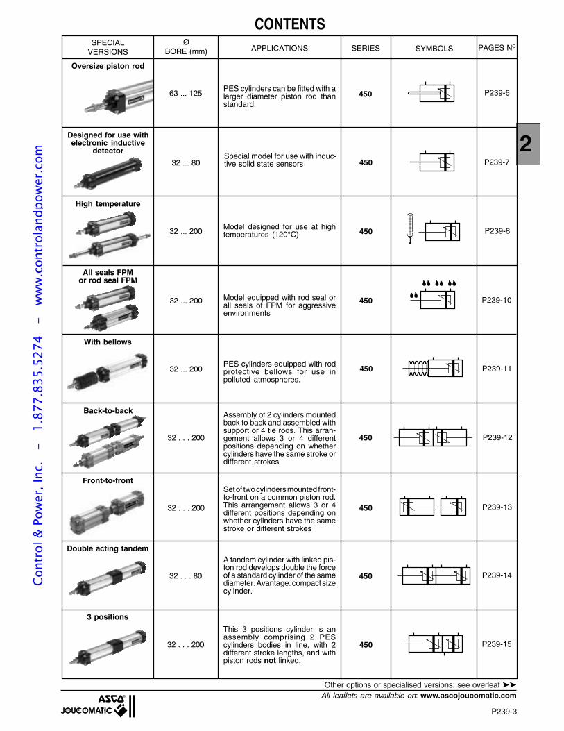
2
P239-3
All leaflets are available on: www.ascojoucomatic.com
CONTENTSAPPLICATIONS SERIES SYMBOLS
32 ... 200 450
With bellows
32 . . . 200 450
Front-to-front
32 . . . 200
Double acting tandem
32 . . . 80
3 positions
32 . . . 200
450
P239-11
P239-12
450 P239-13
P239-14
450 P239-15
SPECIALVERSIONS
ØBORE (mm) PAGES NO
Oversize piston rod
High temperature
All seals FPMor rod seal FPM
32 ... 200
32 ... 200
32 ... 80
63 ... 125
P239-10
P239-8
P239-7
P239-6
450
450
450
450
Back-to-back
PES cylinders can be fitted with alarger diameter piston rod thanstandard.
Model designed for use at hightemperatures (120°C)
Model equipped with rod seal orall seals of FPM for aggressiveenvironments
PES cylinders equipped with rodprotective bellows for use inpolluted atmospheres.
Assembly of 2 cylinders mountedback to back and assembled withsupport or 4 tie rods. This arran-gement allows 3 or 4 differentpositions depending on whethercylinders have the same stroke ordifferent strokes
Set of two cylinders mounted front-to-front on a common piston rod.This arrangement allows 3 or 4different positions depending onwhether cylinders have the samestroke or different strokes
A tandem cylinder with linked pis-ton rod develops double the forceof a standard cylinder of the samediameter. Avantage: compact sizecylinder.
This 3 positions cylinder is anassembly comprising 2 PEScylinders bodies in line, with 2different stroke lengths, and withpiston rods not linked.
Designed for use withelectronic inductive
detector
Other options or specialised versions: see overleaf
Special model for use with induc-tive solid state sensors
Cont
rol &
Pow
er, I
nc.
-
1.87
7.83
5.52
74
- w
ww
.con
trol
andp
ower
.com
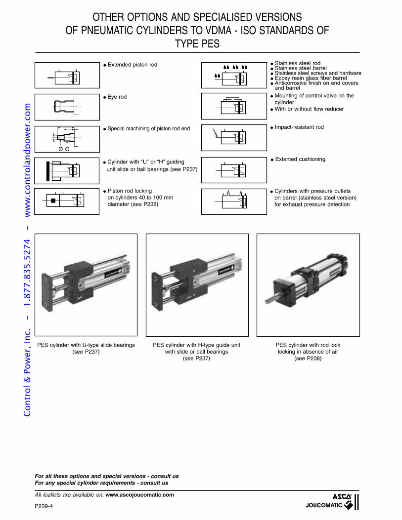
P239-4
All leaflets are available on: www.ascojoucomatic.com
OTHER OPTIONS AND SPECIALISED VERSIONSOF PNEUMATIC CYLINDERS TO VDMA - ISO STANDARDS OF
TYPE PES
Ø Ø
Extended piston rod
Eye rod
Special machining of piston rod end
Piston rod lockingon cylinders 40 to 100 mmdiameter (see P238)
Impact-resistant rod
Extented cushioning
Mounting of control valve on thecylinder
With or without flow reducer
Cylinder with “U” or “H” guidingunit slide or ball bearings (see P237)
Cylinders with pressure outletson barrel (stainless steel version)for exhaust pressure detection
Stainless steel rod Stainless steel barrel Stainless steel screws and hardware Epoxy resin glass fiber barrel Anticorrosive finish on end covers
and barrel
PES cylinder with U-type slide bearings(see P237)
PES cylinder with H-type guide unitwith slide or ball bearings
(see P237)
PES cylinder with rod locklocking in absence of air
(see P238)
For all these options and special versions - consult usFor any special cylinder requirements - consult us
Cont
rol &
Pow
er, I
nc.
-
1.87
7.83
5.52
74
- w
ww
.con
trol
andp
ower
.com
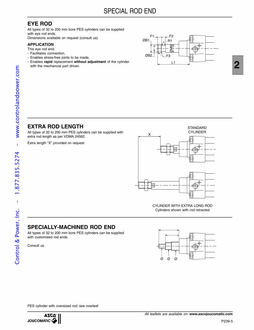
2
P239-5
All leaflets are available on: www.ascojoucomatic.com
SPECIAL ROD END
EYE RODAll types of 32 to 200 mm bore PES cylinders can be suppliedwith eye rod ends.Dimensions available on request (consult us)
APPLICATIONThis eye rod end:- Facilitates connection,- Enables stress-free joints to be made,- Enables rapid replacement without adjustment of the cylinder
with the mechancial part driven.
EXTRA ROD LENGTHAll types of 32 to 200 mm PES cylinders can be supplied withextra rod length as per VDMA 24562.
Extra length “X” provided on request
SPECIALLY-MACHINED ROD ENDAll types of 32 to 200 mm bore PES cylinders can be suppliedwith customised rod ends.
Consult us
PES cylinder with oversized rod: see overleaf
R1F2F1
L1
F3
ØB1
ØB2
ØM
M
X
STANDARDCYLINDER
CYLINDER WITH EXTRA LONG RODCylinders shown with rod retracted
Ø Ø Ø
Cont
rol &
Pow
er, I
nc.
-
1.87
7.83
5.52
74
- w
ww
.con
trol
andp
ower
.com
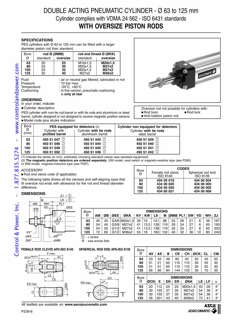
P239-6
All leaflets are available on: www.ascojoucomatic.com
VDKW
WHM
AM
øBe11
øMM
KV*
SW*øKK
L8 + 1ZJ + 1
ØEEPL1
AM ØB ØEE ØKK KV KW L8 M ØMM PL1 SW VD WH ZJ
DOUBLE ACTING PNEUMATIC CYLINDER - Ø 63 to 125 mmCylinder complies with VDMA 24 562 - ISO 6431 standards
WITH OVERSIZE PISTON RODS
SPECIFICATIONSPES cylinders with Ø 63 to 125 mm can be fitted with a largerdiameter piston rod than standard.
PES equipped for detectors (2) Cylinder non equipped for detectorsCylinder with
profiled barrelCylinder with tie rods
aluminium barrelCylinder with tie rods
steel barrel
BoreØ
(mm)
63 450 51 047 ... 450 51 043 ... 450 51 039 ...80 450 51 048 ... 450 51 044 ... 450 51 040 ...
100 450 51 049 ... 450 51 045 ... 450 51 041 ...125 450 51 050 ... 450 51 046 ... 450 51 042 ...
(1)
(1)
(1)
(1)
(1)
(1)
(1)
(1)
(1)
(1)
(1)
(1)
(1) Indicate the stroke (in mm), preferably choosing standard values (see standard equipment)(2) The magnetic position detectors are ordered separately: UNI model, reed switch or magneto-resistive type (see P295)or BIM model, magneto-inductive type (see P297)
ORDERINGIn your order, indicate Cylinder description:PES cylinder with non-tie rod barrel or with tie rods and aluminium or steelbarrel, cylinder designed or not designed to receive magnetic position sensors Model code plus stroke indication:
ACCESSORY Rod end clevis code (if applicable):
The following table shows all the clevises and self-aligning eyes thatfit oversize rod ends with allowance for the rod end thread diameterdifference.
CODESFemale rod clevis
ISO 8140Spherical rod end
ISO 8139
BoreØ
63 434 00 019 434 00 00480 434 00 020 434 00 005
100 434 00 020 434 00 005125 434 00 021 434 00 006
DIMENSIONS
DIMENSIONSBoreØ
63 40 45 G3/8 M20x1,5 30 10 121 86 25 26 21 6 46 16780 54 45 G3/8 M27x2 41 13,5 128 119 30 24 27 6 65 193
100 54 55 G1/2 M27x2 41 13,5 138 119 32 25 27 6 65 203125 72 60 G1/2 M36x2 55 18 160 152 40 32 36 10 80 240
ØCNH9 AX
ØK
K
EN
h12
α α
CHLFER max.
E max.
ØCKH9/d10 AV
LE
CE
CM
B m
ax.
CL
ER max.
ØK
K
+0,6
+0,1
5
FEMALE ROD CLEVIS AP2-ISO 8140 SPHERICAL ROD END AP6-ISO 8139 DIMENSIONSBoreØ
63 33 33 48 80 40 20 40 2080 51 51 65 110 110 30 55 30
100 51 51 65 110 110 30 55 30125 56 56 84 144 125 35 70 35
AV AX B CE CH ØCK CL CM
DIMENSIONSBoreØ
63 20 112 25 25 M20x1,5 40 26 4°80 30 155 37 35 M27x2 54 36 4°
100 30 155 37 35 M27x2 54 36 4°125 35 201 43 40 M36x2 72 41 4°
ØCN E EN ER ØKK LE LF α
Oversize rod not possbile for cylinders with: Rod boot Rod lock Anti-rotation piston rod
1 : + stroke
rod Ø (ØMM)standard oversize standard oversize
rod end thread Ø (ØKK)BoreØ63 20 25 M16x1,5 M20x1,580 25 30 M20x1,5 M27x2
100 25 32 M20x1,5 M27x2125 32 40 M27x2 M36x2
: size across flats
Fluid : air or neutral gas filtered, lubricated or notPressure : 10 bar max.Temperature : -20°C, +60°CCushioning : In this version, pneumatic cushioning
is only at rear
Cont
rol &
Pow
er, I
nc.
-
1.87
7.83
5.52
74
- w
ww
.con
trol
andp
ower
.com
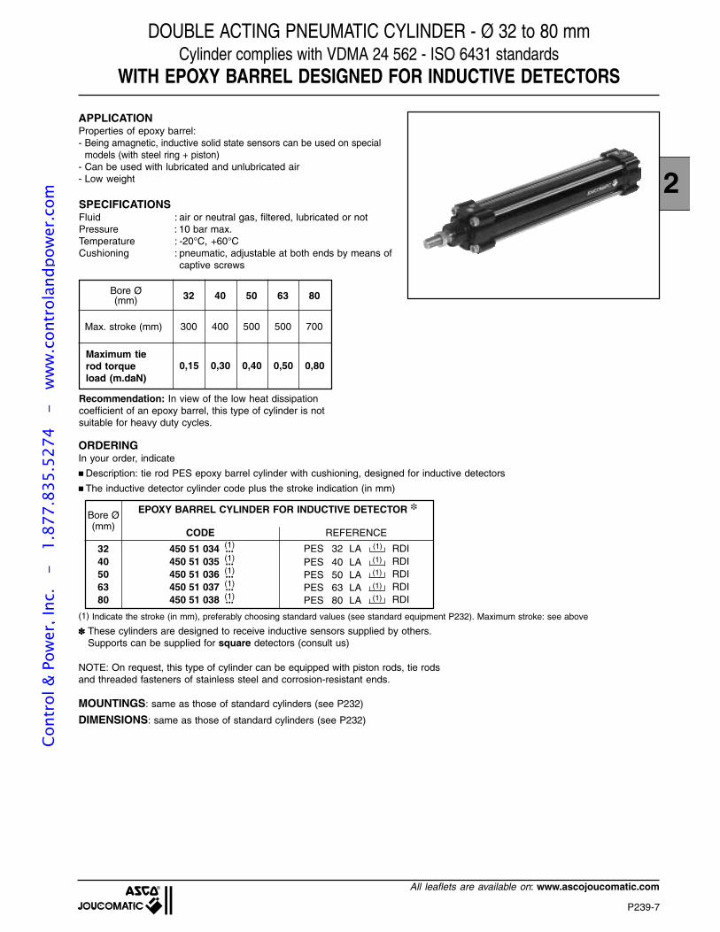
2
P239-7
All leaflets are available on: www.ascojoucomatic.com
DOUBLE ACTING PNEUMATIC CYLINDER - Ø 32 to 80 mmCylinder complies with VDMA 24 562 - ISO 6431 standards
WITH EPOXY BARREL DESIGNED FOR INDUCTIVE DETECTORS
APPLICATIONProperties of epoxy barrel:- Being amagnetic, inductive solid state sensors can be used on special
models (with steel ring + piston)- Can be used with lubricated and unlubricated air- Low weight
SPECIFICATIONSFluid : air or neutral gas, filtered, lubricated or notPressure : 10 bar max.Temperature : -20°C, +60°CCushioning : pneumatic, adjustable at both ends by means of
captive screws
Bore Ø(mm) 32 40 50 63 80
300 400 500 500 700Max. stroke (mm)
0,15 0,30 0,40 0,50 0,80Maximum tierod torqueload (m.daN)
Recommendation: In view of the low heat dissipationcoefficient of an epoxy barrel, this type of cylinder is notsuitable for heavy duty cycles.
ORDERINGIn your order, indicate
Description: tie rod PES epoxy barrel cylinder with cushioning, designed for inductive detectors
The inductive detector cylinder code plus the stroke indication (in mm)
Bore Ø(mm)
3240506380
450 51 034 ...450 51 035 ...450 51 036 ...450 51 037 ...450 51 038 ...
(1)
(1)
(1)
(1)
(1)
These cylinders are designed to receive inductive sensors supplied by others.Supports can be supplied for square detectors (consult us)
NOTE: On request, this type of cylinder can be equipped with piston rods, tie rodsand threaded fasteners of stainless steel and corrosion-resistant ends.
(1) Indicate the stroke (in mm), preferably choosing standard values (see standard equipment P232). Maximum stroke: see above
MOUNTINGS: same as those of standard cylinders (see P232)
DIMENSIONS: same as those of standard cylinders (see P232)
EPOXY BARREL CYLINDER FOR INDUCTIVE DETECTOR
CODE REFERENCE
RDIRDIRDIRDIRDI
(1)
(1)PES 32 LAPES 40 LAPES 50 LAPES 63 LAPES 80 LA
(1)
(1)
(1)
Cont
rol &
Pow
er, I
nc.
-
1.87
7.83
5.52
74
- w
ww
.con
trol
andp
ower
.com
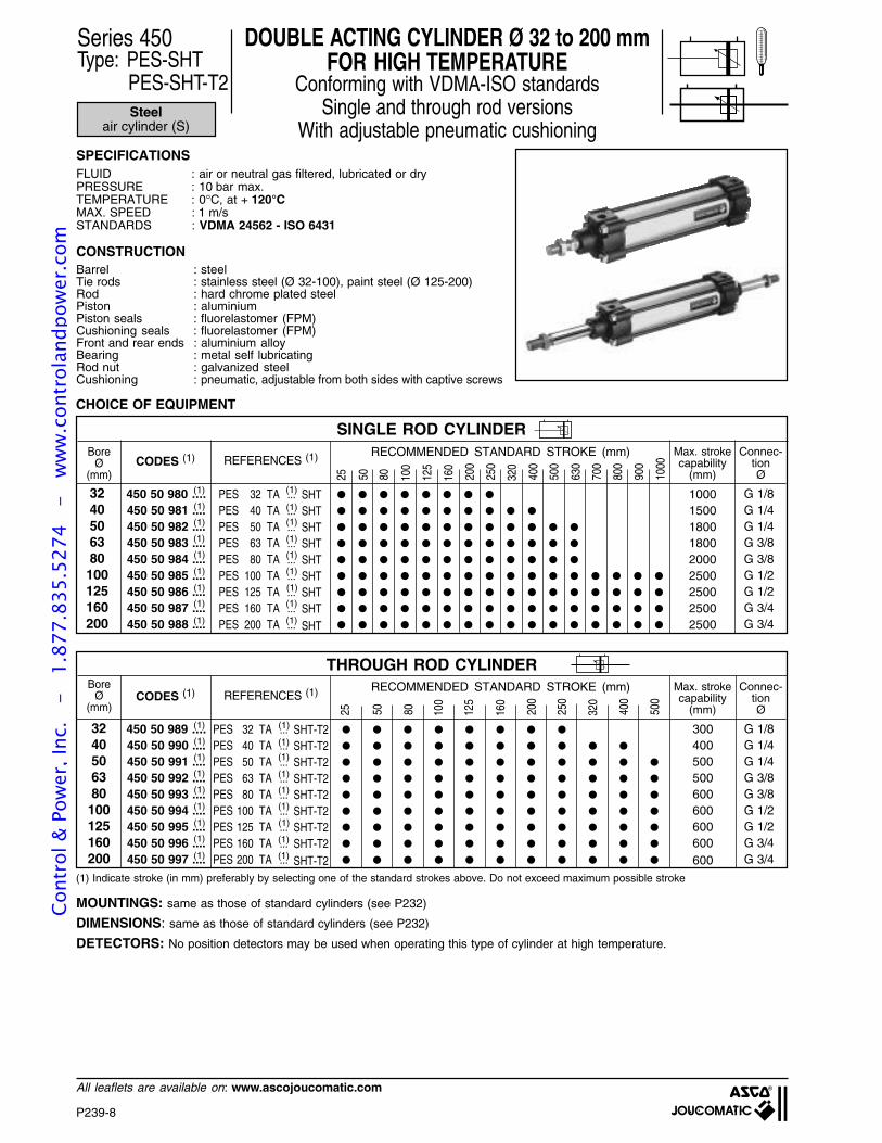
P239-8
All leaflets are available on: www.ascojoucomatic.com
PES 32 TA ...PES 40 TA ...PES 50 TA ...PES 63 TA ...PES 80 TA ...PES 100 TA ...PES 125 TA ...PES 160 TA ...PES 200 TA ...
CODES (1)BoreØ
(mm)
450 50 980 ....450 50 981 ....450 50 982 ....450 50 983 ....450 50 984 ....450 50 985 ....450 50 986 ....450 50 987 ....450 50 988 ....
3240506380100125160200
REFERENCES (1)
SHTSHTSHTSHTSHTSHTSHTSHTSHT
(1)
(1)
(1)
(1)
(1)
(1)
(1)
(1)
(1)
(1)
(1)
(1)
(1)
(1)
(1)
(1)
G 1/8G 1/4G 1/4G 3/8G 3/8G 1/2G 1/2G 3/4G 3/4
Connec-tionØ
Max. strokecapability
(mm)
RECOMMENDED STANDARD STROKE (mm)
100015001800180020002500250025002500
Series 450Type: PES-SHT
PES-SHT-T2
DOUBLE ACTING CYLINDER Ø 32 to 200 mmFOR HIGH TEMPERATURE
Conforming with VDMA-ISO standardsSingle and through rod versions
With adjustable pneumatic cushioningSPECIFICATIONSFLUID : air or neutral gas filtered, lubricated or dryPRESSURE : 10 bar max.TEMPERATURE : 0°C, at + 120°CMAX. SPEED : 1 m/sSTANDARDS : VDMA 24562 - ISO 6431
CONSTRUCTIONBarrel : steelTie rods : stainless steel (Ø 32-100), paint steel (Ø 125-200)Rod : hard chrome plated steelPiston : aluminiumPiston seals : fluorelastomer (FPM)Cushioning seals : fluorelastomer (FPM)Front and rear ends : aluminium alloyBearing : metal self lubricatingRod nut : galvanized steelCushioning : pneumatic, adjustable from both sides with captive screws
25 50 80 100
125
160
200
250
320
400
500
630
700
800
900
1000
(1)
CHOICE OF EQUIPMENT
(1) Indicate stroke (in mm) preferably by selecting one of the standard strokes above. Do not exceed maximum possible stroke
MOUNTINGS: same as those of standard cylinders (see P232)
DIMENSIONS: same as those of standard cylinders (see P232)
DETECTORS: No position detectors may be used when operating this type of cylinder at high temperature.
(1)
Steelair cylinder (S)
SINGLE ROD CYLINDER
PES 32 TA ...PES 40 TA ...PES 50 TA ...PES 63 TA ...PES 80 TA ...PES 100 TA ...PES 125 TA ...PES 160 TA ...PES 200 TA ...
CODES (1)Bore
Ø(mm)
450 50 989 ....450 50 990 ....450 50 991 ....450 50 992 ....450 50 993 ....450 50 994 ....450 50 995 ....450 50 996 ....450 50 997 ....
3240506380100125160200
REFERENCES (1)
SHT-T2SHT-T2SHT-T2SHT-T2SHT-T2SHT-T2SHT-T2SHT-T2SHT-T2
(1)
(1)
(1)
(1)
(1)
(1)
(1)
(1)
(1)
(1)
(1)
(1)
(1)
(1)
(1)
(1)
G 1/8G 1/4G 1/4G 3/8G 3/8G 1/2G 1/2G 3/4G 3/4
Connec-tionØ
Max. strokecapability
(mm)
RECOMMENDED STANDARD STROKE (mm)
300400500500600600600600600
25 50 80 100
125
160
200
250
320
400
500
(1) (1)
THROUGH ROD CYLINDER
Cont
rol &
Pow
er, I
nc.
-
1.87
7.83
5.52
74
- w
ww
.con
trol
andp
ower
.com
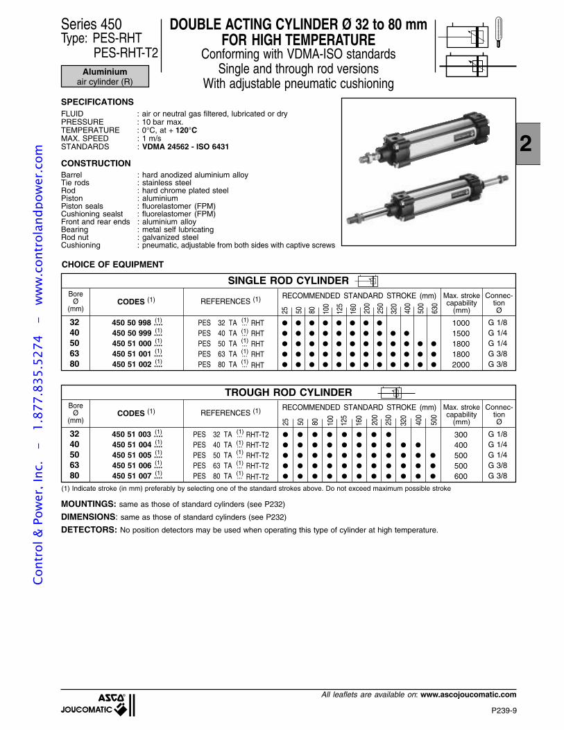
2
P239-9
All leaflets are available on: www.ascojoucomatic.com
PES 32 TA ...PES 40 TA ...PES 50 TA ...PES 63 TA ...PES 80 TA ...
CODES (1)Bore
Ø(mm)
450 50 998 ....450 50 999 ....450 51 000 ....450 51 001 ....450 51 002 ....
3240506380
REFERENCES (1)
RHTRHTRHTRHTRHT
(1)
(1)
(1)
(1)
(1)
(1)
(1)
(1)
(1)
(1)
G 1/8G 1/4G 1/4G 3/8G 3/8
Connec-tionØ
Max. strokecapability
(mm)
RECOMMENDED STANDARD STROKE (mm)
10001500180018002000
DOUBLE ACTING CYLINDER Ø 32 to 80 mmFOR HIGH TEMPERATURE
Conforming with VDMA-ISO standardsSingle and through rod versions
With adjustable pneumatic cushioningSPECIFICATIONSFLUID : air or neutral gas filtered, lubricated or dryPRESSURE : 10 bar max.TEMPERATURE : 0°C, at + 120°CMAX. SPEED : 1 m/sSTANDARDS : VDMA 24562 - ISO 6431
CONSTRUCTIONBarrel : hard anodized aluminium alloyTie rods : stainless steelRod : hard chrome plated steelPiston : aluminiumPiston seals : fluorelastomer (FPM)Cushioning sealst : fluorelastomer (FPM)Front and rear ends : aluminium alloyBearing : metal self lubricatingRod nut : galvanized steelCushioning : pneumatic, adjustable from both sides with captive screws
25 50 80 100
125
160
200
250
320
400
500
630
CHOICE OF EQUIPMENT
(1) Indicate stroke (in mm) preferably by selecting one of the standard strokes above. Do not exceed maximum possible stroke
MOUNTINGS: same as those of standard cylinders (see P232)
DIMENSIONS: same as those of standard cylinders (see P232)
DETECTORS: No position detectors may be used when operating this type of cylinder at high temperature.
Series 450Type: PES-RHT
PES-RHT-T2Aluminium
air cylinder (R)
SINGLE ROD CYLINDER
PES 32 TA ...PES 40 TA ...PES 50 TA ...PES 63 TA ...PES 80 TA ...
CODES (1)Bore
Ø(mm)
450 51 003 ....450 51 004 ....450 51 005 ....450 51 006 ....450 51 007 ....
3240506380
REFERENCES (1)
RHT-T2RHT-T2RHT-T2RHT-T2RHT-T2
(1)
(1)
(1)
(1)
(1)
(1)
(1)
(1)
(1)
(1)
G 1/8G 1/4G 1/4G 3/8G 3/8
Connec-tionØ
Max. strokecapability
(mm)
RECOMMENDED STANDARD STROKE (mm)
300400500500600
25 50 80 100
125
160
200
250
320
400
500
TROUGH ROD CYLINDER
Cont
rol &
Pow
er, I
nc.
-
1.87
7.83
5.52
74
- w
ww
.con
trol
andp
ower
.com
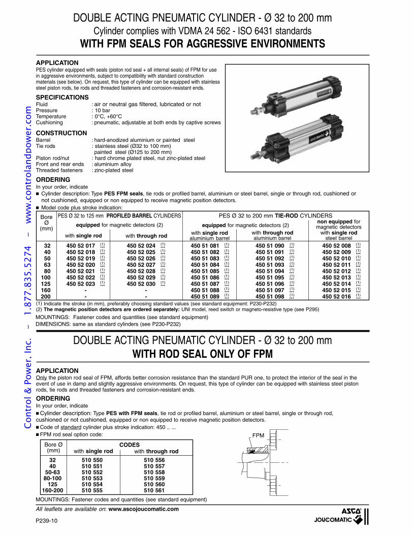
P239-10
All leaflets are available on: www.ascojoucomatic.com
32 450 52 017 ... 450 52 024 ... 450 51 081 ... 450 51 090 ... 450 52 008 ...40 450 52 018 ... 450 52 025 ... 450 51 082 ... 450 51 091 ... 450 52 009 ...50 450 52 019 ... 450 52 026 ... 450 51 083 ... 450 51 092 ... 450 52 010 ...63 450 52 020 ... 450 52 027 ... 450 51 084 ... 450 51 093 ... 450 52 011 ...80 450 52 021 ... 450 52 028 ... 450 51 085 ... 450 51 094 ... 450 52 012 ...
100 450 52 022 ... 450 52 029 ... 450 51 086 ... 450 51 095 ... 450 52 013 ...125 450 52 023 ... 450 52 030 ... 450 51 087 ... 450 51 096 ... 450 52 014 ...160 - - 450 51 088 ... 450 51 097 ... 450 52 015 ...200 - - 450 51 089 ... 450 51 098 ... 450 52 016 ...
DOUBLE ACTING PNEUMATIC CYLINDER - Ø 32 to 200 mmCylinder complies with VDMA 24 562 - ISO 6431 standards
WITH FPM SEALS FOR AGGRESSIVE ENVIRONMENTS
PES Ø 32 to 125 mm PROFILED BARREL CYLINDERS PES Ø 32 to 200 mm TIE-ROD CYLINDERS
with single rod with through rod with single rodaluminium barrel
BoreØ
(mm)
(1)
(1)
(1)
(1)
(1)
(1)
(1)
(1)
(1)
(1)
(1)
(1)
(1) Indicate the stroke (in mm), preferably choosing standard values (see standard equipment: P230-P232)(2) The magnetic position detectors are ordered separately: UNI model, reed switch or magneto-resistive type (see P295)
ORDERINGIn your order, indicate Cylinder description: Type PES FPM seals, tie rods or profiled barrel, aluminium or steel barrel, single or through rod, cushioned or
not cushioned, equipped or non equipped to receive magnetic position detectors. Model code plus stroke indication:
with single rodsteel barrel
with through rodaluminium barrel
equipped for magnetic detectors (2)non equipped formagnetic detectors
(1)
(1)
(1)
(1)
(1)
(1)
(1)
(1)
(1)
(1)
(1)
(1)
(1)
(1)
(1)
(1)
(1)
(1)
(1)
(1)
(1)
(1)
(1)
(1)
(1)
(1)
(1)
(1)
(1)
SPECIFICATIONSFluid : air or neutral gas filtered, lubricated or notPressure : 10 barTemperature : 0°C, +60°CCushioning : pneumatic, adjustable at both ends by captive screws
equipped for magnetic detectors (2)
ORDERINGIn your order, indicate Cylinder description: Type PES with FPM seals, tie rod or profiled barrel, aluminium or steel barrel, single or through rod,cushioned or not cushioned, equipped or non equipped to receive magnetic position detectors. Code of standard cylinder plus stroke indication: 450 .. ... FPM rod seal option code:
DOUBLE ACTING PNEUMATIC CYLINDER - Ø 32 to 200 mmWITH ROD SEAL ONLY OF FPM
CODESwith single rod with through rod
Bore Ø(mm)
32 510 550 510 55640 510 551 510 557
50-63 510 552 510 55880-100 510 553 510 559
125 510 554 510 560160-200 510 555 510 561
MOUNTINGS: Fastener codes and quantities (see standard equipment)DIMENSIONS: same as standard cylinders (see P230-P232)
APPLICATIONPES cylinder equipped with seals (piston rod seal + all internal seals) of FPM for usein aggressive environments, subject to compatibility with standard constructionmaterials (see below). On request, this type of cylinder can be equipped with stainlesssteel piston rods, tie rods and threaded fasteners and corrosion-resistant ends.
FPM
MOUNTINGS: Fastener codes and quantities (see standard equipment)
CONSTRUCTIONBarrel : hard-anodized aluminium or painted steelTie rods : stainless steel (Ø32 to 100 mm)
painted steel (Ø125 to 200 mm)Piston rod/nut : hard chrome plated steel, nut zinc-plated steelFront and rear ends : aluminium alloyThreaded fasteners : zinc-plated steel
APPLICATIONOnly the piston rod seal of FPM, affords better corrosion resistance than the standard PUR one, to protect the interior of the seal in theevent of use in damp and slightly aggressive environments. On request, this type of cylinder can be equipped with stainless steel pistonrods, tie rods and threaded fasteners and corrosion-resistant ends.
Cont
rol &
Pow
er, I
nc.
-
1.87
7.83
5.52
74
- w
ww
.con
trol
andp
ower
.com
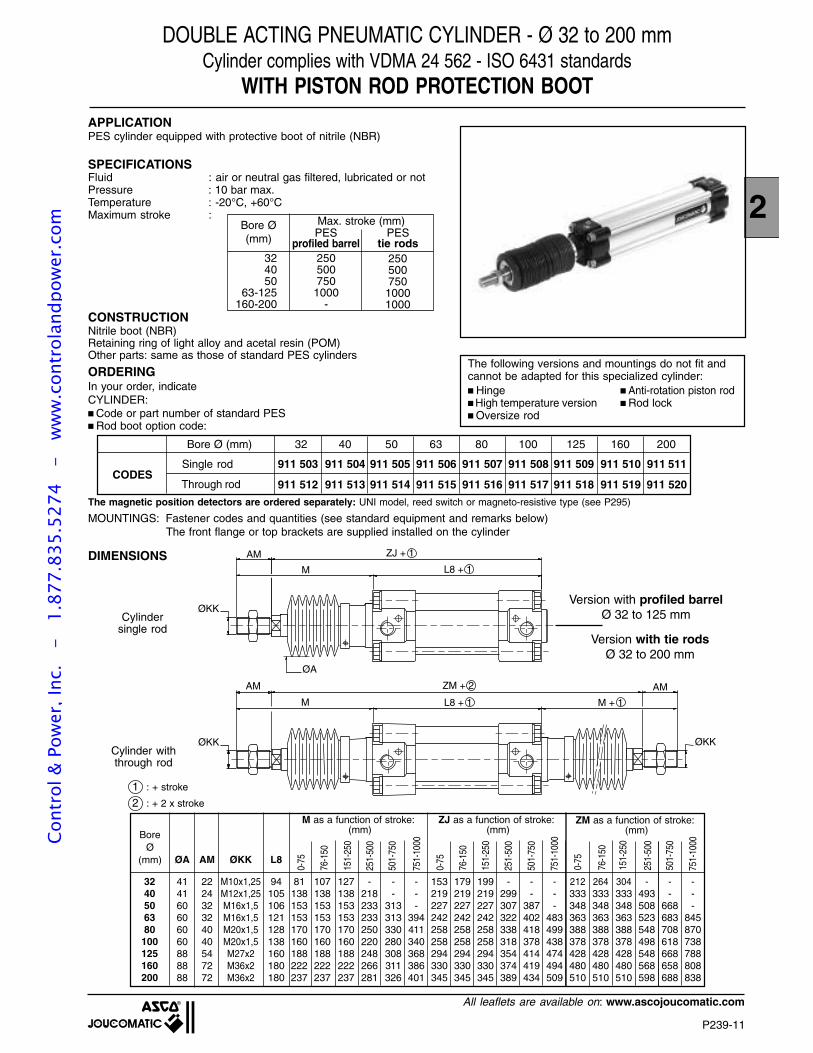
2
P239-11
All leaflets are available on: www.ascojoucomatic.com
DOUBLE ACTING PNEUMATIC CYLINDER - Ø 32 to 200 mmCylinder complies with VDMA 24 562 - ISO 6431 standards
WITH PISTON ROD PROTECTION BOOTAPPLICATIONPES cylinder equipped with protective boot of nitrile (NBR)
SPECIFICATIONSFluid : air or neutral gas filtered, lubricated or notPressure : 10 bar max.Temperature : -20°C, +60°CMaximum stroke :
The following versions and mountings do not fit andcannot be adapted for this specialized cylinder: Hinge Anti-rotation piston rod High temperature version Rod lock Oversize rod
BoreØ
(mm) ØA AM ØKK L8
41 22 M10x1,25 94 81 107 127 - - - 153 179 199 - - - 212 264 304 - - -41 24 M12x1,25 105 138 138 138 218 - - 219 219 219 299 - - 333 333 333 493 - -60 32 M16x1,5 106 153 153 153 233 313 - 227 227 227 307 387 - 348 348 348 508 668 -60 32 M16x1,5 121 153 153 153 233 313 394 242 242 242 322 402 483 363 363 363 523 683 84560 40 M20x1,5 128 170 170 170 250 330 411 258 258 258 338 418 499 388 388 388 548 708 87060 40 M20x1,5 138 160 160 160 220 280 340 258 258 258 318 378 438 378 378 378 498 618 73888 54 M27x2 160 188 188 188 248 308 368 294 294 294 354 414 474 428 428 428 548 668 78888 72 M36x2 180 222 222 222 266 311 386 330 330 330 374 419 494 480 480 480 568 658 80888 72 M36x2 180 237 237 237 281 326 401 345 345 345 389 434 509 510 510 510 598 688 838
3240506380100125160200
M as a function of stroke: (mm)
Bore Ø(mm)
Max. stroke (mm)
324050
63-125160-200
250500750
1000-
CONSTRUCTIONNitrile boot (NBR)Retaining ring of light alloy and acetal resin (POM)Other parts: same as those of standard PES cylinders
ORDERINGIn your order, indicateCYLINDER: Code or part number of standard PES Rod boot option code:
MOUNTINGS: Fastener codes and quantities (see standard equipment and remarks below)The front flange or top brackets are supplied installed on the cylinder
Bore Ø (mm) 32 40 50 63 80 100 125 160 200
911 503 911 504 911 505 911 506 911 507 911 508 911 509 911 510 911 511CODES
Single rod
Through rod 911 512 911 513 911 514 911 515 911 516 911 517 911 518 911 519 911 520
ØKK
AM ZJ + 1
L8 + 1
ØA
ØKK
AM ZM + 2
L8 + 1
ØKK
AM
M M + 1
M
0-75
76-1
50
151-
250
251-
500
501-
750
751-
1000
ZJ as a function of stroke: (mm)
0-75
76-1
50
151-
250
251-
500
501-
750
ZM as a function of stroke: (mm)
0-75
76-1
50
151-
250
251-
500
501-
750
751-
1000
751-
1000
Version with profiled barrelØ 32 to 125 mm
Version with tie rodsØ 32 to 200 mm
1 : + stroke
2 : + 2 x stroke
DIMENSIONS
PESprofiled barrel
PEStie rods
25050075010001000
Cylindersingle rod
Cylinder withthrough rod
The magnetic position detectors are ordered separately: UNI model, reed switch or magneto-resistive type (see P295)
Cont
rol &
Pow
er, I
nc.
-
1.87
7.83
5.52
74
- w
ww
.con
trol
andp
ower
.com
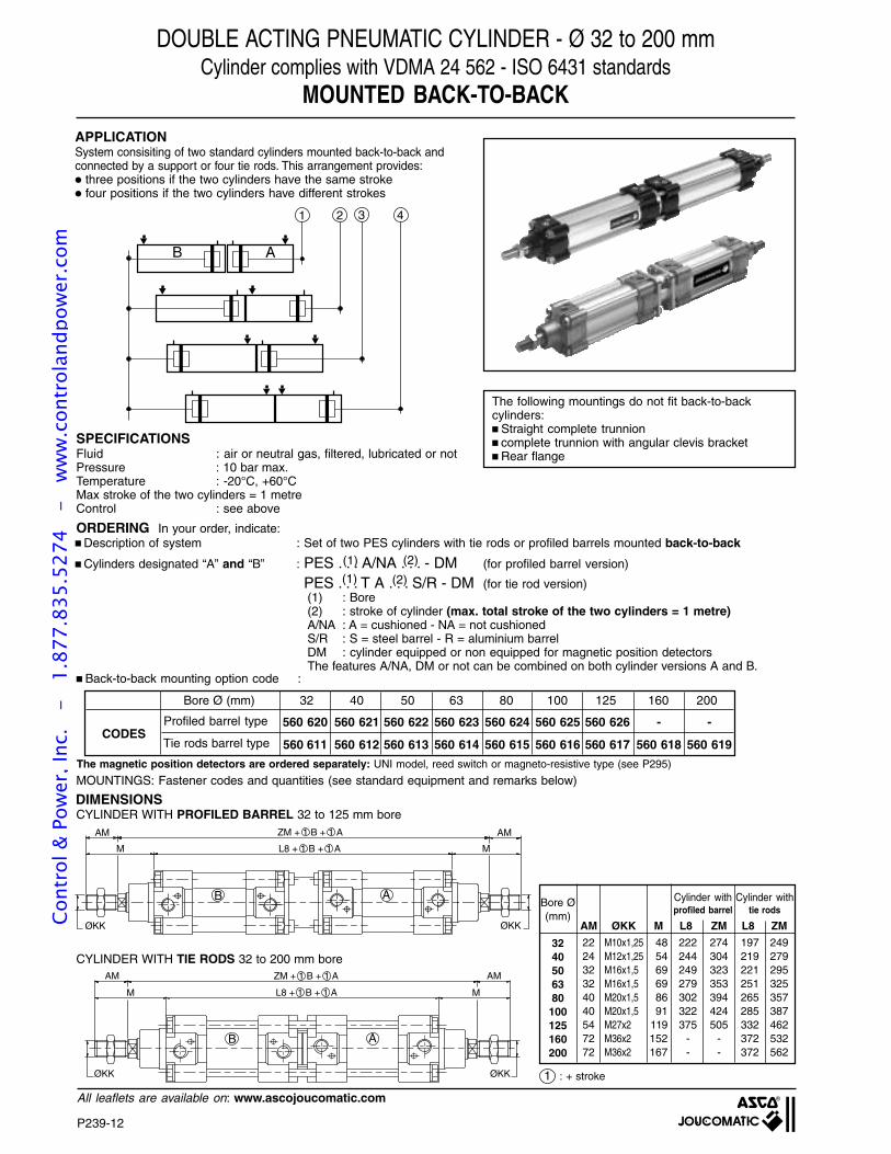
P239-12
All leaflets are available on: www.ascojoucomatic.com
DOUBLE ACTING PNEUMATIC CYLINDER - Ø 32 to 200 mmCylinder complies with VDMA 24 562 - ISO 6431 standards
MOUNTED BACK-TO-BACK
APPLICATIONSystem consisiting of two standard cylinders mounted back-to-back andconnected by a support or four tie rods. This arrangement provides: three positions if the two cylinders have the same stroke four positions if the two cylinders have different strokes
1 2 3 4
B A
SPECIFICATIONSFluid : air or neutral gas, filtered, lubricated or notPressure : 10 bar max.Temperature : -20°C, +60°CMax stroke of the two cylinders = 1 metreControl : see above
ORDERING In your order, indicate: Description of system : Set of two PES cylinders with tie rods or profiled barrels mounted back-to-back
Cylinders designated “A” and “B” : PES . . . A/NA . . . - DM (for profiled barrel version)
PES . . . T A . . . S/R - DM (for tie rod version)(1) : Bore(2) : stroke of cylinder (max. total stroke of the two cylinders = 1 metre)A/NA : A = cushioned - NA = not cushionedS/R : S = steel barrel - R = aluminium barrelDM : cylinder equipped or non equipped for magnetic position detectorsThe features A/NA, DM or not can be combined on both cylinder versions A and B.
DIMENSIONS
Back-to-back mounting option code :
Bore Ø (mm) 32 40 50 63 80 100 125 160 200
560 620 560 621 560 622 560 623 560 624 560 625 560 626 - -CODES
MOUNTINGS: Fastener codes and quantities (see standard equipment and remarks below)
Bore Ø(mm)
AM ØKK M L8 ZM L8 ZM
22 M10x1,25 48 222 274 197 24924 M12x1,25 54 244 304 219 27932 M16x1,5 69 249 323 221 29532 M16x1,5 69 279 353 251 32540 M20x1,5 86 302 394 265 35740 M20x1,5 91 322 424 285 38754 M27x2 119 375 505 332 46272 M36x2 152 - - 372 53272 M36x2 167 - - 372 562
3240506380
100125160200
Cylinder withprofiled barrel
Cylinder withtie rods
ZM + 1 B + 1 A
L8 + 1 B + 1 A
AMAM
MM
ØKK ØKK
B A
CYLINDER WITH TIE RODS 32 to 200 mm bore
CYLINDER WITH PROFILED BARREL 32 to 125 mm boreZM + 1 B + 1 A
L8 + 1 B + 1 A
AM
M
AM
M
ØKK ØKK
B A
1 : + stroke
The following mountings do not fit back-to-backcylinders: Straight complete trunnion complete trunnion with angular clevis bracket Rear flange
(1) (2)
(1) (2)
Profiled barrel type
Tie rods barrel type 560 611 560 612 560 613 560 614 560 615 560 616 560 617 560 618 560 619
The magnetic position detectors are ordered separately: UNI model, reed switch or magneto-resistive type (see P295)
Cont
rol &
Pow
er, I
nc.
-
1.87
7.83
5.52
74
- w
ww
.con
trol
andp
ower
.com
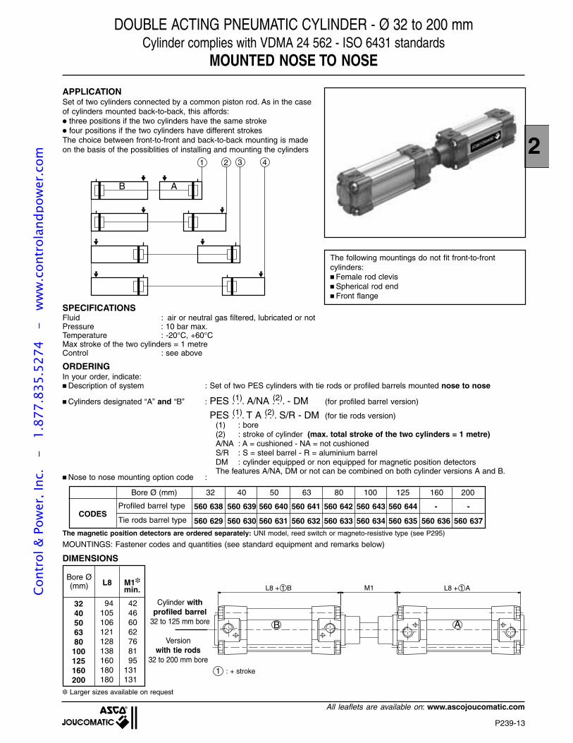
2
P239-13
All leaflets are available on: www.ascojoucomatic.com
M1L8 + 1 B L8 + 1 A
B A
DOUBLE ACTING PNEUMATIC CYLINDER - Ø 32 to 200 mmCylinder complies with VDMA 24 562 - ISO 6431 standards
MOUNTED NOSE TO NOSE
1 2 3 4
B A
APPLICATIONSet of two cylinders connected by a common piston rod. As in the caseof cylinders mounted back-to-back, this affords: three positions if the two cylinders have the same stroke four positions if the two cylinders have different strokesThe choice between front-to-front and back-to-back mounting is madeon the basis of the possiblities of installing and mounting the cylinders
SPECIFICATIONSFluid : air or neutral gas filtered, lubricated or notPressure : 10 bar max.Temperature : -20°C, +60°CMax stroke of the two cylinders = 1 metreControl : see above
The following mountings do not fit front-to-frontcylinders: Female rod clevis Spherical rod end Front flange
Bore Ø(mm) L8 M1
min.
94 42105 46106 60121 62128 76138 81160 95180 131180 131
3240506380
100125160200
Cylinder withprofiled barrel
32 to 125 mm bore
Versionwith tie rods
32 to 200 mm bore
ORDERINGIn your order, indicate:
Larger sizes available on request
Description of system : Set of two PES cylinders with tie rods or profiled barrels mounted nose to nose
Cylinders designated “A” and “B” : PES . . . A/NA . . . - DM (for profiled barrel version)
PES . . . T A . . . S/R - DM (for tie rods version)(1) : bore(2) : stroke of cylinder (max. total stroke of the two cylinders = 1 metre)A/NA : A = cushioned - NA = not cushionedS/R : S = steel barrel - R = aluminium barrelDM : cylinder equipped or non equipped for magnetic position detectorsThe features A/NA, DM or not can be combined on both cylinder versions A and B.
DIMENSIONS
Nose to nose mounting option code :
MOUNTINGS: Fastener codes and quantities (see standard equipment and remarks below)
(1) (2)
(1) (2)
1 : + stroke
Bore Ø (mm) 32 40 50 63 80 100 125 160 200
560 638 560 639 560 640 560 641 560 642 560 643 560 644 - -CODES
Profiled barrel type
Tie rods barrel type 560 629 560 630 560 631 560 632 560 633 560 634 560 635 560 636 560 637
The magnetic position detectors are ordered separately: UNI model, reed switch or magneto-resistive type (see P295)
Cont
rol &
Pow
er, I
nc.
-
1.87
7.83
5.52
74
- w
ww
.con
trol
andp
ower
.com
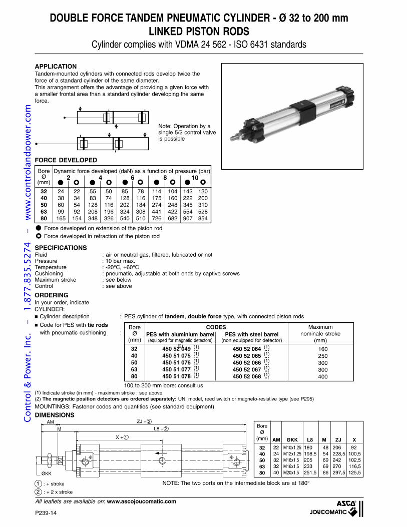
P239-14
All leaflets are available on: www.ascojoucomatic.com
DOUBLE FORCE TANDEM PNEUMATIC CYLINDER - Ø 32 to 200 mmLINKED PISTON RODS
Cylinder complies with VDMA 24 562 - ISO 6431 standards
APPLICATIONTandem-mounted cylinders with connected rods develop twice theforce of a standard cylinder of the same diameter.This arrangement offers the advantage of providing a given force witha smaller frontal area than a standard cylinder developing the sameforce.
Note: Operation by asingle 5/2 control valveis possible
FORCE DEVELOPED
AM ZJ + 2
L8 + 2M
ØKK
X + 1
BoreØ
(mm)
3240506380
Dynamic force developed (daN) as a function of pressure (bar)
BoreØ
(mm) AM ØKK L8 M ZJ X
22 M10x1,25 180 48 206 9224 M12x1,25 198,5 54 228,5 100,532 M16x1,5 205 69 242 102,532 M16x1,5 233 69 270 116,540 M20x1,5 251,5 86 297,5 125,5
3240506380
ORDERINGIn your order, indicateCYLINDER: Cylinder description : PES cylinder of tandem, double force type, with connected piston rods
Code for PES with tie rodswith pneumatic cushioning :
2 4 6 8 10
BoreØ
(mm)
3240506380
450 52 049 ...450 51 075 ...450 51 076 ...450 51 077 ...450 51 078 ...
450 52 064 ...450 52 065 ...450 52 066 ...450 52 067 ...450 52 068 ...
CODESPES with aluminium barrel(equipped for magnetic detectors)
(2)
PES with steel barrel(non equipped for detector)
2 : + 2 x stroke
DIMENSIONS
(1)
(1)
(1)
(1)(1)
(1)
(1)
(1)
(1)(1)
NOTE: The two ports on the intermediate block are at 180°
MOUNTINGS: Fastener codes and quantities (see standard equipment)
24 22 55 50 85 78 114 104 142 13038 34 83 74 128 116 175 160 222 20060 54 128 116 202 184 274 248 345 31099 92 208 196 324 308 441 422 554 528
165 154 348 326 540 510 726 682 907 854
(1) Indicate stroke (in mm) - maximum stroke : see above
Force developed on extension of the piston rodForce developed in retraction of the piston rod
1 : + stroke
100 to 200 mm bore: consult us
(2) The magnetic position detectors are ordered separately: UNI model, reed switch or magneto-resistive type (see P295)
SPECIFICATIONSFluid : air or neutral gas, filtered, lubricated or notPressure : 10 bar max.Temperature : -20°C, +60°CCushioning : pneumatic, adjustable at both ends by captive screwsMaximum stroke : see belowControl : see above
160250300300400
Maximumnominale stroke
(mm)
Cont
rol &
Pow
er, I
nc.
-
1.87
7.83
5.52
74
- w
ww
.con
trol
andp
ower
.com
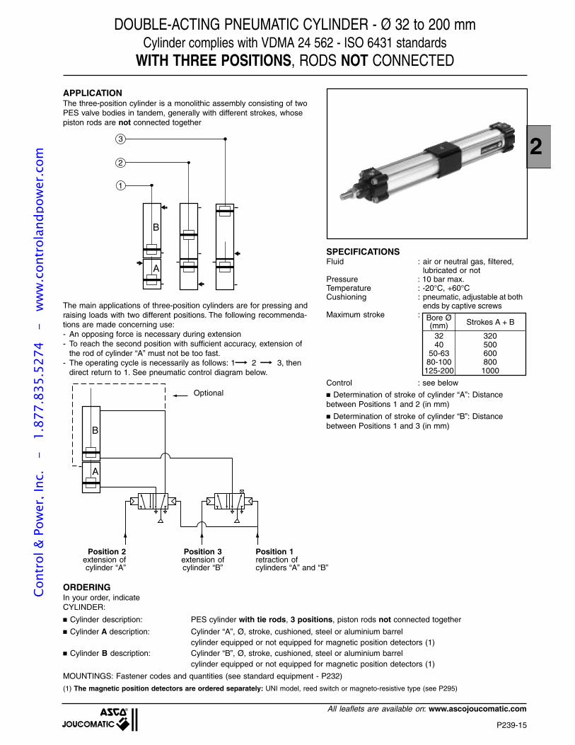
2
P239-15
All leaflets are available on: www.ascojoucomatic.com
DOUBLE-ACTING PNEUMATIC CYLINDER - Ø 32 to 200 mmCylinder complies with VDMA 24 562 - ISO 6431 standards
WITH THREE POSITIONS, RODS NOT CONNECTED
APPLICATIONThe three-position cylinder is a monolithic assembly consisting of twoPES valve bodies in tandem, generally with different strokes, whosepiston rods are not connected together
1
2
3
B
A
The main applications of three-position cylinders are for pressing andraising loads with two different positions. The following recommenda-tions are made concerning use:- An opposing force is necessary during extension- To reach the second position with sufficient accuracy, extension of
the rod of cylinder “A” must not be too fast.- The operating cycle is necessarily as follows: 1 2 3, then
direct return to 1. See pneumatic control diagram below.
B
A
ORDERINGIn your order, indicateCYLINDER:
Optional
Position 2extension ofcylinder “A”
Position 3extension ofcylinder “B”
Position 1retraction ofcylinders “A” and “B”
Cylinder description: PES cylinder with tie rods, 3 positions, piston rods not connected together
Cylinder A description: Cylinder “A”, Ø, stroke, cushioned, steel or aluminium barrelcylinder equipped or not equipped for magnetic position detectors (1)
Cylinder B description: Cylinder “B”, Ø, stroke, cushioned, steel or aluminium barrelcylinder equipped or not equipped for magnetic position detectors (1)
MOUNTINGS: Fastener codes and quantities (see standard equipment - P232)
(1) The magnetic position detectors are ordered separately: UNI model, reed switch or magneto-resistive type (see P295)
SPECIFICATIONSFluid : air or neutral gas, filtered,
lubricated or notPressure : 10 bar max.Temperature : -20°C, +60°CCushioning : pneumatic, adjustable at both
ends by captive screwsMaximum stroke :
Control : see below Determination of stroke of cylinder “A”: Distancebetween Positions 1 and 2 (in mm)
Determination of stroke of cylinder “B”: Distancebetween Positions 1 and 3 (in mm)
3240
50-6380-100125-200
3205006008001000
Bore Ø(mm) Strokes A + B
Cont
rol &
Pow
er, I
nc.
-
1.87
7.83
5.52
74
- w
ww
.con
trol
andp
ower
.com
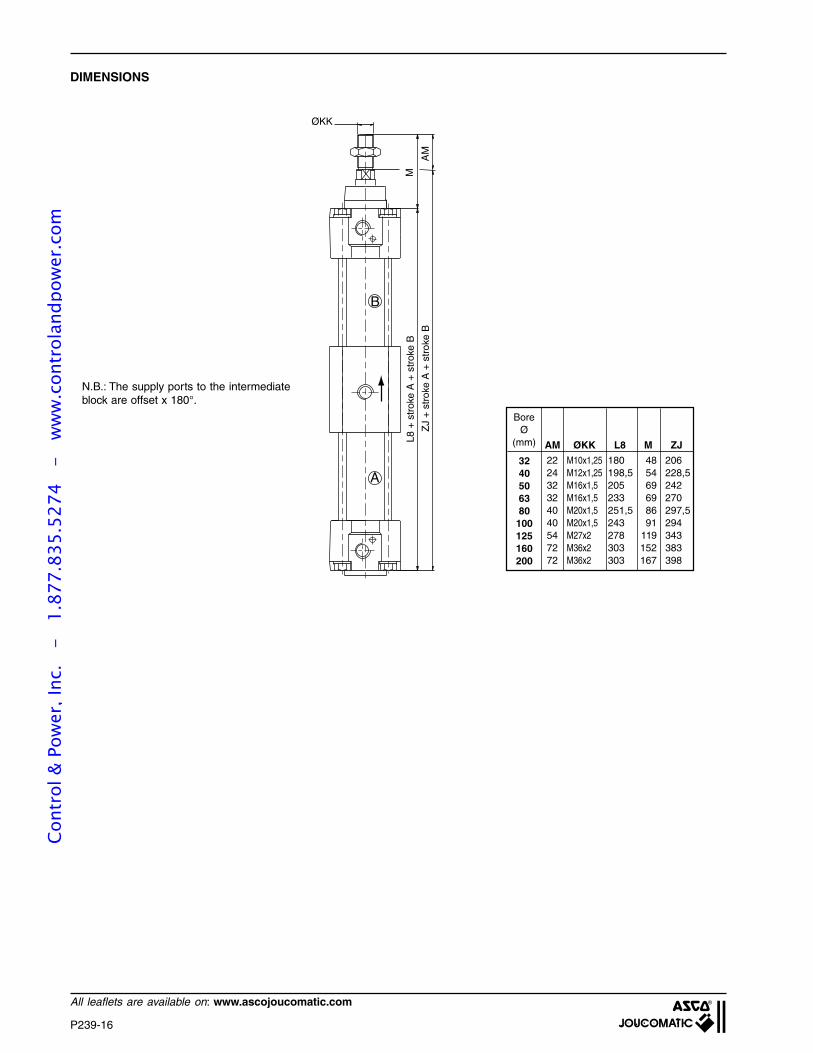
P239-16
All leaflets are available on: www.ascojoucomatic.com
AM
ZJ
+ c
ours
e A
+ c
ours
e B
L8 +
cou
rse
A +
cou
rse
BM
ØKK
B
A
DIMENSIONS
BoreØ
(mm) AM ØKK L8 M ZJ
22 M10x1,25 180 48 20624 M12x1,25 198,5 54 228,532 M16x1,5 205 69 24232 M16x1,5 233 69 27040 M20x1,5 251,5 86 297,540 M20x1,5 243 91 29454 M27x2 278 119 34372 M36x2 303 152 38372 M36x2 303 167 398
3240506380
100125160200
N.B.: The supply ports to the intermediateblock are offset x 180°.
L8 +
str
oke
A +
str
oke
B
ZJ
+ st
roke
A +
str
oke
B
Cont
rol &
Pow
er, I
nc.
-
1.87
7.83
5.52
74
- w
ww
.con
trol
andp
ower
.com
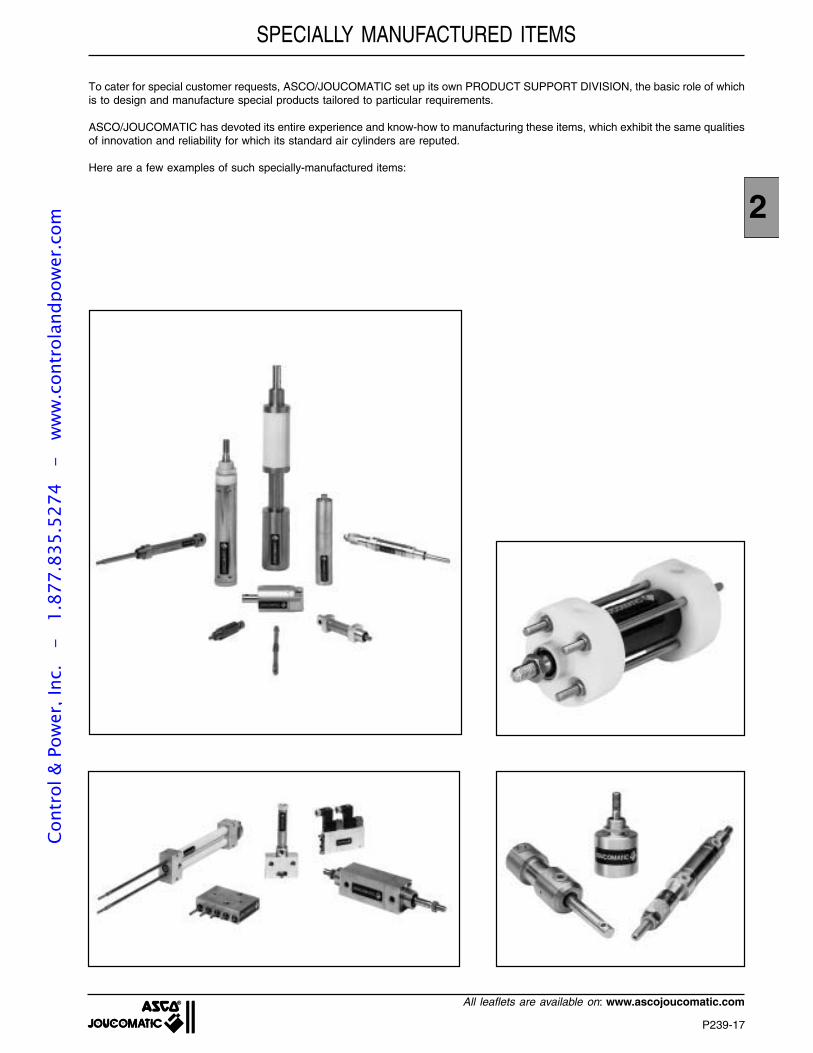
2
P239-17
All leaflets are available on: www.ascojoucomatic.com
To cater for special customer requests, ASCO/JOUCOMATIC set up its own PRODUCT SUPPORT DIVISION, the basic role of whichis to design and manufacture special products tailored to particular requirements.
ASCO/JOUCOMATIC has devoted its entire experience and know-how to manufacturing these items, which exhibit the same qualitiesof innovation and reliability for which its standard air cylinders are reputed.
Here are a few examples of such specially-manufactured items:
SPECIALLY MANUFACTURED ITEMSCo
ntro
l & P
ower
, Inc
. -
1.
877.
835.
5274
-
ww
w.c
ontr
olan
dpow
er.c
om
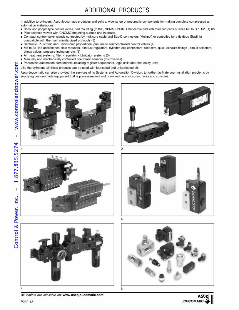
P239-18
All leaflets are available on: www.ascojoucomatic.com
ADDITIONAL PRODUCTS
In addition to cylinders, Asco-Joucomatic produces and sells a wide range of pneumatic components for making complete compressed airautomation installations: Spool and poppet type control valves, pad mounting (to ISO, VDMA, CNOMO standards) and with threaded ports of sizes M5 to G 1 1/2. (1) (2) Pilot solenoid valves with CNOMO mounting surface and interface. Compact control-valve islands connected by multicore cable and Sub-D connectors (Multipol) or controlled by a fieldbus (Buslink)
compatible with the main standardized protocols (3) Sentronic, Pulstronic and Servotronic proportional pneumatic servocontrolled control valves (4) M5 to B1 line accessories: flow reducers, exhaust regulators, cylinder lock connectors, silencers, quick-exhaust fittings , circuit selectors,
check valves, pressure indicators etc. (6) Air treatment systems: filter - regulator - lubricator systems (5) Manually and mechanically controlled pneumatic sensors (microvalves). Pneumatic automation components including register-sequencers, logic cells and time delay units.
Like the cylinders, all these products can be used with lubricated and unlubricated air.
Asco-Joucomatic can also provided the services of its Systems and Automation Division, to further facilitate your installation problems bysupplying custom-made equipment that is pre-assembled and pre-wired, in enclosures, racks and consoles.
1 2
3 4
5 6
Cont
rol &
Pow
er, I
nc.
-
1.87
7.83
5.52
74
- w
ww
.con
trol
andp
ower
.com
2
P239-19
All leaflets are available on: www.ascojoucomatic.com
MEANS OF PRODUCTION
Thanks to the long experience and the solid know-how of its engineers and technicians, ASCO-JOUCOMATIC has become a worldleader in fluid system technology. In the fields of both pneumatic components and valves for all fluids, the name of the company iswell-known throughout the world. It symbolizes quality and competetiveness.
1 2
3 4
1 - Product design using CAD techniques2 - Cylinders undergoing endurance tests3 - Machining center with palletization4 - Cylinder assembly and testing line
Cont
rol &
Pow
er, I
nc.
-
1.87
7.83
5.52
74
- w
ww
.con
trol
andp
ower
.com
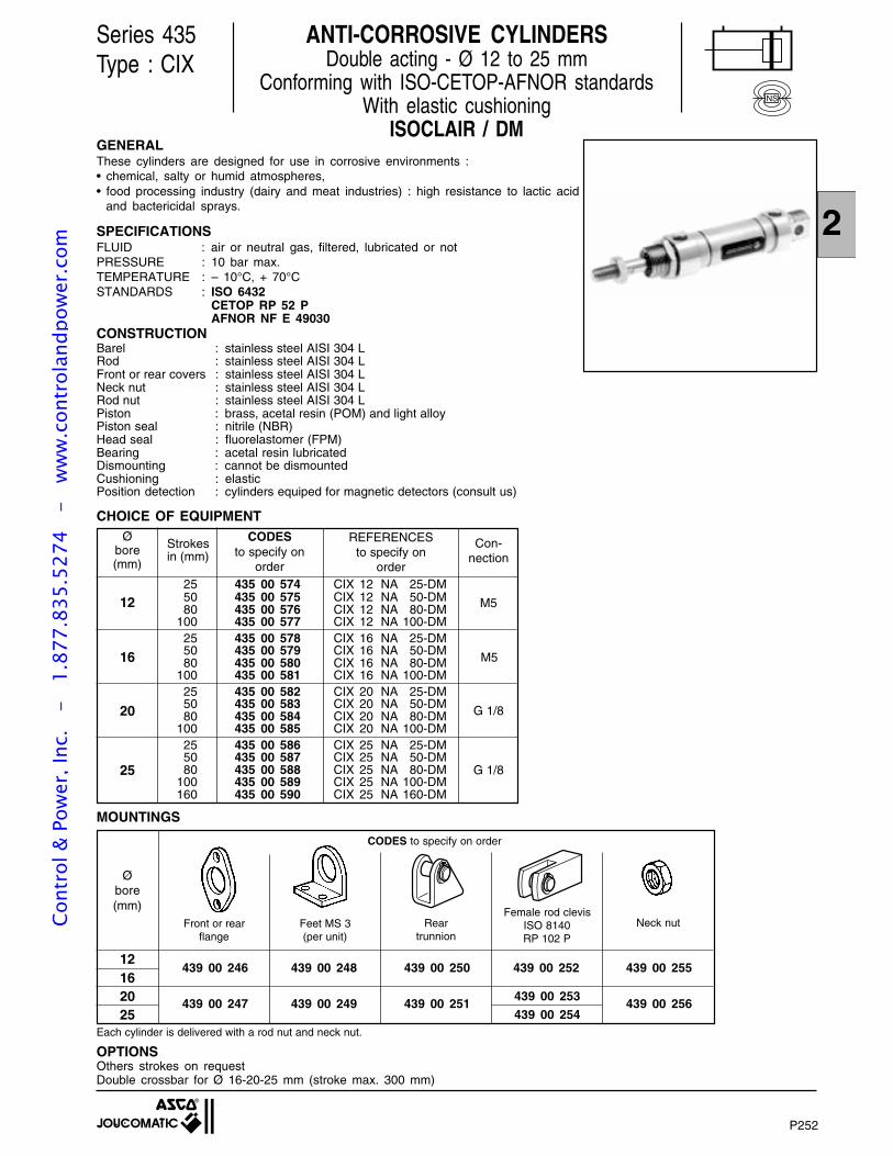
P252-1
2
439 00 246 439 00 248 439 00 250 439 00 252 439 00 255
439 00 247 439 00 249 439 00 251 439 00 256
GENERALThese cylinders are designed for use in corrosive environments :• chemical, salty or humid atmospheres,• food processing industry (dairy and meat industries) : high resistance to lactic acid
and bactericidal sprays.
SPECIFICATIONSFLUID : air or neutral gas, filtered, lubricated or notPRESSURE : 10 bar max.TEMPERATURE : – 10°C, + 70°CSTANDARDS : ISO 6432
CETOP RP 52 PAFNOR NF E 49030
CONSTRUCTIONBarel : stainless steel AISI 304 LRod : stainless steel AISI 304 LFront or rear covers : stainless steel AISI 304 LNeck nut : stainless steel AISI 304 LRod nut : stainless steel AISI 304 LPiston : brass, acetal resin (POM) and light alloyPiston seal : nitrile (NBR)Head seal : fluorelastomer (FPM)Bearing : acetal resin lubricatedDismounting : cannot be dismountedCushioning : elasticPosition detection : cylinders equiped for magnetic detectors (consult us)
CHOICE OF EQUIPMENT
Series 435Type : CIX
25 435 00 574 CIX 12 NA 25-DM50 435 00 575 CIX 12 NA 50-DM80 435 00 576 CIX 12 NA 80-DM
100 435 00 577 CIX 12 NA 100-DM25 435 00 578 CIX 16 NA 25-DM50 435 00 579 CIX 16 NA 50-DM80 435 00 580 CIX 16 NA 80-DM
100 435 00 581 CIX 16 NA 100-DM25 435 00 582 CIX 20 NA 25-DM50 435 00 583 CIX 20 NA 50-DM80 435 00 584 CIX 20 NA 80-DM
100 435 00 585 CIX 20 NA 100-DM25 435 00 586 CIX 25 NA 25-DM50 435 00 587 CIX 25 NA 50-DM80 435 00 588 CIX 25 NA 80-DM
100 435 00 589 CIX 25 NA 100-DM160 435 00 590 CIX 25 NA 160-DM
12
20
16
25
M5
G 1/8
G 1/8
M5
OPTIONSOthers strokes on requestDouble crossbar for Ø 16-20-25 mm (stroke max. 300 mm)
REFERENCESto specify on
order
ANTI-CORROSIVE CYLINDERSDouble acting - Ø 12 to 25 mm
Conforming with ISO-CETOP-AFNOR standardsWith elastic cushioning
ISOCLAIR / DM
Con-nection
CODESto specify on
order
Strokesin (mm)
Øbore(mm)
MOUNTINGS
Each cylinder is delivered with a rod nut and neck nut.
12162025
CODES to specify on order
Female rod clevisISO 8140RP 102 P
Neck nutFeet MS 3(per unit)
Front or rearflange
Reartrunnion
439 00 253
439 00 254
Øbore(mm)
P252
NS
Cont
rol &
Pow
er, I
nc.
-
1.87
7.83
5.52
74
- w
ww
.con
trol
andp
ower
.com
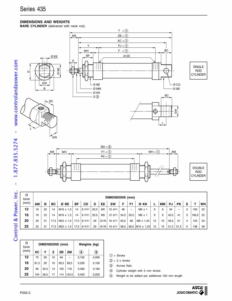
P252-2
Series 435
DIMENSIONS AND WEIGHTSBARE CYLINDER (delivered with neck nut).
AM B BC Ø BE BF CD D EE EW F F1 Ø KK L MM PJ PK S T WH
16 22 14 M16 x 1,5 14 6 H11 20,5 M5 12 d11 48 – M6 x 1 9 6 34 – 3 100 22
16 22 14 M16 x 1,5 14 6 H11 20,5 M5 12 d11 54,5 55,5 M6 x 1 9 6 40,5 41 3 106,5 22
20 31 17,5 M22 x 1,5 17,5 8 H11 29 G1/8 16 d11 63,5 68 M8 x 1,25 12 10 46,5 51 4 125 24
22 31 17,5 M22 x 1,5 17,5 8 H11 29 G1/8 16 d11 68,5 68,5 M10 x 1,25 12 10 51,5 51,5 5 136 28
12
16
20
25
Øbore(mm)
DIMENSIONS (mm)
XC Y Z ZB ZM 4 5
75 29 10 84 – 0,150 0,090
81,5 29 10 90,5 99,5 0,200 0,100
95 32,5 13 105 116 0,300 0,160
104 36,5 17 114 124,5 0,400 0,200
12
16
20
25
Øbore(mm)
DIMENSIONS (mm) Weights (kg)
1 + Stroke
2 + 2 x stroke
3 Across flats
4 Cylinder weight with 0 mm stroke
5 Weight to be added per additional 100 mm length
SINGLEROD
CYLINDER
T + 1
ZB + 1
XC + 1
PJ + 1
F + 1
AM
Y
WH
BF
S
BC
Ø EE
Ø BEØ MMØ KKZ 3
Ø CDØ BE
Ø EE
D
Ø B
E
EW
B
BC
L
EW
L
EW
BC
WH + 1F1 + 1WHAM AM
PK + 1
ZM + 2
DOUBLEROD
CYLINDER
Cont
rol &
Pow
er, I
nc.
-
1.87
7.83
5.52
74
- w
ww
.con
trol
andp
ower
.com
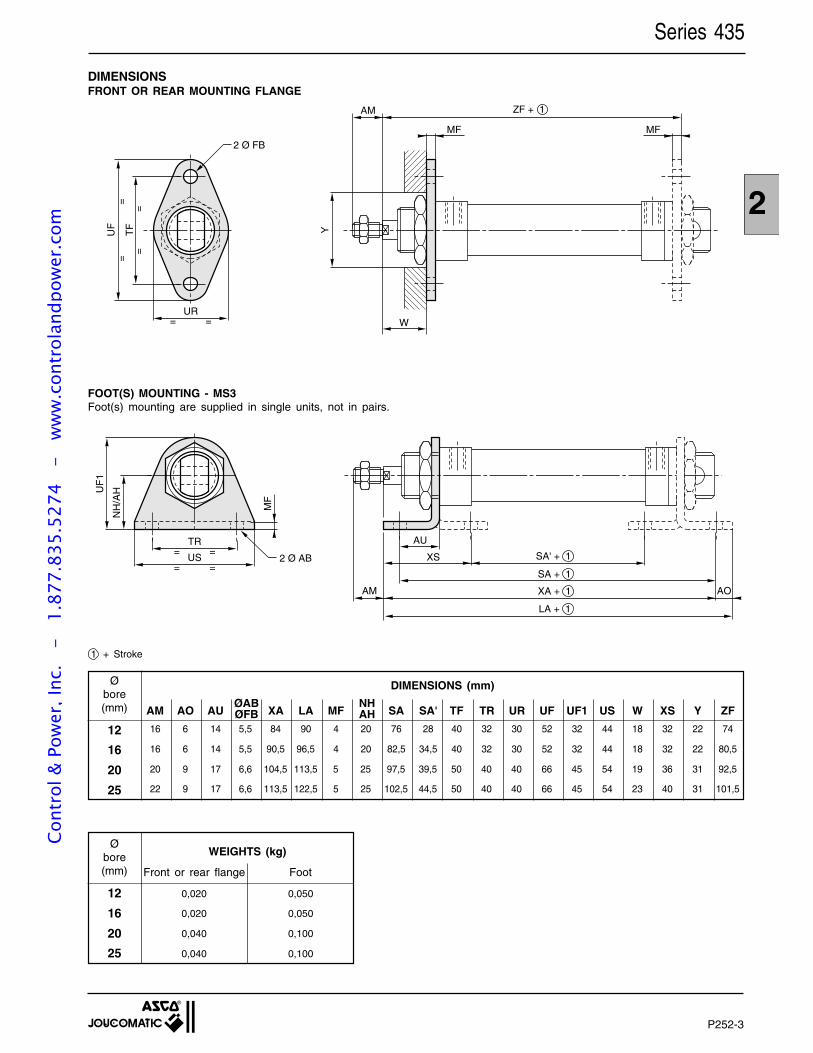
P252-3
2
DIMENSIONSFRONT OR REAR MOUNTING FLANGE
MF
YTF
UF
==
==
UR= =
AM
MF
W
ZF + 1
2 Ø FB
FOOT(S) MOUNTING - MS3Foot(s) mounting are supplied in single units, not in pairs.
TR= =
US= =
UF
1
NH
/AH
MF
2 Ø AB
AU
SA' + 1XS
AM AO
SA + 1
XA + 1
LA + 1
1 + Stroke
12
16
20
25
Øbore(mm)
0,020 0,050
0,020 0,050
0,040 0,100
0,040 0,100
WEIGHTS (kg)
Front or rear flange Foot
Series 435
AM AO AU XA LA MF SA SA' TF TR UR UF UF1 US W XS Y ZF
16 6 14 5,5 84 90 4 20 76 28 40 32 30 52 32 44 18 32 22 74
16 6 14 5,5 90,5 96,5 4 20 82,5 34,5 40 32 30 52 32 44 18 32 22 80,5
20 9 17 6,6 104,5 113,5 5 25 97,5 39,5 50 40 40 66 45 54 19 36 31 92,5
22 9 17 6,6 113,5 122,5 5 25 102,5 44,5 50 40 40 66 45 54 23 40 31 101,5
12
16
20
25
Øbore(mm)
DIMENSIONS (mm)
NHAH
ØABØFB
Cont
rol &
Pow
er, I
nc.
-
1.87
7.83
5.52
74
- w
ww
.con
trol
andp
ower
.com
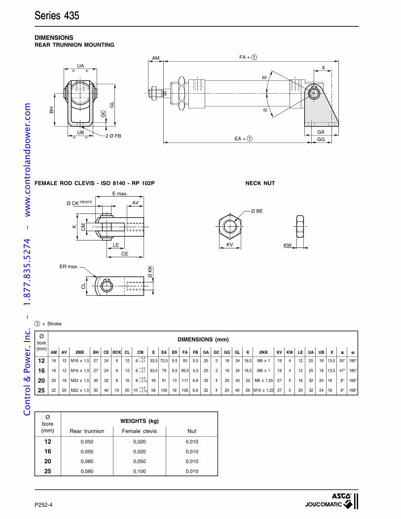
P252-4
Series 435
DIMENSIONSREAR TRUNNION MOUNTING
UA
FA + 1B
H GL
GC
= =
UB= = 2 Ø FB
AM
GG
GAEA + 1
X
ω
α
FEMALE ROD CLEVIS - ISO 8140 - RP 102P NECK NUT
KV KW
Ø BE
DIMENSIONS (mm)Øbore(mm)
AM AV ØBE BH CE ØCK CL CM E EA ER FA FB GA GC GG GL K ØKK KV KW LE UA UB X ααααα ωωωωω
16 12 M16 x 1,5 27 24 6 12 6 33,5 72,5 9,5 93 5,5 25 3 16 34 16,5 M6 x 1 19 4 12 25 18 13,5 50° 180°
16 12 M16 x 1,5 27 24 6 12 6 33,5 79 9,5 99,5 5,5 25 3 16 34 16,5 M6 x 1 19 4 12 25 18 13,5 47° 180°
20 16 M22 x 1,5 30 32 8 16 8 45 91 13 117 6,6 32 4 20 40 22 M8 x 1,25 27 5 16 32 24 16 8° 168°
22 20 M22 x 1,5 30 40 10 20 10 56 100 16 126 6,6 32 4 20 40 26 M10 x 1,25 27 5 20 32 24 16 8° 168°
+ 0,4+ 0,1
+ 0,4+ 0,1
+ 0,5+ 0,15
+ 0,5+ 0,15
12
16
20
25
1 + Stroke
12
16
20
25
Øbore(mm)
0,050 0,020 0,010
0,050 0,020 0,010
0,080 0,050 0,010
0,080 0,100 0,010
WEIGHTS (kg)
Rear trunnion Female clevis Nut
Series 435
E max.
Ø CK H9/d10 AV
LE
CE
K CM
CL
Ø K
KER max.
Cont
rol &
Pow
er, I
nc.
-
1.87
7.83
5.52
74
- w
ww
.con
trol
andp
ower
.com
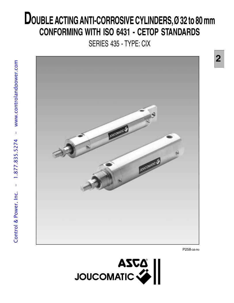
P258-GB-R0
DOUBLE ACTING ANTI-CORROSIVE CYLINDERS, Ø 32 to 80 mmCONFORMING WITH ISO 6431 - CETOP STANDARDS
SERIES 435 - TYPE: CIX
22
Cont
rol &
Pow
er, I
nc.
-
1.87
7.83
5.52
74
- w
ww
.con
trol
andp
ower
.com

P258-2
Cont
rol &
Pow
er, I
nc.
-
1.87
7.83
5.52
74
- w
ww
.con
trol
andp
ower
.com
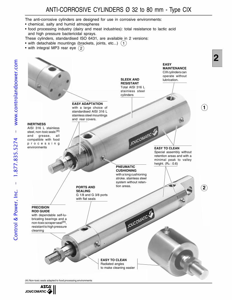
P258-3
2EASYMAINTENANCECIX cylinders canoperate withoutlubrication.
EASY TO CLEANSpecial assembly withoutretention areas and with aminimal peak to valleyheight. (Ra : 0.6)
EASY ADAPTATIONwith a large choice ofstandardised AISI 316 Lstainless steel mountingsand rear covers.
SLEEK ANDRESISTANTTotal AISI 316 Lstainless steelcylinders
PNEUMATICCUSHIONINGwith a long cushioningstroke. stainless steelsystem without reten-tion areas.PORTS AND
SEALINGG 1/8 and G 3/8 portswith flat seals
EASY TO CLEANRadiated anglesto make cleaning easier
ANTI-CORROSIVE CYLINDERS Ø 32 to 80 mm - Type CIXThe anti-corrosive cylinders are designed for use in corrosive environments:• chemical, salty and humid atmospheres• food processing industry (dairy and meat industries): total resistance to lactic acid
and high pressure bactericidal sprays.These cylinders, standardised ISO 6431, are available in 2 versions:• with detachable mountings (brackets, joints, etc...)• with integral MP3 rear eye
12
1
2
INERTNESSAISI 316 L stainlesssteel, non-toxic seals ()
and grease, allcompatible with foodp r o c e s s i n genvironments
PRECISIONROD GUIDEwith dependable self-lu-bricating bearings and anon-toxic scraper seal(),resistant to high pressurecleaning
() Non-toxic seals adapted to food processing environments
Cont
rol &
Pow
er, I
nc.
-
1.87
7.83
5.52
74
- w
ww
.con
trol
andp
ower
.com
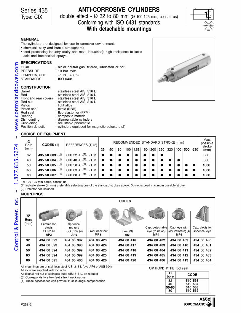
P258-4
GENERALThe cylinders are designed for use in corrosive environments:• chemical, salty and humid atmospheres• food processing industry (dairy and meat industries): high resistance to lactic
acid and bactericidal sprays.
SPECIFICATIONSFLUID : air or neutral gas, filtered, lubricated or notPRESSURE : 10 bar max.TEMPERATURE : –10°C, +80°CSTANDARDS : ISO 6431
CONSTRUCTIONBarrel : stainless steel AISI 316 LRod : stainless steel AISI 316 LFront and rear covers : stainless steel AISI 316 LRod nut : stainless steel AISI 316 LPiston : light alloyPiston seal : nitrile (NBR)Rod seal : fluorelastomer (FPM)Bearing : composite materialDismounting : dismountable cylindersCushioning : adjustable pneumaticPosition detection : cylinders equipped for magnetic detectors (2)
32 435 50 603 ---- CIX 32 A ---- - DM 800
40 435 50 604 ---- CIX 40 A ---- - DM 800
50 435 50 605 ---- CIX 50 A ---- - DM 1000
63 435 50 606 ---- CIX 63 A ---- - DM 1000
80 435 50 607 ---- CIX 80 A ---- - DM 1000
Series 435Type: CIX
ANTI-CORROSIVE CYLINDERSdouble effect - Ø 32 to 80 mm (Ø 100-125 mm, consult us)
Conforming with ISO 6431 standardsWith detachable mountings
25 50 80 100 125 160 200 250 320 400 500 630
RECOMMENDED STANDARD STROKE (mm)ØBore(mm)
CODES (1) REFERENCES (1) (2)
(1)
(1)
(1)
(1)
(1)
(1)
(1)
(1)
(1)
(1)
Max.possiblestroke(mm)
NS
For 100-125 mm bores, consult us(1) Indicate stroke (in mm) preferably selecting one of the standard strokes above. Do not exceed maximum possible stroke.(2) Detector not included
All mountings are of stainless steel AISI 316 L (eye AP6 of AISI 304)All rods are supplied with rod nutsAdditional rod nut of stainless steel AISI 316 L, on request(3) Corresponds to a two feet + front neck nut set(4) These accessories can provide 4° solid angle compensation
MOUNTINGS
CHOICE OF EQUIPMENT
OPTION: PTFE rod sealØ
bore CODE
3240
50-6380
510 536510 537510 538510 539
ØBore(mm)
32 434 00 392 434 00 397 434 00 423 434 00 416 434 00 402 434 00 409 434 00 430
40 434 00 393 434 00 398 434 00 424 434 00 417 434 00 403 434 00 410 434 00 431
50 434 00 394 434 00 399 434 00 425 434 00 418 434 00 404 434 00 411 434 00 432
63 434 00 394 434 00 399 434 00 425 434 00 419 434 00 405 434 00 412 434 00 433
80 434 00 395 434 00 400 434 00 426 434 00 420 434 00 406 434 00 413 434 00 434
CODES
Cap, detachableeye (trunnion)
MP4
Cap, eye withspherical bearing (4)
MP6
Cap, clevis forspherical eyeFeet (3)
MS1
Female rodclevis
ISO 8140AP2
Sphericalrod end
ISO 8139 (4)AP6
Front neck nutMR3
P258-2
Cont
rol &
Pow
er, I
nc.
-
1.87
7.83
5.52
74
- w
ww
.con
trol
andp
ower
.com
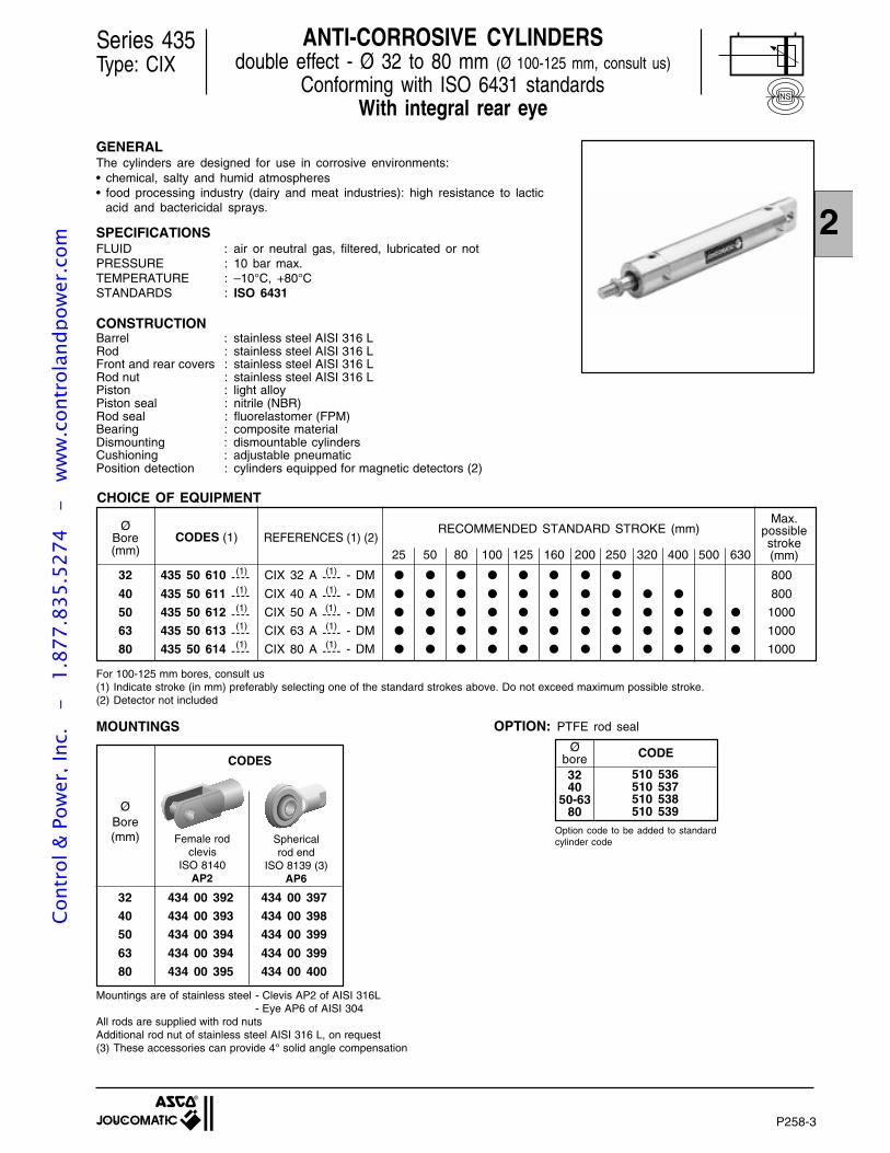
P258-5
2
GENERALThe cylinders are designed for use in corrosive environments:• chemical, salty and humid atmospheres• food processing industry (dairy and meat industries): high resistance to lactic
acid and bactericidal sprays.
SPECIFICATIONSFLUID : air or neutral gas, filtered, lubricated or notPRESSURE : 10 bar max.TEMPERATURE : –10°C, +80°CSTANDARDS : ISO 6431
CONSTRUCTIONBarrel : stainless steel AISI 316 LRod : stainless steel AISI 316 LFront and rear covers : stainless steel AISI 316 LRod nut : stainless steel AISI 316 LPiston : light alloyPiston seal : nitrile (NBR)Rod seal : fluorelastomer (FPM)Bearing : composite materialDismounting : dismountable cylindersCushioning : adjustable pneumaticPosition detection : cylinders equipped for magnetic detectors (2)
32 435 50 610 ---- CIX 32 A ---- - DM 800
40 435 50 611 ---- CIX 40 A ---- - DM 800
50 435 50 612 ---- CIX 50 A ---- - DM 1000
63 435 50 613 ---- CIX 63 A ---- - DM 1000
80 435 50 614 ---- CIX 80 A ---- - DM 1000
Series 435Type: CIX
ANTI-CORROSIVE CYLINDERSdouble effect - Ø 32 to 80 mm (Ø 100-125 mm, consult us)
Conforming with ISO 6431 standardsWith integral rear eye
25 50 80 100 125 160 200 250 320 400 500 630
RECOMMENDED STANDARD STROKE (mm)ØBore(mm)
CODES (1) REFERENCES (1) (2)
(1)
(1)
(1)
(1)
(1)
(1)
(1)
(1)
(1)
(1)
Max.possiblestroke(mm)
NS
For 100-125 mm bores, consult us(1) Indicate stroke (in mm) preferably selecting one of the standard strokes above. Do not exceed maximum possible stroke.(2) Detector not included
ØBore(mm)
Mountings are of stainless steel - Clevis AP2 of AISI 316L- Eye AP6 of AISI 304
All rods are supplied with rod nutsAdditional rod nut of stainless steel AISI 316 L, on request(3) These accessories can provide 4° solid angle compensation
32 434 00 392 434 00 397
40 434 00 393 434 00 398
50 434 00 394 434 00 399
63 434 00 394 434 00 399
80 434 00 395 434 00 400
MOUNTINGS
CODES
Female rodclevis
ISO 8140AP2
Sphericalrod end
ISO 8139 (3)AP6
CHOICE OF EQUIPMENT
OPTION: PTFE rod seal
Øbore CODE
3240
50-6380
510 536510 537510 538510 539
Option code to be added to standardcylinder code
P258-3
Cont
rol &
Pow
er, I
nc.
-
1.87
7.83
5.52
74
- w
ww
.con
trol
andp
ower
.com
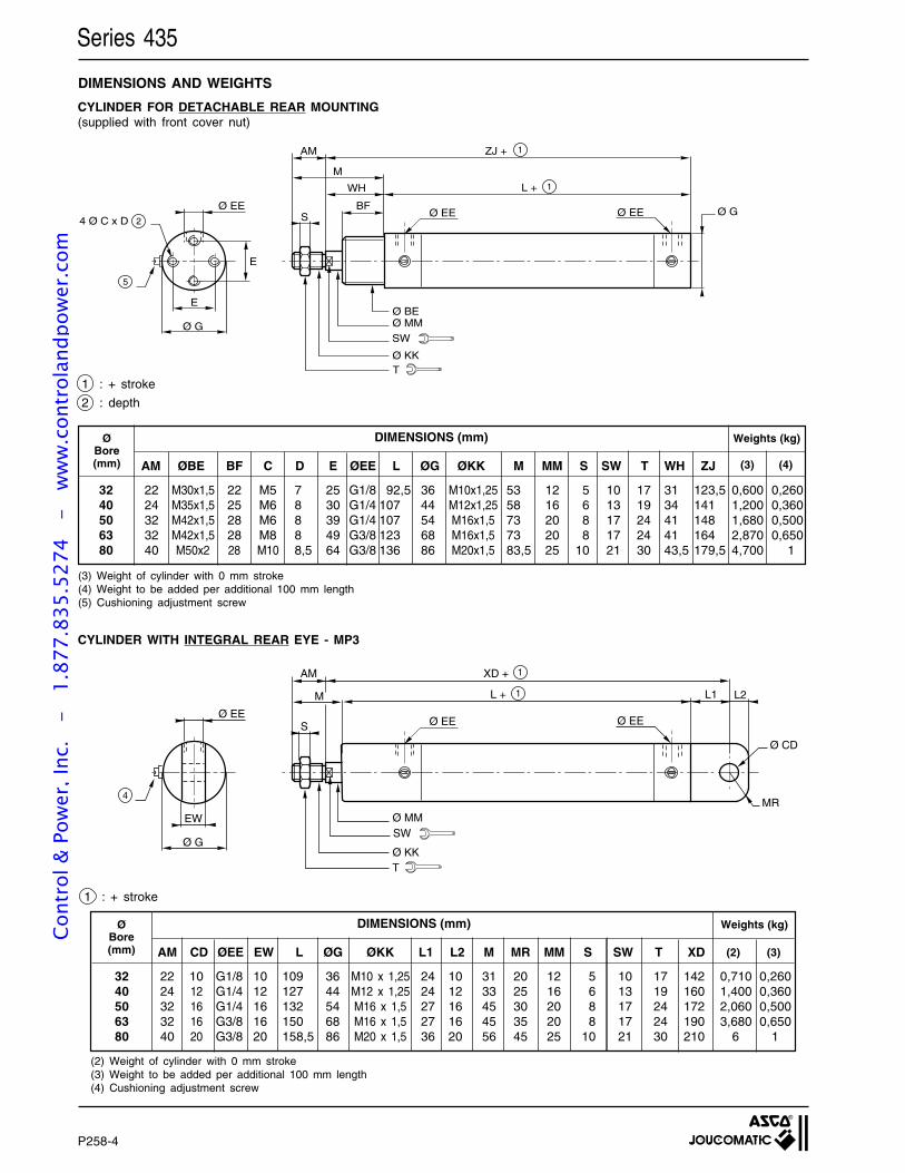
P258-6
DIMENSIONS AND WEIGHTS
Series 435
1 : + stroke
2 : depth
CYLINDER FOR DETACHABLE REAR MOUNTING(supplied with front cover nut)
CYLINDER WITH INTEGRAL REAR EYE - MP3
1 : + stroke
(2) Weight of cylinder with 0 mm stroke(3) Weight to be added per additional 100 mm length(4) Cushioning adjustment screw
(3) Weight of cylinder with 0 mm stroke(4) Weight to be added per additional 100 mm length(5) Cushioning adjustment screw
ZJ +
L +
AM
WH
BFS Ø EE Ø EE
Ø BEØ MM
Ø KK
Ø EE
E
E
Ø G
1
1
Ø G4 Ø C x D 2
M
5
T
SW
ØBore(mm)
32 22 M30x1,5 22 M5 7 25 G1/8 92,5 36 M10x1,25 53 12 5 10 17 31 123,5 0,600 0,26040 24 M35x1,5 25 M6 8 30 G1/4 107 44 M12x1,25 58 16 6 13 19 34 141 1,200 0,36050 32 M42x1,5 28 M6 8 39 G1/4 107 54 M16x1,5 73 20 8 17 24 41 148 1,680 0,50063 32 M42x1,5 28 M8 8 49 G3/8 123 68 M16x1,5 73 20 8 17 24 41 164 2,870 0,65080 40 M50x2 28 M10 8,5 64 G3/8 136 86 M20x1,5 83,5 25 10 21 30 43,5 179,5 4,700 1
DIMENSIONS (mm)
AM ØBE BF C D E ØEE L ØG ØKK M MM S SW T WH ZJ
Weights (kg)
(3) (4)
XD +
L +
AM
Ø EE Ø EE
Ø MM
Ø KK
Ø EE
EW
Ø G
1
1
M
MR
Ø CD
L1 L2
S
4
T
SW
ØBore(mm)
DIMENSIONS (mm)
AM CD ØEE EW L ØG ØKK L1 L2 M MR MM S SW T XD
32 22 10 G1/8 10 109 36 M10 x 1,25 24 10 31 20 12 5 10 17 142 0,710 0,26040 24 12 G1/4 12 127 44 M12 x 1,25 24 12 33 25 16 6 13 19 160 1,400 0,36050 32 16 G1/4 16 132 54 M16 x 1,5 27 16 45 30 20 8 17 24 172 2,060 0,50063 32 16 G3/8 16 150 68 M16 x 1,5 27 16 45 35 20 8 17 24 190 3,680 0,65080 40 20 G3/8 20 158,5 86 M20 x 1,5 36 20 56 45 25 10 21 30 210 6 1
Weights (kg)
(2) (3)
P258-4
Cont
rol &
Pow
er, I
nc.
-
1.87
7.83
5.52
74
- w
ww
.con
trol
andp
ower
.com
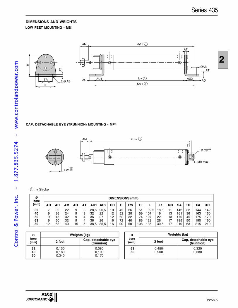
P258-7
2
DIMENSIONS AND WEIGHTS
CAP, DETACHABLE EYE (TRUNNION) MOUNTING - MP4
LOW FEET MOUNTING - MS1
Series 435
1 : + Stroke
Øbore(mm)
Cap, detachable eye(trunnion)2 feet
32 0,130 0,08040 0,180 0,10050 0,340 0,170
Øbore(mm)
Cap, detachable eye(trunnion)2 feet
63 0,450 0,32080 0,900 0,580
Weights (kg)Weights (kg)
TR= =
E= =
AT
2 Ø ABAU1
AM
L + 1
SA + 1
XA + 1
AU2
ØAB
AOAO
AT
AT
H
XD + AM
EW
1
MR max.
Ø CDH9
L1
-0,2-0,6
32 7 32 22 9 3 28,5 20,5 10 45 26 51 92,5 18,5 11 142 32 144 14240 9 36 24 9 3 32 22 12 52 28 59 107 19 13 161 36 163 16050 9 45 32 9 4 36 27 12 62 32 74 107 22 13 170 45 175 17063 9 50 32 9 4 36 26 16 72 40 86 123 26 17 185 50 190 19080 12 63 40 15 5 38,5 35,5 16 90 50 108 136 30,5 17 210 63 215 210
Øbore(mm)
DIMENSIONS (mm)
AB AH AM AO AT AU1 AU2 CD E EW H L L1 MR SA TR XA XD
P258-5
Cont
rol &
Pow
er, I
nc.
-
1.87
7.83
5.52
74
- w
ww
.con
trol
andp
ower
.com
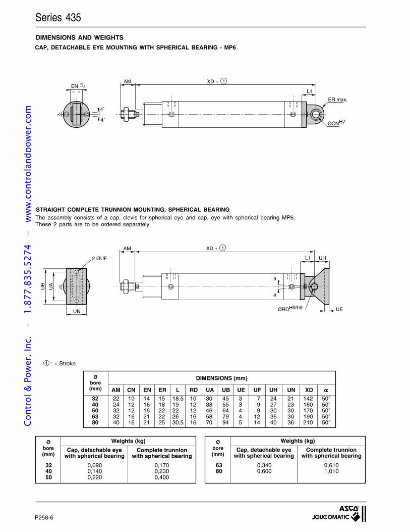
P258-8
DIMENSIONS AND WEIGHTS
STRAIGHT COMPLETE TRUNNION MOUNTING, SPHERICAL BEARING
CAP, DETACHABLE EYE MOUNTING WITH SPHERICAL BEARING - MP6
The assembly consists of a cap, clevis for spherical eye and cap, eye with spherical bearing MP6.These 2 parts are to be ordered separately.
L1
UEØRDH9/h9
UH
a
a
XD + AM 1
UN
2 ØUF
UB
UA
Series 435
1 : + Stroke
Øbore(mm)
Complete trunnionwith spherical bearing
Cap, detachable eyewith spherical bearing
32 0,090 0,17040 0,140 0,23050 0,220 0,400
Øbore(mm)
Complete trunnionwith spherical bearing
Cap, detachable eyewith spherical bearing
63 0,340 0,61080 0,600 1,010
Weights (kg)Weights (kg)
L1
ØCNH7
ER max.
4˚
4˚
EN==
+0- 0,1
XD + AM 1
32 22 10 14 15 18,5 10 30 45 3 7 24 21 142 50°40 24 12 16 18 19 12 38 55 3 9 27 23 160 50°50 32 12 16 22 22 12 46 64 4 9 30 30 170 50°63 32 16 21 22 26 16 58 79 4 12 36 30 190 50°80 40 16 21 25 30,5 16 70 94 5 14 40 36 210 50°
Øbore(mm)
DIMENSIONS (mm)
AM CN EN ER L RD UA UB UE UF UH UN XD ααααα
P258-6
Cont
rol &
Pow
er, I
nc.
-
1.87
7.83
5.52
74
- w
ww
.con
trol
andp
ower
.com
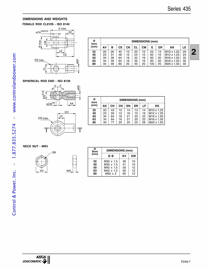
P258-9
2
DIMENSIONS AND WEIGHTS
Series 435
FEMALE ROD CLEVIS - ISO 8140
NECK NUT - MR3
Ø B KV KW
32 M30 x 1,5 36 1040 M35 x 1,5 41 1050 M42 x 1,5 50 1263 M42 x 1,5 50 1280 M50 x 2 65 12
ØBore(mm)
DIMENSIONS (mm)
SPHERICAL ROD END - ISO 8139
32 20 26 40 10 20 10 52 13 M10 x 1,25 2040 23 31 48 12 24 12 62 15 M12 x 1,25 2450 34 39 64 16 32 16 83 20 M16 x 1,50 3263 34 39 64 16 32 16 83 20 M16 x 1,50 3280 40 48 80 20 40 20 105 25 M20 x 1,50 40
Øbore(mm)
DIMENSIONS (mm)
AV B CE CK CL CM E ER KK LE
E max.
øCKH9/d10 AV
LE
CE
CM
B m
ax.
CL
ER max.
øK
K
øCNH9 AX
øK
K
EN
h12
4˚ 4˚
CH
LFER max.
32 20 43 10 14 13 14 M10 x 1,2540 23 50 12 16 15 16 M12 x 1,2550 34 64 16 21 20 22 M16 x 1,5063 34 64 16 21 20 22 M16 x 1,5080 40 77 20 25 25 26 M20 x 1,50
Øbore(mm)
DIMENSIONS (mm)
AX CH CN EN ER LF KK
ØB
KV KW
P258-7
Cont
rol &
Pow
er, I
nc.
-
1.87
7.83
5.52
74
- w
ww
.con
trol
andp
ower
.com
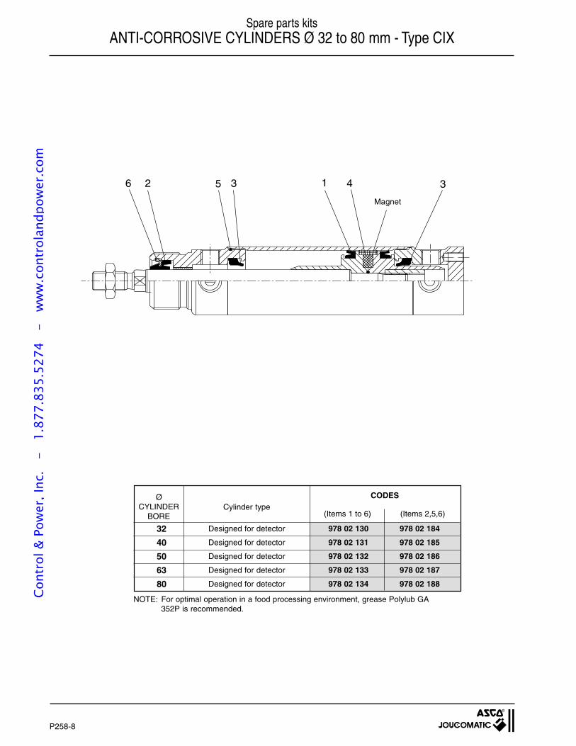
P258-10
35 312 46
Spare parts kitsANTI-CORROSIVE CYLINDERS Ø 32 to 80 mm - Type CIX
Magnet
32
40
50
63
80
Designed for detector 978 02 130 978 02 184
Designed for detector 978 02 131 978 02 185
Designed for detector 978 02 132 978 02 186
Designed for detector 978 02 133 978 02 187
Designed for detector 978 02 134 978 02 188
CODESØCYLINDER
BORECylinder type
NOTE: For optimal operation in a food processing environment, grease Polylub GA352P is recommended.
(Items 1 to 6) (Items 2,5,6)
P258-8
Cont
rol &
Pow
er, I
nc.
-
1.87
7.83
5.52
74
- w
ww
.con
trol
andp
ower
.com
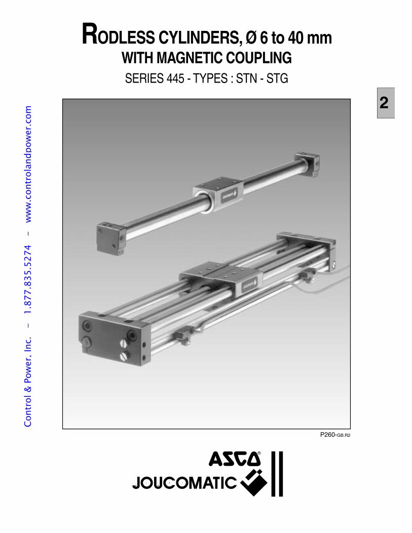
2
RODLESS CYLINDERS, Ø 6 to 40 mmWITH MAGNETIC COUPLINGSERIES 445 - TYPES : STN - STG
P260-GB.R2
Cont
rol &
Pow
er, I
nc.
-
1.87
7.83
5.52
74
- w
ww
.con
trol
andp
ower
.com
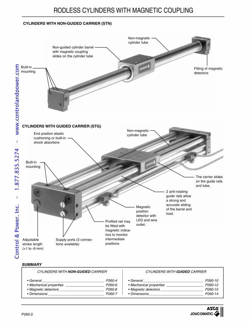
P260-2
CYLINDERS WITH NON-GUIDED CARRIER (STN)
CYLINDERS WITH GUIDED CARRIER (STG)
CYLINDERS WITH NON-GUIDED CARRIER
• General ________________________________ P260-4• Mechanical properties ____________________ P260-6• Magnetic detectors _______________________ P260-8• Dimensions _____________________________ P260-7
SUMMARY
CYLINDERS WITH GUIDED CARRIER
• General _______________________________ P260-10• Mechanical properties ___________________ P260-12• Magnetic detectors ______________________ P260-15• Dimensions ____________________________ P260-14
Adjustablestroke length(+1 to -6 mm)
The carrier slideson the guide railsand tube.
2 anti-rotatingguide rails allowa strong andaccurate slidingof the barrel andload.
Magneticpositiondetector withLED and wireoutlet.
Profiled rail maybe fitted withmagnetic indica-tors to monitorintermediatepositions
Supply ports (3 connec-tions available)
Non-guided cylinder barrelwith magnetic couplingslides on the cylinder tube
Non-magneticcylinder tube
Non-magneticcylinder tube
Built-inmounting
Built-inmounting
End position elasticcushioning or built-inshock absorbers
RODLESS CYLINDERS WITH MAGNETIC COUPLING
Fitting of magneticdetectors
Cont
rol &
Pow
er, I
nc.
-
1.87
7.83
5.52
74
- w
ww
.con
trol
andp
ower
.com
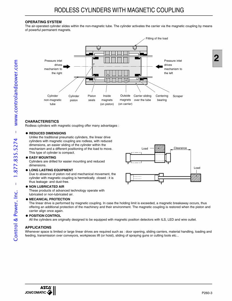
2
P260-3
OPERATING SYSTEMThe air-operated cylinder slides within the non-magnetic tube. The cylinder activates the carrier via the magnetic coupling by meansof powerful permanent magnets.
CHARACTERISTICSRodless cylinders with magnetic coupling offer many advantages :
REDUCED DIMENSIONSUnlike the traditional pneumatic cylinders, the linear drivecylinders with magnetic coupling are rodless, with reduceddimensions, an easier sliding of the cylinder within themechanism and a different positioning of the load to move.This type of cylinder is compact.
EASY MOUNTINGCylinders are drilled for easier mounting and reduceddimensions.
LONG LASTING EQUIPMENTDue to absence of piston rod and mechanical movement, thecylinder with magnetic coupling is hermetically closed : it isthus leakage- and dust-free.
NON LUBRICATED AIRThese products of advanced technology operate withlubricated or non-lubricated air.
MECANICAL PROTECTIONThe linear drive is performed by magnetic coupling. In case the holding limit is exceeded, a magnetic breakaway occurs, thusoffering an additional protection of the machinery and their environment. The magnetic coupling is restored when the piston andcarrier align once again.
POSITION CONTROLAll the cylinders are originally designed to be equipped with magnetic position detectors with ILS, LED and wire outlet.
APPLICATIONSWhenever space is limited or large linear drives are required such as : door opening, sliding carriers, material handling, loading andfeeding, transmission over conveyors, workpieces lift (or hoist), sliding of spraying guns or cutting tools etc...
RODLESS CYLINDERS WITH MAGNETIC COUPLING
Fitting of the load
Cylindernon-magnetic
tube
Cylinderpiston
Insidemagnets
(on piston)
Outsidemagnets
(on carrier)
Carrier slidingover the tube
Centeringbearing
ScraperPistonseals
Load
Pressure inlet drives
mechanism to the right
Pressure inletdrivesmechanism tothe left
•
•
•
•
•
•
Load Clearance
Cont
rol &
Pow
er, I
nc.
-
1.87
7.83
5.52
74
- w
ww
.con
trol
andp
ower
.com
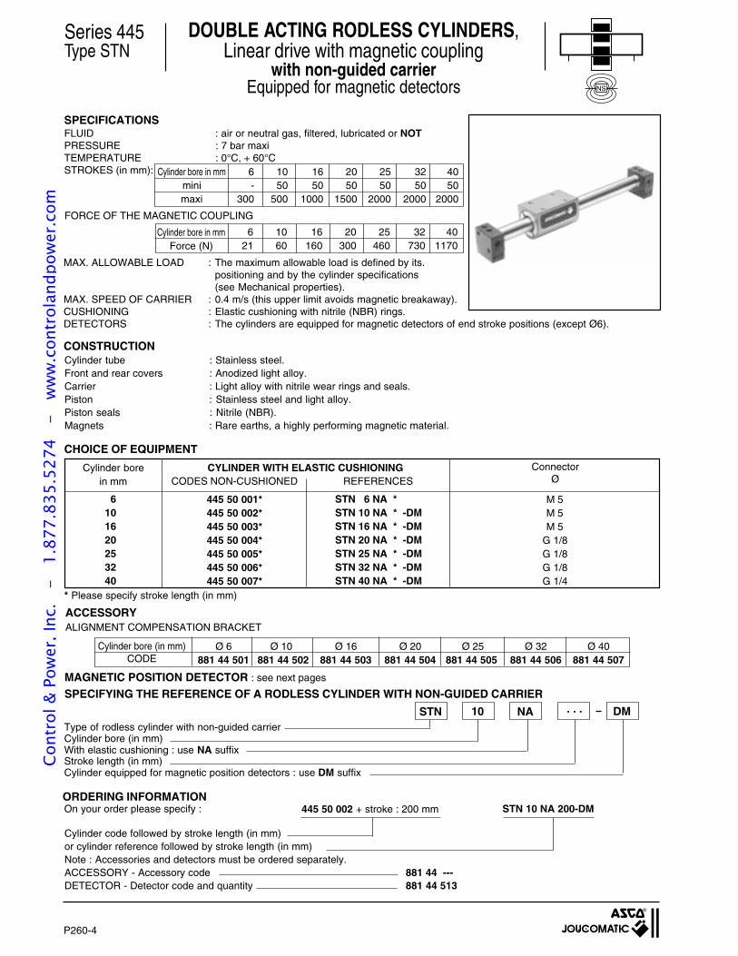
P260-4
CODES NON-CUSHIONED
445 50 001*445 50 002*445 50 003*445 50 004*445 50 005*445 50 006*445 50 007*
Type of rodless cylinder with non-guided carrierCylinder bore (in mm)With elastic cushioning : use NA suffixStroke length (in mm)Cylinder equipped for magnetic position detectors : use DM suffix
REFERENCES
STN 6 NA *STN 10 NA * -DMSTN 16 NA * -DMSTN 20 NA * -DMSTN 25 NA * -DMSTN 32 NA * -DMSTN 40 NA * -DM
FORCE OF THE MAGNETIC COUPLING
MAX. ALLOWABLE LOAD : The maximum allowable load is defined by its.positioning and by the cylinder specifications(see Mechanical properties).
MAX. SPEED OF CARRIER : 0.4 m/s (this upper limit avoids magnetic breakaway).CUSHIONING : Elastic cushioning with nitrile (NBR) rings.DETECTORS : The cylinders are equipped for magnetic detectors of end stroke positions (except Ø6).
CONSTRUCTION
CHOICE OF EQUIPMENT
* Please specify stroke length (in mm)
Cylinder code followed by stroke length (in mm)or cylinder reference followed by stroke length (in mm)Note : Accessories and detectors must be ordered separately.ACCESSORY - Accessory code 881 44 ---DETECTOR - Detector code and quantity 881 44 513
445 50 002 + stroke : 200 mm STN 10 NA 200-DMOn your order please specify :ORDERING INFORMATION
NA . . .10STN DM
SPECIFYING THE REFERENCE OF A RODLESS CYLINDER WITH NON-GUIDED CARRIER
ALIGNMENT COMPENSATION BRACKET
SPECIFICATIONSFLUID : air or neutral gas, filtered, lubricated or NOTPRESSURE : 7 bar maxiTEMPERATURE : 0°C, + 60°CSTROKES (in mm):
Cylinder tube : Stainless steel.Front and rear covers : Anodized light alloy.Carrier : Light alloy with nitrile wear rings and seals.Piston : Stainless steel and light alloy.Piston seals : Nitrile (NBR).Magnets : Rare earths, a highly performing magnetic material.
6 10 16 20 25 32 40- 50 50 50 50 50 50
300 500 1000 1500 2000 2000 2000
Cylinder bore in mmminimaxi
6 10 16 20 25 32 4021 60 160 300 460 730 1170
Cylinder bore in mmForce (N)
MAGNETIC POSITION DETECTOR : see next pages
M 5M 5M 5
G 1/8G 1/8G 1/8G 1/4
Cylinder borein mm
6101620253240
CYLINDER WITH ELASTIC CUSHIONING ConnectorØ
Ø 6 Ø 10 Ø 16 Ø 20 Ø 25 Ø 32 Ø 40881 44 501 881 44 502 881 44 503 881 44 504 881 44 505 881 44 506 881 44 507
Cylinder bore (in mm)CODE
Series 445Type STN
DOUBLE ACTING RODLESS CYLINDERS,Linear drive with magnetic coupling
with non-guided carrierEquipped for magnetic detectors NS
ACCESSORY
Cont
rol &
Pow
er, I
nc.
-
1.87
7.83
5.52
74
- w
ww
.con
trol
andp
ower
.com
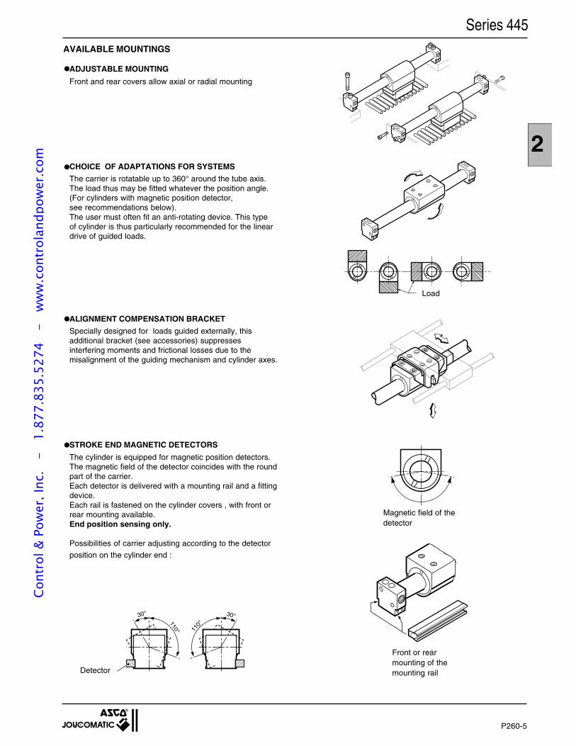
2
P260-5
110°
30°
110°
30°
Series 445
Detector
Load
Magnetic field of thedetector
Front or rearmounting of themounting rail
AVAILABLE MOUNTINGS
ADJUSTABLE MOUNTING
Front and rear covers allow axial or radial mounting
CHOICE OF ADAPTATIONS FOR SYSTEMS
The carrier is rotatable up to 360° around the tube axis.The load thus may be fitted whatever the position angle.(For cylinders with magnetic position detector,see recommendations below).The user must often fit an anti-rotating device. This typeof cylinder is thus particularly recommended for the lineardrive of guided loads.
ALIGNMENT COMPENSATION BRACKET
Specially designed for loads guided externally, thisadditional bracket (see accessories) suppressesinterfering moments and frictional losses due to themisalignment of the guiding mechanism and cylinder axes.
STROKE END MAGNETIC DETECTORS
The cylinder is equipped for magnetic position detectors.The magnetic field of the detector coincides with the roundpart of the carrier.Each detector is delivered with a mounting rail and a fittingdevice.Each rail is fastened on the cylinder covers , with front orrear mounting available.End position sensing only.
Possibilities of carrier adjusting according to the detector
position on the cylinder end :
•
•
•
•
Cont
rol &
Pow
er, I
nc.
-
1.87
7.83
5.52
74
- w
ww
.con
trol
andp
ower
.com
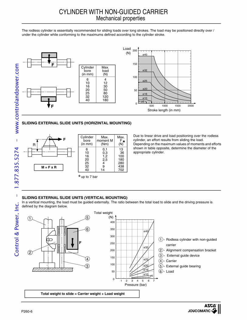
P260-6
F
ø40
400
0 1 2 3 4 5 6 7
ø32
ø25
ø20
ø16
ø10 ø6
350
300
250
200
150
100
50
F
6
4
3
2
1 5
FR
200
150
100
50
0500 1000 1500 2000
ø40
ø32
ø20
ø25
ø16
ø10ø6
F
M = F x R
CYLINDER WITH NON-GUIDED CARRIERMechanical properties
The rodless cylinder is essentially recommended for sliding loads over long strokes. The load may be positioned directly over /under the cylinder while conforming to the maximums defined according to the cylinder stroke.
SLIDING EXTERNAL SLIDE UNITS (HORIZINTAL MOUNTING)
SLIDING EXTERNAL SLIDE UNITS (VERTICAL MOUNTING)In a vertical mounting, the load must be guided externally. The ratio between the total load to slide and the driving pressure isdefined by the diagram below.
*up to 7 bar
1 - Rodless cylinder with non-guided
carrier
2 - Alignment compensation bracket
3 - External guide device
4 - Carrier
5 - External guide bearing
6 - Load
Due to linear drive and load positioning over the rodlesscylinder, an effort results from sliding the load.Depending on the maximum values of moments and effortsshown in table opposite, determine the diameter of theappropriate cylinder.
Stroke length (in mm)
Load(N)
Max.load(N)
412305080
120180
Cylinderbore
(in mm)
6101620253240
Max.F
(N)
1336
100180280438702
*
Total weight to slide = Carrier weight + Load weight
Total weight(N)
Pressure (bar)
Cylinderbore
(in mm)
6101620253240
Max.moment M
(Nm)
0,10,31,22,549
14
Cont
rol &
Pow
er, I
nc.
-
1.87
7.83
5.52
74
- w
ww
.con
trol
andp
ower
.com
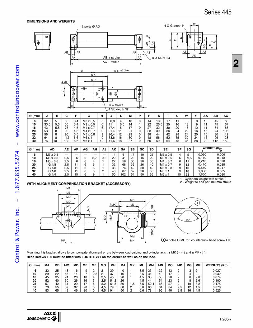
2
P260-7
A +A
S A
S D
B B
L
4-ØF
AE AF
AA
AF AE
AA
AH
AG
P
S T
U
R
SG
Y
M
AK
W
AJ AJ
ØJ
SB
SC
Mounting this bracket allows to compensate alignment errors between load guiding and cylinder axis : ± MK ( ) and ± MP ( ).
Head screws F90 must be fitted with LOCTITE 241 on the carrier as well as on the load.
90°
1
MB
MC
MD
ME
MA
MF
MG
MH
MJMK
MP
MO
ØM
QM
R
MN
MM
+ --
+--
DIMENSIONS AND WEIGHTS2 ports Ø AD
8 Ø M2 x 0,4
4 SE depth SF
WITH ALIGNMENT COMPENSATION BRACKET (ACCESSORY)
1 4 holes Ø ML for countersunk head screw F90
4 Ø G depth H
1 - Cylinders weight with stroke 02 - Weight to add per 100 mm stroke
A
32,533,54353566476
B
55,55,5888
10
C
5556759096112132
G
M3 x 0,5M3 x 0,5M4 x 0,7M4 x 0,7M5 x 0,8M6 x 1M6 x 1
H
566999
12
J
6,81117,421,426,433,641,6
M
10141721233037
P
0100000
R
14222733384860
S
18,526,53239445669
T
17253036425264
U
11162024283543
W
8131622243236
Y
09
1216202428
AC
656786
106112128152
AB
454564748096
112
AA
10111116161620
L
46,58
11121618
Ø (mm)
6101620253240
AD
M5 x 0,8M5 x 0,8M5 x 0,8
G 1/8G 1/8G 1/8G 1/4
F
3,43,44,54,55,56,66,6
AE
—2,52,52,52,52,52,5
SG
59,5
1113131823
AF
—66
11111115
AG
—666666
AH
—3,746589
AJ
—0,511121
AK
14222732364650
SA
414159687487
102
SB
17253036425264
SC
10162026303850
SD
25223540425565
SE
M3 x 0,5M3 x 0,5M4 x 0,7M4 x 0,7M5 x 0,8M6 x 1M6 x 1
SF
466999
15
Ø (mm)
6101620253240
WEIGHTS (Kg)1 2
0,0500,1100,2100,4100,5501,0301,830
0,0060,0130,0280,0350,0470,0650,080
AC + stroke
stroke
AB + stroke
Series 445
C + stroke
Ø (mm)
6101620253240
MA
32294552577383
MB
25223540425565
MC
18152430313949
MD
16142026293746
ME
97
1016172030
MF
22,54568
10
MG
222,52,53,24,54,5
MH
29374551,261,87991
MJ
0162026303850
MK
11111,522
ML
3,53,54,54,55,56,66,6
MM
2331384452,46678
MN
32405054668496
MO
13172023273440
MP
222222,52,5
MQ
3468
101216
MR
222,62,63,24,54,5
WEIGHTS (Kg)
0,0270,0320,0740,1000,1750,3700,525
Cont
rol &
Pow
er, I
nc.
-
1.87
7.83
5.52
74
- w
ww
.con
trol
andp
ower
.com
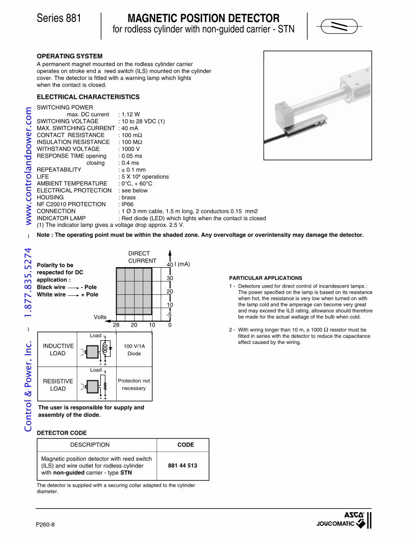
P260-8
40
30
20
10
-5
0102028
- +-
- +-
Polarity to berespected for DCapplication :Black wire - PoleWhite wire + Pole
MAGNETIC POSITION DETECTORfor rodless cylinder with non-guided carrier - STN
OPERATING SYSTEMA permanent magnet mounted on the rodless cylinder carrieroperates on stroke end a reed switch (ILS) mounted on the cylindercover. The detector is fitted with a warning lamp which lightswhen the contact is closed.
I (mA)
Series 881
(1) The indicator lamp gives a voltage drop approx. 2.5 V.
Note : The operating point must be within the shaded zone. Any overvoltage or overintensity may damage the detector.
The user is responsible for supply andassembly of the diode.
1 - Detectors used for direct control of incandescent lamps :The power specified on the lamp is based on its resistancewhen hot, the resistance is very low when turned on withthe lamp cold and the amperage can become very greatand may exceed the ILS rating, allowance should thereforebe made for the actual wattage of the bulb when cold.
2 - With wiring longer than 10 m, a 1000 Ω resistor must befitted in series with the detector to reduce the capacitanceeffect caused by the wiring.
PARTICULAR APPLICATIONS
DETECTOR CODE
Magnetic position detector with reed switch(ILS) and wire outlet for rodless cylinderwith non-guided carrier - type STN
DESCRIPTION
The detector is supplied with a securing collar adapted to the cylinderdiameter.
Volts
INDUCTIVELOAD
100 V/1ADiode
RESISTIVE LOAD
DIRECTCURRENT
Protection notnecessary
Load
Load
ELECTRICAL CHARACTERISTICS
SWITCHING POWERmax. DC current : 1.12 W
SWITCHING VOLTAGE : 10 to 28 VDC (1)MAX. SWITCHING CURRENT : 40 mACONTACT RESISTANCE : 100 mΩINSULATION RESISTANCE : 100 MΩWITHSTAND VOLTAGE : 1000 VRESPONSE TIME opening : 0.05 ms closing : 0.4 msREPEATABILITY : ± 0.1 mmLIFE : 5 X 10⁶ operationsAMBIENT TEMPERATURE : 0°C, + 60°CELECTRICAL PROTECTION : see belowHOUSING : brassNF C20010 PROTECTION : IP66CONNECTION : 1 Ø 3 mm cable, 1.5 m long, 2 conductors 0.15 mm2INDICATOR LAMP : Red diode (LED) which lights when the contact is closed
CODE
881 44 513
Cont
rol &
Pow
er, I
nc.
-
1.87
7.83
5.52
74
- w
ww
.con
trol
andp
ower
.com

2
P260-9
1
2
3
4
12B
A
B
A
12
DIMENSIONS WITH DETECTORThe detector must be mounted according to dimension A below. The detector position may be adjusted allowing a 1 mm overlap.
MOUNTING THE DETECTORFit the rail either on front or rear cylinder cover.
Respect the directional mounting of detector with LED inwards andmounting instructions of parts.
The detector is screwed into the rail by means of the locking screw.Max. screwing torque : < 0.2 Nm.
••
•
Metal plate
LED
Series 445
Cylinderbore (in mm)
101620253240
A
2833363943,549
B
49,549,543,543,543,539,5
Cont
rol &
Pow
er, I
nc.
-
1.87
7.83
5.52
74
- w
ww
.con
trol
andp
ower
.com
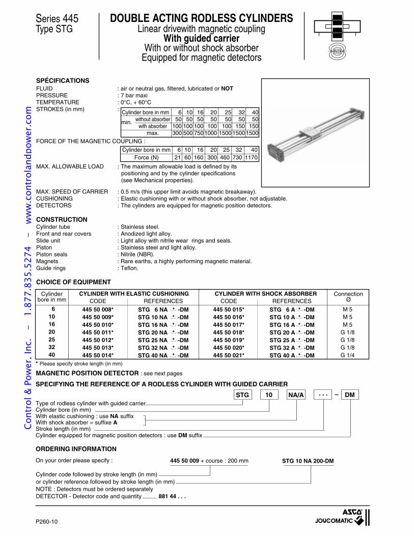
P260-10
REFERENCES
STG 6 A * -DMSTG 10 A * -DMSTG 16 A * -DMSTG 20 A * -DMSTG 25 A * -DMSTG 32 A * -DMSTG 40 A * -DM
REFERENCES
STG 6 NA * -DMSTG 10 NA * -DMSTG 16 NA * -DMSTG 20 NA * -DMSTG 25 NA * -DMSTG 32 NA * -DMSTG 40 NA * -DM
Cylinder bore in mm 6 10 16 20 25 32 40without absorber 50 50 50 50 50 50 50
with absorber 100 100 100 100 100 150 150max. 300 500 7501000 1500 15001500
Series 445Type STG
DOUBLE ACTING RODLESS CYLINDERSLinear drivewith magnetic coupling
With guided carrierWith or without shock absorber
Equipped for magnetic detectors
SPÉCIFICATIONSFLUID : air or neutral gas, filtered, lubricated or NOTPRESSURE : 7 bar maxiTEMPERATURE : 0°C, + 60°CSTROKES (in mm) :
FORCE OF THE MAGNETIC COUPLING :
MAX. ALLOWABLE LOAD : The maximum allowable load is defined by itspositioning and by the cylinder specifications(see Mechanical properties).
MAX. SPEED OF CARRIER : 0.5 m/s (this upper limit avoids magnetic breakaway).CUSHIONING : Elastic cushioning with or without shock absorber, not adjustable.DETECTORS : The cylinders are equipped for magnetic position detectors.
CONSTRUCTIONCylinder tube : Stainless steel.Front and rear covers : Anodized light alloy.Slide unit : Light alloy with nitrile wear rings and seals.Piston : Stainless steel and light alloy.Piston seals : Nitrile (NBR).Magnets : Rare earths, a highly performing magnetic material.Guide rings : Teflon.
CHOICE OF EQUIPMENT
* Please specify stroke length (in mm)
MAGNETIC POSITION DETECTOR : see next pages
Type of rodless cylinder with guided carrierCylinder bore (in mm)With elastic cushioning : use NA suffixWith shock absorber = suffixe AStroke length (in mm)Cylinder equipped for magnetic position detectors : use DM suffix
. . .10STG DMNA/A
SPECIFYING THE REFERENCE OF A RODLESS CYLINDER WITH GUIDED CARRIER
ORDERING INFORMATION
445 50 009 + course : 200 mm STG 10 NA 200-DMOn your order please specify :
Cylinder code followed by stroke length (in mm)or cylinder reference followed by stroke length (in mm)NOTE : Detectors must be ordered separatelyDETECTOR - Detector code and quantity 881 44 . . .
min.
Cylinder bore in mm 6 10 16 20 25 32 40Force (N) 21 60 160 300 460 730 1170
ConnectionØ
CYLINDER WITH SHOCK ABSORBERCYLINDER WITH ELASTIC CUSHIONINGCylinderbore in mm
6101620253240
M 5M 5M 5
G 1/8G 1/8G 1/8G 1/4
CODE
445 50 015*445 50 016*445 50 017*445 50 018*445 50 019*445 50 020*445 50 021*
CODE
445 50 008*445 50 009*445 50 010*445 50 011*445 50 012*445 50 013*445 50 014*
NS
Cont
rol &
Pow
er, I
nc.
-
1.87
7.83
5.52
74
- w
ww
.con
trol
andp
ower
.com
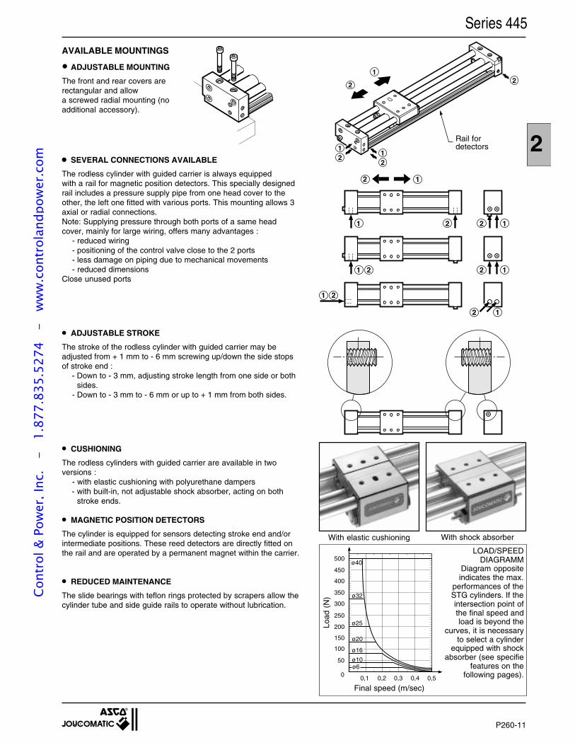
2
P260-11
12
2
1 2
1
1 2
1 2
2 1
12
1
2
12
12
2
With elastic cushioning With shock absorber
AVAILABLE MOUNTINGS
ADJUSTABLE MOUNTING
The front and rear covers arerectangular and allowa screwed radial mounting (noadditional accessory).
Series 445
SEVERAL CONNECTIONS AVAILABLE
The rodless cylinder with guided carrier is always equippedwith a rail for magnetic position detectors. This specially designedrail includes a pressure supply pipe from one head cover to theother, the left one fitted with various ports. This mounting allows 3axial or radial connections.Note: Supplying pressure through both ports of a same headcover, mainly for large wiring, offers many advantages :
- reduced wiring- positioning of the control valve close to the 2 ports- less damage on piping due to mechanical movements- reduced dimensions
Close unused ports
ADJUSTABLE STROKE
The stroke of the rodless cylinder with guided carrier may beadjusted from + 1 mm to - 6 mm screwing up/down the side stopsof stroke end :
- Down to - 3 mm, adjusting stroke length from one side or bothsides.
- Down to - 3 mm to - 6 mm or up to + 1 mm from both sides.
CUSHIONING
The rodless cylinders with guided carrier are available in twoversions :
- with elastic cushioning with polyurethane dampers- with built-in, not adjustable shock absorber, acting on both
stroke ends.
MAGNETIC POSITION DETECTORS
The cylinder is equipped for sensors detecting stroke end and/orintermediate positions. These reed detectors are directly fitted onthe rail and are operated by a permanent magnet within the carrier.
REDUCED MAINTENANCE
The slide bearings with teflon rings protected by scrapers allow thecylinder tube and side guide rails to operate without lubrication.
Load
(N
)
Final speed (m/sec)
LOAD/SPEEDDIAGRAMM
Diagram oppositeindicates the max.
performances of theSTG cylinders. If theintersection point ofthe final speed andload is beyond the
curves, it is necessaryto select a cylinder
equipped with shockabsorber (see specifie
features on thefollowing pages).
•
•
•
•
•
•
Rail fordetectors
0,1 0,2 0,3 0,4 0,5
50
0
100
150
200
250
300
350
400
450
500
ø32
ø25
ø20
ø16
ø10ø6
ø40
Cont
rol &
Pow
er, I
nc.
-
1.87
7.83
5.52
74
- w
ww
.con
trol
andp
ower
.com
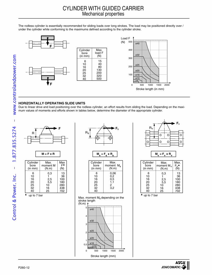
P260-12
0 500 1000 1500 2000
100
200
300
400
500ø40
ø32
ø25
ø20
ø16
ø10ø6
0 500 1000 1500 2000
5ø40
ø32
ø25
ø20
ø16ø10
4
3
2
1
0,5ø6
FRv
v
FRs
sFR
F
F
Max.moment Mv(N.m)
0,312,55,5
101625
Max.
(N)
1336
100180280438702
FMax.
moment Ms(N.m)
0,060,20,51,123,2
CYLINDER WITH GUIDED CARRIERMechanical properties
Due to linear drive and load positioning over the rodless cylinder, an effort results from sliding the load. Depending on the maxi-mum values of moments and efforts shown in tables below, determine the diameter of the appropriate cylinder.
HORIZONTALLY OPERATING SLIDE UNITS
The rodless cylinder is essentially recommended for sliding loads over long strokes. The load may be positioned directly over /under the cylinder while conforming to the maximums defined according to the cylinder stroke.
Max.load F
(N)
154080
130200320500
Cylinderbore
(in mm)
6101620253240
M = F x R Ms = Fs x Rs Mv = Fv x Rv
Max.moment M
(N.m)
0,312,55,5
101625
MaxF
(N)
1336
100180280438702
*Cylinder
bore(in mm)
6101620253240
Cylinderbore
(in mm)
6101620253240
* up to 7 bar
Cylinderbore
(in mm)
6101620253240
Stroke length (mm)
Max. moment M depending on thestroke length(N.m)
* up to 7 bar
Stroke length (in mm)
*v
s
s v
Load F(N)
Cont
rol &
Pow
er, I
nc.
-
1.87
7.83
5.52
74
- w
ww
.con
trol
andp
ower
.com
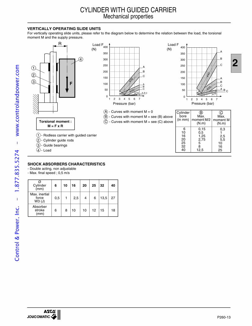
2
P260-13
10
2 3 4 5 6 7
50
100
150
200
250
300
350
400
A
B
C
ABCA B C
ø16
ø25
ø40
10
2 3 4 5 6 7
50
100
150
200
250
300
350
400
A
B
C
ABC
A B C
ø32
ø20ø10
4
1
3
2
R
F
VERTICALLY OPERATING SLIDE UNITSFor vertically operating slide units, please refer to the diagram below to determine the relation between the load, the torsionalmoment M and the supply pressure.
Torsional moment :M = F x R
Load F(N)
Pressure (bar)
Load F(N)
Pressure (bar)
Cylinderbore
(in mm)
6101620253240
CMax.
moment M(N.m)
0,312,55,5
101625
BMax.
moment M/2(N.m)
0,150,51,252,7558
12,5
A - Curves with moment M = 0B - Curves with moment M = see (B) aboveC - Curves with moment M = see (C) above
6 10 16 20 25 32 40
0,5 1 2,5 4 6 13,5 27
6 8 10 10 12 15 18
SHOCK ABSORBERS CHARACTERISTICS- Double acting, non adjustable- Max. final speed ; 0,5 m/s
ØCylinder
(mm)
Max. inertialforce
W3 (J)
Absorberstroke (mm)
1 - Rodless carrier with guided carrier2 - Cylinder guide rods3 - Guide bearings4 - Load
CYLINDER WITH GUIDED CARRIERMechanical properties
Cont
rol &
Pow
er, I
nc.
-
1.87
7.83
5.52
74
- w
ww
.con
trol
andp
ower
.com
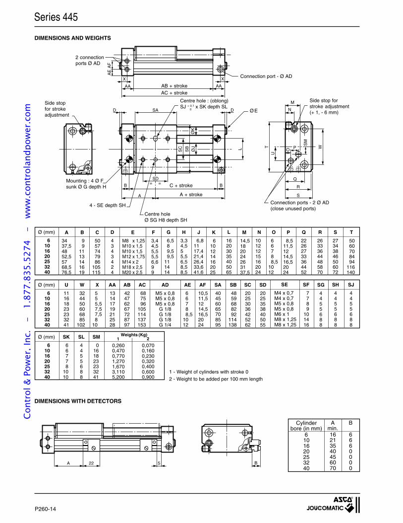
P260-14
SAD D
A
B B= =
LSC
SB
ØJ
ØK
WTU
S
R
Q
M
N
PO
SM
X
AA
X
AA
AF
AE
SD
A 22 5 B
DIMENSIONS AND WEIGHTS
Connection port - Ø AD
Ø E
1 - Weight of cylinders with stroke 02 - Weight to be added per 100 mm length
Mounting : 4 Ø Fsunk Ø G depth H
2 connectionports Ø AD
4 - SE depth SH
Centre holeØ SG H8 depth SH
Side stop forstroke adjustment(+ 1, - 6 mm)
A
3437,54852,55768,576,5
B
99
1113141619
C
5057747986
105115
E
M8 x 1,25M10 x 1,5M10 x 1,5M12 x 1,75M14 x 2M18 x 2,5M20 x 2,5
G
6,589,59,5
111414
J
6,81117,421,426,433,641,6
K
6101214162025
L
16203035405065
M
14,5182024263137,5
O
66788,5
1012
P
8,511,51214,516,52024
H
3,34,555,56,58,58,5
D
4343424
Ø (mm)
6101620253240
F
3,44,55,55,56,699
S
27343846506072
T
5060708494
116140
AD
M5 x 0,8M5 x 0,8M5 x 0,8
G 1/8G 1/8G 1/8G 1/4
SK
66778
1010
SL
4455688
SM
0161823233241
SE
M4 x 0,7M4 x 0,7M5 x 0,8M5 x 0,8M6 x 1M8 x 1,25M8 x 1,25
SF
7789
101416
SJ
4455688
SH
4455688
SA
40456065708595
X
555,57,57,58
10
SD
20253538405055
SC
20253036425262
SB
4859688292
114138
AF
10,511,51214,516,52024
AE
66788,5
1012
AC
687596
105114137153
AB
42476267728797
AA
13141719212528
W
324450606885
102
U
11161823233241
SG
4455688
R
26333644485870
Q
22262733364452
N
10121215162024
Ø (mm)
6101620253240
Ø (mm)
6101620253240
Weights (Kg)1 2
0,2600,4700,7701,2701,6703,1105,200
0,0700,1600,2300,3200,4000,6000,900
DIMENSIONS WITH DETECTORS
Cylinderbore (in mm)
6101620253240
Amin.16213540456070
B
6660000
A + stroke
Series 445
Side stopfor strokeadjustment
C + stroke
AB + strokeAC + stroke
Connection ports - 2 Ø AD(close unused ports)
Centre hole : (oblong)SJ + 0,1 x SK depth SL
0
Cont
rol &
Pow
er, I
nc.
-
1.87
7.83
5.52
74
- w
ww
.con
trol
andp
ower
.com
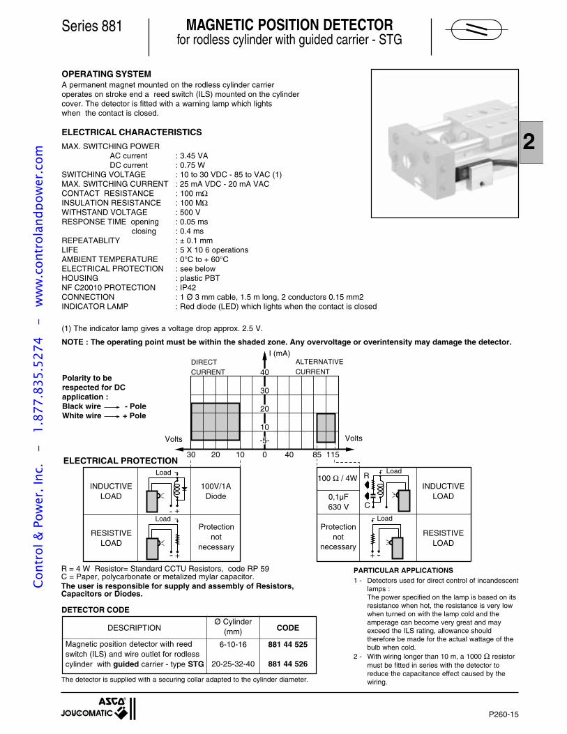
2
P260-15
Polarity to berespected for DCapplication :Black wire - PoleWhite wire + Pole
CODE
881 44 525
881 44 526
Series 881
OPERATING SYSTEMA permanent magnet mounted on the rodless cylinder carrieroperates on stroke end a reed switch (ILS) mounted on the cylindercover. The detector is fitted with a warning lamp which lightswhen the contact is closed.
ELECTRICAL CHARACTERISTICS
MAX. SWITCHING POWER AC current : 3.45 VA DC current : 0.75 WSWITCHING VOLTAGE : 10 to 30 VDC - 85 to VAC (1)MAX. SWITCHING CURRENT : 25 mA VDC - 20 mA VACCONTACT RESISTANCE : 100 mΩINSULATION RESISTANCE : 100 MΩWITHSTAND VOLTAGE : 500 VRESPONSE TIME opening : 0.05 ms closing : 0.4 msREPEATABLITY : ± 0.1 mmLIFE : 5 X 10 6 operationsAMBIENT TEMPERATURE : 0°C to + 60°CELECTRICAL PROTECTION : see belowHOUSING : plastic PBTNF C20010 PROTECTION : IP42CONNECTION : 1 Ø 3 mm cable, 1.5 m long, 2 conductors 0.15 mm2INDICATOR LAMP : Red diode (LED) which lights when the contact is closed
(1) The indicator lamp gives a voltage drop approx. 2.5 V.
NOTE : The operating point must be within the shaded zone. Any overvoltage or overintensity may damage the detector.
PARTICULAR APPLICATIONS1 - Detectors used for direct control of incandescent
lamps :The power specified on the lamp is based on itsresistance when hot, the resistance is very lowwhen turned on with the lamp cold and theamperage can become very great and mayexceed the ILS rating, allowance shouldtherefore be made for the actual wattage of thebulb when cold.
2 - With wiring longer than 10 m, a 1000 Ω resistormust be fitted in series with the detector toreduce the capacitance effect caused by thewiring.
The user is responsible for supply and assembly of Resistors,Capacitors or Diodes.
R = 4 W Resistor= Standard CCTU Resistors, code RP 59C = Paper, polycarbonate or metalized mylar capacitor.
The detector is supplied with a securing collar adapted to the cylinder diameter.
MAGNETIC POSITION DETECTORfor rodless cylinder with guided carrier - STG
Magnetic position detector with reedswitch (ILS) and wire outlet for rodlesscylinder with guided carrier - type STG
DESCRIPTIONØ Cylinder
(mm)
6-10-16
20-25-32-40
DETECTOR CODE
40
020 40
-
10
-5
30
20
I (mA)
- +
- +- -+ -
30 10 85 115
INDUCTIVELOAD
100V/1ADiode
RESISTIVELOAD
Protectionnot
necessary
Load
Volts
Load
100 Ω / 4W
0,1µF630 V
R
C
Load
Load
RESISTIVELOAD
Protectionnot
necessary
INDUCTIVELOAD
Volts
DIRECTCURRENT
I (mA)ALTERNATIVECURRENT
ELECTRICAL PROTECTION
Cont
rol &
Pow
er, I
nc.
-
1.87
7.83
5.52
74
- w
ww
.con
trol
andp
ower
.com

P260-16
YOUR NOTESCo
ntro
l & P
ower
, Inc
. -
1.
877.
835.
5274
-
ww
w.c
ontr
olan
dpow
er.c
om
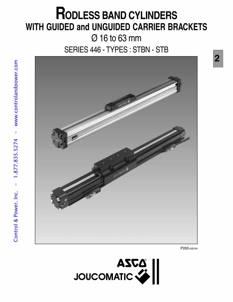
P265-GB-R4
2
RODLESS BAND CYLINDERSWITH GUIDED and UNGUIDED CARRIER BRACKETS
Ø 16 to 63 mmSERIES 446 - TYPES : STBN - STB
Cont
rol &
Pow
er, I
nc.
-
1.87
7.83
5.52
74
- w
ww
.con
trol
andp
ower
.com
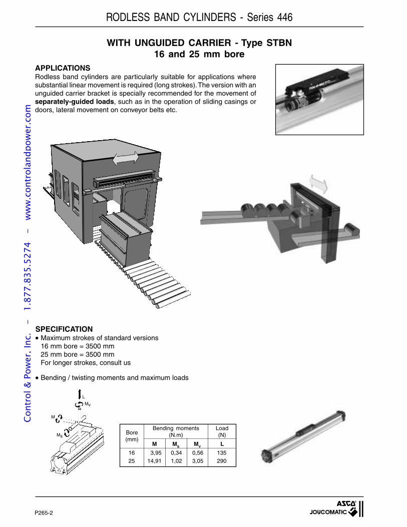
P265-2
RODLESS BAND CYLINDERS - Series 446
WITH UNGUIDED CARRIER - Type STBN16 and 25 mm bore
APPLICATIONSRodless band cylinders are particularly suitable for applications wheresubstantial linear movement is required (long strokes). The version with anunguided carrier bracket is specially recommended for the movement ofseparately-guided loads, such as in the operation of sliding casings ordoors, lateral movement on conveyor belts etc.
SPECIFICATION Maximum strokes of standard versions
16 mm bore = 3500 mm25 mm bore = 3500 mmFor longer strokes, consult us
Bending / twisting moments and maximum loads
Bore(mm)
16 3,95 0,34 0,56 13525 14,91 1,02 3,05 290
M MV LMS
Bending moments(N.m)
Load(N)
L
Mv
M
Ms
Cont
rol &
Pow
er, I
nc.
-
1.87
7.83
5.52
74
- w
ww
.con
trol
andp
ower
.com
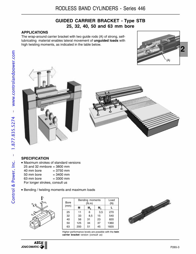
P265-3
2
RODLESS BAND CYLINDERS - Series 446
GUIDED CARRIER BRACKET - Type STB25, 32, 40, 50 and 63 mm bore
APPLICATIONSThe wrap-around carrier bracket with two guide rods (A) of strong, self-lubricating material enables lateral movement of unguided loads withhigh twisting moments, as indicated in the table below.
(A)
Bore(mm)
M MV LMS
Bending moments(N.m)
Load(N)
25 11 6 3,5 27032 33 8,5 15 54040 56 31 23 82050 125 34 37 136063 200 51 45 1820
L
MvM
Ms
SPECIFICATION Maximum strokes of standard versions
25 and 32 mmbore = 3800 mm40 mm bore = 3750 mm50 mm bore = 3400 mm63 mm bore = 3300 mmFor longer strokes, consult us
Bending / twisting moments and maximum loads
Higher performance levels are possible with the twincarrier bracket version (consult us)
Cont
rol &
Pow
er, I
nc.
-
1.87
7.83
5.52
74
- w
ww
.con
trol
andp
ower
.com
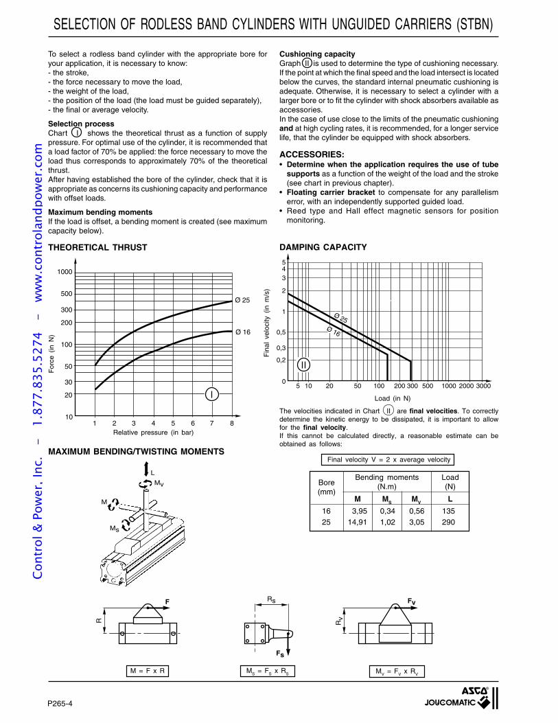
P265-4
To select a rodless band cylinder with the appropriate bore foryour application, it is necessary to know:- the stroke,- the force necessary to move the load,- the weight of the load,- the position of the load (the load must be guided separately),- the final or average velocity.
Selection processChart I shows the theoretical thrust as a function of supplypressure. For optimal use of the cylinder, it is recommended thata load factor of 70% be applied: the force necessary to move theload thus corresponds to approximately 70% of the theoreticalthrust.After having established the bore of the cylinder, check that it isappropriate as concerns its cushioning capacity and performancewith offset loads.
Maximum bending momentsIf the load is offset, a bending moment is created (see maximumcapacity below).
Cushioning capacityGraph II is used to determine the type of cushioning necessary.If the point at which the final speed and the load intersect is locatedbelow the curves, the standard internal pneumatic cushioning isadequate. Otherwise, it is necessary to select a cylinder with alarger bore or to fit the cylinder with shock absorbers available asaccessories.In the case of use close to the limits of the pneumatic cushioningand at high cycling rates, it is recommended, for a longer servicelife, that the cylinder be equipped with shock absorbers.
ACCESSORIES:• Determine when the application requires the use of tube
supports as a function of the weight of the load and the stroke(see chart in previous chapter).
• Floating carrier bracket to compensate for any parallelismerror, with an independently supported guided load.
• Reed type and Hall effect magnetic sensors for positionmonitoring.
MAXIMUM BENDING/TWISTING MOMENTS
M = F x R MS = FS x RS
Load (in N)
The velocities indicated in Chart II are final velocities. To correctlydetermine the kinetic energy to be dissipated, it is important to allowfor the final velocity.If this cannot be calculated directly, a reasonable estimate can beobtained as follows:
Final velocity V = 2 x average velocity
Fin
al v
eloc
ity (
in m
/s)
SELECTION OF RODLESS BAND CYLINDERS WITH UNGUIDED CARRIERS (STBN)
Relative pressure (in bar)
For
ce (
in N
)
DAMPING CAPACITYTHEORETICAL THRUST
MV = FV x RV
Bore(mm)
16 3,95 0,34 0,56 13525 14,91 1,02 3,05 290
M MV LMS
Bending moments(N.m)
Load(N)
1000
500
300
200
100
50
1 2 3 4 5 6 8
Ø 25
7
30
20
10
Ø 16
5
5
43
2
1
0,5
0,3
0,2
010 20 50 100 200 300 500 1000 2000 3000
Ø 25Ø 16
L
Mv
M
Ms
R
F Rs
Fs
Rv
Fv
Cont
rol &
Pow
er, I
nc.
-
1.87
7.83
5.52
74
- w
ww
.con
trol
andp
ower
.com
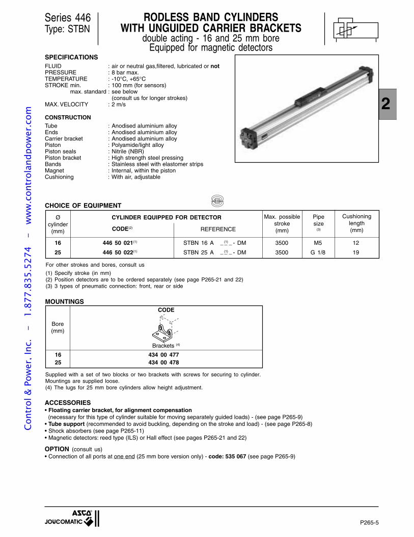
P265-5
2
Series 446Type: STBN
SPECIFICATIONSFLUID : air or neutral gas,filtered, lubricated or notPRESSURE : 8 bar max.TEMPERATURE : -10°C, +65°CSTROKE min. : 100 mm (for sensors)
max. standard : see below(consult us for longer strokes)
MAX. VELOCITY : 2 m/s
CONSTRUCTIONTube : Anodised aluminium alloyEnds : Anodised aluminium alloyCarrier bracket : Anodised aluminium alloyPiston : Polyamide/light alloyPiston seals : Nitrile (NBR)Piston bracket : High strength steel pressingBands : Stainless steel with elastomer stripsMagnet : Internal, within the pistonCushioning : With air, adjustable
16 446 50 021(1) STBN 16 A (1) - DM 3500 M5 12
25 446 50 022(1) STBN 25 A (1) - DM 3500 G 1/8 19
Øcylinder
(mm)
CHOICE OF EQUIPMENT
Cushioninglength(mm)
CYLINDER EQUIPPED FOR DETECTOR
Bore(mm)
16 434 00 47725 434 00 478
CODE
OPTION (consult us)• Connection of all ports at one end (25 mm bore version only) - code: 535 067 (see page P265-9)
ACCESSORIES• Floating carrier bracket, for alignment compensation (necessary for this type of cylinder suitable for moving separately guided loads) - (see page P265-9)• Tube support (recommended to avoid buckling, depending on the stroke and load) - (see page P265-8)• Shock absorbers (see page P265-11)• Magnetic detectors: reed type (ILS) or Hall effect (see pages P265-21 and 22)
Supplied with a set of two blocks or two brackets with screws for securing to cylinder.Mountings are supplied loose.(4) The lugs for 25 mm bore cylinders allow height adjustment.
Brackets (4)
For other strokes and bores, consult us
(1) Specify stroke (in mm)(2) Position detectors are to be ordered separately (see page P265-21 and 22)(3) 3 types of pneumatic connection: front, rear or side
MOUNTINGS
CODE(2) REFERENCE
RODLESS BAND CYLINDERSWITH UNGUIDED CARRIER BRACKETS
double acting - 16 and 25 mm boreEquipped for magnetic detectors
Pipesize
(3)
Max. possiblestroke(mm)
NS
Cont
rol &
Pow
er, I
nc.
-
1.87
7.83
5.52
74
- w
ww
.con
trol
andp
ower
.com
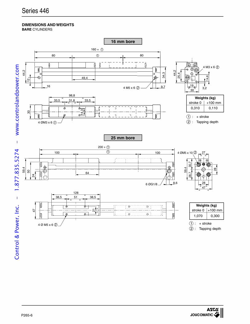
P265-6
28,7
30,7
59,4
24
50
6 ØG1/8
4 Ø M5 x 6
100 1001
2
1
2
200 +
64
47
38,5 38,551128
=
= =
=
==
28
28
47= =
= =59
,4
27= =
4 ØM5 x 10
8,6
21
49,4
= =9,74 M5 x 6 216
80
160 +
80
44,2
12
34,3
19
25,4
14,8
3,2
4 M3 x 6
1
2
44,2
30
1
31,833,5 33,5
14,3
30
98,8
4 ØM3 x 6 2
=
= =
=
Series 446
DIMENSIONS AND WEIGHTSBARE CYLINDERS
25 mm bore
16 mm bore
1 : + stroke
2 : Tapping depth
+100 mmstroke 0Weights (kg)
1 : + stroke
2 : Tapping depth
+100 mmstroke 0Weights (kg)
0,310 0,110
1,070 0,300
Cont
rol &
Pow
er, I
nc.
-
1.87
7.83
5.52
74
- w
ww
.con
trol
andp
ower
.com
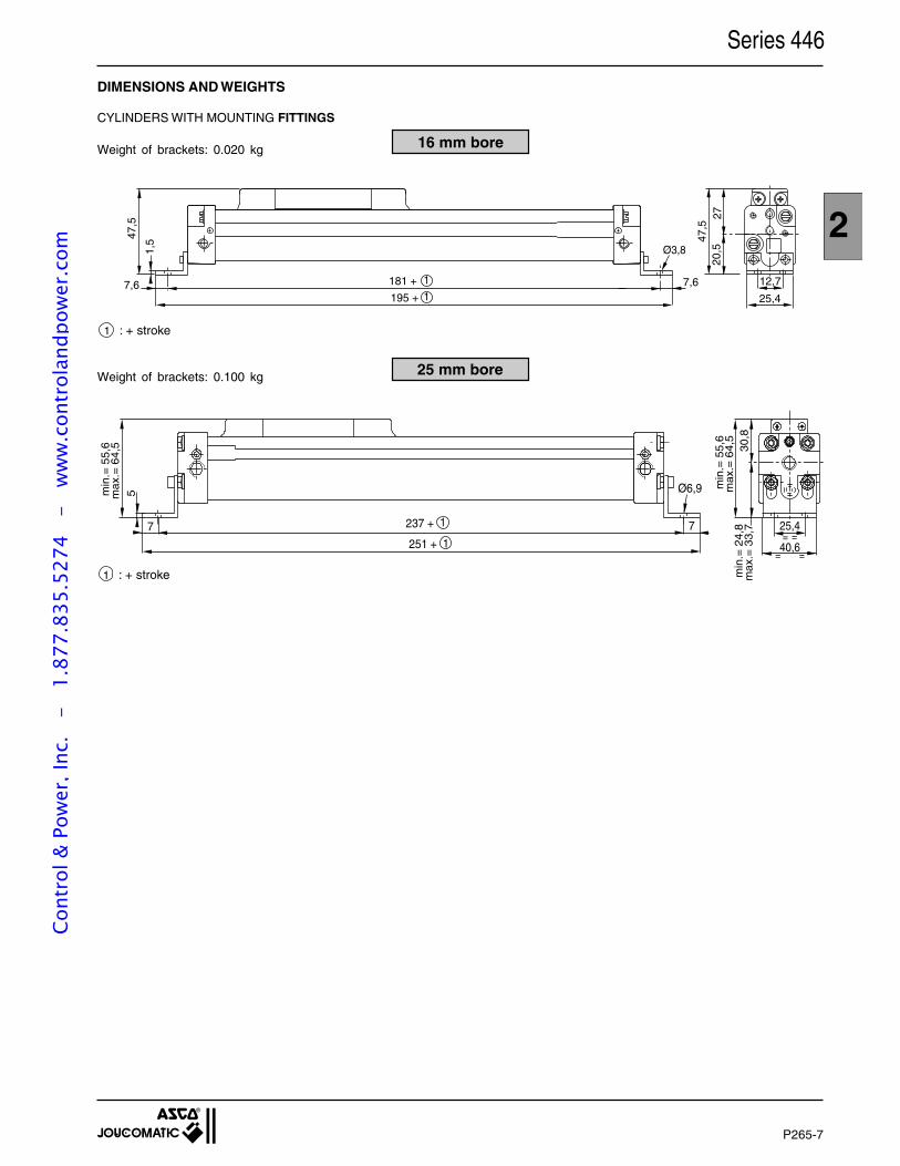
P265-7
2
DIMENSIONS AND WEIGHTS
CYLINDERS WITH MOUNTING FITTINGS
16 mm bore
25 mm bore
1 : + stroke min
.= 2
4,8
max
.= 3
3,7
min
.= 5
5,6
max
.= 6
4,5
30,8
min
.= 5
5,6
max
.= 6
4,5
5
71
1 25,4
40,6= =
= =7
Ø6,9
237 +
251 +
Series 446
1 : + stroke
Weight of brackets: 0.020 kg
Weight of brackets: 0.100 kg
7,6 7,6181 +
195 +
1
1
Ø3,8
47,5
20,5
2747
,5
25,4
1,5
12,7
Cont
rol &
Pow
er, I
nc.
-
1.87
7.83
5.52
74
- w
ww
.con
trol
andp
ower
.com
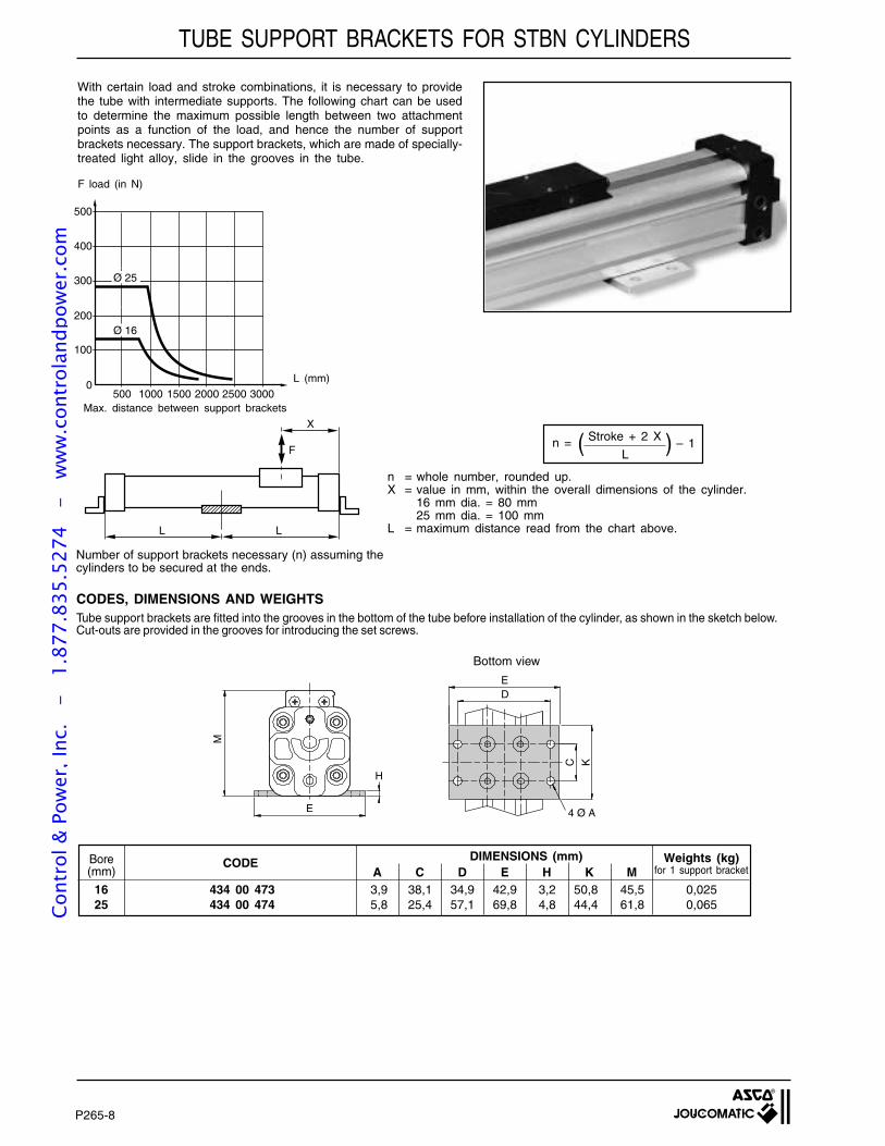
P265-8
TUBE SUPPORT BRACKETS FOR STBN CYLINDERS
With certain load and stroke combinations, it is necessary to providethe tube with intermediate supports. The following chart can be usedto determine the maximum possible length between two attachmentpoints as a function of the load, and hence the number of supportbrackets necessary. The support brackets, which are made of specially-treated light alloy, slide in the grooves in the tube.
DIMENSIONS (mm)
Tube support brackets are fitted into the grooves in the bottom of the tube before installation of the cylinder, as shown in the sketch below.Cut-outs are provided in the grooves for introducing the set screws.
Bore(mm)
CODEC D E H K MA
16 434 00 473 3,9 38,1 34,9 42,9 3,2 50,8 45,5 0,02525 434 00 474 5,8 25,4 57,1 69,8 4,8 44,4 61,8 0,065
Weights (kg)for 1 support bracket
L (mm)
F load (in N)
Max. distance between support brackets
Number of support brackets necessary (n) assuming thecylinders to be secured at the ends.
n = – 1( Stroke + 2 X )L
n = whole number, rounded up.X = value in mm, within the overall dimensions of the cylinder.
16 mm dia. = 80 mm25 mm dia. = 100 mm
L = maximum distance read from the chart above.
CODES, DIMENSIONS AND WEIGHTS
Bottom view
ED
C K
4 Ø A
H
E
M
0
100
200
300
400
500
500 1000 1500 2000 2500 3000
Ø 16
Ø 25
LL
F
X
Cont
rol &
Pow
er, I
nc.
-
1.87
7.83
5.52
74
- w
ww
.con
trol
andp
ower
.com
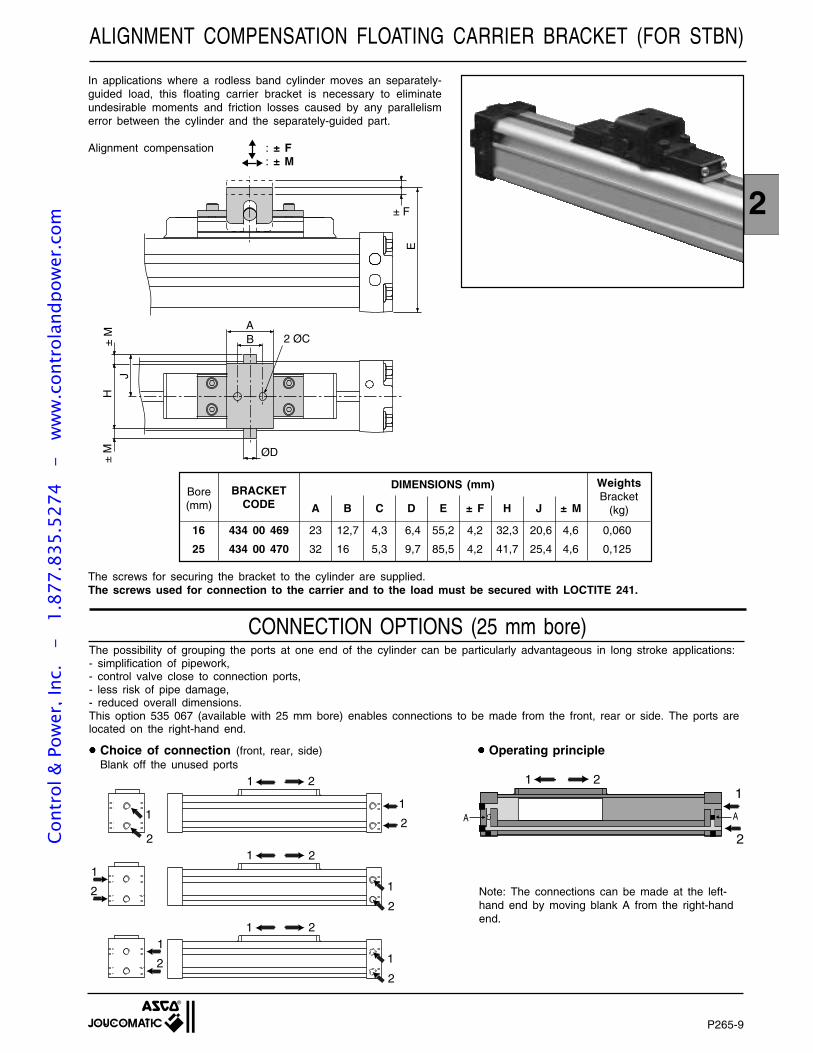
P265-9
2
ALIGNMENT COMPENSATION FLOATING CARRIER BRACKET (FOR STBN)
16 434 00 469 23 12,7 4,3 6,4 55,2 4,2 32,3 20,6 4,6 0,060
25 434 00 470 32 16 5,3 9,7 85,5 4,2 41,7 25,4 4,6 0,125
Bore(mm)
BRACKETCODE A B C D E ± F H J ± M
The screws for securing the bracket to the cylinder are supplied.The screws used for connection to the carrier and to the load must be secured with LOCTITE 241.
WeightsBracket
(kg)
In applications where a rodless band cylinder moves an separately-guided load, this floating carrier bracket is necessary to eliminateundesirable moments and friction losses caused by any parallelismerror between the cylinder and the separately-guided part.
Alignment compensation : ± F: ± M
DIMENSIONS (mm)
CONNECTION OPTIONS (25 mm bore)
1
1
2
1
1
2
2
2
1
1
2
2
1
2 1
1
2
2
Choice of connection (front, rear, side)Blank off the unused ports
The possibility of grouping the ports at one end of the cylinder can be particularly advantageous in long stroke applications:- simplification of pipework,- control valve close to connection ports,- less risk of pipe damage,- reduced overall dimensions.This option 535 067 (available with 25 mm bore) enables connections to be made from the front, rear or side. The ports arelocated on the right-hand end.
Note: The connections can be made at the left-hand end by moving blank A from the right-handend.
2 ØCAB
± F
H
J±
M±
M
E
ØD
Operating principle
11
2
2
AA
Cont
rol &
Pow
er, I
nc.
-
1.87
7.83
5.52
74
- w
ww
.con
trol
andp
ower
.com
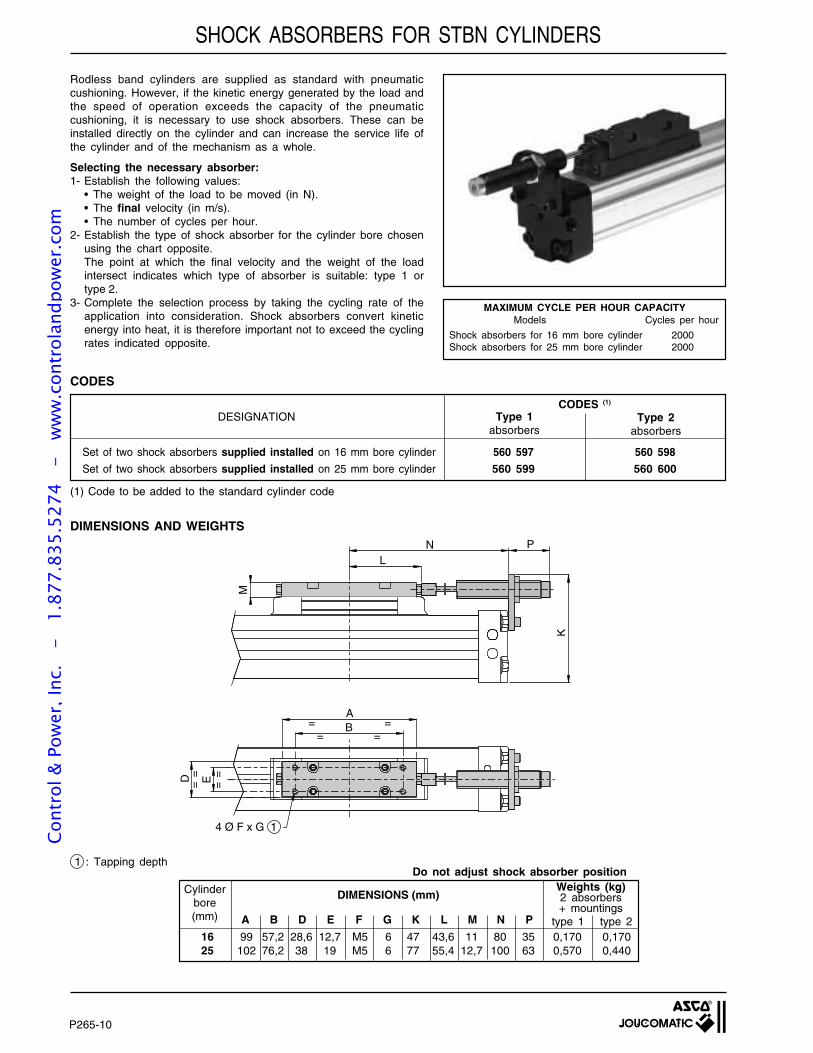
P265-10
Rodless band cylinders are supplied as standard with pneumaticcushioning. However, if the kinetic energy generated by the load andthe speed of operation exceeds the capacity of the pneumaticcushioning, it is necessary to use shock absorbers. These can beinstalled directly on the cylinder and can increase the service life ofthe cylinder and of the mechanism as a whole.
Selecting the necessary absorber:1- Establish the following values:
• The weight of the load to be moved (in N).• The final velocity (in m/s).• The number of cycles per hour.
2- Establish the type of shock absorber for the cylinder bore chosenusing the chart opposite.The point at which the final velocity and the weight of the loadintersect indicates which type of absorber is suitable: type 1 ortype 2.
3- Complete the selection process by taking the cycling rate of theapplication into consideration. Shock absorbers convert kineticenergy into heat, it is therefore important not to exceed the cyclingrates indicated opposite.
SHOCK ABSORBERS FOR STBN CYLINDERS
Cycles per hourModels
Shock absorbers for 16 mm bore cylinder 2000Shock absorbers for 25 mm bore cylinder 2000
MAXIMUM CYCLE PER HOUR CAPACITY
Type 1absorbers
CODES (1)
DESIGNATION
CODES
DIMENSIONS AND WEIGHTS
16 99 57,2 28,6 12,7 M5 6 47 43,6 11 80 35 0,170 0,17025 102 76,2 38 19 M5 6 77 55,4 12,7 100 63 0,570 0,440
Cylinderbore(mm)
DIMENSIONS (mm)Weights (kg)2 absorbers+ mountings
A B D E F G K L M N P
Do not adjust shock absorber position
Type 2absorbers
Set of two shock absorbers supplied installed on 16 mm bore cylinder 560 597 560 598
Set of two shock absorbers supplied installed on 25 mm bore cylinder 560 599 560 600
(1) Code to be added to the standard cylinder code
= == =
==
==
AB
D E
4 Ø F x G 1
KL
M
N P
1 : Tapping depth
type 1 type 2
Cont
rol &
Pow
er, I
nc.
-
1.87
7.83
5.52
74
- w
ww
.con
trol
andp
ower
.com
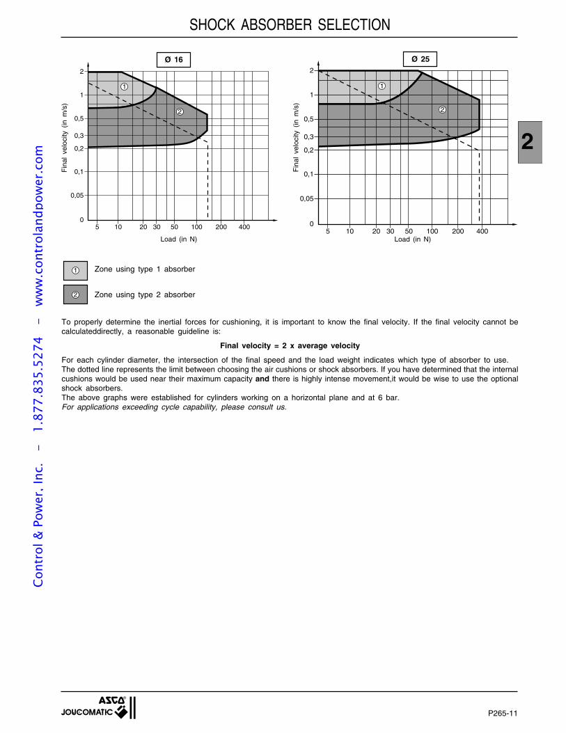
P265-11
2
SHOCK ABSORBER SELECTION
Ø 25Ø 16
2
2
1
0,5
0,3
0,2
0,1
0,05
05 10 20 30 50 100 200 400
1
Fin
al v
eloc
ity (
in m
/s)
Load (in N)
2
1 Zone using type 1 absorber
Zone using type 2 absorber
To properly determine the inertial forces for cushioning, it is important to know the final velocity. If the final velocity cannot becalculateddirectly, a reasonable guideline is:
Final velocity = 2 x average velocity
For each cylinder diameter, the intersection of the final speed and the load weight indicates which type of absorber to use.The dotted line represents the limit between choosing the air cushions or shock absorbers. If you have determined that the internalcushions would be used near their maximum capacity and there is highly intense movement,it would be wise to use the optionalshock absorbers.The above graphs were established for cylinders working on a horizontal plane and at 6 bar.For applications exceeding cycle capability, please consult us.
2
2
1
0,5
0,3
0,2
0,1
0,05
05 10 20 30 50 100 200 400
1
Load (in N)
Fin
al v
eloc
ity (
in m
/s)
Cont
rol &
Pow
er, I
nc.
-
1.87
7.83
5.52
74
- w
ww
.con
trol
andp
ower
.com
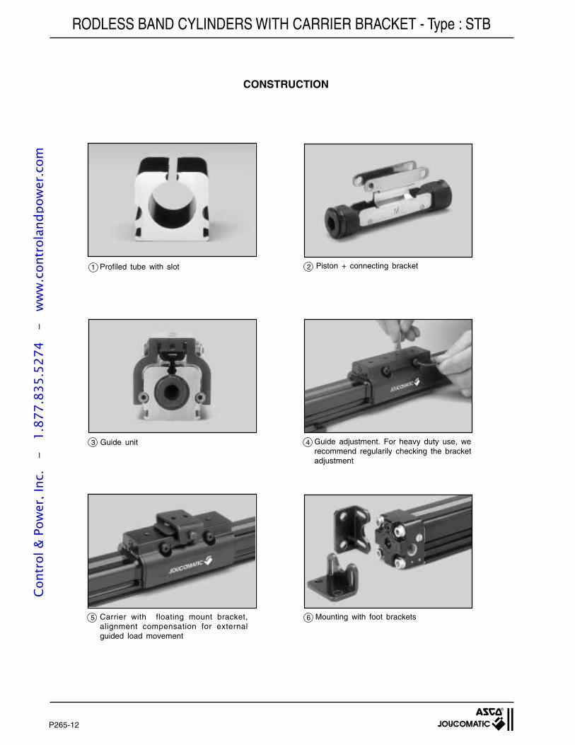
P265-12
CONSTRUCTION
Profiled tube with slot
Guide unit
Carrier with floating mount bracket,alignment compensation for externalguided load movement
1
3
5
Piston + connecting bracket2
Guide adjustment. For heavy duty use, werecommend regularily checking the bracketadjustment
4
Mounting with foot brackets6
RODLESS BAND CYLINDERS WITH CARRIER BRACKET - Type : STBCo
ntro
l & P
ower
, Inc
. -
1.
877.
835.
5274
-
ww
w.c
ontr
olan
dpow
er.c
om
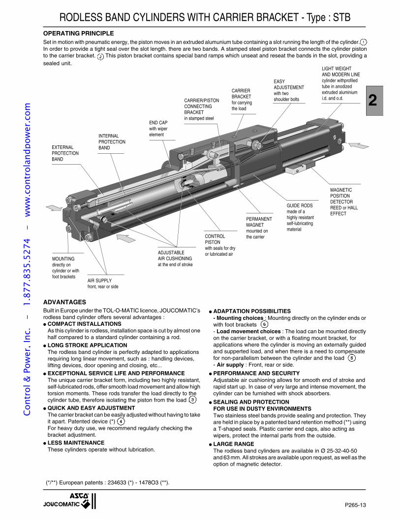
P265-13
2
Set in motion with pneumatic energy, the piston moves in an extruded alumunium tube containing a slot running the length of the cylinder.In order to provide a tight seal over the slot length. there are two bands. A stamped steel piston bracket connects the cylinder pistonto the carrier bracket. This piston bracket contains special band ramps which unseat and reseat the bands in the slot, providing asealed unit.
EXTERNALPROTECTIONBAND
INTERNALPROTECTIONBAND
END CAPwith wiperelement
CARRIER/PISTONCONNECTINGBRACKETin stamped steel
CARRIERBRACKETfor carryingthe load
MOUNTINGdirectly oncylinder or withfoot brackets
AIR SUPPLYfront, rear or side
ADJUSTABLEAIR CUSHIONINGat the end of stroke
CONTROLPISTONwith seals for dryor lubricated air
PERMANENTMAGNETmounted onthe carrier
GUIDE RODSmade of ahighly resistantself-lubricatingmaterial
MAGNETICPOSITIONDETECTORREED or HALLEFFECT
EASYADJUSTEMENTwith twoshoulder bolts
LIGHT WEIGHTAND MODERN LINEcylinder withprofiledtube in anodizedextruded aluminiumi.d. and o.d.
ADVANTAGES
(*/**) European patents : 234633 (*) - 1478O3 (**).
Built in Europe under the TOL-O-MATIC licence, JOUCOMATIC’srodless band cylinder offers several advantages : COMPACT INSTALLATIONS
As this cylinder is rodless, installation space is cut by almost onehalf compared to a standard cylinder containing a rod.
LONG STROKE APPLICATIONThe rodless band cylinder is perfectly adapted to applicationsrequiring long linear movement, such as : handling devices,lifting devices, door opening and closing, etc...
EXCEPTIONAL SERVICE LIFE AND PERFORMANCEThe unique carrier bracket form, including two highly resistant,self-lubricated rods, offer smooth load movement and allow hightorsion moments. These rods transfer the load directly to thecylinder tube, therefore isolating the piston from the load .
QUICK AND EASY ADJUSTMENTThe carrier bracket can be easily adjusted without having to takeit apart. Patented device (*)For heavy duty use, we recommend regularly checking thebracket adjustment.
LESS MAINTENANCEThese cylinders operate without lubrication.
ADAPTATION POSSIBILITIES- Mounting choices : Mounting directly on the cylinder ends orwith foot brackets- Load movement choices : The load can be mounted directlyon the carrier bracket, or with a floating mount bracket, forapplications where the cylinder is moving an externally guidedand supperted load, and when there is a need to compensatefor non-parallelism between the cylinder and the load- Air supply : Front, rear or side.
PERFORMANCE AND SECURITYAdjustable air cushioning allows for smooth end of stroke andrapid start up. In case of very large and intense movement, thecylinder can be furnished with shock absorbers.
SEALING AND PROTECTIONFOR USE IN DUSTY ENVIRONMENTSTwo stainless steel bands provide sealing and protection. Theyare held in place by a patented band retention method (**) usinga T-shaped seals. Plastic carrier end caps, also acting aswipers, protect the internal parts from the outside.
LARGE RANGEThe rodless band cylinders are available in Ø 25-32-40-50and 63 mm. All strokes are available upon request, as well as theoption of magnetic detector.
RODLESS BAND CYLINDERS WITH CARRIER BRACKET - Type : STBOPERATING PRINCIPLE
Cont
rol &
Pow
er, I
nc.
-
1.87
7.83
5.52
74
- w
ww
.con
trol
andp
ower
.com
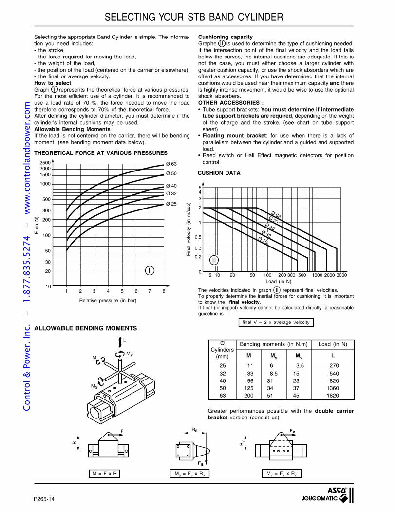
P265-14
Cushioning capacityGraphe II is used to determine the type of cushioning needed.If the intersection point of the final velocity and the load fallsbelow the curves, the internal cushions are adequate. If this isnot the case, you must either choose a larger cylinder withgreater cushion capacity, or use the shock absorders which areofferd as accessories. If you have determined that the internalcushions would be used near their maximum capacity and thereis highly intense movement, it would be wise to use the optionalshock absorbers.OTHER ACCESSORIES :• Tube support brackets: You must determine if intermediate
tube support brackets are required, depending on the weightof the charge and the stroke. (see chart on tube supportsheet)
• Floating mount bracket: for use when there is a lack ofparallelism between the cylinder and a guided and supportedload.
• Reed switch or Hall Effect magnetic detectors for positioncontrol.
ALLOWABLE BENDING MOMENTS
M = F x R MS = FS x RSM
V = F
V x R
V
L
MvM
Ms
Load (in N)
The velocities indicated in graph II represent final velocities.To properly determine the inertial forces for cushioning, it is importantto know the final velocity.If final (or impact) velocity cannot be calculated directly, a reasonableguideline is :
final V = 2 x average velocity
R
F Rs
Fs
Rv
Fv
Selecting the appropriate Band Cylinder is simple. The informa-tion you need includes:- the stroke,- the force required for moving the load,- the weight of the load,- the position of the load (centered on the carrier or elsewhere),- the final or average velocity.How to selectGraph I represents the theoretical force at various pressures.For the most efficient use of a cylinder, it is recommended touse a load rate of 70 %: the force needed to move the loadtherefore corresponds to 70% of the theoretical force.After defining the cylinder diameter, you must determine if thecylinder's internal cushions may be used.Allowable Bending MomentsIf the load is not centered on the carrier, there will be bendingmoment. (see bending moment data below).
Fin
al v
eloc
ity (
in m
/sec
)
CUSHION DATA
F (
in N
)
THEORETICAL FORCE AT VARIOUS PRESSURES
250020001500
1000
500
300
200
100
50
1 2 3 4 5 6 8
Ø 63
Ø 50
Ø 40
Ø 32
Ø 25
7
30
20
10
Relative pressure (in bar)
5
5
43
2
1
0,5
0,3
0,2
010 20 50 100 200 300 500 1000 2000 3000
Ø 63Ø 50Ø 40
Ø 32Ø 25
SELECTING YOUR STB BAND CYLINDER
Greater performances possible with the double carrierbracket version (consult us)
ØCylinders
(mm)
25 11 6 3.5 27032 33 8.5 15 54040 56 31 23 82050 125 34 37 136063 200 51 45 1820
M MS MV L
Bending moments (in N.m) Load (in N)
Cont
rol &
Pow
er, I
nc.
-
1.87
7.83
5.52
74
- w
ww
.con
trol
andp
ower
.com
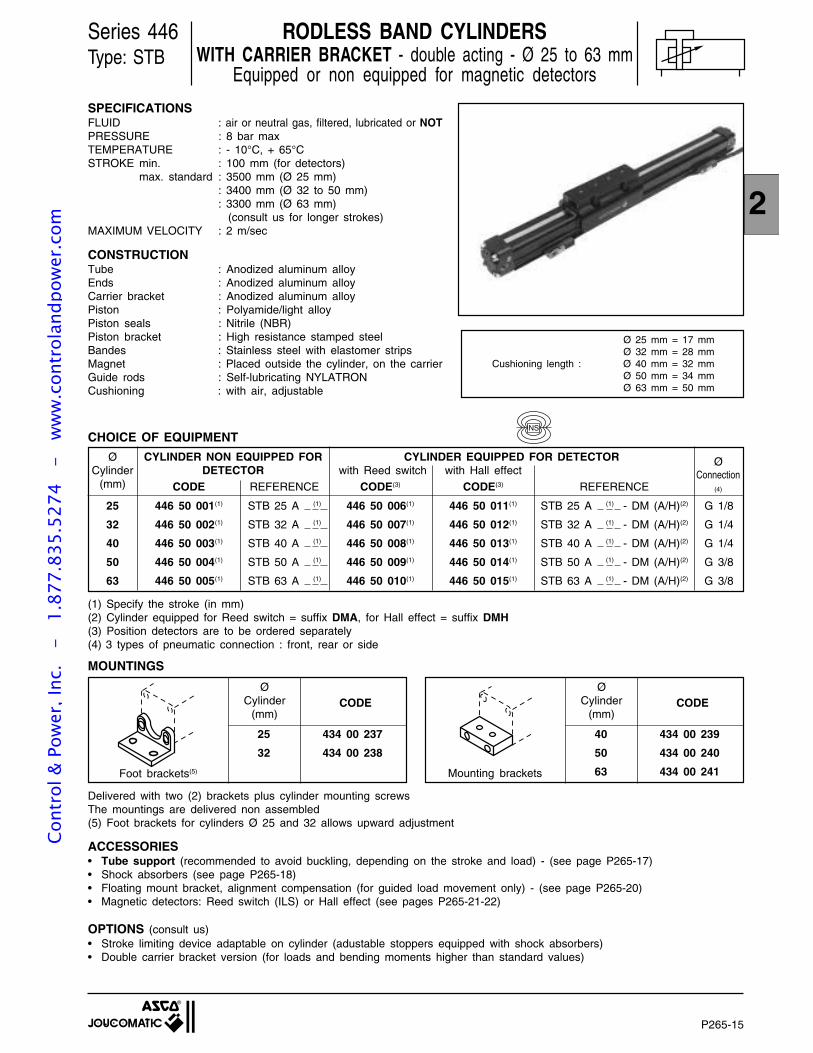
P265-15
2
Series 446Type: STB
Ø 25 mm = 17 mmØ 32 mm = 28 mm
Cushioning length : Ø 40 mm = 32 mmØ 50 mm = 34 mmØ 63 mm = 50 mm
RODLESS BAND CYLINDERSWITH CARRIER BRACKET - double acting - Ø 25 to 63 mm
Equipped or non equipped for magnetic detectors
SPECIFICATIONSFLUID : air or neutral gas, filtered, lubricated or NOTPRESSURE : 8 bar maxTEMPERATURE : - 10°C, + 65°CSTROKE min. : 100 mm (for detectors)
max. standard : 3500 mm (Ø 25 mm): 3400 mm (Ø 32 to 50 mm): 3300 mm (Ø 63 mm) (consult us for longer strokes)
MAXIMUM VELOCITY : 2 m/sec
CONSTRUCTIONTube : Anodized aluminum alloyEnds : Anodized aluminum alloyCarrier bracket : Anodized aluminum alloyPiston : Polyamide/light alloyPiston seals : Nitrile (NBR)Piston bracket : High resistance stamped steelBandes : Stainless steel with elastomer stripsMagnet : Placed outside the cylinder, on the carrierGuide rods : Self-lubricating NYLATRONCushioning : with air, adjustable
25 446 50 001(1) STB 25 A (1) 446 50 006(1) 446 50 011(1) STB 25 A (1) - DM (A/H)(2) G 1/8
32 446 50 002(1) STB 32 A (1) 446 50 007(1) 446 50 012(1) STB 32 A (1) - DM (A/H)(2) G 1/4
40 446 50 003(1) STB 40 A (1) 446 50 008(1) 446 50 013(1) STB 40 A (1) - DM (A/H)(2) G 1/4
50 446 50 004(1) STB 50 A (1) 446 50 009(1) 446 50 014(1) STB 50 A (1) - DM (A/H)(2) G 3/8
63 446 50 005(1) STB 63 A (1) 446 50 010(1) 446 50 015(1) STB 63 A (1) - DM (A/H)(2) G 3/8
ØConnection
(4)
with Reed switch with Hall effectCYLINDER EQUIPPED FOR DETECTORCYLINDER NON EQUIPPED FOR
DETECTORØ
Cylinder(mm) CODE
MOUNTINGS
25 434 00 237
32 434 00 238
ØCylinder
(mm)CODE
40 434 00 239
50 434 00 240
63 434 00 241
ØCylinder
(mm)CODE
Mounting brackets
Delivered with two (2) brackets plus cylinder mounting screwsThe mountings are delivered non assembled(5) Foot brackets for cylinders Ø 25 and 32 allows upward adjustment
REFERENCE CODE(3) CODE(3) REFERENCE
Foot brackets(5)
ACCESSORIES• Tube support (recommended to avoid buckling, depending on the stroke and load) - (see page P265-17)• Shock absorbers (see page P265-18)• Floating mount bracket, alignment compensation (for guided load movement only) - (see page P265-20)• Magnetic detectors: Reed switch (ILS) or Hall effect (see pages P265-21-22)
OPTIONS (consult us)• Stroke limiting device adaptable on cylinder (adustable stoppers equipped with shock absorbers)• Double carrier bracket version (for loads and bending moments higher than standard values)
CHOICE OF EQUIPMENTNS
(1) Specify the stroke (in mm)(2) Cylinder equipped for Reed switch = suffix DMA, for Hall effect = suffix DMH(3) Position detectors are to be ordered separately(4) 3 types of pneumatic connection : front, rear or side
Cont
rol &
Pow
er, I
nc.
-
1.87
7.83
5.52
74
- w
ww
.con
trol
andp
ower
.com
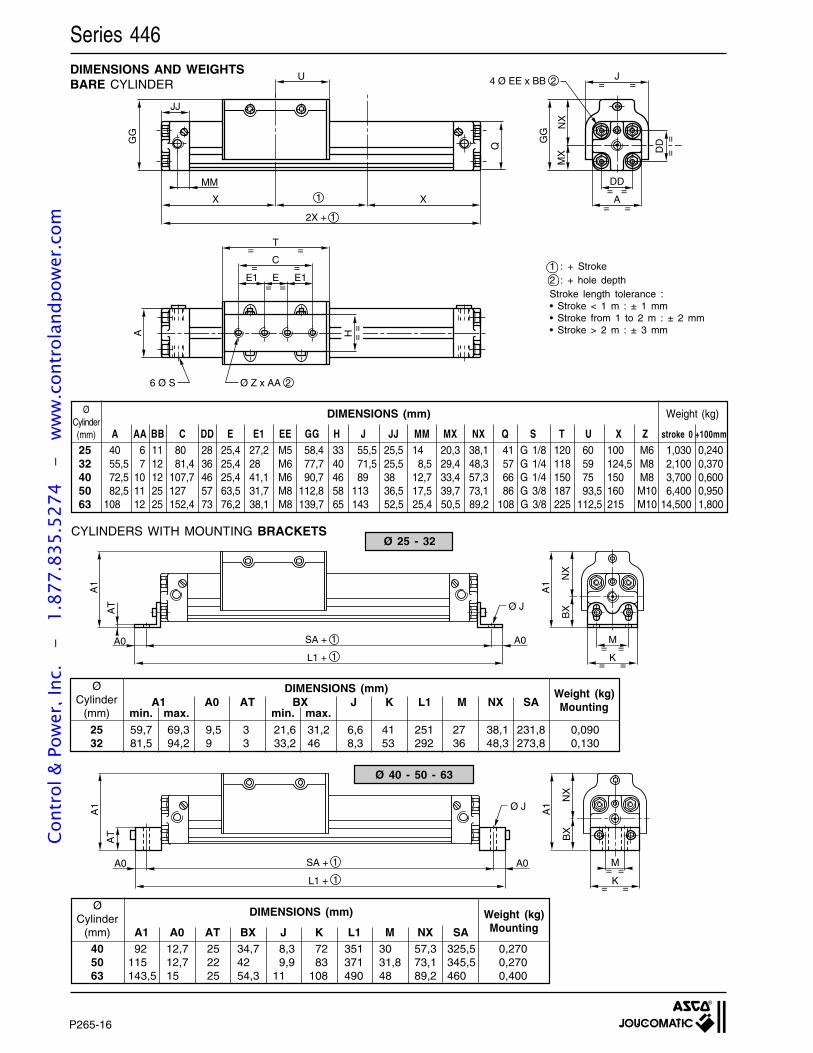
P265-16
CYLINDERS WITH MOUNTING BRACKETS
1 : + Stroke2 : + hole depthStroke length tolerance :• Stroke < 1 m : ± 1 mm• Stroke from 1 to 2 m : ± 2 mm• Stroke > 2 m : ± 3 mm
DIMENSIONS AND WEIGHTSBARE CYLINDER
M
K
A1
BXAT Ø J
SA +
L1 +
A0 A01
1= =
= =
A1
NX
Ø 40 - 50 - 63
M
K
A1
AT
Ø J
SA +
L1 +
A0 A01
1= =
= =
BX
A1
NX
25 40 6 11 80 28 25,4 27,2 M5 58,4 33 55,5 25,5 14 20,3 38,1 41 G 1/8 120 60 100 M6 1,030 0,24032 55,5 7 12 81,4 36 25,4 28 M6 77,7 40 71,5 25,5 8,5 29,4 48,3 57 G 1/4 118 59 124,5 M8 2,100 0,37040 72,5 10 12 107,7 46 25,4 41,1 M6 90,7 46 89 38 12,7 33,4 57,3 66 G 1/4 150 75 150 M8 3,700 0,60050 82,5 11 25 127 57 63,5 31,7 M8 112,8 58 113 36,5 17,5 39,7 73,1 86 G 3/8 187 93,5 160 M10 6,400 0,95063 108 12 25 152,4 73 76,2 38,1 M8 139,7 65 143 52,5 25,4 50,5 89,2 108 G 3/8 225 112,5 215 M10 14,500 1,800
ØCylinder(mm) A AA BB C DD E E1 EE GG H J JJ MM MX NX Q S T U X Z stroke 0 +100mm
Weight (kg)DIMENSIONS (mm)
25 59,7 69,3 9,5 3 21,6 31,2 6,6 41 251 27 38,1 231,8 0,09032 81,5 94,2 9 3 33,2 46 8,3 53 292 36 48,3 273,8 0,130
min. max. min. max.A1 A0 AT BX J K L1 M NX SA
ØCylinder
(mm)
Weight (kg)Mounting
DIMENSIONS (mm)
40 92 12,7 25 34,7 8,3 72 351 30 57,3 325,5 0,27050 115 12,7 22 42 9,9 83 371 31,8 73,1 345,5 0,27063 143,5 15 25 54,3 11 108 490 48 89,2 460 0,400
A1 A0 AT BX J K L1 M NX SA
ØCylinder
(mm)
Weight (kg)Mounting
DIMENSIONS (mm)
Ø 25 - 32
T
C
E
= =
= =
= =E1 E1
A
6 Ø S Ø Z x AA
GG
U
MM
X X
2X +
J= =
DD
A= =
= =
GG
MX D
D=
=
1
1
2
4 Ø EE x BB 2
JJ
H ==
Q
NX
Series 446Co
ntro
l & P
ower
, Inc
. -
1.
877.
835.
5274
-
ww
w.c
ontr
olan
dpow
er.c
om
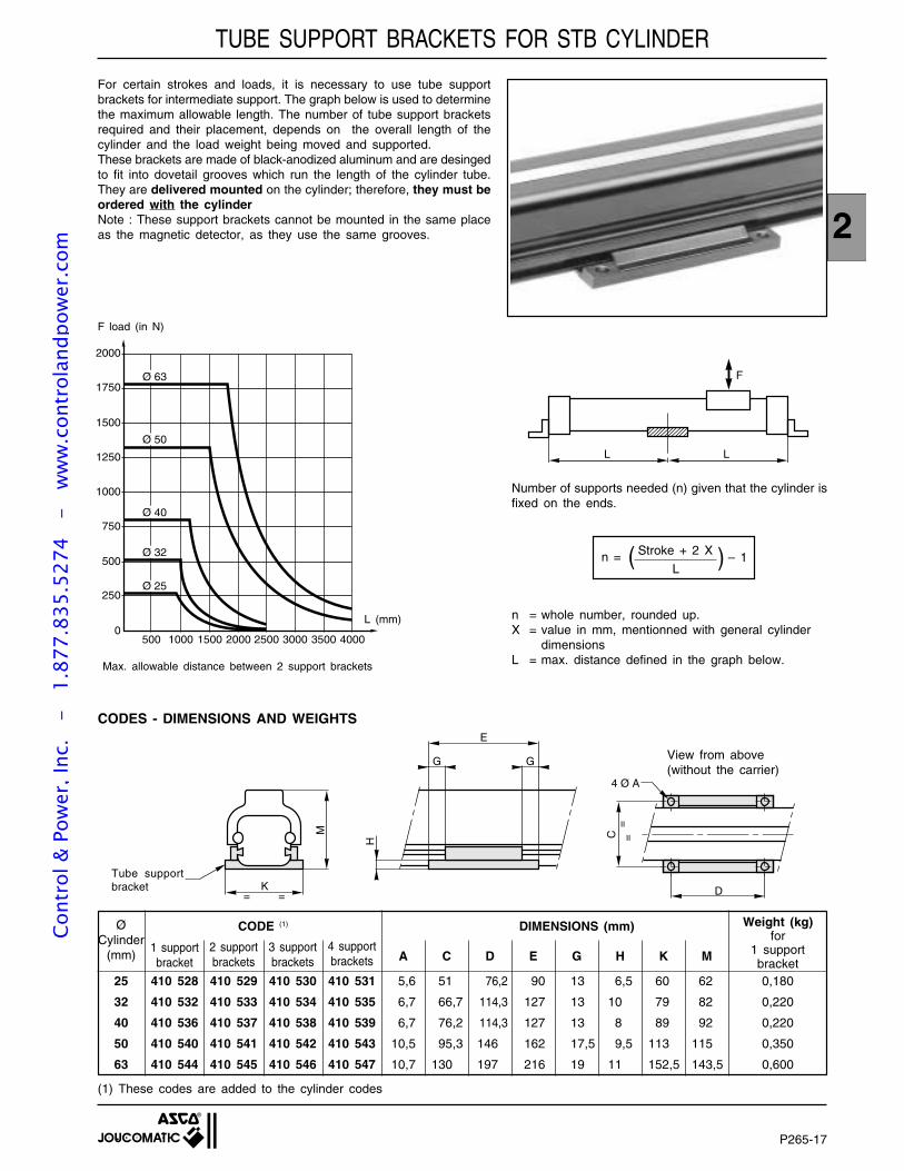
P265-17
2
K
M
E
GG
H
D
C=
=
= =
4 Ø A
For certain strokes and loads, it is necessary to use tube supportbrackets for intermediate support. The graph below is used to determinethe maximum allowable length. The number of tube support bracketsrequired and their placement, depends on the overall length of thecylinder and the load weight being moved and supported.These brackets are made of black-anodized aluminum and are desingedto fit into dovetail grooves which run the length of the cylinder tube.They are delivered mounted on the cylinder; therefore, they must beordered with the cylinderNote : These support brackets cannot be mounted in the same placeas the magnetic detector, as they use the same grooves.
25 410 528 410 529 410 530 410 531 5,6 51 76,2 90 13 6,5 60 62 0,180
32 410 532 410 533 410 534 410 535 6,7 66,7 114,3 127 13 10 79 82 0,220
40 410 536 410 537 410 538 410 539 6,7 76,2 114,3 127 13 8 89 92 0,220
50 410 540 410 541 410 542 410 543 10,5 95,3 146 162 17,5 9,5 113 115 0,350
63 410 544 410 545 410 546 410 547 10,7 130 197 216 19 11 152,5 143,5 0,600
CODE (1) DIMENSIONS (mm)
C D E G H K MA1 supportbracket
ØCylinder
(mm)
(1) These codes are added to the cylinder codes
CODES - DIMENSIONS AND WEIGHTS
n = whole number, rounded up.X = value in mm, mentionned with general cylinder
dimensionsL = max. distance defined in the graph below.
Number of supports needed (n) given that the cylinder isfixed on the ends.
n = – 1Stroke + 2 X )L
0
250
500
750
1000
1250
1500
1750
2000
500 1000 1500 2000 2500 3000 3500 4000
Ø 25
Ø 32
Ø 40
Ø 50
Ø 63
L (mm)
F load (in N)
(
View from above(without the carrier)
Tube supportbracket
2 supportbrackets
3 supportbrackets
4 supportbrackets
Max. allowable distance between 2 support brackets
Weight (kg)for
1 supportbracket
TUBE SUPPORT BRACKETS FOR STB CYLINDER
LL
F
Cont
rol &
Pow
er, I
nc.
-
1.87
7.83
5.52
74
- w
ww
.con
trol
andp
ower
.com
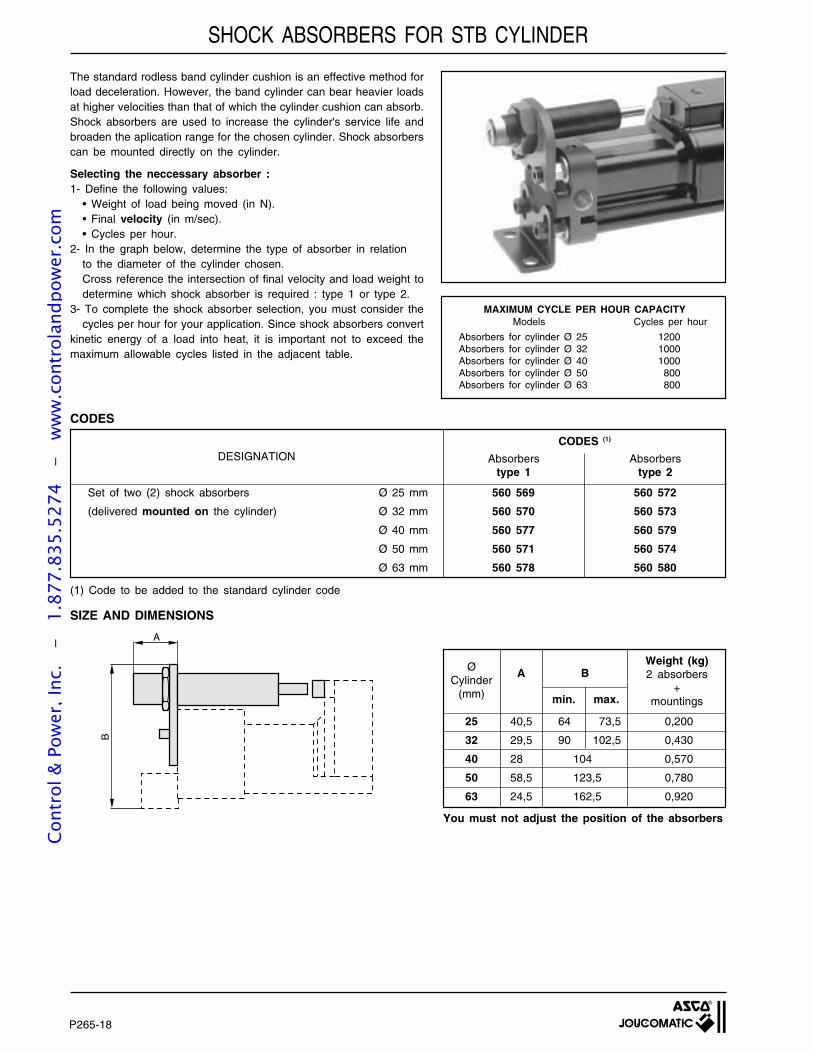
P265-18
The standard rodless band cylinder cushion is an effective method forload deceleration. However, the band cylinder can bear heavier loadsat higher velocities than that of which the cylinder cushion can absorb.Shock absorbers are used to increase the cylinder's service life andbroaden the aplication range for the chosen cylinder. Shock absorberscan be mounted directly on the cylinder.
Selecting the neccessary absorber :1- Define the following values:
• Weight of load being moved (in N).• Final velocity (in m/sec).• Cycles per hour.
2- In the graph below, determine the type of absorber in relationto the diameter of the cylinder chosen.Cross reference the intersection of final velocity and load weight todetermine which shock absorber is required : type 1 or type 2.
3- To complete the shock absorber selection, you must consider thecycles per hour for your application. Since shock absorbers convert
kinetic energy of a load into heat, it is important not to exceed themaximum allowable cycles listed in the adjacent table.
Cycles per hourModels
Absorbers for cylinder Ø 25 1200Absorbers for cylinder Ø 32 1000Absorbers for cylinder Ø 40 1000Absorbers for cylinder Ø 50 800Absorbers for cylinder Ø 63 800
MAXIMUM CYCLE PER HOUR CAPACITY
Set of two (2) shock absorbers Ø 25 mm 560 569 560 572
(delivered mounted on the cylinder) Ø 32 mm 560 570 560 573
Ø 40 mm 560 577 560 579
Ø 50 mm 560 571 560 574
Ø 63 mm 560 578 560 580
CODES (1)
DESIGNATION
CODES
Absorberstype 1
Absorberstype 2
(1) Code to be added to the standard cylinder code
SIZE AND DIMENSIONS
B
A
25 40,5 64 73,5 0,200
32 29,5 90 102,5 0,430
40 28 104 0,570
50 58,5 123,5 0,780
63 24,5 162,5 0,920
Weight (kg)2 absorbers
+mountings
AØCylinder
(mm)
B
min. max.
You must not adjust the position of the absorbers
SHOCK ABSORBERS FOR STB CYLINDERCo
ntro
l & P
ower
, Inc
. -
1.
877.
835.
5274
-
ww
w.c
ontr
olan
dpow
er.c
om
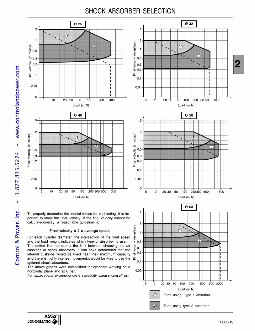
P265-19
2
SHOCK ABSORBER SELECTION
Ø 63
Ø 40 Ø 50
Ø 32Ø 25
To properly determine the inertial forces for cushioning, it is im-portant to know the final velocity. If the final velocity cannot becalculateddirectly, a reasonable guideline is:
Final velocity = 2 x average speed
For each cylinder diameter, the intersection of the final speedand the load weight indicates which type of absorber to use.The dotted line represents the limit between choosing the aircushions or shock absorbers. If you have determined that theinternal cushions would be used near their maximum capacityand there is highly intense movement,it would be wise to use theoptional shock absorbers.The above graphs were established for cylinders working on ahorizontal plane and at 6 bar.For applications exceeding cycle capability, please consult us.
Fin
al v
eloc
ity (
in m
/sec
)
Load (in N)
2
1 Zone using type 1 absorber
Zone using type 2 absorber
2
2
1
0,5
0,3
0,2
0,1
0,05
05 10 20 30 50 100 200 400
1
5
1
0,5
0,3
0,2
0,1
0,05
05 10 20 30 50 100 200 1000300 500
2
2
1
Fin
al v
eloc
ity (
in m
/sec
)
Load (in N)Load (in N)
5
1
0,5
0,3
0,2
0,1
0,05
05 10 20 30 50 100 200 1500300 500
2
2
1
5
1
0,5
0,3
0,2
0,1
0,05
05 10 20 30 50 100 200 1000300 500
2
2
1
Fin
al v
eloc
ity (
in m
/sec
)
Fin
al v
eloc
ity (
in m
/sec
)
Load (in N)Load (in N)
5
1
0,5
0,3
0,2
0,1
05 10 20 30 50 100 200 1000500
2
0,05
2000
2
1
Fin
al v
eloc
ity (
in m
/sec
)
Cont
rol &
Pow
er, I
nc.
-
1.87
7.83
5.52
74
- w
ww
.con
trol
andp
ower
.com
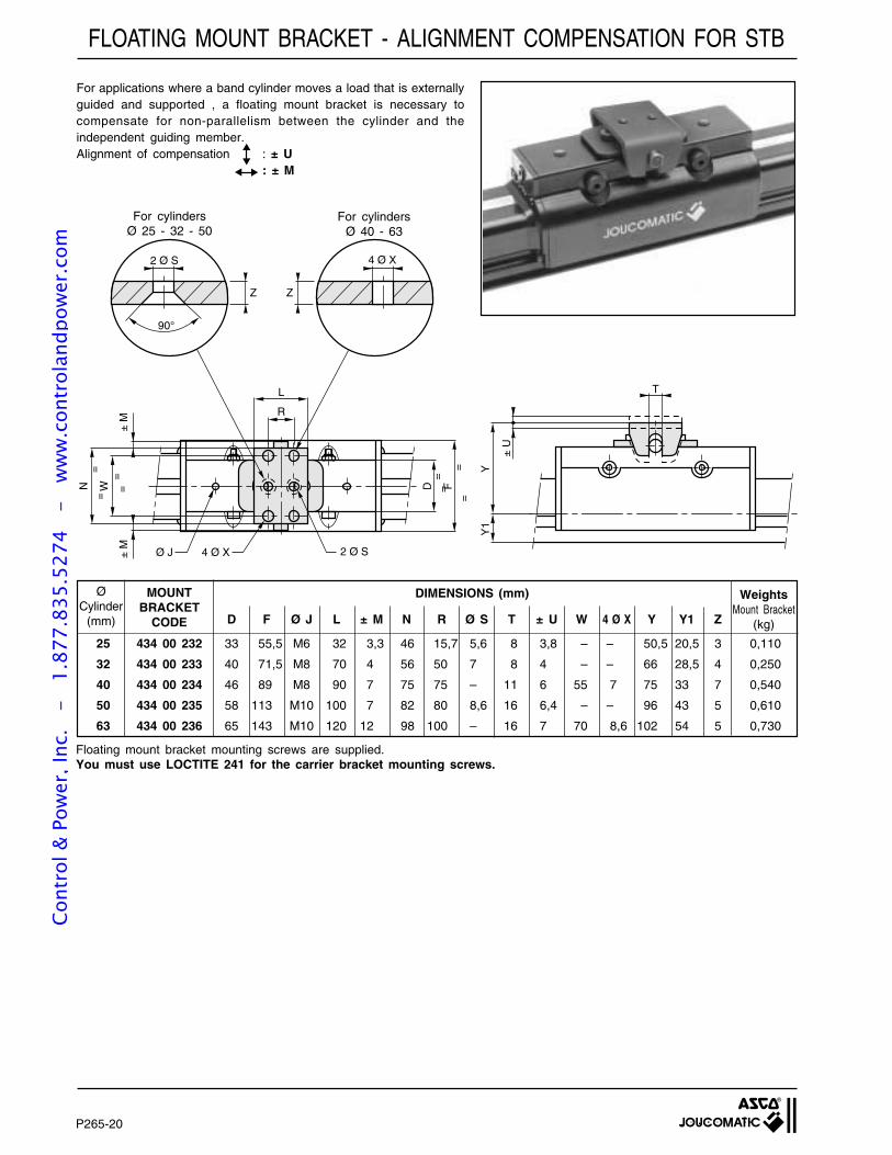
P265-20
FLOATING MOUNT BRACKET - ALIGNMENT COMPENSATION FOR STB
Floating mount bracket mounting screws are supplied.You must use LOCTITE 241 for the carrier bracket mounting screws.
For cylindersØ 25 - 32 - 50
For cylindersØ 40 - 63
For applications where a band cylinder moves a load that is externallyguided and supported , a floating mount bracket is necessary tocompensate for non-parallelism between the cylinder and theindependent guiding member.Alignment of compensation : ± U
: ± M
25 434 00 232 33 55,5 M6 32 3,3 46 15,7 5,6 8 3,8 – – 50,5 20,5 3 0,110
32 434 00 233 40 71,5 M8 70 4 56 50 7 8 4 – – 66 28,5 4 0,250
40 434 00 234 46 89 M8 90 7 75 75 – 11 6 55 7 75 33 7 0,540
50 434 00 235 58 113 M10 100 7 82 80 8,6 16 6,4 – – 96 43 5 0,610
63 434 00 236 65 143 M10 120 12 98 100 – 16 7 70 8,6 102 54 5 0,730
ØCylinder
(mm)
MOUNTBRACKET
CODE D F Ø J L ± M N R Ø S T ± U W 4 Ø X Y Y1 Z
WeightsMount Bracket
(kg)
DIMENSIONS (mm)
N W
± M
± M
L
RD
=F
=
==
Ø J 2 Ø S4 Ø X
T
± U
YY
1
90°
2 Ø S
=
=
==
4 Ø X
Z Z
Cont
rol &
Pow
er, I
nc.
-
1.87
7.83
5.52
74
- w
ww
.con
trol
andp
ower
.com
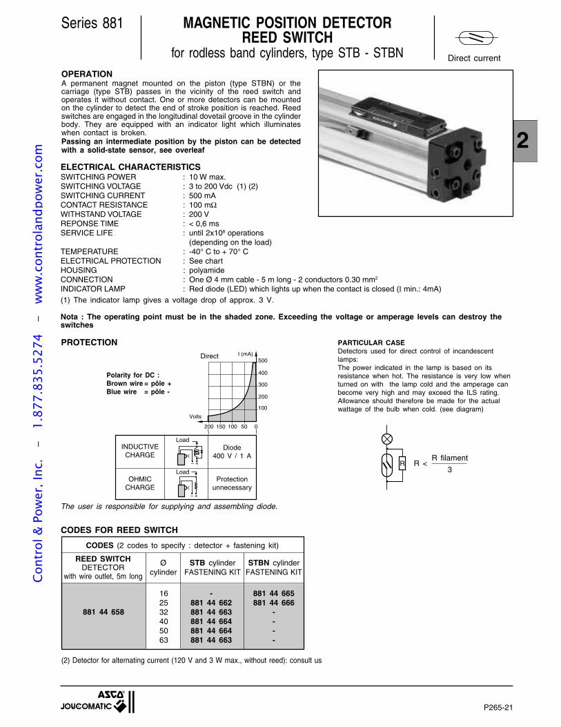
P265-21
2
Series 881 MAGNETIC POSITION DETECTORREED SWITCH
for rodless band cylinders, type STB - STBN
ELECTRICAL CHARACTERISTICSSWITCHING POWER : 10 W max.SWITCHING VOLTAGE : 3 to 200 Vdc (1) (2)SWITCHING CURRENT : 500 mACONTACT RESISTANCE : 100 mΩWITHSTAND VOLTAGE : 200 VREPONSE TIME : < 0,6 msSERVICE LIFE : until 2x10⁸ operations
(depending on the load)TEMPERATURE : -40° C to + 70° CELECTRICAL PROTECTION : See chartHOUSING : polyamideCONNECTION : One Ø 4 mm cable - 5 m long - 2 conductors 0.30 mm2
INDICATOR LAMP : Red diode (LED) which lights up when the contact is closed (I min.: 4mA)(1) The indicator lamp gives a voltage drop of approx. 3 V.
The user is responsible for supplying and assembling diode.
PROTECTION
INDUCTIVECHARGE
Protectionunnecessary
OHMICCHARGE
Polarity for DC :Brown wire = pôle +Blue wire = pôle -
Direct
Diode400 V / 1 A
OPERATIONA permanent magnet mounted on the piston (type STBN) or thecarriage (type STB) passes in the vicinity of the reed switch andoperates it without contact. One or more detectors can be mountedon the cylinder to detect the end of stroke position is reached. Reedswitches are engaged in the longitudinal dovetail groove in the cylinderbody. They are equipped with an indicator light which illuminateswhen contact is broken.Passing an intermediate position by the piston can be detectedwith a solid-state sensor, see overleaf
– +
– +
Load
CODES FOR REED SWITCH
Load
Nota : The operating point must be in the shaded zone. Exceeding the voltage or amperage levels can destroy theswitches
050100150200
Volts
500
300
200
100
400
I (mA)
(2) Detector for alternating current (120 V and 3 W max., without reed): consult us
R <R filament
3R
PARTICULAR CASEDetectors used for direct control of incandescentlamps:The power indicated in the lamp is based on itsresistance when hot. The resistance is very low whenturned on with the lamp cold and the amperage canbecome very high and may exceed the ILS rating.Allowance should therefore be made for the actualwattage of the bulb when cold. (see diagram)
Direct current
CODES (2 codes to specify : detector + fastening kit)
881 44 658
881 44 665881 44 666
----
REED SWITCHDETECTOR
with wire outlet, 5m long
Øcylinder
STB cylinderFASTENING KIT
STBN cylinderFASTENING KIT
162532405063
-881 44 662881 44 663881 44 664881 44 664881 44 663
Cont
rol &
Pow
er, I
nc.
-
1.87
7.83
5.52
74
- w
ww
.con
trol
andp
ower
.com
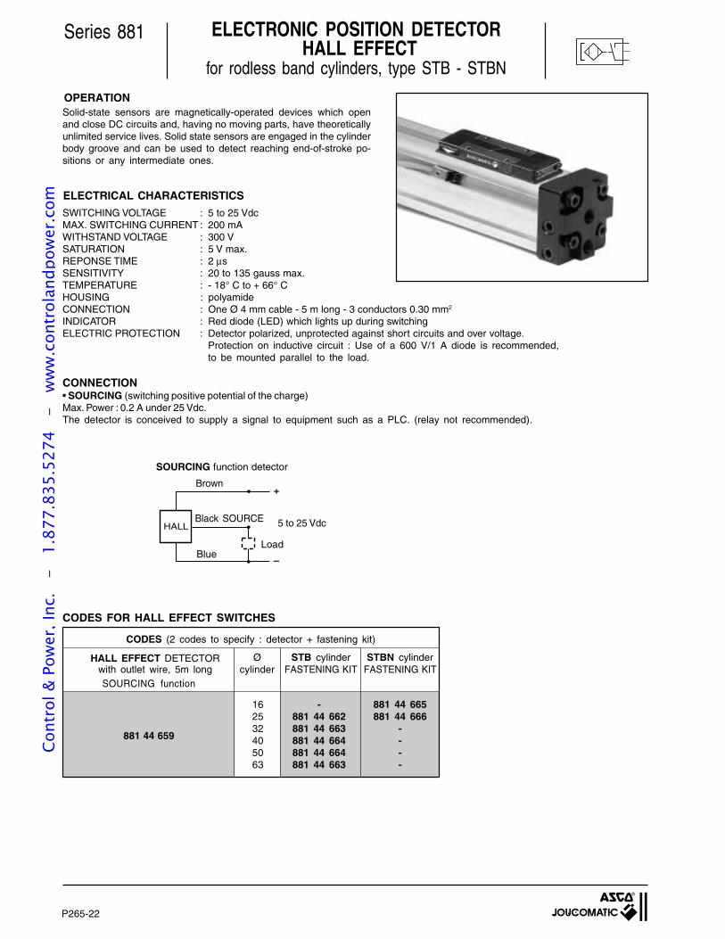
P265-22
Series 881 ELECTRONIC POSITION DETECTOR HALL EFFECT
for rodless band cylinders, type STB - STBN
ELECTRICAL CHARACTERISTICS
OPERATIONSolid-state sensors are magnetically-operated devices which openand close DC circuits and, having no moving parts, have theoreticallyunlimited service lives. Solid state sensors are engaged in the cylinderbody groove and can be used to detect reaching end-of-stroke po-sitions or any intermediate ones.
SWITCHING VOLTAGE : 5 to 25 VdcMAX. SWITCHING CURRENT : 200 mAWITHSTAND VOLTAGE : 300 VSATURATION : 5 V max.REPONSE TIME : 2 µsSENSITIVITY : 20 to 135 gauss max.TEMPERATURE : - 18° C to + 66° CHOUSING : polyamideCONNECTION : One Ø 4 mm cable - 5 m long - 3 conductors 0.30 mm2
INDICATOR : Red diode (LED) which lights up during switchingELECTRIC PROTECTION : Detector polarized, unprotected against short circuits and over voltage.
Protection on inductive circuit : Use of a 600 V/1 A diode is recommended,to be mounted parallel to the load.
CONNECTION• SOURCING (switching positive potential of the charge)Max. Power : 0.2 A under 25 Vdc.The detector is conceived to supply a signal to equipment such as a PLC. (relay not recommended).
CODES FOR HALL EFFECT SWITCHES
SOURCING function detector
HALL
–
+Brown
Blue
Black SOURCE
Load
881 44 659
881 44 665881 44 666
----
HALL EFFECT DETECTORwith outlet wire, 5m long
CODES (2 codes to specify : detector + fastening kit)
Øcylinder
STB cylinderFASTENING KIT
STBN cylinderFASTENING KIT
162532405063
-881 44 662881 44 663881 44 664881 44 664881 44 663
SOURCING function
5 to 25 Vdc
Cont
rol &
Pow
er, I
nc.
-
1.87
7.83
5.52
74
- w
ww
.con
trol
andp
ower
.com
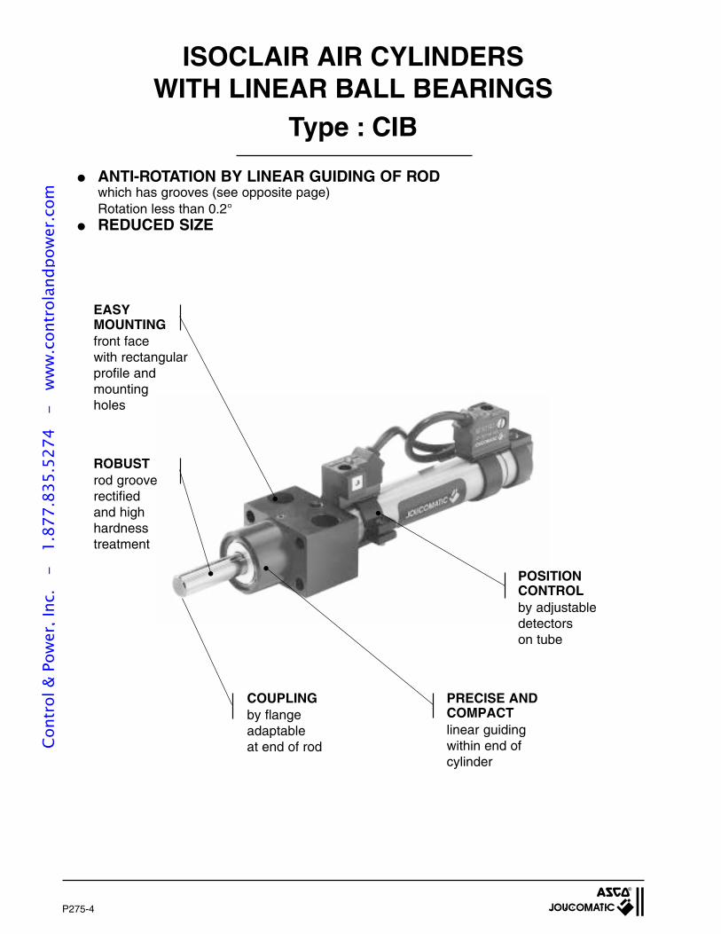
P275-4
ISOCLAIR AIR CYLINDERSWITH LINEAR BALL BEARINGS
Type : CIB
ANTI-ROTATION BY LINEAR GUIDING OF RODwhich has grooves (see opposite page)Rotation less than 0.2°
REDUCED SIZE
ROBUSTrod grooved,rectifiedand highhardnesstreatment
PRECISE ANDCOMPACTlinear guidingwithin end ofcylinder
COUPLINGby flangeadaptableat end of rod
EASYMOUNTINGfront facewith rectangularprofile andmountingholes
POSITIONCONTROLby adjustabledetectorson tube
Cont
rol &
Pow
er, I
nc.
-
1.87
7.83
5.52
74
- w
ww
.con
trol
andp
ower
.com
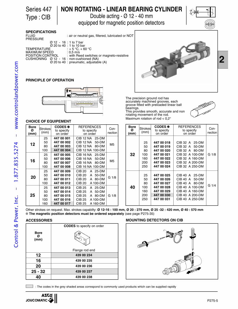
2
P275-5
CODES to specify on order
Flange rod end
12 439 00 234
16 439 00 235
20 439 00 236
25 - 32 439 00 237
40 439 00 238
NON ROTATING - LINEAR BEARING CYLINDERDouble acting - Ø 12 - 40 mm
equipped for magnetic position detectors
Series 447Type : CIB
PRINCIPLE OF OPERATION
The precision ground rod hasaccurately machined grooves, eachgroove fitted with preloaded linear ballbearings.This provides smooth, accurate and nonrotating movement of the rod.Maximum rotation of rod < 0,2°
CODES REFERENCESto specify to specifyon order on order
25 447 00 001 CIB 12 NA 25-DM50 447 00 002 CIB 12 NA 50-DM12 80 447 00 003 CIB 12 NA 80-DM M5
100 447 00 004 CIB 12 NA 100-DM25 447 00 005 CIB 16 NA 25-DM50 447 00 006 CIB 16 NA 50-DM16 80 447 00 007 CIB 16 NA 80-DM M5
100 447 00 008 CIB 16 NA 100-DM25 447 00 009 CIB 20 A 25-DM50 447 00 010 CIB 20 A 50-DM 20 80 447 00 011 CIB 20 A 80-DM G 1/8
100 447 00 012 CIB 20 A 100-DM25 447 00 013 CIB 25 A 25-DM50 447 00 014 CIB 25 A 50-DM
25 80 447 00 015 CIB 25 A 80-DM G 1/8100 447 00 016 CIB 25 A 100-DM160 447 00 017 CIB 25 A 160-DM
CHOICE OF EQUIPEMENT
BoreØ
(mm)Con-
nection
CODES REFERENCESto specify to specifyon order on order
25 447 00 018 CIB 32 A 25-DM50 447 00 019 CIB 32 A 50-DM80 447 00 020 CIB 32 A 80-DM
32 100 447 00 021 CIB 32 A 100-DM G 1/8160 447 00 022 CIB 32 A 160-DM200 447 00 023 CIB 32 A 200-DM250 447 00 024 CIB 32 A 250-DM
25 447 00 025 CIB 40 A 25-DM50 447 00 026 CIB 40 A 50-DM80 447 00 027 CIB 40 A 80-DM
40 100 447 00 028 CIB 40 A 100-DM G 1/4
160 447 00 029 CIB 40 A 160-DM200 447 00 030 CIB 40 A 200-DM250 447 00 031 CIB 40 A 250-DM
BoreØ
(mm)
Con-nection
Strokes(mm)
Other strokes on request. Max. strokes capabilty: Ø 12-16 : 100 mm, Ø 20 : 270 mm, Ø 25 -32 : 420 mm, Ø 40 : 570 mm The magnetic position detectors must be ordered separately (see page P275-35)
ACCESSORIES
BoreØ
(mm)
Strokes(mm)
SPECIFICATIONSFLUID : air or neutral gas, filtered, lubricated or NOTPRESSURE
Ø 12 - 16 : 1 to 7 barØ 20 to 40 : 1 to 10 bar
TEMPERATURE : + 5 °C, + 60 °CMAXIMUM SPEED : 0,5 m/sPOSITION CONTROL : with Reed switches or magneto-resistiveCUSHIONING Ø 12 - 16 : non-cushioned (NA)
Ø 20 to 40 : pneumatic, adjustable (A)
NS
: The codes in the grey shaded areas correspond to commonly used products which can be supplied rapidly
MOUNTING DETECTORS ON CIB
Cont
rol &
Pow
er, I
nc.
-
1.87
7.83
5.52
74
- w
ww
.con
trol
andp
ower
.com
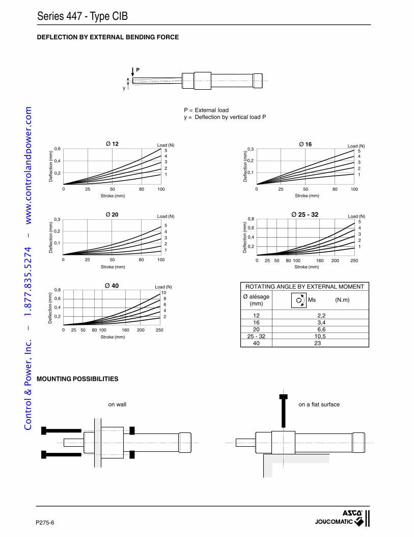
P275-6
y
P
Series 447 - Type CIB
DEFLECTION BY EXTERNAL BENDING FORCE
MOUNTING POSSIBILITIES
P = External loady = Deflection by vertical load P
on wall on a flat surface
Ø 12
3
5
1
4
2
0,6
0,4
0,2
0 25 50 80 100
Def
lect
ion
(mm
)
Load (N)
Def
lect
ion
(mm
)D
efle
ctio
n (m
m)
Load (N)
Load (N)0,3
0,2
0,1
Ø 20
0 25 50 80 100
3
5
1
4
2D
efle
ctio
n (m
m)
Def
lect
ion
(mm
)
Load (N)
0 25 50 80 100 160 200
0,6
0,4
0,2
6
10
2
8
4
250
Ø 400,8
Ø 16
3
5
1
4
2
0 25 50 80 100
0,3
0,2
0,1
Load (N)
0 25 50 80 100 160 200
0,6
0,4
0,2
3
5
1
4
2
250
Ø 25 - 320,8
Stroke (mm) Stroke (mm)
Stroke (mm) Stroke (mm)
Stroke (mm)
ROTATING ANGLE BY EXTERNAL MOMENT
Ø alésage(mm)
Ms (N.m)
2,23,46,6
10,523
121620
25 - 3240
Cont
rol &
Pow
er, I
nc.
-
1.87
7.83
5.52
74
- w
ww
.con
trol
andp
ower
.com
2
P275-7
DIMENSIONS
Series 447 - Type CIB
ØG
ØK
J
TØE
D B=
=
==
C==
A==
121620
25 - 3240
BoreØ
(mm) A B C D E G J K T
DIMENSIONS (mm)
439 00 234439 00 235439 00 236439 00 237439 00 238
CODESto specifyon order
30 17 21 10 6 5,9 11 3,4 1530 17 23 10 8 5,9 11 3,4 1540 20 30 12 10 7,6 15 4,5 2050 25 38 14 13 9,2 14 5,5 2060 30 46 17 16 12,2 18 6,6 25
FLANGE ROD END
VDA AR
ZA ZB +
ZT +
TR
US
TF
UF
NB
PA 21
UT max.
AO
1
4 ØAB 3
ØEE
2 ØI
2 ØH
1
2
4
4
AQK
ØD
h7Ø
BE
h8
5
SH
TQ
1 : + stroke
2 : Side mounting(opened holes)
3 : Front mounting(opened holes)
4 : Adjustment screw forpneumatic cushioning(except Ø 12 and 16)
5 : Reed switches or magneto-resistive,with connector or wires, adjustable ontube
121620253240
BoreØ
(mm) A ØAB AO AQ AR ØBE D ØEE ØH I K NB PA SH TF TQ TR UF US UT VD ZA ZB ZT
DIMENSIONS (mm)
25 4,5 13 24 12 21 6 M5 5,5 10 16 20 19 30 14 23 26 22 34 - 16,5 54,5 56 110,526 4,5 13 24 12 23 8 M5 5,5 10 18 21 19 32 16 24 27 24 35 - 16,5 55,5 60 115,528 5,5 15,5 31 18 30 10 G1/8 6,6 12,2 24 30 24 34 22 30 34 32 44 59 22,5 66 64,5 130,532 6,6 16 32 18 34 13 G1/8 9 15,4 26 30 25 36 24 36 41 36 53 68 25 73 65 13832 6,6 16 32 37 34 13 G1/8 9 15,4 29 39 25 41 27 36 41 39 53 68 25 73 76 14934 9 22,5 45 44 42 16 G1/4 11 19 39 45,5 35 46 36 46 51 52 67 82 32 88,5 108,5 197
Cont
rol &
Pow
er, I
nc.
-
1.87
7.83
5.52
74
- w
ww
.con
trol
andp
ower
.com
P275-9
2• INTEGRAL LINEAR AND ANTI-ROTATION GUIDES
• EASY MOUNTINGcompact design, narrow body, stackable,ambidextrous, standard detector mountable in anyposition, adjustable stroke
TWIN ROD / TWIN PISTON AIR CYLINDERSWITH PLAIN OR BALL BEARINGS LINEAR GUIDE
Types: P2L and P2B
SAFE ANDCOMPACTDESIGNfirm and directmounting bythrough body
PNEUMATICCONNECTION2 ports at side
DETECTORMounted directlyon side or top
RUGGED ANTI-ROTATION SYSTEMby two integral rodsin actuator,precision-machined
POSITIONMONITORINGby standardreed switch or electronicmagnetic detectors"UNI" or "COMPACT"types(common to all cylinders)
SMALLSIZEnarrow stackablebody
HIGHPRECISIONwith ball bearinglinear guide version
QUIET AND USERFRIENDLYadjustable stopwith elastic cushioningreducing noise,adjustable stroke
EASE OFINSTALLATIONintegral flangewith calibrated holesfor precise adaptationload
Cont
rol &
Pow
er, I
nc.
-
1.87
7.83
5.52
74
- w
ww
.con
trol
andp
ower
.com
P275-10
CYLINDERS WITH PLAIN BEARINGS GUIDE (type P2L)
MAXIMUM ADMISSIBLE LOAD “F” ON THE ROD END
Projection distance “d” (in mm)
MAXIMUM ALLOWABLE MOMENTS "Ms" AT ROD END
Projection distance “d” (in mm)
Projection distance “d” (in mm)
Cylinder with plain bearings guiderods in the vertical plane
Cylinder with plain bearings guiderods in the horizontal plane
10 25 50 75 100 125 1500
20
40
60
80
100
120
140
160
180
Fd
F (N)
I
Ø32
Ø25Ø20Ø16
10 25 50 75 100 125 1500
10
20
30
40
50
60
70
80
90
Fd
F (N)
IIØ
32Ø25
Ø20Ø16
Fd
L10 +
G
10 25 50 75 100 125 1500
0,5
1,0
1,5
2,0
2,5
3,0
3,5
Ms (N.m)
Ms
IIIØ
32Ø25
Ø20
Ø16
d = the projection distance (in mm) corresponding to the dimensionL10 + the stroke length + the distance from the load centre ofgravity (G) to the mating surface of the cylinder flangeNote: the values in charts (I), (II) and (III) correspond to those inregular horizontal movement. In the event of vibration or jerkymovement, halve the maximum allowable values.
Cont
rol &
Pow
er, I
nc.
-
1.87
7.83
5.52
74
- w
ww
.con
trol
andp
ower
.com
P275-11
2
CYLINDERS WITH BALL BEARINGS GUIDE (type P2B)
Projection distance “d” (in mm)
MAXIMUM ADMISSIBLE LOAD “F” ON THE ROD END
MAXIMUM ALLOWABLE MOMENTS "Ms" AT ROD END
Projection distance “d” (in mm)
Projection distance “d” (in mm)
Cylinder with ball bearings guiderods in the horizontal plane
service-life of cylinder: 5000 km
10 25 50 75 100 125 1500
20
40
60
80
100
120
Fd
I
F (N)
Ø32
Ø25
Ø20Ø16
10 25 50 75 100 125 1500
10
20
30
40
50
60
70
80
Fd
F (N)
II
Ø32
Ø25
Ø20Ø16
10 25 50 75 100 125 1500
0,5
1,0
1,5
2,0
2,5
Ms (N.m)
Ms
III
Ø32
Ø25Ø20
Ø16
Fd
L10 +
G
Whatever the stroke of the cylinder, its movement is only a small pro-portion of the travel (not more than 30 mm), it is necessary to reducethe maximum allowable torques and loads by multiplying the valuestaken from charts (I), (II) and (III) by coefficient 0.6. The curves allowfor this reduction in performance.
d = the projection distance (in mm) corresponding to the dimensionL10 + the stroke length + the distance from the load centre ofgravity (G) to the mating surface of the cylinder flangeNote: the values in charts (I), (II) and (III) correspond to those inregular horizontal movement. In the event of vibration or jerkymovement, halve the maximum allowable values.
Cylinder with ball bearings guiderods in the vertical plane
service-life of cylinder: 5000 km
Cont
rol &
Pow
er, I
nc.
-
1.87
7.83
5.52
74
- w
ww
.con
trol
andp
ower
.com
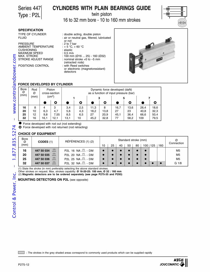
P275-12
Series 447Type : P2L
CYLINDERS WITH PLAIN BEARINGS GUIDEtwin piston
16 to 32 mm bore - 10 to 160 mm strokes
SPECIFICATIONTYPE OF CYLINDER : double acting, double pistonFLUID : air or neutral gas, filtered, lubricated
or notPRESSURE : 2 to 7 barAMBIENT TEMPERATURE : + 5 °C, + 60 °CCUSHIONING : elasticMAXIMUM SPEED : 0,5 m/sMAX. STROKE : 100 mm (Ø16 ... 25) - 160 (Ø32)STROKE ADJUST RANGE : nominal stroke +0 to –5 mm
(retracted rods)POSITIONS CONTROL : with Reed switches
or electronic (magnetoresistant)detectors
CHOICE OF EQUIPMENT
NS
(1) State the stroke (in mm) preferably selecting the above standard strokes.Other strokes on request. Max. strokes capabilty: Ø 16-20-25: 100 mm, Ø 32 : 160 mm(2) Magnetic detectors are to be ordered separately (see page P275-35 and P293)
M5M5
M5G 1/8
16202532
P2L 16 NA ---- - DM
P2L 20 NA ---- - DMP2L 25 NA ---- - DM
P2L 32 NA ---- - DM
(1)
(1)
(1)
(1)
(1)
(1)
(1)
(1)
447 50 034 ----447 50 035 ----447 50 036 ----447 50 037 ----
Standard stroke (mm)BoreØ
(mm)
ØConnectionRÉFÉRENCES (1) (2)CODES (1)
10 25 40 50 80 100 125 160
Force developed with rod out (rod extending)Force developed with rod returned (rod retracting)
FORCE DEVELOPED BY CYLINDER
16 8 4 3 3,4 2,5 11,3 8 16,7 13,6 26,4 18,620 10 6,3 4,7 5,6 4,3 18,2 13,8 27 23 40,8 32,325 12 9,8 7,55 8,5 6,5 27 20,9 45,1 36,4 66,6 50,432 16 16,1 12,1 13,1 10 45,2 32,8 77 58,2 109 79,5
Dynamic force developed (daN)as a function of input pressure (bar)
1 3 5 7
BoreØ
(mm)
RodØ
(mm)
Pistoncross-section
(cm2)
: The strokes in the grey shaded areas correspond to commonly used products which can be supplied rapidly
MOUNTING DETECTORS ON P2L (see opposite)
Cont
rol &
Pow
er, I
nc.
-
1.87
7.83
5.52
74
- w
ww
.con
trol
andp
ower
.com
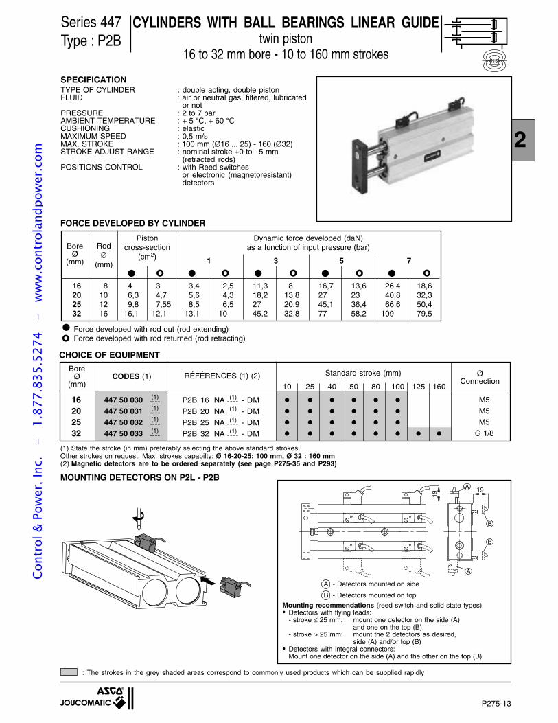
P275-13
2
Series 447Type : P2B
CHOICE OF EQUIPMENT
NS
M5
M5
M5G 1/8
16202532
P2B 16 NA ---- - DM
P2B 20 NA ---- - DM
P2B 25 NA ---- - DM
P2B 32 NA ---- - DM
(1)
(1)
(1)
(1)
(1)
(1)
(1)
(1)
447 50 030 ----447 50 031 ----447 50 032 ----447 50 033 ----
BoreØ
(mm)RÉFÉRENCES (1) (2)CODES (1)
Force developed with rod out (rod extending)Force developed with rod returned (rod retracting)
FORCE DEVELOPED BY CYLINDER
16 8 4 3 3,4 2,5 11,3 8 16,7 13,6 26,4 18,620 10 6,3 4,7 5,6 4,3 18,2 13,8 27 23 40,8 32,325 12 9,8 7,55 8,5 6,5 27 20,9 45,1 36,4 66,6 50,432 16 16,1 12,1 13,1 10 45,2 32,8 77 58,2 109 79,5
Dynamic force developed (daN)as a function of input pressure (bar)
1 3 5 7
BoreØ
(mm)
RodØ
(mm)
Pistoncross-section
(cm2)
10 25 40 50 80 100 125 160
CYLINDERS WITH BALL BEARINGS LINEAR GUIDEtwin piston
16 to 32 mm bore - 10 to 160 mm strokes
SPECIFICATIONTYPE OF CYLINDER : double acting, double pistonFLUID : air or neutral gas, filtered, lubricated
or notPRESSURE : 2 to 7 barAMBIENT TEMPERATURE : + 5 °C, + 60 °CCUSHIONING : elasticMAXIMUM SPEED : 0,5 m/sMAX. STROKE : 100 mm (Ø16 ... 25) - 160 (Ø32)STROKE ADJUST RANGE : nominal stroke +0 to –5 mm
(retracted rods)POSITIONS CONTROL : with Reed switches
or electronic (magnetoresistant)detectors
(1) State the stroke (in mm) preferably selecting the above standard strokes.Other strokes on request. Max. strokes capabilty: Ø 16-20-25: 100 mm, Ø 32 : 160 mm(2) Magnetic detectors are to be ordered separately (see page P275-35 and P293)
Standard stroke (mm) ØConnection
MOUNTING DETECTORS ON P2L - P2B
B
A
A
19
19
B
: The strokes in the grey shaded areas correspond to commonly used products which can be supplied rapidly
Mounting recommendations (reed switch and solid state types)• Detectors with flying leads:
- stroke ≤ 25 mm: mount one detector on the side (A)and one on the top (B)
- stroke > 25 mm: mount the 2 detectors as desired,side (A) and/or top (B)
• Detectors with integral connectors:Mount one detector on the side (A) and the other on the top (B)
A - Detectors mounted on side
B - Detectors mounted on top
Cont
rol &
Pow
er, I
nc.
-
1.87
7.83
5.52
74
- w
ww
.con
trol
andp
ower
.com
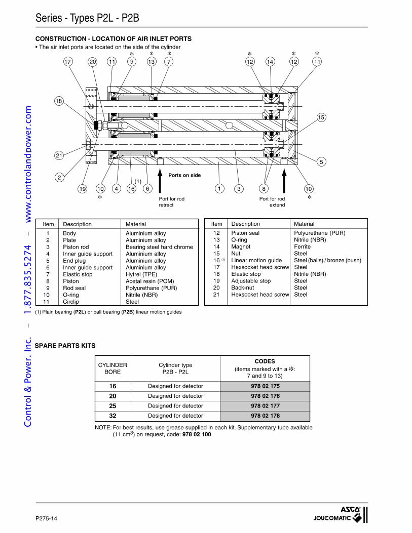
P275-14
1 3
12
5
7
610 16
20
2
21
19
18
17 11 9
8
14 12
10
15
13
4
11
Series - Types P2L - P2B
CONSTRUCTION - LOCATION OF AIR INLET PORTS• The air inlet ports are located on the side of the cylinder
Port for rodretract
Ports on side
(1) Plain bearing (P2L) or ball bearing (P2B) linear motion guides
Port for rodextend
SPARE PARTS KITS
16
20
25
32
Designed for detector 978 02 175
Designed for detector 978 02 176
Designed for detector 978 02 177
Designed for detector 978 02 178
CODES(items marked with a :
7 and 9 to 13)
CYLINDERBORE
Cylinder typeP2B - P2L
(1)
Item Description Material
1 Body Aluminium alloy2 Plate Aluminium alloy3 Piston rod Bearing steel hard chrome4 Inner guide support Aluminium alloy5 End plug Aluminium alloy6 Inner guide support Aluminium alloy7 Elastic stop Hytrel (TPE)8 Piston Acetal resin (POM)9 Rod seal Polyurethane (PUR)
10 O-ring Nitrile (NBR)11 Circlip Steel
Item Description Material
12 Piston seal Polyurethane (PUR)13 O-ring Nitrile (NBR)14 Magnet Ferrite15 Nut Steel16 (1) Linear motion guide Steel (balls) / bronze (bush)17 Hexsocket head screw Steel18 Elastic stop Nitrile (NBR)19 Adjustable stop Steel20 Back-nut Steel21 Hexsocket head screw Steel
NOTE: For best results, use grease supplied in each kit. Supplementary tube available(11 cm3) on request, code: 978 02 100
Cont
rol &
Pow
er, I
nc.
-
1.87
7.83
5.52
74
- w
ww
.con
trol
andp
ower
.com
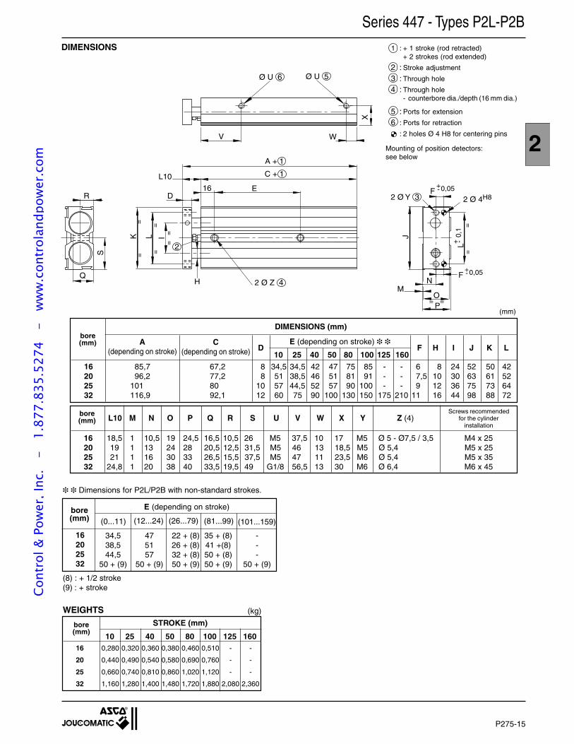
P275-15
2
MOP
JK L
L
A + 1
C + 1
E16D
I
2 Ø Z 4
V W
X
N
S
R
Q
Ø U 5
2 Ø Y 3
2
H
Ø U 6
2 Ø 4H8F
= =
==
==
==
==
L10+- 0,05
F+- 0,05
+ -0,
1
Series 447 - Types P2L-P2B
1 : + 1 stroke (rod retracted)+ 2 strokes (rod extended)
2 : Stroke adjustment
3 : Through hole
4 : Through hole- counterbore dia./depth (16 mm dia.)
5 : Ports for extension
6 : Ports for retraction
: 2 holes Ø 4 H8 for centering pins
Mounting of position detectors:see below
DIMENSIONS
Dimensions for P2L/P2B with non-standard strokes.
(8) : + 1/2 stroke(9) : + stroke
(mm)
10 25 40 50 80 100 125 16016 0,280 0,320 0,360 0,380 0,460 0,510 - -
20 0,440 0,490 0,540 0,580 0,690 0,760 - -
25 0,660 0,740 0,810 0,860 1,020 1,120 - -
32 1,160 1,280 1,400 1,480 1,720 1,880 2,080 2,360
bore(mm)
WEIGHTS (kg)
STROKE (mm)
E (depending on stroke)
34,5 47 22 + (8) 35 + (8) -38,5 51 26 + (8) 41 +(8) -44,5 57 32 + (8) 50 + (8) -
50 + (9) 50 + (9) 50 + (9) 50 + (9) 50 + (9)
(101...159)
bore(mm) (0...11) (12...24) (26...79)
16202532
(81...99)
E (depending on stroke)
16 85,7 67,2 8 34,5 34,5 42 47 75 85 - - 6 8 24 52 50 4220 96,2 77,2 8 51 38,5 46 51 81 91 - - 7,5 10 30 63 61 5225 101 80 10 57 44,5 52 57 90 100 - - 9 12 36 75 73 6432 116,9 92,1 12 60 75 90 100 130 150 175 210 11 16 44 98 88 72
L10 M N O P Q R S U V W X Y Z (4)Screws recommended
for the cylinderinstallation
16 18,5 1 10,5 19 24,5 16,5 10,5 26 M5 37,5 10 17 M5 Ø 5 - Ø7,5 / 3,5 M4 x 2520 19 1 13 24 28 20,5 12,5 31,5 M5 46 13 18,5 M5 Ø 5,4 M5 x 2525 21 1 16 30 33 26,5 15,5 37,5 M5 47 11 23,5 M6 Ø 5,4 M5 x 3532 24,8 1 20 38 40 33,5 19,5 49 G1/8 56,5 13 30 M6 Ø 6,4 M6 x 45
bore(mm)
bore(mm)
DIMENSIONS (mm)
A(depending on stroke)
C(depending on stroke) 10 25 40 50 80 100 125 160
D F H I J K L
Cont
rol &
Pow
er, I
nc.
-
1.87
7.83
5.52
74
- w
ww
.con
trol
andp
ower
.com

P275-16
MICRO SLIDE TABLESWITH BALL BEARINGS
Type : TMB
• VERY COMPACT AND PRECISE TABLESfor all available air cylindersParticularly well adapted to micromechanics
• LESS THAN 0.05 mmbetween axes of fixed and mobile elementsduring stroke
LINEAR BEARING2 rows of ball bearings
"pen" typemicro-detectorwith LED
Fixed part
Pneumaticconnectionon rear face
EASYINSTALLATIONvarious mountingpossibilitiesof load
Mobile part ofload bearing
Cont
rol &
Pow
er, I
nc.
-
1.87
7.83
5.52
74
- w
ww
.con
trol
andp
ower
.com
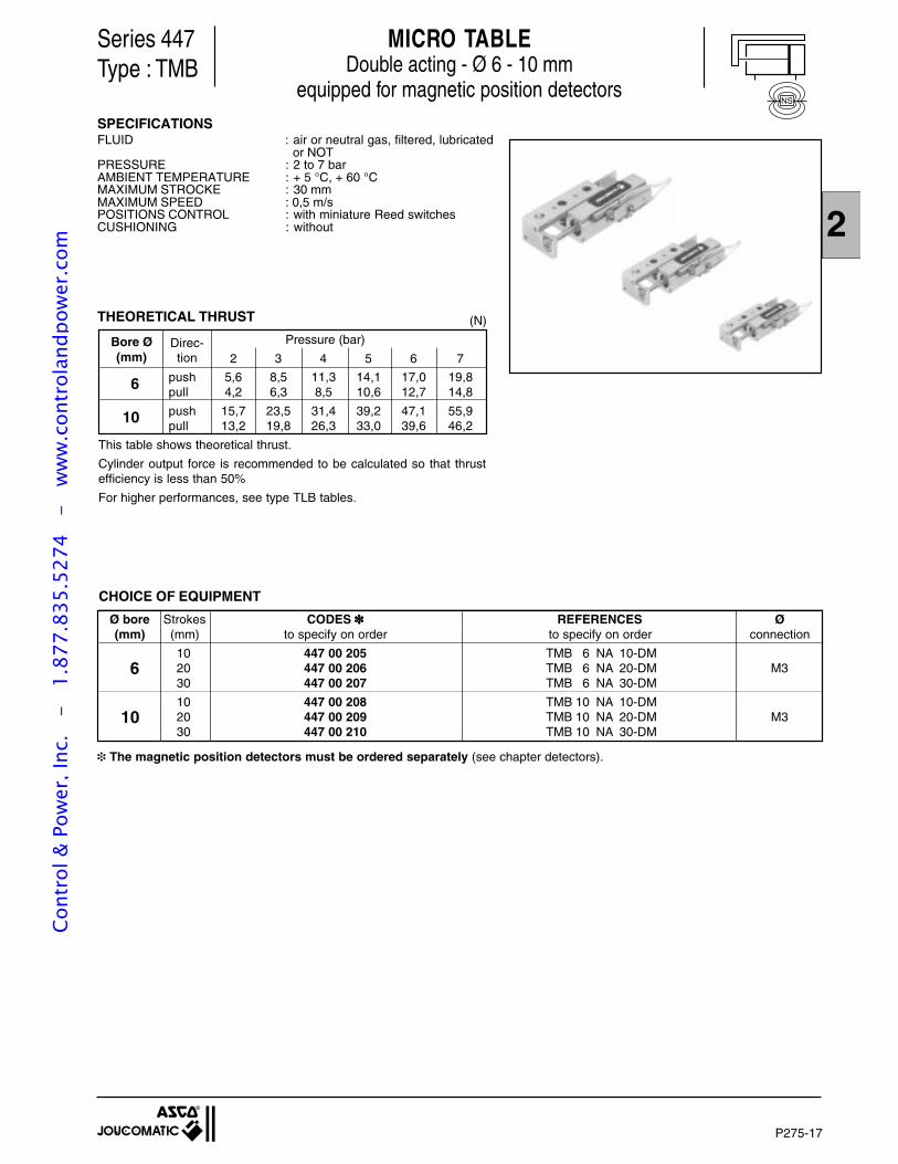
2
P275-17
Series 447Type : TMB
SPECIFICATIONSFLUID : air or neutral gas, filtered, lubricated
or NOTPRESSURE : 2 to 7 barAMBIENT TEMPERATURE : + 5 °C, + 60 °CMAXIMUM STROCKE : 30 mmMAXIMUM SPEED : 0,5 m/sPOSITIONS CONTROL : with miniature Reed switchesCUSHIONING : without
MICRO TABLEDouble acting - Ø 6 - 10 mm
equipped for magnetic position detectors
(N)THEORETICAL THRUST
CHOICE OF EQUIPMENT
Ø bore Strokes CODES REFERENCES Ø(mm) (mm) to specify on order to specify on order connection
10 447 00 205 TMB 6 NA 10-DM6 20 447 00 206 TMB 6 NA 20-DM M3
30 447 00 207 TMB 6 NA 30-DM
10 447 00 208 TMB 10 NA 10-DM10 20 447 00 209 TMB 10 NA 20-DM M3
30 447 00 210 TMB 10 NA 30-DM
The magnetic position detectors must be ordered separately (see chapter detectors).
Bore Ø Pressure (bar)(mm) 2 3 4 5 6 7
push 5,6 8,5 11,3 14,1 17,0 19,86pull 4,2 6,3 8,5 10,6 12,7 14,8
push 15,7 23,5 31,4 39,2 47,1 55,910pull 13,2 19,8 26,3 33,0 39,6 46,2
This table shows theoretical thrust.
Cylinder output force is recommended to be calculated so that thrustefficiency is less than 50%
For higher performances, see type TLB tables.
Direc-tion
NS
Cont
rol &
Pow
er, I
nc.
-
1.87
7.83
5.52
74
- w
ww
.con
trol
andp
ower
.com
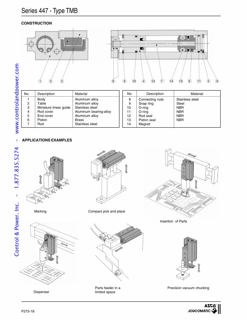
P275-18
Series 447 - Type TMB
CONSTRUCTION
No. Description Material
1 Body Aluminum alloy2 Table Aluminum alloy3 Miniature linear guide Stainless steel4 Rod cover Aluminum bearing-alloy5 End cover Aluminum alloy6 Piston Brass7 Rod Stainless steel
APPLICATIONS EXAMPLES
Compact pick and place
8 Connecting nuts Stainless steel9 Snap ring Steel
10 O-ring NBR11 O-ring NBR12 Rod seal NBR13 Piston seal NBR14 Magnet
No Description Material
Insertion of Parts
Precision vacuum chuckingParts feeder in alimited spaceDispenser
Marking
1 3 2 8 9 10 4 12 7 14 13 6 11 5 9
Cont
rol &
Pow
er, I
nc.
-
1.87
7.83
5.52
74
- w
ww
.con
trol
andp
ower
.com
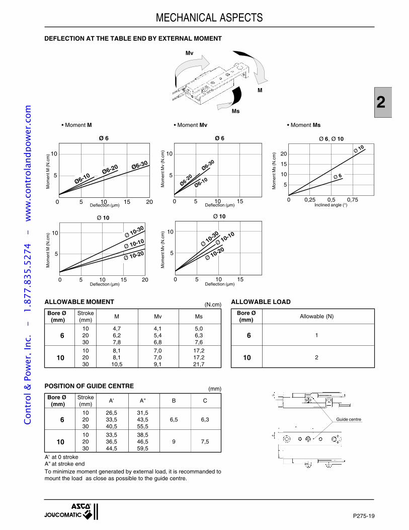
2
P275-19
(mm)
Bore Ø StrokeA' A" B C
(mm) (mm)
10 26,5 31,56 20 33,5 43,5 6,5 6,3
30 40,5 55,5
10 33,5 38,510 20 36,5 46,5 9 7,5
30 44,5 59,5
A' at 0 strokeA" at stroke endTo minimize moment generated by external load, it is recommanded tomount the load as close as possible to the guide centre.
POSITION OF GUIDE CENTRE
DEFLECTION AT THE TABLE END BY EXTERNAL MOMENT
5 10 150
Ø 6
5
10
Ø6-10
Ø6-30
Ø6-20
• Moment M • Moment Mv • Moment Ms
Mom
ent M
(N.c
m)
Mom
ent M
(N.c
m)
Deflection (µm)
Deflection (µm)
Deflection (µm)
Deflection (µm)
Inclined angle (°)
(N.cm)
Bore Ø StrokeM Mv Ms
(mm) (mm)
10 4,7 4,1 5,06 20 6,2 5,4 6,3
30 7,8 6,8 7,6
10 8,1 7,0 17,210 20 8,1 7,0 17,2
30 10,5 9,1 21,7
ALLOWABLE MOMENT ALLOWABLE LOAD
Bore ØAllowable (N)
(mm)
6 1
10 2
Mom
ent M
v (N
.cm
)M
omen
t Mv
(N.c
m)
Mom
ent M
s (N
.cm
)
MECHANICAL ASPECTS
0,25 0,5 0,750
Ø 6, Ø 10
10
20
15
5
Ø 10
Ø 6
M
Ms
Mv
Guide centre
5 10 150
Ø 10
10
5Ø 10-20
Ø 10-30
Ø 10-10
20
5 10 150
Ø 6
5
10
Ø6-10Ø6-20 Ø6-30
20
5 10 150
Ø 10
5
10
Ø 10-10
Ø 10-20Ø 10-30
Cont
rol &
Pow
er, I
nc.
-
1.87
7.83
5.52
74
- w
ww
.con
trol
andp
ower
.com
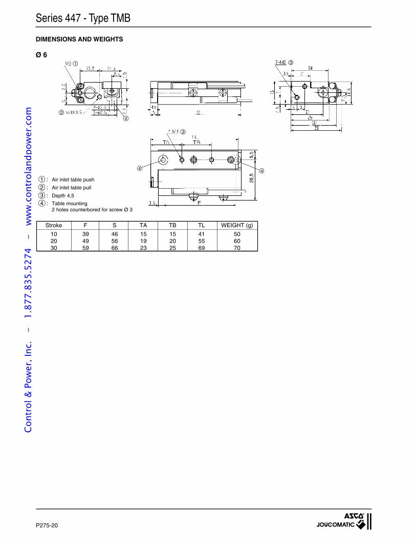
P275-20
Series 447 - Type TMB
DIMENSIONS AND WEIGHTS
Ø 6
Stroke F S TA TB TL WEIGHT (g)
10 39 46 15 15 41 5020 49 56 19 20 55 6030 59 66 23 25 69 70
1
2
3
3
4
44
1 : Air inlet table push
2 : Air inlet table pull
3 : Depth 4,5
4 : Table mounting2 holes counterbored for screw Ø 3
Cont
rol &
Pow
er, I
nc.
-
1.87
7.83
5.52
74
- w
ww
.con
trol
andp
ower
.com
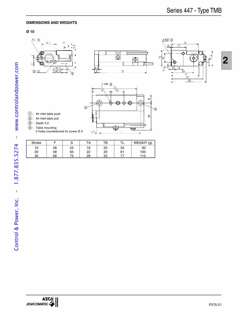
2
P275-21
DIMENSIONS AND WEIGHTS
1 : Air inlet table push
2 : Air inlet table pull
3 : Depth 4,5
4 : Table mounting2 holes counterbored for screw Ø 3
Stroke F S TA TB TL WEIGHT (g)
10 48 55 16 20 55 9020 58 65 22 20 61 10030 68 75 28 25 77 110
Ø 10
1
2
3
3
Series 447 - Type TMB
4
44
Cont
rol &
Pow
er, I
nc.
-
1.87
7.83
5.52
74
- w
ww
.con
trol
andp
ower
.com
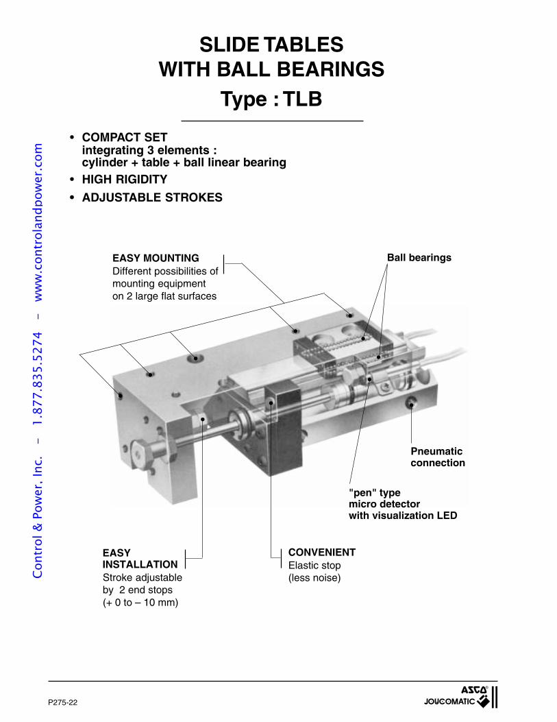
P275-22
SLIDE TABLESWITH BALL BEARINGS
Type : TLB
• COMPACT SETintegrating 3 elements :cylinder + table + ball linear bearing
• HIGH RIGIDITY
• ADJUSTABLE STROKES
EASY MOUNTINGDifferent possibilities ofmounting equipmenton 2 large flat surfaces
EASYINSTALLATIONStroke adjustableby 2 end stops(+ 0 to – 10 mm)
CONVENIENTElastic stop(less noise)
"pen" typemicro detectorwith visualization LED
Pneumaticconnection
Ball bearings
Cont
rol &
Pow
er, I
nc.
-
1.87
7.83
5.52
74
- w
ww
.con
trol
andp
ower
.com
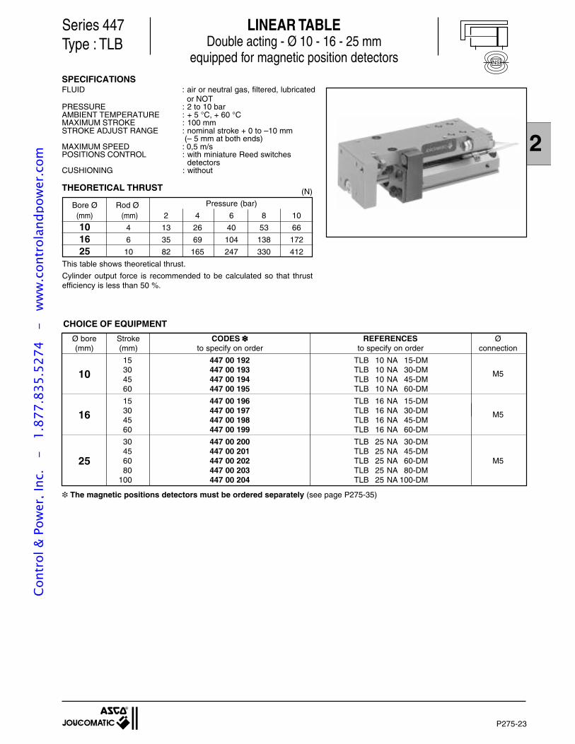
2
P275-23
Ø bore Stroke CODES REFERENCES Ø(mm) (mm) to specify on order to specify on order connection
15 447 00 192 TLB 10 NA 15-DM
10 30 447 00 193 TLB 10 NA 30-DM M545 447 00 194 TLB 10 NA 45-DM60 447 00 195 TLB 10 NA 60-DM
15 447 00 196 TLB 16 NA 15-DM
16 30 447 00 197 TLB 16 NA 30-DM M545 447 00 198 TLB 16 NA 45-DM60 447 00 199 TLB 16 NA 60-DM
30 447 00 200 TLB 25 NA 30-DM45 447 00 201 TLB 25 NA 45-DM
25 60 447 00 202 TLB 25 NA 60-DM M580 447 00 203 TLB 25 NA 80-DM
100 447 00 204 TLB 25 NA 100-DM
LINEAR TABLEDouble acting - Ø 10 - 16 - 25 mm
equipped for magnetic position detectors
Series 447Type : TLB
SPECIFICATIONSFLUID : air or neutral gas, filtered, lubricated
or NOTPRESSURE : 2 to 10 barAMBIENT TEMPERATURE : + 5 °C, + 60 °CMAXIMUM STROKE : 100 mmSTROKE ADJUST RANGE : nominal stroke + 0 to –10 mm
(– 5 mm at both ends)MAXIMUM SPEED : 0,5 m/sPOSITIONS CONTROL : with miniature Reed switches
detectorsCUSHIONING : without
THEORETICAL THRUST (N)
CHOICE OF EQUIPMENT
The magnetic positions detectors must be ordered separately (see page P275-35)
Bore Ø Rod Ø Pressure (bar)
(mm) (mm) 2 4 6 8 10
10 4 13 26 40 53 66
16 6 35 69 104 138 172
25 10 82 165 247 330 412
This table shows theoretical thrust.
Cylinder output force is recommended to be calculated so that thrustefficiency is less than 50 %.
NS
Cont
rol &
Pow
er, I
nc.
-
1.87
7.83
5.52
74
- w
ww
.con
trol
andp
ower
.com
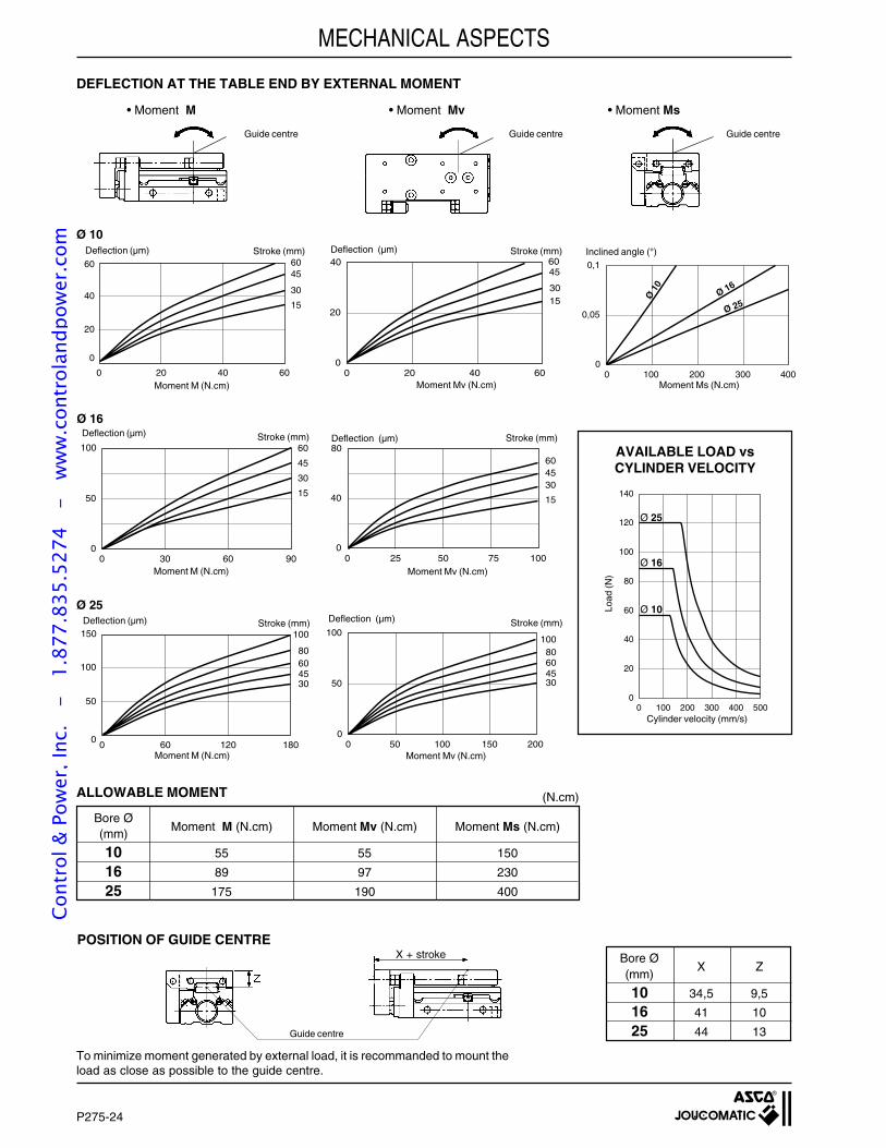
P275-24
MECHANICAL ASPECTS
Bore Ø(mm)
X Z
10 34,5 9,5
16 41 10
25 44 13Guide centre
To minimize moment generated by external load, it is recommanded to mount theload as close as possible to the guide centre.
ALLOWABLE MOMENT
Bore Ø(mm)
Moment M (N.cm) Moment Mv (N.cm) Moment Ms (N.cm)
10 55 55 150
16 89 97 230
25 175 190 400
(N.cm)
AVAILABLE LOAD vsCYLINDER VELOCITY
Guide centre Guide centreGuide centre
0 100 4000
0,05
0,1
Ø 1
0
Ø 16
Ø 25
200 3000 20 40 60
40
20
30
6045
15
0
60
Moment Ms (N.cm)
Stroke (mm) Inclined angle (°)
Ø 10
0 20 40 60
40
0
20
30
6045
15
Ø 16
0 50 100
80
0
4030
6045
15
25 75
Ø 25
Cylinder velocity (mm/s)
100
120
140
80
60
40
20
00 100 200 300 400 500
Ø 25
Ø 16
Ø 10Load
(N)
0 100 200
60
10080
4530
0
50
100
50 1500 60 120 180
150
100
0
60
100
80
45
50
30
0 30 60 90
100
50
0
30
60
45
15
Stroke (mm)Stroke (mm)
Stroke (mm) Stroke (mm)
Stroke (mm)Deflection (µm) Deflection (µm)
Deflection (µm)Deflection (µm)
Deflection (µm) Deflection (µm)
Moment M (N.cm) Moment Mv (N.cm)
Moment M (N.cm) Moment Mv (N.cm)
Moment M (N.cm) Moment Mv (N.cm)
X + strokePOSITION OF GUIDE CENTRE
DEFLECTION AT THE TABLE END BY EXTERNAL MOMENT
• Moment M • Moment Mv • Moment Ms
Cont
rol &
Pow
er, I
nc.
-
1.87
7.83
5.52
74
- w
ww
.con
trol
andp
ower
.com
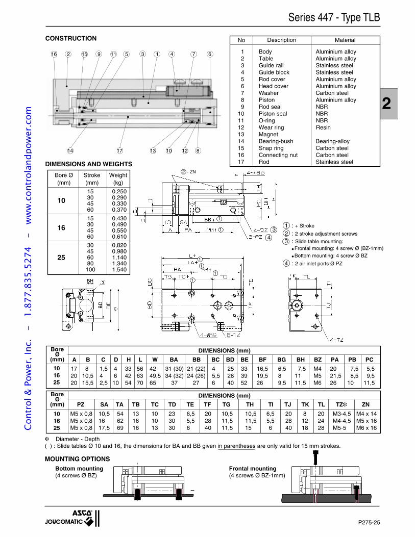
2
P275-25
CONSTRUCTION
Series 447 - Type TLB
No Description Material
1 Body Aluminium alloy2 Table Aluminium alloy3 Guide rail Stainless steel4 Guide block Stainless steel5 Rod cover Aluminium alloy6 Head cover Aluminium alloy7 Washer Carbon steel8 Piston Aluminium alloy9 Rod seal NBR
10 Piston seal NBR11 O-ring NBR12 Wear ring Resin13 Magnet14 Bearing-bush Bearing-alloy15 Snap ring Carbon steel16 Connecting nut Carbon steel17 Rod Stainless steel
16 2 15 9 11 5 3 1 4 7 6
14 17 13 10 12 8
DIMENSIONS AND WEIGHTS
Bore Ø Stroke Weight(mm) (mm) (kg)
25
16
10
2 - ZN
15 0,25030 0,29045 0,33060 0,370
15 0,43030 0,49045 0,55060 0,610
30 0,82045 0,98060 1,14080 1,340100 1,540
1
1
34
1
1
1
1
Diameter - Depth( ) : Slide tables Ø 10 and 16, the dimensions for BA and BB given in parentheses are only valid for 15 mm strokes.
Bottom mounting(4 screws Ø BZ)
BoreØ
(mm) PZ SA TA TB TC TD TE TF TG TH TI TJ TK TL TZ ZN
DIMENSIONS (mm)
M5 x 0,8 10,5 54 13 10 23 6,5 20 10,5 10,5 6,5 20 8 20 M3-4,5 M4 x 14M5 x 0,8 16 62 16 10 30 5,5 28 11,5 11,5 5,5 28 12 24 M4-4,5 M5 x 16M5 x 0,8 17,5 69 16 13 30 6 40 11,5 15 6 40 18 28 M5-5 M6 x 16
17 8 1,5 4 33 56 42 31 (30) 21 (22) 4 25 33 16,5 6,5 7,5 M4 20 7,5 5,520 10,5 4 6 42 63 49,5 34 (32) 24 (26) 5,5 28 39 19,5 8 11 M5 21,5 8,5 9,520 15,5 2,5 10 54 70 65 37 27 6 40 52 26 9,5 11,5 M6 26 10 11,5
BoreØ
(mm) A B C D H L W BA BB BC BD BE BF BG BH BZ PA PB PC
DIMENSIONS (mm)
101625
101625
MOUNTING OPTIONSFrontal mounting(4 screws Ø BZ-1mm)
1 : + Stroke
2 : 2 stroke adjustment screws
3 : Slide table mounting: Frontal mounting: 4 screw Ø (BZ-1mm) Bottom mounting: 4 screw Ø BZ
4 : 2 air inlet ports Ø PZ
Cont
rol &
Pow
er, I
nc.
-
1.87
7.83
5.52
74
- w
ww
.con
trol
andp
ower
.com
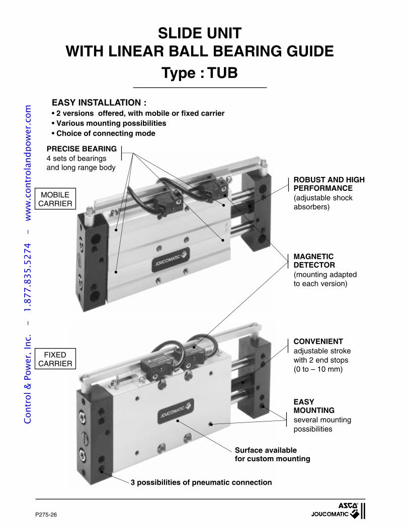
P275-26
SLIDE UNITWITH LINEAR BALL BEARING GUIDE
Type : TUB
EASY INSTALLATION :• 2 versions offered, with mobile or fixed carrier• Various mounting possibilities• Choice of connecting mode
MOBILECARRIER
FIXEDCARRIER
3 possibilities of pneumatic connection
EASYMOUNTINGseveral mountingpossibilities
Surface availablefor custom mounting
ROBUST AND HIGHPERFORMANCE(adjustable shockabsorbers)
MAGNETICDETECTOR(mounting adaptedto each version)
CONVENIENTadjustable strokewith 2 end stops(0 to – 10 mm)
PRECISE BEARING4 sets of bearingsand long range body
Cont
rol &
Pow
er, I
nc.
-
1.87
7.83
5.52
74
- w
ww
.con
trol
andp
ower
.com
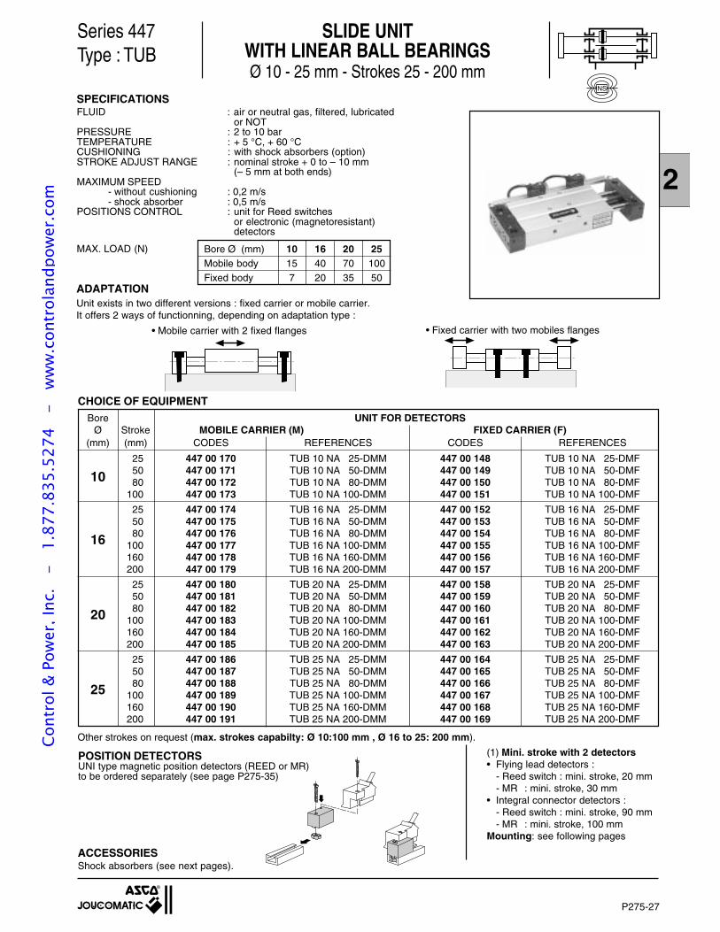
2
P275-27
SLIDE UNITWITH LINEAR BALL BEARINGSØ 10 - 25 mm - Strokes 25 - 200 mm
Series 447Type : TUB
SPECIFICATIONSFLUID : air or neutral gas, filtered, lubricated
or NOTPRESSURE : 2 to 10 barTEMPERATURE : + 5 °C, + 60 °CCUSHIONING : with shock absorbers (option)STROKE ADJUST RANGE : nominal stroke + 0 to – 10 mm
(– 5 mm at both ends)MAXIMUM SPEED
- without cushioning : 0,2 m/s- shock absorber : 0,5 m/s
POSITIONS CONTROL : unit for Reed switchesor electronic (magnetoresistant)detectors
Bore Ø (mm) 10 16 20 25Mobile body 15 40 70 100Fixed body 7 20 35 50
MAX. LOAD (N)
NS
ACCESSORIESShock absorbers (see next pages).
ADAPTATIONUnit exists in two different versions : fixed carrier or mobile carrier.It offers 2 ways of functionning, depending on adaptation type :
• Fixed carrier with two mobiles flanges• Mobile carrier with 2 fixed flanges
CHOICE OF EQUIPMENT
Bore UNIT FOR DETECTORSØ Stroke MOBILE CARRIER (M) FIXED CARRIER (F)
(mm) (mm) CODES REFERENCES CODES REFERENCES
25 447 00 170 TUB 10 NA 25-DMM 447 00 148 TUB 10 NA 25-DMF50 447 00 171 TUB 10 NA 50-DMM 447 00 149 TUB 10 NA 50-DMF10 80 447 00 172 TUB 10 NA 80-DMM 447 00 150 TUB 10 NA 80-DMF
100 447 00 173 TUB 10 NA 100-DMM 447 00 151 TUB 10 NA 100-DMF
25 447 00 174 TUB 16 NA 25-DMM 447 00 152 TUB 16 NA 25-DMF50 447 00 175 TUB 16 NA 50-DMM 447 00 153 TUB 16 NA 50-DMF80 447 00 176 TUB 16 NA 80-DMM 447 00 154 TUB 16 NA 80-DMF16 100 447 00 177 TUB 16 NA 100-DMM 447 00 155 TUB 16 NA 100-DMF
160 447 00 178 TUB 16 NA 160-DMM 447 00 156 TUB 16 NA 160-DMF200 447 00 179 TUB 16 NA 200-DMM 447 00 157 TUB 16 NA 200-DMF
25 447 00 180 TUB 20 NA 25-DMM 447 00 158 TUB 20 NA 25-DMF50 447 00 181 TUB 20 NA 50-DMM 447 00 159 TUB 20 NA 50-DMF80 447 00 182 TUB 20 NA 80-DMM 447 00 160 TUB 20 NA 80-DMF20 100 447 00 183 TUB 20 NA 100-DMM 447 00 161 TUB 20 NA 100-DMF
160 447 00 184 TUB 20 NA 160-DMM 447 00 162 TUB 20 NA 160-DMF200 447 00 185 TUB 20 NA 200-DMM 447 00 163 TUB 20 NA 200-DMF
25 447 00 186 TUB 25 NA 25-DMM 447 00 164 TUB 25 NA 25-DMF50 447 00 187 TUB 25 NA 50-DMM 447 00 165 TUB 25 NA 50-DMF80 447 00 188 TUB 25 NA 80-DMM 447 00 166 TUB 25 NA 80-DMF25 100 447 00 189 TUB 25 NA 100-DMM 447 00 167 TUB 25 NA 100-DMF
160 447 00 190 TUB 25 NA 160-DMM 447 00 168 TUB 25 NA 160-DMF200 447 00 191 TUB 25 NA 200-DMM 447 00 169 TUB 25 NA 200-DMF
Other strokes on request (max. strokes capabilty: Ø 10:100 mm , Ø 16 to 25: 200 mm).
(1) Mini. stroke with 2 detectors• Flying lead detectors :
- Reed switch : mini. stroke, 20 mm- MR : mini. stroke, 30 mm
• Integral connector detectors :- Reed switch : mini. stroke, 90 mm- MR : mini. stroke, 100 mm
Mounting: see following pages
POSITION DETECTORSUNI type magnetic position detectors (REED or MR)to be ordered separately (see page P275-35)
Cont
rol &
Pow
er, I
nc.
-
1.87
7.83
5.52
74
- w
ww
.con
trol
andp
ower
.com
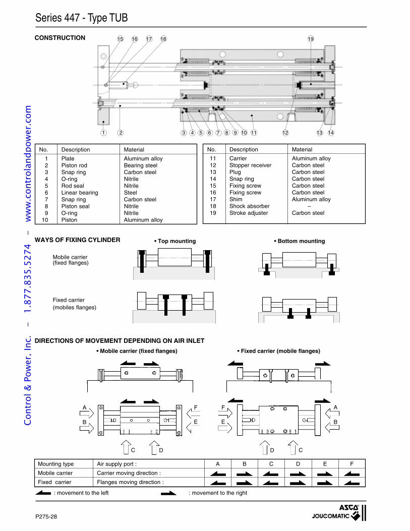
P275-28
CONSTRUCTION
No. Description Material
1 Plate Aluminum alloy2 Piston rod Bearing steel3 Snap ring Carbon steel4 O-ring Nitrile5 Rod seal Nitrile6 Linear bearing Steel7 Snap ring Carbon steel8 Piston seal Nitrile9 O-ring Nitrile
10 Piston Aluminum alloy
No. Description Material
11 Carrier Aluminum alloy12 Stopper receiver Carbon steel13 Plug Carbon steel14 Snap ring Carbon steel15 Fixing screw Carbon steel16 Fixing screw Carbon steel17 Shim Aluminum alloy18 Shock absorber –19 Stroke adjuster Carbon steel
WAYS OF FIXING CYLINDER • Bottom mounting• Top mounting
Mobile carrier(fixed flanges)
Fixed carrier(mobiles flanges)
DIRECTIONS OF MOVEMENT DEPENDING ON AIR INLET
• Mobile carrier (fixed flanges) • Fixed carrier (mobile flanges)
Mounting type Air supply port : A B C D E F
Mobile carrier Carrier moving direction :
Fixed carrier Flanges moving direction :
: movement to the left : movement to the right
A
B
DC
F
E
Series 447 - Type TUB
A
B
D C
F
E
1 2 3 4 5 6 7 8 9 10 11 12 13 14
15 16 17 18 19
Cont
rol &
Pow
er, I
nc.
-
1.87
7.83
5.52
74
- w
ww
.con
trol
andp
ower
.com
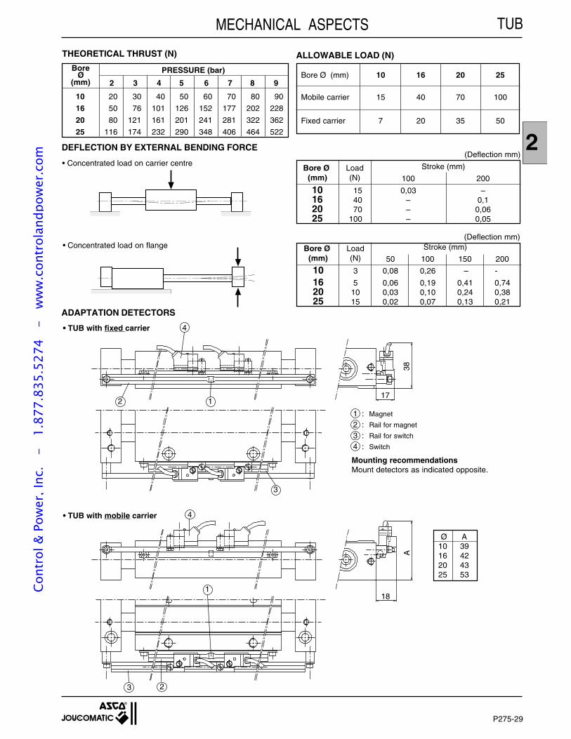
2
P275-29
THEORETICAL THRUST (N)
MECHANICAL ASPECTS
Bore Ø (mm) 10 16 20 25
Mobile carrier 15 40 70 100
Fixed carrier 7 20 35 50
ALLOWABLE LOAD (N)
10 20 30 40 50 60 70 80 90
16 50 76 101 126 152 177 202 228
20 80 121 161 201 241 281 322 362
25 116 174 232 290 348 406 464 522
PRESSURE (bar)
2 3 4 5 6 7 8 9
BoreØ
(mm)
DEFLECTION BY EXTERNAL BENDING FORCE
Bore Ø Load Stroke (mm)(mm) (N) 100 200
10 15 0,03 –16 40 – 0,120 70 – 0,0625 100 – 0,05
(Deflection mm)
(Deflection mm)• Concentrated load on flange
• Concentrated load on carrier centre
Bore Ø Load Stroke (mm)(mm) (N) 50 100 150 200
10 3 0,08 0,26 – -
16 5 0,06 0,19 0,41 0,7420 10 0,03 0,10 0,24 0,3825 15 0,02 0,07 0,13 0,21
ADAPTATION DETECTORS
• TUB with mobile carrier
• TUB with fixed carrier
1738
18
A2
4
1
4
1
23
3
Ø A10 3916 4220 4325 53
1 : Magnet
2 : Rail for magnet
3 : Rail for switch
4 : Switch
Mounting recommendationsMount detectors as indicated opposite.
TUBCo
ntro
l & P
ower
, Inc
. -
1.
877.
835.
5274
-
ww
w.c
ontr
olan
dpow
er.c
om
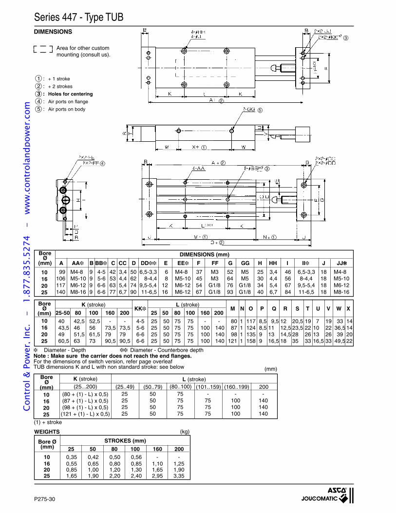
P275-30
Series 447 - Type TUBDIMENSIONS
Area for other custom mounting (consult us).
1 : + 1 stroke
2 : + 2 strokes
3 : Holes for centering
4 : Air ports on flange
5 : Air ports on body
3
2
5
1
3
1
4 + 2
+ 2+ 1
99 M4-8 9 4-5 42 3,4 50 6,5-3,3 6 M4-8 37 M3 52 M5 25 3,4 46 6,5-3,3 18 M4-8106 M5-10 9 5-6 53 4,4 62 8-4,4 8 M5-10 45 M3 64 M5 30 4,4 56 8-4,4 18 M5-10117 M6-12 9 6-6 63 5,4 74 9,5-5,4 12 M6-12 54 G1/8 76 G1/8 34 5,4 67 9,5-5,4 18 M6-12140 M8-16 9 6-6 77 6,7 90 11-6,5 16 M6-12 67 G1/8 93 G1/8 40 6,7 84 11-6,5 18 M8-16
BoreØ
(mm) A AA B BB C CC D DD E EE F FF G GG H HH I II J JJ
DIMENSIONS (mm)
10162025
K (stroke) L (stroke)
25-50 80 100 160 200KK
25 50 80 100 160 200M N O P Q R S T U V W X
40 42,5 52,5 - - 4-5 25 50 75 75 - - 80 1 117 8,5 9,5 12 20,5 19 7 19 33 1443,5 46 56 73,5 73,5 5-6 25 50 75 75 100 140 87 1 124 8,5 11 12,5 23,5 22 10 22 36,5 1449 51,5 61,5 79 79 6-6 25 50 75 75 100 140 98 1 135 9 13 14,5 28 26 13 26 39 2060,5 63 73 90,5 90,5 6-6 25 50 75 75 100 140 121 1 158 9 16,5 18 35 33 16,5 33 49,5 22
Diameter - Depth Diameter - Counterbore depthNote : Make sure the carrier does not reach the end flanges.For the dimensions of switch version, refer page overleafTUB dimensions K and L with non standard stroke: see below
(80 + (1) - L) x 0,5)(87 + (1) - L) x 0,5)(98 + (1) - L) x 0,5)(121 + (1) - L) x 0,5)
10162025
25 50 75 - - -25 50 75 75 100 14025 50 75 75 100 14025 50 75 75 100 140
10 0,35 0,42 0,50 0,56 - -16 0,55 0,65 0,80 0,85 1,10 1,2520 0,85 1,00 1,20 1,30 1,65 1,9025 1,65 1,90 2,20 2,40 2,95 3,35
25 50 80 100 160 200
STROKES (mm)
(25...200) (50..79) (80..100) (101..159) (160..199) 200(25..49)K (stroke) L (stroke)Bore
Ø(mm)
(mm)
10162025
BoreØ
(mm)
(1) + stroke
(kg)
Bore Ø(mm)
WEIGHTS
Cont
rol &
Pow
er, I
nc.
-
1.87
7.83
5.52
74
- w
ww
.con
trol
andp
ower
.com
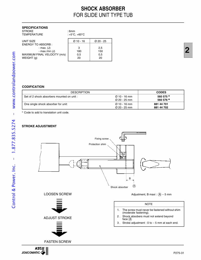
2
P275-31
SHOCK ABSORBERFOR SLIDE UNIT TYPE TUB
CODIFICATION
DESCRIPTION CODES
Set of 2 shock absorbers mounted on unit : Ø 10 - 16 mm 560 575
Ø 20 - 25 mm 560 576
One single shock absorber for unit: Ø 10 - 16 mm 881 44 701 Ø 20 - 25 mm 881 44 702
Code to add to translation unit code.
NOTE
1. The screw must never be fastened without shim(moderate fastening).
2 . Shock absobers must not extend beyondface A
3 . Stroke adjustment : 0 to – 5 mm at each end.
LOOSEN SCREW
ADJUST STROKE
FASTEN SCREW
STROKE ADJUSTMENT
Shock absorber
B
A
Adjustment, B maxi : A – 5 mm
Fixing screw
Protection shim
SPECIFICATIONSSTROKE : 6mmTEMPERATURE : +5°C, +60°C
UNIT SIZE Ø 10 - 16 Ø 20 - 25ENERGY TO ABSORB :
- max. (J) 3 2,5- max./mn (J) 180 150
MAXIMUM FINAL VELOCITY (m/s) 0,5 0,5WEIGHT (g) 20 20
Cont
rol &
Pow
er, I
nc.
-
1.87
7.83
5.52
74
- w
ww
.con
trol
andp
ower
.com
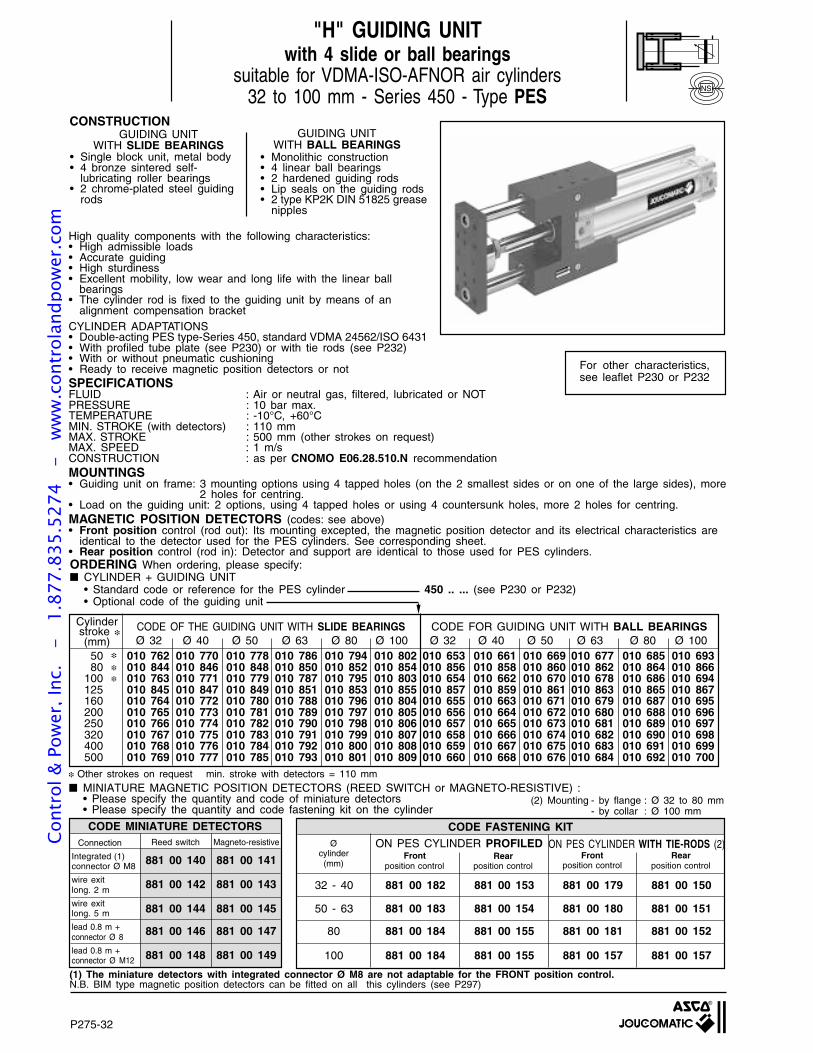
P275-32
NS
"H" GUIDING UNITwith 4 slide or ball bearings
suitable for VDMA-ISO-AFNOR air cylinders32 to 100 mm - Series 450 - Type PES
CONSTRUCTIONGUIDING UNIT
WITH SLIDE BEARINGS• Single block unit, metal body• 4 bronze sintered self-
lubricating roller bearings• 2 chrome-plated steel guiding
rods
GUIDING UNITWITH BALL BEARINGS
• Monolithic construction• 4 linear ball bearings• 2 hardened guiding rods• Lip seals on the guiding rods• 2 type KP2K DIN 51825 grease
nipples
For other characteristics,see leaflet P230 or P232
(1) The miniature detectors with integrated connector Ø M8 are not adaptable for the FRONT position control.N.B. BIM type magnetic position detectors can be fitted on all this cylinders (see P297)
CODE MINIATURE DETECTORSReed switch Magneto-resistive
881 00 140 881 00 141
881 00 142 881 00 143
881 00 144 881 00 145
881 00 146 881 00 147
881 00 148 881 00 149
CODE FASTENING KIT
32 - 40 881 00 182 881 00 153 881 00 179 881 00 150
50 - 63 881 00 183 881 00 154 881 00 180 881 00 151
80 881 00 184 881 00 155 881 00 181 881 00 152
100 881 00 184 881 00 155 881 00 157 881 00 157
Frontposition control
Rearposition control
Frontposition control
Rearposition control
ON PES CYLINDER PROFILED ON PES CYLINDER WITH TIE-RODS (2)Connection
Integrated (1)connector Ø M8
wire exitlong. 2 m
wire exitlong. 5 m
lead 0.8 m +connector Ø 8
lead 0.8 m +connector Ø M12
Øcylinder(mm)
(2) Mounting - by flange : Ø 32 to 80 mm- by collar : Ø 100 mm
MINIATURE MAGNETIC POSITION DETECTORS (REED SWITCH or MAGNETO-RESISTIVE) :• Please specify the quantity and code of miniature detectors• Please specify the quantity and code fastening kit on the cylinder
Other strokes on request min. stroke with detectors = 110 mm
ORDERING When ordering, please specify: CYLINDER + GUIDING UNIT
• Standard code or reference for the PES cylinder 450 .. ... (see P230 or P232)• Optional code of the guiding unit
High quality components with the following characteristics:• High admissible loads• Accurate guiding• High sturdiness• Excellent mobility, low wear and long life with the linear ball
bearings• The cylinder rod is fixed to the guiding unit by means of an
alignment compensation bracketCYLINDER ADAPTATIONS• Double-acting PES type-Series 450, standard VDMA 24562/ISO 6431• With profiled tube plate (see P230) or with tie rods (see P232)• With or without pneumatic cushioning• Ready to receive magnetic position detectors or notSPECIFICATIONSFLUID : Air or neutral gas, filtered, lubricated or NOTPRESSURE : 10 bar max.TEMPERATURE : -10°C, +60°CMIN. STROKE (with detectors) : 110 mmMAX. STROKE : 500 mm (other strokes on request)MAX. SPEED : 1 m/sCONSTRUCTION : as per CNOMO E06.28.510.N recommendationMOUNTINGS• Guiding unit on frame: 3 mounting options using 4 tapped holes (on the 2 smallest sides or on one of the large sides), more
2 holes for centring.• Load on the guiding unit: 2 options, using 4 tapped holes or using 4 countersunk holes, more 2 holes for centring.MAGNETIC POSITION DETECTORS (codes: see above)• Front position control (rod out): Its mounting excepted, the magnetic position detector and its electrical characteristics are
identical to the detector used for the PES cylinders. See corresponding sheet.• Rear position control (rod in): Detector and support are identical to those used for PES cylinders.
50 010 762 010 770 010 778 010 786 010 794 010 802 010 653 010 661 010 669 010 677 010 685 010 69380 010 844 010 846 010 848 010 850 010 852 010 854 010 856 010 858 010 860 010 862 010 864 010 866
100 010 763 010 771 010 779 010 787 010 795 010 803 010 654 010 662 010 670 010 678 010 686 010 694125 010 845 010 847 010 849 010 851 010 853 010 855 010 857 010 859 010 861 010 863 010 865 010 867160 010 764 010 772 010 780 010 788 010 796 010 804 010 655 010 663 010 671 010 679 010 687 010 695200 010 765 010 773 010 781 010 789 010 797 010 805 010 656 010 664 010 672 010 680 010 688 010 696250 010 766 010 774 010 782 010 790 010 798 010 806 010 657 010 665 010 673 010 681 010 689 010 697320 010 767 010 775 010 783 010 791 010 799 010 807 010 658 010 666 010 674 010 682 010 690 010 698400 010 768 010 776 010 784 010 792 010 800 010 808 010 659 010 667 010 675 010 683 010 691 010 699500 010 769 010 777 010 785 010 793 010 801 010 809 010 660 010 668 010 676 010 684 010 692 010 700
Cylinder stroke
(mm)CODE OF THE GUIDING UNIT WITH SLIDE BEARINGS CODE FOR GUIDING UNIT WITH BALL BEARINGSØ 32 Ø 40 Ø 50 Ø 63 Ø 80 Ø 100 Ø 32 Ø 40 Ø 50 Ø 63 Ø 80 Ø 100
Cont
rol &
Pow
er, I
nc.
-
1.87
7.83
5.52
74
- w
ww
.con
trol
andp
ower
.com
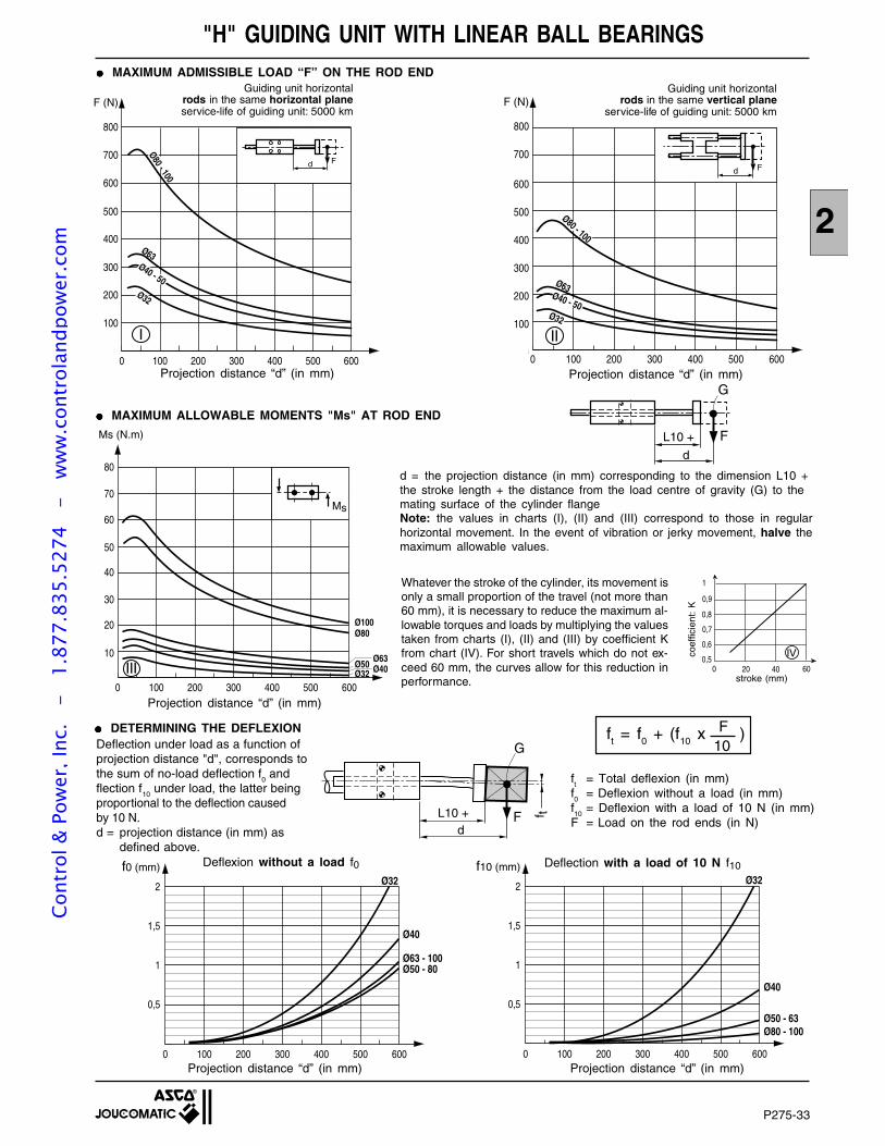
P275-33
2
"H" GUIDING UNIT WITH LINEAR BALL BEARINGS
Projection distance “d” (in mm) Projection distance “d” (in mm)
Projection distance “d” (in mm)
MAXIMUM ADMISSIBLE LOAD “F” ON THE ROD END
Ø32
Ø40
Ø63 - 100Ø50 - 80
0 100 200 300 400 500 6000
0,5
1
1,5
2
f0 (mm)
0 100 200 300 400 500 6000
0,5
1
1,5
2
f10 (mm)Ø32
Ø40
Ø50 - 63Ø80 - 100
10ft = f0 + (f10 x )F
MAXIMUM ALLOWABLE MOMENTS "Ms" AT ROD END
DETERMINING THE DEFLEXION
Deflexion without a load f0 Deflection with a load of 10 N f10
Projection distance “d” (in mm)
Projection distance “d” (in mm)
d = the projection distance (in mm) corresponding to the dimension L10 +the stroke length + the distance from the load centre of gravity (G) to themating surface of the cylinder flangeNote: the values in charts (I), (II) and (III) correspond to those in regularhorizontal movement. In the event of vibration or jerky movement, halve themaximum allowable values.
stroke (mm)0 100 200 300 400 500 600
0
10
20
30
40
50
60
70
80
Ms (N.m)
Ø32 Ø40Ø50
Ø80Ø100
Ø63
Ms
III
0 100 200 300 400 500 6000
100
200
300
400
500
600
700
800
F (N)
Ø32
Ø63
Ø80 - 100
Ø40 - 50
Fd
II
20 40 600,5
0,6
0,7
0,8
0,9
0
1
IV
Guiding unit horizontalrods in the same vertical plane
service-life of guiding unit: 5000 km
Fd
L10 +
G
0 100 200 300 400 500 600
100
300
500
700
200
400
600
800
F (N)
Ø32
Ø63Ø40 - 50
Ø80 - 100
Fd
I
Guiding unit horizontalrods in the same horizontal planeservice-life of guiding unit: 5000 km
ft
= Total deflexion (in mm)f0
= Deflexion without a load (in mm)f10
= Deflexion with a load of 10 N (in mm)F = Load on the rod ends (in N)
Whatever the stroke of the cylinder, its movement isonly a small proportion of the travel (not more than60 mm), it is necessary to reduce the maximum al-lowable torques and loads by multiplying the valuestaken from charts (I), (II) and (III) by coefficient Kfrom chart (IV). For short travels which do not ex-ceed 60 mm, the curves allow for this reduction inperformance.
coef
ficie
nt:
K
Deflection under load as a function ofprojection distance "d", corresponds tothe sum of no-load deflection f
0 and
flection f10
under load, the latter beingproportional to the deflection causedby 10 N.d = projection distance (in mm) as
defined above.
Fd
L10 +
G
f t
Cont
rol &
Pow
er, I
nc.
-
1.87
7.83
5.52
74
- w
ww
.con
trol
andp
ower
.com
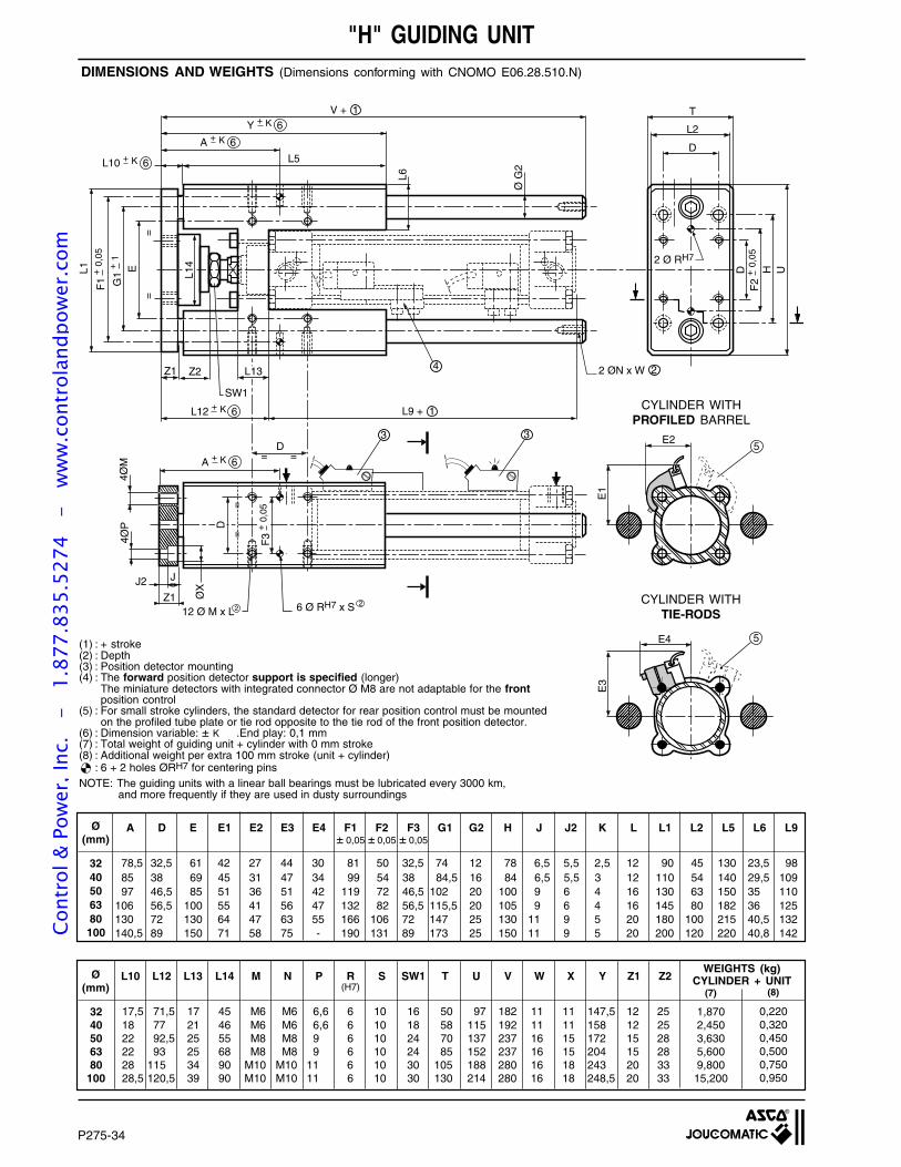
P275-34
D
4ØP
ØX
JJ2
V + 1
Z1 Z2
E D H U
Ø G
2
L6
T
L2
D
L1
3
4
SW1
2 ØN x W 2
Z112 Ø M x L
= =
3
6 Ø RH7 x S 22
D
4ØM
2 Ø RH7
=
=
=
=
G1
+1
F1
+0,
05
F2
+0,
05
F3
+0,
05
A + K 6
A + K 6
Y + K 6
L10 + K 6
E3
E4
E1
E2
5
5
L13
L5
L12 + K 6 L9 + 1
L14
"H" GUIDING UNITDIMENSIONS AND WEIGHTS (Dimensions conforming with CNOMO E06.28.510.N)
CYLINDER WITHPROFILED BARREL
CYLINDER WITHTIE-RODS
(1) : + stroke(2) : Depth(3) : Position detector mounting(4) : The forward position detector support is specified (longer)
The miniature detectors with integrated connector Ø M8 are not adaptable for the frontposition control
(5) : For small stroke cylinders, the standard detector for rear position control must be mountedon the profiled tube plate or tie rod opposite to the tie rod of the front position detector.
(6) : Dimension variable: ± K .End play: 0,1 mm(7) : Total weight of guiding unit + cylinder with 0 mm stroke(8) : Additional weight per extra 100 mm stroke (unit + cylinder)
: 6 + 2 holes ØRH7 for centering pinsNOTE: The guiding units with a linear ball bearings must be lubricated every 3000 km,
and more frequently if they are used in dusty surroundings
3240506380100
Ø(mm)
A D E E1 E2 E3 E4 F1 F2 F3 G1 G2 H J J2 K L L1 L2 L5 L6 L9± 0,05 ± 0,05 ± 0,05
78,5 32,5 61 42 27 44 30 81 50 32,5 74 12 78 6,5 5,5 2,5 12 90 45 130 23,5 9885 38 69 45 31 47 34 99 54 38 84,5 16 84 6,5 5,5 3 12 110 54 140 29,5 10997 46,5 85 51 36 51 42 119 72 46,5 102 20 100 9 6 4 16 130 63 150 35 110
106 56,5 100 55 41 56 47 132 82 56,5 115,5 20 105 9 6 4 16 145 80 182 36 125130 72 130 64 47 63 55 166 106 72 147 25 130 11 9 5 20 180 100 215 40,5 132140,5 89 150 71 58 75 - 190 131 89 173 25 150 11 9 5 20 200 120 220 40,8 142
Ø(mm)
L10 L12 L13 L14 M N P R S SW1 T U V W X Y Z1 Z2(H7)
0,2200,3200,4500,5000,7500,950
1,8702,4503,6305,6009,80015,200
(8)(7)
WEIGHTS (kg)CYLINDER + UNIT
17,5 71,5 17 45 M6 M6 6,6 6 10 16 50 97 182 11 11 147,5 12 2518 77 21 46 M6 M6 6,6 6 10 18 58 115 192 11 11 158 12 2522 92,5 25 55 M8 M8 9 6 10 24 70 137 237 16 15 172 15 2822 93 25 68 M8 M8 9 6 10 24 85 152 237 16 15 204 15 2828 115 34 90 M10 M10 11 6 10 30 105 188 280 16 18 243 20 3328,5 120,5 39 90 M10 M10 11 6 10 30 130 214 280 16 18 248,5 20 33
3240506380
100
Cont
rol &
Pow
er, I
nc.
-
1.87
7.83
5.52
74
- w
ww
.con
trol
andp
ower
.com
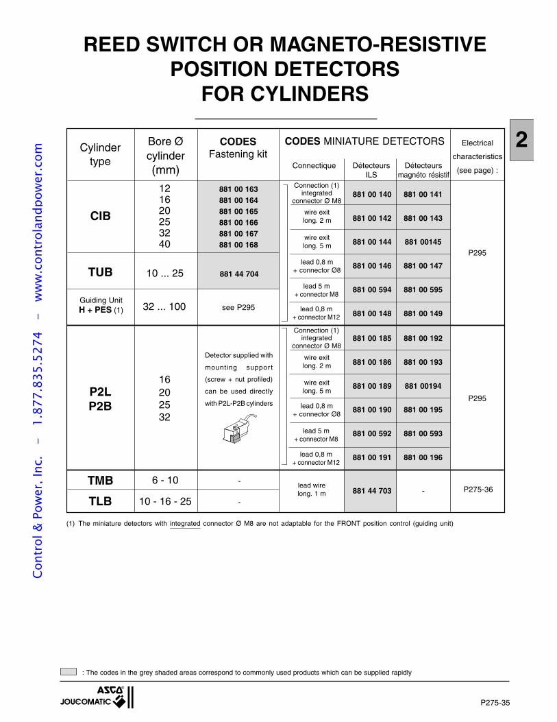
P275-35
2
REED SWITCH OR MAGNETO-RESISTIVEPOSITION DETECTORS
FOR CYLINDERS
(1) The miniature detectors with integrated connector Ø M8 are not adaptable for the FRONT position control (guiding unit)
CODES MINIATURE DETECTORSBore Øcylinder(mm)
Cylindertype
12 881 00 16316 881 00 16420 881 00 16525 881 00 16632 881 00 16740 881 00 168
P2LP2B
16202532
TUB
Guiding UnitH + PES (1)
10 ... 25 881 44 704
32 ... 100 see P295
TMB
TLB
6 - 10 -
10 - 16 - 25 -
Connection (1)integrated
connector Ø M8
wire exitlong. 2 m
wire exitlong. 5 m
lead 0,8 m+ connector Ø8
lead 0,8 m+ connector M12
P295
P275-36lead wirelong. 1 m
Connectique Détecteurs DétecteursILS magnéto résistif
Electrical
characteristics
(see page) :
CIB
CODESFastening kit
881 44 703 -
Connection (1)integrated
connector Ø M8
wire exitlong. 2 m
wire exitlong. 5 m
lead 0,8 m+ connector Ø8
lead 0,8 m+ connector M12
P295
: The codes in the grey shaded areas correspond to commonly used products which can be supplied rapidly
Detector supplied with
mounting suppor t
(screw + nut profiled)
can be used directly
with P2L-P2B cylinders
881 00 140 881 00 141
881 00 142 881 00 143
881 00 144 881 00145
881 00 146 881 00 147
881 00 594 881 00 595
881 00 148 881 00 149
lead 5 m+ connector M8
881 00 185 881 00 192
881 00 186 881 00 193
881 00 189 881 00194
881 00 190 881 00 195
881 00 592 881 00 593
881 00 191 881 00 196
lead 5 m+ connector M8
Cont
rol &
Pow
er, I
nc.
-
1.87
7.83
5.52
74
- w
ww
.con
trol
andp
ower
.com
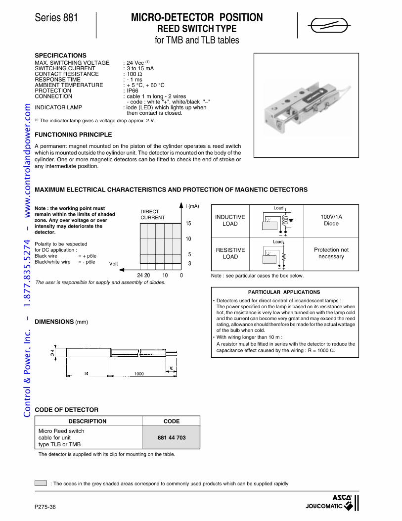
P275-36
Series 881
SPECIFICATIONSMAX. SWITCHING VOLTAGE : 24 Vcc (1)
SWITCHING CURRENT : 3 to 15 mACONTACT RESISTANCE : 100 ΩRESPONSE TIME : - 1 msAMBIENT TEMPERATURE : + 5 °C, + 60 °CPROTECTION : IP66CONNECTION : cable 1 m long - 2 wires
- code : white "+", white/black "–"INDICATOR LAMP : iode (LED) which lights up when
then contact is closed.(1) The indicator lamp gives a voltage drop approx. 2 V.
FUNCTIONING PRINCIPLE
A permanent magnet mounted on the piston of the cylinder operates a reed switchwhich is mounted outside the cylinder unit. The detector is mounted on the body of thecylinder. One or more magnetic detectors can be fitted to check the end of stroke orany intermediate position.
The user is responsible for supply and assembly of diodes.
MAXIMUM ELECTRICAL CHARACTERISTICS AND PROTECTION OF MAGNETIC DETECTORS
Note : the working point mustremain within the limits of shadedzone. Any over voltage or overintensity may deteriorate thedetector.
Polarity to be respectedfor DC application :Black wire = + pôleBlack/white wire = - pôle
15
10
5
3
24 20 10 0
Volt
Load
Load
Note : see particular cases the box below.
RESISTIVELOAD
INDUCTIVELOAD
100V/1ADiode
Protection notnecessary
DIMENSIONS (mm)
CODE OF DETECTOR
1000
Ø 4
I (mA)DIRECTCURRENT
PARTICULAR APPLICATIONS
•Detectors used for direct control of incandescent lamps :The power specified on the lamp is based on its resistance whenhot, the resistance is very low when turned on with the lamp coldand the current can become very great and may exceed the reedrating, allowance should therefore be made for the actual wattageof the bulb when cold.
•With wiring longer than 10 m :A resistor must be fitted in series with the detector to reduce thecapacitance effect caused by the wiring : R = 1000 Ω.
MICRO-DETECTOR POSITIONREED SWITCH TYPE
for TMB and TLB tables
DESCRIPTION CODE
Micro Reed switchcable for unit 881 44 703type TLB or TMB
The detector is supplied with its clip for mounting on the table.
: The codes in the grey shaded areas correspond to commonly used products which can be supplied rapidly
Cont
rol &
Pow
er, I
nc.
-
1.87
7.83
5.52
74
- w
ww
.con
trol
andp
ower
.com
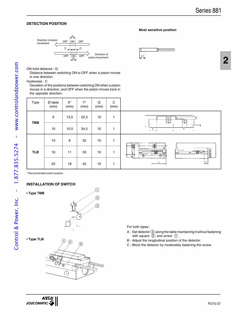
P275-37
2
Series 881
DETECTION POSITION
Direction of pistonmovement
Direction ofpiston movement
ON hold distance : QDistance between switching ON to OFF when a piston movesin one direction.
Hysteresis : CDeviation of the positions between switching ON when a pistonmoves in a direction, and OFF when the piston moves back inthe opposite direction.
Type Ø table X* Y* Q C(mm) (mm) (mm) (mm) (mm)
TMB
6 13,5 22,5 10 1
10 10,5 34,5 10 1
10 8 32 10 1
TLB 16 11 33 10 1
25 18 42 10 1
* Recommended switch position
INSTALLATION OF SWITCH
• Type TMB
• Type TLB1 2
3
2
3
1
For both types :
A - Set detector 3 along the table maintaining it wihout fasteningwith square 2 and screw 1 .
B - Adjust the longitudinal position of the detector.C - Block the detector by moderately fastening the screw.
OFF ON OFF
OFF ON OFF
Q
Q
C C
Most sensitive position
Cont
rol &
Pow
er, I
nc.
-
1.87
7.83
5.52
74
- w
ww
.con
trol
andp
ower
.com

P275-38
Cont
rol &
Pow
er, I
nc.
-
1.87
7.83
5.52
74
- w
ww
.con
trol
andp
ower
.com
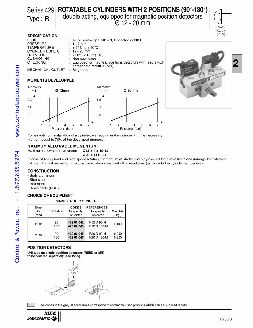
P285-3
2
ROTATABLE CYLINDERS WITH 2 POSITIONS (90°-180°)double acting, equipped for magnetic position detectors
Ø 12 - 20 mm
SPECIFICATION
MAXIMUM ALLOWABLE MOMENTUMMaximum allowable momentum Ø12 = 4 x 10⁻³J
Ø20 = 1x10⁻²JIn case of heavy load and high speed rotation, momentum at stroke end may exceed the above limits and damage the rotatablecylinder. To limit momentum, reduce the rotation speed with flow regulators (as close to the cylinder as possible).
CONSTRUCTION- Body aluminium- Stop steel- Rod steel- Seals nitrile (NBR)
Ø 20
SINGLE ROD CYLINDER
CHOICE OF EQUIPMENT
Bore CODES REFERENCESØ Rotation to specify to specify Weights
(mm) on order on order ( kg )
90° 429 00 042 R12 D 90-M180° 429 00 043 R12 D 180-M
90° 429 00 046 R20 D 90-M 0.250180° 429 00 047 R20 D 180-M 0.320
Ø 12 0.130
Series 429Type : R
NS
For an optimum installation of a cylinder, we recommend a cylinder with the necessarymoment equal to 70% of the developed moment
Momentsm.N Ø 12mm Ø 20mm
Pressure (bar) Pressure (bar)1 2 3 4 5 6 7
0,1
0,2
0,3
1 2 3 4 5 6 7
0,5
1
1,5
Momentsm.N
FLUID : Air or neutral gas, filtered, lubricated or NOTPRESSURE : 1 - 7 barTEMPERATURE : + 5° C to + 60°CCYLINDER BORE Ø : 12 - 20 mmROTATION : x 90° - x 180° (± 5°)CUSHIONING : Non cushionedCHECKING : Equipped for magnetic positions detectors with reed switch
or magneto-resistive (MR)MECHANICAL OUTLET : Single rod
MOMENTS DEVELOPPED
POSITION DETECTORSUNI type magnetic position detectors (REED or MR)to be ordered separately (see P295).
: The codes in the grey shaded areas correspond to commonly used products which can be supplied rapidly
Cont
rol &
Pow
er, I
nc.
-
1.87
7.83
5.52
74
- w
ww
.con
trol
andp
ower
.com
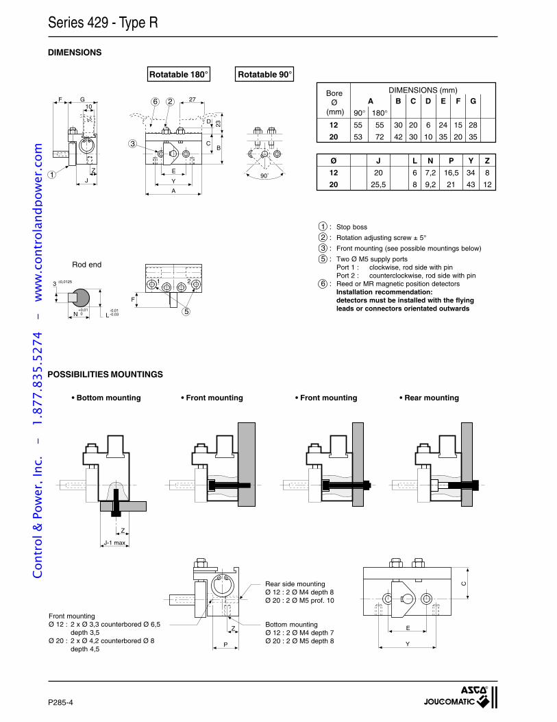
P285-4
Z
J
10GF
F
1 2
E
Y
D
27
CB
23
A
L-0,01-0,03
3 ±0,0125
N+0,01 0 5
1
3
90˚
26
E
Y
C
Z
J-1 max
Z
P
POSSIBILITIES MOUNTINGS
• Bottom mounting • Front mounting • Front mounting • Rear mounting
Bottom mountingØ 12 : 2 Ø M4 depth 7Ø 20 : 2 Ø M5 depth 8
Rear side mountingØ 12 : 2 Ø M4 depth 8Ø 20 : 2 Ø M5 prof. 10
DIMENSIONS
1 : Stop boss
2 : Rotation adjusting screw ± 5°
3 : Front mounting (see possible mountings below)
5 : Two Ø M5 supply portsPort 1 : clockwise, rod side with pinPort 2 : counterclockwise, rod side with pin
6 : Reed or MR magnetic position detectorsInstallation recommendation:detectors must be installed with the flyingleads or connectors orientated outwards
Rotatable 90°Rotatable 180°
90°55
53
180°55
72
B
30
42
C
20
30
D
6
10
E
24
35
F
15
20
G
28
35
A
12
20
Ø
12
20
J
20
25,5
L
6
8
N
7,2
9,2
Y
34
43
Z
8
12
P
16,5
21
BoreØ
(mm)
DIMENSIONS (mm)
Series 429 - Type R
Rod end
Front mountingØ 12 : 2 x Ø 3,3 counterbored Ø 6,5
depth 3,5Ø 20 : 2 x Ø 4,2 counterbored Ø 8
depth 4,5
Cont
rol &
Pow
er, I
nc.
-
1.87
7.83
5.52
74
- w
ww
.con
trol
andp
ower
.com
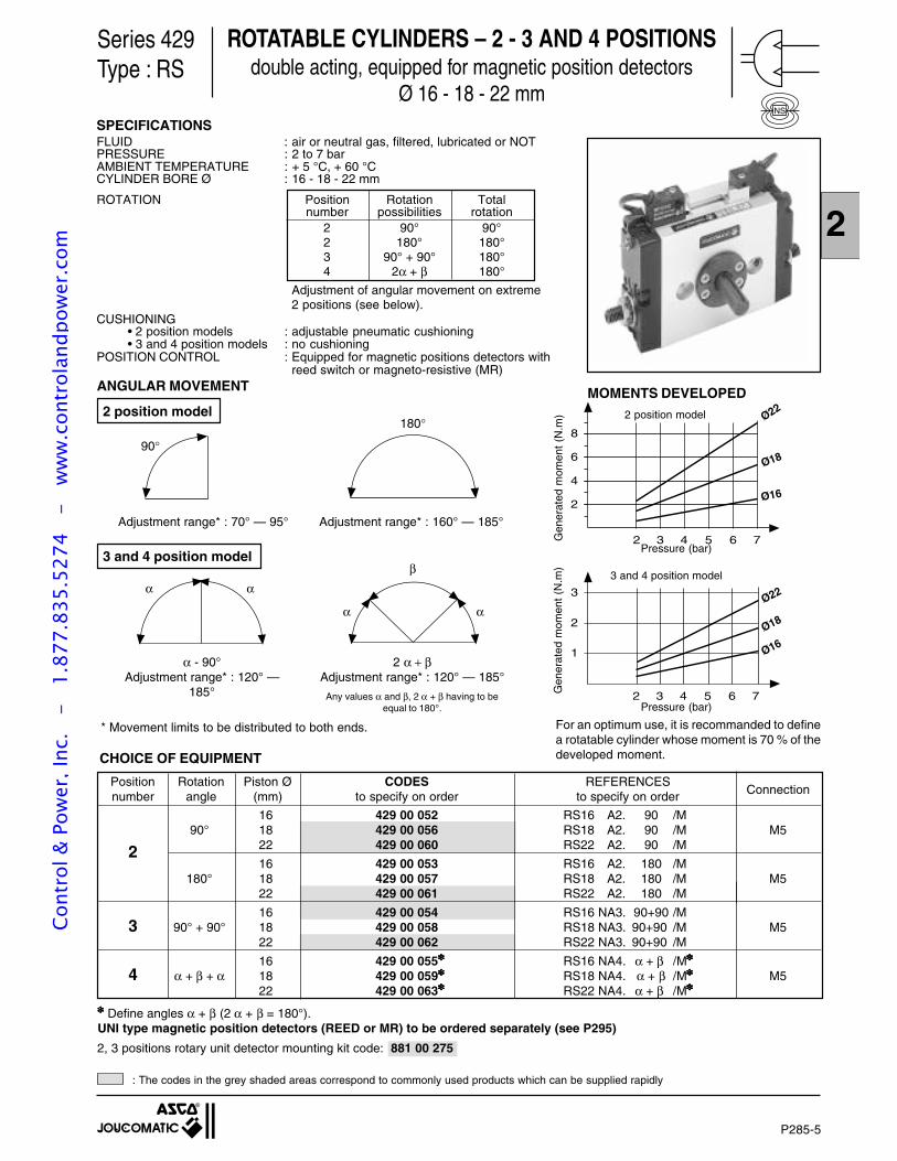
P285-5
2
Series 429Type : RS
ROTATABLE CYLINDERS – 2 - 3 AND 4 POSITIONSdouble acting, equipped for magnetic position detectors
Ø 16 - 18 - 22 mmNS
MOMENTS DEVELOPED
8
6
4
2
3 5 7
Ø22
Ø18
Ø16
2 4 6Pressure (bar)
3
2
1
Ø22
3 5 72 4 6
Ø18
Ø16
Pressure (bar)
For an optimum use, it is recommanded to definea rotatable cylinder whose moment is 70 % of thedeveloped moment.
3 and 4 position model
2 position model
Gen
erat
ed m
omen
t (N
.m)
Gen
erat
ed m
omen
t (N
.m)
Adjustment range* : 70° — 95°
180°
90°
Adjustment range* : 160° — 185°
3 and 4 position model
αα
α
β
α
α - 90°Adjustment range* : 120° —
185°
2 α + βAdjustment range* : 120° — 185°
Any values α and β, 2 α + β having to beequal to 180°.
* Movement limits to be distributed to both ends.
CHOICE OF EQUIPMENT
Define angles α + β (2 α + β = 180°).UNI type magnetic position detectors (REED or MR) to be ordered separately (see P295)
Position Rotation Piston Ø CODES REFERENCESnumber angle (mm) to specify on order to specify on order Connection
16 429 00 052 RS16 A2. 90 /M90° 18 429 00 056 RS18 A2. 90 /M M5
2 22 429 00 060 RS22 A2. 90 /M
16 429 00 053 RS16 A2. 180 /M180° 18 429 00 057 RS18 A2. 180 /M M5
22 429 00 061 RS22 A2. 180 /M
16 429 00 054 RS16 NA3. 90+90 /M3 90° + 90° 18 429 00 058 RS18 NA3. 90+90 /M M5
22 429 00 062 RS22 NA3. 90+90 /M
16 429 00 055 RS16 NA4. α + β /M
4 α + β + α 18 429 00 059 RS18 NA4. α + β /M M522 429 00 063 RS22 NA4. α + β /M
2 position model
ANGULAR MOVEMENT
SPECIFICATIONSFLUID : air or neutral gas, filtered, lubricated or NOTPRESSURE : 2 to 7 barAMBIENT TEMPERATURE : + 5 °C, + 60 °CCYLINDER BORE Ø : 16 - 18 - 22 mm
ROTATION Position Rotation Totalnumber possibilities rotation
2 90° 90°2 180° 180°3 90° + 90° 180°4 2α + β 180°
Adjustment of angular movement on extreme2 positions (see below).
CUSHIONING• 2 position models : adjustable pneumatic cushioning• 3 and 4 position models : no cushioning
POSITION CONTROL : Equipped for magnetic positions detectors withreed switch or magneto-resistive (MR)
: The codes in the grey shaded areas correspond to commonly used products which can be supplied rapidly
2, 3 positions rotary unit detector mounting kit code: 881 00 275
Cont
rol &
Pow
er, I
nc.
-
1.87
7.83
5.52
74
- w
ww
.con
trol
andp
ower
.com
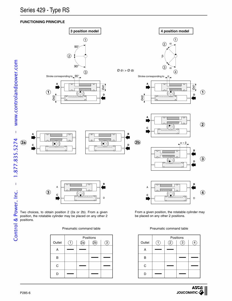
P285-6
A
D
α
Ød1
1
D
B
α + β
3
C
B
4
1
2
3
90°
90°
α
α
β
12
34
C
A
2
A
D
90°
1
C
A
2aD
B
2b
C
B
3D
A
D
A
Ød1
Ød2
Ød2
FUNCTIONING PRINCIPLE
Series 429 - Type RS
Two choices, to obtain position 2 (2a or 2b). From a givenposition, the rotatable cylinder may be placed on any other 2positions.
Ø d1 > Ø d2
Pneumatic command table
Positions
Outlet 1 2 3 4
A
B
C
D
Pneumatic command table
Positions
Outlet 1 2a 2b 3
A
B
C
D
From a given position, the rotatable cylinder maybe placed on any other 2 positions.
3 position model 4 position model
Stroke corresponding to Stroke corresponding to
Cont
rol &
Pow
er, I
nc.
-
1.87
7.83
5.52
74
- w
ww
.con
trol
andp
ower
.com
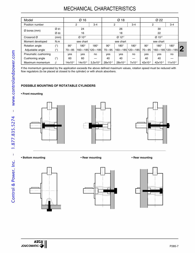
P285-7
2
Model Ø 16 Ø 18 Ø 22Position number 2 3-4 2 3-4 2 3-4
Ø bores (mm)Ø d1 24 26 30
Ø d2 16 18 22
Crossrod Ø (mm) Ø 10h7 Ø 12h7 Ø 15h7
Moment developed N.m see chart see chart see chart
Rotation angle (°) 90° 180° 180° 90° 180° 180° 90° 180° 180°
Adjustable angle (°) 70—95 160—185 120—185 70—95 160—185 120—185 70—95 160—185 120—185
Pneumatic cushioning yes yes no yes yes no yes yes no
Cushioning angle (°) 60 60 — 40 40 — 40 40 —
Maximum momentum J 14x10-2 14x10-2 3,5x10⁻² 28x10-2 28x10-2 7x10⁻² 42x10-2 42x10-2 11x10-2
MECHANICAL CHARACTERISTICS
If the momentum generated by the application exceeds the above defined maximum values, rotation speed must be reduced withflow regulators (to be placed at closest to the cylinder) or with shock absorbers.
POSSIBLE MOUNTING OF ROTATABLE CYLINDERS
• Front mounting
• Bottom mounting • Rear mounting • Rear mounting
Cont
rol &
Pow
er, I
nc.
-
1.87
7.83
5.52
74
- w
ww
.con
trol
andp
ower
.com
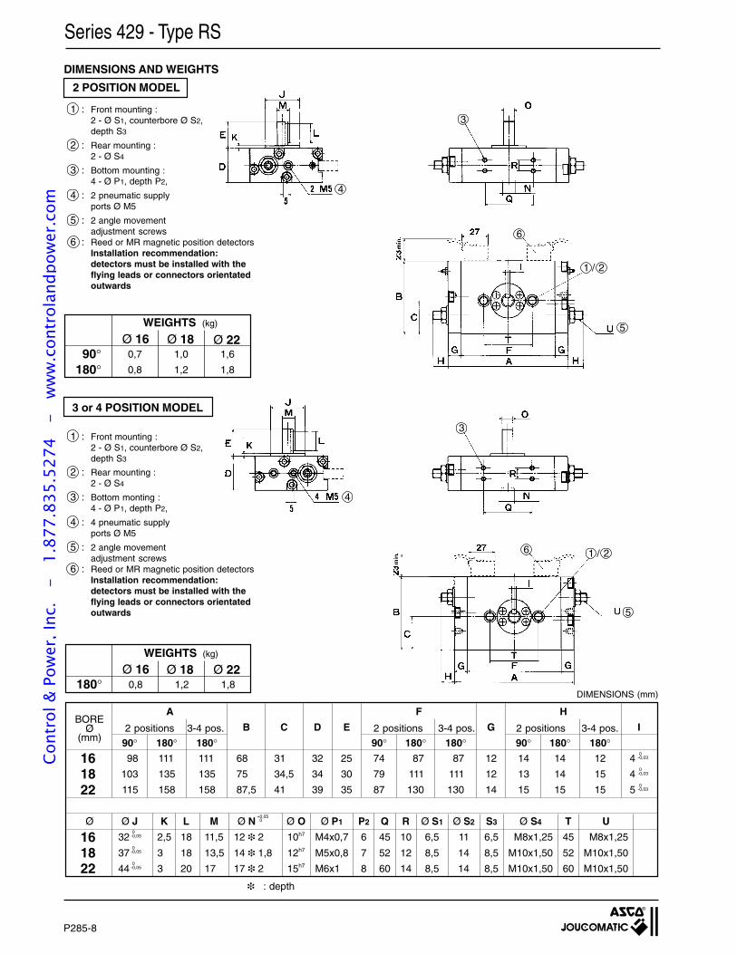
P285-8
DIMENSIONS AND WEIGHTS
161822
161822
A
98
103
115
90°111
135
158
180°68
75
87,5
B
31
34,5
41
C
32
34
39
D
25
30
35
E
180°111
135
158
12
12
14
G I
4
4
5
0-0,03
0-0,03
0-0,03
H
14
13
15
90°14
14
15
180° 180°12
15
15
F
74
79
87
90° 180°87
111
130
87
111
130
180°
2,5
3
3
K
18
18
20
L
11,5
13,5
17
MØ J
32
37
44
0-0,05
0-0,05
0-0,05
10h7
12h7
15h7
Ø O
12 2
14 1,8
17 2
Ø N+0,05 0
M4x0,7
M5x0,8
M6x1
Ø P1
6
7
8
P2 Q
45
52
60
R
10
12
14
Ø S1
6,5
8,5
8,5
Ø S2
11
14
14
S3
6,5
8,5
8,5
Ø S4
M8x1,25
M10x1,50
M10x1,50
T
45
52
60
U
M8x1,25
M10x1,50
M10x1,50
BOREØ
(mm)2 positions 3-4 pos. 2 positions
Ø
2 positions
: depth
3-4 pos.3-4 pos.
3 or 4 POSITION MODEL
Series 429 - Type RS
2 POSITION MODEL
1 : Front mounting :2 - Ø S1, counterbore Ø S2,depth S3
2 : Rear mounting :2 - Ø S4
3 : Bottom mounting :4 - Ø P1, depth P2,
4 : 2 pneumatic supplyports Ø M5
5 : 2 angle movementadjustment screws
6 : Reed or MR magnetic position detectorsInstallation recommendation:detectors must be installed with theflying leads or connectors orientatedoutwards
WEIGHTS (kg)
0,7
0,8
90°180°
Ø 161,0
1,2
1,6
1,8
Ø 18 Ø 22
1 : Front mounting :2 - Ø S1, counterbore Ø S2,depth S3
2 : Rear mounting :2 - Ø S4
3 : Bottom monting :4 - Ø P1, depth P2,
4 : 4 pneumatic supplyports Ø M5
5 : 2 angle movementadjustment screws
6 : Reed or MR magnetic position detectorsInstallation recommendation:detectors must be installed with theflying leads or connectors orientatedoutwards
0,8180°Ø 16
1,2 1,8Ø 18 Ø 22
WEIGHTS (kg)
4
DIMENSIONS (mm)
1 / 2
5
6
3
1 / 2
4
5
6
3
Cont
rol &
Pow
er, I
nc.
-
1.87
7.83
5.52
74
- w
ww
.con
trol
andp
ower
.com
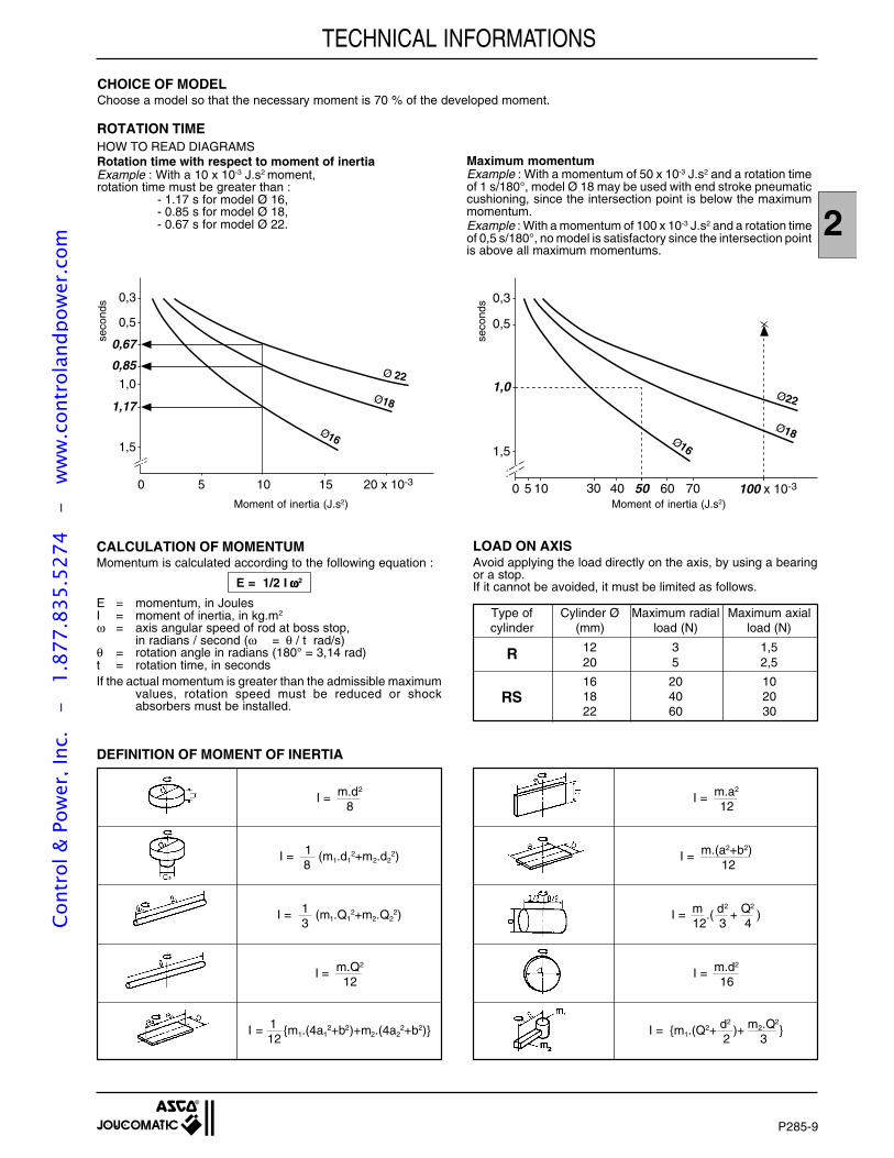
P285-9
2
TECHNICAL INFORMATIONS
CHOICE OF MODELChoose a model so that the necessary moment is 70 % of the developed moment.
ROTATION TIMEHOW TO READ DIAGRAMSRotation time with respect to moment of inertiaExample : With a 10 x 10-3 J.s2 moment,rotation time must be greater than :
- 1.17 s for model Ø 16,- 0.85 s for model Ø 18,- 0.67 s for model Ø 22.
100 x 10-350
0,3
0,5
1,0
1,5
0 5 10 30 40 60 70
Ø16
Ø18
Ø22
Moment of inertia (J.s2)
0,3
0,5
1,0
1,5
1,17
5 10 15 20 x 10-30
0,85
0,67
Ø16
Ø18
Ø 22
Moment of inertia (J.s2)
CALCULATION OF MOMENTUMMomentum is calculated according to the following equation :
E = 1/2 I ω ω ω ω ω2
E = momentum, in JoulesI = moment of inertia, in kg.m2
ω = axis angular speed of rod at boss stop,in radians / second (ω = θ / t rad/s)
θ = rotation angle in radians (180° = 3,14 rad)t = rotation time, in secondsIf the actual momentum is greater than the admissible maximum
values, rotation speed must be reduced or shockabsorbers must be installed.
LOAD ON AXISAvoid applying the load directly on the axis, by using a bearingor a stop.If it cannot be avoided, it must be limited as follows.
Type of Cylinder Ø Maximum radial Maximum axialcylinder (mm) load (N) load (N)
12 3 1,5R20 5 2,5
16 20 10RS 18 40 20
22 60 30
I = 1 m1.(4a12+b2)+m2.(4a2
2+b2)12
I = m.Q2
12
I = 1 (m1.Q12+m2.Q2
2)3
I = 1 (m1.d12+m2.d2
2)8
I = m.d2
8
I = m1.(Q2+ d2)+ m2.Q2
2 3
I = m.d2
16
I = m .( d2+ Q2
)12 3 4
I = m.(a2+b2)12
I = m.a2
12
DEFINITION OF MOMENT OF INERTIA
seco
nds
seco
nds
Maximum momentumExample : With a momentum of 50 x 10-3 J.s2 and a rotation timeof 1 s/180°, model Ø 18 may be used with end stroke pneumaticcushioning, since the intersection point is below the maximummomentum.Example : With a momentum of 100 x 10-3 J.s2 and a rotation timeof 0,5 s/180°, no model is satisfactory since the intersection pointis above all maximum momentums.
Cont
rol &
Pow
er, I
nc.
-
1.87
7.83
5.52
74
- w
ww
.con
trol
andp
ower
.com

P285-10
Cont
rol &
Pow
er, I
nc.
-
1.87
7.83
5.52
74
- w
ww
.con
trol
andp
ower
.com
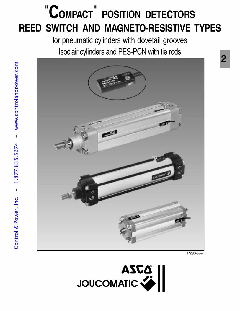
2
P293-GB-R1
"COMPACT" POSITION DETECTORSREED SWITCH AND MAGNETO-RESISTIVE TYPES
for pneumatic cylinders with dovetail groovesIsoclair cylinders and PES-PCN with tie rods
2
Cont
rol &
Pow
er, I
nc.
-
1.87
7.83
5.52
74
- w
ww
.con
trol
andp
ower
.com
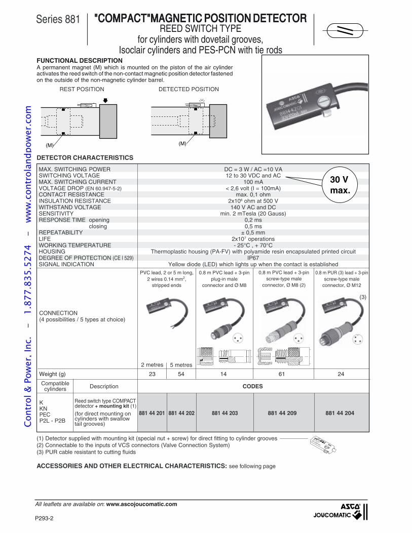
P293-2
All leaflets are available on: www.ascojoucomatic.com
Weight (g) 23 54 14 61 24
A permanent magnet (M) which is mounted on the piston of the air cylinderactivates the reed switch of the non-contact magnetic position detector fastenedon the outside of the non-magnetic cylinder barrel.
FUNCTIONAL DESCRIPTION
"COMPACT"MAGNETIC POSITION DETECTOR"COMPACT"MAGNETIC POSITION DETECTOR"COMPACT"MAGNETIC POSITION DETECTOR"COMPACT"MAGNETIC POSITION DETECTOR"COMPACT"MAGNETIC POSITION DETECTORREED SWITCH TYPE
for cylinders with dovetail grooves,Isoclair cylinders and PES-PCN with tie rods
Series 881
DETECTOR CHARACTERISTICS
PVC lead, 2 or 5 m long,2 wires 0.14 mm2,
stripped ends
0.8 m PVC lead + 3-pinplug-in male
connector and Ø M8
0.8 m PUR (3) lead + 3-pinscrew-type male
connector, Ø M12
2 metres 5 metres
REST POSITION DETECTED POSITION
(M) (M)
CONNECTION(4 possibilities / 5 types at choice)
30 Vmax.
881 44 201 881 44 202 881 44 203 881 44 209 881 44 204
Reed switch type COMPACTdetector + mounting kit (1)
(for direct mounting oncylinders with swallowtail grooves)
CODESDescriptionCompatiblecylinders
KKNPECP2L - P2B
ACCESSORIES AND OTHER ELECTRICAL CHARACTERISTICS: see following page
(1) Detector supplied with mounting kit (special nut + screw) for direct fitting to cylinder grooves(2) Connectable to the inputs of VCS connectors (Valve Connection System)(3) PUR cable resistant to cutting fluids
0,8 m PVC lead + 3-pinscrew-type male
connector, Ø M8 (2)
881 44 20130V-100mA max.
MAX. SWITCHING POWER DC = 3 W / AC =10 VASWITCHING VOLTAGE 12 to 30 VDC and ACMAX. SWITCHING CURRENT 100 mAVOLTAGE DROP (EN 60.947-5-2) < 2,6 volt (I = 100mA)CONTACT RESISTANCE max. 0,1 ohmINSULATION RESISTANCE 2x10⁶ ohm at 500 VWITHSTAND VOLTAGE 140 V AC and DCSENSITIVITY min. 2 mTesla (20 Gauss)RESPONSE TIME opening 0,2 ms
closing 0,5 msREPEATABILITY ± 0,5 mmLIFE 2x10⁷ operationsWORKING TEMPERATURE - 25°C , + 70°CHOUSING Thermoplastic housing (PA-FV) with polyamide resin encapsulated printed circuitDEGREE OF PROTECTION (CE I 529) IP67SIGNAL INDICATION Yellow diode (LED) which lights up when the contact is established
(3)
Cont
rol &
Pow
er, I
nc.
-
1.87
7.83
5.52
74
- w
ww
.con
trol
andp
ower
.com
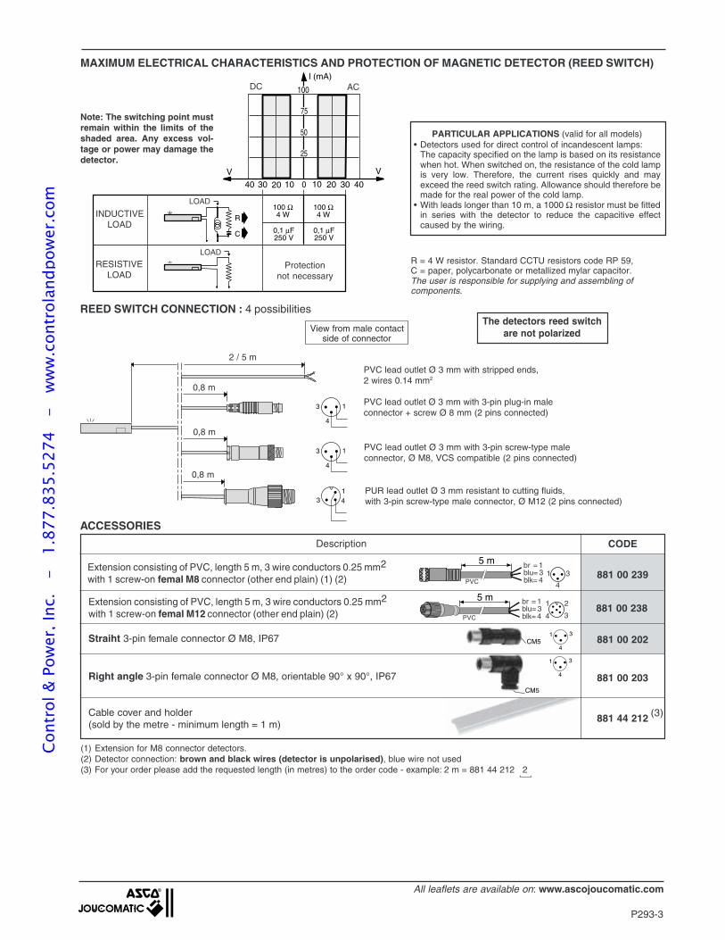
P293-3
All leaflets are available on: www.ascojoucomatic.com
13 4
13
4
13
4
100 Ω4 W
100 Ω4 W
0,1 µF250 V
50
75
100
25
V V
0 10 20 30 4010203040
l (mA)
0,1 µF250 V
R
C
RESISTIVELOAD
INDUCTIVELOAD
Protectionnot necessary
LOAD
LOAD
DC AC
(1) Extension for M8 connector detectors.(2) Detector connection: brown and black wires (detector is unpolarised), blue wire not used(3) For your order please add the requested length (in metres) to the order code - example: 2 m = 881 44 212 2
MAXIMUM ELECTRICAL CHARACTERISTICS AND PROTECTION OF MAGNETIC DETECTOR (REED SWITCH)
R = 4 W resistor. Standard CCTU resistors code RP 59,C = paper, polycarbonate or metallized mylar capacitor.The user is responsible for supplying and assembling ofcomponents.
REED SWITCH CONNECTION : 4 possibilities
View from male contactside of connector
PVC lead outlet Ø 3 mm with 3-pin plug-in maleconnector + screw Ø 8 mm (2 pins connected)
PUR lead outlet Ø 3 mm resistant to cutting fluids,with 3-pin screw-type male connector, Ø M12 (2 pins connected)
The detectors reed switchare not polarized
PVC lead outlet Ø 3 mm with 3-pin screw-type maleconnector, Ø M8, VCS compatible (2 pins connected)
PVC lead outlet Ø 3 mm with stripped ends,2 wires 0.14 mm2
PARTICULAR APPLICATIONS (valid for all models)• Detectors used for direct control of incandescent lamps:
The capacity specified on the lamp is based on its resistancewhen hot. When switched on, the resistance of the cold lampis very low. Therefore, the current rises quickly and mayexceed the reed switch rating. Allowance should therefore bemade for the real power of the cold lamp.
• With leads longer than 10 m, a 1000 Ω resistor must be fittedin series with the detector to reduce the capacitive effectcaused by the wiring.
Note: The switching point mustremain within the limits of theshaded area. Any excess vol-tage or power may damage thedetector.
0,8 m
0,8 m
0,8 m
2 / 5 m
1 3
4
CM5
CODE
881 00 239
881 00 238
Description
Extension consisting of PVC, length 5 m, 3 wire conductors 0.25 mm2
with 1 screw-on femal M8 connector (other end plain) (1) (2)
Extension consisting of PVC, length 5 m, 3 wire conductors 0.25 mm2
with 1 screw-on femal M12 connector (other end plain) (2)
Straiht 3-pin female connector Ø M8, IP67
Right angle 3-pin female connector Ø M8, orientable 90° x 90°, IP67
881 00 202
881 00 203
1 3
4CM5
5 m br = 1
blk= 4blu= 3
1
4 3
2
PVC
5 m br = 1
blk= 4blu= 3 1
4
3PVC
ACCESSORIES
Cable cover and holder(sold by the metre - minimum length = 1 m)
881 44 212 (3)
Cont
rol &
Pow
er, I
nc.
-
1.87
7.83
5.52
74
- w
ww
.con
trol
andp
ower
.com
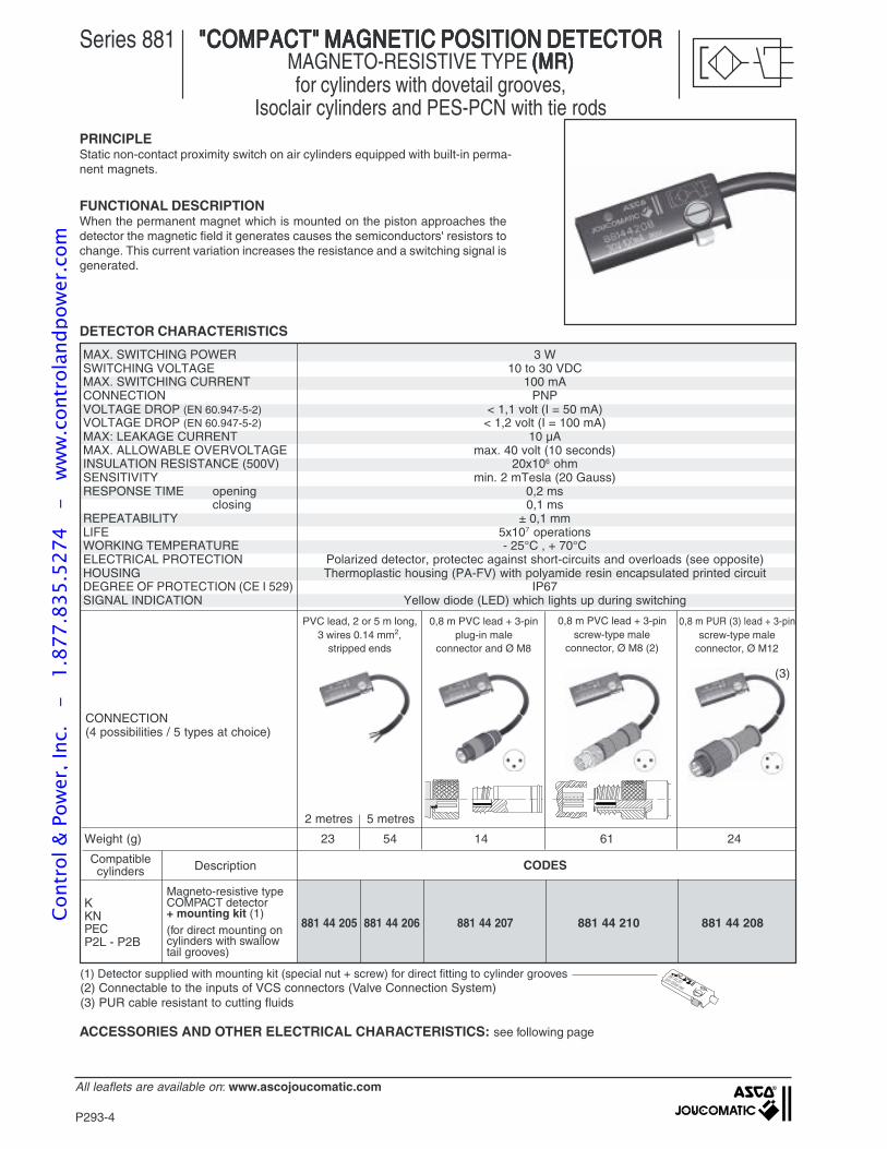
P293-4
All leaflets are available on: www.ascojoucomatic.com
PVC lead, 2 or 5 m long,3 wires 0.14 mm2,
stripped ends
0,8 m PVC lead + 3-pinplug-in male
connector and Ø M8
0,8 m PUR (3) lead + 3-pinscrew-type male
connector, Ø M12
2 metres 5 metres
881 44 205 881 44 206 881 44 207 881 44 210 881 44 208
CODES
0,8 m PVC lead + 3-pinscrew-type male
connector, Ø M8 (2)
PRINCIPLE
"COMPACT" MAGNETIC POSITION DETECTOR"COMPACT" MAGNETIC POSITION DETECTOR"COMPACT" MAGNETIC POSITION DETECTOR"COMPACT" MAGNETIC POSITION DETECTOR"COMPACT" MAGNETIC POSITION DETECTORMAGNETO-RESISTIVE TYPE (MR)(MR)(MR)(MR)(MR)for cylinders with dovetail grooves,
Isoclair cylinders and PES-PCN with tie rods
Series 881
FUNCTIONAL DESCRIPTIONWhen the permanent magnet which is mounted on the piston approaches thedetector the magnetic field it generates causes the semiconductors' resistors tochange. This current variation increases the resistance and a switching signal isgenerated.
Static non-contact proximity switch on air cylinders equipped with built-in perma-nent magnets.
DETECTOR CHARACTERISTICS
CONNECTION(4 possibilities / 5 types at choice)
MAX. SWITCHING POWER 3 WSWITCHING VOLTAGE 10 to 30 VDCMAX. SWITCHING CURRENT 100 mACONNECTION PNPVOLTAGE DROP (EN 60.947-5-2) < 1,1 volt (I = 50 mA)VOLTAGE DROP (EN 60.947-5-2) < 1,2 volt (I = 100 mA)MAX: LEAKAGE CURRENT 10 µAMAX. ALLOWABLE OVERVOLTAGE max. 40 volt (10 seconds)INSULATION RESISTANCE (500V) 20x106 ohmSENSITIVITY min. 2 mTesla (20 Gauss)RESPONSE TIME opening 0,2 ms
closing 0,1 msREPEATABILITY ± 0,1 mmLIFE 5x10⁷ operationsWORKING TEMPERATURE - 25°C , + 70°CELECTRICAL PROTECTION Polarized detector, protectec against short-circuits and overloads (see opposite)HOUSING Thermoplastic housing (PA-FV) with polyamide resin encapsulated printed circuitDEGREE OF PROTECTION (CE I 529) IP67SIGNAL INDICATION Yellow diode (LED) which lights up during switching
Magneto-resistive typeCOMPACT detector+ mounting kit (1)(for direct mounting oncylinders with swallowtail grooves)
DescriptionCompatiblecylinders
KKNPECP2L - P2B
Weight (g) 23 54 14 61 24
ACCESSORIES AND OTHER ELECTRICAL CHARACTERISTICS: see following page
(1) Detector supplied with mounting kit (special nut + screw) for direct fitting to cylinder grooves(2) Connectable to the inputs of VCS connectors (Valve Connection System)(3) PUR cable resistant to cutting fluids
881 44 20130V-100mA max.
(3)
Cont
rol &
Pow
er, I
nc.
-
1.87
7.83
5.52
74
- w
ww
.con
trol
andp
ower
.com
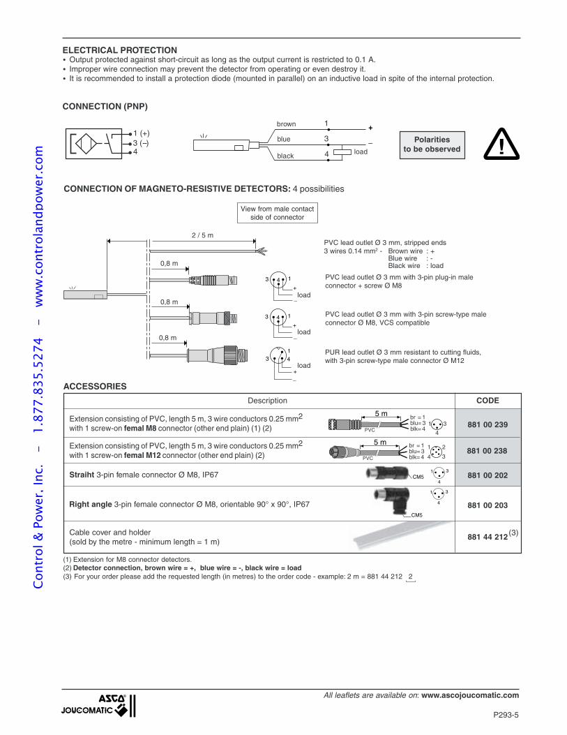
P293-5
All leaflets are available on: www.ascojoucomatic.com
ELECTRICAL PROTECTION
CONNECTION OF MAGNETO-RESISTIVE DETECTORS: 4 possibilities
CONNECTION (PNP)
View from male contactside of connector
PUR lead outlet Ø 3 mm resistant to cutting fluids,with 3-pin screw-type male connector Ø M12
PVC lead outlet Ø 3 mm, stripped ends3 wires 0.14 mm2 - Brown wire : +
Blue wire : -Black wire : load
PVC lead outlet Ø 3 mm with 3-pin plug-in maleconnector + screw Ø M8
PVC lead outlet Ø 3 mm with 3-pin screw-type maleconnector Ø M8, VCS compatible
_
+
• Output protected against short-circuit as long as the output current is restricted to 0.1 A.• Improper wire connection may prevent the detector from operating or even destroy it.• It is recommended to install a protection diode (mounted in parallel) on an inductive load in spite of the internal protection.
blue
brown
blackload
Polaritiesto be observed
1 (+) 3 (--) 4
1
3
4
(1) Extension for M8 connector detectors.(2) Detector connection, brown wire = +, blue wire = -, black wire = load(3) For your order please add the requested length (in metres) to the order code - example: 2 m = 881 44 212 2
2 / 5 m
load
load
load
13 4
13 4+
_
+_
13 4+
_
0,8 m
0,8 m
0,8 m
1 3
4
CM5
CODE
881 00 239
881 00 238
Description
Extension consisting of PVC, length 5 m, 3 wire conductors 0.25 mm2
with 1 screw-on femal M8 connector (other end plain) (1) (2)
Extension consisting of PVC, length 5 m, 3 wire conductors 0.25 mm2
with 1 screw-on femal M12 connector (other end plain) (2)
Straiht 3-pin female connector Ø M8, IP67
Right angle 3-pin female connector Ø M8, orientable 90° x 90°, IP67
881 00 202
881 00 203
1 3
4CM5
5 m br = 1
blk= 4blu= 3
1
4 3
2
PVC
5 m br = 1
blk= 4blu= 3 1
4
3PVC
ACCESSORIES
Cable cover and holder(sold by the metre - minimum length = 1 m)
881 44 212 (3)
!
Cont
rol &
Pow
er, I
nc.
-
1.87
7.83
5.52
74
- w
ww
.con
trol
andp
ower
.com
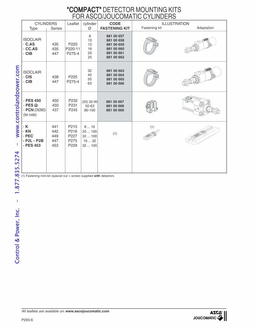
P293-6
All leaflets are available on: www.ascojoucomatic.com
"COMPACT""COMPACT""COMPACT""COMPACT""COMPACT" DETECTOR MOUNTING KITSFOR ASCO/JOUCOMATIC CYLINDERS
ISOCLAIR- C.AS 435 P220- CC.AS 435 P220-11- CIB 447 P275-4
81012162025
881 00 657881 00 658881 00 659881 00 660881 00 661881 00 662
ISOCLAIR- CIS 438 P225- CIB 447 P275-4
32405063
881 00 663881 00 664881 00 665881 00 666
- PES 450 450 P232- PES ΩΩΩΩΩ 450 P231- PCN (CNOMO) 437 P245(tie rods)
881 00 667881 00 668881 00 669
(25) 32-4050-63
80-100
AdaptationFastening kit
- K 441 P215- KN 442 P216- PEC 449 P227- P2L - P2B 447 P275- PES 453 453 P229
8 ... 1620 ... 10032 ... 10016 ... 32
32 ... 100
(1)
(1)
CYLINDERS Leaflet cylinder CODE ILLUSTRATIONType Series Ø FASTENING KIT
(1) Fastening mini-kit (special nut + screw) supplied with detectors
Cont
rol &
Pow
er, I
nc.
-
1.87
7.83
5.52
74
- w
ww
.con
trol
andp
ower
.com
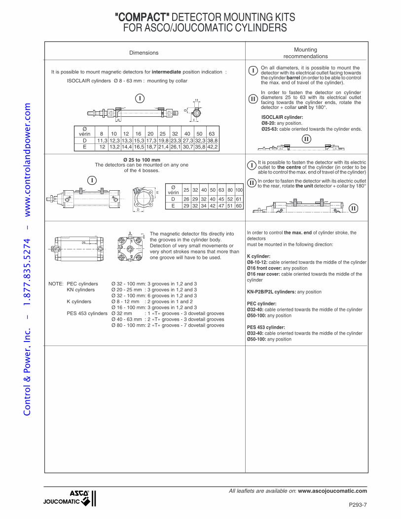
P293-7
All leaflets are available on: www.ascojoucomatic.com
Ø 25 to 100 mmThe detectors can be mounted on any one
of the 4 bosses.
25 32 40 50 63 80 100Øvérin
D 26 29 32 40 45 52 61E 29 32 34 42 47 51 60
25 E
D
11
On all diameters, it is possible to mount thedetector with its electrical outlet facing towardsthe cylinder barrel (in order to be able to controlthe max. end of travel of the cylinder).
In order to fasten the detector on cylinderdiameters 25 to 63 with its electrical outletfacing towards the cylinder ends, rotate thedetector + collar unit by 180°.
It is possible to mount magnetic detectors for intermediate position indication :
8 10 12 16 20 25 32 40 50 63D 11,3 12,3 13,3 15,3 17,3 19,8 23,3 27,3 32,3 38,8E 12 13,2 14,4 16,5 18,7 21,4 26,1 30,7 35,8 42,2
Øvérin
E
D
It is possible to fasten the detector with its electricoutlet to the centre of the cylinder (in order to beable to control the max. end of travel of the cylinder)
In order to fasten the detector with its electric outletto the rear, rotate the unit detector + collar by 180°
9
25
1
1
2
3
In order to control the max. end of cylinder stroke, thedetectorsmust be mounted in the following direction:
K cylinder:Ø8-10-12: cable oriented towards the middle of the cylinderØ16 front cover: any positionØ16 rear cover: cable oriented towards the middle of thecylinder
KN-P2B/P2L cylinders: any position
PEC cylinder:Ø32-40: cable oriented towards the middle of the cylinderØ50-100: any position
PES 453 cylinder:Ø32-40: cable oriented towards the middle of the cylinderØ50-100: any position
The magnetic detector fits directly intothe grooves in the cylinder body.Detection of very small movements orvery short strokes means that more thanone groove will have to be used.
NOTE: PEC cylinders Ø 32 - 100 mm: 3 grooves in 1,2 and 3KN cylinders Ø 20 - 25 mm : 3 grooves in 1,2 and 3
Ø 32 - 100 mm: 6 grooves in 1,2 and 3K cylinders Ø 8 - 12 mm : 2 grooves in 1 and 2
Ø 16 - 100 mm: 3 grooves in 1,2 and 3PES 453 cylinders Ø 32 mm : 1 «T» grooves - 3 dovetail grooves
Ø 40 - 63 mm : 2 «T» grooves - 3 dovetail groovesØ 80 - 100 mm: 2 «T» grooves - 7 dovetail grooves
Dimensions Mountingrecommendations
"COMPACT""COMPACT""COMPACT""COMPACT""COMPACT" DETECTOR MOUNTING KITSFOR ASCO/JOUCOMATIC CYLINDERS
ISOCLAIR cylinder:Ø8-20: any position.Ø25-63: cable oriented towards the cylinder ends.
ISOCLAIR cylinders Ø 8 - 63 mm : mounting by collar
Cont
rol &
Pow
er, I
nc.
-
1.87
7.83
5.52
74
- w
ww
.con
trol
andp
ower
.com
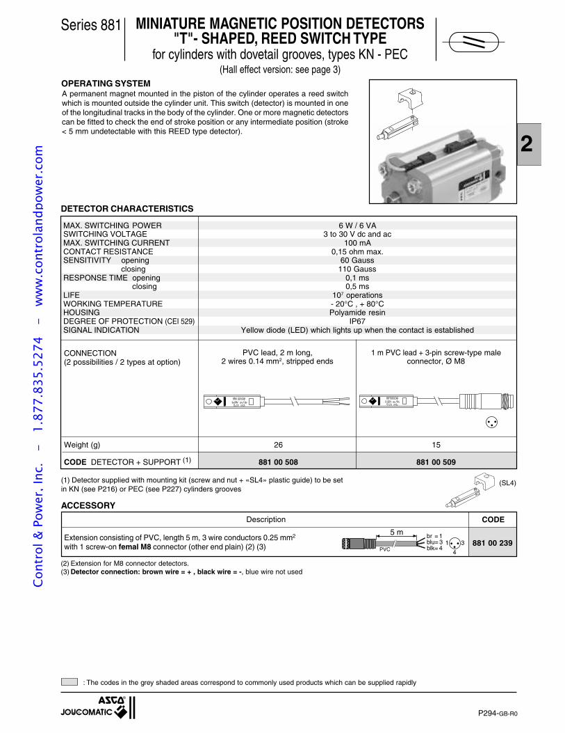
2
P294-1
MINIATURE MAGNETIC POSITION DETECTORS"T"- SHAPED, REED SWITCH TYPE
for cylinders with dovetail grooves, types KN - PEC(Hall effect version: see page 3)
Series 881
OPERATING SYSTEM
Weight (g) 26 15
CODE DETECTOR + SUPPORT (1) 881 00 508 881 00 509
PVC lead, 2 m long,2 wires 0.14 mm2, stripped ends
1 m PVC lead + 3-pin screw-type maleconnector, Ø M8
CONNECTION(2 possibilities / 2 types at option)
Description CODE
881 00 239Extension consisting of PVC, length 5 m, 3 wire conductors 0.25 mm2
with 1 screw-on femal M8 connector (other end plain) (2) (3)
(2) Extension for M8 connector detectors.(3) Detector connection: brown wire = + , black wire = -, blue wire not used
A permanent magnet mounted in the piston of the cylinder operates a reed switchwhich is mounted outside the cylinder unit. This switch (detector) is mounted in oneof the longitudinal tracks in the body of the cylinder. One or more magnetic detectorscan be fitted to check the end of stroke position or any intermediate position (stroke< 5 mm undetectable with this REED type detector).
DETECTOR CHARACTERISTICS
ACCESSORY
MAX. SWITCHING POWER 6 W / 6 VASWITCHING VOLTAGE 3 to 30 V dc and acMAX. SWITCHING CURRENT 100 mACONTACT RESISTANCE 0,15 ohm max.SENSITIVITY opening 60 Gauss
closing 110 GaussRESPONSE TIME opening 0,1 ms
closing 0,5 msLIFE 107 operationsWORKING TEMPERATURE - 20°C , + 80°CHOUSING Polyamide resinDEGREE OF PROTECTION (CEI 529) IP67SIGNAL INDICATION Yellow diode (LED) which lights up when the contact is established
: The codes in the grey shaded areas correspond to commonly used products which can be supplied rapidly
5 m br = 1
blk= 4blu= 3 1
4
3PVC
P294-GB-R0
(SL4)(1) Detector supplied with mounting kit (screw and nut + «SL4» plastic guide) to be setin KN (see P216) or PEC (see P227) cylinders grooves
Cont
rol &
Pow
er, I
nc.
-
1.87
7.83
5.52
74
- w
ww
.con
trol
andp
ower
.com
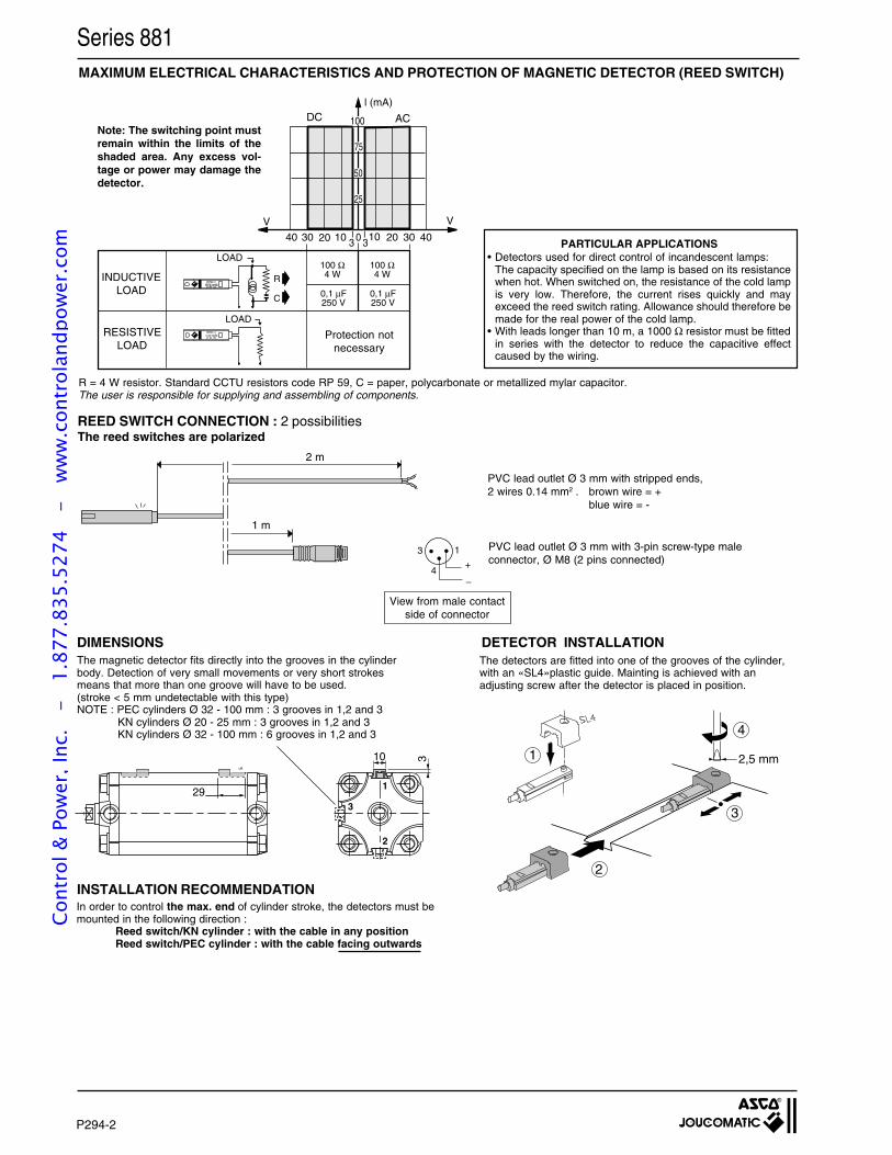
P294-2
R = 4 W resistor. Standard CCTU resistors code RP 59, C = paper, polycarbonate or metallized mylar capacitor.The user is responsible for supplying and assembling of components.
MAXIMUM ELECTRICAL CHARACTERISTICS AND PROTECTION OF MAGNETIC DETECTOR (REED SWITCH)
REED SWITCH CONNECTION : 2 possibilitiesThe reed switches are polarized
View from male contactside of connector
PVC lead outlet Ø 3 mm with 3-pin screw-type maleconnector, Ø M8 (2 pins connected)
Series 881
DIMENSIONS DETECTOR INSTALLATIONThe magnetic detector fits directly into the grooves in the cylinderbody. Detection of very small movements or very short strokesmeans that more than one groove will have to be used.(stroke < 5 mm undetectable with this type)NOTE : PEC cylinders Ø 32 - 100 mm : 3 grooves in 1,2 and 3
KN cylinders Ø 20 - 25 mm : 3 grooves in 1,2 and 3KN cylinders Ø 32 - 100 mm : 6 grooves in 1,2 and 3
The detectors are fitted into one of the grooves of the cylinder,with an «SL4»plastic guide. Mainting is achieved with anadjusting screw after the detector is placed in position.
13
4+_
2 m
1 m
PVC lead outlet Ø 3 mm with stripped ends,2 wires 0.14 mm2 . brown wire = +
blue wire = -
R
C
100 Ω4 W
100 Ω4 W
0,1 µF250 V
50
75
100
25
V V
0 10 20 30 4010203040
l (mA)
0,1 µF250 V
3 3
RESISTIVELOAD
INDUCTIVELOAD
Protection notnecessary
LOAD
LOAD
DC ACNote: The switching point mustremain within the limits of theshaded area. Any excess vol-tage or power may damage thedetector.
PARTICULAR APPLICATIONS• Detectors used for direct control of incandescent lamps:
The capacity specified on the lamp is based on its resistancewhen hot. When switched on, the resistance of the cold lampis very low. Therefore, the current rises quickly and mayexceed the reed switch rating. Allowance should therefore bemade for the real power of the cold lamp.
• With leads longer than 10 m, a 1000 Ω resistor must be fittedin series with the detector to reduce the capacitive effectcaused by the wiring.
l
10
29
3
1
2
3
INSTALLATION RECOMMENDATIONIn order to control the max. end of cylinder stroke, the detectors must bemounted in the following direction :
Reed switch/KN cylinder : with the cable in any positionReed switch/PEC cylinder : with the cable facing outwards
1
2
4
3
2,5 mm
Cont
rol &
Pow
er, I
nc.
-
1.87
7.83
5.52
74
- w
ww
.con
trol
andp
ower
.com
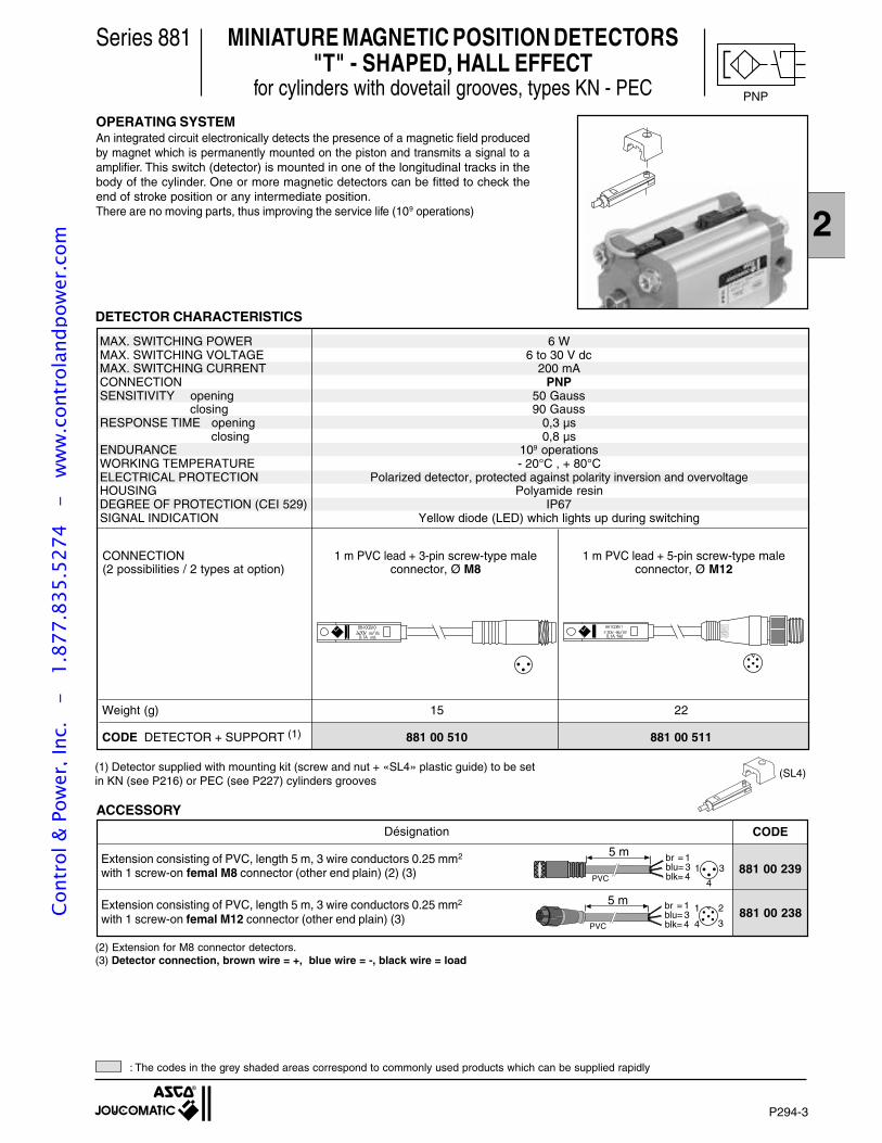
2
P294-3
MINIATURE MAGNETIC POSITION DETECTORS"T" - SHAPED, HALL EFFECT
for cylinders with dovetail grooves, types KN - PEC
Series 881
OPERATING SYSTEMAn integrated circuit electronically detects the presence of a magnetic field producedby magnet which is permanently mounted on the piston and transmits a signal to aamplifier. This switch (detector) is mounted in one of the longitudinal tracks in thebody of the cylinder. One or more magnetic detectors can be fitted to check theend of stroke position or any intermediate position.There are no moving parts, thus improving the service life (109 operations)
MAX. SWITCHING POWER 6 WMAX. SWITCHING VOLTAGE 6 to 30 V dcMAX. SWITCHING CURRENT 200 mACONNECTION PNPSENSITIVITY opening 50 Gauss
closing 90 GaussRESPONSE TIME opening 0,3 µs
closing 0,8 µsENDURANCE 109 operationsWORKING TEMPERATURE - 20°C , + 80°CELECTRICAL PROTECTION Polarized detector, protected against polarity inversion and overvoltageHOUSING Polyamide resinDEGREE OF PROTECTION (CEI 529) IP67SIGNAL INDICATION Yellow diode (LED) which lights up during switching
DETECTOR CHARACTERISTICS
Désignation CODE
Extension consisting of PVC, length 5 m, 3 wire conductors 0.25 mm2
with 1 screw-on femal M12 connector (other end plain) (3)
881 00 239
881 00 238
Extension consisting of PVC, length 5 m, 3 wire conductors 0.25 mm2
with 1 screw-on femal M8 connector (other end plain) (2) (3)
5 m br = 1
blk= 4blu= 3
1
4 3
2
PVC
ACCESSORY
: The codes in the grey shaded areas correspond to commonly used products which can be supplied rapidly
(2) Extension for M8 connector detectors.(3) Detector connection, brown wire = +, blue wire = -, black wire = load
1 m PVC lead + 3-pin screw-type maleconnector, Ø M8
CONNECTION(2 possibilities / 2 types at option)
Weight (g) 15 22
CODE DETECTOR + SUPPORT (1) 881 00 510 881 00 511
1 m PVC lead + 5-pin screw-type maleconnector, Ø M12
5 m br = 1
blk= 4blu= 3 1
4
3PVC
(SL4)(1) Detector supplied with mounting kit (screw and nut + «SL4» plastic guide) to be setin KN (see P216) or PEC (see P227) cylinders grooves
PNP
Cont
rol &
Pow
er, I
nc.
-
1.87
7.83
5.52
74
- w
ww
.con
trol
andp
ower
.com
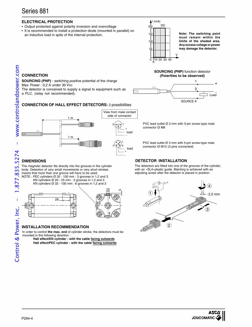
P294-4
_
+
ELECTRICAL PROTECTION• Output protected against polarity inversion and overvoltage• It is recommended to install a protection diode (mounted in parallel) on
an inductive load in spite of the internal protection.
13 4
1
3 4
+_
+
_
PVC lead outlet Ø 3 mm with 5-pin screw-type maleconnector Ø M12 (3 pins connected)
1 m
1 m
load
load
PVC lead outlet Ø 3 mm with 3-pin screw-type maleconnector Ø M8
View from male contactside of connector
CONNECTIONSOURCING (PNP) - switching positive potential of the chargeMax. Power : 0,2 A under 30 VccThe detector is conceived to supply a signal to equipment such asa PLC. (relay not recommended).
CONNECTION OF HALL EFFECT DETECTORS: 2 possibilities
Series 881
SOURCING (PNP) function detector(Polarities to be observed)
DIMENSIONS DETECTOR INSTALLATIONThe magnetic detector fits directly into the grooves in the cylinderbody. Detection of very small movements or very short strokesmeans that more than one groove will have to be used.NOTE : PEC cylinders Ø 32 - 100 mm : 3 grooves in 1,2 and 3
KN cylinders Ø 20 - 25 mm : 3 grooves in 1,2 and 3KN cylinders Ø 32 - 100 mm : 6 grooves in 1,2 and 3
The detectors are fitted into one of the grooves of the cylinder,with an «SL4»plastic guide. Mainting is achieved with anadjusting screw after the detector is placed in position.
l
10
29
3
1
2
3
INSTALLATION RECOMMENDATIONIn order to control the max. end of cylinder stroke, the detectors must bemounted in the following direction :
Hall effect/KN cylinder : with the cable facing outwardsHall effect/PEC cylinder : with the cable facing outwards
100
150
200
50
V
0 10 20 30 40
l (mA)
6
DC
Note: The switching pointmust remain within thelimits of the shaded area.Any excess voltage or powermay damage the detector.
SOURCE 4
1
3
Load
1
2
4
3
2,5 mm
Cont
rol &
Pow
er, I
nc.
-
1.87
7.83
5.52
74
- w
ww
.con
trol
andp
ower
.com
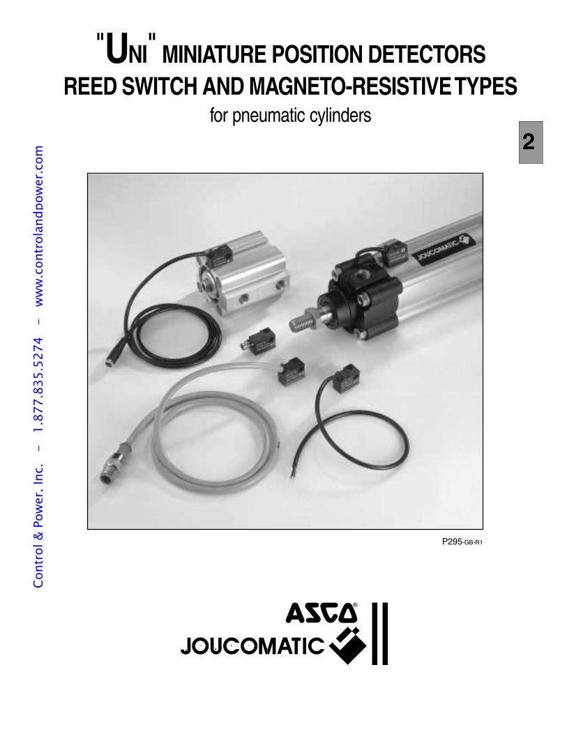
P295-GB-R1
"UNI" MINIATURE POSITION DETECTORSREED SWITCH AND MAGNETO-RESISTIVE TYPES
for pneumatic cylinders2
Cont
rol &
Pow
er, I
nc.
-
1.87
7.83
5.52
74
- w
ww
.con
trol
andp
ower
.com
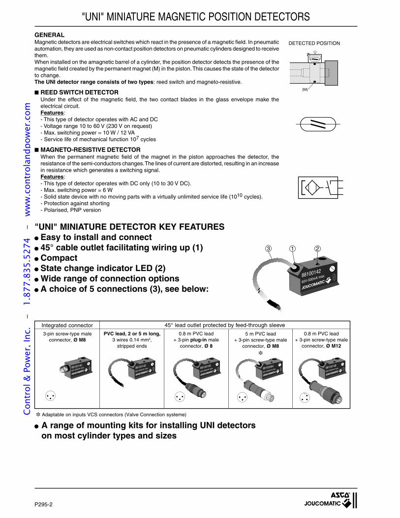
P295-2
"UNI" MINIATURE MAGNETIC POSITION DETECTORS
GENERALMagnetic detectors are electrical switches which react in the presence of a magnetic field. In pneumaticautomation, they are used as non-contact position detectors on pneumatic cylinders designed to receivethem.When installed on the amagnetic barrel of a cylinder, the position detector detects the presence of themagnetic field created by the permanent magnet (M) in the piston. This causes the state of the detectorto change.The UNI detector range consists of two types: reed switch and magneto-resistive.
REED SWITCH DETECTORUnder the effect of the magnetic field, the two contact blades in the glass envelope make theelectrical circuit.Features:- This type of detector operates with AC and DC- Voltage range 10 to 60 V (230 V on request)- Max. switching power = 10 W / 12 VA- Service life of mechanical function 107 cycles
MAGNETO-RESISTIVE DETECTORWhen the permanent magnetic field of the magnet in the piston approaches the detector, theresistance of the semi-conductors changes. The lines of current are distorted, resulting in an increasein resistance which generates a switching signal.Features:- This type of detector operates with DC only (10 to 30 V DC).- Max. switching power = 6 W- Solid state device with no moving parts with a virtually unlimited service life (1010 cycles).- Protection against shorting- Polarised, PNP version
"UNI" MINIATURE DETECTOR KEY FEATURES Easy to install and connect 45° cable outlet facilitating wiring up (1) Compact State change indicator LED (2) Wide range of connection options A choice of 5 connections (3), see below:
88100142
60V-500mA max.
3 1 2
A range of mounting kits for installing UNI detectorson most cylinder types and sizes
(M)
DETECTED POSITION
3-pin screw-type maleconnector, Ø M8
PVC lead, 2 or 5 m long,3 wires 0.14 mm2,
stripped ends
0.8 m PVC lead+ 3-pin plug-in male
connector, Ø 8
0.8 m PVC lead+ 3-pin screw-type male
connector, Ø M12
45° lead outlet protected by feed-through sleeve
88100140
60V-500mA max. 88100142
60V-500mA max. 88100146
60V-500mA max.
Integrated connector
88100148
60V-500mA max.
5 m PVC lead+ 3-pin screw-type male
connector, Ø M8
88100594
60V-500mA max.
Adaptable on inputs VCS connectors (Valve Connection systeme)Cont
rol &
Pow
er, I
nc.
-
1.87
7.83
5.52
74
- w
ww
.con
trol
andp
ower
.com
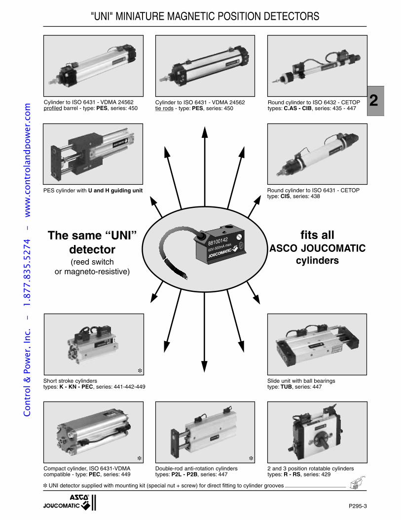
P295-3
2
88100142
60V-500mA max.
"UNI" MINIATURE MAGNETIC POSITION DETECTORS
Cylinder to ISO 6431 - VDMA 24562profiled barrel - type: PES, series: 450
Cylinder to ISO 6431 - VDMA 24562tie rods - type: PES, series: 450
Round cylinder to ISO 6432 - CETOPtypes: C.AS - CIB, series: 435 - 447
Round cylinder to ISO 6431 - CETOPtype: CIS, series: 438
PES cylinder with U and H guiding unit
Short stroke cylinderstypes: K - KN - PEC, series: 441-442-449
Slide unit with ball bearingstype: TUB, series: 447
2 and 3 position rotatable cylinderstypes: R - RS, series: 429
Double-rod anti-rotation cylinderstypes: P2L - P2B, series: 447
Compact cylinder, ISO 6431-VDMAcompatible - type: PEC, series: 449
UNI detector supplied with mounting kit (special nut + screw) for direct fitting to cylinder grooves
The same “UNI”detector(reed switch
or magneto-resistive)
fits allASCO JOUCOMATIC
cylinders
Cont
rol &
Pow
er, I
nc.
-
1.87
7.83
5.52
74
- w
ww
.con
trol
andp
ower
.com
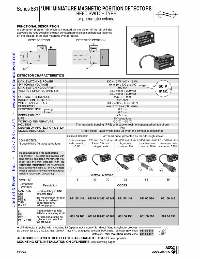
P295-4
A permanent magnet (M) which is mounted on the piston of the air cylinderactivates the reed switch of the non-contact magnetic position detector fastenedon the outside of the non-magnetic cylinder barrel.
FUNCTIONAL DESCRIPTION
"UNI"MINIATURE MAGNETIC POSITION DETECTORSREED SWITCH TYPEfor pneumatic cylinder
Series 881
DETECTOR CHARACTERISTICS
REST POSITION DETECTED POSITION
(M) (M)
88100142
60V-500mA max.
88100140
60V-500mA max.
ACCESSORIES AND OTHER ELECTRICAL CHARACTERISTICS: see oppositeMOUNTING KITS, INSTALLATION ON CYLINDERS: see following pages
UNI detector supplied with mounting kit (special nut + screw) for direct fitting to cylinder grooves(1) Version for 230 V AC/DC max. (50 mA - 11.5 VA), on request, with 2 m PUR cable, detector only, code: 881 00 418
detector + mini mounting kit (), code: 881 00 417
3-pin screw-typemale connector,
Ø M8
PVC lead, 2 or 5 m long,2 wires 0.14 mm2,
stripped ends
0.8 m PVC lead + 3-pinplug-in male
connector, Ø 8
0.8 m PVC lead + 3-pinscrew-type male
connector, Ø M12
45° lead outlet protected by feed-through sleeve
2 metres 5 metres
88100140
60V-500mA max. 88100142
60V-500mA max.
CONNECTION(5 possibilities / 6 types at option)
60 Vmax.
Integrated connector
MAX. SWITCHING POWER DC = 10 W / AC =1 2 VASWITCHING VOLTAGE 10 to 60 V DC and ACMAX. SWITCHING CURRENT 500 mAVOLTAGE DROP (EN 60.947-5-2) < 2.7 volt (I = 200mA)
< 2.9 volt (I = 500mA)CONTACT RESISTANCE max. 0.1 ohmINSULATION RESISTANCE 1010 ohmWITHSTAND VOLTAGE DC = 470 V - AC = 600 VSENSITIVITY min. 3 mTesla (30 Gauss)RESPONSE TIME opening 0.2 ms
closing 0.6 msREPEATABILITY ± 0.1 mmLIFE 107 operationsWORKING TEMPERATURE -20 °C , +70 °CHOUSING Thermoplastic housing (PPS) with expoxy resin encapsulated printed circuitDEGREE OF PROTECTION (CE I 529) IP67SIGNAL INDICATION Green diode (LED) which lights up when the contact is established
88100148
60V-500mA max.
881 00 140 881 00 142 881 00 144 881 00 146 881 00 594 881 00 148
Reed switch type UNIdetector only
the mounting kit for eachcylinder is orderedseparately (seefollowing pages)
Reed switch type UNIdetector + mounting kit ()
(for direct mounting oncylinders with swallowtail grooves)
(1)
CODESDescription
CAS - CISCIBPESPES ΩTUBR - RS
Compatiblecylinders
KKNPECP2L - P2B
88100146
60V-500mA max.
881 00 185 881 00 186 881 00 189 881 00 190 881 00 592 881 00 191
5 m PVC lead + 3-pinscrew-type maleconnector, Ø M8
Recommendation for applicationFor cylinder + detector applications withlong travels and large movements youmust use the mini-detector with M8connector integrated in the housing andlead outlets with cable (2- or 3- wire) typeclass 6 especially intented for this purpose(specific accessory: consult us)
Weight (g) 6 30 70 22 86 35
88100594
60V-500mA max.
Cont
rol &
Pow
er, I
nc.
-
1.87
7.83
5.52
74
- w
ww
.con
trol
andp
ower
.com
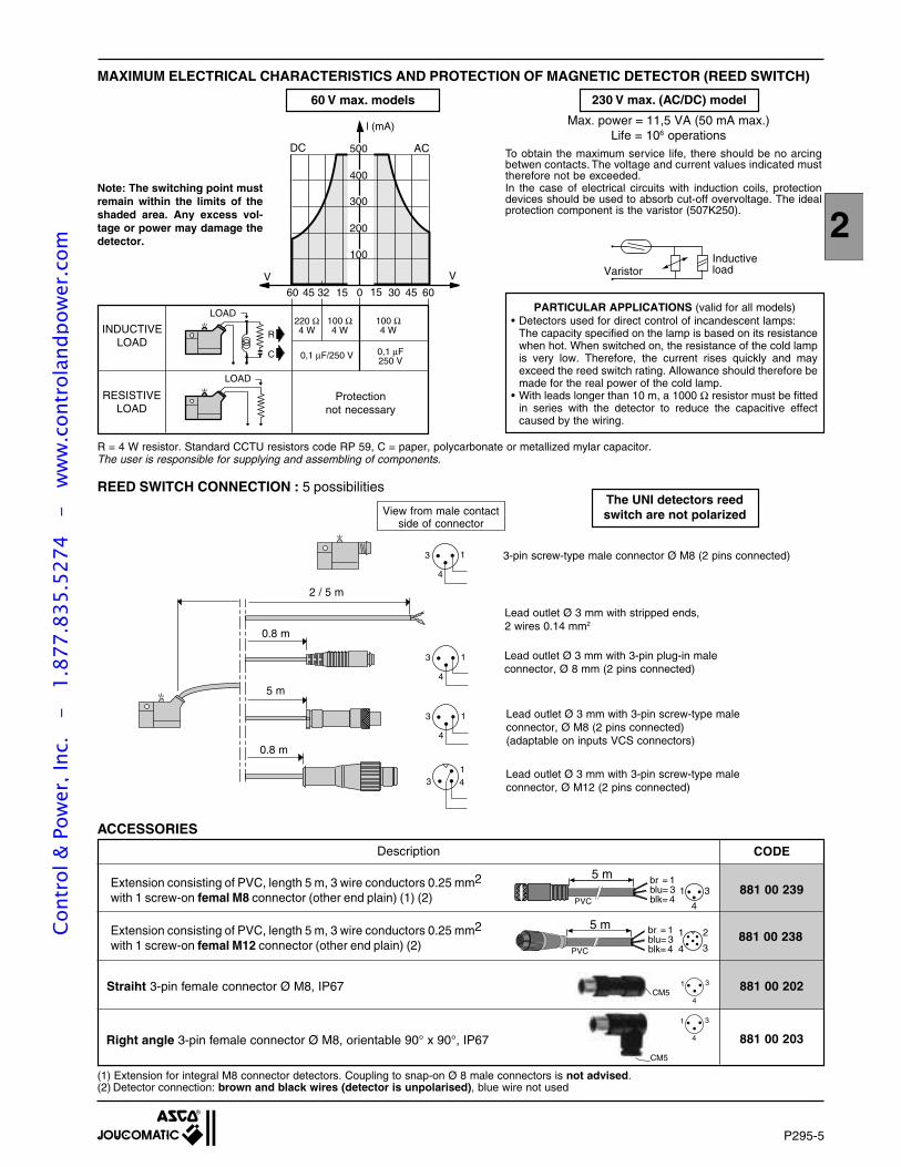
P295-5
2
1 3
4
CM5
ACCESSORIES
(1) Extension for integral M8 connector detectors. Coupling to snap-on Ø 8 male connectors is not advised.(2) Detector connection: brown and black wires (detector is unpolarised), blue wire not used
CODE
881 00 239
881 00 238
Description
Extension consisting of PVC, length 5 m, 3 wire conductors 0.25 mm2
with 1 screw-on femal M8 connector (other end plain) (1) (2)
Extension consisting of PVC, length 5 m, 3 wire conductors 0.25 mm2
with 1 screw-on femal M12 connector (other end plain) (2)
Straiht 3-pin female connector Ø M8, IP67
Right angle 3-pin female connector Ø M8, orientable 90° x 90°, IP67
881 00 202
881 00 203
MAXIMUM ELECTRICAL CHARACTERISTICS AND PROTECTION OF MAGNETIC DETECTOR (REED SWITCH)
R
C
220 Ω4 W
100 Ω4 W
100 Ω4 W
0,1 µF/250 V 0,1 µF250 V
200
300
400
500
100
V V
0 15 30 45 6015324560
l (mA)
RESISTIVELOAD
INDUCTIVELOAD
Protectionnot necessary
LOAD
DC AC
R = 4 W resistor. Standard CCTU resistors code RP 59, C = paper, polycarbonate or metallized mylar capacitor.The user is responsible for supplying and assembling of components.
REED SWITCH CONNECTION : 5 possibilities
LOAD
3-pin screw-type male connector Ø M8 (2 pins connected)
View from male contactside of connector
13 4
13
4
13
4
13
4
Lead outlet Ø 3 mm with stripped ends,2 wires 0.14 mm2
Lead outlet Ø 3 mm with 3-pin plug-in maleconnector, Ø 8 mm (2 pins connected)
Lead outlet Ø 3 mm with 3-pin screw-type maleconnector, Ø M12 (2 pins connected)
0.8 m
0.8 m
2 / 5 m
1 3
4CM5
The UNI detectors reedswitch are not polarized
60 V max. models 230 V max. (AC/DC) model
Note: The switching point mustremain within the limits of theshaded area. Any excess vol-tage or power may damage thedetector.
Max. power = 11,5 VA (50 mA max.)Life = 106 operations
InductiveloadVaristor
PARTICULAR APPLICATIONS (valid for all models)• Detectors used for direct control of incandescent lamps:
The capacity specified on the lamp is based on its resistancewhen hot. When switched on, the resistance of the cold lampis very low. Therefore, the current rises quickly and mayexceed the reed switch rating. Allowance should therefore bemade for the real power of the cold lamp.
• With leads longer than 10 m, a 1000 Ω resistor must be fittedin series with the detector to reduce the capacitive effectcaused by the wiring.
To obtain the maximum service life, there should be no arcingbetwen contacts. The voltage and current values indicated musttherefore not be exceeded.In the case of electrical circuits with induction coils, protectiondevices should be used to absorb cut-off overvoltage. The idealprotection component is the varistor (507K250).
5 m br = 1
blk= 4blu= 3
1
4 3
2
PVC
5 m br = 1
blk= 4blu= 3 1
4
3PVC
5 m
Lead outlet Ø 3 mm with 3-pin screw-type maleconnector, Ø M8 (2 pins connected)(adaptable on inputs VCS connectors)
Cont
rol &
Pow
er, I
nc.
-
1.87
7.83
5.52
74
- w
ww
.con
trol
andp
ower
.com

P295-6
PRINCIPLE
"UNI"MINIATURE MAGNETIC POSITION DETECTORSMAGNETO-RESISTIVE TYPE (MR)
for pneumatic cylinder
Series 881
FUNCTIONAL DESCRIPTIONWhen the permanent magnet which is mounted on the piston approaches thedetector the magnetic field it generates causes the semiconductors' resistors tochange. This current variation increases the resistance and a switching signal isgenerated.
Static non-contact proximity switch on air cylinders equipped with built-in perma-nent magnets.
88100141
30V-200mA max.
MR
88100143
30V-200mA max.
MR
DETECTOR CHARACTERISTICS
ACCESSORIES AND OTHER ELECTRICAL CHARACTERISTICS: see oppositeMOUNTING KITS, INSTALLATION ON CYLINDERS: see following pages
Detector supplied with mounting kit (special nut + screw) for direct fitting to cylinder grooves
88100141
30V-200mA max.
MR 88100143
30V-200mA max.
MR 88100149
30V-200mA max.
MR88100147
30V-200mA max.
MR
CONNECTION(5 possibilities / 6 types at option)
MAX. SWITCHING POWER 6 WSWITCHING VOLTAGE 10 to 30 V DCMAX. SWITCHING CURRENT 200 mACONNECTION PNPVOLTAGE DROP < 1.1 Volt (I = 50 mA)
< 1.4 Volt (I = 200 mA)MAX: LEAKAGE CURRENT 10 µAMAX. ALLOWABLE OVERVOLTAGE 50 Volt (10 seconds)INSULATION RESISTANCE 1010 ohmSENSITIVITY min. 3 mTesla (30 Gauss)RESPONSE TIME opening 0.2 ms
closing 0.1 msREPEATABILITY ± 0.1 mmWORKING TEMPERATURE -20°C , +70°CELECTRICAL PROTECTION Polarized detector, protectec against short-circuits and overloads (see opposite)
and incorporated recovery diodeHOUSING Thermoplastic housing (PPS) with epoxy resin encapsulated printed circuitDEGREE OF PROTECTION (CE I 529) IP67SIGNAL INDICATION Green diode (LED) which lights up during switching
Magneto-resistive type UNIdetector only
the mounting kit for eachcylinder is orderedseparately (see followingpages)
Magneto-resistive type UNIdetector + mounting kit ()
(for direct mounting oncylinders with swallowtail grooves)
CODESDescription
CAS - CISCIBPESPES ΩTUBR - RS
Compatiblecylinders
KKNPECP2L - P2B
3-pin screw-typemale connector,
Ø M8
PVC lead, 2 or 5 m long,3 wires 0.14 mm2,
stripped ends
0.8 m PVC lead + 3-pinplug-in male
connector, Ø 8
0.8 m PVC lead + 3-pinscrew-type male
connector, Ø M12
45° lead outlet protected by feed-through sleeveIntegrated connector5 m PVC lead + 3-pin
screw-type maleconnector, Ø M8
881 00 141 881 00 143 881 00 145 881 00 147 881 00 595 881 00 149
881 00 192 881 00 193 881 00 194 881 00 195 881 00 593 881 00 196
Weight (g) 6 30 70 22 86 35
2 metres 5 metres
Recommendation for applicationFor cylinder + detector applications with longtravels and large movements you must usethe mini-detector with M8 connectorintegrated in the housing and lead outletswith cable (3- wire) type class 6 especiallyintented for this purpose(specific accessory: consult us)
88100595
30V-200mA max.
MR
Cont
rol &
Pow
er, I
nc.
-
1.87
7.83
5.52
74
- w
ww
.con
trol
andp
ower
.com
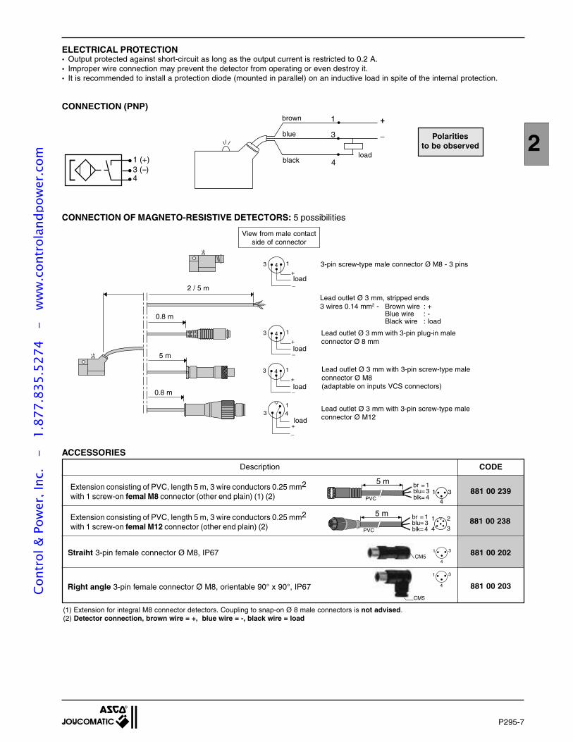
P295-7
2_
+
(1) Extension for integral M8 connector detectors. Coupling to snap-on Ø 8 male connectors is not advised.(2) Detector connection, brown wire = +, blue wire = -, black wire = load
13 4
13 4+
_
+_
13 4+
_
13 4+
_
ELECTRICAL PROTECTION• Output protected against short-circuit as long as the output current is restricted to 0.2 A.• Improper wire connection may prevent the detector from operating or even destroy it.• It is recommended to install a protection diode (mounted in parallel) on an inductive load in spite of the internal protection.
CONNECTION OF MAGNETO-RESISTIVE DETECTORS: 5 possibilities
Lead outlet Ø 3 mm with 3-pin screw-type maleconnector Ø M12
blue
brown
blackload
Lead outlet Ø 3 mm, stripped ends3 wires 0.14 mm2 - Brown wire : +
Blue wire : -Black wire : load
0.8 m
2 / 5 m
CONNECTION (PNP)
0.8 m
load
load
load
Lead outlet Ø 3 mm with 3-pin plug-in maleconnector Ø 8 mm
View from male contactside of connector
3-pin screw-type male connector Ø M8 - 3 pins
Polaritiesto be observed
1 (+) 3 (--) 4
1
3
4
1 3
4
CM5
ACCESSORIES
CODE
881 00 239
881 00 238
Description
Extension consisting of PVC, length 5 m, 3 wire conductors 0.25 mm2
with 1 screw-on femal M8 connector (other end plain) (1) (2)
Extension consisting of PVC, length 5 m, 3 wire conductors 0.25 mm2
with 1 screw-on femal M12 connector (other end plain) (2)
Straiht 3-pin female connector Ø M8, IP67
Right angle 3-pin female connector Ø M8, orientable 90° x 90°, IP67
881 00 202
881 00 203
1 3
4CM5
5 m br = 1
blk= 4blu= 3
1
4 3
2
PVC
5 m br = 1
blk= 4blu= 3 1
4
3PVC
5 m
Lead outlet Ø 3 mm with 3-pin screw-type maleconnector Ø M8(adaptable on inputs VCS connectors)
load
Cont
rol &
Pow
er, I
nc.
-
1.87
7.83
5.52
74
- w
ww
.con
trol
andp
ower
.com
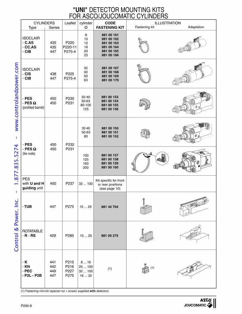
P295-8
CYLINDERS Leaflet cylinder CODE ILLUSTRATIONType Series Ø FASTENING KIT
"UNI" DETECTOR MOUNTING KITSFOR ASCO/JOUCOMATIC CYLINDERS
ISOCLAIR- C.AS 435 P220- CC.AS 435 P220-11- CIB 447 P275-4
81012162025
881 00 161881 00 162881 00 163881 00 164881 00 165881 00 166
ISOCLAIR- CIS 438 P225- CIB 447 P275-4
32405063
881 00 167881 00 168881 00 169881 00 170
- PES 450 P230- PES ΩΩΩΩΩ 450 P231(profiled barrel)
32-4050-63
80-100125
881 00 153881 00 154881 00 155881 00 156
- PES 450 P232- PES ΩΩΩΩΩ 450 P231(tie rods) 100
125160200
881 00 150881 00 151881 00 152
PESwith U and H 450 P237guiding unit
32 ... 100Kit specific for front
or rear positions(see page 10)
- TUB 447 P275 10 ... 25 881 44 704
ROTATABLE- R - RS 429 P285 10 ... 25 881 00 275
32-4050-63
80
881 00 157881 00 158881 00 159881 00 160
AdaptationFastening kit
- K 441 P215- KN 442 P216- PEC 449 P227- P2L - P2B 447 P275
8 ... 1620 ... 10032 ... 10016 ... 32
(1)
(1) Fastening mini-kit (special nut + screw) supplied with detectors
(1)
Cont
rol &
Pow
er, I
nc.
-
1.87
7.83
5.52
74
- w
ww
.con
trol
andp
ower
.com
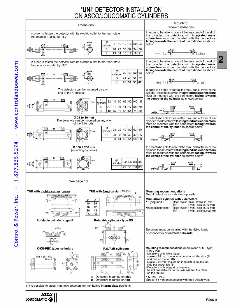
P295-9
2
"UNI" DETECTOR INSTALLATIONON ASCO/JOUCOMATIC CYLINDERS
Dimensions Mountingrecommendations
21E max
D
32 40 50 63 80 100 125Ø
cylinderD 27 31 36 41 47 58 69E 42 45 51 55 64 71 82
In order to be able to control the max. end of travel of thecylinder, the detectors with integrated male connectorsmust be mounted with the connectors facing towardsthe centre of the cylinder as shown below:
The detectors can be mounted on anyone of the 4 bosses.
It is possible to install magnetic detectors for monitoring intermediate positions.
Ø 25 to 80 mmThe detectors can be mounted on any one
of the 4 tie rods.
21
E max.
D
In order to be able to control the max. end of travel of thecylinder, the detectors with integrated male connectorsmust be mounted with the connectors facing towardsthe centre of the cylinder as shown below:
25 32 40 50 63 80Øcylinder
D 26 30 34 42 47 55E 36 44 47 51 56 63
Ø 100 à 200 mm(mounting by collar)
E max.
21
100 125 160 200Øcylinder
E 75 88 106 127
In order to be able to control the max. end of travel of thecylinder, the detectors with integrated male connectorsmust be mounted with the connectors facing towardsthe centre of the cylinder as shown below:
21 E
D
15
In order to be able to control the max. end of travel ofthe cylinder, the detectors with integrated maleconnectors must be mounted with the connectorsfacing towards the centre of the cylinder as shownbelow:8 10 12 16 20 25Ø
cylinderD 28 29 30 32 34 36E 13 14 15 17 19 21
32 40 50 63Øcylinder
D 41 46 51 57E 26 31 36 42
In order to be able to control the max. end of travel ofthe cylinder, the detectors with integrated maleconnectors must be mounted with the connectorsfacing towards the centre of the cylinder as shownbelow:
In order to fasten the detector with its electric outlet to the rear rotatethe detector + collar by 180°
In order to fasten the detector with its electric outlet to the rear rotatethe detector + collar by 180°
17
38
A
Magnet MagnetTUB with mobile carrier TUB with fixed carrier
Ø A10 3916 4220 4325 53
Mini. stroke cylinder with 2 detectors• Flying lead : - Reed switch : mini. stroke, 20 mm
- MR : mini. stroke,30 mm•Integral connector: - Reed switch : mini. stroke,90 mm
- MR : mini. stroke,100 mm
Mounting recommendationsMount detectors as indicated opposite.
27
23
27
23 Detectors must be installed with the flying leadsor connectors orientated outwards
Rotatable cylinder - type R Rotatable cylinder - type RS
A
23
23
B
A
B
Mounting recommendations (reed switch or MR type)• P2L / P2B- Detectors with flying leads:
stroke ≤ 25 mm: mount one detector on the side (A)and one on the top (B)stroke > 25 mm: mount the 2 detectors as desired,side (A) and/or top (B)
- Detectors with integral connectors:Mount one detector on the side (A) and the otheron the top (B)
A - Detectors mounted on sideB - Detectors mounted on top
l
12
21
23
K-KN-PEC types cylinders P2L/P2B cylinders
• K - KN - PECStroke < 5 mm undetectable with reed switch type.
21 ED
15
See page 10
Cont
rol &
Pow
er, I
nc.
-
1.87
7.83
5.52
74
- w
ww
.con
trol
andp
ower
.com
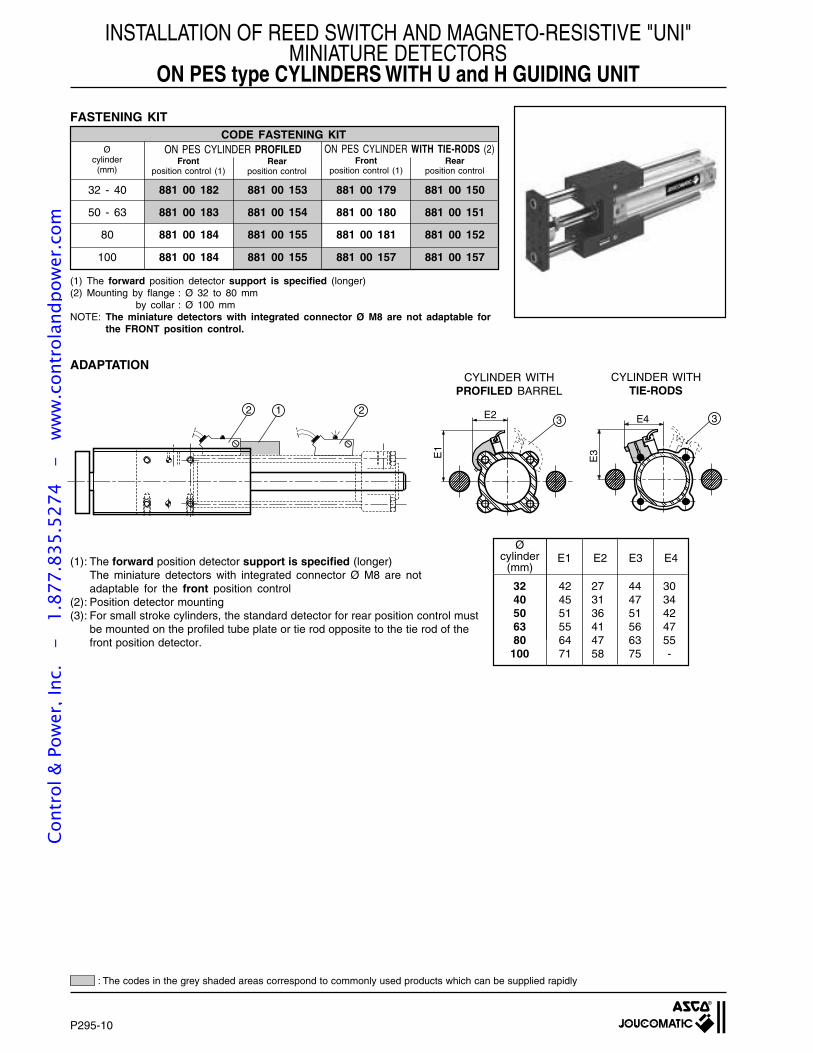
P295-10
INSTALLATION OF REED SWITCH AND MAGNETO-RESISTIVE "UNI"MINIATURE DETECTORS
ON PES type CYLINDERS WITH U and H GUIDING UNIT
FASTENING KITCODE FASTENING KIT
ON PES CYLINDER PROFILED ON PES CYLINDER WITH TIE-RODS (2)
(1) The forward position detector support is specified (longer)(2) Mounting by flange : Ø 32 to 80 mm
by collar : Ø 100 mmNOTE: The miniature detectors with integrated connector Ø M8 are not adaptable for
the FRONT position control.
Øcylinder
(mm)Rear
position controlFront
position control (1)Rear
position controlFront
position control (1)
32 - 40 881 00 182 881 00 153 881 00 179 881 00 150
50 - 63 881 00 183 881 00 154 881 00 180 881 00 151
80 881 00 184 881 00 155 881 00 181 881 00 152
100 881 00 184 881 00 155 881 00 157 881 00 157
2
E3
E4
E1
E2
213 3
ADAPTATION
32 42 27 44 3040 45 31 47 3450 51 36 51 4263 55 41 56 4780 64 47 63 55
100 71 58 75 -
Øcylinder
(mm)E1 E2 E3 E4(1): The forward position detector support is specified (longer)
The miniature detectors with integrated connector Ø M8 are notadaptable for the front position control
(2): Position detector mounting(3): For small stroke cylinders, the standard detector for rear position control must
be mounted on the profiled tube plate or tie rod opposite to the tie rod of thefront position detector.
CYLINDER WITHTIE-RODS
CYLINDER WITHPROFILED BARREL
: The codes in the grey shaded areas correspond to commonly used products which can be supplied rapidly
Cont
rol &
Pow
er, I
nc.
-
1.87
7.83
5.52
74
- w
ww
.con
trol
andp
ower
.com
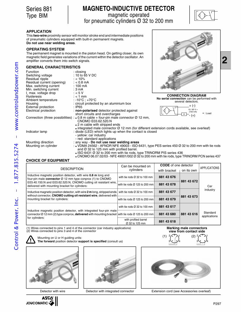
2
Marking male connectorsview from contact side
CODE of one detector
Type BIMMAGNETO-INDUCTIVE DETECTOR
magnetic operatedfor pneumatic cylinders Ø 32 to 200 mm
APPLICATIONThis two-wire proximity sensor will monitor stroke end and intermediate positionsof pneumatic cylinders equipped with built-in permanent magnets.Do not use near welding areas.
OPERATING SYSTEMThe permanent magnet is mounted in the piston head. On getting closer, its ownmagnetic field generates variations of the current within the detector oscillator. Anamplifier converts them into switch signals.
Series 881
CONNECTION DIAGRAMNo serial connection can be performed with
several detectors.
10 / 65 V =(100 mA)
Carindustry
881 43 672
881 43 616
881 43 673
Standardapplications
DESCRIPTION
with tie rods Ø 32 to 100 mm 881 43 676
with tie rods Ø 125 to 200 mm 881 43 678
with tie rods Ø 32 to 100 mm 881 43 677
with tie rods Ø 125 to 200 mm 881 43 679
with tie rods Ø 32 to 100 mm 881 43 617
with tie rods Ø 125 to 200 mm 881 43 680
881 43 618
CHOICE OF EQUIPMENT
Extension cord (see Accessories overleaf)Detector with integrated connectorDetector with wire
GENERAL CHARACTERISTICS
- (+)
+ (-)
APPLICATIONS
Inductive magnetic position detector, with wire 0.8 m long andfour-pin male connector Ø 12 mm type conprox (1) to CNOMOE03.40.150.N and E03.62.520.N, CNOMO cutting oil resistant wire,delivered with mounting bracket for cylinders:
Inductive magnetic position detector, with wire 2 m long, stripped endswithout connector, CNOMO cutting oil resistant wire, delivered withmounting bracket for cylinders:
Inductive magnetic position detector, with integrated four-pin maleconnector Ø 12 mm (2) type conprox, delivered with mounting bracketfor cylinders:
with profiled barrelØ 32 to 125 mm
Can be mounted oncylinders with bracket on its own
12
3 4
12
3 4
(2)(1)
(1) Wires connected to pins 1 and 4 of the connector (car industry applications)(2) Wires connected to pins 3 and 4 of the connector
: Load
P297
Function : closingSwitching voltage : 10 to 65 V DCResidual ripple : < 10%Residual current (opening) : < 0.8 mAMax. switching current : 100 mAMin. switching current : 3 mAIL max. voltage drop : < 5 VHysteresis : < 1 mmAmbient temperature : -10°C ; +70°CHousing : circuit protected by an aluminium boxExternal protection : IP65Electrical protection : non-polarised detector protected against
short circuits and overchargesConnection (three possibilities) : 0.8 m cable + four-pin male connector Ø 12 mm,
CNOMO E03.62.520.N 2 m cable with stripped ends integrated male connector Ø 12 mm (for different extension cords available, see overleaf)
Indicator lamp : diode (LED) which lights up when the contact is closed - yellow: car industry
- red: standard applicationsMounting direction : any way - Do not use near welding areasMounting on cylinder : VDMA 24562 - AFNOR NFE 49003 - ISO 6431, type PES series 450 Ø 32 to 200 mm with tie rods
and Ø 32 to 125 mm with profiled barrel. ISO 6431 Ø 32 to 200 mm with tie rods, type TRINORM PIS series 436 CNOMO 06.07.02/03 - NFE 49001/002 Ø 32 to 200 mm with tie rods, type TRINORM PCN series 437
!Mounting on U or H guiding units:The forward position detector support is specified (consult us)
Cont
rol &
Pow
er, I
nc.
-
1.87
7.83
5.52
74
- w
ww
.con
trol
andp
ower
.com
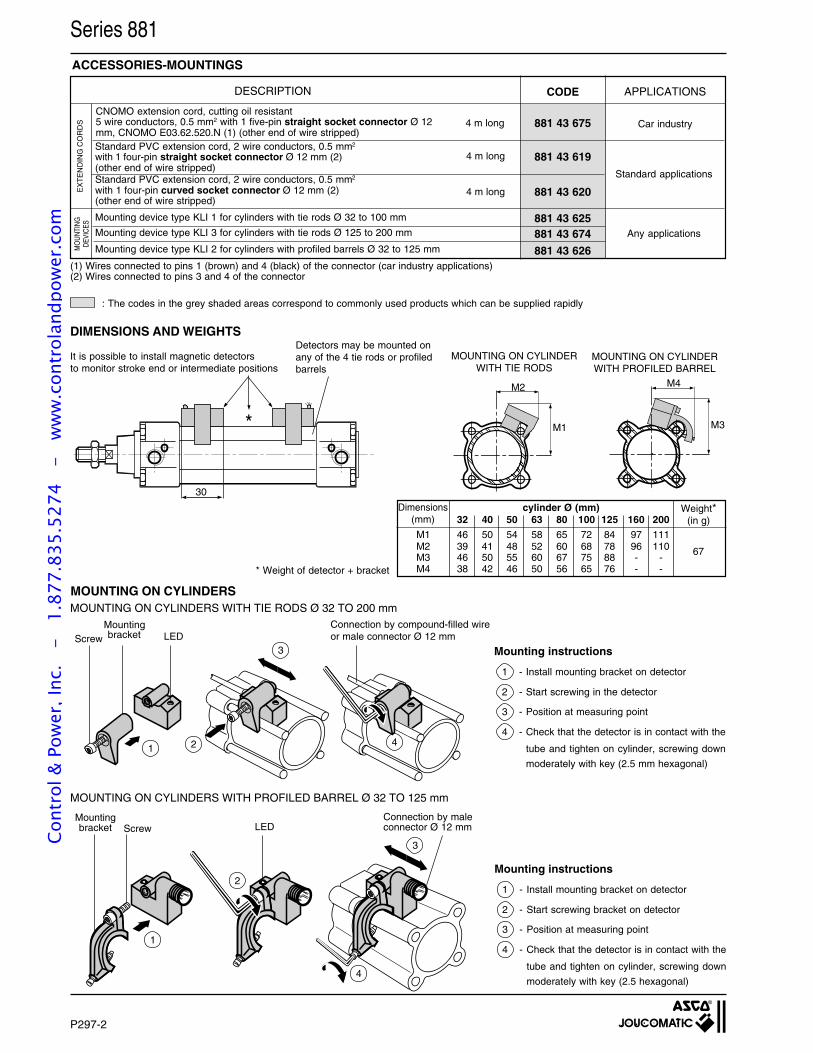
Series 881
(1) Wires connected to pins 1 (brown) and 4 (black) of the connector (car industry applications)(2) Wires connected to pins 3 and 4 of the connector
Standard PVC extension cord, 2 wire conductors, 0.5 mm2
with 1 four-pin straight socket connector Ø 12 mm (2)(other end of wire stripped)Standard PVC extension cord, 2 wire conductors, 0.5 mm2
with 1 four-pin curved socket connector Ø 12 mm (2)(other end of wire stripped)
Mounting device type KLI 1 for cylinders with tie rods Ø 32 to 100 mm
881 43 675
881 43 619
881 43 620
Car industry
Standard applications
EX
TE
ND
ING
CO
RD
SM
OU
NTI
NG
DEV
ICES
Mounting device type KLI 2 for cylinders with profiled barrels Ø 32 to 125 mm
Mounting device type KLI 3 for cylinders with tie rods Ø 125 to 200 mm Any applications
ACCESSORIES-MOUNTINGS
881 43 674881 43 625
881 43 626
DESCRIPTION
4 m long
4 m long
4 m long
CODE APPLICATIONS
CNOMO extension cord, cutting oil resistant5 wire conductors, 0.5 mm2 with 1 five-pin straight socket connector Ø 12mm, CNOMO E03.62.520.N (1) (other end of wire stripped)
P297-2
MOUNTING ON CYLINDERS WITH PROFILED BARREL Ø 32 TO 125 mm
14
3LED
Connection by compound-filled wireor male connector Ø 12 mm
Mounting instructions
1 - Install mounting bracket on detector
2 - Start screwing bracket on detector
3 - Position at measuring point
4 - Check that the detector is in contact with the
tube and tighten on cylinder, screwing down
moderately with key (2.5 hexagonal)
Mounting instructions
1 - Install mounting bracket on detector
2 - Start screwing in the detector
3 - Position at measuring point
4 - Check that the detector is in contact with the
tube and tighten on cylinder, screwing down
moderately with key (2.5 mm hexagonal)
LEDConnection by maleconnector Ø 12 mm
3
4
2
1
MOUNTING ON CYLINDERS
2
ScrewMountingbracket
Mountingbracket Screw
MOUNTING ON CYLINDERS WITH TIE RODS Ø 32 TO 200 mm
32 40 50 63 80 100 125 160 200
M1 46 50 54 58 65 72 84 97 111M2 39 41 48 52 60 68 78 96 110M3 46 50 55 60 67 75 88 - -M4 38 42 46 50 56 65 76 - -
67
* Weight of detector + bracket
Dimensions(mm)
cylinder Ø (mm) Weight*(in g)
*
30
M4M2
M3M1
Detectors may be mounted onany of the 4 tie rods or profiledbarrels
It is possible to install magnetic detectorsto monitor stroke end or intermediate positions
MOUNTING ON CYLINDERWITH TIE RODS
MOUNTING ON CYLINDERWITH PROFILED BARREL
DIMENSIONS AND WEIGHTS
: The codes in the grey shaded areas correspond to commonly used products which can be supplied rapidly
Cont
rol &
Pow
er, I
nc.
-
1.87
7.83
5.52
74
- w
ww
.con
trol
andp
ower
.com