ORDERING INFORMATION
82
Phone: +370-5-2651474 Fax: +370-5-2651483 1 Brackets & Rails 2 Base Mounts & Accessories 3 Optical Mounts 4 Optical Positioners 5 Base Positioners 6 Translation & Rotation Stages 7 Fine Adjustment Screws 9 Opto- Mechanics & Sets 10 Optical Tables Light Test & Measurement Instruments Lasers & Laser Accessories 11 12 e-mail: [email protected] www.standa.lt 8-1 Motorized Positioners & Controllers Motorised Positioners & Controllers 8 ORDERING INFORMATION for Motorized Translation and Rotation stages Continued on next page DEFAULT CHOICE Default choice for ordering motorized translation or rotation stages is with damper RD1. When damper RD is used, vibrations and motor noise is greatly reduced, settling time is improved and system resonances are suppressed. Example: 8MT175‑100 - translation stage 8MT175‑100 with damper RD1. 8MR190‑2‑28 - rotation stage 8MR190‑2‑28 with damper RD1. REVOLUTION SENSOR Revolution sensor counts stepper motor axis revolutions. It consists of Codewheel with one mark and Optointerrupter. When motor is connected to Standa controller 8SMC1‑USBhF, signal from revolution sensor allows monitoring of motor axis revolutions, possible loss of steps and detecting motor stalling. It is not as accurate as encoder, which provides feedback for each step of motor. Revolution sensor determines whether there was any loss of steps within one revolution of motor axis. This information is reported to the controller and corrective actions can be taken. Revolution sensor can also be used for precise home position setting. For ordering motorized stages with revolution sensor, please add symbols E4 to the code of motorized stages. Example: 8MT175‑100‑E4 - translation stage 8MT175‑100 with revolution sensor E4. 8MR190‑2‑28‑E4 - rotation stage 8MR190‑2‑28 with revolution sensor E4.
-
Upload
khangminh22 -
Category
Documents
-
view
0 -
download
0
Transcript of ORDERING INFORMATION
Phone: +370-5-2651474
Fax: +370-5-2651483
1Br
acke
ts
& R
ails
2
Base
M
ount
s &
A
cces
sori
es3
Opt
ical
M
ount
s4
Opt
ical
Po
siti
oner
s5
Base
Po
siti
oner
s6
Tran
slat
ion
&
Rota
tion
St
ages
7
Mot
oris
ed
Posi
tion
ers
&
Con
trol
lers
8
Fine
A
djus
tmen
t Sc
rew
s9
Opt
o-
Mec
hani
cs &
Se
ts10
Opt
ical
Ta
bles
Ligh
t Te
st &
M
easu
rem
ent
Inst
rum
ents
Lase
rs &
La
ser
Acc
esso
ries
11
12e-m
ail: [email protected] w
ww
.standa.lt
8-1
Motorized Positioners & ControllersM
otor
ised
Po
siti
oner
s &
C
ontr
olle
rs8
ORDERING INFORMATIONfor Motorized Translation and Rotation stages
Continued on next page
DEFAULT CHOICE
Default choice for ordering motorized translation or rotation stages is with damper RD1. When damper RD is used, vibrations and motor noise is greatly reduced, settling time is improved and system resonances are suppressed.
Example:8MT175‑100 - translation stage 8MT175‑100 with damper RD1.8MR190‑2‑28 - rotation stage 8MR190‑2‑28 with damper RD1.
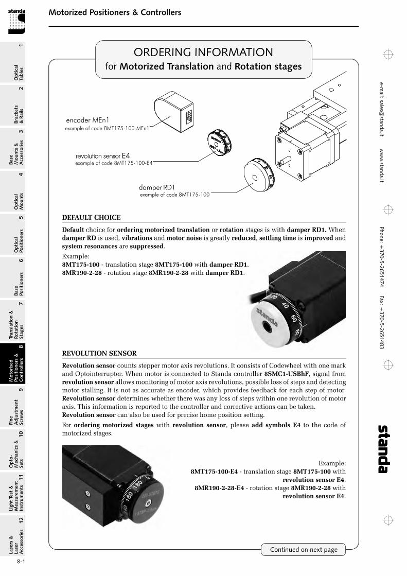
REVOLUTION SENSOR
Revolution sensor counts stepper motor axis revolutions. It consists of Codewheel with one mark and optointerrupter. When motor is connected to Standa controller 8SMC1‑USBhF, signal from revolution sensor allows monitoring of motor axis revolutions, possible loss of steps and detecting motor stalling. It is not as accurate as encoder, which provides feedback for each step of motor. Revolution sensor determines whether there was any loss of steps within one revolution of motor axis. This information is reported to the controller and corrective actions can be taken.Revolution sensor can also be used for precise home position setting.
For ordering motorized stages with revolution sensor, please add symbols E4 to the code of motorized stages.
Example:8MT175‑100‑E4 - translation stage 8MT175‑100 with
revolution sensor E4.8MR190‑2‑28‑E4 - rotation stage 8MR190‑2‑28 with
revolution sensor E4.
Phon
e: +
370-
5-26
5147
4 Fa
x: +
370-
5-26
5148
31
Brackets &
Rails
2
Base M
ounts &
Accessories
3O
ptical M
ounts4
Optical
Positioners5
Base Positioners
6
Translation &
Rotation Stages
7
Motorised
Positioners &
Controllers
8
Fine A
djustment
Screws
9
Opto-
Mechanics &
Sets
10O
ptical Tables
Light Test &
Measurem
ent Instrum
ents
Lasers &
Laser A
ccessories 11
12e-
mai
l: sa
les@
stan
da.lt
ww
w.s
tand
a.lt
8-2
Motorized Positioners & ControllersM
otorised Positioners &
C
ontrollers8
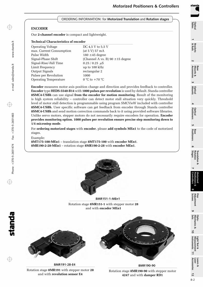
Technical Characteristics of encoder
operating Voltage DC 4,5 V to 5,5 Vmax. Current Consumption (at 5 V) 57 mAPulse Width 180 ±45 degreeSignal-Phase Shift (Channel A vs. B) 90 ±15 degreeSignal-rise/-Fall Time 0.25 / 0.25 µSLimit Frequency up to 100 kHzoutput Signals rectangular 2Pulses per revolution 1000operating Temperature 0 °C to +70 °C
Encoder measures motor axis position change and direction and provides feedback to controller. Encoder type HEDS‑5540‑B14 with 1000 pulses per revolution is used by default. Standa controller 8SMC4‑USBh can use signal from the encoder for motion monitoring. result of the monitoring is high system reliability – controller can detect motor stall situation very quickly. Threshold level of motor stall detection is programmable using program SMCVieW included with controller 8SMC4‑USBh. User specific software can get feedback from encoder through Standa controller 8SMC4‑USBh and send motion correction commands back to it using provided software libraries.Unlike servo motors, stepper motors do not necessarily require encoders for operation. Encoder provides monitoring option. 1000 pulses per revolution ensure precise step monitoring down to 1/4 microstep mode.
For ordering motorized stages with encoder, please add symbols MEn1 to the code of motorized stages.
Example:8MT175‑100‑MEn1 – translation stage 8MT175‑100 with encoder MEn1.8MR190‑2‑28‑MEn1 – rotation stage 8MR190‑2‑28 with encoder MEn1.
ENCODER
our 2‑channel encoder is compact and lightweight.
ORDERING INFORMATION: for Motorized Translation and Rotation stages
8MR191-28-E4
rotation stage 8MR191 with stepper motor 28 and with revolution sensor E4
8MR151-1-MEn1
rotation stage 8MR151‑1 with stepper motor 28 and with encoder MEn1
8MR190-90
rotation stage 8MR190‑90 with stepper motor 4247 and with damper RD1
Phone: +370-5-2651474
Fax: +370-5-2651483
1Br
acke
ts
& R
ails
2
Base
M
ount
s &
A
cces
sori
es3
Opt
ical
M
ount
s4
Opt
ical
Po
siti
oner
s5
Base
Po
siti
oner
s6
Tran
slat
ion
&
Rota
tion
St
ages
7
Mot
oris
ed
Posi
tion
ers
&
Con
trol
lers
8
Fine
A
djus
tmen
t Sc
rew
s9
Opt
o-
Mec
hani
cs &
Se
ts10
Opt
ical
Ta
bles
Ligh
t Te
st &
M
easu
rem
ent
Inst
rum
ents
Lase
rs &
La
ser
Acc
esso
ries
11
12e-m
ail: [email protected] w
ww
.standa.lt
8-3
Motorized Positioners & ControllersM
otor
ised
Po
siti
oner
s &
C
ontr
olle
rs8
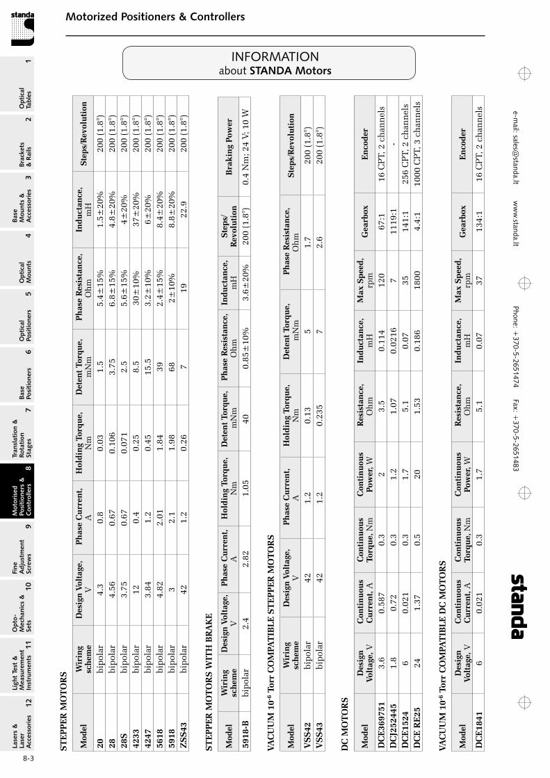
INFORMATIONabout STANDA Motors
ST
EP
PE
R M
OT
OR
S
Mod
elW
irin
g
sch
eme
Des
ign
Vol
tage
, V
Ph
ase
Cu
rren
t,
AH
old
ing
Torq
ue,
N
m
Det
ent
Torq
ue,
m
Nm
Ph
ase
Res
ista
nce
, o
hm
Ind
uct
ance
, m
HS
tep
s/R
evol
uti
on
20bi
pol
ar4.
30.
80.
031.
55.
4±15
%1.
5±20
%20
0 (1
.8°)
28bi
pol
ar4.
560.
670.
106
3.75
6.8±
15%
4.8±
20%
200
(1.8
°)28
Sbi
pol
ar3.
750.
670.
071
2.5
5.6±
15%
4±20
%20
0 (1
.8°)
4233
bip
olar
120.
40.
258.
530
±10
%37
±20
%20
0 (1
.8°)
4247
bip
olar
3.84
1.2
0.45
15.5
3.2±
10%
6±20
%20
0 (1
.8°)
5618
bip
olar
4.82
2.01
1.84
392.
4±15
%8.
4±20
%20
0 (1
.8°)
5918
bip
olar
32.
11.
9868
2±10
%8.
8±20
%20
0 (1
.8°)
ZS
S43
bip
olar
421.
20.
267
1922
.920
0 (1
.8°)
DC
MO
TO
RS
Mod
elD
esig
n
Volt
age,
V C
onti
nu
ous
Cu
rren
t, A
Con
tin
uou
s To
rqu
e, N
m
Con
tin
uou
s Po
wer
, W R
esis
tan
ce,
oh
mIn
du
ctan
ce,
mH
Max
Sp
eed
, rp
mG
earb
oxE
nco
der
DC
E36
9751
3.6
0.58
70.
32
3.5
0.11
412
067
:116
CP
T, 2
ch
ann
els
DC
J252
445
1.8
0.72
0.3
1.2
1.07
0.02
167
1119
:1-
DC
E15
246
0.02
10.
31.
75.
10.
0735
141:
125
6 C
PT,
2 c
han
nel
sD
CE
RE
2524
1.37
0.5
201.
530.
186
1800
4.4:
110
00 C
PT,
3 c
han
nel
s
VA
CU
UM
10‑
6 To
rr C
OM
PAT
IBL
E D
C M
OT
OR
S
Mod
elD
esig
n
Volt
age,
V C
onti
nu
ous
Cu
rren
t, A
Con
tin
uou
s To
rqu
e, N
m
Con
tin
uou
s Po
wer
, W R
esis
tan
ce,
oh
mIn
du
ctan
ce,
mH
Max
Sp
eed
, rp
mG
earb
oxE
nco
der
DC
E18
416
0.02
10.
31.
75.
10.
0737
134:
116
CP
T, 2
ch
ann
els
VA
CU
UM
10‑
6 To
rr C
OM
PAT
IBL
E S
TE
PP
ER
MO
TO
RS
Mod
elW
irin
g
sch
eme
Des
ign
Vol
tage
, V
Ph
ase
Cu
rren
t,
AH
old
ing
Torq
ue,
N
m
Det
ent
Torq
ue,
mN
m P
has
e R
esis
tan
ce,
oh
mS
tep
s/R
evol
uti
on
VS
S42
bip
olar
421.
20.
135
1.7
200
(1.8
°)V
SS
43bi
pol
ar42
1.2
0.23
57
2.6
200
(1.8
°)
ST
EP
PE
R M
OT
OR
S W
ITH
BR
AK
E
Mod
elW
irin
g
sch
eme
Des
ign
Vol
tage
, V
Ph
ase
Cu
rren
t,
AH
old
ing
Torq
ue,
N
m
Det
ent
Torq
ue,
mN
m P
has
e R
esis
tan
ce,
oh
mIn
du
ctan
ce,
mH
Ste
ps/
Rev
olu
tion
B
rak
ing
Pow
er
5918
‑Bbi
pol
ar2.
42.
821.
0540
0.85
±10
%3.
6±20
%20
0 (1
.8°)
0.4
Nm
; 24
V; 1
0 W
Phon
e: +
370-
5-26
5147
4 Fa
x: +
370-
5-26
5148
31
Brackets &
Rails
2
Base M
ounts &
Accessories
3O
ptical M
ounts4
Optical
Positioners5
Base Positioners
6
Translation &
Rotation Stages
7
Motorised
Positioners &
Controllers
8
Fine A
djustment
Screws
9
Opto-
Mechanics &
Sets
10O
ptical Tables
Light Test &
Measurem
ent Instrum
ents
Lasers &
Laser A
ccessories 11
12e-
mai
l: sa
les@
stan
da.lt
ww
w.s
tand
a.lt
8-4
Motorized Positioners & ControllersM
otorised Positioners &
C
ontrollers8
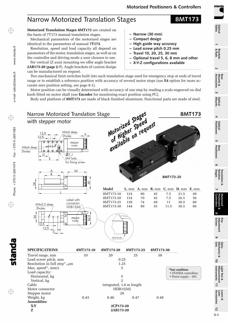
Narrow Motorized Translation Stages
SPECIFICATIONS 8MT173‑10 8MT173‑20 8MT173‑25 8MT173‑30Travel range, mm 10 20 25 30Lead screw pitch, mm 0.25resolution in full step*, µm 1.25Max. speed*, mm/s 5Load capacity:
Horizontal, kg 5Vertical, kg 2
Cable integrated, 1.6 m lengthMotor connector HDB15(M)Stepper motor 28Weight, kg 0.43 0.46 0.47 0.48Assemblies:
X‑Y 2CP173‑20 Z 2AB173‑20
8MT173-20
Motorized Translation Stages 8MT173 are created on the basis of 7T173 manual translation stages.
Mechanical parameters of the motorized stages are identical to the parameters of manual 7T173.
resolution, speed and load capacity all depend on parameters of the motor, translation stages, as well as on the controller and driving mode a user chooses to use.
For vertical (Z axis) mounting we offer angle bracket 2AB173‑20 (page 2‑7). Angle brackets of custom design can be manufactured on request.
8MT173
Model L, mm A, mm B, mm C, mm D, mm E, mm8MT173-10 124 60 45 7.5 21.5 498MT173-20 134 70 45 7.5 26.5 568MT173-25 138 74 49 11 30.5 608MT173-30 144 80 55 11.5 36.5 66
Narrow Motorized Translation Stage 8MT173with stepper motor
– Narrow (30 mm)– Compact design– High guide way accuracy– Lead screw pitch 0.25 mm– Travel 10, 20, 25, 30 mm– Optional travel 5, 6, 8 mm and other– X-Y-Z configurations available
Two mechanical limit switches built into each translation stage used for emergency stop at ends of travel range or to establish a reference position with accuracy of several motor steps (use E4 option for more ac-curate zero position setting, see page 8-1).
Motor position can be visually determined with accuracy of one step by reading a scale engraved on dial knob fitted on motor shaft (use Encoder for monitoring exact position using PC).
Body and platform of 8MT173 are made of black finished aluminum. Functional parts are made of steel.
Motorized
Stages
of highe
r Speed
availab
le on re
quest
*Test condition: • STANDA controllers;• Power supply – 36V.
Phone: +370-5-2651474
Fax: +370-5-2651483
1Br
acke
ts
& R
ails
2
Base
M
ount
s &
A
cces
sori
es3
Opt
ical
M
ount
s4
Opt
ical
Po
siti
oner
s5
Base
Po
siti
oner
s6
Tran
slat
ion
&
Rota
tion
St
ages
7
Mot
oris
ed
Posi
tion
ers
&
Con
trol
lers
8
Fine
A
djus
tmen
t Sc
rew
s9
Opt
o-
Mec
hani
cs &
Se
ts10
Opt
ical
Ta
bles
Ligh
t Te
st &
M
easu
rem
ent
Inst
rum
ents
Lase
rs &
La
ser
Acc
esso
ries
11
12e-m
ail: [email protected] w
ww
.standa.lt
8-5
Motorized Positioners & ControllersM
otor
ised
Po
siti
oner
s &
C
ontr
olle
rs8
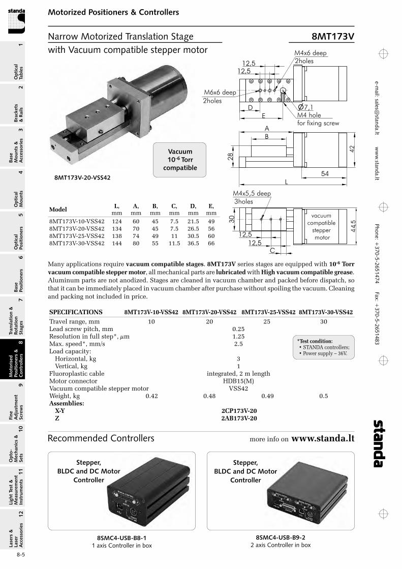
8MT173V-20-VSS42
SPECIFICATIONS 8MT173V‑10‑VSS42 8MT173V‑20‑VSS42 8MT173V‑25‑VSS42 8MT173V‑30‑VSS42Travel range, mm 10 20 25 30Lead screw pitch, mm 0.25resolution in full step*, µm 1.25Max. speed*, mm/s 2.5Load capacity:
Horizontal, kg 3Vertical, kg 1
Fluoroplastic cable integrated, 2 m lengthMotor connector HDB15(M)Vacuum compatible stepper motor VSS42Weight, kg 0.42 0.48 0.49 0.5Assemblies:
X‑Y 2CP173V‑20 Z 2AB173V‑20
with Vacuum compatible stepper motor
Vacuum10-6 Torr
compatible
Recommended Controllers more info on www.standa.lt
Many applications require vacuum compatible stages. 8MT173V series stages are equipped with 10‑6 Torr vacuum compatible stepper motor, all mechanical parts are lubricated with High vacuum compatible grease. Aluminum parts are not anodized. Stages are cleaned in vacuum chamber and packed before dispatch, so that it can be immediately placed in vacuum chamber after purchase without spoiling the vacuum. Cleaning and packing not included in price.
Narrow Motorized Translation Stage 8MT173V
*Test condition: • STANDA controllers;• Power supply – 36V.
Model L, mm
A, mm
B, mm
C, mm
D, mm
E, mm
8MT173V-10-VSS42 124 60 45 7.5 21.5 498MT173V-20-VSS42 134 70 45 7.5 26.5 568MT173V-25-VSS42 138 74 49 11 30.5 608MT173V-30-VSS42 144 80 55 11.5 36.5 66
8SMC4-USB-B8-11 axis Controller in box
Stepper, BLDC and DC Motor
Controller
8SMC4-USB-B9-22 axis Controller in box
Stepper, BLDC and DC Motor
Controller
Phon
e: +
370-
5-26
5147
4 Fa
x: +
370-
5-26
5148
31
Brackets &
Rails
2
Base M
ounts &
Accessories
3O
ptical M
ounts4
Optical
Positioners5
Base Positioners
6
Translation &
Rotation Stages
7
Motorised
Positioners &
Controllers
8
Fine A
djustment
Screws
9
Opto-
Mechanics &
Sets
10O
ptical Tables
Light Test &
Measurem
ent Instrum
ents
Lasers &
Laser A
ccessories 11
12e-
mai
l: sa
les@
stan
da.lt
ww
w.s
tand
a.lt
8-6
Motorized Positioners & ControllersM
otorised Positioners &
C
ontrollers8
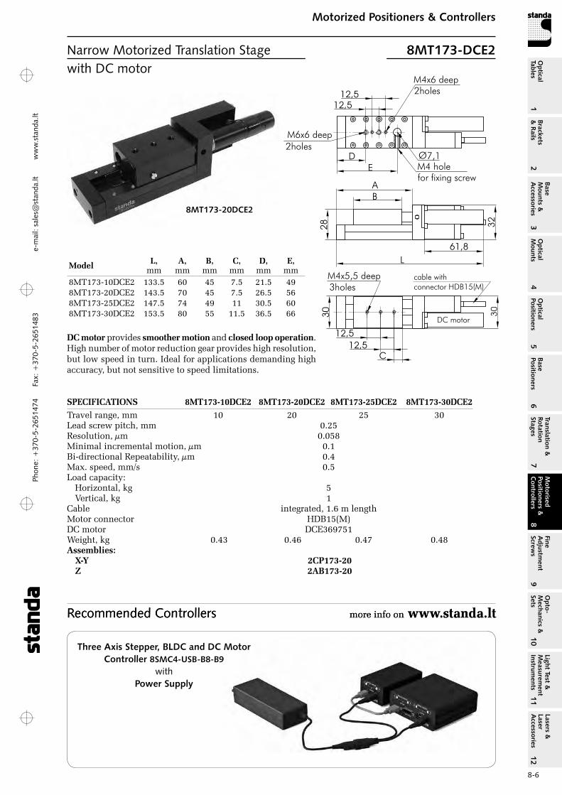
8MT173-20DCE2
SPECIFICATIONS 8MT173‑10DCE2 8MT173‑20DCE2 8MT173‑25DCE2 8MT173‑30DCE2Travel range, mm 10 20 25 30Lead screw pitch, mm 0.25resolution, µm 0.058Minimal incremental motion, µm 0.1Bi-directional repeatability, µm 0.4Max. speed, mm/s 0.5Load capacity:
Horizontal, kg 5Vertical, kg 1
Cable integrated, 1.6 m lengthMotor connector HDB15(M)DC motor DCE369751Weight, kg 0.43 0.46 0.47 0.48Assemblies:
X‑Y 2CP173‑20 Z 2AB173‑20
with DC motor
Model L, mm
A, mm
B, mm
C, mm
D, mm
E, mm
8MT173-10DCE2 133.5 60 45 7.5 21.5 498MT173-20DCE2 143.5 70 45 7.5 26.5 568MT173-25DCE2 147.5 74 49 11 30.5 608MT173-30DCE2 153.5 80 55 11.5 36.5 66
DC motor provides smoother motion and closed loop operation. High number of motor reduction gear provides high resolution, but low speed in turn. Ideal for applications demanding high accuracy, but not sensitive to speed limitations.
Narrow Motorized Translation Stage 8MT173-DCE2
C
12,5
12,5
M4x5,5 deep3holes
30
D
12,5
12,5
E
Ø7,1M4 holefor fixing screw
M4x6 deep2holes
M6x6 deep
2holes
A
28
B
L
61,8
Recommended Controllers more info on www.standa.lt Recommended Controllers more info on www.standa.lt
Three Axis Stepper, BLDC and DC MotorController 8SMC4-USB-B8-B9
with Power Supply
Phone: +370-5-2651474
Fax: +370-5-2651483
1Br
acke
ts
& R
ails
2
Base
M
ount
s &
A
cces
sori
es3
Opt
ical
M
ount
s4
Opt
ical
Po
siti
oner
s5
Base
Po
siti
oner
s6
Tran
slat
ion
&
Rota
tion
St
ages
7
Mot
oris
ed
Posi
tion
ers
&
Con
trol
lers
8
Fine
A
djus
tmen
t Sc
rew
s9
Opt
o-
Mec
hani
cs &
Se
ts10
Opt
ical
Ta
bles
Ligh
t Te
st &
M
easu
rem
ent
Inst
rum
ents
Lase
rs &
La
ser
Acc
esso
ries
11
12e-m
ail: [email protected] w
ww
.standa.lt
8-7
Motorized Positioners & ControllersM
otor
ised
Po
siti
oner
s &
C
ontr
olle
rs8
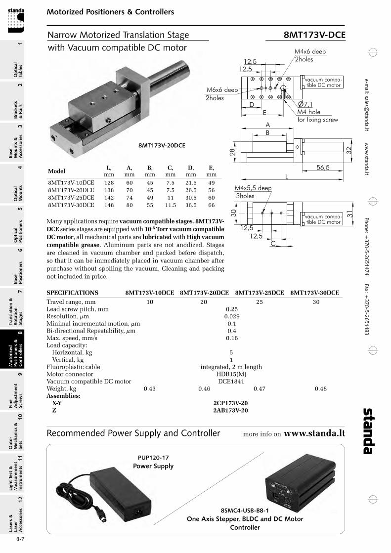
8MT173V-20DCE
with Vacuum compatible DC motor
SPECIFICATIONS 8MT173V‑10DCE 8MT173V‑20DCE 8MT173V‑25DCE 8MT173V‑30DCETravel range, mm 10 20 25 30 Lead screw pitch, mm 0.25resolution, µm 0.029Minimal incremental motion, µm 0.1Bi-directional repeatability, µm 0.4Max. speed, mm/s 0.16Load capacity:
Horizontal, kg 5Vertical, kg 1
Fluoroplastic cable integrated, 2 m lengthMotor connector HDB15(M)Vacuum compatible DC motor DCE1841Weight, kg 0.43 0.46 0.47 0.48Assemblies:
X‑Y 2CP173V‑20 Z 2AB173V‑20
C
12,5
12,5
M4x5,5 deep3holes
30
D
12,5
12,5
E
�7,1M4 holefor fixing screw
M4x6 deep2holes
M6x6 deep
2holes
A
28
B
L
56,5Model L, mm
A, mm
B, mm
C, mm
D, mm
E, mm
8MT173V-10DCE 128 60 45 7.5 21.5 498MT173V-20DCE 138 70 45 7.5 26.5 568MT173V-25DCE 142 74 49 11 30.5 608MT173V-30DCE 148 80 55 11.5 36.5 66
Many applications require vacuum compatible stages. 8MT173V‑DCE series stages are equipped with 10‑6 Torr vacuum compatible DC motor, all mechanical parts are lubricated with High vacuum compatible grease. Aluminum parts are not anodized. Stages are cleaned in vacuum chamber and packed before dispatch, so that it can be immediately placed in vacuum chamber after purchase without spoiling the vacuum. Cleaning and packing not included in price.
Narrow Motorized Translation Stage 8MT173V-DCE
Recommended Power Supply and Controller more info on www.standa.lt
PUP120-17Power Supply
8SMC4-USB-B8-1 One Axis Stepper, BLDC and DC Motor
Controller
Phon
e: +
370-
5-26
5147
4 Fa
x: +
370-
5-26
5148
31
Brackets &
Rails
2
Base M
ounts &
Accessories
3O
ptical M
ounts4
Optical
Positioners5
Base Positioners
6
Translation &
Rotation Stages
7
Motorised
Positioners &
Controllers
8
Fine A
djustment
Screws
9
Opto-
Mechanics &
Sets
10O
ptical Tables
Light Test &
Measurem
ent Instrum
ents
Lasers &
Laser A
ccessories 11
12e-
mai
l: sa
les@
stan
da.lt
ww
w.s
tand
a.lt
8-8
Motorized Positioners & ControllersM
otorised Positioners &
C
ontrollers8
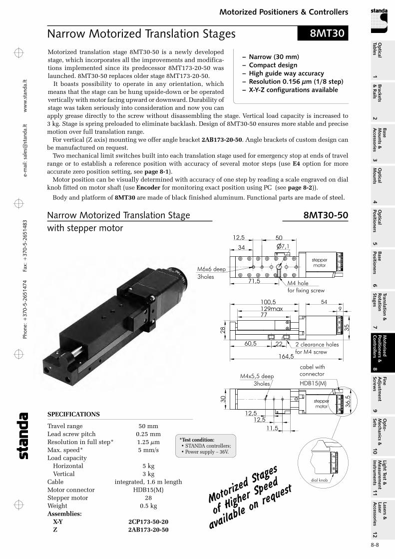
Narrow Motorized Translation Stage 8MT30-50with stepper motor
Narrow Motorized Translation Stages 8MT30
SPECIFICATIONS
Travel range 50 mmLead screw pitch 0.25 mmresolution in full step* 1.25 µm Max. speed* 5 mm/sLoad capacity
Horizontal 5 kg Vertical 3 kg
Cable integrated, 1.6 m lengthMotor connector HDB15(M)Stepper motor 28Weight 0.5 kgAssemblies:
X‑Y 2CP173‑50‑20Z 2AB173‑20‑50
11,5
12,5
12,5
3holes
30
36
,5
164,5
60,5 22
28
77
35
2 clearance holes
for M4 screw
M4x5,5 deep
stepper
motor
54
9
cabel with
HDB15(M)
100,5
71,5
34
12,5 50
�7,1
M4 holefor fixing screw
M6x6 deep
3holes
stepper
motor
129max
connector
Motorized translation stage 8MT30-50 is a newly developed stage, which incorporates all the improvements and modifica-tions implemented since its predecessor 8MT173-20-50 was launched. 8MT30-50 replaces older stage 8MT173-20-50.
It boasts possibility to operate in any orientation, which means that the stage can be hung upside-down or be operated vertically with motor facing upward or downward. Durability of stage was taken seriously into consideration and now you can
– Narrow (30 mm)– Compact design– High guide way accuracy– Resolution 0.156 µm (1/8 step)– X-Y-Z configurations available
Motorized
Stages
of highe
r Speed
available
on requ
est
apply grease directly to the screw without disassembling the stage. Vertical load capacity is increased to 3 kg. Stage is spring preloaded to eliminate backlash. Design of 8MT30-50 ensures more stable and precise motion over full translation range.
For vertical (Z axis) mounting we offer angle bracket 2AB173‑20‑50. Angle brackets of custom design can be manufactured on request.
Two mechanical limit switches built into each translation stage used for emergency stop at ends of travel range or to establish a reference position with accuracy of several motor steps (use E4 option for more accurate zero position setting, see page 8‑1).
Motor position can be visually determined with accuracy of one step by reading a scale engraved on dial knob fitted on motor shaft (use Encoder for monitoring exact position using PC (see page 8‑2)).
Body and platform of 8MT30 are made of black finished aluminum. Functional parts are made of steel.
*Test condition: • STANDA controllers;• Power supply – 36V.

Phone: +370-5-2651474
Fax: +370-5-2651483
1Br
acke
ts
& R
ails
2
Base
M
ount
s &
A
cces
sori
es3
Opt
ical
M
ount
s4
Opt
ical
Po
siti
oner
s5
Base
Po
siti
oner
s6
Tran
slat
ion
&
Rota
tion
St
ages
7
Mot
oris
ed
Posi
tion
ers
&
Con
trol
lers
8
Fine
A
djus
tmen
t Sc
rew
s9
Opt
o-
Mec
hani
cs &
Se
ts10
Opt
ical
Ta
bles
Ligh
t Te
st &
M
easu
rem
ent
Inst
rum
ents
Lase
rs &
La
ser
Acc
esso
ries
11
12e-m
ail: [email protected] w
ww
.standa.lt
8-9
Motorized Positioners & ControllersM
otor
ised
Po
siti
oner
s &
C
ontr
olle
rs8
11,5
12,5
12,5
3holes
30
210
60,5 22
28
77
2 clearance holes
for M4 screw
M4x5,5 deep
100,5
71,5
34
12,5 50
�7,1
M4 holefor fixing screw
M6x6 deep
3holes
129max
41
,13
6
90,5
Narrow Motorized Translation Stage 8MT30V-50-VSS42with Vacuum compatible stepper motor
Narrow Motorized Translation Stage 8MT30-50DCEwith DC motor
SPECIFICATIONS
Travel range 50 mmLead screw pitch 0.25 mmresolution in full step* 1.25 µm Max. speed* 2.5 mm/sLoad capacity
Horizontal 3 kg Vertical 1 kg
Fluoroplastic cable integrated, 2 m lengthMotor connector HDB15(M)Vacuum compatible VSS42 stepper motor Weight 0.55 kgAssemblies:
X‑Y 2CP173V‑50‑20Z 2AB173V‑20‑50
SPECIFICATIONS
Travel range 50 mmLead screw pitch 0.25 mmresolution 0.014 µmMinimal incremental motion 0.1 µmBi-directional repeatability 0.4 µm Max. speed 7 mm/sLoad capacity
Horizontal 5 kg Vertical 1 kg
Cable integrated, 1.6 m lengthMotor connector HDB15(M)DC motor DCE rE25 Weight 0.5 kgAssemblies:
X‑Y 2CP173‑50‑20Z 2AB173‑20‑50
Many applications require vacuum compatible stages. 8MT30V‑50 stage is equipped with 10‑6 Torr vacuum compatible stepper motor, all mechanical parts are lubricated with High vacuum compatible grease. Aluminum parts are not anodized. Stages are
DC motor provides smoother motion and closed loop operation. High number of motor reduction gear provides high resolution, but low speed in turn. Ideal for applications demanding high accuracy but not sensitive to speed limitations.
cleaned in vacuum chamber and packed before dispatch, so that it can be immediately placed in vacuum chamber after purchase without spoiling the vacuum. Cleaning and packing not included in price.
*Test condition: • STANDA controllers;• Power supply – 36V.
11,5
12,5
12,5
3holes3
0
164,5
60,5 22
28
77
2 clearance holes
for M4 screw
M4x5,5 deep
100,5
71,5
34
12,5 50
�7,1
M4 holefor fixing screw
M6x6 deep
3holes
129max
54
11,5
12,5
12,5
3holes3
0
164,5
60,5 22
28
77
2 clearance holes
for M4 screw
M4x5,5 deep
100,5
71,5
34
12,5 50
�7,1
M4 holefor fixing screw
M6x6 deep
3holes
129max
54
8SMC4-USB-B8-11 axis Controller in box
Stepper, BLDC and DC Motor Controller
8SMC4-USB-B9-22 axis Controller in box
Phon
e: +
370-
5-26
5147
4 Fa
x: +
370-
5-26
5148
31
Brackets &
Rails
2
Base M
ounts &
Accessories
3O
ptical M
ounts4
Optical
Positioners5
Base Positioners
6
Translation &
Rotation Stages
7
Motorised
Positioners &
Controllers
8
Fine A
djustment
Screws
9
Opto-
Mechanics &
Sets
10O
ptical Tables
Light Test &
Measurem
ent Instrum
ents
Lasers &
Laser A
ccessories 11
12e-
mai
l: sa
les@
stan
da.lt
ww
w.s
tand
a.lt
8-10
Motorized Positioners & ControllersM
otorised Positioners &
C
ontrollers8
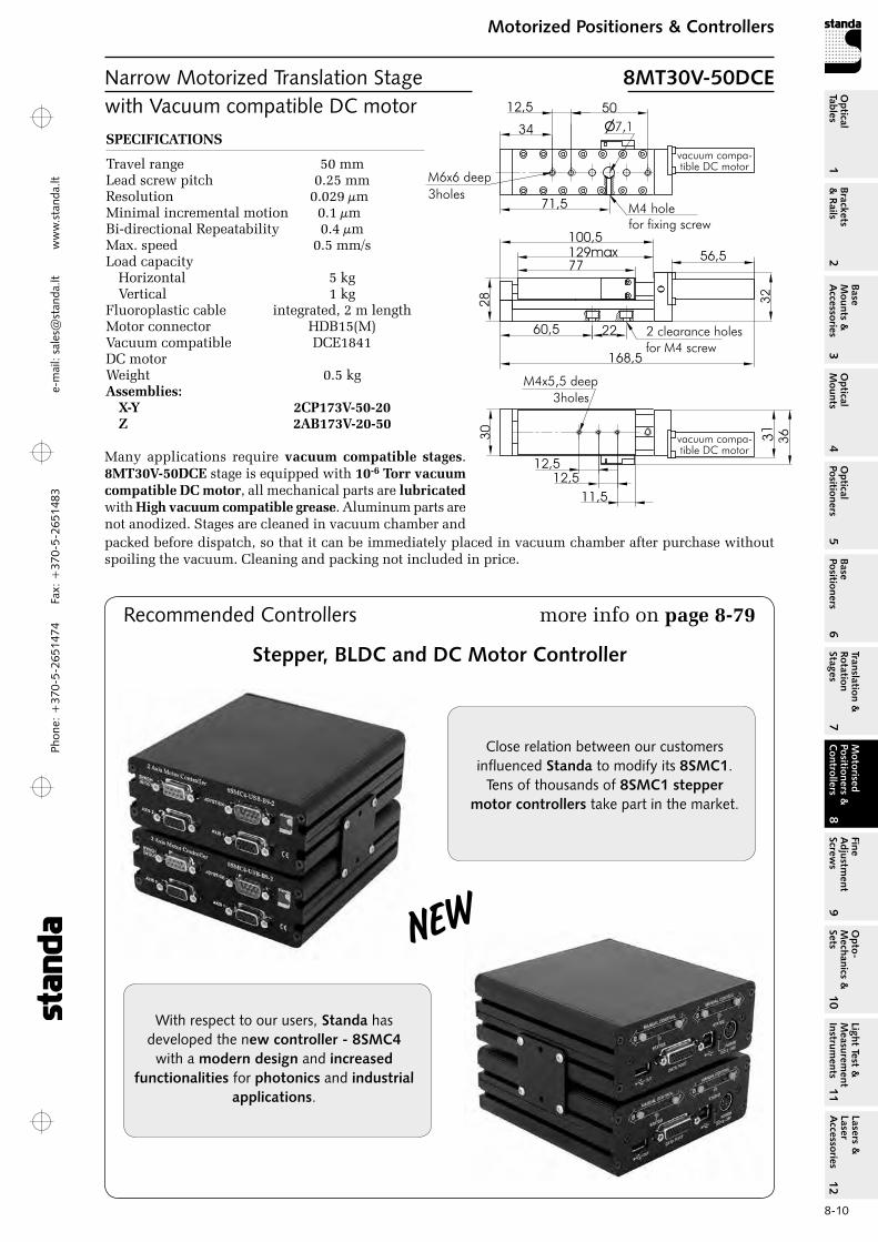
Narrow Motorized Translation Stage 8MT30V-50DCEwith Vacuum compatible DC motor SPECIFICATIONS
Travel range 50 mmLead screw pitch 0.25 mmresolution 0.029 µmMinimal incremental motion 0.1 µmBi-directional repeatability 0.4 µm Max. speed 0.5 mm/sLoad capacity
Horizontal 5 kg Vertical 1 kg
Fluoroplastic cable integrated, 2 m lengthMotor connector HDB15(M)Vacuum compatible DCE1841DC motor Weight 0.5 kgAssemblies:
X‑Y 2CP173V‑50‑20Z 2AB173V‑20‑50
Many applications require vacuum compatible stages. 8MT30V‑50DCE stage is equipped with 10‑6 Torr vacuum compatible DC motor, all mechanical parts are lubricated with High vacuum compatible grease. Aluminum parts are not anodized. Stages are cleaned in vacuum chamber and packed before dispatch, so that it can be immediately placed in vacuum chamber after purchase without spoiling the vacuum. Cleaning and packing not included in price.
11,5
12,5
12,5
3holes
30
168,5
60,5 22
28
77
2 clearance holes
for M4 screw
M4x5,5 deep
100,5
71,5
34
12,5 50
�7,1
M4 holefor fixing screw
M6x6 deep
3holes
129max 56,5
36
11,5
12,5
12,5
3holes
30
168,5
60,5 22
28
77
2 clearance holes
for M4 screw
M4x5,5 deep
100,5
71,5
34
12,5 50
�7,1
M4 holefor fixing screw
M6x6 deep
3holes
129max 56,5
36
11,5
12,5
12,5
3holes
30
168,5
60,5 22
28
77
2 clearance holes
for M4 screw
M4x5,5 deep
100,5
71,5
34
12,5 50
�7,1
M4 holefor fixing screw
M6x6 deep
3holes
129max 56,5
36
more info on page 8‑79
With respect to our users, Standa has developed the new controller - 8SMC4
with a modern design and increased functionalities for photonics and industrial
applications.
Close relation between our customers influenced Standa to modify its 8SMC1.
Tens of thousands of 8SMC1 stepper motor controllers take part in the market.
Recommended Controllers
Stepper, BLDC and DC Motor Controller
New
Phone: +370-5-2651474
Fax: +370-5-2651483
1Br
acke
ts
& R
ails
2
Base
M
ount
s &
A
cces
sori
es3
Opt
ical
M
ount
s4
Opt
ical
Po
siti
oner
s5
Base
Po
siti
oner
s6
Tran
slat
ion
&
Rota
tion
St
ages
7
Mot
oris
ed
Posi
tion
ers
&
Con
trol
lers
8
Fine
A
djus
tmen
t Sc
rew
s9
Opt
o-
Mec
hani
cs &
Se
ts10
Opt
ical
Ta
bles
Ligh
t Te
st &
M
easu
rem
ent
Inst
rum
ents
Lase
rs &
La
ser
Acc
esso
ries
11
12e-m
ail: [email protected] w
ww
.standa.lt
8-11
Motorized Positioners & ControllersM
otor
ised
Po
siti
oner
s &
C
ontr
olle
rs8
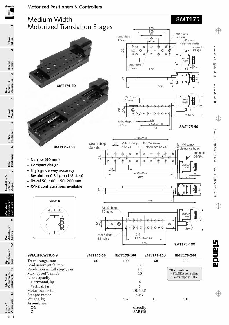
8MT175-50
8MT175-100
SPECIFICATIONS 8MT175‑50 8MT175‑100 8MT175‑150 8MT175‑200Travel range, mm 50 100 150 200Lead screw pitch, mm 0.5resolution in full step*, µm 2.5Max. speed*, mm/s 10Load capacity
Horizontal, kg 8 Vertical, kg 3
Motor connector DB9(M)Stepper motor 4247Weight, kg 1 1.5 1.5 1.6Assemblies:
X‑Y directly Z 2AB175
Medium Width Motorized Translation Stages
– Narrow (50 mm)– Compact design– High guide way accuracy– Resolution 0.31 µm (1/8 step)– Travel 50, 100, 150, 200 mm– X-Y-Z configurations available
8MT175-150
8MT175-50
114
12,5x8=1002
5
50
78
589
stepper
motor
M6x7 deep
10 holes
M4x7 deep
8 holes
25
9
42
235
170
25
50
75
100
125
M4x7 deep
4 holes
M6x7 deep
10 holes
M3x7 deep
2 holes
for M6 screw
4 clearance holes
stepper
motor
connector
DB9(M)
12,5
view A
25
8MT175
view A
*Test condition: • STANDA controllers;• Power supply – 36V.
Phon
e: +
370-
5-26
5147
4 Fa
x: +
370-
5-26
5148
31
Brackets &
Rails
2
Base M
ounts &
Accessories
3O
ptical M
ounts4
Optical
Positioners5
Base Positioners
6
Translation &
Rotation Stages
7
Motorised
Positioners &
Controllers
8
Fine A
djustment
Screws
9
Opto-
Mechanics &
Sets
10O
ptical Tables
Light Test &
Measurem
ent Instrum
ents
Lasers &
Laser A
ccessories 11
12e-
mai
l: sa
les@
stan
da.lt
ww
w.s
tand
a.lt
8-12
Motorized Positioners & ControllersM
otorised Positioners &
C
ontrollers8
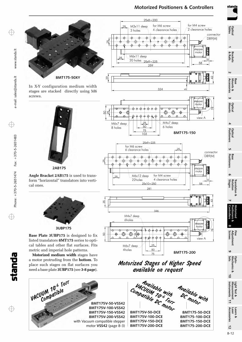
In X-Y configuration medium width stages are stacked directly using M6 screws.
8MT175-150
Angle Bracket 2AB175 is used to trans-form “horizontal” translators into verti-cal ones.
2AB175
Motorized Stages of higher Speed available on request
8MT175-200
VAcUUM
10-6 Tor
r
compati
ble
8MT175V-50-VSS428MT175V-100-VSS428MT175V-150-VSS428MT175V-200-VSS42
with Vacuum compatible stepper motor VSS42 (page 8-3)
Available with Dc motor
Available with
VAcUUM 10 -6 Torr
compatible Dc motor8MT175-50-DCE
8MT175-100-DCE8MT175-150-DCE8MT175-200-DCE
8MT175V-50-DCE8MT175V-100-DCE8MT175V-150-DCE8MT175V-200-DCE
Base Plate 3UBP175 is designed to fix listed translators 8MT175 series to opti-cal tables and other flat surfaces. Fits metric and imperial hole patterns.
Motorized medium width stages have a motor protruding from the bottom. To place such stages on flat surfaces you need a base plate 3UBP175 (see 3‑8 page).
3UBP175
8MT175-50XY
Phone: +370-5-2651474
Fax: +370-5-2651483
1Br
acke
ts
& R
ails
2
Base
M
ount
s &
A
cces
sori
es3
Opt
ical
M
ount
s4
Opt
ical
Po
siti
oner
s5
Base
Po
siti
oner
s6
Tran
slat
ion
&
Rota
tion
St
ages
7
Mot
oris
ed
Posi
tion
ers
&
Con
trol
lers
8
Fine
A
djus
tmen
t Sc
rew
s9
Opt
o-
Mec
hani
cs &
Se
ts10
Opt
ical
Ta
bles
Ligh
t Te
st &
M
easu
rem
ent
Inst
rum
ents
Lase
rs &
La
ser
Acc
esso
ries
11
12e-m
ail: [email protected] w
ww
.standa.lt
8-13
Motorized Positioners & ControllersM
otor
ised
Po
siti
oner
s &
C
ontr
olle
rs8
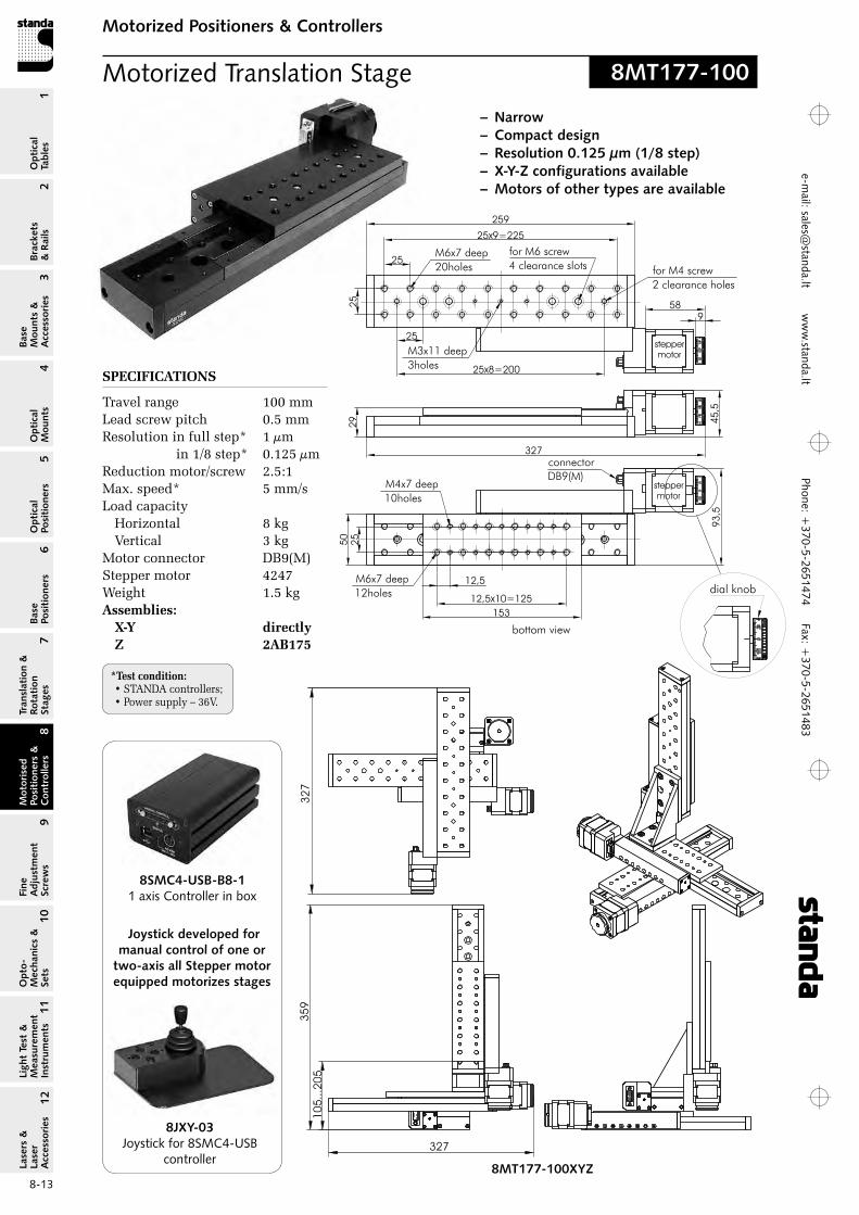
SPECIFICATIONS
Travel range 100 mmLead screw pitch 0.5 mmresolution in full step* 1 µm
in 1/8 step* 0.125 µmreduction motor/screw 2.5:1Max. speed* 5 mm/sLoad capacity
Horizontal 8 kg Vertical 3 kg
Motor connector DB9(M)Stepper motor 4247Weight 1.5 kgAssemblies:
X‑Y directly Z 2AB175
Motorized Translation Stage
– Narrow– Compact design– Resolution 0.125 µm (1/8 step)– X-Y-Z configurations available– Motors of other types are available
bottom view
8MT177-100
*Test condition: • STANDA controllers;• Power supply – 36V.
Joystick developed for manual control of one or
two-axis all Stepper motor equipped motorizes stages
8SMC4-USB-B8-11 axis Controller in box
8MT177-100XYZ
8JXY-03Joystick for 8SMC4-USB
controller

Phon
e: +
370-
5-26
5147
4 Fa
x: +
370-
5-26
5148
31
Brackets &
Rails
2
Base M
ounts &
Accessories
3O
ptical M
ounts4
Optical
Positioners5
Base Positioners
6
Translation &
Rotation Stages
7
Motorised
Positioners &
Controllers
8
Fine A
djustment
Screws
9
Opto-
Mechanics &
Sets
10O
ptical Tables
Light Test &
Measurem
ent Instrum
ents
Lasers &
Laser A
ccessories 11
12e-
mai
l: sa
les@
stan
da.lt
ww
w.s
tand
a.lt
8-14
Motorized Positioners & ControllersM
otorised Positioners &
C
ontrollers8
*Test condition: • STANDA controllers;• Power supply – 36V.
Motorized Translation Stage
25
19,5 50
50x3=150
32 25
25x5=125
for M6 screw
2 clearance holes
M6x11 deep
8 holes
for M4 screw
6 clearance holes
connector
DB9(M)
stepper
motor
42
,5
35
255
25
40
50
75
50
81
9
58
stepper
motor
M6x6 deep
8 holes
M4x6 deep
13 holes
189
view A
25
40
55
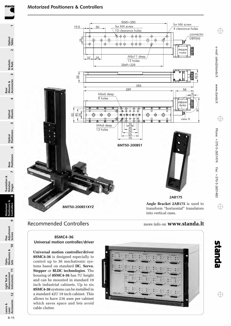
8MT50
8MT50-100BS1
for M4 screw
6 clearance holes
stepper
motor
35
42
,5
19,5 50
50x4=200
32 25
25x7=175
for M6 screw
4 clearance holes
M6x11 deep
10 holes
connector
DB9(M)
305
25
40
50
58
9
239
81
stepper
motor
view A
75
50
M6x6 deep
8 holes
M4x6 deep
13 holes
25
40
55
8MT50-150BS1
view A
– Narrow– Compact design– High speed– Heavy load capacity– X-Y-Z configurations available– Motors of other types are available
8MT50-200BS1
SPECIFICATIONS
Travel range
8MT50-100BS1 100 mm
8MT50-150BS1 150 mm
8MT50-200BS1 200 mmBall screw pitch 1 mmresolution in full step* 5 µm Max. speed* 20 mm/sLoad capacity
Horizontal 30 kg Vertical 8 kg
Motor connector DB9(M)Stepper motor 4247Weight
8MT50-100BS1 1.1 kg
8MT50-150BS1 1.4 kg
8MT50-200BS1 1.65 kgAssemblies:
X‑Y directly Z 2AB175
Phone: +370-5-2651474
Fax: +370-5-2651483
1Br
acke
ts
& R
ails
2
Base
M
ount
s &
A
cces
sori
es3
Opt
ical
M
ount
s4
Opt
ical
Po
siti
oner
s5
Base
Po
siti
oner
s6
Tran
slat
ion
&
Rota
tion
St
ages
7
Mot
oris
ed
Posi
tion
ers
&
Con
trol
lers
8
Fine
A
djus
tmen
t Sc
rew
s9
Opt
o-
Mec
hani
cs &
Se
ts10
Opt
ical
Ta
bles
Ligh
t Te
st &
M
easu
rem
ent
Inst
rum
ents
Lase
rs &
La
ser
Acc
esso
ries
11
12e-m
ail: [email protected] w
ww
.standa.lt
8-15
Motorized Positioners & ControllersM
otor
ised
Po
siti
oner
s &
C
ontr
olle
rs8
8MT50-200BS1
25
19,5 50
50x5=250
32 25
25x9=225
for M4 screw
10 clearance holes
for M6 screw
4 clearance holes
M6x11 deep
12 holes
35
355
42
,58
1
40
50
25
9
58
stepper
motor
stepper
motor
connector
DB9(M)
289
view A
75
50
M6x6 deep
8 holes
M4x6 deep
13 holes
25
40
55
8MT50-200BS1XYZAngle Bracket 2AB175 is used to transform “horizontal” translators into vertical ones.
2AB175
Recommended Controllers more info on www.standa.lt
8SMC4-36Universal motion controller/driver
Universal motion controller/driver 8SMC4‑36 is designed especially to control up to 36 mechatronic sys-tems based on standard DC, Servo, Stepper or BLDC technologies. The housing of 8SMC4‑36 has 7U height and can be mounted in standard 19 inch industrial cabinets. Up to six 8SMC4‑36 systems can be installed in a standard 42U 19 inch cabinet. This allows to have 216 axes per cabinet which saves space and lets avoid cable clutter.
Phon
e: +
370-
5-26
5147
4 Fa
x: +
370-
5-26
5148
31
Brackets &
Rails
2
Base M
ounts &
Accessories
3O
ptical M
ounts4
Optical
Positioners5
Base Positioners
6
Translation &
Rotation Stages
7
Motorised
Positioners &
Controllers
8
Fine A
djustment
Screws
9
Opto-
Mechanics &
Sets
10O
ptical Tables
Light Test &
Measurem
ent Instrum
ents
Lasers &
Laser A
ccessories 11
12e-
mai
l: sa
les@
stan
da.lt
ww
w.s
tand
a.lt
8-16
Motorized Positioners & ControllersM
otorised Positioners &
C
ontrollers8
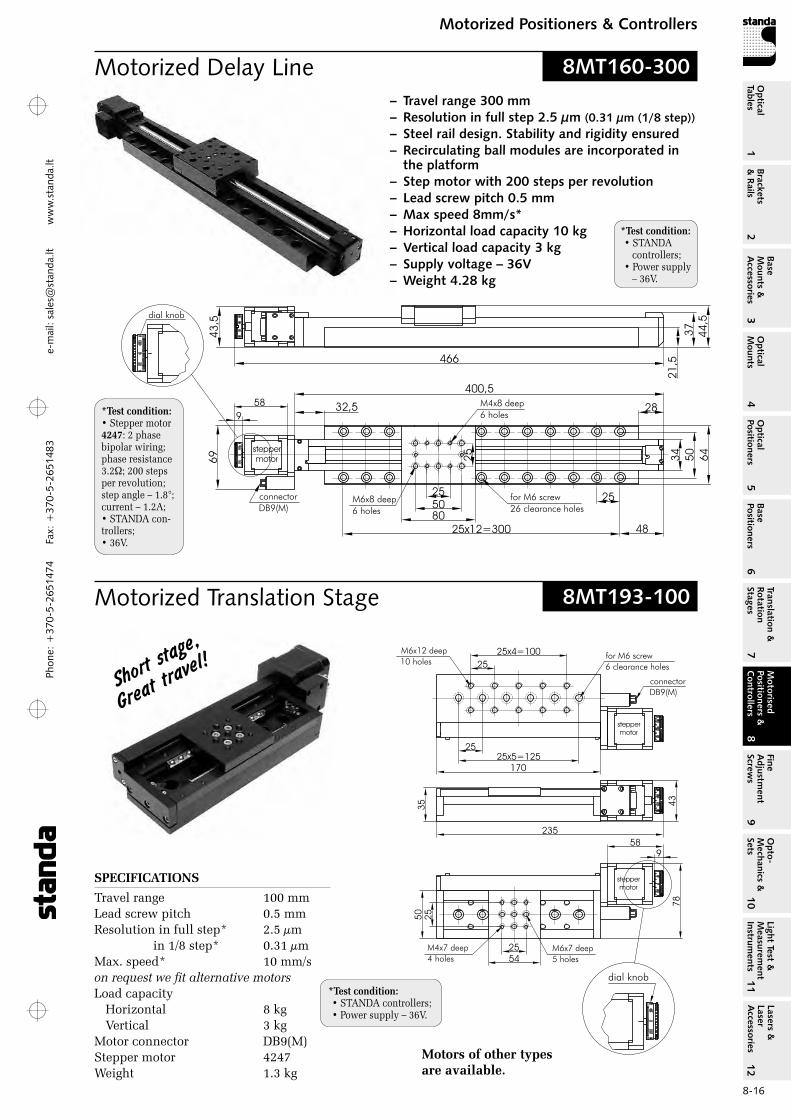
– Travel range 300 mm– Resolution in full step 2.5 µm (0.31 µm (1/8 step))– Steel rail design. Stability and rigidity ensured– Recirculating ball modules are incorporated in
the platform– Step motor with 200 steps per revolution– Lead screw pitch 0.5 mm– Max speed 8mm/s*– Horizontal load capacity 10 kg– Vertical load capacity 3 kg– Supply voltage – 36V– Weight 4.28 kg
Motorized Delay Line
*Test condition:• Stepper motor 4247: 2 phase bipolar wiring; phase resistance 3.2; 200 steps per revolution; step angle – 1.8°; current – 1.2A;• STANDA con-trollers;• 36V.
8MT160-300
Motorized Translation Stage
SPECIFICATIONS
Travel range 100 mmLead screw pitch 0.5 mmresolution in full step* 2.5 µm in 1/8 step* 0.31 µmMax. speed* 10 mm/s on request we fit alternative motorsLoad capacity
Horizontal 8 kg Vertical 3 kg
Motor connector DB9(M)Stepper motor 4247Weight 1.3 kg
Short s
tage,
great tra
vel!
Motors of other types are available.
8MT193-100
*Test condition: • STANDA controllers;• Power supply – 36V.
*Test condition: • STANDA controllers;• Power supply – 36V.
Phone: +370-5-2651474
Fax: +370-5-2651483
1Br
acke
ts
& R
ails
2
Base
M
ount
s &
A
cces
sori
es3
Opt
ical
M
ount
s4
Opt
ical
Po
siti
oner
s5
Base
Po
siti
oner
s6
Tran
slat
ion
&
Rota
tion
St
ages
7
Mot
oris
ed
Posi
tion
ers
&
Con
trol
lers
8
Fine
A
djus
tmen
t Sc
rew
s9
Opt
o-
Mec
hani
cs &
Se
ts10
Opt
ical
Ta
bles
Ligh
t Te
st &
M
easu
rem
ent
Inst
rum
ents
Lase
rs &
La
ser
Acc
esso
ries
11
12e-m
ail: [email protected] w
ww
.standa.lt
8-17
Motorized Positioners & ControllersM
otor
ised
Po
siti
oner
s &
C
ontr
olle
rs8
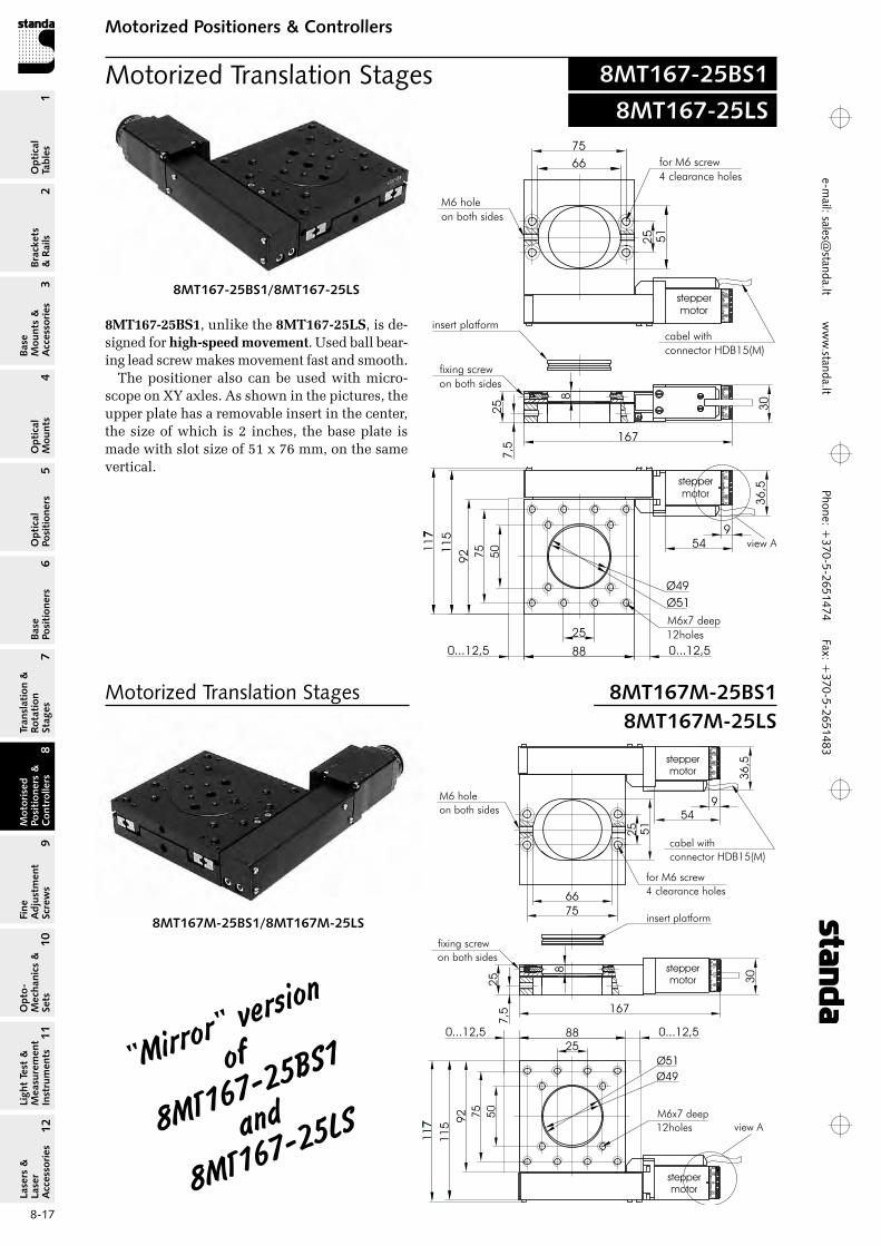
Motorized Translation Stages
25
8
7,5
88
25
92 50
75
11
5
167
0...12,5 0...12,5
for M6 screw
4 clearance holes
25
75
M6x7 deep
12holes
insert platform
fixing screw
on both sides
cabel with
connector HDB15(M)
51
M6 hole
on both sides
66
30
11
7
Ø51
Ø49
stepper
motor
stepper
motor
54
9
stepper
motor
36
,5
view A
8MT167M-25BS1/8MT167M-25LS
8MT167-25BS1
Motorized Translation Stages 8MT167M-25BS18MT167M-25LS
8MT167-25LS
25
8
7,5
88
25
92 5075115
167
0...12,5 0...12,5
for M6 screw4 clearance holes
25
75
M6x7 deep12holes
insert platform
fixing screwon both sides
cabel withconnector HDB15(M)
51
M6 holeon both sides
66
30
117
Ø51Ø49
549
36,5stepper
motor
steppermotor
view A
8MT167‑25BS1, unlike the 8MT167‑25LS, is de-signed for high‑speed movement. Used ball bear-ing lead screw makes movement fast and smooth.
The positioner also can be used with micro-scope on XY axles. As shown in the pictures, the upper plate has a removable insert in the center, the size of which is 2 inches, the base plate is made with slot size of 51 x 76 mm, on the same vertical.
8MT167-25BS1/8MT167-25LS
"Mirror" ver
sion
of
8MT167-25B
S1
and
8MT167-25L
S
Phon
e: +
370-
5-26
5147
4 Fa
x: +
370-
5-26
5148
31
Brackets &
Rails
2
Base M
ounts &
Accessories
3O
ptical M
ounts4
Optical
Positioners5
Base Positioners
6
Translation &
Rotation Stages
7
Motorised
Positioners &
Controllers
8
Fine A
djustment
Screws
9
Opto-
Mechanics &
Sets
10O
ptical Tables
Light Test &
Measurem
ent Instrum
ents
Lasers &
Laser A
ccessories 11
12e-
mai
l: sa
les@
stan
da.lt
ww
w.s
tand
a.lt
8-18
Motorized Positioners & ControllersM
otorised Positioners &
C
ontrollers8
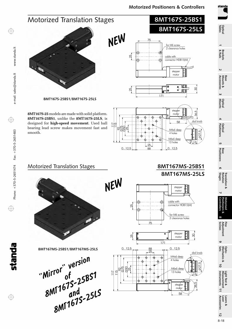
Motorized Translation Stages
2550�
75�92
115
117
258812,50... 12,50...
25 30
171
25
75
58
36,5
Ø27
,5
13
M4x6 deep4 holes
M6x6 deep13 holes
dial knob
steppermotor
steppermotor
cable withconnector HDB15(M)
for M6 screw2 clearance holes
steppermotor
8MT167MS-25BS1/8MT167MS-25LS
8MT167S-25BS1
Motorized Translation Stages 8MT167MS-25BS18MT167MS-25LS
8MT167S-25LS
75
25
for M6 screw2 clearance holes
steppermotor
cable withconnector HDB15(M)
30252550
�75
�92
25
115
117
88
58
steppermotor
12,50... 12,50...
M6x6 deep13 holes
M4x6 deep4 holes
36,5
Ø27
,5
13
dial knob
171
8MT167S‑25 models are made with solid platform. 8MT167S‑25BS1, unlike the 8MT167S‑25LS, is designed for high‑speed movement. Used ball bearing lead screw makes movement fast and smooth.
8MT167S-25BS1/8MT167S-25LS
"Mirror" ver
sion
of
8MT167S-25
BS1
and
8MT167S-25
LS
New
New
Phone: +370-5-2651474
Fax: +370-5-2651483
1Br
acke
ts
& R
ails
2
Base
M
ount
s &
A
cces
sori
es3
Opt
ical
M
ount
s4
Opt
ical
Po
siti
oner
s5
Base
Po
siti
oner
s6
Tran
slat
ion
&
Rota
tion
St
ages
7
Mot
oris
ed
Posi
tion
ers
&
Con
trol
lers
8
Fine
A
djus
tmen
t Sc
rew
s9
Opt
o-
Mec
hani
cs &
Se
ts10
Opt
ical
Ta
bles
Ligh
t Te
st &
M
easu
rem
ent
Inst
rum
ents
Lase
rs &
La
ser
Acc
esso
ries
11
12e-m
ail: [email protected] w
ww
.standa.lt
8-19
Motorized Positioners & ControllersM
otor
ised
Po
siti
oner
s &
C
ontr
olle
rs8
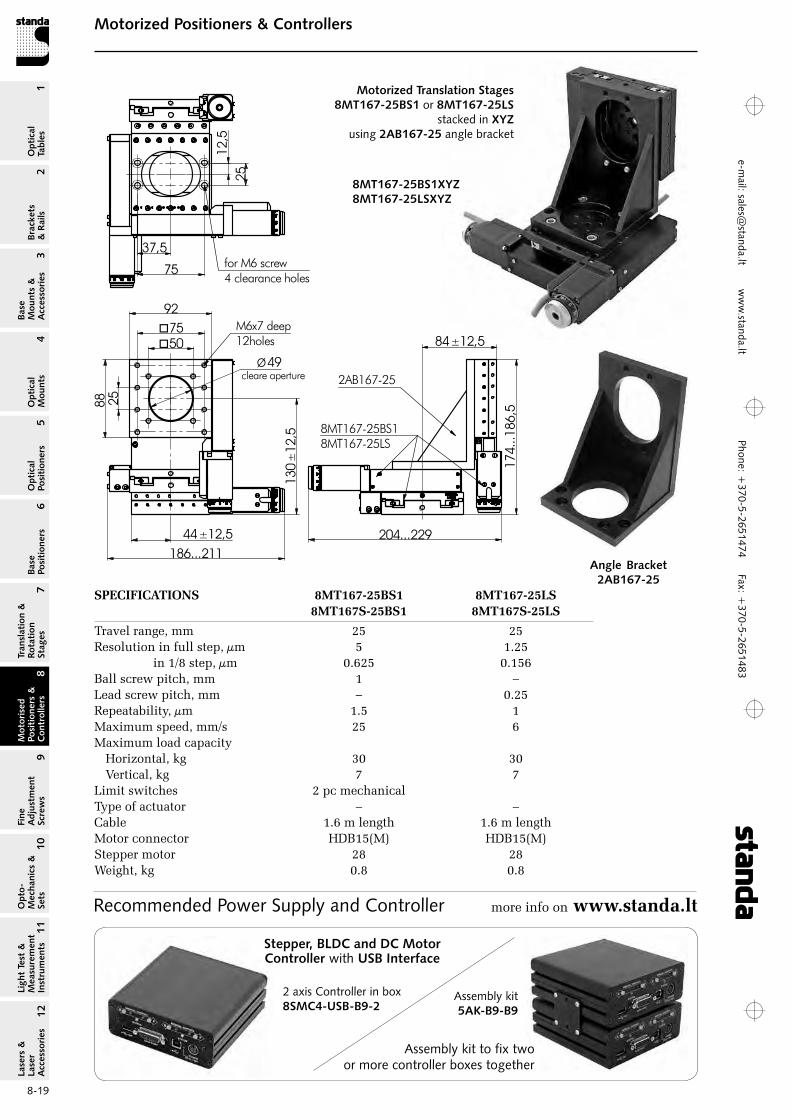
Motorized Translation Stages 8MT167-25BS1 or 8MT167-25LS
stacked in XYZ using 2AB167-25 angle bracket
Angle Bracket 2AB167-25
2588
92
Ø49
M6x7 deep12holes50�
75�
130
±12
,5
25
75 for M6 screw4 clearance holes
204...229
174.
..186
,5
186...21144±12,5
84±12,5
cleare aperture 2AB167-25
8MT167-25BS18MT167-25LS
37,5
12,5
SPECIFICATIONS 8MT167‑25BS1 8MT167‑25LS 8MT167S‑25BS1 8MT167S‑25LS
Travel range, mm 25 25resolution in full step, µm 5 1.25 in 1/8 step, µm 0.625 0.156Ball screw pitch, mm 1 –Lead screw pitch, mm – 0.25repeatability, µm 1.5 1Maximum speed, mm/s 25 6Maximum load capacity
Horizontal, kg 30 30 Vertical, kg 7 7
Limit switches 2 pc mechanical Type of actuator – –Cable 1.6 m length 1.6 m lengthMotor connector HDB15(M) HDB15(M)Stepper motor 28 28Weight, kg 0.8 0.8
8MT167-25BS1XYZ 8MT167-25LSXYZ
Recommended Power Supply and Controller more info on www.standa.lt
2 axis Controller in box8SMC4-USB-B9-2
Assembly kit5AK-B9-B9
Assembly kit to fix two or more controller boxes together
Stepper, BLDC and DC Motor Controller with USB Interface
Phon
e: +
370-
5-26
5147
4 Fa
x: +
370-
5-26
5148
31
Brackets &
Rails
2
Base M
ounts &
Accessories
3O
ptical M
ounts4
Optical
Positioners5
Base Positioners
6
Translation &
Rotation Stages
7
Motorised
Positioners &
Controllers
8
Fine A
djustment
Screws
9
Opto-
Mechanics &
Sets
10O
ptical Tables
Light Test &
Measurem
ent Instrum
ents
Lasers &
Laser A
ccessories 11
12e-
mai
l: sa
les@
stan
da.lt
ww
w.s
tand
a.lt
8-20
Motorized Positioners & ControllersM
otorised Positioners &
C
ontrollers8
Motorized Translation Stages
255075
100125
255075
152
9126
100
25
fixing screwon both sides
for M6 screw4 holes
M6x7 deep10 holes
M4x7 deep16 holes
M6x7 deep20 holes
500... 500...
7567
51
8
insert platform7T167-25.07-01
steppermotor
steppermotor
Ø51
Ø49
50
135
228
230
43,6
connectorDB9(M)
58
13
Ø27
,5
dial knob
steppermotor
steppermotor 25
5075
100125
255075
152
9126
100
50 25
135
224
43,5
fixing screwon both sides
for M6 screw4 holes
M6x7 deep10 holes
M4x7 deep16 holes
M6x7 deep20 holes
51
7567
8
500...500...
Ø51
Ø49
insert platform7T167-25.07-01
227
connectorDB9(M)
Ø37
13
dial knob
60
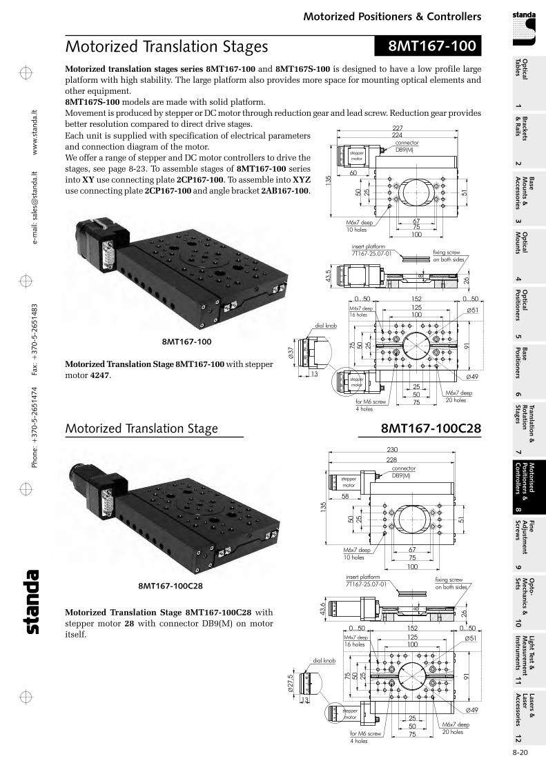
8MT167-100
8MT167-100C28
Motorized translation stages series 8MT167‑100 and 8MT167S‑100 is designed to have a low profile large platform with high stability. The large platform also provides more space for mounting optical elements and other equipment.8MT167S‑100 models are made with solid platform.Movement is produced by stepper or DC motor through reduction gear and lead screw. reduction gear provides better resolution compared to direct drive stages.
Motorized Translation Stage 8MT167‑100C28 with stepper motor 28 with connector DB9(M) on motor itself.
8MT167-100
Motorized Translation Stage 8MT167-100C28
Motorized Translation Stage 8MT167‑100 with stepper motor 4247.
Each unit is supplied with specification of electrical parameters and connection diagram of the motor.We offer a range of stepper and DC motor controllers to drive the stages, see page 8-23. To assemble stages of 8MT167‑100 series into XY use connecting plate 2CP167‑100. To assemble into XYZ use connecting plate 2CP167‑100 and angle bracket 2AB167‑100.

Phone: +370-5-2651474
Fax: +370-5-2651483
1Br
acke
ts
& R
ails
2
Base
M
ount
s &
A
cces
sori
es3
Opt
ical
M
ount
s4
Opt
ical
Po
siti
oner
s5
Base
Po
siti
oner
s6
Tran
slat
ion
&
Rota
tion
St
ages
7
Mot
oris
ed
Posi
tion
ers
&
Con
trol
lers
8
Fine
A
djus
tmen
t Sc
rew
s9
Opt
o-
Mec
hani
cs &
Se
ts10
Opt
ical
Ta
bles
Ligh
t Te
st &
M
easu
rem
ent
Inst
rum
ents
Lase
rs &
La
ser
Acc
esso
ries
11
12e-m
ail: [email protected] w
ww
.standa.lt
8-21
Motorized Positioners & ControllersM
otor
ised
Po
siti
oner
s &
C
ontr
olle
rs8
Motorized Translation Stage 8MT167-100-28
255075
100125
255075
152
9126
100
25
136
36,6
fixing screwon both sides
for M6 screw4 holes
M6x7 deep10 holes
M4x7 deep16 holes
M6x7 deep20 holes
500... 500...
7567
51
8
insert platform7T167-25.07-01
steppermotor
steppermotor
Ø51
Ø49
cable withconnector HDB15(M)
50
58
222224
13
Ø27
,5dial knob
255075
100125
255075
152
9126
100
25
fixing screwon both sides
for M6 screw4 holes
M6x7 deep10 holes
M4x7 deep16 holes
M6x7 deep20 holes
500... 500...
7567
51
8
insert platform7T167-25.07-01
DCEmotor
DCEmotor
Ø51
Ø49clear aperture
50
connectorHDB15(M)
266268
132
145
38
95
8MT167-100-28
8MT167-100DCE2
Motorized Translation Stage 8MT167‑100‑28 with stepper motor 28.
Motorized Translation Stage 8MT167‑100DCE2 with DC motor DCE RE25.
Motorized Translation Stage (DC motor) 8MT167-100DCE2
Insert platform included
Phon
e: +
370-
5-26
5147
4 Fa
x: +
370-
5-26
5148
31
Brackets &
Rails
2
Base M
ounts &
Accessories
3O
ptical M
ounts4
Optical
Positioners5
Base Positioners
6
Translation &
Rotation Stages
7
Motorised
Positioners &
Controllers
8
Fine A
djustment
Screws
9
Opto-
Mechanics &
Sets
10O
ptical Tables
Light Test &
Measurem
ent Instrum
ents
Lasers &
Laser A
ccessories 11
12e-
mai
l: sa
les@
stan
da.lt
ww
w.s
tand
a.lt
8-22
Motorized Positioners & ControllersM
otorised Positioners &
C
ontrollers8
Motorized Translation Stages
500... 500...152125100
255075
9126
75100
50 25
135
227,5
M6x7 deep15 holes
connectorDB9(M)
M4x7 deep30 holes
for M6 screw4 holes
M6x7 deep27 holes
255075
steppermotor
230
Ø27
,5
13
dial knob
58
43,5
500... 500...152125100
255075
9126
75100
50 25
135
224
M6x7 deep15 holes
connectorDB9(M)
M4x7 deep30 holes
for M6 screw4 holes
M6x7 deep27 holes
225
255075
steppermotor
Ø37
13
dial knob
60
43,5
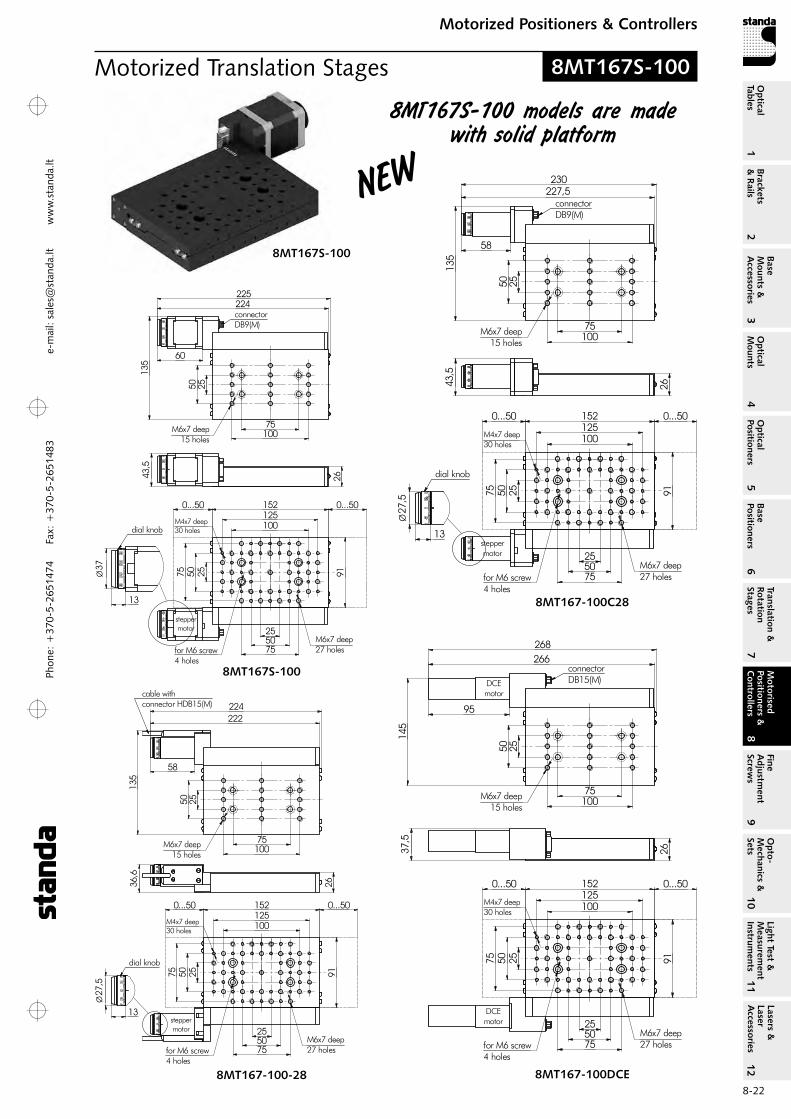
8MT167S-100
8MT167-100C28
8MT167S-100
500... 500...152125100
255075
9126
75100
50 25
135
222
M6x7 deep15 holes
M4x7 deep30 holes
for M6 screw4 holes
M6x7 deep27 holes
255075
steppermotor
224
Ø27
,5
13
dial knob
58
cable withconnector HDB15(M)
36,6
500... 500...152125100
255075
9126
75100
50 25
M6x7 deep15 holes
M4x7 deep30 holes
for M6 screw4 holes
M6x7 deep27 holes
255075
DCEmotor
268
37,5
145
connectorDB15(M)
95
266
DCEmotor
8MT167-100-28 8MT167-100DCE
8MT167S-100 models are made with solid platform
8MT167S-100
New

Phone: +370-5-2651474
Fax: +370-5-2651483
1Br
acke
ts
& R
ails
2
Base
M
ount
s &
A
cces
sori
es3
Opt
ical
M
ount
s4
Opt
ical
Po
siti
oner
s5
Base
Po
siti
oner
s6
Tran
slat
ion
&
Rota
tion
St
ages
7
Mot
oris
ed
Posi
tion
ers
&
Con
trol
lers
8
Fine
A
djus
tmen
t Sc
rew
s9
Opt
o-
Mec
hani
cs &
Se
ts10
Opt
ical
Ta
bles
Ligh
t Te
st &
M
easu
rem
ent
Inst
rum
ents
Lase
rs &
La
ser
Acc
esso
ries
11
12e-m
ail: [email protected] w
ww
.standa.lt
8-23
Motorized Positioners & ControllersM
otor
ised
Po
siti
oner
s &
C
ontr
olle
rs8
To stack the 8MT167 stages in X-Y-Z coordinates you need a connecting plate 2CP167-100
and an angle bracket 2AB167-50.
Motorized Stag
es
of higher Sp
eed
available on
request
Motors of oth
er types
are available
8MT167-100DCE2 8MT167-100
more info on www.standa.lt
SPECIFICATIONS 8MT167‑100 8MT167‑100C28 8MT167‑100‑28 8MT167‑100DCE2 8MT167S‑100 8MT167S‑100C28 8MT167S‑100‑28 8MT167S‑100DCE2
Travel range, mm 100 100 100 100resolution in full step, µm 1 1 1 – in 1/8 step, µm 0.125 0.125 0.125 –Lead screw pitch, mm 0.5 0.5 0.5 0.5reduction motor/screw 2.5:1 2.5:1 2.5:1 11:1Bi-direction repeatability, µm 2 2 2 0.8Minimal incremental motion, µm – – – 0.2resolution (calculated), µm – – – 0.023Maximum speed, mm/s 5 5 5 5.5Maximum load capacity
Horizontal, kg 7 7 7 7 Vertical, kg 3 3 3 3
Limit switches 2 pc mechanicalCable 1.6 m lengthMotor connector DB9(M) DB9(M) HDB15(M) HDB15(M)Stepper motor 4247 28 28 –DC motor – – – DCE rE25Weight, kg 1.4 1.4 1.4 1.5
8MT167-100XYZ
Three Axis Stepper, BLDC and DC MotorController 8SMC4-USB-B8-B9
with Power Supply
Recommended Controller
Phon
e: +
370-
5-26
5147
4 Fa
x: +
370-
5-26
5148
31
Brackets &
Rails
2
Base M
ounts &
Accessories
3O
ptical M
ounts4
Optical
Positioners5
Base Positioners
6
Translation &
Rotation Stages
7
Motorised
Positioners &
Controllers
8
Fine A
djustment
Screws
9
Opto-
Mechanics &
Sets
10O
ptical Tables
Light Test &
Measurem
ent Instrum
ents
Lasers &
Laser A
ccessories 11
12e-
mai
l: sa
les@
stan
da.lt
ww
w.s
tand
a.lt
8-24
Motorized Positioners & ControllersM
otorised Positioners &
C
ontrollers8
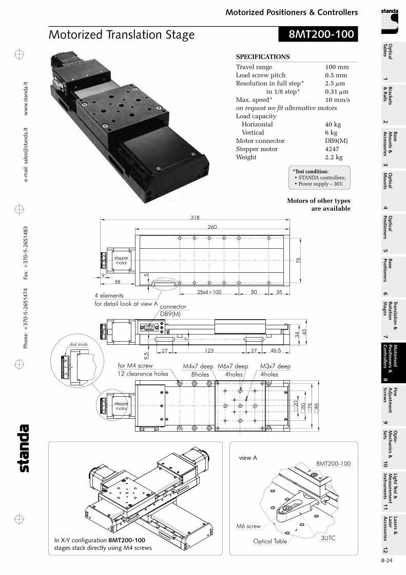
SPECIFICATIONS
Travel range 100 mmLead screw pitch 0.5 mmresolution in full step* 2.5 µm in 1/8 step* 0.31 µmMax. speed* 10 mm/s on request we fit alternative motorsLoad capacity
Horizontal 40 kg Vertical 6 kg
Motor connector DB9(M)Stepper motor 4247Weight 2.2 kg
Motors of other types are available
Motorized Translation Stage
In X-Y configuration 8MT200-100 stages stack directly using M4 screws
view A
8MT200-100
*Test condition: • STANDA controllers;• Power supply – 36V.
Phone: +370-5-2651474
Fax: +370-5-2651483
1Br
acke
ts
& R
ails
2
Base
M
ount
s &
A
cces
sori
es3
Opt
ical
M
ount
s4
Opt
ical
Po
siti
oner
s5
Base
Po
siti
oner
s6
Tran
slat
ion
&
Rota
tion
St
ages
7
Mot
oris
ed
Posi
tion
ers
&
Con
trol
lers
8
Fine
A
djus
tmen
t Sc
rew
s9
Opt
o-
Mec
hani
cs &
Se
ts10
Opt
ical
Ta
bles
Ligh
t Te
st &
M
easu
rem
ent
Inst
rum
ents
Lase
rs &
La
ser
Acc
esso
ries
11
12e-m
ail: [email protected] w
ww
.standa.lt
8-25
Motorized Positioners & ControllersM
otor
ised
Po
siti
oner
s &
C
ontr
olle
rs8
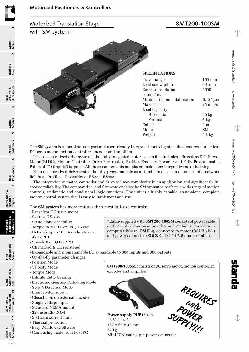
SPECIFICATIONS
Travel range 100 mmLead screw pitch 0.5 mmEncoder resolution 4000 counts/revMinimal incremental motion 0.125 µmMax. speed 25 mm/sLoad capacity
Horizontal 40 kg Vertical 6 kg
Cable* 2 mMotor SMWeight 2.5 kg
The SM system is a complete, compact and user-friendly integrated control system that features a brushless DC servo motor, motion controller, encoder and amplifier.
It is a decentralized drive system. It is a fully integrated motor system that includes a Brushless D.C. Servo-Motor (BLDC), Motion Controller, Drive-Electronics, Position Feedback Encoder and Fully Programmable Points of I/o (Inputs/outputs). All these components are placed inside one integral frame or housing.
Each decentralized drive system is fully programmable as a stand-alone system or as part of a network fieldbus - Profibus, DeviceNet or rS232, rS485.
The integration of motor, controller and drive reduces complexity in an application and significantly in-creases reliability. The command set and firmware enables the SM system to perform a wide range of motion controls, arithmetic and conditional logic functions. The unit is a highly capable, stand-alone, complete motion control system that is easy to implement and use.
The SM system has more features than most full-size controls: - Brushless DC servo motor - S-232 & rS-485 - Stand alone capability - Torque to 2000+ oz. in. / 15 NM - Network up to 100 Servida Motors - 4kHz PID - Speeds 0 - 10,000 rPM - CE marked & UL registered - Expandable and programmable I/o expandable to 800 inputs and 800 outputs - on-the-fly parameter changes - Position Mode - Velocity Mode - Torque Mode - Infinite ratio Gearing - Electronic Gearing/ Following Mode - Step & Direction Mode - Limit switch inputs - Closed loop on external encoder - Single voltage input - Standard NEMA mount - 32k user EEProM - Software current limit - Thermal protection - Easy Windows Software - Contouring mode from host PC
*Cable supplied with 8MT200‑100SM consists of power cable and rS232 communication cable and includes connector to computer rS232 (DSUB9), connector to motor (DSUB 7W2) and power connector (SoCKET DC 2.1/5.5 mm for Cable).
Motorized Translation Stage 8MT200-100SMwith SM system
reqUireSonlyPOwerSUPPLY!!!
8MT200‑100SM consists of DC servo motor, motion controller, encoder and amplifier.
Power supply PUP120‑17 36 V; 3.34 A 167 x 65 x 37 mm 640 g Mini-DIN male 4-pin power connector
Phon
e: +
370-
5-26
5147
4 Fa
x: +
370-
5-26
5148
31
Brackets &
Rails
2
Base M
ounts &
Accessories
3O
ptical M
ounts4
Optical
Positioners5
Base Positioners
6
Translation &
Rotation Stages
7
Motorised
Positioners &
Controllers
8
Fine A
djustment
Screws
9
Opto-
Mechanics &
Sets
10O
ptical Tables
Light Test &
Measurem
ent Instrum
ents
Lasers &
Laser A
ccessories 11
12e-
mai
l: sa
les@
stan
da.lt
ww
w.s
tand
a.lt
8-26
Motorized Positioners & ControllersM
otorised Positioners &
C
ontrollers8
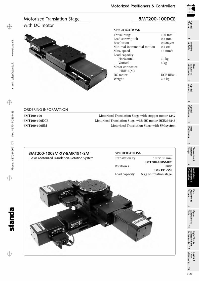
SPECIFICATIONS
Travel range 100 mmLead screw pitch 0.5 mmresolution 0.028 µmMinimal incremental motion 0.2 µmMax. speed 13 mm/sLoad capacity
Horizontal 30 kg Vertical 5 kg
Motor connector HDB15(M)
DC motor DCE rE25Weight 2.2 kg
ORDERING INFORMATION
8MT200‑100 Motorized Translation Stage with stepper motor 4247
8MT200‑100DCE Motorized Translation Stage with DC motor DCE336548
8MT200‑100SM Motorized Translation Stage with SM system
SPECIFICATIONS
Translation xy 100x100 mm 8MT200‑100SMXYrotation z 360° 8MR191‑SMLoad capacity 5 kg on rotation stage
8MT200-100SM-XY-8MR191-SM 3 Axis Motorized Translation-Rotation System
Motorized Translation Stage 8MT200-100DCEwith DC motor
Phone: +370-5-2651474
Fax: +370-5-2651483
1Br
acke
ts
& R
ails
2
Base
M
ount
s &
A
cces
sori
es3
Opt
ical
M
ount
s4
Opt
ical
Po
siti
oner
s5
Base
Po
siti
oner
s6
Tran
slat
ion
&
Rota
tion
St
ages
7
Mot
oris
ed
Posi
tion
ers
&
Con
trol
lers
8
Fine
A
djus
tmen
t Sc
rew
s9
Opt
o-
Mec
hani
cs &
Se
ts10
Opt
ical
Ta
bles
Ligh
t Te
st &
M
easu
rem
ent
Inst
rum
ents
Lase
rs &
La
ser
Acc
esso
ries
11
12e-m
ail: [email protected] w
ww
.standa.lt
8-27
Motorized Positioners & ControllersM
otor
ised
Po
siti
oner
s &
C
ontr
olle
rs8
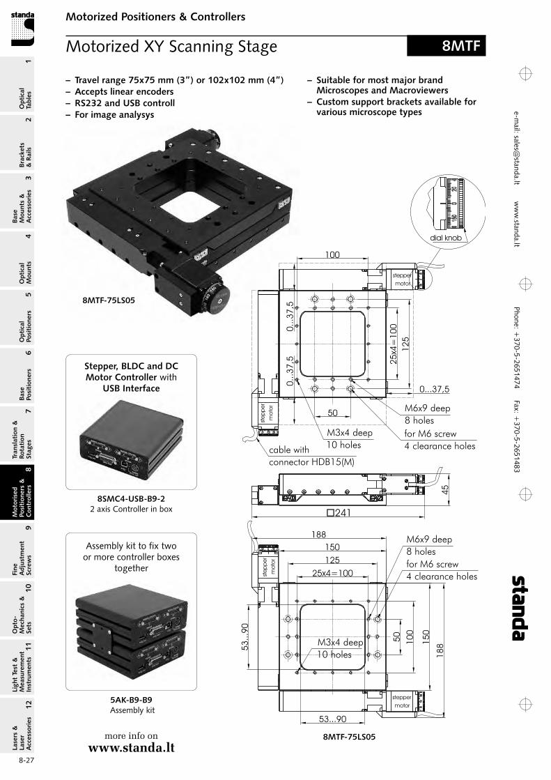
Motorized XY Scanning Stage 8MTF
150
150
188
188
�241
45
25x4=100
125
50
50
12
5
25x4=
100
for M6 screw
4 clearance holes
M6x9 deep
8 holes
for M6 screw
4 clearance holes
M6x9 deep
8 holes
stepper
motor
cable with
connector HDB15(M)
53...90
53
...9
0
0...3
7,5
0..
.37
,5
0...37,5
dial knob
100
M3x4 deep
10 holes
M3x4 deep
10 holes
100ste
pp
er
mo
tor
ste
pp
er
mo
tor
stepper
motor
– Travel range 75x75 mm (3”) or 102x102 mm (4”) – Accepts linear encoders – RS232 and USB controll – For image analysys
8MTF-75LS05
8MTF-75LS05
– Suitable for most major brand Microscopes and Macroviewers
– Custom support brackets available for various microscope types
Stepper, BLDC and DC Motor Controller with
USB Interface
8SMC4-USB-B9-22 axis Controller in box
more info on www.standa.lt
5AK-B9-B9 Assembly kit
Assembly kit to fix two or more controller boxes
together

Phon
e: +
370-
5-26
5147
4 Fa
x: +
370-
5-26
5148
31
Brackets &
Rails
2
Base M
ounts &
Accessories
3O
ptical M
ounts4
Optical
Positioners5
Base Positioners
6
Translation &
Rotation Stages
7
Motorised
Positioners &
Controllers
8
Fine A
djustment
Screws
9
Opto-
Mechanics &
Sets
10O
ptical Tables
Light Test &
Measurem
ent Instrum
ents
Lasers &
Laser A
ccessories 11
12e-
mai
l: sa
les@
stan
da.lt
ww
w.s
tand
a.lt
8-28
Motorized Positioners & ControllersM
otorised Positioners &
C
ontrollers8
SPECIFICATIONS
Travel range 75x75 mm (3”) 102x102 mm (4”) Lead screw pitch 0.5 mmresolution in full step* 2.5 µm in 1/8 step* 0.31 µmMax. speed* 10 mm/sLoad capacity
Horizontal 50 kg Vertical 6 kg
Cable integrated, 1.6 m lengthMotor connector HDB15(M)Stepper motor 28
ORDERING INFORMATION
8MTF‑75LS05 Travel range 75x75 mm (3”)8MTF‑102LS05 Travel range 102x102 mm (4”)
25
75
1252
5x5
=125
150
stepper
motor
ste
pp
er
mo
tor
ste
pp
er
mo
tor
stepper
motor
272,5
45
0...51
0...5
10...5
1
0...51
for M6 screw
4 clearance holes
M3x4 deep
12 holes
M6x9 deep
12 holes
64...1
15
25
75
125
175
25x5=125
150
175
214
214
for M6 screw
4 clearance holes
M3x4 deep
12 holes
M6x9 deep
12 holes
viewA
cable with
connector HDB15(M)
64...115
dial knob
8MTF-102LS05
5
5
15
15
deep 4mm
view A
*Test condition: • STANDA controllers;• Power supply – 36V.
Joystick developed for manual control of one or
two-axis all Stepper motor equipped motorizes stages
8JXY-03Joystick for 8SMC4-USB controller

Phone: +370-5-2651474
Fax: +370-5-2651483
1Br
acke
ts
& R
ails
2
Base
M
ount
s &
A
cces
sori
es3
Opt
ical
M
ount
s4
Opt
ical
Po
siti
oner
s5
Base
Po
siti
oner
s6
Tran
slat
ion
&
Rota
tion
St
ages
7
Mot
oris
ed
Posi
tion
ers
&
Con
trol
lers
8
Fine
A
djus
tmen
t Sc
rew
s9
Opt
o-
Mec
hani
cs &
Se
ts10
Opt
ical
Ta
bles
Ligh
t Te
st &
M
easu
rem
ent
Inst
rum
ents
Lase
rs &
La
ser
Acc
esso
ries
11
12e-m
ail: [email protected] w
ww
.standa.lt
8-29
Motorized Positioners & ControllersM
otor
ised
Po
siti
oner
s &
C
ontr
olle
rs8
*Test condition:• Ball screw pitch - 2.5 mm• Stepper motor: 2 phase bipolar wiring;
phase resistance 2.4 ; 200 steps per revolution; step angle – 1.8°; current – 1.5 A;
• STANDA controllers;• 36 V.
SPECIFICATIONSTravel range 340..2840 mmBall screw pitch 2.5/4/5/10 mmresolution in full step* 12.5 µm in 1/8 step* 1.57 µmMax. speed* 40 mm/s
on request we fit alternative motorsLoad capacity
Horizontal 40 kgVertical 10 kg
Motor connector DB9(M)Stepper motor
8MT195X 59188MT195Z 5918-B
Resolution and speed of 8MT195 series stages can be varied choosing appropriate ball screw pitch. Several standard options are available and should be specified upon ordering.
For applications requiring travel over 500 mm we suggest using 8MT295X series stages (X) paired with 8MT195X series stages (Y) to make XY assemblies.
For applications requiring vertical Z axis movement, we suggest using stages with brake mounted on motor, to prevent carrier sliding down when motor current is turned off. ordering code of Z stages is 8MT195Z, see ordering information on the 8‑31 page.
Long-Travel Motorized Linear Stages 8MT195 series
A
A
50
78 7510.5
81
connectorDB9(M)
75
33 33L1=travel range + 150
5070
12
M6x12 deep2 holes
Ø6H7
56.4
Ø
steppermotor
steppermotor
76
L=travel range + 361
6.52.5
5
10.5
4 elem.
A-A
Place forSlide Nut 3SN195
37Ø
13 dial knob
8MT195X-340-2.5
8MT195 series stages are designed to provide high‑speed move-ment. Standard motors allow moving loads up to 40 kg. Load capacity can be increased using more powerful motors. This stage provides moderate resolution and accuracy. 8MT195 series stages are supplied equipped with 3P195 platform, 3BP195 bases plates (2 pc) and appropriate amount of 3SN195 inserts.
8MT195X
A
A
50
78 7510.5
81
connectorDB9(M)
75
33 33L1=travel range + 150
5070
12
M6x12 deep2 holes
Ø6H7
stepper motorwith brake
stepper with motor brake
124
L=travel range + 395
6.52.5
5
10.5
4 elem.
A-A
Place forSlide Nut 3SN195
56.4
Ø
8MT195Z
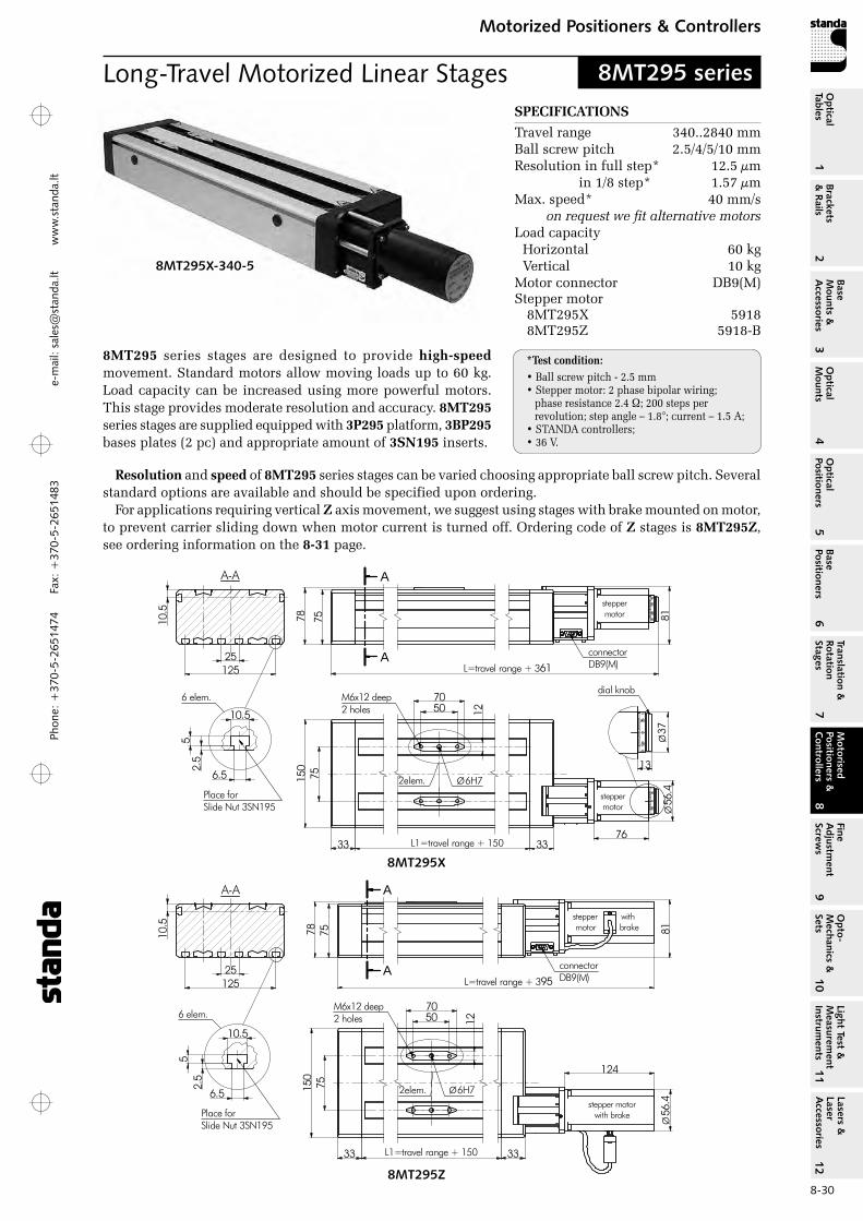
Phon
e: +
370-
5-26
5147
4 Fa
x: +
370-
5-26
5148
31
Brackets &
Rails
2
Base M
ounts &
Accessories
3O
ptical M
ounts4
Optical
Positioners5
Base Positioners
6
Translation &
Rotation Stages
7
Motorised
Positioners &
Controllers
8
Fine A
djustment
Screws
9
Opto-
Mechanics &
Sets
10O
ptical Tables
Light Test &
Measurem
ent Instrum
ents
Lasers &
Laser A
ccessories 11
12e-
mai
l: sa
les@
stan
da.lt
ww
w.s
tand
a.lt
8-30
Motorized Positioners & ControllersM
otorised Positioners &
C
ontrollers8
SPECIFICATIONS
Travel range 340..2840 mmBall screw pitch 2.5/4/5/10 mmresolution in full step* 12.5 µm in 1/8 step* 1.57 µmMax. speed* 40 mm/s
on request we fit alternative motorsLoad capacity
Horizontal 60 kgVertical 10 kg
Motor connector DB9(M)Stepper motor
8MT295X 59188MT295Z 5918-B
*Test condition:• Ball screw pitch - 2.5 mm• Stepper motor: 2 phase bipolar wiring;
phase resistance 2.4 ; 200 steps per revolution; step angle – 1.8°; current – 1.5 A;
• STANDA controllers;• 36 V.
Resolution and speed of 8MT295 series stages can be varied choosing appropriate ball screw pitch. Several standard options are available and should be specified upon ordering.
For applications requiring vertical Z axis movement, we suggest using stages with brake mounted on motor, to prevent carrier sliding down when motor current is turned off. ordering code of Z stages is 8MT295Z, see ordering information on the 8‑31 page.
Long-Travel Motorized Linear Stages 8MT295 series
8MT295X-340-5
8MT295 series stages are designed to provide high‑speed movement. Standard motors allow moving loads up to 60 kg. Load capacity can be increased using more powerful motors. This stage provides moderate resolution and accuracy. 8MT295 series stages are supplied equipped with 3P295 platform, 3BP295 bases plates (2 pc) and appropriate amount of 3SN195 inserts.
A
A
25
78 7510.5
81connectorDB9(M)
75
33 33L1=travel range + 150
5070
12
M6x12 deep2 holes
Ø6H7
56.4
Ø
steppermotor
steppermotor
76
L=travel range + 361
6 elem.
A-A
125
6.5
10.5
2.5
5
Place forSlide Nut 3SN195
150
2elem.
37Ø
13
dial knob
8MT295X
A
A
25
78 7510.5
81
connectorDB9(M)
75
33 33L1=travel range + 150
5070
12
M6x12 deep2 holes
Ø6H7
124
L=travel range + 395
6 elem.
A-A
125
6.5
10.5
2.5
5
Place forSlide Nut 3SN195
150
2elem.
stepper with motor brake
stepper motorwith brake 56
.4Ø
8MT295Z
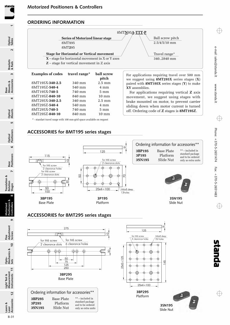
Phone: +370-5-2651474
Fax: +370-5-2651483
1Br
acke
ts
& R
ails
2
Base
M
ount
s &
A
cces
sori
es3
Opt
ical
M
ount
s4
Opt
ical
Po
siti
oner
s5
Base
Po
siti
oner
s6
Tran
slat
ion
&
Rota
tion
St
ages
7
Mot
oris
ed
Posi
tion
ers
&
Con
trol
lers
8
Fine
A
djus
tmen
t Sc
rew
s9
Opt
o-
Mec
hani
cs &
Se
ts10
Opt
ical
Ta
bles
Ligh
t Te
st &
M
easu
rem
ent
Inst
rum
ents
Lase
rs &
La
ser
Acc
esso
ries
11
12e-m
ail: [email protected] w
ww
.standa.lt
8-31
Motorized Positioners & ControllersM
otor
ised
Po
siti
oner
s &
C
ontr
olle
rs8
For applications requiring travel over 500 mm we suggest using 8MT295X series stages (X) paired with 8MT195X series stages (Y) to make XY assemblies.
For applications requiring vertical Z axis movement, we suggest using stages with brake mounted on motor, to prevent carrier sliding down when motor current is turned off. ordering code of Z stages is 8MT195Z.
Ordering information for accessories**3BP295 Base Plate 3P295 Platform 3SN195 Slide Nut
** – included in standard package and to be ordered only as extra units
3SN195Slide Nut
3BP195Base Plate
8MTN95A-TTT-P
Ordering information for accessories**3BP195 Base Plate 3P195 Platform 3SN195 Slide Nut
** – included in standard package and to be ordered only as extra units
Series of Motorized linear stage8MT1958MT295
Travel range*340..2840 mm
Stage for Horizontal or Vertical movementX – stage for horizontal movement in X or Y axesZ – stage for vertical movement in Z axis
ORDERING INFORMATION
ACCESSORIES for 8MT195 series stages
ACCESSORIES for 8MT295 series stages
3BP295Base Plate
3P195Platform
3BP295Platform
3SN195Slide Nut
Examples of codes travel range* ball screw pitch 8MT195X-340-2.5 340 mm 2.5 mm 8MT195Z-540-4 540 mm 4 mm 8MT195X-740-5 740 mm 5 mm8MT195Z-840-10 840 mm 10 mm8MT295X-340-2.5 340 mm 2.5 mm 8MT295Z-540-4 540 mm 4 mm 8MT295X-740-5 740 mm 5 mm8MT295Z-840-10 840 mm 10 mm
Ball screw pitch2.5/4/5/10 mm
* - standart travel range with 100 mm-grid space available on request
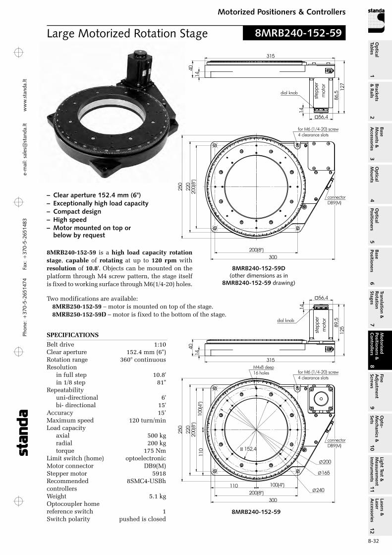
Phon
e: +
370-
5-26
5147
4 Fa
x: +
370-
5-26
5148
31
Brackets &
Rails
2
Base M
ounts &
Accessories
3O
ptical M
ounts4
Optical
Positioners5
Base Positioners
6
Translation &
Rotation Stages
7
Motorised
Positioners &
Controllers
8
Fine A
djustment
Screws
9
Opto-
Mechanics &
Sets
10O
ptical Tables
Light Test &
Measurem
ent Instrum
ents
Lasers &
Laser A
ccessories 11
12e-
mai
l: sa
les@
stan
da.lt
ww
w.s
tand
a.lt
8-32
Motorized Positioners & ControllersM
otorised Positioners &
C
ontrollers8
Large Motorized Rotation Stage 8MRB240-152-59
8MRB240-152-59
200(8")
200(
8")
315
40
125
220
14
250
300
for M6 (1/4-20) screw4 clearance slots
89,5
1456,4�
connectorDB9(M)
stepp
erm
otordial knob
100(
4")
110
110 100(4")
� 152,4
Ø165
Ø200
M4x8 deep16 holes
Ø240
– Clear aperture 152.4 mm (6") – Exceptionally high load capacity – Compact design– High speed – Motor mounted on top or
below by request
200(8")
200(
8")
315
40
127
220
14
250
300
for M6 (1/4-20) screw4 clearance slots
86,5
14
56,4�
connectorDB9(M)
stepp
erm
otor
dial knob
8MRB240-152-59D(other dimensions as in
8MRB240-152-59 drawing)
8MRB240‑152‑59 is a high load capacity rotation stage, capable of rotating at up to 120 rpm with resolution of 10.8'. objects can be mounted on the platform through M4 screw pattern, the stage itself is fixed to working surface through M6(1/4-20) holes.
Two modifications are available:8MRB250‑152‑59 – motor is mounted on top of the stage.8MRB250‑152‑59D – motor is fixed to the bottom of the stage.
SPECIFICATIONS
Belt drive 1:10Clear aperture 152.4 mm (6")rotation range 360° continuous resolution
in full step 10.8' in 1/8 step 81"
repeatability uni-directional 6' bi- directional 15'
Accuracy 15’ Maximum speed 120 turn/min Load capacity
axial 500 kg radial 200 kg torque 175 Nm
Limit switch (home) optoelectronic Motor connector DB9(M) Stepper motor 5918 recommended 8SMC4-USBh controllers Weight 5.1 kg optocoupler home reference switch 1 Switch polarity pushed is closed

Phone: +370-5-2651474
Fax: +370-5-2651483
1Br
acke
ts
& R
ails
2
Base
M
ount
s &
A
cces
sori
es3
Opt
ical
M
ount
s4
Opt
ical
Po
siti
oner
s5
Base
Po
siti
oner
s6
Tran
slat
ion
&
Rota
tion
St
ages
7
Mot
oris
ed
Posi
tion
ers
&
Con
trol
lers
8
Fine
A
djus
tmen
t Sc
rew
s9
Opt
o-
Mec
hani
cs &
Se
ts10
Opt
ical
Ta
bles
Ligh
t Te
st &
M
easu
rem
ent
Inst
rum
ents
Lase
rs &
La
ser
Acc
esso
ries
11
12e-m
ail: [email protected] w
ww
.standa.lt
8-33
Motorized Positioners & ControllersM
otor
ised
Po
siti
oner
s &
C
ontr
olle
rs8
8MR190-90Large Motorized Rotation Stages– Hardened steel with aluminium body– Large diameter ball bearings– Worm Gear Ratio is 1:120– Hall-effect reference limit switch – Stepper motor or DC motor with encoder– Motor can be optionaly equipped with reduction gear – 1.8m long cable included – Vacuum compatible versions are available up to 10-6 Torr using step motor– Very high load capacity
SPECIFICATIONSrotation range 360° continuousresolution
in full step* 54 arcsec.in 1/8 step* 6.75 arcsec.
repeatability 72 arcsec.(bidirectional) Backlash 40 arcsec. max.Max.rotation speed* 10 turn/minWobble 40 µraCable 1.6 m lengthMotor connector DB9(M)Stepper motor 5918Load capacity
Horizontal 60 kg radial 25 kg
Weight 6.6 kg
ORDERING INFORMATION
8MR190‑90‑59
rotation Stage with stepper motor 5918 (2.1 A, 200 steps)
8MR190‑90‑4247
rotation Stage with stepper motor 4247 (see next page)(1.2 A, 200 steps)
Large Motorized Rotation Stage 8MR190-90-59
*Test condition: • STANDA controllers;• Power supply – 36V.
8MR190-90-59
steppermotor
steppermotor
266
150(
6")
205
60°60°
150(6")190
204
95
95
60
for M6(1/4-20) screw3 clearance holes
M5x8 deep6holes
Ø89clear aperture
connectorDB9(M)
Ø188
Ø138
76
70
70
56,4
62,5

Phon
e: +
370-
5-26
5147
4 Fa
x: +
370-
5-26
5148
31
Brackets &
Rails
2
Base M
ounts &
Accessories
3O
ptical M
ounts4
Optical
Positioners5
Base Positioners
6
Translation &
Rotation Stages
7
Motorised
Positioners &
Controllers
8
Fine A
djustment
Screws
9
Opto-
Mechanics &
Sets
10O
ptical Tables
Light Test &
Measurem
ent Instrum
ents
Lasers &
Laser A
ccessories 11
12e-
mai
l: sa
les@
stan
da.lt
ww
w.s
tand
a.lt
8-34
Motorized Positioners & ControllersM
otorised Positioners &
C
ontrollers8
SPECIFICATIONSrotation range 360° continuousresolution
in full step* 54 arcsec.in 1/8 step* 6.75 arcsec.
repeatability 72 arcsec.(bidirectional) Backlash 40 arcsec. max.Max.rotation speed* 6 turn/minWobble 40 µraMotor connector DB9(M)Stepper motor 4247Load capacity
Horizontal 60 kg radial 25 kg
Weight 5.7 kg
Vacuum 10-6 TorrCompatible
8MR190V-90-VSS43
SPECIFICATIONS for 8MR190V‑90‑VSS43rotation range 360° continuousresolution
in full step* 54 arcsec.in 1/8 step* 6.75 arcsec.
repeatability (bidirectional) 72 arcsec. Backlash 40 arcsec. max.Max. rotation speed* 4 turn/minWobble 40 µraFluoroplastic cable 2 m lengthMotor connector HDB15(M)Stepper motor VSS43Load capacity
Horizontal 40 kg radial 20 kg
Weight 5.7 kg
8MR190-90-4247
ORDERING INFORMATION
8MR190V‑90‑VSS43
rotation Stage with stepper vacuum motor VSS43
8MR190V‑90‑VSS42G6
rotation Stage with stepper vacuum motor VSS42 and reduction gear
Large Motorized Rotation Stage 8MR190-90-4247
*Test condition: • STANDA controllers;• Power supply – 36V.
*Test condition: • STANDA controllers;• Power supply – 36V.
stepper motor VSS43
steppermotor
steppermotor
257
150(
6")
205
60°60°
150(6")190
204
95
95
51
for M6(1/4-20) screw3 clearance holes
M5x8 deep6holes
Ø89clear aperture
connectorDB9(M)
Ø188
Ø13870
70
61
42�
37Ø
12,7
dial knob
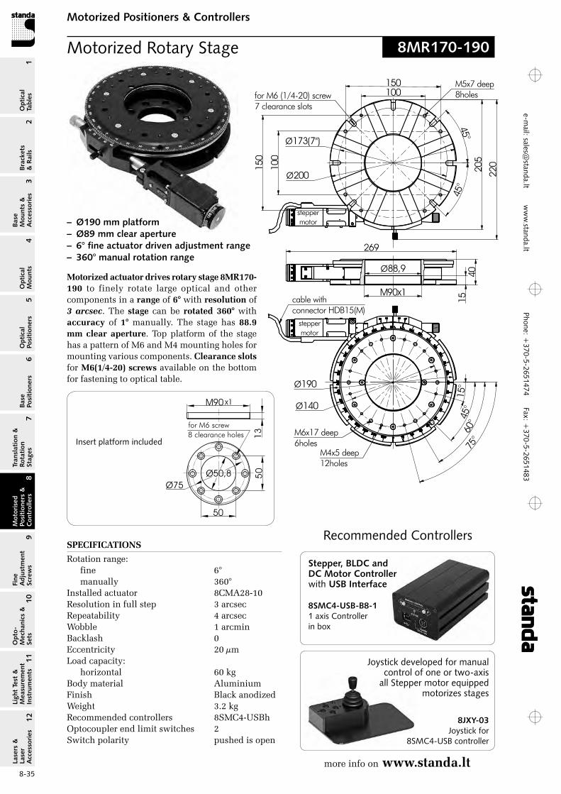
Phone: +370-5-2651474
Fax: +370-5-2651483
1Br
acke
ts
& R
ails
2
Base
M
ount
s &
A
cces
sori
es3
Opt
ical
M
ount
s4
Opt
ical
Po
siti
oner
s5
Base
Po
siti
oner
s6
Tran
slat
ion
&
Rota
tion
St
ages
7
Mot
oris
ed
Posi
tion
ers
&
Con
trol
lers
8
Fine
A
djus
tmen
t Sc
rew
s9
Opt
o-
Mec
hani
cs &
Se
ts10
Opt
ical
Ta
bles
Ligh
t Te
st &
M
easu
rem
ent
Inst
rum
ents
Lase
rs &
La
ser
Acc
esso
ries
11
12e-m
ail: [email protected] w
ww
.standa.lt
8-35
Motorized Positioners & ControllersM
otor
ised
Po
siti
oner
s &
C
ontr
olle
rs8
8MR170-190 Motorized Rotary Stage
4015
90M x1
Ø88,9
45°
45°
Ø173(7")
Ø200
for M6 (1/4-20) screw7 clearance slots
220205
269
15°
45°
60°
75°
M4x5 deep12holes
M6x17 deep6holes
Ø140
Ø190
100
100
150
150 M5x7 deep8holes
cable withconnector HDB15(M)
steppermotor
steppermotor
Insert platform included
Motorized actuator drives rotary stage 8MR170‑190 to finely rotate large optical and other components in a range of 6° with resolution of 3 arcsec. The stage can be rotated 360° with accuracy of 1° manually. The stage has 88.9 mm clear aperture. Top platform of the stage has a pattern of M6 and M4 mounting holes for mounting various components. Clearance slots for M6(1/4‑20) screws available on the bottom for fastening to optical table.
– Ø190 mm platform – Ø89 mm clear aperture – 6° fine actuator driven adjustment range– 360° manual rotation range
SPECIFICATIONS
rotation range:fine 6° manually 360°
Installed actuator 8CMA28-10 resolution in full step 3 arcsec repeatability 4 arcsec Wobble 1 arcmin Backlash 0 Eccentricity 20 µm Load capacity:
horizontal 60 kg Body material Aluminium Finish Black anodized Weight 3.2 kg recommended controllers 8SMC4-USBh optocoupler end limit switches 2 Switch polarity pushed is open
Recommended Controllers
more info on www.standa.lt
8SMC4-USB-B8-11 axis Controller in box
Stepper, BLDC and DC Motor Controller with USB Interface
Joystick developed for manual control of one or two-axis
all Stepper motor equipped motorizes stages
8JXY-03Joystick for
8SMC4-USB controller
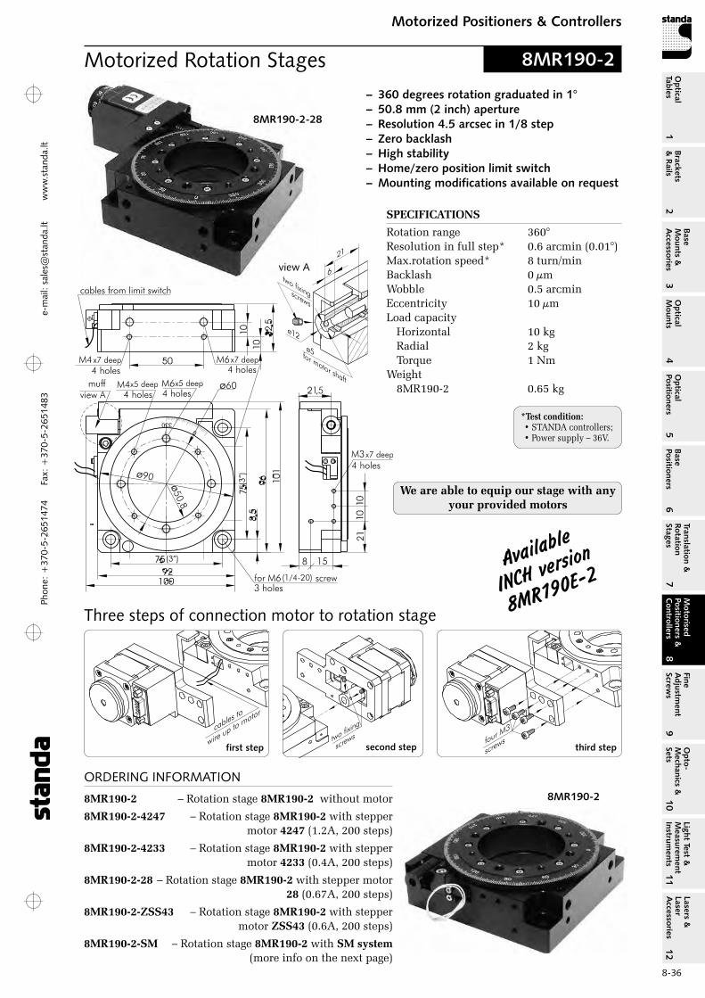
Phon
e: +
370-
5-26
5147
4 Fa
x: +
370-
5-26
5148
31
Brackets &
Rails
2
Base M
ounts &
Accessories
3O
ptical M
ounts4
Optical
Positioners5
Base Positioners
6
Translation &
Rotation Stages
7
Motorised
Positioners &
Controllers
8
Fine A
djustment
Screws
9
Opto-
Mechanics &
Sets
10O
ptical Tables
Light Test &
Measurem
ent Instrum
ents
Lasers &
Laser A
ccessories 11
12e-
mai
l: sa
les@
stan
da.lt
ww
w.s
tand
a.lt
8-36
Motorized Positioners & ControllersM
otorised Positioners &
C
ontrollers8
8MR190-2Motorized Rotation Stages– 360 degrees rotation graduated in 1°– 50.8 mm (2 inch) aperture– Resolution 4.5 arcsec in 1/8 step– Zero backlash– High stability– Home/zero position limit switch– Mounting modifications available on request
SPECIFICATIONS
rotation range 360°resolution in full step* 0.6 arcmin (0.01°)Max.rotation speed* 8 turn/minBacklash 0 µmWobble 0.5 arcminEccentricity 10 µmLoad capacity
Horizontal 10 kg radial 2 kg Torque 1 Nm
Weight 8Mr190-2 0.65 kg
ORDERING INFORMATION
8MR190‑2 – rotation stage 8MR190‑2 without motor
8MR190‑2‑4247 – rotation stage 8MR190‑2 with stepper motor 4247 (1.2A, 200 steps)
8MR190‑2‑4233 – rotation stage 8MR190‑2 with stepper motor 4233 (0.4A, 200 steps)
8MR190‑2‑28 – rotation stage 8MR190‑2 with stepper motor 28 (0.67A, 200 steps)
8MR190‑2‑ZSS43 – rotation stage 8MR190‑2 with stepper motor ZSS43 (0.6A, 200 steps)
8MR190‑2‑SM – rotation stage 8MR190‑2 with SM system (more info on the next page)
8MR190-2
8MR190-2-28
view A
Three steps of connection motor to rotation stage
second stepfirst step third step
We are able to equip our stage with any your provided motors
Available
iNch vers
ion
8Mr190e-2
*Test condition: • STANDA controllers;• Power supply – 36V.
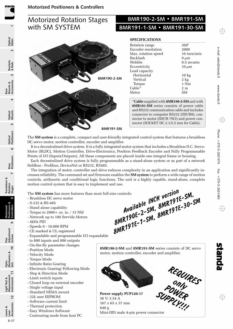
Phone: +370-5-2651474
Fax: +370-5-2651483
1Br
acke
ts
& R
ails
2
Base
M
ount
s &
A
cces
sori
es3
Opt
ical
M
ount
s4
Opt
ical
Po
siti
oner
s5
Base
Po
siti
oner
s6
Tran
slat
ion
&
Rota
tion
St
ages
7
Mot
oris
ed
Posi
tion
ers
&
Con
trol
lers
8
Fine
A
djus
tmen
t Sc
rew
s9
Opt
o-
Mec
hani
cs &
Se
ts10
Opt
ical
Ta
bles
Ligh
t Te
st &
M
easu
rem
ent
Inst
rum
ents
Lase
rs &
La
ser
Acc
esso
ries
11
12e-m
ail: [email protected] w
ww
.standa.lt
8-37
Motorized Positioners & ControllersM
otor
ised
Po
siti
oner
s &
C
ontr
olle
rs8
8MR190-2-SM
8MR191-SM
SPECIFICATIONSrotation range 360°Encoder resolution 2000Max. rotation speed 16 turn/minBacklash 0 µmWobble 0.5 arcminEccentricity 10 µmLoad capacity
Horizontal 10 kg Vertical 2 kgTorque 1 Nm
Cable* 2 mMotor SM
*Cable supplied with 8MR190‑2‑SM and with 8MR191‑SM series consists of power cable and rS232 communication cable and includes connector to computer rS232 (DSUB9), con-nector to motor (DSUB 7W2) and power con-nector (SoCKET DC 2.1/5.5 mm for Cable).
Motorized Rotation Stages with SM SYSTEM
8MR190-2-SM • 8MR191-SM
8MR191-1-SM • 8MR191-30-SM
The SM system is a complete, compact and user-friendly integrated control system that features a brushless DC servo motor, motion controller, encoder and amplifier.
It is a decentralized drive system. It is a fully integrated motor system that includes a Brushless D.C. Servo-Motor (BLDC), Motion Controller, Drive-Electronics, Position Feedback Encoder and Fully Programmable Points of I/o (Inputs/outputs). All these components are placed inside one integral frame or housing.
Each decentralized drive system is fully programmable as a stand-alone system or as part of a network fieldbus - Profibus, DeviceNet or rS232, rS485.
The integration of motor, controller and drive reduces complexity in an application and significantly in-creases reliability. The command set and firmware enables the SM system to perform a wide range of motion controls, arithmetic and conditional logic functions. The unit is a highly capable, stand-alone, complete motion control system that is easy to implement and use.
The SM system has more features than most full-size controls: - Brushless DC servo motor - S-232 & rS-485 - Stand alone capability - Torque to 2000+ oz. in. / 15 NM - Network up to 100 Servida Motors - 4kHz PID - Speeds 0 - 10,000 rPM - CE marked & UL registered - Expandable and programmable I/o expandable to 800 inputs and 800 outputs - on-the-fly parameter changes - Position Mode - Velocity Mode - Torque Mode - Infinite ratio Gearing - Electronic Gearing/ Following Mode - Step & Direction Mode - Limit switch inputs - Closed loop on external encoder - Single voltage input - Standard NEMA mount - 32k user EEProM - Software current limit - Thermal protection - Easy Windows Software - Contouring mode from host PC
Available
iNch vers
ion
8Mr190e-2-
SM, 8Mr191
e-SM,
8Mr191e-1-
SM, 8Mr191
e-30-SM
reqUireSonlyPOwerSUPPLY!!!
8MR190‑2‑SM and 8MR191‑SM series consists of DC servo motor, motion controller, encoder and amplifier.
Power supply PUP120‑17 36 V; 3.34 A 167 x 65 x 37 mm 640 g Mini-DIN male 4-pin power connector
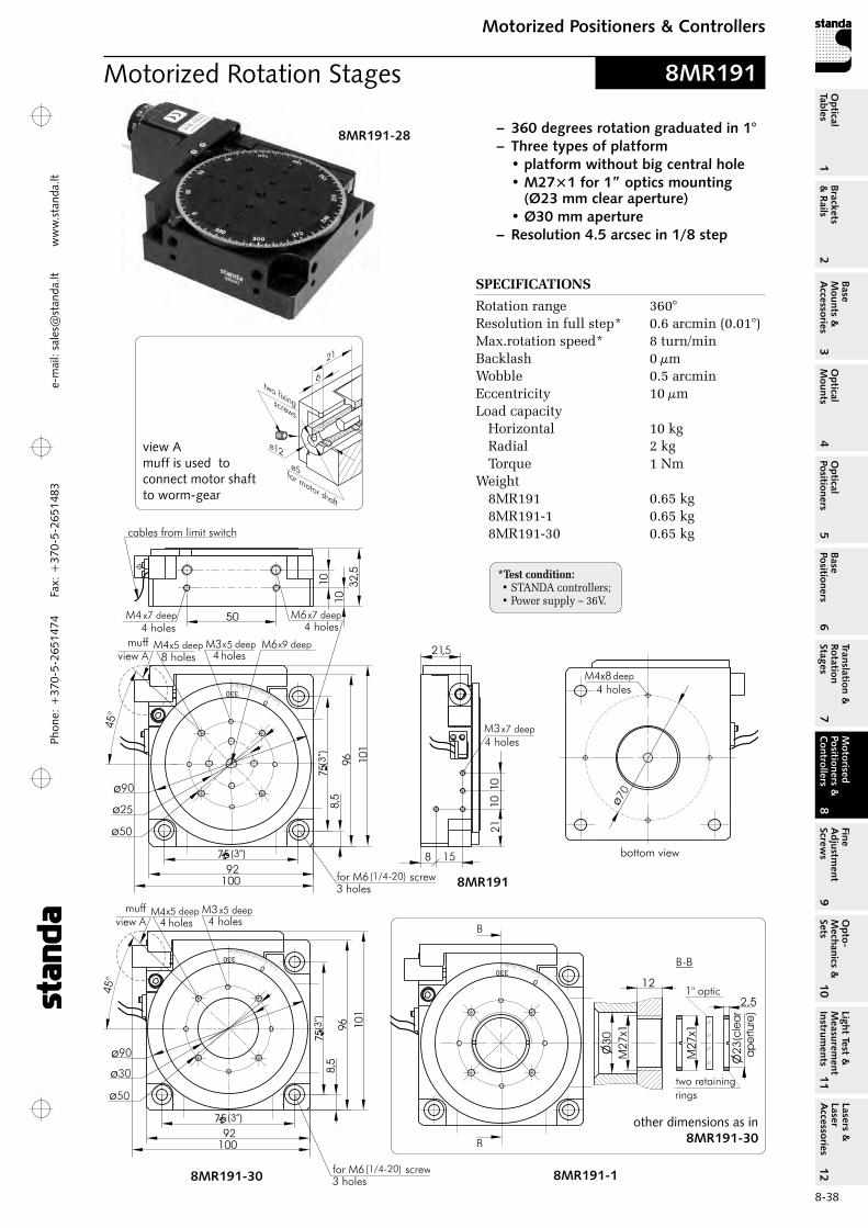
Phon
e: +
370-
5-26
5147
4 Fa
x: +
370-
5-26
5148
31
Brackets &
Rails
2
Base M
ounts &
Accessories
3O
ptical M
ounts4
Optical
Positioners5
Base Positioners
6
Translation &
Rotation Stages
7
Motorised
Positioners &
Controllers
8
Fine A
djustment
Screws
9
Opto-
Mechanics &
Sets
10O
ptical Tables
Light Test &
Measurem
ent Instrum
ents
Lasers &
Laser A
ccessories 11
12e-
mai
l: sa
les@
stan
da.lt
ww
w.s
tand
a.lt
8-38
Motorized Positioners & ControllersM
otorised Positioners &
C
ontrollers8
8MR191-28 – 360 degrees rotation graduated in 1°– Three types of platform • platform without big central hole • M27×1 for 1” optics mounting (Ø23 mm clear aperture) • Ø30 mm aperture– Resolution 4.5 arcsec in 1/8 step
Motorized Rotation Stages
8MR191
8MR191-30 8MR191-1
other dimensions as in 8MR191-30
8MR191
SPECIFICATIONS
rotation range 360°resolution in full step* 0.6 arcmin (0.01°)Max.rotation speed* 8 turn/minBacklash 0 µmWobble 0.5 arcminEccentricity 10 µmLoad capacity
Horizontal 10 kg radial 2 kg Torque 1 Nm
Weight8Mr191 0.65 kg 8Mr191-1 0.65 kg 8Mr191-30 0.65 kg
bottom view
view Amuff is used to connect motor shaft to worm-gear
*Test condition: • STANDA controllers;• Power supply – 36V.

Phone: +370-5-2651474
Fax: +370-5-2651483
1Br
acke
ts
& R
ails
2
Base
M
ount
s &
A
cces
sori
es3
Opt
ical
M
ount
s4
Opt
ical
Po
siti
oner
s5
Base
Po
siti
oner
s6
Tran
slat
ion
&
Rota
tion
St
ages
7
Mot
oris
ed
Posi
tion
ers
&
Con
trol
lers
8
Fine
A
djus
tmen
t Sc
rew
s9
Opt
o-
Mec
hani
cs &
Se
ts10
Opt
ical
Ta
bles
Ligh
t Te
st &
M
easu
rem
ent
Inst
rum
ents
Lase
rs &
La
ser
Acc
esso
ries
11
12e-m
ail: [email protected] w
ww
.standa.lt
8-39
Motorized Positioners & ControllersM
otor
ised
Po
siti
oner
s &
C
ontr
olle
rs8
Available
iNch vers
ion
8Mr191e
8Mr191e-1
8Mr191e-30
We are able to equip our stages with motors of your choice
8MR190-2-SM
rotation stage 8MR190‑2 with SM system
8MR191-28
rotation stage 8MR191 with stepper motor 28
8MR191-1-4233
rotation stage 8MR191‑1 with stepper motor 4233
8MR191-30-4247
rotation stage 8MR191‑30 with stepper motor 4247
Recommended Controllers more info on www.standa.lt
ORDERING INFORMATION
Examples of codes for motorized rotation stages 8MR191:
8MR191 – rotation stage 8MR191 without motor
8MR191‑1‑4247 – rotation stage 8MR191‑1 with stepper motor 4247 (1.2A, 200 steps)
8MR191‑30‑4233 – rotation stage 8MR191‑30 with stepper motor 4233 (0.4A, 200 steps)
8MR191‑28 – rotation stage 8MR191 with stepper motor 28 (0.67A, 200 steps)
8MR191‑1‑ZSS43 – rotation stage 8MR191‑1 with stepper motor ZSS43 (0.6A, 200 steps)
8MR191‑30‑SM – rotation stage 8MR191‑30 with SM system
(more info on the 8‑37 page)
8SMC4-USB-B8-11 axis Controller in box
Stepper, BLDC and DC Motor Controller with USB Interface
Joystick developed for manual control of one or two-axis all Stepper motor equipped
motorizes stages
8JXY-03Joystick for
8SMC4-USB controller

Phon
e: +
370-
5-26
5147
4 Fa
x: +
370-
5-26
5148
31
Brackets &
Rails
2
Base M
ounts &
Accessories
3O
ptical M
ounts4
Optical
Positioners5
Base Positioners
6
Translation &
Rotation Stages
7
Motorised
Positioners &
Controllers
8
Fine A
djustment
Screws
9
Opto-
Mechanics &
Sets
10O
ptical Tables
Light Test &
Measurem
ent Instrum
ents
Lasers &
Laser A
ccessories 11
12e-
mai
l: sa
les@
stan
da.lt
ww
w.s
tand
a.lt
8-40
Motorized Positioners & ControllersM
otorised Positioners &
C
ontrollers8
Mini Motorized Rotation Stage 8MR174-11-20
8MR174-11-28, 7T184-13 (2 pieces)
and 7VT174-5 stacked
Mini Motorized Rotation Stages
SPECIFICATIONS
rotation range 360° resolution in full step* 0.9 arcmin
(0.015°)Uni-directional repeatability 0.4 arcminBi-directional repeatability 1.6 arcminMax. rotation speed* 75°/s (36V)
30°/s (12V)Wobble 1 arcminEccentricity 10 µmLoad capacity
Horizontal 3 kg radial 1.5 kg Torque 0.15 Nm
Cable integrated, 1.6 m lengthMotor connector HDB15(M)Stepper motor 20Weight 0.3 kg
Model L, mm m, mm motor 8Mr174-11-28 111 54 288Mr174-11-28S 98 41 28S
25
20
40
30
32
45
32
4
20 48
93,5
39,611M2,5x6 deep
4holes
for M3 screw
3 clearance holes
stepper
motor
37
5
M3x6 deep
4holes on
knob
cable with
connector HDB15(M)
8MR174-11-288MR174-11-28S
8MR174-11
3UBP-04
3UBP universal base plates for stacking the translation stages to STANDA optical tables or to another stages. Page 3-6
3UBP-02 3UBP-03
8MR174-11-28S
Available
iNch vers
ion
8Mr174e-11
-20
8Mr174e-11
-28
8Mr174e-11
-28S
SPECIFICATIONS
rotation range 360° resolution in full step* 0.9 arcmin
(0.015°)Uni-directional repeatability 0.4 arcminBi-directional repeatability 1.6 arcminMax. rotation speed* 75°/s (36V) 30°/s (12V)Wobble 1 arcminEccentricity 10 µmLoad capacity
Horizontal 4 kg radial 1.5 kg Torque
8Mr174-11-28 0.5 Nm8Mr174-11-28S 0.35 Nm
Cable integrated, 1.6 m lengthMotor connector HDB15(M)Weight
8Mr174-11-28 0.4 kg8Mr174-11-28S 0.35 kg
*Test condition: • STANDA controllers;• Power supply – 36V.
*Test condition: • STANDA controllers;• Power supply – 36V.
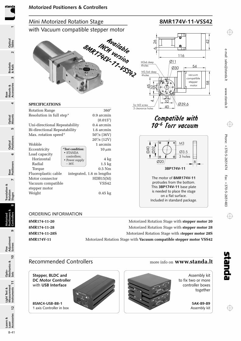
Phone: +370-5-2651474
Fax: +370-5-2651483
1Br
acke
ts
& R
ails
2
Base
M
ount
s &
A
cces
sori
es3
Opt
ical
M
ount
s4
Opt
ical
Po
siti
oner
s5
Base
Po
siti
oner
s6
Tran
slat
ion
&
Rota
tion
St
ages
7
Mot
oris
ed
Posi
tion
ers
&
Con
trol
lers
8
Fine
A
djus
tmen
t Sc
rew
s9
Opt
o-
Mec
hani
cs &
Se
ts10
Opt
ical
Ta
bles
Ligh
t Te
st &
M
easu
rem
ent
Inst
rum
ents
Lase
rs &
La
ser
Acc
esso
ries
11
12e-m
ail: [email protected] w
ww
.standa.lt
8-41
Motorized Positioners & ControllersM
otor
ised
Po
siti
oner
s &
C
ontr
olle
rs8
20
40
30
32
45
32
42
0
116
39,6
11
M2,5x6 deep
4holes
for M3 screw
3 clearance holes
54
M3x6 deep
4holesØ
Ø
Ø
vacuumcompatible
steppermotor 5
84
2
62
6
SPECIFICATIONS
rotation range 360° resolution in full step* 0.9 arcmin
(0.015°)Uni-directional repeatability 0.4 arcminBi-directional repeatability 1.6 arcminMax. rotation speed* 50°/s (36V)
20°/s (12V)Wobble 1 arcminEccentricity 10 µmLoad capacity
Horizontal 4 kg radial 1.5 kg Torque 0.5 Nm
Fluoroplastic cable integrated, 1.6 m lengthsMotor connector HDB15(M)Vacuum compatible VSS42 stepper motorWeight 0.45 kg
compatible with 10-6 Torr vacuum
�4
0
�3
2
8
Ø3.5
3 holes
M3
Ø20
The motor of 8MR174V-11 protrudes from the bottom. This 3BP174V-11 base plate is needed to place the stage
on a flat surface. Included in standard package.
3BP174V-11
Available iNch version
8Mr174eV-11-VSS42
ORDERING INFORMATION
8MR174‑11‑20 Motorized rotation Stage with stepper motor 20
8MR174‑11‑28 Motorized rotation Stage with stepper motor 28
8MR174‑11‑28S Motorized rotation Stage with stepper motor 28S
8MR174V‑11 Motorized rotation Stage with Vacuum compatible stepper motor VSS42
Recommended Controllers more info on www.standa.lt
Mini Motorized Rotation Stage 8MR174V-11-VSS42with Vacuum compatible stepper motor
*Test condition: • STANDA controllers;• Power supply – 36V.
8SMC4-USB-B8-11 axis Controller in box
Stepper, BLDC and DC Motor Controller with USB Interface
5AK-B9-B9 Assembly kit
Assembly kit to fix two or more
controller boxes together

Phon
e: +
370-
5-26
5147
4 Fa
x: +
370-
5-26
5148
31
Brackets &
Rails
2
Base M
ounts &
Accessories
3O
ptical M
ounts4
Optical
Positioners5
Base Positioners
6
Translation &
Rotation Stages
7
Motorised
Positioners &
Controllers
8
Fine A
djustment
Screws
9
Opto-
Mechanics &
Sets
10O
ptical Tables
Light Test &
Measurem
ent Instrum
ents
Lasers &
Laser A
ccessories 11
12e-
mai
l: sa
les@
stan
da.lt
ww
w.s
tand
a.lt
8-42
Motorized Positioners & ControllersM
otorised Positioners &
C
ontrollers8
Motorized Rotation Stages
8MR151-1
8MR151-30
SPECIFICATIONS
rotation range 360°resolution in full step* 0.6 arcmin in 1/8 step* 4.5 arcsecMax. rotation speed* 50°/sWobble 0.6 arcminEccentricity 10 µmLoad capacity
Horizontal 6 kgradial 1.7 kgTorque 0.5 Nm
Cable integrated, 1.6 m lengthMotor connector HDB15(M)Stepper motor 28Weight 0.56 kg
8MR151
8MR151-308MR151-1
ORDERING INFORMATION
8MR151‑1 M27×1 for 1” optics mounting (Ø23 mm clear aperture)
8MR151‑30 Ø30 mm aperture
2VP150 vertical plate
Available
iNch vers
ion
8Mr151e
32
50
12,5
18
7
7
15
50
6129,5
M32 holes M6
2 holes
M6
6,52 holes
Angle bracket 2VP150 - for vertical mounting.
2VP150
(1/4-20)
(”2
)
(”2)
(1/4-20)
(”2)
(”2
)
*Test condition: • STANDA controllers;• Power supply – 36V.
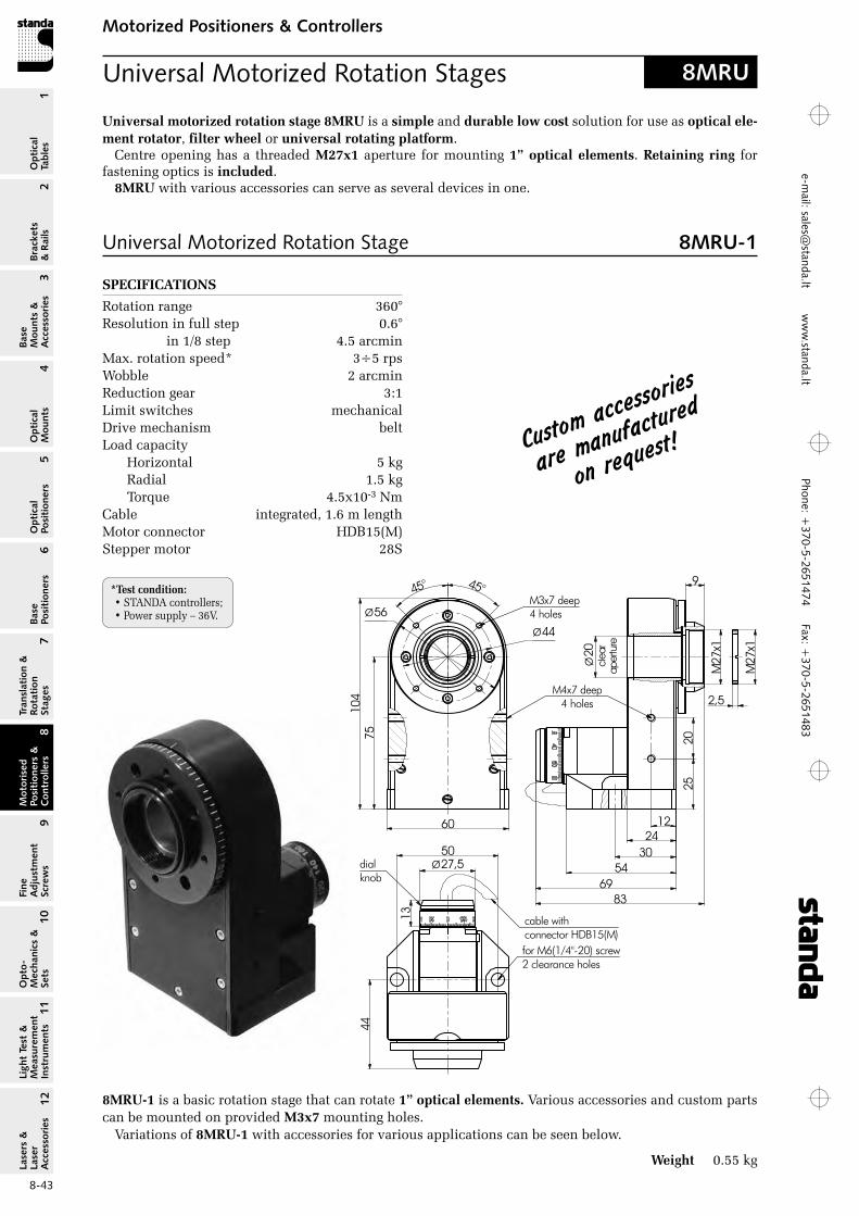
Phone: +370-5-2651474
Fax: +370-5-2651483
1Br
acke
ts
& R
ails
2
Base
M
ount
s &
A
cces
sori
es3
Opt
ical
M
ount
s4
Opt
ical
Po
siti
oner
s5
Base
Po
siti
oner
s6
Tran
slat
ion
&
Rota
tion
St
ages
7
Mot
oris
ed
Posi
tion
ers
&
Con
trol
lers
8
Fine
A
djus
tmen
t Sc
rew
s9
Opt
o-
Mec
hani
cs &
Se
ts10
Opt
ical
Ta
bles
Ligh
t Te
st &
M
easu
rem
ent
Inst
rum
ents
Lase
rs &
La
ser
Acc
esso
ries
11
12e-m
ail: [email protected] w
ww
.standa.lt
8-43
Motorized Positioners & ControllersM
otor
ised
Po
siti
oner
s &
C
ontr
olle
rs8
Universal Motorized Rotation Stages 8MRU
Universal Motorized Rotation Stage 8MRU-1
*Test condition: • STANDA controllers;• Power supply – 36V.
Universal motorized rotation stage 8MRU is a simple and durable low cost solution for use as optical ele‑ment rotator, filter wheel or universal rotating platform.
Centre opening has a threaded M27x1 aperture for mounting 1” optical elements. Retaining ring for fastening optics is included.
8MRU with various accessories can serve as several devices in one.
8MRU‑1 is a basic rotation stage that can rotate 1” optical elements. Various accessories and custom parts can be mounted on provided M3x7 mounting holes.
Variations of 8MRU‑1 with accessories for various applications can be seen below.
Weight 0.55 kg
SPECIFICATIONS
rotation range 360°resolution in full step 0.6° in 1/8 step 4.5 arcminMax. rotation speed* 3÷5 rpsWobble 2 arcminreduction gear 3:1Limit switches mechanicalDrive mechanism beltLoad capacity
Horizontal 5 kgradial 1.5 kgTorque 4.5x10⁻³ Nm
Cable integrated, 1.6 m lengthMotor connector HDB15(M)Stepper motor 28S
custom acce
ssories
are manufa
ctured
on request
!
9
27M
x1
Ø20
clea
rap
ertu
re
2520
83
12
3054
69
M4x7 deep4 holes
50
for M6(1/4"-20) screw2 clearance holes
cable withconnector HDB15(M)
13
27,5Ødialknob
24
27M
x1
2,5
45° 45°
7510
4
60
Ø44
Ø56M3x7 deep4 holes
44
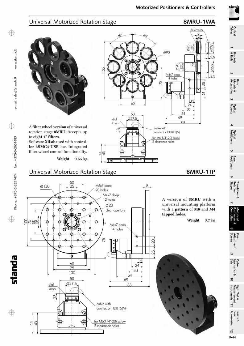
Phon
e: +
370-
5-26
5147
4 Fa
x: +
370-
5-26
5148
31
Brackets &
Rails
2
Base M
ounts &
Accessories
3O
ptical M
ounts4
Optical
Positioners5
Base Positioners
6
Translation &
Rotation Stages
7
Motorised
Positioners &
Controllers
8
Fine A
djustment
Screws
9
Opto-
Mechanics &
Sets
10O
ptical Tables
Light Test &
Measurem
ent Instrum
ents
Lasers &
Laser A
ccessories 11
12e-
mai
l: sa
les@
stan
da.lt
ww
w.s
tand
a.lt
8-44
Motorized Positioners & ControllersM
otorised Positioners &
C
ontrollers8
Universal Motorized Rotation Stage 8MRU-1TP
A version of 8MRU with a universal mounting platform with a pattern of M6 and M4 tapped holes.
Weight 0.7 kg
Universal Motorized Rotation Stage 8MRU-1WA
2520
83
12
3054
69
M4x7 deep4 holes
50
for M6(1/4"-20) screw2 clearance holes
cable withconnector HDB15(M)13
27,5Ødialknob
24
75
60
945° 45°
135
Ø90
Ø20
clea
rap
ertu
re
27M
x1
2,5
2,5
27M
x1
8elements
Ø23 clea
rap
ertu
re
6
9
4344
8
2520
83
12
3054
69
M4x7 deep4 holes
50
for M6(1/4"-20) screw2 clearance holes
cable withconnector HDB15(M)
13
27,5Ødialknob
24
75
60
2550
75100
255075100
M6x7 deep20 holes
M4x7 deep12 holes
Ø20clear aperture
Ø130
4344
A filter wheel version of universal rotation stage 8MRU. Accepts up to eight 1” filters.Software XiLab used with control-ler 8SMC4‑USB has integrated filter wheel control functionality.
Weight 0.65 kg

Phone: +370-5-2651474
Fax: +370-5-2651483
1Br
acke
ts
& R
ails
2
Base
M
ount
s &
A
cces
sori
es3
Opt
ical
M
ount
s4
Opt
ical
Po
siti
oner
s5
Base
Po
siti
oner
s6
Tran
slat
ion
&
Rota
tion
St
ages
7
Mot
oris
ed
Posi
tion
ers
&
Con
trol
lers
8
Fine
A
djus
tmen
t Sc
rew
s9
Opt
o-
Mec
hani
cs &
Se
ts10
Opt
ical
Ta
bles
Ligh
t Te
st &
M
easu
rem
ent
Inst
rum
ents
Lase
rs &
La
ser
Acc
esso
ries
11
12e-m
ail: [email protected] w
ww
.standa.lt
8-45
Motorized Positioners & ControllersM
otor
ised
Po
siti
oner
s &
C
ontr
olle
rs8
Motorized Screws– Manual drive with a dial knob– Resolution 0.156 µm (1/8 step)– Scale on the dial knob allows reading
accuracy to a step
Model M, mm L min, mm L max, mm
8MS00-10 37 143.5 153.58MS00-25 47 153.5 178.5
– Two limit switches– Optional power supplies for higher voltages/
speeds are available
8MS00-10
8MS00
8MS00-10-28
Model M, mm L min, mm L max, mm
8MS00-10-28 37 157.5 167.58MS00-25-28 47 167.5 192.5
SPECIFICATIONSTravel range
8MS00-10-28 10 mm8MS00-25-28 25 mm
Lead screw pitch 0.25 mmresolution in full step 1.25 µm Nominal force 80 NCable integrated, 1.6 m lengthMotor connector HDB15(M)Stepper motor 28Weight
8MS00-10-28 0.45 kg8MS00-25-28 0.5 kg
SPECIFICATIONSTravel range
8MS00-10 10 mm8MS00-25 25 mm
Lead screw pitch 0.25 mmresolution in full step 1.25 µm Nominal force 60 NMotor connector DB9(M)Stepper motor 4233Weight
8MS00-10 0.5 kg8MS00-25 0.55 kg
8MS00V-10
SPECIFICATIONSTravel range
8MS00V-10 10 mm8MS00V-25 25 mm
Lead screw pitch 0.25 mmresolution in full step 1.25 µm Nominal force 30 NFluoroplastic cable integrated, 2 m lengthMotor connector HDB15(M)Stepper motor VSS43Weight
8MS00V-10 0.55 kg8MS00V-25 0.6 kg
Motorized Screws 8MS00-10-288MS00-25-28
Motorized Screws 8MS00-108MS00-25
Motorized Screws 8MS00V-108MS00V-25
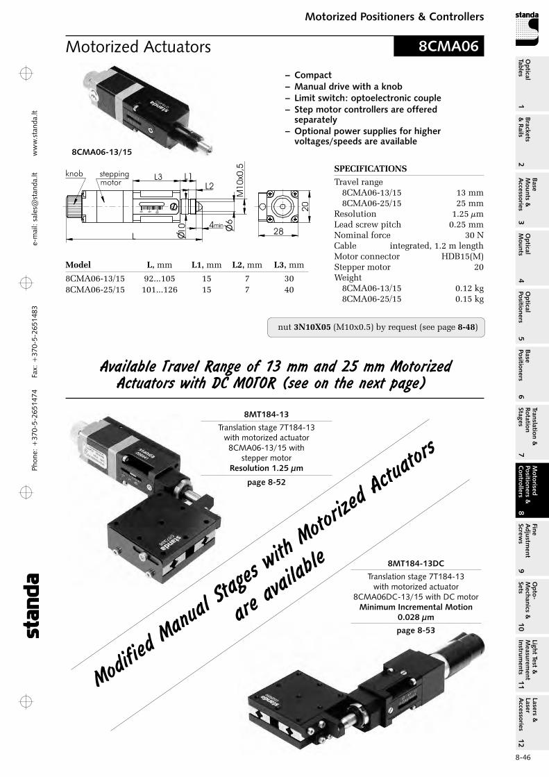
Phon
e: +
370-
5-26
5147
4 Fa
x: +
370-
5-26
5148
31
Brackets &
Rails
2
Base M
ounts &
Accessories
3O
ptical M
ounts4
Optical
Positioners5
Base Positioners
6
Translation &
Rotation Stages
7
Motorised
Positioners &
Controllers
8
Fine A
djustment
Screws
9
Opto-
Mechanics &
Sets
10O
ptical Tables
Light Test &
Measurem
ent Instrum
ents
Lasers &
Laser A
ccessories 11
12e-
mai
l: sa
les@
stan
da.lt
ww
w.s
tand
a.lt
8-46
Motorized Positioners & ControllersM
otorised Positioners &
C
ontrollers8
Motorized Actuators
SPECIFICATIONS
Travel range8CMA06-13/15 13 mm8CMA06-25/15 25 mm
resolution 1.25 µmLead screw pitch 0.25 mmNominal force 30 NCable integrated, 1.2 m lengthMotor connector HDB15(M)Stepper motor 20Weight
8CMA06-13/15 0.12 kg8CMA06-25/15 0.15 kg
Model L, mm L1, mm L2, mm L3, mm
8CMA06-13/15 92...105 15 7 308CMA06-25/15 101...126 15 7 40
nut 3N10X05 (M10x0.5) by request (see page 8‑48)
8CMA06
Available Travel range of 13 mm and 25 mm Motorized Actuators with Dc MOTOr (see on the next page)
8CMA06-13/15
Modified
Manu
al Sta
ges wi
th Moto
rized A
ctuato
rs
are av
ailable
8MT184-13
Translation stage 7T184-13 with motorized actuator
8CMA06-13/15 with stepper motor
Resolution 1.25 µm
page 8-52
8MT184-13DC
Translation stage 7T184-13 with motorized actuator
8CMA06DC-13/15 with DC motorMinimum Incremental Motion
0.028 µm
page 8-53
– Compact– Manual drive with a knob– Limit switch: optoelectronic couple– Step motor controllers are offered
separately – Optional power supplies for higher
voltages/speeds are available

Phone: +370-5-2651474
Fax: +370-5-2651483
1Br
acke
ts
& R
ails
2
Base
M
ount
s &
A
cces
sori
es3
Opt
ical
M
ount
s4
Opt
ical
Po
siti
oner
s5
Base
Po
siti
oner
s6
Tran
slat
ion
&
Rota
tion
St
ages
7
Mot
oris
ed
Posi
tion
ers
&
Con
trol
lers
8
Fine
A
djus
tmen
t Sc
rew
s9
Opt
o-
Mec
hani
cs &
Se
ts10
Opt
ical
Ta
bles
Ligh
t Te
st &
M
easu
rem
ent
Inst
rum
ents
Lase
rs &
La
ser
Acc
esso
ries
11
12e-m
ail: [email protected] w
ww
.standa.lt
8-47
Motorized Positioners & ControllersM
otor
ised
Po
siti
oner
s &
C
ontr
olle
rs8
encoder DC motor
gear
Ultra-High Resolution Compact Motorized Actuator with DC motor
8CMA16DC
Model L, mm L1, mm L2, mm L3, mm
8CMA16DC-13/15 109.5...122.5 15 7 508CMA16DC-25/15 119.5...144.5 15 7 60
SPECIFICATIONS Travel range
8CMA16DC-13/15 13 mm8CMA16DC-25/15 25 mm
resolution 0.1µmMinimal incremental motion 0.028 µmLead screw pitch 0.25 mmMax.speed 0.15 mm/sNominal force 30 NCable integrated, 1.2 m lengthMotor connector IDC-10FDC motor DCE1524Weight
8CMA16DC-13/15 0.12 kg8CMA16DC-25/15 0.15 kg
encoderDC motor
gear
vacuum compatible
SPECIFICATIONS Travel range
8CMA16DCV-13/15 13 mm8CMA16DCV-25/15 25 mm
resolution 0.1 µmMinimal incremental motion 0.028 µmLead screw pitch 0.25 mmMax.speed 0.15 mm/sNominal force 30 NCable integrated, 2 m lengthMotor connector IDC-10FVacuum compatible DC motor DCE1841Weight
8CMA16DCV-13/15 0.12 kg8CMA16DCV-25/15 0.15 kg
compatible with
10-6 Torr
vacuum
Model L, mm L1, mm L2, mm L3, mm
8CMA16DCV-13/15 125...138 15 7 508CMA16DCV-25/15 135...160 15 7 60
8CMA16DC-13/15
8CMA16DC-25/15
Ultra-High Resolution Compact Motorized 8CMA16DCVActuator with Vacuum compatible DC motor
Recommended controller for DC Motor
8SMC4-USB-B8-11 axis Controller in box
Stepper, BLDC and DC Motor Controller with USB Interface
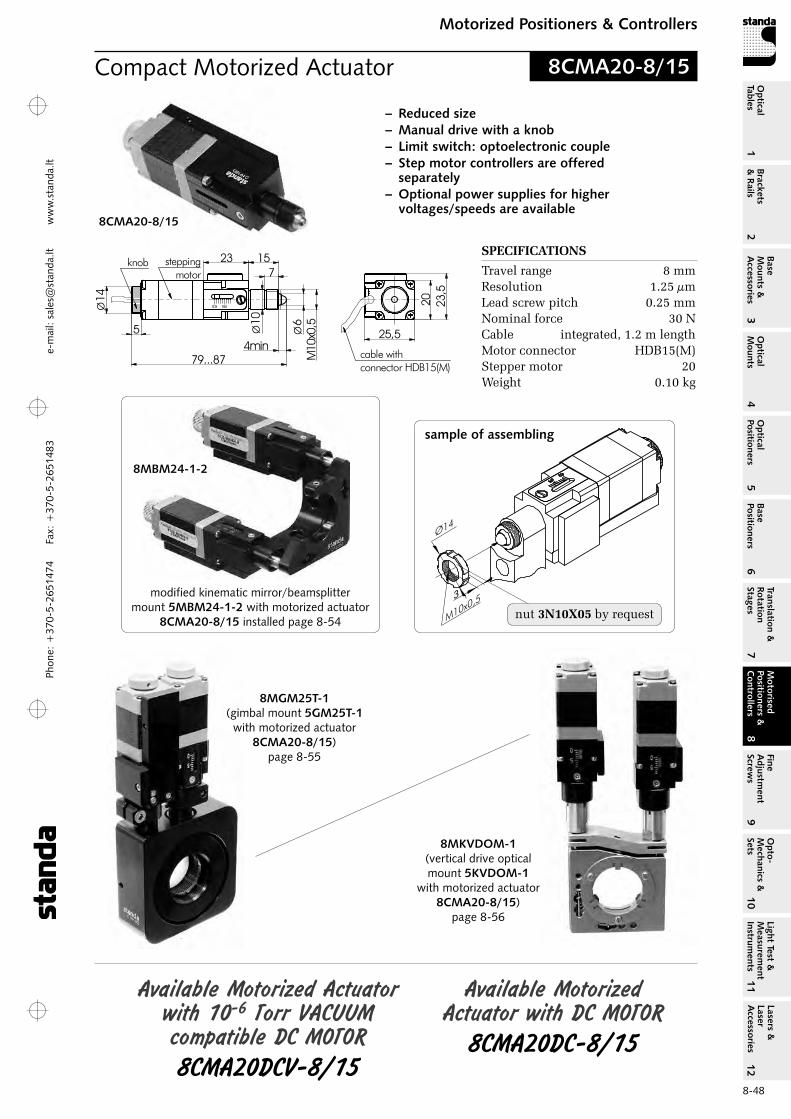
Phon
e: +
370-
5-26
5147
4 Fa
x: +
370-
5-26
5148
31
Brackets &
Rails
2
Base M
ounts &
Accessories
3O
ptical M
ounts4
Optical
Positioners5
Base Positioners
6
Translation &
Rotation Stages
7
Motorised
Positioners &
Controllers
8
Fine A
djustment
Screws
9
Opto-
Mechanics &
Sets
10O
ptical Tables
Light Test &
Measurem
ent Instrum
ents
Lasers &
Laser A
ccessories 11
12e-
mai
l: sa
les@
stan
da.lt
ww
w.s
tand
a.lt
8-48
Motorized Positioners & ControllersM
otorised Positioners &
C
ontrollers8
8MBM24-1-2
nut 3N10X05 by request
sample of assembling
8CMA20-8/15
Compact Motorized Actuator
SPECIFICATIONS
Travel range 8 mmresolution 1.25 µmLead screw pitch 0.25 mmNominal force 30 NCable integrated, 1.2 m lengthMotor connector HDB15(M)Stepper motor 20Weight 0.10 kg
8CMA20-8/15
Available Motorized Actuator with Dc MOTOr
8cMA20Dc-8/15
Available Motorized Actuator with 10-6 Torr VAcUUM compatible Dc MOTOr 8cMA20DcV-8/15
25,5
20 23,5
4min
Ø 6
10M
x0,510
Ø
71523
79...87
steppingmotor
knob
cable withconnector HDB15(M)
5
14Ø
modified kinematic mirror/beamsplitter mount 5MBM24-1-2 with motorized actuator
8CMA20-8/15 installed page 8-54
8MGM25T-1(gimbal mount 5GM25T-1
with motorized actuator 8CMA20-8/15)
page 8-55
8MKVDOM-1(vertical drive optical mount 5KVDOM-1
with motorized actuator 8CMA20-8/15)
page 8-56
– Reduced size– Manual drive with a knob– Limit switch: optoelectronic couple– Step motor controllers are offered
separately – Optional power supplies for higher
voltages/speeds are available

Phone: +370-5-2651474
Fax: +370-5-2651483
1Br
acke
ts
& R
ails
2
Base
M
ount
s &
A
cces
sori
es3
Opt
ical
M
ount
s4
Opt
ical
Po
siti
oner
s5
Base
Po
siti
oner
s6
Tran
slat
ion
&
Rota
tion
St
ages
7
Mot
oris
ed
Posi
tion
ers
&
Con
trol
lers
8
Fine
A
djus
tmen
t Sc
rew
s9
Opt
o-
Mec
hani
cs &
Se
ts10
Opt
ical
Ta
bles
Ligh
t Te
st &
M
easu
rem
ent
Inst
rum
ents
Lase
rs &
La
ser
Acc
esso
ries
11
12e-m
ail: [email protected] w
ww
.standa.lt
8-49
Motorized Positioners & ControllersM
otor
ised
Po
siti
oner
s &
C
ontr
olle
rs8
Motorized Actuator
SPECIFICATIONS Travel range 10 mmresolution 1.25 µmLead screw pitch 0.25 mmNominal force 70 NCable integrated, 1.2 m lengthMotor connector HDB15(M)Stepper motor 28Weight 0.15 kg
8CMA28-10
Modified Manual Stages with
Motorized Actuators
are available
8MR170-190(rotation stage 7R170-190
with motorized actuator 8CMA28-10)
8MR128(micro rotation stage 7R128
with motorized actuator 8CMA06-13/10)
8MBM57-6(mirror/beamsplitter mount 5BM57-6
with motorized actuator 8CMA28-10)
Related Controllers
more info on www.standa.lt
8SMC4-USB-B8-11 axis Controller in box
– Compact– Manual drive with a knob– Two limit switches– Step motor controllers are offered separately – Optional power supplies for higher voltages/
speeds are available

Phon
e: +
370-
5-26
5147
4 Fa
x: +
370-
5-26
5148
31
Brackets &
Rails
2
Base M
ounts &
Accessories
3O
ptical M
ounts4
Optical
Positioners5
Base Positioners
6
Translation &
Rotation Stages
7
Motorised
Positioners &
Controllers
8
Fine A
djustment
Screws
9
Opto-
Mechanics &
Sets
10O
ptical Tables
Light Test &
Measurem
ent Instrum
ents
Lasers &
Laser A
ccessories 11
12e-
mai
l: sa
les@
stan
da.lt
ww
w.s
tand
a.lt
8-50
Motorized Positioners & ControllersM
otorised Positioners &
C
ontrollers8
Motorized Fiber Coupling Stage– Fiber coupling stage
of flexure design– Rotating platform
on the top– Compact block design– Motorized Actuator
8CMA28-10– Long-term stability– Smooth motion
8MTF2
7FA1 7FA2 7FA3 7FA4 7FA5
3WFA-01
7FA4
7FA1
7FA3
7FA2
Fiber coupling stage 7TF2 with accessories
7FA7
7FA6
SPECIFICATIONS
Travel range in each XYZ direction 2 mmresolution 0.2 µmCross-Talk 20 µm/mmMechanical stability flexure design with
Stainless Steel SpringLoad capacity 1.5 kgType of actuator 8CMA28-10Cable 1.2 m length cable includedMotor connector HDB15(M)Weight 1.6 kg Other dimensions
such as 7TF2(page 7-27)
Accessories for Fiber Coupling Stage page 7‑27

Phone: +370-5-2651474
Fax: +370-5-2651483
1Br
acke
ts
& R
ails
2
Base
M
ount
s &
A
cces
sori
es3
Opt
ical
M
ount
s4
Opt
ical
Po
siti
oner
s5
Base
Po
siti
oner
s6
Tran
slat
ion
&
Rota
tion
St
ages
7
Mot
oris
ed
Posi
tion
ers
&
Con
trol
lers
8
Fine
A
djus
tmen
t Sc
rew
s9
Opt
o-
Mec
hani
cs &
Se
ts10
Opt
ical
Ta
bles
Ligh
t Te
st &
M
easu
rem
ent
Inst
rum
ents
Lase
rs &
La
ser
Acc
esso
ries
11
12e-m
ail: [email protected] w
ww
.standa.lt
8-51
Motorized Positioners & ControllersM
otor
ised
Po
siti
oner
s &
C
ontr
olle
rs8
Motorized YZ Translation Stage
SPECIFICATIONS
Tilt y ±2°rotation z ±2,5°resolution in full step 1,25 µm in 1/8 step 0,156 µmLead screw pitch 0.25 mmrepeatability 1 µmMaximum load capacity 10 kgType of actuator 8CMA28-10Cable 1.2 m length cable includedMotor connector DB15(M)Weight 1,3 kg
bottom view
8MTP116
Manual Multi-Axis Tilt platform6TP116
Motorized Actuator8CMA28-10
Stepper, BLDC and DC Motor Controller with USB Interface
2 axis Controller in box8SMC4-USB-B9-2
Assembly kit5AK-B9-B9
Assembly kit to fix two or more controller boxes
together
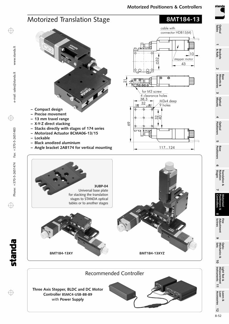
Phon
e: +
370-
5-26
5147
4 Fa
x: +
370-
5-26
5148
31
Brackets &
Rails
2
Base M
ounts &
Accessories
3O
ptical M
ounts4
Optical
Positioners5
Base Positioners
6
Translation &
Rotation Stages
7
Motorised
Positioners &
Controllers
8
Fine A
djustment
Screws
9
Opto-
Mechanics &
Sets
10O
ptical Tables
Light Test &
Measurem
ent Instrum
ents
Lasers &
Laser A
ccessories 11
12e-
mai
l: sa
les@
stan
da.lt
ww
w.s
tand
a.lt
8-52
Motorized Positioners & ControllersM
otorised Positioners &
C
ontrollers8
Motorized Translation Stage
– Compact design– Precise movement– 13 mm travel range– X-Y-Z direct stacking– Stacks directly with stages of 174 series– Motorized Actuator 8CMA06-13/15– Lockable– Black anodized aluminium– Angle bracket 2AB174 for vertical mounting
3UBP-04 Universal base plate
for stacking the translation stages to STANDA optical
tables or to another stages
8MT184-13
1621
40
32
32
38,3
69
M3x4 deep9 holes
�3
2
117...124
for M3 screw4 clearance holes
43
stepper motor
10
cable with
connector HDB15(M)
Three Axis Stepper, BLDC and DC MotorController 8SMC4-USB-B8-B9
with Power Supply
Recommended Controller
8MT184-13XYZ8MT184-13XY
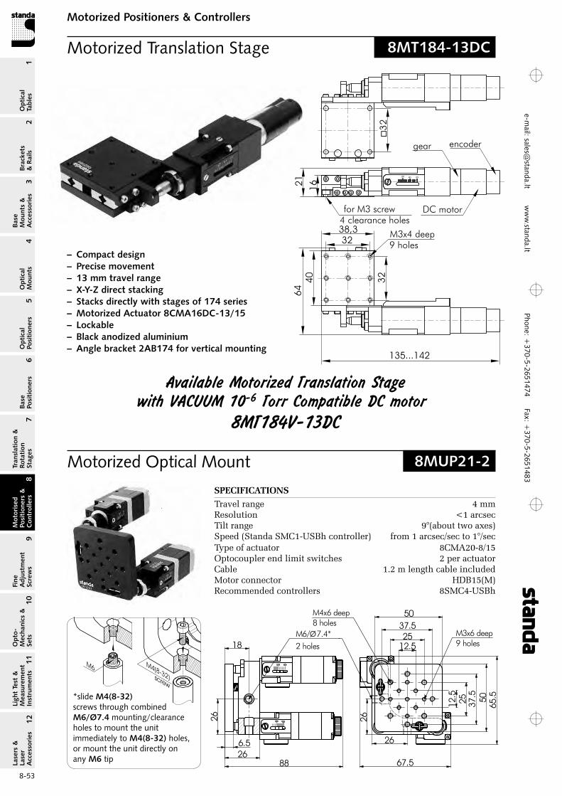
Phone: +370-5-2651474
Fax: +370-5-2651483
1Br
acke
ts
& R
ails
2
Base
M
ount
s &
A
cces
sori
es3
Opt
ical
M
ount
s4
Opt
ical
Po
siti
oner
s5
Base
Po
siti
oner
s6
Tran
slat
ion
&
Rota
tion
St
ages
7
Mot
oris
ed
Posi
tion
ers
&
Con
trol
lers
8
Fine
A
djus
tmen
t Sc
rew
s9
Opt
o-
Mec
hani
cs &
Se
ts10
Opt
ical
Ta
bles
Ligh
t Te
st &
M
easu
rem
ent
Inst
rum
ents
Lase
rs &
La
ser
Acc
esso
ries
11
12e-m
ail: [email protected] w
ww
.standa.lt
8-53
Motorized Positioners & ControllersM
otor
ised
Po
siti
oner
s &
C
ontr
olle
rs8
Motorized Translation Stage
– Compact design– Precise movement– 13 mm travel range– X-Y-Z direct stacking– Stacks directly with stages of 174 series– Motorized Actuator 8CMA16DC-13/15– Lockable– Black anodized aluminium– Angle bracket 2AB174 for vertical mounting
8MT184-13DC
Available Motorized Translation Stage with VAcUUM 10-6 Torr compatible Dc motor
8MT184V-13Dc
1621
40
32
32
38,3 M3x4 deep9 holes
�3
2
135...142
for M3 screw4 clearance holes
64
gear encoder
DC motor
67.5
65.5
26
26
12.525
37.550
12.5
25 37.5 50
M4x6 deep8 holes
M3x6 deep9 holes
M6/Ø7.4* 2 holes
6.526
18
26
88
8MUP21-2Motorized Optical Mount
M6
M4(8-32)screw
*slide M4(8-32) screws through combined M6/Ø7.4 mounting/clearance holes to mount the unit immediately to M4(8-32) holes, or mount the unit directly on any M6 tip
SPECIFICATIONS
Travel range 4 mmresolution <1 arcsecTilt range 9°(about two axes)Speed (Standa SMC1-USBh controller) from 1 arcsec/sec to 1°/secType of actuator 8CMA20-8/15optocoupler end limit switches 2 per actuatorCable 1.2 m length cable includedMotor connector HDB15(M)recommended controllers 8SMC4-USBh
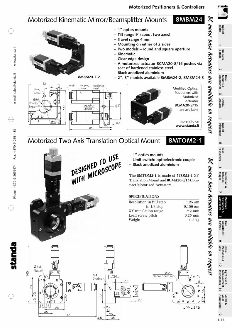
Phon
e: +
370-
5-26
5147
4 Fa
x: +
370-
5-26
5148
31
Brackets &
Rails
2
Base M
ounts &
Accessories
3O
ptical M
ounts4
Optical
Positioners5
Base Positioners
6
Translation &
Rotation Stages
7
Motorised
Positioners &
Controllers
8
Fine A
djustment
Screws
9
Opto-
Mechanics &
Sets
10O
ptical Tables
Light Test &
Measurem
ent Instrum
ents
Lasers &
Laser A
ccessories 11
12e-
mai
l: sa
les@
stan
da.lt
ww
w.s
tand
a.lt
8-54
Motorized Positioners & ControllersM
otorised Positioners &
C
ontrollers8
Motorized Kinematic Mirror/Beamsplitter Mounts– 1” optics mounts– Tilt range 9° (about two axes)– Travel range 4 mm– Mounting on either of 2 sides– Two models – round and square aperture– Kinematic– Clear edge design– A motorized actuator 8CMA20-8/15 pushes via
seat of hardened stainless steel– Black anodized aluminium– 2”, 3” models available 8MBM24-2, 8MBM24-38MBM24-1-2
Modified Optical Positioners with
Motorized Actuator
8CMA20-8/15 are available
more info onwww.standa.lt
14
5
145
15
1550
50
15
15
�4,5
2holes
6
11
25
35
36
�3
1
36
13 M27x1
�2
5,5
2,5
M27x1
M42holes
9,5
24
23cleare aperture
25
25
17,5
17,5
5
5
�
4,5
Motorized Two Axis Translation Optical Mount
SPECIFICATIONS
resolution in full step 1.25 µm in 1/8 step 0.156 µmXY translation range ±2 mmLead screw pitch 0.25 mmWeight 0.8 kg
– 1” optics mounts– Limit switch: optoelectronic couple– Black anodized aluminium
The 8MTOM2‑1 is made of 5TOM2‑1 XY Trans lation Mount and 8CMA20‑8/15 Com-pact Motorized Actuators.
DeSigNeD
TO USe
wiTh MicrOS
cOPe
8MBM24
8MTOM2-1
Dc motor base Actuators are available on request
Dc motor base Actuators are available on request
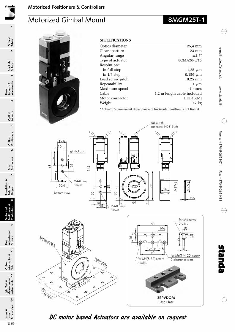
Phone: +370-5-2651474
Fax: +370-5-2651483
1Br
acke
ts
& R
ails
2
Base
M
ount
s &
A
cces
sori
es3
Opt
ical
M
ount
s4
Opt
ical
Po
siti
oner
s5
Base
Po
siti
oner
s6
Tran
slat
ion
&
Rota
tion
St
ages
7
Mot
oris
ed
Posi
tion
ers
&
Con
trol
lers
8
Fine
A
djus
tmen
t Sc
rew
s9
Opt
o-
Mec
hani
cs &
Se
ts10
Opt
ical
Ta
bles
Ligh
t Te
st &
M
easu
rem
ent
Inst
rum
ents
Lase
rs &
La
ser
Acc
esso
ries
11
12e-m
ail: [email protected] w
ww
.standa.lt
8-55
Motorized Positioners & ControllersM
otor
ised
Po
siti
oner
s &
C
ontr
olle
rs8
Motorized Gimbal Mount
SPECIFICATIONS
optics diameter 25,4 mmClear aperture 23 mmAngular range ±2,5°Type of actuator 8CMA20-8/15resolution* in full step 1,25 µm in 1/8 step 0,156 µmLead screw pitch 0.25 mmrepeatability 1 µmMaximum speed 4 mm/sCable 1.2 m length cable includedMotor connector HDB15(M)Weight 0.7 kg
*Actuator`s movement dependance of horizontal position is not lineral.
50
25(1”)
40
5
16
22
10
4
10
M6
for M4(8-32) screw
3holes
for M6(1/4-20) screw
2 clearance slots
for M4 screw
2holes
3BPVDOMBase Plate
bottom view
8MGM25T-1
Dc motor based Actuators are available on request

Phon
e: +
370-
5-26
5147
4 Fa
x: +
370-
5-26
5148
31
Brackets &
Rails
2
Base M
ounts &
Accessories
3O
ptical M
ounts4
Optical
Positioners5
Base Positioners
6
Translation &
Rotation Stages
7
Motorised
Positioners &
Controllers
8
Fine A
djustment
Screws
9
Opto-
Mechanics &
Sets
10O
ptical Tables
Light Test &
Measurem
ent Instrum
ents
Lasers &
Laser A
ccessories 11
12e-
mai
l: sa
les@
stan
da.lt
ww
w.s
tand
a.lt
8-56
Motorized Positioners & ControllersM
otorised Positioners &
C
ontrollers8
Motorized Vertical Drive Optical Mounts
– 1", 2" optics diameter – Stainless steel– Compact/robust design – Annealed front panel
3BPVDOM Universal Base Plate is designed to attach Motorized Vertical Drive Mirror Mounts 8MKVDOMV
to STANDA optical tables or to another stages.
50
25(1”)
40
5
16
22
10
4
10
M6
for M4(8-32) screw
3holes
for M6(1/4-20) screw
2 clearance slots
for M4 screw
2holes
SPECIFICATIONS
optics diameter 25.4 mmClear aperture 23 mmTilt/tip range ±2.5°Sensitivity by horizontal 3.8 arcsec. in full step
of actuator by vertical 3.9 arcsec. in full step of actuator
in the middle tilt of platformType of actuator 8CMA20-8/15Travel range of actuator 6 mmresolution in full step 1.25 µm in 1/8 step 0.156 µmLead screw pitch 0.25 mmrepeatability 1 µmCable 1.2 m length cable includedMotor connector HDB15(M)Weight 0.5 kg
8MKVDOM
Motorized Vertical Drive Optical Mount 8MKVDOM-1
Motorized Vertical Drive Optical Mounts 8MKVDOM are designed to minimize mount-induced wavefront distortions. In conventional mounts, the mirror is tightened by a side screw. Radial forces acting on the mirror induces parasitic wavefront distortion, such as astigmatism. 8MKVDOM mirror mounts use secure 3‑points mirror suspension in between frontal flat spring and the back plate. Uniformly distributed axial forces eliminate wavefront distortion.
Due thermal processes on optic holding part, all metal inner tensions were removed and part makes none micro movements.
These mounts are ideal for industrial applications in different optical devices (laser cavities, optical sub-assemblies, limited space applications) because of their long-term stability.
Stepper, BLDC and DC Motor Controller with USB Interface
2 axis Controller in box8SMC4-USB-B9-2
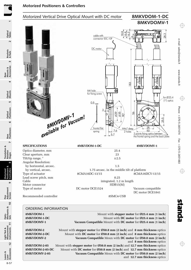
Phone: +370-5-2651474
Fax: +370-5-2651483
1Br
acke
ts
& R
ails
2
Base
M
ount
s &
A
cces
sori
es3
Opt
ical
M
ount
s4
Opt
ical
Po
siti
oner
s5
Base
Po
siti
oner
s6
Tran
slat
ion
&
Rota
tion
St
ages
7
Mot
oris
ed
Posi
tion
ers
&
Con
trol
lers
8
Fine
A
djus
tmen
t Sc
rew
s9
Opt
o-
Mec
hani
cs &
Se
ts10
Opt
ical
Ta
bles
Ligh
t Te
st &
M
easu
rem
ent
Inst
rum
ents
Lase
rs &
La
ser
Acc
esso
ries
11
12e-m
ail: [email protected] w
ww
.standa.lt
8-57
Motorized Positioners & ControllersM
otor
ised
Po
siti
oner
s &
C
ontr
olle
rs8
5018
316
.3618
.8
28.3cable with
connector IDC-10F
5.77.6
3
0.5
Ø29
Ø35
90°
M4 holefor fixing screw
frontal flat spring
for Ø25.4(1") optics
25.5
the frontal spring and the back plate
25M4x7 deep2 holes
DC motor
56
16.8
3 points fixing optics between
Motorized Vertical Drive Optical Mount with DC motor 8MKVDOM-1-DC8MKVDOMV-1
8MKVDOMV-1
available
for Vacu
um!
ORDERING INFORMATION8MKVDOM‑1 Mount with stepper motor for Ø25.4 mm (1 inch)8MKVDOM‑1‑DC Mount with DC motor for Ø25.4 mm (1 inch)8MKVDOMV‑1 Vacuum Compatible Mount with DC motor for Ø25.4 mm (1 inch)
8MKVDOM‑2 Mount with stepper motor for Ø50.8 mm (2 inch) and 8 mm thickness optics8MKVDOM‑2‑DC Mount with DC motor for Ø50.8 mm (2 inch) and 8 mm thickness optics8MKVDOMV‑2 Vacuum Compatible Moun with DC motor for Ø50.8 mm (2 inch)
and 8 mm thickness optics8MKVDOM‑2‑05 Mount with stepper motor for Ø50.8 mm (2 inch) and 12.7 mm thickness optics8MKVDOM‑2‑05‑DC Mount with DC motor for Ø50.8 mm (2 inch) and 12.7 mm thickness optics8MKVDOMV‑2‑05 Vacuum Compatible Moun with DC motor for Ø50.8 mm (2 inch)
and 12.7 mm thickness optics
SPECIFICATIONS 8MKVDOM‑1‑DC 8MKVDOMV‑1
optics diameter, mm 25.4Clear aperture, mm 23Tilt/tip range, ° ±2.5Angular resolution:
by horizontal, arcsec. 1.5by vertical, arcsec. 1.75 arcsec. in the middle tilt of platform
Type of actuator 8CMA16DC-13/15 8CMA16DCV-13/15Lead screw pitch, mm 0.25Cable integrated, 1.2 m lengthMotor connector HDB15(M)Type of motor DC motor DCE1524 Vacuum compatible DC motor DCE1841recommended controller 8SMC4-USB
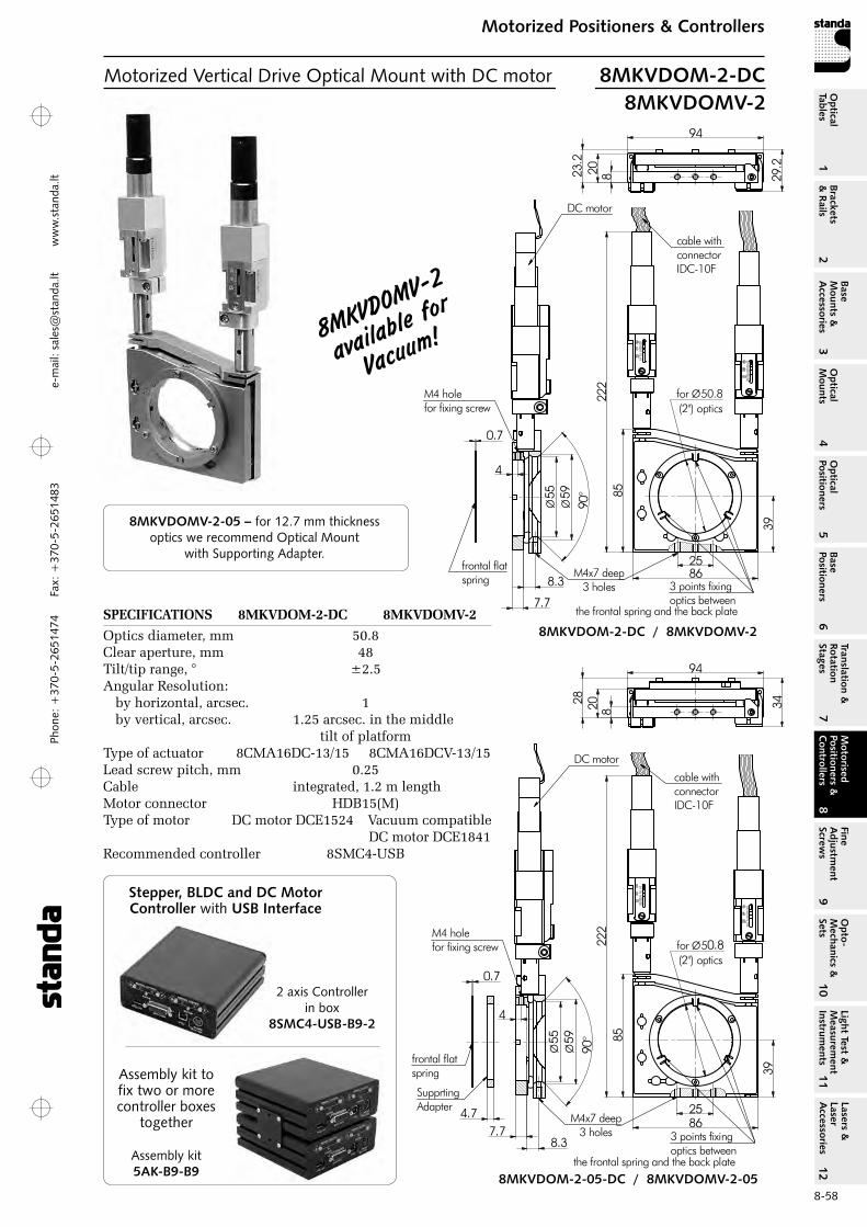
Phon
e: +
370-
5-26
5147
4 Fa
x: +
370-
5-26
5148
31
Brackets &
Rails
2
Base M
ounts &
Accessories
3O
ptical M
ounts4
Optical
Positioners5
Base Positioners
6
Translation &
Rotation Stages
7
Motorised
Positioners &
Controllers
8
Fine A
djustment
Screws
9
Opto-
Mechanics &
Sets
10O
ptical Tables
Light Test &
Measurem
ent Instrum
ents
Lasers &
Laser A
ccessories 11
12e-
mai
l: sa
les@
stan
da.lt
ww
w.s
tand
a.lt
8-58
Motorized Positioners & ControllersM
otorised Positioners &
C
ontrollers8
9 0°55
Ø59
Ø
7.7
8.3
0.7
4
M4 holefor fixing screw
39
86
8522
282023
.2frontal flatspring
29.2
94
cable withconnector IDC-10F
DC motor
for Ø50.8(2") optics
3 points fixing optics between
the frontal spring and the back plate
M4x7 deep3 holes
25
Motorized Vertical Drive Optical Mount with DC motor 8MKVDOM-2-DC8MKVDOMV-2
8MKVDOMV-2
available
for
Vacuum!
8MKVDOMV-2-05 – for 12.7 mm thickness optics we recommend Optical Mount
with Supporting Adapter.
90°55
Ø59
Ø
7.78.3
0.7
4
M4 holefor fixing screw
39
86
8522
282028
frontal flat spring
34
94
cable withconnector IDC-10F
4.7
SupprtingAdapter
DC motor
for Ø50.8(2") optics
3 points fixing optics between
the frontal spring and the back plate
25M4x7 deep
3 holes
8MKVDOM-2-DC / 8MKVDOMV-2
8MKVDOM-2-05-DC / 8MKVDOMV-2-05
SPECIFICATIONS 8MKVDOM‑2‑DC 8MKVDOMV‑2
optics diameter, mm 50.8Clear aperture, mm 48Tilt/tip range, ° ±2.5Angular resolution:
by horizontal, arcsec. 1by vertical, arcsec. 1.25 arcsec. in the middle tilt of platform
Type of actuator 8CMA16DC-13/15 8CMA16DCV-13/15Lead screw pitch, mm 0.25Cable integrated, 1.2 m lengthMotor connector HDB15(M)Type of motor DC motor DCE1524 Vacuum compatible DC motor DCE1841recommended controller 8SMC4-USB
Stepper, BLDC and DC Motor Controller with USB Interface
2 axis Controllerin box
8SMC4-USB-B9-2
Assembly kit5AK-B9-B9
Assembly kit to fix two or more controller boxes
together
9 0°55
Ø59
Ø
7.7
8.3
0.7
4
M4 holefor fixing screw
39
86
8522
282023
.2frontal flatspring
29.2
94
cable withconnector IDC-10F
DC motor
for Ø50.8(2") optics
3 points fixing optics between
the frontal spring and the back plate
M4x7 deep3 holes
25
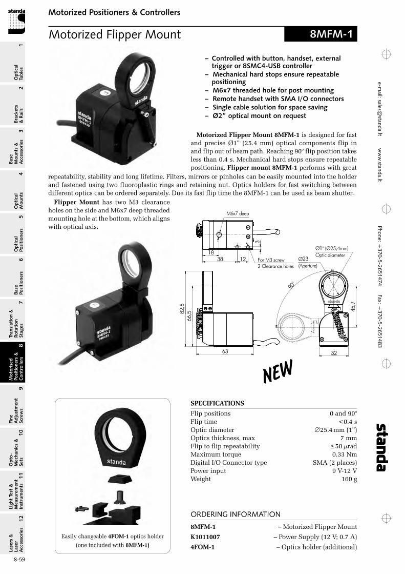
Phone: +370-5-2651474
Fax: +370-5-2651483
1Br
acke
ts
& R
ails
2
Base
M
ount
s &
A
cces
sori
es3
Opt
ical
M
ount
s4
Opt
ical
Po
siti
oner
s5
Base
Po
siti
oner
s6
Tran
slat
ion
&
Rota
tion
St
ages
7
Mot
oris
ed
Posi
tion
ers
&
Con
trol
lers
8
Fine
A
djus
tmen
t Sc
rew
s9
Opt
o-
Mec
hani
cs &
Se
ts10
Opt
ical
Ta
bles
Ligh
t Te
st &
M
easu
rem
ent
Inst
rum
ents
Lase
rs &
La
ser
Acc
esso
ries
11
12e-m
ail: [email protected] w
ww
.standa.lt
8-59
Motorized Positioners & ControllersM
otor
ised
Po
siti
oner
s &
C
ontr
olle
rs8
82,5
66,5
Ø23(Aperture)
M6x7 deep
312
1838 For M3 screw
2 Clearance holes
63 32
Ø1'' (Ø25,4mm)Optic diameter
90°
45,7
Motorized Flipper Mount
Motorized Flipper Mount 8MFM‑1 is designed for fast and precise Ø1” (25.4 mm) optical components flip in and flip out of beam path. reaching 90° flip position takes less than 0.4 s. Mechanical hard stops ensure repeatable positioning. Flipper mount 8MFM‑1 performs with great
repeatability, stability and long lifetime. Filters, mirrors or pinholes can be easily mounted into the holder and fastened using two fluoroplastic rings and retaining nut. optics holders for fast switching between different optics can be ordered separately. Due its fast flip time the 8MFM-1 can be used as beam shutter.
SPECIFICATIONS
Flip positions 0 and 90°Flip time <0.4 soptic diameter ∅25.4 mm (1”)optics thickness, max 7 mmFlip to flip repeatability ≤50 µradMaximum torque 0.33 NmDigital I/o Connector type SMA (2 places)Power input 9 V-12 VWeight 160 g
8MFM-1
– Controlled with button, handset, external trigger or 8SMC4-USB controller
– Mechanical hard stops ensure repeatable positioning
– M6x7 threaded hole for post mounting– Remote handset with SMA I/O connectors– Single cable solution for space saving– Ø2” optical mount on request
ORDERING INFORMATION
8MFM‑1 – Motorized Flipper Mount
K1011007 – Power Supply (12 V; 0.7 A)
4FOM‑1 – optics holder (additional)
Easily changeable 4FOM‑1 optics holder
(one included with 8MFM‑1)
New
Flipper Mount has two M3 clearance holes on the side and M6x7 deep threaded mounting hole at the bottom, which aligns with optical axis.
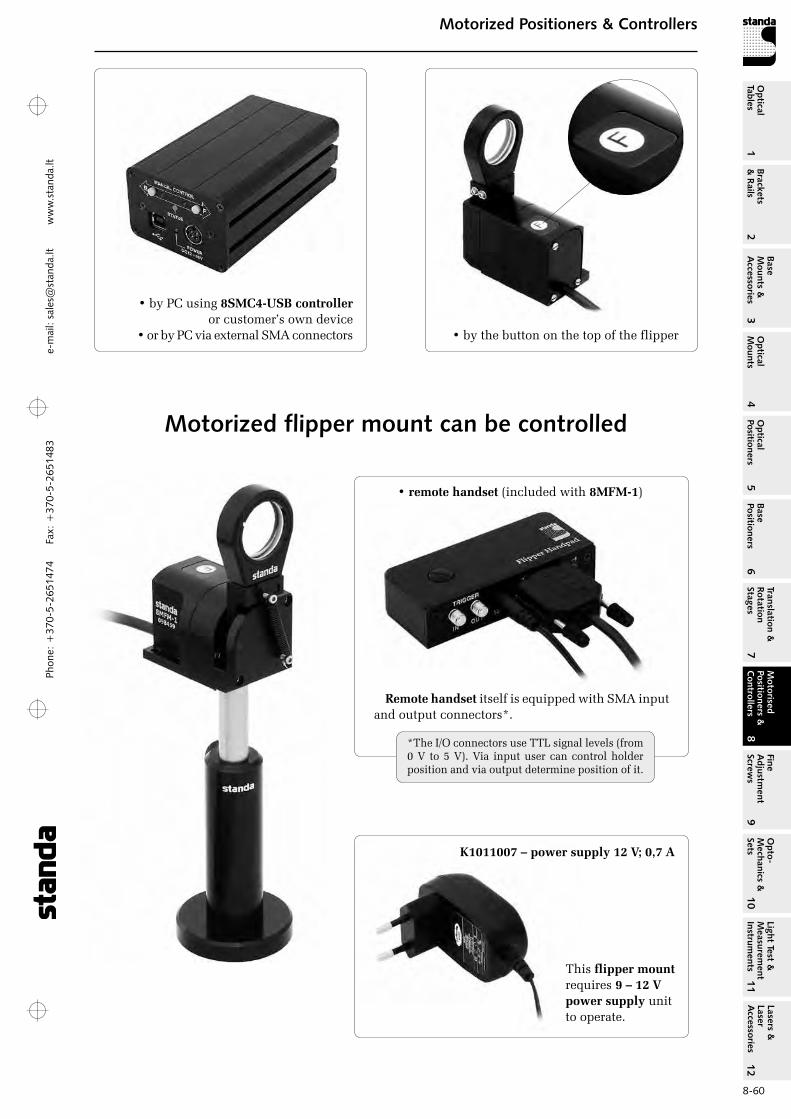
Phon
e: +
370-
5-26
5147
4 Fa
x: +
370-
5-26
5148
31
Brackets &
Rails
2
Base M
ounts &
Accessories
3O
ptical M
ounts4
Optical
Positioners5
Base Positioners
6
Translation &
Rotation Stages
7
Motorised
Positioners &
Controllers
8
Fine A
djustment
Screws
9
Opto-
Mechanics &
Sets
10O
ptical Tables
Light Test &
Measurem
ent Instrum
ents
Lasers &
Laser A
ccessories 11
12e-
mai
l: sa
les@
stan
da.lt
ww
w.s
tand
a.lt
8-60
Motorized Positioners & ControllersM
otorised Positioners &
C
ontrollers8
Motorized flipper mount can be controlled
• by the button on the top of the flipper
• by PC using 8SMC4‑USB controller or customer’s own device
• or by PC via external SMA connectors
• remote handset (included with 8MFM‑1)
Remote handset itself is equipped with SMA input and output connectors*.
*The I/o connectors use TTL signal levels (from 0 V to 5 V). Via input user can control holder position and via output determine position of it.
This flipper mount requires 9 – 12 V power supply unit to operate.
K1011007 – power supply 12 V; 0,7 A

Phone: +370-5-2651474
Fax: +370-5-2651483
1Br
acke
ts
& R
ails
2
Base
M
ount
s &
A
cces
sori
es3
Opt
ical
M
ount
s4
Opt
ical
Po
siti
oner
s5
Base
Po
siti
oner
s6
Tran
slat
ion
&
Rota
tion
St
ages
7
Mot
oris
ed
Posi
tion
ers
&
Con
trol
lers
8
Fine
A
djus
tmen
t Sc
rew
s9
Opt
o-
Mec
hani
cs &
Se
ts10
Opt
ical
Ta
bles
Ligh
t Te
st &
M
easu
rem
ent
Inst
rum
ents
Lase
rs &
La
ser
Acc
esso
ries
11
12e-m
ail: [email protected] w
ww
.standa.lt
8-61
Motorized Positioners & ControllersM
otor
ised
Po
siti
oner
s &
C
ontr
olle
rs8
Motorized Vertical Translation Stage
bottom view
Motorized Vertical Trans‑lation Stage 8MVT188‑20 boasts our unique design. Being very com-pact, it provides smooth and stable adjustment of height. It has a large travel range, and it sup-ports large loads. While moving the platform stays parallel to the base.
Examples of use: mak-ing up for height differ-ences during the set up; automation of techno-
logical processes, like laser welding.A stepper motor type – 5918,
200 steps. Customer can specify any other types of motors to in-stall. Load capacity and speed all great ly depend on the motor. We can test and select an appropriate motor for your requirements.
The lead screw acts at a vary-ing angle, so the resolution of the stage varies with position.
The platform has an array of M6 holes spaced by 25 mm. The base has six M6 and two ∅6.5 holes.
Material: black anodized alu-minum.
Motorized Mirror MountMotorized Mirror Mounts 8MMA60 are designed for precise angular alignment of optical elements. Platform is tilted about two axes. A retaining ring keeps optics in a non-through mounting opening of the platform.
The ring is fixed by 3 screws. It has 3 dents with which it clamps optics against
Motor type: 200 steps, bipolar
(4 leads), 33 per phase. Motors of other types
are available.
similar 3 rests in the plat-form.
The dents are exactly opposite to the rests – this minimizes deformation.
SPECIFICATIONS
Tilt range 5° both axesVisual reading dial knobs graduated in
200 steps per revolutionresolution 0.0016° (0°00’06”) per stepoptics accepted (see the drawing)
diameter (D), and clear aperture (A): 8MMA60-1 ∅25.4 mm (1”), A=21.4 mm 8MMA60-40 ∅40 mm, A=36 mm 8MMA60-2 ∅50.8 (2”), A=46.8 mm custom sizes available
optics thickness 10 mm (retaining rings for custom thickness available)
Material black anodized aluminiumWeight 1.08 kg
– Pantograph design– 16 ball bearings– Stepping motor drive– Precision lead screw– 95 mm vertical travel– Height: min 89 mm
max 184 mm– Top and bottom plates
parallel to 1 mm– Load capacity 8 kg
(depending on motor and controller)
– Supply voltage – 36 V– Weight: 4.3 kg
8MVT188-20
8MMA60
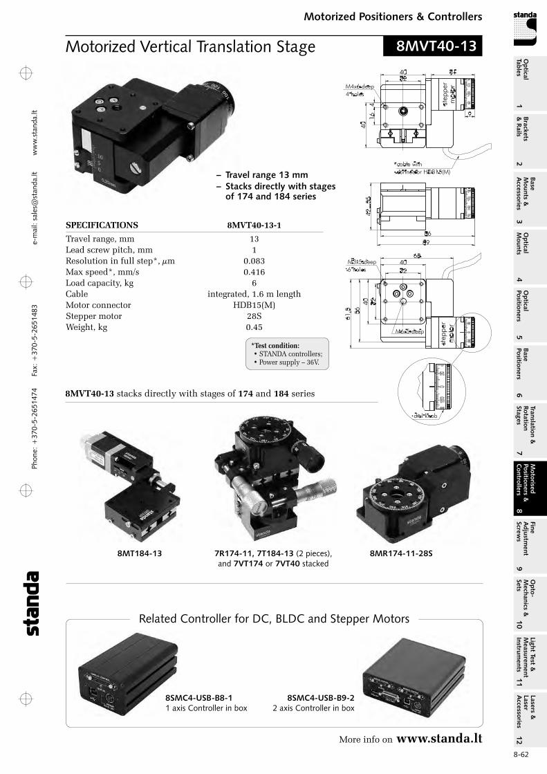
Phon
e: +
370-
5-26
5147
4 Fa
x: +
370-
5-26
5148
31
Brackets &
Rails
2
Base M
ounts &
Accessories
3O
ptical M
ounts4
Optical
Positioners5
Base Positioners
6
Translation &
Rotation Stages
7
Motorised
Positioners &
Controllers
8
Fine A
djustment
Screws
9
Opto-
Mechanics &
Sets
10O
ptical Tables
Light Test &
Measurem
ent Instrum
ents
Lasers &
Laser A
ccessories 11
12e-
mai
l: sa
les@
stan
da.lt
ww
w.s
tand
a.lt
8-62
Motorized Positioners & ControllersM
otorised Positioners &
C
ontrollers8
Motorized Vertical Translation Stage
42
...5
5
86
89
61
,5
40
56
40
32
32
40
41
6
32
40
9
41
65
M3x5 deep
6 holes
M6x5 deep
M4x6 deep
4 holes
cable with
connector HDB15(M)
dial knob
stepper
moto
rst
epper
moto
r
8MVT40-13
– Travel range 13 mm– Stacks directly with stages
of 174 and 184 series
SPECIFICATIONS 8MVT40‑13‑1
Travel range, mm 13Lead screw pitch, mm 1resolution in full step*, µm 0.083Max speed*, mm/s 0.416Load capacity, kg 6Cable integrated, 1.6 m lengthMotor connector HDB15(M)Stepper motor 28SWeight, kg 0.45
8MT184-13 8MR174-11-28S7R174-11, 7T184-13 (2 pieces), and 7VT174 or 7VT40 stacked
8MVT40‑13 stacks directly with stages of 174 and 184 series
*Test condition: • STANDA controllers;• Power supply – 36V.
More info on www.standa.lt
Related Controller for DC, BLDC and Stepper Motors
8SMC4-USB-B8-11 axis Controller in box
8SMC4-USB-B9-22 axis Controller in box
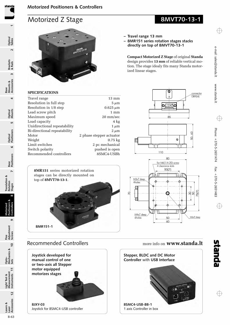
Phone: +370-5-2651474
Fax: +370-5-2651483
1Br
acke
ts
& R
ails
2
Base
M
ount
s &
A
cces
sori
es3
Opt
ical
M
ount
s4
Opt
ical
Po
siti
oner
s5
Base
Po
siti
oner
s6
Tran
slat
ion
&
Rota
tion
St
ages
7
Mot
oris
ed
Posi
tion
ers
&
Con
trol
lers
8
Fine
A
djus
tmen
t Sc
rew
s9
Opt
o-
Mec
hani
cs &
Se
ts10
Opt
ical
Ta
bles
Ligh
t Te
st &
M
easu
rem
ent
Inst
rum
ents
Lase
rs &
La
ser
Acc
esso
ries
11
12e-m
ail: [email protected] w
ww
.standa.lt
8-63
Motorized Positioners & ControllersM
otor
ised
Po
siti
oner
s &
C
ontr
olle
rs8
Motorized Z Stage 8MVT70-13-1
– Travel range 13 mm– 8MR151 series rotation stages stacks
directly on top of 8MVT70-13-1
50...
63
5060
30 50
50(2")
75(3
")
110 85
80
70
M4x7 deep6holes
M3x7 deep4holes
for M6(1/4-20) screw4 clearance slots
M6x9 deep
connectorDB9(M)
50...
63
5060
30 5050(2")
75(3
")
110 85
80
70
M4x7 deep6holes
M3x7 deep4holes
for M6(1/4-20) screw4 clearance slots
M6x9 deep
connectorDB9(M)
Compact Motorized Z Stage of original Standa design provides 13 mm of reliable vertical mo-tion. The stage idealy fits many Standa motor-ized linear stages.
8MR151-1
8MR151 series motorized rotation stages can be directly mounted on top of 8MVT70‑13‑1.
SPECIFICATIONS
Travel range 13 mm resolution in full step 5 µm resolution in 1/8 step 0.625 µm Lead screw pitch 1 mm Maximum speed 20 mm/sec Load capacity 4 kg Unidirectional repeatability 1 µm Bi-directional repeatability 2 µm Motor 2 phase stepper actuator Weight 0.75 kg Limit switches 2 pc mechanical Switch polarity pushed is openrecommended controllers 8SMC4-USBh
Recommended Controllers more info on www.standa.lt
Joystick developed for manual control of one or two-axis all Stepper motor equipped motorizes stages
8JXY-03Joystick for 8SMC4-USB controller
8SMC4-USB-B8-11 axis Controller in box
Stepper, BLDC and DC Motor Controller with USB Interface
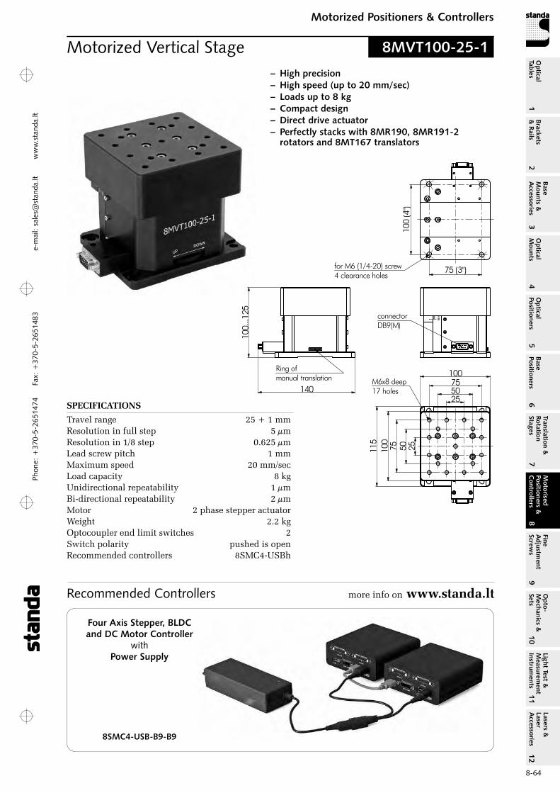
Phon
e: +
370-
5-26
5147
4 Fa
x: +
370-
5-26
5148
31
Brackets &
Rails
2
Base M
ounts &
Accessories
3O
ptical M
ounts4
Optical
Positioners5
Base Positioners
6
Translation &
Rotation Stages
7
Motorised
Positioners &
Controllers
8
Fine A
djustment
Screws
9
Opto-
Mechanics &
Sets
10O
ptical Tables
Light Test &
Measurem
ent Instrum
ents
Lasers &
Laser A
ccessories 11
12e-
mai
l: sa
les@
stan
da.lt
ww
w.s
tand
a.lt
8-64
Motorized Positioners & ControllersM
otorised Positioners &
C
ontrollers8
Motorized Vertical Stage 8MVT100-25-1
– High precision– High speed (up to 20 mm/sec)– Loads up to 8 kg– Compact design– Direct drive actuator– Perfectly stacks with 8MR190, 8MR191-2
rotators and 8MT167 translators
140
connectorDB9(M)
Ring ofmanual translation
100
(4")
75 (3")for M6 (1/4-20) screw4 clearance holes
100.
..125
255075100
255075100
115
M6x8 deep17 holes
SPECIFICATIONS
Travel range 25 + 1 mm resolution in full step 5 µm resolution in 1/8 step 0.625 µm Lead screw pitch 1 mm Maximum speed 20 mm/sec Load capacity 8 kg Unidirectional repeatability 1 µm Bi-directional repeatability 2 µm Motor 2 phase stepper actuator Weight 2.2 kg optocoupler end limit switches 2 Switch polarity pushed is open recommended controllers 8SMC4-USBh
Recommended Controllers more info on www.standa.lt
Four Axis Stepper, BLDC and DC Motor Controller
with Power Supply
8SMC4-USB-B9-B9
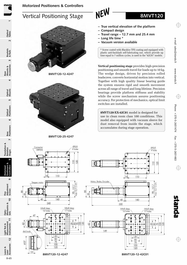
Phone: +370-5-2651474
Fax: +370-5-2651483
1Br
acke
ts
& R
ails
2
Base
M
ount
s &
A
cces
sori
es3
Opt
ical
M
ount
s4
Opt
ical
Po
siti
oner
s5
Base
Po
siti
oner
s6
Tran
slat
ion
&
Rota
tion
St
ages
7
Mot
oris
ed
Posi
tion
ers
&
Con
trol
lers
8
Fine
A
djus
tmen
t Sc
rew
s9
Opt
o-
Mec
hani
cs &
Se
ts10
Opt
ical
Ta
bles
Ligh
t Te
st &
M
easu
rem
ent
Inst
rum
ents
Lase
rs &
La
ser
Acc
esso
ries
11
12e-m
ail: [email protected] w
ww
.standa.lt
8-65
Motorized Positioners & ControllersM
otor
ised
Po
siti
oner
s &
C
ontr
olle
rs8
Vertical Positioning Stage 8MVT120
– True vertical elevation of the platform – Compact design– Travel range – 12.7 mm and 25.4 mm– Long life time *– Vacuum version available
New
Vertical positioning stage provides high-precision positioning and smooth travel for loads up to 10 kg. The wedge design, driven by precision rolled leadscrew, converts horizontal motion into vertical. Together with high quality linear bearing guide the system ensures rigid and smooth movement across all range of travel and long lifetime. Precision bearings provide platform stiffness and stability while the screw mechanism assures positioning accuracy. For protection of mechanics, optical limit switches are installed.
140
240
110
120
Ø6,64 holes
11015
66
ConnectorDB9(M)
35
Stepper motor
40
95...
107,
7H
ub 1
2,7
(1/2
'')
5075100
5025
25
75 100
120
120
M6x8 deep17 holes
M4x8 deep16 holes
47
42
13
37Ø
dial knob
95...
107,
7H
ub 1
2,7
(1/2
'')
140
330
110
120
Ø6,64 holes
11015
40
3566
Motor, Brake, Encoder
25 50 75 100
120
255075100120
M6x8 deep17 holes
M4x8 deep16 holes
149
42
8MVT120-12-4247 8MVT120-12-42C01
8MVT120-12-4247
8MVT120-25-4247
* Screw coated with BlackIce TFE coating and equipped with plastic anti-backlash self-lubricating nut, which provide up time equal to 7 million cycles, is used in the "42C01" models.
8MVT120‑XX‑42C01 model is designed foruse in clean room class 100 conditions. This model also equipped with vacuum sleeve for dust removal from inside the stage, which accumulates during stage operation.

Phon
e: +
370-
5-26
5147
4 Fa
x: +
370-
5-26
5148
31
Brackets &
Rails
2
Base M
ounts &
Accessories
3O
ptical M
ounts4
Optical
Positioners5
Base Positioners
6
Translation &
Rotation Stages
7
Motorised
Positioners &
Controllers
8
Fine A
djustment
Screws
9
Opto-
Mechanics &
Sets
10O
ptical Tables
Light Test &
Measurem
ent Instrum
ents
Lasers &
Laser A
ccessories 11
12e-
mai
l: sa
les@
stan
da.lt
ww
w.s
tand
a.lt
8-66
Motorized Positioners & ControllersM
otorised Positioners &
C
ontrollers8
145245
66 110.
..135
,4H
ub 2
5,4
(1'')
120
Ø6,64 holes
35
ConnectorDB9(M)
Stepper motor
110
110
40
M6x8 deep17 holes
M4x8 deep16 holes
25
255075100120
50 75 100
120
17,5
47
13
37Ø
dial knob
42
145
330
3566 11
0...1
35,4
Hub
25,
4 (1
'')Motor, Brake, Encoder
120
Ø6,64 holes
17,5 110
110
120
40
M6x8 deep17 holes
M4x8 deep16 holes
25 50 75 100
255075100120
42
145,5
SPECIFICATIONS 8MVT120‑12‑4247 8MVT120‑12‑42C01 8MVT120‑25‑4247 8MVT120‑25‑42C01
Travel range, mm 12.7 12.7 25.4 25.4resolution in full step, µm 2.5 – 5 – in 1/256 step, µm 0.018 * – 0.019 * –Encoder pulses per revolution by request 4000 by request 4000Travel per 1 pulse, µm - 0.18 - 0.36Lead screw pitch, mm 1 1.44 ** 1 1.44 **Wedge reduction rate 2:1 2:1 1:1 1:1Unidirectional repeatability, µm 1,5 1,5 1,5 1,5Bi-direction repeatability, µm 3 3 3 3Accuracy, µm 10 10 10 10Lift parallelism (to the base), µm 35 35 (by request up to 10 µm) (by request up to 15 µm)Maximum speed, mm/s 10 12 20 25Maximum load capacity, kg 10 (15 kg by request) 10 10 (20 kg by request) 10Stepper motor 4247 – 4247 –Brushless DC motor - DB42-100 – DB42-100Brake by request + by request +optocoupler end limit switches 2 3 2 3Switch polarity Pushed is openMotor connector DB9(M) by request DB9(M) by requestMaterial AluminiumFinish Black anodize hard coverWeight, kg 3,5 3,9 4,05 4,5recommended Controller 8SMC4-USB
8MVT120-25-4247 8MVT120-25-42C01
* With Standa 8SMC4-USB controller** Screw coated with BlackIce TFE coating and equipped with plastic anti-backlash self-lubricating nut, which provide up time equal to
7 million cycles, is used in the "42C01" models.
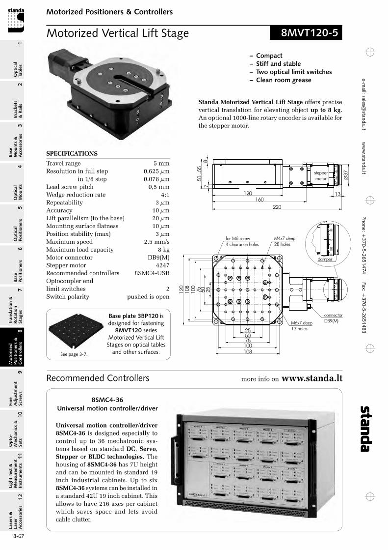
Phone: +370-5-2651474
Fax: +370-5-2651483
1Br
acke
ts
& R
ails
2
Base
M
ount
s &
A
cces
sori
es3
Opt
ical
M
ount
s4
Opt
ical
Po
siti
oner
s5
Base
Po
siti
oner
s6
Tran
slat
ion
&
Rota
tion
St
ages
7
Mot
oris
ed
Posi
tion
ers
&
Con
trol
lers
8
Fine
A
djus
tmen
t Sc
rew
s9
Opt
o-
Mec
hani
cs &
Se
ts10
Opt
ical
Ta
bles
Ligh
t Te
st &
M
easu
rem
ent
Inst
rum
ents
Lase
rs &
La
ser
Acc
esso
ries
11
12e-m
ail: [email protected] w
ww
.standa.lt
8-67
Motorized Positioners & ControllersM
otor
ised
Po
siti
oner
s &
C
ontr
olle
rs8
Motorized Vertical Lift Stage 8MVT120-5
12050
...55
220
1310
812
0
108
for M6 screw4 clearance holes
steppermotor
connectorDB9(M)
damper
7160
8
255075100
255075100
M6x7 deep13 holes
M4x7 deep28 holes
37Ø
– Compact – Stiff and stable – Two optical limit switches – Clean room grease
Standa Motorized Vertical Lift Stage offers precise vertical translation for elevating object up to 8 kg. An optional 1000-line rotary encoder is available for the stepper motor.
Recommended Controllers more info on www.standa.lt
8SMC4-36Universal motion controller/driver
Universal motion controller/driver 8SMC4‑36 is designed especially to control up to 36 mechatronic sys-tems based on standard DC, Servo, Stepper or BLDC technologies. The housing of 8SMC4‑36 has 7U height and can be mounted in standard 19 inch industrial cabinets. Up to six 8SMC4‑36 systems can be installed in a standard 42U 19 inch cabinet. This allows to have 216 axes per cabinet which saves space and lets avoid cable clutter.
SPECIFICATIONS
Travel range 5 mm resolution in full step 0,625 µm
in 1/8 step 0.078 µm Lead screw pitch 0,5 mm Wedge reduction rate 4:1 repeatability 3 µm Accuracy 10 µm Lift parallelism (to the base) 20 µm Mounting surface flatness 10 µm Position stability (max) 3 µm Maximum speed 2.5 mm/s Maximum load capacity 8 kg Motor connector DB9(M) Stepper motor 4247 recommended controllers 8SMC4-USBoptocoupler end limit switches 2 Switch polarity pushed is open
Base plate 3BP120 is designed for fastening
8MVT120 series Motorized Vertical Lift Stages on optical tables
and other surfaces. See page 3-7.

Phon
e: +
370-
5-26
5147
4 Fa
x: +
370-
5-26
5148
31
Brackets &
Rails
2
Base M
ounts &
Accessories
3O
ptical M
ounts4
Optical
Positioners5
Base Positioners
6
Translation &
Rotation Stages
7
Motorised
Positioners &
Controllers
8
Fine A
djustment
Screws
9
Opto-
Mechanics &
Sets
10O
ptical Tables
Light Test &
Measurem
ent Instrum
ents
Lasers &
Laser A
ccessories 11
12e-
mai
l: sa
les@
stan
da.lt
ww
w.s
tand
a.lt
8-68
Motorized Positioners & ControllersM
otorised Positioners &
C
ontrollers8
SPECIFICATIONS 8MG99 8MG00
Travel range ±2.5° 0.5°resolution 8MGXX-50 16.12” 20.6” 8MGXX-80 10.96” 16.5”Height of center of rotation 8MGXX-50 50 mm 50 mm 8MGXX-80 80 mm 80 mmLoad capacity 2 kg 2 kgLifetime – 20 million full stepsWeight 1.2 kg 1.2 kg
Motorized Goniometers
– Rotates an object without obscuring the optical path
– Smooth operation with ball bearings– 1 or 2 axes of rotation (stackable)– Superb stability– Compact square body
Goniometers rotate an object about an axis in space located outside the body of the unit (usually – above the platform),so the axis is not obscured by the unit itself.
Goniometers have small travel range and greater stability, compared to rotation stages.
Goniometers have to have different heights of points of rotation, so that, when you stack gonio meters one on top of the other, they rotate an object about a com-mon point in space.
The mechanism rolls smoothly on ball bearings.The position is read within one revolution on the
scale engraved on the dial knob sitting on the axle of the motor. Position can be read to each step. overall position accounting is up-to your computer.
Goniometers have two limit switches to signal an “out of limits” error situation. The switches may also be used to roughly establish a zero reference.
The stage is driven by a stepping motor. A dial knob on its axle allows manual drive. As standard, we use stepping motors of these parameters: 200 steps, bipolar (4 leads), 33 per phase. A customer can order motors of other types. We offer our Stepper Motor Controllers to control the motorized stages.
8MG00; 8MG99 stacked
8MG00-50; 8MG99-50
8MG00-80; 8MG99-80
8MG99-50
8MG99-80
8MG99 • 8MG00

Phone: +370-5-2651474
Fax: +370-5-2651483
1Br
acke
ts
& R
ails
2
Base
M
ount
s &
A
cces
sori
es3
Opt
ical
M
ount
s4
Opt
ical
Po
siti
oner
s5
Base
Po
siti
oner
s6
Tran
slat
ion
&
Rota
tion
St
ages
7
Mot
oris
ed
Posi
tion
ers
&
Con
trol
lers
8
Fine
A
djus
tmen
t Sc
rew
s9
Opt
o-
Mec
hani
cs &
Se
ts10
Opt
ical
Ta
bles
Ligh
t Te
st &
M
easu
rem
ent
Inst
rum
ents
Lase
rs &
La
ser
Acc
esso
ries
11
12e-m
ail: [email protected] w
ww
.standa.lt
8-69
Motorized Positioners & ControllersM
otor
ised
Po
siti
oner
s &
C
ontr
olle
rs8
8MID Motorized Iris Diaphragms are available with various aperture ranges, with max. apertures from 5 mm to 98 mm.
Irises with max. apertures from 5 mm to 27 mm are shown on this page. For irises with max. apertures from 30 mm to 50 mm see page 8‑70. Motorized iris with max. aperture of 98 mm is shown on page 8-71.
Irises with max. apertures up to 27 mm close from min. to max. in 1.2 seconds with resolution depending on aperture size (see table below).
Zero aperture motorized iris diaphragms are available on request, max. aperture sizes from 12 mm to 40 mm.
Motorized Iris Diaphragm 8MID10-40
Temperature limits:AR - leaves with Ar coating, for temperatures up to 180 °CN - springsteel, black finished, for temperatures up to 250 °CH - stainless steel, for temperatures up to 400 °C
6237
50 48
diaphragm mount
34
17
M4x6 deep
M3x6 deep2holes
dmax. dmin. average number of Model Diaphragm aperture, aperture, steps 1 mm of used mm mm aperture
8MID5-0.5-Ar 10IBS10-5-0.5-Ar 5 0.5 385 8MID5-0.5-N 10IBS10-5-0.5-N 5 0.5 385 8MID7-0.5-Ar 10IBS12-7-0.5-Ar 7 0.5 301 8MID7-0.5-N 10IBS12-7-0.5-N 7 0.5 301 8MID8-1-N 10IBS14.8-8-1-N 8 1 244 8MID8.2-0.8-N 10IBS14-8.2-0.8-N 8.2 0.8 240 8MID12-1-Ar 10IBS19.8-12-1-Ar 12 1 1808MID12-1-H 10IBS19.8-12-1-H 12 1 180 8MID12-1-N 10IBS19.8-12-1-N 12 1 180 8MID14-1-Ar 10IBS22-14-1-Ar 14 1 161 8MID14-1-N 10IBS22-14-1-N 14 1 161 8MID15-1-H 10IBS24-15-1-H 15 1 141 8MID15-1-N 10IBS24-15-1-N 15 1 141 8MID18-1-Ar 10IBS28-18-1-Ar 18 1 118 8MID20-1.2-Ar 10IBS30-20-1.2-Ar 20 1.2 106 8MID20-1.2-H 10IBS30-20-1.2-H 20 1.2 106 8MID20-1.2-N 10IBS30-20-1.2-N 20 1.2 106 8MID22-1.5-N 10IBS33-22-1.5-N 22 1.5 102 8MID25-1.5-N 10IBS37-25-1.5-N 25 1.5 89 8MID27-1.5-Ar 10IBS40-27-1.5-Ar 27 1.5 79 8MID27-1.5-H 10IBS40-27-1.5-H 27 1.5 79 8MID27-1.5-N 10IBS40-27-1.5-N 27 1.5 79
SPECIFICATIONS
Closing speed (min to max) 1.2 seconds Stepper motor/gear 50:1 Limit switch 2 mechanical Switch polarity pushed is closed recommended controllers 8SMC4-USB

Phon
e: +
370-
5-26
5147
4 Fa
x: +
370-
5-26
5148
31
Brackets &
Rails
2
Base M
ounts &
Accessories
3O
ptical M
ounts4
Optical
Positioners5
Base Positioners
6
Translation &
Rotation Stages
7
Motorised
Positioners &
Controllers
8
Fine A
djustment
Screws
9
Opto-
Mechanics &
Sets
10O
ptical Tables
Light Test &
Measurem
ent Instrum
ents
Lasers &
Laser A
ccessories 11
12e-
mai
l: sa
les@
stan
da.lt
ww
w.s
tand
a.lt
8-70
Motorized Positioners & ControllersM
otorised Positioners &
C
ontrollers8
Motorized Iris Diaphragm 8MID40-70
99
54,382
50
34,4
M6x9 deep
M4x6 deep2holes
58
diaphragm mount
Ødmin...dmaxclear aperture
8MID Motorized Iris Diaphragms are avail-able with various aperture ranges, with max. apertures from 5 mm to 98 mm.
Irises with max. apertures from 5 mm to 27 mm are shown on page 8-69. For irises with max. apertures from 30 mm to 50 mm see this page. Motorized iris with max. aper-ture of 98 mm is shown on page 8-71.
Irises with max. apertures from 30 mm to 50 mm close from min. to max. in 2 seconds with resolution depending on aperture size (see table below).
Zero aperture motorized iris diaphragms are available on request, max. aperture sizes from 12 mm to 40 mm.
Temperature limits:AR - leaves with Ar coating, for temperatures up to 180 °CN - springsteel, black finished, for temperatures up to 250 °CH - stainless steel, for temperatures up to 400 °C
Recommended Controllers more info on www.standa.lt
dmax. dmin. average number Model Diaphragm aperture, aperture, of steps 1 mm used mm mm of aperture
8MID30-1.5-H 10IBS43-30-1.5-H 30 1.5 125 8MID30-1.5-N 10IBS43-30-1.5-N 30 1.5 125 8MID34-2-Ar 10IBS49-34-2-Ar 34 2 111 8MID34-2-H 10IBS49-34-2-H 34 2 111 8MID36-2.5-N 10IBS50-36-2.5-N 36 2.5 106 8MID37-2.5-N 10IBS53-37-2.5-N 37 2.5 100 8MID40-2.5-N 10IBS60-40-2.5-N 40 2.5 90 8MID42-2.5-N 10IBS58-42-2.5-N 42 2.5 91 8MID45-2.5-H 10IBS64-45-2.5-H 45 2.5 84 8MID45-2.5-N 10IBS64-45-2.5-N 45 2.5 84 8MID50-2.5-N 10IBS70-50-2.5-N 50 2.5 75
SPECIFICATIONS
Closing speed (min to max) 2 seconds Stepper motor/gear 50:1 Limit switch 2 mechanical Switch polarity pushed is closed recommended controllers 8SMC4-USB
Four Axis Stepper, BLDC and DC Motor Controller
with Power Supply
8SMC4-USB-B9-B9
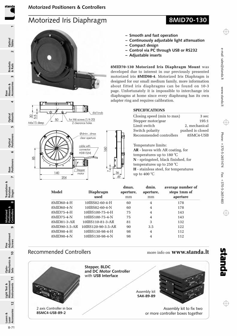
Phone: +370-5-2651474
Fax: +370-5-2651483
1Br
acke
ts
& R
ails
2
Base
M
ount
s &
A
cces
sori
es3
Opt
ical
M
ount
s4
Opt
ical
Po
siti
oner
s5
Base
Po
siti
oner
s6
Tran
slat
ion
&
Rota
tion
St
ages
7
Mot
oris
ed
Posi
tion
ers
&
Con
trol
lers
8
Fine
A
djus
tmen
t Sc
rew
s9
Opt
o-
Mec
hani
cs &
Se
ts10
Opt
ical
Ta
bles
Ligh
t Te
st &
M
easu
rem
ent
Inst
rum
ents
Lase
rs &
La
ser
Acc
esso
ries
11
12e-m
ail: [email protected] w
ww
.standa.lt
8-71
Motorized Positioners & ControllersM
otor
ised
Po
siti
oner
s &
C
ontr
olle
rs8
Recommended Controllers more info on www.standa.lt
Motorized Iris Diaphragm 8MID70-130
8MID70‑130 Motorized Iris Diaphragm Mount was developed due to interest in our previously presented motorized iris 8MID98‑4. Motorized Iris Diaphragm is designed for our small medium family, more information about fitted iris diaphragms can be found on 10-3 page. Unfortunately it is impossible to interchange iris diaphragms at home since every diaphramg has its own adapter ring and requires calibration.
– Smooth and fast operation– Continuously adjustable light attenuation– Compact design– Control via PC through USB or RS232– Adjustable inserts
85
140
204
Steppermotor
for M6 screws (1/4-20)2 clearance holes
50M6x15 deep
160
4936
30 5.5
7
cable with connector HDB15(M)
Ødmin...dmaxclear aperture
dial knob
Temperature limits:AR - leaves with Ar coating, for temperatures up to 180 °CN - springsteel, black finished, for temperatures up to 250 °CH - stainless steel, for temperatures up to 400 °C
dmax. dmin. average number of Model Diaphragm aperture, aperture, steps 1mm of used mm mm aperture
8MID60-4-H 10IBS82-60-4-H 60 4 178 8MID60-4-N 10IBS82-60-4-N 60 4 178 8MID75-4-H 10IBS100-75-4-H 75 4 143 8MID75-4-N 10IBS100-75-4-N 75 4 143 8MID81-3-Ar 10IBS110-81-3-Ar 81 3 132 8MID90-3.5-Ar 10IBS120-90-3.5-Ar 90 3.5 122 8MID98-4-H 10IBS130-98-4-H 98 4 112 8MID98-4-N 10IBS130-98-4-N 98 4 112
2 axis Controller in box8SMC4-USB-B9-2
Assembly kit5AK-B9-B9
Assembly kit to fix two or more controller boxes together
Stepper, BLDC and DC Motor Controller with USB Interface
SPECIFICATIONS
Closing speed (min to max) 3 sec Stepper motor/gear 195:1Limit switch 2, mechanical Switch polarity pushed is closed recommended controllers 8SMC4-USB
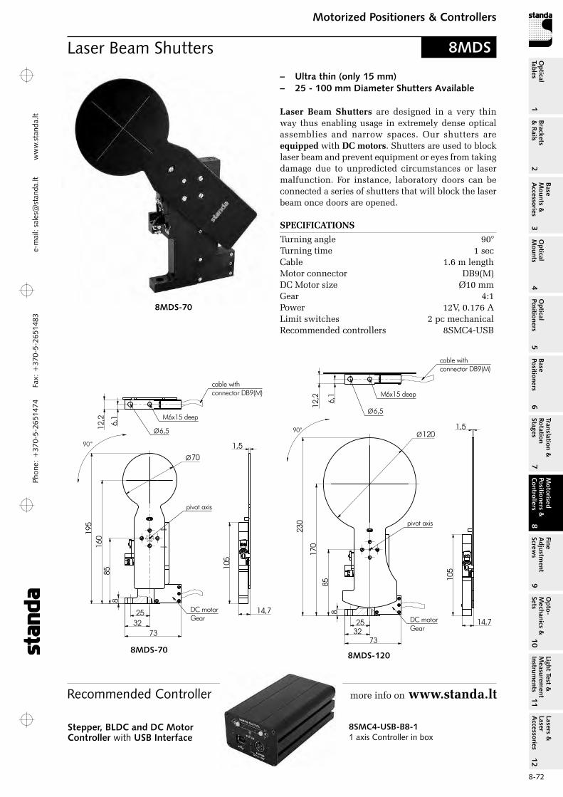
Phon
e: +
370-
5-26
5147
4 Fa
x: +
370-
5-26
5148
31
Brackets &
Rails
2
Base M
ounts &
Accessories
3O
ptical M
ounts4
Optical
Positioners5
Base Positioners
6
Translation &
Rotation Stages
7
Motorised
Positioners &
Controllers
8
Fine A
djustment
Screws
9
Opto-
Mechanics &
Sets
10O
ptical Tables
Light Test &
Measurem
ent Instrum
ents
Lasers &
Laser A
ccessories 11
12e-
mai
l: sa
les@
stan
da.lt
ww
w.s
tand
a.lt
8-72
Motorized Positioners & ControllersM
otorised Positioners &
C
ontrollers8
8MDS-1208MDS-70
Laser Beam Shutters 8MDS
2532
73
885
170
230
Ø120
14,7
1,5
105
cable withconnector DB9(M)
Ø6,5
M6x15 deep
90°
pivot axis
DC motorGear
6,1
12,2
Ø70
195
Ø6,5
73
160
14,7
1,5
M6x15 deep
2532
90 °
8
cable withconnector DB9(M)
85
pivot axis
105
DC motorGear
6,1
12,2
– Ultra thin (only 15 mm) – 25 - 100 mm Diameter Shutters Available
Laser Beam Shutters are designed in a very thin way thus enabling usage in extremely dense optical assemblies and narrow spaces. our shutters are equipped with DC motors. Shutters are used to block laser beam and prevent equipment or eyes from taking damage due to unpredicted circumstances or laser malfunction. For instance, laboratory doors can be connected a series of shutters that will block the laser beam once doors are opened.
8MDS-70
Recommended Controller more info on www.standa.lt
SPECIFICATIONS
Turning angle 90° Turning time 1 sec Cable 1.6 m length Motor connector DB9(M) DC Motor size Ø10 mm Gear 4:1 Power 12V, 0.176 A Limit switches 2 pc mechanical recommended controllers 8SMC4-USB
8SMC4-USB-B8-11 axis Controller in box
Stepper, BLDC and DC Motor Controller with USB Interface

Phone: +370-5-2651474
Fax: +370-5-2651483
1Br
acke
ts
& R
ails
2
Base
M
ount
s &
A
cces
sori
es3
Opt
ical
M
ount
s4
Opt
ical
Po
siti
oner
s5
Base
Po
siti
oner
s6
Tran
slat
ion
&
Rota
tion
St
ages
7
Mot
oris
ed
Posi
tion
ers
&
Con
trol
lers
8
Fine
A
djus
tmen
t Sc
rew
s9
Opt
o-
Mec
hani
cs &
Se
ts10
Opt
ical
Ta
bles
Ligh
t Te
st &
M
easu
rem
ent
Inst
rum
ents
Lase
rs &
La
ser
Acc
esso
ries
11
12e-m
ail: [email protected] w
ww
.standa.lt
8-73
Motorized Positioners & ControllersM
otor
ised
Po
siti
oner
s &
C
ontr
olle
rs8
Nano Positioners
SPECIFICATIONS
Travel range 100 mmLow frictional forceStraightness 5 µBacklash 0Stiffness 100 N/µresolution 50 nmSpeed 0.001-150 mm/srepeatability 0.1 µPrecision 0.5 µLoad capacity 3 kgWeight 1.3 kg
8NANO-100
8NANO-100XY
8NTS-XCompact Single Axis
Piezo Actuator
8NTS-XYZ-2002(3)D Piezo Scanning Stage
8NTS-XYZ-200-APiezo Scanning Stage
with Central Hole
8NTS-XYZ-40-SPMPlane-Parallel Nano Piezo
Scanning Stage
8NTS-ZZ Axis Piezo Potioning Stage
8NSCNano Stage Controllers
Piezo Scanning Nano-Stages, Positioners and controllers
Pages 8-73...8-77
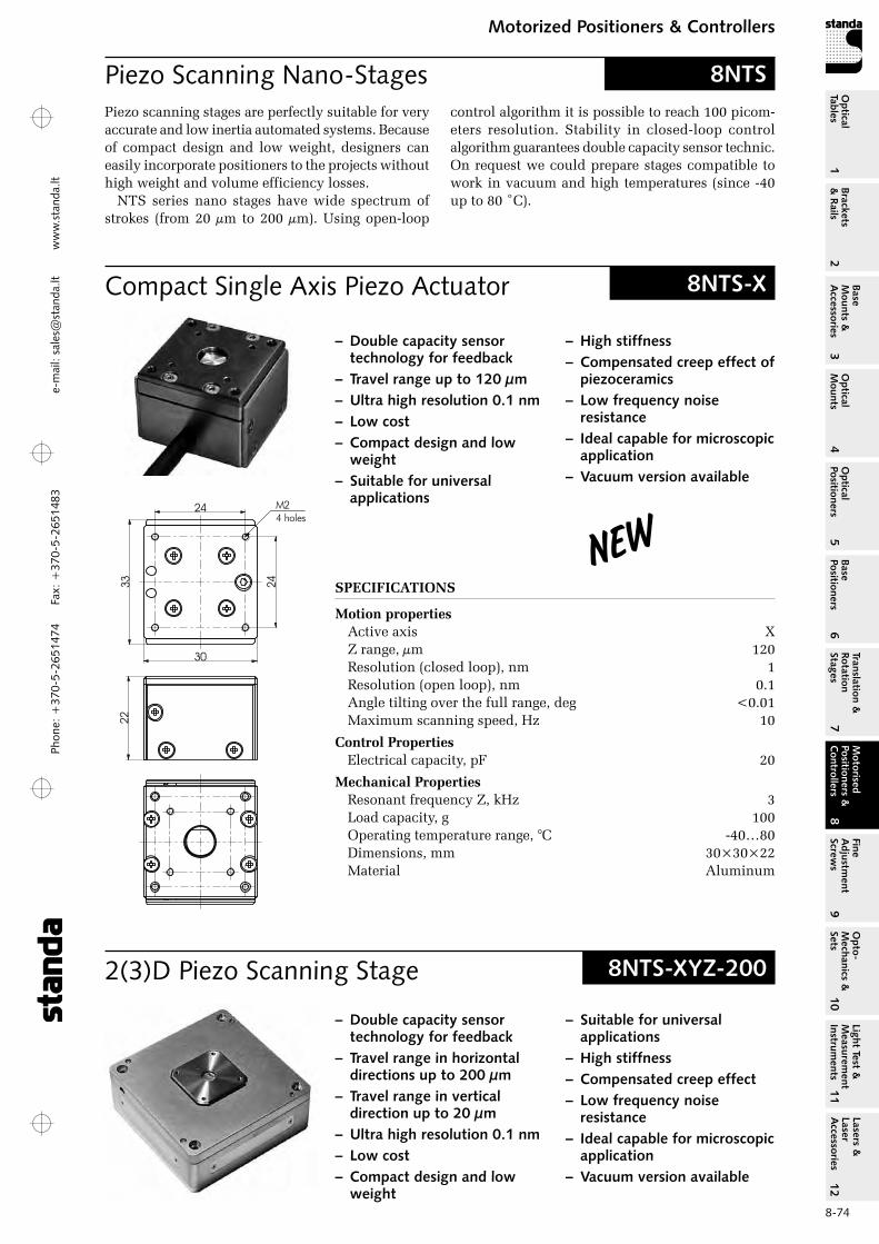
Phon
e: +
370-
5-26
5147
4 Fa
x: +
370-
5-26
5148
31
Brackets &
Rails
2
Base M
ounts &
Accessories
3O
ptical M
ounts4
Optical
Positioners5
Base Positioners
6
Translation &
Rotation Stages
7
Motorised
Positioners &
Controllers
8
Fine A
djustment
Screws
9
Opto-
Mechanics &
Sets
10O
ptical Tables
Light Test &
Measurem
ent Instrum
ents
Lasers &
Laser A
ccessories 11
12e-
mai
l: sa
les@
stan
da.lt
ww
w.s
tand
a.lt
8-74
Motorized Positioners & ControllersM
otorised Positioners &
C
ontrollers8
Compact Single Axis Piezo Actuator
2(3)D Piezo Scanning Stage
8NTS-X
8NTS-XYZ-200
– Double capacity sensor technology for feedback
– Travel range up to 120 µm – Ultra high resolution 0.1 nm – Low cost – Compact design and low
weight – Suitable for universal
applications
– Double capacity sensor technology for feedback
– Travel range in horizontal directions up to 200 µm
– Travel range in vertical direction up to 20 µm
– Ultra high resolution 0.1 nm – Low cost – Compact design and low
weight
30
33
24
24
M24 holes
22
– High stiffness – Compensated creep effect of
piezoceramics – Low frequency noise
resistance – Ideal capable for microscopic
application – Vacuum version available
– Suitable for universal applications
– High stiffness – Compensated creep effect – Low frequency noise
resistance – Ideal capable for microscopic
application – Vacuum version available
Piezo Scanning Nano-Stages 8NTSPiezo scanning stages are perfectly suitable for very accurate and low inertia automated systems. Because of compact design and low weight, designers can easily incorporate positioners to the projects without high weight and volume efficiency losses.
NTS series nano stages have wide spectrum of strokes (from 20 µm to 200 µm). Using open-loop
control algorithm it is possible to reach 100 picom-eters resolution. Stability in closed-loop control algorithm guarantees double capacity sensor technic. on request we could prepare stages compatible to work in vacuum and high temperatures (since -40 up to 80 ˚C).
SPECIFICATIONS
Motion propertiesActive axis XZ range, µm 120resolution (closed loop), nm 1resolution (open loop), nm 0.1Angle tilting over the full range, deg <0.01Maximum scanning speed, Hz 10
Control PropertiesElectrical capacity, pF 20
Mechanical Propertiesresonant frequency Z, kHz 3Load capacity, g 100operating temperature range, °C -40…80Dimensions, mm 30×30×22Material Aluminum
New
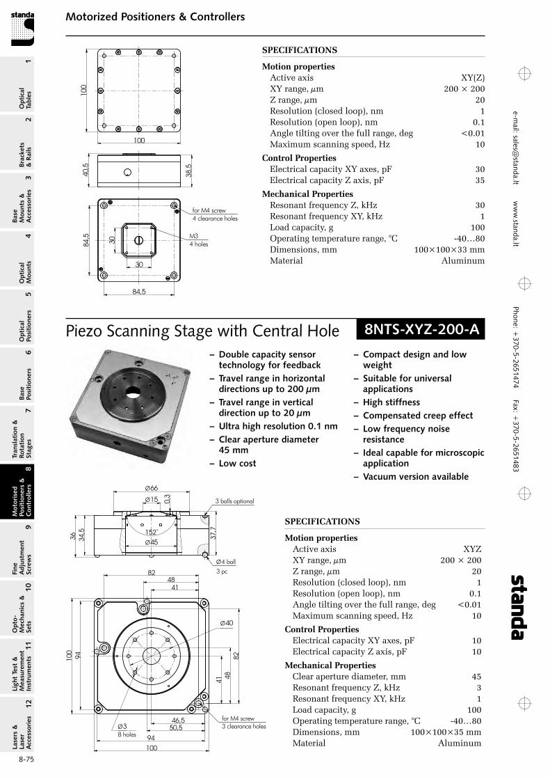
Phone: +370-5-2651474
Fax: +370-5-2651483
1Br
acke
ts
& R
ails
2
Base
M
ount
s &
A
cces
sori
es3
Opt
ical
M
ount
s4
Opt
ical
Po
siti
oner
s5
Base
Po
siti
oner
s6
Tran
slat
ion
&
Rota
tion
St
ages
7
Mot
oris
ed
Posi
tion
ers
&
Con
trol
lers
8
Fine
A
djus
tmen
t Sc
rew
s9
Opt
o-
Mec
hani
cs &
Se
ts10
Opt
ical
Ta
bles
Ligh
t Te
st &
M
easu
rem
ent
Inst
rum
ents
Lase
rs &
La
ser
Acc
esso
ries
11
12e-m
ail: [email protected] w
ww
.standa.lt
8-75
Motorized Positioners & ControllersM
otor
ised
Po
siti
oner
s &
C
ontr
olle
rs8
SPECIFICATIONS
Motion properties Active axis XY(Z) XY range, µm 200 × 200 Z range, µm 20 resolution (closed loop), nm 1 resolution (open loop), nm 0.1 Angle tilting over the full range, deg <0.01 Maximum scanning speed, Hz 10
Control Properties Electrical capacity XY axes, pF 30 Electrical capacity Z axis, pF 35
Mechanical Properties resonant frequency Z, kHz 30 resonant frequency XY, kHz 1 Load capacity, g 100 operating temperature range, °C -40…80 Dimensions, mm 100×100×33 mm Material Aluminum
30
30
84,5
84,5
38,5
40,5
100
100
M34 holes
for M4 screw4 clearance holes
Piezo Scanning Stage with Central Hole 8NTS-XYZ-200-A
– Double capacity sensor technology for feedback
– Travel range in horizontal directions up to 200 µm
– Travel range in vertical direction up to 20 µm
– Ultra high resolution 0.1 nm – Clear aperture diameter
45 mm – Low cost
– Compact design and low weight
– Suitable for universal applications
– High stiffness – Compensated creep effect – Low frequency noise
resistance – Ideal capable for microscopic
application – Vacuum version available
SPECIFICATIONS
Motion properties Active axis XYZ XY range, µm 200 × 200 Z range, µm 20 resolution (closed loop), nm 1 resolution (open loop), nm 0.1 Angle tilting over the full range, deg <0.01 Maximum scanning speed, Hz 10
Control Properties Electrical capacity XY axes, pF 10 Electrical capacity Z axis, pF 10
Mechanical Properties Clear aperture diameter, mm 45 resonant frequency Z, kHz 3 resonant frequency XY, kHz 1 Load capacity, g 100 operating temperature range, °C -40…80 Dimensions, mm 100×100×35 mm Material Aluminum
34,5
36
152˚
Ø45
Ø66
Ø15 0,3
37,7
Ø4 ball3 pc
3 balls optional
100
94
82
41
46,5
41
8294
50,5
48
48
100
Ø40
Ø38 holes
for M4 screw3 clearance holes
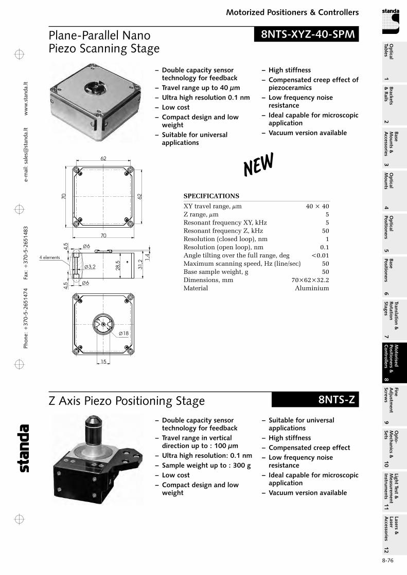
Phon
e: +
370-
5-26
5147
4 Fa
x: +
370-
5-26
5148
31
Brackets &
Rails
2
Base M
ounts &
Accessories
3O
ptical M
ounts4
Optical
Positioners5
Base Positioners
6
Translation &
Rotation Stages
7
Motorised
Positioners &
Controllers
8
Fine A
djustment
Screws
9
Opto-
Mechanics &
Sets
10O
ptical Tables
Light Test &
Measurem
ent Instrum
ents
Lasers &
Laser A
ccessories 11
12e-
mai
l: sa
les@
stan
da.lt
ww
w.s
tand
a.lt
8-76
Motorized Positioners & ControllersM
otorised Positioners &
C
ontrollers8
Z Axis Piezo Positioning Stage
Plane-Parallel Nano Piezo Scanning Stage
8NTS-Z
8NTS-XYZ-40-SPM
– Double capacity sensor technology for feedback
– Travel range in vertical direction up to : 100 µm
– Ultra high resolution: 0.1 nm – Sample weight up to : 300 g – Low cost – Compact design and low
weight
– Double capacity sensor technology for feedback
– Travel range up to 40 µm – Ultra high resolution 0.1 nm – Low cost – Compact design and low
weight – Suitable for universal
applications
– Suitable for universal applications
– High stiffness – Compensated creep effect – Low frequency noise
resistance – Ideal capable for microscopic
application – Vacuum version available
– High stiffness – Compensated creep effect of
piezoceramics – Low frequency noise
resistance – Ideal capable for microscopic
application – Vacuum version available
28,5
31,2 1,
4
70
70
62
62
6Ø
6Ø
4,5
4,5
3,2Ø
4 elements
15
Ø18
SPECIFICATIONS
XY travel range, µm 40 × 40 Z range, µm 5 resonant frequency XY, kHz 5 resonant frequency Z, kHz 50 resolution (closed loop), nm 1 resolution (open loop), nm 0.1 Angle tilting over the full range, deg <0.01 Maximum scanning speed, Hz (line/sec) 50 Base sample weight, g 50 Dimensions, mm 70×62×32.2 Material Aluminium
New

Phone: +370-5-2651474
Fax: +370-5-2651483
1Br
acke
ts
& R
ails
2
Base
M
ount
s &
A
cces
sori
es3
Opt
ical
M
ount
s4
Opt
ical
Po
siti
oner
s5
Base
Po
siti
oner
s6
Tran
slat
ion
&
Rota
tion
St
ages
7
Mot
oris
ed
Posi
tion
ers
&
Con
trol
lers
8
Fine
A
djus
tmen
t Sc
rew
s9
Opt
o-
Mec
hani
cs &
Se
ts10
Opt
ical
Ta
bles
Ligh
t Te
st &
M
easu
rem
ent
Inst
rum
ents
Lase
rs &
La
ser
Acc
esso
ries
11
12e-m
ail: [email protected] w
ww
.standa.lt
8-77
Motorized Positioners & ControllersM
otor
ised
Po
siti
oner
s &
C
ontr
olle
rs8
Single channel
controller Available
!8NSC controllers lineup
74,2
109,2
76
40Ø
14,5
52
25 1,5
53,5
Ø20
70
SPECIFICATIONS
Motion properties Active axis Z resolution (closed loop), nm 1 resolution (open loop), nm 0.1 Angle tilting over the full range, deg <0.01 Maximum scanning speed, Hz 10
Control Properties Electrical capacity Z axis, pF 15
Mechanical Properties resonant frequency Z, kHz 0.5 Load capacity, g 300 operating temperature range, °C -40…80 Dimensions, mm 108×73×67.5 Material Aluminum
Nano Stages Controllers 8NSC
– Closed Loop Feedback – DAC – USB / RS-232C communication – Synchronization OUT – High Voltage Amplifier -5/150 V – NSpec Software
Electronic controllers 8NSC is designed to con-trol piezo positioners of 8NTS series.
8NSC‑1000 is able to control 3 piezo stages.
8NSC‑3061 can control 9 piezo stages and up to 4 stepper motor translation stages with micro step option, for instance, for rough adjustment of scanning head (stage).
8NSC-3061 SPM controller contains 2-channel lock-in amplifier to provide resonant SPM techniques, for example non-contact SPM mode. Lock in amplifier includes high stable voltage generator based on digital frequency synthesizer. High speed data processing is implemented using programmable logic (FPGA). This allows to perform high quality lock-in detection up to 1.5 MHz band.
8NSC-1000 3 axis controller 8NSC-3061
9 axis controller
SPECIFICATIONS
CPU 32 bit; rISC PC interface USB 2.0 other interfaces rS 232, rS 485, SYNC I/o Voltage -10 – 150 V Noise <5 ppm Bit (digital-analog converters) 18 bit
8NSC‑3061 Piezo control
Number of channels max 9 Stepper motor control
Number of channels 4 Power supply 24 V, 3 A Support microstepping mode up to 1/16 step
Lock-in amplifier Number of channels 2 Coefficient preamplifier 1 – 100 Voltage range ±10 V Bit ADC 16 bit Amplitude of the output voltage 10 mV – 10 V Stability of the main oscillator <5 ppm
8NSC‑1000 Piezo control
Number of channels max 3
Software:Basic Nspec software, SDK for Windows, Linux, Mac OS, Android for Tablet PC.
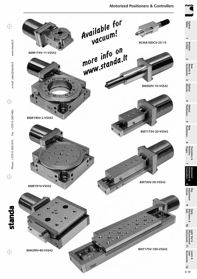
Phon
e: +
370-
5-26
5147
4 Fa
x: +
370-
5-26
5148
31
Brackets &
Rails
2
Base M
ounts &
Accessories
3O
ptical M
ounts4
Optical
Positioners5
Base Positioners
6
Translation &
Rotation Stages
7
Motorised
Positioners &
Controllers
8
Fine A
djustment
Screws
9
Opto-
Mechanics &
Sets
10O
ptical Tables
Light Test &
Measurem
ent Instrum
ents
Lasers &
Laser A
ccessories 11
12e-
mai
l: sa
les@
stan
da.lt
ww
w.s
tand
a.lt
8-78
Motorized Positioners & ControllersM
otorised Positioners &
C
ontrollers8
Available
for
vacuum!
more info o
n
www.standa.lt
8MR174V-11-VSS42
8MR190V-2-VSS42
8MR191V-VSS42
8MG99V-80-VSS42
8CMA16DCV-25/15
8MS00V-10-VSS42
8MT173V-20-VSS42
8MT30V-50-VSS42
8MT175V-100-VSS42
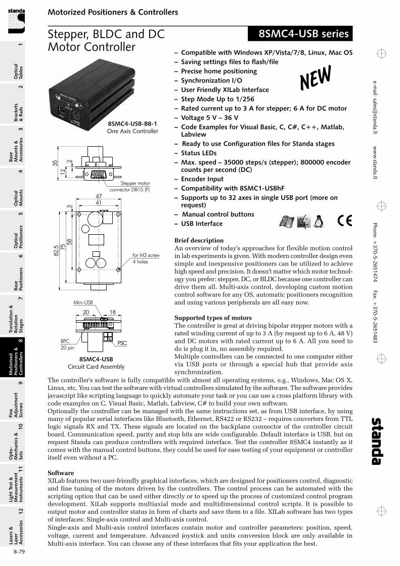
Phone: +370-5-2651474
Fax: +370-5-2651483
1Br
acke
ts
& R
ails
2
Base
M
ount
s &
A
cces
sori
es3
Opt
ical
M
ount
s4
Opt
ical
Po
siti
oner
s5
Base
Po
siti
oner
s6
Tran
slat
ion
&
Rota
tion
St
ages
7
Mot
oris
ed
Posi
tion
ers
&
Con
trol
lers
8
Fine
A
djus
tmen
t Sc
rew
s9
Opt
o-
Mec
hani
cs &
Se
ts10
Opt
ical
Ta
bles
Ligh
t Te
st &
M
easu
rem
ent
Inst
rum
ents
Lase
rs &
La
ser
Acc
esso
ries
11
12e-m
ail: [email protected] w
ww
.standa.lt
8-79
Motorized Positioners & ControllersM
otor
ised
Po
siti
oner
s &
C
ontr
olle
rs8
Stepper, BLDC and DC Motor Controller
8SMC4-USB series
Brief descriptionAn overview of today's approaches for flexible motion control in lab experiments is given. With modern controller design even simple and inexpensive positioners can be utilized to achieve high speed and precision. It doesn't matter which motor technol-ogy you prefer: stepper, DC, or BLDC because one controller can drive them all. Multi-axis control, developing custom motion control software for any oS, automatic positioners recognition and using various peripherals are all easy now.
Supported types of motorsThe controller is great at driving bipolar stepper motors with a rated winding current of up to 3 A (by request up to 6 A, 48 V) and DC motors with rated current up to 6 A. All you need to do is plug it in, no assembly required.Multiple controllers can be connected to one computer either via USB ports or through a special hub that provide axis synchronization.
The controller's software is fully compatible with almost all operating systems, e.g., Windows, Mac oS X, Linux, etc. You can test the software with virtual controllers simulated by the software. The software provides javascript like scripting language to quickly automate your task or you can use a cross platform library with code examples on C, Visual Basic, Matlab, Labview, C# to build your own software.optionally the controller can be managed with the same instructions set, as from USB interface, by using many of popular serial interfaces like Bluetooth, Ethernet, rS422 or rS232 – requires converters from TTL logic signals rX and TX. These signals are located on the backplane connector of the controller circuit board. Communication speed, parity and stop bits are wide configurable. Default interface is USB, but on request Standa can produce controllers with required interface. Test the controller 8SMC4 instantly as it comes with the manual control buttons, they could be used for ease testing of your equipment or controller itself even without a PC.
SoftwareXILab features two user-friendly graphical interfaces, which are designed for positioners control, diagnostic and fine tuning of the motors driven by the controllers. The control process can be automated with the scripting option that can be used either directly or to speed up the process of customized control program development. XiLab supports multiaxial mode and multidimensional control scripts. It is possible to output motor and controller status in form of charts and save them to a file. XILab software has two types of interfaces: Single-axis control and Multi-axis control.Single-axis and Multi-axis control interfaces contain motor and controller parameters: position, speed, voltage, current and temperature. Advanced joystick and units conversion block are only available in Multi-axis interface. You can choose any of these interfaces that fits your application the best.
New75
47
358
41
82,5
20 18
Stepper motorconnector DB15 (F)
Mini-USB
BPC20 pin
PSC
3512
2
for M3 screw4 holes
8SMC4-USBCircuit Card Assembly
– Compatible with Windows XP/Vista/7/8, Linux, Mac OS– Saving settings files to flash/file– Precise home positioning– Synchronization I/O – User Friendly XILab Interface– Step Mode Up to 1/256– Rated current up to 3 A for stepper; 6 A for DC motor– Voltage 5 V – 36 V– Code Examples for Visual Basic, C, C#, C++, Matlab,
Labview– Ready to use Configuration files for Standa stages– Status LEDs– Max. speed – 35000 steps/s (stepper); 800000 encoder
counts per second (DC)– Encoder Input– Compatibility with 8SMC1-USBhF– Supports up to 32 axes in single USB port (more on
request)– Manual control buttons– USB Interface
8SMC4-USB-B8-1One Axis Controller
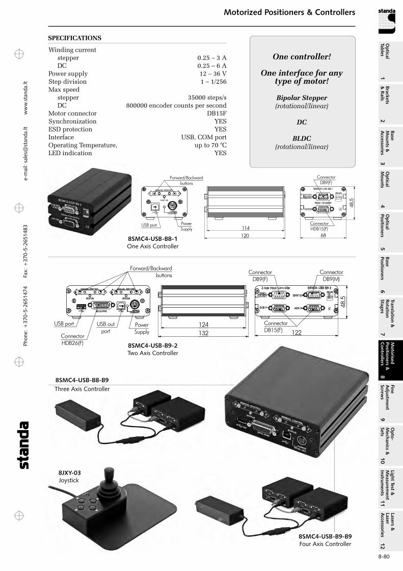
Phon
e: +
370-
5-26
5147
4 Fa
x: +
370-
5-26
5148
31
Brackets &
Rails
2
Base M
ounts &
Accessories
3O
ptical M
ounts4
Optical
Positioners5
Base Positioners
6
Translation &
Rotation Stages
7
Motorised
Positioners &
Controllers
8
Fine A
djustment
Screws
9
Opto-
Mechanics &
Sets
10O
ptical Tables
Light Test &
Measurem
ent Instrum
ents
Lasers &
Laser A
ccessories 11
12e-
mai
l: sa
les@
stan
da.lt
ww
w.s
tand
a.lt
8-80
Motorized Positioners & ControllersM
otorised Positioners &
C
ontrollers8
USB port USB outport
Forward/Backwardbuttons
PowerSupply
ConnectorDB15(F)
ConnectorDB9(F)
ConnectorHDB26(F)
124122
48,5
ConnectorDB9(M)
132
8SMC4-USB-B8-1One Axis Controller
8SMC4-USB-B9-2Two Axis Controller
8SMC4-USB-B8-B9Three Axis Controller
8SMC4-USB-B9-B9Four Axis Controller
8JXY-03Joystick
SPECIFICATIONS
Winding current stepper 0.25 – 3 A DC 0.25 – 6 A
Power supply 12 – 36 VStep division 1 – 1/256Max speed stepper 35000 steps/s DC 800000 encoder counts per second
Motor connector DB15FSynchronization YESESD protection YESInterface USB, CoM portoperating Temperature, up to 70 °CLED indication YES
One controller!
One interface for any type of motor!
Bipolar Stepper(rotational/linear)
DC
BLDC(rotational/linear)
120
11468
48,5
Forward/Backwardbuttons
USB port PowerSupply
ConnectorDB9(F)
ConnectorHDB15(F)
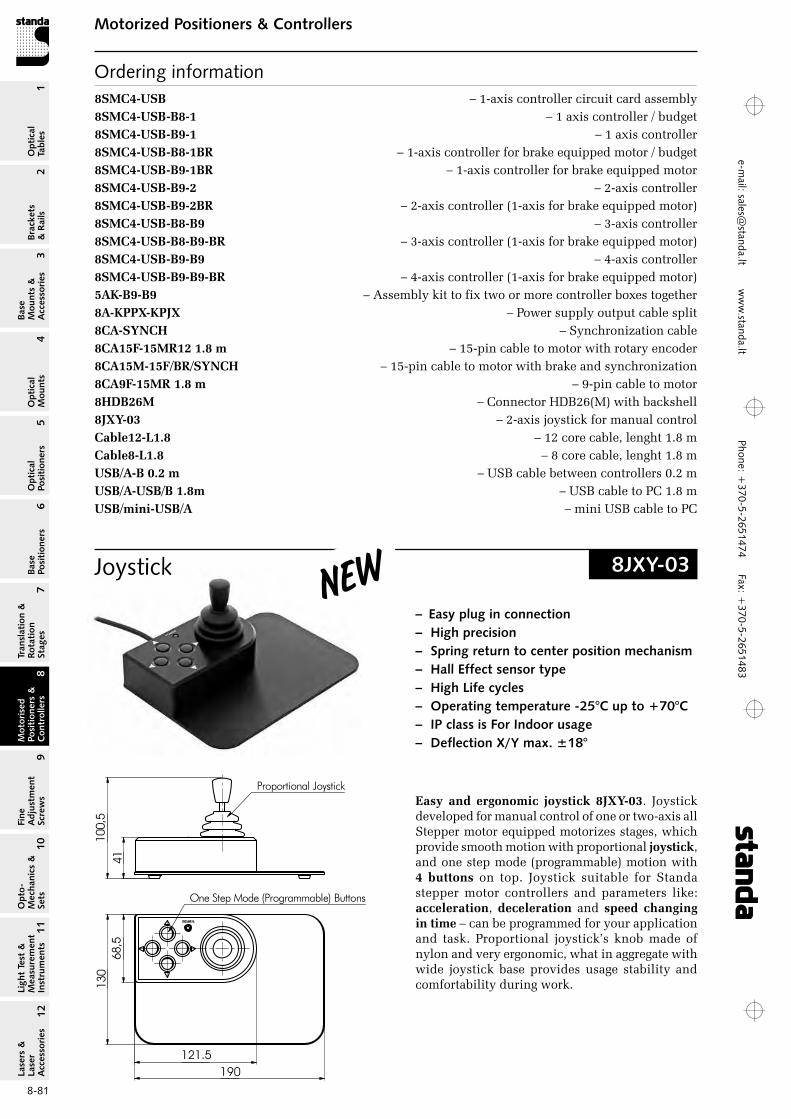
Phone: +370-5-2651474
Fax: +370-5-2651483
1Br
acke
ts
& R
ails
2
Base
M
ount
s &
A
cces
sori
es3
Opt
ical
M
ount
s4
Opt
ical
Po
siti
oner
s5
Base
Po
siti
oner
s6
Tran
slat
ion
&
Rota
tion
St
ages
7
Mot
oris
ed
Posi
tion
ers
&
Con
trol
lers
8
Fine
A
djus
tmen
t Sc
rew
s9
Opt
o-
Mec
hani
cs &
Se
ts10
Opt
ical
Ta
bles
Ligh
t Te
st &
M
easu
rem
ent
Inst
rum
ents
Lase
rs &
La
ser
Acc
esso
ries
11
12e-m
ail: [email protected] w
ww
.standa.lt
8-81
Motorized Positioners & ControllersM
otor
ised
Po
siti
oner
s &
C
ontr
olle
rs8
8SMC4‑USB – 1-axis controller circuit card assembly8SMC4‑USB‑B8‑1 – 1 axis controller / budget8SMC4‑USB‑B9‑1 – 1 axis controller8SMC4‑USB‑B8‑1BR – 1-axis controller for brake equipped motor / budget8SMC4‑USB‑B9‑1BR – 1-axis controller for brake equipped motor8SMC4‑USB‑B9‑2 – 2-axis controller8SMC4‑USB‑B9‑2BR – 2-axis controller (1-axis for brake equipped motor)8SMC4‑USB‑B8‑B9 – 3-axis controller8SMC4‑USB‑B8‑B9‑BR – 3-axis controller (1-axis for brake equipped motor)8SMC4‑USB‑B9‑B9 – 4-axis controller8SMC4‑USB‑B9‑B9‑BR – 4-axis controller (1-axis for brake equipped motor)5AK‑B9‑B9 – Assembly kit to fix two or more controller boxes together8A‑KPPX‑KPJX – Power supply output cable split8CA‑SYNCH – Synchronization cable8CA15F‑15MR12 1.8 m – 15-pin cable to motor with rotary encoder8CA15M‑15F/BR/SYNCH – 15-pin cable to motor with brake and synchronization8CA9F‑15MR 1.8 m – 9-pin cable to motor8HDB26M – Connector HDB26(M) with backshell8JXY‑03 – 2-axis joystick for manual controlCable12‑L1.8 – 12 core cable, lenght 1.8 mCable8‑L1.8 – 8 core cable, lenght 1.8 mUSB/A‑B 0.2 m – USB cable between controllers 0.2 mUSB/A‑USB/B 1.8m – USB cable to PC 1.8 mUSB/mini‑USB/A – mini USB cable to PC
Ordering information
Joystick 8JXY-03
– Easy plug in connection– High precision– Spring return to center position mechanism– Hall Effect sensor type– High Life cycles– Operating temperature -25°C up to +70°C– IP class is For Indoor usage– Deflection X/Y max. ±18°
Easy and ergonomic joystick 8JXY‑03. Joystick developed for manual control of one or two-axis all Stepper motor equipped motorizes stages, which provide smooth motion with proportional joystick, and one step mode (programmable) motion with 4 buttons on top. Joystick suitable for Standa stepper motor controllers and parameters like: acceleration, deceleration and speed changing in time – can be programmed for your application and task. Proportional joystick’s knob made of nylon and very ergonomic, what in aggregate with wide joystick base provides usage stability and comfortability during work.
190
130
121.5
68,5
100,
5
Proportional Joystick
One Step Mode (Programmable) Buttons
41
New
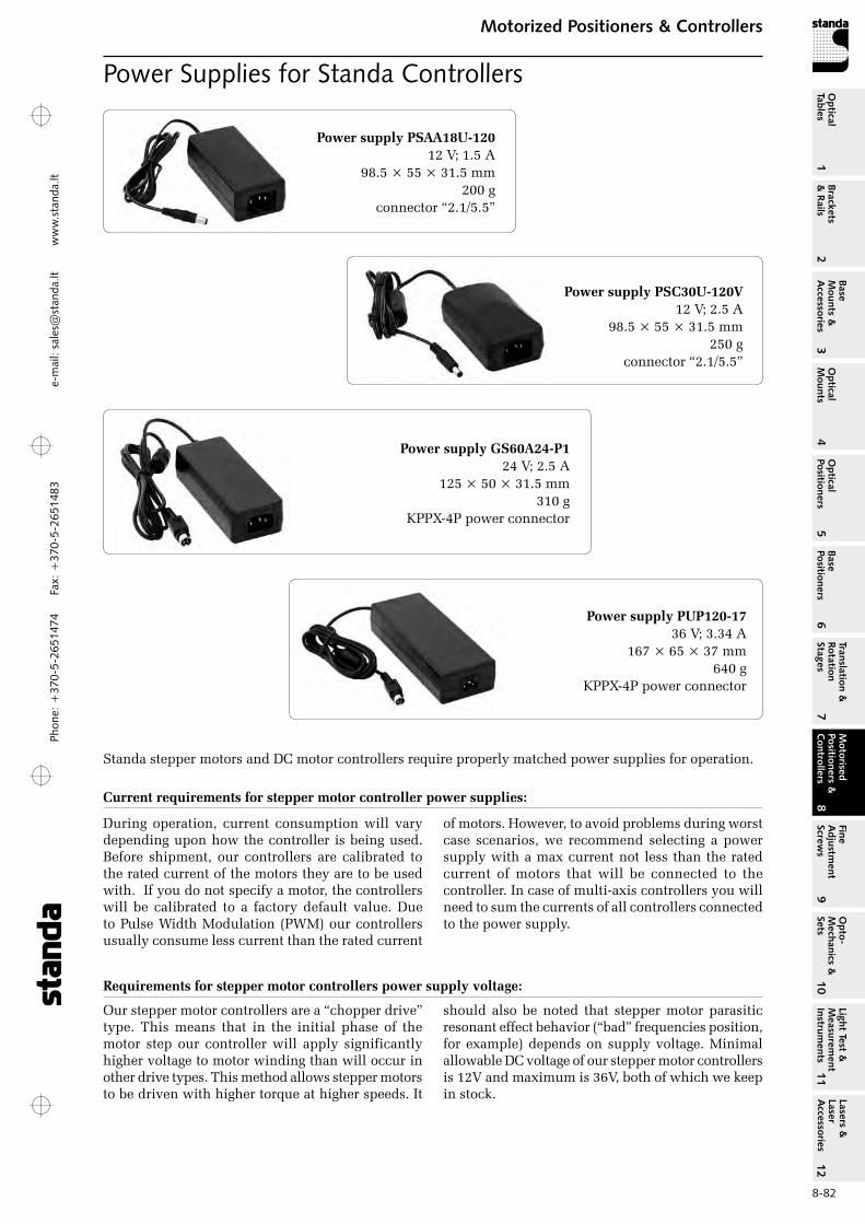
Phon
e: +
370-
5-26
5147
4 Fa
x: +
370-
5-26
5148
31
Brackets &
Rails
2
Base M
ounts &
Accessories
3O
ptical M
ounts4
Optical
Positioners5
Base Positioners
6
Translation &
Rotation Stages
7
Motorised
Positioners &
Controllers
8
Fine A
djustment
Screws
9
Opto-
Mechanics &
Sets
10O
ptical Tables
Light Test &
Measurem
ent Instrum
ents
Lasers &
Laser A
ccessories 11
12e-
mai
l: sa
les@
stan
da.lt
ww
w.s
tand
a.lt
8-82
Motorized Positioners & ControllersM
otorised Positioners &
C
ontrollers8
Power Supplies for Standa Controllers
Requirements for stepper motor controllers power supply voltage:
our stepper motor controllers are a “chopper drive” type. This means that in the initial phase of the motor step our controller will apply significantly higher voltage to motor winding than will occur in other drive types. This method allows stepper motors to be driven with higher torque at higher speeds. It
should also be noted that stepper motor parasitic resonant effect behavior (“bad” frequencies position, for example) depends on supply voltage. Minimal allowable DC voltage of our stepper motor controllers is 12V and maximum is 36V, both of which we keep in stock.
Standa stepper motors and DC motor controllers require properly matched power supplies for operation.
Current requirements for stepper motor controller power supplies:
During operation, current consumption will vary depending upon how the controller is being used. Before shipment, our controllers are calibrated to the rated current of the motors they are to be used with. If you do not specify a motor, the controllers will be calibrated to a factory default value. Due to Pulse Width Modulation (PWM) our controllers usually consume less current than the rated current
of motors. However, to avoid problems during worst case scenarios, we recommend selecting a power supply with a max current not less than the rated current of motors that will be connected to the controller. In case of multi-axis controllers you will need to sum the currents of all controllers connected to the power supply.
Power supply PSAA18U‑120 12 V; 1.5 A
98.5 × 55 × 31.5 mm 200 g
connector “2.1/5.5”
Power supply PSC30U‑120V 12 V; 2.5 A
98.5 × 55 × 31.5 mm 250 g
connector “2.1/5.5”
Power supply GS60A24‑P1 24 V; 2.5 A
125 × 50 × 31.5 mm 310 g
KPPX-4P power connector
Power supply PUP120‑1736 V; 3.34 A
167 × 65 × 37 mm 640 g
KPPX-4P power connector