ORDERING GUIDE
52
Revised October 1st, 2017* ORDERING GUIDE Table of Contents TopWorx™ Discrete Valve Control Products 2-13 GO™ Switch Products 14-27 Nuclear Products 28 GO™ Switch Accessories 29-30 Safety Shower Mounting Kits 31-36 VIP Mounting Kits 37-48 *This price list dated October 1st, 2017 supersedes all previous price lists. Prices and specifications are subject to change without notice. If printed, this document is uncontrolled. Refer to password-protected Distributor Support Center at www.topworx.com for the most updated pricing and options. TopWorx™ Switchbox • GO™ Switch • Safety Shower Mounting Kits • VIP Mounting Kits
-
Upload
khangminh22 -
Category
Documents
-
view
1 -
download
0
Transcript of ORDERING GUIDE

Revised October 1st, 2017*ORDERING GUIDE
Table of Contents
TopWorx™ Discrete Valve Control Products 2-13
GO™ Switch Products 14-27
Nuclear Products 28
GO™ Switch Accessories 29-30
Safety Shower Mounting Kits 31-36
VIP Mounting Kits 37-48
*This price list dated October 1st, 2017 supersedes all previous price lists. Prices and specifications are subject to change without notice. If printed, this document is uncontrolled. Refer to password-protected Distributor Support Center at www.topworx.com for the most updated pricing and options.
TopWorx™ Switchbox • GO™ Switch • Safety Shower Mounting Kits • VIP Mounting Kits

2
TopWorx™ Valve Control Solutions
TopWorx™ D-Series, DXP, DXR & DXS Consult factory for options not shown below.
DXP Tropicalized Aluminum DXR Composite Resin ("S" Silicone O-Rings only; Stainless steel conduit entries) (Area Classification "0" only available with ATEX/IECEx approv- als) 232
DXS 316 Stainless steel
Bus NetworkAS AS-Interface w(2) SPDT GO Switches (Area class cannot be 0) *FF Foundation Fieldbus w/ 0 -10K Pot
*FL Foundation Fieldbus w/(2) SPDT GO Switches
*FP Foundation Fieldbus w/(2) SPDT GO Switches and 0-10K Pot DN DeviceNet w(2) SPDT GO Switches (Area class cannot be 0)
PB Profibus w/(2) SPDT GO Switches (Area class cannot be 0) Partial Stroke Test ES ESD/PST Module w/GO Switch (Area class cannot be 0)
GO SwitchesL2 (2)GO Switches SPDT hermetic seal L4 (4)GO Switches SPDT hermetic seal(not avail able with pilot)Z2 (2)GO Switches DPDT hermetic seal Z4 (4)GO Switches DPDT hermetic seal, (not available with pilot) Mechanical Switches(Area class cannot be 2, DXR with G approval not available with pilot) M2 (2)Mech SPDT M4 (4)Mech SPDT M6 (6)Mech SPDT T2 (2)Mech DPDT K2 (2)Mech SPDT gold contactsK4 (4)Mech SPDT gold contacts
Proximity SwitchesR2 (2) SPDT Prox switches R4 (4) SPDT Prox switches (R2 & R4 only available with DXR and Ex me certification)
Inductive SensorsE2 (2) p+f NJ2-V3-N inductive NAMUR E4 (4) p+f NJ2-V3-N inductive NAMUR
Analog Output (Available with 2-switch options only for L,Z,M,K,E,T)
_X 4-20mA transmitter _H 4-20mA transmitter with HART (Not available with switch option T; LH, ZH not available w/pilot valve) (LH, ZH Not available with DXR)Example:LH =(2) GO Switches with HART™ transmitter
* *FF, *FL and *FP with Area Classification "0" has an ib protection
0 Intrinsically safe (Bus/sensor cannot be AS, DN, ES, PB, or _X; Requires appropriate I.S. barrier) - North America Class I Div 1&2 Groups A, B, C, D Type 4, 4X - ATEX/IECEx Zone 0 II2GD, T6/T4 Ex ia IIC Ex tb IIIC, IP66/67 (Foundation Fieldbus) Zone 1, Ex ib IIC T4, IP67
1 Explosion proof / Flame proof (DXP/S only) - North America Class I Div 1 Groups C, D; Class I Div 2, Groups A, B, C, D. (Groups A & B must be hermetically sealed) Type 4, 4X, - ATEX/IECEx Zone 1 II2G, II2GD, T6/T4/T3 Ex d IIB+H2 Ex tb IIIC IP66/67 (O-Rings must be S for DUST certification)
2 Non-incendive (Bus/sensor must be L, Z, P, E, AS, FF,_X, _H, _E or DN) - North America Class I Div 2 Groups A, B, C, D; Class II Div 2 Groups F,G - ATEX (DXP/S only) II3G Ex nA nC tb, IP66/67 (O-Rings must be S for DUST certification)
G General Purpose Type 4, 4X (not available with DXR with mechanical switches)
C Flameproof (DXS not available with valve; Conduit entries must be E or M) ATEX/IECEx II2G, II2GD, T6/T4/T3 Ex d IIC Ex tb IIIC IP66/67
M Flameproof (only available with R2 and R4 sensor options) (DXR only) ATEX/IECEx Zone 1, II2GD Ex e mb IIC T4, Ex tb IIIC T66 IP67 (Not available w/ pilot) W No approvals; Type 4, 4X IP66/68
G Standard 90° Green OPEN, Red CLOSED
R Standard 90° Green CLOSED, Red OPEN
B 90O Black OPEN, Yellow CLOSED
Y 90° Yellow OPEN, Black CLOSED
1 3 way, 90O
L Port
3 3 way, 90O
T Port
5 3 way, 90O
T Port
7 3 way, 180O
T Port 3 position
9 3 way, 180O
T Port 3 position
S 1/4" DD 316 stainless steel
N NAMUR 316 stainless steel
DXP/DXS (Metal Conduit Entries)E (2) 3/4" NPT
4 (2) 3/4" NPT (2) 1/2" NPT
M (2) M20
3 (4) M20
6 (4) 3/4" NPT
DXR P (2) 1/2" NPT
E (2) 3/4" NPT
M (2) M20
Conduit EntriesShaftVisual DisplayArea ClassificationBus/SensorEnclosure
Enclosure Bus/Sensor Area Classification Visual Display Shaft Conduit Entries-
Ordering GuideFill in the boxes to createyour 'ordering number.'
See next column
For complete information on certification options, go to www.topworx.com
and download the applicable product
certificate.

www.topworx.com
3
TopWorx™ Valve Control Solutions
B Buna-N
S Silicone
NOTE:For Temperatures below -40°C, Silicone o-rings are recom-mended
Blank No pilot device(s) 1 (1) 24 Vdc pilot, fail open/closed 0.5 W (non- I.S.) 0.5W (I.S) 2 (2) 24 Vdc pilots, fail last position 0.5W (non-I.S) 0.5W (I.S) 4 (1) 220 Vac pilot, 2W, fail open/closed 5 (2) 220 Vac pilots, 2W, fail last position 7 (1) 110 Vac pilot, 1.1W, fail open/closed 8 (2) 110 Vac pilots, 1.1W, fail last position P (1) piezo pilot, fail open/closed (FF only) R (2) piezo pilots, fail last position (FF only)
Blank No Spool Valve
A Aluminum Hard coat anodized (IP65)
6 316 Stainless steel (IP65)
Blank No Spool Valve
2 .86 Cv (1/4" NPT Ports)
3 3.7 Cv (1/2" NPT Ports) (For manual override consult factory) (Spool Valve A) (Spool Valve 6)
Blank No override 1 Single Pushbutton Momentary/Latching 2 Dual Pushbutton Momentary/Latching T Partial stroke test button with lockable cover (Sensor ES only) (Not avail w/ Area Class C) (DXP/S - Conduit Entries 4 or 3 only. DXR - consult factory)
Manual OverrideValve CvSpool ValvePilotO-Rings
Manual OverrideValve CvSpool ValvePilotO-Rings
Pneumatic Accessories
Flow Control, 1/8" NPT (1 per kit) AL-M20
Flow Control, 1/4" NPT (1 per kit) AL-M21
Flow Control, 1/2" NPT (1 per kit) AL-M22
Exhaust Protectors, 1/4" NPT (2 per kit) AL-M32
Exhaust Protectors, 1/2" NPT (2 per kit) AL-M33
Slip-Lok, 1/2'' x 1/2" AV-SLPP
Slip-Lok, 3/4'' x 1/2'' AV-SLEP
Miscellaneous
TopWorx Demo Case ATK2 Net (Includes Valvetop DXP, TXP, TVL, cutaway GO Switch models 20, 35, & 70, and accessories)
ESD Demo Case ATK-ESD Net (Includes working DXP-ES1GN4B1A2T mounted to rack and pinion actuator with control box
Description Part Number List PriceAccessories
Blank No Regional Cert B InMetro (Area Class 0,1 and C only)
N NEPSI
F FISCO (Bus/Sensor must be FF; Area Class must be 0)
K KOSHA (DXP/S only) (Area class 1 or C)
R EAC (DXP/S only)(O-Rings must be B or S, B= Gas Approved;S = Gas/Dust Approved)
A ANZEx Ex d IIC, Ex d IIB+H2 (DXP/S only)
P PESO (India) (Gas approval only)
Regional Certs
Regional Certs

4
TopWorx™ Valve Control Solutions
TopWorx™ T-Series TXP, TXS Consult factory for options not shown below.
ShaftVisual DisplayArea ClassificationBus/SensorEnclosure
Enclosure Bus/Sensor Area Classification Visual Display Shaft-
Ordering GuideFill in the boxes to createyour 'ordering number.'
TXP Tropicalized Aluminum
TXS 316 Stainless Steel
Bus NetworkAS AS-Interface (Area class cannot be 0) PB Profibus DP (Area class must be 1, C or W)
Mechanical Switches(Area class cannot be 2)M2 (2) Mech SPDT No AdderM4 (4) Mech SPDT K2 (2) Mech SPDT w/ gold contacts T2 (2) Mech DPDT (not available with pilot) Proximity SwitchesR2 (2) SPDT 200mA max R4 (4) SPDT 200mA max *P2 (2) SPDT 3A max *P4 (4) SPDT 3A max * Not reccommended with Area Class 0
GO SwitchesL2 (2) GO™ Switches SPDT hermetically sealed (TXP/TXS w/o pilot valve only)
G2 (2) GO™Switches SPDT hermetically sealed 3A/24VDC; 4A/120VAC
G4 (4) GO™Switches SPDT hermetically sealed 3A/24VDC; 4A/120VAC Q2 (2) GO™Switches SPDT hermetically sealed 1A/24VAC
Q4 (4) GO™Switches SPDT hermetically sealed 1A/24VDC
Inductive SensorsE2 (2) p+f NJ2-V3-N inductive NAMUR
Analog Output0X 4-20 mA Transmitter with no switches
Examples:AS = AS-i with “R” type reed switches
0 Intrinsically safe ATEX/IECEx Zone 1 II2GD Ex ia IIC Ex tb IIIC, IP66/67
C Flame Proof ATEX/IECEx II2GD Ex d IIC Ex tb IIIC, IP66/67 (w/o pilot valve)
1 Explosion proof Cl I Div 1 Grps C,D Cl II Div 1 Grps E-G (NEC aprovals w/o pilot valve) ATEX/IECEx Zone 1 II2GD Ex d IIB Ex tb IIIC, IP66/67
2 Non-incendive Cl I Div 2 Grps A-D Cl II Div 2 Grps F&G (NEC aprovals w/o pilot valve) ATEX II3GD (Not available with all sensing options) Ex nA nC IIC, IP66/67 Ex tb IIIC
G General Purpose Type 4X
W No approvals Type 4, 4x IP66/68
G Standard 90° Green OPEN, Red CLOSED
R Standard 90° Green CLOSED, Red OPEN
B 90O Black OPEN, Yellow CLOSED
F Flat-top with skirt indicator (TXP & TXS only) (Indicator not provided with "L" Shaft option)
Y 90O Yellow OPEN, Black CLOSED
J 3 Way T Port, Green/Red
K 3 Way L Port, Green/Red
N NAMUR 304 stainless steel
L 1" Extended Linear Shaft
See next column
Mounting Kits for TXP
Mounting Kit for 20 x 80 AV-TA09
Mounting Kit for 20 x 80 (flattop only) AV-TA10
Mounting Kit for 30 x 80 AV-TA11
Mounting Kit for 30 x 80 (flattop only) AV-TA12
Mounting Kit for 30 x 130 AV-TA13
Mounting Kit for 30 x 130 (flattop only) AV-TA14
Mounting Kit for 50 x 130 AV-TA15
Mounting Kit for 50 x 130 (flattop only) AV-TA16
Mounting Kit for existing standard shaft brackets AV-PL001-1
Description Part Number List Price
T-Series Mounting Kits (All hardware included)
Stainless Steel Mounting Kits for TXS
Mounting Kit for 20 x 80 AV-TS09
Mounting Kit for 20 x 80 (flattop only) AV-TS10
Mounting Kit for 30 x 80 AV-TS11
Mounting Kit for 30 x 80 (flattop only) AV-TS12
Mounting Kit for 30 x 130 AV-TS13
Mounting Kit for 30 x 130 (flattop only) AV-TS14
Mounting Kit for 50 x 130 AV-TS15
Mounting Kit for 50 x 130 (TXS flattop only) AV-TS16
Description Part Number List Price
For complete information on certification options, go to www.topworx.com
and download the applicable product certificate.
www.topworx.com
5
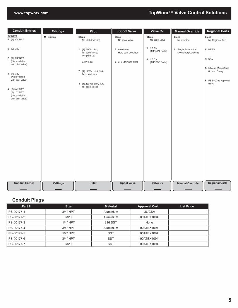
Conduit PlugsPart # Size Material Approval Cert.c List Pricece
PS-00177-1 3/4" NPT Aluminium UL/CSA
PS-00177-2 M20 Aluminium 00ATEX1094
PS-00177-3 1/4" NPT 316 SST None
PS-00177-4 3/4" NPT Aluminium 00ATEX1094
PS-00177-5 1/2" NPT SST 00ATEX1094
PS-00177-6 3/4" NPT SST 00ATEX1094
PS-00177-7 M20 SST 00ATEX1094
TopWorx™ Valve Control Solutions
Conduit Entries
Conduit Entries
Valve CvSpool ValvePilotO-Rings
O-Rings Pilot Spool Valve Valve Cv
TXP/TXSP (2) 1/2” NPT
M (2) M20
E (2) 3/4" NPT (Not available with pilot valve)
3 (4) M20 (Not available with pilot valve)
4 (2) 3/4" NPT (2) 1/2" NPT (Not available with pilot valve)
M Silicone
Blank No pilot device(s)
1 (1) 24Vdc pilot, fail open/closed 1W (non I.S) 0.5W (I.S)
7 (1) 110Vac pilot, 3VA, fail open/closed
4 (1) 220Vac pilot, 3VA fail open/closed
Blank No spool valve
A Aluminum Hard coat anodized
6 316 Stainless steel
Blank No spool valve
1 1.0 Cv (1/4” NPT Ports)
8 1.0 Cv (1/4" BSP Ports)
Regional Certs
Blank No Regional Cert
N NEPSI
R EAC
B InMetro (Area Class 0,1 and C only)
P PESO(Gas approval only)
Regional Certs
Blank No override
1 Single Pushbutton Momentary/Latching
Manual Override
Manual Override
6
TopWorx™ Valve Control Solutions
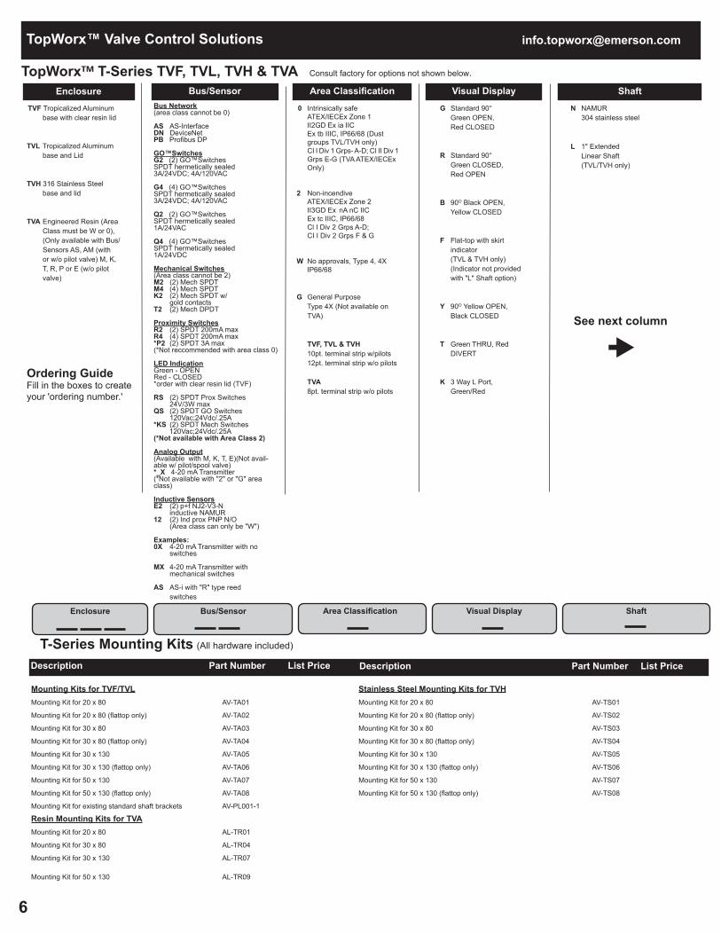
TopWorx™ T-Series TVF, TVL, TVH & TVA Consult factory for options not shown below.
ShaftVisual DisplayArea ClassificationBus/SensorEnclosure
Enclosure Bus/Sensor Area Classification Visual Display Shaft
Ordering GuideFill in the boxes to createyour 'ordering number.'
TVF Tropicalized Aluminum base with clear resin lid
TVL Tropicalized Aluminum base and Lid
TVH 316 Stainless Steel base and lid
TVA Engineered Resin (Area Class must be W or 0), (Only available with Bus/ Sensors AS, AM (with or w/o pilot valve) M, K, T, R, P or E (w/o pilot valve)
Bus Network(area class cannot be 0)
AS AS-Interface DN DeviceNet PB Profibus DP
GO™SwitchesG2 (2) GO™Switches SPDT hermetically sealed 3A/24VDC; 4A/120VAC
G4 (4) GO™Switches SPDT hermetically sealed 3A/24VDC; 4A/120VAC
Q2 (2) GO™Switches SPDT hermetically sealed 1A/24VAC
Q4 (4) GO™Switches SPDT hermetically sealed 1A/24VDC
Mechanical Switches(Area class cannot be 2)M2 (2) Mech SPDT M4 (4) Mech SPDT K2 (2) Mech SPDT w/ gold contacts T2 (2) Mech DPDT Proximity SwitchesR2 (2) SPDT 200mA max R4 (4) SPDT 200mA max *P2 (2) SPDT 3A max (*Not reccommended with area class 0)
LED IndicationGreen - OPENRed - CLOSED *order with clear resin lid (TVF)
RS (2) SPDT Prox Switches 24V/3W max QS (2) SPDT GO Switches 120Vac;24Vdc/.25A *KS (2) SPDT Mech Switches 120Vac;24Vdc/.25A (*Not available with Area Class 2)
Analog Output(Available with M, K, T, E)(Not avail-able w/ pilot/spool valve)*_X 4-20 mA Transmitter (*Not available with "2" or "G" area class)
Inductive SensorsE2 (2) p+f NJ2-V3-N inductive NAMUR 12 (2) Ind prox PNP N/O (Area class can only be "W")
Examples: 0X 4-20 mA Transmitter with no switches
MX 4-20 mA Transmitter with mechanical switches
AS AS-i with "R" type reed switches
0 Intrinsically safe ATEX/IECEx Zone 1 II2GD Ex ia IIC Ex tb IIIC, IP66/68 (Dust groups TVL/TVH only) CI I Div 1 Grps- A-D; CI II Div 1 Grps E-G (TVA ATEX/IECEx Only)
2 Non-incendive ATEX/IECEx Zone 2 II3GD Ex nA nC IIC Ex tc IIIC, IP66/68 Cl I Div 2 Grps A-D; CI I Div 2 Grps F & G
W No approvals, Type 4, 4X IP66/68
G General Purpose Type 4X (Not available on TVA)
TVF, TVL & TVH 10pt. terminal strip w/pilots 12pt. terminal strip w/o pilots TVA 8pt. terminal strip w/o pilots
G Standard 90° Green OPEN, Red CLOSED
R Standard 90° Green CLOSED, Red OPEN
B 90O Black OPEN, Yellow CLOSED
F Flat-top with skirt indicator (TVL & TVH only) (Indicator not provided with "L" Shaft option)
Y 90O Yellow OPEN, Black CLOSED
T Green THRU, Red DIVERT
K 3 Way L Port, Green/Red
N NAMUR 304 stainless steel
L 1" Extended Linear Shaft (TVL/TVH only)
See next column
Mounting Kits for TVF/TVLMounting Kit for 20 x 80 AV-TA01
Mounting Kit for 20 x 80 (flattop only) AV-TA02
Mounting Kit for 30 x 80 AV-TA03
Mounting Kit for 30 x 80 (flattop only) AV-TA04
Mounting Kit for 30 x 130 AV-TA05
Mounting Kit for 30 x 130 (flattop only) AV-TA06
Mounting Kit for 50 x 130 AV-TA07
Mounting Kit for 50 x 130 (flattop only) AV-TA08
Mounting Kit for existing standard shaft brackets AV-PL001-1
Resin Mounting Kits for TVAMounting Kit for 20 x 80 AL-TR01
Mounting Kit for 30 x 80 AL-TR04
Mounting Kit for 30 x 130 AL-TR07
Mounting Kit for 50 x 130 AL-TR09
Description Part Number List Price
T-Series Mounting Kits (All hardware included)
Stainless Steel Mounting Kits for TVH Mounting Kit for 20 x 80 AV-TS01
Mounting Kit for 20 x 80 (flattop only) AV-TS02
Mounting Kit for 30 x 80 AV-TS03
Mounting Kit for 30 x 80 (flattop only) AV-TS04
Mounting Kit for 30 x 130 AV-TS05
Mounting Kit for 30 x 130 (flattop only) AV-TS06
Mounting Kit for 50 x 130 AV-TS07
Mounting Kit for 50 x 130 (flattop only) AV-TS08
Description Part Number List Price

www.topworx.com
7
TopWorx™ Valve Control Solutions
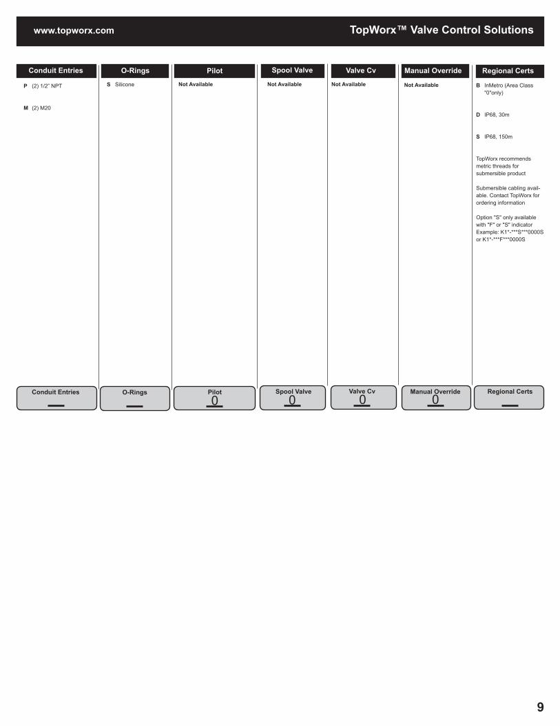
Conduit Entries
Conduit Entries
Valve CvSpool ValvePilotO-Rings
O-Rings Pilot Spool Valve Valve Cv
TVF/TVL/TVHP (2) 1/2” NPT
M (2) M20
E (2) 3/4" NPT
1 (2) M25
TVAA (2) 1/2"NPT Resin
C (2) M20 Resin
M Silicone
Blank No pilot device(s)
1 (1) 24Vdc pilot, fail open/closed 1W (non I.S) 0.5W (I.S)
2 (2) 24Vdc pilots fail last position 1W (non-I.S.) (Not available in TVA) 0.5W (I.S.)
4 (1) 220Vac pilot, 3VA fail open/closed (Not available in TVA)
5 (2) 220Vac pilots, 3VA fail last position (Not available in TVA)
7 (1) 110Vac pilot, 3VA, fail open/closed (Not available in TVA)
8 (2) 110Vac pilots, 3VA fail last position (Not available in TVA)
Blank No spool valve
A Aluminum Hard coat anodized
6 316 Stainless steel
Blank No spool valve
1 1.0 Cv (1/4” NPT Ports)
8 1.0 Cv (1/4" BSP Ports)
Blank No override
1 Single Pushbutton Momentary/Latching
2 Dual Pushbutton Momentary Latching
Manual Override
Manual Override
N NEPSI
R EAC (Not available in TVA)
B InMetro (Area Class "0"only)
P Peso (Gas approval only)
Regional Certs
Regional Certs

8
TopWorx™ Valve Control Solutions
TopWorx™ K-Series K1 Consult factory for options not shown below.
ShaftVisual DisplayArea ClassificationBus/SensorEnclosure
Enclosure Bus/Sensor Area Classification Visual Display Shaft
Ordering GuideFill in the boxes to createyour 'ordering number.'
K1P Aluminum
K1S Stainless Steel
GO SwitchesL2 (2) GO™ Switches SPDT hermetically sealed
Mechanical Switches*M2 (2) Mech SPDT K2 (2) Mech SPDT w/ gold contacts
*Not available with Area Class "0"
Inductive SensorsE2 (2) p+f NJ2-V3-N J2 (2) P+F NJ2-11-SN-G *42 (2) P+F NBB2-V3-E2 *52 (2) P+F NBB3-V3-Z4
*Not available with Area Class "0"
Proximity SwitchesR2 (2) SPDT 1 Amp max *P2 (2) SPDT 3 Amp max
*Not available with Area Class "0"
Analog Output0X 4-20 mA Transmitter with no switches 0H 4-20 mA Transmitter with no switches P+F Options N002 P+F model NJ4-12GM-N N003 P+F model SJ3.5-NN004 P+F model SJ3.5-SNN005 P+F NCN4-12GM35-N0N006 P+F NJ2-12GK-SNN007 P+F SJ3.5-S1NN009 P+F NJ4-12GK-SNN010 P+F NJ5-11-N-GN011 P+F NJ2-11-N-GN015 P+F NJ2-12GM-NN017 P+F NJ2-12GK-NN020 P+F NCB2-12GM35-N0N021 P+F SJ3.5-N-BUN023 P+F NJ2-11-SN-GN026 P+F NJ4-12GK-NN028 P+F NCB2-V3-N0
0 Intrinsically safe ATEX/IECEx Zone 1 Ex ia IIC Ex tb IIIC, IP66/67
1 Explosion proof Class I, Div 1, Groups B, C, D; Class II, Div 1, Groups E, F, G; Class III; Type 4, 4X, 6 and 6P; IP66/67
C Flameproof ATEX/IECEx Zone 1 Ex dB IIC T6/T4, Ex tb IIC IP66/67
Z NA Zones Class I, Zone 1, AEx/Ex d IIC T6/T4 Zone 21, AEx tb/tD, IIIC IP66/67, Type 4, 4X, 6, 6P W No approvals Type 4, 4X IP66/67
G Standard 90° Green OPEN, Red CLOSED
R Standard 90° Green CLOSED, Red OPEN
B 90O Black OPEN, Yellow CLOSED
F Flat-top with
Y 90O Yellow OPEN, Black CLOSED
1 3 way, 90O
L Port
3 3 way, 90O
T Port
5 3 way, 90O
T Port
S Stainless Steel Flag Indicator
N NAMUR 316 stainless steel
B Linear : 18.5 Min, 50.0 Max C Linear : 18.5 Min, 85.0 Max
D Linear : 18.5 Min, 110.0 Max
L Linear : 100.0 Min, 224.0 Max
Linear options only available with "F" Flat-top "Visual Display"
See next column
www.topworx.com
9
TopWorx™ Valve Control Solutions
Conduit Entries
Conduit Entries
Valve CvSpool ValvePilotO-Rings
O-Rings Pilot Spool Valve Valve Cv
P (2) 1/2” NPT
M (2) M20
S Silicone Not Available
Not Available
Not Available
Manual Override
Manual Override
B InMetro (Area Class "0"only)
D IP68, 30m
S IP68, 150m
TopWorx recommends metric threads for submersible product
Submersible cabling avail-able. Contact TopWorx for ordering information
Option "S" only available with "F" or "S" indicatorExample: K1*-***S***0000S or K1*-***F***0000S
Regional Certs
Regional Certs
Not Available
00 0 0

10
TopWorx™ Valve Control Solutions
TopWorx™ K-Series K2 Consult factory for options not shown below.
ShaftVisual DisplayArea ClassificationBus/SensorEnclosure
Enclosure Bus/Sensor Area Classification Visual Display Shaft
Ordering GuideFill in the boxes to createyour 'ordering number.'
K2P Aluminum
K2S Stainless Steel
GO SwitchesL2 (2) GO™ Switches SPDT hermetically sealed Z2 (2) GO™ Switches DPDT hermetically sealed
Mechanical Switches*M2 (2) Mech SPDT *M4 (4)Mech SPDT K2 (2) Mech SPDT w/ gold contacts K4 (4) Mech SPDT w/ gold contacts *T2 (2)Mech DPDT U2 (2)Mech DPDT w/gold contacts
*Not available with Area Class "0"
Inductive SensorsE2 (2) p+f NJ2-V3-N E4 (4) p+f NJ2-V3-N inductive NAMUR
*42 (2) P+F NBB2-V3-E2 *44 (4) P+F NBB2-V3-E2 *52 (2) P+F NBB3-V3-Z4 *54 (2) P+F NBB3-V3-Z4 J2 (2) P+F NJ2-11-SN *Not available with Area Class "0"
Proximity SwitchesR2 (2) SPDT 1Amp max R4 (4) SPDT 1Amp max *P2 (2) SPDT 3Amp max *P4 (4) SPDT 3Amp max
*Not available with Area Class "0"
Analog Output(Available with 2-switches options with L, M, K, E, N)
_X 4-20mA transmitter _H 4-20mA HART transmitter
P+F Options N002 P+F model NJ4-12GM-N N003 P+F model SJ3.5-NN004 P+F model SJ3.5-SNN005 P+F NCN4-12GM35-N0N006 P+F NJ2-12GK-SNN007 P+F SJ3.5-S1NN008 P+F NJ5-18GK-SNN009 P+F NJ4-12GK-SNN010 P+F NJ5-11-N-GN011 P+F NJ2-11-N-GN013 P+F NJ5-18GK-NN015 P+F NJ2-12GM-NN016 P+F NJ5-18GM-NN017 P+F NJ2-12GK-NN020N019 P+F NJ2-12GM40-E2N020 P+F NCB2-12GM35-N0N021 P+F SJ3.5-N-BUN022 P+F NBN4-12GM40-Z0N023 P+F NJ2-11-SN-GN025 P+F NCB2-12GM40-N0N026 P+F NJ4-12GK-NN028 P+F NCB2-V3-N0
0 Intrinsically safe ATEX/IECEx Zone 1 Ex ia IIC Ex tb IIIC, IP66/67
1 Explosion proof Class I, Div 1, Groups B, C, D; Class II, Div 1, Groups E, F, G; Class III; Type 4, 4X, 6 and 6P; IP66/67
C Flameproof ATEX/IECEx Zone 1 Ex dB IIC T6/T4, Ex tb IIC IP66/67
Z NA Zone Class I, Zone 1, AEx/EX d IIC T6/T4 Zone 21, AEx tb/tD, IIIC IP66/67, Type 4, 4X, 6, 6P W No approvals Type 4, 4X IP66/67
G Standard 90° Green OPEN, Red CLOSED
R Standard 90° Green CLOSED, Red OPEN
B 90O Black OPEN, Yellow CLOSED
F Flat-top with no indicator
Y 90O Yellow OPEN, Black CLOSED
1 3 way, 90O
L Port
3 3 way, 90O
T Port
5 3 way, 90O
T Port
S Stainless Steel Flag Indicator
N NAMUR 316 stainless steel
B Linear : 18.5 Min, 50.0 Max C Linear : 18.5 Min, 85.0 Max
D Linear : 18.5 Min, 110.0 Max
L Linear : 100.0 Min, 224.0 Max
Linear options only available with "F" Flat-top "Visual Display"
See next column

www.topworx.com
11
TopWorx™ Valve Control Solutions
Conduit Entries
Conduit Entries
Valve CvSpool ValvePilotO-Rings
O-Rings Pilot Spool Valve Valve Cv
P (2) 1/2” NPT
M (2) M20
1 (2) M25
3 (4) M20
5 (4) M25
E (2) 3/4 NPT
6 (4) 3/4 NPT
S Silicone
Not Available
Not Available
Not Available
Manual Override
Manual Override
B InMetro (Area Class "0"only)
D IP68, 30m
S IP68, 150m
5 400°C/ Continuous
Option 5 limited to K2_-M2WFN_S00005
TopWorx recommends metric threads for submersible product
Submersible cabling avail-able. Contact TopWorx for ordering information
Option "S" only available with "F" or "S" indicatorExample: K1*-***S***0000S or K1*-***F***0000S
Regional Certs
Regional Certs
Not Available
00 0 0

12
TopWorx™ Valve Control Solutions
TopWorx™ K-Series K5L & K7L Consult factory for options not shown below.
ShaftVisual DisplayArea ClassificationBus/SensorEnclosure
Enclosure Bus/Sensor Area Classification Visual Display Shaft
Ordering GuideFill in the boxes to createyour 'ordering number.'
K5L Aluminum
K7L Aluminum
K5L only available with M, K, R, P, 4, 5, E, N028 & (2) switches
GO SwitchesL2 (2) GO™ Switches SPDT hermetically sealed
Mechanical Switches*M2 (2) Mech SPDT *M4 (4)Mech SPDT K2 (2) Mech SPDT w/gold contacts K4 (4) Mech SPDT w/gold contacts *T2 (2)Mech DPDT U2 (2)Mech DPDT w/gold contacts
*Not available with Area Class "G" or "D"
Proximity SwitchesR2 (2) SPDT 1Amp max R4 (4) SPDT 1Amp max *P2 (2) SPDT 3Amp max *P4 (4) SPDT 3Amp max
*Not available with Area Class "G" or "D"
Inductive SensorsE2 (2) p+f NJ2-V3-N inductive NAMUR E4 (4) p+f NJ2-V3-N inductive NAMUR
J2 (2) P+F NJ2-11-SN
*42 (2) P+F NBB2-V3-E2 *44 (4) P+F NBB2-V3-E2 *52 (2) P+F NBB3-V3-Z4 *54 (4) P+F NBB3-V3-Z4
*Not available with Area Class "G" or "D"
Analog Output(Available with 2-switches options with M, K, E, N)
_X 4-20mA transmitter _H 4-20mA HART transmitter
P+F Options N002 P+F NJ4-12GM-N N003 P+F SJ3.5-NN004 P+F SJ3.5-SNN005 P+F NCN4-12GM35-N0N006 P+F NJ2-12GK-SNN007 P+F SJ3.5-S1NN009 P+F NJ4-12GK-SNN010 P+F NJ5-11-N-GN011 P+F NJ2-11-N-GN013 P+F NJ5-18GK-NN015 P+F NJ2-12GM-NN016 P+F NJ5-18GM-NN017 P+F NJ2-12GK-NN020 P+F NCB2-12GM35-N0N021 P+F SJ3.5-N-BUN023 P+F NJ2-11-SN-GN026 P+F NJ4-12GK-NN028 P+F NCB2-V3-N0
G Intrinsically Safe Gas Groups Only ATEX/IECEx Zone 1 II2G, Ex ia IIC IP66/67
D Intrinsically Safe Gas and Dust Groups ATEX/IECEX Zone 1/21 II2GD, Ex ia IIC; Ex tb IIIC IP66/67 W No approvals, IP66/67
G Standard 90° Green OPEN, Red CLOSED R Standard 90° Green CLOSED, Red OPEN
B 90O Black OPEN, Yellow CLOSED
F Flat-top with no indicator
Y 90O Yellow OPEN, Black CLOSED
1 3 way, 90O
L Port
3 3 way, 90O
T Port
5 3 way, 90O
T Port
N NAMUR 316 stainless steel
B Linear : 18.5 Min, 50.0 Max C Linear : 18.5 Min, 85.0 Max
D Linear : 18.5 Min, 110.0 Max
L Linear : 100.0 Min, 224.0 Max
Linear options only available with "F" Flat-top "Visual Display"
See next column

www.topworx.com
13
TopWorx™ Valve Control Solutions
Conduit Entries
Conduit Entries
Valve CvSpool ValvePilotO-Rings
O-Rings Pilot Spool Valve Valve Cv
P (2) 1/2” NPT
M (2) M20
M Silicone
Not Available
Not Available
Not Available
Manual Override
Manual Override
*Option 1-4 limited to K7L-M2WFN_M0000_
1 250°C/3 hours $50
2 300°C/3 hours $100
3 350°C/3 hours $200
4 400°C/3 hours $350
Regional Certs
Regional Certs
Not Available
00 0 0

[email protected]™ Switch Proximity Sensors and Limit Switches
14
GO™ Switch Models 11 and 21
11 11/2" square x 4 9/16" overall. Add 1/2" for bottom conduit outlet
21 11/2" square x 3 13/16" overall. Add 1/2" for bottom conduit outlet
1 SPDT (Form C)
3 SPDT (Form C) Latching (maintained contact) (Outlet position must be 2, 4 or 5)
5 DMDB, two-circuit, Form Z (Model 11 only)
6 DMDB, two circuit, Form Z Latching (maintained contact) (Outlet position must be 2, 4 or 5) (Model 11 only)
1 Standard sensing - approx. 3/8" side sensing
2 Extended sensing - approx. 9/16" side sensing (Contact Form must be 1 or 3) (Model 11 only)
7 Precision sensing - approx. 1/4" side sensing (minimal differential)
1 Behind sensing area
2 Left of sensing area
3 Right of sensing area
4 Same side as sensing area
5 Bottom of enclosure
1 Brass - coated with flat black lacquer.
2 Stainless steel**
3 Brass - corrosion resistant coating (polyurethane)
4 Stainless steel - corrosion resistant coating (polyurethane)**
**Stainless steel switches are recommended for wet or harsh environments.
0 CSA/FM Cl I, Div 2, Grps A-D; Cl II, Div 1&2, Grps E-G; Cl III (Wiring must be 00) (Lead seal req'd within 18")
2 High temperature to 350°F (176°C) (Contact form must be 1 or 3; sensing is 1 and enclosure is 2 or 4) (Wiring must be F) (Model 11 only)
3 UL Cl I, Div 1, Grps A-D; Cl II, Div 1, Grps E-G; Cl III (Enclosure must be 2 or 4) (Wiring must be A, B, or F) (Lead seal req'd within 18") (Does not incl. a ground wire)
4 CSA/FM Cl I, Div 1, Grps A-D; Cl II, Div 1, Grps E-G; Cl III (Enclosure must be 2 or 4) (Wiring must be A, B, or F) (Lead seal req'd within 18")
6 CSA/FM Cl I, Div 2, Grps A-D; Cl II, Div 2, Grps F-G; Cl III (Wiring must be A, B, or F) (Lead seal req'd within 18")
7 cUL certified General Purpose (If a QDC is required. Connec tor must be DCD, 4DD, or 4DE)
8 UL listed General Purpose (Does not incl. a ground wire)
F ATEX/IECEx Zone 0 Ex ia IIC T6 Ga, Ex ia IIIC T85°C Da, (-40°C<Ta<50°C) (Wiring must be S or 00/00M)
G ATEX/IECEx Zone 0 Ex ia IIC T4 Ga, Ex ia IIIC T135°C Da, (-40°C<Ta<100°C) (Wiring must be S or 00/00M)
H ATEX/IECEx Zone 0 Ex ia IIC T3 Ga, Ex ia IIIC T 200°C Da, (-40°C<Ta<150°C) (Wiring must be S)
Terminal Block00 1/2" - 14 NPT
00M M20
Lead Wires - 18 Gauge,PVC insulatedA2 3' A3 6' A4 12'A5 25' A6 50' A7 100' A8 250'
Cable - 16 Gauge,SO rubber insulatedB2 3' B3 6' B4 12' B5 25' B6 50' B7 100' B8 250'
Quick DisconnectMini Connector*(Area Classification must be 7 or 8)DCA 3 pin DCD 4 pin
Quick DisconnectM12x1(Area Classification must be 7 or 8)DMD 4 pin
SubSea Connector*(Area Classification must be 7 or 8; Enclosure must be 2 or 4)3DD 3 pin 4DD 4 pin 3DE 3 pin 900 4DE 4 pin 900
Hi-Temp Lead Wires 18 Gauge, TeflonTM insulatedF2 3' F3 6' F4 12' F5 25' F6 50' F7 100' F8 250'
Cable - 18 Gauge Blue Silicone (Area Classifica-tion must be F, G, or H) S2 3' S3 6' S4 12' S5 25' S6 50' S7 100' S8 250'
* See pg.29 for cordsets
Model Contact Form Sensing Range Outlet Position Enclosure Material Approvals Wiring Options- -
Model Contact Form Sensing Range Outlet Position Enclosure Material Area Classification Wiring Options
Extended Sensing Range with External Target Magnets
Switch Type Magnet Sensing Differential
10 Series SPDT w/Standard Sensing
AMP3 1" 1/2"
AMS4 1 1/4" 11/16"
AMC5 3 3/8" 1 1/2"
AMF6 2 7/16" 1 1/2"
10 Series SPDT w/Extended Sensing
AMP3 1 1/4" 5/8"
AMS4 1 9/16" 11/16"
AMC5 3 3/4" 1 1/2"
AMF6 3" 1 11/16"
20 Series SPDT w/Standard Sensing
AMP3 1" 3/4"
AMS4 1 3/8" 7/8"
AMC5 3 3/8" 1 3/4"
AMF6 2 7/16" 1 15/16"
Regional Certs
Regional Certs
R EAC (Area Classification F, G, & H only)
Blank
-
Ordering GuideFill in the boxes to create your ordering number.'

15
www.topworx.com GO™ Switch Proximity Sensors and Limit Switches
Regional CertsCurrently not available
-
GO™ Switch Model 31Model Contact Form Sensing Range Outlet Position Enclosure Material Area Classification Wiring Options
31 1" square x 3 1/4" overall
1 SPDT (Form C)
7 Approx. 1/4" end sensing
5 1/2"-14 NPT conduit hub on bottom of enclosure
2 Stainless steel
4 Stainless steel - corrosion resistant coating (polyurethane)
3 UL Cl I, Div 1, Grps A-D; Cl II, Div 1, Grps E-G; Cl III (Wiring A, B, or F) (Lead seal req'd within 18") (Does not incl. a ground wire)
4 cULus Cl I, Div 1, Grps A-D; Cl II, Div 1, Grps E-G; Cl III (Wiring A, B, or F) (Lead seal req'd within 18")
5 UL CI I, Div 2, Grps A-D; CI II, Div 2, Grps E-G; Cl III (Wiring A, B, or F) (Lead seal req'd within 18") (Does not incl. a ground wire)
6 cULus Cl I, Div 2, Grps A-D; Cl II, Div 2, Grps E-G; (Wiring A, B, or F) (Lead seal req'd within 18")
7 cULus listed General Purpose (If a QDC is required. Connectors must be DCD or DMD)
8 UL listed General Purpose (Does not incl. a ground wire)
Lead Wires - 18 Gauge,PVC insulatedA2 3' A3 6' A4 12' A5 25' A6 50' A7 100' A8 250'
Cable - 18 Gauge, PVC insulatedB2 3' B3 6' B4 12' B5 25' B6 50' B7 100' B8 250'
Quick DisconnectMini Connector*(Area Classification must be 7 or 8)DCA 3 pin DCD 4 pin
Quick DisconnectM12x1(Area Classification must be 7 or 8)DMD 4 pin
Hi-Temp LeadsTeflonTM insulatedF2 3' F3 6' F4 12' F5 25'F6 50' F7 100' F8 250'
*See pg.29 for cordsets
Ordering GuideFill in the boxes to create your ordering number.
Extended Sensing Range with External Target Magnets
Magnet Sensing Differential
AMP3 3/4" 1 1/4"
AMS4 1" 1 1/2"
AMC5 2 5/8" 3 1/2"
AMF6 1 5/8" 4 1/4"
Regional CertsModel Contact Form Sensing Range Outlet Position Enclosure Material Area Classification Wiring Options--31 1 7 5
Regional Certs
P Peso
K Kosha
R EAC
Blank
-
GO™ Switch Models 12 & 22Model Contact Form Sensing Range Outlet Position Enclosure Material Area Classification Wiring Options
12 11/2" square x 4 9/16" overall.
22 11/2" square x 3 3/16" overall.
1 SPDT (Form C)
3 SPDT (Form C) Latching (maintained contact) (Outlet position must be 2, 4 or 5)
1 Standard sensing - approx. 3/8" side sensing
2 Extended sensing - approx. 9/16" side sensing (Contact Form must be 1 or 3) (Model 12)
7 Precision sensing - approx. 1/4" side sensing (minimal differential)
1 Behind sensing area
2 Left of sensing area
3 Right of sensing area
4 Same side as sensing area
5 Bottom of enclosure
2 Stainless steel
9 ATEX/IECEx Zone 1 Ex de IIC T6 Gb, Ex tb IIIC T85°C Db, (-40°C < Ta < 60°C) IP66/68
Terminal Block00 1/2" - 14 NPT
00M M20
Regional CertsModel Contact Form Sensing Range Outlet Position Enclosure Material Area Classification Wiring Options-- 2 9

[email protected]™ Switch Proximity Sensors and Limit Switches
16
Regional Certs
Currently not available
-
GO™ Switch Model 35Model Contact Form Sensing Range Outlet Position Enclosure Material Area Classification Wiring Options
35 3/4" square x 2 1/2" overall
1 SPDT Hermetic seal (Form C)
3 Approx. 0.100" end sensing
3 No conduit hub 1 Copper - coated with flat black lacquer
7 cULus listed General Purpose
8 UL listed General Purpose (Does not incl. a ground wire)
Lead Wires - 18 GaugePVC insulatedA2 3' A3 6' A4 12' A5 25' A6 50' A7 100' A8 250'
Cable - 18 GaugePVC insulatedB2 3'B3 6' B4 12' B5 25' B6 50' B7 100' B8 250'
Regional CertsModel Contact Form Sensing Range Outlet Position Enclosure Material Area Classification Wiring Options--35 1 3 3 1
Extended Sensing Range with External Target Magnets
Magnet Sensing Differential
AMP3 1 1/8" 1"
AMS4 1 1/2" 1 3/4"
AMC5 3 5/8" 1 3/4"
AMF6 2 9/16" 2 5/8"
TopWorx™ offers custom body tubes for many different types of applications and industries. Consult the factory for a quote.
GO™ Switch Model 52MModel Sensing Range IndicationEnclosure Material Area Classification Wiring Options
52M M12 - 1 Mounting Thread
5 1.5mm (0.060")
0 No LED
1 CE
Cable - 22 Gauge Oil and UV resistant PVC Insulated JacketB 2m
Quick Disconnect M12x1D 4pin
Model Contact Form Outlet PositionEnclosure Material Area Classification Wiring Options--52M 5 06 1
6 316L Stainless Steel

17
www.topworx.com GO™ Switch Proximity Sensors and Limit Switches
Currently not available
GO™ Switch Model 81Model Contact Form Sensing Range Outlet Position Enclosure Material Area Classification Wiring Options
81 11/2" square x 4 7/8" over all. Subtract 1/2" from length for side outlet
1 SPDT (Form C)
2 DPDT (Form CC)
0 Approx. 1/4" end sensing
1 Side outlet
5 Bottom of enclosure
1 Brass - coated with flat black lacquer
2 Stainless steel**
3 Brass - corrosion resistant coating (polyurethane)
4 Stainless steel** - corrosion resistant coating (polyurethane)
**Stainless steel switches are recom-mended for wet or harsh environments.
2 High temperature to 350OF (176OC) (Wiring must be F) (Enclosure must be 2 or 4)
3 UL Cl I, Div 1, Grps A-D; Cl II, Div 1, Grps E-G; Cl III (Enclosure must be 2 or 4) (Wiring must be A, B, or F) (Lead seal req'd within 18") (Does not incl. a ground wire)
4 CSA Cl I, Div 1; Grps A-D; Cl II, Div 1,Grps E-G; Cl III (Enclosure must be 2 or 4) (Wiring must be A, B,or F) (Lead seal req'd within 18")
5 UL Cl I, Div 2, Grps A-D; Cl II, Div 2, Grps E-G; Cl III (Enclosure must be 2 or 4) (Wiring must be A, B, or F) (Lead seal req'd within 18") (Does not incl. a ground wire)
6 CSA Cl I, Div 2; Grps A-D; Cl II, Div 2, Grps F,G; Cl III (Wiring must be A, B, or F) (Lead seal req'd within 18")
7 cULus certified General Purpose (If a QDC is required. Con nectors must be DCD, 4DD, or 4DE)
8 UL listed General Purpose (Does not incl. a ground wire)
F ATEX/IECEx Zone 0 Ex ia IIC T6 Ga, Ex ia IIIC T85°C Da, (-40°C < Ta < 50°C) (Wiring must be S)
G ATEX/IECEx Zone 0 Ex ia IIC T4 Ga, Ex ia IIIC T135°C Da, (-40°C < Ta < 100°C) (Wiring must be S)
H ATEX/IECEx Zone 0 Ex ia IIC T3 Ga, Ex ia IIIC T200°C Da, (-40°C < Ta < 150°C) (Wiring must be S)
Lead Wires - 18 GaugePVC insulatedA2 3' A3 6' A4 12' A5 25' A6 50' A7 100' A8 250'
Cable - 16 GaugeSO rubber insulated(Contact form must be 1)B2 3' B3 6' B4 12' B5 25' B6 50' B7 100' B8 250'
Quick DisconnectMini Connector*(Area Classification must be 7 or 8)DCA 3 pin DCD 4 pin DCH 7 pin
SubSea Connector*(Area Classification must be 7 or 8; Enclosure must be 2 or 4)3DD 3 pin 4DD 4 pin 8DD 8 pin 3DE 3 pin 900 4DE 4 pin 900
Hi-Temp Leads18 Gauge, TeflonTM insulatedF2 3' F3 6' F4 12' F5 25' F6 50' F7 100' F8 250'
Cable -18 Gauge Blue Silicone (Area Classifica-tion must be F, G,or H)S2 3' S3 6' S4 12'S5 25' S6 50' S7 100' S8 250'
*See pg.29 for cordsets
Extended Sensing Range with External Target Magnets
Magnet Sensing Differential
AMP3 1" 3/4"
AMS4 1 3/8" 1 1/8"
AMC5 3 7/8" 2 1/8"
AMF6 2 3/4" 1 5/8"
Regional CertsModel Contact Form Sensing Range Outlet Position Enclosure Material Area Classification Wiring Options--81 0
Regional Certs
-

[email protected]™ Switch Proximity Sensors and Limit Switches
18
Currently not avail-able
6
GO™ Switch Models 72,74,76
72 3/8" - 24 mounting thread No conduit entry
72M M12 - 1 mounting thread No conduit entry
74 5/8" - 18 mounting thread 13/16" No conduit entry
74M M18 - 1 mounting thread No conduit entry
76 5/8" - 18 mounting thread No conduit entry
76M M18 - 1 mounting thread No conduit entry
1 SPDT
3 Standard sensing .100" end sensing (Rated 2,000psi) (Model 74 or 76)
4 .072" end sensing (Rated 5,000psi) (Model 74 or 76)
5 .060" end sensing (Rated 10,000psi) (Model 74 or 76)
6 .040" end sensing (Rated 2,000psi) (Model 72)
2 Side entry with (Approval must be 2 or 8 and Wiring must be F)
5 Bottom of enclosure
6 316L stainless steel
8 316L stainles steel w/ Xylan coating
2 HiTemp to 4000F (Wiring must be F)
7 cULus General Purpose (If a QDC is required. Connector must be DBD or DMD)
8 UL General Purpose (Does not incl. a ground wire)
9 ATEX/IECEx Zone 1 Ex db IIC T6/T4/T3 Gb, Ex tb IIIC T85°C/T135°C/T200°C Db, IP66 (-55°C ≤ Ta ≤ 50°C/100°C/100°C) (Wiring must be R)
F ATEX/IECEx Zone 0 Ex ia IIC T6 Ga Ex ia IIIC T85°C Da (-40°C < Ta < 50°C) (Wiring must be S)
G ATEX/IECEx Zone 0 Ex ia IIC T4 Ga Ex ia IIIC T135°C Da (-40°C ≤ Ta ≤ 100°C) (Wiring must be S)
H ATEX/IECEx Zone 0 Ex ia IIC T3 Ga Ex ia IIIC T200°C Da (-40°C ≤ Ta ≤ 150°C) (Wiring must be S)
Lead Wires - 18 Gauge,PVC insulatedA2 3' A3 6' A4 12' A5 25' A6 50' A7 100' A8 250'
Cable - 18 Gauge,PVC insulatedB2 3' B3 6' B4 12' B5 25' B6 50' B7 100' B8 250'
Water Resistant Squeeze Connector18 Gauge, PVC insulatedC2 3' C3 6' C4 12' C5 25' C6 50' C7 100' C8 250'
Micro Connector*(Area Classification must be 7 or 8)DBA 3 pin DBD 4 pin
Quick DisconnectM12x1(Area Classification must be 7 or 8)DMD 4 pin
Hi-Temp Leads18 Gauge, TeflonTM F2 3' F3 6' F4 12' F5 25' F6 50' F7 100' F8 250'
Cable -18 Gauge Blue Silicone (Area Classification must be F, G,or H)S2 3' S3 6' S4 12' S5 25' S6 50' S7 100' S8 250'
Raychem Cable(Area Classification must be 9)R2 3' R3 6' R4 12' R5 25' R6 50'R7 100' R8 250'
* See pg. 29 for cordsets
Ordering GuideFill in the boxes to create your ordering number.'
Model Contact Form Sensing Range Outlet Position Enclosure Material Area Classification Wiring Options
Regional CertsModel Sensing Range Outlet Position Enclosure Material Area Classification Wiring Options-
Regional Certs
Contact Form
1
Extended Sensing Range with External Target Magnets 72 Series
Magnet Sensing Differential
AMP3 0.12" 0.07"
AMS4 0.15" 0.10"
AMS7 0.13" 0.05"
Extended Sensing Range with External Target Magnets74, 76 Series
Magnet Sensing Differential
AMP3 0.20" 0.25"
AMS4 0.35" 0.15"
AMS7 0.20" 0.05"
- -

19
www.topworx.com GO™ Switch Proximity Sensors and Limit Switches
GO™ Switch Models 70 Series with Connection Head Terminals
Currently not available
GO™ Switch Models 72,74,76
7LG Green LED indication 5/8" - 18 mounting thread 1/2" NPT conduit entry
7LR Red LED indication 5/8" - 18 mounting thread 1/2" NPT conduit entry
7LY Dual LED indication 5/8" - 18 mounting thread 1/2" NPT conduit entry
Note: LEDs wired to N/O contact only on models 7LG and 7LR
1 SPDT
3 Standard sensing approx. .100" end sensing
5 Bottom of enclosure 6 316L stainless steel (rated 2,000psi)
8 cULus listed General Purpose
E cULus listed Cl I, Div 2, Grps A-D; Cl II, Div 2, Grps E-G; Class III (Wiring must be A or B) (Lead seal req'd within 18")
Lead Wires - 18 GaugePVC insulatedA2 3' A3 6' A4 12' A5 25' A6 50' A7 100' A8 250'
Cable - 18 Gauge PVC insulatedB2 3' B3 6' B4 12' B5 25' B6 50' B7 100' B8 250'
Quick Disconnect*(Area Classification 8 only)Mini Connector*DCA 3 pin DCD 4 pin
Quick DisconnectM12x1(Area Classification 8 only)DMD 4 pin
*See pg.29 for cordsets
GO™ Switch Model 7L
Model Contact Form Sensing Range Outlet Position Enclosure Material Area Classification Wiring Options
73 5/8" - 18 mounting thread
73M M18 -1 mount- ing thread
75 5/8" - 18 mounting thread
75M M18 - 1 mount- ing thread
77 3/4" - 16 mounting thread
7G 5/8" - 18 mounting thread
7GM M18 - 1 mount ing thread
7I 1" - 14 mount- ing thread
1 SPDT (Models 73 -77 & 7I)
7G (Hermetically Sealed)
2 DPDT (Model 7G & 7I only)
3 Standard sensing .100" end sensing (Rated 2,000psi)
4 .072" end sensing (Rated 5,000psi)
5 .060" end sensing (Rated 10,000psi)
5 Bottom of enclosure
6 316L stainless steel
X ATEX/IECEx Zone 1 Ex de IIC T6/T4 Gb Ex tb IIIC T85°C/T130°C Db, IP66 (-40°C≤Ta≤50°C/100°C) (Model 73 and 7G-1 Hermetically Sealed)
Y ATEX/IECEx Zone 1 Ex de IIC T6/T4 Gb Ex tb IIIC T85°C/T130°C Db, IP66 (-40°C≤Ta≤50°C/100°C)
JAM Aluminum M20 conduit entry
JAP Aluminum 1/2" NPT conduit entry
JSM Stainless Steel M20 conduit entry
JSP Stainless Steel 1/2" NPT conduit entry
Model Contact Form
1Sensing Range Outlet Position Enclosure Material Area Classification Wiring Options
- -Regional Certs
P PESO
K Kosha
Blank
Regional Certs
Model Contact Form Sensing Range Outlet Position Enclosure Material Area Classification Wiring Options
Model Contact Form
1Sensing Range Outlet Position Enclosure Material Area Classification Wiring Options
- - Regional Certs
Regional Certs
3 5 6
Extended Sensing Range with External Target Magnets
Magnet Sensing Differential
AMP3 0.20" 0.25"
AMS4 0.35" 0.15"
AMS7 0.20" 0.05"
-
-
Extended Sensing Range with External Target Magnets73,75, 77 Series
Magnet Sensing Differential
AMP3 0.20" 0.25"
AMS4 0.35" 0.15"
AMS7 0.20" 0.05"
Extended Sensing Range with External Target Magnets 7G & 7I Series
Magnet Sensing Differential
AMP3 0.15" 0.30"
AMS4 0.20" 0.30"
65
[email protected]™ Switch Proximity Sensors and Limit Switches
20
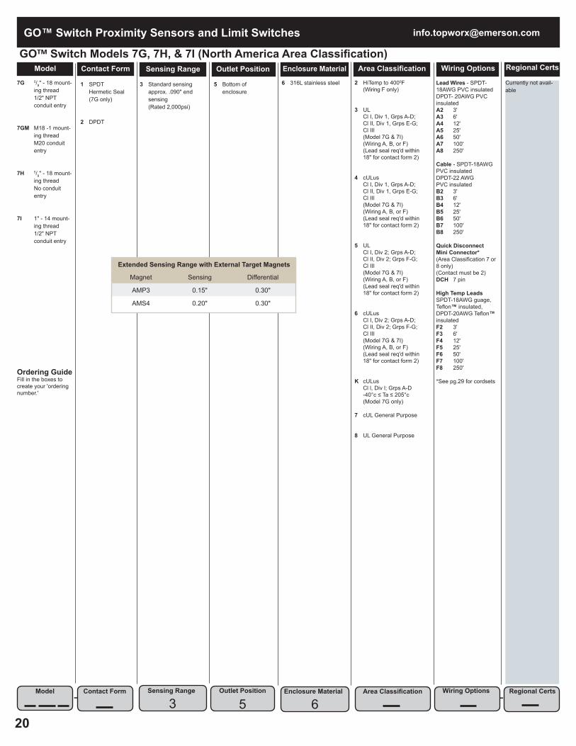
Model Contact Form Sensing Range Outlet Position Enclosure Material Area Classification Wiring Options
Lead Wires - SPDT-18AWG PVC insulatedDPDT- 20AWG PVC insulatedA2 3' A3 6' A4 12' A5 25' A6 50' A7 100' A8 250'
Cable - SPDT-18AWG PVC insulatedDPDT-22 AWGPVC insulatedB2 3' B3 6' B4 12' B5 25' B6 50' B7 100' B8 250'
Quick DisconnectMini Connector*(Area Classification 7 or 8 only)(Contact must be 2)DCH 7 pin
High Temp LeadsSPDT-18AWG guage, Teflon™ insulated, DPDT-20AWG Teflon™ insulatedF2 3' F3 6' F4 12' F5 25' F6 50' F7 100' F8 250'
*See pg.29 for cordsets
2 HiTemp to 4000F (Wiring F only)
3 UL Cl I, Div 1, Grps A-D; Cl II, Div 1, Grps E-G; Cl III (Model 7G & 7I) (Wiring A, B, or F) (Lead seal req'd within 18" for contact form 2)
4 cULus Cl I, Div 1, Grps A-D; Cl II, Div 1, Grps E-G; Cl III (Model 7G & 7I) (Wiring A, B, or F) (Lead seal req'd within 18" for contact form 2)
5 UL Cl I, Div 2; Grps A-D; Cl II, Div 2; Grps F-G; Cl III (Model 7G & 7I) (Wiring A, B, or F) (Lead seal req'd within 18" for contact form 2)
6 cULus Cl I, Div 2; Grps A-D; Cl II, Div 2; Grps F-G; Cl III (Model 7G & 7I) (Wiring A, B, or F) (Lead seal req'd within 18" for contact form 2)
K cULus Cl l, Div l; Grps A-D -40°c ≤ Ta ≤ 205°c (Model 7G only)
7 cUL General Purpose
8 UL General Purpose
6 316L stainless steel
5 Bottom of enclosure
3 Standard sensing approx. .090" end sensing (Rated 2,000psi)
1 SPDT Hermetic Seal (7G only)
2 DPDT
7G 5/8" - 18 mount- ing thread 1/2" NPT conduit entry
7GM M18 -1 mount- ing thread M20 conduit entry
7H 5/8" - 18 mount- ing thread No conduit entry
7I 1" - 14 mount- ing thread 1/2" NPT conduit entry
Ordering GuideFill in the boxes to create your 'ordering number.'
Model Contact Form Sensing Range Outlet Position
5Enclosure Material Area Classification Wiring Options
-
GO™ Switch Models 7G, 7H, & 7I (North America Area Classification)
Extended Sensing Range with External Target Magnets
Magnet Sensing Differential
AMP3 0.15" 0.30"
AMS4 0.20" 0.30"
Regional Certs
Currently not avail-able
Regional Certs
-3 6

21
www.topworx.com GO™ Switch Proximity Sensors and Limit Switches
Model Contact Form Sensing Range Outlet Position Enclosure Material Area Classification Wiring Options
Lead Wires - SPDT-18AWG PVC insulatedDPDT- 20AWG PVC insulatedA2 3' A3 6' A4 12' A5 25' A6 50' A7 100' A8 250'
Cable - SPDT-18AWG PVC insulatedDPDT-22 AWGPVC insulatedB2 3' B3 6' B4 12' B5 25' B6 50' B7 100' B8 250'
Hi-Temp LeadsSPDT-18AWG gauge, TeflonTM insulatedDPDT-20AWG TeflonTM insulatedF2 3' F3 6' F4 12' F5 25' F6 50' F7 100' F8 250'
Hi-Temp Leads18 gauge, Peek insulatedH2 3' H3 6' H4 12' H5 25' H6 50' H7 100' H8 250'
Cable - 18 gauge Blue Silicone (Area Classifica-tion must be F, G, or H)S2 3' S3 6' S4 12' S5 25' S6 50' S7 100' S8 250'
9 ATEX/IECEx Zone 1 Ex db IIC T6 Gb, Ex tb IIIC T85°C Db, IP66 (-40°C ≤ Ta ≤ 50°C) (Wiring A or B) Ex db IIC T4 Gb, Ex tb IIIC T135°C Db, IP66 (-40C ≤ Ta ≤100°C/150°C) (Wiring F) Ex db IIC T3 Gb, Ex tb IIIC T200°C Db, IP66 (-40C ≤ Ta ≤150°C) (Wiring H) (7G-1, 7G-2 and 7I-2)
T ATEX/IECEx Zone 1 Ex db IIC T6 Gb, Ex tb IIIC T85°C Db, IP66 (-40°C ≤ Ta ≤ 50°C) (Wiring A) Ex db IIC T6 Gb, Ex tb IIIC T85°C Db, IP66 (-60°C ≤ Ta ≤ 50°C) (Wiring B) (7G-1 only) Ex db IIC T4 Gb, Ex tb IIIC T135°C Db, IP66 (-40°C≤ Ta≤100°C) (Wiring F) Ex db IIC T3 Gb, Ex tb IIIC T200°C Db, IP66 (-40°C≤ Ta≤150°C) (Wiring H) (Models 7G-1 and 7G-2 Hermetically Sealed)
F ATEX/IECEx Zone 0, Ex ia IIC T6 Ga, Ex ia IIIC T85°C Da (-40°C ≤ Ta ≤ 50°C) (Models 7G-1 and 7G-2 Hermetically Sealed) (Wiring must be S)
G ATEX/IECEx Zone 0, Ex ia IIC T4 Ga, Ex ia IIIC T135°CDa (-40C ≤ Ta ≤ 100°C) (Models 7G-1 and 7G-2 Hermetically Sealed) (Wiring must be S)
H ATEX/IECEx Zone 0, Ex ia IIC T3 Ga Ex ia IIIC T200°C Da (-40C ≤ Ta ≤ 150C) (Models 7G-1 and 7G-2 Hermetically Sealed) (Wiring must be S)
6 316L stainless steel
5 Bottom of enclosure
3 Standard sensing approx. .090" end sensing (Rated 2,000psi)
1 SPDT Hermetic Seal (7G only)
2 DPDT
7G 5/8" - 18 mount- ing thread 1/2" NPT conduit entry (3/4" NPT con duit entry for DPDT hermetic seal)
7GM M18 -1 mount- ing thread M20 conduit entry (M25 conduit entry for DPDT hermetic seal)
7H 5/8" - 18 mount- ing thread No conduit entry
7I 1" - 14 mount- ing thread 1/2" NPT conduit entry
Ordering GuideFill in the boxes to create your 'ordering number.'
Model Contact Form Sensing Range Outlet Position
5Enclosure Material Area Classification Wiring Options
-
GO™ Switch Models 7G, 7H, & 7I (IEC Area Classification)
Extended Sensing Range with External Target Magnets
Magnet Sensing Differential
AMP3 0.15" 0.30"
AMS4 0.20" 0.30"
Regional Certs
B InMetro (Area Classification 9 & T only)
K KOSHA (Area Classification 9 & T only)
N NEPSI (Area Classification 9 & T only)
P PESO (Area Classification 9, T, F, G & H only)
R EAC (Area Classification 9, T, F, G & H only)
Blank
Regional Certs
-3 6
[email protected]™ Switch Proximity Sensors and Limit Switches
22
Currently not avail-able
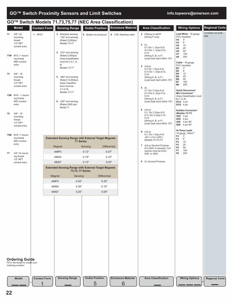
Model Contact Form Sensing Range Outlet Position Enclosure Material Area Classification Wiring OptionsGO™ Switch Models 71,73,75,77 (NEC Area Classification)
71 3/8"- 24 mounting thread 1/2" NPT conduit entry
71M M12 -1 mount- ing thread M20 conduit entry
73 5/8" - 18 mounting thread 1/2" NPT conduit entry
73M M18 - 1 mount- ing thread M20 conduit entry
75 5/8" - 18 mounting thread 1/2" NPT conduit entry
75M M18 -1 mount- ing thread M20 conduit entry
77 3/4"-16 mount ing thread 1/2" NPT conduit entry
1 SPDT
3 Standard sensing .100" end sensing (Rated 2,000psi) Models 73-77
4 .072" end sensing (Rated 5,000psi) (Area Classification must be 2,3,7, or 8) Models 73-77
5 .060" end sensing (Rated 10,000psi) (Area Classifica tions must be 2,7,or 8) Models 73-77
6 .040" end sensing (Rated 2000 psi) Model 71
5 Bottom of enclosure
6 316L Stainless steel
2 HiTemp to 4000F (Wiring F only)
3 UL Cl I Div 1, Grps A-D; Cl II Div 1, Grps E-G; Cl III (Wiring A, B, or F) (Lead seal req'd within 18")
4 cULus Cl I Div 1 Grps A-D; Cl II Div 1, Grps E-G; Cl III (Wiring A, B, or F) (Lead seal req'd within 18")
5 UL CI I Div 2 Grps A-D; CI II Div 2, Grps F,G; Cl III (Wiring A, B, or F) (Lead Seal req'd within 18")
6 cULus Cl I, Div 2 Grps A-D; Cl II, Div 2 Grps F-G; Cl III (Wiring A, B, or F) (Lead seal req'd within 18")
K cULus Cl l, Div l; Grps A-D -40°c ≤ Ta ≤ 205°c (Models 73,75,77)
7 cULus General Purpose (If a QDC is required. Con nectors must be DCD, 4DD, or 4DE)
8 UL General Purpose
Lead Wires - 18 gauge,PVC insulatedA2 3' A3 6' A4 12' A5 25' A6 50' A7 100' A8 250'
Cable - 18 gauge,PVC insulatedB2 3' B3 6' B4 12' B5 25' B6 50' B7 100' B8 250'
Quick DisconnectMini Connector*(Area Classification must be 7 or 8)DCA 3 pin DCD 4 pin
SubSea Connector*(Models 73-77)3DD 3 pin 4DD 4 pin 3DE 3 pin 90° 4DE 4 pin 90°
Hi-Temp Leads18 gauge, TeflonTM F2 3' F3 6' F4 12' F5 25' F6 50' F7 100' F8 250'
Ordering GuideFill in the boxes to create your 'ordering number.'
Model Contact Form
1Sensing Range Outlet Position Enclosure Material Area Classification Wiring Options
-
Extended Sensing Range with External Target Magnets 71 Series
Magnet Sensing Differential
AMP3 0.12" 0.07"
AMS4 0.15" 0.10"
AMS7 0.13" 0.05"
Extended Sensing Range with External Target Magnets73,75, 77 Series
Magnet Sensing Differential
AMP3 0.20" 0.25"
AMS4 0.35" 0.15"
AMS7 0.20" 0.05"
Regional Certs
Regional Certs-5 6

23
www.topworx.com GO™ Switch Proximity Sensors and Limit Switches
B InMetro (Area Classification 9 & T only) (73, 75, 77)
K KOSHA (Area Classification 9 & T only)
N NEPSI (Area Classification 9 & T only) (73, 75, 77)
P PESO (Area Classification 9, T, F, G & H only) (73, 75, 77)
R EAC (Area Classification 9, T, F, G & H only)
Blank
Model Contact Form Sensing Range Outlet Position Enclosure Material Area Classification Wiring OptionsGO™ Switch Models 71,73,75,77 (IEC Area Classification)
71 3/8"- 24 mounting thread 1/2" NPT conduit entry
71M M12 -1 mount- ing thread M20 conduit entry
73 5/8" - 18 mounting thread 1/2" NPT conduit entry
73M M18 - 1 mount- ing thread M20 conduit entry
75 5/8" - 18 mounting thread 1/2" NPT conduit entry
75M M18 -1 mount- ing thread M20 conduit entry
77 3/4"-16 mount ing thread 1/2" NPT conduit entry
1 SPDT
3 Standard sensing .100" end sensing (Rated 2000psi) Models 73-77
4 .072" end sensing (Rated 5,000psi) (Area Classification must be 9 & T) Models 73-77
5 .060" end sensing (Rated 10,000psi) (Area Classification must be 9 & T) Models 73-77
6 .040" end sensing (Rated 2,000psi) Model 71
5 Bottom of enclosure
6 316L Stainless steel
9 ATEX/IECEx Zone 1 Ex db IIC T6 Gb, Ex tb IIIC T85°C Db, IP66 (-40°C ≤ Ta ≤ 50°C) (Wiring A or B) Ex db IIC T4 Gb, Ex tb IIIC T135°C Db, IP66 (-40C ≤ Ta ≤ 100°C) (Wiring F) Ex db IIC T3 Gb, Ex tb IIIC T200°C Db, IP66 (-40C ≤ Ta ≤ 150°C) (Wiring H)
T ATEX/IECEx Zone 1 Ex db IIC T6 Gb, Ex tb IIIC T85°C Db, IP66 (-40°C ≤ Ta ≤ 50°C) (Wiring A) Ex db IIC T6 Gb, Ex tb IIIC T85°C Db, IP66 (-60°C ≤ Ta ≤ 50°C) (Wiring B) (73 Only) Ex db IIC T4 Gb, Ex tb IIIC T135°C Db, IP66 (-40°C≤ Ta ≤ 100°C) (Wiring F) Ex db IIC T3 Gb, Ex tb IIIC T200°C Db, IP66 (-40°C≤ Ta ≤ 150°C) (Wiring H) (73 Hermetically Sealed)
F ATEX/IECEx Zone 0, Ex ia IIC T6 Ga; Ex ia IIIC T85°C Da; (-40°C ≤ Ta ≤ 50°C) (73 Hermetically Sealed) (Wiring must be S)
G ATEX/IECEx Zone 0, Ex ia IIC T4 Ga; Ex ia IIIC T135°C Da; (-40°C ≤ Ta ≤ 100°C) (73 Hermetically Sealed) (Wiring must be S)
H ATEX/IECEx Zone 0, Ex ia IIC T3 Ga; Ex ia IIIC T200°C Da; (-40°C ≤ Ta ≤ 150°C) (73 Hermetically Sealed) (Wiring must be S)
Lead Wires - 18 Gauge,PVC insulatedA2 3' A3 6' A4 12' A5 25' A6 50' A7 100' A8 250'
Cable - 18 Gauge,PVC insulatedB2 3' B3 6' B4 12' B5 25' B6 50' B7 100' B8 250'
Hi-Temp Leads18 Gauge, TeflonTM F2 3' F3 6' F4 12' F5 25' F6 50' F7 100' F8 250'
Hi-Temp Leads18 Gauge, Peek insulatedH2 3' H3 6' H4 12' H5 25' H6 50' H7 100' H8 250'
Cable - 18 Gauge Blue Silicone (Area Classifica-tion must be F, G,or H)S2 3' S3 6' S4 12' S5 25' S6 50' S7 100' S8 250'
*See pg.29 for cordsets
Ordering GuideFill in the boxes to create your 'ordering number.'
Model Contact Form
1Sensing Range Outlet Position Enclosure Material Area Classification Wiring Options
-
Extended Sensing Range with External Target Magnets 71 Series
Magnet Sensing Differential
AMP3 0.12" 0.07"
AMS4 0.15" 0.10"
AMS7 0.13" 0.05"
Extended Sensing Range with External Target Magnets73,75, 77 Series
Magnet Sensing Differential
AMP3 0.20" 0.25"
AMS4 0.35" 0.15"
AMS7 0.20" 0.05"
Regional Certs
Regional Certs-5 6

[email protected]™ Switch Proximity Sensors and Limit Switches
24
Contact Form
JSP (1/2" NPT) only available with 7J
JSM (M20) only avail able with 7JM
2 303 stainless steel
6 316L stainless steel
5 Bottom of enclosure
3 Standard sensing approx. 2.5 mm (0.100") end sensing
1 SPDT
7J 5/8" x 2 5/32" 1/2" NPT
7JM M18 x 1
GO™ Switch Models 7JModel Contact Form Sensing Range Outlet Position Enclosure Material Area Classification Wiring Options
Model Contact Form Outlet Position Area Classification Wiring Options- -
Regional Certs
Regional Certs
Sensing Range
3Enclosure Material
2
N NEPSI (Area Classification 9 only)
R EAC (Area Classification 9)
Blank
-
3 UL Cl I, Div 1, Grps A-D; CI II, Div 1, Grps E-G; Cl III (lead seal req'd within 18")
4 cULus Cl I, Div 1, Grps A-D; CI II, Div 1, Grps E-G; Cl III (Lead seal req'd within 18")
5 UL Cl I, Div 2, Grps A-D; CI II, Div 2, Grps F-G; Cl III (Lead seal req'd within 18")
6 cULus Cl I, Div 2, Grps A-D; CI II, Div 2, Grps F-G; Cl III (Lead seal req'd within 18")
7 cULus General Purpose
8 UL General Purpose
9 ATEX/IECEx Zone 1 Ex db IIC T6 Gb, Ex tb IIIC T85°C Db, IP66/68 (-40°< Ta < 75°C)
Y ATEX/IECEx Zone 1 Ex de IIC T6 Gb, Ex tb IIIC T85°C Db, IP66/68 (-40°< Ta < 75°C)
F ATEX/IECEx Zone 0 Ex ia IIC T6 Ga Ex ia IIIC T85°C Da (-40°C < Ta < 50°C)
G ATEX/IECEx Zone 0 Ex ia IIC T4 Ga Ex ia IIIC T135°C Da (-40°C ≤ Ta ≤ 100°C)
H ATEX/IECEx Zone 0 Ex ia IIC T3 Ga Ex ia IIIC T200°C Da (-40°C ≤ Ta ≤ 150°C)
1 5

25
www.topworx.com GO™ Switch Proximity Sensors and Limit Switches
GO™ Switch Models 7JContact Form
Lead Wires - 18 gauge,PVC insulated A2 3' A3 6' A4 12' A5 25'A6 50' A7 100' A8 250'
Cable - 18 gauge,PVC insulatedB2 3' B3 6' B4 12' B5 25' B6 50' B7 100' B8 250'
Quick DisconnectMini Connector*(Area Classification must be 7 or 8)DCA 3 pin DCD 4 pin
Quick DisconnectM12x1(Area Classification must be 7 or 8)DMD 4 pin
Micro Connector*(Area Classification must be 7 or 8)DBA 3 pin DBD 4 pin
SubSea Connector*3DD 3 pin 4DD 4 pin 3DE 3 pin 900 4DE 4 pin 900
Hi-Temp Leads18 gauge, TeflonTM insulatedF2 3' F3 6' F4 12' F5 25' F6 50' F7 100' F8 250'
*See pg.29 for cordsets
2 HiTemp to 4000F (Contact 4, 7, or 8 only) (Wiring F only)
3 UL CI I Div 1, Grps A-D; CI II Div1, Grps E-G; Cl III (7CX and 7DX only) (Does not incl. a ground wire)
4 cULus CI I Div 1, Grps A-D; CI II Div1, Grps E-G; Cl III (7CX and 7DX only)
5 UL CI I Div 2, Grps A-D; CI II Div 2, Grps F-G; Cl III (7CX and 7DX only) (Does not incl. a ground wire)
6 cULus CI I Div 2, Grps A-D; CI II Div2, Grps F-G; Cl III (7CX and 7DX only)
7 cUL General Purpose (If a QDC is required. Con nectors must be DCD, DBD, 4DD, or 4DE)
8 UL General Purpose (Does not incl. a ground wire)
9 ATEX/IECEx Zone 1 Ex db IIC T6 Gb, Ex tb IIIC T85°C Db, IP66 (-40°C ≤ Ta ≤ 50°C) (Wiring A or B) Ex db IIC T4 Gb, Ex tb IIIC T135°C Db, IP66 (-40C ≤ Ta ≤100°C) (Wiring F) Ex db IIC T3 Gb, Ex tb IIIC T200°C Db, IP66 (-40C ≤ Ta ≤150°C) (Wiring H)
T ATEX/IECEx Zone 1 Ex db IIC T6 Gb, Ex tb IIIC 85°C Db, IP66 (-40°C < Ta < 50°C) (Wiring A or B) Ex db IIC T4 Gb, Ex tb IIIC T135ºC Db, IP66 (-40°C ≤ Ta ≤ 100°C) (Wiring F) Ex db IIC T3 Gb, Ex tb IIIC T200ºC Db, IP66 (-40°C ≤ Ta ≤ 150°C) (Wiring H) (7CX and 7DX only, Hermetically Sealed)
5 Stainless steel (rated 3,000psi operating) (3 to 1 safety factor applies to standard probe lengths)
2 Side entry 3600 adjustable (Wiring A, B, or F only) No conduit hub 5 5 Top outlet
6 Side entry 3600 adjustable No conduit hub (Approval 7 or 8 only) (Wiring D or SubSea only)
7 Side entry 3600 adjustable with 1/2" NPT conduit hub (Wiring A, B, or F only)
8 Top outlet (Wiring SubSea only)
3 Standard sensing approx. .090" end sensing (Recommended air gap .015" - .040")
2 SPST (Form A) N/O output with bi- color LED indica tion
3 SPST (Form B) N/C output with bi- color LED indica tion
4 SPDT (Form C) without LED
5 SPDT (Form C) with dual LED’s 7 SPST (Form A) N/O output w/o LED indication
8 SPST (Form B) N/C output w/o LED indication
7C 1.025" probe length
7CX 1.025" probe length (Contact Form 4 only) (Outlet Position 5 only)
7D 1.250" probe length
7DX 1.250" probe length (Contact Form 4 only) (Outlet Position 5 only)
7E 2.062" probe length
7F Custom probe length* 1.000" -5.000" Use the "Probe Selection Chart"tofind Probe Code, then the "Pric ing Table"to determine base price. (See pg 26) *Probe lengths shorter than 1.275" require a taller upper switch housing
GO™ Switch Models 7C, 7D, 7E & 7FModel Contact Form Sensing Range Outlet Position Enclosure Material Area Classification Wiring Options
Model Contact Form Outlet Position Area Classification Wiring Options- -
Regional Certs
Regional Certs
Sensing Range
3Enclosure Material
5
Currently not available
-

[email protected]™ Switch Proximity Sensors and Limit Switches
26
Probe Selection Chart"A" Range Probe "A" Range Probe "A" Range Probe
Min Max Length Code Min Max Length Code Min Max Length Code1.015 1.040 1.000 A1 2.365 2.390 2.350 G1 3.715 3.740 3.700 N1
1.040 1.065 1.025 * 2.390 2.415 2.375 G2 3.740 3.765 3.725 N2
1.065 1.090 1.050 A3 2.415 2.440 2.400 G3 3.765 3.790 3.750 N3
1.090 1.115 1.075 A4 2.440 2.465 2.425 G4 3.790 3.815 3.775 N4
1.115 1.140 1.100 A5 2.465 2.490 2.450 G5 3.815 3.840 3.800 N5
1.140 1.165 1.125 A6 2.490 2.515 2.475 G6 3.840 3.865 3.825 N6
1.165 1.190 1.150 A7 2.515 2.540 2.500 G7 3.865 3.890 3.850 N7
1.190 1.215 1.175 A8 2.540 2.565 2.525 G8 3.890 3.915 3.875 N8
1.215 1.240 1.200 A9 2.565 2.590 2.550 G9 3.915 3.940 3.900 N9
1.240 1.265 1.225 B1 2.590 2.615 2.575 H1 3.940 3.965 3.925 P1
1.265 1.290 1.250 ** 2.615 2.640 2.600 H2 3.965 3.990 3.950 P2
1.290 1.315 1.275 B3 2.640 2.665 2.625 H3 3.990 4.015 3.975 P3
1.315 1.340 1.300 B4 2.665 2.690 2.650 H4 4.015 4.040 4.000 P4
1.340 1.365 1.325 B5 2.690 2.715 2.675 H5 4.040 4.065 4.025 P5
1.365 1.390 1.350 B6 2.715 2.740 2.700 H6 4.065 4.090 4.050 P6
1.390 1.415 1.375 B7 2.740 2.765 2.725 H7 4.090 4.115 4.075 P7
1.415 1.440 1.400 B8 2.765 2.790 2.750 H8 4.115 4.140 4.100 P8
1.440 1.465 1.425 B9 2.790 2.815 2.775 H9 4.140 4.165 4.125 P9
1.465 1.490 1.450 C1 2.815 2.840 2.800 J1 4.165 4.190 4.150 R1
1.490 1.515 1.475 C2 2.840 2.865 2.825 J2 4.190 4.215 4.175 R2
1.515 1.540 1.500 C3 2.865 2.890 2.850 J3 4.215 4.240 4.200 R3
1.540 1.565 1.525 C4 2.890 2.915 2.875 J4 4.240 4.265 4.225 R4
1.565 1.590 1.550 C5 2.915 2.940 2.900 J5 4.265 4.290 4.250 R5
1.590 1.615 1.575 C6 2.940 2.965 2.925 J6 4.290 4.315 4.275 R6
1.615 1.640 1.600 C7 2.965 2.990 2.950 J7 4.315 4.340 4.300 R7
1.640 1.665 1.625 C8 2.990 3.015 2.975 J8 4.340 4.365 4.325 R8
1.665 1.690 1.650 C9 3.015 3.040 3.000 J9 4.365 4.390 4.350 R9
1.690 1.715 1.675 D1 3.040 3.065 3.025 K1 4.390 4.415 4.375 S1
1.715 1.740 1.700 D2 3.065 3.090 3.050 K2 4.415 4.440 4.400 S2
1.740 1.765 1.725 D3 3.090 3.115 3.075 K3 4.440 4.465 4.425 S3
1.765 1.790 1.750 D4 3.115 3.140 3.100 K4 4.465 4.490 4.450 S4
1.790 1.815 1.775 D5 3.140 3.165 3.125 K5 4.490 4.515 4.475 S5
1.815 1.840 1.800 D6 3.165 3.190 3.150 K6 4.515 4.540 4.500 S6
1.840 1.865 1.825 D7 3.190 3.215 3.175 K7 4.540 4.565 4.525 S7
1.865 1.890 1.850 D8 3.215 3.240 3.200 K8 4.565 4.590 4.550 S8
1.890 1.915 1.875 D9 3.240 3.265 3.225 K9 4.590 4.615 4.575 S9
1.915 1.940 1.900 E1 3.265 3.290 3.250 L1 4.615 4.640 4.600 T1
1.940 1.965 1.925 E2 3.290 3.315 3.275 L2 4.640 4.665 4.625 T2
1.965 1.990 1.950 E3 3.315 3.340 3.300 L3 4.665 4.690 4.650 T3
1.990 2.015 1.975 E4 3.340 3.365 3.325 L4 4.690 4.715 4.675 T4
2.015 2.040 2.000 E5 3.365 3.390 3.350 L5 4.715 4.740 4.700 T5
2.040 2.065 2.025 E6 3.390 3.415 3.375 L6 4.740 4.765 4.725 T6
2.065 2.090 2.050 E7 3.415 3.440 3.400 L7 4.765 4.790 4.750 T7
2.090 2.115 2.075 E8 3.440 3.465 3.425 L8 4.790 4.815 4.775 T8
2.115 2.140 2.100 E9 3.465 3.490 3.450 L9 4.815 4.840 4.800 T9
2.140 2.165 2.125 F1 3.490 3.515 3.475 M1 4.840 4.865 4.825 V1
2.165 2.190 2.150 F2 3.515 3.540 3.500 M2 4.865 4.890 4.850 V2
2.190 2.215 2.175 F3 3.540 3.565 3.525 M3 4.890 4.915 4.875 V3
2.215 2.240 2.200 F4 3.565 3.590 3.550 M4 4.915 4.940 4.900 V4
2.240 2.265 2.225 F5 3.590 3.615 3.575 M5 4.940 4.965 4.925 V5
2.265 2.290 2.250 F6 3.615 3.640 3.600 M6 4.965 4.990 4.950 V6
2.290 2.315 2.275 F7 3.640 3.665 3.625 M7 4.990 5.015 4.975 V7
2.315 2.340 2.300 F8 3.665 3.690 3.650 M8 5.015 5.040 5.000 V8
2.340 2.365 2.325 F9 3.690 3.715 3.675 M9
Probe Code A1 - A9 B1 - B9 C1 - C9 D1 - D9 E1 - E9 F1 - F9 G1 - G9 H1 - H9 J1 - J9 K1 - K9 L1 - L9 M1 - M9 N1 - N9 P1 - P9 R1 - R9 S1 - S9 T1 - T9 V1 - V8
Pricing Table
Model
LPS

27
www.topworx.com GO™ Switch Proximity Sensors and Limit Switches
48 Defender Turbine Valve Monitoring System
Heavy Duty 11 Gauge Steel 12" x 10" x 5" - ANSI 61 Light Gray
Model 74-LLS: SPDT, environmentally sealed, rated 4A @ 120VAC, 3A @ 24VDC, with prewired HiTempTM Teflon lead wires. Choose number of switches (minimum 1, maximum 10)
01000 (1) Leverless Limit Switch
02000 (2) Leverless Limit Switches
03000 (3) Leverless Limit Switches
04000 (4) Leverless Limit Switches
05000 (5) Leverless Limit Switches
06000 (6) Leverless Limit Switches
07000 (7) Leverless Limit Switches
08000 (8) Leverless Limit Switches
09000 (9) Leverless Limit Switches
10000 (10) Leverless Limit Switches
000 Male/Female Mil Spec Quick Disconnect with back shell connection to 1-1/4" flex conduit 001 Male/Female Mil Spec Quick Disconnect with 25 ft. cable 002 Male/Female Mil Spec Quick Disconnect with 50 ft. cable 003 Male/900 Female Mil Spec Quick Disconnect with back shell connection to 1-1/4" flex conduit 004 Male/900 Female Mil Spec Quick Disconnect with 25 ft. cable 005 Male/900 Female Mil Spec Quick Disconnect with 50 ft. cable 006 Male/450 Female Mil Spec Quick Disconnect with back shell connection to 1-1/4" flex conduit 007 Male/450 Female Mil Spec Quick Disconnect with 25 ft. cable 008 Male/450 Female Mil Spec Quick Disconnect with 50 ft. cable 010 Male/900 Female Mil Spec Quick Disconnect with 25 ft. of HiTempTM cable 012 Male/Female Mil Spec Quick Disconnect with 75 ft. cable 013 Male/900 Female Mil Spec Quick Disconnect with 100 ft. cable 016 Male/900 Female Mil Spec Quick Disconnect with 50 ft. of HiTempTM cable
Model Wiring OptionsGO Switches
Ordering GuideFill in the boxes to createyour 'ordering number.'
Model GO Switches Wiring Options
DEFENDERTM - Turbine Trip Switch System
-48
DEFENDER Calibration Unit ACP 48
GO™ Switch 74-LLS
Description Part Number List PriceDEFENDER Accessories
Model Port Arrangement Sensing Range Port Position Enclosure Material Area Classification Termination
7 Supply, Cylinder, and Exhaust (60 psi max supply pressure)
7A 5/8" (16mm) dia. x 3-15/16" (100mm) long with 5/8"- 18UNF x 1-7/8" (48mm) threads
3 Standard sensing approx. .062"
2 Three side port outlets (1/8"-27 NPT) 3-way
2 303 stainless steel (rated 2,000psi)
6 Aluminum base, stainless steel probe (rated 2,000psi)
1 No approvals
99 Always "99"
GO™ Switch Model 7A
Model Port Arrangement Sensing Range Port Position Enclosure Material Area Classification Termination- -7A 7 3 2 1 99
Model Sensor Area Classification WiringLPS Luminator Linear Position Sensor
D (1) SPDT Hermetically sealed
W (1) SPST Hermetically sealed
Z1 c-UL-us listed explosion proof Cl I, Div 1 & 2, Grps A-D Cl II, Div 1 & 2, Grps E-G; Cl III (Visual Display option must be N)
Z2 c-UL-us non-incendive Cl I, Div 2, Grps A-D Cl II, Div 2, Grps E-G; Class III
GP c-UL-us listed general purpose
G Green LED (Area Class Z2 or GP only)
R Red LED (Area Class Z2 or GP only)
N No visual indication
Note: LEDs wired to N/O contact only
Lead Wires - 18 gauge PVC insulatedA2 3' A3 6' A4 12' A5 25' A6 50' A7 100' A8 250'
Cable - 18 Gauge PVC insulatedB2 3' B3 6' B4 12' B5 25' B6 50' B7 100' B8 250'
Quick DisconnectMini Connector*(Approval must be GP)DCA 3 pin DCD 4 pin
*See pg.29 for cordsets
Visual Display
Ordering GuideFill in the boxes to createyour 'ordering number.'
Model Sensor Area Classification Visual Display Wiring- -LPS
Model LPS

[email protected]™ Switch Proximity Sensors and Limit Switches
28
Model Sensor Target Termination
Nuclear Qualified Switches
C7 Nuclear Containment C8 Nuclear Containment
H7 Harsh Nuclear
H8 Harsh Nuclear
M7 Mild Nuclear
M8 Mild Nuclear
R7 Ringhals Containment
SV7 **MSIV AP1000
*CONTACT FACTORY for EPR Qualified
Sensors
1 Single Pole Double Throw (Form C) (C7, & R7 Hermeti cally Sealed) 2 Double Pole Double Throw (Form CC) (C8, H8, & M8 Her metically Sealed)
3 C-AMS7A (sensing range determined by switch model) 4 C-AMS12 (extended sensing range determined by switch model)
5 Bottom of Enclosure
Peek Cable - (C7, R7, C8, H8, M8)Peek Wire - (H7 & SV7 Only) P3 6' P4 12' P20 20' P_ _ _ Greater than 20' - specify length in 5ft. incrementsTefzel Wire - (M7 Only)Z3 6' Z4 12' Z20 20' Z_ _ _ Greater than 20' - specify length in 5ft. incrementsEGS Flex Conduit Peek Cable (All Except H7, M7)PC3 6' PC4 12' PC20 20' PC_ _ _ Greater than 20' - specify length in 5ft. incrementsEGS GEN 3 Disconnect and Match-ing Cable (C7, H7, M7, R7, C8, H8, M8) E0 Switch side only, cable not includedE3 6' E4 12' E20 20' E_ _ _ Greater than 20' - specify length in 5ft. incrementsMirion Disconnect (C7 & H7 Only)M0 Connector only only, cable not includedM3 6' E4 12' M20 20' M_ _ _ Greater than 20' - specify length in 5ft. incrementsSouria 8NA Disconnect (C7, H7 & SV7 Only)K1S0 Connector only only, cable not includedK1S3 6' K1S4 12' K120 20' K1S_ _ _ Greater than 20' - specify length in 5ft. incrementsSouria 8NA45 Disconnect (H7 & M7 Only)K2S0 Connector only only, cable not includedK2S3 6' K2S4 12' K2S20 20' K2S_ _ _ Greater than 20' - specify length in 5ft. increments
Outlet Position
Ordering GuideFill in the boxes to createyour 'ordering number.'
Model Sensor Target Outlet Position Termination- -5
2 303 Stainless Steel
Enclosure
Enclosure
2
T ATEX/IECEx Zone 1 Ex db IIC T6 Gb (P & Z Terminations only)(Cert not avail able with SV7 Model)
1 No additional approvals
2 RCC-E EPR K1++ (C7 only) w/Mirion Connector
3 RCC-E EPR K1+ (C7 only) w/Mirion Connector
4 RCC-E EPR K1 (C7 or H7 only) w/ Souria 8NA Connector
5 RCC-E EPR K2 w/ Souria 8N45 Connector or Lead Wire
6 RCC-E EPR K3 w/ Souriau 8N45 Connec tor or Lead Wire
Note: All applications requiring IP67/68 must be provided with EGS Flex Conduit
Area Classification
Area Classification
TopWorx Nuclear DXN
DXN 316L Stainless Steel Discrete Valve Controller
LN 2 Nuclear GO Switches, SPDT with Hermetic Seal
Q Containment
Z Harsh
P Mild
D No Indicator
Visual DisplayArea ClassificationBus/SensorEnclosure
Area Classification Visual DisplayEnclosure Bus/Sensor-
Ordering GuideFill in the boxes to createyour 'ordering number.'
N Namur 304 Stainless Steel
S 1/4" DD 304 Stainless Steel
Shaft
E (2) 3/4" NPTM (2) M20 3 (4) M20 4 (2) 3/4" (2) 1/2" NPT6 (4) 3/4" NPTN (4) 3/4" NPT w/ EGS GEN 3 Disconnect & Matching Cable & (2) 3/4" NPT plugs
Conduit Entries
S Silicone
O-Rings Termination
Peek Cable_3 72" _4 144" _20 20' _ _ _ Greater than 144" specify length in 5ft. increments
O-Rings TerminationShaft Conduit Entries
DXN LN SD***NOTE: Nuclear products are limited to pre-approved distributors only. CONTACT FACTORY for all pricing.***
-
TopWorx™ has a complete line of globally nuclear qualified position sensors that have been tested to and/or exceed new generation and existing plant qualifications.

29
www.topworx.com GO™ Switch Proximity Sensors and Limit Switches
Peek Cable_3 72" _4 144" _20 20' _ _ _ Greater than 144" specify length in 5ft. increments
Mini Cordsets3-Pin3 - Pin, 3 ft. (.9 m) A-ECA 3 - Pin, 6 ft. (1.8 m) A-ECB
3 - Pin, 12 ft. (3.6 m) A-ECC
3 - Pin, 20 ft. (6.1 m) A-ECU 3 - Pin, 30 ft. (9.1 m) A-ECV 3 - Pin, 3 ft. 90o (.9 m) A-ECA-90 3 - Pin, 6 ft. 90o (1.8 m) A-ECB-90 3 - Pin, 12 ft. 90o (3.6 m) A-ECC-90
4-Pin4 - Pin, 3 ft. (.9 m) A-ECD
4 - Pin, 6 ft. (1.8 m) A-ECE
4 - Pin, 12 ft. (3.6 m) A-ECF
4 - Pin, 20 ft. (6.1 m) A-ECW 4 - Pin, 30 ft. (9.1 m) A-ECX
5-Pin5 - Pin, 3 ft. (.9 m) A-ECG 5 - Pin, 6 ft. (1.8 m) A-ECT
5 - Pin, 12 ft. (3.6 m) A-ECL 5 - Pin, 20 ft. (6.1 m) A-ECY 5 - Pin, 30 ft. (9.1 m) A-ECZ
7-Pin7 - Pin, 3 ft. (.9 m) A-ECH 7 - Pin, 6 ft. (1.8 m) A-ECJ 7 - Pin, 12 ft. (3.6 m) A-ECK 7 - Pin, 20 ft. (6.1 m) A-EFA 7 - Pin, 30 ft. (9.1 m) A-EFB
SubSeaTM Underwater Cordsets16 gauge SO cable rated 194OF (90OC) 600V (certified not to leak underwater)(Specify length of cable (ft.) required.) (e.g. A-3ED20 = 3 pin and 20 ft. cable)
3 pin female connector and minimum 12 ft. A-3ED12 (3658 mm) (3 pin .395" dia.) cable A-3ED_ _
4 pin female connector and minimum 12 ft. A-4ED12 (3658 mm) (4 pin .425" dia.) cable A-4ED_ _
8 pin female connector and minimum 12 ft. A-8ED12 (3658 mm) (8 pin .645" dia.) cable A-8ED_ _
3 pin 900 female connector w/ minimum 12 ft. A-3EE12 (3658 mm) (3 pin .395" dia) cable A-3EE_ _
4 pin 900 female connector w/ minimum 12 ft. A-4EE12 (3658 mm) (4 pin .425" dia) cable A-4EE_ _
Description Part Number List Price
Micro Cordsets3-Pin3 - Pin, 6 ft. (1.8 m) A-EBB 3 - Pin, 12 ft. (3.6 m) A-EBC 3 - Pin, 20 ft. (6.1 m) A-EBU 3 - Pin, 30 ft. (9.1 m) A-EBV
4-Pin4 - Pin, 6 ft. (1.8 m) A-EBE 4 - Pin, 12 ft. (3.6 m) A-EBF 4 - Pin, 20 ft. (6.1 m) A-EBW 4 - Pin, 30 ft. (9.1 m) A-EBX
5-Pin5 - Pin, 6 ft. (1.8 m) A-EBT 5 - Pin, 12 ft. (3.6 m) A-EBL 5 - Pin, 20 ft. (6.1 m) A-EBY 5 - Pin, 30 ft. (9.1 m) A-EBZ
Euro M12 Cordsets4-Pin4 - Pin, 3 ft. (.9 m) A-EMA 4 - Pin, 6 ft. (1.8 m) A-EME
4 - Pin, 12 ft. (3.6 m) A-EMF
4 - Pin, 20 ft. (6.1 m) A-EMW 4 - Pin, 30 ft. (9.1 m) A-EMX 4 - Pin, 3 ft. 90o (.9 m) A-EMA-90 4 - Pin, 6 ft. 90o (1.8 m) A-EME-90 4 - Pin, 12 ft. 90o (3.6 m) A-EMF-90
Watertight Cable GlandPlastic cable gland is easy to install on any GO Switch with a 1/2" NPT or M20 conduit entry.
3 or 4 conductor SO cable, 1/2" NPT A-GLD1
3 or 4 conductor PVC/Silicone/Raychem A-GLD2 cable, 1/2" NPT
3 or 4 conductor SO cable, M20 A-GLM1
3 or 4 conductor PVC/Silicone, Raychem A-GLM2 cable, M20
Hazardous Location Conduit UnionDesigned specifically for hazardouse locations, these glands are approved for class 1, 2, and 3 locations.
1/2" NPT expanding A-UNX 1/2" NPT non-expanding A-UNN
Description Part Number List Price
GO™ Switch Accessories

[email protected]™ Switch Proximity Sensors and Limit Switches
3030
www.topworx.comSquare Switches 10 Series stainless steel heavy duty mounting kit ABS2 10 - 20 Series stainless steel universal mounting kit ABS3 10 - 20 Series brass combination cover plate and mounting kit ABB4 10 - 20 Series stainless steel combination cover plate and mounting kit ABS5 80 Series stainless steel mounting kit ABS6 35 Series stainless steel strap bracket ABS11 10 - 20 Series brass cover plate AHB1 10 - 20 Series brass bottom cover plate with 1/2" x 14 NPT conduit outlet AHB3 10 - 20 Series stainless steel cover plate AHS2
Round Switches 70 Series stainless steel heavy duty “L” bracket ABS9 Stroke-To-GO® mounting hardware (2) 1/4-20 x 5/8 stainless steel cap screws AHN1 3/8" nickel plated brass jam nuts (2) for Models 71 and 72 AHS7 M12x1 316 stainless steel jam nuts (2) for model 52M, 71M and 72M AHS-27 5/8" nickel plated brass jam nuts (2) for Models 73, 74, 75, 76, 7A, 7G and 7H AHS8 5/8" stainless steel jam nuts (2) for Models 73, 74, 75, 76, 7A, 7G and 7H AHS18 3/4" stainless steel jam nuts (2) for Model 77 AHS9
3/8" Parker ThredSeal®, nut and washer for Models 71 and 72 AHS13 5/8" Parker ThredSeal®, nut and washer for Models 73, 74, 75, 76, 7A, 7G and 7H AHS14 3/4" Parker ThredSeal®, nut and washer for Model 77 AHS15 1" Parker ThredSeal®, nut and washer for Model 7I AHS17 1" zinc plated steel jam nuts (2) for Model 7I AHS16 5/8" Parker ThredSeal®, nut and washer (VitonTM) for Models 73, 74, 75, 76, 7A, 7G and 7H AHS19 3/4" Parker ThredSeal®, nut and washer (VitonTM) for Model 77 AHS20 3/8" Parker ThredSeal®, nut and washer (VitonTM) for Models 71 and 72 AHS23 GrafoilTM sealant tape for 70 Series (.005 x 1/2" x 24") AHF16
Target Magnets Plastic covered Target Magnet with 7/32" (6mm) mounting holes; 7/8" x 2 9/16" x 17/32" thick AMP3 Stainless Steel covered Target Magnet with 3/16" (5mm) holes; 1 1/4" x 17/16" x 1" thick AMS4
Stainless Steel covered Target Magnet with 5/16" (8mm) mounting holes; 215/16" x 5" x 25/32" AMC5
Flexible Target Magnet; 3" x 12" x 3/8" for all square switches AMF6 Bolt Style Target Magnet in threaded assembly 2" long with 7/16" -20 thread for round switches AMS7 Bolt Style Target Magnet in threaded assembly 1" long with 3/8-16 x 3/4" threads AMS8 Bolt Style Target Magnet in threaded assembly 2" x 11/16" long with 7/16" -20 thread for round switches AMS12
Other Accessories GO™ Switch Demo Case
(Includes cutaway GO™ Switch models 20, 30, 35, 70, 80, & STG, and accessories) ATK1
GO™ Switch Tester ATP1
GO™ Switch Demo Pouch ATK72
(Includes cutaway GO™ Switch Models 20 & 70)
GO™ Switch Accessories Part Number List Price

31
Model Product Description Base702DX Discrete Transmitter
Wireless Field Mount Transmitter Wireless Output
OptionsCode Measurement Add
61 Leak Detection (For Trace Tek® Sensor Cables & Probes) $0
32 Discrete Dual Inputs (Dry Contact) Detects Momentary Inputs and Counts
42 Discrete Dual Input and Output, Configurable
Code Housing AddD Dual Compartment Housing - Aluminum
E Dual Compartment Housing - Stainless Steel
Code Conduit Threads Add1 1/2-14NPT
Code Certifications AddI5 FM Intrinsically Safe, Non-incendive
I1 ATEX Intrinsically Safe
I6 CSA Intrinsically Safe
I7 IECEx Intrinsically Safe
NA No Approval
I2 INMETRO Intrinsically Safe
I3 NEPSI Intrinsically Safe
I4 TIIS Intrinsically Safe
IU ATEX Intrinsically Safe for Zone 2
IY IECEx Intrinsically Safe for Zone 2
N5 FM Division 2, Non-Incendive
N6 CSA Division 2, Non-Incendive
Code Wireless Burst Rate, Operating Frequency and Protocol Add Add
WA3 User Configurable Transmit Rate, 2.4GHz DSSS, Wireless HART
Code Wireless Antenna and SmartPower Options Add
WK1 (1) Long Range, Integral Antenna, Long Life Power Module Adapter, Intrinsically Safe
WM1 (1) Extended range, Integral Antenna, Long Life Power Module Adapter, Intrinsically Safe
WN1 High-gain, Remote Antenna, Adaptor for Black Power Module (I.S. Power Module sold separately)
Code Meter AddM5 LCD Meter
Code Mounting Bracket AddB4 Universal L mounting bracket for 2- inch pipe mounting - SST bracket and bolts
Code Configuration AddC1 Factory Configure Date, Descriptor, Message Fields and Wireless Parameters
Code Cable Gland AddG2 Cable Gland (7.5mm-11.9mm)
G4 Thin Wire Cable Gland (3mm-8mm)
Rosemount 702 Discrete Transmitter*
*Standard options listed. For other, non-listed options, please contact your Topworx™ Sales Representative.
Description Part Number PricePower Module for Emerson Devices 701PBKKF
Rosemount 702 Power Modules
*Long-lie Power Module must be ordered and shipped seperately, order model 701PBKKF
www.topworx.com TopWorx™ Wireless Valve Control Solutions

32
Model Product Description Quantity Price
WL-UN01-11L
Safety Shower and Eyewash Station Kit w/ UL General Purpose Latching Switches#4-U13060-S51#4-U13061-S5111-32528-DBA3-Pin 6ft Micro Cordset (A-EBB)3-Pin 12ft Micro Cordset (A-EBC)1/2" NPT Cable Gland (A-GLD2)
112112
WL-UN02-11L
Insulated Safety Shower and Eyewash Station Kit w/ UL General Purpose Latching Switches#4-U13064-S6111-32528-DBA3-Pin 6ft Micro Cordset (A-EBB)3-Pin 12ft Micro Cordset (A-EBC)1/2" NPT Cable Gland (A-GLD2)
12112
$0
WL-UN03-11L
Eyewash Station Kit w/ UL General Purpose Latching Switches#4-U13061-S5111-32528-DBA3-Pin 12ft Micro Cordset (A-EBC)1/2" NPT Cable Gland (A-GLD2)
1111
WL-UN04-11L
Safety Shower Kit w/ UL General Purpose Latching Switches#4-U13060-S5111-32528-DBA3-Pin 6ft Micro Cordset (A-EBB)1/2" NPT Cable Gland (A-GLD2)
1111
WL-UN12-11L
Safety Shower and Eyewash Station Kit w/ CSA General Purpose Latching Switches#4-U13060-S51#4-U13061-S5111-32527-DBD3-Pin 6ft Micro Cordset (A-EBE)3-Pin 12ft Micro Cordset (A-EBF)1/2" NPT Cable Gland (A-GLD2)
112112
WL-UN13-11L
Insulated Safety Shower and Eyewash Station w/ CSA General Purpose Latching Switches#4-U13064-S6111-32527-DBD3-Pin 6ft Micro Cordset (A-EBE)3-Pin 12ft Micro Cordset (A-EBF)1/2" NPT Cable Gland (A-GLD2)
12112
WL-UN28-11L
Safety Shower and Eyewash Station w/ UL General Purpose Non-Latching Switches#4-U13060-S51#4-U13061-S5111-12528-DBA3-Pin 6ft Micro Cordset (A-EBB)3-Pin 12ft Micro Cordset (A-EBC)1/2" NPT Cable Gland (A-GLD2)
112112
Wired Safety Shower Mounting Kits
[email protected]™ Safety Shower Mounting Kits

33
Model Product Description Quantity Price
WL-UN05-11LFM Intrinsically Safe 702 Wireless Transmitter702DX32D1I5WA3WK1B4WL-UN01-11L
11
WL-UN06-11LATEX Intrinsically Safe 702 Wireless Transmitter702DX32D1I1WA3WK1B4WL-UN01-11L
11
$3,468 $3,46
WL-UN07-11L CSA Intrinsically Safe 702 Wireless Transmitter702DX32D1I6WA3WK1B4WL-UN12-11L
11
WL-UN09-11L FM Intrinsically Safe 702 Wireless Transmitter702DX32D1I5WA3WK1B4WL-UN02-11L
11
WL-UN10-11LFM Intrinsically Safe 702 Wireless Transmitter w/ Extended Antenna702DX32D1I5WA3WM1B4WL-UN02-11L
11
WL-UN20-11L FM Intrinsically Safe 702 Wireless Transmitter702DX32D1I5WA3WK1B4WL-UN03-11L
11
WL-UN23-11L FM Instrinsically Safe 702 Wireless Transmitter702DX22D1I5WA3WK1B4WL-UL28-11L
11
WL-UN31-11LFM Instrinsically Safe 702 Wireless Transmitter w/ CSA/FM Class I, Div 2 Latching Switches702DX32D1I5WA3WK1B4#4-U13061-S5111-32526-A4
111
WL-UN32-11L
FM Instrinsically Safe 702 Wireless Transmitter w/ CSA/FM Class I, Div 2 Latching Switches702DX32D1I5WA3WK1B4#4-U13061-S51#4-U13060-S5111-32526-A4
1111
WL-UN34-11L FM Instrinsically Safe 702 Wireless Transmitter w/ Factory Configurable Date702DX32D1I5WA3WK1B4C1WL-UN05-11L
11
WL-UN37-11LFM Instrinsically Safe 702 Wireless Transmitter w/ High Gain Remote Antenna702DX32D1I5WA3WN1B4 WL-UN01-11L
11
Wireless Safety Shower Mounting Kits
www.topworx.com TopWorx™ Safety Shower Mounting Kits

34
Model Product Description Base1420 Smart Wireless Gateway
Code Power Input AddA 24 VDC Nominal (10.5-30 VDC)
Code Ethernet Communications - Physical Connection Add1 Ethernet
2 Duel Ethernet
Code Code Wireless Update Rate, Operating Frequency and Protocol AddA3 User Configurable Update Rate, 2.4GHz DSSS, WirelessHART
Code Serial Communication AddN None
A Modbus RTU via RS485
Code Ethernet Communication - Data Protocol Add2 Webserver, Modbus TCP/IP, AMS Ready
4 Webserver, Modbus TCP/IP, AMS Ready, OPC
5 DeltaV Ready
6 Ovation Ready
8 Webserver, EtherNet/IP, AMS Ready, HART-IP
9 Webserver, EtherNet/IP, Modbus, TCP/IP, AMS Ready, HART-IP
Code Product Certifications AddN5 FM Division 2, Non-Incendive
N6 CSA Division 2, Non-Incendive
N1 ATEX Type n
ND ATEX Dust
N7 IECEx Type n
NF IECEx Dust
KD FM & CSA Division 2, Non-incendive and ATEX Type N
N3 China Type n
N4 TIIS Type n
NM Technical Regulations Customs Union (EAC) Type n
Code AdapAdapters AddJ1 CM 20 Conduit Adapter
J2 PG 13.5 Conduit Adapter
J3 3/4 NPT Conduit Adapters
Code AdapAntenna Options (10) AddWL2 Remote Omni-Antenna Kit, 50ft (15.2m) cable, Lightning Arrestor
WL3 Remote Omni-Antenna Kit, 20ft (6.1m) and 30ft (9.1m) cables, Lightning Arrestor
WL4 Remote Omni-Antenna Kit, 10ft (3.0m) and 40ft (12.2m) cables, Lightning Arrestor
WN2 High-gain, Remote Antenna kit, 25'(7.6m) cable, Lightning Arrestor
Code ReRedundancy Options Add
RD Gateway Redundancy
Code AdapAdvance Options AddRS Radio SilenceSilence
Typical Model Number: 1420 A 2 A3 A 2 N5
Rosemount 1420 Network Gateway*
*Standard options listed. For other, non-listed options, please contact your Topworx Sales Representative.
™[email protected]™ Wireless Valve Control Solutions

35
Rosemount 775 Smart Wireless THUM™ AdapterModel Product Description Base
775 Smart Wireless THUM™ Adapter
Code Output BaseX Wireless
Code Housing BaseD Aluminum
E Stainless Steel
Code Mounting Connection Add1 1/2 - 14 NPT
2 M20
Code PlantWeb Functionality Add1 HART Data
Code Certifications AddN1 ATEX Type N
N2 INMETRO Type N
N7 IECEx Type N
I2 INMETRO Intrinsically Safe
I3 China Intrinsically Safe
I5 FM Intrinsically Safe, Non-incendive
I6 CSA Intrinsically Safe
I1 ATEX Intrinsically Safe
I7 IECEx Intrinsically Safe
NA No Approval
Code Wireless Transmit Rate, Operating Frequency and Protocol AddWA3 User Configurable Burst Rate, 2.4GHz DSSS, WirelessHART
Code Wireless Antenna and SmartPower Options AddWK9 Long range, Integral Antenna, Power Scavenging
Typical Model Number: 775XD11I5WA3WK9
www.topworx.com TopWorx™ Wireless Valve Control Solutions

36
™
Model Product Description Base
1410 Smart Wireless Gateway, 2.4GHz DSSS, Wireless HART, Webserver, AMS Ready, HART IP
Code Wireless Configuration Add
A 24 VDC Nominal (10.5-30 VDC)
B 100 Device Network (10.5-30 VDC)
C 25 Device Network with 781 Field Link Support (10.5-30 VDC)
D 100 Device Network with 781 Field Link Support (10.5-30 VDC)
E Device Network with 781 Field Link Support
Code Ethernet Communications - Physical Connection Add
1 Single Ethernet Connection
2 Duel Ethernet Connection
Code Serial Communication Add
N None
A Modbus RTU via RS485
Code Ethernet Communication - Data Protocols Add
D1 Modbus TCP/IP
D2 OPC
D3 Ethernet/IP
D4 Modbus TCP/IP, OPC
D5 Ethernet/IP, Modbus TCP/IP
D6 Ethernet/IP, OPC
E2 Ovation Ready
E3 Weserver Ready
Code Antenna Options Add
WL0 SMA-toN-Type Adapter Cable, External Antenna
WX2 Basic Antenna
WL2 SMA-to-N-Type Adapter Cable, and Remote Antenna Kit
WN2 SMA-to-N-Type Adapter Cable, and High-Gain Remote Antenna Kit
WNA For use with 781 Remote Field Link
Code Product Certification Ad Add d
NA No Approvals
N5 FM Division 2, Non-Incendive
N6 CSA Division 2, Non-Incendive
N1 ATEX Type n
ND ATEX Dust
N7 IECEx Type n
NF IECEx Dust
KD FM & CSA Division 2, Non-incendive and ATEX Type N
N3 China Type n
N4 TIIS Type n
Code Host Integration Ad Add d
R1 Emerson RTU (Control wave ROC Flow Boss)
H1 Honeywell
H2 Yokogawa
H3 ABB
H4 Siemans
H5 Invensys
H6 Allen Bradley
Code Oil & Gas Options Ad Add d
G Oil & Gas Interface
Code Redundancy Options Ad Add d
RD Gateway Redundancy
Code Advanced Options Ad Add d
RS Radio Silence
Typical model number: 1410 A 2 A D4 WX2 N6
[email protected]™ Wireless Valve Control Solutions
1410 Smart Wireless Gateway

www.topworx.com
37
VIP™ Accessory Mounting Kits
For ISO/Namur Quarter-Turn Actuators Cast BracketsStainless Steel Brackets Aluminum Stainless Steel Stainless Steel (GO Switches) (DXP/DXR/DXS), K-Series 4N20080-G41S 4N20080-G41A 4N20080-G41SC 4N20080-G_ _S 4N30080-G41S 4N30080-G41A 4N30080-G_ _ S 4N30130-G41S 4N30130-G41A 4N30130-G_ _ S 4N50130-G41S 4N50130-G41A 4N50130-G_ _ S T-Series mount directly to ISO/Namur 20 x 80 actuators.
Mounting Kits for Namur Actuators (DXP/DXR/DXS, K-Series, T-Series, GO Switches)
Applicable Switches Part Number GO™ Switch DXP/DXR/DXS T-Series*FISHER 657 ACTUATORS 657/667 Sizes 30, 34, 40, 45, 46, 56, 60, 70, (Stroke 3/4"- 4") DXP/DXR/DXS 4-F09203-S24N T-Series* 4-F09203-S2TL 657 Size 30 20, 70 4-F09200-S2_ 657 Size 34 20, 70 4-F09205-S2_ 657 Size 40 20, 70 4-F09210-S2U 657 Sizes 45 & 46 20, 70 4-F09215-S2U 657 Sizes 50 & 60 20, 70 4-F09220-S2U 657 Sizes 70 & 87 20, 70 4-F09225-S2U 657 Size 80 20, 70 4-F09226-S2U
FISHER 667 ACTUATORS 657/667 Sizes 30, 34, 40, 45, 46, 56, 60, 70, 76 (Stroke 3/4"- 4") DXP/DXR/DXS 4-F09203-S24N T-Series* 4-F09203-S2TL 667 Size 30 20, 70 4-F09300-S2U 667 Size 34 20, 70 4-F09305-S2U 667 Size 40 20, 70 4-F09310-S2U 667 Sizes 45 & 46 20, 70 4-F09315-S2U 667 Sizes 50 & 60 20, 70 4-F09320-S2U 667 Size 70 & 76 20, 70 4-F09323-S2U 667 Sizes 80 & 87 20, 70 4-F09325-S2U
*Choose shaft option "L" in T-Series model number for linear applications.
Mounting Kits for Fisher 657/667* (GO™ Switch, DXP/DXR/DXS, T-Series)

VIP™ Accessory Mounting Kits [email protected]
38
For ISO/Namur Quarter-Turn Actuators: For All Other Valves & Acuators:
Example: 4N20080-G20S Example: 4-B05521-S2_ Mounting Options Mounting Options: 2 0 S= GO Switch Model 21 2 = GO Switch Model 217 0 S = GO Switch Model 73,75, 7G and 7L 7 = GO Switch Model 73,75,7G and 7L8 0 S = GO Switch Model 81 4= D Series4 1 S = D Series (Stainless Steel Bracket) 4N = D Series w/ Namur Shaft4 1 A = D Series (Cast Aluminum Bracket) T = T Series w/ Namur Shaft (where applicable)4 1 SC = D Series (Cast Stainless Bracket 20 x 80 only) TL = T Series with Linear Shaft
How to Order
Description Applicable Products Kit Numbers List Price
ACTREG ACUATORS (NAMUR)
A20, 40, 80, 130, 200, 300, 500, 850, 1200, & 1750
AIR TORQUE ACTUATORS 'AT' SERIES (NAMUR)
05,10, 20, 25, & 30
35 &40
50, 60 & 70
D Series20,70, 80 Series
D Series20, 70, 80 Series
D Series20, 70, 80 Series
D Series20, 70, 80 Series
4N30080-G41S4N30080-G_ _S
4N20080-G41S4N20080-G_ _S
4N30130-G41S4N30130-G_ _ S
4N50130-D41S4N50130-D_ _ S

www.topworx.com
39
VIP™ Accessory Mounting Kits
Description Applicable Products Kit Numbers List Price
AUTOMAX RACK & PINION ROTARY ACUATORSSUPERNOVA SERIES
SNA050, 063, 085 & 100
SNA115, 125, 150, 175 & 200
SN115, S125
S200
BAUMANN Size 32-70
BETTIS CB/CBA/CBB SERIES ACTUATORS CB-315 & 415
CB-420 & 520
CB-525 &725
BETTIS D SERIES (NAMUR)
25, 40, 65, 100, 150, 200, & 350
600, 950, 1600
D Series
D Series
D Series
D Series
D Series
D Series20, 70 Series
D Series20,70 Series
D Series20,70 Series
D Series20, 70, & 80 Series
D Series20, 70, 80 Series
4-N20080-G41S
4N30130-G41S
4N30130-D41S
4N50130-D41S
4-B02052-S24N
4-B05015-S244-B05015-S2_
4-B05020-S244-B05020-S2_
4-B05030-S244-B05030-S2_
4N20080-G41S4N20080-G_ _ S
4N30130-G41S4N30130-G_ _ S

VIP™ Accessory Mounting Kits [email protected]
40
®™
Description Applicable Products Kit Numbers List Price
BETTIS RPB & RPBQ SERIES RPB-250, 450, 1000, 2250, 5000 & 11000
BETTIS RPC SERIES (NAMUR) RPC-250/251, 450/451, 1000/1001, 2250/2251, 5000/5001, 11000/11001
BETTIS G SERIES (NAMUR) 1, 2, 3, 4, 5, 7, 8, 10, 13
BETTIS HD SERIES ROTARY ACTUACTORS HD-521, 522 & 721 & 722
HD-731 & 732
BETTIS T SERIES ROTARY ACTUATORS T-3 & 4
T-5 & 8
D Series
D Series20, 70, 80 Series
D Series20, 70, 80 Series
D Series20, 70 Series
D Series20, 70 Series
D Series20, 70 Series
D Series20,70 Series
4-B05250-S24
4N20080-G41S4N20080-G_ _ S
4N20080-G41S4N20080-G_ _ S
4-B05510-S244-B05510-S2_
4-B05520-S244-B05520-S2_
4-B05310-S244-B05310-S2_
4-B05320-S244-B05320-S2_
CONBRACO ACTUATORS (NAMUR) CT-20-60, 30-60, 40-60, 50-60, 60-60
CT-70-60, 80-60
CT90-60
D Series20, 70, 80 Series
D Series20, 70, 80 Series
D Series20, 70, 80 Series
4N20080-G41S4N20080-G_ _S
4N30130-G41S4N30130-G_ _S
4N50130-G41S4N50130-G_ _ S

www.topworx.com
41
VIP™ Accessory Mounting Kits
Description Applicable Products Kit Numbers List Price
EL-O-MATIC RACK & PINION ACTUATORS E & P SERIES (NAMUR) E25, E40, E65, E100, E150, E350, P35, P60, P150, P280
P500, P750, P1100, P2500, P4000
EXEECO GEAR OPERATORS (SEE ROTORK) FIELD Q (NAMUR)
Q40, Q65, Q100, Q150, Q200, Q350
Q600, Q950, Q1600
FISHER DIAPHRAGM ACTUATORS Types 57T & 555T
D Series20, 70, 80 Series
D Series20, 70, 80 Series
D Series20,70, 80 Series
D Series20,70, 80 Series
20, 70 Series
4N20080-G41S4N20080-G_ _ S
4N30130-G41S4N30130-G_ _ S
4N20080-G41S4N20080-G _ _ S
4N30130-G41S4N30130-G _ _ S
4-F09010-S2_
FISHER 470 ACTUATORS 470-40
470, 471-46 & 60
470, 471-80
470, 471, 46-80 470, 471-100
470, 471-130
472-100 (same as 657-70) 478-23 & 40 w/ 4-1/8" stroke 478-68
FISHER 585 PISTON ACTUATORS 585 Size 100 585C Size 25
585C Size 50
FISHER 655 ACTUATORS 655-3B 655 Size 32
FISHER 656 ACTUATORS (3/8" - 1" Dia. Valve Shaft) 656 Size 30, 40 & 60
D Series20, 70 Series
D Series
D Series
70 SeriesD Series20, 70 Series
D Series20, 70 Series
20, 70 Series20, 70 Series20 Series
D Series
70 SeriesD Series
T Series70 Series
70 Series70 Series
D Series20, 70 Series
4-F09030-S24N4-F09030-S2_
4-F09035-S24N
4-F09040-S24N
4-F09041-S274-F09045-S24N4-F09045-S2_
4-F09050-S24N4-F09050-S2_
4-F09225-S2U4-F09055-S2_4-F09057-S22
4-F09140-S24N
4-F09140-S274-F09145-S24N
4-F09145-S2TL4-F09145-S27
4-F09152-S274-F09153-S27
4-F09155-S24N4-F09155-S2_

VIP™ Accessory Mounting Kits [email protected]
42
Description Applicable Products Kit Numbers List Price
FISHER 657 ACTUATORS 657/667 Sizes 30, 34, 40, 45, 46, 56, 60, 70, (Stroke 1-4")
657 Size 30
657 Size 34 657 Size 40 657 Sizes 45 & 46 657 Sizes 50 & 60 657 Sizes 70 & 87
657 Size 80
FISHER 667 ACTUATORS 657/667 Sizes 30, 34, 40, 45, 46, 56, 60, 70, 76 (Stroke 1-4") 667 Size 30 667 Size 34
667 Size 40 667 Sizes 45 & 46 667 Sizes 50 & 60 667 Size 70
667 Sizes 80 & 87 667 Size 80
FISHER 1008 1008 Size 30, 40, 50
D Series
20, 70 Series
20, 70 Series
20, 70 Series
20, 70 Series
20, 70 Series
20, 70 Series
D Series20, 70 Series
D Series
20, 70 Series
20, 70 Series
20, 70 Series
20, 70 Series
20, 70 Series
20, 70 Series
20, 70 Series
D Series
70 Series
4-F09203-S24N
4-F09200-S2_
4-F09205-S2_
4-F09210-S2U
4-F09215-S2U
4-F09220-S2U
4-F09225-S2U
4-F09226-S24N4-F09226-S2U
4-F09203-S24N
4-F09300-S2U
4-F09305-S2U
4-F09310-S2U
4-F09315-S2U
4-F09320-S2U
4-F09323-S2U
4-F09325-S2U
4-F09325-S24N
4-F09350-S27
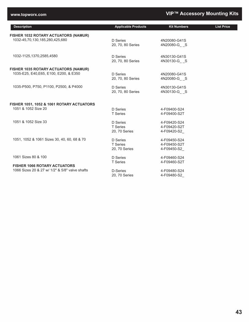
www.topworx.com
43
VIP™ Accessory Mounting Kits
Description Applicable Products Kit Numbers List Price
FISHER 1032 ROTARY ACTUATORS (NAMUR) 1032-45,70,130,185,280,425,680
1032-1125,1370,2585,4580
FISHER 1035 ROTARY ACTUATORS (NAMUR) 1035-E25, E40,E65, E100, E200, & E350
1035-P500, P750, P1100, P2500, & P4000
FISHER 1051, 1052 & 1061 ROTARY ACTUATORS 1051 & 1052 Size 20
1051 & 1052 Size 33
1051, 1052 & 1061 Sizes 30, 40, 60, 68 & 70
1061 Sizes 80 & 100
FISHER 1066 ROTARY ACTUATORS 1066 Sizes 20 & 27 w/ 1/2" & 5/8" valve shafts
D Series20, 70, 80 Series
D Series20, 70, 80 Series
D Series20, 70, 80 Series
D Series20, 70, 80 Series
D SeriesT Series
D SeriesT Series20, 70 Series
D SeriesT Series20, 70 Series
D SeriesT Series
D-Series20, 70 Series
4N20080-G41S4N20080-G_ _S
4N30130-G41S4N30130-G_ _S
4N20080-G41S4N20080-G_ _S
4N30130-G41S4N30130-G_ _S
4-F09400-S244-F09400-S2T
4-F09420-S244-F09420-S2T4-F09420-S2_
4-F09450-S244-F09450-S2T4-F09450-S2_
4-F09460-S244-F09460-S2T
4-F09480-S244-F09480-S2_

VIP™ Accessory Mounting Kits [email protected]
44
™
Description Applicable Products Kit Numbers List Price
FISHER 1077 MANUAL HANDWHEEL ROTARY ACTUATORS 1077-6M
1077-7M 1077-9M 1077-10M
FISHER 1078 AAA MANUAL ACTUATORS 1078-B
1078-C
1078-D
1078-1A
FISHER 2052 ACTUATORS Size 1
Size 2
D Series20, 70 Series
D Series
20, 70 Series
20, 70 Series
D SeriesT Series20, 70 Series
D SeriesT Series
D Series20, 70 Series
D SeriesT Series20, 70 Series
D SeriesT Series20, 70 Series
D SeriesT Series20, 70 Series
4-F09565-S244-F09565-S2_
4-F09575-S24
4-F09580-S2_
4-F09585-S2_
4-F09597-S244-F09597-S2T4-F09597-S2_
4-F09600-S244-F09600-S2T
4-F09599-S244-F09599-S2_
4-F09571-S244-F09571-S2T4-F09571-S2_
4-F09451-S244-F09451-S2T4-F09451-S2_
4-F09452-S244-F09452-S2T4-F09452-S2_

www.topworx.com
45
VIP™ Accessory Mounting Kits
Description Applicable Products Kit Numbers List Price
FISHER 2052 ACTUATORS Size 3
FISHER 3710 POSITIONER
FISHER D4 ACTUATORS Size 40 (w/ 3/4" travel) Size 40 (w/ 3/4" travel)
FISHER GX ACTUATORS Size 225, 750 & 1200
GENERAL TORQUE (SEE KTM)
GRINNEL ROTARY ACTUATORS (NAMUR) Size 2, 4, 8, 12, 20, 35
Size 55, 70, 100, 150
HYTORK ACTUATORS (NAMUR) XL-45,70,130,185,280,425,680
XL-1125,1370,2585,4580
D SeriesT Series20, 70 Series
D Series
D Series70 Series
D SeriesT Series70 Series
D Series20, 70, 80 Series
D Series20, 70, 80 Series
D Series20, 70, 80 Series
D Series20, 70, 80 Series
4-F09454-S244-F09454-S2T4-F09454-S2_
4-F09710-S24
4-F09242-S24N4-F09242-S27
4-F09240-S24N4-F09240-S2TL4-F09240-S27
4N20080-G41S4N20080-G _ _ S
4N30130-G41S 4N30130-G_ _S
4N20080-G41S4N20080-G_ _S
4N30130-G41S4N30130-G_ _S

VIP™ Accessory Mounting Kits [email protected]
46
Description Applicable Products Kit Numbers List Price
JAMESBURY RACK & PINION ACTUATORS SP25, 50, SP6SR60, SP9SR80, SP8SR40, SP13SR60, SP18SR80
SP100, 200, SP18SR40, SP26SR60, SP36SR80, SP52SR60, SP72SR80
JAMESBURY QUADRA-POWR & QUADRA-POWR II ACTUATORS B (Size 30, 40, 50, 60S) QP 1M & 2M
C (Size 30, 40, 50, 60S) QP 3M
JAMESBURY VANE ACTUATORS V60
V150
D Series
D Series
D Series
D Series
D Series
D Series
4-N05310-S24
4-N05320-S24
4-N05310-S24
4-N05320-S24
4-N05310-S24
4-N05320-S24
JAMESBURY ACTUATORS (NAMUR) VP-02, 04
VP-08, 10
VP-12, 14, 22
KEYSTONE 79U/79E 006, 012 024, 036, 065, 066, 090, 091, 180, 181
KINETROL VANE ACTUATORS 029 w/ SAE hardware 039 w/ SAE hardware 059 w/ SAE hardware 079 w/ SAE hardware 089 w/ SAE hardware 099 w/ SAE hardware 109 w/ SAE hardware 129 w/ SAE hardware 149 w/ SAE hardware 169 w/ SAE hardware 209-100 w/ SAE hardware MASONEILAN-DRESSER CAMFLEX II ACTUATORS Actuator size 4-1/2 for valve sizes 1, 1-1/2, 2 Actuator size 6 for valve sizes 3" & 4"
MASONEILAN-DRESSER DIAPHRAGM ACTUATORS MODELS 37 & 38 37/38 Sizes 11 & 13
37/38 Sizes 15 & 18
MARWIN CONTROLS (NAMUR) 52/UT-O, 63/UT-1, 85/UT-2.5
D Series20, 70, 80 Series
D Series20, 70, 80 Series
D Series20, 70, 80 Series
D SeriesD Series
D SeriesD SeriesD SeriesD SeriesD SeriesD SeriesD SeriesD SeriesD SeriesD SeriesD Series
4N20080-G41S4N20080-G_ _S
4N30080-G41S4N30080-G_ _S
4N50130-G41S4N50130-G_ _S
4-K05006-S244-K05024-S24
4-K10029-S244-K10039-S244-K10059-S244-K10079-S244-K10089-S244-K10099-S244-K10109-S244-K10129-S244-K10149-S244-K10169-S244-K10209-S24
D Series70 Series
D Series20, 70 Series
D Series20, 70 Series
D Series20, 70, 80 Series
4-M02120-S244-M02120-S27
4-M02210-S24N4-M02210-S2_
4-M02220-S24N4-M02220-S2_
4N30080-G41S4N30080-G_ _S

www.topworx.com
47
VIP™ Accessory Mounting Kits
Description Applicable Products Kit Numbers List Price
NELES CONTROLS CYLINDER ACTUATORSMODELS BC & BJ Sizes 8, 9 & 10
Sizes 12 & 16
Size 20
Size 25
Size 32
Size 40
ORBIT PISTON ACTUATORSLG & LS SERIES 124D 185D4, 14, 20, 23 185D5 205D5 & 6 206 266
ORBIT DIAPHRAGM ACTUATORS 80100, 80625, 160100, 160625 & 1601125
Series 84, 164 & 165, 84100, 10084, 164100, 100164, 100165 & 100167
84625, 164625, 62584, 625164 & 625165
316ss mounting kits; require D Series w/ 45º indicator and Namur shaft LS-269-D-32 LS-267-D-15 LS-205-D-26-X-S LS-208-D-31 LS-205-D5/D15 84625 (also listed above) 164100 size 3 (also listed above) LS-124-D2, D12, D21, D22 LS-205-D-6, D16 ORBIT DIAPHRAGM ACTUATORS LS-185-D5, D15 LS-185-D4, D14 LS/LG-2611-T-29 LS-207-D19/LS-267-D19 LS-267-D16 LS-4214-D-33
PROTECH ACTUATORS (NAMUR) 100, 200, 250, 260, & 300
400 & 500
D Series20, 70 Series
D Series20, 70 Series
D Series20, 70 Series
D Series20, 70 Series
D Series20, 70 Series
D Series
20, 70 Series20, 70 Series20, 70 Series20, 70 Series20, 70 Series20, 70 Series
20, 70 Series
20, 70 Series
20, 70 Series
D SeriesD SeriesD SeriesD SeriesD SeriesD SeriesD SeriesD SeriesD Series
4-N05410-S244-N05410-S2_
4-N05415-S244-N05415-S2_
4-N05420-S244-N05420-S2_
4-N05425-S244-N05425-S2_
4-N05430-S244-N05430-S2_
4-N05435-S24
4-O18005-S2_4-O18010-S2_4-O18015-S2_4-O18020-S2_4-O18025-S2_4-O18030-S2_
4-O18040-S2_
4-O18050-S2_
4-O18060-S2_
4-O18R65-M24N4-O18R66-M24N4-O18R67-M24N4-O18R68-M24N4-O18R69-M24N4-O18R70-M24N4-O18R71-M24N4-O18R72-M24N4-O18R73-M24N
D SeriesD SeriesD SeriesD SeriesD SeriesD Series
D Series20, 70, 80 Series
D Series20, 70, 80 Series
4-O18R75-M24N4-O18R76-M24N4-O18R77-M24N4-O18R78-M24N4-O18R79-M24N4-O18R81-M24N
4N20080-G41S4N20080-G_ _S
4N30130-G41S4N30130-G_ _S

VIP™ Accessory Mounting Kits [email protected]
48
Description Applicable Products Kit Numbers List Price
ROTORK SP RANGE PNEUMATIC ACTUATORS 40
50
ROTORK SP RANGE PNEUMATIC ACTUATORS 70
TRIAC ACTUATORS (NAMUR) TR-20, 40, 80, 130, 200
TR-500, 850, 1200, 1750
UNITORQ ACTUATORS (NAMUR) M10, 20, 30, 52, 73, 103, 148, 222, & 295
M586, 1213, 2366, 2958, & 4200
WORCESTER CONTROLS PNEUMATIC ACTUATORS Series 34 - Sizes A & B
D SeriesT Series20, 70, 80 Series
D SeriesT Series20, 70, 80 Series
D SeriesT Series20, 70, 80 Series
D Series20, 70, 80 Series
D Series20, 70, 80 Series
D Series20, 70, 80 Series
D Series20, 70, 80 Series
D Series20, 70 Series
4-B05015-S244-B05015-S2T4-B05015-S2_
4-B05020-S244-B05020-S2T4-B05020-S2_
4-B05030-S244-B05030-S2T4-B05030-S2_
4N20080-G41S4N20080-G_ _S
4N30130-G41S4N30130-G_ _S
4N20080-G41S4N20080-G_ _S
4N30130-G41S4N30130-G_ _S
4-W15340-S244-W15340-S2_
WORCESTER CONTROLS 39/R6 SERIES (NAMUR) 1039/R6, 1539/R6, & 2039/R6
2539/R6, 3039/R6, 3339/R6 & 3539/R6
4039/R6 & 4239/R6
XOMOX MATRYX (E & P SERIES NAMUR) E25, 40, 65, 100, 200, 350
E600, 950, 1600
P500, 750, 1100, 2500, 4000
D Series20, 70, 80 Series
D Series20, 70, 80 Series
D Series20, 70, 80 Series
D Series20, 70, 80 Series
D Series20, 70, 80 Series
D Series20, 70, 80 Series
4N20080-G41S4N20080-G_ _S
4N30080-G41S4N30080-G_ _S
4N50130-G41S4N50130-G_ _S
4N20080-G41S4N20080-G_ _S
4N30080-G41S4N30080-G_ _S
4N30130-G41S4N30130-G_ _S
XOMOX MATRYX PISTON ACTUATORS 26051, 26061, 26062, 26071, 26081, 26002 33071, 33081, 33082, 33101, 33102, 33121 45102, 45121, 45122, 45141, 45161 XOMOX XRP Rack and Pinion Actuators XS006, XS012, XS025, XS050
XS090, XS130, XS180, XS205 XS380, XS630
D SeriesD SeriesD Series
D-Series 20, 70, 80 Series
D-Series 20, 70, 80 Series
4-X15110-S244-X15120-S244-X15130-S24
4N20080-G41S4N20080-G_ _5
4N30130-G41S4N30130-G_ _ 5

www.topworx.com
49
VIP™ Accessory Mounting Kits

Notes


ES-00449-1 R28
Visit www.topworx.com for comprehensive informationon our company, capabilities, and products –including model numbers, data sheets, specifications,dimensions, and certifications.
www.topworx.com
GLOBAL SUPPORT OFFICES
TopWorx Americas3300 Fern Valley RoadLouisville, Kentucky 40213 USA+1 502 969 [email protected]
TopWorx Europe, Middle East, Africa Horsfield WayBredbury Industrial EstateStockport SK6 2SUUnited Kingdom+44 0 161 406 5155 [email protected]
TopWorx Asia-Pacific1 Pandan CrescentSingapore 128461+65 6891 [email protected]
The Emerson logo is a trademark and a service mark of Emerson Electric Co. © 2017 Emerson Electric Co. © 2017 TopWorx™, All rights reserved. TopWorx™, GO™ Switch, and VIP, are all trademarks of TopWorx™. All other marks are the property of their respective owners. Information herein – including product specifications – is subject to change without notice.
About Emerson Process ManagementEmerson Process Management is a powerful, global, single source of process improvement technology and expertise. We help major companies in selected industries optimize their plants and processes to achieve higherquality, greater reliability and faster time to market, while steadily advancingproductivity and profitability. We can build it - providing experienced projectmanagement, engineering and a single point of accountability for the entireinstrumentation and automation system. We can connect it -- seamlesslyintegrating people and technology at every level of the process. We canimprove it -- creating more efficient utilization of energy and raw materials.And we can sustain it -- producing greater reliability, month after month,year after year. From the field, to the plant, to the bottom line -- whereperformance is the question, Emerson is the answer.