Observation of ferromagnetic ordering in conjugated polymers exhibiting OMAR effect
7
Observation of ferromagnetic ordering in conjugated polymers exhibiting OMAR effect Sayani Majumdar a,b,⇑ , Jan-Olof Lill c , Johan Rajander c , Himadri Majumdar d a Nanospin, Department of Applied Physics, Aalto University School of Science, FI-00076 Aalto, Finland b Wihuri Physical Laboratory, Department of Physics and Astronomy, University of Turku, 20014, Finland c Accelerator Laboratory, Turku PET Center, Åbo Akademi University, 20500, Finland d VTT Technical Research Center of Finland, FI-02150 Espoo, Finland article info Article history: Received 24 November 2014 Received in revised form 9 February 2015 Accepted 26 February 2015 Available online 2 March 2015 Keywords: Organic magnetoresistance Magnetic semiconductor PIXE abstract We report observation of ferromagnetic (FM) ordering in p-conjugated polymeric semiconductors, namely regio-regular poly (3-hexyl thiophene) (RRP3HT) and 1-(3-methoxycarbonyl)propyl-1-phenyl- [6,6]-methanofullerene (PCBM), in the temperature range of 5–300 K. Diodes made from these polymers exhibit sizable magnetoresistance (known commonly as OMAR). However, upon blending these two materials, the FM ordering is suppressed by a huge paramagnetic (PM) signal. In the diodes with RRP3HT:PCBM blend showing PM response, OMAR decreases substantially. Particle induced X-ray emission spectroscopy indicate presence of dilute magnetic impurities as residues from the synthesis process in the individual polymers. However the impurity signal is unable to explain the temperature dependence of magnetization in these materials and the observed paramagnetism of the RRP3HT:PCBM blend. We propose a hypothesis for the origin of the FM nature of these polymers based on ours and pre- viously reported experimental observations and pointed out that the reported organic magnetoresistance might have a close correlation with the ferromagnetic interaction in these polymers. Ó 2015 Elsevier B.V. All rights reserved. 1. Introduction Over the past two decades, the growth of organic electronics has been phenomenal [1–3]. However, until recently, all research has been predominantly focused towards the understanding of charge transport in organic semiconductors (OS) small molecules and pi-conjugated polymers (PCP) and its implications in devices. Study of spin in organics is a relatively unexplored territory. It pro- vides a whole new scope of physics along with immense potential for application. Spintronics (spin-based electronics) refers to the study of the role played by electron spin in solid state physics, and possible devices that specifically exploit spin properties instead of or in addition to charge degrees of freedom [4]. In recent years semiconductors are studied widely as promising spin transport materials [5] for spintronic applications. Although great research effort is dedicated to explore the inorganic magnetic semiconductors for spintronic applications very little attention has been paid to the use OS molecules and PCPs as spintronic materials. Long spin-correlation length is expected in OS compared to their inorganic counterparts as they are composed of mainly light mole- cules and possess low spin–orbit interaction and hyperfine interac- tion [6]. PCPs are especially the better choice as their conjugation length is much higher than the small molecules and oligomers, leading to better transport properties and simpler fabrication pro- cess [7]. The ability to manipulate electron spin in organic mole- cules offers an alternative route to conventional spintronics, both from fundamental and technological points of view and with the emergence of different experimental results, it is fast becoming a subject of huge research interest [8–12]. Increased ferromagnetism at the ferromagnet–OS interface [12 and references therein] especially raised high interest for highly spin polarized interface (termed as ‘‘spinterface’’) in the organic spintronic devices. Magnetic field effects on OS were demonstrated already in the early nineties [13]. However, demonstration of successful spin injection and transport in lateral [14] and vertical [15] spin-valve devices and at the same time large magnetoresistance (OMAR) and magneto-electroluminescence (MEL) response in OS diode devices with non-magnetic electrode at room temperature under a small applied magnetic field (10–100 mT) [16–18] caused resur- gence of interest. Several experiments have so far successfully demonstrated efficient spin injection and transport in organic spin-valve structures and their successful operations, even at room http://dx.doi.org/10.1016/j.orgel.2015.02.025 1566-1199/Ó 2015 Elsevier B.V. All rights reserved. ⇑ Corresponding author at: Wihuri Physical Laboratory, Department of Physics and Astronomy, University of Turku, 20014, Finland. E-mail address: sayani.majumdar@utu.fi (S. Majumdar). Organic Electronics 21 (2015) 66–72 Contents lists available at ScienceDirect Organic Electronics journal homepage: www.elsevier.com/locate/orgel
Transcript of Observation of ferromagnetic ordering in conjugated polymers exhibiting OMAR effect

Organic Electronics 21 (2015) 66–72
Contents lists available at ScienceDirect
Organic Electronics
journal homepage: www.elsevier .com/locate /orgel
Observation of ferromagnetic ordering in conjugated polymersexhibiting OMAR effect
http://dx.doi.org/10.1016/j.orgel.2015.02.0251566-1199/� 2015 Elsevier B.V. All rights reserved.
⇑ Corresponding author at: Wihuri Physical Laboratory, Department of Physicsand Astronomy, University of Turku, 20014, Finland.
E-mail address: [email protected] (S. Majumdar).
Sayani Majumdar a,b,⇑, Jan-Olof Lill c, Johan Rajander c, Himadri Majumdar d
a Nanospin, Department of Applied Physics, Aalto University School of Science, FI-00076 Aalto, Finlandb Wihuri Physical Laboratory, Department of Physics and Astronomy, University of Turku, 20014, Finlandc Accelerator Laboratory, Turku PET Center, Åbo Akademi University, 20500, Finlandd VTT Technical Research Center of Finland, FI-02150 Espoo, Finland
a r t i c l e i n f o a b s t r a c t
Article history:Received 24 November 2014Received in revised form 9 February 2015Accepted 26 February 2015Available online 2 March 2015
Keywords:Organic magnetoresistanceMagnetic semiconductorPIXE
We report observation of ferromagnetic (FM) ordering in p-conjugated polymeric semiconductors,namely regio-regular poly (3-hexyl thiophene) (RRP3HT) and 1-(3-methoxycarbonyl)propyl-1-phenyl-[6,6]-methanofullerene (PCBM), in the temperature range of 5–300 K. Diodes made from these polymersexhibit sizable magnetoresistance (known commonly as OMAR). However, upon blending these twomaterials, the FM ordering is suppressed by a huge paramagnetic (PM) signal. In the diodes withRRP3HT:PCBM blend showing PM response, OMAR decreases substantially. Particle induced X-rayemission spectroscopy indicate presence of dilute magnetic impurities as residues from the synthesisprocess in the individual polymers. However the impurity signal is unable to explain the temperaturedependence of magnetization in these materials and the observed paramagnetism of the RRP3HT:PCBMblend. We propose a hypothesis for the origin of the FM nature of these polymers based on ours and pre-viously reported experimental observations and pointed out that the reported organic magnetoresistancemight have a close correlation with the ferromagnetic interaction in these polymers.
� 2015 Elsevier B.V. All rights reserved.
1. Introduction
Over the past two decades, the growth of organic electronicshas been phenomenal [1–3]. However, until recently, all researchhas been predominantly focused towards the understanding ofcharge transport in organic semiconductors (OS) small moleculesand pi-conjugated polymers (PCP) and its implications in devices.Study of spin in organics is a relatively unexplored territory. It pro-vides a whole new scope of physics along with immense potentialfor application. Spintronics (spin-based electronics) refers to thestudy of the role played by electron spin in solid state physics,and possible devices that specifically exploit spin propertiesinstead of or in addition to charge degrees of freedom [4].
In recent years semiconductors are studied widely as promisingspin transport materials [5] for spintronic applications. Althoughgreat research effort is dedicated to explore the inorganic magneticsemiconductors for spintronic applications very little attention hasbeen paid to the use OS molecules and PCPs as spintronic materials.Long spin-correlation length is expected in OS compared to their
inorganic counterparts as they are composed of mainly light mole-cules and possess low spin–orbit interaction and hyperfine interac-tion [6]. PCPs are especially the better choice as their conjugationlength is much higher than the small molecules and oligomers,leading to better transport properties and simpler fabrication pro-cess [7]. The ability to manipulate electron spin in organic mole-cules offers an alternative route to conventional spintronics, bothfrom fundamental and technological points of view and with theemergence of different experimental results, it is fast becoming asubject of huge research interest [8–12]. Increased ferromagnetismat the ferromagnet–OS interface [12 and references therein]especially raised high interest for highly spin polarized interface(termed as ‘‘spinterface’’) in the organic spintronic devices.
Magnetic field effects on OS were demonstrated already in theearly nineties [13]. However, demonstration of successful spininjection and transport in lateral [14] and vertical [15] spin-valvedevices and at the same time large magnetoresistance (OMAR)and magneto-electroluminescence (MEL) response in OS diodedevices with non-magnetic electrode at room temperature undera small applied magnetic field (�10–100 mT) [16–18] caused resur-gence of interest. Several experiments have so far successfullydemonstrated efficient spin injection and transport in organicspin-valve structures and their successful operations, even at room

Fig. 1. Device structure and magnetoresistance response as a function of magneticfield (B) at 300 K for an ITO/RRP3HT/Al diode measured with 1 lA current (Blacksquare) when B was scanned from 0 to +300 mT and 0 to �300 mT with a scanspeed of 1 mT/s and showing resistance hysteresis (Red circle) behavior when B wasscanned from 0 to +300 mT, +300 mT to �300 mT and back to +300 mT at a scanspeed of 20 lT/s. Arrows indicate the direction of the sweeping field. (Inset)Current–voltage characteristics of one such diode at 300 K. (For interpretation ofthe references to color in this figure legend, the reader is referred to the web versionof this article.)
S. Majumdar et al. / Organic Electronics 21 (2015) 66–72 67
temperature [19,20], paving the way for future commercial applica-tions. However, the reason for large OMAR effect in organic diodeshas not been explained very successfully yet. Different models havebeen proposed to explain the observed effects [21–25] but differ-ences between theory and experimental results still exist.
Ferromagnetism in conjugated polymers has been demonstrat-ed before. Ferromagnetic (FM) ordering was shown in dopedpoly(3-methyl thiophene) (P3MT) using Superconducting quan-tum interface designed (SQUID) magnetometer and electron spinresonance (ESR) measurements and it was found that FM orderingin P3MT is independent of magnetic impurities [26]. Hoppingtransport in conducting polymers has also been shown to be sig-nificantly affected in presence of such FM ordering [27]. Morerecently ferromagnetism in polythiophene was observed using dif-ferent techniques like Faraday rotation [28] and magnetic forcemicroscopy (MFM) measurements [29]. In our previous works wehave observed that there are signatures of magnetic domain for-mation in OS [30] from magneto-transport measurements. Inorganic spin-valves fabricated with regio-regular poly (3-hexylthiophene) (RRP3HT) [17] as the spacer we observed enhancedswitching field than the expected values from using La0.7Sr0.3MnO3
and Co electrodes. Furthermore, ITO/RRP3HT/Al diodes showedhysteretic nature of device resistance as a function of magneticfields [30]. These observations indicate signatures of trapped spinsin the bulk of the PCPs forming magnetic domains. The magneticproperties and their physical origin in the PCPs is therefore anessential characteristic that needs to be investigated in order tofully understand different organic spintronic devices and fordesigning devices with new functionalities.
In an earlier report [31] we chose the RRP3HT:PCBM blend as themodel system to study the effect of electron–hole (e–h) recombina-tion on the OMAR response of the device. We found that withdecreasing probability of Coulombically bound e–h pair formation,the OMAR response decreased significantly. In our presentexperiment also, we have chosen RRP3HT, 1-(3-methoxycar-bonyl)propyl-1-phenyl-[6,6]-methanofullerene (PCBM) and theRRP3HT:PCBM blend (1:1) as the test systems to investigate themagnetic properties. In the present paper, we report the magneticcharacterization together with their OMAR characteristics whichpoints towards a very intriguing correlation between magneticand magnetotransport properties of these p-conjugated polymers,so far unnoticed.
2. Experimental
The device structure used for the magneto-transport experi-ments is described earlier [31]. For the magnetic measurements,RRP3HT, either pure powder (as received from Sigma–Aldrich) ordrop-casted films from chloroform or dichlorobenzene (DCB) solu-tion on ITO or SiO2 substrates were used. The PCBM powder wasmeasured as received. For the blend, 1:1 weight ratio ofRRP3HT:PCBM was dissolved in DCB and films were made bydrop-coating method on SiO2 substrates to minimize any magneticsignal from the substrates. For all the films, a solution of density5 mg/ml was used and the approximate thicknesses of the filmswere �1 lm. The sample preparation was done in a nitrogen-filledglove-box and using anhydrous solutions. After fabrication, thefilms are transferred in a nitrogen atmosphere to the SQUID magne-tometer. Temperature dependence of magnetization, M, was mea-sured both after cooling the sample under zero field and thenmeasuring the sample while heating under an applied field (ZFC)and during cooling the sample under the measuring field (FC) attemperatures between 5 and 300 K. Magnetic hysteresis curveswere recorded in the field of B = ±150 mT. All measurements in thiscase were made in dark. The external field B was always appliedalong the plane of the films. For the measurement of spontaneous
polarization in dark and under light, the thin-film sample was illu-minated using an Ar-ion laser working at k = 514.5 nm (2.42 eV). Tore-confirm the magnetic data, ac-susceptibility was measured fromthe RRP3HT powder using the vibrating sample magnetometer ofthe Quantum Design Physical Property Measurement System(PPMS) at two different frequencies of 1 and 5 kHz between 10and 300 K.
For elemental analysis by the particle induced X-ray emission(PIXE) technique, about 15 mg of the polymer sample materialwas pressed to a pellet (diameter 13 mm). Pure graphite was usedas backing material to minimize the amount of sample material[32]. The samples were irradiated with a 3 MeV proton beam fromthe Åbo Akademi MGC-20 cyclotron. The acquisition time wasabout 500 s with a beam current of 10 nA. All irradiations were per-formed in air to avoid heating and charge build-up. A strong ionluminescence from the irradiated spot on the polymer sampleswas observed in the beginning of the proton irradiation but fadedaway within a few seconds. This phenomenon indicates somechanges in the molecular structure but does not affect the elemen-tal concentration measurements. The radiation emitted from thesample during the irradiation was measured with an IGP X-raydetector for PIXE analysis. The integrated charge on the target need-ed for quantification was determined from measurements of lightinduced in air by the proton beam [33]. The obtained PIXE spectrawere analyzed using the GUPIX software package [34]. The calibra-tion was checked using the USGS granite CRM G-2. The procedurewith the quality assurance has been described earlier [35].
3. Results and discussion
Fig. 1 shows magnetoresistance curves for an ITO/RRP3HT/Aldiode (device schematics as shown in figure) showing a typicalpositive magnetoresistance (closed circle) and a hysteretic (opencircle) curve between �300 mT and +300 mT. In the typical scan,

0 50 100 150 200 250 300
2
3
4
RRP3HT ZFC RRP3HT FC PCBM ZFC PCBM FC
FC
ZFC
FC
ZFC
B = 150 mT
T (K)
Mag
netiz
atio
n/un
it m
ass
(10-3
Am
2 /Kg)
(a)
0 50 100 150 200 250 300
6.6
6.8
7.0
7.2
RRP3HT:PCBM ZFC RRP3HT:PCBM FC
ZFC
Mag
netiz
atio
n (1
0-8 A
m2 )
T (K)
(b)FC
B = 150 mT
-300 -200 -100 0 100 200 300-4
-2
0
2
4
0 100 200 300
0.0
0.5
1.0
' (10
-4 A
m2 )
T (K)
' (10
-4 A
m2 )
B (mT)
1 k Hz 10 K
RRP3HT
(c)
Fig. 2. Zero-field cooled (ZFC) (open) and field cooled (FC) (closed) magnetization of(a) RRP3HT and PCBM powders under an applied field of 150 mT. The arrowsindicate the domain freezing temperatures. (b) ZFC (open) and FC (closed)magnetization of RRP3HT:PCBM (1:1) blend film on SiO2 under 100 mT magneticfield. (c) Real part of ac-susceptibility as a function of bias field at 10 K for RRP3HTpowder measured with a driving frequency of 1 kHz.
68 S. Majumdar et al. / Organic Electronics 21 (2015) 66–72
the diode was scanned from 0 to +300 mT and then scanned from 0to �300 mT after a sufficient time interval. In the hysteretic scanthe magnetoresistance was measured continuously from 0 to+300 mT, +300 mT to �300 mT and back to +300 mT. The scanspeed for the hysteresis measurement was 20 lT/s. In the hystere-sis measurement the %MR plot differed completely from a typicalMR plot. The measurement was done by sending a constant currentand measuring the voltage in presence of a certain magnetic field.For the measurement with 1 mT/s, the sample was subjected to theexternal magnetic field (between 0 and 300 mT) for only 5 minwhile in the 20 lT/s. case, the sample was subjected to the mag-netic field for almost 1 day and the difference between them clear-ly indicate that the magnetoresistance behavior of the organicdiodes are time dependent. It is important to mention here thatno evidence of such hysteretic behavior in current–voltage charac-teristics (inset Fig. 1), measured without a magnetic field, wasobserved and the device was stable for the whole measurementperiod and afterwards. Therefore, such hysteretic nature of %MRcould possibly indicate a long relaxation time of polarized spinsat a particular site leading to formation of magnetically aligneddomains within the device. In case of PCPs, a localized carrier ina deep trap state could become magnetically polarized under anapplied magnetic field and can form bound magnetic polarons thatcan lead to long range magnetic interactions and modify the mag-netotransport properties of the material. To verify this hypothesis,magnetization measurements of the individual polymer compo-nents is essential and we performed a thorough DC magnetizationmeasurement using SQUID magnetometer and also some confir-mation experiments using AC susceptibility measurements.
For magnetization measurements, first RRP3HT and PCBM pow-ders were separately wrapped in clean Teflon� [36] tape and mea-sured separately in the SQUID magnetometer in the temperaturerange of 5–300 K both in ZFC and FC directions with an appliedfield of 150 mT (Fig. 2(a)). Magnetization value increases fastbelow 100 K for both RRP3HT and PCBM. The ZFC and FC curvesstart to separate from each other below 150 K, which is usuallyobserved for frustrated or low-dimensional magnetic systems likespin glasses and indicate domain freezing behavior. The measuredsaturation magnetic moment (MS) for both materials are given inTable 1. It was additionally found that for films made from RRP3HTdissolved in chloroform and in DCB the MS values were widely dif-ferent (not shown here). While the RRP3HT-from-DCB film showedclear FM signal till room temperature, for the RRP3HT-from-chlo-roform film, it was almost impossible to measure the signal above50 K. This difference in MS values suggests a dependence of themagnetic response of organic films on its morphology. It has beenproven extensively in literature that uses of either chloroform orDCB lead to complete different crystallization of the thiophenepolymer. One of the very early work by the group in Cambridge[37] clearly demonstrate that change in solvent changesmicrostructure of the thiophene. This leads to formation or non-formation of defect states that works as traps and change carrierconcentration. For the films made from the RRP3HT:PCBM blend,no difference in FC and ZFC were observed and the M was foundto be temperature independent (Fig. 2(b)). To confirm the magneticdata, ac-susceptibility of RRP3HT powder and film was measuredusing a completely different setup (vibrating sample magnetome-
Table 1Magnetic moment (MS) and coercive field (HC) values of different polymers at 5 K and 300
Polymer ; MS @ 5 K
RRP3HT powder 5.57 � 1020 lB kg�1
RRP3HT film from dichlorobenzene solution 1.08 � 1020 lB cc�1
RRP3HT film from chloroform solution 5.9 � 1018 lB cc�1
PCBM 2.5 � 1020 lB kg�1
ter in the PPMS) where the powder was wrapped in a tissue andplaced inside a plastic straw. Fig. 2 (c) shows real part of ac-suscep-tibility as a function of magnetic field at 10 K. The time-dependentmagnetic moment induced in the sample due to an applied field of1 kHz frequency shows a non-zero value dependent on the appliedmagnetic field confirming ferromagnetic interaction. Also tem-perature dependent AC susceptibility data confirms similar trend
K.
MS @ 300 K HC @ 5 K (mT) MS from impurities
3.98 � 1020 lB kg�1 11.2 3.5–4.5 � 1020 lB kg�1
8.85 � 1019 lB cc�1 4.5 –Not measurable 16.5 –1.99 � 1020 lB kg�1 �6.7 �9 ± 1.8 � 1020 lB Kg�1
S. Majumdar et al. / Organic Electronics 21 (2015) 66–72 69
in magnetic moment as shown and discussed before for DC magne-tization (inset of Fig. 2(c)).
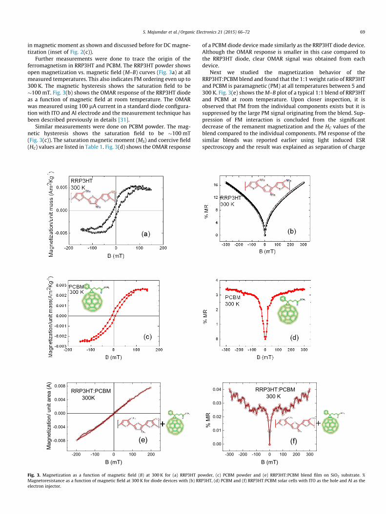
Further measurements were done to trace the origin of theferromagnetism in RRP3HT and PCBM. The RRP3HT powder showsopen magnetization vs. magnetic field (M–B) curves (Fig. 3a) at allmeasured temperatures. This also indicates FM ordering even up to300 K. The magnetic hysteresis shows the saturation field to be�100 mT. Fig. 3(b) shows the OMAR response of the RRP3HT diodeas a function of magnetic field at room temperature. The OMARwas measured using 100 lA current in a standard diode configura-tion with ITO and Al electrode and the measurement technique hasbeen described previously in details [31].
Similar measurements were done on PCBM powder. The mag-netic hysteresis shows the saturation field to be �100 mT(Fig. 3(c)). The saturation magnetic moment (MS) and coercive field(HC) values are listed in Table 1. Fig. 3(d) shows the OMAR response
-200 -100 0 100 200
-0.008
-0.004
0.000
0.004
0.008
Mag
netiz
atio
n/ u
nit a
rea
(A)
B (mT)
RRP3HT:PCBM300K
(e)
Fig. 3. Magnetization as a function of magnetic field (B) at 300 K for (a) RRP3HT poMagnetoresistance as a function of magnetic field at 300 K for diode devices with (b) RRelectron injector.
of a PCBM diode device made similarly as the RRP3HT diode device.Although the OMAR response is smaller in this case compared tothe RRP3HT diode, clear OMAR signal was obtained from eachdevice.
Next we studied the magnetization behavior of theRRP3HT:PCBM blend and found that the 1:1 weight ratio of RRP3HTand PCBM is paramagnetic (PM) at all temperatures between 5 and300 K. Fig. 3(e) shows the M–B plot of a typical 1:1 blend of RRP3HTand PCBM at room temperature. Upon closer inspection, it isobserved that FM from the individual components exists but it issuppressed by the large PM signal originating from the blend. Sup-pression of FM interaction is concluded from the significantdecrease of the remanent magnetization and the HC values of theblend compared to the individual components. PM response of thesimilar blends was reported earlier using light induced ESRspectroscopy and the result was explained as separation of charge
-300 -200 -100 0 100 200 300
0.00
0.01
0.02
0.03
0.04
% M
R
B (mT)
(f)
RRP3HT:PCBM 300 K
wder, (c) PCBM powder and (e) RRP3HT:PCBM blend film on SiO2 substrate. %P3HT, (d) PCBM and (f) RRP3HT:PCBM solar cells with ITO as the hole and Al as the

Table 2Elemental concentrations in the materials given in lg/g of dry weight. Typicalstatistical errors in % and limit of detection (LOD) in lg/g are in the columns to theright.
Elemental content ; RRP3HT PCBM Error (%) LOD
S 180,360 bdl 0.2 190Br 3975 bdl 0.4 1.4Mn bdl bdl – 8.7Fe bdl 15 20 4.9Ni 12 1.7 14 1.2
bdl – below detection limit.
70 S. Majumdar et al. / Organic Electronics 21 (2015) 66–72
carriers into different paths on the polymer and fullerene blends[38]. In a RRP3HT:PCBM blend, PCBM is embedded in the conjugatedpolymer and acts as a strong electron acceptor whose lowest unoc-cupied molecular orbital (LUMO) lies below the excitonic state. Ithas been shown earlier that upon irradiation, electron is transferredfrom a polymer chain to a fullerene molecule within femtosecondtime scale [39], whereas the electron back transfer is much slowerand this electron transfer results in a charge-separated state.Krinichnyi [38] showed that upon irradiation, this charge separatedstate can give rise to a huge PM signal and the effective PM suscep-tibility of the generated polarons and fullerene anion-radicals, isinversely proportional to the probability of their recombination, inexcellent agreement with the transport data in Ref. [25]. However,we observe a strong PM signal from the 1:1 blend of RRP3HT andPCBM already in the dark, implying that a ground state charge trans-fer complex is formed in the RRP3HT:PCBM blend at the interfacebetween the polymer and fullerene molecule, leading to separationof free carriers. Existence of such charge-transfer complexes havebeen reported before [40,41]. The PM signal arising from these freecarriers suppress the individual FM ordering in RRP3HT and PCBMand we observe only a large PM signal. Fig. 3(f) shows the OMARresponse of a diode made from the blend – orders of magnitudesmaller than that of a RRP3HT or PCBM diode. Recently Yang et al.[29] has shown ferromagnetic ordering using MFM imaging fromP3HT:PCBM blend which was annealed for more than 12 h. Theyreported magnetic domains of sizes from tens to hundreds ofnanometers, distributed uniformly over the entire film, in the crys-talline phase of the blend that was achieved using the slow dryingprocess. However, this fabrication technique is completely differentfrom ours and hence should not be directly compared to our results.While preparing our samples for magnetic measurements, we havekept the preparation condition identical to the diode conditions.Therefore it can be concluded that depending on film morphologyand carrier concentration, magnetic properties of organic semicon-ductors can change significantly.
In order to investigate the origin of the FM ordering in the poly-mer RRP3HT and fullerene PCBM, impurities in these materialswere checked by PIXE analysis. Fig. 4 shows a typical PIXE spec-trum, with clear peaks from S, Ni and Br. Sulfur can be found inthe RRP3HT backbone and bromine in the ends of the polymerchain, the other elements are considered to be impurities. Elemen-tal concentrations and statistical uncertainties for the samples areshown in Table 2.
From the PIXE data we find that both RRP3HT and PCBM sam-ples contain small amounts of magnetic impurities like Fe, Ni, Co,Mn etc. Traces of Ni were found in both the polymers while Fewas the main magnetic impurity in PCBM. Earlier [42–44] veryweak FM was observed in C60 molecule and the FM ordering wasattributed to the presence of Fe impurities. In RRP3HT the Ni impu-rity amount is �12 lg/g and in PCBM the Fe impurity amount is
2 4 6 8 10 12 14101
102
103
104
Ni(Kα)
Br(Kβ)
Br(Kα)
Inte
nsity
[a.u
.]
X-ray energy [keV]
RRP3HTS
esc
Fig. 4. A typical energy spectrum of regio-regular poly(3-hexyl thiophene)(RRP3HT) showing presence of Ni among different impurities.
�15 lg/g (Table 2). Now, spin magnetic moment of Ni variesbetween 2.9 and 3.3 lB/atom in octahedral complexes andbetween 3.7 and 4.0 lB/atom for tetrahedral complexes [45]. ForFe, the spin moments vary between 5.1 and 5.7 lB/atom in octahe-dral complexes and between 5.3 and 5.5 lB/atom in tetrahedralcomplexes. So, the magnetic moment from Ni impurity (inRRP3HT) can be calculated as �3.5–4.5 � 1020 lB/kg and that forFe impurity (in PCBM) can be �9 � 1020 lB/kg. Both the valuesare similar in magnitude and shows quite good matching withthe experimentally obtained results of RRP3HT at room tem-perature while that for PCBM is a bit lower suggesting that themeasured magnetic moment in the pure polymer powder can arisefrom the magnetic impurities present in the samples. However, weobserved from Fig. 2(a) that the magnetization of both RRP3HT andPCBM is temperature dependent, in contrary to the temperatureindependent magnetization expected from Ni and Fe in the5–300 K range. The impurity concentration is also too dilute to leadto long-range magnetic interaction between the impurities. Hence,it is also a possibility that the FM interaction in RRP3HT and PCBMmight be mediated via an intermediary that gives rise to long-range FM ordering, as previously shown in EuO where the O2
ligands mediates the super-exchange interaction [46]. Comparisonbetween C60 and PCBM shows that presence of hydrogen atoms, i.e.hyperfine interaction, in PCBM increases FM ordering (results notshown here). This indicates that the hyperfine interaction mightplay the role of the intermediary in the long-range FM orderingin OS. From our measurements, the magnetization value suggeststhat the strength of magnetic interaction inside the polymer is ofthe order of few milliteslas (mT) which is quite comparable tothe hyperfine strength of the organic semiconductors. [47]. How-ever, detailed nuclear magnetic resonance (NMR) study of hydro-gen atoms is needed to further elaborate the role of hyperfineinteraction in determining FM ordering in OS.
Another important point is the morphology dependence of themagnetic saturation moment in RRP3HT. Although the amount ofmagnetic impurity is same, the saturation moment varies by almost2 orders of magnitude depending on the film morphology (Table 1).So, it becomes evident that depending on the crystallinity and thedomain size FM interaction can vary significantly. EarlierNascimento et al. [48] have shown similar FM ordering in dopedP3MT using SQUID magnetometer and ESR spectroscopy data andthey found that FM ordering in P3MT is independent of magneticimpurities. They attributed the magnetic property to the interac-tion of spin ½ polarons, which can be either FM or anti-ferromag-netic (AFM) depending on morphology. It is, therefore, possiblethat a trapped carrier mediated FM interaction, as is usuallyobserved in metal-oxide systems [40], could also play an importantrole here. Recently, Gulacsi et al. [49] showed that pentagon-chainpolymers with electron densities above half filling can become fer-romagnetic or half metallic due to an unexpected mechanism inmulti-orbital polygon chains with different size-dependent Cou-lomb interaction strengths. This interaction can turn the dispersiveband into an effectively flat band in a pentagon chain polymer sys-tem leading to long range FM ordering. The carrier concentration of

102 103 104
102
103
Sample in dark (B = 0)
B swiched off
Sample under optical excitation (B = 0)M
agne
tizat
ion
(A/m
)
300 KRRP3HT
B = 150 mT
time (sec)
Fig. 5. Magnetization as a function of time in RRP3HT thin films under opticalexcitation and in dark after switching the external magnetic field (B) off showingsignificantly increased spontaneous magnetic moment under light.
S. Majumdar et al. / Organic Electronics 21 (2015) 66–72 71
the pure P3HT (without doping) is�1016/cc. According to the calcu-lations of Gulacsi et al. [49] this carrier density can produce enoughsite dependent Coulomb interactions and is sufficient to turn thedispersive band into flat band leading to ferromagnetism and halfmetallicity. de Paula et al. [50] have shown that depending on num-ber of polarons, the ferro and paramagnetic properties can be mod-ified and they attributed this to the distance dependent interactionsbetween spin ½ polarons in different polymer chains. We have alsoobserved that carrier concentration plays a significant role in deter-mining the magnetic interaction strength in polymers. Fig. 5 showsthat relaxation in spontaneous magnetization in RRP3HT thin filmsin darkness and under light. After the external field is switched off,it can be seen clearly that spontaneous magnetization decays muchfaster in absence of light (i.e. when carrier concentration is low) andalmost 1 order of magnitude lower than that under light. This againindicates that number of carriers and Coulomb interaction strengthcan play an important role in inducing FM interaction.
Finally, we have observed that when a sizable FM ordering in amaterial exists, we always find a large OMAR response in the diodeswith the respective material as shown in Fig. 3. However, when weobserve a large PM signal, the OMAR response is significantlyreduced. In order to explain this observation we consider the prob-able effect of spin dynamics on the hopping transport. Dependingon whether the carrier spins are aligned in a certain direction ornot, the available numbers of hopping sites change significantly.Earlier Zuppiroli et al. [27] showed that hopping transport in con-ducting polymers can be significantly affected in presence of FMordering. When a carrier with a particular spin orientation hopsto its neighboring site, the hopping probability is not the same ifthe spin of the carrier is parallel or anti-parallel to the neighboringspin. According to Pauli exclusion principle, two carriers with samespin configuration cannot occupy the same site and therefore polar-ized spins at some hopping sites eventually ‘‘block’’ some transportchannels for the carriers which lead to magnetic field dependentresistance in organic based devices, as also pointed out by Harmonand Flatte [51]. Also another possibility is that like in many otherfrustrated or weak magnetic systems, inside the polymers therecould be regions where spins are aligned in the direction of magnet-ic field (FM domains) together with regions of random spin orienta-tions (PM domains). Even magnetizations in the grains and thegrain boundaries are different leading to the formation of domainsand domain walls. Now there could be also tunneling of carriersbetween magnetically aligned domains separated by thin domainwalls and could lead to grain boundary tunneling kind of magne-toresistance response. Therefore we conclude that whether the car-riers are aligned or not can significantly modify the hopping ofcarriers through the system. Together with our present observation,it can be inferred that with sizable number of polarized spins insidea material, magneto-transport properties inside the material would
be modified and therefore FM ordering in OS might have a correla-tion with the OMAR effect. However, further experiments like elec-tric-field induced magnetization study are necessary to clarify thetrue origin of this effect.
In conclusion, we have observed FM ordering in RRP3HT andPCBM but in 1:1 blends of these materials a large PM signal isobserved. PIXE analysis of the individual materials suggests thepresence of magnetic impurities which can almost account forthe observed magnetic moment in the powders. However, thesedilute magnetic impurities are unable to explain the morphologyand temperature dependence of magnetization in these polymerthin films. In samples with FM ordering, we observe significantOMAR effect but OMAR disappears in RRP3HT:PCBM blend filmshaving PM response. This is in accordance with a charge transfercomplex formed in the blend giving rise to free carriers. Thereforeit can be concluded that transport mechanism in conjugated poly-mers can be modified due to presence of polarized spins and thisknowledge can be very useful for future printed magnetic sensorsusing these polymers. However, further work is needed to eluci-date whether the coexistence of OMAR and FM ordering in con-ducting polymers is coincidental or strongly correlated.
Acknowledgements
The authors gratefully acknowledge the Kone and Jenny andAntti Wihuri Foundation and Prof. Ronald Österbacka for financialsupport.
References
[1] T.W. Tang, S.A. Van Slyke, Appl. Phys. Lett. 51 (1987) 913.[2] A. Tsumura, H. Koezuka, T. Ando, Appl. Phys. Lett. 49 (1986) 1210.[3] H.E.A. Huitema, G.H. Gelinck, J.B.P.H. van der Putten, K.E. Kuijk, C.M. Hart, E.
Cantatore, P.T. Herwig, A.J.J.M. van Breemen, D.M. de Leeuw, Nature 414 (2001)599.
[4] G.A. Prinz, Science 282 (1998) 5394.[5] I. Zutic, J. Fabian, S. Das Sarma, Rev. Mod. Phys. 76 (2004) 323.[6] P.P. Ruden, D.L. Smith, J. Appl. Phys. 95 (2004) 4898.[7] S. Majumdar, H.S. Majumdar, R. Laiho, R. Österbacka, J Alloys Compd. 423
(2006) 169.[8] D. Sun, E. Ehrenfreund, Z.V. Vardeny, Chem. Commun. 50 (2014) 1781.[9] S. Majumdar, H.S. Majumdar, Org. Electron. 13 (2012) 2653.
[10] F. Djeghloul et al., Sci. Rep. 3 (2013) 1272.[11] A.J. Drew et al., Nat. Mater. 8 (2009) 109.[12] S. Majumdar, S. Dey, H. Huhtinen, J. Dahl, M. Tuominen, P. Laukkanen, S. van
Dijken, H.S. Majumdar, Spin 4 (2014) 1440009.[13] E.L. Frankevich, A.A. Lymarev, I. Sokolik, F.E. Karasz, S. Blumstengel, R.
Baughman, H.H. Hörhold, Phys. Rev. B 46 (1992) 9320.[14] V. Dediu, M. Murgia, F.C. Matacotta, C. Taliani, S. Barbanera, Solid State
Commun. 122 (2002) 181.[15] Z.H. Xiong, D. Wu, Z.V. Vardeny, J. Shi, Nature 427 (2004) 821.[16] J. Kalinowski, M. Cocchi, D. Virgili, V. Fattori, P. Di Marco, Phys. Rev. B 70
(2004) 205303.[17] T.L. Francis, Ö. Mermer, G. Veeraraghavan, M. Wohlgenannt, New J. Phys. 6
(2004) 185.[18] Ö. Mermer, G. Veeraraghavan, T.L. Francis, Y. Sheng, D.T. Nyugen, M.
Wohlgenannt, A. Köhler, M.K. Al-Suti, M.S. Khan, Phys. Rev. B 72 (2005) 205202.[19] M. Cinchetti, K. Heimer, J.-P. Wüstenberg, O. Andreyev, M. Bauer, S. Lach, C.
Ziegler, Y. Gao, M. Aeschlimann, Nat. Mater. 8 (2009) 115.[20] S. Majumdar, H.S. Majumdar, P. Laukkanen, J. Värynen, R. Laiho, R. Österbacka,
Appl. Phys. Lett. 89 (2006) 122114.[21] V.N. Prigodin, J.D. Bergeson, D.M. Lincoln, A.J. Epstein, Synth. Met. 156 (2006) 757.[22] P. Desai, P. Shakya, T. Kreouzis, W.P. Gillin, N.A. Morley, M.R.J. Gibbs, Phys. Rev.
B 75 (2007) 094423.[23] P.A. Bobbert, T.D. Nyugen, F.W.A. van Oost, B. Koopmans, M. Wohlgenannt,
Phys. Rev. Lett. 99 (2007) 216801.[24] B. Hu, Y. Wu, Nat. Mater. 6 (2007) 985.[25] F.J. Wang, H. Bässler, Z.V. Vardeny, Phys. Rev. Lett. 101 (2008) 236805.[26] O.R. Nascimento, A.J.A. de Oliveira, E.C. Pereira, A.A. Correa, L. Walmsley, J.
Phys. Condens. Matter. 20 (2008) 035214.[27] L. Zuppiroli, M.N. Bussac, S. Paschen, O. Chauvet, L. Forro, Phys. Rev. B 50
(1994) 5196.[28] P. Gangopadhyay, G. Koeckelberghs, A. Persoons, Chem. Mater. 23 (2011) 516.[29] B. Yang, Z. Xiao, Y. Yuan, T.V. Jayaraman, J.E. Shield, R. Skomski, J. Huang,
Polymer 54 (2013) 490.[30] S. Majumdar, H.S. Majumdar, H. Aarnio, R. Laiho, R. Österbacka, Phys. Status
Solidi RRL 3 (2009) 242.

72 S. Majumdar et al. / Organic Electronics 21 (2015) 66–72
[31] S. Majumdar, H.S. Majumdar, H. Aarnio, D. Vanderzande, R. Laiho, R.Österbacka, Phys. Rev. B 79 (2009) 201202.
[32] K.-E. Saarela, J.-O. Lill, F.J. Hernberg, L. Harju, A. Lindroos, S.-J. Heselius, Nucl.Instr. Meth. B 1003 (1995) 466.
[33] J.-O. Lill, Nucl. Instr. Meth. B 150 (1999) 114.[34] J.A. Maxwell, J.L. Campbell, W. Teesdale, Nucl. Instr. Meth. B 43 (1989)
218.[35] J.-O. Lill, Quantitative elemental analysis of thick solid samples using the PIXE
technique and a millimetre-sized proton beam (Dissertation), Åbo AkademiUniversity, Turku, 2008.
[36] Teflon tape has negligible magnetic moment in the magnetic field range<300 mT. Above 1 T, it shows diamagnetic behaviour.
[37] J.-F. Chang, B. Sun, D.W. Breiby, M.M. Nielsen, T.I. Sölling, M. Giles, I.McCulloch, H. Sirringhaus, Chem. Mater. 16 (2004) 4772.
[38] V.I. Krinichnyi, Sol. Energy Mater. Sol. Cells 92 (2008) 942.[39] C.H. Lee, G. Yu, D. Moses, K. Pakbaz, C. Zhang, N.S. Sariciftci, A.J. Heeger, F.
Wudl, Phys. Rev. B 48 (1993) 15425.
[40] Z. Xu, H. Zang, B. Hu, J. Miner. Met. Mater. Soc. 60 (9) (2008) 49.[41] P. Parkinson, J. Lloyd-Hughes, M.B. Johnston, L.M. Herz, Phys. Rev. B 78 (2008)
115321.[42] R. Höhne, P. Esquinazi, Adv. Mater. 14 (2002) 753.[43] D. Spemann, Nucl. Imstrum. Methods B 210 (2003) 531.[44] T. Makarova, F. Palacio (Eds.), Carbon-Based Magnetism, Elsevier, Amsterdam,
2006.[45] A.B.P. Lever, Inorg. Chem. 4 (1965) 763.[46] B.T. Matthias, R.M. Bozorth, J.H. Van Vleck, Phys. Rev. Lett. 7 (1961) 160;
A. Mauger et al., J. Phys. CS 41 (1980) 263.[47] P. Bobbert, Nat. Mater. 9 (2010) 288.[48] A. Kaminski, S. Das Sarma, Phys. Rev. Lett. 88 (2002) 247202.[49] Z. Gulacsi, A. Kampf, D. Volhardt, Phys. Rev. Lett. 105 (2010) 266403.[50] F.R. de Paula, D. Schiavo, E.C. Pereira, A.J.A. de Oliveira, J. Magn. Magn. Mater.
370 (2014) 110.[51] N.J. Harmon, M.E. Flatte, Phys. Rev. Lett. 108 (2012) 186602.