Design Analysis and Fabrication of a Tensile Creep Testing ...
13
_____________________________________________________________________________________________________ *Corresponding author: E-mail: [email protected]; British Journal of Applied Science & Technology 14(3): 1-13, 2016, Article no.BJAST.23803 ISSN: 2231-0843, NLM ID: 101664541 SCIENCEDOMAIN international www.sciencedomain.org Design Analysis and Fabrication of a Tensile Creep Testing Machine J. L. Chukwuneke 1* , P. C. Okolie 1 , D. C. Ugwuegbu 2 and J. E. Sinebe 3 1 Department of Mechanical Engineering, Nnamdi Azikiwe University, Awka, Nigeria. 2 Department of Mechanical Engineering, Federal Polytechnic, Nekede, Nigeria. 3 Department of Mechanical Engineering, Delta State University, Oleh, Nigeria. Authors’ contributions This work was carried out in collaboration between all authors. Author JLC conceived and designed the study, performed the structural analysis, wrote the protocol, wrote the first draft of the manuscript and managed literature searches. Authors PCO, DCU and JES managed the analyses of the study, fabrication and literature searches. All authors read and approved the final manuscript. Article Information DOI: 10.9734/BJAST/2016/23803 Editor(s): (1) Manoj Gupta, Department of Mechanical Engineering, NUS, 9 Engineering Drive 1, Singapore 117576, Singapore. Reviewers: (1) Azuddin Mamat, University of Malaya, Malaysia. (2) Seung-Bok Choi, Inha University, South Korea. Complete Peer review History: http://sciencedomain.org/review-history/13099 Received 22 nd December 2015 Accepted 15 th January 2016 Published 28 th January 2016 ABSTRACT This work covers the design analysis and fabrication of a tensile creep test machine for determining the creep curve for thermoplastic materials (Teflon) and light metals (aluminum, lead) that creep easily. The apparatus consists of four primary systems which are the load application system, the heat generation and control system, the strain measuring system and then the frame and the Specimen grip. The insulating material for the heating chamber is clay and the maximum temperature the chamber can hold is 300°C. The maximum amount of load that would not topple the machine is 2457N and the dial indicator measures a maximum extension of 10 mm with an accuracy of 0.01 mm. Any specimen to be used on the machine must be designed to have a cross sectional end diameter of 16 mm, a gauge length of 65 mm and an overall length of 145 mm. Creep Tests were carried out using Teflon/Polytetrafluoroethylene as the test specimen at a constant load of 0.44MPa and at varying temperatures of 80°C, 100°C and 120°C for a duration of two hours; the results show that at constant load and varying temperature, the elongation increases with time and also the creep rate decreases with time as temperature increases. Secondly, Creep tests were carried out on Teflon/Polytetrafluoroethylene test specimen at a constant temperature of 100°C and Original Research Article
-
Upload
khangminh22 -
Category
Documents
-
view
6 -
download
0
Transcript of Design Analysis and Fabrication of a Tensile Creep Testing ...

_____________________________________________________________________________________________________ *Corresponding author: E-mail: [email protected];
British Journal of Applied Science & Technology 14(3): 1-13, 2016, Article no.BJAST.23803
ISSN: 2231-0843, NLM ID: 101664541
SCIENCEDOMAIN international www.sciencedomain.org
Design Analysis and Fabrication of a Tensile Creep Testing Machine
J. L. Chukwuneke 1*, P. C. Okolie 1, D. C. Ugwuegbu 2 and J. E. Sinebe 3
1Department of Mechanical Engineering, Nnamdi Azikiwe University, Awka, Nigeria.
2Department of Mechanical Engineering, Federal Polytechnic, Nekede, Nigeria. 3Department of Mechanical Engineering, Delta State University, Oleh, Nigeria.
Authors’ contributions
This work was carried out in collaboration between all authors. Author JLC conceived and designed
the study, performed the structural analysis, wrote the protocol, wrote the first draft of the manuscript and managed literature searches. Authors PCO, DCU and JES managed the analyses of the study,
fabrication and literature searches. All authors read and approved the final manuscript.
Article Information
DOI: 10.9734/BJAST/2016/23803 Editor(s):
(1) Manoj Gupta, Department of Mechanical Engineering, NUS, 9 Engineering Drive 1, Singapore 117576, Singapore. Reviewers:
(1) Azuddin Mamat, University of Malaya, Malaysia. (2) Seung-Bok Choi, Inha University, South Korea.
Complete Peer review History: http://sciencedomain.org/review-history/13099
Received 22 nd December 2015 Accepted 15 th January 2016
Published 28 th January 2016
ABSTRACT
This work covers the design analysis and fabrication of a tensile creep test machine for determining the creep curve for thermoplastic materials (Teflon) and light metals (aluminum, lead) that creep easily. The apparatus consists of four primary systems which are the load application system, the heat generation and control system, the strain measuring system and then the frame and the Specimen grip. The insulating material for the heating chamber is clay and the maximum temperature the chamber can hold is 300°C. The maximum amount of load that would not topple the machine is 2457N and the dial indicator measures a maximum extension of 10 mm with an accuracy of 0.01 mm. Any specimen to be used on the machine must be designed to have a cross sectional end diameter of 16 mm, a gauge length of 65 mm and an overall length of 145 mm. Creep Tests were carried out using Teflon/Polytetrafluoroethylene as the test specimen at a constant load of 0.44MPa and at varying temperatures of 80°C, 100°C and 120°C for a duration of two hours; the results show that at constant load and varying temperature, the elongation increases with time and also the creep rate decreases with time as temperature increases. Secondly, Creep tests were carried out on Teflon/Polytetrafluoroethylene test specimen at a constant temperature of 100°C and
Original Research Article

Chukwuneke et al.; BJAST, 14(3): 1-13, 2016; Article no.BJAST.23803
2
at varying stresses of 1 kg, 2 kg and 3 kg for duration of two hours. The results show that at constant temperature and at varying load, the extension and the creep rate increases with time as the load increases. These Creep curves show excellent agreement with experimentally determined data using stress relaxation.
Keywords: Aluminum; creep test; design; load; machine; material; mild steel; Teflon; temperature;
tensile.
1. INTRODUCTION
Success in today’s market place requires improvement in efficiency, quality and accuracy of testing facilities and testing equipment. Testing is an essential part of all engineering activity, it is necessary at any point in the engineering process [1]. Iron, steel, aluminum, copper, lead and zinc and their alloys are metals that are mostly used for the production of appliances, devices, machines and buildings. Recent developments associated with the innovative use of thermoplastics in structural applications demand accurate engineering data. More specifically, the assessment of structural performance requires data that spans appropriate range of stress, time, temperature, and strain rate [2]. The spectrum of their properties determines the essential demands on testing machines. Creep testing machines are predominantly used to measure how a given material will perform under load at a specific temperature. The primary use of the creep testing machine is to enable students generate values for creep-time curve. Creep is the time-dependent deformation that happens when metals or other materials are subjected to a constant load at high temperature over a period of time. “High temperature” is a relative term that is dependent upon the materials involved. The temperature at which a material starts to creep depends on its melting point [3]. Creep is a time and temperature dependent phenomenon, occurring under load control. In creep, the material’s temperature is a governing factor regarding what happens. However, some creep may occur even at low homologous temperatures, and they are not always negligible. Creep at room temperature is more common in polymeric materials and is called cold flow or deformation under load [4]. Plastics also creep at ambient temperatures but, compared to lead, they are able to sustain much greater extensions before failure, the creep curves are similar in shape to those for metals, but the mechanism of deformation is quite different because of the difference in structure of the material [4].
In materials science, creep is the tendency of a solid material to slowly move or deform permanently under the influence of stresses. It occurs as a result of long term exposure to high levels of stress that are below the yield strength of the material [5]. Creep is more severe in materials that are subjected to heat for long periods, and near melting point. Creep always increases with temperature. The rate of this deformation is a function of the material properties, exposure time, exposure temperature and the applied structural load. Depending on the magnitude of the applied stress and its duration, the deformation may become so large that a component can no longer perform its function for example creep of a turbine blade will cause the blade to contact the casing, resulting in the failure of the blade [5]. Creep is usually of concern to engineers and metallurgists when evaluating components that operate under high stresses or high temperatures. Creep is a deformation mechanism that may or may not constitute a failure mode. Creep deformation does not occur suddenly upon the application of stress. Instead, strain accumulates as a result of long-term stress [6]. The temperature range in which creep deformation may occur differs in various materials. For example, tungsten requires a temperature in the thousands of degrees before creep deformation can occur while ice will creep near 0°C (32°F). As a rule of thumb, the effects of creep deformation generally become noticeable at approximately 30% of the melting point (as measured on a thermodynamic temperature scale such as Kelvin) for metals and 40–50% of melting point for ceramics [7]. Virtually any material will creep upon approaching its melting temperature. Since the minimum temperature is relative to the melting point, creep can be seen at relatively low temperatures for some materials. This work is aimed at designing and fabricating a tensile creep testing machine that would be used to perform creep tests on Polytetrafluoroethylene (Teflon). The relevance of this work is not restricted only to its application as a creep testing

Chukwuneke et al.; BJAST, 14(3): 1-13, 2016; Article no.BJAST.23803
3
machine in the engineering laboratory but its significance in the allied and oil industries is also very important [1]. Knowledge of the creep behavior of any material is therefore important because many mechanical systems and components like steam boilers and reactors, steam generators or turbine rotors must operate at high temperature under significant stress. For this reason, the components and structures need to be designed on the basis that excessive creep distortion must not occur within the expected operating life of the plant. Knowledge of the creep behavior of any material is therefore important [8]. In architectural and building designs, a good number of polymer composite materials are currently used as structural and semi-structural components. Due to exposure to intermittent solar radiation, the creep behavior of these polymer based materials has also come under scrutiny [1]. It is thus imperative in materials design for high temperature applications, to account for creep behavior to safeguard against likely failure short of projected design life time. It is evident that the creep testing machine is very important in the making of plastics, metals and other engineering materials and it is also very important in the industrial sector because with it, appropriate tests can be carried out on materials before they can be used to venture into production. It helps to detect when failure will occur. The creep testing machine is either at elevated temperature at constant load or it is at constant temperature at different load. The creep test machine that will be set up will be less space consuming; hence it can be used in small shops and also can be afforded by schools and other technical/engineering institutions to serve as a teaching aid in smaller foundry shops because the machine shop is cheap.
2. METHODOLOGY 2.1 Materials Selection Table 1 shows the detailed description of each system.
2.2 Design Consideration and Analysis 2.2.1 Frame and grips 2.2.1.1 Frame The frame was made out of two standing rectangular tubing made of mild steel, four cross
rectangular tubing, two angle bars and a rectangular top plate. 2.2.1.2 Grips The test piece grip consists of two shafts made of mild steel that hold the test piece up and down. The test piece and the tip of each shaft are threaded so that the two can be fastened together easily. 2.2.1.3 Axial or normal stress acting on the shaft This stress is present in the upper and lower test piece grip and it is gotten from the Eqn. (1):
= (1)
Where = Axial stress, F = Axial force as a result of the action of weight on the load beam = 19.62N, A = Area of the shaft under consideration = 1.77 × 10⁻⁴m2. Hence, the axial stress is 0.11MPa. 2.2.2 Load application system 2.2.2.1 Mechanical advantage The load application system is of the first class lever type. It consists of a load beam which is pivoted by a pillow box bearing, with the effort applied at the right hand side with the corresponding effort at the left hand side. The free body diagram for the load application system is shown in Fig. 1. Consider a straight lever with parallel forces acting in the same plane as shown in Fig. 1. The points A and C through which the effort (P) and load (W) is applied respectively. Point B is the fulcrum about which the lever is supported and capable of turning. The perpendicular distance between the load point and fulcrum (l1) is known as the load arm and the perpendicular distance between the effort point and fulcrum (l2) is called the effort arm [9]. According to the principle of moments;
W × l = P × l or =
(2)
Where l1 = 10 cm and l2 = 60 cm. Hence, M.A = 6:1.

Chukwuneke et al.; BJAST, 14(3): 1-13, 2016; Article no.BJAST.23803
4
2.2.2.2 Maximum load applied to the hanger
The maximum weight applied to the hanger is that which if exceeded results in the toppling of the machine. Total weight of the machine= Weight of the load application system+ weight of the heat generation and control system+ Weight of the strain measuring system+ Weight of the ,ixtures, grips and the frame+ weight of specimen (3)
Where:
Weight of the load beam = 5.3N, Weight of the load hanger = 1.962N, Weight of the load
application system = 22N, Weight of the pillow box bearing and connecting shaft = 14.7N, Weight of heat generation and control system = 134N, Weight of the heating chamber = 101N, Weight of the control box = 33N, Weight of the strain measuring system = Weight of the dial gauge and stand = 2.5N, Weight of the frame and grips = 92N. Hence, total weight of the machine = 250.5N (25 kg). Therefore maximum weight to be applied to the load hanger (effort) which if exceeded will topple the machine is 250.5N (25 kg).
Table 1. Material selection
Machine components Material selected Criteria for s election Machine frame Mild steel (76.2 mm by 38.1 mm by
1 mm thick rectangular tubing and 38.1 mm by 38.1 mm by 2 mm thick angle bar)
High strength, good machinability, good weldability, resistance to heat, low cost , ease of availability, Light weight
Rectangular top plate Mild steel (3 mm thick sheet metal) Load beam Mild steel (3 mm thick metal bar) Heating chamber Mild steel (38.1 mm by 1 mm thick
square tubing and 1mm thick sheet metal )
Locking pin and locking slot Mild steel (2 mm thick metal bar and 9 mm diameter metal pin)
Test piece grip (upper and lower grip) and pillow box bearing connecting shaft
Mild steel (15 mm and 20 mm diameter shaft respectively)
High strength, good machinability, low notch sensitivity factor, good heat treatment properties, high wear resistant properties, light weight, ease of availability, low cost
Load hanger Light weight Load beam fulcrum A pair of Pillow box bearing
connected with a 20mm diameter mild steel shaft
Easy to mount and erect, cleanliness, suitable for an easy deflection of the load beam on load application, suitable for low speed rotation of the connecting shaft as a result of light load acting on the load beam.
Heating element 1900W – 240V heating element Readily available and relatively cheap Insulating (lagging) material Moist clay High refractory, resistance to heat, low
thermal conductivity Temperature measuring device
Thermocouple High temperature sensitivity
Temperature controller Digital display Easy temperature display, High sensitivity
Contactor 12 volt contactor Optimum voltage specification for the temperature controller
Strain measuring device Dial indicator High sensitivity, High accuracy(0.001mm)
Load (Masses used) 1 kg, 1.5 kg, 2 kg, and 3 kg Light weights below the maximum applied load
Pilot Lamp red and green Red for indicating that the circuit is on while green for indicating that the heater is on
Control box Light weight Specimen Teflon Low melting temperature, low creep rate

Chukwuneke et al.; BJAST, 14(3): 1-13, 2016; Article no.BJAST.23803
5
Table 2. Frame design dimensions
S/N Dimensions Values Units 1 Height of each standing rectangular tubing 700.0 Mm 2 Breath of each standing rectangular tubing 38.1 Mm 3 Length of each standing rectangular tubing 76.2 Mm 4 Thickness of each standing rectangular tubing 1.0 Mm 5 Mass of each standing rectangular tubing 0.794 Kg 6 Weight of each standing rectangular tubing 7.8 N 7 Length of each crossed supporting rectangular tubing 500.0 Mm 8 Height of each crossed supporting rectangular tubing 76.2 Mm 9 Breath of each crossed supporting rectangular tubing 38.1 Mm 10 Mass of each crossed supporting rectangular tubing 0.57 Kg 11 Weight of each crossed supporting rectangular tubing 5.6 N 12 Height of each angle bar 38.1 Mm 13 Breath of each angle bar 38.1 Mm 14 Length of each angle bar 500 Mm 15 Thickness of each angle bar 2 Mm 16 Mass of each angle bar 0.9 Kg 17 Weight of each angle bar 8.8 N 18 Length of rectangular top plate 700 Mm 19 Breath of rectangular top plate 250 Mm 20 Thickness of rectangular top plate 3 Mm 21 Mass of rectangular top plate 3 Kg 22 Weight of rectangular top plate 29 N
Table 3. Grip design dimensions
S/N Dimensions Values Units 1 Length of the upper shaft 330 Mm 2 Length of the down shaft 200 Mm 3 Diameter of each shaft 15 Mm 4 Mass of the up shaft 0.41 Kg 5 Weight of the up shaft 4 N 6 Mass of the down shaft 0.32 Kg 7 Weight of the down shaft 3.1 N
Fig. 1. Free body diagram of a first class lever sy stem [9] 2.2.2.3 Pillow block bearing and connecting
shaft The fulcrum of the load application system consists of a pair of pillow box bearing which is
connected with the help of a 20 mm diameter and 130 mm length of shaft. A pillow block bearing is a type of solid bearing which is the simplest form of journal bearing. It is
Chukwuneke et al.; BJAST, 14(3): 1-13, 2016; Article no.BJAST.23803
6
simply a block of cast iron with a hole for a shaft providing running fit. The lower portion of the block is extended to form a base plate with two holes to receive bolts for fastening it to the frame. An oil hole is drilled at the top for lubrication. Since there is no provision for wear adjustment, this type of bearing is used when the shaft speed is not very high and the shaft carries light loads only [9]. The connecting shaft connects the load beam with the two pairs of the bearing. The shaft helps to create a smooth movement of the load beam on load application because as the bearing rotates the shaft, the load beam which is welded onto the shafts rotates also [9]. The materials used for the shaft have the following properties: high strength, good machinability, low notch sensitivity factor, good heat treatment, and high wear resistant. 2.2.3 Heating generation and control system 2.2.3.1 Volume of the heating chamber The volumes of the exterior and interior of the heating chamber are given as;
2 = 3 4 ℎ (4) Where L = Length of the exterior and interior of
the chamber are 250 mm and 174 mm respectively,
b = Breath of the exterior and interior of the chamber are 250 mm and 174 mm respectively,
h = Height of the exterior and interior of the chamber are 300 mm and 224 mm respectively.
Hence, the volumes of exterior and interior heating chamber, V, are 0.0188 m3 and 0.00678 m3 respectively. 2.2.3.2 Area of the heating chamber The area of the exterior and interior heating chamber is given as; 6 = 2(34 + 3ℎ + 4ℎ) (5)
Hence, area of exterior and interior heating chamber, A, are 0.425 m2 and 0.217 m2 respectively.
2.2.3.3 Quantity of heat generated in the heating chamber
Consider the heating element which is a current carrying electrical conductor [10]. When electrical current passes through the conductor, heat is generated (Qg) and it is given by; 78 = 9 : (6)
78 = ;< (7)
78 = 92 (8) Where Qg = Quantity of heat generated = 1900W, R = Electrical resistance of the conductor material, V = Voltage flow through the conductor = 240V, I = Current flow through the conductor. Hence, the value of resistance, R and current, I are 30Ω and 7.9A respectively. The heating element has a rating of 1900W and 240V. Therefore the quantity of heat generated is 1900W. 2.2.3.4 Quantity of heat transferred The quantity of heat transferred through each of the three modes of heat transfer (conduction, convection and radiation) is equal to the amount of heat generated in the heating chamber [10]; Rate of electrical energy dissipated in the chamber = Rate of heat transferred across the wall. Therefore, the quantity of heat transferred across the walls of the heating chamber is 1900W.
2.2.3.5 Heat transfer through conduction Using Fourier’s law of heat conduction;
7 = =6 >? >@ (9)
Where; Q = Heat flow through the body per unit time or the quantity of heat transferred through conduction (in watts), A = Surface cross sectional area of heat flow, T1 = Temperature of the interior of the furnace, T2 = Temperature of the exterior of the furnace, x = Thickness of insulation, and k = Thermal conductivity of the insulating material. The following are the assumptions on which Fourier’s law is based [10]; Conduction of heat

Chukwuneke et al.; BJAST, 14(3): 1-13, 2016; Article no.BJAST.23803
7
takes place under steady state conditions, The heat flow is unidirectional, The temperature gradient is constant and the temperature profile is linear, There is no internal heat generation, The boundary surfaces are isothermal in character, The material is homogenous and isotropic (i. e., the value of thermal conductivity is constant in all directions).
2.2.3.6 Heat conduction through a composite wall (steady-state one dimension)
The general heat conduction equation in Cartesian coordinates;
ABC@ + AB
CD + CBCE + FG
H = . AB
AI (10)
Since the heat conduction under the conditions,
steady state (ABAI = 0), one-dimension KAB
CD = CBCE =
0 and with no internal heat generation is
considered, the equation reduces to ABC@ = 0 [10].
Consider the Fig. 2 which represents a side of the heating chamber being treated as a composite wall through which heat flows only in the x-direction.
Since the quantity of heat transmitted per unit time through each layer is the same, then the equations of heat flow by conduction through the different layers of the composite walls are given by:
7 = HL(>? >)ML (11)
7 = HN(>? >O)MN (12)
7 = HP(>O? >Q)MP (13)
2.2.3.7 Thickness of the insulation The thickness of insulation can be obtained through the Fourier’s law of heat conduction for a composite wall.
Summing the three Eqns. (11, 12, 13);
7 = (>? >Q)RSLTLU SNTNU SPTPV (14)
Where kA = Thermal conductivity of the Interior metal surface, kB= Thermal conductivity of the lagging material, kC = Thermal conductivity of the exterior metal surface, Q = 1900W.
A = Surface cross sectional area of the chamber in the direction of heat flow = the Area of the interior of the heating chamber = 0.217 m2 (Calculated), T1 = 300°C, T 2 = 70°C, L A and LC = 1.0 mm = 1×10⁻³m, kA and kC = 45Wm-1K-1 (Mild steel), kB = 0.15Wm-1K-1(moist clay).
Therefore, the thickness of the insulating chamber (LB) = 4.0 ×10⁻³m (40 mm).
Fig. 2. Heat transfer through a composite wall [10] Where; Q = Quantity of heat that is transferred between the layers of the wall, LA = Thickness of the interior metal
surface, LB = Thickness of the insulating material, LC = Thickness of the exterior metal surface, T1 and T4 (T1> T4) = Temperature at the wall surface ‘1’ and ‘4’ respectively, T2 and T3 = Temperature of the wall surface ‘2’ and ‘3’ respectively, Thf = Temperature of the hot fluid, Tcf = Temperature of the cold fluid, hhf = Convective
heat transfer coefficient of the hot fluid, hcf = Convective heat transfer coefficient of the cold fluid. (The suffices hf and cf stand for hot fluid and cold fluid respectively)

Chukwuneke et al.; BJAST, 14(3): 1-13, 2016; Article no.BJAST.23803
8
2.2.3.8 Heat transfer by convection
Consider the Fig. 2 which represents a side of the heating chamber being treated as a composite wall through which heat flows only in the x-direction. Since the quantity of heat transmitted per unit time through each layer is the same, then the equations of heat flow by convection through the different layers of the composite walls; 7 = ℎWX6YZWX − Z\ = ℎ]X6YZ − Z]X\ (15) Where; hhf = Convective heat transfer coefficient of the hot fluid, hcf = Convective heat transfer coefficient of the cold fluid, Q = 1900W, A = 0.217m2, T1 = Thf = 300°C, T 4 = 70°C, T cf = 25°C. Therefore, the heat convective transfer coefficient of the hot and cold fluids are; ℎWX = 8755.76Wm-2K-1 and ℎ]X = 162.143Wm-2K-1 respectively. 2.2.3.9 Overall heat transfer coefficient
While dealing with problems of fluid to fluid heat transfer across a metal boundary, it is usual conventional to adopt an overall heat transfer coefficient (U), which gives the heat transmitted per unit area per time per degree temperature difference between the bulk fluids on each side of the metal [10]. Referring to Fig. 2 the equations of heat flow through the fluid and the metal surface; 7 = ℎWX6YZWX − Z\ (16)
7 = HL(>? >)ML (17)
7 = HN(>? >O)MN (18)
7 = HP(>O? >Q)MP (19)
7 = ℎ]X6YZ − Z]X\ (20)
Summing Eqns. (16, 17, 18, 19 and 20);
7 = (>? >Q)_
``aUSLTLU SNTNU SPTPU `bac
(21)
If U is the overall coefficient of heat transfer;
7 = d6YZWX − Z]X\ = (>? >Q)_
``aUSLTLU SNTNU SPTPU `bac
(22)
d = _
``aUSLTLU SNTNU SPTPU `bac
(23)
Where LA = LC =1×10⁻³m, LB = 4.0 ×10⁻³m, kA and kC= 45Wm-1K-1F (Mild steel), kB = 0.15Wm-1K-1 (moist clay), hhf = 8755.76Wm-2K-1, hcf = 162.143Wm-
2K-1.
Therefore; U = 30.31Wm-2K-1. 2.2.4 Strain measuring instrument The maximum amount of extension obtained is 4mm and the dial gauge used is calibrated to an accuracy of 0.01 mm and also measures a maximum extension of 10mm. The stand for the dial gauge will be held in such a way that the movable tip will rest directly on a bolt which is welded to the top of the shaft so that any slightest extension on deformation will be measured by the inward movement of the sterm. 2.2.5 Specimen design Any specimen to be tested on the machine must have an overall length of 145 mm, gauge length of 65 mm and a cross sectional end diameter of 20 mm. Using a tap of 12 mm, an internal thread is created at the two ends of the Teflon specimen.
Table 4. Standard internal threaded-end specimen dimensions, mm [11]
Specific length Dimension (mm) Gauge length 65 Overall length 145 Length of reduced section 105 Length of end section 20 Diameter 10 Diameter of end section 16
The tensile force and stress acting on the specimen as a result of an applied load (effort) can be determined as shown below; Consider a load of mass 1.5 kg acting on the load beam; e × f = g × f (24) Where; P = Applied load (Effort) = 14.7N, l2= Effort arm = 600 mm, l1 = Load arm = 100 mm, W = the corresponding tensile force (Load). Hence; W = 88.3N and using Eq. (1); Tensile stress acting on the specimen, = 0.44MPa. Similarly, the corresponding tensile force and stress that would be created when loads of 1 kg, 2 kg and 3 kg act on the lever arm can be calculated using the above method and is tabulated in Table 5.

Chukwuneke et al.; BJAST, 14(3): 1-13, 2016; Article no.BJAST.23803
9
Fig. 3. Internal threaded end specimen
Fig. 4. Projected view of the specimen
Table 5. Varying load, corresponding tensile force and stress acting on the specimen
S/N Mass of applied load (kg)
Applied load (effort in N)
Corresponding tensile force (load in N)
Corresponding tensile stress (MPa)
1 1 9.81 58.8 0.29 2 1.5 14.7 88.2 0.44 3 2 19.6 117.6 0.58 4 3 29.4 176.4 0.88

Chukwuneke et al.; BJAST, 14(3): 1-13, 2016; Article no.BJAST.23803
10
Fig. 5. Projected view of creep test machine with d imensions
Fig. 6. Isometric view of the tensile creep test ma chine
S/N DESCRIPTION
1 Rectangular tubing
2 Bottom plate
3 Down test piece grip
4 Chamber door
5 Dial gauge
6 Heating Chamber
7 Load beam (Lever arm)
7 Pillow block bearing
8 Locking pin slot
9 Locking pin
10 Specimen
11 Control box
12 Rectangular top plate
Chukwuneke et al.; BJAST, 14(3): 1-13, 2016; Article no.BJAST.23803
11
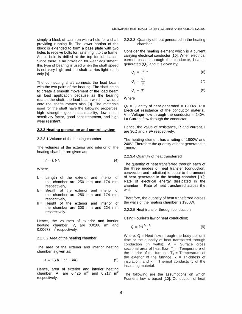
3. RESULTS AND DISCUSSION Experimental creep tests were carried out on Polytetrafluoroethylene (Teflon) specimen with a cross sectional diameter of 16 mm, gauge length of 65 mm and an overall length of 145 mm. The experiment carried out was of two types; Constant load at varying temperature and Constant temperature at varying load.
3.1 Constant Load at Varying Temperature Experiment
Three sets of experiments were conducted under this type. A load of 2 kg (0.58MPa) was made to act on the specimen at varying temperatures of 80°C, 100°C, and 120°C.
Fig. 7. Creep curves for Teflon at constant load of 2 kg (0.58MPa) and varying temperatures of 80°C, 100°C and 120°C
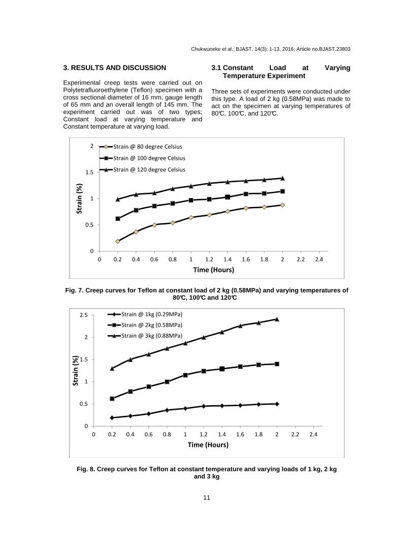
Fig. 8. Creep curves for Teflon at constant tempera ture and varying loads of 1 kg, 2 kg and 3 kg
0
0.5
1
1.5
2
0 0.2 0.4 0.6 0.8 1 1.2 1.4 1.6 1.8 2 2.2 2.4
Str
ain
(%
)
Time (Hours)
Strain @ 80 degree Celsius
Strain @ 100 degree Celsius
Strain @ 120 degree Celsius
0
0.5
1
1.5
2
2.5
0 0.2 0.4 0.6 0.8 1 1.2 1.4 1.6 1.8 2 2.2 2.4
Str
ain
(%
)
Time (Hours)
Strain @ 1kg (0.29MPa)
Strain @ 2kg (0.58MPa)
Strain @ 3kg (0.88MPa)

Chukwuneke et al.; BJAST, 14(3): 1-13, 2016; Article no.BJAST.23803
12
Fig. 7 shows the Creep Curves for Teflon at constant load of 2 kg (0.58MPa) and varying temperatures of 80°C, 100°C and 120°C within a time interval of two hours. These Creep curves show excellent agreement with experimentally determined data using stress relaxation tests [12]. A clear observation of the three plots show that an increase in temperature at constant load for a given period of time produces more extension; hence an increase in the strain and also causes a decrease in creep rate. The slope
of each curve is the creep rate hCiCBj for that
particular curve. A clear observation shows that the steady state creep decreases gradually as temperature increases. 3.2 Constant Temperature at Varying
Load Experiment Three sets of experiments were conducted under this type. Loads of 1 kg, 2 kg and 3 kg were made to act on the specimen at constant temperature of 100°C. Fig. 8 shows the Creep Curves for Teflon at constant temperature of 100°C and varying load of 1 kg (0.29MPa), 2 kg (0.58MPa), and 3 kg (0.88MPa) within a time interval of two hours. These Creep curves show excellent agreement with experimentally determined data using stress relaxation tests [12]. A clear observation of the three plots show that an increase in load (stress) at constant temperature for a given period of time produces more extension; hence an increase in the strain and also causes an increase in the creep rate. The slope of each curve is the creep
rate hCiCBj for that particular curve. A clear
observation shows that the steady state creep increases gradually as the applied load (stress) increases. 4. CONCLUSION The aim of this work which is to design and construct a tensile creep testing machine that would be used to perform simple creep tests on Polytetrafluoroethylene (Teflon) has not only been achieved but also this apparatus can also be produced locally using available materials. Tests conducted with this machine were found reliable and the results did not deviate so much from standard results. Creep tests were carried out on Polytetrafluoroethylene (Teflon) test-piece of overall length of 145 mm, gauge length of 65 mm
and cross sectional diameter 16 mm; results obtained were in agreement with what is obtainable in practice. The testing machine now provides additional testing facilities for engineering students to carry out creep test on thermoplastic materials, aluminum and lead in the department of mechanical engineering laboratory of any university. It must be noted that the creep test machine must not be used for materials that take very high time to creep like metals with very high melting temperature. The creep testing machine developed in this work has proven to be satisfactory and cost effective. COMPETING INTERESTS Authors have declared that no competing interests exist. REFERENCES 1. Momoh JJ, Ajueyitsi ONA, Onipede AIM.
Development of a low cost mechanically operated tensile and creep testing machine. Journal of Engineering and Applied Sciences. 2008;491-495.
2. Trantina GG, Ysseldyke DA. An engineering design system for thermoplastics, proceedings of society of plastics engineers. Technical Conference. 2001;635-639.
3. Evans HE. Mechanisms of creep fracture. Elsevier Applied Science Publishers, New York. 2000;16–24.
4. Shen Y. The rate of creep deformation, a dissertation submitted for the degree of master of philosophy. Department of Materials Science and Metallurgy, St Edmund’s College, University of Cambridge, Cambridge. 2003;25-28, 42-58, 69-81.
5. Wikipedia. Creep (deformation). Wikipedia; Online Free Encyclopedia; 2011. Available:http://en.wikipedia.org/wiki/Creep_%28deformation%29 Retrieved on 27-9-2015 and last modified on the website on 02-07-2012.
6. Flinn RA, Paul KC. Trojan Engineering Materials Science. 4th edition. Houghton Mifflin Company: Boston, MA. 2004;27–31.
7. Xia Z, Ellyin F. An Experimental study on the effect of prior plastic straining on creep behavior of stainless steel. Journal of Engineering Materials and Technology. 1993;200-205.
8. Gedney RA. Tensile testing basics. Tips and trends quality test and inspection

Chukwuneke et al.; BJAST, 14(3): 1-13, 2016; Article no.BJAST.23803
13
ADMET Inc Norwood MA. 2005;56-66, 71-88.
9. Khurmi RS, Gupta JK. A textbook on machine design. Eurasia Publishing House (Pvt.) Ltd. Ram Nagar, New Delhi-110 055. 2005;56, 58, 62, 71, 114, 437.
10. Rajput RK. Heat and mass transfer. Revised edition. Chand S. 2000;13, 14, 18, 19, 38, 45, 506 and 538.
11. American Society of Testing Materials International Handbook. Standard Test Methods for Tension Testing of Metallic Materials, 100 Barr Harbor Drive, West Conshohocken, United State. 2004;14-17.
12. Woodford DA, Grzywinski GG. Creep analysis of thermoplastics using stress relaxation. Journal of Polymer Engineering and Science. 1995;35(24):1931-1937.
_________________________________________________________________________________ © 2016 Chukwuneke et al.; This is an Open Access article distributed under the terms of the Creative Commons Attribution License (http://creativecommons.org/licenses/by/4.0), which permits unrestricted use, distribution, and reproduction in any medium, provided the original work is properly cited.
Peer-review history: The peer review history for this paper can be accessed here:
http://sciencedomain.org/review-history/13099