
Experimental and Numerical Study of Semi-displacement ...
16
Deift University of Technology Ship Hydromechanics laboratory Library Mekelweg 2 26282 CD Deift Phone: +31 (0)15 2786873 E-mail: p.w.deheer©tudelft.nl Experimental and Numerical Study of Semi-displacement Mono-hull and Catamaran in calm water and incident waves C. Lugni', A. Colagrossi', M. Landrini', O.M. Faltinsen2 (1INSEAN, The Italian Ship Model Basin, Roma - Italy, 2 Centre for Ships and Ocean Structures, NTNU, Trondheim - Norway) ABSTRACT There is a broad variety of high-speed vessels. In the present work, the attention is focused on semi displace- ment mono-hulls and catamarans both in calm water and in incident head sea waves. Experimental and nu- merical studies have been performed to investigate the main features of the flow pattern near the bow, along the vessel and downstream the transom. In the steady model tests, the Froude number has been varied in a wide range and the interaction between the two catamaran demi-hulls was studied by compar- ing the related flow field with the one generated by a mono-hull identical to a catamaran demi-hull. The ex- periments data have been compared with results of lin- ear 3D and nonlinear 2D+t computations. In the mono- hull case, for ship-length Froude number smaller than 0.6 the former capture the phasing of the wave pattern and give more reliable quantitative information. At hi- gher speeds, the latter agree better with the measure- ments. This is due to two factors: the transverse waves become less relevant and the importance of nonlinear- ities increases. In the catamaran case, the same trend is observed but the 2D+t theory gives globally the best agreement at smaller speeds than for the mono-hull. For both the models, the linear code is not able to predict the stern flow correctly at ship-length Froude equal or greater than about 0.5. This is because, from this value on. experimentally the transom stern stays dry during the vessel motion. The 2D+t method was used to ana- lyze the mechanisms driving the transom flow field and the interaction between the demi-hulls. In the unsteady experiments, different wave am- 25th Symposium on Naval Hydrodynamics St. John's, Canada, 8-13 August2004 plitudes and vessel speeds have been considered and the incoming wave frequency was varied in the heave and pitch resonance range. This study highlighted the effect of nonlinearities on the mono-hull and catamaran flow patterns and showed the relevance of the interaction be- tween steady and unsteady flows on the wave induced body motions. Such investigation was performed by combining in a synergic manner the experimental data with 3D linear computations. For the considered speeds and within the resonance range, the measured mean trim and sinkage of the catamaran are mainly governed by the steady flow. INTRODUCTION The design features of high-speed vessels in use can be very different. The vessel weight can be supported by submerged hulls, hydrofoils, air cushion, or a combina- tion of these effects. Cavitation and ventilation on foils, struts and propulsors limit the speed. Mono-hulls and catamarans, often equipped with foils, trim tabs andlor interceptors to minimize wave induced motions, repre- sent nowadays the most popular concepts. Catamaran designs include the wave-piercing and semi SWATH (Small Water-plane Area Twin Hull) style hulls. A mono- hull with the same displacement as a catamaran is char- acterized by a lower wave induced vertical acceleration since its larger length is beneficial from this point of view. The beam-to-draught ratio B/D of high-speed mono-hulls may vary from around 5 to values larger than 7. Large B/D values result in more limited accel- erations in heave and pitch motions. Faltinsen (1990). However the roll motions of monohulls need special at- tention. A SWATH vessel has higher heave and pitch
-
Upload
khangminh22 -
Category
Documents
-
view
1 -
download
0
Transcript of Experimental and Numerical Study of Semi-displacement ...

Deift University of TechnologyShip Hydromechanics laboratory
LibraryMekelweg 2 26282 CD DeiftPhone: +31 (0)15 2786873E-mail: p.w.deheer©tudelft.nl
Experimental and Numerical Study of Semi-displacementMono-hull and Catamaran in calm water and incident waves
C. Lugni', A. Colagrossi', M. Landrini', O.M. Faltinsen2
(1INSEAN, The Italian Ship Model Basin, Roma - Italy, 2 Centre for Ships andOcean Structures, NTNU, Trondheim - Norway)
ABSTRACT
There is a broad variety of high-speed vessels. In thepresent work, the attention is focused on semi displace-
ment mono-hulls and catamarans both in calm waterand in incident head sea waves. Experimental and nu-merical studies have been performed to investigate themain features of the flow pattern near the bow, along thevessel and downstream the transom.
In the steady model tests, the Froude number hasbeen varied in a wide range and the interaction betweenthe two catamaran demi-hulls was studied by compar-ing the related flow field with the one generated by amono-hull identical to a catamaran demi-hull. The ex-periments data have been compared with results of lin-ear 3D and nonlinear 2D+t computations. In the mono-hull case, for ship-length Froude number smaller than0.6 the former capture the phasing of the wave patternand give more reliable quantitative information. At hi-gher speeds, the latter agree better with the measure-ments. This is due to two factors: the transverse wavesbecome less relevant and the importance of nonlinear-ities increases. In the catamaran case, the same trendis observed but the 2D+t theory gives globally the bestagreement at smaller speeds than for the mono-hull. Forboth the models, the linear code is not able to predictthe stern flow correctly at ship-length Froude equal orgreater than about 0.5. This is because, from this valueon. experimentally the transom stern stays dry duringthe vessel motion. The 2D+t method was used to ana-lyze the mechanisms driving the transom flow field andthe interaction between the demi-hulls.
In the unsteady experiments, different wave am-
25th Symposium on Naval HydrodynamicsSt. John's, Canada, 8-13 August2004
plitudes and vessel speeds have been considered and theincoming wave frequency was varied in the heave andpitch resonance range. This study highlighted the effectof nonlinearities on the mono-hull and catamaran flowpatterns and showed the relevance of the interaction be-tween steady and unsteady flows on the wave inducedbody motions. Such investigation was performed bycombining in a synergic manner the experimental datawith 3D linear computations. For the considered speedsand within the resonance range, the measured mean trimand sinkage of the catamaran are mainly governed bythe steady flow.
INTRODUCTION
The design features of high-speed vessels in use can bevery different. The vessel weight can be supported bysubmerged hulls, hydrofoils, air cushion, or a combina-tion of these effects. Cavitation and ventilation on foils,struts and propulsors limit the speed. Mono-hulls andcatamarans, often equipped with foils, trim tabs andlorinterceptors to minimize wave induced motions, repre-sent nowadays the most popular concepts. Catamarandesigns include the wave-piercing and semi SWATH(Small Water-plane Area Twin Hull) style hulls. A mono-hull with the same displacement as a catamaran is char-acterized by a lower wave induced vertical accelerationsince its larger length is beneficial from this point ofview. The beam-to-draught ratio B/D of high-speedmono-hulls may vary from around 5 to values largerthan 7. Large B/D values result in more limited accel-erations in heave and pitch motions. Faltinsen (1990).However the roll motions of monohulls need special at-tention. A SWATH vessel has higher heave and pitch

natural periods and generally lower vertical excitationloads than a similarly sized catamaran. On the otherhand, if control surfaces are not introduced, a thresh-old Froude number exists beyond which the SWATH isdynamically unstable in the vertical plane. When oper-ating in head-sea conditions, its seakeeping behaviour isbetter than the one of a corresponding catamaran. How-ever, if the sea state, speed and heading cause resonantvertical motions, the SWATH may not have a good sea-keeping behaviour. Surface Effect Ships (SES) use anair cushion mechanism to obtain the desired cruise ve-locity and performances. The excess pressure in the aircushion between the two SES hulls lifts the vessel andcarries about 80% of its weight. On the other hand, itreduces the metacentric height and causes wave genera-tion and additional wave resistance. However, the totalcalm water resistance is smaller than the one of a cata-maran of similar dimensions. A drawback with an SESis that it can suffer more speed loss in waves than forinstance a catamaran. Further, the skirts in the how ofan SES are easily worn out. Trimarans and pentamaranswith a large center hull combined with smaller outriggerhulls represent interesting new concepts.
In the case of mono-hulls and catamarans, com-prehensive experimental studies have been performedby Molland et al. (1995) in calm water conditions. Themodel tests showed that the forward speed effect ontrim and sinkage starts to be significant at a ship-lengthFroude around 0.35. This has important consequenceson the vessel performances since trim and sinkage aredirectly connected with the resistance and matter alsofor the wetdeck slamming on multi-hull vehicles. Doc-tors (2003) conducted calm water tests on five differenttransom-stern mono-hull models to investigate the tran-sition from wet to dry transom. A dry transom is gen-erally beneficial and affects the trim and rise as well asthe damping of vertical ship motions. The author identi-fied the transom-draft Froude number as the parametergoverning such transition. Keuning (1988) performedhigh-speed mono-hull experiments in calm water andhead sea waves and analyzed the wave elevation nearthe vessel and the variation of the hydrodynamic co-efficients along the ship hull. Forced heave and pitchmodel tests on a high-speed catamaran were presentedin Ohkusu and Faltinsen (1991). A weak interaction be-
tween the demi-hulls was suggested by the fairly goodagreement of the measured hydrodynamic forces withnumerical 2D+t results based on the assumption of hy-
drodynamically independent demi-hulls.
The numerical studies of wave resistance andwave induced ship motions on mono-hulls and catama-
rans are mainly based on the assumptions of incom-pressible fluid in irrotational motion. The solution ofthe more general unsteady Navier-Stokes Equations isstill in its infancy and the use of Reynolds AveragedNavier-Stokes equations would lead anyway to uncer-tainties in the turbulence modeling. Linear wave resis-tance analyses based on the Michell's thin-ship theory(Michell 1898) and accounting for the transom effecthave been presented by different researchers (i.e. Mol-land et al. 1994. and Doctors and Day 1997). The de-veloped methods have been applied to high-speed mono-and multi-hull vessels. In the latter case, the diffrac-tion of the waves generated by one demi-hull due to thepresence of the other demi-hull is not accounted for, i.e.the waves generated by the separated hulls are simplysuperimposed. This type of analysis is very efficientand important at a pre-design stage. However, the roleplayed by the nonlinearities becomes more and morerelevant as the Froude number increases. The same istrue for the interaction between steady and unsteadyflows when the seakeeping is of concern. In principlethree-dimensional effects should be accounted for. Sev-eral numerical codes exist handling them properly forthe linear seakeeping case. However, the solution ofthe fully nonlinear three-dimensional problem is chal-lenging from the numerical and CPU time requirementspoints of views. In terms of nonlinear effects, sim-plifications are often made, for instance, by includingnonlinearities associated with hydrostatic and Froude-Kriloff loads. In terms of three-dimensional effects,rather accurate approximate solutions may be obtainedby using physical considerations. This is based on thatdivergent waves dominate for a semi displacement ves-sel in deep water. The main 3D effects can thereforebe adequately captured by using a 2D+t (also referredto as 2.5D) theory. In this case the longitudinal flowvariations are assumed smaller than the transverse ones,leading to a sequence of 2D problems in the ship cross-planes. The 3D information travels one way only, thatis the solution in each cross-plane is influenced just bythe flow upstream. Faltinsen (2001) pointed out the rel-evance of 3D flow effects in the close vicinity of boththe bow and the transom stern. These aspects representa limitation for the 2D+t theory since this one assumesthat both velocity potential and free-surface elevation
are zero at the bow and it is not aware of what happensdownstream. The latter implies a predicted pressure atthe transom stern different from the atmospheric value.These considerations are also relevant in unsteady flowconditions. Fontaine et al. (2000) accounted for thebow wave elevation by combining a 3D bow model withthe 2.5D theory. A domain decomposition method (seei.e. Greco et al. 2002) can be introduced to couplea global 2D+t modeling with a local 3D analysis forthe description of the transom-stern flow. The samestrategy can also be applied to handle other phenom-ena characterized by three-dimensional flow features,i.e. the water on deck and the wetdeck slamming. Ifthe water-hull interaction is not characterized by partic-ularly small angles between the impacting free surfaceand the hull, slamming loads can be modeled as an in-tegrated part of the analysis. Otherwise local hydroe-lasticity will matter. In this case it is not practical totreat the slamming phenomenon within the global anal-ysis due to the very different time scales involved. Ob-viously, the global elastic effect of the slamming mustbe included in the global analysis to describe properlythe occurrence of whipping. Springing. i.e. steady-statewave induced global resonant hydroelastic vibrations,may be a relevant fatigue issue for larger high-speedvessels. Since the natural frequencies are high, head seaare of major concern in this context. Springing may beexcited by linear and nonlinear wave effects. The lin-ear wave excitation corresponds to small incident wavelengths relative to the ship length. The spatial oscilla-tions of head-sea waves cause strong variations of theflow in the longitudinal ship direction. As a result, inthis case a 2D+t theory is not suitable.
Still many mechanisms are not fully understoodand quantified. For instance the relevance of nonlineareffects including the interactions of the steady and un-steady flows. The study of such aspects is more chal-lenging for the catamarans where the interaction be-tween the demi-hulls represents an additional factor en-tering the problem. Present research work aims to amore clear picture of the flow features and of the sea-keeping properties of these vehicles. Consequently adedicated experimental investigation of the effect of thevessels forward speed has been carried out both in calmwater and in incident head sea waves by using a mono-hull and a catamaran model. Several Froude numbers,wave amplitudes and wave frequencies have been se-lected. The mono-hull geometry is used to analyze the
interaction between the demi-hulls of the catamaran.Therefore it has been shaped identically to a demi-hull.implying a much smaller beam-to-draught ratio than theone characterizing the usual mono-hull high speed ves-sels. Detailed measurements of the steady and unsteadywave-field features have been made both along the hulland downstream the transom stern. Also the flow areabetween the two demi-hulls of the catamaran was stud-ied. The experiments have been compared with nonlin-ear 2D+t and linear 3D Rankine Panel Method compu-tations. The results confirmed the relevance of a non-linear flow description and the validity of a parabolizedapproach in case of sufficiently large Froude numbers.In the next two sections the mathematical models usedfor the numerical computations are described. Section3 deals with the experimental set-up. A numerical andexperimental study for monohulls and catamarans insteady conditions is then reported in Section 4. Finallyin section 5 the unsteady motion of the catamaran inwaves is considered.
i 2D+t THEORY
The 2D+t theory leads to a sequence of 2D problems tobe solved in the transverse cross-sectional planes of thevessel. The 3D effects are partially accounted for sincethe generic cross-section is influenced by the flow in theupstream cross-sections of the hull. The nonlinearitiesof the problem are retained. For vertical ship motionsand steady symmetric flows (straight coarse), this ap-proach is suitable at sufficiently large Froude numbers,let us say larger than 0.4, so that the ship transversewave system is not dominating. For horizontal wave in-duced motions and steady antisymmetric flows (maneu-vering), the transverse waves are less important also atsmall Froude numbers, i.e. the 2D+t theory can be usedfor Froude number smaller than 0.4. Faltinsen and Zhao(1991) used the 2.5D method to study the ship motionsof high speed mono-hulls. Nonlinear steady and lin-ear unsteady analyses were considered and the interac-tion between steady and unsteady flows was accountedfor. Maruo and Song (1994) retained also the nonlin-earities in the unsteady problem but assumed linear in-cident waves. In our case, the 2D+t theory is applied toinvestigate the steady flow patterns for mono-hulls andcatamarans. In the latter case the interaction betweenthe demi-hulls is accounted for. No correction of thelocal flows at the bow and at the transom stern is intro-

duced. Damping foils, trim tab and interceptors are notmodeled. In the following the solution method is brieflyoutlined under the assumptions of inviscid steady flowinduced by a ship with constant forward speed and fixedtrim and sinkage.
Figure 1: Qualitative sketch of the 2D+t approxima-tion for the steady three-dimensional flow around a shipwith constant forward speed U. Left: 3D ship problem.Right: equivalent unsteady 2D problem (2D+t).
Let us consider a ship moving with constant ve-locity U (see left sketch in Figure 1). We assume abeam-to-draft ratio B/D 0(1) and both B and Dindividually much smaller than the ship length L. sayr = B/L, D/L « 1. We also assume the Froude num-ber Fr = U//L = 0(1). In a ship-fixed frameof reference, the hull geometry is given implicitly asN(x, y, z) = O and the a priori unknown free surfacecan be represented as )'V(x, y, z) = z - (xx, y) = O.Assuming that the fluid is in irrotational motion, theflow field is described by the Laplace equation com-bined with the kinematic hull (7-1) boundary condition
VVN=O (1)
and the kinematic and dynamic free surface (W) bound-ary conditions
VVW=O and p=O (2)
respectively. The statement of the problem is completedby the upstream radiation condition
Ux as x p (3)
It is convenient to formulate the problem in terms of theperturbation potential , linked to 1 by 4 = Ux +
. The longitudinal gradient /3x can be neglectedwith respect to those in the transverse plane. There-fore, the problem for reduces to a sequence of two-dimensional problems in the ship cross planes. The re-lated boundary conditions imply the generic cross plane
ì2D is influenced by the upstream solution and unaware
of the following cross sections. The problem sequencecan be solved once given the conditions at the bow and
the far-field behavior of the solution at each hull crosssection. In a fixed frame of reference with respect tothe unperturbed fluid the problem can be re-written as atwo-dimensional time-dependent problem. This is fullyequivalent to the unsteady problem of the free-surfaceflow generated by a body deforming in time (see rightsketch in Figure 1). Consistently, the resulting approx-imation is called here 2D+t. The 2D unsteady prob-lem is solved through the Mixed Eulerian Lagrangianmethod (Longuett-Higgins and Cokelet 1 976, Faltinsen1977. and originally suggested by Ogilvie 1967), thatis the problem is split in a kinetic and a time evolutionstep. The kinetic problem for is solved by means ofthe Green's second identity used as integral representa-tion of the velocity potential. Applying the latter at thedomain boundary leads to an integral equation for theunknown boundary data 5z/3n and , on the free sur-face and body boundary, respectively. The continuityof the velocity potential is enforced at the intersectionpoints between the body and the free surface. A Bound-ary Element Method (BEM) with linear shape functionsfor the geometry and boundary data is then introduced.The relevant integrals are computed analytically, andafter some manipulations the discretized integral equa-tions lead to a system of linear algebraic equations forthe unknowns at the collocation points. The system in-fluence matrices are only dependent on the geometry ofthe problem. In the time evolution step, the free-surfaceboundary conditions, expressed in a Lagrangian form,and the body velocity are integrated in time to providethe new boundary configuration and related data for thenext time instant. The time stepping is performed by afourth-order Runge-Kutta method. The discretization ofthe free surface is controlled through numerical regrid-ding and the grid refinement is adapted to the evolutionof the solution. If the angle between the body and thefree surface becomes too small, the jet-like flow createdis partially cut to avoid numerical errors (cf Zhao andFaltinsen 1993). Unphysical reflection of the outgoingwaves is prevented by using a damping layer technique(for short waves) and a panel stretching (for longer wavecomponents) toward the edges of the computational do-main. Invariance of the solution under mesh refinementand size changes of the computational domain has beenwidely checked. Since a BEM is used, bow wave post-
breaking phenomena cannot be studied. The breakingis limited by cutting off the jet flow in the plunging bowwaves. This is not believed to be an important error
Free Swface(x)
nek/Thd) Seeth,,. (e) d/dl.p=eone
NH,,IIS,rth,.,(,.c UJJ

source.
2 LINEAR 3D METHOD
In our analysis of the steady and unsteady mono-hulland catamaran flows, we used a linear 3D method as ad-ditional numerical instrument. In the following its fea-tures are briefly outlined, for more details see i.e. Nakos(1990).
We consider the free-surface flow generated bya ship advancing at constant forward speed U in reg-ular incoming waves. The problem is solved by us-ing the potential flow theory and neglecting the non-linearities connected with the wave-body interactions.In case of vessels with transom stern, the latter is con-sidered always wet. The total velocity potential of thefluid is decomposed as the sum of the steady and un-steady wave fields, the latter consisting of the incident,the diffraction and the radiation waves. Then the prob-lem is split into eight sub-problems: one steady andseven unsteady. Assuming small amplitude of the inci-dent waves and ship motions, we linearize the free sur-face conditions for the unsteady problems around thesteady free surface. Then a further linearization is per-formed. Two alternatives are considered: the Double-Model (DM) and the Neuman-Kelvin (NK) lineariza-tion (see i.e. Nakos 1990). These are, respectively, alow-speed and a slender-body approximation. In thisway, the free-surface boundary conditions can be trans-fered on the undisturbed free surface and the steady andunsteady problems may be solved separately. Once thisis accomplished, the pressure can be evaluated from theBernoulli's equation. Its integration over the ship sur-face furnishes the added mass and damping coefficients,the restoring forces and the wave exciting forces. Therestoring terms are due to both the hydrostatic pressureand the steady hydrodynamic pressure. The ResponseAmplitude Operator (RAO) is obtained by coupling thefluid dynamic problem with the body motion throughthe hydrodynamic loads. Finally, the steady wave pat-tern and the radiation and diffraction waves are calcu-lated from the related kinematic free-surface conditions.
Here both the steady and unsteady potentials arerepresented in terms of source distributions on the body7-/ and the free siirfare W The nrnhle.m is then snlved
system of algebraic equations for the unknown sourcestrengths at the collocation points. The collocation po-ints on 7-/ are placed at the centers of the correspondingpanels. The same is made for those along the free sur-face but additionally they are rigidly shifted one paneldownstream in order to enforce numerically the radi-ation condition (see i.e. Bertram 1990). In practice,this numerical radiation condition is valid only for r =Uw/g> 0.25, when waves do not propagate upstreamthe ship. Here We is the encounter circular frequency.An important task is represented by the evaluation ofthe rn terms in the body boundary conditions for theradiation problems. They represent the interaction withthe steady flow and their estimate can lead to relevantnumerical errors. Therefore the Tn- terms are often ne-glected. Here, in the DM case, they are estimated byusing an extrapolation procedure for the velocity gra-dient on the body boundary. In the NK case the effectof the local steady flow is not incorporated in the rnterms and the evaluation of the non-zero rn terms isstraightforward.
3 EXPERIMENTAL SET-UP
A dedicated and comprehensive experimental investi-gation has been performed to analyze the steady andunsteady behaviour of semi-displacement mono-hul Isand catamarans. A catamaran model was built con-sistently with the geometric ratios normally used forsemi-displacement catamarans. The main characteris-tics are reported in table 1. The same parameters havebeen considered for the mono-hull geometry coinciding
therefore with a catamaran demi-hull. This leads to ashape finer than those of the existing semi-displacementmono-hulls. The experimental activity has been car-ried out at the INSEAN basin No. 2: 220 m long, 9 mlarge and 3.6 m deep. During the tests, each model wastowed by the carriage through a constant force mecha-nism. Trim and sinkage were free while the center ofrotation was fixed to the center of gravity of the vessel.The model tests reproduced two main conditions: for-ward motion in calm water and in head sea waves. In the
former case, several Froude numbers have been inves-tigated for the mono-hull geometry: Fr = U//L =0.3 - 0.8 with a step iFr = 0.1. A smaller number of

Figure 2: Body plan of the demi-huit and hydrostaticproperties. 2p indicates the distance between the cen-trelines of the catamaran demi-hulls, cf Figure 3.
the hull. This was composed by an array of 40 trans-ducers placed transversally to the basin. The distancebetween two consecutive wave probes was 4 cm. Torefine the grid of measure each run was repeated shift-ing the sensor array of 2 cm transversally to the vesselaxis. With this set-up. the wave field has been recordedwithin a lateral distance of 0.5L from the model hull. Avery detailed picture of the steady wave pattern has beenachieved, also including the area between the two demi-hulls in the catamaran case. Figu-re 3 gives a sketch of
L-4m
X =6.25L =25 mLCG = 1.7 mKG =3 m
= 0.26 LT =2 mBWL = 175m2p =5 mA =40.48m
Figure 3: Sketch: top view of the wave probes (indi-cated by the dots) used along the external profile of acatamaran demi-huIt and along the vessel central axis.
the wave probe arrangement along the external profileof a catamaran demi-hull and along the vessel centralaxis. The external probes were placed to follow the shipprofile at a distance of 3 cm from the hull. The sensorswere fixed to the carriage and therefore moved with thevessel forward speed. The same wave probe locations
as those used to measure the external wave pattern ofthe catamaran have been considered for the mono-hull.
In the tests in waves, experimental transfer func-tions in heave and pitch were estimated both by a tran-sient test technique and regular waves of different steep-nesses. More in detail, Response Amplitude Operators(RAO) have been determined preliminarily by a tran-sient test technique. In this way the frequency rangecharacterizing the resonance area of heave and pitchmotions has been identified. Then, for this range of fre-quencies. tests have been carried out in regular head seawaves with different steepnesses and considering seve-ral Froude numbers. Also in this case we measured thewave profile along the hull and the centreplane of thecatamaran.
Our studies are of fundamental nature and par-ticular care has been taken in performing a dedicatederror analysis; for instance each test condition was re-peated between 5 and 10 times to ensure repeatability.The error analysis did not investigate the error bias butjust the precision error. Results of such study will bediscussed in the following sections for some variablesof interest. Due to space limits the unsteady investiga-tion will be presented for the catamaran only.
4 DISCUSSION: STEADY CASE
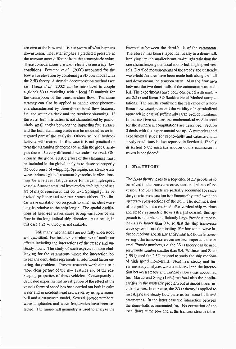
Systematic calm water experiments have been carriedout for both the mono-hull and catamaran models. Suchstudy aimed to a better understanding of the steady wavepattern features and to verify the validity and limits ofthe numerical methods presented in sections 1 and 2.The NK linearization is used for the linear 3D (3D RPM)results, that is the basis steady flow is assumed givenjust by the uniform flow due to the ship speed. The re-sults of the repeatability analysis for the model tests arereported by presenting the experiments as mean mea-sured values and error bars. The latter are given as+a, with a the standard deviation. The wave profilesalong the mono-hull are presented in figure 4 for twoselected Froude numbers, respectively, Fr = 0.5 (top)and Fr = 0.7 (bottom). Numerically the wave eleva-tion was calculated following the ship profile at a dis-tance of 3 cm from the hull. This was made to be con-sistent with the measurements (see section 3). Globallythe agreement between the experiments and the numer-ical results is satisfactory. Locally large discrepancies
0.8
-0.8
1.6
-1.6
-d.42.21
-0.2 01.28 0.99
020.84
102
04 x/L0.74 Fr,
Figure 4: Wave profile along the mono-hull forFr = 0.5 (top) and Fr = 0.7 (bottom). Experiments(symbols: mean value and error bar) and numerical re-suits obtained by the 3D RPM (dashed line) and 2D+t(solid line) methods. Fr = U/J, with x the longi-tudinal distance from the bow.
can be detected in the bow area between the model testsand the 2D+t theory at the smaller Froude number. Theformer predict a negative wave elevation, the latter gives
a quite large free-surface rise along the hull. This dis-agreement can be partially explained by ventilation ofthe sensors in the bow area. Such phenomenon impliesan underestimated wave elevation since the probes staymore dry than they should be. This is indirectly con-firmed by a larger experimental error bar near the bow.The two results fit quite well at the larger speed. In
this case, the 2D+t model is able to capture the bowsplash phenomenon. The stern wave disturbance is pre-dicted correctly by the nonlinear method for both thespeeds. Also at this Froude number the experimen-tal repeatability is less satisfactory in the vicinity ofthe bow, the same phenomena described for the smallerspeed are believed to be the main reason for it. The3D RPM results agree better with the experiments atthe smaller speed. when the nonlinearities are less im-portant and the three-dimensional effects are stronger.At the larger Fr the agreement is stili satisfactory but asmoother bow rise-up and a deeper trough near the sternare predicted as a consequence of the linear formula-
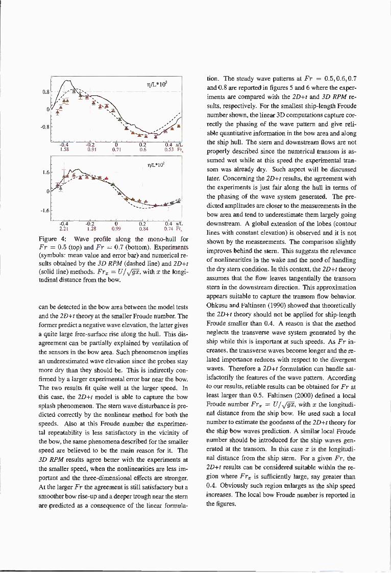
tion. The steady wave patterns at Fr = 0.5, 0.6, 0.7and 0.8 are reported in figures 5 and 6 where the exper-iments are compared with the 2D+t and 3D RPM re-suits. respectively. For the smallest ship-length Froudenumber shown. the linear 3D computations capture cor-rectly the phasing of the wave pattern and give reh-able quantitative information in the bow area and alongthe ship hull. The stem and downstream flows are notproperly described since the numerical transom is as-sumed wet while at this speed the experimental tran-som was already dry. Such aspect will be discussedhater. Concerning the 2D+t results, the agreement withthe experiments is just fair along the hull in terms ofthe phasing of the wave system generated. The pre-dicted amplitudes are closer to the measurements in thebow area and tend to underestimate them largely goingdownstream. A global extension of the lobes (contourlines with constant elevation) is observed and it is notshown by the measurements. The comparison slightlyimproves behind the stem. This suggests the relevanceof nonlinearities in the wake and the need of handlingthe dry stern condition. In this context, the 2D+t theoryassumes that the flow leaves tangentially the transomstem in the downstream direction. This approximationappears suitable to capture the transom flow behavior.Ohkusu and Faltinsen (1990) showed that theoreticallythe 2D+, theory should not be applied for ship-lengthFroude smaller than 0.4. A reason is that the methodneglects the transverse wave system generated by theship while this is important at such speeds. As Fr in-creases, the transverse waves become longer and the re-lated importance reduces with respect to the divergentwaves. Therefore a 2D+t formulation can handle sat-isfactorily the features of the wave pattern. Accordingto our results, reliable results can be obtained for Fr atleast larger than 0.5. Faltinsen (2000) defined a localFroude number Fr = with i the longitudi-nal distance from the ship bow. He used such a localnumber to estimate the goodness of the 2D+t theory forthe ship bow waves prediction. A similar local Froudenumber should be introduced for the ship waves gen-erated at the transom. In this case i is the longitudi-nal distance from the ship stern. For a given Fr. the2D+t results can be considered suitable within the re-gion where Fr is sufficiently large, say greater than0.4. Obviously such region enlarges as the ship speedincreases. The local bow Froude number is reported inthe figures.

05
-05
-05 0Fr. 071
Fr 06
05
-05
-05 0Fr .' 085
Fr=0.7
o-5
-03
-05 0Fr .- 099
Fr 0.8
05
-05
Fr = 03
J xIL fl041 022
Ezp
05 i xìL Ji0.6 049 042
os J iL Ji07 057 030
I .1 I I I
-os o os ¡ iL JiFr, 113 08 065 057
Figure 5: Contour lines of the mono-hull steady wavepattern. From top to bottom: Fr = 0.5, 0.6, 0.7 and0.8. In each plot the experiments (bottom) are com-pared with the 2D+t results (top). Fr = U/«/, withx the longitudinal distance from the bow.
05
-05
05
-05
05
-05
RPM 3D
ExperÉnts
05 RPM 3D
Figure 6: Contour lines of the mono-hull steady wavepattern. From to bottom: Fr = 0.5, 0.6, 0.7and 0.8. Ineach plot the experiments (bottom) are compared withthe 3D RPM results (top). Fr = with i thelongitudinal distance from the bow.
-05 Exs-05 0 05 J xiL Ji
Fr, 113 08 065 057
-os oFr. 071
Fr = 0.6
0505
i xiL Ji0.41 0.32
05 J xiL Ji06 0.49 042
-03 0
Fr 0.85Fr- 0.7
05 1 7JL ii07 0.57 050
-05 0Fr 099
Fr = 0.8
Globally, for Fr larger than 0.5 the 2D+t theory givesbetter results than the 3D RPM code. This is due to twofactors: the transverse waves become progressively lessrelevant and the importance of nonlinearities increases.The linear results underestimate the peaks and troughsalong the hull and in the wake. However the dimensionof the lobes of the global wave system is reproducedquite nicely while the 2D+t results show a wider exten-sion of the lobes even at the largest speed.
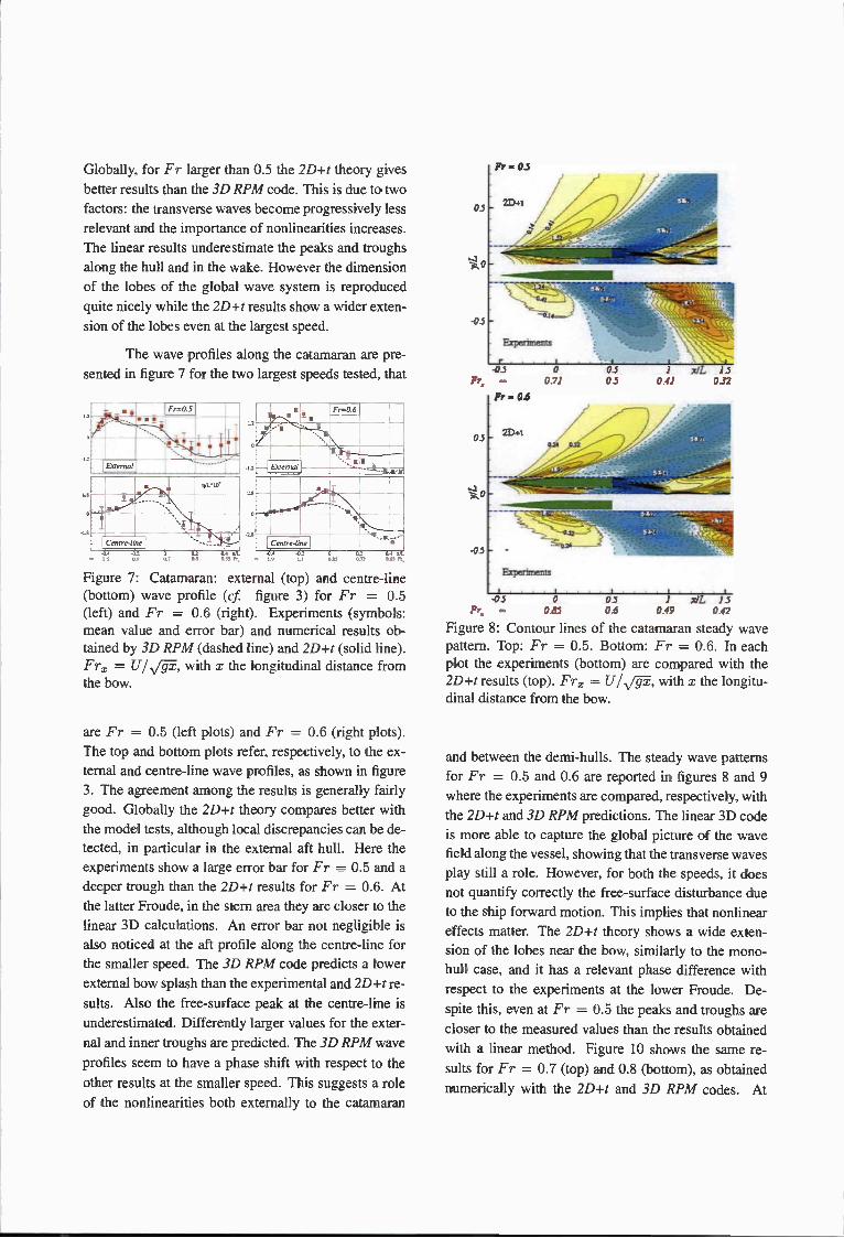
The wave profiles along the catamaran are pre-sented in figure 7 for the two largest speeds tested, that
Figure 7: Catamaran: external (top) and centre-line(bottom) wave profile (cf figure 3) for Fr = 0.5(left) and Fr = 0.6 (right). Experiments (symbols:mean value and error bar) and numerical results ob-tained by 3D RPM (dashed line) and 2D+t (solid line).Fr = U/,/gx, with x the longitudinal distance fromthe bow.
are Fr = 0.5 (left plots) and Fr = 0.6 (right plots).The top and bottom plots refer, respectively, to the ex-ternal and centre-line wave profiles, as shown in figure3. The agreement among the results is generally fairlygood. Globally the 2D+t theory compares better withthe model tests, although local discrepancies can be de-tected, in particular in the external aft hull. Here theexperiments show a large error bar for Fr = 0.5 and adeeper trough than the 2D+t results for Fr = 0.6. Atthe latter Froude, in the stern area they are closer to thelinear 3D calculations. An error bar not negligible isalso noticed at the aft profile along the centre-line forthe smaller speed. The 3D RPM code predicts a lowerexternal bow splash than the experimental and 2D+t re-sults. Also the free-surface peak at the centre-line isunderestimated. Differently larger values for the exter-nal and inner troughs are predicted. The 3D RPM waveprofiles seem to have a phase shift with respect to theother results at the smaller speed. This suggests a roleof the nonlinearities both externally to the catamaran
05
-05
Experimerns
o os J xiL JiFr 0.85 06 049 042
Figure 8: Contour lines of the catamaran steady wavepattern. Top: Fr = 0.5. Bottom: Fr = 0.6. In eachplot the experiments (bottom) are compared with the2D+r results (top). Fr = U/'7, with x the longitu-dinal distance from the bow.
and between the demi-hulls. The steady wave patternsfor Fr = 0.5 and 0.6 are reported in figures 8 and 9where the experiments are compared, respectively, withthe 2D+t and 3D RPM predictions. The linear 3D codeis more able to capture the global picture of the wavefield along the vessel, showing that the transverse wavesplay still a role. However, for both the speeds, it doesnot quantify correctly the free-surface disturbance dueto the ship forward motion. This implies that nonlineareffects matter. The 2D+t theory shows a wide exten-sion of the lobes near the bow, similarly to the mono-hull case, and it has a relevant phase difference withrespect to the experiments at the lower Froude. De-spite this, even at Fr = 0.5 the peaks and troughs arecloser to the measured values than the results obtainedwith a linear method. Figure 10 shows the same re-sults for Fr = 0.7 (top) and 0.8 (bottom), as obtainednumerically with the 2D+t and 3D RPM codes. At

these larger speeds the nonlinearities are quite impor-tant, therefore the linear results underestimate substan-tially the wave pattern. On the other hand, it is inter-esting to note that the two results agree quite well interms of phasing. This confirms the unimportance ofthe transverse waves at such Froude numbers. Top
05
-05
Fr
05
-05
Expermnts
-05 0071
Experiments
-1 t05 1 xiL 1505 041 0.32
Fr = 0 7
2D.t
05 1 zJL 150.7 057 050
.05 0 05 1 JL isFr Iii 08 0.65 0.57
Figure 10: Contour lines of the catamaran steady wavepattern. Top: Fr = 0.7. Bottom: Fr 0.8. In eachplot the 3D RPM (bottom) are compared with the 2D+tresults (top). Fr = with x the longitudinaldistance from the bow.
dry. A nonlinear BEM solver, as used in the presentstudy, was adopted to simulate the flow evolution un-til the incipient wave breaking and a Smoothed Parti-cle Hydrodynamics (SPH) method was initialized bythe BEM to handle the post-breaking evolution of thewave system. in the bottom of the figure 11, the re-sults obtained by using just the BEM 2D+t method forFr = 0.5 are given. As we can see, the 2D+t formu-lation is able to reproduce the flow scenario behind thetransom: hull hollow, rooster tail and incipient breakingdivergent wave system. Nevertheless, since the plung-ing jet is cut to avoid the occurrence of impact on theunderlying water, the energy of the wave system is fo-cused close to the crest of the divergent wave. Differ-ently, in the physical phenomenon the breaking causesa spatial spread of the wave energy. Figure 12 showsthe longitudinal wave cut along the centre-line of the
-05 0 05 J x/L 15Fr, 085 06 049 042
Figure 9: Contour lines of the catamaran steady wavepattern. Top: Fr = 0.5. Bottom: Fr = 0.6. In eachplot the experiments (bottom) are compared with the 3DRPM results (top). Fr = U/,', with x the longitu-dinal distance from the bow.
picture of figure 11 shows the experimental wave fieldbehind the transom for the mono-hull at Fr = 0.5. Thedry transom causes the formation of a hollow just be-hind the vessel. The water reaches a minimum valueand then rises to form a rooster tail developing into adivergent breaking wave system. The mono-hull tran-som flow features have been thoroughly investigated byLandrini et al. (2001) due to the practical relevanceof the resulting breaking phenomena. These lead tovortical structures responsible of the visible signatureleft downstream by the ship. In their study, the authorsused the 2D+t theory. The transom was enforced to be
05
-0.3
Fr,-05
RPM 3D
o099

0.1
-0.1
0.2 0.4 .t/LFr 1.12 0.79
Figure 11: Mono-hull: transom stern wave field atFr = 0.5. Experimental picture (top) and contour linesof the steady wave pattern predicted by 2D+r theory(bottom). Fr = U/J, with z the longitudinal dis-tance from the transom.
mono-hull transom as obtained by the 2D+r theory. Theresults show that the rooster tail height is not affected bythe Froude number while both its horizontal width andthe extension of the hollow increase with the speed. Thehollow extension can be measured as the longitudinaldistance between the transom position and the locationwhere the free surface becomes zero. The wave ele-vation downstream a catamaran demi-hull transom (seefigure 13) shows a quite different behaviour. Except forthe smaller speeds, showing an increase of the hollowextension with the Froude number, the hollow widthis not particularly affected by the speed. The roostertail height is lower than the corresponding value for themono-hull. It shows a non monotonic but rather lim-ited variation with the Froude number. This demi-hullwave behaviour behind the transom is due to the pres-ence of the other demi-hull. The arrangement of thetwo demi-hulls causes three rooster tails downstreamthe catamaran, respectively, in correspondence of thedemi-hull transom sterns and of the catamaran centre-line (cf 2Dt contour plots in figures 8 and 10).
It is important to understand if the main responsible
02 03 0.4 0.5
Figure 12: Mono-hull: cut of the steady wave patterna ong the centre-line of the transom stern. z is the lon-gitudinal distance from the transom.
S
(J J, 07 ,JL
- 6 0. ((2 0.3 0.4 07 ,./L
Figure 13: Catamaran: cut of the steady wave patternalong the centre-line of the demi-hull transom stern. zis the longitudinal distance from the transom.
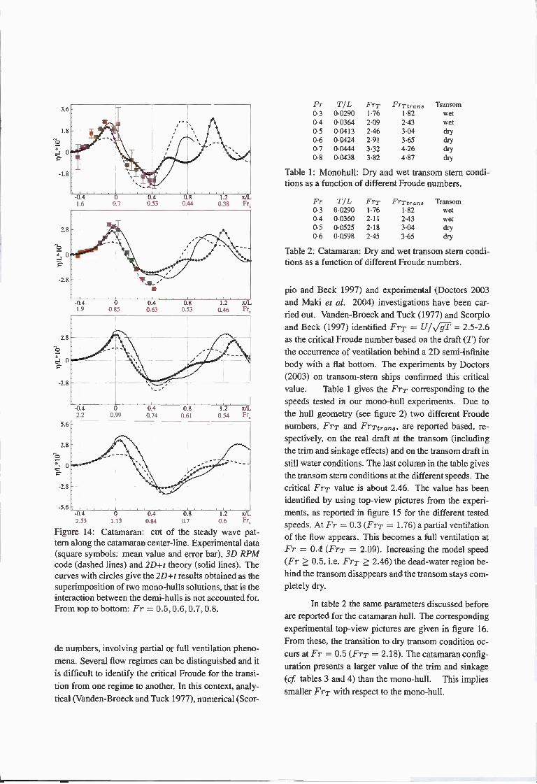
mechanisms are connected with the hydrodynamic in-teraction between the demi-hulls or if they are relatedto the demi-hulls interference only. The latter means thediffraction caused by one demi-hull on the waves gen-erated by the other demi-hull is negligible and the cata-maran wave pattern is just given by the sum of the wavefields produced by each demi-hull as if the other was notthere. To this purpose figure 14 gives the longitudinalwave cut along the centre-line of the catamaran for dif-ferent Froude numbers. The 3D RPM and 2D+t calcu-lations are presented together with the experiments (forthe tested speeds). In the plots, the curves with circlesgive the 2Dt results obtained as the superimpositionof two mono-hulls solutions, that is the interaction be-tween the demi-hulls is not accounted for but just theirinterference. From the results, the interference is not thegoverning mechanism. The interaction between the twodemi-hulls plays a fundamental role. This interactionis mainly nonlinear as evidenced both by difficulties ofthe linear solution in capturing the first peak and by thephase shifting existing between the linear and nonlinearresults accounting for the demi-hull interaction.
As previously discussed, the 2D+t model en-forces a dry transom stern condition independently from
the forward speed. In reality the flow at the transomstern can be quite complicated at sufficiently small Frou-
3.6 -
1.8
-1.8
2.8
*0
-2.8
2.8
-2.8
5.6
2.8
o
-2.8
-5.6
-d.41.6
-0.4'.9
0.7
o0.55
040.53
0.40.63
0.80.44
0.80.53
12 x0.38 Fr
1.2 x/L0.46 Fr
-0.4 0 0.4 0.8 1.2 xJL2.53 1.13 0.84 0.7 0.6 Fr
Figure 14: Catamaran: cut of the steady wave pat-tern along the catamaran center-line. Experimental data(square symbols: mean value and error bar), 3D RPMcode (dashed lines) and 2D+s theory (solid lines). Thecurves with circles give the 2Dt results obtained as thesuperimposition of two mono-hulls solutions, that is theinteraction between the demi-hulls is not accounted for.From top to bottom: Fr = 0.5,0.6,0.7,0.8.
de numbers, involving partial or full ventilation pheno-mena. Several flow regimes can be distinguished and itis difficult to identify the critical Froude for the transi-tion from one regime to another. In this context, analy-tical (Vanden-Broeck and Tuck 1977), numerical (Scor-
Table 1: Moriohull: Dry and wet transom stern condi-tions as a function of different Froude numbers.
Table 2: Catamaran: Dry and wet transom stern condi-tions as a function of different Froude numbers.
pio and Beck 1997) and experimental (Doctors 2003and Maki et al. 2004) investigations have been car-ned out. Vanden-Broeck and Tuck (1977) and Scorpioand Beck (1997) identified FTT = U/vT = 2.5-2.6as the critical Froude number based on the draft (T) forthe occurrence of ventilation behind a 2D semi-infinitebody with a flat bottom. The experiments by Doctors(2003) on transom-stern ships confirmed this criticalvalue. Table 1 gives the Fry corresponding to thespeeds tested in our mono-hull experiments. Due tothe hull geometry (see figure 2) two different Froudenumbers, Fry and FrTtraTIS. are reported based, re-spectively, on the real draft at the transom (includingthe trim and sinkage effects) and on the transom draft instill water conditions. The last column in the table givesthe transom stern conditions at the different speeds. Thecritical Fi-T value is about 2.46. The value has beenidentified by using top-view pictures from the experi-ments, as reported in figure 15 for the different testedspeeds. At Fr = 0.3(FrT 1.76)a partial ventilationof the flow appears. This becomes a full ventilation atFr = 0.4 (Fry = 2.09). Increasing the model speed(Fr > 0.5, i.e. Fry 2.46) the dead-water region be-hind the transom disappears and the transom stays com-pletely dry.
In table 2 the same parameters discussed beforeare reported for the catamaran hull. The corresponding
experimental top-view pictures are given in figure 16.From these, the transition to dry transom condition oc-curs at Fr = 0.5 (Fry = 2.18). The catamaran config-uration presents a larger value of the trim and sinkage(cf tables 3 and 4) than the mono-hull, This impliessmaller Fry with respect to the mono-hull.
Fr T/L FrT FrTtraThS Transom03 00290 176 182 wet04 00364 209 243 wet05 00413 246 304 dry06 00424 291 365 dry07 00444 332 426 dry08 00438 382 487 dry
Fr T/L FrT Frytra Transom03 00290 176 182 wet04 00360 211 243 wet05 00525 218 304 dry06 00598 245 365 dry
2.2 0.99 0.74 0.61 0.54

Figure 15: Pictures of the monohull transom sternfield. From top to bottom: Fr 0.3,0.5,0.7 (left col-umn), Fr = 0.4.0.6,0.8 (right column).
Figure 16: Pictures of the Catamaran transom sternfield. From top to bottom: Fr = 0.3,0.4, 0.5,0.6.
5 DISCUSSION: UNSTEADY CASE
A second experimental activity was dedicated to thestudy of the unsteady behaviour of the mono-hull and
Table 3: Monohull: mean value for carriage speed (U),sinkage(s) and trim (8) and related standard deviation(o).
Fr Velocity (mis) Sinkage (mm) Trim (degree)
Table 4: Catamaran: mean value for carriage speed (U),sinkage(s) and trim (9) and related standard deviation(a).
catamaran models. Preliminarily, the heave and pitchfrequency resonance ranges for Fr = 0.3,0.4 and 0.5have been identified through the transient test technique(Colagrossi et al. 2001). Then, tests in regular incom-ing waves within such range and with different waveamplitudes have been performed. Also in this case acareful error analysis has been realized. In the follow-ing the results will be discussed for the catamaran.
The RAO experimental data are presented in fig-ure 17 together with the predictions by the 3D linearRPM code. The standard deviation (a) connected withthe transient test technique is also given in the plotsshowing a good reliability of the experiments. For thenumerics both the NK and DM approximations (see sec-tion 2) are considered. The NK approach neglects theinteraction with the local steady flow. The DM accountsfor it hut not in a consistent way for a high-speed ship.The numerical results overestimate the pitch motion.For all investigated speeds. the DM linearization showsthe best agreement with the experiments. This is consis-tent with the conclusions in Bertram (1999) document-ing an important role of the interaction with the steadyflow in the wave induced body motions even at Froudearound 0.2, for a S-175 ship. A strong amplificationof the motions is generally observed near the resonancedue to a small damping level. This suggests the needof proper active control systems and foils. However itshould also be noted that the values of the wavelength-to-ship length ratio giving resonance in heave and pitchin head sea increase with the Froude number. This im-
Fr Velocity (mis)U a
Sinkage (mm)s a
Trim (degree)O a
03 1880 0001 -6189 0.110 -0010 00010.4 2510 0001 -13974 0057 0543 009305 3133 0001 -19637 0.057 1177 0.00406 3754 0.0001 -16684 0.029 1424 0.00307 4384 0.0001 -14054 0021 1348 000108 5008 0003 -12536 0.413 1328 0022
U a s a O a03 1883 00005 -8792 0.321 0025 000804 2509 00003 -21385 0072 0424 000905 3125 0006 -27062 0.223 2652 0021

2.5
03
- Tnrns, TeST Tech17 Cre-ces. Test)
O reg esveOsA=0.0125)Drrgwasr (AA = 00187)* reg, wsvr)kA=0.025(
reg wsvrIkA=0.05)Nrn. recetTe INK bese 110w)NeST, reselTs (DM bose liess)
AIL
A/L
12
lo
<9
12
6
2 A/L
I - 2 AILO
AIL
Figure 17: Catamaran: heave (, left) and pitch (9,right) Response Amplitude Operators. From top to bot-tom: Fr = 0.3,0.4,0.5. A and k = 27r/A are theregular incoming wave amplitude and wavenumber. re-spectively. A is the incoming wavelength.
.24
XIL2 3
Figure 18: Heave (o Response Amplitude Operator forthe mono-hull (dashed) and catamaran (solid) vesselsat Fr = 0.5. A and A are the regular incoming waveamplitude and wavelength, respectively.
plies that the excitation loads along the ship becomestronger in phase as Fr increases. The consequence islarger excitation loads. The experiments evidence clearnonlinear effects. The regular wave results do not showa convergence to the transient test results as the waveamplitude reduces. One possible error source is a varia-tion of the wave amplitude along the track of the model.This aspect has not been investigated. At high Froudenumbers the RAO for the pitch motion shows a doublepeak behaviour, typical for the multi-hull vessels. So itproves that it is important to account for the hull inter-action in the ship motions calculations. The RAO re-lated to the heave motion is practically unchanged withrespect to the mono-hull configuration (see figure 18).From the experiments, the mean trim and sinkage arenot influenced substantially by the incident wave steep-ness, even at a wave frequency equal to the heave andpitch resonance frequency. as shown in the left and rightplots of figure 19, respectively. It implies that they are
060 034
-24-
o
0.4 0.5 r 0.3 04 05 Fr0.40 (H, 0.55 071 047 S (H?)
Figure 19: Catamaran: mean trim and sinkage in calmwater and in regular waves. Regular waves have beengenerated with frequency u(Hz) close to the heave (,left) and pitch (9, right) resonance frequencies.
dominated by the steady flow. These results are relevantfor instance for the wetdeck slamming which is sensi-tive to the trim angle (Ge 2002). In the wetdeck slam-ming predictions it also matters an accurate estimate ofthe relative motions in the impact area. The presentedresults suggest that the theoretical methods to evaluatewave induced motions have to be improved for a betterprediction of for instance wetdeck slamming.

CONCLUSIONS
An experimental investigation has been carried out toanalyze the flow field around semi-displacement mono-hulls and catamarans both in calm water and in inci-dent head sea waves. The mono-hull model has beenshaped identically to a catamaran demi-hull to investi-gate the interaction between the demi-hulls of the cata-maran and the related influence on the rooster tail devel-oping from the transom stern. The chosen mono-hullgeometry implies a much smaller beam-to-draught ra-tio than the one characterizing the usual mono-hull highspeed vessels. A dedicated error analysis of the tests hasbeen performed confirming a general reliability of themeasurements. The physical investigation was focusedon the wave-field features at the bow, along the hulland downstream the transom stern. In the steady ex-periments, very detailed measurements of the wave pat-tern were performed for both models, including the in-ner region between the two catamaran demi-hulls. Theinfluence of the Froude number has been analyzed byvarying such parameter in a wide range. The experi-mental data were compared with the results by a linear3D RPM code and a nonlinear 2D+r method. For themono-hull, the 3D RPM simulations are able to cap-ture the wave pattern along the hull for Froude numberssmaller than 0.6. They do not succeeded in handling thestern and wake flows for Fr > 0.5. This is because awet transom is assumed while at those speeds both theexperimental mono-hull and catamaran transoms weredry. At Fr 0.6 the nonlinearities become relevantand the linear method gives only a qualitative informa-tion. The opposite trend is shown by the 2D+t results.These are not satisfactory at the smaller Froude due tothe relevance of the transverse wave pattern. For Frgreater than 0.6 they fit well with the experiments. Thestern and wake flows are properly described since a drytransom condition is enforced. For the catamaran, thesame trend is observed but the 2Dt theory gives glob-ally the best agreement at smaller speeds than for themono-hull. For both geometries this model predicts awide extension of the lobes near the bow region. This isnot observed from the measurements. The 2D+t modelhas been used to investigate the physical mechanismscausing the flow features downstream the transom, andto quantify the related influence of the interaction be-tween the catamaran demi-hulls. In the unsteady exper-iments, both a transient test technique and regular in-
coming waves have been used to simulate seaway con-ditions. The former method was applied to identify theheave and pitch resonance frequency regions. Then reg-ular incoming waves were generated within such areasof interest. This means we studied a frequency rangewhere nonlinearities matter for the wave-body interac-tions. During the tests the Froude number and the am-plitude of the incoming waves have been varied and theimportance of nonlinear effects brought into the prob-lem has been deduced. The interaction between thesteady and unsteady wave fields was studied by combin-
ing in a synergic way the information from the experi-ments with the results from a linear unsteady 3D code.The results confirmed that the interaction plays a rele-vant role and should be properly accounted for. For theconsidered speeds and within the heave and pitch res-onance ranges. the experiments showed that the meantrim and sinkage of the catamaran are mainly governedby the steady flow. This is relevant for instance for thewetdeck slamming.
ACKNOWLEDGEMENTS
Present research activity is partially supported by theCentre for Ships and Ocean Structures, NTNU. Trond-heim, within the "Green Water Events and Related Struc-tural Loads" project, and partially done within the frame-work of the "Programma di Ricerca sulla Sicurezza"funded by Ministero Infrastrutture e Trasporti.
REFERENCES
Bertram, V. Fulfilling Open-Boundary and RadiationCondition in Free-Surface Problems Using RankineSources. Ship Technology Research 37(2), 1990.
Bertram, V. Numerical ínnvestigation of steady floweffects in three-dimensional seakeeping computations.Proceedings 22th Symposium on Naval Hydrodynam-ics. Washington D.C.. USA, 1999.
Colagrossi, A., C. Lugni, M. Landrini, andG. Graziani. Numerical and experimental transienttests for ship seakeeping. mt. Journal Off. and OceanStruct., Volume 11, pp. 67-73, 2001.
Doctors, L. Hydrodynamics of the flow behind a tran-som stern. Proceedings of 29th Israel Conference onMechanical Engineering, pp. 1-11. Haifa, Israel. 2003.

Doctors, L. and A. Day. Resistance prediction fortransom-stern vessels. Proceedings of 5th International
Conferance for Fast Sea Transportation (FAST'97),Volume 2, pp. 743-750. Sydney, Australia, 1997.
Faltinsen, O. Numerical solutions of transient nonlin-ear free-surface motion outside or inside moving bod-ies. Proc. 2d mt. Conf. Num. Ship Hydr.. 1977.
Faltinsen, O. Steady and vertical dynamic behaviour ofprismatic planing hulls. Proceedings HADMAR 2001.Varna, Bulgaria, 2001.
Faltinsen, O. and R. Zhao. Numerical predictions ofship motions at high forward speed. Phil. Trans. R. Soc.Lond. A Vol. 334, pp. 241-252, 1991.
Faltinsen, O. M. Sea loads on ships and offshorestructures. Cambridge, England: Cambridge UniversityPress, 1990.
Faltinsen, O. M. Sea loads on High Speed Marine Ve-hicles. Trondheim, Norway: NTNU, 2000.
Fontaine, E., O. Faltinsen, and R. Comte. New in-sight into the generation of ship bow waves. J. FluidMech. Vol. 421, pp. 15-38, 2000.
Ge, C. Global Hydroelastic Responce of Catamaransdue to Wetdeck Slamming. Ph. D. thesis, Dept. MarineStructures, NTNU, Trondheim, Norway, 2002.
Greco, M., O. M. Faltinsen, and M. Landrini. Wa-ter Shipping on a Vessel in Head Waves. Proceedings24t Symposium on Naval Hydrodynamics, technicalsession: Slamming, Green Water and Capsizing, pp. 1-14. Fukuoka, Japan, 2002.
Hess, J. and A. Smith. Calculation of nonliftingpotential flow about arbitrary bodies. Prog. Aero.Sci. Vol. 8. pp. 1-138, 1996.
Keuning, J. Distribution of added mass and dampingalong the length of a ship model at high forward speed.Technical report. Report No. 81 7-P, Delft University ofTechnology: Ship Hydrodynamics Laboratory, 1988.
Landrini, M., A. Colagrossi, and M. Tulin. Breakingbow and transom waves: numerical simulations. l6International Workshop on Water Waves and FloatingBodies. Hiroshima, Japan. 2001.
Longuett-Higgins, M. S. and E. D. Cokelet. The de-formation of steep surface waves on water. I A numer-ical method of computation. Proc. R. Soc. London A,Volume 350, pp. 1-26, 1976.
Maki, K., A. Troesch, and R. Beck. Qualitative inves-tigation of transom stern flow ventilation. 19th Interna-tional Workshop on Water Waves and Floating Bodies.Cortona, Italy, 2004.
Maruo, H. and W. Song. Nonlinear analysis of bowwave breaking and deck wetness of a high speed shipby the parabolic approximation. Proc. 20th Symp. onNaval Hydrod. National Academy Press, 1994.
Michell, J. The wave resistance of a ship. Philosophi-cal Magazine Vol. 45, pp. 106-123, 1898.
Molland, A., J. Wellicome, and P. Couser. Theoreticalprediction of the wave resistance of slender hull formsin catamaran configurations. Technical report, ReportNo. 72, Southampton University: Ship Science, 1994,September).
Molland, A., J. Wellicome, and P. Couser. Resistanceexperiments on a systematic sense of high speed dis-plcement hull forms: Variation of length-displacementratio and breadth-draught ratio. The Royal Institutionof Naval Architects, 1995.
Nakos, D. Ship Wave Patterns and Motions by aThree Dimensional Rankine Panel Method. Ph. D. the-sis, MIT, Cambridge, 1990.
Ogilvie, T. F. Nonlinear high-Froude-number free sur-face problems. J. of Engineering Mathematics 1(3), pp.2 15-235, 1967.
Ohkusu, M. and O. Faltinsen. Prediction of radiationforces on a catamaran at high froude number. Proc.of 18th Symp. on Naval Hydrod., pp. 5-20. NationalAcademy Press, Washington D.C., USA, 1990.
Ohkusu, M. and O. Faltinsen. Prediction of radiationforces on a catamaran at high froude number. Proc.of 18th Symp. on Naval Hydrod., pp. 5-20. NationalAcademy Press, Washington D.C., USA, 1991.
Scorpio, S. and R. Beck. Two-dimensional invscidtransom stern flow. International Workshop onWater Waves and Floating Bodies. France, 1997.
Vanden-Broeck, J. and E. Tuck. Computation of near-bow or stern flows, using series expansion in Froudenumber. 2 International Conf in Num. Ship Hydro.Berkeley. California, 1977.
Zhao, R. and O. M. Faltinsen. Water entry of two-dimensional bodies. J. Fluid Mech. Vol. 243, pp. 593-612,1993.