Laminar Film Condensation From Moist Air In Vertical Tubes ...
Upload
independentCategory
view
1download
0
A
pswdifoltcipflcN©
K
1
tlpot
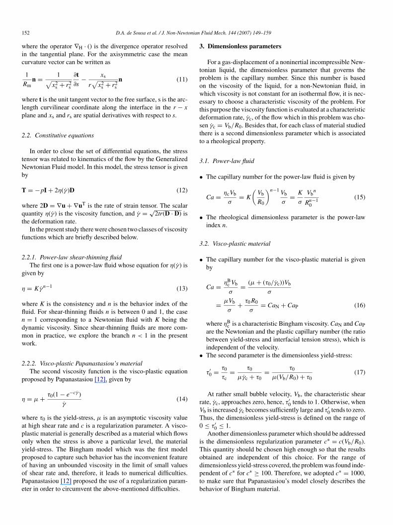
DPf
0d
J. Non-Newtonian Fluid Mech. 144 (2007) 149–159
Numerical investigation on gas-displacement of a shear-thinningliquid and a visco-plastic material in capillary tubes
Dione A. de Sousa b, Edson J. Soares a,b, Rogerio S. de Queiroz b, Roney L. Thompson a,c,∗a Grupo de Escoamento de Fluidos Complexos, Brazil
b Department of Mechanical Engineering, Universidade Federal do Espirito Santo, Avenida Fernando Ferrari 514, 29075-910 Goiabeiras, ES, Brazilc Laboratorio de Mecanica Aplicada, PGMEC, Department of Mechanical Engineering, Universidade Federal Fluminense, Rua Passo da Patria 156,
24210-240 Niteroi, RJ, Brazil
Received 23 August 2006; received in revised form 20 March 2007; accepted 20 March 2007
bstract
An elliptic mesh generation technique, with the Galerkin Finite Element Method is used to compute the free surface of the two-phase flowroblem of a gas displacing a non-Newtonian material in a capillary tube. Two classes of non-Newtonian materials were investigated: a power-lawhear-thinning liquid and a visco-plastic material with the viscosity function proposed by Papanastasiou [T.C. Papanastasiou, Flows of materialsith yield-stress, J. Rheol. 31 (1987) 385–404]. The results were given as a function of a non-Newtonian capillary number and a rheologicalimensionless parameter: the behavior index in the shear-thinning liquid case and a dimensionless yield-stress (equivalent to Bingham number)n the visco-plastic material. The goal of the present work is to study flow patterns, configuration of the interface between the two phases, andraction of the mass of non-Newtonian material deposited at the wall, as functions of the dimensionless numbers cited. Some general resultsf experimental and numerical works found in literature were reproduced with a quite good agreement and a wider range of the dimension-ess numbers was investigated. In both classes of materials studied, as the displaced fluid departs from Newtonian behavior, the fraction ofhe mass deposited on the tube wall decreases and the shape of the interface becomes flatter. It was offered a plausible explanation for thisounter-intuitive result related to visco-plastic fluid, i.e. an apparent increase of its viscosity (increasing the dimensionless yield-stress number),nduces a decrease of the layer thickness left behind. Concerning flow patterns, it was possible to identify ranges, dependent on rheologicalroperties and capillary number, where the transition between bypass flows and fully recirculating flows occurs. In the Newtonian case all the
ow patterns predicted by Taylor [G.I. Taylor, Deposition of a viscous fluid on the wall a tube, J. Fluid Mech. 10 (1961) 161–165] were wellaptured. In the visco-plastic and pseudo-plastic case it was found an interesting type of intermediate flow regime which is not present in theewtonian transition.2007 Published by Elsevier B.V.inite
aiaci
eywords: Gas-displacement; Shear-thinning liquids; Visco-plastic materials; F
. Introduction
The liquid displacement by gas injection is a phenomenonhat occurs in many industrial processes as well as in some bio-ogical flows. The enhanced oil recovery, mucus displacement in
ulmonary airways, gas assisted injection molding and coatingf catalytic converters are examples of such processes. Generallyhese two-phase flows take place inside an internal passage char-∗ Corresponding author at: Laboratorio de Mecanica Aplicada, PGMEC,epartment of Mechanical Engineering, Universidade Federal Fluminense, Ruaasso da Patria 156, 24210-240 Niteroi, RJ, Brazil. Tel.: +55 21 2629 5577;ax: +55 21 2629 8588.
E-mail address: [email protected] (R.L. Thompson).
ouwcaicts
377-0257/$ – see front matter © 2007 Published by Elsevier B.V.oi:10.1016/j.jnnfm.2007.03.006
element method; Free surface flows
cterized by a small length scale. As a consequence, they occurn a laminar regime, sometimes with negligible inertial effects,nd the capillary forces play a fundamental role on the cited pro-esses. The configuration of the interface between gas and liquids an important result and is strictly related to the effectivenessf the displacing process. An important parameter which can besed to evaluate this effectiveness is the fraction of mass of liquidhich is left behind adjacent to the wall. In many practical appli-
ations the displaced liquid exhibits non-Newtonian behaviornd therefore the rheological properties of this liquid constitute
mportant parameters of the operating window of a typical pro-ess since they affect both, the configuration of the interface andhe fraction of mass which is left behind. The complete under-tanding of the displacing mechanism of non-Newtonian liquids,
150 D.A. de Sousa et al. / J. Non-Newtonian
sa
aipopIttira
apitpfbanlt
cpfinwcntAwtf
fltbefar
o
fifltlmttgtlss[
vtazbitamnfygDstsecews[
mottTsrtdpta
Nt
Fig. 1. Gas-displacement of a liquid within a capillary tube.
pecially concerning the combined effects of interfacial tensionnd rheological parameters, is in early stages of investigation.
Fig. 1 shows a first approximation of the problem describedbove: gas displacing a liquid in a capillary tube. The tube isnitially occupied by a liquid when a gas is injected. The gashase forms a bubble that displaces the liquid leaving a fractionf mass behind near to the wall. It is worth noting that thisrocess can be done at constant pressure or at constant flow rate.n the former case, the interfacial front can accelerate while inhe latter, the gas bubble velocity reaches a constant value andhe configuration of the interface reaches a fixed shape. Whennertia effects can be neglected, however, the interfacial fronteaches a constant velocity even for a constant pressure process,s reported in Taylor [1] and Cox [2].
For a Newtonian liquid, this flow has been investigated innumber of theoretical and experimental works after pioneer
apers of Fairbrother and Stubbs [3] and Bretherton [4]. Whennertial effects can be neglected, the dimensionless parameterhat governs the problem is the capillary number (Ca). Thisarameter signifies the ratio of the viscous to interfacial tensionorces. For a constant pressure process the capillary number isased on the external pressure which is imposed, since no char-cteristic velocity exists. For a constant flow rate process oregligible inertia, however, the usual expression for the capil-ary number is Ca = μV/σ, where μ is the fluid viscosity, σ ishe interfacial tension and V is the displacement velocity.
Taylor [1] studied this problem, for a quite large range ofapillary number. In his theoretical analysis, he suggested threeossible flow regimes of the liquid flow near the interface. Therst one, a bypass flow, which would occur at high capillaryumbers, the flow would pass completely and no recirculationould appear near the free surface. The other two have recir-
ulation flow patterns. The second one, at a moderate capillaryumber, the liquid would have a timid recirculation and a stagna-ion point would arise in the liquid, after the tip of the interface.t low capillary numbers, a third streamline pattern would formhen the recirculation of the liquid would have a surface con-
act with the gas and in this case a stagnation ring would also beormed.
Cox [2], continuing Taylor’s study for a Newtonian viscousuid, found experimentally that the amount of mass deposited on
he tube wall asymptotically reaches 0.60 as the capillary num-er approaches 10. In a subsequent work, Cox [5] investigatedxperimentally the streamline patterns suggested by Taylor andound the two extreme cases suggested, namely, a bypass flow
nd a fully recirculating flow for high and low capillary numbers,espectively.The shear thinning behavior of the displaced liquid in this typef flow was studied by Poslinski and Coyle [6]. They used the
brti
Fluid Mech. 144 (2007) 149–159
nite element method to solve the two-dimensional model of theow. Kamisli and Ryan [7] performed experiments and showed
hat the thickness of the deposited layer falls with the power-aw index. They presented a singular perturbation analysis to
odel this situation, but their predictions followed the oppositerend of the experimental results. Soares et al. [8] also usedhe finite element method to analyze shear-thinning effects onas–liquid displacement and the predictions followed the samerend observed experimentally. However, the range of power-aw index analyzed was rather small. They also investigate thetreamline patterns and found, at moderate capillary number, thetagnation point after the tip of the interface suggested by Taylor1].
Articles dealing with the analysis of gas-displacement ofisco-plastic materials in capillary tubes are scarcer. In the con-ext of Hele-Shaw geometry, the numerical work of Alexandround Entov [9] is a rare example. They have shown that stagnantones propagate with the bubble, and that the rear part of theubble has constant width. Poslinski et al. [10] reported an exper-mental gas-assisted displacement of visco-plastic materials inubes for two samples of visco-plastic materials. They developedsimple isothermal model to describe gas–liquid dynamics. Theain conclusion is that for high gas penetration rates the thick-
ess of liquid attached is close to the Newtonian one. However,or low gas penetration rates this fraction of mass falls as theield-stress is increased. An important numerical study on theas-displacement of a visco-plastic material was carried out byimakopoulos and Tsamopoulos [11]. They solved the tran-
ient problem using finite element method in tubes to investigatehe effects of yield-stress, inertia and applied gas pressure intraight and suddenly constricted tubes. The constitutive modelmployed was the one proposed by Papanastasiou [12] whichonsiders a parameter to regularize the Bingham model. Theffect of yield-stress on the fractional mass deposited on the tubeall followed the same trend observed experimentally by Poslin-
ki et al. [10]. More recently, Dimakopoulos and Tsamopoulos13] extended their approach to a more complex geometry.
The numerical work done by Allouche et al. [14] on displace-ent of two visco-plastic fluids is very interesting in the context
f the present work since they made a detailed discussion onhe layer thickness of the displaced fluid as well as the transi-ion between the regimes of bypass and fully recirculating flows.hey analyzed the problem in the limit of high Capillary numbertudying the effects of Bingham number, viscosity ratio and theatio between the two yield stresses. They proposed an heuris-ic explanation for the selection of the layer thickness of theisplaced fluid based on arguments of minimization of entropyroduction. As it will become clear, this explanation has impor-ant similarities with the one presented here, which is based onforce balance.
Free surface problems are inherently non-linear even forewtonian fluids under creeping flow conditions because of
he non-linearities introduced by the conditions at the surface
oundary. The prediction of the steady flow free surface profileequires therefore a convergent iteration scheme. The numericalechniques that handle interface problems can be roughly dividednto two. In the first one, the mesh is fixed and the position of the
onian
iobmsepfiowtsbaaodRtsSN
mamncgsuawapups
2
ubiiiri
2
giic
woT
ci
iu
n
wi
n
At
n
w
t
u
w
at
D.A. de Sousa et al. / J. Non-Newt
nterface is tracked with this constraint. One example of this kindf method is the marker-and-cell methodology (MAC), adoptedy Tome et al. [15]. Examples of the second kind where theesh is adapted are becoming more common. Szabo and Has-
ager [16] have used the arbitrary Lagrange–Euler (ALE) finitelement technique to carry out numerical simulations for the dis-lacement of one Newtonian fluid by another immiscible to therst one in straight, vertical annular wells and analyzed effectsf Reynolds number and buoyancy number. Another approachas proposed by Sackinger et al. [17] who developed a mapping
echnique using a pseudo-solid domain with finite element. Aimilar approach which can give accurate predictions, developedy Santos [18] and Christodoulou and Scriven [19], is to applyn elliptic grid generation methodology in the deformed bound-ry problem. In this method, the physical domain is mappednto a computational fixed reference frame where the partialifferential equations for each dimension considered are solved.ecent examples of interesting complex problems in which this
echnique has been applied are found in Romero et al. [20], whotudied the problem of the low-flow limit in slot coating, andoares et al. [21], who studied the liquid–liquid displacement ofewtonian fluids, among others.In the present paper we employ an elliptic grid generation
ethodology to study the two-phase flow of a gas displacingnon-Newtonian material in a tube via a Galerkin Finite Ele-ent Method. The main objective of this work is to investigate
umerically how the general results and theoretical analysisonducted by Taylor [1], in his classical work concerningas displacing a Newtonian fluid, are sensitive to variation ofome non-Newtonian parameters. The constitutive equationssed to represent the rheological behavior of the liquid were:shear-thinning power-law fluid and a visco-plastic materialith the Papanastasiou’s viscosity function. Therefore, besidesnon-Newtonian capillary number, the results concerning flowatterns, fraction of mass left adjacent to the wall and config-ration of the interface were given mainly in function of theower-law index, for the shear-thinning liquid, and a dimen-ionless yield-stress for the visco-plastic material.
. Mathematical formulation
In this paper the flow near the gas–liquid interface is analyzedsing a moving frame of reference attached to the tip of theubble, as shown in Fig. 2. A basic assumption of this analysiss that the bubble is not accelerating and the configuration of the
nterface has come to a fixed shape. As discussed above, sincenertia is neglected, this is a good approximation. Relative to theeference frame adopted, the capillary tube wall moves with thenterface velocity Vb while the interface is stationary.Fig. 2. Flow domain for gas-displacement of liquid in a tube.
n
n
Ioi
Fluid Mech. 144 (2007) 149–159 151
.1. Conservation equations and boundary conditions
The velocity and pressure fields, and the shape of theas–liquid interface are defined by the governing equations thatmpose conservation of mass and momentum for a noninertialncompressible fluid, together with the appropriate boundaryonditions:
1
r
∂
∂r(rv) + ∂u
∂r= 0 (1)
1
r
∂
∂r(rTxr) + ∂
∂x(Txx) = 0 (2)
1
r
∂
∂r(rTrr) − Tθθ
r+ ∂
∂x(Trx) = 0 (3)
here u and v are, respectively, the axial and radial componentsf the velocity field u and the quantities Txx, Txr, Trx, Trr andθθ are the components of the stress tensor T.
In order to facilitate the following description of the boundaryonditions, the boundaries are labelled from 1 to 5, as illustratedn Fig. 2.
Far enough upstream of the interface, Boundary 1, the flows taken to be fully developed and the pressure is assumed to beniform:
· ∇u = 0, p = Pin (4)
here n is the unit vector normal to the boundary surface and ps the pressure field.
Far enough downstream, Boundary 2, the traction vanishes:
· T = 0 (5)
long the symmetry axis, Boundary 3, both the shear stress andhe radial velocity vanish:
· [T · t] = 0, n · u = 0 (6)
here t is a unit vector tangent to the boundary surface.The no-slip and impermeability conditions are imposed along
he tube wall, Boundary 4:
= Vbex (7)
here ex is the unit vector in the x-direction.At the gas–liquid interface, Boundary 5, the traction bal-
nces the capillary pressure, and there is no mass flow acrosshe interface:
· u = 0 (8)
· T =(
σ
Rm− P0
)n (9)
n Eq. (9), σ is the liquid surface tension, P0 is a constant pressuren the gas phase and 1/R is the local mean curvature of the
mnterface, defined as1
Rm≡ ∇H · n ≡ ∇ · n − (nn · ∇) · n (10)
1 onian
wic
wlp
2
tNb
T
wqt
f
2
g
η
wfln
dmw
2
p
η
wapoypooPe
3
tpowetdstt
3
•
•
3
•
•
rV
T0
is the dimensionless regularization parameter c∗ = c(Vb/R0).This quantity should be chosen high enough so that the resultsobtained are independent of this choice. For the range of
52 D.A. de Sousa et al. / J. Non-Newt
here the operator ∇H · () is the divergence operator resolvedn the tangential plane. For the axisymmetric case the meanurvature vector can be written as
1
Rmn = 1√
x2s + r2
s
∂t∂s
− xs
r√
x2s + r2
s
n (11)
here t is the unit tangent vector to the free surface, s is the arc-ength curvilinear coordinate along the interface in the r − x
lane and xs and rs are spatial derivatives with respect to s.
.2. Constitutive equations
In order to close the set of differential equations, the stressensor was related to kinematics of the flow by the Generalizedewtonian Fluid model. In this model, the stress tensor is giveny
= −pI + 2η(γ)D (12)
here 2D = ∇u + ∇uT is the rate of strain tensor. The scalaruantity η(γ) is the viscosity function, and γ = √
2tr(D · D) ishe deformation rate.
In the present study there were chosen two classes of viscosityunctions which are briefly described below.
.2.1. Power-law shear-thinning fluidThe first one is a power-law fluid whose equation for η(γ) is
iven by
= Kγn−1 (13)
here K is the consistency and n is the behavior index of theuid. For shear-thinning fluids n is between 0 and 1, the case= 1 corresponding to a Newtonian fluid with K being the
ynamic viscosity. Since shear-thinning fluids are more com-on in practice, we explore the branch n < 1 in the presentork.
.2.2. Visco-plastic Papanastasiou’s materialThe second viscosity function is the visco-plastic equation
roposed by Papanastasiou [12], given by
= μ + τ0(1 − e−cγ )
γ(14)
here τ0 is the yield-stress, μ is an asymptotic viscosity valuet high shear rate and c is a regularization parameter. A visco-lastic material is generally described as a material which flowsnly when the stress is above a particular level, the materialield-stress. The Bingham model which was the first modelroposed to capture such behavior has the inconvenient feature
f having an unbounded viscosity in the limit of small valuesf shear rate and, therefore, it leads to numerical difficulties.apanastasiou [12] proposed the use of a regularization param-ter in order to circumvent the above-mentioned difficulties.dptb
Fluid Mech. 144 (2007) 149–159
. Dimensionless parameters
For a gas-displacement of a noninertial incompressible New-onian liquid, the dimensionless parameter that governs theroblem is the capillary number. Since this number is basedn the viscosity of the liquid, for a non-Newtonian fluid, inhich viscosity is not constant for an isothermal flow, it is nec-
ssary to choose a characteristic viscosity of the problem. Forhis purpose the viscosity function is evaluated at a characteristiceformation rate, γc, of the flow which in this problem was cho-en γc = Vb/R0. Besides that, for each class of material studiedhere is a second dimensionless parameter which is associatedo a rheological property.
.1. Power-law fluid
The capillary number for the power-law fluid is given by
Ca = ηcVb
σ= K
(Vb
R0
)n−1Vb
σ= K
σ
Vbn
Rn−10
(15)
The rheological dimensionless parameter is the power-lawindex n.
.2. Visco-plastic material
The capillary number for the visco-plastic material is givenby
Ca = ηBc Vb
σ= (μ + (τ0/γc))Vb
σ
= μVb
σ+ τ0R0
σ= CaN + CaP (16)
where ηBc is a characteristic Bingham viscosity. CaN and CaP
are the Newtonian and the plastic capillary number (the ratiobetween yield-stress and interfacial tension stress), which isindependent of the velocity.The second parameter is the dimensionless yield-stress:
τ′0 = τ0
τc= τ0
μγc + τ0= τ0
μ(Vb/R0) + τ0(17)
At rather small bubble velocity, Vb, the characteristic shearate, γc, approaches zero, hence, τ′
0 tends to 1. Otherwise, whenb is increased γc becomes sufficiently large and τ′
0 tends to zero.hus, the dimensionless yield-stress is defined on the range of≤ τ′
0 ≤ 1.Another dimensionless parameter which should be addressed
imensionless yield-stress covered, the problem was found inde-endent of c∗ for c∗ ≥ 100. Therefore, we adopted c∗ = 1000,o make sure that Papanastasiou’s model closely describes theehavior of Bingham material.
onian
3
tpI
m
wrg
4
4
osdpdtStottddc
∇∇wtbη
ed
tb
dttSdto⎛⎜⎜⎝
AbxpbmEe
4e
ttbneaf
D.A. de Sousa et al. / J. Non-Newt
.3. Mass fraction
The fraction of liquid mass that remains in a layer betweenhe injected gas and the tube wall is an output dimensionlessarameter that is strictly related to the efficiency of the process.t is calculated from a mass balance and is given by
= Vb − u
Vb= 1 − R2
b
R20
(18)
here u is the mean velocity of the liquid in the monophaseegion. The right-hand side of the equality shows the equivalenteometric dimensionless expression for incompressible flows.
. Solution method
.1. The free-boundary problem
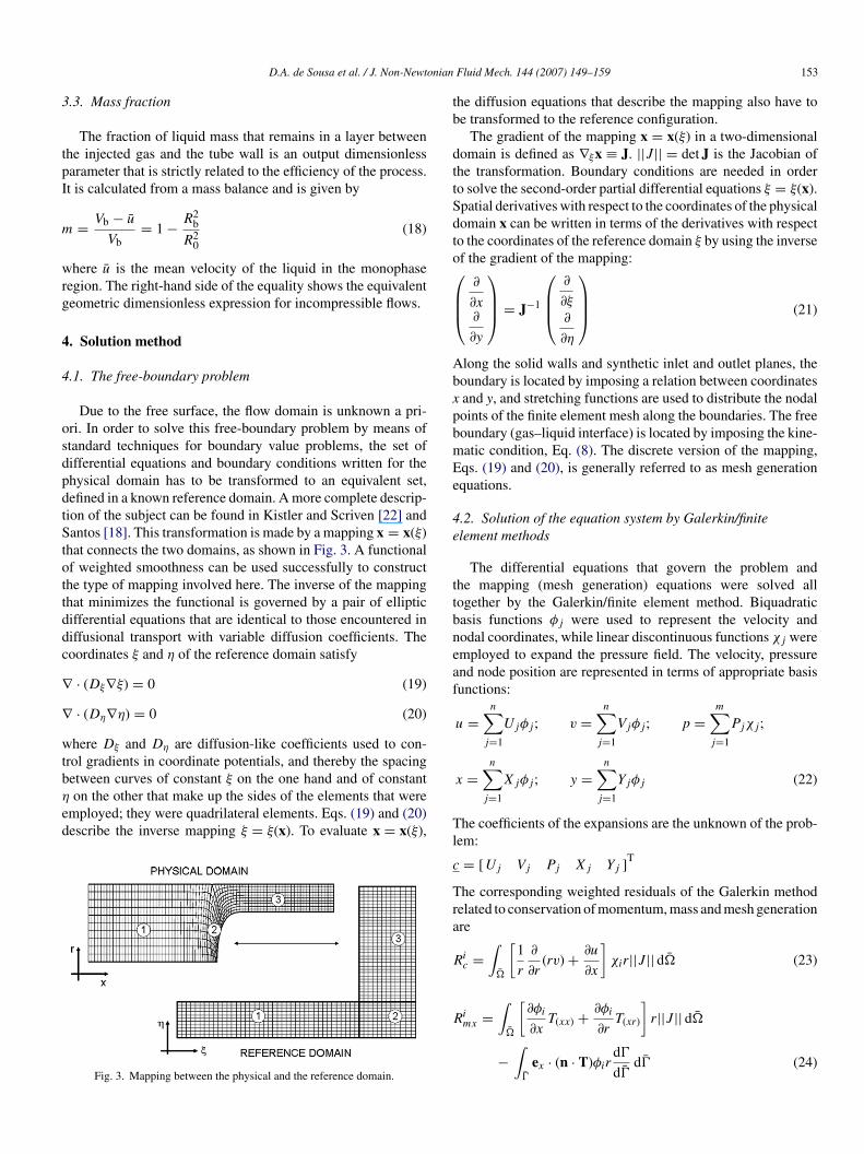
Due to the free surface, the flow domain is unknown a pri-ri. In order to solve this free-boundary problem by means oftandard techniques for boundary value problems, the set ofifferential equations and boundary conditions written for thehysical domain has to be transformed to an equivalent set,efined in a known reference domain. A more complete descrip-ion of the subject can be found in Kistler and Scriven [22] andantos [18]. This transformation is made by a mapping x = x(ξ)
hat connects the two domains, as shown in Fig. 3. A functionalf weighted smoothness can be used successfully to constructhe type of mapping involved here. The inverse of the mappinghat minimizes the functional is governed by a pair of ellipticifferential equations that are identical to those encountered iniffusional transport with variable diffusion coefficients. Theoordinates ξ and η of the reference domain satisfy
· (Dξ∇ξ) = 0 (19)
· (Dη∇η) = 0 (20)
here Dξ and Dη are diffusion-like coefficients used to con-rol gradients in coordinate potentials, and thereby the spacing
etween curves of constant ξ on the one hand and of constanton the other that make up the sides of the elements that weremployed; they were quadrilateral elements. Eqs. (19) and (20)escribe the inverse mapping ξ = ξ(x). To evaluate x = x(ξ),
Fig. 3. Mapping between the physical and the reference domain.
Tl
c
Tra
R
R
Fluid Mech. 144 (2007) 149–159 153
he diffusion equations that describe the mapping also have toe transformed to the reference configuration.
The gradient of the mapping x = x(ξ) in a two-dimensionalomain is defined as ∇ξx ≡ J. ||J || = det J is the Jacobian ofhe transformation. Boundary conditions are needed in ordero solve the second-order partial differential equations ξ = ξ(x).patial derivatives with respect to the coordinates of the physicalomain x can be written in terms of the derivatives with respecto the coordinates of the reference domain ξ by using the inversef the gradient of the mapping:
∂
∂x∂
∂y
⎞⎟⎟⎠ = J−1
⎛⎜⎜⎝
∂
∂ξ
∂
∂η
⎞⎟⎟⎠ (21)
long the solid walls and synthetic inlet and outlet planes, theoundary is located by imposing a relation between coordinatesand y, and stretching functions are used to distribute the nodaloints of the finite element mesh along the boundaries. The freeoundary (gas–liquid interface) is located by imposing the kine-atic condition, Eq. (8). The discrete version of the mapping,qs. (19) and (20), is generally referred to as mesh generationquations.
.2. Solution of the equation system by Galerkin/finitelement methods
The differential equations that govern the problem andhe mapping (mesh generation) equations were solved allogether by the Galerkin/finite element method. Biquadraticasis functions φj were used to represent the velocity andodal coordinates, while linear discontinuous functions χj weremployed to expand the pressure field. The velocity, pressurend node position are represented in terms of appropriate basisunctions:
u =n∑
j=1
Ujφj; v =n∑
j=1
Vjφj; p =m∑
j=1
Pjχj;
x =n∑
j=1
Xjφj; y =n∑
j=1
Yjφj (22)
he coefficients of the expansions are the unknown of the prob-em:
= [ Uj Vj Pj Xj Yj ]T
he corresponding weighted residuals of the Galerkin methodelated to conservation of momentum, mass and mesh generationre
ic =
∫�
[1
r
∂
∂r(rv) + ∂u
∂x
]χir||J || d� (23)
∫ [ ]
imx =�
∂φi
∂xT(xx) + ∂φi
∂rT(xr) r||J || d�
−∫
�
ex · (n · T)φird�
d�d� (24)
1 onian Fluid Mech. 144 (2007) 149–159
R
R
R
4b
etfwgsaatfild1F
5
5
wac[gaip
Fu
Fn
impmtait(
Fobs(cC
pii
5
ontTstb
54 D.A. de Sousa et al. / J. Non-Newt
imr =
∫�
[∂φi
∂xT(xr) + ∂φi
∂rT(rr) + φ
rTθθ
]r||J || d�
−∫
�
er · (n · T)φird�
d�d� (25)
iξ = −
∫�
Dξ
(∂φ
∂x
∂ξ
∂x+ ∂φ
∂r
∂ξ
∂r
)||J || d�
+∫
�
Dξ(∇ξ · n)φi
d�
d�d� (26)
iη = −
∫�
Dη
(∂φ
∂x
∂η
∂x+ ∂φ
∂r
∂η
∂r
)||J || d�
+∫
�
Dη(∇η · n)φi
d�
d�d� (27)
.3. Solution of the non-linear system of algebraic equationy Newton’s method
As indicated above, the system of partial differentialquations, and boundary conditions is reduced to a set of simul-aneous algebraic equations for the coefficients of the basisunctions of all the fields. This set is non-linear and sparse. Itas solved by Newton’s method. In order to improve the initialuess it was necessary to solve intermediate problems. The firstuccessful free surface flow was computed using a fixed bound-ry flow field with slippery surface in place of the free boundarys the initial condition for Newton’s method. The linear sys-em of equations at each Newton iteration was solved using arontal solver. A mesh convergence analysis was performed byncreasing the elements number until the solution changed byess that 1% between successive refinements. The domain wasivided into 900 elements that correspond to 3801 nodes and7,904 degrees of freedom. A representative mesh is shown inig. 4.
. Results
.1. Preliminary results
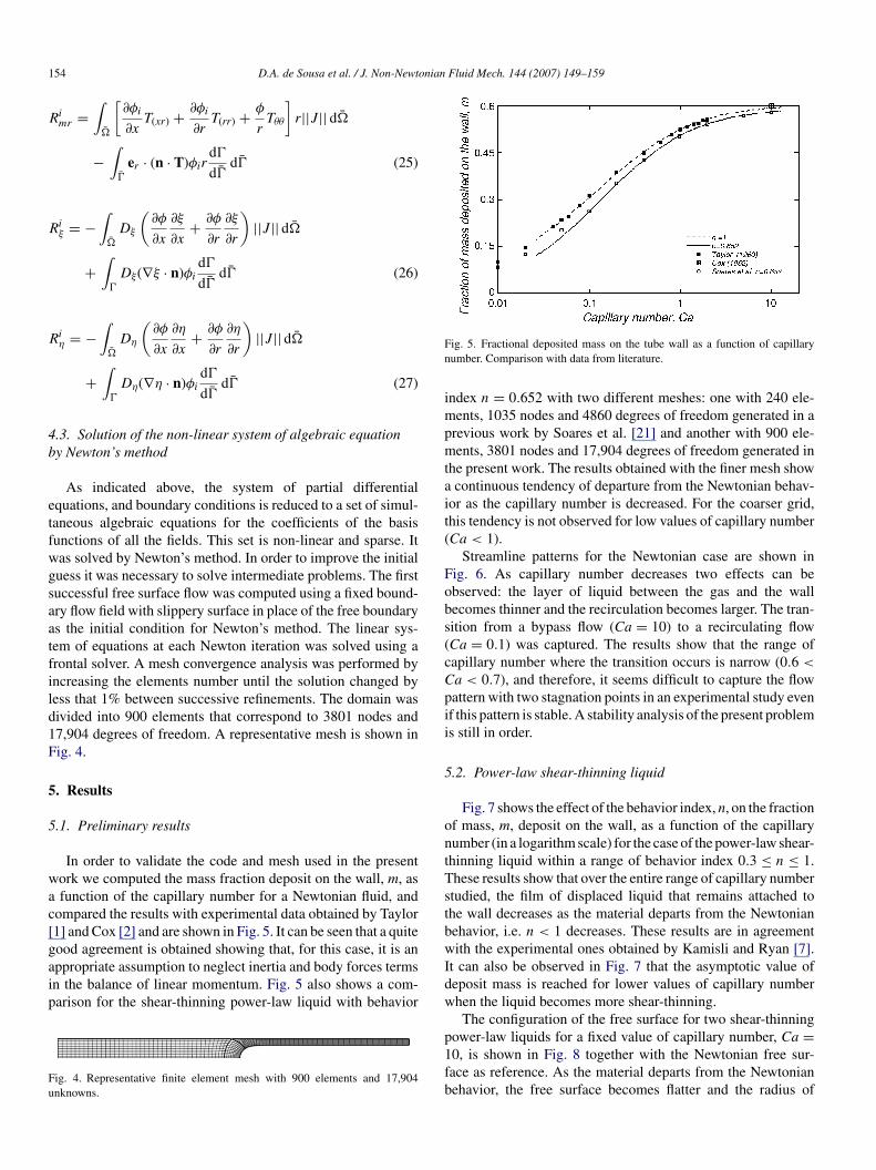
In order to validate the code and mesh used in the presentork we computed the mass fraction deposit on the wall, m, asfunction of the capillary number for a Newtonian fluid, and
ompared the results with experimental data obtained by Taylor1] and Cox [2] and are shown in Fig. 5. It can be seen that a quite
ood agreement is obtained showing that, for this case, it is anppropriate assumption to neglect inertia and body forces termsn the balance of linear momentum. Fig. 5 also shows a com-arison for the shear-thinning power-law liquid with behaviorig. 4. Representative finite element mesh with 900 elements and 17,904nknowns.
wIdw
p1fb
ig. 5. Fractional deposited mass on the tube wall as a function of capillaryumber. Comparison with data from literature.
ndex n = 0.652 with two different meshes: one with 240 ele-ents, 1035 nodes and 4860 degrees of freedom generated in a
revious work by Soares et al. [21] and another with 900 ele-ents, 3801 nodes and 17,904 degrees of freedom generated in
he present work. The results obtained with the finer mesh showcontinuous tendency of departure from the Newtonian behav-
or as the capillary number is decreased. For the coarser grid,his tendency is not observed for low values of capillary numberCa < 1).
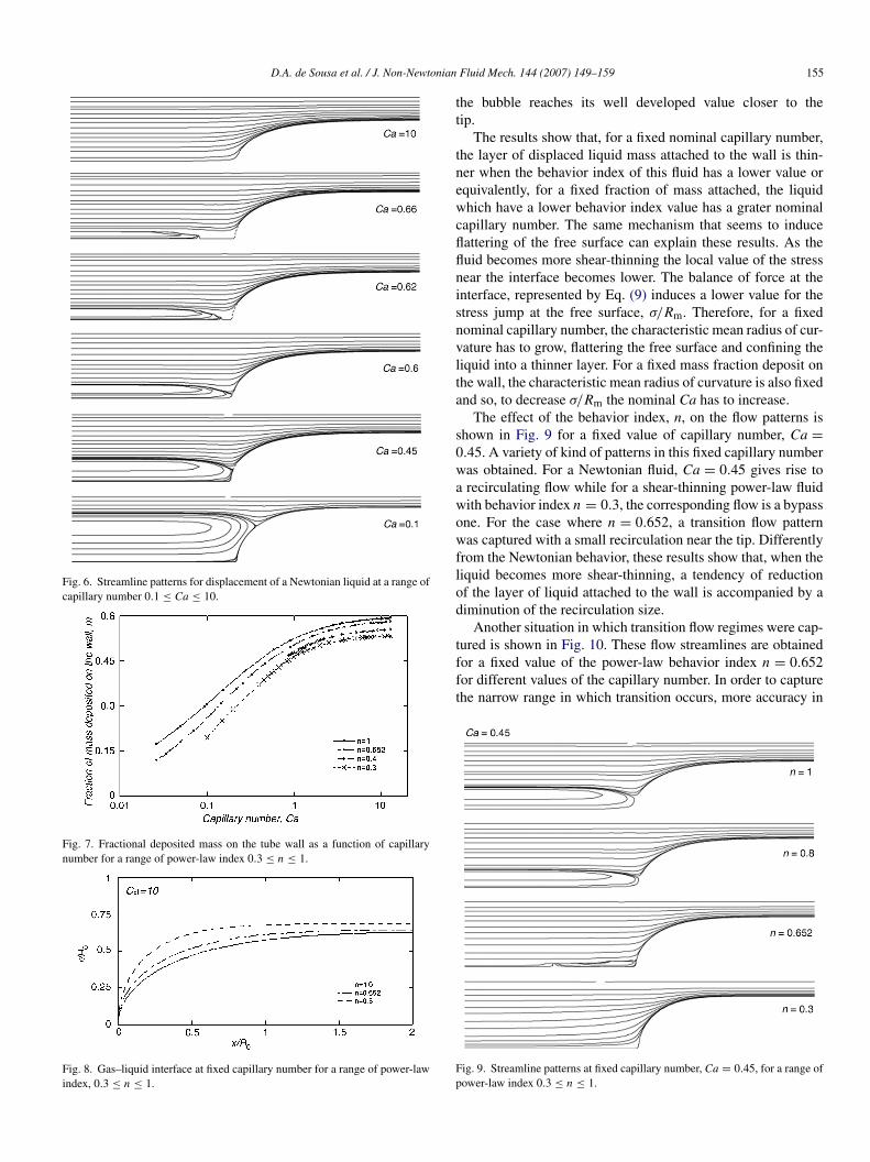
Streamline patterns for the Newtonian case are shown inig. 6. As capillary number decreases two effects can bebserved: the layer of liquid between the gas and the wallecomes thinner and the recirculation becomes larger. The tran-ition from a bypass flow (Ca = 10) to a recirculating flowCa = 0.1) was captured. The results show that the range ofapillary number where the transition occurs is narrow (0.6 <
a < 0.7), and therefore, it seems difficult to capture the flowattern with two stagnation points in an experimental study evenf this pattern is stable. A stability analysis of the present problems still in order.
.2. Power-law shear-thinning liquid
Fig. 7 shows the effect of the behavior index, n, on the fractionf mass, m, deposit on the wall, as a function of the capillaryumber (in a logarithm scale) for the case of the power-law shear-hinning liquid within a range of behavior index 0.3 ≤ n ≤ 1.hese results show that over the entire range of capillary numbertudied, the film of displaced liquid that remains attached tohe wall decreases as the material departs from the Newtonianehavior, i.e. n < 1 decreases. These results are in agreementith the experimental ones obtained by Kamisli and Ryan [7].
t can also be observed in Fig. 7 that the asymptotic value ofeposit mass is reached for lower values of capillary numberhen the liquid becomes more shear-thinning.The configuration of the free surface for two shear-thinning
ower-law liquids for a fixed value of capillary number, Ca =0, is shown in Fig. 8 together with the Newtonian free sur-ace as reference. As the material departs from the Newtonianehavior, the free surface becomes flatter and the radius of
D.A. de Sousa et al. / J. Non-Newtonian
Fig. 6. Streamline patterns for displacement of a Newtonian liquid at a range ofcapillary number 0.1 ≤ Ca ≤ 10.
Fig. 7. Fractional deposited mass on the tube wall as a function of capillarynumber for a range of power-law index 0.3 ≤ n ≤ 1.
Fig. 8. Gas–liquid interface at fixed capillary number for a range of power-lawindex, 0.3 ≤ n ≤ 1.
tt
tnewcflflnisnvlta
s0wawowflod
tfft
Fp
Fluid Mech. 144 (2007) 149–159 155
he bubble reaches its well developed value closer to theip.
The results show that, for a fixed nominal capillary number,he layer of displaced liquid mass attached to the wall is thin-er when the behavior index of this fluid has a lower value orquivalently, for a fixed fraction of mass attached, the liquidhich have a lower behavior index value has a grater nominal
apillary number. The same mechanism that seems to induceattering of the free surface can explain these results. As theuid becomes more shear-thinning the local value of the stressear the interface becomes lower. The balance of force at thenterface, represented by Eq. (9) induces a lower value for thetress jump at the free surface, σ/Rm. Therefore, for a fixedominal capillary number, the characteristic mean radius of cur-ature has to grow, flattering the free surface and confining theiquid into a thinner layer. For a fixed mass fraction deposit onhe wall, the characteristic mean radius of curvature is also fixednd so, to decrease σ/Rm the nominal Ca has to increase.
The effect of the behavior index, n, on the flow patterns ishown in Fig. 9 for a fixed value of capillary number, Ca =.45. A variety of kind of patterns in this fixed capillary numberas obtained. For a Newtonian fluid, Ca = 0.45 gives rise torecirculating flow while for a shear-thinning power-law fluidith behavior index n = 0.3, the corresponding flow is a bypassne. For the case where n = 0.652, a transition flow patternas captured with a small recirculation near the tip. Differently
rom the Newtonian behavior, these results show that, when theiquid becomes more shear-thinning, a tendency of reductionf the layer of liquid attached to the wall is accompanied by aiminution of the recirculation size.
Another situation in which transition flow regimes were cap-
ured is shown in Fig. 10. These flow streamlines are obtainedor a fixed value of the power-law behavior index n = 0.652or different values of the capillary number. In order to capturehe narrow range in which transition occurs, more accuracy inig. 9. Streamline patterns at fixed capillary number, Ca = 0.45, for a range ofower-law index 0.3 ≤ n ≤ 1.

156 D.A. de Sousa et al. / J. Non-Newtonian Fluid Mech. 144 (2007) 149–159
Fc
rawrwlaC
anAter
5
s(5TyTcy
Fig. 11. Velocity profile far enough from the tip of the interface for a fixed afixed reference frame for a range of dimensionless yield-stress, 0 ≤ τ′
0 ≤ 0.85.
Fn
is
ofntand τ′
0 = 0.85 and the Newtonian case (τ′0 = 0) as reference. It
can be observed that, over the entire range of capillary numberinvestigated, the film of displaced liquid that remains attached
ig. 10. Streamline patterns at fixed power-law index, n = 0.652 for a range ofapillary number, 0.025 < Ca < 0.6.
epresenting the capillary number is needed. The extreme situ-tions are represented, at one side, by the flow pattern obtainedith a capillary number Ca = 0.556 where there is a bypass flow
egime and, at the other side with a capillary number Ca = 0.026here a huge recirculation takes almost the whole domain of the
iquid and a very thin layer of liquid is present between the wallnd the gas which is displacing. Intermediate cases, namely,a = 0.462 and 0.464, show an interesting tiny recirculationttached to the tip. This flow regime exhibits a pattern which isot present in the gas–liquid displacement of a Newtonian fluid.nother interesting feature of this transition is represented by
he case in which Ca = 0.460. It is worth noting that, differ-ntly from the Newtonian case, in this one, the thickness of theecirculation is almost constant over the entire liquid domain.
.3. Visco-plastic material
Fig. 11 shows the velocity profile for three values of dimen-ionless yield stresses, τ′
0 = 0.5, τ′0 = 0.75 and τ′
0 = 0.85which correspond to Bingham numbers of Bn = 1, 3 and.67) and the Newtonian case (τ′
0 = 0, Bn = 0) as reference.hese profiles give a physical meaning to each dimensionless
ield-stress by examining the correspondent plug flow region.he dimensionless yield-stress was preferred, as a rheologi-al parameter because the Bingham number is unbounded asield-stress becomes more significant while τ′0 is a normal-Fs
ig. 12. Fractional deposited mass on the tube wall as a function of capillaryumber for a range of dimensionless yield-stress, 0 ≤ τ′
0 ≤ 0.85.
zed dimensionless visco-plastic number, i.e. 0 ≤ τ′0 < 1 and
o, unity constitute an upper limit of a plastic dominating flow.The fraction of mass deposit on the wall, m, as a function
f the capillary number and the configuration of the free sur-ace for the visco-plastic material at a fixed value of capillaryumber, Ca = 10, are shown in Figs. 12 and 13, respectively, forhree values of dimensionless yield stresses, τ′
0 = 0.5, τ′0 = 0.75
ig. 13. Gas–liquid interface at fixed capillary number for a range of dimen-ionless yield-stress, 0 ≤ τ′
0 ≤ 0.85.

onian Fluid Mech. 144 (2007) 149–159 157
tbtn[nat
idaibtoi
τ
ioNsrV
mfostcots
D
atecsnthcot
taiibc
v
Fd
olhrsfttawa
vrbrFwith the Newtonian ones, presented in Fig. 6 in which the tran-sition occurred within the range 0.6 < Ca < 0.7, show that, forthe cases investigated, the capillary number where transitionhappens decreases when the visco-plastic material departs from
D.A. de Sousa et al. / J. Non-Newt
o the wall decreases as the material departs from the Newtonianehavior, i.e. τ′
0 > 0 increases. This result is in agreement withhe experimental results obtained by Poslinski et al. [10] and theumerical results obtained by Dimakopoulos and Tsamopoulos11] although they have investigated a small range of Binghamumber at low values of this parameter (τ′
0 < 0.23 or Bn < 0.3)nd explore high (steady) capillary numbers which are moreypical in gas-assisted injection molding.
This result can be considered, at a first glance, counter-ntuitive. This is because “intuition” would say that is moreifficult (for a gas) to displace a fluid with a high viscosity thennother with a low viscosity. And, an increase of yield-stressncreases the viscosity of the fluid. Consequently, what woulde expected is that the layer thickness should increase whenhe dimensionless yield-stress is increased. However, thinkingf the paradigmatic Bingham fluid [23], for example, where thentensity of the extra-stress τ is given by
= μγ + τ0 (28)
t can be seen that the Newtonian and yield-stress terms havepposite tendencies, since the Newtonian stress (but not theewtonian viscosity) is affected by an increase of the dimen-
ionless yield-stress, which leads to lower the local value of theate of deformation (without changing its characteristic value,b/R0), as the region of unyielded fluid in the domain is aug-ented. What we can infer from the present results and others
rom the literature, e.g. [11,14,24], is that, at least in this kindf problem, the decrease of the Newtonian stress (or power-lawtress in the case of Herschel-Bulkley model) is stronger thanhe increase in the yield-stress, and by this consequence the localombined stress decreases. The explanation here is similar to thene developed by Allouche et al. [14], the difference lying onhe fact that they consider a dissipation function based on thetress power of the following form:
=∫
�
(μγ2 + τ0γ) d� (29)
nd hypothesize that the configuration of the interface is suchhat this dissipation function is minimum (minimization ofntropy production principle). In this case there are also twoontributions, namely a Newtonian and plastic one that have theame opposite tendencies discussed above. Although they areot exactly the same, there is a strong similarity between thewo explanations. It is worth noting that the explanation givenere and the one given by Allouche et al. [14] do not addressompletely the subject since they do not explain why an increasen Bingham number affects more Newtonian contribution thanhe plastic one.
The results obtained for the visco-plastic material followedhe same tendency presented by the pseudo-plastic liquid. Thus,n increase of the yield number induces the local stress at thenterface, σ/Rm, to decrease. Therefore, for a fixed nominal cap-llary number, the fraction of mass decreases and the interface
ecomes flatter. For a fixed mean radius of curvature, the nominalapillary number increases.Fig. 14 shows a sequence of flow streamlines for a fixedalue of capillary number, Ca = 0.3. In the Newtonian case,
Fr
ig. 14. Streamline patterns at fixed capillary number, Ca = 0.3, for a range ofimensionless yield-stress 0 ≤ τ′
0 ≤ 0.75.
ne can find a recirculating flow. This recirculation becomesess intense for the visco-plastic case of τ′
0 = 0.5, and for aigher value of the dimensionless yield-stress τ′
0 = 0.75, theegime is a bypass flow. The case τ′
0 = 0.85 which was nothown in Fig. 14 presents also a bypass flow pattern. There-ore, for Ca = 0.3, there is a change in the flow regime withinhe range of dimensionless yield-stress 0.5 < τ′
0 < 0.75. As inhe shear-thinning case, and differently from the Newtonian one,tendency of reduction of the fraction of mass attached to theall is accompanied by a diminution of the recirculation size,
s the dimensionless yield-stress becomes higher.Transition regimes were captured in Figs. 15 and 16 for the
isco-plastic materials correspondent to τ′0 = 0.5 and τ′
0 = 0.75,espectively. In the case where τ′
0 = 0.5, Fig. 15, transitionetween bypass and recirculating flow regimes occur within theange 0.3 < Ca < 0.4. For a dimensionless number τ′
0 = 0.75,ig. 16, this range is 0.2 < Ca < 0.3. These results, combined
ig. 15. Streamline patterns at fixed dimensionless yield-stress, τ′0 = 0.5 for a
ange of capillary number, 0.30 ≤ Ca ≤ 0.40.
158 D.A. de Sousa et al. / J. Non-Newtonian
Fr
t(ertsfaa
6
ouettTcfn[nosfl
awr0fFtwbτ
t
siaigmfl
ssoc0awτ
osac
cbwdoierrvmorcoeclmwsotre
totws
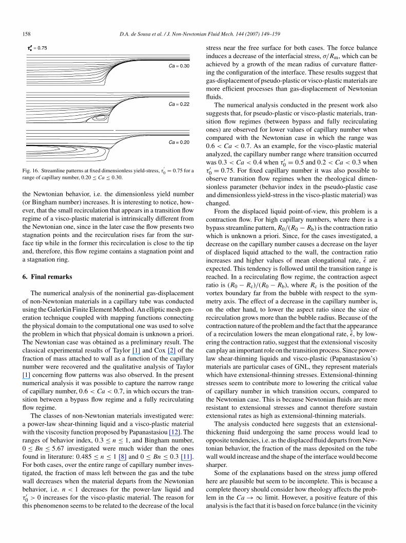
ig. 16. Streamline patterns at fixed dimensionless yield-stress, τ′0 = 0.75 for a
ange of capillary number, 0.20 ≤ Ca ≤ 0.30.
he Newtonian behavior, i.e. the dimensionless yield numberor Bingham number) increases. It is interesting to notice, how-ver, that the small recirculation that appears in a transition flowegime of a visco-plastic material is intrinsically different fromhe Newtonian one, since in the later case the flow presents twotagnation points and the recirculation rises far from the sur-ace tip while in the former this recirculation is close to the tipnd, therefore, this flow regime contains a stagnation point andstagnation ring.
. Final remarks
The numerical analysis of the noninertial gas-displacementf non-Newtonian materials in a capillary tube was conductedsing the Galerkin Finite Element Method. An elliptic mesh gen-ration technique coupled with mapping functions connectinghe physical domain to the computational one was used to solvehe problem in which that physical domain is unknown a priori.he Newtonian case was obtained as a preliminary result. Thelassical experimental results of Taylor [1] and Cox [2] of theraction of mass attached to wall as a function of the capillaryumber were recovered and the qualitative analysis of Taylor1] concerning flow patterns was also observed. In the presentumerical analysis it was possible to capture the narrow rangef capillary number, 0.6 < Ca < 0.7, in which occurs the tran-ition between a bypass flow regime and a fully recirculatingow regime.
The classes of non-Newtonian materials investigated were:power-law shear-thinning liquid and a visco-plastic materialith the viscosity function proposed by Papanastasiou [12]. The
anges of behavior index, 0.3 ≤ n ≤ 1, and Bingham number,≤ Bn ≤ 5.67 investigated were much wider than the ones
ound in literature: 0.485 ≤ n ≤ 1 [8] and 0 ≤ Bn ≤ 0.3 [11].or both cases, over the entire range of capillary number inves-
igated, the fraction of mass left between the gas and the tube
all decreases when the material departs from the Newtonianehavior, i.e. n < 1 decreases for the power-law liquid and′0 > 0 increases for the visco-plastic material. The reason forhis phenomenon seems to be related to the decrease of the localhcla
Fluid Mech. 144 (2007) 149–159
tress near the free surface for both cases. The force balancenduces a decrease of the interfacial stress, σ/Rm, which can bechieved by a growth of the mean radius of curvature flatter-ng the configuration of the interface. These results suggest thatas-displacement of pseudo-plastic or visco-plastic materials areore efficient processes than gas-displacement of Newtonianuids.
The numerical analysis conducted in the present work alsouggests that, for pseudo-plastic or visco-plastic materials, tran-ition flow regimes (between bypass and fully recirculatingnes) are observed for lower values of capillary number whenompared with the Newtonian case in which the range was.6 < Ca < 0.7. As an example, for the visco-plastic materialnalyzed, the capillary number range where transition occurredas 0.3 < Ca < 0.4 when τ′
0 = 0.5 and 0.2 < Ca < 0.3 when′0 = 0.75. For fixed capillary number it was also possible tobserve transition flow regimes when the rheological dimen-ionless parameter (behavior index in the pseudo-plastic casend dimensionless yield-stress in the visco-plastic material) washanged.
From the displaced liquid point-of-view, this problem is aontraction flow. For high capillary numbers, where there is aypass streamline pattern, R0/(R0 − Rb) is the contraction ratiohich is unknown a priori. Since, for the cases investigated, aecrease on the capillary number causes a decrease on the layerf displaced liquid attached to the wall, the contraction rationcreases and higher values of mean elongational rate, ¯ε arexpected. This tendency is followed until the transition range iseached. In a recirculating flow regime, the contraction aspectatio is (R0 − Rc)/(R0 − Rb), where Rc is the position of theortex boundary far from the bubble with respect to the sym-etry axis. The effect of a decrease in the capillary number is,
n the other hand, to lower the aspect ratio since the size ofecirculation grows more than the bubble radius. Because of theontraction nature of the problem and the fact that the appearancef a recirculation lowers the mean elongational rate, ¯ε, by low-ring the contraction ratio, suggest that the extensional viscosityan play an important role on the transition process. Since power-aw shear-thinning liquids and visco-plastic (Papanastasiou’s)
aterials are particular cases of GNL, they represent materialshich have extensional-thinning stresses. Extensional-thinning
tresses seem to contribute more to lowering the critical valuef capillary number in which transition occurs, compared tohe Newtonian case. This is because Newtonian fluids are moreesistant to extensional stresses and cannot therefore sustainxtensional rates as high as extensional-thinning materials.
The analysis conducted here suggests that an extensional-hickening fluid undergoing the same process would lead topposite tendencies, i.e. as the displaced fluid departs from New-onian behavior, the fraction of the mass deposited on the tubeall would increase and the shape of the interface would become
harper.Some of the explanations based on the stress jump offered
ere are plausible but seem to be incomplete. This is because aomplete theory should consider how rheology affects the prob-em in the Ca → ∞ limit. However, a positive feature of thisnalysis is the fact that it is based on force balance (in the vicinity

onian
owedtk
ncTzospwhar
tcAeisbmt
A
h
iR
R
[
[
[
[
[
[
[
[
[
[
[
[
[
D.A. de Sousa et al. / J. Non-Newt
f the free surface). In this connection it can be concluded thathat has to be considered in non-Newtonian analysis in gen-
ral is how stresses are affected by a change of a parameter. Aifferent approach, based on viscosity for example, could leado a misinterpretation of the results, since stress is a function ofinematics which is affected by the parameter considered.
Different kinds of flow regimes were obtained, for bothon-Newtonian materials analyzed, in the transition range ofapillary number, when compared with the Newtonian case.he main difference is that, in the Newtonian case, recirculationones at high Ca occur fully contained in the liquid domain, withne stagnation point only. As the capillary number decreases, thetagnation point approaches the free surface. For the pseudo-lastic and visco-plastic materials investigated in the presentork the opposite was observed. The recirculation zone starts atigh Ca, attached to the free surface, with one stagnation pointnd a stagnation ring. As the capillary number decreases, theecirculation zone moves away from the bubble.
The reason for this different behavior during transition inhe cases of pseudo-plastic and visco-plastic materials whenompared to the Newtonian case is still under investigation.s discussed above, an interesting path to study is how the
xtensional properties of the material that is being displacednfluence the problem. Therefore, the examination of the tran-ition range using other models, which can predict differentehavior depending on the type of the flow, such as viscoelasticodels, would probably give important information to clarify
his point.
cknowledgments
We would like to acknowledge a reviewer of this article foris valuable suggestions.
This research was partially funded by grants from the Brazil-an Science and Technology Secretary MCT, the Brazilianesearch Council CNPq.
eferences
[1] G.I. Taylor, Deposition of a viscous fluid on the wall a tube, J. Fluid Mech.10 (1961) 161–165.
[2] B.G. Cox, On driving a viscous fluid out of a tube, J. Fluid Mech. 20 (1962)81–96.
[3] F. Fairbrother, A.E. Stubbs, J. Chem. Soc. 1 (1935) 527.[4] F.P. Bretherton, The motion of long bubble in tubes, J. Fluid Mech. 10
(1960) 166–188.
[
[
Fluid Mech. 144 (2007) 149–159 159
[5] B.G. Cox, An experimental investigation of the streamlines in viscous fluidexpelled from a tube, J. Fluid Mech. 20 (1964) 193–200.
[6] A.J. Poslinski, D.J. Coyle, Steady gas penetration through non Newtonianliquids in tube and slit geometries: isothermal shear thinning effects, in:Proceedings of the Polymer Processing Society, Annual Meeting, vol. 10,1994, p. 219.
[7] F. Kamisli, M.E. Ryan, Perturbation method in gas-assisted power-law fluiddisplacement in a circular tube and rectangular channel, Chem. Eng. J. 75(1999) 167–176.
[8] E.J. Soares, M.S. Carvalho, P.R. Souza Mendes, Gas-displacement of non-Newtonian liquids in capillary tubes, Int. J. Heat Fluid Flow. 27 (2006)95–104.
[9] A.N. Alexandrou, V. Entov, On the steady-state advancement of fingers andbubbles in a Hele-Shaw cell filled by a non-Newtonian fluid, Eur. J. Appl.Math. 8 (1997) 73–87.
10] A.J. Poslinski, P.O. Oehler, V.K. Stokes, Isothermal gas-assisted displace-ment of a visco-plastic liquid in tubes, Poly. Eng. Sci. 35 (1995) 877–892.
11] Y. Dimakopoulos, J. Tsamopoulos, Transient displacement of a visco-plastic material by air in straight and constricted tubes, J. Non-Newton.Fluid Mech. 112 (2003) 43–75.
12] T.C. Papanastasiou, Flows of materials with yield-stress, J. Rheol. 31 (1987)385–404.
13] Y. Dimakopoulos, J. Tsamopoulos, Transient displacement of Newtonianand viscoplastic liquids by air in complex tubes, J. Non-Newton. FluidMech. 142 (2007) 162–182.
14] M. Allouche, I.A. Frigaard, G. Sona, Static wall layers in the displacementof two visco-plastic fluids in a plane channel, J. Fluid Mech. 424 (2000)243–277.
15] M.F. Tome, B. Duffy, S. McKee, A numerical technique for solvingunsteady non-Newtonian free surface flows, J. Non-Newton. Fluid Mech.62 (1) (1996) 9–34.
16] P. Szabo, O. Hassager, Displacement of one Newtonian fluid by another:density effects in axial annular flow, Int. J. Multiphase Flow 23 (1) (1997)113–129.
17] P.A. Sackinger, P.R. Shunk, R.R. Rao, A Newton–Rhaphson pseudo-soliddomain mapping technique for free and moving boundary problems: a finiteelement implementation, J. Comput. Phys. 125 (1996) 83–103.
18] J.M. Santos, Two-phase cocurrent downflow through constricted passages,Ph.D. Thesis, University of Minnesota, MN, USA, 1991.
19] K.N. Christodoulou, L.E. Scriven, Discretization of free surface flows andother moving boundary, J. Comput. Phys. 99 (1992) 39–55.
20] O.J. Romero, W.J. Suszynski, L.E. Scriven, M.S. Carvalho, Low-flow limitin slot coating of dilute solution of high molecular weight polymer, J.Non-Newton. Fluid Mech. 118 (2004) 137–156.
21] E.J. Soares, M.S. Carvalho, P.R. Souza Mendes, Immiscible liquid–liquiddisplacement in capillary tubes, J. Fluids Eng. 127 (1) (2005) 24–31.
22] S.F. Kistler, L.E.S. Scriven, Coating flow theory by finite element andasymptotic analysis of the Navier–Stokes system, Int. J. Numer. Meth.
Fluids 43 (1983) 207.23] N. Balmforth, I. Frigaard, Viscoplastic fluids: from theory to application,J. Non-Newton. Fluid Mech. 142 (2007) 1–3.
24] C. Gabard, J.P. Hulin, Miscible displacement of non-Newtonian fluids invertical tube, Eur. Phys. J. E 11 (2003) 231–241.
Copyright © 2022 FDOKUMEN