
Development of Strain in Oxides Grown in Steam Tubes
9
DEVELOPMENT OF STRAIN IN OXIDES GROWN IN STEAM TUBES I.G. Wright a , A.S. Sabau b , and R.B. Dooley* c Oak Ridge National Laboratory, 1, Bethel Valley Road, Oak Ridge, TN 37831, USA *Structural Integrity Associates, Inc., Oakville, Toronto L6J 7L7, Ontario, Canada a [email protected], b [email protected], c [email protected] Keywords: exfoliation; steam oxidation; computation of strains in oxides Abstract. In this study, the foundation is being developed for the numerical simulation of the processes that determine the oxide scale exfoliation behavior of the steam-side surfaces of superheater and reheater tubes in a steam boiler. Initially, the assumptions concerning the base state for calculating oxide strains also were critically examined. The state of stress-strain of an oxide growing on the inside surface of an externally-heated tube was considered for the conditions experienced in a boiler during transition from full- to partial-load operation. Since the rate at which the oxide grows is an important consideration, it was necessary to determine the appropriate temperature to use in the oxidation rate calculations. The existence of a temperature gradient through the tube, and the cyclic nature of the boiler operation (temperature and pressure) were considered; the growth temperature of the oxide was taken to be the oxide surface temperature. It was determined that the commonly-used approach for accounting for geometrical effects when calculating stress-strain development in a growing oxide scale of using the analogy of an infinitely- long flat plate gave sufficiently different results than when using a cylindrical geometry, that the latter was adopted as the preferred calculation procedure. Preliminary calculation of strains developed in multilayered oxides formed on alloy T22 as a function of boiler operating conditions indicated the magnitude of the strains in each layer; the large strain gradients between the layers inferred the importance of the detailed scale morphology in determining the mode of exfoliation. Introduction A major concern resulting from the growth of oxide on the inside surfaces of steam tubes is that, as the oxide scales become thicker, there is a reduction in the ability to accommodate stresses resulting from the growth process (volume change) and from thermal transients (especially upon cool down). Accommodating these stresses leads to modification of the scale morphology, the development of flaws, and the eventual exfoliation of the oxide from the tube surface into the steam flow. Factors such as the extent and frequency of exfoliation, the size and shape of the oxide particles lost, the location in the boiler where exfoliation occurs, and boiler operating parameters determine the subsequent fate of the exfoliant, but in extreme cases blocking of tube bends and/or erosion of the steam turbine can result [1-3]. In order to anticipate the occurrence of scale exfoliation, it is necessary to develop a quantitative understanding of contributions from all sources to the stress accumulated in the scale, the interactions among these stresses, and of the processes by which such stress is accommodated. There has been a considerable amount of pioneering work conducted in this area by several research groups [3-13], and the intent of this effort is to build on that foundation. Common assumptions used in the estimation of stresses and strains in oxide scales include: (a) uniform temperature/no temperature gradient through the oxide scale; (b) semi-infinite, thick, flat plate geometry; (c) isothermal conditions, or temperature cycling quite unrepresentative of boiler operation; and (d) no effects of steam pressure. Laboratory oxidation experiments often are performed using specimen geometries quite different from those experienced on the inside of tubes. The intent of this study is to attempt to incorporate a proper accounting of these factors into a
Transcript of Development of Strain in Oxides Grown in Steam Tubes

DEVELOPMENT OF STRAIN IN OXIDES GROWN IN STEAM TUBES
I.G. Wrighta, A.S. Sabaub, and R.B. Dooley*c Oak Ridge National Laboratory, 1, Bethel Valley Road, Oak Ridge, TN 37831, USA *Structural Integrity Associates, Inc., Oakville, Toronto L6J 7L7, Ontario, Canada
[email protected], [email protected], [email protected]
Keywords: exfoliation; steam oxidation; computation of strains in oxides
Abstract. In this study, the foundation is being developed for the numerical simulation of the
processes that determine the oxide scale exfoliation behavior of the steam-side surfaces of
superheater and reheater tubes in a steam boiler. Initially, the assumptions concerning the base state
for calculating oxide strains also were critically examined. The state of stress-strain of an oxide
growing on the inside surface of an externally-heated tube was considered for the conditions
experienced in a boiler during transition from full- to partial-load operation. Since the rate at which
the oxide grows is an important consideration, it was necessary to determine the appropriate
temperature to use in the oxidation rate calculations. The existence of a temperature gradient
through the tube, and the cyclic nature of the boiler operation (temperature and pressure) were
considered; the growth temperature of the oxide was taken to be the oxide surface temperature. It
was determined that the commonly-used approach for accounting for geometrical effects when
calculating stress-strain development in a growing oxide scale of using the analogy of an infinitely-
long flat plate gave sufficiently different results than when using a cylindrical geometry, that the
latter was adopted as the preferred calculation procedure. Preliminary calculation of strains
developed in multilayered oxides formed on alloy T22 as a function of boiler operating conditions
indicated the magnitude of the strains in each layer; the large strain gradients between the layers
inferred the importance of the detailed scale morphology in determining the mode of exfoliation.
Introduction
A major concern resulting from the growth of oxide on the inside surfaces of steam tubes is
that, as the oxide scales become thicker, there is a reduction in the ability to accommodate stresses
resulting from the growth process (volume change) and from thermal transients (especially upon
cool down). Accommodating these stresses leads to modification of the scale morphology, the
development of flaws, and the eventual exfoliation of the oxide from the tube surface into the steam
flow. Factors such as the extent and frequency of exfoliation, the size and shape of the oxide
particles lost, the location in the boiler where exfoliation occurs, and boiler operating parameters
determine the subsequent fate of the exfoliant, but in extreme cases blocking of tube bends and/or
erosion of the steam turbine can result [1-3].
In order to anticipate the occurrence of scale exfoliation, it is necessary to develop a
quantitative understanding of contributions from all sources to the stress accumulated in the scale,
the interactions among these stresses, and of the processes by which such stress is accommodated.
There has been a considerable amount of pioneering work conducted in this area by several
research groups [3-13], and the intent of this effort is to build on that foundation. Common
assumptions used in the estimation of stresses and strains in oxide scales include: (a) uniform
temperature/no temperature gradient through the oxide scale; (b) semi-infinite, thick, flat plate
geometry; (c) isothermal conditions, or temperature cycling quite unrepresentative of boiler
operation; and (d) no effects of steam pressure. Laboratory oxidation experiments often are
performed using specimen geometries quite different from those experienced on the inside of tubes.
The intent of this study is to attempt to incorporate a proper accounting of these factors into a

computational methodology that provides a realistic basis for modeling of the exfoliation process.
The approaches used for addressing the issues listed above are discussed in the following.
Effect Typical of Steam Boiler Operating Cycles on Steam-Side Oxide Growth
An example of the thermal cycle associated with standard steam boiler operation is shown
schematically in Fig. 1. The load of the boiler follows demand, so that periods of full load are
followed by period when the boiler operates at partial load. In order to calculate the oxide growth
associated with the conditions experienced during a boiler operating cycle, it is necessary to
explicitly specify the parameters associated with that cycle. Since actual boiler operating schedules
can vary significantly, and details usually are not readily available, the values used (shown in Table
I) were based on plant experience for a ‘typical’ boiler schedule, and are similar to those discussed
in Gonzales et al. [14] and Zarrabi and Rose [15]. In Table 1, Tst and Tg are the internal (steam) and
external (combustion gas) gas temperatures, respectively, and Pst and Pg are the pressures of the
steam and combustion gas, respectively. It is assumed that the boiler is shut down only at scheduled
maintenance intervals (in this case, every four years). The time taken to change from partial-to-full
load, or vice versa, is taken as one hour.
Figure 1. Assumed Temperature Cycle.
Table 1. Assumed Boiler Operating Conditions.
Load Duration
(hrs)
Tg
(°C)
Tst
(°C)
Pg
(bar)
Pst
(bar)
Full 14 1 200 550 2 170
Partial 8 550 460 1 100
Thus, the oxide thickness (dox), at a given time (tk) is given by:
!
dox.(k)
2 = dox,(k"1)
2 + d dox2( ) . (1)
!
where : d dox2( ) = 2"t kp Tgr tk( )( ), denoting that the usual parabolic oxidation relationship (dox
2 = 2 kp
!t) now takes account of the periods of scale growth under the conditions associated with full load
and partial load; and
!
kp T( ) = A e"Q RT , indicating that the parabolic rate constant (kp) corresponds to
the prevailing oxide growth temperature (Tgr), and where t is time; A is the Arrhenius constant, Q is
the activation energy for the rate-controlling process; and R is the Universal Gas Constant.
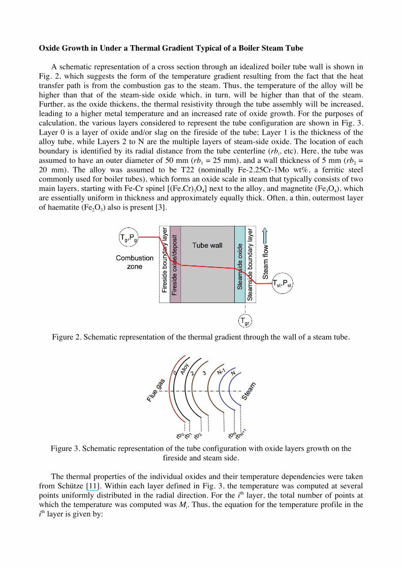
Oxide Growth in Under a Thermal Gradient Typical of a Boiler Steam Tube
A schematic representation of a cross section through an idealized boiler tube wall is shown in
Fig. 2, which suggests the form of the temperature gradient resulting from the fact that the heat
transfer path is from the combustion gas to the steam. Thus, the temperature of the alloy will be
higher than that of the steam-side oxide which, in turn, will be higher than that of the steam.
Further, as the oxide thickens, the thermal resistivity through the tube assembly will be increased,
leading to a higher metal temperature and an increased rate of oxide growth. For the purposes of
calculation, the various layers considered to represent the tube configuration are shown in Fig. 3.
Layer 0 is a layer of oxide and/or slag on the fireside of the tube; Layer 1 is the thickness of the
alloy tube, while Layers 2 to N are the multiple layers of steam-side oxide. The location of each
boundary is identified by its radial distance from the tube centerline (rbi, etc). Here, the tube was
assumed to have an outer diameter of 50 mm (rb1 = 25 mm), and a wall thickness of 5 mm (rb2 =
20 mm). The alloy was assumed to be T22 (nominally Fe-2.25Cr-1Mo wt%, a ferritic steel
commonly used for boiler tubes), which forms an oxide scale in steam that typically consists of two
main layers, starting with Fe-Cr spinel [(Fe,Cr)3O4] next to the alloy, and magnetite (Fe3O4), which
are essentially uniform in thickness and approximately equally thick. Often, a thin, outermost layer
of haematite (Fe2O3) also is present [3].
Figure 2. Schematic representation of the thermal gradient through the wall of a steam tube.
Figure 3. Schematic representation of the tube configuration with oxide layers growth on the
fireside and steam side.
The thermal properties of the individual oxides and their temperature dependencies were taken
from Schütze [11]. Within each layer defined in Fig. 3, the temperature was computed at several
points uniformly distributed in the radial direction. For the ith layer, the total number of points at
which the temperature was computed was Mi. Thus, the equation for the temperature profile in the
ith layer is given by:

!
Ti, j = Ti rj( ) = ai + bi ln rj . (2)
where j ranges from 1 to Mi. The coefficients ai and bi were determined through the continuity of
temperature and heat flux in the radial direction at boundary radii (rb) between adjacent layers, and
the heat transfer boundary conditions on the flue gas side and steam side were calculated from
appropriate temperature-dependent relationships [16]. The following values were used in this
study: gas-side (hg) and steam-side (hst) heat transfer coefficients of 100 and 2 800 W/m2K,
respectively, based on the ranges listed by French [17]. These HTC values incorporate the effects
of convection and thermal radiation in the system. The thermal conductivity of each of the three
oxide types was evaluated over the temperature range of 400 to 600°C, (based on the expressions
given by Armitt, et al. [1]). Over that temperature range, the thermal conductivity values (k) were 3
W/mK for all three oxide types, and 30 W/mK for alloy T22 [18]. The oxidation-specific
parameters used for alloy T22 were: A = 6.22 x 1020 µm2/hr and Q = 326 kJ/mole [3].
If the oxide is assumed to grow predominantly at the oxide-steam interface, the oxidation
temperature can be taken as that of the oxide surface (Tos), i.e., Tgr = Tos. In that case, a few iterative
steps are required to obtain the oxide thickness (dox) grown during the thermal cycle. The iterations
end when the difference between the old and new oxide surface temperature is smaller than the
acceptable error (taken as 0.1°C). Otherwise, a new growth temperature is assigned and a new
iteration is conducted. Thus, for an arbitrarily-chosen oxide growth period of four years (35 040 h),
when the oxidation temperature was taken as the steam temperature (Tgr=Tst), the calculated total
oxide thickness was approximately 240 µm whereas, where Tgr=Tos the thickness was 480 µm. The
large difference between the two cases is illustrated in Fig. 4a. The oxide surface temperature was
approximately 26°C higher than the steam temperature at full load, and 3°C at partial load (Fig.
4b). In the remainder of this paper, the results shown are only for the case where Tgr= Tos.
(a) (b)
Figure 4. Difference in total oxide thickness on alloy T22 for assumption that the oxidation
temperature (Tgr) is Tst or Tos: (a) differences in thickness for oxide growth (at full load conditions);
(b) temperature differences during cooling from full to partial load.
Comparison Stress-Strain Development on the Inside of a Tube vs. a Flat Plate
Before proceeding to calculate the stresses and strains associated with oxide grown in steam
tubes, it was necessary to evaluate the magnitude of differences that would result from considering
the oxide to grow on a flat plate compared to the inside of a tube. For a flat-plate geometry
involving a thin oxide on a thick substrate, the strain and stresses normal to the plate surface may
be estimated using a relationship involving temperature-dependent thermal expansion
coefficients[8]:

strain:
!
"#th
= #th,met
T,TR( ) $#th,ox T,TR( ) . (3)
and stress:
!
"FP
=Eox#$
th
1%&. (4)
where E is the Young’s modulus and " is the Poisson’s ratio. Other expressions for the flat-plate
configuration also have been developed to take into account the oxide thickness [19]. The materials
properties used were close to those for alloy T22, and the oxide scale had properties of a composite
of the actually-expected oxide layers. Also, it is usual to assume that the scale is stress-free at
temperature, so that the reference state for stress generation in the oxide was taken to be the full-
load regime. Following Noda et al. [16], the reference temperature at each location (full-load state)
was taken to be
!
Ti, jR = Ti rj( ), and the current temperature was given by
!
Ti, j = Ti rj( ). Values were
calculated for the hoop stress developed in the overall oxide scale as a result of the temperature
variation between the various layers (defined in the previous section). As shown in Fig. 5a, the
oxide scale is in tension at all times. As the oxide thickens with time, the maximum hoop stress
increases, while the minimum hoop stress decreases, that is, the stress range experienced by the
oxide increases with increasing thickness. Scale failure would be expected when these maximum
values exceed some criterion.
(a) (b)
Figure 5. Hoop strains developed in an oxide under partial load conditions calculated for
(a) flat plate geometry and (b) hollow tube geometry
The methodology used to calculate the stresses and strains associated with the oxide grown on
the inside surfaces of a tube was based on formulations presented by Noda et al. [16], Davies and
Bruce [20], and Ackay and Kaynak [21], extended to include temperature- and spatial-dependent
thermal strains. As a first approximation, plasticity and creep effects were neglected in both the
oxide scale and metal. Also, the time-dependence was neglected, since the time scale between the
full- and partial-load regimes was very large (i.e., one hour) for transient phenomena to be
considered implicitly. Details of the computational methodology are reported elsewhere [22].
In addition to thermal stresses and strains, the contribution from the system pressures were
considered. The pressure conditions on the hot gas side and steam side of a steam tube are given
by:
!
" r,1,1 = #pg ,
!
" r,N ,M N= #pst . (5)

where pg and pst are the pressures of the flue gas and steam, respectively, and the axial force
equation was used to solve for model constants. The stress-strain equations were solved for both
the full- and partial-load regimes by considering the free thermal expansion (
!
"th,i
) given by the
temperature distribution within the oxide and metal. The stress strain fields were computed at 7 and
5 points within the tube and oxide, respectively.
A test case run to assess the accuracy of this methodology used a configuration of two hollow
cylinders (representing a tube with a single layer of oxide scale on its inner surface) that undergo
elastic deformation upon cooling from full load to partial load. Temperature gradient effects were
neglected, and a uniform temperature was assumed for both the reference (full load, 550°C) and
current state (partial load, 460°C). Also, pressure effects on the inner and outer surfaces were
neglected, so that the same pressure was used on both surfaces in both states. The tube was
assumed to have an outer diameter of 60 mm and a wall thickness of 5 mm, with a 200 mm-thick
oxide on its inside surface (after cooling to room temperature). The same materials properties were
used as for the flat plat case.
In any comparison of stresses and strains in flat-plate and cylindrical geometries, care is required
to ensure that the parameters involved are directly equivalent. The results for the test case are
shown in Table 2, and indicate that the free thermal strain (
!
"#th
) for the flat plate case is lower than
that the equivalent parameter (
!
"#s ) for cylindrical geometry (which involves only the hoop strain
component that generates stress), and that both are positive. However, the total hoop strain (
!
"# ) for
cylindrical geometry, which includes the effects of the thermal strains, is larger and negative.
Table 2. Average Strain in the Oxide Scale for the Test Case.
Assumption
Free Thermal
Strain
!
"#th
x103
Hoop Strain Component
that Generates Stress
!
"#s x103
Hoop
Strain
!
"# x103
Flat plate 0.91 0.91 (shear) 0.91 (shear)
Cylindrical (tube) 0.91 1.14 -1.86
The calculated hoop stresses for the cylindrical case at partial load as a function of oxide
thickness (including the loading due to the steam pressure) are shown in Fig. 5b which indicates
that, while the oxide always was in tension, the hoop strain in the oxide was significantly greater
than for the flat plate case (and more than twice that at full load). Also, the strain variation
experienced by the oxide (maximum to minimum) as it thickened from 12 to 400 µm, was slightly
larger for the cylindrical case (and much larger for the partial-load than the full-load condition).
Based on these results for the tube/oxide dimensions considered, the errors associated with the use
of a flat-plate assumption were approximately 25% for the hoop strain (and 4% for the hoop stress).
Strain Evolution During Transition From Full- to Partial-Load Regimes
In order to understand the evolution of strain in the oxide scale during transition from the full-
to partial-load regimes specified earlier, calculations were made of the hoop stress in a single-
layered (composite) oxide due to pressure loading only; to thermal expansion only; and to a
combination of pressure loading and thermal expansion, and the results are shown in Fig. 6. The
effect of the pressure change during the transition period was to decrease the strain in the oxide
(Fig. 6a), whereas the effect of the !CTE was to increase oxide strain (the reference/zero strain
state is the full-load regime). Figure 6c shows a net increase in strain due to the combined effects of
pressure and !CTE loading during transition from full to partial load.

Figure 6. Hoop strain (
!
"#s ) as function of time during the transition from the full to partial load, due
to: (a) pressure loading only; (b) thermal expansion only; (c) pressure and thermal expansion.
Stress-strain development in real oxide scales often requires consideration of interaction
among different oxide layers; in the case of alloy T22, two- and sometimes three-layered scales are
formed in steam [3] (Fig. 7a). The temperature-dependence of the CTE of the major oxide layers,
(a) (b)
Figure 7. Schematic diagram of the oxide layers formed on T22 (a); and (b) temperature-
dependence of the CTE of the alloy and oxides (after Osgerby and McCartney [23]).
(a) (b)
Figure 8. Calculated hoop strains developed in the oxide layers formed on the steam-side of a T22
tube during transition from full to partial load: (a) Fe-Cr spinel layer; and (b) magnetite layer.
shown in Fig. 7b, is such that both experience significantly greater change in volume than the alloy
over the temperature range of interest in the boiler operating cycle [23]. By inspection of Fig. 7b,
cooling from 550 to 460°C would be expected to result in both oxide layers being in tension. The
calculated values for the hoop strain developed in the Fe-Cr spinel and Fe3O4 during load

transitioning are shown in Fig. 8, and indicate that the tensile strain developed in the magnetite
layer is approximately twice that in the spinel. As the oxide thickens, the absolute value of the
strain developed decreases slightly, but the range between minimum and maximum strain
increases, particularly for the spinel. These calculations also show that the strain rate varied from
1.2 x 10⁻⁷ s-1 at an oxide thickness of 12 µm, to 1.0 x 10⁻⁷ s-1 for a 400 µm-thick oxide, during the 1-
hour cooling ramp from full- to partial-load conditions.
In Fig. 9, the calculated strain profiles through a tube wall with a 400 µm-thick scale illustrate
the very large strain gradients that develop along the various interfaces on cooling from the
thermally unstressed state (full load) to the partial load condition. The implication for scale failure
at such interfaces is obvious, and suggests that the details of the scale morphology will be very
important in determining the location and mode of failure.
Figure 9. Calculated strains profiles though the wall of a steam tube (T22 with a 400 µm-thick
scale) as a function of distance.
Summary and Conclusions
The results described indicated that calculations using a flat plate geometry sufficiently under-
estimate the strain developed in oxide formed on the inside surface of a tube that the use of a
cylindrical geometry should be adopted as the preferred calculation procedure. Consideration of the
prevailing temperature gradient through a steam tube showed, for the specific boiler operating
conditions assumed, that the outer surface of the oxide was up to 26°C hotter than the steam, and
that such a difference in temperature could result in a doubling of the oxide thickness over four
years of boiler operation. When considering the oxides formed in steam on a ferritic steel such as
T22, the temperature-dependence of the CTE of the individual layers was of particular importance
in the development of strain, since the boiler operating cycle traversed the maximum differences in
CTE among the oxide layers and the alloy. Preliminary calculation of strains developed in
multilayered oxides formed on alloy T22 as a function of boiler operating conditions (including
temperature and pressure cycling) indicated large differences between the layers. It is suggested
that the routes taken to accommodate such large strain gradients between the layers will depend
heavily on details of the scale morphology, so that the evolution of scale morphology assumes a
most important role in determining scale exfoliation behavior.
Acknowledgements
This research was sponsored by EPRI, Charlotte, North Carolina under a Work for Others
program (agreement No. EP-P18842/C9306) with the U.S. Department of Energy, Office of Fossil
Energy, Advanced Research Materials Program, under Contract DE-AC05-00OR22725 with UT-

Battelle, LLC. We also express our thanks to Bruce Pint and Peter Tortorelli for reviewing the
manuscript.
References
1. J. Armitt, D.R. Holmes, M.I. Manning, D.B. Meadowcroft, E. Metcalfe, The Spalling of Steam
Grown Oxide from Superheater and Reheater Tube Steels, EPRI Report No. FP 686 (1978).
2. R.B. Dooley, S.J. Paterson and I.G. Wright, presented at a EPRI-NPL Workshop on Scale
Growth and Exfoliation in Steam Plant, National Physical Lab., Teddington, England (2003).
3. I.G. Wright, M. Schütze, P. F. Tortorelli, and R.B. Dooley, Oxide Growth and Exfoliation on
Alloys Exposed to Steam, EPRI Report No. (2007).
4. C.H. Hsueh and A.G. Evans, “Oxidation-induced stresses and some effects on the behavior of
oxide-films,” J. Appl. Phys. Vol. 54 (1983), pp. 6672-6686
5. W. Christl, A. Rahmel and M. Schütze, “Behavior of oxide scales on 2.25Cr-1Mo steel during
thermal cycling. I. Scales formed in oxygen and air,” Oxid. Met., Vol. 31 (1989), p. 35
6. J. Robertson, and M.I. Manning, Mater. Sci. and Technol. Vol. 6 (1990), p. 81
7. Nagl and Evans, “The mechanical failure of oxide scales under tensile or compressive load,” J.
Mater. Sci. Vol. 28 (1993), pp. 6247-6260
8. M. Schütze, Protective Oxide Scales and Their Breakdown, John Wiley, Chichester/UK (1997).
9. C.H. Hsueh and E.R. Fuller, Jr., Analytical modeling of oxide thickness effects on residual
stresses in thermal barrier coatings,” Scripta Mater. Vol. 42 (2000), pp. 781-787
10. H. Steiner, Stress Effects in Cylindrical Tubes of Austenitic and Ferritic/Martensitic Steels with
Oxide Scales, FZKA Report No. 6737 (2002).
11. M. Schütze, “Modelling oxide scale fracture,” Mater. High Temp., 22, 147-154 (2005).
12. H. Steiner and J. Konys, Stresses in Oxidized Claddings and Mechanical Stability of Oxide
Scales, FZKA Report No. 7191 (2006).
13. H. Steiner, J. Konys, and M. Heck, “Growth stresses in oxidized tubes under uni- and multi-
axial oxidation strain, “ Oxid. Met. Vol. 66, Nos. 1-2 (2006), pp. 37-67
14. M.M.P. Gonzalez, F.J.F. Garcia, I.S Ramon, and H.S Roces, “Experimental thermal behavior of
a power plant reheater,” Energy Vol. 31, No. 5 (2006), pp. 665-676
15. K. Zarrabi, and I. Rose, “Mid-wall temperature in an eroded section of an austenitic
superheater/reheater tube,” J. Eng. Matl. and Technol.-Trans. ASME, 123 (3), 334-337 (2001).
16. N. Noda, R.B. Hetnarski, and Y. Tanigawa, Thermal Stresses, 2nd ed, Taylor and Francis, New
York (2003).
17. D.N French, Metallurgical Failures in Fossil Fired Boilers, J. Wiley, New York (1992).
18. F. Starr, J. Castle, and R. Walker, “Potential problems in the identification of the root cause of
superheater tube failures in 9Cr martensitic alloys,” Mater. High Temp. Vol. 21 (2004), pp.
147-160
19. C.H. Hsueh, “Modeling of elastic deformation of multilayers due to residual stresses and
external bending,” J. Appl. Phys. Vol. 91 (2002), pp. 9652-9656
20. G.C. Davies and D.M Bruce, “A stress analysis model for composite coaxial cylinders,” J.
Mater. Sci. Vol. 32, No. 20 (1997), pp. 5425-5437
21. I.H. Akcay, and I. Kaynak, “Analysis of multilayered composite cylinders under thermal
loading,” J. Reinf. Plastics and Composites Vol. 24, No. 11 (2005), pp. 1169-1179
22. A. S. Sabau and I.G. Wright, “Estimation of thermal strains developed during oxide growth in
steam tubes,” in preparation for J. Appl. Phys., 2008.
23. S.J. Osgerby and L.N. McCartney, “Steam oxidation of 9-12Cr martensitic steels:
characterisation and modeling the spalling of oxide scale,” pp. 1613-1620 in Materials for
Advanced Power Engineering 2002, J. Lecomte-Beckers, M. Carton, F. Schubert, and P. J.
Ennis, Eds., Forschungszentrum Jülich GmbH (2002).