Case Study of Supporting Tubes Failure
6
CASE STUDY OF SUPPORTING TUBE FAILURE V. Sijacki Zeravcic 1 , M. Djukic 1 , G. Bakic 1 , B. Andjelic 2 , B. Rajicic 1 1 Faculty of Mechanical Engineering, Department of Material Science, University of Belgrade, Kraljice Marije 16, 11120 Belgrade 35, Serbia 2 Techical Faculty, Department of Physics & Materials, University of Kragujevac, Svetog Save 65, 32000 Cacak, Serbia [email protected] ABSTRACT This paper deals with determination of the failures causes of boiler supporting tubes in a 350 MW fossil fuel power plant. Due to frequent fractures of supporting tubes occurring always at the same location in the furnace and the ensuing reduction of the plant availability as well as substation financial losses, there was an urgent need to resolve the problem. Standard investigation procedure was applied on samples removed from upward inclined section of supporting tubes system. On the basis of comprehensive experimental investigations that were carried out on damaged sample it was concluded that supporting tube fractured due to multiple-mode mechanisms. Root cause failure analysis based on test results and service history of operation revealed that failure occurred mainly due to unbeneficial operating and design factors. Introduction Damages of boiler tubes present one of the primary causes of thermal power plat forced outages in many utilities worldwide, including even in the most advanced countries. This is due to a very complex interconnection of design and history of operation of the each particular boiler unit [1-4]. Boiler tubes structural integrity present major goal in contemporary thermal power plant maintenance programs. Boiler supporting tube system main function, as a part of boiler evaporator system, is supporting and suspension of boiler heating surfaces. Supporting tubes system assured that temperature expansion of heating surfaces corresponds to the temperature expansion of the boiler structure. supporting tube system of tower type once-through boilers was usually divided into upward inclined section in the area of furnace roof and the vertical section which are mutually linked with tube bends. During boiler operation supporting tubes are like evaporator tubes exposed to the high thermo-mechanical stresses and unsteady thermal load. Supporting tubes are cooled with two-phase water-vapor mixture which flow inside tubes. The aim of this paper is to identify the damage mechanisms and root cause of failure of investigated supporting tube. Background During exploitation of 350 MW forced circulation once-through tower-type boiler of power plant failures of supporting tubes in the ”horizontal” (slightly inclined) section occurred mainly in the vicinity of transition of ”horizontal” to vertical section at the furnace roof. Failure of supporting tubes occurred after replacement of endangered area of supporting tube system (transition of ”horizontal” to vertical section) and after only 3000 hours of service. Boiler main technical data are presented in Table 1. Table 1: Boiler main technical data Production of primary steam 277.8 kg/s Temperature of primary steam 540 °C Primary steam pressure 186 bar Production of hot reheated steam 248.8 kg/s Temperature of hot reheated steam 540 °C Hot reheated steam pressure 43.75 bar Temperature of feed water 255 °C
-
Upload
belgradefacultymechanicalengineering -
Category
Documents
-
view
0 -
download
0
Transcript of Case Study of Supporting Tubes Failure
CASE STUDY OF SUPPORTING TUBE FAILURE
V. Sijacki Zeravcic1, M. Djukic1, G. Bakic1, B. Andjelic2, B. Rajicic1
1Faculty of Mechanical Engineering, Department of Material Science, University of Belgrade, Kraljice Marije 16, 11120 Belgrade 35, Serbia
2 Techical Faculty, Department of Physics & Materials, University of Kragujevac, Svetog Save 65, 32000 Cacak, Serbia
ABSTRACT
This paper deals with determination of the failures causes of boiler supporting tubes in a 350 MW fossil fuel power plant. Due to frequent fractures of supporting tubes occurring always at the same location in the furnace and the ensuing reduction of the plant availability as well as substation financial losses, there was an urgent need to resolve the problem. Standard investigation procedure was applied on samples removed from upward inclined section of supporting tubes system. On the basis of comprehensive experimental investigations that were carried out on damaged sample it was concluded that supporting tube fractured due to multiple-mode mechanisms. Root cause failure analysis based on test results and service history of operation revealed that failure occurred mainly due to unbeneficial operating and design factors.
Introduction
Damages of boiler tubes present one of the primary causes of thermal power plat forced outages in many utilities worldwide, including even in the most advanced countries. This is due to a very complex interconnection of design and history of operation of the each particular boiler unit [1-4]. Boiler tubes structural integrity present major goal in contemporary thermal power plant maintenance programs. Boiler supporting tube system main function, as a part of boiler evaporator system, is supporting and suspension of boiler heating surfaces. Supporting tubes system assured that temperature expansion of heating surfaces corresponds to the temperature expansion of the boiler structure. supporting tube system of tower type once-through boilers was usually divided into upward inclined section in the area of furnace roof and the vertical section which are mutually linked with tube bends. During boiler operation supporting tubes are like evaporator tubes exposed to the high thermo-mechanical stresses and unsteady thermal load. Supporting tubes are cooled with two-phase water-vapor mixture which flow inside tubes. The aim of this paper is to identify the damage mechanisms and root cause of failure of investigated supporting tube.
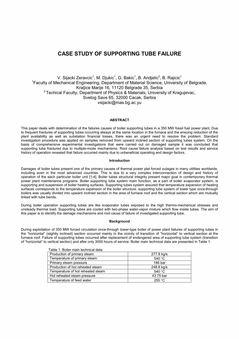
Background During exploitation of 350 MW forced circulation once-through tower-type boiler of power plant failures of supporting tubes in the ”horizontal” (slightly inclined) section occurred mainly in the vicinity of transition of ”horizontal” to vertical section at the furnace roof. Failure of supporting tubes occurred after replacement of endangered area of supporting tube system (transition of ”horizontal” to vertical section) and after only 3000 hours of service. Boiler main technical data are presented in Table 1. Table 1: Boiler main technical data
Production of primary steam 277.8 kg/s Temperature of primary steam 540 °C Primary steam pressure 186 bar Production of hot reheated steam 248.8 kg/s Temperature of hot reheated steam 540 °C Hot reheated steam pressure 43.75 bar Temperature of feed water 255 °C
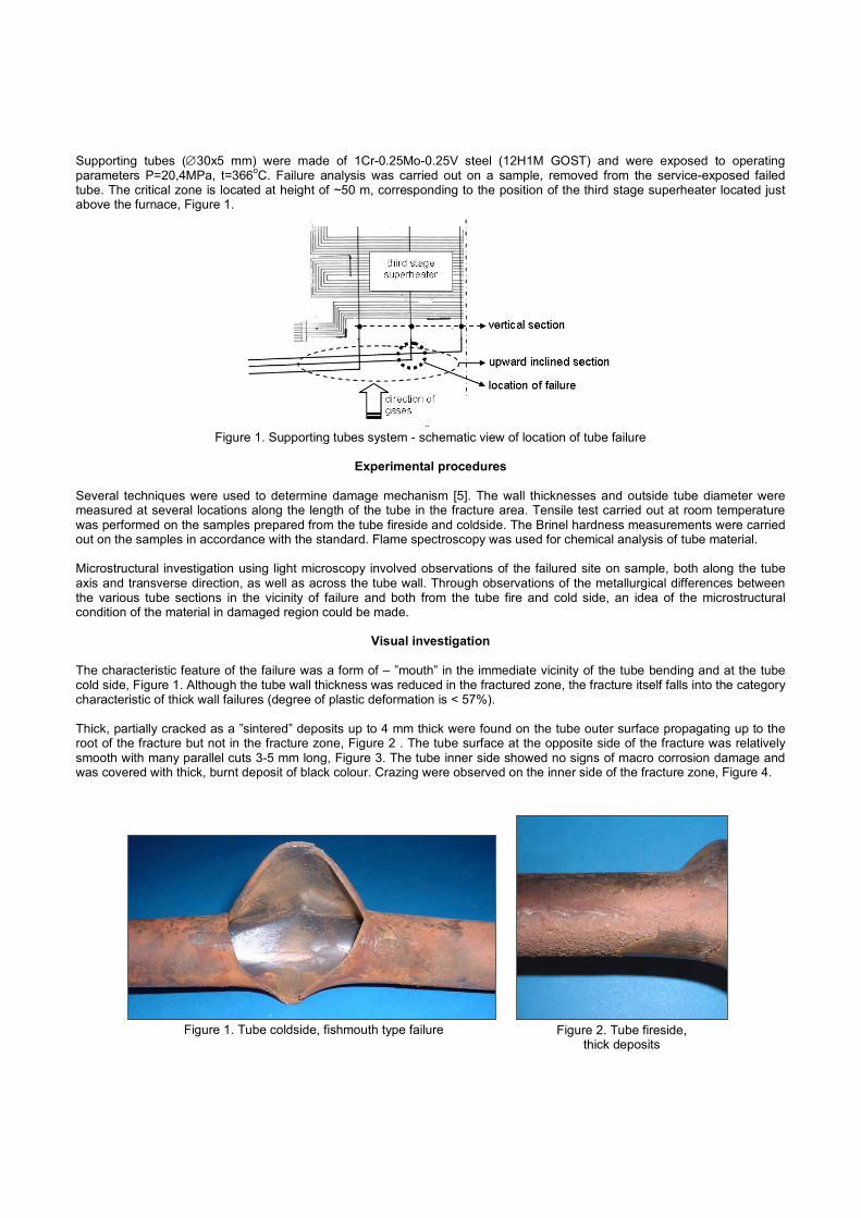
Supporting tubes (∅30x5 mm) were made of 1Cr-0.25Mo-0.25V steel (12H1M GOST) and were exposed to operating parameters P=20,4MPa, t=366oC. Failure analysis was carried out on a sample, removed from the service-exposed failed tube. The critical zone is located at height of ~50 m, corresponding to the position of the third stage superheater located just above the furnace, Figure 1.
Figure 1. Supporting tubes system - schematic view of location of tube failure
Experimental procedures
Several techniques were used to determine damage mechanism [5]. The wall thicknesses and outside tube diameter were measured at several locations along the length of the tube in the fracture area. Tensile test carried out at room temperature was performed on the samples prepared from the tube fireside and coldside. The Brinel hardness measurements were carried out on the samples in accordance with the standard. Flame spectroscopy was used for chemical analysis of tube material. Microstructural investigation using light microscopy involved observations of the failured site on sample, both along the tube axis and transverse direction, as well as across the tube wall. Through observations of the metallurgical differences between the various tube sections in the vicinity of failure and both from the tube fire and cold side, an idea of the microstructural condition of the material in damaged region could be made.
Visual investigation
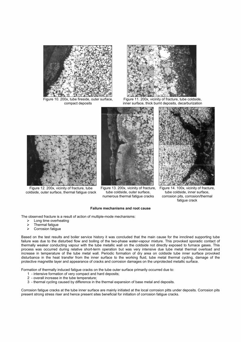
The characteristic feature of the failure was a form of – ”mouth” in the immediate vicinity of the tube bending and at the tube cold side, Figure 1. Although the tube wall thickness was reduced in the fractured zone, the fracture itself falls into the category characteristic of thick wall failures (degree of plastic deformation is < 57%). Thick, partially cracked as a ”sintered” deposits up to 4 mm thick were found on the tube outer surface propagating up to the root of the fracture but not in the fracture zone, Figure 2 . The tube surface at the opposite side of the fracture was relatively smooth with many parallel cuts 3-5 mm long, Figure 3. The tube inner side showed no signs of macro corrosion damage and was covered with thick, burnt deposit of black colour. Crazing were observed on the inner side of the fracture zone, Figure 4.
Figure 1. Tube coldside, fishmouth type failure Figure 2. Tube fireside, thick deposits

Dimension control The tube wall thickness in the fracture zone is less than nominal 5.0 mm and in the range 2.2 – 3.5 mm. The zones outside the fractured one were nearly intact with thickness close to the nominal (4.7-5.1 mm) The outer diameter of tube sample had increased from the original value of 30 mm to a maximum of about 35 mm in the vicinity of fishmouth type failure. The length of the failure was approximately 70 mm. It was interested to note that secondary cracks in the vicinity of fishmouth failure were not observed.
Chemical composition analysis Chemical composition of investigated material on the tube fireside as well as the standard data for 12H1MF steel (GOST TU 14-3-460-75) are presented in Table 2. The results obtained for supporting tube are satisfactory other than carbon content which was significantly lower than minimum standard recommended value. Table 2: Chemical composition of investigated samples
Chemical composition, wt % C Si Mn P S Cr Mo V
specimen 0.053 0.228 0.562 0.005 0.014 1.003 0.257 0.194 12H1MF TU 14-3-460-75
0.08-0.15
0.17-0.37
0.40-0.70
max 0.025
max 0.025
0.90-1.20
0.25-0.35
0.15-0.30
Mechanical properties
The results of mechanical testing carried out on the specimens prepared from the part of the tube outside the fracture zone both from the tube fireside (specimen1) and tube coldside (specimen2) are given in Table 3. The results show that none of the measured parameters was satisfactory indicating that the material was in the state of an increased brittlement. Table 3: Chemical composition of investigated samples
Yield stress, MPa
Tensile strength, MPa
Elongation, %
Hardness, HBS
specimen 1 445 676 20 233-277 specimen 2 402 669 20 242-276 12H1MF TU 14-3-460-75 min 260 450-610 min 21 143-185
Figure 3. Tube fireside, deposit, crazing
Figure 4. Tube coldside, fracture zone, burnt deposit of black color, crazing

Microstructural investigation Based on the microstructural investigation carried out on the different sections of the supporting tube sample the following feature were observed:
Microstructure of all samples tested is characterisitc of the overheating/overburning, Figure 5-6. Degree of the overheating/overburning was more pronounced at the inner suface layer of the tube coldside in the
vicinity of fracture where overburn microstructure was observed with a complete thermal decomposition of the microstructural phases, Figure 7-8
The grain growth and the presence of decarburized layer is characterisitic of the subsurface layers on the tube outer side, Figure 9
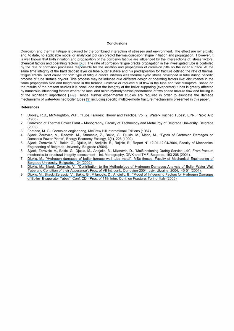
At the outer side of the tube, specifically on the fire side, a very compact deposits up to 5 mm thick were present, Figure 10
At the ineer side of the tube, thick, burnt deposits were present, Figure 11 The presences of numerous thermal fatigue cracks were observed at the tube outer side at the locations where the
deposit fractured transversally, Figure 12-13 and where thermal and corrosion fatigue occurred from the tube inner side at the site of corrosion pits, Figure 14.
Figure 5. 200x, tube fireside, near outer surface, thermal decomposition
Figure 6. 200x, tube coldside, near inner surface, thermal decomposition
Figure 7. 1000x, vicinity of fracture, tube coldside, middle section, overburning –
complete thermal decomposition
Figure 8. 200x, vicinity of fracture tube coldside, overburning,
thermal fatigue crack
Figure 9. 200x, tube coldside, outer surface, decarburization, grain growth,
thermal decomposition
Failure mechanisms and root cause
The observed fracture is a result of action of multiple-mode mechanisms: Long time overheating Thermal fatigue Corrosion fatigue
Based on the test results and boiler service history it was concluded that the main cause for the innclined supporting tube failure was due to the disturbed flow and boiling of the two-phase water-vapour mixture. This provoked sporadic contact of thermally weaker conducting vapour with the tube metallic wall on the coldside not directly exposed to furnace gases. This process was occurred during relative short-term operation but was very intensive due tube metal thermal overload and increase in temperature of the tube metal wall. Periodic formation of dry area on coldside tube inner surface provoked disturbance in the heat transfer from the inner surface to the working fluid, tube metal thermal cycling, damage of the protective magnetite layer and appearance of cracks and corrosion damages on the unprotected metallic surface. Formation of thermally induced fatigue cracks on the tube outer surface primarily occurred due to:
1 - intensive formation of very compact and hard deposits; 2 - overall increase in the tube temperature; 3 - thermal cycling caused by difference in the thermal expansion of base metal and deposits.
Corrosion fatigue cracks at the tube inner surface are mainly initiated at the local corrosion pitts under deposits. Corrosion pits present strong stress riser and hence present sites beneficial for initiation of corrosion fatigue cracks.
Figure 10. 200x, tube fireside, outer surface, compact deposits
Figure 11. 200x, vicinity of fracture, tube coldside, inner surface, thick burnt deposits, decarburization
Figure 12. 200x, vicinity of fracture, tube coldside, outer surface, thermal fatigue crack
Figure 13. 200x, vicinity of fracture, tube coldside, outer surface,
numerous thermal fatigue cracks
Figure 14. 100x, vicinity of fracture, tube coldside, inner surface,
corrosion pits, corrosion/thermal fatigue crack
Conclusions
Corrosion and thermal fatigue is caused by the combined interaction of stresses and environment. The effect are synergistic and, to date, no applicable model or analytical tool can predict thermal/corrosion fatigue initiation and propagation. However, it is well known that both initiation and propagation of the corrosion fatigue are influenced by the intereactions of: stress factors, chemical factors and operating factors [3,6]. The rate of corrosion fatigue cracks propagation in the investigated tube is controled by the rate of corrosion processes responsible for the initiation and propagation of corrosion pitts on the inner surface. At the same time integrity of the hard deposit layer on tube outer surface and his predisposition for fracture defined the rate of thermal fatigue cracks. Root cause for both type of fatigue cracks initiation was thermal cyclic stress developed in tube during periodic process of tube surface dry-out. This process may be induced due diifferent design or operating factors like: disturbance in the flame propagation side and height-wise in the furnace, unstable or reduced fluid flow in the tube and flow disruptors. Based on the results of the present studies it is concluded that the integrity of the boiler supporing (evaporator) tubes is greatly affected by numerous influencing factors where the local and micro hydrodynamics phenomena of two phase mixture flow and boiling is of the significant importance [7-9]. Hence, further experimental studies are required in order to elucidate the damage mechanisms of water-touched boiler tubes [9] including specific multiple-mode fracture mechanisms presented in this paper. References 1. Dooley, R.B., McNaughton, W.P., “Tube Failures: Theory and Practice, Vol. 2, Water-Touched Tubes”, EPRI, Paolo Alto
(1988). 2. Corrosion of Thermal Power Plant – Monography, Faculty of Technology and Metalurgy of Belgrade University, Belgrade
(2002). 3. Fontana, M. G., Corrosion engineering, McGraw Hill International Editions (1987). 4. Sijacki Zeravcic, V., Radovic, M., Stamenic, Z., Bakic, G., Djukic, M., Matic, M., “Types of Corrosion Damages on
Domestic Power Plants“, Energy-Economy-Ecology, 3(1), 223 (1999). 5. Sijacki Zeravcic, V., Bakic, G., Djukic, M., Andjelic, B., Rajicic, B., Report No 12-01-12.04/2004, Faculty of Mechanical
Engineering of Belgrade University, Belgrade (2004). 6. Sijacki Zeravcic, V., Bakic, G., Djukic, M., Andjelic, B., Milanovic, D., ”Malfunctioning During Service Life”, From fracture
mechanics to structural integrity assessment – Int. Monography, DIVK and TMF, Belgrade, 193-208 (2004). 7. Djukic, M., ”Hydrogen damages of boiler furnace wall tube metal”, MSc theses, Faculty of Mechanical Engineering of
Belgrade University, Belgrade, 124 (2002). 8. Djukic, M., Sijacki Zeravcic, V., ”Contribution to the Methodology of Hydrogen Damages Analysis of Boiler Water Wall
Tube and Condition of their Apperance”, Proc. of VII Int. conf., Corrosion-2004, Lviv, Ukraine, 2004, 45-51 (2004). 9. Djukic, M., Sijacki Zeravcic, V., Bakic, G., Milanovic, D., Andjelic, B., ”Model of Influencing Factors for Hydrogen Damages
of Boiler Evaporator Tubes”, Conf. CD - Proc. of 11th Inter. Conf. on Fracture, Torino, Italy (2005).