Smart Pressure Transmitter User's Manual - Azbil Corporation
Upload
khangminh22Category
view
1download
0
Smart Displacement typeLevel Transmitter
Model SLX 110/120
User’s Manual
CM2-SLX100-2001

Copyright, Notices and Trademarks
© 2001-2020 Azbil Corporation. All Rights Reserved.
While this information is presented in good faith and believed to be accurate, Azbil Corporation disclaims the implied warranties of mer-chantability and fitness for a particular purpose and makes no express warranties except as may be stated in its written agreement with and for its customer.
In no event is Azbil Corporation liable to anyone for any indirect, spe-cial or consequential damages. This information and specifications in this document are subject to change without notice.

Thank you for purchasing the Azbil Corporation smart displacement type level transmitter.
Model SLX110/120 offers high performance and highly reliable level transmitters with a microprocessor incorporated in each one.
Most operations such as starting measurement, reading of measured data, check or change of various set values and setting condition, etc. can be easily performed by using the smart communicator SFC.


Model SLX 110/120 - Smart displacement type level transmitter i
Safety
About this manualCorrect installation, operation and periodic maintenance are essential to the safe use of this instrument. Carefully read the safety precautions described in this instruction manual and have a thorough understanding before starting installation, operation or maintenance.
When you receive the product, check to see if it is of the correct specifications or if there is any damage caused by transportation. This instrument is shipped after being tested according to a strict quality control program. If you find any omissions in aspects of quality and specifications, inform us of the model number and product number described on the identification plate.
The identification plate is attached to the transmitter part.
WARNING
Indicates a potentially hazardous situation that may result in death or serious injury in the event of improper handling.
CAUTION
Indicates a potentially hazardous situation that may result in light to moderate injuries or only in property damage in the event of improper handling.
For correct and safe use of the instrument, be sure to observe the cautions described on the following pages. Azbil Corporation will not be responsible for any damage that is a result of handling of the product against these cautions.

Safety Azbil Corporation
ii Model SLX 110/120 - Smart displacement type level transmitter
Safety precautions
Cautions on installation
WARNING
• Do not use the instrument beyond the rated pressure, connection specification and rated temperature specified for the instrument. This may result in serious accident due to damage.
• Wiring in an explosion-proof area should be performed according to the work procedure specified in the explosion-proof guideline.
CAUTION
• After installation, do not use this instrument as a foothold, etc. This may damage the instrument or may result in physical injury
• Avoid hitting the glass part of the display with tools. This may damage the glass and result in physical injury.
• Perform installation correctly. Insufficient installation or no installation may result in output errors or violate applicable regulations.
• This product is heavy. Pay attention to the scaffolding and wear safety shoes.
Cautions on wiring
WARNING
Do not perform wiring with wet hands or with power turned on. This may result in electrical shock. Work with dry hands or wear gloves and turn off power.
CAUTION
• Carefully check the specifications and perform wiring correctly. Incorrect wiring may damage the instrument or cause mis-operation.
• Use a power supply that conforms to the specifications. Using the wrong power supply may damage the instrument.
Azbil Corporation Safety
Model SLX 110/120 - Smart displacement type level transmitter iii
Cautions on maintenance
WARNING
• When removing this instrument from the process for maintenance, be especially careful of residual pressure or any residual fluid remaining in the process line or in the instrument.
• When carrying out venting or draining, check the direction of venting or draining and prevent it from coming into contact with the human body. This may result in burns or physical injury.
• When the instrument is used in an explosion-proof area, do not leave the transmitter part uncovered for fear of sparks or ignition.
CAUTION
This instrument is shipped under strict product control by Azbil Corporation. Do not modify the instrument under any circumstances as this may damage the instrument.
Cautions on use of communication devices
CAUTION
Using a transceiver, cellular phone, pager, etc. near this instrument may prevent the instrument from functioning correctly depending on the transmission frequency being used. Observe the following precautions.
• Check beforehand the distance at which the communication device will not affect the operation of this instrument and use the communication device at a greater distance.
• Use the communication device after putting the cover on the transmitter part.

iv Model SLX 110/120 - Smart displacement type level transmitter

Table of Contents
Chapter 1 : Installation1-1 : Names of components and parts .................................................................. 1-11-2 : Safety precautions ........................................................................................ 1-41-3 : Specifications ................................................................................................ 1-41-4 : Installation condition ..................................................................................... 1-4
Installation standard of explosion-proof type .............................................. 1-51-5 : Unpacking and storage ................................................................................. 1-6
Unpacking .................................................................................................. 1-6Checking instrument .................................................................................. 1-6Checking specification ............................................................................... 1-7Storage ....................................................................................................... 1-7
1-6 : Installation method ........................................................................................ 1-9External type .............................................................................................. 1-9Internal type ............................................................................................... 1-9Heat insulation ........................................................................................... 1-10Main unit, float mounting procedure ........................................................... 1-10
In case of external type (* when float is set after main unit is fixed) .. 1-11In the case of internal type (when float is set before main unit is fixed) 1-16Flange bolt tightening torque ............................................................. 1-16
Electrical wiring .......................................................................................... 1-18Wiring for waterproof model............................................................... 1-18Wiring for explosion-proof model ....................................................... 1-20
Chapter 2 : Operation2-1 : Principles of operation .................................................................................. 2-12-2 : Indicator (optional) ........................................................................................ 2-3
Component part names of indicator ........................................................... 2-3Digital display ............................................................................................. 2-3Analog bar graph display ........................................................................... 2-4Display during external adjustment switch operation ................................. 2-4
2-3 : Items to be checked before operation .......................................................... 2-5General checking procedure ...................................................................... 2-5Checking set data ...................................................................................... 2-6
SFC connections ............................................................................... 2-6Communication start .......................................................................... 2-7Checking set data .............................................................................. 2-8Printing example ................................................................................ 2-9
Zero span adjustment ................................................................................ 2-10When liquid level in chamber (liquid tank) can be changed up to upper limit ..................................................... 2-10When adjusting zero point to output value according to real level .... 2-16
Table of Contents
2-4 : Operation start .............................................................................................. 2-18Before operation start ................................................................................. 2-18Start operation ............................................................................................ 2-18When steady operation is reached ............................................................. 2-18
2-5 : Operation stop .............................................................................................. 2-192-6 : Operation using SFC .................................................................................... 2-19
Principles of key operation ......................................................................... 2-19Interaction with screen ............................................................................... 2-20
Correction of input ............................................................................. 2-20SFC keyboard ............................................................................................ 2-21Basic operation of key input ....................................................................... 2-22SFC key functions ...................................................................................... 2-23
Green key functions ........................................................................... 2-24Orange key functions ......................................................................... 2-26Yellow key functions .......................................................................... 2-28Dark green key functions ................................................................... 2-30White key functions............................................................................ 2-31
Dedicated functions .................................................................................... 2-32Operation when starting measurement ..................................................... 2-32Display measured data .............................................................................. 2-33
Liquid level input (mm)....................................................................... 2-33Output being transmitted (%) ............................................................. 2-33Torque tube temperature (°C) ........................................................... 2-33Angle sensor temperature (°C) .......................................................... 2-35Input angle ......................................................................................... 2-36
Displaying and changing set data for measurement .................................. 2-37Lower range value (LRV) ................................................................... 2-37Upper range value (URV) .................................................................. 2-40Span .................................................................................................. 2-41Specific gravity................................................................................... 2-42Torque tube temperature coefficient .................................................. 2-44Range ................................................................................................ 2-46Offset angle ....................................................................................... 2-48Material coefficient ............................................................................. 2-50Damping time constant ...................................................................... 2-52
Printing ....................................................................................................... 2-53How to feed recording paper ............................................................. 2-53Maintenance printout ......................................................................... 2-54Action printout .................................................................................... 2-56
Display and change of setting of this instrument ........................................ 2-58Changeable and non-changeable data ............................................. 2-58Tag No. .............................................................................................. 2-59Serial number .................................................................................... 2-60Software version ................................................................................ 2-61Indicator display format...................................................................... 2-62

Table of Contents
Engineering unit value ....................................................................... 2-63Burnout direction................................................................................ 2-65
DE output format ........................................................................................ 2-67Output signal mode setting ................................................................ 2-67Information quantity setting................................................................ 2-67Fail-safe mode setting ....................................................................... 2-67
Constant current source mode ................................................................... 2-68Constant current source mode setting ............................................... 2-68Cancellation of constant current source mode .................................. 2-69
Memo recording ......................................................................................... 2-69Writing to scratch pad 1 ..................................................................... 2-69Writing to scratch pad 2 ..................................................................... 2-72
Charging SFC ............................................................................................ 2-72Procedure .......................................................................................... 2-73
2-7 : Operation of external adjustment switch (with indicator) .............................. 2-74Basic operation method ............................................................................. 2-74Function ..................................................................................................... 2-74Operation procedure .................................................................................. 2-75
Zero adjustment to adjust to real level (pinpoint adjustment) ............ 2-75Damping adjustment .......................................................................... 2-76Zero span adjustment ........................................................................ 2-76Zero adjustment ................................................................................. 2-77Span adjustment ................................................................................ 2-78Operation sequence .......................................................................... 2-79
Chapter 3 : Maintenance3-1 : Daily maintenance items ............................................................................... 3-1
Visual inspection ........................................................................................ 3-1Zero adjustment ......................................................................................... 3-1
3-2 : Items of periodic maintenance check ........................................................... 3-2Verification of functions .............................................................................. 3-2Disassembly and cleaning of wetted parts ................................................. 3-2
Primary disassembly/cleaning (when inside of torque tube housing is not cleaned) ......................... 3-2Secondary disassembly/cleaning (cleaning inside of torque tube housing) ............................................................................................. 3-4Reassembly, reinstallation ................................................................. 3-5Handling of torque tube ..................................................................... 3-6
Inspection of instrument ............................................................................. 3-6Zero and span adjustment ......................................................................... 3-7
3-3 : When output shift is large ............................................................................. 3-8Adjustment ................................................................................................. 3-8
3-4 : Zero span calibration with weight ................................................................. 3-12Difference between adjustment and calibration ......................................... 3-12
Table of Contents
Adjustment (key sequence [SET], [ENTER]): .................................... 3-12Calibration (key sequence [CORRECT], [ENTER]): .......................... 3-12
Procedure for calibration with weight ......................................................... 3-133-5 : Calibrating output signal ............................................................................... 3-17
Instruments used ........................................................................................ 3-17Setup .......................................................................................................... 3-17Calibrating output signal 0% ...................................................................... 3-18Calibrating output signal 100% .................................................................. 3-20Saving calibrated values and canceling constant current source mode .... 3-22
3-6 : Returning all set data to factory settings ....................................................... 3-233-7 : Insulation resistance test and withstand voltage test .................................... 3-24
Test procedure ........................................................................................... 3-24Judgment criteria ........................................................................................ 3-24
3-8 : Replacement parts and recommended replacement cycle ........................... 3-25Replacement parts list ................................................................................ 3-25Table for selection of chamber-bonnet gasket parts ................................. 3-26Recommended replacement cycle ............................................................. 3-27Replacing terminal block with indicator (LCD) ........................................... 3-27
3-9 : Starting instrument after maintenance .......................................................... 3-29
Chapter 4 : Repair4-1 : Using dedicated apparatus necessary for repair .......................................... 4-24-2 : Troubleshooting ............................................................................................ 4-2
Operation check ......................................................................................... 4-2When error occurs during communication ................................................. 4-3Self-diagnostic message ............................................................................ 4-4
When this instrument is suspected to involve error (serious fault or light fault)............................................. 4-4
Indicator (option) error messages .............................................................. 4-8Self-diagnostics upon power-up ........................................................ 4-8Self-diagnostics during normal operation ......................................... 4-8
4-3 : Removal/installation method ......................................................................... 4-10
Chapter 5 : Cautions Regarding Explosion-proof Models5-1: Cautions Regarding Explosion-proof Models ............................................... 5-1

List of Figure
Figure 1-1 Main Unit Section (T type, S-S type, S-B type) .......................................................1-1Figure 1-2 Main Unit Section (T-S type, T-B type) ....................................................................1-1Figure 1-3 Chamber ..................................................................................................................1-2Figure 1-4 Float .........................................................................................................................1-2Figure 1-5 Float mounting tool ..................................................................................................1-2Figure 1-6 Hexagon wrench ......................................................................................................1-2Figure 1-7 Sticker of measuring unit .........................................................................................1-3Figure 1-8 Gasket .....................................................................................................................1-3Figure 1-9 Nameplate ...............................................................................................................1-5Figure 1-10 Float and hanger .....................................................................................................1-7Figure 1-11 4 view of an internal type installation .......................................................................1-9Figure 1-12 Applying heat installation .........................................................................................1-10Figure 1-13 Removing a bling flange ..........................................................................................1-11Figure 1-14 Inside the chamber ..................................................................................................1-11Figure 1-15 ................................................................................................................................1-13Figure 1-16 Float mounting tool ..................................................................................................1-14Figure 1-17 Float hanger section ................................................................................................1-14Figure 1-18 View from bonnet head ............................................................................................1-14Figure 1-19 Mounting the float hanger (Case 1) .........................................................................1-15Figure 1-20 Mounting the float hanger (case2) ...........................................................................1-15Figure 1-21 Blind flange and bonnet flange bolts .......................................................................1-16Figure 1-22 Electrical wiring ........................................................................................................1-18Figure 1-23 Electrical wiring when voltage input (1 to 5 V) .........................................................1-18Figure 1-24 Relationship between Supply Voltage and External Load Resistance ....................1-20Figure 1-25 Locking of transmitter part Case ..............................................................................1-21Figure 1-26 Cable gland .............................................................................................................1-21Figure 1-27 Overall view of cable gland ......................................................................................1-22Figure 1-28 Exploded view of cable gland ..................................................................................1-22Figure 1-29 Structure of Pressure-Proof Elbow ..........................................................................1-23Figure 1-30 Cable gland connections .........................................................................................1-23Figure 1-31 Matching lock nut end face and O-ring groove end face .........................................1-25Figure 1-32 Hook spanner pin type -FP ......................................................................................1-25Figure 2-1 Schematic Structural Drawing .................................................................................2-2Figure 2-2 Signal Block Diagram ..............................................................................................2-2Figure 2-3 Names of Parts of Indicator Display Section ...........................................................2-3Figure 2-4 4.5 digit 7 segment LCD ..........................................................................................2-3Figure 2-5 Error Display on Indicator ........................................................................................2-3Figure 2-6 Connection with SFC ...............................................................................................2-6Figure 2-7 SFC keyboard ..........................................................................................................2-21Figure 2-8 Switch position .........................................................................................................2-74Figure 3-1 ................................................................................................................................3-3Figure 3-2 ................................................................................................................................3-4Figure 3-3 ................................................................................................................................3-4Figure 3-4 Placing torque tube housing assembly on bonnet ...................................................3-5Figure 3-5 Setting the torque arm .............................................................................................3-5Figure 3-6 Points of calibration loaded .....................................................................................3-13Figure 3-7 Setup for output signal calibration ...........................................................................3-17Figure 3-8 Replacement parts ..................................................................................................3-25Figure 3-9 An installed terminal block with LCD indicator .........................................................3-27

List of Table
Table 1-1: Shipping accessory reference table ........................................................................1-6Table 1-2: Azbil Corporation standard product external type S-B type, T-B type .....................1-12Table 1-3: Tightening Torque ...................................................................................................1-17Table 1-4: Temperature level for Explosion-proof ....................................................................1-21Table 2-1: Display during external adjustment switch operation ..............................................2-4Table 2-2: ................................................................................................................................2-79Table 3-1: Tightening torques for flange bolts and screw .........................................................3-6

Model SLX 110/120 - Smart displacement type level transmitter 1-1
Chapter 1 : Installation
1-1 : Names of components and partsMain unit (external type side - side (S-S), external type side - bottom (S-B), internal type top (T))
+
-
Bonnet
Bolt/NutGasket
Cover
Torque tubehousing
ExtensionSensorhousing
Caseof transmitter
External adjustment switch(Available only when built-inindicator is mounted)
Transmitter position : Left side
Transmitter position :Right side
Figure 1-1 Main Unit Section (T type, S-S type, S-B type)
Main unit (external type top - side (T-S), external type top - bottom (T-B))
+
-
Bonnet
Cover
Torque tubehousing
ExtensionSensorhousing
Caseof transmitter
External adjustment switch(Available only when built-inindicator is mounted)
Transmitter position : Left side
Transmitter position :Right side
Figure 1-2 Main Unit Section (T-S type, T-B type)

Installation Azbil Corporation
1-2 Model SLX 110/120 - Smart displacement type level transmitter
(T-B) (T-S)(S-S) (S-B)
Figure 1-3 Chamber
Figure 1-4 Float
Others (accessories)
Figure 1-5 Float mounting tool
Figure 1-6 Hexagon wrench

Azbil Corporation Installation
Model SLX 110/120 - Smart displacement type level transmitter 1-3
Pa hPa kPa MPa kPaGMPaG Pa abs hPa abs kPa abs MPa abs
mmH2O mmAq inH2O gf/cm2 kgf/cm2
atm mbar bar psi mmHginHg kgf/cm2 G mbar G bar G m3
kgf/cm2 abs mmHg abs inHg abs km/h l/h k/h Sk /h t/hm3/h km3/h Nm3/h kNm3/h /min
k/min m3/min Nm/min N/min Nm3/mink/D m3/D t/D Nm3/D kg/hmm m kg/m3 g/cm3 %
t kgX10 X102 X103
RANGE80370187-001 REV 05
0 50 100 0 50 100
Figure 1-7 Sticker of measuring unit
Figure 1-8 Gasket
Installation Azbil Corporation
1-4 Model SLX 110/120 - Smart displacement type level transmitter
1-2 : Safety precautions
WARNING
• Do not use the instrument beyond the rated pressure, connection specification and rated temperature specified for the instrument. This may result in serious accident due to damage.
• Wiring in an explosion-proof area should be performed according to the work procedure specified in the explosion-proof guideline.
CAUTION
• After installation, do not use this instrument as a foothold, etc. This may damage the instrument or may result in physical injury
• Avoid hitting the glass part of the display with tools. This may damage the glass and result in physical injury.
• Perform installation correctly. Insufficient installation or no installation may result in output errors or violate applicable regulations.
• This product is heavy. Pay attention to the scaffolding and wear safety shoes.
1-3 : SpecificationsRefer to specification sheets No. SS2-SLX100-0100.
1-4 : Installation condition
CAUTIONS
• If the instrument receives radiant heat from the plant side, make sure the ambient temperature of the transmitter part meets the operating conditions.
• Pay attention to the relationship between the fluid temperature and ambient temperature.
• Avoid installation in a corrosive atmosphere.
• Install the instrument in an environment with a vibration acceleration of 5 m/s2 (9 to 60 Hz) or less.
• Install the instrument in an environment with a magnetic field of 1 mT or less.• Install the instrument in an environment with an electromagnetic induction of 400
A/m or less.

Azbil Corporation Installation
Model SLX 110/120 - Smart displacement type level transmitter 1-5
Installation standard of explosion-proof type* Reference material: National Institute of Industrial Safety Technical Guideline/”Factory Explosion-Proof Electrical Installation Guide for Users (Gas Explosion-Proof 1994)” issued by corporate judicial person Technology Institution of Industrial Safety.
Install the instrument in a location that matches the following explosion class, ignition temperature and explosion-proof structure divisions.
(1) Explosion class and ignition temperature of target gas:
II CT3 (IIC: all gases/vapor, T3: gas/vapor with ignition temperature exceeding 200 ºC
II CT4 (IIC: all gases/vapor, T4: gas/vapor with ignition temperature exceeding 135 ºC
II CT5 (IIC: all gases/vapor, T5: gas/vapor with ignition temperature exceeding 100 ºC
II CT6 (IIC: all gases/vapor, T6: gas/vapor with ignition temperature exceeding 85 ºC
(2) Zones
Can be installed in “Zone 1” or “Zone 2”,
Can not be installed in “Zone 0”.
(3) Ambient temperature: -20 ºC to 55 ºC
The ambient temperature refers to “temperature in an atmosphere at a distance of 1 m or more from the instrument”.
WARNING
The explosion-proof performance cannot be guaranteed at a temperature exceeding 55 ºC.
An example of an identification plate and approval mark is shown below. (In the case of IICT6)
Figure 1-9 Nameplate

Installation Azbil Corporation
1-6 Model SLX 110/120 - Smart displacement type level transmitter
1-5 : Unpacking and storage
UnpackingUnpack the product with care so that no shock is given to the instrument.
Checking instrumentCheck to see if the following items are included.
• Main unit (section from bonnet above, including up to transmitter part)
• Float (not provided if “no float” is specified in model number)
• Chamber (not provided in the case of internal type or if “no chamber” is specified in model number)
• Float mounting tool (not provided if “no float” is specified in model number)
• Unit seal (inside transmitter part cover)
• Bolt/nut between chamber/bonnet (when “with external type chamber” is specified)
• Gasket between chamber/bonnet (when “external type chamber” is specified)
Table 1-1: Shipping accessory reference table
External type Internal type
Model number of options 2(Refer to Note)
Chamber - - -D -D - -
Float - -C - -C - -C
Instrument Accessory shipped
Main unit a a a a a a
Float a None a None a None
Chamber a a None None None None
Float mounting tool a None a None a None
Unit seal a a a a a a
Bolt / Nut a a None None None None
Gasket a a a a None None
Hexagon wrench a a a a a a
~Note
Basic model No. Selections Options 1 Options 2SLX110SLX120
- - -
The option “C” in the options 2 means “without float“.
The option “D” in the options 2 means “without chamber“.

Azbil Corporation Installation
Model SLX 110/120 - Smart displacement type level transmitter 1-7
CAUTION
• In the case of an internal type top type (top mount type) with an extremely long float, the product is shipped with the hanger and float separated as shown in the figure below.
• In this case, the total number of accessories is 3 (hanger, float and assembly pin).• Please assemble them, referring to the figure below.
Figure 1-10 Float and hanger
Assembly method:
(1) Remove the tag.
(2) Engage the hanger with the float so that the assembly pin can be inserted.
(3) Insert the assembly pin and adequately bend it using pliers so that the pin does not come out.
Checking specificationMake sure the specifications on the identification plate conform to your requirements.
Make sure the model number and product number of the main unit, float and chamber match.
• Tag No. (TAG No.)
• Model number (MODEL)
• Product number (PROD No.)
• Measuring range (RANGE)
• Supply voltage (SUPPLY)
• Explosion-proof certification approval mark (in the case of explosion-proof specification)
For any inquiries, contact your nearest Azbil Corporation branch or sales office and be sure to inform us of the model number and product number described on the identification plate.
Storage(In the case of long-term storage after purchase)
Store the product as it was delivered.

Installation Azbil Corporation
1-8 Model SLX 110/120 - Smart displacement type level transmitter
Store the product indoors at normal temperature, normal humidity (approximately 25°C, 65%RH), and free from vibration or shock.
Azbil Corporation Installation
Model SLX 110/120 - Smart displacement type level transmitter 1-9
1-6 : Installation method
External type• Install the chamber in a vertical position.
• If the chamber installed on an angle, the float will contact the chamber, preventing correct output from being obtained.
• If viscosity of the liquid to be measured increases in the chamber due to a temperature drop or if heat loss becomes a problem, it is recommended to keep the chamber and connection pipe path warm with a heat insulating material.
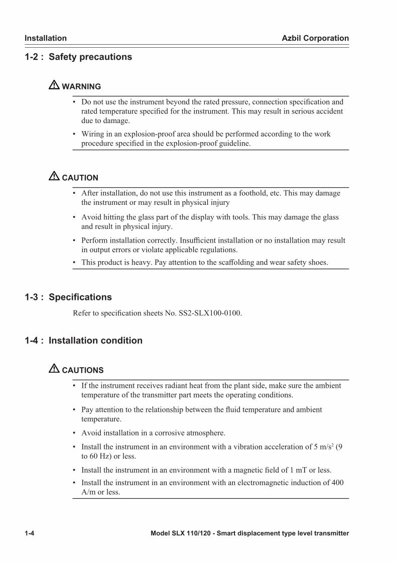
Internal typeIf the liquid level changes violently, prepare a guide pipe to prevent the float from vibrating.
+
-
Guide pipe
Figure 1-11 4 view of an internal type installation

Installation Azbil Corporation
1-10 Model SLX 110/120 - Smart displacement type level transmitter
Heat insulation
CAUTION
Do not apply heat insulation to the transmitter part and extension section under any circumstances. This may cause an increase in temperature at the transmitter part resulting in insufficient performance and early deterioration of component parts, etc.
ExtensionTramsmitter part
No warmer available.
Figure 1-12 Applying heat installation
Main unit, float mounting procedure
CAUTION
The provided float mounting tool does not fully support installation to chambers made by other manufacturers. When the main unit and float are installed in chambers of other manufacturers, check the possibility of installation beforehand.

Azbil Corporation Installation
Model SLX 110/120 - Smart displacement type level transmitter 1-11
In case of external type (* when float is set after main unit is fixed)
1. Remove the blind flange.
Gasket
Bonnet
Blind flange
Figure 1-13 Removing a bling flange
Float hanger
Gasket
Float rod
Chamber
Figure 1-14 Inside the chamber
Installation Azbil Corporation
1-12 Model SLX 110/120 - Smart displacement type level transmitter
CAUTION
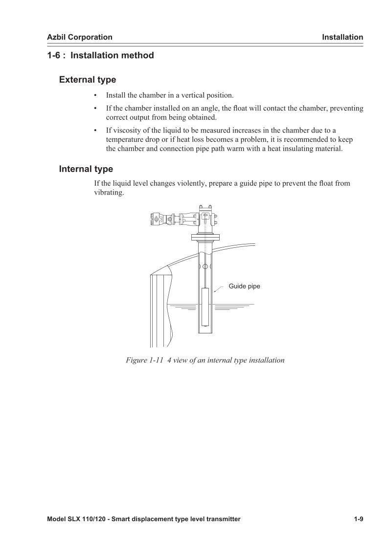
Caution on installation using float mounting tool (external type S-B type, T-B type)
• When the float is inserted into (placed below) the chamber first with some external type S-B type, T-B type, the float may drop into the lower section connection flange.
• In the case of an external type S-B type, T-B type, be sure to check whether the float drops or not when the float is installed in the chamber (see Table 1-2 : Azbil Corporation standard product external type S-B type, T-B type).
• If the float drops into the lower section connection flange, tilt the float so that it does not drop and carefully mount it or do not install it using the float mounting tool.
Table 1-2: Azbil Corporation standard product external type S-B type, T-B type
Basic model number Chamber size (in.)
Lower section connection flange
outer diameter
Lower section connection flange
inner diameter
SLX 110 3 1.5 in. / 40 mm2 in. / 50 mm
39.6 mm50.7 mm
SLX120(range 2000mm or more only)
4 1.5 in. / 40 mm2 in. / 50 mm
39.6 mm50.7 mm
SLX 120 5 1.5 in. / 40mm2 in. / 50 mm
39.6 mm50.7 mm
• For the float diameter, see Specification sheets No. SS2-SLX100-0100.

Azbil Corporation Installation
Model SLX 110/120 - Smart displacement type level transmitter 1-13
2. Slowly lower the main unit from the upper section of the chamber and fix it to the flange using bolts and nuts.
Figure 1-15
~Note • Check that the gasket has been inserted• Be careful not to bend the float rod.• For the tightening torque, See “Table 1-3 : Tightening Torque” on
page 1-17..

Installation Azbil Corporation
1-14 Model SLX 110/120 - Smart displacement type level transmitter
3. When viewed from the bonnet head, one can see that the bonnet interior is divided into 4 areas by the torque arm and pin (see the figure below). Insert the float mounting tool from the bonnet head, and adjust the float hanger so that it sits in a position as shown in case 1 or 2 (Figure 1-18).
~Note If the bonnet interior is dark, illuminate it with a flashlight.
Handle
Insert into the float hanger hole
Float hanger hole
Float hanger
Figure 1-16 Float mounting tool Figure 1-17 Float hanger section
Pin
Bonnet part
Torque arm
Float hanger point
Torque tube housing
Float hanger point Case 2:The float hanger should be located inthis area and the position of the floathanger hole is distant from the torquearm.
Case 1:The float hanger should be located inthis area and the position of the floathanger hole is distant from the torquearm.
Figure 1-18 View from bonnet head

Azbil Corporation Installation
Model SLX 110/120 - Smart displacement type level transmitter 1-15
4. Hook the float mounting tool through the float hanger hole by introducing the tool from the center outward, lift the float and hook the float hanger notch over the pin.
~Note • When lifting the float, be careful not to apply excessive force to the torque arm.
• Make sure the hanger is hooked over both sides of the pin.Case 1
A tool for mounting float
Bonnet stopper
Torque arm
Hanger
Cut image
Figure 1-19 Mounting the float hanger (Case 1)
Hook the float hanger over the pin while moving it forward the torque tube housing. (direction of arrow in the Figure 1-19)
Case 2
A tool formounting float Bonnet stopper
Torque arm
Hanger
Cut image
Figure 1-20 Mounting the float hanger (case2)
Hook the float hanger notch over the pin in the direction away from the torque tube housing (direction indicated by an arrow in the Figure 1-20).
5. Fix the blind flange with a nut.
• Do not forget to put the gasket on.
• For the tightening torque, see Flange bolt tightening torque.

Installation Azbil Corporation
1-16 Model SLX 110/120 - Smart displacement type level transmitter
In the case of internal type (when float is set before main unit is fixed)
(1) Remove the blind flange.(2) Insert the float into the liquid tank but make sure it doesn’t fall.(3) Move the main unit above the liquid tank and hold it from directly above.
~Note Use a crane pulley, etc. to lift it.
(4) Lift the float and hook the float hanger over the pin of the torque arm inside the main unit.
~Note • The float hanger can be oriented in any direction.• Make sure the hanger is hooked over both sides of the pin.
(5) Slowly lower the main unit from above the liquid tank and fix it to the flange using bolts and nuts.
~Note • Make sure the gasket is inserted in between.• For the tightening torque, see Table 1-3 : Tightening Torque.
(6) Fix the blind flange with a nut.
~Note • Do not forget to put the gasket on.• For the tightening torque, see Table 1-3 : Tightening Torque.
Flange bolt tightening torque
Blind flange
Bonnet flange
Figure 1-21 Blind flange and bonnet flange bolts

Azbil Corporation Installation
Model SLX 110/120 - Smart displacement type level transmitter 1-17
Table 1-3: Tightening Torque
Flange position Bolt size Tightening torque (N.m)
Blind flange M14 127 +/-20
Bonnet flange(3in. CLASS 150)(4in. CLASS 150)
M16 147 +/-20
Bonnet(3in. CLASS 300)(3in. CLASS 600)(4in. CLASS 300)(5in. CLASS 150)(5in. CLASS 300)
M20 245 +/-20

Installation Azbil Corporation
1-18 Model SLX 110/120 - Smart displacement type level transmitter
Electrical wiring
Wiring for waterproof modelThis section describes the wiring to which the explosion-proof standard is not applicable.
• Conduct wiring as shown in the figure below. An external load resistor of 250W or more is required for communication with the SFC.
• Both right and left conduits can be used.
• Put a plug into the conduit that is not used to prevent moisture or precipitation from entering.
CHK- / S- S+
CHK+/ M-
E
M+
DISP FLOW UP ZERO DOWN
SUPPLY+ (S+ Terminal)SUPPLY- (CHK- / S- Terminal)
Load resistancemore than 250 Ohms
Supply voltageDC 24V
Ground
External ground
-
+Control signal
4-20mA
Figure 1-22 Electrical wiring
In the case of a receiver with voltage input (1 to 5 V), conduct wiring as shown in the figure below.
CHK- / S - S+
CHK+ /M -
E
M+
DISP FLOW UP ZERO DOWN
%
SUPPLY+ (S+Terminal)SUPPLY- (CHK-/S-Terminal)
Load resistancemore than 250 Ohms
Supply voltage DC 24V
Ground
-
+
External ground
Control signal
4-20mA
Figure 1-23 Electrical wiring when voltage input (1 to 5 V)

Azbil Corporation Installation
Model SLX 110/120 - Smart displacement type level transmitter 1-19
Piping for wiringDraw wires into the transmitter part case as follows:
• Draw wire into the terminal section of this instrument by setting a conduit pipe in the conduit hole (G1/2 internal screw) next to this instrument and passing it through this pipe.
• To prevent precipitation from getting into this instrument, plug the conduit coupling section with a sealant or plug.
• Route the wiring cable in such a way so as it enters the main unit of this instrument from the lower section.
• Use a pressure-proof elbow to change the electrical wiring direction (1, 2, 3 indicated in additional specification) if required.
GroundingThere are two grounding terminals; one on the terminal block of this instrument (internal grounding terminal) and the other on the transmitter part case (external grounding terminal). Ground either one.
• Use a grounding terminal with a resistance to ground of 100 ohms or less or connect it to ground of good quality.
• The explosion-proof type absolutely requires grounding.
• Cautions when welding is performed near the transmitter part
• Ground the welding machine and the welding power supply transformer to a place different from the one for grounding of this instrument. The welding current may have adverse effects.
Power supply and external load resistanceIt is necessary to determine the relationship between the external load resistance used for this instrument and power supply voltage in such a way as it falls within the shaded area in the figure below.
The external load resistance refers to a sum total of resistances connected to the output terminal of this instrument such as the resistance of cables making up the loop and the internal resistance of the instruments connected at some midpoints.

Installation Azbil Corporation
1-20 Model SLX 110/120 - Smart displacement type level transmitter
The horizontal axis and vertical axis in the figure below are the power supply voltage and external load resistance respectively.
0 18.5 2413.0
250
45
Load
Res
ista
nce
(Ohm
s)
Supply voltage E (DC V)
1467
R=E-13
0.0218
500
Operable range
Figure 1-24 Relationship between Supply Voltage and External Load ResistanceNote) A load resistance of at least 250W is required for communication with the SFC.
Wiring for explosion-proof modelFor explosion-proof type wiring, see instructions on Wiring for waterproof model and the following instructions.
See National Institute of Industrial Safety technical guideline/”Factory Explosion-Proof Electrical Installation Guide for Users (Gas Explosion-Proof 1994)” issued by corporate judicial person Technology Institution of Industrial Safety, for details.
WARNING
• The pressure-proof packing type cable adapter provided for this instrument was subjected to a certificate examination as part of the transmitter part case and obtained a certificate of conformance. Therefore, note that conducting drawing of external wires in combination with a cable adapter other than the provided cable adapter will not be covered by the certificate.
• Fasten the transmitter part cover and lock it.It is mandatory to lock the cover of the explosion-proof transmitter part case.
Azbil Corporation Installation
Model SLX 110/120 - Smart displacement type level transmitter 1-21
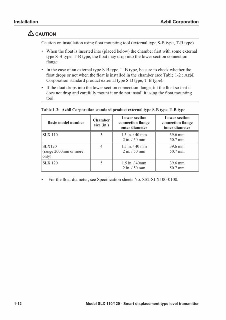
This instrument has a locking structure. First, unlock the transmitter part case using a hexagonal-head wrench (for fixing screw female M3 with hexagonal hole, across flats S=1.5 mm) and conduct wiring.
M3 (Cover locking screw)
Figure 1-25 Locking of transmitter part Case
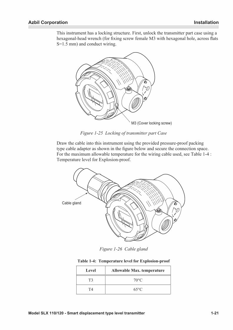
Draw the cable into this instrument using the provided pressure-proof packing type cable adapter as shown in the figure below and secure the connection space. For the maximum allowable temperature for the wiring cable used, see Table 1-4 : Temperature level for Explosion-proof.
Cable gland
Figure 1-26 Cable gland
Table 1-4: Temperature level for Explosion-proof
Level Allowable Max. temperature
T3 70°C
T4 65°C

Installation Azbil Corporation
1-22 Model SLX 110/120 - Smart displacement type level transmitter
Cable gland and flameproof universal elbow for JIS Flameproof apparatusThe cable gland is used to seal the terminal section of the cable, maintain the explosion-proof performance and improve the insulation performance and mechanical strength.
If it is necessary to change the orientation of the cable, use a pressure-proof elbow.
Structure of cable glandAn overall view and exploded view of the cable gland are shown below.
Figure 1-27 Overall view of cable gland
O-ring
Hub body
Packing case
Packing
Washer
Packing ground
Clamp ring
Clamp nut
Coupling
Union nut
Hexa -recess stopper screw
Hexa -recessstopper screw
Figure 1-28 Exploded view of cable gland

Azbil Corporation Installation
Model SLX 110/120 - Smart displacement type level transmitter 1-23
Flameproof universal elbowThe structure of the pressure-proof elbow is shown below.
O-ring
Lock nut
Elbow
Figure 1-29 Structure of Pressure-Proof Elbow
Mounting exampleAttach the cable gland and pressure-proof elbow to the conduit coupling opening of the terminal box as shown in the figure below.
When only cable gland is used When cable gland and pressure-proof elbow are used together
COVE
R MUST BE KEPT TIG
HTWHILECIRCUITSARE
ALIVE %
Cable gland
COVE
R MUST BE KEPT TIGHT
WHILECIRCUITSARE
ALIVE %
Elbow
Cable gland
Figure 1-30 Cable gland connections
Installation Azbil Corporation
1-24 Model SLX 110/120 - Smart displacement type level transmitter
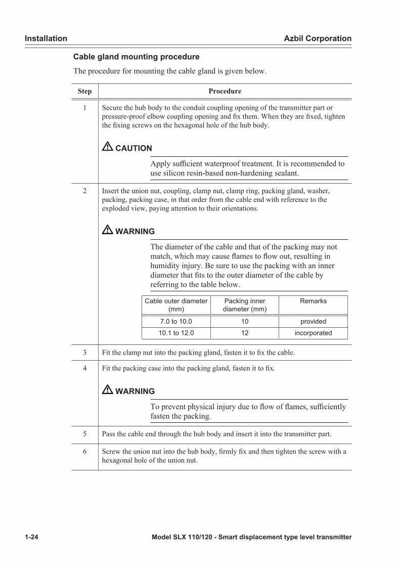
Cable gland mounting procedureThe procedure for mounting the cable gland is given below.
Step Procedure
1 Secure the hub body to the conduit coupling opening of the transmitter part or pressure-proof elbow coupling opening and fix them. When they are fixed, tighten the fixing screws on the hexagonal hole of the hub body.
CAUTION
Apply sufficient waterproof treatment. It is recommended to use silicon resin-based non-hardening sealant.
2 Insert the union nut, coupling, clamp nut, clamp ring, packing gland, washer, packing, packing case, in that order from the cable end with reference to the exploded view, paying attention to their orientations.
WARNING
The diameter of the cable and that of the packing may not match, which may cause flames to flow out, resulting in humidity injury. Be sure to use the packing with an inner diameter that fits to the outer diameter of the cable by referring to the table below.
Cable outer diameter (mm)
Packing inner diameter (mm)
Remarks
7.0 to 10.0 10 provided
10.1 to 12.0 12 incorporated
3 Fit the clamp nut into the packing gland, fasten it to fix the cable.
4 Fit the packing case into the packing gland, fasten it to fix.
WARNING
To prevent physical injury due to flow of flames, sufficiently fasten the packing.
5 Pass the cable end through the hub body and insert it into the transmitter part.
6 Screw the union nut into the hub body, firmly fix and then tighten the screw with a hexagonal hole of the union nut.

Azbil Corporation Installation
Model SLX 110/120 - Smart displacement type level transmitter 1-25
The flameproof universal elbow mounting procedureThe procedure for mounting the pressure-proof elbow is given below.
Step Procedure
1 Match the end face of the lock nut with the end face of the O-ring groove, referring to the figure below.
Elbow
Lock nut O-ringLock nut end face
O-ring groove end face
Figure 1-31 Matching lock nut end face and O-ring groove end face
2 Screw the pressure-proof elbow into the conduit coupling opening of the transmitter part until the lock nut end face touches the end face of the coupling opening.
CAUTION
Apply sufficient waterproof treatment.
3 Turn the pressure-proof elbow to loosen it then set it to the desired position.
CAUTION
Do not loosen more than one turn.
4 Firmly fasten the lock nut using a dedicated tool to fix.
* The dedicated tool includes a hook spanner pin type, etc. (e.g., FP3438 manufactured by ASAHI, JAN code 006454, etc.
Figure 1-32 Hook spanner pin type -FP

Installation Azbil Corporation
1-26 Model SLX 110/120 - Smart displacement type level transmitter
Model SLX 110/120 - Smart displacement type level transmitter 2-1
Chapter 2 : Operation
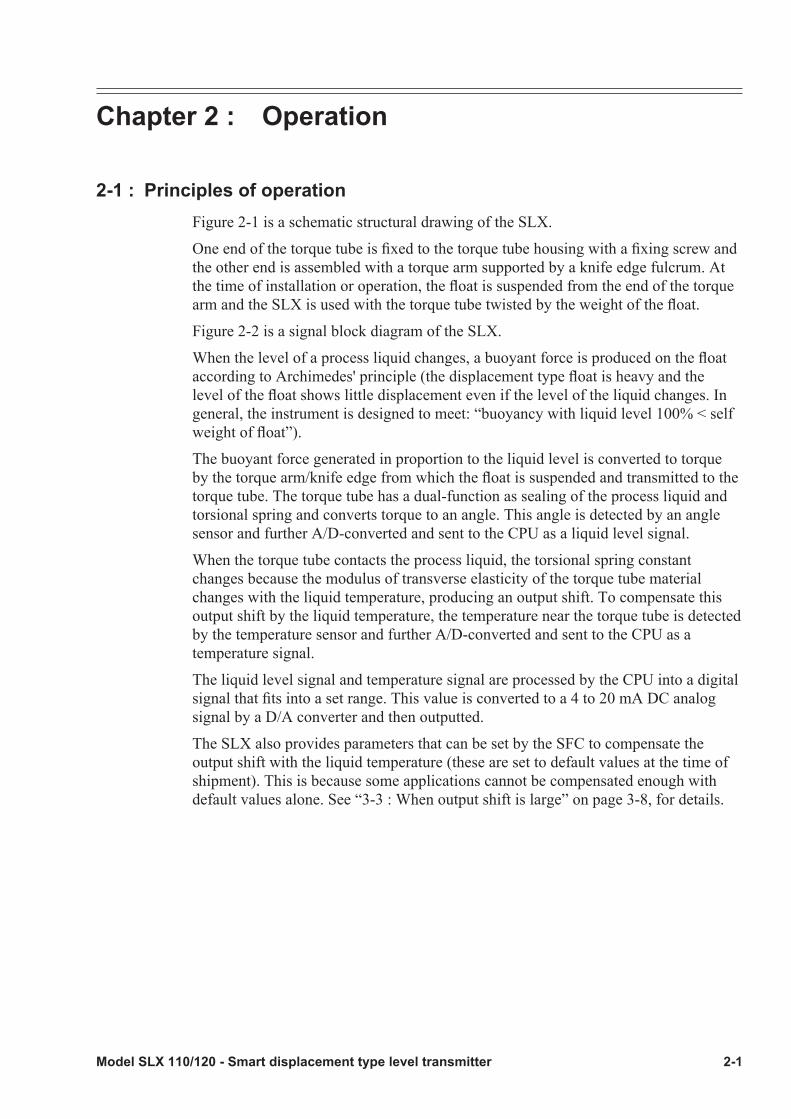
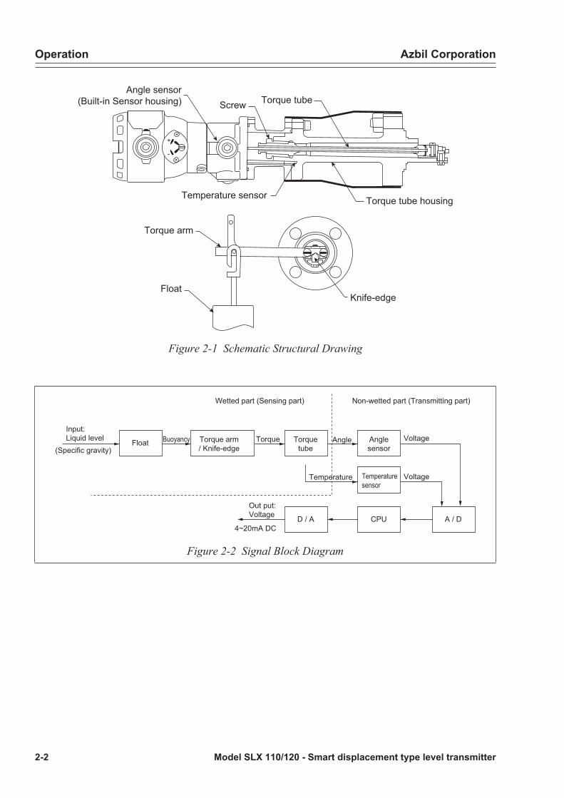
2-1 : Principles of operationFigure 2-1 is a schematic structural drawing of the SLX.
One end of the torque tube is fixed to the torque tube housing with a fixing screw and the other end is assembled with a torque arm supported by a knife edge fulcrum. At the time of installation or operation, the float is suspended from the end of the torque arm and the SLX is used with the torque tube twisted by the weight of the float.
Figure 2-2 is a signal block diagram of the SLX.
When the level of a process liquid changes, a buoyant force is produced on the float according to Archimedes' principle (the displacement type float is heavy and the level of the float shows little displacement even if the level of the liquid changes. In general, the instrument is designed to meet: “buoyancy with liquid level 100% < self weight of float”).
The buoyant force generated in proportion to the liquid level is converted to torque by the torque arm/knife edge from which the float is suspended and transmitted to the torque tube. The torque tube has a dual-function as sealing of the process liquid and torsional spring and converts torque to an angle. This angle is detected by an angle sensor and further A/D-converted and sent to the CPU as a liquid level signal.
When the torque tube contacts the process liquid, the torsional spring constant changes because the modulus of transverse elasticity of the torque tube material changes with the liquid temperature, producing an output shift. To compensate this output shift by the liquid temperature, the temperature near the torque tube is detected by the temperature sensor and further A/D-converted and sent to the CPU as a temperature signal.
The liquid level signal and temperature signal are processed by the CPU into a digital signal that fits into a set range. This value is converted to a 4 to 20 mA DC analog signal by a D/A converter and then outputted.
The SLX also provides parameters that can be set by the SFC to compensate the output shift with the liquid temperature (these are set to default values at the time of shipment). This is because some applications cannot be compensated enough with default values alone. See “3-3 : When output shift is large” on page 3-8, for details.
Operation Azbil Corporation
2-2 Model SLX 110/120 - Smart displacement type level transmitter
+
-
Torque arm
FloatKnife-edge
Torque tube housing
Torque tube
Temperature sensor
ScrewAngle sensor
(Built-in Sensor housing)
Figure 2-1 Schematic Structural Drawing
A / D
Float Torquetube
Anglesensor
Torque arm/ Knife-edge
Temperaturesensor
D / A CPU
AngleTorqueBuoyancyInput:Liquid level Voltage
VoltageTemperature
(Specific gravity)
Out put:Voltage
4~20mA DC
Wetted part (Sensing part) Non-wetted part (Transmitting part)
Figure 2-2 Signal Block Diagram

Azbil Corporation Operation
Model SLX 110/120 - Smart displacement type level transmitter 2-3
2-2 : Indicator (optional)
Component part names of indicatorThe names of the parts of the indicator display section are as follows.
DISP FLOW UP ZERO DOWN
Bar graphDigital display
Not used External adjustment
Figure 2-3 Names of Parts of Indicator Display Section
Digital displayOutput values of this instrument are digital-displayed in percentage or arbitrary engineering unit values. The digital display of this instrument uses a 4.5-digit 7-segment LCD as shown below and the following points should be noted.
DISP FLOW UP ZERO DOWN
Figure 2-4 4.5 digit 7 segment LCD
• When the display value falls within the following range, a display limit value appears blinking.
Display value range DisplayDisplay value < -19999 1999Display value > 19999 1999
- In the event of any malfunction, the display of this instrument may appear as follows. If this happens, see “Indicator (option) error messages” on page 4-8 and take the appropriate action according to the error content.
Figure 2-5 Error Display on Indicator

Operation Azbil Corporation
2-4 Model SLX 110/120 - Smart displacement type level transmitter
Analog bar graph displayOutput values of this instrument are displayed in a 11-segment analog bar graph. The ON/blink statuses of the bar graph segments at this time are as follows.
Segment display status
0%5%15%25%35%45%55%65%75%85%95%100%
0%5%15%25%35%45%55%65%75%85%95%100%
Output (OUT)OUT<
<=OUT<<=OUT<<=OUT<<=OUT<<=OUT<<=OUT<<=OUT<<=OUT<<=OUT<<=OUT<<=OUT<<=OUT< Only rightmost segment blinks
Blink
ON
In constant current mode, the entire bar graph blinks.
When blinking, the bar graph display and digital display blink alternately.
Display during external adjustment switch operationDuring an external adjustment switch operation, the following operation status is displayed. The judgment criteria corresponding to the display status are shown below.
Table 2-1: Display during external adjustment switch operation
Adjustment mode Indicator display
Normal status (None)
Pinpoint adjustment ZERO DOWNq
Damping adjustment pUP ZERO
Zero-span adjustment ZERO
For the adjustment method, see “2-7 : Operation of external adjustment switch (with indicator)” on page 2-74.
Azbil Corporation Operation
Model SLX 110/120 - Smart displacement type level transmitter 2-5
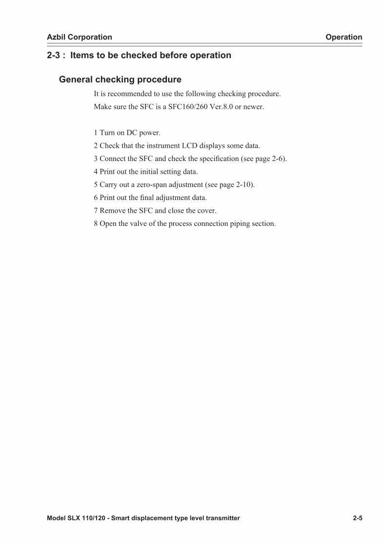
2-3 : Items to be checked before operation
General checking procedureIt is recommended to use the following checking procedure.
Make sure the SFC is a SFC160/260 Ver.8.0 or newer.
1 Turn on DC power.
2 Check that the instrument LCD displays some data.
3 Connect the SFC and check the specification (see page 2-6).
4 Print out the initial setting data.
5 Carry out a zero-span adjustment (see page 2-10).
6 Print out the final adjustment data.
7 Remove the SFC and close the cover.
8 Open the valve of the process connection piping section.

Operation Azbil Corporation
2-6 Model SLX 110/120 - Smart displacement type level transmitter
Checking set data
SFC connections• Connect the SFC as shown in the figure below.
• Be sure to connect the SFC communication cable and terminals of this instrument as follows.Red wire: Supply + terminal
Black wire: Supply - terminal
CHK-/S- S+
CHK+/M -
E
M +
DISP FLOW UP ZERO DOWN
%
SUPPLY+ (S+ Terminal)
SUPPLY-(CHK- / S- Terminal)
Load resistancemore than250 Ohms Supply voltage
24V DC
Ground
Black
Communication cable
Red
SFC
-
+Control signal4-20mA
External ground
Figure 2-6 Connection with SFC
Azbil Corporation Operation
Model SLX 110/120 - Smart displacement type level transmitter 2-7
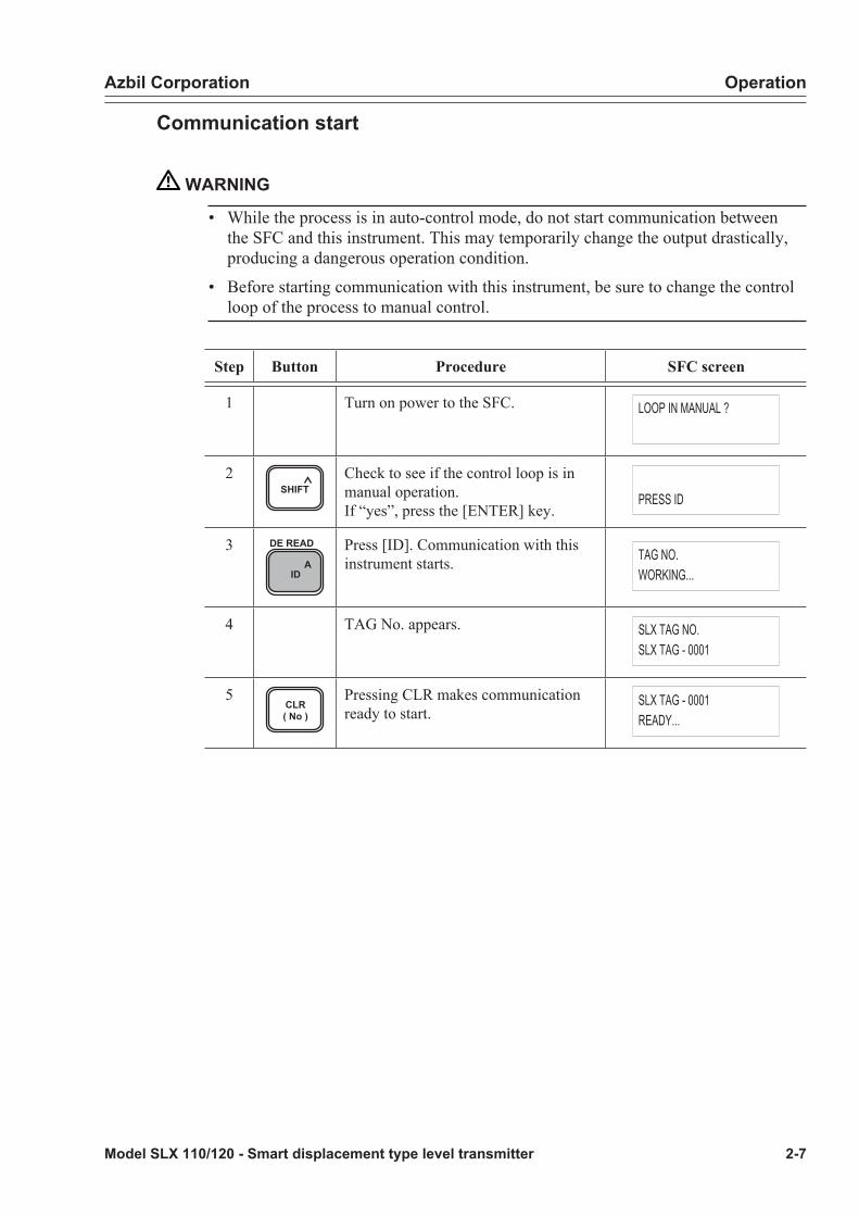
Communication start
WARNING
• While the process is in auto-control mode, do not start communication between the SFC and this instrument. This may temporarily change the output drastically, producing a dangerous operation condition.
• Before starting communication with this instrument, be sure to change the control loop of the process to manual control.
Step Button Procedure SFC screen
1 Turn on power to the SFC. LOOP IN MANUAL ?
2SHIFT
Check to see if the control loop is in manual operation.If “yes”, press the [ENTER] key.
PRESS ID
3A
ID
DE READ Press [ID]. Communication with this instrument starts. TAG NO.
WORKING...
4 TAG No. appears. SLX TAG NO.SLX TAG - 0001
5CLR( No )
Pressing CLR makes communication ready to start.
SLX TAG - 0001READY...
Operation Azbil Corporation
2-8 Model SLX 110/120 - Smart displacement type level transmitter
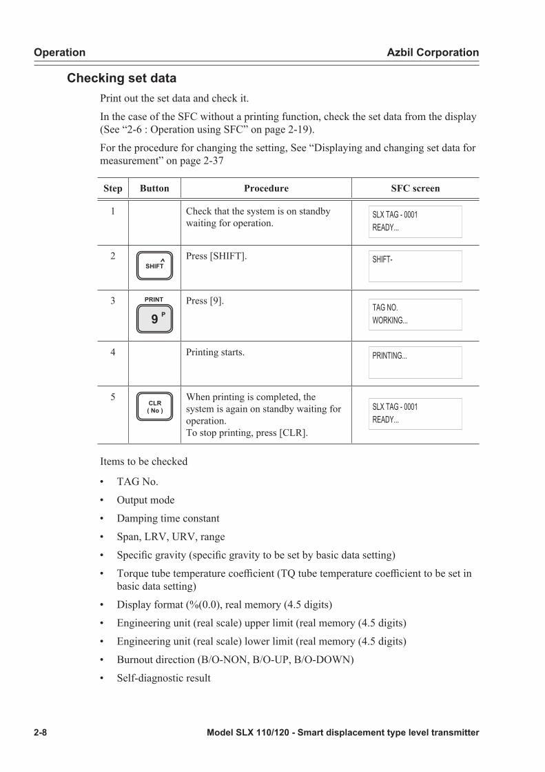
Checking set dataPrint out the set data and check it.
In the case of the SFC without a printing function, check the set data from the display (See “2-6 : Operation using SFC” on page 2-19).
For the procedure for changing the setting, See “Displaying and changing set data for measurement” on page 2-37
Step Button Procedure SFC screen
1 Check that the system is on standby waiting for operation.
SLX TAG - 0001READY...
2SHIFT
Press [SHIFT]. SHIFT-
3P9
PRINT Press [9].TAG NO.WORKING...
4 Printing starts. PRINTING...
5CLR( No )
When printing is completed, the system is again on standby waiting for operation.To stop printing, press [CLR].
SLX TAG - 0001READY...
Items to be checked
• TAG No.
• Output mode
• Damping time constant
• Span, LRV, URV, range
• Specific gravity (specific gravity to be set by basic data setting)
• Torque tube temperature coefficient (TQ tube temperature coefficient to be set in basic data setting)
• Display format (%(0.0), real memory (4.5 digits)
• Engineering unit (real scale) upper limit (real memory (4.5 digits)
• Engineering unit (real scale) lower limit (real memory (4.5 digits)
• Burnout direction (B/O-NON, B/O-UP, B/O-DOWN)
• Self-diagnostic result

Azbil Corporation Operation
Model SLX 110/120 - Smart displacement type level transmitter 2-9
Printing example
Meaning
‘01-01-01 08:30Tag No. SLX-0001
Type : SLXANA/DE : ANALOG XMTRSER1# : 9909141101SW VER : 3.0DAMP : 10.0 sSPAN : 301 mmLRV : 0 mmURV : 300 mmRANGE : 300 mm
GRAVITY : 1.000COEF TQ : 0.954
DIGITAL METERTYPE : ENG. UNIT (4.5DIG)
EUHI : 150EULO : -150
F/SAFE DOWNSCALE
INPUT : 150mmOUTPUT : 50.0%TQTT : T=200°CPTST : T=25.0°C
OFFSET : 0.1234COEF MT : 1.000SENS IN : 3.060SENS LO : 3.460SENS SP : -0.800
STATUS CHECK= OK
Date/timeTag No.Sensor type (printed as SLX)Output mode (analog, DE)Serial numberS/W versionDamping time constantSpanLRVURVRange
Specific gravity (specific gravity to be set in basic data setting)Torque tube temperature coefficient (COEF TQ set in basic data setting)
Display format (%(0.0), real memory (4.5 digits)
Engineering unit (real scale) upper limit Engineering unit (real scale) lower limit
Burnout direction (B/O-NON, B/O-UP, B/O-DOWN)
Input valueOutput valueTorque tube temperatureAngle sensor temperature
Offset angle (OFFSET to be set in basic data setting)Material coefficient (COEF MT to be set in basic data setting)Input angleCalibration lower limit angleCalibration span angle
Self-diagnostic result(In the event of an error, status messages generated are printed sequentially)
Operation Azbil Corporation
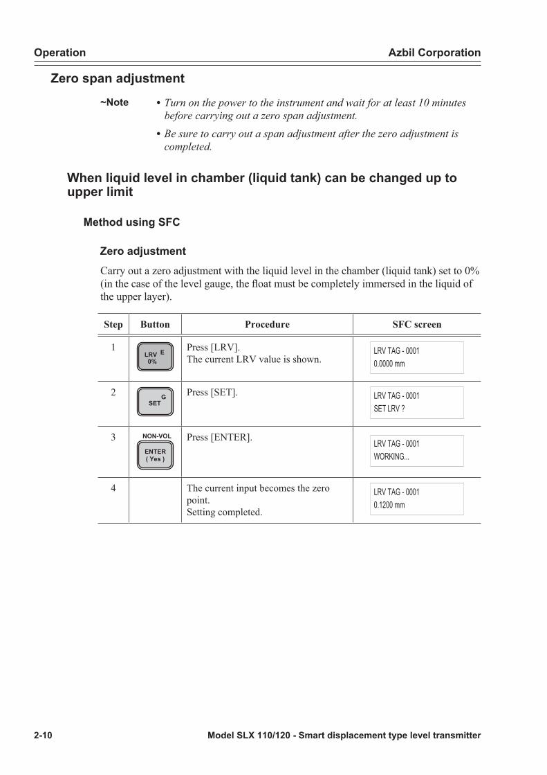
2-10 Model SLX 110/120 - Smart displacement type level transmitter
Zero span adjustment~Note • Turn on the power to the instrument and wait for at least 10 minutes
before carrying out a zero span adjustment.• Be sure to carry out a span adjustment after the zero adjustment is
completed.
When liquid level in chamber (liquid tank) can be changed up to upper limit
Method using SFC
Zero adjustment Carry out a zero adjustment with the liquid level in the chamber (liquid tank) set to 0% (in the case of the level gauge, the float must be completely immersed in the liquid of the upper layer).
Step Button Procedure SFC screen
1LRV E0%
Press [LRV]. The current LRV value is shown.
LRV TAG - 00010.0000 mm
2 GSET
Press [SET]. LRV TAG - 0001SET LRV ?
3ENTER( Yes )
NON-VOL Press [ENTER]. LRV TAG - 0001WORKING...
4 The current input becomes the zero point. Setting completed.
LRV TAG - 00010.1200 mm

Azbil Corporation Operation
Model SLX 110/120 - Smart displacement type level transmitter 2-11
Span adjustment
• The following procedure is based on water level adjustment.
1. Set specific gravity to 1 (water).2. Set water 100%.3. Carry out a span adjustment.4. Change the specific gravity to the specific gravity of the fluid to be measured.
~Note • When the fluid to be measured can be set to liquid level 100%, the specific gravity need not be changed before and after the adjustment.
• When the specific gravity of the fluid to be measured is lighter than water, it is possible to carry out span adjustment without changing specific gravity (conventional water level adjustment) by inputting the liquid level for which specific gravity is converted beforehand (giving 100% equivalent buoyancy generated).
• In the case of the level gauge, carry out span adjustment with the float completed immersed in the liquid of the lower layer without changing specific gravity.
Set the liquid level in the chamber to water 100%.
Step Button Procedure SFC screen
1 BCONF
Press [CONF]. SLX CONFIGFUNCTION CONFIG ?
2 HNEXT
or
LPREV
press [NEXT] or [PREV] to display the basic data setting screen.
SLX CONFIGFUNCTION CONFIG ?
3ENTER( Yes )
NON-VOL Press [ENTER]. SLX CONFIGWORKING...
4 The current specific gravity set value is displayed.
GRAVITY0.9000
5 Enter value of 1 as specific gravity of water.
GRAVITY1_

Operation Azbil Corporation
2-12 Model SLX 110/120 - Smart displacement type level transmitter
Step Button Procedure SFC screen
6ENTER( Yes )
NON-VOL Press [ENTER]. GRAVITYENTERED IN SFC
7 HNEXT
or
LPREV
Press [NEXT] or [[PREV]] to display the download selection screen.
DATA CONFIGDOWNLOAD DATA ?
8ENTER( Yes )
NON-VOL Press [ENTER]. DATA CONFIGWORKING...
9CLR( No )
Change of specific gravity has been completed.press [CLR] once to return to the original condition.
DATA CONFIGDATA LOAD !
SLX CONFIGDATA CONFIG ?
10URV F100%
Press URV. The current URV value is displayed.
URV TAG - 00013001 mm
11 GSET
Press SET. URV TAG - 0001SET URV
12ENTER( Yes )
NON-VOL Press [ENTER]. URV TAG - 0001WORKING...
13 The current input becomes the span point.
URV TAG - 00013000 mm
14 BCONF
Press [CONF]. SLX CONFIGFUNCTION CONFIG ?

Azbil Corporation Operation
Model SLX 110/120 - Smart displacement type level transmitter 2-13
Step Button Procedure SFC screen
15 HNEXT
or
LPREV
press [NEXT] or [[PREV]] to display the basic data setting screen.
SLX CONFIGDATA CONFIG ?
16ENTER( Yes )
NON-VOL Press [ENTER]. SLX CONFIGWORKING...
17 The current specific gravity set value (water) is displayed.
GRAVITY1.0000
18 Enter the specific gravity of the fluid to be measured.
Example: Enter value of 0.9
GRAVITY0.9_
19ENTER( Yes )
NON-VOL Press [ENTER]. GRAVITYENTERED IN SFC
20 HNEXT
or
LPREV
Press NEXT or [PREV] to display the download selection screen.
DATA CONFIGDOWNLOAD DATA ?
21ENTER( Yes )
NON-VOL Press [ENTER]. DATA CONFIGWORKING...
22CLR( No )
Setting completedpress [CLR] once to return to the original condition.
DATA CONFIGDATA LOAD !
SLX CONFIGDATA CONFIG ?

Operation Azbil Corporation
2-14 Model SLX 110/120 - Smart displacement type level transmitter
Method using external adjustment switch (with indicator)For detailed explanations of the external adjustment switch, See “2-7 : Operation of external adjustment switch (with indicator)” on page 2-74
Zero adjustmentCarry out zero adjustment by giving 0% equivalent input.
Step Procedure LCD screen
1 Hold the switch clockwise (+) for approximately 3 sec.
2 When “pUP ZERO” appears, turn OFF the switch. This enters “Damping adjustment mode”.
UP ZERO
3 Turn the switch counterclockwise (-) and display “199.9” below “0”.
4 “ZERO” appears after approximately 10 sec. and “Zero span adjustment mode” is entered. The current output value is displayed in digital. When zero adjustment is not performed, the normal condition is restored after approximately 30 sec.
ZERO
5 Hold the switch counterclockwise for approximately 3 sec. When “ZERODOWNq” is displayed, turn OFF the switch. The current input becomes the zero point. After approximately 2 sec., the normal condition is restored.

Azbil Corporation Operation
Model SLX 110/120 - Smart displacement type level transmitter 2-15
Span adjustmentPerform span adjustment by giving 100% equivalent input.
Step Procedure LCD screen
1 Hold the switch clockwise (+) for approximately 3 sec.
2 When “pUP ZERO” appears, turn OFF the switch. This enters “Damping adjustment mode”.
UP ZERO
3 Turn the switch counterclockwise (-) and display “199.9” below “0”.
4 “ZERO” appears after approximately 10 sec. and “Zero span adjustment mode” is entered. The current output value is displayed in digital. When zero adjustment is not performed, the normal condition is restored after approximately 30 sec.
5 Hold the switch clockwise (+) for approximately 3 sec. When “pUP ZERO” is displayed, turn OFF the switch. The current input becomes the zero point. After approximately 2 sec., the normal condition is restored.
Operation Azbil Corporation
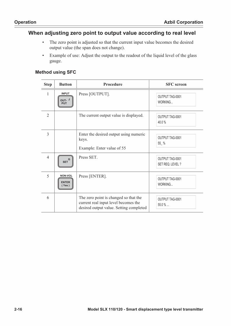
2-16 Model SLX 110/120 - Smart displacement type level transmitter
When adjusting zero point to output value according to real level• The zero point is adjusted so that the current input value becomes the desired
output value (the span does not change).
• Example of use: Adjust the output to the readout of the liquid level of the glass gauge.
Method using SFC
Step Button Procedure SFC screen
1OUT- JPUT
INPUT Press [OUTPUT]. OUTPUT TAG-0001WORKING...
2 The current output value is displayed. OUTPUT TAG-000140.0 %
3 Enter the desired output using numeric keys.
Example: Enter value of 55
OUTPUT TAG-000155_ %
4 GSET
Press SET. OUTPUT TAG-0001SET REQ. LEVEL ?
5ENTER( Yes )
NON-VOL Press [ENTER]. OUTPUT TAG-0001WORKING...
6 The zero point is changed so that the current real input level becomes the desired output value. Setting completed
OUTPUT TAG-000155.0 % ...

Azbil Corporation Operation
Model SLX 110/120 - Smart displacement type level transmitter 2-17
Method using external adjustment switch
Step Procedure SFC screen
1 Hold the switch counterclockwise (-) for approximately 3 sec.
2 When “ZERO DOWNq” appears, turn OFF the switch. This enters “Zero adjustment mode to adjust to real level”.
ZERO DOWN
3-1 Hold the switch counterclockwise (-). The readout reduces continuously.When the desired readout appears, turn OFF the switch.The normal condition is restored after approximately 10 sec.
ZERO DOWN
3-2 Hold the switch clockwise (+). The readout increases continuously. When the desired readout appears, turn OFF the switch.The normal condition is restored after approximately 10 sec.
ZERO DOWN
Operation Azbil Corporation
2-18 Model SLX 110/120 - Smart displacement type level transmitter
2-4 : Operation start
Before operation startBefore starting operation, carry out the following final check.
• Check to see if the transmitter part cover is closed correctly.
• Tighten the lock on the front of the cover (fixing screw with hexagonal hole M3) with a hexagonal wrench.
• Make sure no coupling section of the pressure container is left unfastened and there is no looseness.
Start operationOpen the valve of the process coupling piping section and introduce the liquid to be measured into the chamber (liquid tank).
~Note • At this time, adjust the open level of the valve so that no drastic pressure/liquid level changes (including flashing) occur.
• Make sure there is no liquid or gas leakage from the coupling of the pressure container such as the chamber and bonnet.
When steady operation is reachedWhen the pressure, temperature, etc. reach a steady operation state, use the following procedure to check the output values.
• If the output value (display value) is not stable, perform a damping adjustment by SFC (see “Damping time constant” on page 2-52) or external adjustment switch (see “Damping adjustment” on page 2-76).
• When the glass gauge is provided together, compare the output values of this instrument with the readouts of the glass gauge liquid level and check to see if any output shift has occurred.
If an output shift has occurred, See “3-3 : When output shift is large” on page 3-8 to adjust it appropriately.

Azbil Corporation Operation
Model SLX 110/120 - Smart displacement type level transmitter 2-19
2-5 : Operation stopTurn the power off.
When the instrument is not used for a long period of time (operation stopped) after the installation, it is recommended to remove the float.
2-6 : Operation using SFCThe SFC is used to check measured data and to change the set data of this instrument.
This chapter explains how to use the SFC to communicate with this instrument and gives the basics to be able to operate from the SFC.
For details of the SFC, see the SFC Instruction Manual (CM2-SFC100-2001).
The SFC that can be used with the SLX is SFC160/260 Ver.8.0 or newer.
WARNING
Always the SFC is a non-hazardous location, otherwise an explosion can result from an electrical discharge.
Principles of key operationThe following points should be noted when using the SFC keys.
• Slowly and firmly press the keys. If the screen does not respond, it means that the key input has not been accepted. Slowly press the key once again.
• If a key is pressed and the screen of the data display window does not change, the key may be invalid at that stage or the key may not be used in this instrument. Press necessary keys.
• If you have pressed the wrong key and want to redo the procedure from the beginning with the original factory settings, see Chapter 4 : Repair.
Operation Azbil Corporation
2-20 Model SLX 110/120 - Smart displacement type level transmitter
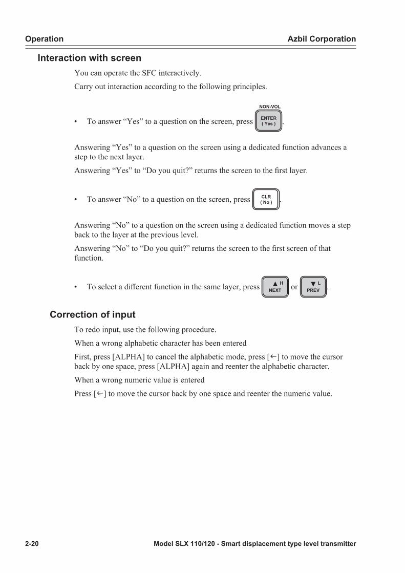
Interaction with screenYou can operate the SFC interactively.
Carry out interaction according to the following principles.
• To answer “Yes” to a question on the screen, press ENTER( Yes )
NON-VOL
.
Answering “Yes” to a question on the screen using a dedicated function advances a step to the next layer.
Answering “Yes” to “Do you quit?” returns the screen to the first layer.
• To answer “No” to a question on the screen, press CLR( No ) .
Answering “No” to a question on the screen using a dedicated function moves a step back to the layer at the previous level.
Answering “No” to “Do you quit?” returns the screen to the first screen of that function.
• To select a different function in the same layer, press HNEXT or L
PREV .
Correction of inputTo redo input, use the following procedure.
When a wrong alphabetic character has been entered
First, press [ALPHA] to cancel the alphabetic mode, press [f] to move the cursor back by one space, press [ALPHA] again and reenter the alphabetic character.
When a wrong numeric value is entered
Press [f] to move the cursor back by one space and reenter the numeric value.

Azbil Corporation Operation
Model SLX 110/120 - Smart displacement type level transmitter 2-21
SFC keyboard
S-SFC
AID
BCONF
CDAMP
DUNITS
HNEXT
GSETURV F
100%LRV E0%
MENU IITEM
OUT- JPUT
COR- KRECT
LPREV
M N7 O8 P9
Q R4 S5 T6
X3W2V1USTAT
YSPAN
Z0
ALPHA SHIFT CLR( No )
ENTER( Yes )
DE READ
DE CONF. INPUT RESET
FEED PRINT
A DE
F/S DIR SW VER
URL ACT PR SCR PAD TIME
NON-VOL
Figure 2-7 SFC keyboard
Operation Azbil Corporation
2-22 Model SLX 110/120 - Smart displacement type level transmitter
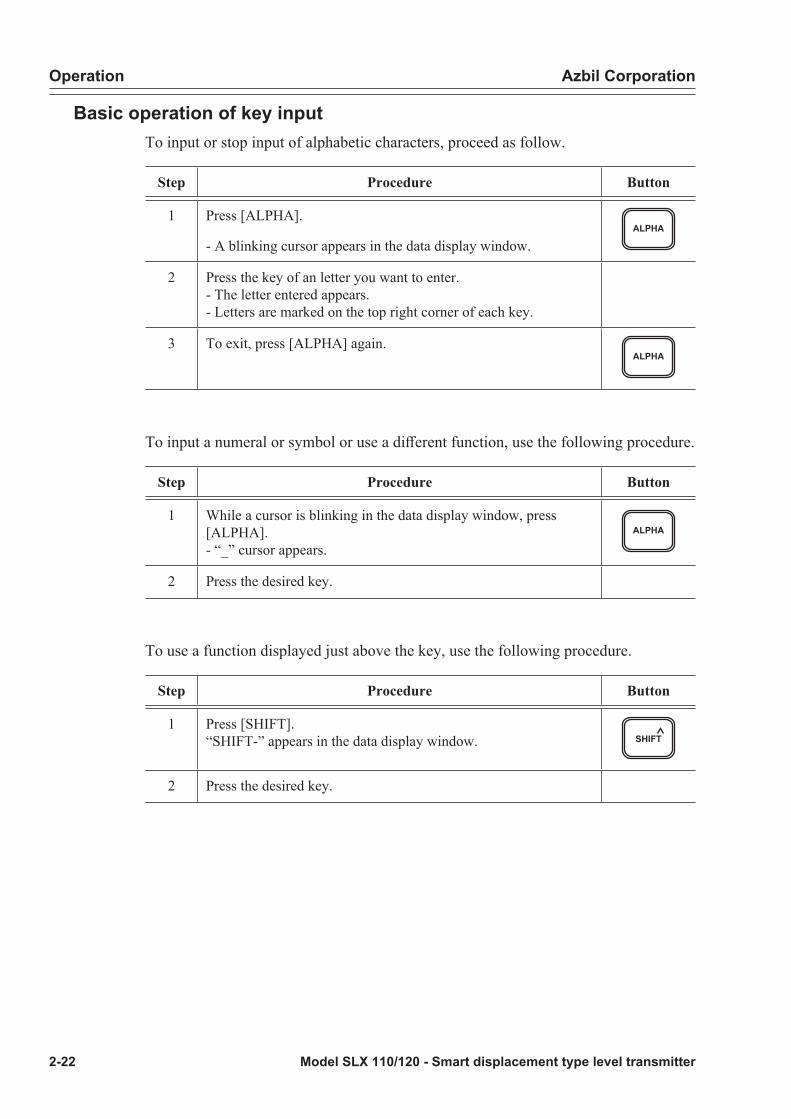
Basic operation of key inputTo input or stop input of alphabetic characters, proceed as follow.
Step Procedure Button
1 Press [ALPHA].
- A blinking cursor appears in the data display window.ALPHA
2 Press the key of an letter you want to enter.- The letter entered appears.- Letters are marked on the top right corner of each key.
3 To exit, press [ALPHA] again.ALPHA
To input a numeral or symbol or use a different function, use the following procedure.
Step Procedure Button
1 While a cursor is blinking in the data display window, press [ALPHA].- “_” cursor appears.
ALPHA
2 Press the desired key.
To use a function displayed just above the key, use the following procedure.
Step Procedure Button
1 Press [SHIFT].“SHIFT-” appears in the data display window. SHIFT
2 Press the desired key.

Azbil Corporation Operation
Model SLX 110/120 - Smart displacement type level transmitter 2-23
SFC key functionsThe SFC keys are color-coded according to main functions.
The SFC functions include functions common to other devices and functions only applicable to this instrument (dedicated functions).
The common functions can be operated by using LRV, URV, alphabetic character key, numeric key, etc. (Also includes functions used by pressing [SHIFT].)
The dedicated functions are organized in a hierarchic structure and are accessed by pressing [CONF].
The 32 keys on the keyboard are color-coded into five types according to their functions to make it easier for you to find the necessary keys.
The color codes are as follows.
CAUTION
There are also keys that will not be used for measurements using this instrument.
Key color coding Main functions
Green - Starts communication with this instrument.- Enables functions dedicated to this instrument to be used.- Sets or changes measuring conditions.- Displays data set in this instrument.- Selects a menu.
Orange - Displays measured data.- Selects a screen.- Saves data.
Yellow - Enters a numeric value.- Prints data.- Allows a memo to be made.
Dark green - Diagnostics.- Checks span of setting range.
White - Moves the cursor in the data display window.- Changes the function of another color key.- Cancels the currently set content.
All - Enters alphabetic character.(Used after pressing [ALPHA])

Operation Azbil Corporation
2-24 Model SLX 110/120 - Smart displacement type level transmitter
Green key functionsThe functions of a green key when pressed with or without pressing [SHIFT] are described here.
Their main functions are to:
• Start communication with this instrument.
• Enable functions dedicated to this instrument to be displayed/changed.
• Display or change measuring conditions.
• Display data set in this instrument.
• Select a parameter (item).
Display on key
Description
When the key alone is pressed When key is pressed after [SHIFT]
AID
DE READ ID:Starts communication with this instrument.TAG NO. of this instrument appears.TAG NO. can be changed in this screen.
Used when converted output is DE.The function is the same as ID.
BCONF
Dedicated function: For use of functions dedicated to this instrument.These dedicated functions are organized in a hierarchic structure. See “Dedicated functions” on page 2-32
No function
CDAMP
Damping:Shows current damping time constant. The damping time constant can be changed in this screen.
No function
DUNITS
No function No function
LRV E0%
LRV0%: Displays the lower range value of the current setting range. The lower range value can be changed in this screen.
No function
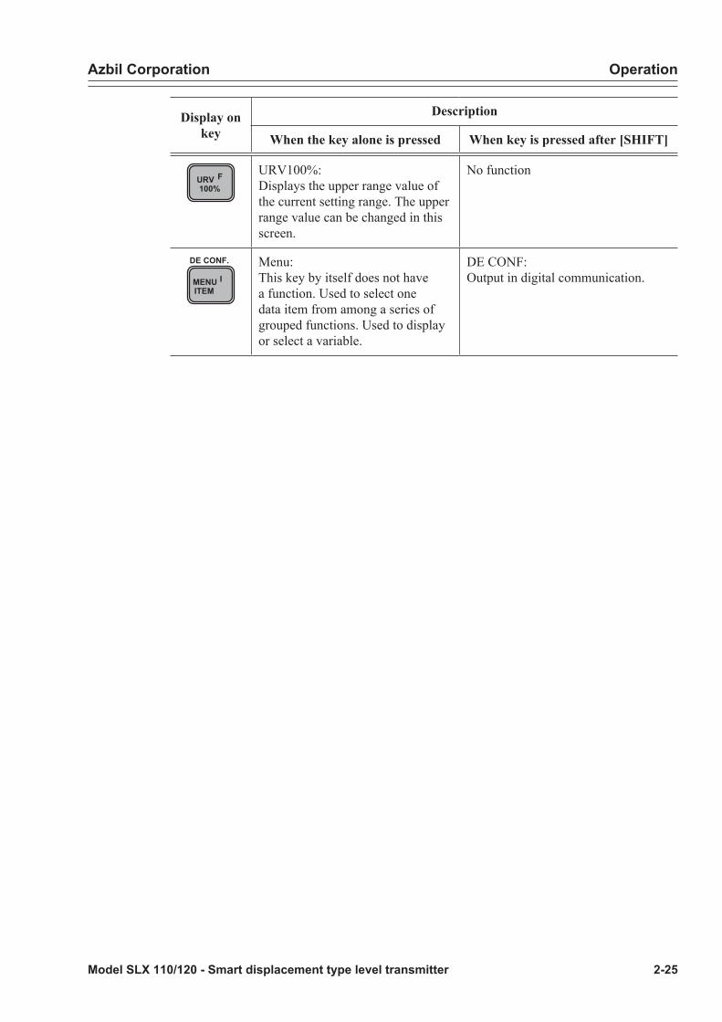
Azbil Corporation Operation
Model SLX 110/120 - Smart displacement type level transmitter 2-25
Display on key
Description
When the key alone is pressed When key is pressed after [SHIFT]
URV F100%
URV100%:Displays the upper range value of the current setting range. The upper range value can be changed in this screen.
No function
MENU IITEM
DE CONF. Menu:This key by itself does not have a function. Used to select one data item from among a series of grouped functions. Used to display or select a variable.
DE CONF:Output in digital communication.
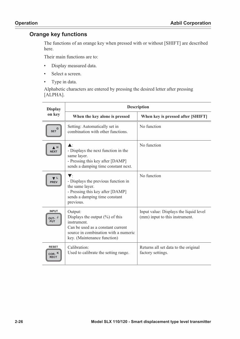
Operation Azbil Corporation
2-26 Model SLX 110/120 - Smart displacement type level transmitter
Orange key functionsThe functions of an orange key when pressed with or without [SHIFT] are described here.
Their main functions are to:
• Display measured data.
• Select a screen.
• Type in data.Alphabetic characters are entered by pressing the desired letter after pressing [ALPHA].
Display on key
Description
When the key alone is pressed When key is pressed after [SHIFT]
GSET
Setting: Automatically set in combination with other functions.
No function
HNEXT
p:- Displays the next function in the same layer.- Pressing this key after [DAMP] sends a damping time constant next.
No function
LPREV
q:- Displays the previous function in the same layer.- Pressing this key after [DAMP] sends a damping time constant previous.
No function
OUT- JPUT
INPUT Output:Displays the output (%) of this instrument.Can be used as a constant current source in combination with a numeric key. (Maintenance function)
Input value: Displays the liquid level (mm) input to this instrument.
COR- KRECT
RESET Calibration:Used to calibrate the setting range.
Returns all set data to the original factory settings.

Azbil Corporation Operation
Model SLX 110/120 - Smart displacement type level transmitter 2-27
Display on key
Description
When the key alone is pressed When key is pressed after [SHIFT]
ENTER( Yes )
NON-VOL ENTER:Used to send data to this instrument.Used to answer “Yes” to a question on the screen.
Non-volatile data:Writes set data to a non-volatile memory of this instrument and data is retained even if power to this instrument is turned off.
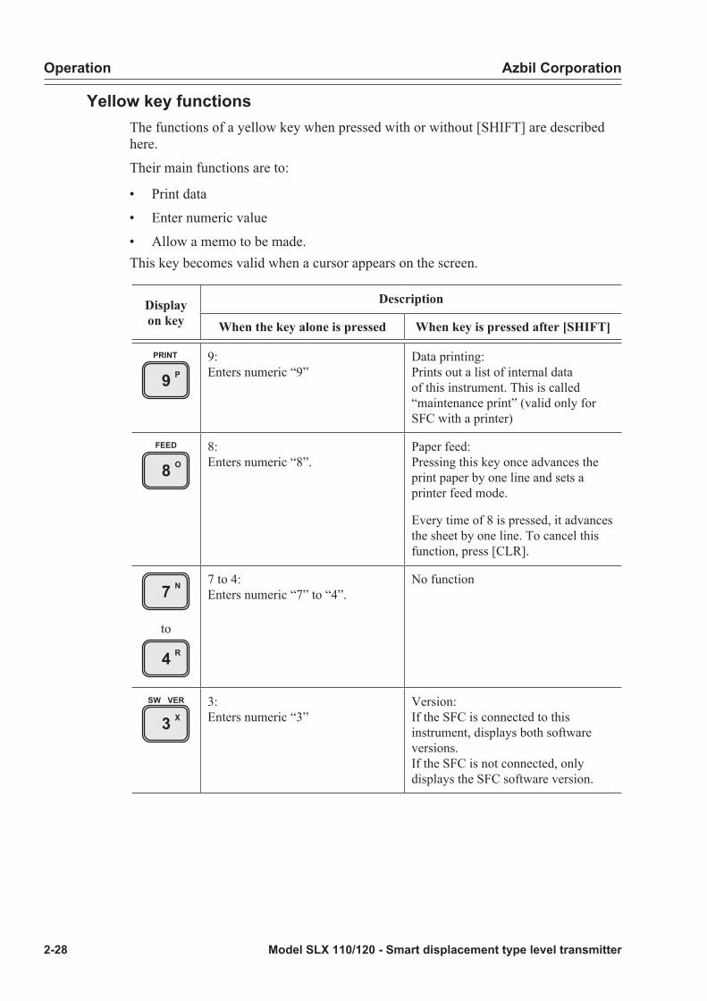
Operation Azbil Corporation
2-28 Model SLX 110/120 - Smart displacement type level transmitter
Yellow key functionsThe functions of a yellow key when pressed with or without [SHIFT] are described here.
Their main functions are to:
• Print data
• Enter numeric value
• Allow a memo to be made.This key becomes valid when a cursor appears on the screen.
Display on key
Description
When the key alone is pressed When key is pressed after [SHIFT]
P9PRINT 9:
Enters numeric “9”Data printing:Prints out a list of internal data of this instrument. This is called “maintenance print” (valid only for SFC with a printer)
O8FEED 8:
Enters numeric “8”.Paper feed:Pressing this key once advances the print paper by one line and sets a printer feed mode.
Every time of 8 is pressed, it advances the sheet by one line. To cancel this function, press [CLR].
N7
to
R4
7 to 4:Enters numeric “7” to “4”.
No function
X3SW VER 3:
Enters numeric “3”Version:If the SFC is connected to this instrument, displays both software versions.If the SFC is not connected, only displays the SFC software version.

Azbil Corporation Operation
Model SLX 110/120 - Smart displacement type level transmitter 2-29
Display on key
Description
When the key alone is pressed When key is pressed after [SHIFT]
W2
V1
2,1:Enters numeric “2”, “1”.
No function
TIME +/-: Enters [+/-]./: After pressing [ALPHA] once, enter “/”.
Time: Displays the current date and time (valid only for SFC with a printer).
M ·: Enters a decimal point.g: After pressing [ALPHA] once, enter a space.
Memo: Used to write a memo.
Z0ACT PR 0: Enter numeric “0” Action print: Every time this function
is used, response from this instrument is printed. This is called “action print”. To close this function, press [CLR] (valid only for SFC with a printer).
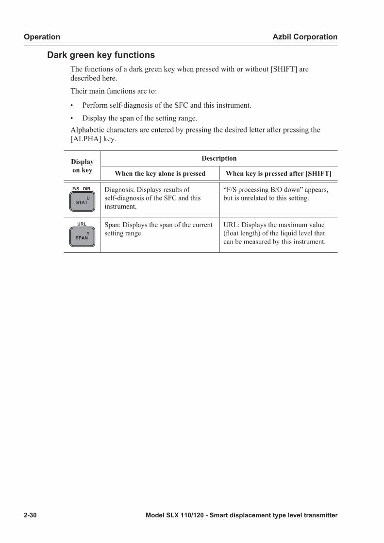
Operation Azbil Corporation
2-30 Model SLX 110/120 - Smart displacement type level transmitter
Dark green key functionsThe functions of a dark green key when pressed with or without [SHIFT] are described here.
Their main functions are to:
• Perform self-diagnosis of the SFC and this instrument.
• Display the span of the setting range.Alphabetic characters are entered by pressing the desired letter after pressing the [ALPHA] key.
Display on key
Description
When the key alone is pressed When key is pressed after [SHIFT]
USTAT
F/S DIR Diagnosis: Displays results of self-diagnosis of the SFC and this instrument.
“F/S processing B/O down” appears, but is unrelated to this setting.
YSPAN
URL Span: Displays the span of the current setting range.
URL: Displays the maximum value (float length) of the liquid level that can be measured by this instrument.
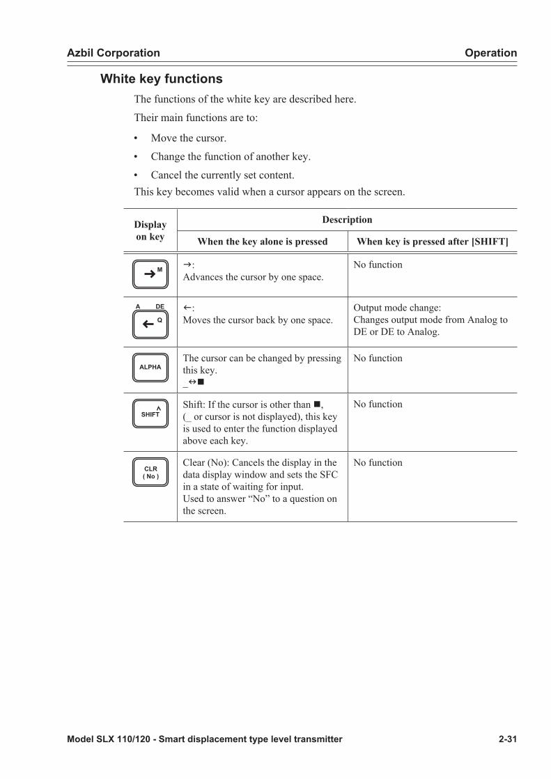
Azbil Corporation Operation
Model SLX 110/120 - Smart displacement type level transmitter 2-31
White key functionsThe functions of the white key are described here.
Their main functions are to:
• Move the cursor.
• Change the function of another key.
• Cancel the currently set content.This key becomes valid when a cursor appears on the screen.
Display on key
Description
When the key alone is pressed When key is pressed after [SHIFT]
M g:Advances the cursor by one space.
No function
Q
A DE f:Moves the cursor back by one space.
Output mode change:Changes output mode from Analog to DE or DE to Analog.
ALPHAThe cursor can be changed by pressing this key._nn
No function
SHIFTShift: If the cursor is other than n, (_ or cursor is not displayed), this key is used to enter the function displayed above each key.
No function
CLR( No )
Clear (No): Cancels the display in the data display window and sets the SFC in a state of waiting for input.Used to answer “No” to a question on the screen.
No function

Operation Azbil Corporation
2-32 Model SLX 110/120 - Smart displacement type level transmitter
Dedicated functionsThe following are the main dedicated functions of the SFC.
• Settings of basic functions
• Settings of basic data
• Display of serial number.
• Display of torque tube temperature
• Display of angle sensor temperature
• Display of input angle The dedicated functions are organized in a hierarchic structure. Press the dedicated function key, and then conduct operations according to the instructions that appear displayed on the screen.
Operation when starting measurement
Step Button Procedure SFC screen
1 Turn on the power to the SFC. LOOP IN MANUAL ?
2ENTER( Yes )
NON-VOL Make sure that the control loop has been set to “manual operation”. If it is not set to manual operation, press [ENTER].
PRESS ID
3A
ID
DE READ Press [ID].Communication with this instrument commences.
TAG NO.WORKING...
4 TAG No. appears. Confirm whether the instrument is the one that is to be measured.
SLX TAG NO.SLX TAG - 0001
5CLR( No )
Pressing [CLR] makes communication ready to start.
SLX TAG - 0001READY...
For the connection of the SFC, See “2-4 : Operation start” on page 2-18
Start all the following operations in this state (“READY...” state).
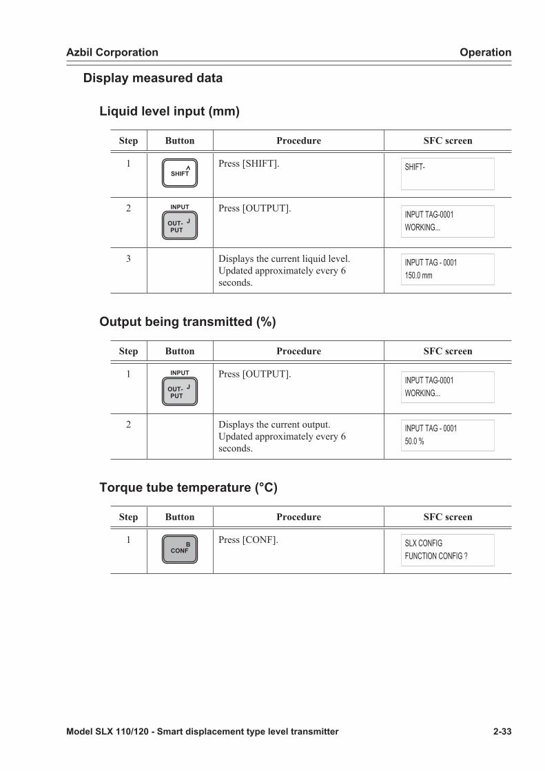
Azbil Corporation Operation
Model SLX 110/120 - Smart displacement type level transmitter 2-33
Display measured data
Liquid level input (mm)
Step Button Procedure SFC screen
1SHIFT
Press [SHIFT]. SHIFT-
2OUT- JPUT
INPUT Press [OUTPUT]. INPUT TAG-0001WORKING...
3 Displays the current liquid level.Updated approximately every 6 seconds.
INPUT TAG - 0001150.0 mm
Output being transmitted (%)
Step Button Procedure SFC screen
1OUT- JPUT
INPUT Press [OUTPUT]. INPUT TAG-0001WORKING...
2 Displays the current output.Updated approximately every 6 seconds.
INPUT TAG - 000150.0 %
Torque tube temperature (°C)
Step Button Procedure SFC screen
1 BCONF
Press [CONF]. SLX CONFIGFUNCTION CONFIG ?

Operation Azbil Corporation
2-34 Model SLX 110/120 - Smart displacement type level transmitter
Step Button Procedure SFC screen
2 HNEXT
or
LPREV
press [NEXT] or [PREV] to go to the torque tube temperature reading screen.
SLX CONFIGTQTUBE TEMP ?
3ENTER( Yes )
NON-VOL Press [ENTER]. TQTUBE TEMPWORKING...
4CLR( No )
Displays the current torque tube temperature.Updated approximately every 6 seconds.Pressing [CLR] twice sets the mode back to the “Please perform next operation” state.
TQTUBE TEMP152.3 C

Azbil Corporation Operation
Model SLX 110/120 - Smart displacement type level transmitter 2-35
Angle sensor temperature (°C)
Step Button Procedure SFC screen
1 BCONF
Press [CONF]. SLX CONFIGFUNCTION CONFIG ?
2 HNEXT
or
LPREV
Press [NEXT] or [PREV] to go to the angle sensor temperature reading screen.
SLX CONFIGPTS TEMP ?
3ENTER( Yes )
NON-VOL Press [ENTER].Communication commences SLX CONFIG
WORKING...
4CLR( No )
CLR( No )
Displays the current angle sensor temperature.
Updated every approximately 6 seconds.
Pressing [CLR] twice sets the mode back to the “Please perform next operation” state.
PTS TEMP25.3 C

Operation Azbil Corporation
2-36 Model SLX 110/120 - Smart displacement type level transmitter
Input angleThis is for service/maintenance purposes and is not required for normal usage.
Step Button Procedure SFC screen
1 BCONF
Press the [CONF]. SLX CONFIGFUNCTION CONFIG ?
2 HNEXT
or
LPREV
Press [NEXT] or [PREV] to go to the sensor angle reading screen.
SLX CONFIGENTERED DEG ?
3ENTER( Yes )
NON-VOL Press [ENTER]. SLX CONFIGWORKING...
4CLR( No )
Displays the current sensor angle.
Updated every approximately 6 seconds.
Pressing [CLR] twice sets the mode back to the “Please perform next operation” state.
ENTERED DEG3.456 DEG

Azbil Corporation Operation
Model SLX 110/120 - Smart displacement type level transmitter 2-37
Displaying and changing set data for measurement
Lower range value (LRV)LRV: Liquid level (mm) outputting 0%
Display of lower range value
Step Button Procedure SFC screen
1LRV E0%
Press [LRV]. The current lower range value will appear.
LRV TAG - 00010.0000 mm
Changing lower range valueThe allowable setting range is +-2/3 of the upper range value. If a value beyond the allowable setting range is entered, “ENTRY > SENS RNG” will appear on the lower row for 2 sec. and the former value will remain current.
Numeric inputEnter numeric values for the lower range value of the liquid level in millimeters.
Step Button Procedure SFC screen
1LRV E0%
Press [LRV]. The current lower value will appear.
LRV TAG - 00010.1200 mm
2 Enter the desired liquid level the using numeric keys.Example: Enter value of 0.
LRV TAG - 00010_ mm
3ENTER( Yes )
NON-VOL Press [ENTER]. LRV TAG - 0001WORKING...
4 The lower range value is set to 0 mm. Setting completed.
LRV TAG - 00010.0000 mm
During an elevation, it is possible to set the lower range value using this method.
For example, when 10% of a range is desired: 0 to 300 mm is set as a lower limit value, 300 mm x 10% = 30 mm, and so the lower range value is set to 30 mm.
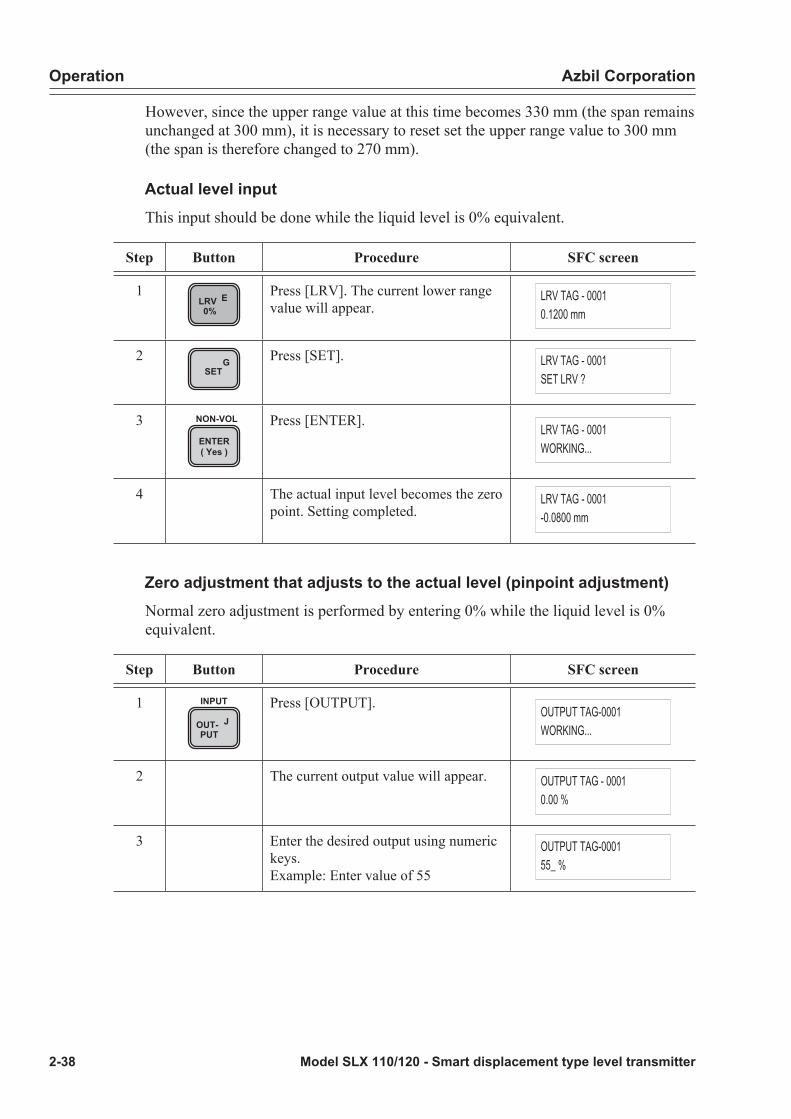
Operation Azbil Corporation
2-38 Model SLX 110/120 - Smart displacement type level transmitter
However, since the upper range value at this time becomes 330 mm (the span remains unchanged at 300 mm), it is necessary to reset set the upper range value to 300 mm (the span is therefore changed to 270 mm).
Actual level inputThis input should be done while the liquid level is 0% equivalent.
Step Button Procedure SFC screen
1LRV E0%
Press [LRV]. The current lower range value will appear.
LRV TAG - 00010.1200 mm
2 GSET
Press [SET]. LRV TAG - 0001SET LRV ?
3ENTER( Yes )
NON-VOL Press [ENTER]. LRV TAG - 0001WORKING...
4 The actual input level becomes the zero point. Setting completed.
LRV TAG - 0001-0.0800 mm
Zero adjustment that adjusts to the actual level (pinpoint adjustment)Normal zero adjustment is performed by entering 0% while the liquid level is 0% equivalent.
Step Button Procedure SFC screen
1OUT- JPUT
INPUT Press [OUTPUT]. OUTPUT TAG-0001WORKING...
2 The current output value will appear. OUTPUT TAG - 00010.00 %
3 Enter the desired output using numeric keys.Example: Enter value of 55
OUTPUT TAG-000155_ %
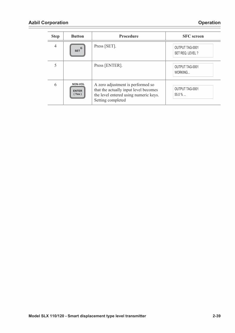
Azbil Corporation Operation
Model SLX 110/120 - Smart displacement type level transmitter 2-39
Step Button Procedure SFC screen
4 GSET
Press [SET]. OUTPUT TAG-0001SET REQ. LEVEL ?
5 Press [ENTER]. OUTPUT TAG-0001WORKING...
6ENTER( Yes )
NON-VOL A zero adjustment is performed so that the actually input level becomes the level entered using numeric keys. Setting completed
OUTPUT TAG-000155.0 % ...

Operation Azbil Corporation
2-40 Model SLX 110/120 - Smart displacement type level transmitter
Upper range value (URV)URV: Liquid level (mm) for outputting 100%
Display of upper range value
Step Button Procedure SFC screen
1URV F100%
Press [URV]. The current upper range value will appear.
URV TAG - 0001300.1 mm
Changing upper range valueSuppose the allowable setting range is a maximum of 1.7 times the range and the span exceeds 0.4 times the range. If a value beyond the allowable setting range is entered “ENTRY > SENS RNG” will appear on the lower row for 2 sec. and the former value will remain current.
Numeric inputEnter the liquid level (mm) to be set as the upper range value using numeric keys.
Step Button Procedure SFC screen
1URV F100%
Press [URV]. The current upper range value will appear.
URV TAG - 0001300.1 mm
2 Enter the desired liquid level using numeric keys.Example: Enter value of 300.
URV TAG - 0001300_ mm
3ENTER( Yes )
NON-VOL Press [ENTER]. URV TAG - 0001WORKING...
4 The upper range value is set to 300 mm. Setting completed.
URV TAG - 0001300.0 mm
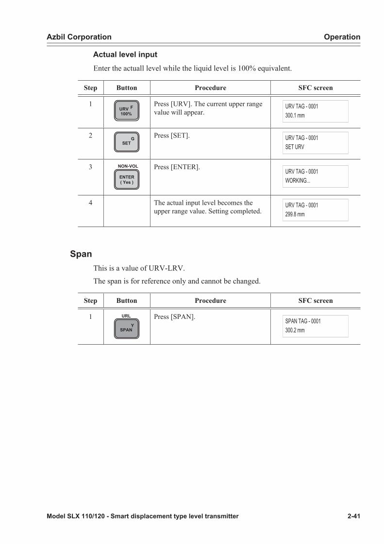
Azbil Corporation Operation
Model SLX 110/120 - Smart displacement type level transmitter 2-41
Actual level inputEnter the actuall level while the liquid level is 100% equivalent.
Step Button Procedure SFC screen
1URV F100%
Press [URV]. The current upper range value will appear.
URV TAG - 0001300.1 mm
2 GSET
Press [SET]. URV TAG - 0001SET URV
3ENTER( Yes )
NON-VOL Press [ENTER]. URV TAG - 0001WORKING...
4 The actual input level becomes the upper range value. Setting completed.
URV TAG - 0001299.8 mm
SpanThis is a value of URV-LRV.
The span is for reference only and cannot be changed.
Step Button Procedure SFC screen
1Y
SPAN
URL Press [SPAN]. SPAN TAG - 0001300.2 mm
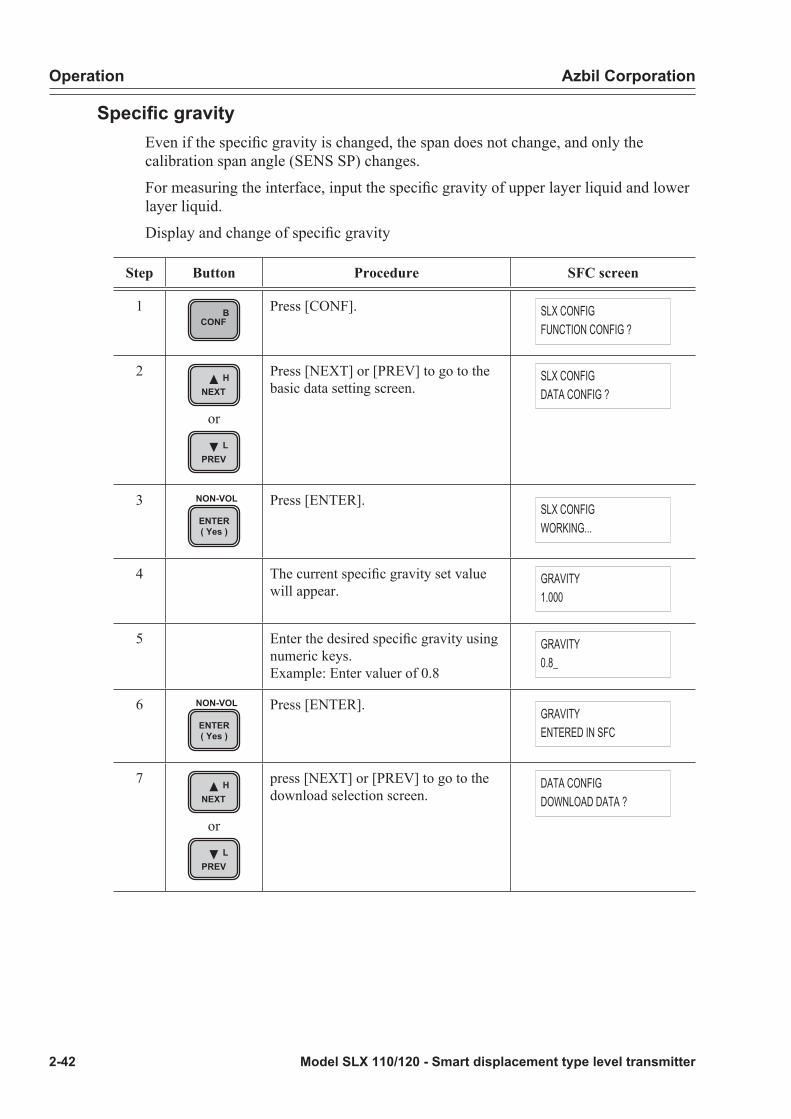
Operation Azbil Corporation
2-42 Model SLX 110/120 - Smart displacement type level transmitter
Specific gravityEven if the specific gravity is changed, the span does not change, and only the calibration span angle (SENS SP) changes.
For measuring the interface, input the specific gravity of upper layer liquid and lower layer liquid.
Display and change of specific gravity
Step Button Procedure SFC screen
1 BCONF
Press [CONF]. SLX CONFIGFUNCTION CONFIG ?
2 HNEXT
or
LPREV
Press [NEXT] or [PREV] to go to the basic data setting screen.
SLX CONFIGDATA CONFIG ?
3ENTER( Yes )
NON-VOL Press [ENTER]. SLX CONFIGWORKING...
4 The current specific gravity set value will appear.
GRAVITY1.000
5 Enter the desired specific gravity using numeric keys.Example: Enter valuer of 0.8
GRAVITY0.8_
6ENTER( Yes )
NON-VOL Press [ENTER]. GRAVITYENTERED IN SFC
7 HNEXT
or
LPREV
press [NEXT] or [PREV] to go to the download selection screen.
DATA CONFIGDOWNLOAD DATA ?

Azbil Corporation Operation
Model SLX 110/120 - Smart displacement type level transmitter 2-43
Step Button Procedure SFC screen
8ENTER( Yes )
NON-VOL Press [ENTER]. DATA CONFIGWORKING...
9 Setting completed. DATA CONFIGDATA LOAD !

Operation Azbil Corporation
2-44 Model SLX 110/120 - Smart displacement type level transmitter
Torque tube temperature coefficientWhen the output shift from the process due to temperature is large, this change to the coefficient can reduce the shift. For the method of determining the coefficient, See “3-3 : When output shift is large” on page 3-8
Step Button Procedure SFC screen
1 BCONF
Press [CONF]. SLX CONFIGFUNCTION CONFIG ?
2 HNEXT
or
LPREV
Press [NEXT] or [PREV] to go to the basic data setting screen.
SLX CONFIGDATA CONFIG ?
3ENTER( Yes )
NON-VOL Press [ENTER]. SLX CONFIGWORKING...
4 The current specific gravity set value is displayed.Example: Enter value of 0.8
GRAVITY0.800
5 HNEXT
or
LPREV
Press [NEXT] or [PREV] to go to the temperature compensation coefficient setting screen.Example: 1
COEF TQ1.000
6 Enter the desired torque tube temperature coefficient using numeric keys.Example: Enter value of 1.2
COEF TQ1.2_
7ENTER( Yes )
NON-VOL Press [ENTER]. COEF TQENTERED IN SFC
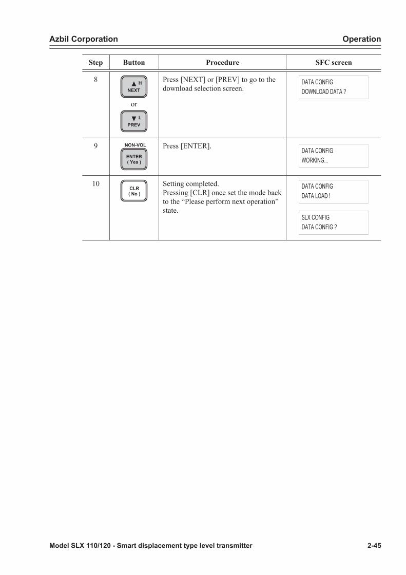
Azbil Corporation Operation
Model SLX 110/120 - Smart displacement type level transmitter 2-45
Step Button Procedure SFC screen
8 HNEXT
or
LPREV
Press [NEXT] or [PREV] to go to the download selection screen.
DATA CONFIGDOWNLOAD DATA ?
9ENTER( Yes )
NON-VOL Press [ENTER]. DATA CONFIGWORKING...
10CLR( No )
Setting completed.Pressing [CLR] once set the mode back to the “Please perform next operation” state.
DATA CONFIGDATA LOAD !
SLX CONFIGDATA CONFIG ?

Operation Azbil Corporation
2-46 Model SLX 110/120 - Smart displacement type level transmitter
RangeThis refers to the length of the float. It is normally not required to change the range
Pressing [SHIFT] + [SPAN] shows the range as an URL.
SHIFT + YSPAN
URL
Step Button Procedure SFC screen
1 BCONF
Press [CONF]. SLX CONFIGFUNCTION CONFIG ?
2 HNEXT
or
LPREV
Press [NEXT] or [PREV] to go to the SERIAL No. screen.
SLX CONFIGSERIAL NO. ?
3ENTER( Yes )
NON-VOL Press [ENTER]. SLX CONFIGWORKING...
4 The serial number will appear. SERIAL NO.0105010137
5 HNEXT
or
LPREV
Press [NEXT] or [PREV] to go to the standard setting screen.
BASE CONFIG ?
6ENTER( Yes )
NON-VOL Press [ENTER]. BASE CONFIG ?WORKING...
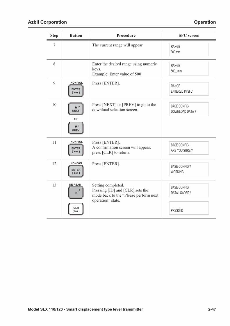
Azbil Corporation Operation
Model SLX 110/120 - Smart displacement type level transmitter 2-47
Step Button Procedure SFC screen
7 The current range will appear. RANGE300 mm
8 Enter the desired range using numeric keys.Example: Enter value of 500
RANGE500_ mm
9ENTER( Yes )
NON-VOL Press [ENTER]. RANGEENTERED IN SFC
10 HNEXT
or
LPREV
Press [NEXT] or [PREV] to go to the download selection screen.
BASE CONFIGDOWNLOAD DATA ?
11ENTER( Yes )
NON-VOL Press [ENTER].A confirmation screen will appear. press [CLR] to return.
BASE CONFIGARE YOU SURE ?
12ENTER( Yes )
NON-VOL Press [ENTER]. BASE CONFIG ?WORKING...
13A
ID
DE READ
CLR( No )
Setting completed.Pressing [ID] and [CLR] sets the mode back to the “Please perform next operation” state.
BASE CONFIGDATA LOADED !
PRESS ID

Operation Azbil Corporation
2-48 Model SLX 110/120 - Smart displacement type level transmitter
Offset angleThis is normally not required to be changed. (However, be sure to set the offset angle when replacing the transmitter part.)
Step Button Procedure SFC screen
1 BCONF
Press [CONF]. SLX CONFIGFUNCTION CONFIG ?
2 HNEXT
or
LPREV
Press [NEXT] or [PREV] to go to the SERIAL No. screen.
SLX CONFIGSERIAL NO. ?
3ENTER( Yes )
NON-VOL Press [ENTER]. SLX CONFIGWORKING...
4 The serial number will appear. SERIAL NO.0105010137
5 HNEXT
or
LPREV
press [NEXT] or [PREV] to go to the standard setting screen.
BASE CONFIG ?
6ENTER( Yes )
NON-VOL Press [ENTER]. BASE CONFIG ?WORKING...
7 The current range will appear. RANGE300 mm
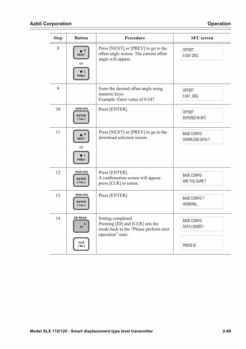
Azbil Corporation Operation
Model SLX 110/120 - Smart displacement type level transmitter 2-49
Step Button Procedure SFC screen
8 HNEXT
or
LPREV
Press [NEXT] or [PREV] to go to the offset angle screen. The current offset angle will appear.
OFFSET0.0351 DEG
9 Enter the desired offset angle using numeric keys.Example: Enter value of 0.547
OFFSET0.547_ DEG
10ENTER( Yes )
NON-VOL Press [ENTER]. OFFSETENTERED IN SFC
11 HNEXT
or
LPREV
Press [NEXT] or [PREV] to go to the download selection screen.
BASE CONFIGDOWNLOAD DATA ?
12ENTER( Yes )
NON-VOL Press [ENTER].A confirmation screen will appear. press [CLR] to return.
BASE CONFIGARE YOU SURE ?
13ENTER( Yes )
NON-VOL Press [ENTER]. BASE CONFIG ?WORKING...
14A
ID
DE READ
CLR( No )
Setting completed.Pressing [ID] and [CLR] sets the mode back to the “Please perform next operation” state.
BASE CONFIGDATA LOADED !
PRESS ID
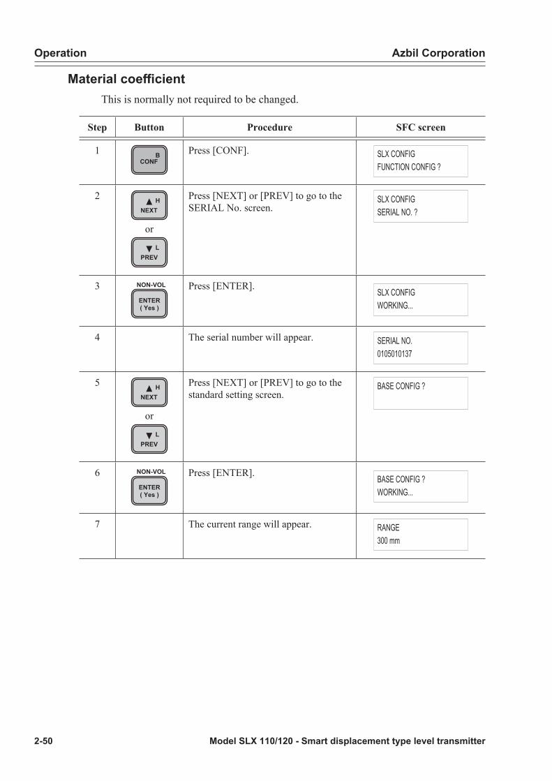
Operation Azbil Corporation
2-50 Model SLX 110/120 - Smart displacement type level transmitter
Material coefficientThis is normally not required to be changed.
Step Button Procedure SFC screen
1 BCONF
Press [CONF]. SLX CONFIGFUNCTION CONFIG ?
2 HNEXT
or
LPREV
Press [NEXT] or [PREV] to go to the SERIAL No. screen.
SLX CONFIGSERIAL NO. ?
3ENTER( Yes )
NON-VOL Press [ENTER]. SLX CONFIGWORKING...
4 The serial number will appear. SERIAL NO.0105010137
5 HNEXT
or
LPREV
Press [NEXT] or [PREV] to go to the standard setting screen.
BASE CONFIG ?
6ENTER( Yes )
NON-VOL Press [ENTER]. BASE CONFIG ?WORKING...
7 The current range will appear. RANGE300 mm

Azbil Corporation Operation
Model SLX 110/120 - Smart displacement type level transmitter 2-51
Step Button Procedure SFC screen
8 HNEXT
or
LPREV
Press [NEXT] or [PREV] to go to the material coefficient screen. The current material coefficient will appear.
COEF MT 1.0000
9 Enter the desired material coefficient using numeric keys.Example: Enter value of 1.4
COEF MT 1.4_
10ENTER( Yes )
NON-VOL Press [ENTER]. COEF TQENTERED IN SFC
11 HNEXT
or
LPREV
Press [NEXT] or [PREV] to go to the download selection screen.
BASE CONFIGDOWNLOAD DATA ?
12ENTER( Yes )
NON-VOL Press [ENTER].A confirmation screen will appear. press [CLR] to return.
BASE CONFIGARE YOU SURE ?
13ENTER( Yes )
NON-VOL Press [ENTER]. BASE CONFIG ?WORKING...
14A
ID
DE READ
CLR( No )
Setting completed.Pressing [ID] and [CLR] sets the mode back to the “Please perform next operation” state.
BASE CONFIGDATA LOADED !
PRESS ID

Operation Azbil Corporation
2-52 Model SLX 110/120 - Smart displacement type level transmitter
Damping time constant
Step Button Procedure SFC screen
1 CDAMP
Press [DAMP]. The current damping time constant value will appear.
DAMP TAG - 00010.0 s
2 HNEXT
or
LPREV
Press [NEXT] or [PREV] to select the desired damping time constant.
DAMP TAG - 0001WORKING...
3 The damping time constant is changed.Setting completed.
DAMP TAG - 00015.0 s
Allowable damping time constants (sec.): 0, 0.5, 1, 2, 3, 4, 5, 10, 50, 100
Factory setting: 2.0 s
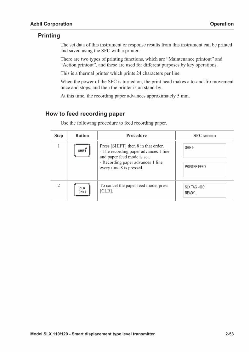
Azbil Corporation Operation
Model SLX 110/120 - Smart displacement type level transmitter 2-53
PrintingThe set data of this instrument or response results from this instrument can be printed and saved using the SFC with a printer.
There are two types of printing functions, which are “Maintenance printout” and “Action printout”, and these are used for different purposes by key operations.
This is a thermal printer which prints 24 characters per line.
When the power of the SFC is turned on, the print head makes a to-and-fro movement once and stops, and then the printer is on stand-by.
At this time, the recording paper advances approximately 5 mm.
How to feed recording paperUse the following procedure to feed recording paper.
Step Button Procedure SFC screen
1SHIFT
Press [SHIFT] then 8 in that order.- The recording paper advances 1 line and paper feed mode is set.- Recording paper advances 1 line every time 8 is pressed.
SHIFT-
PRINTER FEED
2CLR( No )
To cancel the paper feed mode, press [CLR].
SLX TAG - 0001READY...
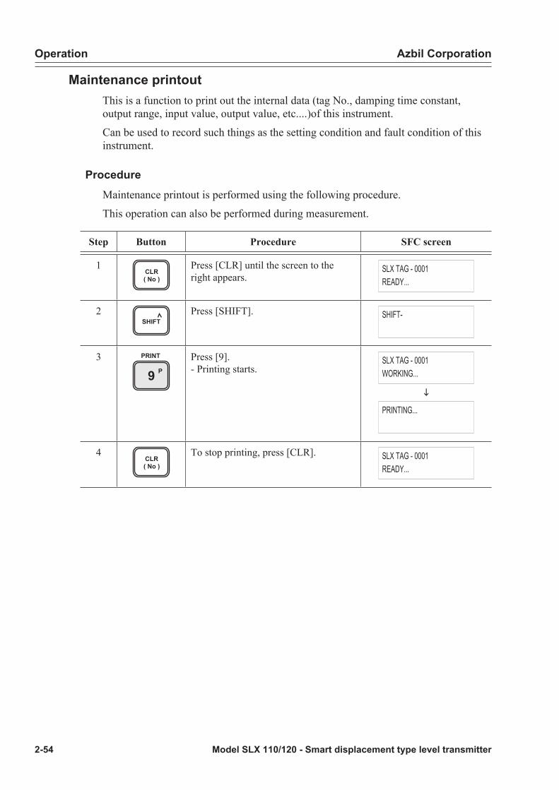
Operation Azbil Corporation
2-54 Model SLX 110/120 - Smart displacement type level transmitter
Maintenance printoutThis is a function to print out the internal data (tag No., damping time constant, output range, input value, output value, etc....)of this instrument.
Can be used to record such things as the setting condition and fault condition of this instrument.
ProcedureMaintenance printout is performed using the following procedure.
This operation can also be performed during measurement.
Step Button Procedure SFC screen
1CLR( No )
Press [CLR] until the screen to the right appears.
SLX TAG - 0001READY...
2SHIFT
Press [SHIFT]. SHIFT-
3P9
PRINT Press [9].- Printing starts.
SLX TAG - 0001WORKING...
i
PRINTING...
4CLR( No )
To stop printing, press [CLR]. SLX TAG - 0001READY...

Azbil Corporation Operation
Model SLX 110/120 - Smart displacement type level transmitter 2-55
Examples of maintenance printout
Printing example Meaning
‘01-01-01 08:30Tag No. SLX-0001
Type : SLXANA/DE : ANALOG XMTRSER1# : 9909141101SW VER : 3.0DAMP : 10.0 sSPAN : 301 mmLRV : 0 mmURV : 300 mmRANGE : 300 mm
GRAVITY : 1.000COEF TQ : 0.954
DIGITAL METERTYPE : ENG. UNIT (4.5DIG)
EUHI : 150EULO : -150
F/SAFE DOWNSCALE
INPUT : 150mmOUTPUT : 50.0%TQTT : T=200°CPTST : T=25.0°C
OFFSET : 0.1234COEF MT : 1.000SENS IN : 3.060SENS LO : 3.460SENS SP : -0.800
STATUS CHECK= OK
Date/timeTag No.Sensor type (printed as SLX)Output mode (analog, DE)Serial numberS/W versionDamping time constantSpanLRVURVRange
Specific gravity (specific gravity to be set in basic data setting)Torque tube temperature coefficient (COEF TQ set in basic data setting)
Display format (%(0.0), real memory (4.5 digits)
Engineering unit (real scale) upper limit Engineering unit (real scale) lower limit
Burnout direction (B/O-NON, B/O-UP, B/O-DOWN)
Input valueOutput valueTorque tube temperatureAngle sensor temperature
Offset angle (OFFSET to be set in basic data setting) Material coefficient (COEF MT to be set in basic data setting) Input angleCalibration lower limit angleCalibration span angle
Self-diagnostic result(In the event of an error, status messages generated are printed sequentially)
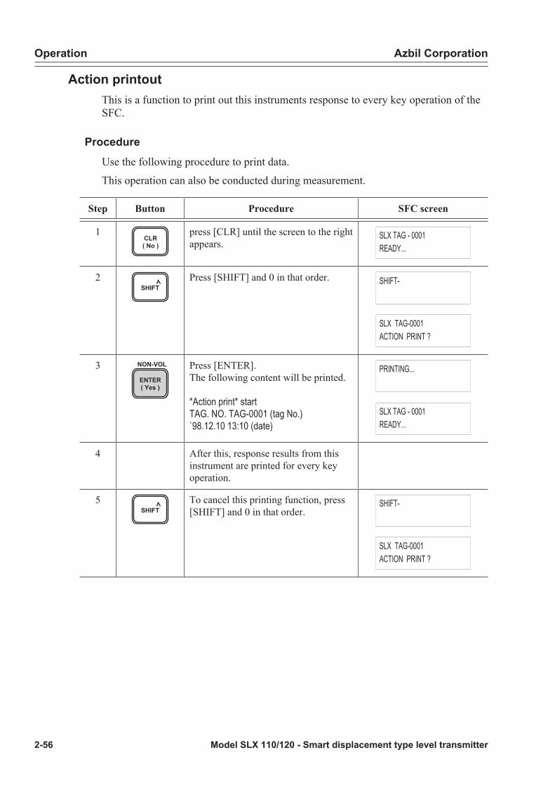
Operation Azbil Corporation
2-56 Model SLX 110/120 - Smart displacement type level transmitter
Action printoutThis is a function to print out this instruments response to every key operation of the SFC.
ProcedureUse the following procedure to print data.
This operation can also be conducted during measurement.
Step Button Procedure SFC screen
1CLR( No )
press [CLR] until the screen to the right appears.
SLX TAG - 0001READY...
2SHIFT
Press [SHIFT] and 0 in that order. SHIFT-
SLX TAG-0001ACTION PRINT ?
3ENTER( Yes )
NON-VOL Press [ENTER].The following content will be printed.
*Action print* startTAG. NO. TAG-0001 (tag No.)`98.12.10 13:10 (date)
PRINTING...
SLX TAG - 0001READY...
4 After this, response results from this instrument are printed for every key operation.
5SHIFT
To cancel this printing function, press [SHIFT] and 0 in that order.
SHIFT-
SLX TAG-0001ACTION PRINT ?

Azbil Corporation Operation
Model SLX 110/120 - Smart displacement type level transmitter 2-57
Step Button Procedure SFC screen
6CLR( No )
Press [CLR].
* Action print* endis printed and printing is finished.
PRINTING...
SLX TAG - 0001READY...
Example of action printoutA printout example which corresponds to key operations is shown below.
Z0ACT PR
SHIFT ENTER( Yes )
NON-VOL
keys
0SHIFT CLR( No ) keys
CDAMP keys
* ACTIONPRINT * STARTTAG. No. TAG-0001
'01. 07. 10 16:11
DAMP TAG-00010.0 s
SPAN TAG-0001300.0 mm
LRV TAG-00010.000 mm
* ACTION PRINT * END
Key operationPrinting example of corresponding action printout
YSPAN
URL
LRV E0%
Action Printout Example

Operation Azbil Corporation
2-58 Model SLX 110/120 - Smart displacement type level transmitter
Display and change of setting of this instrument
Changeable and non-changeable dataa: Changeable -: Not changeable
Item Display Change
Tag No. a a
Serial number a -
Software version a -
Indicator display format a a
Engineering unit value (real scale) URV/LRV
a a
Burnout direction a a

Azbil Corporation Operation
Model SLX 110/120 - Smart displacement type level transmitter 2-59
Tag No.Once communication with this instrument has started, set the tag No. using the following procedure.
The tag No. is given on the identification plate of this instrument.
Here, a case where the tag. No is to be changed to “TAG-0001” is given.
Step Button Procedure SFC screen
1ALPHA
T6
AID
DE READ
GSET
Press [ALPHA], [6], [ID] and [SET] in that order.
SLX TAG NO.SLX TAG
2 TIME Press [ALPHA] and [+/-] in that order. SLX TAG NO.SLX TAG-
3 Press enter value of 0001 in that order. SLX TAG NO.SLX TAG - 0001
4ENTER( Yes )
NON-VOL Press [ENTER].- A tag No. “TAG-0001” is set.
SLX TAG NO.WORKING...
i
SLX TAG NO.SLX TAG - 0001
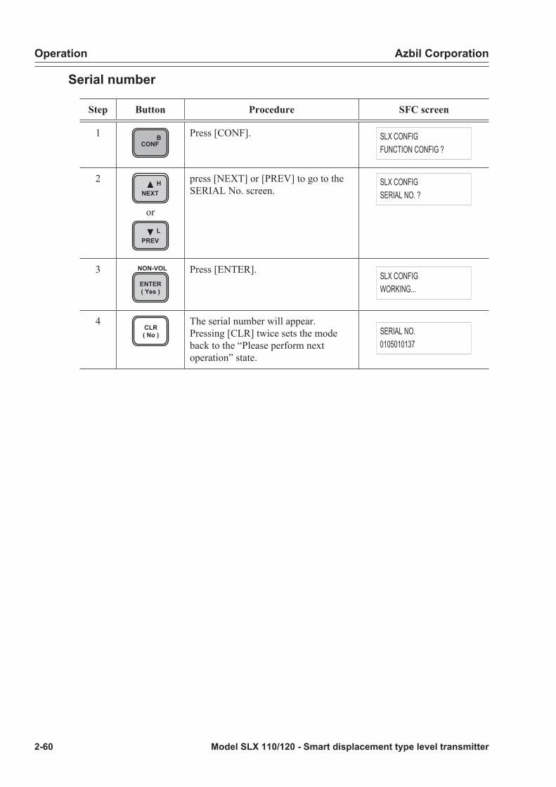
Operation Azbil Corporation
2-60 Model SLX 110/120 - Smart displacement type level transmitter
Serial number
Step Button Procedure SFC screen
1 BCONF
Press [CONF]. SLX CONFIGFUNCTION CONFIG ?
2 HNEXT
or
LPREV
press [NEXT] or [PREV] to go to the SERIAL No. screen.
SLX CONFIGSERIAL NO. ?
3ENTER( Yes )
NON-VOL Press [ENTER]. SLX CONFIGWORKING...
4CLR( No )
The serial number will appear.Pressing [CLR] twice sets the mode back to the “Please perform next operation” state.
SERIAL NO.0105010137
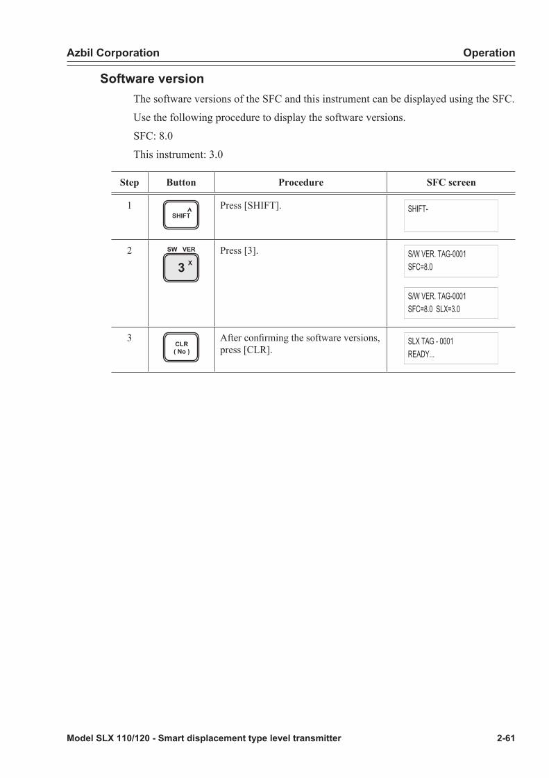
Azbil Corporation Operation
Model SLX 110/120 - Smart displacement type level transmitter 2-61
Software versionThe software versions of the SFC and this instrument can be displayed using the SFC.
Use the following procedure to display the software versions.
SFC: 8.0
This instrument: 3.0
Step Button Procedure SFC screen
1SHIFT
Press [SHIFT]. SHIFT-
2X3
SW VER Press [3]. S/W VER. TAG-0001SFC=8.0
S/W VER. TAG-0001SFC=8.0 SLX=3.0
3CLR( No )
After confirming the software versions, press [CLR].
SLX TAG - 0001READY...

Operation Azbil Corporation
2-62 Model SLX 110/120 - Smart displacement type level transmitter
Indicator display formatOnly two types; PV value and engineering unit value (real scale) are available.
Step Button Procedure SFC screen
1 BCONF
Press [CONF]. SLX CONFIGFUNCTION CONFIG ?
2ENTER( Yes )
NON-VOL Press [ENTER]. SLX CONFIGWORKING...
3 The current display format appears.Example: PV value.
DISPLAY TYPE% (0.0)
4MENU IITEM
DE CONF. Press [MENU] and select a display format. Example: engineering unit value (real scale).
DISPLAY TYPEENG.UNIT (4.5 DIG)
5 HNEXT
or
LPREV
press [NEXT] or [PREV] to go to the download selection screen.
DOWNLOAD DATA ?
6ENTER( Yes )
NON-VOL Press [ENTER]. FUNCTION CONFIG ?WORKING...
7CLR( No )
Setting completed. It takes approximately 6 sec. until the entry comes up in the display.Pressing [CLR] once sets the mode back to the “Please perform next operation” state.
FUNCTION CONFIGDATA LOADED !

Azbil Corporation Operation
Model SLX 110/120 - Smart displacement type level transmitter 2-63
Engineering unit valueUpper range value/lower range value
Step Button Procedure SFC screen
1 BCONF
Press [CONF]. SLX CONFIGFUNCTION CONFIG ?
2ENTER( Yes )
NON-VOL Press [ENTER]. SLX CONFIGWORKING...
3 The current display format appears.Example: PV value
DISPLAY TYPE% (0.0)
4MENU IITEM
DE CONF. Press [MENU] and select a display format. DISPLAY TYPE
ENG.UNIT (4.5 DIG)
5ENTER( Yes )
NON-VOL Press [ENTER]. DISPLAY TYPEWORKING...
6-1 The current engineering unit value (real scale) will appear.
EULO (at 0%)0.0
6-2 HNEXT
or
LPREV
To set an upper range value, press [NEXT] or [PREV] to go to the engineering unit upper range value setting screen and set the upper range value.
EUHI (at 100%)300.0
7 Enter the desired engineering unit upper range value using numerical keys.Example: Enter value of 100
EULO (at 0%)100_
8ENTER( Yes )
NON-VOL Press [ENTER]. EULO (at 0%)ENTERED IN SFC
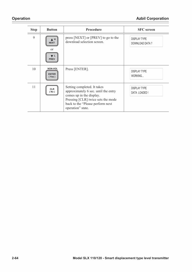
Operation Azbil Corporation
2-64 Model SLX 110/120 - Smart displacement type level transmitter
Step Button Procedure SFC screen
9 HNEXT
or
LPREV
press [NEXT] or [PREV] to go to the download selection screen.
DISPLAY TYPEDOWNLOAD DATA ?
10ENTER( Yes )
NON-VOL Press [ENTER]. DISPLAY TYPEWORKING...
11CLR( No )
Setting completed. It takes approximately 6 sec. until the entry comes up in the display.Pressing [CLR] twice sets the mode back to the “Please perform next operation” state.
DISPLAY TYPEDATA LOADED !
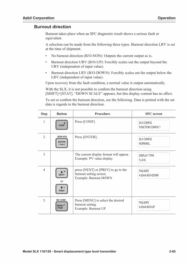
Azbil Corporation Operation
Model SLX 110/120 - Smart displacement type level transmitter 2-65
Burnout directionBurnout takes place when an SFC diagnostic result shows a serious fault or equivalent.
A selection can be made from the following three types. Burnout direction LRV is set at the time of shipment.
• No burnout direction (B/O-NON): Outputs the current output as is.
• Burnout direction URV (B/O-UP): Forcibly scales out the output beyond the URV (independent of input value).
• Burnout direction LRV (B/O-DOWN): Forcibly scales out the output below the LRV (independent of input value).
Upon recovery from the fault condition, a normal value is output automatically.
With the SLX, it is not possible to confirm the burnout direction using [SHIFT]+[STAT]. “DOWN SCALE” appears, but this display content has no effect.
To set or confirm the burnout direction, see the following. Data is printed with the set data is regards to the burnout direction.
Step Button Procedure SFC screen
1 BCONF
Press [CONF]. SLX CONFIGFUNCTION CONFIG ?
2ENTER( Yes )
NON-VOL Press [ENTER]. SLX CONFIGWORKING...
3 The current display format will appear.Example: PV value display
DISPLAY TYPE% (0.0)
4 HNEXT
or
LPREV
press [NEXT] or [PREV] to go to the burnout setting screen.Example: Burnout DOWN
FAILSAFE4-20mA B/O=DOWN
5MENU IITEM
DE CONF. Press [MENU] to select the desired burnout setting.Example: Burnout UP
FAILSAFE4-20mA B/O=UP
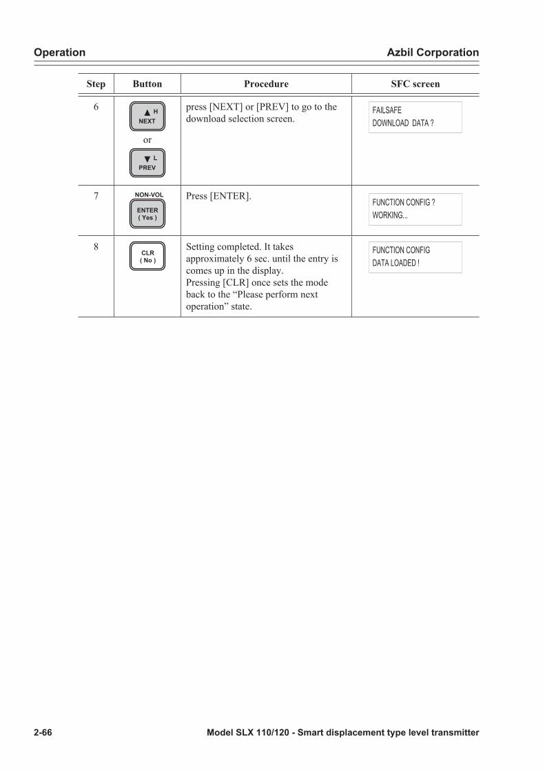
Operation Azbil Corporation
2-66 Model SLX 110/120 - Smart displacement type level transmitter
Step Button Procedure SFC screen
6 HNEXT
or
LPREV
press [NEXT] or [PREV] to go to the download selection screen.
FAILSAFEDOWNLOAD DATA ?
7ENTER( Yes )
NON-VOL Press [ENTER]. FUNCTION CONFIG ?WORKING...
8CLR( No )
Setting completed. It takes approximately 6 sec. until the entry is comes up in the display.Pressing [CLR] once sets the mode back to the “Please perform next operation” state.
FUNCTION CONFIGDATA LOADED !

Azbil Corporation Operation
Model SLX 110/120 - Smart displacement type level transmitter 2-67
DE output formatWhen digital (DE) output is used, the output signal mode and information quantity mode, etc. should be set. Here, these will be explained focusing on their operations.
Using the digital (DE) output as the output format of the SLX allows bi-directional communication between the SLX and the host system. At this time, three types of setting are available (necessary) according to operations carried out by means of communication.
Output signal mode settingSelect the type of data to be output from three of the following:
• Single range
• Dual range
• Single range & secondary variable (Single range W/SV) (this mode cannot be set)
Information quantity settingSelect the number of bytes of data to be output from among the following two:
• DE-6 bytes (DE-6 BYTE)
• DE-4 bytes (DE-4 BYTE) (this mode cannot be set)
Fail-safe mode settingSelect the type of fail-safe.
CAUTION
Since the fail-safe mode is set by the host system, this selection has no effect.

Operation Azbil Corporation
2-68 Model SLX 110/120 - Smart displacement type level transmitter
Constant current source mode
Constant current source mode settingExample: When output is fixed to 50% (12 mA)
Step Button Procedure SFC screen
1OUT- JPUT
INPUT Press [OUTPUT]. OUTPUT TAG-0001WORKING...
2 The current output data will appear.Example: 65.2%
OUTPUT TAG-000165.20 %
3 Enter 50% using numeric keys. OUTPUT TAG-000150_ %
4ENTER( Yes )
NON-VOL Press [ENTER]. OUTPUT TAG-0001WORKING...
5 The 50% constant current source mode is set. A “#” will appear. 12 mA is output and the indicator display starts to blink.
OUTPUT TAG-000150_ % #
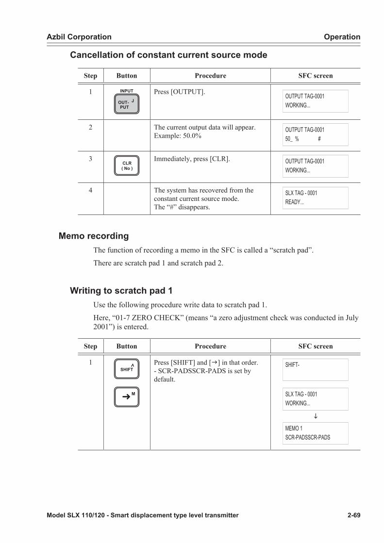
Azbil Corporation Operation
Model SLX 110/120 - Smart displacement type level transmitter 2-69
Cancellation of constant current source mode
Step Button Procedure SFC screen
1OUT- JPUT
INPUT Press [OUTPUT]. OUTPUT TAG-0001WORKING...
2 The current output data will appear.Example: 50.0%
OUTPUT TAG-000150_ % #
3CLR( No )
Immediately, press [CLR]. OUTPUT TAG-0001WORKING...
4 The system has recovered from the constant current source mode.The “#” disappears.
SLX TAG - 0001READY...
Memo recordingThe function of recording a memo in the SFC is called a “scratch pad”.
There are scratch pad 1 and scratch pad 2.
Writing to scratch pad 1Use the following procedure write data to scratch pad 1.
Here, “01-7 ZERO CHECK” (means “a zero adjustment check was conducted in July 2001”) is entered.
Step Button Procedure SFC screen
1SHIFT
M
Press [SHIFT] and [g] in that order.- SCR-PADSSCR-PADS is set by default.
SHIFT-
SLX TAG - 0001WORKING...
i
MEMO 1SCR-PADSSCR-PADS

Operation Azbil Corporation
2-70 Model SLX 110/120 - Smart displacement type level transmitter
Step Button Procedure SFC screen
2Z0
ACT PR
V1
TIME
N7
Press [0], [1], [+/-] and [7] in that order.
MEMO 101-7
3ALPHA
M
Press [ALPHA] and [g] in that order. MEMO 101-7
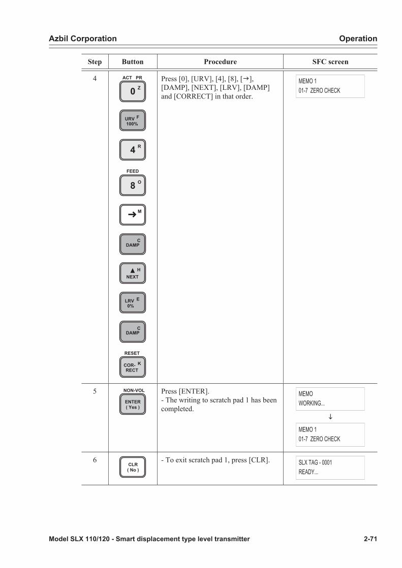
Azbil Corporation Operation
Model SLX 110/120 - Smart displacement type level transmitter 2-71
Step Button Procedure SFC screen
4Z0
ACT PR
URV F100%
R4
O8FEED
M
CDAMP
HNEXT
LRV E0%
CDAMP
COR- KRECT
RESET
Press [0], [URV], [4], [8], [g], [DAMP], [NEXT], [LRV], [DAMP] and [CORRECT] in that order.
MEMO 101-7 ZERO CHECK
5ENTER( Yes )
NON-VOL Press [ENTER].- The writing to scratch pad 1 has been completed.
MEMOWORKING...
i
MEMO 101-7 ZERO CHECK
6CLR( No )
- To exit scratch pad 1, press [CLR]. SLX TAG - 0001READY...
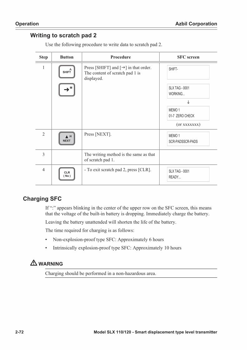
Operation Azbil Corporation
2-72 Model SLX 110/120 - Smart displacement type level transmitter
Writing to scratch pad 2Use the following procedure to write data to scratch pad 2.
Step Button Procedure SFC screen
1SHIFT
M
Press [SHIFT] and [g] in that order.The content of scratch pad 1 is displayed.
SHIFT-
SLX TAG - 0001WORKING...
i
MEMO 101-7 ZERO CHECK
(or xxxxxxx)
2 HNEXT
Press [NEXT]. MEMO 1SCR-PADSSCR-PADS
3 The writing method is the same as that of scratch pad 1.
4CLR( No )
- To exit scratch pad 2, press [CLR]. SLX TAG - 0001READY...
Charging SFCIf “:” appears blinking in the center of the upper row on the SFC screen, this means that the voltage of the built-in battery is dropping. Immediately charge the battery.
Leaving the battery unattended will shorten the life of the battery.
The time required for charging is as follows:
• Non-explosion-proof type SFC: Approximately 6 hours
• Intrinsically explosion-proof type SFC: Approximately 10 hours
WARNING
Charging should be performed in a non-hazardous area.

Azbil Corporation Operation
Model SLX 110/120 - Smart displacement type level transmitter 2-73
ProcedureUse the following procedure to change the battery.
Use the provided battery charger only.
Step Procedure
1 Turn OFF the power to the SFC.
2 Disconnect the communication cable on the transmitter side.
3 Pull out the SFC plug of the communication cable.
4 Connect the plug of the battery charger cable to the SFC.
5 Connect the plug of the battery charger main unit to an 100 VAC receptacle.Charging starts.
6 After a predetermined charging time has passed, remove the battery charger to finish charging.

Operation Azbil Corporation
2-74 Model SLX 110/120 - Smart displacement type level transmitter
2-7 : Operation of external adjustment switch (with indicator)Data can be read by the SFC even while the external adjustment switch is in operation. What is read is data immediately before the adjustment mode was entered.~Note:• If an SFC communication has been started while operating the external
adjustment switch, adjustment will be stopped as long as the communication continues.
• In the case of the DE output mode, the external adjustment switch cannot be used.• The change is reflected in the output after the normal condition is recovered from
the adjustment mode.• Do not use a magnetic driver because this may prevent accurate adjustment.• In the case of an engineering unit (real scale) display format, it may take a few
seconds after each adjustment mode is entered until a correct value is displayed.• Start operation after correct value appears.
+
-
Switch
Figure 2-8 Switch position
Basic operation methodWhile pushing in the switch toward the back using a flat-head screwdriver, turn the switch clockwise (+) or counterclockwise (-).
Function• Zero adjustment to adjust to real level (pinpoint adjustment)
• Damping adjustment
• Zero span adjustmentThe operation sequence of the entire external adjustment switch is given on “Operation sequence” on page 2-79.
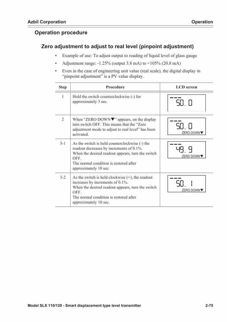
Azbil Corporation Operation
Model SLX 110/120 - Smart displacement type level transmitter 2-75
Operation procedure
Zero adjustment to adjust to real level (pinpoint adjustment)• Example of use: To adjust output to reading of liquid level of glass gauge
• Adjustment range: -1.25% (output 3.8 mA) to +105% (20.8 mA)
• Even in the case of engineering unit value (real scale), the digital display in “pinpoint adjustment” is a PV value display.
Step Procedure LCD screen
1 Hold the switch counterclockwise (-) for approximately 3 sec.
2 When “ZERO DOWNq” appears, on the display turn switch OFF. This means that the “Zero adjustment mode to adjust to real level” has been activated. ZERO DOWN
3-1 As the switch is held counterclockwise (-) the readout decreases by increments of 0.1%.When the desired readout appears, turn the switch OFF.The normal condition is restored after approximately 10 sec.
ZERO DOWN
3-2 As the switch is held clockwise (+), the readout increases by increments of 0.1%.When the desired readout appears, turn the switch OFF.The normal condition is restored after approximately 10 sec.
ZERO DOWN

Operation Azbil Corporation
2-76 Model SLX 110/120 - Smart displacement type level transmitter
Damping adjustment• Satiable damping time constant (sec.):
• The cyclic direction does not change (from 0 to 100, not from 100 to 0)
• Caution: “199.9” is not a damping time constant.
Step Procedure LCD screen
1 Hold the switch clockwise (+) for approximately 3 sec.
2 When “pUP ZERO” appears on the display, turn the switch OFF. This means that the “Damping adjustment mode” has been activated.
UP ZERO
3-1 Every time the switch is turned counterclockwise (-) one turn, the damping time constant decreases by an increment of 1. The normal condition is restored after approximately 10 sec. UP ZERO
3-2 Every time the switch is turned clockwise (+) one turn, the damping time constant increases by an increment of 1. The normal condition is restored after approximately 10 sec. UP ZERO
Zero span adjustment• Zero adjustment can also be performed from “pinpoint adjustment”.
• The set value immediately before the “zero span adjustment mode” was entered is used as the damping time constant during zero span adjustment.
• In the case of an engineering unit value (real scale) display, the digital display in “zero span adjustment” is engineering unit value (real scale) display.

Azbil Corporation Operation
Model SLX 110/120 - Smart displacement type level transmitter 2-77
Zero adjustmentCarry out zero adjustment by giving 0% equivalent input.
Step Procedure LCD screen
1 Hold the switch clockwise (+) for approximately 3 sec.
2 When “pUP ZERO” appears on the display, turn the switch OFF. This means that the “Damping adjustment mode” has been activated.
UP ZERO
3 Turn the switch counterclockwise (-) and “199.9” below “0” will appear.
4 “ZERO” appears after approximately 10 sec. and “Zero span adjustment mode” is activated. The current output value is displayed. If zero adjustment is not performed, the normal condition will be restored after approximately 30 sec.
ZERO
5 Hold the switch counterclockwise for approximately 3 sec. When “ZERO DOWNq” appears, turn the switch OFF. The current input becomes the zero point. After approximately 2 sec., the normal condition will be restored.
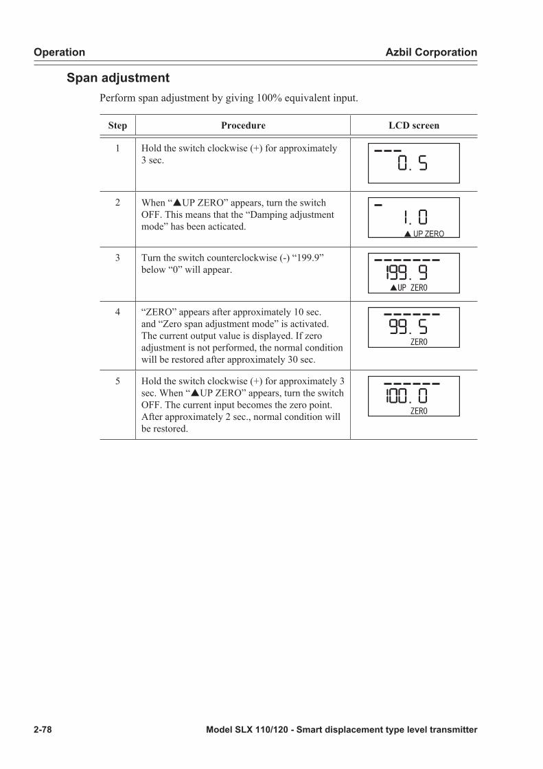
Operation Azbil Corporation
2-78 Model SLX 110/120 - Smart displacement type level transmitter
Span adjustmentPerform span adjustment by giving 100% equivalent input.
Step Procedure LCD screen
1 Hold the switch clockwise (+) for approximately 3 sec.
2 When “pUP ZERO” appears, turn the switch OFF. This means that the “Damping adjustment mode” has been acticated.
UP ZERO
3 Turn the switch counterclockwise (-) “199.9” below “0” will appear.
4 “ZERO” appears after approximately 10 sec. and “Zero span adjustment mode” is activated. The current output value is displayed. If zero adjustment is not performed, the normal condition will be restored after approximately 30 sec.
5 Hold the switch clockwise (+) for approximately 3 sec. When “pUP ZERO” appears, turn the switch OFF. The current input becomes the zero point. After approximately 2 sec., normal condition will be restored.

Azbil Corporation Operation
Model SLX 110/120 - Smart displacement type level transmitter 2-79
Operation sequenceNormal mode (OFF)
Clockwise (+)Counterclockwise (-) Clockwise (+)Counterclockwise (-)
Approx. 3sec clockwise (+)Approx. 3sec counterclockwise (-)
Approx. 3sec clockwise (+)Approx. 3sec counterclockwise (-)
Zero span adjustment mode after approximately 10 sec.
Damping adjustment modeReverts to normal condition in approximately 10 sec.
Zero adjustment mode (pinpoint adjustment)to adjust to real levelReverts to normal condition in approximately 10 sec.
ZERO DOWN
ZERO DOWN ZERO DOWN UP ZERO
UP ZERO
UP ZERO
Zero span adjustment modeZero span adjustment modeReverts to normal condition in approximately 30 sec.
Zero adjustment completedReverts to normal condition in approximately 2 sec.
Span sadjustment completedReverts to normal condition in approximately 2 sec.
Table 2-2:
Adjust mode Indicator display
Normal status (none)
Pinpoint adjustment ZERO DOWNq
Damping adjustment pUP ZERO
Zero-span adjustment ZERO

Operation Azbil Corporation
2-80 Model SLX 110/120 - Smart displacement type level transmitter
Model SLX 110/120 - Smart displacement type level transmitter 3-1
Chapter 3 : Maintenance
WARNING
• Do not use the instrument beyond the rated pressure, connection specification and rated temperature specified for the instrument. This may result in serious accident due to damage.
• Wiring in an explosion-proof area should be performed according to the work procedure specified in the explosion-proof guideline.
CAUTION
• After installation, do not use this instrument as a foothold, etc. This may damage the instrument or may result in physical injury
• Avoid hitting the glass part of the display with tools. This may damage the glass and result in physical injury.
• Perform installation correctly. Insufficient installation or no installation may result in output errors or violate applicable regulations.
• This product is heavy. Pay attention to the scaffolding and wear safety shoes.
3-1 : Daily maintenance items(to be carried out during operation with instrument installed on the process)
Visual inspectionCheck for the following items.
• Fracture, corrosion, or damage of components
• Leakage from flange section.
• Noize when the chamber (liquid tank) touches the float due to vibration
• Error display on indicator
• Check whether reading is stable or not
Zero adjustmentIf there is any difference evident from the level gauge, conduct “Operation of external adjustment switch (with indicator)” on page 2-74.

Maintenance Azbil Corporation
3-2 Model SLX 110/120 - Smart displacement type level transmitter
3-2 : Items of periodic maintenance check
Verification of functions• With the device installed on process equipment, run a functional check with water
filled in chamber (or, use water in lieu of process fluid) by varying water level. Or, remove the main body and run a functional check by calibrating weight.
• If specified accuracy is not achieved, perform following maintenance checks.
~Note The guaranteed accuracy of SLX is by means of weight calibration.
Disassembly and cleaning of wetted partsIf rated accuracy is not achieved by a test as described in 1) above, or if the measured fluid is of high viscosity, adhesive or extremely corrosive, disassemble/clean as follows:
For description/nomenclature of parts, refer to “Names of components and parts” on page 1-1, “Principles of operation” on page 2-1 and drawings at the end of this manual.
Primary disassembly/cleaning (when inside of torque tube housing is not cleaned)
• If there is no deposit inside of the torque tube housing or on the knife-edge pivot, primary disassembly/cleaning is recommended.
• Disassemble SLX into two or three parts and clean in the following order: External tube type : Body, float and chamber
Internal tube type : Body and float
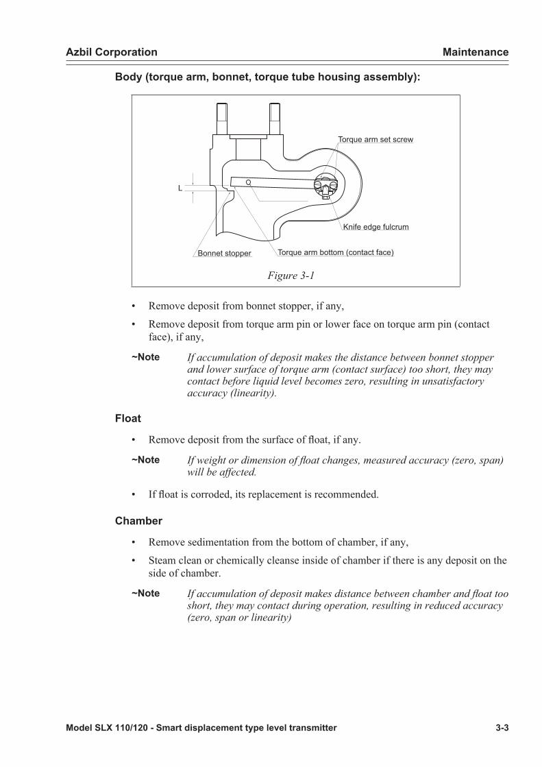
Azbil Corporation Maintenance
Model SLX 110/120 - Smart displacement type level transmitter 3-3
Body (torque arm, bonnet, torque tube housing assembly):
L
Bonnet stopper Torque arm bottom (contact face)
Knife edge fulcrum
Torque arm set screw
Figure 3-1
• Remove deposit from bonnet stopper, if any,
• Remove deposit from torque arm pin or lower face on torque arm pin (contact face), if any,
~Note If accumulation of deposit makes the distance between bonnet stopper and lower surface of torque arm (contact surface) too short, they may contact before liquid level becomes zero, resulting in unsatisfactory accuracy (linearity).
Float
• Remove deposit from the surface of float, if any.
~Note If weight or dimension of float changes, measured accuracy (zero, span) will be affected.
• If float is corroded, its replacement is recommended.
Chamber
• Remove sedimentation from the bottom of chamber, if any,
• Steam clean or chemically cleanse inside of chamber if there is any deposit on the side of chamber.
~Note If accumulation of deposit makes distance between chamber and float too short, they may contact during operation, resulting in reduced accuracy (zero, span or linearity)
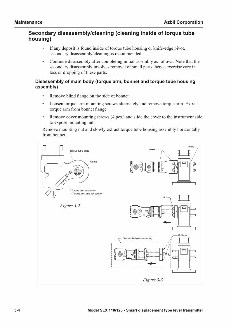
Maintenance Azbil Corporation
3-4 Model SLX 110/120 - Smart displacement type level transmitter
Secondary disassembly/cleaning (cleaning inside of torque tube housing)
• If any deposit is found inside of torque tube housing or knife-edge pivot, secondary disassembly/cleaning is recommended.
• Continue disassembly after completing initial assembly as follows. Note that the secondary disassembly involves removal of small parts, hence exercise care in loss or dropping of these parts.
Disassembly of main body (torque arm, bonnet and torque tube housing assembly)
• Remove blind flange on the side of bonnet.
• Loosen torque arm mounting screws alternately and remove torque arm. Extract torque arm from bonnet flange.
• Remove cover mounting screws (4 pcs.) and slide the cover to the instrument side to expose mounting nut.
Remove mounting nut and slowly extract torque tube housing assembly horizontally from bonnet.
Torque tube plate
Guide
Torque arm assembly(Torque arm and set screws)
Figure 3-2
+
-
+
-
+
-
Torque tube housing assemblyGuide pin
Nut
xxxxxxxxxxxx
Figure 3-3

Azbil Corporation Maintenance
Model SLX 110/120 - Smart displacement type level transmitter 3-5
Torque arm
• Remove deposit on contacts of knife-edge, bonnet stopper or pin if any.
Bonnet
• Remove deposit from bonnet stopper, if any.
Torque tube housing assembly
• Remove deposit from knife-edge or torque plate, if any,
• To clean inside of torque tube housing, inject steam or pour in appropriate detergent through a gap between torque tube housing and torque tube.
WARNING
Steam, detergent or deposit, which has been injected into inside of torque tube housing will flow out through the gap between torque tube housing and torque tube because the interior of the torque tube housing is sealed. In addition to extreme caution to be exercised during cleaning work, do not point inlet/outlet of steam or detergent to any person.
Reassembly, reinstallation• Install and assemble in the reverse order of disassembly. Refer to Figure 3-4 and
Figure 3-5.
Guide pin
Guide hole
Torque arm set screw
Figure 3-4 Placing torque tube housing assembly on bonnet
Figure 3-5 Setting the torque arm

Maintenance Azbil Corporation
3-6 Model SLX 110/120 - Smart displacement type level transmitter
Installation of torque tube housing assembly and bonnetInsert guide pin of torque tube housing assembly into the hole of bonnet's guide hole while installing.
Installation of torque tube plate and torque arm
• Set torque arm in the torque tube plate's slot and tighten torque arm mounting screw alternately. Temporarily tighten screws slightly short of fastening of the arm.
• While pressing bottom of torque arm against bonnet stopper so that the torque arm does not shift, tighten torque arm mounting screws at the specified torque.
• Tightening torque for flange bolt and screw is as follows:Table 3-1: Tightening torques for flange bolts and screw
Bonnet flange Refer to P-14
Torque tube housing flange Blind flange M14 127+20 (N.m)
Torque arm mounting screw M6 3.7+0.3 (N.m)
Cover mounting screw M4 1.5+0.3 (N.m)
CAUTION
Right hand or left hand orientation of instrument head cannot be reversed on SLX. The orientation has been set at the time of factory shipment. Under no circumstance, torque tube housing should be mounted on the opposite side of side flange of bonnet when assembling.
Handling of torque tube• SLX has been designed to facilitate replacement of torque tube by disassembling
its main body, taking into consideration of possible corrosion,
• However, replacement of torque tube requires specific dedicated tools. Also, pressure-withstanding test of metallic contact surface of torque tube housing (pressure sealing surface) is required.
• For replacement or removal of torque tube, please consult with out sales office or service station closest to your plant.
Inspection of instrument• Open the front cover of instrument and verify that no water has seeped inside. If
necessary, tighten screws or replace O-ring for prevention of water intrusion.
• Do not disassemble two plugs on sensor assembly or mounting screws of sensor housing and its extension. If necessary, please consult with our sales office or service station closest to your plant.

Azbil Corporation Maintenance
Model SLX 110/120 - Smart displacement type level transmitter 3-7
Zero and span adjustment• Calibrate in installed position on process equipment, with water filled,Refer to “Zero span adjustment” on page 2-10
• Or calibrate with weight.Refer to “3-4 : Zero span calibration with weight” on page 3-12
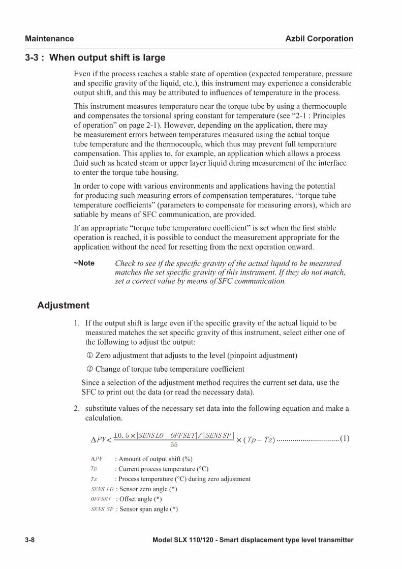
Maintenance Azbil Corporation
3-8 Model SLX 110/120 - Smart displacement type level transmitter
3-3 : When output shift is largeEven if the process reaches a stable state of operation (expected temperature, pressure and specific gravity of the liquid, etc.), this instrument may experience a considerable output shift, and this may be attributed to influences of temperature in the process.
This instrument measures temperature near the torque tube by using a thermocouple and compensates the torsional spring constant for temperature (see “2-1 : Principles of operation” on page 2-1). However, depending on the application, there may be measurement errors between temperatures measured using the actual torque tube temperature and the thermocouple, which thus may prevent full temperature compensation. This applies to, for example, an application which allows a process fluid such as heated steam or upper layer liquid during measurement of the interface to enter the torque tube housing.
In order to cope with various environments and applications having the potential for producing such measuring errors of compensation temperatures, “torque tube temperature coefficients” (parameters to compensate for measuring errors), which are satiable by means of SFC communication, are provided.
If an appropriate “torque tube temperature coefficient” is set when the first stable operation is reached, it is possible to conduct the measurement appropriate for the application without the need for resetting from the next operation onward.
~Note Check to see if the specific gravity of the actual liquid to be measured matches the set specific gravity of this instrument. If they do not match, set a correct value by means of SFC communication.
Adjustment
1. If the output shift is large even if the specific gravity of the actual liquid to be measured matches the set specific gravity of this instrument, select either one of the following to adjust the output:
j Zero adjustment that adjusts to the level (pinpoint adjustment)
k Change of torque tube temperature coefficient
Since a selection of the adjustment method requires the current set data, use the SFC to print out the data (or read the necessary data).
2. substitute values of the necessary set data into the following equation and make a calculation.
............................... (1)
: Amount of output shift (%) : Current process temperature (°C) : Process temperature (°C) during zero adjustment
: Sensor zero angle (*) : Offset angle (*) : Sensor span angle (*)
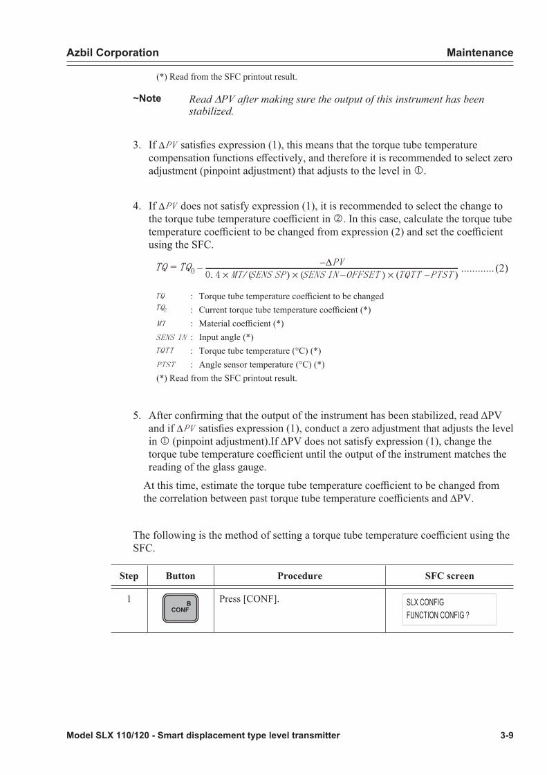
Azbil Corporation Maintenance
Model SLX 110/120 - Smart displacement type level transmitter 3-9
(*) Read from the SFC printout result.
~Note Read DPV after making sure the output of this instrument has been stabilized.
3. If satisfies expression (1), this means that the torque tube temperature compensation functions effectively, and therefore it is recommended to select zero adjustment (pinpoint adjustment) that adjusts to the level in j.
4. If does not satisfy expression (1), it is recommended to select the change to the torque tube temperature coefficient in k. In this case, calculate the torque tube temperature coefficient to be changed from expression (2) and set the coefficient using the SFC.
............ (2)
: Torque tube temperature coefficient to be changed : Current torque tube temperature coefficient (*) : Material coefficient (*)
: Input angle (*) : Torque tube temperature (°C) (*) : Angle sensor temperature (°C) (*)
(*) Read from the SFC printout result.
5. After confirming that the output of the instrument has been stabilized, read DPV and if satisfies expression (1), conduct a zero adjustment that adjusts the level in j (pinpoint adjustment).If DPV does not satisfy expression (1), change the torque tube temperature coefficient until the output of the instrument matches the reading of the glass gauge.
At this time, estimate the torque tube temperature coefficient to be changed from the correlation between past torque tube temperature coefficients and DPV.
The following is the method of setting a torque tube temperature coefficient using the SFC.
Step Button Procedure SFC screen
1 BCONF
Press [CONF]. SLX CONFIGFUNCTION CONFIG ?

Maintenance Azbil Corporation
3-10 Model SLX 110/120 - Smart displacement type level transmitter
Step Button Procedure SFC screen
2 HNEXT
or
LPREV
Press [NEXT] or [PREV] to go to the basic data setting screen.
SLX CONFIGDATA CONFIG ?
3ENTER( Yes )
NON-VOL Press [ENTER]. SLX CONFIGWORKING...
4 The current specific gravity set value will appear.Example: 0.8
GRAVITY0.800
5 HNEXT
or
LPREV
Press [NEXT] or [PREV] to go to the coefficient setting screen. Example: 0
COEF TQ 0.000
6 Enter the desired torque tube temperature coefficient using numeric keys.Example: Enter value of 1.3
COEF TQ 1.3_
7ENTER( Yes )
NON-VOL Press [ENTER]. COEF TQENTERED IN SFC
8 HNEXT
or
LPREV
Press [NEXT] or [PREV] to go to the download selection screen.
DATA CONFIGDOWNLOAD DATA ?
9ENTER( Yes )
NON-VOL Press [ENTER]. DATA CONFIGWORKING...
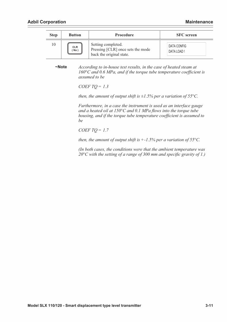
Azbil Corporation Maintenance
Model SLX 110/120 - Smart displacement type level transmitter 3-11
Step Button Procedure SFC screen
10CLR( No )
Setting completed.Pressing [CLR] once sets the mode back the original state.
DATA CONFIGDATA LOAD !
~Note According to in-house test results, in the case of heated steam at 160°C and 0.6 MPa, and if the torque tube temperature coefficient is assumed to be
COEF TQ = 1.3
then, the amount of output shift is ±1.5% per a variation of 55°C.
Furthermore, in a case the instrument is used as an interface gauge and a heated oil at 150°C and 0.1 MPa flows into the torque tube housing, and if the torque tube temperature coefficient is assumed to be
COEF TQ = 1.7
then, the amount of output shift is +-1.5% per a variation of 55°C.
(In both cases, the conditions were that the ambient temperature was 20°C with the setting of a range of 300 mm and specific gravity of 1.)
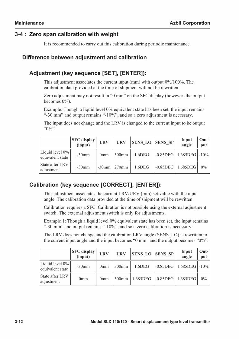
Maintenance Azbil Corporation
3-12 Model SLX 110/120 - Smart displacement type level transmitter
3-4 : Zero span calibration with weightIt is recommended to carry out this calibration during periodic maintenance.
Difference between adjustment and calibration
Adjustment (key sequence [SET], [ENTER]):This adjustment associates the current input (mm) with output 0%/100%. The calibration data provided at the time of shipment will not be rewritten.
Zero adjustment may not result in “0 mm” on the SFC display (however, the output becomes 0%).
Example: Though a liquid level 0% equivalent state has been set, the input remains “-30 mm” and output remains “-10%”, and so a zero adjustment is necessary.
The input does not change and the LRV is changed to the current input to be output “0%”.
SFC display (input) LRV URV SENS_LO SENS_SP Input
angleOut- put
Liquid level 0% equivalent state -30mm 0mm 300mm 1.6DEG -0.85DEG 1.685DEG -10%
State after LRV adjustment -30mm -30mm 270mm 1.6DEG -0.85DEG 1.685DEG 0%
Calibration (key sequence [CORRECT], [ENTER]):This adjustment associates the current LRV/URV (mm) set value with the input angle. The calibration data provided at the time of shipment will be rewritten.
Calibration requires a SFC. Calibration is not possible using the external adjustment switch. The external adjustment switch is only for adjustments.
Example 1: Though a liquid level 0% equivalent state has been set, the input remains “-30 mm” and output remains “-10%”, and so a zero calibration is necessary.
The LRV does not change and the calibration LRV angle (SENS_LO) is rewritten to the current input angle and the input becomes “0 mm” and the output becomes “0%”.
SFC display (input) LRV URV SENS_LO SENS_SP Input
angleOut-put
Liquid level 0% equivalent state -30mm 0mm 300mm 1.6DEG -0.85DEG 1.685DEG -10%
State after LRV adjustment 0mm 0mm 300mm 1.685DEG -0.85DEG 1.685DEG 0%

Azbil Corporation Maintenance
Model SLX 110/120 - Smart displacement type level transmitter 3-13
Procedure for calibration with weight
1. Remove the main unit from the process and place it on a frame in a place with minimal ambient disturbance such as the control room.
2. Prepare the following calibration weights according to the calculation expression below.• Level gauge: weight 1 (mass F1), weight 2 (mass F2) Liquid gauge expression
• Interface gauge: weight 3 (mass F3), weight 4 (mass F4) Interface gauge expression
~Note • Weights 1 and 3 include pans for weights, etc.• According to the level gauge, “weight 1 + weight 2” is 0% calibrated
load and “weight 1” is 100% calibrated load.• According to the interface gauge, “weight 3 + weight 4” is 0%
calibrated load and “weight 3” is 100% calibrated load.• For 0% calibrated load and 100% calibrated load, see Figure A.• When carrying out an elevation, also carry out calibration with
weights using the following procedure.
Then, make an elevation setting with reference to “Displaying and changing set data for measurement” on page 2-37.
Liquid surface(boundary surface)
Liquid surface(boundary surface)
Mea
surin
g ra
nge
=Flo
at le
ngth
H
Mea
surin
g ra
nge
=Flo
at le
ngth
H
100% Calibration loaded 0% Calibration loaded
Figure 3-6 Points of calibration loaded

Maintenance Azbil Corporation
3-14 Model SLX 110/120 - Smart displacement type level transmitter
Liquid gauge expression
Fb: Mass of float (FLOAT LOAD is given on identification plate or is the measured value of float mass)
D: Float diameter (mm)H: Float length (mm): Specific gravity (g/cm3)a: Constant, a = 5.76 x 10⁻⁷
Interface gauge expression
Fb: Mass of float (FLOAT LOAD described on identification plate or measured value of float mass)
r1: Specific gravity of upper layer liquid (g/cm3)r2: Specific gravity of lower layer liquid (g/cm3), r2>r1
Other parameters are same to (a) liquid gauge.
3. Turn the power to the instrument ON and connect the SFC.(See “2-3 : Items to be checked before operation” on page 2-5.)
4. Make sure the value of specific gravity conforms with the specific gravity of the fluid to be measured and carry out the setting.(See “Displaying and changing set data for measurement” on page 2-37.)
5. Calibrate the LRV.
Step Button Procedure SFC screen
1 Apply 0% calibrated load to the torque arm.
SLX TAG - 0001READY...
2LRV E0%
Press [LRV]. The current LRV will appear.Example: 0.12 mm
LRV TAG - 00010.1200 mm
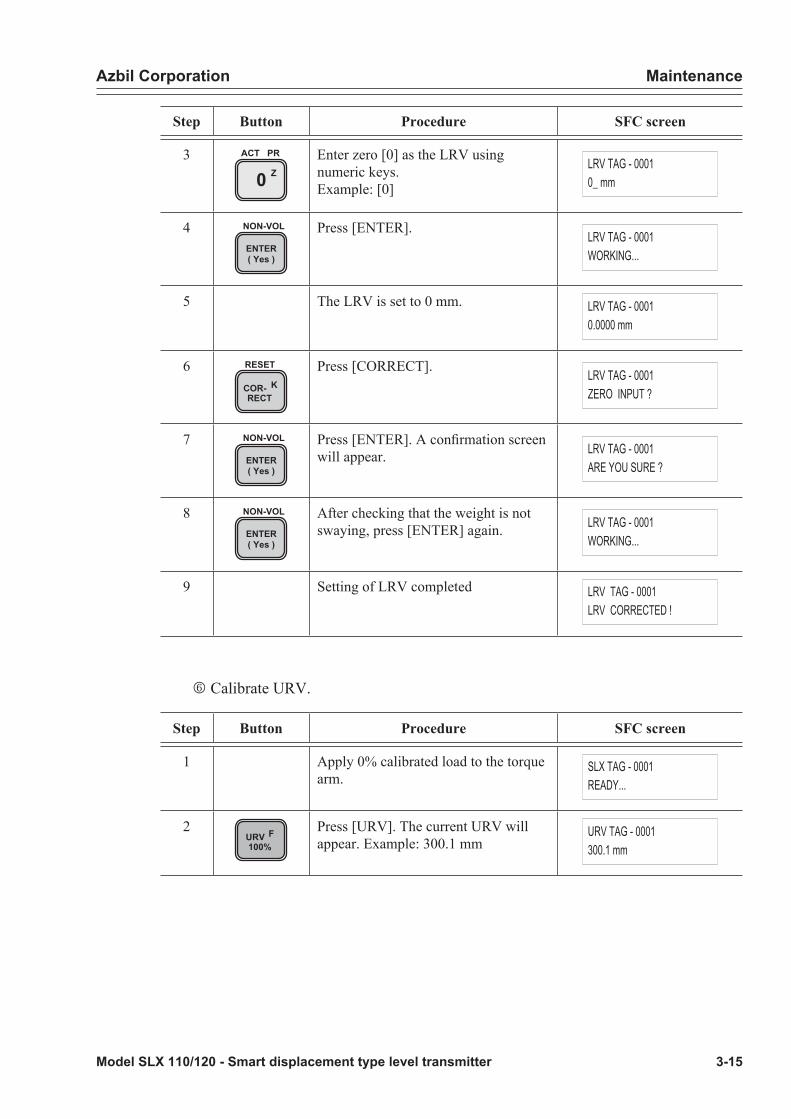
Azbil Corporation Maintenance
Model SLX 110/120 - Smart displacement type level transmitter 3-15
Step Button Procedure SFC screen
3Z0
ACT PR Enter zero [0] as the LRV using numeric keys.Example: [0]
LRV TAG - 00010_ mm
4ENTER( Yes )
NON-VOL Press [ENTER]. LRV TAG - 0001WORKING...
5 The LRV is set to 0 mm. LRV TAG - 00010.0000 mm
6COR- KRECT
RESET Press [CORRECT]. LRV TAG - 0001ZERO INPUT ?
7ENTER( Yes )
NON-VOL Press [ENTER]. A confirmation screen will appear. LRV TAG - 0001
ARE YOU SURE ?
8ENTER( Yes )
NON-VOL After checking that the weight is not swaying, press [ENTER] again. LRV TAG - 0001
WORKING...
9 Setting of LRV completed LRV TAG - 0001LRV CORRECTED !
o Calibrate URV.
Step Button Procedure SFC screen
1 Apply 0% calibrated load to the torque arm.
SLX TAG - 0001READY...
2URV F100%
Press [URV]. The current URV will appear. Example: 300.1 mm
URV TAG - 0001300.1 mm

Maintenance Azbil Corporation
3-16 Model SLX 110/120 - Smart displacement type level transmitter
Step Button Procedure SFC screen
3 Enter the desired liquid level as the URV using numeric keys.Example: Enter value of 300
URV TAG - 0001300_ mm
4ENTER( Yes )
NON-VOL Press [ENTER]. URV TAG - 0001WORKING...
5 The URV is set to 300 mm. URV TAG - 0001300.0 mm
6COR- KRECT
RESET Press [CORRECT]. URV TAG - 0001CORRECT LRV ?
7ENTER( Yes )
NON-VOL Press [ENTER]. A confirmation screen will appear. URV TAG - 0001
ARE YOU SURE !?
8ENTER( Yes )
NON-VOL After checking that the weight is not swaying, press [ENTER] again. URV TAG - 0001
WORKING...
9 Setting of URV completed. URV TAG - 0001URV CORRECTED
CAUTION
Be sure to calibrate the URV after calibrating the LRV first.
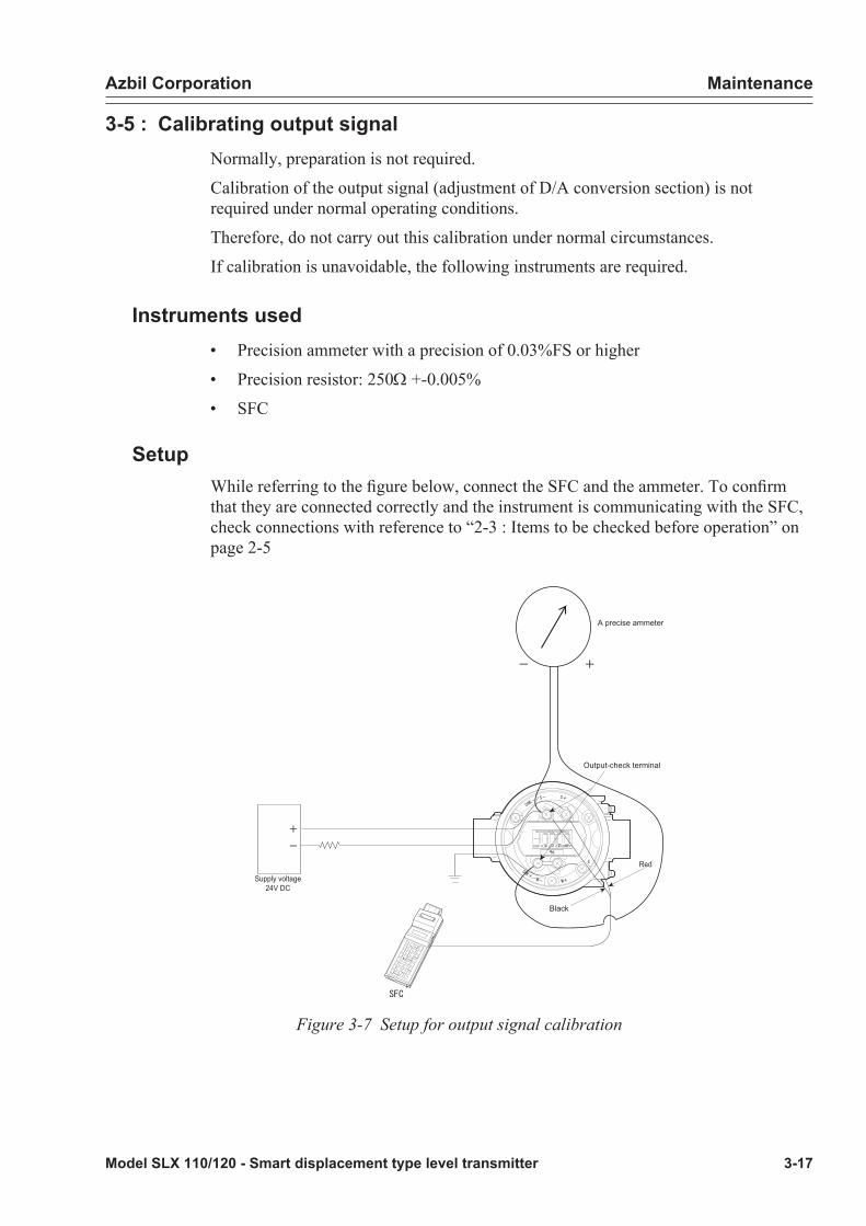
Azbil Corporation Maintenance
Model SLX 110/120 - Smart displacement type level transmitter 3-17
3-5 : Calibrating output signalNormally, preparation is not required.
Calibration of the output signal (adjustment of D/A conversion section) is not required under normal operating conditions.
Therefore, do not carry out this calibration under normal circumstances.
If calibration is unavoidable, the following instruments are required.
Instruments used• Precision ammeter with a precision of 0.03%FS or higher
• Precision resistor: 250W +-0.005%
• SFC
SetupWhile referring to the figure below, connect the SFC and the ammeter. To confirm that they are connected correctly and the instrument is communicating with the SFC, check connections with reference to “2-3 : Items to be checked before operation” on page 2-5
Black
A precise ammeter
Output-check terminal
Supply voltage24V DC
Red
Figure 3-7 Setup for output signal calibration

Maintenance Azbil Corporation
3-18 Model SLX 110/120 - Smart displacement type level transmitter
Calibrating output signal 0%Use the following procedure to set the output to 0% and to calibrate so that the reading of the ammeter becomes 4 mA.
Step Button Procedure SFC screen
1OUT- JPUT
INPUT Press [OUTPUT]. OUTPUT TAG-0001WORKING...
i
OUTPUT TAG - 00010.00 %
2Z0
ACT PR Enter value of 0. OUTPUT TAG - 00010
3ENTER( Yes )
NON-VOL Press [ENTER].- This sets the instrument to a 4 mA (0%) constant current source mode.- Once the constant current source mode is activated, a “#” appears on the screen.
OUTPUT TAG-0001WORKING...
i
OUTPUT TAG - 00010.00 % #
4 Make sure the ammeter indicates 4 mA.
OUTPUT TAG - 00010.00 % #
5OUT- JPUT
INPUT Press [OUTPUT].The current output is 0%.
OUTPUT TAG-0001WORKING...
i
OUTPUT TAG - 00010.00 % #
6COR- KRECT
RESET Press [CORRECT].- Carry out step 7 if the reading is lower than 4 mA, and carry out step 8 if the reading is higher than 4 mA.
OUTPUT TAG - 0001CORRECT DAC ZERO

Azbil Corporation Maintenance
Model SLX 110/120 - Smart displacement type level transmitter 3-19
Step Button Procedure SFC screen
7 HNEXT
Press [NEXT].Check the reading of the ammeter, while pressing this key.
OUTPUT TAG-0001WORKING...
OUTPUT TAG - 0001INCREASED 4mA #
OUTPUT TAG - 0001CORRECT DAC ZERO #
8 LPREV
Press [PREV].Check the reading of the ammeter, while pressing this key.
OUTPUT TAG-0001WORKING...
i
OUTPUT TAG - 0001DECREASED 4mA
OUTPUT TAG - 0001CORRECT DAC ZERO
9CLR( No )
When calibration is completed, press [CLR].
SLX TAG - 0001READY...
10 - Save the calibrated values according to 4 and exit the constant current source mode.
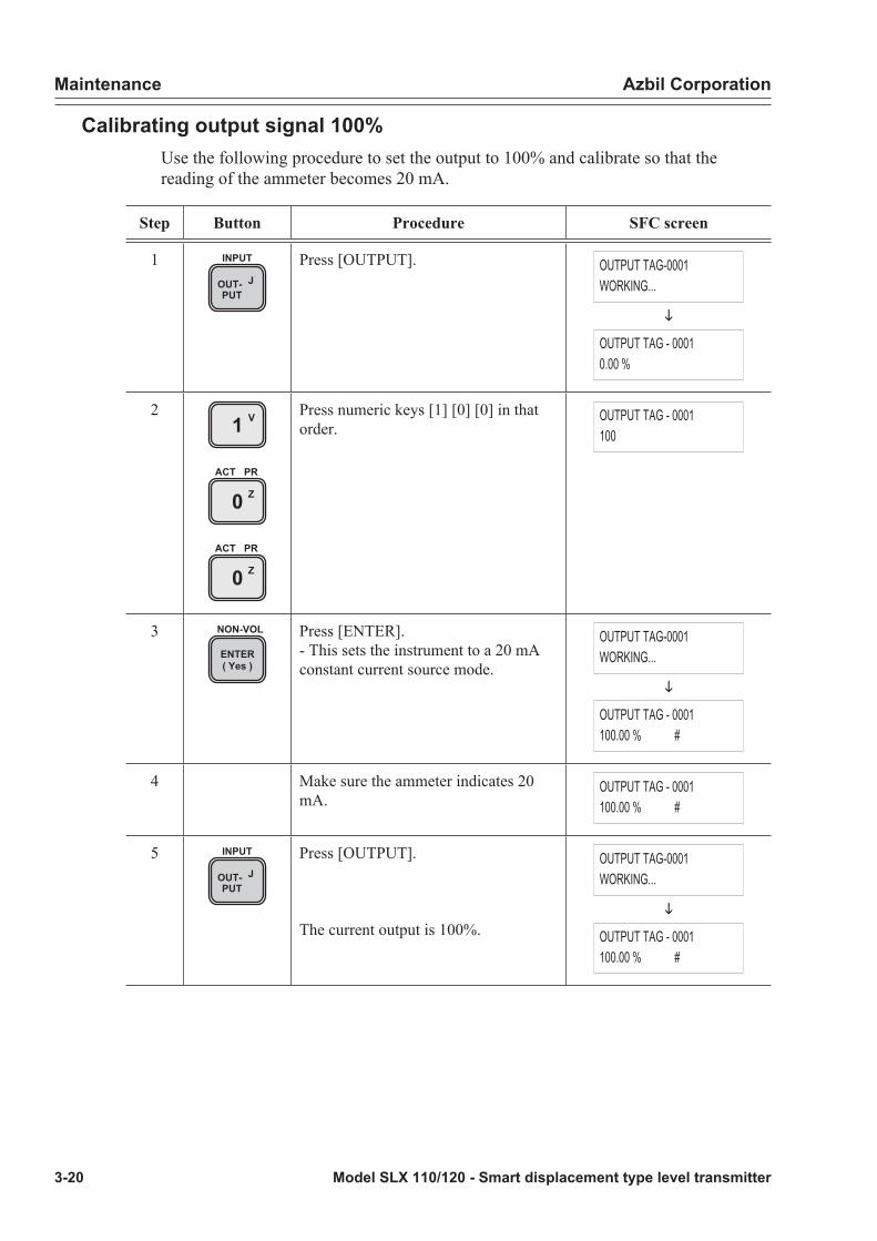
Maintenance Azbil Corporation
3-20 Model SLX 110/120 - Smart displacement type level transmitter
Calibrating output signal 100%Use the following procedure to set the output to 100% and calibrate so that the reading of the ammeter becomes 20 mA.
Step Button Procedure SFC screen
1OUT- JPUT
INPUT Press [OUTPUT]. OUTPUT TAG-0001WORKING...
i
OUTPUT TAG - 00010.00 %
2 V1
Z0ACT PR
Z0ACT PR
Press numeric keys [1] [0] [0] in that order.
OUTPUT TAG - 0001100
3ENTER( Yes )
NON-VOL Press [ENTER].- This sets the instrument to a 20 mA constant current source mode.
OUTPUT TAG-0001WORKING...
i
OUTPUT TAG - 0001100.00 % #
4 Make sure the ammeter indicates 20 mA.
OUTPUT TAG - 0001100.00 % #
5OUT- JPUT
INPUT Press [OUTPUT].
The current output is 100%.
OUTPUT TAG-0001WORKING...
i
OUTPUT TAG - 0001100.00 % #
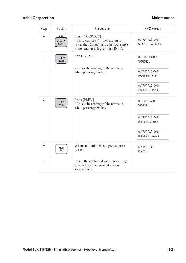
Azbil Corporation Maintenance
Model SLX 110/120 - Smart displacement type level transmitter 3-21
Step Button Procedure SFC screen
6COR- KRECT
RESET Press [CORRECT].- Carry out step 7 if the reading is lower than 20 mA, and carry out step 8 if the reading is higher than 20 mA.
OUTPUT TAG - 0001CORRECT DAC SPAN
7 HNEXT
Press [NEXT].
- Check the reading of the ammeter, while pressing this key.
OUTPUT TAG-0001WORKING...
OUTPUT TAG - 0001INCREASED 20mA
OUTPUT TAG - 0001INCREASED 4mA #
8 LPREV
Press [PREV].- Check the reading of the ammeter, while pressing this key.
OUTPUT TAG-0001WORKING...
i
OUTPUT TAG - 0001DECREASED 20mA
OUTPUT TAG - 0001DECREASED 4mA #
9CLR( No )
When calibration is completed, press [CLR].
SLX TAG - 0001READY...
10 - Save the calibrated values according to 4 and exit the constant current source mode.

Maintenance Azbil Corporation
3-22 Model SLX 110/120 - Smart displacement type level transmitter
Saving calibrated values and canceling constant current source modeUse the following procedure to forcibly write the calibrated values into the non-volatile memory of this instrument and cancel the constant current source mode.
Step Button Procedure SFC screen
1SHIFT
Press [SHIFT]. SHIFT- #
2ENTER( Yes )
NON-VOL Press [ENTER].- Forced data writing is completed.
SLX TAG NO.WORKING...
i
SLX TAG - 0001DATA NONVOLATILE #
SLX TAG - 0001READY...
3OUT- JPUT
INPUT Press [OUTPUT].The current output is 100%.
SLX TAG - 0001WORKING...
i
OUTPUT TAG - 0001100 % #
4CLR( No )
Press [CLR].- The “#” disappears, indicating that the constant current source mode has been cancelled.
SLX TAG - 0001WORKING...
i
SLX TAG - 0001READY...
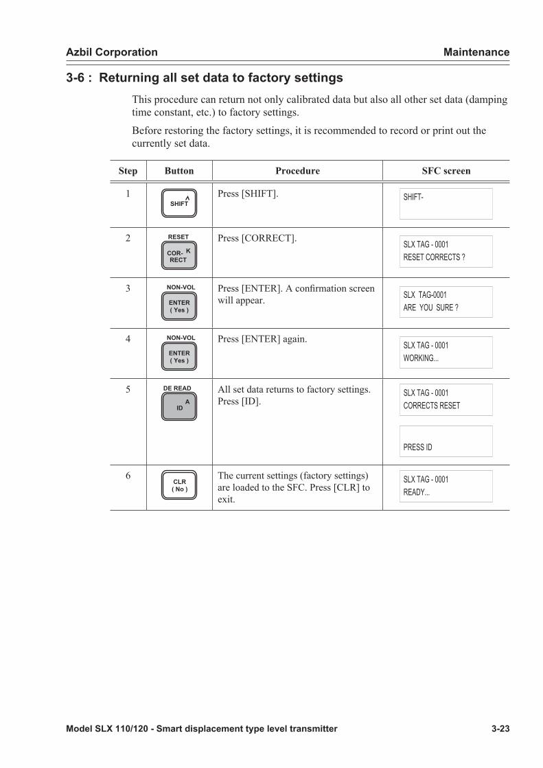
Azbil Corporation Maintenance
Model SLX 110/120 - Smart displacement type level transmitter 3-23
3-6 : Returning all set data to factory settingsThis procedure can return not only calibrated data but also all other set data (damping time constant, etc.) to factory settings.
Before restoring the factory settings, it is recommended to record or print out the currently set data.
Step Button Procedure SFC screen
1SHIFT
Press [SHIFT]. SHIFT-
2COR- KRECT
RESET Press [CORRECT]. SLX TAG - 0001RESET CORRECTS ?
3ENTER( Yes )
NON-VOL Press [ENTER]. A confirmation screen will appear. SLX TAG-0001
ARE YOU SURE ?
4ENTER( Yes )
NON-VOL Press [ENTER] again. SLX TAG - 0001WORKING...
5A
ID
DE READ All set data returns to factory settings. Press [ID].
SLX TAG - 0001CORRECTS RESET
PRESS ID
6CLR( No )
The current settings (factory settings) are loaded to the SFC. Press [CLR] to exit.
SLX TAG - 0001READY...
Maintenance Azbil Corporation
3-24 Model SLX 110/120 - Smart displacement type level transmitter
3-7 : Insulation resistance test and withstand voltage test
CAUTION
Do not carry out any insulation resistance test and withstand voltage test in principle.Such tests may damage built-in varistors for surge voltage absorption. When these tests are unavoidable, carefully carry out these tests according to the specified procedure.
Test procedure
(1) Remove the external wiring from the instrument.
(2) Short between + and - SUPPLY terminals and between + and - METER terminals. (The product is shipped with these METER terminals shorted.)
(3) Conduct tests between the shorted SUPPLY terminals and the grounding terminal and between the METER terminals and the grounding terminal.
(4) The applied voltage and judgment criteria are as follows. To prevent damage of the instrument, do not apply any voltage exceeding the following values.
Judgment criteriaThe judgment criteria for these tests are as follows.
Test Judgement criteria
Insulation resistance test 20MW or more at test voltage of 25V DC (25°C, 60%RH or bellow)
WIthstand voltage test 50V AC, 1 minute, leakage current 2mA

Azbil Corporation Maintenance
Model SLX 110/120 - Smart displacement type level transmitter 3-25
3-8 : Replacement parts and recommended replacement cycle
Replacement parts list
No Name Parts No.Maximum
quantity per unit
Resale unit quantity
1 Terminal block with indicator 80393178-001 1 1
2 Cover O-ring 80020935-183 1 10
3 Plug (with O-ring) 80377115-001 3 1
4 Cover(with window, standard finish, O-ring) 80370008-001 1 1
Cover(with window, anti-corrosion finish, O-ring) 80370008-002 1 1
Cover(with window, anti-severe-corrosion finish, O-ring) 80370008-003 1 1
Cover(no window, standard finish, O-ring) 80277119-001 1 1
Cover(no window, anti-corrosion finish, O-ring) 80277119-002 1 1
Cover(no window, anti-severe-corrosion finish, O-ring) 80277119-003 1 1
5 Pressure-proof packing type cable adapter 80343903-003 2 1
6 Chamber-bonnet gasket See page 3-26 1 1
7
Blind flange gasket (main material 1, 2) 80354690-001 1 1
Blind flange gasket (main material 3) 80354690-002 1 1
Blind flange gasket (main material 4) 80354690-003 1 1
No.1 to 3 are products with limited life and require periodic replacement.No.3 and 4 are included here because they involve the possibility of misplacement, damage (cracked on glass).No.5 to 7 require replacement for every re-tightening.
1. Terminal block with indicator
4. Cover
3. Plug(with O-ring)
5. Pressure-proof type cable adapter
2. Cover O-ring
Figure 3-8 Replacement parts

Maintenance Azbil Corporation
3-26 Model SLX 110/120 - Smart displacement type level transmitter
Table for selection of chamber-bonnet gasket parts Check the product model number and select the correct parts number.
Basic model No.
Selection specificationQty Parts No.Measurement
rangeConnect format
Main material
Other material Pressure rating
6. Chamber-bonnet gasket
Gas
ket SLX110 - 1, 2, 3, 4 1, 2 U,M,A,E 1,A,B,G 1 80353472-001
i - i i i 2,3,4,C,D,E,F,H,J,K 1 80353472-002
i - i 3 i G 1 80353472-007
i - i i i 2, 3,4,C,D,E,F,H,J,K 1 80353472-008
i - i 4 i 1,A,B,G 1 80353472-013
i - i i i 2, 3,4,C,D,E,F,H,J,K 1 80353472-014
i - i 2 D 1,A,B,G 1 80353472-101
i - i i i 2, 3,4,C,D,E,F,H,J,K 1 80353472-102
i - i 3 i 1,A,B,G 1 80353472-107
i - i i i 2, 3,4,C,D,E,F,H,J,K 1 80353472-108
i - i 4 D, W 1,A,B,G 1 80353472-113
i - i i i 2, 3,4,C,D,E,F,H,J,K 1 80353472-114
SLX120 Except 20 1, 2, 3, 4 1, 2 U,M,A,E 1, A, B, G 1 80353472-005
i i i i i 2,3,C.D.H 1 80353472-006
i 20 i i i 1, A, B, G 1 80353472-003
i i i i i 2,3,C.D.H 1 80353472-004
i Except 20 i 3 i 1, A, B, G 1 80353472-011
i i i i i 2,3,C.D.H 1 80353472-012
i 20 i i i 1, A, B, G 1 80353472-009
i i i i i 2,3,C.D.H 1 80353472-010
i Except 20 i 4 i 1, A, B, G 1 80353472-017
i i i i i 2,3,C.D.H 1 80353472-018
i 20 i i i 1, A, B, G 1 80353472-015
i i i i i 2,3,C.D.H 1 80353472-016
i Except 20 i 2 D 1, A, B, G 1 80353472-105
i i i i i 2,3,C.D.H 1 80353472-106
i 20 i i i 1, A, B, G 1 80353472-103
i i i i i 2,3,C.D.H 1 80353472-104
i Except 20 i 3 i 1, A, B, G 1 80353472-111
i i i i i 2,3,C.D.H 1 80353472-112
i 20 i i i 1, A, B, G 1 80353472-109
i i i i i 2,3,C.D.H 1 80353472-110
i Except 20 i 4 D,W 1, A, B, G 1 80353472-117
i i i i i 2,3,C.D.H 80353472-118
i 20 i i i 1, A, B, G 80353472-115
i i i i i 2,3,C.D.H 80353472-116
“Except 20” means “03, A3, 04, A4, 05, 06, 07, 08, 10, 12, 15”.

Azbil Corporation Maintenance
Model SLX 110/120 - Smart displacement type level transmitter 3-27
Recommended replacement cycle• Terminal block with indicator (LCD): 5 years
• Cover O-ring, plug (with O-ring)
Average ambient temperature
Replacement cycle
30°C or below 10 years
30°C to 40°C 5 years
40°C to 50°C 2 years
Replacing terminal block with indicator (LCD)This section describes the replacement procedure after the cover is removed.
j Remove the grounding screws. Also remove the collar at this time.
Grounding screw
Collar
Earth screw Collar
Figure 3-9 An installed terminal block with LCD indicator

Maintenance Azbil Corporation
3-28 Model SLX 110/120 - Smart displacement type level transmitter
k Remove the three screws that fix the terminal block.
Fixing screw
Fixing screw
l Draw the terminal block toward you, remove the two connectors and separate the terminal block from the instrument.
Connector ofangle sensor (4 wires)
Connector oftemperature sensor (2 wires)
m Remove the three plates.
Plate

Azbil Corporation Maintenance
Model SLX 110/120 - Smart displacement type level transmitter 3-29
n Remove the board from the connector of the terminal block and replace the terminal block.
Terminal block
Connector
Board
o Assemble the terminal block into the instrument in the reverse order.
If the terminal block is assembled into the case, turn the terminal block so that the lead wires are not caught and bind the lead wires together.
Recommended tightening torque of fixing screws, grounding screws: 1.2 +-0.1Nsm
Attach a collar to the grounding screws.
3-9 : Starting instrument after maintenance*See “Chapter 2 : Operation” on page 2-1

Maintenance Azbil Corporation
3-30 Model SLX 110/120 - Smart displacement type level transmitter

Model SLX 110/120 - Smart displacement type level transmitter 4-1
Chapter 4 : Repair
WARNING
• Do not use the instrument beyond the rated pressure, connection specification and rated temperature specified for the instrument. This may result in serious accident due to damage.
• Wiring in an explosion-proof area should be performed according to the work procedure specified in the explosion-proof guideline.
CAUTION
• After installation, do not use this instrument as a foothold, etc. This may damage the instrument or may result in physical injury
• Avoid hitting the glass part of the display with tools. This may damage the glass and result in physical injury.
• Perform installation correctly. Insufficient installation or no installation may result in output errors or violate applicable regulations.
• This product is heavy. Pay attention to the scaffolding and wear safety shoes.
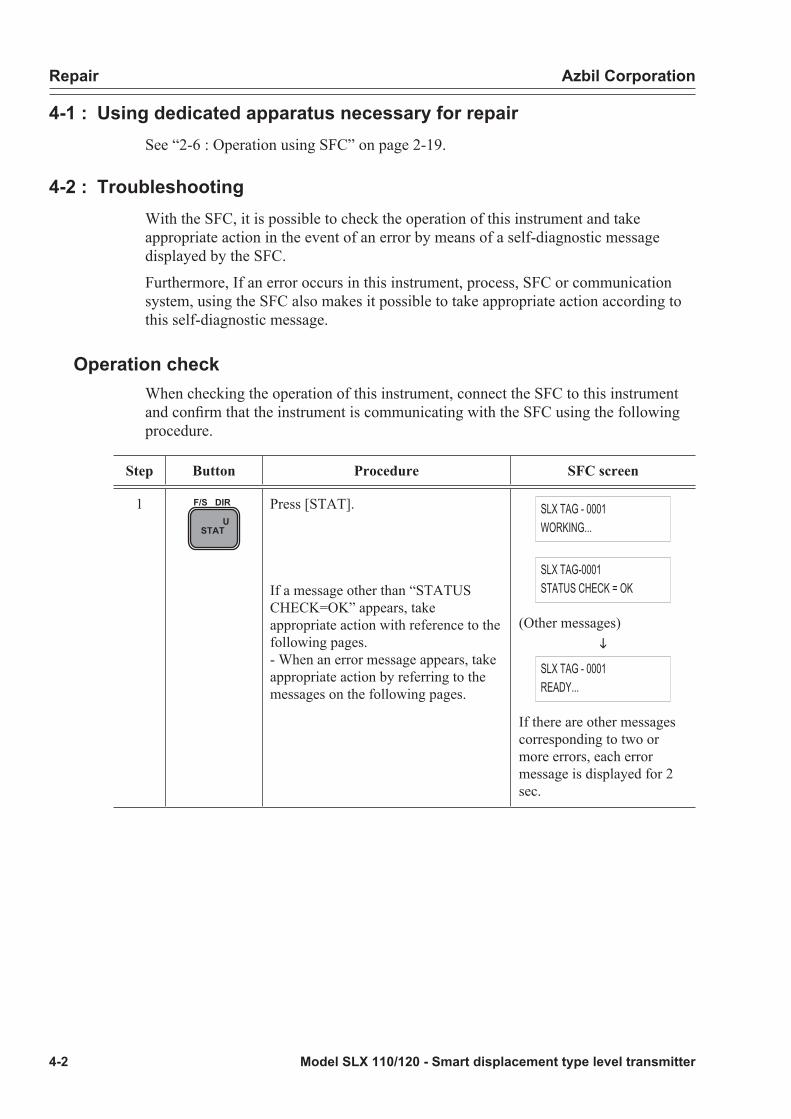
Repair Azbil Corporation
4-2 Model SLX 110/120 - Smart displacement type level transmitter
4-1 : Using dedicated apparatus necessary for repairSee “2-6 : Operation using SFC” on page 2-19.
4-2 : TroubleshootingWith the SFC, it is possible to check the operation of this instrument and take appropriate action in the event of an error by means of a self-diagnostic message displayed by the SFC.
Furthermore, If an error occurs in this instrument, process, SFC or communication system, using the SFC also makes it possible to take appropriate action according to this self-diagnostic message.
Operation checkWhen checking the operation of this instrument, connect the SFC to this instrument and confirm that the instrument is communicating with the SFC using the following procedure.
Step Button Procedure SFC screen
1U
STAT
F/S DIR Press [STAT].
If a message other than “STATUS CHECK=OK” appears, take appropriate action with reference to the following pages.- When an error message appears, take appropriate action by referring to the messages on the following pages.
SLX TAG - 0001WORKING...
SLX TAG-0001STATUS CHECK = OK
(Other messages)i
SLX TAG - 0001READY...
If there are other messages corresponding to two or more errors, each error message is displayed for 2 sec.

Azbil Corporation Repair
Model SLX 110/120 - Smart displacement type level transmitter 4-3
When error occurs during communicationWhen an error message appears during communication, take action as follows.
Message Action Button
SLX TAG-0001CRITICAL STAT
- Press [STAT].Take action according to the message displayed.
USTAT
F/S DIR
- In this case, the operations of [ID], [OUTPUT] and [STAT] are active. A
ID
DE READ
OUT- JPUT
INPUT
USTAT
F/S DIR
- After taking action, press [STAT] and make sure “Self-diagnostic result OK” appears.
USTAT
F/S DIR
: The battery is running out of electricity. Charge it according to the procedures in “Charging SFC” on page 2-72
***** #
- Press [STAT] and take action according to the message displayed. U
STAT
F/S DIR
- When the error is repaired, “#” disappears.
- After “#” disappears, press [STAT] and make sure “Self-diagnostic result OK” appears.
USTAT
F/S DIR

Repair Azbil Corporation
4-4 Model SLX 110/120 - Smart displacement type level transmitter
Self-diagnostic messageWhen an error occurs, pressing [STAT] displays a self-diagnostic message. The meaning of the message and the troubleshooting method are as follows.
When this instrument, process, SFC or communication system is suspected to involve error.
Message Meaning Action Button
TAG NO.NO XMTR RESPONSE
No response from transmitter
- Carry out the communication starting procedure again.
- Press [STAT] and see the message.
- Check the loop, SFC connection loop, load resistance and supply voltage.
USTAT
F/S DIR
When this instrument is suspected to involve error (serious fault or light fault)
Serious fault:Refers to a state or fault that causes serious trouble in the operation of the SLX and may damage the SLX itself if left unattended.
The output continues in the set burnout direction. (The output is set to the burnout direction lower range value at the time of shipment.)
Message Meaning Action
SLX TAG - 0001PTS SENS FAULT #
The connector of the angle sensor is disconnected or there is a problem with the angle sensor.
Check the connector and if the problem persists, contact Azbil Corporation (the transmitter part needs to be replaced).
SLX TAG - 0001TC SENS FAULT #
The connector of the temperature sensor is disconnected or there is a problem with the angle sensor.
Check the connector and if the problem persists, contact Azbil Corporation (the temperature sensor needs to be replaced).
SLX TAG - 0001PTS RANGE OVER #
The input angle exceeds the permissible value.
Contact Azbil Corporation.
SLX TAG - 0001NVM FAULT #
SLX non-volatile memory error.
Contact Azbil Corporation (the transmitter part needs to be replaced).
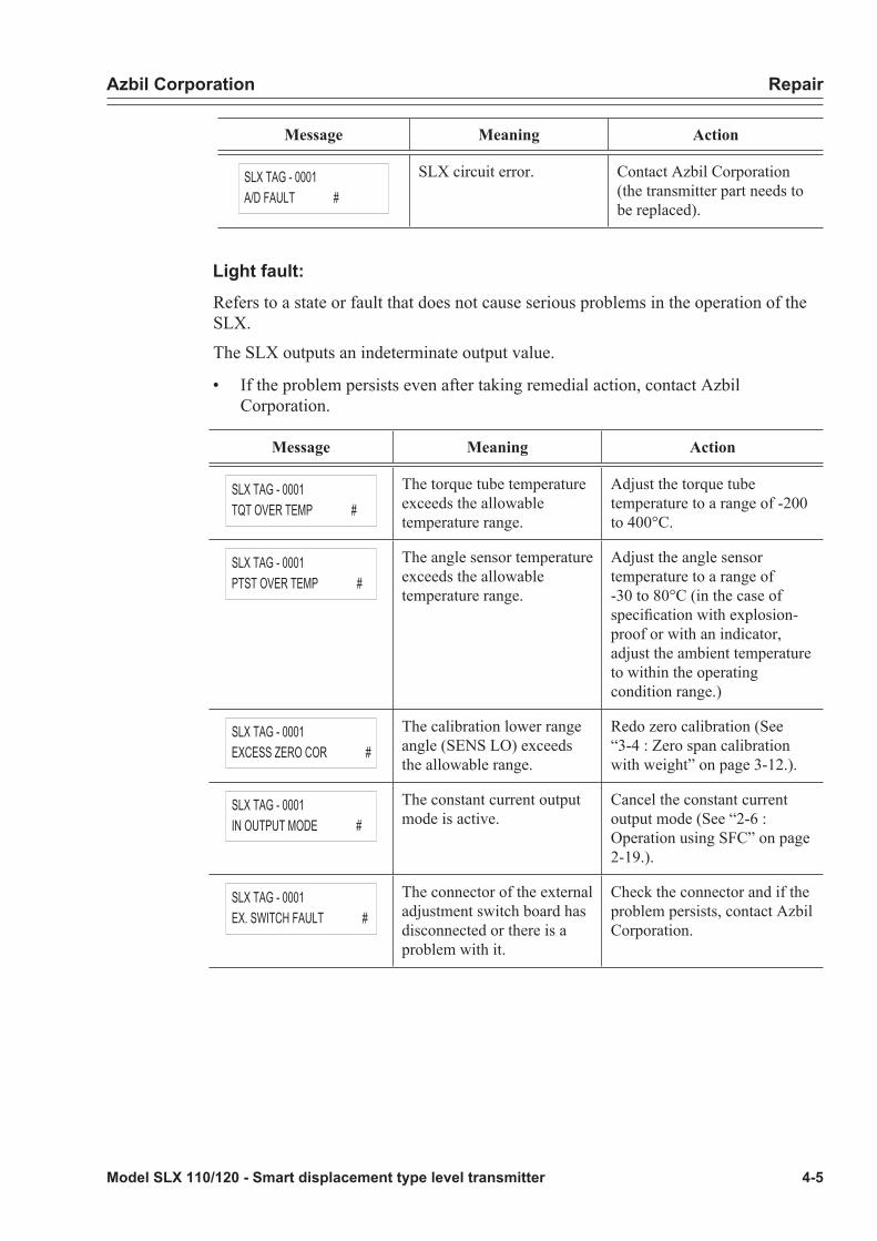
Azbil Corporation Repair
Model SLX 110/120 - Smart displacement type level transmitter 4-5
Message Meaning Action
SLX TAG - 0001A/D FAULT #
SLX circuit error. Contact Azbil Corporation (the transmitter part needs to be replaced).
Light fault:Refers to a state or fault that does not cause serious problems in the operation of the SLX.
The SLX outputs an indeterminate output value.
• If the problem persists even after taking remedial action, contact Azbil Corporation.
Message Meaning Action
SLX TAG - 0001TQT OVER TEMP #
The torque tube temperature exceeds the allowable temperature range.
Adjust the torque tube temperature to a range of -200 to 400°C.
SLX TAG - 0001PTST OVER TEMP #
The angle sensor temperature exceeds the allowable temperature range.
Adjust the angle sensor temperature to a range of -30 to 80°C (in the case of specification with explosion-proof or with an indicator, adjust the ambient temperature to within the operating condition range.)
SLX TAG - 0001EXCESS ZERO COR #
The calibration lower range angle (SENS LO) exceeds the allowable range.
Redo zero calibration (See “3-4 : Zero span calibration with weight” on page 3-12.).
SLX TAG - 0001IN OUTPUT MODE #
The constant current output mode is active.
Cancel the constant current output mode (See “2-6 : Operation using SFC” on page 2-19.).
SLX TAG - 0001EX. SWITCH FAULT #
The connector of the external adjustment switch board has disconnected or there is a problem with it.
Check the connector and if the problem persists, contact Azbil Corporation.

Repair Azbil Corporation
4-6 Model SLX 110/120 - Smart displacement type level transmitter
• When SFC or communication system is suspected to be experiencing error
Message Meaning Action
SLX TAG - 0001SFC FAULT
SFC defect - Redo the communication start procedure.- If this message still appears, contact Azbil Corporation.
SLX TAG - 0001FAILED COMM CHK
Introductory remarks of error message
SLX TAG-0001ILLEGAL RESPONSE 1or2or..11
Communication defect Check the connection between the SFC and transmitter, wiring and power supply.
SLX TAG - 0001PRINTER FAIL !
Printer operation impossible Contact Azbil Corporation.
SLX TAG - 0001LOW LOOP RES
Insufficient loop resistance Check the resistance value.
SLX TAG - 0001HI RES / LOW VOLT
- Excessive loop resistance- Insufficient applied voltage
- Check the loop resistance.- Increase the applied voltage.
• When operational error is suspected
Message Meaning Action
NOT SUPORT
The key pressed is not applicable.
Press the correct key.
EXCESSIVE OUTPUT
Required output value in constant current source mode > output range (-1.25% to 105%)When inappropriate numeric value is input by dedicated function
Press [CLR] and redo input.
CLR( No )
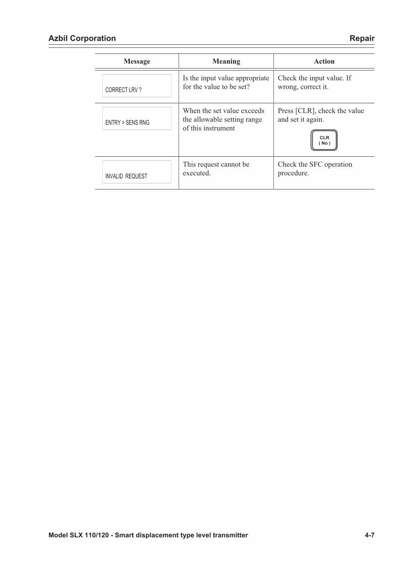
Azbil Corporation Repair
Model SLX 110/120 - Smart displacement type level transmitter 4-7
Message Meaning Action
CORRECT LRV ?
Is the input value appropriate for the value to be set?
Check the input value. If wrong, correct it.
ENTRY > SENS RNG
When the set value exceeds the allowable setting range of this instrument
Press [CLR], check the value and set it again.
CLR( No )
INVALID REQUEST
This request cannot be executed.
Check the SFC operation procedure.
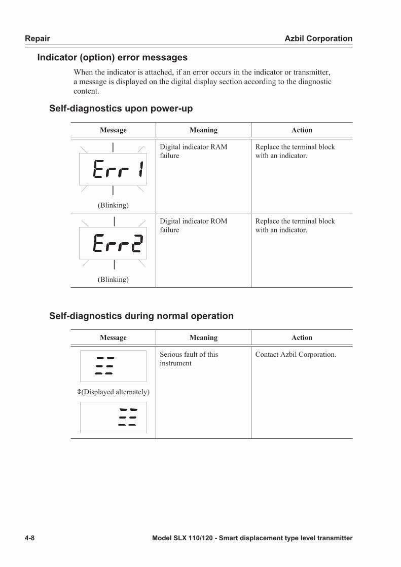
Repair Azbil Corporation
4-8 Model SLX 110/120 - Smart displacement type level transmitter
Indicator (option) error messagesWhen the indicator is attached, if an error occurs in the indicator or transmitter, a message is displayed on the digital display section according to the diagnostic content.
Self-diagnostics upon power-up
Message Meaning Action
(Blinking)
Digital indicator RAM failure
Replace the terminal block with an indicator.
(Blinking)
Digital indicator ROM failure
Replace the terminal block with an indicator.
Self-diagnostics during normal operation
Message Meaning Action
o(Displayed alternately)
Serious fault of this instrument
Contact Azbil Corporation.

Azbil Corporation Repair
Model SLX 110/120 - Smart displacement type level transmitter 4-9
Message Meaning Action
o(Displayed alternately)
Fault of this instrument or indicator
Contact Azbil Corporation.

Repair Azbil Corporation
4-10 Model SLX 110/120 - Smart displacement type level transmitter
4-3 : Removal/installation method* For the method of removal or reinstallation of the main unit, see “1-6 : Installation method” on page 1-9.

Model SLX 110/120 - Smart displacement type level transmitter 5-1
Chapter 5 : Cautions Regarding Explosion-proof Models
5-1: Cautions Regarding Explosion-proof Models[NEPSI flameproof]Select an installation location for an NEPSI flameproof model in accordance with the following criteria.
Warning• Fasten the cover sufficiently tightly, and do not under any circumstances re-
move it with the power on if there is an explosive atmosphere surrounding the device. Doing so can cause an explosion to occur.
Caution• Be sure to ground the device using the ground terminal on its exterior.
• When using the device, give sufficient consideration to preventing corrosion, deformation, damage, etc., with respect to the products case, cover, and the like.
• When installing, operating, and maintaining the product, be sure to read this manual. In addition, observe the requirements in the following standards.
GB 3836.13-2013: Explosive atmospheres—Part 13: Equipment repair, overhaul and reclamation
GB/T 3836.15-2017: Explosive atmospheres—Part 15:Electrical installa-tions design, selection and erection
GB/T 3836.16-2017: Explosive atmospheres—Part 16:Electrical installa-tions inspection and maintenance
GB 50257-2014: Code for construction and acceptance of electric equip-ment on fire and explosion hazard electric equipment installation engi-neering
• Wiring work should strictly follow “People’s Republic of China Electrical Safety Code for Areas with Danger of Explosion (Provisional).”

Azbil Corporation
5-2 Model SLX 110/120 - Smart displacement type level transmitter


We would like to express our appreciation for your purchase and use of Azbil Corporation’s products.
You are required to acknowledge and agree upon the following terms and conditions for your purchase of Azbil Corporation’s products (system products, field instruments, control valves, and control products), unless otherwise stated in any separate document, including, without limitation, estimation sheets, written agreements, catalogs, specifications and instruction manuals.
1. Warranty period and warranty scope
1.1 Warranty period
Azbil Corporation’s products shall be warranted for one (1) year from the date of your purchase of the said products or the delivery of the said products to a place designated by you.
1.2 Warranty scope
In the event that Azbil Corporation’s product has any failure attributable to azbil during the aforementioned warranty period, Azbil Corporation shall, without charge, deliver a replacement for the said product to the place where you purchased, or repair the said product and deliver it to the aforementioned place. Notwithstanding the foregoing, any failure falling under one of the following shall not be covered under this warranty:
(1) Failure caused by your improper use of azbil product (noncompliance with conditions, environment of use, precautions, etc. set forth in catalogs, specifications, instruction manuals, etc.);
(2) Failure caused for other reasons than Azbil Corporation’s product;(3) Failure caused by any modification or repair made by any person other than Azbil Corporation or Azbil Corporation’s
subcontractors; (4) Failure caused by your use of Azbil Corporation’s product in a manner not conforming to the intended usage of that product; (5) Failure that the state-of-the-art at the time of Azbil Corporation’s shipment did not allow Azbil Corporation to predict; or (6) Failure that arose from any reason not attributable to Azbil Corporation, including, without limitation, acts of God, disasters, and
actions taken by a third party.
Please note that the term “warranty” as used herein refers to equipment-only-warranty, and Azbil Corporation shall not be liable for any damages, including direct, indirect, special, incidental or consequential damages in connection with or arising out of Azbil Corporation’s products.
2. Ascertainment of suitability
You are required to ascertain the suitability of Azbil Corporation’s product in case of your use of the same with your machinery, equipment, etc. (hereinafter referred to as “Equipment”) on your own responsibility, taking the following matters into consideration:
(1) Regulations and standards or laws that your Equipment is to comply with.(2) Examples of application described in any documents provided by Azbil Corporation are for your reference purpose only, and
you are required to check the functions and safety of your Equipment prior to your use. (3) Measures to be taken to secure the required level of the reliability and safety of your Equipment in your use
Although azbil is constantly making efforts to improve the quality and reliability of Azbil Corporation’s products, there exists a possibility that parts and machinery may break down. You are required to provide your Equipment with safety design such as fool-proof design,*1 and fail-safe design*2 (anti-flame propagation design, etc.), whereby preventing any occurrence of physical injuries, fires, significant damage, and so forth. Furthermore, fault avoidance,*3 fault tolerance,*4 or the like should be incorporated so that the said Equipment can satisfy the level of reliability and safety required for your use.
*1. A design that is safe even if the user makes an error. *2. A design that is safe even if the device fails. *3. Avoidance of device failure by using highly reliable components, etc. *4. The use of redundancy.
3. Precautions and restrictions on application
3.1 Restrictions on application
Please follow the table below for use in nuclear power or radiation-related equipment.
Nuclear power quality*5 required Nuclear power quality*5 not required
Within a radiation controlled area*6
Cannot be used (except for limit switches for nuclear power*7)
Cannot be used (except for limit switches for nuclear power*7)
Outside a radiation controlled area*6
Cannot be used (except for limit switches for nuclear power*7)
Can be used
*5. Nuclear power quality: compliance with JEAG 4121 required*6. Radiation controlled area: an area governed by the requirements of article 3 of “Rules on the Prevention of Harm from
Ionizing Radiation,” article 2 2 4 of “Regulations on Installation and Operation of Nuclear Reactors for Practical Power Generation,” article 4 of “Determining the Quantity, etc., of Radiation-Emitting Isotopes,”etc.
*7. Limit switch for nuclear power: a limit switch designed, manufactured and sold according to IEEE 382 and JEAG 4121.
Any Azbil Corporation’s products shall not be used for/with medical equipment.
The products are for industrial use. Do not allow general consumers to install or use any Azbil Corporation’s product. However, azbil products can be incorporated into products used by general consumers. If you intend to use a product for that purpose, please contact one of our sales representatives.
3.2 Precautions on application
you are required to conduct a consultation with our sales representative and understand detail specifications, cautions for operation, and so forth by reference to catalogs, specifications, instruction manual, etc. in case that you intend to use azbil product for any purposes specified in (1) through (6) below. Moreover, you are required to provide your Equipment with fool-proof design, fail-safe design, anti-flame propagation design, fault avoidance, fault tolerance, and other kinds of protection/safety circuit design on your own responsibility to ensure reliability and safety, whereby preventing problems caused by failure or nonconformity.
Terms and Conditions

(1) For use under such conditions or in such environments as not stated in technical documents, including catalogs, specification, and instruction manuals
(2) For use of specific purposes, such as: * Nuclear energy/radiation related facilities
[When used outside a radiation controlled area and where nuclear power quality is not required] [When the limit switch for nuclear power is used]
* Machinery or equipment for space/sea bottom * Transportation equipment [Railway, aircraft, vessels, vehicle equipment, etc.] * Antidisaster/crime-prevention equipment * Burning appliances * Electrothermal equipment * Amusement facilities * Facilities/applications associated directly with billing
(3) Supply systems such as electricity/gas/water supply systems, large-scale communication systems, and traffic/air traffic control systems requiring high reliability
(4) Facilities that are to comply with regulations of governmental/public agencies or specific industries (5) Machinery or equipment that may affect human lives, human bodies or properties (6) Other machinery or equipment equivalent to those set forth in items (1) to (5) above which require high reliability and safety
4. Precautions against long-term use
Use of Azbil Corporation’s products, including switches, which contain electronic components, over a prolonged period may degrade insulation or increase contact-resistance and may result in heat generation or any other similar problem causing such product or switch to develop safety hazards such as smoking, ignition, and electrification. Although acceleration of the above situation varies depending on the conditions or environment of use of the products, you are required not to use any Azbil Corporation’s products for a period exceeding ten (10) years unless otherwise stated in specifications or instruction manuals.
5. Recommendation for renewal
Mechanical components, such as relays and switches, used for Azbil Corporation’s products will reach the end of their life due to wear by repetitious open/close operations.
In addition, electronic components such as electrolytic capacitors will reach the end of their life due to aged deterioration based on the conditions or environment in which such electronic components are used. Although acceleration of the above situation varies depending on the conditions or environment of use, the number of open/close operations of relays, etc. as prescribed in specifications or instruction manuals, or depending on the design margin of your machine or equipment, you are required to renew any Azbil Corporation’s products every 5 to 10 years unless otherwise specified in specifications or instruction manuals. System products, field instruments (sensors such as pressure/flow/level sensors, regulating valves, etc.) will reach the end of their life due to aged deterioration of parts. For those parts that will reach the end of their life due to aged deterioration, recommended replacement cycles are prescribed. You are required to replace parts based on such recommended replacement cycles.
6. Other precautions
Prior to your use of Azbil Corporation’s products, you are required to understand and comply with specifications (e.g., conditions and environment of use), precautions, warnings/cautions/notices as set forth in the technical documents prepared for individual Azbil Corporation’s products, such as catalogs, specifications, and instruction manuals to ensure the quality, reliability, and safety of those products.
7. Changes to specifications
Please note that the descriptions contained in any documents provided by azbil are subject to change without notice for improvement or for any other reason. For inquires or information on specifications as you may need to check, please contact our branch offices or sales offices, or your local sales agents.
8. Discontinuance of the supply of products/parts
Please note that the production of any Azbil Corporation’s product may be discontinued without notice. After manufacturing is discontinued, we may not be able to provide replacement products even within the warranty period.
For repairable products, we will, in principle, undertake repairs for five (5) years after the discontinuance of those products. In some cases, however, we cannot undertake such repairs for reasons, such as the absence of repair parts. For system products, field instruments, we may not be able to undertake parts replacement for similar reasons.
9. Scope of services
Prices of Azbil Corporation’s products do not include any charges for services such as engineer dispatch service. Accordingly, a separate fee will be charged in any of the following cases:
(1) Installation, adjustment, guidance, and attendance at a test run (2) Maintenance, inspection, adjustment, and repair(3) Technical guidance and technical education (4) Special test or special inspection of a product under the conditions specified by you
Please note that we cannot provide any services as set forth above in a nuclear energy controlled area (radiation controlled area) or at a place where the level of exposure to radiation is equivalent to that in a nuclear energy controlled area.
AAS-511A-014-10


Document Number: CM2-SLX100-2001
Document Name: Smart Displacement type Level TransmitterModel SLX 110/120User’s Manual
Date: 1st edition: Aug. 20014th edition: Feb. 2020
Issued/Edited by: Azbil Corporation

Copyright © 2022 FDOKUMEN