6 - 20 KW FM transmitter series
57
User’s manual – Page 1 of 57 6 - 20 KW FM transmitter series User and maintenance manual Revision 1.0
-
Upload
khangminh22 -
Category
Documents
-
view
1 -
download
0
Transcript of 6 - 20 KW FM transmitter series

User’s manual – Page 1 of 57
6 - 20 KW FM transmitter series User and maintenance manual
Revision 1.0

User’s manual – Page 2 of 57
TX-GX – 87÷108 MHz FM transmitter series
Preliminary notes
We used the utmost care in making a complete manual with detailed, precise, and updated information; however, the contents herein cannot be regarded as binding towards our company.
Sielco Srl, in their constant commitment to improve the quality of their products, reserve the right to vary the device’s technical features without prior notice. For updates, please visit our web-site www.sielco.org or contact our local dealer or agent.
The manufacturer will not be held responsible for any consequences caused by errors or improper handling and over which he has no direct control.
The described options may vary from model to model to meet the specific requirements of our customers.
All rights reserved. No part of this document may be reproduced in any form or by any means, including recording or photocopy without prior written authorization of Sielco Srl.
Via Toscana 57/ 59 - 20090 Buccinasco (Milano) - Italy
Tel +39-02-45713300
Fax +39-02-45713351
E-mail: [email protected]
Web: www.sielco.org
For further information about how Sielco ensures compliance with EC regulations, refer to Chap.3.
This label indicates the express declaration by Sielco Srl that the product associated with this manual conforms to Directive
1999/05/EC 1999/05/CE
0470

User’s manual – Page 3 of 57
TX-GX – 87÷108 MHz FM transmitter series
Contents
1 INTRODUCTION ........................................................................................................................ 5
2 SAFETY FIRST! ........................................................................................................................ 6 2.1 Safety suggestions ........................................................................................................................ 6 2.2 Warning instruction ........................................................................................................................ 8 2.3 Symbols used in this manual ....................................................................................................... 10
3 THE ADDED VALUE OF SIELCO PRODUCTS ............................................................................... 11 3.1 Full conformity to EC regulations ................................................................................................ 11 3.2 Reliable quality ............................................................................................................................ 11 3.3 Savings on all fronts .................................................................................................................... 11
4 THE TX-GX TRANSMISSION SYSTEMS ..................................................................................... 12 4.1 General description ..................................................................................................................... 12 4.2 Architecture ................................................................................................................................. 12 4.3 General interconnection diagram ................................................................................................ 14 4.4 TX-GX internal wiring .................................................................................................................. 15 4.5 Configurations of the TX-GX systems ......................................................................................... 16 4.6 TX-GT families – front views and mechanical layouts ................................................................ 16 4.7 TX-GX main modules .................................................................................................................. 22 4.8 Connections with the outside ...................................................................................................... 27 4.9 Dual Drive option ......................................................................................................................... 27 4.10 Technical specifications .............................................................................................................. 28
5 INSTALLATION ....................................................................................................................... 30 5.1 Check the supplied parts ............................................................................................................. 30 5.2 General safety rules .................................................................................................................... 30 5.3 Choosing the proper room and placement .................................................................................. 30 5.4 Wiring the system ........................................................................................................................ 31
6 BASIC OPERATIONS ............................................................................................................... 32 6.1 Initial start-up ............................................................................................................................... 32 6.2 Turning on the system ................................................................................................................. 33
7 MENU AND NAVIGATION COMMANDS ....................................................................................... 34 7.1 Multifunction knob ....................................................................................................................... 34 7.2 ESCAPE button ........................................................................................................................... 34
8 DESCRIPTION OF THE MENUS .................................................................................................. 35 8.1 Features common to all the menus ............................................................................................. 35 8.2 Default screen ............................................................................................................................. 36 8.3 System Status menu .............................................................................................................. 36 8.4 Set Amplifier Power menu ................................................................................................. 37 8.5 Set Frequency menu .............................................................................................................. 38 8.6 Amplifier 1 Status menu ................................................................................................... 39 8.7 Amplifier 2 Status menu ................................................................................................... 39 8.8 Amplifier 3 Status menu ................................................................................................... 39 8.9 Exciter Status menu ............................................................................................................ 40 8.10 Dual Drive Status menu ...................................................................................................... 40 8.11 System Alarms menu .............................................................................................................. 42 8.12 Temporal Power Reduction menu ...................................................................................... 43 8.13 SMS settings menu................................................................................................................. 44 8.14 GSM Status menu ..................................................................................................................... 45 8.15 SMS numbers menu ................................................................................................................... 47 8.16 Password menu ......................................................................................................................... 48 8.17 System Setup menu ............................................................................................................... 50 8.18 “Installation manual” menu .......................................................................................................... 51 8.19 Menus diagram ............................................................................................................................ 53
9 SYSTEM ALARMS ................................................................................................................... 54 9.1 System alarms ............................................................................................................................. 54

User’s manual – Page 4 of 57
TX-GX – 87÷108 MHz FM transmitter series
10 MAINTENANCE AND WARRANTY ..................................................................................... 55 10.1 Maintenance ................................................................................................................................ 55 10.2 Warranty ...................................................................................................................................... 55
11 INDEX .................................................................................................................................... 56
12 CE CONFORMITY DECLARATION ............................................................................................. 57

User’s manual – Page 5 of 57
TX-GX – 87÷108 MHz FM transmitter series
1 INTRODUCTION
Congratulations on your purchase! The TX-GX transmitter series is equipped with the most modern technology available, to provide
you with maximum performance at minimal operating costs, while fully conforming to technical regulations. Easy use, quality,
compactness, and low electrical consumption make the TX-GX series the best offered on the market today. The TX-GX series
transmitters range from 6 KW to 20 KW. The user himself can also equip the transmitter with the “Dual Drive” option, for the
automatic switchover to a backup exciter in case of failure of the main one. These are just a few of the advanced characteristics that
make the TX-GT series truly unique:
Low performance costs. The unique design reduces internal loss and allows the device to achieve an extremely high yield –
typically greater than 61 % – minimizing electrical consumption and thus decreasing operating costs.
Sturdy modular construction. Reliable modular construction minimizes and facilitates maintenance operations. In addition, it
ensures a greater average time between failures, as well as ease of maintenance.
Easy to use and to configure. All the transmitters use a control unit equipped with a large 5” LCD screen, an handy
multifunction knob, and only few other buttons. This allows the user to easily set the functions of the system, and to view the operating parameters in the blink of an eye.
Nominal RF output power over the full FM range particularly stable over time. The output power can be varied from a
minimum level up to the rated one, and the operating frequency includes the full FM range, without the adjustment of other parameters.
Amplifier units entirely modular and highly reliable. The amplifier units are composed of multiple compact modules
produced from the latest advances in technology and working in perfect synergy. Thanks to internal balancing circuits, when a failure occurs in one of the modules, the others are automatically rebalanced, allowing for transmission at reduced power. Each module is easily identifiable, inspectable, and removable without the assistance of a welder, thanks to the reduced number of interconnections achieved using multi-polar connectors.
RF output stages have a reverse intermodulation figure lower than the one of the standard bipolar construction. Low
enough to approach that of tube equipment, due to the MOS-FET design.
Low dissipation. The reduction in internal loss and overall elevated yield minimize the heat dissipation; as a result, the TX-GT
series performs well even in challenging environmental conditions.
Stable, reliable power supply. The amplifier units integrate power sources with active power factor correction (PCF), as
agreed in recent regulations. As such, impact on the power source is minimal, resulting in greater reliability over the entire system.
Easy diagnostics and easy-to-read parameters, thanks to a comprehensive metering and alarms section with a large LCD
display. All parameters and alarms are easily accessible from remote sites via the telemetry option, which allows the user to change from stand-by to “on air” mode in a moment. Upon request, an external controller can be provided for use of the system from an office or from other service points.
Compliance with the strictest regulations. This system was designed in full compliance with strict international regulations
and the strict EC anti-magnetic noise requirements.
And that’s not all: Sielco Srl products provide greater value added and the best quality. For further details, please refer to chapter. 3.
Please note that the manufacturer, in its continuous attempt to further improve the quality this product, reserves the right to change its technical features without prior notice.
Warning! Before starting any operations it is essential to read this entire manual in order to avoid damage to objects or people.

User’s manual – Page 6 of 57
TX-GX – 87÷108 MHz FM transmitter series
2 SAFETY FIRST !
2.1 Safety suggestions
Regardless of how well electrical equipment is designed, personnel can be exposed to dangerous electrical shock when protective
covers are removed for maintenance or other activities. Therefore, the user is obliged to see that all safety regulations are
consistently observed and that each individual assigned to the equipment has a clear understanding of the first aid related to
electrical shocks.
IN ADDITION THESE SAFETY PRACTICES MUST BE FOLLOWED:
Do not attempt to adjust unprotected circuit or to dress leads with power on.
Always avoid placing parts of the body in series between ground and circuit points.
To avoid burns, do not touch heavily loaded or overheated components without precautions.
Remember that some semiconductor cases and solid-state circuits carry high voltages.
Do not assume that all dangers of electrical shock are removed when the power is off. Charged capacitors can retain dangerous voltages for a long time after the power has been turned off. These capacitors should be discharged through a suitable resistor before touching any circuit point.
Don't take chances. Be fully trained. Sielco equipment should be operated and maintained by fully qualified personnel.
Do not service alone and do not perform internal adjustments unless another person capable of providing first aid and resuscitation is present.
Some components used in the construction contain Beryllium Oxide (BeO). This substance is harmless as it is, but becomes highly dangerous if it is ground to powder. Special disposal procedures must be observed in case of failure of these devices.
2.1.a General safety recommendations
When connecting the equipment (or the system) to the power, please follow these important recommendations:
This product/system is intended to operate from a power source that will not apply more than 10% of the specified voltage between the supply conductors or between supply conductors and ground. A protective-ground connection by way of the grounding conductor in the power cord is essential for safe operation.
This equipment is grounded through the grounding conductor of the power cord. To avoid electrical shock, plug the power cord into a properly wired socket before connecting to the product input or output terminals.
Upon loss of the protective-ground connection, all accessible conductive parts (including parts that may appear to be insulating) can render an electric shock.
To avoid fire hazard, use only fuses of correct type, voltage rating, and current rating. Refer to qualified service personnel for fuse replacement.
To avoid explosion, do not operate this equipment in an explosive atmosphere.
To avoid personal injury, do not remove covers or panels. Do not operate the system without the covers and panels properly installed.
Note: This section is not intended to contain a complete statement of all safety precautions which should be observed by
personnel in using this electronic equipment or others.
Sielco Srl shall NOT be responsible for injury or damage resulted from improper procedures or from using it by improperly
trained or inexperienced personnel.

User’s manual – Page 7 of 57
TX-GX – 87÷108 MHz FM transmitter series
2.1.b Good practices
In maintaining the equipment/system covered in this manual, please keep in mind the following, standard good practices:
When connecting any instrument (wattmeter, spectrum analyzer, etc.) to a high frequency output, use the appropriate attenuator or dummy load to protect the final stages of the amplifiers and the instrument input.
When inserting or removing printed circuit boards (PCBs), cable connectors, or fuses, always turn off power from the affected portion of the equipment. After power is removed, allow sufficient time for the power supplies to bleed down before reinserting PCBs.
When troubleshooting, remember that FETs and other metal-oxide semiconductor (MOS) devices may appear defective because of leakage between traces or component leads on the printed circuit board. Clean the printed circuit board and recheck the MOS device before assuming it is defective.
When replacing MOS devices, follow standard practices to avoid damage caused by static charges and soldering.
When removing components from PCBs (particularly ICs), use care to avoid damaging PCB traces.
2.1.c First aid in case of electrical shock
If someone seems unable to free himself under electric shock contact, turn the power off before rendering aid. A muscular spasm
or unconsciousness can make a victim unable to free himself from the electrical power.
If power cannot be turned off immediately, very carefully loop a length of dry non-conducting material (such as a rope, insulating
material, or clothing) around the victim and pull him free of the power. Carefully avoid touching him or his clothing until free of power.
2.1.d Emergency resuscitation technique
Step 1
Check the victim for responsiveness. If there is no response, immediately call for medical
assistance, and then return to the person
Step 2
Position the person flat on their back. Kneel by their side and place one hand on the forehead and
the other under the chin. Tilt the head back and lift the chin until teeth almost touch. Look and listen
for breathing.
Step 3
If not breathing normally, pinch the nose and cover the mouth with yours. Give two full breaths. The
person's chest will rise if you are giving enough air.
DO NOT TOUCH VICTIM OR HIS CLOTHING
BEFORE POWER IS DISCONNECTED OR YOU
CAN BECOME A SHOCK VICTIM YOURSELF
User’s manual – Page 8 of 57
TX-GX – 87÷108 MHz FM transmitter series
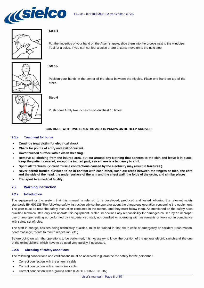
Step 4
Put the fingertips of your hand on the Adam's apple, slide them into the groove next to the windpipe.
Feel for a pulse. If you can not feel a pulse or are unsure, move on to the next step.
Step 5
Position your hands in the center of the chest between the nipples. Place one hand on top of the
other.
Step 6
Push down firmly two inches. Push on chest 15 times.
CONTINUE WITH TWO BREATHS AND 15 PUMPS UNTIL HELP ARRIVES
2.1.e Treatment for burns
Continue treat victim for electrical shock.
Check for points of entry and exit of current.
Cover burned surface with a clean dressing.
Remove all clothing from the injured area, but cut around any clothing that adheres to the skin and leave it in place. Keep the patient covered, except the injured part, since there is a tendency to chill.
Splint all fractures. (Violent muscle contractions caused by the electricity may result in fractures.).
Never permit burned surfaces to be in contact with each other, such as: areas between the fingers or toes, the ears and the side of the head, the under surface of the arm and the chest wall, the folds of the groin, and similar places.
Transport to a medical facility.
2.2 Warning instruction
2.2.a Introduction
The equipment or the system that this manual is referred to is developed, produced and tested following the relevant safety
standards EN 602125.The following safety instruction advice the operator about the dangerous operation concerning the equipment.
The user must be read the safety instruction contained in the manual and they must follow them. As mentioned on the safety rules
qualified technical staff only can operate this equipment. Sielco srl declines any responsibility for damages caused by an improper
use or improper setting up performed by inexperienced staff, not qualified or operating with instruments or tools not in compliance
with safety set of rules.
The staff in charge, besides being technically qualified, must be trained in first aid in case of emergency or accident (reanimation,
heart massage, mouth to mouth respiration, etc.).
Before going on with the operations to be performed, it is necessary to know the position of the general electric switch and the one
of the extinguishers, which have to be used very quickly if necessary.
2.2.b Checking of safety conditions
The following connections and verifications must be observed to guarantee the safety for the personnel:
Correct connection with the antenna cable
Correct connection with a mains line cable
Correct connection with a ground cable (EARTH CONNECTION)

User’s manual – Page 9 of 57
TX-GX – 87÷108 MHz FM transmitter series
Verification of the ambient (where the equipments is installed) compliance with the specification declared by the manufacturer: altitude, humidity, temperature.
2.2.c AC/DC Line warning
This equipment/system works with dangerous high voltages and currents. Any voltage present inside this equipment can be
potentially dangerous for personnel. The technical staff designed for the service and repair operations must be qualified and they
must take the appropriate safety measures stated on safety rules.
2.2.d Service and operational warning
The technical staff in charge of the service operations inside the equipment/system with any cover removed must check that the
mains line is disconnected. After the service operation is completed, the covers must be correctly mounted before the connection
with the mains line. The high voltage is present on the mains stage of the equipments also when the mains switch is in OFF
positions and the mains line cable is connected.
If it is really necessary, and after authorization of Sielco srl, very qualified technical staff only can work with on live parts. In this
special case special safety precautions must be taken. Sielco srl declines any responsibility if any safety rule is not respected. The
replacement of the accessible fuse must be made with the transmitters turned off and using a fuse with the identical characteristics
only as specified by the manufacturer.
Care must be taken when the equipment is switched on, as dangerous R.F. high voltages are available both at the RF
output and inside the equipment.
The electromagnetic fields generated nearby an antenna and/or nearby its connecting cables may cause risks of fire, electric shock
or burns.
Before working inside the equipment, disconnect the power supply through an external switching breaker (5)
The switches embedded in the unit do not guarantee complete separation from the mains: some circuits are stay live.
High earth leakage currents! Before connecting the power supply, a good ground connection must be provided.

User’s manual – Page 10 of 57
TX-GX – 87÷108 MHz FM transmitter series
2.2.e Warning symbols
The following symbols are used on this equipment to advise the user about the most important dangerous parts.
Symbol Colour Explanation
Black/yellow Live part shock risk of electric shock.
Black/yellow To preserve the instrument from damages the operator
must refer to an explanation in the instruction manual.
White/black Protective earth (grounding) terminal.
~ ALTERNATING CURRENT
I MAIN SWITCH ON
O MAIN SWITCH OFF
European Directive 2002/96/EC requires that the equipment bearing this symbol on the
product and/or its packaging must not be disposed of with unsorted municipal waste.
The symbol indicates that this product should be disposed of separately from regular
household waste streams. It is your responsibility to dispose of this and other electric
and electronic equipment via designated collection facilities appointed by the
government or local authorities. Correct disposal and recycling will help prevent potential negative
consequences to the environment and human health. For more detailed information about the disposal of your
old equipment, please contact your local authorities waste disposal service, or the shop where you purchased
the product.
2.3 Symbols used in this manual
For quick reference, we can use symbols that attract immediate attention, and which simply and efficiently advise and inform the
user.
The symbol of the open hand stresses a description of the highest importance concerning technical assistance, dangerous situations, safety warnings, advice, and/or information of the highest importance. Where such symbol is not heeded, serious problems/consequences may arise.
The written notebook represents practical, important advice that we recommend be followed in order to obtain the best possible performance from the device.
The display messages (menu, options, etc.) are written in this font (Courier New).
Important sentences and words are underlined.
For ease of reference, cross references to sections, chapters, page numbers, diagrams, etc. may be indicated using the symbol .
For example: “3.1” means “refer to paragraph 3.1”.
User’s manual – Page 11 of 57
TX-GX – 87÷108 MHz FM transmitter series
3 THE ADDED VALUE OF S IELCO PRODUCTS
3.1 Full conformity to EC regulations
As is well known, broadcast equipments must conform to strict regulations in terms of quality, safety, and electromagnetic
compatibility. The latter aspect is of particular importance, as it ensures that the transmitter doesn’t interfere with other devices and
that it is not interfered with. In ensuring electromagnetic compatibility, a number of extremely precise measurements are taken that
are often performed by people using inappropriate or uncertified devices; therefore, any results obtained under such conditions are
unreliable. For example, if a user is not equipped with an extremely expensive, large anechoic room duly certified by a competent
body, measurements may be rendered entirely useless.
Sielco Srl is particularly careful about guaranteeing its clients conformity to regulations. To this end, after having taken
measurements during the research phase, Sielco Srl uses a certified laboratory and an international certification body to certify the
full conformity of its products based on measurements taken according to regulations.
3.2 Reliable quality
A famous ad running since the 1980’s guarantees “reliable quality over time”. In order to ensure that each device produced in series
conforms to testing and validation regulations, Sielco Srl carefully manages all the documents relevant to the design, and to the
testing and verifications procedures, in order to achieve the objectives.
3.3 Savings on all fronts
Choosing a product merely because it costs less than another one doesn’t make sense if its operating costs are high. For this
reason, Sielco srl has undertaken to ensure that its products provide maximum return on the investment made in purchasing them.
In particular, the TX-GX series transmitters are distinguished by the following features:
Savings in electrical consumption – the high yield allows for significant savings in terms of electrical energy consumed. In
terms of the RF power supplied, a smaller electrical bill “reimburses” the user a portion of the purchase cost – month after month.
Lower transportation costs – the modular structure of our systems allows, particularly when they have to be installed in
uncomfortable sites, the easy separation of the modules from the racks so they can be carried more easily.
Use more versatile – The use of “Standard” equipments allows a more quick and simple maintenance, replacing the fault
equipment with a spare one.
Less maintenance – the high energy yield also means less heat dissipation and less wear on components, minimizing service
calls and their associated expenses.

User’s manual – Page 12 of 57
TX-GX – 87÷108 MHz FM transmitter series
4 THE TX-GX TRANSMISSION SYSTEMS
4.1 General description
The TX-GT series includes FM power transmission systems from 5 KW to 30 KW, housed in racks high up to 36 units. Models up to
15 KW are housed in single racks, the ones of greater power in two racks side by side. Within the family are used the same basic
modules (control unit, combiner, exciter and amplifier modules). Exciters and amplifiers are all Sielco standard products belonging to
the EXC / RFBxxGX family of transmitters and amplifiers, separately EC certified. The system control unit is housed in a separate
subrack, as well as the combiner. Other components may be part of the most powerful system (TX20KGX), as an external power
combiner and a dummy load. Apart from the control unit, based on a microcontroller specifically designed, the auxiliary circuits are
basically passive. A ventilation circuit with an axial or radial fan is always mounted inside the cabinets to extract the hot air
generated during operation.
All models are used for the direct transmission from the antenna, and meet the latest national and international standards. Being
used in a high electrical pollution environment, The systems are well protected from noise radiated or coming from the electric
systems.
The input of the TX-GX system can be the signal coming from the director studio or a radio link receiver. Optionally, the transmission
system can be preceded or combined with other LF devices, such as an internal or external stereo encoder, RDS or other sub-
carriers signal generators, processors, and audio limiters.
4.2 Architecture
All TX-GX models are based on the same electro/mechanical project. They adopt a common mechanic, with 24, 30, 36 or 42 units
19" UL standard racks. They are based on the same layout with a limited variety of internal modules, combined according to the TX-
GT model. The RF signal is generated by a transmitter/exciter EXC30GT (the systems equipped with the Dual Drive option mount
two exciters, singly active). The output signal of the exciter is divided into 2 or 3 parts, each of which feeds the corresponding
amplifier module. These modules, identical to each other, can output an RF power of 3, 3.5 or 5 KW (according to the model). Their
number and model determine the overall power of the transmitter system (which thus may vary between 6 and 15 KW). All the
exciters are the EXC30GT model, whereas the amplifier modules are from the RFBxxxxGT series. Depending on the model, the TX-
GX system can mount two or three RFB3000GX, RFB3500GX or RFB5000GT units.
Adopting modules coming from the same families, individually tested for EC, EMC and electrical safety compliances at the end of
2007, each TX-GX system model conforms to the same rules for the transmission part.
The solution used to combine the signals coming from the RFB-GX amplifiers is essentially passive, and doesn’t contribute to the
generation of specific noise.
The control unit, produced in a subrack individually shielded, adopts low power and low emissions components. It is also equipped
with a power supply of reduced power, EC certified. Thanks to these characteristics, this unit doesn’t significantly affect the overall
EMC performance compared with the amplifier units and their power supplies. The metal structure that contains the entire
transmitter system contributes further to shield the pre-certified individual components.
All base models can be equipped with the optional Dual Drive function, consisting of a second exciter (EXC30GT), an "LF input"
splitter, and a "Coaxial Switch". With this option the system provides increased security for the continuity of operation, having the
possibility to switch over to the working amplifiers in case of failure of one or two of them.
The 20 KW (TX20KGX) model perform a passive sum (no active units used) of two TX10KGX models outputs . TX20KGX is
composed of two racks.

User’s manual – Page 13 of 57
TX-GX – 87÷108 MHz FM transmitter series
4.2.a Block diagram of a TX-GX system
Based on the same mechanical rack and on the same layout, the TX-GX systems up to 15 KW mainly differ because of the number
and/or model of amplifier modules. Except for the different output power, their performances are directly comparable and
proportional to those of the base model TX15KGX (15 KW).
The TX15KGX components are mounted in a 36 (42 on request) units 19" standard rack. The components include one or two exciter
(EXC30GT) and three amplifier modules (RFB5000GX).
The following image shows the block diagram of the “standard” transmitter for models from 6 KW to 15 KW, complete with the Dual
Drive option (input BF splitter, a second exciter, the coaxial switch). Depending on the model, the number of RF amplifier modules
can be three (as in the diagram) or two.

User’s manual – Page 14 of 57
TX-GX – 87÷108 MHz FM transmitter series
4.3 General interconnection diagram
The following interconnection diagram refers to the TX-GX systems having power range from 6 KW to 15 KW:

User’s manual – Page 15 of 57
TX-GX – 87÷108 MHz FM transmitter series
4.4 TX-GX internal wiring
The following image shows the internal wirings of the TX10KGX, TX10KGX+ and TX15KGX systems:
TX10KGX+ TX10KGT
TX15KGX TX10KGT
TX10KGX TX10KGT
User’s manual – Page 16 of 57
TX-GX – 87÷108 MHz FM transmitter series
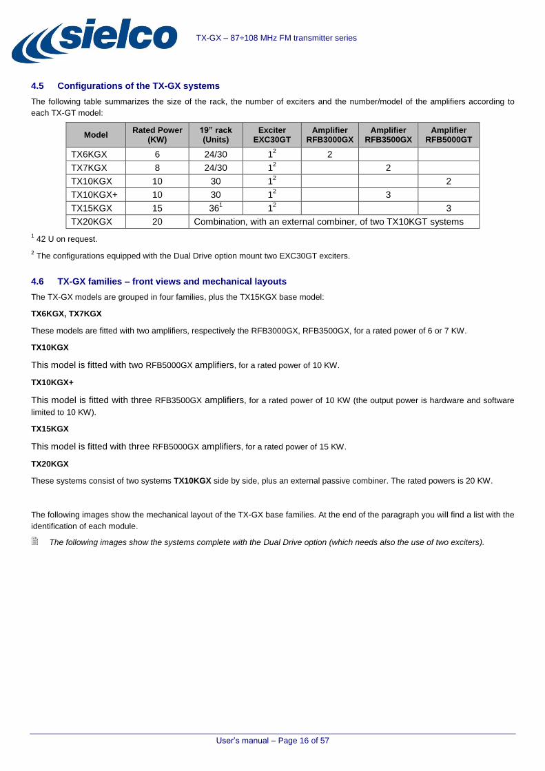
4.5 Configurations of the TX-GX systems
The following table summarizes the size of the rack, the number of exciters and the number/model of the amplifiers according to
each TX-GT model:
Model Rated Power
(KW) 19” rack (Units)
Exciter EXC30GT
Amplifier RFB3000GX
Amplifier RFB3500GX
Amplifier RFB5000GT
TX6KGX 6 24/30 12 2
TX7KGX 8 24/30 12 2
TX10KGX 10 30 12 2
TX10KGX+ 10 30 12 3
TX15KGX 15 361 1
2 3
TX20KGX 20 Combination, with an external combiner, of two TX10KGT systems
1 42 U on request.
2 The configurations equipped with the Dual Drive option mount two EXC30GT exciters.
4.6 TX-GX families – front views and mechanical layouts
The TX-GX models are grouped in four families, plus the TX15KGX base model:
TX6KGX, TX7KGX
These models are fitted with two amplifiers, respectively the RFB3000GX, RFB3500GX, for a rated power of 6 or 7 KW.
TX10KGX
This model is fitted with two RFB5000GX amplifiers, for a rated power of 10 KW.
TX10KGX+
This model is fitted with three RFB3500GX amplifiers, for a rated power of 10 KW (the output power is hardware and software
limited to 10 KW).
TX15KGX
This model is fitted with three RFB5000GX amplifiers, for a rated power of 15 KW.
TX20KGX
These systems consist of two systems TX10KGX side by side, plus an external passive combiner. The rated powers is 20 KW.
The following images show the mechanical layout of the TX-GX base families. At the end of the paragraph you will find a list with the
identification of each module.
The following images show the systems complete with the Dual Drive option (which needs also the use of two exciters).

User’s manual – Page 17 of 57
TX-GX – 87÷108 MHz FM transmitter series
TX6KGX, TX7KGX – mechanical layout
1
2
3
6
4
5
8

User’s manual – Page 18 of 57
TX-GX – 87÷108 MHz FM transmitter series
TX10KGX - mechanical layout
1
2
3
6
4
5
8

User’s manual – Page 19 of 57
TX-GX – 87÷108 MHz FM transmitter series
TX10KGX+ - mechanical layout
1
2
3
5
4
6
7
8

User’s manual – Page 20 of 57
TX-GX – 87÷108 MHz FM transmitter series
TX15GX - mechanical layout
[1] Control Unit (ASRFB10KCON) – provides the full management of the transmitter (e.g. setting the system in working or stand-
by mode) and notifies active alarms. For details 4.7.a.
If used in systems equipped with the Dual Drive option, the Control Unit will also select which exciter (A or B) will receive the LF signals coming from the outside.
[2] A Exciter (EXC30GT) (standard) – modulates the RF signal with the LF signal present at the selected LF input. The RF output
is connected to the Combiner, which will split this signal into two/three signals according to the number of Amplifiers. For details 4.7.d.
[3] B Exciter (EXC30GT) (present only in systems equipped with the Dual Drive option).
In the base systems (without the Dual Drive option) the LF signals coming from outside the system are directly connected to the exciter A. Instead, in systems equipped with the Dual Drive option, the incoming LF signals are connected to the Control Unit, which selects which exciter is connected to the incoming LF signals.
[4] RF Amplifier 1 (RFB-GX) – the output of this amplifier is coupled by the Combiner with the outputs of the other RF amplifiers in
order to obtain the system RF output signal. The amplifier model depends on the TX-GX system. For more details 4.7.e.
[5] RF Amplifier 2 (RFB-GX) – second RF amplifier. The amplifier model depends on the TX-GX system. For more details
4.7.e.
1
2
3
5
4
6
7
8

User’s manual – Page 21 of 57
TX-GX – 87÷108 MHz FM transmitter series
[6] Combiner (COVxxGT) – this unit couples the RF signals coming from the amplifiers in order to obtain the system RF output
signal. The type of Combiner (with two or three ways) depends on the number of RF amplifiers equipping the TX-GT system. For more details 4.7.b.
[7] RF Amplifier 3 (RFB-GX) – third RF amplifier. The amplifier model depends on the TX-GX system. For more details 4.7.e.
[8] System power panel – it includes various breakers: the main breaker, the breakers for each RF amplifier and a breaker for
services. On the rear side of this panel, the fuse protecting the cooling fan mounted on the upper part of the rack can be accessed. For more details 4.7.c.

User’s manual – Page 22 of 57
TX-GX – 87÷108 MHz FM transmitter series
4.7 TX-GX main modules
The Control Unit and the Exciter models are the same for all the TX-GX systems. According to the system (with two or three ways)
there are two types of Combiner. The Amplifier models and their number change according to the TX-GX system.
For further information about the composition of each TX-GX model 4.5.
4.7.a Control Unit ASRFB10KCON
The Control Unit provides the full management of the transmitter, from the power on/stand-by, to the RF output power level of each
Amplifier and the frequency operation value of the Exciter (or “Exciters” when the system is equipped with the Dual Drive option).
The control bus connecting the Control Unit with the other modules is RS485 type. The only setting to be manually carried out is
related to the audio parameters, which has to be directly set via the Exciter control panel.
The system current status is stored on EPROM. The Control Unit loads these data to restart the system with the same working
mode and parameters prior to a possible lack of power supply.
Forced Stand-by command of all the system modules
All modules are parallel connected to a contact, managed by the Control Unit, which is used to set in stand-by mode all the devices,
with a result which is similar to the Interlock command. This “Hardware control” works in parallel with the command sent via the
RS485 control bus, ensuring to block of the system even in case of fault of the bus.
Main parts
The main parts of the Control Unit are the following:
[9] Audio signals switching board – when the system is equipped with the Dual Drive option, this board performs, according to
the CPU commands, the exchange of the input LF signals between the two LF signals groups, respectively connected to the Exciter A and Exciter B.
In the base systems (without the Dual Drive option), the LF signals coming form outside are directly connected to the Exciter A. The Audio signals switching board is mounted anyway, in anticipation of a future installation of the Dual Drive option.
9 10 11 12 13
14 15
16
User’s manual – Page 23 of 57
TX-GX – 87÷108 MHz FM transmitter series
[10] RS485 interface board – enables communication via RS485 protocol among the CPU and an external management system.
[11] ETHERNET WEB browser interface (connection to and control of the transmitter through a Web page by a PC, tablet or
smartphone running operating systems Android, iOS, Windows Phone 7 / Windows Mobile, Symbian, etc.) SNMP (connection to and control of the transmitter through standard SNMP software)
[12] 12 V lead-type buffer battery – in case of lack of power supply, the battery feeds the CPU board for the time necessary to
send an alarm (option).
Thanks to the data stored in the EPROM memory, mounted on the CPU board, at the end of a possible power outage the system resumes operation in the status it was when the power failed.
[13] Control Unit power supply
[14] Control board for encoder, buttons and LEDs mounted on the front panel
[15] Display
[16] CPU board
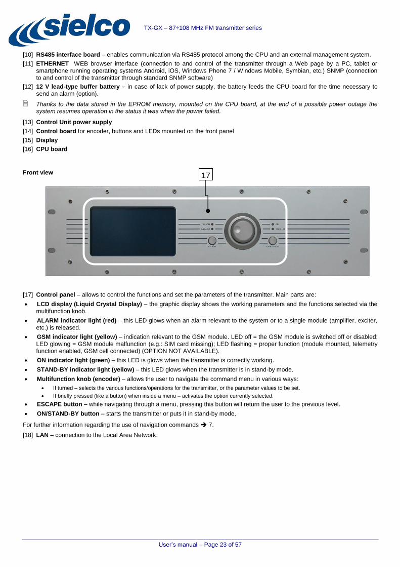
Front view
[17] Control panel – allows to control the functions and set the parameters of the transmitter. Main parts are:
LCD display (Liquid Crystal Display) – the graphic display shows the working parameters and the functions selected via the
multifunction knob.
ALARM indicator light (red) – this LED glows when an alarm relevant to the system or to a single module (amplifier, exciter,
etc.) is released.
GSM indicator light (yellow) – indication relevant to the GSM module. LED off = the GSM module is switched off or disabled;
LED glowing = GSM module malfunction (e.g.: SIM card missing); LED flashing = proper function (module mounted, telemetry function enabled, GSM cell connected) (OPTION NOT AVAILABLE).
ON indicator light (green) – this LED is glows when the transmitter is correctly working.
STAND-BY indicator light (yellow) – this LED glows when the transmitter is in stand-by mode.
Multifunction knob (encoder) – allows the user to navigate the command menu in various ways:
If turned – selects the various functions/operations for the transmitter, or the parameter values to be set.
If briefly pressed (like a button) when inside a menu – activates the option currently selected.
ESCAPE button – while navigating through a menu, pressing this button will return the user to the previous level.
ON/STAND-BY button – starts the transmitter or puts it in stand-by mode.
For further information regarding the use of navigation commands 7.
[18] LAN – connection to the Local Area Network.
17

User’s manual – Page 24 of 57
TX-GX – 87÷108 MHz FM transmitter series
Rear view
[19] Fuse holder – protective fuse holder for the power supply socket (2 A fuse).
[20] Power switch – allows the user to turn on/off the Control Unit.
[21] RS-232 – connect this port to a PC for activities like the software update and the pre-configuration of the system using the
TXPCSAT software (used to manage the telemetry functions via PC).
[22] AUX I/O 1 – emergency command for enabling / disabling the amplifier modules (hardware interlock command). This command
operates on all the amplifiers modules.
[23] GSM ANTENNA – male FME connector (present only with the telemetry option) used to connect the Control Unit to the
external GSM magnetic antenna (the included or another one prepared by the user) (OPTION NOT AVAILABLE).
[24] RS-485 INT – RS 485 control bus connecting the Control Unit to the Exciter and Amplifier modules.
[25] B.B. INPUT – inputs for the LF signals coming from external sources. Starting from the left are available the following inputs:
RIGHT – Cannon connector, right channel input
LEFT – Cannon connector, left channel input
AES/EBU – Cannon connector, AES/EBU digital standard input
AUX – female BNC connector, auxiliary modulating channel (RDS/SCA) input
MPX – female BNC connector, broadband stereo composite modulating signal input
[26] EXCITER A – LF signal outputs to be connected to the low frequency signals inputs of the Exciter A. Starting from the left are
available the following outputs:
RIGHT – Cannon connector, right channel output
LEFT – Cannon connector, left channel output
AES/EBU – Cannon connector, AES/EBU digital standard output
AUX – female BNC connector, auxiliary modulating channel (RDS/SCA) output
MPX – female BNC connector, broadband stereo composite modulating signal output
[27] EXCITER B – LF signal outputs to be connected to the low frequency signals inputs of the Exciter B. Starting from the left are
available the following outputs:
RIGHT – Cannon connector, right channel output
LEFT – Cannon connector, left channel output
AES/EBU – Cannon connector, AES/EBU digital standard output
AUX – female BNC connector, auxiliary modulating channel (RDS/SCA) output
MPX – female BNC connector, broadband stereo composite modulating signal output
[28] RS-485 EXT – external management via RS485 protocol. This port cannot be used for the management of the system from
outside.
Pay great attention in making connections with BF connectors described at the points [25], [26], [27]. Any reversal connection would result in the absence of signal at the exciters LF signal inputs.
With base systems (not equipped with the Dual Drive option), the LF signals coming from the external sources are directly connected to the exciter A.
[29] COMBINER I/O – data bus connecting the Control Unit to the Combiner.
19 20 21 23 22 25 26
31 32 30 18 29 28 27
24

User’s manual – Page 25 of 57
TX-GX – 87÷108 MHz FM transmitter series
[30] AUX I/O 2 – this port enables the user to “force” the operation of the transmitter using the supplied Manual Enable key 5.1.
It is advisable to place the Manual Enable key in a known point inside the rack. It can thus be used to force the operation of the transmitter during testing operation.
The command performed using the Manual Enable key overrides active INTERLOCK signals or malfunction of the Control Unit.
[31] Earth connection – it allows the connection of the unit to ground for a safe functioning.
[32] Power line plug – IEC-type AC power input plug. Single phase, 195 to 264 VAC – 50/60Hz.
4.7.b Combiner COVxxGT
According to the number of Amplifier modules, the type of the Combiner is a “three-ways” or a “two-ways” one.
The Combiner includes the unbalance load (50 ohm, RF type resistors). In case of failure of one of the amplifier modules, the
system will continue to operate with reduced output. In case of severe damage (complete shutdown of a transmitter due to a fault),
depending on the number of employed amplifier modules the maximum value of reduced output power will be:
3 dB / 2500 W max for the “three-ways” TX-GT systems
6 dB / 1500 W max for the “two-ways” TX-GT systems
Block of the transmitter operation due to the temperature measured by the probe mounted in the Combiner
By measuring the temperature of the combiner heat sink (on which are mounted the unbalance load resistors) the two/three sensors
(depending on whether the combiner is a “two” or “three” ways) allow the Control Unit to monitor the progress of the temperature,
reducing the output power of the system in case of failure. The temperature of this heat sink can also shown by the LCD display of
the Control Unit.
There are also thermal protections which automatically intervene when the heat sink temperature exceeds 90 °C, blocking the
operation of the whole system and setting each module in STAND BY mode, with an RF output power of 0 W.
The automatic restart of the system takes place only when the temperature of the heat sink is below 70 °C.
Front view
[33] ALARM – (red) LED indicator. It starts glowing in case of malfunction of the Combiner.
[34] ON – (green) LED indicator. It glows when the Combiner is powered and working.
[35] RF MONITOR – female BNC connector which makes available a -57 dB attenuated R.F. sample.
33 34 35

User’s manual – Page 26 of 57
TX-GX – 87÷108 MHz FM transmitter series
4.7.c Main power system panel
This panel acts as a switch and distributor of the mains voltage to the various modules of the system. Depending on the number of
amplifier modules, the panel is composed of a different number of switches:
Front panel for two-ways (two Amplifier modules) systems:
Front panel for three-ways (three Amplifier modules) systems:
[36] GENERAL – Main general breaker.
[37] AMP-1 – Amplifier 1 power switch.
[38] AMP-2 – Amplifier 2 power switch.
[39] AMP-3 – Amplifier 3 power switch.
[40] AUX – Services (the cooling fan mounted in the upper side of the rack, Control Unit, Exciters, Combiner, etc.).
On the rear side of this module is placed the fuse protecting the system cooling fan.
4.7.d Exciter EXC30GT
EXC30GT is part of a series of Sielco transmitters equipped with the latest technologies, to enable the highest performance and
lowest operating costs in full compliance with technical regulations. Flexibility, quality, compactness and low power consumption
make this device the best on the market
For detailed information about EXC30GT please refer to the user’s manual.
The use of the Exciter EXC30GT within the TX-GX systems
All the TX-GX systems use as exciter the EXC30GT. The base systems use only one exciter, whereas the systems equipped with
the Dual Drive option use two exciters, named in the menu as “Exciter 1” and “Exciter 2”. The parameters of the exciter(s) are set via
the Control Unit; with the exception of the “audio” parameters (MPX, mono, stereo, etc. modulation levels) which, when the system is
put into operation, must be directly manually set onto the unit(s).
Regardless of the TX-GX model, in two-ways systems the output power of the exciter is 10 W, whereas in the case of three-way
systems the output power is 15 W.
36 37 38 40
36 37 38 40 39

User’s manual – Page 27 of 57
TX-GX – 87÷108 MHz FM transmitter series
4.7.e Amplifier RFB-GX
The choice of the RFB-GX family is due to the high efficiency, versatility, light weight, small size and low power consumption of
these products. As for all the devices of this range, the use of the amplifiers RFB-GX represents a winning choice because it allows
to obtain substantial benefits for the entire life of the product. Also, more importantly, there are savings thanks to their low power
consumptions. RFB-GX is simple and quick to install, and put in operation. Setup is easy thanks to the intuitive control interface, the
graphic LCD display, the multi-function knob and other few buttons. The modern, attractive design of the transmitters RFB-GT
reflects the philosophy of a reliable project, aimed at reducing the number and costs of the maintenance interventions.
For details about the Amplifiers RFB-GT please refer to their user’s manuals.
The use of the amplifier RFB-GX within the TX-GX systems
According to the RF output power and the configuration of the system, the TX-GX systems mount different models of amplifiers.
They are: RFB3000GX (3.0 KW), RFB3500GX (3.5 KW), RFB5000GX (5.0 KW). These devices are completely managed by the
Control Unit via the RS-485 bus.
4.8 Connections with the outside
All the external connections pass through openings available in the top of the rack:
[41] Outlet air duct. 250 mm diameter.
[42] Cable pass-through for the passage of the power cord.
The system comes with an additional cable gland to be used in case there is the need to pass the power cord through the floor of the rack.
[43] Opening for the passage of LF and data cables.
[44] 1-5/8” flange for the connection to the antenna.
On request, the output of the RF signal can be made on the rear door of the rack.
4.9 Dual Drive option
This option consists in the installation of a second exciter (Exciter B) and some rewiring of the LF input signals. The option makes
the LF signals directly connected to the Control Unit (4.7.a ref. [25]). The LF switching board fitted in the Control Unit provides the
connection of the LF input signals to the “active” exciter (4.7.a ref. [26] or [27]).
With regards to the signal from the “active” exciter, the Combiner is already equipped with an RF switch selecting the RF output of
the “active” exciter.
The exciter not used is set in stand-by mode. If the active exciter shows a fault, the Control Unit performs the following steps:
1) Sets in stand-by mode the fault exciter
44
42
Front side
41
43

User’s manual – Page 28 of 57
TX-GX – 87÷108 MHz FM transmitter series
2) Changes the RF switch (mounted into the Combiner) to the output of the backup exciter.
3) Starts the backup exciter.
In case of switch to the backup exciter, the Control Unit doesn’t provide an automatic return to the primary one. The restoring is not possible via telemetry, but only via a manual command.
4.10 Technical specifications
The following paragraphs show the specifications of the basic models of the transmitters TX-GX series.
Features common to all models:
Ventilation system, which extracts the hot air out of the rack through the outlet air duct on the roof of the rack.
Possibility (option) to have the RF output on the upper side or on the rear side of the rack.
System prepared for the installation of the “Dual Drive” option.
System prepared for the complete remote management via GSM telemetry (option) and partial management via SMS.
4.10.a TX6KGX, TX7KGX main technical specifications
Frequency range ................................................................................................................................................................ 87.5 - 108 MHz
Rated RF output power ......................................................................................................... 6.2 / 7.2 KW typical; 5.9 / 6.9 KW minimum
Exciter power …… ............................................................................................................................................................................. 10 W
Output power ALC stability ................................................................................................................................................................. ± 3%
Harmonic and spurious emissions .................................................................................................................................................. < 80 dB
Output RF impedance ................................................................................................................................................................... 50 Ohm
RF output connector ............................................................................................................................................................... flange 1-5/8”
RF sampling connector....................................................................................................................................................................... BNC
Modulation input .............................................................................................................................................................. -3,5 ÷ +12,5 dBm
Modulation signal ................................................................................................................................................... Mpx, L & R, Mono, Aux
S/N stereo…….. .............................................................................................................................................................................. >75 dB
Power supply...... .............................................................................................................................. 400 Vac ± 15% 3 phases with neutral
Total consumption ................................................................................................................................................................. <8.7, 9.7 kVA
Operative temperature range ...................................................................................... recommended: 0 to 35 °C; extreme: – 5 to + 45 °C*
Relative humidity ……………………………………………………………………………..….. ................................ up to 95 % not condensing
Operative atmospheric pressure ……………………………………………………………………………..….. ...................... 86 kPa to 106 kPa
Dimensions (30 units 19” UL standard rack) .............................................................................................. 59 x 102 x 160 cm (W x D x H)
Weight .......................................................................................................................................................................................... 200 Kg**
* With the reduction of the power
** Net weight including the ventilation system
4.10.b TX10KGX technical specifications
Frequency range ............................................................................................................................................................... 87.5 – 108 MHz
Rated RF output power ......................................................................................................................... 10.5 KW typical; 9.5 KW minimum
Exciter power ... ................................................................................................................................................................................. 10 W
Output power ALC stability ................................................................................................................................................................. ± 3%
Harmonic and spurious emissions .................................................................................................................................................. < 80 dB
Output RF impedance ................................................................................................................................................................... 50 Ohm
RF output connector ............................................................................................................................................................... flange 1-5/8”
RF sampling connector....................................................................................................................................................................... BNC
Modulation input .............................................................................................................................................................. -3.5 ÷ +12.5 dBm
Modulation signal ................................................................................................................................................... Mpx, L & R, Mono, Aux
S/N stereo…….. .............................................................................................................................................................................. >75 dB
Power supply...... .............................................................................................................................. 400 Vac ± 15% 3 phases with neutral
Total consumption ......................................................................................................................................................................<17,5 kVA
Operative temperature range ...................................................................................... recommended: 0 to 35 °C; extreme: – 5 to + 45 °C*
Relative humidity……………………………………………………………………………..….. ................................. up to 95 % not condensing
Operative atmospheric pressure ……………………………………………………………………………..….. ...................... 86 kPa to 106 kPa
Dimensions (30 units 19” UL standard rack) ............................................................................................... 59 x 102 x 160 cm (W x D x H)
Weight .......................................................................................................................................................................................... 210 Kg**
* With the reduction of the power
** Net weight including the ventilation system

User’s manual – Page 29 of 57
TX-GX – 87÷108 MHz FM transmitter series
4.10.c TX10KGX+ technical specifications
Frequency range ................................................................................................................................................................ 87.5 - 108 MHz
Rated RF output power .......................................................................................................................... 10.7 KW typical; 10 KW minimum
Exciter power….. ................................................................................................................................................................................ 10 W
Output power ALC stability ................................................................................................................................................................. ± 3%
Harmonic and spurious emissions .................................................................................................................................................. < 80 dB
Output RF impedance ................................................................................................................................................................... 50 Ohm
RF output connector ............................................................................................................................................................... flange 1-5/8”
RF sampling connector....................................................................................................................................................................... BNC
Modulation input .............................................................................................................................................................. -3.5 ÷ +12.5 dBm
Modulation signal ................................................................................................................................................... Mpx, L & R, Mono, Aux
S/N stereo………............................................................................................................................................................................. >75 dB
Power supply...... .............................................................................................................................. 400 Vac ± 15% 3 phases with neutral
Total consumption ........................................................................................................................................................................ <21 kVA
Operative temperature range ...................................................................................... recommended: 0 to 35 °C; extreme: – 5 to + 45 °C*
Relative humidity ……………………………………………………………………………..….. ................................ up to 95 % not condensing
Operative atmospheric pressure ……………………………………………………………………………..….. ...................... 86 kPa to 106 kPa
Dimensions (30 units 19” UL standard rack) ............................................................................................... 59 x 102 x 160 cm (W x D x H)
Weight .......................................................................................................................................................................................... 260 Kg**
* With the reduction of the power
** Net weight including the ventilation system
4.10.d TX15KGx main technical specifications
Frequency range ................................................................................................................................................................ 87.5 - 108 MHz
Rated RF output power ............................................................................................................................. 15 KW typical; 14 KW minimum
Exciter power….. ................................................................................................................................................................................ 20 W
Output power ALC stability ................................................................................................................................................................. ± 3%
Harmonic and spurious emissions .................................................................................................................................................. < 80 dB
Output RF impedance ................................................................................................................................................................... 50 Ohm
RF output connector ............................................................................................................................................................... flange 1-5/8”
RF sampling connector....................................................................................................................................................................... BNC
Modulation input .............................................................................................................................................................. -3.5 ÷ +12.5 dBm
Modulation signal ................................................................................................................................................... Mpx, L & R, Mono, Aux
S/N stereo………............................................................................................................................................................................. >75 dB
Power supply...... .............................................................................................................................. 400 Vac ± 15% 3 phases with neutral
Total consumption ........................................................................................................................................................................ <28 kVA
Operative temperature range ...................................................................................... recommended: 0 to 35 °C; extreme: – 5 to + 45 °C*
Relative humidity ……………………………………………………………………………..….. ................................ up to 95 % not condensing
Operative atmospheric pressure ……………………………………………………………………………..….. ...................... 86 kPa to 106 kPa
Dimensions (30 units 19” UL standard rack) ............................................................................................... 58 x 102 x 190 cm (W x D x H)
Weight .......................................................................................................................................................................................... 350 Kg**
* With the reduction of the power
** Net weight including the ventilation system
4.10.e TX20KGT technical specifications
Frequency range ................................................................................................................................................................ 87.5 - 108 MHz
Rated RF output power .......................................................................................................................... 20 KW typical; 19.5 KW minimum
Exciter power….. .......................................................................................................................................................................... 2 x 10 W
Output power ALC stability ................................................................................................................................................................. ± 3%
Harmonic and spurious emissions .................................................................................................................................................. < 80 dB
Output RF impedance ................................................................................................................................................................... 50 Ohm
RF output connector ............................................................................................................................................................... flange 3-1/8”
RF sampling connector....................................................................................................................................................................... BNC
Modulation input .............................................................................................................................................................. -3.5 ÷ +12.5 dBm
Modulation signal ................................................................................................................................................... Mpx, L & R, Mono, Aux
S/N stereo…….. .............................................................................................................................................................................. >75 dB
Power supply...... .............................................................................................................................. 400 Vac ± 15% 3 phases with neutral
Total consumption ........................................................................................................................................................................ <45 kVA
Operative temperature range ...................................................................................... recommended: 0 to 35 °C; extreme: – 5 to + 45 °C*
Relative humidity ……………………………………………………………………………..….. ................................ up to 95 % not condensing
Operative atmospheric pressure ……………………………………………………………………………..….. ...................... 86 kPa to 106 kPa
Dimensions (30 units 19” UL standard rack) .......................................................................... 2 racks 59 x 102 x 160 cm (W x D x H) each
Weight .......................................................................................................................................................................................... 520 Kg**
* With the reduction of the power
** Net weight including the ventilation system

User’s manual – Page 30 of 57
TX-GX – 87÷108 MHz FM transmitter series
Manual Enable key
5 INSTALLATION
Warning! To ensure safe performance, it is absolutely essential to comply with all the instructions outlined in this chapter.
5.1 Check the supplied parts
Ensure that the following parts are included in the package:
The system complete with all modules installed and all internal wiring made.
The user’s manual.
The Manual Enable key (15 pins, DB male connector) which can be used to force the operation of the
transmitter during checks and tests even with a fault Control Unit or an active Interlock input. To use the key 4.7.a.
During the normal operation it is recommended to keep the Manual Enable key inside the rack.
If any part is missing or damaged, contact your supplier at once.
5.2 General safety rules
Warning! In order to prevent serious damage to objects or people, the following rules must be strictly followed.
Although in most cases no special instruments are required, the system should be installed only by skilled personnel. To make best use of the system and prevent damage to it, it is necessary to comply with the instructions outlined in this manual. Should doubts or technical problems arise during the installation procedure, it is strongly recommended that you contact Sielco Srl or a local agent/dealer.
Sielco Srl would be happy to provide qualified technical assistance. Technical intervention by personnel not authorized by Sielco Srl should not be performed.
The user should not access the inside of the modules. Tampering with the factory settings renders the warranty null and void, and may also affect the system’s performance, causing costly damage.
No adjustments or internal calibrations are required for normal operations. The rack must be properly grounded and all the modules must have all their covers closed in order to prevent electrical shocks and to fully comply with EC, EMI, and other safety regulations.
Never touch the inside of the modules without first disconnecting the system from the mains. Opening the rear panel of the rack give access to dangerous AC, DC and radiofrequency voltages.
Do not operate the system if the modules are without the covers properly screwed into place: It may be dangerous to objects or people. Due to the high RF fields, you may also experience a malfunction of the transmitter or of electronic measurement instrument you are using.
5.3 Choosing the proper room and placement
The floor where the system will be installed, must be able to support a weight of at least 1000 Kg/m2
when installing systems up to
15 KW (1500 Kg/m2
when installing systems with higher power).
The room must be clean and free from excessive dust.
Around the point where the system will be installed there must be sufficient space both for the air pipe (for the hot air extracted from
the rack through outlet air duct) and the maintenance activities (minimum space required: 4 x 4 x 4 meters). The floor must be flat
and regular, not affecting the physical stability of the rack.
Suggested environmental operating temperature range: from 0 to 35 °C; maximum temperature range: from – 5 to + 45 °C. Relative
humidity: up to 95%, not condensing.
5.3.a Electrical conditions
The mains must adequately support the system’s power consumption (including a sufficient safety margin).
The power supply nominal value must be 400 VAC three-phase with neutral.
Mains fluctuations and electrical discharges due to weather or nearby industrial machinery may cause significant trouble, especially in mountain areas and in locations close to industrial areas. In such cases, it is advisable, if not indispensable, to install a protector, an insulating transformer, or possibly an electromechanical mains voltage regulator.

User’s manual – Page 31 of 57
TX-GX – 87÷108 MHz FM transmitter series
5.4 Wiring the system
This section describes the minimum connections required to place the transmitter in operation.
In order to obtain the best operating conditions, for the signals interconnections between the RF amplifiers and the combiner the system comes with cables of equal length. In the case of interventions on these wirings (e.g.: for the replacement of one of the modules), it is important paying attention to use RF cables with the same length.
5.4.a The air pipe (outside the rack)
The size of the outlet air duct (4.8) is 250 mm. Only a suitable air pipe ensures the proper cooling of the system.
5.4.b Wiring into the antenna
Connect the RF output flange ( 4.8 ref.[44]) to the antenna using a proper 50 Ohm rigid cable of good quality and with low
attenuation.
It is very important to ensure that the antenna, cables, and connectors have the correct impedance and are appropriate to the transmitter’s rated power.
The antenna must be suitable for FM broadcasting and able to resonate at the operating frequency with the minimum possible SWR.
The antenna must be grounded via a copper braid of suitable cross-section to prevent lightening or static electricity from reaching the amplifier through the antenna cable.
5.4.c Connection to modulation signals
Connect the modulation inputs according to the desired operating mode (monophonic or stereophonic) and the type of source being
used (mono, stereo, or multiplex signal). When installing a system equipped with the Dual Drive option, the modulation signals must
be connected to the Control Unit ( 4.7.a) whereas, in the case of base systems, these signals must be connected directly to the
Exciter A ( 4.7.d). These cables must enter through the opening available on top of the rack ( 4.8).
5.4.d Wiring into the mains
WARNING: for the wiring of the system into the mains contact qualified personnel and comply with installation regulations.
The equipment can be connected to the mains both permanently, by installing a suitable current breaker with overcurrent protection upstream the electrical plant, or to an industrial three-phase electrical outlet (400 VAC) connected to a power cable with conductors of at least 10 mm
2.
1) In a permanent installation, a 4-poles current breaker, 400VAC, with overcurrent protection, tripping curve C, and power threshold equivalent to 1.5 times the nominal current value, must be installed upstream the system power connection.
2) Use an appropriate power cable with at least 10 mm2
conductors. Connect it to the main terminal on the bottom of the rack,
observing the connections of the wires: phases (L1, L2 and L3), neutral (N) and the grounding .
3) Pass the cable through one of the two holes, the one on the top or the other one in the bottom of the rack. These holes are provided with plastic gland that prevents the cable to disconnect once fixed.
4) Connect the power cable to a suitable three-phase outlet (400 VAC nominal voltage).
5) Ensure that the grounding system is fully functional.
6) Ensure that the GENERAL power switch (4.7.c) is turned OFF, if it is not OFF, do so now.
7) Connect the system to the main and turn ON the GENERAL power switch.
The power at the output of the plant and/or electrical outlet must comply with the information given on par. 4.10.
The system should not be used if near the lower voltage limit with high-impedance lines: if the line voltage falls below a certain limit at full load, the low voltage sensor circuit could trigger a continuous, extremely dangerous on/off cycle. In such case, install an external voltage stabilizer.
In order to ensure proper operation and comply with safety regulations, proper grounding is required. Use the yellow/green lead of the power cable. Never connect the earth to the mains neutral lead.
Never turn the system on without an antenna connection, even when in stand-by.

User’s manual – Page 32 of 57
TX-GX – 87÷108 MHz FM transmitter series
6 BASIC OPERATIONS
Following installation, the first time the system is turned on it is absolutely fundamental following the instructions outlined in this chapter. Failure performing the adjustments and controls explained in this section could cause serious damage to the device or interference with other broadcasters or services that operate via radio; any such damage will be the sole responsibility of the user.
The transmitter stores the operating mode in which it was working before the power supply was turned off (or a mains failure took place). Therefore, before continuing, it is important to ensure that it is connected to an RF load able to support the maximum deliverable power.
Operating the transmitter without an antenna, or when the antenna is improperly connected, may cause damages, particularly to the final stages of the amplifiers, that are not covered by the warranty.
Proper adjustment of the parameters should be made to conform to local regulations; such conformity is the full responsibility of the user.
6.1 Initial start-up
1) Ensure that all the switches of the Main Power System Panel (4.7.c) are turned OFF.
2) Ensure that all the power switches of the modules (located on the rear panels of each device) are switched “ON”.
3) Turn the switches GENERAL [36] and AUX [40] of the Main Power System Panel “ON” (4.7.c).
4) Successively, turn the switches of each Amplifier modules “ON”. They are named AMP-1 [37], AMP-2 [38], AMP-3 [39] (AMP-3 is only available with systems equipped with three amplifiers).
5) Via the LCD display of the Control Unit verify that the RS485 control bus (connecting the Control Unit to the modules) is correctly working. In case of problems check the settings of the RS485 bus system of each module (6.1.a)
6) Carry out the basic settings (frequency, output power, modulation, etc.) and verify the correct operation (e.g.: check the RF reflected power level, etc.) via the menu.
7) Adjust appropriately the levels of the input LF signals.
For the adjustments to be directly carried out on the exciter and on the amplifier modules please refer to their user’s manuals.
6.1.a Settings of the RS485 system bus
The first time the system is turned on, and also after some particular maintenance operations (e.g.: the installation of a new module)
it is important to verify the RS485 bus system settings. Incorrect configurations may cause the lack of recognition of one or more
modules (an amplifier, an exciter, etc.).
Module1 Address
2 Baud rate
Exciter 1 1 38400
Exciter 2 2 38400
Amplifier 1 3 38400
Amplifier 2 4 38400
Amplifier 3 5 38400
1 The list refer to a system equipped with the maximum number of modules (two exciters + three amplifiers), and corresponds to the
physical sequence of the modules starting from the top of the rack.
2 In the case of systems with different compositions, for example with a single exciter, the address of the second exciter (missing) is
left unused (the amplifier 1 continues to be associated to the address 3).
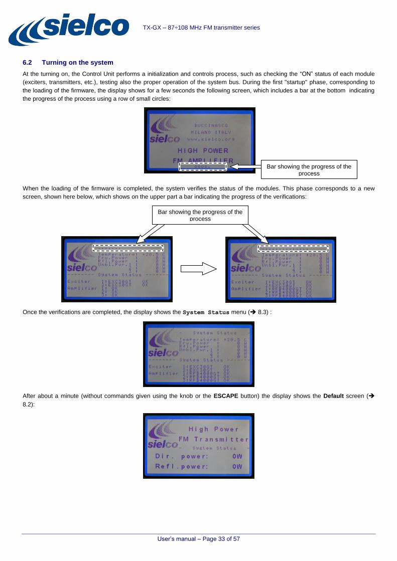
User’s manual – Page 33 of 57
TX-GX – 87÷108 MHz FM transmitter series
6.2 Turning on the system
At the turning on, the Control Unit performs a initialization and controls process, such as checking the “ON” status of each module
(exciters, transmitters, etc.), testing also the proper operation of the system bus. During the first "startup" phase, corresponding to
the loading of the firmware, the display shows for a few seconds the following screen, which includes a bar at the bottom indicating
the progress of the process using a row of small circles:
When the loading of the firmware is completed, the system verifies the status of the modules. This phase corresponds to a new
screen, shown here below, which shows on the upper part a bar indicating the progress of the verifications:
Once the verifications are completed, the display shows the System Status menu ( 8.3) :
After about a minute (without commands given using the knob or the ESCAPE button) the display shows the Default screen (
8.2):
Bar showing the progress of the process
Bar showing the progress of the process
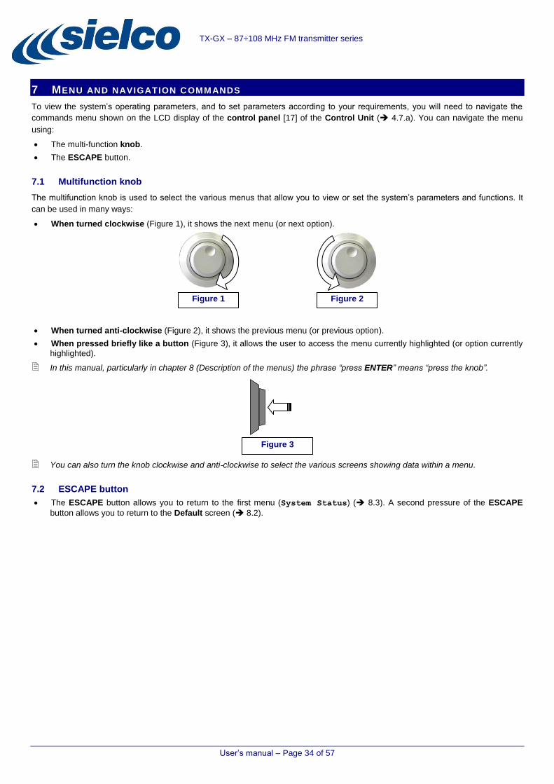
User’s manual – Page 34 of 57
TX-GX – 87÷108 MHz FM transmitter series
7 MENU AND NAVIGATION C OMMANDS
To view the system’s operating parameters, and to set parameters according to your requirements, you will need to navigate the
commands menu shown on the LCD display of the control panel [17] of the Control Unit ( 4.7.a). You can navigate the menu
using:
The multi-function knob.
The ESCAPE button.
7.1 Multifunction knob
The multifunction knob is used to select the various menus that allow you to view or set the system’s parameters and functions. It
can be used in many ways:
When turned clockwise (Figure 1), it shows the next menu (or next option).
When turned anti-clockwise (Figure 2), it shows the previous menu (or previous option).
When pressed briefly like a button (Figure 3), it allows the user to access the menu currently highlighted (or option currently
highlighted).
In this manual, particularly in chapter 8 (Description of the menus) the phrase “press ENTER” means “press the knob”.
You can also turn the knob clockwise and anti-clockwise to select the various screens showing data within a menu.
7.2 ESCAPE button
The ESCAPE button allows you to return to the first menu (System Status) ( 8.3). A second pressure of the ESCAPE
button allows you to return to the Default screen ( 8.2).
Figure 3
Figure 1 Figure 2

User’s manual – Page 35 of 57
TX-GX – 87÷108 MHz FM transmitter series
8 DESCRIPTION OF THE MENUS
This description follows the structure of the menus. The images are taken from the LCD display of the control panel [17] of the
Control Unit ( 4.7.a).
The following menu descriptions refer to software version 1.7.1.
To reduce the power consumption of the system and the wear of the display background, the brightness of the display is reduced after some minutes of inactivity of the knob or of the ESCAPE button.
8.1 Features common to all the menus
Conventionally, the menus relevant to systems with more modules having the same function (exciters, amplifiers) use a numbering
that reflects the physical sequence of modules mounted on the rack, starting with the higher installed module. For example, the first
exciter is numbered 1, the second exciter is numbered 2, the first amplifier is numbered 1, the second amplifier is numbered 2, etc.
Apart from the Default screen (8.2), most of the menu screens in the upper half section show the main information relevant to the
operation of the transmitter, while in the bottom half section list the information of the selected menu (with the exception, for
example, of menus describing each stored alarm / event 8.11). Here below an example of a menu:
To select a menu, starting from the Default one press the knob. To move to the next menu turn the knob (two clicks).
The order in which the menus are described in the following paragraphs follows the sequence in which they can be selected rotating
the knob.
The menus providing the ability to make / edit settings, in the last row show the text Press ENTER to Setup:
In some menus the cursor (a small gray rectangle) flashes meaning that the system is waiting for data. In these cases, to quit the menu without entering data, press the ESCAPE key.
ENTER command
To confirm the selection of an option or a setting press the knob. Conventionally, this manual names this command “ENTER”.
Therefore, when in the following descriptions there is the phrase "press ENTER" the meaning is "press the knob".
Information relevant to the transmitter operation
Specific information relevant to the selected menu
“Warning”: alarm/malfunction
status

User’s manual – Page 36 of 57
TX-GX – 87÷108 MHz FM transmitter series
8.2 Default screen
After about a minute of inactivity of the navigation commands (knob, ENTER command or ESCAPE button), the display returns
showing the Default screen:
Information shown on the screen:
Sielco logo.
Information relevant to active alarms (if any).
Direct power level.
Reflected power level.
To get information about the status of the system, and/or to change system’s settings, press ENTER, this will open the first menu (System Status - 8.3).
After some minutes of inactivity, to reduce the power consumption of the system and the wear of the display, the background brightness of the display is reduced.
8.3 System Status menu
From the Default screen, press ENTER to access the System Status menu, that summarizes the status of the RS485 system
bus. The following example refers to a “three-ways” system equipped with the Dual Drive option:
Exciter 1: EXC30GT (exciter model) OK (communication link correctly working).
Exciter 2: Fail, 485 Addr.2 (in this example there is a communication link fault with the exciter 2, identified as – “address 2 ” of
the RS485 bus)
Amplifier 1: RFB4000GT (amplifier model) OK (communication link correctly working).
Amplifier 2: RFB4000GT (amplifier model) OK (communication link correctly working).
Amplifier 3: RFB4000GT (amplifier model) OK (communication link correctly working).
In the previous screen the Warning message, shown on the upper side of the menu, points out that there is a problem with the
status of the system (due to the communication link fault of the exciter 2).
The information provided on this menu are automatically updated.
To avoid problems such as the one in the previous example (non-recognition of the second exciter), pay attention to the configuration of the system, for example during the allocation of the ports and the relevant Baud rate of the RS485 bus (6.1.a).
When the system is in operation, a fault on the RS485 bus relevant to a specific device doesn’t affect the operation of the device itself. However has it to be considered that from that moment the device becomes independent, and any commands from the Control Unit will NOT be received by the device. If the system is equipped with the telemetry option, as a result of a fault like the mentioned one, an alarm signal is sent via SMS.

User’s manual – Page 37 of 57
TX-GX – 87÷108 MHz FM transmitter series
8.4 Set Amplifier Power menu
The Set Amplifier Power menu allows setting the system’s RF output power level. To access this menu, from System
Status rotate clockwise (two clicks) the knob:
The information relevant to the menu are shown in the lower half section of the screen:
Set Amplifier Power – name of the menu.
10050 – current level of the set output power.
Amp1 Output Power: 0.0W – output power level of Amplifier 1.
Amp2 Output Power: 0.0W - output power level of Amplifier 2.
Amp3 Output Power: 0.0W - output power level of Amplifier 3.
1) Press ENTER button to highlight the tens digit of W of the output power level to be set. Turn the knob to select the new value,
in the example "7”:
2) Press ENTER to confirm the set value, moving the cursor on the hundreds of W:
3) Turn the knob to select the new value, then press ENTER to confirm the set value:
After the third ENTER command the Control Unit will process the new target output power, at the same time the last three lines of
the menu will show the changes in progress on the output of the amplifiers (if ON-AIR) to obtain the set output power level.
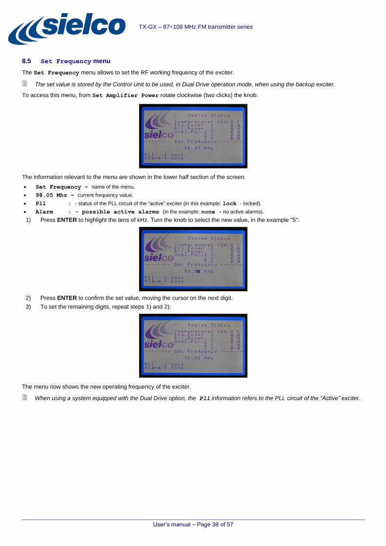
User’s manual – Page 38 of 57
TX-GX – 87÷108 MHz FM transmitter series
8.5 Set Frequency menu
The Set Frequency menu allows to set the RF working frequency of the exciter.
The set value is stored by the Control Unit to be used, in Dual Drive operation mode, when using the backup exciter.
To access this menu, from Set Amplifier Power rotate clockwise (two clicks) the knob:
The information relevant to the menu are shown in the lower half section of the screen:
Set Frequency – name of the menu.
98.05 Mhz – current frequency value.
Pll : - status of the PLL circuit of the “active” exciter (in this example: lock - locked).
Alarm : - possible active alarms (in the example: none – no active alarms).
1) Press ENTER to highlight the tens of kHz. Turn the knob to select the new value, in the example "5":
2) Press ENTER to confirm the set value, moving the cursor on the next digit.
3) To set the remaining digits, repeat steps 1) and 2):
The menu now shows the new operating frequency of the exciter.
When using a system equipped with the Dual Drive option, the Pll information refers to the PLL circuit of the “Active” exciter.

User’s manual – Page 39 of 57
TX-GX – 87÷108 MHz FM transmitter series
8.6 Amplifier 1 Status menu
The Amplifier 1 Status menu shows information relevant to the Amplifier 1.
To access this menu, from Set Frequency rotate clockwise (two clicks) the knob:
The information relevant to the menu are shown in the lower half section of the screen:
Amplifier 1 Status - name of the menu.
Output Power : – output power level of the amplifier.
Vswr : - reflected power level.
RF temp : - temperature of the amplifier’s power circuits.
Alarm : - possible active alarms relevant to the amplifier (in the example: none – no active
alarms).
8.7 Amplifier 2 Status menu
The Amplifier 2 Status menu shows information relevant to the Amplifier 2.
To access this menu, from Amplifier 1 Status rotate clockwise (two clicks) the knob:
The information relevant to the menu are shown in the lower half section of the screen.
Amplifier 2 Status - name of the menu.
Output Power : – output power level of the amplifier.
Vswr : - reflected power level.
RF temp : - temperature of the amplifier’s power circuits.
Alarm : - possible active alarms relevant to the amplifier (in the example: none – no active alarms).
8.8 Amplifier 3 Status menu
The Amplifier 3 Status menu shows information relevant to the Amplifier 3.
To access this menu, from Amplifier 2 Status rotate clockwise (two clicks) the knob:
The information relevant to the menu are shown in the lower half section of the screen.
Amplifier 3 Status - name of the menu.
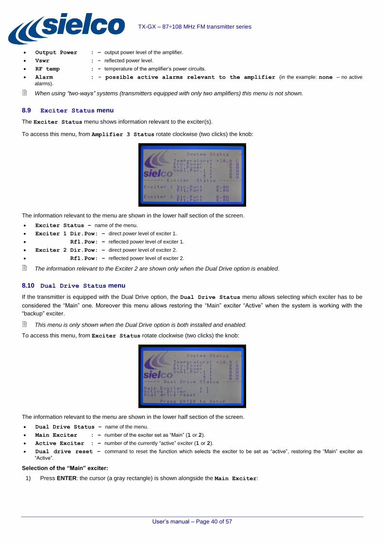
User’s manual – Page 40 of 57
TX-GX – 87÷108 MHz FM transmitter series
Output Power : – output power level of the amplifier.
Vswr : - reflected power level.
RF temp : - temperature of the amplifier’s power circuits.
Alarm : - possible active alarms relevant to the amplifier (in the example: none – no active
alarms).
When using “two-ways” systems (transmitters equipped with only two amplifiers) this menu is not shown.
8.9 Exciter Status menu
The Exciter Status menu shows information relevant to the exciter(s).
To access this menu, from Amplifier 3 Status rotate clockwise (two clicks) the knob:
The information relevant to the menu are shown in the lower half section of the screen.
Exciter Status – name of the menu.
Exciter 1 Dir.Pow: – direct power level of exciter 1.
Exciter 1 Rfl.Pow: – reflected power level of exciter 1.
Exciter 2 Dir.Pow: – direct power level of exciter 2.
Exciter 1 Rfl.Pow: – reflected power level of exciter 2.
The information relevant to the Exciter 2 are shown only when the Dual Drive option is enabled.
8.10 Dual Drive Status menu
If the transmitter is equipped with the Dual Drive option, the Dual Drive Status menu allows selecting which exciter has to be
considered the “Main” one. Moreover this menu allows restoring the “Main” exciter “Active” when the system is working with the
“backup” exciter.
This menu is only shown when the Dual Drive option is both installed and enabled.
To access this menu, from Exciter Status rotate clockwise (two clicks) the knob:
The information relevant to the menu are shown in the lower half section of the screen.
Dual Drive Status – name of the menu.
Main Exciter : – number of the exciter set as “Main” (1 or 2).
Active Exciter : – number of the currently “active” exciter (1 or 2).
Dual drive reset – command to reset the function which selects the exciter to be set as “active”, restoring the “Main” exciter as
“Active”.
Selection of the “Main” exciter:
1) Press ENTER: the cursor (a gray rectangle) is shown alongside the Main Exciter:

User’s manual – Page 41 of 57
TX-GX – 87÷108 MHz FM transmitter series
2) Press ENTER a second time, the cursor moves to the right of the colon and starts flashing:
3) To set as “Main” one of the two exciters (1 or 2) turn the knob. Confirm pressing ENTER (the gray square returns to the left
of the colon):
Restoring the “Main” exciter “Active” if the system is working with the “Backup” exciter:
The following example shows the situation in which, following the intervention of the exchange logic, the main exciter (2) (Main
Exciter : 2) has been replaced by the backup exciter (1) (Active Driver: 1):
1) Press ENTER the cursor (a grey rectangle) is shown next to the Main Exciter:
2) Rotate the knob to select Dual drive reset. Then press ENTER.
3) The system carries out the exchange, setting “Active” the “Main” exciter.
If the cause of the previous exchange is still present, the system returns selecting as “Active” the “backup” exciter.

User’s manual – Page 42 of 57
TX-GX – 87÷108 MHz FM transmitter series
8.11 System Alarms menu
This menu lists up to 60 alarms or events relevant to the system. If the maximum number (60) is reached, the system removes the
oldest alarm/event, leaving room for the new one.
To access this menu, from Dual Drive Status rotate clockwise (two clicks) the knob:
The information relevant to the menu are shown in the lower half section of the screen:
System Alarms – name of the menu.
60 Alarms – number of stored alarms/events (in this example there are 60 stored alarms/events).
To access information relevant to each specific event press ENTER. The menu displays the information, starting from the most
recent event:
The shown information are:
Number and type of the alarm/event.
Date and time of the event.
Transmitter’s working status at the time of the event.
To quit the page of the event, press ESCAPE.
The following image highlights the information relevant to the stored event:
Number of the alarm/event Definition of the alarm/event
Event date & time
Information relevant to the system’s working status at
the time of the event

User’s manual – Page 43 of 57
TX-GX – 87÷108 MHz FM transmitter series
To clear the stored alarms/events list, press ENTER when in a page showing the details of an alarm/event. The following screen is
displayed:
To quit the menu leaving the data stored, press ESCAPE.
To delete the list of stored data, press ENTER. The display shows a screen like the following one, to confirm the deletion of the data:
8.12 Temporal Power Reduction menu
This menu allows to schedule transmission at reduced output power in a specific daily time band (which will be repeated 7/7 days).
This function can be enabled/disabled via SMS.
To access this menu, from System Alarms rotate clockwise (two clicks) the knob:
The shown information are:
Temporary Power Reduction – name of the menu.
Status : – status of the function (in this example: Off – disabled).
Reduction : – percentage value of the output power.
From : – start time of the period (daily) with the transmitter operating at reduced power.
To : – end time of the period (daily) with the transmitter operating at reduced power.
1) To set the function press ENTER:

User’s manual – Page 44 of 57
TX-GX – 87÷108 MHz FM transmitter series
2) The cursor appears on the left of Status:. Turn the knob to enable/disable this function:
3) Press ENTER to select Reduction. Then enter the percentage value of the output power by turning the knob:
4) Press ENTER to enter the start time (From) of the period broadcasting at reduced power.
For both the times (From and To) the “hours” and “minutes” fields have to be separately set.
5) Once the "minutes" field for the end time (To) has been set, to store the new settings press ENTER:
8.13 SMS settings menu
This menu, available when the system is equipped with the telemetry function, enable setting the parameters for the SMS function.
This menu is always displayed, even in the absence of the telemetry option.
To access this menu, from Temporal Power Reduction rotate clockwise (two clicks) the knob:
The shown information are:
SMS settings – name of the menu.
SMS Status : – status of the SMS function (in this example: Enabled – enabled).
SMS Delay : – delay in sending the SMS.
Max SMS/Day : – daily maximum number of SMS.
Max SMS/Hour : – hourly maximum number of SMS.

User’s manual – Page 45 of 57
TX-GX – 87÷108 MHz FM transmitter series
1) To select the first field (SMS Status) press ENTER: the flashing cursor is shown to the right of the field SMS Status:
2) To enable/disable this function press the knob: the blinking cursor moves to the right of the colon:
3) Turn the knob to enable/disable the function. Press ENTER: the setting will be stored and the cursor will be moved to the
next field:
4) Proceed as described in steps 2) and 3) setting the other fields.
To quit the settings procedure (for example when you want to change only some values), press ESCAPE when the cursor is blinking on the right of the colon.
5) To open the next menu press ENTER.
8.14 GSM Status menu
This menu provides information about the status of the GSM connection. It also allows setting the GSM connection parameters.
To access this menu, from Sms settings rotate clockwise (two clicks) the knob:
The shown information are:
GSM Status – name of the menu.
Status : – status of the connection via GSM (in this example: Enabled - I TIM – enabled, with TIM as service provider).
RX level : – GSM received signal level.
It is recommended to disable the PIN of the SIM card before using it with the TX-GT system

User’s manual – Page 46 of 57
TX-GX – 87÷108 MHz FM transmitter series
1) To access the GSM connection settings, press ENTER. The display will show the following submenu:
The data are relevant to:
Status : – status of the GSM connection (in this example: Enabled - I TIM – enabled, with TIM as service provider).
Network : – selection of the GSM network (in this example: Auto – automatic selection).
Name : – name of the position. This data is added to the SMS and provides the receiver with the reference of the transmitter system
that sent the message.
Code : – identifier of a specific transmitter system, useful when in the same position there are more systems or equipments.
IMEI : – identifier of the SIM card.
2) Turn the knob to select the field to edit and press ENTER (the cursor moves to the right of the colon):
3) Turn the knob to change the field.
4) Press ENTER to confirm the new data (the cursor is shown to the left of the colon).
5) Continue for all the fields to be changed. Then press ESCAPE to exit the menu.
If the telemetry option is not present, the Status field is automatically set to Disabled.
If the system doesn’t detect the telemetry option, the display shows the following screen to inform the user that it is Not
Installed:
It is still possible searching for the presence of the GSM module by pressing ENTER. During the search, the display shows the
following screen:
When the search is completed, if GSM module has not been found the display returns to the previous screen:

User’s manual – Page 47 of 57
TX-GX – 87÷108 MHz FM transmitter series
8.15 SMS numbers menu
This menu allows entering up to five telephone numbers to which the alarm/event notifications will be sent via SMS.
Each number is associated with specific events/alarms. Each time one of these events/alarm becomes active, the system sends to
the telephone number an SMS reporting the identifier of the event/alarm.
If two telephone numbers are associated with the same alarm/event, the system sends a notification to both numbers if that alarm/event becomes active.
A telephone number NOT associated with events / alarms, will NEVER be used by the system.
Each phone number can be associated with up to 8 events/alarms.
To access this menu, from GSM Status rotate clockwise (two clicks) the knob:
The shown information are:
SMS numbers – name of the menu.
Num. 1 – first telephone number.
Num. 2 – second telephone number.
Num. 3 – third telephone number.
Num. 4 – forth telephone number.
Num. 5 – fifth telephone number.
To view/edit a phone number and its associated alarms:
1) Press ENTER, then rotate the knob moving the cursor near the desired number (in the example the second number, Num.
2):
2) Press ENTER to confirm the selection: the display shows the screen relevant to the selected phone number:

User’s manual – Page 48 of 57
TX-GX – 87÷108 MHz FM transmitter series
3) Enter the phone number: rotate the knob to set the first digit, then confirm ENTER (the cursor will move one digit to the right).
Continue until the entire number is entered.
4) After setting the last digit of the telephone number, to select to the second field ("Alarm:") press ENTER twice, then turn the
knob to select the alarms associated with the set telephone number. Confirm the selected event/alarm by pressing ENTER. A dash is add, rotate the knob to select another event/alarm and press ENTER to confirm the new selection. Continue until you
have entered all the events/alarms that you want to relate to the phone number:
5) To confirm the settings and exit the phone number page, press ESCAPE.
The sequence of alarms/events displayed in the Alarm field is fixed. The alarms/events not related to the number are replaced
by a series of four points ("-. . . . -"). In the example above, the third alarm ("MPX "), next to the alarm "AC ", is not
associated with the number, so it is replaced by "-. . . .- ".
selectable alarms:
LPWR: low RF output power level.
AC: no mains.
MPX: no MPX signal (PAY ATTENTION selecting this alarm in case of use with radio links or communication satellites).
UNBL: unbalanced power (of the system) alarm.
VSWR: Voltage Standing Wave Ratio alarm.
T.SYS: system temperature alarm. Relevant to the temperature measured on the CPU board.
T.RF: temperature alarm. Relevant to the temperature of the combiner heatsink.
UNLOCK: exciter’s PLL unlocked alarm.
8.16 Password menu
This menu allows enabling/disabling the access to certain features of the system.
To access this menu, from SMS numbers rotate clockwise (two clicks) the knob:
The shown information are:
Password – name of the menu.
Level 1 : – Level 1 password: block of any access to the system menu, both in display and setting. The only shown screen is the
startup one, with the system model; no other information, such as the level or frequency of the output signal, are given. The access using a password can be enabled or disabled (in this example the level 1 is "Off", meaning that there is no need to enter a password to access the
system information).

User’s manual – Page 49 of 57
TX-GX – 87÷108 MHz FM transmitter series
Level 2 : – Level 2 password: block of any changes of programmable parameters. Complete access to the system parameters
visualization. The access using a password can be enabled or disabled (in this example level 2 is “Off”, meaning that there is no need to enter
a password to access and/or change the parameters of the system).
Remains always active (though not shown) the level 3 password which will unlock, if entered, all types of access (allowing to enter, for example, new level 1 and/or level 2 passwords If they were forgotten).
Setting/enabling a password
1) Press ENTER: the cursor will be displayed next to Level 1:
2) To select the password to be set/changed turn the knob. Press ENTER to confirm:
3) To enable/disable the password, turn the knob (On: password enabled, Off password disabled). Confirm with ENTER.
4) If On has been selected, the display shows the menu for setting the password:
5) The cursor highlights the first character to be set. Turn the knob to enter the first character. Press ENTER to confirm the set character, selecting the next one. Once the fifth character has been set, press ENTER to return to the Default menu:
With the Password function enabled, to enter the menus after having pressed ENTER the system prompts for the password:

User’s manual – Page 50 of 57
TX-GX – 87÷108 MHz FM transmitter series
If enabled, the Level 2 password (accessing and editing of the system parameters) will be required when trying to change a parameter.
8.17 System Setup menu
This menu helps to set the basic parameters of the transmitter. These activities are usually carried out at the factory, during the
assembly of the system. However, they might become necessary even in a second time, for example when implementing the "Dual
Drive" option.
With this menu the user can manage parameters that are very important for the operation of the system. We therefore recommend caution when changing/setting these data.
During the installation of the system we recommend to check the settings of this menu.
To access this menu, from Password rotate clockwise (two clicks) the knob:
The shown information are:
System Setup – name of the menu.
Dual Driver : – enabling, if installed, of the Dual Drive option (in this example this option is installed and On - enabled).
Max Power : –maximum value of the RF output power that can be set. For the value to be entered in this field please refer to the
following paragraph.
Coupler : – this setting determines whether the system is a two-ways (2 Way) or a three-ways (3 Way).
Time & Date : – date and system time. These information are particularly important because they are used for example in the
alarms history (System Alarms menu) and when planning the daily periods of reduced power operation (Temporal Power Reduction
menu).
Firmware Rev. : – firmware revision (installed in the system).
Care should be taken setting the Coupler field: in the case for example of a three-ways system, setting 2 Way the
third amplifier will not be managed, with the result of an high level of unbalance.
Updating the menu data:
1) To select the setting to be changed, press ENTER, the colon next to Dual Driver will flash showing the position of the
cursor.
2) To change the setting, turn the knob, then press ENTER to confirm the setting and move to the next field (in the example the
Dual Driver has been set Off). (To move to the next field without changing the setting, press ENTER).
Setting system date and time:
3) When the cursor is at the side of the Coupler field, press ENTER once to move the cursor to the "hours" (in this example
"12") and turn the knob to set the hours.
4) Press ENTER to move the cursor to the "minutes" ("44" in the example), turn the knob to set the minutes.
5) Press ENTER to move the cursor to "days" ("20" in the example), turn the knob to set the day of the month.
6) Press ENTER to move the cursor to the "month" ("02" image), turn the knob to set the month.
7) Press ENTER to move the cursor to the "year" ("12" image), turn the knob to set the year.
8) Press ENTER to store the date and time and to return to menu.
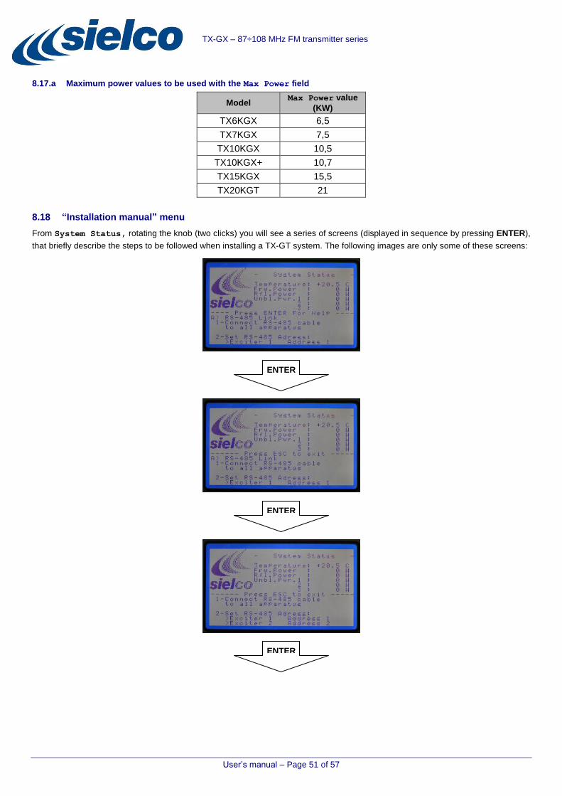
User’s manual – Page 51 of 57
TX-GX – 87÷108 MHz FM transmitter series
8.17.a Maximum power values to be used with the Max Power field
Model Max Power value
(KW)
TX6KGX 6,5
TX7KGX 7,5
TX10KGX 10,5
TX10KGX+ 10,7
TX15KGX 15,5
TX20KGT 21
8.18 “Installation manual” menu
From System Status, rotating the knob (two clicks) you will see a series of screens (displayed in sequence by pressing ENTER),
that briefly describe the steps to be followed when installing a TX-GT system. The following images are only some of these screens:
ENTER
ENTER
ENTER
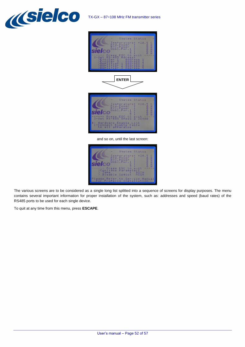
User’s manual – Page 52 of 57
TX-GX – 87÷108 MHz FM transmitter series
and so on, until the last screen:
The various screens are to be considered as a single long list splitted into a sequence of screens for display purposes. The menu
contains several important information for proper installation of the system, such as: addresses and speed (baud rates) of the
RS485 ports to be used for each single device.
To quit at any time from this menu, press ESCAPE.
ENTER

User’s manual – Page 53 of 57
TX-GX – 87÷108 MHz FM transmitter series
8.19 Menus diagram
STARTUP
SCREENSHOTS
DEFAULT
SCREENSHOT
BASIC CONTROLS To access the first menu (System Status) from the default screen, press
ENTER *.
To select a menu, turn the knob (two clicks to access the next menu)
To exit a menu during setting activities press (usually) ESCAPE
To return to System Status (first menu) from any menu, press ESCAPE
* “Press ENTER” means “Press the knob”
NOTE 1. After about one minute of inactivity (no command by turning the knob or
pressing ENTER or ESCAPE), the display automatically displays the Default screen.
2. This diagram is relevant to a system with three amplifiers + Dual Drive option. According to your system, and/or to the installed options, some menus may be not shown.
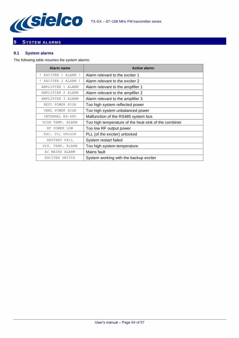
User’s manual – Page 54 of 57
TX-GX – 87÷108 MHz FM transmitter series
9 SYSTEM ALARMS
9.1 System alarms
The following table resumes the system alarms:
Alarm name Active alarm:
! EXCITER 1 ALARM ! Alarm relevant to the exciter 1
! EXCITER 2 ALARM ! Alarm relevant to the exciter 2
AMPLIFIER 1 ALARM Alarm relevant to the amplifier 1
AMPLIFIER 2 ALARM Alarm relevant to the amplifier 2
AMPLIFIER 3 ALARM Alarm relevant to the amplifier 3
REFL POWER HIGH Too high system reflected power
UNBL POWER HIGH Too high system unbalanced power
INTERNAL RS-485 Malfunction of the RS485 system bus
HIGH TEMP. ALARM Too high temperature of the heat sink of the combiner
RF POWER LOW Too low RF output power
EXC. PLL UNLOCK PLL (of the exciter) unlocked
RESTART FAIL System restart failed
SYS. TEMP. ALARM Too high system temperature
AC MAINS ALARM Mains fault
EXCITER SWITCH System working with the backup exciter

User’s manual – Page 55 of 57
TX-GX – 87÷108 MHz FM transmitter series
10 MAINTENANCE AND WARRANTY
10.1 Maintenance
Strictly follow the instructions outlined in this section
10.1.a Clogging caused by dust
Since the transmitter is air cooled, it is subject to clogging caused by dust. Because of the high-quality materials used in its
manufacture, if it is installed as set forth according to the instructions in Chapter 5, it will not require special maintenance for quite
some time.
A regular service routine, mainly to remove internal dust, is recommended every 6 months to one year at the most.
10.1.b Ventilation fans
It is advisable to check the proper functioning of all the fans in the system (the main one installed on the top of the rack and those
mounted in each module) and provide immediate replacement if there is a sudden increase in noise, damage of operation or
performance degradation.
Insufficient maintenance could result in a shutdown of a module or even of the entire system.
It is advisable ordering new impellers of the ventilation systems every 2 years, always with models of the same type of good quality
and mounted on ball bearings.
10.1.c Periodic overhaul
After a few years of continuous service, it is advisable to have the system overhauled in our factory or in a specialized Sielco Srl
laboratory, where its characteristics can be checked against the initial parameters. If necessary, at this time regular maintenance
operations can also be carried out.
Never modify the original settings without utilizing the proper testing equipment and standard procedures, and without having
received authorization by Sielco Srl or an authorized representative.
10.1.d Maintenance
In order to avoid any risk of electric shock or damage to the equipment, do not disconnect or modify the protective devices of the
system during maintenance operations.
10.2 Warranty
Like all Sielco Srl solid-state equipment, this transmitter carries a one-year warranty on all its components, with the exception of the
final RF power modules, which may be damaged by faulty output connections.
Notes:
The warranty will become null and void if a device is tampered or if the failure is due to improper use or maintenance, or external causes such as a mains over-voltage.
The warranty is valid when only original spare parts have been used and when the intervention have been carried out by Sielco Srl authorized personnel.
Products shall be delivered to the laboratory carriage prepaid, and will be returned by freight forward.
The warranty doesn’t cover any indirect damage caused by non-operation or faulty operation.

User’s manual – Page 56 of 57
TX-GX – 87÷108 MHz FM transmitter series
11 INDEX
Alarms; 55
Antenna; 32
Buttons ESCAPE; 23; 35
ON/STAND-BY; 23
Commands ENTER; 36
knob; 35
Daily power reduction; 44
Declaration of conformity; 58
Dual Drive option; 27
General safety rules; 31
GSM connection status; 46
Indicators ALARM; 23
GSM; 23
ON; 23
STAND-BY; 23
Installation; 31 choosing the proper room and
placement; 31
connection to modulation signals; 32
connections with the outside; 27
electrical conditions; 31
RS485 system bus; 33
wiring into the antenna; 32
wiring into the mains; 32
Introduction; 5
Knob; 35
Mains; 32
Maintenance; 56
Menu Amplifier 1 Status; 40
Amplifier 2 Status; 40
Amplifier 3 Status; 40
commands; 35
common features; 36
Default screen; 37
Diagram; 54
Dual Drive Status; 41
Exciter Status; 41
GSM Status; 46
initial startup; 34
installation manual; 52
Password; 49
Set Amplifier Power; 38
Set Frequency; 39
SMS Numbers; 48
SMS Settings; 45
System Alarms; 43
System Setup; 51
System Status; 37
Temporal Power Reduction; 44
Menus diagram; 54
Modulation; 32
Multifunction knob; 35
Passwords; 49
Safety; 6
SMS; 45
SMS numbers; 48
Symbols; 10
System alarms; 55
System base parameters; 51
Technical specifications; 28
TX-GT modules amplifier; 27
combiner; 25
Dual Drive option; 27
exciter; 26
main power panel; 26
TX-GT modules control unit; 22
TX-GT systems architecture; 12
block diagram; 13
configurations; 16
front views; 16
general description; 12
general interconnection diagram; 14
wiring; 15
Warning symbols; 10
Warnings; 8
Warranty; 56
Wiring; 15

Sede Operativa Via Toscana, 57/59 - 20090 - Buccinasco (MI) Tel. +39-02-45713300 Fax +39-02-45713351 e-mail: [email protected] www.sielco.org
TX-GX – 87÷108 MHz FM transmitter series
12 CE CONFORMITY DECLARATION
In fulfillment of the official provisions:
2006/95/CE (Low Voltage)
2004/108/CE, 92/31/CEE (Electromagnetic Compatibility)
1999/05/CE (R&TTE)
We hereby declare, under our responsibility, that the products:
Compact Transmitters Series:
- EXC5GT
- EXC10GT
- EXC25GT
- EXC30GT
- EXC50GX
- EXC100GX
- EXC150GX
- EXC250GX
- EXC300GX
- EXC500GX
- EXC1000GX
- EXC1500GX
- EXC2000GX
- EXC3000GX
- EXC3500GX
- EXC5000GX
Amplifiers Series:
- RFB500GX
- RFB1000GX
- RFB1500GX
- RFB2000GX
- RFB3000GX
- RFB3500GX
- RFB5000GX
Combined Transmitters Series:
- TX250GX
- TX300GX
- TX500GX
- TX700GX
- TX1000GX
- TX1500GX
- TX2000GX
- TX3000GX
- TX3500GX
- TX5000GX
- TX6KGX
- TX7KGX
- TX10KGX
- TX10KGX+
- TX15KGX
- TX20KGX
Conforms to the basic series of Radio tests (art. 3.2 1999/05/CE) defined inside the Technical Standard:
ETSI EN 302 018-2 V 1.2.1 (2006-03) - (Radio) ed alla ETSI EN 301 511 V 9.0.2 (2003-03) - (GSM)
Conforms with the Specific Technical Standard:
ETSI EN 301 489-1 v 1.9.2 (2011-09); ETSI EN 301 489-11 v 1.3.1 (2006-05);
ETSI EN 301 489-7 v 1.3.1 (2005-11)-(EMC)
EN 62311 (2008)
EN 60215:89 +A1:92 + A2: 94 (Low Voltage)
Notified Body: NEMKO AS identification number: 0470
Buccinasco, 12/02/2015