nv5lt/nv3.5lt transmitter
219
4: TROUBLESHOOTING MANUAL NV5LT/NV3.5LT TRANSMITTER Document ID: NHB-NV3.5LT-NV5LT-TRB Version: 5.0 Issue Date: 2021-03-01 Status: Standard Making Digital Radio Work
-
Upload
khangminh22 -
Category
Documents
-
view
3 -
download
0
Transcript of nv5lt/nv3.5lt transmitter

4: TROUBLESHOOTING MANUAL
NV5LT/NV3.5LTTRANSMITTER
Document ID: NHB-NV3.5LT-NV5LT-TRBVersion: 5.0 Issue Date: 2021-03-01Status: Standard
Making Digital Radio Work


VERSION 5.0 2021-03-01 PAGE III
NV5LT/NV3.5LT TROUBLESHOOTING MANUAL
Contact Information
Nautel Limited10089 Peggy’s Cove RoadHackett’s Cove, NS Canada B3Z 3J4
Toll Free: +1.877.6NAUTEL (662.8835) (Canada & USA only) or
Phone: +1.902.823.3900 orFax: +1.902.823.3183
Nautel Inc. 201 Target Industrial Circle Bangor, Maine USA 04401
Phone: +1.207.947.8200 Fax: +1.207.947.3693
Customer Service (24-hour support) +1.877.628.8353 (Canada & USA only)+1.902.823.5100 (International)
Email: [email protected]: www.nautel.com
The comparisons and other information provided in this document have been prepared in good faith based on publicly available information. For verification of materials, the reader is encouraged to consult the respective manufacturer's most recent publication on the official website or through contact with Customer Service.
© Copyright 2021 NAUTEL. All rights reserved.


NV5LT/NV3.5LT TROUBLESHOOTING MANUAL TABLE OF CONTENTS
VERSION 5.0 2021-03-01 PAGE 4.V
CONTENTS
Contact Information 4.iii
RELEASE CONTROL RECORD 4.vii
Responding to alarms 4.1.1
Corrective Maintenance 4.1.1Electrostatic Protection 4.1.3Identifying an Alarm 4.1.4Accessing the Inside of the Transmitter 4.1.28Troubleshooting Tips 4.1.30Replacement Procedures 4.1.40RF Power Module Replacement 4.1.41Troubleshooting RF Power Modules 4.1.43LVPS Module Replacement 4.1.47Power Supply Module Replacement 4.1.49Remote Interface PWB Replacement 4.1.51Fan Tray Cooling Fan Replacement 4.1.53Reject Load Replacement 4.1.55Controller Replacement 4.1.57Single-Board Computer (SBC) Replacement 4.1.59Controller PWB Replacement - Controller 4.1.62Exciter Replacement 4.1.64Exciter/Control PWB Replacement - Exciter 4.1.66Module Control/Interface PWB Replacement 4.1.69Power Supply Interface PWB Replacement 4.1.71

NV5LT/NV3.5LT TROUBLESHOOTING MANUAL TABLE OF CONTENTS
PAGE 4.VI VERSION 5.0 2021-03-01
Parts Lists 4.2.1
Family Tree 4.2.1How to Locate Information About a Specific Part 4.2.1Column Content 4.2.2OEM Code to Manufacturers Cross-Reference 4.2.4Common Abbreviations/Acronyms 4.2.4
Wiring/connector lists 4.3.1
Wiring Lists Provided 4.3.1Wiring Lists Not Provided 4.3.1Connector Mating Information 4.3.1Wire Colours 4.3.1Printed Wiring Board Patterns 4.3.1
Reading Electrical Schematics 4.4.1
Component Values 4.4.1Graphic and Logic Symbols 4.4.1Reference Designations 4.4.1Unique Symbols 4.4.2Identifying Schematic Diagrams 4.4.2Structure of Schematics 4.4.3Locating Schematic Diagram(s) for a Functional Block 4.4.3Locating a Part or Assembly on a Schematic 4.4.4
Mechanical Drawings 4.5.1
Identifying Mechanical Drawings 4.5.1Content of Mechanical Drawings 4.5.1Locating a Part or Assembly on a Mechanical Drawing 4.5.2
List of terms 4.6.1

NV5LT/NV3.5LT TROUBLESHOOTING MANUAL
VERSION 5.0 2021-03-01 PAGE 4.VII
RELEASE CONTROL RECORD
ISSUE DATE REASON
5.0 2021-03-01 Release 5 of NV5LT/NV3.5LT (NARF71D/01). Supports software version NVLT SW 4.4 and newer.

NV5LT/NV3.5LT TROUBLESHOOTING MANUAL
PAGE 4.VIII VERSION 5.0 2021-03-01

NV5LT/NV3.5LT TROUBLESHOOTING MANUAL RESPONDING TO ALARMS
VERSION 5.0 2021-03-01 PAGE 4.1.1
SECTION 4.1: RESPONDING TO ALARMS
This section provides instructions you need when performing troubleshooting on the NV5LT/NV3.5LT transmitter. This section includes the following topics:
Corrective Maintenance
Electrostatic Protection - see page 4.1.3
Identifying an Alarm - see page 4.1.4
Accessing the Inside of the Transmitter - see page 4.1.28
Troubleshooting Tips - see page 4.1.30
Replacement Procedures - see page 4.1.41
If none of the procedures and alarms described in this section address your problem, contact Nautel for assistance. See “Technical Support” in the Pre-Installation Manual.
Corrective Maintenance
Corrective maintenance procedures consist of identifying and correcting defects or deficiencies that arise during transmitter operation. Local and/or remote alarm signals are generated when a malfunction occurs. If an alarm condition is caused by a malfunction in the RF power stage, the transmitter may maintain operation at a reduced RF output level. The nature of the fault – and station policy – will dictate whether an immediate maintenance response is necessary. Fault analysis and rectification may be conducted from three different levels, with a different technical competence level required for each: on-air troubleshooting, remote or local, and off-air troubleshooting.
On-Air Troubleshooting
On-air troubleshooting can be performed from a remote location, or locally at the transmitter site.
CAUTION! The transmitter contains many solid state devices that may be damaged if subjected to excessive heat or high voltage transients. Take every effort to ensure that circuits are not overdriven or disconnected from their loads while turned on.

NV5LT/NV3.5LT TROUBLESHOOTING MANUAL RESPONDING TO ALARMS
PAGE 4.1.2 VERSION 5.0 2021-03-01
Remote Troubleshooting
Remote on-air troubleshooting consists of monitoring the transmitter's radiated signal using an on-air monitor or via a LAN connection, and observing the status of each remote fault alarm indicator. Information obtained from these sources should enable an operator to decide whether an alarm response may be deferred to a more convenient time, an immediate corrective action must be taken, or if a standby transmitter must be enabled (if one is available). It is recommended that the significance of remote indications, and the appropriate responses, be incorporated into a station's standard operating procedures. Refer to “Identifying an Alarm” on page 4.1.4 to determine the remedial action required for a given fault.
Local Troubleshooting
Local on-air troubleshooting consists of monitoring the transmitter's integral meters and fault alarm indicators. Analysis of this data will normally identify the type of fault, and in most cases will determine what corrective action must be taken. Refer to “Identifying an Alarm” on page 4.1.4 to determine the remedial action required for a given fault.
The power amplifier stage contains an integral modular reserve (IMR) feature. This feature permits the transmitter to operate at a reduced RF output level when a malfunction occurs in one of its power modules. Station operating procedures will dictate whether a reduced RF output level is acceptable. When a reduced RF output level can be tolerated, replacement of the defective RF power module may be deferred to a convenient time.
A defective RF power module may be removed from the transmitter for servicing, while the transmitter is operating, provided that the conditions in the removal instructions detailed in “Removing an RF Power Module” on page 4.1.42 are met.
Off-Air Troubleshooting
Off-air troubleshooting must be performed when the replacement of a defective RF power amplifier module, or routine on-air calibration adjustments, will not restore operation.
It is recommended that the transmitter’s output be connected to a precision 50 resistive dummy load (rated for at least the maximum transmitter power rating) before starting off-air troubleshooting procedures. If an appropriate dummy load is not available, troubleshooting for a majority of faults can be performed with RF power stage turned off. The transmitter may remain connected to its antenna system for these procedures.
NOTE: Reduce the RF output level to a minimal value when troubleshooting faults in the power amplifier stage while the transmitter’s RF output is connected to the antenna system.

NV5LT/NV3.5LT TROUBLESHOOTING MANUAL RESPONDING TO ALARMS
VERSION 5.0 2021-03-01 PAGE 4.1.3
Electrostatic Protection
The transmitter's assemblies contain semiconductor devices that are susceptible to damage from electrostatic discharge. The following precautions must be observed when handling an assembly which contains these devices.
Electrical Discharging of Personnel
Personnel should be electrically discharged by a suitable grounding system (e.g., anti-static mats, grounding straps) when removing an assembly from the transmitter, and while handling the assembly for maintenance procedures.
Handling/Storage
An assembly should be placed in an anti-static bag when it is not installed in a host transmitter, or when it is not undergoing maintenance. Electronic components should be stored in anti-static materials.
Tools/Test Equipment
Testing and maintenance equipment – including soldering and unsoldering tools – should be suitable (i.e., grounded tip) for contact with static sensitive semiconductor devices.
Stress Current Protection
Every precaution should be taken to ensure the static sensitive semiconductor devices are protected from unnecessary stress current. This is achieved by ensuring that current is not flowing when an electrical connection is broken, and that voltages are not present on external control/monitoring circuits when they are connected.
CAUTION! Electrostatic energy is produced when two insulating materials are rubbed together. A person wearing rubber-soled shoes, walking across a nylon carpet or a waxed floor, can generate an extremely large electrostatic charge. This effect is magnified during periods of low humidity. Semiconductor devices such as integrated circuits, field-effect transistors, thyristors and Schottky diodes may be damaged by this high voltage unless adequate precautions are taken.

NV5LT/NV3.5LT TROUBLESHOOTING MANUAL RESPONDING TO ALARMS
PAGE 4.1.4 VERSION 5.0 2021-03-01
Identifying an Alarm
You can identify an alarm locally by viewing the front panel (see “Front Panel Alarm Checks”) or remotely by viewing the AUI’s Transmitter Status page (see “Controller/Exciter Front Panel Alarm Checks” on page 4.1.6).
Front Panel Alarm Checks
There two ways to check for alarms on the front panel:
Alarm/Status LEDs
View Alarms Screen - see page 4.1.5
Alarm/Status LEDs
There are four LEDs on the left-hand side of the LCD display that provide information about the operational status of various sections of the transmitter - Exciter, Power Amplifier, Output Network and Power Supply (see Figure 4.1.1). The LEDs can glow green, amber or red. Typically, green indicates normal operation, amber indicates a warning, and red indicates a fault or error.
Figure 4.1.1: Alarm/Status LEDs
When an LED is:
Green - transmitter is on, with no known faults.
Amber - a fault is present that may cause a reduction in RF power, but the transmitter is still producing RF power.
Red - a fault is present and the transmitter is not producing RF power.
When a fault is present, the transmitter may still produce an RF output. In this case, or if the transmitter has shut down, you should schedule and commence more in-depth fault diagnosis. See “View Alarms Screen” on page 4.1.5.
ExciterPower AmplifierOutput Network
Power Supply

NV5LT/NV3.5LT TROUBLESHOOTING MANUAL RESPONDING TO ALARMS
VERSION 5.0 2021-03-01 PAGE 4.1.5
View Alarms Screen
If an alarm exists and is currently being recognized by the transmitter system, it is displayed in the View Alarms screen (Main Menu -> View Status -> View Alarms) of the front panel Display (see Figure 4.1.2).
Figure 4.1.2: View Alarms Screen
1. Scroll through the View Alarms screen to view the active faults.
2. Attempt to clear any latching alarms by pressing the checkmark button in the Main Menu ->Reset Alarms screen. If the alarm persists, it will not clear from the display.
3. Locate the alarm name in Table 4.1.1 on page 4.1.9 to determine the cause of the alarm andperform any recommended procedures in the Description and Troubleshooting Action column.This may also lead to replacing a suspect PWB, power supply or fan, as detailed in “ReplacementProcedures” on page 4.1.41.
NOTE: Before undertaking any troubleshooting, record all meter readings and note if any other alarms are displayed on the View Alarms page. Record all alarms.
NOTE: Table 4.1.1 on page 4.1.9 contains a column for most Alarms that can occur, sorted alphanumerically for each sub-system, including both the names displayed on the AUI and, if different, the front panel UI (in parentheses). The Description and Troubleshooting Action column provides a brief description of the alarm, troubleshooting tips and a cross-reference to more detailed troubleshooting, as applicable.
4. If troubleshooting and subsequent replacement of a suspect PWB or module causes the alarm todisappear from the View Alarms screen, the alarm has been successfully cleared. If the faultcondition does not clear, contact Nautel.

NV5LT/NV3.5LT TROUBLESHOOTING MANUAL RESPONDING TO ALARMS
PAGE 4.1.6 VERSION 5.0 2021-03-01
Controller/Exciter Front Panel Alarm Checks
There are two LEDs on the left-hand side of the Controller/Exciter that provide information about its operational status - Power and Status (see Figure 4.1.3). The Power LED will illuminate green when a valid LVPS input voltage is applied to the A2J1 connector and +5V is present to power the LED. The tri-color Status LED can be green, amber or red and be solid or blinking.
When the Status LED is:
Green (solid) - controller/exciter is operational, with no known faults
Amber (solid) - controlled inhibit
Red (solid) - inhibiting fault
Green/Amber (blinking) - controller/exciter is operational with non-critical faults
Green/Red (blinking) - controller/exciter is operational with critical faults
Amber/Red (blinking) - inhibiting fault (latching)
Figure 4.1.3: Controller/Exciter Front Panel

NV5LT/NV3.5LT TROUBLESHOOTING MANUAL RESPONDING TO ALARMS
VERSION 5.0 2021-03-01 PAGE 4.1.7
AUI Transmitter Status Page Checks
If an alarm exists and is being recognized by the transmitter (i.e., the Status button at the bottom of the AUI display will be red), it is displayed on the transmitter status page (see Figure 4.1.4). The Device name indicates the sub-system origin of the alarm. The sub-systems that can be displayed are:
Controller: All alarms in this sub-system apply to the controller.
Exciter A or B: All alarms in this sub-system apply to an exciter (A or B).
Rack #: All alarms in this sub-system apply to a rack (cabinet) (only 1 for NV5LT/NV3.5LT)
RF Module #: All alarms in this sub-system apply to a specific RF power module (1 through 2)
Figure 4.1.4: Transmitter Status Page
1. Click the Status button to go to the Transmitter Status page (see Figure 4.1.4). View the list ofactive faults. Alarms are listed by their origin (Device column), then by name (Alarm column), andthen by severity (Level column) [single orange ! indicates low severity (RF output not affected);single red ! indicates medium severity (RF output is reduced); two red ! indicates high severity (RFoutput is inhibited)].

NV5LT/NV3.5LT TROUBLESHOOTING MANUAL RESPONDING TO ALARMS
PAGE 4.1.8 VERSION 5.0 2021-03-01
2. Attempt to clear any latching alarms by pressing the Reset button on the bottom banner of the page. If the alarm persists, it will not be cleared from the display.
3. Locate the alarm name in Table 4.1.1 on page 4.1.9 to determine the cause of the alarm and perform any recommended procedures in the Description and Troubleshooting Action column. This may also lead to replacing a suspect PWB, power supply or fan, as detailed in “Replacement Procedures” on page 4.1.41.
NOTE: Table 4.1.1 on page 4.1.9 contains a column for most Alarms that can occur, sorted alphanumerically for each sub-system (e.g., Controller, Rack, etc.), including both the names displayed on the AUI and, if different, the front panel UI (in parentheses). The Description and Troubleshooting Action column provides a brief description of the alarm, troubleshooting tips and a cross-reference to more detailed troubleshooting, as applicable. The Front Panel LED (color) column gives a brief description of the severity of the alarm recorded by the Controller/Exciter. Green indicated operational with no faults, Amber indicates a non-critical fault and Red indicates an inhibiting fault.
4. If troubleshooting and subsequent replacement of a suspect PWB or module causes the alarm to disappear from the Transmitter Status page, the alarm has been successfully cleared. If the fault condition does not clear, contact Nautel.
NOTE: Before undertaking any troubleshooting, record all AUI meter readings and note if any other alarms are displayed on the Transmitter Status page. Record all alarms. The most convenient way to do this is by using a web browser over a LAN connection to save screen shots of critical status, meter and alarm pages. From the Meter List View page, press the information (i) button for each sub-device (Controller, Exciter, Rack and Modules) to view (and save) detailed information (see “Viewing Real-Time Meters - AUI” on page 3.2.40 of the Operations and Maintenance Manual).

NV5LT/NV3.5LT TROUBLESHOOTING MANUAL RESPONDING TO ALARMS
VERSION 5.0 2021-03-01 PAGE 4.1.9
Table 4.1.1: Troubleshooting Alarms
Device and Alarm Name (AUI, UI)
Front Panel LED (color) Description and Troubleshooting Action
Controller: AC Summary
PS (red) Not displayed in AUI or UI status. Configurable as a remote output. This alarms occurs if there are any ac input related alarms present. Check for other specific ac fault alarms.
Controller: All PAs Inactive
Power Amplifier (red) This alarm indicates that all of the transmitter’s power amplifiers are inactive due to external conditions such as ac loss, removal of power supply modules or RF power modules, or faults in the power supply modules or RF power modules. If there are power supply module or RF power module related alarms present, follow the associated troubleshooting procedure.
Controller: Audio Loss Summary
Exciter (red) Not displayed in AUI or UI status. Configurable as a remote output. This alarms occurs if there are any audio loss alarms present. Check for specific audio loss alarms and troubleshoot accordingly. Ensure the preset audio settings agree with the audio being applied to the exciter.
Controller: Auto Changeover Occurred (Auto Changeover)
Exciter (amber) This alarm occurs when the controller has initiated an exciter changeover to the standby exciter, due to a possible fault with the main exciter.
Controller: Changeover in Progress (In Changeover)
Exciter (red) This alarm occurs only while an exciter changeover is in progress. It will clear once the changeover is complete.
Controller: Combiner Match
Output Network (red) This alarm occurs if there is an excessive amount of power in the transmitter combining stage that cannot be accounted for. This may be the result of a fault in the combiner.
Controller: Config File Not Found (Cfg File Not Found)
Exciter (red) This alarm occurs when the controller does not find a valid configuration file to load at power-up. This alarm is unlikely, but may occur during replacement of a controller module. It clears when the correct settings are entered.
Controller: CPLD Version Mismatch (CPLD Ver Mismatch)
Exciter (red) This alarm occurs when there is an incompatible software release in the controller module’s CPLD. Update the software to clear the fault.
Controller: Current Imbalance
Output Network (red) This alarm occurs if the Combiner Match alarm occurs due to a PA current imbalance in the RF power modules

NV5LT/NV3.5LT TROUBLESHOOTING MANUAL RESPONDING TO ALARMS
PAGE 4.1.10 VERSION 5.0 2021-03-01
Controller: Cutback Active
Output Network (amber)
This alarm occurs whenever the transmitter experiences a cutback. A cutback (reduction in power) occurs when repeated shutback alarms occur within a prescribed time period. Shutbacks occur when the transmitter's peak reflected power exceeds 2:1 due to a transient SWR condition (arc or lightning) within the output transmission line or antenna system. The transmitter shuts back and recovers to a series of cutback levels (depending on the severity of the alarm), with each level being a 15% reduction in power from the power attained before the last shutback. Inspect the output transmission line for punctures or damage. After repairing damage, or if no damage is found, attempt to reset the latched condition.
Controller: Digital Player Audio Low
Exciter (red) This alarms occurs if the audio player is in use on the host, but no digital audio is detected by the controller.
Controller: Discharging PA Volts (Discharging PA V)
PS (red) This alarm occurs when the transmitter has initiated a shutback sequence, and residual PA voltage energy stored in the capacitors in the power supplies and PAs is being discharged. During a shutback sequence, the RF drive to the PAs is turned off immediately after the event, and this occurs faster than the power supply modules can be inhibited. Therefore, PA voltage is still being applied to the capacitors with no drive to discharge the energy. To discharge the stored energy from the capacitors, the PA bias is increased to a discharge level after the power supplies have been inhibited. This causes the stored energy to be dissipated through dc current in the FET. This alarm should only occur with a Residual PA Volts Present alarm. See Residual PA Volts Present alarm for more information.
Controller: Entered Firmware Upgrade (Entr Firmware Upgr)
Exciter (red) This alarm occurs when the transmitter is in “firmware upgrade” mode. It should only be displayed during a transmitter software upgrade.
Controller: Exciter Audio Reset
Exciter (red) This alarm occurs if the audio processing within the exciter required a reset. if this alarm is re-occurring, replace the controller (see “Controller Replacement” on page 4.1.56).
Controller: Exciter A (or B) Offline
Exciter (red) This alarm occurs if the serial communication fails between the controller and the associated exciter, or a problem has occurred with the associated exciter. Check all connections to the exciter and make sure that its front panel power LED is on.
Controller: Exciter Summary
Exciter (amber) Not displayed in AUI or UI status. Configurable as a remote output. This alarm occurs if there are any exciter related alarms present. Check for specific exciter related alarms.
Device and Alarm Name (AUI, UI)
Front Panel LED (color) Description and Troubleshooting Action

NV5LT/NV3.5LT TROUBLESHOOTING MANUAL RESPONDING TO ALARMS
VERSION 5.0 2021-03-01 PAGE 4.1.11
Controller: External Interlock Open (External Interlock)
Exciter (red) The external interlock input wired to the controller (A4) or optional remote interface PWB (A16), if used, is open. Check the interlock connection between REMOTE I/O-A pins 19 and 20 on the controller (verify a ground potential at pin 19) or optional remote interface PWB J2 pins 19 and 20 or TB1-1 and 2. If the interlock is intact, check all external interlock switches. Otherwise, suspect a problem with the interlock circuitry on the controller or optional remote interface PWB.
Controller: External Summary
- Not displayed in AUI or UI status. Configurable as a remote output. This alarm occurs if there are any external related alarms present. Check for specific external related alarms and troubleshoot accordingly.
Controller: Forward Power Limiting (Fwd Power Limiting)
Output Network (amber)
When the High Forward Power alarm is active, this alarm occurs if the high forward power limiting threshold is exceeded [1.063 times the maximum power setting for all modes; e.g., 5,846 W (NV5LT) or 4,384 W (NV3.5LT) for FM mode]. The transmitter will fold back the forward power each time the threshold is exceeded. This alarm occurs only if the exciter ALC cannot respond fast enough to transmitter load changes. Suspect the module control/interface PWB (A3).
Controller: Forward Power Shutdown (Fwd Power Shutdown)
Output Network (red) This alarm occurs if the transmitter tries to reduce the forward power below minimum due to repeated Forward Power Limiting alarms. The transmitter latches off. See Controller: Forward Power Limiting for troubleshooting tips.
Controller: High Forward Power (High Fwd Power)
Output Network (amber)
This alarm occurs if the transmitter’s average forward power exceeds the high forward power threshold [1.036 times the maximum power setting for all modes; e.g., 5,698 W (NV5LT) or 4,274 W (NV3.5LT) for FM mode]. This alarm occurs only if the exciter ALC cannot respond fast enough to transmitter load changes. Suspect the module control/interface PWB (A3).
Controller: High Reflected Summary
Output Network (amber)
Not displayed in AUI or UI status. Configurable as a remote output. This alarm occurs if there are alarms present that are related to high reflected power on the transmitter’s RF output. Check for specific reflected power related alarms and troubleshoot accordingly.
Controller: High Reject Power (High Reject)
Output Network (amber)
This alarm occurs if any of the transmitter’s reject loads’ average power exceeds the high reject power threshold (1200 W). Typically, high reject power is a result of RF power module failure or removal.
Controller: High RF Drive
Exciter (red) This alarm occurs if the RF drive power from the exciter is greater than the high threshold (45% above the setpoint). This may be the result of a calibration problem with either the exciter or the transmitter RF drive sample. Check all connections to the exciter.
Device and Alarm Name (AUI, UI)
Front Panel LED (color) Description and Troubleshooting Action

NV5LT/NV3.5LT TROUBLESHOOTING MANUAL RESPONDING TO ALARMS
PAGE 4.1.12 VERSION 5.0 2021-03-01
Controller: High Splitter Temperature (High Splitter Temp)
Exciter (amber) This alarm occurs if the temperature sensed by the RF drive splitter (A7) exceeds 75°C (167°F). The temperature typically increases due to PA failures or RF module removal, but may also be the result of a blockage or a failure of the reject fans. Check the reject load’s associated fan tray and replace fan(s) if necessary (see “Fan Tray Cooling Fan Replacement” on page 4.1.52).
Controller: High SWR Output Network (amber)
This alarm occurs if the transmitter's average reflected power exceeds the high SWR threshold (140 W). The NV5LT/NV3.5LT takes no action. Inspect the antenna and transmission line system for damage or de-tuning.
Controller: High SWR Shutdown
Output Network (red) This alarm occurs if the transmitter tries to reduce the forward power below a level that is equivalent to a 3:1 VSWR (user-configurable) at the SWR Foldback threshold due to a gradually degrading load match. This alarm causes the transmitter to latch off. Inspect the antenna and transmission line system for damage or de-tuning.
Controller: High Temperature Summary
- Not displayed in AUI or UI status. Configurable as a remote output. This alarm occurs if there are high temperature related alarms occurring. Check for specific temperature related alarms and troubleshoot accordingly.
Controller: Host Network Down
Exciter (amber) This alarm indicates that the microcontroller that runs the remote interfacing applications is unable to acquire an IP address. When this alarm is present, it will not be possible to access any remote AUI functionality. Check that the Ethernet cable is properly connected to A1J8A (LAN) on the rear of the transmitter. If the alarm is still present see “Network Setup” on page 3.2.86 of the Operations and Maintenance Manuals for information on setting up the network connection. Disable the alarm by setting DHCP to OFF and setting the IP Address to all zeroes (i.e. 0.0.0.0).
Controller: Host Not Booted
Exciter (amber) This alarm indicates that the controller’s host has not finished booting. The remote AUI will not yet be available. This alarm normally occurs with an ac loss or software upgrade. It will clear when the host completes booting.
Controller: Host Not Responding
Exciter (red) This alarm indicates that the controller’s host is not communicating with the rest of the transmitter. If the watchdog function is enabled, the DSP will automatically reset the host. If this alarm persists, the controller may require reprogramming or replacement. If necessary, replace the exciter/control PWB (A4A1) (see “Exciter/Control PWB Replacement - Controller” on page 4.1.58).
Controller: Local UI Failure (UI Failure)
Exciter (red) This alarm occurs if there is a fault with the LCD user interface (UI), preventing it from being used to control the transmitter. The transmitter will automatically switch to remote control mode to allow use of the AUI or digital I/O.
Device and Alarm Name (AUI, UI)
Front Panel LED (color) Description and Troubleshooting Action

NV5LT/NV3.5LT TROUBLESHOOTING MANUAL RESPONDING TO ALARMS
VERSION 5.0 2021-03-01 PAGE 4.1.13
Controller: Low AC Operation
Power Supply (red) This alarm occurs if the ac input voltage is less than 175 V ac, but greater than 90 V ac. Transmitter RF output power will be limited to approximately 33% of maximum power or to the current setpoint, whichever is less.
Controller: Low Battery
Exciter (amber) This alarm occurs if the backup battery voltage falls below an acceptable level (2.7 V). The NV5LT/NV3.5LT takes no action on this alarm. Use a digital multimeter to measure the battery voltage (with ac power on). If the battery voltage is low, replace the battery. If battery voltage is OK, cycle ac power (off, then on). If the alarm does not clear, suspect the exciter/control PWB (A1).
Controller: Low Battery/Memory Summary
Power Supply (red) Not displayed in AUI or UI status. Configurable as a remote output. This alarm occurs if there is a specific battery or memory related alarm present. Check for specific alarms and troubleshoot accordingly.
Controller: Low Efficiency
Output network (amber)
This alarm occurs in conjunction with the Combiner Match alarm to indicate that the transmitter is exhibiting low Dc-RF efficiency.
Controller: Low Forward Power (Low Fwd Power)
Output Network (amber)
This alarm occurs if the transmitter’s average forward power is below the low forward power threshold (defaulted to 50% of the setpoint and is user adjustable). Check for associated alarms and follow the associated troubleshooting procedure, if applicable.
Controller: Low RF Drive
Exciter (red) This alarm occurs if the RF drive power from the exciter is less than the low threshold (70% of the setpoint). This may be the result of a calibration problem with either the exciter or the transmitter RF drive sample. Check all connections to the exciter. Check the RF drive connection between the exciter RF output and the RF drive splitter input.
Controller: LVPS Fail Power Supply (red) This alarm occurs if the LVPS voltage is less than 36 V or greater than 53 V. This may be a result of an ac power failure or an LVPS fault. Check the dc output voltage of the suspect LVPS. If the dc voltage is out of tolerance, replace the LVPS module (see “LVPS / Power Supply Module Replacement” on page 4.1.48). If the dc voltage is acceptable, suspect the controller.
Controller: LVPS Shutback
Power Supply (red) This alarm occurs if the LVPS voltage decreases below 36V while the transmitter is RF on. It will not clear until the LVPS voltage increases above 37V. This alarm triggers to turn off power to the fans to prevent power fluctuations that may cause lock ups on the module control/interface PWB. If the transmitter is connected to a UPS, the controller and remote AUI will still be accessible. Check all LVPS connections and the LED status on power supply modules.
Controller: Maintenance Required Summary
- Not displayed in AUI or UI status. Configurable as a remote output. Check for related alarms and troubleshoot accordingly.
Device and Alarm Name (AUI, UI)
Front Panel LED (color) Description and Troubleshooting Action

NV5LT/NV3.5LT TROUBLESHOOTING MANUAL RESPONDING TO ALARMS
PAGE 4.1.14 VERSION 5.0 2021-03-01
Controller: Missing Preset
Exciter (red) This alarm indicates that there are no presets programmed into the transmitter. In this state, the transmitter’s front panel UI will default to the first time startup screen (see Figure 2.9.1 on page 2.9.4 of the Installation Manual) and the user will not be able to enable RF without first programming a preset.
Controller: Mode/ Frequency Mismatch (Mode/Freq Mismatch)
Exciter (red) This alarm occurs if there is a mismatch between the operating mode or carrier frequency of the transmitter and one or more of the associated exciters. Suspect a possible communication problem between the controller and exciter(s). The alarm should clear once the transmitter transfers the preset settings to the exciter.
Controller: Off-Air Summary
- Not displayed in AUI or UI status. Configurable as a remote output. This alarm occurs if there are any alarms present that cause the transmitter to be in an RF off state. Check for associated alarms, and follow the associated troubleshooting procedure, if present.
Controller: Output Network Summary
Output Network (amber)
Not displayed in AUI or UI status. Configurable as a remote output. This alarm occurs if there are any alarms present that are related to the output network of the transmitter. Check for associated alarms, and follow the associated troubleshooting procedure, if present.
Controller: Overall Summary
- Not displayed in AUI or UI status. Configurable as a remote output. This alarm occurs if there are any controller related alarms present.Check for associated alarms, and follow the associated troubleshooting procedure, if present.
Controller: PA Pwr Foldback
Output Network (amber)
This alarm occurs if the control system determines that the calculated dissipation in any FET on a PA is above the high dissipation threshold (300 W), or the forward power being requested from an individual PA [calculated as output power - combiner losses] is greater than the PA output high threshold (850 W). The forward power of the transmitter will be limited to a level such that neither of these thresholds are exceeded. Check for associated alarms. Typically, the assertion of this alarm is the result of a PA failure or RF power module removal, or a high SWR condition.
Controller: Power Amplifier Summary (PA Summ)
- This alarm occurs if there are any alarms present that are related to the power amplifiers. Check for associated alarms, and follow the associated troubleshooting procedure, if present.
Controller: Power Discrepancy
Output Network (amber)
This alarm occurs in conjunction with the Combiner Match alarm to indicate unaccounted for RF power in the combiner.
Controller: Power Supply Summary
- Not displayed in AUI or UI status. Configurable as a remote output. This alarm occurs if there are any alarms present that are related to the power supplies. Check for associated alarms, and follow the associated troubleshooting procedure, if present.
Device and Alarm Name (AUI, UI)
Front Panel LED (color) Description and Troubleshooting Action

NV5LT/NV3.5LT TROUBLESHOOTING MANUAL RESPONDING TO ALARMS
VERSION 5.0 2021-03-01 PAGE 4.1.15
Controller: PS Current Foldback (PS Curr Foldback)
Power Supply (amber) This alarm occurs if the transmitter is limiting its output power to avoid drawing excessive current (48 A per supply) from the power supply modules. This may occur when there are PA failures and the transmitter is attempting to compensate to attain the setpoint level. Check for associated alarms, and follow the associated troubleshooting procedure if present.
Controller: Rack # Fault
Power Amplifier (red) This alarm indicates that a critical fault has occurred in the associated rack, resulting in the transmitter’s RF output being inhibited. Check for associated alarms to continue troubleshooting.
Controller: Rack # Not Responding (Rack # Offline)
Power Amplifier (red) This alarm occurs if serial communication is lost with the associated rack controller (module control/interface PWB). This will inhibit the transmitter’s RF output, since this connection is used for monitoring power and adjusting the PA voltage. Check all connections between the controller and the rack. If the alarm persists, suspect a fault with the associated rack’s controller (module control/interface PWB).
Controller: Rack Shutback
Power Amplifier (red) This alarm indicates a connection issue between the controller and the (rack) module control/interface PWB(s), such that the "shutback" signal is unavailable due to a hardware fault (typically, the 9-pin D-sub daisy-chain cable is disconnected). In addition, a "Rack # Not Responding" alarm will also be present to signify a communication loss between the controller and (rack) module control/interface PWB(s).
Controller: Rack 1 Sync Required
Power Amplifier (red) This alarm indicates that the Rack data for scale factors or transmitter type is out of sync with the Controller data. This condition is automatically resolved based on the controller's internal rules for transmitter type determination. This alarm will appear in the events log only, and the customer does not need to take any action.
Controller: Rebooted Exciter
Exciter (red) This is an informational only alarm that displays when the watchdog timer reboots the controller’s main microcontroller (DSP) or on an ac power interruption.
Controller: Reboot Required
Exciter (red) This alarm indicates that exciter setup changes have been made, typically via the System Settings page of the AUI. Typically, the DSP will reboot itself automatically; however, if this alarm persists for more than five minutes, cycle the transmitter’s ac power (off, then on) to store the changes.
Controller: Reduced Power Summary
Output Network (amber)
Not displayed in AUI or UI status. Configurable as a remote output. This alarm occurs if there are any alarms present that caused the transmitter’s RF output power to be reduced. Check for associated alarms, and follow the associated troubleshooting procedure, if present.
Device and Alarm Name (AUI, UI)
Front Panel LED (color) Description and Troubleshooting Action

NV5LT/NV3.5LT TROUBLESHOOTING MANUAL RESPONDING TO ALARMS
PAGE 4.1.16 VERSION 5.0 2021-03-01
Controller: Reject Foldback (Rej Foldback)
Output Network (amber)
This alarm occurs if any of the transmitter’s reject load’s’ average power exceeds its reject power foldback threshold (1500 W). The transmitter’s forward power will be reduced each time the alarm occurs, until the fault clears. Typically, high reject power is a result of RF power module failure or removal or PA power supply failure or removal. Check for associated alarms, and follow the associated troubleshooting procedure if present.
Controller: Reject Shutback
Output Network (red) This alarm occurs if any of the transmitter’s reject load’s average power exceeds its reject power shutback threshold (1800 W). The transmitter will shut back and attempt to find a safe operating power level by entering reject foldback mode. Typically, high reject power is a result of RF power module failure/removal or PA power supply failure/removal. Check for associated alarms, and follow the associated troubleshooting procedure.
Controller: Residual PA Volts Present (Residual PA V Pres)
Exciter (red) This alarm indicates that after the transmitter has turned off its RF output, it is unable to discharge the PA volts to a level that is below 10 V. This condition will not allow the transmitter to turn on its RF output; however the condition will be cleared once the PA volts reaches a level that is below 10 V. This condition will typically occur with a failed PA or power supply module. Check for associated alarms and follow the associated troubleshooting procedure.
Controller: SRC1 Unlock
Exciter (amber) This alarm indicates that no valid AES/EBU stream data is being detected on the selected AES/EBU input. Check audio input cables. The NV5LT/NV3.5LT takes no action on this alarm.
Controller: Standby Exciter Test (Standby Exc Test)
Exciter (amber) This alarm occurs when a standby exciter test has been initiated by the user. Exciter changeovers are inhibited during a standby exciter test.
Controller: SWR Foldback
Output Network (amber)
This alarm occurs if the transmitter's average reflected power exceeds the SWR foldback threshold (200 W) due to a gradually degrading load match. The forward power of the transmitter will be limited to a level such that this threshold is not exceeded. If the load match improves while the transmitter is producing RF output, the forward power will increase. If the transmitter encounters a 3:1 VSWR (user-configurable) while in SWR foldback mode, an SWR Shutdown alarm occurs. Inspect the antenna and transmission line system for damage or de-tuning.
Device and Alarm Name (AUI, UI)
Front Panel LED (color) Description and Troubleshooting Action

NV5LT/NV3.5LT TROUBLESHOOTING MANUAL RESPONDING TO ALARMS
VERSION 5.0 2021-03-01 PAGE 4.1.17
Controller: SWR Shutback
Output Network (red) This alarm occurs if the transmitter's reflected power exceeds the SWR shutback threshold (600 W). The transmitter will shut back and attempt to find a safe operating point by entering its SWR foldback mode. This may be the result of a transient SWR condition (arc or lightning) within the output transmission line or antenna system. Attempt to reset the latched condition by pressing Reset [using the remote AUI’s Reset button (see “Reset:” on page 1.2.14 of the Operations and Maintenance Manual) or using the local front panel display (see “Resetting alarms” on page 1.2.67 of the Operations and Maintenance Manual)]. Inspect the output transmission line and antenna for punctures or damage. If no damage can be found, suspect the output power probe (A15). See also Cutback Active alarm.
Controller: Transmitter PA Biasing
- This is an informational alarm only that is displayed when the bias routine has been initiated.
Controller: Turn On Delay
Exciter (red) This alarm occurs, if the turn-on delay function is enabled, and transmitter is not permitted turn-on until the delay period elapses. The turn-on delay function is enabled upon an ac power failure and is typically used to add delay for use with an external generator.
Controller: Very Low Forward Power (Very Low Fwd Power)
Output Network (amber)
This alarm occurs if transmitter’s average forward power is below the low forward power threshold (defaulted to 12.5% of the setpoint and is user adjustable). Check for associated alarms, and follow the associated troubleshooting procedure, if present.
Controller: +1.2V Fail Power Supply (red) This alarm occurs if the +1.2 V supply in the controller is 10% higher or 10% lower than its desired value. Check the output voltage of the LVPS module. If necessary, replace the LVPS (see “LVPS / Power Supply Module Replacement” on page 4.1.48).
Controller: +1.8V Fail Power Supply (red) This alarm occurs if the +1.8 V supply in the controller is 10% higher or 10% lower than its desired value. Check the output voltage of the LVPS module. If necessary, replace the LVPS (see “LVPS / Power Supply Module Replacement” on page 4.1.48).
Controller: +3.3V Fail Power Supply (red) This alarm occurs if the +3.3 V supply in the controller is 10% higher or 10% lower than its desired value. Check the output voltage of the LVPS module. If necessary, replace the LVPS (see “LVPS / Power Supply Module Replacement” on page 4.1.48).
Controller: +15V Fail Power Supply (red) This alarm occurs if the +15 V power supply in the controller is 2 V higher or 2 V lower than the desired value.
Controller: -15V Fail Power Supply (red) This alarm occurs if the -15 V power supply in the controller is 2 V higher or 2 V lower than the desired value.
Device and Alarm Name (AUI, UI)
Front Panel LED (color) Description and Troubleshooting Action

NV5LT/NV3.5LT TROUBLESHOOTING MANUAL RESPONDING TO ALARMS
PAGE 4.1.18 VERSION 5.0 2021-03-01
Controller: +5V A Fail Power Supply (red) This alarm occurs if the +5 V supply in the controller is 10% lower or 10% higher than the desired value. Check the output voltage of the LVPS module. If necessary, replace the LVPS (see “LVPS / Power Supply Module Replacement” on page 4.1.48). There may also be a problem with the controller’s power supply PWB.
Controller: +5V B Fail Power Supply (red) This alarm occurs if the secondary +5 V supply in the controller is 10% lower or 10% higher than the desired value. Check the output voltage of the LVPS module. If necessary, replace the LVPS (see “LVPS / Power Supply Module Replacement” on page 4.1.48). There may also be a problem with the controller’s power supply PWB.
Exciter A/B: AES Digital 1 Audio Low (Dig 1 Aud Low)
Exciter (amber) This alarm indicates the Digital 1 input level is too low or is not applied. The threshold and timing for this alarm can be adjusted in the Audio Low menu in the user interface (see “Setting Low Audio Thresholds” on page 3.2.110) of the Operations & Maintenance Manual.
Exciter A/B: AES Digital 2 Audio Low (Dig 2 Aud Low)
Exciter (amber) This alarm indicates the Digital 2 input level is too low or is not applied. The threshold and timing for this alarm can be adjusted in the Audio Low menu in the user interface (see “Setting Low Audio Thresholds” on page 3.2.110) of the Operations & Maintenance Manual.
Exciter A/B: Analog Left (or Right) Audio Low (Anlg L or R Aud Low)
Exciter (amber) This alarm indicates the analog left or right audio input level is too low or is not applied. The threshold and timing for this alarm can be adjusted in the UI’s Audio Low menu (see “Setting Low Audio Thresholds” on page 3.2.110) of the Operations & Maintenance Manual.
Exciter A/B: Audio Processor Offline (Audio Proc Offline)
Exciter (amber) This alarm occurs if the exciter is configured to include an Orban Inside audio processor, but it is not communicating with the processor on the internal serial bus. Check all connections to the Orban Inside audio processor card.
Exciter A/B: Audio Processor Output Fail (Audio Proc O/P Fail)
Exciter (amber) This alarm occurs if the exciter is configured to include an Orban Inside audio processor, but it is not detecting audio from the processor. Check all connections to the Orban Inside audio processor card.
Exciter A/B: Audio Shutdown
Exciter (red) This alarm occurs if the exciter’s audio processing and FM modulation code is shut down. Should display only during a software upgrade.
Exciter A/B: DSP Audio Reset
Exciter (red) This alarm indicates that the exciter detected a misalignment in the audio buffers and has restarted the audio processing in the DSP. If the condition persists or re-occurs, there may be a fault with the exciter hardware.
Exciter A/B: Entered Firmware Upgrade (Firmware Upgr)
Exciter (red) This alarm occurs when the exciter is in “firmware upgrade” mode. It should only be displayed during a transmitter software upgrade.
Device and Alarm Name (AUI, UI)
Front Panel LED (color) Description and Troubleshooting Action

NV5LT/NV3.5LT TROUBLESHOOTING MANUAL RESPONDING TO ALARMS
VERSION 5.0 2021-03-01 PAGE 4.1.19
Exciter A/B: External Mute (Ext Mute)
- This alarm occurs if the exciter has been muted (0 W) by the transmitter. This is typical when the transmitter is in an ‘Rf off’ condition, or any other condition that causes the RF drive to be inhibited (external interlock open, etc.). If this alarm persists and there are no other causing conditions present, check the transmitter link cable on the exciter.
Exciter A/B: External Summary Alarm
- Not displayed in AUI or UI status. Configurable as a remote output. This alarms occurs if there are any external related alarms present. Check for specific external related alarms and troubleshoot accordingly.
Exciter A/B: Fan Fail Exciter (red) This alarm occurs if the exciter's cooling fan has been enabled, but the fan tachometer measurement is below 2000 RPM. This alarm limits the exciter RF output power to 10 W; however, if the fan speed recovers to an acceptable level, the exciter RF output power will recover to the correct operating level. Inspect the fan and, if necessary, replace it. In dual exciter systems, a changeover to the standby exciter will occur if the faulty exciter is inhibited due to the fault or its operating power level is limited enough to affect the transmitter RF output power level.
Exciter A/B: Fan Volts Fail
- This alarm is for information only and should only occur when there is no Exciter Fan Volts present. Inspect the LVPS-A supply and circuitry and, if necessary, replace.
Exciter A/B: FPGA Test Failed (FPGA Fail)
Exciter (red) This alarm occurs if the FPGA on the main exciter card is not responding. This alarm prevents the exciter from producing modulation or RF power, and may be the result of a failed software upgrade or a hardware failure on the exciter/control PWB.
Exciter A/B: High PA Dissipation (High PA Diss)
Power Amplifier (amber)
This alarm occurs when there is excessive power dissipation (approximately 300 W) in the exciter’s power amplifier.
Exciter A/B: High PA Temperature (High PA Temp)
Power Amplifier (red) This alarm will inhibit the exciter if the heatsink temperature sensed within the exciter’s power stage exceeds 85°C (185°F). This alarm will clear when the heatsink temperature decreases to 75°C (167°F). This fault is likely related to an associated fan failure or blockage.
Exciter A/B: High SWR Exciter (amber) This alarm occurs if the exciter is experiencing high reflected power (greater than 17.5 W). Check the connection and the RF load at the exciter’s output.
Exciter A/B: Licensing Error
Exciter (red) This alarm should only occur if there is a fault with the memory on the exciter. It indicates that the exciter has not been licensed for the current mode of operation.
Device and Alarm Name (AUI, UI)
Front Panel LED (color) Description and Troubleshooting Action

NV5LT/NV3.5LT TROUBLESHOOTING MANUAL RESPONDING TO ALARMS
PAGE 4.1.20 VERSION 5.0 2021-03-01
Exciter A/B: Low Battery
Exciter (amber) This alarm occurs if the backup battery voltage falls below 2.7 V. The NV5LT/NV3.5LT takes no action on this alarm. Use a digital multimeter to check the battery voltage (with ac power on). If the battery voltage is low, replace the battery. If the battery voltage is OK, cycle ac power (off, then on). If the alarm does not clear, suspect the exciter/control PWB.
Exciter A/B: Missing Preset
Exciter (red) Visible only when replacing an exciter. This alarm occurs when there are no presets programmed into the exciter. The transmitter should automatically correct this.
Exciter A/B: Modulation Loss (Mod Loss)
Exciter (red) This alarm, enabled by the user, indicates that the exciter’s audio modulation level is below the level specified in the audio loss settings of the active preset (see “Mod Loss” on page 3.2.66 of the Operations & Maintenance Manual to enable/disable this alarm and to configure the resulting action). Depending on the setting, this alarm could trigger a preset change, inhibit the RF or have no effect (alarm only). Check the appropriate program input(s) and the mod loss setting for the preset.
Exciter A/B: MPX Audio Low (MPX Aud Low)
Exciter (amber) This alarm indicates the MPX input level is too low or is not applied. The threshold and timing for this alarm can be adjusted in the Audio Low menu in the user interface (see “Setting Low Audio Thresholds” on page 3.2.110) of the Operations & Maintenance Manual.
Exciter A/B: No Active 10MHz (No Act 10MHz)
Exciter (red) This alarms occurs if there is a fault with the current 10 MHz source being used to clock the exciter. Check the external 10 MHz source or suspect the oscillator on the exciter.
Exciter A/B: No External 10MHz (No Ext 10MHz)
Exciter (red) This alarms occurs if there is a fault with the external 10 MHz source being used to clock the exciter. Check the external 10 MHz source.
Exciter A/B: No Transmitter Communication (No Xmtr Comms)
Exciter (red) This alarm occurs if the exciter is not detecting communication over the serial bus from the transmitter controller. This alarm is typically only visible in the Events Log, since it will not be transmitted when communication is interrupted.
Exciter A/B: No 1PPS Exciter (amber) This alarm occurs if the pilot output locking to 1 PPS is enabled and the 1 PPS signal is not present.
Exciter A/B: On Audio Backup
Exciter (red) This alarm occurs if the main audio source has been lost, and the exciter has switched to the backup source as configured by the user.
Exciter A/B: PA Missing
Exciter (red) This alarm occurs if the exciter is unable to establish communications with the exciter’s PA, via the PS distribution PWB. Check all connections within the exciter.
Device and Alarm Name (AUI, UI)
Front Panel LED (color) Description and Troubleshooting Action

NV5LT/NV3.5LT TROUBLESHOOTING MANUAL RESPONDING TO ALARMS
VERSION 5.0 2021-03-01 PAGE 4.1.21
Exciter A/B: PA Voltage Fail (PA Volts Fail)
Power Supply (red) This alarm occurs if the exciter PA’s power supply voltage is below 20 V. Check for a blown fuse in the exciter. Check LVPS module’s output voltage.
Exciter A/B: Pilot Unsync
Exciter (amber) This alarm occurs if the pilot output locking to 1 PPS is enabled, but the exciter has not yet locked onto the incoming signal (if present). It may indicate that the GPS receiver is not detecting a signal. Check the GPS receiver and antenna.
Exciter A/B: PLL Unlock
Exciter (red) This alarm occurs when the internal PLL of the exciter in unable to lock to the selected 10 MHz reference. Possible causes are an out-of-range 10 MHz input or a hardware failure on the exciter/control PWB (A1).
Exciter A/B: Power Supply Summary Alarm
- Not displayed in AUI or UI status. Configurable as a remote output. This alarm occurs if there are any alarms present that are related to the power supplies. Check for associated alarms, and follow the associated troubleshooting procedure, if present.
Exciter A/B: Preamp Voltage Fail (Preamp V Fail)
Power Supply (red) This alarm occurs if the pre-amplifier’s power supply voltage is below 20 V. Check for a blown fuse in the exciter. Check LVPS module’s output voltage.
Exciter A/B: Rebooted Exciter (Rebooted Exc)
Exciter (red) This is an informational alarm only that is displayed when the watchdog timer reboots the exciter’s main microcontroller (DSP) or after an ac power interruption.
Exciter A/B: Reboot For Settings Needed (Need Reboot)
Exciter (red) This alarm indicates that exciter setup changes have been made, typically via the AUI. Typically, the DSP will reboot itself automatically. If the alarm persists for more than five minutes, cycle the ac power (turn off, then on) to store the changes.
Exciter A/B: SCA 1 (or 2) Audio Low (SCA 1 or 2 Aud Low)
Exciter (amber) This alarm indicates the SCA 1 or 2 input level is too low or is not applied. The threshold and timing for this alarm can be adjusted in the Audio Low menu in the user interface (see “Setting Low Audio Thresholds” on page 3.2.110) of the Operations & Maintenance Manual.
Exciter A/B: SRC1 (or SRC2) Unlock
Exciter (amber) This alarm indicates that no valid AES/EBU stream data is being detected on the selected AES/EBU input. Check audio input cables. The NV5LT/NV3.5LT takes no action on this alarm.
Exciter A/B: Summary Alarm
- Not displayed in AUI or UI status. Configurable as a remote output. This alarm occurs if there are any alarms present. Check for specific alarms and troubleshoot accordingly.
Exciter A/B: SWR Foldback
Exciter (amber) This alarm occurs if the exciter reduces its output power due to a high SWR. The exciter will attempt to maintain a reflected power level of 25 W at all times. Check the connection and the RF load at the exciter’s output.
Device and Alarm Name (AUI, UI)
Front Panel LED (color) Description and Troubleshooting Action

NV5LT/NV3.5LT TROUBLESHOOTING MANUAL RESPONDING TO ALARMS
PAGE 4.1.22 VERSION 5.0 2021-03-01
Exciter A/B: SWR Shutback
Exciter (red) This alarm occurs if there is a sudden increase in the reflected power sensed by the exciter due to an external condition (e.g., open or shorted RF drive cable). The exciter’s RF output is reduced to 0 W. The threshold for this alarm is typically set to 75 W. Check the connection and the RF load at the exciter’s output.
Exciter A/B: Temperature Summary Alarm
- Not displayed in AUI or UI status. Configurable as a remote output. This alarm occurs if there are high temperature related alarms occurring. Check for specific temperature related alarms and troubleshoot accordingly.
Exciter A/B: Unsigned DSP Image (Bad DSP Image)
Exciter (red) This alarm indicates that the exciter is operating with ‘unsigned code’, but is otherwise operational. This alarm may only be displayed if the transmitter is operating with a ‘beta’ version of factory software.
Exciter A/B: Unsigned FPGA Image (Bad FPGA Image)
Exciter (red) This alarm indicates that the exciter is operating with ‘unsigned code’, but is otherwise operational. This alarm may only be displayed if the transmitter is operating with a ‘beta’ version of factory software.
Exciter A/B: Unsupported Audio Configuration
Exciter (red) This alarm indicates that the user has selected a preset configuration for the audio processing in the exciter that cannot be implemented. This may be due to attempting to use the same physical input for multiple purposes, or because two incompatible modes have been selected.
Exciter A/B: +15V Fail, -15V Fail
Power Supply (red) This alarm occurs if the +15 V or -15 V power supply in the controller is 2 V higher or 2 V lower than the desired value.
Exciter A/B: +5V A or B Fail, +3.3V Fail, +1.8V Fail, +1.2V Fail
Power Supply (red) This alarm occurs if the associated power supply in the exciter is 10% higher or 10% lower than the desired value.
Module #: Fan 1-6 Fail Power Amplifier (amber)
This alarm occurs if the module fans have been enabled, but the fan tachometer measurement is below 2200 RPM. Inspect the affected fan and, if necessary, replace it (see “Module Cooling Fan Replacement” on page 4.1.47).
Module #: Fan Fail Shutdown
Power Amplifier (red) This alarm occurs when more than one of the module’s six fans have failed. The module will shut down. Failed fans must be repaired or replaced before the module can operate. Check for associated Fan 1-6 Fail alarms and troubleshoot accordingly.
Module #: Fan Volts Fail (Fan V Fail)
Power Supply (red) This alarm occurs if the associated module’s cooling fan supply voltage is 10% high or 10% low. This may be the result of a circuit fault on the module control/interface PWB.
Device and Alarm Name (AUI, UI)
Front Panel LED (color) Description and Troubleshooting Action

NV5LT/NV3.5LT TROUBLESHOOTING MANUAL RESPONDING TO ALARMS
VERSION 5.0 2021-03-01 PAGE 4.1.23
Module #: High Reject Power (High Rej)
Power Amplifier (red) This alarm occurs if the associated module’s reject load power exceeds 400 W. This may be the result of PA failures. Check for associated alarms and troubleshoot accordingly. This alarm may be accompanied by a Reject Foldback alarm, which means the transmitter power will be reduced to protect the reject load.
Module #: High RF Drive Power (RF Drv High)
Power Amplifier (red) This alarm is indication only and occurs if the input RF drive (exciter power) is greater than 45 W. Check the exciter power setpoint to make sure it is correct for the transmitter.
Module #: High Temperature (High Temp)
Power Amplifier (red) This alarm occurs if the associated module’s heatsink temperature exceeds 85°C (185°F). This alarm is most likely caused by excessive ambient temperature, a module fan failure or blockage, or excessive power amplifier dissipation. This alarm will clear when the module’s heatsink temperature decreases to 75°C (167°F).
Module #: Low RF Drive Power (RF Drv Low)
- This alarm occurs if the input RF drive (exciter power) is less than 10 W and the transmitter has not intentionally reduced it to that level. This may be the result of an exciter fault, excessive load variation on the active exciter output, or defective components on the RF drive splitter/changeover assembly.
Module #: Missing Power Amplifier (red) This alarm occurs if the RF power module is removed. If the associated RF power module is present, and the alarm still occurs, try reseating the RF power module. If the alarm persists, suspect a fault with circuitry on the module control/interface PWB (A3). See also Rack #: Module Extraction Shutback alarm.
Module #: No PAs Operational (No PAs Op)
Power Amplifier (red) This alarm occurs when all of the power amplifiers in the associated module are inactive due to external conditions such as ac power loss, removal of power supplies, or faults in the power supplies or power amplifiers. Check for associated alarms and troubleshoot accordingly.
Module #: PA Current Imbalance (PA Curr Imb)
Output Network (amber)Power Amplifier (red)
This alarm occurs when the maximum PA current on one side of the power module combiner exceeds 3.5 times the maximum PA current on the other side of the combiner. This will latch off the module, since it indicates a possible fault in the transmitter combiner or output network. If more than one module has this alarm, the transmitter will shut down with a Combiner Match alarm.
Module #: PA Volts A (or B) Fail [PA V A (or B) Fail]
Power Supply (red) This alarm indicates the PA voltage from the power supply does not match the requested setpoint. This is likely caused by a power supply failure. Check the associated power supply module (A or B).
Device and Alarm Name (AUI, UI)
Front Panel LED (color) Description and Troubleshooting Action

NV5LT/NV3.5LT TROUBLESHOOTING MANUAL RESPONDING TO ALARMS
PAGE 4.1.24 VERSION 5.0 2021-03-01
Module #: PA 1-4 Fail Power Amplifier (red) This alarm occurs if (1) the PA voltage for the suspect PA is greater than 16 V; (2) the RF drive level to the suspect RF power module (with failed PA) is greater than 10 W; and (3) if conditions (1) and (2) are met, the dc input current for the suspect PA has fallen below a preset threshold (typically less than 50% of the average PA current of the operational PAs). This may be caused by a cabling fault on the PA, loss of PA voltage, bias voltage or RF drive, or a defective FET. The transmitter’s output power may be reduced, depending on the power setpoint.The alarm can also occur after initiating a Xmtr PA Bias routine, which is required after replacing an RF power module or the controller module. In this case the alarm indicates that the bias routine failed for the specified PA, possibly as a result of a PA bias circuit failure or an actual PA failure. Attempt to operate the PA in the desired mode. If the fault clears, the alarm was likely caused by a PA bias circuit fault. If the fault remains and/or the PA current levels are below average, it is likely a PA failure.
Module #: PS A (or B) AC Fail
Power Supply (red) This alarm occurs if one of the two module power supplies (1 or 2) is reporting an ac failure, indicating its ac input voltage is less than 175 V ac. If a bank of power supply modules are indicating an AC Fail alarm, it is possible that an ac phase loss has occurred. Check the ac voltage applied to the suspect power supply module. If the ac voltage is acceptable, replace the module (see “LVPS / Power Supply Module Replacement” on page 4.1.48).
Module #: PS A (or B) Current Limit
Power Supply (red) This alarm occurs if one of the two module power supplies (1 or 2) is reporting a current limit, indicating that the power being delivered by the module has reached 2750 W. This may relate to the operating mode and/or the load impedance at the transmitter’s RF output. Check for other transmitter related alarms.
Module #: PS A (or B) Fail
Power Supply (red) This alarm occurs if one of the two module power supplies (1 or 2) is reporting a PS failure, indicating its output voltage is outside its acceptable range, based on the control setting. Check the dc voltage output of the suspect power supply module. If the dc voltage is out of tolerance, replace the power supply module (see “LVPS / Power Supply Module Replacement” on page 4.1.48). If the voltage is acceptable, suspect the PS interface PWB (A1).
Device and Alarm Name (AUI, UI)
Front Panel LED (color) Description and Troubleshooting Action

NV5LT/NV3.5LT TROUBLESHOOTING MANUAL RESPONDING TO ALARMS
VERSION 5.0 2021-03-01 PAGE 4.1.25
Module #: PS A (or B) High Temperature [PS A (or B) Temp]
Power Supply (red) This alarm occurs if one of the two module power supplies (1 or 2) is reporting a high temperature alarm, indicating its operating temperature has exceeded its internal threshold of 105°C (221°F). Both module power supplies are inhibited while this fault exists. This alarm is most likely caused by a module fan failure or blockage. Verify the module turns on and its fan is operational. If the fan is not operational, inspect it for possible blockage. If necessary, replace the power supply module (see “LVPS / Power Supply Module Replacement” on page 4.1.48). If the alarm persist after replacing the module, suspect the PS interface PWB (A1).
Module #: PS A (or B) Low Line
Power Supply (red) This alarm occurs if one of the two module power supplies (1 or 2) is reporting a low ac input voltage (less than 175 V ac, higher than 90 V ac). The power supply will limit its associated module’s output.
Module #: PS A (or B) Missing
Power Supply (red) This alarm occurs if the module power supply (A or B) is removed, or has not been detected on the serial bus. Install an operational power supply module. The alarm may persist for several seconds after replacing a power supply module, before the power supply module is recognized. If the alarm persists after one minute, try reseating the power supply module. This alarm may also be caused by an ac power loss to the power supply module.
Module #: Reject Power Shutback (Rej Shutback)
Output Network (amber)
This alarm occurs when the reject power in the power module’s combiner suddenly exceeds 600 W, requiring a shutback. This may be the result of a PA failure or, under certain conditions, may indicate a fault in the transmitter’s RF combiner/filter. The module will be latched off until a reset is initiated.
Module #: RF Drive Loss (RF Drv Loss)
Power Amplifier (red) This alarm occurs if the input RF drive (exciter power) is less than 1 W when it is expected to be 2 W or higher, based on the measurements from the remaining power modules. Check the RF drive cable between the splitter and the module control/interface PWB (A3).
Module #: Switch Inhibit (Switch Inh)
Power Amplifier (red) This alarm occurs if the module front panel switch is in the DISABLE (down) position. Set the switch to its ENABLE (up) position to enable the module.
Rack #: AC Phase Loss A/B/C
Power Supply (red) This alarm occurs if several power supply modules report a PS AC Fail alarm, indicating that one of the phases of the main ac power source may have been lost. Check the three amber LEDs in the bottom, rear of the transmitter. If the LEDs are off, there is likely a problem with the ac service. Measure the ac source voltage at the service entrance. Normally this should measure between 175 and 265 V ac line-line [for 3-phase (nominal 208 V ac) and 1-phase (nominal 240 V ac)] or between 303 and 459 V ac line-line [for 3-phase (nominal 400 V ac)]. While this alarm is active, the transmitter’s ALC function will not allow an increase in output power.
Device and Alarm Name (AUI, UI)
Front Panel LED (color) Description and Troubleshooting Action

NV5LT/NV3.5LT TROUBLESHOOTING MANUAL RESPONDING TO ALARMS
PAGE 4.1.26 VERSION 5.0 2021-03-01
Rack #: Communication Fail (Comm Fail)
- This alarm occurs if communication with the controller has been interrupted. This alarm is typically only visible in the Events Log, since it will not be transmitted when communication is interrupted.
Rack #: Discharging PA Volts (Discharging PA V)
PS (red) This alarm occurs when the transmitter has initiated a shutback sequence, and residual PA voltage energy stored in the capacitors in the power supplies and PAs is being discharged. During a shutback sequence, the RF drive to the PAs is turned off immediately after the event, and this occurs faster than the power supply modules can be inhibited. Therefore, PA voltage is still being applied to the capacitors with no drive to discharge the energy. To discharge the stored energy from the capacitors, the PA bias is increased to a discharge level after the power supplies have been inhibited. This causes the stored energy to be dissipated through dc current in the FET. This alarm should only occur with a Residual PA Volts Present alarm. See Residual PA Volts Present alarm for more information.
Rack #: EEPROM Fail - This alarm occurs if the rack is unable to load its configuration from EEPROM. This is a non-critical fault, since all of the information is retrievable from the power supply modules and the controller.
Rack #: High Ambient Temperature (High Amb Temp)
- This alarm is indication only and occurs if the transmitter’s ambient temperature exceeds 60°C (140°F). Check the intake air filters or cooling system.
Rack #: LVPS A (or B) Fail
Power Supply (red) This alarm occurs if LVPS module A (U2) or B (U3) is reporting a PS failure, indicating its output voltage is outside its acceptable range, based on the control setting. Check the dc output voltage of the suspect LVPS. If the dc voltage is out of tolerance, replace the LVPS module (see “LVPS / Power Supply Module Replacement” on page 4.1.48). If the dc voltage is acceptable, suspect the PS interface PWB (A1).
Rack #: LVPS A (or B) AC Fail
Power Supply (red) This alarm occurs if LVPS module A (U2) or B (U3) is reporting an ac failure, indicating its ac input voltage is less than 175 V ac. Check the ac voltage applied to the suspect LVPS module. If the ac voltage is acceptable, replace the LVPS module (see “LVPS / Power Supply Module Replacement” on page 4.1.48).
Rack #: LVPS A (or B) High Temperature [LVPS A (or B) Temp]
Power Supply (red) This alarm occurs if LVPS module A (U2) or B (U3) is reporting a high temperature alarm, indicating its operating temperature has exceeded its internal threshold of 105°C (221°F). This alarm is likely caused by a module fan failure or blockage. Allow the module to cool and attempt to reset the alarm. Verify the module turns on and its fan is operational. If the fan is not operational, inspect it for blockage. If necessary, replace the LVPS module (see “LVPS / Power Supply Module Replacement” on page 4.1.48).
Device and Alarm Name (AUI, UI)
Front Panel LED (color) Description and Troubleshooting Action

NV5LT/NV3.5LT TROUBLESHOOTING MANUAL RESPONDING TO ALARMS
VERSION 5.0 2021-03-01 PAGE 4.1.27
Rack #: LVPS A (or B) Low Line
Power Supply (red) This alarm occurs if LVPS A (U2) or LVPS B (U3) is reporting a low ac input voltage (less than 175 V ac, higher than 90 V ac). The power supply will limit its associated module’s output.
Rack #: LVPS A (or B) Missing
Power Supply (amber) This alarm occurs if LVPS module A (U2) or B (U3) has been removed. Install an operational LVPS module. The alarm may persist for several seconds after replacing an LVPS module, before the LVPS module is recognized. If the alarm persists after one minute, try reseating the LVPS module. This alarm may also be caused by an ac power loss to the LVPS module. This alarm only occurs if the system is configured to use LVPS A or B, as applicable (see “Configuring LVPS Hardware” on page 3.2.114) of the Operations & Maintenance Manual.
Rack #: Module Extraction Shutback
Power Amplifier (red) This alarm occurs if the RF power module is removed without first being inhibited via its front panel switch. Try reseating the RF power module. If the alarm persists, suspect a fault with circuitry on the associated module control/interface PWB.
Rack #: Reject Fan Volts Fail (Rej Fan V Fail)
Power Supply (red) This alarm occurs if the fan voltage for the module is 10% high or 10% low from the expected value. This may be the result of a fault with the associated circuit on the module control/interface PWB (A3).
Rack #: Residual PA Volts (Residual PA V)
Exciter (red) This alarm indicates that after the transmitter has turned off its RF output, it is unable to discharge the PA volts to a level that is below 10 V. This condition will not allow the transmitter to turn on its RF output; however the condition will be cleared once the PA volts reaches a level that is below 10 V. If the condition cannot be cleared automatically, the transmitter will still be allowed to turn on. This condition will typically occur with a failed PA or power supply module. Check for associated alarms and follow the associated troubleshooting procedure.
Rack #: +15V Fail Power Supply (red) This alarm occurs if the +15 V supply on the module control/interface PWB (A3) is outside its acceptable voltage range (between +13.5 and +16.5 V).
Rack #: +3.3V Fail Power Supply (red) This alarm occurs if the +3.3 V supply on the module control/interface PWB (A3) is outside its acceptable voltage range (between +3.0 and +3.6 V).
Rack #: +5V Fail Power Supply (red) This alarm occurs if the +5 V supply on the module control/interface PWB (A3) is outside its acceptable voltage range (between +4.5 and +5.5 V).
Device and Alarm Name (AUI, UI)
Front Panel LED (color) Description and Troubleshooting Action

NV5LT/NV3.5LT TROUBLESHOOTING MANUAL RESPONDING TO ALARMS
PAGE 4.1.28 VERSION 5.0 2021-03-01
Accessing the Inside of the Transmitter
See Figure 4.1.5. The front of the NV5LT/NV3.5LT has an upper, hinged door that provides access to the remote interface PWB (A16, if installed) and a removable access panel that provides access to RF power modules 1 and 2 (A8 and A9), LVPS modules A (U2) and B (U3, if purchased), power supply modules (U4 through U7) and exciters A (A4) and B (A5, if purchased).
The rear of the NV5LT/NV3.5LT has two removable access panels. Removing the upper panel provides access to the rear panel of exciters A (A4) and B (A5, if purchased), reject load (A13), fan tray (A14) and various other PWBs and assemblies. Removing the lower panel provides access to the ac input terminal block (TB1) and the power supply interface PWB (A1).

NV5LT/NV3.5LT TROUBLESHOOTING MANUAL RESPONDING TO ALARMS
VERSION 5.0 2021-03-01 PAGE 4.1.29
Figure 4.1.5: Front and Rear Access Panels
1/4-TURN LATCHES8 in front panel12 in rear panel
LOWER, REAR PANEL10 M5 screwsLOCK OUT AC POWER BEFORE REMOVING!

NV5LT/NV3.5LT TROUBLESHOOTING MANUAL RESPONDING TO ALARMS
PAGE 4.1.30 VERSION 5.0 2021-03-01
Troubleshooting Tips
RF Power Module Faults
Power Supply Module and LVPS Faults - see page 4.1.34
Troubleshooting NTP Issues - see page 4.1.39
RF Power Module Faults
There are many alarms on the front panel UI or remote AUI, prefixed by the text RF Module, that indicate faults related to one or more of the RF power modules. The number that appears after RF Module (1-2) identifies the position of the affected module. Numbers correspond to modules in a left to right, top to bottom sequence, as viewed from the front of the transmitter.
1. Check the forward power reading on the UI or AUI. If it is less than the preset level, one or more RFpower modules are defective. Proceed to “RF Power Module Fault Validation” on page 4.1.31.
2. If the forward power reading in Step 1 is normal, go to the front panel UI’s Alarms screen or clickthe remote AUI’s Status button on the remote AUI to check for other alarms that may havetriggered the RF power module alarm.
3. From the remote AUI’s Meter List View page (see Figure 4.1.6), click the i (information) buttonnext to the RF Modules # folder in the Transmitter Layout section to view the status screen for allmodules or click the right-hand arrow to expand the RF Modules folder to allow clicking on the ibutton for an individual RF Module (e.g., RF Module 1, see Figure 4.1.7 on page 4.1.31). This screendisplays critical parameters for both RF power modules. As an aid in troubleshooting, compareparameters to isolate possible module faults.

NV5LT/NV3.5LT TROUBLESHOOTING MANUAL RESPONDING TO ALARMS
VERSION 5.0 2021-03-01 PAGE 4.1.31
Figure 4.1.6: AUI - Meter List View page
Figure 4.1.7: RF Module status Screen
RF Power Module Fault Validation
Each RF power module has a multi-colour LED on its front panel, which can help in identifying a fault and allowing you to determine whether remedial action is required now or later.
1. Click here to open theMeter List View page
2. Click here to open theRF Module status screen
3. Click here to expandfolder to allow viewing of
each RF Module’sstatus screen
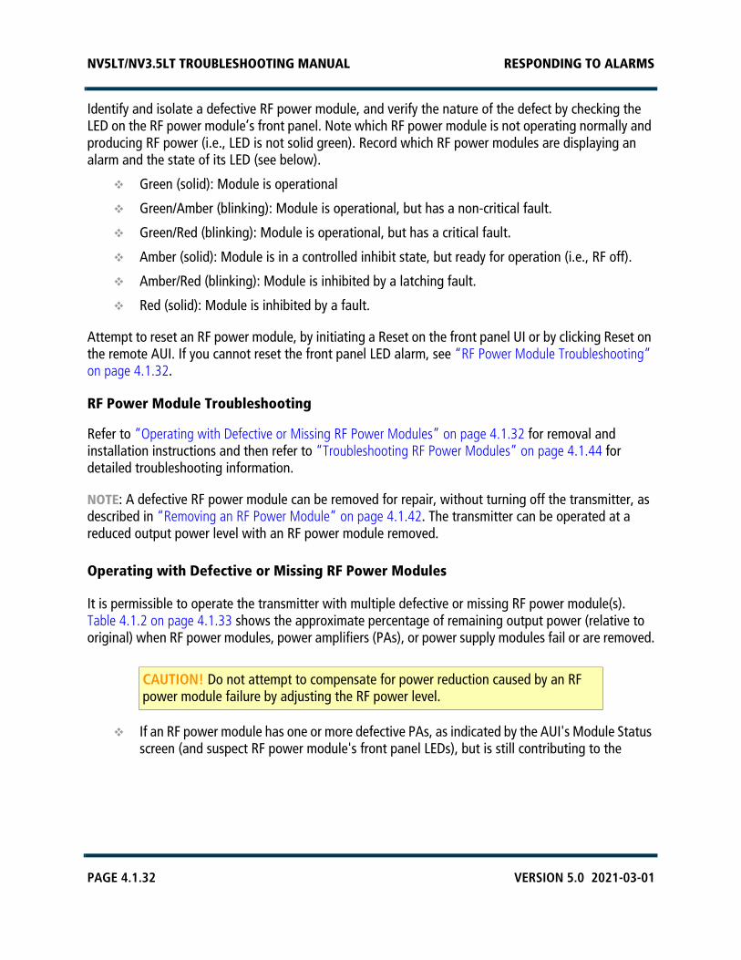
NV5LT/NV3.5LT TROUBLESHOOTING MANUAL RESPONDING TO ALARMS
PAGE 4.1.32 VERSION 5.0 2021-03-01
Identify and isolate a defective RF power module, and verify the nature of the defect by checking the LED on the RF power module’s front panel. Note which RF power module is not operating normally and producing RF power (i.e., LED is not solid green). Record which RF power modules are displaying an alarm and the state of its LED (see below).
Green (solid): Module is operational
Green/Amber (blinking): Module is operational, but has a non-critical fault.
Green/Red (blinking): Module is operational, but has a critical fault.
Amber (solid): Module is in a controlled inhibit state, but ready for operation (i.e., RF off).
Amber/Red (blinking): Module is inhibited by a latching fault.
Red (solid): Module is inhibited by a fault.
Attempt to reset an RF power module, by initiating a Reset on the front panel UI or by clicking Reset on the remote AUI. If you cannot reset the front panel LED alarm, see “RF Power Module Troubleshooting” on page 4.1.32.
RF Power Module Troubleshooting
Refer to “Operating with Defective or Missing RF Power Modules” on page 4.1.32 for removal and installation instructions and then refer to “Troubleshooting RF Power Modules” on page 4.1.44 for detailed troubleshooting information.
NOTE: A defective RF power module can be removed for repair, without turning off the transmitter, as described in “Removing an RF Power Module” on page 4.1.42. The transmitter can be operated at a reduced output power level with an RF power module removed.
Operating with Defective or Missing RF Power Modules
It is permissible to operate the transmitter with multiple defective or missing RF power module(s). Table 4.1.2 on page 4.1.33 shows the approximate percentage of remaining output power (relative to original) when RF power modules, power amplifiers (PAs), or power supply modules fail or are removed.
If an RF power module has one or more defective PAs, as indicated by the AUI's Module Statusscreen (and suspect RF power module's front panel LEDs), but is still contributing to the
CAUTION! Do not attempt to compensate for power reduction caused by an RF power module failure by adjusting the RF power level.

NV5LT/NV3.5LT TROUBLESHOOTING MANUAL RESPONDING TO ALARMS
VERSION 5.0 2021-03-01 PAGE 4.1.33
transmitter's RF output, it may be left on. The transmitter will take necessary precautions to reduce the stress on components due to the failure, i.e., power reduction.
If an RF power module must be removed, turn it off prior to disengaging its blind-matingconnectors. Refer to “RF Power Module Replacement” on page 4.1.42 to disable a module withthe transmitter on air. At all other times, turn off the switching power supplies by pressing theRF Off button, then switch off the ac power source at the service entrance.
NOTE: There are many possible combinations of PA/module failures or extractions. The best and worstcase situations are shown in Table 4.1.2 on page 4.1.33.
When maintenance is complete and it is safe to return the transmitter to normal service,enable all RF power module supplies by setting the switch on the front of the associated RFpower module(s) to its ‘ENABLE (up)’ position.
Table 4.1.2: Output Power Level vs. PA/Module Failure/Removal
PA/Module Failures/RemovalRF Output Power
(% of original RF output power)
Best Case Worst Case
1 RF Power Module 25 25
2 RF Power Modules 0 0
1 RF Power Amplifier 77 77
2 RF Power Amplifiers 56 38
3 RF Power Amplifiers 39 26
4 RF Power Amplifiers 25 17
5 RF Power Amplifiers 14 9
6 RF Power Amplifiers 6 4
1 Power Supply Module 56 56
2 Power Supply Modules 25 25

NV5LT/NV3.5LT TROUBLESHOOTING MANUAL RESPONDING TO ALARMS
PAGE 4.1.34 VERSION 5.0 2021-03-01
Power Supply Module and LVPS Faults
There are various power supply module and LVPS module related alarms on the front panel UI or remote AUI.
Power supply module alarms are prefixed by the text RF Module and then PS. The number that appears after RF Module (1-2) identifies the position of the affected module. The letter that appears after PS (A or B) identifies the affected power supply module. There are two power supply modules for each RF power module.
Low voltage power supply (LVPS) alarms are prefixed by the text LVPS. The letter that appears after LVPS (A, B) identifies the affected LVPS module.
1. Check the front panel LEDs of the power supply modules and LVPS modules. Normally, only the ACOK and DC OK LEDs should be on (solid green). If not, the associated power supply module or LVPSmodule may be defective. Proceed to “Power Supply or LVPS Module Fault Validation” onpage 4.1.37.
2. From the remote AUI’s Meter List View page (see Figure 4.1.8 on page 4.1.35):
click the i (information) button next to the RF Modules # folder in the Transmitter Layoutsection to view the status screen for all modules or click the right-hand arrow to expand theRF Modules folder to allow clicking on the i button for an individual RF Module (e.g., RFModule 1, see Figure 4.1.9 on page 4.1.35). This screen displays critical parameters for thepower supply modules. As an aid in troubleshooting, compare parameters to isolate possiblefaults.
click the i (information) button next to the Rack # folder in the Transmitter Layout section andthen to view the Rack status screen (see Figure 4.1.10 on page 4.1.36). This screen displaysLVPS meters.

NV5LT/NV3.5LT TROUBLESHOOTING MANUAL RESPONDING TO ALARMS
VERSION 5.0 2021-03-01 PAGE 4.1.35
Figure 4.1.8: AUI - Meter List View page
Figure 4.1.9: Module Status - Power Supply Meters
1. Click here to open theMeter List View page
3. Click here to viewpower supply modulemeters
2. Click here to viewLVPS meters

NV5LT/NV3.5LT TROUBLESHOOTING MANUAL RESPONDING TO ALARMS
PAGE 4.1.36 VERSION 5.0 2021-03-01
Figure 4.1.10: Rack Status - LVPS meters

NV5LT/NV3.5LT TROUBLESHOOTING MANUAL RESPONDING TO ALARMS
VERSION 5.0 2021-03-01 PAGE 4.1.37
Power Supply or LVPS Module Fault Validation
Each power supply and LVPS module has four LEDs on its front panel (see Figure 4.1.11, which can help in identifying a fault and allowing you to determine whether remedial action is required now or later.
Figure 4.1.11: Power Supply Module LEDs
Record which power supply modules are displaying an alarm and the state of its LEDs (see below).
AC OK LED
Green (solid): Ac voltage is present and within acceptable limits.
Green (blinking): Ac voltage is present, but outside acceptable limits.
DC OK LED
Green (solid): Power supply is enabled and output regulated.
Green (blinking): Power supply is experiencing an over-current condition.
SERVICE LED
Amber (solid): Power supply is experiencing a high temperature condition.
FAULT LED
Red (solid): Module is experiencing and internal fault.
Red (blinking): Communication has been lost with the rack controller.
Other combinations of power supply module LEDs, and the corresponding power supply condition, are listed in Table 4.1.3 on page 4.1.38.
Top of Power Supply Module

NV5LT/NV3.5LT TROUBLESHOOTING MANUAL RESPONDING TO ALARMS
PAGE 4.1.38 VERSION 5.0 2021-03-01
Table 4.1.3: Other Power Supply LED States
Operating with Defective or Missing Power Supply or LVPS Modules
You can operate the transmitter - at normal desired power level - with one defective or missing LVPS module, assuming the transmitter was using dual LVPS modules. To replace an LVPS module, go to “LVPS / Power Supply Module Replacement” on page 4.1.48.
You can operate the transmitter - at a reduced output power level - with multiple defective or missing power supply module(s) (see Table 4.1.2 on page 4.1.33). To replace a power supply module, go to “LVPS / Power Supply Module Replacement” on page 4.1.48.
ConditionPower Supply LED State
AC OK(green)
DC OK(green)
SERVICE(amber)
FAULT(red)
OK On On Off Off
Thermal alarm (5 degrees before shutdown) On On On Off
Thermal shutdown On Off On On
Defective fan, blown ac fuse, boost stage failure or over voltage latched shutdown
On Off Off On
Ac present, but not within limits Blinks Off Off Off
Ac not present Off Off Off Off
Non-catastrophic internal failure On On Off On
Standby On Off Off Off
Service Request (PMBus mode) On On Blinks Off
Communications Fault On On Off Blinks

NV5LT/NV3.5LT TROUBLESHOOTING MANUAL RESPONDING TO ALARMS
VERSION 5.0 2021-03-01 PAGE 4.1.39
Troubleshooting NTP Issues
Use the following procedure to troubleshoot a transmitter that is not receiving NTP date/time updates from an NTP server.
Requirements:
Access to the transmitter’s AUI
SSH connection using PuTTY
Procedure:
1. Confirm network connectivity to the transmitter:
Log in to the transmitter’s AUI.
SSH into the transmitter using PuTTY. Log in using root.
NOTE: If you do not have the root password, you may need to obtain it from another source, such as an OS Recovery Information Sheet.
2. Confirm the AUI settings are actually in use by the transmitter’s operating system:
In PuTTY, type ntpq –pn. Press Enter.
This will return the NTP server in use by the transmitter.
Verify that it matches up with the server listed in the User Settings -> NTP Servers section ofthe AUI. See Figure 4.1.12.
Figure 4.1.12: User Settings -> NTP Servers
3. If they differ from that shown in the Remote AUI, you may be looking at cached data. Clear thebrowser cache.
In PuTTY, type: traceroute <NTP address>. Press Enter.
This is will send a packet of data (like a ping) to the NTP server, but will report each ‘hop’along the way.
If the traceroute command fails, suspect a network issue.

NV5LT/NV3.5LT TROUBLESHOOTING MANUAL RESPONDING TO ALARMS
PAGE 4.1.40 VERSION 5.0 2021-03-01
4. Confirm that the transmitter can actually contact the NTP server.
In PuTTY, type: traceroute <NTP address>. Press Enter.
This is will send a packet of data (like a ping) to the NTP server, but will report each ‘hop’along the way.
If the traceroute command fails, suspect a network issue.
5. If the transmitter’s local time is >1000 seconds different than the NTP server time, the NTPdaemon on the transmitter may not update the clock. Try forcing a manual update of the NTPinformation.
In PuTTY, type service ntpstop. Press Enter. This stops the NTP service.
In PuTTY, type date. Press Enter. This indicates the time and date on the transmitter.
In PuTTY, type ntpdate <NTP address>. Press Enter. This indicates the time and date on theNTP server.
In PuTTY, type ntpdate –u <NTP address>. Press Enter. This updates the transmitter time tomatch the NTP server time.
If the NTP server is reachable by the transmitter, you will see the screen shown inFigure 4.1.13.
Figure 4.1.13: NTP Server Reachable
If you’re using a faulty server address, you will see the screen shown in Figure 4.1.14.
Figure 4.1.14: Faulty NTP Server
If the ntpdate –u command still fails after confirming the NTP server address, it is possiblethat UDP port 123 may be blocked on the router or some other firewall. It may need to beopened for the specific transmitter IP address.
In PuTTY, type service ntpstart. Press Enter. This starts the NTP service.
In PuTTY, type date. Press Enter. You should observe that the time and date has been updated.
6. Still not working?
It has been observed that NTP issues were resolved by performing an OS Recovery. Beforereplacing hardware, perform an OS Recovery.

NV5LT/NV3.5LT TROUBLESHOOTING MANUAL RESPONDING TO ALARMS
VERSION 5.0 2021-03-01 PAGE 4.1.41
Replacement Procedures
Table 4.1.4 lists the procedures available in this manual for replacing modules, PWBs and cooling fans.
Table 4.1.4: Replacement Procedures
Module Replacement Procedure
RF Power Module See page 4.1.42
Power Amplifier PWB See page 4.1.45
RF Module Cooling Fan See page 4.1.47
LVPS / Power Supply Modules See page 4.1.48
Remote Interface PWB See page 4.1.50
Fan Tray Cooling Fan See page 4.1.52
Reject Load Assembly See page 4.1.54
Controller Module See page 4.1.56
Exciter/Control PWB - Controller See page 4.1.58
Exciter Module See page 4.1.61
Exciter/Control PWB - Exciter See page 4.1.63
Pre-Amplifier PWB - Exciter See page 4.1.65
Module Control/Interface PWB See page 4.1.68
Power Supply Interface PWB See page 4.1.70
UPS Interface Power Supply See page 4.1.71
Power Module Combiner PWB (NAPH06) See page 4.1.73
Power Module Combiner PWB (NAPH07) See page 4.1.76

NV5LT/NV3.5LT TROUBLESHOOTING MANUAL RESPONDING TO ALARMS
PAGE 4.1.42 VERSION 5.0 2021-03-01
RF Power Module Replacement
Removing an RF Power Module
1. Confirm the location of the RF power module that is being removed. Note the alarm text includes aModule number (1-2) that is not identified on the RF power module. See Figure 4.1.15 on page4.1.43 to determine the location for a given RF power module (1 - 2).
2. Remove the front filter panel by loosening its eight (8) quarter-turn fasteners (see Figure 4.1.5 onpage 4.1.29) and lifting it out of its two bottom slots.
3. Set the ENABLE/DISABLE switch on the front of the suspect RF power module to its DISABLE(down) position. This inhibits the module’s associated pair of power supply modules.
4. Remove and retain the two M5 securing screws in the front of the module. If necessary, remove theM8 shipping screw in the back of the module (the shipping screws do not need to be reinstalled,and may have already been removed during installation or previous maintenance).
5. Grasp the handle on the front of the RF power module and carefully pull the RF power module outof the transmitter, noting that there are catches on the transmitter tray that will prevent the rear ofthe RF power module from being fully extracted. When the module reaches these catches, lift therear of the module over the catches by tilting the module’s front down and then lift by the rearhandle. The module weighs 14.5 kg (32 lbs).
Installing an RF Power Module
1. Grasp the front and rear handles on the RF power module and insert it into the transmitter,ensuring that the rear of the module clears the catches in the transmitter tray.
2. Carefully push the RF power module into place so that its edge-card connector mates with thetransmitter.
3. Install both M5 securing screws in the RF power module’s front panel.
4. Set the ENABLE/DISABLE switch on the front of the RF power module to its ENABLE position (seeFigure 4.1.15 on page 4.1.43). This activates the RF power module and its two associated powersupplies.
5. Install the front filter panel by positioning it in its two bottom slots and tightening its eight (8)quarter-turn fasteners (see Figure 4.1.5 on page 4.1.29).
WARNING! Fans with rotating blades are present at the bottom of the RF power module. Take care when removing the module.

NV5LT/NV3.5LT TROUBLESHOOTING MANUAL RESPONDING TO ALARMS
VERSION 5.0 2021-03-01 PAGE 4.1.43
Figure 4.1.15: RF Power Module Numbers/Locations
21
Enable/DisableSwitch
M5securing
screws(2 per
module)
Partial Front View - Front Filter Panel Removed

NV5LT/NV3.5LT TROUBLESHOOTING MANUAL RESPONDING TO ALARMS
PAGE 4.1.44 VERSION 5.0 2021-03-01
Troubleshooting RF Power Modules
Maintenance Philosophy
Maintenance on an RF power module consists of replacing PA PWBs or cooling fans.
Special Tools and Test Equipment
The following tools and test equipment are required to troubleshoot an RF power module.
Digital multimeter
Torque screwdriver, capable of torquing up to 0.67 N-m (6 in-lbs). Required for installing attaching hardware for PA PWB FETs.
Soldering iron and desoldering tool
NV5LT/NV3.5LT station spares kit, if purchased (contains replacement PA PWBs and cooling fans)
NV5LT/NV3.5LT site spares kit, if purchased (contains replacement cooling fans)
Electrical schematics SD-22 and SD-30 in Section 4 of this manual.
Mechanical drawings MD-8 and MD-16 in Section 5 of this manual.
Electrostatic Precautions
The RF power module contains semiconductor devices that are susceptible to damage from electrostatic discharge. Be sure to follow the electrostatic precautions in “Electrostatic Protection” on page 4.1.3 at all times.
Preparation for Troubleshooting
1. Follow the procedure in “Removing an RF Power Module” on page 4.1.42 to remove the RF powermodule from the transmitter.
2. Place the RF power module on a suitable work surface.
3. Based on the front panel UI or remote AUI alarm that prompted RF power module troubleshooting,replace either the defective PA PWB (see “PA PWB Replacement” on page 4.1.45) or defectivecooling fan (see “Module Cooling Fan Replacement” on page 4.1.47).
NOTE: If a failure occurs, you must replace the entire power amplifier PWB, rather than an individual FET. A spare power amplifier PWB (NAPA31C) is provided in the transmitter station spares kit, if purchased. To order a station spares kit or replacement power amplifier PWB contact Nautel. Failure to observe this recommendation may void your equipment warranty or cause further failures.

NV5LT/NV3.5LT TROUBLESHOOTING MANUAL RESPONDING TO ALARMS
VERSION 5.0 2021-03-01 PAGE 4.1.45
PA PWB Replacement
See Figures MD-8 and MD-16 in the Mechanical Drawings section (Section 5) of this manual.
1. Remove the RF power module’s right-hand side cover (see Figure 4.1.16 on page 4.1.47) byremoving 11 M3 countersunk screws. Retain hardware for re-installation.
2. Before replacing a suspect PA PWB, verify the fault is with the suspect PA PWB by performing thecontinuity and resistance checks detailed in “PA Resistance Checks” on page 4.1.46. If you areprompted to replace a PA PWB, return to Step 3 of this procedure.
3. Unsolder and remove the four solder connections to the defective PA PWB. They include two24 AWG links (to pads V and X), a white 12 AWG wire (to pad U) and a 16 AWG link (to pad D).
4. Remove the two #4 screws, split and flat washers securing the FET to the heat sink.
5. Remove the four M3 screws securing the PA PWB to the heat sink.
6. Obtain the replacement NAPA31C PA PWB from the station spares kit, if purchased.
NOTE: FETs are static sensitive and must be handled in a static protected manner.
7. Spread a small amount of thermal compound (Nautel Part # HAG39, from the station spares kit),thinly and evenly, on the bottom of the FET flange on the new PA PWB.
8. Secure the PA PWB on the module's heat sink using the four screws removed in Step 5. Ensurecorrect orientation (same as the adjacent PWB). Do not tighten the four screws at this time.
9. Secure the FET (Q1) with two # 4 screws, a mini-flat washer and a new split washer. Using a torquescrewdriver, alternate tightening the left and right screws on each FET, a quarter turn at a time,until 6 inch-pounds (0.67 Newton-meters) of torque has been applied.
10. Tighten the four PWB screws.
11. Solder the wires removed in Step 3.
12. Re-install the RF power module right-hand cover and return the module to the transmitter (see“Installing an RF Power Module” on page 4.1.42).
CAUTION! When installing FET securing hardware, you can damage the FET case if you fully tighten one screw while the other is loose. Avoid this by alternately tightening the two screws.

NV5LT/NV3.5LT TROUBLESHOOTING MANUAL RESPONDING TO ALARMS
PAGE 4.1.46 VERSION 5.0 2021-03-01
PA Resistance Checks
1. Using a digital multimeter, check the continuity across fuse F1 on the suspect PA PWB.
If the measurement is an open circuit, replace the PA PWB (see “PA PWB Replacement” onpage 4.1.45).
If the measurement is short circuit (near 0 ), proceed to Step 2.
2. Using a digital multimeter, measure the resistance between each gate lead of the FET and themetal flange of the FET.
If the measurement is less than 8 k, replace the PA PWB (see “PA PWB Replacement” onpage 4.1.45).
If the measurement is between 8 kand 17.5 k, check the other PA PWBs for a failure. Ifnone of the other PA PWBs have failed, replace the original suspect PA PWB.
If the measurement is greater than 17.5 k, proceed to Step 3.
3. Using a digital multimeter, check the continuity between each drain lead of the FET (positive meterprobe) and the metal flange of the FET (negative meter probe).
If the measurement is open circuit, the PA PWB is OK and does not require replacement.Continue troubleshooting and suspect a problem with an associated PWB.
If the measurement is not open circuit, replace the PA PWB (see “PA PWB Replacement” onpage 4.1.45).

NV5LT/NV3.5LT TROUBLESHOOTING MANUAL RESPONDING TO ALARMS
VERSION 5.0 2021-03-01 PAGE 4.1.47
Module Cooling Fan Replacement
See Figure 4.1.16.
1. Remove the RF power module’s right-hand side cover by removing 11 M3 countersunk screws.Retain hardware for re-installation.
2. Disconnect the suspect cooling fan’s mating plug (B1P1 through B6P1). Cut the tyrap that securesthe fan wiring to the splitter PWB.
3. Remove and retain the cooling fan’s two M3 captive screws that secure the fan to the module.
4. Obtain a replacement fan (Nautel Part # ZAP50) from the site spares kit or station spares kit orfrom a suitable equivalent (vendor part # is Minebea Motor Mfg. Corp. 3115RL-07W-B79-E51).
5. Install the replacement fan using retained screws. Torque hardware to 1.0 inch-pounds only toavoid cracking the fan’s body. Twist the fan’s mating plug three times (reduces RFI) and reconnectit to the splitter PWB. Secure the wiring using a tyrap (Nautel Part # HT66) from the ancillary kit.
6. Re-install the right-hand side cover using retained hardware.
7. Return the RF power module to the transmitter (see “Installing an RF Power Module” onpage 4.1.42).
Figure 4.1.16: Replacing a Power Module Cooling Fan
COOLING FANSB1 - B6(B1 removed)B1
B2B3
B4B5
B6
RIGHT-HANDSIDE COVER

NV5LT/NV3.5LT TROUBLESHOOTING MANUAL RESPONDING TO ALARMS
PAGE 4.1.48 VERSION 5.0 2021-03-01
LVPS / Power Supply Module Replacement
Figure 4.1.17: Location of LVPS / Power Supply Modules
WARNING! Lethal voltages exist inside the transmitter when the power is turned on. Follow replacement instructions carefully to ensure safety for maintenance personnel during power supply replacement.
Front filter panelremoved for clarity
Power Supply Associated RFModule Power Module 1A (U4), 1B (U5) 1 (A8)2A (U6), 2B (U7) 2 (A9)3A (U8), 3B (U9)• 3 (A10)•4A (U10),4B (U11)• 4 (A11)•
Used only inNV10LT/NV7.5LT
LVPS A (U2)LVPS B (U3, optional)

NV5LT/NV3.5LT TROUBLESHOOTING MANUAL RESPONDING TO ALARMS
VERSION 5.0 2021-03-01 PAGE 4.1.49
1. Use the transmitter’s remote AUI or controller UI alarm status/logs to isolate the defective low voltage power supply (LVPS), noting there may be redundant (dual) supplies installed or Power Supply module.
2. Remove the transmitter front filter panel and locate the suspect LVPS / Power Supply module. See Figure 4.1.17 on page 4.1.48.
3. Using Figure 4.1.18 as a guide, remove the LVPS / Power Supply module from the front of the transmitter.
4. Locate or obtain a replacement LVPS / Power Supply module (Nautel Part # UG132).
5. Using Figure 4.1.18 as a guide, reinstall the new LVPS / Power Supply module.
Figure 4.1.18: Removing/Installing LVPS / Power Supply Modules
6. Verify the AC OK and DC OK LEDs on the front of the LVPS / Power Supply module are solid green.
NOTE: The FAULT LED (red) may blink temporarily until communication is established between the power supply and the transmitter.
7. The transmitter should resume normal operation and the alarm should clear.
8. Close the transmitter’s front door.
AC OK and DC OK LEDs should be on (green)after successful power supply installation.
If the associated RF power module is disabled,the DC OK LED will not turn on until the moduleis enabled.

NV5LT/NV3.5LT TROUBLESHOOTING MANUAL RESPONDING TO ALARMS
PAGE 4.1.50 VERSION 5.0 2021-03-01
Remote Interface PWB Replacement
Using Figure 4.1.19 as a guide, replace the remote interface PWB as follows:
Figure 4.1.19: Remote Interface PWB Location
1. Turn off and lock out the transmitter’s main ac power.
2. Open the front hinged, UI panel to gain access to the optional remote interface PWB.
3. Remove all customer interface wiring from the remote interface PWB. Note the destination of eachwire for ease of reconnecting.
4. Disconnect the two D-sub connectors (W20P2 and W21P2) from the bottom of the PWB and theCat5E connector (W29P2) from the right-hand side of the PWB (mates with J2).
UI hinged panel and cabinetside removed for clarity
RemoteInterface PWB
D-sub connectorsW20P2 and W21P2

NV5LT/NV3.5LT TROUBLESHOOTING MANUAL RESPONDING TO ALARMS
VERSION 5.0 2021-03-01 PAGE 4.1.51
5. Remove and retain six sets of mounting hardware from the remote interface PWB. Remove theremote interface PWB from the transmitter.
6. Locate or obtain a replacement remote interface PWB (Nautel Part # NAPI143/01).
7. Set jumpers E1 and E2 on the new remote interface PWB to the same positions as the defectivePWB.
8. As applicable, use an indelible marker to identify the LED and switch labels on the new remoteinterface PWB to match the labels on the defective PWB.
9. Install the new remote interface PWB using retained hardware.
10. Reconnect D-sub connectors W20P2 and W21P2, Cat5E connector W29P2 and all customerinterface wiring to the new remote interface PWB.
11. Return the transmitter to service.

NV5LT/NV3.5LT TROUBLESHOOTING MANUAL RESPONDING TO ALARMS
PAGE 4.1.52 VERSION 5.0 2021-03-01
Fan Tray Cooling Fan Replacement
See Figure 4.1.20.
Figure 4.1.20: Removing the Fan Tray
1. Remove the transmitter’s upper, rear panel.
2. Disconnect D-sub cable W5P2 from the fan tray assembly.
3. Remove and retain the M4 screw that secures the fan tray to the transmitter.

NV5LT/NV3.5LT TROUBLESHOOTING MANUAL RESPONDING TO ALARMS
VERSION 5.0 2021-03-01 PAGE 4.1.53
Figure 4.1.21: Fan Tray Assembly
4. Remove the fan tray from the transmitter.
5. Disconnect the suspect fan’s mating plug (B1P1 or B2P1).
6. From the bottom of the fan tray, remove and retain the cooling fan’s two M3 screws that securethe fan to the fan tray. See Figure 4.1.21 on page 4.1.53.
7. Obtain a replacement fan (Nautel Part # ZAP50) from the site spares kit, if purchased or a suitableequivalent (vendor part # is Minebea Motor Mfg. Corp. 3115RL-07W-B79-E51).
8. Install the replacement fan using retained screws.
9. Reinstall the fan tray and secure using M4 screw. Reconnect D-sub connector W5P2.
10.
11.
Access fan removal hardware(two M3 screws) from bottomof fan tray.
NOTE:Fan B1 is 5 kW Reject Fan 1Fan B2 is 5 kW Reject Fan 2

NV5LT/NV3.5LT TROUBLESHOOTING MANUAL RESPONDING TO ALARMS
PAGE 4.1.54 VERSION 5.0 2021-03-01
Reject Load Replacement
Using Figure 4.1.22 as a guide, replace a reject load assembly as follows:
Figure 4.1.22: Replacing the Reject Load
Remove air blocker panel(eight screws).
Access to cables
PARTIAL FRONT VIEW(front panel removed)
PARTIAL FRONT VIEW(front panel and air blocker removed)
M5 securing hardware (remove lower screws;loosen upper screws inkey slots
PARTIAL REAR VIEW(upper panel removed)

NV5LT/NV3.5LT TROUBLESHOOTING MANUAL RESPONDING TO ALARMS
VERSION 5.0 2021-03-01 PAGE 4.1.55
1. Remove the transmitter’s front panel and upper, rear panel.
2. From the front of the transmitter, remove the air blocker panel that is secured with four screws.
3. From the front of the transmitter, disconnect the mating connectors (one ribbon cable and one N-type) from the back of the reject load assembly.
4. There are four M5 screws that secure the reject load assembly to the transmitter, accessible fromthe front and rear of the transmitter. Remove and retain the two lower screws. Loosen the upperscrews that are in key slots; they do not need to be removed.
5. From the front of the transmitter, remove the reject load assembly.
6. Obtain a replacement reject load (Nautel Part # NAL14) and install by reversing the instructions inStep 1 through Step 5.
7.

NV5LT/NV3.5LT TROUBLESHOOTING MANUAL RESPONDING TO ALARMS
PAGE 4.1.56 VERSION 5.0 2021-03-01
Controller Replacement
Figure 4.1.23: Location of Controller Module
1. If possible, use the local front panel UI and the remote AUI to record all custom user settingsincluding: network settings, preset/audio settings, user accounts, logs, SNMP configuration, emailconfiguration, time zone, notifications and playlists. It is recommended that all User Settings belogged prior to replacing the controller module and then restored upon completion of the change.
2. Press RF Off. Turn off and lock out the transmitter’s main ac power.
3. Remove the transmitter’s front filter panel and upper, rear panel.
4. From the rear of the transmitter, disconnect the mating connectors from the controllermodule (A4).
M5 securinghardware
ControllerModule
PARTIAL FRONT VIEW(front panel removed)
PARTIAL REAR VIEW(panels removed)

NV5LT/NV3.5LT TROUBLESHOOTING MANUAL RESPONDING TO ALARMS
VERSION 5.0 2021-03-01 PAGE 4.1.57
5. From the front of the transmitter, remove the two M5 screws that secure the controller module tothe transmitter and pull out the controller module. If you are replacing the controller module’sexciter/control PWB (A1), see “Exciter/Control PWB Replacement - Controller” on page 4.1.58.
6. Obtain a replacement controller module (Nautel Part # NAE106E or newer) and install it byreversing the instructions in Step 4 and Step 5.
7. Install the transmitter’s front filter panel and upper, rear panel.
8. Enable and turn on ac power to the transmitter.
9. Use the remote AUI’s System Settings -> Upgrade Software page to view the Details of theinstalled software. Upgrade software as required. See the Operations & Maintenance Manual andany applicable Nautel-supplied Information Sheets for detailed instructions.
10. Restore all custom user settings that were recorded in
11. Ensure the transmitter configuration is restored in the Controller’s UI HW Config menu byselecting Installed Exciter (A/B), LVPS Hardware (correct number of LVPS modules) and UPSInstalled (yes/no). See the Operations & Maintenance Manual for detailed instructions.
12. With RF off and the system interlock circuit intact (closed), use the controller’s front panel UI toinitiate a Xmtr PA Bias routine (see Main Menu -> System Settings -> Factory Settings ->Calibration; refer to the Operations and Maintenance Manual for more detail).
13. Restore the transmitter to the desired operational state.
CAUTION! There are two possible configurations for the controller module being installed, each with a potential different effect on transmitter operation.
– A “blank” controller module, which is the typical configuration shipped by Nautel,will take on the transmitter’s profile (transmitter type, calibration data, etc.) uponinstallation. It should require no additional configuration or setup.
– A “configured” controller module is one that has been configured for a specificcustomer’s transmitter. Upon installation, the transmitter will take on the controller’s profile. If this controller was not configured for the transmitter it was installed in,your transmitter’s operational characteristics may change. If this occurs, CONTACTNAUTEL to restore proper operation.

NV5LT/NV3.5LT TROUBLESHOOTING MANUAL RESPONDING TO ALARMS
PAGE 4.1.58 VERSION 5.0 2021-03-01
Exciter/Control PWB Replacement - Controller
Using Figure 4.1.24 as a guide, replace the controller module’s exciter/control PWB (A4A1) as follows:
Figure 4.1.24: Exciter/Control PWB Location - Controller
1. Remove the controller module (A4) as described in “Controller Replacement” on page 4.1.56.
2. Place the controller module on a suitable work surface. Remove the top cover. Retain hardware forre-installation.
3. Disconnect all mating plugs from the exciter/control PWB (A1) inside the controller module.
TOP VIEW(cover removed)
EXCITER/CONTROL
PWBA1

NV5LT/NV3.5LT TROUBLESHOOTING MANUAL RESPONDING TO ALARMS
VERSION 5.0 2021-03-01 PAGE 4.1.59
4. At the rear panel, remove any securing hardware for connectors that protrude through the rearpanel. Retain all hardware for re-installation.
– Locate the two DB-25 connectors (J2A and J2B) and the two DB-9 connectors (J5A and J5B) on the rear panel.Using a 5 mm nut driver or socket, remove the mounting nuts.
– Locate the AES/EBU XLR audio connector (J3) on the rear panel. Remove the two small pan-head Phillips screws.
– Remove the silver push button connector lock ("push" lever) on the XLR connector. Locate the HAS78 removal toolfrom the ancillary kit, provided with the transmitter. Follow the manufacturer's instructions in Figure 4.1.25 onpage 4.1.60 to remove the push button. You will need access to the front and rear of the receptacle to remove it.
– See Figure 4.1.26 on page 4.1.60. Remove the locking rings from five BNC connectors (J4A, J4B, J6A, J6B andJ7). To remove the locking rings, use small 4 - 6 inch slip-jaw pliers. In a counter-clockwise direction, gently loosen(do not tightly pinch or deform) each locking ring. Typically, half a turn with the pliers will loosen a locking ringenough to remove it by hand. Remove and retain the locking rings.
5. Remove the three small Phillips screws, which mount the front of the exciter/control PWB to thechassis, located along the edge of the exciter/control PWB. Retain hardware for re-installation.
6. Slightly lift the front edge of the exciter/control PWB and pull towards the front of the controller.
7. Locate or obtain a replacement exciter/control PWB (Nautel Part # NAPE87A or newer). Removethe “push” lever from the XLR connector as detailed in Step 4.
8. Install the replacement exciter/control PWB. Replace all hardware for the through-chassisconnectors. Take care not to over-tighten the BNC connector locking rings.
9. Install the three Philips screws that mount the front of the exciter/control PWB to the chassis.
10. Install the “push” lever into the XLR connector. Align it with the slot located on the top section ofthe connector body and gently press it into position.
11. Reconnect all internal cables to the exciter/control PWB. If necessary, refer to Section 4.3 (Wiring/Connector Lists) of this manual for connector mating details for A1.
12. Reinstall the controller’s top cover.
13. Remove the “Interlock” jumper, if applicable, from J2A of the original exciter/control PWB andreinstall it on the new exciter/control PWB between J2A pins 19 and 20.
14. Re-install the controller in the transmitter and reconnect all external mating connectors, removedpreviously. Restore all previous settings as described in “Controller Replacement” on page 4.1.56.
CAUTION! When re-installing the exciter/control PWB, lift the PWB high enough so that the mounting pillars do not damage parts on the underside of the PWB.

NV5LT/NV3.5LT TROUBLESHOOTING MANUAL RESPONDING TO ALARMS
PAGE 4.1.60 VERSION 5.0 2021-03-01
Figure 4.1.25: Removing the XLR connector’s “push” lever
Figure 4.1.26: Loosening the BNC connector’s locking ring

NV5LT/NV3.5LT TROUBLESHOOTING MANUAL RESPONDING TO ALARMS
VERSION 5.0 2021-03-01 PAGE 4.1.61
Exciter Replacement
Figure 4.1.27: Location of Exciter Module
1. Ensure the controller module’s integrated exciter (A4) is operating as the main RF drive source anddisable automatic changeover (see the Operations & Maintenance Manual).
NOTE: If it is not possible to operate the controller’s integrated exciter, press RF Off and turn off the transmitter’s main ac power source.
2. Remove the transmitter’s front filter panel and upper, rear panel.
3. From the rear of the transmitter, disconnect the mating connectors from the exciter module (A5).
M5 securinghardware
ExciterModule
PARTIAL FRONT VIEW(front panel removed)
PARTIAL REAR VIEW(panels removed)

NV5LT/NV3.5LT TROUBLESHOOTING MANUAL RESPONDING TO ALARMS
PAGE 4.1.62 VERSION 5.0 2021-03-01
4. From the front of the transmitter, remove the two M5 screws that secure the exciter module to thetransmitter and pull out the exciter module. If you are replacing the exciter module’s exciter/controlPWB (A1), see “Exciter/Control PWB Replacement - Exciter” on page 4.1.63.
5. Obtain a replacement exciter module (Nautel Part # NAE107D or newer) and install it by reversingthe instructions in Step 3 and Step 4.
6. Install the transmitter’s front filter panel and upper, rear panel.
7. If it was necessary to turn RF off and disable ac power in Step 1, enable and turn on ac power tothe transmitter.
8. Restore the transmitter to the desired operational state. If the replacement exciter is intended to bethe main RF drive source, use the Changeover menu to establish the main/active exciter. Restorethe automatic changeover setting, if applicable.

NV5LT/NV3.5LT TROUBLESHOOTING MANUAL RESPONDING TO ALARMS
VERSION 5.0 2021-03-01 PAGE 4.1.63
Exciter/Control PWB Replacement - Exciter
Using Figure 4.1.28 as a guide, replace the exciter module’s exciter/control PWB (A5A1) as follows:
Figure 4.1.28: Exciter/Control PWB Location - Exciter
1. Remove the exciter module (A5) as described in “Exciter Replacement” on page 4.1.61.
2. Place the exciter module on a suitable work surface. Remove the top cover. Retain hardware for re-installation.
3. Disconnect all mating plugs from the exciter/control PWB (A1), inside the exciter.
TOP VIEW(cover removed)
EXCITER/CONTROL
PWB
A1

NV5LT/NV3.5LT TROUBLESHOOTING MANUAL RESPONDING TO ALARMS
PAGE 4.1.64 VERSION 5.0 2021-03-01
4. At the rear panel, remove any securing hardware for connectors that protrude through the rearpanel. Retain all hardware for re-installation.
– Locate the two DB-9 connectors (J3A and J3B) and the DB-15 connector (J5) on the rear panel. Using a 5 mm nutdriver or socket, remove the mounting nuts.
– Locate the AES/EBU XLR audio connector (J4) on the rear panel. Remove the two small pan-head Phillips screws.
– Remove the silver push button connector lock (“push” lever) on the XLR connector. Locate the HAS78 removal toolfrom the ancillary kit, provided with the transmitter. Follow the manufacturer's instructions in Figure 4.1.25 onpage 4.1.60 to remove the push button. You will need access to the front and rear of the receptacle to remove it.
– See Figure 4.1.26 on page 4.1.60. Remove the locking rings from five BNC connectors (J6, J7A, J7B, J8A andJ8B). To remove the locking rings, use small 4 - 6 inch slip-jaw pliers. In a counter-clockwise direction, gentlyloosen (do not tightly pinch or deform) each locking ring. Typically, half a turn with the pliers will loosen a lockingring enough to remove it by hand. Remove and retain the locking rings.
5. Remove the four small Phillips screws, which mount the front of the exciter/control PWB to thechassis, located along the edge of the exciter/control PWB. Retain hardware for re-installation.
6. Slightly lift the front edge of the exciter/control PWB and pull towards the front of the exciter.
7. Locate or obtain a replacement exciter/control PWB (Nautel Part # NAPE86A or newer). Removethe “push” lever from the XLR connector as detailed in Step 4.
8. Install the replacement exciter/control PWB. Replace all hardware for the through-chassisconnectors. Take care not to over-tighten the BNC connector locking rings.
9. Install the four Philips screws that mount the front of the exciter/control PWB to the chassis.
10. Install the “push” lever into the XLR connector. Align it with the slot located on the top section ofthe connector body and gently press it into position.
11. Reconnect all internal cables to the exciter/control PWB. If necessary, refer to Section 4.3 (Wiring/Connector Lists) of this manual for connector mating details for A1.
12. Reinstall the exciter’s top cover.
13. Re-install the exciter in the transmitter and reconnect all external mating connectors, removedpreviously. Restore all previous settings as described in “Exciter Replacement” on page 4.1.61.
CAUTION! When re-installing the exciter/control PWB, lift the PWB high enough so that the mounting pillars do not damage parts on the underside of the PWB.

NV5LT/NV3.5LT TROUBLESHOOTING MANUAL RESPONDING TO ALARMS
VERSION 5.0 2021-03-01 PAGE 4.1.65
Pre-Amplifier PWB Replacement - Exciter
Using Figure 4.1.29 and Figure 4.1.30 on page 4.1.66 as guides, replace the exciter module’s pre-amplifier PWB (A5A3) as follows:.
Figure 4.1.29: Pre-Amplifier PWB Location - Exciter
1. Remove the exciter module (A5) as described in “Exciter Replacement” on page 4.1.61.
2. Place the exciter module on a suitable work surface. Remove the top cover. Retain hardware.
3. Loosen the plastic nut that secures voltage regulator U1to its heatsink (see Figure 4.1.30 on page4.1.66). Remove and retain the plastic nut and washer.
4. Unsolder U1’s three mounting leads from the pre-amplifier PWB and carefully pull it away from itsheatsink. This should also allow you to remove the heatsink and insulator for U1. Retain U1, itsheatsink and its insulator.
5. Unsolder and remove the four solder connections to the defective pre-amplifier PWB. They includethree 20 AWG links (to pads B, C and D) and a coaxial connection (to pads A and E).
TOP VIEW(cover removed)
PRE-AMPLIFIERPWBA3

NV5LT/NV3.5LT TROUBLESHOOTING MANUAL RESPONDING TO ALARMS
PAGE 4.1.66 VERSION 5.0 2021-03-01
Figure 4.1.30: Pre-Amplifier PWB Assembly DetailM4 SECURING
SCREWS (QTY 6)
PLASTICHARDWARE
FOR U1HEATSINK FOR U1
WIRES TO UNSOLDER(4 PLACES)
PADSA and E
PAD B PAD C
PAD D
INSULATOR
U1 LEADS TO UNSOLDER

NV5LT/NV3.5LT TROUBLESHOOTING MANUAL RESPONDING TO ALARMS
VERSION 5.0 2021-03-01 PAGE 4.1.67
6. Remove the six M3 screws securing the pre-amplifier PWB to the heat sink. Carefully remove thepre-amplifier PWB from the exciter, taking care not to damage any of the links and wiring close tothe PWB.
7. Obtain the replacement NAPA35 pre-amplifier PWB from the station spares kit, if purchased.
NOTE: FETs are static sensitive and must be handled in a static protected manner.
8. Spread a small amount of thermal compound (Nautel Part # HAG39, from the station spares kit),thinly and evenly, on the bottom of the new pre-amplifier PWB.
9. Secure the pre-amplifier PWB on the exciter’s heat sink using the six screws removed in Step 6.Ensure correct orientation. Tighten the screws.
10. Re-solder the four connections removed in Step 5.
11. Re-install voltage regulator U1, its insulator and its heatsink on the plastic screw (see Figure 4.1.30on page 4.1.66 for proper orientation). Ensure the leads of U1 are correctly positioned to allow re-soldering to the three pads on the pre-amplifier PWB. Secure the items using the nut and washerremoved in Step 3 and torque hardware to 2 inch-pounds (0.22 Newton-meters).
12. Re-solder the three leads of U1 to the pre-amplifier PWB.
13. Re-install the exciter module’s top cover, using retained hardware, and re-install the exciter modulein the transmitter as described in “Exciter Replacement” on page 4.1.61.

NV5LT/NV3.5LT TROUBLESHOOTING MANUAL RESPONDING TO ALARMS
PAGE 4.1.68 VERSION 5.0 2021-03-01
Module Control/Interface PWB Replacement
Using Figure 4.1.31 as a guide, replace the module control/interface PWB (A3) as follows:
Figure 4.1.31: Module Control/Interface PWB Location
M3 securing hardware (14 nuts/washers)
Module Control/Interface PWB
PARTIAL REAR VIEW(panels removed)
M3 securing hardwarefor card-edge connectors (2 sets per card, 8 sets per PWB); remove from the front

NV5LT/NV3.5LT TROUBLESHOOTING MANUAL RESPONDING TO ALARMS
VERSION 5.0 2021-03-01 PAGE 4.1.69
1. Turn off (disable) and lock out the transmitter’s ac power source, and UPS source (to LVPS), ifapplicable.
2. Remove the transmitter’s upper, rear panel and front panel.
3. From the front of the transmitter, remove the RF power modules that are mated with the modulecontrol/interface PWB.
4. Disconnect the mating connectors from the module control/interface PWB.
5. Remove 14 sets of M3 nuts and washers that secure the module control/interface PWB to thetransmitter. Remove eight M3 screws that connect the PWB’s edge-card connectors to thetransmitter. Pull out the module control/interface PWB.
6. Obtain a replacement module control/interface PWB (Nautel Part # NAPC158B) and install it byreversing the instructions in Step 1 through Step 5.
7. From the rear of the transmitter, set DIP switch S1on the NAPC158B as follows:
8. Re-install the RF power modules.
9. Enable and turn on ac power to the transmitter.
10. Ensure new PWB has the same software as the original, and if necessary, perform a softwareupgrade. Refer to the Operations and Maintenance manual for instructions.
11. The calibration data for the NAPC158B PWB must be synced from the controller. To sync the caldata, navigate the UI menu as follows:
– System Settings -> Factory Settings -> Calibration -> Cal Backup -> Sync Cal -> Send Cal to Racks
12. Return the transmitter to service.
S1 Position A3S1 Setting
6 OFF (right)
5 (F BTLDR) OFF (right)
4 (RS485 TERM) ON (left)
3 (ADDR 1) OFF (right)
2 (ADDR 2) OFF (right)
1 OFF (right)

NV5LT/NV3.5LT TROUBLESHOOTING MANUAL RESPONDING TO ALARMS
PAGE 4.1.70 VERSION 5.0 2021-03-01
Power Supply Interface PWB Replacement
Using Figure 4.1.32 as a guide, replace the power supply interface PWB (A1) as follows:
Figure 4.1.32: Power Supply Interface PWB Location
1. Turn off and lock out the transmitter’s main ac power.
2. Remove the transmitter’s lower, rear panel and front panel.
3. From the front of the transmitter, pull the power supply modules that are mated with the powersupply interface PWB forward so that they disengage from the PWB.
4. From the rear of the transmitter, disconnect the mating connectors and wiring from the powersupply interface PWB. Record the placement of all wiring and jumpers to ensure the replacementPWB connections are identical.
5. Remove 24 sets of M3 nuts and washers that secure the power supply interface PWB to thetransmitter and pull out the power supply interface PWB.
M3 securing hardware (24 nuts/washers)
Power SupplyInterface PWB (A1)
PARTIAL REAR VIEW(panels removed)

NV5LT/NV3.5LT TROUBLESHOOTING MANUAL RESPONDING TO ALARMS
VERSION 5.0 2021-03-01 PAGE 4.1.71
6. Obtain a replacement power supply interface PWB (Nautel Part # NAPI150A/01) and install it byreversing the instructions in Step 1 through Step 5.
7. Re-install the power supply modules.
8. Enable and turn on ac power to the transmitter.
9. Return the transmitter to service.
UPS Interface Power Supply Replacement
See Figure 4.1.33 on page 4.1.72.
1. Turn off and lock out the transmitter’s main ac power.
2. Remove the rear top panel, which is secured with 1/4-turn fasteners.
3. From the rear of the transmitter:
Disconnect the power cable to the UPS Interface assembly by removing the 220 V ac plug(Nautel Part # JD43) from the UPS Interface assembly at J1.
Remove the six M4 screws that secure the UPS Interface to the transmitter and retain. Disconnect the wiring from the terminal block on the defective power supply (Nautel part # UG31), noting connections.
Remove the UPS Interface assembly from the transmitter to gain access to the four M4 screws that secure power supply from underneath. Remove the four M4 screws and retain.
4. Obtain the replacement power supply (Nautel Part # UG31) and install in the UPS assembly using the four M4 screws retained in step 3. Apply ac power to the UPS interface only. Use a DMM to monitor the dc voltage between the +V and -V terminals of the UG31. Adjust the power supply output voltage potentiometer until the DMM reads 30 V dc.
5. Install the UPS Interface assembly in the transmitter by reversing the instructions in steps 2 andstep 3.
6. Enable and turn on ac power to the transmitter.
7. Return the transmitter to service.
CAUTION! There are high voltages present. It is recommeded to use a shrouded adjustment tool to avoid shorting the ac voltage to the chassis.

NV5LT/NV3.5LT TROUBLESHOOTING MANUAL RESPONDING TO ALARMS
PAGE 4.1.72 VERSION 5.0 2021-03-01
Figure 4.1.33: UPS Interface Assembly
COVER REMOVED FOR CLARITY
220 V ac UPS INPUT
UG31 POWER SUPPLY

NV5LT/NV3.5LT TROUBLESHOOTING MANUAL RESPONDING TO ALARMS
VERSION 5.0 2021-03-01 PAGE 4.1.73
Power Module Combiner PWB (NAPH06) Replacement
1. Disable the associated NAA61 RF power module using the “Enable/Disable” switch located on thefront of the RF power module (switch down). The power module status LED should turn red.
2. Remove the two (2) M5 Phillips screws securing the RF power module to the transmitter rack andretain hardware.
3. Remove the RF power module from the transmitter rack and place on a suitable work bench. SeeFigure 4.1.34 for proper orientation on work bench for top cover removal.
Figure 4.1.34: RF Power Module Orientation
4. Remove the top cover (11 x M3 Phillips screws) and retain hardware.
5. Using a standard soldering iron, remove the high-power resistors (R1 through R6; Nautel Part #RT69) by first unsoldering their leads from the PWB traces (both sides) and then removing theresistor securing screws (2 M3 Phillips screws per resistor); retain hardware. See Figure 4.1.35 onpage 4.1.74.
6. Using the standard iron, Unsolder the power amplifier output links from both the combiner PWBinput (pads F and G) and the power amplifier (PA) PWB outputs; retain links.
NOTE: If unable to remove the power module, ensure the M8 shipping bolt in the rear of the module has been removed.
WARNING Resistors R1 through R6 (Nautel part # RT69) contains Beryllium Oxide (BeO). These devices are non-hazardous during normal device operation and under normal device failure conditions. DO NOT cut, crush or grind devices because the resulting dust may be HAZARDOUS IF INHALED. Unserviceable devices should be disposed of as harmful waste.

NV5LT/NV3.5LT TROUBLESHOOTING MANUAL RESPONDING TO ALARMS
PAGE 4.1.74 VERSION 5.0 2021-03-01
Figure 4.1.35: NAPH06 Combiner PWB De-soldering locations
7. Using the standard iron, unsolder wire #05 (white coaxial cable marked with “-05”) reject powersample coaxial cable core from pad C and shield from pad E. Tie back cable temporarily.
8. Unsolder the larger combiner connections (two places, spades A and B) using a Weller SP80L(80W) or equivalent soldering iron. Ensure combiner connections (copper straps) are cleaned inpreparation for the replacement combiner PWB.
9. Remove eight (8) M3 Phillips screws that mount the combiner PWB; retain hardware.
10. Remove the combiner PWB (A6). Clean residual thermal paste from the heat sink surface wherethe high power resistors (R1 to R6) were mounted.
11. Install replacement combiner PWB and secure using eight (8) M3 Phillips screws retained in Step 9.Torque screws to 6 lb-in.
12. Solder larger connections (copper straps) at pads A and B, using the Weller SP80L (80W) solderingiron or equivalent.
CAUTION: Do not apply excessive solder; prevents overflow of solder down into the hybrid combiner region.

NV5LT/NV3.5LT TROUBLESHOOTING MANUAL RESPONDING TO ALARMS
VERSION 5.0 2021-03-01 PAGE 4.1.75
13. Re-install the power amplifier output links between the combiner pads F and G and the PA outputsusing the standard soldering iron. If links are damaged, use tinned copper wire (Nautel part #WF09) to make new links.
14. Apply a very thin and evenly distributed layer of thermal paste (Nautel part # HAG39 to the bottomof the high power resistors (Nautel Part # RT69). Install the resistors in the R1 through R6 positionon the combiner PWB by first securing the two (2) M3 Phillips screws retained in Step 5 and torqueto 6 lb-in.
15. Solder the high power resistor leads (both sides) to the associated combiner PWB pads using thestandard iron.
16. Solder wire #05 (reject power sample coaxial cable) core to pad C and shield to pad E using thestandard iron.
17. Install top cover using hardware retained in Step 4.
18. Return the NAA61 RF power module to the transmitter rack and secure in place using hardwareretained in Step 2 and the M8 shipping bolt (if used). Enable the power module using the front“Enable/Disable”switch (switch up). The power module status LED should be green.
19. Return to normal operation and via the RF Module Meter Summary screen, ensure that theassociated RF power module reject power meter is equal to the remaining power module’s rejectpower meter readings (± 50 W).
CAUTION: Do not apply excessive solder; avoid solder wicking up the lead towards the resistor body, as the bend in the lead provides thermal strain relief.
CAUTION: Ensure there are no short circuits between the core and the shield; measure with DMM set to resistance and ensure greater than 40 k ohms.

NV5LT/NV3.5LT TROUBLESHOOTING MANUAL RESPONDING TO ALARMS
PAGE 4.1.76 VERSION 5.0 2021-03-01
Power Module Combiner PWB (PR82C) Replacement
1. Disable the associated NAA61 RF power module using the “Enable/Disable” switch located on thefront of the RF power module (switch down). The power module status LED should turn red.
2. Remove the two (2) M5 Phillips screws securing the RF power module to the transmitter rack andretain hardware.
3. Remove the RF power module from the transmitter rack and place on a suitable work bench. SeeFigure 4.1.36 for proper orientation on work bench for top cover removal.
Figure 4.1.36: RF Power Module Orientation
4. Remove the top cover (11 x M3 Phillips screws) and retain hardware.
5. Using the standard soldering iron, remove the high-power resistors (R1 and R2; Nautel Part #RT69) by first unsoldering their leads from the PWB traces (both sides) and then removing theresistor securing screws (2 M3 Phillips screws per resistor); retain hardware. See Figure 4.1.37 onpage 4.1.77.
6. Using the standard iron, Unsolder the power amplifier output links from both the combiner PWBinput (pads D and E) and the power amplifier (PA) PWB outputs; retain links.
NOTE: If unable to remove the power module, ensure the M8 shipping bolt in the rear of the module has been removed.
WARNING Resistors R1 and R2 (Nautel part # RT69) contains Beryllium Oxide (BeO). These devices are non-hazardous during normal device operation and under normal device failure conditions. DO NOT cut, crush or grind devices because the resulting dust may be HAZARDOUS IF INHALED. Unserviceable devices should be disposed of as harmful waste.

NV5LT/NV3.5LT TROUBLESHOOTING MANUAL RESPONDING TO ALARMS
VERSION 5.0 2021-03-01 PAGE 4.1.77
Figure 4.1.37: PR82C Combiner PWB De-soldering locations
7. Unsolder the larger combiner connections (two places, spades A and B) and output connector link(pad C) using the Weller SP80L (80W) or equivalent soldering iron. Ensure combiner and outputconnections (copper straps/link) are cleaned in preparation for the replacement combiner PWB.
8. Remove eight (8) M3 Phillips screws that mount the combiner PWB; retain hardware.
9. Remove the combiner PWB (A7). Clean residual thermal paste from the heat sink surface wherethe high power resistors (R1and R2) were mounted.
10. Install replacement combiner PWB and secure using eight (8) M3 Phillips screws retained in Step 8.Torque screws to 6 lb-in.
11. Solder larger connections (copper straps) at pads A and B and connector link at pad C, using theWeller SP80L (80W) soldering iron or equivalent.
12. Re-install the power amplifier output links between the combiner pads D and E and the PA outputsusing the standard soldering iron. If links are damaged, use tinned copper wire (Nautel part #WF09) to make new links.
CAUTION: Do not apply excessive solder; prevents overflow of solder down into the hybrid combiner region.

NV5LT/NV3.5LT TROUBLESHOOTING MANUAL RESPONDING TO ALARMS
PAGE 4.1.78 VERSION 5.0 2021-03-01
13. Apply a very thin and evenly distributed layer of thermal paste (Nautel part # HAG39) to the bottom of the high power resistors (Nautel Part # RT69). Install the resistors in the R1 and R2 position on the combiner PWB by first securing the two (2) M3 Phillips screws retained in Step 5 and torque to 6 lb-in.
14. Solder the high power resistor leads (both sides) to the associated combiner PWB pads using the standard iron.
15. Install top cover using hardware retained in Step 4.
16. Return the NAA61 RF power module to the transmitter rack and secure in place using hardware retained in Step 2 and the M8 shipping bolt (if used). Enable the power module using the front “Enable/Disable”switch (switch up). The power module status LED should be green.
17. Return to normal operation and via the RF Module Meter Summary screen, ensure that the associated RF power module reject power meter is equal to the remaining power module’s reject power meter readings (± 50 W).
CAUTION: Do not apply excessive solder; avoid solder wicking up the lead towards the resistor body, as the bend in the lead provides thermal strain relief.

NV5LT/NV3.5LT TROUBLESHOOTING MANUAL PARTS LISTS
VERSION 5.0 2021-03-01 PAGE 4.2.1
SECTION 4.2: PARTS LISTS
This section contains reference designation lists that provide descriptive and provisioning information for all electrical and mechanical parts that have an assigned reference designation and form a part of the subject equipment.
Topics in this section include
Family Tree
How to Locate Information About a Specific Part
Column Content on page 4.2.2
Family Tree
Figure 4.2.1 on page 4.2.4 and Figure 4.2.2 on page 4.2.5 depict the family tree for the subject equipment. It is based on the descending order of the reference designation hierarchy and identifies all assemblies that have an assigned Nautel configuration control number.
How to Locate Information About a Specific Part
To locate the information for a specific part, the assigned reference designation for the part must be known. In addition, the Nautel nomenclature (e.g., NAA61C) assigned to the assembly containing the part or the full reference designation, including the reference designation of all higher assemblies, must be known.
When the Nautel Nomenclature is Known:
Refer to the family tree (Figure 4.2.1 on page 4.2.4 and Figure 4.2.2 on page 4.2.5) and identify theblock(s) associated with the Nautel nomenclature. Locate the part's reference designation in theidentified reference designation list in this section, noting they are sorted alphanumerically.

NV5LT/NV3.5LT TROUBLESHOOTING MANUAL PARTS LISTS
PAGE 4.2.2 VERSION 5.0 2021-03-01
When the Reference Designation is Known:
Refer to the family tree depicted in Figure 4.2.1 on page 4.2.4 and Figure 4.2.2 on page 4.2.5 withthe full reference designation.
Follow the family tree branches to the block that represents the lowest level assembly assigned aNautel configuration control number, then locate the reference designation information for thatNautel configuration control number.
Locate the part's reference designation and associated Nautel Part # in the list provided at the endof this section. In a PDF manual, use Ctrl-F (find) to quickly locate the reference designation.
Reference Designation Lists
Reference designation lists are provided for:
assemblies that are assigned an alpha-prefixed Nautel nomenclature (e.g., NAA61C)
cable harnesses that are assigned a numbered Nautel part (e.g., 219-8401-01)
optional kits that are assigned a numbered Nautel part
To obtain the full reference designation for a specific part the Nautel configuration control number must be located in the family tree (Figure 4.2.1 on page 4.2.4 and Figure 4.2.2 on page 4.2.5) to include the reference designation of all higher level assemblies. The reference designation lists are presented in alphanumeric order - for each component level of the transmitter - are divided into columns to aid in locating specific information.
Column Content
The following paragraphs provide an explanation of the purpose and contents of each column in the part number indexes.
Component Level, Stock Code Column
This column contains the Component Level number (01 through 10, as required) and the Nautel Stock Code (part number) assigned to each part.

NV5LT/NV3.5LT TROUBLESHOOTING MANUAL PARTS LISTS
VERSION 5.0 2021-03-01 PAGE 4.2.3
Component Level
This number represents the level of a component in relation to the highest level parts list. In this case the highest level parts list is the NV5LT/NV3.5LT’s overall parts list, or the top block in the family tree shown in Figure 4.2.1 on page 4.2.4.
Components that are directly descended from the highest level parts list are component level 01. The associated stock code and description for level 01 items appear in bold text in the reference designation list, followed by their sub-assembly components, as applicable. Level 01 items are sorted alphanumerically.
Components that are directly descended from component level 01 items are component level 02. The associated stock code and description for level 02 items appear below their associated level 01 component, slightly indented, followed by their sub-assembly components, as applicable. Level 02 items are sorted alphanumerically
Component level 03 through 10 items, as applicable, descend similarly to component level 02 items, with continuing indentations to identify each new level.
Stock Code
This number is Nautel's drawing number for Nautel manufactured parts, Nautel's configuration control number for assemblies that are under configuration control management, or Nautel's inventory management number for purchased parts. When a Nautel configuration control number (e.g., NAPC*) is shown in this column, its sub-assembly reference designation items are listed below it.
NOTE: This section includes Nautel part numbers only. It does not include original equipment manufacturer (OEM) information (i.e., vendor part numbers). Some vendor information is provided in the Responding to Alarms section of this manual, otherwise contact Nautel to order a replacement part or to request assistance to find a suitable replacement.
Description Column
The Description column contains the name and descriptive information for each part. The key word is presented first, followed by the adjective identifiers.
Reference Designation Column
The Reference Designation column contains the reference designation(s) for a specific part. When multiple reference designations apply to a part, they are sorted alphanumerically. These designations are assigned in accordance with the requirements of IPC-2612-2010 - Sectional Requirements for Electronic Diagramming Documentation (Schematic and Logic Descriptions).

NV5LT/NV3.5LT TROUBLESHOOTING MANUAL PARTS LISTS
PAGE 4.2.4 VERSION 5.0 2021-03-01
Figure 4.2.1: NV5LT/NV3.5LT Family Tree
219-8005-12-FAM01 Iss. A
A7A22-WAY SPLITTER PWB
NAPH10
(OPTIONAL)
A4A7ORBAN PWB
NAPX37
A4A8EXTERNAL BATTERY PWB
219-5190-02
A4A1EXCITER/CONTROLLER PWB
NAPE87B
A4A2POWER SUPPLY DISTRIBUTION PWB
NAPS46
A8A7COMBINER (RHS) PWB
PR82C
A5A8NOT USED
A5A2POWER SUPPLY DISTRIBUTION PWB
NAPS47E/01
A7RF DRIVE SPLITTER/CHANGEOVER ASSY
NAI22A/01
A7A1SPLITTER/CHANGEOVER PWB
NAPH09/01A
A6
NOT USED
A2UI INTERFACE PWB
NAPI142A
A1POWER SUPPLY INTERFACE PWB
NAPI150A/01
A4CONTROLLER (with integral EXCITER A)
NAE106E
A4A3PRE-AMP PWB
NAPA27A
A4A4POWER AMPLIFIER PWB
NAPA31C
A8A5SPLITTER/INTERFACE PWB
NAPH05
A5A4POWER AMPLIFIER PWB
NAPA31C
A4A5OUTPUT POWER PROBE PWB
NAPP06/01
A4A6LED PWB
206-3060
NOT USEDA10 - A11
A5A6LED PWB
206-3060
A8A6COMBINER (LHS) PWB
NAPH06
(OPTIONAL)
A5A7ORBAN PWB
NAPX37
A5A1EXCITER/CONTROLLER PWB
NAPE86A
RF POWER MODULE 1A8
NAA61C
A8A1 - A8A4PA PWB, LDMOS
NAPA31C
5 kW or 3.5 kW FM BROADCAST TRANSMITTER
NV5LT or NV3.5LT
NARF71D/01
A3MODULE CONTROL/INTERFACE PWB
NAPC158B
EXCITER B
(OPTIONAL)
A5
NAE107D
A5A3PRE-AMP PWB
NAPA35
A5A5OUTPUT POWER PROBE PWB
NAPP06/01
RF POWER MODULE 2(SAME AS A8)
A9
NAA61C

NV5LT/NV3.5LT TROUBLESHOOTING MANUAL PARTS LISTS
VERSION 5.0 2021-03-01 PAGE 4.2.5
Figure 4.2.2: NV5LT/NV3.5LT Family Tree (continued)
219-8005-12-FAM02 Iss. A
U8 - U11NOT USED
A13A12-INPUT REJECT LOAD PWB
206-8080
A12A110kW FILTER ASSY
NAF118
A15A6DC REFLECTED POWER PROBE PWB
219-6520
(OPTIONAL)
U3LOW VOLTAGE POWER SUPPLY B
UG132
U4 - U7RF MODULE POWER SUPPLY 1A - 4B
UG132
(OPTIONAL)
A16REMOTE INTERFACE PWB
NAPI143/01
A131-INPUT REJECT LOAD ASSY
NAL14
U1USER INTERFACE DISPLAY
UW146
A12COMBINER/FILTER ASSY
NAF119A/03
U2LOW VOLTAGE POWER SUPPLY A
UG132
A15A2REFLECTED POWER PROBE PWB
206-6520
A14A12-WAY FAN TRAY INTERFACE PWB
NAPI155
A15A4FORWARD PWR/RF SAMPLE PROBE PWB
206-6524
A15A5FORWARD PWR/RF SAMPLE PROBE PWB
206-6524
A15OUTPUT POWER PROBE ASSY
NAFP109B
A15A1FORWARD PWR/RF SAMPLE PROBE PWB
206-6524
A142-WAY FAN TRAY ASSY
NAX264
A15A3RF MONITOR PROBE PWB
206-6522

NV5LT/NV3.5LT TROUBLESHOOTING MANUAL PARTS LISTS
PAGE 4.2.6 VERSION 5.0 2021-03-01

StockCode: NAE106E Page 1 of 46
Description: Controller Assy, w/FM Digital Exciter, NVLT, CE,
Component Lvl, StockCode Reference DesignationDescription
206-306001 LED PWB Assy A06CCFS0702 Cap,SMT,Ceramic,0.1uF,10%,50V,X7R,0805 C01, C02, C03, C04HR10702 LED,Light Pipe,Optical,PWB, Right Angle HW01, HW02JU2502 MTA, Keyed Square Post Header Assy, 4 pin J01LCFS0102 Inductor, SMT, Choke, 600ohms, 2A, 0805 L01, L02, L03, L04QDLS0402 Diode,SMT,LED,Bicolor,Red/ Green,1210 DS01, DS02RFFS3002 Resistor, SMT, MF, 221ohms, 1%, 1/10W, 0603 R02, R03, R04RFFS3402 Resistor,SMT,MF,475ohms,1%, 1/10W,0603 R01
206-591301 Ribbon Clamp Assy
219-3002-0201 Cableset Assy Exciter/Controll er NVLT (NAE106D)JDP2402 Conn, Coax, BNC, Plug, 50ohm, Crimp W1P1, W1P2JP4502 Conn, Recept, Ribbon Cable, 20 pin W2P1, W2P2, W3P1, W3P2JP5102 Conn, Recept, Ribbon Cable, 40 pin W4P1, W4P2JQ1702 Conn, Contact, Pin, HDP-20 Strip P01JR2802 Conn, Plug, D-Sub, 9 pin P01JT1602 Conn, Lock Screw, D-Sub, 4-40, Male, Kit P01JT6002 Conn, Coax, BNC, Recept, Bulkhead, RG188 J01, J03JU0202 MTA, Standard Dust Cover, 4 pi n P02, P03JU2702 MTA, Keyed Closed End Housing, 4 pin,22AWG P02, P03JU6302 Conn, 2mm, Housing 2, PH Serie s, White P04, P05JU6402 Conn, Term, PH Series, Crimp, 30-24 AWG P04, P05LA0202 Toroid, Ferrite, 12.7mm, K Mtl W1L1
219-5190-0201 External Battery PWB Assy A08BBHT0402 Battery Holder, SMT, 20mm Coin Cell XBT01JU7502 Conn, 2mm, Shrouded Header, PH Series, R/A, White J01

StockCode: NAE106E Page 2 of 46
Description: Controller Assy, w/FM Digital Exciter, NVLT, CE,
Component Lvl, StockCode Reference DesignationDescription
CBP0801 Capacitor, Feed-Thru, Ceramic, 1000pF C01, C02, C03, C04, C05, C06, C07, C08, C09
JDP2101 Conn, Coax, N, Recept, Panel, 50ohm J02
NAPA27A01 PA PWB Assy, VS300 Pre-Amp A03CCFS2802 Cap,SMT,Ceramic,47pF,2%,50V,C0G,0603 C05CCFS6002 Cap,SMT,Ceramic,1uF,10%,100V, X7R,1210 C03, C04CCFS6602 Cap, SMT, Ceramic, 10+/-0.5pF, 100V COG, 1206 C10, C16CCFS6702 Cap, SMT, Ceramic, 12+/-0.5pF, 100V COG, 1206 C12CT2002 Capacitor, SMT, Ceramic, 1000p F, 5%, 63V C01, C08, C14, C17CT6102 Capacitor, SMT, Ceramic, 0.022 uF, 100V, 10%, 1206 C06, C11CT6602 Capacitor, SMT, Ceramic, 0.1uF 10%, 100V C07, C09CT6802 Cap, SMT, Electrolytic, 68uF, 20%, 63V C15LA5602 Bead, Ferrite, SMT, 95 ohm, 2.85mm H x 9.6mm Lg L02, L05LS2602 Inductor, SMT, 82nH, 2%, 2.5A, 4.20mm H x 4.95mm L04LS2702 Inductor, SMT, 120nH, 2%,1.5A, 4.20mm H x 4.95mm L06LS2902 Inductor, SMT, 43nH, 2%, 4A, 3.15mm H x 6.86mm Lg L01, L03LS3402 Inductor, SMT, 28nH, 2%, 4A 3.15mm H x 6.86mm L L07, L08QAP6002 Transistor, FET, N-Channel, LDMOS, 10W, 50V Q01RAD1302 Resistor, SMT, MF, 100 Ohms, 1% 1/4W R01
NAPA31C01 PA PWB Assy, LDMOS (QAP66) A04CS9402 Capacitor, SMT, Porcelain,36pF 500V, 2% C18CS9502 Capacitor, SMT, Porcelain,15pF 500V, 2% C15CS9602 Capacitor, SMT, Porcelain, 2pF 500V, +/-0.1pF C14CT5202 Capacitor,SMT,Ceramic,470pF, 200V,10% C17CT5302 Capacitor,SMT,Ceramic,0.001uF, 50V,10% C08, C10, C12, C16CT6602 Capacitor, SMT, Ceramic, 0.1uF 10%, 100V C06, C20CT7402 Cap, SMT, Ceramic, 10uF, X7R, 100V, Stacked C21, C22

StockCode: NAE106E Page 3 of 46
Description: Controller Assy, w/FM Digital Exciter, NVLT, CE,
Component Lvl, StockCode Reference DesignationDescription
CT7502 Cap, SMT, Electrolytic, 470uF, 20%, 63VDC, Low ESR C01, C02, C03, C04, C05CT7902 Capacitor, SMT, Ceramic,0.01uF 50V, 10% C11, C13FA6402 Fuse, SMT, 125VAC, VDC, 30A, Fast Acting F01LS2602 Inductor, SMT, 82nH, 2%, 2.5A, 4.20mm H x 4.95mm L05LS4002 Inductor, SMT, 5nH, 5%, Mini Spring L01, L03LS4102 Inductor, SMT, 100nH, 5%, Midi Spring L02QAP6602 Transistor, FET, LDMOS, Dual, Ruggedized Q01QDSS0102 Diode, SMT, Schottky, 30V, 0.2A, SOD-323 CR01QDZS0102 Diode,SMT,Zener,5.1V,5%,3W,SMB CR02RAD4502 Resistor, SMT, MF, 47.5K Ohms, 1% 1/4W R01RAD49Z02 Resistor,SMT,MF,10ohms, 1%,2W R02RAD54Z02 Resistor,SMT,4.7 ohms, 5%,2W R04, R05RAD8002 Resistor, SMT,10k Ohms, 1%, 1W 2512 R03TZ11802 Transformer, Gate Drive, VHF, 3T/1 Turn T03WE5402 Cable, Coax, 12 Ohm, 600V, 200 C, TFE T02A, T02BWE5602 Cable, Coax, 50 Ohm, 70% VP, 150C, PTFE, 11mm Min T01
NAPE87B01 Exciter/Controller PWB Assy, VS/NVLT w/CE A01BBHT0102 Holder, 20mm Coin Cell, PWB Mt XBT01BBLT0102 Battery, Lithium, 3V,20mm Coin Cell BT01CCFS0102 Cap,SMT,Ceramic,0.001uF,10%,50V,X7R,0603 C008, C033, C122, C125, C127, C152, C158, C159, C161,
C162, C175, C176, C180, C182, C183, C185,, C188, C189, C193, C194, C198, C199, C200, C203, C205, C206, C222, C223, C224, C225, C228, C229,, C230, C233, C234, C237, C251, C253, C255, C353, C354, C355, C360, C364, C366, C369, C370, C382,, C383, C384, C386, C387, C392, C393, C398, C399, C400, C401, C502, C503, C539, C591
CCFS0202 Cap,SMT,Ceramic,0.0022uF,10%, 50V,X7R,0603 C128CCFS0302 Cap,SMT,Ceramic,0.0047uF,10%, 50V,X7R,0603 C022, C035, C063, C069CCFS0402 Cap,SMT,Ceramic,0.01uF,10%,50V,X7R,0603 C243, C256, C257, C258, C259, C273, C274, C275, C276,
C286, C287, C288, C296, C297, C299, C300,, C305, C306, C310, C311, C315, C316, C319, C320, C323, C324, C325, C326, C411
CCFS0602 Cap, SMT, Ceramic, 0.047uF, 10%, 50V, X7R, 0603 C034, C067CCFS1002 Cap,SMT,Ceramic,1uF,10%,25V,X7R,1206 C174, C177, C266, C280

StockCode: NAE106E Page 4 of 46
Description: Controller Assy, w/FM Digital Exciter, NVLT, CE,
Component Lvl, StockCode Reference DesignationDescription
CCFS2302 Cap,SMT,Ceramic,18pF,2%,50V, C0G,0603 C018, C021, C027, C028, C062, C066, C073, C079, C134, C141, C171, C173, C464, C473, C544, C578,, C585
CCFS2402 Cap,SMT,Ceramic,22pF,2%,50V, C0G,0603 C014, C017, C039, C046, C047, C053, C054, C058, C059, C077, C106, C107, C108, C109, C112, C129,, C133, C142, C534, C579, C580, C582
CCFS3202 Cap,SMT,Ceramic,100pF,2%,50V,C0G,0603 C020, C030, C042, C051, C061, C083, C088, C093, C094, C097, C098, C104, C110, C138, C208, C210,, C220, C227, C289, C290, C292, C293, C437, C459, C467, C485, C499, C505, C518, C542, C543, C570, C587
CCFS3302 Cap,SMT,Ceramic,150pF,1%,50V, C0G,0603 C445CCFS3402 Cap,SMT,Ceramic,220pF,2%,50V, C0G,0603 C029, C068CCFS3702 Cap,SMT,Ceramic,390pF,2%,50V,C0G,0603 C529CCFS3802 Cap,SMT,Ceramic,470pF,2%,50V, C0G,0603 C015, C016, C023, C038, C045, C048, C052, C055, C057,
C060, C071, C074, C078, C115, C116, C117,, C118, C119, C120, C130, C143, C155, C409, C429, C434, C435, C525, C548, C550, C574, C575, C581, C593
CCFS4202 Cap,SMT,Ceramic,1000pF,2%,50V, C0G,0805 C090, C092, C095, C096, C099, C105, C191, C192, C196, C271, C367, C368
CCFS4702 Cap,SMT,Ceramic,3900pF,2%,50V, C0G,1206 C436

StockCode: NAE106E Page 5 of 46
Description: Controller Assy, w/FM Digital Exciter, NVLT, CE,
Component Lvl, StockCode Reference DesignationDescription
CCFS5202 Cap, SMT, Ceramic, 0.1uF, 10%, 25V X7R, 0603 C002, C003, C011, C013, C019, C025, C026, C037, C040, C050, C056, C065, C070, C072, C075, C076,, C080, C082, C087, C091, C111, C113, C114, C121, C124, C126, C132, C137, C139, C146, C147, C148,, C149, C151, C153, C154, C156, C163, C164, C165, C166, C167, C168, C170, C172, C178, C184, C187,, C195, C201, C202, C207, C209, C216, C217, C218, C219, C226, C231, C232, C235, C238, C239, C240,, C241, C244, C245, C246, C247, C248, C249, C250, C254, C261, C262, C264, C268, C269, C270, C277,, C281, C282, C283, C284, C285, C291, C294, C295, C298, C301, C302, C303, C304, C307, C308, C309,, C312, C313, C314, C318, C321, C322, C327, C328, C329, C331, C334, C338, C339, C340, C341, C342,, C343, C344, C349, C350, C356, C357, C358, C359, C361, C362, C363, C371, C372, C373, C374, C375,, C376, C377, C378, C379, C380, C381, C385, C388, C389, C390, C394, C395, C402, C403, C404, C407,, C410, C412, C413, C415, C416, C417, C419, C421, C422, C423, C424, C426, C427, C432, C433, C438,, C439, C440, C441, C442, C443, C444, C446, C447, C448, C449, C456, C457, C458, C461, C462, C463,, C465, C466, C468, C469, C470, C471, C472, C474, C475, C476, C477, C478, C479, C480, C481, C482,, C483, C484, C486, C487, C488, C489, C490, C491, C492, C493, C494, C495, C496, C497, C498, C500,, C501, C506, C507, C508, C509, C510, C511, C512, C513, C514, C515, C516, C517, C520, C521, C522,, C524, C526, C528, C530, C531, C532, C533, C536, C541, C545, C546, C547, C549, C551, C553, C554,, C555, C556, C557, C560, C562, C563, C564, C566, C568, C573, C583, C584, C586, C588, C589, C592
CCFS5302 Cap, SMT, Ceramic,47uF,20%, 6.3V, 1210 C009, C010, C012, C043, C044, C049, C430, C460, C576, C577
CCFS5702 Cap,SMT,Ceramic,10uF,20%,6.3V, X5R,0805 C001, C005, C006, C007, C081, C084, C086, C089, C131, C150, C179, C181, C337, C347, C348, C504,, C523, C527, C569, C571, C572
CCFS5802 Cap,SMT,Ceramic,22uF,20%,6.3V, X5R,1206 C140, C186, C330, C332, C333, C336, C346, C397, C405, C406
CCFS6002 Cap,SMT,Ceramic,1uF,10%,100V, X7R,1210 C031, C123, C214, C215, C236, C558, C567CCFS6202 Cap, SMT, Ceramic, 10uF, 10%, 25V C265, C418, C425, C537, C538, C540

StockCode: NAE106E Page 6 of 46
Description: Controller Assy, w/FM Digital Exciter, NVLT, CE,
Component Lvl, StockCode Reference DesignationDescription
CCFS7302 Cap, SMT, Ceramic, 1uF, 10%, 16V, X5R, 0603 C024, C041, C064, C085, C135, C136, C144, C145, C157, C160, C204, C252, C345, C351, C352, C365,, C391, C519, C590
CT5102 Capacitor,SMT,Ceramic,0.1uF, 100V,10% C032, C197, C213, C221, C561, C565CT8502 Cap, SMT, Ceramic, 3 Terminal, 22pF, 16vDC, 600mA C100, C101, C102, C103, C260, C263, C267, C272, C278,
C279, C335, C396, C408, C414, C450, C451,, C452, C453, C454, C594
CT8602 Cap, SMT, Ceramic, 3 Terminal, 1000pF, 16vDC, 600m C242, C317, C420, C428, C431, C455CTFS0402 Cap,SMT,Tantalum,100uF,10%,10V,2917 C004, C036, C190, C535, C552CX3802 Cap,SMT,Ceramic,4.7uF,10%,10V, X5R, 1206 C169, C559HAJ6602 Terminal, SMT, Test Point, PWB TP04, TP06, TP07, TP15, TP18, TP19, TP20JF4702 Conn, Header,Square Post,Gold, Dual,40-pin J17, J19JM4402 Conn, Modular Jack, RJ45, Shld , Side, PWB, 50u J01JM4902 Conn, Socket, 1xMag RJ45 + 2x USB-A J08JQ1502 Conn, Post Shunt, 2 Pos, .10 C entreline E01, E02JQ1602 Conn, Header, SIP, 12 Pin Breakaway, 10 Ctr J16, J21, XE01, XE02JQ5302 Conn, Header, Ribbon Cbl, 40- Pin J15JQ5502 Conn, Header, Ribbon Cbl, 20 Pin J11, J12JQ7602 Conn, Header, Ribbon Cable 14 pin J13JS2102 Conn, BNC, Recept, Rt Angle, P WB Mt J14JT10002 Conn, Dual, BNC, PWB, Rt Angle J04, J06JT12102 Conn, Dual, D-Sub, F/M, 9 pin, Rt. Angle, PWB J05JT6102 Conn, BNC, Recept, 50ohm,Insul , Rt Angle J07JT7802 Connector,Dual,D-Sub,M/F, 25-pin,Rt Agl,PWB J02JT8702 Conn,3-pin,PWB Mount, Fem, XLR J03JU2502 MTA, Keyed Square Post Header Assy, 4 pin J10JU7402 Conn, 2mm, Shrouded Header, PH Series, Top, White J09

StockCode: NAE106E Page 7 of 46
Description: Controller Assy, w/FM Digital Exciter, NVLT, CE,
Component Lvl, StockCode Reference DesignationDescription
LCFS0102 Inductor, SMT, Choke, 600ohms, 2A, 0805 L002, L004, L005, L006, L007, L010, L011, L012, L016, L017, L018, L019, L020, L023, L024, L025,, L028, L029, L030, L031, L033, L035, L036, L037, L038, L039, L040, L042, L043, L044, L045, L046,, L047, L048, L049, L050, L051, L052, L053, L054, L055, L056, L057, L058, L059, L060, L061, L062,, L064, L069, L071, L073, L074, L075, L076, L077, L078, L080, L081, L082, L083, L084, L086, L087,, L088, L089, L090, L097, L098, L099, L100, L102, L103, L110, L111, L122, L123, L124, L125, L129,, L130, L131, L132, L133, L134, L137, L138, L140, L144, L145, L146, L147, L154, L155, L156, L157,, L158, L159, L160, L161, L162, L163, L164, L171, L174, L176, L177
LCFS0202 Inductor, SMT, Choke, 2000 ohm s, 80mA, 0805 L022, L034, L093, L095, L105, L106, L107, L108, L109, L126, L127, L128, L135, L136, L139, L141,, L142, L143, L148, L149, L150, L151, L152, L153, L165, L166, L167, L168, L169, L170, L172, L173,, L175, L179
LS1702 Inductor,SMT,Pwr,Shielded,P116 7 Series,3.5A,3.6uH L003, L013LS2002 Inductor,SMT,560nH,325mA,2520 L008, L009, L021, L041LS2202 Choke,SMT,Common Mode,2200 ohm ,200mA,1206 L117, L119LS2402 Inductor, SMT, 10uH, 2.4A, RMS L027LS4802 Choke, SMT, Common Mode, 600 ohm, 260mA L063, L065, L066, L067, L068, L070, L072, L079, L085, L091,
L092, L094, L096, L101, L104, L112,, L113, L114, L115, L116, L118, L120, L121, L178, L180
QBNS0102 Transistor,SMT,NPN,Switch/Amp ,SOT-23 Q01, Q02, Q04QDDS0202 Diode, SMT, Schottky, 40V, 1A, SMA CR01QDRS0102 Diode,SMT,Switching,250V,0.2A, SOD-323 CR04, CR05, CR06, CR07, CR08, CR09, CR10, CR11, CR12,
CR13, CR14, CR15, CR16, CR17, CR18, CR19QDSS0102 Diode, SMT, Schottky, 30V, 0.2A, SOD-323 CR02, CR03, CR22, CR23QM4802 Diode,SMT,Transient Suppr,10V, SMB CR20, CR21QS2602 Transistor, SMT, P-Channel FET 130mA Q03RAD2602 Resistor, SMT, MF, 1210 Ohms, 1% 1/4W R085, R086, R093, R094RAD3302 Resistor, SMT, MF, 4750 Ohms, 1%, 1/4W R172, R173, R174, R175, R176, R180, R181, R183, R184,
R187, R188RAD4402 Resistor, SMT, MF, 39.2K Ohms, 1% 1/4W R399, R402, R407, R410RAD5302 Resistor,SMT,MF,49.9ohms,1%, 1/10W,0603 R170RAD5702 Resistor, SMT, 25.5 ohms, 1%, 2512 R182, R197RAE2502 Resistor,SMT,MF,3.74K,1%,1/10W ,0603 R021RAE3102 Resistor,SMT,MF,6.49K,1%,1/10W ,0603 R003

StockCode: NAE106E Page 8 of 46
Description: Controller Assy, w/FM Digital Exciter, NVLT, CE,
Component Lvl, StockCode Reference DesignationDescription
RAE3402 Resistor,SMT,MF,49.9R,1%,1/10W 0603 R240, R241, R465, R469, R473, R474RFFS0102 Resistor,SMT,MF,0.0ohms,Jumper ,0603 R207, R208, R325RFFS0202 Resistor, SMT, MF, 1.00ohms, 1%, 1/10W, 0603 R119, R120, R121, R132, R186, R346, R347, R356, R357,
R379RFFS1002 Resistor, SMT, MF, 4.75ohms, 1%, 1/10W, 0603 R019, R028, R030, R039, R128, R136, R222, R236, R242,
R247, R249, R250, R252, R256, R257, R265,, R419, R431, R446, R457, R459, R475
RFFS1502 Resistor, SMT, MF, 12.1ohms, 1%, 1/10W, 0603 R142, R143, R144, R145, R146, R147, R152, R153, R157, R158, R160, R161, R162, R163, R167, R168
RFFS1802 Resistor, SMT, MF, 22.1ohms, 1%, 1/10W, 0603 R063, R067, R075, R076, R077, R079, R083, R097, R113, R117, R122, R124, R125, R149, R166, R178,, R198, R210, R253, R254, R262, R303, R324, R337, R370, R384, R386, R390, R406, R422, R424, R436,, R438, R444, R445, R454, R483
RFFS1902 Resistor, SMT, MF, 27.4ohms, 1%, 1/10W, 0603 R015, R016, R023, R024, R464, R470RFFS2102 Resistor, SMT, MF, 39.2ohms, 1%, 1/10W, 0603 R082, R089, R090, R098, R479, R480, R481, R482RFFS2302 Resistor, SMT, MF, 56.2ohms, 1%, 1/10W, 0603 R335, R336RFFS2602 Resistor, SMT, MF, 100ohms, 1%, 1/10W, 0603 R046, R048, R060, R064, R069, R072, R116, R118, R129,
R150, R151, R193, R215, R220, R227, R228,, R229, R243, R244, R259, R260, R263, R288, R319, R320, R321, R322, R327, R328, R329, R330
RFFS2702 Resistor, SMT, MF, 121ohms, 1%, 1/10W, 0603 R139RFFS2802 Resistor, SMT, MF, 150ohms, 1%, 1/10W, 0603 R070, R071RFFS2902 Resistor,SMT,MF,182ohms,1%, 1/10W,0603 R223, R238RFFS3002 Resistor, SMT, MF, 221ohms, 1%, 1/10W, 0603 R025, R044RFFS3102 Resistor, SMT, MF, 274ohms, 1%, 1/10W, 0603 R022, R050, R058, R099, R100, R103, R104, R134, R397,
R405, R409, R412, R414, R426, R434, R440,, R484RFFS3302 Resistor, SMT, MF, 392ohms, 1%, 1/10W, 0603 R052, R054, R055, R065, R066, R068, R073, R074, R420,
R427, R428RFFS3402 Resistor,SMT,MF,475ohms,1%, 1/10W,0603 R001, R007, R012, R013, R029, R031, R033, R034, R035,
R040, R059, R105, R106, R107, R108, R114,, R127, R209, R221, R237, R239, R361, R363, R371, R375, R380, R382, R388, R430, R451, R460, R461, R466
RFFS3602 Resistor, SMT, MF, 681ohms, 1%, 1/10W, 0603 R396, R404, R408, R411RFFS3702 Resistor, SMT, MF, 825ohms, 1%, 1/10W, 0603 R360

StockCode: NAE106E Page 9 of 46
Description: Controller Assy, w/FM Digital Exciter, NVLT, CE,
Component Lvl, StockCode Reference DesignationDescription
RFFS3802 Resistor,SMT,MF,1000ohms,1%, 1/10W,0603 R017, R037, R042, R043, R062, R078, R081, R087, R088, R095, R096, R115, R189, R196, R199, R205,, R211, R218, R219, R224, R225, R226, R232, R233, R234, R235, R255, R258, R264, R266, R268, R271,, R272, R274, R276, R277, R278, R281, R282, R310, R311, R333, R352, R364, R393, R394, R395, R400,, R413, R416, R417, R468
RFFS3902 Resistor,SMT,MF,1210ohms,1%, 1/10W,0603 R004, R005, R006, R036, R140RFFS4002 Resistor,SMT,MF,1500ohms,1%, 1/10W,0603 R201, R202, R365, R366, R367, R447RFFS4202 Resistor,SMT,MF,2210ohms,1%, 1/10W,0603 R126, R131, R203, R204, R348, R350, R376, R381, R389,
R391, R392RFFS4502 Resistor,SMT,MF,3920ohms,1%, 1/10W,0603 R027, R047RFFS4602 Resistor, SMT, MF, 4750ohms, 1%, 1/10W, 0603 R101, R111, R130, R156, R309, R312, R334, R351, R425RFFS5002 Resistor,SMT,MF,10.0Kohms,1%, 1/10W,0603 R002, R008, R011, R018, R026, R032, R045, R049, R051,
R053, R057, R061, R080, R084, R091, R092,, R102, R110, R133, R137, R138, R154, R155, R159, R164, R165, R169, R171, R177, R179, R185, R190,, R191, R192, R195, R200, R206, R212, R213, R214, R217, R261, R267, R284, R285, R286, R287, R289,, R290, R291, R292, R293, R294, R295, R296, R297, R298, R299, R300, R301, R302, R304, R305, R306,, R307, R308, R313, R315, R316, R317, R338, R345, R349, R353, R372, R385, R415, R418, R421, R423,, R429, R432, R433, R435, R437, R439, R441, R442, R443, R448, R449, R453, R462, R463, R485, R486, R487
RFFS5202 Resistor,SMT,MF,15.0Kohms,1%, 1/10W,0603 R014, R450, R452, R455, R456, R458, R471, R472RFFS5402 Resistor,SMT,MF,22.1Kohms,1%, 1/10W,0603 R010, R112RFFS5702 Resistor,SMT,MF,39.2Kohms,1%, 1/10W,0603 R216RFFS5802 Resistor, SMT, MF, 47.5Kohms, 1%, 1/10W, 0603 R194, R269, R270, R279, R280RFFS5902 Resistor,SMT,MF,56.2Kohms,1%, 1/10W,0603 R383RFFS6002 Resistor,SMT,MF,68.1Kohms,1%, 1/10W,0603 R056RFFS6202 Resistor,SMT,MF,100Kohms,1%, 1/10W,0603 R020, R038, R467RFFS6302 Resistor, SMT, MF, 121Kohms, 1%, 1/10W, 0603 R403RFFS6502 Resistor, SMT, MF, 182Kohms, 1%, 1/10W, 0603 R109RFFS6602 Resistor, SMT, MF, 221Kohms, 1%, 1/10W, 0603 R009RFFS7402 Resistor,SMT,MF,1.00Mohms,1%, 1/10W,0603 R123RFFS8302 Resistor, SMT, MF, 28.7K Ohms, 1%, 1/10W, 0603 R041RFFS8702 Resistor, SMT, 200ohm, 1%, 1/10W, 0603 R135, R141, R355, R359RFFS8802 Resistor, SMT, MF, 10.0Mohms, 1%, 1/10W, 0603 R148

StockCode: NAE106E Page 10 of 46
Description: Controller Assy, w/FM Digital Exciter, NVLT, CE,
Component Lvl, StockCode Reference DesignationDescription
RT5002 Resistor,SMT,MF,0.0 ohms, Jumper,0805 R344, R476, R477, R478, R488RX6202 Thermistor, PTC, SMT, 1206, 1.5-6 Ohm, 30V Max, 0. RT01SD7702 Switch, SMT, SPST, Momentary, w/ESD gnd S01TZ10202 Transformer, SMT, Balun, 4.5- 1000MHz T02, T03TZ10302 Transformer, SMT, 4:1, 2-300 MHz T04TZ8802 Transformer,SMT,50 ohms,0.03 to 125MHz T01UC7702 IC, Temp, Sensor, 3.3V, 1-Wire MSOP-8 U105UD6502 IC,SMT,Differential Line Receivr, 100dB CMR U013UD8002 IC, SMT, Inverter, UHS, Dual, UnBFR, 6p SC70 1.2mm U056, U075UDLS0302 IC,SMT,CMOS,Hex Schm,Trig,Inv, SOIC-14 U103UDLS0402 IC,SMT,CMOS,8-Bit Shft Reg,Par I/P, SOIC-16 U087UDLS0502 IC,SMT,CMOS,8-Bit Shft Reg,Par O/P, SOIC-16 U090UDLS0902 IC,SMT,CMOS,Hex Inverter,Unbuf f,SO-14 U001UDMS1102 IC. SMT, NAND Flash 4Gb, x8, 1b ECC, TSOP-48 U015UDOS0102 IC,SMT,Dual Optocoupler,SOIC-8 U079, U080, U085, U086, U092, U093UDTS0502 IC, SMT, RS-232 Transceiver, 3.3V, SO-16 U050UDTS0602 IC, SMT, USB-OTG Transceiver, QFN-24 U011UDTS0702 IC, SMT, Full Duplex RS485 RxTx, SOIC-8 U100, U102ULAS0102 IC,SMT,Opamp,Quad,Single Suppl y,SOIC-14 U077, U095, U096UM10002 LC Filter, SMT, 0603, 200MHz, 16Vdc, 150mA, 25pF, U044, U045, U046, U047, U116, U117, U118, U121, U122UM10202 Filter LC, SMT, 0603, 500MHz, 16Vdv, 200mA, 10pF, U107, U119UM8602 Filter, SMT, Band Pass FM, 20MHz BW U076UMDS0102 IC,SMT,DAC,8-Bit,4-ch,SPI, SOIC-14 U073, U088, U089UP10402 IC, SMT, Voltage Regulator, Dual, ADJ TSSOP16 U066UP10502 IC, SMT, DC-DC Converter, Boost/Inverting MSOP8 U052UP10802 IC, SMT, Quad USB Power Contro ller, SOIC-16 U009UP9302 IC,SMT,Op Amp,Audio,Dual,SO-8 U017, U018, U030, U037, U038, U059US0602 IC, SMT, CMOS, PLL, 6GHz, TSSOP-16 U065US0702 IC, SMT, ADC, 1.25MSPS, 16bit, TQFP-48 U019US0802 IC, SMT, Blackfin DSP, 500MHz, bga-316 U063US0902 IC, SMT, Battery Backup,SOIC-8 U002US1202 IC, SMT, Rectifier, Bridge, 400V, 0.5A, SOIC-4 U110, U111, U113, U120US1302 IC, SMT, SDRAM, 16Mx16, 3.3V, TSOP-54 U104, U108, U109US1602 IC, SMT, Differential Audio Am p, MSOP-8 U021, U031, U036

StockCode: NAE106E Page 11 of 46
Description: Controller Assy, w/FM Digital Exciter, NVLT, CE,
Component Lvl, StockCode Reference DesignationDescription
US1902 IC, SMT, Digital Step Attenator, QFN-20 U094US2002 IC, SMT, stereo Volume Control , SOIC-16 U014US2102 IC, SMT, SiGe Gain Block, 20dB , SOT-89-3 U099US2302 IC, SMT, Power Shift Register, SOIC-16 U060, U068US2502 IC, SMT, ADC, 11-ch, 10-bit, 3.3V, SPI, SSOP-20 U098US3002 IC, SMT, CMOS, Quad And Gate, SOIC-14 U016, U020, U054US3102 IC, SMT, CMOS, Quad Tri-State Buff, SOIC-14 U106, U112US3502 IC, SMT, RF QDUC, 1GSPS, TQFP- 100 U062US3702 IC, SMT, Audio DAC, 24-bit, 96 KHz, SSOP-16 U067US3902 IC, SMT, Stereo ADC, 24-bit, 216KHz, SSOp-28 U033US4302 Oscillator, SMT, VCSO, 983.04 MHz Fund, LVPECL Y04UT10002 Oscillator, SMT, 25MHz, 50ppm, 3.3V Y05UT11002 IC, Voltage Regulator, 1.5A, ADJ, Low Drop U003UT11402 IC, Voltage Regulator, +8V, 1A DPAK U091UT11502 IC, SMT, ARM Processor, 266MHz TFBGA296 U029UT11602 Oscillator, SMT, TCVCXO, 3.3V, 2ppm, 5x3.2mm U082UT8302 IC,SMT,Ultrafast Single Supply Comparator,TSSOP U055, U097UT9302 IC,SMT,Voltage Regulator,5V, 1A, D2PAK U012UW11002 Res, SMT Network, 0402x8, 4.7K , 5% U022, U023, U024, U032, U078, U081, U084UW12502 IC, SMT, SPI Flash, 32Mbit, SOIC8W U053, U115UW6302 Res,SMT Network,0402x8,39R U005, U007, U025, U028, U034, U035, U039, U040, U041,
U042, U043, U057, U058, U061, U064, U069,, U070, U071UW8002 IC,SMT,SRC,Async,2-ch,TQFP-48 U072UW9002 IC,SMT,Quad 2 TO 1 DATA Sel/ Mux 3 States Output,3 U048, U051, U101, U114UW9102 IC,SMT,SPI UART,3.3V U049UX12302 IC, SMT, 4-port USB Hub, LQFP- 32 U008UX12402 IC, SMT, CPLD, 3.3V, 144 Macro cell, 100-TQFP U074UX6402 IC,SMT,Power Supervisor,Dual I/P,33/1.5V,MSOP U026UX6502 IC,SMT,3A Sync Buck Converter, SO-20 w/pwr pad U006, U010UX8302 IC,SMT,2.5V Reference,0.1%,SOT -23-6 U027, U083UX93Z02 IC,SMT,Ethernet Phy,3.3V,LQFP 48 U004XFPS0702 Crystal, SMT, Fund, 12MHz Y03XFPS1002 Crystal,SMT,Fund,ParRes,32.768 kHz, 20ppm, 12.5pF, Y02, Y07

StockCode: NAE106E Page 12 of 46
Description: Controller Assy, w/FM Digital Exciter, NVLT, CE,
Component Lvl, StockCode Reference DesignationDescription
NAPP06/0101 Output Power Probe PWB Assy, NVE-LT A05CCFS0402 Cap,SMT,Ceramic,0.01uF,10%,50V,X7R,0603 C04, C10CCFS0702 Cap,SMT,Ceramic,0.1uF,10%,50V,X7R,0805 C06, C07CCFS1002 Cap,SMT,Ceramic,1uF,10%,25V,X7R,1206 C03, C09CCFS6202 Cap, SMT, Ceramic, 10uF, 10%, 25V C05, C08CX3802 Cap,SMT,Ceramic,4.7uF,10%,10V, X5R, 1206 C01RAD0502 Resistor, SMT, MF, 22.1 Ohms, 1% 1/4W R05, R25RAD1102 Resistor, SMT, MF, 68.1 Ohms, 1% 1/4W R22RAD1202 Resistor, SMT, MF, 82.5 Ohms, 1% 1/4W R06, R23, R24RAD1402 Resistor, SMT, MF, 121 Ohms, 1%, 1/4W, 1206 R03, R07, R12RAD1502 Resistor, SMT, MF, 150 Ohms, 1% 1/4W R11, R14, R15, R16, R17, R30, R31, R32RAD1702 Resistor, SMT, MF, 221 Ohms, 1% 1/4W R04, R13RAD1802 Resistor, SMT, MF, 274 Ohms, 1% 1/4W R18, R27RAD1902 Resistor, SMT, MF, 332 Ohms, 1% 1/4W R02, R09, R19, R21, R26, R28RAD2502 Resistor, SMT, MF, 1000 Ohms, 1% 1/4W R08RAD2902 Resistor, SMT, MF, 2210 Ohms, 1% 1/4W R01, R10, R20, R29UX12202 IC, SMT, tru RMS power detecto r, 5.5V U01, U02
NAPS4601 PS Distribution PWB Assy, Exctr/Cntrllr NVLT A02CCFS0102 Cap,SMT,Ceramic,0.001uF,10%,50V,X7R,0603 C110, C151CCFS0402 Cap,SMT,Ceramic,0.01uF,10%,50V,X7R,0603 C121, C131CCFS0502 Cap,SMT,Ceramic,0.022uF,10%,50 V,X7R,0603 C125, C134, C139, C142CCFS1002 Cap,SMT,Ceramic,1uF,10%,25V,X7R,1206 C086CCFS2302 Cap,SMT,Ceramic,18pF,2%,50V, C0G,0603 C023, C026CCFS2402 Cap,SMT,Ceramic,22pF,2%,50V, C0G,0603 C001, C007, C011, C014, C017, C019, C022, C025, C029,
C035, C037, C051, C052, C055, C081, C083,, C104, C108, C146, C155, C158, C163, C165, C166, C168, C177, C178, C180, C182, C184, C187, C188, C190
CCFS3202 Cap,SMT,Ceramic,100pF,2%,50V,C0G,0603 C058, C062, C072, C082, C101, C157, C173CCFS3402 Cap,SMT,Ceramic,220pF,2%,50V, C0G,0603 C042, C046, C050CCFS3602 Cap,SMT,Ceramic,330pF,2%,50V, C0G,0603 C120, C129, C141

StockCode: NAE106E Page 13 of 46
Description: Controller Assy, w/FM Digital Exciter, NVLT, CE,
Component Lvl, StockCode Reference DesignationDescription
CCFS3802 Cap,SMT,Ceramic,470pF,2%,50V, C0G,0603 C008, C009, C012, C013, C018, C020, C021, C024, C028, C034, C038, C049, C053, C056, C079, C080,, C099, C105, C147, C156, C159, C162, C164, C167, C169, C175, C176, C179, C181, C183, C185, C186, C189
CCFS4202 Cap,SMT,Ceramic,1000pF,2%,50V, C0G,0805 C128CCFS5202 Cap, SMT, Ceramic, 0.1uF, 10%, 25V X7R, 0603 C003, C004, C005, C006, C010, C015, C027, C030, C031,
C032, C033, C036, C054, C059, C060, C063,, C064, C065, C066, C067, C068, C069, C070, C071, C073, C075, C076, C077, C087, C088, C102, C112,, C117, C118, C119, C124, C126, C127, C130, C135, C136, C140, C143, C145, C148, C152, C153, C171,, C172, C174
CCFS5302 Cap, SMT, Ceramic,47uF,20%, 6.3V, 1210 C040, C041, C044, C045, C144CCFS6002 Cap,SMT,Ceramic,1uF,10%,100V, X7R,1210 C160CCFS6102 Cap,SMT,Ceramic,0.001uF,10%, 100V,X7R,0805 C094, C096, C098, C111, C113, C161CCFS7202 Cap, SMT, Ceramic, 10uF, 10%, X7R, 50V, 2220 C047CT5002 Capacitor,SMT,Ceramic,0.01uF, 100V,10% C149CT5102 Capacitor,SMT,Ceramic,0.1uF, 100V,10% C084, C093, C106, C109, C114, C150, C154CT5702 Capacitor, SMT, Al Electroytic 330uF, 25VDC,ESR 0. C039, C043, C048CT6402 Capacitor, SMT, Ceramic, 2.2uF 10%, 100V, X7R, 181 C085, C095, C097, C107, C115, C122, C123, C132, C133,
C137, C138CT7502 Cap, SMT, Electrolytic, 470uF, 20%, 63VDC, Low ESR C002, C016, C103, C116CTFS0202 Cap,SMT,Tantalum,1uF,10%,35V, 1411 C057, C061, C074, C078, C100, C170FA5602 Fuse, SMT, Fuse Block, 7A VeryFast Acting Installe F01FA7202 Fuse, 20A, 150V, 10x38mm, High Speed F02FC2702 Fuse Clip, 20A, 13/32 Dia Fuse, PWBMt XF02HAJ6602 Terminal, SMT, Test Point, PWB TP01, TP02, TP03, TP04, TP05, TP06, TP07, TP08, TP09, TP10
TP11JM4402 Conn, Modular Jack, RJ45, Shld , Side, PWB, 50u J02JQ3402 Conn, Socket, D-Sub, 9 pin, PW B Mt J07JQ5302 Conn, Header, Ribbon Cbl, 40- Pin J04JQ5502 Conn, Header, Ribbon Cbl, 20 Pin J05, J06JT12102 Conn, Dual, D-Sub, F/M, 9 pin, Rt. Angle, PWB J03JT14802 Connector, Header, 2 pos, 90 deg, PWB,20A, 600V, 7 J01JU6002 MTA, Keyed Square Post Header Assy, 3 pin J08LA4402 Inductor, Choke, Toroid, 10uH, 10A L76

StockCode: NAE106E Page 14 of 46
Description: Controller Assy, w/FM Digital Exciter, NVLT, CE,
Component Lvl, StockCode Reference DesignationDescription
LCFS0102 Inductor, SMT, Choke, 600ohms, 2A, 0805 L32, L33, L34, L35, L36, L37, L38, L39, L40, L41, L42, L49, L55, L56, L63, L64, L73, L77
LCFS0202 Inductor, SMT, Choke, 2000 ohm s, 80mA, 0805 L01, L02, L03, L04, L05, L06, L07, L08, L09, L10, L11, L12, L13, L14, L15, L16, L17, L18, L19, L20,, L21, L22, L26, L27, L28, L29, L30, L31, L43, L44, L47, L48, L53, L54, L57, L58, L59, L60, L61, L62,, L65, L66, L67, L68, L69, L70, L72, L74, L75, L78, L79, L80, L81, L82, L83, L84, L85, L86, L87, L88,, L89, L90, L91, L92, L93, L94
LS4502 Inductor, SMT, Shielded, 33uH, 3.3A RMS L23, L24, L25LS4602 Choke. Common Mode, 170ohms @100MHz. 20A L52LS4902 Inductor, Toroid, 10uH, 20A L71QBNS0102 Transistor,SMT,NPN,Switch/Amp ,SOT-23 Q01, Q02, Q03, Q04, Q05, Q06, Q10QDLS0102 Diode, SMT, LED, Green, (560nm), 0603 DS02QDRS0102 Diode,SMT,Switching,250V,0.2A, SOD-323 CR01, CR02, CR03, CR04, CR25, CR26QDS0202 Diode, SMT, Schottky, 3.5Ax2, 100V DPAK U09, U11, U17QM6602 LED, Bi-Level, PWB Mount, Thru -hole, Green/Green DS01QN5302 Transistor,SMT,MOSFET,N-Channe l,60V,115mA,SOT-23 Q07, Q08, Q09QR7002 Suppressor, Transient Voltage, SMT 60V Clamp CR07, CR08, CR09, CR10, CR11, CR12, CR13, CR14, CR15,
CR16, CR17, CR18, CR19, CR20, CR21, CR22,, CR23, CR24QR7102 Transistor, FET, P-channel, D2Pak Q11RAD1002 Resistor, SMT, MF, 56.2 Ohms, 1% 1/4W R189, R190RAD2102 Resistor, SMT, MF, 475 Ohms, 1% 1/4W R008, R009, R016, R017, R019, R021, R023, R024, R033,
R044, R054, R061, R062, R065, R086, R087,, R092, R097, R160, R175, R176, R178, R181, R184, R185, R193, R194, R202, R204, R206, R207, R208, R209
RAD3702 Resistor, SMT, MF, 10.0K Ohms, 1%, 1/4W R124, R125, R132, R133, R153, R154, R155, R156RAD4102 Resistor, SMT, MF, 22.1K Ohms, 1% 1/4W R157RAD4802 Resistor, SMT, MF, 82.5K Ohms, 1% 1/4W R161RAD49Z02 Resistor,SMT,MF,10ohms, 1%,2W R118, R121, R123RAD7502 Resistor, SMT, 2 Ohms, 5%, 1/4 W, 1206 R158RAD8002 Resistor, SMT,10k Ohms, 1%, 1W 2512 R093, R094, R099, R100, R187, R188RAD8202 Resistor, AMT, MF, 0.2 Ohms, 1 %, 2W, 2512 R163RFCS0402 Resistor, SMT, 0.002 ohms, 1%, 5W R098RFFS0102 Resistor,SMT,MF,0.0ohms,Jumper ,0603 R001, R026, R027, R048, R090, R095, R104, R107, R108,
R109, R111, R113, R128, R134, R135, R166,, R168, R169, R170, R177, R179, R182, R198, R199
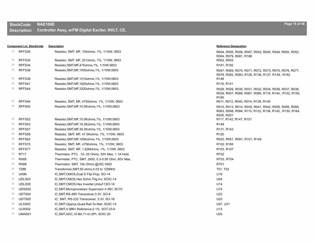
StockCode: NAE106E Page 15 of 46
Description: Controller Assy, w/FM Digital Exciter, NVLT, CE,
Component Lvl, StockCode Reference DesignationDescription
RFFS2602 Resistor, SMT, MF, 100ohms, 1%, 1/10W, 0603 R004, R005, R006, R007, R043, R045, R049, R050, R052, R064, R079, R081, R186
RFFS3002 Resistor, SMT, MF, 221ohms, 1%, 1/10W, 0603 R002, R003RFFS3402 Resistor,SMT,MF,475ohms,1%, 1/10W,0603 R191, R192RFFS3802 Resistor,SMT,MF,1000ohms,1%, 1/10W,0603 R047, R069, R070, R071, R072, R073, R075, R076, R077,
R078, R082, R083, R126, R136, R137, R139,, R162RFFS3902 Resistor,SMT,MF,1210ohms,1%, 1/10W,0603 R146RFFS4102 Resistor,SMT,MF,1820ohms,1%, 1/10W,0603 R116, R141RFFS4402 Resistor,SMT,MF,3320ohms,1%, 1/10W,0603 R028, R029, R030, R031, R032, R034, R036, R037, R038,
R039, R057, R066, R067, R080, R119, R144,, R152, R159, R195
RFFS4602 Resistor, SMT, MF, 4750ohms, 1%, 1/10W, 0603 R011, R012, R040, R074, R129, R140RFFS5002 Resistor,SMT,MF,10.0Kohms,1%, 1/10W,0603 R010, R013, R014, R035, R041, R042, R055, R056, R058,
R063, R068, R084, R115, R122, R138, R145,, R150, R164, R200, R201
RFFS5202 Resistor,SMT,MF,15.0Kohms,1%, 1/10W,0603 R117, R142, R147, R151RFFS5302 Resistor,SMT,MF,18.2Kohms,1%, 1/10W,0603 R148RFFS5702 Resistor,SMT,MF,39.2Kohms,1%, 1/10W,0603 R131, R143RFFS5802 Resistor, SMT, MF, 47.5Kohms, 1%, 1/10W, 0603 R120RFFS6202 Resistor,SMT,MF,100Kohms,1%, 1/10W,0603 R025, R051, R091, R101, R149RFFS7002 Resistor, SMT, MF, 475Kohms, 1%, 1/10W, 0603 R102, R165RFFS7702 Resistor, SMT, MF, 1.82Mohms, 1%, 1/10W, 0603 R103, R167RT1702 Thermistor, PTC, .15-.25 Ohms, 50V Max, 1.1A Hold, RT02RX6502 Thermister, PTC, SMT, 2920, 0.3-0.95 Ohm, 60V Max, RT03, RT04RX6802 Thermistor, SMT, 10k Ohms @25C 0402 RT01TZ8802 Transformer,SMT,50 ohms,0.03 to 125MHz T01, T02UA9602 IC,SMT,CMOS,Dual D Flip-Flop, SO-14 U19UDLS0302 IC,SMT,CMOS,Hex Schm,Trig,Inv, SOIC-14 U04UDLS0902 IC,SMT,CMOS,Hex Inverter,Unbuf f,SO-14 U14UDSS0202 IC,SMT,Microprocessor Supervisor 4.38V, SC70 U15UDTS0402 IC,SMT,RS-485 Transceiver,3.3V ,SO-8 U22UDTS0502 IC, SMT, RS-232 Transceiver, 3.3V, SO-16 U03ULAS0202 IC,SMT,Opamp,Quad,Rail-To-Rail ,SOIC-14 U07, U21ULRS0202 IC,SMT,4.096V Reference,0.1%, SOT-23-6 U13UMAS0102 IC,SMT,ADC,10-Bit,11-ch,SPI, SOIC-20 U05

StockCode: NAE106E Page 16 of 46
Description: Controller Assy, w/FM Digital Exciter, NVLT, CE,
Component Lvl, StockCode Reference DesignationDescription
UP11202 IC, SMT, Step Down Reg., 75V, 3A, TSSOP-20 U08, U10, U16US3102 IC, SMT, CMOS, Quad Tri-State Buff, SOIC-14 U12US4102 IC, SMT, CMOS, Quad XOR Gate SOIC-14 U01UT11002 IC, Voltage Regulator, 1.5A, ADJ, Low Drop U18UT7402 IC, Amplifier, Instrumentation U06, U20UW11402 IC, SMT, Dual SPI UART, 3.3V U02XFPS1802 Crystal, SMT, Fund, Par Res, 14.7456MHz, 30ppm, 18 Y01
RX4901 Thermistor,-30/105ºC,10Kohms@ 25ºC,Neg,Bvalue 3435 RT01
ZAP5001 Fan, 80mm, Brushless, 48Vdc, EMI Caps, Tach w/conn B01
END OF ITEM

StockCode: NAE107D Page 17 of 46
Description: FM Digital Exciter Assy, NVLT/GV (Analog),
Component Lvl, StockCode Reference DesignationDescription
206-306001 LED PWB Assy A06CCFS0702 Cap,SMT,Ceramic,0.1uF,10%,50V,X7R,0805 C01, C02, C03, C04HR10702 LED,Light Pipe,Optical,PWB, Right Angle HW01, HW02JU2502 MTA, Keyed Square Post Header Assy, 4 pin J01LCFS0102 Inductor, SMT, Choke, 600ohms, 2A, 0805 L01, L02, L03, L04QDLS0402 Diode,SMT,LED,Bicolor,Red/ Green,1210 DS01, DS02RFFS3002 Resistor, SMT, MF, 221ohms, 1%, 1/10W, 0603 R02, R03, R04RFFS3402 Resistor,SMT,MF,475ohms,1%, 1/10W,0603 R01
219-3102-0101 Cableset Assy Exciter NVLT/GV (NAE107B)JDP2402 Conn, Coax, BNC, Plug, 50ohm, Crimp W1P1, W1P2, W2P1JQ1702 Conn, Contact, Pin, HDP-20 Strip P01JQ1802 Conn, Contact, Socket, HDP-20 Strip P02JR3802 Conn, Socket, D-Sub, HDP-20, 2 5 pin P02JR3902 Conn, Plug, D-Sub, 25 pin, HDP -20 P01JT1602 Conn, Lock Screw, D-Sub, 4-40, Male, Kit P01, P02JT6002 Conn, Coax, BNC, Recept, Bulkhead, RG188 J01, J03, W2J1JU0202 MTA, Standard Dust Cover, 4 pi n P04JU0702 MTA, Standard Dust Cover, 8 pi n P03JU2702 MTA, Keyed Closed End Housing, 4 pin,22AWG P04JU2802 MTA, Keyed Closed End Housing, 8 pin,22AWG P03LA0202 Toroid, Ferrite, 12.7mm, K Mtl W1L1
CBP0801 Capacitor, Feed-Thru, Ceramic, 1000pF C01, C02, C03, C04, C05, C06, C07, C08, C09
JA7601 Conn,Coupler,RJ45,Feed-Thru, Shielded U01
JDP2101 Conn, Coax, N, Recept, Panel, 50ohm J02

StockCode: NAE107D Page 18 of 46
Description: FM Digital Exciter Assy, NVLT/GV (Analog),
Component Lvl, StockCode Reference DesignationDescription
NAPA31C01 PA PWB Assy, LDMOS (QAP66) A04CS9402 Capacitor, SMT, Porcelain,36pF 500V, 2% C18CS9502 Capacitor, SMT, Porcelain,15pF 500V, 2% C15CS9602 Capacitor, SMT, Porcelain, 2pF 500V, +/-0.1pF C14CT5202 Capacitor,SMT,Ceramic,470pF, 200V,10% C17CT5302 Capacitor,SMT,Ceramic,0.001uF, 50V,10% C08, C10, C12, C16CT6602 Capacitor, SMT, Ceramic, 0.1uF 10%, 100V C06, C20CT7402 Cap, SMT, Ceramic, 10uF, X7R, 100V, Stacked C21, C22CT7502 Cap, SMT, Electrolytic, 470uF, 20%, 63VDC, Low ESR C01, C02, C03, C04, C05CT7902 Capacitor, SMT, Ceramic,0.01uF 50V, 10% C11, C13FA6402 Fuse, SMT, 125VAC, VDC, 30A, Fast Acting F01LS2602 Inductor, SMT, 82nH, 2%, 2.5A, 4.20mm H x 4.95mm L05LS4002 Inductor, SMT, 5nH, 5%, Mini Spring L01, L03LS4102 Inductor, SMT, 100nH, 5%, Midi Spring L02QAP6602 Transistor, FET, LDMOS, Dual, Ruggedized Q01QDSS0102 Diode, SMT, Schottky, 30V, 0.2A, SOD-323 CR01QDZS0102 Diode,SMT,Zener,5.1V,5%,3W,SMB CR02RAD4502 Resistor, SMT, MF, 47.5K Ohms, 1% 1/4W R01RAD49Z02 Resistor,SMT,MF,10ohms, 1%,2W R02RAD54Z02 Resistor,SMT,4.7 ohms, 5%,2W R04, R05RAD8002 Resistor, SMT,10k Ohms, 1%, 1W 2512 R03TZ11802 Transformer, Gate Drive, VHF, 3T/1 Turn T03WE5402 Cable, Coax, 12 Ohm, 600V, 200 C, TFE T02A, T02BWE5602 Cable, Coax, 50 Ohm, 70% VP, 150C, PTFE, 11mm Min T01
NAPA3501 PA PWB Assy, RFMD A03CCFS0102 Cap,SMT,Ceramic,0.001uF,10%,50V,X7R,0603 C19CCFS0402 Cap,SMT,Ceramic,0.01uF,10%,50V,X7R,0603 C04, C06, C14, C20, C22CCFS0702 Cap,SMT,Ceramic,0.1uF,10%,50V,X7R,0805 C24CCFS6002 Cap,SMT,Ceramic,1uF,10%,100V, X7R,1210 C10, C12, C15CCFS6202 Cap, SMT, Ceramic, 10uF, 10%, 25V C05, C11
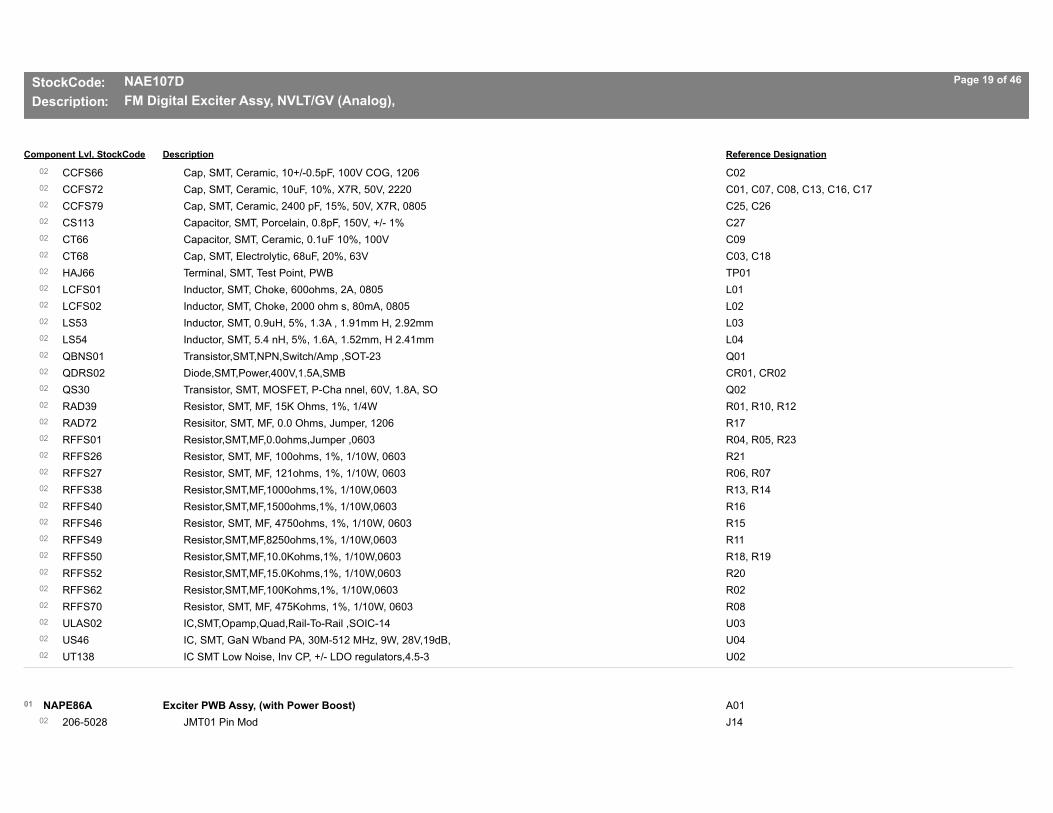
StockCode: NAE107D Page 19 of 46
Description: FM Digital Exciter Assy, NVLT/GV (Analog),
Component Lvl, StockCode Reference DesignationDescription
CCFS6602 Cap, SMT, Ceramic, 10+/-0.5pF, 100V COG, 1206 C02CCFS7202 Cap, SMT, Ceramic, 10uF, 10%, X7R, 50V, 2220 C01, C07, C08, C13, C16, C17CCFS7902 Cap, SMT, Ceramic, 2400 pF, 15%, 50V, X7R, 0805 C25, C26CS11302 Capacitor, SMT, Porcelain, 0.8pF, 150V, +/- 1% C27CT6602 Capacitor, SMT, Ceramic, 0.1uF 10%, 100V C09CT6802 Cap, SMT, Electrolytic, 68uF, 20%, 63V C03, C18HAJ6602 Terminal, SMT, Test Point, PWB TP01LCFS0102 Inductor, SMT, Choke, 600ohms, 2A, 0805 L01LCFS0202 Inductor, SMT, Choke, 2000 ohm s, 80mA, 0805 L02LS5302 Inductor, SMT, 0.9uH, 5%, 1.3A , 1.91mm H, 2.92mm L03LS5402 Inductor, SMT, 5.4 nH, 5%, 1.6A, 1.52mm, H 2.41mm L04QBNS0102 Transistor,SMT,NPN,Switch/Amp ,SOT-23 Q01QDRS0202 Diode,SMT,Power,400V,1.5A,SMB CR01, CR02QS3002 Transistor, SMT, MOSFET, P-Cha nnel, 60V, 1.8A, SO Q02RAD3902 Resistor, SMT, MF, 15K Ohms, 1%, 1/4W R01, R10, R12RAD7202 Resisitor, SMT, MF, 0.0 Ohms, Jumper, 1206 R17RFFS0102 Resistor,SMT,MF,0.0ohms,Jumper ,0603 R04, R05, R23RFFS2602 Resistor, SMT, MF, 100ohms, 1%, 1/10W, 0603 R21RFFS2702 Resistor, SMT, MF, 121ohms, 1%, 1/10W, 0603 R06, R07RFFS3802 Resistor,SMT,MF,1000ohms,1%, 1/10W,0603 R13, R14RFFS4002 Resistor,SMT,MF,1500ohms,1%, 1/10W,0603 R16RFFS4602 Resistor, SMT, MF, 4750ohms, 1%, 1/10W, 0603 R15RFFS4902 Resistor,SMT,MF,8250ohms,1%, 1/10W,0603 R11RFFS5002 Resistor,SMT,MF,10.0Kohms,1%, 1/10W,0603 R18, R19RFFS5202 Resistor,SMT,MF,15.0Kohms,1%, 1/10W,0603 R20RFFS6202 Resistor,SMT,MF,100Kohms,1%, 1/10W,0603 R02RFFS7002 Resistor, SMT, MF, 475Kohms, 1%, 1/10W, 0603 R08ULAS0202 IC,SMT,Opamp,Quad,Rail-To-Rail ,SOIC-14 U03US4602 IC, SMT, GaN Wband PA, 30M-512 MHz, 9W, 28V,19dB, U04UT13802 IC SMT Low Noise, Inv CP, +/- LDO regulators,4.5-3 U02
NAPE86A01 Exciter PWB Assy, (with Power Boost) A01206-502802 JMT01 Pin Mod J14

StockCode: NAE107D Page 20 of 46
Description: FM Digital Exciter Assy, NVLT/GV (Analog),
Component Lvl, StockCode Reference DesignationDescription
BBHT0102 Holder, 20mm Coin Cell, PWB Mt XBT01BBLT0102 Battery, Lithium, 3V,20mm Coin Cell BT01CCFS0102 Cap,SMT,Ceramic,0.001uF,10%,50V,X7R,0603 C034, C050, C053, C089, C096, C098, C139, C140, C141,
C142, C143, C144, C157, C158, C159, C161,, C164, C166, C316, C319, C339
CCFS0302 Cap,SMT,Ceramic,0.0047uF,10%, 50V,X7R,0603 C015, C020, C035, C038CCFS0402 Cap,SMT,Ceramic,0.01uF,10%,50V,X7R,0603 C117, C129, C130CCFS0602 Cap, SMT, Ceramic, 0.047uF, 10%, 50V, X7R, 0603 C018, C036CCFS1002 Cap,SMT,Ceramic,1uF,10%,25V,X7R,1206 C113, C116, C118CCFS2302 Cap,SMT,Ceramic,18pF,2%,50V, C0G,0603 C031, C032, C039, C040, C234, C235CCFS3202 Cap,SMT,Ceramic,100pF,2%,50V,C0G,0603 C041, C042, C044, C046, C067, C068, C069, C076, C079,
C080, C082, C087, C088, C090, C262, C265,, C273, C279, C294, C297, C305, C307
CCFS3402 Cap,SMT,Ceramic,220pF,2%,50V, C0G,0603 C004, C005, C006, C014, C016, C017, C019, C021, C037CCFS3702 Cap,SMT,Ceramic,390pF,2%,50V,C0G,0603 C043CCFS4202 Cap,SMT,Ceramic,1000pF,2%,50V, C0G,0805 C054, C063, C065, C073, C075, C077, C078, C081, C084,
C085, C086, C091, C114, C119, C125, C126,, C131, C132

StockCode: NAE107D Page 21 of 46
Description: FM Digital Exciter Assy, NVLT/GV (Analog),
Component Lvl, StockCode Reference DesignationDescription
CCFS5202 Cap, SMT, Ceramic, 0.1uF, 10%, 25V X7R, 0603 C003, C009, C010, C012, C024, C025, C029, C030, C047, C051, C057, C060, C062, C064, C066, C071,, C072, C092, C093, C094, C095, C097, C100, C101, C102, C103, C104, C105, C107, C108, C109, C110,, C120, C121, C122, C123, C124, C127, C128, C133, C134, C135, C136, C137, C145, C146, C147, C148,, C149, C150, C151, C152, C153, C154, C155, C156, C160, C162, C163, C165, C167, C168, C169, C170,, C171, C173, C174, C175, C176, C177, C178, C179, C180, C182, C183, C184, C185, C186, C187, C188,, C189, C190, C191, C192, C193, C194, C195, C196, C197, C198, C199, C200, C201, C202, C203, C204,, C205, C206, C207, C208, C209, C210, C211, C212, C213, C214, C215, C216, C217, C218, C219, C220,, C221, C222, C224, C225, C226, C227, C228, C229, C230, C231, C233, C236, C237, C238, C239, C240,, C241, C242, C244, C245, C246, C247, C248, C249, C250, C251, C252, C253, C254, C255, C256, C257,, C258, C259, C260, C261, C263, C264, C266, C267, C268, C269, C270, C271, C272, C274, C275, C276,, C277, C278, C280, C281, C282, C283, C284, C286, C287, C288, C289, C290, C291, C292, C293, C295,, C296, C298, C299, C300, C301, C302, C303, C304, C306, C308, C309, C310, C311, C312, C313, C314,, C315, C317, C320, C321, C322, C323, C324, C325, C326, C327, C328, C329, C330, C331, C332, C333,, C334, C335, C336, C338, C340, C341, C342, C344, C345, C346, C347, C348, C349, C350, C352, C353,, C354, C355, C356, C358, C359, C360, C362, C363, C364, C365
CCFS5302 Cap, SMT, Ceramic,47uF,20%, 6.3V, 1210 C001, C002, C008, C026, C027, C028, C074, C083, C106, C357
CCFS5702 Cap,SMT,Ceramic,10uF,20%,6.3V, X5R,0805 C007, C048, C049, C052, C055, C056, C115, C172, C181, C223, C232, C243, C285, C318, C337, C343,, C361
CCFS6202 Cap, SMT, Ceramic, 10uF, 10%, 25V C045, C058, C061, C070, C111, C351CT5702 Capacitor, SMT, Al Electroytic 330uF, 25VDC,ESR 0. C011, C013, C022, C023, C033CT6802 Cap, SMT, Electrolytic, 68uF, 20%, 63V C059, C099CTFS0402 Cap,SMT,Tantalum,100uF,10%,10V,2917 C112CX3802 Cap,SMT,Ceramic,4.7uF,10%,10V, X5R, 1206 C138HAJ6602 Terminal, SMT, Test Point, PWB TP01, TP04, TP07, TP10, TP11, TP14JF3502 Conn, BNC, Recept, PWB Mt J13, J15JF4702 Conn, Header,Square Post,Gold, Dual,40-pin J16JM4402 Conn, Modular Jack, RJ45, Shld , Side, PWB, 50u J02

StockCode: NAE107D Page 22 of 46
Description: FM Digital Exciter Assy, NVLT/GV (Analog),
Component Lvl, StockCode Reference DesignationDescription
JN6002 Conn, Receptacle, Right Angle, SMA, PWB Mount J01JQ1502 Conn, Post Shunt, 2 Pos, .10 C entreline E01, E02JQ1602 Conn, Header, SIP, 12 Pin Breakaway, 10 Ctr XE01, XE02JQ5402 Conn, Header, Ribbon Cbl, 10- Pin J11JQ7702 Conn, SMT, Header, Ribbon Cabl e, 14 pin J10JS1802 Conn, Plug, D-Sub, 15 pin, PWB Mt J05JS4302 Conn, Plug, D-Sub, 25 pin, Ver t PWB J09JT10002 Conn, Dual, BNC, PWB, Rt Angle J07, J08JT6102 Conn, BNC, Recept, 50ohm,Insul , Rt Angle J06JT8702 Conn,3-pin,PWB Mount, Fem, XLR J04JT9902 Connector, Dual, D-Sub, F/F, 9 pin, Rt. Angle, PWB J03JU2502 MTA, Keyed Square Post Header Assy, 4 pin J12LCFS0102 Inductor, SMT, Choke, 600ohms, 2A, 0805 L01, L02, L03, L05, L07, L11, L12, L14, L15, L17, L18, L20,
L21LS1702 Inductor,SMT,Pwr,Shielded,P116 7 Series,3.5A,3.6uH L04, L06, L10LS2002 Inductor,SMT,560nH,325mA,2520 L08, L09, L13, L19QBNS0102 Transistor,SMT,NPN,Switch/Amp ,SOT-23 Q01, Q03QDRS0102 Diode,SMT,Switching,250V,0.2A, SOD-323 CR01, CR04QDSS0102 Diode, SMT, Schottky, 30V, 0.2A, SOD-323 CR05, CR06QM4802 Diode,SMT,Transient Suppr,10V, SMB CR02, CR03QS2602 Transistor, SMT, P-Channel FET 130mA Q02RAD1502 Resistor, SMT, MF, 150 Ohms, 1% 1/4W R030, R035, R041, R047RAD2602 Resistor, SMT, MF, 1210 Ohms, 1% 1/4W R092, R093, R114, R115, R123, R124, R135, R136RAD4402 Resistor, SMT, MF, 39.2K Ohms, 1% 1/4W R261, R265, R268, R272, R275, R279, R282, R286RAD5702 Resistor, SMT, 25.5 ohms, 1%, 2512 R205, R211RAE2502 Resistor,SMT,MF,3.74K,1%,1/10W ,0603 R014RAE3402 Resistor,SMT,MF,49.9R,1%,1/10W 0603 R004, R061, R071, R084, R125, R126, R127, R145, R153,
R155, R163, R168, R178, R179, R181, R185,, R189, R190, R191, R196, R198, R199, R200, R203, R206, R207, R208, R209, R215, R216, R225
RFFS0102 Resistor,SMT,MF,0.0ohms,Jumper ,0603 R259, R289RFFS0202 Resistor, SMT, MF, 1.00ohms, 1%, 1/10W, 0603 R220, R221RFFS1402 Resistor, SMT, MF, 10.0ohms, 1%, 1/10W, 0603 R246RFFS1802 Resistor, SMT, MF, 22.1ohms, 1%, 1/10W, 0603 R023, R045, R066, R072, R159, R210, R224, R226RFFS2102 Resistor, SMT, MF, 39.2ohms, 1%, 1/10W, 0603 R263, R267, R270, R274, R277, R281, R284, R288

StockCode: NAE107D Page 23 of 46
Description: FM Digital Exciter Assy, NVLT/GV (Analog),
Component Lvl, StockCode Reference DesignationDescription
RFFS2602 Resistor, SMT, MF, 100ohms, 1%, 1/10W, 0603 R021, R036, R044, R054, R062, R081, R104, R148, R176, R177, R183, R186, R195, R201, R214, R231,, R247, R250, R264, R271, R278, R285
RFFS2702 Resistor, SMT, MF, 121ohms, 1%, 1/10W, 0603 R151, R157RFFS2802 Resistor, SMT, MF, 150ohms, 1%, 1/10W, 0603 R042, R043RFFS3002 Resistor, SMT, MF, 221ohms, 1%, 1/10W, 0603 R016, R033RFFS3102 Resistor, SMT, MF, 274ohms, 1%, 1/10W, 0603 R055, R079, R218, R262, R266, R269, R273, R276, R280,
R283, R287RFFS3302 Resistor, SMT, MF, 392ohms, 1%, 1/10W, 0603 R031, R032, R037, R040, R049, R053, R057, R074, R075,
R078, R080RFFS3402 Resistor,SMT,MF,475ohms,1%, 1/10W,0603 R003, R077, R095, R166, R173, R175RFFS3602 Resistor, SMT, MF, 681ohms, 1%, 1/10W, 0603 R086, R105, R111, R120, R122, R129, R132, R147RFFS3702 Resistor, SMT, MF, 825ohms, 1%, 1/10W, 0603 R073RFFS3802 Resistor,SMT,MF,1000ohms,1%, 1/10W,0603 R005, R006, R008, R013, R022, R038, R069, R076, R085,
R087, R088, R089, R091, R097, R101, R102,, R103, R107, R110, R117, R118, R119, R121, R128, R131, R146, R154, R156, R217, R230
RFFS3902 Resistor,SMT,MF,1210ohms,1%, 1/10W,0603 R052, R139, R140, R141, R152, R158RFFS4002 Resistor,SMT,MF,1500ohms,1%, 1/10W,0603 R094, R096RFFS4202 Resistor,SMT,MF,2210ohms,1%, 1/10W,0603 R001, R002, R007, R009, R010, R019, R098, R165, R172,
R180, R236RFFS4502 Resistor,SMT,MF,3920ohms,1%, 1/10W,0603 R020, R039, R233RFFS4602 Resistor, SMT, MF, 4750ohms, 1%, 1/10W, 0603 R229, R235RFFS5002 Resistor,SMT,MF,10.0Kohms,1%, 1/10W,0603 R015, R017, R018, R024, R025, R026, R027, R034, R046,
R048, R050, R051, R056, R058, R060, R063,, R064, R065, R067, R068, R070, R082, R083, R099, R100, R106, R109, R112, R113, R116, R130, R133,, R134, R137, R138, R142, R143, R144, R150, R161, R162, R164, R167, R169, R170, R171, R174, R182,, R184, R187, R188, R192, R193, R194, R197, R202, R204, R212, R213, R237, R238, R239, R240, R241,, R242, R248, R253, R254, R256, R257, R258, R290, R291
RFFS5602 Resistor, SMT, MF, 33.2Kohms, 1%, 1/10W, 0603 R232RFFS5802 Resistor, SMT, MF, 47.5Kohms, 1%, 1/10W, 0603 R090RFFS5902 Resistor,SMT,MF,56.2Kohms,1%, 1/10W,0603 R219RFFS6002 Resistor,SMT,MF,68.1Kohms,1%, 1/10W,0603 R059RFFS6202 Resistor,SMT,MF,100Kohms,1%, 1/10W,0603 R011, R012, R028

StockCode: NAE107D Page 24 of 46
Description: FM Digital Exciter Assy, NVLT/GV (Analog),
Component Lvl, StockCode Reference DesignationDescription
RFFS8302 Resistor, SMT, MF, 28.7K Ohms, 1%, 1/10W, 0603 R029RFFS8702 Resistor, SMT, 200ohm, 1%, 1/10W, 0603 R222, R223, R227, R228, R234, R244RFFS8802 Resistor, SMT, MF, 10.0Mohms, 1%, 1/10W, 0603 R260SA6002 Switch,SMt,Mom.,1PSTNO S01TZ10202 Transformer, SMT, Balun, 4.5- 1000MHz T04TZ10302 Transformer, SMT, 4:1, 2-300 MHz T03TZ7002 Transformer, SMT, 1:1 0 800MHz T05TZ8802 Transformer,SMT,50 ohms,0.03 to 125MHz T01, T02UD6502 IC,SMT,Differential Line Receivr, 100dB CMR U11UDLS0902 IC,SMT,CMOS,Hex Inverter,Unbuf f,SO-14 U32UDTS0402 IC,SMT,RS-485 Transceiver,3.3V ,SO-8 U29, U55, U57, U60UDTS0502 IC, SMT, RS-232 Transceiver, 3.3V, SO-16 U49UM6102 Filter, SMT, Band Pass FM U64UP10402 IC, SMT, Voltage Regulator, Dual, ADJ TSSOP16 U16UP9302 IC,SMT,Op Amp,Audio,Dual,SO-8 U02, U03, U06, U12, U17, U19, U22, U27, U30US0302 IC, SMT, CMOS, Dual 4-1 MUX, TSSOP-16 U44, U51US0502 IC, SMT, RF DAC, 1GSPS, TQFP- 100 U58US0702 IC, SMT, ADC, 1.25MSPS, 16bit, TQFP-48 U13US0802 IC, SMT, Blackfin DSP, 500MHz, bga-316 U38US0902 IC, SMT, Battery Backup,SOIC-8 U20US1202 IC, SMT, Rectifier, Bridge, 400V, 0.5A, SOIC-4 U67, U68, U69, U70, U71, U72US1302 IC, SMT, SDRAM, 16Mx16, 3.3V, TSOP-54 U26US1602 IC, SMT, Differential Audio Am p, MSOP-8 U14, U18, U23, U28, U31US1702 IC, SMT, Audio DAC, 24-bit,192 KHz, SSOP-28 U01US1802 IC, SMT, ADC, 4ch, 24-bit, 192 KHz U25US1902 IC, SMT, Digital Step Attenator, QFN-20 U62, U66US2002 IC, SMT, stereo Volume Control , SOIC-16 U08US2102 IC, SMT, SiGe Gain Block, 20dB , SOT-89-3 U65US2202 IC, SMT, Dual LVDS, Transceive r, TSSOP-16 U52, U54US2502 IC, SMT, ADC, 11-ch, 10-bit, 3.3V, SPI, SSOP-20 U21US2902 IC, SMT, CMOS, PLL/Divider, 48-LFCSP U63US3102 IC, SMT, CMOS, Quad Tri-State Buff, SOIC-14 U15US3302 Oscillator, SMT, VCSO, 635.04 MHz Fund, LVPECL Y02UT11002 IC, Voltage Regulator, 1.5A, ADJ, Low Drop U47

StockCode: NAE107D Page 25 of 46
Description: FM Digital Exciter Assy, NVLT/GV (Analog),
Component Lvl, StockCode Reference DesignationDescription
UT11402 IC, Voltage Regulator, +8V, 1A DPAK U59UT11602 Oscillator, SMT, TCVCXO, 3.3V, 2ppm, 5x3.2mm U33UT8302 IC,SMT,Ultrafast Single Supply Comparator,TSSOP U46UT9302 IC,SMT,Voltage Regulator,5V, 1A, D2PAK U05UW12502 IC, SMT, SPI Flash, 32Mbit, SOIC8W U50UW12602 IC, SMT, FPGA, Spartan 3A-DSP- 3400 484BGA U56UW6302 Res,SMT Network,0402x8,39R U35, U36, U37, U39, U41, U42, U45UW8002 IC,SMT,SRC,Async,2-ch,TQFP-48 U34, U43UW9102 IC,SMT,SPI UART,3.3V U48, U53UW9402 IC,SMT,ADC,RF,14 bit,TQFP-64 U61UX6402 IC,SMT,Power Supervisor,Dual I/P,33/1.5V,MSOP U10UX6502 IC,SMT,3A Sync Buck Converter, SO-20 w/pwr pad U04, U07UX8302 IC,SMT,2.5V Reference,0.1%,SOT -23-6 U09, U24XFPS02Z02 Crystal,SMT,Fund,Par Res, 32.768kHz Y01
NAPP06/0101 Output Power Probe PWB Assy, NVE-LT A05CCFS0402 Cap,SMT,Ceramic,0.01uF,10%,50V,X7R,0603 C04, C10CCFS0702 Cap,SMT,Ceramic,0.1uF,10%,50V,X7R,0805 C06, C07CCFS1002 Cap,SMT,Ceramic,1uF,10%,25V,X7R,1206 C03, C09CCFS6202 Cap, SMT, Ceramic, 10uF, 10%, 25V C05, C08CX3802 Cap,SMT,Ceramic,4.7uF,10%,10V, X5R, 1206 C01RAD0502 Resistor, SMT, MF, 22.1 Ohms, 1% 1/4W R05, R25RAD1102 Resistor, SMT, MF, 68.1 Ohms, 1% 1/4W R22RAD1202 Resistor, SMT, MF, 82.5 Ohms, 1% 1/4W R06, R23, R24RAD1402 Resistor, SMT, MF, 121 Ohms, 1%, 1/4W, 1206 R03, R07, R12RAD1502 Resistor, SMT, MF, 150 Ohms, 1% 1/4W R11, R14, R15, R16, R17, R30, R31, R32RAD1702 Resistor, SMT, MF, 221 Ohms, 1% 1/4W R04, R13RAD1802 Resistor, SMT, MF, 274 Ohms, 1% 1/4W R18, R27RAD1902 Resistor, SMT, MF, 332 Ohms, 1% 1/4W R02, R09, R19, R21, R26, R28RAD2502 Resistor, SMT, MF, 1000 Ohms, 1% 1/4W R08RAD2902 Resistor, SMT, MF, 2210 Ohms, 1% 1/4W R01, R10, R20, R29UX12202 IC, SMT, tru RMS power detecto r, 5.5V U01, U02

StockCode: NAE107D Page 26 of 46
Description: FM Digital Exciter Assy, NVLT/GV (Analog),
Component Lvl, StockCode Reference DesignationDescription
NAPS47E/0101 PS Distribution PWB Assy, (used w/NAPA35) A02CCFS0102 Cap,SMT,Ceramic,0.001uF,10%,50V,X7R,0603 C004, C008, C115, C117CCFS0202 Cap,SMT,Ceramic,0.0022uF,10%, 50V,X7R,0603 C041CCFS0402 Cap,SMT,Ceramic,0.01uF,10%,50V,X7R,0603 C014, C046, C049, C054, C062, C080, C100, C102CCFS0502 Cap,SMT,Ceramic,0.022uF,10%,50 V,X7R,0603 C070, C071, C077, C104CCFS1002 Cap,SMT,Ceramic,1uF,10%,25V,X7R,1206 C003, C009, C141CCFS2302 Cap,SMT,Ceramic,18pF,2%,50V, C0G,0603 C016, C019CCFS2402 Cap,SMT,Ceramic,22pF,2%,50V, C0G,0603 C031, C096, C120, C123, C124, C126, C139CCFS3202 Cap,SMT,Ceramic,100pF,2%,50V,C0G,0603 C018, C020, C023, C029, C030, C087, C140CCFS3402 Cap,SMT,Ceramic,220pF,2%,50V, C0G,0603 C055, C056, C057CCFS3602 Cap,SMT,Ceramic,330pF,2%,50V, C0G,0603 C088, C089, C090CCFS3802 Cap,SMT,Ceramic,470pF,2%,50V, C0G,0603 C032, C107, C121, C127, C130, C132, C134CCFS4202 Cap,SMT,Ceramic,1000pF,2%,50V, C0G,0805 C118CCFS5202 Cap, SMT, Ceramic, 0.1uF, 10%, 25V X7R, 0603 C013, C015, C026, C028, C038, C042, C043, C044, C045,
C047, C048, C050, C051, C052, C053, C058,, C059, C064, C065, C066, C068, C074, C075, C076, C081, C083, C084, C085, C086, C091, C092, C093,, C095, C106, C108, C111, C116, C119, C122, C131, C133, C136, C137, C142
CCFS5302 Cap, SMT, Ceramic,47uF,20%, 6.3V, 1210 C034, C035, C039, C040CCFS6002 Cap,SMT,Ceramic,1uF,10%,100V, X7R,1210 C025, C060, C069CCFS6102 Cap,SMT,Ceramic,0.001uF,10%, 100V,X7R,0805 C005, C073, C098, C099, C128, C138CCFS6202 Cap, SMT, Ceramic, 10uF, 10%, 25V C002, C021, C037CCFS7202 Cap, SMT, Ceramic, 10uF, 10%, X7R, 50V, 2220 C036CT5002 Capacitor,SMT,Ceramic,0.01uF, 100V,10% C067CT5102 Capacitor,SMT,Ceramic,0.1uF, 100V,10% C007, C078, C094, C097, C109, C125, C135CT5702 Capacitor, SMT, Al Electroytic 330uF, 25VDC,ESR 0. C010, C011, C012CT6402 Capacitor, SMT, Ceramic, 2.2uF 10%, 100V, X7R, 181 C006, C063, C072, C082, C101, C103, C105, C110, C112,
C113, C114CT7502 Cap, SMT, Electrolytic, 470uF, 20%, 63VDC, Low ESR C001, C033, C061, C079CTFS0202 Cap,SMT,Tantalum,1uF,10%,35V, 1411 C017, C022, C024, C027, C129FA5602 Fuse, SMT, Fuse Block, 7A VeryFast Acting Installe F01FA7202 Fuse, 20A, 150V, 10x38mm, High Speed F02FC2702 Fuse Clip, 20A, 13/32 Dia Fuse, PWBMt XF2

StockCode: NAE107D Page 27 of 46
Description: FM Digital Exciter Assy, NVLT/GV (Analog),
Component Lvl, StockCode Reference DesignationDescription
HAJ6602 Terminal, SMT, Test Point, PWB TP01, TP03, TP04, TP05, TP06, TP07, TP08, TP09, TP10, TP11TP12
JF4702 Conn, Header,Square Post,Gold, Dual,40-pin J02JS1302 Conn, Socket, D-Sub, 25 pin, P WB Mt J03JT14802 Connector, Header, 2 pos, 90 deg, PWB,20A, 600V, 7 J01JU6002 MTA, Keyed Square Post Header Assy, 3 pin J04KC5102 Relay,24Vdc,FORM A,NO,80 Amp PWB K01LA4402 Inductor, Choke, Toroid, 10uH, 10A L41LCFS0102 Inductor, SMT, Choke, 600ohms, 2A, 0805 L01, L02, L03, L04, L05, L06, L07, L08, L10, L11, L15, L16,
L17, L18, L19, L22, L23, L24, L33, L39LCFS0202 Inductor, SMT, Choke, 2000 ohm s, 80mA, 0805 L09, L20, L25, L26, L28, L29, L30, L31, L32, L34, L35, L36,
L37, L38LS2402 Inductor, SMT, 10uH, 2.4A, RMS L21LS4502 Inductor, SMT, Shielded, 33uH, 3.3A RMS L12, L13, L14LS4602 Choke. Common Mode, 170ohms @100MHz. 20A L27LS4902 Inductor, Toroid, 10uH, 20A L40QBNS0102 Transistor,SMT,NPN,Switch/Amp ,SOT-23 Q03QDDS0202 Diode, SMT, Schottky, 40V, 1A, SMA CR08QDLS0102 Diode, SMT, LED, Green, (560nm), 0603 DS02QDLS0702 Diode, SMT, LED, Amber, (592nm), 0603 DS03QDRS0102 Diode,SMT,Switching,250V,0.2A, SOD-323 CR07, CR09, CR10, CR12, CR13QDS0202 Diode, SMT, Schottky, 3.5Ax2, 100V DPAK U05, U06, U07QDZS0202 Diode,SMT,Zener,15V,5%,3W,SMB CR11QM6602 LED, Bi-Level, PWB Mount, Thru -hole, Green/Green DS01QMN0102 Transister, FET, SMT, N-ch, 100V, DPAK Q01QN5302 Transistor,SMT,MOSFET,N-Channe l,60V,115mA,SOT-23 Q04, Q05, Q06QR7002 Suppressor, Transient Voltage, SMT 60V Clamp CR01, CR02, CR03, CR04, CR05, CR06QR7102 Transistor, FET, P-channel, D2Pak Q02RAD2102 Resistor, SMT, MF, 475 Ohms, 1% 1/4W R011, R107, R127, R128, R130, R133, R141RAD3702 Resistor, SMT, MF, 10.0K Ohms, 1%, 1/4W R057, R064, R065, R067, R104, R105, R118, R119RAD4102 Resistor, SMT, MF, 22.1K Ohms, 1% 1/4W R068, R070, R071, R152RAD4802 Resistor, SMT, MF, 82.5K Ohms, 1% 1/4W R072RAD49Z02 Resistor,SMT,MF,10ohms, 1%,2W R047, R048, R049RAD7502 Resistor, SMT, 2 Ohms, 5%, 1/4 W, 1206 R017, R069RAD7602 Resistor, SMT, 1000 Ohms, 5%, 1W, 2512 R012, R020, R031, R040

StockCode: NAE107D Page 28 of 46
Description: FM Digital Exciter Assy, NVLT/GV (Analog),
Component Lvl, StockCode Reference DesignationDescription
RAD8002 Resistor, SMT,10k Ohms, 1%, 1W 2512 R059, R060, R073, R079, R108, R109RAD8202 Resistor, AMT, MF, 0.2 Ohms, 1 %, 2W, 2512 R122RFCS0402 Resistor, SMT, 0.002 ohms, 1%, 5W R110RFFS0102 Resistor,SMT,MF,0.0ohms,Jumper ,0603 R014, R021, R037, R039, R046, R050, R051, R058, R074,
R111, R112, R113, R114, R131, R134, R135,, R136, R144, R145
RFFS2602 Resistor, SMT, MF, 100ohms, 1%, 1/10W, 0603 R006, R036, R042, R066, R102, R106, R121, R138, R155RFFS3402 Resistor,SMT,MF,475ohms,1%, 1/10W,0603 R016RFFS3802 Resistor,SMT,MF,1000ohms,1%, 1/10W,0603 R004, R024, R054, R055, R061, R062, R063, R076, R077,
R100, R101, R124, R125, R126, R132RFFS3902 Resistor,SMT,MF,1210ohms,1%, 1/10W,0603 R087RFFS4002 Resistor,SMT,MF,1500ohms,1%, 1/10W,0603 R003, R120RFFS4102 Resistor,SMT,MF,1820ohms,1%, 1/10W,0603 R081, R084RFFS4302 Resistor, SMT, MF, 2740ohms, 1%, 1/10W, 0603 R043RFFS4402 Resistor,SMT,MF,3320ohms,1%, 1/10W,0603 R075, R086, R137RFFS4602 Resistor, SMT, MF, 4750ohms, 1%, 1/10W, 0603 R002, R005, R008, R029, R056, R094, R096RFFS5002 Resistor,SMT,MF,10.0Kohms,1%, 1/10W,0603 R009, R019, R028, R033, R034, R035, R044, R053, R078,
R080, R083, R098, R149RFFS5202 Resistor,SMT,MF,15.0Kohms,1%, 1/10W,0603 R030, R082, R085, R088, R151RFFS5302 Resistor,SMT,MF,18.2Kohms,1%, 1/10W,0603 R099RFFS5402 Resistor,SMT,MF,22.1Kohms,1%, 1/10W,0603 R025RFFS5602 Resistor, SMT, MF, 33.2Kohms, 1%, 1/10W, 0603 R157RFFS5702 Resistor,SMT,MF,39.2Kohms,1%, 1/10W,0603 R095, R097RFFS5802 Resistor, SMT, MF, 47.5Kohms, 1%, 1/10W, 0603 R032, R089RFFS5902 Resistor,SMT,MF,56.2Kohms,1%, 1/10W,0603 R038RFFS6202 Resistor,SMT,MF,100Kohms,1%, 1/10W,0603 R103, R123, R129, R159RFFS6302 Resistor, SMT, MF, 121Kohms, 1%, 1/10W, 0603 R023, R041, R156RFFS6502 Resistor, SMT, MF, 182Kohms, 1%, 1/10W, 0603 R026RFFS6602 Resistor, SMT, MF, 221Kohms, 1%, 1/10W, 0603 R013RFFS7002 Resistor, SMT, MF, 475Kohms, 1%, 1/10W, 0603 R045, R092, R117, R139, R142, R154RFFS7202 Resistor, SMT, MF, 681Kohms, 1%, 1/10W, 0603 R150RFFS7302 Resistor,SMT,MF,825Kohms,1%, 1/10W,0603 R158RFFS7502 Resistor, SMT, MF, 1.21Mohms, 1%, 1/10W, 0603 R027RFFS7702 Resistor, SMT, MF, 1.82Mohms, 1%, 1/10W, 0603 R093, R143RT6002 Resistor, Chip, AIN, 50 Ohm, 2%, 30W, 3725 R001, R007

StockCode: NAE107D Page 29 of 46
Description: FM Digital Exciter Assy, NVLT/GV (Analog),
Component Lvl, StockCode Reference DesignationDescription
RX6502 Thermister, PTC, SMT, 2920, 0.3-0.95 Ohm, 60V Max, RT02, RT03RX6802 Thermistor, SMT, 10k Ohms @25C 0402 RT01UA9602 IC,SMT,CMOS,Dual D Flip-Flop, SO-14 U18UDLS0902 IC,SMT,CMOS,Hex Inverter,Unbuf f,SO-14 U17UDMS0402 IC,SMT,CMOS,8-Ch Analog MUX, SOIC-16 U08UDOS0102 IC,SMT,Dual Optocoupler,SOIC-8 U19UDSS0202 IC,SMT,Microprocessor Supervisor 4.38V, SC70 U16ULAS0202 IC,SMT,Opamp,Quad,Rail-To-Rail ,SOIC-14 U13, U15ULCS0102 IC,SMT,Comparator,Quad,SOIC-14 U03, U20ULRS0202 IC,SMT,4.096V Reference,0.1%, SOT-23-6 U04UP10502 IC, SMT, DC-DC Converter, Boost/Inverting MSOP8 U02UP11202 IC, SMT, Step Down Reg., 75V, 3A, TSSOP-20 U09, U10, U11UT7402 IC, Amplifier, Instrumentation U12, U14UX18402 IC, SMT, Micro, ADC, PWM, TQFP-32, 16k Flash U01XFPS1802 Crystal, SMT, Fund, Par Res, 14.7456MHz, 30ppm, 18 Y01
RX4901 Thermistor,-30/105ºC,10Kohms@ 25ºC,Neg,Bvalue 3435 RT01
UT8701 Voltage Regulator, Adj, 1.5A, 60V IN A3U1
ZAP5001 Fan, 80mm, Brushless, 48Vdc, EMI Caps, Tach w/conn B01
END OF ITEM

StockCode: NARF71D/01 Page 30 of 46
Description: Final Assy, NV5LT/NV3.5LT,
Component Lvl, StockCode Reference DesignationDescription
219-808601 UI Interface Cable Assy, NVLTJN6102 Conn, 16 Pin, Dual Row Crimp P02JQ1702 Conn, Contact, Pin, HDP-20 Strip P01JR2802 Conn, Plug, D-Sub, 9 pin P01JS3302 Conn, Shell, D-Sub, 9 pin P01JT1602 Conn, Lock Screw, D-Sub, 4-40, Male, Kit P01JU5802 Conn, Contact for Socket DF11, 22AWG P02
219-809501 RF Drive Cable Assy, NVLT LP W11JDP4102 Conn, Coax, BNC, Plug, 50ohm, Crimp,RG142 W11P2JT1202 Conn, Coax, N, Plug, Crimp, RG 142 W11P1
219-8101-1301 Cableset Assy, 5kW NVLTUA18302 Cable, 6.5ft, 15-pin, HD, D-Su b, M/M, Str-Thru W01
NAPI142A01 UI Interface PWB Assy (NVLT) A02CCFS0402 Cap,SMT,Ceramic,0.01uF,10%,50V,X7R,0603 C22CCFS0902 Cap,SMT,Ceramic,0.47uF,10%,25V,X7R,0805 C19, C20CCFS2402 Cap,SMT,Ceramic,22pF,2%,50V, C0G,0603 C01, C03, C04, C05, C06, C25CCFS3202 Cap,SMT,Ceramic,100pF,2%,50V,C0G,0603 C02, C21CCFS3802 Cap,SMT,Ceramic,470pF,2%,50V, C0G,0603 C07, C09, C10, C11, C12, C23CCFS5202 Cap, SMT, Ceramic, 0.1uF, 10%, 25V X7R, 0603 C13, C14, C15, C16, C17CCFS6002 Cap,SMT,Ceramic,1uF,10%,100V, X7R,1210 C08, C24CCFS6202 Cap, SMT, Ceramic, 10uF, 10%, 25V C18HAJ6602 Terminal, SMT, Test Point, PWB TP01JQ3402 Conn, Socket, D-Sub, 9 pin, PW B Mt J02JS12902 Conn, Socket, D-Sub, HD15pin, 90deg, PWB J01LCFS0102 Inductor, SMT, Choke, 600ohms, 2A, 0805 L02, L08, L16, L17LCFS0202 Inductor, SMT, Choke, 2000 ohm s, 80mA, 0805 L01, L03, L04, L05, L06, L07, L09, L10, L11, L12, L15, L18

StockCode: NARF71D/01 Page 31 of 46
Description: Final Assy, NV5LT/NV3.5LT,
Component Lvl, StockCode Reference DesignationDescription
LS2202 Choke,SMT,Common Mode,2200 ohm ,200mA,1206 L13, L14QK1402 Diode, LED, Amber DS01, DS02, DS03, DS04QR7002 Suppressor, Transient Voltage, SMT 60V Clamp CR01, CR02, CR03, CR04, CR05, CR06, CR07, CR08, CR09RAD1902 Resistor, SMT, MF, 332 Ohms, 1% 1/4W R07, R08, R13, R23RAD2102 Resistor, SMT, MF, 475 Ohms, 1% 1/4W R01, R02, R03, R04, R05, R17, R18, R24RAD7502 Resistor, SMT, 2 Ohms, 5%, 1/4 W, 1206 R06, R25RAE3402 Resistor,SMT,MF,49.9R,1%,1/10W 0603 R10, R11, R15, R16RFFS0102 Resistor,SMT,MF,0.0ohms,Jumper ,0603 R14, R20, R21, R22RFFS5002 Resistor,SMT,MF,10.0Kohms,1%, 1/10W,0603 R09, R12, R19SA7002 Switch, MOM, SPDT, PB, Black, No LED S01, S03SA7102 Switch, MOM, SPDT, PB, RED No LED S02UDTS0302 IC,SMT,RS-485 Transceiver,Sgl ,SOIC-8 U01, U02UG3502 IC, CMOS, Hex Schmitt, Trigger Inverter, SOIC-14 U03UT13002 IC, SMT, Voltage Regulator,5V, 1.5A, 150C, D2PAK U04
NARF71D01 Final Assy, 5kW NVLT/GV (Basic)206-591402 Tyrap Anchor Assy219-805502 Ferrite Clamp Assy L01, L02219-805902 AC Ferrite Bracket Assy L05
219-805503 Ferrite Clamp Assy219-8101-1202 Cableset Assy, 5kW NVLT/GV
JDP2403 Conn, Coax, BNC, Plug, 50ohm, Crimp W12P1, W12P2, W13P1, W13P2JF3303 Conn, Coax, BNC, Plug,50ohm,Crimp, RG58/303 W06P2, W07P2JT10403 Conn, Coax, SMA, Plug, Crimp, RG58 W06P1, W07P1, W08P1, W09P1, W09P2, W10P1, W10P2,
W30P1, W30P2JT1203 Conn, Coax, N, Plug, Crimp, RG 142 W16P1, W16P2JT1303 Conn, Coax, Jack, BNC, Crimp W08J1UA12903 Cable, 3ft, 9-pin D-sub, M/F Straight-Through W02UA18303 Cable, 6.5ft, 15-pin, HD, D-Su b, M/M, Str-Thru W03UA19603 Cable, 1ft, 9-pin, D-sub, M/F, Straight-Through W04, W05
219-810402 AC Present LED Assy NVLT/GVBAP4403 LED, Pilot Light, Amber, 230 Vac DS01, DS02, DS03
219-8106-0802 DC Cable Set Assy, 5kW NVLT/GV

StockCode: NARF71D/01 Page 32 of 46
Description: Final Assy, NV5LT/NV3.5LT,
Component Lvl, StockCode Reference DesignationDescription
219-8108-0802 AC/LV Cable Set Assy, 5kW NVLT/GVJT14903 Connector,Plug, 2 pos, Socket, 20A, 600V, 7.62mm, P03, P04, P05
219-8978-0502 Ancillary Kit, NVLT/GV 3.5-10kW175-503003 Equipment Hardware Kit (Imperi al)175-5030-0303 Equipment Hardware Kit (Metric )211-506003 Interlock Jumper Wire
JR5602 Pwr Dist Block, 175A, 2/0-8AWG x 1, 4-14 AWG x 4 TB01NAA61C02 RF Power Module Assy, LDMOS (Ruggedized) A08, A09
206-591403 Tyrap Anchor Assy211-501503 Wire Jumper219-501703 Wire JumperJA4403 Conn, Coax, Recept, 7/16 DIN, Panel,50ohm J01NAPA31C03 PA PWB Assy, LDMOS (QAP66) A01, A02, A03, A04
CS9404 Capacitor, SMT, Porcelain,36pF 500V, 2% C18CS9504 Capacitor, SMT, Porcelain,15pF 500V, 2% C15CS9604 Capacitor, SMT, Porcelain, 2pF 500V, +/-0.1pF C14CT5204 Capacitor,SMT,Ceramic,470pF, 200V,10% C17CT5304 Capacitor,SMT,Ceramic,0.001uF, 50V,10% C08, C10, C12, C16CT6604 Capacitor, SMT, Ceramic, 0.1uF 10%, 100V C06, C20CT7404 Cap, SMT, Ceramic, 10uF, X7R, 100V, Stacked C21, C22CT7504 Cap, SMT, Electrolytic, 470uF, 20%, 63VDC, Low ESR C01, C02, C03, C04, C05CT7904 Capacitor, SMT, Ceramic,0.01uF 50V, 10% C11, C13FA6404 Fuse, SMT, 125VAC, VDC, 30A, Fast Acting F01LS2604 Inductor, SMT, 82nH, 2%, 2.5A, 4.20mm H x 4.95mm L05LS4004 Inductor, SMT, 5nH, 5%, Mini Spring L01, L03LS4104 Inductor, SMT, 100nH, 5%, Midi Spring L02QAP6604 Transistor, FET, LDMOS, Dual, Ruggedized Q01QDSS0104 Diode, SMT, Schottky, 30V, 0.2A, SOD-323 CR01QDZS0104 Diode,SMT,Zener,5.1V,5%,3W,SMB CR02RAD4504 Resistor, SMT, MF, 47.5K Ohms, 1% 1/4W R01RAD49Z04 Resistor,SMT,MF,10ohms, 1%,2W R02RAD54Z04 Resistor,SMT,4.7 ohms, 5%,2W R04, R05RAD8004 Resistor, SMT,10k Ohms, 1%, 1W 2512 R03TZ11804 Transformer, Gate Drive, VHF, 3T/1 Turn T03

StockCode: NARF71D/01 Page 33 of 46
Description: Final Assy, NV5LT/NV3.5LT,
Component Lvl, StockCode Reference DesignationDescription
WE5404 Cable, Coax, 12 Ohm, 600V, 200 C, TFE T02A, T02BWE5604 Cable, Coax, 50 Ohm, 70% VP, 150C, PTFE, 11mm Min T01
NAPH0503 Splitter/Interface PWB Assy A05CCFS0104 Cap,SMT,Ceramic,0.001uF,10%,50V,X7R,0603 C14CCFS0404 Cap,SMT,Ceramic,0.01uF,10%,50V,X7R,0603 C01, C02, C03, C04, C05, C06, C07, C08, C09, C10, C11, C12,
C13, C15, C16, C17, C18, C19, C20, C21,, C22, C23, C28, C29C30, C31, C32, C33, C34, C35, C36, C37, C38, C39, C40
CT5004 Capacitor,SMT,Ceramic,0.01uF, 100V,10% C24, C25, C26, C27CT6504 Cap, SMT, Ceramic, 6.8pF, 50V, +/-0.25pF, 1206 C42JT13904 Terminal Block, 4-Pos, Tri-Bar rier, 30A, PWB Moun TB01JU6004 MTA, Keyed Square Post Header Assy, 3 pin J01, J02, J03, J04, J05, J06LS3404 Inductor, SMT, 28nH, 2%, 4A 3.15mm H x 6.86mm L L01QDLS0404 Diode,SMT,LED,Bicolor,Red/ Green,1210 DS01QDSS0104 Diode, SMT, Schottky, 30V, 0.2A, SOD-323 CR01RAD1504 Resistor, SMT, MF, 150 Ohms, 1% 1/4W R06, R07RAD1704 Resistor, SMT, MF, 221 Ohms, 1% 1/4W R01, R02RFFS4404 Resistor,SMT,MF,3320ohms,1%, 1/10W,0603 R08RT5704 Resistor, SMT, AIN, 100 ohms, 2%, 30W, 3725 R03, R05RT6004 Resistor, Chip, AIN, 50 Ohm, 2%, 30W, 3725 R04RX6504 Thermister, PTC, SMT, 2920, 0.3-0.95 Ohm, 60V Max, RT01, RT02, RT03, RT04, RT05, RT06SD6404 Switch, Rocker, Right Angle, SPDT, ON-ON S01
NAPH0603 Combiner PWB Assy (LHS) A06CCFS6804 Cap, SMT, Ceramic, 1000pF, 5%, 100V, C0G, 1206 C01CX4004 Cap, SMT, Ceramic, 8.2 +/-0.25 pF, 50V, COG, 0805 C04LS3404 Inductor, SMT, 28nH, 2%, 4A 3.15mm H x 6.86mm L L01QK5304 Diode, SMT, Shottky, 70V, 15mA , SOD-123 CR01RAD1504 Resistor, SMT, MF, 150 Ohms, 1% 1/4W R08, R09RAD3104 Resistor, SMT, MF, 3320 Ohms, 1% 1/4W R07
PR82C03 PWB Detail, Combiner (RHS) AD350A-12011 A07RT6903 Resistor, (BeO), Flange Mount, Film, 50 Ohms, 5%, A06R1, A06R2, A06R3, A06R4, A06R5, A06R6, A07R1,
A07R2RX4903 Thermistor,-30/105ºC,10Kohms@ 25ºC,Neg,Bvalue 3435 RT01UX15803 Coupler, Hybrid, 90 degrees, 3dB, 600W, Caseless A05U1ZAP5003 Fan, 80mm, Brushless, 48Vdc, EMI Caps, Tach w/conn B01, B02, B03, B04, B05, B06
NAF119A/0302 Combiner/Filter Assy, 5kW A12

StockCode: NARF71D/01 Page 34 of 46
Description: Final Assy, NV5LT/NV3.5LT,
Component Lvl, StockCode Reference DesignationDescription
HL5303 Nut, Hex, Panel, 3/8-32 x 1/10", Brass Ni Plate J05HM6303 Washer, Tooth Internal, 3/8 x 1/2 OD, Phos. Bronze J05JA5203 Conn, Coax, N, Recept, 50 ohm J05JA8203 Conn, 7/16 DIN, Plug, 19.51mm Ferrule, Flange Mt. J01JA8303 Conn, 7/16 DIN, Plug, 14.73mm Ferrule, Flange Mt. J02NAF11803 Filter Assy, 10kW (LHS) A01
206-610204 Inductor Assy L02NAFP109B02 Power Probe Assy, NVLT/GV (DC REFLD) A15
206-652003 Refld Power Probe PWB Assy A02JN6004 Conn, Receptacle, Right Angle, SMA, PWB Mount J01RAD5204 Resistor,2512 SMT,100 ohms, 1%,1W, R01, R03
206-652203 RF Monitor Probe PWB Assy A03JN6004 Conn, Receptacle, Right Angle, SMA, PWB Mount J01RAD2304 Resistor, SMT, MF, 681 Ohms, 1% 1/4W R02RAD5204 Resistor,2512 SMT,100 ohms, 1%,1W, R01, R03
206-652403 Fwd Power/RF Sample Probe PWB Assy A01, A04, A05JN6004 Conn, Receptacle, Right Angle, SMA, PWB Mount J01RAD2304 Resistor, SMT, MF, 681 Ohms, 1% 1/4W R02RAD5204 Resistor,2512 SMT,100 ohms, 1%,1W, R01, R03
219-652003 DC Refld Power Probe PWB Assy A06CCFS0104 Cap,SMT,Ceramic,0.001uF,10%,50V,X7R,0603 C01JN6004 Conn, Receptacle, Right Angle, SMA, PWB Mount J01QK5304 Diode, SMT, Shottky, 70V, 15mA , SOD-123 CR01RAD3104 Resistor, SMT, MF, 3320 Ohms, 1% 1/4W R04RAD5204 Resistor,2512 SMT,100 ohms, 1%,1W, R01, R03
NAI22A/0102 RF Drive Splitter/Changeover Assy, 5kW NVLT/GV A07NAPH09/01A03 RF Drive Splitter/Changeover PWB Assy, NVLT A01
CCFS0404 Cap,SMT,Ceramic,0.01uF,10%,50V,X7R,0603 C01, C02, C05, C06CCFS6804 Cap, SMT, Ceramic, 1000pF, 5%, 100V, C0G, 1206 C04CX4004 Cap, SMT, Ceramic, 8.2 +/-0.25 pF, 50V, COG, 0805 C03JQ3404 Conn, Socket, D-Sub, 9 pin, PW B Mt J03JS2104 Conn, BNC, Recept, Rt Angle, P WB Mt J01, J02KB4404 Relay, Coaxial, SPDT, 12VDC K01LS3404 Inductor, SMT, 28nH, 2%, 4A 3.15mm H x 6.86mm L L01

StockCode: NARF71D/01 Page 35 of 46
Description: Final Assy, NV5LT/NV3.5LT,
Component Lvl, StockCode Reference DesignationDescription
QDRS0104 Diode,SMT,Switching,250V,0.2A, SOD-323 CR01QK5304 Diode, SMT, Shottky, 70V, 15mA , SOD-123 CR02RAD1404 Resistor, SMT, MF, 121 Ohms, 1%, 1/4W, 1206 R06RAD1904 Resistor, SMT, MF, 332 Ohms, 1% 1/4W R05RAD3104 Resistor, SMT, MF, 3320 Ohms, 1% 1/4W R04RAD7204 Resisitor, SMT, MF, 0.0 Ohms, Jumper, 1206 R02
NAPH1003 2-Way RF Drive Splitter/Atten PWB Assy (NV5LT) A02JS2104 Conn, BNC, Recept, Rt Angle, P WB Mt J01, J02
RT6903 Resistor, (BeO), Flange Mount, Film, 50 Ohms, 5%, A2R1RX4903 Thermistor,-30/105ºC,10Kohms@ 25ºC,Neg,Bvalue 3435 RT01UX15803 Coupler, Hybrid, 90 degrees, 3dB, 600W, Caseless A2U1
NAL1402 Reject Load Assy,1-Input 1500W , 5kW NVLT/GV A13206-591303 Ribbon Clamp Assy206-808003 2 Input Reject PWB Assy A01
CCFS0104 Cap,SMT,Ceramic,0.001uF,10%,50V,X7R,0603 C01, C02JQ5404 Conn, Header, Ribbon Cbl, 10- Pin J01QDSS0104 Diode, SMT, Schottky, 30V, 0.2A, SOD-323 CR01, CR02RAD1704 Resistor, SMT, MF, 221 Ohms, 1% 1/4W R19, R20, R22, R23RAD3104 Resistor, SMT, MF, 3320 Ohms, 1% 1/4W R21, R24
219-625203 Ribbon Cable Assy - NAL14JP5004 Conn, Recept, Ribbon Cable, 10 pin W1P01, W1P02
JDP2103 Conn, Coax, N, Recept, Panel, 50ohm J01RT6903 Resistor, (BeO), Flange Mount, Film, 50 Ohms, 5%, A1R01, A1R02, A1R03, A1R07, A1R08, A1R09, A1R13,
A1R14, A1R15NAPC158B02 Module Control/Interface PWB Assy (NVLT/GV) A03
CCFS0103 Cap,SMT,Ceramic,0.001uF,10%,50V,X7R,0603 C002, C005, C039, C040, C041, C043, C051, C074, C124, C128, C129, C130, C132, C135, C154, C163,, C167, C192, C201, C206, C207, C213, C217, C239, C247, C302, C303, C304, C313, C318, C338, C360,, C362, C363, C364, C423, C424, C425, C426, C461, C467, C508, C511, C512, C513, C514, C515, C516,, C606, C607, C608, C609, C659, C664, C706

StockCode: NARF71D/01 Page 36 of 46
Description: Final Assy, NV5LT/NV3.5LT,
Component Lvl, StockCode Reference DesignationDescription
CCFS0403 Cap,SMT,Ceramic,0.01uF,10%,50V,X7R,0603 C079, C090, C095, C096, C194, C244, C294, C352, C355, C356, C358, C375, C415, C418, C419, C421,, C448, C500, C503, C504, C506, C534, C554, C555, C556, C557, C565, C568, C595, C598, C599, C601,, C612, C633, C643, C658, C668
CCFS0503 Cap,SMT,Ceramic,0.022uF,10%,50 V,X7R,0603 C275, C277, C296CCFS1003 Cap,SMT,Ceramic,1uF,10%,25V,X7R,1206 C048, C064, C082, C085, C253, C254CCFS2303 Cap,SMT,Ceramic,18pF,2%,50V, C0G,0603 C103, C104CCFS2403 Cap,SMT,Ceramic,22pF,2%,50V, C0G,0603 C009, C010, C011, C012, C098, C099, C100, C101, C171,
C175, C176, C177, C178, C270, C271, C272,, C273, C376, C377, C385, C386, C387, C388, C389, C390, C391, C393, C394, C399, C400, C436, C437,, C438, C439, C442, C451, C452, C453, C454, C455, C457, C458, C460, C468, C469, C473, C475, C479,, C482, C484, C487, C537, C538, C539, C540, C543, C544, C545, C546, C547, C549, C550, C552, C563,, C564, C574, C575, C585, C588, C603, C610, C615, C636, C637, C638, C639, C641, C644, C645, C646,, C647, C648, C650, C651, C652, C655, C656, C661, C662, C666, C669, C670, C671, C680, C681, C682,, C683, C686, C688, C689, C693, C697, C702, C703
CCFS3203 Cap,SMT,Ceramic,100pF,2%,50V,C0G,0603 C022, C075, C089, C114, C115, C168, C173, C191, C230, C260, C287, C392, C456, C464, C548, C614,, C640, C649, C676
CCFS3403 Cap,SMT,Ceramic,220pF,2%,50V, C0G,0603 C268, C269CCFS3603 Cap,SMT,Ceramic,330pF,2%,50V, C0G,0603 C288, C291CCFS3703 Cap,SMT,Ceramic,390pF,2%,50V,C0G,0603 C189, C236CCFS3803 Cap,SMT,Ceramic,470pF,2%,50V, C0G,0603 C018, C019, C020, C021, C110, C111, C112, C113, C172,
C183, C184, C185, C186, C283, C284, C285,, C286, C370, C371, C372, C373, C374, C379, C380, C381, C382, C383, C384, C401, C402, C432, C433,, C434, C435, C441, C443, C444, C445, C446, C447, C449, C450, C459, C470, C471, C472, C474, C477,, C483, C486, C488, C524, C525, C526, C527, C529, C530, C531, C532, C533, C535, C536, C551, C566,, C567, C573, C576, C586, C589, C604, C611, C616, C623, C624, C625, C626, C628, C629, C630, C631,, C632, C634, C635, C642, C653, C654, C657, C660, C663, C667, C672, C673, C674, C675, C678, C679,, C684, C685, C687, C690, C694, C698, C701, C704
CCFS4203 Cap,SMT,Ceramic,1000pF,2%,50V, C0G,0805 C193, C208, C243, C251

StockCode: NARF71D/01 Page 37 of 46
Description: Final Assy, NV5LT/NV3.5LT,
Component Lvl, StockCode Reference DesignationDescription
CCFS5203 Cap, SMT, Ceramic, 0.1uF, 10%, 25V X7R, 0603 C003, C004, C013, C014, C015, C016, C028, C029, C030, C031, C032, C033, C044, C045, C046, C047,, C049, C050, C052, C053, C054, C055, C056, C057, C058, C059, C060, C061, C062, C063, C066, C069,, C070, C071, C072, C073, C076, C077, C078, C080, C084, C086, C091, C097, C102, C105, C106, C107,, C108, C116, C117, C118, C119, C120, C121, C133, C134, C136, C137, C138, C139, C140, C141, C142,, C143, C144, C145, C146, C147, C148, C149, C150, C151, C152, C153, C155, C156, C157, C158, C159,, C160, C162, C164, C165, C166, C169, C170, C174, C179, C180, C181, C182, C187, C188, C195, C196,, C197, C198, C199, C200, C202, C203, C214, C215, C216, C218, C219, C220, C221, C222, C223, C224,, C225, C226, C227, C228, C229, C231, C234, C235, C237, C238, C241, C242, C245, C246, C248, C249,, C250, C255, C274, C276, C278, C279, C280, C281, C289, C290, C292, C293, C298, C299, C300, C301,, C305, C306, C316, C317, C319, C320, C321, C322, C323, C324, C325, C326, C327, C328, C329, C330,, C333, C334, C335, C336, C337, C339, C340, C341, C345, C347, C348, C349, C350, C351, C353, C354,, C357, C359, C361, C365, C395, C396, C397, C398, C403, C404, C405, C406, C407, C408, C409, C410,, C411, C412, C413, C414, C416, C417, C420, C422, C427, C462, C463, C465, C466, C476, C478, C480,, C481, C485, C489, C490, C491, C492, C493, C494, C495, C496, C497, C498, C499, C501, C502, C505,, C507, C509, C510, C517, C519, C541, C542, C553, C558, C559, C560, C561, C562, C569, C570, C571,, C572, C577, C578, C579, C580, C582, C583, C584, C587, C590, C591, C592, C593, C594, C596, C597,, C600, C602, C605, C613, C617, C618, C665, C692, C696, C700
CCFS5303 Cap, SMT, Ceramic,47uF,20%, 6.3V, 1210 C232, C262, C265CCFS5703 Cap,SMT,Ceramic,10uF,20%,6.3V, X5R,0805 C240, C518CCFS6003 Cap,SMT,Ceramic,1uF,10%,100V, X7R,1210 C008, C017, C023, C035, C038, C088, C109, C123, C127,
C161, C190, C205, C211, C259, C282, C308,, C311, C342, C343, C378, C440, C528, C627, C677
CCFS6103 Cap,SMT,Ceramic,0.001uF,10%, 100V,X7R,0805 C036, C042, C125, C131, C209, C212, C309, C312, C344, C691, C695, C699
CCFS6203 Cap, SMT, Ceramic, 10uF, 10%, 25V C261

StockCode: NARF71D/01 Page 38 of 46
Description: Final Assy, NV5LT/NV3.5LT,
Component Lvl, StockCode Reference DesignationDescription
CT5003 Capacitor,SMT,Ceramic,0.01uF, 100V,10% C034, C037, C122, C126, C204, C210, C307, C310, C346, C366, C367, C368, C369, C428, C429, C430,, C431, C520, C521, C522, C523, C619, C620, C621, C622
CT5703 Capacitor, SMT, Al Electroytic 330uF, 25VDC,ESR 0. C257, C258CT6403 Capacitor, SMT, Ceramic, 2.2uF 10%, 100V, X7R, 181 C026, C027, C067, C068, C087, C092, C093, C094, C256,
C263, C266, C267, C295, C297, C314, C315CT7503 Cap, SMT, Electrolytic, 470uF, 20%, 63VDC, Low ESR C001, C065, C081, C083, C233, C252, C332CX3603 Capacitor, SMT, Tantalum, 47uF 10%, 25V C264FA4603 Fuse,SMT,Fuse Block,3A Very Fast Acting,Installed F08FA5603 Fuse, SMT, Fuse Block, 7A VeryFast Acting Installe F01, F02, F05, F06FA6903 Fuse, SMT, Fuse Block, 10A, Very Fast Acting, Inst F03, F04, F07HAC5503 Terminal,PC Screw 10-32,30 Amp E01, E02, E03, E04, E05, E06, E07, E08, E09, E10HAJ6603 Terminal, SMT, Test Point, PWB TP02, TP14, TP15, TP23, TP31, TP34, TP39, TP40, TP43, TP44
TP45, TP46, TP51, TP54, TP55, TP56JF3503 Conn, BNC, Recept, PWB Mt J06, J07, J11, J12, J13, J14JF4703 Conn, Header,Square Post,Gold, Dual,40-pin J09JMT0103 Connector, Modular, RJ45, Vert , PWB, Shld, 50u Au J16, J17, J18JN8603 Conn, Edge Card, 72 Contacts, Dual Row, 30u, Gold, J21, J22, J23, J24JQ1603 Conn, Header, SIP, 12 Pin Breakaway, 10 Ctr J10JQ3303 Conn, Plug, D-Sub, 9 pin, PWB Mt J01, J04, J15JQ3403 Conn, Socket, D-Sub, 9 pin, PW B Mt J03, J08, J19JQ5403 Conn, Header, Ribbon Cbl, 10- Pin J02JS12903 Conn, Socket, D-Sub, HD15pin, 90deg, PWB J05, J20JT16003 Conn, SMA, Straight, PWB Mt J25LCFS0103 Inductor, SMT, Choke, 600ohms, 2A, 0805 L008, L009, L010, L011, L033, L040, L041, L049, L053, L057,
L058, L059, L073, L074, L089, L096,, L102, L105, L107, L108, L126, L127, L134, L135, L136, L137, L138, L145, L148, L149, L150, L151,, L152, L155, L158, L159, L160, L177, L184, L191, L194, L196, L198, L204, L205, L222, L223, L225, L227

StockCode: NARF71D/01 Page 39 of 46
Description: Final Assy, NV5LT/NV3.5LT,
Component Lvl, StockCode Reference DesignationDescription
LCFS0203 Inductor, SMT, Choke, 2000 ohm s, 80mA, 0805 L001, L002, L003, L004, L005, L006, L007, L012, L013, L014, L015, L016, L017, L018, L019, L020,, L021, L022, L023, L024, L025, L026, L027, L028, L029, L030, L031, L032, L034, L035, L036, L037,, L038, L039, L042, L043, L044, L045, L046, L047, L048, L050, L051, L054, L055, L056, L060, L061,, L063, L064, L066, L067, L069, L070, L071, L077, L078, L079, L080, L083, L084, L085, L086, L087,, L088, L090, L091, L092, L093, L094, L095, L097, L098, L099, L100, L101, L103, L104, L106, L112,, L113, L114, L115, L116, L118, L119, L120, L121, L122, L123, L124, L125, L131, L132, L133, L139,, L140, L141, L142, L143, L144, L146, L147, L153, L154, L156, L157, L166, L167, L168, L169, L172,, L173, L174, L175, L176, L178, L179, L180, L181, L182, L183, L186, L187, L188, L189, L190, L192,, L193, L195, L199, L200, L201, L202, L203, L206, L207, L208, L209, L210, L211, L212, L213, L214,, L215, L216, L217, L218, L219, L220, L221, L224, L226, L228, L229, L230, L231, L232, L233, L234,, L235, L236, L237, L238, L239, L240, L241, L242, L243, L244, L245, L246, L247, L248, L249, L250
LS2203 Choke,SMT,Common Mode,2200 ohm ,200mA,1206 L062, L065, L068, L076, L081, L082, L109, L110, L111, L117, L128, L129, L130, L165, L170, L171,, L185, L197
LS4503 Inductor, SMT, Shielded, 33uH, 3.3A RMS L052, L163, L164LS4703 Inductor, SMT, Shielded, 15uH, 5A RMS L072, L075, L161, L162QBNS0103 Transistor,SMT,NPN,Switch/Amp ,SOT-23 Q01, Q06, Q07, Q08, Q09, Q15, Q16, Q17QDLS0103 Diode, SMT, LED, Green, (560nm), 0603 DS02, DS03, DS04, DS05QDLS0703 Diode, SMT, LED, Amber, (592nm), 0603 DS01QDRS0103 Diode,SMT,Switching,250V,0.2A, SOD-323 CR01, CR02, CR07, CR08, CR09, CR15, CR17, CR18, CR19,
CR20, CR21, CR26, CR29, CR30, CR31, CR32,, CR33, CR34, CR37, CR38, CR51, CR52, CR53, CR54, CR55, CR65, CR66, CR67, CR69, CR70, CR71, CR72,, CR73, CR74, CR77, CR78, CR79, CR80, CR81, CR82, CR83, CR84, CR86, CR87
QDS0203 Diode, SMT, Schottky, 3.5Ax2, 100V DPAK Q02, Q05, Q11, Q12, Q13, Q14QDSS0103 Diode, SMT, Schottky, 30V, 0.2A, SOD-323 CR03, CR04, CR05, CR06, CR89, CR90QDSS0303 Diode, SMT, Shottky, 40V, 3A, SMA CR85, CR88QMN0103 Transister, FET, SMT, N-ch, 100V, DPAK Q03, Q04, Q10QR7003 Suppressor, Transient Voltage, SMT 60V Clamp CR10, CR11, CR12, CR13, CR14, CR16, CR22, CR23, CR24,
CR25, CR27, CR28, CR35, CR36, CR39, CR40,, CR41, CR42, CR43, CR44, CR45, CR46, CR47, CR48, CR49, CR50, CR56, CR57, CR58, CR59, CR60, CR61,, CR62, CR63, CR64, CR68, CR75, CR76

StockCode: NARF71D/01 Page 40 of 46
Description: Final Assy, NV5LT/NV3.5LT,
Component Lvl, StockCode Reference DesignationDescription
RAD0103 Resistor, SMT, MF, 10 Ohms, 1% 1/4W R356, R402RAD1003 Resistor, SMT, MF, 56.2 Ohms, 1% 1/4W R414, R418RAD1503 Resistor, SMT, MF, 150 Ohms, 1% 1/4W R370RAD1703 Resistor, SMT, MF, 221 Ohms, 1% 1/4W R074, R156, R161, R240, R253, R413, R423, R431, R535,
R546, R551, R636, R651, R695, R706, R745RAD2103 Resistor, SMT, MF, 475 Ohms, 1% 1/4W R001, R002, R003, R013, R020, R039, R040, R041, R051,
R112, R175, R192, R193, R194, R197, R258,, R262, R269, R282, R288, R292, R306, R315, R318, R327, R328, R329, R330, R393, R436, R437, R438,, R447, R506, R533, R536, R537, R538, R539, R540, R541, R542, R543, R544, R545, R552, R553, R555,, R591, R593, R594, R595, R596, R597, R598, R599, R600, R601, R602, R612, R613, R620, R665, R670,, R672, R673, R674, R675, R676, R677, R678, R679, R680, R681, R708, R709, R719, R729, R743, R746,, R761, R763, R765, R766, R767, R768, R769, R770, R771, R772, R773, R774, R775, R777, R778, R781,, R788, R793, R795, R796, R797, R798, R804, R805
RAD2703 Resistor, SMT, MF, 1500 Ohms, 1% 1/4W R408, R716RAD4103 Resistor, SMT, MF, 22.1K Ohms, 1% 1/4W R050, R084, R215, R361, R468, R508, R511, R557, R560,
R625, R626, R721, R724, R744RAD49Z03 Resistor,SMT,MF,10ohms, 1%,2W R420, R421, R760RAD50Z03 Resistor,SMT,MF,20ohms, 1%,2W R042RAD55Z03 Resistor,SMT,150 Ohms,, 1%,2W R469RAD6903 Resistor, SMT, 590 Ohms, 1%, 1 W, 2512 R331, R362, R382, R403RAD7503 Resistor, SMT, 2 Ohms, 5%, 1/4 W, 1206 R026, R046, R098, R140, R407, R412, R532, R534, R590,
R592, R608, R669, R671, R712, R762, R764,, R794RAD8003 Resistor, SMT,10k Ohms, 1%, 1W 2512 R490, R493RAE2103 Resistor, SMT, MF, 49.9 Ohms, 1% 1/4W R351, R400, R619, R621RAE3403 Resistor,SMT,MF,49.9R,1%,1/10W 0603 R085, R097, R099, R102, R198, R199, R299, R300, R301,
R308, R710, R711RFCS0403 Resistor, SMT, 0.002 ohms, 1%, 5W R027, R028, R029, R030, R177, R178, R179, R180, R311,
R312, R313, R314, R424, R425, R426, R427RFFS0103 Resistor,SMT,MF,0.0ohms,Jumper ,0603 R021, R022, R048, R049, R116, R118, R119, R132, R141,
R142, R255, R259, R272, R279, R286, R391,, R394, R404, R405, R406, R501, R573, R574, R578, R579, R728, R780, R785, R787, R800, R801, R806, R807
RFFS1403 Resistor, SMT, MF, 10.0ohms, 1%, 1/10W, 0603 R146, R696, R697, R704RFFS1803 Resistor, SMT, MF, 22.1ohms, 1%, 1/10W, 0603 R103, R130, R401, R725, R726, R730, R731

StockCode: NARF71D/01 Page 41 of 46
Description: Final Assy, NV5LT/NV3.5LT,
Component Lvl, StockCode Reference DesignationDescription
RFFS2303 Resistor, SMT, MF, 56.2ohms, 1%, 1/10W, 0603 R549, R550RFFS2503 Resistor,SMT,MF,82.5ohms,1%, 1/10W,0603 R332, R383RFFS2603 Resistor, SMT, MF, 100ohms, 1%, 1/10W, 0603 R008, R017, R035, R036, R037, R038, R053, R054, R055,
R056, R105, R106, R136, R181, R188, R189,, R190, R191, R195, R201, R202, R203, R204, R278, R305, R323, R324, R325, R326, R335, R336, R337,, R338, R399, R432, R433, R434, R435, R448, R449, R450, R457, R505, R513, R516, R517, R518, R519,, R520, R521, R522, R528, R529, R530, R531, R562, R565, R566, R567, R568, R569, R570, R571, R572,, R577, R586, R587, R588, R589, R631, R632, R633, R634, R637, R638, R640, R643, R644, R645, R646,, R647, R648, R649, R658, R659, R660, R661, R717, R720, R733, R736, R737, R738, R739, R740, R741,, R742, R756, R757, R758, R759, R782, R789
RFFS2803 Resistor, SMT, MF, 150ohms, 1%, 1/10W, 0603 R228RFFS3103 Resistor, SMT, MF, 274ohms, 1%, 1/10W, 0603 R321, R378RFFS3203 Resistor, SMT, MF, 332ohms, 1%, 1/10W, 0603 R411RFFS3403 Resistor,SMT,MF,475ohms,1%, 1/10W,0603 R415, R416, R419, R422RFFS3603 Resistor, SMT, MF, 681ohms, 1%, 1/10W, 0603 R073, R079, R158, R160, R239, R252, R635, R650, R700,
R705RFFS3703 Resistor, SMT, MF, 825ohms, 1%, 1/10W, 0603 R052, R096, R230, R375, R470, R509, R510, R558, R559,
R629, R630, R722, R723, R751RFFS3803 Resistor,SMT,MF,1000ohms,1%, 1/10W,0603 R031, R064, R065, R107, R114, R129, R139, R182, R183,
R226, R231, R233, R275, R512, R556, R561,, R639, R663, R664, R732, R749, R750, R802
RFFS3903 Resistor,SMT,MF,1210ohms,1%, 1/10W,0603 R439RFFS4003 Resistor,SMT,MF,1500ohms,1%, 1/10W,0603 R086, R241, R364, R479RFFS4103 Resistor,SMT,MF,1820ohms,1%, 1/10W,0603 R443RFFS4203 Resistor,SMT,MF,2210ohms,1%, 1/10W,0603 R063, R381RFFS4403 Resistor,SMT,MF,3320ohms,1%, 1/10W,0603 R442, R446, R713RFFS4603 Resistor, SMT, MF, 4750ohms, 1%, 1/10W, 0603 R009, R018, R061, R062, R069, R070, R071, R072, R127,
R157, R162, R212, R213, R214, R217, R221,, R287, R290, R298, R304, R333, R347, R348, R349, R350, R384, R454, R464, R465, R466, R467, R523,, R524, R525, R526, R527, R547, R554, R582, R583, R584, R585, R606, R607, R652, R653, R654, R655,, R703, R747, R748, R752, R753, R754, R755, R779, R783, R784, R786, R790, R791
RFFS4703 Resistor, SMT, MF, 5620ohms, 1%, 1/10W, 0603 R220, R322, R379

StockCode: NARF71D/01 Page 42 of 46
Description: Final Assy, NV5LT/NV3.5LT,
Component Lvl, StockCode Reference DesignationDescription
RFFS5003 Resistor,SMT,MF,10.0Kohms,1%, 1/10W,0603 R005, R006, R007, R011, R015, R016, R019, R024, R025, R032, R033, R034, R044, R045, R047, R057,, R058, R059, R060, R066, R075, R078, R080, R083, R092, R093, R094, R095, R100, R101, R104, R115,, R120, R125, R126, R131, R133, R134, R135, R138, R145, R148, R149, R150, R151, R153, R155, R159,, R163, R166, R167, R169, R170, R171, R176, R184, R185, R186, R187, R196, R200, R206, R207, R208,, R209, R216, R219, R222, R225, R227, R229, R232, R234, R235, R238, R247, R248, R249, R250, R251,, R254, R256, R257, R260, R261, R263, R264, R271, R273, R277, R280, R281, R283, R285, R291, R296,, R297, R302, R303, R317, R319, R320, R339, R340, R341, R342, R343, R344, R352, R355, R357, R360,, R363, R371, R372, R373, R374, R376, R377, R380, R390, R395, R397, R398, R409, R410, R417, R428,, R429, R430, R440, R444, R458, R459, R460, R461, R471, R474, R475, R478, R486, R487, R488, R489,, R491, R492, R498, R502, R504, R515, R548, R564, R605, R611, R614, R616, R617, R618, R622, R623,, R624, R642, R656, R657, R662, R666, R667, R668, R682, R683, R684, R685, R686, R687, R688, R689,, R690, R693, R694, R698, R699, R701, R702, R707, R714, R715, R735, R776, R799, R803
RFFS5103 Resistor,SMT,MF,12.1Kohms,1%, 1/10W,0603 R121, R152, R154, R164, R165, R274, R396, R441, R445, R451, R503
RFFS5203 Resistor,SMT,MF,15.0Kohms,1%, 1/10W,0603 R113, R124, R143, R295, R310, R604, R610RFFS5303 Resistor,SMT,MF,18.2Kohms,1%, 1/10W,0603 R004, R014, R023, R043, R087, R242, R365, R480RFFS5503 Resistor,SMT,MF,27.4Kohms,1%, 1/10W,0603 R012, R168, R270, R284, R455RFFS5803 Resistor, SMT, MF, 47.5Kohms, 1%, 1/10W, 0603 R076, R077, R081, R082, R223, R224, R236, R237, R353,
R354, R358, R359, R452, R453, R456, R472,, R473, R476, R477
RFFS6203 Resistor,SMT,MF,100Kohms,1%, 1/10W,0603 R067, R068, R210, R211, R345, R346, R462, R463, R485RFFS7003 Resistor, SMT, MF, 475Kohms, 1%, 1/10W, 0603 R010, R334, R385, R392, R499, R507, R514, R563, R641,
R734RFFS7203 Resistor, SMT, MF, 681Kohms, 1%, 1/10W, 0603 R089, R090, R109, R110, R244, R245, R266, R267, R367,
R368, R387, R388, R482, R483, R495, R496RFFS7303 Resistor,SMT,MF,825Kohms,1%, 1/10W,0603 R123, R128, R144, R294, R309, R603, R609RFFS7503 Resistor, SMT, MF, 1.21Mohms, 1%, 1/10W, 0603 R088, R091, R108, R111, R243, R246, R265, R268, R366,
R369, R386, R389, R481, R484, R494, R497RT4403 Thermistor, PTC, 3.30-5.21 Ohms, 60V Max, 0.17A Ho RT01

StockCode: NARF71D/01 Page 43 of 46
Description: Final Assy, NV5LT/NV3.5LT,
Component Lvl, StockCode Reference DesignationDescription
RX6403 Thermistor, PTC, SMT, 2920, 0.35-1.4 Ohm, 50V Max, RT03, RT04SC5203 Switch, DIP, SMT, Recessed, 6-way, SPST S01UC6203 IC,SMT,Low Voltage Temp Sensor SO-8 U21UD5903 IC,SMT,Dual D Flip-Flop,TSSOP U22UD6603 IC,SMT,Quad RS-422 DIFF Line Driver U16UD6703 IC,SMT,Quad 2 to 1 DATA Sel/ Mux 3 States Outputs, U17, U26UD9003 IC, SMT, High Side Gate Driver 4A, SO-8 U12, U20, U74UDLS0203 IC, SMT, CMOS, Octal Latch, SOIC-20 U45, U46UDLS0403 IC,SMT,CMOS,8-Bit Shft Reg,Par I/P, SOIC-16 U01, U09, U38, U65, U89UDLS0503 IC,SMT,CMOS,8-Bit Shft Reg,Par O/P, SOIC-16 U62, U73UDMS1403 IC, SMT, SRAM, 32Kx8, 3.3V, 28 -SOIC U48UDTS0303 IC,SMT,RS-485 Transceiver,Sgl ,SOIC-8 U07, U49, U75, U76, U77, U78, U87UDTS0503 IC, SMT, RS-232 Transceiver, 3.3V, SO-16 U52UDTS0703 IC, SMT, Full Duplex RS485 RxTx, SOIC-8 U55UG3503 IC, CMOS, Hex Schmitt, Trigger Inverter, SOIC-14 U36ULAS0203 IC,SMT,Opamp,Quad,Rail-To-Rail ,SOIC-14 U02, U08, U13, U15, U18, U23, U37, U42, U44, U63, U64, U67,
U69, U88, U91, U93ULCS0103 IC,SMT,Comparator,Quad,SOIC-14 U19, U54UMAS0103 IC,SMT,ADC,10-Bit,11-ch,SPI, SOIC-20 U10, U14, U43, U68, U92UMDS0103 IC,SMT,DAC,8-Bit,4-ch,SPI, SOIC-14 U11, U24, U41, U66, U90UP11203 IC, SMT, Step Down Reg., 75V, 3A, TSSOP-20 U81, U82US1903 IC, SMT, Digital Step Attenator, QFN-20 U57, U71US2303 IC, SMT, Power Shift Register, SOIC-16 U51US3003 IC, SMT, CMOS, Quad And Gate, SOIC-14 U25, U39, U40, U47, U53US3103 IC, SMT, CMOS, Quad Tri-State Buff, SOIC-14 U27, U30, U50UT11003 IC, Voltage Regulator, 1.5A, ADJ, Low Drop U72UT7403 IC, Amplifier, Instrumentation U03, U04, U05, U06, U32, U33, U34, U35, U58, U59, U60, U61,
U83, U84, U85, U86UT9103 IC,SMT,Quad RS-422 Receiver, 16-SOIC U28UX11003 IC, SMT, TruPwr Detect, LF-2.5 GHz, MSOP U56, U70UX14403 IC, SMT, Micro, 128K, 3.3V, 100-CBGA U31UX8303 IC,SMT,2.5V Reference,0.1%,SOT -23-6 U29XFPS02Z03 Crystal,SMT,Fund,Par Res, 32.768kHz Y01
NAPI150A/0102 Power Supply Interface PWB Assy NVLT/GV A01

StockCode: NARF71D/01 Page 44 of 46
Description: Final Assy, NV5LT/NV3.5LT,
Component Lvl, StockCode Reference DesignationDescription
CCFS0103 Cap,SMT,Ceramic,0.001uF,10%,50V,X7R,0603 C021, C023, C026, C027, C040, C042, C044, C045, C056, C058, C063, C066, C067, C068, C069, C072,, C073, C074, C075, C076, C083, C085, C087, C088, C101, C103, C105, C106
CCFS0403 Cap,SMT,Ceramic,0.01uF,10%,50V,X7R,0603 C017, C018, C019, C020, C036, C037, C038, C039, C051, C055, C057, C059, C060, C061, C062, C079,, C080, C081, C082, C097, C098, C099, C100
CCFS2403 Cap,SMT,Ceramic,22pF,2%,50V, C0G,0603 C078CCFS3203 Cap,SMT,Ceramic,100pF,2%,50V,C0G,0603 C001CCFS3803 Cap,SMT,Ceramic,470pF,2%,50V, C0G,0603 C077CCFS5203 Cap, SMT, Ceramic, 0.1uF, 10%, 25V X7R, 0603 C007, C011, C012, C013, C014, C015, C016, C025, C028,
C034, C035, C046, C052, C053, C070, C071,, C089, C095, C096, C107
CCFS5703 Cap,SMT,Ceramic,10uF,20%,6.3V, X5R,0805 C033, C054, C094, C112CT5003 Capacitor,SMT,Ceramic,0.01uF, 100V,10% C064, C065CTFS0203 Cap,SMT,Tantalum,1uF,10%,35V, 1411 C002HAC13003 1 Pin Screw Terminal, Power Tap M4 Surface Mount. E01, E02, E03, E04, E05, E06, E07, E08, E09, E10, E11, E12,
E13, E14, E15, E16, E17, E18, E19, E20,, E21, E22, E23, E24, E25, E26, E27, E28
HAJ6603 Terminal, SMT, Test Point, PWB TP01, TP04, TP12, TP13, TP25, TP28HR2603 Connector, Quick-Dis, M, 1/4 Tab, PWB E29, E30JA11903 Conn, PwrBlade, 3ACP+4P+24S, Vertical Solder Recep J02, J03, J04, J05, J06, J07, J08, J09, J10, J11JS13003 Conn, Socket, D-Sub, HD 15pin, Straight, PWB J01LCFS0103 Inductor, SMT, Choke, 600ohms, 2A, 0805 L01, L03, L12, L13, L14, L15, L18, L19, L20, L21, L24, L25,
L26, L27, L30, L31, L32, L33, L36, L37,, L38, L39LCFS0203 Inductor, SMT, Choke, 2000 ohm s, 80mA, 0805 L28, L29LS2203 Choke,SMT,Common Mode,2200 ohm ,200mA,1206 L02, L06, L09, L10, L11, L16, L17, L22, L23, L34, L35, L40,
L41QDLS0103 Diode, SMT, LED, Green, (560nm), 0603 DS01, DS02QR7003 Suppressor, Transient Voltage, SMT 60V Clamp CR01, CR02, CR03, CR04, CR05, CR06, CR07, CR08, CR09,
CR10QR8103 Diode, SMT, TVS, Vw8.5V, Vb10.5V, Vc13.5V, SMF CR11, CR12, CR13, CR14, CR15, CR16, CR17, CR18, CR19,
CR20RAD2103 Resistor, SMT, MF, 475 Ohms, 1% 1/4W R124RAD55Z03 Resistor,SMT,150 Ohms,, 1%,2W R034, R056, R142, R164RAD8003 Resistor, SMT,10k Ohms, 1%, 1W 2512 R119, R120, R123, R125

StockCode: NARF71D/01 Page 45 of 46
Description: Final Assy, NV5LT/NV3.5LT,
Component Lvl, StockCode Reference DesignationDescription
RFFS0103 Resistor,SMT,MF,0.0ohms,Jumper ,0603 R002, R006, R009, R021, R023, R047, R049, R057, R089, R090, R126, R133, R135, R155, R157
RFFS2303 Resistor, SMT, MF, 56.2ohms, 1%, 1/10W, 0603 R004, R005, R011, R012, R018, R019, R026, R029RFFS2603 Resistor, SMT, MF, 100ohms, 1%, 1/10W, 0603 R027, R028, R039, R040, R051, R052, R063, R064, R091,
R099, R100, R101, R102, R115, R116, R117,, R118, R122, R137, R138, R147, R148, R159, R160, R169, R170
RFFS3003 Resistor, SMT, MF, 221ohms, 1%, 1/10W, 0603 R015, R016RFFS3403 Resistor,SMT,MF,475ohms,1%, 1/10W,0603 R001, R008, R010, R014, R017, R020, R025, R033RFFS4403 Resistor,SMT,MF,3320ohms,1%, 1/10W,0603 R031, R042RFFS4503 Resistor,SMT,MF,3920ohms,1%, 1/10W,0603 R081, R084RFFS4603 Resistor, SMT, MF, 4750ohms, 1%, 1/10W, 0603 R013, R035, R037, R058, R060, R092, R093, R095, R097,
R103, R105, R108, R109, R112, R113, R121,, R127, R129, R131, R143, R145, R165, R167
RFFS4703 Resistor, SMT, MF, 5620ohms, 1%, 1/10W, 0603 R082, R085RFFS4903 Resistor,SMT,MF,8250ohms,1%, 1/10W,0603 R054, R066, R074, R080RFFS5003 Resistor,SMT,MF,10.0Kohms,1%, 1/10W,0603 R022, R024, R036, R038, R044, R046, R048, R050, R061,
R107, R111, R134, R136, R146, R153, R154,, R156, R158, R168
RFFS5103 Resistor,SMT,MF,12.1Kohms,1%, 1/10W,0603 R030, R032, R053, R055, R073, R079, R104, R106, R139, R141, R161, R163
RFFS5203 Resistor,SMT,MF,15.0Kohms,1%, 1/10W,0603 R140, R150RFFS5303 Resistor,SMT,MF,18.2Kohms,1%, 1/10W,0603 R072, R078RFFS5403 Resistor,SMT,MF,22.1Kohms,1%, 1/10W,0603 R059, R068RFFS5503 Resistor,SMT,MF,27.4Kohms,1%, 1/10W,0603 R043, R067, R071, R077, R151, R173RFFS5603 Resistor, SMT, MF, 33.2Kohms, 1%, 1/10W, 0603 R162, R172RFFS5703 Resistor,SMT,MF,39.2Kohms,1%, 1/10W,0603 R041, R065, R149, R171RFFS5803 Resistor, SMT, MF, 47.5Kohms, 1%, 1/10W, 0603 R070, R076RFFS6203 Resistor,SMT,MF,100Kohms,1%, 1/10W,0603 R069, R075, R110, R114RFFS6603 Resistor, SMT, MF, 221Kohms, 1%, 1/10W, 0603 R144, R152RFFS6803 Resistor, SMT, MF, 332Kohms, 1%, 1/10W, 0603 R166, R174UD8203 IC, SMT, 2-Input Logic, UHS Univ Config SC70-6 U08UDLS0403 IC,SMT,CMOS,8-Bit Shft Reg,Par I/P, SOIC-16 U06, U07, U12, U13, U15, U16UDTS0303 IC,SMT,RS-485 Transceiver,Sgl ,SOIC-8 U01, U02, U03, U04UR10703 IC, Programmable Shunt Ref, 2.5V, TO-92 U05, U09, U14, U17US2303 IC, SMT, Power Shift Register, SOIC-16 U10, U11
NAX26402 Fan Tray Assy (2-way) 5kW NVLT /GV A14

StockCode: NARF71D/01 Page 46 of 46
Description: Final Assy, NV5LT/NV3.5LT,
Component Lvl, StockCode Reference DesignationDescription
NAPI15503 Fan Tray Interface PWB Assy (2-way) (NV5LT) A01CCFS2404 Cap,SMT,Ceramic,22pF,2%,50V, C0G,0603 C02, C03, C11, C15CCFS3204 Cap,SMT,Ceramic,100pF,2%,50V,C0G,0603 C01, C10, C14CCFS3804 Cap,SMT,Ceramic,470pF,2%,50V, C0G,0603 C06, C07, C12, C16CCFS6004 Cap,SMT,Ceramic,1uF,10%,100V, X7R,1210 C05, C09, C13HAJ6604 Terminal, SMT, Test Point, PWB TP01, TP02JQ3304 Conn, Plug, D-Sub, 9 pin, PWB Mt J01JU6004 MTA, Keyed Square Post Header Assy, 3 pin J02, J03LCFS0104 Inductor, SMT, Choke, 600ohms, 2A, 0805 L01, L05, L06, L07, L11, L13, L15, L17LCFS0204 Inductor, SMT, Choke, 2000 ohm s, 80mA, 0805 L02, L03, L08, L09, L12, L14, L16, L18RAD2104 Resistor, SMT, MF, 475 Ohms, 1% 1/4W R01, R02, R07, R09RAD7504 Resistor, SMT, 2 Ohms, 5%, 1/4 W, 1206 R04, R06, R08RFFS6204 Resistor,SMT,MF,100Kohms,1%, 1/10W,0603 R05RX6504 Thermister, PTC, SMT, 2920, 0.3-0.95 Ohm, 60V Max, RT01, RT02
ZAP5003 Fan, 80mm, Brushless, 48Vdc, EMI Caps, Tach w/conn B01, B02UG13202 Power Supply, 18-53Vdc, 47A, 2250W/1200W, 90-265Va U02, U04, U05, U06, U07
UW14601 Display, 20x4 LCD, 3.3 - 5V, -20/+70 U01
END OF ITEM

NV5LT/NV3.5LT TROUBLESHOOTING MANUAL WIRING/CONNECTOR LISTS
VERSION 5.0 2021-03-01 PAGE 4.3.1
SECTION 4.3: WIRING/CONNECTOR LISTS
This section contains the wiring information for the hard-wired assemblies of the transmitter, and applicable connector mating information.
Wiring Lists Provided
Wiring lists are provided in tabular format. Table 4.3.1 on page 4.3.2 lists the tables containing wiring information. These tables provide non-printed wiring pattern, point-to-point (source and destination) interconnection information.
Wiring Lists Not Provided
Separate wiring lists are not provided for some assemblies, including:
Assemblies that have a separate maintenance manual. Refer to the appropriate maintenancemanual for detailed wiring information for these assemblies, if provided.
Assemblies that have their wiring information shown in tables on their assembly detail drawing(s).Refer to the Mechanical Drawings section of this manual for detailed wiring information for theseassemblies.
Connector Mating Information
Where applicable, a connector mating table is provided after the corresponding wiring list. Table 4.3.2 on page 4.3.2 identifies all provided connector information.
Wire Colours
Every effort is made to manufacture assemblies using the wire colour shown in the Colour column of the wiring list tables. Sometimes, a white wire will be substituted for the listed colour. In such cases, wires must be identified by their assigned numbers.
Printed Wiring Board Patterns
Printed wiring pattern information for printed wiring boards (PWBs) is beyond the scope of this manual, and therefore not provided.

NV5LT/NV3.5LT TROUBLESHOOTING MANUAL WIRING/CONNECTOR LISTS
PAGE 4.3.2 VERSION 5.0 2021-03-01
Table 4.3.1: Wiring Lists Provided
TABLE # Description
Table 4.3.3 Wiring List - NV5LT/NV3.5LT Transmitter (page 4.3.2)
Table 4.3.5 Wiring List - NAE106E Controller (with integral exciter) (page 4.3.7)
Table 4.3.7 Wiring List - NAE107D Exciter (page 4.3.9)
Table 4.3.9 Wiring List - NAA61C RF Power Module (page 4.3.11)
Table 4.3.2: Connector Mating Information Provided
TABLE # Description
Table 4.3.4 Connector Mating Information - NV5LT/NV3.5LT Transmitter (page 4.3.5)
Table 4.3.6 Connector Mating Information - NAE106E Controller (with integral exciter) (page 4.3.8)
Table 4.3.8 Connector Mating Information - NAE107D Exciter (page 4.3.10)
Table 4.3.10 Connector Mating Information - NAA61C RF Power Module (page 4.3.12)
Table 4.3.3: Wiring List - NV5LT/NV3.5LT Transmitter
Source Destination Wire # Colour Size RemarksTB1-1B1 A1E27-- 1 Grey 10 3-ph @ 208VAC- - 2 - - Not UsedTB1-1B3 A1E9-- 3 Grey 10 3-ph @ 208VACTB1-2B1 A1E28-- 4 Grey 10 3-ph @ 208VAC- - 5 - - Not UsedTB1-2B3 A1E12-- 6 Grey 10 3-ph @ 208VACTB1-3B1 A1E18-- 7 Grey 10 3-ph @ 208VACTB1-3B2 A1E15-- 8 Grey 10 3-ph @ 208VAC
TB1-1B1 A1E27-- 1 Grey 10 3-ph @ 380VAC- - 2 - - Not UsedTB1-2B1 A1E9-- 3 Grey 10 3-ph @ 380VACTB1-4B1 A1E28-- 4 Grey 10 3-ph @ 380VAC

NV5LT/NV3.5LT TROUBLESHOOTING MANUAL WIRING/CONNECTOR LISTS
VERSION 5.0 2021-03-01 PAGE 4.3.3
- - 5 - - Not UsedTB1-3B1 A1E12-- 6 Grey 10 3-ph @ 380VAC TB1-4B4 A1E18-- 7 Grey 10 3-ph @ 380VAC TB1-4B3 A1E15-- 8 Grey 10 3-ph @ 380VAC
TB1-1B1 A1E27-- 1 Grey 10 1-ph @ 240VAC - - 2 - - Not UsedTB1-1B3 A1E9-- 3 Grey 10 1-ph @ 240VAC TB1-2B1 A1E28-- 4 Grey 10 1-ph @ 240VAC - - 5 - - Not UsedTB1-1B4 A1E12-- 6 Grey 10 1-ph @ 240VAC TB1-2B4 A1E18-- 7 Grey 10 1-ph @ 240VAC TB1-2B3 A1E15-- 8 Grey 10 1-ph @ 240VAC A1E13-- E2-- 9 White 10A1E14-- E3-- 10 Black 10A1E16-- E4-- 11 White 10A1E17-- E5-- 12 Black 10E6-- A3E5-- 13 White 14E7-- A3E6-- 14 Black 14E8-- P3-1 15 White 14E9-- P3-2 16 Black 14E10-- P4-1 17 White 14E11-- P4-2 18 Black 14E12-- P5-1 19 White 14E13-- P5-2 20 Black 14E1-- E21-- 21 Black 2E1-- E21-- 22 Black 2E14- E15- 23 Green-Yellow 14- - 24 - - Not Used- - 25 - - Not Used- - 26 - - Not Used- - 27 - - Not Used- - 28 - - Not Used- - 29 - - Not Used- - 30 - - Not Used- - 31 - - Not Used- - 32 - - Not Used
Table 4.3.3: Wiring List - NV5LT/NV3.5LT Transmitter
Source Destination Wire # Colour Size Remarks

NV5LT/NV3.5LT TROUBLESHOOTING MANUAL WIRING/CONNECTOR LISTS
PAGE 4.3.4 VERSION 5.0 2021-03-01
TB1-5B1 E1 - Green-Yellow 12TB1-5B1 E1 - Green-Yellow 12TB1-5B2 E1 - Green-Yellow 12TB1-5B2 E1 - Green-Yellow 12
A1E23-- A3E9-- 101 White 10A1E24-- E16-- 102 Black 10A1E19-- A3E10-- 103 White 10A1E20-- E16-- 104 Black 10A1E25-- A3E7-- 105 White 10A1E26-- E17-- 106 Black 10A1E21-- A3E8-- 107 White 10A1E22-- E17-- 108 Black 10A1E7-- A3E3-- 109 White 10A1E8-- E18-- 110 Black 10A1E3-- A3E4-- 111 White 10A1E4-- E18-- 112 Black 10A1E10-- A3E1-- 113 White 10A1E11-- E19-- 114 Black 10A1E5-- A3E2-- 115 White 10A1E6-- E19-- 116 Black 10
A1E27-- DS1-X1 201 Grey 14A1E28-- DS1-X2 202 Grey 14A1E9-- DS2-X1 205 Grey 14A1E15-- DS2-X2 206 Grey 14A1E12-- DS3-X1 203 Grey 14A1E18-- DS3-X2 204 Grey 14
Table 4.3.3: Wiring List - NV5LT/NV3.5LT Transmitter
Source Destination Wire # Colour Size Remarks

NV5LT/NV3.5LT TROUBLESHOOTING MANUAL WIRING/CONNECTOR LISTS
VERSION 5.0 2021-03-01 PAGE 4.3.5
Table 4.3.4: Connector Mating Information - NV5LT/NV3.5LT Transmitter
Connector Mate RemarksA13W1P1 A3J2P1 A2J2P2 U1H1P3 A4 - DC INPUTP4 A5A2J1 If A5 installedP5 A6A2J1 If A6 installedP6 - P18 N/A Not UsedP19 N/A Not UsedP20 N/A Not UsedP21 N/A Not UsedP22 N/A Not UsedP23 N/A Not UsedP24 N/A Not UsedW1P1 A3J5W1P2 A2J1W2P1 A4 - XMTR LINKW2P2 A3J19W3P1 A3J20W3P2 A1J1W4P1 A3J15W4P2 A7A1J3W5P1 A3J8W5P2 A14A1J1W6P1 A15A1J1W6P2 A3J6W7P1 A15A2J1W7P2 A3J7W8P1 A15A3J1W9P1 A15A4J1W9P2 A5A1J1 If A5 installedW10P1 A15A5J1W10P2 A6A1J1 If A6 installedW11P1 A4J2W11P2 A7A1J1W12P1 A7A2J1W12P2 A3J14

NV5LT/NV3.5LT TROUBLESHOOTING MANUAL WIRING/CONNECTOR LISTS
PAGE 4.3.6 VERSION 5.0 2021-03-01
Connector Mate RemarksW13P1 A7A2J2W13P2 A3J13W14 N/A Not UsedW15 N/A Not UsedW16P1 A12J5W16P2 A13J1W17 N/A Not UsedW18 N/A Not UsedW19 N/A Not UsedW20P1 A4 - REMOTE I/O-A If A16 installedW20P2 A16J4 If A16 installedW21P1 A4 - REMOTE I/O-B If A16 installedW21P2 A16J3 If A16 installedW22 N/A Not UsedW23P1 A4A1J1 If A5 installedW23P2 A3J16 If A5 installedW24P1 A3J18 If A5 installedW24P2 A5A1J2 If A5 installedW25 N/A If A5 installedW26P1 A4A2J3A If A5 installedW26P2 A5A1J5 If A5 installedW27P1 A5J2 If A5 installedW27P2 A7A1J2 If A5 installedW28 N/A If A5 installedW29P1 A4 - LAN If A16 installedW29P2 A16J2 If A16 installedW30P1 A15A6J1 If A15A6J1 installed, else tie backW30P2 A3J25 If A3J25 installed, else tie backW31P1 N/A Not UsedW31P2 N/A Not UsedW32P1 N/A Not UsedW32P2 N/A Not UsedW33P1 N/A Not UsedW33P2 N/A Not Used
Table 4.3.4: Connector Mating Information - NV5LT/NV3.5LT Transmitter

NV5LT/NV3.5LT TROUBLESHOOTING MANUAL WIRING/CONNECTOR LISTS
VERSION 5.0 2021-03-01 PAGE 4.3.7
Table 4.3.5: Wiring List - NAE106E Controller (with integral exciter)
Source Destination Wire # Colour Size RemarksA2-A- C1E1-- - 20 LinkC1E2-- A5-C- - 20 LinkA2-B- C2E1-- - 20 LinkC2E2-- A5-B- - 20 LinkA2-C- C3E1-- - 20 LinkC3E2-- A5-A- - 20 LinkA2-D- C4E1-- - White 16 LinkC4E2-- A4-B- - White 16 LinkA2-E- C5E1-- - 20 LinkC5E2-- A4-V- - 20 LinkA2-F- C6E1-- - 20 LinkC6E2-- A3-C- - 20 LinkA2-G- C7E1-- - 20 LinkA2-H- C8E1-- - 20 LinkA2-J- C9E1-- - 20 LinkC9E2-- A3-B- - 20 LinkA3-D- A4-X- - 20 LinkA4-D- A5-D- - 20 LinkA5-F- J2-Conductor - 20 LinkP1-1 P2-2 1 White 22P1-2 P2-3 2 White 22P1-5 P3-2 3 White 22P1-8 P3-3 4 White 22P1-9 P3-4 5 White 22P4-1 P5-1 6 White 22P4-2 P5-2 7 Black 22J1-Conductor A5-M- J1 Conductor 50 Ohm CoaxialJ1-Shield A5-L- J1 Shield 50 Ohm CoaxialJ3-Conductor A3-A- J3 Conductor 50 Ohm CoaxialJ3-Shield A3-E- J3 Shield 50 Ohm CoaxialRT1-A-- C7E2-- RT1-A Black 22RT1-B-- C8E2-- RT1-B Black 22

NV5LT/NV3.5LT TROUBLESHOOTING MANUAL WIRING/CONNECTOR LISTS
PAGE 4.3.8 VERSION 5.0 2021-03-01
Table 4.3.6: Connector Mating Information - NAE106E Controller (with integral exciter)
Connector Mate RemarksB1P1 A2J8P1 A2J7P2 A1J10P3 A6J1P4 A8J1P5 A1J9W1P1 A1J14W1P2 J3W2P1 A1J11W2P2 A2J6W3P1 A1J12W3P2 A2J5W4P1 A1J15W4P2 A2J4

NV5LT/NV3.5LT TROUBLESHOOTING MANUAL WIRING/CONNECTOR LISTS
VERSION 5.0 2021-03-01 PAGE 4.3.9
Table 4.3.7: Wiring List - NAE107D Exciter (optional)
Source Destination Wire # Colour Size RemarksP1-1 P2-1 1 White 22P1-5 P2-5 2 Black 22P1-11 P2-11 3 White 22P1-13 P2-24 4 Black 22P1-18 P2-4 5 White 22P1-17 P2-17 6 White 22P1-19 P2-15 7 White 22P1-22 P2-12 8 Black 22P1-23 P2-23 9 White 22P1-24 P2-13 10 White 22P1-25 P2-25 11 White 22P2-7 P4-4 12 White 22P2-16 P4-2 13 White 22P2-20 P4-3 14 White 22P1-9 P3-6 15 White 22P1-10 P3-5 16 Black 22P2-3 P3-1 17 White 22J1-Conductor A5-M- J1 Conductor 50 Ohm CoaxialJ1-Shield A5-L- J1 Shield 50 Ohm CoaxialJ3-Conductor A3-A- J3 Conductor 50 Ohm CoaxialJ3-Shield A3-G- J3 Shield 50 Ohm CoaxialC1E1-- A2-A- LINK 20A5-C- C1E2-- LINK 20C2E1-- A2-B- LINK 20A5-B- C2E2-- LINK 20C3E1-- A2-C- LINK 20A5-A- C3E2-- LINK 20C4E1-- A2-D- LINK White 16A4-B- C4E2-- LINK White 16C5E1-- A2-E- LINK 20A4-V- C5E2-- LINK 20C6E1-- A2-F- LINK 20A3-C- C6E2-- LINK 20C7E1-- A2-G- LINK 20C8E1-- A2-H- LINK 20C9E1-- A2-J- LINK 20

NV5LT/NV3.5LT TROUBLESHOOTING MANUAL WIRING/CONNECTOR LISTS
PAGE 4.3.10 VERSION 5.0 2021-03-01
Source Destination Wire # Colour Size RemarksA3-B- C9E2-- LINK 20A3-D- A4-X- LINK 20A4-D- A5-D- LINK 20A5-F- J2Conductor LINK 20C8E2-- RT1- RT1-A Black 22 Thermistor LeadC7E2-- RT1- RT1-B Black 22 Thermistor Lead
Table 4.3.8: Connector Mating Information - NAE107D Exciter (optional)
Connector Mate RemarksB1P1 A2J4P1 A2J3P2 A1J9P3 A8J5P4 A6J1W1P1 A1J15W1P2 J3W2P1 A1J13W2P1 A8J3 Used with Exgine systems onlyW3P1 A1J14 Used with Exgine systems onlyW3P2 A8J2 Used with Exgine systems onlyW4P1 A8J1 Used with Exgine systems onlyW4P2 U1J1 Used with Exgine systems onlyW5P1 A1J11 Used with Exgine systems onlyW5P2 A8J8 Used with Exgine systems onlyW6P1 A1J13 Used with Exgine systems onlyW6P2 A8J4 Used with Exgine systems only
Table 4.3.7: Wiring List - NAE107D Exciter (optional)

NV5LT/NV3.5LT TROUBLESHOOTING MANUAL WIRING/CONNECTOR LISTS
VERSION 5.0 2021-03-01 PAGE 4.3.11
Table 4.3.9: Wiring List - NAA61C RF Power Module
Source Destination Wire # Colour Size RemarksA5TB1-1 A1-U 1 White 12A5TB1-3 A2-U 2 White 12A5TB1-2 A3-U 3 White 12A5TB1-4 A4-U 4 White 12A5-A A1-V - - 24 LinkA5-D A2-V - - 24 LinkA5-G A3-V - - 24 LinkA5-K A4-V - - 24 LinkA5-C A1-X - - 24 LinkA5-F A2-X - - 24 LinkA5-J A3-X - - 24 LinkA5-M A4-X - - 24 LinkA1-D A6-F - - 16 LinkA2-D A6-G - - 16 LinkA3-D A7-D - - 16 LinkA4-D A7-E - - 16 LinkA7-C J1-Center - - 10 LinkA5-P A6-C 5 Conductor - 50 Ohm CoaxA5-N A6-E 5 Shield - 50 Ohm Coax

NV5LT/NV3.5LT TROUBLESHOOTING MANUAL WIRING/CONNECTOR LISTS
PAGE 4.3.12 VERSION 5.0 2021-03-01
Table 4.3.10: Connector Mating Information - NAA61C RF Power Module
Connector Mate RemarksB1P1 A5J1 Fan 1 ConnectionB2P1 A5J2 Fan 2 ConnectionB3P1 A5J3 Fan 3 ConnectionB4P1 A5J4 Fan 4 ConnectionB5P1 A5J5 Fan 5 ConnectionB6P1 A5J6 Fan 6 Connection

NV5LT/NV3.5LT TROUBLESHOOTING MANUAL READING ELECTRICAL SCHEMATICS
VERSION 5.0 2021-03-01 PAGE 4.4.1
SECTION 4.4: READING ELECTRICAL SCHEMATICS
This section contains electrical schematics and logic diagrams for the transmitter. Block diagrams, simplified electrical schematics, and logic diagrams may be included. Refer to Table 4.4.1 on page 4.4.5 for an itemized listing.
Component Values
Unless otherwise specified on the logic or schematic diagram, the following defaults apply:
Graphic and Logic Symbols
The graphic symbols used on electrical schematics are in accordance with IPC-2612-2010 - Sectional Requirements for Electronic Diagramming Documentation (Schematic and Logic Descriptions).
The logic symbols used on electrical schematics and logic diagrams are in accordance with IPC-2612-2010.
Reference Designations
Reference designations were assigned in accordance with IPC-2612-2010.
Each electrical symbol is identified with its basic reference designation. To obtain the full reference designation for a specific part, prefix this basic identifier with the reference designation assigned to all higher assemblies. For example, the complete designation for a resistor (R1) on a printed wiring board (A1), that is part of a larger board (A2), would be A2A1R1.
10
5
24V Unidentified transient suppressors are part number 0603E SDA-TR1 (Nautel Part # QR70)
Unidentified diodes are part number BAS21HT1 (Nautel Part # QDRS01)
Resistor values are shown in ohms (e.g. 10 ohms; K = 1,000 and M = 1,000,000)Resistor power ratings are not shown when less than 0.5 W
Capacitor values are shown in microfarads (uF) (e.g. 5 uF)

NV5LT/NV3.5LT TROUBLESHOOTING MANUAL READING ELECTRICAL SCHEMATICS
PAGE 4.4.2 VERSION 5.0 2021-03-01
Unique Symbols
Nautel uses unique symbols on electrical schematics to describe logic (two-state) signals. These signals differ from single-state signals or analog signals that may have multiple values.
Type of Inputs and Outputs
On electrical schematics, names used to describe logic (two-state) input and output signals are prefixed with a # symbol.
Logic Level Convention
The # prefix identifies an input or output signal that has two distinct states: high and low.
The suffix on an input or output signal name identifies the active (true) state of the signal. The high suffix (+) indicates the more positive of the two levels used to represent the logic states. The low suffix (-) indicates the less positive of the two levels.
Two types of logic, positive and negative, may be represented on a particular schematic. In positive logic, high represents the active (true) state, and low represents the inactive (false) state. In negative logic, low represents the active (true) state, and high represents the inactive (false) state.
Identifying Schematic Diagrams
Each electrical schematic in this section is identified by a number that is both the figure number and the page number. The numbers are assigned sequentially are prefixed by the letters SD. The electrical schematics and logic diagrams included in this section are listed in Table 4.4.1 on page 4.4.5.

NV5LT/NV3.5LT TROUBLESHOOTING MANUAL READING ELECTRICAL SCHEMATICS
VERSION 5.0 2021-03-01 PAGE 4.4.3
Structure of Schematics
The electrical schematics are structured in a hierarchical format that is based on function and signal flow. Wherever practical, the signal flow is from left to right. Normally, inputs originate on the left-hand side and outputs extend to the right-hand side. Exceptions are shown by an arrow indicating the direction of signal flow.
NOTE: The physical location of a part or assembly was not necessarily a factor during creation of the schematic. The full reference designation assigned to a part or assembly, in conjunction with the family tree (see Section 4.2, “Parts Lists” on page 4.2.1) and the assembly detail drawings (see Section 4.5, “Mechanical Drawings” on page 4.5.1), will identify its location.
Figures SD-1 through SD-9 identify each major stage and its detailed interconnection. Each stage contains cross-references that identify which blocks are the signal sources for inputs, or the destinations for outputs.
When a sub-function is treated as a block in figures SD-1 through SD-4, its detailed circuit information is included in its own schematic drawing(s), which is also included in this section.
Locating Schematic Diagram(s) for a Functional Block
The text inside a functional block provides the key to locating its schematic diagram(s).
1. When a functional block is assigned a reference designation (e.g., A4A4), refer to the family treesin Section 4.2, “Parts Lists” on page 4.2.1. Follow the family tree branches to the block thatcontains the desired reference designation, and associated Nautel nomenclature (e.g., NAPA31BPower Amplifier PWB). Note the reference designations and Nautel nomenclatures of all higherassemblies in the path.Example: A4 NAE106E Exciter/Controller Assembly > A4A4 NAPA31C Power Amplifier PWB.
2. Refer to Table 4.4.1 on page 4.4.5 and use the reference designation and Nautel nomenclature toidentify the appropriate schematic diagram(s).Example: NAPA31C Power Amplifier PWB is shown on schematic SD-22.
3. If necessary, refer to the referenced figure in the schematics at the end of this section and locatethe next, lower-level assembly. Then, repeat this procedure until the desired schematic diagram isfound.

NV5LT/NV3.5LT TROUBLESHOOTING MANUAL READING ELECTRICAL SCHEMATICS
PAGE 4.4.4 VERSION 5.0 2021-03-01
Locating a Part or Assembly on a Schematic
The full reference designation assigned to a part or assembly is the key to physically locating that part or assembly.
NOTE: Full reference designations contain the assembly hierarchical coding. When the end item is divided into units (cabinets), the first coding is a unit number (1, 2, 3, etc.). When the end item is divided into assemblies, the first coding is an assembly number (A1, A2, A3, etc.). If a unit or an assembly is divided into sub-assemblies, assembly coding that identifies assembly relationship (1A1, A2A1, A2A1A1, etc.) is added.
1. Refer to the family trees in Section 4.2, “Parts Lists” on page 4.2.1.
2. Follow the family tree branches to the block that contains the desired reference designation, while noting the Nautel nomenclatures and names of all higher assemblies in the path. Example: A4 NAE106E Exciter/Controller Assembly > A4A4 NAPA31C Power Amplifier PWB.
NOTE: The drawings in the Mechanical Drawings section depict the assembly detail of the transmitter and its modules and assemblies
3. Refer to Table 4.5.1 in Section 4.5, “Mechanical Drawings” on page 4.5.1. Use the Nautel nomenclature and name of each family tree block in the path, starting at the highest assembly – this is normally Figure MD-1 – to determine the figure number(s) for that assembly. Example: NAPA31C Power Amplifier PWB is shown on MD-8.
4. Refer to the referenced figure (e.g., MD-8) in Section 4.5, “Mechanical Drawings” on page 4.5.1 to locate the desired part or assembly.

NV5LT/NV3.5LT TROUBLESHOOTING MANUAL READING ELECTRICAL SCHEMATICS
VERSION 5.0 2021-03-01 PAGE 4.4.5
Table 4.4.1: List of Electrical Schematics
Figure # TitleSD-1 NV5LT/NV3.5LT Transmitter - Ac-Dc Power Stage
SD-2 NV5LT/NV3.5LT Transmitter - Control/Monitor Stage
SD-3 NV5LT/NV3.5LT Transmitter - RF Drive Stage
SD-4 NV5LT/NV3.5LT Transmitter - RF Power Stage
SD-5 NAPI150A/01 Power Supply Interface PWB (Sheet 1 of 3)
SD-6 NAPI150A/01 Power Supply Interface PWB (Sheet 2 of 3)
SD-7 NAPI150A/01 Power Supply Interface PWB (Sheet 3 of 3)
SD-8 NAPI142A UI Interface PWB
SD-9 NAPC158B Module Control/Interface PWB (Sheet 1 of 8)
SD-10 NAPC158B Module Control/Interface PWB (Sheet 2 of 8)
SD-11 NAPC158B Module Control/Interface PWB (Sheet 3 of 8)
SD-12 NAPC158B Module Control/Interface PWB (Sheet 4 of 8)
SD-13 NAPC158B Module Control/Interface PWB (Sheet 5 of 8)
SD-14 NAPC158B Module Control/Interface PWB (Sheet 6 of 8)
SD-15 NAPC158B Module Control/Interface PWB (Sheet 7 of 8)
SD-16 NAPC158B Module Control/Interface PWB (Sheet 8 of 8)
SD-17 NAE106E Controller (Sheet 1 of 2)
SD-18 NAE106E Controller (Sheet 2 of 2)
SD-19 NAPS46 Power Supply Distribution PWB (Sheet 1 of 2)
SD-20 NAPS46 Power Supply Distribution PWB (Sheet 2 of 2)
SD-21 NAPA27A Pre-Amplifier PWB
SD-22 NAPA31C Power Amplifier PWB
SD-23 NAPP06/01 Output Power Probe PWB
SD-24 LED PWB (206-3060)
SD-25 NAE107D Exciter
SD-26 NAPS47E/01 Power Supply Distribution PWB (Sheet 1 of 2)
SD-27 NAPS47E/01 Power Supply Distribution PWB (Sheet 2 of 2)
SD-28 NAPA35 Pre-Amplifier PWB
SD-29 NAI22A/01 RF Drive Splitter/Changeover Assembly
SD-30 NAA61C RF Power Module
SD-31 NAX264 2-Way Fan Tray Assembly
SD-32 NAFP109B Output Power Probe and Sample PWBs
SD-33 NAPI143/01 Remote Interface PWB (Optional)
SD-34 UPS Interface Assembly (Optional)
SD-35 NAL14 Reject Load Assembly
SD-36 NAF119A/03 Combiner/Filter Assembly

NV5LT/NV3.5LT TROUBLESHOOTING MANUAL READING ELECTRICAL SCHEMATICS
PAGE 4.4.6 VERSION 5.0 2021-03-01

VERSION 5.0 2021-03-01 SD-1
Figure SD-1: NV5LT/NV3.5LT Transmitter - Ac-Dc Power Stage
N/C
+5V
2
5B
3
1
2-4
3B
1
2-4
1B
2
5B
4B
3B
3
1
3
1
3-4
1
5B
1-4
4B
3-4
1
3B
4
2
2B
3
1
1B
L5
L5
L5
X2
X1
X2
X1
X2
X1
DS1
DS1
X2
X1
X2
X1
DS3
N/C
N/C
N/C
J1
PWB
A1
J5
J3
J4
J2
J6
5V OUT
SDA 1SDA 0
SCL 1
RS485-
SCL 0
GND
J1
J1
J1
J1
J5
J3
J4
J2
J1
N/C
AC GND
P51
TO RF
N/C
N/C
4
1
3-4
2-4
1
2
4B
3-4
1
2B
4
1-4
1-4
1
2
4
2
2B
2
1B
3
2
2
4
1
X1
X2
DS1
DS3
N/C
DS3
N/C
N/C
J7
RESET
VAC L1
J1
J1
J7
A1
E6
E8
2N/C
MONITOR STAGEFROM CONTROL/
POWER CAPABILITY
** 156-303VAC
(156-459VAC**)POWER SOURCE
3-PHASE AC
POWER CAPABILITY
** 90-175VAC
240VAC NOM.
1-PHASE ACPOWER SOURCE
POWER CAPABILITYREDUCED OUTPUT
208VAC NOM.
3-PHASE ACPOWER SOURCE
N/A (SPARE)
SPI STATUS LOAD RS485 (-)
N/A (SPARE)
SPI SCK RS485 (+)SPI SCK RS485 (-)
RS485 (-)
5A
1
N/C
3A
1
N/C
TB11A
5A
4A
3A
1
1
- OR -
N/C
1
5A
N/C1
4A
N/C
1
3A
N/C
N/C
N/C
2A
N/C
1
1A
NEUTRAL 2A
NEUTRAL 1A (A)
VAC LINE 2A
NEUTRAL 1C
VAC LINE 2B/NEUTRAL 1B
VAC LINE 2A/
VAC LINE 1B
VAC LINE 1A (A)
VAC LINE 3B
VAC LINE 3A
VAC LINE 2B
VAC LINE 2A
VAC LINE 1B
VAC LINE 1A (A)
W3P2
X2DS2
X1
X2
X1
AC GND
DS2
E15
E28
CONNECTIONS
380VAC NOM.
E9
E1
E15
E28
CONNECTIONS
240VAC NOM.
E9
E27
PART OF
3-PHASECONNECTIONS
U7J1
J1
U3J1
# PS ON -POWER CAP
# OUTPUT ENABLE -PS MARGIN LVPS A
# PROTOCOL (RS485) -
RS485+UNIT ADDR
VAC L2/N
J1
# RECTIFIER FAULT -
ALERT #0ALERT #1
8V
VOUT LVPS A (-)
VOUT LVPS A (+)VOUT LVPS A (-)
9
3
138
PS INTERFACE
E22PART OF
E26
E20
E24
J6
PLATE
E14GND
GND
GND
PA VOLTS (2B) -
PA VOLTS (2A) -
PA VOLTS (1B) -
PA VOLTS (1A) -
LVPS (AUX)
LVPS (EXCITER B) **
LVPS (CONTROLLER)
LVPS (RACK)
REAR PANEL
TO RF POWER STAGE
TO ALL SHEETS
MONITOR STAGE
TO RF
DRIVE STAGE
TO CONTROL/
FROM EXTERNAL
380VAC NOM.
REDUCED OUTPUT
(90-265VAC**)
REDUCED OUTPUT
FROM EXTERNAL
** 90-175VAC
(90-265VAC**)
FROM EXTERNAL
SPI STATUS LOAD RS485 (+)
N/C
RS485 (+)
1
N/C
N/C
1
4A
N/C
- OR -
1
2A
N/C
N/C
1
1
1
N/C
N/C
2A
TB11A
TB1
1
NEUTRAL 3A
VAC LINE 3A
VAC LINE 1A (A)
VAC LINE 2C/
VAC LINE 1C
NEUTRAL 1A (A)
AC GND
A A
AC GND
A ADS2
AX1
X2
E18
E12 3-PHASE
E2
E27
E18
E12
1-PHASE
E1
E2
PS INTERFACE
E15
E18
E12
E27
208VAC NOM.
E1
E9
U6
U4
U5
J1
J1
SHELF ADDR
LOGIC GND
U2
# MODULE PRESENT -
VOUT LVPS A (+)
10
5
W3P2
E21
PWB
E23
E19
E25
E13
E16
E14
E17
*
E2
E4
E3
E5
E13
E10
E7
E9
E11
LVPS
E1
GND
PA VOLTS (2B) +
N/A
LVPS RTN (AUX)
PA VOLTS (1A) +
PA VOLTS (1B) +
PA VOLTS (2A) +
LVPS RTN (RACK)
TO CONTROL/
POWER STAGE
MONITOR STAGE
E28
E2 E12
NEUTRAL
LINE 2
LINE 2/N
LINE 1
AC GND
LINE 3
LINE 2
LINE 1
S2190207 V1
14
12
11
42
*
POWER SUPPLY*
MODULE 1BPOWER SUPPLY*
MODULE 1A
(OPTIONAL)
D2D3
D6
C4C5
C1
B2
A6
A2
P2P3
LOW VOLTAGE POWER SUPPLYMODULE A
ALL OPTIONS ARE SHOWN FOR REFERENCE.2) ONLY ONE AC SOURCE WIRING SCHEME APPLIES PER TRANSMITTER.
CONNECTOR IS A BLIND-MATE CONNECTION.*
P5 IS NOT USED IN THIS CONFIGURATION AND IS TIED BACK.
FOR ASSOCIATED POWER SUPPLY MODULE.
*
*
REFERENCEGROUND
D5
B5
B1
B3
A4
P6P4
LVPS (B) +
LVPS (A) +
E15
AC GND
LINE 3
LINE 1
AC GND
7
6
15
1
A
POWER SUPPLYMODULE 2B
MODULE 2A
POWER SUPPLY*
A
D1
D4
LOW VOLTAGE POWER SUPPLY*MODULE B
A3
B6
C3
C6
A
P1
A1
A
DENOTES SEE LVPS A FOR PIN ASSIGNMENT OF J1
*
STATION
*
A5
B4
C2
P5
P7
DISTRIBUTION
LVPS (A) -
LVPS (B) -
1) CONNECTION BETWEEN POWER SUPPLY MODULE J1 AND PS INTERFACE PWB
SPI STATUS DATA RS485 (+)SPI STATUS DATA RS485 (-)
# OVERTEMP WARNING -
# POWER FAIL WARNING -
CURRENT SHARE LVPS A
LVPS RTN (EXCITER B) **
LVPS RTN (CONTROLLER)

VERSION 5.0 2021-03-01 SD-2
Figure SD-2: NV5LT/NV3.5LT Transmitter - Control/Monitor Stage
N/C
GND
N/A
8
3
A1J1
A1J2B
I/O-A)
GND
GND
N/AN/A
GND
GND
GND
GND
GND
N/C
J10
J9
J20
J18
J15
J16
J19
J3
J4
*
25
1
TB3
25
1
W4P1
W3P1
W1P1
*W29P2
*W20P2
N/AN/A
N/A
GND
GND
N/C
LAN
N/A
GND
GNDGND
J1
PWB
***
***
TO RF
TO RF
GND
GND
GND
7
I/O-B)
GND
GND
26
TB2
26
GND
N/A
GND
A2
J2
P1
A4
****
P2
U1
TO/FROM
LVPS (RACK)
(EXCITER LINK)
A2J3B(XMTR LINK)
A1J8CA1J8B
(REMOTE
CONTROLLERASSY
PART OF
(REMOTE
LAN*
W23P1
W2P1
*W21P1
*W20P1
# EXT EXCITER RF MUTE -
EXT EXCITER RX (-)
EXT EXCITER TX (-)
EXT EXCITER RX (+)
# XMTR INTERRUPT -
# XMTR SHUTBACK -
RS485 -
REFLECTED POWER SAMPLEFORWARD POWER SAMPLE
TOTAL PA CURRENT SAMPLE
+15V OUT
SHIELD
DEBUG UART
PROGRAM/DEBUG
W3P1
W24P1**
W4P1
W23P2
W2P2
*W21P2
*W20P2
J17
J4 N/C
J20
J18
INTERFACE
A3
J5
N/C***
THRU***
***
***
J2
PWBINTERFACE
A16
J1
N/C
# RF OFF -LCD RX RS422 (-)
LCD TX RS422 (-)LCD TX RS422 (+)
+15V
+15V
W1P2
REMOTE
EXT +15V INEXT +15V IN
UI INTERFACE
W29P1
12
219
23
163
185
4
2
14
7
*W20P1
78
CONTROL)(SYSTEM
5
GND (SC)
RX (SC)
3
2
ASSY
PART OF
SYSTEMCONTROLLER
POWER SUPPLY
EXCITER
N/AN/A
N/A
N/A
+5V
POWER STAGETO AC/DC
DRIVE STAGE
SHEET 2
A2J3A
A4
A1J2A
EXT EXCITER TX (+)
# XMTR PA VOLTS ENABLE -
RS485 +
PA VOLTAGE SAMPLE
+15V OUT
J15
PWB
MODULECONTROL/
PART OF
N/C
THRU
(OPTIONAL)
REMOTE
J4
TB1
+15V
LCD RX RS422 (+)
N/A (GND)
****
24
13
20
19
17
15
8
1
A2J2
TX (SC)
4
6
1
TO/FROM
H1 POWER AMPLIFIEROUTPUT NETWORK
N/A
DISPLAY
DRIVE STAGE
(DUAL ONLY)
219-8005-12-SCH01 Iss. A
SPI STATUS DATA RS485 +FROM AC/DC
DRIVE STAGE EXCITER B STREAMING DATA TX +(DUAL ONLY) EXCITER B STREAMING DATA TX -
EXCITER B TX +
DRIVE STAGE RF DRIVE SPLITTER TEMP +RF DRIVE SPLITTER TEMP -
RF DRIVE POWER SAMPLE
DC REFLD POWER SAMPLE
FROM RFPOWER STAGE REFLD POWER SAMPLE
FWD POWER SAMPLE
8
7
5
3
2
87
5
3
2
10
USB DEVICESFROM EXTERNAL
2221
12
# DIGITAL IN 2 -98
6
3
5
24
1519
17
14
2
622
25
INTERLOCK (+)*FROM EXTERNAL
N/C
10
9
5
8
69
55
4
3
14127
8
112
42
2
1
8
7
5 15 15
3 13 13
2 9 9
6 6
8 11 117 10 10
5 8 8
3 7 7
2 2 2
10
2221 SIGNALS EQUIVALENT TO J4
12SIGNALS EQUIVALENT TO J4
9 MONITOR/8
SIGNALS EQUIVALENT TO J3TO/FROM
6
3SIGNALS EQUIVALENT TO J3
5
24
1519
12
2117
9
14
223
163
6 1822 5
REMOTE INPUT 10 (# AUTO EXCITER CHANGEOVER
25 4 REMOTE INPUT 7 (# PRESET 2 -)
2
14
REMOTE INPUT 4 (# POWER DECREASE -)
REMOTE INPUT 3 (# POWER INCREASE -)
1 7 REMOTE INPUT 1 (# RF ON -)
EXCITER RELAY +15V SUPPLY
SPI STATUS LOAD RS485 -
SPI SCK RS485 -
SPI SCK RS485 +
RS485 -
# EXCITER B MUTE -
EXCITER B RX -
EXCITER B RX +
9 13# LOCAL/REMOTE TOGGLE (SWITCH/GPIO 4)# RF OFF - (SWITCH/GPIO 3)
7 10# LOCAL -/# REMOTE + (LED/GPIO 2)
# RF ON - (SWITCH/GPIO 1)4 12
5 16LCD +5V
LCD GNDLCD RX2 2LCD TX1 1
TO "NOT ASSIGNED".
P19 - P24, W31, W32, & W33 ARE NOT USED IN THIS CONFIGURATION.
CONTROLLER INPUTS/OUTPUTS SHOWN ARE LIMITED TO TRANSMITTER SPECIFIC CONNECTIONS.
IF A16 IS INSTALLED, ELSE CONNECT DIRECTLY TO A4-LAN (A1J8A).
IS EQUIVALENT TO TB3-9).DENOTES SIGNALS ARE EQUIVALENT TO J3/J4. (EX. J3-3 IS EQUIVALENT TO TB2-3; AND J4-9
DENOTES OPTIONAL ITEM.DENOTES CONNECTION PRESENT ON DUAL EXCITER SYSTEMS ONLY.
A1J8A (LAN)
INTERLOCK (SC) +# DIGITAL OUT (SC) -
+15V (SC)
A1J2A
POWER STAGE SPI STATUS DATA RS485 -
FROM RF EXCITER B TX -
LVPS RTN (RACK)
FROM RF
6
1
4
6
1
9
4
13
11
23
# DIGITAL IN 1 -7
25
20
4
18
1
16
11
INTERLOCK (-)*
EXTERNAL LAN
INTERLOCK CIRCUIT
10
3
13
3
4
15
E5
6
8
E6
7
1
7
6
1
W30P2 J25
W7P2 J7
W24P1**
6
1 12 12
4 14 14
6 5 5
1 1 1
9 3 3
4 4 4
23
13
11CONTROLLER
7 EXTERNAL
4
25
2024
1813
1620
119
11
# INTERLOCK -
ENABLE/DISABLE [TOGGLE] -)
10 17
15
2 8
1
REMOTE INPUT 9 (# PRESET 3 -)
REMOTE INPUT 2 (# RF OFF -)
REMOTE INPUT 6 (# RESET -)
REMOTE INPUT 5 (# PRESET 1 -)
# EXCITER RELAY CONTROL -
SPI STATUS LOAD RS485 +
RS485 +
3 11# RF ON -/# RF OFF + (LED/GPIO 0)
8 9
6 15
SEE CONTROLLER SECTION OF MANUAL FOR MORE DETAILS ON CUSTOMER CONNECTIONS.
DENOTES W29 CONNECTION IS OPTIONAL; CUSTOMER CAN CONNECT TO A16J1
P6 - P18 ARE NOT USED.
NOTES:
(REMOTE I/O-A)
INTERLOCK (SC) -
ANALOG OUT (SC)
CONTROLLER
W6P2 J6
EXT EXCITER STREAMING DATA RX (+)
# EXCITER B CONTROL SELECT -
REMOTE INPUTS AND OUTPUTS ARE USER CONFIGURABLE; DEFAULT SETTINGS ARE SHOWN IN BRACKETS.
REMOTE OUTPUT 8 (# POWER SUPPLY SUMMARY ALARM -)
REMOTE OUTPUT 6 (# HIGH REFLECTED SUMMARY ALARM -)REMOTE OUTPUT 5 (# FORWARD POWER LOW ALARM -)
REMOTE OUTPUT 3 (# HIGH TEMPERATURE SUMMARY ALARM -)
REMOTE OUTPUT 1 (# OVERALL SUMMARY ALARM -)
REMOTE OUTPUT 16 (# AUTO EXCITER CHANGEOVER ENABLED STATUS -)
REMOTE OUTPUT 15 (# PRESET 3 STATUS -)
REMOTE OUTPUT 11 (# PRESET 1 STATUS -)
REMOTE OUTPUT 12 (# REMOTE ENABLED STATUS -)
REMOTE INPUT 8 (# EXCITER A/B SELECT [TOGGLE] -)
EXT EXCITER STREAMING DATA RX (-)
PRESET # SELECT AND STATUS ONLY EXIST IF CONFIGURED ACCORDINGLY; OTHERWISE DEFAULTED
REMOTE OUTPUT 9 (# AC SUMMARY ALARM +)
REMOTE OUTPUT 7 (# POWER AMPLIFIER SUMMARY ALARM -)
REMOTE OUTPUT 4 (# EXTERNAL SUMMARY ALARM -)
REMOTE OUTPUT 2 (# EXTERNAL INTERLOCK OPEN ALARM -)
REMOTE OUTPUT 14 (# EXCITER B STATUS -)
REMOTE OUTPUT 10 (# RF ON STATUS -)
REMOTE OUTPUT 13 (# PRESET 2 STATUS -)

VERSION 5.0 2021-03-01 SD-3
Figure SD-3: NV5LT/NV3.5LT Transmitter - RF Drive Stage
P3
P3
A4PART OF
PART OF
P4
A1J2
N/AA1J3
A4
A1J3
A5
A7
N/A
NOTE:
A7
S2190209 V1
N/AN/A
(DC INPUT)
A2J62
(DC INPUT)2
A2J3A 26
W26P1
(RF OUT)
W26P2
63
W4P24
A1J5(RF OUT)
(XMTR LINK)A1J2
A2J1(DC INPUT)
5(XMTR LINK)
4
EXCITER B 3
PART OF
A2J2 W13P1
A2J1 W12P1
SPLITTER/
87
W4P22
MONITOR STAGEFROM CONTROL/
0RF DRIVE (2)
-90RF DRIVE (1)
RF DRIVE SPLITTER TEMP -
RF DRIVE POWER SAMPLE
RF DRIVE (A)
RF DRIVE (B)
EXCITER RELAY +15V SUPPLY# EXCITER RELAY CONTROL -
TO RF
MONITOR STAGE
ASSY
RF DRIVE
3A1J3
4W4P2 W4P2
GND
N/CW9P2
1
A2J11
W11P1J2
1
W11P1J2
W24P2
W11P2 A1J1
5
8
6
ASSY
A1J3
RF DRIVE
1 GND
POWER STAGE
TO CONTROL/
6
5
SPLITTER/CHANGEOVER
0
-90
GND
(RF OUT)
(EXCITER A)
POWER STAGE LVPS RTN (CONTROLLER)
FROM RF XMTR RF SAMPLE (B)
MONITOR STAGEEXCITER B RX -
EXCITER B RX +FROM CONTROL/
FROM AC/DCPOWER STAGE LVPS RTN (EXCITER B)
POWER STAGE LVPS RTN (CONTROLLER)
(EXCITER A)CONTROLLER ASSY
FROM RF
MONITOR STAGE
# EXCITER RELAY CONTROL -
9ANALOG AES/EBU OUT (-) 2
ANALOG AES/EBU OUT (SHIELD)J2 W27P1
2
2
W24P2
RF DRIVE SPLITTER TEMP +
RF DRIVE (2)POWER STAGE
RF DRIVE (1)
W27P2 A1J2
RF DRIVE SPLITTER TEMP +7
2 RF DRIVE POWER SAMPLE
TO CONTROL/
EXCITER B STREAMING DATA TX -EXCITER B STREAMING DATA TX +
EXCITER B TX +
CONNECTIONS. SEE EXCITER SECTION OF MANUAL FOR MORE DETAILS ON CUSTOMER CONNECTIONS.2) EXCITER INPUTS/OUTPUTS SHOWN FOR DUAL EXCITER SYSTEMS ARE LIMITED TO TRANSMITTER SPECIFIC
SEE CONTROLLER SECTION OF MANUAL FOR MORE DETAILS ON CUSTOMER CONNECTIONS.1) CONTROLLER INPUTS/OUTPUTS SHOWN ARE LIMITED TO TRANSMITTER SPECIFIC CONNECTIONS.
CONTROLLER ASSY
FROM AC/DC
POWER STAGE
LVPS (CONTROLLER)
# EXCITER B MUTE -
LVPS (EXCITER B)
FROM AC/DC LVPS (CONTROLLER)
POWER STAGE
FROM CONTROL/ EXCITER RELAY +15V SUPPLY
ANALOG AES/EBU OUT (+) 1
3
A1J1W9P2
1
1
RF DRIVE (A)
CHANGEOVER
TO RF
W11P2 A1J1 A2J2 W13P1
8
1
RF DRIVE SPLITTER TEMP -
EXCITER B TX -
MONITOR STAGE
DUAL EXCITER SYSTEM
A2J1 W12P1
SINGLE EXCITER SYSTEM

VERSION 5.0 2021-03-01 SD-4
Figure SD-4: NV5LT/NV3.5LT Transmitter - RF Power Stage
J22
J21
A5P1
A5P1
L1
J2
J1
1-2
GND
A1J1
A1J1
N/A
GNDN/AN/AN/A
N/AN/AN/A
J8
J3
J1
J2
W10P2 N/C
2
GND
J21
2
A9
A8
N/A
N/A
*
STAGE
FROM
A5P1**
PART OF
E8
E16
E9
W13P2 J13
J14W12P2
FAN TACH 6FAN TACH 5
66FAN TACH 467
FAN TACH 164FAN TACH 2
6162
HEATSINK TEMP +18HEATSINK TEMP -
REJ PWR SAMPLE4RF DRIVE SAMPLE
13
PART OF
J22 **
72
70
16GND59
+5V14
10GND11
8
5GND6
2
58
49
THRU29
THRU48
28
19
MODULECONTROL/
PART OF
(SAME AS A8)
J1RF POWER
PART OF
J1
RF POWERMODULE 1
PART OF
FILTER ASSY
A12
NOTES:
FAN
ASSYLOAD
A13
E20
PROBEPOWER
A15
9
7
54
2
9
76
4
21
9
7
54
2
N/C
N/C
9
76
4
21
XMTR RF SAMPLE (AUX)
XMTR RF SAMPLE (B)
RF MONITOR
DC REFLD POWER SAMPLE
REFLD POWER SAMPLE
FWD POWER SAMPLE
PWB
A3
CUSTOMER
*
MODULE
A9
E17
E7
68
65FAN TACH 3
63
60
17
A5P1
A8
71
69
15
GND12
GND9
THRU
GND7
3
1
THRU
38
39
A3
PWB
MODULE
L2
5kW COMBINER/
5kW REJ LD PWR (1-2)
TRAYASSY
A14
REJECT1-INPUT
W16P2 J1
ASSY
OUTPUT
8
6
3
W5P21
10
8
5
3
A13W1P2
A5J1 W10P1
A4J1 W9P1
TO ANTENNA SYSTEM
A1J1 W6P1
A2J1 W7P1
A6J1 W30P1
8
6
3
W5P11
10
8
5
3
A13W1P1
MODULE
PART OF
SHEET 1
E10
J1
A3J1 W8P1 W8J1
(SAME AS A8)S2190210 V2
RF POWER
PA VOLTS (2B) +
PA VOLTS (2A) -
PA VOLTS (1B) +FROM AC/DC
POWER STAGE
PA VOLTS (1B) -
PA VOLTS (1A) +
RF DRIVE (2)
RF DRIVE (1)
# MODULE INHIBIT -# MODULE PRESENT -
MODULE 1RF POWER
FAN VOLTS -
FAN VOLTS +
# POWER -
RF DRIVE
RF DRIVE
BIAS 4
BIAS 2
POWER STAGEFROM AC/DC
PA V 3
PA V 2 COMBINER/FILTER ASSY CONNECTOR ARE BLIND-MATE CONNECTIONS.
ARE BLIND-MATE CONNECTIONS.
1) RF POWER MODULE/SPLITTER INTERFACE PWB (A5) EDGE CARD
** DENOTES THAT CONNECTOR SYMBOL REPRESENTS MULTIPLE PINS.
TRANSMITTER CHASSIS IS BLIND MATE.
REJ FAN VOLTS -REJ FAN VOLTS -
5kW REJ FAN 1 TACH5kW REJ FAN 2 TACH
REJ FAN VOLTS +REJ FAN VOLTS +
INTERFACE
5kW REJ LD PWR 1-2 SAMPLE
TO RF DRIVE STAGE
TO CONTROL/MONITOR STAGE
TRANSMITTER RF OUTPUT
PA VOLTS (2B) -
PA VOLTS (2A) +
RF DRIVE
PA VOLTS (1A) -
INTERFACE
FAN VOLTS -
FAN VOLTS +
# FAULT -
J5 W16P1
PA V 4
BIAS 3
BIAS 1
PA V 1
2) RF POWER MODULE OUTPUT CONNECTOR J1 AND SPECIFIC 10kW
CONNECTOR P1 AND MODULE CONTROL/INTERFACE PWB CONNECTOR
SEE RF POWER MODULE 1 FOR PIN INFORMATION.
* DENOTES GROUND CONNECTION BETWEEN RF POWER MODULE AND
REJ FAN VOLTS -
REJ FAN VOLTS +
CONTROL/
RF MONITOR

VERSION 5.0 2021-03-01 SD-5
Figure SD-5: NAPI150A/01 Power Supply Interface PWB (Sheet 1 of 3)
(+)
(-)
L1
+5V
SCK
+5V
8G
28V
31V
53V
31V
35V
38V
42V
46V
(-)
(+)
(-)
(+)
(-)
(+)
+5V
+5V
475R33
+5V
0.1C25
0.1C53
0.1C52
8G
35V
38V
42V
46V
48V
28V
48V
53V
475R25
R570.0
N/A
+5V
(RS-485)SERIAL BUS
(RS-485)SPI PS STATUS LOAD
SPI SCK(RS-485)
SPI LVPS OUTPUT SET DATA(RS-485)
9 J1
0.0R2
10 J1
4 J1L3
+5V
+5V
12 J1
+5V
8VCC
2RE
+5V
+5V
7DO/RI
7DO/RI
6DO/RI
7DO/RI
DS36C278TMU4
6DO/RI
(+)SERIAL BUSLVPS 4B
(-)LVPS 4A
(+)
(+)SERIAL BUSLVPS 3B
(-)LVPS 3A
(+)
(+)SERIAL BUSLVPS 2B
(-)LVPS 2A
(+)
(+)SERIAL BUSLVPS 1B
(-)LVPS 1A
(+)
(-)
(+)SPI PS STATUS DATA
TO SHEET 3
TO SHEET 3
16GND
+5V7
CLR
10RCK
2SER_IN
10RCK
15SRCK
+5V 1VCC
2SER_IN
9SER_OUT
14DRAIN7
4DRAIN1
3DRAIN0
9SER_OUT
14DRAIN7
13DRAIN6
12DRAIN5
11DRAIN4
6DRAIN3
PS MARGINLVPS B
PS MARGIN
N/A
0.0R6
0.0R9
3 J1100pFC1 C2
1.035V
5 J1
CR124V
L2
2 J1
1 J1
R134750
PS_STATUS_DATA(MISO)
L9
7 J1
L6
6 J1
11 J1
L11
15 J1
14 J1
3DE
5GND
DS36C278TMU3
+5V
0.1C12
56.2R12
475R14
4DI
0.1C7
56.2R5
475R8
475R10
0.1C15
475R1
56.2R18
56.2R19
475R20
475R17
56.2R26
56.2R29
CR724V
8VCC
DS36C278TMU2
DS36C278TMU18
VCC
6DO/RI
8VCC
L17
L16
L22
L34
L41
(-)
SERIAL BUS
(-)
(-)
SERIAL BUS
(-)
SERIAL BUS
(RS-485)
SERIAL BUS
1VCC
15SRCK
7CLR
16GND
13DRAIN6
11DRAIN4
12DRAIN5
5DRAIN2
6DRAIN3
3DRAIN0
5DRAIN2
4DRAIN1
0.01C57
0.001C58
LVPS A
56.2R4
56.2R11
221R15
221R16
L23
L35
L40
L10
0.01C55
0.001C56
219-4080-02 SCH01 SHEET 1 OF 3 VA
1RO
FROM SHEET 3
0.1C13
A2J9
B2J9
A2J8
B2J8
A2J3
B2J3
A2J2
B2J2
5GND
3DE
1RO
5GND
3DE
1RO
5GND
2RE
3DE
LVPS_OUTPUT_SET_DATA(MOSI)1RO
R7727.4K
C5J6
STPIC6C595MU10
CR224V
0.1C14
7DO/RI
CR624V
6DO/RI
0.1C11
CR424V
0.1C16
CR924V
CR1024V
B2J11
A2J11
A2J5
B2J10
A2J10
B2J4
A2J4
B2J5
CR824V
13J1
2RE
4DI
8J1
#PS_STATUS_LOAD-
2RE
4DI
4DI
0.01C51
1GND
2GND
5VCC U8:B
NC7SZ57P6X
R843920
R855620
R7818.2K
R7912.1K
C5J7
R75100K
R748250
R813920
R825620
R69100K
R7047.5K
R7127.4K
R7218.2K
CR324V
CR524V
3
6
4U8:A
R808250
R7312.1K
R7647.5KSTPIC6C595M
U11

VERSION 5.0 2021-03-01 SD-6
Figure SD-6: NAPI150A/01 Power Supply Interface PWB (Sheet 2 of 3)
(-)
5V
5V
(-)
E29
(-)
(+)
VOUT
VOUT
POWERSUPPLYLVPS B
POWERSUPPLY
PS 2B
VOUT
PS 1B
VOUTPS 1A
8V
(-)
(+)
8V
(-)
(+)
5V
5V
5V
5V
(-)
(+)
8V
(-)
(+)
B1 J5
P7 J5
P6 J5
B1 J3
P7 J3
P6 J3
D4 J5
D4 J3
D4 J4
D4 J2
P7 J4
P6 J4P5 J4
P4 J2
P5 J2
E24
E23
2B
2A
1B
1A
L20
E8
E7
GND
VAC L1
GND
VAC L1
GND
VAC L1
GND
VAC L1
4B
4A
3B
3A
8V
8V
100KR114
100KR110
GND
TP4
GND
TP28
L25
L27
(-)
(+)
LVPS A
VOUT
PS 2A
VOUT
8V
P4 J5
P5 J5
P4 J3
P5 J3
P4 J4
B1 J2
B1 J4
P6 J2
P7 J2
E22
E21
E25
E26
E19
E20
L12
L18
E6
E5
E10
E11
E4
E3
L14
VOUT(+)
LVPS A
(+)
VAC_6_(N)E18
VAC_4_(N)
VAC_3_(L)
VAC_2_B(N)E9
VAC_1_B(L)E1
VAC_1_A(L)
R124
1W475
L28
C2 J6
P7 J7
P6 J70.01C65
LVPS-B
D4 J7
L24D4 J6
P7 J6P4 J6
P6 J6
LVPS-A
VAC_5_(L)
VAC_6_(N)
VAC_3_(L)
LVPS CURRENTSHARE OUT
CURRENT SHARE
# OUTPUT ENABLE -
LOGIC GND
# PROTOCOL(RS-485) -
SHELF ADDR
UNIT ADDR
# PS ON -
E17
GND
VAC L1
VAC L2/N
# OUTPUT ENABLE -
# PROTOCOL
SHELF ADDR
GND
VAC L1
0.01C82
L32
L38
L30
C4J5
A1J5
0.1C89
10C94
D1J5
(-)
(+)
P3J5
VAC_5_(L) P1J5
A3J3
C5J3
A1J3
D1J3
D2J3
P3J3
VAC_1_A(L) P1J3
A3J4
C5J4
R14015.0K
D1J4
(-)
(+)
P3J4
VAC_3_(L) P1J4
A3J2
C5J2
R166332K
D1J2
(-)
(+)
VAC_2_A(N)
P3J2
VAC_1_A(L) P1J2
SUPPLY
POWER
POWER
SUPPLY
8V B1 J11
PS 4B(-) P7 J11
(+)P6 J11
8V B1 J9
(-) P7 J9
VOUT(+)
P6 J9
5V
0.01C38
5V
PS 3B(-) P7 J10
(+)P6 J10P5 J10
VOUTPS 3A
(-)P4 J8
(+)P5 J8
L15
L21
8V
CR17VTVS8V5ASMF-M3
R2410.0K
10C33
VAC_1_B(L)
10C54
VAC_5_(L)
R313320
VAC_1_B(L)
R5922.1K
VAC_4_(N)
VAC_3_(L)
# OUTPUT ENABLE -C4J11
(RS-485) -
UNIT ADDRA1J11
SHELF ADDRD1J11
(-)
VOUT
(+)
P3J11
P1J11
LOGIC GND
# OUTPUT ENABLE -
A3J9
MARGINING
(RS-485) -
C5J9
UNIT ADDRA1J9
SHELF ADDRD1J9
# PS ON -D2J9
VOUT
P3J9
P1J9
LOGIC GNDA3J10
MARGININGC5J10
# PROTOCOL
SHELF ADDRD1J10
(-)
(+)
P3J10
P1J10
LOGIC GND
# OUTPUT ENABLE -
A3J8
(RS-485) -
MARGININGC5J8
UNIT ADDR
SHELF ADDR
# PS ON -
D1J8
(-)
(+)
VAC L2/N
P3J8
P1J8
SUPPLY
POWER
POWER
SUPPLY
LVPS B
VOUT
VAC_5_(L)E12
E2
VAC_2_A(N)E28
E27
R890.0
22pFC78
470pFC77
GND
TP1
P4 J7
P5 J7
DS2G
R120
1W10.0K
L26
0.01C59
0.01C61
B1 J6
B1 J7
VTVS8V5ASMF-M38V
CR19
0.01C64
TP12
P5 J6
R119
1W10.0K
GND
TP25
VAC_4_(N)
LVPS B
E16
LOGIC GND
(RS-485) -
UNIT ADDR
E13
E14
# PS ON -
VAC L2/N
L33
L39
0.01C81
0.01C99
0.01C100
8V
CR13VTVS8V5ASMF-M3
0.01C79
0.01C97
L31
L37
0.01C80
VTVS8V5ASMF-M38V
CR12
0.01C98
2W150R142
10.0KR146
U14TL431A
U17TL431A
R1350.0
R15015.0K
R152221K
C1J5
C5J5
A3J5
D2J5
VAC_6_(N)
C4J3
P2J5
0.1C107
10C112
R17233.2K
R174332K
C1J3
(-)
(+)
VAC_2_A(N) P2J3
R1330.0
R13410.0K
R144221K
A1J4
C1J4
C4J4
VAC_4_(N)
D2J4
P2J4
R1550.0
R15610.0K
C4J2
C1J2
A1J2
P2J2
D2J2
POWER
SUPPLY
SUPPLY
POWER
VOUTP4 J11
P5 J11
PS 4A P4 J9
P5 J9
5V
5V D4 J8
D4 J10
D4 J9
D4 J11
0.01C36
VOUTP4 J10
8V
8V
B1 J8
B1 J10
0.01C18
P6 J8
P7 J8
8V
CR18VTVS8V5ASMF-M3
L13
L19
8V
CR15VTVS8V5ASMF-M3
R423320
R4410.0K
10.0KR38
39.2KR41
27.4KR43U5
TL431A
VAC_2_B(N)
R668250
27.4KR67
R6822.1K
U9TL431A
VAC_6_(N)
R2210.0K
R3610.0K
VAC_2_B(N)
R4810.0K
# PROTOCOL
LOGIC GND
MARGINING
A3J11
C5J11
C1J11
# PS ON -D2J11
VAC L2/N
C4J9
P2J11
# PROTOCOLC1J9
(-)
(+)
VAC L2/NP2J9
UNIT ADDR
(RS-485) -
# OUTPUT ENABLE -C4J10
C1J10
A1J10
VOUT
# PS ON -
VAC L2/NP2J10
D2J10
# PROTOCOL
C4J8
C1J8
A1J8
VOUT
P2J8
D2J8
POWER
SUPPLY
SUPPLY
POWER
E15
TP13
DS1G
VTVS8V5ASMF-M38V
CR20
L36
2W150R164
10.0KR168
R1570.0
R16233.2K
R5010.0K
10.0KR61
39.2KR65
R548250
219-4080-02 SCH01 SHEET 2 OF 3 VA
SHARE IN L29LVPS CURRENT
C2J7CURRENT SHARE
A3J7
C1J7
A1J7
D2J7
P2J7
C4J60.01C60
C1J6
D1J6LVPS-A
P3J6
P1J6
# OUTPUT ENABLE -
(RS-485) -R13610.0K
UNIT ADDR
SHELF ADDR
VOUT
GND
VAC L1
LOGIC GND
# OUTPUT ENABLE -
(RS-485) -
MARGINING
UNIT ADDR
SHELF ADDR
# PS ON -
VOUT
GND
VAC L1
LOGIC GND
MARGINING
# PROTOCOL
SHELF ADDR
GND
VAC L1
LOGIC GND
# OUTPUT ENABLE -
(RS-485) -
MARGINING
UNIT ADDR
SHELF ADDR
# PS ON -
GND
VAC L2/N
VAC L1
0.1C28
0.01C20
0.1C46
0.01C39
0.01C19
E30
LVPS A R900.0
C4J7
D1J7
P3J7
R125
1W10.0K
LVPS-B
P1J7
A1J6
A3J6
D2J6
P2J6
R123
1W10.0K
# PROTOCOL
LOGIC GND
MARGINING
# PS ON -
39.2KR149
27.4KR151
8V
CR14VTVS8V5ASMF-M3
VAC L2/N
# PROTOCOL
27.4KR173
VAC L2/N
UNIT ADDR
(RS-485) -
# OUTPUT ENABLE -
# PS ON -
VAC L2/N
VOUT
# PROTOCOL
VOUT
R230.0
2W150R34
R490.0
R210.0
0.01C17
R470.0
VTVS8V5ASMF-M38V
CR16
0.01C37
0.01C62
R15810.0K
39.2KR171
8V
CR11VTVS8V5ASMF-M3
2W150R56

VERSION 5.0 2021-03-01 SD-7
Figure SD-7: NAPI150A/01 Power Supply Interface PWB (Sheet 3 of 3)
1
R138100
R160100
3
9QH+5V
+5V
+5V
+5V
+5V
+5V
+5V
+5V
+5V
+5V
+5V
+5V
+5V
TP16
+5V
+5V
+5V
4
R148100
R170100
R137100
R147100
R169100
4750R167
TP26
TP31
TP23
TP29
2
7QH
9QH
7QH
+5V
+5V
+5V
+5V
+5V
+5V
TP3
TP8
5
0
TP20
R159100
+5V +5VTP6
LVPS BSUPPLY
LVPS A
POWER
D3 J7# LOW POWERCAPACITY -
A4 J7# POWER FAILWARNING -
A5 J7
PRESENT -# MODULE
WARNING -# OVERTEMP
R102100
# RECTIFIERFAULT -
FROM SHEET 1
# LOW POWERCAPACITY - R122
100
WARNING -# POWER FAIL
PRESENT -
WARNING -
FAULT -
12.1KR104
4750R103
4750R109
0.0R126
4750R127
4750R129
4750R131
10 SA
5 G
3E
14D
13C
MC74HC165ADU13
8GND
9QH
1SHIFT/LOAD
1 SHIFT/LOAD
6 H
5G 8GND
2B
WARNING -# POWER FAIL
POWER# MODULEPRESENT -
2A
WARNING -# POWER FAIL
POWER# MODULEPRESENT -
1B
WARNING -# POWER FAIL
POWER PRESENT -# MODULE
1A
WARNING -# POWER FAIL
POWER PRESENT -# MODULE
6 H
4F 8GND
14D
12 BMC74HC165AD
U16
10 SA
1SHIFT/LOAD
1 SHIFT/LOAD
6H
5G
8GND
4F
14 D
13 C
12B
4BWARNING -
# POWER FAIL
POWER# MODULEPRESENT -
+5V
4AWARNING -
# POWER FAIL
POWER# MODULEPRESENT -
3B# POWER FAIL
WARNING -
POWER PRESENT -# MODULE
+5V
3A# POWER FAIL
WARNING -
POWER PRESENT -# MODULE
6 H
5 G
4F
14D
13C
12B
6H
5G
4F
14 D
13 C
12B
15CLK_INH
7QH
+5V
8GND
0.1C34
POWER
SUPPLY
R91100
D5 J7
B5 J7
R99100
R117100
A5 J6
A4 J6
D3 J6
# MODULER101100
R116100
B5 J6
D5 J6
# OVERTEMP
# RECTIFIERR115100
0.001C69
0.001C68
0.001C75
SCK
0.001C67
0.001C66
0.001C73
4750R97
4750R95
+5V
+5V
TP15 TP18TP17
6H
4F
12B
11A
15CLK_INH
7QH
16VCC
2CLK
10 SA 9QH
2 CLK
4F
15CLK_INH
7QH
13C
16 VCC
14D
3E
MC74HC165ADU12
12B
11 A
SUPPLY
SUPPLY
SUPPLY
SUPPLY
+5V
+5V
+5V
+5V
4750R145
+5V
0.001C88
0.001C106
+5V
4750R143
+5V
0.001C87
0.001C105
4750R165
+5V
5 G
15CLK_INH
3E
16VCC
13C
11 A
2CLK
10 SA
2 CLK
15CLK_INH
3E
MC74HC165ADU15
16VCC
11A
SUPPLY
SUPPLY
SUPPLY
SUPPLY
0.001C23
12.1KR32
R28100
R40100 0.001
C27
4750R37
0.001C42
0.001C45
12.1KR55
R52100
4750R60
0.001C21
12.1KR30
R27100
R39100 0.001
C26
4750R35
0.001C40R63
100 0.001C44
12.1KR53
4750R58
10SA
3 E
TP10TP9
11A
2CLK
10.0KR46
10 SA
TP2
2 CLK
3E
TP7
11A
9QH
8GND
0.1C35
16VCC
15CLK_INH
7QH
9QH
16VCC +5V
TO SHEET 1
R118100
R100100
12.1KR106
4750R105
4750R113
TP19 TP22TP21
R64100
R51100
TP5
219-4080-02 SCH01 SHEET 3 OF 3 VA
#PS_STATUS_LOAD-
0.1C70
4750R108
4750R121
A4 J5
A4 J3
A4 J4
A5 J4
A4 J2
A5 J2
A4 J11
A5 J11
A4 J9
A5 J9
MC74HC165ADU7
1 SHIFT/LOAD
1 SHIFT/LOAD
A4 J10
A5 J10
A4 J8
A5 J8
10.0KR111
4750R93
0.001C74
0.001C63
0.1C71
10.0KR107
0.001C72
0.001C76
TP14
A5 J5
0.001C85
12.1KR141
TP27
0.001C103
A5 J3 12.1KR163
TP32
10.0KR153
0.001C83
12.1KR139
TP24
0.001C101
12.1KR161
TP30
0.1C96
0.1C95
MC74HC165ADU6
TP11
4750R112
4750R92
10.0KR154
PS_STATUS_DATA(MISO)

VERSION 5.0 2021-03-01 SD-8
Figure SD-8: NAPI142A UI Interface PWB
L17
+5V
L16
332R7
+5V
4DI
2RE
L9
6J2+5V
1.0C24
+5V
+5V
+5V
+5V
332R13
3DE
1RO
L7
L15
L10
9J2
11J1
8J2
4J2
10J1
5J1
1J2
5J2
LCD TX
2.0R25
3 J2L5
12 J1
3 J1
+15V2 J1
470pFC12
332R8
L11
REMOTE
3 4
U3:B
1RO
3DE
DS36C278TMU1
0.1C17
49.9R15
+5V49.9R16
REMOTE/
2RE
8 VCC
+5V
470pFC7
470pFC23
470pFC10
CR524V
CR424V
+5VL8
# RF OFF -
L3# RF ON -
L2
S2190095 V1
7 J2L6
LCD RX 2 J2
8 J1
7 J1
4 J1
LCD TX RS422 (-)
LCD TX RS422 (+)
6 J1
1 J1
475R5
475R4
L12
470pFC11
DS3A
332R23
DS1A
+5V
CR824V
C21100pF
14 VCC 7GNDU3:GMM74HC14M
DS4A
1 2
U3:A
RF OFFDS2A
475R17
8 VCC
4 DI
475R18
0.47C19
LOCAL
RF OFF
RF ON
R1149.9
7 DO/RI
DS36C278TMU2
6DO/RI
0.47C20
10C18
+5V
475R1
475R24
CR324V
10.0KR9
+5V
475R3
10.0KR12
CR624V
+5V
470pFC9
10.0KR19
CR924V
GND
1.0C8C13
0.1
L1
L18
L4
# RF OFF -
CR224V
CR724V
R1049.9
475R2
TP1
2.0R6
22pFC6
LOCAL
# RF ON -/# RF OFF +
5GND
0.1C14
22pFC1
22pFC25
22pFC4
0.1C16
# LOCAL -/# REMOTE +
22pFC5
RF ON
CR124V
7DO/RI
6DO/RI
0.1C15
L14
C220.01
1 IN
4GND
3OUTL7805ABD2TU4
4 3
2 1
S3 # LOCAL/REMOTE (TOGGLE) -
4 3
2 1
S2
22pFC3
4 3
2 1
S1
5GND
LCD RX RS422 (-)
LCD RX RS422 (+)
L13
C2100pF

VERSION 5.0 2021-03-01 SD-9
Figure SD-9: NAPC158B Module Control/Interface PWB (Sheet 1 of 8)
+5V
14D
13C
/RXD1
/RXD0
WE/
RE/
D0
D2
D5D4
D7
CPU A1
A3
A5
A7
A8
A10
A12
A14
0.1C149
0.1C491
L223
L9
9J3
4J33J3
7J3
1J3
8J8
6J8
2J81J8
4J15
5 J1
+5V
R8100
R789100
R782100
+5V
+5V
11A
12B
10SA
+5V
+5V +5V +5V
/TXD1
/TXD0
/MISO
D3
D1
D6
OK
0.1C481
R632100
R633100
R634100
CR15
R982.0
A4
A0
A2
A9
A6
A11
A13
TP13
2W10
R760
0.1C542
0.1C462
L73
L11
GND GND
8J3
6J32J3
7J8
3J8
5J15
R17100 +5V
0.1C480
R631100
TP31 TP51
22pFC662
22pFC652
475R774
L426 J1
L19 J1
4 J8
22pFC680
22pFC681
10 J2
4 J103 J10
+3.3V1 J10
+3.3V6 J9
5 J9
4 J93 J9
L43
L2
0.1C397
56.2R550
56.2R549
2CLK
4750R18
+5V 16VCC
10.0KR216
+5V 8VCC
0.0R787
5G
4750R786
4750R791
15CLK_INH
0.1C509
0.1C510
3DE
1RO
10.0KR687
10.0KR688
0.0R780
4750R779
10.0KR799
E2PQ1
E1PQ0
K4AVCC
K8VCC
K6VCC
C10VCC
0.1C494
0.1C495
0.1C498 A5
VCCA9
VCC
10.0KR260
J9PD2
H9PD4
XCK1/H8
PD5
H2PA2
K7GND
G10GND
G1GND
D1GND
A3GND
A6GND
B8PH0
A7PH1
C5PJ0
E5PJ2
C4PJ5
E4PJ7
ATxmega128A1-CUU31
ALE1/
ALE2/C7
PH3
H6PC0
SCK/J8
PC7
MOSI/
F1PR1
H7PC5
#MAIN_SPI_ENABLE-
150R228
3N/C
1.0C64
FROM SHEET 3
6VS
7HO
3D1
18Q1U46:B
5D3
16Q3U46:D
7D5
14Q5U46:F
9D7
12Q7U46:H
2D0
19Q0U45:A
4D2
17Q2U45:C
6D4
15Q4U45:E
8D6
13Q6U45:G
27WE
22OE
11I/O0
13I/O2
17I/O5
19I/O7
23A1
25A3
1A5
3A7
4A8
6A10
8A12
10A14
14GND
+15V
+3.3V
+5V
FANS_SCK
REJ_FAN_VOLTS
2.0R712
L74
2.0R794
L10
L225
2.0R26
L227
SCK_3V3
MOSI_3V3
TO SHEETS5, 6, 7 & 8
VOLTS -
VOLTS +
VOLTS -
REJ FAN
EXCITER RELAY+15V SUPPLY
# EXCITER RELAYCONTROL (B) -
TO SHEETS 5 & 7
TO SHEET 4
L18
475R788
8 J1
L24
22pFC615
7 J1
L7
475R1
475R3
22pFC682
22pFC683
L5
L6
475R2
5 J8
9 J8
PM4_FAN_DATA
L6922pFC575
475R719
9 J2
L322pFC671
475R795
L171
2 J10
1 J20
2 J20
2 J91 J9
MISO
L19
L25
CR1
CR87L236
CR2
CR86
L234
L235
L70
L4
475R416
R195100 100pF
C115 R3910.0
475R422
1SHIFT/LOAD
4750R9
4750R790
4750R783
0.1C665
7DO/RI
+5V
0.001C132 1 2
U36:A
CR34
6DO/RI
0.1C396
+5V
3E
4F
7QH
6H
FANS_DATA9QH
8GND
+3.3V
5GND
4DI 4750
R290
2RE
+3.3V +3.3V
G8PD7
18pFC103
18pFC104
Y132.768kHz
G9PD6
H1AVCC
C1VCC
F10VCC
K2PA7
A2VCC
TP30
R2550.0
R2590.0
F9PE0
H10PD3
+3.3V
10.0KR291
F4PDI
5 64
U27:B G7PC6
K9GND
K3GND
E10PE3
D10GND
D3PK7
A8GND
CS0/B6
PH4
B4PJ4
D5PJ1
A4PJ3
J7PC4
D4PJ6
(PART OF 1 of 2)
B7PH2
#PS_STATUS_CS-
F2PR0
R638100
4
5
6U39:B
MMBT4401LT1Q1
R311000
CR85MBRA340T3
R22710.0K
TP27
1000R226
5N/C
+15V
2IN
4GND
1.0C48
R10322.1
FAN73711MU12
8VB
6D4
15Q4U46:E
2D0
19Q0U46:A
4D2
17Q2U46:C
5D3
16Q3U45:D
3D1
18Q1U45:B
8D6
13Q6U46:G
7D5
14Q5U45:F
9D7
12Q7U45:H
PWB PART:HR133
HW2
2.2C67
2.2C68
PWB PART:HR133
HW3
Q3FDD3672
20CE
15I/O3
16I/O4
12I/O1
26A4
24A2
21A0
18I/O6
5A9
7A11
2A6
0.1C476
28VCC
9A13
C1470μF63V2.2
C262.2C27
RT1RXE017
+5V
+5V
GND GND
#FANS_LOAD-
1.0C88
100pFC89
L222
L8
100pFC676
1.0C677
1.0C8
1.0C23
100pFC614
100pFC640
0.1C613
GND GND
MODULE_FAN_PWM
SCK
MOSI
TO SHEET 8
AUX REJ FAN
AUX REJ FAN
REJ FAN
VOLTS +
475R778
475R798 2 3
1
U27:A
9 810
U27:C
+15V
R637100
1
2
3U39:A
F310A
33μHL52
10.0KR115
TP14TP34
2.0R46
TP15 TP55
AUX REJ FAN 2 TACH
AUX REJ FAN 3 TACH
AUX REJ FAN 4 TACH
REJ FAN 1 TACH
REJ FAN 3 TACH
# REJECT LOAD
HEATSINK TEMP -
DEBUG UART
DEBUGPROGRAM/
INTERFACE
FROM SHEET 4
S2190281 SHEET 1 OF 8 V1
470pFC663
0.0R785
470pFC653
4750R784
0.001C5
470pFC673
0.001C659
470pFC674
0.1C496
DS36C278TMU78
/TOSC2
/TOSC1
FAN_VOLTS
#RE-
+3.3V
F3RESET/PDI
L58
L41
+3.3V
AUX REJ FAN 1 TACH
REJ FAN 2 TACH
HEATSINK TEMP -
FROM SHEET 8
# REJECT LOAD
PS RS485 (+)
PS RS485 (-)
FROM SHEET 8
470pFC616
0.001C2
0.001C664
470pFC675
470pFC684
470pFC576
CR5924V
470pFC672 5 6
4
U50:B
CR6124V
12 1113
U50:D
10.0KR200
1VDD
10.0KR776
#WE-#CS-
DS1A
+3.3V20VCC
10GND
1
11 LATCHENABLE
OUTPUTENABLE
U46:ISN74AHC573DW
9
10
8U39:C
12
13
11U39:D
A2A1
K
Q26CWQ10FN
C81470μF63V
2W20
R42
14VCC
7GND
U53:E74VHCT08AM
14VCC
7GND
U40:E74VHCT08AM
GND
CY62256VNLL-70SNXIU48
MC74HC165ADU1
10.0KR548
1000R107
20VCC
10GND
1
11 LATCHENABLE
OUTPUTENABLE
U45:ISN74AHC573DW
TP43
14VCC
7GNDU39:E
74VHCT08AM
14VCC
7GND
U27:E74VHC125M
PS_STATUS_DATA(MISO)
TO SHEETS 3,4,5,6,7,8,10

VERSION 5.0 2021-03-01 SD-10
Figure SD-10: NAPC158B Module Control/Interface PWB (Sheet 2 of 8)
22pFC460
L213
1
CR77
0.0R807
RXD/
+5V
TERM
475R620
TX
TX
2 J16
1 J16
(-)
+5V
+5V
+5V
CR21
MUTE -
MUTE -
(+)
GND
(-)
(+)
(-)
(+)
(-)
L132
22pFC473
475R318
L212
L214
R31015.0K
R29515.0K
R61015.0K
TP33
TP32
2
+5V
0.0R801
TXD/
DAC1/
+3.3V
4DI
475R282
475R258
R1320.0
L247
L239
L238
2J4
2J19
1J19
1J4
3J15
(-)
(-)
TX
6 J18
3 J18
6 J17
3 J17
(+)
(+)
(-)
L156
475R315
L207
221R74
681R73
681R79
+5V
CR18
CR29
L113
(-)
(+)
22pFC475
R60415.0K
TP35
R2311000
CR30
L83
FROM SHEET 3
FROM SHEET 8
FROM SHEET 7
FROM SHEET 6
FROM SHEET 5
VOLTS ENABLE -
# XMTR SHUTBACK-
MODULE_REJ_SHUTBACK_REF
PM3_REJ_SENSE
PM1_REJ_SENSE
+5V
0.1C558
+5V
+5V
22pFC171
470pFC172
#SWR_SHUTBACK_LATCH+
#REJ_SHUTBACK_LATCH+
470pFC459
475R292
L121
+3.3V
+3.3V
ADDRESS
0.001C508
100R305
10.0KR614
#PM4_REJ_TRIP- G4PB3
#PM2_REJ_TRIP-J10PD1
/AREF+2.5V J1PA0
0.0R806
E8PE5
85
S1:5
E9 PE4
/ADCG3
PA4
E6PE7
F6PC2
H5PB5
G5PB4
F5PQ3
C2PK5
C3PK4
J3PB0
K5PB7
10.0KR150
B9PF6
10.0KR698
D9PF4
C8PF2
D7PF0
B2PK2
10.0KR176
3DE
1 RO
10.0KR702
10.0KR254
CR37
Q7MMBT4401LT1
J4 IS TO NEXT RACK
NOTE:
10.0KR134
10.0KR229
CR26
470pFC477
22pFC479
L116
(+)
SPARE DAC
#EXCITER_A_MUTE+
22pFC702
470pFC701
#PM_LEDS_LOAD+
#PM2_DAC_LOAD+
#PM1_DAC_LOAD+
470pFC687
22pFC688
#RF_ATTEN_LOAD+
22pFC686
#PM2_ADC_CS-
#MAIN_ADC_CS-
VOLTS ENABLE -
5J4
XMTR RS485
XMTR RS485
EXCITERMUTE - 8 J16
TO SHEET 4
TO SHEET 5
TO SHEET 7
TO SHEET 6
TO SHEET 5
TO SHEET 3
TO SHEET 4
(RS232)LCD RX
LCD TX
8 J4
8 J19
(-)
(+)CONTROL/
EXCITER B
(-)
(+)EXCITER A
470pFC573
22pFC574
5 J18
+3.3V
CR1124V
221R253
100pFC75
0.001C516
681R239
ADM3202ARNU52 11
T1IN
8R2IN
7DO/RI
6DO/RI
0.1C605
+5V 16VCC
49.9R301
+5V 16 VCC
1000R663
4DI
3DE
8GND
8GND
15OE
R73122.1
470pFC551
22pFC552
1.0C161
100pFC464
R10249.9
# EXCITER A
CONTROL/EXCITER
LCD TX RS422 (-)
LCD TX RS422 (+)
LCD RX RS422 (-)
LCD RX RS422 (+)
EXCITER B
RX
EXCITERRX
# RF OFF -
FROM SHEET 4
FROM SHEET 3
# XMTR PA
# XMTR INTERRUPT -
PM4_REJ_SENSE
PM2_REJ_SENSE
0.1C158
+5V
0.1C102
0.1C579
0.1C517
0.1C553
0.1C159
FWD_PWR_SAMPLEREFLD_PWR_SAMPLE
L131
475R306
475R288
470pFC472
L120
0.001C167
R309825K
10
11
13U54:D0.001C461
+3.3V
R294825K
6
7
1U54:B0.001C467
R609825K
+3.3V
+5V
100pFC168
CR513 4
U36:B10.0KR657
10.0KR611
#PM3_REJ_TRIP- H4PB2
#PM1_REJ_TRIP-K10PD0
0.1C499
E7 PE6
76
S1:6
F7PE2
F8PE1
0.0R800
112
S1:2
121
S1:1
/ADC
K1 PA6
B3PK1
G2PA1
9 810
U50:C A1 PK0
10.0KR616
J6PC3
G6PC1
B5PH7
J2PA3
D6PH6
10.0KR261
J5PB6
10.0KR296
J4PB1
E3PQ2
B10PF5
A10PF7
C9PF3
D8PF1
H3PA5
+3.3V
+3.3V
B1PK3
C6PH5
D2PK6
10.0KR232
0.1C478
DS36C278TMU49
8VCC
2 RE
+3.3V
10.0KR219
10.0KR281
10.0KR303
12 1113
U30:D
+3.3V
10.0KR285
R6641000
2 31
U30:A
+3.3V+3.3V
J19 IS FROM PREVIOUS RACK
RS485
94
S1:4R61949.9
R62149.9
10.0KR135
12
13
14U18:D
4
5
6U25:B
9
10
8U40:C
10.0KR803
1
2
3U47:A
4
5
6U47:B
R556100010.0K
R622
MBRA340T3CR88
+15V
L237
R2331000
CR81 R7034750
+3.3V +3.3V +3.3V
L119
4750R157
22pFC482
470pFC483
L112
CR4124V
(+)
CR4624V
CR4824V L129
#EXCITER_B_MUTE+
10.0KR131
#PS_STATUS_LOAD-
475R804
#PM3_DAC_LOAD+
#PM4_DAC_LOAD+
L248
L240
#MAIN_DAC_LOAD+
#SHUTBACK_CLEAR+
475R555
#PM3_ADC_CS-
#PM1_ADC_CS-
#PM4_ADC_CS-
# XMTR PA6J4
9J4
# CONTROL/ 7 J16
TO SHEET 8
# DIG OUT 2 -
TO SHEETS 3 & 4
(RS232)
7 J19
(-)
EXCITER
(+)
475R112
L71 L224
L82
4 J18
5 J17
4 J17
CR4324V
CR4424V
+3.3VR2790.0
R2860.0
470pFC441
22pFC442
CR1024V
CR4024V
+5V
CR2424V
CR2524V
+5V
10.0KR682
681R650
681R160
221R161
221R695
681R700
15GND
12R1OUT
10T2IN
7T2OUT
6V-
9R2OUT
+5V
221R745
8VCC
681R158
681R705
221R706
9
10
11
U28:C
CR19 CR2010.0KR624
10.0KR686
1 SELECT
R29949.9
R30049.96
5
3
U55:A
49.9R308
7
8
2
U55:B
11 10
U36:E
0.001C515
0.1C571
5GND
2RE
1RO
+5V
Q9MMBT4401LT1
R73022.1
15OE
3
2
1
U16:A
+15V
R72522.1
R72622.1
475R175
475R262
470pFC486
22pFC487L215
CR1224V
CR1324V L65
CR4524V
L128
L130
2.0R608
CR3524V
CR3624V
L126L127
R19849.9
CR2224V
CR2324V
L76
R71049.9
R71149.9
CR1424V L68
R9949.9
# EXCITER B
STREAMING RX
+15V (LCD/UI)
RX
EXCITER A
CONTROL/
0.1C463
470pFC474
0.001C163
4
5
2U54:A
8
9
14U54:C
R603825K
R181100
10.0KR605
12 1113
U27:D
103
S1:3
231
U50:A
10.0KR196
+3.3V
10.0KR126
10.0KR623
R13310.0K
1
2
3U25:A
R8021000
9
10
8U25:C
10.0KR398
10.0KR104
10.0KR504
1
2
3U53:A
22pFC484
470pFC488
CR4224V L117
L110
CR7524V
221R240
221R651
15
14
13
U28:D
7
6
5
U28:B
+5V
0.1C562
Q6MMBT4401LT1
RT32920L050
L221
CR4924V
L109R19949.9
CR1624V
+5V
+5V
+5V
5 J19
+5V
10.0KR701
10.0KR251
F BTLDR
ATxmega128A1-CUU31
CR38
7DO/RI
STREAMING TXEXCITER BQ17
MMBT4401LT1
EXCITER ASTREAMING TX
470pFC685
TO SHEET 8
3 J19TO SHEET 6TO SHEET 5TO SHEET 3
# XMTR SHUTBACK -L115
R2751000
16 VCC
0.1C1645
C2-2
V+
0.1C1694
C2+
0.1C166
3 C1-
13 R1IN
0.1C162
0.1C170
681R635
221R636
8J17
8J5
4J5
5J5
3J5
2J5
6J5
2J18
1J18
2J17
1J17
6J16
+3.3V
11 J5
6 J19
9 J19
4750R606
4750R607
4750R298
10.0KR280
10.0KR297
PART 2 OF 2
12
13
11U25:D
#INHIBIT_OUT+
L147
1000R182
5GND
6DO/RI
R7133320
#EXCITER_B_STREAMING_SELECT+
10.0KR302 4
5
6U40:B
9
10
8U53:C
12
13
11U53:D
6J15
5J3 # EXCITER RELAY CONTROL (B) +
9
10
8U47:C Q16MMBT4401LT1
4 J19
Q15MMBT4401LT1
475R665
TO SHEET 7
# DIG OUT 1 -
# EXCITER B CONTROL SELECT -Q8MMBT4401LT1
10.0KR234
10.0KR699
L62
L118
L81
# XMTR INTERRUPT -L114
R1831000
13 12
U36:F
CR7624V
910
11
1
0
CR2724V
CR2824V
R8549.9
R9749.9
1
2
3
U28:A
43
2
1
0
76
5
1
0
CR4724V
0.1C465
0.1C466
SN74HC257PWU26
0.1C165
14T1OUT
1C1+
1 SELECT
76
5
1
0
910
11
1
0DS36C278TM
U711
10
9
U16:C
221R156
681R252 4
3
2
1
0
SN74HC257PWU17
5
6
7
U16:B
7J18
8J18
7J17
4J16
5J16
12J5
10J5
7J5
1J5
3J16
4750R287
4750R304
1
2
3U40:A
4
5
6U53:B
10.0KR277
L111
CR3924V
R720100
1213
14
1
0
CR5024V
1213
14
1
0
13
14
15
U16:D
1 VCC 4GNDU55:CSN65HVD31D
S2190281 SHEET 2 OF 8 V1
14 VCC 7GNDU47:E74VHCT08AM
14VCC
7GNDU30:E
74VHC125M
14VCC
7GNDU36:G
MM74HC14M
4ENABLE
16VCC
12ENABLE
8GND
DS26C32ATMU28:E
14VCC
7GND
U50:E74VHC125M
14VCC
7GNDU25:E
74VHCT08AM
3 VCC 12GNDU54:EMC3302D
4ENABLE
16 VCC
12ENABLE
8GNDDS26C31TM
U16:E

VERSION 5.0 2021-03-01 SD-11
Figure SD-11: NAPC158B Module Control/Interface PWB (Sheet 3 of 8)
+
R220.0
SCKMOSI
0.01C555
R69610.0
12OUT
15IS
18SW
12OUT
15IS
18SW
17SW
20BST
+3.3V
+5V
-
TP4
TP1
TP5
TP6
R480.0
R490.0
R210.0
0.1C4
TP2
0.1C3
+5V
TP40
0.01C554
0.01C95
0.01C96
R14610.0
R69710.0
R70410.0
19PRE
16IS
7FB
17SW
20BST
16IS
7FB
19PRE
TP16
TP21
+15V
+5V
TP3
R1391000
2W150
R469
TP22
FROM SHEET 2
FROM SHEET 1
SPLITTERRF DRIVE 7 J15
2 J15
4 J1
L26
L602 J2
L541 J1
L631 J2
MOSI
475R20
L232
+5V
+5V
470pFC657
470pFC586
L27 R2318.2K
475R746
L61
475R761
L55
L64
0.01C658
+5V
CR3BAT54HT1
15 CS
0.1C69
11 A9
0.1C84
+2.5V
+5V 20VCC
0.1C593
7A6
6 A5
0.1C46
1000R64
4 A3
3A2
0.1C590
10.0KR47
TLC1543IDWU10
10GND
MISO16DATA_OUT
+5VL160
LVPS IN RTN(25-53V)
LVPS INE5
FROM SHEET 2
FROM SHEET 1
TO SHEET 1
FROM SHEET 2
LVPS V
LVPS V
6DATA
13 LDAC
5REFD
0.1C91 3
REFB
+5V 14VDD
0.1C97
10C518
10.0KR184
LVPS_V
12DACA
TLV5620IDU24
11DACB
10DACC
0.1C274
0.1C289
0.1C290
0.1C293
2.2C297
2.2C315
47.5KR456
10.0KR170
6COMP
21GNDPAD
10AGND
LM5576MHU81
6COMP
14PGND
10AGND
0.01C565
10.0KR707
0.01C79
10.0KR125
1210R439
PWB PART:HR133
HW11
+5V
SWR_SHUTBACK_REF
+15V
+5V
TO SHEET 4
TO SHEET 2
TO SHEET 4
TO SHEET 2
FROM SHEET 1
TEMP 8 J15
1 J15
L14
L213 J1
2 J1
3 J2
SCK
#MAIN_ADC_CS-
10.0KR19
470pFC654
22pFC655
470pFC660
22pFC661 L233
+5V
+5V
L15470pFC667
475R793
R418.2K
L22
475R729
475R781
R1418.2K
470pFC642
475R777
470pFC589
470pFC611
475R743
R4318.2K
R1227.4K
0.01C668
10.0KR16
10.0KR25
0.01C643
10.0KR45
0.01C612
0.1C80
1000R129
1500R716
R717100
0.1C86
10.0KR714 R715
10.0K
R10475K 0.001
C706
CR4BAT54HT1
R105100
12 A10
0.1C70R106
100
R7280.0
9 A8
0.1C582
0.1C47
1000R65R66
10.0K
0.1C580
R74422.1K 825
R751
8 A7
R632210
0.1C591
0.1C592R749
1000 1000R750
5A4
0.1C45R62
4750
0.1C44R61
4750
1A0
2 A1
TP10
13REF-
19EOC
+3.3V
E6
(25-53V)0.01C346
FROM SHEET 1
100KR485
R490
1W10.0K
R493
1W10.0K
TP54
1.0C343
7 CLK8
LOAD
4 REFC
1GND
0.1C561
2 REFA
+2.5V
+3.3VDS2G
TP23
1.0C342
R69310.0K
R16610.0K
9DACD
R16710.0K
3320R442
0.1C276
0.1C292
R15212.1K10.0K
R153
R16412.1K
3
2
1U23:A
R16512.1K10.0K
R171
10
9
8U23:C
5
6
7U23:B
13PGND14
PGND
21GNDPAD
13PGND
0.01C90
0.01C557
R11315.0K
TP17
0.01C294
220pFC268
R420
2W10
R421
2W10
1820R443
10.0KR444
27.4KR455
PWB PART:HR133
HW12
0.1C569
+3.3V
4750R127
R4544750
C25833025V47
C26247C265
10.0KR151
TP18
DS3G
+15V10.0KR409
TP45
TO SHEETS 1,3,5,7
10.0KR410
332R411
TP46
L66
475R13
L67
470pFC604
1
4
85
t°EN
U21TMP36FS
10.0KR11
10.0KR6
10
9
8U18:C
R7474750
R7484750
0.1C237
DS5G
2 IN
1N/C
3GND
5ADJ
4OUTLP38500TS-ADJU72
10.0KR149R155
10.0K
47C232
C332470μF63V
150R370
R69410.0K
2.2C295
2.2C314
3320R446
47.5KR453
10.0KR148 R154
12.1K
12
13
14U23:D
LM5576MHU82
0.01C556
220pFC269
0.022C296
47.5KR452
C25733025V10
C261 C2644725V
R45112.1K
DS4G
1500R408
L23
0.1C570
LVPS_V
+15V
+3.3V
22pFC656
10.0KR15
CR5BAT54HT1
22pFC585
17 ADDRESS
0.1C541
+3.3V
14REF+
#SHUTBACK_CLEAR+
330pFC288
10.0KR440
1 VCC
0.022C275
3VIN
5 SYNC
+3.3V12.1KR445
9RAMP
11SS
4VIN
S2190281 SHEET 3 OF 8 V1
2
3
1U18:A
L20
R136100
10.0KR138
6
5
7U18:B
0.01C568
10.0KR7
4VDD
11GNDU18:E
TLV2374ID
0.1C560
4 VDD 11GNDU2:ETLV2374ID
0.1C617
22pFC666
10.0KR5
10
9
8U2:C
CR6BAT54HT1
22pFC641
10.0KR24
22pFC588
22pFC610
10.0KR44
18I/O_CLK
+2.5V
2210R381
10.0KR363
F83A0.001
C344
#MAIN_DAC_LOAD+
+2.5V
12.1KR441
8RT
9 RAMP
11 SS
2 SD
5 SYNC
4VIN
330pFC291
8 RT
1 VCC
0.022C277
33μHL164
2 SD
3 VIN
10.0KR145
10.0KR689
10.0KR690
R123825K
4PRE
5Q
3CLK
6Q
2D
1
CLR
U22:A
FAN_VOLTS
4 VDD 11GNDU23:ETLV2374ID
22pFC603
12
13
14U2:D
3
2
1U2:A
5
6
7U2:B
10C240
10.0KR380
4VIN
1GND1
2GND2
6VOUTLT1790BIS6-2.5
U2933μHL163
A2A1
K
Q136CWQ10FN
A2A1
K
Q146CWQ10FN
R1141000
6
7
1U19:B
RF DRIVE POWER SAMPLE
FAST_SWR_SHUTBACK_REF
REJ POWER SAMPLE 4
REJ POWER SAMPLE 3
REJ POWER SAMPLE 2
#REJ_SHUTBACK_LATCH+
REJ POWER SAMPLE 1
A1
A2K
Q126CWQ10FN
MODULE_REJ_SHUTBACK_REF
3VCC
12GNDU19:E
MC3302D

VERSION 5.0 2021-03-01 SD-12
Figure SD-12: NAPC158B Module Control/Interface PWB (Sheet 4 of 8)
J7
J6
SCK
R35610
#
4DI
2RE
1RO
2RE
+5V
+5V
(-)(RS485)
(+)
(-)
8 J20
J25 L249
R35149.9
5GND
3DE
274R378 C236
390pF
3 DE
4 DI
TP44
TP39
(+)
(-)
(+)
(-)
(+)
1W
R362590
C2081000pF
FROM SHEET 1
FROM SHEET 2
FROM SHEET 1
FROM SHEET 2
REFLD PWR SAMPLE(REFLD DC)
REFLD PWR SAMPLE
FWD PWR SAMPLE
FROM SHEET 1
475R415
R40210
+5V
10.0KR498
13 OE
10RESET
12 LATCH_CLK
14A
8GND
16VCC
8 VCC
1QB
2QC
20C0.5
4QE 17 C2
6QG 15 C8
9SQH
9SQH
15QA
2QC
20C0.5
4QE
5QF
17C2
16C4
18GND
13P/S
4CLOCK
5LE
+5V
7PUP1
6VDD
21PGND
11GND
13P/S
12VSS
3DATA
8PUP2
6VDD
8 VCC+5V
+5V
1 VPOS
6FLTR
+3.3V
0.1C174 2
IREF
+3.3V
8 VCC
2 RE
4 DI
+5V
5GND
7DO/RI
4 DI
8VCC
3 DE
2 RE+5V
5COMM
7VRMS
8SREF
4PWDN
5GND
1RO
5GND
1RO
+5V
PWR
0.001C192
0.1C195
FWD
221R413
221R551
221R431
221R535
L205
0.1C412
12J20
10J20
3J20
TO SHEET 1
TO SHEET 2
13 J20
FROM SHEET 3
FAST SHUTBACK
FROM SHEET 3
FROM SHEET 2
MOSI
+5V
22pFC703
470pFC704
475R805
L250
C2511000pF
R40049.9
1W
R403590
MOSI_3V3
SCK_3V3
0.001C705
4750R221
8GND
0.1C255
16 VCC
11SHIFT_CLK
14A
13OE
0.1C214
11SHIFT_CLK
10 RESET
12LATCH_CLK
7 DO/RI
6 DO/RI
DS36C278TMU76
15QA
2RF1
R39710.0K
5QF
7QH
3QD
16C4
19 C1
1 C16
1QB
2RF1
R34010.0K
6QG
7QH
3QD
1 C16
15C8
19 C1
C2431000pF
21PGND
10GND11
GND
12VSS
0.1C235
8PUP2
9VDD
3DATA
14RF2
+5V
4CLOCK
10GND
14RF2
18GND
0.1C188
7PUP1
5LE
9VDD
0.1C395
R5474750
3RFIN
2 IREF0.1C231
C2440.01
C1940.01
3RFIN
1VPOS
6FLTR
R5544750
3 DE
0.1C361
1RO
6DO/RI
8SREF
R37956204PWDN
R3225620
7VRMS
5COMM
6DO/RI
7DO/RI
7DO/RI
6DO/RI
9
8
14U19:C
R144825K
BAT54HT1CR90
4
5
2U19:A
BAT54HT1CR89
SMPL
REFLD
R385475K
10.0KR390
SMPLPWR
R334475K
10.0KR339
CR6224V
CR6324V
CR6424V
CR6824V
1.0C259
100pFC260
2.0R412
0.1C405
TP20
10.0KR163
3
2
1U63:A
0.1C414R577
100
0.1C559
14J20
15J20
11J20
7J20
6J20
0.0R405
4J20
TO SHEET 2
TO SHEET 2
56.2R414
475R419 CR58
24VCR6024V
TP56
C1931000pF 82.5
R332 C189390pF
0.1C404
R5274750
0.001C239
0.1C245
R128825K
CR5624V
CR5724V
221R423
221R546
0.1C196
12
13
14U63:DR572100
SPI PS STATUS DATA(RS485) (MISO)
#SHUTBACK_CLEAR+
+3.3V
#RF_ATTEN_LOAD+
+3.3V
DS36C278TMU77
PE4302U71
100pFC173
MC74HC595ADU62
(RS485) (MOSI)
DS36C278TMU75
SPI PS STATUS LOAD
SPI SCK(RS485) (SCK)
DS36C278TMU87
+5V (PS CTRL/MON)L204
PS_STATUS_DATA(MISO)
+3.3V
FWD_PWR_SAMPLE
+3.3V
S2190281 SHEET 4 OF 8 V1
#PS_STATUS_LOAD-
0.1C398
L170
FAST_SWR_SHUTBACK_REF
R2205620
1W
R382590
SWR_SHUTBACK_REF
0.1C403
82.5R383
0.1C234
MC74HC595ADU73
100pFC230
AD8361ARMU70
PE4302U57
AD8361ARMU56
0.1C187
L165
L197
RT42920L050
+3.3V
#SWR_SHUTBACK_LATCH+
R14315.0K
4750R162
REFLD_PWR_SAMPLE
4750R333
14 VCC 7GNDU22:CSN74LVC74APW
+5V 4VDD
11GNDU63:E
TLV2374ID
56.2R418
1W
R331590 274
R321
L185
10PRE
13
CLR12 D 9Q
11 CLK 8Q
U22:B
4750R384
R12415.0K
SPI LVPS OUTPUT SET DATA

VERSION 5.0 2021-03-01 SD-13
Figure SD-13: NAPC158B Module Control/Interface PWB (Sheet 5 of 8)
2VCC
2VCC
2VCC
8RS-
CR55
SCK
SCK
22pFC564
L125
8 RS-
8RS-
8RS-
2VCC
L172
R496681K
R495681K
R482681K
0.1C337
0.1C316
R522100
R520100
R505100
R519100
R518100
R516100
C3750.01
L191
22pFC670
22pFC469
22pFC400
L17
L80
TP53
TP52
R483681K
+5V
0.1C317
R517100
R521100
E9PA VOLTS (1A) +
J14RF DRIVE (1)
100KR463
0.1C351
+5V
+5V
0.1C301
1RS+
0.1C299
1RS+
50 OHMS
4GND
6N/C
0.01C369
5OUT
7N/C
6N/C
0.01C367
5OUT
7N/C
3N/C
SAMPLE (1)
SAMPLE (1)
TEMP (1)
POWER SAMPLE20kW-A RF DRIVE
PA V 4 (1)
PA V 3 (1)
RF DRIVE (1)
10.0KR429
10.0KR428
10.0KR430
475R506
L241
22pFC377
22pFC273
22pFC386
L182
475R543
64 J21L201
475R436
63 J21L181
62 J21L200
61 J21
1500R479
0.001C364
0.001C304
0.001C363
CR66 R449100
CR69
CR65
+5V
L199
+5V
+5V
C3260.1
1 SHIFT/LOAD
14D
13C
12B
11A
0.1C325
0.1C324
0.1C323
12 A10
4A3
0.1C321
0.1C320
1A0
17 ADDRESS
15CS
0.1C333
TO SHEET 6PM1_FAN_DATA
TO SHEET 2
TO SHEET 1
+2.5V
+5V20VCC
10GND
11A9
PM1_FAN_VOLTS
+15V
FROM SHEET 1
FROM SHEET 2
FROM SHEET 1
3 N/C
FAN73711MU74
1 VDD
1 VCC
2 SER_IN
10RCK
13LDAC
7CLK
0.1C330
0.1C334
4 REFC
2.2C256
14DRAIN7
11DRAIN4
6DRAIN3
4DRAIN1
9DACD
0.1C329
R46110.0K
12DACA
L12
470pFC567
L123
475R553
L166
0.1C280
0.1C278
L158
R46822.1K
L196
L16
22pFC563
L168
470pFC381 C390
22pF
L174L188
470pFC380 C388
22pF
L145
PM2_FAN_VOLTS
L194
# POWER (4) -
# POWER (3) -
# FAULT (3) -
# POWER (2) -
# FAULT (2) -
# POWER (1) -
BIAS 4 (1)
BIAS 3 (1)
BIAS 2 (1)
FAN VOLTS (2) -
FAN VOLTS (2) +
FAN VOLTS (1) -
FAN VOLTS (1) +
PA VOLTS (1B) +E10
1.0C311
0.001C312
1.0C308
0.001C309
100KR462
+15V
0.1C349
C3590.1
1RS+
C3580.01
R427
0.0025W
0.1C300
R426
0.0025W
C3540.1
C3550.01
1RS+
R425
0.0025W
0.1C298
R424
0.0025W
7N/C
5OUT
3N/C
3N/C
6N/C
0.01C368
4GND
7N/C
5OUT
4GND
3N/C
6N/C
0.01C366
4GND
REJECT PWR
RF DRIVE
HEATSINK
PA V 2 (1)
PA V 1 (1)
L17822pFC393
L179TP4822pF
C394
22pFC689
470pFC690
68 J21L203
475R545
67 J21
66 J21L202
475R544
L183
65 J21
22pFC376
22pFC272
22pFC271
22pFC385
475R533
L18022pFC270
L1920.001C338
10.0KR502R503
12.1K
L186
L193
1000R512
0.001C691
10.0KR169R168
27.4K
SCKMOSI
CR71 R531100
+5V
+5VCR70 R530
100
CR67 R450100
R529100
+5V
+5V0.001C362
0.001C303
R448100
R528100
0.001C302
0.001C360
R457100 0.001
C313L195
10
9
8U91:C
3
2
1U91:A
0.1C692
12
13
14U91:D
R50822.1K
R51122.1K 825
R510825R509
12
13
14U93:D
10
9
8U93:C
C3350.1
C3360.1
3
2
1U93:A
2CLK
10SA
6H
5G
4F
3E
9A8
8A7
7A6
0.1C341
6A5
5A4
C3480.1
TLC1543IDWU92
3 A2
0.1C319
2A1
18I/O_CLK
+5V
FROM SHEET 1
FROM SHEET 3
MISO
19EOC
PM1_REJ_SENSE
0.1C340
0.1C339
13REF-
C252470μF63V
F710A
FROM SHEET 1
FROM SHEET 1
FROM SHEET 2
+2.5VR49110.0K
5 N/C
2 IN
R40122.1
8G
16GND
7 CLR0.1C160
15 SRCK
1GND
6 DATA
8LOAD
14 VDD
5 REFD
2REFA
3REFB
+5V
A2A1
K
Q116CWQ10FN
1.0C254
R4072.0
Q10FDD3672
13DRAIN6
9SER_OUT
12DRAIN5
5DRAIN2
0.1C328
10.0KR487
3DRAIN0
R48910.0K 10.0K
R488
10DACC
0.1C306
10.0KR460
0.1C305
10.0KR459
11DACB
C3450.1
475R797
475R709
470pFC679
L13
L122
475R613
L78
470pFC471
470pFC402
L167
0.1C281R435
100
R47647.5K
R434100
R47747.5K
10
9
8U88:C
0.1C279R433
100
R432100
R47247.5K
5
6
7U88:B
L159
L198
+5VC3650.1
22pFC669
L12422pFC468
L169
22pFC399
475R540
L176470pFC382 C391
22pFL190
L175
475R539
L189
470pFC374 C389
22pF
L173
475R537
L187
L155
L1842.0R534
2.0R532
L1771.0C282 C392
100pF
# FAULT (4) -
# FAULT (1) -
BIAS 1 (1)
TO SHEET 6
+5V (1)
C3570.1
C3560.01
0.1C350
C3530.1
C3520.01
TP49 22pFC387
TP50
475R438
475R437
475R447
0.001C318
10.0KR515R480
18.2K
+5V
5
6
7U93:BC3270.1
5
6
7U91:B
MC74HC165ADU89
0.1C322
PWB PART:HR133
HW10
TP47
10.0KR417
R48610.0K
R45810.0K
2.2C26315μH
L162
L77
12
13
14U88:D
R47347.5K
F57A
F67A
3
2
1U88:A
C233470μF63V
L79
2.0R592
1.0C440
1.0C378
475R538
C191100pF
C287100pF
+5V
+5V
+5V
+5V
18 J21
L24213 J5
57J2156J21
54J21 PM1_PA4_CURRENT_SENSE
52J2151J21
49J21PM1_PA3_CURRENT_SENSE
PM1_PA2_CURRENT_SENSE
47J21
45J21
42J21 FROM SHEET 1
40J21 FROM SHEET 2#PM1_ADC_CS-
FROM SHEET 1#FANS_LOAD-
470pFC373
37J21
34J21470pFC286
32J21
FAN TACH 4 (1)29J21
470pFC372
PM1_PA1_CURRENT_SENSE
28J2127J21 FAN TACH 3 (1)
25J21
23J2122J21 FAN TACH 2 (1)
20J21
FAN TACH 1 (1)
7J21
# MODULE8J21
# MODULE
14REF+
1.21MR481
8GND
9QH
4750R526
7QH
470pFC566
+5V
STPIC6C595MU51
475R552
10.0KR478
10.0KR492
7HO
8VB
2.2C266
16J24
15J23
16J22
16J21
5J21
6J21
2J21
71J22
69J22
72J21
70J21
60J21
12J21
0.01C310
0.01C307
475R541
13 J21
475R536
470pFC383
4VDD
11GNDU91:E
TLV2374ID
4VDD
11GNDU88:E
TLV2374ID
4 J21
475R542
17 J21
470pFC384
PA_VOLTS_1B_SENSE
58J21MAX4080SASA
U86
PM1_PA4_CURRENT_SENSEPA_VOLTS_1B_SENSE
PA_VOLTS_1A_SENSE
55J21
53J21
50J21
MAX4080SASAU85
48J21
46J21
43J21
41J21
44J21
PM1_PA2_CURRENT_SENSE
PM1_PA1_CURRENT_SENSE
FROM SHEET 1
MAX4080SASAU84
PA_VOLTS_1A_SENSE
38J21
FROM SHEET 1
FAN TACH 6 (1)
FANS_SCK
39J21
PM1_PA3_CURRENT_SENSE
35J21
33J21
30J21
FAN TACH 5 (1)
36J21
31J21
26J21
24J21
21J21
470pFC371
MAX4080SASAU83
470pFC285
19J21
9J21
10J21 INHIBIT (1) -
470pFC284
470pFC370
PRESENT (1) -470pFC283
16DATA_OUTR501
0.0
R513100
C3470.1
R507475K
1.21MR494
1.21MR497
15CLK_INH
16VCC
4750R467
4750R466
4750R524
1.0C253
FAN_VOLTS
4750R523
4750R465
MODULE_FAN_PWM
4750R464
470pFC678
475R796
475R708
475R612
470pFC470
470pFC401
MOSI
#PM_LEDS_LOAD+
10.0KR475
MOSI
#PM1_DAC_LOAD+
TLV5620IDU90
10.0KR471
4GND
825R470
6VS
PWB PART:HR133
HW9
15J24
16J23
15J22
15J21
3J21
1J21
72J22
70J22
71J21
59J21
14J21
69J21
11J21
4 VDD 11GNDU93:ETLV2374ID
470pFC379
1.21MR484
R514475K
4750R525
2.2C267
10.0KR474
15μHL161
S2190281 SHEET 5 OF 8 V1

VERSION 5.0 2021-03-01 SD-14
Figure SD-14: NAPC158B Module Control/Interface PWB (Sheet 6 of 8)
5OUT
7N/C
3N/C
4GND
3N/C
6N/C
5OUT
7N/C
4GND
3N/C
4GND
6N/C
22pFC693
SCK
+5V
+5V
0.1C227
0.1C202
L152
E7
J13
R314
0.0025W
R312
0.0025W
6N/C
4GND
5OUT
7N/C
6N/C
3N/C
5OUT
7N/C
TP37
L243
TP38
L244
R563475K
0.1C228
R326100
R325100
R323100
C4480.01
E8 R313
0.0025W
R311
0.0025W
R3940.0
R562100
0.1C203
R324100
PA VOLTS (2B) +
PA VOLTS (2A) +
+5V
+15V
0.1C409
+5V
C4210.01
MAX4080SASAU611
RS+
8 RS-
8RS-
C4180.01
MAX4080SASAU591
RS+
8 RS-
2 VCC
50 OHMS
PA_VOLTS_2B_SENSE
58J22
55J22
53J22
50J22
48J22
46J22
43J22
44J22
41J22
39J22
PA_VOLTS_2A_SENSE
38J22
35J22
36J22
33J22
30J22
31J22
26J22
24J22
21J22
19J22
9J22
10J22
REJECT PWR 13 J22
RF DRIVE 4 J22
HEATSINK 17 J22
POWER SAMPLE
PA V 2 (2)
PA V 3 (2)
PA V 1 (2)
L139
L133
L140
470pFC694
L21168 J22
67 J22
66 J22
22pFC437
22pFC176
22pFC436
L141
L153
L146
L154
0.001C695
10.0KR283
L157 R335100
0.1C696
C2410.1
C2420.1
1SHIFT/LOAD
10SA
6H
+5V
5G
+5V
4F
4750R349
4750R583
6A5
5 A4
TLC1543IDWU68
3A2
2 A1
18 I/O_CLK
7QH
+5V
0.1C249
TO SHEET 1
SCK
+5V
R37610.0K
R37410.0K
11DACB
10.0KR357
+5V
470pFC447
0.1C182
L150
470pFC445
0.1C180
475R594
L148
2.0R590
BIAS 4 (2)
L136BIAS 3 (2)3J22
L134BIAS 1 (2)1J22
59J22
11J22
L138+5V (2)14J22
RF DRIVE (2)
+5V
+5V
TP42
100KR346
+5V
TP41
100KR345
0.1C413
0.1C410
+5V
2VCC
0.1C200
2VCC
C4190.01
0.1C199
MAX4080SASAU601
RS+
2VCC
0.1C198
8RS-
C4150.01
0.1C197
MAX4080SASAU581 RS+
57J22
52J22
56J22
54J22
51J22
0.01C431
49J22
47J22
45J22
42J22
40J22
34J22
37J22
32J22
0.01C429
28J22
29J22
27J22
25J22
23J22
20J22
22J22
7J22
8J22
SAMPLE (2)
SAMPLE (2)
TEMP (2)18 J22
14 J520kW-B RF DRIVE
PA V 4 (2)
475R598
22pFC457
475R599
22pFC451
10.0KR317
22pFC458
TP36
475R593
475R393
22pFC439
L144
L210
22pFC178
22pFC438
L143
L209
65 J22
64 J22
L208
L14263 J22
62 J22
61 J22
0.001C247
10.0KR395
0.001C217R365
18.2K
1000R561
10.0KR564
R28427.4K
R387681K
R368681K
CR74 R589100
CR54
CR73
R338100
R588100
CR53
CR72 R587100
L206 R586100
0.1C246
0.1C216
0.1C215
5
6
7U67:B
825R559 C407
0.1825R558
12
13
14U67:D
R55722.1K
12
13
14U69:D
5
6
7U69:BC2260.1
C2250.1
R36122.1K 825
R375
2 CLK
4750R585
4750R584
4750R350
+5V
+5V
3E
14 D
MC74HC165ADU65
+5V
12B
13C
+5V
4750R348
4750R582
11A
+5V
4750R347
0.1C224
9 A8
0.1C223
0.1C222
8A7
7 A6
C4080.1
12 A10
0.1C250
4A3
0.1C221
0.1C220
1 A0
0.1C218
0.1C219
17ADDRESS
15CS
11A9
8GND
PM2_FAN_DATA9QH
16VCC
TO SHEET 2
+2.5V
0.1C248
MISO
MOSI
#PM2_DAC_LOAD+
0.1C229
0.1C238
10.0KR377
9DACDR37110.0K
10DACC
R34410.0K
TLV5620IDU66
12DACA
R34110.0K
R35847.5K
12
13
14U64:D
R35947.5K10.0K
R360
10
9
8U64:C
R35447.5K10.0K
R355
R35347.5K10.0K
R352
3
2
1U64:A
L151
475R597
470pFC446
475R596
475R595
0.1C181
L149
470pFC444
0.1C179
1.0C190
L1375J22
6J22
L135BIAS 2 (2)2J22
60J22
12J22
1.0C211
1.0C205
0.001C212
0.001C209
0.01C430
0.01C428
10.0KR319
10.0KR320
22pFC177
22pFC175
R388681K
R39612.1K
1500R364
R337100
R367681K
CR52 R336100
R56022.1K
10
9
8U69:C
10
9
8U67:C
3
2
1U67:A
+5V
3
2
1U69:A
0.1C411
5
6
7U64:B
C4220.1 PM2_PA4_CURRENT_SENSE
PM2_PA2_CURRENT_SENSE
C4170.1 PM2_PA3_CURRENT_SENSE
PM2_PA1_CURRENT_SENSE
R399100
PA_VOLTS_2B_SENSE
PA_VOLTS_2A_SENSE
1.21MR386
R568100
PM2_PA3_CURRENT_SENSE
PM2_PA2_CURRENT_SENSE
PM2_PA1_CURRENT_SENSE
FROM SHEET 1MOSI
PM2_FAN_VOLTS
FROM SHEET 1
FROM SHEET 1#FANS_LOAD-
FROM SHEET 5PM1_FAN_DATA
FAN TACH 6 (2)
FAN TACH 5 (2)
FAN TACH 4 (2)
15CLK_INH
0.001C424
470pFC433
0.001C206
470pFC184
0.001C423
# MODULEINHIBIT (2) -
470pFC432
# MODULEPRESENT (2) -
10GND
1GND
13LDAC
6 DATAFROM SHEET 1
8 LOADFROM SHEET 2
14 VDD
5 REFD
+2.5V3
REFB 10.0KR342
TO SHEET 7
C45522pF
C45322pF
S2190281 SHEET 6 OF 8 V1
4 VDD 11GNDU64:ETLV2374ID
4 VDD 11GNDU69:ETLV2374ID
C4200.1
C4160.1
RF DRIVE (2)
470pFC449
R571100
470pFC443
470pFC450
R569100
R570100
R392475K
PM2_PA4_CURRENT_SENSE
1.21MR369
R566100
1.21MR366
R565100
FROM SHEET 2
C4060.1
FROM SHEET 1
#PM2_ADC_CS-
FROM SHEET 5
0.001C426
FANS_SCK
470pFC435
475R602
0.001C207
0.001C425
470pFC186
470pFC434
475R601
475R328
FAN TACH 3 (2)
FAN TACH 2 (2)
475R600
475R327
FAN TACH 1 (2)
475R330
475R591
PM2_REJ_SENSE
19EOC
14REF+
20VCC
13REF-
16DATA_OUT
10.0KR372
7 CLKFROM SHEET 1
10.0KR373
2REFA
4 REFC
C4270.1
C45422pF
C45222pF
C456100pF
4VDD
11GNDU67:E
TLV2374ID
0.01C210
0.01C204
1.21MR389
R567100
0.001C201
470pFC185
475R329
0.001C213
470pFC183
10.0KR343

VERSION 5.0 2021-03-01 SD-15
Figure SD-15: NAPC158B Module Control/Interface PWB (Sheet 7 of 8)
+5V
+5V
+5V
7J23
8J23
18 J23
L245 L246
R244681K
0.1C153
0.1C134
0.1C133
10SA
6H
5 G
11A
8GND
9QH
7QH
L96
L105
PM3
TP28
+5V
0.1C492
0.1C497
0.1C493
9J23
13 J23
4 J23
17 J23
L84
+5V
R267681K
R266681K
R245681K
2CLK
4F
3 E
14D
13C
12B
R649100
R647100
R648100
R278100
R646100
R645100
R643100
R644100
16VCC
MISO
SCK
0.1C150
R1402.0
TP19
L53
L40
TP29
RF DRIVE (3)
0.01C126
1.0C127
0.001C131
0.01C122
1.0C123
0.001C125
100KR210
S2190281 SHEET 7 OF 8 V1
+15V
+5V
8RS-
2 VCC
0.1C118
2 VCC
2VCC
1 RS+0.1C116
50 OHMS
4GND
3N/C
6N/C
6N/C
0.01C522
4GND
6N/C
6N/C
7N/C
0.01C520
SAMPLE (3)
SAMPLE (3)
TEMP (3)
40kW RF DRVREJECT LOAD
POWER SAMPLE
PA V 4 (3)
PA V 2 (3)
PA V 3 (3)
PA V 1 (3)
RF DRIVE (3)
470pFC535
22pFC549
22pFC543
470pFC529
470pFC536
22pFC550
PA_VOLTS_3B_SENSE
PA_VOLTS_3A_SENSE
475R269
PM3_PA4_CURRENT_SENSE
PM3_PA1_CURRENT_SENSE
MOSI
68 J23
67 J23
22pFC100
22pFC538
22pFC99
L217
475R197
61 J23L92
0.001C154
10.0KR273
0.001C135
10.0KR642
1000R639
1.21MR246
+5V
0.001C129
0.001C512
0.001C124
R658100
L216
L106
1SHIFT/LOAD
9 A8
8A7
7A6
6A5
5 A4
12A10
2A1
1A0
17 ADDRESS
15 CS
0.1C148
PM3_FAN_DATA
FROM SHEET 1
FROM SHEET 3
PM3_REJ_SENSETO SHEET 2
TO SHEET 1
0.1C156
0.1C155
PM3_FAN_VOLTS
1.0C82
FROM SHEET 1
FROM SHEET 1
FROM SHEET 2
+2.5V
3 N/C6
VS
7HO
1GND
6DATA
8 LOAD
+5V 14VDD
4REFC
5REFD
2REFA
1.0C85
10DACC
0.1C121
10.0KR208
12DACA
R23647.5K
R189100
L108
L107
C5190.1
C5340.01
475R676
L101 L88
L99 L86
C22100pF1.0
C627
1.0C109 C548
100pF
BIAS 4 (3)
BIAS 2 (3)
BIAS 1 (3)
TO SHEET 8
FAN VOLTS (3) -
FAN VOLTS (3) +
E4PA VOLTS (3B) +
E3PA VOLTS (3A) +
+5V
C5070.1
C5060.01
2VCC
1RS+
0.1C119
R180
0.0025W
C5050.1
8RS-
C5040.01
R179
0.0025W
1 RS+
C5020.1
C5030.01
1RS+
8RS-
0.1C117
R178
0.0025W
C5010.1
C5000.01
R177
0.0025W
8 RS-
5OUT
7N/C
0.01C523
3N/C
7N/C4
GND
5OUT
5OUT
7N/C
3N/C
0.01C521
3N/C
4GND
5OUT
RF DRIVE
HEATSINK
475R677
475R678
10.0KR185
TP24
470pFC698
22pFC697
PM3_PA3_CURRENT_SENSE
PM3_PA2_CURRENT_SENSE
SCK
22pFC540
22pFC101
L220
L95
L94
66 J23L219
65 J23
64 J23L218
63 J23L93
475R670
62 J23
22pFC98
R2720.0
R27412.1K
R640100
R24218.2K
R641475K
0.001C699
10.0KR271
1.21MR265
1.21MR268
1.21MR243
0.001C514
0.001C130
CR80 R661100
CR33 R204100
CR32 R203100
CR79
+5V
+5V
CR31
+5V
R202100 +5V
R201100 +5V
+5V
0.001C128
10
9
8U42:C
3
2
1U42:A
5
6
7U42:B
825R629 C489
0.1825R630
10
9
8U44:C
12
13
14U44:D
3
2
1U44:A
5
6
7U44:B
MC74HC165ADU38
3A2
4A3
TLC1543IDWU43
18I/O_CLK
+5V
+2.5V
+5V
+15V
CR17
5N/C
2IN
1VDD
R13022.1
FAN73711MU20
4GND
8VB
13LDAC
7CLK
0.1C147
3REFB
PWB PART:HR133
HW6
Q4FDD3672
10.0KR159
9DACD
0.1C146
10.0KR249R250
10.0K
R20910.0K
11DACB
0.1C120
C4850.1
2.2C9415μH
L75
2.2C92
0.1C108
0.1C107R190
100
R23747.5K
0.1C105
0.1C106
R22347.5K
L59
L57
R21522.1K
F17A
+5V
F27A
470pFC533 C547
22pF
470pFC532 C546
22pFL100 L87
475R675
470pFC530 C544
22pF
470pFC531 C545
22pF
475R673
PM4_FAN_VOLTS
2.0R764
L89L102
C114100pF1.0
C528
2.0R669
BIAS 3 (3)
FAN VOLTS (4) -
FAN VOLTS (4) +
+5V (3)
100KR211
475R672
10.0KR186
10.0KR187
22pFC539
22pFC537
1500R241
R499475K
R27027.4K
0.001C513
CR78
+5V
R660100
R659100
0.001C511
12
13
14U42:D
C83470μF63V
F410A
R25610.0K
A2A1
K
Q56CWQ10FN
2.2C87
0.1C145
10.0KR248R247
10.0K
R20610.0K 10.0K
R207
R191100
R22447.5K
R188100
C65470μF63V
475R674
L98 L85
2.0R671
PA_VOLTS_3B_SENSE
PM3_PA4_CURRENT_SENSE
58J2315 J5
56J23
53J23
54J23
51J23
49J23
47J23
44J23
FROM SHEET 1FROM SHEET 142J23
39J23
FROM SHEET 2#PM3_ADC_CS-
FROM SHEET 1PA_VOLTS_3A_SENSE
FROM SHEET 1#FANS_LOAD-
PM3_PA3_CURRENT_SENSE
FROM SHEET 6PM2_FAN_DATA
36J23FAN TACH 6 (3)
34J23
31J23
FAN TACH 5 (3)
29J23
27J23 470pFC112
24J23
25J23
470pFC525
22J23
19J23
20J23
FAN TACH 1 (3)
470pFC111
# MODULEINHIBIT (3) -
# MODULEPRESENT (3) -
16DATA_OUT
0.1C139
0.1C138 13
REF-
C1440.1
11A9
15CLK_INH
TO SHEET 8
4750R654
4750R213
MOSI
#PM3_DAC_LOAD+10.0KR225
TLV5620IDU41
5J23
1J23
72J24
70J24
71J23
69J23
60J23
11J23
12J23
L90 L103
L91
L97
L104
4VDD
11GNDU37:E
TLV2374ID
4VDD
11GNDU44:E
TLV2374ID
55J23
50J23
57J23
52J23
PM3_PA2_CURRENT_SENSE
48J23
46J23
43J23
45J23
MAX4080SASAU34
41J23
FANS_SCK
40J23
470pFC527
38J23
35J23
470pFC113
33J23
30J23
37J23
32J23
475R680
475R194
PM3_PA1_CURRENT_SENSE FAN TACH 4 (3)
FAN TACH 3 (3)26J23
475R679
28J23
23J23
475R193MAX4080SASA
U32
FAN TACH 2 (3)21J23
475R192
10J23
470pFC110
0.1C142
0.1C141
0.1C140
19EOC
0.1C157
14REF+
20VCC
C4900.1
0.1C700
R62522.1K
R62622.1K
C1510.1
C1520.1
10GND
C1430.1
0.1C137
0.1C136
4750R655
4750R214
4750R653
4750R212
MODULE_FAN_PWM
4750R652
4750R217
FAN_VOLTS
10.0KR235
10.0KR238
10
9
8U37:C
10.0KR222
10.0KR257
5
6
7U37:B
825R230
PWB PART:HR133
HW5
15μHL72
3J23
6J23
2J23
71J24
69J24
72J23
59J23
70J23
14J23J12
TP25
TP26
MAX4080SASAU35
4VDD
11GNDU42:E
TLV2374ID
MAX4080SASAU33
470pFC526
475R681
470pFC524
12
13
14U37:D
3
2
1U37:A
2.2C93

VERSION 5.0 2021-03-01 SD-16
Figure SD-16: NAPC158B Module Control/Interface PWB (Sheet 8 of 8)
SCKMOSI
475R40
0.1C77
L48
L45
L49
2.0R762
C64622pF
L32
L29
L33
1.0C38
1.0C35
100KR68
100KR67
TP7
475R41
475R39
475R51
R12112.1K
R8718.2K
1000R732
825R52
0.1C76
0.1C66
L47
L46
1.0C17
C64822pF
C64722pF
C64522pF
L31
L30
TP8
TP9
1500R86
R8422.1K
C6020.1
C5970.1
+5V
+15V
0.1C583
+5V
5OUT
7N/C
1RS+
MAX4080SASAU6
3N/C
8RS-
4GND
6N/C
3N/C
8RS-
5OUT
4GND
7N/C
1RS+
MAX4080SASAU4
3N/C
8RS-
2VCC
4GND
6N/C
50 OHMS
PA_VOLTS_4B_SENSE
PM4_PA4_CURRENT_SENSE
58J24
55J24
53J24
50J24
PM4_PA2_CURRENT_SENSE
48J24
46J24
44J2443J24
41J24
39J24
PA_VOLTS_4A_SENSE
PM4_PA3_CURRENT_SENSE
38J24
36J2435J24
33J24
30J24
31J24
PM4_PA1_CURRENT_SENSE
26J24
24J24
21J24
19J24
9J24
10J24
22pFC650
22pFC651
18 J24
FROM SHEET 1
FROM SHEET 1
FROM SHEET 7
FROM SHEET 1
FROM SHEET 7
FAN TACH 6 (4)
FAN TACH 5 (4)
FAN TACH 4 (4) 66 J24
FAN TACH 3 (4) 65 J24
FAN TACH 2 (4) 64 J24
FAN TACH 1 (4) 63 J24
# MODULE 62 J24
PRESENT (4) -
470pFC634
470pFC628
470pFC635
REJ_FAN_VOLTS
FANS_SCK
470pFC626
22pFC639
CR9
475R772
CR83
CR8
0.1C73
0.001C74
0.1C50
0.001C51
0.1C49
C710.11.21M
R108
C720.1
10SA
0.001C609
4F
3E
+5V
14D
+5V
13C
+5V
12B
4750R69
9A8
8A7
7A6
6A5
5A4
R739100
3A2
2A1
11A9
7QH
9QH
PM4_REJ_SENSE
MISO16DATA_OUT
10GND
+2.5V
TO SHEET 1
TO SHEET 2
TO SHEET 1
1GND
MOSI 6DATA
#PM4_DAC_LOAD+ 8LOAD
+5V 14VDD
5REFD
2REFA
3REFB
10.0KR93
10DACC
11DACB
10.0KR80
R38100
R7647.5K
+5V
470pFC630
475R765
BIAS 4 (4)
BIAS 3 (4)3J24
BIAS 1 (4)1J24
60J24
12J24
+5V (4)14J24
E2
0.01C37
E1
0.01C34
RF DRIVE (4) J11
+5V
+5VC6000.1
0.001C42
R29
0.0025W
TP12
+5V
C5960.1
0.001C36
R27
0.0025W
TP11
0.1C594
+5V
0.1C584
6N/C
4GND
2VCC
5OUT
7N/C
1RS+
2VCC
MAX4080SASAU5
6N/C
2VCC
1RS+
7N/C
5OUT
MAX4080SASAU3
3N/C
8RS-
0.01C622 54J24
56J24
57J24
51J24
52J24
49J24
47J24
0.01C621
45J24
40J24
42J24
0.01C620
37J24
34J24
32J24
29J24
28J2427J24
0.01C619
23J2422J24
20J24
25J24
8J24
7J24
L3413 J24
L28
L35
4 J24
17 J24
FROM SHEET 2
FROM SHEET 1
FROM SHEET 1
68 J24
67 J24
INHIBIT (4) -
# MODULE 61 J24
L50
475R769
L44
L51
475R770
#PM4_ADC_CS-
#FANS_LOAD-
PM3_FAN_DATA
PM4_FAN_VOLTS
475R773
22pFC12
470pFC21
22pFC11
470pFC20
470pFC624
22pFC637
475R771
22pFC10
470pFC19 CR7
470pFC623
22pFC636 L226
475R763
22pFC9
470pFC18 L56
R1190.0
R733100
R734475K
+5V
R109681K
R72122.1K
825R722R724
22.1K
C600.1
R90681K 1.21M
R91
R110681K 1.21M
R111
C590.11.21M
R88R89681K
2CLK
+5V
+5V
0.001C41
4750R72
4750R755
5G
6H
+5V0.001C40
4750R71
0.001C607
4750R754
0.001C39
4750R70
0.001C606R756
100
+5V
+5V
0.001C43R53
100
11A
0.1C58R742
100
0.1C56
0.1C57
R740100
R741100
0.1C55
C5770.1
C5780.1
4A3
0.1C53
0.1C54
R737100
R738100
C780.1
1A0
15CS
12A10
15CLK_INH
8GND
MC74HC165ADU9
0.1C587
16VCC
19EOC
14REF+
20VCC
13REF-
SCK
13LDAC
7CLK
0.1C63
10.0KR101
4REFC
R9210.0K
9DACD
10.0KR94R95
10.0K
R5710.0K 10.0K
R58
R6010.0K
12DACA
TLV5620IDU11
R8147.5K
12
13
14U8:D
R37100
R7747.5K10.0K
R78
R8247.5K10.0K
R83
10
9
8U8:C
R35100
10.0KR75
3
2
1U8:A
C6180.1
470pFC632
475R768
470pFC631
475R766
475R767
470pFC629
C649100pF
5J24
6J24
BIAS 2 (4)2J24
11J24
59J24
R30
0.0025W
R28
0.0025W
10.0KR33
10.0KR34
475R775
470pFC625
22pFC638
CR82
CR84
825R96 C572
0.1
0.001C608
4750R753
4750R752
0.1C52R736
100
10.0KR59
R36100
5
6
7U8:B
PA VOLTS (4B) +
PA VOLTS (4A) +
REJECT PWRSAMPLE (4)
RF DRIVESAMPLE (4)
HEATSINKTEMP (4)
C6010.01
PA V 2 (4)
C5980.01
PA V 3 (4)
PA V 1 (4)
22pFC644
PA_VOLTS_4B_SENSE
PA_VOLTS_4A_SENSE
PM4_PA3_CURRENT_SENSE
PM4_PA2_CURRENT_SENSE
PM4_PA1_CURRENT_SENSE
18I/O_CLK
1SHIFT/LOAD
L39 R56100
L230
L38
L229
PM4_FAN_DATA
+5V
0.1C61
FROM SHEET 1
FROM SHEET 2
0.1C14
S2190281 SHEET 8 OF 8 V1
4VDD
11GNDU13:E
TLV2374ID
4VDD
11GND
U15:ETLV2374ID
PA V 4 (4)
0.1C31
C5990.01
0.1C29
C5950.01
RF DRIVE (4)
10.0KR120
10
9
8U13:C
10.0KR32
5
6
7U13:B
3
2
1U13:A
10.0KR735
PM4_PA4_CURRENT_SENSE 12
13
14U15:D
825R723
10
9
8U15:C
5
6
7U15:B
TLC1543IDWU14
R5022.1K
17ADDRESS
R55100
L37 R54100
L228
+5VL36
+2.5V
0.1C16
FROM SHEET 1
0.1C150.1
C62
0.1C130.1
C32R10010.0K
C6330.01
0.1C30
4VDD
11GNDU8:E
TLV2374ID
0.1C28
3
2
1U15:A
L231
R757100
R758100
R759100
0.1C33

VERSION 5.0 2021-03-01 SD-17
Figure SD-17: NAE106E Controller (Sheet 1 of 2)
*
RX
J5A
J19J17J16
J2A
J3
J5B
J13
A1
GND
(-)(+)
(-)
TX
GND
J3B
J3A
J2
(+)
(-)(+)
GND
TXRX
P1
A7
JTAG
J1
J21
J4A
W3P1
P2
W3P2
P1
J7
GND
(-)
+15V
J1
FROM REMOTE
J1
(OPTIONAL)
AUDIOPROCESSOR
EXCITER VIA XMTR
DATASTREAMING
CONSOLE)(RDS/RBDS OR
AES/EBUANALOG
SCA 1RIGHT/
ANALOGBALANCED
LEFT/
N/AN/A
GNDGNDGND
AUDIO PROC TX
I2S PROC DATA INI2S LRCKI2S BCK+3.3V-D
+5V-B
(-)(+) 4
5
(-)(+) 3
6
RICTS
98
DSRGND
6
DTRTXD 3
4
DCD 1
SPI BOOTINT USB
J12
GND 19
GND 321
20
187
17
152
1
J4B
(-)13
J2A
PWB
EXCITER/
GND 9
GND 6
(-) 7
3
(+)
J2B
4
914
10
81
4
132
11
# RF MUTE -
N/CN/C
N/A
N/AN/A EXTERNAL LAN
RX+
TX+
(+)
GNDGNDGND+15V OUT
# PA FAULT ALARM -
# LOW RF ALARM -
# HIGH TEMP ALARM -
GND# SUMMARY ALARM -
GNDGNDGND# AC OK STATUS -
# EXCITER B STATUS -# PRESET 3 STATUS -
# PRESET 1 STATUS -# PRESET 2 STATUS -
# RF ON STATUS -
PILOT SAMPLE
GNDGND
GND
GNDGND
GNDGNDN/A
N/CN/C
LCD RXLCD TX
J5
DISTRIBUTION
(PART 1 OF 3)
8
3
# XMTR INTERRUPT -
LCD RX# XMTR SHUTBACK -
RS485 -
SHLDANALOG AES/EBU
TO EXCITER 1ANALOG AES/EBU
DIGITAL OUT
INTERLOCK (-)INTERLOCK (+)
ANALOG OUT TO /FROM
# LED 1B (GREEN) +
+5V
TO/FROM XMTR
4 PWB
P32 A6
S2190192 VB
CONTROLLER
PWB
FROM EXTERNAL
RS-232
AUDIO IN
SCA 1
AUDIO PROC RX
+5V-B
I2S PROC DATA OUT
J1
RTS
RXD 2
7
5
USB
J8C
GND
GND
J10
16
23
8
9
J8A
5
4
14
(+)
CONTROL
2
J6B
J7
(+)
(PART 1 OF 2)
1
2
5
(-)
7
6
8
5
3
12
RX+
TX+
N/A
TO /FROM
SHIELD
+15V OUT
GND
# REMOTE STATUS -
GND
GND
N/A
PWB
A2
J7
PS
J3A7
LCD TX
# XMTR PA VOLTS ENABLE -
SHLD
RS485 +
TO EXCITER 2
# LED 1A (RED) + 3 LED
USB
J8B
J6A
87
21
19
BOOTLOADER1716
14
1211
USB DEVICE
TO/FROM 9
76
4
EXT +15V IN
21
# INTERLOCK - 4
# RF ON - 32# AUTO EXCITER CHANGEOVER ENBL/DSBL (TOGGLE) -
# PRESET 3 - 8
# PRESET 1 -# POWER DECREASE - 5
6
# RESET - 3
10MHz1
SHIELD 24
25
MPX SCA 2/RDS226
MPX SCA 1PROGRAM SOURCES
2223
12
89
SHIELD 6
53
914
25
101513
81
18
41614
132
1
A7W1P2*11
A7W1P1*
EXCITER VIA XMTR
9
# EXCITER B CONTROL SELECT -7
1945
SCK (DSP) 1716 2
ANALOG AES/EBU OUT (SRC) 14ANALOG OUT (SC1)
9
1211
4
9 2
# XMTR PA VOLTS ENABLE -76
# XMTR SHUTBACK + 4# SPI UART CS -
MISO ADC/SPI UART# ADC CS -
21 6
7
4 4
12 2
1
# DIGITAL IN 2 - 9
5
ANALOG AES/EBU* DENOTES OPTIONAL ITEM
TO REMOTE
MONITOR
20
18
EXTERNAL
15
10
13
8
EXT +15V IN
# RF OFF -
5
3
1
# PRESET 2 -
# EXCITER A/B SELECT (TOGGLE) -
# POWER INCREASE - 4
7
2
MPX BAL/UNBAL
13
11
12
10
1PPS IN
FROM EXTERNAL
MPX SCA 3
11
24
7
21
7
6
4
10
19
20
5
3
12
2
17
TO EXTERNAL
MOSI (DSP) 20
18
8
3
6
15
10
13
8 1
6
1
5
5
3
3
SYSTEM CONTROLLER
8
3
5
# DIGITAL IN 1 - 8
CONTROLLER
TO REMOTE
TOTAL XMTR PA CURRENT SAMPLE
XMTR REFLECTED POWER SAMPLEXMTR PA VOLTAGE SAMPLE
# POWER SUPPLY FAULT ALARM -
# HIGH REFLECTED POWER ALARM -
# INTERLOCK OPEN ALARM -
# EXTERNAL FAULT ALARM -
XMTR FORWARD POWER SAMPLE
# AUTO EXCITER CHANGEOVER ENABLED STATUS -

VERSION 5.0 2021-03-01 SD-18
Figure SD-18: NAE106E Controller (Sheet 2 of 2)
(+)(-)
PWB
A2
J6
J4
J8
+5V-A
B
R
B
E
PWB
A8
BT1
V
P4 P5
B
J11
J15
J11
J15
C
M
W2P1
W4P1
N/AN/A
N/AN/A
N/AN/A
N/AN/A
N/AGND
N/A
N/AN/A
N/A
N/AN/A
GND
N/AN/A
N/A
N/AN/A
J6
J4
PS
J1
J2
PS
+
-
A
C
D
B
X D
J9
F
L
A
N/A
GND
N/A
N/A
N/A
N/A
N/A
N/A
N/A
GND
A2
EXCITER PA
(PART 2 OF 3)
G
J121
8
141
19
45
W2P2
3531
16
3432
9
368
12W4P2
1
B1P1
F
J
J
GNDGND
+15V+15V
+5V-A+5V-A
+5V-B+5V-B
GNDGND
GNDGND
GND
W
B1L1
BATTERY1
8
141
19
45
W2P1
3531
16
3432
9
368
12 PWBW4P1
A1
1
PWB
17
1015
6
1112
1128
24
385
1
42
33
1715
27
2321
30
J14 W1P1
W1L1
EXCTR RF MONITOR
17
1015
6
1112
W2P2
1128
24
385
1
42
33
1715
27
2321
30W4P2
DISTRIBUTION
(PART 3 OF 3)
A
TO EXTERNALMONITOR
DRIVE INPUT
S2190193 VB
HEATSINK
H
7
20
18
3
37
14
10
18
40
7
3
2
EXCTR FAN V +
EXCTR FAN V -
F
C5
C4
C9
F
C6
+5V-A
GND
+5V-B
GND
B1
A3
PWB
J12
EXTERNAL
A4
7
20
18
3
37
14
10
18
40
7
2
A5
D
16
9
13
2
29
26
3
6
20
39
13
25
19
22
C1
C3
EXCTR PA BIAS
EXCTR RF OUTPUT
16
9
13
2
29
26
3
6
20
39
13
25
19
PWB
22
C
TO XMTR RF
RT110K @ 25C
C2
DISTRIBUTION
LVPS IN(30-53V)
# XMTR INTERRUPT +
EXCTR PA HEATSINK TEMP -EXCTR FWD PWR SAMPLE
CONTROLEXCTR FAN TACH
(PART 2 OF 2)
V BAT +
EXCTR FAN TACH
EXCTR PA BIAS
EXCTR PRE-AMP BIAS PRE-AMP PA PWB OUTPUT
EXCTR PRE-AMP BIAS
EXCTR REFLD PWR SAMPLE
C7
C8
# SPI UART IRQ -
EXCTR REFLD PWR SAMPLE
# INTERLOCK (SC1) -
V BAT -
EXCITER/
EXCTR PA HEATSINK TEMP +
EXCTR PA VOLTS
POWERPROBE
EXCTR PRE-AMP VOLTS
W1P2 J3
# EXCITER B CONTROL SELECT +
EXCTR FWD PWR SAMPLE

VERSION 5.0 2021-03-01 SD-19
Figure SD-19: NAPS46 Power Supply Distribution PWB (Sheet 1 of 2)
CR4 CR3
L86
MOSI
L29
100KR25
475R87
L48
L47
SCK
TP5
3320R66
3320R28
L85
L87
221R2
221R3
L66
475R61
L16
L17
475R23
475R24
SCK
CR25
CR26
L20
L21
CR1
CR2
100KR51
18pFC26
R1621000
0.1C172
R45100
475R86
475R16
L63
L70
L7
R303320
R313320
R52100
0.1C154
+5V-A
22pFC55
470pFC56
L936 J5
14 J5
475R208
L9413 J5
475R184
L697 J2
470pFC49
22pFC51
20 J5
L89
L90
L78
VREF 0.1C87
0.1C70
0.1C71
1000R76
0.1C65
+5V-A
+5V-A
475R181
L74
Q4MMBT4401LT1
10.0KR42
16DATA_OUT
13REF-
19EOC
20VCC
475R204 B8J3
L84B7J3
B6J3
SHD
(-)A5J3
(+)A4J3
SHDA6J3
(-)A2J3
(+)A1J3
4J2
470pFC183
2J5
+5V-A
LCD TX (TTL)
LCD RX (RS232)
N/A (GND)
OUT BAES/EBU
N/A (GND)
AES/EBUANALOG
# DIGITAL IN 2 -
N/A (CPLD IN 5)
(CPLD OUT 5)# SPI UART CS -
N/A (CPLD OUT 2)
EXCTR FAN TACH
# XMTR INTERRUPT -
B4 J3
7 J7
6 J7
CR2324V
A8 J3
470pFC175
0.0R1
20 J4
18 J516 J5
12 J5
10 J59 J5
L28
1 J8
B9 J3
+5V-A
10.0KR201
+3.3V
22pFC1
6XTAL1
7XTAL2
5RESET
8VDD
21GPIO3/RIB
+3.3V
28GPIO7/RIA
R480.0
24RXB
20GPIO2/CDB
19GPIO1/DTRB
18GPIO0/DSRB
15IRQ
14SDA^VSS
9I2C^SPI
1RTSA
4RXA
16CTSB
26GPIO5/DTRA
12N/C^SO
LVPS-A
6V-
8R2IN
9R2OUT
7T2OUT
12R1OUT
13R1INADM3202ARN
U3
Q3MMBT4401LT1
8VCC
2 RE
1RO
+3.3V
Q10MMBT4401LT1
82.5KR161
22pFC165
470pFC167
L43
L44
7B
5GND
6A
+5V-A
22pFC190
2J7
B3J3
3J2
2J2
9J7
8J7
14J4
B2J3
B1J3
2J8
3J8
12J4
16J4
L30
475R65
475R207
2 J6
470pFC169
470pFC185
22pFC188
CR1124V
6 J2
L26
475R62
17 J5
1 J5
L31 R67332010.0K
R68
10.0KR10
R186100
L27
0.1C88R80
3320
R81100
1000R126
0.1C60
0.1C76
R691000 1000
R70
R79100
1000R82R83
1000
0.1C66
0.1C68
1000R71
R744750 1000
R75
R13210K
R13310K
0.1C64
1000R72
1000R73
R12410K
R12510K
R15310K
R15610K
C50.1
R6100
10
9
8U1:C
C30.1
C60.1
R4100
R7100
4
5
6U1:B
1
2
3U1:A
4750R40
470pFC164
22pFC168
+5V-A
10GND
TLC1543IDWU5
470pFC181
0.0R182
470pFC179 L83
A9J3
4
5
6
1
3
1
1
1
T2
CR1324V
L88
475R206
18J4
R64100
ANALOG
OUT A
# DIGITAL IN 1 -
N/A (GND)
N/A (CPLD OUT 1)
# XMTR SHUTBACK -
CR924V
CR1924V
1 J7
0.0R90
0.0R128
470pFC176L79
475R193
475R194
L80A7 J3
19 J5
15 J5
470pFC53
11 J5
8 J5
3 J5
470pFC156
475R175
7 J5
5 J5
CR2124V
B5 J3
L82 R1990.0
10.0KR200
+5V-A
L81
+3.3V
+5V-A
L65 R1770.0
22pFC14
Y114.7456MHz
+3.3V
10.0KR13
25 GPIO4/DSRA
10.0KR14
3320R29
3320R32
13 SCL^SCLK
11A1^SI
2 31
U12:A 10A0^CS
27GPIO6/CDA
1000R47
R49100
+3.3V
23TXB
3320R39
3320R38
+3.3V
2CTSA
3TXA
22VSS
10.0KR16417
RTSB
5C2-
10T2IN
15GND
3C1-
1C1+
4C2+
11 T1IN
16VCC
14T1OUT
R343320
2V+
3DE
4 DILTC1480IS8
U22
FAN ENABLE
R43100
R50100
CR1424V
L75
475R185
22pFC19
470pFC20
470pFC79
22pFC81
L8
0.1C171
56.2R189
56.2R190
475R191
22pFC29L14
22pFC17L5
L91
1J2
CR1224V
8J2
CR724V
L13
L64
L6
L924J5
470pFC186
22pFC187
+5V-A
10.0KR56 R57
3320
0.1C73
1000R77R78
1000
R15410K
R15510K
C40.1
R5100
13
12
11U1:D
475R202
4
5
6
1
3
1
1
1
T1
CR2424V
CR2024V
R1980.0
0.1C27
12 1113
U12:D
3320R36
3320R37
IRF9540NSPBFQ11
22.1KR157
3320R195
470pFC80
22pFC83
CR1824V
475R192
CR824V
CR1024V
100pFC157
S2190020 SHEET 1 OF 2 V2
ANALOGAES/EBU
(SC1) (DAC)ANALOG OUT
L72
22pFC184
# ADC CS -(CPLD OUT 4)
15 CS
MOSI 17ADDRESS
12A10
EXCTR_PA_CURR_SAMPLE 9A8
SPARE ADC 8A7
+5V-B 7A6
+15V 4 A3
EXCTR_PREAMP_V 3 A2
LVPS-B 2A1
LVPS-A
N/A (GND)
# EXCITER BCONTROL SELECT -
# XMTR PA
+3.3V
4750R1122pF
C177
ANALOG OUT (SC1)
(CPLD IN 4)
MISO ADC/SPI UART
470pFC13
0.1C32
0.1C30
1 2
U4:A
+3.3V
470pFC189
LCD RX (TTL)
LCD TX (RS232)
GND (SC1)
RX (SC1)
# DIGITAL OUT (SC1) -
# LED 2B (GREEN) +
# LED 2A (RED) +
# SPI UART IRQ -
RS485 -
RS485 +
EXCTR FAN V -
EXCTR FAN V +
EXCTR FAN TACH
# XMTR INTERRUPT +
(CPLD I/O 1)
Q6MMBT4401LT1
22pFC182
22pFC180
+5V-A
+5V-A
OUT (SRC)
10.0KR41
22pFC166
18I/O_CLK
EXCTR_PRE_AMP_CURR_SAMPLE
0.1C69
1.0C86
10.0KR84
4VIN
1GND1
2GND2
6VOUT
U13LT1790BIS6-4.096
5 64
U12:B
14REF+
11A9
FAN_VOLTS
+5V-A 0.1C67
5A4
6A5
1 A0
VOLTS ENABLE -
18pFC23
4750R1222pF
C178
# INTERLOCK (SC1) - A3 J3
9 810
U12:C
(CPLD I/O 2)
22pFC52
10.0KR63
22pFC155
470pFC12 13 12
U4:F
11 10
U4:E
0.1C36
CR1624V
10.0KR35
CR1524V
CR1724V
SC16IS752IPWU2
470pFC28
475R33
470pFC18
475R17
475R209
TX (SC1)
(CPLD IN 2)
FAN_VOLTS
(CPLD IN 1)
(CPLD IN 3)
# XMTR SHUTBACK +
Q5MMBT4401LT1
0.1C31
0.1C33
3 4
U4:B
0.01C149
1.0C160
2.0R158
RT42920L075/60
SELECT + (DSP OUT)
# XMTR PA VOLTSENABLE + (CPLD OUT 3)
INTERLOCK (SC1) +
# EXCITER B CONTROL
Q1MMBT4401LT1
INTERLOCK (SC1) -
Q2MMBT4401LT1

VERSION 5.0 2021-03-01 SD-20
Figure SD-20: NAPS46 Power Supply Distribution PWB (Sheet 2 of 2)
LVPS IN
(-)
(+)
15IS
17SW18SW
17SW
16IS
17SW
+15V
F
D
(-)
22pFC158
22pFC35
22pFC37
22pFC108
22pFC104
7FB
16IS
7FB
15IS16IS
18SW
7FB
18SW
15IS
2.2C85
2.2C97
C1420.022
C1310.01
C1210.01
+5V-B
C4333025V
C3933025V
GND
TP1
(+)
475R21
475R9
475R8
L12
L59
L67
L1
L3
B
1000R137
TP8
TP6
TP2
TP3
+5V-A
+5V-A
+3.3V
0.1C10
+5V-A
1000pFC128
#RESET-
LVPS-B
LVPS-B
3VIN
0.1C136
330pFC141
9RAMP
8RT
2SD
SYNC_5V-B
330pFC129
0.1C130
9RAMP
3VIN
5SYNC
11 SS
1 VCC
0.1C126
+5V-A
+5V-A
LVPS-B
14PGND
10AGND
6COMP
12OUT
20BST
13PGND
6COMP
12OUT
19PRE
20BST
21GNDPAD
13PGND
6COMP
19PRE
20BST
7N/C
6N/CMAX4080SASA
U20
7N/C
6N/C
LVPS-A LVPS-B
R93
1W10.0K
R94
1W10.0K
R99
1W10.0K
0.1C152
1.82MR167
0.1C118
1.82MR103
+5V-A
+15V
+5V-B
+5V-A
LVPS-B
LVPS-A
TO SHEET 1
TO SHEET 1
EXCTR PA VOLTS
+15V
N/A16 J6
13 J6
N/A 11 J6
N/A9 J6
35 J4
37 J4
31 J4
11 J4
15 J4
27 J4
23 J4
28 J4
N/A 24 J4
N/A4 J4
5 J4
N/A 1 J4
470pFC159
470pFC34
470pFC38
470pFC99
470pFC105
L77
+15VL36
0.1C59
L33
0.1C75
L40
0.1C102
+5V-A
22pFC22
L735J2
7J6
L371J6
100pFC58 4J6
L32
100pFC72 19J6
L38
100pFC101
5J7
32J4
10J4
470pFC24
BIAS470pFC147
BIAS470pFC162
470pFC9
470pFC8
1 2
U14:A
+5V-A
+5V-A
+5V-A
+5V-A
+5V-A
0.1C93
2 J1
1 J1
0.1C145
5 6
U14:C
0.001C96
L52
3320R152
+3.3VTP7
+5V-A
0.1C124
LVPS-A
LVPS-A
C2470μF63V
0.1C84
2.2C95
TP11
2.2C137
2.2C138
11SS
4VIN
SYNC_15V
15.0KR147
5 SYNC
1 VCC
2SD
5SYNC
2.2C132
2.2C133
1VCC
4VIN
8 RT
11SS
SYNC_5V-A
0.1C117
330pFC120
2.2C122
2.2C123
8 RT9 RAMP
2SD
3VIN
4VIN
LVPS V
R187
1W10.0K
R188
1W10.0K
DS2G
2W0.2
R163
5W0.002R98
13PGND
21GNDPAD
0.022C139
19PRE
21GNDPAD
10AGND
14PGND
0.022C134
10AGND
12OUT
14PGND
0.022C125
F17A
F220A
3N/C
4GND
5OUT
4GND
5OUT
3N/C
MAX4080SASAU6
3320R144
1210R146
R14818.2K
220pFC50
R123
2W10
10.0KR138
1820R141
R14339.2K
220pFC46
R121
2W10
10.0KR115
1820R116
R13139.2K
220pFC42
R118
2W10
10C47 C48
33025V
10.0KR122
47C44
47C45
10.0KR58
GND
TP4
47C40
47C41
10.0KR55
0.001C98C103
470μF63V
2.2C107
0.001C113
2.2C115 C116
470μF63V
0.001C161
0.001C111
EXCTR_PREAMP_V
17 J6
10 J6
12 J6
15 J6
6 J6
+5V 38 J4
39 J4
33 J4
29 J4
21 J4
25 J4
19 J4
13 J4
17 J4
3 J4
2 J4
26 J4
6 J4
L62
G
H
475R44
475R176
L15
L19
475R54
475R92
30 J4
22 J4
L54
L58
A
C
475R97
C1701.035V0.1
C174
+5V-B
0.1C63
L35
+5V-A
+5V-AL41
L56
0.1C77 L42
L11L61
L18
L22
L60
L68
L2
L4L53
L57 R1790.0
CR2224V
100pFC62
L34
14J6
8J6
3J6
5J6
L39
L55
18J6
20J6
100pFC82 L49
4J7
34J4
3J7
475R160
9J4
8J4
7J4
E
J
475R178
40J4
36J4
1000R139
15.0KR151
+5V-A
10PR
13
CLR12 D 9Q
11CLK
8Q
U19:B
4PR
1
CLR2D
5Q
3 CLK 6Q
U19:A
100KR91
TP9
15.0KR142
DS1:BG L9
R950.0
t° RT110K @ 25C
L10
LVPS-AS2190020 SHEET 2 OF 2 V2
0.1C143
0.1C135
0.1C127
LVPS-A
0.1C153
0.1C15
3320R119
100KR149
LVPS V
+3.3V
LM5576MHU16
LM5576MHU10
R1294750
R100
1W10.0K
2VCC
2 VCC
0.001C110
C571.035V
C1001.035V
N/A (DAC 1)
470pFC21
EXCTR PA 22pFC25
BIAS (DAC)22pFC146
BIAS (DAC)22pFC163
PWR SAMPLE22pFC11
PWR SAMPLE22pFC7
+15V (SC1)
+15V
+5V-A
+5V-A
N/A (SPARE)
N/A (ADC IN 1)
GND (ADC IN 3 -)
(ADC IN 3 +)
(ADC IN 2)
EXCTR PA
(ADC IN 4)
EXCTR REFLD
(ADC IN 5)
EXCTR FWD
Q92N7002LT1
3 4
U14:B9 8
U14:D
Q82N7002LT1
3VCC
1GND
2RESET
U15ADM803MAKS
0.1C140
14 VCC 7GNDU14:GMM74AHCU04M
0.1C119
Q72N7002LT1
15.0KR117
4VDD
11GNDU7:E
TLV2374ID
4VDD
11GNDU21:E
TLV2374ID
0.1C54
47.5KR120
14VCC
7GNDU1:E
SN74AHC86D
14VCC
7GNDU12:E
74VHC125M
(25-53V)C16470μF63V
0.001C94
100KR101
RT32920L075/60
47C144
10.0KR150
R14510.0K
33μHL25
A2A1
K
U176CWQ10FN
R1404750
33μHL24
A2A1
K
U116CWQ10FN
GND
TP10
33μHL23
A2A1
K
U96CWQ10FN
LM5576MHU8
0.1C106
0.1C114
10μHL71
10μHL76
EXCTR_PRE_AMP_CURR_SAMPLE
0.1C148
0.1C150
0.001C151
R165475K
12
13
14U21:D
1RS+
8RS-
EXCTR_PA_CURR_SAMPLE
0.1C109
0.1C112
R102475K
12
13
14U7:D
1RS+
8 RS-
RT2RXE110
100pFC173
C611.035V
C741.035V
N/A (DAC 2)
475R19
HEATSINK TEMP
EXCTR PA
EXCTR PRE-AMP
EXCTR FWD
EXCTR REFLD
+5V-B
+5V-A
N/A (ADC IN 6)
N/A (SPARE)
HEATSINK TEMP +
GND (ADC IN 2 -)
AMBIENT TEMP
EXCTR PRE-AMP
EXCTR PA
PWR SAMPLE
PWR SAMPLE
1000R136
R1593320
14 VCC 7GNDU19:C74HVCT74M
14VCC
7GNDU4:G
SN74AHCT14D
2IN
1N/C
3GND
5ADJ
4OUTLP38500TS-ADJ
U18
DS1:AG
C781.035V
EXCTR PRE-AMP VOLTS

VERSION 5.0 2021-03-01 SD-21
Figure SD-21: NAPA27A Pre-Amplifier PWB
* *
0.1C7
1.0C4
* *
* * * * *
0.1C9
100R1
10pFC10
12pFC12
RF DRIVE INPUT
PRE-AMP VL5
*
1.0C3
1000pFC8
L482nH
*
PRE-AMP BIAS
C11000pF
L2
68uFC15
63V0.022C11
47pFC5
1000pFC14
10pFC16L7
0.0355μHL8
0.0355μH C171000pF
S2110045 V2
0.022C6
L6120nH
RF OUTPUT
L143nH
Q1MRF6V2010N
L343nH
* DENOTES A MICRO-STRIP TRANSMISSION LINE OF SPECIFIC LENGTH AND CHARACTERISTIC IMPEDANCE.

VERSION 5.0 2021-03-01 SD-22
Figure SD-22: NAPA31C Power Amplifier PWB
T
X
U
B
T3
82nH
R4
2W4.7
R5
2W4.7
C110.01
T1
Y
A
M
V
L5 L4
G
W
RF DRIVE
PA BIAS
PA V
5.1V
CR21SMB5918B
0.1C20
10C21
10C22
T2:B
T2:A
C17470pF
C130.01
D
L2100nH 36pF
C18
470μFC4
63V470μFC5
63V
L35nH
L15nH
470μFC1
63V470μFC2
63V470μFC3
63V
Q1:AMRFE6VP61K25H
C100.001
C120.001
C160.001
2pFC14
15pFC15
C
C60.1
CR1BAT54HT1
1W10.0K
R3
2W
R21047.5K
R1
Q1:BMRFE6VP61K25H
C80.001
RF OUT
F130A
S2110145 SHEET 1 OF 1 V1

VERSION 5.0 2021-03-01 SD-23
Figure SD-23: NAPP06/01 Output Power Probe PWB
+5V
RF IN
10C8 1 V+
1V+
150R17
274R27
* * *150R31
150R30
10C5
150R11
221R4
*
R2482.5
332R21 R25
22.1
S2110126 V1
C
0.1C7
1.0C9
6VRMS
2FLTR
4COM
332R19
274R18
332R26
R2382.5
R7121
2210R1
332R2
332R9
R682.5
150R15
150R16
GND
KGND
LGND
150R32
RF OUT
1.0C3
0.1C6
B
A
D
4.7C11
2FLTR
5 ENBL
4.7C12
4.7C1
5ENBL
6VRMS
3RF_IN
121R12
221R13
3RF_IN
4COM
R2268.1
121R3
R81000
R522.1
J
H
RF SAMPLE
MRF MONITOR
GND
F
E
4.7C2
2210R20
2210R29
G
REFLD PWR SAMPLE
0.01C10
2210R10
150R14
FWD PWR SAMPLE
ADL5501U2
0.01C4
ADL5501U1
332R28
* DENOTES A MICRO-STRIP TRANSMISSION LINE OF SPECIFIC LENGTH AND CHARACTERISTIC IMPEDANCE.

VERSION 5.0 2021-03-01 SD-24
Figure SD-24: LED PWB (206-3060)
L1
L4
L2
L3
R1475
0.1C2
2 J1
1 J1
S2060273 V1
R2221
R3221
4 J1
3 J1
0.1C3
0.1C1
R42210.1
C4
R
DS1:A
DS2:BG
DS1:BG
R
DS2:A

VERSION 5.0 2021-03-01 SD-25
Figure SD-25: NAE107D Exciter
J1
**
AUDIO
J1
P1
N/A
N/A
GND
GND
GND
-15V
+15V
+5V-A
+5V-A
GND
IN 2
(-)
(+)
(-)
(+)
(+)
(-)
(-)
(-)
3
2
3
4
8
2
9
J10
J5
J2
J9
J2
J12
J9
P2
N/C
P2
***
SCLSDA
N/A
N/A
N/A
N/A
N/A
N/A
P1
W5P2*
P3*
***
J2
*
J4
J1 LAN
B1L1
**
*
R
C
A D
B
X D
A
J
M
GND
PWB
A7
GND
GND
+5V-B
IN 1
(-)
(+)
(+)
(+)
P2
1
J6
J7A
J7B
6
5
7
1
J8A
J1
J9
J11
P2
W1L1
GND
N/A
N/A
P4
W
B
B
E
V
C
B
K
H
F
LJ1
J2
LVPS IN
10MHz SOURCE
(OPTIONAL)
PWBDISTRIBUTION
A2PART OF
(+) 1
I2S LRCKI2S BCK
+3.3V-D
+5V-AA7W1P1**
AUDIO IN
BALANCED
N/C (GND)
FAN V (ADC IN)
N/C (+5V-B)
14
9
10
1
8
4
2
13
11A7W1P2**
BOOTLOADER J16
J3BCONSOLE 1-9
SHIELD
J4
SHIELD11
SHIELD 12
13
14
SHIELD
7
1
1PPS IN
PWB
A1
21
1
13
25
23
11
7
16
8
4
6
N/C
19 N/C (FPGA OUT 1)
N/C (GND)14
8
N/C (GND)2
174
J14W3P1*
1-8
10
9
7
5
4
2
W5P1*
3
4
N/C
2
1
J2BOOTLOADER
N/C 15
N/C 16
N/C
N/C
6
4
N/C (GND) 2
1718
W3P2*1-8
10
9
7
5
4
2
1
J5N/C 7
5
A6
2
B1P13
C
G
PS
D
F
A8
W4P1*1-8
-
+
EXCTR FWD PWR SAMPLE
EXCTR PA HEATSINK TEMP (-)
EXCTR PA VOLTS
EXCTR PRE-AMP VOLTS
NOTES:
W4P2*
PWB
A3
J1 J2RJ45 COUPLER
A4
N/C
PROBEPOWER
A5
RF MONITOR
(30-53V)
W2J1
PROCESSOR
PS
J3
(-) 2
+5V-A
ANALOG
N/C (GND)
N/C (GND)
EXT 10MHz
7
6
5
3
J3A
12
1-9
SHIELD
10
SHIELD
2
15
10
J924
12
9
20
3
5
MPX/PILOT SAMPLEJ8B
N/C (+5V OUT)22
6
N/C (+3.3V OUT)18
N/C (FPGA OUT 2)
15
5
J15 W1P1
8
J13 W6P1*
3
6
1
J13
N/C
N/C
N/C
J3
14
3
7
19
5
8
J4W6P2*
J8
3
6
1
6
J3W2P1
LED
1
A
C1
C3
B
A2
C7
C2
H
E
C5
C4
J
C9
EXCTR REFLD PWR SAMPLE
+5V-A
EXCTR PA BIAS
EXCTR PRE-AMP BIAS
W1P2 J3
***
PRE-AMP
U1
PA PWB
N/C
N/C
PWB
OUTPUT RF OUTPUT
C8
C6
14
9S2190194 V1
10
1
AUDIO PROC TX8
I2S PROC DATA IN4
2
13
11
ANALOGAES/EBU
SCA 2
FROM EXTERNAL
RIGHT
LEFT
AES/EBU
EXT EXCITER RX (+)
# EXT EXCITER RF MUTE -FROM CONTROLLER
EXCITER RF SAMPLEFROM TRANSMITTER
8 N/C (SPI RX)
1
24
25
23
11
10
21
# LED 1B (GREEN) +
# LED 1A (RED) + PWB
+5V-A
EXCTR FAN V -
EXCTR FAN TACH
EXCTR FAN V +
PART OF
INT RF DRIVE
10MHz(SBX IN)
LVDS
1PPS
EXT EXCITER TX (-)
D
DENOTES ITEM IS OPTIONAL (FOR USE WITH ORBAN INSIDE SYSTEMS ONLY).
DENOTES ITEM IS OPTIONAL (FOR USE WITH EXGINE SYSTEMS ONLY). ONLY APPLICABLE CONNECTIONS ARE
NAE107A IS FM MODE ONLY. NAE107A/01 HOUSES AN EXGINE PWB AND IS CAPABLE OF IBOC OPERATION.
1-8
TO CONTROLLER
DRIVE INPUT
TO EXTERNAL
TO CUSTOMER LAN
7 AUDIO PROC RX
6
5 I2S PROC DATA OUT
3
RDS/RBDS INPUT
12
SCA 1 INPUT
SCA 2 INPUT
COMPOSITE INPUT (BALANCED)
SCA 1
PROGRAM SOURCES
ANALOG
EXT EXCITER RX (-)VIA XMTR LINK
20 N/C (GND)
13
12
22
N/C (SPI TX)
FROM EXTERNAL
9
PWBDISTRIBUTION
# EXCTR SWR SHUTBACK +
EXCITER/CONTROL
RS-485 (-)
RS-485 (+)EXGINE PWB
(OPTIONAL)
EXT EXCITER TX (+)
B1
RT110K @ 25C
DENOTES W2P1 MATES TO A1J13 WHEN A8 IS NOT INSTALLED.
SHOWN ON THE OPTIONAL EXGINE PWB. P3 IS TIED BACK IN CHASSIS WHEN A8 IS NOT INSTALLED.
LINK VIA XMTR
TO XMTR RF
MONITOR
EXT EXCITER STREAMING DATA TX (+)
EXT EXCITER STREAMING DATA TX (-)
EXCTR PA HEATSINK TEMP (+)
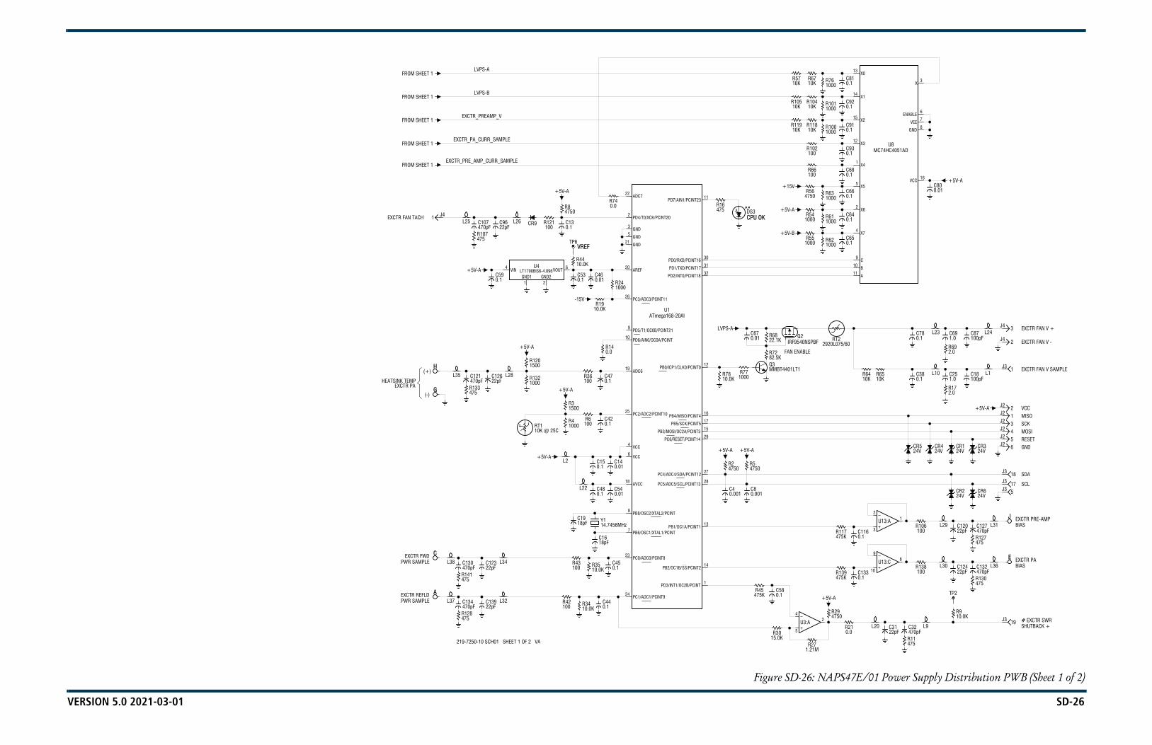
VERSION 5.0 2021-03-01 SD-26
Figure SD-26: NAPS47E/01 Power Supply Distribution PWB (Sheet 1 of 2)
(-)G
475R107
L26
0.1C53
C480.1
0.01C46
C540.01
0.01C67
R551000
R10410K
R210.0
L9
L1
5J3
4J2
1J2
SCL
SDA
GND
MOSI
VCCMISO
A
C
H
C150.1
C140.01 4750
R5
R564750
R541000
R102100
R11810K
R66100
R6710K
+5V-A
2.0R17
2.0R69
E
J
6J2
3J2
5J2
2J2
1J3
2J4
3J4
SCK
R43100
TP6
R271.21M
475R11
L24
470pFC134
470pFC130
L35(+)
1 J4L25
L28
0.1C59
CR9
0.1C44
10.0KR34
0.1C45
10.0KR35
+5V-A
-15V
1PD3/INT1/OC2B/PCINT
14PB2/OC1B/SS/PCINT2
13PB1/OC1A/PCINT1
27PC4/ADC4/SDA/PCINT12
15PB3/MOSI/OC2A/PCINT3
16PB4/MISO/PCINT4
ATmega168-20AIU1
32PD2/INT0/PCINT18
30PD0/RXD/PCINT16
11PD7/AIN1/PCINT23
C80.001
C40.001
+5V-A+5V-A
82.5KR72
LVPS-A
CPU OK
11A
9C
1000R61 0.1
C64
1X4
12X3
15 X2
1000R76 0.1
C81
L10R6510K
0.1C78
16VCC
7VEE
3X
470pFC132
22pFC124
470pFC127
22pFC120
18J3
+5V-A
100pFC87
L37
475R128
475R141
L38EXCTR FWD
L32
L34
+5V-A
1500R120
1000R13222pF
C126
R12110022pF
C96
R42100
18pFC16
Y114.7456MHz18pF
C19
0.1C42
L2
1000R4
0.1C47
0.0R14
R36100
R1910.0K
1000R24
R740.0
VREF
0.1C13
4750R8
28PC5/ADC5/SCL/PCINT13
17PB5/SCK/PCINT5
29PC6/RESET/PCINT14
12PB0/ICP1/CLK0/PCINT0
31PD1/TXD/PCINT17
0.1C58R45
475K
R3015.0K
4750R2
R77100010.0K
R78
DS3A
0.1C133
4750R294
5
2U3:A
0.1C116R117
475K
10B
1000R63
0.1C65
0.1C66
1000R62
4X7
2X6
5X5
0.1C93
1000R100 0.1
C91
14X1
13X0
470pFC32
22pFC31
R106100
2
3
1U13:A
CR424V
CR524V
0.1C38
C800.01
8GND
6ENABLE
MC74HC4051ADU8
19J3
475R130
TP2
10.0KR9
475R127
L31
17J3
CR324V
100pFC18
L22
R6100
1500R3
10.0KR44
22.1KR68
R139475K
0.1C68
1000R101 0.1
C92
RT22920L075/60
R138100
9
10
8U13:C
L23
L36
CR624V
22pFC139PWR SAMPLE
22pFC123PWR SAMPLE
EXCTR FAN TACH
FROM SHEET 1EXCTR_PRE_AMP_CURR_SAMPLE
EXCTR_PA_CURR_SAMPLEFROM SHEET 1
EXCTR_PREAMP_VFROM SHEET 1
FROM SHEET 1
7 PB6/OSC1/XTAL1/PCINT
8PB8/OSC2/XTAL2/PCINT
+5V-A 6VCC
25PC2/ADC2/PCINT10
19ADC6
FAN ENABLE
10PD6/AIN0/OC0A/PCINT
26PC3/ADC3/PCINT11
+5V-B5GND
2PD4/T0/XCK/PCINT20
22ADC7
R10510K
L20# EXCTR SWRSHUTBACK +
BIAS
BIAS
R6410K
EXCTR FAN V SAMPLE
1.0C69
EXCTR FAN V +
+5V-A
EXCTR REFLD
EXCTR PAHEATSINK TEMP 470pF
C121
475R133
+5V-A
470pFC107
LVPS-B
LVPS-AFROM SHEET 1
24PC1/ADC1/PCINT9
23PC0/ADC0/PCINT8
18AVCC
4VCC
Q3MMBT4401LT1
20 AREF
9PD5/T1/OC0B/PCINT21
3GND
+5V-A
+15V+5V-A
21GND
R16475
R11910K
R5710K
L29
EXCTR PA
EXCTR PRE-AMP
RESETCR124V
1.0C25
EXCTR FAN V -IRF9540NSPBFQ2
L30
CR224V
219-7250-10 SCH01 SHEET 1 OF 2 VA
t° RT110K @ 25C
4 VIN
1GND1
2GND2
6VOUTU4
LT1790BIS6-4.096

VERSION 5.0 2021-03-01 SD-27
Figure SD-27: NAPS47E/01 Power Supply Distribution PWB (Sheet 2 of 2)
0.1C97
R158825K
0.1C86
0.1C85
0.1C76
0.1C75
15IS
16IS
+15V
L16
LVPS-A
12J3
13J3
25J3
9J3
22J310J3
23J3
B
D
+15V
+5V-B
+5V-A
GND GND
1.0C141
7FB
16IS
7FB
15IS16
IS
7FB
15IS
C1040.022
C1020.01
C1000.01
PWB
PART
:HR
133
HW3
PWB
PART
:HR
133
HW2
PWB
PART
:HR
133
HW1
R49
2W10
R48
2W10
R47
2W10
TP9
0.1C109
C1233025V
47C35
47C34
C1133025V
C1033025V
2W0.2
R122
0.1C28
L19
L18
L33
C171.035V
LVPS-B
L424J3
20J3
8J3
21J3
11J3
F
-15V
1000R124
TP8 TP1
TP7
TP4
TP3
5W0.002R110
C601.0
L17
L11 L3
(30-53V)LVPS IN
0.001C98
+5V-A
+5V-A
+5V-A
1000pFC118
#RESET-
0.1C142
1.0C9
330pFC90
SYNC_5V-B
330pFC89
3320R75 0.1
C8410C2
100KR129
LVPS V
LVPS V
14PGND
10AGND
6COMP
12OUT
LM5576MHU11
18SW
17SW
20BST
13PGND
6COMP
12OUT
LM5576MHU10
19PRE
17SW
20BST
21GNDPAD
13PGND
6COMP
19PRE
17SW
20BST
#
2.2C72
2.2C82
R944750
0.1C94
0.001C73
LVPS-A
0.01C49
6RT
3VIN
0.1C95
+5V-A
LT3580IMS8EU2
4SW
4GND
5OUT
MAX4080SASAU14
7N/C
3N/C
10C37
0.1C51
100pFC29
0.1C50 1.0
C22
35V
100pFC23
L5
0.001C138
-15V
+5V-B
+5V-A
VOLTSPRE-AMP
TO SHEET 1
TO SHEET 1
EXCTR PA VOLTS
TO SHEET 1(-)
(+)
R23121K 681K
R150 0.01C62
33.2KR157
L27
GND
1 2
U17:A
+5V-A
0.1C131
+5V-A
0.1C119
+5V-A
0.1C111
0.1C43
R1551004
5
2U20:A
475KR154
R41121K221K
R1347.5KR321.0
C3
R15222.1K
R7022.1K
R7122.1K
1SMB5929B15V
CR11
100KR159
LVPS IN
5 6
U17:C
Q1FDD3672
CR10
8730
K1:A
30W50R1
+5V-A
0.1C7
2.2C6
0.001C5
R40
1W1000
R31
1W1000
R20
1W1000
R12
1W1000
CR7
2.2C105
2.2C114
SYNC_15V
15.0KR88
Q62N7002LT1
Q52N7002LT1
2.2C103
2.2C113
15.0KR82
SYNC_5V-A
Q42N7002LT1
0.1C74
330pFC88
2.2C112
2.2C101
47.5KR89
TP11
DS2G
R59
1W10.0K
C33470μF63V
100KR123
TP10
21GNDPAD
13PGND
19PRE
14PGND
10AGND
21GNDPAD
18SW
14PGND
10AGND
12OUT
18SW
LM5576MHU9
F330A
F220A
2.2C63
R9918.2K
1210R87
A2A1
K
U76CWQ10FN
R9739.2K
1820R84
A2A1
K
U66CWQ10FN
R9539.2K
1820R81
A2A1
K
U56CWQ10FN
R109
1W10.0K
10μHL40
R79
1W10.0K
2.2C110 C61
470μF63V
R9810.0K
10C36
10.0KR53
33μHL14
R964750
47C4033μH
L13
10.0KR28
+5V-B
47C39
10.0KR33
33μHL12
7 SS
0.1C26
10C21
56.2KR38
+5V-A
0.001C115
0.001C117
0.1C108
2VC
1FB
7N/C
3N/C
6N/CMAX4080SASA
U12
4GND
6N/C
5OUT
CR8STPS140A
R26182K
0.1C52
0.1C122
0.1C106
1.82MR93
0.1C136
1.82MR143
L15
100pFC20
L8
L7
100pFC30C24
1.035V
L39100pFC140C129
1.035V
0.001C128
+15V
+5V-A
TO SHEET 1
EXCTR
TO SHEET 1
1000R125
0.1C137
TP5
R1373320
86
85
K1:B
30W50R7
+5V-A
4PR
1
CLR2D
5Q
3CLK
6Q
U18:A
10PR
13
CLR12D
9Q
11CLK
8Q
U18:B
3 6
4 5MOCD223-MU19:B
15.0KR85
F17A
13L21:A10μH
2 4L21:B10μH
L6C271.035V
3VINLVPS-A
9RAMP
8RT
2SD
9RAMP
3VINLVPS-A
5SYNC
11SS
1VCC
LVPS-B
LVPS-B
9 PPAD
22.1KR25
+5V-A
1 RS+
2VCC
R142475K
8RS-
0.1C125
219-7250-10 SCH01 SHEET 2 OF 2 VA
3 4
U17:B9 8
U17:D
3VCC
1GND
2RESET
U16ADM803MAKS
14VCC
7GND
U17:GMM74AHCU04M
4VDD
11GNDU13:E
TLV2374ID
14VCC
7GNDU18:C
74HVCT74M
3VCC
12GND
U3:EMC3302D
10.0KR149121K
R156
CR13
R15115.0K
2 J1
1 J1 3VCC
12GNDU20:E
MC3302D
4VIN
11SS
3320R86
1VCC
5SYNC 220pF
C57
0.022C77
5SYNC
2SD 10.0K
R83
11SS
1VCC
4VIN
8RT
220pFC56
0.022C71
10.0KR80
0.1C83
8RT
2SD
3VINLVPS-A
4VIN
9 RAMP
0.022C70
220pFC55
LVPS-A
R108
1W10.0K
DS1:BG
C79470μF63V
R73
1W10.0K
0.001C99
DS1:AG
LVPS-A
R60
1W10.0K
C1470μF63V
8 SYNC
5SHDN
2200pFC41
R92475K2 VCC
8RS-
12
13
14U13:D
RT32920L075/60
1RS+ 12
13
14U15:D
0.1C135
1000R126
CR12
4VDD
11GNDU15:E
TLV2374ID
TP12
100KR103
10μHL41
EXCTR_PA_CURR_SAMPLE
EXCTR_PRE_AMP_CURR_SAMPLE
EXCTR_PREAMP_V

VERSION 5.0 2021-03-01 SD-28
Figure SD-28: NAPA35 Pre-Amplifier PWB
C
A
L1
0.01C20
4750R15
CF
10C5
G
E
B
10C1
1.0C12
10C13
0.0R5
10C7
10pFC2
10C8
0.01C4
D
F
H
0.0R4
V IN (+30-53V)
RF IN
VBIAS IN+
50 OHMS
0.01C6
10C11
+28V
0.001C19
0.01C14
7C-
10C+
11VIN+28V
2RF_IN
5N/C
8N/C
1.0C15
10C16
4ADJ-
16BYP+
12LDO+
9PPAD
6RF_OUT/VDS
7RF_OUT/VDS
C186863V
RF OUT
C36863V
0.1C9
4VDD
11GNDU3:E
TLV2374ID
15KR12
15KR1
15KR10
121R6
R161500
R170.0
10.0KR19
R21100
+28V
R131000
1.0C10
2RT
8N/C
9N/C
13EN-
14MODE
1EN+
4N/C
1VGS
3RF_IN
R230.0
6VOUT
5LDO-
17PPAD
15ADJ+
3BYP-
TP1
GND
-7V
0.8pFC27
L30.9μH
C252400pF
121R7
R141000
LTC3260HMSEU2
INSTALLED NEXT HIGHER ASSY.
-7V
0.1C24
RFHA1003U4
10.0KR18
10C17
L40.0054μH
S2190107 V1
C262400pF
L2
CR2MRS1504T3
MRS1504T3CR1
0.01C22
R2015.0K
Q1MMBT4401LT1
Q2IRFL9014
475KR8
8250R11
100KR2
50 OHMS
3
2
1U3:A
U1 SHOWN FOR REFERENCE ONLY.
3V_IN
1ADJ
2V_OUTLM317HVT
U1

VERSION 5.0 2021-03-01 SD-29
Figure SD-29: NAI22A/01 RF Drive Splitter/Changeover Assembly
C
B
A
L TEMP+
-
0.01C1
CR1
D
M TEMP-
S2190035 V1
R20.0
4 J3
5 J3
J1
0.01C6
7 J3+
1 J3
2 J3
J2
0.01C2
8 J3
0.01C5
1000pFC4
1N5711CR2
5
6
K1:B
250W
R350332
R5121R6
C38.2pF
POWER SAMPLERF DRIVE
# EXCITER RELAYCONTROL (B) -
EXCITER RELAY
EXCITER B
EXCITER ARF DRIVE IN
RF DRIVESPLITTER TEMP
RF DRIVE IN
+15V SUPPLY
3320R4
L10.028μH
1IN
2ISO
30
4-90
10261-3U1
1COM3 NO
2 NC
4
K1:A
BA
J2 TO MODULE B
250W
R150
TO MODULE AJ1
S2190026 V2
1IN
2ISO
30
4-90
10261-3U1
A1 DETAILNAPH09/01 RF Drive
Splitter/Changeover PWB
A2 DETAILNAPH10 2-Way RF Drive
Splitter/Attenuator PWB

VERSION 5.0 2021-03-01 SD-30
Figure SD-30: NAA61C RF Power Module
+5V
BIAS 4
BIAS 3
BIAS 2
BIAS 1
PA V 4
PA V 1
1
0.01C31
0.01C20 R2
150R6
J5
J4
J2
J1
B5P1
B4P1
B2P1
B1P1
J6
J5
J4
J3
J2
LH
BE
K
G
A
N
4
2
PA V 4
PA V 3
F
R1
R6
R5
-90
0
C4
-90
-180
RF OUT
PA V 2
PA V 3
0.01C22
221
L1
R1
J6
J3
B6P1
B3P1
A5
J1
R3
30W100
0.01C17
0.01C19
P1
Q
R
P1
M
J
F
C
P
D
3
1
PA V 2
PA V 1
E
G
C
R2 A7
0.01C23
0.01C15
0.01C37
221
0.01C16
0.01C38
R5
30W100
0.01C32
D
71
60
12
70
14
9
810
56
3
1
THRU
58
49
THRU
38
THRU 0.01C24
28
19
6.8pFC42
20.01C13
1
3
2
3
20.01C7
1
3
20.01C3
150R7
B6 1B6P1
B6L1
B5 1B5P1
B4L1B4P1
B3 1B3P1
B3L1
B2L1B2P1
B1 1
B1L1
0.01C34
68
6566
63
18
0.01C39
0.01C18
62
4
13
0.01C1
RT1
A4
PA3
A2
CA1
250W50
B
1000pFC1 CR1R7
3320
A
150R9
59
0.01C3672
69
16
11
15
3320R8
7
0.01C26
2
0.01C27
48
29
39
P1
THRU 0.01C25
RT52920L075/60
RT62920L075/60
RT32920L075/60
RT12920L075/60
0.028μH
1
3
20.01C11
1
3
20.01C5
3
1
B5L1
B4
B2
1
1
B1P1
0.01C30
0.01C35
0.01C29
0.01C33
0.01C28
67
64
17
0.01C21
DISABLE 61
ENABLE
2 13S1:A
C
PA4
C
A3
PA2
PA1
250W50
250W50
R150250W
50250W
R2
A6
50250W
R3
50250W
R4
RT42920L075/60
RT22920L075/60
1
0.01C9
R4
30W50
0.01C40
C
250W50
A
L10.028μH
CB
S2190001 V2
FAN VOLTS -
CR1BAT54HT1
RF DRIVE
FAN TACH 6
FAN TACH 3FAN TACH 4
FAN TACH 1
0.01C8
PA TEMP
RF DRIVE SAMPLE
REJ PWR SAMPLE
MODULE SPLITTER/INTERFACE PWB
COMBINER (RHS) PWB
V
150R8
COMBINER (LHS) PWB
FAN VOLTS +
# POWER -
POWERDS1:B
G
# FAULT -
FAULT
0.001C14
0.01C10
FAN TACH 5
FAN TACH 2
0.01C12
0.01C4
0.01C6
t°
10K @ 25C
0.01C2
1IN
2ISO
30
4-90
A5U1
U
X
V
X
U
U
V
X
U1N5711
R
DS1:A
V
X
8.2pF
# MODULE PRESENT -# MODULE INHIBIT -

VERSION 5.0 2021-03-01 SD-31
Figure SD-31: NAX264 2-Way Fan Tray Assembly
7 J1
3 J1
1 J1
3J2
3J3
2 J1
6 J1
8 J1
1 J3
1 J2
1.0C13
2.0R8
475R2
L13
L17
L2
L3
2J2
2J3
TP1
1.0C9
2.0R6
475R1
REJ FAN VOLTS +
L6
22pFC11
470pFC12
22pFC15
470pFC16
FAN V
22pFC2
22pFC3
REJ FAN VOLTS -
REJ FAN 2 TACH
REJ FAN 1 TACH
100pFC1
1.0C5L1
2.0R4
TP2
L12
L16
475R9
100KR5
L11
L15RT2
2920L075/60
L8
L9
100pFC14
4J1
5J1
475R7
RT12920L075/60
100pFC10
S2190030 V1
GND
L5
470pFC6
470pFC7
REJ FAN 1 VOLTS
REJ FAN 2 VOLTSL7
L14
L18REJ FAN 2 TACH
REJ FAN 1 TACH
A1 DETAILNAPI155 2-Way
Fan Tray Interface PWB
5 kW Reject Fan 1
5 kW Reject Fan 2

VERSION 5.0 2021-03-01 SD-32
Figure SD-32: NAFP109B Output Power Probe and Sample PWBs
* *
A3
*
A4
* *
A6
A5J1
A1
1001W
R1
A2
681R2 100
1W
R1 R31001W
A2J1
A1J1
A3J1
A4J1
J1
A6J1
FWD PWR REFLD PWR RF MONITOR PWB RF SAMPLE PWB AA5
RF SAMPLE PWB B
*
DC REFLD PWR PROBE PWB
RF OUTPUT
PROBE PWB
R31001W
PROBE PWB
R31001W
1001W
R1 R31001W
1001W
R1681R2R3
1001W 681
R21001W
R1 1N5711CR1
0.001C1
R31001W
RF MONITOR
RF INPUT
FWD PWR SAMPLE
REFLD PWR SAMPLE
EXCITER RF SAMPLE (A)
EXCITER RF SAMPLE (B)
DC REFLD PWR SAMPLE
S2190465 V1
681R2 100
1W
R11W
R43320
* DENOTES A MICRO-STRIP TRANSMISSION LINE OF SPECIFIC LENGTH AND CHARACTERISTIC IMPEDANCE.

VERSION 5.0 2021-03-01 SD-33
Figure SD-33: NAPI143/01 Remote Interface PWB (Optional)
L104
L101
L118
L116
L108
L105
475R61
475R76
475R65
L71
L68
L85
L83
L75
L72
L54
L53
L47
L66
L58
L57
INTLK
20
E1:3
L33
# #
L123
OUT
(+)
475R6
475R1
L41
L42
L45
L37
INT
L99
475R86
475R80
L127
L128
L131
L122
L107
L109
L106
L102
L100
L119
L110
L111
L103
475R67
475R69
475R64
475R60
475R62
475R78
475R79
475R73
475R70
475R71
L74
L76
L73
L69
L67
L86
L77
L78
L70
L56
L48
L49
L63
L65
L60
L52
L55
L50
LCL
TP4
TP2
475R32
475R81
(-)
475R3
475R4
475R8
475R10
475R9
475R2
L39
L40
L43
L46
L44
L38
+15V
GND
TP1
EXT
TP6
L34
475R83
475R84
475R88
475R90
475R89
475R82
L125
L126
L129
L132
L130
L124
(-)
L113
475R66
475R63
475R68
L80
L51
TP5
TP3
475R5
475R7
475R85
475R87
19 J3
14 J3
2 J3
11 J3
9 J3
4 J3
3 J3
470pFC79
470pFC92
470pFC83
CHANGEOVERENABLED STATUS
+15V
EXCITER B STATUS
PRESET 3 STATUS
+15V
PRESET 2 STATUS
+15V
+15V
RF ON STATUS
AC OK STATUS
+15V
POWER SUPPLY
+15V
POWER ALARM
+15V
LOW RF ALARM
EXTERNAL
+15V
HIGH
+15V
ALARM
+15V
22pFC30
470pFC53
L18
475R17
L17
22pFC23
470pFC46
L11
475R30
L30
22pFC34
470pFC57
L22
475R21
L21
22pFC24
470pFC47
REMOTE OUTPUT 14
REMOTE OUTPUT 15
REMOTE OUTPUT 13
REMOTE OUTPUT 10
REMOTE OUTPUT 9
REMOTE OUTPUT 8
REMOTE OUTPUT 5
REMOTE OUTPUT 4
REMOTE OUTPUT 3
6 J1
4 J1
1 J1
6
GND3
GNDE1:2
20 J3
10 J3
24 J3
22pFC118
L112
L36
TOTAL PACURRENT SAMPLE
10.0KR43
PA VOLTAGE
L79
POWER SAMPLE
L88
470pFC58
22pFC35
L59 L23
6J2
4J2
1J2
20J4 # INTERLOCK -
25
15
5
24
21
EXT +15V IN 9
+15V IN 10 J4
13 J4
ANALOG 12 J4
26
23
16
6
L517REMOTE INPUT 9
L6REMOTE INPUT 7 4
15REMOTE INPUT 5
L9REMOTE INPUT 3 14
L1REMOTE INPUT 2 8
REMOTE INPUT 1 7
L32 L35
INT
L98
E2:3
S10
470pFC14
S6
470pFC18
0.1C67
0.001C68
E2:1
E2:2
L121
1.0C65
100pFC41
470pFC97
22pFC130
L92
L93
470pFC101
22pFC134
L96
L87
21J4+15V OUT(TO CONTROLLER)
(0.1A MAX)22
OUT
13
(+) ANALOG12
23J419J4
11J4
3J4
4J4
15J4
8J4
7J4
18 J3
17 J3
16 J3
1 J3
13 J3
12 J3
8 J3
7 J3
6 J3
470pFC80
470pFC82
BAT54HT1CR65
BAT54HT1CR61
470pFC77
BAT54HT1CR64
BAT54HT1CR60
470pFC75
470pFC74
BAT54HT1CR58
BAT54HT1CR59
BAT54HT1CR54
470pFC86
470pFC89
BAT54HT1CR50
470pFC84
BAT54HT1CR48
BAT54HT1CR45
470pFC78
470pFC81
BAT54HT1CR44
BAT54HT1CR41
470pFC76
BAT54HT1CR40
AUTO EXCITER
+15V
A
DS16
BAT54HT1CR33
+15V
A
DS13
A
DS15
BAT54HT1CR30
A
DS11
A
DS12 REMOTE STATUS
PRESET 1 STATUS
BAT54HT1CR25
BAT54HT1CR26
+15V
FAULT ALARM
+15V
A
DS9
BAT54HT1CR39
BAT54HT1CR24
R
DS7
HIGH REFLECTED
PA FAULT ALARM
BAT54HT1CR37
BAT54HT1CR38
+15V
+15V
FAULT ALARM
R
DS4
R
DS5
BAT54HT1CR35
TEMP ALARM
OPEN ALARMINTERLOCK
R
DS2
R
DS3
BAT54HT1CR29
BAT54HT1CR32
SUMMARYR
DS1
BAT54HT1CR27
475R20
475R18
L20
22pFC27
22pFC25
470pFC50
475R15
470pFC48
475R12
470pFC45
22pFC22
475R13
L12
L13
22pFC21
470pFC44
22pFC40
470pFC63
22pFC39
470pFC62
22pFC37
475R27
470pFC60
475R24
L27
L29
22pFC32
475R22
470pFC55
22pFC31
470pFC54
L24
22pFC29
475R19
470pFC52
22pFC26
475R16
470pFC49 L16
L19
L14
REMOTE OUTPUT 16
REMOTE OUTPUT 11
REMOTE OUTPUT 12
REMOTE OUTPUT 7
REMOTE OUTPUT 6
REMOTE OUTPUT 2
REMOTE OUTPUT 1
8 J1
SHD3
SHD1
SHD4
SHD2
MOUNTING PIN:
MOUNTING PIN:
MOUNTING PIN:
MOUNTING PIN:
J1:9
7 J1
5 J1
5
2 J1
3 J1
4
RMT
1
2
CR2324V
25 J3
5 J3
15 J3
L11722pFC121
475R77
475R75
22 J3
23 J3
L114
L115
475R74
475R72
21 J3
22pFC43
470pFC64
L84
10.0KR46
L81
L82
10.0KR40
SAMPLE
REFLECTEDPOWER SAMPLE
10.0KR39
FORWARD
470pFC94
22pFC127
L64
475R28
470pFC61
475R26
22pFC38 L28
L61
L62
475R25
475R23
L25
L26
8J2
5J2
7J2
3J22J2
20
26
10
23
22
21
AES/EBU
(0.1A MAX) 22 J4
24 J4
25
19
11
L3
L45
18
3
REMOTE INPUT 8
L7
L101REMOTE INPUT 6
L8REMOTE INPUT 4 2
L2
100pFC42
1.0C66
2.0R34
+15V
1.0C71
100pFC124
2.0R58
1500R92
G
DS18
470pFC13
S8
470pFC15
470pFC16
S7
S9
470pFC17
470pFC20
470pFC11
470pFC19
S2
S3
470pFC12
S1
EXT +15V
0.1C70
0.001C69
2W150R51
2W150R52
GND
2.0R33
1.0C72
2.0R59
100pFC125
L31
470pFC96
22pFC129L90
L91
470pFC98
470pFC99
22pFC131
22pFC132
470pFC100
470pFC103
22pFC133
22pFC136
L94
L97
470pFC93
470pFC102
22pFC126
22pFC135
L95
470pFC95
22pFC128L89
9J4
+15V OUT
AES/EBU24
10
25J4
6J4
16J4
5J4
18J4
17J4
1J4
2J4
14J4
470pFC73
BAT54HT1CR55
470pFC91
BAT54HT1CR51
BAT54HT1CR49
A
DS10
A
DS14
BAT54HT1CR28
BAT54HT1CR31
R
DS6
R
DS8
BAT54HT1CR34
BAT54HT1CR36
22pFC28
470pFC51
475R11
L15
475R29
475R14
22pFC119
22pFC116
R310.0
R910.0
470pFC59
470pFC56
22pFC33
22pFC36
S4
S5
S2190083 SHEET 1 OF 1 V2
18
22pFC110
17
R531500
16
1
22pFC123
13
R451500
12
8
22pFC114
7
R371500
6
DENOTES TB3
DENOTES TB2
E1:1
# INTERLOCK -
470pFC87
L120+15V
CR6324V
AUTO EXCITERCHANGEOVER
22pFC4 EXCITER A/B
PRESET 3
CR5324V
RESET
22pFC8 POWER DECR
POWER INCR
CR2124V
R561500
R541500
CR1024V
19
22pFC111
22pFC113
R551500
CR524V
CR724V
22pFC108
R491500
R501500
CR324V
CR224V
2
14
22pFC106
22pFC105
R471500
CR2024V
CR124V
R441500
CR1724V
11
22pFC117
22pFC120
R381500
R411500
CR1124V
CR1224V
9
22pFC115
R361500
CR624V
CR924V
4
22pFC109
22pFC112
R351500
CR424V
3
22pFC107
SHD3
SHD1
SHD4
SHD2
MOUNTING PIN:
MOUNTING PIN:
MOUNTING PIN:
MOUNTING PIN:
J2:9
DENOTES TB1
470pFC90 CR18
24V
CR1524V
CR2224V 1500
R57
DS17G
CR5724V
22pFC3
ENABLE/DISABLE(TOGGLE)
(TOGGLE)SELECT
REMOTE INPUT 10
CR5624V
CR6224V
22pFC5
22pFC6 PRESET 2
22pFC7
22pFC10
PRESET 1
CR4324V
CR4624V
22pFC1
22pFC9
RF OFF
CR4224V
22pFC2 RF ON
R481500
CR824V
22pFC104
R421500
CR1424V
CR1924V
22pFC122
470pFC88
470pFC85
CR1624V
CR1324V
CR4724V
CR5224V

VERSION 5.0 2021-03-01 SD-34
LINE 1+30V
PX U1
CR1
FROM AC
(88-264VAC)POWER SOURCE AC GND
N
E1
(+30V PS)UPS INTERFACE ASSY
A1N/C
K1
MUST WIRE TO IT.
NOTE:PX IS JD43 CONNECTOR SUPPLIED
TO XMTR GND NEARLVPS DISTRIBUTION PLATE (E11)
DISTRIBUTION PLATE (E10)
(47-63Hz) LINE 2/NEUTRAL
E2 E3
L
P2V-
V+
SUPPLYPOWER
A100
A2 K2
WITH THE UPGRADE KIT. THE USER
TO XMTR LVPS
P1
+30V RETURN
S2190354 V1
+30V
J1
Figure SD-34: UPS Interface Assembly (Optional)
Nautel Part # 219-5140-02UPS Interface Upgrade Kit

VERSION 5.0 2021-03-01 SD-35
Figure SD-35: NAL14 Reject Load Assembly
150R19 ** *
A **J1
0.001C1
REJECTPWB
A1
*** DENOTES OPTIONAL ITEM.
J1
***
R
***
R
GND10
8
65
3
W1P1W1P21
BAT54HT1CR1
1 INPUT
250W
R1450
250W
R1350
250W
R1550
250W
R850
250W
R750
250W
R950
250W
R250
250W
R150
250W
R350
FAN TACHW
FAN TACH
B
WB1
B
GND9
7
4
2
B2
REJECT LOADPOWER
10
8
65
3
1
* DENOTES SHORT CIRCUIT STUB
** DENOTES A MICRO-STRIP TRANSMISSION LINE OF SPECIFIC
R20150 3320
R21
FAN VOLTS +
FAN VOLTS +
REJECT POWER SAMPLE 1
S2190450 V1
9
4
7
2 LENGTH AND CHARACTERISTIC IMPEDANCE.
FAN VOLTS -
FAN VOLTS -

VERSION 5.0 2021-03-01 SD-36
Figure SD-36: NAF119A/03 Combiner/Filter Assembly
**
**
A1
J2
J1
J5RF IN 2
RF IN 1
S2190428 V1
**
5kW
** **
5kW LOW PASS FILTER ASSY
5kW REJ LD PWR
RF OUTPUT
**
**
**
**
FILTER ARE SHOWN FOR REFERENCE ONLY.
**
DENOTES INDUCTORS AND CAPACITORS IN LOW PASS
** **

NV5LT/NV3.5LT TROUBLESHOOTING MANUAL MECHANICAL DRAWINGS
VERSION 5.0 2021-03-01 PAGE 4.5.1
SECTION 4.5: MECHANICAL DRAWINGS
This section contains mechanical drawings for assemblies of the transmitter. Dimensional drawings may be included. Refer to Table 4.5.1 on page 4.5.2 for an itemized list.
Assembly detail drawings for assemblies and modules that have separate manuals are not included. Refer to the appropriate maintenance manual for the assembly detail of these assemblies.
Identifying Mechanical Drawings
Each mechanical drawing in this section is identified by a number that is both the figure number and the page number. The numbers are assigned sequentially and are prefixed by the letters MD. Drawings in this section are listed in Table 4.5.1 on page 4.5.2.
Content of Mechanical Drawings
Mechanical drawings are illustrations that depict the location of electrical components and show assembly outline detail. Dimensional information is included, where appropriate.
When a module or assembly is the subject of its own assembly detail drawing, and it is also shown in a higher level assembly, the detail depicted in the higher level assembly may have minor differences from the module or assembly actually installed. In this case, always refer to the assembly detail drawing of the module or assembly for detailed information.
Locating a Part or Assembly on a Mechanical Drawing
1. When a part or assembly is assigned a reference designation (e.g., A2A1 or A2A1R1), refer to the family trees in Section 4.2, “Parts Lists” on page 4.2.1. Follow the family tree branches to the block that contains the desired reference designation and Nautel nomenclature (e.g., NAPA31C Power Amplifier PWB). Note the reference designations and Nautel nomenclatures of all higher assemblies in the path.Example: A4 NAE106E Controller Assembly > A4A4 NAPA31C Power Amplifier PWB.
2. Refer to Table 4.5.1 on page 4.5.2. Use the reference designation and Nautel nomenclature to identify the appropriate mechanical drawing. Example: NAPA31C Power Amplifier PWB is shown on Figure MD-8.
3. If necessary, refer to the referenced figure (e.g., MD-8) in the mechanical drawings at the end of this section and locate the next, lower-level assembly. Then, repeat this procedure until the desired part or assembly is found.

NV5LT/NV3.5LT TROUBLESHOOTING MANUAL MECHANICAL DRAWINGS
PAGE 4.5.2 VERSION 5.0 2021-03-01
Table 4.5.1: List of Mechanical Drawings
Figure # TitleMD-1
MD-2
MD-3
MD-4
MD-5
MD-6
MD-7
MD-8
MD-9
MD-10
MD-11
MD-12
MD-13
MD-14
MD-15
MD-16
MD-17
MD-18
MD-19
MD-20
MD-21
NV5LT/NV3.5LT Transmitter
NAPI150A/01 Power Supply Interface PWB
NAPI142A UI Interface PWB
NAPC158B Module Control/Interface PWB
NAE106E Controller Assembly (with Integral Exciter A)
NAPS46 Power Supply Distribution PWB
NAPA27A Pre-Amplifier PWB
NAPA31C Power Amplifier PWB
NAPP06/01 Output Power Probe PWB
LED PWB (206-3060)
External Battery PWB (219-5190-02)
NAE107D Exciter Assembly
NAPS47E/01 Power Supply Distribution PWB
NAPA35 Pre-Amplifier PWB
NAI22A/01 RF Drive Splitter/Changeover Assembly
NAA61C RF Power Module
NAL14 1-Input Reject Load Assembly
NAX264 2-Way Fan Tray Assembly
NAPI155 2-Way Fan Tray Interface PWB
NAFP109B Output Power Probe Assembly
NAPI143/01 Remote Interface PWB (Optional)

VERSION 5.0 2021-03-01 MD-1
Figure MD-1: NV5LT/NV3.5LT Transmitter
UI INTERFACE PWB
RF POWER MODULESA8=1A9=2
EXCITER B (OPTIONAL)
LVPS A (U2) andLVPS B (U3, OPTIONAL)
CONTROLLERASSEMBLY (EXCITER A)
1-INPUT REJECT LOADASSEMBLY
RF POWERMODULE SUPPLIES
U4/U5=1A/1BU6/U7=2A/2B
OUTPUT POWER PROBE
UI INTERFACE DISPLAY
2-WAY FAN TRAY ASSEMBLY
COMBINER/FILTER
MODULE CONTROL/INTERFACE PWB
POWER SUPPLYINTERFACE PWB
RF DRIVE SPLITTER/CHANGEOVER ASSEMBLY

VERSION 5.0 2021-03-01 MD-2
Figure MD-2: NAPI150A/01 Power Supply Interface PWB
R13
C62
L2 L6 CR
4
L9CR
5
CR
7
L10 CR
9 CR
10
R32
C23
R28
R30
C21
R27
R44
R42
R43
R40
C27
R39
C26
L23
C42
R52
C40
R51
R66
R64
R60
R58
R63
C51
L27
R90
L26
L25
R89
L24
C59
C63
R92
C65
CR
20C
64
R102
R10
1
R100
R10
4
C74
C71
R11
7C
73R
116
R11
5
R12
5
L28
R124
C85
R13
8R
141
C83
R13
7R
139
R15
2R
150
R15
1C
88R
148
C87
R14
7
R15
5
L41
R16
0C
103
R15
9C
101
R17
2R
167
R17
0R
165
R16
9
R1
C11
R5
C12
R11 C13
C14
R17
R18
C16
R20
R29
R33C25
R31
R41
C28
C33
R49
L22
R65
R61
R59
U9
C61
C60
CR
19
C69
C75
R11
8C
70
R12
3
R14
0
C89
R14
9
C94
R15
7
L40
R16
8R
171
R16
6
U17
C2L1
L3R9
R16R15
R57
R80
R77
C53 R84
R73
R82
R97
R95
TP12
L29
R131
R122 R129
R126C76TP28
C1
CR
1
CR
3C
R2
U1
L14
C19
C20
R24
L15
R22
L13
C17
CR
6
CR
8
R21
L11
L12
U4U3
E6
E5
R34
CR
18L1
7
R37
E3
R35
TP1
L20
L21
R50
C38
C39
U7
C35
R48
L19
R46
R47
C36
L18
CR
17
R56
R67
R68
C45
R55
C44
R53
R79
R78
R85
U11
R74
R72
C52 R81
TP13
DS2
R93
U13
C68R
91
R10
5 R11
2
C67
C66
R10
3R
109
DS1
C77
C78
C72
R121R127
C81
CR
14L3
5
L33
R13
6
R14
2R
145
L31
R13
4R
133
R14
3
C79
C96
U16
L38
R15
8
CR
13
C99
L39
C10
0
R16
3
L37
R15
6
R16
1
C97
L36
R17
4R
173
C10
6C
105
E2
R2 R6
C7
R10R4
R8
R23
C18
R14
R19
C15
R12
R26
R38
R25
E4
R36
CR
16L1
6
C37
U6
C34
C46
CR
15
R54
C54
U10
R99
R10
6
R11
3
U12
R13
5
R14
6
C80
CR
12L3
4
R14
4
U14
TP25
C95
U15
P1
P2
P3
P4
P5
P6
1
P7
34
6D ABC
2
5
J3
C98
CR
11
R16
2
C11
2
C10
7
E1
1
J1
TP11
P1
P2
P3
P4
P5
P6
1
P7
34
6D ABC
2
5
J2
TP5TP6
TP2
TP21TP22
TP9 TP19
R76 C58
E29 E30
R110
TP16TP17
TP7
R71R70
C56C55
R69
TP26TP27
TP31TP32
TP30
TP23
R153
TP4
TP3
U2
E18E12
E17
L32
E16
C82
R12
0
R114
TP10 TP20
R75 C57
R111
E13
TP8TP15
TP18
L30
R107
R10
8
U8
E22 E26
E25E21
R16
4
R154
E28
E27
E23E19
TP24 TP29
U5
P1
P2
P3
P4
P5
P6
1
P7
34
6D ABC
2
5
J9
P1
P2
P3
P4
P5
P6
1
P7
34
6D ABC
2
5
J11
P1
P2
P3
P4
P5
P6
1
P7
34
6D ABC
2
5
J7
E14
E15E9
R11
9
TP14
E20 E24
P1
P2
P3
P4
P5
P6
1
P7
34
6D ABC
2
5
J8
P1
P2
P3
P4
P5
P6
1
P7
34
6D ABC
2
5
J10
P1
P2
P3
P4
P5
P6
1
P7
34
6D ABC
2
5
J6
E11
E10
E7
P1
P2
P3
P4
P5
P6
1
P7
34
6D ABC
2
5
J5
E8
P1
P2
P3
P4
P5
P6
1
P7
34
6D ABC
2
5
J4
B C E F H I K L
A
N
1
2
3
4
6
7
8
9
10
A D G J M
5
11
219-4080-02 MCH01 VA
GND
GNDGND
LVPS-B
LVPS-A
GND
4A 2A
(-)
(+)
(-)
(+)
3A
(-)
(+)
(-)
(+)
1A
CTR
L/M
ON
4B LVPS B
(U/S)
2B
WARNING
WARNING
L1(D)
3B
(-)
(+)
(-)
(+)
LVPS A
(-)
(+)
(-)
(+)
(U/S)
IN OUT
1B
(U/S)
(U/S)
(-)
(+)
(U/S)
(-)
(+)
(U/S)
L1(B)
A ADJ
PS INTERFACE
(U/S) (U/S)
(U/S)(U/S)
L2/N(C)L1(C)
LVPS CURR SHARELVPSB ADJ
L2/N(B)
LVPS
L2/N(A)
L1(A)
SER.NAPI150
HIGH VOLTAGE
L2/N(D)
HIGH VOLTAGE

VERSION 5.0 2021-03-01 MD-3
Figure MD-3: NAPI142A UI Interface PWB
L5
CR5
C5
L6 C6
L1 C1
L3L2 C
2C
3
R9
R12
CR
6
C20
C23 L1
8
L4 C4
CR
3
L16
C21
CR1
R7
TP1
R11
CR4
R14
CR8
CR9
R17
R21R22
C16
L17
C11
C12
CR2
C7
C8
C9
C13
R13
R10
L13
DS2
C18
C19
R16
R19
R18
R20
L14
R23 L15
C25
C10
S3 S2R15
CR7
C17 C24
L12
R5
L11
L10
R2
C14R6
R1 R8
INO
UT G
ND
U4
R3
R4 C22 R25
L7
L9
U3
L8
C15
R24
DS4 DS3 DS1
S1
U1
U2
1
J2
1
J1
B C E F
1
2
A
M2190096 V1
D
(U/S) RF ON
(U/S)
(U/S)
REMOTE/LOCAL
(U/S) (U/S)
GND
(U/S)
SER.
REMOTE
(U/S)
RF OFF RF ON
NAPI142UI INTERFACE
RF OFF
LOCAL

VERSION 5.0 2021-03-01 MD-4
Figure MD-4: NAPC158B Module Control/Interface PWB
L13
L4
L38
L31
R40
CR10
C46
C44
R98
R123
L74
L80
R664
L87
C149
R801
R299 R301
L150
R333
R349
R394
DS4
CR57
L167
CR60
L189
R466
R475
L12
L3
L39
L40
L37
L36
L35
L34
L28
L29
L30
L26
L27
R41
C22
L57
R39
L56
R32
C41
R53
C31
C39
C29
C30
C28
CR11
R84
C47
C45
R103
R498
C82
C703
C704
CR19
CR21
R149
C89
R146
C94
L79
R167
R166
R623
R164
R170
L91
L90
L84
L85
L86
C114
R186
R185
C105
C97
R184
CR36
L108
R204
C119
R201
R202
C117
C118
C116
R200
R225
R251
R799
R275
R807
R806
CR41
R295
R294
CR45
R304
R309
L130
CR49
C186
L155
C183
C184
L153
R317
L149
L148
L146
L147
L159
R330
R334
C196
R350
R347
R348
R351
C208
R361
R375
R363
R356
C237
C246
R385
C245
C244
R400
C263
L166
L171
R418
C268
L185
C273
L184 L1
94C2
70C2
71L1
92L1
87L1
86L1
88
L196
R467C3
04
R465
C313
C301
C302
C299
C310
C300
C298
C296
C297
R452
C294
C295
R478
C333
C342
L5
L33
L32
CR3
R47CR
6
C40
CR12 CR
13CR
14 CR16
L76
CR23
L81
CR27
CR25
CR28
R165
L88
L89
R195
R203
R288
R310
C167
C185
C174
C173
L151
L152
DS2 C2
32C2
36
C243
C256
C261
C269
C272
L190
L191
C303
R451
R455
R454
R493
L7
L2
L20 L238 L41
R46R26
C17
L47
C5
R17CR2
R44R45R16
R15 R24R25
L25
L43
L55
R79 R99
C60
R91R90
C72R110
R88R89 R109
C56
C57
C54C53
C50C51R87
R86
C63
R101
R77 R82R95
C61C62
R75R76
R80R81
R92
R107
C70
L67L64
R113
L69
R140
CR17
L78
C86R139
R148R133
R134TP17
R131 R145
R152
R142R141 R150
R175
R193
L94
L100
C107
R182
Q15
C103TP22
TP21
R162 C102TP20
CR39
R253
C144R245R246
R211R244
R243
C127 C140
C141
C137C138
C135C134
R242
C125 R241
TP31
C122C147
R257R256
R250R224 R237
R238
C146C145
R222R223 R236
R235
R247
R261R229
R219
R255R226
R260
L112R233R232 L114
L120
R622R556
R285
R281
C158
R800
C159
R287
R282
L119
L117
L129
L131L156
C166
R305 TP35
R328
L143
C181
R303
R322
R302
R300R308 C188
L127
R369R368C226
R367R366R346
C223C222
C211
C220C219
R365
C216C217
R364C209
C229C204
R376R377
R354 R359R374
C227C228
R357R352R353 R358
R371
R339
R379
C235R340
R406
R404
C260
CR56
R407
CR55
TP46
TP44 R411
C255
DS3
CR59CR61
CR58
L182
L169
R420
R470
C327
R484R483
R463R482
R481
C323C324C3
11
C320C321
R480
C317C318
R479C309
C330C307
R461R473 R477
R489
C328C329
C305C306
R471R472 R476
R486R458
R485
DS5
R453
C341
L8L9
L11
L10
L1
R1
C661
C640
C685
TP2
L227
C12
L237
L233
C21
R56
CR9
L59L5
3
RT1
R30
C9C1
0C1
8C1
9
CR7
R28
R29
R33
R34
R27
L51
L50
R37
C15
R35
R36
C13
C14
L44
L45
L46
R18
U2
R21
R22
L24
L22
L21
R43R14
L42
R23
L54
TP5
L62
L71
F1
R72
R85
U16
R97
R96
R108
R70
C58
C59
U15 C71
R69
C49
C55
C52
R78 R83
U11
C66
R94
R100
R93
C48
CR15
U12
C64
C67
C69
R106
L63 L66
R124
L70
L249
R114
TP56
CR18
CR20
C85
C92
U20
A1 A2
K
Q5
L77
F3
C84
C91R135
R136
R138
U21
R155
TP15
C90
R805
U19
R132
L250
R153
R151TP16
R198
R199
L83
C113 R194
R161R160 U2
8
L105
L107
C101
L95
L96
R192
C111
C110 L106 R1
97
C98
C99
R180
L93
L92
R178
R179
R187
R177
L104
L103
C106
L97
L99
L98
TP23
C96
C95
U27
U29 C104
R181
R163 R176
U30
L109
L113
C130
R215
R214
R252
R230
R239Q9
R240
C131
R212
R217
U44
C124
C128
C142
C143
C148
U35
C133
C136
C139
R210
C126
U34
U33
U41
C123
C150
R249
U32
R248
R264
R254
R259
R227
R228
DS1 U3
9
R258
R231
R234
Q7
Q8CR37
CR38
R286
U47
CR88
Q16
E6
L123
L122
U49
CR42
R279 L118
CR44CR46
CR48
C168
C178
CR51
C164
C165
R329
C191
L145
L144
L158
C175
C176 R327
L141
L142
L157
R319
R320
L139
L140
L154
C179
L136
L134
L135
L133
C180
TP34R298
C163
U53
U54
C172
C171
R318L1
28
L126
CR50
C169
CR47
L132
R338
F5
C207
C225
C224
R336
R335
C212
U61 U69C2
00C2
06
TP42
C221
U59
C199
C198
C210
C215
C218U60
R345
TP41
R355 R360
C238U58
R373
C197
U66
C205
R372
TP39
TP40
C239
L160
C195
C194
U63
C240
C214
C234
R362
R405
C259
U75
C254
C253
U74
F7
R410
R403
TP45
R402
R408
R409
C251
R422R416 CR62
R419R423
L183
R415
R414
C287
C286
U77
C267
L181
L180 C2
83C2
84
R417
R429
L168
R430
L178
L179
L193
L175
R428
C278
L172
L173
L174
C277
A1A2
K
Q14
C275
A1A2
K
Q13
R468
R450
L198
R464
U86 C326
C325
U93
R448
C312
R457
TP53
R462
U85
U84
C322
C316
C319
TP52
R474
R460
U83 U90
R488
C308
R487R459
TP54
C315
R456
R469
C314
R505
C339
R504C340
L6
J11
C660
C686
C11
C20
E1
E2
C8R665R13
R55
CR8
R38
C16
L48
L49
CR5
CR4
R71
L68
L65
U14
U13
U9
R102
U10
A1A2
K
Q2
U8
DG
Q3
C87
L72
CR22
CR24
DG
Q4
F4
C88L73
C112
C115
L82
Q6 R183
C100
R171
L101
L102
C108
CR40
C132
R213
R216
U43
U42
C129 U38
L110
L111
U40 R263
U37
U31
R280
U48
U50
C177
U52
R306
C170 R3
21
U55
L138
L137
C189
C182
R337
U67
U65
C201
R370
C230
C231
C193 R3
78
U62
U64
R381
J6
R412
R401
L161
+
C252
C257
C258U7
3
C285
U78
C266
CR63
R421
C265
L176
L177
U89
U87
U91
R449
U88
R490
F8
L58L248
R73R804
C23
R19
R111
R68
R130
C38C77C78
R121R120
C73R119
C36R116
TP14
C34
R60TP8
TP9
C32C33
R57
R52R50 R115
TP13
TP7
R3 C2 R49 R66 C706
R154C80
R105R64
R63
R8TP10
R61R6R5
TP1
L61
R127
L19 TP18
L121
R262
CR29
R267R268
C152
R266R265
C157
C156
R274R273
C153R272
C160C699R499
L125
R344R209TP26
TP37
TP38
TP25
C202C120C121 C190
R190
R341R325
R206
R291
TP27
R296
R196
C162R276L115
CR68
R437
C336
R389R388
R497R496
C242
R387 R495R494
C250
R396R503R502
C337R501
R392C695
R507
TP43 TP55
R492R491
TP49
TP50
C282
R434C280
C293
R384
R390
R444R445
R397R442
C290
C274R441
R439
C614 R74
C702
1
J17
1
J16
C75
F2
R158
L225
U17
L247
U26
U7 R112
TP4
C43
R54
R51
C42
U6
TP12
R159
R126
U5
U4
C37
C74
C76
R67R118
TP19
TP11
L17
L16 R59
U3
C35
C27
C68
R58
R48
U18
U25
U24
U1
R65
L52
R9
CR26R157
R125
R104
L15
L14 L60
R129
R128 U2
2
C79R62
L18
R4
TP6TP3
CR35
R315CR431
J18
CR54
CR30
CR33
U36
TP32 TP33
CR52
C213
R314C151
R278
CR31
TP29
R312
R313
U51
C155
C154
R277
C700TP28
C203
R311
L124
R343R208
R189
R188
R290
R323
R324
R342R207
TP24
TP36
C192
R297U46
U56
TP30
C161
RT3
U57
R331
C187
J9
1
L116
L165
L170
L197
R438
F6
R431R413
U76
CR67
R436
L195
R427
R399
C335
A1 A2
K
Q11
R447
R386
C241
CR65
R425
R426
R398
R395
C338
C696 C692
C247
C249
C248TP47
R424 C334
R433
R432
C279
TP48
TP51
C276
L164
U82
A1A2
K Q12
R446
C291
C292
R380 U7
2
U70
L163
U81
R443
R440
R382 C289
C288
U71
C701
+
C83
C93
L75
+
C65
R156
R2
C26 +
C81
+
C1
J25
CR1 U23
1J2
1
J1
J12
CR34
CR53
E3
E4
E7
E8
3 2 1A
BC
DE
FG
HI
JK
LM
NO
P
45
GRID1
R292
CR32
R332
R191
Y1
E5
13
45
62
on
S1
U45
R326
C109
1
J4
1
J5
J13
1
J10
E9
E10
+
C233
L162
U92U68
CR66
CR64
DG
Q10
R435
R383
+
C332
C264
C262
C281
J7
J14
1
J15
1
J19
1
J20
1
J8
1
J3
1
2
3
4
6
7
8
9
B C E F H I K L N O
5
10
A
M2190282 V1
D G J M
FRONT VIEW
GND
FWD
GND
GND
PWR SMPL
ELEVATEDPOTENTIAL
REFLDPWRSMPL
GND
GND GND GND
CAUTIONHEATSINKS AT
1
7APM4
1
1
5432 1
2
GND
+ 5V
U/SJ22
1
10A J21
1
+ 48V
3A
S/C
7A
CPU
OK
(-)
6
+ 15V
UI
+15
V
U/S
PA V
4A
PA V
4B
PA V
3A
PA V
3B
(NEX
T RA
CK)
PA V
2A
PA V
2B
FAN V/MONREJ LD
LD MONAUX REJ REJ LD MON
FANSPM3
10A
FANSREJ LD
J23
+ 2.5V
(+ )
PRGMISP
+ 3.3V
LVPSRTN
F BTLDRRS485 TERM
PM27A
+ 3.3V
FWD
PM1FANS
FANS
LOGIC
RF DRV 4
FANS
10A
RF DRV 3
EXCTR A
U/S
AUX REJ LDFAN V
FANS
7A
PM1/2
+ 5V
ADDR
PA V
1A
PA V
1B
RF DRV
J24
XMTR CTRL
+ 48V NOM
LVPS IN
PS CTRL/MON
NAPC158
MODULE
REFLD
EXCTR/CTRL
U/S
FANSPM3/4
REFLD DC
EXCTR B
(PREVIOUS RACK)
RF DRV 2(25-53V)
DEBUG
XMTR CTRL
SER.
RF DRV 1
CONTROL/INTERFACE
R544
L202
C390
L204
C526
C539
R706
R772
L230
C647
C657
R797
C675
C682
C364
C360
R528
R534
R545
R535
L199
C370
R543
L203
R546
L200
L201
C393
C394
C379
C387
C388
C389
C402
C401
C410
C411
R585
R583
R582
C423
R591
L206
R506
C440
C449
C450
C443
L242
R606
R269
C470
C471
R609
R610
R624
C494
R655
R653
R652
R661
R658
R670
C527
C540
C524
C525
C537
C538
C529
C518
R555
C555
C554
C688
L240
R694
R693
C556
C563
C564
C566
C567
C559
C609
R759
C606
R756
R757
R773
L226
C623
R771
R775
L231
L228
L229
C650
C651
C645
C644
C646
R777
R781
C669
C670
R794
R796
C677
R795
C344
C346
C351
C363
C391
C392
C409
R584
C448
C461
R619
R621
C492
R654
R660
R686
C557
R704
R710
R711
L222
R707
L223
C594
R758
C618
C649
C648
C680
C673
C674
C681
R510R511
C345 R521R520
R509C347
R517R518
R515
R169R168
R512
R549
R548C396
R547C395
C372
C386
C369
C366
R541
C381R539
R537
R536
C405L205
C403
C404
R553
R560R559C406
R569R570
C407R558 R567
R566
R564
R561
R573R574
C412
C442C441
C460C459
R605
C434
C438R601
L210
C431
C428
R598
R590
C446
C454R596
R594
R593
C690
C474C475
C472C473
R614R611
R618
R613
C476
C486
L215CR75
R636
R626R630C485
R647R648
R629C489
R644R645
R642
R271 R639
R802R803
R634R633
R637R632
R638
C491
C495
C488C483
C552C551
C517C553
C515
R680
L219
C523
C520
R677
R669
C546
C532R675
R673
R672
R688
R687
C542
R666
R684
L239
R709
R703
R701
C568
L224C573
R726R731
C579R730
C572R724
R723
R722C577
R717C582
C580
R221
R729
C586
C575C576
R42R31
R11
C625
C638
C622
C619
R769
R762
R767 C631
R765
R779
C617
C612 C643
C642C611
R746
C604
L23
C654R20
R791
C664
C668
C672C663 C667 C684
R526
C350
R524
R522
R523
R508
C348
C691
R516
R514R513
R519
C377
C373
C378
R531
CR71
R533
C376
C371
C385
CR69
C367
C368
C383
C384
R542
C374
C380
R538
R540
R551 R554
R552
C400
C399
R571
C408
R557
R283
R563R562
R565
R568
R284
R572
L207 L212
R589
CR74
C435
C439R602
L211C4
26
R592
R586
C436
C437
C432
C433
L208
L209
R600R587
CR72
C429
C430
C457
C458
R599
C445
C444
C452
C453
C451
R597
R595
R603
L244
L246
R393
C694
L241
C689
L245
C698C693
L243
L214L213
R617
R612
C469
C468
R616
C478
C467
R607
R608 C479C477
C487
R650R635
C493
R649
R625
C490
R640R641
R643
R646
R270
Q17
R631
C496
C484
R620
C482
R391L221
R681
C528R671
R682
C514
CR80
R663
R662
L220
C511
R659 R679
L216
CR78
L218
L217
C521
C522
C550
C535
C536
R678
C549
C543
C544
C545
C531
C530
R676
R674
C541
C510
C509
C687
R689
R667
R668 R685
R683
C562
R705
R708
C561
R702
CR89
R696
C560
R143
CR90
C574
R720
C571 R725
C587
C584
R742
R721
C578
C570 R728
R719
R220
R716
C585
C613R776
R764
C626
CR84 C639
C605
R755
R760
C627
CR85C3
R10
R763
C624
C636R752
R753
C607
CR82 C637
C621
C620
R770
C634
C635
C629
C628
R766
R768
C630
R780
R761
C641
R774
C615C616
C610C603
R778
C652C653
C655
L232
C678
C679
C665
C676
L236
R790
R788
C671
R793
C662 C666 C683
R798
C349
R525
C343
R530
CR70
C375
C382
C365
RT4
C413
R588
CR73
C447
R604
C427
C456
C455
C497
C516
CR79
C547
C548
C519
C534
C533
R690
R712
C565
R697
C583
CR83R754
C608
Q1
C632
C633
L235
L234
R789
171
272
J21
171
272
J22
R550
C361
C398
C357C356
C354
C352
R532
C466CR76
R656
C422 C507
C420 C505C419 C504
C417 C502
C415 C500
R578R579
C414C462
C498
C480
C697
R12R695
C4
C602
R741R740
C600R737R738
C599
C597R735
R732
C595
R699
R786C558 R784
R714 R744 C659
C592R749R750 R782
C590R747 C658
R743
C397
R527
C362
R529
C359C358
C355
C353
C465C508
R651R657
C512
C424
C421 C506
C418 C503
C416 C501
C481
R577
C463
C499
C464
CR77
R745
R7R700
C601
C598
R736
R734R733
R739
C596
CR81
R751
R787
R698
R715
R713C593
R785
R783
R748
C569R144
C591
C588C589
C656
C425
C513
CR87CR86
171
272
J23
171
272
J24
N K I H E BO M L J G F D C A
REAR VIEW
M2190283 V1

VERSION 5.0 2021-03-01 MD-5
Figure MD-5: NAE106E Controller Assembly (with Integral Exciter A)
POWER SUPPLY DISTRIBUTION PWB
EXCITER/CONTROL
PWB
POWER AMPLIFIERPWB
LED PWB
REAR VIEW
TOP VIEW
OUTPUT POWERPROBE PWB
PRE-AMPLIFIERPWB
EXTERNALBATTERY PWB
A1
A6
A2
B1
A3
A4
A5A8
FRONT VIEW

VERSION 5.0 2021-03-01 MD-6
Figure MD-6: NAPS46 Power Supply Distribution PWB
R20
4
C55
C24
CR
7C
36
RT1
R90
C135
R14
0
L60
C11
8
R10
7C
101R
179
L75
L70
R184
C17
4
L83
CR
21R
182
CR
26R
202
CR
19C
R24
L90R20
8L8
2C
172
L79
L89
R20
9C
183
L92
L48
L40
C72
C56
C53
C51
R40
C22
R21
C20
R16
Q2
R82
C66
C58
Q6
R67
C33
C17
L8
R13
R73
C64
C45
R37
R38
Q3
R72
C50
C46
C42
CR
10
CR
9
R161
C85
C84
C14
5
C143
C12
4
R119
R99
C10
7C
96
R175
R17
0C
152 C
151
R14
5C
122
R14
3R
129
C11
2R
101
C14
6C
104
R91
C16
1R
103
R10
9C
109
R97
L55
C99
L81
L80
L94
C18
9
L42 L4
3R
26
L28L2
7C
62
R87
R44
C32
R13
2R
133
C16
0
C15
7
R102
R186
C165C167 C166
CR13CR11
C187
C185
C182C181
C179
C176C175C177
C173
R191
C171CR15
L91
CR
8
C80 C79
L41
C75
R77
R79R78
C71
R75R74
C68
L37
L34
R56R28
L22
L20L21C15
C12C13C35R23 R24
R42L15
L12
R19
C9C11
C7C8L2
R2R6R5
R12
8
R126R80
R84
U13
R125
C67
C60
L35
L33
R69
R123
R122
R118
TP3R54
R47R48
R43
R35R39
R31R32
R29
R17
R10
R7
C16
2
C16
3
L66 L65R176
R177
L62L61
R16
9
R16
8
R162
C148
R15
6
R15
5
R150R151
R149
R147
C141
R144
C13
1 Q8
R137R138 R139
R142R141
C126
R116R117
R11
3
R104
R10
8
C110
C97C102
R93L53
C93
CR12
C164
C168
L69
L78
L74
R181
R18
5 C169
C188
R20
7C
184
L87
L85
R19
9
C178
R20
1
C180
R20
0
R198
L84
L86
R190
L73
CR18
CR
23
R19
3
C170
CR
20
R19
4
C190
C83C82
C81
L49
L47
R76
R83
L39
L38
C74
C70
C73
C49
C57
C52
L32
L31
L30
R65
R61R62
R57
R58
Q5
C1
C14 R51
U4
C34
R25L19
L17 L16
C29L13
R33
C21
C25
C28
Q4
L10
L6
C19
L4
L7
L3
R11
R14
R8
TP1
C5C4
L1
T1
C88
C87
C86
R71
R81
C65
C69
C76
TP4
R70
C54
C59
R64
R66
U12
C47
C44 R121
C41
C40
R45
R49
R55
R52R50
F1R30
R34
R36
C23
U2
C30C31
C18
CR1
Q1
+
C2
C6
C15
8
L68 L67L64
R178
C15
9
R16
5
R164
R16
7
R16
6
R16
3
C154 C15
3
C15
0
U21
U20
C14
7
C14
4
R15
4
R15
3R
148
C13
7
C13
8
Q9
R146
C14
2
R120
C12
3
C128C129
R136
TP10C120 R
131
C115
C11
9
Q7
U7
R11
1
R115
TP9
C98
C113
C11
1
R98
U6R10
0
C10
6
C10
5
L57
L56
C95
R92
R94
L52
C94
C10
8
AB A
DS1
L76
L93
R19
5
L26
R86
L44C77
C78
1
J6
1
J5
R27
1
J4
R15
8
L24
L25
R124
A2 A1
K
U17
L23
U3
A2 A1
K
U9
Y1
C15
5
TP7
C13
3
C13
2
L63
RT3
C15
6
Q10
C12
1
C114
R95
CR17CR14
H
L36 R157
R160
L59
R63 R152
C136
C13
4
R159U15
C127
R135
R134
C117
C38
L18
C27
C26
L5L58
C10R9
R4L54
R3
DS2R1
C186
L88
R206
CR
25
R188
R187
L77
R192
U22
R189
CR16
L72
CR22
J1
J8
G
TP5
C63
S G
DQ11U5
C149
EU18
R68
TP11
TP6
C48
C13
9
RT2
U16
TP2
C43C130
C12
5
U14
U10
C140
+
C116C37
L14
L9L1
1
D
R41CR3
B
C
R12CR2 C10
0
C3
T2
L71
A
B
(UPPER)
(LOWER)
J3
1
J2
1
J1
F
L29
RT4
A2 A1
K
U11
U19
C61
+
C103
CR4
A
+
C16
U1
U8
C39
F2
TP8
1J7
A
B
-A
1
2
3
4
6
7
8
9
B C
5
-D -C -B
10
A D
11
REAR VIEW FRONT VIEW
M2190021 V2
VREF
LVPS
V
+5V-B
GND
GND
ELEVATED
+3.3V
GND
LVPS-B
+5V-A
POTENTIAL
+15V
HEATSINKS AT
LVPS-A
CAUTION
J3
(U/S)
CTRLSYS
+J1
-(U/S)EBU
7A
J2
20A
LCD/LED
SPIEXCTRCTRL/
EXCTR/CTRLADC/LOGIC
AES/
(U/S)CTRLXMTR
FAN
NAPS46SER.
LVPS IN
EXC
TR/C
TRL
LVPS
PS DISTRIBUTION

VERSION 5.0 2021-03-01 MD-7
Figure MD-7: NAPA27A Pre-Amplifier PWB
C7
C9
C12C1
R1
C3
D
C5
L1
B C6
L2
C4
L7
C14
C11
L5
L4
C16
L6
Q1 C10
C17
C
+C15
C8
AL8L3
B C
1
2
A
M2110046 V1
SER.
PANAPA27
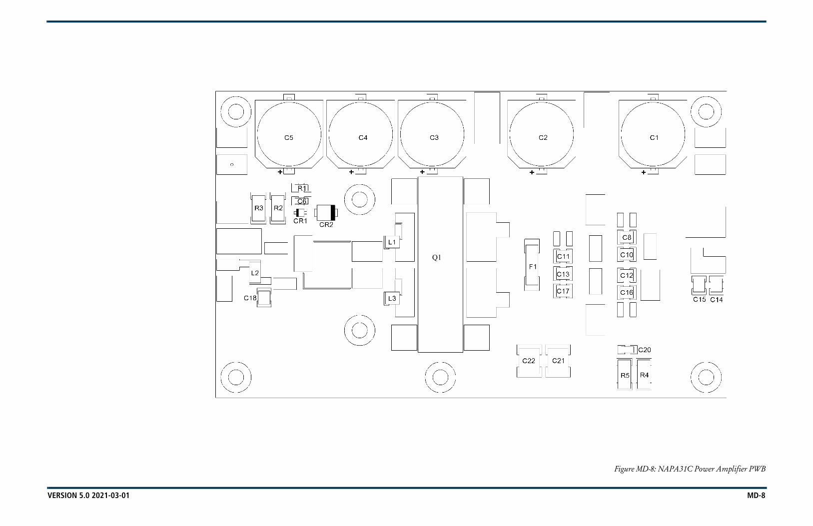
VERSION 5.0 2021-03-01 MD-8
Figure MD-8: NAPA31C Power Amplifier PWB
Q1

VERSION 5.0 2021-03-01 MD-9
Figure MD-9: NAPP06/01 Output Power Probe PWB
R5
R6
R15
R31
R2
R3
R4
R18
R19
C6
C7C8
R1
R7
R8
C1
R14
R16 R20
R21
R24
R25
R17
C10
U2R26
R23 R27
C5
R22
R30
R32
C9
R29
R13
U1
C3
R28R9
R10
R12
R11
C4
B C
1
2
3
A
M2110127 V1
K L
G
D
J
A C F
H
E
M
B
SER.
POWEROUTPUT
PROBENAPP06

VERSION 5.0 2021-03-01 MD-10
Figure MD-10: LED PWB (206-3060)
L4
R4
R3
C3
C2
L1
R1
L2
L3
C4
C1
R2
1J1
RG DS2
GR
DS1
M2060067 V1
LEDASSY206-3060

VERSION 5.0 2021-03-01 MD-11
Figure MD-11: External Battery PWB (219-5190-02)
1
J1
++
BT1
M2190142 V1
BATTERYEXTERNAL
ASSY 219-5190

VERSION 5.0 2021-03-01 MD-12
Figure MD-12: NAE107D Exciter Assembly
POWER SUPPLY DISTRIBUTION PWB
EXCITER/CONTROL
PWB
POWER AMPLIFIERPWB
LED PWB
FRONT VIEW
TOP VIEW
OUTPUT POWERPROBE PWB
PRE-AMPLIFIERPWB
EXGINE PWB(NOT USED FOR
ANALOG OPERATION)
A1
A6
A2
B1
A3
A4
A5
A8
REAR VIEW

VERSION 5.0 2021-03-01 MD-13
Figure MD-13: NAPS47E/01 Power Supply Distribution PWB
C17
C92
C85
L30
C13
6
R14
4C
140
C18
C16
C27
C29
R14
R30
R26
C47
C45
C42
C48
R24
DS3
C40
C39
R15
4
R39
R46
R44
R42
R43
C57
C56
C55
R14
9
R58
R64
R65
R56
R55
R54
R61
R62
R63
F1
C69
R74
C68
R66
R67
C63
R76
C93
C91
C86
R75
C82
R79
CR
11
R107
C11
5
C10
6R
117
R10
4R
99R
98C
104
R97
R96
R95
R94
R10
3C
108
C121
C12
4C
123
C13
8R
145
R14
3C
135
L39
R141
C13
4
L3
C41
C10
3
L1
L9
L7
L4
C15
L2CR2 CR6
R3
C13
R8
CR1
CR4
R28
C6
C38
R17
L20
R45
C52L18
L17
C50L15
L22
R49
R53
R47
TP3R33
CR10
R158
C12
0
C12
7
L25 L26
L28R120
R132
R134
R77
C95
R10
5
R11
9
C80
R129
C90R88
R86
Q5
C10
2
R125R126R83
R84R85 C118
C83C84
R82R81
R114
R112R111
C117
C122C72
L32
R108
R15
2
C142
R123C97AB
R9
L8
L5L6
C20
C23
C4 C8
C14
C19RT1
R2
R6R4
R5
CR3
CR51
J2
TP1
TP4
CR
7
C7
C5
C43
R37
C58
R51
R50
U3
C32
R27
R29
R69
C60
TP5
L21
C51
C37
R25
L19
TP6
C46
C44
C49
R35
R34
R36
R38
C54
C53 C59
C65
C64
R16
R19
R57
U4
C36
R48
C35
C34
R15
1
R32
R13
R41U19
R15
5 C3
R150
CR
12
R121
L29
L24
R127
C12
6
L31
CR9
R78
R12
2
U12
U13
R131C11
6C
119
R93
R92
R10
6
C78
C81
C13
2
R10
2
R101
R10
0
R11
8
R87
C11
4
Q6
C89
C2R124
R89
C11
2
C10
1
C88TP8
R80
U15C111
C110
Q4
R113
C99 TP9
R73
C94
C12
8
U14
C73
C13
0
L34
L33
L27
R128
R109
R23
C9 R71
R70
C98
C13
9
R21
RT2
CR8
A1A2
KU7
A2 A1
KU6
U2
A2 A1
KU5
+
C33
C141
C62
R7
R1
C96 L35
C87
C12
5
RT3
C11
3
Q3
C10
7C
105
+
C79
C10
0
C109
1
L10
R133R11
H
C133
R139
C28L11
R72C21 R68
R130
L36
C76
C71
U16 R137
C131
R136
R135
C74
L38
R12 R59
R31
L37
DS2
J
L23
C25
C31
1
J4
G
R138
C22
C26 C67
S G
DQ2L16
C66
E
U1
U8
Y1
TP7
TP11
C12
U11
C77
C13
7
C11
U17
U10
C75
C70
R142
DR110
C
BR40
C12
9
R20
R60
R15
6
U20
G S
DQ1
CR13R159
L41
C30
F
U18
C24
L14
L13
A
654321
A B C D E F
GRID1
C10
+
C61
U9
L12
R15
7
F2
TP10TP12
K1
TP2
+
C1
L40
J1
1
J3
REAR VIEW219-7250-10-MCH01
FRONT VIEW
GND
+15V
LVPS
V
GND
+5V-B
VREF
+5V-A
ELEVATED
GND
LVPS-B
POTENTIAL
LVPS IN
HEATSINKS AT
LVPS-A
CAUTION
K1(U/S)
CPU
+15V
+J1
-(U/S)
OK
7A
(U/S)L40
DS1
SER.NAPS47
FAN
+5V-B
20A
(U/S)
DS1
EXC
TR
PRGM
PS DISTRIBUTION
+5V-A
L41
LVPS IN
(U/S)

VERSION 5.0 2021-03-01 MD-14
Figure MD-14: NAPA35 Pre-Amplifier PWB
U2
R10
R14
R16
R23
R20
C20
C24
C6
C2
R11
R4
R12
R6
R7
C14R15
A
L4
D
L2
R18B
R8R2C5
R13 Q
1
C11
C4
C1
C7
Q2
R1 CR2
C15
R5 C10
L1C
C3
+
C9
C26
C22
E
C27
U4
L3
G
TP1
C12
C8
R19
CR1
+C
18
C25
R21
C19
U3R17
H
C17
F
C13
C16
B C
1
2
3
A
M2190108 V1
GNDV IN
RFIN
RF
OU
T
SER
.N
APA3
5
V BIAS
POW
ER A
MPL
IFIE
R

VERSION 5.0 2021-03-01 MD-15
Figure MD-15: NAI22A/01 RF Drive Splitter/Changeover Assembly
C5
R5
R2
R1
C4L1
R4
CR1
C2C1
CR2
C6
C3
R6
COMNO
NC
K1
J2
1
J3
J1
1
2
3
B C E FA
M2190042 V1
D G
E
A
C
M (-
)
EXCTR A
SER.
B
EXCTR B
F
L (+
)
D
SPLITTER/CHANGEOVERNAPH09
J2
J1
B C E F H
1
2
3
4
A
M2190027 V2
D G
5
DC
SER.
B A
NAPH10
4 WAY RF DRIVESPLITTER/ATTENUATOR
2-WAYRF DRIVESPLITTER/
ATTENUATORPWB
RF DRIVESPLITTER/
CHANGEOVERPWB
FRONT VIEW
REAR VIEW

VERSION 5.0 2021-03-01 MD-16
Figure MD-16: NAA61C RF Power Module
PA PWBs(A1 - A4)
SPLITTER/INTERFACE
PWBCOOLING FANS
(B1 - B6)
COMBINERPWB (LHS)
COMBINERPWB (RHS)
FRONTVIEW REAR
VIEW
RIGHT-SIDE VIEW(COVER REMOVED
NOTE:PA PWB A1 is PA 1PA PWB A2 is PA 2PA PWB A3 is PA 3PA PWB A4 is PA 4Fan B1 is Module Fan 1Fan B2 is Module Fan 2Fan B3 is Module Fan 3Fan B4 is Module Fan 4Fan B5 is Module Fan 5Fan B6 is Module Fan 6

VERSION 5.0 2021-03-01 MD-17
Figure MD-17: NAL14 1-Input Reject Load Assembly
L2
1-INPUTREJECT
PWB
TOP VIEW
END VIEW

VERSION 5.0 2021-03-01 MD-18
Figure MD-18: NAX264 2-Way Fan Tray Assembly
2-WAY FAN TRAYINTERFACE PWB
COOLING FANS x 2
NOTE:Fan B1 is 5 kW Reject Fan 1Fan B2 is 5 kW Reject Fan 2

VERSION 5.0 2021-03-01 MD-19
Figure MD-19: NAPI155 2-Way Fan Tray Interface PWB
C3
C2
L5
R1
R2
L6
C9 C13
R4
R7
C11
C10 L15
R9C16
L18
L2
C7
C6
L3
L8L9
R5
C12
L14
L12
R6L13
R8
C15
L17C14C
1L1
TP1
L11
RT2
1
J3
C5TP2
L16
L7
RT1
1
J2
1
J1
1
2
B C E FA
M2190031 V2
D G
FAN VGND
FAN TRAY INTERFACE
SER.NAPI155

VERSION 5.0 2021-03-01 MD-20
Figure MD-20: NAFP109B Output Power Probe
R2
R1
R3
J1
M2060070 V1
(U/S)
206-
6524
PP54
ISS.
A
RF
SAM
PLE
PWR
PR
OBE
R1
J1
R3
M2060071 V1
(U/S)
206-
6520
PWR
PR
OBE
PP49
ISS.
A
REF
LD
R2
R1
J1
R3
M2060072 V1
PWR
PR
OBE
206-
6522
RF
MO
NIT
OR
PP53
ISS.
A
(U/S)
R1
CR
1
C1
R3
R4
J1
FRONT REAR
M2190112 V1
DC
REF
LD
219-
6520
PS92
ISS.
A
J1 (U/S)
PWR
PR
OBE
A2
A3 A1, A4, A5
A6

VERSION 5.0 2021-03-01 MD-21
Figure MD-21: NAPI143/01 Remote Interface PWB (Optional)
C74
C45
C87
C58
C89
C60
C100
C17
C102
C19
C105
L101
R61
L68
R12
CR
25L4
8C
R2
C22
L12
L103
R63
L70
R14
CR
27L5
0C
R4
L14
L105
R65
R66
L73
L72
R16
R17
CR
29L5
2C
R6
L16
L107
R67
R68
L75
L74
R18
R19
L54
CR
8L1
8
R69
R70
L77
L76
R20
R21
L56
CR
10L2
0
R72
L79
R23
L59
CR
13L2
3
R74
L81
R25
L61
CR
15
C35
L25
R76
L83
C70
R27
CR
37L6
3C
R17
C37
L27
R78
L85
R52
R29
CR
19L2
9
R33
C125
L121
R59
C72
C66
R34
CR
22L3
2
R91
R81
L88
R32
L36
L33
CR
23
L124
R82
R83
L90
L89
L38
L39
L3
L127
R85
L92
L41
L5
C133
L129
R87
L94
L43
L7
C7
C135
L131
R89
L96
L45
L9
C9
DS1
7
L99
R3
R5
R7
R9
C77C76C75C73
R53
R41
TP1
C44 C46 C47 C48
C85C84C83C82C81C80
R50 DS12
R45
C51 C52 C53 C54 C55 C56
C92C90 C91C88 L98
TP3
TP2
C59 C61 C62 C63
C41
C93 C94 C95 C96 C97C98
CR63
CR56
CR52 CR53
CR46 CR47
C64C43C12 C13 C14 C15
C101 C103
C18 C20
C104 C107
L100
R60
R62
R64
L71
L69
L67
R55CR64
CR60
R47CR54
R49CR58
CR48
R44CR50
R11
R13
R15
CR
28
CR
26
CR
24
CR40
L51
L49
L47
CR
5
CR
3
CR
1
C21 C23 C24 C25
L15
L13
L11
C111 C113 C115
L109 L111 L113
R71
R73
L80
L78
R56 DS16
CR
61
R54 DS14
CR
59
DS10R48CR55
DS8CR
51C
R49
R42 DS6
CR
31
DS2CR41 R36
R22
R24
CR
36
CR
35
CR
34
CR
33
CR
32
CR
30
L60
L58
L57
L55
L53
CR
14
CR
12
CR
11
CR
9
CR
7
C33C32C31C30C29C28
L24
L22
L21
L19
L17
C119 C121 C123
L115 L117 L119
C124
L120
R75
R77
R79 C71
R58L8
6
L84
L82
C69
E21
C67
C68 R
51
TP6
TP5
TP4
R26
R28
R30
C65
CR
39
CR
38
L66
L65
L64
L62
L34
CR
20
CR
18
CR
16
C40C39C38C36
L30
L28
L26 C
R21
L31
C131C129C126 C127
L122
L123 L128
L125
L126
R80
R84
R86
L93
L91
L87
S8
CR62
CR57
S4
S6
CR42 CR43
S2
L40
L42
R31
L37
L6L4L2L1
C5C4C3C2
C136
L132
L130
R88
R90
L97
L95
L44
L46
L10
L8
C10C8
R37CR44
CR
65
DS4R38
CR
45
R57
DS1
8R
92 S10
R2
R4
R6
R1
TB1
R8
R10
C86 C99C79C78
DS11
R40
R39
C57C16
C50C49
C42 C11
C117C109
DS15
S7
DS13
DS9
R46
R43
S3
S5
DS7
DS5
S1
DS1R35
L35
C34C6
C26 C27C1
S9
DS3
2
1
4 6
53
8 10
9
1412
13
18
17 19
22
2321
26
257 11
2416 20
15
1 53 9 13 17 19 2321 252 4 6 8 10 1412 18 22 26
7 11 152416 20
TB22
1
4 6
53
8 10
9
1412
13
18
17 19
22
2321
26
257 11
2416 20
15
1 53 9 13 17 19 2321 252 4 6 8 10 1412 18 22 26
7 11 152416 20
TB3
1
J4
1
J1
1 E1
1
J2
1
J3
B C E F
1
2
3
4
6
7
A D
5
M2190084 V3
GND
GND
EXT INT
LAN
65
34
21
LCL
REM
OTE
INTE
RFA
CE
SER
.
STAT
US
ALAR
MS
(TB2
-22)
(TB2
-23)
(TB2
-24)
(TB2
-21)
LEFT TO RIGHT
UNLABELLEDREF DES
CUSTOMERALARM/
(TB2-19)
AUTO EXCITER
EXCITER B(TB2-18)
(TB2-2)
(TB2-1)RF ON
(TB2-12)
POWER SUPPLY
HIGH REFLDPOWER
(TB2-9)
(TB2-7)
INTERLOCKOPEN
+15V
CURRENTTOTAL PA
VOLTAGE
FORWARD
SAMPLES
CHANGEOVERENABLE/DISABLE
(TB3-5)(TOGGLE)
EXCITER A/B
RESET
DECREASEPOWER
RF OFF(TB3-8)
GNDRMT
CUSTOMERCONTROL
CONSECUTIVENUMBERS
NAP
I143
STATUS
CHANGEOVERENABLED
REMOTE
EXTERNALFAULT
FAULT
(TB2-4)
REFLECTED
PA
POWER
POWER
(TB3-18)
AUTO EXCITER
(TOGGLE)
(TB3-1)
SELECT
(TB3-2)
INTL
K
PRESET 3(TB3-17)
PRESET 2(TB2-16)
(TB2-14) (TB3-4)
(TB2-13)AC OK
PRESET 1
LOW RF(TB2-8) POWER
INCREASE
(TB2-6)
RF ON(TB3-7)
SUMMARY
TRANSMITTER ALARM/STATUS TRANSMITTER CONTROL
(TB2-17)
PRESET 3
PRESET 1 PRESET 2
(TB3-15)
HIGH TEMP
PA FAULT(TB2-11)
(TB3-14)
(TB2-3)
TO CONTROLLER

NV5LT/NV3.5LT TROUBLESHOOTING MANUAL LIST OF TERMS
VERSION 5.0 2021-03-01 PAGE 4.6.1
SECTION 4.6: LIST OF TERMS
This section defines some of the terms that are used in Nautel documentation.
AES/EBU. Audio Engineering Society/European Broadcasting Union (AES/EBU) is the name of a digital audio transfer standard. The AES/EBU digital interface is usually implemented using 3-pin XLR connectors (the same type connector used in professional micros). One cable carries both left-channel and right-channel audio data to the receiving device.
AUI. The Advanced User Interface is the advanced remote control/monitoring feature that allows for extensive remote control and monitoring of the transmitter.
Cutback. A reduction in RF output power, caused by the occurrence of multiple shutbacks within a pre-defined period.
DHCP. Dynamic Host Carrier Protocol.
DSP. Digital Signal Processing.
EEPROM. Electrically Erasable Programmable Read-Only Memory.
Foldback. A reduction in RF output power, caused by adverse load conditions (high VSWR). No shutbacks or cutbacks have occurred.
LED. Light Emitting Diode (also referred to as lamp).
LVPS. Low Voltage Power Supply. A module or modules used in the ac-dc power stage that generates the low level dc supply voltage for the transmitter.
Preset. A setting that controls power level, frequency and audio parameters. The NV5LT/NV3.5LT allows you to pre-program multiple presets.
PWB. Printed Wiring Board.
Shutback. A complete, but temporary loss of RF output power, caused by any one of a variety of faults, including high VSWR, high reject load power, RF drive failure, or an open external interlock.
Shutdown. A complete and permanent loss of RF output power. Typically follows repeated cutback, foldback or shutback events.
Surge protection panel. An electrical panel that protects equipment from electrical surges in the ac power supply, antenna or site ground caused by lightning strikes.
UI. The User Interface is the front panel LCD screen that allows for extensive local control and monitoring of the transmitter.
VSWR. Voltage standing wave ratio. This is an expression of the ratio of reverse voltage to forward voltage on the feedline and antenna system. An ideal VSWR of 1:1 provides maximum transmitter-antenna efficiency.

NV5LT/NV3.5LT TROUBLESHOOTING MANUAL LIST OF TERMS
PAGE 4.6.2 VERSION 5.0 2021-03-01


NV5LT/NV3.5LT TROUBLESHOOTING MANUAL
Document: NHB-NV3.5LT-NV5LT-TRB
Issue: 2021-03-01
Nautel Limited10089 Peggy’s Cove RoadHackett’s Cove, NS Canada B3Z 3J4
Toll Free: +1.877.6NAUTEL (662.8835) (Canada & USA only) or
Phone: +1.902.823.3900 orFax: +1.902.823.3183
Nautel Inc. 201 Target Industrial Circle Bangor, Maine USA 04401
Phone: +1.207.947.8200 Fax: +1.207.947.3693
Customer Service (24-hour support) +1.877.628.8353 (Canada & USA only)+1.902.823.5100 (International)
Email: [email protected]: www.nautel.com
© Copyright 2021 NAUTEL. All rights reserved.