Platinum-i Series Intelligent Transmitter™ - BroadcastStore.com
280
Platinum-i Series Intelligent Transmitter™ T.M. No. 888-9057-001 © Copyright Harris Corporation 2007, 2010, 2011 All rights reserved TECHNICAL MANUAL 888-9057-001 Platinum-i Series Intelligent Transmitter™ Rev E, Apr 08, 2011
-
Upload
khangminh22 -
Category
Documents
-
view
0 -
download
0
Transcript of Platinum-i Series Intelligent Transmitter™ - BroadcastStore.com

TECHNICAL MANUAL888-9057-001
Platinum-i Series Intelligent Transmitter™
Platinum-i Series Intelligent Transmitter™
T.M. No. 888-9057-001
© Copyright Harris Corporation 2007, 2010, 2011 All rights reserved
Rev E, Apr 08, 2011


l
t
.
Technical Assistance
HARRIS technical and troubleshooting assistance is available from HARRIS Field Service during normal business hours (8:00 AM - 5:00 PM Central Time). Emergency service is available 24 hours a day by telephone only. Telephone 217/222-8200 to contact the Field Service Department. HARRIS Service may also be contacted via FAX at 217/221-7086.E-mail non-urgent support questions to [email protected]. Other on-line assistance, including technical manuals, white papers, software downloads, and service bulletins is available for no charge at https://premier.harris.com/broadcast/ (log-in required). Address written correspondence to Field Service Department, HARRIS Broadcast Communications Division, P.O. Box 4290, Quincy, Illinois 62305-4290, USA. For global contact information, please visit: http://www.broadcast.harris.com/contact.
Replaceable Parts Service
Replacement parts are available from HARRIS Service Parts Department from 7:00 AM to 11:00 PM Central Time, seven days a week. Telephone 217/222-8200 or email [email protected] to contact the Service Parts Department. Emergency replacement parts are available by telephone only, 24 hours a day, seven days a week by calling 217/222-8200.
Unpacking
Carefully unpack the equipment and preform a visual inspection to determine if any apparent damage was incurred during shipment. Retain the shipping materials until it has been verified that all equipment has been received undamaged. Locate and retain all PACKING CHECK LISTs. Use the PACKING CHECK LIST to help locate and identify any components or assemblies which are removed for shipping and must be reinstalled. Also remove any shipping supports, straps, and packing materials prior to initial turn on.
Returns And Exchanges
No equipment can be returned unless written approval and a Return Authorization is received from HARRIS Broadcast Communications Division. Special shipping instructions and coding will be provided to assure proper handling. Complete details regarding circumstances and reasons for return are to be included in the request for return. Custom equipment or special order equipment is not returnable. In those instances where return or exchange of equipment is at the request of the customer, or convenience of the customer, a restocking fee will be charged. All returns will be sent freight prepaid and properly insured by the customer. When communicating with
Technical AssistanceTechnical and troubleshooting assistance for HARRIS Transmission products is available from HARRIS Field Service (factory location: Quincy, Illinois, USA) during normal businesshours (8:00 AM - 5:00 PM Central Time). Telephone +1-217-222-8200 to contact the Field Service Department; FAX +1-217-221-7086; or E-mail questions to [email protected] service is available 24 hours a day, seven days a week, by telephone only. Online assistance, including technical manuals, white papers, software downloads, and service bulletins, is available at http://www.broadcast.harris.com/servicesandsupport Address written correspondence to Field Service Department, HARRIS Broadcast Communications Division, P.O. Box 4290, Quincy, Illinois 62305-4290, USA. For other global service contact information, please visit: http://www.broadcast.harris.com/contact.NOTE: For all service and parts correspondence, you will need to provide the Sales Order number, as well as the Serial Number for the transmitter or part in question. For future reference, record those numbers here: ___________________/____________________Please provide these numbers for any written request, or have these numbers ready in the event you choose to call regarding any Service, or Parts requests. For warranty claims it wilbe required, and for out of warranty products, this will help us to best identify what specific hardware was shipped.
Replaceable Parts ServiceReplacement parts are available from HARRIS Service Parts Department 7:00 AM to 7:00 PM Central Time, Monday through Friday, and 8:00 AM to 1:00 PM Central Time on Saturday. Telephone +1-217-222-8200 or email [email protected] to contact the Service Parts Department. Emergency replacement parts are available by telephone only, 24 hours a day, seven daysa week by calling +1-217-222-8200.
UnpackingCarefully unpack the equipment and perform a visual inspection to determine if any apparendamage was incurred during shipment. Retain the shipping materials until it has been verifiedthat all equipment has been received undamaged. Locate and retain all PACKING CHECK LISTs. Use the PACKING CHECK LIST to help locate and identify any components or assemblies which are removed for shipping and must be reinstalled. Also remove any shipping supports, straps, and packing materials prior to initial turn on.
Returns And ExchangesNo equipment can be returned unless written approval and a Return Authorization is receivedfrom HARRIS Broadcast Communications Division. Special shipping instructions and coding will be provided to assure proper handling. Complete details regarding circumstancesand reasons for return are to be included in the request for return. Custom equipment or special order equipment is not returnable. In those instances where return or exchange of equipment is at the request of the customer, or convenience of the customer, a restocking feewill be charged. All returns will be sent freight prepaid and properly insured by the customerWhen communicating with HARRIS Broadcast Communications Division, specify the HARRIS Order Number or Invoice Number.
2/23/2011 888-9057-001 iiiWARNING: Disconnect primary power prior to servicing.
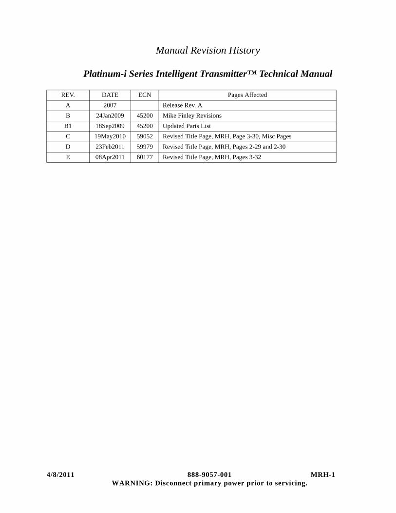
Manual Revision History
Platinum-i Series Intelligent Transmitter™ Technical Manual
REV. DATE ECN Pages Affected
A 2007 Release Rev. A
B 24Jan2009 45200 Mike Finley Revisions
B1 18Sep2009 45200 Updated Parts List
C 19May2010 59052 Revised Title Page, MRH, Page 3-30, Misc Pages
D 23Feb2011 59979 Revised Title Page, MRH, Pages 2-29 and 2-30
E 08Apr2011 60177 Revised Title Page, MRH, Pages 3-32
4/8/2011 888-9057-001 MRH-1WARNING: Disconnect primary power prior to servicing.

abinet0 001
Guide to Using Harris Parts List InformationThe Harris Replaceable Parts List Index portrays a tree structure with the major items being leftmost in the index. The example below shows the Transmitter as the highest item in the tree structure. If you were to look at the bill of materials table for the Transmitter you would find the Control Cabinet, the PA Cabinet, and the Output Cabinet. In the Replaceable Parts List Index the Control Cabinet, PA Cabinet, and Output Cabinet show up one indentation level below the Transmitter and implies that they are used in the Transmitter. The Controller Board is indented one level below the Control Cabinet so it will show up in the bill of material for the Control Cabinet. The tree structure of this same index is shown to the right of the table and shows indentation level versus tree structure level.
Example of Replaceable Parts List Index and equivalent tree structure:
Replaceable Parts List Index Part Number Page
Table 7-1. Transmitter 994 9283 001 7-2Table 7-2. Control Cabinet 992 9244 002 7-3Table 7-3. Controller Board 992 8344 002 7-6Table 7-4. PA Cabinet 992 9400 002 7-7Table 7-5. PA Amplifier 994 7894 002 7-9Table 7-6. PA Amplifier Board 992 7904 002 7-10Table 7-7. Output Cabinet 992 9450 001 7-12
The part number of the item is shown to the right of the description as is the page in the manual where the bill for that part number starts. Inside the actual tables, four main headings are used:
• Table #-#. ITEM NAME - HARRIS PART NUMBER - this line gives the information that corresponds to the Replaceable Parts List Index entry;
• HARRIS P/N column gives the ten DIGIT Harris part number (usually in ascending order);
• DESCRIPTION column gives a 25 character or less description of the part number;
• REF. SYMBOLS/EXPLANATIONS column 1) gives the reference designators for the item (i.e., C001, R102, etc.) that corresponds to the number found in the schematics (C001 in a bill of material is equiva-lent to C1 on the schematic) or 2) gives added information or further explanation (i.e., “Used for 208V operation only,” or “Used for HT 10LS only,” etc.).
NOTE: Inside the individual tables some standard conventions are used:
• A # symbol in front of a component such as #C001 under the REF. SYMBOLS/EXPLANATIONS col-umn means that this item is used on or with C001 and is not the actual part number for C001.
• In the ten digit part numbers, if the last three numbers are 000, the item is a part that Harris has pur-chased and has not manufactured or modified. If the last three numbers are other than 000, the item is either manufactured by Harris or is purchased from a vendor and modified for use in the Harris product.
• The first three digits of the ten DIGIT part number tell which family the part number belongs to - for example, all electrolytic (can) capacitors will be in the same family (524 xxxx 000). If an electrolytic (can) capacitor is found to have a 9xx xxxx xxx part number (a number outside of the normal family of numbers), it has probably been modified in some manner at the Harris factory and will therefore show up farther down into the individual parts list (because each table is normally sorted in ascending order). Most Harris made or modified assemblies will have 9xx xxxx xxx numbers associated with them.
The term “SEE HIGHER LEVEL BILL” in the description column implies that the reference designated part number will show up in a bill that is higher in the tree structure. This is often the case for components that may be frequency determinant or voltage determinant and are called out in a higher level bill structure that is more customer dependent than the bill at a lower level.
Transmitter994 9283 001
Control Cabinet 992 9244 002
Controller Board 992 8344 002
PA Cabinet992 9400 002
PA Amplifier992 7894 002
PA Amplifier Board 992 7904 002
Output C 992 945
2/22/2011 888-9057-001 vWARNING: Disconnect primary power prior to servicing.
2/22/2011 888-9057-001 MRH-1WARNING: Disconnect primary power prior to servicing.

! WARNING:THE CURRENTS AND VOLTAGES IN THIS EQUIPMENT ARE DANGEROUS. PERSONNEL MUST AT ALL TIMES OBSERVE SAFETY WARNINGS, INSTRUC-TIONS AND REGULATIONS.
This manual is intended as a general guide for trained and qualified personnel who are aware of the dangers inherent in handling potentially hazardous electrical/electronic circuits. It is not intended to contain a complete statement of all safety precautions which should be observed by personnel in using this or other electronic equipment.
The installation, operation, maintenance and service of this equipment involves risks both to personnel and equipment, and must be performed only by qualified personnel exercising due care. HARRIS CORPORATION shall not be responsible for injury or damage resulting from improper procedures or from the use of improperly trained or inexperienced personnel performing such tasks. During installation and operation of this equipment, local building codes and fire protection standards must be observed.
The following National Fire Protection Association (NFPA) standards are recommended as reference:
- Automatic Fire Detectors, No. 72E- Installation, Maintenance, and Use of Portable Fire Extinguishers, No. 10- Halogenated Fire Extinguishing Agent Systems, No. 12A
! WARNING:ALWAYS DISCONNECT POWER BEFORE OPENING COVERS, DOORS, ENCLO-SURES, GATES, PANELS OR SHIELDS. ALWAYS USE GROUNDING STICKS AND SHORT OUT HIGH VOLTAGE POINTS BEFORE SERVICING. NEVER MAKE INTERNAL ADJUSTMENTS, PERFORM MAINTENANCE OR SERVICE WHEN ALONE OR WHEN FATIGUED.
Do not remove, short-circuit or tamper with interlock switches on access covers, doors, enclosures, gates, panels or shields. Keep away from live circuits, know your equipment and don’t take chances.
! WARNING:IN CASE OF EMERGENCY ENSURE THAT POWER HAS BEEN DISCONNECTED.
! WARNING:IF OIL FILLED OR ELECTROLYTIC CAPACITORS ARE UTILIZED IN YOUR EQUIPMENT, AND IF A LEAK OR BULGE IS APPARENT ON THE CAPACITOR CASE WHEN THE UNIT IS OPENED FOR SERVICE OR MAINTENANCE, ALLOW THE UNIT TO COOL DOWN BEFORE ATTEMPTING TO REMOVE THE DEFEC-TIVE CAPACITOR. DO NOT ATTEMPT TO SERVICE A DEFECTIVE CAPACITOR WHILE IT IS HOT DUE TO THE POSSIBILITY OF A CASE RUPTURE AND SUBSE-QUENT INJURY.
2/22/2011 888-9057-001 viiWARNING: Disconnect primary power prior to servicing.

FIRST-AID
viii 888-9057-001 2/22/2011WARNING: Disconnect primary power prior to servicing.

Personnel engaged in the installation, operation, maintenance or servicing of this equipment are urged to become familiar with first-aid theory and practices. The following information is not intended to be complete first-aid procedures, it is a brief and is only to be used as a reference. It is the duty of all personnel using the equipment to be prepared to give adequate Emergency First Aid and there by prevent avoidable loss of life.
Treatment of Electrical Burns
1. Extensive burned and broken skin
a. Cover area with clean sheet or cloth. (Cleanest available cloth article.)
b. Do not break blisters, remove tissue, remove adhered particles of clothing, or apply any salve or ointment.
c. Treat victim for shock as required.
d. Arrange transportation to a hospital as quickly as possible.
e. If arms or legs are affected keep them elevated.
NOTE:If medical help will not be available within an hour and the victim is conscious and not vomiting, give him a weak solution of salt and soda: 1 level teaspoonful of salt and 1/2 level teaspoonful of baking soda to each quart of water (neither hot or cold). Allow victim to sip slowly about 4 ounces (a half of glass) over a period of 15 minutes. Discontinue fluid if vomiting occurs. (Do not give alcohol.)
2. Less severe burns - (1st & 2nd degree)
a. Apply cool (not ice cold) compresses using the cleanest available cloth article.
b. Do not break blisters, remove tissue, remove adhered particles of clothing, or apply salve or ointment.
c. Apply clean dry dressing if necessary.
d. Treat victim for shock as required.
e. Arrange transportation to a hospital as quickly as possible.
f. If arms or legs are affected keep them elevated.
REFERENCE:ILLINOIS HEART ASSOCIATIONAMERICAN RED CROSS STANDARD FIRST AID AND PERSONAL SAFETY MANUAL (SECOND EDITION)
2/22/2011 888-9057-001 ixWARNING: Disconnect primary power prior to servicing.

x 888-9057-001 2/22/2011WARNING: Disconnect primary power prior to servicing.

Table of Contents
Section 1Platinum-i Series Digital Transmitter
IntroductionIntroduction . . . . . . . . . . . . . . . . . . . . . . . . . . . . . . . . 1-5
Transmitter Configurations. . . . . . . . . . . . . . . . . . . 1-5Organization of Transmitter Documentation . . . . . 1-6
General Description. . . . . . . . . . . . . . . . . . . . . . . . . . 1-8Transmitter System Theory of Operation . . . . . . . . . 1-9
Control System . . . . . . . . . . . . . . . . . . . . . . . . . . . . 1-9 Main Controller Board . . . . . . . . . . . . . . . . . . . . 1-9PA Cabinet Slave Controller . . . . . . . . . . . . . . . . 1-9RF Module Controller . . . . . . . . . . . . . . . . . . . . 1-1050 RF Module Power Supply Controller Bd . . . 1-10
Control Cabinet. . . . . . . . . . . . . . . . . . . . . . . . . . . 1-10Exciter switcher . . . . . . . . . . . . . . . . . . . . . . . . . 1-10Transmitter AGC Module . . . . . . . . . . . . . . . . . 1-10Phase and Gain. . . . . . . . . . . . . . . . . . . . . . . . . . 1-10
Signal Interface. . . . . . . . . . . . . . . . . . . . . . . . . . . 1-11RF PA Cabinets. . . . . . . . . . . . . . . . . . . . . . . . . . . 1-11
PTCD5P1-i. . . . . . . . . . . . . . . . . . . . . . . . . . . . . 1-11PTCD10P1-i. . . . . . . . . . . . . . . . . . . . . . . . . . . . 1-11PTCD20P2-i. . . . . . . . . . . . . . . . . . . . . . . . . . . . 1-12PTCD30P3-i. . . . . . . . . . . . . . . . . . . . . . . . . . . . 1-12PTCD40P4-i. . . . . . . . . . . . . . . . . . . . . . . . . . . . 1-12
50 Volt Power Supply . . . . . . . . . . . . . . . . . . . . . . 1-12RF Output Systems. . . . . . . . . . . . . . . . . . . . . . . . 1-13
RF Hybrids, a Refresher Course . . . . . . . . . . . . . . . 1-13Splitting . . . . . . . . . . . . . . . . . . . . . . . . . . . . . . . . 1-14Combining . . . . . . . . . . . . . . . . . . . . . . . . . . . . . . 1-15PA Cabinet Combining . . . . . . . . . . . . . . . . . . . . . 1-15Hybrids In Attenuators . . . . . . . . . . . . . . . . . . . . . 1-16Hybrids as Phase Shifters . . . . . . . . . . . . . . . . . . . 1-18Adding Phase and Gain Adjustments . . . . . . . . . . 1-19
Platinum RF Combining Parameters. . . . . . . . . . . . 1-20Two PA Cabinets . . . . . . . . . . . . . . . . . . . . . . . . 1-20Percent of Cabinet Power With (3) PA Cabinets 1-21Percent of Power With (4) PA Cabinets. . . . . . . 1-21Drive Power Meter Calibration . . . . . . . . . . . . . 1-22
Section 2Installation
Introduction . . . . . . . . . . . . . . . . . . . . . . . . . . . . . . . . 2-1Installation Planning . . . . . . . . . . . . . . . . . . . . . . . . . 2-1
Space Requirements. . . . . . . . . . . . . . . . . . . . . . . 2-3
1
Weights . . . . . . . . . . . . . . . . . . . . . . . . . . . . . . . . . . 2-3RF System Layout . . . . . . . . . . . . . . . . . . . . . . . . . 2-3Air System . . . . . . . . . . . . . . . . . . . . . . . . . . . . . . . 2-4
Outside Air Cooling. . . . . . . . . . . . . . . . . . . . . . . 2-4Air Conditioning . . . . . . . . . . . . . . . . . . . . . . . . . 2-5
Electrical Power . . . . . . . . . . . . . . . . . . . . . . . . . . . 2-5Circuit Breaker Selection. . . . . . . . . . . . . . . . . . . 2-5Isolation Transformer . . . . . . . . . . . . . . . . . . . . . 2-6
Unpacking and Equipment Inventory . . . . . . . . . . . . 2-7Equipment Required for Unloading . . . . . . . . . . . . 2-7Inventory and Inspection . . . . . . . . . . . . . . . . . . . . 2-8
Packing Check List . . . . . . . . . . . . . . . . . . . . . . . 2-8Factory Test Data Sheets . . . . . . . . . . . . . . . . . . . 2-8
Cabinet Placement and Leveling . . . . . . . . . . . . . . . 2-9Grounding . . . . . . . . . . . . . . . . . . . . . . . . . . . . . . . . 2-10Tap Transformers . . . . . . . . . . . . . . . . . . . . . . . . . . 2-10UPS Installation . . . . . . . . . . . . . . . . . . . . . . . . . . . 2-10Installation of 50 Volt Supplies. . . . . . . . . . . . . . . . 2-11RF Output Coax . . . . . . . . . . . . . . . . . . . . . . . . . . . 2-11AC Primary Wiring . . . . . . . . . . . . . . . . . . . . . . . . . 2-12Inter-cabinet Wiring . . . . . . . . . . . . . . . . . . . . . . . . 2-12Input Signal Wiring. . . . . . . . . . . . . . . . . . . . . . . . . 2-13Interlocks and Interfaces . . . . . . . . . . . . . . . . . . . . . 2-13
External Interlock: TB1-1, 2 . . . . . . . . . . . . . . . . 2-13Fail-safe Interlock: TB1-3, 4 . . . . . . . . . . . . . . . . 2-13Individual PA Cabinet External Interlocks. . . . . . 2-13External Blower Control: . . . . . . . . . . . . . . . . . . . 2-14RF Samples . . . . . . . . . . . . . . . . . . . . . . . . . . . . . 2-14
Remote Control I/O: . . . . . . . . . . . . . . . . . . . . . . . . 2-15Command In. . . . . . . . . . . . . . . . . . . . . . . . . . . . . 2-15
J31 COMMAND INPUTS: . . . . . . . . . . . . . . . . 2-16J32: Status Outputs . . . . . . . . . . . . . . . . . . . . . . 2-17J33: Analog Outputs . . . . . . . . . . . . . . . . . . . . . 2-19Optional Remote Status . . . . . . . . . . . . . . . . . . . 2-20
Transmitter Check Out . . . . . . . . . . . . . . . . . . . . . . 2-21Control Cabinet Pre-Operational Check Out . . . . 2-21
Three Phase AC and Logic Supply Checkout . . 2-21UPS Operations Test . . . . . . . . . . . . . . . . . . . . . 2-22GUI Setup . . . . . . . . . . . . . . . . . . . . . . . . . . . . . 2-23
PA Cabinet Pre-Operational Check Out . . . . . . . . 2-24PA Cabinet Checkout. . . . . . . . . . . . . . . . . . . . . 2-24
Module Installation . . . . . . . . . . . . . . . . . . . . . . . 2-25Control System Check Out. . . . . . . . . . . . . . . . . . 2-26VSWR Foldback And VSWR Fault Check Out. . 2-27
Initial Application of RF Power . . . . . . . . . . . . . . . 2-27Power Calibration . . . . . . . . . . . . . . . . . . . . . . . . . . 2-29

Table of Contents (continued)
Basics of Power Calibration.. . . . . . . . . . . . . . . . . 2-29Power Calibration . . . . . . . . . . . . . . . . . . . . . . . . . 2-29
System Forward Power. . . . . . . . . . . . . . . . . . . . 2-29Reflected Power . . . . . . . . . . . . . . . . . . . . . . . . . 2-29PA Cabinet Power Calibration . . . . . . . . . . . . . . 2-30PTCD20P2 Reject Load . . . . . . . . . . . . . . . . . . . 2-30Three and Four Cabinet Calibration . . . . . . . . . . 2-30
VSWR Calibration. . . . . . . . . . . . . . . . . . . . . . . . . . 2-31Power Limit . . . . . . . . . . . . . . . . . . . . . . . . . . . . . . . 2-32
Section 3Software Installation/Setup
Introduction . . . . . . . . . . . . . . . . . . . . . . . . . . . . . . . . 3-1eCDi™ and the Platinum-i™ Transmitter . . . . . . . . . 3-1Hardware . . . . . . . . . . . . . . . . . . . . . . . . . . . . . . . . . . 3-2Features . . . . . . . . . . . . . . . . . . . . . . . . . . . . . . . . . . . 3-2
Web GUI (Graphical User Interface) . . . . . . . . . . . 3-3Touch Screen Calibration . . . . . . . . . . . . . . . . . . . . 3-3SNMP Agent . . . . . . . . . . . . . . . . . . . . . . . . . . . . . . 3-4
Level 1 / Level 2 Functionality . . . . . . . . . . . . . . . . . 3-4Security . . . . . . . . . . . . . . . . . . . . . . . . . . . . . . . . . . . 3-5Downloading the Manual. . . . . . . . . . . . . . . . . . . . . . 3-6Setup . . . . . . . . . . . . . . . . . . . . . . . . . . . . . . . . . . . . . 3-7Detailed Installation Procedures by Transmitter . . . . 3-7APEX Exciter Setup . . . . . . . . . . . . . . . . . . . . . . . . . 3-8
Setting APEX IP Address . . . . . . . . . . . . . . . . . . . . 3-9CD-1A Electronic Serial Number Reset . . . . . . . . . 3-10eCDi™ Configuration . . . . . . . . . . . . . . . . . . . . . . . 3-11
Troubleshooting Tips . . . . . . . . . . . . . . . . . . . . . . 3-13Apply Changes . . . . . . . . . . . . . . . . . . . . . . . . . . . 3-28Backing Up the Configuration . . . . . . . . . . . . . . . 3-29Restoring a Configuration File . . . . . . . . . . . . . . . 3-29Reset Computer IP Address . . . . . . . . . . . . . . . . . 3-29
eCDi Software Updates . . . . . . . . . . . . . . . . . . . . . . 3-30Updating the eCDi™. . . . . . . . . . . . . . . . . . . . . . . 3-31
Getting Starting... . . . . . . . . . . . . . . . . . . . . . . . . 3-31Main Controller Software Update . . . . . . . . . . . . . . 3-33Network Firewall Setup . . . . . . . . . . . . . . . . . . . . . . 3-42Firewall Ports. . . . . . . . . . . . . . . . . . . . . . . . . . . . . . 3-43
Optional Port Settings . . . . . . . . . . . . . . . . . . . . . . 3-43PowerCD™ IP address and Port Settings . . . . . . . 3-46
2
Section 4Operation
Introduction . . . . . . . . . . . . . . . . . . . . . . . . . . . . . . . . 4-1Graphical User Interface . . . . . . . . . . . . . . . . . . . . . 4-1376 Micro Controller . . . . . . . . . . . . . . . . . . . . . . . 4-1CPLD Complex Programable Logic Device . . . . . 4-2
Front Control Panel . . . . . . . . . . . . . . . . . . . . . . . . . . 4-3CONTROL Pushbuttons . . . . . . . . . . . . . . . . . . . . . 4-3STATUS Indicators / Pushbuttons . . . . . . . . . . . . . 4-3Auxiliary Control Panel . . . . . . . . . . . . . . . . . . . . . 4-4
GUI and eCDi Control. . . . . . . . . . . . . . . . . . . . . . . . 4-5Introduction. . . . . . . . . . . . . . . . . . . . . . . . . . . . . . . 4-5Network Log On Screen . . . . . . . . . . . . . . . . . . . . . 4-6A short Tutorial on the GUI Display Screen. . . . . . 4-7
GUI Display Screen. . . . . . . . . . . . . . . . . . . . . . . . . . 4-9Fault & Event Screen . . . . . . . . . . . . . . . . . . . . . . . 4-9
Fault Alarm Listing . . . . . . . . . . . . . . . . . . . . . . 4-10Control Section . . . . . . . . . . . . . . . . . . . . . . . . . . . 4-11
Status and Metering Screens . . . . . . . . . . . . . . . . . . 4-11Drive Chain. . . . . . . . . . . . . . . . . . . . . . . . . . . . . . 4-11
Meters Button Selected . . . . . . . . . . . . . . . . . . . 4-13PA Cabinet Tab . . . . . . . . . . . . . . . . . . . . . . . . . . . 4-15Output Tab . . . . . . . . . . . . . . . . . . . . . . . . . . . . . . 4-18
Output Tab Summary . . . . . . . . . . . . . . . . . . . . . 4-18Output Tab Faults . . . . . . . . . . . . . . . . . . . . . . . . 4-18Output Tab Meters . . . . . . . . . . . . . . . . . . . . . . . 4-19Output Tab, Control . . . . . . . . . . . . . . . . . . . . . . 4-19Output Tab, Service Button . . . . . . . . . . . . . . . . 4-20
P.S. Power Supply Tab . . . . . . . . . . . . . . . . . . . . . 4-21Power Supply Summary. . . . . . . . . . . . . . . . . . . 4-21
System Tab . . . . . . . . . . . . . . . . . . . . . . . . . . . . . . 4-24Performance Tab . . . . . . . . . . . . . . . . . . . . . . . . . . 4-26
GUI Screen Faults Summary List . . . . . . . . . . . . . . 4-28
Section 5Control System Theory of Operation
Control System Overall Desription . . . . . . . . . . . . . . 5-1Transmitter Control System . . . . . . . . . . . . . . . . . . 5-1Micro Module . . . . . . . . . . . . . . . . . . . . . . . . . . . . . 5-3
Features of the 376 module include: . . . . . . . . . . 5-3CPLD, Complex Programmable Logic Device . . . 5-4
I/O Expansion. . . . . . . . . . . . . . . . . . . . . . . . . . . . 5-4Life Support Backup . . . . . . . . . . . . . . . . . . . . . . 5-4
Controller Area Network (CAN) Bus. . . . . . . . . . . 5-5Main Controller . . . . . . . . . . . . . . . . . . . . . . . . . . . . . 5-7

Table of Contents (continued)
Transmitter Control . . . . . . . . . . . . . . . . . . . . . . . . 5-7Graphical User Interface (GUI) . . . . . . . . . . . . . . 5-7Remote Controls . . . . . . . . . . . . . . . . . . . . . . . . . 5-8
Control Panel and Indicator Display . . . . . . . . . . . . . 5-8Introduction . . . . . . . . . . . . . . . . . . . . . . . . . . . . . 5-8
Modes of Operation . . . . . . . . . . . . . . . . . . . . . . . . 5-9Button Press . . . . . . . . . . . . . . . . . . . . . . . . . . . . . 5-9Button / Indicator Lighting . . . . . . . . . . . . . . . . 5-10 Messages in the LED Display. . . . . . . . . . . . . . 5-11
FP Error . . . . . . . . . . . . . . . . . . . . . . . . . . . . . . 5-11Com Error, Main Controller . . . . . . . . . . . . . . 5-11
Main Controller . . . . . . . . . . . . . . . . . . . . . . . . . . . . 5-12Platinum-i TV Controller . . . . . . . . . . . . . . . . . . . 5-12
Micromodule Interface (Sheet 2) . . . . . . . . . . . . 5-12Micro Module (Sheet 3). . . . . . . . . . . . . . . . . . . 5-12Development Hardware & Bd Version (Sheet 3)5-13RS232 Watch Dog & Front Panel Interface (Sheet 4)5-13
Controller Analog Sense (Sheet 5) . . . . . . . . . . 5-14CPLD (Sheet 6) . . . . . . . . . . . . . . . . . . . . . . . . . 5-14Cabinet Bus Controller (Sheet 7) . . . . . . . . . . . . 5-15Transmitter ON/OFF Control (Sheet 8) . . . . . . . 5-15Foldback Voltage D / A and Can Bus Interface (Sheet 9) . . . . . . . . . . . . . . . . . . . . . . . . . . . . . . . . . . . . 5-15
Controller/Exciter Switcher Interface (Sheet 10)5-15Line Voltage and AGC Monitoring (Sheet 11) . 5-16Interlocks (Sheet 12) . . . . . . . . . . . . . . . . . . . . . 5-16Peak Detectors (Sheets 13 and 14). . . . . . . . . . . 5-16Fault Detection (Sheet 15) . . . . . . . . . . . . . . . . . 5-17Dual Tran Interface (Sheet 16). . . . . . . . . . . . . . 5-17Remote Commands Input (Sheet 17) . . . . . . . . . 5-17Remote Status Output Drivers (Sheets 18 and 19)5-18Optional Remote Status Output Drivers (Sheet 20)5-18
Remote Analog Outputs (Sheet 21) . . . . . . . . . . 5-18DC Distribution . . . . . . . . . . . . . . . . . . . . . . . . . 5-18
The SLAVE CONTROLLER DESCRIPTION . . 5-18Slave Controller . . . . . . . . . . . . . . . . . . . . . . . . . . 5-18
Sheet 1 . . . . . . . . . . . . . . . . . . . . . . . . . . . . . . . . 5-19Sheet 2 . . . . . . . . . . . . . . . . . . . . . . . . . . . . . . . . 5-20Sheets 3 and 4 . . . . . . . . . . . . . . . . . . . . . . . . . . 5-20Sheet 6 . . . . . . . . . . . . . . . . . . . . . . . . . . . . . . . . 5-21Sheet 7 . . . . . . . . . . . . . . . . . . . . . . . . . . . . . . . . 5-21Sheet 8 . . . . . . . . . . . . . . . . . . . . . . . . . . . . . . . . 5-21Sheet 9 . . . . . . . . . . . . . . . . . . . . . . . . . . . . . . . . 5-21
Graphical User Interface . . . . . . . . . . . . . . . . . . . . . 5-21
3
Section 6Control Cabinet
Introduction. . . . . . . . . . . . . . . . . . . . . . . . . . . . . . . . 6-1Control Cabinet Common. . . . . . . . . . . . . . . . . . . . . 6-2
Control Interconnects . . . . . . . . . . . . . . . . . . . . . . . 6-2AC Power Distribution. . . . . . . . . . . . . . . . . . . . . . 6-2DC Power Supplies . . . . . . . . . . . . . . . . . . . . . . . . 6-3Diode ORing . . . . . . . . . . . . . . . . . . . . . . . . . . . . . 6-3
Wiring Diagram, Control Cabinet Digital. . . . . . . . . 6-3RF Flow Path . . . . . . . . . . . . . . . . . . . . . . . . . . . . . 6-3
Multiple AGC Paths . . . . . . . . . . . . . . . . . . . . . . 6-4Main Controller . . . . . . . . . . . . . . . . . . . . . . . . . . . 6-4Front Panel Switch Unit . . . . . . . . . . . . . . . . . . . . . 6-4Display Unit . . . . . . . . . . . . . . . . . . . . . . . . . . . . . . 6-4
Accessory Tray . . . . . . . . . . . . . . . . . . . . . . . . . . . . . 6-5Exciter Switcher (843-5275-211) . . . . . . . . . . . . . . 6-5
Logic Card Detailed Circuit Description (839-7900-043). . . . . . . . . . . . . . . . . . . . . . . . . . . . . . . . . . . 6-5
Exciter Switcher Relay Board Panel(839-7900-080)6-6
Operational Setup and Adjustment . . . . . . . . . . . 6-6Troubleshooting . . . . . . . . . . . . . . . . . . . . . . . . . . 6-6
AGC . . . . . . . . . . . . . . . . . . . . . . . . . . . . . . . . . . . . 6-7Detailed Circuit Description . . . . . . . . . . . . . . . . 6-7Operational Setup and Adjustment . . . . . . . . . . . 6-9Troubleshooting . . . . . . . . . . . . . . . . . . . . . . . . . 6-10
Phase and Gain . . . . . . . . . . . . . . . . . . . . . . . . . . . 6-10Detailed Circuit Description . . . . . . . . . . . . . . . 6-10Operational Setup and Adjustment . . . . . . . . . . 6-13Troubleshooting . . . . . . . . . . . . . . . . . . . . . . . . . 6-13
UPS. . . . . . . . . . . . . . . . . . . . . . . . . . . . . . . . . . . . 6-13UPS Battery Testing . . . . . . . . . . . . . . . . . . . . . 6-13
Section 7PA Cabinet
Introduction. . . . . . . . . . . . . . . . . . . . . . . . . . . . . . . . 7-1Theory of Operation . . . . . . . . . . . . . . . . . . . . . . . . . 7-1
AC Power Flow . . . . . . . . . . . . . . . . . . . . . . . . . . . 7-1Fan and air flow monitoring . . . . . . . . . . . . . . . . 7-1Interlock Circuits . . . . . . . . . . . . . . . . . . . . . . . . . 7-2
SCR crowbar . . . . . . . . . . . . . . . . . . . . . . . . . . . 7-2Mechanical Shorting Switch . . . . . . . . . . . . . . . 7-2
PA Cabinet Control Logic . . . . . . . . . . . . . . . . . . . 7-2RF Input and Driver System . . . . . . . . . . . . . . . . . . . 7-3
Power Divider . . . . . . . . . . . . . . . . . . . . . . . . . . . . 7-3

Table of Contents (continued)
PA Output Combiner Network. . . . . . . . . . . . . . . . . . 7-3Gysel Combiner Theory. . . . . . . . . . . . . . . . . . . . . . . 7-4Maintenance and Troubleshooting. . . . . . . . . . . . . . . 7-6
Cooling System . . . . . . . . . . . . . . . . . . . . . . . . . . . . 7-6Air Filter Replacement . . . . . . . . . . . . . . . . . . . . . 7-6
Air Switch Adjustment . . . . . . . . . . . . . . . . . . . . . . 7-6Back Door Fan . . . . . . . . . . . . . . . . . . . . . . . . . . . . 7-8Check for Loose Connections . . . . . . . . . . . . . . . . . 7-8Check MOV Boards . . . . . . . . . . . . . . . . . . . . . . . . 7-9Checking Multiple PA Cabinet Interlocks . . . . . . . 7-9Cleaning . . . . . . . . . . . . . . . . . . . . . . . . . . . . . . . . . 7-9RF Trouble Shooting Divider and Combiner . . . . 7-10
Power Divider. . . . . . . . . . . . . . . . . . . . . . . . . . . 7-10Combiner . . . . . . . . . . . . . . . . . . . . . . . . . . . . . . 7-10
Section 8RF Amplifier Modules
General Information. . . . . . . . . . . . . . . . . . . . . . . . . . 8-1Factory Module Repair . . . . . . . . . . . . . . . . . . . . . . 8-1Local Module Repair. . . . . . . . . . . . . . . . . . . . . . . . 8-2Module Part Numbers . . . . . . . . . . . . . . . . . . . . . . . 8-2
RF Amplifier Modules Theory of Operation. . . . . . . 8-3Driver Module, Low Band (Band I) . . . . . . . . . . . . 8-5Driver Module, High Band (Band II) . . . . . . . . . . . 8-6PA Module. . . . . . . . . . . . . . . . . . . . . . . . . . . . . . . . 8-7RF Quarter Modules . . . . . . . . . . . . . . . . . . . . . . . . 8-8Low Band Quarter Module . . . . . . . . . . . . . . . . . . . 8-9High Band Quarter Module. . . . . . . . . . . . . . . . . . 8-10Quarter Module Bias . . . . . . . . . . . . . . . . . . . . . . . 8-11Protection, Control and Monitor Subsystem. . . . . 8-12Module Status LEDs . . . . . . . . . . . . . . . . . . . . . . . 8-13
Red LED Fault Blink Codes. . . . . . . . . . . . . . . . 8-14Module Troubleshooting . . . . . . . . . . . . . . . . . . . . . 8-15
Platinum? TV Module Test Fixture (992-8556-002) (Optional Equipment) . . . . . . . . . . . . . . . . . . . . . 8-16
Troubleshooting Based on Module Swapping . . . 8-18Troubleshooting Based on Module Blink Codes . 8-18Isolating Other Failures. . . . . . . . . . . . . . . . . . . . . 8-23Locating Failed RF FETs . . . . . . . . . . . . . . . . . . . 8-25
DC Resistance Test . . . . . . . . . . . . . . . . . . . . . . . 8-25Idle Current Test . . . . . . . . . . . . . . . . . . . . . . . . . 8-25
Parts Replacement Procedures. . . . . . . . . . . . . . . . . 8-27Soldering Precautions . . . . . . . . . . . . . . . . . . . . . . 8-27Quarter Module Replacement . . . . . . . . . . . . . . . . 8-28RF FET Replacement . . . . . . . . . . . . . . . . . . . . . . 8-29Testing and Replacing Isolation Resistors . . . . . . 8-33
4
Pass FET Replacement . . . . . . . . . . . . . . . . . . . . . 8-33Chip Cap Replacement . . . . . . . . . . . . . . . . . . . . . 8-33
Test Procedure Solid State TV Modules . . . . . . . . . 8-34Pre-operational Checks . . . . . . . . . . . . . . . . . . . . . 8-34
Initial Power Up . . . . . . . . . . . . . . . . . . . . . . . . . 8-34Idle Current Check . . . . . . . . . . . . . . . . . . . . . . . 8-34Over/Under Voltage Check . . . . . . . . . . . . . . . . 8-35
RF Testing. . . . . . . . . . . . . . . . . . . . . . . . . . . . . . . 8-35Application of Drive. . . . . . . . . . . . . . . . . . . . . . 8-36Gain Check. . . . . . . . . . . . . . . . . . . . . . . . . . . . . 8-36ISO Volts Check . . . . . . . . . . . . . . . . . . . . . . . . . 8-37Overdrive Check . . . . . . . . . . . . . . . . . . . . . . . . 8-37VSWR Protection Check . . . . . . . . . . . . . . . . . . 8-38
Section 950 Volt Supply
Introduction . . . . . . . . . . . . . . . . . . . . . . . . . . . . . . . . 9-1Theory of Operation . . . . . . . . . . . . . . . . . . . . . . . . . 9-1
Transformer Primary. . . . . . . . . . . . . . . . . . . . . . . . 9-1Six Phase SCR Rectification. . . . . . . . . . . . . . . . . . 9-2DC Supply Filtering . . . . . . . . . . . . . . . . . . . . . . . . 9-2Control Board . . . . . . . . . . . . . . . . . . . . . . . . . . . . . 9-2
Controller Power Supply . . . . . . . . . . . . . . . . . . . 9-350 V Supply Regulation Circuitry . . . . . . . . . . . . 9-3Fault Protection Circuits. . . . . . . . . . . . . . . . . . . . 9-4GO / NOGO Circuit . . . . . . . . . . . . . . . . . . . . . . . 9-4
Troubleshooting and Maintenance . . . . . . . . . . . . . . 9-5OVERTEMP Fault . . . . . . . . . . . . . . . . . . . . . . . . 9-6OVERVOLTAGE . . . . . . . . . . . . . . . . . . . . . . . . . 9-7OVERCURRENT . . . . . . . . . . . . . . . . . . . . . . . . 9-7Breaker Trips . . . . . . . . . . . . . . . . . . . . . . . . . . . . 9-7Slave Controller Power Supply Fault Indication . 9-7Delay Angle Balance Adjust . . . . . . . . . . . . . . . . 9-8Vendor Repair. . . . . . . . . . . . . . . . . . . . . . . . . . . . 9-8
Section 10Parts List
Parts List Index . . . . . . . . . . . . . . . . . . . . . . . . . . . . 10-1
Appendix AMain Controller Board Replacement Procedure . . . . a-1

Section 1Platinum-i Series Digital Transmitter Introduction
2/23/11 888-9057-001WARNING: Disconnect primary AC power pri
1
1.1 IntroductionThis manual is part of the documentation for the Harris Digital Platinum-iTM solid state VHF transmitter including the following models and the average power rating. Larger models are available by customer request.
MODEL HIGH BAND POWER LOW BAND POWER
PTCD5P1-i 2.0 KW 1.8 KW
PTCD10P1-i 4.0 KW 3.5 KW
PTCD20P2-i 8.0 KW 7.0 KW
PTCD30P3-i 12.0 KW 10.5 KW
PTCD40P4-i 16.0 KW 14.0 KW
1.1.1 Transmitter Configurations
The Platinum-i series is a control cabinet that can be used in several Platinum transmitter configurations.
• New transmitters with Apex exciters and Cool Fuel mask filters. The single auto-matic gain control (AGC) loop around the total transmitter is the standard for this configuration. This configuration of transmitters and the resulting power levels appears above.
• Retrofit of this control cabinet with Apex exciters, single AGC and Cool Fuel mask filter and with existing digital transmitters (14 way combiner) will give similar per-formance and power levels.
1-5or to servicing.

Section 1 Platinum-i Series Digital
• Retrofit of this cabinet with Apex exciters, Cool Fuel Filter and single AGC with existing (12 way visual combiner) HSP and LSP transmitters on the same channel will work for 3.5 KW high band, 3KW low band per PA cabinet power levels.
• Retrofit of this cabinet with Apex exciters, Cool Fuel Filter and single AGC with existing Visual PA only style HS and LS transmitters will give will work for 4.5 KW high band, 4KW low band per PA cabinet power levels on the same channel.
• Any use of the CD1A series of exciters will result in lower power levels such as 2.5 KW per PA cabinet. The single AGC configuration may also require lower power because of the fixed non-linear correction. Loss of a PA module may also require operator adjustment of power to stay within the mask limits and have reasonable EVM errors. Multiple AGCs are available as a customer special order.
1.1.2 Organization of Transmitter Documentation
• The documentation consists of:
a. Apex Exciter Manual, a separate document.
b. Platinum-i Digital Technical Manual (this manual)
c. Platinum-i Digital Drawing Package for High Band or for Low Band
• Organization of the Technical Manuals
The text part of the manual is divided into the following sections.
Section 1: Introduction
Section 2: Hardware Installation
Section 3: Software Installation and Setup
Section 4: Operation
Section 5: Control System Theory of Operation
Section 6: Control Cabinet
Section 7: PA Cabinet
Section 8: RF Modules
Section 9: 50 Volt Power Supply
Section 10: Parts Listing
1-6 888-9057-001 2/23/11WARNING: Disconnect and lockout primary AC power prior to servicing.

Section 1 Platinum-i Series Digital
There are different drawing packages for low band and high band systems, the drive chains and modules are different. The drawing packages are organized in sections with tab separators as follows:
SYSTEM SUBSYSTEM
100 PTCD5P1i 600 Control System
200 PTCD10P1i 700 Control Cabinet
300 PTCD20P2i 800 PA Cabinet
400 PTCD30P3i 900 50 Volt Power Supply
500 PTCD40P4i 1000 High Power RF Modules
2/23/11 888-9057-001 1-7WARNING: Disconnect and lockout primary AC power prior to servicing.

Section 1 Platinum-i Series Digital
Figure 1-1 PTCD10P1-i
1.2 General Description
The Digital Platinum-iTM consists of a control cabinet, one or more power amplifier cabinets (PA). and RF output system. The RF system includes a mask filter, harmonic filter and could include a combiner for multiple channels into one antenna.
1-8 888-9057-001 2/23/11WARNING: Disconnect and lockout primary AC power prior to servicing.

Section 1 Platinum-i Series Digital
The eCDi version of the control cabinet will be used with new Platinum-i cabinets and as a retrofit to older PA cabinets. The different versions of the PA cabinet will use various drive configuration and different modules types.
• The new version with APEX exciter will use the standard analog version of the mod-ules and an overall single AGC unit.
• The classic digital version will use the specially biased driver modules that were needed to work with the CD1A exciter and an AGC for each PA cabinet.
• The third use will be to retrofit existing analog transmitters to digital service. These PAs will continue to uses the 12 or 17 visual PA module configuration as the digital power amplifier.
1.3 Transmitter System Theory of Operation
1.3.1 Control System
The transmitter uses a distributed architecture control system. This means that some transmitter sub-systems include self monitoring and protection and report to the Main Controller for display on the GUI (Graphical User Interface) and to a remote interface. The heart of the system is the 376 Micro Module and the XC95288XL CPLD which is used for control and monitoring interface.
1.3.1.1 Main Controller Board
This board is responsible for transmitter control and monitoring. The Main Controller is responsible for system level control (multiple sub-systems) since it is the only part of the control system which can monitor the entire transmitter. This printed wiring board is mounted just below the top of the cabinet and also serves as the customer and system Input and Output, I/O. It gathers status and fault data from the individual sub-systems and reports that information to the operator locally and by remote control.
1.3.1.2 PA Cabinet Slave Controller
This board interfaces with the module and power supply controller boards to transfer information to the main controller. It also has control functions related to that PA cabinet.
2/23/11 888-9057-001 1-9WARNING: Disconnect and lockout primary AC power prior to servicing.

Section 1 Platinum-i Series Digital
1.3.1.3 RF Module Controller
A logic and control board responsible for protection and control of the one RF Driver or PA Module that it is part of.
1.3.1.4 50 RF Module Power Supply Controller Bd
Responsible for control and monitoring of the 50V RF amplifier power supplies.
1.3.2 Control Cabinet.
The control cabinet contains a digital exciter, and an optional second exciter. The RF signal path includes an optional exciter switcher, automatic gain control module and phase and gain modules when more than one PA cabinet is used. The main controller e and the GUI are part of the control cabinet. The RF drive levels to the PA cabinet input(s) are in the 25 to 100mW range.
1.3.2.1 Exciter switcher
If optional dual exciters and an exciter switcher are used, both exciters are fed a SMPTE 310 signal, and each exciter's output feeds a logic controlled coax switch. The selected exciter signal in a single PA cabinet system then goes to the AGC. When more than one PA cabinet is used the AGC output is connected to one or more Phase and Gain units.
1.3.2.2 Transmitter AGC Module
The single exciter output/exciter switcher output to the transmitter AGC module, whose job is to maintain a constant drive level by monitoring a sample of transmitter output, and correspondingly controlling PA cabinet input drive. Phase and Gain Module
1.3.2.3 Phase and Gain
In transmitters with multiple PA cabinets, the AGC module is followed by one or more phase and gain modules. Each phase and gain module splits the drive into two signals whose relative amplitude and phase are adjustable. This allows trimming to compensate for small gain and phase differences between cabinets, so that the PA cabinet outputs maintain the proper phase and amplitude relationships when combined in the following
1-10 888-9057-001 2/23/11WARNING: Disconnect and lockout primary AC power prior to servicing.

Section 1 Platinum-i Series Digital
3 dB or 4.77 dB hybrid combiner(s). Phase and Gain units are adjusted for minimum hybrid reject load power.
1.3.3 Signal Interface
Signal interface for signal input and monitoring by remote control is located on top of the transmitter. This location is also used for the control and monitoring cable interconnect with the PA cabinet(s) and the monitor sample cables.
1.3.4 RF PA Cabinets
The PA cabinets have independent:
• AC power feed from a circuit breaker.
• Cabinet level control system
• Cooling system, fan and interlock pressure switch
• Logic power supply
• 50 Volt RF module supplies with control logic
• Rear Door interlock
• Cabinet external interlock to protect combining hybrid reject loads
Maintenance can be performed on one PA cabinet while the others are operating.
Each transmitter configuration is documented by a block diagram in the appropriate drawing package system section one through five.
1.3.4.1 PTCD5P1-i
The low band unit has one driver module, a seven way power divider, seven PA modules and a seven way combiner. The high band is similar, adding a PA stage between the driver and the seven way power divider. A drive sample between the driver output and the seven way power divider are used for metering AGC. The cabinet output line is sampled for cabinet power metering.
1.3.4.2 PTCD10P1-i
Low Band
2/23/11 888-9057-001 1-11WARNING: Disconnect and lockout primary AC power prior to servicing.

Section 1 Platinum-i Series Digital
The PA input RF is amplified by a driver module then divided by a 14 way splitter. Each splitter output drives a PA module. The PA's are combined in a 14 way combiner.
High Band
The driver output is the input to a PA module. This PA module output is divided 14 ways by the drive splitter. Each splitter output is amplified by a PA module. The PA module outputs are recombined in a 14 way combiner, whose output becomes the cabinet's RF output. The higher power transmitters use multiple cabinets of this basic architecture.
1.3.4.3 PTCD20P2-i
In a 2 PA transmitter, the Exciter output passes through an AGC unit then a phase and gain module. The resulting two outputs are for each of two3.5 KW PA cabinets. The cabinet outputs are combined with a 3dB quadrature hybrid combiner.
1.3.4.4 PTCD30P3-i
In this system, the AGC output is the input to the first phase and gain unit (AB/CD) has the A output connected to another phase and gain module, A/B. This A/B unit drives A and B PA cabinets. The B output of AB/CD is the drive path for PA cabinet C.
At the outputs of the three PA cabinets, a 3dB hybrid combines the first two PA cabinet outputs, which combines with the third PA in a 4.77/1.76dB asymmetrical hybrid combiner.
1.3.4.5 PTCD40P4-i
The signal from the AGC is divided by one phase and gain unit, and each those two signals is divided into two more signals by another phase and gain unit. These four signals are inputs driving the four PA cabinets. The outputs from A and B are combined in a 3 dB hybrid. Similar outputs from C and D are combined in another 3 dB hybrid. The outputs from these two hybrids are combined in a third 3dB hybrid
1.3.5 50 Volt Power Supply
These regulated supplies convert the AC power to 50 volts DC for the RF amplifier modules. Each is rated at 300 amps, and designed to accommodate -10% to +20%
1-12 888-9057-001 2/23/11WARNING: Disconnect and lockout primary AC power prior to servicing.

Section 1 Platinum-i Series Digital
power line voltage changes. Internal supply fault protection is interfaced to the slave controller.
The PTCD5P1i has one supply. Larger PA cabinets have two 50 volt power supplies. The supply uses SCRs for voltage regulation. When two power supplies are used, one supply will be connected as a delta load, the other as a wye load to reduce supply induced AC mains harmonics. Each supply also has a tuned power line
Single cabinet PAs may have optional internal diode ORing to power driver modules from either supply.
The 50 Volt supply is covered in detail in this manual section 9.
1.3.6 RF Output Systems
The transmitter output network has several functions, depending on the system, including combining RF amplifiers, removing out-of-band signals, and filtering harmonics from the outputs. The sharp tuned (Cool Fuel) filter together with the Apex exciter allow higher average power while still meeting out of band emission specifications by filtering IMD product near the mask filter shoulder. Some RF systems contain channel combiners, allowing two or more channels to share the same transmission line and antenna.
Directional coupler units develop RF samples for metering RF power levels and are used as feedback samples for the exciter real time correction circuits. The IPA sample inputs on the Apex exciter are not used, the Apex exciter IPA mode should be set to bypass. The Platinum transmitter system interconnect drawings detail these RF sample connections.
The combining of transmitters on different frequencies often require special attention to the sample lines for exciter correction and VSWR monitoring. The sample lines may require filtering and phasing networks to remove unwanted frequencies in the RF samples.
1.4 RF Hybrids, a Refresher Course
Hybrids are a special RF circuit, whose properties are useful for combining RF power from two sources, and for attenuating and phase-shifting RF signals. This section is an introduction or review of hybrid operation,
2/23/11 888-9057-001 1-13WARNING: Disconnect and lockout primary AC power prior to servicing.

Section 1 Platinum-i Series Digital
The combiners and dividers incorporate hybrids. Therefore, it is important to understand the rules under which hybrids operate, before trying to analyze the subsystems in which they are applied.
A 3 dB quadrature hybrid is the most commonly encountered type. It is typically drawn as shown in the diagram below. The four ports are (1) input, (2) 0o output, (3) -90o output, and (4) reject. This type of hybrid is symmetrical, which means that the device operates by the same rules for waves incident on either pair of ports.
Other types of hybrids, with different amplitude and phase relationships, also exist and are useful for non-symmetrical combining, subtracting one signal from another, etc.
The rules for the operation of 3 dB quadrature hybrids are listed below. Rules number 4 and beyond may be derived from the first three. Other types of hybrids follow similar sets of rules.
1.4.1 Splitting
a. A signal incident upon any one of the four symmetrical ports will split equally between the opposite and cross ports.
b. In a 3 dB hybrid, each output terminated in Zo (normally 50 Ohms) will receive an amount of power 3 dB below the power into the input port. If both outputs are terminated in 50 Ohms, half of the input power will be passed to each output port. In this case, the voltage amplitude at each output port will be 0.707 times that at the input port.
c. The signal at the opposite port will be in phase with the input, while the signal at the cross (diagonal) port will be in quadrature (phase shifted by -90o).
d. Any mismatch at an output port will result in power reflected back into the hybrid. Signals reflected back into the hybrid by a mismatch are treated in the same manner as input signals incident upon that port.
1-14 888-9057-001 2/23/11WARNING: Disconnect and lockout primary AC power prior to servicing.

Section 1 Platinum-i Series Digital
1.4.2 Combining
a. Two equal-amplitude signals applied in quadrature to adjacent ports will sum and reappear at one opposite port.
b. The sum port will be the port directly opposite the input port with lagging relative phase, and diagonally across from the input port with leading phase.
c. Any amplitude difference, or any phase difference other than 90o between the two input signals, will result in power appearing at the fourth, or “reject,” port.
1.4.3 PA Cabinet Combining
2/23/11 888-9057-001 1-15WARNING: Disconnect and lockout primary AC power prior to servicing.

Section 1 Platinum-i Series Digital
1.4.4 Hybrids In Attenuators
A special case occurs if a signal is input to port 1, and the two output ports see mismatches whose impedances are identical in magnitude and phase. By rule 1, the power is split and appears in quadrature at ports 2 and 3. Since the impedances at ports 2 and 3 are identical, the signals reflected back into ports 2 and 3 have the same amplitude and are still in quadrature. By rule 5, the reflected signals add together, with the sum appearing at port 4, the reject port. This is the basis for attenuator and phase-shifter operation.
An adjustable attenuator can be made from a 3 dB hybrid and two 50 ohm rheostats or variable resistors ganged together. Power is input to port 1, and ports 2 and 3 are each terminated with one section of the rheostat, so that each sees the same impedance (see Figure 1-2). Port 4 is taken as the attenuator output.
Figure 1-2 3dB Hybrid
If the pots are both set for 50 ohms, ports 2 and 3 see matched terminations, and the pots absorb all of the power, with no power being reflected from them back into the hybrid; this gives maximum attenuation (see Figure 1-3). If the pots are set for zero ohms (a short circuit), the signals that appear at ports 2 and 3, still in quadrature and equal in amplitude, are completely reflected back into the hybrid. Thus all of the input power appears at port 4, and the attenuation is minimum. Intermediate settings give intermediate values of attenuation.
Input
Output
Variable R
Variable R
3dB Hybrid
1 2
34
1-16 888-9057-001 2/23/11WARNING: Disconnect and lockout primary AC power prior to servicing.

Section 1 Platinum-i Series Digital
Figure 1-3 Maximum Attenuation
In our applications, PIN diodes in parallel with 50 ohm resistors are used instead of rheostats. The amount of bias current through the diodes controls their RF impedance. The impedances seen at ports 2 and 3 are the parallel combination of the 50 ohm and PIN diode impedances. When the PIN diodes are biased “off”, they appear as open circuits, resulting in 50 ohm loads seen at ports 2 and 3. Thus, all of the RF power is absorbed in the 50 ohm resistors, giving maximum attenuation. If the diodes are biased “on,” they appear as short circuits, resulting in short circuits appearing at ports 2 and 3. This causes complete reflection of the RF power incident on ports 2 and 3, and the RF recombines at port 4, resulting in minimum attenuation (see Figure 1-4). Varying the bias current in the PIN diodes varies their impedance and, hence, the amount of attenuation.
Figure 1-4 No Attenuation
Input
Output
3 dB hybrid
-90
50 ohm
50 ohm
0 º
1 2
34
Input
Output
1 2
34
2/23/11 888-9057-001 1-17WARNING: Disconnect and lockout primary AC power prior to servicing.

Section 1 Platinum-i Series Digital
1.4.5 Hybrids as Phase Shifters
The non reflecting, voltage controlled phase shifter uses one hybrid. It is often used on printed circuit boards when a voltage controlled phase shifter is required. A typical application is for this circuit to replace the line stretchers in multiple power amplifier transmitter systems, with the required control voltage provided by manual or automatic means.
In the circuit in Figure 1-5, the signal from the RF source is applied to port 1 of the hybrid. The hybrid splits the signal into two components, which are applied to the varicap diodes, D1 and D2. The diodes are located at the outputs of the hybrid and, due to the capacitive load they present, always reflect 100% of their signal back to the hybrid.
A reverse bias (in the case of Figure 1-5, a positive voltage applied from the battery and potentiometer) is applied to the varicap diodes through the control voltage input. This causes the capacity of the diodes to change, which results in a variable phase shift to the RF signals they reflect. The common forward bias is applied to the diodes results in both having the same capacity and phase shift. Since the voltage applied to the diodes had a 90 phase difference, the reflected signal will also have the same 90 phase difference. This causes the reflected signals to add in the output (port 4 of HY1) and cancel at the input (port 1). Varying the reverse bias (the control voltage) produces a variable phase
shift from the input to the output.
Figure 1-5
1-18 888-9057-001 2/23/11WARNING: Disconnect and lockout primary AC power prior to servicing.

Section 1 Platinum-i Series Digital
When it is desirable to operate parallel final amplifiers to achieve greater power output, two 3db hybrids (HY 1 and HY 2) are used to split the common drive signal and combine the output signals of the two amplifiers. We assume the amplifiers have equal gain and delays.
HY 1 receives V 0from the exciter or IPA amplifier. It splits the signal into two equal parts to drive amplifiers A and B.
Amplifier A gets V 0from port 2 of HY 1 and delivers V 0to port 1 of HY 2. Amplifier B gets V - 90from port 3 of HY 1and delivers V -90to port 4 of HY 2.
Reject load #2 (port 2 of HY 2) gets 70.7V0from amplifier A and 70.7V-180from amplifier B. The two voltages are opposite in phase and cancel leaving zero volts in the reject load.
In the output load (port 3 of HY 2) both voltages are 7.07V -90. The sum of these two voltages is 141.4V -90, which is 400 W.
Figure 1-6 Operation of Parallel Amplifiers
1.4.6 Adding Phase and Gain Adjustments
The outputs of the two amplifiers must have the same voltage (power) and be at the correct phase to ensure proper combining into the output load. With parallel amplifiers this necessitates controls to balance power and adjust phase.
Refer to Figure 1-13. Two attenuators and a line stretcher have been added to direct the outputs of the amplifiers through HY 2 to the output load. This is necessary because
2/23/11 888-9057-001 1-19WARNING: Disconnect and lockout primary AC power prior to servicing.

Section 1 Platinum-i Series Digital
multiple real world amplifiers (even solid state amplifiers) will have slight gain and phase differences between them. Equal output power is obtained in each amplifier by adjusting attenuator AT1 and/or AT2 for minimum power at reject load 2 (port 2 of HY 2). The reject load wattmeter is for this purpose.
The two attenuators may be separate devices installed as shown in Figure 1-13, or the gain control of the IPA or driver stage or the automatic power control (APC) of amplifiers A and B may serve the function.
Proper phase of the amplifier’s output signal is obtained by adjusting the line stretcher for minimum power at reject load 2. The line stretcher changes the length of line feeding one amplifier and thus its input phase. A fixed length of line is added to the input of the other amplifier as a coarse phase, to set the output of the two amplifiers at the required 90 phase difference with the line stretcher set at mid range.
Figure 1-7 Adding Gain and Phase Adjustments
In the Platinum transmitter the mechanical attenuators have been replaced by voltage controlled Hybrid attenuators. The line stretcher has been replaced by the hybrid phase shifter that uses varicap diodes.
1.5 Platinum RF Combining Parameters
1.5.0.1 Two PA Cabinets
The parameters for the two cabinet system are easy to determine by applying the hybrid rules for division and combining to determine how to calibrate the cabinet power levels and the reject load wattage. When one cabinet does not put out power, the other cabinet will deliver half of its output power to the antenna, the other half to the reject load. The
1-20 888-9057-001 2/23/11WARNING: Disconnect and lockout primary AC power prior to servicing.

Section 1 Platinum-i Series Digital
cabinet output power is calibrated in watts and the reject power in percentage of the loads rating.
Example:
Total power out (TPO) is 7.4 KW, each cabinets output is 3.7 KW (ignoring losses) and cabinet half power would be 1.85 KW. The reject load is rated at 2.5 KW, the power calibration in this case would be 1.85 / 2.5 or 74 percent.
1.5.0.2 Percent of Cabinet Power With (3) PA Cabinets
1.5.0.3 Percent of Power With (4) PA Cabinets
This information can be used to calibrate the power metering for the cabinet and reject loads. This is assuming the phase and gain controls have minimized the amount of reject power and the cabinets output powers are about the same.
CABINET CABINET CABINET A/B AB/C COMBINEDA B C REJECT REJECT OUTPUT
100 0 0 50 16.6 33.30 100 0 50 16.6 33.30 0 100 0 66.6 33.3
100 100 0 0 66.6 133.3100 0 100 50 16.6 133.3100 100 100 0 0 300
CABINETS A/B CABINETS C/D AB/CD COMBINEDA & B REJECT C & D REJECT REJECT OUTPUT
ONE 50 BOTH 0 25 225BOTH 0 ONE 50 25 225BOTH 0 NONE 0 100 100ONE 50 ONE 50 0 100
BOTH 0 BOTH 0 0 400
2/23/11 888-9057-001 1-21WARNING: Disconnect and lockout primary AC power prior to servicing.

Section 1 Platinum-i Series Digital
1.5.0.4 Drive Power Meter Calibration
The drive levels can be calibrated using the drive directional coupler element. The Agilent power meter has a offset feature, enter the coupling ratio from the element as the offset. The power meter now reads the power direct. This procedure can also be used as an alternative to calibrate the cabinet power out and reject load power.
1-22 888-9057-001 2/23/11WARNING: Disconnect and lockout primary AC power prior to servicing.

Platinum-i Series™
Section 2Installation
2/23/11 888-9057-001WARNING: Disconnect and lockout AC primary pow
2
2.1 IntroductionThis section contains information necessary to install and to perform initial checkout procedures on Platinum-i Series television transmitters. The drawing package will contain drawings referred to in section 2, use the first page Cover Sheet to locate the drawings.
2.2 Installation Planning
The information in this section is intended to be used only as a general guideline in planning installation. Since all installations differ in some respects, and in order to conform to local building and electrical codes, the information contained herein must be adapted for each particular installation.
Planning and preparation are the most important factors in a successful, efficient, and safe installation phase of a new transmitter. Study equipment manuals beforehand and become thoroughly familiar with the installation requirements for each piece of equipment.
The transmitter equipment installation phases should be planned carefully before the equipment arrives and a detailed plan worked out and written down. Know what installation equipment and materials Harris is supplying with the transmitter and what equipment and materials the station must supply. In general, a transmitter installation requires that the following areas be addressed:
a. Have a clear plan for transmitter system monitoring and make provision for any needed RF monitoring samples. Make sure the monitoring equipment will be suitably located for convenient operation and monitoring. STL and remote con-trol equipment should also be planned early. While not part of the transmitter, monitoring and control equipment (and the STL) must be available when installa-tion is completed to test the transmitter and to put it into service.
2-1er prior to servicing.

Section 2 InstallationPlatinum-i Series™
b. Plan a star point grounding system for the building and equipment cabinets. This grounding system should incorporate the grounding system for the AC service entrance and the grounding system for the tower.
c. When considering the sequence of events during an installation, it is important to approach the transmitter, its peripherals, and the building as a system. “typical” drawings are used as references. It must be assumed special requirements will cause deviations from the published installation drawings in order to accommo-date a particular configuration or building requirement.
d. In a new installation, interior walls should be in place, ceiling work should be complete, concrete floors should be aged and well sealed, and all painting be completed before arrival of the equipment or the transmitter is placed in the room. Transmitters and other electronic equipment can be damaged or made inoperable by dust and dirt entering the equipment. Even a plastic covering placed over the transmitter rarely keeps out concrete dust and plaster dust created from drywall installation.
e. In a new installation, will electrical power be available when needed? Often transmitter installation and checkout is held up because primary power is not available.
f. In an existing facility, must an existing transmitter remain on the air during instal-lation of the new equipment? Plan how this is to be done to minimize off-air time.
g. A staging area should be chosen and set aside to place the boxes and crates that contain all the smaller parts and assemblies not shipped attached to the transmit-ter. A separate area should be used to stage all installation materials (plumbing materials, wire, conduit and accessories, loose hardware, etc.)
h. Each piece of equipment should be inspected for shipping damage. Inventory all equipment and the contents of each box and compare to the packing check list that comes with the equipment.
i. Think about how the equipment will be unloaded. Will the proper lifting and moving equipment be there when the truck containing the transmitter arrives? Will there be enough workers there to help?
j. Equipment placement must be worked out carefully. Use a station layout drawing to determine equipment placement and the order in which the equipment should be set in place. If possible, lay out equipment location with lines marked on the floor.
k. When planning placement of the output RF system, make certain the ceiling or overhead framing will support the weight of the RF components. If not, structure modification or floor-mounted components may be required.
l. The electrical and RF plumbing work should begin at the start of the installation in order not to delay completion, however the transmitter, RF output system and cooling system plumbing should be installed prior to running electrical conduits or air handling ducts in the transmitter space. This will prevent interference issues between RF lines and electrical conduit and cooling ductwork.
2-2 888-9057-001 2/23/11WARNING: Disconnect and lockout AC primary power prior to servicing.

Section 2 InstallationPlatinum-i Series™
m. Hanging hardware must be on-hand to avoid delays. Ensure that all pipe hangers, conduit hangers, threaded rod, beam clamps, Unistrut and Unistrut hardware are on site.
Ensure that all necessary tools are on site and in good shape when needed. Check transmitter and other equipment technical manuals to see if any specialized tools are required. Make arrangements to obtain them if necessary.
2.2.0.1 Space Requirements
(Refer to Transmitter Outline drawings.)
To allow for servicing the transmitter, a minimum clearance of 4 feet in front of and 5 feet behind the cabinets is recommended. Minimum clearances are shown in the drawings.
Planning for the transmitter room should allow space for program input, monitoring, remote control, and test equipment as well as the transmitter. Additional area may also be required for tower lighting, HVAC equipment, storage, and a workbench.
2.2.1 Weights
Weights are listed below each cabinet on the Transmitter Outline drawing. Be sure to include this information in your planning for the building and verify that the structure is capable of safely supporting the total weight of the transmitter and its peripheral equipment. The 50 Volt power supplies are furnished with two metal wheels for easy movement and installation in the transmitter.
Consider the type of floor on which the power supply will rest. The weight is carried on two wheels, which will possibly mar the floor. Long term weight may damage the floor, making power supply removal for maintenance very difficult. Protection of tiled floors should be considered.
2.2.2 RF System Layout
Refer to the RF Layout drawing for the transmitter and RF system floor plan. A system of overhead supports and hangers is needed to support the coaxial lines, filters, and other RF components. The support system should be installed so that the RF components are completely supported by the hangers, to minimize the weight carried by the output connectors at the top of the cabinets.
2/23/11 888-9057-001 2-3WARNING: Disconnect and lockout primary AC power prior to servicing.

Section 2 InstallationPlatinum-i Series™
n. An overhead grid of Unistrut™ or angle iron and 3/8 inch threaded rod is most commonly used. Pipe hangers for steam pipe may be used to hold the coax, com-biners, etc. Pay special attention to the different types of materials being used. For example, if galvanized parts are used to support copper RF plumbing, the two must be separated using adhesive-backed rubber strips or tape to prevent galvanic corrosion.
o. The basic transmitter generally includes filters and directional couplers for meter-ing and AGC sample. One or more hybrid combiners are present in multiple cab-inet systems. Line is included for a typical installation up to the filter output. Any other RF line components are purchased separately. Be sure to obtain all compo-nents necessary for your installation.
2.2.3 Air System
2.2.3.1 Outside Air Cooling
The Transmitter Outline drawing shows a typical exhaust duct and blower system, and the total transmitter requirement for cooling air. Do not include control cabinet in an overhead hood system, hood turbulent air flow can compromise control cabinet air flow.
The minimum ceiling height to properly handle exhaust air as shown is 12 feet.
The outline drawing also shows a typical air intake and pre-filter system. Minimum air flow requirements are 3,500 CFM per PA cabinet.
The intake blower should be sized to provide slight positive room pressure. A manometer installed to sense pressure drop across the filters can be used to indicate when pre-filter replacement is due.
If the existing space on site will not permit construction of the recommended air system, then care must be taken to modify the design to fit the available space and still properly cool the transmitter.
Keep in mind that the recommended system is sized only for cooling the transmitter. Any additional cooling load in the building must be considered when selecting the air system components.
The transmitter exhaust should not be the only exhaust in the room, as heat from the peripheral equipment would then be drawn through the transmitter. Additional flushing air is recommended for the removal of heat from any equipment surrounding the transmitter. A good guideline is to keep input air no greater than 5 C degrees above ambient. The maximum transmitter operating temperature is 50 degrees C at sea level
2-4 888-9057-001 2/23/11WARNING: Disconnect and lockout AC primary power prior to servicing.

Section 2 InstallationPlatinum-i Series™
(derate 2 C degrees for each 1000 feet above sea level). A high altitude fan blade is available if this rating is exceeded. Contact Harris field service for information and application assistance when high altitude operation is required.
2.2.3.2 Air Conditioning
The heat load for planning air conditioning is 6,600 BTU for each PA, the control cabinet heat load is 500 BTU. The best approach is to keep the room cool with a N+1 system and to minimize the air ducts used. The use of supply ducts is preferred over ducting of return air.
2.2.4 Electrical Power
Two standards are commonly used as a source of data for AC power systems: the National Electrical Code published by the National Fire Protection Association in the United States, and the Canadian Electrical Code published by the Canadian Standards Association. These standards should be followed since they are referenced in most state and local codes.
The transmitter is designed to operate from 208, 220/240 or 480 volts, 60 Hz or 380/415 volts, 50 Hz. If voltage variations in excess of +/-10% are anticipated, the transmitter power input must be equipped with automatic voltage regulators (optional) capable of correcting the primary AC mains voltage.
The transmitter requires a relatively stable source of input power. For this reason, the primary power for the transmitter should originate at the main power distribution system and remain isolated from other electrical distributions.
All wiring and signal inputs are at the top of the cabinets. Overhead cabling is used. No access is provided in the cabinet floors for under-floor or trench wiring.
AC power to the transmitter should be run in metallic conduit, connected to earth ground for safety and to provide shielding against interference. All phases should be run within the same conduit to cancel induced magnetic fields. The power run must be terminated in a power distribution panel, whose enclosure must also be connected to earth ground.
2.2.4.1 Circuit Breaker Selection
Refer to AC Distribution Diagram for the connection and breaker sizing information. It is important that the circuit breakers withstand the listed inrush current. Each cabinet is
2/23/11 888-9057-001 2-5WARNING: Disconnect and lockout primary AC power prior to servicing.
Section 2 InstallationPlatinum-i Series™
fed from the distribution panel through a separate circuit breaker. If fuses are used, contact Harris Field Service for guidance on fuse sizing and phase loss protection.
Starting Surge Requirement
A short-duration starting surge, due to transformer inrush current, will last for a portion of the first few cycles after power is turned on. During this surge, the line voltage at the cabinets must not drop below 80% of the rated line voltage.
Disconnect Location
The circuit breaker panel should be located near the transmitter in a well lighted area. As a safety precaution, controls for disconnecting the main power service supplying the transmitter must be convenient to the operator and maintenance personnel. Emergency lighting should be provided.
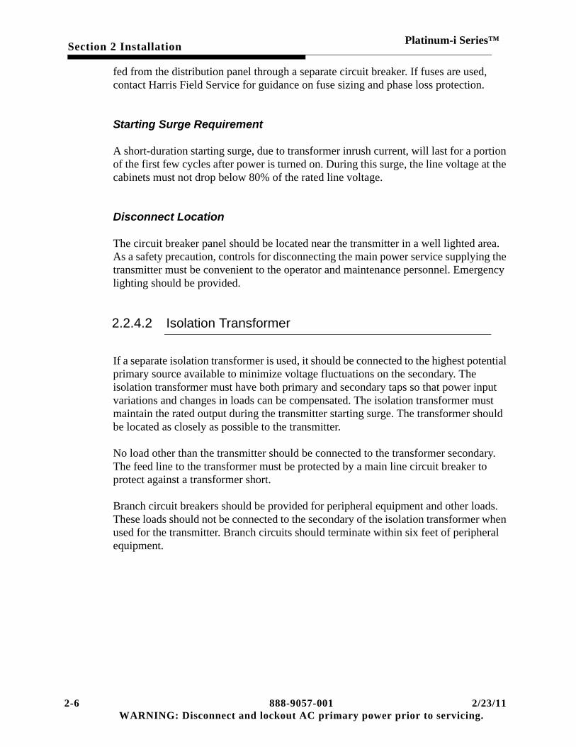
2.2.4.2 Isolation Transformer
If a separate isolation transformer is used, it should be connected to the highest potential primary source available to minimize voltage fluctuations on the secondary. The isolation transformer must have both primary and secondary taps so that power input variations and changes in loads can be compensated. The isolation transformer must maintain the rated output during the transmitter starting surge. The transformer should be located as closely as possible to the transmitter.
No load other than the transmitter should be connected to the transformer secondary. The feed line to the transformer must be protected by a main line circuit breaker to protect against a transformer short.
Branch circuit breakers should be provided for peripheral equipment and other loads. These loads should not be connected to the secondary of the isolation transformer when used for the transmitter. Branch circuits should terminate within six feet of peripheral equipment.
2-6 888-9057-001 2/23/11WARNING: Disconnect and lockout AC primary power prior to servicing.

Section 2 InstallationPlatinum-i Series™
2.3 Unpacking and Equipment Inventory
2.3.1 Equipment Required for Unloading
Before the truck arrives with the new transmitter, have ready on site a fork lift truck or a suitable unloading dock, a pallet jack, heavy duty two wheel cart, and any other equipment necessary to unload up to 1100 pounds (500 kg) at the site in question. The cabinets and power supplies are too heavy to be safely unloaded by hand.
An area large enough to store the boxes should be prepared in advance to help the unloading process.
Remove the cabinets from the truck and set in a location where they cannot be damaged.
IMPORTANT:DO NOT USE THE ROUNDED EDGES OF THE CABINETS FOR PUSHING, PULLING OR LIFTING!
The Control cabinet and skid together weigh approximately 470 pounds (215 kg). The skid itself weighs 30 pounds (14 kg).
PA cabinet with skid weighs approximately 990 pounds (450 kg). The amplifier cabinet skids weigh 65 pounds (30 kg) each.
The 50 volt power supplies weigh approximately 450 pounds (205 kg) each. Most are shipped two per skid, with any odd unit sent on a final skid. Be prepared for 900+ pounds (410+ kg).
Weights are generally marked on each box. Check the markings on each container before lifting.
IMPORTANT:As each piece is unloaded, inspect for visible damage to unit or packing con-tainer. If any damage is observed unpack and inspect for damage show delivery damage and note damage on bill of lading. Claims for damage must be filed promptly (48 hours) or claim may be denied. Retain shipping materials until all parts have been located or as proof of shipping damage.
When the transmitter is delivered to the site, the shipment should be inspected and inventoried before installation is begun. This section provides information to assist unpacking and inventory.
2/23/11 888-9057-001 2-7WARNING: Disconnect and lockout primary AC power prior to servicing.

Section 2 InstallationPlatinum-i Series™
2.3.2 Inventory and Inspection
2.3.2.1 Packing Check List
Each transmitter shipment will be accompanied by a packing check list identifying which equipment is packed in the various crates and boxes. Be sure to locate this document when the shipment arrives.
The contents of the shipment should be as indicated on the packing lists. If the contents are incomplete, or if any part is damaged electrically or mechanically, notify the Harris TV Customer Service Department:
Phone at 217-222-8200
FAX at 217-221-7086,
or at the following address:
Harris Corporation,
Broadcast Division
PO Box 4290
Quincy, IL 62305
Attn. Customer Service Department
2.3.2.2 Factory Test Data Sheets
A set of factory test data is supplied with each transmitter. It lists parameters for operation of the transmitter at your power level and channel. These readings were recorded during factory testing. Locate the test data, copy, and file the original so that copies may be made as needed.
Record the same readings periodically to establish and maintain an information base from which to work in the event of future changes or problems.
2-8 888-9057-001 2/23/11WARNING: Disconnect and lockout AC primary power prior to servicing.

Section 2 InstallationPlatinum-i Series™
2.4 Cabinet Placement and Leveling
Four bolts hold each cabinet to its skid. They are located two per side, front and rear. Also, remove the blocks that support the bottom of each rear door.
Use a chalk line or similar method to mark the floor position for each cabinet to ensure even alignment.
! WARNING:CAUTION: DO NOT USE THE ROUNDED EDGES OF THE CABINETS FOR PUSHING, PULLING OR LIFTING!
Using proper lifting equipment, remove each cabinet from its skid.
If equipment is not available to lift the cabinet off the skid, you may want to remove the back doors to lighten the load.
! CAUTION: THE DOOR WEIGHS 175 POUNDS (80 KG).
Removing doors will require three people. Remove the block used to support the door during shipment. Open the door and block it up at the bottom. Disconnect the fan wiring. Two people wearing gloves should support the door while the third person removes the hinge pins starting at the bottom and working up. Then, the door may be set aside and rollers (pipe) and a ramp used to remove the cabinet from the skid.
! WARNING:SLIDE CABINET OFF TO THE FRONT OR BACK OF SKID (NOT THE SIDE) TO AVOID BENDING BOTTOM PANEL.
Replace the door after the cabinet is set in place. Have two people position the door on suitable blocking material while the third person inserts the hinge pins starting from the top down. Reinstall the fan wiring.
Starting with one end cabinet, move each cabinet to the approximate location.
2/23/11 888-9057-001 2-9WARNING: Disconnect and lockout primary AC power prior to servicing.

Section 2 InstallationPlatinum-i Series™
When each cabinet is in its final position, you may need to level the cabinet. Check the level in all three planes. Metal plates shims under the cabinet edges can be used for leveling.
Bolt the cabinets together using the two holes at the top and two at the bottom of each cabinet.
2.5 Grounding
The ground strap runs along the top of the cabinets, then forward and over to the control cabinet. The station ground may be installed up the side of the PA cabinet or between the first PA and control cabinet.
2.6 Tap Transformers
The two (optional four) power supplies in the control cabinet, the supply with each slave controller in the PA cabinets, and the 50 volt power supplies should be tapped for the correct line voltage. It will be easier to re-tap the 50 volt supplies before installation. See the following drawings:
• Wiring Diagram for Control cabinet: 843-5583-001
• Wiring Diagram for PA cabinet: 843-5275-963
• Wiring Diagram for 50 Volt Supplies: 839-8106-235
2.7 UPS Installation
Remove the UPS from the shipping box, locate the manual for the UPS and review the installation section of that manual. The UPS manufactures recommend that the batteries not be charged before final installation. Therefore the UPS is not installed or tested with the transmitter.
install the UPS on the shelf below the GUI computer, the power connections to the cabinet rear. The bracket above is used to hold the UPS in place, align the front fold of this bracket with the front of the UPS.
Checkout the UPS following the UPS manual instructions.
2-10 888-9057-001 2/23/11WARNING: Disconnect and lockout AC primary power prior to servicing.

Section 2 InstallationPlatinum-i Series™
2.8 Installation of 50 Volt Supplies
Half of the power supplies have the primary connected as DELTA loads, the others as WYE loads. Each PA cabinet should have PS1 wired as a DELTA unit and PS2 should be WYE connected. Check the serial numbers with the factory test data and install each supply in the same location as it was tested. The 50 volt power supply weigh about 450 pounds (205 kg). Use a mechanical lifting device to remove them from the skid. Two access holes in the top are provided to attach lifting eyes to the transformer. Use a spreader bar to prevent bending the lifting eyes.
NOTE:The center of gravity is close to in line with lifting eye bolt holes.
The power supplies are furnished with two metal wheels for easy movement and installation in the transmitter. Roll one supply into the cabinet, allowing room for the other supply. The terminal boards should face the rear of the cabinet. After both supplies are positioned, install the rear panel and feed the cables through the holes and up to the terminal board. Each supply should be centered in its slot and tight against the panel. This forms an air seal needed to maintain proper air flow throughout the cabinet.
! WARNING:REVERSING THE 50 VOLT SUPPLY POLARITY WILL DAMAGE THE PA MODULES
Use hardware as supplied with washers (1-split, 1-flat) to connect the two cables marked (+) to left side of the 50 V bus bar, and two cables (-) to the right side.
2.9 RF Output Coax
! WARNING:WHEN INSTALLING RF PLUMBING OR AIR SYSTEM WIRING, DO NOT STEP ON THE TOP OF THE DOORS, THE CONNECTORS ON TOP OF THE PA CABINETS. LEAVE THE PROTECTIVE COVER IN PLACE THAT PROTECTS THE I/O ON TOP OF THE CONTROL CABINET.
(Refer to RF Plumbing Layout drawings.)
Because almost every station is different, refer to the suggested layout for information for location of hybrids, loads, couplers and filters. Install the directional couplers for each cabinet first, and work from there out toward the loads and antenna. Note where
2/23/11 888-9057-001 2-11WARNING: Disconnect and lockout primary AC power prior to servicing.

Section 2 InstallationPlatinum-i Series™
multiple PA cabinet installations require equal line lengths into hybrids. Make any desired VSWR measurements of the RF plant before making final connections to the cabinets.
2.10 AC Primary Wiring
(Refer to AC Power Distribution drawing.)
Three phase AC power wiring for each amplifier cabinet should be installed through the hole provided for conduit directly above the main contactor. Removal of the safety shield over the contactor is required, and the shield must be replaced after completing the AC power wiring in each cabinet.
All cabinets must be phased identically; that is, each phase connects to the same point in each cabinet, and each 50 volt power supply is connected like the others. For example, at PS1: TB2-1 connects to phase A on all supplies, etc. All logic must be powered from the same phase.
The power for the control cabinet is fed through the conduit hole in the left rear top of the cabinet. There is an option that requires a dual AC mains feed. The three phase power runs to the terminal block(s) mounted on the left wall of cabinet. Again, the safety shield must be removed before installation, and replaced after completion.
2.11 Inter-cabinet Wiring
(Refer to the Cabinet Interconnect Drawing)
A cable tray (not furnished) should be installed along the top of the transmitter for cabinet interconnecting. Install the control and monitor cables in this tray. It may be plastic or metal, and attached to the top of the cabinet with screws or bolts.
Run the cables from the control cabinet through the cable tray to each PA cabinet. Observe the mechanical keying of the ribbon cable.
The RF sample lines may be installed in the cable tray as well. RF sample lines should be constructed from double shielded cable. Make sure each pair of RF sample lines is of equal length. The line length is not critical but should be kept reasonably short. Directional couplers are set to level with maximum length of 50 feet for RG223/U coax. Make forward and reflected sample cable pairs from the same roll of coax if possible to keep insertion losses equal. If the transmitter architecture utilizes two or more drive paths, the cables used for PA Drive A & B samples should be of equal length as well.
2-12 888-9057-001 2/23/11WARNING: Disconnect and lockout AC primary power prior to servicing.

Section 2 InstallationPlatinum-i Series™
2.12 Input Signal Wiring
All input, RF inter-cabinet and remote control connections are made at the I/O panel on top of the control cabinet. Use the silkscreen as a guide to connect cable during installation.
2.13 Interlocks and Interfaces
External and fail-safe interlocks are connected to the I/O panel Refer to the Cabinet Interconnect drawing and/or the control cabinet wiring diagram.
2.13.1 External Interlock: TB1-1, 2
When normally closed interlock switches open, the external interlock prevents the transmitter from being started up. If opened during operation, the transmitter switches the transmitter off. Reclosure of the interlock action is determined by the end user as guided by the safety requirements.
The external interlock type of operation is user selectable by main controller. It can either turn the transmitter off (as an OFF command) when the interlock is opened, or temporarily hold the transmitter off while the interlock is open, restoring to normal operation when the interlock is closed. This is a software setup option.
The external contact closure or other device must sink 50 microampere to less than 0.5 volts. Open circuit voltage at TB1-2 is +5 V, and TB1-1 is ground. If no interlock is used, jumper TB1, 1-2.
2.13.2 Fail-safe Interlock: TB1-3, 4
When open, the fail-safe interlock will mute the RF output of the exciter. Normal operation will resume when closed. This interlock may be used for the remote control system fail-safe interlock, or reject load thermal cut out. Current in the loop should be above 5 mA. The open circuit voltage of TB 1-3 is +12 volts and TB1-4 is 0 volts.
2.13.3 Individual PA Cabinet External Interlocks
! DANGER:THE THERMAL INTERLOCK SWITCHES ON HYBRID REJECT LOADS MUST BE CONNECTED TO INTERLOCK OFF AFFECTED TRANSMITTER CABINETS
2/23/11 888-9057-001 2-13WARNING: Disconnect and lockout primary AC power prior to servicing.

Section 2 InstallationPlatinum-i Series™
TO PREVENT OPERATOR EXPOSURE TO HOT OIL SPILLING FROM A REJECT LOAD ABSORBING EXCESSIVE POWER.
Each PA cabinet has an interlock circuit that is used to turn off the appropriate PA cabinets when a reject load thermal interlock opens. The electrical connections are available by cutting the orange jumper between pins 4 and 5 of the cabinet control cable. Normal connection is to turn off the cabinets that can furnish power to that reject load. The two cabinet interlocks are connected in parallel then with the normally closed interlock switch. Systems with more than two cabinets have the larger load connected to the system interlock.
2.13.4 External Blower Control:
K2, part of the I/O panel contains 4 form C contacts, connect external blower contactors or air conditioning controls as needed.
! WARNING:WIRING ABOVE 48 VOLTS MAY INTRODUCE A SAFETY HAZARD. 24 VOLT AC COIL CONTACTORS ARE SUGGESTED.
They may be used for air system contactor control as desired. The contacts are rated 5 amps, 240 volts AC maximum.
2.13.5 RF Samples
The metering RF samples are optimized for a voltage of 3 volts at the detector test points. Levels higher than that will require adding attenuator pads for the proper levels.
The feedback samples for the digital exciters should be as follows:
Apex exciter, samples should be as close to minus five dBm as possible measured at the exciter sample input. Attenuator pads are available in 1 dB steps to control the level.
CD1A level should be plus 5 dBm.
Special note to customers with both Apex and CD 1A exciters installed: Attenuate the post mask filter sample only in the splitter output path connected to the Apex, not in the path connected to the CD 1A. In this manner, the CD 1A level can be maintained at +5 dBm while the Apex sample level can be attenuated to -5dBm.
SMA Pads
2-14 888-9057-001 2/23/11WARNING: Disconnect and lockout AC primary power prior to servicing.

Section 2 InstallationPlatinum-i Series™
556-0145-000Pad, Fixed 50 Ohm 1 dB with SMA
556-0144-000Pad, Fixed 50 Ohm 2 dB with SMA
556-0143-000Pad, Fixed 50 Ohm 3 dB with SMA
550-0142-000Pad, Fixed 50 Ohm 4 dB with SMA
550-0141-000Pad, Fixed 50 Ohm 5 dB with SMA
556-0140-000Pad, Fixed 50 Ohm 6 dB with SMA
550-0139-000Pad, Fixed 50 Ohm 8 dB with SMA
550-0138-000Pad, Fixed 50 Ohm 10 dB with SMA
550-0134-000Pad, Fixed 50 Ohm 12 dB with SMA
550-0137-000Pad, Fixed 50 Ohm 15 dB with SMA
555-0136-000Pad, Fixed 50 Ohm 20 dB with SMA
2.14 Remote Control I/O:
Three "D" connectors for parallel remote control interface:
• J31 Command in
• J32 Status out
• J33 Analog out
• J34 Optional Exciter Switcher
Refer to Control Cabinet Wiring Diagram.
2.14.1 Command In
The Command inputs are all optocoupled and require a current source to energize the LED. This can be done either within the transmitter or externally. The Controller board internal voltage source can be activated with JP2 jumper placed in the 1-2 position, which will supply +5 volts from the internal supply for the optocouplers. If JP2 is placed in the 2-3 position the optocouplers must be supplied a voltage on pins 19 & 37
2/23/11 888-9057-001 2-15WARNING: Disconnect and lockout primary AC power prior to servicing.

Section 2 InstallationPlatinum-i Series™
of J31. The optocouplers require a minimum current of 5 mA, and the maximum current should be less than 20 mA.
Open circuit voltage with the internal source (JP2 1-2) is +5 volts. Any external source (JP2 2-3) should be less than 36 volts.
2.14.1.1 J31 COMMAND INPUTS:
1 TRANSMITTER ON
2 TRANSMITTER OFF
3 POWER RAISE
4 POWER LOWER
5 NO CONNECTION
6 NO CONNECTION
7 SELECT EXCITER A (OPT)
8 SELECT EXCITER B (OPT)
9 SELECT MANUAL EXCITER SWITCHER MODE (OPT)
10 SELECT AUTO EXCITER SWITCHER MODE (OPT)
11 NO CONNECTION
12-18 NO CONNECTION
20-36 GROUNDS
19,37 (OPT +5V J2 1-2) OR USE EXTERNAL SUPPLY (J2 2-3)
The functions marked (OPT) are used when the optional exciter switcher is installed.
Command Functions:
TRANSMITTER ON: Turns transmitter on and enables RF output.
TRANSMITTER OFF: Turns transmitter off and disables RF output.
2-16 888-9057-001 2/23/11WARNING: Disconnect and lockout AC primary power prior to servicing.

Section 2 InstallationPlatinum-i Series™
RAISE/LOWER: Raises or lowers the transmitter output power.
SELECT EXCITER (OPT): Selects exciter "A" or "B" via the optional exciter switcher.
SELECT MANUAL/AUTO (OPT): Selects the mode of operation for the exciter switcher. MANUAL mode requires that the selection be done manually. When in AUTO mode, if an exciter failure is detected, the switcher will automatically switch to the alternate exciter if not in a foldback or muted state.
2.14.1.2 J32: Status Outputs
The Status outputs are N-Channel enhancement mode FETs with a 10 Ohm resistor in series and a 30 volt zener (avalanche) diode clamp to ground. An internal voltage source of +5volts can be made available to the outputs by placing main controller optional status jumper JP3 in the 1-2 position. When in the 2-3 position, an external voltage source must be supplied. The open collector stand-off voltage is 30 volts DC, and maximum current sink is 50 ma. Each output is asserted low for status true condition.
J32 STATUS OUTPUTS:
1-16OPTIONAL VOLTAGE OUTPUT
See information above
17-18 NOT USED
19 OPTIONAL STATUS VOLTAGE INPUT
20 TRANSMITTER ON
21 LOCAL
22 VSWR FOLDBACK ACTIVE
23 VSWR FAULT
24 SPARE 1
25 SPARE 2
26 EXTERNAL INTERLOCK
2/23/11 888-9057-001 2-17WARNING: Disconnect and lockout primary AC power prior to servicing.

Section 2 InstallationPlatinum-i Series™
27 AC POWER PHASE LOSS
28 EXCITER MUTE
29 EXCITER FAULT
30 PA CABINET POWER SUPPLY FAULT
31 PA CABINET MODULE FAULT
32 PA CABINET COOLING AIR LOSS
33 PA DOOR INTERLOCK
34 SPARE 1 FAULT
35 NOT USED
36 GROUND
37 OPTIONAL STATUS VOLTAGE INPUT
Status Functions:
TRANSMITTER ON: Indicates the state of the transmitter. The line will be asserted low when the transmitter is on.
LOCAL: Indicates the transmitter will not accept remote command inputs. This line will be asserted low when the transmitter is in the LOCAL mode.
NOTE:The remote TX OFF command will still work in the local mode. This was done for safety. The only way to defeat this is removing the control input cable.
VSWR FOLDBACK ACTIVE: Indicates antenna VSWR has caused the transmitter to reduce its output power by some amount. It will be asserted low while the foldback is active.
VSWR FAULT: A sudden major increase in reflected power has created a VSWR fault.
EXTERNAL INTERLOCK: Indicates the status of the external interlock. If the interlock is open, a low will be asserted.
2-18 888-9057-001 2/23/11WARNING: Disconnect and lockout AC primary power prior to servicing.

Section 2 InstallationPlatinum-i Series™
PHASE LOSS: Indicates status of the internal AC phase loss detector. If detector senses low voltage on one of the three phase power lines or the phase sequence is reversed, PHASE LOSS will be asserted low.
EXCITER MUTE: Indicates that some function has muted the exciter. Asserted low for mute.
EXCITER FAULT: Indicates exciter fault directly in single exciter configuration. Indicates exciter fault from optional exciter switcher if used. Asserted low for fault.
SUPPLY FAULT: Indicates one or more of the 50 volt power supplies has failed. Asserted low upon fault.
MODULE FAULT: Indicates one or more of the cabinet RF modules has faulted off. Asserted low upon fault.
AIR LOSS: Indicates one or more of the cabinets has lost air supply. Asserted low upon loss of cabinet pressure.
DOOR INTERLOCK: Asserted low if one or more of the cabinet doors is open.
SPARE FAULT: Not used at this time.
2.14.1.3 J33: Analog Outputs
The analog outputs on the I/O panel provide both calibrated and un-calibrated readings for some functions. The calibrated outputs are a function of the monitoring system. The raw outputs come directly from the RF peak detectors. Each output is buffered by a voltage follower, with a 100 Ohm resistor in series with the signal, before leaving the main controller board.
J33 CALIBRATED OUTPUTS RANGE:
1 FORWARD POWER 0-3.0 VOLT = 0-100%
2 VSWR 1.0-2.0 VOLTS = 1.0-2.0 VSWR
3 NC
4 NC
5 REJECT LOAD 1 POWER
2/23/11 888-9057-001 2-19WARNING: Disconnect and lockout primary AC power prior to servicing.

Section 2 InstallationPlatinum-i Series™
6 REJECT LOAD 2 POWER
7 REJECT LOAD 3 POWER
8 FORWARD POWER 0-2.5 volts = 0-100% power, not power linear
9 NC
10 REFLECTED POWER 0-2.5 volts = 0-100% power, not power linear
11-19 NC
20-36 ANALOG GROUND SIDE OF 1-10
37 NC
2.14.1.4 Optional Remote Status
The optional exciter switcher supplies an output showing which exciter is selected. Each line is asserted low to indicate the corresponding condition. These drivers have the same ratings as the other status outputs. J34, pin 9 is the current source for the opto couplers in the connected equipment, and is supplied by the voltage J34 - 9.
J34 OPTIONAL STATUS
1 EXCITER A SELECTED
2 EXCITER B SELECTED
3 MANUAL SELECTED
4 FUTURE OPTION
5 FUTURE OPTION
6 GROUND
7 GROUND
8 GROUND
9 VOLTAGE, This voltage follows the main status selection choice.
2-20 888-9057-001 2/23/11WARNING: Disconnect and lockout AC primary power prior to servicing.

Section 2 InstallationPlatinum-i Series™
Optional Status Functions:
EXCITER A SELECTED: Indicates exciter "A" is selected.
EXCITER B SELECTED: Indicates exciter "B" is selected.
MANUAL SELECTED: Indicates the switcher is in the manual mode.
2.15 Transmitter Check Out
! WARNING:BEFORE PROCEEDING WITH CHECK OUT, INSPECT THE TRANSMITTER FOR AC POWER SHORTS, LOOSE HARDWARE, WIRING ERRORS, UNCONNECTED WIRES, MISSING PARTS, AND DEBRIS.
The following procedures are the sequential steps to safely turn on the transmitter for the first time, and should be performed in the order listed. It is recommended that the installation personnel read the general description in section one, the controls and operation material in section three, and these procedures before starting.
2.15.1 Control Cabinet Pre-Operational Check Out
! WARNING:BEFORE APPLYING PRIMARY AC MAINS POWER FOR THE FIRST TIME, TURN OFF ALL CIRCUIT BREAKERS THAT DISTRIBUTE POWER TO THE CONTROL AND PA CABINETS.
2.15.1.1 Three Phase AC and Logic Supply Checkout
STEP 1 Open circuit breakers on the front panel.
STEP 2 Apply 3 phase power to the control cabinet only.
STEP 3 Remove cover over the AC terminal blocks and carefully measure the AC line voltages. Verify correct voltage and connections. Refer to the control cabinet wiring diagram 843-5583-001, sheet 3.
STEP 4 If the voltage does not correspond to the values for the power supplies as wired, then re-tap the supplies for the correct voltage.
2/23/11 888-9057-001 2-21WARNING: Disconnect and lockout primary AC power prior to servicing.

Section 2 InstallationPlatinum-i Series™
STEP 5 Turn on circuit breaker CB1 (located in front, in the bottom panel) in the control cabinet.
STEP 6 Check that the phase monitor green LED is on. If not, first check that its voltage range is adjusted to the correct settings. Next, reverse any two cabinet AC input wires to cause the LED to come on. Refer to the AC Distribution Drawing as required. The phase monitor LED will be dark when the phases are wrong. In a dual feed transmitter, check the second phase loss monitor. CB2 is the breaker suppling voltage for K3. Both monitors must see low voltage or improper phase sequence to generate a logic fault.
NOTE:All cabinets must be phased the same. Correct phasing of each PA cabinet is a part of the PA cabinet Operational Checkout. The low voltage and phase sequence sensor in the control cabinet will protect all cabinets from most AC power line problems.
2.15.1.2 UPS Operations Test
Charge the UPS unit for at least 8 hours before testing to ensure the batteries are fully charged. The STACO unit does NOT require any steps to connect the battery.
STEP 1 Unplug the load from the UPS.
STEP 1 Push the Main switch on the front panel to start the UPS, the cooling fan should start indicating the UPS is energized and performing self test.
STEP 2 After 7 to 10 seconds, the start-up will be completed, then the Utility LED and the Inverter LED will light up simultaneously.
STEP 3 Simulate a Mains failure by disconnecting the input power cord of the UPS to verify the UPS remains in operation (DC Mode) when the AC Mains power is absent. The utility LED should extinguish and the alarm will sound continuously until the battery low voltage cut off is reached. The UPS should continue to provide AC power to the load. To mute the internal alarm, push the Test/Silence Button on the front panel.
STEP 4 Reconnect the UPS power cord to the AC Mains, connect the load to the UPS. Power up the GUI, the load on the UPS and verify that power is applied.
2-22 888-9057-001 2/23/11WARNING: Disconnect and lockout AC primary power prior to servicing.

Section 2 InstallationPlatinum-i Series™
2.15.1.3 GUI Setup
STEP 1 Power up the GUI with the AC from the UPS. The GUI computer should boot up to the home screen.
STEP 2 Close the first control cabinet circuit breaker and check on the GUI screen for nominal logic power supply voltages. Use the GUI to double check the AC line voltage. Verify the voltages with an independent meter if needed. Use the Factory Test Data sheets as a guide.
STEP 3 If there are dual supplies with the dual AC feed, open CB1A and repeat the power supply test with CB1B, checking the second power supply voltages.
STEP 4 In a dual supply system verify that all the indicating LEDs on the ORing board are illuminated to indicate that all supplies are functioning.
STEP 5 The actual logic supply voltages must closely match for proper AGC action. Apply power to one supply at a time and carefully set the correct power supply voltages to the correct value at the load.
The fail-safe and external interlocks are active and may be on or off. External site system wiring must be connected to these interlock terminals or jumpers must be added at the terminals to turn these indicators off before the transmitter can be turned on. The exciter should indicate mute.
STEP 1 Check the external interlock by operating whatever is connected to external interlock, if there is nothing to connect place jumper at TB1-1 and 2 on I/O panel.
STEP 2 Press transmitter ON push-button.
STEP 3 Check for the external blowers (supply and exhaust blowers) to start.
STEP 4 Open the fail-safe circuit. The Fail-safe fault should indicate and the exciter should mute. Re-close the fail-safe circuit. Check for normal status.
STEP 5 Open the external interlock. The external interlock status should be on and the transmitter should shut off. Press ON button. The transmitter should not come on. Re-close the circuit. The external interlock status indication should go out. The transmitter should come back on if the setup selection is "auto-restart". If setup option is "lockout’, the transmitter should not come back on until a manual ON command is given.
STEP 6 Check operation of RAISE and LOWER buttons, both on the control panel of the cabinet and the GUI screen.
2/23/11 888-9057-001 2-23WARNING: Disconnect and lockout primary AC power prior to servicing.

Section 2 InstallationPlatinum-i Series™
STEP 7 If the system has a remote control, place transmitter in the REMOTE mode and check for operation of transmitter ON/OFF and RAISE/LOWER from the remote.
STEP 8 Check that LOCAL mode locks out remote commands. Local mode will NOT lockout a remote off command.
STEP 9 Return exciter to minimum power when done by depressing and holding LOWER commands for about 15 seconds.
STEP 10 Press OFF push-button at the control cabinet.
2.15.2 PA Cabinet Pre-Operational Check Out
! WARNING:CHECK 50V BUS BAR CABLES FOR TIGHT CONNECTION AND INSPECT FOR CABLES WHICH MIGHT SHORT BUS BAR TO GROUND. CHECK FOR CORRECT POLARITY. REVERSE POLARITY WILL DAMAGE THE RF MODULES AND/OR THE CAPACITOR BANK.
2.15.2.1 PA Cabinet Checkout
Perform the following for each PA cabinet:
STEP 1 TURN OFF BOTH BREAKERS located behind the lower two bottom removable extrusion panel on the front of the PA cabinet.
STEP 2 Unplug the three pin plug at J2 on the slave controller board. This places the local slave controller in total control of the cabinet.
IMPORTANT:Unplugging J2 on the Slave Controller removes system external interlock control of the PA cabinet. Systems larger than two cabinets will have reject loads for a pair of PA cabinets. Do not allow any drive to be present if dummy load cooling is not active.
STEP 3 Turn on the AC mains power to the cabinet at the disconnect.
STEP 4 Turn on CB1, control breaker, located behind the lower left panel. The +12 volt supply will illuminate the green LED on the front of the slave controller. Check all slave controller supply voltages at slave controller J4.
• J4-5 is +12 volts
2-24 888-9057-001 2/23/11WARNING: Disconnect and lockout AC primary power prior to servicing.

Section 2 InstallationPlatinum-i Series™
• J4-6 is -12 volts
• J4-1 and 2 are +5 volts
STEP 5 Press cabinet ON. You should hear the contactor energize. Air loss, PS-1, and PS-2 LED's should be illuminated, (PS-2 may not be used). Press cabinet OFF.
! WARNING:BEFORE CHANGING CABINET AC WIRING IN THE FOLLOWING STEP (IF NECES-SARY) ENSURE THAT ALL AC POWER IS REMOVED FROM CABINET.
STEP 6 Turn on CB2, fan breaker, located behind the lower right panel. Press the cabinet on switch on the slave controller. Check for proper blower rotation. Removing a air filter will allow observation of the fan blade as it slows to a stop. Rotation should be clockwise. The rear door fan and the 50 volt power supplies must have the same phase rotation. If the fan is rotating in the wrong direction, reverse two cabinet AC input wires, not the blower wiring.
The fan blows air into the cabinet. The air loss LED should go out, and the PS Fault LED's will go out as the 50 volt power supplies come on. (If the air loss LED remains on, insert the amplifier modules most of the way into the cabinet to provide more back pressure, without engaging the connectors, and try again.)
STEP 7 Check air switch operation by momentarily shutting off CB2.
STEP 8 Check door interlock operation by opening the rear door while cabinet is running. When the door is opened while the power supplies are on, the door must remain open for 10 seconds to allow the 50 volt capacitor bank to totally discharge and allow the SCR to reset. It should shut down and restart a few seconds after door is closed. Check for door interlock indication at control cabinet while door is open.
STEP 9 Check the 50 volt supplies. Measure the voltage at pin 3 or 4 of a module connector from the front of the cabinet. (PS-1 powers the right column, and PS-2 the left.)
STEP 10 Turn off the PA cabinet and replace J2 on the slave controller.
2.15.3 Module Installation
! WARNING:DO NOT USE EXCESSIVE FORCE OR SLAM MODULES INTO THE SLOTS.
2/23/11 888-9057-001 2-25WARNING: Disconnect and lockout primary AC power prior to servicing.

Section 2 InstallationPlatinum-i Series™
The modules may now be installed. Refer to factory test data for placement of modules by serial number and slot number. Low band PA cabinets have Driver and Power Amplifier Modules. High Band PA Cabinets have three types of modules, Drivers, PA Drivers and PAs. The drivers are keyed and will not fit into a PA slot. Although each type is interchangeable and will work in any like socket, when starting out it is best to reassemble them in the same locations as tested. Keep a record of any changes for future reference. Make sure each module is completely seated.
2.15.4 Control System Check Out
STEP 1 Apply power to all cabinets and peripherals.
STEP 2 Turn on all cabinet breakers.
STEP 3 Check the CABINET SELECT LED on each slave controller. For systems with single PA cabinets, this LED should illuminate continuously. For multiple-cabinet systems, the LED's should be flashing.
STEP 4 Momentarily switch off each PA cabinet logic breaker CB1 and look for a CONTROL FAULT on the control cabinet while the breaker is off. Depress and hold power LOWER controls for 15 seconds each to ensure that exciters are turned all the way down.
STEP 5 Press transmitter ON push-button.
STEP 6 Check air system for proper operation. There should be slight negative air pressure above transmitter, and positive pressure inside the cabinets of approximately 0.7 inches of water. The positive pressure inside the cabinet may be measured by temporarily removing a mounting screw from one of the cover plates on the top rear of the cabinet.
STEP 7 Check that all modules are enabled, PA modules will illuminate the left half of the green LED. The right half will illuminate when drive is present. Modules in the drive chain will illuminate full green even when no drive is present. It is normal for the red module LED's to come on momentarily as the transmitter 50 volt supplies come up to voltage at turn on. They also will come on at shut-down, gradually fading out as the supplies discharge.
STEP 8 Check MODULE FAULT status for each module. Check to see that all modules are enabled (1/2 green LED on); press transmitter ON to enable any modules that are not already on.
STEP 9 Squeeze the disable switch in the handle of the first module. The module LED's should go out. You should see the MODULE FAULT indication using the GUI screen, and a module fault in the alarms queue. Re-enable the module by pressing transmitter ON at the control cabinet.
2-26 888-9057-001 2/23/11WARNING: Disconnect and lockout AC primary power prior to servicing.

Section 2 InstallationPlatinum-i Series™
The MODULE FAULT on the control cabinet should go out. DELETE the alarm from the queue. Repeat for each module in turn.
2.15.5 VSWR Foldback And VSWR Fault Check Out
This exercise involves using the exciter as a source for forward and reflected power samples in order to test for proper VSWR foldback operation and fault detection.
It is recommended that you read and understand this procedure and that you make notes of the original jumper positions and cable connections before starting.
STEP 1 Depress and hold exciter LOWER buttons for 15 seconds to ensure minimum output.
STEP 2 Connect exciter output to J21, forward power controller board, part of the I/O, 1A3.
STEP 3 Slowly raise exciter power until the display indicates 100% power. Note the power level in KW.
STEP 4 Depress the exciter lower button until the power reads zero. Move the exciter output cable to J8. Use the 20 dB (1%) pad stored in a clip inside the control cabinet, to the right of the UPS, to reduce the level.
STEP 5 Increase the exciter output power until the VSWR FOLDBACK ACTIVE is indicating. The reflected power indication on the display should be approximately 1% of the forward power. If substantially different from this reading, perform procedure as required to adjust the reflected power calibration.
NOTE: Verify that the forward and reflected samples are properly reconnected. An ohm-meter check of the cable and sample element should measure between 50 and 200 ohms. This will check for open and shorted cables.
2.16 Initial Application of RF Power
STEP 1 Check that the AGC module is OFF MODE.
STEP 2 LOWER the exciter to minimum drive.
STEP 3 Press transmitter ON push-button.
STEP 4 Check to see that all RF amplifier modules are enabled.
2/23/11 888-9057-001 2-27WARNING: Disconnect and lockout primary AC power prior to servicing.

Section 2 InstallationPlatinum-i Series™
STEP 5 Slowly raise power while observing VSWR, FORWARD POWER, and, in a multiple PA cabinet system, REJECT POWER(s). Stop at approximately 25% forward power. Check to be certain the combined output at each hybrid in a multiple PA system is higher than the reject load for the hybrid. If any reject load power is higher than the hybrid's output, this suggests a phase error in drive cabling. Check that drive cable connections are correct and the correct length. Verify the hard line lengths follow the installation guidelines.
STEP 6 Phase and Gain module alignment: A single cabinet transmitter will not have any phase and gain units, A two PA system has one phase and gain module, the procedure is performed only once. In a 3 PA systems, perform this sequence on the lower level (A / B) phase and gain module, then proceed to the top level ([A+B] / C) module. In 4 PA cabinet systems, begin with the (A / B) and (C / D) phase and gain modules, then proceed to the top level ([A+B] / [C+D]) module.
STEP 7 Adjust phase and gain module phase control for minimum reject power.
STEP 8 Adjust gain control for minimum reject power.
STEP 9 This completes the phase and gain module alignment in two PA system. For larger systems, proceed to the next phase and gain module.
STEP 10 Using an external power meter or calorimetric metering to confirm power output, slowly increase power to 50%.
NOTE:If external power meter and user display panel readings do not agree, refer to the power calibration procedures in Section 2.16.
STEP 11 Increase power slowly to 100%. In multiple PA systems, watch the reject load power while increasing drive, and make slight readjustments to the phase and gain module controls as above if necessary. Note that the second half of the green LED on each vision PA module illuminates, indicating presence of RF drive.
STEP 12 Compare DC INPUT POWER and 50 volt supply currents to factory test data.
STEP 13 Check all PA modules for output one at a time by squeezing the disable switch for each module and noting a drop in power output of the cabinet as seen on the PA cabinet power information screen. Re-enable each module using a transmitter ON command before proceeding to the next module. Wait 5 or 10 seconds for the re-enabling of the module to take effect. Each module turn off should cause approximately the same change in cabinet power output. Remember this requires AGC to be turned off.
2-28 888-9057-001 2/23/11WARNING: Disconnect and lockout AC primary power prior to servicing.

Section 2 InstallationPlatinum-i Series™
STEP 14 Switch AGC back ON when done and RAISE power to 100%.
NOTE:Refer to AGC adjustments if needed.
2.17 Power Calibration
2.17.1 Basics of Power Calibration.
Power calibration is based on the use of a RF average power meter such as those manufactured by Agilent. Study the power meter manual for calibration and the use of offsets. The Analog to Digital conversion input is limited to about four volts. The system and other metering in the control cabinet requires RF level at the board input of about 40 to 60 mW for 3 volts of metering. This allows for some over-range and still have sufficient level or resolution of smaller voltages. The RF metering input to the PA Cabinet slave controller have more latitude, there is a range adjustment control for each of the RF detectors, this allows the full scale RF level range to be set to three volts at the peak detector test point. Further calibration will be done through the GUI service screen.
2.17.2 Power Calibration
2.17.2.1 System Forward Power
Some of the power calibrations are based on forward power, calibrate it first.
STEP 1 Using the precision coupler in the RF system and the precision power meter to establish the output power.
STEP 2 Verify the RF level at the board input, the signal should be between 40 to 60 mW. Connect the cable back to the control board.
STEP 3 Go to the output service system screen and verify nominal power is correct. If not, set to proper level.
STEP 4 On the output system service screen and using the pull-down keyboard. enter in the reading from the power meter.
2.17.2.2 Reflected Power
This would follow forward power calibration.
2/23/11 888-9057-001 2-29WARNING: Disconnect and lockout primary AC power prior to servicing.

Section 2 InstallationPlatinum-i Series™
STEP 1 Remove the cable from the reflected sample controller input, Rotate the reflected sample element to couple with forward power.
STEP 2 Verify the RF level, 40 to 60mW.
STEP 3 Connect the 20 dB pad to the reflected input, connect the cable to the pad.
STEP 4 Use the service screen to calibrate the reflected power metering to read one percent of the forward power.
STEP 5 Remove the pad, rotate the element to the reflected position and reconnect the cable.
2.17.2.3 PA Cabinet Power Calibration
The sample elements have coupling ratios marked on the element. These can be used as offset inputs to the power meter. The slave controller calibrate pot is adjusted for 3 volts at the peak detector test point. Next use the PA service button to access and set the PA power levels. Verify nominal power is correct, reset if necessary. Calibrate each cabinet by selecting Cab1, Cab2, etc.
2.17.2.4 PTCD20P2 Reject Load
The power in the reject load is half of a single cabinet with perfect hybrids. If the level measured at the top of the control cabinet is in the 40 to 60 mW range, calibrate the reject load to be 80 percent of the reject load rating.
2.17.2.5 Three and Four Cabinet Calibration
Using the tables below calibrate the reject loads.
Figure 2-1 Three Cabinets
CABINET CABINET CABINET A/B AB/C COMBINEDA B C REJECT REJECT OUTPUT
100 0 0 50 16.6 33.30 100 0 50 16.6 33.30 0 100 0 66.6 33.3
100 100 0 0 66.6 133.3100 0 100 50 16.6 133.3100 100 100 0 0 300
2-30 888-9057-001 2/23/11WARNING: Disconnect and lockout AC primary power prior to servicing.

Section 2 InstallationPlatinum-i Series™
Figure 2-2 Four Cabinets
2.18 VSWR Calibration
VSWR calibration follows forward and reflected power calibration. The VSWR foldback will limit the reflected power to a fixed value
The VSWR foldback will limit the reflected power to a fixed value, the 1.22:1 value is 1% of the normal forward power. An example is a PTCD20P2 that has an normal forward power of 6.2 KW. The foldback will limit the reflected power to 62 Watts. The second line of protection is the module internal VSWR protection. Modules will always VSWR protect using the module logic.
IF you have confidence in the power calibration, you can let the software use the default values of 1.22:1 as the foldback fault point and 1.40:1 for VSWR fault. Other values can be entered from the Output tab, service screen. If you want to verify operation, substitute a variable level RF source for the reflected sample such the output of the back-up exciter and increase the level to check the foldback point.
The following things can be done to help in the VSWR fault checking.
• To check the fault point without foldback interaction, simply set the foldback point to a higher value than the desired fault point. After checking, remember to set the fold-back to the desired lower point.
• A quick check of foldback can be done simply by setting the foldback to a value slightly lower than the actual VSWR. This would trigger a foldback event, GUI should indicate that foldback is occurring and the output power will be a lower value.
• There is a button on this page that will turn off the VSWR control actions including any VSWR indicators. This button will time out in 5 minuets and VSWR control will return to normal. Turning off the VSWR control will allow RF levels or trip points to be reached without any change in transmitter output power.
CABINETS A/B CABINETS C/D AB/CD COMBINEDA & B REJECT C & D REJECT REJECT OUTPUT
ONE 50 BOTH 0 25 225BOTH 0 ONE 50 25 225BOTH 0 NONE 0 100 100ONE 50 ONE 50 0 100
BOTH 0 BOTH 0 0 400
2/23/11 888-9057-001 2-31WARNING: Disconnect and lockout primary AC power prior to servicing.

Section 2 InstallationPlatinum-i Series™
2.19 Power Limit
The exciter has a power limit adjustment, Increase the output power to 110%, the exciter power limit should be set to limit the transmitter power to 110%.
2-32 888-9057-001 2/23/11WARNING: Disconnect and lockout AC primary power prior to servicing.

Platinum-i Series™
Section 3Software Installation/Setup
2/23/11 888-9057-001WARNING: Disconnect and lockout AC primary pow
3
Legal NoticeBefore using the screens and programs associated with this product you acknowledge that such are protected under the United States and
international copyright laws; the programs may be used only as authorized under the terms of license from Harris Corporation and its
licensors, and that you are informed as to such license terms.
3.1 Introduction
eCDi™ is Transmitter Network Interface that provides a network connection for control and monitoring of Harris Platinum-i transmitters.
! WARNING:ECDI™ IS A REMOTE CONTROL DEVICE. MAINTENANCE PERSONNEL SHOULD TAKE ALL NECESSARY PRECAUTIONS TO DISABLE THE ECDI™ DURING TRANS-MITTER MAINTENANCE. SPECIFICALLY, THE TRANSMITTER SHOULD BE PLACED IN THE REMOTE DISABLE (LOCAL) MODE BEFORE SERVICING. ALWAYS DISCON-NECT PRIMARY POWER BEFORE SERVICING EQUIPMENT.
3.2 eCDi™ and the Platinum-i™ Transmitter
For the Harris Platinum-i Digital VHF Transmitter, the eCDi™ control concept includes a local GUI touchscreen interface in addition to its normal networking capabilities. In the transmitter the eCDi™ is the local transmitter control interface using the 12" VGA touchscreen and has been named the "Display Unit." This means that the eCDi™ provides both local and remote control for the transmitter.
3-1er prior to servicing.

Section 3 Software Installation/SetupPlatinum-i Series™
Information in this section of the manual covers the basic setup and operation of the remote networking side of the Display Unit (eCDi™).
3.3 Hardware
• Single Board Computer. Includes a 20GB hard drive, 4 port internal ethernet switch and power supply.
• 1 ethernet port mounted on the front of the unit for configuration and utility monitor-ing. Eliminates the need to access the rear of the unit after installation.
• 1 ethernet port mounted on the rear for connection to the station LAN or WAN.
• 3 ethernet ports mounted on the rear for permanent interconnect to transmitters and exciters that have an ethernet interface (RJ-45).
• 2 serial ports mounted on the rear for connection to transmitters and exciters with a serial interface.
3.4 Features
Web GUI Interface - The Web GUI interface allows access to transmitter control, status and logging for any of the supported transmitters via a standard web browser interface (Netscape or IE). The only other software required is a Java plug-in and it is downloaded from the eCDi™ the first time a computer accesses the unit.
Performance Monitoring - An optional software upgrade provides for performance monitoring of DTV transmitters by networking an embedded version of the CD-EYE™ application.
Common Interface - The Web GUI creates a common display platform for all transmitters. This allows immediate understanding of transmitter control and monitoring regardless of the transmitter model.
Fault Logging - The fault log will hold up to 1000 events, is viewable on-line or can be downloaded to Microsoft Excel or another common spreadsheet program.
Meter Logging - Meter logging occurs periodically at a customer configured time interval. The Meter log will hold up to 1000 events and can be downloaded to Microsoft Excel or another common spreadsheet program.
Email Notification - faults and warnings are automatically sent to a customer configured email address.
SNMP Agent - provides for connection to the Harris Broadcast Manager (HBM)or RECON remote control system. It can also be connected, in a limited form, to other
3-2 888-9057-001 2/23/11WARNING: Disconnect and lockout AC primary power prior to servicing.

Section 3 Software Installation/SetupPlatinum-i Series™
non-Harris based SNMP Network Managers. For more information about SNMP connectivity see eCDi manual.
Remote Software Updates and Upgrades - eCDi™ uses In-System Programming (ISP) that allows remote loading of software updates and upgrades.
eCDi™ Interfaces
eCDi™ allows access to transmitter control and monitoring via the following interfaces:
• Web GUI
• SNMP Agent
• WAP (Wireless Access Protocol) via Cell Phone
3.4.1 Web GUI (Graphical User Interface)
The Web GUI allows broadcasters to control and monitor their transmitter(s) through a standard web browser (Netscape or IE) from anywhere network access is available. This is the standard interface supplied with all eCDi™ units. An example of the Web GUI main screen is shown in Figure 3-1. This main menu structure and layout is basically the same for all transmitters, allowing operators to only have to learn one type of interface for multiple types of transmitters. Actual readings and control buttons available will be determined by the transmitter application. For more information on the Web GUI see " Section 4 Operation".
3.4.2 Touch Screen Calibration
Each time the computer reboots you have a Touch Screen Calibration option.
Normally this is not needed, select NO or wait for the option to time out.
If you select the option, proceed with caution!
First there will be a box in the upper left hand corner, carefully touch the exact center, a stylus is the preferred tool.
Second step is touching the box in the lower right hand corner.
Third is to touch the box in the upper right hand corner.
If at any time this procedure is not following the above description, STOP. Turn the GUI AC power off and restart the boot up process.
If this procedure is not completed correctly, the touch screen may be useless and require assistance from Harris field service to recover.
2/23/11 888-9057-001 3-3WARNING: Disconnect and lockout primary AC power prior to servicing.

Section 3 Software Installation/SetupPlatinum-i Series™
Figure 3-1 Web GUI Interface Example
3.4.3 SNMP Agent
The SNMP (Simple Network Management Protocol) Agent in eCDi™ provides network connectivity using the Harris Broadcast Manager (HBM). HBM is a network manager application that allows the centralized control and monitoring of multiple transmitters and sites, but does not come with eCDi™.
NOTE:The eCDi can also be accessed by other non-Harris SNMP Network Managers. In this case, the MIB (Management Information Base) is a common MIB that is used by nearly all Harris transmitters. A second “Extended” MIB exists and is exclusively used by the Harris Broadcast Manager.
3.5 Level 1 / Level 2 Functionality
eCDi™ has 2 levels of software functionality that can be used with either the Web GUI or the SNMP connection using the HBM Network Manager:
3-4 888-9057-001 2/23/11WARNING: Disconnect and lockout AC primary power prior to servicing.

Section 3 Software Installation/SetupPlatinum-i Series™
a. Level 1 - Transmitter Remote Status Monitoring and Control. This allows monitoring and control of virtually all transmitter parameters (limited to the information that is available on the serial port of the transmitter). For most of the listed transmitters, if it is available locally at the transmitter, it will be available via the Web GUI. This level of functionality is included on all eCDi™ units.
b. Level 2 (optional upgrade) - Performance Monitoring and Control (only available for DTV transmitters). This is an integrated form of the CD-EYE, 8-VSB monitoring software and is an optional add-on to the base Level 1 software. This allows performance monitoring of DTV transmitters with either CD-1A or APEX exciters. Parameters to be monitored include:
1. Spectral Emissions - Equivalent to a spectrum analyzer plot of the system output. Used to confirm compliance with FCC DTV emission mask.
2. EVM (Error Vector Magnitude) and SNR (Signal-to-Noise Ratio) mea-surements and the Eye Diagram.
3. Constellation Diagram - This is an I (symbol) versus Q plot. Can be used to show amplifier non-linearity.
4. RTAC (Real Time Adaptive Correction) Linear Correction - This plot shows the gain and phase correction employed for linear distortions (Fre-quency response and Group delay) versus the frequency across the channel.
5. RTAC Non-Linear Correction (APEX exciter only) - This plot will display the AM-AM and AM-PM correction employed for non-linear distortions in the amplifier chain.
3.6 Security
eCDi™ provides password protection using 3 levels of security functionality:
1. Engineer - allows access to all functions
2. Operator - allows access to all status monitoring but limits transmittercontrol and configuration.
3. Monitor - allows access to all status monitoring with no control capability.
! CAUTION:OVERALL NETWORK SECURITY IS THE RESPONSIBILITY OF THE CUSTOMER. INTEGRATION OF THE UNIT SHOULD BE BEHIND THE CUSTOMERS FIREWALL WITH ACCESS THROUGH A VPN (VIRTUAL PRIVATE NETWORK).
2/23/11 888-9057-001 3-5WARNING: Disconnect and lockout primary AC power prior to servicing.

Section 3 Software Installation/SetupPlatinum-i Series™
3.7 Downloading the Manual
The electronic version of this manual is available as a download from the eCDi™ Help menu.
Remote Computer Requirements
The following lists the minimum recommended requirements for a remote computer that will be used to access the eCDi™ via the WEB Browser interface.
Hardware:
• Pentium III 400 MHz (Intel PIII+-compatible, 1GHz+ recommended)
• 128MB RAM (256MB or more recommended)
• 75MB of available hard drive space
• Mouse (mouse-wheel recommended)
• 28.8k modem (56k modem recommended or high speed TCP/IP network if available)
• SVGA monitor running in at least 800x600 resolution
• SVGA Video card (hardware acceleration with Direct3D driver support recommended)
Operating System
• Windows 98 (1st edition) or newer
• Windows ME
• Windows 2000 with Service Pack 2 or newer
• Windows XP
Web Browser
• Internet Explorer 5.5 or higher with default security permissions
• Netscape 7.0 or higher
NOTE:Microsoft DirectX 7.0 or later is highly recommended (comes pre-installed on Windows 2000 and Windows XP).
3-6 888-9057-001 2/23/11WARNING: Disconnect and lockout AC primary power prior to servicing.

Section 3 Software Installation/SetupPlatinum-i Series™
3.8 Setup
The information contained in this section is intended to explain the following:
• Connection of all required cables between the Platinum-i eCDi™ and the transmitter and exciters and to the station LAN or WAN.
• Setup and configuration of the eCDi™ for connection to the station LAN or WAN to provide Web GUI access.
! CAUTION:OVERALL NETWORK SECURITY IS THE RESPONSIBILITY OF THE CUSTOMER. INTEGRATION OF THE UNIT SHOULD BE BEHIND THE CUSTOMERS FIREWALL WITH ACCESS THROUGH A VPN (VIRTUAL PRIVATE NETWORK).
NOTE:For SNMP connection to a network manager such as the Harris Broadcast Manager, refer to eCDi manual after installing the eCDi™. Use of the Web Browser interface is discussed in " Section 3 Operation".
IMPORTANT:All ethernet cables connected to the eCDi™ should be shielded twisted pair (STP) category 5 (Cat 5) cable. All cables supplied with the eCDi™ are shielded.
c. The left most Ethernet connection is the WAN connection. This should be con-nected to the Station LAN or WAN or possibly a LAN modem if the only connec-tion to the site is via dial-up phone line. For more information on setting IP addresses for this port see "3.12 eCDi™ Configuration" on page 3-11.
d. Exciter (male D connector) is for serial connection to CD-1A exciters in DTV transmitters. To connect 2 exciters, this cable must have a “Y” adaptor installed.
e. The 2 Ethernet connections labeled EX1 and EX2 will be connected primarily to exciters with ethernet ports, such as APEX™.
3.9 Detailed Installation Procedures by Transmitter
For AC power, serial and Ethernet connections refer to the appropriate transmitter procedure in the following paragraphs.
IMPORTANT:(If the eCDi™ is to be connected to one or more APEX exciters, then also be sure to see "3.10 APEX Exciter Setup" on page 3-8.
2/23/11 888-9057-001 3-7WARNING: Disconnect and lockout primary AC power prior to servicing.

Section 3 Software Installation/SetupPlatinum-i Series™
IMPORTANT:If you are connecting the eCDi™ to a CD-1A, 8-VSB exciter, see "3.11 CD-1A Electronic Serial Number Reset" on page 3-10.
NOTE:The most important one of the above is the Main Controller firmware but the transmitter software/firmware is a package and all 4 should be updated to the most current release levels at the same time. Failure to update all 4 to the levels on the upgrade disk or CD could cause operational conflicts.
3.10 APEX Exciter Setup
IMPORTANT:The APEX exciter software must be 4.0 or later to activate the Ethernet port for use with eCDi™. This software (along with the Harris ISP program and program-ming instructions) can be obtained via download from the Harris Premier web site or by contacting Harris Technical support. To check the software revision of your APEX press the “System Control” button on the APEX front panel. This will bring up the screen shown in Figure 3-2. If the software revision is not 4.0 or later, it must be upgraded using the Harris ISP (In-System Programming) soft-ware, and the files downloaded from the web site, before it will communicate with the eCDi™.
Figure 3-2 APEX Software Revision Check
NOTE:For more information regarding APEX upgrades, see the APEX technical manual, 888-2491-001.
Control Softwarerevision
3-8 888-9057-001 2/23/11WARNING: Disconnect and lockout AC primary power prior to servicing.

Section 3 Software Installation/SetupPlatinum-i Series™
The Harris ISP (In-System Programming)2.0 software, provided at no cost, is used to update the firmware memory in the APEX exciter via the serial port on the front or back of the unit. The Harris ISP 2.0 program, upgrade software and instructions can be downloaded from the Harris Premier Website. Please note that Harris ISP 2.0 must be used. Harris ISP 1.10, which comes loaded on the Diamond and Sigma transmitter GUI, is not compatible with APEX. Do not load Harris ISP 2.0 on a Diamond and/or Sigma transmitter GUI as it is not backward compatible.
3.10.1 Setting APEX IP Address
If one or more APEX exciters are to be connected to the eCDi™, it is necessary to set an IP Address and Subnet Mask for each exciter. Go to the display on the front of the APEX exciter and select Home - Setup - Serial I/O. This will bring up the screen in Figure 3-3A. Select NEXT to open the Ethernet Setup screen shown in Figure 3-3B. Click on each number to bring up the edit window and change them one at a time to that shown here. The exciter will have to be shut off and then turned back on before the changes will take effect.
The following IP addresses were implemented as of eCDi™ software revision 2.6.K or higher. For all previous versions see the NOTE below.
• IP Address: 192.168.217.200
• Subnet Mask: 255.255.255.0
Set the second exciter to:
• IP Address: 192.168.217.201
• Subnet Mask: 255.255.255.0
NOTE:
For all eCDi™ software revisions before 2.6.K use the following IP addresses for the APEX exciter:
Exciter 1: 192.168.0.200
Exciter 2: 192.168.0.201
2/23/11 888-9057-001 3-9WARNING: Disconnect and lockout primary AC power prior to servicing.

Section 3 Software Installation/SetupPlatinum-i Series™
Figure 3-3 APEX Exciter Ethernet Setup Screen
3.11 CD-1A Electronic Serial Number Reset
The CD-1A has an Electronic Serial number or ESN. If this has been set to something other than the factory default value (this normally only happens if the CD-EYE program has been used with the CD-1A), it must then be reset before the eCDi™ will be able to communicate with the CD-1A. To reset the ESN, pull the exciter all the way out on its rack slides. Open the exciter by pulling up on the top half of the exciter. Use the prop arm to hold up the upper half of the exciter. Dipswitch S3-5 and S3-6 should be placed in the OFF position. Then switch S3-5 to the ON position and then back to OFF. Finally, press the reset button located on the same board as S3. The ESN is now reset and the CD-1A should communicate with the eCDi™. Dipswitch S3 is located near the front of the exciter on the Corrector Controller board. See Figure 3-4 below for the location of dipswitch S3.
NOTE:For dual exciter systems, don’t forget to reset the second exciter as well.
Select Next
(A)
(B)
NOTE:The exciter will have to be shut off (ac power removed) and then turned back on before the changes will take effect.
3-10 888-9057-001 2/23/11WARNING: Disconnect and lockout AC primary power prior to servicing.

Section 3 Software Installation/SetupPlatinum-i Series™
NOTport softw2.6.Kthe c192.255.
Figure 3-4 CD-1A Exciter, S3 Location
3.12 eCDi™ Configuration
Now that the eCDi™ unit is turned on, connect an external computer with a 10 base T network connection directly to the ethernet port on the front of the eCDi™ using the provided ethernet cable labeled “Configure.” This port must be used for the initial configuration of the unit. As of eCDi™ software Rev 2.6.K, the configuration port has a fixed IP address of 192.168.217.254 or a name of ecdi-local on all units.
STEP 1 The eCDi™ supports DHCP which means the computer to be connected for configuration can be set to “Obtain an IP Address Automatically” as shown in Figure 3-5. In this mode eCDi™ will assign the remote computer an IP address when it connects.
•Right-click on Network Neighborhood and select Properties. This can also be accessed by selecting “Network and Dialup Connections” in the Control Panel.
•Next, right-click on the LAN connection and select Properties again.
Dipswitch S3
Reset Switch
E: The Configuration IP address for any are revision before is 192.168.0.254 and
omputer must be set to:168.0.1255.255.0
2/23/11 888-9057-001 3-11WARNING: Disconnect and lockout primary AC power prior to servicing.

Section 3 Software Installation/SetupPlatinum-i Series™
•Click on Internet Protocol (TCP\IP) and click on Properties again.
•This brings up the IP address screen. Select “Obtain an IP address auto-matically” as shown. Click OK and close all windows and re-boot.
Figure 3-5 Changing the Remote Computer IP Address
STEP 2 To access the eCDi™ and the configuration screens, open a browser (such as IE or Netscape) and type one of the following into the Address bar of the browser and press Enter: (these addresses are only implemented in eCDi™ software revision 2.6.K and above)
http://192.168.217.254
http://ecdi-local (this is a fixed eCDi™ domain name on the configuration port)
NOTE:If you have an eCDi™ software revision before 2.6.K then the configuration port IP address is http://192.168.0.254
This will bring up the screen shown in Figure 3-6. Do not login to the application yet.
Right Clickand selectProperties
Click on Internet Protocoland then click Properties
IMPORTANT!Make a note of the computer settings before making any changes, so it can be easily reset after configuring the eCDi™.
Note: If the computer is changed to DHCP mode from a fixed IP address, the computer may have to be re-started
3-12 888-9057-001 2/23/11WARNING: Disconnect and lockout AC primary power prior to servicing.

Section 3 Software Installation/SetupPlatinum-i Series™
Figure 3-6 eCDi™ Login Screen
3.12.1 Troubleshooting Tips
1. When using DHCP, connection problems can occur if the computer fails to release it old IP address. To check this: (Do not type the quote marks)
A. Open a DOS Prompt and type “ipconfig” and press enter. This should return an IP address in the range of 192.168.217.1 to 192.168.217.49. If not, then in the same DOS window type “ipconfig/release” and press enter. Then type “ipconfig/renew” and press enter.
B. Type “ipconfig” again to verify an address has been issued in the range given above.
Do not loginhere at this time
Then click here
Click here
2/23/11 888-9057-001 3-13WARNING: Disconnect and lockout primary AC power prior to servicing.

Section 3 Software Installation/SetupPlatinum-i Series™
NOTE:If connection cannot be made, try setting the remote computer to a fixed IP address. Select “Use the following IP address” as shown to the right. Then enter the IP address 192.168.217.1 with a subnet mask of 255.255.255.0 (this address is only valid if you have eCDi™ software revision 2.6.K or higher). Try Step 2 again. If it still does not work, try several different ethernet cables.
NOTE:If you have an eCDi™ software revision before 2.6.K then enter you must set a fixed IP address of 192.168.0.1 with a subnet mask of 255.255.255.0
3-14 888-9057-001 2/23/11WARNING: Disconnect and lockout AC primary power prior to servicing.

Section 3 Software Installation/SetupPlatinum-i Series™
IMPORTANT:To run eCDi™ requires that the Java 2 Runtime Environment plug-in be loaded. If the computer used to access the eCDi™ does not have this plug-in installed, it will be automatically downloaded from the eCDi™ and the screen in Figure 3-7 will appear asking if you want to load the plug-in. Select Yes and then follow the on-screen instructions to load the plug-in. This will not require a computer restart and will only happen the first time a computer logs on to eCDi™.
Figure 3-7 Java 2 Runtime Environment Plug-in
To get the computer to use the latest plug-in, it is sometimes necessary to unload all previous versions of the Java Runtime Environment using Add/Remove programs in the Windows Control Panel. Once all versions are removed, accessing the eCDi™ will automatically load it again.
STEP 3 Click on “Service eCDi” as shown on the left side of the login screen in Figure 3-6. This provides access to the Configure and Upgrade options. Click on Configure. This will bring up the Configuration Login screen in Figure 3-8.
NOTE:It could be several minutes before this screen pops up.
2/23/11 888-9057-001 3-15WARNING: Disconnect and lockout primary AC power prior to servicing.

Section 3 Software Installation/SetupPlatinum-i Series™
Figure 3-8 Configuration Login Screen (Administrator password required)
STEP 4 Type in the following and then press OK:
User Name - adminPassword - admin (This can and should be changed immediately, once the configuration screens are accessed).NOTE- No recovery if password lost.
STEP 5 When the login is accepted the main menu will appear as shown in Figure 3-9. Click on General to open the screen in Figure 3-10.
CAUTION:The eCDi™ will only ask for the administrator password once per session. To prevent unauthorized access to the configuration, the browser should be closed and then re-opened, which then requires that the administrator password be entered again.
3-16 888-9057-001 2/23/11WARNING: Disconnect and lockout AC primary power prior to servicing.

Section 3 Software Installation/SetupPlatinum-i Series™
Figure 3-9 Main Configuration Menu Screen
Figure 3-10 General Configuration Screen
STEP 6 Set a new administrator password. Although shown checked here, the “Allow remote administration” checkbox should only be checked if you want to be able to access these configuration screens via the station LAN or WAN. If this box is not checked, then only a local connection to the front of the eCDi™ unit will allow access to the configuration screens.
The PRESET button resets all configuration settings back to factory defaults
2/23/11 888-9057-001 3-17WARNING: Disconnect and lockout primary AC power prior to servicing.

Section 3 Software Installation/SetupPlatinum-i Series™
STEP 7 Set the Location of the box and/or any call letters. This is used by the browser applet, email and SNMP.
STEP 8 Set the correct time and date. This information is used for time stamping of the metering and fault logs. Use the pull down menu to select the appropriate time zone.
STEP 9 Time Server IP (recommended): If there is a time server available on the local network it will be auto-detected or can be set manually. An internet time server could also be used. If no time server is specified, the internal pc clock will be used and will require manual setting at frequent intervals for accurate time stamping of logs.
NOTE:Time Zone setting will affect the time even when a Time Server is used.
STEP 10 When all changes are made, press Submit and then press Back to return to the main menu.
STEP 11 Select Feature Key on the main menu to get the screen shown in Figure 3-11. The Feature key number is normally entered at the factory before shipment, but is also recorded in the Factory Test Data included with the unit. If not already entered, type in the 40 character key to setup the eCDi™ for the correct hardware and features.
STEP 12 Once the key is entered, click on Submit and then verify that the correct hardware and features are displayed. Depending on the transmitter type (chosen by the feature key) you may also need to select the correct type of exciter for each exciter position. If you change the exciter selection, click on Submit to finish the Feature Key configuration.
The Feature Key is an encrypted code word that contains all of the hardware configuration, such as transmitter type and any add on features such as Performance Monitoring. The Feature Key is coded to the hardware in the eCDi™ and therefore can only be used on a specific eCDi™ unit.
NOTE:Other than the exciter selections, the text boxes below the Feature Key box are not editable and can only be changed with a different Feature Key. If the transmitter hardware or features purchased do not match the information
3-18 888-9057-001 2/23/11WARNING: Disconnect and lockout AC primary power prior to servicing.

Section 3 Software Installation/SetupPlatinum-i Series™
displayed, contact technical support.
Figure 3-11 Feature Key Configuration Screen
STEP 13 Once the information is entered, submitted and verified, press Back to return to the main menu. Click on User mgmt to access the User Management screen in Figure 3-12.
an example. Do notuse this for yourinstallation.
This screen is onlyNOTE:
These features are chosen by the Feature Key and connot be changed without changing the Key
The exciter type must be chosen on site depending on the equipment present. If no exciter is to be controlled, then select None/Other.
2/23/11 888-9057-001 3-19WARNING: Disconnect and lockout primary AC power prior to servicing.

Section 3 Software Installation/SetupPlatinum-i Series™
STEP 14 To add users, Type in a Username and password and then select their level of access: Engineer, Operator or Monitor (none of these can change configuration). Users can be deleted using the Delete user pull down menu.
The 3 password levels set the Web GUI transmitter control access level.Engineer provides access to all Web GUI screens and control functions.Operator provides access to all GUI screens, but limits functionality to basic On, Off, Raise and Lower power (these functions depend on the transmitter).Monitor provides access to all screens but prevents any transmitter control.
NOTE:Passwords are case sensitive, but Usernames are not.
Factory default name and passwords are, Engineer access is the word ENGINEER for the name and the password. In a similar manner, OPERATOR and MONITOR are used for name and password for other levels of access.
If a user has lost the password to get into the local GUI, the passwords can be reset here.
Figure 3-12 User Management Screen
STEP 15 When all changes are made, press Submit and then press Back to return to the main menu. Click on Network to access the screen in Figure 3-13.
3-20 888-9057-001 2/23/11WARNING: Disconnect and lockout AC primary power prior to servicing.

Section 3 Software Installation/SetupPlatinum-i Series™
STEP 16 If you are connecting to a network (via the WAN connection on the eCDi™) that supports DHCP then click the “dhcp” button and the dhcp server should assign all of the required IP addresses automatically. Problems with this function should be directed to the station network administrator.If the network does not use dhcp, or if it is desired to have a static IP address, then select “static” and manually enter at least the IP Address and the Subnet mask.
Figure 3-13 Network Configuration Screen
STEP 17 When all changes are made, press Submit and then press Back to return to the main menu. Click on SNMP to access the screen in Figure 3-14.
IMPORTANT:The SNMP Configuration screen only needs to be set up if an SNMP Network Manager is going to be used to access the eCDi™. If the web browser is going to be the only interface then skip to STEP 27, to continue the eCDi™ configuration.
NOTE:If your network supports Default DNS then the host name can be used to access the eCDi™. IF not, the IP address must be used.Example: http://137.237.242.26 or http://my-ecdi.bpd.harris.com or whatever is enabled in HostName and Domain Name).
NOTE:The information in this picture is for example only.
2/23/11 888-9057-001 3-21WARNING: Disconnect and lockout primary AC power prior to servicing.

Section 3 Software Installation/SetupPlatinum-i Series™
STEP 18 SNMP Manager Configuration. In the “Add IP Address” box, type in the IP addresses of the computers to which all SNMP trap messages will be sent. To delete a trap destination, use the “Delete IP Address” pull down menu and select the destination to be deleted.
STEP 19 SNMP Agent Configuration. Type in the name of the “rw community” (read/write Community).
STEP 20 Checking the “ENABLE SET” checkbox sets this eCDi™ to accept SNMP SET (remote control) commands (this is a high security risk unless SNMP V3 is used).Un-checking this box means that an SNMP manager will only be able to provide status and monitoring (GET commands).
STEP 21 Select the appropriate version of traps for your SNMP system by selecting v1 Traps or v2 Traps (SNMP Version 1 or SNMP Version 2).
Figure 3-14 SNMP Configuration
STEP 22 When all changes are made, press Submit and then press Back to return to the main menu.Click on SNMP v3 to access the screen in Figure 3-16.
NOTE:When “Apply” is pressed on the Configuration main menu (see Figure 3-9) the eCDi™ will send test SNMP Trap messages to all specified SNMP Network Managers.
NOTE:See Section 6 for additional SNMP information.
NOTE:See Section 7 for Firewall port information
3-22 888-9057-001 2/23/11WARNING: Disconnect and lockout AC primary power prior to servicing.

Section 3 Software Installation/SetupPlatinum-i Series™
STEP 23 If you are using SNMP v3 (version 3) then User Names and Passwords must be entered for each user. Simply type the User Name and Password into the text boxes and press Submit. Users may be deleted by using the delete user pull down menu. To edit a user requires that it simply be deleted and re-entered.
STEP 24 Next select the type of security functionality to be used by selecting either “MD5 & DES” for authentication and encryption or select “Noauth and Noenc” for no authorization or encryption.
STEP 25 Lastly, select the V3 only checkbox to prevent V1 and V2 logins that would bypass the username and password security of V3.
Figure 3-15 SNMP v3 Setup
STEP 26 When all changes are made, press Submit and then press Back to return to the main menu. Click on Email to access the screen in Figure 3-16.
NOTE:See Section 6 for additional SNMP information.
2/23/11 888-9057-001 3-23WARNING: Disconnect and lockout primary AC power prior to servicing.

Section 3 Software Installation/SetupPlatinum-i Series™
STEP 27 This screen is for setting up Email addresses that will be alerted when there is a fault condition in the transmitter. To add an address, simply type the address in the “Add address” text box and click on Submit. The address should then show up in the Address List. The Delete address pull down menu can then be used to delete any entered addresses.
NOTE:If an address is entered incorrectly simply delete it and add it again.
STEP 28 The station Network Administrator should be able to supply the SMTP Server IP and the eCDi email address. The email address is used as the sender address, so recipients know from where the email was sent.
STEP 29 If your mail server requires authentication then check the “Requires Auth” checkbox and enter a User Name and Password for each address.
Figure 3-16 Email Configuration Screen
STEP 30 Set Email Filters. Email filters provide a way to block or limit the alert emails being sent. Figure 3-17 shows the choices for the 3 categories of email filters:
A. Faults
B. Warnings
C. Info
3-24 888-9057-001 2/23/11WARNING: Disconnect and lockout AC primary power prior to servicing.

Section 3 Software Installation/SetupPlatinum-i Series™
Figure 3-17 Email Filters
•Selecting “None” (no filter) will allow all indications for the selected category to send an email alert.
• Selecting “Sum” will block all Summary indications in the selected category. All other indications in that category will send an email alert.
• Selecting “All but Sum” (the most common selection) will block all emails but the Summary indications for the selected category (i.e. only summary indications will send an alert email).
• Selecting “All” will block all emails for that category. This is most commonly used for the Info category since these are mostly Status indications.
NOTE:Checking the “Local Mode” checkbox will disable all email alerts when the transmitter is in Local mode (or Remote Disable as the case may be).
STEP 31 When all changes are made, press Submit and then press Back to return to the main menu. Click on Applet to access the screen in Figure 3-18.
IMPORTANT:When “Apply” is pressed on the Configuration main menu (shown in Figure 3-9), the eCDi™ will send a test email to all of the addresses in the list. It will also send SNMP Trap messages to all specified SNMP Network Managers.
2/23/11 888-9057-001 3-25WARNING: Disconnect and lockout primary AC power prior to servicing.

Section 3 Software Installation/SetupPlatinum-i Series™
STEP 32 The Communication settings shown here are the defaults. The Refresh and Retry Intervals should only be changed if connection problems are experienced.
Enable SSL (Secure Socket Layer) encryption is an option for added security, but keep in mind that this will slow down the overall connection and could take several minutes to obtain the encryption key.
Allow Save Credentials checkbox enables (checked) and disables (unchecked) the Save Credentials? checkbox on the eCDi™ login screen shown in Figure 3-6 on page 3-13 and at the right. In other words, if the Allow Save Credentials: checkbox is not checked in the Applet Configuration screen, then the Save Credentials? function on the login screen is grayed out and not functional.
! CAUTION:USING THE SAVE CREDENTIALS FUNCTION GREATLY INCREASES NETWORK SECURITY RISK, AS THIS CAUSES THE USERNAME AND PASSWORD TO BE SAVED AS A COOKIE AND PASSED TO THE ECDI™ AS A LIGHTLY SCRAMBLED TEXT FILE.
Figure 3-18 Applet Configuration Screen
NOTE:See Section 7 for Firewall Port settings and options
3-26 888-9057-001 2/23/11WARNING: Disconnect and lockout AC primary power prior to servicing.

Section 3 Software Installation/SetupPlatinum-i Series™
STEP 33 Set Fault Log Filters. Fault Log filters (new as of eCDi™ firmware revision 3.0.L) provide a way to block or limit the entries in the Fault Log. Figure 3-17 shows the choices for the 3 categories of filters:
A. Faults
B. Warnings
C. Info
Figure 3-19 Fault Log Filters
•Selecting “None” (no filter) will allow all indications for the selected category to be entered into the Fault Log.
•Selecting “Sum” will block all Summary indications in the selected category. All other indications in that category will be entered into the Fault Log.
•Selecting “All but Sum” (the most common selection) will block all entries but the Summary indications for the selected category (i.e. only summary indications will be entered into the Fault Log).
• Selecting “All” will block all Fault Log entries for that category. This is most commonly used for the Info category since these are mostly Status indications.
STEP 34 When all changes are made, press Submit and then press Back to return to the main menu. Click on Meter Logging to access the screen in Figure 3-20.
2/23/11 888-9057-001 3-27WARNING: Disconnect and lockout primary AC power prior to servicing.

Section 3 Software Installation/SetupPlatinum-i Series™
For information on setting up:
The Meterlog, see eCDi manual page 3-7
Performance Monitoring alarms, see eCDi manual page 3-20
Figure 3-20 Meterlog and Performance Monitoring Configuration Screens
3.12.2 Apply Changes
Once all of the Configuration information is entered on the individual screens, you must click on “Apply.” to actually send the changes to the eCDi™. The Apply button is on the Main Configuration menu shown in Figure 3-21. As stated previously, this will also cause test emails and SNMP trap messages to be sent to all entered addresses.
Figure 3-21 Main ConfigurationMenu Screen
3-28 888-9057-001 2/23/11WARNING: Disconnect and lockout AC primary power prior to servicing.

Section 3 Software Installation/SetupPlatinum-i Series™
3.12.3 Backing Up the Configuration
On the Configuration main menu (shown in Figure 3-21) click on <<Download to save the configuration to a file. This will bring up a window asking if you want to save the file to disk and the file will be called “ecdi_config.zip.” Make sure the “Save file to disk” button is checked and click OK.
NOTE:The file is actually just a text file that has all of the eCDi™ configuration settings. The *.zip extension was placed on the file so that the browser asks if you want to save the file to disk instead of opening the file. To view the file in a text editor, make a copy of the file and change the extension to ecdi_config.txt.
Changing the original file name is not recommended, since the >>Upload function will only load a file with the default name ecdi_config.zip. To save multiple config files, save each file in a different subdirectory.
NOTE:To reset the eCDi™ to the default configuration settings, press the PRESET button shown in Figure 3-21. This will not reset the Feature Key.
3.12.4 Restoring a Configuration File
To restore a saved configuration file press the >>Upload button and then browse for the ecdi_config.zip file. The upload function will only upload a file with the exact name “ecdi_config.zip.”
3.12.5 Reset Computer IP Address
Don’t forget to change the IP address of your computer back to its previous IP address configuration if you used a static IP address.
2/23/11 888-9057-001 3-29WARNING: Disconnect and lockout primary AC power prior to servicing.

Section 3 Software Installation/SetupPlatinum-i Series™
3.13 eCDi Software Updates
This section provides instructions necessary to install software updates on the eCDi™. The procedure is very simple but could require 20 minutes or more to upload the new software but only about 2 minutes to upgrade at which time the eCDi™ will be offline.
Please note that as of software revision 2.6.K (and higher) the fixed eCDi™ configuration port IP address has changed (the ethernet port on the front of the unit). The old address was 192.168.0.254. The new Configuration port IP address as of Revision 2.6.K is:
192.168.217.254 (subnet mask of 255.255.255.0)
If you are using DHCP on the remote computer which is connecting to the eCDi™ then no changes are required to connect. If you are using a fixed IP address to access the eCDi™ then set the IP address of the remote computer to 192.168.217.1.
For more information see "3.12 eCDi™ Configuration" on page 3-11. If you are connecting to APEX exciters, you will need to change their IP addresses to:
Exciter 1: 192.168.217.200Exciter 2: 192.168.217.201
For more information on setting IP addresses in the APEX exciter see"3.10.1 Setting APEX IP Address" on page 3-9.
Please Read before updating Software
3-30 888-9057-001 2/23/11WARNING: Disconnect and lockout AC primary power prior to servicing.

Section 3 Software Installation/SetupPlatinum-i Series™
3.13.1 Updating the eCDi™
If it is necessary to update the software in the eCDi™, the administrator login and password are required.
3.13.1.1 Getting Starting...
STEP 1 Open a connection to the eCDi™. This will bring up the screen shown in Figure 3-22. Click on “Service eCDi” (upper left portion of the screen) and then select “Upgrade”. This will open the window in Figure 3-23.
Figure 3-22 Upgrade Login
2/23/11 888-9057-001 3-31WARNING: Disconnect and lockout primary AC power prior to servicing.

Section 3 Software Installation/SetupPlatinum-i Series™
STEP 2 Type in the Administrator username and password. If login is successful, this will open the screen in Figure 3-24.
Default User Name - admin Default Password - admin
Figure 3-23 Administrator Login
STEP 3 Browse for the upgrade file “ecdi.bin” and then click on Submit. This will upload the file to the eCDi™ and start the upgrade process.
Figure 3-24 eCDi™ Upgrade Screen
NOTE:The upgrade process is automatic. Once the new software is uploaded, it will take about 2 minutes to finish the upgrade. The eCDi™ will not be operational during the 2 minute upgrade period.
REMEMBER:
This procedure should be performed twice! The first time using the smaller ecdi.bin file and then again using the larger ecdi.bin file.
3-32 888-9057-001 2/23/11WARNING: Disconnect and lockout AC primary power prior to servicing.

Section 3 Software Installation/SetupPlatinum-i Series™
3.14 Main Controller Software Update
To update the software on the main controller board it is required to have the Harris ISP program version 0030. This can be downloaded from the Harris website as can the latest main controller software revision. http://www.broadcast.harris.com
This procedure also requires that the transmitter be off for a length of time so it is best to coordinate the update with a regularly scheduled maintenance period.
1. Before the board can be updated some data needs to be documented. Go through the following procedure and document the specified data.
On the local GUI select the following screens and take note of the specified data.
A. Select Drive > Service > Driver screen and document the following:
a.Number of exciters in the green box: .........__________b.Exciter sense level: .....................................__________c. Number of AGCs: ......................................__________d.Redundant AGC Enabled or Disabled
(If the redundant AGC is enabled it will be highlighted green)
B. Select Drive > Service > Cabinet Drive Power > screen and document the following:
a.Nominal drive power
b.Cabinet drive power:
Cab 1 Cab 2 Cab 3 Cab 4 Cab 5 Cab 6 Cab 7 Cab 8
Cab 1 Cab 2 Cab 3 Cab 4 Cab 5 Cab 6 Cab 7 Cab 8
2/23/11 888-9057-001 3-33WARNING: Disconnect and lockout primary AC power prior to servicing.

Section 3 Software Installation/SetupPlatinum-i Series™
C. Select PA > Service > Power > screen and document the following:
a.Cabinet Nominal Forward Power:
b.Cabinet Forward Power:
c.Cabinet Reflected Power:
D. Select Output > Service > System screen and document the following:
a.Nominal Forward Power: ...........................__________b.VSWR Fault Point: .....................................__________c.VSWR Foldback Point: ..............................__________
E. Select Output > Service > Reject Power screen: (Only for multiple PA Systems)
a.Reject Load Power Reading:
F. Select PS > Service screen and document the following:
a.Nominal AC line voltage in the grey box:..__________b.AC Mains mode in the grey box: ...............__________
G. Select the System > Service screen and document the following:
a.Model # in the grey area: ............................__________b.RF ON Delay in the blue box: ....................__________c.The Channel Number: .................................__________d.External Interlock set to Auto Restart or Manual
(The selected option will be highlighted green)
NOTE:If the CS tab is present on the local GUI continue on to items H through K. If the CS tab is not present skip to step 2 of the procedure.
Cab 1 Cab 2 Cab 3 Cab 4 Cab 5 Cab 6 Cab 7 Cab 8
Cab 1 Cab 2 Cab 3 Cab 4 Cab 5 Cab 6 Cab 7 Cab 8
Cab 1 Cab 2 Cab 3 Cab 4 Cab 5 Cab 6 Cab 7 Cab 8
AB CD AB/C AB/CD EF GH EF/G EF/GH ABCD/EFGH
3-34 888-9057-001 2/23/11WARNING: Disconnect and lockout AC primary power prior to servicing.

Section 3 Software Installation/SetupPlatinum-i Series™
H. Select CS > Service CS Model Name screen and document the following:
a.CS Model Name in the grey area: ..............__________b.Exciter type in the green box: .....................__________c.Number of Cabinets in the grey box: ..........__________d.XMTR type in the grey box: ......................__________
I. Select CS > Service > CS Module Config screen and document which modules are in or out for each PA cabinet in the system: The green "In" or the grey "Out" is the status to reference, not the white box.
Cabinet-1 Cabinet-2 Cabinet-3 Cabinet-4
------------ ------------ ------------ ------------
Cabinet-5 Cabinet-6 Cabinet-7 Cabinet-8
------------ ------------ ------------ ------------
2/23/11 888-9057-001 3-35WARNING: Disconnect and lockout primary AC power prior to servicing.

Section 3 Software Installation/SetupPlatinum-i Series™
J. Select CS > Service > CS Reject Config screen and document the set-tings for all of the reject loads. The grey box on the right is the status to document.
K. Select CS > Service > CS RF Det Config screen and document the set-tings under each group. The grey box on the right is the status to docu-ment.
Reject Loads
CAB1_VisFwd CAB5_VisFwd
CAB1_VisRef CAB5_VisRef
CAB1_Drv CAB5_Drv
CAB2_VisFwd CAB6_VisFwd
CAB2_VisRef CAB6_VisRef
CAB2_Drv CAB6_Drv
CAB3_VisFwd CAB7_VisFwd
CAB3_VisRef CAB7_VisRef
CAB3_Drv CAB7_Drv
CAB4_VisFwd CAB8_VisFwd
CAB4_VisRef CAB8_VisRef
CAB4_Drv CAB8_Drv
3-36 888-9057-001 2/23/11WARNING: Disconnect and lockout AC primary power prior to servicing.

Section 3 Software Installation/SetupPlatinum-i Series™
2. Install the Harris In-System-Programming (ISP) software by first unzip-ping the downloaded file and then running the setup.exe file.
3. Place the transmitter in the OFF state.
4. Connect a 9 pin serial cable from the serial port on a PC to J13 on the main controller board.
5. Start the Harris ISP software and configure the serial port as shown in Fig-ure 3-25.
Figure 3-25 ISP Serial Port Configuration
Aural A
Aural B
Aural C
Aural D
Aural E
Aural F
Aural G
Aural H
DRV A
DRV B
DRV C
DRV D
2/23/11 888-9057-001 3-37WARNING: Disconnect and lockout primary AC power prior to servicing.

Section 3 Software Installation/SetupPlatinum-i Series™
6. Select Query Micros and double-click the main controller.Figure 3-26
Figure 3-26 ISP Main Controller Icon
7. Select Program File Figure 3-27.
Figure 3-27 ISP Program File Button
3-38 888-9057-001 2/23/11WARNING: Disconnect and lockout AC primary power prior to servicing.
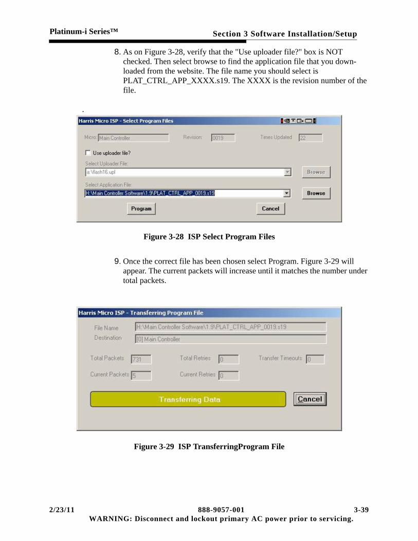
Section 3 Software Installation/SetupPlatinum-i Series™
8. As on Figure 3-28, verify that the "Use uploader file?" box is NOT checked. Then select browse to find the application file that you down-loaded from the website. The file name you should select is PLAT_CTRL_APP_XXXX.s19. The XXXX is the revision number of the file.
.
Figure 3-28 ISP Select Program Files
9. Once the correct file has been chosen select Program. Figure 3-29 will appear. The current packets will increase until it matches the number under total packets.
Figure 3-29 ISP TransferringProgram File
2/23/11 888-9057-001 3-39WARNING: Disconnect and lockout primary AC power prior to servicing.

Section 3 Software Installation/SetupPlatinum-i Series™
10. Once the transfer is complete the programming will automatically begin Figure 3-30.
Figure 3-30 ISP Programming Begins
11. When the programming is complete as is shown in Figure 3-31 select OK and disconnect the serial cable from the main controller.
Figure 3-31 ISP Programming Completes
12. Wait two minutes before continuing.
13. On the main controller board there is a micro module. On the micro module there is a reset button S1. Press this to reset the micro module.
3-40 888-9057-001 2/23/11WARNING: Disconnect and lockout AC primary power prior to servicing.

Section 3 Software Installation/SetupPlatinum-i Series™
14. If errors appear as shown in Figure 3-32 or Figure 3-33 select close and attempt the programming again. If no errors appear continue to step 15.
Figure 3-32 ISP Transfer Fail Error
Figure 3-33 ISP Program Fail Error
15. Verify that the revision number is correct by selecting the System >Service > Revision screen. The software revision here should match the number in the file name that was downloaded from the website.
2/23/11 888-9057-001 3-41WARNING: Disconnect and lockout primary AC power prior to servicing.

Section 3 Software Installation/SetupPlatinum-i Series™
Figure 3-34 Revision Screen
16. The next step is to reenter and verify all the system information that was collected in step 1 of this procedure. It is very important that these steps are followed exactly as they are listed.
A. On the System > Service > System page use the arrows to choose a sys-tem other than what your system is then select STORE.
B. Then use the arrows to select your system and select STORE again.
C. If there was a CS tab prior to the update now is the time to select CUST_spec with the arrows and then select STORE.
D. Now refer to step 1 of this procedure and verify that all of the data that was documented is correct.
E. Turn the transmitter on and verify all of the power calibrations. They should be accurate but still need to be verified.
3.15 Network Firewall Setup
This section is intended to give experienced networking personnel the ability to setup up the necessary ports to allow the eCDi™ to be controlled through a firewall.
Network connectivity to eCDi™ requires a standard TCP/IP network supporting:
• Typical network protocols such as ARP, ICMP, etc.
• 10Mb or 100Mb speeds at half-duplex or full-duplex
3-42 888-9057-001 2/23/11WARNING: Disconnect and lockout AC primary power prior to servicing.

Section 3 Software Installation/SetupPlatinum-i Series™
3.16 Firewall Ports
To be able to use the eCDi™ through a firewall, the following lists of ports require bidirectional functionality (common in todays LANs) with the specified ports being the establish/destination ports for the connection. Most are optional, depending on what features of eCDi the customer will use:
3.16.1 Optional Port Settings
To alleviate the problem of duplicate port settings on a firewall, especially when using 2 eCDi™ behind the same firewall, the eCDi™ configuration screens offer the ability to change the Inbound port settings.
From the Main configuration screen choose “Applet”. This will open the screen shown here in Figure 3-35.
Outbound traffic from eCDi™ :
• tcp/25 (smtp)
• tcp/42 (dns)
• udp/42 (dns)
• tcp/123 (ntp)
• udp/123 (ntp)
• tcp/161 (snmp)
• udp/161 (snmp)
• udp/162 (snmptrap)
Inbound traffic to eCDi™ :
• tcp/443 (https)
• tcp/80 (http)
• tcp/8888 (xml)
• tcp/161 (snmp)
• udp/161 (snmp)
2/23/11 888-9057-001 3-43WARNING: Disconnect and lockout primary AC power prior to servicing.

Section 3 Software Installation/SetupPlatinum-i Series™
Figure 3-35 Applet Configuration Screen
This screen allows you to change the HTTP port and the XML port. The defaults are shown on the previous page, but the other choices include:
The SNMP port can also be changed on the “SNMP General” configuration screen shown in Figure 3-36.
For HTTP: (Default 80)
• 8090• 8091• 8092• 8093• 8094• 8095• 8096• 8097• 8098• 8099
For XML: (Default 8888)
• 8890• 8891• 8892• 8893• 8894• 8895• 8896• 8897• 8898• 8899• 443
3-44 888-9057-001 2/23/11WARNING: Disconnect and lockout AC primary power prior to servicing.

Section 3 Software Installation/SetupPlatinum-i Series™
Figure 3-36 SNMP General Configuration Screen
The SNMP port choices include the default of 161 and the following:
• 8170• 8171• 8172• 8173• 8174• 8175• 8176• 8177• 8178• 8179
IMPORTANT:Multiple eCDi™ units behind the same firewall will require different port set-tings on each of the required interfaces. Set the HTTP and XML ports for web browser access. The SNMP port settings are only required for systems using a network manager to access the eCDi™, such as HBM or RECON.
2/23/11 888-9057-001 3-45WARNING: Disconnect and lockout primary AC power prior to servicing.

Section 3 Software Installation/SetupPlatinum-i Series™
3.16.2 PowerCD™ IP address and Port Settings
See the “PowerCD Transmitter Operators Manual” 888-2574-001, for recommended IP addressing and port settings as well as additional router setup information.
3-46 888-9057-001 2/23/11WARNING: Disconnect and lockout AC primary power prior to servicing.

Platinum-i Series™
Section 4Operation
2/23/11 888-9057-001WARNING: Disconnect and lockout AC primary pow
4
4.1 Introduction4.1.1 Graphical User Interface
There are several levels of control in this transmitter, the top level is the Graphical User Interface, GUI. This interface utilizes a computer with a liquid crystal display. This computer can be networked or connections to other computers enabling them to control the transmitter with the same graphical user interface. The GUI is a control interface, the transmitter control system will continue to function even if the GUI is not functioning.
4.1.2 376 Micro Controller
The intermediate level of control is the 376 micro module. This controller board is responsible for:
• Transmitter ON/OFF functions
• PA cabinet interface
• Basic transmitter control using the front panel controls
• Transmitter fault protection; monitoring forward, reflected and reject power
• Back up power metering using the front panel display
• Interface with APEX and CD1A exciters for power control and VSWR foldback
• Parallel remote control and external interlock
Extended status and control is available through the GUI display computer,
4-1er prior to servicing.

Section 4 OperationPlatinum-i Series™
4.1.3 CPLD Complex Programable Logic Device
This is the basic level controller and gives the transmitter a critical life support functionality. This life support function is controlled by a watchdog circuit triggered when the 376 micro is unresponsive.
The CPLD will control the transmitter ON/OFF state. It will respond to front panel and customer parallel remote commands. The RF detector outputs will be monitored, compared to references and protect the transmitter from fault conditions.
It also serves as memory mapped I/O to the 376 Microcontroller.
Figure 4-1 Controller Block Diagram
4-2 888-9057-001 2/23/11WARNING: Disconnect and lockout AC primary power prior to servicing.

Section 4 OperationPlatinum-i Series™
4.2 Front Control Panel
This is the panel located in the control cabinet below the GUI display panel.
4.2.1 CONTROL Pushbuttons
The front control panel has six control buttons, these buttons function through the CPLD to control the transmitter at the basic level.
• Remote Enable - Enables remote control by hardwired parallel contacts or by remote computer access to the GUI computer and display
• Remote Disable - Locks out all control functions except transmitter off.
• Power Raise and Lower - Local raise and lower control of exciter output power
• Transmitter ON and OFF. The transmitter ON command button on this panel can only be overridden by a latched off command from remote control. If this failure hap-pens, the only remedy is the disconnection of the faulty control connection.
• These critical functions are hard wired to the CPLD Controller inputs. The other but-tons and indicators are controlled by the microprocessor and other support circuits that are part of this control panel assembly.
4.2.2 STATUS Indicators / Pushbuttons
These buttons illuminate to indicate status of the subsections. Green illumination for no faults or warnings. Yellow indicates a warning, warnings indicate a parameter approaching a fault condition. Red indicates a fault has been reported. Pushing the
2/23/11 888-9057-001 4-3WARNING: Disconnect and lockout primary AC power prior to servicing.

Section 4 OperationPlatinum-i Series™
button replicates selecting a tab on the GUI display and will switch the GUI display to the appropriate display page. The small digital display will be used to scroll critical transmitter parameters if the GUI is not functioning.
• Drive Chain - Fault status of one or more RF modules in the drive chain before the PA power divider
• Power Amp - One or more RF PA modules is reporting a fault
• Output Fault - The output directional coupler that monitors reflected power has seen a sudden increase in reflected power. A slow increase in reflected power will result in VSWR foldback, which reduces forward power to limit the reflected to a set value.
• Power Supply fault is the result of one or more 50 volt power supplies not sending an OK signal to the slave controller
• System faults are External, Fail-safe and a Front Panel caused by the removal of the interconnecting cable. As an example, some of these screen illustrations include a system fault caused by an open external interlock.
• Performance.
4.2.3 Auxiliary Control Panel
The operator can use the handles at each end of the control panel to pull the top of the panel forward, it will rotate on a bottom hinge allowing access to more buttons and indicator LEDs. These buttons and indicators are backup for the GUI interface. The control functions are:
The top row allows independent ON - OFF control of each PA cabinet. The LED indicator above each button indicates the state of the cabinet. Green indicates the cabinet is powered on, red indicates a fault or interlock. No illumination indicates that PA is off.
The RF switch area allows two RF switches to each change to one of two positions.
4-4 888-9057-001 2/23/11WARNING: Disconnect and lockout AC primary power prior to servicing.

Section 4 OperationPlatinum-i Series™
The Exciter switches have the same functions as the controls on the front of the exciter switcher logic and the LEDs will display the same information.
The power raise and lower buttons are used for exciter power control. The front control from section 3.2.1 are hardwired to the selected exciter. These buttons are software control inputs. In analog service the Aural buttons implement aural (sound) control.
The buttons through software control raise or lower the power as a Coarse or fast changing control or a Fine slowly changing control.
The vertical row of LED to the right indicate the status of the digital communication links between the main control system and the Apex exciter(s). These LEDs also show that the control system is communicating with the PA slave controllers.
4.3 GUI and eCDi Control
4.3.1 Introduction
The top level of control is the computer interface. A common graphical interface is used for the local GUI and remote control interface. The GUI interface has a common look and operation across new Harris product lines. The GUI interface has a separate Technical Manual, 888-2517-001, covering the eCDi GUI interface as a computer program.
IMPORTANT:The section 2.4.3 in the GUI manual applies to the older versions of Platinum transmitters and should not be used with the new Platinum-i version
The eCDi manual shall be used for functional eCDi information and this manual shall be used for operator information using the actual Platinum-i GUI screens.
The transmitter eCDi computer will automatically boot up and load the local version of the eCDi program. Levels of access are determined by passwords which are set up using the Local UI tab on the local screen.
Levels of access:
• Monitor allows access to all screens, but prevents any transmitter control.
• Operator provides access to all screens but limits control to ON, OFF, Raise and Lower control functions.
• Engineer has access to all GUI screens and control functions.
2/23/11 888-9057-001 4-5WARNING: Disconnect and lockout primary AC power prior to servicing.

Section 4 OperationPlatinum-i Series™
When logging on remotely the in a similar fashion, access the transmitter at the different control capacity levels is controlled by passwords. These are set up with the User Management screen, part of the Service eCDi, selected from the network log on page.
4.3.2 Network Log On Screen
Figure 4-2 Network Log On Screen
This screen will appear after the network computer finishes the log on sequence. Operator will enter user name and password to access the program.
Default User Name - admin Default Password - admin
NOTE:The screens shown for illustration are typical, they will change due to configura-tion and software versions.
4-6 888-9057-001 4/8/11WARNING: Disconnect and lockout AC primary power prior to servicing.

Section 4 OperationPlatinum-i Series™
4.3.3 A short Tutorial on the GUI Display Screen
The GUI screen is a Touch screen. Simply touch the tabs/buttons to select an action. If operating by remote control on your pc, use your mouse to select a tab/button and click.
NOTE:There are 2 types of access actions:
"Tabs" which are below each screen "Buttons" which are located within the screens.
The GUI screen is comprised of easily accessible imbedded layers (also called pages). The Home screen is considered Layer 1. The 2nd Layer screens are comprised of the Tab buttons below each display screen. From the Home screen you can access Layer 2 screens using these Tab buttons. Example: Touching/clicking on the Drive Tab takes you to layer 2 displaying the Drive Chain data. (Drive, PA, Output, P.S., and System Tabs are all 2nd layer screens). You can select the Home Tab at any time to return to the Layer 1 Home screen. You will notice, you can also select any 2nd layer Tab at any time, regardless of what Layer you are viewing, as all Tabs are visible at all times. (a great feature to provide you quick access without having to sequence through complex multiple screens).
Other Layers (pages) include, but are not limited to:
"The "SFMCS" Layer: (Summary - Faults - Meters- Control - Service) buttons.
"The "Cab ID" Layer: (Cab ID 1, Cab ID 2 etc.) buttons located on the lower left side of the main screen section (above the Tabs)
"The "System/Cabinets" Layer: Ex: Found in the P.S. screen when activating the "Meters" button.
When viewing a Tab screen, in our example the Drive (Tab) screen, you will notice 5 buttons on the right side of the Drive Chain screen: Summary, Faults, Meters, Control, and Service. This is the "SFMCS" Layer. Touching/clicking any of these buttons takes you to that button's information. For example, select the Summary button. Specific Drive Chain information is displayed. You will note while in the Summary mode, you can also access the other "SFMCS" buttons at any time. Also note, as you return to different Tab screens, the GUI remembers what button you pushed last on that screen.
NOTE:In the Summary Mode on the different Tab screens, often there are shortcut but-tons displayed on these screens. These buttons are recognized by their green color and centered black symbol. These "drill down" to specific transmitter infor-mation.
2/23/11 888-9057-001 4-7WARNING: Disconnect and lockout primary AC power prior to servicing.

Section 4 OperationPlatinum-i Series™
Following is an example of a partial flow diagram of an HT30 (3 Cabinet) illustrating the accessibility and architecture of the different Layers. You will soon recognize accessing the screens/layers is very intuitive by design and quite convenient.
Imbedded Screen Layers
Layer 1 Layer 2 SFMCS Cab ID System/Cabinets
Home |___________ Drive |________Summary |________Faults |________Meters |_____________________AGC/Visual Drive
|________Control |________Service
|___________PA |________Summary |________Faults |_________Cab ID 1 |_________Cab ID 2 |_ _ _ _ _ _ |________Meters |_________Cab ID 3 * |_ _ _ _ |________Control |________Service
|___________Output |________Summary |________Faults |________Meters |________Control |________Service
|____________P.S. |________Summary |________Faults |________Meters |____________________System/Cabinets |________Cab ID 1
4-8 888-9057-001 2/23/11WARNING: Disconnect and lockout AC primary power prior to servicing.

Section 4 OperationPlatinum-i Series™
Figure 4-3 Home Screen
4.4 GUI Display Screen
The home screen is the default display screen at turn on or from the logon screen. The screen has three areas. The right section is the transmitter control section, this is the GUI version of the front control panel. The upper left section displays status and various meter readings. The tabs along the bottom of the this screen section allow paging to different display information screens. When the symbol in the tab turns from green to red, it indicates that there is a fault and picking that red tab will take you to that fault screen. The symbol |-|
-| indicates that pushing that button opens a page with more information, sometimes called a "drill-down" button.
The bottom left screen is called the fault log, in reality it is an event log, logging events that are a change in status. Active faults are indicated by the event having a red background. A yellow background is a warning, something is out of range, but no action has been taken. This part of the display can also display the password access, blink code and help screens.
4.4.1 Fault & Event Screen
This screen logs events and faults, warning events have a yellow background, faults a red background. There are two buttons to the right to page up and page down. The clear button will clear all infgormation except active alarms.
2/23/11 888-9057-001 4-9WARNING: Disconnect and lockout primary AC power prior to servicing.

Section 4 OperationPlatinum-i Series™
4.4.1.1 Fault Alarm Listing
Fault Description Fault Trigger
Phase Loss 90% of Nominal Line Voltage; 60ms trip for under 300V, 1s tripfor over 300V.
AC Low Nominal Line Voltage -10%.
AC High Nominal Line Voltage +10%.
External Interlock External Interlock connection opens.
Fail Safe Interlock Fail Safe Interlock connection opens.
Front Panel Interlock Occurs when the Front Panel Switch board is not connectedto the Controller board.
Visual Reflected Over Load Visual reflected power is greater than the comparator trippoint set by EEProm through uC.
LVPS Low LVPS -10%
LVPS High LVPS +10%
VSWR Visual Foldback Occurs when the visual VSWR reaches 1.2:1
Exciter A Fault Internal to exciter.
Exciter B Fault Internal to exciter.
PA Cabinet Air Fault Occurs when PA Cabinet is on and the pressure is below thethreshold of the air pressure switch.
PA Cabinet Door Fault Occurs in PA Cabinets when rear door is open.
PA Cabinet PS1 Fault Occurs in a PA Cabinet when the Power Supply Controllerfor 50V PS1 has detected a fault within the supply.
PA Cabinet PS2 Fault Occurs in a PA Cabinet when the Power Supply Controllerfor 50V PS2 has detected a fault within the supply.
PA Cabinet Interlock Occurs when an individual PA Cabinet interlock is opened,usually due to an external load temperature switch.
PA Cabinet Module(17:1) Fault Occurs when a PA Module is faulted.
4-10 888-9057-001 2/23/11WARNING: Disconnect and lockout AC primary power prior to servicing.

Section 4 OperationPlatinum-i Series™
4.4.2 Control Section
This section of the GUI screen is always visible. There are two sections of this screen, selection between them is controlled by the TX and Exciter tabs at the bottom. The TX tab is active in Figure 3-3 and shows the transmitter ON and OFF buttons at the top, the digital power raise and lower buttons below and an alternate action button at the bottom for enabling or disabling the remote control.
The exciter tab enables the control screen for the exciters, this give the operator control of the exciter switcher. This panel can activate or disable automatic exciter switching, and select either exciter at any time. If automatic exciter switching is enabled, switching manually to an exciter that is below the 50% RF output threshold, will result in an automatic switch back to the original exciter. Changing to manual operation will allow this operation.
4.5 Status and Metering Screens
Home Page
The home page displays transmitter ON OFF status, remote control status and drive chain status, in this GUI application the swithchable part of the drive chain is between exciters when the optional exciter is present. This home page also displays the transmitter system output power, reflected power and individual PA cabinet forward power readings. The digital metering of EVM and SNR complete the ability of this page to display the most important transmitter operating parameters.
4.5.1 Drive Chain
Figure 4-4 Drive Chain, Summary Selected
2/23/11 888-9057-001 4-11WARNING: Disconnect and lockout primary AC power prior to servicing.

Section 4 OperationPlatinum-i Series™
This view of metering the drive chain is from the exciter to the PA module power divider. The five buttons to the right of the metering screen select 5 further display pages, Summary, Faults, Meters, Control and the Service page.
The left block titled Exciters shows which exciter is selected and the power output of that exciter. The A and B buttons can be used to change exciters. The surround of the active exciter button will turn green, indicating the active status. The small inner button will indicate fault status, green is no fault, red indicates a fault.
The back up / alternate exciter button will indicate the status of the backup exciter, green center is no faults and red center indicates that exciter has a fault.
The next block to the right is the control block for the exciter switcher. This needed for two exciter systems. There are two switching modes, manual and automatic. Manual mode only responds to operator action. In automatic mode, the exciter switcher logic monitors the RF level. If the level is lower that a set point, it will switch to the other exciter if that exciter is above the set level. Certain control functions such as VSWR foldback will inhibit exciter switching.
The next block, Drivers meters the drive power at the input of the PA power divider.
The last block is metering of the AGC voltage for the individual cabinet AGC modules.
Figure 4-5 Drive Chain, Fault Button
The left two buttons, data buttons, one for each exciter indicate which exciters are above the exciter switcher RF level thresholds. The fault information to the right is from the exciter, reporting more fault information.
4-12 888-9057-001 2/23/11WARNING: Disconnect and lockout AC primary power prior to servicing.

Section 4 OperationPlatinum-i Series™
4.5.1.1 Meters Button Selected
Figure 4-6 Drive, Meters Button, Driver
This is a display of the Exciter power and cabinet drive power.
Figure 4-7 Drive, Meters, AGC
This screen meters the AGC control voltage, if there is only one AGC, the other will meter zero.
2/23/11 888-9057-001 4-13WARNING: Disconnect and lockout primary AC power prior to servicing.

Section 4 OperationPlatinum-i Series™
Figure 4-8 Drive, Control Button
This screen duplicates the control and status indicators of the exciter switcher. One additional button allows muting the RF drive by forcing the AGC output to zero.
Figure 4-9 Drive, Service Button
This screen allows the maintenance personnel to configure the number of exciters and the number of AGC units. Exciter power display can be calibrated to match exciter. Push cabinet Drive Power button for next screen. Cabinet nominal power can be entered and cabinet actual drive power can be calibrated.
4-14 888-9057-001 2/23/11WARNING: Disconnect and lockout AC primary power prior to servicing.

Section 4 OperationPlatinum-i Series™
4.5.2 PA Cabinet Tab
Figure 4-10 PA Tab, Summary Screen
The selection of this page in summary mode shows the power output of each PA cabinet. The button below each meter will switch to a detailed metering display of that particular PA Cabinet.
Figure 4-11 PA Tab, Faults
This screen displays faults that can occur.
• Module faults
2/23/11 888-9057-001 4-15WARNING: Disconnect and lockout primary AC power prior to servicing.

Section 4 OperationPlatinum-i Series™
• Cabinet Communication Faults
• Cooling, low air flow/pressure
• Door Interlock, rear door open
• External Interlock, usually used for hybrid reject load interlock
• 50 Volt Power Supply Fault
The green fault information turns red when the fault is active. Buttons across the bottom allow cabinet selection. The cabinet ID shows the slave controller ID for the cabinet selected by the cabinet select buttons.
Figure 4-12 PA Tab, Meter Button
Another screen to meter each PA cabinet output power, cabinet reflected power, drive power and voltage and current of each 50 volt supply.
The top row of buttons selects the cabinet in multiple PA systems, and the bottom row above the page tabs selects the function to be metered.
The power supply button goes to the same screen that is available from the power supply tab.
4-16 888-9057-001 2/23/11WARNING: Disconnect and lockout AC primary power prior to servicing.

Section 4 OperationPlatinum-i Series™
Figure 4-13 PA Tab, Control Button
This screen allows individual ON or OFF commands to be sent to PA Cabinets.
Figure 4-14 PA Cabinet, Service Button
This screen is used to calibrate the individual cabinet metering parameters.
2/23/11 888-9057-001 4-17WARNING: Disconnect and lockout primary AC power prior to servicing.

Section 4 OperationPlatinum-i Series™
4.5.3 Output Tab
4.5.3.1 Output Tab Summary
Figure 4-15 Output Tab, Summary Button
This page displays metering of the system Output power, Reflected power and calculated VSWR. It also displays the power output of individual PA Cabinets.
4.5.3.2 Output Tab Faults
Output Tab Faults lists possible faults at the system level.
• System Forward Power, VSWR Trip and VSWR Foldback status.
• Reject Load excess dissipation fault.
• Mute status:
a. System control mute
b. Mute Fault due to operation of the RF coax switches. During operation of the switches drive will be muted. Should a switch fail to complete a transfer, the drive will remain muted as controlled by the coax transfer switch interlock sys-tem.
4-18 888-9057-001 2/23/11WARNING: Disconnect and lockout AC primary power prior to servicing.
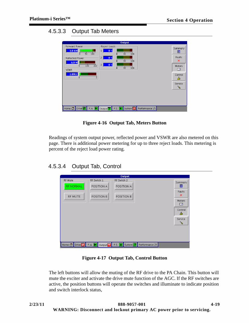
Section 4 OperationPlatinum-i Series™
4.5.3.3 Output Tab Meters
Figure 4-16 Output Tab, Meters Button
Readings of system output power, reflected power and VSWR are also metered on this page. There is additional power metering for up to three reject loads. This metering is percent of the reject load power rating.
4.5.3.4 Output Tab, Control
Figure 4-17 Output Tab, Control Button
The left buttons will allow the muting of the RF drive to the PA Chain. This button will mute the exciter and activate the drive mute function of the AGC. If the RF switches are active, the position buttons will operate the switches and illuminate to indicate position and switch interlock status,
2/23/11 888-9057-001 4-19WARNING: Disconnect and lockout primary AC power prior to servicing.

Section 4 OperationPlatinum-i Series™
4.5.3.5 Output Tab, Service Button
Service Screen, System button selected.
Figure 4-18 Output Tab, Service Button, System
This screen is used to calibrate the system power metering and reject loads. Determine the proper forward power using the RF power meter and the precision calibrated coupler. The offset can be entered into the digital power meter and power read directly. Verify that the sample DC voltage is in a range of 3 to 4.0 volts at TP 18 on the controller circuit board. Add pads if needed to reduce the sample below the 4 volt maximum.
In a similar fashion actual reflected power can be calibrated. If there is no precision reflected coupler, the furnished reflected coupler is reversed to meter forward power and a 20 dB pad is added in series with the cable. Now the reflected power can be calibrated at one percent of forward power. The reject loads can be calibrated by turning off cabinets using the hybrid power division rules. Knowing the theoretical reject power, then calibrate the reject power as a percentage of the reject load power rating.
Once the proper reflected power calibration is done, the desired VSWR fault and foldback values can be selected. VSWR control is software based and no further calibration is needed. The actual operation can be checked by substitution of the reflected signal, the RF signal level can be changed to verify operation. The VSWR protection can be disabled as needed by the VSWR Protect button to make VSWR calibration easier. This button has a time out function, five minutes after pushing, VSWR protection will return to normal.
4-20 888-9057-001 2/23/11WARNING: Disconnect and lockout AC primary power prior to servicing.

Section 4 OperationPlatinum-i Series™
Service Screen, RF Switch selected.
Figure 4-19 RF Switch Enable Screen
When the RF switches are enabled, the RF coax switch control buttons will appear on the output control screen.
4.5.4 P.S. Power Supply Tab
4.5.4.1 Power Supply Summary
Figure 4-20 Power Supply, Summary Button
2/23/11 888-9057-001 4-21WARNING: Disconnect and lockout primary AC power prior to servicing.

Section 4 OperationPlatinum-i Series™
Screen displays AC mains and logic supply voltages and 50 Volt supply OK status.
Figure 4-21 Power Supply, Fault Button
This screen displays AC mains voltage sensor status. A fault indicates low line voltage or that the phase sequence is reversed.
Figure 4-22 Power Supply, Meters, System Button
This screen meters the control cabinet AC line voltage and logic supply voltages when the System button is selected.
4-22 888-9057-001 2/23/11WARNING: Disconnect and lockout AC primary power prior to servicing.

Section 4 OperationPlatinum-i Series™
Figure 4-23 PS Meters Button, Cabinets Selected
Meters the 50 Volt module supplies, select the PA cabinet using the cabinet buttons.
Figure 4-24 Power Supply, Service Screen
The power line voltage calibration is done on this screen, the other function is the setting of a nominal AC line voltage, this scales the bargraph.
2/23/11 888-9057-001 4-23WARNING: Disconnect and lockout primary AC power prior to servicing.

Section 4 OperationPlatinum-i Series™
4.5.5 System Tab
Figure 4-25 System, Summary
Status of transmitter, remote control, external interlocks and cabinet communication.
Figure 4-26 System, Fault
The possible faults are in green, active faults are red.
4-24 888-9057-001 2/23/11WARNING: Disconnect and lockout AC primary power prior to servicing.

Section 4 OperationPlatinum-i Series™
Figure 4-27 System, Service Screen
The Configure screen is used to select the model number of the transmitter. The RF On Delay adjusts the RF power reduction time length used during the turn on cycle and the channel number is selected. External Interlock selects a choice of transmitter function following an external interlock open and restore cycle. Auto Restart turns the transmitter back on following an opening and re closure of the external interlock. The manual selection requires an operator ON command to restart the transmitter. Auto restart is the normal mode, this is used unless safety regulations require manual restart.
Revision is the board and software information.
Service allows the capture of a snapshot of the transmitter at that point in time. This is functional only on the transmitter GUI screen and is grayed out on other screens.
2/23/11 888-9057-001 4-25WARNING: Disconnect and lockout primary AC power prior to servicing.

Section 4 OperationPlatinum-i Series™
4.5.6 Performance Tab
Figure 4-28 Performance, Summary Button
The Apex exciter can pass on the data to this display for EVM, SNR, shoulder levels and the eye pattern.
Figure 4-29 Performance, Faults Button
The fault tables turn from green to red when a fault is active.
4-26 888-9057-001 2/23/11WARNING: Disconnect and lockout AC primary power prior to servicing.

Section 4 OperationPlatinum-i Series™
Figure 4-30 Performance Tab, Meters Button
This now displays signal quality metering.
Figure 4-31 Performance, Control Button
2/23/11 888-9057-001 4-27WARNING: Disconnect and lockout primary AC power prior to servicing.

Section 4 OperationPlatinum-i Series™
4.6 GUI Screen Faults Summary List
GUI FAULT MATRIX WORKSHEET
SCREEN TITLE FAULT NAME FAULT NOTES WARNING
DRIVE CHAINExciter A Summary Fault Check exciter for more informationExciter B Summary Fault Check exciter for more informationActive Exciter Mute Check exciter for more information
Unlock Check exciter for more informationExciter Power Check exciter for more information
P.A. CABINETModule Faults Individual Module Faults Check fault blink code on moduleCabinet Faults Forward Power Low RF power at the cabinet output Y
Reflected Power High reflected power at cabinet YDrive Power Abnormal drive power level Y
Cooling Cabinet Air Check motor and air switch S2Interlocks Door Check for door closure or discharge circuit
failureExternal Reject load thermal overtemperature switch
Power Supply 50V Power Supply 1 Check power supply card for fault display50V Power Supply 2 Check power supply card for fault display
OUTPUTSystem Forward Power Little or no output power Y
VSWR Trip Software set, High reflected powerVSWR Foldback Software set, moderate reflected power Y
Reject Loads Reject 1 Reject load power exceeds load rating YReject 2 Reject load power exceeds load rating YReject 3 Reject load power exceeds load rating Y
Mutes RF Mute Multiple causesRF Switch 1 Mute Interlocks of switch are not completeRF Switch 2 Mute Interlocks of switch are not complete
POWER SUPPLYSystem AC Low Control system line voltage summary fault Y
AC Phase Loss Loss of phase sensor, low or missing phase+ 5 Volt DC Control system voltage monitoring+ 12 Volt DC Control system voltage monitoring- 12 Volt DC Control system voltage monitoring+3.3 Volt DC Control system voltage monitoring
AC Mains A-B Control system line voltage monitoringB-C Control system line voltage monitoringC-A Control system line voltage monitoring
SYSTEMSystem Interlocks External External interlock to 1A7TB1 1-2
Failsafe Failsafe interlock to 1A7TB1 3-4Front Panel No cable connection to J4 front panel
PERFORMANCE Shoulder Compliance Check Exciter(s)SNR Check Exciter(s)
4-28 888-9057-001 2/23/11WARNING: Disconnect and lockout AC primary power prior to servicing.

Section 4 OperationPlatinum-i Series™
2/23/11 888-9057-001 4-29WARNING: Disconnect and lockout primary AC power prior to servicing.

Section 4 OperationPlatinum-i Series™
4-30 888-9057-001 2/23/11WARNING: Disconnect and lockout AC primary power prior to servicing.

Platinum-i Series™
Section 5Control System Theory of Operation
2/23/11 888-9057-001WARNING: Disconnect and lockout AC primary pow
5
5.1 Control System Overall DesriptionThe control system for the Harris Platinum-i series of VHF TV transmitters consists of a Control Cabinet that contains a controller board, front panel interface and the GUI monitoring system. The main controller printed wiring board is mounted on the underside of the Input/Output panel.
Each PA Cabinet has a slave controller, communicating with the control cabinet over a parallel bus and command lines. The slave controller has monitoring, protection and control functions.
NOTE:Each logic signal has an active and inactive state and a unique name within the system. To differentiate between active high or active low logic states on the schematics, a forward slash (/) is placed in front of an active LOW signal name such as /RF_MUTE. This means that if this logic line is pulled low, the transmit-ter RF will be muted. By the same logic, the signal RF_MUTE_LED (an active high signal with no forward slash) will turn on the RF mute LED when it goes high. In some cases, a logic signal may act as a toggle with both states active, as with the signal /ON_OFF, where LOW = ON and a HIGH = OFF. If this signal is inverted it would be ON_/OFF.
5.1.1 Transmitter Control System
The Platinum-i transmitters utilize a very advanced but simple to use control system. It is a microprocessor, serial communication based software control system but uses backup Life Support logic circuitry and hard wired control lines, allowing the transmitter to be on the air even if the main control system fails.
5-1er prior to servicing.

Section 5 Control System Theory of Platinum-i Series™
Figure 5-1 Controller Block Diagram
Figure 5-1 shows a simplified block diagram of the transmitter control system. The left side of the diagram shows the external connections to the transmitter or more specifically the External I/O Board. The right side of the diagram shows the internal control system inter-connections from the Main Controller to the various sub-systems inside the transmitter cabinet.
NOTE:eCDi™ is an Transmitter Network Interface appliance that provides a complete comprehensive remote control and monitoring of every data point within the transmitter. It includes an SNMP (Simple Network Management Protocol) man-ager, and allows integration with most Control Systems via the Internet or LAN.
REMOTECUSTOMERCOMMANDS
REMOTECUSTOMER
STATUS
CABINET BUS
LINE VOLTAGEMONITOR
TX ON/OFFCONTROL
EXCITERSWITCHER
INTERLOCKS
FRONT PANELINTERFACE
DISPLAY UNITINTERFACE
PEAKDETECTORS
MICRO MODULE
XC95288XL CPLD
CAN
AD
DR
ES
S B
US
DA
TA
BU
S
FP CONTROLS
TX ON/OFF CONTROL
EEPOTs &FAULT
DETECTION
TX
FA
UL
TIN
PU
TS
SPI BUS
ANALOG DETECTOR INPUTS
SPI BUS
REMOTECUSTOMER
ANALOG
SPI D/AEXCITER ANALOG SENSE
EXCITER STATUS & CONTROL
LINE VOLTAGE & AGC SAMPLES
AGC ENABLE STATUS
DIFFERENTIALTRANCEIVERS
INTERLOCK STATUS
CONTROLLER BLOCK DIAGRAM
CABINET BUS CONTROL
DATA BUS
CABINET ANALOG SAMPLE
FOLDBACK D/AVISUAL & AURAL FOLDBACK
SHEET 11ANALOG DETECTOR INPUTS
OPTION REMOTE STATUS
SERIES /PARALLEL
CONVERTOR
CUSTOMER I/O SPI BUS
LVPS INPUT
+12V +5V
-12V
+3.3VREGULATOR
+3.3V
DUAL TRANCONTROLLER
INTERFACE
DUAL TRAN CONTROLS
DUAL TRAN STATUS
FORWARD POWER SAMPLE
DUAL TRANAGC OPTION
AGC MUTE COMMANDS
PHASEMONITOR
PHASE LOSS
5-2 888-9057-001 2/23/11WARNING: Disconnect and lockout AC primary power prior to servicing.

Section 5 Control System Theory ofPlatinum-i Series™
5.1.2 Micro Module
The control board in the transmitter use the 376 Micro Module. The micro module is a daughter board with a standardized interface which is plugged into a motherboard. It contains Flash memory for storage of its programming and SRAM for program execution. The programming in the flash memory can be re-programmed or upgraded using In-System Programming or ISP (no hardware needs to be changed) via serial connection. In general the micro modules are responsible for control, monitoring and reporting, but have very little to do with transmitter protection which is handled mainly by the CPLDs.
Figure 5-2 Micro Module Block Diagram
5.1.2.1 Features of the 376 module include:
a. Built-in CAN (Controller Area Network) bus controller
b. 16 A/D inputs for analog metering
c. A serial EEPROM for non-volatile memory storage
d. A built in clock running at 4.194MHz which will let the micro run at 16-25MHz
uC
68HC1668HC376
BASICTM
Module Block Diagram
BDM XTAL
AnalogVoltage
Ref(+4.095V)
FLASH512K x 16
RAM128K x 16
Adrs (18:0)Data (15:0)
/CS (10:2)
SPI
IRQ
Tx, Rx
Clkout
CANTx,CANRx
AN(7:0)
AN(15:8)
'376I/O
SerialEEPROM
POR
/Reset_OC
+5VDC
GND
2/23/11 888-9057-001 5-3WARNING: Disconnect and lockout primary AC power prior to servicing.

Section 5 Control System Theory of Platinum-i Series™
e. Power failure detection
f. A watchdog which will reset the micro if it is not triggered at least every 1.6 sec-onds (this time interval will change depending on the application). A discrete logic device or CPLD is provided on the motherboard to act as an I/O expansion device and as life support if the micro module fails.
g. Multiple I/O lines whose direction of signal flow is based on the flash memory programming. These could be control or status, inputs or outputs, depending on the particular use.
The main responsibility of the micro module is control of the CPLD and the reporting and receiving of information over the CAN bus. This means that the CPLD will continue to monitor and protect the systems to which it is connected even if the micro module fails. However, there will be no reporting of information to the rest of the transmitter system since access to the CAN bus is gone without the micro module.
5.1.3 CPLD, Complex Programmable Logic Device
The transmitter control board with the micro module also incorporate a CPLD (Complex Programmable Logic Device) with the exception of the module controllers. The CPLD is not a microprocessor but is actually just programmed discrete logic and is therefore very stable and reliable. The CPLD’s in the transmitter perform two vital functions in terms of control and transmitter monitoring:
• I/O Expansion
• Life Support Backup
5.1.3.1 I/O Expansion
Each Micro Module only has a limited number of Input/Output or I/O lines available. The CPLDs provide a way to easily expand the available I/O ports on each control board. Basically, the CPLDs are actually controlling and monitoring the I/O for each control board. The micro module is taking that information and relaying it, via the CAN bus, to the Main Controller for display on the front panel control screen or a remote control system. If the micro module wants to send a control command, it simply addresses the correct I/O line on the CPLD and it then sends out the command.
5.1.3.2 Life Support Backup
The CPLD monitors the watchdog circuit or more specifically the RESET line on the micro module. If the micro module stops executing its program, the watchdog circuit
5-4 888-9057-001 2/23/11WARNING: Disconnect and lockout AC primary power prior to servicing.
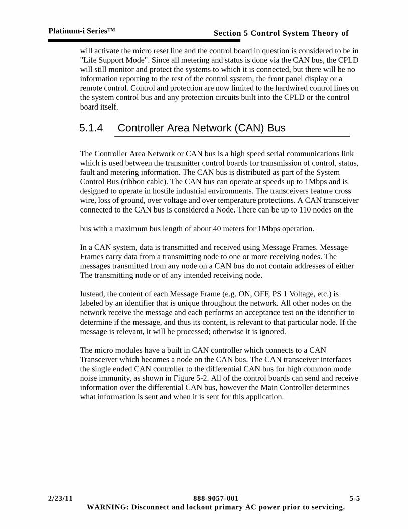
Section 5 Control System Theory ofPlatinum-i Series™
will activate the micro reset line and the control board in question is considered to be in "Life Support Mode". Since all metering and status is done via the CAN bus, the CPLD will still monitor and protect the systems to which it is connected, but there will be no information reporting to the rest of the control system, the front panel display or a remote control. Control and protection are now limited to the hardwired control lines on the system control bus and any protection circuits built into the CPLD or the control board itself.
5.1.4 Controller Area Network (CAN) Bus
The Controller Area Network or CAN bus is a high speed serial communications link which is used between the transmitter control boards for transmission of control, status, fault and metering information. The CAN bus is distributed as part of the System Control Bus (ribbon cable). The CAN bus can operate at speeds up to 1Mbps and is designed to operate in hostile industrial environments. The transceivers feature cross wire, loss of ground, over voltage and over temperature protections. A CAN transceiver connected to the CAN bus is considered a Node. There can be up to 110 nodes on the
bus with a maximum bus length of about 40 meters for 1Mbps operation.
In a CAN system, data is transmitted and received using Message Frames. Message Frames carry data from a transmitting node to one or more receiving nodes. The messages transmitted from any node on a CAN bus do not contain addresses of either The transmitting node or of any intended receiving node.
Instead, the content of each Message Frame (e.g. ON, OFF, PS 1 Voltage, etc.) is labeled by an identifier that is unique throughout the network. All other nodes on the network receive the message and each performs an acceptance test on the identifier to determine if the message, and thus its content, is relevant to that particular node. If the message is relevant, it will be processed; otherwise it is ignored.
The micro modules have a built in CAN controller which connects to a CAN Transceiver which becomes a node on the CAN bus. The CAN transceiver interfaces the single ended CAN controller to the differential CAN bus for high common mode noise immunity, as shown in Figure 5-2. All of the control boards can send and receive information over the differential CAN bus, however the Main Controller determines what information is sent and when it is sent for this application.
2/23/11 888-9057-001 5-5WARNING: Disconnect and lockout primary AC power prior to servicing.

Section 5 Control System Theory of Platinum-i Series™
All fault reporting and status and metering information displayed on the GUI is sent on the CAN bus to the Main Controller and to the External I/O board for remote monitoring. Transmitter control signals are also sent via CAN but are also sent over hardwired parallel control lines.
The parallel control lines are used for quick actuation of critical functions, such as ON, OFF, RF mute, AC_Low and Fault Off. These lines are also the backup control lines in a Life Support mode when the Main Controller (and therefore the CAN bus) is not operational. Each board in the control system can independently activate some or all of the parallel control lines to protect the transmitter in case of a fault or other condition that may adversely affect the transmitter. These parallel control signals are duplicated in the CAN messages. The following is a brief explanation of each of the parallel control lines included in the system control bus.
a. ON_/OFF This command corresponds to the transmitter operator pushing the "ON" or "OFF" button, thereby turning the transmitter on or off respectively. This signal is high for ON and low for OFF.
b. /RESTRIKE (reset). When the transmitter is already turned ON and the operator presses the "ON" button again, this line will be pulsed low for a minimum of 100ms. This will cause the slave controller boards to reset any faults and status and try to return to normal operation. This command is basically a RESET pulse which will try to turn on any transmitter components which have faulted off due to a critical fault condition. If they are still faulty, this will be detected and the component will simply be shut off again. This will not reset or clear the Fault Log.
5-6 888-9057-001 2/23/11WARNING: Disconnect and lockout AC primary power prior to servicing.

Section 5 Control System Theory ofPlatinum-i Series™
c. /FLT_OFFThis command is initiated whenever a fault occurs that requires all RF to be shut off and the PA supplies to be disabled. This is a latching type signal that requires user input to clear the fault and turn the transmitter back on. This signal is active low. The Main Controller, Power Block Controller, External I/O and RF Monitor boards monitor this line and have the ability to activate it if necessary.
d. /RF_MUTE The /RF_MUTE line shuts down all RF output temporarily until the fault condition is cleared. This is a non-latching signal. The Main Controller, Power Block Controller, External I/O and RF Monitor Boards monitor this line and have the ability to activate it if necessary.
e. /PS_MUTE The /PS_MUTE line shuts down the output of the 32 Volt PA module supplies temporarily until the fault condition is cleared. This is a non-latching signal. The Main Controller,
f. /AC_LOW This signal is an early warning of impending loss of control voltage. When the AC line voltage that powers the LVPS(s) drops below an acceptable threshold the board will pull this open collector line low. Phase samples L3-L1 (C-A) are continuously monitored. Monitor Boards.
5.2 Main Controller
The Main Controller is the primary interface between the transmitter and the operator via the front panel Graphical User Interface or GUI. It is connected to all transmitter subsystems, both internal and external to the transmitter, through either an RS-485 serial port or the CAN (Controller Area Network) bus and dedicated parallel control lines. The CAN bus and the parallel control lines are distributed on a single multiconductor cable called the System Control Bus. The Main Controller is mounted directly behind the front control panel. It is directly connected to the front panel switchboard which is considered a "Mezzanine" board. The front panel switchboard uses a CPLD to serialize the I/O (the control lines and status signals) to and from the Main Controller.
5.2.1 Transmitter Control
The Main Controller is the central point for all system control, metering and diagnostics. It reports this information to the operator via the Graphical User Interface or GUI and through several remote control options.
5.2.1.1 Graphical User Interface (GUI)
The GUI is a touchscreen LCD display which is equivalent to 1/4 of a VGA display. This is the primary local interface for the operator but is not required to operate the
2/23/11 888-9057-001 5-7WARNING: Disconnect and lockout primary AC power prior to servicing.

Section 5 Control System Theory of Platinum-i Series™
transmitter. The primary operator controls, ON, OFF, RAISE, LOWER are located on the front panel next to the GUI. Operation and navigation of the GUI is covered in Section XXX of this manual.
5.2.1.2 Remote Controls
There are 3 remote control and monitoring options which can all access information gathered by the Main Controller via the External I/O Board.
Standard Parallel Remote Control System - The External I/O Panel has connections for dedicated remote control systems with the standard parallel control inputs, status outputs and analog metering outputs.
• One serial port, is available for operator connection to run the In-System Program-ming or ISP software, supplied by Harris, to update the software for the Main Con-troller and/or any other micro in the transmitter.
5.3 Control Panel and Indicator Display
The switch panel provides a local user interface that is an alternative or backup to using the touchscreen. It provides a means to decode button pressed information and then send the decoded information on to the various controllers for them to determine what needs to be done. The controllers will then send back information that will determine what button/indicator are to be lit, and what color. In event of a CAN bus error, these panels (one on the driver cabinet and one on each HPA system power supply cabinet) become the operating controls at the transmitter. The switch panels are capable of turning the transmitter on and off, but no transmitter information will be given. This is possible because each area of the transmitter system has its own micro-processor control board which is capable of operating and protecting its own area. Each of the control boards only needs to get on/off commands from the switch panel. In the driver, the local control bus provides parallel lines which connect its switch panel to the RFU controller, the mode controller, and the external I/O boards. The system bus provides other parallel lines which pass critical information.
5.3.0.1 Introduction
Due to the complexity of the switch panel, the theory broken up into the following operations:
• Modes of Operation.
• Button Presses
5-8 888-9057-001 2/23/11WARNING: Disconnect and lockout AC primary power prior to servicing.

Section 5 Control System Theory ofPlatinum-i Series™
• Button / Indicator Lighting
• Error Messages and Indications.
The following definitions may be useful.
MAX 6954: A Maxim LED/Key Matrix Controller. Used to control 128 LEDs and 32 switches.
Micro-controller: The primary programmable device of the switch panel. It is a Freescale MC9S12DP256 micro-controller.
Hardwired switches: The hardwired switches are switches that are directly connected to the transmitter’s controllers via connector J4 and ultimately, the parallel lines of the system bus. They include the following 6 switches: On, Off, Power Raise, Power Lower, Remote Enable, and Remote Disable, see Figure 6-15.
Hot buttons: The lower six buttons on the front of the panel surrounded by a silk screen called STATUS. These buttons indicate if a summery fault has occurred and in what function. Green is normal, orange is warning, and red is fault. The hot buttons includes following: Drive Chain, Power Amp, Output, Power Supply, System, and Performance. By pressing these buttons, the user can open the appropriate screen on the display, see Figure 6-15.
ISP: In System Programming. The process used to update firmware/software on a board without having to change physical components.
5.3.1 Modes of Operation
The switch panel has a dipswitch which allows either of two modes of operations to be selected.
• In Factory Test mode, the switch panel will provide a means for lamp and switch testing.
This is not for customer use since the hardwired switches are still connected to the transmitter’s controllers and will work normally.
5.3.1.1 Button Press
There are 38 buttons on the switch panel. Six of these buttons are hardwired directly to the transmitter’s controllers via the 26-pin connector J4. They include Remote Enable, Remote Disable, Power Lower, Power Raise, Transmitter On and OFF. This is done due to the critical nature of these buttons. The other 32 buttons are programmable.
When a hardwired button is pressed, the switch momentarily applies ground to pull the signal line low. The signal line is connected directly to the connector J4 and sent on to the other controllers via a ribbon cable. The controller in charge of that button will
2/23/11 888-9057-001 5-9WARNING: Disconnect and lockout primary AC power prior to servicing.

Section 5 Control System Theory of Platinum-i Series™
acknowledge that it received the hardwired switch signal by sending back a reply with information that will tell the MAX 6954 to blink that particular switch. Then the controller next determines what to do based on the current state of the transmitter. If all is well, it will reply to the switch panel with new information that will now request it to light that button solid. If all is not well, it will most likely turn off the LEDs to that button.
To determine if a programmable switch has been pressed, the MAX 6954 scans the 4x8 matrix of switches. It does this by holding one of the four rows of switches at a level ‘1’, then it looks at the eight columns and stores their states into a switch register for that particular row. After all four rows are scanned, it will repeat the scan to “debounce” the results. It again looks at the eight columns and compares the new results to the switch register storing the previous scan results for that row. If the compared information is not the same, the new information is then placed into the switch register and the next scan is performed. If they are the same information and it shows one or more of the inputs are at a level ‘1’, it knows that particular switch or switches has been pressed. The results of this are placed into the debounced register for that particular row. This will cause the MAX 6954 to send an interrupt to the micro-controller. The micro-controller will then pull the information from all 4 debounced registers and decode them to determine which switch in that row was pressed. Once this is determined, it blinks the LEDs for that button and then it immediately sends the information to the controller that is responsible for that switch. The controller will then send an acknowledge packet to the switch panel micro controller, which will process it’s information to determine the new state of the button. Once it determines the new state of the button, it waits for a status update packet from the switch panel and then sends the new button status. Each button status will include the button number and the state. The switch panel micro controller will act on that information and set the switches accordingly.
5.3.1.2 Button / Indicator Lighting
For the most part, the front panel does not light any indicators without a status from the controller. The only exception to this is when the unit is going through a start up lamp test.
To determine the correct lighting state of each button/indicator, the front panel will send a status update to the controller. The front panel will send out a status update request to a controller and wait for a reply to the request for 200 mS. If a controller replies to the status update, it will reply with a list of data that includes all the id numbers of button/indicators it is in charge of, and their status’. Each button/indicator id number is decoded to determine which LEDs are associated with it, then the status of these LEDs are set to one of 6 possible states (solid red, solid green, solid orange, blinking green, blinking orange, or off) and that controller’s status is set to being online.
5-10 888-9057-001 2/23/11WARNING: Disconnect and lockout AC primary power prior to servicing.

Section 5 Control System Theory ofPlatinum-i Series™
If a controller does not respond to three status requests, it’s status will be set to being offline, the status indicator for that controller on the back of the front panel will blink red and an error message stating that it’s offline will scroll on the LED display in the lower right corner of the front panel. Once an offline controller starts to respond to a status request, it’s status will be changed to being online and control of the corresponding status LED will be returned to the controller.
5.3.1.3 Messages in the LED Display
Normal message sequence is the model number, forward power and reflected power. This will be shown until the external I/O controller sends information to set the LED display to show the model number of the particular transmitter it’s in. The model number will be seen during normal operations. If the front panel is in bootloader mode, the screen will remain blank. If the front panel is in factory test mode, then “TEST” is displayed on the LED display. The remaining five messages are error messages.
5.3.1.3.1 FP Error
This error is displayed when the front panel determines that a hardwired button has been pressed for longer then 30 seconds. This is to alert the operator so that the condition can be corrected immediately. This condition is caused by either a sticking button, or by something leaning against the button. The only exception to this is the power raise and power lower buttons.
5.3.1.3.2 Com Error, Main Controller
This error is displayed when the front panel does not receive a status update from the external I/O controller in the driver cabinet after 3 attempts. The front panel will then cause the external I/O status indicator on the back panel to blink red. The front panel will continue to send requests to the external I/O until it starts to reply with status updates. When status updates are again being received, the external I/O status indicator is returned to the control of the external I/O and the model number is shown. The possible causes for this error condition are that the micro-controller on external I/O maybe locked up or busy with a time consuming process such as ISP.
2/23/11 888-9057-001 5-11WARNING: Disconnect and lockout primary AC power prior to servicing.

Section 5 Control System Theory of Platinum-i Series™
5.4 Main Controller
5.4.1 Platinum-i TV Controller
The Platinum TV Controller schematic is in section 600. Sheet one is the block diagram for the controller.
The interconnection of the control cabinet components is shown in the Basic Wiring Diagram for the control cabinet. The Controller receives transmitter on/off and power raise/lower commands from the front panel and also cabinet and external interlock signals. It also interfaces with external remote control signals, and supplies output drives to all status indicators. Peak Detectors for Forward and Reflected, and for up to 3 reject loads, are also located on the controller.
5.4.1.1 Micromodule Interface (Sheet 2)
This sheet is the pin for pin interface between the controller and the micromodule. The micromodule is a multipurpose card used in various transmitters.
5.4.1.2 Micro Module (Sheet 3)
The control board in the transmitter use the 376 Micro Module. The micro module is a daughter board with a standardized interface which is plugged into a motherboard. It contains Flash memory for storage of its programming and SRAM for program execution. The programming in the flash memory can be re-programmed or upgraded using In-System Programming or ISP (no hardware needs to be changed) via serial connection. In general the micro modules are responsible for control, monitoring and reporting, but have very little to do with transmitter protection which is handled mainly by the CPLDs.
• Features of the 376 module include:
Built-in CAN (Controller Area Network) bus controller
16 A/D inputs for analog metering
A serial EEPROM for non-volatile memory storage
5-12 888-9057-001 2/23/11WARNING: Disconnect and lockout AC primary power prior to servicing.

Section 5 Control System Theory ofPlatinum-i Series™
A built in clock running at 4.194MHz which will let the micro run at 16-25MHz
• Power failure detection
A watchdog which will reset the micro if it is not triggered at least every 1.6 seconds (this time interval will change depending on the application). A discrete logic device or CPLD is provided on the motherboard to act as an I/O expansion device and as life support if the micro module fails.
Multiple I/O lines whose direction of signal flow is based on the flash memory programming. These could be control or status, inputs or outputs, depending on the particular use.
The main responsibility of the micro module is control of the CPLD and the reporting and receiving of information over the CAN bus. This means that the CPLD will continue to monitor and protect the systems to which it is connected even if the micro module fails. However, there will be no reporting of information to the rest of the transmitter system since access to the CAN bus is gone without the micro module.
5.4.1.3 Development Hardware & Bd Version (Sheet 3)
Sheet three shows hardware that is reserved for board development and testing by Harris engineering. The Assembly Revision is a hardware revision control that uses pull down zero ohm resistors to allow the hardware revision to be accessed by the microprocessor. The diagnostic LEDs flash in a regular sequence during normal operation.
5.4.1.4 RS232 Watch Dog & Front Panel Interface (Sheet 4)
Sheet 4 of the drawing shows several interfaces used in the controller.
• BDM is Background Debug Mode provides for emulation and debugging for the 376 microcontroller. There is no user usage of this connection.
• U43, the EEPROM, is a 128/256K, SPI Bus Serial high speed EEPROM. This is used for storing the program for the 376microcontroller.
• U100 is a watchdog timer IC. A watchdog timeout occurs if it's input has not been toggled within 1.6 seconds. A master reset occurs on watchdog time-outs unless the Watchdog Disable line on the module interface is held above 4.5v. The watchdog input (kick watchdog) shall be made available on the module interface. This line may
2/23/11 888-9057-001 5-13WARNING: Disconnect and lockout primary AC power prior to servicing.

Section 5 Control System Theory of Platinum-i Series™
be monitored to ensure the microprocessor is still alive and the reset line on the mod-ule interface may be monitored for when a reset is taking place. There is a RESET switch S2 that can force a reset at any time.
• U104 is the RS232 microprocessor interface for use in communication with exciters.
• The front panel is connected to the main controller using J7, the protection and opamp buffering interface with the CPLD inputs.
5.4.1.5 Controller Analog Sense (Sheet 5)
Sheet 5 includes four analog multiplexer / demultiplexer CMOS integrated circuits. These select one of eight inputs to an output. These chips become four of the analog inputs to the micromodule.
5.4.1.6 CPLD (Sheet 6)
The Controller will have an XC95288 to act as memory mapped I/O and perform critical functions in the event that the Micro Module fails. The Micro Module will interface to the CPLD through /CS2, /CS7, address lines 19 down to 16 and the data lines 15 down to 8.
• Critical Life Support Functionality
The critical life support functionality occurs when an on board watchdog is triggered as a result of an unresponsive Micro Module.
The CPLD will control the transmitter on/off state and under life support conditions will respond to the front panel and the customer remote commands. The outputs of the detectors will be compared to thresholds set in EEPots by the Micro Module before the fault status is passed to the CPLD. This will allow the CPLD to mute the transmitter during a forward or reflected overdrive.
The CPLD will also monitor all discrete external customer I/O, the front panel switch board I/O, and the interlocks, so that the controller can maintain critical functionality during the event of a micro failure.
• Status Indicators
The CPLD will give the following status indicators. A red LED will indicate a Board Reset. A red LED will indicate if the CPLD is not programmed. Two red LEDs will indicate a Faulted Off condition and a RF Mute condition.
5-14 888-9057-001 2/23/11WARNING: Disconnect and lockout AC primary power prior to servicing.

Section 5 Control System Theory ofPlatinum-i Series™
5.4.1.7 Cabinet Bus Controller (Sheet 7)
Refer to sheet seven. This sheet contains the circuits that communicate with the slave controller over the twisted pair ribbon cable cabinet bus. U84 is the chip that issues the control commands to the slave controller cards. The U95, U96, U98 and U99 are the transceiver chips that perform the two way communication of commands and status. The U78 and U66 perform a conversion of the balanced analog signal to the unbalanced input to U65. The TLV2548 is a serial analog to digital convertor. Under the control of the micro it will convert the analog voltage to serial digital data that the micro will process for monitoring and display.
5.4.1.8 Transmitter ON/OFF Control (Sheet 8)
Each of the four chips on sheet 8 will switch the cabinet ON and OFF lines high and low. An additional input is used to pulse the plus 12 volt lines for resetting modules or power supplies that are reporting a fault to the slave controller. Part of U97 is used to control the relay K2. K2 can be used to control exhaust fans or other parts of a transmitter cooling system.
5.4.1.9 Foldback Voltage D / A and Can Bus Interface (Sheet 9)
The foldback digital to analog converter changes the digital foldback control value to an analog voltage. The analog voltage is an input to the exciter I/O to control the foldback circuitry of the exciter. Provisions include two outputs for analog transmitters. The foldback is again buffered by the U4 on sheet 10. Test points are available to monitor these DC control voltages. The bottom part of the sheet shows the CAN interface that communicates with the GUI computer display unit.
5.4.1.10 Controller/Exciter Switcher Interface (Sheet 10)
J8 is the controller input / output that goes to the exciter I/O panel either directly or as switched by the I/O control switching relays in the exciter switcher. The exciter sense lines are used for exciter power metering. This allows the front panel and the GUI to control the exciter switcher and the exciter power.
2/23/11 888-9057-001 5-15WARNING: Disconnect and lockout primary AC power prior to servicing.

Section 5 Control System Theory of Platinum-i Series™
5.4.1.11 Line Voltage and AGC Monitoring (Sheet 11)
The opto-coupler supply AGC status to the multiplexer chip U48, the one output line allows the microprocessor to poll the AGC to see if the status is ON or OFF. The AGC control voltages are buffered and become input to multiplexer U57.
DC sample voltages from the AC line sample units are adjusted to a nominal DC voltage of three volts or less at the test points. The actual calibration scaling is done by the microprocessor. There are two AC line sample sections for those systems that dual AC power feeds to the control cabinet.
5.4.1.12 Interlocks (Sheet 12)
The External, Failsafe and Phase loss interlocks are isolated by opto-coupler. A spare is also available for use in custom systems.
The external interlock is a series system of switches, a complete set of closed switches complete the interlock. The external interlock is connected to 1A7TB1 terminals one and two. 1A7TB1 connects to J11 by wiring harness. In a similar manner, the Failsafe interlock connects to 1A7TB1 terminals three and four. Any interlock not used requires a jumper wire to complete the interlock.
5.4.1.13 Peak Detectors (Sheets 13 and 14)
NOTE:This control system is designed for both analog and digital service, the analog visual circuits are used for the digital signal path. Visual Forward becomes Digi-tal Forward, Visual Reflected becomes Digital Reflected and no Aural circuitry is used in the digital cabinet version.
Each channel of peak detection is actually composed of two identical detectors, the RF input is connected to one detector, the other is only connected to ground. Each detector diode output voltage is a function of RF input and diode temperature. The top diode has an output voltage that changes with RF input and temperature. The lower diode output is only changes with temperature. After opamp unity gain buffering, the two voltages are inputs to the following differential amplifier, the output of this is the difference of the two voltages representing the RF input voltage only. This circuit is designed for three volt at the test point at maximum input RF voltage. This voltage will be used with a lookup table in software to correct for the diode nonlinearity. This uncorrected voltage is also available at the remote interface as “Raw Visual Forward”. Reflected and reject loads are metered with similar circuitry.
5-16 888-9057-001 2/23/11WARNING: Disconnect and lockout AC primary power prior to servicing.

Section 5 Control System Theory ofPlatinum-i Series™
5.4.1.14 Fault Detection (Sheet 15)
Digital system power output peak detector DC voltage (VIS_FWD_PWR), the + input to the comparator U60 is compared with a DC voltage from the wiper of a digital pot. This pot is part of U83, a quad digitally controlled potentiometer. The SO, serial output pin allows the microprocessor to read the wiper position. The SI is the serial data input pin, serial data into this pin changes the wiper position. SCK is the serial clock for the SPI bus. CS is the chip select pin, microprocessor pulls this pin low to select the chip.
The high terminal is connected to the 4.096 volt reference and the low terminal is connected to ground. The microprocessor addresses this pot, then sets the resistor wiper setting. This voltage divider generates the inverting input voltage for the comparator, determining the comparator change point. When the power is below the set point of 80% of nominal, the forward power fault is generated (VIS_FWD_FLT). This will generate a WARNING type fault.
In a similar manner, the output reflected power, (VIS_RFLD_PWR), is compared to a digitally controlled voltage and generated a reflected fault.
The three reject loads are compared with a voltage that is calculated to be 75% of the load rating. Above this point, a warning only is generated and a fault will shut down two cabinets if the load rating is exceeded.
5.4.1.15 Dual Tran Interface (Sheet 16)
This is interfacing for the Dual Tran interfacing, detailed information is included in the Dual Tran documentation.
5.4.1.16 Remote Commands Input (Sheet 17)
The parallel control command inputs are opto-coupler and are inputs to an eight bit parallel-input/serial output shift register. The /RMT_I/O_CS line is used to inhibit remote control commands when remote is DISABLED.
Jumper JP2 allows powering the opto-coupler from the internal 5 volts or a voltage furnished by the remote control system. The furnished voltage shall not exceed 12 volts. This voltage has a 15 volt zener clamp diode, CR2 and a 0.2 A current limiting Posistor R31.
The +5V_ISOL, 5 volts, is furnished from U3, a 5 volt DC to DC supply rated at 150 mA maximum.
2/23/11 888-9057-001 5-17WARNING: Disconnect and lockout primary AC power prior to servicing.

Section 5 Control System Theory of Platinum-i Series™
5.4.1.17 Remote Status Output Drivers (Sheets 18 and 19)
The 74AHCT594 devices contain an 8-bit serial-in, parallel-out shift register that feeds an 8-bit D-type storage register. Separate clocks and direct overriding clear (SRCLR, RCLR) inputs are provided on both the shift and storage registers. U46 is used to change the serial status information into stored status information that is opto-coupled and then drives the gate of the 2N7002 FETs. When the fault is valid, the FET pulls the line low, indicating to the remote control that the fault is active.
U47, sheet 19 drives 8 more status lines. The bottom two status lines are direct from the CPLD, isolated and are part of the RF coax switch control system.
5.4.1.18 Optional Remote Status Output Drivers (Sheet 20)
J31 pins 1-3 are used to output the status of the exciter switcher, the status lines come direct from the CPLD. The status lines at pins four and five are status lines from an analog transmitter system with redundant drive paths.
5.4.1.19 Remote Analog Outputs (Sheet 21)
The microprocessor digital values are sequenced to the input of U61, a multiple output digital to analog convertor. The digital values are converted to an analog voltages at the outputs of U61. These voltages are buffered by sections of U69 through U72, and are available for remote metering at J33.
5.4.1.20 DC Distribution
The last sheet of the drawing shows the DC distribution and the voltage present LEDs. There is a three terminal regulator for the 3.3 volt sense. and a LM4040 is used as a 4.096 volt reference. This reference is used by the analog to digital metering circuitry and the voltage can be checked at the test point.
5.4.2 The SLAVE CONTROLLER DESCRIPTION
5.4.3 Slave Controller
The Slave Controller in the Platinum TV transmitter series is the local controller for each PA cabinet. All of the slave controllers communicate with the Monitor in the
5-18 888-9057-001 2/23/11WARNING: Disconnect and lockout AC primary power prior to servicing.

Section 5 Control System Theory ofPlatinum-i Series™
control cabinet via a communications bus, which loops from the Monitor through all the Slave controllers and is terminated at the last controller on the bus.
The slave controller has a unique address code, set by means of a DIP switch, S1, on the slave controller board. This allows the Monitor to send commands to, and receive data from each slave controller.
The address latching and bus interface logic for the slave controller are shown on Sheet 1 of the drawing.
5.4.3.1 Sheet 1
A slave controller address, received by bus transceivers U1 - U4, is stored in the Cabinet Address, Latch U6, and is then compared with the cabinet address selected on S1 by U7. If the address numbers do not match, the slave ignores the following data. If a match is seen, DS1 (ADR Select) lights briefly and the same signal operates the Read Strobe encoder U8, generating a read strobe on one of 8 output lines based on the low 3 bits of data from the cabinet address latch. The read strobe is then used to select a block of 8 status conditions (sheets 3 and 4) to be fed back along the bus to the monitor as data.
If an analog reading is being called, the ADR Select line, along with low on the C/D* and WR* lines, clocks the MUX ADR LATCH U9, storing the 6 low data bits and routing them as address to the analog multiplexers shown on Sheet 6.
The Control Bus Receiver U5 receives the C/D*, WR* and RD* lines from separate Bus conductors and uses them to provide drives to the latches and transceivers on Sheet 1.
The Power Up Reset circuit, U13, switches from a low to a high output as the 5-volt power supply rises at turn-on. This signal is used to reset the TX ON/OFF Latch (sheet 2), and the delay latches on sheet 7 when power comes on.
A Cabinet Interlock input is provided (Sheet 4) for use with some versions of the transmitter as inputs for reject load interlock contacts. It is isolated by U36 and then read as a status, and also routed to U10 (sheet 1), where the external interlock light DS7 is lit if an interlock occurs. Since this feature is not always used, J15 can be set to disable this interlock.
2/23/11 888-9057-001 5-19WARNING: Disconnect and lockout primary AC power prior to servicing.

Section 5 Control System Theory of Platinum-i Series™
5.4.3.2 Sheet 2
This sheet contains the cabinet ON/OFF logic, power supply control and fault detection. ON/OFF commands are received from the main controller through J2, but if the external connection is removed from J2 the cabinet can be controlled locally with S2 and S3.
An ON command sets TX ON/OFF Latch U20, sending an AC-CTRL* signal through U25-1 and U25-3 to turn on the cabinet AC contactor. A cabinet door fault causes a LOW on pin 2 of U25, stopping the contactor from turning ON.
The contactor applies power to the cabinet blower and to the 50 Volt power supplies. PS1 and PS2 also receive ON commands from U19-3 and U19-5, but the ON commands are delayed until U11-12 receives an AIR ON* signal indicating proper cooling air pressure.
Each power supply receives a control command turning it ON and OFF, and returns a PS OK signal when it is operating and has not faulted. The PS OK signals are monitored by U18-6 and U18-8, indicated by PS Fault LED'S DS3 and D54. Each will show a FAULT condition if the TX ON/OFF LATCH is set to ON and it's power supply is not returning a PS OK signal. The PS FAULT lights will light briefly each time the PA is operated to ON, until the power supplies come on, and then will light only if the supply faults.
A power supply can be reset with the same ON command used to reset the modules.
The TXD and TXD* signals processed by the TX ON/OFF LATCH are used elsewhere on the board to control the modules and other logic. The ON command sent to the TX ON/OFF LATCH is also sent to U22, the STSET ONESHOT. U22 produces a 700ms one-shot pulse, STSET and STSET*, which are used to reset PA modules and other equipment when the ON button is pressed while the transmitter is operating.
5.4.3.3 Sheets 3 and 4
Receive MODF (Module Fault) status from, each of the 17 PA modules in the cabinet, and also Cabinet Interlock if used. The status of each is read back to the Monitor board, arid the MODF signals are also used to route reset signals to the proper modules.
Sheet 5
This sheet contains 6 additional RF peak detectors functionally identical to the detectors on the main controller. These added detectors are used as needed to detect added samples in larger transmitters.
5-20 888-9057-001 2/23/11WARNING: Disconnect and lockout AC primary power prior to servicing.

Section 5 Control System Theory ofPlatinum-i Series™
5.4.3.4 Sheet 6
The Analog Channel multiplexers is used to select and route to the Monitor board the voltages and current samples from both power supplies and the outputs from the RF peak detectors shown on Sheet 5. U41 is included to convert the selected signals to the proper form for sending along the monitor bus, and K1 disconnects the bus from U4l when control power is lost to the cabinet to prevent loading of the bus by the unpowered circuits.
5.4.3.5 Sheet 7
This contains drivers and logic, which are custom-programmed PAL IC's. This circuitry is used to automatically switch to alternate modes in some parallel-driver versions of the transmitter.
5.4.3.6 Sheet 8
The Module-Enable circuits, also programmed by PAL IC's, which receive the TXD and TXD* signals, the STSET* reset command, all MODF and PS SET signals and the EXTINT* signal if external interlock is used. The PAL's contain the necessary logic to turn the PA modules ON and OFF as commanded or if interlocked, and also to route the STSET* pulse to the enable (EN) line for only those modules which are faulted.
5.4.3.7 Sheet 9
All power connections and the power bus protection.
5.5 Graphical User Interface
This is a basically a vendor display driven by an Intel hardware computer running a version of Linux software. The only Harris built part is the interface board and it is only for interconnection of cables. Drawing 843-5575-182 is included for reference in troubleshooting the power supply output voltages or changing the hard drive.
2/23/11 888-9057-001 5-21WARNING: Disconnect and lockout primary AC power prior to servicing.

Section 5 Control System Theory of Platinum-i Series™
5-22 888-9057-001 2/23/11WARNING: Disconnect and lockout AC primary power prior to servicing.

Platinum-i Series™
Section 6Control Cabinet
2/23/11 888-9057-001WARNING: Disconnect and lockout AC primary pow
6
6.1 IntroductionThe control cabinet contains the exciter and control elements of the transmitter. Documentation includes Wiring Diagram, Control Cabinet Common 843-5583-001 that is common to the analog and digital versions of the cabinet and for digital, Wiring Diagram Control Cabinet Digital 843-5583-003.
The Apex and CD1A exciters can both be used with an exciter switcher for exciter redundancy, automatic switching can be controlled by the RF levels from the exciters.
The next unit in the RF path depends on the configuration. Single Power Amplifier cabinet systems do not need phase and gain units.
• The classic digital configuration used with CD1A exciters has AGCs following the phase and gain units, the AGCs are used to keep the drive level constant.
• The new eCDi system is similar to the analog transmitter, using a single AGC before the phase and gain units to keep the transmitter output power constant. It should only be used with Apex exciters.
The control components in the control cabinet include the GUI eCDi interface computer, the main controller and the front control push button panel.
The exciters have self-contained power supplies, the logic and RF control subassemblies utilize DC power supplies in the bottom of the cabinets. More power supplies are available for a diode OR’d redundant supply configuration. A UPS (Uninterruptable AC Power Supply) is included to provide power to the GUI, one exciter and one set of control power supplies.
6-1er prior to servicing.

Section 6 Control CabinetPlatinum-i Series™
6.2 Control Cabinet Common
This description is used because the 843-5583-001drawings are common to the digital and the analog transmitters. The 843-5583-003 are unique to the digital control cabinet. The reference to the -002 version of the drawing is for the analog control cabinet.
6.2.1 Control Interconnects
Sheet one of the drawing shows the cables that interconnect the three elements of the control system, the main controller, the display unit assembly and the control panel unit. This sheet also shows the UPS input power wiring and the output load distribution terminal block TB6. The UPS AC power loads are the GUI display unit, one exciter and one set of logic and Accessory Tray power supplies.
The second and third sheet shows the AC and DC power distribution wiring. Sheet three shows the AC input wiring for single and dual DC supply configurations.
6.2.2 AC Power Distribution
The top two blocks show the single AC feed, single or dual power supply to the left. The jumper wires from TB3 to TB4. The right block shows the connections for a second AC feed and circuit breaker CB1B. There are three 1A8 units that furnish DC samples for AC line voltage metering.
NOTE:The 380-415 volt configuration is for 50 Hertz international transmitters. 60 Hertz 480 volt transmitters will use a 480 to 240 volt external step down trans-former. This is documented with the AC Distribution drawing in the appropriate systems section.
TB3 and TB4 are shown again at the right edge of sheet 2 with the load wiring. Relays K4 and K5 switch the UPS and the back door fan to the backup AC feed if the main feed is not available. The phase monitor relays K1 and K3 have the closed when AC is OK contacts connected in parallel, requiring both AC feeds to fail before the transmitter is turned off. The phase monitor relays have adjustable drop out voltages, normally set at approximately 90% of the voltage the 50 volt supplies are tapped, for example for 208 they are set for 185-187 volt threshold, there is a scale on top of the monitor that can be used.
This state is the same as normal OFF state, main contactors open in the PA cabinets. No AC changes occur in the control cabinet, the UPS will continue to power the GUI display unit and the main controller until the UPS battery is discharged.
6-2 888-9057-001 2/23/11WARNING: Disconnect and lockout AC primary power prior to servicing.

Section 6 Control CabinetPlatinum-i Series™
6.2.3 DC Power Supplies
The triple output supply PS1A and the optional backup supply PS1B supply control power and the negative 12 volts for the Accessory Tray. The other +12 supply PS2A and optional backup supply PS2B furnish the positive 12 voltage requirements of the Accessory Tray.
6.2.4 Diode ORing
Steering diodes are used to allow the paralleling of two supplies and protection from one supply going low in output voltage. In the dual supply option, the power supplies should have the output voltages set as close as possible to the same voltage. There are monitoring LEDs to indicate the presence of input voltages from each supply.
6.3 Wiring Diagram, Control Cabinet Digital
This drawing details the RF flow path for the different configurations and the interconnections to the Input/Output Panel (I/O Panel).
6.3.1 RF Flow Path
The block diagram, RF flow from the appropriate system will help in understanding of the RF flow path of the wiring diagram of the control cabinet for digital operation. The exciter RF output goes to the accessory tray directional coupler in a single exciter system or to one of the exciter switcher relay panel, 1A8. The other exciter RF is connected to the exciter switcher in a similar manner. The selected exciter is connected to the directional coupler.
• Sheet 2, Single AGC Path, this directional coupler output is cabled to the digital AGC input. The four diagrams on that sheet show the four accessory tray configura-tion for the different size transmitters. The RF output from the AGC, single PA or the Phase and Gain modules, multiple PA cabinets are cabled to the RF output jacks located on the I/O panel. The I/O panel also has a cable connection for the AGC transmitter output AGC sample.
• Sheet 3, this shows the DC power supply distribution, the power supplies are in the bottom of the cabinet. The thermistor connections will only be used when retrofitting "classic" CD1A systems with multiple AGC units.
2/23/11 888-9057-001 6-3WARNING: Disconnect and lockout primary AC power prior to servicing.

Section 6 Control CabinetPlatinum-i Series™
6.3.1.1 Multiple AGC Paths
• Sheet 4, in a similar manner, the first connection is to the Phase and Gain module(s) and after one, two or three P&G units the signal connects to an AGC unit for each PA cabinet. The AGC output cables to the RF output connectors on the I/O panel. An PA AGC sample for each AGC is connected to the I/O panel.
6.3.2 Main Controller
The main controller has two levels of control, the EPLD and the microprocessor.
6.3.3 Front Panel Switch Unit
Control Panel (Switch Board) – The switch board uses a different microprocessor, not the micro module used by most controllers on this list. It is responsible for directing the commands to and from the individual boards to light the correct LEDs. It is also responsible for detecting if a key is pressed and sending the information to the correct board.
The switch panel provides a local user interface that is an alternative or backup to using the touchscreen. It provides a means to decode button pressed information and then send the decoded information on to the various controllers for them to determine what needs to be done. The controllers will then send back information that will determine what button/indicator are to be lit, and what color. In event of a CAN bus error, this panel in the driver cabinet becomes the operating controls at the transmitter. The switch panels are capable of turning the transmitter on and off, but no transmitter information will be given. This is possible because each PA cabinet control board which is capable of operating and protecting its own area. Each of the control boards only needs to get on/off commands from the switch panel. The system bus provides other parallel lines which pass critical information such as parallel remote control.
6.3.4 Display Unit
The display unit is an eCDi system with CAN bus capability and a GUI interface added. eCDi™ is a transmitter network interface appliance that provides a network connection for control and monitoring of Harris transmitters that have a serial connection port. For the Platinum-i this includes a local GUI touchscreen interface in addition to its normal networking capabilities. This becomes the local transmitter control interface using the attached 12" VGA touchscreen and has been named the “Display Unit.” This means that the eCDi™ provides both local and remote control for the Platinum-i transmitter. For more information refer to the control section of the manual, Section 5.
6-4 888-9057-001 2/23/11WARNING: Disconnect and lockout AC primary power prior to servicing.

Section 6 Control CabinetPlatinum-i Series™
6.4 Accessory Tray
6.4.1 Exciter Switcher (843-5275-211)
The exciter switcher consists of two sections: the logic is mounted in the accessory tray above the exciters, and the relay panel is mounted in the cabinet on the back of the hinged door above the accessory tray. (Refer to the exciter switcher logic board and relay panel schematics.) The RF output of each exciter is detected, and the detected DC samples are routed to the exciter logic board. When the switcher is in automatic mode, if the output sample drops below a preset threshold, the logic board signals the relay panel to switch to the other exciter. However, this switching action will only occur if the second exciter’s output is above its preset threshold. These threshold controls are marked SET on the front of the switcher logic panel. In manual mode, either exciter may be selected regardless of its output level. LEDs indicate automatic mode, exciter A or B active, and faults (output below threshold) on exciter A or B. The relay panel also switches the I/O paths between the main controller and exciters, commands from the control system are routed to the active exciter.
6.4.1.1 Logic Card Detailed Circuit Description (839-7900-043)
The analog board is also used in the digital transmitter and uses the same schematic. For digital service, the aural indicating LEDs CR3 and CR5 are removed from the board. The set control is positioned at maximum sensitivity so that the aural comparators are satisfied. The remaining "visual" set controls are adjusted to determine the point at which the level is considered too low to be satisfactory. When the exciter RF level is below this point, the comparator output switches to a high state and the green LED is extinguished. This logic state is OR’d with the unused aural and will control the output of that gate. The logic flow states are annotated on the drawing, K1 is a magnetic latching relay and will retain its logic state during a power failure. The K1 relay controls the status of the status LEDs and the Q1 drive transistor for the 4 port coax transfer relay. The coax relay is energized when B exciter is selected.
Automatic or manual only switching is selectable by the switch on the front of the module or by local or remote GUI control. This status is stored by another magnetic latching relay K2. Automatic switching will occur if the active exciter RF level is lower than the level determined by the SET adjustment. This level is usually 50%, but is adjustable to other values if required.
The input labeled MUTED acts as a switching inhibit control line to prevent switching when the control system is in mute or VSWR foldback. This will not inhibit the manual switching mode.
2/23/11 888-9057-001 6-5WARNING: Disconnect and lockout primary AC power prior to servicing.

Section 6 Control CabinetPlatinum-i Series™
6.4.1.2 Exciter Switcher Relay Board Panel(839-7900-080)
This board switches the I/O lines main controller to the I/O connector on the back of the exciter to control the on air exciter. The I/O connection of the standby exciter is not connected to anything. This board has jumpers to select analog or digital operation.
The RF detectors (815-5476-003) are not part of the relay board but are mounted adjacent to the board. The detector blocks have internal diodes that detect the RF level. The resulting DC voltage is cabled to the logic card comparator inputs.
6.4.1.3 Operational Setup and Adjustment
After AGC and all other setups are finished, the switching point is determined by the SET adjustment.
STEP 1Note the exciter power output readings.
STEP 2Lower the power of the standby exciter and observe the power level when the RF PRESENCE LED changes state. This point can be changed by adjustment of the SET control. The normal set point is 25% of the normal exciter output power.
STEP 3Switch exciters and repeat steps 1 and 2 for the second exciter.
6.4.1.4Troubleshooting
Verify that the RF detectors have RF present and the DC output voltage is present. If this is OK, trace the DC back to the switcher logic card and check the comparator output. Using the schematic as a guide the logic can be traced to the output coax relay driver and the status driver transistors.
SE
LEC
T
EXCITER
A
B
RF
PR
ES
EN
CE
RF
PR
ES
EN
CE
MO
DE
AUTO
MANUAL
EXCITER A
EXCITER B
SET
SET
6-6 888-9057-001 2/23/11WARNING: Disconnect and lockout AC primary power prior to servicing.

Section 6 Control CabinetPlatinum-i Series™
6.4.2 AGC
(Refer to AGC schematic 843-5460-171.)
Two types of AGC operation are used.
• Total system power control, designed to be used with Apex exciters. The AGC or automatic gain control acts as a voltage controlled attenuator, (VCA), controlled by a feedback loop to hold the output power of the transmitter constant. The exciter output power is the reference, the total transmitter output power is compared to the refer-ence. Any difference changes the control voltage of the voltage controlled attenuator. An output amplifier U6 can be used to compensate for some of the loss in the AGC card. Two types of AGC operation are used.
• Individual PA cabinet drive control used with CD1A exciters. This has one AGC for each PA cabinet, Drive levels do not change when a PA module fails. When the digi-tal AGC loop does not include the PA stages, the gain of the transmitter section of U8 has connections that can be used with thermistors mounted to sample air temperature. This will allow a correction for the change in PA gain with temperature when the AGC is used to control the drive. The GUI has a setup page that allows the selection of single or multiple AGCs.
When both types of exciters are used in a single AGC system, operator power changes may be required when the backup CD1A is used.
6.4.2.1 Detailed Circuit Description
• RF Signal Path
The exciter input is sampled by DC1, attenuated by the selectable fixed pads followed by a variable hybrid attenuator. The normal configuration is 4 dB in the circuit and the other sections are bypassed. The variable attenuator output is followed by a 12 dB fixed attenuator and 15 dB gain amplifier for a net gain of 3dB. The amplifier may be bypassed, depending on system gain requirements, by changing JP4, JP5 and JP6. The output amplifier power limit is 100mW.
• Voltage Controlled Amplifier
DC1 sample level is 10 dB below the input and is rectified by diodes CR5 and CR13, a voltage doubler. The two dc voltages are buffered and the value is squared by the analog multiplier IC, AD633. The analog/digital switch is left in the digital position, U9 is not used. The RF sample is rectified by the voltage doubler CR5 and CR13 and buffered by U2. The AD633 is an analog multiplier used to square the sample voltage to scale it to power, (E2/R).The digital path has RC integration (R86, C25) to make the detector
2/23/11 888-9057-001 6-7WARNING: Disconnect and lockout primary AC power prior to servicing.

Section 6 Control CabinetPlatinum-i Series™
output signal proportional to the RMS value. The transmitter sample is rectified in a similar manner as the exciter. The two samples are buffered by sections of U8. The two samples are compared by U9, buffered by another section of U9 and control the current flow through the attenuator diodes using Q1. This attenuator has a range of 20dB; the change in attenuation controls the PA drive in each cabinet. Adjustment of TX ADJ, to reduce PA power output, sets the amount of available attenuation decrease that is available for drive increase. Switch S1 changes from active AGC to a fixed minimum value of attenuation. The LED, DS1, is illuminated when the AGC is active. The AGC voltage is buffered by Q2 and available for metering by the transmitter monitoring system. The active status is also available for monitoring.
The analog option is not used. The red inspectors paint is to remind you not to move the digital switch, S2.
• RF MUTE input
This input allows the AGC to be forced to a high attenuation state, "muting" the AGC output. This overrides the TX SAMPLE and the positive voltage forces the AGC to maximum attenuation. This is part of the normal turn on sequence when RF is muted for a controlled few seconds. Mute is also used for VSWR fault.
The COMP test point voltage value is a good indication of the normal or low gain status of the transmitter. Normal values are around the minus one to minus three volts.
6-8 888-9057-001 2/23/11WARNING: Disconnect and lockout AC primary power prior to servicing.

Section 6 Control CabinetPlatinum-i Series™
6.4.2.2 Operational Setup and Adjustment
•Single AGC.
STEP 1Turn the exciter down to 25% of its nominal value to prevent excess drive when AGC is turned off.
STEP 2Turn off AGC.
STEP 3Increase exciter power untill total output power is 100%.NOTE: Now the exciter output power level should be in the approximate range of 70 to 120 mW. If lower than this, add BNC pads to the output of the AGC (J3-BOTTOM) to raise the exciter power. If a large change in output power is required, this pad value can be reduced to keep the exciter in this 70 to 120 mW window. After setting AGC, the exciter output power should be within a 100 to 200 mW widow.
STEP 4Turn AGC back on and adjust the set control on the module front to reduce the output power to 70%.NOTE: If the power level cannot be increased to the required level using the set control, the RF transmitter sample is too high, add BNC attenuator pad(s) to the in line with the TX sample. (J1-TOP). Normal level for this sample is 10 to 35 mW.
STEP 5 Raise the exciter power to increase the total power output to 100%
• PA drive control AGC.
For multiple AGC configurations, start by turning off all AGCs and perform the phase and gain adjustments in the following section 6.4.3.
STEP 1 Turn the exciter down to 25% of its nominal value to prevent excess drive when AGC is turned off.
STEP 2 Turn off each AGC.
STEP 3 Increase exciter power untill total output power is 100%.
STEP 4 Turn each AGC back on in sequence and adjust the set control on the module front to reduce that PA cabinet output power to 70%. When all AGCs are set to 70%, proceed to the next step.
STEP 5 Raise the exciter power to increase the total power output to 100%
STEP 6 Check the reject load(s) and trim the phase and gain slightly for minimum reject load power
GND
AGC
COMP
EXC
TX
ON
OFF
VCA
MODE
ADJUST
SET
2/23/11 888-9057-001 6-9WARNING: Disconnect and lockout primary AC power prior to servicing.

Section 6 Control CabinetPlatinum-i Series™
6.4.2.3 Troubleshooting
a. Gain Test: when the AGC is turned off, a fixed voltage divider generates a -10 volt level that will set the voltage controlled attenuator to minimum attenuation. Use a power meter to measure the input power, reconnect the input cable and measure the output power. The loss should be approximately 3dB plus the value of the fixed pad following the directional coupler. If higher, the attenuator diodes may have changed characteristics and should be replaced with a new matched set of four diodes.
b. No signal detected voltage at exciter and the amplifier test points. Verify the RF sample is present, if so, use a voltmeter to signal trace the paths to the compara-tor. When working, the two comparator inputs should be close to the same value. The DC voltage from the comparator output can the traced to verify current flow through the attenuator diodes.
NOTE:The AGC unit can be completely bypassed by a BNC barrel and an attenuator pad of 6 to 8 dB.
6.4.3 Phase and Gain
• Refer to schematic 843-5285-391
The phase and gain unit provides three functions. First it divides the RF drive signal into two paths in order to drive two separate high power amplifier chains. After amplification, the high power signals are combined to sum their powers. In order for the powers to sum properly, the two signals must be equal in amplitude and 90 degrees difference in phase. The module provides the amplitude adjustment and relative phase adjustment of each drive path needed to compensate for imperfections in the amplifier chains.
6.4.3.1 Detailed Circuit Description
• Input Hybrid
Input hybrid HY5 splits the input signal into two equal outputs. The signal at P2 is 90 degrees lagging the P1 signal. The signal from each output of HY5 passes through two additional hybrids. The first in each path, HY2 & HY3, are used as a variable attenuators, the second in each path, HY1 & HY4, are used as variable phase shifters.Window comparators driving front panel LEDs DS4 & DS3 indicate the status of the adjustment ranges.
6-10 888-9057-001 2/23/11WARNING: Disconnect and lockout AC primary power prior to servicing.

Section 6 Control CabinetPlatinum-i Series™
• Gain Adjustment
The GAIN ADJUST (R2) on the front panel is a voltage divider between plus 12 volts and ground. This adjustable voltage is buffered by two opamps in U2. The section of U2 associated with the CHB attenuator inverts the control signal change such that an increase in the control voltage to the CHA attenuator circuit results in a decrease to the CHB attenuator circuit.
The voltages on the bases of Darlington transistors Q1 and Q2 control the emitter currents which change the bias current through the HP3081 pin diodes. If little or no diode bias current flows, the diodes present a high impedance to the RF signal emitting from attenuator hybrids (HY2 & HY3) and only the impedance of the paralleled 56.2 ohm resistors is seen. Since this impedance is close to the hybrid characteristic impedance, most of the RF signal is absorbed in the 56.2 ohm resistors resulting in maximum attenuation from input to output of each attenuator hybrid. However, if current is flowing in the pin diodes, the total impedance presented to the signals from HY2 & HY3 is less than that of the 56.2 ohm resistors since the diodes are paralleled across the resistors. The resultant impedance mis-match causes the RF signal to be reflected back to the hybrid and appear at the output of the hybrid. This appears as a reduction of attenuation from input to output of the attenuation hybrid.
• Gain Monitoring
The comparators in U3 monitor the bias voltage from Q2, comparing it with two fixed and one variable reference voltage. The comparators with the fixed voltages drive red LEDs in DS4. The right red LED illuminates when the gain reaches maximum in the “B” amplifier path, the left for maximum “A” path gain. This will alert the operator that the adjustment limit has been reached. The yellow LED in the center is a reference indicator that shows where the setting of the GAIN ADJUST pot was when the high power combiner was last properly set up for minimum reject load power. The indicator has an adjustable reference voltage. After proper amplitude balance has been achieved, the GAIN BALANCE INDICATOR ADJUSTMENT may be used to illuminate the yellow LED. Further small adjustments of amplitude balance that may be needed from time to time will not extinguish the yellow LED. However, if larger amplitude changes become necessary, the LED will extinguish. This will alert the operator to check for a gain loss in one of the amplification paths that may be failure related.
• Phase Adjustment
In a manner similar to gain adjustment, the PHASE ADJUST control is used to increase the phase delay in one path while decreasing it in the other path. The shift in each phase hybrid is controlled by the voltage bias on the KV3901 varicap diodes. The varicap diodes are in series with 120pf capacitors C27,C33, C31 and C38. As the varicap diode bias is increased, the varicap capacitance value increases presenting a different reactive impedance to the RF signals emanating from hybrids HY1 and HY4. The reflected signal from this reactive impedance is combined in HY1 or HY4 and appears at the
2/23/11 888-9057-001 6-11WARNING: Disconnect and lockout primary AC power prior to servicing.

Section 6 Control CabinetPlatinum-i Series™
output of the hybrid with a phase different than the signal applied to the input. A change in adjustment of the PHASE ADJUST control causes the varicap bias in one path to be increased while the bias on the varicaps in the other path is decreased.
• Phase Monitoring
The A-B PHASE LEDs show the position of the PHASE ADJUST control by comparing the control voltage to fixed voltages established by voltage divider resistors at the input pins of each section of U1. The illumination of the LED indicates the center of the range of adjustment +/-10 degrees (approximately) from quadrature. Adjustment from the center of the range that causes the LED to extinguish should alert operators to a change in the system that could indicate a failure. The red LEDs indicate end of the adjustment range.
• Gain Stages
RF amplifiers U4 and U5 are used to overcome losses sustained in the phase and gain circuits. Each amplifier is capable of approximately 14db of gain. The attenuation value of the resistive pad installed at the input of each amplifier is chosen to provide approximately unity gain between the Phase & Gain assembly input and both outputs.
6-12 888-9057-001 2/23/11WARNING: Disconnect and lockout AC primary power prior to servicing.

Section 6 Control CabinetPlatinum-i Series™
6.4.3.2 Operational Setup and Adjustment
A two PA cabinet system the has one phase and gain unit. Monitor Reject Load 1 on the output page of the GUI and adjust front panel PHASE for minimum power. Then adjust GAIN for minimum reject power. Repeat phase and gain again, checking for further improvement. The reject power should be one percent or less when nulled. Any red LEDs illuminated indicate end of the control range and troubleshooting is required.
A three cabinet is adjusted in a similar manner, the phase and gain of the pair A-B is set first, monitoring reject load 1 and once that null is found, the AB/C is nulled by monitoring reject load 2.
A four cabinet system requires a null of cabinets AB while monitoring reject load 1, then a nulling of cabinets CD while monitoring reject load 2. The final step is to null the pairs of PA cabinets AB versus CD while monitoring reject load 3.
6.4.3.3Troubleshooting
•Gain check, the input to output gain should be unity when the GAIN control is in the center of the range.
•The drawing is well annotated with level information and DC control voltages that help with troubleshooting.
6.4.4 UPS
Section 10 is an abbreviated copy of the UPS manual with notes on obtaining access for changing the battery. The original UPS manual is part of the documents shipped with the transmitter. It is difficult to estimate battery life since life is a function of cycling and temperature. The life could be as short as one year.
6.4.4.1 UPS Battery Testing
Simply remove the power input cable from the UPS, a series of short beeps will be heard. The battery holdup time is about 7 minuets, replace the battery if hold up time is less than 5 minuets.
PHASE / GAIN
+ 12 V
- 12 V
GAINA B
MAX
MAX
PHASE
MAX
MAX
- +
2/23/11 888-9057-001 6-13WARNING: Disconnect and lockout primary AC power prior to servicing.

Section 6 Control CabinetPlatinum-i Series™
6-14 888-9057-001 2/23/11WARNING: Disconnect and lockout AC primary power prior to servicing.

Platinum-i Series™
Section 7PA Cabinet
2/23/11 888-9057-001WARNING: Disconnect and lockout AC primary pow
7
7.1 IntroductionThe power amplifier cabinets amplify the milliwatt RF signal from the control cabinet. This cabinet is a stand alone unit containing:
• Independent AC power control, using a individual cabinet external disconnect
• Cabinet level logic and logic power supply
• Back door cooling fan
• RF driver chain
• Two 50V RF module power supplies
7.2 Theory of Operation
7.2.1 AC Power Flow
The incoming AC is connected to the line side of the main contactor. Wires from the line side go to a printed wiring board containing an array of MOVs for line transient protection. Two other wires connect to the logic supply circuit breaker, this provides single phase AC power to the power supply for the PA cabinet slave controller logic. When this contactor closes, three phase AC is connected to the fan and two 50 volt supplies.
7.2.1.1 Fan and air flow monitoring
The pressure switch monitors the air pressure, it must be closed before the 50 volt power supplies are turned on.
7-1er prior to servicing.

Section 7 PA CabinetPlatinum-i Series™
7.2.1.2 Interlock Circuits
When the back door is open, AC power will be present unless the wall breaker feeding this cabinet is open. A safety shield over the main contactor provides protection from contact with AC power if present in the cabinet.
The back door is interlocked for protection from contact with AC mains voltage and the high currents available from the 50 volt power supplies. Opening the interlock removes +12 volt coil voltage from the auxiliary relay K2 resulting in no coil voltage for K1, the AC contactor.
7.2.1.2.1 SCR crowbar
This crowbar works in conjunction with the door interlock to discharge the 1.4 Farad capacitor bank. When the back door is opened, the B section of the door interlock switch connects the 50 volt bus to the gate of SCR through current limiting resistors. This turns on the SCR which connects discharges the filter capacitors through one ohm current limiting resistors. When the main contactor is energized, the auxiliary contact shorts this voltage to ground. When the 50 volt supply is totally discharged, the gate voltage is zero and the current flow is zero and the SCR will no longer conduct. When the back door is opened, wait about ten seconds before re-closing to allow the current through the SCR to be zero, allowing the reset to an open circuit.
7.2.1.2.2 Mechanical Shorting Switch
When the door opens fully, the mechanical shorting switch located at the hinge side of the cabinet will close, further discharging the filter capacitors. This is independent of the SCR circuit, acting as a backup.
7.2.2 PA Cabinet Control Logic
This is commonly called the slave controller. The master controller in the control cabinet sends each slave controller on and off commands. The slave controller has a multiple input multiplex system that allows the main control system to control the multiplex switch position, sequentially sending status and monitoring voltage samples to the control cabinet for meter reading. Detailed information on the PA cabinet logic is in the control logic section 6.
NOTE:Module theory of operation is covered in section 9.
7-2 888-9057-001 2/23/11WARNING: Disconnect and lockout AC primary power prior to servicing.

Section 7 PA CabinetPlatinum-i Series™
7.3 RF Input and Driver System
Low Band transmitters, the exciter RF from the AGC or phase and gain unit is the input to a driver module. The output of the driver module and divided 14 ways by the power divider. The Low Band PA modules increase the outputs of the divider by 18.5 dB.
Current High Band transmitters follow the driver with a PA module for more gain and drive power. Classic digital Platinum transmitter use two PA modules in parallel at this stage. These two modules are biased differently than the regular PA modules. This drive power becomes the input to the power splitter, the outputs are amplified by PA modules.
7.3.1 Power Divider
The power divider uses quarter wave 75 ohm transmission lines to match the output 50 ohm impedance to 112 ohms to make the impedance matching easier. The parallel combination of the parallel outputs is then impedance matched to be 50 ohms to match the driver output impedance. See Figure 7-1.
Figure 7-1 Power Divider
7.4 PA Output Combiner Network
The PA outputs are then combined by a 14-way Gysel combiner to provide a combined output from each cabinet. The combiner contains isolation resistors attached to a heat pipe. These loads provide isolation between module ports, allowing shut off and removal of any module without affecting the performance of the remaining modules.
Under normal operation with all modules installed and operating, these loads absorb minimal power. Should one or more of the modules be disabled, shut off, disconnected from its power connector or removed from the cabinet, the load resistors will absorb some power.
2/23/11 888-9057-001 7-3WARNING: Disconnect and lockout primary AC power prior to servicing.

Section 7 PA CabinetPlatinum-i Series™
The amount absorbed is slightly higher when the modules are disconnected and removed than when they are merely shut off. This is because removing a module presents an open circuit to that combiner port, as opposed to merely disabling the module, in which the combiner sees the isolation resistors present in the module’s output combiner.
The amount of power absorbed by any single load is highest when a single module is removed. The total amount of power absorbed by all the resistors is highest when half of the modules are removed.
Figure 7-2 Gysel Combiner
7.5 Gysel Combiner Theory
The Gysel combiner, shown in Figure 7-2, is another modification of the Wilkinson combiner. The Gysel combiner can combine any number of amplifiers, being limited only by the availability of the correct impedance transmission line used to connect each amplifier to the output load (RL).
The output side of this circuit (the left side of Figure 7-3, within dotted box) including the amplifiers) functions like a conventional Wilkinson combiner, it is the right side that is of interest here. At the right side, all of the 1/4 wavelength, 50 ohm transmission lines are joined together. Since each line feeds the same voltage to this junction, it appears as a virtual open during normal operation of this combiner. 1/4 wavelength away from this virtual open circuit, the 50 ohm transmission lines present a short circuit to reject loads (R1 through R4), placing them at virtual ground. The 1/4 wavelength, 50 ohm lines that connect each reject load to its amplifier appear as an open circuit to the amplifier. This
7-4 888-9057-001 2/23/11WARNING: Disconnect and lockout AC primary power prior to servicing.

Section 7 PA CabinetPlatinum-i Series™
makes the entire reject circuit (reject loads R1 through R4 and their eight transmission lines) invisible to the two amplifiers.
Figure 7-3 Gysel Combiner
If an amplifier fails, its output becomes a virtual ground, as with the other combiners studied. The impedance inverting properties of its two 1/4 wavelength output lines present open circuits to the output load and its reject load. The improper (higher) impedance presented to each good amplifier by the output circuit is brought back down to 50 ohms by the reject loads and their network of 1/4 wavelength, 50ohm interconnecting transmission lines.
2/23/11 888-9057-001 7-5WARNING: Disconnect and lockout primary AC power prior to servicing.

Section 7 PA CabinetPlatinum-i Series™
7.6 Maintenance and Troubleshooting
7.6.1 Cooling System
7.6.1.1 Air Filter Replacement
Disposable filter media is used for air filters when the pressure drop exceeds 0.5 inches. The filter media used is Harris part number 448-0921-000. This part number is for quantity one and for convenience, they can be ordered by the case of 60 filters. To purchase locally, the brand is American Air Filter, Frontline Blue, AAF part number is 627-130-500.
Specifications for equivalent media:
• Initial pressure drop at 300 FPM is 0.09 inches of water
• Arrestance 80-85 at 300 FPM
Air Filter Pleasure Drop Monitoring
Air filters. must be changed as necessary to allow sufficient air movement through the cabinet. To establish baseline performance, make the following measurements:
a. Connect a sensitive manometer (such as Dwyer model 40-1) to the small hole in the rear door near the top, see Figure 7-4.
b. Measure the pressure drop across the filters when new. Then, block one side of the air input to the cabinet and measure again.
c. Record these values for future reference.
d. Change the filters when the restriction is equal to the pressure drop measured above.
7.6.2 Air Switch Adjustment
a. Turn transmitter OFF and open rear door of the cabinet requiring adjustment.
b. Remove the tubing connecting the air switch to the port on the divider panel.
c. Connect a length of tubing from the air switch tube to a tee connector at the manometer. See Figure 7-5.
7-6 888-9057-001 2/23/11WARNING: Disconnect and lockout AC primary power prior to servicing.

Section 7 PA CabinetPlatinum-i Series™
Figure 7-4 Back Door Sample Point
Figure 7-5 Test Setup
2/23/11 888-9057-001 7-7WARNING: Disconnect and lockout primary AC power prior to servicing.

Section 7 PA CabinetPlatinum-i Series™
d. Check for +12 volts at J-3 pin 12 on the slave controller, then connect the volt meter to pin 2.
e. Connect a source of vacuum to the tee at the manometer, and gradually supply vacuum until +12 volts appears at J-3 pin 2.
f. Note the manometer reading when the air switch closes.
g. Adjust the air switch threshold to -0.25 inches H20 column. Turn the adjustment screw in top of cabinet clockwise to increase the pressure differential required to activate the switch, or counter-clockwise to decrease the differential.
h. Remove vacuum and check to see that J-3 pin 2 falls to 0 volts.
i. Reconnect the air tubing in the cabinet and check for normal operation. Press transmitter ON, and confirm air switch operation by momentarily switching the fan breaker off while observing the air loss LED.
7.6.3 Back Door Fan
Three phase back door motors have sealed ball bearings that require no routine lubrication, the normal failure is the bearing seals, that allow lubrication to leak out. Any sign of oil leakage indicates that the motor should be replaced or rebuilt with new bearings.
Inspect fan blades for any sign of fatigue from excessive flexing causing cracking where the aluminum blades are riveted to the hub. When removing blades the use of a fan hub puller is recommended.
7.6.4 Check for Loose Connections
! WARNING:DISCONNECT ALL POWER TO PA CABINET BEFORE CHECKING CONNECTIONS
All wiring should be periodically checked for tight connections. This is most important in the high-current circuits (cabinet AC feed, AC breaker to DC power supplies, power supply to DC bus bars, DC bus to module connectors, etc.). Also check wires for lead dress and abrasions. High-current wires may be physically jolted from their positions by current surges at turn-on.
7-8 888-9057-001 2/23/11WARNING: Disconnect and lockout AC primary power prior to servicing.

Section 7 PA CabinetPlatinum-i Series™
RF cables rarely give trouble, but should be checked for tight connection. Inspect for signs of cables being pinched at sliding assemblies such as slave controllers.
7.6.5 Check MOV Boards
Periodically visually inspect all MOVs to ensure proper transient protection, especially after thunderstorms. Replace if any damage is suspected.
7.6.6 Checking Multiple PA Cabinet Interlocks
Disconnect the thermal interlock switch and verify the correct PA cabinets do turn off. If they do not turn off, check the jumper plug J15 is in the correct 1-2 position.
7.6.7 Cleaning
Use a vacuum cleaner as required to clean the cabinets. Be aware of static discharge problems with the use of high velocity air in dry climates when cleaning any circuit-board with static sensitive components. A variety of static-safe vacuum equipment is available at most computer supply dealers.
A soft natural bristled paint brush with metal binding and wood handle can be used to dislodge dust with minimum static generation. Hold the metal binding and touch a grounded surface to discharge any difference in potential before working on the board. Do not use nylon brushes with plastic handles.
Printed circuit board edge connectors may be cleaned using a commercial cleaner such as Cramolin or Stabilant 22A. Apply a small amount of the cleaner to the contacts, then remove it with a clean, lint-free cloth. Do not use a pencil eraser to clean contacts, as gold or silver contact plating will be removed. To clean motherboard sockets, wrap cloth around a small plastic or metal card slightly thinner than the circuit boards. Apply a small amount of the cleaner, and insert the cloth-covered card into the connector. Reposition the cloth to a dry area to remove the cleaner.
Inspect the RF amplifier module fins for accumulated dirt that may have gone past the air filters. Remove using a brush and vacuum. Do not spray any liquids that may seep into the circuit board area. Outside panel surfaces may be cleaned with a damp cloth using water or mild household cleaners.
2/23/11 888-9057-001 7-9WARNING: Disconnect and lockout primary AC power prior to servicing.

Section 7 PA CabinetPlatinum-i Series™
7.6.8 RF Trouble Shooting Divider and Combiner
7.6.8.1 Power Divider
The output power of any divider can be verified by power measurement. An analog average power meter can be used to compare outputs but does not accurately measure the power.
7.6.8.2 Combiner
High Output VSWR Fault (1 blink) The cause for this fault is often external to the module. First, check the system VSWR on the display panel, and check for a VSWR foldback or VSWR overload condition on the transmitter. Check the other modules in the same cabinet for VSWR faults as well. If either is found, suspect a problem in the system outside the cabinets.
If not, then the problem is either in the suspect module or its cabinet. The swap test is the easiest way to isolate the problem. Swap the VSWR faulting module with a properly working one from another slot. If the problem remains in the same slot, check the RF output cable, connector, and 50 ohm combiner reject load for that module slot. Inspect the RF cables for poor shield crimp. Disconnect each end of the cable and inspect for center pin heating. Verify that the center pins concentric and have not pulled back from the end. Any part of one Gysel network loop may be interchanged with a similar section of another loop. The part numbers of the cable is stamped on shrink tubing at each end of the cable.
If the problem follows the module, use the information in the RF module section to troubleshoot. The location of the directional coupler is just before the output connector, the only true VSWR in the module would be a bad connection between the directional coupler and the output connector.
7-10 888-9057-001 2/23/11WARNING: Disconnect and lockout AC primary power prior to servicing.

Platinum-i Series™
Section 8RF Amplifier Modules
2/23/11 888-9057-001WARNING: Disconnect and lockout AC primary pow
8
8.1 General InformationThis section is intended to be used as a guide in isolating faults and troubleshooting Analog and Digital Platinum III TV RF power amplifiers. Understanding the theory of operation is crucial in troubleshooting success. There will be additional information to include the older "Classic" version of the digital modules where appropriate.
8.1.1 Factory Module Repair
When a module failure occurs, the module may be returned to the factory for repair.
Pack carefully to avoid damage, special shipping boxes are available from Harris.
USA customers may send a module in for repair by sending via Federal Express to:
Harris Repair Department
3200 Wismann Lane
Quincy, IL 62301
International customers should contact Harris Repair Department first:
By phone: 217-222-8200By FAX: 217-224-2840By mail to the above address
Include the part number and serial number of the module when requesting service. Instructions to ship the module will be processed and communicated to you.
8-1er prior to servicing.

Section 8 RF Amplifier ModulesPlatinum-i Series™
Please provide as detailed information as possible about the nature of the failure and the operating condition of the module at the time of failure. This data will help our Repair Department service your module promptly and efficiently.
If you do not stock a spare module and require another unit for operation, a spare may be obtained as a loaner or rental unit from the Harris Repair Department while your unit is shipped to our factory for repair.
If you are located within the United States, you will be billed for shipping charges, and if your warranty has expired a rental fee will be charged for use of the module.
If you are located outside the United States, the same loaner service will be offered wherever feasible, but in addition to any shipping charges you will be responsible for all import duties, transfer fees or international tariffs.
8.1.2 Local Module Repair
If local repair is necessary, the following troubleshooting guide and repair procedures are recommended. We strongly recommend reading the appropriate parts of the Theory of Operation before proceeding.
The optional PA Module Test Fixture (992-8556-002) is needed for local testing or repair. The fixture will allow testing of a PA or driver module while using the transmitter as the source of DC power and RF drive.
8.1.3 Module Part Numbers
DESCRIPTION PART NUMBER
Analog Drivers 992-8964-SXX
Analog High Power Drivers 992-8965-SXX
Analog and Digital PAs 992-8969-SXX
Digital Drivers 992-7182-0XX
Digital Drive PAs 992-7191-0XX
The last three digits of the part number designate the module channel information. The character S identifies the system other than system M which is 0. The following two numbers identify the channel.
8-2 888-9057-001 2/23/11WARNING: Disconnect and lockout AC primary power prior to servicing.

Section 8 RF Amplifier ModulesPlatinum-i Series™
Figure 8-1 High Band Quarter Module
8.2 RF Amplifier Modules Theory of Operation
RF amplifier module assemblies are made from quarter modules, each quarter module has four RF field effect transistors (FETs). Two pairs of push-pull transistors are operated in parallel. The push-pull operation reduces distortion.
Harris builds and tests analog modules, then rebiases analog modules for digital drive service. The PA modules do not have the bias changed. Testing as an analog module makes it easier to evaluate the amplitude and phase distortions.
Quarter modules can be connected in various series and parallel combinations. This and class A or AB bias are utilized to make different types of RF modules:
• Driver modules - multistage gain units used to amplify a low level signal to the drive levels needed by the subsequent amplifier stages.
• 525 Watt drivers for analog service. These are used for as a high power driver.
• 1000 Watt PA modules - single-stage high power amplifiers which use four parallel quarter module stages to achieve output powers of 1050 W peak (280 W average).
• Older Classic Digital transmitters also use RF modules with different bias settings for enhanced linearity. These are identified by part numbers:
2/23/11 888-9057-001 8-3WARNING: Disconnect and lockout primary AC power prior to servicing.

Section 8 RF Amplifier ModulesPlatinum-i Series™
992-7182-0XX Digital Drivers, all channels.
992-7191-0XX High band Digital PAs biased for driver stage service.
Different transmitter configurations will utilize one or more of these types of modules. New Platinum-i transmitters will use the same modules as analog transmitters.
A multi-pin connector, J2, on the rear of each module supplies RF drive, 50 Volts DC, and ENABLE commands to the module, and returns a fault status signal back to the transmitter controller. RF output is passed through a separate coaxial connector. The rear panels of drivers and PAs are mechanically keyed differently, so that Driver units cannot be plugged into PA slots. If a driver module could be installed in a PA module location or slot, the higher drive power present would destroy the input stages.
Classic Digital transmitters only. In an emergency, a PA can be substituted for a Driver PA, transmitter output power may have to be reduced to maintain performance and multiple PA cabinet transmitters should have the reject power checked and the Phase and Gain module adjusted if needed.
The modules are "hot-pluggable," meaning that they can be removed or inserted during transmitter operation without turning the transmitter off. A disable switch is located in the front handle of each module for this purpose. As a precaution, squeeze the handle and observe the LEDs. If they remain illuminated, follow procedures for a shorted 50 volt switching transistor (passFET) before removing the module.
The modules protect themselves by automatically disabling themselves if an improper operating condition is detected. A protection, control, and monitor (PCM) system monitors the modules operating conditions. If all of the conditions are acceptable, upon an ENABLE signal from the transmitter controller, the PCM system will enable the module by switching on the 50 Volts. If a fault condition arises or the ENABLE signal is interrupted, the PCM system disables the module by turning off the 50 Volts DC.
Descriptions of the various subsystems of Platinum modules are given below. First, the RF signal paths of the modules are traced; then, the subsystems are described in more detail.
Refer to the cover sheet of the drawing package for your transmitter to locate the necessary drawing numbers for the modules and subassemblies.
For information on Wilkinson dividers and combiners, refer to appendix at the end of this chapter.
8-4 888-9057-001 2/23/11WARNING: Disconnect and lockout AC primary power prior to servicing.

Section 8 RF Amplifier ModulesPlatinum-i Series™
8.2.1 Driver Module, Low Band (Band I)
(Refer to the Low Band Driver Amplifier Schematic 839-)
Figure 8-2 Low Band Driver Module, Simplified Block Diagram
The low band driver module consists of a class A stage, driving a second stage consisting of two parallel class A amplifier blocks. The bias current per device will be marked on the hold-down spring clamping bar. This works for analog and digital.
A pi input attenuator (R4, R5, R6 on the Driver RF input assembly) is used to set the overall gain of each low band driver to 35 dB. The input attenuator also serves to improve the modules input return loss.
The attenuator output feeds the first amplifier stage, which produces about 24 dB gain. The output passes to a 2 dB fixed attenuator, used to improve the output match seen by the first stage.
The RF signal then feeds the 2-way Divider assembly. On this divider assembly there is in the signal path a microstrip directional coupler (which provides a forward drive power sample for overdrive protection), a microstrip trombone line section (for phase adjustment), and a foreshortened Wilkinson 2-way microstrip divider. The dividers two outputs drive two parallel Class A amplifiers. The outputs are recombined using a foreshortened Wilkinson microstrip combiner, which passes the signal through a directional coupler to the module output. The directional coupler provides a reflected power sample to the modules protection, control and monitor (PCM) system.
On the input and output Driver RF Interconnection assemblies are provided optional capacitors for response correction. On the input assembly, A5A4, are C1 and C15. On
2/23/11 888-9057-001 8-5WARNING: Disconnect and lockout primary AC power prior to servicing.

Section 8 RF Amplifier ModulesPlatinum-i Series™
the driver RF interconnect assembly is C4. A capacitor may be added where needed for frequency response correction and or input matching.
The low band driver output is rated at 75 Watts average.
8.2.2 Driver Module, High Band (Band II)
(Refer to the High Band Driver Amplifier Schematic 843-4999-639)
Figure 8-3 High Band Driver Module, Simplified Block Diagram
The high band driver module consists of two cascaded class A stages, driving a third stage consisting of two parallel class AB amplifier blocks. These are class a in the classical version of the driver, 992-7182-0XX.
A pi input attenuator (R4/R5/R6 on the input Driver RF interconnection assembly) is used to set the overall gain of each high band driver to 35 dB. The input attenuator also serves to improve the modules input return loss.
The attenuator feeds the first amplifier stage, which produces about 17 dB gain. Its output passes to a 2 dB fixed attenuator, used to improve the output match seen by the first stage. The signal then passes through a L-section matching network to the second class A stage.
The RF signal then feeds the 2-way Divider assembly. On this divider assembly there is in the signal path a microstrip directional coupler (which provides a forward drive power sample for overdrive protection), a microstrip trombone line section (for phase adjustment), and a Wilkinson 2-way microstrip divider. The dividers two outputs drive two parallel Class A amplifiers. The outputs are recombined using a Wilkinson microstrip combiner, which passes the signal through a directional coupler to the module output. The directional coupler provides a reflected power sample to the modules protection, control and monitor (PCM) system.
8-6 888-9057-001 2/23/11WARNING: Disconnect and lockout AC primary power prior to servicing.

Section 8 RF Amplifier ModulesPlatinum-i Series™
On the input and output Driver RF Interconnection assemblies are provisions for response correction. On the A5A6 assembly are C4 and C12. On the A5A4 RF interconnection assembly is C13. On the two way divider RF Interconnection assembly is C14. These capacitors are added as needed for response correction.
High band drivers have a rated output of 65 Watts average.
8.2.3 PA Module
(Refer to the RF PA Module Schematic 843-4999-637)
PA modules consist of four parallel class AB amplifier blocks. Low Band PA modules produce 18.5 dB gain overall, and the gain for a high band PA is 13.7 dB. Quarter module bias can vary depending on application and transistor parameters.
Analog/Digital PA quarter modules were biased at 300 or 400 mA. per FET dependant on the channel and the FET parameters. Special PA modules used in the drive chain of digital transmitters will be biased at 0.8Amps for low band and 0.7 Amps for high band per RF FET.
The module RF input signal feeds the 2-way Divider assembly. On this divider assembly there is in the signal path a microstrip directional coupler (which provides a forward drive power sample for overdrive protection), a microstrip trombone line section (for phase adjustment), and a Wilkinson 2-way microstrip divider.
The Wilkinson combiner in the Low Band module is a foreshortened Wilkinson combiner. Resistors are used in the Wilkinson divider and combiner circuits to provide isolation between ports.
The Wilkinson dividers two outputs feeds the two 2-way Wilkinson microstrip/stripline dividers on the 2X2-Way Divider assembly. The 2X2-Way Divider assemblies four outputs feeds the four class AB amplifiers.
The outputs of the four amplifiers feed into the two 2-way Wilkinson combiners on the 2X2-way Combiner assembly. The output of the two combiners feeds into the two inputs of the 2-way Wilkinson Combiner assembly. The output of this combiner passes through a directional coupler to the RF output jack. The directional coupler sends a voltage sample of the output port reflected power to the PCM system.
The Low Band and High Band PA modules are rated at 285 watts average.
2/23/11 888-9057-001 8-7WARNING: Disconnect and lockout primary AC power prior to servicing.

Section 8 RF Amplifier ModulesPlatinum-i Series™
.
Figure 8-4 PA Module Block Diagram
8.2.4 RF Quarter Modules
The RF amplifier subassemblies within a driver or PA module are called "quarter modules." The quarter modules use n-channel Field Effect Transistors, or FETs, as their active devices. FETs offer several advantages over bipolar junction transistors (BJTs),
8-8 888-9057-001 2/23/11WARNING: Disconnect and lockout AC primary power prior to servicing.

Section 8 RF Amplifier ModulesPlatinum-i Series™
including improved ruggedness, better linearity, and less susceptibility to thermal runaway.
N-channel FETs operate similarly to NPN Bipolar Junction Transistors. In a common-emitter bipolar amplifier, a small change in base-emitter voltage results in a small change in base current. The base current modulates the collector current, and the output is taken at the collector. Similarly, in a common-source FET amplifier, a small change in gate-source voltage modulates the drain current, and the amplifier output is taken at the drain.
Each quarter module uses four RF FETs. The input contains a gain matching pad, a phase matching coax line and a two-way power divider. Divider outputs each drive a push-pull FET pair. The FET outputs are recombined in a two way combiner, whose output is the output of the quarter module.
Temperature compensated bias voltage for each RF FET is generated from a 15 Volt supply. The supply is part of the module control card (PCM) and switches on with application of 50 Volts to the quarter modules. The quarter module supplies voltages representing temperature and ISO voltage to the module PCM system.
For any given channel, class A and class AB amplifier blocks use the same quarter module circuit. The bias voltage adjustment potentiometer controls the quiescent drain current for each FET, which determines each quarter modules class of operation.
In cases where quarter modules are biased class AB, as in the PA module, each quarter module is capable producing 70 Watts average output into a 50 ohm load. The excess power is necessary to overcome losses in the combining stage.
When the quarter modules are biased class A, as in driver modules, they exhibit improved linearity and about 1-2 dB higher gain. The trade-off, however, is lower power output capability and reduced efficiency. Thus, class A stages are used as pre-amp and driver stages, and class AB stages are used in final power amplifier stages.
Because low band and high band quarter modules utilize slightly different architectures, the circuits are described individually below.
8.2.5 Low Band Quarter Module
(Refer to Low Band Quarter module Schematic 839-7900-701)
The RF input signal first passes through TL1 (Phase setting coax) and then through AT1 Which sets the gain of the quarter module to 19.25 dB. The RF input signal then passes to T1, a two-way coaxial power divider which also performs an impedance transformation. R5 provides isolation between the two divider output ports.
2/23/11 888-9057-001 8-9WARNING: Disconnect and lockout primary AC power prior to servicing.

Section 8 RF Amplifier ModulesPlatinum-i Series™
The upper and lower RF amplifier halves are identical. In the upper circuit, C1 blocks DC from the input. Components T2/T3 continue the impedance transformation from the divider to the gates of RF transistors Q1 and Q2. T3 also establishes a 180 phase relationship between the signal voltages sent to the two transistors, which is the basis for push-pull operation.
R2 and R3 "swamp" the transistor gate input impedances, which are highly capacitive. C6/C7/C9/C10 block the DC gate bias from reaching the quarter module input. C8/C5/C11 complete the input impedance transformation.
An R,L, and C drain-to-gate negative feedback loop exists around each FET. The feedback will ensure stability at low frequencies. C25 and C24 block the 50 Volts present at the drains from reaching the gates through the feedback loops.
L5/L6/C23 form a balanced L-network, which act as both a low-pass filter and an impedance transformer between the FETs and T6. T6 continues the output impedance transformation and combines the transistor outputs in series. C28, C29/R19, and C4 bypass one port of T6 to ground, and C30 and C31 couple the RF to T8.
T8 is a two-way combining transformer which combines the outputs of the upper and lower amplifier halves and completes the output match. R15 provides isolation between T8?s input ports.
If any phase or amplitude difference exists between the signal in the upper and lower amplifier halves a voltage will develop across R15.
This RF voltage will be coupled through toroidal transformer T9, to CR1, an RF detector which produces a DC signal proportional to the amount of imbalance. This DC signal is called the ISO voltage sample, and it is sent to the PCM system through J1-2.
8.2.6 High Band Quarter Module
(Refer to High Band Quarter Module Schematic 839-7900-702)
The RF input to the quarter module passes through TL1 (Phase setting coax) and AT1 (Attenuator which sets the gain of the quarter module to 14.25 dB). The RF input then passes through a two-way Wilkinson power divider, consisting of two 75 ohm microstrip sections. R1 provides isolation between the divider outputs.
The upper and lower amplifier halves on the schematic are identical. In the upper amplifier, C9 couples RF into the amplifier while blocking DC. T1 is a coaxial balun transformer, which provides both a step-down impedance transformation and an unbalanced-to-balanced transformation. Its two output signals differ in phase by 180, which establishes push-pull operation in the RF FET pair Q1 and Q2.
8-10 888-9057-001 2/23/11WARNING: Disconnect and lockout AC primary power prior to servicing.
Section 8 RF Amplifier ModulesPlatinum-i Series™
R3 and R4 shunt load the highly capacitive gate input impedance of the FETs. C2 completes the input impedance transformation. An adjustable voltage divider feeds bias voltages to the gates of the RF FETs, controlling their quiescent drain currents.
Series inductors feed 50 Volts to the FET drains, and act as RF chokes, blocking the RF from appearing on the power supply lines.
The sliding short sections form small inductances. Together with C4/C5/C37 they form a balanced L-net, which provides both a low-pass response and an impedance step-up transformation between the FET drains and the input of T3.
T3 is a coaxial balun, fabricated from semi-rigid coax. It adds the output voltages of Q1 and Q2 in series, and continues the output impedance transformation. Its outer conductor is grounded by C13, and the RF output is coupled through C15.
The outputs of the two amplifier halves are recombined by a two-way Wilkinson combiner, composed of two 75 ohm microstrip sections.
If any phase or amplitude difference exists between the signal in the upper and lower amplifier halves, an RF voltage develop across R11 and L9. L9 is the primary of a toroidal transformer, whose secondary is L10. Any RF voltage will be coupled through the toroidal transformer to R12/CR1/C33 an RF peak detector which produces a DC signal proportional to the amount of imbalance. This signal is called the ISO voltage sample, and it is sent to the PCM system through J1-2.
8.2.7 Quarter Module Bias
The +15 Volts for the FET bias voltage divider is furnished by a step-down regulator in the Protection, Monitoring and Control Subsystem. This regulated voltage switches with the switched 50 Volts.
Thermistor R1 is mounted to the heat sink between RF FETS Q2 and Q3 and completes a resistive voltage divider between the +15 Volts and ground. As the heatsink temperature increases the resistance of the thermistor decreases.
The change in thermistor resistance changes the voltage reference for the bias adjustment. This change in reference tracks the change in bias current with temperature. This proportional voltage is divided down by the four bias adjust controls R24, R25, R26 and R27 for precise adjustment of the static current of the individual RF FETS.
The reference voltage is also monitored by the module control board, excessive heat sink temperature will result in a temperature fault. R2(HB)or R16(LB) is used for temperature calibration. The voltage is factory adjusted for 5.30 Volts when the heatsink temperature is 25oC. Any adjustment of R2 or R16 will affect the FET static current bias settings.
2/23/11 888-9057-001 8-11WARNING: Disconnect and lockout primary AC power prior to servicing.
Section 8 RF Amplifier ModulesPlatinum-i Series™
8.2.8 Protection, Control and Monitor Subsystem
(Refer to Logic Printed Wiring schematic, 839-7900-700.)
Each module is controlled and monitored by a module protection, control, and monitor (PCM) subsystem. Drivers and PA modules utilize essentially the same PCM subsystem. It consists of sensors and control logic within each module, and provides protection against improper operating conditions. The heart of the module PCM subsystem is a printed circuit assembly commonly known as the module control board.
The module control board performs protection from different detrimental operating conditions through an essentially common scheme. It collects voltage samples that provide indications of the operating parameters, and compares these samples to reference voltages. Voltage comparators (U4, U6, U7, and U13) are used to compare the samples to the references, and their outputs are digital signals which indicate either a normal operating condition or a fault.
These digital signals drive PALs (Programmable Array Logic) (U1, U2, U3), which are ICs consisting of hundreds of digital logic gates. The PALs perform two functions. They send signals to the pass FETs, which are used as high-current switches to turn on or off the 50 Volts DC supplied to the quarter modules. They also determine the operating status indications given by the front panel LEDs.
Upon a module ENABLE signal, after the cabinet DC power supply reaches 44 Volts, the control logic turns on the pass FETs. If a fault is detected, the control logic will turn off the pass FETs, disabling the module.
The PCM subsystem performs several functions:
* Monitors input power level and protects the module from being overdriven. A sample from the coupler at the input of the power divider is received at J1-9. If the sample is above the reference established by voltage divider R20-R21, U6 pin 14 will go low, indicating normal drive in a PA module. If the sample goes above the reference set by R101, U6 pin 1 will go low, indicating an overdrive fault.
* Monitors output reflected power, and protects the module from elevated load VSWR. Output reflected samples from the output directional coupler assembly are received at J1-22. The VSWR fault threshold is established by R8. If the voltage at U6 pin 5, determined by the reflected power, is greater than the voltage at pin 4, then pin 2 will go low, indicating a VSWR fault.
* Monitors the DC power supply voltage, and protects the module from high and low voltage extremes. The DC supply is sampled at J1-23, and is scaled down by R48, R47, and R42. A maximum voltage reference is established by the +15 Volt regulated supply,
8-12 888-9057-001 2/23/11WARNING: Disconnect and lockout AC primary power prior to servicing.

Section 8 RF Amplifier ModulesPlatinum-i Series™
R43, and R44. If the sample exceeds the reference, U7 pin 1 will go high, indicating an overvoltage fault.
Likewise, a minimum voltage reference is established by R45 and R46. If the reference exceeds the DC supply sample, U7 pin 2 is driven high, indicating an undervoltage fault.
* Monitors ISO voltage samples of the quarter modules, protecting the amplifier from damage due to imbalances between the two halves of a quarter module. The ISO voltage samples are combined by a OR circuit and collected at J1-3, 4, 16 and 17 on the controller board.
A reference is established by R38 and R81. If the ISO voltage sample exceeds the reference, U6 pin 13 is driven low, indicating a fault.
* Monitors the temperature of the quarter modules, turning off the amplifier if excessive temperatures are encountered. A voltage is developed on each module by the thermistor circuitry that is proportional to the heat sink temperature. These voltages are routed to the module controller board, J1-5, 6, 7 and 8. The voltages are compared to a reference by comparator U13. If any quarter module temperature voltage is lower than the reference, the comparator output will go low. This switches the output of the Schmitt trigger high.
*Enables the 50 Volts DC to the quarter modules by controlling a pair of high-power switching FETs (pass FETs) located on the module rear panel. If no faults are present, PAL U1 pin 12 sends a signal to U7 pin 8, which controls a circuit that turns on the pass FETs, a pair of n-channel switching FETs. If a fault condition occurs, the switching FETs are turned off.
The switched 50 Volts dc is reduced to 15 Volts by R39 and U10. This 15 Volts is routed to each quarter module for bias circuitry power.
The incoming 50 Volt DC power is switched on and off by the pass FET assembly, controlling the application of 50 Volts to the Quarter Modules. This switched 50 Volts is reduced to 15 Volts by regulator U10. The +15 is supplied to each module to be used for temperature sensing and FET biasing.
The logic will not allow the module to enable if a fault condition exists, to protect the module from damage.
8.2.9 Module Status LEDs
Each module uses two front panel LEDs to display its current operating status. The LEDs are driven by signals from the PALs and U8 and U9, which are NAND gates configured as buffers. The status can be interpreted from the LEDs as follows:
2/23/11 888-9057-001 8-13WARNING: Disconnect and lockout primary AC power prior to servicing.

Section 8 RF Amplifier ModulesPlatinum-i Series™
Steady Red - 50 Volts applied to the module, but the module is not enabled. This will normally occur if a module is removed and then reinserted in the slot. The red LEDs will illuminate then fade out as the supply capacitors discharge each time the transmitter is turned off.
Left 1/2 Green LED Illuminated - Module is enabled but little or no RF drive is supplied to the module.
Driver modules, because of their low input drive level, do not have a drive level indication. Thus, when a driver module is enabled, both halves of the green LED are illuminated regardless of drive level. This is the only difference between the PCM systems on drivers and PAs.
Full Green LED Illuminated - A full green LED illuminated indicates normal module operation. - Module is enabled. Additionally, in PA modules, the presence of RF drive is indicated.
No LEDs Illuminated - The 50 Volt DC power is not reaching the module, or the module has been turned off by pulling on the front handle (mechanical disable).
In some cases this could be the symptom of a module control fault. If you have not disabled the module turn off the transmitter momentarily while removing the module. This will prevent possible arcing of the input connector pins if the module was in fact on but not lighting any LEDs.
8.2.9.1 Red LED Fault Blink Codes
If a module fault occurs, the red light will blink on and off. The number of blinks between pauses is the "blink code," and is used to determine the type of fault. A longer pause identifies the start of the blink code. Blink code help is available through the GUI screen. The blink code is as follows:
1 Blink - High VSWR condition at the module output.
2 Blinks - RF input overdriven
3 Blinks - An elevated ISO voltage resulted from an imbalance between halves of a quarter module.
4 Blinks - The power supply voltage applied to the module is too high or too low.
5 Blinks - The quarter module temperature is too high.
8-14 888-9057-001 2/23/11WARNING: Disconnect and lockout AC primary power prior to servicing.

Section 8 RF Amplifier ModulesPlatinum-i Series™
6 Blinks - The pass FET transistors that switch the 50 Volts to the quarter modules have failed.
8.3 Module Troubleshooting
! CAUTION:USE EXTREME CARE WHEN REPAIRING OR TESTING RF AMPLIFIER MODULES. BECAUSE THEY ARE CAPABLE OF PRODUCING OVER 1000 WATTS OF OUTPUT POWER, SERIOUS RF BURNS CAN RESULT FROM COMING IN CONTACT WITH ANY HIGH POWER POINTS INSIDE THE MODULE WHILE IT IS OPERATING.
! CAUTION:THESE MODULES OPERATE WITH 50 VOLT POWER SUPPLIES CAPABLE OF VERY HIGH CURRENTS. ACCIDENTAL SHORT CIRCUITS OCCURRING INSIDE THE MODULES CAN CAUSE SERIOUS DAMAGE DUE TO THE HIGH CURRENTS INVOLVED. CAREFULLY INSPECT THE MODULE FOR ANY DEBRIS THAT COULD CAUSE A SHORT TO OCCUR AFTER ANY REPAIR ACTIVITY.
! CAUTION:FAILURE TO USE PROPER SOLDERING TECHNIQUES OR MATERIALS CAN CAUSE DAMAGE TO THE REPLACEMENT COMPONENTS, OR MAY RESULT IN JOINTS WITH POOR ELECTRICAL OR MECHANICAL INTEGRITY, CAUSING SUBSEQUENT DAMAGE TO THE MODULE. PLEASE READ THE SECTION ENTITLED "SOLDERING PRECAUTIONS" BEFORE ATTEMPTING ANY REPAIR ACTIVITY.
Module faults are most easily verified by swapping the suspected faulty module with a known working module in another slot. If the fault follows the module, then the problem is probably internal to the module. If the fault remains at the same slot after substituting modules, then the search for the problem should probably focus on the rest of the transmitter system.
2/23/11 888-9057-001 8-15WARNING: Disconnect and lockout primary AC power prior to servicing.

Section 8 RF Amplifier ModulesPlatinum-i Series™
8.3.1 Platinum? TV Module Test Fixture (992-8556-002) (Optional Equipment)
Refer to Figures A-4 & A-5
Figure 8-5 Wiring Diagram PA Module Extender(Harris PN 992-8556-002) (Drawing 843 5285 162)
8-16 888-9057-001 2/23/11WARNING: Disconnect and lockout AC primary power prior to servicing.

Section 8 RF Amplifier ModulesPlatinum-i Series™
Figure 8-6 Module Test Fixture
The Platinum TV Module Test Fixture consists of a table top assembly with a interconnect cable ending in a plug assembly that is inserted into an empty module slot. The cable to the test load is routed through the end cover opposite the fan and connected inside the test fixture by reaching through the cooling slot.
An interlocked Safety Cover must be in place to activate RF drive to the module under test.
Breaker CB1 limits the current to 50 amps, protecting the cable. Breaker CB2 at the test fixture trips from excess module current and can be used as module power switch. Interlock switch S2 and driver relay K1 prevent application of RF drive until the cover is closed.
2/23/11 888-9057-001 8-17WARNING: Disconnect and lockout primary AC power prior to servicing.

Section 8 RF Amplifier ModulesPlatinum-i Series™
Fuse F1 provides protection for the small signal wiring in the extender and the 50 Volt DC fan.
Enable switch S1 allows local control of the module on the extender while the transmitter is on.
! CAUTION:AN EXTERNAL RF LOAD MUST BE CONNECTED TO THE MODULE AT ALL TIMES DURING TEST. BE SURE TO DISABLE AND REMOVE THE MODULE OR TURN OFF THE BREAKER BEFORE REMOVING THE EXTENDER FROM THE CABINET.
8.3.2 Troubleshooting Based on Module Swapping
Many situations exist in which a problem exhibited by a module could be due to a problem either with the module itself, or somewhere else in the transmitter. For example, VSWR faults could be due to either a failure or misadjustment of the VSWR sensing circuitry in the module, or due to a problem with the transmitter cabinet RF connector, combiner cables, reject loads, etc. In fact, most fault indications could be caused by either module or system problems. Thus it is desirable to first isolate the problem to the module or system before continuing the troubleshooting process.
Since the modules are designed for interchangeability with other modules of the same type, one easy test to determine whether a problem lies in the system or in the module is the "swap test," which involves swapping the suspect module with another and observing whether the symptom follows the module.
8.3.3 Troubleshooting Based on Module Blink Codes
The general procedure for troubleshooting based on a module blink code involves several steps.
The first is to check for causes consistent with the blink code (such as checking the DC supply voltage if blink code 4 occurs). Often, this will give an indication of whether the problem lies within the system or the module.
If this does not locate the problem, then the next step is to check for correct threshold voltages on the module logic board. Fault blink codes result from a sample voltage taken within the module exceeding some preset threshold. Thus, if no other module or system problem is found, the problem may be due to an incorrectly set fault threshold (as in the case of thresholds set with potentiometers), or a defective component (such as a resistor) used to establish a threshold. The theory of operation of the module
8-18 888-9057-001 2/23/11WARNING: Disconnect and lockout AC primary power prior to servicing.

Section 8 RF Amplifier ModulesPlatinum-i Series™
Protection, Control and Monitor subsystem, gives detailed descriptions of how these thresholds are derived and compared against the corresponding voltage samples.
Finally, if neither of these steps yields success, the problem may lie in a PAL or logic gate on the module control board. This type of problem is generally rare. Measuring voltages at various points in the logic circuitry on the module control board can isolate this type of problem.
A set of troubleshooting procedures, one procedure for each fault code, is given below:
High Output VSWR Fault (1 blink) The cause for this fault is often external to the module. First, check the system VSWR on the display panel, and check for a VSWR foldback or VSWR overload condition on the transmitter. Check the other modules in the same cabinet for VSWR faults as well. If either is found, suspect a problem in the system outside the cabinets.
If not, the problem is either in the suspect module or its cabinet. The swap test is the easiest way to isolate the problem. Swap the VSWR faulting module with a properly working one from another slot. If the problem remains in the same slot, check the RF output cable, connector, and combiner reject load for that module slot.
If the problem follows the module, check the solder connections at the directional coupler and the RF output jack inside the module. If no problem is found, the problem could be an improperly set VSWR fault threshold or a defective module logic board. See paragraphs giving procedure used to check and set the VSWR threshold located on section 8.5.2.5.
Input Overdrive Fault (2 blinks) Normally, this protects the module from damage due to excess RF drive (at least 3 dB above the drive required to drive the module to full power). To isolate the cause of fault, reduce the visual exciter RF output to zero, then enable the module with a transmitter ON command. If the fault remains, the problem is likely to be with the module control board.
If the fault clears when RF drive is removed, check to see that the module is not being overdriven. If not, then the overdrive threshold on the control board may be misadjusted. See procedure located in section 8.5.2.4 to check the Overdrive Threshold.
ISO Voltage Fault (3 blinks) The RF input to the quarter module passes through a two-way divider on the quarter module, and is then fed to two parallel amplifiers on the quarter module. The outputs of these two amplifiers are recombined in a two way combiner on the same board. The combiner contains a 10 Watt reject load resistor, called an ISO resistor because it is used to provide isolation between the combiner input ports.
2/23/11 888-9057-001 8-19WARNING: Disconnect and lockout primary AC power prior to servicing.

Section 8 RF Amplifier ModulesPlatinum-i Series™
If outputs of the two parallel amplifiers are equal in amplitude and phase, the voltage across the ISO resistor will be very small. Should some component fail on one of the amplifiers, its output would decrease to a level much lower than the other parallel amplifier, which would cause the voltage across the ISO resistor to increase significantly. If the ISO voltage of any quarter module exceeds about 1.9 Volts, the control board shuts the power amplifier module down and indicates an ISO fault.
An ISO fault will almost always be caused by a component failure in a quarter module (RF FET, chip cap, ISO resistor, or open solder connection). The common cause is a damaged RF FET.
Damaged FETs are sometimes caused by problems in the module output combiner, examine this area first before trying to re-enable the module to avoid further damage. With DC power and RF drive removed, visually inspect the connections between the quarter module outputs and combiner inputs, between the combiner sections, between the combiner output and the directional coupler, and between the coupler and the output connector. An inspection mirror aids the examination greatly. Next, use an ohmmeter to confirm an open between the output connector center pin and chassis, and continuity between the center pin and each quarter module output. Also examine each quarter module, especially the area near its output.
If no problems are found with the output circuitry, try to confirm the ISO fault with the module on the test fixture. Put the safety cover down (applying RF drive), switch on the DC power and attempt to enable the module. If the ISO fault does not occur again, there may be a problem in the system rather than with the module (for example, an open cabinet combiner dump load or a damaged module RF power input connector).
If the ISO fault is confirmed, check the bias current of each quarter module, one at a time with no drive applied (lift the safety cover to remove RF drive). A quarter module with bad FET(s) will have lower bias current than the others. Check the section on bias current setting to confirm the correct bias current for each quarter module. If a quarter module with low bias current is found, first record its total bias current, then observe the current while turning off bias to each FET one at a time with the bias adjustment pots. Record the current after turning each pot off and look for one or more FETs whose bias current is zero or lower than the others.
If no quarter modules or FETs indicate low bias current, there are two possibilities: either a shorted, open or damaged component on a quarter module, or a problem with the PCM (logic) board. Try to rule out a problem with the PCM board first. If a storage oscilloscope or peak-holding DMM (e.g. Fluke 87) is available, try to confirm an ISO voltage greater than about 1.9 Volts. Remove DC power, clip a probe onto the ISO voltage line close the safety cover, connect the probe to the scope or DMM, apply DC and enable the module. If the ISO voltage does not appear, look for problems on the module PCM board (check for 0.9-1.0 Volts on U6 pin 10). If no storage scope or peak-holding DMM is available, proceed to looking for problems on the quarter modules after checking for 0.9-1.0 Volts on U6 pin 10 of the PCM board.
8-20 888-9057-001 2/23/11WARNING: Disconnect and lockout AC primary power prior to servicing.

Section 8 RF Amplifier ModulesPlatinum-i Series™
To find a problem on a quarter module, first try to locate one quarter module that is the source of the ISO fault. With DC power off and RF drive removed, connect a scope or meter to the ISO voltage line, and disconnect the 50 Volt wires from all but quarter module #1 (nearest the back of the module). Cover the exposed ends of the loose 50 Volt lines with electrical tape to prevent them from shorting within the module. Close the safety cover (applying RF drive), turn on the DC power and try to enable the module, observing whether or not an ISO fault occurs. Shut off the DC, remove the 50 Volt connection from quarter module #1, reconnect the 50 Volt line for quarter module #2, and again try to enable the module. Repeat with each of the remaining quarter modules. The module should ISO fault during one of these trials (the quarter module with the problem is the one with its 50 Volts connected when the fault occurs), and the ISO voltage should read a low value (several tenths of a Volt or less) during the other trials.
Once a quarter module with a problem is located, perform a careful visual inspection, looking for burned or broken components, bad solder joints, solder splashes, loose hardware, open circuit board traces, etc. Check the output ISO resistor (low band R15; high band R11) by lifting one lead and measuring with an ohmmeter (should measure 190 to 210 ohms for low band, or 95 to 105 ohms for high band).
See the procedure located in section 8.5.2.3 to check for the correct ISO Fault Threshold.
Power Supply Voltage Fault (4 blinks) The RF FET transistors operate on a nominal 50 Volt DC supply. If the power supply voltage is too high or too low, the devices could be damaged. The control board monitors the voltage, and reports a power supply voltage fault if it is not between approximately 44 and 54 Volts.
If several modules exhibit the same fault, check the voltage of the power supply and look for faulty connections. Remember that heavy current draw could cause the supply voltage to drop significantly lower than that measured with only a voltmeter loading the line. If only one module exhibits the fault, check the DC supply voltage and connections, plus the module power supply pins and the wiring to its slot. If no problem is found in the power supply or connections, then the problem could be on the control board, either in the control logic or the comparator thresholds. See the procedure for checking for correct Over/Under Voltage Fault Threshold located in 8.5.1.3 in this section.
Over Temperature Fault (5 blinks) The module can be damaged if it is not cooled properly while operating. To protect the amplifier, each quarter module has a temperature sensing circuit that signals the control board to disable the power amplifier if the temperature of any quarter module temperature exceeds 80oC. When this occurs, the logic disables the module, and commands the red LED to blink five times.
First, check the cabinet air filters and module heatsink for accumulated dust. Verify that the cabinet air plenum is providing proper air flow to the module slot. Measure the air
2/23/11 888-9057-001 8-21WARNING: Disconnect and lockout primary AC power prior to servicing.

Section 8 RF Amplifier ModulesPlatinum-i Series™
inlet temperature, it should be below the maximum temperature rating of 50oC. If the temperature is more than a few degrees above outside temperature, the air supply system may not be adequate.
If an improper module fault is suspected, allow the module to cool to room ambient. Re-enable the module, a real temperature fault will not cause an immediate fault, the thermal mass of the heat sink requires at least ten minuets to generate a temperature fault.
Check quarter module temperature calibration as follows: Supply +50 Volts to the module and, without enabling it, check the voltages at test point TP-1 on each quarter module center board. This voltage represents the temperature of the heatsink at the location of the temperature sensor. The voltage is calibrated to be 5.30 Volts at a temperature of 25oC. The calibration control is R2 on each quarter module board. The voltage at TP1 is compared against a reference voltage of 5.82 Volts generated by a voltage divider.
Measure the quarter module temperature reporting inputs at U13 pins 5,7,9, and 11. If any quarter module input is lower than the reference check for an overheated quarter module, an incomplete temperature reporting circuit, or failure of a quarter module bias and temperature reporting circuit. If the reference voltage is lower than all the temperature reporting lines, the outputs of U13 should be high, and the output of U5 should be low, and the module should not be reporting a temperature fault. If a temperature fault is reported check for proper operation of comparator U13, Schmitt trigger U5, or possible PAL failure.
Pass FET Failure Fault (6 blinks) Should one of the pass FET DC switch transistors fail to a shorted condition, the control board will sense it and blink the red LED six times. The pass FETs are 60 amp 100 Volt MOSFETs used as DC switches to enable and disable the module as necessary by applying or removing DC from the quarter modules.
! CAUTION:IF A PASS-FET FAILURE IS INDICATED, THE MODULE CANNOT BE TURNED OFF EXCEPT BY TURNING OFF THE PA CABINET OR BY DISABLING THE POWER SUPPLY WHICH POWERS THE PA. A MODULE INDICATING PASS-FET FAILURE SHOULD NOT BE REMOVED FOR SERVICE WITH POWER APPLIED, AS COMPONENT DAMAGE COULD RESULT.
A shorted pass FET (drain-source short) is normally confirmed by measuring the resistance from the red 50 Volt wire of any quarter module to the +50 Volt pins of the input connector with an ohmmeter.
8-22 888-9057-001 2/23/11WARNING: Disconnect and lockout AC primary power prior to servicing.

Section 8 RF Amplifier ModulesPlatinum-i Series™
If open pass FETs are suspected check the voltage at collector (case) of Q1 of the Module Control Board as the module is enabled and disabled. This voltage is fed through resistance to the gate of the pass FETs. When Q1 collector is high (enabled), +50 Volts should appear at the quarter modules. When Q1 collector is low (disabled), no voltage should be present at the quarter modules.
If a fault is suspected in the gate voltage circuit, trace signals back through CR4, R58, and C9 to the oscillator U4. Pin 7 should show a triangle wave with peaks at 0 and +15 Volts. Buffer U7 pin 14 should be low if enabled. PAL U1 pin 12 should be low if enabled, and +5 Volts if disabled.
8.3.4 Isolating Other Failures
This section includes troubleshooting procedures for situations where a problem is not indicated as a fault by the module logic and control circuit, and no blink code is given.
Amplifier Module Will Not Enable, Has 50 Volts Applied To It But No LEDs Will Light The cause could be a loss of the 15 Volt DC supply in the module. Check the following:
If fuse F1 on the module control board is open, check for a short circuit on the 15 Volt line after the 15 Volt regulator.
If resistor R80 on the module control board is open, look at the 15 Volt regulator U11 itself. The regulators tab is internally connected to its output, and thus must be isolated from the chassis. Use an ohmmeter to check whether the regulator tab has shorted to the chassis.
Amplifier Module Will Not Enable, Has a Steady Red LED Illuminated and Will Not Change to the Green LED Illuminated A possible cause could be that the module control board is not receiving the enable command from the slave controller. Try enabling the module on the bench or on extender, or try the swap test after reading the precautions in section A.3.2. If the module now enables, use a multimeter to check the enable wiring in the transmitter cabinet.
If the module still does not enable while in a different cabinet slot, check the continuity of the yellow enable wire inside the module. This wire runs from the black plastic power connector on the module rear panel to a feedthrough capacitor, then to J1-12 on the module control board. If this wire is intact, then the module control board is probably defective. The module is normally enabled by grounding this control line.
Module Has Only 1/2 Green LED Illuminated and Low or No RF Output The module has been enabled but little or no RF drive has been applied to the quarter modules. This indication is given only in PA modules; drivers have both green LEDs on during an enable condition, regardless of drive level. This indication is sometimes a
2/23/11 888-9057-001 8-23WARNING: Disconnect and lockout primary AC power prior to servicing.

Section 8 RF Amplifier ModulesPlatinum-i Series™
normal condition in PA modules used in the drive chain of a transmitter whose output power is significantly below 30kW.
If this is not the case, then the cause for loss of drive could be either in the module or in the transmitter cabinet. First, check for normal exciter and transmitter output levels.
If the exciter drive level seems normal, try the module in a different cabinet slot that is known to have proper RF drive. If the problem doesn’t follow the module, then inspect the cables leading to the module RF input for that transmitter slot. If the problem does follow the module, check the RF input cable inside the module, connected between the black power connector on the module inside rear panel and the 4-way power divider.
Module Has Full Green LED Illuminated But No RF Output
PA modules: Since an insufficient drive level causes one of the green LEDs to go out, that cause is ruled out. This condition would most likely be caused by a failure of the pass FET driving circuitry on the module control board. The control board logic has illuminated the green enable LED, but it is not turning on the pass FETs. This will not allow the quarter modules to receive the 50 Volts DC that they need in order to operate. See the paragraphs on Pass FET Failure Fault (6 blinks) located on page A-22 in this section.
Driver modules: The pass FET driving circuitry could also be the culprit, as in PA modules. In driver modules, however, a more likely cause is insufficient or no drive.
Try swapping driver modules, if the problem follows the module, check the module RF path, starting with the RF input cable inside the module, then moving to the input attenuator (R4, R5, R6) on the interconnect board, then to the first stage. Also, check the connections between each stage and the next.
If this doesn’t isolate the problem, check the DC voltage and current supplied to each quarter module, through the red wire connected to screw terminal TB1. Measure the applied voltages and normal idle currents for each quarter module.
If a quarter module indicates 50 Volts present but no current, check the 15 Volts supplied through J1-1.
If the problem stays in the same transmitter slot, the problem is within the transmitter (AGC module, phase and gain module if present, preamp if present, power divider if parallel drivers are used, or RF cables).
8-24 888-9057-001 2/23/11WARNING: Disconnect and lockout AC primary power prior to servicing.

Section 8 RF Amplifier ModulesPlatinum-i Series™
8.3.5 Locating Failed RF FETs
8.3.5.1 DC Resistance Test
The most common symptom of a bad FET is an ISO fault (3 blinks). Using a analog or digital multimeter (or equal), measure the DC resistance from the gate to ground of each FET. This is done with the module on the bench with neither RF or DC power applied. Compare the resistance measured from one FET to the next. The resistance indicated will vary with the voltage of the multimeter used. A resistance on one FET significantly lower than the others indicates a bad FET or leakage in a gate chip capacitor.
If no FET indicates a low gate to ground resistance proceed to idle current testing.
8.3.5.2 Idle Current Test
First, it is necessary to determine the original bias current per FET, and to determine on which quarter module the failed FET lies. For this procedure, no RF drive will be applied; however, a RF load resistor should still be placed at the module output to prevent oscillation.
Starting with the first quarter module (nearest the logic board) and working toward the front handle, measure the total idle current of each quarter module in turn. Either insert a current meter in line with the 50 Volt wire at TB1, or use a clamp-on DC current meter if available. With no RF drive applied, apply 50 Volts and enable the module. Note the quarter module current, disable the module, remove the 50 Volts and move the current meter to the next quarter module.
If no current meter of sufficient range is available, a small resistance can be placed in series with the 50 V line, and the voltage drop used to calculate current from Ohms Law (I=V/R). Values from 0.1 to 0.2 ohms should be satisfactory. A sensitive digital meter with a millivolts range is needed to use this technique.
After taking the current measurements on each quarter module, determine the correct bias current setting per FET. A bias current value marked on the hold down spring should be used instead of this chart.
• Analog and Platinum-i Modules:
Driver: Low Band1.0 Amp, High Band,Quarters # 1&2 = 400mA, 3&4=1.0 Amp.
HB&LB PAs:all FETs bias at 300 or 400ma, check hold down spring bar.
2/23/11 888-9057-001 8-25WARNING: Disconnect and lockout primary AC power prior to servicing.

Section 8 RF Amplifier ModulesPlatinum-i Series™
• Classic series digital drivers:
The nominal bias current per FET is:
Low and high band driver 1.0 Amp.
Driver PA Low Band 0.8 Amp
Driver PA High Band 0.7 Amp
PA Module 0.3 or 0.4 Amps as marked on hold down clamp
Now that the correct bias current is known and the quarter module with failed FET(s) has been located, one can locate the failed FET. Move the current meter to the quarter module showing abnormally low current. Again, apply DC power only and enable the module. While observing idle current, slowly rotate the bias control for each transistor counterclockwise, one at a time; this should reduce the current for the corresponding FET.
If the idle current does not drop when the pot is turned fully counterclockwise, then the RF FET is probably bad. To determine which pot affects the idle current of each FET, refer to Figure A-6. Note the location difference between high band and low band quarter modules.
Procedure for setting bias current on a quarter module:
First, determine the correct bias current per FET. Connect a current meter in series with the 50 Volts to the quarter module. Next, set the bias pots fully counterclockwise, apply 50 Volts, and enable the module. The current meter connected to the quarter module being adjusted should read almost zero current (less than 20 mA). Slowly turn each bias pot clockwise to set the current for the corresponding FET, then adjust the next bias pot until a total of twice the current per FET is reached, and so on, until the last FET is adjusted such that the total current is four times the current per FET.
Example: On a low band class AB stage, after determining that the correct bias for a given quarter module is 400 mA per FET, start with all bias pots fully counterclockwise. Slowly turn R25 clockwise until 400 mA is reached, then turn R26 clockwise until 800 mA is reached, then R27 until 1.2 A is reached, and finally turn R28, stopping at 1.6 A total.
! CAUTION:ADJUSTING THE BIAS POTS TOO FAR CLOCKWISE OR TOO QUICKLY CAN DESTROY AN RF FET DUE TO EXCESSIVE CURRENT. GO SLOWLY.
8-26 888-9057-001 2/23/11WARNING: Disconnect and lockout AC primary power prior to servicing.

Section 8 RF Amplifier ModulesPlatinum-i Series™
8.4 Parts Replacement Procedures
8.4.1 Soldering Precautions
Please read the following precautions before attempting any repair activity:
a. Be sure to use the correct type of solder depending on the repair being made. For soldering coaxial cables, use a SN 96, AG 4 alloy for lowest loss and best mechanical strength. For all other joints, use SN 63, PB 37 for its low melting point.
b. Always use electrical solder with a rosin flux. Never use plumbing solder or acid fluxes, which can cause copper to corrode. Start with clean, tinned leads, which will minimize the need for flux. If it is necessary to use additional flux, use as lit-tle as possible.
c. Choose the correct soldering equipment for the job. Use tips that are the appropri-ate size for the components involved. Use a grounded iron when installing static-sensitive components (most semiconductors).
d. Choose a soldering temperature just hot enough to melt the solder quickly, while as low as possible to prevent damage to the new components. An iron with a tem-perature adjustment is best. Typical settings are:
650F for small chip caps750F for RF FET tabs800F for coax cables and wiring on large pads.
e. Make the new joint as mechanically sound as possible before making the electri-cal solder connection. Provide mechanical strain relief for leads on components which are flange-mounted.
f. Clean all flux residue away from the area when finished. When working around devices where thermal compound is used, be sure not to allow solvents to flow between the device and the heat sink, which can cause the heat thermal com-pound to dissolve.
g. Be sure to search for and remove solder splashes, solder bridges, loose solder wire or wire lead clippings, and screws before replacing the cover. Loose metal inside the module can lead to short circuits, which can cause serious damage to the module and possible injury.
2/23/11 888-9057-001 8-27WARNING: Disconnect and lockout primary AC power prior to servicing.

Section 8 RF Amplifier ModulesPlatinum-i Series™
8.4.2 Quarter Module Replacement
Figure 8-7 Quarter Module RF FED Bias Pots
Platinum quarter modules can be field replaced with another quarter module FACTORY TUNED to the same channel. The gain of each quarter module is adjusted by the value of the quarter module input pad. The input to output phase relationship is set by TL1, the phase setting coax. This coax must remain with the quarter module, use the replacement cable already attached to the REPLACEMENT quarter module for proper phasing. Replacement quarter modules are furnished with the bias for PA usage, for DRIVER or driver PA usage the bias must be reset.
8-28 888-9057-001 2/23/11WARNING: Disconnect and lockout AC primary power prior to servicing.

Section 8 RF Amplifier ModulesPlatinum-i Series™
8.4.3 RF FET Replacement
! CAUTION:THE RF AMPLIFIER FETS ARE SENSITIVE TO DAMAGE FROM STATIC ELECTRICAL DISCHARGE, AND SHOULD BE HANDLED IN AN ANTI-STATIC ENVIRONMENT. A GROUNDED WORKING SURFACE, GROUNDED IRON, AND ELECTROSTATIC DISCHARGE BRACELET SHOULD BE USED.
! CAUTION:IN ORDER TO PROTECT THE NEW FETS FROM ACCIDENTAL DAMAGE TO OVERCURRENT, BE SURE TO TURN OFF THE BIAS (FULLY COUNTER-CLOCKWISE) TO ALL FOUR FET POSITIONS ON THE QUARTER MODULE BEFORE INSTALLING THE NEW FETS.
! CAUTION:WHEN CLEANING THE OLD THERMAL COMPOUND FROM UNDERNEATH THE FET AFTER REMOVAL, USE A SWAB WITH JUST ENOUGH SOLVENT TO CLEAN THE SURFACE. DO NOT USE TOO MUCH SOLVENT, AND DO NOT USE AN AEROSOL SPRAY CLEANER, AS EITHER MAY SEEP UNDERNEATH NEARBY FETS AND DISSOLVE THE THERMAL COMPOUND FROM UNDER THEM, CAUSING PREMATURE FAILURE.
! WARNING:RF TRANSISTORS, ISOLATION RESISTORS, AND INPUT ATTENUATORS CONTAIN BERYLLIUM OXIDE (BEO) CERAMIC, A HAZARDOUS MATERIAL. THE LIDS ARE MADE FROM AL2O3 AND ARE HARMLESS. THE BEO IS HARMLESS WHILE INTACT, BUT THE DUST IS TOXIC. AVOID CRUSHING OR BREAKING THE BEO CERAMIC, AND DISPOSE OF FAILED DEVICES PROPERLY.
The Phillips FET (ON4402H) is used for both low band and high band modules. Each FET is marked with a gain code and a threshold code. For replacement the gain code is the most important. The quarter module has been assembled in the factory with FETs that have the same gain code. When the quarter module is aligned the gain is set with an attenuator on the input. Therefore the FET being replaced must have the same gain code as the other FETs on the quarter module for proper performance. The gain code is a number (3 through 7) located above and to the left of the ON4402H marking on the cap.
Each gain code has a part number assigned to it. These are shown in the following table:
2/23/11 888-9057-001 8-29WARNING: Disconnect and lockout primary AC power prior to servicing.

Section 8 RF Amplifier ModulesPlatinum-i Series™
Figure 8-8 FET Marking Code
Gain Code Harris Part Number
3 380-0737-003
4 380-0737-004
5 380-0737-005
6 380-0737-006
7 380-0737-007
Once a failed FET is isolated, remove it from the board using the following procedure:
a. Turn off the bias to all four FETs by rotating the bias control pots counter-clock-wise.
b. Remove the clamp holding down the transistors.
c. Using a 45 Watt soldering iron with a wide blunt tip, desolder the leads lifting them with a small knife. It is important to use enough heat to quickly flow the sol-der and work quickly so as not to damage the foil.
d. Remove the old heat sink compound. Use a small amount of solvent, such as Iso-propyl Alcohol, on a swab, being careful not to allow it to run. Do not use sprays of any kind, as they may dissolve the heat sink compound from underneath nearby FETs.
D4 PH mnON4402Hdate code
Gain Code
Gate Tab
Threshold code
8-30 888-9057-001 2/23/11WARNING: Disconnect and lockout AC primary power prior to servicing.

Section 8 RF Amplifier ModulesPlatinum-i Series™
e. Re-flow the solder left on the foil where the tabs will seat. Be sure the surface is smooth and that no solder bridges remain.
To install the new FET:
a. Tin the bottom of the FET leads lightly with solder.
b. Use the following procedure for filling a syringe with thermal compound.
1. Required Equipment:
a. A 5mL syringe
b. Zinc oxide (Wakefield ) thermal compound
c. A stirrer (clean, no lint)
d. A clean cloth
2. Procedure:
a. On a clean, dry surface open the heat sink compound jar and stir the compound thoroughly with a clean stirrer. Make sure there is no set-tling in the compound before proceeding.
b. Assemble the syringe if necessary.
c. Put syringe tip in the compound up to the beginning of the barrel of the syringe.
d. Push and pull plunger several times while the tip is in the compound (2 to 4 times) to make sure there are no air gaps when filling the syringe.
e. With the tip of the syringe still in the compound, begin swirling the tip around in the compound while drawing back the plunger to fill the syringe to 5mL.
f. Remove syringe from compound and clean off carefully with the clean cloth.
c. Apply heat sink compound on the RF FET.
1. Required Equipment:
a. Xacto knife (blade #11). Use only a fresh blade for this procedure (no nicks or mars, has not been used for anything else. When in doubt, change the blade)
b. Cleaning solvent
c. Q-tip
d. Wakefield compound in new 5mL syringe
e. A clean cloth
f. ESD (electro static discharge) equipment
2/23/11 888-9057-001 8-31WARNING: Disconnect and lockout primary AC power prior to servicing.

Section 8 RF Amplifier ModulesPlatinum-i Series™
2. Procedure:
a. Make sure you are ESD safe through the entire procedure.
b. Take the FET to be installed and make sure the back side is clean. Make sure that the heat sink mounting surface is clean as well. If the surfaces are not clean, clean them with a Q-tip dipped in cleaning solvent. Make sure solvent is dry before proceeding.
c. Use the Xacto knife (blade #11). Only use a clean, fresh blade (this blade should only be used for this procedure). Measure out a small amount (1-2mm from the tip of the syringe) of compound from the dispensing syringe onto the Xacto blade.
d. Apply the compound evenly on the FET by moving the flat side of the blade in a circular motion on the back side of the FET. Clean excess compound off the blade.
e. Holding the Xacto blade at a 45 degree angle or less from the FETs surface, gently press down with the blade edge.
f. Continuing to hold the blade at 45 degrees or less, and starting at one end of the FET, sweep slowly across the FET. Made sure the blade does not lift up. There should be a thin opaque film left on the sur-face after sweeping. The gold flashed back of the FET is slightly concave, the heat sink compound should be thickest in the center. There should be excess heat sink compound on the blade. Carefully wipe the excess compound off on a clean cloth (do NOT try to re-use this compound).
g. Place FET firmly into the holes of the PC board. Try to pull the FET up, applying moderate force. If the FET resists being pulled up, it is well seated. If it is easily pulled up, clean both surfaces, inspect for surface irregularities, and try again.
h. Install spacer, levelers and leaf spring. Insure that leaf spring and levelers are centered over the FET packages and that the spacer is resting flush with the heatsink. Tighten the screw securely. The leaf spring should bottom out on the spacer and the split washer should be fully compressed.
i. Solder the leads using low-temperature solder. Inspect for solder bridges. Scrape away any flux using a small knife. Do not use any sprays or liquids that may run under the transistor and dissolve the heatsink compound. Inspect for proper flow of solder between the FET leads and the board foil.
j. Check to see that all bias pots of the quarter module have been turned fully counter-clockwise before applying any power.
Refer to the section on Idle Current Testing to set bias controls
8-32 888-9057-001 2/23/11WARNING: Disconnect and lockout AC primary power prior to servicing.

Section 8 RF Amplifier ModulesPlatinum-i Series™
! WARNING:RF TRANSISTORS, ISOLATION RESISTORS, AND INPUT ATTENUATORS CONTAIN BERYLLIUM OXIDE (BEO) CERAMIC, A HAZARDOUS MATERIAL. THE LIDS ARE MADE FROM AL2O3 AND ARE HARMLESS. THE BEO IS HARMLESS WHILE INTACT, BUT THE DUST IS TOXIC. AVOID CRUSHING OR BREAKING THE BEO CERAMIC, AND DISPOSE OF FAILED DEVICES PROPERLY.
8.4.4 Testing and Replacing Isolation Resistors
In order to test ISO resistors, it is necessary to desolder one of the leads before testing the resistor with an ohmmeter.
When replacing a flange-mounted ISO resistor, bend the resistor leads curving upward slightly to provide mechanical strain relief to allow for differing expansion between the circuit board and the heat sink. Be sure to clean away the old thermal compound from the heat sink surface, and apply just enough compound to the flange of the new device in order to assure a good thermal interface. After applying reasonable torque to the flange screws, solder the leads quickly using a hot iron.
8.4.5 Pass FET Replacement
If pass FET replacement is necessary, replace both FETs with the matching parts. If this is not done there may be a tendency for one FET to carry more of the current and lead to a repeated failure.
When pass FETs are replaced, change Q1 and R72 on the Module Control Board, and change the 5.6 ohm resistors and the zener diode on the pass FET bus bar assembly. These parts are typically stressed in the event of pass FET failure and replacing them will promote long term reliability.
Use the same ESD procedures outlined in the section on RF FET replacement. The FET drains are insulated from the chassis with SIL-PADS, silicon insulating pads that need no heat sink compound.
Before enabling the module, check to see that the drains are not shorted to the chassis using an ohmmeter.
8.4.6 Chip Cap Replacement
It is a common technique to use two irons with small tips (one on each side) when removing or installing chip caps. Both sides of the chip cap should be heated simultaneously to avoid residual stresses which might later cause a failure.
2/23/11 888-9057-001 8-33WARNING: Disconnect and lockout primary AC power prior to servicing.

Section 8 RF Amplifier ModulesPlatinum-i Series™
Note that the capacitor values listed in the Parts List are typical values. Check the value of the capacitor to be replaced before ordering a replacement part.
8.5 Test Procedure Solid State TV Modules
Install transmitter section of module test fixture into transmitter.
Attach RF output cable to module test fixture through access slot in the fixture, and connect to wattmeter and 50 ohm load (1kW).
Install input wattmeter. Use RF input access cable on side of test fixture.
Attach extension section and install module onto fixture. (Do not install module protective cover at this time.)
Perform a complete visual inspection of the module to be repaired.
Remove red wire from TB1 and install a current meter in line. The current meter needs to be capable of measuring 400 mA steps accurately, and up to 10 Amps total. A clamp-on probe, if available, makes the task easier. Use an ammeter that is resistant to RFI.
8.5.1 Pre-operational Checks
8.5.1.1 Initial Power Up
Close CB2, this breaker is only to protect the wiring between transmitter and test fixture.
Apply 50 Volts DC only to module by turning on circuit breaker CB1. (Red LED on module front panel will be on.)
The +5 and +15 Volt PCM supplies can be checked when 50 Volts is applied.
8.5.1.2 Idle Current Check
The module cover section of the extender assembly should be removed so that no RF drive can be applied.
Enable module with MODULE ENABLE switch on test fixture.
8-34 888-9057-001 2/23/11WARNING: Disconnect and lockout AC primary power prior to servicing.

Section 8 RF Amplifier ModulesPlatinum-i Series™
Red LED will extinguish. On PA modules one half of green LED will illuminate. On driver modules both halves of green LED will be on.
Note the current reading of the quarter module, the current should be four times the nominal value or the four times the value marked on the FET hold down clamping bar. The test procedure allows other idle currents if the values are marked on the clamp spring.
If quarter module currents are all OK, the module is ready for RF testing. If the current is incorrect, refer to Idle Current Test procedures.
8.5.1.3 Over/Under Voltage Check
Since there are no adjustments this is an operational check only. Measure the voltages at U7:
Pin 4 = 10.3V +/- 0.2V 50 Volt supply sample approximately 1/5th ratio
Pin 5 = 11.1V +/- 0.2V Over threshold
Pin 6 = 8.9V +/- 0.2V Under threshold
To simulate over voltage fault, connect an isolated supply at the junction of R47 and R48. Monitor U7 pin 7 voltage to note trip point.
Inject increasing DC voltage until the circuit trips.
To simulate under voltage fault connect a 100k ohm variable resistor across R47.
Monitor U7 pin 7 and decrease the value of resistance until the circuit trips.
If an external 50 Volt source is available to operate the entire module you may check the trip points for operation at 44 Volts and 53.5 Volts.
8.5.2 RF Testing
! CAUTION:IF THE UNIT BEING TESTED IS A DRIVER BE SURE THE FIXTURE IS CONNECTED TO A DRIVER POSITION IN THE TRANSMITTER. EXCESSIVE DRIVE WILL DESTROY THE INPUT ATTENUATOR IF A DRIVER IS DRIVEN FORM THE HIGH RF LEVELL OF A PA SLOT.
2/23/11 888-9057-001 8-35WARNING: Disconnect and lockout primary AC power prior to servicing.

Section 8 RF Amplifier ModulesPlatinum-i Series™
Complete RF testing is not usually required after module repair. If the gain measures OK and the module combiner reject loads are cool, a module power drop test will confirm the module is putting out normal power in a normal phase relationship.
Testing of drivers may be done in a PA slot if the drive cable access loop on the extender is removed and a external source of RF is applied (i.e. the standby exciter in dual configurations).
NOTE:IF YOU ATTEMPT TO OPERATE A PA IN A DRIVER SLOT, THE DRIVE LEVEL WILL BE INSUFFICIENT TO COMPLETE THE TESTS.
8.5.2.1 Application of Drive
To test a driver module it is recommended to adjust exciter power to minimum before applying RF in the configurations with only one driver in the path.
Install protective cover on the module and note the power output on the wattmeter. PA module output should be in proportion to the others in the system. Check the repaired module output power against other good modules.
8.5.2.2 Gain Check
Modules are tested for analog service and the Classic drivers and PA drivers have the bias changed.
Analog PA gain is measured in factory test at visual frequency with carrier only operating at 625 Watts.
Digital PA Gain is measured 600 watts average power.
Low band driver gain is measured at 30 Watts average power.
High band driver gain is measured at 150 Watts average power.
Turn off module and move the wattmeter to meter the input power. Turn on module and using an element of appropriate range measure the input power. Turn off the module and if needed move metering to the output, turn on module and measure output power. Bird type wattmeters may have problems with digital power accuracy but the ratio may be OK.
Calculate gain in dB using 10 log(P out/P in).
8-36 888-9057-001 2/23/11WARNING: Disconnect and lockout AC primary power prior to servicing.

Section 8 RF Amplifier ModulesPlatinum-i Series™
Since the driver input power is in mW, it will be necessary to use a power meter with an appropriate range to measure input power.
All driver modules should have a gain of 35 dB +/-0.5 dB.
Low band PA modules should measure 18 dB minimum.
High Band PA modules should measure 13 dB minimum
INPUT/POWER DIVIDER PWA.
In Driver modules the pad is constructed using three resistors. The resistors are selected using Table A-2, (817-2100-639) Input Attenuator/Driver.
8.5.2.3 ISO Volts Check
Adjust PA power to 250 Watts. For a high band driver use 150 Watts aural and for a low band driver use 65 Watts.
If necessary, manually disable some of the other modules to bring the drive level up as required.
Measure the voltage at P1-2 on any one of the four quarter modules. (They are wired in parallel.)
Verify the value to be 0.3 Volts DC or less.
To test the fault threshold, remove the RF Drive.
Using an isolated DC supply (possibly a 9 Volt battery and a variable resistance), inject voltage at P1-2 of any quarter module and slowly increase voltage until the module faults.
The module should trip off between 1.7 and 2.1 Volts.
8.5.2.4 Overdrive Check
Perform this check only after verifying that the module gain adjustment is correct. See paragraph on Gain Check located elsewhere in this section.
Pre-set the Overdrive Pot R101 fully clockwise
2/23/11 888-9057-001 8-37WARNING: Disconnect and lockout primary AC power prior to servicing.

Section 8 RF Amplifier ModulesPlatinum-i Series™
MODULE TYPE DRIVE LEVEL TRIP TOLERANCE
High Band PA 120 WattsCW 2 Watts
Low Band PA 35 Watts CW 1 Watt
Low Band Drivers 140 milliwattsCW 10 milliwatts
High Band Drivers 350 milliwattsCW 10 milliwatts
To set the trip point adjust R101 CCW until the module faults and gives a blink code 2 on the red LED.
The red LED display has a few seconds time delay before indicating. It may be helpful to observe the power meter or quarter module current which will react instantaneously, while setting the overdrive trip point.
Check the setting by reducing the power, enable the module, and increase power. The drive power level must trip within the allowed tolerance. If not readjust R101 as required.
8.5.2.5 VSWR Protection Check
• Precise Method:
STEP 1 Connect a 50 ohm termination to the module RF input. Connect a signal generator, test amplifier, and power meter to the module output per Figure A-7.
Figure 8-9 VSWR Protection Test Setup
STEP 2 Apply 50 V DC and enable the module.
8-38 888-9057-001 2/23/11WARNING: Disconnect and lockout AC primary power prior to servicing.

Section 8 RF Amplifier ModulesPlatinum-i Series™
STEP 3 Set the signal generator to the Aural carrier frequency and apply 94.5 Watts CW into the PA module RF output.
STEP 4 Slowly adjust R8 CCW until the module disables and gives a blink code of one on the red LED.
STEP 5 Reduce the signal generator level and enable the module. Slowly raise the signal generator level while monitoring the power applied to the module. The module should disable between 90 and 100 Watts. If not, readjust R8 as required.
STEP 6 Turn off the 50 V DC.
• Field Calibration
STEP 1 If the control card has functioning power supplies, measure the voltage at U6 pin 4 and adjust R8 for the same voltage on the new board.
OR
STEP 1 Measure the resistance from wiper of R8 to ground and adjust R8 for the same resistance value.
2/23/11 888-9057-001 8-39WARNING: Disconnect and lockout primary AC power prior to servicing.

Section 8 RF Amplifier ModulesPlatinum-i Series™
Table 8-1 Input Attenuator/Driver
8-40 888-9057-001 2/23/11WARNING: Disconnect and lockout AC primary power prior to servicing.

Section 8 RF Amplifier ModulesPlatinum-i Series™
Table 8-2 30 Watt Attenuators
2/23/11 888-9057-001 8-41WARNING: Disconnect and lockout primary AC power prior to servicing.

Section 8 RF Amplifier ModulesPlatinum-i Series™
8-42 888-9057-001 2/23/11WARNING: Disconnect and lockout AC primary power prior to servicing.

Platinum-i Series™
Section 950 Volt Supply
2/23/11 888-9057-001WARNING: Disconnect and lockout AC primary pow
9
9.1 IntroductionThe RF Driver and Power Amplifier modules operate on this 50 volt power supply. There are three versions of the power supplies for different AC line voltages.
• 736-0296-000 for 208/240 volts AC 60 Hz
• 736-0312-000 for 416/480 volts AC 60 Hz
• 736-0295-000 for 380/416 volts AC 50 Hz
The supply is rated a 300 amps maximum. The supply includes a control system that sequences the turn-on and includes fault protection.
9.2 Theory of Operation
9.2.1 Transformer Primary
The primary of the main transformer can be connected as a DELTA or WYE load to the AC mains. One supply in a cabinet is configured as a Delta, the other a WYE. This shifts the apparent AC phase 30 degrees, resulting in the cabinet appearing to the AC power line as a 12 phase load. This reduces the power line harmonic content by 50%. The series L2 choke and capacitors are for fifth harmonic filtering, the fifth harmonic is the most harmful to motors. The 480 volt supply includes a breaker protecting the harmonic filter from excessive currents. Drawing 839-7911-207 is a guide for all the primary connection combinations for various AC line voltages.
NOTE:The breaker on the front of some supplies disconnects the harmonic filter, this does NOT remove the powers supply from service.
9-1er prior to servicing.

Section 9 50 Volt SupplyPlatinum-i Series™
9.2.2 Six Phase SCR Rectification
The T1 WYE secondary voltages are applied to the six SCR full wave bridge mounted on a fan cooled heatsink, the SCRs come in pairs called power blocks. Wires from the SCRs are connected to a PC board containing a RC snubber network. The snubber protects the SCR from noise and line transients. The RC time constant also controls the SCR commutation time. CR1, mounted on the front of the heat sink furnishes a path for current flow when the SCRs are not conducting. A thermal switch on the heat sink closes when the heat sink temperature exceeds 100 degrees centigrade. T2, a smaller transformer, has two functions. Six small rectifiers generate the unregulated V+ for the power supply and the three phase line voltage sample for the SCR gate control circuit.
9.2.3 DC Supply Filtering
The rectified output is filtered by a choke input filter. The L1 inductor is follow by an external capacitor network consisting of six 240,000 mF. capacitors, 1.4Farad total. The large value of capacitance is needed for video bypassing in visual service. This value is retained for digital service because of control logic timing. The return current passes through a metering shunt allowing the controller board to provide a current metering sample to the control and metering system.
9.2.4 Control Board
Figure 9-1 50 Volt Supply Control PC Board
The control board has several basic sections, control 24 volt supply, control logic and 50 volt DC voltage regulation.
9-2 888-9057-001 2/23/11WARNING: Disconnect and lockout AC primary power prior to servicing.

Section 9 50 Volt SupplyPlatinum-i Series™
9.2.4.1 Controller Power Supply
The rectified V+ flows through steering diode CR58 to filter capacitor C22. D6, a three terminal reference diode develops a 6.06 reference voltage, REF#2, that can be monitored at TP2. These circuits are active whenever AC power is present.
When AC power is first applied to the supply, the V+ biases FET Q7 on, the bias voltage clamped by steering diode CR30 to REF#2. The low ohmic state of Q7 removes the bias from the series regulator transistor Q8, effectively turning off the 24 volt supply. When the transmitter PA cabinet control system logic has a satisfied air switch closure, it will send current through the opto-isolator Q4. The transistor in Q4 now conducts and removes the bias from FET Q7, allowing the Q8 to generate 24 volts, effectively turning the 50V supply on.
The turn on sequence starts with 6 volts of bias on Q 16, 17 and 18, this will turn those transistors on, resetting the SCRs to off. During turn-on, all three LEDs will flash momentarily.
9.2.4.2 50 V Supply Regulation Circuitry
U5A is the differential amplifier that compares the supply output voltage with reference REF#1. This reference develops voltage when the 24 volts is turned on and charges C9. This time constant was chosen to ramp up the output voltage at a rate that does not cause a overcurrent condition as the large 1.44 farad capacitor bank charges. U5B is a differential amplifier that has the + input tied to +12 volts and the inverting input is the output of U5A. This feedback control voltage is a input to the inverting terminals of the six opamps that control the SCR firing angle. The non inverting inputs are connected to the proper AC line voltage sample from transformer T2. When the AC sample exceeds the feedback control voltage, the transition is capacity coupled to the bipolar and FET transistors that generate the drive for the trigger transformers. The pulses gate the SCRs into conduction.
As the 50V supply load increases the circuit will fire the SCRs earlier in the AC line cycle, sending more energy to the choke input filter network. During an AC power outage, the drop in V+ as compared to REF#2 will turn on transistor Q20, this discharges the ramp timing capacitor, C9, to limit the charging current when AC voltage returns. The voltage adjust, R41 adjusts the over a range of 46 to 56 volts. The delay balance adjustments R62 to R66 adjust five of the SCRs to balance for even firing angles. This adjustment is for minimum ripple. The output voltage regulation is 0.5% no load to full load and the ripple is less than 150 mV p-p.
2/23/11 888-9057-001 9-3WARNING: Disconnect and lockout primary AC power prior to servicing.

Section 9 50 Volt SupplyPlatinum-i Series™
9.2.4.3 Fault Protection Circuits
a. Overvoltage Protection
A sample of the output voltage of the supply is compared with REF#2 by U8-C. If the output voltage exceeds 57 volts, the opamp and Q21 turn on SCR U40. This turns on the overvoltage indicator LED, DS1. The current flowing through CR32 and CR55 will shut off the 24 volt regulator, turning off the supply.
b. Overcurrent Protection
The current shunt scales the current to 50 mV at 300 amps. U3B amplifies the voltage drop across the shunt, R75 is adjusted to calibrate the current metering sample to be 1.00 volts per 100 amps. The following opamp compares this voltage with a reference and will turn on CR41, the indicator for an overcurrent fault. The fault current set point is 335 amps. Overcurrent fault will shut off the 24 Volt regulator and illuminates DS2
c. Overtemperature Protection
When the heat sink temperature reaches 100 degrees centigrade, the thermal switch will close, firing the SCR, removing the 24 Volts and illuminating DS3. When the switch cools to about 65 degrees centigrade, it will reopen, allowing the power supply to be reset.
9.2.4.4 GO / NOGO Circuit
The output is also monitored by a GO/NOGO circuit, when the output voltage is higher than 46 volts Q19 is turned on, this sends current trough an opto-isolator in the PA cabinet controller telling that logic that the supply is working. When this signal is not present, the PA cabinet controller card reports a power supply fault.
9-4 888-9057-001 2/23/11WARNING: Disconnect and lockout AC primary power prior to servicing.

Section 9 50 Volt SupplyPlatinum-i Series™
9.3 Troubleshooting and Maintenance
When a supply is in a fault condition it is important that the PA cabinet extrusion cover in front of the supply be removed and the 3 LEDs on the front edge of the supply control card be checked for fault status. This card is located at the top of the supply, it is not behind a safety cover. The D connector on the front is J1, the power supply interface to the transmitter control system. The 3 LEDs are to the left of the connector, it is normal for them to flash on briefly when the supply is enabled by the logic. Removing this D connector will not allow the supply to furnish 50 volts even with AC power applied.
Figure 9-2 Front of Power Supply Installed
IMPORTANT:REMOVING THE FRONT COVER EXPOSES AC POWER LINE WIRING. DO NOT OPERATE WITH THIS COVER REMOVED
2/23/11 888-9057-001 9-5WARNING: Disconnect and lockout primary AC power prior to servicing.

Section 9 50 Volt SupplyPlatinum-i Series™
9.3.0.1 OVERTEMP Fault
Overtemperature Fault occurs when the heat sink temperature exceeds 100 degrees centigrade, closing the temperature fault switch.
The normal cause of this fault is failure of the heat sink cooling fan. The front cover may be removed to improve air flow, if room temperatures are cooler, the flow of cooling air from the back door fan may keep the heatsink at a temperature below the fault point.
The fan may be changed from the front without removing the supply if a short stubby screwdriver is used. The cabinet should be turned off and the cabinet input AC breaker locked out to prevent injury. If you remove the supply to change the fan, check that the rewiring is done correctly and insure the connections are tight.
NOTE:OPENING THE TWO CIRCUIT BREAKERS ON THE FRONT OF THE CAB-INET DOES NOT REMOVE AC FROM THE CABINET, OPEN WALL BREAKER TO REMOVE AC POWER FROM THE CABINET.
Figure 9-3 Power Supply Front, Front Cover Removed
9-6 888-9057-001 2/23/11WARNING: Disconnect and lockout AC primary power prior to servicing.

Section 9 50 Volt SupplyPlatinum-i Series™
9.3.0.2 OVERVOLTAGE
Fault troubleshooting is started by replacing the power supply control card. Check the wire number 19 from the board socket J2 to the L2 choke output. A common problem is a D connector pin that did not latch during assembly and the pin works back out of the connector shell.
9.3.0.3 OVERCURRENT
Remove drive from that cabinet and check meter reading of current. Pull all modules above that supply to remove the load. Try another control card. Check the connection integrity of the wiring around the current shunt.
9.3.0.4 Breaker Trips
• Wall breaker trips when cabinet turns on:
Check for shorts from line to ground. If the harmonic choke appears overheated, the choke could have a winding to frame short.
• Control breaker trips at turn on:
The protection unit on the contactor K1 could have shorted. Otherwise investigate for a wire to ground short.
9.3.0.5 Slave Controller Power Supply Fault Indication
This is not a fault that has a LED indicator on the supply control card. The slave controller fault is reporting that the GO/NOGO signal is not present. A common problem related to this fault is one SCR is not firing. Often this results in a power supply that you can hear making a low frequency noise.
Connecting a scope to the input of the filter choke will show the missing pulse from the SCR that is not firing. The easiest way is to connect the scope probe to the left terminal of the diode CR1, which is mounted on the front of the fan cooled heat sink. This the cathode terminal and is electrically connected to the choke input.
A SCR that is not firing usually is a wiring problem, check the wiring to J2 that the card plugs into and the small connector at the gate of the SCR. Substitution of a suspect SCR with a good SCR is the best way to find a bad SCR.
2/23/11 888-9057-001 9-7WARNING: Disconnect and lockout primary AC power prior to servicing.

Section 9 50 Volt SupplyPlatinum-i Series™
Figure 9-4 Choke Input Waveform
9.3.0.6 Delay Angle Balance Adjust
Monitor the choke input waveform as shown above, adjust the phase balance control to minimize the voltage difference at the lowest point in the waveform, the notch voltages should be within 0.2 volts of each other. This adjustment minimizes ripple voltage in the supply.
9.3.0.7 Vendor Repair
Control boards and supplies can be returned for repair, Harris will make arrangements with the vendor for repair, Harris will need to set up a return authorization before a power supply can be shipped to the vendor.
9-8 888-9057-001 2/23/11WARNING: Disconnect and lockout AC primary power prior to servicing.

Section 10Parts List
888-9057-001WARNING: Disconnect primary power prior
10
10.1 Parts List IndexReplaceable Parts List IndexTable 10-1 FORMAT TRANSMITTER , PTCD40P4I - - - - - - - - 995 0022 001 (L) 10-3Table 10-2 XMTR LOW BAND PTCD40P4I - - - - - - - - - - - - 971 0030 012 (O) 10-4Table 10-3 CONTROL CABINET PLAT W/GUI DIGITAL- - - - - 971 0030 001 (L) 10-4Table 10-4 *ASSY DISPLAY UNIT W/ GUI - - - - - - - - - - - 971 0004 009 (A) 10-7Table 10-5 P/S 12V 15A PS2 - - - - - - - - - - - - - - - - - - - 971 0030 032 (C) 10-7Table 10-6 P/S TRIPPLE OUTPUT PS1 - - - - - - - - - - - - - - 971 0030 033 (C) 10-7Table 10-7 ASSY ACC TRAY 10 SLOT - - - - - - - - - - - - - - 992 8009 007 (C) 10-7Table 10-8 ASSY POWER SUPPLY GATING- - - - - - - - - - - 992 9104 002 (A) 10-8Table 10-9 BASIC LINE VOLTAGE SAMPLE - - - - - - - - - - 994 8935 002 (E) 10-8Table 10-10 RF PA MODULE ASSY - - - - - - - - - - - - - - - - 992 8969 000 (A) 10-9Table 10-11 MOD PA CH-2 TUNED - - - - - - - - - - - - - - - - 992 8969 002 (A) 10-9Table 10-12 MOD 1/4 PA/DR CH-2 TUNED - - - - - - - - - - - - 992 8960 002 (J1) 10-9Table 10-13 MOD 1/4 BASIC LB - - - - - - - - - - - - - - - - - 992 8958 001 (H) 10-9Table 10-14 MODULE RF BASIC PA LB1 - - - - - - - - - - - - - 992 8966 001 (J) 10-10Table 10-15 MOD PA CH-3 TUNED - - - - - - - - - - - - - - - - 992 8969 003 (A) 10-12Table 10-16 MOD 1/4 PA/DR CH3 TUNED - - - - - - - - - - - - 992 8960 003 (H1) 10-12Table 10-17 MOD PA CH-4 TUNED - - - - - - - - - - - - - - - - 992 8969 004 (A) 10-12Table 10-18 MOD 1/4 PA/DR CH4 TUNED - - - - - - - - - - - - 992 8960 004 (G1) 10-12Table 10-19 MODULE RF BASIC PA LB2 - - - - - - - - - - - - - 992 8967 001 (J) 10-13Table 10-20 MOD PA CH-5 TUNED - - - - - - - - - - - - - - - - 992 8969 005 (A) 10-14Table 10-21 MOD 1/4 PA/DR CH5 TUNED - - - - - - - - - - - - 992 8960 005 (G1) 10-14Table 10-22 MOD PA CH-6 TUNED - - - - - - - - - - - - - - - - 992 8969 006 (A) 10-15Table 10-23 MOD 1/4 PA/DR CH6 TUNED - - - - - - - - - - - - 992 8960 006 (G1) 10-15Table 10-24 MODULE PA CH-7 TUNED - - - - - - - - - - - - - - 992 8969 007 (A) 10-15Table 10-25 MOD 1/4 PA/DR CH-7 TUNED - - - - - - - - - - - - 992 8960 007 (C1) 10-15Table 10-26 MOD 1/4 BASIC HB - - - - - - - - - - - - - - - - - 992 8959 001 (J) 10-15Table 10-27 PWA 1/4 MOD HB RF - - - - - - - - - - - - - - - - 992 8957 001 (F-) 10-16Table 10-28 MODULE RF BASIC PA HB - - - - - - - - - - - - - 992 8968 001 (K) 10-17Table 10-29 MODULE PA CH-8 TUNED - - - - - - - - - - - - - - 992 8969 008 (A) 10-18Table 10-30 MOD 1/4 PA/DR CH8 TUNED - - - - - - - - - - - - 992 8960 008 (C1) 10-18Table 10-31 MODULE PA CH-9 TUNED - - - - - - - - - - - - - - 992 8969 009 (A) 10-19Table 10-32 MOD 1/4 PA/DR CH9 TUNED - - - - - - - - - - - - 992 8960 009 (C1) 10-19Table 10-33 MODULE PA CH-10 TUNED - - - - - - - - - - - - - 992 8969 010 (A) 10-19
10-1 to servicing.

Section 10 Parts ListPlatinum-i Series™
Table 10-34 MOD 1/4 PA/DR CH10 TUNED - - - - - - - - - - - - 992 8960 010 (C1) 10-19Table 10-35 MODULE PA CH-11 TUNED - - - - - - - - - - - - - 992 8969 011 (A) 10-19Table 10-36 MOD 1/4 PA/DR CH11 TUNED - - - - - - - - - - - - 992 8960 011 (C) 10-20Table 10-37 MODULE PA CH-12 TUNED - - - - - - - - - - - - - 992 8969 012 (A) 10-20Table 10-38 MOD 1/4 PA/DR CH12 TUNED - - - - - - - - - - - - 992 8960 012 (D) 10-20Table 10-39 MODULE PA CH-13 TUNED - - - - - - - - - - - - - 992 8969 013 (A) 10-20Table 10-40 MOD 1/4 PA/DR CH13 TUNED - - - - - - - - - - - - 992 8960 013 (F) 10-20Table 10-41 MOD PA CH-E2 TUNED - - - - - - - - - - - - - - - 992 8969 102 (B) 10-21Table 10-42 MOD 1/4 PA/DR CHE2 TUNED - - - - - - - - - - - - 992 8960 102 (J1) 10-21Table 10-43 MOD PA CH-E3 TUNED - - - - - - - - - - - - - - - 992 8969 103 (A) 10-21Table 10-44 MOD 1/4 PA/DR CHE3 TUNED - - - - - - - - - - - - 992 8960 103 (K) 10-21Table 10-45 MOD PA CH-E4 TUNED - - - - - - - - - - - - - - - 992 8969 104 (C) 10-21Table 10-46 MOD 1/4 PA/DR CHE4 TUNED - - - - - - - - - - - - 992 8960 104 (H1) 10-22Table 10-47 MODULE PA CH-E5 TUNED - - - - - - - - - - - - - 992 8969 105 (A) 10-22Table 10-48 MOD 1/4 PA/DR CH-E5 TUNED - - - - - - - - - - - 992 8960 105 (C1) 10-22Table 10-49 MODULE PA CH-E6 TUNED - - - - - - - - - - - - - 992 8969 106 (A) 10-22Table 10-50 MOD 1/4 PA/DR CH-E6 TUNED - - - - - - - - - - - 992 8960 106 (C1) 10-22Table 10-51 MODULE PA CH-E7 TUNED - - - - - - - - - - - - - 992 8969 107 (A) 10-23Table 10-52 MOD 1/4 PA/DR CH-E7 TUNED - - - - - - - - - - - 992 8960 107 (C1) 10-23Table 10-53 MODULE PA CH-E8 TUNED - - - - - - - - - - - - - 992 8969 108 (A) 10-23Table 10-54 MOD 1/4 PA/DR CH-E8 TUNED - - - - - - - - - - - 992 8960 108 (C) 10-23Table 10-55 MODULE PA CH-E9 TUNED - - - - - - - - - - - - - 992 8969 109 (A) 10-24Table 10-56 MOD 1/4 PA/DR CH-E9 TUNED - - - - - - - - - - - 992 8960 109 (D) 10-24Table 10-57 MODULE PA CH-E10 TUNED- - - - - - - - - - - - - 992 8969 110 (A) 10-24Table 10-58 MOD1/4 PA/DR CH-E10 TUNED - - - - - - - - - - - 992 8960 110 (E) 10-24Table 10-59 MODULE PA CH-E11 TUNED- - - - - - - - - - - - - 992 8969 111 (A) 10-24Table 10-60 MOD 1/4 PA/DR CHE11 TUNED - - - - - - - - - - - 992 8960 111 (D) 10-24Table 10-61 MODULE PA CH-E12 TUNED- - - - - - - - - - - - - 992 8969 112 (A) 10-25Table 10-62 MOD 1/4 PA/DR CHE12 TUNED - - - - - - - - - - - 992 8960 112 (C1) 10-25Table 10-63 KIT 480V MOD PA CABINET - - - - - - - - - - - - - 992 9511 084 (B) 10-25Table 10-64 ASSY PH/GAIN CH-4 5 6 - - - - - - - - - - - - - - - 992 9549 001 (B) 10-25Table 10-65 ASSY PWB LB PHASE & GAIN - - - - - - - - - - - - 992 9549 003 (H-) 10-25Table 10-66 ASSY PH/GAIN CH E2-E4 2 3 - - - - - - - - - - - - - 992 9549 005 (A) 10-27Table 10-67 ASSY PWB CH E2-E4 2 3 - - - - - - - - - - - - - - - 992 9549 006 (G-) 10-27Table 10-68 *PWA CONTROLLER - - - - - - - - - - - - - - - - - 901 0210 011 (E-) 10-29Table 10-69 *PWA 376 MICRO MODULE - - - - - - - - - - - - - 992 7203 001 (K-) 10-29Table 10-70 SPK 208V/60HZ (PTCD-I) - - - - - - - - - - - - - - - 990 1114 010 (B) 10-30Table 10-71 SPK 220V/60HZ (PTCD-I) - - - - - - - - - - - - - - - 990 1114 011 (B) 10-30Table 10-72 SPK 220V/50HZ 240V/480V/60HZ (PTCD-I) - - - - - - 990 1114 012 (B) 10-31Table 10-73 SPK BD - CH 2 3 (PTCD-I) - - - - - - - - - - - - - - - 990 1120 005 (A) 10-32Table 10-74 SPK BD - CH 4 5 6 (PTCD-I) - - - - - - - - - - - - - - 990 1120 006 (A) 10-32Table 10-75 SPK BD - HB (PTCD-I) - - - - - - - - - - - - - - - - - 990 1120 007 (A) 10-32Table 10-76 SPK BASLER POWER SUPPLY - - - - - - - - - - - - 990 1125 002 (A) 10-33Table 10-77 SPK BASLER 380/416VAC- - - - - - - - - - - - - - - 990 1125 010 (A) 10-33Table 10-78 SPK BASLER 208/240VAC- - - - - - - - - - - - - - - 990 1125 011 (A) 10-33Table 10-79 SPK BASLER 416/480VAC- - - - - - - - - - - - - - - 990 1125 012 (A) 10-33Table 10-80 BASIC SLAVE CONT. PCB - - - - - - - - - - - - - - 992 8003 004 (AJ-) 10-34Table 10-81 KIT SPARE SEMI CONDUCTOR PLATINUM XMTRS- 994 9208 010 (A) 10-36
10-2 888-9057-001WARNING: Disconnect primary power prior to servicing.

Section 10 Parts ListPlatinum-i Series™
Table 10-1 FORMAT TRANSMITTER , PTCD40P4I - 995 0022 001 (L)Harris PN Description Qty UM Reference Designators472 1792 000 TRANSFORMER 480/208 3KVA 0 EA484 0538 000 FILTER, VHF DTV BANDPASS 0 EA484 0539 000 FILTER, VHF DTV BANDPASS 0 EA484 0546 000 FILTER, VHF DTV BANDPASS 0 EA484 0547 000 FILTER, VHF DTV BANDPASS 0 EA484 0548 000 FILTER, VHF DTV BANDPASS 0 EA484 0549 000 FILTER, VHF DTV BANDPASS 0 EA570 0392 006 CONTACTOR, 110A 3P 208V 60HZ 0 EA570 0392 007 CONTACTOR, 110A 3P 220/240V 0 EA570 0392 008 CONTACTOR, 110A 3P 240/277V 0 EA700 0801 000 RES, 10KW LOAD 8932-115 0 EA700 0802 000 RES 10KW LOAD 8932-230 0 EA736 0295 000 *P/S 50VDC 300A 380/415V 50HZ 0 EA736 0296 000 *P/S 50VDC 300A 208/240V 60HZ 0 EA736 0312 000 *P/S 50VDC 300A 416/480V 60HZ 0 EA736 0597 000 UPS 1KVA VAR OUT 2RU 0 EA740 0837 000 MON PH 350-440V 3 PH 0 EA740 1139 000 PHASE MONITOR 208V-240V 0 EA774 0037 009 KIT PURCHASED MYAT RF LINE PTCD40P40 EA774 0037 010 KIT PURCHASED DIE RF LINE PTCD40P40 EA971 0030 012 XMTR LOW BAND PTCD40P4I 0 EA971 0030 013 XMTR HIGH BAND PTCD40P4I 0 EA971 0030 036 * KIT PLAT NG REDUNDANT P/S MOD CTLR CAB0 EA971 0030 038 KIT PLAT DUAL EXC UPGRADE DIGITAL0 EA971 0030 043 KIT SINGLE EXCITER PTCDI 0 EA971 0059 000 KIT FD PARTS LIST PTCD40P4I 0 EA988 9057 001 DOC PKG PLAT PTCDI LOW BAND TRANSMITTERS0 EA988 9057 002 DOC PKG PLAT PTCDI HIGH BAND TRANSMITTERS0 EA992 8553 001 PWA MOV-AC 198-250 VAC 0 EA992 8553 003 PWA MOV-AC 342-432 VAC 0 EA992 8964 000 RF DRIVER MODULE ASSY 0 EA992 8969 000 RF PA MODULE ASSY 0 EA992 9511 084 KIT 480V MOD PA CABINET 0 EA992 9549 001 ASSY PH/GAIN CH-4 5 6 0 EA992 9549 005 ASSY PH/GAIN CH E2-E4 2 3 0 EA994 9912 001 EXCITER APEX 0 EA735 0001 000 *CONTROL BOARD FOR 50V PS 0 EA901 0210 011 *PWA CONTROLLER 0 EA990 1114 010 SPK 208V/60HZ (PTCD-I) 0 EA990 1114 011 SPK 220V/60HZ (PTCD-I) 0 EA990 1114 012 SPK 220V/50HZ 240V/480V/60HZ (PTCD-I)0 EA990 1120 005 SPK BD - CH 2 3 (PTCD-I) 0 EA990 1120 006 SPK BD - CH 4 5 6 (PTCD-I) 0 EA990 1120 007 SPK BD - HB (PTCD-I) 0 EA990 1125 002 SPK BASLER POWER SUPPLY 0 EA990 1125 010 SPK BASLER 380/416VAC 0 EA990 1125 011 SPK BASLER 208/240VAC 0 EA990 1125 012 SPK BASLER 416/480VAC 0 EA992 8003 004 BASIC SLAVE CONT. PCB 0 EA994 9208 010 KIT SPARE SEMI CONDUCTOR PLATINUM XMTRS0 EA
888-9057-001 10-3WARNING: Disconnect primary power prior to servicing.

Section 10 Parts ListPlatinum-i Series™
Table 10-2 XMTR LOW BAND PTCD40P4I - 971 0030 012 (O)Harris PN Description Qty UM Reference Designators34010083 CU STRAP .020 X 2 X 100 1 EA358 3190 000 PLUG WHT .500 HOLE 8 EA358 3251 000 EYEBOLT 5/16-18 4 LG 4 EA556 0047 000 *ATTEN BNC 3DB 2W 50 OHM 2 EA #DC6 FWD/REFLD620 0122 000 ADAPTER N-PLUG/N-JACK RT ANG 4 EA 2A23J1 3A23J1 4A23J1 5A23J1620 0276 000 ADAPTER 1-5/8 IN. 3 EA620 0455 000 ADAPTER BNC JACK-JACK 16 EA 2J004 2J005 2J014 2J015 3J004 3J005
3J014 3J015 4J004 4J005 4J014 4J015 5J004 5J005 5J014 5J015
620 0573 000 CONN ANCHOR INS 1-5/8 3 EA620 0663 000 REDUCER TAPER MYAT 4 EA620 2570 000 LINE SECT 1-5/8 SINGLE 3 EA620 2570 101 ELEMENT 37.5DB LB 7/8 8 EA 2A23 3A23 4A23 5A23620 2570 205 ELEMENT 45DB LB 1-5/8 11 EA DC1 DC3 DC4 DC1A DC1B DC2C
DC1D620 2570 301 ELEMENT 50DB LB 3-1/8 5 EA DC5 DC6620 2573 000 LINE SECT 3-1/8 3PORT 1 EA DC6620 2596 000 LINE SECTION 7/8 DUAL 4 EA 2A23 3A23 4A23 5A23620 2615 000 LINE SECT 3-1/8 DUAL 1 EA DC5620 2618 000 LINE SECT 1-5/8 DUAL 4 EA DC2A DC2B DC2C DC2D646 1353 000 NAMEPLATE XMTR EQUIPMENT 1 EA700 0628 000 RF LOAD 5KW 1-5/8 EIA FLANGED 2 EA RL001 RL002839 7900 063 PLATE BLANK COVER 4 EA839 7900 138 PLENUM HONEYCOMB 4 EA 2A17 3A17 4A17 5A17917 2100 137 BUSS ENTER CABLE PA 3 EA917 2100 138 BUSS ENT CABLE CONT CAB 1 EA917 2100 153 CABLE TX ON/UNIT 2J10 1 EA917 2100 154 CABLE TX ON/UNIT 3J10 1 EA917 2100 155 CABLE TX ON/UNIT 4J10 1 EA917 2274 004 CABLE TX ON/OFF UNIT 5 1 EA939 7900 844 PLATE INPUT PTCD20PE 4 EA939 8013 001 TUBE COAX 3.125 X 4.50 LG 4 EA939 8014 001 TUBE COAX 1.315 X 2.97 LG 4 EA943 4999 100 BLANK PA MODULE 8 EA943 4999 206 BLANK PLENUM ASSY 8 EA943 4999 309 SHELF HB COMB HEAD 4 EA952 9200 108 BLANK TRAY ASSY 10 SLOT 5 EA971 0030 001 CONTROL CABINET PLAT W/GUI DIGITAL1 EA992 7080 001 CABINET VISUAL PA 4 EA992 8012 016 MODULE AGC LOW BAND W/GAIN 1 EA992 9511 265 KIT COAX PA PTCD40P4 1 EA992 9511 820 KIT COAX XMTR PTCD40P4I 1 EA992 9545 002 DIODE GATING ASSY-DIGITAL PLATINUM4 EA A21
Table 10-3 CONTROL CABINET PLAT W/GUI DIGITAL - 971 0030 001 (L)Harris PN Description Qty UM Reference Designators266010002 GROMMET STRIP 0.090 0.45 FT411310030 GASKET RUBBER 10.5 FT250 0626 000 CORD AC IEC PLUG TO IEC RECP 1 EA299 0012 000 NYLON ROPE 1/8 IN D 0.3 FT299 0015 000 TAPE PVC VINYL CLOSED 0 RL
10-4 888-9057-001WARNING: Disconnect primary power prior to servicing.
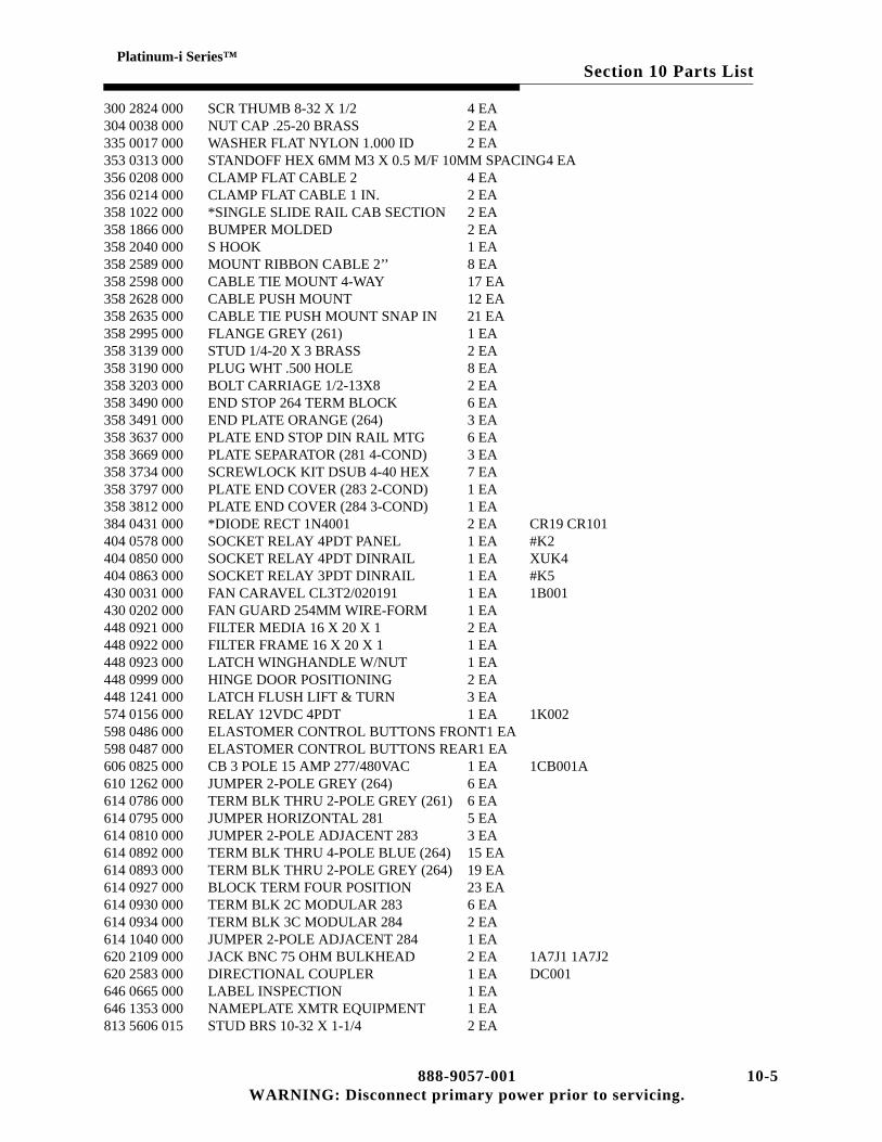
Section 10 Parts ListPlatinum-i Series™
300 2824 000 SCR THUMB 8-32 X 1/2 4 EA304 0038 000 NUT CAP .25-20 BRASS 2 EA335 0017 000 WASHER FLAT NYLON 1.000 ID 2 EA353 0313 000 STANDOFF HEX 6MM M3 X 0.5 M/F 10MM SPACING4 EA356 0208 000 CLAMP FLAT CABLE 2 4 EA356 0214 000 CLAMP FLAT CABLE 1 IN. 2 EA358 1022 000 *SINGLE SLIDE RAIL CAB SECTION 2 EA358 1866 000 BUMPER MOLDED 2 EA358 2040 000 S HOOK 1 EA358 2589 000 MOUNT RIBBON CABLE 2’’ 8 EA358 2598 000 CABLE TIE MOUNT 4-WAY 17 EA358 2628 000 CABLE PUSH MOUNT 12 EA358 2635 000 CABLE TIE PUSH MOUNT SNAP IN 21 EA358 2995 000 FLANGE GREY (261) 1 EA358 3139 000 STUD 1/4-20 X 3 BRASS 2 EA358 3190 000 PLUG WHT .500 HOLE 8 EA358 3203 000 BOLT CARRIAGE 1/2-13X8 2 EA358 3490 000 END STOP 264 TERM BLOCK 6 EA358 3491 000 END PLATE ORANGE (264) 3 EA358 3637 000 PLATE END STOP DIN RAIL MTG 6 EA358 3669 000 PLATE SEPARATOR (281 4-COND) 3 EA358 3734 000 SCREWLOCK KIT DSUB 4-40 HEX 7 EA358 3797 000 PLATE END COVER (283 2-COND) 1 EA358 3812 000 PLATE END COVER (284 3-COND) 1 EA384 0431 000 *DIODE RECT 1N4001 2 EA CR19 CR101404 0578 000 SOCKET RELAY 4PDT PANEL 1 EA #K2404 0850 000 SOCKET RELAY 4PDT DINRAIL 1 EA XUK4404 0863 000 SOCKET RELAY 3PDT DINRAIL 1 EA #K5430 0031 000 FAN CARAVEL CL3T2/020191 1 EA 1B001430 0202 000 FAN GUARD 254MM WIRE-FORM 1 EA448 0921 000 FILTER MEDIA 16 X 20 X 1 2 EA448 0922 000 FILTER FRAME 16 X 20 X 1 1 EA448 0923 000 LATCH WINGHANDLE W/NUT 1 EA448 0999 000 HINGE DOOR POSITIONING 2 EA448 1241 000 LATCH FLUSH LIFT & TURN 3 EA574 0156 000 RELAY 12VDC 4PDT 1 EA 1K002598 0486 000 ELASTOMER CONTROL BUTTONS FRONT1 EA598 0487 000 ELASTOMER CONTROL BUTTONS REAR1 EA606 0825 000 CB 3 POLE 15 AMP 277/480VAC 1 EA 1CB001A610 1262 000 JUMPER 2-POLE GREY (264) 6 EA614 0786 000 TERM BLK THRU 2-POLE GREY (261) 6 EA614 0795 000 JUMPER HORIZONTAL 281 5 EA614 0810 000 JUMPER 2-POLE ADJACENT 283 3 EA614 0892 000 TERM BLK THRU 4-POLE BLUE (264) 15 EA614 0893 000 TERM BLK THRU 2-POLE GREY (264) 19 EA614 0927 000 BLOCK TERM FOUR POSITION 23 EA614 0930 000 TERM BLK 2C MODULAR 283 6 EA614 0934 000 TERM BLK 3C MODULAR 284 2 EA614 1040 000 JUMPER 2-POLE ADJACENT 284 1 EA620 2109 000 JACK BNC 75 OHM BULKHEAD 2 EA 1A7J1 1A7J2620 2583 000 DIRECTIONAL COUPLER 1 EA DC001646 0665 000 LABEL INSPECTION 1 EA646 1353 000 NAMEPLATE XMTR EQUIPMENT 1 EA813 5606 015 STUD BRS 10-32 X 1-1/4 2 EA
888-9057-001 10-5WARNING: Disconnect primary power prior to servicing.

Section 10 Parts ListPlatinum-i Series™
827 6893 001 PLATE 1 EA839 7900 098 GROUND STRAP CAB 1 EA839 7900 261 GND STRAP-CONT CAB 1 EA843 5583 001 WIRING DIA CTRL CAB COMMON 0 DWG843 5583 002 WIRING DIA. CTRL CAB ANALOG 0 DWG843 5583 003 WIRING DIA. CTRL CAB DIGITAL 0 DWG901 0210 011 *PWA CONTROLLER 1 EA 1A3901 0210 020 PWA BUSS TERMINATION 1 EA901 0210 031 *PWA SWITCH BOARD 1 EA9010215141G PWA CAN ADAPTER 1 EA917 2413 412 RAIL CARRIER 3.8 1 EA917 2413 582 RAIL CARRIER 5.7 INCH 2 EA917 2567 003 DIN RAIL CUT LENGTH 108MM 1 EA922 0900 099 EXC/CONT-TOP/BASE TRIM 2 EA922 0900 100 CAB VERTICAL TRIM 2 EA922 0900 121 TRIM MOUNTING PLATE 12 EA922 0900 366 FOAM DOOR LOWER 1 EA922 0900 500 DIN MTG RAIL DUAL TB2 1 EA922 0900 514 SPACER MTG LINE V SAMPLE 4 EA922 1195 012 COVER C.B. BLANK 1 EA922 1297 013 RAIL CABLE SUPPORT 2 EA922 1297 014 BRACKET CABLE SUPPORT 2 EA922 1311 007 FOAM DOOR SIDE 2 EA922 1345 025 CABLE 25 TO 37 PIN INTERFACE 1 EA939 7900 136 COVER - TERMINATOR BD 1 EA939 7900 839 CABLE RETRACTOR 1 EA943 4999 079 FOAM INNER DOOR 1 EA943 4999 105 KICKPLATE FRONT 1 EA943 4999 107 BRK’T SLIDE SUPPORT 2 EA943 4999 765 BRKT MTG LINE V BOX 1 EA943 5275 882 PANEL RIGHT SIDE CONTROL CABINET1 EA943 5275 884 PANEL LEFT SIDE CONTROL CABINET 1 EA943 5275 894 FRONT PANEL TOP 1 EA943 5285 084 BRACKET C.B. TRIPLE 1 EA943 5285 241 BRACKET C.B. PANEL MTG. 2 EA943 5285 257 COVER BASE SAFETY 1 EA943 5285 503 PLATE AC TERM BLOCK MTG 1 EA 1TB1A943 5285 505 COVER AC TERMINAL BLOCK 1 EA943 5494 509 DOOR REAR 1 EA943 5494 510 SKIN REAR DOOR 1 EA943 5494 511 HAT FAN MTG 1 EA943 5576 404 BRACKET EXC RETROFIT 2 EA943 5576 405 UPPER BLANK PANEL 1 EA943 5576 406 MIDDLE BLANK PANEL 1 EA943 5576 407 LOWER BLANK PANEL 1 EA943 5583 005 CABLES RIBBON CTRL CABINET 1 EA943 5583 006 PANEL CB MTG 1 EA943 5583 010 WELDMENT 1 EA943 5583 012 SHELF DISPLAY UNIT 1 EA943 5583 015 PANEL PWA COVER REAR 1 EA943 5583 021 PANEL SILKSCREEN DIGITAL 1 EA943 5583 029 BASE PLATE CONTROL CAB 1 EA943 5583 030 COVER I/O PANEL 1 EA943 5583 033 BRACKET UPS HOLDING 1 EA
10-6 888-9057-001WARNING: Disconnect primary power prior to servicing.

Section 10 Parts ListPlatinum-i Series™
943 5583 034 SPACER HINGE 1 EA943 5583 035 HINGE DISPLAY DOOR 1 EA943 5583 037 PANEL I/O 1 EA943 5583 043 SHELF UPS 1 EA943 5583 045 COVER CIRCUIT BREAKER PANEL 1 EA943 5583 046 STANDOFF ISOLATOR 2 EA943 5583 048 BRACKET MOV BD 1 EA943 5583 058 GROUND STRAP I/O PANEL 1 EA943 5583 059 PATENT LABEL- PLATINUM SERIES INTELLIGENT XMTR1 EA943 5583 078 BRACKET UPS HOLDING RIGHT 1 EA943 5583 098 PANEL CONTROL INNER 1 EA943 5583 099 PANEL CONTROL 1 EA943 5583 100 PANEL STOP 2 EA943 9153 012 LABEL CONTROL CAB REAR 1 EA952 9242 004 CABLE DRIVER BASE 1 EA952 9242 007 CABLE ACC TRAY DIGITAL 1 EA952 9242 011 CABLE MAINS BREAKER 1 EA952 9242 015 CABLE DIGITAL RF CABLE 1 EA952 9242 017 CABLE CONRTOL 1 EA971 0004 009 *ASSY DISPLAY UNIT W/ GUI 1 EA971 0030 032 P/S 12V 15A PS2 1 EA PS2A971 0030 033 P/S TRIPPLE OUTPUT PS1 1 EA PS1A992 8009 007 ASSY ACC TRAY 10 SLOT 1 EA992 9104 002 ASSY POWER SUPPLY GATING 1 EA A9994 8935 002 BASIC LINE VOLTAGE SAMPLE 3 EA 1A008402 0107 000 CLIP FUSE 0.562DIA 1 EA556 0075 000 *ATTEN BNC 20DB 2W 50 OHM 1 EA
Table 10-4 *ASSY DISPLAY UNIT W/ GUI - 971 0004 009 (A)Harris PN Description Qty UM Reference Designators746 0308 000 LCD DISPLAY 12 VGA COLOR 1 EA971 0004 002 DISPLAY UNIT/MINUS GUI 1 EA
Table 10-5 P/S 12V 15A PS2 - 971 0030 032 (C)Harris PN Description Qty UM Reference Designators560 0049 000 *MOV 275WVAC 75J 14MM DISC 1 EA736 0285 000 PSU LINEAR SINGLE 12/15VDC 1 EA843 5583 028 WIRING DIAGRAM 0 DWG952 9242 001 CABLE POWER SUP PS2 1 EA
Table 10-6 P/S TRIPPLE OUTPUT PS1 - 971 0030 033 (C)Harris PN Description Qty UM Reference Designators560 0049 000 *MOV 275WVAC 75J 14MM DISC 1 EA736 0280 000 PSU LINEAR TRIPLE OUTPUT 1 EA843 5583 027 WIRING DIAGRAM 0 DWG952 9242 003 CABLE POWER SUP PS1 1 EA
Table 10-7 ASSY ACC TRAY 10 SLOT - 992 8009 007 (C)Harris PN Description Qty UM Reference Designators306 0014 000 NUT STOP 1/4-20 2 EA312 0075 000 WASHER SPRING 1/4 6 EA358 1021 001 SLIDE DRAWER 2 EA358 1866 000 BUMPER MOLDED 2 EA
888-9057-001 10-7WARNING: Disconnect primary power prior to servicing.

Section 10 Parts ListPlatinum-i Series™
358 2105 000 CARD GUIDE 20 EA822 0900 244 LOCK FRONT PANEL-ACCESS 2 EA939 7900 105 HINGE MODULE LEFT 1 EA939 7900 106 HINGE MODULE RIGHT 1 EA939 8106 412 NAMEPLATE 10 SLOT ACC TRAY 1 EA943 4999 087 BLANK 19.0 EXTRUSION 1 EA943 4999 098 SIDE PANEL - ACCESSORY 1 EA943 4999 099 SIDE PANEL - ACCESSORY 1 EA943 4999 107 BRK’T SLIDE SUPPORT 0 EA943 4999 579 TOP PNL ACCESS CAGE 10 1 EA943 4999 580 BOT PNL ACCESS CAGE 10 1 EA943 5275 207 REAR PNL ACC TRAY 10 SLOT 1 EA952 9200 108 BLANK TRAY ASSY 10 SLOT 0 EA992 8012 011 MODULE AGC LOW BAND W/GAIN 0 EA992 8012 012 MODULE AGC HIGH BAND W/GAIN 0 EA992 8013 002 EXC SW MOD ACC TRAY 10 0 EA992 9549 001 ASSY PH/GAIN CH-4 5 6 0 EA992 9549 002 ASSY VHF HB PHASE & GAIN 0 EA
Table 10-8 ASSY POWER SUPPLY GATING - 992 9104 002 (A)Harris PN Description Qty UM Reference Designators384 0610 000 LED GRN T1-3/4 VERT 8 EA DS001 DS002 DS003 DS004 DS005
DS006 DS007 DS008384 0763 000 RECT SCHOTTKY 1045 ESD 8 EA CR001 CR002 CR003 CR004 CR005
CR006 CR007 CR008404 0842 000 *HEATSINK TO220 8 EA CR002 CR003 CR004 CR005 CR006
CR007 CR008*410 0405 000 THERMAL INTERFACE TO220 8 EA CR002 CR003 CR004 CR005 CR006
CR007 CR008*548 2400 301 RES 1K OHM 1/2W 1% 2 EA R003 R004548 2400 337 RES 2.37K OHM 1/2W 1% 6 EA R001 R002 R005 R006 R007 R008610 1066 000 CONN .25 FASTON PC MOUNT 13 EA843 5460 131 SCH POWER SUPPLY GATING 0 DWG843 5460 133 PWB POWER SUPPLY GATING 1 EA
Table 10-9 BASIC LINE VOLTAGE SAMPLE - 994 8935 002 (E)Harris PN Description Qty UM Reference Designators358 0976 000 BUSHING STRAIN RELI 1 EA384 0431 000 *DIODE RECT 1N4001 1 EA CR001398 0039 000 FUSE SLOW CART .100A 250V 1 EA F001402 0129 000 CLIP 1/4 DIA FUSE 2 EA XF001472 1597 000 XFMR PWR 16V 70MA 2 EA T001 T002522 0555 000 *CAP 100UF 50V 20% (8X11.5) 1 EA C001548 2400 281 RES 681 OHM 1/2W 1% 1 EA R001548 2400 347 RES 3.01K OHM 1/2W 1% 1 EA R002548 2400 393 RES 9.09K OHM 1/2W 1% 1 EA R003614 0772 000 TERM STRIP 6 TERM 1 EA TB001614 0909 000 TERM STRIP 3C PCB MODULAR 237 1 EA TB002646 0665 000 LABEL INSPECTION 1 EA839 9291 001 PWB LINE V SAMPLE 1 EA839 9295 001 TOP COVER 1 EA839 9297 001 SCHEM LINE VOLT SAMPLE 0 DWG939 9293 001 CHASSIS BTM 1 EA999 2461 001 HARDWARE LIST 1 EA
10-8 888-9057-001WARNING: Disconnect primary power prior to servicing.

Section 10 Parts ListPlatinum-i Series™
Table 10-10 RF PA MODULE ASSY - 992 8969 000 (A)Harris PN Description Qty UM Reference Designators992 8969 002 MOD PA CH-2 TUNED 0 EA992 8969 003 MOD PA CH-3 TUNED 0 EA992 8969 004 MOD PA CH-4 TUNED 0 EA992 8969 005 MOD PA CH-5 TUNED 0 EA992 8969 006 MOD PA CH-6 TUNED 0 EA992 8969 007 MODULE PA CH-7 TUNED 0 EA992 8969 008 MODULE PA CH-8 TUNED 0 EA992 8969 009 MODULE PA CH-9 TUNED 0 EA992 8969 010 MODULE PA CH-10 TUNED 0 EA992 8969 011 MODULE PA CH-11 TUNED 0 EA992 8969 012 MODULE PA CH-12 TUNED 0 EA992 8969 013 MODULE PA CH-13 TUNED 0 EA992 8969 102 MOD PA CH-E2 TUNED 0 EA992 8969 103 MOD PA CH-E3 TUNED 0 EA992 8969 104 MOD PA CH-E4 TUNED 0 EA992 8969 105 MODULE PA CH-E5 TUNED 0 EA992 8969 106 MODULE PA CH-E6 TUNED 0 EA992 8969 107 MODULE PA CH-E7 TUNED 0 EA992 8969 108 MODULE PA CH-E8 TUNED 0 EA992 8969 109 MODULE PA CH-E9 TUNED 0 EA992 8969 110 MODULE PA CH-E10 TUNED 0 EA992 8969 111 MODULE PA CH-E11 TUNED 0 EA992 8969 112 MODULE PA CH-E12 TUNED 0 EA
Table 10-11 MOD PA CH-2 TUNED - 992 8969 002 (A)Harris PN Description Qty UM Reference Designators817 2100 744 TEST REQUIREMENTS MODULE 0 DWG992 8960 002 MOD 1/4 PA/DR CH-2 TUNED 4 EA A001 A002 A003 A004992 8966 001 MODULE RF BASIC PA LB1 1 EA
Table 10-12 MOD 1/4 PA/DR CH-2 TUNED - 992 8960 002 (J1)Harris PN Description Qty UM Reference Designators2520420000A WIRE RIBBON SILVER 0.005 X 0.100 0 FT #AT001519 0036 000 <*>CAP RF CHIP 27PF 5% 500V 2 EA C023 C033519 0060 000 <*>CAP RF CHIP 270PF 5% 200V 10 EA C008 C019 C005A C011A C016A C022A
C005B C011B C016B C022B548 2400 330 RES 2K OHM 1/2W 1% 4 EA R021 R022 R023 R024817 2100 741 TEST REQ LB 1/4 MOD 0 DWG839 7900 701 SCH LB 1/4 MODULE 0 DWG917 2100 612 ATTENUATOR SELECT IN TEST 1 EA AT001917 2100 644 INDUCTOR OUTPUT LOOP 4 EA L005 L006 L007 L008917 2100 710 INDUCTOR FEED BACK 20T 4 EA L001 L002 L003 L004917 2442 001 COAX INPUT PHASE MATCH 1 EA992 8958 001 MOD 1/4 BASIC LB 1 EA
Table 10-13 MOD 1/4 BASIC LB - 992 8958 001 (H)Harris PN Description Qty UM Reference Designators550190009 *RTV SILICONE CLEAR DOW 3140 0 EA #T009860001010 *SEALANT GLYPTOL RED 0 QT860004055 SOLDER SN62/PB36/AG2 0.032 0 EA
888-9057-001 10-9WARNING: Disconnect primary power prior to servicing.

Section 10 Parts ListPlatinum-i Series™
302 0053 000 SCREW PHMS 4-40 X 5/16 SST 2 EA302 0132 000 SCR 8-32 X 5/8 2 EA302 0401 000 SCREW SHMS 4-40 X 1/4 SST 2 EA #R015 #RT001302 0814 004 SCREW SEMS PPHMS 4-40 X 1/4 8 EA310 0006 000 WASHER FLAT #8 SST (ANSI NARROW)2 EA310 0016 000 *WASHER FLAT #4 SST (NON-ANSI) 1 EA #RT001314 0003 000 LOCKWASHER SPLIT #4 SST (ANSI) 2 EA314 0006 000 LOCKWASHER SPLIT #8 SST (ANSI) 2 EA314 0037 000 WASHER SPLIT-LOCK 4 SS 2 EA #R015 #RT001356 0235 000 CABLE TIE 0.75 DIA. 18 EA358 3435 000 LEVELER RF FET 4 EA #Q001 Q002 Q003 Q004358 3436 000 SPACER 0.305 LONG 2 EA358 3438 000 SPRING LEAF 2 EA404 0818 000 HEATSINK 1/4 MODULE 1 EA414 0286 000 TOROID FERRITE 10 EA414 0287 000 TOROID FERRITE 20 EA548 2332 000 RES 200 OHM 2W 5% 1 EA R005646 0665 000 LABEL INSPECTION 1 EA700 1252 000 RES 200 OHM 10W 5% FLANGED 1 EA R015839 7900 701 SCH LB 1/4 MODULE 0 DWG843 4999 644 FAMILY TREE LB PA MOD 0 DWG843 4999 645 FAMILY TREE LB DRIVER 0 DWG917 2100 331 TRIMMED COAX 5.9 4 EA917 2100 332 TRIMMED COAX 2.9 4 EA917 2100 334 TRIMMED COAX 3.85 4 EA917 2100 619 TRIMMED COAX 4 EA #T006 T007917 2100 682 MOSFET RF PWR ON4402H ESD 4 EA Q001 Q002 Q003 Q004943 5140 013 BRACKET MTG 2 EA992 8608 001 THERMISTOR ASSEMBLY 1 EA RT001992 8956 001 PWA 1/4 MOD LB RF 1 EA
Table 10-14 MODULE RF BASIC PA LB1 - 992 8966 001 (J)Harris PN Description Qty UM Reference Designators74060079 BRZ FGR STK CLIP ON REV BEND 0.25 EA540014103 CARTON SHIPPING 0 EA540014107 INSERT FOAM PACKAGING 0 ST2520420000A WIRE RIBBON SILVER 0.005 X 0.100 0.4 FT252 0423 000 TEFLON INSULATED HOOK-UP 2 FT302 0052 000 SCREW PHMS 4-40 X 1/4 SST 8 EA302 0053 000 SCREW PHMS 4-40 X 5/16 SST 3 EA302 0054 000 SCREW PHMS 4-40 X 3/8 SST 4 EA302 0106 000 SCR 6-32 X 3/8 2 EA302 0108 000 SCR 6-32 X 1/2 10 EA302 0364 000 SCREW FHMS 4-40 X 3/16 SST 6 EA302 0378 000 SCREW FHMS 4-40 X 3/4 SST 4 EA302 0380 000 SCR 6-32 X 5/16 11 EA302 0401 000 SCREW SHMS 4-40 X 1/4 SST 6 EA302 0661 000 SCREW FHMS 4-40 X 1/4 SST 3 EA306 0003 000 NUT HEX 4-40 10 EA306 0004 000 NUT HEX 6-32 4 EA306 0071 000 NUT HEX #6-32 UNDERSIZE 16 EA306 0072 000 NUT HEX #4-40 UNDERSIZE 3 EA310 0003 000 WASHER FLAT #4 SST (ANSI NARROW)18 EA
10-10 888-9057-001WARNING: Disconnect primary power prior to servicing.

Section 10 Parts ListPlatinum-i Series™
310 0012 000 WASHER FLAT #6 SST (ANSI NARROW)30 EA310 0017 000 WASHER FLAT #6 SST (NON-ANSI) 7 EA312 0006 000 WASHER INT LOCK 8 5 EA314 0003 000 LOCKWASHER SPLIT #4 SST (ANSI) 21 EA314 0005 000 LOCKWASHER SPLIT #6 SST (ANSI) 44 EA314 0037 000 WASHER SPLIT-LOCK 4 SS 9 EA336 1239 000 SCREW ROLL PPH 6-32 X 3/8 12 EA344 0009 000 SETSCREW 8-32 X 3/16 STEEL (CUP) 2 EA350 0105 000 RIVET 3/16 ALUM .126/.25 4 EA350 0155 000 RIVET POP .156 X .392 10 EA354 0386 000 TERM LOCKING #10 RING 1 EA356 0235 000 CABLE TIE 0.75 DIA. 20 EA356 0237 000 CLAMP CABLE 1/4 DIA 1 EA356 0241 000 CABLE CLAMP TIE 6 EA358 1214 000 SCREWLOCK M/F 4-40X3/16 1 EA380 0715 000 XSTR MOSFET IXTH67N10 ESD 2 EA Q001 Q002384 0831 000 LED LIGHT BAR MOUNT ESD 2 EA386 0438 000 *ZENER 1N5243B 13V 5% 0.5W 1 EA CR001410 0335 000 WASHER SHLDR 0.115 ID NYLON 1 EA410 0413 000 THERMAL INTERFACE TO-247 3 EA410 0414 000 THERMAL PAD 1.000 X .800 2 EA414 0292 000 CORE BALUN 2500 PERM 4 EA L014 L015 L016 L017424 0013 000 GROMMET 0.381 GROOVE DIA 1 EA424 0598 000 BUSHING SPLIT GUIDE PIN 2 EA508 0560 000 CAP FEEDTHRU 1000PF 5 EA C001 C002 C003 C004 C005508 0561 000 EMI FILTER FEEDTHRU 2 EA FL001 FL002516 0417 000 CAP 1000PF 10% 200V X7R CK05 2 EA C023 C028516 0831 000 CAP 0.010UF 10% 100V X7R CK05 4 EA C024 C025 C026 C027519 0011 000 <*>CAP RF CHIP 2.4PF +-.25PF 500V 1 EA544 1654 000 RES 100 OHM 250W 5% FLANGED 3 EA544 1660 000 RES 100 OHM 20W 2% FLANGED 3 EA548 2400 073 RES 5.62 OHM 1/2W 1% 2 EA R001 R002610 1222 000 PLUG/RECP D 25 PIN 1 EA646 0665 000 LABEL INSPECTION 1 EA646 1519 000 LABEL WARNING RF RADIATION 1 EA843 4999 528 PWB PASS FET GATE BIAS 1 EA843 4999 637 SCH PA MODULE 0 DWG843 4999 644 FAMILY TREE LB PA MOD 0 DWG917 2100 146 TAPE SWITCH ASSY 1 EA917 2100 386 CABLE LED BOARD 1 EA917 2100 627 CABLE ASSEMBLY DC FEED 1 EA917 2100 747 MAIN I/O CONN ASSY 1 EA939 7900 054 EXTRUSION FLAPPER 1 EA943 4999 084 MODULE FACE EXTRUSION 1 EA943 4999 454 MODULE FRONT PANEL 1 EA943 4999 456 MODULE COVER 1 EA943 4999 518 BUSS BAR DC (VERTICAL) 2 EA943 4999 526 INSULATOR BUSS BAR 3 EA943 4999 585 ANGLE HEATSINK MOUNTING 2 EA943 4999 650 CHASSIS MODULE 1 EA943 4999 651 LOGIC CHASSIS 1 EA943 4999 652 LOGIC COVER 1 EA943 4999 653 CABLE MODULE MAIN 1 EA943 5140 015 SPACER INSULATOR 2 EA
888-9057-001 10-11WARNING: Disconnect primary power prior to servicing.

Section 10 Parts ListPlatinum-i Series™
992 8023 001 PWA LED BOARD 1 EA A0079928127002T PWA LOGIC/CONTROL TESTED 1 EA A002992 8557 102 DIVIDER 2-WAY LB1 1 EA A003992 8558 102 COMB LB1 2 X 2 WAY 1 EA A006992 8559 102 COMB LB1 2-WAY 1 EA A005992 8560 102 DIVIDER LB1 2 X 2 WAY 1 EA A004992 8976 001 COUPLER ASSY LB MODULE 1 EA A001992 9018 001 RF PLUG ASSY 1 EA J001
Table 10-15 MOD PA CH-3 TUNED - 992 8969 003 (A)Harris PN Description Qty UM Reference Designators817 2100 744 TEST REQUIREMENTS MODULE 0 DWG992 8960 003 MOD 1/4 PA/DR CH3 TUNED 4 EA A001 A002 A003 A004992 8966 001 MODULE RF BASIC PA LB1 1 EA
Table 10-16 MOD 1/4 PA/DR CH3 TUNED - 992 8960 003 (H1)Harris PN Description Qty UM Reference Designators2520420000A WIRE RIBBON SILVER 0.005 X 0.100 0 FT #AT001519 0038 000 <*>CAP RF CHIP 33PF 5% 500V 2 EA C023 C033519 0052 000 <*>CAP RF CHIP 120PF 5% 300V 2 EA C008 C019519 0060 000 <*>CAP RF CHIP 270PF 5% 200V 8 EA C005A C011A C016A C022A C005B
C011B C016B C022B548 2400 277 RES 619 OHM 1/2W 1% 4 EA R021 R022 R023 R024817 2100 741 TEST REQ LB 1/4 MOD 0 DWG839 7900 701 SCH LB 1/4 MODULE 0 DWG917 2100 612 ATTENUATOR SELECT IN TEST 1 EA AT001917 2100 646 OUTPUT INDUCT. LOOP 1.8 4 EA L005 L006 L007 L008917 2100 711 INDUCTOR FEEDBACK 13T 4 EA L001 L002 L003 L004917 2442 001 COAX INPUT PHASE MATCH 1 EA992 8958 001 MOD 1/4 BASIC LB 1 EA
Table 10-17 MOD PA CH-4 TUNED - 992 8969 004 (A)Harris PN Description Qty UM Reference Designators817 2100 744 TEST REQUIREMENTS MODULE 0 DWG992 8960 004 MOD 1/4 PA/DR CH4 TUNED 4 EA A001 A002 A003 A004992 8967 001 MODULE RF BASIC PA LB2 1 EA
Table 10-18 MOD 1/4 PA/DR CH4 TUNED - 992 8960 004 (G1)Harris PN Description Qty UM Reference Designators2520420000A WIRE RIBBON SILVER 0.005 X 0.100 0 FT #AT001519 0041 000 <*>CAP RF CHIP 43PF 5% 500V 2 EA C023 C033519 0052 000 <*>CAP RF CHIP 120PF 5% 300V 2 EA C008 C019519 0060 000 <*>CAP RF CHIP 270PF 5% 200V 8 EA C005A C011A C016A C022A C005B
C011B C016B C022B548 2400 277 RES 619 OHM 1/2W 1% 4 EA R021 R022 R023 R024817 2100 741 TEST REQ LB 1/4 MOD 0 DWG839 7900 701 SCH LB 1/4 MODULE 0 DWG917 2100 612 ATTENUATOR SELECT IN TEST 1 EA AT001917 2100 648 OUTPUT INDUCTOR LOOP 1.7 4 EA L005 L006 L007 L008917 2100 711 INDUCTOR FEEDBACK 13T 4 EA L001 L002 L003 L004917 2442 001 COAX INPUT PHASE MATCH 1 EA992 8958 001 MOD 1/4 BASIC LB 1 EA
10-12 888-9057-001WARNING: Disconnect primary power prior to servicing.

Section 10 Parts ListPlatinum-i Series™
Table 10-19 MODULE RF BASIC PA LB2 - 992 8967 001 (J)Harris PN Description Qty UM Reference Designators74060079 BRZ FGR STK CLIP ON REV BEND 0.25 EA540014103 CARTON SHIPPING 0 EA540014107 INSERT FOAM PACKAGING 0 ST2520420000A WIRE RIBBON SILVER 0.005 X 0.100 0.4 FT252 0423 000 TEFLON INSULATED HOOK-UP 2 FT302 0052 000 SCREW PHMS 4-40 X 1/4 SST 8 EA302 0053 000 SCREW PHMS 4-40 X 5/16 SST 3 EA302 0054 000 SCREW PHMS 4-40 X 3/8 SST 4 EA302 0106 000 SCR 6-32 X 3/8 5 EA302 0108 000 SCR 6-32 X 1/2 10 EA302 0364 000 SCREW FHMS 4-40 X 3/16 SST 6 EA302 0378 000 SCREW FHMS 4-40 X 3/4 SST 4 EA302 0380 000 SCR 6-32 X 5/16 11 EA302 0401 000 SCREW SHMS 4-40 X 1/4 SST 6 EA302 0661 000 SCREW FHMS 4-40 X 1/4 SST 3 EA306 0003 000 NUT HEX 4-40 10 EA306 0004 000 NUT HEX 6-32 4 EA306 0071 000 NUT HEX #6-32 UNDERSIZE 16 EA306 0072 000 NUT HEX #4-40 UNDERSIZE 3 EA310 0003 000 WASHER FLAT #4 SST (ANSI NARROW)18 EA310 0012 000 WASHER FLAT #6 SST (ANSI NARROW)30 EA310 0017 000 WASHER FLAT #6 SST (NON-ANSI) 7 EA312 0006 000 WASHER INT LOCK 8 5 EA314 0003 000 LOCKWASHER SPLIT #4 SST (ANSI) 21 EA314 0005 000 LOCKWASHER SPLIT #6 SST (ANSI) 44 EA314 0037 000 WASHER SPLIT-LOCK 4 SS 9 EA336 1239 000 SCREW ROLL PPH 6-32 X 3/8 12 EA344 0009 000 SETSCREW 8-32 X 3/16 STEEL (CUP) 2 EA350 0105 000 RIVET 3/16 ALUM .126/.25 4 EA350 0155 000 RIVET POP .156 X .392 10 EA354 0386 000 TERM LOCKING #10 RING 1 EA356 0235 000 CABLE TIE 0.75 DIA. 20 EA356 0237 000 CLAMP CABLE 1/4 DIA 1 EA356 0241 000 CABLE CLAMP TIE 6 EA358 1214 000 SCREWLOCK M/F 4-40X3/16 1 EA380 0715 000 XSTR MOSFET IXTH67N10 ESD 2 EA Q001 Q002384 0831 000 LED LIGHT BAR MOUNT ESD 2 EA386 0438 000 *ZENER 1N5243B 13V 5% 0.5W 1 EA CR001410 0335 000 WASHER SHLDR 0.115 ID NYLON 1 EA410 0413 000 THERMAL INTERFACE TO-247 3 EA410 0414 000 THERMAL PAD 1.000 X .800 2 EA414 0292 000 CORE BALUN 2500 PERM 4 EA L014 L015 L016 L017424 0013 000 GROMMET 0.381 GROOVE DIA 1 EA424 0598 000 BUSHING SPLIT GUIDE PIN 2 EA508 0560 000 CAP FEEDTHRU 1000PF 5 EA C001 C002 C003 C004 C005508 0561 000 EMI FILTER FEEDTHRU 2 EA FL001 FL002516 0417 000 CAP 1000PF 10% 200V X7R CK05 2 EA C023 C028516 0831 000 CAP 0.010UF 10% 100V X7R CK05 4 EA C024 C025 C026 C027519 0011 000 <*>CAP RF CHIP 2.4PF +-.25PF 500V 1 EA544 1654 000 RES 100 OHM 250W 5% FLANGED 3 EA544 1660 000 RES 100 OHM 20W 2% FLANGED 3 EA548 2400 073 RES 5.62 OHM 1/2W 1% 2 EA R001 R002
888-9057-001 10-13WARNING: Disconnect primary power prior to servicing.

Section 10 Parts ListPlatinum-i Series™
610 1222 000 PLUG/RECP D 25 PIN 1 EA646 0665 000 LABEL INSPECTION 1 EA646 1519 000 LABEL WARNING RF RADIATION 1 EA843 4999 528 PWB PASS FET GATE BIAS 1 EA843 4999 637 SCH PA MODULE 0 DWG843 4999 644 FAMILY TREE LB PA MOD 0 DWG917 2100 146 TAPE SWITCH ASSY 1 EA917 2100 386 CABLE LED BOARD 1 EA917 2100 627 CABLE ASSEMBLY DC FEED 1 EA917 2100 747 MAIN I/O CONN ASSY 1 EA939 7900 054 EXTRUSION FLAPPER 1 EA943 4999 084 MODULE FACE EXTRUSION 1 EA943 4999 454 MODULE FRONT PANEL 1 EA943 4999 456 MODULE COVER 1 EA943 4999 518 BUSS BAR DC (VERTICAL) 2 EA943 4999 526 INSULATOR BUSS BAR 3 EA943 4999 585 ANGLE HEATSINK MOUNTING 2 EA943 4999 650 CHASSIS MODULE 1 EA943 4999 651 LOGIC CHASSIS 1 EA943 4999 652 LOGIC COVER 1 EA943 4999 653 CABLE MODULE MAIN 1 EA943 5140 015 SPACER INSULATOR 2 EA992 8023 001 PWA LED BOARD 1 EA A0079928127002T PWA LOGIC/CONTROL TESTED 1 EA A002992 8557 104 DIVIDER LB2 2-WAY SSTV 1 EA A003992 8558 104 COMB LB2 2X2 WAY SSTV 1 EA A006992 8559 104 COMB LB2 2-WAY SSTV 1 EA A005992 8560 104 DIVIDER LB2 2X2 WAY 1 EA A004992 8976 001 COUPLER ASSY LB MODULE 1 EA A001992 9018 001 RF PLUG ASSY 1 EA J001
Table 10-20 MOD PA CH-5 TUNED - 992 8969 005 (A)Harris PN Description Qty UM Reference Designators817 2100 744 TEST REQUIREMENTS MODULE 0 DWG992 8960 005 MOD 1/4 PA/DR CH5 TUNED 4 EA A001 A002 A003 A004992 8967 001 MODULE RF BASIC PA LB2 1 EA
Table 10-21 MOD 1/4 PA/DR CH5 TUNED - 992 8960 005 (G1)Harris PN Description Qty UM Reference Designators2520420000A WIRE RIBBON SILVER 0.005 X 0.100 0 FT #AT001519 0041 000 <*>CAP RF CHIP 43PF 5% 500V 2 EA C023 C033519 0052 000 <*>CAP RF CHIP 120PF 5% 300V 2 EA C008 C019519 0066 000 <*>CAP RF CHIP 470PF 5% 200V 4 EA C005A C011A C016A C022A548 2400 277 RES 619 OHM 1/2W 1% 4 EA R21 R22 R23 R24817 2100 741 TEST REQ LB 1/4 MOD 0 DWG839 7900 701 SCH LB 1/4 MODULE 0 DWG917 2100 612 ATTENUATOR SELECT IN TEST 1 EA AT001917 2100 649 OUTPUT INDUC. LOOP 1.25 4 EA L005 L006 L007 L008917 2100 711 INDUCTOR FEEDBACK 13T 4 EA L001 L002 L003 L004917 2442 001 COAX INPUT PHASE MATCH 1 EA992 8958 001 MOD 1/4 BASIC LB 1 EA
10-14 888-9057-001WARNING: Disconnect primary power prior to servicing.

Section 10 Parts ListPlatinum-i Series™
Table 10-22 MOD PA CH-6 TUNED - 992 8969 006 (A)Harris PN Description Qty UM Reference Designators817 2100 744 TEST REQUIREMENTS MODULE 0 DWG992 8960 006 MOD 1/4 PA/DR CH6 TUNED 4 EA A001 A002 A003 A004992 8967 001 MODULE RF BASIC PA LB2 1 EA
Table 10-23 MOD 1/4 PA/DR CH6 TUNED - 992 8960 006 (G1)Harris PN Description Qty UM Reference Designators2520420000A WIRE RIBBON SILVER 0.005 X 0.100 0 FT #AT001519 0041 000 <*>CAP RF CHIP 43PF 5% 500V 2 EA C023 C033519 0052 000 <*>CAP RF CHIP 120PF 5% 300V 2 EA C008 C019519 0060 000 <*>CAP RF CHIP 270PF 5% 200V 8 EA C005A&B C011A&B C016A&B
C022A&B548 2400 277 RES 619 OHM 1/2W 1% 4 EA R021 R022 R023 R024817 2100 741 TEST REQ LB 1/4 MOD 0 DWG839 7900 701 SCH LB 1/4 MODULE 0 DWG917 2100 612 ATTENUATOR SELECT IN TEST 1 EA AT001917 2100 650 OUTPUT INDUCTOR LOOP 1.1 4 EA L005 L006 L007 L008917 2100 711 INDUCTOR FEEDBACK 13T 4 EA L001 L002 L003 L004992 8958 001 MOD 1/4 BASIC LB 1 EA
Table 10-24 MODULE PA CH-7 TUNED - 992 8969 007 (A)Harris PN Description Qty UM Reference Designators817 2100 744 TEST REQUIREMENTS MODULE 0 DWG992 8960 007 MOD 1/4 PA/DR CH-7 TUNED 4 EA992 8968 001 MODULE RF BASIC PA HB 1 EA
Table 10-25 MOD 1/4 PA/DR CH-7 TUNED - 992 8960 007 (C1)Harris PN Description Qty UM Reference Designators2520420000A WIRE RIBBON SILVER 0.005 X 0.100 0 FT L007519 0021 000 <*>CAP RF CHIP 6.2PF +-.25PF 500V 2 EA C037 C038519 0028 000 <*>CAP RF CHIP 12PF 5% 500V 1 EA C008519 0042 000 <*>CAP RF CHIP 47PF 5% 500V 4 EA C004 C005 C006 C007519 0049 000 <*>CAP RF CHIP 91PF 5% 500V 2 EA C002 C003817 2100 742 TEST REQ HB 1/4 MOD 0 DWG839 7900 702 SCH HB 1/4 MODULE 0 DWG917 2100 542 LOOP INDUCTOR 2T 1 EA L008917 2100 544 BALUN SEMI-RIGID 11.00 2 EA T003 T004917 2100 545 COAX TRIM 11.00 4 EA917 2100 612 ATTENUATOR SELECT IN TEST 1 EA AT1917 2442 001 COAX INPUT PHASE MATCH 1 EA TL1992 8959 001 MOD 1/4 BASIC HB 1 EA
Table 10-26 MOD 1/4 BASIC HB - 992 8959 001 (J)Harris PN Description Qty UM Reference Designators550190009 *RTV SILICONE CLEAR DOW 3140 0 EA860001010 *SEALANT GLYPTOL RED 0 QT860004055 SOLDER SN62/PB36/AG2 0.032 0 EA2520420000A WIRE RIBBON SILVER 0.005 X 0.100 0.2 FT254 0055 000 WIRE 16AWG SOLID 600V 1 FT L001 L002 L003 L004302 0053 000 SCREW PHMS 4-40 X 5/16 SST 2 EA302 0132 000 SCR 8-32 X 5/8 2 EA302 0401 000 SCREW SHMS 4-40 X 1/4 SST 2 EA #R011 #RT001
888-9057-001 10-15WARNING: Disconnect primary power prior to servicing.

Section 10 Parts ListPlatinum-i Series™
302 0814 004 SCREW SEMS PPHMS 4-40 X 1/4 8 EA310 0006 000 WASHER FLAT #8 SST (ANSI NARROW)2 EA310 0016 000 *WASHER FLAT #4 SST (NON-ANSI) 1 EA #RT001314 0003 000 LOCKWASHER SPLIT #4 SST (ANSI) 2 EA314 0006 000 LOCKWASHER SPLIT #8 SST (ANSI) 2 EA314 0037 000 WASHER SPLIT-LOCK 4 SS 2 EA #R011 #RT001356 0235 000 CABLE TIE 0.75 DIA. 4 EA358 3435 000 LEVELER RF FET 4 EA #Q001 Q002 Q003 Q004358 3436 000 SPACER 0.305 LONG 2 EA358 3438 000 SPRING LEAF 2 EA404 0818 000 HEATSINK 1/4 MODULE 1 EA519 0080 000 CAP RF CHIP 220PF 10% 4 EA C013 C015 C017 C019540 1600 101 RES 10 OHM 3W 5% 4 EA R003 R004 R005 R006544 1661 000 RES 100 OHM 10W 5% FLANGED 1 EA R011548 2332 000 RES 200 OHM 2W 5% 2 EA R001A R001B646 0665 000 LABEL INSPECTION 1 EA839 7900 702 SCH HB 1/4 MODULE 0 DWG843 4999 643 FAMILY TREE HB PA MOD 0 DWG843 4999 646 FAMILY TREE HB DRIVER 0 DWG917 2100 682 MOSFET RF PWR ON4402H ESD 4 EA Q001 Q002 Q003 Q004943 5140 013 BRACKET MTG 2 EA992 8608 001 THERMISTOR ASSEMBLY 1 EA RT001992 8957 001 PWA 1/4 MOD HB RF 1 EA
Table 10-27 PWA 1/4 MOD HB RF - 992 8957 001 (F-)Harris PN Description Qty UM Reference Designators254 0001 000 BUS WIRE 22AWG SOLID TINNED CU 0.1 FT #L010296 0310 000 TUBING TEFLON 20AWG THIN WALL 0.1 FT #L010358 3288 000 POWER TAP PC MOUNT 25AMP 1 EA TB001384 0843 000 DIODE 1N4154 ESD 1 EA CR001516 0417 000 CAP 1000PF 10% 200V X7R CK05 6 EA C025 C026 C027 C028 C033 C043516 0484 000 CAP 0.100UF 10% 100V X7R CK06 2 EA C029 C030516 0831 000 CAP 0.010UF 10% 100V X7R CK05 7 EA C021 C022 C023 C024 C042 C044 C045516 0890 000 *CAP 470PF 10% 200V C0G 4 EA C009 C011 C034 C035524 0375 000 CAP 100UF 63V 20% 105C 2 EA C031 C032548 2400 166 RES 47.5 OHM 1/2W 1% 1 EA R012548 2400 201 RES 100 OHM 1/2W 1% 1 EA R013548 2400 283 RES 715 OHM 1/2W 1% 1 EA R015548 2400 309 RES 1.21K OHM 1/2W 1% 4 EA R007 R008 R009 R010548 2400 318 RES 1.5K OHM 1/2W 1% 1 EA R014548 2400 322 RES 1.65K OHM 1/2W 1% 1 EA R016548 2400 330 RES 2K OHM 1/2W 1% 1 EA R017548 2400 343 RES 2.74K OHM 1/2W 1% 4 EA R024 R025 R026 R027548 2400 468 RES 49.9K OHM 1/2W 1% 2 EA R022 R023550 0913 000 POT 5K OHM 1/2W 10% 4 EA R018 R019 R020 R021550 0957 000 TRIMPOT 500 OHM 1/2W 10% 1 EA R002610 1223 000 HEADER 3 POSITION 1 EA J001817 2350 417 SPEC LABEL S/N ASSY 0 DWG839 7900 702 SCH HB 1/4 MODULE 0 DWG843 4999 641 PWB TEFLON RF 1/4 MOD HB 1 EA917 2100 536 WIRE ASSY 14 TURN TOROID 1 EA L009
10-16 888-9057-001WARNING: Disconnect primary power prior to servicing.

Section 10 Parts ListPlatinum-i Series™
Table 10-28 MODULE RF BASIC PA HB - 992 8968 001 (K)Harris PN Description Qty UM Reference Designators74060079 BRZ FGR STK CLIP ON REV BEND 0.25 EA540014103 CARTON SHIPPING 0 EA540014107 INSERT FOAM PACKAGING 0 ST2520420000A WIRE RIBBON SILVER 0.005 X 0.100 0.4 FT252 0423 000 TEFLON INSULATED HOOK-UP 2 FT302 0052 000 SCREW PHMS 4-40 X 1/4 SST 8 EA302 0053 000 SCREW PHMS 4-40 X 5/16 SST 3 EA302 0054 000 SCREW PHMS 4-40 X 3/8 SST 4 EA302 0106 000 SCR 6-32 X 3/8 2 EA302 0108 000 SCR 6-32 X 1/2 10 EA302 0364 000 SCREW FHMS 4-40 X 3/16 SST 6 EA302 0378 000 SCREW FHMS 4-40 X 3/4 SST 4 EA302 0380 000 SCR 6-32 X 5/16 11 EA302 0401 000 SCREW SHMS 4-40 X 1/4 SST 6 EA302 0661 000 SCREW FHMS 4-40 X 1/4 SST 3 EA306 0003 000 NUT HEX 4-40 10 EA306 0004 000 NUT HEX 6-32 4 EA306 0071 000 NUT HEX #6-32 UNDERSIZE 16 EA306 0072 000 NUT HEX #4-40 UNDERSIZE 3 EA310 0003 000 WASHER FLAT #4 SST (ANSI NARROW)18 EA310 0012 000 WASHER FLAT #6 SST (ANSI NARROW)30 EA310 0017 000 WASHER FLAT #6 SST (NON-ANSI) 7 EA314 0003 000 LOCKWASHER SPLIT #4 SST (ANSI) 21 EA314 0005 000 LOCKWASHER SPLIT #6 SST (ANSI) 44 EA314 0037 000 WASHER SPLIT-LOCK 4 SS 9 EA336 1239 000 SCREW ROLL PPH 6-32 X 3/8 12 EA344 0009 000 SETSCREW 8-32 X 3/16 STEEL (CUP) 2 EA350 0105 000 RIVET 3/16 ALUM .126/.25 4 EA350 0155 000 RIVET POP .156 X .392 10 EA354 0386 000 TERM LOCKING #10 RING 1 EA356 0235 000 CABLE TIE 0.75 DIA. 20 EA356 0237 000 CLAMP CABLE 1/4 DIA 1 EA356 0241 000 CABLE CLAMP TIE 6 EA358 1214 000 SCREWLOCK M/F 4-40X3/16 1 EA380 0715 000 XSTR MOSFET IXTH67N10 ESD 2 EA Q001 Q002384 0831 000 LED LIGHT BAR MOUNT ESD 2 EA386 0438 000 *ZENER 1N5243B 13V 5% 0.5W 1 EA CR001410 0335 000 WASHER SHLDR 0.115 ID NYLON 1 EA410 0413 000 THERMAL INTERFACE TO-247 3 EA410 0414 000 THERMAL PAD 1.000 X .800 2 EA414 0292 000 CORE BALUN 2500 PERM 4 EA L014 L015 L016 L017424 0013 000 GROMMET 0.381 GROOVE DIA 1 EA424 0598 000 BUSHING SPLIT GUIDE PIN 2 EA508 0560 000 CAP FEEDTHRU 1000PF 5 EA C001 C002 C003 C004 C005508 0561 000 EMI FILTER FEEDTHRU 2 EA FL001 FL002516 0417 000 CAP 1000PF 10% 200V X7R CK05 2 EA C023 C028516 0831 000 CAP 0.010UF 10% 100V X7R CK05 4 EA C024 C025 C026 C027544 1654 000 RES 100 OHM 250W 5% FLANGED 3 EA544 1660 000 RES 100 OHM 20W 2% FLANGED 3 EA548 2400 073 RES 5.62 OHM 1/2W 1% 2 EA R001 R002610 1222 000 PLUG/RECP D 25 PIN 1 EA646 0665 000 LABEL INSPECTION 1 EA
888-9057-001 10-17WARNING: Disconnect primary power prior to servicing.

Section 10 Parts ListPlatinum-i Series™
646 1519 000 LABEL WARNING RF RADIATION 1 EA843 4999 528 PWB PASS FET GATE BIAS 1 EA843 4999 637 SCH PA MODULE 0 DWG843 4999 643 FAMILY TREE HB PA MOD 0 DWG917 2100 146 TAPE SWITCH ASSY 1 EA917 2100 386 CABLE LED BOARD 1 EA917 2100 627 CABLE ASSEMBLY DC FEED 1 EA917 2100 747 MAIN I/O CONN ASSY 1 EA939 7900 054 EXTRUSION FLAPPER 1 EA943 4999 084 MODULE FACE EXTRUSION 1 EA943 4999 454 MODULE FRONT PANEL 1 EA943 4999 456 MODULE COVER 1 EA943 4999 518 BUSS BAR DC (VERTICAL) 2 EA943 4999 526 INSULATOR BUSS BAR 3 EA943 4999 585 ANGLE HEATSINK MOUNTING 2 EA943 4999 650 CHASSIS MODULE 1 EA943 4999 651 LOGIC CHASSIS 1 EA943 4999 652 LOGIC COVER 1 EA943 4999 653 CABLE MODULE MAIN 1 EA943 5140 015 SPACER INSULATOR 2 EA992 8023 001 PWA LED BOARD 1 EA A0079928127002T PWA LOGIC/CONTROL TESTED 1 EA A002992 8557 007 DIVIDER HB 2-WAY 1 EA A003992 8558 007 COMBINER HB 2 X 2 WAY 1 EA A006992 8559 007 COMB HB 2-WAY 1 EA A005992 8560 007 DIVIDER HB 2 X 2 WAY 1 EA A004992 8975 001 COUPLER ASSY HB MODULE 1 EA A001992 9018 001 RF PLUG ASSY 1 EA J001
Table 10-29 MODULE PA CH-8 TUNED - 992 8969 008 (A)Harris PN Description Qty UM Reference Designators817 2100 744 TEST REQUIREMENTS MODULE 0 DWG992 8960 008 MOD 1/4 PA/DR CH8 TUNED 4 EA992 8968 001 MODULE RF BASIC PA HB 1 EA
Table 10-30 MOD 1/4 PA/DR CH8 TUNED - 992 8960 008 (C1)Harris PN Description Qty UM Reference Designators2520420000A WIRE RIBBON SILVER 0.005 X 0.100 0 FT L007519 0028 000 <*>CAP RF CHIP 12PF 5% 500V 1 EA C008519 0032 000 <*>CAP RF CHIP 18PF 5% 500V 2 EA C037 C038519 0049 000 <*>CAP RF CHIP 91PF 5% 500V 2 EA C002 C003519 0050 000 <*>CAP RF CHIP 100PF 5% 500V 4 EA C004 C005 C006 C007817 2100 742 TEST REQ HB 1/4 MOD 0 DWG839 7900 702 SCH HB 1/4 MODULE 0 DWG917 2100 542 LOOP INDUCTOR 2T 1 EA L008917 2100 544 BALUN SEMI-RIGID 11.00 2 EA T003 T004917 2100 545 COAX TRIM 11.00 4 EA917 2100 612 ATTENUATOR SELECT IN TEST 1 EA AT1917 2442 001 COAX INPUT PHASE MATCH 1 EA TL1992 8959 001 MOD 1/4 BASIC HB 1 EA
10-18 888-9057-001WARNING: Disconnect primary power prior to servicing.

Section 10 Parts ListPlatinum-i Series™
Table 10-31 MODULE PA CH-9 TUNED - 992 8969 009 (A)Harris PN Description Qty UM Reference Designators817 2100 744 TEST REQUIREMENTS MODULE 0 DWG992 8960 009 MOD 1/4 PA/DR CH9 TUNED 4 EA992 8968 001 MODULE RF BASIC PA HB 1 EA
Table 10-32 MOD 1/4 PA/DR CH9 TUNED - 992 8960 009 (C1)Harris PN Description Qty UM Reference Designators2520420000A WIRE RIBBON SILVER 0.005 X 0.100 0 FT L007519 0028 000 <*>CAP RF CHIP 12PF 5% 500V 1 EA C008519 0032 000 <*>CAP RF CHIP 18PF 5% 500V 2 EA C037 C038519 0049 000 <*>CAP RF CHIP 91PF 5% 500V 2 EA C002 C003519 0050 000 <*>CAP RF CHIP 100PF 5% 500V 4 EA C004 C005 C006 C007817 2100 742 TEST REQ HB 1/4 MOD 0 DWG839 7900 702 SCH HB 1/4 MODULE 0 DWG917 2100 542 LOOP INDUCTOR 2T 1 EA L008917 2100 544 BALUN SEMI-RIGID 11.00 2 EA T003 T004917 2100 545 COAX TRIM 11.00 4 EA917 2100 612 ATTENUATOR SELECT IN TEST 1 EA AT1917 2442 001 COAX INPUT PHASE MATCH 1 EA TL1992 8959 001 MOD 1/4 BASIC HB 1 EA
Table 10-33 MODULE PA CH-10 TUNED - 992 8969 010 (A)Harris PN Description Qty UM Reference Designators817 2100 744 TEST REQUIREMENTS MODULE 0 DWG992 8960 010 MOD 1/4 PA/DR CH10 TUNED 4 EA992 8968 001 MODULE RF BASIC PA HB 1 EA
Table 10-34 MOD 1/4 PA/DR CH10 TUNED - 992 8960 010 (C1)Harris PN Description Qty UM Reference Designators2520420000A WIRE RIBBON SILVER 0.005 X 0.100 0 FT L007519 0028 000 <*>CAP RF CHIP 12PF 5% 500V 1 EA C008519 0036 000 <*>CAP RF CHIP 27PF 5% 500V 2 EA C037 C038519 0049 000 <*>CAP RF CHIP 91PF 5% 500V 2 EA C002 C003519 0050 000 <*>CAP RF CHIP 100PF 5% 500V 4 EA C004 C005 C006 C007817 2100 742 TEST REQ HB 1/4 MOD 0 DWG839 7900 702 SCH HB 1/4 MODULE 0 DWG917 2100 542 LOOP INDUCTOR 2T 1 EA L008917 2100 544 BALUN SEMI-RIGID 11.00 2 EA T003 T004917 2100 545 COAX TRIM 11.00 4 EA917 2100 612 ATTENUATOR SELECT IN TEST 1 EA AT1917 2442 001 COAX INPUT PHASE MATCH 1 EA TL1992 8959 001 MOD 1/4 BASIC HB 1 EA
Table 10-35 MODULE PA CH-11 TUNED - 992 8969 011 (A)Harris PN Description Qty UM Reference Designators817 2100 744 TEST REQUIREMENTS MODULE 0 DWG992 8960 011 MOD 1/4 PA/DR CH11 TUNED 4 EA992 8968 001 MODULE RF BASIC PA HB 1 EA
888-9057-001 10-19WARNING: Disconnect primary power prior to servicing.

Section 10 Parts ListPlatinum-i Series™
Table 10-36 MOD 1/4 PA/DR CH11 TUNED - 992 8960 011 (C)Harris PN Description Qty UM Reference Designators519 0026 000 <*>CAP RF CHIP 10PF 5% 500V 1 EA C001519 0028 000 <*>CAP RF CHIP 12PF 5% 500V 2 EA C037 C038519 0047 000 <*>CAP RF CHIP 75PF 5% 500V 2 EA C002 C003519 0050 000 <*>CAP RF CHIP 100PF 5% 500V 4 EA C004 C005 C006 C007817 2100 742 TEST REQ HB 1/4 MOD 0 DWG839 7900 702 SCH HB 1/4 MODULE 0 DWG917 2100 539 OUTPUT LOOP 1/2 TURN 2 EA L007 L008917 2100 540 BALUN SEMI-RIGID 9.97 2 EA T003 T004917 2100 541 COAX TRIM 9.97 2 EA T001 T002917 2100 612 ATTENUATOR SELECT IN TEST 1 EA AT1917 2442 001 COAX INPUT PHASE MATCH 1 EA TL1992 8959 001 MOD 1/4 BASIC HB 1 EA
Table 10-37 MODULE PA CH-12 TUNED - 992 8969 012 (A)Harris PN Description Qty UM Reference Designators817 2100 744 TEST REQUIREMENTS MODULE 0 DWG992 8960 012 MOD 1/4 PA/DR CH12 TUNED 4 EA992 8968 001 MODULE RF BASIC PA HB 1 EA
Table 10-38 MOD 1/4 PA/DR CH12 TUNED - 992 8960 012 (D)Harris PN Description Qty UM Reference Designators519 0026 000 <*>CAP RF CHIP 10PF 5% 500V 1 EA C001519 0028 000 <*>CAP RF CHIP 12PF 5% 500V 2 EA C037 C038519 0047 000 <*>CAP RF CHIP 75PF 5% 500V 2 EA C002 C003519 0050 000 <*>CAP RF CHIP 100PF 5% 500V 4 EA C004 C005 C006 C007817 2100 742 TEST REQ HB 1/4 MOD 0 DWG839 7900 702 SCH HB 1/4 MODULE 0 DWG917 2100 539 OUTPUT LOOP 1/2 TURN 2 EA L007 L008917 2100 540 BALUN SEMI-RIGID 9.97 2 EA T003 T004917 2100 541 COAX TRIM 9.97 2 EA T001 T002917 2100 612 ATTENUATOR SELECT IN TEST 1 EA AT1917 2442 001 COAX INPUT PHASE MATCH 1 EA TL1992 8959 001 MOD 1/4 BASIC HB 1 EA
Table 10-39 MODULE PA CH-13 TUNED - 992 8969 013 (A)Harris PN Description Qty UM Reference Designators817 2100 744 TEST REQUIREMENTS MODULE 0 DWG992 8960 013 MOD 1/4 PA/DR CH13 TUNED 4 EA992 8968 001 MODULE RF BASIC PA HB 1 EA
Table 10-40 MOD 1/4 PA/DR CH13 TUNED - 992 8960 013 (F)Harris PN Description Qty UM Reference Designators519 0026 000 <*>CAP RF CHIP 10PF 5% 500V 1 EA C001519 0028 000 <*>CAP RF CHIP 12PF 5% 500V 2 EA C037 C038519 0046 000 <*>CAP RF CHIP 68PF 5% 500V 2 EA C002 C003519 0050 000 <*>CAP RF CHIP 100PF 5% 500V 4 EA C004 C005 C006 C007817 2100 742 TEST REQ HB 1/4 MOD 0 DWG839 7900 702 SCH HB 1/4 MODULE 0 DWG917 2100 539 OUTPUT LOOP 1/2 TURN 2 EA L007 L008917 2100 540 BALUN SEMI-RIGID 9.97 2 EA T003 T004917 2100 541 COAX TRIM 9.97 2 EA T001 T002
10-20 888-9057-001WARNING: Disconnect primary power prior to servicing.

Section 10 Parts ListPlatinum-i Series™
917 2100 612 ATTENUATOR SELECT IN TEST 1 EA AT1917 2442 001 COAX INPUT PHASE MATCH 1 EA TL1992 8959 001 MOD 1/4 BASIC HB 1 EA
Table 10-41 MOD PA CH-E2 TUNED - 992 8969 102 (B)Harris PN Description Qty UM Reference Designators515 0034 000 *CAP 10PF 1206 C0G 50V 5% 1 EA817 2100 744 TEST REQUIREMENTS MODULE 0 DWG992 8960 102 MOD 1/4 PA/DR CHE2 TUNED 4 EA A001 A002 A003 A004992 8966 001 MODULE RF BASIC PA LB1 1 EA
Table 10-42 MOD 1/4 PA/DR CHE2 TUNED - 992 8960 102 (J1)Harris PN Description Qty UM Reference Designators2520420000A WIRE RIBBON SILVER 0.005 X 0.100 0 FT #AT001519 0041 000 <*>CAP RF CHIP 43PF 5% 500V 2 EA C023 C033519 0048 000 <*>CAP RF CHIP 82PF 5% 500V 4 EA C053 C054 C055 C056519 0060 000 <*>CAP RF CHIP 270PF 5% 200V 2 EA C008 C019519 0067 000 <*>CAP RF CHIP 510PF 5% 100V 4 EA C005A C011A C016A C022A548 2400 330 RES 2K OHM 1/2W 1% 4 EA R021 R022 R023 R024817 2100 741 TEST REQ LB 1/4 MOD 0 DWG839 7900 701 SCH LB 1/4 MODULE 0 DWG917 2100 612 ATTENUATOR SELECT IN TEST 1 EA AT001917 2100 643 OUTPUT INDUCT.LOOP 2.0 4 EA L005 L006 L007 L008917 2100 710 INDUCTOR FEED BACK 20T 4 EA L001 L002 L003 L004917 2442 001 COAX INPUT PHASE MATCH 1 EA992 8958 001 MOD 1/4 BASIC LB 1 EA
Table 10-43 MOD PA CH-E3 TUNED - 992 8969 103 (A)Harris PN Description Qty UM Reference Designators817 2100 744 TEST REQUIREMENTS MODULE 0 DWG992 8960 103 MOD 1/4 PA/DR CHE3 TUNED 4 EA A001 A002 A003 A004992 8966 001 MODULE RF BASIC PA LB1 1 EA
Table 10-44 MOD 1/4 PA/DR CHE3 TUNED - 992 8960 103 (K)Harris PN Description Qty UM Reference Designators2520420000A WIRE RIBBON SILVER 0.005 X 0.100 0 FT #AT001519 0060 000 <*>CAP RF CHIP 270PF 5% 200V 10 EA C008 C019 C005A C011A C016A C022A
C005B C011B C016B C022B519 0167 109 CAP RF CHIP 22PF 2% 500V 2 EA C023 C033548 2400 330 RES 2K OHM 1/2W 1% 4 EA R021 R022 R023 R024817 2100 741 TEST REQ LB 1/4 MOD 0 DWG839 7900 701 SCH LB 1/4 MODULE 0 DWG917 2100 612 ATTENUATOR SELECT IN TEST 1 EA AT001917 2100 645 INDUCTOR OUTPUT LOOP 4 EA917 2100 710 INDUCTOR FEED BACK 20T 4 EA L001 L002 L003 L004917 2442 001 COAX INPUT PHASE MATCH 1 EA992 8958 001 MOD 1/4 BASIC LB 1 EA
Table 10-45 MOD PA CH-E4 TUNED - 992 8969 104 (C)Harris PN Description Qty UM Reference Designators817 2100 744 TEST REQUIREMENTS MODULE 0 DWG992 8960 104 MOD 1/4 PA/DR CHE4 TUNED 4 EA A001 A002 A003 A004992 8967 001 MODULE RF BASIC PA LB2 1 EA
888-9057-001 10-21WARNING: Disconnect primary power prior to servicing.

Section 10 Parts ListPlatinum-i Series™
Table 10-46 MOD 1/4 PA/DR CHE4 TUNED - 992 8960 104 (H1)Harris PN Description Qty UM Reference Designators2520420000A WIRE RIBBON SILVER 0.005 X 0.100 0 FT #AT001519 0038 000 <*>CAP RF CHIP 33PF 5% 500V 2 EA C023 C033519 0052 000 <*>CAP RF CHIP 120PF 5% 300V 2 EA C008 C019519 0060 000 <*>CAP RF CHIP 270PF 5% 200V 8 EA C005A C011A C016A C022A C005B
C011B C016B C022B548 2400 277 RES 619 OHM 1/2W 1% 4 EA R21 R22 R23 R24817 2100 741 TEST REQ LB 1/4 MOD 0 DWG839 7900 701 SCH LB 1/4 MODULE 0 DWG917 2100 612 ATTENUATOR SELECT IN TEST 1 EA AT001917 2100 647 INDUCTOR OUTPUT LOOP 1.8 4 EA L005 L006 L007 L008917 2100 711 INDUCTOR FEEDBACK 13T 4 EA L001 L002 L003 L004917 2442 001 COAX INPUT PHASE MATCH 1 EA992 8958 001 MOD 1/4 BASIC LB 1 EA
Table 10-47 MODULE PA CH-E5 TUNED - 992 8969 105 (A)Harris PN Description Qty UM Reference Designators817 2100 744 TEST REQUIREMENTS MODULE 0 DWG992 8960 105 MOD 1/4 PA/DR CH-E5 TUNED 4 EA992 8968 001 MODULE RF BASIC PA HB 1 EA
Table 10-48 MOD 1/4 PA/DR CH-E5 TUNED - 992 8960 105 (C1)Harris PN Description Qty UM Reference Designators2520420000A WIRE RIBBON SILVER 0.005 X 0.100 0 FT L007519 0021 000 <*>CAP RF CHIP 6.2PF +-.25PF 500V 2 EA C037 C038519 0028 000 <*>CAP RF CHIP 12PF 5% 500V 1 EA C008519 0042 000 <*>CAP RF CHIP 47PF 5% 500V 4 EA C004 C005 C006 C007519 0049 000 <*>CAP RF CHIP 91PF 5% 500V 2 EA C002 C003817 2100 742 TEST REQ HB 1/4 MOD 0 DWG839 7900 702 SCH HB 1/4 MODULE 0 DWG917 2100 542 LOOP INDUCTOR 2T 1 EA L008917 2100 544 BALUN SEMI-RIGID 11.00 2 EA T003 T004917 2100 545 COAX TRIM 11.00 4 EA917 2100 612 ATTENUATOR SELECT IN TEST 1 EA AT1917 2442 001 COAX INPUT PHASE MATCH 1 EA TL1992 8959 001 MOD 1/4 BASIC HB 1 EA
Table 10-49 MODULE PA CH-E6 TUNED - 992 8969 106 (A)Harris PN Description Qty UM Reference Designators817 2100 744 TEST REQUIREMENTS MODULE 0 DWG992 8960 106 MOD 1/4 PA/DR CH-E6 TUNED 4 EA992 8968 001 MODULE RF BASIC PA HB 1 EA
Table 10-50 MOD 1/4 PA/DR CH-E6 TUNED - 992 8960 106 (C1)Harris PN Description Qty UM Reference Designators2520420000A WIRE RIBBON SILVER 0.005 X 0.100 0 FT L007519 0028 000 <*>CAP RF CHIP 12PF 5% 500V 1 EA C008519 0032 000 <*>CAP RF CHIP 18PF 5% 500V 2 EA C037 C038519 0049 000 <*>CAP RF CHIP 91PF 5% 500V 2 EA C002 C003519 0050 000 <*>CAP RF CHIP 100PF 5% 500V 4 EA C004 C005 C006 C007817 2100 742 TEST REQ HB 1/4 MOD 0 DWG
10-22 888-9057-001WARNING: Disconnect primary power prior to servicing.

Section 10 Parts ListPlatinum-i Series™
839 7900 702 SCH HB 1/4 MODULE 0 DWG917 2100 542 LOOP INDUCTOR 2T 1 EA L008917 2100 544 BALUN SEMI-RIGID 11.00 2 EA T003 T004917 2100 545 COAX TRIM 11.00 4 EA917 2100 612 ATTENUATOR SELECT IN TEST 1 EA AT1917 2442 001 COAX INPUT PHASE MATCH 1 EA TL1992 8959 001 MOD 1/4 BASIC HB 1 EA
Table 10-51 MODULE PA CH-E7 TUNED - 992 8969 107 (A)Harris PN Description Qty UM Reference Designators817 2100 744 TEST REQUIREMENTS MODULE 0 DWG992 8960 107 MOD 1/4 PA/DR CH-E7 TUNED 4 EA992 8968 001 MODULE RF BASIC PA HB 1 EA
Table 10-52 MOD 1/4 PA/DR CH-E7 TUNED - 992 8960 107 (C1)Harris PN Description Qty UM Reference Designators2520420000A WIRE RIBBON SILVER 0.005 X 0.100 0 FT L007519 0028 000 <*>CAP RF CHIP 12PF 5% 500V 1 EA C008519 0032 000 <*>CAP RF CHIP 18PF 5% 500V 2 EA C037 C038519 0049 000 <*>CAP RF CHIP 91PF 5% 500V 2 EA C002 C003519 0050 000 <*>CAP RF CHIP 100PF 5% 500V 4 EA C004 C005 C006 C007817 2100 742 TEST REQ HB 1/4 MOD 0 DWG839 7900 702 SCH HB 1/4 MODULE 0 DWG917 2100 542 LOOP INDUCTOR 2T 1 EA L008917 2100 544 BALUN SEMI-RIGID 11.00 2 EA T003 T004917 2100 545 COAX TRIM 11.00 4 EA917 2100 612 ATTENUATOR SELECT IN TEST 1 EA AT1917 2442 001 COAX INPUT PHASE MATCH 1 EA TL1992 8959 001 MOD 1/4 BASIC HB 1 EA
Table 10-53 MODULE PA CH-E8 TUNED - 992 8969 108 (A)Harris PN Description Qty UM Reference Designators817 2100 744 TEST REQUIREMENTS MODULE 0 DWG992 8960 108 MOD 1/4 PA/DR CH-E8 TUNED 4 EA992 8968 001 MODULE RF BASIC PA HB 1 EA
Table 10-54 MOD 1/4 PA/DR CH-E8 TUNED - 992 8960 108 (C)Harris PN Description Qty UM Reference Designators519 0026 000 <*>CAP RF CHIP 10PF 5% 500V 1 EA C001519 0028 000 <*>CAP RF CHIP 12PF 5% 500V 2 EA C037 C038519 0047 000 <*>CAP RF CHIP 75PF 5% 500V 2 EA C002 C003519 0050 000 <*>CAP RF CHIP 100PF 5% 500V 4 EA C004 C005 C006 C007817 2100 742 TEST REQ HB 1/4 MOD 0 DWG839 7900 702 SCH HB 1/4 MODULE 0 DWG917 2100 539 OUTPUT LOOP 1/2 TURN 2 EA L007 L008917 2100 540 BALUN SEMI-RIGID 9.97 2 EA T003 T004917 2100 541 COAX TRIM 9.97 2 EA T001 T002917 2100 612 ATTENUATOR SELECT IN TEST 1 EA AT1917 2442 001 COAX INPUT PHASE MATCH 1 EA TL1992 8959 001 MOD 1/4 BASIC HB 1 EA
888-9057-001 10-23WARNING: Disconnect primary power prior to servicing.

Section 10 Parts ListPlatinum-i Series™
Table 10-55 MODULE PA CH-E9 TUNED - 992 8969 109 (A)Harris PN Description Qty UM Reference Designators817 2100 744 TEST REQUIREMENTS MODULE 0 DWG992 8960 109 MOD 1/4 PA/DR CH-E9 TUNED 4 EA992 8968 001 MODULE RF BASIC PA HB 1 EA
Table 10-56 MOD 1/4 PA/DR CH-E9 TUNED - 992 8960 109 (D)Harris PN Description Qty UM Reference Designators519 0026 000 <*>CAP RF CHIP 10PF 5% 500V 1 EA C001519 0028 000 <*>CAP RF CHIP 12PF 5% 500V 2 EA C037 C038519 0047 000 <*>CAP RF CHIP 75PF 5% 500V 2 EA C002 C003519 0050 000 <*>CAP RF CHIP 100PF 5% 500V 4 EA C004 C005 C006 C007817 2100 742 TEST REQ HB 1/4 MOD 0 DWG839 7900 702 SCH HB 1/4 MODULE 0 DWG917 2100 539 OUTPUT LOOP 1/2 TURN 2 EA L007 L008917 2100 540 BALUN SEMI-RIGID 9.97 2 EA T003 T004917 2100 541 COAX TRIM 9.97 2 EA T001 T002917 2100 612 ATTENUATOR SELECT IN TEST 1 EA AT1917 2442 001 COAX INPUT PHASE MATCH 1 EA TL1992 8959 001 MOD 1/4 BASIC HB 1 EA
Table 10-57 MODULE PA CH-E10 TUNED - 992 8969 110 (A)Harris PN Description Qty UM Reference Designators817 2100 744 TEST REQUIREMENTS MODULE 0 DWG992 8960 110 MOD1/4 PA/DR CH-E10 TUNED 4 EA992 8968 001 MODULE RF BASIC PA HB 1 EA
Table 10-58 MOD1/4 PA/DR CH-E10 TUNED - 992 8960 110 (E)Harris PN Description Qty UM Reference Designators519 0026 000 <*>CAP RF CHIP 10PF 5% 500V 1 EA C001519 0028 000 <*>CAP RF CHIP 12PF 5% 500V 2 EA C037 C038519 0046 000 <*>CAP RF CHIP 68PF 5% 500V 2 EA C002 C003519 0050 000 <*>CAP RF CHIP 100PF 5% 500V 4 EA C004 C005 C006 C007817 2100 742 TEST REQ HB 1/4 MOD 0 DWG839 7900 702 SCH HB 1/4 MODULE 0 DWG917 2100 539 OUTPUT LOOP 1/2 TURN 2 EA L007 L008917 2100 540 BALUN SEMI-RIGID 9.97 2 EA T003 T004917 2100 541 COAX TRIM 9.97 2 EA T001 T002917 2100 612 ATTENUATOR SELECT IN TEST 1 EA AT1917 2442 001 COAX INPUT PHASE MATCH 1 EA TL1992 8959 001 MOD 1/4 BASIC HB 1 EA
Table 10-59 MODULE PA CH-E11 TUNED - 992 8969 111 (A)Harris PN Description Qty UM Reference Designators817 2100 744 TEST REQUIREMENTS MODULE 0 DWG992 8960 111 MOD 1/4 PA/DR CHE11 TUNED 4 EA992 8968 001 MODULE RF BASIC PA HB 1 EA
Table 10-60 MOD 1/4 PA/DR CHE11 TUNED - 992 8960 111 (D)Harris PN Description Qty UM Reference Designators2520420000A WIRE RIBBON SILVER 0.005 X 0.100 0 FT L008500 1350 000 CAP 62PF 1% 250VDC CLAD 2 EA C002 C003
10-24 888-9057-001WARNING: Disconnect primary power prior to servicing.

Section 10 Parts ListPlatinum-i Series™
519 0026 000 <*>CAP RF CHIP 10PF 5% 500V 1 EA C001519 0028 000 <*>CAP RF CHIP 12PF 5% 500V 2 EA C037 C038519 0050 000 <*>CAP RF CHIP 100PF 5% 500V 4 EA C004 C005 C006 C007817 2100 742 TEST REQ HB 1/4 MOD 0 DWG839 7900 702 SCH HB 1/4 MODULE 0 DWG917 2100 539 OUTPUT LOOP 1/2 TURN 1 EA L007917 2100 540 BALUN SEMI-RIGID 9.97 2 EA T003 T004917 2100 541 COAX TRIM 9.97 2 EA T001 T002917 2100 612 ATTENUATOR SELECT IN TEST 1 EA AT1917 2442 001 COAX INPUT PHASE MATCH 1 EA TL1992 8959 001 MOD 1/4 BASIC HB 1 EA
Table 10-61 MODULE PA CH-E12 TUNED - 992 8969 112 (A)Harris PN Description Qty UM Reference Designators817 2100 744 TEST REQUIREMENTS MODULE 0 DWG992 8960 112 MOD 1/4 PA/DR CHE12 TUNED 4 EA992 8968 001 MODULE RF BASIC PA HB 1 EA
Table 10-62 MOD 1/4 PA/DR CHE12 TUNED - 992 8960 112 (C1)Harris PN Description Qty UM Reference Designators2520420000A WIRE RIBBON SILVER 0.005 X 0.100 0 FT L008500 1350 000 CAP 62PF 1% 250VDC CLAD 2 EA C002 C003519 0026 000 <*>CAP RF CHIP 10PF 5% 500V 1 EA C001519 0028 000 <*>CAP RF CHIP 12PF 5% 500V 2 EA C037 C038519 0050 000 <*>CAP RF CHIP 100PF 5% 500V 4 EA C004 C005 C006 C007817 2100 742 TEST REQ HB 1/4 MOD 0 DWG839 7900 702 SCH HB 1/4 MODULE 0 DWG917 2100 539 OUTPUT LOOP 1/2 TURN 1 EA L007917 2100 540 BALUN SEMI-RIGID 9.97 2 EA T003 T004917 2100 541 COAX TRIM 9.97 2 EA T001 T002917 2100 612 ATTENUATOR SELECT IN TEST 1 EA AT1917 2442 001 COAX INPUT PHASE MATCH 1 EA TL1992 8959 001 MOD 1/4 BASIC HB 1 EA
Table 10-63 KIT 480V MOD PA CABINET - 992 9511 084 (B)Harris PN Description Qty UM Reference Designators472 1778 000 TRANSFORMER STEP DOWN 480/240V 1 EA939 8106 208 PLT MTG STEP-ON XFMR 480V P/S 1 EA939 8106 209 COVER SAFETY STEP-ON XFMR 1 EA992 8553 005 PWA MOV-AC 384-552VAC 1 EA
Table 10-64 ASSY PH/GAIN CH-4 5 6 - 992 9549 001 (B)Harris PN Description Qty UM Reference Designators922 1195 028 BLOCK HEATSINK 2 EA952 9193 019 PHASE/GAIN TRAY 10 SLOT 1 EA992 9549 003 ASSY PWB LB PHASE & GAIN 1 EA
Table 10-65 ASSY PWB LB PHASE & GAIN - 992 9549 003 (H-)Harris PN Description Qty UM Reference Designators358 1214 000 SCREWLOCK M/F 4-40X3/16 1 EA J004358 1923 000 PAD RELAY 5 EA XHY001 XHY002 XHY003 XHY004
XHY005380 0527 000 XSTR TIP120 ESD 2 EA Q001 Q002
888-9057-001 10-25WARNING: Disconnect primary power prior to servicing.

Section 10 Parts ListPlatinum-i Series™
382 0719 000 *IC LM324A (DIP-14) 3 EA U001 U002 U003382 1155 000 IC PSCQ-2-90 ESD 5 EA HY001 HY002 HY003 HY004 HY005382 1499 000 IC CA5815C ESD 2 EA U004 U005384 0205 000 *DIODE RECT 1N4148/914 7 EA CR001 CR002 CR003 CR004 CR005
CR020 CR021384 0355 000 DIODE HP5082-3081/A5S139 ESD 8 EA CR007 CR008 CR009 CR010 CR015
CR016 CR017 CR018384 0837 000 DIODE TVS (UNIDIR) ICTE-12 2 EA CR012 CR019384 0880 000 LED GRN T1 RTANG 2 EA DS001 DS002384 0954 000 LED ARRAY;3 LED VERT MTG ESD 2 EA DS003 DS004404 0674 000 SOCKET DIP 14 PIN (DL) 3 EA XU001 XU002 XU003494 0196 000 INDUCTOR 100UH 10% (9250) 4 EA L004 L005 L006 L008494 0218 000 CHOKE WIDE BAND 2.5 TURN 2 EA494 0345 000 CHOKE RF 1.2 UH 1 EA L001494 0398 000 INDUCTOR 10.0UH 10% (9250) 5 EA L002 L003 L007 L009 L010516 0453 000 CAP 0.100UF 10% 100V X7R 22 EA C004 C006 C007 C010 C012 C017 C024
C026 C029 C030 C040 C041 C043 C051 C053 C056 C058 C060 C061 C063 C065 C066
516 0530 000 CAP 0.010UF 10% 100V X7R 21 EA C001 C002 C003 C005 C008 C011 C014 C015 C016 C022 C036 C039 C042 C044 C045 C046 C047 C048 C050 C052 C069
516 0736 000 CAP 1000PF 10% 100V X7R 9 EA C049 C054 C055 C057 C059 C062 C064 C067 C068
516 0778 000 CAP 120PF 5% 100V C0G 4 EA C027 C031 C037 C038516 0815 000 CAP NETWORK .001UF 10% 1 EA C009516 0955 000 CAP 1.0PF +/-.5PF 100VDC 4 EA C028 C032 C033 C034522 0531 000 CAP 1UF 50V 20% 5MM NON-POLAR 4 EA C018 C021 C023 C025522 0548 000 CAP 10UF 50V 20% (5X11) 2 EA C019 C020522 0550 000 *CAP 100UF 35V 20% (6.3X11) 2 EA C013 C035528 0036 000 *DIODE VARACTOR KV3901 4 EA CR006 CR011 CR013 CR014540 1380 000 RES NETWORK 10K OHM 2% 2 EA R040 R041540 1383 000 RES NETWORK 100K OHM 2% 1 EA R012540 1415 000 RES NTW 20K OHM 2% 1 EA R009540 1524 000 RES NTWK 100K 2% SIP 5/10 1 EA R010548 2400 143 RES 27.4 OHM 1/2W 1% 1 EA R052548 2400 152 RES 34 OHM 1/2W 1% 1 EA R054548 2400 168 RES 49.9 OHM 1/2W 1% 1 EA R056548 2400 173 RES 56.2 OHM 1/2W 1% 4 EA R045 R046 R050 R051548 2400 185 RES 75 OHM 1/2W 1% 4 EA R013 R014 R043 R044548 2400 186 RES 76.8 OHM 1/2W 1% 1 EA R004548 2400 216 RES 143 OHM 1/2W 1% 1 EA R003548 2400 221 RES 162 OHM 1/2W 1% 2 EA R049 R055548 2400 229 RES 196 OHM 1/2W 1% 2 EA R048 R053548 2400 230 RES 200 OHM 1/2W 1% 1 EA R032548 2400 268 RES 499 OHM 1/2W 1% 1 EA R029548 2400 293 RES 909 OHM 1/2W 1% 1 EA R008548 2400 296 RES 976 OHM 1/2W 1% 1 EA R005548 2400 301 RES 1K OHM 1/2W 1% 9 EA R011 R015 R017 R025 R026 R027 R028
R042 R047548 2400 334 RES 2.21K OHM 1/2W 1% 1 EA R038548 2400 373 RES 5.62K OHM 1/2W 1% 1 EA R007548 2400 385 RES 7.5K OHM 1/2W 1% 1 EA R035548 2400 386 RES 7.68K OHM 1/2W 1% 1 EA R033548 2400 390 RES 8.45K OHM 1/2W 1% 1 EA R023
10-26 888-9057-001WARNING: Disconnect primary power prior to servicing.

Section 10 Parts ListPlatinum-i Series™
548 2400 401 RES 10K OHM 1/2W 1% 2 EA R019 R022548 2400 404 RES 10.7K OHM 1/2W 1% 1 EA R016548 2400 415 RES 14K OHM 1/2W 1% 3 EA R020 R031 R034548 2400 419 RES 15.4K OHM 1/2W 1% 1 EA R006548 2400 468 RES 49.9K OHM 1/2W 1% 2 EA R024 R037548 2400 501 RES 100K OHM 1/2W 1% 2 EA R018 R036548 2400 601 RES 1MEG OHM 1/2W 1% 2 EA R021 R030550 1098 000 POT 1K 20 TURN CERMET PC MNT 2 EA R001 R002550 1099 000 ADAPTER PANEL MOUNT 2 EA #R001 #R002550 1100 000 POT 100 OHM 1/2W 10% 1 EA R039610 0905 000 PLUG D 9 PIN RT ANG 1 EA J004610 0933 000 TEST POINT OVAL-LOOP THRU 10 EA TP001 TP002 TP003 TP004 TP005 TP006
TP007 TP008 TP009 TP010620 2543 000 RECP BNC PC MT RT ANGLE 3 EA J001 J002 J003817 2350 417 SPEC LABEL S/N ASSY 0 DWG843 5285 391 SCH VHF PHASE & GAIN 0 DWG843 5285 392 COMP LOCATOR VHF PHASE & GAIN 0 DWG843 5285 393 PWB VHF PHASE & GAIN ASSY 1 EA999 2884 001 HARDWARE LIST LB PHASE & GAIN 1 EA
Table 10-66 ASSY PH/GAIN CH E2-E4 2 3 - 992 9549 005 (A)Harris PN Description Qty UM Reference Designators922 1195 028 BLOCK HEATSINK 2 EA952 9193 019 PHASE/GAIN TRAY 10 SLOT 1 EA992 9549 006 ASSY PWB CH E2-E4 2 3 1 EA
Table 10-67 ASSY PWB CH E2-E4 2 3 - 992 9549 006 (G-)Harris PN Description Qty UM Reference Designators358 1214 000 SCREWLOCK M/F 4-40X3/16 1 EA358 1923 000 PAD RELAY 5 EA XHY001 XHY002 XHY003 XHY004
XHY005380 0527 000 XSTR TIP120 ESD 2 EA Q001 Q002382 0719 000 *IC LM324A (DIP-14) 3 EA U001 U002 U003382 1499 000 IC CA5815C ESD 2 EA U004 U005382 1601 000 IC PSCQ-2-70 ESD 5 EA HY001 HY002 HY003 HY004 HY005384 0205 000 *DIODE RECT 1N4148/914 7 EA CR001 CR002 CR003 CR004 CR005
CR020 CR021384 0355 000 DIODE HP5082-3081/A5S139 ESD 8 EA CR007 CR008 CR009 CR010 CR015
CR016 CR017 CR018384 0837 000 DIODE TVS (UNIDIR) ICTE-12 2 EA CR012 CR019384 0880 000 LED GRN T1 RTANG 2 EA DS001 DS002384 0954 000 LED ARRAY;3 LED VERT MTG ESD 2 EA DS003 DS004404 0674 000 SOCKET DIP 14 PIN (DL) 3 EA XU001 XU002 XU003494 0196 000 INDUCTOR 100UH 10% (9250) 4 EA L004 L005 L006 L008494 0218 000 CHOKE WIDE BAND 2.5 TURN 2 EA494 0345 000 CHOKE RF 1.2 UH 1 EA L001494 0398 000 INDUCTOR 10.0UH 10% (9250) 5 EA L002 L003 L007 L009 L010516 0453 000 CAP 0.100UF 10% 100V X7R 22 EA C004 C006 C007 C010 C012 C017 C024
C026 C029 C030 C040 C041 C043 C051 C053 C056 C058 C060 C061 C063 C065 C066
516 0530 000 CAP 0.010UF 10% 100V X7R 21 EA C001 C002 C003 C005 C008 C011 C014 C015 C016 C022 C036 C039 C042 C044 C045 C046 C047 C048 C050 C052 C069
888-9057-001 10-27WARNING: Disconnect primary power prior to servicing.

Section 10 Parts ListPlatinum-i Series™
516 0736 000 CAP 1000PF 10% 100V X7R 9 EA C049 C054 C055 C057 C059 C062 C064 C067 C068
516 0778 000 CAP 120PF 5% 100V C0G 4 EA C027 C031 C037 C038516 0815 000 CAP NETWORK .001UF 10% 1 EA C009516 0961 000 CAP 4.7PF +/-.5PF 100VDC 2 EA C032 C034522 0531 000 CAP 1UF 50V 20% 5MM NON-POLAR 4 EA C018 C021 C023 C025522 0548 000 CAP 10UF 50V 20% (5X11) 2 EA C019 C020522 0550 000 *CAP 100UF 35V 20% (6.3X11) 2 EA C013 C035528 0036 000 *DIODE VARACTOR KV3901 4 EA CR006 CR011 CR013 CR014540 1380 000 RES NETWORK 10K OHM 2% 2 EA R040 R041540 1383 000 RES NETWORK 100K OHM 2% 1 EA R012540 1415 000 RES NTW 20K OHM 2% 1 EA R009540 1524 000 RES NTWK 100K 2% SIP 5/10 1 EA R010548 2400 131 RES 20.5 OHM 1/2W 1% 1 EA R052548 2400 143 RES 27.4 OHM 1/2W 1% 1 EA R054548 2400 168 RES 49.9 OHM 1/2W 1% 1 EA R056548 2400 173 RES 56.2 OHM 1/2W 1% 4 EA R045 R046 R050 R051548 2400 185 RES 75 OHM 1/2W 1% 4 EA R013 R014 R043 R044548 2400 186 RES 76.8 OHM 1/2W 1% 1 EA R004548 2400 216 RES 143 OHM 1/2W 1% 1 EA R003548 2400 229 RES 196 OHM 1/2W 1% 2 EA R049 R055548 2400 230 RES 200 OHM 1/2W 1% 1 EA R032548 2400 239 RES 249 OHM 1/2W 1% 2 EA R048 R053548 2400 268 RES 499 OHM 1/2W 1% 1 EA R029548 2400 293 RES 909 OHM 1/2W 1% 1 EA R008548 2400 296 RES 976 OHM 1/2W 1% 1 EA R005548 2400 301 RES 1K OHM 1/2W 1% 9 EA R011 R015 R017 R025 R026 R027 R028
R042 R047548 2400 334 RES 2.21K OHM 1/2W 1% 1 EA R038548 2400 373 RES 5.62K OHM 1/2W 1% 1 EA R007548 2400 385 RES 7.5K OHM 1/2W 1% 1 EA R035548 2400 386 RES 7.68K OHM 1/2W 1% 1 EA R033548 2400 390 RES 8.45K OHM 1/2W 1% 1 EA R023548 2400 401 RES 10K OHM 1/2W 1% 2 EA R019 R022548 2400 404 RES 10.7K OHM 1/2W 1% 1 EA R016548 2400 415 RES 14K OHM 1/2W 1% 3 EA R020 R031 R034548 2400 419 RES 15.4K OHM 1/2W 1% 1 EA R006548 2400 468 RES 49.9K OHM 1/2W 1% 2 EA R024 R037548 2400 501 RES 100K OHM 1/2W 1% 2 EA R018 R036548 2400 601 RES 1MEG OHM 1/2W 1% 2 EA R021 R030550 1098 000 POT 1K 20 TURN CERMET PC MNT 2 EA R001 R002550 1099 000 ADAPTER PANEL MOUNT 2 EA #R001 #R002550 1100 000 POT 100 OHM 1/2W 10% 1 EA R039610 0905 000 PLUG D 9 PIN RT ANG 1 EA J004610 0933 000 TEST POINT OVAL-LOOP THRU 10 EA TP001 TP002 TP003 TP004 TP005 TP006
TP007 TP008 TP009 TP010620 2543 000 RECP BNC PC MT RT ANGLE 3 EA J001 J002 J003817 2350 417 SPEC LABEL S/N ASSY 0 DWG843 5285 391 SCH VHF PHASE & GAIN 0 DWG843 5285 392 COMP LOCATOR VHF PHASE & GAIN 0 DWG843 5285 393 PWB VHF PHASE & GAIN ASSY 1 EA999 2884 001 HARDWARE LIST LB PHASE & GAIN 1 EA
10-28 888-9057-001WARNING: Disconnect primary power prior to servicing.

Section 10 Parts ListPlatinum-i Series™
Table 10-68 *PWA CONTROLLER - 901 0210 011 (E-)Harris PN Description Qty UM Reference Designators860001010 *SEALANT GLYPTOL RED 0 QT314 0003 000 LOCKWASHER SPLIT #4 SST (ANSI) 6 EA #J2 #J8 #J13357 0037 000 SCREW 6-32 X .25 BHMS 2 EA357 0059 000 NUT HEX 6-32 2 EA358 3734 000 SCREWLOCK KIT DSUB 4-40 HEX 3 EA #J2 #J8 #J13358 3789 000 STANDOFF HEX 6-32 X 5/16 M/F 2 EA408 0355 000 SHIELD RF 1 EA Z1566 0037 000 CONVERTER DC/DC 5V .75W ESD 2 EA U3 U40610 0877 000 HDR 2C VERT 1ROW UNSHR 1 EA JP1610 0900 000 HDR 3C VERT 1ROW UNSHR 3 EA JP2 JP3 JP4610 0902 000 HDR 10C VERT 2ROW UNSHR 1 EA J10610 1107 000 HDR 12C VERT 1ROW FRICTION 1 EA J14610 1423 004 HDR 4C 1ROW VERTICAL 3 EA J1 J6 J12610 1441 026 HDR 26C 2ROW VERTICAL 2 EA (J4) J7612 1184 000 JUMPER SHUNT 2C 0.1’’ PITCH 3 EA 1/JP2 1/JP3 1/JP4612 2139 001 RECP D STRT 9C PCB 3 EA (J11) (J34) J13612 2139 003 RECP D STRT 25C PCB 3 EA (J3) (J5) J2612 2139 004 RECP D STRT 37C PCB 4 EA (J31) (J32) (J33) J8620 2023 000 RECEPTACLE BNC VERT PCB 7 EA (J21) (J22) (J23) (J24) (J25) (J26) (J28)801 0210 010 SPEC CONTROLLER 0 DWG801 0210 011 SCH CONTROLLER 0 DWG817 2350 417 SPEC LABEL S/N ASSY 0 DWG861 1014 021 SW PLATINUM-I ANALOG/DIGITAL MAIN CONTROLLER0 DWG861 1130 031 SW/FW PLAT2_CTRL 0 DWG901 0210 010 *PWA CONTROLLER SMT 1 EA992 7203 001 *PWA 376 MICRO MODULE 1 EA
Table 10-69 *PWA 376 MICRO MODULE - 992 7203 001 (K-)Harris PN Description Qty UM Reference Designators381 0029 000 N-MOSFET 2N7002 3 EA Q1 Q2 Q3383 0126 000 IC MAX705/ADM705 (SOIC-08) 1 EA U7383 0166 000 IC CY7C109B/71024 2 EA U5 U6383 0277 001 IC LM4040CIM3-4.1 ESD 1 EA CR2383 0426 000 IC NC7ST04 1 EA U1385 0012 000 *DIODE SCHOTTKY MBR0520 1 EA CR1389 0010 001 LED RED 0805 DIFFUSED ESD 1 EA DS2389 0010 002 LED GREEN 0805 DIFFUSED ESD 1 EA DS1393 0050 000 IC MC68376 PROG/ESD 1 EA U2393 0063 000 EEPROM (SPI) 25C040A 1 EA U3393 0077 000 FLASH 29F800 (TSOP-48) 1 EA U4445 0008 000 XTAL 4.194304 MHZ 1 EA Y1496 0059 000 IND CHIP 1UH 10% 3 EA L1 L2 L3515 0134 111 *CAP 27PF 0805 C0G 100V 5% 2 EA C25 C26515 0137 501 *CAP 0.1UF 1206 X7R 50V 10% 22 EA C4 C5 C6 C7 C8 C9 C10 C11 C13 C14
C16 C17 C18 C19 C20 C21 C22 C23 C24 C29 C27.C28
526 0383 000 CAP 10UF 10V 10% SMT 6032 5 EA C1 C2 C3 C12 C15540 1568 000 RES NTWK 10K OHM 5% BUSS 5 EA R13 R14 R17 R25 R26545 0308 109 RES 22.1 OHM 1% 1/8W 0805 11 EA R1 R2 R3 R6 R7 R8 R15 R16 R19 R20
R22545 0308 121 RES 68.1 OHM 1% 1/8W 0805 1 EA R5545 0308 201 RES 100 OHM 1% 1/8W 0805 1 EA R29
888-9057-001 10-29WARNING: Disconnect primary power prior to servicing.

Section 10 Parts ListPlatinum-i Series™
545 0308 208 RES 200 OHM 1% 1/8W 0805 1 EA R10545 0308 301 RES 1K OHM 1% 1/8W 0805 5 EA R4 R9 R12 R18 R21545 0308 305 RES 1.5K OHM 1% 1/8W 0805 1 EA R28545 0308 306 RES 1.62K OHM 1% 1/8W 0805 1 EA R11545 0308 401 RES 10K OHM 1% 1/8W 0805 1 EA R23545 0308 408 RES 20K OHM 1% 1/8W 0805 1 EA R24545 0308 601 RES 1M OHM 1% 1/8W 0805 1 EA R27604 1163 000 SW PB MOM SPST-NO TACT (SMT) 1 EA S1610 1369 004 PLUG 80C 2 ROW VERTICAL 2 EA J1 J2817 2350 417 SPEC LABEL S/N ASSY 0 DWG843 5522 000 SPEC 376 MICRO MODULE 0 DWG843 5522 001 SCH 376 MICR0 MODULE 0 DWG843 5522 003 *PWB 376 MICRO MODULE 1 EA
Table 10-70 SPK 208V/60HZ (PTCD-I) - 990 1114 010 (B)Harris PN Description Qty UM Reference Designators354 0780 000 CONTACT SOCKET SIZE 16 2 EA354 0781 000 CONTACT SKT SIZE-8 12/14AWG 4 EA384 0848 000 *SURGE SUPPRESSOR 240 VOLT 1 EA398 0039 000 FUSE SLOW CART .100A 250V 5 EA430 0030 001 FAN 115VAC 106CFM 4.69SQ 1 EA430 0031 000 FAN CARAVEL CL3T2/020191 1 EA430 0272 000 *FAN 106CFM 230VAC 4.69SQ 1 EA436 0295 000 MOTOR 1HP 1140RPM 3 PHASE 1 EA448 0921 000 FILTER MEDIA 16 X 20 X 1 6 EA524 0378 000 CAP 240 000 UF 60VDC 6 EA542 0282 000 RES 1 OHM 5% 100W 3 EA559 0054 000 *THERMISTOR NTC 25K @ 25C 1 EA560 0036 000 MOV 150WVAC 80J 20MM DISC 10 EA560 0042 000 MOV 510WVAC 190J 20MM DISC 12 EA560 0049 000 *MOV 275WVAC 75J 14MM DISC 12 EA570 0392 006 CONTACTOR 110A 3P 208V 60HZ 1 EA574 0156 000 RELAY 12VDC 4PDT 1 EA574 0362 000 RELAY 2PDT 12VDC 1 EA598 0486 000 ELASTOMER CONTROL BUTTONS FRONT1 EA598 0487 000 ELASTOMER CONTROL BUTTONS REAR1 EA604 0525 000 SW PRESS. 1 EA606 0824 000 CB 3 POLE 7.5 AMP 277/480VAC 1 EA606 0825 000 CB 3 POLE 15 AMP 277/480VAC 1 EA606 0834 000 CB 2 POLE 4 AMP 250VAC 1 EA606 0963 000 CB 2 POLE 1 AMP 277/480VAC 1 EA620 2535 000 CONTACT PIN SIZE-8 COAX 2 EA620 2536 000 RECEPTACLE PANEL COAXIAL 2 EA620 2537 000 PLUG HOUSING 12 POS 1 EA700 1225 000 TERMINATION 50 OHM 800W FLANGED1 EA943 5285 436 BUTTON TAPERED PLUNGER 1 EA
Table 10-71 SPK 220V/60HZ (PTCD-I) - 990 1114 011 (B)Harris PN Description Qty UM Reference Designators354 0780 000 CONTACT SOCKET SIZE 16 2 EA354 0781 000 CONTACT SKT SIZE-8 12/14AWG 4 EA384 0848 000 *SURGE SUPPRESSOR 240 VOLT 1 EA398 0039 000 FUSE SLOW CART .100A 250V 5 EA
10-30 888-9057-001WARNING: Disconnect primary power prior to servicing.

Section 10 Parts ListPlatinum-i Series™
430 0030 001 FAN 115VAC 106CFM 4.69SQ 1 EA430 0031 000 FAN CARAVEL CL3T2/020191 1 EA430 0272 000 *FAN 106CFM 230VAC 4.69SQ 1 EA436 0295 000 MOTOR 1HP 1140RPM 3 PHASE 1 EA448 0921 000 FILTER MEDIA 16 X 20 X 1 6 EA524 0378 000 CAP 240 000 UF 60VDC 6 EA542 0282 000 RES 1 OHM 5% 100W 3 EA559 0054 000 *THERMISTOR NTC 25K @ 25C 1 EA560 0036 000 MOV 150WVAC 80J 20MM DISC 10 EA560 0042 000 MOV 510WVAC 190J 20MM DISC 12 EA560 0049 000 *MOV 275WVAC 75J 14MM DISC 12 EA570 0392 007 CONTACTOR 110A 3P 220/240V 1 EA574 0156 000 RELAY 12VDC 4PDT 1 EA574 0362 000 RELAY 2PDT 12VDC 1 EA598 0486 000 ELASTOMER CONTROL BUTTONS FRONT1 EA598 0487 000 ELASTOMER CONTROL BUTTONS REAR1 EA604 0525 000 SW PRESS. 1 EA606 0824 000 CB 3 POLE 7.5 AMP 277/480VAC 1 EA606 0825 000 CB 3 POLE 15 AMP 277/480VAC 1 EA606 0834 000 CB 2 POLE 4 AMP 250VAC 1 EA606 0963 000 CB 2 POLE 1 AMP 277/480VAC 1 EA620 2535 000 CONTACT PIN SIZE-8 COAX 2 EA620 2536 000 RECEPTACLE PANEL COAXIAL 2 EA620 2537 000 PLUG HOUSING 12 POS 1 EA700 1225 000 TERMINATION 50 OHM 800W FLANGED1 EA943 5285 436 BUTTON TAPERED PLUNGER 1 EA
Table 10-72 SPK 220V/50HZ 240V/480V/60HZ (PTCD-I) - 990 1114 012 (B)Harris PN Description Qty UM Reference Designators354 0780 000 CONTACT SOCKET SIZE 16 2 EA354 0781 000 CONTACT SKT SIZE-8 12/14AWG 4 EA384 0848 000 *SURGE SUPPRESSOR 240 VOLT 1 EA398 0039 000 FUSE SLOW CART .100A 250V 5 EA430 0030 001 FAN 115VAC 106CFM 4.69SQ 1 EA430 0031 000 FAN CARAVEL CL3T2/020191 1 EA430 0272 000 *FAN 106CFM 230VAC 4.69SQ 1 EA436 0295 000 MOTOR 1HP 1140RPM 3 PHASE 1 EA448 0921 000 FILTER MEDIA 16 X 20 X 1 6 EA524 0378 000 CAP 240 000 UF 60VDC 6 EA542 0282 000 RES 1 OHM 5% 100W 3 EA559 0054 000 *THERMISTOR NTC 25K @ 25C 1 EA560 0036 000 MOV 150WVAC 80J 20MM DISC 10 EA560 0042 000 MOV 510WVAC 190J 20MM DISC 12 EA560 0049 000 *MOV 275WVAC 75J 14MM DISC 12 EA570 0392 007 CONTACTOR 110A 3P 220/240V 1 EA574 0156 000 RELAY 12VDC 4PDT 1 EA574 0362 000 RELAY 2PDT 12VDC 1 EA598 0486 000 ELASTOMER CONTROL BUTTONS FRONT1 EA598 0487 000 ELASTOMER CONTROL BUTTONS REAR1 EA604 0525 000 SW PRESS. 1 EA606 0824 000 CB 3 POLE 7.5 AMP 277/480VAC 1 EA606 0825 000 CB 3 POLE 15 AMP 277/480VAC 1 EA606 0834 000 CB 2 POLE 4 AMP 250VAC 1 EA606 0963 000 CB 2 POLE 1 AMP 277/480VAC 1 EA
888-9057-001 10-31WARNING: Disconnect primary power prior to servicing.

Section 10 Parts ListPlatinum-i Series™
620 2535 000 CONTACT PIN SIZE-8 COAX 2 EA620 2536 000 RECEPTACLE PANEL COAXIAL 2 EA620 2537 000 PLUG HOUSING 12 POS 1 EA700 1225 000 TERMINATION 50 OHM 800W FLANGED1 EA943 5285 436 BUTTON TAPERED PLUNGER 1 EA
Table 10-73 SPK BD - CH 2 3 (PTCD-I) - 990 1120 005 (A)Harris PN Description Qty UM Reference Designators735 0001 000 *CONTROL BOARD FOR 50V PS 1 EA736 0196 000 *PSU LINEAR TRIPLE OUTPUT 1 EA736 0397 000 PSU +5/+12VDC 110W 1 EA746 0308 000 LCD DISPLAY 12 VGA COLOR 1 EA901 0210 011 *PWA CONTROLLER 1 EA901 0210 031 *PWA SWITCH BOARD 1 EA971 0030 032 P/S 12V 15A PS2 1 EA971 0030 033 P/S TRIPPLE OUTPUT PS1 1 EA992 8003 004 BASIC SLAVE CONT. PCB 1 EA992 8012 016 MODULE AGC LOW BAND W/GAIN 1 EA992 8013 003 EXC SW MOD ACC TRAY 10 1 EA992 9104 002 ASSY POWER SUPPLY GATING 1 EA992 9549 005 ASSY PH/GAIN CH E2-E4 2 3 1 EA
Table 10-74 SPK BD - CH 4 5 6 (PTCD-I) - 990 1120 006 (A)Harris PN Description Qty UM Reference Designators735 0001 000 *CONTROL BOARD FOR 50V PS 1 EA736 0196 000 *PSU LINEAR TRIPLE OUTPUT 1 EA736 0397 000 PSU +5/+12VDC 110W 1 EA746 0308 000 LCD DISPLAY 12 VGA COLOR 1 EA901 0210 011 *PWA CONTROLLER 1 EA901 0210 031 *PWA SWITCH BOARD 1 EA971 0030 032 P/S 12V 15A PS2 1 EA971 0030 033 P/S TRIPPLE OUTPUT PS1 1 EA992 8003 004 BASIC SLAVE CONT. PCB 1 EA992 8012 016 MODULE AGC LOW BAND W/GAIN 1 EA992 8013 003 EXC SW MOD ACC TRAY 10 1 EA992 9104 002 ASSY POWER SUPPLY GATING 1 EA992 9549 001 ASSY PH/GAIN CH-4 5 6 1 EA
Table 10-75 SPK BD - HB (PTCD-I) - 990 1120 007 (A)Harris PN Description Qty UM Reference Designators736 0397 000 PSU +5/+12VDC 110W 1 EA746 0308 000 LCD DISPLAY 12 VGA COLOR 1 EA901 0210 031 *PWA SWITCH BOARD 1 EA992 8013 003 EXC SW MOD ACC TRAY 10 1 EA992 9104 002 ASSY POWER SUPPLY GATING 1 EA992 8003 004 BASIC SLAVE CONT. PCB 1 EA901 0210 011 *PWA CONTROLLER 1 EA736 0196 000 *PSU LINEAR TRIPLE OUTPUT 1 EA971 0030 033 P/S TRIPPLE OUTPUT PS1 1 EA971 0030 032 P/S 12V 15A PS2 1 EA735 0001 000 *CONTROL BOARD FOR 50V PS 1 EA992 9549 002 ASSY VHF HB PHASE & GAIN 1 EA992 8012 015 MODULE AGC HIGH BAND W/GAIN 1 EA
10-32 888-9057-001WARNING: Disconnect primary power prior to servicing.

Section 10 Parts ListPlatinum-i Series™
Table 10-76 SPK BASLER POWER SUPPLY - 990 1125 002 (A)Harris PN Description Qty UM Reference Designators384 0841 000 *DUAL THYRISTOR 520A IRMS ESD 3 EA430 0272 000 *FAN 106CFM 230VAC 4.69SQ 1 EA735 0001 000 *CONTROL BOARD FOR 50V PS 1 EA384 0946 000 RECT IRKE56 400V 55A 1 EA CR001
Table 10-77 SPK BASLER 380/416VAC - 990 1125 010 (A)Harris PN Description Qty UM Reference Designators384 0841 000 *DUAL THYRISTOR 520A IRMS ESD 1 EA430 0272 000 *FAN 106CFM 230VAC 4.69SQ 1 EA442 0129 000 THERMOSTAT 158-212 DEG F 1 EA S1448 1111 000 COVER SIDE PSU 1 EA472 1780 000 TRANSFORMER 1 EA T1472 1782 000 XFMR 3PH SYNC 1 EA T2492 0873 000 INDUCTOR 175UH 1 EA L1492 0875 001 INDUCTOR (L2) FOR BASLER PSU 1 EA L2510 0767 000 CAP 25MFD. 1 EA560 0117 000 RESISTOR 300A SHUNT 1 EA614 0937 000 TERMINAL BLOCK 1 EA TB2614 0938 000 TERM BLK (TB-1) FOR BASLER PSU 1 EA TB1735 0001 000 *CONTROL BOARD FOR 50V PS 1 EA839 7911 207 WIRING DIAG POWER SUPPLIES 0 DWG843 5497 001 SCH 380V 50HZ BASLER P/S 0 DWG843 5497 003 WIRING DIAG 50HZ BASLER P/S 0 DWG
Table 10-78 SPK BASLER 208/240VAC - 990 1125 011 (A)Harris PN Description Qty UM Reference Designators384 0841 000 *DUAL THYRISTOR 520A IRMS ESD 1 EA430 0272 000 *FAN 106CFM 230VAC 4.69SQ 1 EA442 0129 000 THERMOSTAT 158-212 DEG F 1 EA S1448 1111 000 COVER SIDE PSU 1 EA472 1779 000 TRANSFORMER 1 EA T1472 1783 000 XFMR (T2) FOR BASLER PSU 1 EA T2492 0873 000 INDUCTOR 175UH 1 EA L1492 0874 000 INDUCTOR 10.2MH 1 EA L2506 0261 000 CAPACITOR 40 UFD 370 VAC 1 EA560 0117 000 RESISTOR 300A SHUNT 1 EA614 0937 000 TERMINAL BLOCK 1 EA TB2614 0939 000 TERMINAL BLOCK 1 EA TB1735 0001 000 *CONTROL BOARD FOR 50V PS 1 EA839 7911 207 WIRING DIAG POWER SUPPLIES 0 DWG843 5497 002 SCH 208/240 60HZ BASLER P/S 0 DWG843 5497 004 WIRING DIAG 60HZ BASLER P/S 0 DWG
Table 10-79 SPK BASLER 416/480VAC - 990 1125 012 (A)Harris PN Description Qty UM Reference Designators384 0841 000 *DUAL THYRISTOR 520A IRMS ESD 1 EA430 0272 000 *FAN 106CFM 230VAC 4.69SQ 1 EA442 0129 000 THERMOSTAT 158-212 DEG F 1 EA S1448 1111 000 COVER SIDE PSU 1 EA472 1781 000 TRANSFORMER 1 EA T1
888-9057-001 10-33WARNING: Disconnect primary power prior to servicing.

Section 10 Parts ListPlatinum-i Series™
472 1782 000 XFMR 3PH SYNC 1 EA T2492 0873 000 INDUCTOR 175UH 1 EA L1492 0876 001 INDUCTOR (L2) FOR BASLER PSU 1 EA L2510 0767 000 CAP 25MFD. 1 EA560 0117 000 RESISTOR 300A SHUNT 1 EA614 0937 000 TERMINAL BLOCK 1 EA TB2614 0940 000 TERM BLK (TB-1) FOR BASLER PSU 1 EA TB1735 0001 000 *CONTROL BOARD FOR 50V PS 1 EA839 7911 207 WIRING DIAG POWER SUPPLIES 1 DWG843 5497 005 *SCH BASLER CONTROLLER PCB 0 DWG843 5497 006 SCH 480V 60HZ BASLER P/S 0 DWG
Table 10-80 BASIC SLAVE CONT. PCB - 992 8003 004 (AJ-)Harris PN Description Qty UM Reference Designators354 0685 000 TERMINAL MALE 25 EA382 0409 000 IC 74C221 ESD 5 EA U021 U022 U048 U056 U061382 0510 000 IC ILQ74 8 EA U023 U024 U028 U029 U030 U031 U036
U055382 0522 000 IC LM393 (DIP-08) 1 EA U013382 0596 000 IC DG507A 1 EA U038382 0768 000 IC 74HC00 DIP-14 1 EA U018382 0769 000 IC 74HC02 ESD 1 EA U011382 0774 000 IC 74HC14 ESD 1 EA U010382 0776 000 IC 74HC27 ESD 1 EA U012382 0778 000 *IC 74HC32 (DIP-14) 1 EA U015382 0781 000 *IC 74HC74 (DIP-14) 1 EA U020382 0791 000 IC 74HC138 ESD 1 EA U008382 0840 000 IC 74HC573 ESD 5 EA U006 U009 U026 U027 U032382 0940 000 IC 75172 ESD 2 EA U001 U003382 0983 000 IC 75462 ESD 3 EA U014 U019 U025382 1002 000 IC DG508A 1 EA U037382 1045 000 IC 74HC541 1 EA U035382 1073 000 IC DP8311N OCTAL LATCH ESD 3 EA U050 U052 U054382 1148 000 IC 75173 (ESD) 3 EA U002 U004 U005382 1149 000 IC AD7512DI (ESD) 1 EA U041382 1150 000 IC 74HC682 (ESD) 1 EA U007382 1152 000 IC 74HC11 (ESD) 1 EA U017382 1161 000 IC OP-07C/LT1097 ESD 2 EA U039 U040384 0205 000 *DIODE RECT 1N4148/914 6 EA CR002 CR003 CR004 CR005 CR006
CR007384 0642 000 *DIODE SCHOTTKY 5082-2835 12 EA CR028 CR029 CR030 CR031 CR032
CR033 CR034 CR035 CR036 CR037 CR038 CR039
384 0661 000 LED GRN T1-3/4 RTANG 2 EA DS001 DS006384 0662 000 LED RED T1-3/4 RTANG 5 EA DS002 DS003 DS004 DS005 DS007384 0719 000 DIODE TVS (UNIDIR) ICTE-5 1 EA CR040384 0837 000 DIODE TVS (UNIDIR) ICTE-12 2 EA CR041 CR042384 0854 000 DIODE ARRAY 8 ISOLATED ESD 6 EA CR008 CR009 CR010 CR011 CR012
CR013386 0032 000 ZENER 1N747A 3.6V ESD 1 EA CR001404 0509 000 SOCKET DIP 28 PIN (DL) 1 EA XU038404 0673 000 SOCKET DIP 8 PIN (DL) 6 EA XU013 XU014 XU019 XU025 XU039
XU040404 0674 000 SOCKET DIP 14 PIN (DL) 8 EA XU010 XU011 XU012 XU015 XU017
XU018 XU020 XU041
10-34 888-9057-001WARNING: Disconnect primary power prior to servicing.

Section 10 Parts ListPlatinum-i Series™
404 0675 000 SOCKET DIP 16 PIN (DL) 26 EA U055 XU001 XU002 XU003 XU004 XU005 XU008 XU021 XU022 XU023 XU024 XU028 XU029 XU030 XU031 XU036 XU037 XU048 XU056 XU061
404 0767 000 SOCKET DIP 20 PIN (DL) 10 EA XU006 XU007 XU009 XU026 XU027 XU032 XU035 XU050 XU052 XU054
404 0797 000 SOCKET DIP 24 PIN (DL) 5 EA XU044 XU045 XU049 XU051 XU053478 0392 000 XFMR RF MODEL T4-1 6 EA T001 T002 T003 T004 T005 T006506 0239 000 CAP 0.022UF 5% 100V 6 EA C023 C026 C029 C032 C035 C038515 0134 101 *CAP 10PF 0805 C0G 100V 5% 6 EA C090 C091 C092 C093 C094 C095516 0453 000 CAP 0.100UF 10% 100V X7R 33 EA C001 C002 C003 C004 C005 C006 C042
C043 C045 C046 C047 C048 C049 C050 C051 C052 C053 C054 C055 C056 C057 C058 C060 C061 C062 C063 C064 C071 C072 C073 C074 C075 C076
516 0736 000 CAP 1000PF 10% 100V X7R 13 EA C022 C025 C028 C031 C034 C037 C065 C066 C067 C068 C069 C070 C080
516 0813 000 NTWK CAP .01UF 50V 20% SIP 2 EA C013 C014522 0548 000 CAP 10UF 50V 20% (5X11) 3 EA C077 C078 C079526 0049 000 CAP 6.8UF 35V 20% 3 EA C040 C041 C084526 0108 000 CAP 4.7UF 35V 20% 6 EA C024 C027 C030 C033 C036 C039526 0318 000 CAP 10UF 35V 20% 1 EA C097526 0342 000 CAP 2.7UF 35V 10% 3 EA C007 C008 C009540 1372 000 RES NETWORK 680 OHM 2% 1 EA R027540 1386 000 RES NETWORK 10K OHM 2% 3 EA R031 R032 R035540 1492 000 RES NETWORK 1.8K 9 SIP 3 EA R033 R034 R037540 1600 209 RES 220 OHM 3W 5% 2 EA R063 R079548 2400 105 RES 11 OHM 1/2W 1% 1 EA R096548 2400 201 RES 100 OHM 1/2W 1% 3 EA R016 R018 R097548 2400 212 RES 130 OHM 1/2W 1% 1 EA R003548 2400 230 RES 200 OHM 1/2W 1% 6 EA R047 R048 R049 R050 R051 R052548 2400 277 RES 619 OHM 1/2W 1% 7 EA #R005 R019 R022 R023 R024 R025 R038548 2400 301 RES 1K OHM 1/2W 1% 4 EA R083 R094 R095 R098548 2400 326 RES 1.82K OHM 1/2W 1% 4 EA R008 R011 R012 R014548 2400 342 RES 2.67K OHM 1/2W 1% 6 EA R053 R069 R070 R071 R072 R073548 2400 401 RES 10K OHM 1/2W 1% 13 EA R001 R006 R007 R009 R010 R013 R015
R017 R040 R041 R042 R061 R066548 2400 405 RES 11K OHM 1/2W 1% 1 EA R045548 2400 454 RES 35.7K OHM 1/2W 1% 1 EA R004548 2400 542 RES 267K OHM 1/2W 1% 4 EA R020 R021 R026 R147548 2400 566 RES 475K OHM 1/2W 1% 3 EA R064 R065 R088548 2400 569 RES 511K OHM 1/2W 1% 1 EA R002550 0949 000 TRIMPOT 100K OHM 1/2W 10% 6 EA R060 R074 R075 R076 R077 R078550 0956 000 TRIMPOT 2K OHM 1/2W 10% 1 EA R046550 0970 000 TRIMPOT 1K OHM 1/2W 10% 6 EA R054 R055 R056 R057 R058 R059578 0023 000 RELAY 2PDT 12VDC 2A LATCHING 1 EA K001604 0851 000 SW RKR 8PST DIP 1 EA S001604 0866 000 SWITCH PB SPDT MOM RTANG 2 EA S002 S003610 0738 000 PLUG HOUSING 1 EA J002610 0833 000 HOUSING PLUG 12 POS 1 EA J003610 0836 000 HOUSING PLUG 6 POS 1 EA J004610 0900 000 HDR 3C VERT 1ROW UNSHR 2 EA J015 J016610 0933 000 TEST POINT OVAL-LOOP THRU 16 EA TP001 TP002 TP003 TP004 TP005 TP006
TP007 TP008 TP009 TP010 TP011610 0939 000 HOUSING PLUG 4 CKT 1 EA J014610 1079 000 HEADER 20C 2 ROW STRAIGHT 1 EA J005
888-9057-001 10-35WARNING: Disconnect primary power prior to servicing.

Section 10 Parts ListPlatinum-i Series™
610 1080 001 HEADER 26C 2 ROW STRAIGHT 2 EA J001 J013610 1082 000 HEADER 16C 2 ROW STRAIGHT 1 EA J006610 1088 002 LATCH .474 FOR UNIV. EJECTION 8 EA 2/J001 2/J005 2/J006 2/J013612 1184 000 JUMPER SHUNT 2C 0.1’’ PITCH 2 EA #J015 J016620 0700 000 *RECPT MALE SMB PC MOUNT 6 EA J007 J008 J009 J010 J011 J012817 2350 417 SPEC LABEL S/N ASSY 0 DWG839 7900 200 SCHEMATIC SLAVE CONT. 0 DWG843 4999 207 PWB SLAVE CONT. 1 EA917 2100 495 VIS20A VIS CAB INTERLOCK 1 EA U049 U051 U053992 7236 001 PWA MODULE ON DELAY 2 EA #U51 #U53
Table 10-81 KIT SPARE SEMI CONDUCTOR PLATINUM XMTRS - 994 9208 010 (A)Harris PN Description Qty UM Reference Designators380 0125 000 XSTR NPN 2N4401 ESD 1 EA380 0219 000 *XSTR NPN 2N2222A 1 EA380 0527 000 XSTR TIP120 ESD 1 EA380 0591 000 *XSTR NPN 2N5681 1 EA380 0715 000 XSTR MOSFET IXTH67N10 ESD 2 EA380 0726 000 XSTR 2N7000 ESD 1 EA382 0130 000 IC IL74/MCT2 1 EA382 0184 000 *IC LM340A/LM7805AC (TO-220) 1 EA382 0409 000 IC 74C221 ESD 1 EA382 0428 000 *IC LM358 (DIP-8) 1 EA382 0510 000 IC ILQ74 1 EA382 0521 000 IC LM339 (DIP-14) 1 EA382 0522 000 IC LM393 (DIP-08) 1 EA382 0587 000 IC CD4011/MC14011 ESD 1 EA382 0594 000 *IC TL074ACN ESD 1 EA382 0596 000 IC DG507A 1 EA382 0648 000 IC LM339 (DIP-14) 1 EA382 0719 000 *IC LM324A (DIP-14) 1 EA382 0768 000 IC 74HC00 DIP-14 1 EA382 0769 000 IC 74HC02 ESD 1 EA382 0774 000 IC 74HC14 ESD 1 EA382 0776 000 IC 74HC27 ESD 1 EA382 0778 000 *IC 74HC32 (DIP-14) 1 EA382 0781 000 *IC 74HC74 (DIP-14) 1 EA382 0791 000 IC 74HC138 ESD 1 EA382 0840 000 IC 74HC573 ESD 1 EA382 0940 000 IC 75172 ESD 1 EA382 0972 000 IC 4071B ESD 1 EA382 0983 000 IC 75462 ESD 1 EA382 1002 000 IC DG508A 1 EA382 1045 000 IC 74HC541 1 EA382 1073 000 IC DP8311N OCTAL LATCH ESD 1 EA382 1127 000 IC LM317 (TO-220) 1 EA382 1148 000 IC 75173 (ESD) 1 EA382 1149 000 IC AD7512DI (ESD) 1 EA382 1150 000 IC 74HC682 (ESD) 1 EA382 1152 000 IC 74HC11 (ESD) 1 EA382 1155 000 IC PSCQ-2-90 ESD 1 EA382 1161 000 IC OP-07C/LT1097 ESD 3 EA382 1192 000 IC MC14584BCP ESD 1 EA
10-36 888-9057-001WARNING: Disconnect primary power prior to servicing.

Section 10 Parts ListPlatinum-i Series™
382 1426 000 IC LM317L (TO-92) 1 EA382 1499 000 IC CA5815C ESD 1 EA384 0205 000 *DIODE RECT 1N4148/914 5 EA384 0321 000 *DIODE SCHOTTKY 5082-2800 1 EA384 0355 000 DIODE HP5082-3081/A5S139 ESD 4 EA384 0431 000 *DIODE RECT 1N4001 5 EA384 0610 000 LED GRN T1-3/4 VERT 1 EA384 0642 000 *DIODE SCHOTTKY 5082-2835 2 EA384 0661 000 LED GRN T1-3/4 RTANG 1 EA384 0662 000 LED RED T1-3/4 RTANG 1 EA384 0674 000 RECTIFIER 70A 400 PIV ESD 2 EA384 0719 000 DIODE TVS (UNIDIR) ICTE-5 1 EA384 0763 000 RECT SCHOTTKY 1045 ESD 1 EA384 0802 000 DIODE TVS (BIDIR) P6KE18CA ESD 1 EA384 0826 000 LED LIGHT BAR RED ESD 1 EA384 0827 000 LED LIGHT BAR GREEN ESD 1 EA384 0831 000 LED LIGHT BAR MOUNT ESD 1 EA384 0837 000 DIODE TVS (UNIDIR) ICTE-12 2 EA384 0843 000 DIODE 1N4154 ESD 1 EA384 0854 000 DIODE ARRAY 8 ISOLATED ESD 1 EA384 0880 000 LED GRN T1 RTANG 1 EA384 0954 000 LED ARRAY;3 LED VERT MTG ESD 1 EA386 0032 000 ZENER 1N747A 3.6V ESD 1 EA386 0085 000 *ZENER 1N4740A 10V 5% 1W 1 EA386 0394 000 *ZENER 1N5231B 5.1V 5% 0.5W 1 EA386 0438 000 *ZENER 1N5243B 13V 5% 0.5W 1 EA410 0405 000 THERMAL INTERFACE TO220 2 EA410 0413 000 THERMAL INTERFACE TO-247 2 EA410 0414 000 THERMAL PAD 1.000 X .800 2 EA508 0561 000 EMI FILTER FEEDTHRU 1 EA560 0042 000 MOV 510WVAC 190J 20MM DISC 2 EA560 0049 000 *MOV 275WVAC 75J 14MM DISC 2 EA560 0111 000 MOV 275WVAC 140J 20MM DISC 2 EA917 2100 495 VIS20A VIS CAB INTERLOCK 1 EA917 2236 002 FIRMWARE FAULT LATCH U1 1 EA917 2236 003 FIRMWARE LED INDICATION U2 1 EA917 2236 004 FIRMWARE MODULE CONTROL U3 1 EA992 7236 001 PWA MODULE ON DELAY 1 EA992 8608 001 THERMISTOR ASSEMBLY 1 EA
888-9057-001 10-37WARNING: Disconnect primary power prior to servicing.

Section 10 Parts ListPlatinum-i Series™
10-38 888-9057-001WARNING: Disconnect primary power prior to servicing.

Appendix A
2/23/11 888-9057-001WARNING: Disconnect primary power prior to servicin
A
1.1 Main Controller Board Replacement ProcedureBefore the board is removed from the cabinet some data needs to be documented. This information will expedite the setup of the new board.
1. Go through the following procedure and document the specified data. If the board has failed to the point that data can not be retrieved continue on to step 2.
On the local GUI select the following screens and take note of the specified data.
A. Select Drive > Service > Driver screen and document the following:
a.Number of exciters in the green box: .........__________b.Exciter sense level: .....................................__________c. Number of AGCs: ......................................__________d.Redundant AGC Enabled or Disabled
(If the redundant AGC is enabled it will be highlighted green)
B. Select Drive > Service > Cabinet Drive Power > screen and document the following:
a.Nominal drive power
b.Cabinet drive power:
Cab 1 Cab 2 Cab 3 Cab 4 Cab 5 Cab 6 Cab 7 Cab 8
Cab 1 Cab 2 Cab 3 Cab 4 Cab 5 Cab 6 Cab 7 Cab 8
A-1g.

A-
Appendix A
C. Select PA > Service > Power > screen and document the following:
a.Cabinet Nominal Forward Power:
b.Cabinet Forward Power:
c.Cabinet Reflected Power:
D. Select Output > Service > System screen and document the following:
a.Nominal Forward Power: ...........................__________b.VSWR Fault Point: .....................................__________c.VSWR Foldback Point: ..............................__________
E. Select Output > Service > Reject Power screen: (Only for multiple PA Systems)
a.Reject Load Power Reading:
F. Select PS > Service screen and document the following:
a.Nominal AC line voltage in the grey box:..__________b.AC Mains mode in the grey box: ...............__________
G. Select the System > Service screen and document the following:
a.Model # in the grey area: ............................__________b.RF ON Delay in the blue box: ....................__________c.The Channel Number: .................................__________d.External Interlock set to Auto Restart or Manual
(The selected option will be highlighted green)
NOTE:If the CS tab is present on the local GUI continue on to items H through K. If the CS tab is not present skip to step 2 of the procedure.
Cab 1 Cab 2 Cab 3 Cab 4 Cab 5 Cab 6 Cab 7 Cab 8
Cab 1 Cab 2 Cab 3 Cab 4 Cab 5 Cab 6 Cab 7 Cab 8
Cab 1 Cab 2 Cab 3 Cab 4 Cab 5 Cab 6 Cab 7 Cab 8
AB CD AB/C AB/CD EF GH EF/G EF/GH ABCD/EFGH
2 888-9057-001WARNING: Disconnect primary power prior to servicing.

Appendix A
H. Select CS > Service CS Model Name screen and document the following:
a.CS Model Name in the grey area: ..............__________b.Exciter type in the green box: .....................__________c.Number of Cabinets in the grey box: ..........__________d.XMTR type in the grey box: ......................__________
I. Select CS > Service > CS Module Config screen and document which modules are in or out for each PA cabinet in the system: The green "In" or the grey "Out" is the status to reference, not the white box.
Cabinet-1 Cabinet-2 Cabinet-3 Cabinet-4
------------ ------------ ------------ ------------
Cabinet-5 Cabinet-6 Cabinet-7 Cabinet-8
------------ ------------ ------------ ------------
2/23/11 888-9057-001 A-3WARNING: Disconnect primary power prior to servicing.

A-
Appendix A
J. Select CS > Service > CS Reject Config screen and document the set-tings for all of the reject loads. The grey box on the right is the status to document.
K. Select CS > Service > CS RF Det Config screen and document the set-tings under each group. The grey box on the right is the status to docu-ment.
Reject Loads
CAB1_VisFwd CAB5_VisFwd
CAB1_VisRef CAB5_VisRef
CAB1_Drv CAB5_Drv
CAB2_VisFwd CAB6_VisFwd
CAB2_VisRef CAB6_VisRef
CAB2_Drv CAB6_Drv
CAB3_VisFwd CAB7_VisFwd
CAB3_VisRef CAB7_VisRef
CAB3_Drv CAB7_Drv
CAB4_VisFwd CAB8_VisFwd
CAB4_VisRef CAB8_VisRef
CAB4_Drv CAB8_Drv
4 888-9057-001WARNING: Disconnect primary power prior to servicing.

Appendix A
2. The next step is to remove the board from the control cabinet.
! CAUTION:THE REST OF THIS PROCEDURE WILL REQUIRE THE TRANSMITTER TO BE OFF THE AIR.
A. Select OFF on the Platinum-I control cabinet.
B. Remove all power from the Platinum-I control cabinet.
C. Turn off the UPS in the Platinum-I control cabinet.
D. Remove the old main controller board 901-0210-011 from the control cabinet.
E. Install the new main controller board.
F. Apply power to the control cabinet.
G. Turn on the UPS in the control cabinet
Aural A
Aural B
Aural C
Aural D
Aural E
Aural F
Aural G
Aural H
DRV A
DRV B
DRV C
DRV D
2/23/11 888-9057-001 A-5WARNING: Disconnect primary power prior to servicing.

A-
Appendix A
3. The next step is to reenter and verify all the system information that was collected in step 1 of this procedure.
A. On the System > Service > System page use the arrows to select the cor-rect system type then select STORE.
B. If there was a CS tab prior to the update now is the time to select CUST_spec with the arrows and then select STORE.
C. Now refer to step 1 of this procedure and enter the data that was docu-mented. (If the main controller had failed to the point which data could not be retrieved, each screen in step 1 still needs to be accessed and the proper information needs to be entered.)
4. These power calibrations must be performed:
A. System Forward
B. System Reflected
C. Each PA Cabinet Forward
D. Each PA Cabinet Reflected
E. Each PA Cabinet Drive
F. Each Reject Load
G. Each Exciter Sense
5. Return the transmitter to normal operation.
6 888-9057-001WARNING: Disconnect primary power prior to servicing.


![[MI 611-262] Model 876PH Intelligent Transmitter for pH, ORP ...](https://static.fdokumen.com/doc/165x107/631f303d13819e2fbb0f9fb1/mi-611-262-model-876ph-intelligent-transmitter-for-ph-orp-.jpg)