— TTH200 Head-mount temperature transmitter - ABB
44
— ABB MEASUREMENT & ANALYTICS | OPERATING INSTRUCTION | OI/TTH200-EN REV. D TTH200 Head-mount temperature transmitter Temperature transmitter for HART protocol. Suitable for all standard requirements Measurement made easy — TTH200 Introduction The TTH200 with the 4 to 20 mA output and HART communications protocol has global approvals for explosion protection up to Zone 0. Safety-relevant applications up to SIL 3 (redundant) are supported in accordance with IEC 61508. The TTH200 implements various NAMUR recommendations, including NE 89 and NE 107. The TTH200 features a universal sensor input for resistance thermometer, thermocouples, resistance and voltage measurement. Additional Information Additional documentation on TTH200 is available for download free of charge at www.abb.com/temperature. Alternatively simply scan this code:
-
Upload
khangminh22 -
Category
Documents
-
view
1 -
download
0
Transcript of — TTH200 Head-mount temperature transmitter - ABB

— A B B M E A S U R E M E N T & A N A L Y T I C S | OP E R A T I N G I N ST R U C T I ON | O I / T T H 2 0 0 - EN R E V . D
TTH200 Head-mount temperature transmitter
— ABB Measurement & Analytics For your local ABB contact, visit: www.abb.com/contacts For more product information, visit: www.abb.com/temperature
Temperature transmitter for HART protocol. Suitable for all standard requirements
Measurement made easy
OI/
TTH
200
-EN
Rev
. D
12.2
020
— TTH200 Introduction
The TTH200 with the 4 to 20 mA output and HART communications protocol has global approvals for explosion protection up to Zone 0. Safety-relevant applications up to SIL 3 (redundant) are supported in accordance with IEC 61508. The TTH200 implements various NAMUR recommendations, including NE 89 and NE 107. The TTH200 features a universal sensor input for resistance thermometer, thermocouples, resistance and voltage measurement.
Additional Information Additional documentation on TTH200 is available for download free of charge at www.abb.com/temperature. Alternatively simply scan this code:
— We reserve the right to make technical changes or modify the contents of this document without prior notice. With regard to purchase orders, the agreed particulars shall prevail. ABB does not accept any responsibility whatsoever for potential errors or possible lack of information in this document. We reserve all rights in this document and in the subject matter and illustrations contained therein. Any reproduction, disclosure to third parties or utilization of its contents – in whole or in parts – is forbidden without prior written consent of ABB. © ABB 2020 3KXT231002R4201

2 TTH200 HEAD-MOUNT TEMPERATURE TRANSMITTER | OI/TTH200-EN REV. D
Table of contents
1 Safety .......................................................................... 4 General information and instructions .................................. 4 Warnings .................................................................................... 4 Intended use ............................................................................. 5 Improper use ............................................................................. 5 Warranty provisions ................................................................. 5 Notes on data safety ............................................................... 5 Manufacturer’s address .......................................................... 5
2 Use in potentially explosive atmospheres in accordance with ATEX and IECEx ............................ 6 Ex marking ................................................................................. 6
Transmitter .......................................................................... 6 LCD indicator ....................................................................... 6
Temperature data .................................................................... 6 Transmitter .......................................................................... 6 LCD indicator ....................................................................... 6
Electrical data ........................................................................... 7 Transmitter .......................................................................... 7 LCD indicator ....................................................................... 7
Installation instructions .......................................................... 7 ATEX / IECEx ........................................................................ 7 IP protection rating of housing ........................................ 7 Electrical connections ........................................................ 8
Commissioning....................................................................... 10 Operating instructions .......................................................... 10
Protection against electrostatic discharges ................ 10
3 Use in potentially explosive atmospheres in accordance with FM and CSA ................................. 11 Ex marking ............................................................................... 11
Transmitter ........................................................................ 11 LCD indicator ..................................................................... 11
Installation instructions ........................................................ 11 FM / CSA ............................................................................. 11 IP protection rating of housing ...................................... 11 Electrical connections ...................................................... 12
Commissioning....................................................................... 12 Operating instructions .......................................................... 12
Protection against electrostatic discharges ................ 12
4 Design and function ................................................ 13 General ..................................................................................... 13
5 Product identification ............................................ 13 Name plate .............................................................................. 13
6 Transport and storage ............................................ 14 Inspection ................................................................................ 14 Transporting the device ........................................................ 14 Storing the device .................................................................. 14
Ambient conditions .......................................................... 14 Returning devices ................................................................... 14
7 Installation ................................................................ 15 Installation options ................................................................15
Installation in the cover of the connection head .........15 Installation on the measuring inset ................................15 Installation on the top-hat rail.........................................15
Installing / removing the optional LCD indicator ............ 16 Disassembling the LCD indicator .................................. 16 Installing the LCD indicator ............................................ 16 Rotating the LCD indicator ............................................. 16
8 Electrical connections ............................................. 16 Safety instructions ................................................................ 16 Protection of the transmitter from damage caused by highly energetic electric interferences ............................... 17
Suited protective measures ............................................. 17 Conductor material ................................................................ 17 Terminal assignment ............................................................ 18 Electrical data for inputs and outputs ............................... 19
Input - resistance thermometer / resistances ............ 19 Resistance thermometer ................................................. 19 Resistance measurement ................................................ 19 Sensor connection type ................................................... 19 Connection lead ................................................................ 19 Measurement current....................................................... 19 Sensor short circuit .......................................................... 19 Sensor wire break ............................................................. 19 Detection of sensor wire break in accordance with NE 89 in all lines ................................................................. 19 Sensor error signaling ...................................................... 19 Input - thermocouples / voltages .................................. 19 Types ................................................................................... 19 Voltages .............................................................................. 19 Connection lead ................................................................ 19 Detection of sensor wire break in accordance with NE 89 in all lines ................................................................. 19 Input resistance ................................................................ 19 Internal reference junction Pt1000, IEC 60751 Cl. B .... 19 Sensor error signaling ...................................................... 19 Output – HART® ................................................................. 20
Power supply .......................................................................... 20
9 Commissioning ........................................................ 22 General ..................................................................................... 22 Checks prior to commissioning .......................................... 22 Communication ..................................................................... 22 Configuration parameters ................................................... 22 Parameterization of the device ........................................... 23
Parameter description for devices up to SW-Rev. 2.01 .............................................................................................. 24 Parameter description for devices from SW-Rev. 3.00 .............................................................................................. 26 Menu: Easy Setup .............................................................. 26

TTH200 HEAD-MOUNT TEMPERATURE TRANSMITTER | OI/TTH200-EN REV. D 3
Menu: Configuration ......................................................... 28 Menu: Display ..................................................................... 28 Menu: Parameter setup .................................................... 29 Menu: HART-Mapping ....................................................... 29 Menu: Calibration .............................................................. 29 Menu: Diagnostics ............................................................. 29 Menu: Identification ......................................................... 30 Menu: Extras ...................................................................... 30
Factory settings ..................................................................... 31 Basic Setup .............................................................................. 32
HART variables ................................................................... 33 Communication / HART TAG / device addressing ...... 33
10 Operation ................................................................. 33 Safety instructions ................................................................. 33 Process display ....................................................................... 33
Error messages on the LCD display ............................... 34
11 Diagnosis / error messages ................................... 34 Diagnostic information, from SW-Rev. 3.00 ...................... 35
Monitoring of operating data ......................................... 35 Operating hours statistics .............................................. 35
Possible error messages – HART® devices to SW-Rev. 2.01 36 Possible error messages – HART® devices from SW-Rev. 3.00 ............................................................................ 37
12 Special functions (from SW-Rev. 3.00) ................. 38 SIL Check .................................................................................. 38 Switching the HART version ................................................. 38 Configurable diagnosis categorization in accordance with NAMUR NE 107 ............................................................... 38
13 Follow-up / Monitoring ........................................... 39 Event monitor ......................................................................... 39 Configuration monitor .......................................................... 39
14 Maintenance ............................................................ 40 Safety instructions ................................................................ 40 Cleaning .................................................................................. 40
15 Repair ....................................................................... 40 Safety instructions ................................................................ 40 Returning devices .................................................................. 40
16 Recycling and disposal ............................................ 41
17 Specification ............................................................ 41
18 Additional documents ............................................ 41
19 Appendix ................................................................... 42 Return form ............................................................................. 42

TTH200 HEAD-MOUNT TEMPERATURE TRANSMITTER | OI/TTH200-EN REV. D 4
1 Safety
General information and instructions
These instructions are an important part of the product and must be retained for future reference. Installation, commissioning, and maintenance of the product may only be performed by trained specialist personnel who have been authorized by the plant operator accordingly. The specialist personnel must have read and understood the manual and must comply with its instructions. For additional information or if specific problems occur that are not discussed in these instructions, contact the manufacturer. The content of these instructions is neither part of nor an amendment to any previous or existing agreement, promise or legal relationship. Modifications and repairs to the product may only be performed if expressly permitted by these instructions. Information and symbols on the product must be observed. These may not be removed and must be fully legible at all times. The operating company must strictly observe the applicable national regulations relating to the installation, function testing, repair and maintenance of electrical products.
Warnings
The warnings in these instructions are structured as follows:
DANGER The signal word ‘DANGER’ indicates an imminent danger. Failure to observe this information will result in death or severe injury.
WARNING The signal word ‘WARNING’ indicates an imminent danger. Failure to observe this information may result in death or severe injury.
CAUTION The signal word ‘CAUTION’ indicates an imminent danger. Failure to observe this information may result in minor or moderate injury.
NOTICE The signal word ‘NOTICE’ indicates possible material damage.
Note ‘Note’ indicates useful or important information about the product.

TTH200 HEAD-MOUNT TEMPERATURE TRANSMITTER | OI/TTH200-EN REV. D 5
Intended use
This device is intended for the following uses: • To measure the temperature of fluid, pulpy or pasty
substances and gases or resistance/voltage values.
The device has been designed for use exclusively within the technical limit values indicated on the name plate and in the data sheets. • The maximum ambient temperature must not be exceeded. • The IP rating of the housing must be observed during
operation. • For use in potentially explosive atmospheres, follow the
associated guidelines. • When using as a SIL-device in safety-relevant applications,
the SIL Safety Manual should be observed.
Improper use
The following are considered to be instances of especially improper use of the device:
• Material application, for example by painting over the housing, name plate or welding/soldering on parts.
• Material removal, for example by spot drilling the housing.
Warranty provisions
Using the device in a manner that does not fall within the scope of its intended use, disregarding this manual, using underqualified personnel, or making unauthorized alterations releases the manufacturer from liability for any resulting damage. This renders the manufacturer's warranty null and void.
Notes on data safety
This product is designed to be connected to and to communicate information and data via a network interface. It is operator’s sole responsibility to provide and continuously ensure a secure connection between the product and your network or any other network (as the case may be). Operator shall establish and maintain any appropriate measures (such as but not limited to the installation of firewalls, application of authentication measures, encryption of data, installation of anti-virus programs, etc.) to protect the product, the network, its system and the interface against any kind of security breaches, unauthorized access, interference, intrusion, leakage and / or theft of data or information. ABB Automation Products GmbH and its affiliates are not liable for damages and / or losses related to such security breaches, any unauthorized access, interference, intrusion, leakage and / or theft of data or information.
Manufacturer’s address
ABB Automation Products GmbH Measurement & Analytics Schillerstr. 72 32425 Minden Germany Tel: +49 571 830-0 Fax: +49 571 830-1806
Customer service center Tel: +49 180 5 222 580 Email: [email protected]

6 TTH200 HEAD-MOUNT TEMPERATURE TRANSMITTER | OI/TTH200-EN REV. D
2 Use in potentially explosive atmospheres in accordance with ATEX and IECEx
Note • Further information on the approval of devices for use in
potentially explosive atmospheres can be found in the explosion protection test certificates (at www.abb.com/temperature).
• Depending on the design, a specific marking in accordance with ATEX or IECEx applies.
Ex marking
Transmitter
ATEX intrinsic safety The device fulfills the requirements of Directive 2014/34/EU in case of corresponding purchase orders and is approved for use in Zone 0, 1 and 2.
Model TTH200-E1
To HW-Rev. 1.15:
Type Examination Test Certificate
PTB 05 ATEX 2017 X
From HW Rev. 02.00.00:
Type Examination Test Certificate
PTB 20 ATEX 2008 X
II 1 G Ex ia IIC T6...T1 Ga
II 2 (1) G Ex [ia IIC Ga] ib IIC T6...T1 Gb
II 2 G (1D) Ex [ia IIIC Da] ib IIC T6...T1 Gb
ATEX non-sparking and increased safety The device fulfills the requirements of Directive 2014/34/EU in case of corresponding purchase orders and is approved for use in Zone 2.
Model TTH200-E2
Declaration of conformity
II 3 G Ex nA IIC T6...T1 Gc
II 3 G Ex ec IIC T6...T1 Gc
IECEx intrinsic safety Approved for use in Zone 0, 1, and 2.
Model TTH200-H1
To HW-Rev. 1.15:
IECEx certificate of conformity
IECEx PTB 09.0014X
From HW Rev. 02.00.00:
IECEx certificate of conformity
IECEx PTB 20.0035X
Ex ia IIC T6...T1 Ga
Ex [ia IIC Ga] ib IIC T6...T1 Gb
Ex [ia IIIC Da] ib IIC T6...T1 Gb
LCD indicator
ATEX intrinsic safety The device fulfills the requirements of Directive 2014/34/EU in case of corresponding purchase orders and is approved for use in Zone 0, 1 and 2.
Type Examination Test Certificate PTB 05 ATEX 2079 X
II 1G Ex ia IIC T6…T1 Ga
ATEX non-sparking and increased safety The device fulfills the requirements of Directive 2014/34/EU in case of corresponding purchase orders and is approved for use in Zone 2.
Declaration of conformity
II 3 G Ex nA IIC T6...T1 Gc
II 3 G Ex ec IIC T6...T1 Gc
IECEx intrinsic safety Approved for use in Zone 0, 1, and 2.
IECEx certificate of conformity IECEx PTB 12.0028X
Ex ia IIC T6…T1 Ga
Temperature data
Transmitter
ATEX / IECEx intrinsic safety, ATEX non-sparking and increased safety
Temperature class Permissible ambient temperature range
T6 −40 to 56 °C (−40 to 132.8 °F)
T4-T1 −40 to 85 °C (−40 to 185.0 °F)
LCD indicator
ATEX / IECEx intrinsic safety, ATEX non-sparking and increased safety
Temperature class Permissible ambient temperature range
T6 −40 to 56 °C (−40 to 132.8 °F)
T4-T1 -40 to 85 °C (-40 to 185 °F)

TTH200 HEAD-MOUNT TEMPERATURE TRANSMITTER | OI/TTH200-EN REV. D 7
Electrical data
Transmitter
Intrinsic safety type of protection Ex ia IIC (part 1)
Supply circuit
Max. voltage Ui = 30 V
Short-circuit current Ii = 130 mA
Max. power Pi = 0.8 W
Internal inductance Li = 160 µH*
Internal capacitance Ci = 0.57 nF**
* From HW-Rev. 1.12, previously Li = 0.5 mH.
** From HW-Rev. 1.07, previously Ci = 5 nF.
Intrinsic safety type of protection Ex ia IIC (part 2)
Measurement circuit:
resistance thermometer,
resistances
Measurement circuit:
thermocouples, voltages
Max. voltage Uo = 6.5 V Uo = 1.2 V
Short-circuit current Io = 17.8 mA* Io = 50 mA
Max. power Po = 29 mW** Po = 60 mW
Internal inductance Li ≈ 0 mH (negligible) Li ≈ 0 mH
(negligible)
Internal capacitance Ci = 49 nF*** Ci = 49 nF***
Maximum permissible
external inductance
Lo = 5 mH Lo = 5 mH
Maximum permissible
external capacitance
Co = 1.55 μF Co = 1.05 μF
* From HW-Rev. 1.12, previously Io = 25 mA.
** From HW-Rev. 1.12, previously Po = 38 mW.
*** HW-Rev. 1.12 to 1.15: Ci = 118 nF.
Intrinsic safety type of protection Ex ia IIC (part 3)
LCD indicator interface
Max. voltage Uo = 6.2 V
Short-circuit current Io = 65.2 mA
Max. power Po = 101 mW
Internal inductance Li ≈ 0 mH (negligible)
Internal capacitance Ci ≈ 0 nF (negligible)
Maximum permissible external inductance Lo = 5 mH
Maximum permissible external capacitance Co = 1.4 μF
LCD indicator
Intrinsic safety type of protection Ex ia IIC
Supply circuit
Max. voltage Ui = 9 V
Short-circuit current Ii = 65.2 mA
Max. power Pi = 101 mW
Internal inductance Li ≈ 0 mH (negligible)
Internal capacitance Ci ≈ 0 nF (negligible)
Installation instructions
ATEX / IECEx
The installation, commissioning, maintenance and repair of devices in potentially explosive atmospheres must only be carried out by appropriately trained personnel. Works may be carried out only by persons, whose training has included instructions on different types of protection and installation techniques, concerned rules and regulations as well as general principles of zoning. The person must possess the appropriate competences for the type of work to be conducted. When operating with combustible dusts, comply with EN 60079-31. The safety instructions for electrical apparatus in potentially explosive areas must be in accordance with Directive 2014/34/EU (ATEX) and IEC 60079-14 (Installation of electrical equipment in potentially explosive areas). Comply with the applicable regulations for the protection of employees to ensure safe operation.
IP protection rating of housing
The temperature transmitter and LCD indicator Type AS must be installed according to the ‘intrinsic safety’ IP rating such that an IP rating of at least IP 20 is achieved in accordance with IEC 60529. Perform installation according to the ‘non-sparking’ (nA) IP rating or the ‘increased safety’ (ec) IP rating such that an IP rating of at least IP 54 is achieved in accordance with IEC 60529.

8 TTH200 HEAD-MOUNT TEMPERATURE TRANSMITTER | OI/TTH200-EN REV. D
… 2 Use in potentially explosive atmospheres in accordance with ATEX and IECEx
… Installation instructions
Electrical connections
Grounding
If, for functional reasons, the intrinsically safe circuit needs to be grounded by means of a connection to the potential equalization, it may only be grounded at one point.
Intrinsic safety installation check If transmitters are operated in an intrinsically safe circuit, proof that the interconnection is intrinsically safe must be provided in accordance with IEC/EN 60079-14 as well as IEC/EN 60079-25. The supply isolators / DCS inputs must feature intrinsically safe input protection circuits in order to eliminate hazards (spark formation). In order to provide proof of intrinsic safety, the electrical limit value must be used as the basis for the EC-type examination certificates for the equipment (devices); this includes the capacitance and inductance values of the cables. Proof of intrinsic safety is said to have been provided if the following conditions are fulfilled when a comparison is carried out in relation to the limit values of the equipment:
Transmitter
(intrinsically safe equipment)
Supply isolator / DCS input
(related equipment)
Ui ≥ Uo
Ii ≥ Io
Pi ≥ Po
Li + Lc (cable) ≤ Lo
Ci + Cc (cable) ≤ Co
Field (Ex area) Control room (safe area)
A Transmitter B Supply isolator / DCS input with
supply / Segment coupler
Figure 1: Intrinsic safety installation check
Installation in a potentially explosive atmosphere Transmitters can be installed in all kinds of industrial sectors. Potentially explosive systems are divided into zones, meaning that a wide range of different instruments are also required. For this, pay attention to the country-specific guidelines and certificates! Note Ex relevant specifications must be taken from the EC-type examination certificates and other relevant certificates that apply in each case.
ATEX - Zone 0 Marking: II 1 G Ex ia IIC T6…T1 Ga
Ex-area Zone 0 Safe area
A Sensor
B Transmitter in housing with IP rating IP 20
C Supply isolator [Ex ia]
D Interface for LCD indicator
Figure 2: Hookup in ATEX - Zone 0
When using the transmitter in Zone 0, it must be installed in a suitable housing with IP -rating IP 20. The input for the supply isolator must be designed with ‘Ex ia’ type of protection. When using the transmitter in Zone 0, make sure that impermissible electrostatic charging of the transmitter is avoided (observe the warnings on the device). As the user, it is your responsibility to ensure that the sensor instrumentation meets the requirements of applicable explosion protection standards. Note When operating the transmitter in Zone 0 (EPL ‘Ga’), the compatibility of the device materials with the surrounding atmosphere must be guaranteed. Encapsulation material used for the transmitter:
Polyurethane (PUR), WEVO PU-417

TTH200 HEAD-MOUNT TEMPERATURE TRANSMITTER | OI/TTH200-EN REV. D 9
ATEX - Zone 1 (0) Marking: II 2 (1) G Ex [ia IIC Ga] ib IIC T6…T1 Gb
Zone 0 or 1 Ex-area Zone 1 Safe area
A Sensor
B Transmitter in housing with IP-rating IP 20
C Supply isolator [Ex ib]
D Interface for LCD indicator
Figure 3: Hookup in ATEX - Zone 1 (0)
When using the transmitter in Zone 1, it must be installed in a suited housing with IP-rating IP 20. The input of the supply isolator must be designed with ‘Ex ib’ type of protection. As the user, it is your responsibility to ensure that the sensor instrumentation meets the requirements of applicable explosion protection standards. The sensor can be installed in Zone 1 or Zone 0. When using the transmitter in Zone 1, make sure that impermissible electrostatic charging of the temperature transmitter is avoided (observe the warnings on the device).
ATEX - Zone 1 (20) Marking: II 2 G (1D) Ex [ia IIIC Da] ib IIC T6…T1 Gb Zone 20 or 21 Ex-area Zone 1 Safe area
A Sensor
B Transmitter in housing with IP rating IP 20
C Supply isolator [Ex ib]
D Interface for LCD indicator
Figure 4: Hookup in ATEX - Zone 1 (20)
When using the transmitter in Zone 1, it must be installed in a suitable housing with IP -rating IP 20. The input for the supply isolator must be designed with ‘Ex ib’ type of protection. As the user, it is your responsibility to ensure that the sensor instrumentation meets the requirements of applicable explosion protection standards. The sensor can be installed in Zone 20 or Zone 21. When using the transmitter in Zone 1, make sure that impermissible electrostatic charging of the temperature transmitter is avoided (observe the warnings on the device).

10 TTH200 HEAD-MOUNT TEMPERATURE TRANSMITTER | OI/TTH200-EN REV. D
… 2 Use in potentially explosive atmospheres in accordance with ATEX and IECEx
… Installation instructions ATEX - Zone 2 Marking: II 3 G Ex nA IIC T6...T1 Gc II 3 G Ex ec IIC T6...T1 Gc
Ex-area Zone 2 Safe area
A Sensor
B Transmitter in housing with IP rating IP 54
C Supply isolator
D Interface for LCD indicator
Figure 5: Hookup in ATEX - Zone 2
When using the transmitter in Zone 2, observe the following:
• The temperature transmitter must be installed in its own housing. This housing must at least meet IP rating IP 54 (in accordance with EN 60529) and other requirements for potentially explosive atmosphere (e.g. a certified housing). Suitable cable glands must be used for this purpose.
• External measures must be made for the power supply circuit in order to prevent the rated voltage from being up-scaled by more than 40 % in the event of transient disturbances.
• The electrical connections must only be opened or closed when there is no hazardous atmosphere.
• When using the transmitter in Zone 2, make sure that impermissible electrostatic charging of the temperature transmitter is prevented (observe the warnings on the device).
Commissioning
The commissioning and parameterization of the device may also be carried out in potentially explosive atmospheres using a handheld terminal that has been approved accordingly under consideration of an intrinsic safety installation check. Alternatively, an Ex modem can be connected to the circuit outside the potentially explosive atmosphere.
Operating instructions
Protection against electrostatic discharges The plastic parts inside the device can store electrostatic charges. Make sure that no electrostatic charges can accumulate when handling the device.

TTH200 HEAD-MOUNT TEMPERATURE TRANSMITTER | OI/TTH200-EN REV. D 11
3 Use in potentially explosive atmospheres in accordance with FM and CSA
Note • Further information on the approval of devices for use in
potentially explosive atmospheres can be found in the explosion protection test certificates (at www.abb.com/temperature).
• Depending on the design, a specific marking in accordance with FM or CSA applies.
Ex marking
Transmitter
FM Intrinsically Safe
Model TTH200-L1
To HW-Rev. 1.15:
Control Drawing
TTH200-L1H (I.S.)
As of HW-Rev 02.00.00:
Control Drawing
See attached information
Class I, Div. 1 + 2, Groups A, B, C, D
Class I, Zone 0, AEx ia IIC T6
FM Non-Incendive
Model TTH200-L2
To HW-Rev. 1.15:
Control Drawing
TTH200-L2H (N.I.)
As of HW-Rev 02.00.00:
Control Drawing
See attached information
Class I, Div. 2, Groups A, B, C, D
CSA Intrinsically Safe
Model TTH200-R1
To HW-Rev. 1.15:
Control Drawing
TTH200-R1H (I.S.)
As of HW-Rev 02.00.00:
Control Drawing
See attached information
Class I, Div. 1 + 2, Groups A, B, C, D
Class I, Zone 0, Ex ia IIC T6
CSA Non-Incendive
Model TTH200-R2
To HW-Rev. 1.15:
Control Drawing
TTH200-R2H (1) (N.I.)
TTH200-R2H (2, no conduit) (N.I.)
As of HW-Rev 02.00.00:
Control Drawing
See attached information
Class I, Div. 2, Groups A, B, C, D
LCD indicator
FM Intrinsically Safe Control Drawing SAP_214 748
I.S. Class I Div 1 and Div 2, Group: A, B, C, D or
I.S. Class I Zone 0 AEx ia IIC T*
Ui / Vmax = 9 V, Ii / Imax < 65.2 mA, Pi = 101 mW, Ci = 0.4 μF, Li = 0
FM Non-Incendive
Control Drawing SAP_214 751
N.I. Class I Div 2, Group: A, B, C, D oder Ex nL IIC T**, Class I Zone 2
Ui / Vmax = 9 V, Ii / Imax < 65.2 mA, Pi = 101 mW, Ci = 0.4 μF, Li = 0
CSA Intrinsically Safe
Control Drawing SAP_214 749
I.S. Class I Div 1 and Div 2; Group: A, B, C, D or
I.S Zone 0 Ex ia IIC T*
Ui / Vmax = 9 V, Ii / Imax < 65.2 mA, Pi = 101 mW, Ci < 0.4 μF, Li = 0
CSA Non-Incendive
Control Drawing SAP_214 750
N.I. Class I Div 2, Group: A, B, C, D oder Ex nL IIC T**, Class I Zone 2
Ui / Vmax = 9 V, Ii / Imax < 65.2 mA, Pi = 101 mW, Ci < 0.4 μF, Li = 0
* Temp. Ident: T6 Tamb 56 °C, T4 Tamb 85 °C
** Temp. Ident: T6 Tamb 60 °C, T4 Tamb 85 °C
Installation instructions
FM / CSA
The installation, commissioning, maintenance and repair of devices in areas with explosion hazard must only be carried out by appropriately trained personnel. The operator must strictly observe the applicable national regulations with regard to installation, function tests, repairs, and maintenance of electrical devices. (e. g. NEC, CEC).
IP protection rating of housing
The temperature transmitter and LCD display type AS must be installed such that the IP rating of at least IP20 is achieved in accordance with IEC 60529.

12 TTH200 HEAD-MOUNT TEMPERATURE TRANSMITTER | OI/TTH200-EN REV. D
… 3 Use in potentially explosive atmospheres in accordance with FM and CSA
… Installation instructions
Electrical connections
Grounding
If, for functional reasons, the intrinsically safe circuit needs to be grounded by means of a connection to the potential equalization, it may only be grounded at one point.
Intrinsic safety installation check If transmitters are operated in an intrinsically safe circuit, proof that the interconnection is intrinsically safe must be provided in accordance with IEC/EN 60079-14 as well as IEC/EN 60079-25. The supply isolators / DCS inputs must feature intrinsically safe input protection circuits in order to eliminate hazards (spark formation). In order to provide proof of intrinsic safety, the electrical limit value must be used as the basis for the EC-type examination certificates for the equipment (devices); this includes the capacitance and inductance values of the cables. Proof of intrinsic safety is said to have been provided if the following conditions are fulfilled when a comparison is carried out in relation to the limit values of the equipment:
Transmitter
(intrinsically safe equipment)
Supply isolator / DCS input
(related equipment)
Ui ≥ Uo
Ii ≥ Io
Pi ≥ Po
Li + Lc (cable) ≤ Lo
Ci + Cc (cable) ≤ Co
Field (Ex area) Control room (safe area)
A Transmitter B Supply isolator / DCS input with
supply / segment coupler
Figure 6: Intrinsic safety installation check
Installation in a potentially explosive atmosphere Transmitters can be installed in all kinds of industrial sectors. Potentially explosive systems are divided into zones, meaning that a wide range of different instruments are also required. For this, pay attention to the country-specific guidelines and certificates! Note Ex relevant specifications must be taken from the EC-type examination certificates and other relevant certificates that apply in each case.
Commissioning
The commissioning and parameterization of the device may also be carried out in potentially explosive atmospheres using a handheld terminal that has been approved accordingly under consideration of an intrinsic safety installation check. Alternatively, an Ex modem can be connected to the circuit outside the potentially explosive atmosphere.
Operating instructions
Protection against electrostatic discharges The plastic parts inside the device can store electrostatic charges. Make sure that no electrostatic charges can accumulate when handling the device.

TTH200 HEAD-MOUNT TEMPERATURE TRANSMITTER | OI/TTH200-EN REV. D 13
4 Design and function
General
Digital transmitters are communication-ready devices with microprocessor-controlled electronics. They conform to the requirements of IP rating IP 20 and are suited for integration into DIN A and DIN B sensor heads. In the HART® transmitter, an FSK signal is superimposed on the 4 to 20 mA output signal in accordance with the HART standard to facilitate bidirectional communication. The transmitters can be configured, polled, and tested using a DTM, an EDD or using the Field Information Manager (FIM). Handheld terminals can also be used for communication purposes. As an option, the transmitter can be fitted with a type AS LCD display. The LCD display is used exclusively for visualizing current process values. The electrical connection between the LCD display and transmitter is provided by a 6-pin flat ribbon cable with a plug connector. The LCD display can only be operated when connected to transmitters that have an LCD display interface. Note The HMI type A LCD indicator with configuration function optionally used with the TTH300 is not compatible with the TTH200.
5 Product identification
Name plate
Note
Products that are marked with the adjacent symbol may not be disposed of as unsorted municipal waste (domestic waste). They should be disposed of through separate collection of electric and electronic devices.
Note The ambient temperature range n provided on the name plate refers only to the transmitter itself and not to the sensor element used in the measuring inset.
1 Manufacturer, manufacturer address, manufacturing year - week
2 Safety integrity level, SIL logo (optional with HART transmitter)
3 CE mark (EU conformity), if not on additional plate
4 Type designation / model
5 Transmitter communications protocol (HART)
6 2D barcode for serial number in accordance with order
7 Serial number of the device electronics (7 or 8 digits)
8 Software revision
9 Hardware version
j ‘Follow product documentation’ symbol
k Set measuring range of the transmitter
l Measuring point tag (TAG) in accordance with order (optional)
m Set sensor type and circuit type
n Ambient temperature range, on additional plate for Ex versions
o Transmitter specification (supply voltage range, output current range, communications protocol)
p Coding of the type of protection of the device (in accordance with ordering information)
q Serial number of the device (serial number in accordance with order)
Figure 7: Name plate (example)

14 TTH200 HEAD-MOUNT TEMPERATURE TRANSMITTER | OI/TTH200-EN REV. D
… 5 Product identification
… Name plate
Devices with an explosion-proof design are marked with the following special data plate.
1 Type designation in accordance
with approval
2 Type designation
3 Temperature class of the explosion-proof design
4 CE mark (EU conformity) and notified body for quality assurance
5 Ex marking
6 IP rating explosion-proof design
Figure 8: Additional plate for explosion-protected apparatus (example)
Note The name plates displayed are examples. The device identification plates affixed to the device can differ from this representation.
6 Transport and storage
Inspection
Check the devices immediately after unpacking for possible damage that may have occurred from improper transport. Details of any damage that has occurred in transit must be recorded on the transport documents. All claims for damages must be submitted to the shipper without delay and before installation.
Transporting the device
Observe the following instructions: • Do not expose the device to humidity during transport.
Pack the device accordingly. • Pack the device so that it is protected against vibrations
during transport, for example, by using air-cushioned packing.
Storing the device
Bear the following points in mind when storing devices: • Store the device in its original packaging in a dry and
dust-free location. • Observe the permitted ambient conditions for transport
and storage. • Avoid storing the device in direct sunlight. • In principle, the devices may be stored for an unlimited
period. However, the warranty conditions stipulated in the order confirmation of the supplier apply.
Ambient conditions
The ambient conditions for the transport and storage of the device correspond to the ambient conditions for operation of the device. Adhere to the device data sheet!
Returning devices
For the return of devices, follow the instructions in Repair on page 40.

TTH200 HEAD-MOUNT TEMPERATURE TRANSMITTER | OI/TTH200-EN REV. D 15
7 Installation
Installation options
There are three options for installing the transmitter: • Installation in the cover of the connection head
(without springs) • Direct installation on the measuring inset (with springs) • Installation on a top-hat rail
Installation in the cover of the connection head
1
2
3
A10067 Figure 9: Installation example
1. Release the screw plug 3 for the cover of the connection
head. 2. Open the cover 1. 3. Secure the transmitter 2 at the proper position on the
cover, using the captive screws found in the transmitter.
Installation on the measuring inset
A10066
1
2
3
4
Figure 10: Installation example
Note Before mounting the transmitter on the measuring inset, remove the ceramic block on the measuring inset and the captive screws in the transmitter. To install the transmitter on the measuring inset, cambered toothed discs and the corresponding mounting screws are required; these must be ordered as separate accessories:
Measuring inset installation set (2 fixing screws, 2 springs, 2 toothed discs) order number: 263750
1. Remove the ceramic block from the measuring inset 3. 2. Remove the screws from the transmitter 2. Remove the
sleeves from the screw holes and then remove the screws. 3. Insert new fixing screws 1 from above in the fixing holes of
the transmitter. 4. Place the cambered toothed discs 4 with curve facing
upward on the downward protruding screw thread. 5. Connect the power supply cable to the transmitter according
to connection diagram. 6. Place the transmitter in the housing on the measuring inset
and secure it. Note The toothed discs between measuring inset and transmitter are straightened when the screws are tightened. This enables them to grip the mounting screws.
Installation on the top-hat rail
A10103 Figure 11: Installation example
When mounted on a top-hat rail, the transmitter can be placed at a distance from the sensor in a housing that is suitable for the ambient conditions.

16 TTH200 HEAD-MOUNT TEMPERATURE TRANSMITTER | OI/TTH200-EN REV. D
… 7 Installation
Installing / removing the optional LCD indicator
The transmitter can be optionally equipped with an LCD indicator.
NOTICE Damage to the LCD indicator caused by incorrect installation / disassembly The flat ribbon cable of the LCD indicator can become damaged due to incorrect installation / disassembly. • Make sure the flat ribbon cable does not get twisted or
torn when installing / disassembling or rotating the LCD indicator.
Disassembling the LCD indicator The indicator must be removed to enable connection of the sensor line or supply line:
Carefully remove the LCD indicator from the transmitter inset. The LCD indicator is held firmly in place, meaning that you may have to use the tip of a screwdriver to pry it loose. Take care to avoid any mechanical damage.
Installing the LCD indicator No tools are required to install the LCD indicator. 1. Carefully insert the guide pins for the LCD indicator in the
guide holes of the transmitter inset. Make sure the black connection socket fits into the terminal on the transmitter inset.
2. Then press the LCD indicator in as far as it will go. Make sure that the guide pins and connection socket are fully inserted.
Rotating the LCD indicator The position of the LCD indicator can be adjusted to suit the mounting position of the transmitter, to ensure that the display is as clearly legible as possible. There are twelve positions at increments of 30°. 1. Carefully turn the LCD indicator to the left to release it from
its holder. 2. Carefully turn the LCD indicator until the required position is
reached. 3. Insert the LCD indicator into its holder again and turn it to
the right into the required position until it snaps into place.
8 Electrical connections
Safety instructions
DANGER Improper installation and commissioning of the device carries a risk of explosion. For use in potentially explosive atmospheres, observe the information in Use in potentially explosive atmospheres in accordance with ATEX and IECEx on page 6 and Use in potentially explosive atmospheres in accordance with FM and CSA on page 11!
Observe the following instructions: • The electrical connection may only be established by
authorized specialist personnel and in accordance with the connection diagrams.
• The relevant regulations must be observed during electric installation.
• The electrical connection information in the instruction must be observed; otherwise, the electric IP rating may be adversely affected.
• Safe isolation of electric circuits which are dangerous if touched is ensured only if the connected devices satisfy the requirements of DIN EN 61140 (VDE 0140 Part 1) (basic requirements for safe isolation).
• To ensure safe isolation, install connection leads separate from electric circuits which are dangerous if touched, or implement additional insulation measures.
• Connections must only be established in a dead-voltage state!
• The transmitter has no switch-off elements. Therefore, overcurrent protective devices, lightning protection, or voltage disconnection options must be provided with the installation.
• The power supply and signal are routed in the same conductor and should be implemented as a SELV or PELV circuit in accordance with the relevant standard (standard version). For the explosion-proof design, the guidelines in accordance with the Ex standard must be adhered to.
• You need to check that the available power supply corresponds to the information on the name plate.
Note The signal cable wires must be provided with wire end sleeves. The slotted screws of the connection terminals are tightened with a size 1 screwdriver (3.5 or 4 mm).

TTH200 HEAD-MOUNT TEMPERATURE TRANSMITTER | OI/TTH200-EN REV. D 17
Protection of the transmitter from damage caused by highly energetic electric interferences
The transmitter has no switch-off elements. Therefore, overcurrent protective devices, lightning protection, or voltage disconnection options must be provided at the plant. For the shielding and grounding of the device and the connection cable, observe Terminal assignment on page 18.
NOTICE Temperature transmitter damage! Overvoltage, overcurrent and high-frequency interference signals on the supply connection as well as sensor connection side of the device can damage the temperature transmitter.
A Do not weld
B No high-frequency interference signals / switching operations of large consumers
C No overvoltage due to lightning
Figure 12: Warning signs
Overcurrent and overvoltage can occur through for example welding operations, switching operations of large electric consumers, or lightning in the vicinity of the transmitter, sensor, as well as connector cables. Temperature transmitters are sensitive devices on the sensor side as well. Long connector cables to the sensor can encourage damaging interference. This can already happen if temperature sensors are connected to the transmitter during installation, but are not yet integrated into the system (no connection to the supply isolator / DCS)!
Suited protective measures The following items should be observed to protect the transmitter from sensor-side damage: • In the vicinity of the transmitter, sensor and sensor
connector cable in case of a connected sensor, high-energy overvoltage, overcurrent and high-frequency interference signals due to welding operations, lightning, circuit breakers or large consumers of electricity among others should be absolutely avoided.
• The connection cable of the sensor on the transmitter should be disconnected when performing welding work in the vicinity of the installed transmitter, sensor, as well as supply lines from the sensor to the transmitter.
• This correspondingly also applies to the supply side, if there is a connection there.
Conductor material
NOTICE Danger of wire break! The use of stiff cable material can lead to wire breaks in the cables. • Only use cable material with stranded wires.
Supply voltage Power supply cable:
Flexible standard cable material Maximum wire cross section:
1.5 mm2 (AWG 16) Sensor connection Depending on the type of sensor, a variety of cable materials can be used for connections. The integrated internal reference junction makes it possible to directly connect thermal compensating cables.

18 TTH200 HEAD-MOUNT TEMPERATURE TRANSMITTER | OI/TTH200-EN REV. D
… 8 Electrical connections
Terminal assignment
A Potentiometer, four-wire circuit
B Potentiometer, three-wire circuit
C Potentiometer, two-wire circuit
D RTD, four-wire circuit
E RTD, three-wire circuit
F RTD, two-wire circuit
G Voltage measurement
H Thermocouple
I Interface for type AS LCD indicator
1 to 4 Sensor connection (of measuring inset)
5 to 6 4 to 20 mA HART
Figure 13: TTH200 connections

TTH200 HEAD-MOUNT TEMPERATURE TRANSMITTER | OI/TTH200-EN REV. D 19
Electrical data for inputs and outputs
Input - resistance thermometer / resistances
Resistance thermometer • Pt100 in accordance with IEC 60751, JIS C1604, MIL-T-24388 • Ni in accordance with DIN 43760 • Cu in accordance with recommendation OIML R 84 Resistance measurement • 0 to 500 Ω • 0 to 5000 Ω Sensor connection type Two-, three-, four-wire circuit Connection lead • Maximum sensor line resistance
per line 50 Ω in accordance with NE 89 • Three-wire circuit: Symmetrical sensor line resistances • Two-wire circuit: Compensation up to 100 Ω total lead resistance Measurement current < 300 μA Sensor short circuit < 5 Ω (for resistance thermometer) Sensor wire break • Measuring range: 0 to 500 Ω > 0.6 to 10 kΩ • Measuring range: 0 to 5 Ω > 5.3 to 10 kΩ Detection of sensor wire break in accordance with NE 89 in all lines Sensor error signaling • Resistance thermometer:
Sensor short circuit and sensor wire break • Linear resistance measurement:
Sensor wire break
Input - thermocouples / voltages
Types • B, E, J, K, N, R, S, T in accordance with IEC 60584 • U, L in accordance with DIN 43710 • C in accordance with IEC 60584 / ASTM E988 • D in accordance with ASTM E988 Voltages • −125 to 125 mV • −125 to 1100 mV Connection lead • Maximum sensor line resistance:
per line 1.5 kΩ, total 3 kΩ Detection of sensor wire break in accordance with NE 89 in all lines Input resistance > 10 MΩ Internal reference junction Pt1000, IEC 60751 Cl. B (no additional jumpers necessary) Sensor error signaling • Thermocouple:
Sensor wire break • Linear voltage measurement:
Sensor wire break

20 TTH200 HEAD-MOUNT TEMPERATURE TRANSMITTER | OI/TTH200-EN REV. D
… 8 Electrical connections
… Electrical data for inputs and outputs Output – HART®
Note The HART® protocol is an unsecured protocol, as such the intended application should be assessed to ensure that these protocols are suitable before implementation.
Transmission characteristics • Temperature linear • Resistance linear • Voltage linear Output signal • Configurable 4 to 20 mA (standard) • Configurable 20 to 4 mA (Dynamic range: 3.8 to 20.5 mA in accordance with NE 43) Simulation mode 3.5 to 23.6 mA Induced current consumption < 3,5 mA Maximum output current 23.6 mA Configurable error current signal Note Regardless of the alarm setting (underrange or overrange), a high alarm or low alarm is always generated for some internal device errors (e.g. hardware errors). More detailed information can be found in the SIL Safety Manual. Before SW-Rev. 3.00 Note The default factory setting for the error current signal is high alarm 22 mA. • Overrange / high alarm 22 mA (20.0 to 23.6 mA) • Underrange / low alarm 3.6 mA (3.5 to 4.0 mA) From SW-Rev. 3.00 Note The default factory setting for the error current signal is low alarm 3.5 mA, in accordance with NAMUR recommendations NE 93, NE 107 and NE 131. • Overrange / high alarm 22 mA (20.0 to 23.6 mA) • Underrange / low alarm 3.5 mA (3.5 to 4.0 mA)
Power supply
Two-wire technology, polarity safe; power supply lines = signal lines
Note Following calculations apply for standard applications. This should be taken into consideration when working with a higher maximum current.
Input terminal voltage Non-Ex application: US = 11 to 42 V DC Ex applications: US = 11 to 30 V DC Maximum permissible residual ripple for input terminal voltage During communication, this is in accordance with the HART® FSK ‘Physical Layer’ specification. Undervoltage detection on the transmitter If the terminal voltage on the transmitter down-scales a value of 10 V, this may lead to an output current of Ia ≤ 3.6 mA. Maximum load RB = (US − 11 V) / 0.022 A
A TTH200
B TTH200 in Ex-applications
C HART® communication resistance (RB)
Figure 14: Maximum load depending on input terminal voltage
Maximum power • P = Us × 0.022 A • Example: Us = 24 V Pmax = 0.528 W

TTH200 HEAD-MOUNT TEMPERATURE TRANSMITTER | OI/TTH200-EN REV. D 21
Voltage drop on the signal line When connecting the devices, note the voltage drop on the signal line. The minimum supply voltage on the transmitter must not be undershot.
A11122A B
+
-
U1
+
U2
-
R
R250
A Transmitter B Supply isolator / DCS input with
supply / segment coupler
Figure 15: HART load resistance
U1min: Minimum supply voltage on the transmitter U2min: Minimum supply voltage of the supply isolator /
DCS input R: Line resistance between transmitter and supply isolator R250: Resistance (250 Ω) for HART functionality Standard application with 4 to 20 mA functionality When connecting these components, observe the following condition: U1min ≤ U2min - 22 mA × R Standard application with HART functionality Adding resistance R250 increases the minimum supply voltage U2min: U1min ≤ U2min - 22 mA × (R + R250) For HART functionality, use supply isolators or DCS input cards with a HART mark. If this is not possible, a resistance of ≥ 250 Ω (< 1100 Ω) must be added to the interconnection. The signal line can be operated with / without grounding. When establishing a ground connection (minus side), make sure that only one side of the terminal is connected to the equipotential bonding. For further information on the revision of the standard HART® protocol and on switching options, see Communication on page 22.

22 TTH200 HEAD-MOUNT TEMPERATURE TRANSMITTER | OI/TTH200-EN REV. D
9 Commissioning
General
In case of corresponding order the transmitter is ready for operation after mounting and installation of the connections. The parameters are set at the factory. The connected lines must be checked for firm seating. Only firmly seated lines ensure full functionality.
Checks prior to commissioning
The following points must be checked before commissioning the device:
• Correct wiring in accordance with Electrical connections on page 16.
• The ambient conditions must correspond to the information given on the name plate and in the data sheet.
Communication
Note The HART® protocol is an unsecured protocol, as such the intended application should be assessed to ensure that these protocols are suitable before implementation.
Communication with the transmitter takes place using the HART protocol. The communication signal is modulated onto both wires of the signal line in accordance with the HART FSK ‘Physical Layer’ specification. The HART modem is connected at the signal line of the current output via which power is also supplied via the power supply unit.
Configuration parameters
Measurement type • Sensor type, connection type • Error signaling • Measuring range • General information, e.g. TAG number • Damping • Output signal simulation See Order form configuration in the data sheet for details. Write protection Software write protection Diagnostic information in accordance with NE 107 • Sensor error signalling
(wire break or short-circuit) • Device error • Limit value up- / down-scaled • Upper range up- / down-scaled • Simulation active
The device is listed with the FieldComm Group.
1 Transmitter
2 Handheld terminal
3 HART® modem
4 PC with Asset Management Tool
5 Grounding (optional)
6 Power supply unit (process interface)
RB load resistance (if necessary)
Figure 16: Example for HART connection
Manufacturer-ID 0x1A
Device Type ID HART 5: 0x000D
HART 7: 0x1A0D
Profile From SW-Rev. 3.00 (corresponds to HW-Rev. 2.00 and
higher):
HART 5.9 and HART 7.6, switchable via
• Tools
• HART commands
Default, if nothing else ordered: HART 7.6.
SW-Rev. 1.00.06 to 2.01: HART 5.1, previously HART 5
Configuration DTM, EDD, FDI (FIM)
Transmission signal BELL Standard 202

TTH200 HEAD-MOUNT TEMPERATURE TRANSMITTER | OI/TTH200-EN REV. D 23
Operating modes • Point-to-point communication mode – standard (general
address 0) • HART 5: Multidrop mode (addressing 1 to 15) • HART 7: Addressing 0 to 63, independent of current loop
mode • Burst Mode Configuration options / Tools • Device management / Asset management tools • FDT Technology – via TTX200-DTM driver (Asset Vision Basic
/ DAT200) • EDD – via TTX200 EDD driver
(handheld terminal, Field Information Manager / FIM) • FDI Technology – via TTX200 Package
(Field Information Manager / FIM) Diagnosis notice • Overrange / underrange in accordance with NE 43 • HART® diagnosis Extended from SW-Rev. 3.00 • Device status signaling according to NE 107 • Freely configurable diagnostic categorization with
diagnosis history according to NE 107 Tracking of events and configuration changes, from SW-Rev. 3.00 The HART® device stores information on critical events and configuration changes. The information can be output via tools: • Event monitor for logging critical events • Configuration monitor for configuration changes
Parameterization of the device
Note The device does not have operating elements for parameterization on site. Parameterization takes place via the HART interface.
Parameterization of the device takes place via standard HART® tools. These include:
• ABB Handheld HART® Communicator DHH805 (TTX200 EDD)
• ABB Asset Vision Basic (TTX200 DTM) • ABB 800xA Control system (TTX200 DTM) • ABB Field Information Manager / FIM
(TTX200 EDD, TTX200 Package) • Other tools supporting standard HART® EDDs or DTMs
(FDT1.2) Note • Depending on the revision of the device, various DTMs, EDDs
and packages are available, including for HART 5 and HART 7. • Not all tools and frame applications support DTMs or EDDs
at the same level. In particular, optional or advanced EDD / DTM functions may potentially not be available on all tools.
• ABB provides frame applications supporting the full range of functions and performance.

24 TTH200 HEAD-MOUNT TEMPERATURE TRANSMITTER | OI/TTH200-EN REV. D
… 9 Commissioning
… Parameterization of the device
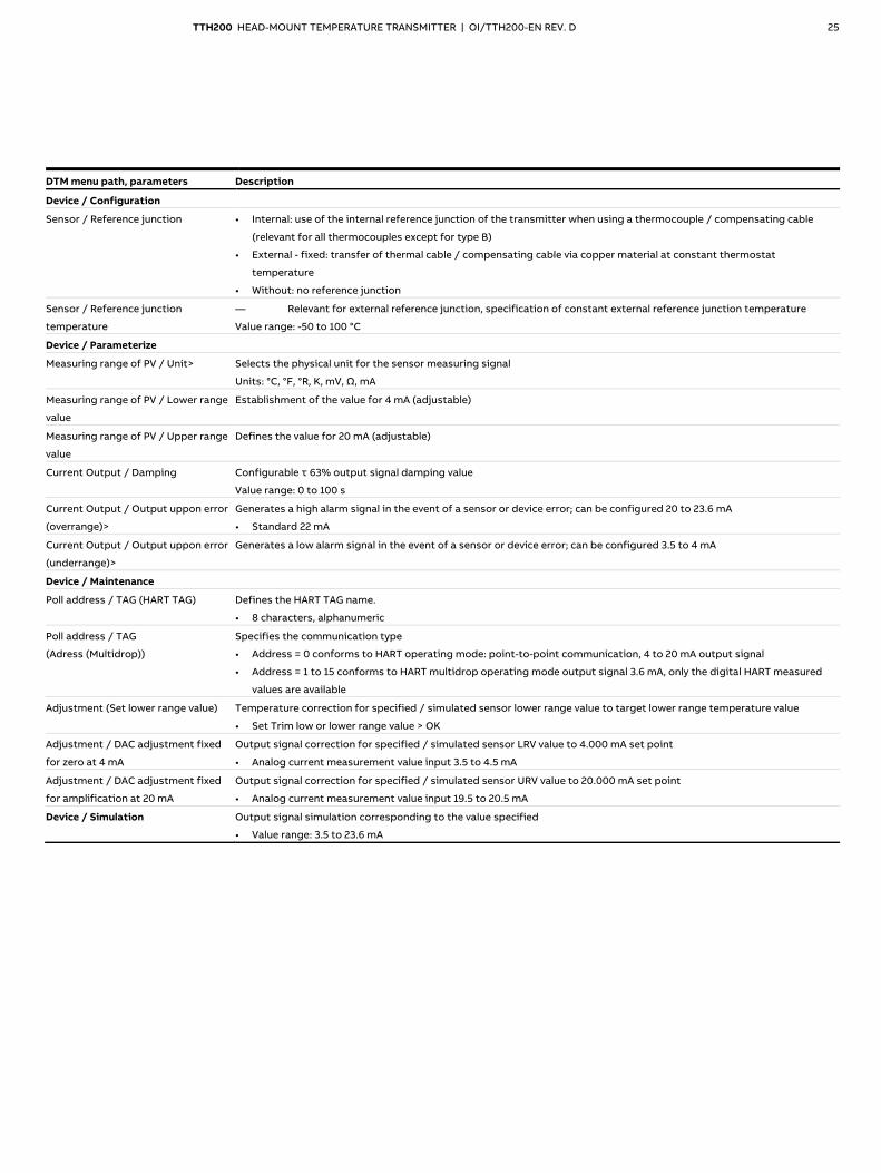
Parameter description for devices up to SW-Rev. 2.01
Note Devices to SW-Rev. 2.01 and from SW-Rev. 3.00 have partly different menus and parameters. The options for process variable representation are increased from SW-Rev. 3.00. Additional device and diagnostic information is provided. The setting and canceling of write protection has changed. In addition, for devices from SW-Rev. 3.00, additional information (event and configuration monitor) and detailed diagnostics can be displayed and configured in tools / drivers such as FIM and DTM. Note Depending on the tool used, the menus and parameters may differ from the following selection.
DTM menu path, parameters Description
Device / Extras
Write protection Activates write protection for the entire device
• Yes: locked, entry combination: ≠ 0110
• No: unlocked, entry combination: 0110
Device reset Configuration data is reset to factory settings
(see Factory settings on page 31).
Factory Reset Configuration data is reset to factory settings
(see Factory settings on page 31).
In addition, the adjustment data and DAC adjustment values are also reset to factory settings.
• Yes / OK
Device / Configuration
<Sensor / Sensor Type Selects sensor type:
• Pt100 (IEC751)
• Pt1000 (IEC751)
• Thermocouple type K (IEC584)
• Thermocouple type B (IEC584)
• Thermocouple type C (ASTME988)
• Thermocouple type D (ASTME988)
• Thermocouple type E (IEC584)
• Thermocouple type J (IEC584)
• Thermocouple type N (IEC584)
• Thermocouple type R (IEC584)
• Thermocouple type S (IEC584)
• Thermocouple type T (IEC584)
• Thermocouple type L (DIN43710)
• Thermocouple type U (DIN43710)
• Thermal voltage -125 to 125 mV
• Thermal voltage -125 to 1100 mV
• Resistance 0 to 500 Ω
• Resistance 0 to 5000 Ω
• Pt10 (IEC751)
• Pt50 (IEC751)
• Pt200 (IEC751)
• Pt500 (IEC751)
• Pt10 (JIS1604)
• Pt50 (JIS1604)
• Pt100 (JIS1604)
• Pt200 (JIS1604)
• Pt10 (IMIL24388)
• Pt50 (IMIL24388)
• Pt100 (MIL24388)
• Pt200 (MIL24388)
• Pt1000 (MIL24388)
• Ni50 (DIN43760)
• Ni100 (DIN43760)
• Ni120 (DIN43760)
• Ni1000 (DIN43760)
• Cu10 (OIML R 84), a=4270
• Cu100 (OIML R 84), a=4270
Sensor / Connection Sensor connection type relevant for all Pt, Ni, Cu resistance thermometers
• Two-wire: sensor connection type in two-wire technology
• Three-wire: sensor connection type in three-wire technology
• Four-wire: sensor connection type in four-wire technology
Sensor / Line resistance Sensor line resistance relevant for all Pt, Ni, Cu resistance thermometers with a two-wire circuit
Value range: 0 to 100 Ω
TTH200 HEAD-MOUNT TEMPERATURE TRANSMITTER | OI/TTH200-EN REV. D 25
DTM menu path, parameters Description
Device / Configuration
Sensor / Reference junction • Internal: use of the internal reference junction of the transmitter when using a thermocouple / compensating cable
(relevant for all thermocouples except for type B)
• External - fixed: transfer of thermal cable / compensating cable via copper material at constant thermostat
temperature
• Without: no reference junction
Sensor / Reference junction
temperature
— Relevant for external reference junction, specification of constant external reference junction temperature
Value range: -50 to 100 °C
Device / Parameterize
Measuring range of PV / Unit> Selects the physical unit for the sensor measuring signal
Units: °C, °F, °R, K, mV, Ω, mA
Measuring range of PV / Lower range
value
Establishment of the value for 4 mA (adjustable)
Measuring range of PV / Upper range
value
Defines the value for 20 mA (adjustable)
Current Output / Damping Configurable τ 63% output signal damping value
Value range: 0 to 100 s
Current Output / Output uppon error
(overrange)>
Generates a high alarm signal in the event of a sensor or device error; can be configured 20 to 23.6 mA
• Standard 22 mA
Current Output / Output uppon error
(underrange)>
Generates a low alarm signal in the event of a sensor or device error; can be configured 3.5 to 4 mA
Device / Maintenance
Poll address / TAG (HART TAG) Defines the HART TAG name.
• 8 characters, alphanumeric
Poll address / TAG
(Adress (Multidrop))
Specifies the communication type
• Address = 0 conforms to HART operating mode: point-to-point communication, 4 to 20 mA output signal
• Address = 1 to 15 conforms to HART multidrop operating mode output signal 3.6 mA, only the digital HART measured
values are available
Adjustment (Set lower range value) Temperature correction for specified / simulated sensor lower range value to target lower range temperature value
• Set Trim low or lower range value > OK
Adjustment / DAC adjustment fixed
for zero at 4 mA
Output signal correction for specified / simulated sensor LRV value to 4.000 mA set point
• Analog current measurement value input 3.5 to 4.5 mA
Adjustment / DAC adjustment fixed
for amplification at 20 mA
Output signal correction for specified / simulated sensor URV value to 20.000 mA set point
• Analog current measurement value input 19.5 to 20.5 mA
Device / Simulation Output signal simulation corresponding to the value specified
• Value range: 3.5 to 23.6 mA

26 TTH200 HEAD-MOUNT TEMPERATURE TRANSMITTER | OI/TTH200-EN REV. D
… 9 Commissioning
… Parameterization of the device
Parameter description for devices from SW-Rev. 3.00
Note Devices to SW-Rev. 2.01 and from SW-Rev. 3.00 have partly different menus and parameters. The options for process variable representation are increased from SW-Rev. 3.00. Additional device and diagnostic information is provided. The setting and canceling of write protection has changed. In addition, for devices from SW-Rev. 3.00, additional information (event and configuration monitor) and detailed diagnostics can be displayed and configured in tools / drivers such as FIM and DTM. Note Depending on the tool used, the menus and parameters may differ from the following selection.
Menu: Easy Setup
Menu / parameter Description
… / Device settings / Easy Setup
HART TAG Measuring point tagging
• 8 characters
Sensor Type Selects sensor type:
• 0 to 500 Ω: Linear resistance measurement 0 to 500 Ω
• 0 to 5000 Ω: Linear resistance measurement 0 to 5000 Ω
• Cal. Van Dusen 1: Callendar-Van Dusen coefficient set 1
• Pt50 (IEC751): Resistance thermometer Pt50 (IEC751)
• Pt100 (IEC751): Resistance thermometer Pt100 (IEC751)
• Pt200 (IEC751): Resistance thermometer Pt200 (IEC751)
• Pt500 (IEC751): Resistance thermometer Pt500 (IEC751)
• Pt1000 (IEC751): Resistance thermometer Pt1000 (IEC751)
• Pt50 (JIS1604): Resistance thermometer Pt50 (JIS1604)
• Pt100 (JIS1604): Resistance thermometer Pt100 (JIS1604)
• Pt50 (IMIL24388): Resistance thermometer Pt50 (MIL24388)
• Pt100 (MIL24388): Resistance thermometer Pt100 (MIL24388)
• Pt200 (MIL24388): Resistance thermometer Pt200 (MIL24388)
• Pt1000 (MIL24388): Resistance thermometer Pt1000 (MIL24388)
• Ni50 (DIN43760): Resistance thermometer Ni50 (DIN43716)
• Ni100 (DIN43760): Resistance thermometer Ni100 (DIN43716)
• Ni120 (DIN43760): Resistance thermometer Ni120 (DIN43716)
• Ni1000 (DIN43760): Resistance thermometer Ni1000 (DIN43716)
• Cu10 a=4260: Resistance thermometer Cu10 a=4260
• Cu100 a=4260: Resistance thermometer Cu100 a=4260
• Pt10 (IEC751): Resistance thermometer Pt10 (IEC751)
• Pt10 (JIS1604): Resistance thermometer Pt10 (JIS1604)
• Pt10 (IMIL24388): Resistance thermometer Pt10 (MIL24388)
• −125 to 125 mV: Linear voltage measurement −125 to 125 mV
• −125 to 1100 mV: Linear voltage measurement −125 to 1100 mV
• TC type B (IEC584): Thermocouple type B (IEC584)
• TC type C (ASTME988): Thermocouple type C (IEC584)
• TC type D (ASTME988): Thermocouple type D (ASTME988)
• TC type E (IEC584): Thermocouple type E (IEC584)
• TC type J (IEC584): Thermocouple type J (IEC584)
• TC type K (IEC584): Thermocouple type K (IEC584)

TTH200 HEAD-MOUNT TEMPERATURE TRANSMITTER | OI/TTH200-EN REV. D 27
Menu / parameter Description
… / Device settings / Easy Setup
Selection of the sensor type (continued):
• TC type N (IEC584): Thermocouple type N (IEC584)
• TC type R (IEC584): Thermocouple type R (IEC584)
• TC type S (IEC584): Thermocouple type S (IEC584)
• TC type T (IEC584): Thermocouple type T (IEC584)
• TC type L (DIN43710): Thermocouple type L (DIN43710)
• TC type U (DIN43710): Thermocouple type U (DIN43710)
• Cal. Van Dusen 2: Callendar Van Dusen coefficient set 2
• Cal. Van Dusen 3: Callendar Van Dusen coefficient set 3
• Cal. Van Dusen 4: Callendar Van Dusen coefficient set 4
• Cal. Van Dusen 5: Callendar Van Dusen coefficient set 5
• Fixpoint table 1: Customer-specific characteristic curve 1
• Fixpoint table 2: Customer-specific characteristic curve 2
• Fixpoint table 3: Customer-specific characteristic curve 3
• Fixpoint table 4: Customer-specific characteristic curve 4
• Fixpoint table 5: Customer-specific characteristic curve 5
R-Connection Sensor connection type relevant for all Pt, Ni, Cu resistance thermometers
• Two-wire: sensor connection type in two-wire technology
• Three-wire: sensor connection type in three-wire technology
• Four-wire: sensor connection type in four-wire technology
2-wire Resistance Sensor line resistance relevant for all Pt, Ni, Cu resistance thermometers with a two-wire circuit
Value range: 0 to 100 Ω
Cold junction compensation
thermocouple
Cold junction compensation for thermocouples:
• Internal: Use of internal cold junction temperature of the transmitter when using thermal compensating cable.
• External - fixed: Use of external fixed cold junction temperature of the transmitter when constant thermostat
temperature is used (can be set with external cold junction temperature).
• None: no Thermocouple cold junction compensation (CJC)
External cold junction temperature Relevant for external cold junction compensation, specification of constant external cold junction temperature
Value range: −50 to 100 °C
Process Variable PV Input / output assignment selects the inputs that are mapped to the current output
• Sensor 1
• Electr. meas. S1
• Temp. electronics
PV Unit Selects the physical unit for the sensor measuring signal
Units: °C, °F, °R, K, mV, Ω, V, kΩ
PV Lower Range Value Establishment of the value for 4 mA (adjustable)
PV Upper Range Value Defines the value for 20 mA (adjustable)
PV Damping Configurable τ 63% output signal damping value
Value range: 0 to 100 s
Looptest Simulates the current output signal
Value range: 3.500 to 23.600 mA
0.000 mA: ends looptest

28 TTH200 HEAD-MOUNT TEMPERATURE TRANSMITTER | OI/TTH200-EN REV. D
… 9 Commissioning
… Parameterization of the device Menu: Configuration
Menu / parameter Description
… Device settings / Detailed setup / Configuration
Sensor Type Selects sensor type:
Table of all sensor types: see ... /Easy Setup / Sensor Type
R-Connection Sensor connection type relevant for all Pt, Ni, Cu resistance thermometers
• Two-wire: sensor connection type in two-wire technology
• Three-wire: sensor connection type in three-wire technology
• Four-wire: sensor connection type in four-wire technology
2-wire Resistance Sensor line resistance relevant for all Pt, Ni, Cu resistance thermometers with a two-wire circuit
Value range: 0 to 100 Ω
Cold junction compensation
thermocouple
Cold junction compensation for thermocouples:
• Internal: Use of internal cold junction temperature of the transmitter when using thermal compensating cable.
• External - fixed: Use of external fixed cold junction temperature of the transmitter when constant thermostat
temperature is used (can be set with external cold junction temperature) .
• None: no Thermocouple cold junction compensation (CJC)
External cold junction temperature Relevant for external cold junction compensation, specification of constant external cold junction temperature
Value range: −50 to 100 °C
Menu: Display
Menu / parameter Description
… / Device settings / Detailed setup/ Display / Display settings
Language Language selects the menu language.
• German
• English
Contrast Sets the display contrast
Value range: 0 to 100 %
… / Device settings / Detailed setup/ Display / Operator Page 1
Display Mode Selects the mode for the operator page (main view) of the display
One line: Show line 1: one measurement value (default PV = process variable)
One line + Bargraph: Show line 1 and Bargraph
Two lines: Show second line with additional measurement value (example electronics temperature)
Two Lines + Bargraph: Show 2 lines and Bargraph
Line 1 View Selects the process value shown in Bargraph view of process display
• Process Variable: Calculated process variable (PV)
• Sensor 1: Measured value of sensor 1
• Electr. meas. S1: Measured value from sensor 1 (in Ω or mV)
• Electronics temp.: Temperature of the transmitter
• Output current: Output current of 4 to 20 mA signal
• Output %: Output value as % of the measuring range
Line 2 View Selects the process value shown in line 2 of process display (only 2 lines)
see table of process variables … / Display / Line 1 View
Bargraph View Selects the process value shown in Bargraph view of process display
see table of process variables … / Display / Line 1 View

TTH200 HEAD-MOUNT TEMPERATURE TRANSMITTER | OI/TTH200-EN REV. D 29
Menu: Parameter setup
Menu / parameter Description
… / Device settings / Detailed setup / Parameter setup / Parameter Current Output
Reaction on errors • Low alarm: in the event of an error, the current, for example 3.5 mA, is output
• High alarm: in the event of an error, the current, for example 22 mA, is output
Menu: HART-Mapping
Menu / parameter Description
… / Device settings / Detailed setup / Parameter setup / HART-Mapping
Process Variable PV Input / output assignment selects the inputs that are mapped to the current output
• Sensor 1
• Electr. meas. S1
• Temp. electronics
PV Unit Selects the physical unit for the sensor measuring signal
Units: °C, °F, °R, K, mV, Ω, V, kΩ
Menu: Calibration
Menu / parameter Description
… / Device settings / Detailed setup / Calibration / Sensor 1 Calibration
Sensor calibration (trimming) is used for fine correction (including to compensate for the tolerance of the sensor). Resetting the calibration is recommended
when changing single-point calibration or two-point calibration. The “Reset to order” option in the Tools menu is used to reset to factory calibration (if this has
been performed).
One point trim Lower value of calibration for sensor 1 (zero point).
Parallel shift of all temperature values.
Finally, a stable reference temperature is required. For example, it can also be the current stable measured temperature.
Two point trim Lower and upper value of calibration for sensor 1 (zero point and amplification). Two exact temperature references are
required. For example ice water (0 °C) and boiling water (100 °C)
Reset trim Reset to the basic calibration for sensor 1 (delete calibration - like factory reset in the Extras menu)
… / Device settings / Detailed setup / Calibration / Current Output
D/A trim Adjustment of current output: allows adjustment of the start point (4 mA) and end point (20 mA) with an existing reference
(precision ammeter).
Menu: Diagnostics
Menu / parameter Description
… / Diagnostics / Overview
Device status Diagnostic notice (maintenance required, failure, etc.)
… / Diagnostics / Extended Diagnostics / Supervising Information
Electronics Temp. Select the ‘Electronics Temp.’ submenu.
Drag indicator: maximum or minimum device temperature
Processvalue Sensor 1 Select the ‘Processvalue Sensor 1’ submenu.
Drag indicator: maximum or minimum sensor temperature for sensor 1
Reset: Resets the values
… / Diagnostics / Extended Diagnostics / Operation Time Statistics
Operation Time Displays device the operation time.

30 TTH200 HEAD-MOUNT TEMPERATURE TRANSMITTER | OI/TTH200-EN REV. D
… 9 Commissioning
… Parameterization of the device
Menu: Identification
Menu / parameter Description
… / Device settings / Identification / Device
Model Displays device type.
Serial Number Device / HART serial
no.
7 or 8-digit serial number of the device electronic unit.
Current Loop Mode Only HART 7:
• Independent of the address
• Enabled = normal operation (output current depends on process variable (PV))
• Disabled = Constant output current (like Multidrop HART 5 address >0)
… / Device Info / Identification / Additional Device Revision
Software Version Displays device software version.
Hardware Version Displays device hardware version.
… / Device Info / Identification / Measurement point
Address (Multidrop) Address range in multidrop mode (HART 5)
Value range: 0 to 15 (0 means no multidrop mode)
Adress (HART 7) Address range (HART 7)
Value range: 0 to 63 (independent of Current Loop Mode)
Information HART 5:
• Address = 0 (Current Loop Mode enabled – Multidrop disabled)
• Address = 1 to 15 (Current Loop Mode disabled – Multidrop enabled)
HART Descriptor / Description Displays the HART Descriptor.
HART Message / Message Display the HART message.
Tag Displays the HART Tag.
Long Tag Display the HART long tag.
Menu: Extras
Menu / parameter Description
… / Device settings / Detailed setup / Extras
SIL Check SIL Check (for SIL devices only)
Checks whether the device configuration is valid for SIL Safety applications.
Factory Reset Device restarts with factory settings applied.
Reset to Order Device restarts with settings according to the customer order.
Device Reset Device restarts without configuration changes.
Set / Reset Write protection
Activates write protection for the entire device
• On: locked
• Off: unlocked
Software Switch HART 5 / HART 7 Switch the device from HART 5 to HART 7 or from HART 7 to HART 5.
A device restart (reset) is recommended after changing the HART version.
Caution: Different driver for tools for HART 5 and HART 7 required.

TTH200 HEAD-MOUNT TEMPERATURE TRANSMITTER | OI/TTH200-EN REV. D 31
Factory settings
The transmitter is configured ex works. Devices from SW-Rev. 3.00 These devices can be reset to the factory setting, as well as to the setting according to the customer order. With the menu item “Factory reset” in the “Extras” menu, the factory settings are reset to the factory settings according to the following table (corresponds to standard configuration BS). The menu item “Reset to order” in the “Extras” menu is used to reset to the configuration ordered by the customer (default configuration BS, customer-specific configuration without special user characteristic BF or customer-specific configuration with special user characteristic BG). The currently set HART protocol remains unchanged during a factory reset and a reset to order. All devices The following table contains the corresponding parameter values when resetting to factory settings.
Menu Designation Parameter Factory setting
Device Setup Write protection — No
Input Sensor Type Pt100 (IEC60751)
R-Connection Three-wire circuit
Lower range value 0
Upper range value 100
Unit Degrees C
Damping Off
Process Alarm Fault signaling To SW rev. 2.01: Overrange / high alarm 22 mA1
From SW-Rev. 3:00: Underrange / low alarm 3.5 mA1
Display Display Bargraph — Process value
Bargraph — Yes, output %
Language — English
Contrast — 50 %
Communication HART-Protocol — HART 5 / 7*
* The currently set HART protocol remains unchanged during any type of reset (all SW revisions).

32 TTH200 HEAD-MOUNT TEMPERATURE TRANSMITTER | OI/TTH200-EN REV. D
… 9 Commissioning
Basic Setup
Sensor error adjustment (adjustment function via tools) The sensor error adjustment can be performed in the Tools via the menu path Device settings / Detailed setup / Calibration. For sensor error adjustment, the sensor connected to the transmitter must be brought to the lower range value temperature / Trim low using a water quench or oven. It is important to make sure the temperature is balanced and stable. Tools for devices from SW rev. 3.00 additionally support a two-point adjustment with “Trim high”. Check that the proper adjustment temperature for the sensor has been entered in the Tools before adjusting it. Based on the comparison of the adjustment temperature entered (setpoints) with the digital temperature measured by the transmitter, which is available after linearization in the form of HART temperature information, the transmitter calculates the temperature deviation resulting from the sensor error. During sensor adjustment (single-point adjustment), the temperature deviation calculated results in an offset shift of the linear characteristic output by the linearization module; the values of this characteristic correspond to the HART signal or are sent to the current output. A pure sensor offset error can be corrected via the calibration function ‘Set lower range value’ or the adjustment function ‘Trim low’. By contrast, if the error is not a pure sensor offset error, it can only be corrected using two-point adjustment or two-point calibration (“Trim high”).
D / A analog output adjustment (4 mA- and 20 mA-Trim) D/A analog output adjustment is used to compensate for errors in the current input of the higher-level system. D/A analog output adjustment for the transmitter can be used to modify the loop current so that the desired value is displayed in the higher-level system. Error compensation for the higher-level system is possible at the lower range value with 4 mA and / or 20 mA (single-point error correction: offset or two-point error correction: offset + linear gradient). The D / A sensor error adjustment can be performed in the Tools via the menu path Device settings / Detailed setup / Calibration. Prior to analog adjustment, it is necessary to determine the loop current values based on iterative entry of current values in simulation mode; the higher-level I/O system displays exactly 4.000 mA or the lower range limit temperature, and 20.000 mA or the upper range limit temperature. The current loop values must be measured using an ammeter and recorded. The lower range limit value or 4.000 mA should then be simulated in D / A analog output compensation mode using sensor simulation. Following this, the iteratively calculated current value at which the higher-level system displays exactly 4.000 mA or the lower range limit value must be entered as an adjustment value. Proceed in a similar manner for the upper range value or 20.000 mA. After this correction, the AD converter error of the higher-level system is corrected by the DA converter of the transmitter For the higher-level system, the value of the analog 4 to 20 mA output signal and the digital HART signal now match. The adjustment should be repeated when connecting the transmitter to another input of a higher-level system.

TTH200 HEAD-MOUNT TEMPERATURE TRANSMITTER | OI/TTH200-EN REV. D 33
HART variables The transmitter provides three HART variables. The HART variables are assigned the following values: • Primary HART variable: process value The primary HART variable is assigned permanently to the
analog output and is accordingly mapped to the 4 to 20 mA signal.
• Secondary HART variable: electronic unit temperature • Third-level HART variable: electric input Communication / HART TAG / device addressing For ease of identification, each HART device features a configurable 8-digit HART TAG. When storing HART TAG measuring point tags with more than 8 digits in the device, use the ‘Message’ parameter, which supports up to 32 characters. The HART LONG TAG with 32 characters can also be used for devices in HART 7 mode. In addition to the HART TAG, each device has a HART address. This address is set to 0 by default, which means that the device operates in HART standard communication mode (point-to-point operation). The following applies for devices in HART 5 mode: When an address in the range 1 to 15 is used, the device switches to HART multidrop mode with constant current output. This operating mode enables users to connect up to 15 devices to a power supply unit in parallel. The following applies for devices in HART 7 mode: HART 7 mode supports an address range from 0 to 63. The address can be selected independently of the activated current loop mode (loop current 4 to 20 mA) or constant output current. The current loop mode is activated/deactivated and the address is selected via the Tools. The operating mode with constant output current enables the connection of up to 64 devices to a power supply unit in parallel. In HART multidrop mode (HART 5) as well as with constant output current (current loop mode deactivated, HART 7), there is no analog output signal available with a value corresponding to the process temperature. The output signal then remains constant at 4.0 mA (from SW rev. 3.00, previously 3.6 mA) and is used exclusively for supplying power to the device. The sensor or process data information is available only as a HART signal.
10 Operation
Safety instructions
If there is a chance that safe operation is no longer possible, take the device out of operation and secure it against unintended startup.
Process display
Note The device does not have operating elements for parameterization on site. Parameterization takes place via the HART interface.
A11169
-
°C
PV 100%
25.7
1
3
2
1 Measuring point tagging (Device TAG)
2 Current process values
3 ‘Parameterization protected’ symbol
Figure 17: Process display (example)
The process display appears on the LCD display when the device is powered on. It shows information about the device and current process values. From SW-Rev. 3.00, two process variables can also be optionally displayed: one is displayed on top of the other.

34 TTH200 HEAD-MOUNT TEMPERATURE TRANSMITTER | OI/TTH200-EN REV. D
… 10 Operation
… Process display
Error messages on the LCD display In the event of an error, different information appears depending on the revision:
• To SW-Rev. 2.01: A symbol or letter (Device Status) and a number (DIAG.NO.)
• As of SW-Rev. 3.00: Corresponding device status symbol and associated diagnostics group.
Process display
To SW-Rev. 2.01
Application F72
Process display
From SW-Rev. 3.00
Sensor
The diagnostic messages are divided into the following groups in accordance with the NAMUR classification scheme:
Symbol
letter*
Status symbols
according to
NAMUR NE 107**
Description
I not applicable OK or Information Device is functioning or
information is available
C Check Function Device is undergoing
maintenance (for
example simulation)
S Off Specification Device or measuring point is
being operated outside of
the specifications
M Maintenance
Required
Request service to prevent
the measuring point from
failing
F Failure Error; measuring point has
failed
* To SW-Rev. 2.01
** From SW-Rev. 3.00
Additionally, the diagnostic messages are divided into the following areas:
Range Description
Electronics Diagnosis for device hardware.
Sensor Diagnosis for sensor elements and connection
lines.
Configuration Diagnosis of the communication interface and
parameterization / configuration.
Operating conditions Diagnosis for ambient and process conditions.
Process
(from SW-Rev. 3.00)
Notes and warnings when leaving the sensor or
process temperature range.
11 Diagnosis / error messages
The transmitter signals messages and errors in different ways. Messages via the HART interface The transmitter signals changed configuration or parameter setting by setting the HART flag ‘Configuration-changed’ (Configuration-changed). The message can be acknowledged via the tools. Error message on the LCD display To SW-Rev. 2.01 If the event of an error, a message consisting of a symbol or letter (device status) and a number (DIAG NO.) will appear at the bottom of the process display. From SW-Rev. 3.00 If the event of an error, a message consisting of a status symbol according to NAMUR NE 107 (device status) and specification of the diagnosis range appear at the bottom of the process display. Detailed information can be read through the tools. Error message on the current output Sensor or device errors can be indicated by underranging or overranging of the current output. Configuration takes place via the tools, menu path “Device settings / Detailed setup / Parameter setup / Parameter Current Output / Reaction on errors”.

TTH200 HEAD-MOUNT TEMPERATURE TRANSMITTER | OI/TTH200-EN REV. D 35
Diagnostic information, from SW-Rev. 3.00
Monitoring of operating data The transmitter saves the highest and lowest values for the electronic unit temperature as well as measured values from the sensor in the non-volatile memory (‘Drag Indicator’).
Value Description
Monitoring of the 4 to 20 mA loop current.
Max. elec. temp. Highest detected internal temperature in °C that the transmitter was subjected to. This value cannot be
reset.
Min. elec. temp. Lowest detected internal temperature in °C that the transmitter was subjected to. This value cannot be
reset.
Max. reading for sensors
Largest measured sensor value. When changing the sensor type (e.g., Pt100 to thermocouple type K), the
value is reset automatically.
Min. reading for sensors Smallest measured sensor value. When changing the sensor type the value is reset automatically.
Reset The drag indicators for the sensor readings are all reset to the current measured value in each case.
Operating hours statistics
Value Description
Operation Time Total hours since commissioning that the supply voltage has been switched on for the transmitter.
Operation Time (according to unit temperature)* The operating hours are categorized according to the measured internal temperature of the transmitter.
Due to rounding and frequently switching the device on and off, the total of the individual values may differ
slightly from the value displayed by the counter for operating hours. Values in the fields on the far left and
right indicate operation of the transmitter outside the specified range. In this event, acknowledged
properties of the transmitter might be limited, in particular, with respect to accuracy and service life.
* In tools such as FIM and DTM

36 TTH200 HEAD-MOUNT TEMPERATURE TRANSMITTER | OI/TTH200-EN REV. D
… 11 Diagnosis / error messages
Possible error messages – HART® devices to SW-Rev. 2.01
Range Displays the
device status
Displays the
DIAG. NO.
Cause Remedy
Electronics F 1 Device defective Replace the device
Electronics S 2 Ambient temperature overshot / undershot Check environment; reposition measuring point
if required
Electronics F 3 EEPROM defective Replace the device
Electronics M 4 Electronics overload Factory reset
Electronics F 5 Memory error Factory reset
Electronics I 7 LCD indicator connected Status info; not an error
Installation / configuration I 8 Device write-protected Status info; not an error
Electronics I 9 EEPROM busy Status info; not an error
Electronics F 12 Sensor input defective (communication) Replace the device
Electronics F 13 Sensor input defective (error) Replace the device
Electronics F 14 Sensor input defective (ADC error) Replace the device
Installation / configuration C 32 Diagnostics simulation mode Not an error, diagnostic info, measurement OK
Sensor F 34 Measuring error, sensor Check sensor connection
Sensor F 35 Short-circuit, sensor Check sensor connection
Sensor F 36 Wire break, sensor Check sensor connection
Sensor F 37 Range overshot, sensor Check measuring limits
Sensor F 38 Range undershot, sensor Check measuring limits
Installation / configuration I 41 Single-point adjustment active, sensor Status info; not an error
Installation / configuration I 42 Two-point adjustment active, sensor Status info; not an error
Installation / configuration F 65 Configuration defective Check configuration:
• Incorrect device
• Measuring span is too small
• Incorrect configuration data
Installation / configuration C 71 Reconfiguration is running Status info; not an error
Operating conditions F 72 Error in the application Check configuration, connections; reset to
factory settings
Installation / configuration I 74 Analog output adjustment active Status info; not an error
Installation / configuration C 75 Analog output in simulation Status info; not an error
Operating conditions S 76 Values overshot Check parameters:
• Sensor limits up-scaled
• Measuring span is too small
Note If the remedial measures listed for the error message do not improve the status of the device, please consult ABB Service.

TTH200 HEAD-MOUNT TEMPERATURE TRANSMITTER | OI/TTH200-EN REV. D 37
Possible error messages – HART® devices from SW-Rev. 3.00
Range Device status message (in the display) Cause Remedy
Sensor Sensor 1: line resistance too high Maintenance required Check sensor or replace / repair sensor
Sensor Sensor 1: short circuit Maintenance required Check sensor or replace / repair sensor
Sensor Sensor 1: wire break / sensor break Maintenance required Check sensor or replace / repair sensor
Sensor Sensor 1: single-point trim active Check function
Sensor Sensor 1: two-point trim active Check function
Sensor Application failure Failure Check sensor connection / Check HART variable mapping
Operation Diagnostics is simulated Check function Terminate / come out of simulation
Operation The analog output is fixed or simulated Check function Terminate / come out of simulation
Operation Application warning Check function Load valid parameter / restart (reset) / check sensor 1
Electronics Electronics temperature measurement
failure
Failure Restart (RESET) or replace transmitter
Electronics Electronics temperature out of
specification
Out of specification Observe spec. ambient temp. range
Electronics Non-volatile data defect Failure Restart (RESET) or replace transmitter
Electronics Non-volatile memory write cycles exceeded Maintenance required Restart (RESET) or replace transmitter
Electronics Device not calibrated Failure Restart (RESET) or replace transmitter
Electronics Electronics failure Failure Restart (RESET) or replace transmitter
Process Sensor 1: above the sensor range Maintenance required Check sensor type, replace / change if necessary
Process Sensor 1: below the sensor range Maintenance required Check sensor type, replace / change if necessary
Process High limit: Alarm Out of specification Verify process or change limit value
Process Low limit: Alarm Out of specification Verify process or change limit value
Process High limit: Warning Out of specification Verify process or change limit value
Process Low limit: Warning Out of specification Verify process or change limit value
Configuration Configuration / Parameterization failure Failure
Note If the remedial measures listed for the error message do not improve the status of the device, please consult ABB Service.

TTH200 HEAD-MOUNT TEMPERATURE TRANSMITTER | OI/TTH200-EN REV. D 38
12 Special functions (from SW-Rev. 3.00)
The tools can be used to execute the following functions on devices from SW-Rev. 3.00 onwards. The exact designations in the various tools can differ from the following description.
SIL Check (From SW-Rev. 3.00 only when device with SIL2 conformity is ordered. The SIL Check function supports the operator in checking important functional safety parameters for the intended device utilization. It therefore facilitates the implementation of the required described in the SIL Safety Manual. A check of the current configuration and set device parameters for SIL conformity is performed. The areas checked include the following: • correct configuration in accordance with NAMUR • correct operation with
– HART 5: deactivated HART Multidrop mode – HART 7: activated Current Loop mode (loop current
4 to 20 mA) • correct setting of the alarm current and allocation of HART
variables • correct temperature configuration • The simulation mode must be switched off The SIL check function can be executed via the tools or via HART commands. Tools: menu path ‘Device settings / Detailed setup / Extras’.
Switching the HART version Devices from SW-Rev. 3.00 support both HART 7 and HART 5. Tools: menu path ‘Device settings / Detailed setup / Extras’. Switch the device from HART 5 to HART 7 and the other way around. A device restart is recommended after changing the HART version. Note Different drivers (DTMs, EDDs, FDI packages) will be required in the Tools for HART 5 and HART 7!
Configurable diagnosis categorization in accordance with NAMUR NE 107 Configuration of all diagnoses in accordance with NE 107 can be made via Tools as of SW-Rev. 3.00. The following categories can be assigned:
• Failure • Maintenance Required • Check Function • Out of Specification
Active diagnosis of the ‘Failure’ category results in a configured alarm current (high alarm, low alarm).

TTH200 HEAD-MOUNT TEMPERATURE TRANSMITTER | OI/TTH200-EN REV. D 39
13 Follow-up / Monitoring
As of SW-Rev. 3.00, the TTX200 transmitter supports the logging of critical events and follow-up of changes in device configuration. Both these monitors can be accessed via Tools:
• Event monitor for the logging of critical events • Configuration monitor for the logging of configuration
changes The time of the event / change is recorded in all log entries (shown in operating hours of the device, two decimal points).
Event monitor When the device is reset (reset, restart) or the supply voltage is powered-down and powered-up, the event monitor is emptied and is then available for storing 48 entries. New entries are cyclically written over the oldest entries. The Event monitor stores the following events: Setting and resetting of the signalization of:
• Upper limit value PV Alarm (Limit HIGH HIGH), the process temperature is higher than the set alarm value.
• Lower limit value PV Alarm (Limit LOW LOW), the process temperature is lower than the set alarm value.
• Upper limit value PV Warning (Limit HIGH), the process temperature is higher than the set warning value.
• Lower limit value PV Warning (Limit LOW), the process temperature is lower than the set warning value.
• Electronics temperature outside the specified range • Electronics temperature too high (above the specified
value). • Electronics temperature too low (below the specified
value).
Configuration monitor Changes to the configuration of the device are saved in non-volatile memory. This information is therefore once again available after device reset (reset, restart) or when the supply voltage is powered-down and powered-up. 50 entries can be saved. New entries are cyclically written over the oldest entries. In addition, the value of the current HART Configuration Change Counters is entered. The following configuration changes can be recorded:
• Sensor configuration change • Change of the set sensor measuring range • Change of the NAMUR configuration • Change of the PV alarm and warning limit values (such as
Limit HIGH HIGH) • Change of the assignment of HART variables (PV, SV, TV
and QV) By default, the listed configuration changes are NOT logged. They can however be released for logging individually in the Tools

40 TTH200 HEAD-MOUNT TEMPERATURE TRANSMITTER | OI/TTH200-EN REV. D
14 Maintenance
Safety instructions
CAUTION Risk of burns due to hot measuring media The device surface temperature may exceed 70 °C (158 °F), depending on the measuring medium temperature! • Before starting work on the device, make sure that it has
cooled sufficiently.
If transmitters are used as intended under normal operating conditions, no maintenance is required.
Cleaning
When cleaning the exterior of meters, make sure that the cleaning agent used does not corrode the housing surface and the gaskets.
When using the device in potentially explosive atmospheres, observe the notice on cleaning in Protection against electrostatic discharges on page 10.
15 Repair
Safety instructions
DANGER Explosion hazard Explosion hazard due to improper repair of the device. • Faulty devices may not be repaired by the operator. • The device may only be repaired by the ABB Service
Department.
On-site repair of the transmitter or exchange of electronic components is not permissible.
Returning devices
Use the original packaging or a secure transport container of an appropriate type if you need to return the device for repair or recalibration purposes. Fill out the return form (see Return form on page 42) and include this with the device. In accordance with the EU Directive governing hazardous materials, the owner of hazardous waste is responsible for its disposal or must observe the following regulations for shipping purposes: All devices delivered to ABB must be free from any hazardous materials (acids, alkalis, solvents, etc.).
Please contact Customer Center Service acc. to page 5 for nearest service location.

TTH200 HEAD-MOUNT TEMPERATURE TRANSMITTER | OI/TTH200-EN REV. D 41
16 Recycling and disposal
Note
Products that are marked with the adjacent symbol may not be disposed of as unsorted municipal waste (domestic waste). They should be disposed of through separate collection of electric and electronic devices.
This product and its packaging are manufactured from materials that can be recycled by specialist recycling companies. Bear the following points in mind when disposing of them:
• As of 8/15/2018, this product will be under the open scope of the WEEE Directive 2012/19/EU and relevant national laws (for example, ElektroG - Electrical Equipment Act - in Germany).
• The product must be supplied to a specialist recycling company. Do not use municipal waste collection points. These may be used for privately used products only in accordance with WEEE Directive 2012/19/EU.
• If there is no possibility to dispose of the old equipment properly, our Service can take care of its pick-up and disposal for a fee.
Trademarks
HART is a registered trademark of FieldComm Group, Austin, Texas, USA
17 Specification
Note The device data sheet is available in the ABB download area at www.abb.com/temperature.
18 Additional documents
Note Declarations of conformity of the device are available in the download area of ABB at www.abb.com/temperature. In addition, these are also included with the device in case of ATEX-certified devices.

42 TTH200 HEAD-MOUNT TEMPERATURE TRANSMITTER | OI/TTH200-EN REV. D
19 Appendix
Return form
Statement on the contamination of devices and components Repair and/or maintenance work will only be performed on devices and components if a statement form has been completed and submitted. Otherwise, the device/component returned may be rejected. This statement form may only be completed and signed by authorized specialist personnel employed by the operator. Customer details: Company: Address: Contact person: Telephone: Fax: Email: Device details: Type: Serial no.: Reason for the return/description of the defect: Was this device used in conjunction with substances which pose a threat or risk to health? Yes No If yes, which type of contamination (please place an X next to the applicable items): biological corrosive / irritating combustible (highly / extremely
combustible) toxic explosive other toxic substances radioactive Which substances have come into contact with the device? 1. 2. 3. We hereby state that the devices/components shipped have been cleaned and are free from any dangerous or poisonous substances. Town/city, date Signature and company stamp

TTH200 HEAD-MOUNT TEMPERATURE TRANSMITTER | OI/TTH200-EN REV. D 43
Notes

— A B B M E A S U R E M E N T & A N A L Y T I C S | OP E R A T I N G I N ST R U C T I ON | O I / T T H 2 0 0 - EN R E V . D
TTH200 Head-mount temperature transmitter
— ABB Measurement & Analytics For your local ABB contact, visit: www.abb.com/contacts For more product information, visit: www.abb.com/temperature
Temperature transmitter for HART protocol. Suitable for all standard requirements
Measurement made easy
OI/
TTH
200
-EN
Rev
. D
12.2
020
— TTH200 Introduction
The TTH200 with the 4 to 20 mA output and HART communications protocol has global approvals for explosion protection up to Zone 0. Safety-relevant applications up to SIL 3 (redundant) are supported in accordance with IEC 61508. The TTH200 implements various NAMUR recommendations, including NE 89 and NE 107. The TTH200 features a universal sensor input for resistance thermometer, thermocouples, resistance and voltage measurement.
Additional Information Additional documentation on TTH200 is available for download free of charge at www.abb.com/temperature. Alternatively simply scan this code:
— We reserve the right to make technical changes or modify the contents of this document without prior notice. With regard to purchase orders, the agreed particulars shall prevail. ABB does not accept any responsibility whatsoever for potential errors or possible lack of information in this document. We reserve all rights in this document and in the subject matter and illustrations contained therein. Any reproduction, disclosure to third parties or utilization of its contents – in whole or in parts – is forbidden without prior written consent of ABB. © ABB 2020 3KXT231002R4201